Dell PowerEdge T20 Owner's Manual
73
Dell PowerEdge T20 Owner's Manual Regulatory Model: D13M Regulatory Type: D13M001
-
Upload
khangminh22 -
Category
Documents
-
view
2 -
download
0
Transcript of Dell PowerEdge T20 Owner's Manual

Dell PowerEdge T20Owner's Manual
Regulatory Model: D13MRegulatory Type: D13M001

Notes, cautions, and warningsNOTE: A NOTE indicates important information that helps you make better use of your product.
CAUTION: A CAUTION indicates either potential damage to hardware or loss of data and tells you how to avoid the problem.
WARNING: A WARNING indicates a potential for property damage, personal injury, or death.
© 2013 - 2018 Dell Inc. or its subsidiaries. All rights reserved. Dell, EMC, and other trademarks are trademarks of Dell Inc. or its subsidiaries. Other trademarks may be trademarks of their respective owners.
2016 - 06
Rev. A04
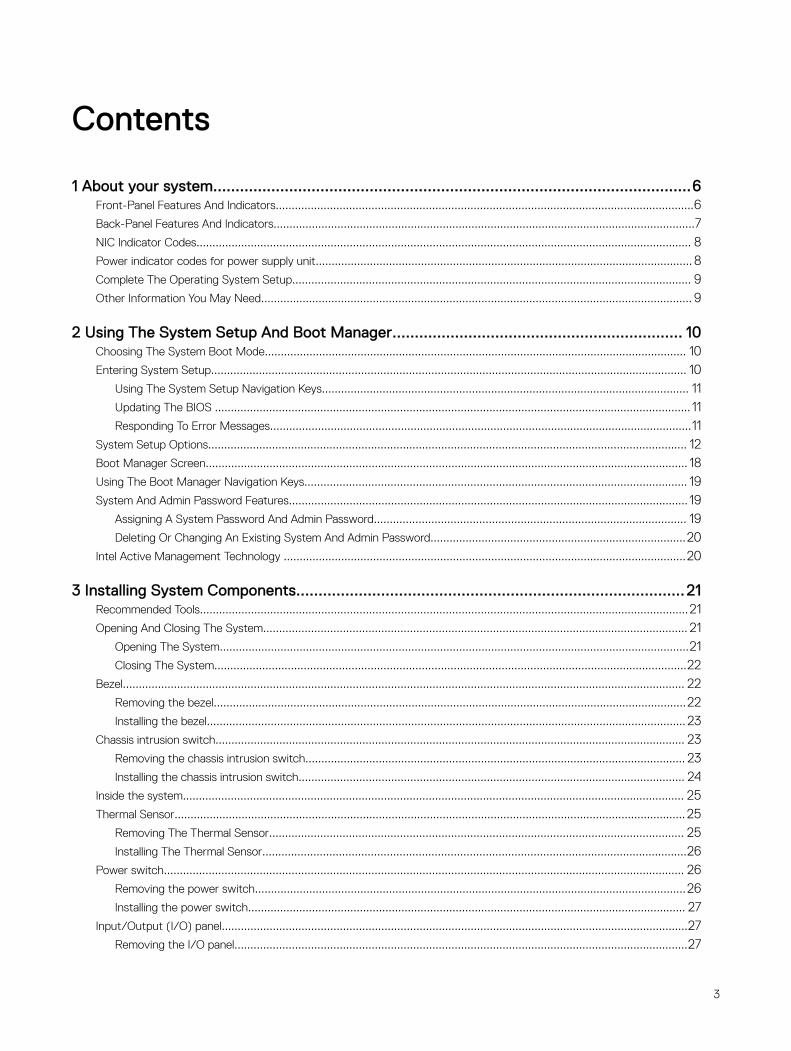
Contents
1 About your system...........................................................................................................6Front-Panel Features And Indicators...................................................................................................................................6Back-Panel Features And Indicators....................................................................................................................................7NIC Indicator Codes........................................................................................................................................................... 8Power indicator codes for power supply unit...................................................................................................................... 8Complete The Operating System Setup............................................................................................................................. 9Other Information You May Need....................................................................................................................................... 9
2 Using The System Setup And Boot Manager................................................................. 10Choosing The System Boot Mode.................................................................................................................................... 10Entering System Setup..................................................................................................................................................... 10
Using The System Setup Navigation Keys................................................................................................................... 11Updating The BIOS ..................................................................................................................................................... 11Responding To Error Messages....................................................................................................................................11
System Setup Options...................................................................................................................................................... 12Boot Manager Screen....................................................................................................................................................... 18Using The Boot Manager Navigation Keys........................................................................................................................ 19System And Admin Password Features............................................................................................................................. 19
Assigning A System Password And Admin Password.................................................................................................. 19Deleting Or Changing An Existing System And Admin Password................................................................................20
Intel Active Management Technology ..............................................................................................................................20
3 Installing System Components.......................................................................................21Recommended Tools.........................................................................................................................................................21Opening And Closing The System..................................................................................................................................... 21
Opening The System...................................................................................................................................................21Closing The System....................................................................................................................................................22
Bezel................................................................................................................................................................................ 22Removing the bezel....................................................................................................................................................22Installing the bezel...................................................................................................................................................... 23
Chassis intrusion switch................................................................................................................................................... 23
Removing the chassis intrusion switch....................................................................................................................... 23Installing the chassis intrusion switch......................................................................................................................... 24
Inside the system............................................................................................................................................................. 25Thermal Sensor................................................................................................................................................................ 25
Removing The Thermal Sensor.................................................................................................................................. 25Installing The Thermal Sensor.....................................................................................................................................26
Power switch................................................................................................................................................................... 26Removing the power switch.......................................................................................................................................26Installing the power switch......................................................................................................................................... 27
Input/Output (I/O) panel..................................................................................................................................................27Removing the I/O panel..............................................................................................................................................27
3
Installing the I/O panel................................................................................................................................................28Hard drives.......................................................................................................................................................................28
Removing the hard drive cage....................................................................................................................................29Installing the hard drive cage......................................................................................................................................29Removing a 3.5-inch hard drive carrier from the hard drive cage............................................................................... 30Installing a 3.5-inch hard drive carrier in the hard drive cage...................................................................................... 30Removing a 2.5-inch hard drive(s) from the optical drive bay.....................................................................................30Installing a 2.5-inch hard drive(s) in the optical drive bay............................................................................................32Removing a 3.5-inch hard drive carrier from the hard drive bay..................................................................................33Installing a 3.5-inch hard drive carrier in the hard drive bay........................................................................................ 33Removing A Hard Drive From A Hard-Drive Carrier.................................................................................................... 34Installing A Hard Drive Into A Hard-Drive Carrier........................................................................................................ 35
Optical drive.....................................................................................................................................................................35Installing the optical drive........................................................................................................................................... 35Removing the optical drive.........................................................................................................................................36
System memory............................................................................................................................................................... 38General memory module installation guidelines...........................................................................................................40
Sample memory configurations........................................................................................................................................ 40Removing a memory module....................................................................................................................................... 41Installing a memory module........................................................................................................................................ 42
System fan....................................................................................................................................................................... 43Removing the system fan...........................................................................................................................................44Installing the system fan............................................................................................................................................. 44
Expansion cards............................................................................................................................................................... 45Expansion Card Installation Guidelines........................................................................................................................45Removing an expansion card......................................................................................................................................45Installing an expansion card........................................................................................................................................ 46
Processors....................................................................................................................................................................... 46Removing The Processor........................................................................................................................................... 46Installing The Processor..............................................................................................................................................48
Power supply unit.............................................................................................................................................................49Removing the power supply unit................................................................................................................................ 49Installing the power supply unit.................................................................................................................................. 50
System Battery................................................................................................................................................................. 51Replacing The System Battery.................................................................................................................................... 51
System board................................................................................................................................................................... 52Removing the system board.......................................................................................................................................52Installing the system board......................................................................................................................................... 52Entering The Service Tag After Replacing The System Board.................................................................................... 53
4 Troubleshooting your system.........................................................................................54Safety first—for you and your system..............................................................................................................................54Power LED Diagnostics.................................................................................................................................................... 54Memory Beep Code......................................................................................................................................................... 55Troubleshooting System Startup Failure........................................................................................................................... 55Troubleshooting external connections.............................................................................................................................. 55
4
Troubleshooting the video subsystem.............................................................................................................................. 55Troubleshooting a USB device..........................................................................................................................................55Troubleshooting a serial I/O device...................................................................................................................................56Troubleshooting A NIC......................................................................................................................................................56Troubleshooting A Wet System........................................................................................................................................ 56Troubleshooting A Damaged System................................................................................................................................ 57Troubleshooting the system battery..................................................................................................................................57Troubleshooting A Non-Redundant Power Supply............................................................................................................58Troubleshooting cooling problems.....................................................................................................................................58Troubleshooting The System Fan..................................................................................................................................... 58Troubleshooting System Memory..................................................................................................................................... 58Troubleshooting An Optical Drive..................................................................................................................................... 59Troubleshooting A Hard Drive...........................................................................................................................................59Troubleshooting Expansion Cards.....................................................................................................................................60Troubleshooting The Processor........................................................................................................................................ 60
5 Using System Diagnostics.............................................................................................62Enhanced Pre-Boot System Assessment Diagnostics...................................................................................................... 62
System diagnostics controls.......................................................................................................................................62
6 Jumpers and connectors............................................................................................... 63System board jumper settings.......................................................................................................................................... 63System Board Connectors................................................................................................................................................63Disabling A Forgotten Password....................................................................................................................................... 64
7 Technical Specifications................................................................................................ 66Environmental Specifications............................................................................................................................................67
8 System Messages......................................................................................................... 69Error Messages................................................................................................................................................................ 69Warning messages............................................................................................................................................................72Alert messages................................................................................................................................................................. 72
9 Getting help.................................................................................................................. 73Contacting Dell EMC........................................................................................................................................................ 73Locating your system Service Tag.................................................................................................................................... 73Documentation feedback..................................................................................................................................................73
5
1About your system
Front-Panel Features And Indicators
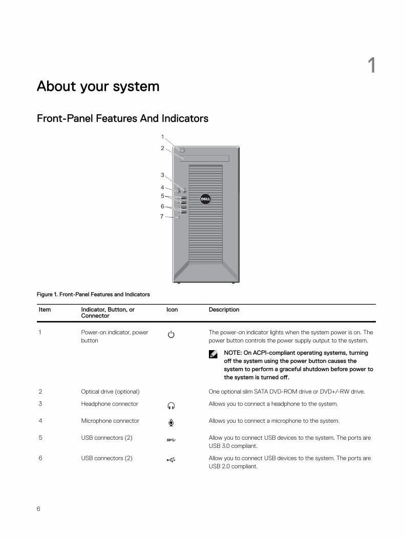
Figure 1. Front-Panel Features and Indicators
Item Indicator, Button, or Connector
Icon Description
1 Power-on indicator, power button
The power-on indicator lights when the system power is on. The power button controls the power supply output to the system.
NOTE: On ACPI-compliant operating systems, turning off the system using the power button causes the system to perform a graceful shutdown before power to the system is turned off.
2 Optical drive (optional) One optional slim SATA DVD-ROM drive or DVD+/-RW drive.
3 Headphone connector Allows you to connect a headphone to the system.
4 Microphone connector Allows you to connect a microphone to the system.
5 USB connectors (2) Allow you to connect USB devices to the system. The ports are USB 3.0 compliant.
6 USB connectors (2) Allow you to connect USB devices to the system. The ports are USB 2.0 compliant.
6
Item Indicator, Button, or Connector
Icon Description
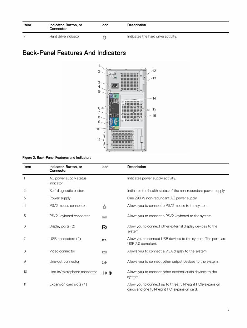
7 Hard drive indicator Indicates the hard drive activity.
Back-Panel Features And Indicators
Figure 2. Back-Panel Features and Indicators
Item Indicator, Button, or Connector
Icon Description
1 AC power supply status indicator
Indicates power supply activity.
2 Self-diagnostic button Indicates the health status of the non-redundant power supply.
3 Power supply One 290 W non-redundant AC power supply.
4 PS/2 mouse connector Allows you to connect a PS/2 mouse to the system.
5 PS/2 keyboard connector Allows you to connect a PS/2 keyboard to the system.
6 Display ports (2) Allow you to connect other external display devices to the system.
7 USB connectors (2) Allow you to connect USB devices to the system. The ports are USB 3.0 compliant.
8 Video connector Allows you to connect a VGA display to the system.
9 Line-out connector Allows you to connect other output devices to the system.
10 Line-in/microphone connector Allows you to connect other external audio devices to the system.
11 Expansion card slots (4) Allow you to connect up to three full-height PCIe expansion cards and one full-height PCI expansion card.
7
Item Indicator, Button, or Connector
Icon Description
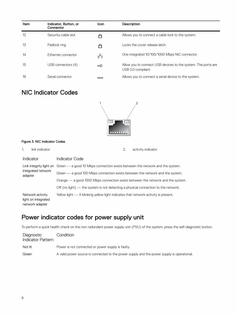
12 Security-cable slot Allows you to connect a cable lock to the system.
13 Padlock ring Locks the cover release latch.
14 Ethernet connector One integrated 10/100/1000 Mbps NIC connector.
15 USB connectors (4) Allow you to connect USB devices to the system. The ports are USB 2.0 compliant.
16 Serial connector Allows you to connect a serial device to the system.
NIC Indicator Codes
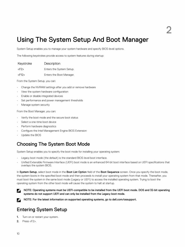
Figure 3. NIC Indicator Codes
1. link indicator 2. activity indicator
Indicator Indicator Code
Link integrity light on integrated network adapter
Green — a good 10 Mbps connection exists between the network and the system.
Green — a good 100 Mbps connection exists between the network and the system.
Orange — a good 1000 Mbps connection exists between the network and the system.
Off (no light) — the system is not detecting a physical connection to the network.
Network activity light on integrated network adapter
Yellow light — A blinking yellow light indicates that network activity is present.
Power indicator codes for power supply unitTo perform a quick health check on the non-redundant power supply unit (PSU) of the system, press the self-diagnostic button.
Diagnostic Indicator Pattern
Condition
Not lit Power is not connected or power supply is faulty.
Green A valid power source is connected to the power supply and the power supply is operational.
8

Figure 4. Power supply unit indicator codes
1. AC power supply status indicator 2. self-diagnostic button
Complete The Operating System SetupTo install an operating system for the first time, see the installation and configuration documentation for your operating system. Be sure that the operating system is installed before installing hardware or software not purchased with the system.
NOTE: For more information on supported operating systems, see dell.com/ossupport.
Other Information You May NeedWARNING: See the safety and regulatory information that shipped with your system. Warranty information may be included within this document or as a separate document.
• The Owner’s Manual provides information about system features and describes how to troubleshoot the system and install or replace system components. This document is available online at www.dell.com/poweredgemanuals.
• Any media that ships with your system that provides documentation and tools for configuring and managing your system, including those pertaining to the operating system, system management software, system updates, and system components that you purchased with your system.
• For latest information on supported operating systems, see dell.com/ossupport.
NOTE: Always check for updates on dell.com/support/manuals and read the updates first because they often supersede information in other documents.
NOTE: When upgrading your system, it is recommended that you download and install the latest BIOS, driver, and systems management firmware on your system from dell.com/support.
9
2Using The System Setup And Boot ManagerSystem Setup enables you to manage your system hardware and specify BIOS-level options.
The following keystrokes provide access to system features during startup:
Keystroke Description
<F2> Enters the System Setup.
<F12> Enters the Boot Manager.
From the System Setup, you can:
• Change the NVRAM settings after you add or remove hardware
• View the system hardware configuration
• Enable or disable integrated devices
• Set performance and power management thresholds
• Manage system security
From the Boot Manager, you can:
• Verify the boot mode and the secure boot status
• Select a one-time boot device
• Perform hardware diagnostics
• Configure the Intel Management Engine BIOS Extension
• Update the BIOS
Choosing The System Boot ModeSystem Setup enables you to specify the boot mode for installing your operating system:
• Legacy boot mode (the default) is the standard BIOS-level boot interface.
• Unified Extensible Firmware Interface (UEFI) boot mode is an enhanced 64-bit boot interface based on UEFI specifications that overlays the system BIOS.
In System Setup, select boot mode in the Boot List Option field of the Boot Sequence screen. Once you specify the boot mode, the system boots in the specified boot mode and then proceeds to install your operating system from that mode. Thereafter, you must boot the system in the same boot mode (Legacy or UEFI) to access the installed operating system. Trying to boot the operating system from the other boot mode will cause the system to halt at startup.
NOTE: Operating systems must be UEFI-compatible to be installed from the UEFI boot mode. DOS and 32-bit operating systems do not support UEFI and can only be installed from the Legacy boot mode.
NOTE: For the latest information on supported operating systems, go to dell.com/ossupport.
Entering System Setup1. Turn on or restart your system.
2. Press <F2>.
10
If your operating system begins to load before you press <F2>, allow the system to finish booting, and then restart your system and try again.
Using The System Setup Navigation Keys
Key Description
Up arrow Moves to the previous field.
Down arrow Moves to the next field.
<Enter> Allows you to type in a value in the selected field (if applicable) or follow the link in the field.
Spacebar Expands or collapses a drop-down list, if applicable.
<Tab> Moves to the next focus area.
NOTE: For the standard graphics browser only.
<Esc> Moves to the previous page till you view the main screen. Pressing <Esc> in the main screen exits the Boot Manager and proceeds with system boot.
NOTE: For most of the options, any changes that you make are recorded but do not take effect until you restart the system.
Updating The BIOS
It is recommended to update your BIOS (system setup), on replacing the system board or if an update is available.
1. Restart the system.
2. Go to dell.com/support.
3. If you do not have your system's Service Tag or Express Service Code:
4. Enter the Service Tag or Express Service Code and click Submit.
NOTE: To locate the Service Tag, click Where is my Service Tag?
NOTE: If you cannot find your Service Tag, click Detect Service Tag. Proceed with the instructions on screen.
5. If you are unable to locate or find the Service Tag, click the product category of your system.
6. Choose the product type from the list.
7. Select your system model and the product support page of your system is displayed.
8. Click Drivers & Downloads.
9. On the Drivers and Downloads screen, under the Operating System drop-down list, select BIOS.
10. Identify the latest BIOS file and click Download File.
11. Select your preferred download method in the Please select your download method below window and click Download File.
The File Download window is displayed.
12. Click Save to save the file on your system.
13. Click Run to install the updated BIOS settings on your system.
Follow the instructions on the screen.
Responding To Error Messages
If an error message is displayed while the system is booting, make a note of the message. For more information, see System Messages.
NOTE: After installing a memory upgrade, it is normal for your system to display a message the first time you start your system.
11
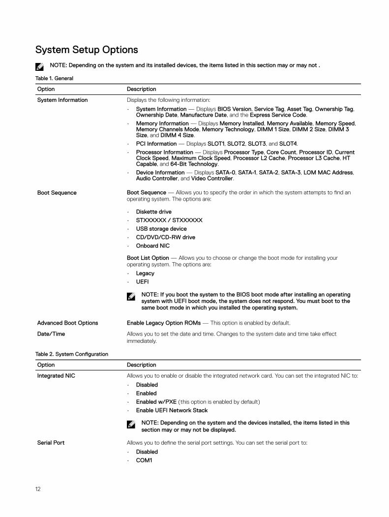
System Setup OptionsNOTE: Depending on the system and its installed devices, the items listed in this section may or may not .
Table 1. General
Option Description
System Information Displays the following information:
• System Information — Displays BIOS Version, Service Tag, Asset Tag, Ownership Tag, Ownership Date, Manufacture Date, and the Express Service Code.
• Memory Information — Displays Memory Installed, Memory Available, Memory Speed, Memory Channels Mode, Memory Technology, DIMM 1 Size, DIMM 2 Size, DIMM 3 Size, and DIMM 4 Size.
• PCI Information — Displays SLOT1, SLOT2, SLOT3, and SLOT4.
• Processor Information — Displays Processor Type, Core Count, Processor ID, Current Clock Speed, Maximum Clock Speed, Processor L2 Cache, Processor L3 Cache, HT Capable, and 64-Bit Technology.
• Device Information — Displays SATA-0, SATA-1, SATA-2, SATA-3, LOM MAC Address, Audio Controller, and Video Controller.
Boot Sequence Boot Sequence — Allows you to specify the order in which the system attempts to find an operating system. The options are:
• Diskette drive
• STXXXXXX / STXXXXXX
• USB storage device
• CD/DVD/CD-RW drive
• Onboard NIC
Boot List Option — Allows you to choose or change the boot mode for installing your operating system. The options are:
• Legacy
• UEFI
NOTE: If you boot the system to the BIOS boot mode after installing an operating system with UEFI boot mode, the system does not respond. You must boot to the same boot mode in which you installed the operating system.
Advanced Boot Options Enable Legacy Option ROMs — This option is enabled by default.
Date/Time Allows you to set the date and time. Changes to the system date and time take effect immediately.
Table 2. System Configuration
Option Description
Integrated NIC Allows you to enable or disable the integrated network card. You can set the integrated NIC to:
• Disabled
• Enabled
• Enabled w/PXE (this option is enabled by default)
• Enable UEFI Network Stack
NOTE: Depending on the system and the devices installed, the items listed in this section may or may not be displayed.
Serial Port Allows you to define the serial port settings. You can set the serial port to:
• Disabled
• COM1
12
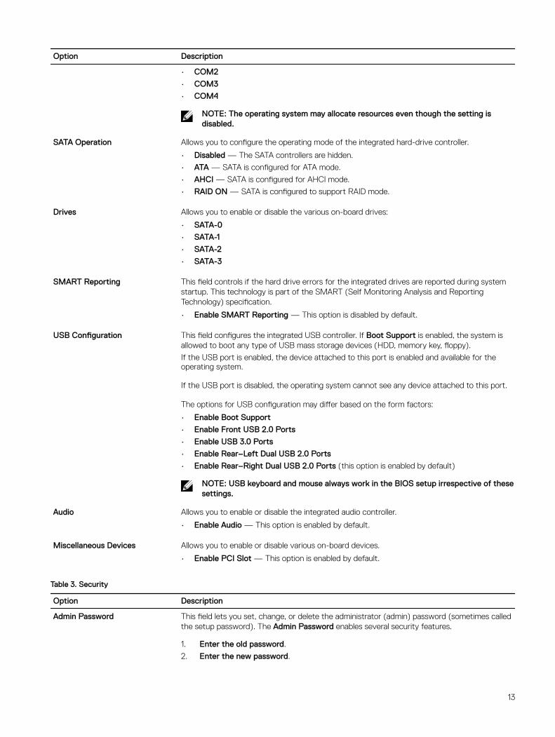
Option Description
• COM2
• COM3
• COM4
NOTE: The operating system may allocate resources even though the setting is disabled.
SATA Operation Allows you to configure the operating mode of the integrated hard-drive controller.
• Disabled — The SATA controllers are hidden.
• ATA — SATA is configured for ATA mode.
• AHCI — SATA is configured for AHCI mode.
• RAID ON — SATA is configured to support RAID mode.
Drives Allows you to enable or disable the various on-board drives:
• SATA-0
• SATA-1
• SATA-2
• SATA-3
SMART Reporting This field controls if the hard drive errors for the integrated drives are reported during system startup. This technology is part of the SMART (Self Monitoring Analysis and Reporting Technology) specification.
• Enable SMART Reporting — This option is disabled by default.
USB Configuration This field configures the integrated USB controller. If Boot Support is enabled, the system is allowed to boot any type of USB mass storage devices (HDD, memory key, floppy).
If the USB port is enabled, the device attached to this port is enabled and available for the operating system.
If the USB port is disabled, the operating system cannot see any device attached to this port.
The options for USB configuration may differ based on the form factors:
• Enable Boot Support
• Enable Front USB 2.0 Ports
• Enable USB 3.0 Ports
• Enable Rear–Left Dual USB 2.0 Ports
• Enable Rear–Right Dual USB 2.0 Ports (this option is enabled by default)
NOTE: USB keyboard and mouse always work in the BIOS setup irrespective of these settings.
Audio Allows you to enable or disable the integrated audio controller.
• Enable Audio — This option is enabled by default.
Miscellaneous Devices Allows you to enable or disable various on-board devices.
• Enable PCI Slot — This option is enabled by default.
Table 3. Security
Option Description
Admin Password This field lets you set, change, or delete the administrator (admin) password (sometimes called the setup password). The Admin Password enables several security features.
1. Enter the old password.
2. Enter the new password.
13
Option Description
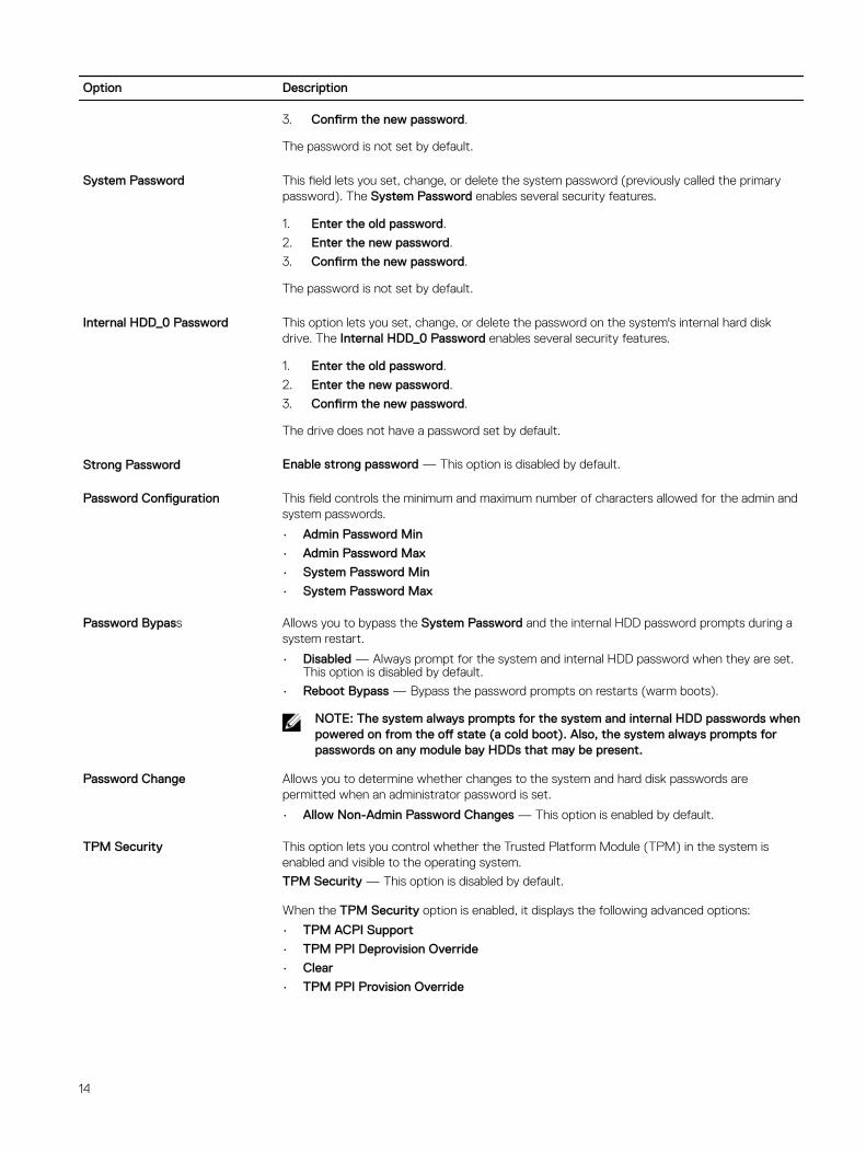
3. Confirm the new password.
The password is not set by default.
System Password This field lets you set, change, or delete the system password (previously called the primary password). The System Password enables several security features.
1. Enter the old password.
2. Enter the new password.
3. Confirm the new password.
The password is not set by default.
Internal HDD_0 Password This option lets you set, change, or delete the password on the system's internal hard disk drive. The Internal HDD_0 Password enables several security features.
1. Enter the old password.
2. Enter the new password.
3. Confirm the new password.
The drive does not have a password set by default.
Strong Password Enable strong password — This option is disabled by default.
Password Configuration This field controls the minimum and maximum number of characters allowed for the admin and system passwords.
• Admin Password Min
• Admin Password Max
• System Password Min
• System Password Max
Password Bypass Allows you to bypass the System Password and the internal HDD password prompts during a system restart.
• Disabled — Always prompt for the system and internal HDD password when they are set. This option is disabled by default.
• Reboot Bypass — Bypass the password prompts on restarts (warm boots).
NOTE: The system always prompts for the system and internal HDD passwords when powered on from the off state (a cold boot). Also, the system always prompts for passwords on any module bay HDDs that may be present.
Password Change Allows you to determine whether changes to the system and hard disk passwords are permitted when an administrator password is set.
• Allow Non-Admin Password Changes — This option is enabled by default.
TPM Security This option lets you control whether the Trusted Platform Module (TPM) in the system is enabled and visible to the operating system.
TPM Security — This option is disabled by default.
When the TPM Security option is enabled, it displays the following advanced options:
• TPM ACPI Support
• TPM PPI Deprovision Override
• Clear
• TPM PPI Provision Override
14
Option Description
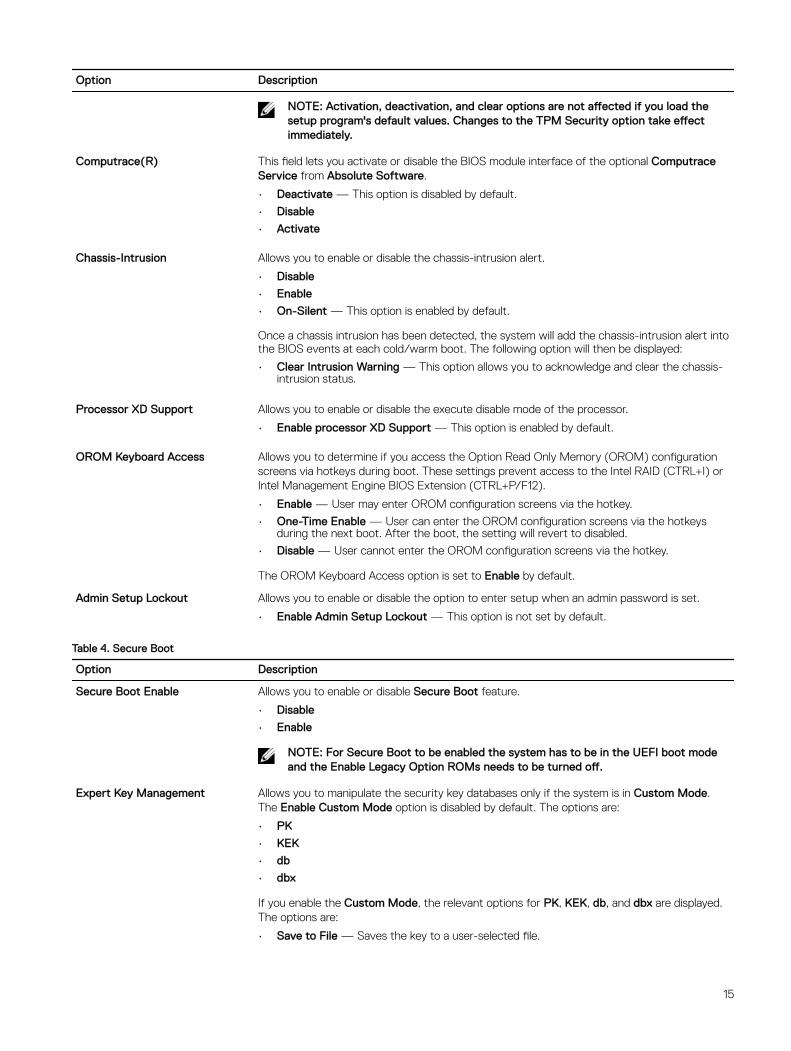
NOTE: Activation, deactivation, and clear options are not affected if you load the setup program's default values. Changes to the TPM Security option take effect immediately.
Computrace(R) This field lets you activate or disable the BIOS module interface of the optional Computrace Service from Absolute Software.
• Deactivate — This option is disabled by default.
• Disable
• Activate
Chassis-Intrusion Allows you to enable or disable the chassis-intrusion alert.
• Disable
• Enable
• On-Silent — This option is enabled by default.
Once a chassis intrusion has been detected, the system will add the chassis-intrusion alert into the BIOS events at each cold/warm boot. The following option will then be displayed:
• Clear Intrusion Warning — This option allows you to acknowledge and clear the chassis-intrusion status.
Processor XD Support Allows you to enable or disable the execute disable mode of the processor.
• Enable processor XD Support — This option is enabled by default.
OROM Keyboard Access Allows you to determine if you access the Option Read Only Memory (OROM) configuration screens via hotkeys during boot. These settings prevent access to the Intel RAID (CTRL+I) or Intel Management Engine BIOS Extension (CTRL+P/F12).
• Enable — User may enter OROM configuration screens via the hotkey.
• One-Time Enable — User can enter the OROM configuration screens via the hotkeys during the next boot. After the boot, the setting will revert to disabled.
• Disable — User cannot enter the OROM configuration screens via the hotkey.
The OROM Keyboard Access option is set to Enable by default.
Admin Setup Lockout Allows you to enable or disable the option to enter setup when an admin password is set.
• Enable Admin Setup Lockout — This option is not set by default.
Table 4. Secure Boot
Option Description
Secure Boot Enable Allows you to enable or disable Secure Boot feature.
• Disable
• Enable
NOTE: For Secure Boot to be enabled the system has to be in the UEFI boot mode and the Enable Legacy Option ROMs needs to be turned off.
Expert Key Management Allows you to manipulate the security key databases only if the system is in Custom Mode. The Enable Custom Mode option is disabled by default. The options are:
• PK
• KEK
• db
• dbx
If you enable the Custom Mode, the relevant options for PK, KEK, db, and dbx are displayed. The options are:
• Save to File — Saves the key to a user-selected file.
15
Option Description
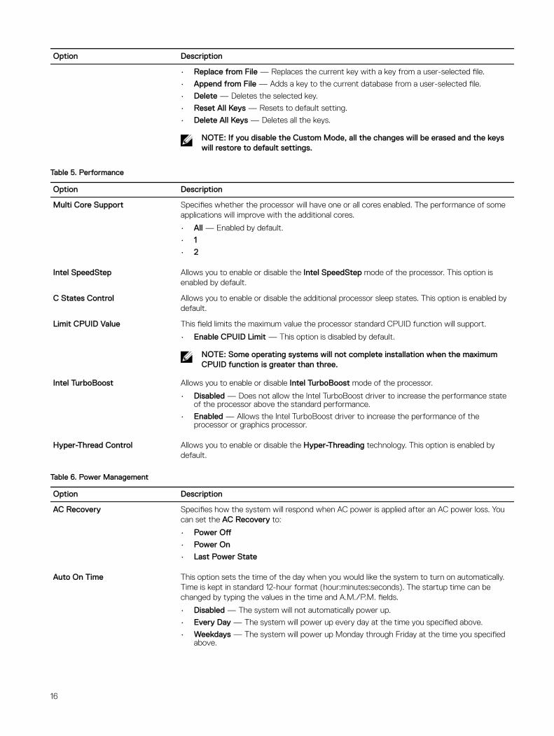
• Replace from File — Replaces the current key with a key from a user-selected file.
• Append from File — Adds a key to the current database from a user-selected file.
• Delete — Deletes the selected key.
• Reset All Keys — Resets to default setting.
• Delete All Keys — Deletes all the keys.
NOTE: If you disable the Custom Mode, all the changes will be erased and the keys will restore to default settings.
Table 5. Performance
Option Description
Multi Core Support Specifies whether the processor will have one or all cores enabled. The performance of some applications will improve with the additional cores.
• All — Enabled by default.
• 1
• 2
Intel SpeedStep Allows you to enable or disable the Intel SpeedStep mode of the processor. This option is enabled by default.
C States Control Allows you to enable or disable the additional processor sleep states. This option is enabled by default.
Limit CPUID Value This field limits the maximum value the processor standard CPUID function will support.
• Enable CPUID Limit — This option is disabled by default.
NOTE: Some operating systems will not complete installation when the maximum CPUID function is greater than three.
Intel TurboBoost Allows you to enable or disable Intel TurboBoost mode of the processor.
• Disabled — Does not allow the Intel TurboBoost driver to increase the performance state of the processor above the standard performance.
• Enabled — Allows the Intel TurboBoost driver to increase the performance of the processor or graphics processor.
Hyper-Thread Control Allows you to enable or disable the Hyper-Threading technology. This option is enabled by default.
Table 6. Power Management
Option Description
AC Recovery Specifies how the system will respond when AC power is applied after an AC power loss. You can set the AC Recovery to:
• Power Off
• Power On
• Last Power State
Auto On Time This option sets the time of the day when you would like the system to turn on automatically. Time is kept in standard 12-hour format (hour:minutes:seconds). The startup time can be changed by typing the values in the time and A.M./P.M. fields.
• Disabled — The system will not automatically power up.
• Every Day — The system will power up every day at the time you specified above.
• Weekdays — The system will power up Monday through Friday at the time you specified above.
16
Option Description
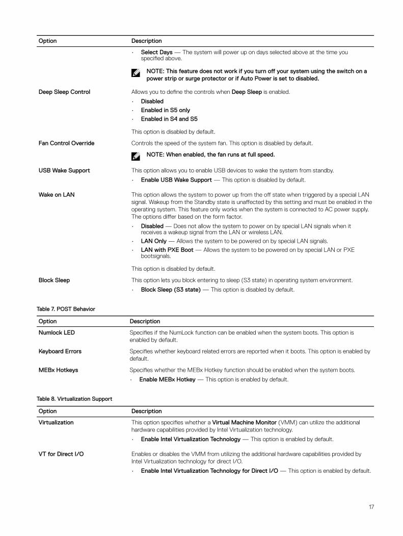
• Select Days — The system will power up on days selected above at the time you specified above.
NOTE: This feature does not work if you turn off your system using the switch on a power strip or surge protector or if Auto Power is set to disabled.
Deep Sleep Control Allows you to define the controls when Deep Sleep is enabled.
• Disabled
• Enabled in S5 only
• Enabled in S4 and S5
This option is disabled by default.
Fan Control Override Controls the speed of the system fan. This option is disabled by default.
NOTE: When enabled, the fan runs at full speed.
USB Wake Support This option allows you to enable USB devices to wake the system from standby.
• Enable USB Wake Support — This option is disabled by default.
Wake on LAN This option allows the system to power up from the off state when triggered by a special LAN signal. Wakeup from the Standby state is unaffected by this setting and must be enabled in the operating system. This feature only works when the system is connected to AC power supply. The options differ based on the form factor.
• Disabled — Does not allow the system to power on by special LAN signals when it receives a wakeup signal from the LAN or wireless LAN.
• LAN Only — Allows the system to be powered on by special LAN signals.
• LAN with PXE Boot — Allows the system to be powered on by special LAN or PXE bootsignals.
This option is disabled by default.
Block Sleep This option lets you block entering to sleep (S3 state) in operating system environment.
• Block Sleep (S3 state) — This option is disabled by default.
Table 7. POST Behavior
Option Description
Numlock LED Specifies if the NumLock function can be enabled when the system boots. This option is enabled by default.
Keyboard Errors Specifies whether keyboard related errors are reported when it boots. This option is enabled by default.
MEBx Hotkeys Specifies whether the MEBx Hotkey function should be enabled when the system boots.
• Enable MEBx Hotkey — This option is enabled by default.
Table 8. Virtualization Support
Option Description
Virtualization This option specifies whether a Virtual Machine Monitor (VMM) can utilize the additional hardware capabilities provided by Intel Virtualization technology.
• Enable Intel Virtualization Technology — This option is enabled by default.
VT for Direct I/O Enables or disables the VMM from utilizing the additional hardware capabilities provided by Intel Virtualization technology for direct I/O.
• Enable Intel Virtualization Technology for Direct I/O — This option is enabled by default.
17
Option Description
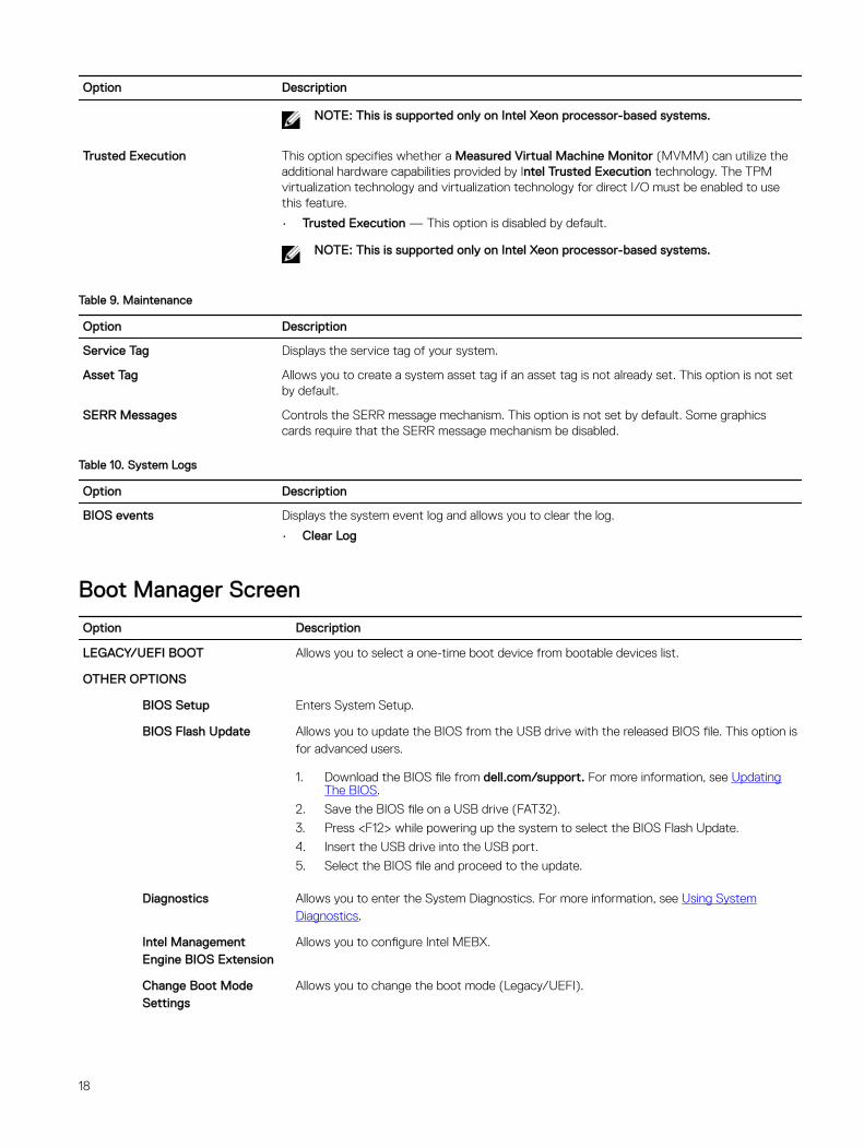
NOTE: This is supported only on Intel Xeon processor-based systems.
Trusted Execution This option specifies whether a Measured Virtual Machine Monitor (MVMM) can utilize the additional hardware capabilities provided by Intel Trusted Execution technology. The TPM virtualization technology and virtualization technology for direct I/O must be enabled to use this feature.
• Trusted Execution — This option is disabled by default.
NOTE: This is supported only on Intel Xeon processor-based systems.
Table 9. Maintenance
Option Description
Service Tag Displays the service tag of your system.
Asset Tag Allows you to create a system asset tag if an asset tag is not already set. This option is not set by default.
SERR Messages Controls the SERR message mechanism. This option is not set by default. Some graphics cards require that the SERR message mechanism be disabled.
Table 10. System Logs
Option Description
BIOS events Displays the system event log and allows you to clear the log.
• Clear Log
Boot Manager Screen
Option Description
LEGACY/UEFI BOOT Allows you to select a one-time boot device from bootable devices list.
OTHER OPTIONS
BIOS Setup Enters System Setup.
BIOS Flash Update Allows you to update the BIOS from the USB drive with the released BIOS file. This option is for advanced users.
1. Download the BIOS file from dell.com/support. For more information, see Updating The BIOS.
2. Save the BIOS file on a USB drive (FAT32).
3. Press <F12> while powering up the system to select the BIOS Flash Update.
4. Insert the USB drive into the USB port.
5. Select the BIOS file and proceed to the update.
Diagnostics Allows you to enter the System Diagnostics. For more information, see Using System Diagnostics.
Intel Management Engine BIOS Extension
Allows you to configure Intel MEBX.
Change Boot Mode Settings
Allows you to change the boot mode (Legacy/UEFI).
18
Option Description
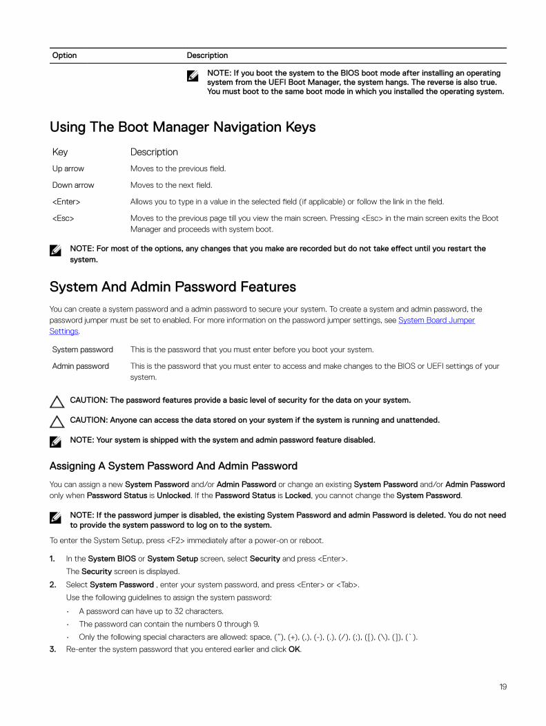
NOTE: If you boot the system to the BIOS boot mode after installing an operating system from the UEFI Boot Manager, the system hangs. The reverse is also true. You must boot to the same boot mode in which you installed the operating system.
Using The Boot Manager Navigation Keys
Key Description
Up arrow Moves to the previous field.
Down arrow Moves to the next field.
<Enter> Allows you to type in a value in the selected field (if applicable) or follow the link in the field.
<Esc> Moves to the previous page till you view the main screen. Pressing <Esc> in the main screen exits the Boot Manager and proceeds with system boot.
NOTE: For most of the options, any changes that you make are recorded but do not take effect until you restart the system.
System And Admin Password FeaturesYou can create a system password and a admin password to secure your system. To create a system and admin password, the password jumper must be set to enabled. For more information on the password jumper settings, see System Board Jumper Settings.
System password This is the password that you must enter before you boot your system.
Admin password This is the password that you must enter to access and make changes to the BIOS or UEFI settings of your system.
CAUTION: The password features provide a basic level of security for the data on your system.
CAUTION: Anyone can access the data stored on your system if the system is running and unattended.
NOTE: Your system is shipped with the system and admin password feature disabled.
Assigning A System Password And Admin Password
You can assign a new System Password and/or Admin Password or change an existing System Password and/or Admin Password only when Password Status is Unlocked. If the Password Status is Locked, you cannot change the System Password.
NOTE: If the password jumper is disabled, the existing System Password and admin Password is deleted. You do not need to provide the system password to log on to the system.
To enter the System Setup, press <F2> immediately after a power-on or reboot.
1. In the System BIOS or System Setup screen, select Security and press <Enter>.
The Security screen is displayed.
2. Select System Password , enter your system password, and press <Enter> or <Tab>.
Use the following guidelines to assign the system password:
• A password can have up to 32 characters.
• The password can contain the numbers 0 through 9.
• Only the following special characters are allowed: space, (”), (+), (,), (-), (.), (/), (;), ([), (\), (]), (`).
3. Re-enter the system password that you entered earlier and click OK.
19
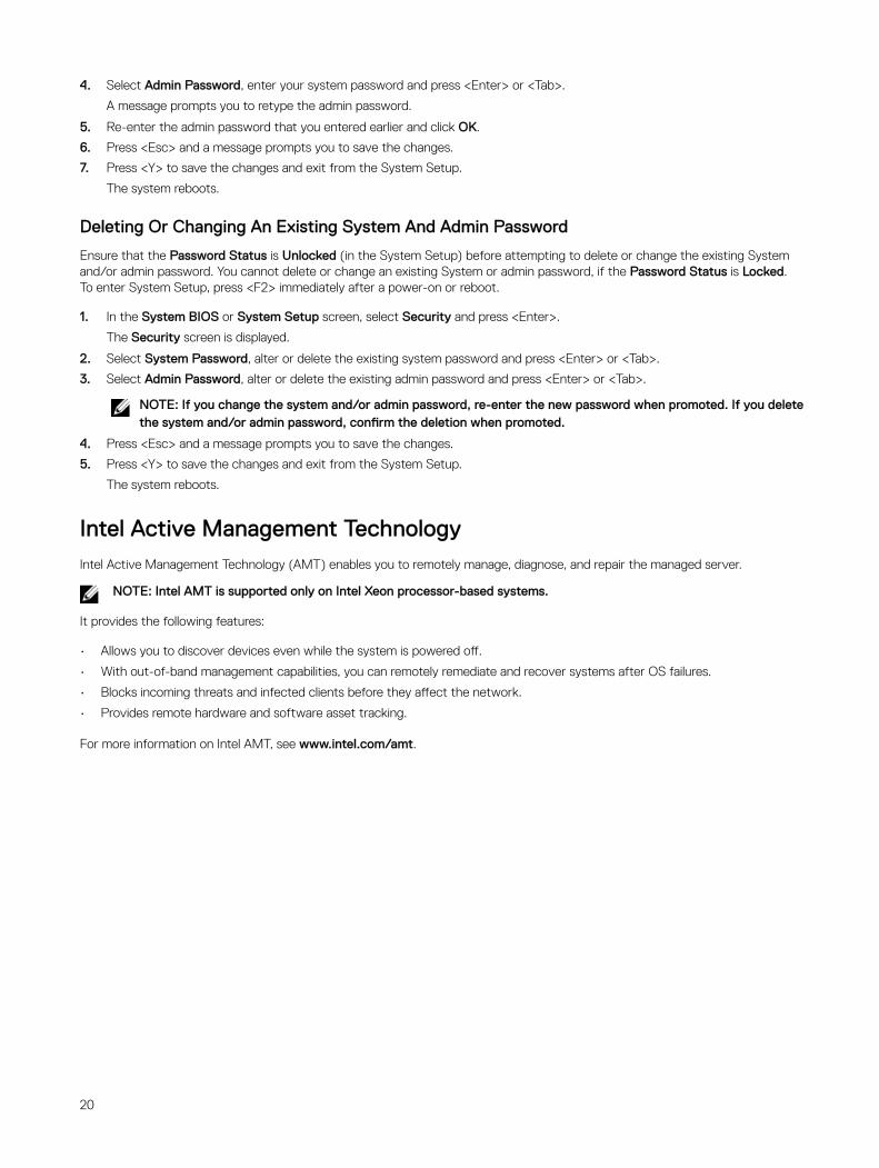
4. Select Admin Password, enter your system password and press <Enter> or <Tab>.
A message prompts you to retype the admin password.
5. Re-enter the admin password that you entered earlier and click OK.
6. Press <Esc> and a message prompts you to save the changes.
7. Press <Y> to save the changes and exit from the System Setup.
The system reboots.
Deleting Or Changing An Existing System And Admin Password
Ensure that the Password Status is Unlocked (in the System Setup) before attempting to delete or change the existing System and/or admin password. You cannot delete or change an existing System or admin password, if the Password Status is Locked.To enter System Setup, press <F2> immediately after a power-on or reboot.
1. In the System BIOS or System Setup screen, select Security and press <Enter>.
The Security screen is displayed.
2. Select System Password, alter or delete the existing system password and press <Enter> or <Tab>.
3. Select Admin Password, alter or delete the existing admin password and press <Enter> or <Tab>.
NOTE: If you change the system and/or admin password, re-enter the new password when promoted. If you delete the system and/or admin password, confirm the deletion when promoted.
4. Press <Esc> and a message prompts you to save the changes.
5. Press <Y> to save the changes and exit from the System Setup.
The system reboots.
Intel Active Management Technology Intel Active Management Technology (AMT) enables you to remotely manage, diagnose, and repair the managed server.
NOTE: Intel AMT is supported only on Intel Xeon processor-based systems.
It provides the following features:
• Allows you to discover devices even while the system is powered off.
• With out-of-band management capabilities, you can remotely remediate and recover systems after OS failures.
• Blocks incoming threats and infected clients before they affect the network.
• Provides remote hardware and software asset tracking.
For more information on Intel AMT, see www.intel.com/amt.
20
3Installing System Components
Recommended ToolsYou may need the following items to perform the procedures in this section:
• #1 and #2 Phillips screwdrivers
• Wrist grounding strap connected to ground
Opening And Closing The SystemWARNING: Whenever you need to lift the system, get others to assist you. To avoid injury, do not attempt to lift the system by yourself.
WARNING: Opening or removing the system cover when the system is on may expose you to a risk of electric shock.
NOTE: It is recommended that you always use a static mat and static strap while working on components in the interior of the system.
CAUTION: Many repairs may only be done by a certified service technician. You should only perform troubleshooting and simple repairs as authorized in your product documentation, or as directed by the online or telephone service and support team. Damage due to servicing that is not authorized by Dell is not covered by your warranty. Read and follow the safety instructions that came with the product.
CAUTION: Do not operate the system without the cover for a duration exceeding five minutes.
Opening The System
1. Turn off the system, including any attached peripherals, and disconnect the system from the electrical outlet and peripherals.
2. Lay the system on its side, on a flat and stable surface.
3. Lift the cover release latch and remove the cover away from the system.
21
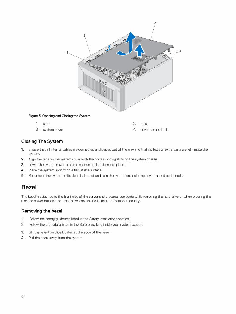
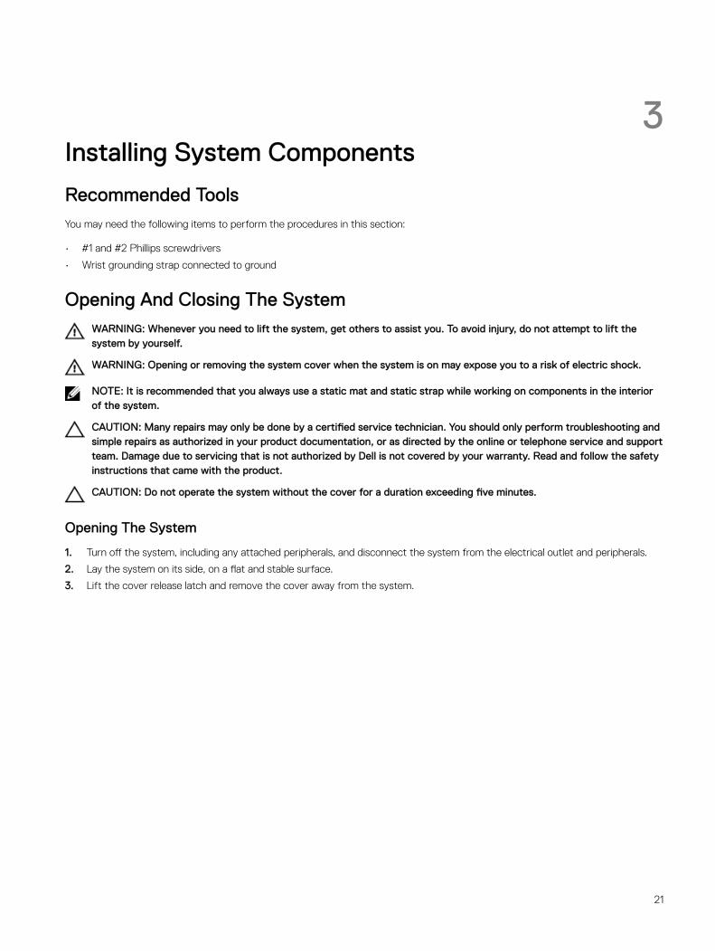
Figure 5. Opening and Closing the System
1. slots 2. tabs
3. system cover 4. cover release latch
Closing The System
1. Ensure that all internal cables are connected and placed out of the way and that no tools or extra parts are left inside the system.
2. Align the tabs on the system cover with the corresponding slots on the system chassis.
3. Lower the system cover onto the chassis until it clicks into place.
4. Place the system upright on a flat, stable surface.
5. Reconnect the system to its electrical outlet and turn the system on, including any attached peripherals.
BezelThe bezel is attached to the front side of the server and prevents accidents while removing the hard drive or when pressing the reset or power button. The front bezel can also be locked for additional security.
Removing the bezel
1. Follow the safety guidelines listed in the Safety instructions section.
2. Follow the procedure listed in the Before working inside your system section.
1. Lift the retention clips located at the edge of the bezel.
2. Pull the bezel away from the system.
22
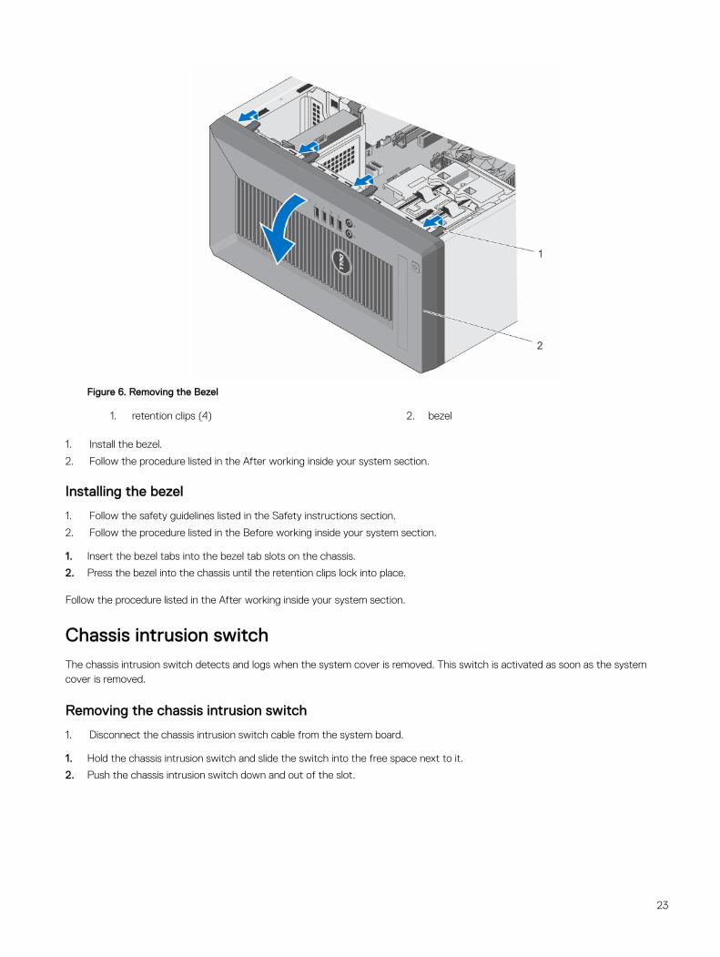
Figure 6. Removing the Bezel
1. retention clips (4) 2. bezel
1. Install the bezel.
2. Follow the procedure listed in the After working inside your system section.
Installing the bezel
1. Follow the safety guidelines listed in the Safety instructions section.
2. Follow the procedure listed in the Before working inside your system section.
1. Insert the bezel tabs into the bezel tab slots on the chassis.
2. Press the bezel into the chassis until the retention clips lock into place.
Follow the procedure listed in the After working inside your system section.
Chassis intrusion switchThe chassis intrusion switch detects and logs when the system cover is removed. This switch is activated as soon as the system cover is removed.
Removing the chassis intrusion switch
1. Disconnect the chassis intrusion switch cable from the system board.
1. Hold the chassis intrusion switch and slide the switch into the free space next to it.
2. Push the chassis intrusion switch down and out of the slot.
23
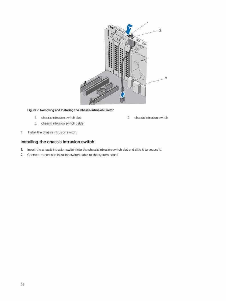
Figure 7. Removing and Installing the Chassis intrusion Switch
1. chassis intrusion switch slot 2. chassis intrusion switch
3. chassis intrusion switch cable
1. Install the chassis intrusion switch.
Installing the chassis intrusion switch
1. Insert the chassis intrusion switch into the chassis intrusion switch slot and slide it to secure it.
2. Connect the chassis intrusion switch cable to the system board.
24
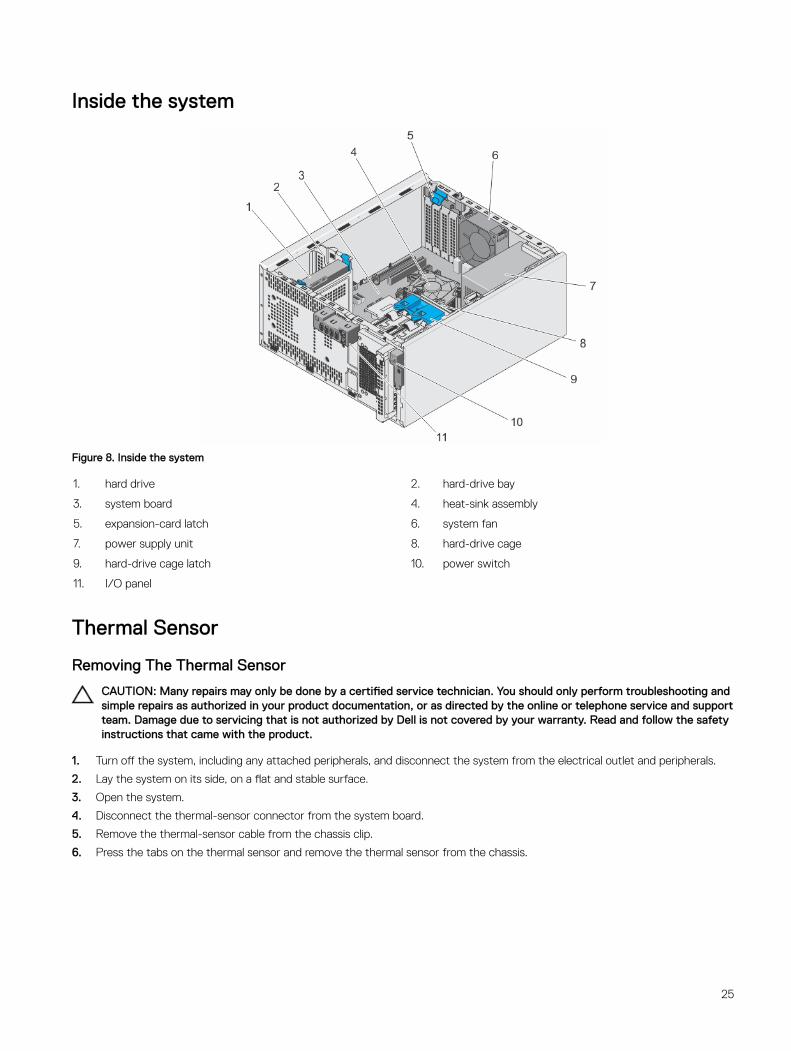
Inside the system
Figure 8. Inside the system
1. hard drive 2. hard-drive bay
3. system board 4. heat-sink assembly
5. expansion-card latch 6. system fan
7. power supply unit 8. hard-drive cage
9. hard-drive cage latch 10. power switch
11. I/O panel
Thermal Sensor
Removing The Thermal Sensor
CAUTION: Many repairs may only be done by a certified service technician. You should only perform troubleshooting and simple repairs as authorized in your product documentation, or as directed by the online or telephone service and support team. Damage due to servicing that is not authorized by Dell is not covered by your warranty. Read and follow the safety instructions that came with the product.
1. Turn off the system, including any attached peripherals, and disconnect the system from the electrical outlet and peripherals.
2. Lay the system on its side, on a flat and stable surface.
3. Open the system.
4. Disconnect the thermal-sensor connector from the system board.
5. Remove the thermal-sensor cable from the chassis clip.
6. Press the tabs on the thermal sensor and remove the thermal sensor from the chassis.
25
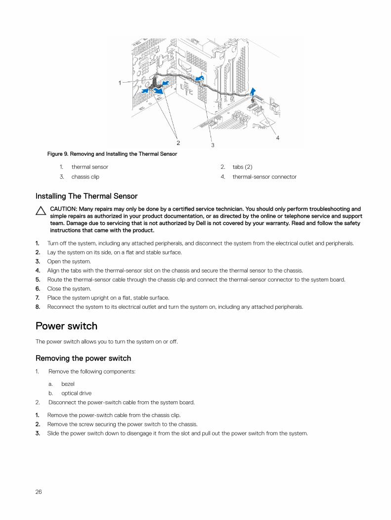
Figure 9. Removing and Installing the Thermal Sensor
1. thermal sensor 2. tabs (2)
3. chassis clip 4. thermal-sensor connector
Installing The Thermal Sensor
CAUTION: Many repairs may only be done by a certified service technician. You should only perform troubleshooting and simple repairs as authorized in your product documentation, or as directed by the online or telephone service and support team. Damage due to servicing that is not authorized by Dell is not covered by your warranty. Read and follow the safety instructions that came with the product.
1. Turn off the system, including any attached peripherals, and disconnect the system from the electrical outlet and peripherals.
2. Lay the system on its side, on a flat and stable surface.
3. Open the system.
4. Align the tabs with the thermal-sensor slot on the chassis and secure the thermal sensor to the chassis.
5. Route the thermal-sensor cable through the chassis clip and connect the thermal-sensor connector to the system board.
6. Close the system.
7. Place the system upright on a flat, stable surface.
8. Reconnect the system to its electrical outlet and turn the system on, including any attached peripherals.
Power switchThe power switch allows you to turn the system on or off.
Removing the power switch
1. Remove the following components:
a. bezel
b. optical drive
2. Disconnect the power-switch cable from the system board.
1. Remove the power-switch cable from the chassis clip.
2. Remove the screw securing the power switch to the chassis.
3. Slide the power switch down to disengage it from the slot and pull out the power switch from the system.
26
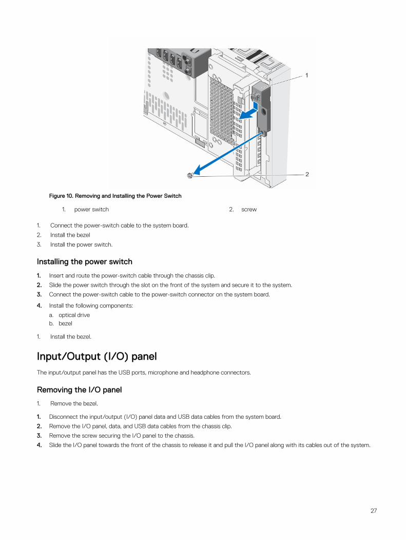
Figure 10. Removing and Installing the Power Switch
1. power switch 2. screw
1. Connect the power-switch cable to the system board.
2. Install the bezel
3. Install the power switch.
Installing the power switch
1. Insert and route the power-switch cable through the chassis clip.
2. Slide the power switch through the slot on the front of the system and secure it to the system.
3. Connect the power-switch cable to the power-switch connector on the system board.
4. Install the following components:
a. optical driveb. bezel
1. Install the bezel.
Input/Output (I/O) panelThe input/output panel has the USB ports, microphone and headphone connectors.
Removing the I/O panel
1. Remove the bezel.
1. Disconnect the input/output (I/O) panel data and USB data cables from the system board.
2. Remove the I/O panel, data, and USB data cables from the chassis clip.
3. Remove the screw securing the I/O panel to the chassis.
4. Slide the I/O panel towards the front of the chassis to release it and pull the I/O panel along with its cables out of the system.
27
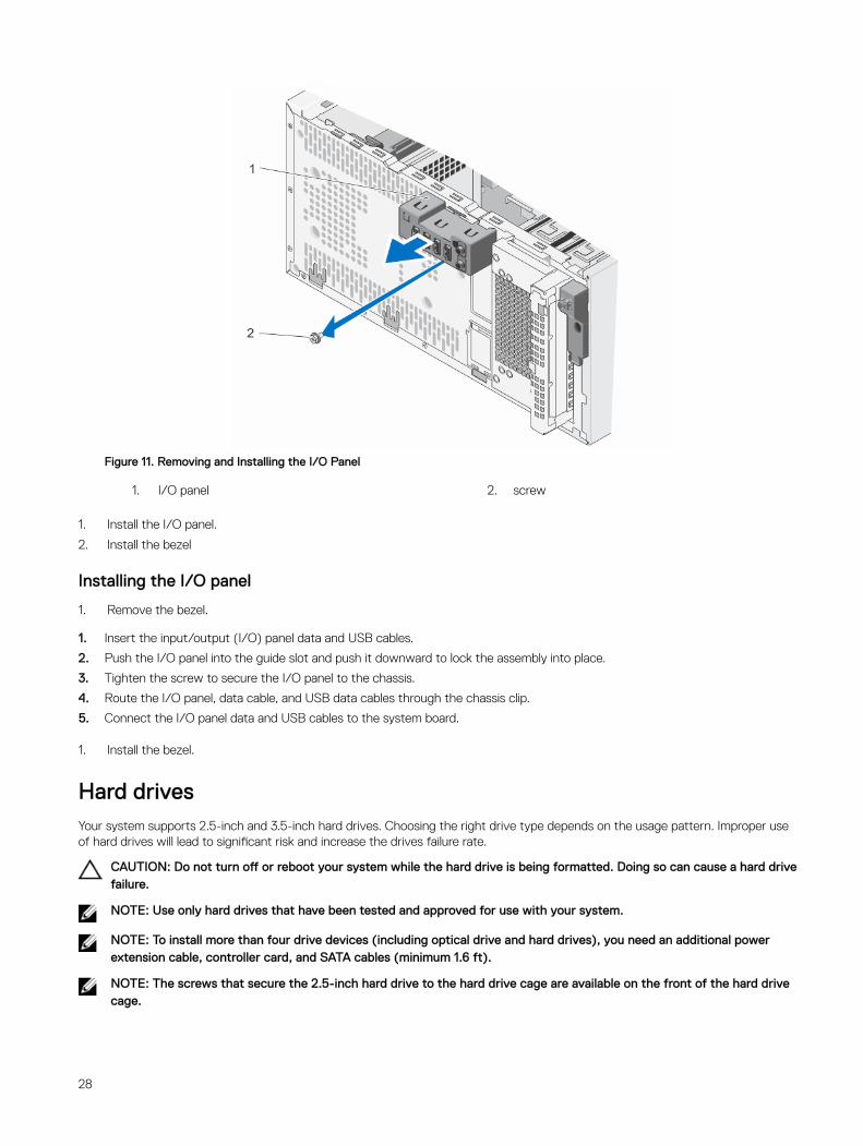
Figure 11. Removing and Installing the I/O Panel
1. I/O panel 2. screw
1. Install the I/O panel.
2. Install the bezel
Installing the I/O panel
1. Remove the bezel.
1. Insert the input/output (I/O) panel data and USB cables.
2. Push the I/O panel into the guide slot and push it downward to lock the assembly into place.
3. Tighten the screw to secure the I/O panel to the chassis.
4. Route the I/O panel, data cable, and USB data cables through the chassis clip.
5. Connect the I/O panel data and USB cables to the system board.
1. Install the bezel.
Hard drivesYour system supports 2.5-inch and 3.5-inch hard drives. Choosing the right drive type depends on the usage pattern. Improper use of hard drives will lead to significant risk and increase the drives failure rate.
CAUTION: Do not turn off or reboot your system while the hard drive is being formatted. Doing so can cause a hard drive failure.
NOTE: Use only hard drives that have been tested and approved for use with your system.
NOTE: To install more than four drive devices (including optical drive and hard drives), you need an additional power extension cable, controller card, and SATA cables (minimum 1.6 ft).
NOTE: The screws that secure the 2.5-inch hard drive to the hard drive cage are available on the front of the hard drive cage.
28
NOTE: Use the vertical type SATA cables to connect hard drives in the hard drive cage to avoid damaging the connector pins. This is applicable for the 2.5-inch hard drives and optical drive.
NOTE: Use right angle connectors to connect to the hard drives in the hard drive bay. You may not be able to close the system cover if incorrect connector cables are used.
NOTE: Do not mix enterprise class hard drives with entry-level hard drives.
Your system supports four 3.5-inch entry-level hard drives and enterprise class hard drives. Entry-level hard drives are designed for 8x5 operating environment and enterprise class hard drives are designed for 24x7 operating environment. Two hard drives are located in the removable hard drive cage and two hard drives are located in the fixed hard drive bay.
Choosing the right hard drive type depends on the usage pattern. Improper use of entry-level hard drives (including workloads exceeding 550 TB/year) leads to significant risk and increases the failure rate of the drives. Due to industry advances, in some cases, the larger capacity drives have been changed to a larger sector size. The larger sector size can have impacts on operating systems and applications. For more information about these hard drives, see the 512e and 4Kn Disk Formats white paper and 4K Sector HDD FAQ document at Dell.com/poweredgemanuals.
All hard drives are connected to the system board through the hard drive backplane. Hard drives are supplied in hot-swappable hard drive carriers that fit in the hard drive slots.
When you format a hard drive, allow enough time for the formatting to be complete. Be aware that high-capacity hard drives can take a long time to format.
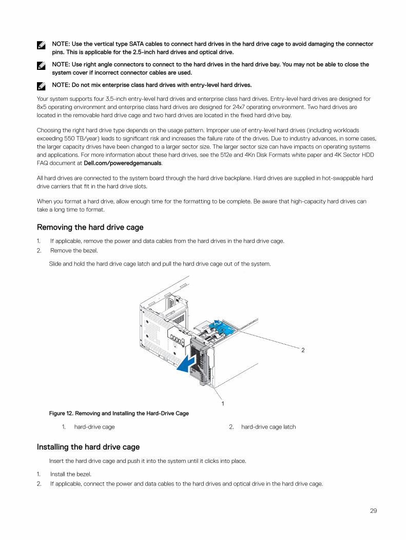
Removing the hard drive cage
1. If applicable, remove the power and data cables from the hard drives in the hard drive cage.
2. Remove the bezel.
Slide and hold the hard drive cage latch and pull the hard drive cage out of the system.
Figure 12. Removing and Installing the Hard-Drive Cage
1. hard-drive cage 2. hard-drive cage latch
Installing the hard drive cage
Insert the hard drive cage and push it into the system until it clicks into place.
1. Install the bezel.
2. If applicable, connect the power and data cables to the hard drives and optical drive in the hard drive cage.
29
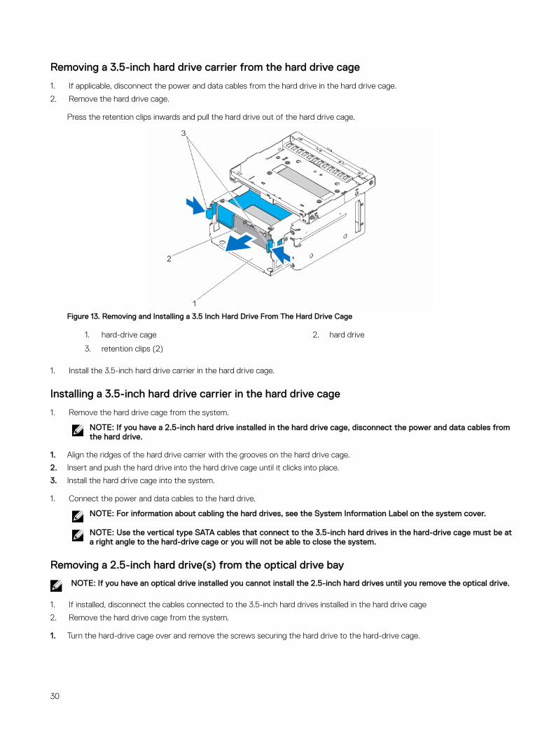
Removing a 3.5-inch hard drive carrier from the hard drive cage
1. If applicable, disconnect the power and data cables from the hard drive in the hard drive cage.
2. Remove the hard drive cage.
Press the retention clips inwards and pull the hard drive out of the hard drive cage.
Figure 13. Removing and Installing a 3.5 Inch Hard Drive From The Hard Drive Cage
1. hard-drive cage 2. hard drive
3. retention clips (2)
1. Install the 3.5-inch hard drive carrier in the hard drive cage.
Installing a 3.5-inch hard drive carrier in the hard drive cage
1. Remove the hard drive cage from the system.
NOTE: If you have a 2.5-inch hard drive installed in the hard drive cage, disconnect the power and data cables from the hard drive.
1. Align the ridges of the hard drive carrier with the grooves on the hard drive cage.
2. Insert and push the hard drive into the hard drive cage until it clicks into place.
3. Install the hard drive cage into the system.
1. Connect the power and data cables to the hard drive.
NOTE: For information about cabling the hard drives, see the System Information Label on the system cover.
NOTE: Use the vertical type SATA cables that connect to the 3.5-inch hard drives in the hard-drive cage must be at a right angle to the hard-drive cage or you will not be able to close the system.
Removing a 2.5-inch hard drive(s) from the optical drive bay
NOTE: If you have an optical drive installed you cannot install the 2.5-inch hard drives until you remove the optical drive.
1. If installed, disconnect the cables connected to the 3.5-inch hard drives installed in the hard drive cage
2. Remove the hard drive cage from the system.
1. Turn the hard-drive cage over and remove the screws securing the hard drive to the hard-drive cage.
30

Figure 14. Removing the hard-drive screws
1. hard drive 2. hard-drive screw sockets (4)
3. hard-drive screw slots (2) 4. hard-drive screws (4)
2. Turn the hard-drive cage.
3. Remove the screws from the bottom of the hard drive that secure the hard drive to the hard drive cage.
4. Remove the screws on the sides of the hard drive cage securing the hard drive to the hard drive cage.
5. Lift and slide the hard drive out of the optical drive bay.
Figure 15. Removing the 2.5 Inch hard drive
1. hard-drive/optical-drive slot 2. hard drive
3. hard-drive screws (8)
NOTE: The screws used to secure the hard drive to the hard-drive cage are available on the front of the hard-drive cage as shown in callout 3.
1. Connect the power and data cables to the hard drive in the optical drive bay.
31
2. Install a 2.5-inch hard drive in the optical drive bay.
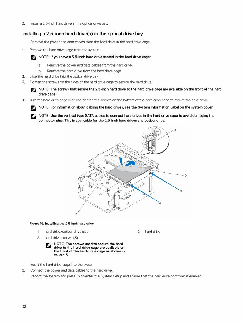
Installing a 2.5-inch hard drive(s) in the optical drive bay
1. Remove the power and data cables from the hard drive in the hard drive cage.
1. Remove the hard drive cage from the system.
NOTE: If you have a 3.5-inch hard drive seated in the hard drive cage:
a. Remove the power and data cables from the hard drive.
b. Remove the hard drive from the hard drive cage.
2. Slide the hard drive into the optical drive bay.
3. Tighten the screws on the sides of the hard drive cage to secure the hard drive.
NOTE: The screws that secure the 2.5-inch hard drive to the hard drive cage are available on the front of the hard drive cage.
4. Turn the hard drive cage over and tighten the screws on the bottom of the hard drive cage to secure the hard drive.
NOTE: For information about cabling the hard drives, see the System Information Label on the system cover.
NOTE: Use the vertical type SATA cables to connect hard drives in the hard drive cage to avoid damaging the connector pins. This is applicable for the 2.5-inch hard drives and optical drive.
Figure 16. Installing the 2.5 Inch hard drive
1. hard-drive/optical-drive slot 2. hard drive
3. hard-drive screws (8)
NOTE: The screws used to secure the hard drive to the hard-drive cage are available on the front of the hard-drive cage as shown in callout 3.
1. Insert the hard drive cage into the system.
2. Connect the power and data cables to the hard drive.
3. Reboot the system and press F2 to enter the System Setup and ensure that the hard drive controller is enabled.
32
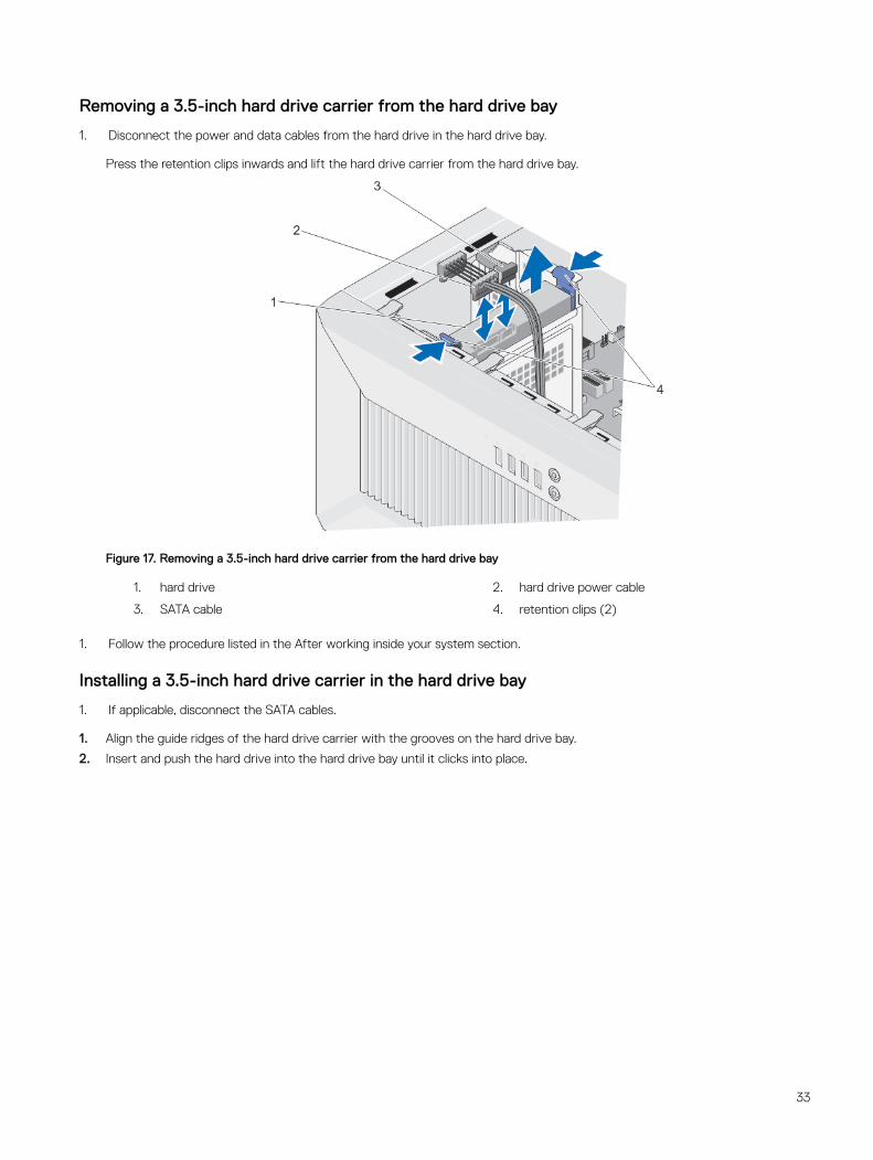
Removing a 3.5-inch hard drive carrier from the hard drive bay
1. Disconnect the power and data cables from the hard drive in the hard drive bay.
Press the retention clips inwards and lift the hard drive carrier from the hard drive bay.
Figure 17. Removing a 3.5-inch hard drive carrier from the hard drive bay
1. hard drive 2. hard drive power cable
3. SATA cable 4. retention clips (2)
1. Follow the procedure listed in the After working inside your system section.
Installing a 3.5-inch hard drive carrier in the hard drive bay
1. If applicable, disconnect the SATA cables.
1. Align the guide ridges of the hard drive carrier with the grooves on the hard drive bay.
2. Insert and push the hard drive into the hard drive bay until it clicks into place.
33
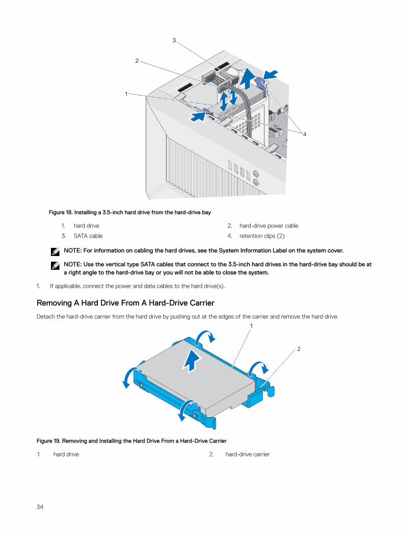
Figure 18. Installing a 3.5-inch hard drive from the hard-drive bay
1. hard drive 2. hard-drive power cable
3. SATA cable 4. retention clips (2)
NOTE: For information on cabling the hard drives, see the System Information Label on the system cover.
NOTE: Use the vertical type SATA cables that connect to the 3.5-inch hard drives in the hard-drive bay should be at a right angle to the hard-drive bay or you will not be able to close the system.
1. If applicable, connect the power and data cables to the hard drive(s).
Removing A Hard Drive From A Hard-Drive Carrier
Detach the hard-drive carrier from the hard drive by pushing out at the edges of the carrier and remove the hard drive.
Figure 19. Removing and Installing the Hard Drive From a Hard-Drive Carrier
1. hard drive 2. hard-drive carrier
34
Installing A Hard Drive Into A Hard-Drive Carrier
1. Align the screw holes on the hard drive with the screws on the hard-drive carrier.
2. Press the hard drive into the hard-drive carrier to secure it.
Optical driveOptical drives retrieve and store data on optical discs such as compact disks (CD), and digital versatile disks (DVD). Optical drives can be categorized into two basic types: optical disk readers and optical disk writers.
Installing the optical drive
NOTE: Only slim 12.7 mm SATA DVD-ROM drive or DVD+/-RW drive can be installed in your system. External optical drives can be connected through USB ports.
NOTE: If you install an optical drive, you cannot install 2.5-inch hard drives.
NOTE: To install more than four drive devices (including optical drive and hard drives), you need an additional power extension cable, controller card, and SATA cables (minimum 1.6 ft).
1. Remove the bezel.
2. If installed, remove the optical drive filler from the bezel and the hard drive cage
3. Remove the hard drive cage.
4. Hold the tabs on the optical-drive filler and remove the optical-drive filler from the hard drive cage.
1. Slide the optical drive into the optical drive bay.
2. Tighten the screws on the back of the optical drive bay to secure the optical drive.
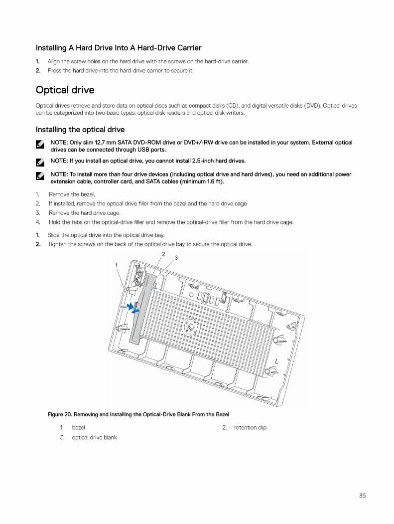
Figure 20. Removing and Installing the Optical-Drive Blank From the Bezel
1. bezel 2. retention clip
3. optical drive blank
35
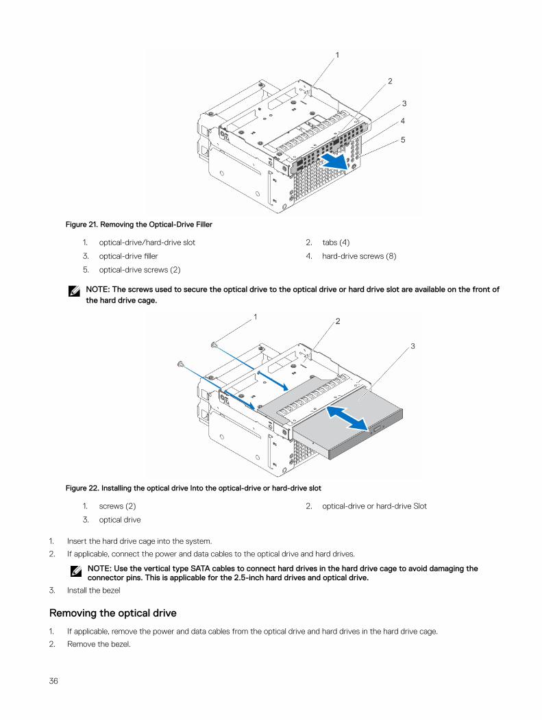
Figure 21. Removing the Optical-Drive Filler
1. optical-drive/hard-drive slot 2. tabs (4)
3. optical-drive filler 4. hard-drive screws (8)
5. optical-drive screws (2)
NOTE: The screws used to secure the optical drive to the optical drive or hard drive slot are available on the front of the hard drive cage.
Figure 22. Installing the optical drive Into the optical-drive or hard-drive slot
1. screws (2) 2. optical-drive or hard-drive Slot
3. optical drive
1. Insert the hard drive cage into the system.
2. If applicable, connect the power and data cables to the optical drive and hard drives.
NOTE: Use the vertical type SATA cables to connect hard drives in the hard drive cage to avoid damaging the connector pins. This is applicable for the 2.5-inch hard drives and optical drive.
3. Install the bezel
Removing the optical drive
1. If applicable, remove the power and data cables from the optical drive and hard drives in the hard drive cage.
2. Remove the bezel.
36
3. Remove the hard drive cage.
4. Remove the screws securing the optical drive.
1. Hold the tabs on the optical drive filler and remove the optical drive filler from the hard drive cage.
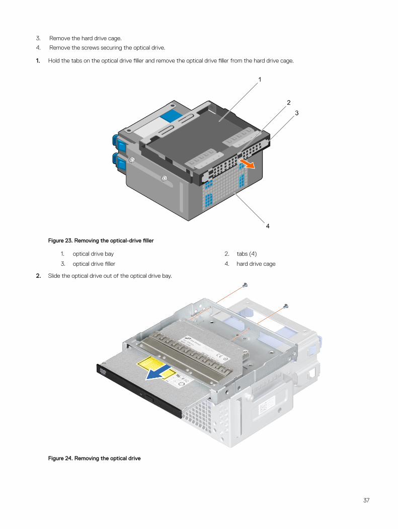
Figure 23. Removing the optical-drive filler
1. optical drive bay 2. tabs (4)
3. optical drive filler 4. hard drive cage
2. Slide the optical drive out of the optical drive bay.
Figure 24. Removing the optical drive
37
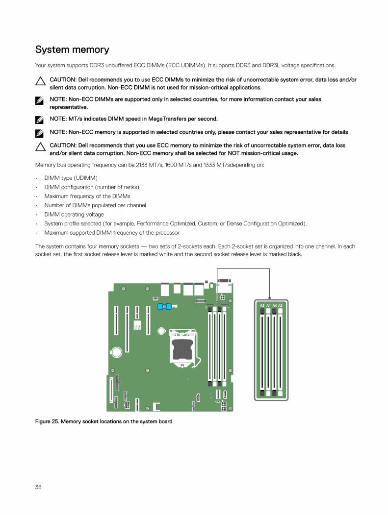
System memoryYour system supports DDR3 unbuffered ECC DIMMs (ECC UDIMMs). It supports DDR3 and DDR3L voltage specifications.
CAUTION: Dell recommends you to use ECC DIMMs to minimize the risk of uncorrectable system error, data loss and/or silent data corruption. Non-ECC DIMM is not used for mission-critical applications.
NOTE: Non-ECC DIMMs are supported only in selected countries, for more information contact your sales representative.
NOTE: MT/s indicates DIMM speed in MegaTransfers per second.
NOTE: Non-ECC memory is supported in selected countries only, please contact your sales representative for details
CAUTION: Dell recommends that you use ECC memory to minimize the risk of uncorrectable system error, data loss and/or silent data corruption. Non-ECC memory shall be selected for NOT mission-critical usage.
Memory bus operating frequency can be 2133 MT/s, 1600 MT/s and 1333 MT/sdepending on:
• DIMM type (UDIMM)
• DIMM configuration (number of ranks)
• Maximum frequency of the DIMMs
• Number of DIMMs populated per channel
• DIMM operating voltage
• System profile selected (for example, Performance Optimized, Custom, or Dense Configuration Optimized).
• Maximum supported DIMM frequency of the processor
The system contains four memory sockets — two sets of 2-sockets each. Each 2-socket set is organized into one channel. In each socket set, the first socket release lever is marked white and the second socket release lever is marked black.
Figure 25. Memory socket locations on the system board
38
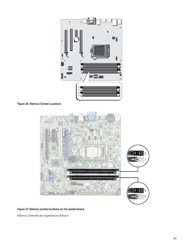
Figure 26. Memory Socket Locations
Figure 27. Memory socket locations on the system board
Memory channels are organized as follows:
39
Processor 1 channel 0: memory sockets A1 and A3
channel 1: memory sockets A2 and A4
The following table shows the memory population and operating frequencies for the supported configurations.
DIMM Type DIMMs Populated/Channel
Operating Frequency (in MT/s) Maximum DIMM Rank/Channel
1.5 V 1.35 V
UDIMM 2 1333, 1600 1333, 1600 Dual rank
General memory module installation guidelines
Memory configurations that fail to observe these guidelines can prevent your system from booting, stop responding during memory configuration, or operating with reduced memory.
NOTE: This system supports only UDIMMs.
The system supports Flexible Memory Configuration, enabling the system to be configured and run in any valid chipset architectural configuration. The following are the recommended guidelines for installing memory modules:
• Up to two UDIMMs can be populated in a channel.
• Populate all sockets with white release tabs first, and then all the sockets with black release tabs.
• Populate the sockets by the highest rank count, in the following order—first in sockets with white release tabs and then with the black release tabs. For example, if you want to mix single-rank and dual-rank memory modules, populate dual-rank memory modules in the sockets with white release tabs and single-rank memory modules in the sockets with black release tabs.
• Memory modules of different capacities can be mixed provided other memory population rules are followed (for example, 2 GB and 4 GB memory modules can be mixed).
• When mixing memory modules with different capacities, populate the sockets with memory modules with highest capacity first. For example, if you want to mix 2 GB and 4 GB memory modules, populate 4 GB memory modules in the sockets with white release tabs and 2 GB memory modules in the sockets with black release tabs.
• If memory modules with different speeds are installed, they will operate at the speed of the slowest installed memory module(s) or slower depending on system DIMM configuration.
Sample memory configurationsThe following table shows sample memory configurations for a single processor configuration that follow the appropriate memory guidelines stated in this section.
CAUTION: Dell recommends you to use ECC DIMMs to minimize the risk of uncorrectable system error, data loss and/or silent data corruption. Non-ECC DIMM is not used for mission-critical applications.
NOTE: 16 GB quad-rank RDIMMs are not supported.
NOTE: Minimum supported memory is 2 GB, and maximum supported memory is 32 GB.
NOTE: 1R and 2R in the following tables indicate single-rank and dual-rank DIMMs respectively.
NOTE: Non-ECC DIMMs are supported only in selected countries, for more information contact your sales representative.
40
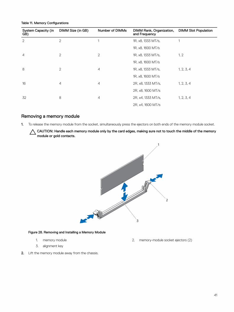
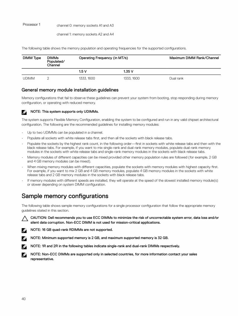
Table 11. Memory Configurations
System Capacity (in GB)
DIMM Size (in GB) Number of DIMMs DIMM Rank, Organization, and Frequency
DIMM Slot Population
2 2 1 1R, x8, 1333 MT/s, 1
1R, x8, 1600 MT/s
4 2 2 1R, x8, 1333 MT/s, 1, 2
1R, x8, 1600 MT/s
8 2 4 1R, x8, 1333 MT/s, 1, 2, 3, 4
1R, x8, 1600 MT/s
16 4 4 2R, x8, 1333 MT/s, 1, 2, 3, 4
2R, x8, 1600 MT/s
32 8 4 2R, x4, 1333 MT/s, 1, 2, 3, 4
2R, x4, 1600 MT/s
Removing a memory module
1. To release the memory module from the socket, simultaneously press the ejectors on both ends of the memory module socket.
CAUTION: Handle each memory module only by the card edges, making sure not to touch the middle of the memory module or gold contacts.
Figure 28. Removing and Installing a Memory Module
1. memory module 2. memory-module socket ejectors (2)
3. alignment key
2. Lift the memory module away from the chassis.
41
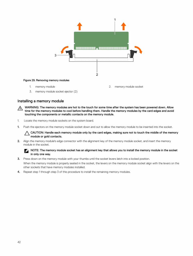
Figure 29. Removing memory modules
1. memory module 2. memory module socket
3. memory module socket ejector (2)
Installing a memory module
WARNING: The memory modules are hot to the touch for some time after the system has been powered down. Allow time for the memory modules to cool before handling them. Handle the memory modules by the card edges and avoid touching the components or metallic contacts on the memory module.
1. Locate the memory module sockets on the system board.
1. Push the ejectors on the memory module socket down and out to allow the memory module to be inserted into the socket.
CAUTION: Handle each memory module only by the card edges, making sure not to touch the middle of the memory module or gold contacts.
2. Align the memory module's edge connector with the alignment key of the memory module socket, and insert the memory module in the socket.
NOTE: The memory module socket has an alignment key that allows you to install the memory module in the socket in only one way.
3. Press down on the memory module with your thumbs until the socket levers latch into a locked position.
When the memory module is properly seated in the socket, the levers on the memory module socket align with the levers on the other sockets that have memory modules installed.
4. Repeat step 1 through step 3 of this procedure to install the remaining memory modules.
42
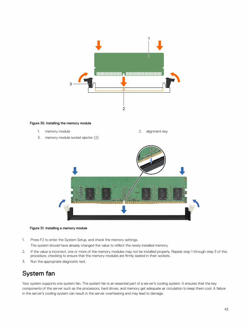
Figure 30. Installing the memory module
1. memory module 2. alignment key
3. memory module socket ejector (2)
Figure 31. Installing a memory module
1. Press F2 to enter the System Setup, and check the memory settings.
The system should have already changed the value to reflect the newly installed memory.
2. If the value is incorrect, one or more of the memory modules may not be installed properly. Repeat step 1 through step 3 of this procedure, checking to ensure that the memory modules are firmly seated in their sockets.
3. Run the appropriate diagnostic test.
System fanYour system supports one system fan. The system fan is an essential part of a server's cooling system. It ensures that the key components of the server such as the processors, hard drives, and memory get adequate air circulation to keep them cool. A failure in the server's cooling system can result in the server overheating and may lead to damage.
43
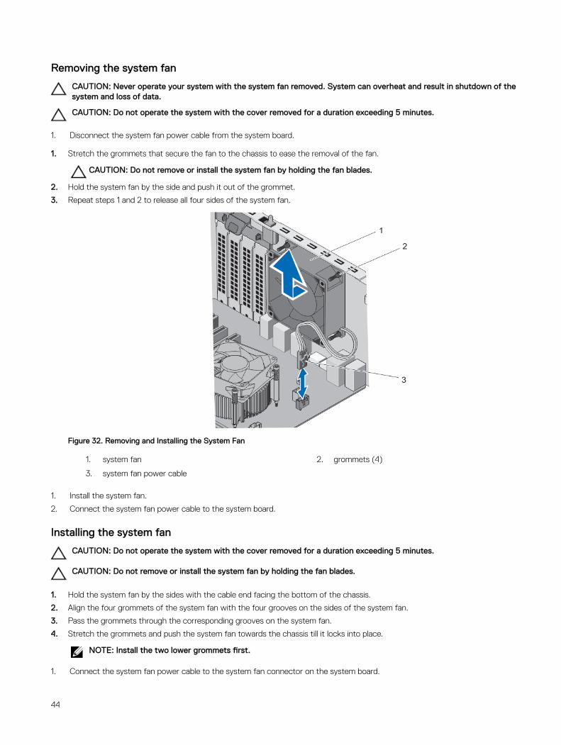
Removing the system fan
CAUTION: Never operate your system with the system fan removed. System can overheat and result in shutdown of the system and loss of data.
CAUTION: Do not operate the system with the cover removed for a duration exceeding 5 minutes.
1. Disconnect the system fan power cable from the system board.
1. Stretch the grommets that secure the fan to the chassis to ease the removal of the fan.
CAUTION: Do not remove or install the system fan by holding the fan blades.
2. Hold the system fan by the side and push it out of the grommet.
3. Repeat steps 1 and 2 to release all four sides of the system fan.
Figure 32. Removing and Installing the System Fan
1. system fan 2. grommets (4)
3. system fan power cable
1. Install the system fan.
2. Connect the system fan power cable to the system board.
Installing the system fan
CAUTION: Do not operate the system with the cover removed for a duration exceeding 5 minutes.
CAUTION: Do not remove or install the system fan by holding the fan blades.
1. Hold the system fan by the sides with the cable end facing the bottom of the chassis.
2. Align the four grommets of the system fan with the four grooves on the sides of the system fan.
3. Pass the grommets through the corresponding grooves on the system fan.
4. Stretch the grommets and push the system fan towards the chassis till it locks into place.
NOTE: Install the two lower grommets first.
1. Connect the system fan power cable to the system fan connector on the system board.
44
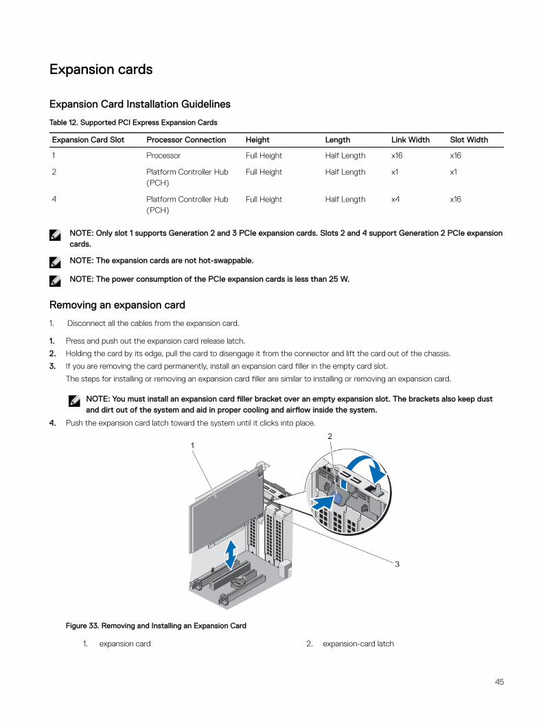
Expansion cards
Expansion Card Installation Guidelines
Table 12. Supported PCI Express Expansion Cards
Expansion Card Slot Processor Connection Height Length Link Width Slot Width
1 Processor Full Height Half Length x16 x16
2 Platform Controller Hub (PCH)
Full Height Half Length x1 x1
4 Platform Controller Hub (PCH)
Full Height Half Length x4 x16
NOTE: Only slot 1 supports Generation 2 and 3 PCIe expansion cards. Slots 2 and 4 support Generation 2 PCIe expansion cards.
NOTE: The expansion cards are not hot-swappable.
NOTE: The power consumption of the PCIe expansion cards is less than 25 W.
Removing an expansion card
1. Disconnect all the cables from the expansion card.
1. Press and push out the expansion card release latch.
2. Holding the card by its edge, pull the card to disengage it from the connector and lift the card out of the chassis.
3. If you are removing the card permanently, install an expansion card filler in the empty card slot.
The steps for installing or removing an expansion card filler are similar to installing or removing an expansion card.
NOTE: You must install an expansion card filler bracket over an empty expansion slot. The brackets also keep dust and dirt out of the system and aid in proper cooling and airflow inside the system.
4. Push the expansion card latch toward the system until it clicks into place.
Figure 33. Removing and Installing an Expansion Card
1. expansion card 2. expansion-card latch
45
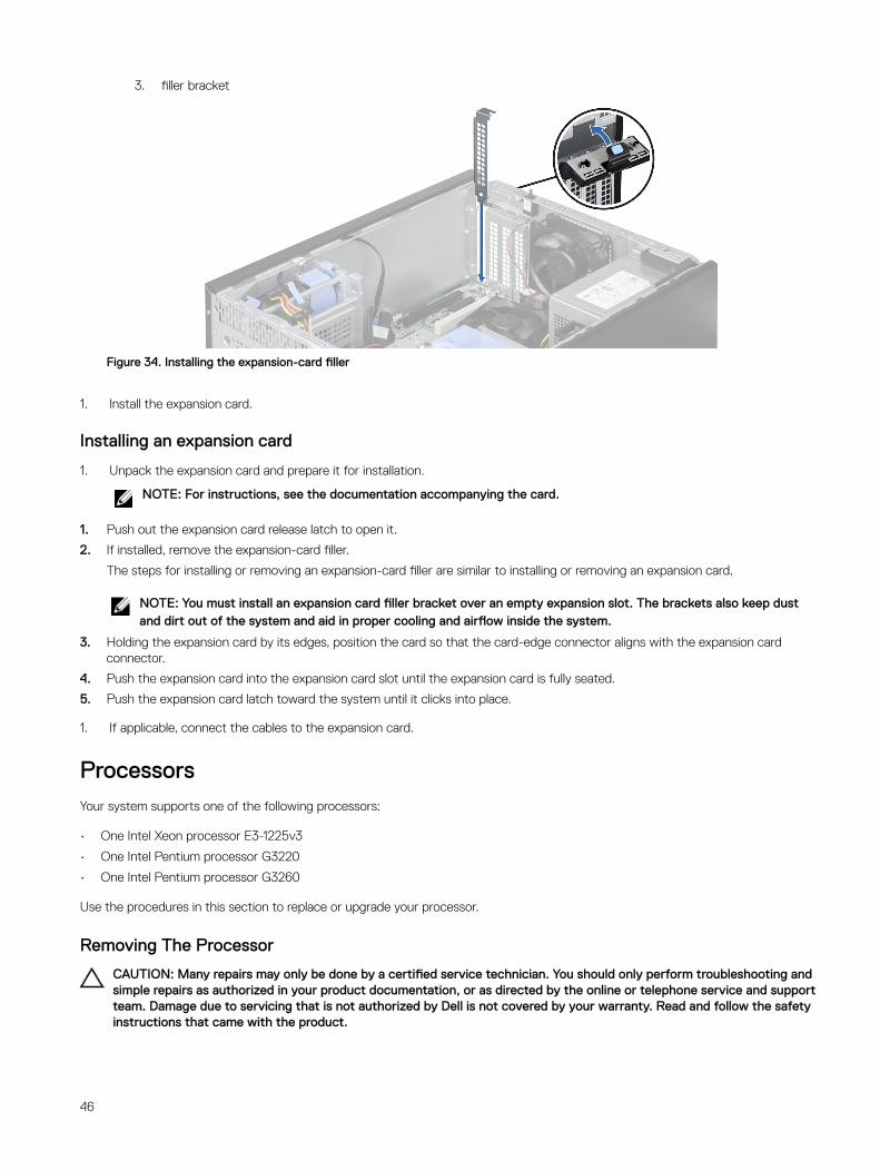
3. filler bracket
Figure 34. Installing the expansion-card filler
1. Install the expansion card.
Installing an expansion card
1. Unpack the expansion card and prepare it for installation.
NOTE: For instructions, see the documentation accompanying the card.
1. Push out the expansion card release latch to open it.
2. If installed, remove the expansion-card filler.
The steps for installing or removing an expansion-card filler are similar to installing or removing an expansion card.
NOTE: You must install an expansion card filler bracket over an empty expansion slot. The brackets also keep dust and dirt out of the system and aid in proper cooling and airflow inside the system.
3. Holding the expansion card by its edges, position the card so that the card-edge connector aligns with the expansion card connector.
4. Push the expansion card into the expansion card slot until the expansion card is fully seated.
5. Push the expansion card latch toward the system until it clicks into place.
1. If applicable, connect the cables to the expansion card.
ProcessorsYour system supports one of the following processors:
• One Intel Xeon processor E3-1225v3
• One Intel Pentium processor G3220
• One Intel Pentium processor G3260
Use the procedures in this section to replace or upgrade your processor.
Removing The Processor
CAUTION: Many repairs may only be done by a certified service technician. You should only perform troubleshooting and simple repairs as authorized in your product documentation, or as directed by the online or telephone service and support team. Damage due to servicing that is not authorized by Dell is not covered by your warranty. Read and follow the safety instructions that came with the product.
46
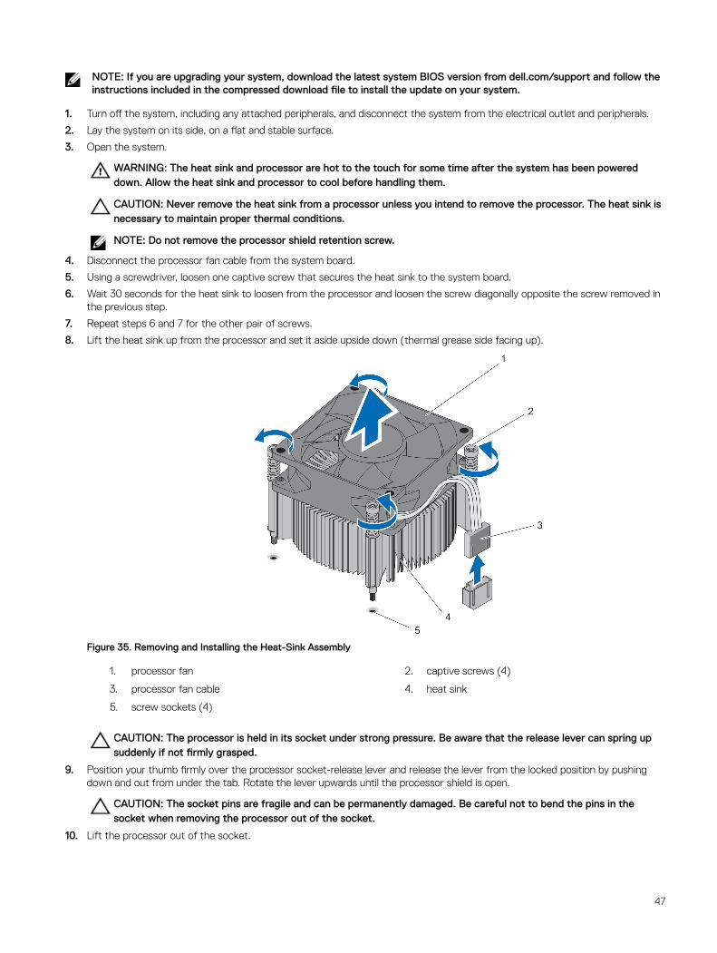
NOTE: If you are upgrading your system, download the latest system BIOS version from dell.com/support and follow the instructions included in the compressed download file to install the update on your system.
1. Turn off the system, including any attached peripherals, and disconnect the system from the electrical outlet and peripherals.
2. Lay the system on its side, on a flat and stable surface.
3. Open the system.
WARNING: The heat sink and processor are hot to the touch for some time after the system has been powered down. Allow the heat sink and processor to cool before handling them.
CAUTION: Never remove the heat sink from a processor unless you intend to remove the processor. The heat sink is necessary to maintain proper thermal conditions.
NOTE: Do not remove the processor shield retention screw.
4. Disconnect the processor fan cable from the system board.
5. Using a screwdriver, loosen one captive screw that secures the heat sink to the system board.
6. Wait 30 seconds for the heat sink to loosen from the processor and loosen the screw diagonally opposite the screw removed in the previous step.
7. Repeat steps 6 and 7 for the other pair of screws.
8. Lift the heat sink up from the processor and set it aside upside down (thermal grease side facing up).
Figure 35. Removing and Installing the Heat-Sink Assembly
1. processor fan 2. captive screws (4)
3. processor fan cable 4. heat sink
5. screw sockets (4)
CAUTION: The processor is held in its socket under strong pressure. Be aware that the release lever can spring up suddenly if not firmly grasped.
9. Position your thumb firmly over the processor socket-release lever and release the lever from the locked position by pushing down and out from under the tab. Rotate the lever upwards until the processor shield is open.
CAUTION: The socket pins are fragile and can be permanently damaged. Be careful not to bend the pins in the socket when removing the processor out of the socket.
10. Lift the processor out of the socket.
47
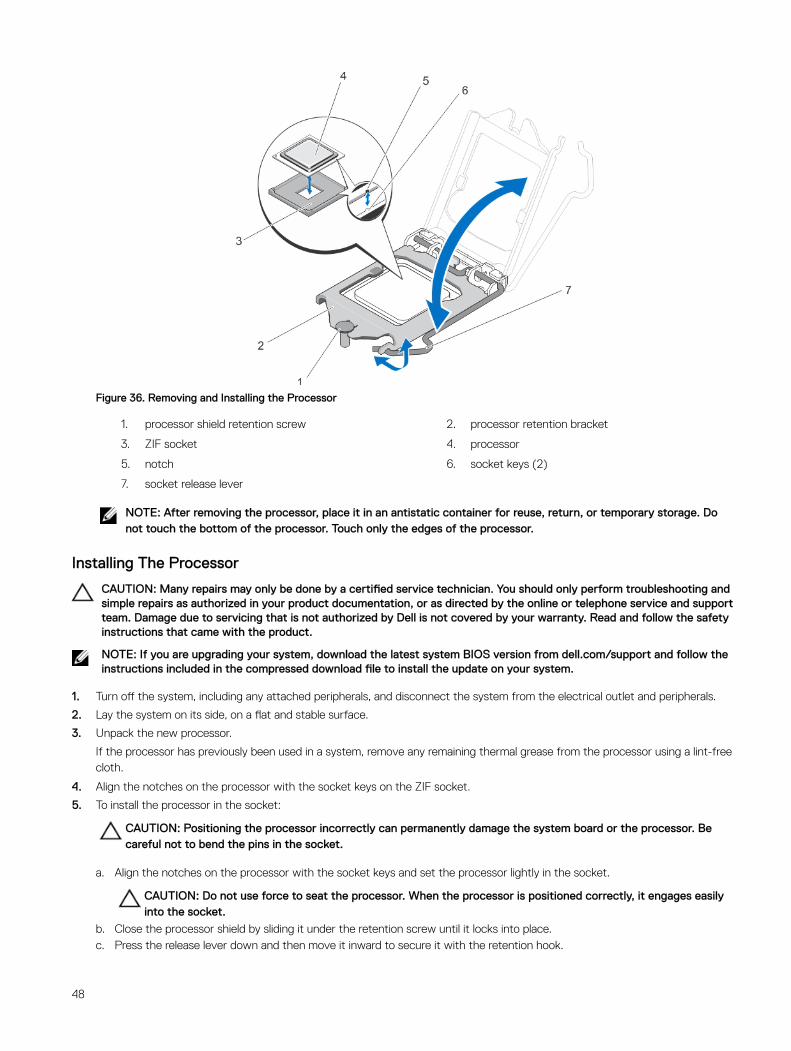
Figure 36. Removing and Installing the Processor
1. processor shield retention screw 2. processor retention bracket
3. ZIF socket 4. processor
5. notch 6. socket keys (2)
7. socket release lever
NOTE: After removing the processor, place it in an antistatic container for reuse, return, or temporary storage. Do not touch the bottom of the processor. Touch only the edges of the processor.
Installing The Processor
CAUTION: Many repairs may only be done by a certified service technician. You should only perform troubleshooting and simple repairs as authorized in your product documentation, or as directed by the online or telephone service and support team. Damage due to servicing that is not authorized by Dell is not covered by your warranty. Read and follow the safety instructions that came with the product.
NOTE: If you are upgrading your system, download the latest system BIOS version from dell.com/support and follow the instructions included in the compressed download file to install the update on your system.
1. Turn off the system, including any attached peripherals, and disconnect the system from the electrical outlet and peripherals.
2. Lay the system on its side, on a flat and stable surface.
3. Unpack the new processor.
If the processor has previously been used in a system, remove any remaining thermal grease from the processor using a lint-free cloth.
4. Align the notches on the processor with the socket keys on the ZIF socket.
5. To install the processor in the socket:
CAUTION: Positioning the processor incorrectly can permanently damage the system board or the processor. Be careful not to bend the pins in the socket.
a. Align the notches on the processor with the socket keys and set the processor lightly in the socket.
CAUTION: Do not use force to seat the processor. When the processor is positioned correctly, it engages easily into the socket.
b. Close the processor shield by sliding it under the retention screw until it locks into place.c. Press the release lever down and then move it inward to secure it with the retention hook.
48

6. To install the heat sink:
CAUTION: Applying too much thermal grease can result in excess grease coming in contact with and contaminating the processor socket.
a. Open the grease applicator included with your processor kit and apply all of the thermal grease in the applicator to the center of the topside of the new processor.
b. Place the heat sink onto the processor.c. Align the heat sink screws with the corresponding slots on the system board.d. Tighten the four screws to secure the heat sink to the system board.
NOTE: Tighten the screws diagonally opposite to each other. Do not over-tighten the heat sink retention screws when installing the heat sink. To prevent over-tightening, tighten the heat sink retention screw until resistance is felt, and stop once the screw is seated. The screw tension should be no more than 6 in-lb (6.9 kg-cm).
NOTE: Do not remove the processor shield retention screw.
7. Connect the processor fan cable to the system board.
8. Close the system.
9. Place the system upright on a flat, stable surface.
10. Reconnect the system to its electrical outlet and turn the system on, including any attached peripherals.
11. Press <F2> to enter the System Setup and check that the processor information matches the new system configuration.
12. Run the system diagnostics to verify that the new processor operates correctly.
Power supply unitYour system supports one AC cabled 290 W power supply unit (PSU).
Removing the power supply unit
1. Disconnect the P1 and P2 power cables from the power supply unit (PSU) to the system board connectors.
2. Remove the screws securing the PSU to the chassis.
3. Press the release tab beside the power supply unit, and slide the PSU towards the front of the system.
4. Lift the PSU out of the system.
49
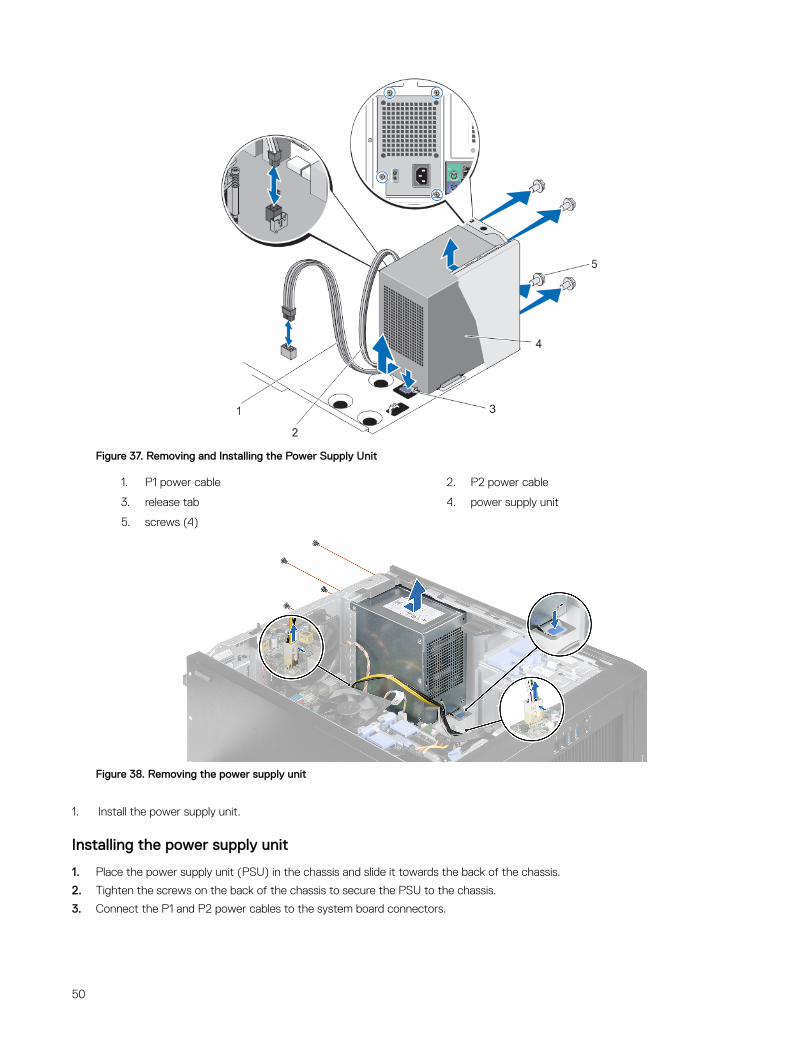
Figure 37. Removing and Installing the Power Supply Unit
1. P1 power cable 2. P2 power cable
3. release tab 4. power supply unit
5. screws (4)
Figure 38. Removing the power supply unit
1. Install the power supply unit.
Installing the power supply unit
1. Place the power supply unit (PSU) in the chassis and slide it towards the back of the chassis.
2. Tighten the screws on the back of the chassis to secure the PSU to the chassis.
3. Connect the P1 and P2 power cables to the system board connectors.
50

System Battery
Replacing The System Battery
WARNING: There is a danger of a new battery exploding if it is incorrectly installed. Replace the battery only with the same or equivalent type recommended by the manufacturer. See your safety information for additional information.
CAUTION: Many repairs may only be done by a certified service technician. You should only perform troubleshooting and simple repairs as authorized in your product documentation, or as directed by the online or telephone service and support team. Damage due to servicing that is not authorized by Dell is not covered by your warranty. Read and follow the safety instructions that came with the product.
1. Turn off the system, including any attached peripherals, and disconnect the system from the electrical outlet and peripherals.
2. Lay the system on its side, on a flat and stable surface.
3. Open the system.
4. Locate the battery socket.
CAUTION: To avoid damage to the battery connector, you must firmly support the connector while installing or removing a battery.
5. Press the release latch to allow the battery to pop-up from the socket and lift the battery out of the system.
Figure 39. Removing and Installing the System Battery
1. release latch
2. system battery
6. To install a new system battery, hold the battery with the "+" facing up and slide it under the securing tabs at the positive side of the connector.
7. Press the battery straight down into the connector until it snaps into place.
8. Close the system.
9. Place the system upright on a flat, stable surface.
10. Reconnect the system to the electrical outlet and turn the system on, including any attached peripherals.
11. Press <F2> to enter the System Setup to confirm that the battery is operating properly.
12. Enter the correct time and date in the System Setup Time and Date fields.
51

System boardA system board (also known as the motherboard) is the main printed circuit board in the system with different connectors used to connect different components or peripherals of the system. A system board provides the electrical connections to the components in the system to communicate.
Removing the system board
CAUTION: If you are using the Trusted Program Module (TPM) with an encryption key, you may be prompted to create a recovery key during program or system setup. Be sure to create and safely store this recovery key. If you replace this system board, you must supply the recovery key when you restart your system or program before you can access the encrypted data on your hard drives.
1. Remove the following:
a. system fan
b. all expansion cards
c. heat sink and processor
d. memory modules
2. Disconnect all the cables from the system board.
1. Remove the eight screws that secure the system board to the chassis.
2. Hold the system board by the sides, slide the system board towards the front of the system and lift the system board out.
Figure 40. Removing the System Board
1. screws (8) 2. system board
1. Install the system board.
2. Connect all the cables to the system board.
Installing the system board
CAUTION: If you are using the Trusted Program Module (TPM) with an encryption key, you may be prompted to create a recovery key during program or system setup. Be sure to create and safely store this recovery key. If you replace this system board, you must supply the recovery key when you restart your system or program before you can access the encrypted data on your hard drives.
1. Unpack the new system board assembly.
52
CAUTION: Do not lift the system board assembly by grasping any components.
1. Lower the system board into the chassis.
2. Push the system board towards the back of the chassis until the system board's screw holes align with the screw holes on the chassis.
3. Secure the system board to the chassis using the eight screws.
NOTE: Dell recommends that you install screws from diagonally opposite corners.
1. Install the following:
a. heat sink and processor
b. memory modules
c. expansion cards
d. system fan
2. Connect all cables to the system board.
3. Enter the system service tag after you install the system board. For more information about entering the service tag, see the Entering The Service Tag After Replacing The System Board section.
Entering The Service Tag After Replacing The System Board
Enter the system service tag after you replace the system board.
NOTE: To replace the system board within the warranty period, contact Dell for technical support. To replace the system board after the system warranty expires, see Removing The System Board.
1. Power on the system.
2. Press <F2> to enter the System Setup.
3. Select Maintenance → Service Tag.
4. Enter the service tag.
NOTE: You can enter the service tag can only when the Service Tag field is empty. Ensure that you enter the correct service tag. Once the service tag is entered, it cannot be updated or changed.
5. Click Apply and Exit.
53
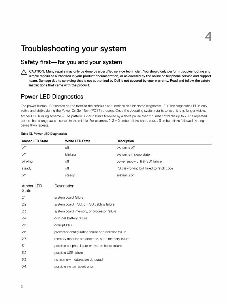
4Troubleshooting your system
Safety first—for you and your systemCAUTION: Many repairs may only be done by a certified service technician. You should only perform troubleshooting and simple repairs as authorized in your product documentation, or as directed by the online or telephone service and support team. Damage due to servicing that is not authorized by Dell is not covered by your warranty. Read and follow the safety instructions that came with the product.
Power LED DiagnosticsThe power button LED located on the front of the chassis also functions as a bicolored diagnostic LED. The diagnostic LED is only active and visible during the Power On Self Test (POST) process. Once the operating system starts to load, it is no longer visible.
Amber LED blinking scheme – The pattern is 2 or 3 blinks followed by a short pause then x number of blinks up to 7. The repeated pattern has a long pause inserted in the middle. For example, 2, 3 = 2 amber blinks, short pause, 3 amber blinks followed by long pause then repeats.
Table 13. Power LED Diagnostics
Amber LED State White LED State Description
off off system is off
off blinking system is in sleep state
blinking off power supply unit (PSU) failure
steady off PSU is working but failed to fetch code
off steady system is on
Amber LED State
Description
2,1 system board failure
2,2 system board, PSU, or PSU cabling failure
2,3 system board, memory, or processor failure
2,4 coin-cell battery failure
2,5 corrupt BIOS
2,6 processor configuration failure or processor failure
2,7 memory modules are detected, but a memory failure
3,1 possible peripheral card or system board failure
3,2 possible USB failure
3,3 no memory modules are detected
3,4 possible system board error
54
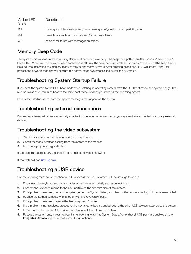
Amber LED State
Description
3,5 memory modules are detected, but a memory configuration or compatibility error
3,6 possible system board resource and/or hardware failure
3,7 some other failure with messages on screen
Memory Beep CodeThe system emits a series of beeps during startup if it detects no memory. The beep code pattern emitted is 1-3-2 (1 beep, then 3 beeps, then 2 beeps). The delay between each beep is 300 ms, the delay between each set of beeps is 3 secs, and the beep sound lasts 300 ms. Reseating the memory modules may fix the memory errors. After emitting beeps, the BIOS will detect if the user presses the power button and will execute the normal shutdown process and power the system off.
Troubleshooting System Startup FailureIf you boot the system to the BIOS boot mode after installing an operating system from the UEFI boot mode, the system hangs. The reverse is also true. You must boot to the same boot mode in which you installed the operating system.
For all other startup issues, note the system messages that appear on the screen.
Troubleshooting external connectionsEnsure that all external cables are securely attached to the external connectors on your system before troubleshooting any external devices.
Troubleshooting the video subsystem1. Check the system and power connections to the monitor.
2. Check the video interface cabling from the system to the monitor.
3. Run the appropriate diagnostic test.
If the tests run successfully, the problem is not related to video hardware.
If the tests fail, see Getting help.
Troubleshooting a USB deviceUse the following steps to troubleshoot a USB keyboard/mouse. For other USB devices, go to step 7.
1. Disconnect the keyboard and mouse cables from the system briefly and reconnect them.
2. Connect the keyboard/mouse to the USB port(s) on the opposite side of the system.
3. If the problem is resolved, restart the system, enter the System Setup, and check if the non-functioning USB ports are enabled.
4. Replace the keyboard/mouse with another working keyboard/mouse.
5. If the problem is resolved, replace the faulty keyboard/mouse.
6. If the problem is not resolved, proceed to the next step to begin troubleshooting the other USB devices attached to the system.
7. Power down all attached USB devices and disconnect them from the system.
8. Reboot the system and, if your keyboard is functioning, enter the System Setup. Verify that all USB ports are enabled on the Integrated Devices screen, in the System Setup options.
55
If your keyboard is not functioning, you can also use remote access. If the system is not accessible, reset the NVRAM_CLR jumper inside your system and restore the BIOS to the default settings.
9. Reconnect and power on each USB device one at a time.
10. If a device causes the same problem, power down the device, replace the USB cable with a known good cable, and power up the device.
If all troubleshooting fails, see Getting help.
Troubleshooting a serial I/O device1. Turn off the system and any peripheral devices connected to the serial port.
2. Swap the serial interface cable with a working cable, and turn on the system and the serial device.
If the problem is resolved, replace the interface cable with a known good cable.
3. Turn off the system and the serial device, and swap the device with a comparable device.
4. Turn on the system and the serial device.
If the problem persists, see Getting help.
Troubleshooting A NIC1. Run the appropriate diagnostic test. See Using System Diagnostics for available diagnostic tests.
2. Restart the system and check for any system messages pertaining to the NIC controller.
3. Check the appropriate indicator on the NIC connector:
• If the link indicator does not light, check all cable connections.
• If the activity indicator does not light, the network driver files might be damaged or missing.
Remove and reinstall the drivers if applicable. See the NIC documentation.
• If applicable, change the autonegotiation setting.
• Use another connector on the switch or hub.
4. Ensure that the appropriate drivers are installed and the protocols are bound. See the NIC documentation.
5. Enter the System Setup and confirm that the NIC ports are enabled on the Integrated Devices screen.
6. Ensure that the NICs, hubs, and switches on the network are all set to the same data transmission speed and duplex. See the documentation for each network device.
7. Ensure that all network cables are of the proper type and do not exceed the maximum length.
If all troubleshooting fails, see Getting Help.
Troubleshooting A Wet SystemCAUTION: Many repairs may only be done by a certified service technician. You should only perform troubleshooting and simple repairs as authorized in your product documentation, or as directed by the online or telephone service and support team. Damage due to servicing that is not authorized by Dell is not covered by your warranty. Read and follow the safety instructions that came with the product.
1. Turn off the system and attached peripherals, and disconnect the system from the electrical outlet.
2. Open the system.
3. Disassemble the following components from the system:
• Hard drives
• Expansion cards
• Power supply
• System fan
• Processor and heat sink
56
• Memory modules
4. Let the system dry thoroughly for at least 24 hours.
5. Reinstall the components you removed in step 3.
6. Close the system.
7. Turn on the system and attached peripherals.
If the system does not start properly, see Getting Help.
8. Run the appropriate diagnostic test. For more information, see Using System Diagnostics.
If the tests fail, see Getting Help.
Troubleshooting A Damaged SystemCAUTION: Many repairs may only be done by a certified service technician. You should only perform troubleshooting and simple repairs as authorized in your product documentation, or as directed by the online or telephone service and support team. Damage due to servicing that is not authorized by Dell is not covered by your warranty. Read and follow the safety instructions that came with the product.
1. Turn off the system and attached peripherals, and disconnect the system from the electrical outlet.
2. Open the system.
3. Ensure that the following components are properly installed:
• Expansion cards
• Power supply
• System fan
• Processor and heat sink
• Memory modules
4. Ensure that all cables are properly connected.
5. Close the system.
6. Run the appropriate diagnostic test. For more information, see Using System Diagnostics.
If the tests fail, see Getting Help.
Troubleshooting the system batteryCAUTION: Many repairs may only be done by a certified service technician. You should only perform troubleshooting and simple repairs as authorized in your product documentation, or as directed by the online or telephone service and support team. Damage due to servicing that is not authorized by Dell is not covered by your warranty. Read and follow the safety instructions that came with the product.
NOTE: If the system is turned off for long periods of time (for weeks or months), the NVRAM may lose its system configuration information. This situation is caused by a defective battery.
1. Re-enter the time and date in the System Setup.
2. Turn off the system and disconnect it from the electrical outlet for at least one hour.
3. Reconnect the system to the electrical outlet and turn on the system.
4. Enter the System Setup.
If the date and time are not correct in the System Setup, check the SEL for system battery messages.
If the problem persists, see Getting help.
NOTE: Some software may cause the system time to speed up or slow down. If the system seems to operate normally except for the time kept in the System Setup, the problem may be caused by software rather than by a defective battery.
57
Troubleshooting A Non-Redundant Power SupplyCAUTION: Many repairs may only be done by a certified service technician. You should only perform troubleshooting and simple repairs as authorized in your product documentation, or as directed by the online or telephone service and support team. Damage due to servicing that is not authorized by Dell is not covered by your warranty. Read and follow the safety instructions that came with the product.
1. Press the self-diagnostic button on the power supply.
2. If the power supply status indicator is not lit, turn off the system and attached peripherals, and disconnect the system from the electrical outlet.
3. Open the system.
4. Reseat the power supply and the cables.
5. Close the system.
6. If the problem persists, see Getting Help.
Troubleshooting cooling problemsCAUTION: Many repairs may only be done by a certified service technician. You should only perform troubleshooting and simple repairs as authorized in your product documentation, or as directed by the online or telephone service and support team. Damage due to servicing that is not authorized by Dell is not covered by your warranty. Read and follow the safety instructions that came with the product.
Ensure that none of the following conditions exist:
• System cover, cooling shroud, EMI filler panel, memory-module blank, or back-filler bracket is removed.
• Ambient temperature is too high.
• External airflow is obstructed.
• A cooling fan is removed or has failed.
• The expansion card installation guidelines have not been followed.
Troubleshooting The System FanCAUTION: Many repairs may only be done by a certified service technician. You should only perform troubleshooting and simple repairs as authorized in your product documentation, or as directed by the online or telephone service and support team. Damage due to servicing that is not authorized by Dell is not covered by your warranty. Read and follow the safety instructions that came with the product.
1. Open the system.
2. Reseat the fan or the fan's power cable.
3. If the fan functions properly, close the system.
If the problem persists, see Getting Help.
Troubleshooting System MemoryCAUTION: Many repairs may only be done by a certified service technician. You should only perform troubleshooting and simple repairs as authorized in your product documentation, or as directed by the online or telephone service and support team. Damage due to servicing that is not authorized by Dell is not covered by your warranty. Read and follow the safety instructions that came with the product.
1. If the system is operational, run the appropriate diagnostic test. See Using System Diagnostics for available diagnostic tests.
If diagnostics indicates a fault, follow the corrective actions provided by the diagnostic program.
2. If the system is not operational, turn off the system and attached peripherals, and unplug the system from the power source. Wait at least 10 seconds and then reconnect the system to power.
58
3. Turn on the system and attached peripherals and note the messages on the screen.
If an error message is displayed indicating a fault with a specific memory module, go to step 12.
4. Enter the System Setup and check the system memory setting. Make any changes to the memory settings, if needed.
If the memory settings match the installed memory but a problem is still indicated, go to step 12.
5. Turn off the system and attached peripherals, and disconnect the system from the electrical outlet.
6. Open the system.
7. Check the memory channels and ensure that they are populated correctly.
8. Reseat the memory modules in their sockets.
9. Close the system.
10. Enter the System Setup and check the system memory setting.
If the problem is not resolved, proceed with the next step.
11. Open the system.
12. If a diagnostic test or error message indicates a specific memory module as faulty, swap or replace the module with a known good memory module.
13. To troubleshoot an unspecified faulty memory module, replace the memory module in the first DIMM socket with a module of the same type and capacity.
If an error message is displayed on the screen, this may indicate a problem with the installed DIMM type(s), incorrect DIMM installation, or defective DIMM(s). Follow the on-screen instructions to resolve the problem. For more information, see General Memory Module Installation Guidelines.
14. Close the system.
15. As the system boots, observe any error message that is displayed and the diagnostic indicators on the front of the system.
16. If the memory problem is still indicated, repeat step 12 through step 15 for each memory module installed.
If the problem persists after all memory modules have been checked, see Getting Help.
Troubleshooting An Optical DriveCAUTION: Many repairs may only be done by a certified service technician. You should only perform troubleshooting and simple repairs as authorized in your product documentation, or as directed by the online or telephone service and support team. Damage due to servicing that is not authorized by Dell is not covered by your warranty. Read and follow the safety instructions that came with the product.
1. Try using a different CD or DVD.
2. Enter the System Setup and ensure that the integrated SATA controller and the drive's SATA port are enabled.
3. Run the appropriate diagnostic test.
4. Turn off the system and attached peripherals, and disconnect the system from the electrical outlet.
5. Open the system.
6. Remove the front bezel.
7. Ensure that the interface cable is securely connected to the drive and to the controller.
8. Ensure that a power cable is properly connected to the drive.
9. Close the system.
If the problem is not resolved, see Getting Help.
Troubleshooting A Hard DriveCAUTION: Many repairs may only be done by a certified service technician. You should only perform troubleshooting and simple repairs as authorized in your product documentation, or as directed by the online or telephone service and support team. Damage due to servicing that is not authorized by Dell is not covered by your warranty. Read and follow the safety instructions that came with the product.
59
CAUTION: This troubleshooting procedure can erase data stored on the hard drive. Before you proceed, back up all files on the hard drive.
1. Run the appropriate diagnostic test. For more information, see Using System Diagnostics.
Depending on the results of the diagnostics test, proceed as needed through the following steps.
2. Ensure that the required device drivers for your controller card are installed and are configured correctly. See the operating system documentation for more information.
3. Restart the system and enter the System Setup.
4. Verify that the controller is enabled and the drives are displayed in the System Setup.
If the problem persists, try troubleshooting the expansion cards or see Getting Help.
Troubleshooting Expansion CardsCAUTION: Many repairs may only be done by a certified service technician. You should only perform troubleshooting and simple repairs as authorized in your product documentation, or as directed by the online or telephone service and support team. Damage due to servicing that is not authorized by Dell is not covered by your warranty. Read and follow the safety instructions that came with the product.
NOTE: When troubleshooting an expansion card, see the documentation for your operating system and the expansion card.
1. Run the appropriate diagnostic test. For more information, see Using System Diagnostics.
2. Turn off the system and attached peripherals, and disconnect the system from the electrical outlet.
3. Open the system.
4. Ensure that each expansion card is firmly seated in its connector.
5. Close the system.
6. If the problem is not resolved, turn off the system and attached peripherals, and disconnect the system from the electrical outlet.
7. Open the system.
8. Remove all expansion cards installed in the system.
9. Close the system.
10. Run the appropriate diagnostic test. For more information, see Using System Diagnostics.
If the tests fail, see Getting Help.
11. For each expansion card you removed in step 8, perform the following steps:
a. Turn off the system and attached peripherals, and disconnect the system from the electrical outlet.b. Open the system.c. Reinstall one of the expansion cards.d. Close the system.e. Run the appropriate diagnostic test. For more information, see Using System Diagnostics.
If a problem is still indicated, see Getting Help.
Troubleshooting The ProcessorCAUTION: Many repairs may only be done by a certified service technician. You should only perform troubleshooting and simple repairs as authorized in your product documentation, or as directed by the online or telephone service and support team. Damage due to servicing that is not authorized by Dell is not covered by your warranty. Read and follow the safety instructions that came with the product.
1. Run the appropriate diagnostics test. See Using System Diagnostics for available diagnostic tests.
2. Turn off the system and attached peripherals, and disconnect the system from the electrical outlet.
3. Open the system.
4. Ensure that the processor and heat sink are properly installed.
60

5. Close the system.
6. Run the appropriate diagnostic test. For more information, see Using System Diagnostics.
If a problem is still indicated, see Getting Help.
61
5Using System DiagnosticsIf you experience a problem with your system, run the system diagnostics before contacting Dell for technical assistance. The purpose of running system diagnostics is to test your system hardware without requiring additional equipment or risking data loss. If you are unable to fix the problem yourself, service and support personnel can use the diagnostics results to help you solve the problem.
Enhanced Pre-Boot System Assessment DiagnosticsThe Enhanced Pre-Boot System Assessment (ePSA) diagnostics (also known as system diagnostics) performs a complete check of your hardware. The ePSA is embedded with the BIOS and is launched by the BIOS internally. The embedded system diagnostics provides a set of options for particular device groups or devices allowing you to:
• Run tests automatically or in an interactive mode
• Repeat tests
• Display or save test results
• Run thorough tests to introduce additional test options to provide extra information about the failed device(s)
• View status messages that inform you if tests are completed successfully
• View error messages that inform you of problems encountered during testing
CAUTION: Use the system diagnostics to test only your system. Using this program with other systems may cause invalid results or error messages.
NOTE: Some tests for specific devices require user interaction. Always ensure that you are present at the system terminal when the diagnostic tests are performed.
1. Power-on the system.
2. As the system boots, press the <F12> key as the Dell logo is displayed.
3. On the boot menu screen, select the Diagnostics option.
The Enhanced Pre-boot System Assessment window is displayed, listing all devices detected in the system. The diagnostics starts running the tests on all the detected devices.
4. If you wish to run a diagnostic test on a specific device, press <Esc> and click Yes to stop the diagnostic test.
5. Select the device from the left pane and click Run Tests.
6. If there are any issues, error codes are displayed.
Note the error code and contact Dell.
System diagnostics controls
Menu Description
Configuration Displays the configuration and status of all detected devices.
Results Displays the results of all tests that are executed.
System health Provides the current overview of the system performance.
Event log Displays a time-stamped log of the results of all tests run on the system. This is displayed if at least one event description is recorded.
62
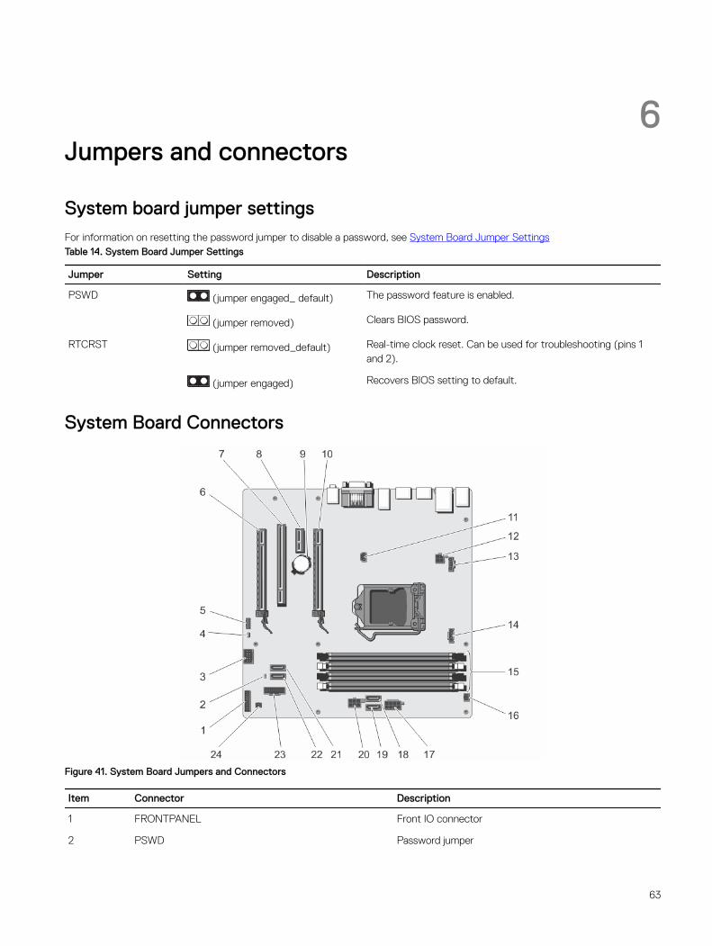
6Jumpers and connectors
System board jumper settingsFor information on resetting the password jumper to disable a password, see System Board Jumper SettingsTable 14. System Board Jumper Settings
Jumper Setting Description
PSWD (jumper engaged_ default) The password feature is enabled.
(jumper removed) Clears BIOS password.
RTCRST (jumper removed_default) Real-time clock reset. Can be used for troubleshooting (pins 1 and 2).
(jumper engaged) Recovers BIOS setting to default.
System Board Connectors
Figure 41. System Board Jumpers and Connectors
Item Connector Description
1 FRONTPANEL Front IO connector
2 PSWD Password jumper
63
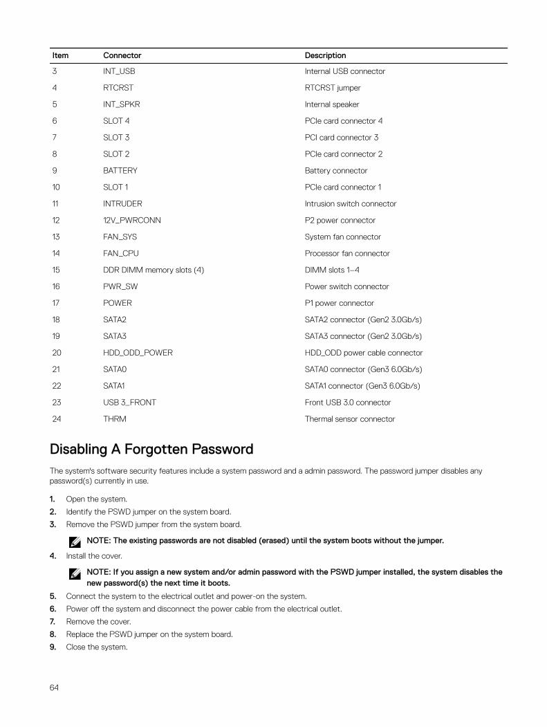
Item Connector Description
3 INT_USB Internal USB connector
4 RTCRST RTCRST jumper
5 INT_SPKR Internal speaker
6 SLOT 4 PCIe card connector 4
7 SLOT 3 PCI card connector 3
8 SLOT 2 PCIe card connector 2
9 BATTERY Battery connector
10 SLOT 1 PCIe card connector 1
11 INTRUDER Intrusion switch connector
12 12V_PWRCONN P2 power connector
13 FAN_SYS System fan connector
14 FAN_CPU Processor fan connector
15 DDR DIMM memory slots (4) DIMM slots 1–4
16 PWR_SW Power switch connector
17 POWER P1 power connector
18 SATA2 SATA2 connector (Gen2 3.0Gb/s)
19 SATA3 SATA3 connector (Gen2 3.0Gb/s)
20 HDD_ODD_POWER HDD_ODD power cable connector
21 SATA0 SATA0 connector (Gen3 6.0Gb/s)
22 SATA1 SATA1 connector (Gen3 6.0Gb/s)
23 USB 3_FRONT Front USB 3.0 connector
24 THRM Thermal sensor connector
Disabling A Forgotten PasswordThe system's software security features include a system password and a admin password. The password jumper disables any password(s) currently in use.
1. Open the system.
2. Identify the PSWD jumper on the system board.
3. Remove the PSWD jumper from the system board.
NOTE: The existing passwords are not disabled (erased) until the system boots without the jumper.
4. Install the cover.
NOTE: If you assign a new system and/or admin password with the PSWD jumper installed, the system disables the new password(s) the next time it boots.
5. Connect the system to the electrical outlet and power-on the system.
6. Power off the system and disconnect the power cable from the electrical outlet.
7. Remove the cover.
8. Replace the PSWD jumper on the system board.
9. Close the system.
64

10. Power on the system.
11. Go to the system setup, and assign a new system or admin password.
For information on assigning a system or admin password, see Assigning A System And Admin Password.
65
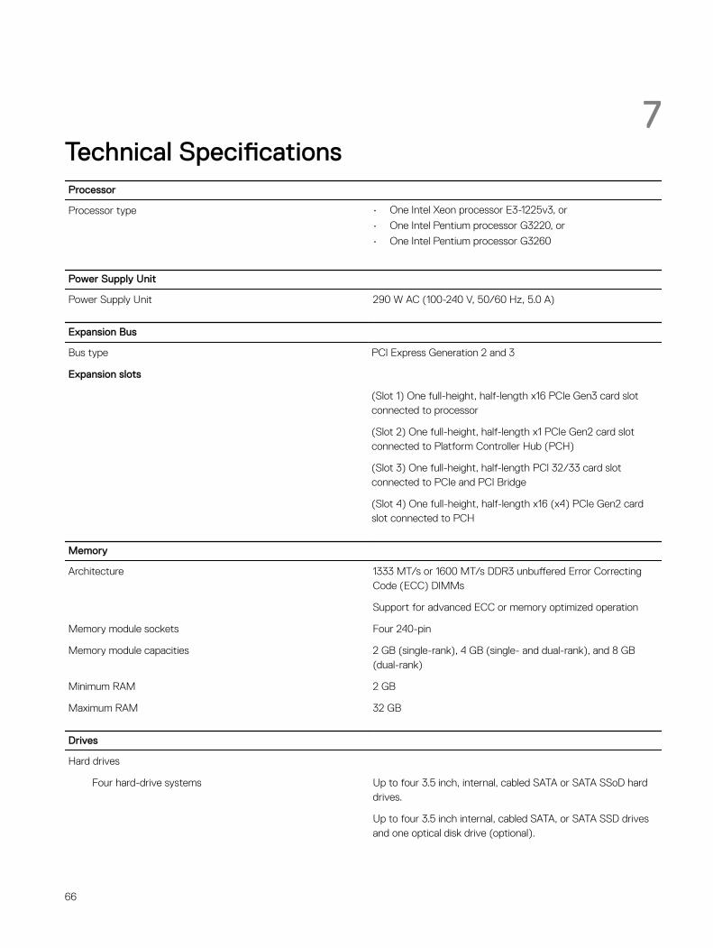
7Technical SpecificationsProcessor
Processor type • One Intel Xeon processor E3-1225v3, or
• One Intel Pentium processor G3220, or
• One Intel Pentium processor G3260
Power Supply Unit
Power Supply Unit 290 W AC (100-240 V, 50/60 Hz, 5.0 A)
Expansion Bus
Bus type PCI Express Generation 2 and 3
Expansion slots
(Slot 1) One full-height, half-length x16 PCIe Gen3 card slot connected to processor
(Slot 2) One full-height, half-length x1 PCIe Gen2 card slot connected to Platform Controller Hub (PCH)
(Slot 3) One full-height, half-length PCI 32/33 card slot connected to PCIe and PCI Bridge
(Slot 4) One full-height, half-length x16 (x4) PCIe Gen2 card slot connected to PCH
Memory
Architecture 1333 MT/s or 1600 MT/s DDR3 unbuffered Error Correcting Code (ECC) DIMMs
Support for advanced ECC or memory optimized operation
Memory module sockets Four 240-pin
Memory module capacities 2 GB (single-rank), 4 GB (single- and dual-rank), and 8 GB (dual-rank)
Minimum RAM 2 GB
Maximum RAM 32 GB
Drives
Hard drives
Four hard-drive systems Up to four 3.5 inch, internal, cabled SATA or SATA SSoD hard drives.
Up to four 3.5 inch internal, cabled SATA, or SATA SSD drives and one optical disk drive (optional).
66
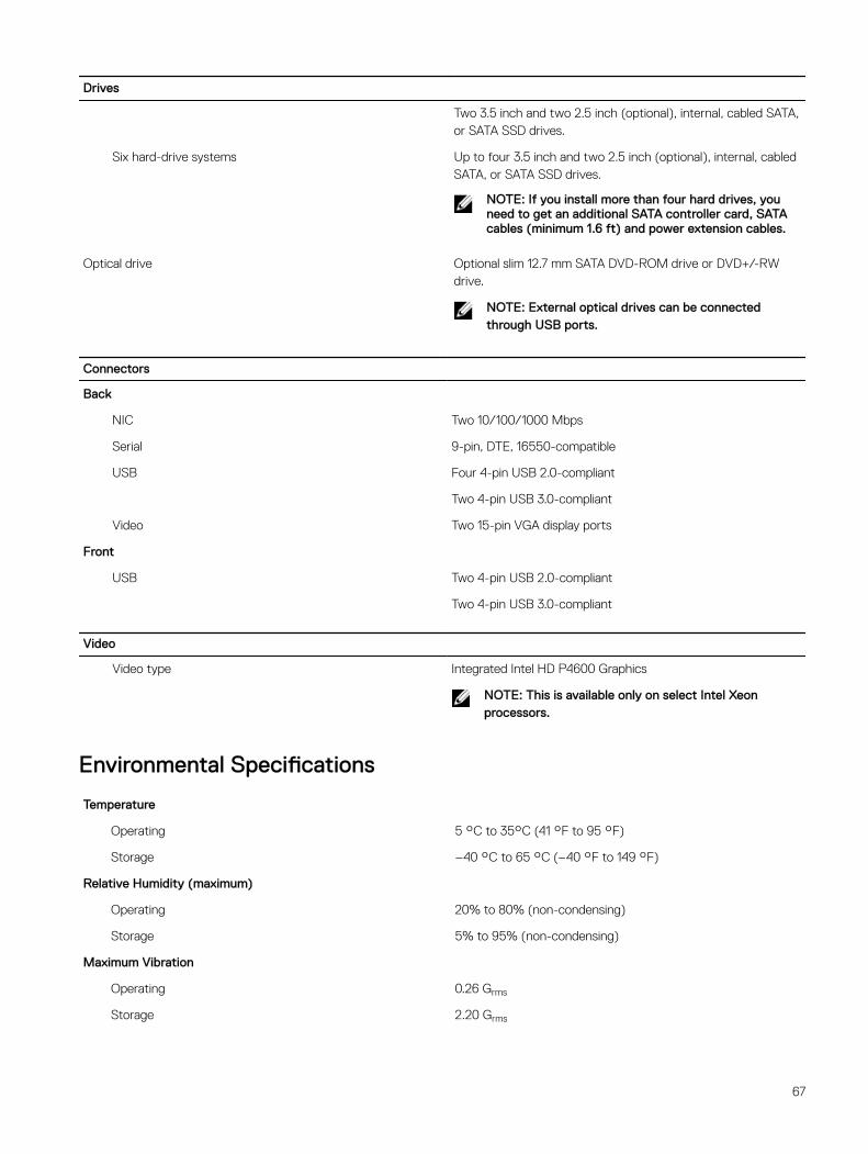
Drives
Two 3.5 inch and two 2.5 inch (optional), internal, cabled SATA, or SATA SSD drives.
Six hard-drive systems Up to four 3.5 inch and two 2.5 inch (optional), internal, cabled SATA, or SATA SSD drives.
NOTE: If you install more than four hard drives, you need to get an additional SATA controller card, SATA cables (minimum 1.6 ft) and power extension cables.
Optical drive Optional slim 12.7 mm SATA DVD-ROM drive or DVD+/-RW drive.
NOTE: External optical drives can be connected through USB ports.
Connectors
Back
NIC Two 10/100/1000 Mbps
Serial 9-pin, DTE, 16550-compatible
USB Four 4-pin USB 2.0-compliant
Two 4-pin USB 3.0-compliant
Video Two 15-pin VGA display ports
Front
USB Two 4-pin USB 2.0-compliant
Two 4-pin USB 3.0-compliant
Video
Video type Integrated Intel HD P4600 Graphics
NOTE: This is available only on select Intel Xeon processors.
Environmental Specifications
Temperature
Operating 5 °C to 35°C (41 °F to 95 °F)
Storage –40 °C to 65 °C (–40 °F to 149 °F)
Relative Humidity (maximum)
Operating 20% to 80% (non-condensing)
Storage 5% to 95% (non-condensing)
Maximum Vibration
Operating 0.26 Grms
Storage 2.20 Grms
67
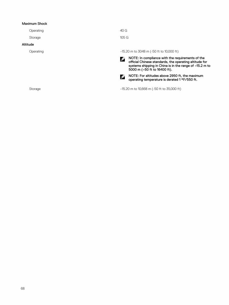
Maximum Shock
Operating 40 G
Storage 105 G
Altitude
Operating –15.20 m to 3048 m (-50 ft to 10,000 ft)
NOTE: In compliance with the requirements of the official Chinese standards, the operating altitude for systems shipping in China is in the range of –15.2 m to 5000 m (–50 ft to 16400 ft).
NOTE: For altitudes above 2950 ft, the maximum operating temperature is derated 1 ºF/550 ft.
Storage –15.20 m to 10,668 m (-50 ft to 35,000 ft)
68
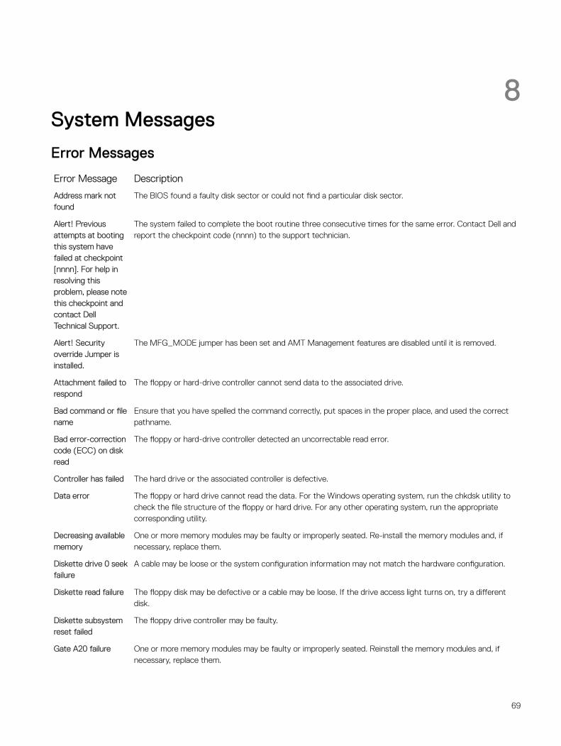
8System Messages
Error Messages
Error Message Description
Address mark not found
The BIOS found a faulty disk sector or could not find a particular disk sector.
Alert! Previous attempts at booting this system have failed at checkpoint [nnnn]. For help in resolving this problem, please note this checkpoint and contact Dell Technical Support.
The system failed to complete the boot routine three consecutive times for the same error. Contact Dell and report the checkpoint code (nnnn) to the support technician.
Alert! Security override Jumper is installed.
The MFG_MODE jumper has been set and AMT Management features are disabled until it is removed.
Attachment failed to respond
The floppy or hard-drive controller cannot send data to the associated drive.
Bad command or file name
Ensure that you have spelled the command correctly, put spaces in the proper place, and used the correct pathname.
Bad error-correction code (ECC) on disk read
The floppy or hard-drive controller detected an uncorrectable read error.
Controller has failed The hard drive or the associated controller is defective.
Data error The floppy or hard drive cannot read the data. For the Windows operating system, run the chkdsk utility to check the file structure of the floppy or hard drive. For any other operating system, run the appropriate corresponding utility.
Decreasing available memory
One or more memory modules may be faulty or improperly seated. Re-install the memory modules and, if necessary, replace them.
Diskette drive 0 seek failure
A cable may be loose or the system configuration information may not match the hardware configuration.
Diskette read failure The floppy disk may be defective or a cable may be loose. If the drive access light turns on, try a different disk.
Diskette subsystem reset failed
The floppy drive controller may be faulty.
Gate A20 failure One or more memory modules may be faulty or improperly seated. Reinstall the memory modules and, if necessary, replace them.
69
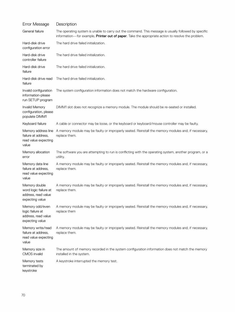
Error Message Description
General failure The operating system is unable to carry out the command. This message is usually followed by specific information—for example, Printer out of paper. Take the appropriate action to resolve the problem.
Hard-disk drive configuration error
The hard drive failed initialization.
Hard-disk drive controller failure
The hard drive failed initialization.
Hard-disk drive failure
The hard drive failed initialization.
Hard-disk drive read failure
The hard drive failed initialization.
Invalid configuration information-please run SETUP program
The system configuration information does not match the hardware configuration.
Invalid Memory configuration, please populate DIMM1
DIMM1 slot does not recognize a memory module. The module should be re-seated or installed.
Keyboard failure A cable or connector may be loose, or the keyboard or keyboard/mouse controller may be faulty.
Memory address line failure at address, read value expecting value
A memory module may be faulty or improperly seated. Reinstall the memory modules and, if necessary, replace them.
Memory allocation error
The software you are attempting to run is conflicting with the operating system, another program, or a utility.
Memory data line failure at address, read value expecting value
A memory module may be faulty or improperly seated. Reinstall the memory modules and, if necessary, replace them.
Memory double word logic failure at address, read value expecting value
A memory module may be faulty or improperly seated. Reinstall the memory modules and, if necessary, replace them.
Memory odd/even logic failure at address, read value expecting value
A memory module may be faulty or improperly seated. Reinstall the memory modules and, if necessary, replace them
Memory write/read failure at address, read value expecting value
A memory module may be faulty or improperly seated. Reinstall the memory modules and, if necessary, replace them.
Memory size in CMOS invalid
The amount of memory recorded in the system configuration information does not match the memory installed in the system.
Memory tests terminated by keystroke
A keystroke interrupted the memory test.
70
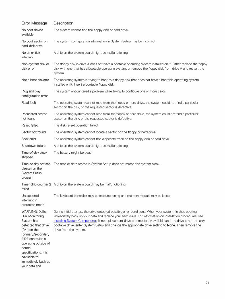
Error Message Description
No boot device available
The system cannot find the floppy disk or hard drive.
No boot sector on hard-disk drive
The system configuration information in System Setup may be incorrect.
No timer tick interrupt
A chip on the system board might be malfunctioning.
Non-system disk or disk error
The floppy disk in drive A does not have a bootable operating system installed on it. Either replace the floppy disk with one that has a bootable operating system, or remove the floppy disk from drive A and restart the system.
Not a boot diskette The operating system is trying to boot to a floppy disk that does not have a bootable operating system installed on it. Insert a bootable floppy disk.
Plug and play configuration error
The system encountered a problem while trying to configure one or more cards.
Read fault The operating system cannot read from the floppy or hard drive, the system could not find a particular sector on the disk, or the requested sector is defective.
Requested sector not found
The operating system cannot read from the floppy or hard drive, the system could not find a particular sector on the disk, or the requested sector is defective.
Reset failed The disk re-set operation failed.
Sector not found The operating system cannot locate a sector on the floppy or hard drive.
Seek error The operating system cannot find a specific track on the floppy disk or hard drive.
Shutdown failure A chip on the system board might be malfunctioning.
Time-of-day clock stopped
The battery might be dead.
Time-of-day not set-please run the System Setup program
The time or date stored in System Setup does not match the system clock.
Timer chip counter 2 failed
A chip on the system board may be malfunctioning.
Unexpected interrupt in protected mode
The keyboard controller may be malfunctioning or a memory module may be loose.
WARNING: Dell's Disk Monitoring System has detected that drive [0/1] on the [primary/secondary] EIDE controller is operating outside of normal specifications. It is advisable to immediately back up your data and
During initial startup, the drive detected possible error conditions. When your system finishes booting, immediately back up your data and replace your hard drive. For information on installation procedures, see Installing System Components. If no replacement drive is immediately available and the drive is not the only bootable drive, enter System Setup and change the appropriate drive setting to None. Then remove the drive from the system.
71
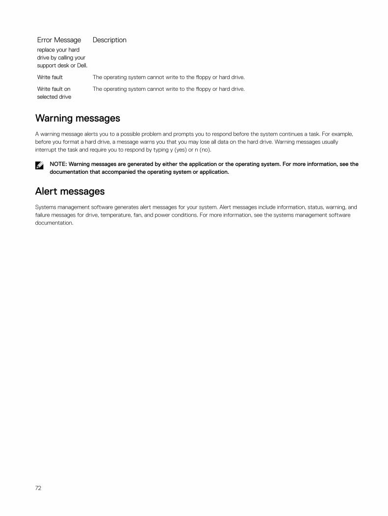
Error Message Descriptionreplace your hard drive by calling your support desk or Dell.
Write fault The operating system cannot write to the floppy or hard drive.
Write fault on selected drive
The operating system cannot write to the floppy or hard drive.
Warning messagesA warning message alerts you to a possible problem and prompts you to respond before the system continues a task. For example, before you format a hard drive, a message warns you that you may lose all data on the hard drive. Warning messages usually interrupt the task and require you to respond by typing y (yes) or n (no).
NOTE: Warning messages are generated by either the application or the operating system. For more information, see the documentation that accompanied the operating system or application.
Alert messagesSystems management software generates alert messages for your system. Alert messages include information, status, warning, and failure messages for drive, temperature, fan, and power conditions. For more information, see the systems management software documentation.
72
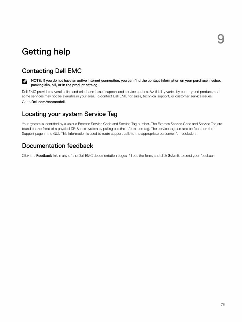
9Getting help
Contacting Dell EMCNOTE: If you do not have an active internet connection, you can find the contact information on your purchase invoice, packing slip, bill, or in the product catalog.
Dell EMC provides several online and telephone-based support and service options. Availability varies by country and product, and some services may not be available in your area. To contact Dell EMC for sales, technical support, or customer service issues:
Go to Dell.com/contactdell.
Locating your system Service TagYour system is identified by a unique Express Service Code and Service Tag number. The Express Service Code and Service Tag are found on the front of a physical DR Series system by pulling out the information tag. The service tag can also be found on the Support page in the GUI. This information is used to route support calls to the appropriate personnel for resolution.
Documentation feedbackClick the Feedback link in any of the Dell EMC documentation pages, fill out the form, and click Submit to send your feedback.
73