Dell EMC PowerEdge T550 Technical Guide
72
Dell EMC PowerEdge T550 Technical Guide Part Number: E76S Regulatory Type: E76S001 December 2021 Rev. A01
-
Upload
khangminh22 -
Category
Documents
-
view
3 -
download
0
Transcript of Dell EMC PowerEdge T550 Technical Guide

Dell EMC PowerEdge T550Technical Guide
Part Number: E76SRegulatory Type: E76S001December 2021Rev. A01

Notes, cautions, and warnings
NOTE: A NOTE indicates important information that helps you make better use of your product.
CAUTION: A CAUTION indicates either potential damage to hardware or loss of data and tells you how to avoid
the problem.
WARNING: A WARNING indicates a potential for property damage, personal injury, or death.
© 2021 Dell Inc. or its subsidiaries. All rights reserved. Dell, EMC, and other trademarks are trademarks of Dell Inc. or its subsidiaries. Othertrademarks may be trademarks of their respective owners.

Chapter 1: Product overview......................................................................................................... 5Introduction...........................................................................................................................................................................5Product features..................................................................................................................................................................5
Chapter 2: System features.......................................................................................................... 6Product comparison............................................................................................................................................................6
Chapter 3: Chassis views and features.......................................................................................... 9Front view of the system.................................................................................................................................................. 9Rear view of the system.................................................................................................................................................. 18Inside the system ............................................................................................................................................................. 20Quick Resource Locator for PowerEdge T550 system........................................................................................... 22
Chapter 4: Processor...................................................................................................................23Processor features .......................................................................................................................................................... 23
Supported processors................................................................................................................................................ 23
Chapter 5: Memory..................................................................................................................... 25Supported memory........................................................................................................................................................... 25
Chapter 6: Storage......................................................................................................................26Drive backplane..................................................................................................................................................................26PERC Controller.................................................................................................................................................................27Storage.................................................................................................................................................................................27
Chapter 7: Networking and PCIe................................................................................................. 29Overview............................................................................................................................................................................. 29OCP 3.0 support................................................................................................................................................................29
Supported OCP cards................................................................................................................................................ 30OCP NIC 3.0 vs. rack Network Daughter Card comparisons........................................................................... 30
Expansion card installation guidelines........................................................................................................................... 31
Chapter 8: Power, thermal, and acoustics................................................................................... 37Power................................................................................................................................................................................... 37
PSU specifications...................................................................................................................................................... 38Thermal................................................................................................................................................................................ 39
Thermal design............................................................................................................................................................. 39Acoustics............................................................................................................................................................................. 40
Acoustical design.........................................................................................................................................................40PowerEdge acoustical specifications..................................................................................................................... 40Acoustical performance............................................................................................................................................. 47PowerEdge T550 acoustical dependencies.......................................................................................................... 48Methods to reduce acoustical output of the T550.............................................................................................49
Contents
Contents 3

Chapter 9: Supported Operating Systems................................................................................... 50
Chapter 10: Dell EMC OpenManage systems management............................................................51Server and Chassis Managers........................................................................................................................................52Dell EMC consoles............................................................................................................................................................ 52Automation Enablers........................................................................................................................................................ 52Integration with third-party consoles...........................................................................................................................52Connections for third-party consoles.......................................................................................................................... 52Dell EMC Update Utilities................................................................................................................................................52Dell resources.....................................................................................................................................................................52
Chapter 11: Appendix A. Additional specifications........................................................................54Chassis dimensions........................................................................................................................................................... 54System weight................................................................................................................................................................... 55Video specifications..........................................................................................................................................................55USB ports specifications................................................................................................................................................. 55Environmental specifications..........................................................................................................................................56
Thermal restriction matrix......................................................................................................................................... 57Particulate and gaseous contamination specifications ...................................................................................... 61Thermal air restrictions...............................................................................................................................................61
Chapter 12: Appendix B. Standards compliance........................................................................... 64
Chapter 13: Appendix C Additional resources...............................................................................65
Chapter 14: Appendix D. Support and Deployment Services ........................................................ 66Deployment Services........................................................................................................................................................66
Dell EMC ProDeploy Enterprise Suite ................................................................................................................... 66Dell EMC ProDeploy for HPC................................................................................................................................... 67Dell EMC Basic Deployment......................................................................................................................................67Dell EMC Server Configuration Services............................................................................................................... 67Dell EMC Residency Services...................................................................................................................................68Dell EMC Data Migration Service............................................................................................................................ 68Support Services......................................................................................................................................................... 68
Dell Technologies Consulting Services..........................................................................................................................71Dell EMC Remote Consulting Services................................................................................................................... 71
Chapter 15: Dell Financial Services (DFS).................................................................................... 72Flex On Demand (FOD)....................................................................................................................................................72Flex On Demand for PowerEdge Servers ...................................................................................................................72
4 Contents

Product overview
Topics:
• Introduction• Product features
IntroductionThe Dell™ PowerEdge™ T550 is Dell's latest 2-socket, tower server designed to run complex workloads using highly scalablememory, I/O, and network options. The systems feature the Intel Ice Lake Processor ( Socket P+ LGA-4189 ), up to 16DIMMs, PCI Express® (PCIe) 4. 0 enabled expansion slots, and a choice of network interface technologies to cover NIC.The PowerEdge T550 is a general-purpose platform capable of handling demanding workloads and applications, such as datawarehouses, ecommerce, databases, and high-performance computing (HPC).
Product featuresThe Dell EMC PowerEdge T550 is a two-socket, tower system. It supports up to 16 DDR4 DIMM slot, 24 drives storagecapacity, and powered with latest Intel Xeon Scalable processors. The T550 supports complete lifecycle management withthe OpenManage portfolio of systems management solutions, including leading remote management with iDRAC9 and LifecycleController.
The Dell EMC PowerEdge T550 is packed with features like:
● Highly optimized air flow design enables tremendous configuration flexibility and industrial leading energy efficiency.● Support payload data of front PERC, Riser, BOSS S2, backplane, and iDRAC.● OCP Mezz 3.0 (supported by x8 PCIe lanes).● Front PERC (fPERC) module with PERC10.5 and PERC11.● Supports Platinum 600 W AC/HVDC, Platinum 800 W AC/HVDC, 1100 W AC/HVDC, 1400 W AC/HVDC and 2400 W AC/
HVDC power supplies.
1
Product overview 5

System features
Topics:
• Product comparison
Product comparisonTable 1. Product comparison
Features PowerEdge T550 PowerEdge T640
Processors Up to two 3rd Generation Intel Xeon Scalableprocessors with up to 32 cores per processor
Up to two 2nd Generation Intel Xeon Scalableprocessors, up to 28 cores per processor
Memory DIMM speed● Up to 3200 MT/sMemory type● RDIMMMemory module slots● 16 DDR4 DIMM slots● Supports registered ECC DDR4 DIMM slots
onlyMaximum RAM● RDIMM 1 TB
DIMM speed● Up to 2993 MT/sMemory type● RDIMM● LRDIMM● NVDIMMMemory module slots● 24 DDR4 DIMM slots (12 NVDIMM only)● Supports registered ECC DDR4 DIMM slots onlyMaximum RAM● RDIMM 3 TB● LRDIMM 3 TB● NVDIMM 192 GB
Storage controllers ● Internal controllers: PERC H345, PERCH355, PERC H755, H755N, HBA355i
● Internal Boot: Internal Dual SD Moduleor Boot Optimized Storage Subsystem(BOSS-S2): HWRAID 2 x M.2 SSDs or USB
● External controller (RAID): PERC H840● External HBAs (non-RAID): HBA355e● Software RAID: S150
● Internal controllers: PERC H330, H730P, H740P,HBA330
● Internal Boot: Boot Optimized Storage Subsystem(BOSS) - HWRAID 2 x M.2 SSDs 240 GB, 480 GB
● External controller (RAID): H840, 12 Gbps SASHBA
● Software RAID: S140
Drive bays Front bays:● Up to 8 x 2.5-inch SAS/SATA (HDD) max
120 TB● 16 x 2.5-inch SAS/SATA (HDD) max 240
TB● 24 x 2.5-inch SAS/SATA (HDD) max 360
TB● 8 x 3.5-inch SAS/SATA (HDD/SAS) max
120 TB● 8 x 3.5-inch SAS/SATA (HDD) + 8 x 2.5-
inch NVMe (SSD) max 240 TB
Front bays:● Up to 8 or 18 x 3.5-inch SAS/SATA (HDD/SSD),
max 216 TB● Up to 16 x 2.5-inch SAS/SATA (HDD/SSD), max
61 TB● Up to 32 x 2.5-inch SAS/SATA (HDD/SDD), max
122 TB● Up to 16 x 2.5-inch with up to 8 NVMe,
SAS/SSD/NVMe (HDD/SDD), max 112 TB
Power supplies ● 600 W Platinum AC/100 - 240 V● 600 W DC/240 V● 800 W Platinum AC/100 - 240 V● 800 W DC/240 V
● 495 W Platinum● 750 W 240 HVDC Platinum● 750 W Titanium● 1100 W 380 HVDC Platinum
2
6 System features

Table 1. Product comparison (continued)
Features PowerEdge T550 PowerEdge T640
● 1100 W Titanium AC/100 - 240 V● 1100 W DC/240 V● 1100 W DC/-48 V● 1400 W Platinum AC/100 - 240 V● 1400 W DC/240 V● 2400 W Platinum AC/100 - 240 V● 2400 W DC/240 V
● 1100 W AC Platinum● 1100 W 48 VDC Platinum● 1600 W AC Platinum● 2000 W AC Platinum● 2400 W AC Platinum
Cooling options ● Air cooling ● Air cooling
Fans Standard (STD) fans/High performance (HPR)Silver fans
Up to eight hot swap fans
Up to eight hot swap fans
Dimension Height: 459.0 mm (18.07 inches) Height: 443.5 mm (17.05 inches)
Width: 200.0 mm (7.87 inches) Width: 304.5 mm (12.00 inches)
Depth: 680.5 mm (26.79 inches) with bezel Depth: 692.8 mm (27.03 inches) with bezel
663.5 mm (28.12 inches) without bezel 659.9 mm (25.98 inches) without bezel
Form factor 5U tower server 5U tower server
Embeddedmanagement
● iDRAC9● iDRAC Direct● iDRAC RESTful API with Redfish● iDRAC Service Manual● Quick Sync 2 wireless module
NOTE: iDRAC Direct and Quick Sync 2 areavailable only as an upsell on T550.
● iDRAC9● iDRAC Direct● iDRAC Service Module● Quick Sync 2 wireless module
Bezel Optional LCD bezel or security bezel Optional LCD bezel or security bezel
OpenManage software ● OpenManage Enterprise● OpenManage Power Manager plug-in● OpenManage SupportAssist plug-in● OpenManage Update Manager plug-in
● OpenManage Enterprise● OpenManage Power Center
Mobility OpenManage Mobile OpenManage Mobile
Integrations andconnections
OpenManageIntegrations● BMC TrueSight● Microsoft System
Center● Red Hat Ansible
Modules● VMware vCenter
and vRealizeOperationsManager
OpenManageConnections● IBM Tivoli
Netcool/OMNIbus● IBM Tivoli Network
Manager IP Edition● Micro Focus
OperationsManager
● Nagios Core● Nagios XI
OpenManageIntegrations● BMC TrueSight● Microsoft System
Center● Red Hat Ansible
Modules● VMware vCenter
● IBM Tivoli Netcool/OMNIbus
● IBM Tivoli NetworkManager IP Edition
● Micro Focus OperationsManager
● Nagios Core● Nagios XI
Security ● Chassis Intrusion Alert● Digitally signed firmware● Secure Boot● Secure Erase● Silicon Root of Trust● System Lockdown (requires iDRAC9
Enterprise or Datacenter)
● Cryptographically signed firmware● Secure Boot● Secure Erase● Silicon Root of Trust● System Lockdown (requires iDRAC9 Enterprise or
Datacenter)● TPM 1.2/2.0 (optional)
System features 7

Table 1. Product comparison (continued)
Features PowerEdge T550 PowerEdge T640
● TPM 1.2/2.0 FIPS, CC-TCG certified, TPM2.0 China NationZ
Embedded NIC 2 x 1 GbE LOM 2 x 10 GbE
Networking options OCP x16 Mezz 3.0 -
GPU options Up to two double wide 300 W, or five singlewide 70 W accelerators
Up to four double wide 300 W or eight single wide150 W accelerators
Ports Front ports
There are two SKUs:
● Base: Status LEDonly○ 1 x USB 2.0○ 1 x USB 3.0
Upsell: Status LEDonly and Quick Sync 2● 1 x USB 2.0● 1 x USB 3.0● 1 x iDRAC Direct
(Micro-AB USB)port
Rear ports● 1 x USB 2.0● 1 x iDRAC ethernet
port● 1 x USB 3.0● 2 x Ethernet● 1 x VGA
Front ports● 1 x Dedicated iDRAC micro-USB● 1 x USB 2.0● 1 x USB 3.0● 6 x USB 2.0/3.0
Internal Port: 1 x USB 2.0
PCIe 3 x PCIe Gen4 slots (all x16) + 1 x PCIe Gen3slot (x8) + Upsell: up to 2 PCIe x16 DW forGPU
8 x PCIe Gen 3 slots (4 x 8)
8 x Gen 3 slots (4 x 16)
Operating System andHypervisors
● Canonical Ubuntu Server LTS● Citrix Hypervisor● Windows Server with Hyper-V● Red Hat Enterprise Linux● SUSE Linux Enterprise Server● VMware ESXiFor specifications and interoperability details,see Dell EMC Enterprise Operating Systemson Servers, Storage, and Networking page atDell.com/OSsupport.
● Canonical Ubuntu Server LTS● Citrix Hypervisor● Windows Server LTSC with Hyper-V● Red Hat Enterprise Linux● SUSE Linux Enterprise Server● VMware ESXiFor specifications and interoperability details,see Dell EMC Enterprise Operating Systems onServers, Storage, and Networking page at Dell.com/OSsupport.
8 System features

Chassis views and features
Topics:
• Front view of the system• Rear view of the system• Inside the system• Quick Resource Locator for PowerEdge T550 system
Front view of the system
Figure 1. Front view of 24 x 2.5-inch drive system
3
Chassis views and features 9

Table 2. Features available on the front of the system
Item Ports, panels, and slots Icon Description
1 Power button Indicates if the system is powered on or off. Press the power button tomanually power on or off the system.
NOTE: Press the power button to gracefully shut down an ACPI-compliant operating system.
2 System health and IDindicator
Indicates the status of the system. For more information aboutSystem health and system ID indicator codes, see the www.dell.com/poweredgemanuals.
3 Information tag N/A The Information tag is a slide-out label panel that contains systeminformation such as Service Tag, NIC, MAC address, and so on. Ifyou have opted for the secure default access to iDRAC, then theInformation tag also contains the iDRAC secure default password.
4 Status LED indicators N/A Enables you to identify any failed hardware components. There areup to five status LEDs and an overall system health LED bar. Formore information about Status LED indicators, see the www.dell.com/poweredgemanuals.
5 USB 2.0 port The USB ports are 4-pin, 2.0-compliant. These ports enable you toconnect USB devices to the system.
6 USB 3.0 port The USB ports are 9-pin and 3.0-compliant. These ports enable you toconnect USB devices to the system.
7 BOSS S2 module (optional) N/A This slot supports the BOSS S2 module.
8 Drive N/A Enables you to install SAS/SATA drives that are supported on yoursystem.
10 Chassis views and features

Figure 2. Front view of 16 x 2.5-inch drive system
Table 3. Features available on the front of the system
Item Ports, panels, and slots Icon Description
1 Power button Indicates if the system is powered on or off. Press the power button tomanually power on or off the system.
NOTE: Press the power button to gracefully shut down an ACPI-compliant operating system.
2 System health and IDindicator
Indicates the status of the system. For more information aboutSystem health and system ID indicator codes, see the www.dell.com/poweredgemanuals.
3 Information tag N/A The Information tag is a slide-out label panel that contains systeminformation such as Service Tag, NIC, MAC address, and so on. Ifyou have opted for the secure default access to iDRAC, then theInformation tag also contains the iDRAC secure default password.
4 Status LED indicators N/A Enables you to identify any failed hardware components. There areup to five status LEDs and an overall system health LED bar. Formore information about Status LED indicators, see the www.dell.com/poweredgemanuals.
Chassis views and features 11

Table 3. Features available on the front of the system (continued)
Item Ports, panels, and slots Icon Description
5 USB 2.0 port The USB ports are 4-pin, 2.0-compliant. These ports enable you toconnect USB devices to the system.
6 USB 3.0 port The USB ports are 9-pin and 3.0-compliant. These ports enable you toconnect USB devices to the system.
7 BOSS S2 module (optional) N/A This slot supports the BOSS S2 module.
8 Drive N/A Enables you to install SAS/SATA drives that are supported on yoursystem.
Figure 3. Front view of 8 x 3.5-inch + 8 x 2.5-inch drive system
Table 4. Features available on the front of the system
Item Ports, panels, and slots Icon Description
1 Power button Indicates if the system is powered on or off. Press the power button tomanually power on or off the system.
NOTE: Press the power button to gracefully shut down an ACPI-compliant operating system.
12 Chassis views and features

Table 4. Features available on the front of the system (continued)
Item Ports, panels, and slots Icon Description
2 System health and IDindicator
Indicates the status of the system. For more information aboutSystem health and system ID indicator codes, see the www.dell.com/poweredgemanuals.
3 Information tag N/A The Information tag is a slide-out label panel that contains systeminformation such as Service Tag, NIC, MAC address, and so on. Ifyou have opted for the secure default access to iDRAC, then theInformation tag also contains the iDRAC secure default password.
4 Status LED indicators N/A Enables you to identify any failed hardware components. There areup to five status LEDs and an overall system health LED bar. Formore information about Status LED indicators, see the www.dell.com/poweredgemanuals.
5 USB 2.0 port The USB ports are 4-pin, 2.0-compliant. These ports enable you toconnect USB devices to the system.
6 USB 3.0 port The USB ports are 9-pin and 3.0-compliant. These ports enable you toconnect USB devices to the system.
7 NVMe drives N/A Enables you to install NVMe drives that are supported on your system.
8 BOSS S2 module (optional) N/A This slot supports the BOSS S2 module.
9 Drive N/A Enables you to install SAS/SATA drives that are supported on yoursystem.
Chassis views and features 13

Figure 4. Front view of 8 x 3.5-inch drive system
Table 5. Features available on the front of the system
Item Ports, panels, and slots Icon Description
1 Power button Indicates if the system is powered on or off. Press the power button tomanually power on or off the system.
NOTE: Press the power button to gracefully shut down an ACPI-compliant operating system.
2 System health and IDindicator
Indicates the status of the system. For more information aboutSystem health and system ID indicator codes, see the www.dell.com/poweredgemanuals.
3 Information tag N/A The Information tag is a slide-out label panel that contains systeminformation such as Service Tag, NIC, MAC address, and so on. Ifyou have opted for the secure default access to iDRAC, then theInformation tag also contains the iDRAC secure default password.
4 Status LED indicators N/A Enables you to identify any failed hardware components. There areup to five status LEDs and an overall system health LED bar. Formore information about Status LED indicators, see the www.dell.com/poweredgemanuals.
14 Chassis views and features

Table 5. Features available on the front of the system (continued)
Item Ports, panels, and slots Icon Description
5 USB 2.0 port The USB ports are 4-pin, 2.0-compliant. These ports enable you toconnect USB devices to the system.
6 USB 3.0 port The USB ports are 9-pin and 3.0-compliant. These ports enable you toconnect USB devices to the system.
7 BOSS S2 module (optional) N/A This slot supports the BOSS S2 module.
8 Drive N/A Enables you to install SAS/SATA drives that are supported on yoursystem.
Figure 5. Front view of 8 x 3.5-inch drive system (upsell configuration)
Table 6. Features available on the front of the system
Item Ports, panels, and slots Icon Description
1 Power button Indicates if the system is powered on or off. Press the power button tomanually power on or off the system.
NOTE: Press the power button to gracefully shut down an ACPI-compliant operating system.
Chassis views and features 15
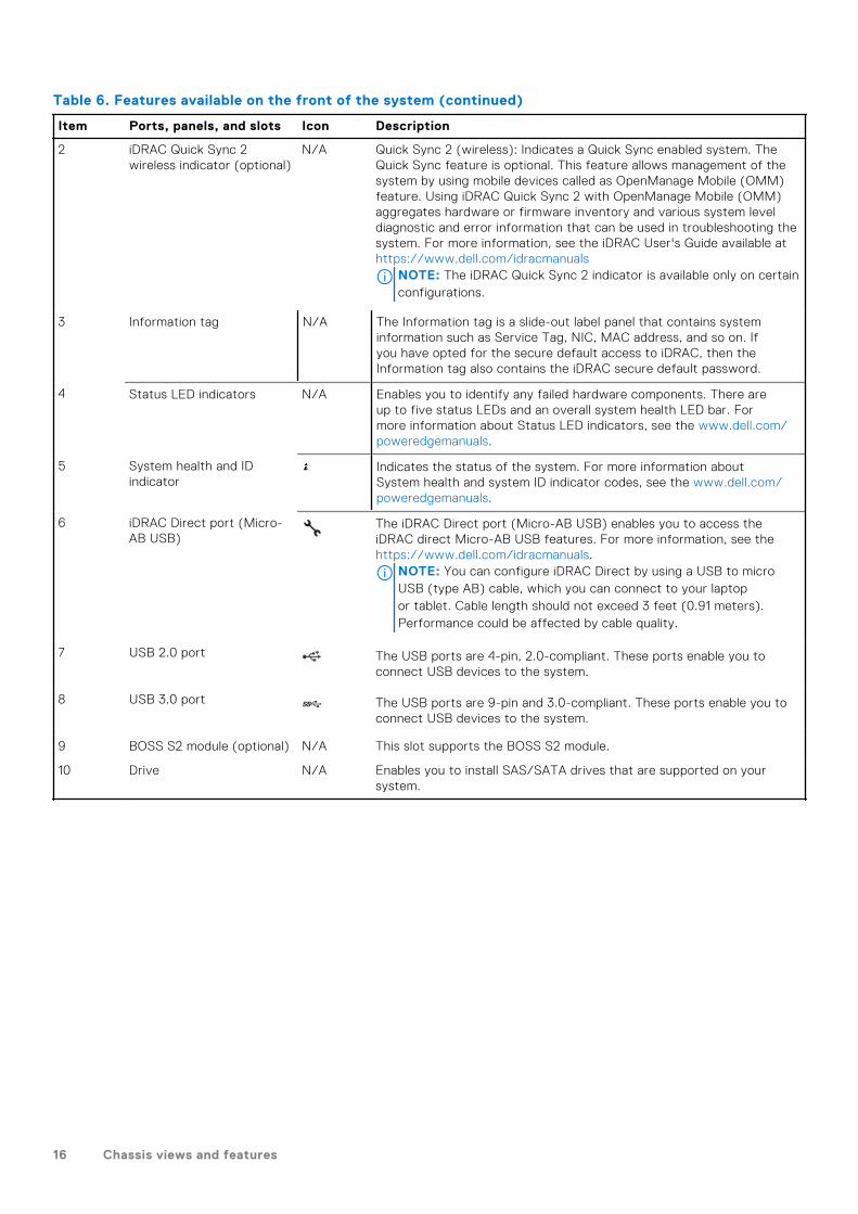
Table 6. Features available on the front of the system (continued)
Item Ports, panels, and slots Icon Description
2 iDRAC Quick Sync 2wireless indicator (optional)
N/A Quick Sync 2 (wireless): Indicates a Quick Sync enabled system. TheQuick Sync feature is optional. This feature allows management of thesystem by using mobile devices called as OpenManage Mobile (OMM)feature. Using iDRAC Quick Sync 2 with OpenManage Mobile (OMM)aggregates hardware or firmware inventory and various system leveldiagnostic and error information that can be used in troubleshooting thesystem. For more information, see the iDRAC User's Guide available athttps://www.dell.com/idracmanuals
NOTE: The iDRAC Quick Sync 2 indicator is available only on certainconfigurations.
3 Information tag N/A The Information tag is a slide-out label panel that contains systeminformation such as Service Tag, NIC, MAC address, and so on. Ifyou have opted for the secure default access to iDRAC, then theInformation tag also contains the iDRAC secure default password.
4 Status LED indicators N/A Enables you to identify any failed hardware components. There areup to five status LEDs and an overall system health LED bar. Formore information about Status LED indicators, see the www.dell.com/poweredgemanuals.
5 System health and IDindicator
Indicates the status of the system. For more information aboutSystem health and system ID indicator codes, see the www.dell.com/poweredgemanuals.
6 iDRAC Direct port (Micro-AB USB)
The iDRAC Direct port (Micro-AB USB) enables you to access theiDRAC direct Micro-AB USB features. For more information, see thehttps://www.dell.com/idracmanuals.
NOTE: You can configure iDRAC Direct by using a USB to microUSB (type AB) cable, which you can connect to your laptopor tablet. Cable length should not exceed 3 feet (0.91 meters).Performance could be affected by cable quality.
7 USB 2.0 port The USB ports are 4-pin, 2.0-compliant. These ports enable you toconnect USB devices to the system.
8 USB 3.0 port The USB ports are 9-pin and 3.0-compliant. These ports enable you toconnect USB devices to the system.
9 BOSS S2 module (optional) N/A This slot supports the BOSS S2 module.
10 Drive N/A Enables you to install SAS/SATA drives that are supported on yoursystem.
16 Chassis views and features

Figure 6. Front view of 8 x 2.5-inch drive system
Table 7. Features available on the front of the system
Item Ports, panels, and slots Icon Description
1 Power button Indicates if the system is powered on or off. Press the power button tomanually power on or off the system.
NOTE: Press the power button to gracefully shut down an ACPI-compliant operating system.
2 System health and IDindicator
Indicates the status of the system. For more information aboutSystem health and system ID indicator codes, see the www.dell.com/poweredgemanuals.
3 Information tag N/A The Information tag is a slide-out label panel that contains systeminformation such as Service Tag, NIC, MAC address, and so on. Ifyou have opted for the secure default access to iDRAC, then theInformation tag also contains the iDRAC secure default password.
4 Status LED indicators N/A Enables you to identify any failed hardware components. There areup to five status LEDs and an overall system health LED bar. Formore information about Status LED indicators, see the www.dell.com/poweredgemanuals.
Chassis views and features 17

Table 7. Features available on the front of the system (continued)
Item Ports, panels, and slots Icon Description
5 USB 2.0 port The USB ports are 4-pin, 2.0-compliant. These ports enable you toconnect USB devices to the system.
6 USB 3.0 port The USB ports are 9-pin and 3.0-compliant. These ports enable you toconnect USB devices to the system.
7 BOSS S2 module (optional) N/A This slot supports the BOSS S2 module.
8 Drive N/A Enables you to install SAS/SATA drives that are supported on yoursystem.
NOTE: For more information, see the Dell EMC PowerEdge T550 Technical Specifications on the product documentation
page.
Rear view of the system
Figure 7. Rear view of the system
18 Chassis views and features

Table 8. Rear view of the system
Item Ports, panels, or slots Icon Description
1 Power supply unit (PSU 1) N/A This is the primary PSU of the system. For more information aboutthe PSU configurations, see www.dell.com/poweredgemanuals.
2 Power supply unit (PSU2)
N/A This PSU provides redundancy to the system. For moreinformation about the PSU configurations, see www.dell.com/poweredgemanuals.
3 PCIe expansion card slots(4)
N/A Enables you to connect PCI Express expansion cards.
4 System identificationbutton
Press the system ID button:● To locate a particular system within a rack.● To turn the system ID on or off.To reset iDRAC, press and hold the button for 16 seconds.
NOTE:
● To reset iDRAC using system ID, ensure that the system IDbutton is enabled in the iDRAC setup.
● If the system stops responding during POST, press and holdthe system ID button (for more than five seconds) to enterthe BIOS progress mode.
5 VGA port Enables you to connect a display device to the system.
6 OCP NIC port (optional) N/A This port supports OCP 3.0. The NIC ports are integrated on theOCP card which is connected to the system board
7 USB ports (2) These ports are USB Type A complaint.
8 iDRAC dedicated port This RJ-45 port enables you to remotely access iDRAC. Formore information, see the iDRAC User's Guide at www.dell.com/poweredgemanuals.
9 NIC ports (2) The NIC ports that are integrated on the system board providenetwork connectivity. These NIC ports can also be shared withiDRAC when iDRAC network settings is set to shared mode.
10 NIC ports (1) The NIC ports that are integrated on the system board providenetwork connectivity. These NIC ports can also be shared withiDRAC when iDRAC network settings is set to shared mode.
NOTE: For more information, see the Dell EMC PowerEdge T550 Technical Specifications on the product documentation
page.
Chassis views and features 19

Inside the system
Figure 8. Inside the system for 24 x 2.5-inch configuration
1. Tape backup unit 2. Cooling fan
3. Intrusion switch 4. Power interposer board
5. Cable retention clip 6. PSU 1
7. OCP air shroud 8. System board
9. Cooling fan cage 10. 2.5-inch drive bay
20 Chassis views and features

Figure 9. Inside the system for 8 x 3.5-inch + 8 x 2.5-inch configuration
1. Tape backup unit 2. Cooling fan
3. Intrusion switch 4. Power interposer board
5. GPU card holder 6. GPU riser
7. PSU 1 8. OCP card
9. System board 10. Cooling fan cage
11. Front PERC module
Chassis views and features 21

Quick Resource Locator for PowerEdge T550 system
Figure 10. Quick Resource Locator for PowerEdge T550 system
22 Chassis views and features

Processor
Topics:
• Processor features
Processor featuresThe 3rd Generation Xeon® Scalable Processors stack is the next generation data center processor offering with the latestfeatures, increased performance, and incremental memory options. This latest generation Xeon Scalable processor supportsusages from entry designs that are based on Intel Xeon Silver processors to advanced capabilities offered in new Intel XeonPlatinum processor.
The following lists the features and functions that are in the upcoming 3rd Generation Intel® Xeon Scalable Processor offering:
● Faster UPI with 3 Intel Ultra Path Interconnect (Intel UPI) at 11.2 GT/s (supported in gold and platinum options)● More, faster I/O with PCI Express 4 and up to 64 lanes (per socket) at 16 GT/s● Enhanced Memory Performance with support for up to 3200 MT/s DIMMs● Increased memory capacity with up to eight channels and up to 256 GB DDR4 DIMM support
Supported processors
Table 9. Supported processors
Tier Proc ClockSpeed(GHz)
Cache(M)
UPI(GT/s)
Cores Threads Turbo MemorySpeed(MT/s)
MemoryCapacity
BPSEnabled
TDP
Gold 6338 2 36 11.2 32 64 Turbo 3200 6 TB Y 205 W
Gold 6338T 2.1 48 11.2 32 64 Turbo 3200 6 TB Y 165 W
Gold 6326 2.8 24 11.2 16 32 Turbo 3200 6 TB Y 185 W
Gold 6314U 2.3 48 11.2 32 64 Turbo 3200 6 TB Y 205 W
Gold 6312U 2.4 36 11.2 24 48 Turbo 3200 6 TB Y 185 W
Gold 5320 2.2 39 11.2 26 52 Turbo 2933 6 TB Y 185 W
Gold 5320T 2.1 30 11.2 20 40 Turbo 2933 6 TB Y 150 W
Gold 5318S 2 36 11.2 24 48 Turbo 2933 6 TB Y 165 W
Gold 5317 2.8 18 11.2 12 24 Turbo 2933 6 TB Y 150 W
Silver 4316 2.3 30 10.4 20 40 Turbo 2666 6 TB N 150 W
Silver 4314 2.3 24 10.4 16 32 Turbo 2666 6 TB Y 135 W
Silver 4310 2.1 18 10.4 12 24 Turbo 2666 6 TB N 120 W
4
Processor 23

Table 9. Supported processors (continued)
Tier Proc ClockSpeed(GHz)
Cache(M)
UPI(GT/s)
Cores Threads Turbo MemorySpeed(MT/s)
MemoryCapacity
BPSEnabled
TDP
Silver 4310T 2.3 15 10.4 10 20 Turbo 2666 6 TB N 105 W
Silver 4309Y 2.6 12 10.4 8 16 Turbo 2666 6 TB N 105 W
Platinum 8352M 2.3 48 11.2 32 64 Turbo 3200 6 TB Y 185 W
24 Processor
Memory
Topics:
• Supported memory
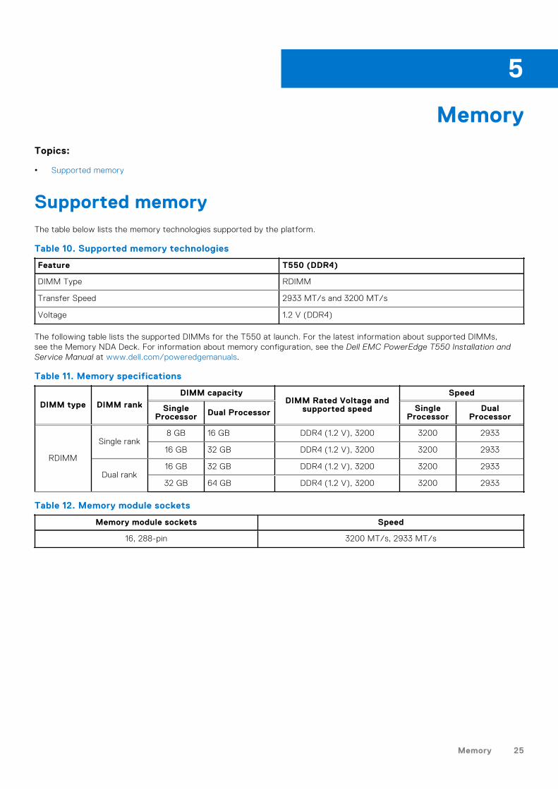
Supported memoryThe table below lists the memory technologies supported by the platform.
Table 10. Supported memory technologies
Feature T550 (DDR4)
DIMM Type RDIMM
Transfer Speed 2933 MT/s and 3200 MT/s
Voltage 1.2 V (DDR4)
The following table lists the supported DIMMs for the T550 at launch. For the latest information about supported DIMMs,see the Memory NDA Deck. For information about memory configuration, see the Dell EMC PowerEdge T550 Installation andService Manual at www.dell.com/poweredgemanuals.
Table 11. Memory specifications
DIMM type DIMM rank
DIMM capacityDIMM Rated Voltage and
supported speed
Speed
SingleProcessor Dual Processor Single
ProcessorDual
Processor
RDIMM
Single rank8 GB 16 GB DDR4 (1.2 V), 3200 3200 2933
16 GB 32 GB DDR4 (1.2 V), 3200 3200 2933
Dual rank16 GB 32 GB DDR4 (1.2 V), 3200 3200 2933
32 GB 64 GB DDR4 (1.2 V), 3200 3200 2933
Table 12. Memory module sockets
Memory module sockets Speed
16, 288-pin 3200 MT/s, 2933 MT/s
5
Memory 25

Storage
Topics:
• Drive backplane• PERC Controller• Storage
Drive backplaneDepending on your system configuration, the drive backplanes supported are listed here:
Table 13. Supported backplane options
System Supported drives options
PowerEdge T5508 x 2.5-inch SAS/SATA backplane
8 x 3.5-inch SAS/SATA backplane
Figure 11. 3.5-inch drive backplane
1. BP_PWR_12. BP_SIG
6
26 Storage

Figure 12. 2.5-inch drive backplane
1. BP_PWR_CTRL 2. BP_SIG
3. BP_PWR_1 4. BP_DST
PERC ControllerThe Dell EMC PowerEdge RAID Controller (PERC) family of enterprise-class controllers is designed for enhanced performance,increased reliability, and fault tolerance. PERC controller also simplifies management - providing a powerful, easy-to-manageway to create a robust infrastructure and help maximize system uptime.
Table 14. Supported PERC controllers
Performance level Description
Entry S150 (SATA) SW RAID SATA
Value H355, H345, HBA355i, HBA355e
Value Performance H755, H755N
Premium performance H840
NOTE: The software RAID S150 is supported on either SATA drives with chipset SATA only backplane or NVMe drives in
universal slots with processor direct PCIe cable connected backplane.
StorageTable 15. Supported Drives - SAS, SATA and NVMe
FormFactor
Type Speed
RotationalSpeed
Capacities
2.5-inch SATASSD
6 Gb N/A 480 GB, 960 GB, 1.92 TB, 3.84 TB
SAS 12Gb
10 K 600 GB, 1.2 TB, 2.4 TB
SAS 12Gb
15 K 900 GB
SASSSD
12Gb
N/A 480 GB, 800 GB, 960 GB, 1.6 TB, 1.92 TB, 3.84 TB, 6.4 TB, 7.68 TB
Storage 27

Table 15. Supported Drives - SAS, SATA and NVMe (continued)
FormFactor
Type Speed
RotationalSpeed
Capacities
2.5-inch(U.2)
NVMeSSD
Gen4 N/A 960 GB, 1.6 TB, 1.92 TB, 3.2 TB, 3.84 TB, 6.4 TB, 7.68 TB
NVMeSSD
Gen3 N/A 375 GB, 400 GB, 750 GB, 800 GB, 960 GB, 1.6 TB, 1.92 TB, 3.2 TB, 3.84 TB, 6.4TB, 7.68 TB
3.5-inch SATA 6 Gb 7.2 K 2 TB, 4 TB, 8 TB, 12 TB, 16 TB
SAS 12Gb
7.2 K 2 TB, 4 TB, 8 TB, 12 TB, 16TB
M.2 SATASSD
6 GB N/A 240 GB, 480 GB
uSD N/A N/A uSD 16 GB, 32 GB, 64 GB
28 Storage

Networking and PCIe
Topics:
• Overview• OCP 3.0 support• Expansion card installation guidelines
OverviewPowerEdge offers a wide variety of options to get information moving to and from our servers. Industry best technologies arechosen, and systems management features are added by our partners to firmware to tie in with iDRAC. These adapters arerigorously validated for worry-free, fully supported use in Dell servers.
The PowerEdge Server Adapter Matrix posted to knowledge portal is the central repository for PowerEdge NIC, HBA and HCAinformation. The matrix covers:
● Part Numbers, Tied SKUs and Customer Kits● Server Compatibility and Support● Optics and Cable Support● Systems Management● Adapter Features● Spec Sheet Links
This document is updated as changes happen, so be sure to bookmark it rather than downloading an offline copy to stay withthe latest information.
NOTE: This is a direct download link to an .XLSX and may not open in a tab as expected depending on your browser.
OCP 3.0 support
Table 16. OCP 3.0 feature list
Feature OCP 3.0
Form factor SFF
PCIe Gen Gen4
Max PCIe width x16
Max no.of ports 4
Port type BT/SFP/SFP+/SFP28/SFP56
Max port speed 100 GbE
NC-SI Yes
SNAPI Yes
WoL Yes
Power consumption 15 W - 150 W
7
Networking and PCIe 29

Supported OCP cards
Table 17. Supported OCP
Form Factor Vendor Port type Port speed Port count
OCP 3.0 Intel SFP+ 10 GbE 2
OCP 3.0 Broadcom BT 1 GbE 4
OCP 3.0 Broadcom BT 10 GbE 2
OCP 3.0 Broadcom SFP28 25 GbE 2
OCP 3.0 Broadcom SFP28 25 GbE 4
OCP 3.0 Broadcom SFP+ 10 GbE 2
OCP 3.0 QLogic BT 10 GbE 2
OCP 3.0 QLogic SFP+ 10 GbE 2
OCP 3.0 QLogic SFP28 25 GbE 2
OCP 3.0 Intel BT 1 GbE 4
OCP 3.0 Intel BT 10 GbE 2
OCP 3.0 Intel SFP+ 10 GbE 4
OCP 3.0 Intel SFP28 25 GbE 2
OCP 3.0 Mellanox SFP28 25 GbE 2
OCP 3.0 SolarFlare SFP28 25 GbE 2
OCP 3.0 SolarFlare SFP28 25 GbE 2
OCP NIC 3.0 vs. rack Network Daughter Card comparisons
Table 18. OCP 3.0, 2.0, and rNDC NIC comparison
Form Factor Dell rNDC OCP 2.0 (LOM Mezz) OCP 3.0 Notes
PCIe Gen Gen 3 Gen 3 Gen 4 Supported OCP3 areSFF (small form factor)
Max PCIe Lanes x8 Up to x16 Up to x16 See server slot prioritymatrix
Shared LOM Yes Yes Yes This is iDRAC portredirect
Aux Power Yes Yes Yes Used for Shared LOM
30 Networking and PCIe

OCP form factors
Figure 13. OCP 3.0 small card form factor (LS)
Table 19. OCP 3.0 Feature List
Features OCP 3.0
Form factor SFF and LFF
PCIe Gen Gen4
Max PCIe width X16
Max of ports 4
Port type BT/SFP/SFP+/SFP28/SFP56
Max port speed 100Gbe
NC-SI Yes
SNAPI Yes
WoL Yes
Power consumption 15 W — 150 W
Expansion card installation guidelinesTable 20. Supported riser configurations
ConfigurationType
Riserconfiguration
Processors x16Processor 1Slot 1(FHFL)
x16Processor 2Slot 2(FHFL)
x16Processor 2Slot 3(FHFL)
x16Processor 2Slot 4(FHHL)
X4 PCH Slot5 (FHHL)
x16Processor 1Slot 6(FHHL)
C0 N/A 2 0 0 1 1 1 1
C0-1 N/A 1 0 0 0 0 1 1
C1 1 x GPUriser
2 1 0 1 1 1 1
C1-1 1 x GPUriser
1 1 0 0 0 1 1
C2 2 x GPUriser
2 1 1 1 1 1 1
Networking and PCIe 31

Table 21. Configuration type C0
Card Type Slot priority Maximum number of cards
FPERC 10.15 H345 Internal 2
PERC/HBA 10.15G H745 Internal 2
FPERC 11 H755N Internal 1
FPERC 11 H755 Internal 2
FPERC HBA11 HBA355i Internal 2
FPERC 11 H355 Internal 2
NIC 25 Gb: Broadcom,Intel, Mellanox
4, 6, 3 3
HBA: FC16: Qlogic,Avago
4, 6, 3 3
NIC 10 Gb: Broadcom,Intel
4, 6, 3 3
NIC 1 Gb: Broadcom,Intel
4, 6, 3, 5 4
OCP 25 Gb: Broadcom,Intel, Mellanox
Internal 1
OCP 10 Gb: Broadcom,Intel, Mellanox
Internal 1
OCP 1 Gb: Broadcom,Intel, Mellanox
Internal 1
BOSS S2: Inventec Internal 1
PCIe SSD Gen3: Intel 4, 6, 3, 5 4
PCIe SSD Gen4:Samsung
4, 6, 3 3
GPU: Nvidia T4 4, 6, 3 3
Serial port module:Inventec
5 1
Foxconn external adapterH840
4, 6, 3 3
Foxconn external adapterHBA355e
4, 6, 3 3
aPERC HBA11 HBA355i 6 1
Table 22. Configuration type C0-1
Card Type Slot priority Maximum number of cards
FPERC 10.15 H345 Internal 2
PERC/HBA 10.15G H745 Internal 2
FPERC 11 H755N Internal 1
FPERC 11 H755 Internal 2
FPERC HBA11 HBA355i Internal 2
FPERC 11 H355 Internal 2
NIC 25 Gb: Broadcom,Intel, Mellanox
6 1
32 Networking and PCIe

Table 22. Configuration type C0-1 (continued)
Card Type Slot priority Maximum number of cards
HBA: FC16: Qlogic,Avago
6 1
NIC 10 Gb: Broadcom,Intel
6 1
NIC 1 Gb: Broadcom,Intel
6, 5 2
OCP 25 Gb: Broadcom,Intel, Mellanox
Internal 1
OCP 10 Gb: Broadcom,Intel, Mellanox
Internal 1
OCP 1 Gb: Broadcom,Intel, Mellanox
Internal 1
BOSS S2: Inventec Internal 1
PCIe SSD Gen3: Intel 6, 5 2
PCIe SSD Gen4:Samsung
6, 5 2
GPU: Nvidia T4 6 1
Serial port module:Inventec
5 1
Foxconn external adapterH840
4, 6, 3 3
Foxconn external adapterHBA355e
4, 6, 3 3
aPERC HBA11 HBA355i 6 1
Table 23. Configuration type C1
Card Type Slot priority Maximum number of cards
FPERC 10.15 H345 Internal 2
PERC/HBA 10.15G H745 Internal 2
FPERC 11 H755N Internal 1
FPERC 11 H755 Internal 2
FPERC HBA11 HBA355i Internal 2
FPERC 11 H355 Internal 2
NIC 25 Gb: Broadcom,Intel, Mellanox
1, 4, 6, 3 4
HBA: FC16: Qlogic,Avago
1, 4, 6, 3 4
NIC 10 Gb: Broadcom,Intel
1, 4, 6, 3 4
NIC 1 Gb: Broadcom,Intel
1, 4, 6, 3, 5 5
OCP 25 Gb: Broadcom,Intel, Mellanox
Internal 1
Networking and PCIe 33

Table 23. Configuration type C1 (continued)
Card Type Slot priority Maximum number of cards
OCP 10 Gb: Broadcom,Intel, Mellanox
Internal 1
OCP 1 Gb: Broadcom,Intel, Mellanox
Internal 1
BOSS S2: Inventec Internal 1
PCIe SSD Gen3: Intel 1, 4, 6, 3, 5 5
PCIe SSD Gen4:Samsung
1, 4, 6, 3 4
GPU: Nvidia A10, A30,A40
1 1
GPU: Nvidia T4 1, 4, 6, 3 4
Serial port module:Inventec
5 1
Foxconn external adapterH840
1, 4, 6, 3 4
Foxconn external adapterHBA355e
1, 4, 6, 3 4
Foxconn external adapterHBA355e
6 1
Table 24. Configuration type C1-1
Card Type Slot priority Maximum number of cards
FPERC 10.15 H345 Internal 2
PERC/HBA 10.15G H745 Internal 2
FPERC 11 H755N Internal 1
FPERC 11 H755 Internal 2
FPERC HBA11 HBA355i Internal 2
FPERC 11 H355 Internal 2
NIC 25 Gb: Broadcom,Intel, Mellanox
1, 6 2
HBA: FC16: Qlogic,Avago
1, 6 2
NIC 10 Gb: Broadcom,Intel
1, 6 2
NIC 1 Gb: Broadcom,Intel
1, 6, 5 3
OCP 25 Gb: Broadcom,Intel, Mellanox
Internal 1
OCP 10 Gb: Broadcom,Intel, Mellanox
Internal 1
OCP 1 Gb: Broadcom,Intel, Mellanox
Internal 1
BOSS S2: Inventec Internal 1
PCIe SSD Gen3: Intel 1, 6, 5 3
34 Networking and PCIe

Table 24. Configuration type C1-1 (continued)
Card Type Slot priority Maximum number of cards
PCIe SSD Gen4:Samsung
1, 6 2
GPU: Nvidia A10, A30,A40
1 1
GPU: Nvidia T4 1, 6 2
Serial port module:Inventec
5 1
Foxconn external adapterH840
1, 6 2
Foxconn external adapterHBA355e
1, 6 2
aPERC HBA11 HBA355i 6 1
Table 25. Configuration type C2
Card Type Slot priority Maximum number of cards
FPERC 10.15 H345 Internal 2
PERC/HBA 10.15G H745 Internal 2
FPERC 11 H755N Internal 1
FPERC 11 H755 Internal 2
FPERC HBA11 HBA355i Internal 2
FPERC 11 H355 Internal 2
NIC 25 Gb: Broadcom,Intel, Mellanox
1, 2, 4, 6, 3 5
HBA: FC16: Qlogic,Avago
1, 2, 4, 6, 3 5
NIC 10 Gb: Broadcom,Intel
1, 2, 4, 6, 3 5
NIC 1 Gb: Broadcom,Intel
1, 2, 4, 6, 3, 5 6
OCP 25 Gb: Broadcom,Intel, Mellanox
Internal 1
OCP 10 Gb: Broadcom,Intel, Mellanox
Internal 1
OCP 1 Gb: Broadcom,Intel, Mellanox
Internal 1
BOSS S2: Inventec Internal 1
PCIe SSD Gen3: Intel 1, 2, 4, 6, 3, 5 6
PCIe SSD Gen4:Samsung
1, 2, 4, 6, 3 5
GPU: Nvidia A10, A30,A40
1, 2 2
GPU: Nvidia T4 1, 2, 4, 6, 3 5
Serial port module:Inventec
5 1
Networking and PCIe 35

Table 25. Configuration type C2 (continued)
Card Type Slot priority Maximum number of cards
Foxconn external adapterH840
1, 2, 4, 6, 3 5
Foxconn external adapterHBA355e
1, 2, 4, 6, 3 5
aPERC HBA11 HBA355i 6 1
36 Networking and PCIe
Power, thermal, and acoustics
PowerEdge servers have an extensive collection of sensors that automatically track thermal activity, which helps regulatetemperature thereby reducing server noise and power consumption. The table below lists the tools and technologies Dell offersto lower power consumption and increase energy efficiency.
Topics:
• Power• Thermal• Acoustics
Power
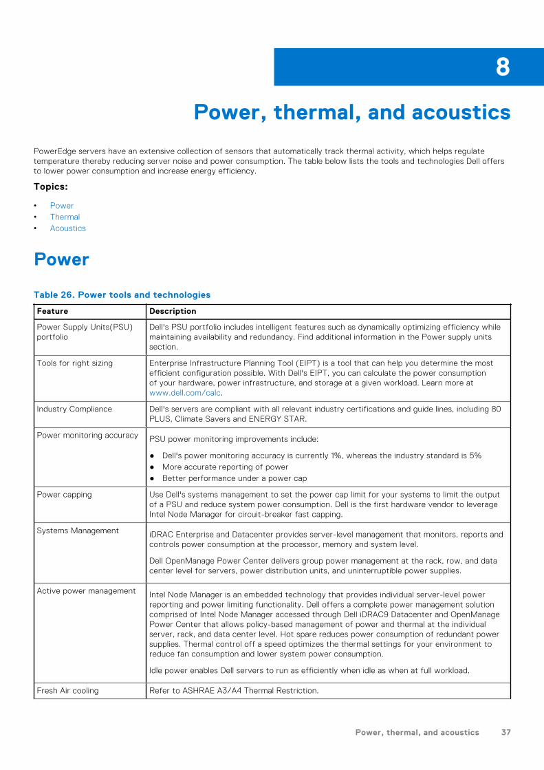
Table 26. Power tools and technologies
Feature Description
Power Supply Units(PSU)portfolio
Dell's PSU portfolio includes intelligent features such as dynamically optimizing efficiency whilemaintaining availability and redundancy. Find additional information in the Power supply unitssection.
Tools for right sizing Enterprise Infrastructure Planning Tool (EIPT) is a tool that can help you determine the mostefficient configuration possible. With Dell's EIPT, you can calculate the power consumptionof your hardware, power infrastructure, and storage at a given workload. Learn more atwww.dell.com/calc.
Industry Compliance Dell's servers are compliant with all relevant industry certifications and guide lines, including 80PLUS, Climate Savers and ENERGY STAR.
Power monitoring accuracy PSU power monitoring improvements include:
● Dell's power monitoring accuracy is currently 1%, whereas the industry standard is 5%● More accurate reporting of power● Better performance under a power cap
Power capping Use Dell's systems management to set the power cap limit for your systems to limit the outputof a PSU and reduce system power consumption. Dell is the first hardware vendor to leverageIntel Node Manager for circuit-breaker fast capping.
Systems Management iDRAC Enterprise and Datacenter provides server-level management that monitors, reports andcontrols power consumption at the processor, memory and system level.
Dell OpenManage Power Center delivers group power management at the rack, row, and datacenter level for servers, power distribution units, and uninterruptible power supplies.
Active power management Intel Node Manager is an embedded technology that provides individual server-level powerreporting and power limiting functionality. Dell offers a complete power management solutioncomprised of Intel Node Manager accessed through Dell iDRAC9 Datacenter and OpenManagePower Center that allows policy-based management of power and thermal at the individualserver, rack, and data center level. Hot spare reduces power consumption of redundant powersupplies. Thermal control off a speed optimizes the thermal settings for your environment toreduce fan consumption and lower system power consumption.
Idle power enables Dell servers to run as efficiently when idle as when at full workload.
Fresh Air cooling Refer to ASHRAE A3/A4 Thermal Restriction.
8
Power, thermal, and acoustics 37

Table 26. Power tools and technologies (continued)
Feature Description
Rack infrastructure Dell offers some of the industry's highest-efficiency power infrastructure solutions, including:● Power distribution units (PDUs)● Uninterruptible power supplies (UPSs)● Energy Smart containment rack enclosuresFind additional information at: https://www.delltechnologies.com/en-us/servers/power-and-cooling.htm.
PSU specifications
The PowerEdge T550 system supports up to two AC power supply units (PSUs).
Table 27. PSU specifications
PSU Class Heatdissipation(maximum)
Frequency
Voltage AC DC Current
High line200–240 V
Low line100–120 V
600 W MixedMode
Platinum
2250BTU/hr
50/60 Hz100 - 240 V,autoranging
600 W 600 W N/A 7.1 A - 3.6 A
N/A 2250BTU/hr
N/A240 V DC,autoranging
N/A N/A 600 W 2.9 A
800 W MixedMode
Platinum
3000BTU/hr
50/60 Hz100 - 240 V,autoranging
800 W 800 W N/A 9.2 A - 4.7 A
N/A 3000BTU/hr
N/A240 V DC,autoranging
N/A N/A 800 W 3.8 A
1100 W DC N/A 4265BTU/hr
N/A-48 V N/A N/A 1100 W DC 27 A
1100 WMixed Mode
Titanium
4100BTU/hr
50/60 Hz100 - 240 V,autoranging
1100 W 1050 W N/A 12 A - 6.3 A
N/A 4100BTU/hr
N/A240 V DC,autoranging
N/A N/A 1100 W DC 5.2 A
1400 WMixed Mode
Platinum
5250BTU/hr
50/60 Hz100 - 240 V,autoranging
1400 W 1050 W N/A 12 A - 8 A
N/A 5250BTU/hr
N/A240 V DC,autoranging
N/A N/A 1400 W 6.6 A
2400 WMixed Mode
Platinum
9000BTU/hr
50/60 Hz100 - 240 V,autoranging
2400 W 1400 W N/A 16 A - 13.5 A
N/A 9000BTU/hr
N/A240 V DC,autoranging
N/A N/A 2400 W 11.2 A
38 Power, thermal, and acoustics

NOTE: This system is also designed to connect to the IT power systems with a phase-to-phase voltage not exceeding 240
V.
NOTE: Heat dissipation is calculated using the PSU wattage rating.
NOTE: When selecting or upgrading the system configuration, to ensure optimum power utilization, verify the system
power consumption with the Dell Energy Smart Solution Advisor available at Dell.com/ESSA.
Thermal
PowerEdge servers have an extensive collection of sensors that automatically track thermal activity, which helps regulatetemperature thereby reducing server noise and power consumption.
Thermal design
Thermal management of the platform helps deliver high performance with the right amount of cooling to components, whilemaintaining the lowest fan speeds possible. This is done across a wide range of ambient temperatures from 10°C to 35°C (50°Fto 95°F) and to extended ambient temperature ranges.
Figure 14. Thermal design characteristics
The thermal design of the PowerEdge T550 reflects the following:
● Optimized thermal design: The system layout is architected for optimum thermal design.● System component placement and layout are designed to provide maximum airflow coverage to critical components with
minimum expense of fan power.● Comprehensive thermal management: The thermal control system regulates the fan speed based on several different
responses from all system-component temperature sensors, as well as inventory for system configurations. Temperaturemonitoring includes components such as processors, DIMMs, chipset, the inlet air ambient, hard disk drives, and OCP.
● Open and closed loop thermal fan speed control: Open loop thermal control uses system configuration to determinefan speed based on inlet air ambient temperature. Closed loop thermal control method uses feedback temperatures todynamically determine proper fan speeds.
● User-configurable settings: With the understanding and realization that every customer has unique set of circumstances orexpectations from the system, in this generation of servers, we have introduced limited user- configurable settings residingin the iDRAC BIOS setup screen. For more information, see the Dell EMC PowerEdge T550 Installation and Service Manualat www.dell.com/poweredgemanuals and “Advanced Thermal Control: Optimizing across Environments and Power Goals” onDell.com.
● Cooling redundancy: The T550 with >4 fans allows N+1 fan redundancy, allowing continuous operation with one fan failure inthe system.
Power, thermal, and acoustics 39

● Environmental Specifications: The optimized thermal management makes the T550 reliable under a wide range of operatingenvironments.
Acoustics
Acoustical design
Dell EMC PowerEdge delivers sound quality and smooth transient response in addition to sound power levels and sound pressurelevels oriented to deployment environments.
Sound quality describes how disturbing or pleasing a person finds a sound, as a function of a variety of psycho-acousticalmetrics and thresholds. Tone prominence is one such metric.
Transient response refers to how sound changes with time.
Sound power level, sound pressure level and loudness refer to amplitude of sound.
A reference for comparison to sound pressure levels and loudness for familiar noise sources is given in the table below.
Table 28. Acoustical Reference Points and Output Comparisons
Value measured at your ears Equivalent familiar noise experience
LpA, dBA, re 20μPa Loudness, sones
90 80 Loud concert
75 40 Data center, vacuum cleaner, voice mustbe elevated to be heard
60 10 Conversation levels
45 4 Whispering, open office layout, normalliving room
35 2 Quiet office
30 1 Quiet library
20 0 Recording studio
For more information about PowerEdge acoustical design and metrics, see Understanding Acoustical Data and Causes of Soundin Dell Enterprise Products.
PowerEdge acoustical specifications
For more information on acoustical specifications, see ENG0019663. (See the category definitions.)
Dell typically categorizes servers in five categories of acoustically acceptable usage:
● Category 1: Table-top in Office Environment● Category 2: Floor-standing in Office Environment● Category 3: General Use Space● Category 4: Attended Data Center● Category 5: Unattended Data Center
Category 1: Floor-standing in Office Environment
When Dell determines that a specific Enterprise product is to be used on a table-top in office environment, for example, ona desk around a seated user’s head height, then the acoustical specification of the following table applies. Small, light-weighttowers are examples of these types of products.
40 Power, thermal, and acoustics

Table 29. Dell Enterprise Category 1, “Table-top in Office Environment” acoustical specificationcategory.
MeasurementPosition reAC0158
Metric, reAC0159
Test Modes, re AC0159 (note must be in steady state, see AC0159, except wherenoted below)
Standby in23±2° CAmbient
Idle in 23±2° CAmbient
Operating in23±2° CAmbient – ifnot otherwisespecified inthe program’sconfigurationdocument,then processorand hard driveoperatingmodes arerequired
Simulate (that is, set fanspeeds representative) for Idleat 28° C & 35° C Ambient,and for 100% loading andmaximum configuration, at 35°C Ambient
Sound Power LWA,m, B ≤ 4.2 ≤ 4.7 ≤ 5.0 Report
Sound Quality(both positionsmust meetlimits): FrontBinaural HEADand RearMicrophone
Tones, Hz, dB No prominent tones per criteria D.10.6 and D.10.8 ofECMA-74
Report tones
Tonality, tu ≤ 0.35 ≤ 0.35 ≤ 0.35 Report
Dell Modulation,%
≤ 35 ≤ 35 ≤ 35 Report
Loudness, sones Report Report Report Report
LpA-singlepoint, dBA
Report Report Report Report
Front BinauralHEAD
Transients ● Oscillation (see AC0159), if observed, during 20-minute steady-state observation, must adhere tothe following two criteria:○ Max. {ΔLpA} < 3.0 dB○ Event count < 3 for “1.5 dB < ΔLpA < 3.0 dB”○ Acoustical Jump (see AC0159), during air
mover speed transition from Idle to OperatingMode must be ≤ 15 dB.
● Startup behavior○ Report Startup behavior re. AC0159○ Startup must proceed smoothly, that is, no
sudden or large jumps, and fan speed duringstartup must not exceed 50% of its maximum
● Transient inputs: Report time-history soundpressure levels re AC0159 “Train of StepFunctions on Processor”
N/A
Any Other No rattles, squeaks, or unexpected noises
Sound should be “even” around the EUT (one side should not be dramatically louder thananother)
Unless otherwise specified, the “default” thermal-related settings shall be selected forBIOS and iDRAC.
Specific operating conditions will be defined in “Configurations & ConfigurationDependencies” for each platform.
Sound Pressure LpA-reported,dBA, re AC0158and programconfigurationdocument
Report for allmics
Report for allmics
Report for allmics
Report for all mics
Category 2: Floor-standing in Office Environment
Power, thermal, and acoustics 41

When Dell determines that a specific Enterprise product is to be used primarily when it is sitting on the floor, that is, next to auser’s feet, then the acoustical specification in the table below applies. Noise from the product should not annoy or otherwiseinterfere with the user’s thoughts or speech, for example, on the telephone.
Table 30. Dell Enterprise Category 2, “Floor-standing in Office Environment” acoustical specificationcategory
MeasurementPosition reAC0158
Metric, reAC0159
Test Modes, re AC0159 (note must be in steady state, see AC0159, except wherenoted below)
Standby in23±2° CAmbient
Idle in 23±2° CAmbient
Operating in23±2° CAmbient – ifnot otherwisespecified inthe program’sconfigurationdocument,then processorand hard driveoperatingmodes arerequired
Simulate (that is, set fanspeeds representative) for Idleat 28° C & 35° C Ambient,and for 100% loading andmaximum configuration, at 35°C Ambient
Sound Power LWA,m, B ≤ 4.9 ≤ 5.1 ≤ 5.4 Report
Sound Quality(both positionsmust meetlimits): FrontBinaural HEADand RearMicrophone
Tones, Hz, dB No prominent tones per criteria D.10.6 and D.10.8 ofECMA-74
Report tones
Tonality, tu ≤ 0.35 ≤ 0.35 ≤ 0.35 Report
Dell Modulation,%
≤ 35 ≤ 35 ≤ 35 Report
Loudness, sones Report Report Report Report
LpA-singlepoint, dBA
Report Report Report Report
Front BinauralHEAD
Transients ● Oscillation (see AC0159), if observed, during 20-minute steady-state observation, must adhere tothe following two criteria:○ Max. {ΔLpA} < 3.0 dB○ Event count < 3 for “1.5 dB < ΔLpA < 3.0 dB”
● Acoustical Jump (see AC0159), during air moverspeed transition from Idle to Operating Modemust be ≤ 15 dB.
● Startup behavior○ Report Startup behavior re. AC0159○ Startup must proceed smoothly, that is, no
sudden or large jumps, and fan speed duringstartup must not exceed 50% of its maximum
● Transient inputs: Report time-history soundpressure levels re AC0159 “Train of StepFunctions on Processor”
N/A
Any Other ● No rattles, squeaks, or unexpected noises● Sound should be “even” around the EUT (one side should not be dramatically louder
than another)● Unless otherwise specified, the “default” thermal-related settings shall be selected for
BIOS and iDRAC.● Specific operating conditions are defined in “Configurations and Configuration
Dependencies” for each platform.
Sound Pressure LpA-reported,dBA, re AC0158and programconfigurationdocument
Report for allmics
Report for allmics
Report for allmics
Report for all mics
42 Power, thermal, and acoustics

Category 3: General Use Space
When Dell determines that a specific Enterprise product is to be predominantly used in a general use space, then the acousticalspecification of the table below applies. These products could be found in laboratories, schools, restaurants, open office spacelayouts, small ventilated closets, etc., though not in close proximity to any particular person nor in quantities greater than a fewin any location. People within proximity of a few of these products should not experience any impact to speech intelligibility orannoyance from the noise of the product. A rack product sitting on a table in a common area is an example.
Table 31. Dell Enterprise Category 3, “General Use” acoustical specification category
MeasurementPosition reAC0158
Metric, reAC0159
Test Modes, re AC0159 (note must be in steady state, see AC0159, except wherenoted below)
Standby in23±2° CAmbient
Idle in 23±2° CAmbient
Operating in23±2° CAmbient – ifnot otherwisespecified inthe program’sconfigurationdocument,then processorand hard driveoperatingmodes arerequired
Simulate (that is, set air moverspeeds representative) for Idleat 28° C & 35° C Ambientand for 100% loading andmaximum configuration, at 35°C Ambient
Sound Power LWA,m, B ≤ 5.2 ≤ 5.5 ≤ 5.8 Report
Sound Quality(both positionsmust meetlimits): FrontBinaural HEADand RearMicrophone
Tones, Hz, dB No prominent tones per criteria D.10.6 and D.10.8 ofECMA-74
Report tones
Tonality, tu ≤ 0.35 ≤ 0.35 ≤ 0.35 Report
Dell Modulation,%
≤ 40 ≤ 40 ≤ 40 Report
Loudness, sones Report Report Report Report
LpA-singlepoint, dBA
Report Report Report Report
Front BinauralHEAD
Transients ● Oscillation (see AC0159), if observed, during 20-minute steady-state observation, must adhere tothe following two criteria:○ Max. {ΔLpA} < 3.0 dB○ Event count < 3 for “1.5 dB < ΔLpA < 3.0 dB”
● Report Acoustical Jump (see AC0159) during airmover speed transition from Idle to OperatingMode.
● Startup behavior○ Report Startup behavior re. AC0159○ Startup must proceed smoothly, that is, no
sudden or large jumps, and air mover speedduring startup must not exceed 50% of itsmaximum
● Transient inputs: Report time-history soundpressure levels re AC0159 “Train of StepFunctions on Processor”
N/A
Any Other No rattles, squeaks, or unexpected noises
Sound should be “even” around the EUT (one side should not be dramatically louder thananother)
Unless otherwise specified, the “default” thermal-related settings shall be selected forBIOS and iDRAC.
Specific operating conditions will be defined in “Configurations & ConfigurationDependencies” for each platform.
Power, thermal, and acoustics 43
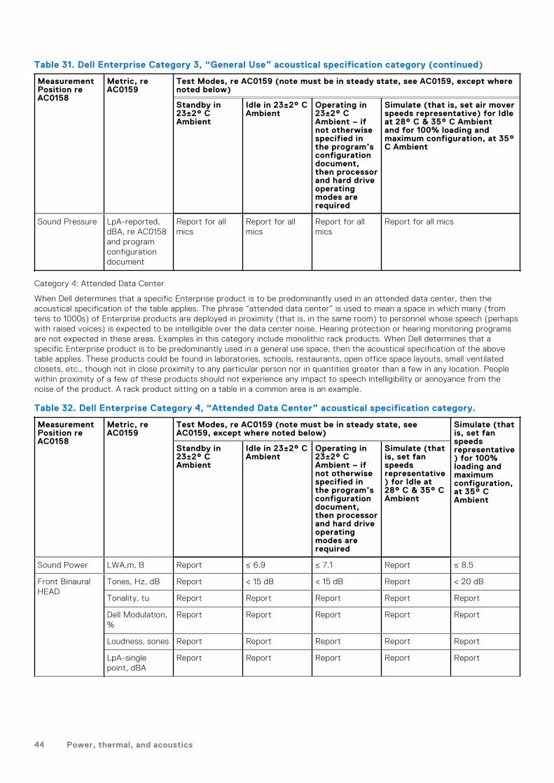
Table 31. Dell Enterprise Category 3, “General Use” acoustical specification category (continued)
MeasurementPosition reAC0158
Metric, reAC0159
Test Modes, re AC0159 (note must be in steady state, see AC0159, except wherenoted below)
Standby in23±2° CAmbient
Idle in 23±2° CAmbient
Operating in23±2° CAmbient – ifnot otherwisespecified inthe program’sconfigurationdocument,then processorand hard driveoperatingmodes arerequired
Simulate (that is, set air moverspeeds representative) for Idleat 28° C & 35° C Ambientand for 100% loading andmaximum configuration, at 35°C Ambient
Sound Pressure LpA-reported,dBA, re AC0158and programconfigurationdocument
Report for allmics
Report for allmics
Report for allmics
Report for all mics
Category 4: Attended Data Center
When Dell determines that a specific Enterprise product is to be predominantly used in an attended data center, then theacoustical specification of the table applies. The phrase “attended data center” is used to mean a space in which many (fromtens to 1000s) of Enterprise products are deployed in proximity (that is, in the same room) to personnel whose speech (perhapswith raised voices) is expected to be intelligible over the data center noise. Hearing protection or hearing monitoring programsare not expected in these areas. Examples in this category include monolithic rack products. When Dell determines that aspecific Enterprise product is to be predominantly used in a general use space, then the acoustical specification of the abovetable applies. These products could be found in laboratories, schools, restaurants, open office space layouts, small ventilatedclosets, etc., though not in close proximity to any particular person nor in quantities greater than a few in any location. Peoplewithin proximity of a few of these products should not experience any impact to speech intelligibility or annoyance from thenoise of the product. A rack product sitting on a table in a common area is an example.
Table 32. Dell Enterprise Category 4, “Attended Data Center” acoustical specification category.
MeasurementPosition reAC0158
Metric, reAC0159
Test Modes, re AC0159 (note must be in steady state, seeAC0159, except where noted below)
Simulate (thatis, set fanspeedsrepresentative) for 100%loading andmaximumconfiguration,at 35° CAmbient
Standby in23±2° CAmbient
Idle in 23±2° CAmbient
Operating in23±2° CAmbient – ifnot otherwisespecified inthe program’sconfigurationdocument,then processorand hard driveoperatingmodes arerequired
Simulate (thatis, set fanspeedsrepresentative) for Idle at28° C & 35° CAmbient
Sound Power LWA,m, B Report ≤ 6.9 ≤ 7.1 Report ≤ 8.5
Front BinauralHEAD
Tones, Hz, dB Report < 15 dB < 15 dB Report < 20 dB
Tonality, tu Report Report Report Report Report
Dell Modulation,%
Report Report Report Report Report
Loudness, sones Report Report Report Report Report
LpA-singlepoint, dBA
Report Report Report Report Report
44 Power, thermal, and acoustics

Table 32. Dell Enterprise Category 4, “Attended Data Center” acoustical specificationcategory. (continued)
MeasurementPosition reAC0158
Metric, reAC0159
Test Modes, re AC0159 (note must be in steady state, seeAC0159, except where noted below)
Simulate (thatis, set fanspeedsrepresentative) for 100%loading andmaximumconfiguration,at 35° CAmbient
Standby in23±2° CAmbient
Idle in 23±2° CAmbient
Operating in23±2° CAmbient – ifnot otherwisespecified inthe program’sconfigurationdocument,then processorand hard driveoperatingmodes arerequired
Simulate (thatis, set fanspeedsrepresentative) for Idle at28° C & 35° CAmbient
Transients ● Oscillation (see AC0159), if observed, during 20-minute steady-state observation, must adhere tothe following two criteria:○ Max. {ΔLpA} < 3.0 dB○ Event count < 3 for “1.5 dB < ΔLpA < 3.0 dB”○ Acoustical Jump (see AC0159), during air
mover speed transition from Idle to OperatingMode must be ≤ 15 dB.
○ Startup behavior■ Report Startup behavior re. AC0159■ Startup must proceed smoothly, that is,
no sudden or large jumps, and fan speedduring startup must not exceed 50% of itsmaximum
∞ Transient inputs: Report time-history soundpressure levels re AC0159 “Train of StepFunctions on Processor”
N/A
Any Other No rattles, squeaks, or unexpected noises
Sound should be “even” around the EUT (one side should not be dramatically louder thananother)
Unless otherwise specified, the “default” thermal-related settings shall be selected forBIOS and iDRAC.
Specific operating conditions will be defined in “Configurations & ConfigurationDependencies” for each platform.
Sound Pressure LpA-reported,dBA
Report for allmics
Report for allmics
Report for allmics
Report for allmics
Report for allmics
Category 5: Unattended Data Center
When Dell determines that a specific Enterprise product is to be predominantly used in an unattended data center (and notblades or blade enclosures; these have their own category), then the acoustical specification in the table below applies. Thephrase “unattended data center” is used to mean a space in which many (from tens to 1000s) of Enterprise products aredeployed together, its own heating and cooling systems condition the space, and operators or servicers of equipment entergenerally only to deploy, service, or decommission equipment. Hearing protection or hearing monitoring programs may beexpected (per government or company guidelines) in these areas. Examples in this category include monolithic rack products.
Power, thermal, and acoustics 45

Table 33. Dell Enterprise Category 5, “Unattended Data Center” acoustical specification category
Measurement Position reAC0158
Metric, reAC0159
Test Modes, re AC0159 (note must be in steady state, see AC0159,except where noted below)
Simulate (thatis, set airmover speedsrepresentative) for 100%loading andmaximumconfiguration,at 35° CAmbient
Standby in23±2° CAmbient
Idle in 23±2°C Ambient
Operating in23±2° CAmbient – ifnototherwisespecified intheprogram’sconfiguration document,thenprocessorand harddriveoperatingmodes arerequired
Simulate (that is,set air mover speedsrepresentative) for Idle at28° C & 35° C Ambient
Sound Power LWA,m, B Report ≤ 7.5 ≤ 7.7 Report ≤ 8.7
Front BinauralHEAD
Tones, Hz, dB Report < 15 dB < 15 dB Report < 20 dB
Tonality, tu Report Report Report Report Report
DellModulation,%
Report Report Report Report Report
Loudness,sones
Report Report Report Report Report
LpA-singlepoint, dBA
Report Report Report Report Report
Front BinauralHEAD
Transients ● Oscillation (see AC0159), ifobserved, during 20-minute steady-stateobservation, must adhere to the followingtwo criteria:○ Max. {ΔLpA} < 3.0 dB○ Event count < 3 for “1.5 dB < ΔLpA <
3.0 dB”● Report Acoustical Jump (see AC0159)
during air mover speed transition fromIdle to Operating Mode.
● Startup behavior○ Report Startup behavior re. AC0159○ Startup must proceed smoothly, that
is, no sudden or large jumps, and airmover speed during startup must notexceed 50% of its maximum
● Transient inputs: Report time-historysound pressure levels re AC0159 “Train ofStep Functions on Processor”
N/A
Any Other No rattles, squeaks, or unexpected noises
Sound should be “even” around the EUT (one side should not be dramatically louder thananother)
Unless otherwise specified, the “default” thermal-related settings shall be selected for BIOSand iDRAC.
Specific operating conditions will be defined in “Configurations & Configuration Dependencies”for each platform.
46 Power, thermal, and acoustics

Table 33. Dell Enterprise Category 5, “Unattended Data Center” acoustical specificationcategory (continued)
Measurement Position reAC0158
Metric, reAC0159
Test Modes, re AC0159 (note must be in steady state, see AC0159,except where noted below)
Simulate (thatis, set airmover speedsrepresentative) for 100%loading andmaximumconfiguration,at 35° CAmbient
Standby in23±2° CAmbient
Idle in 23±2°C Ambient
Operating in23±2° CAmbient – ifnototherwisespecified intheprogram’sconfiguration document,thenprocessorand harddriveoperatingmodes arerequired
Simulate (that is,set air mover speedsrepresentative) for Idle at28° C & 35° C Ambient
SoundPressure
LpA-reported,dBA, reAC0158 andprogramconfigurationdocument
Report for allmics
Report for allmics
Report for allmics
Report for all mics Report for allmics
Acoustical performance
Dell EMC PowerEdge T550 is a tower server appropriate for attended data center environment. However, lower acousticaloutput is attainable with proper hardware or software configurations.
Table 34. Hardware and software configurations for lower acoustical output
Configuration Minimum Basic Mainstream Feature Rich Hilltop
Processor Type Intel Xeon Scalableprocessor
Intel Xeon Scalableprocessor
Intel Xeon Scalableprocessor
Intel Xeon Scalableprocessor
Intel Xeon Scalableprocessor
Processor TDP 105 W / 10C 120 W / 12C 150 W / 24C 185 W / 32C 205 W /32C
Processor Quantity 1 1 1 2 2
RDIMM Memory 8 GB DDR4 16 GB DDR4 16 GB DDR4 32 GB DDR4 32 GB DDR4
Memory Quantity 1 2 4 8 16
Backplane Type 8 x 3.5-inch BP 8 x 3.5-inch BP 8 x 2.5-inch BP 8 x 2.5-inch BP + 8x 2.5-inch BP
8 x 2.5-inch BP + 8x 2.5-inch BP
HDD Type 3.5-inch 7.2K RPMSATA
3.5-inch 7.2K RPMNL-SAS
2.5-inch 10K RPMSAS
2.5-inch 10K RPMSAS
2.5-inch 10K RPMSAS
HDD Quantity 2 4 8 16 16
PSU Type 800 W 800 W 1400 W 1400 W 2400 W
PSU Quantity 1 2 2 2 2
BOSS N/A BOSS 1.5 BOSS 1.5 BOSS 1.5 BOSS 1.5
OCP N/A N/A N/A Dual Port 10GbE Dual Port 25GbE
PCI 1 N/A N/A N/A N/A 300 W DW GPU
PCI 2 N/A N/A N/A N/A 300 W DW GPU
Power, thermal, and acoustics 47

Table 34. Hardware and software configurations for lower acoustical output (continued)
Configuration Minimum Basic Mainstream Feature Rich Hilltop
PCI 3 N/A N/A Dual Port 10GbENIC
N/A N/A
Front PERC PERC H345, H355 PERC H745P PERC H745P PERC H745P PERC H745P
LOM Card 1 Gb 1 Gb 1 Gb 1 Gb 1 Gb
Table 35. Acoustical performance of T550 acoustical configurations
Configuration Minimum Basic Mainstream Feature Rich Hilltop
Acoustical Performance: Idle/ Operating @ 25 °C Ambient
L wA,m (B) Idle 4.3 4.4 4.8 4.9 5.7
Operating 4.4 4.7 4.9 5.3 8.6
K v (B) Idle 0.4 0.4 0.4 0.4 0.4
Operating 0.4 0.4 0.4 0.4 0.4
L pA,m (dB) Idle 35 36 40 41 43
Operating 36 41 41 45 72
Prominent tones No prominent tones in Idle and Operating
Acoustical Performance: Idle @ 28 °C Ambient
L wA,m (B) 5 5 5.1 5.3 6.1
K v (B) 0.4 0.4 0.4 0.4 0.4
L pA,m (dB) 42 42 43 45 47
Acoustical Performance: Max. Loading @ 35 °C Ambient
L wA,m (B) 6.2 6.4 7.4 6.1 8.6
K v (B) 0.4 0.4 0.4 0.4 0.4
L pA,m (dB) 59 61 71 58 72
LwA,m: The declared mean A-weighted sound power level (LwA) is calculated per section 5.2 of ISO 9296 (2017) with datacollected using the methods described in ISO 7779 (2010). Data presented here may not be fully compliant with ISO 7779.
LpA,m: The declared mean A-weighted emission sound pressure level is at the bystander position per section 5.3 of ISO 9296(2017) and measured using methods described in ISO 7779 (2010). The system is placed on standard test table and in a 24Urack enclosure, 25cm above a reflective floor. Data presented here may not be fully compliant with ISO 7779.
Prominent tones: Criteria of D.6 and D.11 of ECMA-74 (17th ed., Dec. 2019) are followed to determine if discrete tones areprominent and to report them, if so.
Idle mode: The steady-state condition in which the server is energized but not operating any intended function.
Operating mode: The maximum of the steady state acoustical output at 50% of CPU TDP or active HDDs or 100% of GPUperC.9.3.2 in ECMA-74 (17th ed., Dec. 2019).
PowerEdge T550 acoustical dependencies
Some product features impact acoustical server output more than others. The following features are considered strong driversof acoustical response, thus configurations or operating conditions that include these features may increase air mover speed andacoustical output of the server:
● Ambient temperature: Dell EMC evaluates the acoustical performance of servers in a 23±2°C environment. Ambienttemperatures in excess of 25°C will have higher acoustical output and may experience larger fluctuations between statechanges.
● Processor thermal design power (TDP): higher wattage processors may require more airflow to cool under load and thusincrease the potential acoustical output of the system.
48 Power, thermal, and acoustics

● Storage type: NVME SSD consumes more power than SAS/SATA drives, and will pre-heat down-stream components (e.g.,Processor, DIMM), and hence requires higher fan speeds and hence higher acoustical outputs.
● System thermal profile selection in BIOS or iDRAC GUI:○ Default Thermal Profile, generally provides a lower air mover speed thus lower acoustical output than those of other
thermal profiles.○ Maximum Performance (Performance Optimized) will result in higher acoustical output○ Sound Cap, for products that support the feature, will limit the maximum acoustical output of the system by sacrificing
some processor performance.● PCIe cards: When 25Gb NIC card or GPU card ≥ 75W is installed, the acoustical outputs will be higher in both idle and
operating conditions.
Methods to reduce acoustical output of the T550
Although the T550 is designed for use in data centers, some users may prefer to use it in a quieter setting. The following is a listof means to do so.
NOTE: Usually, the idle air mover speed of the system cannot be lowered without changing the configuration of the
system, and in some cases, even a configuration change may not reduce idle air mover speeds.
● Reduce ambient temperature: Lowering the ambient temperature allows the system to cool components more efficientlythan at higher ambient temperatures.
● Set target in Third-party PCIe card options: Dell EMC provides airflow customization for third-party PCIe adapters thatare installed in PowerEdge platforms. If automatic cooling response is above desired levels (LFM) based on the cardspecifications, a different LFM target can be set using PCIe Airflow Settings options in iDRAC UI.
● Replace third-party PCI cards with similar Dell supported temperature-controlled cards, if available. Dell EMC works diligentlywith card vendors to validate and develop PCI cards to meet Dell EMC’s exacting standards for thermal performance.
Power, thermal, and acoustics 49

Supported Operating Systems
The PowerEdge T550 system supports the following operating systems:
● Canonical® Ubuntu® Server LTS● Citrix® Hypervisor®● Microsoft® Windows Server® with Hyper-V● Red Hat® Enterprise Linux● SUSE® Linux Enterprise server● VMware® ESXi®
Links to specific OS versions and editions, certification matrices, Hardware Compatibility Lists (HCL) portal, and Hypervisorsupport are available at Dell EMC Enterprise Operating Systems.
9
50 Supported Operating Systems

Dell EMC OpenManage systems management
Figure 15. Dell EMC OpenManage Portfolio
Dell EMC delivers management solutions that help IT Administrators effectively deploy, update, monitor, and manage IT assets.OpenManage solutions and tools enable you to quickly respond to problems by helping them to manage Dell EMC serverseffectively and efficiently; in physical, virtual, local, and remote environments, operating in-band, and out-of-band (agent-free).The OpenManage portfolio includes innovative embedded management tools such as the integrated Dell Remote AccessController (iDRAC), Chassis Management Controller and Consoles like OpenManage Enterprise, OpenManage Power Managerplug in, and tools like Repository Manager.
Dell EMC has developed comprehensive systems management solutions based on open standards and has integrated withmanagement consoles that can perform advanced management of Dell hardware. Dell EMC has connected or integrated theadvanced management capabilities of Dell hardware into offerings from the industry's top systems management vendors andframeworks such as Ansible, thus making Dell EMC platforms easy to deploy, update, monitor, and manage.
The key tools for managing Dell EMC PowerEdge servers are iDRAC and the one-to-many OpenManage Enterprise console.OpenManage Enterprise helps the system administrators in complete lifecycle management of multiple generations ofPowerEdge servers. Other tools such as Repository Manager, which enables simple yet comprehensive change management.
OpenManage tools integrate with systems management framework from other vendors such as VMware, Microsoft, Ansible, andServiceNow. This enables you to use the skills of the IT staff to efficiently manage Dell EMC PowerEdge servers.
Topics:
• Server and Chassis Managers• Dell EMC consoles• Automation Enablers• Integration with third-party consoles• Connections for third-party consoles• Dell EMC Update Utilities• Dell resources
10
Dell EMC OpenManage systems management 51

Server and Chassis Managers● Integrated Dell Remote Access Controller (iDRAC)● iDRAC Service Module (iSM)
Dell EMC consoles● Dell EMC OpenManage Enterprise● Dell EMC Repository Manager (DRM)● Dell EMC OpenManage Enterprise Power Manager plugin to OpenManage Enterprise● Dell EMC OpenManage Mobile (OMM)
Automation Enablers● OpenManage Ansible Modules● iDRAC RESTful APIs (Redfish)● Standards-based APIs (Python, PowerShell)● RACADM Command Line Interface (CLI)● GitHub Scripting Libraries
Integration with third-party consoles● Dell EMC OpenManage Integrations with Microsoft System Center● Dell EMC OpenManage Integration for VMware vCenter (OMIVV)● Dell EMC OpenManage Ansible Modules● Dell EMC OpenManage Integration with ServiceNow
Connections for third-party consoles● Micro Focus and other HPE tools● OpenManage Connection for IBM Tivoli● OpenManage Plug-in for Nagios Core and XI
Dell EMC Update Utilities● Dell System Update (DSU)● Dell EMC Repository Manager (DRM)● Dell EMC Update Packages (DUP)● Dell EMC Server Update Utility (SUU)● Dell EMC Platform Specific Bootable ISO (PSBI)
Dell resourcesFor additional information about white papers, videos, blogs, forums, technical material, tools, usage examples, and otherinformation, go to the OpenManage page at https://www.dell.com/openmanagemanuals or the following product pages:
52 Dell EMC OpenManage systems management

Table 36. Dell resources
Resource Location
Integrated Dell Remote Access Controller (iDRAC) https://www.dell.com/idracmanuals
iDRAC Service Module (iSM) https://www.dell.com/support/kbdoc/000178050/
OpenManage Ansible Modules https://www.dell.com/support/kbdoc/000177308/
OpenManage Essentials (OME) https://www.dell.com/support/kbdoc/000175879/
OpenManage Mobile (OMM) https://www.dell.com/support/kbdoc/000176046
OpenManage Integration for VMware vCenter (OMIVV) https://www.dell.com/support/kbdoc/000176981/
OpenManage Integration for Microsoft System Center(OMIMSSC)
https://www.dell.com/support/kbdoc/000147399
Dell EMC Repository Manager (DRM) https://www.dell.com/support/kbdoc/000177083
Dell EMC System Update (DSU) https://www.dell.com/support/kbdoc/000130590
Dell EMC Platform Specific Bootable ISO (PSBI) Dell.com/support/article/sln296511
Dell EMC Chassis Management Controller (CMC) www.dell.com/support/article/sln311283
OpenManage Connections for Partner Consoles https://www.dell.com/support/kbdoc/000146912
OpenManage Enterprise Power Manager https://www.dell.com/support/kbdoc/000176254
OpenManage Integration with ServiceNow (OMISNOW) Dell.com/support/article/sln317784
NOTE: Features may vary by server. Please refer to the product page on https://www.dell.com/manuals for details.
Dell EMC OpenManage systems management 53

Appendix A. Additional specifications
Topics:
• Chassis dimensions• System weight• Video specifications• USB ports specifications• Environmental specifications
Chassis dimensions
Figure 16. Chassis dimensions
11
54 Appendix A. Additional specifications
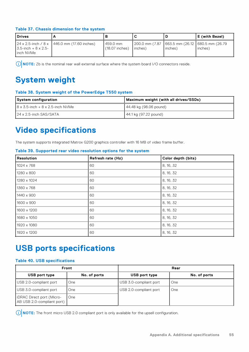
Table 37. Chassis dimension for the system
Drives A B C D E (with Bezel)
24 x 2.5-inch / 8 x3.5-inch + 8 x 2.5-inch NVMe
446.0 mm (17.60 inches) 459.0 mm(18.07 inches)
200.0 mm (7.87inches)
663.5 mm (26.12inches)
680.5 mm (26.79inches)
NOTE: Zb is the nominal rear wall external surface where the system board I/O connectors reside.
System weightTable 38. System weight of the PowerEdge T550 system
System configuration Maximum weight (with all drives/SSDs)
8 x 3.5-inch + 8 x 2.5-inch NVMe 44.48 kg (98.06 pound)
24 x 2.5-inch SAS/SATA 44.1 kg (97.22 pound)
Video specificationsThe system supports integrated Matrox G200 graphics controller with 16 MB of video frame buffer.
Table 39. Supported rear video resolution options for the system
Resolution Refresh rate (Hz) Color depth (bits)
1024 x 768 60 8, 16, 32
1280 x 800 60 8, 16, 32
1280 x 1024 60 8, 16, 32
1360 x 768 60 8, 16, 32
1440 x 900 60 8, 16, 32
1600 x 900 60 8, 16, 32
1600 x 1200 60 8, 16, 32
1680 x 1050 60 8, 16, 32
1920 x 1080 60 8, 16, 32
1920 x 1200 60 8, 16, 32
USB ports specificationsTable 40. USB specifications
Front Rear
USB port type No. of ports USB port type No. of ports
USB 2.0-compliant port One USB 3.0-compliant port One
USB 3.0-compliant port One USB 2.0-compliant port One
iDRAC Direct port (Micro-AB USB 2.0-compliant port)
One
NOTE: The front micro USB 2.0 compliant port is only available for the upsell configuration.
Appendix A. Additional specifications 55

NOTE: The micro USB 2.0 compliant port can only be used as an iDRAC Direct or a management port.
NOTE: The USB 2.0 specifications provide a 5 V supply on a single wire to power connected USB devices. A unit load is
defined as 100 mA in USB 2.0, and 150 mA in USB 3.0. A device may draw a maximum of 5 unit loads (500 mA) from a port
in USB 2.0; 6 (900 mA) in USB 3.0.
NOTE: The USB 2.0 interface can provide power to low-power peripherals but must adhere to USB specification. An
external power source is required for higher-power peripherals to function, such as external CD/DVD Drives.
Environmental specificationsNOTE: For additional information about environmental certifications, refer to the Product Environmental Datasheet located
with the Manuals & Documents on www.dell.com/support/home.
Table 41. Operational climatic range category A2
Temperature Specifications
Allowable continuous operations
Temperature ranges for altitudes <= 900 m (<=2953 ft)
10–35°C (50–95°F) with no direct sunlight on the equipment
Humidity percent ranges (non-condensing at alltimes)
8% RH with -12°C minimum dew point to 80% RH with 21°C (69.8°F)maximum dew point
Operational altitude de-rating Maximum temperature is reduced by 1°C/300 m (33.8°F/984 Ft) above900 m (2953 Ft)
Table 42. Operational climatic range category A3
Temperature Specifications
Allowable continuous operations
Temperature ranges for altitudes <= 900 m (<=2953 ft)
5–40°C (41–104°F) with no direct sunlight on the equipment
Humidity percent ranges (non-condensing at alltimes)
8% RH with -12°C minimum dew point to 80% RH with 24°C (75.2°F)maximum dew point
Operational altitude de-rating Maximum temperature is reduced by 1°C/175 m (1.8°F/574 Ft) above 900m (2953 Ft)
Table 43. Operational climatic range category A4
Temperature Specifications
Allowable continuous operations
Temperature ranges for altitudes <= 900 m (<=2953 ft)
5–45°C (41–113°F) with no direct sunlight on the equipment
Humidity percent ranges (non-condensing at alltimes)
8% RH with -12°C minimum dew point to 80% RH with 24°C (75.2°F)maximum dew point
Operational altitude de-rating Maximum temperature is reduced by 1°C/125 m (1.8°F/410 Ft) above 900m (2953 Ft)
NOTE: Certain system hardware configurations may require operating temperatures to be less than 28°C. For more
information, see the Thermal air restrictions section.
Table 44. Shared requirements across all categories
Temperature Specifications
Allowable continuous operations
56 Appendix A. Additional specifications

Table 44. Shared requirements across all categories (continued)
Temperature Specifications
Maximum temperature gradient (applies to bothoperation and non-operation)
20°C in an hour* (36°F in an hour) and 5°C in 15 minutes (41°F in 15minutes), 5°C in an hour* (41°F in an hour) for tape
NOTE: * - Per ASHRAE thermal guidelines for tape hardware, these arenot instantaneous rates of temperature change.
Non-operational temperature limits -40 to 65°C (-104 to 149°F)
Non-operational humidity limits 5% to 95% RH with 27°C (80.6°F) maximum dew point
Maximum non-operational altitude 12,000 meters (39,370 feet)
Maximum operational altitude 3,048 meters (10,000 feet)
Table 45. Maximum vibration specifications
Maximum vibration Specifications
Operating 0.21 Grms at 5 Hz to 500 Hz (all operation orientations)
Storage 1.88 Grms at 10 Hz to 500 Hz for 15 minutes (all six sides tested)
Table 46. Maximum shock pulse specifications
Maximum shock pulse Specifications
Operating Six consecutively executed shock pulses in the positive and negative x, y,and z axis of 6 G for up to 11 ms.
Storage Six consecutively executed shock pulses in the positive and negative x, y,and z axis (one pulse on each side of the system) of 71 G for up to 2 ms.
Thermal restriction matrix
Appendix A. Additional specifications 57

Table 47. Thermal restriction matrix
DriveConfiguration
Processor
Fans CPUTDP
Fanredundancy
CPU HSK GPU support TBUsupport
CPU blank Fan blank Note GPU riserconfigurationTDP>150
WTDP<=150 W
GPU<=75 W
GPU>75 W
8 x 3.5 1 STDx3
<=185 No HPR HSK STD HSK No No No Yes Yes at Fan2 location
Fan 1/3/4 Riser 0, 1
1 STDx6
<=220 Yes No No No Yes Fan 1/3/4/5/7/8 Riser 0, 1
1 HPRx3
<=220 No Yes No No Yes Fan 1/3/4 No
1 HPRx5*
<=220 Yes Yes/No No Yes Yes Fan 1/3/4/7/8(GPU riser 1 and2 not supported)
No
1 HPRx6
<=220 Yes Yes Yes No Yes Fan 1/3/4/5/7/8 Yes
2 STDx4
<=185 No No No No No No NA Riser 0, 1
2 STDx8
<=220 Yes No No No No NA Riser 0, 1
2 HPRx4
<=220 No Yes No No No NA No
2 HPRx7*
<=220 Yes Yes/No No Yes No Fan1/2/3/4/6/7/8
NOTE: GPUriser 1 and 2notsupported
No
2 HPRx8
<=220 Yes Yes Yes No No NA Yes
8 x 2.516 x 2.524 x 2.5
1 or 2 STDx4
<=185 No HPR HSK STD HSK No No No Yes for 1processor
No NA Riser 0, 1
1 or 2 STDx8
<=220 Yes No No No NA Riser 0, 1
1 or 2 HPRx4
<=220 No Yes No No NA No
1 or 2 HPRx7*
<=220 Yes Yes/No No Yes Fan1/2/3/4/6/7/8
No
58
Ap
pe
nd
ix A. A
dd
ition
al spe
cific
ation
s

Table 47. Thermal restriction matrix (continued)
DriveConfiguration
Processor
Fans CPUTDP
Fanredundancy
CPU HSK GPU support TBUsupport
CPU blank Fan blank Note GPU riserconfigurationTDP>150
WTDP<=150 W
GPU<=75 W
GPU>75 W
NOTE: GPUriser 1 and 2notsupported
1 or 2 HPRx8
<=220 Yes Yes Yes No NA Yes
8 x 3.5 + 8 x2.5 (NVMe)
1 or 2 HPRx4
<=220 No HPR HSK STD HSK Yes No No Yes for 1processor
No NA No or Riser0, 1, 2
1 or 2 HPRx7*
<=220 Yes Yes/No No Yes Fan1/2/3/4/6/7/8
NOTE: GPUriser 1 and 2notsupported
No
1 or 2 HPRx8
<=220 Yes Yes Yes No NA Yes
Ap
pe
nd
ix A. A
dd
ition
al spe
cific
ation
s5
9

NOTE: OCP shroud are required for all drive configurations, even if the OCP card is not installed.
NOTE: DIMM blanks are required for CPU TDP>185 W, but are not required for CPU TDP<=185 W.
NOTE: GPU blank is required at GPU riser slot 2, when a GPU>75 W is installed at GPU riser slot 1.
NOTE: HDD blanks are required for empty HDD slots.
NOTE: *x5 and x7 fan count is applicable only for TBU configuration. Systems without TBU should not use x5 and x7 fan
counts. For TBU configuration, ambient temperature is < 35C.
NOTE: When GPU is selected, HPR fan must be required.
NOTE: GPU>75W must require fan redundancy (Fan quantity = 6 or 8).
NOTE: GPU>75 W does not support TBU.
NOTE: STD fans can also be upgraded to HPR fans.
Thermal matrix for all configurations
Table 48. Thermal matrix for all configurations
- 8x, 16x, 24x 2.5-inch SAS/SATAConfiguration 1
8x 3.5-inch Configuration 2 8x 3.5-inch + 8x2.5-inch NVMeConfiguration 3
Fan STDx4 STDx8 HPRx4 HPRx7x8
STDx3x4
STDx6x8
HPRx3x4
HPRx5x6 x7 x8
HPRx4 HPRx7x8
Fan redundancy No Yes No Yes No Yes No Yes No Yes
Maximum DIMMpower
12 W 12 W 12 W 12 W 12 W 12 W 12 W 12 W 12 W 12 W
CPUTDP
105 WSTDHSK
STDHSK
STDHSK
STDHSK
STDHSK
STDHSK
STDHSK
STDHSK
STDHSK
STDHSK
120 W STDHSK
STDHSK
STDHSK
STDHSK
STDHSK
STDHSK
STDHSK
STDHSK
STDHSK
STDHSK
125 W STDHSK
STDHSK
STDHSK
STDHSK
STDHSK
STDHSK
STDHSK
STDHSK
STDHSK
STDHSK
135 W STDHSK
STDHSK
STDHSK
STDHSK
STDHSK
STDHSK
STDHSK
STDHSK
STDHSK
STDHSK
150 W STDHSK
STDHSK
STDHSK
STDHSK
STDHSK
STDHSK
STDHSK
STDHSK
STDHSK
STDHSK
165 W HPRHSK
HPRHSK
HPRHSK
HPRHSK
HPRHSK
HPRHSK
HPRHSK
HPRHSK
HPRHSK
HPRHSK
185 W HPRHSK
HPRHSK
HPRHSK
HPRHSK
HPRHSK
HPRHSK
HPRHSK
HPRHSK
HPRHSK
HPRHSK
205 W Notsupporte
d
HPRHSK
HPRHSK
HPRHSK
Notsupporte
d
HPRHSK
HPRHSK
HPRHSK
HPRHSK
HPRHSK
220 W Notsupporte
d
HPRHSK
HPRHSK
HPRHSK
Notsupporte
d
HPRHSK
HPRHSK
HPRHSK
HPRHSK
HPRHSK
60 Appendix A. Additional specifications

Particulate and gaseous contamination specifications
The following table defines the limitations that help avoid any damages to the IT equipment and/or, or both failure fromparticulate and gaseous contamination. If the levels of particulate or gaseous pollution exceed the specified limitations andresults in equipment damage or failure, you must rectify the environmental conditions. Remediation of environmental conditionsis the responsibility of the customer.
Table 49. Particulate contamination specifications
Particulate contamination Specifications
Air filtration Data center air filtration as defined by ISO Class 8 per ISO14644-1 with a 95% upper confidence limit.
NOTE: This condition applies to data center environmentsonly. Air filtration requirements do not apply to ITequipment designed to be used outside a data center, inenvironments such as an office or factory floor.
NOTE: Air entering the data center must have MERV11 orMERV13 filtration.
Conductive dust Air must be free of conductive dust, zinc whiskers, or otherconductive particles.
NOTE: This condition applies to data center and non-datacenter environments.
Corrosive dust ● Air must be free of corrosive dust.● Residual dust present in the air must have a deliquescent
point less than 60% relative humidity.
NOTE: This condition applies to data center and non-datacenter environments.
Table 50. Gaseous contamination specifications
Gaseous contamination Specifications
Copper Coupon Corrosion rate <300 Å/month per Class G1 as defined by ANSI/ISA71.04-2013
Silver Coupon Corrosion rate <200 Å/month as defined by ANSI/ISA71.04-2013
NOTE: Maximum corrosive contaminant levels measured at ≤50% relative humidity.
Thermal air restrictions
Thermal air restrictions for different configurations
Table 51. 8 x 3.5-inch drive configuration
Standard Operating Support(ASHRAE A2 compliant)
NOTE: All options supported unlessotherwise noted.
Extended ambient 40° C OperatingSupport (ASHRAE A3 compliant)
Extended ambient 45° C OperatingSupport (ASHRAE A4 compliant)
● 3x or 4x STD fans support onlyprocessor with TDP<=185W
● With STD fans, the following OCP3.0 and NIC support only optic cablewith thermal spec 85C and power<=1.2 W
● 3x or 4x STD fans configurations notsupported.
● 6x or 8x STD fans configurationswith processor TDP > 120 W is notsupported.
● TBU not supported.
● STD fans configurations are notsupported.
● 3x or 4x HPR fans configurationswith CPU TDP > 165 W are notsupported.
● TBU not supported.
Appendix A. Additional specifications 61

Table 51. 8 x 3.5-inch drive configuration
Standard Operating Support(ASHRAE A2 compliant)
NOTE: All options supported unlessotherwise noted.
Extended ambient 40° C OperatingSupport (ASHRAE A3 compliant)
Extended ambient 45° C OperatingSupport (ASHRAE A4 compliant)
○ Broadcom OCP 3.0 QP 25GSFP28
○ Broadcom PCIe QP 25G○ NVIDIA CX6-LX PCIe Dual Port
25G SFP28 at slot 6
● Non-Dell qualified peripheral cardsand Channel devices (FW) cards notsupported.
● NIC consuming power >= 25 W notsupported. For example: CX6 card.
● OCP transfer rate > 25G or coolingtier>10 is not supported.
● Optic cable with spec 85C isrequired.
● Two PSUs are required. Systemperformance may be reduced in theevent of a PSU failure.
● BOSS M.2 module not supported.● Non-Dell qualified peripheral cards
and Channel devices (FW) cards arenot supported.
● NIC consuming power >= 25 W. Forexample: CX6 card.
● OCP transfer rate >25G or coolingtier > 10 not supported.
● Optic cable with spec 85C isrequired.
● Two PSUs are required. Systemperformance may be reduced in theevent of a PSU failure.
Table 52. 8 x 2.5-inch, 16 x 2.5-inch, 24 x 2.5-inch drive configuration
Standard Operating Support(ASHRAE A2 compliant)
Extended ambient 40° C OperatingSupport (ASHRAE A3 compliant)
Extended ambient 45° C OperatingSupport (ASHRAE A4 compliant)
● 4x STD fans support only processorwith TDP<=185W
● With STD fans, the following OCP3.0 and NIC support only optic cablewith thermal Spec 85C and power<=1.2 W○ Broadcom OCP 3.0 QP 25G
SFP28○ Broadcom PCIe QP 25G○ NVIDIA CX6-LX PCIe Dual Port
25G SFP28 at slot 6
● 4x STD fans configurations notsupported.
● 8x STD fans configurations with CPUTDP > 120 W is not supported.
● TBU not supported.● Non-Dell qualified peripheral cards
and Channel devices (FW) cards arenot supported.
● NIC consuming power >= 25 W notsupported. For example: CX6 card.
● OCP transfer rate > 25G or coolingtier > 10 not supported.
● Optic cable with spec 85C isrequired.
● Two PSUs are required. Systemperformance may be reduced in theevent of a PSU failure.
● STD fans configurations are notsupported.
● 4x HPR fans configurations withprocessor TDP > 165 W are notsupported.
● TBU not supported.● BOSS M.2 module is not supported.● Non-Dell qualified peripheral cards
and Channel devices (FW) cards arenot supported.
● NIC consuming power >= 25 W. Forexample: CX6 card.
● OCP transfer rate >25G or coolingtier > 10 not supported.
● Optic cable with spec 85C isrequired.
● Two PSUs are required. Systemperformance may be reduced in theevent of a PSU failure.
Table 53. 8 x 3.5-inch x 8 x NVMe drive configuration
Standard Operating Support(ASHRAE A2 compliant)
Extended ambient 40° C OperatingSupport (ASHRAE A3 compliant)
Extended ambient 45° C OperatingSupport (ASHRAE A4 compliant)
HPR fans are required. ● TBU not supported.● Non-Dell qualified peripheral cards
and Channel devices (FW) cards arenot supported.
● NIC consuming power >= 25 W notsupported. For example: CX6 card.
● OCP transfer rate > 25G or coolingtier > 10 not supported.
● Optic cable with spec 85C isrequired.
● 4x HPR fans configurations with CPUTDP > 165 W are not supported.
● TBU not supported.● BOSS M.2 module is not supported.● Non-Dell qualified peripheral cards
and Channel devices (FW) cards arenot supported.
● NIC consuming power >= 25 W. Forexample: CX6 card.
● OCP transfer rate >25G or coolingtier > 10 not supported.
62 Appendix A. Additional specifications

Table 53. 8 x 3.5-inch x 8 x NVMe drive configuration
Standard Operating Support(ASHRAE A2 compliant)
Extended ambient 40° C OperatingSupport (ASHRAE A3 compliant)
Extended ambient 45° C OperatingSupport (ASHRAE A4 compliant)
● Two PSUs are required. Systemperformance may be reduced in theevent of a PSU failure.
● Optic cable with spec 85C isrequired.
● Two PSUs are required. Systemperformance may be reduced in theevent of a PSU failure.
Appendix A. Additional specifications 63

Appendix B. Standards complianceThe system conforms to the following industry standards.
Table 54. Industry standard documents
Standard URL for information and specifications
ACPIAdvance Configuration and Power InterfaceSpecification, v2.0c
https://uefi.org/specsandtesttools
Ethernet IEEE 802.3-2005 https://standards.ieee.org/
HDGHardware Design Guide Version 3.0 for MicrosoftWindows Server
microsoft.com/whdc/system/platform/pcdesign/desguide/serverdg.mspx
IPMI Intelligent Platform Management Interface, v2.0 intel.com/design/servers/ipmi
DDR4 Memory DDR4 SDRAM Specification jedec.org/standards-documents/docs/jesd79-4.pdf
PCI Express PCI Express Base Specification Rev. 2.0 and 3.0 pcisig.com/specifications/pciexpress
PMBus Power System Management Protocol Specification,v1.2
http://pmbus.org/Assets/PDFS/Public/PMBus_Specification_Part_I_Rev_1-1_20070205.pdf
SAS Serial Attached SCSI, v1.1 http://www.t10.org/
SATA Serial ATA Rev. 2.6; SATA II, SATA 1.0a Extensions,Rev. 1.2
sata-io.org
SMBIOS System Management BIOS Reference Specification,v2.7
dmtf.org/standards/smbios
TPM Trusted Platform Module Specification, v1.2 and v2.0 trustedcomputinggroup.org
UEFI Unified Extensible Firmware Interface Specification, v2.1 uefi.org/specifications
USB Universal Serial Bus Specification, Rev. 2.0 usb.org/developers/docs
12
64 Appendix B. Standards compliance

Appendix C Additional resourcesTable 55. Additional resources
Resource Description of contents Location
Installation and Service Manual This manual, available in PDF format, provides the followinginformation:
● Chassis features● System Setup program● System messages● System codes and indicators● System BIOS● Remove and replace procedures● Troubleshooting● Diagnostics● Jumpers and connectors
Dell.com/Support/Manuals
Getting Started Guide This guide ships with the system, and is also available in PDFformat. This guide provides the following information:
● Initial setup steps● Key system features● Technical specifications
Dell.com/Support/Manuals
Rack Installation Instructions This document ships with the rack kits, and providesinstructions for installing a server in a rack.
Dell.com/Support/Manuals
Information Update This document ships with the system, is also available in PDFformat online, and provides information on system updates.
Dell.com/Support/Manuals
System Information Label The system information label documents the system boardlayout and system jumper settings. Text is minimized dueto space limitations and translation considerations. The labelsize is standardized across platforms.
Inside the system chassiscover
Quick Resource Locator (QRL) This code on the chassis can be scanned by a phoneapplication to access additional information and resources forthe server, including videos, reference materials, service taginformation, and Dell EMC contact information.
Inside the system chassiscover
Energy Smart Solution Advisor(ESSA)
The Dell EMC online ESSA enables easier and moremeaningful estimates to help you determine the mostefficient configuration possible. Use ESSA to calculate thepower consumption of your hardware, power infrastructure,and storage.
Dell.com/calc
13
Appendix C Additional resources 65

Appendix D. Support and DeploymentServices
Dell EMC Global Services include a wide, customizable range of service choices to simplify the assessment, design,implementation, management and maintenance of your IT environment and to help you transition from platform to platform.Depending on your current business requirements and the level of service you want, we can provide you with factory, on-site,remote, modular and specialized services that fit your needs and budget. We'll help you with a little or a lot - your choice - andprovide you with access to our global resources.
Topics:
• Deployment Services• Dell Technologies Consulting Services
Deployment Services
Dell EMC ProDeploy Enterprise Suite
ProDeploy Enterprise Suite gets your server out of the box and into optimized production—fast. Our elite deployment engineerswith broad and deep experience utilizing best-in-class processes along with our established global scale can help you around theclock and around the globe. From simple to the most complex server installations and software integration, we take the guesswork and risk out of deploying your new server technology.
Figure 17. ProDeploy Enterprise Suite capabilities
NOTE: Hardware installation not applicable on selected software products.
Dell EMC ProDeploy Plus
From beginning to end, ProDeploy Plus provides the skill and scale needed to successfully execute demanding deploymentsin today's complex IT environments. Certified Dell EMC experts start with extensive environmental assessments and detailedmigration planning and recommendations. Software installation includes set up of most versions of Dell EMC SupportAssist and
14
66 Appendix D. Support and Deployment Services

OpenManage system management utilities. Post-deployment configuration assistance, testing, and product orientation servicesare also available.
Dell EMC ProDeploy
ProDeploy provides full service installation and configuration of both server hardware and system software by certifieddeployment engineers including set up of leading operating systems and hypervisors as well as most versions of Dell EMCSupportAssist and OpenManage system management utilities. To prepare for the deployment, we conduct a site readinessreview and implementation planning exercise. System testing, validation, and full project documentation with knowledge transfercomplete the process.
Dell EMC ProDeploy for HPC
HPC deployments require specialists that understand that cutting edge is yesterday's news. Dell EMC deploys the world 'sfastest systems and understands the nuances that make them perform. ProDeploy for HPC provides:● Global team of dedicated HPC specialists● Proven track record, thousands of successful HPC deployments● Design validation, benchmarking, and product orientation
Figure 18. Dell EMC ProDeploy for HPC
Dell EMC Basic Deployment
Basic Deployment delivers worry-free professional installation by experienced technicians who know Dell EMC servers inside andout.
Dell EMC Server Configuration Services
With Dell EMC Rack Integration and other Dell EMC PowerEdge Server Configuration Services, you save time by receiving yoursystems racked, cabled, tested, and ready to integrate into the data center. Dell EMC staff pre-configure RAID, BIOS and iDRACsettings, install system images, and even install third-party hardware and software.
Appendix D. Support and Deployment Services 67
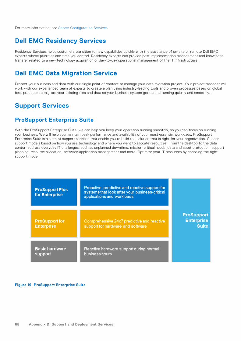
For more information, see Server Configuration Services.
Dell EMC Residency Services
Residency Services helps customers transition to new capabilities quickly with the assistance of on-site or remote Dell EMCexperts whose priorities and time you control. Residency experts can provide post implementation management and knowledgetransfer related to a new technology acquisition or day-to-day operational management of the IT infrastructure.
Dell EMC Data Migration Service
Protect your business and data with our single point of contact to manage your data migration project. Your project manager willwork with our experienced team of experts to create a plan using industry-leading tools and proven processes based on globalbest practices to migrate your existing files and data so your business system get up and running quickly and smoothly.
Support Services
ProSupport Enterprise Suite
With the ProSupport Enterprise Suite, we can help you keep your operation running smoothly, so you can focus on runningyour business. We will help you maintain peak performance and availability of your most essential workloads. ProSupportEnterprise Suite is a suite of support services that enable you to build the solution that is right for your organization. Choosesupport models based on how you use technology and where you want to allocate resources. From the desktop to the datacenter, address everyday IT challenges, such as unplanned downtime, mission-critical needs, data and asset protection, supportplanning, resource allocation, software application management and more. Optimize your IT resources by choosing the rightsupport model.
Figure 19. ProSupport Enterprise Suite
68 Appendix D. Support and Deployment Services
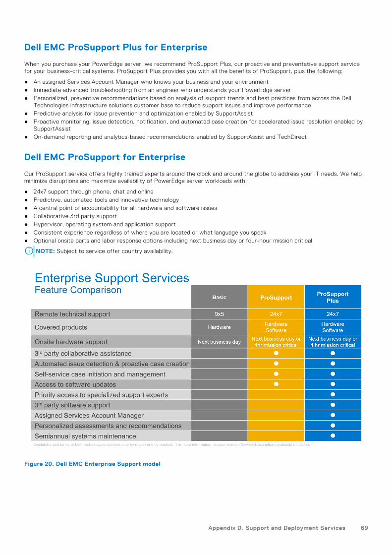
Dell EMC ProSupport Plus for Enterprise
When you purchase your PowerEdge server, we recommend ProSupport Plus, our proactive and preventative support servicefor your business-critical systems. ProSupport Plus provides you with all the benefits of ProSupport, plus the following:
● An assigned Services Account Manager who knows your business and your environment● Immediate advanced troubleshooting from an engineer who understands your PowerEdge server● Personalized, preventive recommendations based on analysis of support trends and best practices from across the Dell
Technologies infrastructure solutions customer base to reduce support issues and improve performance● Predictive analysis for issue prevention and optimization enabled by SupportAssist● Proactive monitoring, issue detection, notification, and automated case creation for accelerated issue resolution enabled by
SupportAssist● On-demand reporting and analytics-based recommendations enabled by SupportAssist and TechDirect
Dell EMC ProSupport for Enterprise
Our ProSupport service offers highly trained experts around the clock and around the globe to address your IT needs. We helpminimize disruptions and maximize availability of PowerEdge server workloads with:
● 24x7 support through phone, chat and online● Predictive, automated tools and innovative technology● A central point of accountability for all hardware and software issues● Collaborative 3rd party support● Hypervisor, operating system and application support● Consistent experience regardless of where you are located or what language you speak● Optional onsite parts and labor response options including next business day or four-hour mission critical
NOTE: Subject to service offer country availability.
Figure 20. Dell EMC Enterprise Support model
Appendix D. Support and Deployment Services 69
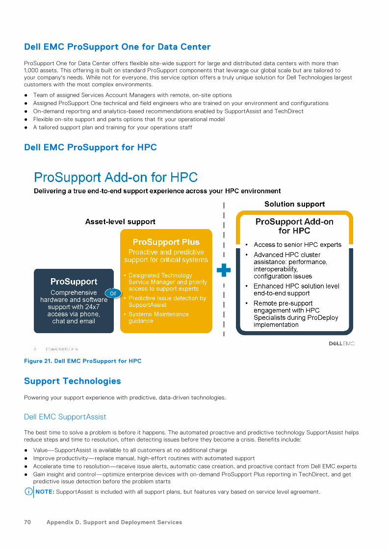
Dell EMC ProSupport One for Data Center
ProSupport One for Data Center offers flexible site-wide support for large and distributed data centers with more than1,000 assets. This offering is built on standard ProSupport components that leverage our global scale but are tailored toyour company's needs. While not for everyone, this service option offers a truly unique solution for Dell Technologies largestcustomers with the most complex environments.
● Team of assigned Services Account Managers with remote, on-site options● Assigned ProSupport One technical and field engineers who are trained on your environment and configurations● On-demand reporting and analytics-based recommendations enabled by SupportAssist and TechDirect● Flexible on-site support and parts options that fit your operational model● A tailored support plan and training for your operations staff
Dell EMC ProSupport for HPC
Figure 21. Dell EMC ProSupport for HPC
Support Technologies
Powering your support experience with predictive, data-driven technologies.
Dell EMC SupportAssist
The best time to solve a problem is before it happens. The automated proactive and predictive technology SupportAssist helpsreduce steps and time to resolution, often detecting issues before they become a crisis. Benefits include:
● Value—SupportAssist is available to all customers at no additional charge● Improve productivity—replace manual, high-effort routines with automated support● Accelerate time to resolution—receive issue alerts, automatic case creation, and proactive contact from Dell EMC experts● Gain insight and control—optimize enterprise devices with on-demand ProSupport Plus reporting in TechDirect, and get
predictive issue detection before the problem starts
NOTE: SupportAssist is included with all support plans, but features vary based on service level agreement.
70 Appendix D. Support and Deployment Services

Figure 22. SupportAssist model
Get started at Dell.com/SupportAssist
Dell EMC TechDirect
Boost IT team productivity when supporting Dell EMC systems. With over 1.4 million self-dispatches processed each year,TechDirect has proven its effectiveness as a support tool. You can:
● Self-dispatch replacement parts● Request technical support● Integrate APIs into your help desk
Or, access all your Dell EMC certification and authorization requirements. Train your staff on Dell EMC products, as TechDirectallows you to:
● Download study guides● Schedule certification and authorization exams● View transcripts of completed courses and exams
Register at techdirect.dell.
Dell Technologies Consulting ServicesOur expert consultants help you transform faster, and quickly achieve business outcomes for the high value workloads Dell EMCPowerEdge systems can handle.
From strategy to full-scale implementation, Dell Technologies Consulting can help you determine how to execute your IT,workforce, or application transformation.
We use prescriptive approaches and proven methodologies combined with Dell Technologies' portfolio and partner ecosystemto help you achieve real business outcomes. From multi-cloud, applications, DevOps, and infrastructure transformations, tobusiness resiliency, data center modernization, analytics, workforce collaboration, and user experiences—we're here to help.
Dell EMC Remote Consulting Services
When you are in the final stages of your PowerEdge server implementation, you can rely on Dell EMC Remote ConsultingServices and our certified technical experts to help you optimize your configuration with best practices for your software,virtualization, server, storage, networking, and systems management.
Appendix D. Support and Deployment Services 71

Dell Financial Services (DFS)Dell Financial Services is a global provider of innovative payment and consumption solutions for hardware, software andservices, allowing organizations to align and scale the cost of IT solutions with technology consumption and budget availability.DFS supports all customers, from consumers to small businesses up to the largest global corporations.
Why leverage Payment Solutions from DFS?
● Optimize Payment Solutions - Tailor one or more of our solutions to your needs and grow the business.● Ease Budget Constraints - Reduce capital expenses and free up budgets with flexible payment solutions.● Increase Efficiency - Flexible payment transactions allow your infrastructure to grow when needed without relying on a
fixed, capital budget.
Topics:
• Flex On Demand (FOD)• Flex On Demand for PowerEdge Servers
Flex On Demand (FOD)● Flex On Demand (FOD) is a metered payment solution for Dell EMC storage, data protection, hyperconverged infrastructure,
servers, converged infrastructure and the Dell Technologies Cloud Platform.● With Flex On Demand, the technology is metered - at a component level - based on how much a specific technology is used.● You are able to choose your committed or baseline capacity and pay for it at an agreed upon rate each month. When
capacity requirements increase above the baseline capacity level, buffer capacity can be utilized at the same rate.● With Flex On Demand, you can scale up and down within the available buffer capacity and easily manage unpredictable
growth, workload bursts, and temporary changes in IT infrastructure requirements.
Flex On Demand for PowerEdge ServersFlex On Demand gives you unprecedented levels of flexibility in how you consume our technology, allowing you to elasticallyscale up or down to meet your needs.
Who could benefit from a Flex On Demand consumption model?
Flex On Demand could benefit customers looking to:
● Conserve cashflow● Achieve predictable payments when usage is variable● Increase business agility by having immediate access to buffer capacity● Shift technology spending from a capital expenditure to an ongoing operating expense
Dell EMC PowerEdge servers and Flex On Demand combine the industry's best-selling servers with innovative consumption-based payment programs. It allows you to improve economics, increase flexibility and embrace choice:
● Improve Economics - Pay for server resources based on actual hourly usage and avoid the costs of over-provisioning soyou can achieve public cloud economics in the data center.
● Increase Flexibility - Respond quickly to new service requests, workload fluctuations and changes driven by the businessto improve IT flexibility.
● Embrace Choice - Choose the infrastructure that's configured to your requirements and payment schedule that works foryou.
15
72 Dell Financial Services (DFS)