Dell PowerEdge FC630
131
Regulatory Model: E02B Regulatory Type: E02B004 Dell PowerEdge FC630 Owner's Manual
-
Upload
khangminh22 -
Category
Documents
-
view
2 -
download
0
Transcript of Dell PowerEdge FC630

Regulatory Model: E02B Regulatory Type: E02B004
Dell PowerEdge FC630 Owner's Manual
Notes, cautions, and warnings
NOTE: A NOTE indicates important information that helps you make better use of your computer.
CAUTION: A CAUTION indicates either potential damage to hardware or loss of data and tells you how to avoid the problem.
WARNING: A WARNING indicates a potential for property damage, personal injury, or death.
© 2016 Dell Inc. All rights reserved. This product is protected by U.S. and international copyright and intellectual property laws. Dell and the Dell logo are trademarksof Dell Inc. inthe United Statesand/orotherjurisdictions. Allothermarksandnamesmentionedhereinmaybetrademarksoftheirrespective companies.
2016 - 03
Rev. A01

Contents 3
Contents
1 Dell PowerEdge FC630 overview .................................................................................................. 7 Supported configurations for the PowerEdge FC630 system ............................................................................ 7 Front panel ................................................................................................................................................................ 8
2.5-inch hard drive or SSD system .................................................................................................................. 9 1.8-inch SSD system ....................................................................................................................................... 10
Diagnostic Indicators ............................................................................................................................................. 11 iDRAC Direct LED indicator codes ................................................................................................................ 11 Using USB diskette or USB DVD or CD drives ............................................................................................. 12 Hard drive or SSD indicator patterns ............................................................................................................. 12
Locating Service Tag of your system ................................................................................................................... 13
2 Documentation resources ......................................................................................................... 14
3 Technical specifications .............................................................................................................. 16 Chassis dimensions............................................................................................................................................... 16 Chassis weight ....................................................................................................................................................... 16 Processor specifications ....................................................................................................................................... 16 System battery specifications ............................................................................................................................... 17 Memory specifications ........................................................................................................................................... 17 RAID controllers ..................................................................................................................................................... 17 PCIe mezzanine card slots ................................................................................................................................... 17 Driver specification ................................................................................................................................................ 17
Hard drives ........................................................................................................................................................ 17 SSDs .................................................................................................................................................................. 17 Optical drive ...................................................................................................................................................... 18 Flash drive ......................................................................................................................................................... 18
Ports and connectors specifications .................................................................................................................... 18 USB ports .......................................................................................................................................................... 18 Internal Dual SD Module ................................................................................................................................. 18
Video specifications ............................................................................................................................................... 18 Environmental specifications................................................................................................................................ 18
Particulate and gaseous contamination specifications ............................................................................... 20 Expanded operating temperature .................................................................................................................. 21 Expanded operating temperature restrictions .............................................................................................. 21
4 Initial system setupand configuration ......................................................................................... 22 Setting up your system .......................................................................................................................................... 22 iDRAC configuration .............................................................................................................................................. 22
Options to set up iDRAC IP address .............................................................................................................. 22 Options to install the operating system ............................................................................................................... 23
Methods to download firmware and drivers .................................................................................................. 23

4 Contents
5 Pre-operating system management applications ........................................................................ 25 Options to manage the pre-operating system applications .............................................................................. 25 System Setup ......................................................................................................................................................... 25
Viewing System Setup..................................................................................................................................... 25 System Setup details ....................................................................................................................................... 26 System BIOS .................................................................................................................................................... 26
iDRAC Settings utility ....................................................................................................................................... 46 Device Settings ................................................................................................................................................. 47
Dell Lifecycle Controller ........................................................................................................................................ 47 Embedded system management ................................................................................................................... 47
Boot Manager ......................................................................................................................................................... 47 Viewing Boot Manager .................................................................................................................................... 47 Boot Manager main menu ............................................................................................................................... 48
PXE boot ................................................................................................................................................................. 48
6 Installing and removing sled components .................................................................................. 49 Safety instructions ................................................................................................................................................. 49
Before working inside your system ................................................................................................................. 50 After working inside your system ................................................................................................................... 50
Recommended tools ............................................................................................................................................. 50
Sled .......................................................................................................................................................................... 50 Removing the sled ........................................................................................................................................... 50 Installing the sled .............................................................................................................................................. 52
Inside the sled ........................................................................................................................................................ 54 Cooling shroud ....................................................................................................................................................... 55
Removing the cooling shroud ......................................................................................................................... 55 Installing the cooling shroud ........................................................................................................................... 55
Processor blank and DIMM blank ........................................................................................................................ 56 Removing a processor or DIMM blank .......................................................................................................... 56 Installing a processor or DIMM blank ............................................................................................................ 57
System memory ..................................................................................................................................................... 58 General memory module installation guidelines. ......................................................................................... 60 Mode-specific guidelines ................................................................................................................................. 60 Sample memory configurations ...................................................................................................................... 61 Removing memory modules ........................................................................................................................... 63
Installing memory modules ............................................................................................................................. 64 PCIe mezzanine card ............................................................................................................................................ 66
Removing a PCIe mezzanine card ................................................................................................................ 66 Installing a PCIe mezzanine card ................................................................................................................... 67
Internal dual SD module (optional) ...................................................................................................................... 68 Replacing an SD card ...................................................................................................................................... 68 Internal USB key............................................................................................................................................... 69 Removing the optional IDSDM card .............................................................................................................. 70 Installing the optional IDSDM card ................................................................................................................. 72
rSPI card (optional) ................................................................................................................................................ 73

Contents 5
Removing the optional rSPI card ................................................................................................................... 73 Installing the optional rSPI card ...................................................................................................................... 74
SD vFlash card ....................................................................................................................................................... 75
Replacing the SD vFlash card ........................................................................................................................ 75 Network Daughter Card ........................................................................................................................................ 77
Removing the Network Daughter Card ......................................................................................................... 77
Installing the Network Daughter Card ........................................................................................................... 79
Processors .............................................................................................................................................................. 80 Removing a heat sink ...................................................................................................................................... 80
Removing a processor ..................................................................................................................................... 81 Installing a processor ....................................................................................................................................... 84 Installing a heat sink ........................................................................................................................................ 85
Hard drives or SSDs .............................................................................................................................................. 87 Hard drive or SSD bay numbering ................................................................................................................. 87
Hard drive or SSD installation guidelines ...................................................................................................... 87
Removing a hard drive or SSD ....................................................................................................................... 88
Installing a hard drive or SSD ......................................................................................................................... 89 Removing a hard drive or SSD blank ............................................................................................................ 90
Installing a hard drive or SSD blank ............................................................................................................... 91 Shutdown procedure for servicing a hard drive or SSD. ............................................................................. 92 Configuring the boot drive ............................................................................................................................... 93
Removing a 2.5-inch hard drive or SSD from a 2.5-inch hard drive or SSD carrier .................................. 93
Installing a 2.5-inch hard drive or SSD in a 2.5-inch hard drive or SSD carrier ......................................... 94
Removing a 1.8-inch SSD from a 1.8-inch SSD carrier ............................................................................... 95 Installing a 1.8-inch SSD in a 1.8-inch SSD carrier ...................................................................................... 95
Removing the hard drive or SSD cage .......................................................................................................... 96 Installing the hard drive or SSD cage ............................................................................................................ 97
Hard drive backplane ............................................................................................................................................ 98
Removing the hard drive or SSD backplane ................................................................................................. 98 Installing the hard drive or SSD backplane ................................................................................................. 100
PERC H730P slim card ....................................................................................................................................... 101
Removing a PERC H730P slim card ........................................................................................................... 101 Installing a PERC H730P slim card ............................................................................................................. 103
Storage controller card ........................................................................................................................................ 104
Removing the PCIe extender or storage controller card. .......................................................................... 104
Installing the PCIe extender or storage controller card ............................................................................. 106 NVRAM backup battery ...................................................................................................................................... 107
Replacing the NVRAM backup battery ........................................................................................................ 107 System board ....................................................................................................................................................... 109
Removing the system board. ........................................................................................................................ 109
Installing the system board ........................................................................................................................... 112 Trusted Platform Module ..................................................................................................................................... 115
Installing the Trusted Platform Module ........................................................................................................ 115 Initializing the TPM for BitLocker users ....................................................................................................... 116
Initializing the TPM for TXT users ................................................................................................................ 116

6 Contents
7 Using system diagnostics ........................................................................................................ 117 Dell Embedded System Diagnostics ................................................................................................................. 117
Running the Embedded System Diagnostics ............................................................................................. 117 Running embedded system diagnostics from an external media ............................................................. 117 System diagnostics controls ......................................................................................................................... 118
8 Jumpers and connectors ......................................................................................................... 119 System board jumper settings ............................................................................................................................ 119
System board connectors ................................................................................................................................... 120 Disabling a forgotten password .......................................................................................................................... 121
9 Troubleshooting your system ................................................................................................. 122 Safety first — for you andyour system ............................................................................................................. 122 Troubleshooting system memory ...................................................................................................................... 122
Troubleshooting hard drives ............................................................................................................................... 123
Troubleshooting USB devices ............................................................................................................................ 124
Troubleshooting Solid State Drives ................................................................................................................... 124 Troubleshooting an internal SD card ................................................................................................................. 125 Troubleshooting processors ............................................................................................................................... 125
Troubleshooting the system board .................................................................................................................... 126 Troubleshooting the NVRAM backup battery ................................................................................................... 126
10 Getting help .......................................................................................................................... 128 Contacting Dell ..................................................................................................................................................... 128
Accessing system information by using QRL ................................................................................................... 128
Quick Resource Locator for FC630 ............................................................................................................. 129

Dell PowerEdge FC630 overview 7
1
Dell PowerEdge FC630 overview The Dell PowerEdge FC630 is a half-height sled supported on the PowerEdge FX2 enclosure and support up to:
• One or two Intel Xeon E5-2600 v3 or E5-2600 v4 processors
• 24 DIMMs
• Single processor: Up totwo 2.5-inch hard drives
• Single processor: Up to eight 1.8-inch SSDs
• Dual processor: Up to two 2.5-inch hard drives
• Dual processor: Up to eight 1.8-inch SSDs
Topics:
• Supported configurations for the PowerEdge FC630 system
• Front panel
• Diagnostic Indicators
• Locating ServiceTagofyoursystem
Supported configurations for the PowerEdge FC630 system The Dell PowerEdge FC630 system supports the following configurations:

8 Dell PowerEdge FC630 overview
Figure 1. FC630 configuration overview
Front panel The features on the front panel include USB management port, iDRAC Direct LED indicator, sled handle and status indicator.

Dell PowerEdge FC630 overview 9
2.5-inch hard drive or SSD system
Figure 2. Front panel features — 2.5-inch hard drive or SSD system
1 Hard drives or SSDs 2 USB management port
3 USB management port or iDRAC Direct port 4 iDRAC Direct LED indicator
5 Sled handle 6 Status indicator
7 Sled power-on indicator,power button
Table 1. Front panel features — 2.5-inch hard drive or SSD system
Item Indicator, Button, or Connector
Icon Description
1 Hard drives or SSDs 2.5-inch hard drive Two2.5-inch hot-swap SAS or system SATAharddrivesor SASor
SATA or PCIe SSDs.
NOTE: Use this button only if directed to do so by qualified support personnel or by the operating system's documentation.
2 USB management port A USB device is connected to the system.
3 USB management port or iDRAC Direct port
The USB management port can function as a regular USB port or provide access to the iDRAC features. For more information, see the Dell Integrated Dell Remote Access Controller User's Guide at Dell.com/ idracmanuals.
4 iDRAC Direct LED indicator The management indicator lights when the iDRAC controls the USB1 port for management functions.
5 Sled handle Used to slide the sled out of the enclosure.
6 Status indicator Provides information about the status of the system.
7 Sled power-on indicator, power
button
The power indicator turns on when the sled power is on. The power button controls the power supply unit output to the system.

10 Dell PowerEdge FC630 overview
1.8-inch SSD system
Figure 3. Front panel features — 1.8-inch SSD system
1 SSDs 2 USB management port
3 USB management port or iDRAC Direct port 4 iDRAC Direct LED indicator
5 Sled handle 6 Status indicator
7 Sled power-on indicator, power button
Table 2. Front panel features — 1.8-inch SSD system
Item Indicator, Button, or Connector
Icon Description
1 SSDs 1.8-inch SSD system
Eight 1.8-inch hot-swap SATA SSDs.
NOTE: Use this button only if directed to do so by qualified support personnel or by the operating system's documentation.
2 USB management port A USB device is connected to thesystem.
3 USB management port or iDRAC Direct port
The USB management port can function as a regular USB port or provide access to the iDRAC features. For more information, see the Dell Integrated Dell Remote Access Controller User's Guide at Dell.com/ idracmanuals.
4 iDRAC Direct LED indicator The management indicator lights when the iDRAC controls the USB1 port for management functions.
5 Sled handle Used to slide the sled out of the enclosure.
6 Status indicator Provides information about the status of the system.
7 Sled power-on indicator, power button
The power indicator turns on when the sled power is on. The power button controls the power supply unit output to the system.

Dell PowerEdge FC630 overview 11
.
Diagnostic Indicators The diagnostic indicators on the system front panel display error status during system startup.
iDRAC Direct LED indicator codes NOTE: The iDRAC Direct LED indicator does not turn on for the USB mode.
Figure 4. iDRAC Direct LED indicator
1 iDRAC Direct statusindicator
Table 3. iDRAC Direct LED indicators
Convention iDRAC Direct LED indicator pattern
Condition
A Green Turns green for a minimum of two seconds at the starting and end of a file transfer.
B Flashing green Indicates file transfer or any operation tasks.
C Green and turns off Indicates that the file transfer is complete.
D Not lit Indicates that the USB is ready to be removed or that a task is complete.
The following table describes iDRAC Direct activity when configuring iDRAC Direct by using your laptop and cable (Laptop Connect).
Table 4. iDRAC Direct LED indicator patterns
iDRAC Direct LED indicator pattern
Condition
Solid green for two seconds Indicates that the laptop is connected.
Flashing green (on for two seconds and off for two seconds)
Indicates that the laptop connected is recognized.
Turns off Indicates that the laptop is unplugged.

12 Dell PowerEdge FC630 overview
Using USBdiskette or USB DVD or CD drives The sled has USB ports on the front which allows youto connect a USB diskette drive, USB flash drive, USB DVD or CD drive, keyboard, or mouse. The USB drives can beused to configure the sled.
To designate the USB diskette drive as the boot drive:
1 connect the USB drive
2 restart the system
3 enter the System Setup
4 set the drive as first in the boot sequence
The USB device is displayed in the boot order setup screen only if it is attached to the system before you run the System Setup. You can also select the boot device bypressing F11 during system start-up and selecting a boot device for the current boot sequence.
Hard drive or SSD indicator patterns The hard drive or SSD (Solid-State Drives) indicators display different patterns as drive events occur in the system.
NOTE: The sled must have a hard drive or SSD or a hard drive blank installed in each drive bay.
Figure 5. Hard drive or SSD indicators
1 drive activityindicator (green) 2 drive status indicator (green and amber)
NOTE: If the drive is in Advanced Host Controller Interface (AHCI) mode, the status LED (on the right side) does not function and remains off.
Drive-Status Indicator Pattern
Flashes green twice per second
Condition
Identifying drive or preparing for removal
Dell PowerEdge FC630 overview 13
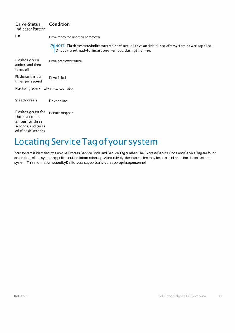
Drive-Status Indicator Pattern
Condition
Off Drive ready for insertion or removal
NOTE: Thedrivestatusindicatorremainsoff untilalldrivesareinitialized aftersystem powerisapplied. Drivesarenotreadyforinsertionorremovalduringthistime.
Flashes green, amber, and then turns off
Flashesamberfour times per second
Drive predicted failure
Drive failed
Flashes green slowly Drive rebuilding
Steady green Driveonline
Flashes green for three seconds, amber for three seconds, and turns off after six seconds
Rebuild stopped
Locating Service Tag of your system Your system is identified by a unique Express Service Code and Service Tag number. The Express Service Code and Service Tag are found on the front of the system by pulling out the information tag. Alternatively, the information may be on a sticker on the chassis of the system. This information is used byDell to route support calls to the appropriate personnel.

14 Documentation resources
2
Documentation resources This section provides information about the documentation resources for your system.
Table 5. Documentation resources for system
Task Document Location
Setting up your system For information about installing the system into a rack, see the Rack documentation included with your rack solution.
Dell.com/poweredgemanuals
For information about turning on the system and the technical specifications of your system, see the Getting Started With Your System that shipped withyoursystem.
For information about Getting Started With Your System that shipped with your system or the Technical specifications section in this document.
Configuring your system For information about iDRAC features, configuring and logging in to iDRAC, and managing your system remotely, see the Integrated Dell Remote Access Controller User's Guide.
For information about installing the operating system, see the operating system documentation.
For information about understanding Remote Access Controller Admin (RACADM) subcommands and supported RACADM interfaces, see the RACADM Command Line Reference Guide for iDRAC.
For information about updating drivers and firmware, see the Download firmware and drivers section in this document.
Managing your system For information about the features of the Dell OpenManage Systems Management, see the Dell OpenManage Systems Management Overview Guide.
For information about setting up, using, and troubleshooting OpenManage, see the Dell OpenManage Server Administrator User’s Guide.
For information about installing, using, and troubleshooting Dell OpenManage Essentials, see the Dell OpenManage Essentials User’s Guide.
Dell.com/poweredgemanuals Dell.com/poweredgemanuals
Dell.com/idracmanuals Dell.com/operatingsystemmanuals
Dell.com/idracmanuals
Dell.com/support/drivers
Dell.com/openmanagemanuals Dell.com/openmanagemanuals
Dell.com/openmanagemanuals

Documentation resources 15
Task Document Location
Working with Dell PowerEdge RAID controllers
Understanding event and error messages
For information about installing and using Dell System E-Support Tool (DSET), see the Dell System E-Support Tool (DSET) User's Guide.
For information about installing and using Active System Manager (ASM), see the Active System Manager User’s Guide.
For understanding the features of Dell Lifecycle Controller (LCC), see the Dell Lifecycle Controller User’s Guide.
For information about partner programs enterprise systems management, see the OpenManage Connections Enterprise Systems Management documents.
For information about connections and client systems management, see the OpenManage Connections Client Systems Management documentation.
For information about viewing inventory, performing configuration and monitoring tasks, remotely turning on or off servers, and enabling alertsforeventsonserversandcomponentsusing the Dell Chassis Management Controller (CMC), see the CMC User’s Guide.
For information about understanding the features of the Dell PowerEdge RAID controllers (PERC) and deploying the PERC cards, see the Storage controller documentation.
For information about checking the event anderror messages generated bythe system firmware and agents that monitor system components, see the Dell Event and Error Messages Reference Guide.
Dell.com/DSET
Dell.com/asmdocs
Dell.com/idracmanuals
Dell.com/ omconnectionsenterprisesystemsmanagement
Dell.com/dellclientcommandsuitemanuals
Dell.com/esmmanuals
Dell.com/storagecontrollermanuals
Dell.com/openmanagemanuals > OpenManage software

16 Technical specifications
3
Technical specifications The technical and environmental specifications of your system are outlined in this section.
Chassis dimensions
Figure 6. Chassis dimensions
Table 6. Chassis dimensions of the Dell PowerEdge FC630 system
System X Y Z
PowerEdge FC630 211.0 mm 40.3 mm 535.8 mm
Chassis weight
Table 7. Chassis weight
System
Maximum weight
PowerEdge FC630 6.4 kg (14.11 lb)
Processor specifications The PowerEdge FC630 system supports up one or two Intel Xeon E5-2600 v3 or E5-2600 v4 product family processors.
CAUTION: For processors of 105 W, 120 W, or 135 W, use heat sinks of 68 mm width.

Technical specifications 17
CAUTION: For processors of 105 W (for acoustic configuration), 135 W (four cores, six cores, or eight cores), or 145 W, use heat sinks of 104 mm width.
NOTE: Mixing processors of different wattages is not supported.
System battery specifications The PowerEdge FC630 system supports CR 2032 3.0-V lithium coin cell system battery.
Memory specifications The PowerEdge FC630 system supports DDR4 registered DIMMs (RDIMMs) and load-reduced DIMMs (LRDIMMs).
Table 8. Memory specifications
Memory module sockets Memory capacity Minimum RAM Maximum RAM Speed
PowerEdge FC630
64 GBquad rank (LRDIMMs)
4 GB with single processor
• Up to 768 GB with a
single processor
• Up to 1536 GB with a dual processor
2400 MT/s, 2133 MT/s, or 1866 MT/s, DDR4 DIMMs
32 GB quad rank (LRDIMMs)
2133 MT/s, or 1866 MT/s,, DDR4 DIMMs
4 GB, 8 GB, 16 GB or 32 GB single rank (RDIMMs)
2400 MT/s, 2133 MT/s, or 1866 MT/s, DDR4 DIMMs
8 GB, 16 GB and 32 GB dual rank (RDIMMs)
2400 MT/s, 2133 MT/s, or 1866 MT/s, DDR4 DIMMs
RAID controllers The PowerEdge FC630 system supports PERC H730P, PERC H730, PERC H330, and PERC H730P slim card .
PCIe mezzanine card slots The PowerEdge FC630 system supports One PCIe x16 Gen 3 slot that supports PCIe mezzanine card
Driver specification
Hard drives ThePowerEdge FC630 system supports:
• Up totwo 2.5-inch, hot-swappable SAS, SATAhard drives or SAS or SATAor PCIe SSDs
SSDs The PowerEdge FC630 system supports:
18 Technical specifications
• Up to eight 1.8-inch, hot-swappable SATA SSDs
Optical drive The PowerEdge FC630 system supports external optional USB DVD and one optional SATA DVD-ROM drive or DVD+/-RW drive.
Flash drive The PowerEdge FC630 system supports internal optional USB, internal optional SD card and optional vFlash card (with integrated iDRAC8 Enterprise).
Ports and connectors specifications
USB ports The PowerEdge FC630 system supports:
• USB 2.0-compliant ports on the front panel
• internal USB 3.0-compliant port
The following table provides more information about the USB specifications:
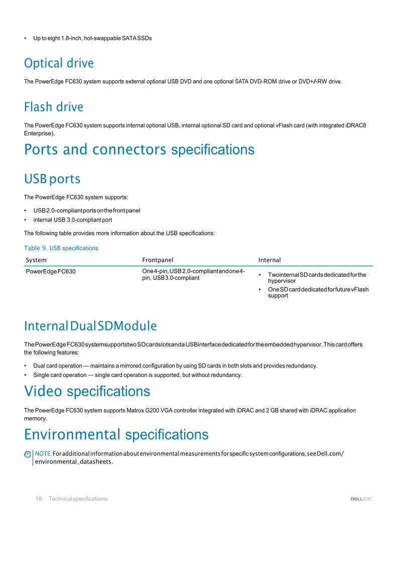
Table 9. USB specifications
System Frontpanel Internal
PowerEdge FC630 One 4-pin, USB 2.0-compliant and one 4- pin, USB 3.0-compliant
• Twointernal SD cards dedicated for the
hypervisor
• One SD card dedicated for future vFlash support
Internal Dual SDModule The PowerEdge FC630 systemsupportstwo SDcardslotsanda USBinterface dedicated for the embedded hypervisor. This card offers the following features:
• Dual card operation — maintains a mirrored configuration by using SD cards in both slots and provides redundancy.
• Single card operation — single card operation is supported, but without redundancy.
Video specifications The PowerEdge FC630 system supports Matrox G200 VGA controller integrated with iDRAC and 2 GB shared with iDRAC application memory.
Environmental specifications NOTE: For additional information about environmental measurements for specific system configurations, see Dell.com/ environmental_datasheets.

Technical specifications 19
Table 10. Temperature specifications
Temperature Specifications
Storage –40°C to 65°C (–40°F to 149°F)
Continuous operation (for altitude less than 950 m or 3117 ft) 10°C to 35°C (50°F to 95°F) with no direct sunlight on the equipment.
Fresh air For information about fresh air, see Expanded Operating Temperature section.
Maximum temperature gradient (operating and storage) 20°C/h (36°F/h)
Table 11. Relative humidity specifications
Relative humidity Specifications
Storage 5% to 95% RH with 33°C (91°F) maximum dew point. Atmosphere must be noncondensing always.
Operating 10% to 80% Relative Humidity with 29°C (84.2°F) maximum dew point.
Table 12. Maximum vibration specifications
Maximum vibration Specifications
Operating 0.26 Grms at 5 Hz to 350 Hz (all operation orientations).
Storage 1.88 Grms at 10 Hz to 500 Hz for 15 min (all six sides tested).
Table 13. Maximum shock specifications
Maximum shock Specifications
Operating Six consecutivelyrun shock pulses in the positive andnegative x, y, and z axes of 40 G for up to 2.3 ms.
Storage Six consecutively run shock pulses in the positive and negative x, y, and z axes (one pulse on each side of the system) of 71 G for up to 2 ms.
Table 14. Maximum altitude specifications
Maximum altitude Specifications
Operating 3048 m (10,000 ft).
Storage 12,000 m (39,370 ft).
20 Technical specifications
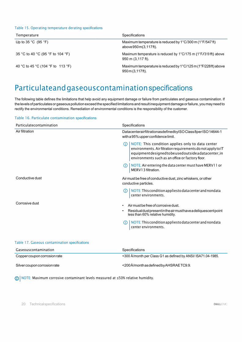
Table 15. Operating temperature derating specifications
Temperature Specifications
Up to 35 °C (95 °F) Maximum temperature is reduced by 1°C/300 m (1°F/547 ft) above 950 m(3,117 ft).
35 °C to 40 °C (95 °F to 104 °F) Maximum temperature is reduced by 1°C/175 m (1°F/319 ft) above 950 m (3,117 ft).
40 °C to 45 °C (104 °F to 113 °F) Maximum temperature is reduced by 1°C/125 m (1°F/228 ft) above 950 m (3,117 ft).
Particulateand gaseouscontamination specifications The following table defines the limitations that help avoid any equipment damage or failure from particulates and gaseous contamination. If the levels of particulates or gaseous pollution exceed the specified limitations and result inequipment damage or failure, you may need to rectify the environmental conditions. Remediation of environmental conditions is the responsibility of the customer.
Table 16. Particulate contamination specifications
Particulatecontamination Specifications
Air filtration DatacenterairfiltrationasdefinedbyISO Class 8per ISO 14644-1 with a 95% upper confidence limit.
NOTE: This condition applies only to data center environments. Air filtration requirements do not apply to IT equipment designed to be used outside a data center, in environments such as an office or factory floor.
NOTE: Air entering the data center must have MERV11 or MERV13 filtration.
Conductive dust Air must be free of conductive dust, zinc whiskers, or other
conductive particles.
NOTE: This condition appliesto data center and nondata center environments.
Corrosive dust
• Air must be free of corrosive dust.
• Residual dust present in the air must have a deliquescent point less than 60% relative humidity.
NOTE: This condition appliesto data center and nondata center environments.
Table 17. Gaseous contamination specifications
Gaseouscontamination Specifications
Copper coupon corrosion rate <300 Å/month per Class G1 as defined by ANSI/ ISA71.04-1985.
Silver coupon corrosion rate <200 Å/month as defined by AHSRAE TC9.9.
NOTE: Maximum corrosive contaminant levels measured at ≤50% relative humidity.
Technical specifications 21
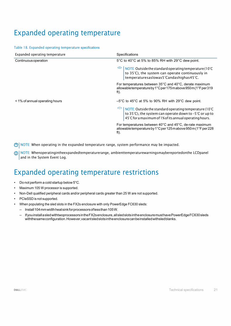
Expanded operating temperature
Table 18. Expanded operating temperature specifications
Expanded operating temperature Specifications
Continuous operation 5°C to 40°C at 5% to 85% RH with 29°C dew point.
NOTE: Outside the standard operating temperature (10°C to 35°C), the system can operate continuously in temperaturesaslowas5°Candashighas45°C.
For temperatures between 35°C and 40°C, derate maximum allowable temperature by 1°C per 175 m above 950 m (1°F per 319 ft).
< 1% of annual operating hours –5°C to 45°C at 5% to 90% RH with 29°C dew point.
NOTE: Outside the standard operating temperature (10°C to 35°C), the system can operate down to –5°C or up to 45°C for a maximum of 1% of its annual operating hours.
For temperatures between 40°C and 45°C, de-rate maximum allowable temperature by 1°C per 125 m above 950 m (1°F per 228 ft).
NOTE: When operating in the expanded temperature range, system performance may be impacted.
NOTE: Whenoperatingintheexpandedtemperaturerange, ambienttemperaturewarningsmaybereportedonthe LCDpanel and in the System Event Log.
Expanded operating temperature restrictions • Do not perform a cold startup below 5°C.
• Maximum 105 W processor is supported.
• Non-Dell qualified peripheral cards and/or peripheral cards greater than 25 W are not supported.
• PCIeSSD is not supported.
• When populating the sled slots in the FX2s enclosure with only PowerEdge FC630 sleds:
– Install 104 mm width heat sink for processors of less than 105 W.
– If you install a sled withtwoprocessors in the FX2s enclosure, all sled slots inthe enclosure must have PowerEdge FC630 sleds withthe same configuration. However,vacant sled slots inthe enclosure can be installed withsled blanks.
22 Initial system setup and configuration
4
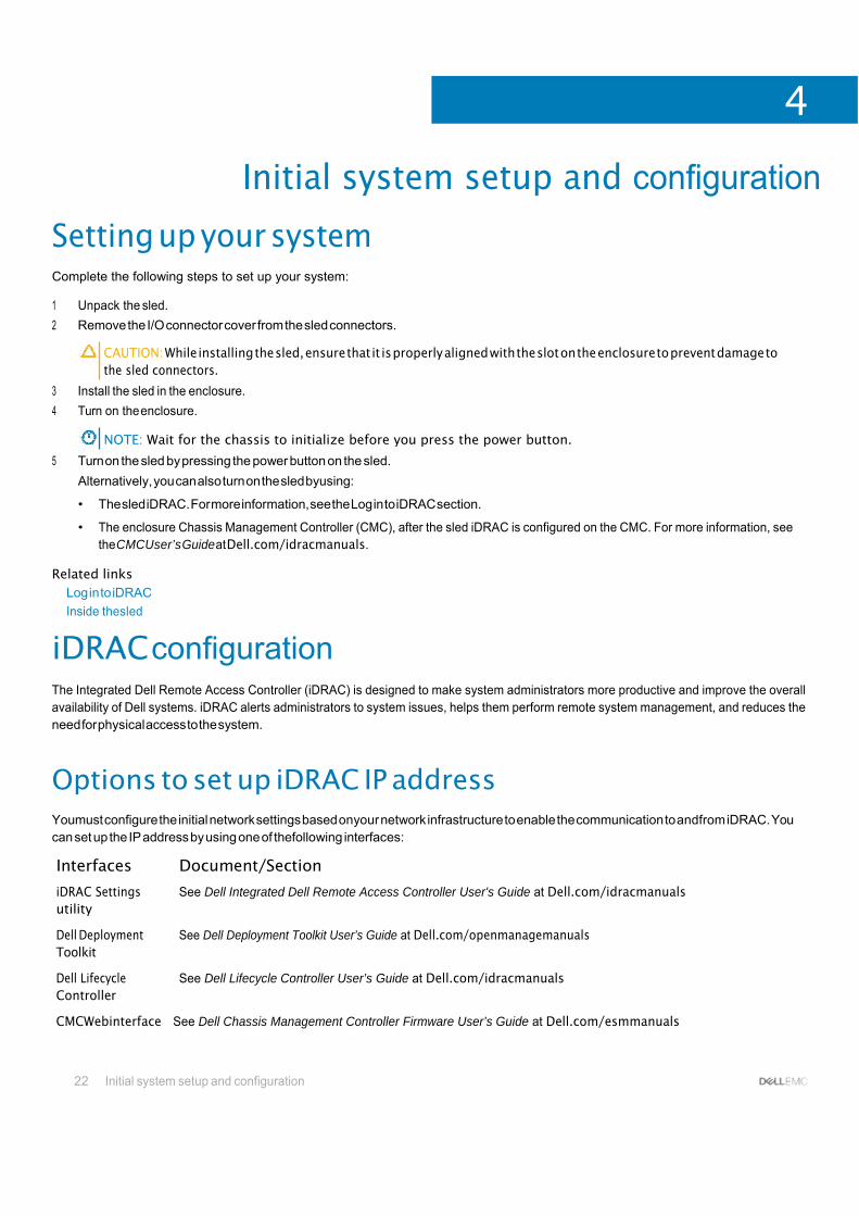
Initial system setup and configuration
Setting up your system Complete the following steps to set up your system:
1 Unpack the sled.
2 Remove the I/O connector cover from the sled connectors.
CAUTION: While installing the sled, ensure that it is properly aligned with the slot on the enclosure to prevent damage to the sled connectors.
3 Install the sled in the enclosure.
4 Turn on the enclosure.
NOTE: Wait for the chassis to initialize before you press the power button.
5 Turn on the sled by pressing the power button on the sled.
Alternatively, you can also turn on the sled byusing:
• The sled iDRAC. For more information, see the Log in to iDRAC section.
• The enclosure Chassis Management Controller (CMC), after the sled iDRAC is configured on the CMC. For more information, see the CMCUser’s Guide at Dell.com/idracmanuals.
Related links Log in to iDRAC
Inside thesled
iDRAC configuration The Integrated Dell Remote Access Controller (iDRAC) is designed to make system administrators more productive and improve the overall availability of Dell systems. iDRAC alerts administrators to system issues, helps them perform remote system management, and reduces the need for physical access to the system.
Options to set up iDRAC IP address Youmust configure the initial network settings based onyour network infrastructure to enable the communication to andfrom iDRAC. You can set up the IP address by using one of thefollowing interfaces:
Interfaces Document/Section
iDRAC Settings utility
Dell Deployment Toolkit
Dell Lifecycle Controller
See Dell Integrated Dell Remote Access Controller User's Guide at Dell.com/idracmanuals
See Dell Deployment Toolkit User’s Guide at Dell.com/openmanagemanuals
See Dell Lifecycle Controller User’s Guide at Dell.com/idracmanuals
CMCWebinterface See Dell Chassis Management Controller Firmware User’s Guide at Dell.com/esmmanuals

Initial system setup and configuration 23
Youmust usethe default iDRAC IP address 192.168.0.120to configuretheinitialnetworksettings, including setting up DHCP ora static IP foriDRAC.
NOTE: Toaccess iDRAC, ensure that you install the iDRAC port card or connect the network cable to the Ethernet connector 1 onthesystemboard.
NOTE: Ensure that you change the default user name and password after setting up the iDRAC IP address.
Log in to iDRAC
You can log in to iDRAC as:
• iDRAC user
• Microsoft ActiveDirectoryuser
• Lightweight Directory Access Protocol (LDAP) user
The default user name and password are root and calvin. You can also log in by using Single Sign-On or Smart Card.
NOTE: You must have iDRAC credentials to log in to iDRAC.
For more information about logging in to iDRAC and iDRAC licenses, see the Integrated Dell Remote Access Controller User's Guide at Dell.com/idracmanuals.
Options to install the operating system If the system is shipped without an operating system, install the supported operating system by using one of the following resources:
Table 19. Resources to install the operating system
Resources Location
Dell Systems Management Tools and Documentation media Dell.com/operatingsystemmanuals
Dell Lifecycle Controller Dell.com/idracmanuals
Dell OpenManage Deployment Toolkit Dell.com/openmanagemanuals
Dell certified VMware ESXi Dell.com/virtualizationsolutions
Supported operating systems on Dell PowerEdge systems Dell.com/ossupport
Installationand How-tovideosforsupportedoperatingsystems on Dell PowerEdge systems
Supported Operating Systems for Dell PowerEdge Systems
Methods to download firmware and drivers You can download the firmware and drivers by using the following methods:
Table 20. Firmware and drivers
Methods Location
From the Dell Support site Dell.com/support/home
Using Dell Remote Access Controller Lifecycle Controller (iDRAC with LC)
Dell.com/idracmanuals
Using Dell Repository Manager (DRM) Dell.com/openmanagemanuals

24 Initial system setup and configuration
Methods Location
Using Dell OpenManage Essentials (OME) Dell.com/openmanagemanuals
Using Dell Server Update Utility (SUU) Dell.com/openmanagemanuals
Using Dell OpenManage DeploymentToolkit (DTK) Dell.com/openmanagemanuals
Downloading the drivers and firmware
Dell recommends that you download and install the latest BIOS, drivers, and systems management firmware on your system. Ensure that you clear the web browser cache before downloading the drivers and firmware.
1 Go to Dell.com/support/drivers.
2 Under the Drivers & Downloads section, type the Service Tagof yoursystem in the Service Tagor Express Service Code box.
NOTE: If you do not have the Service Tag, select Detect My Product to allow the system to automatically detect your Service Tag, or under General support, navigateto your product.
3 Click Drivers& Downloads.
The drivers that are applicable to your selection are displayed.
4 Download the drivers you need to a USB drive, CD, or DVD.

Pre-operating system management applications 25
5
Pre-operating system management applications You can manage basic settings and features of a system without booting to the operating system by using the system firmware.
Options to manage the pre-operatingsystem applications Your system has the following options to manage the pre-operating system applications:
• System Setup
• Boot Manager
• Dell Lifecycle Controller
• Preboot Execution Environment (PXE)
Related links System Setup
Boot Manager
Dell Lifecycle Controller
PXE boot
System Setup By using the System Setup screen, you can configure the BIOS settings, iDRAC settings, and device settings of your system.
NOTE: Help text for the selected field is displayed in the graphical browser by default. Toview the help text in the text browser, press F1.
You can access system setup by using two methods:
• Standard graphical browser—The browser is enabled by default.
• Text browser—The browser is enabled by using Console Redirection.
Related links System Setup details
Viewing System Setup
Viewing SystemSetup To view the System Setup screen, perform the following steps:
1 Turnon, or restart your system.
2 Press F2 immediately after you see the following message:
F2 = System Setup
NOTE: If your operating system begins to load before you press F2, wait for the system to finish booting, and then restart your systemandtryagain.

26 Pre-operating system management applications
Related links System Setup
System Setup details
System BIOS
iDRAC Settings utility
Device Settings
System Setupdetails The System Setup Main Menu screen details are explained as follows:
Option Description
System BIOS Enables you to configure BIOS settings.
iDRAC Settings Enables you to configure iDRAC settings.
The iDRAC settings utility is an interface to set up and configure the iDRAC parameters by using UEFI (Unified Extensible Firmware Interface). You can enable or disable various iDRAC parameters by using the iDRAC settings utility. For more information about this utility, see Integrated Dell Remote Access Controller User’s Guide at Dell.com/idracmanuals.
Device Settings Enables you to configure device settings.
Related links System Setup
Viewing System Setup
System BIOS You can use the System BIOS screen to edit specific functions such as boot order, system password, setup password, set the RAID mode, and enable or disable USB ports. Related links
System BIOS Settings details
Boot Settings
Network Settings
System Security
System Information
Memory Settings
Processor Settings
SATA Settings
Integrated Devices
Serial Communication
System Profile Settings
Miscellaneous Settings
iDRAC Settings utility
Device Settings
Viewing System BIOS

Pre-operating system management applications 27
Viewing System BIOS
To view the System BIOS screen, perform the following steps:
1 Turnon, or restart your system.
2 Press F2 immediately after you see the following message:
F2 = System Setup
NOTE: If your operating system begins to load before you press F2, wait for the system to finish booting, and then restart your systemandtryagain.
3 Onthe System Setup Main Menu screen, click System BIOS.
Related links System BIOS
System BIOS Settings details
System BIOS Settings details
The System BIOS Settings screen details are explained as follows:
Option Description
System Information Specifies information about the system such as the system model name, BIOS version, and Service Tag.
Memory Settings Specifies information and options related to the installed memory.
Processor Settings Specifies information and options related to the processor such as speed and cache size.
SATA Settings Specifies options to enable or disable the integrated SATA controller and ports.
Boot Settings Specifies options to specify the boot mode (BIOS or UEFI). Enables you to modify UEFI and BIOS boot settings.
Network Settings Specifies options to change the network settings.
Integrated Devices Specifies options to manage integrated device controllers and ports and specify related features and options.
Serial Communication
System Profile Settings
Specifies options to manage the serial ports and specify related features and options.
Specifies options to change the processor power management settings, memory frequency, and so on.
System Security Specifies options to configure the system security settings, such as system password, setup password, Trusted Platform Module (TPM) security. It also manages the power and NMI buttons on the system.
Miscellaneous Settings
Related links System BIOS
Specifies options to change the system date, time, and so on.
Viewing System BIOS
Boot Settings
You can use the Boot Settings screen to set the boot mode to either BIOS or UEFI. It also enables you to specify the boot order.

28 Pre-operating system management applications
Related links Boot Settings details
System BIOS
Viewing Boot Settings
Choosing the system boot mode
Changing the boot order
Viewing Boot Settings
To view the Boot Settings screen, perform the following steps:
1 Turnon, or restart your system.
2 Press F2 immediately after you see the following message:
F2 = System Setup
NOTE: If your operating system begins to load before you press F2, wait for the system to finish booting, and then restart your systemandtryagain.
3 Onthe System Setup Main Menu screen, click System BIOS.
4 Onthe System BIOS screen, click Boot Settings.
Related links Boot Settings
Boot Settings details Choosing
the system boot mode
Changing the boot order
Boot Settings details
The Boot Settings screen details are explained as follows:
Option Description
Boot Mode Enables you to set the boot mode of the system.
CAUTION: Switching the boot mode may prevent the system from booting if the operating system is not installed in the same boot mode.
If the operating system supports UEFI, you can set this option to UEFI. Setting this field to BIOS allows compatibility with non-UEFI operating systems. This option is set to BIOS by default.
NOTE: Setting this field to UEFI disablesthe BIOS Boot Settings menu. Setting this field to BIOS disables the UEFI Boot Settings menu.
Boot Sequence Retry
Enables or disables the Boot Sequence Retry feature. If this option is set to Enabled and the system fails to boot, the system reattempts the boot sequence after 30 seconds. This option is set to Enabled by default.
Hard-Disk Failover Specifies the hard drive that is booted in the event of a hard drive failure. The devices are selected in the Hard- Disk Drive Sequence on the Boot Option Setting menu. When this option is set to Disabled, only the first hard drive in the list is attempted to boot. When this option is set to Enabled, all hard drives are attempted to boot in the order selected inthe Hard-Disk Drive Sequence. This option is not enabledfor UEFI Boot Mode.
Boot Option Settings
Related links Boot Settings
Configures the boot sequence and the boot devices.
Viewing Boot Settings
Choosing the system boot mode
Changing the boot order

Pre-operating system management applications 29
Choosing the system boot mode
System Setup enables you to specify one of the following boot modes for installing your operating system:
• BIOS boot mode (the default) is the standard BIOS-level boot interface.
• Unified Extensible Firmware Interface (UEFI) boot mode is an enhanced 64-bit boot interface. If you have configured your system to boot to UEFI mode, it replaces thesystem BIOS.
1 From the System Setup Main Menu, click Boot Settings, and select Boot Mode.
2 Select the boot mode you want the system to boot into.
CAUTION: Switching the boot mode may prevent the system from booting if the operating system is not installed in the same boot mode.
3 After the system boots in the specified boot mode, proceed to install your operating system from that mode.
NOTE: Operating systems must be UEFI-compatible to be installed from the UEFI boot mode. DOS and 32-bit operating systems do not support UEFI and can only be installed from the BIOS boot mode.
NOTE: For the latest information about supported operating systems, go to Dell.com/ossupport.
Related links Boot Settings
Boot Settings details
Viewing Boot Settings
Changing the boot order
You may have to change the boot order if you want to boot from a USB key or an optical drive. The following instructions may vary if you have selected BIOS for Boot Mode.
1 Onthe System Setup Main Menu screen, click System BIOS > Boot Settings.
2 Click Boot Option Settings > Boot Sequence.
3 Use the arrow keys to select a boot device, and use the plus (+) and minus (-) sign keys to move the device down or up in the order.
4 Click Exit, and then click Yes to save the settings on exit.
Related links Boot Settings
Boot Settings details
Viewing Boot Settings
Network Settings
Youcan use the Network Settings screen tomodify PXE device settings. The network settings option is available onlyin the UEFI mode.
NOTE: The BIOSdoesnotcontrolnetworksettingsinthe BIOSmode.Forthe BIOSbootmode,theoptional Boot ROMofthe network controllers handles the network settings.
Related links Network Settings screen details
System BIOS
Viewing Network Settings

30 Pre-operating system management applications
Viewing Network Settings
To view the Network Settings screen, perform the following steps:
1 Turnon, or restart your system.
2 Press F2 immediately after you see the following message:
F2 = System Setup
NOTE: If your operating system begins to load before you press F2, wait for the system to finish booting, and then restart your systemandtryagain.
3 Onthe System Setup Main Menu screen, click System BIOS.
4 Onthe SystemBIOS screen, click Network Settings.
Related links Network Settings
Network Settings screen details
Network Settings screen details
The Network Settings screen details are explained as follows:
Option Description
PXE Device n (n = 1 to4)
PXE Device n Settings(n= 1 to 4)
Related links Network Settings
Enables or disables the device. When enabled, a UEFI boot option is created for the device.
Enables you to control the configuration of the PXE device.
Viewing Network Settings
System Security
Youcan use the SystemSecurity screen to perform specific functions such as setting the system password, setup password and disabling the powerbutton. Related links
System Security Settings details
Operating with a setup password enabled
System BIOS
Viewing System Security
Creating a system and setup password
Using your system password to secure your system
Deleting or changing system and setup password
Viewing SystemSecurity
To view the System Security screen, perform the following steps:
1 Turnon, or restart your system.
2 Press F2 immediately after you see the following message:
F2 = System Setup

Pre-operating system management applications 35
NOTE: If your operating system begins to load before you press F2, wait for the system to finish booting, and then restart your systemandtryagain.
3 Onthe System Setup Main Menu screen, click System BIOS.
4 Onthe System BIOS screen, click System Security.
Related links System Security
System Security Settings details
System Security Settings details
The System Security Settings screen details are explained as follows:
Option Description
Intel AES-NI Improves the speed of applications by performing encryption and decryption by using the Advanced Encryption Standard Instruction Set (AES-NI). This option isset to Enabledbydefault.
System Password Sets the system password. This option is set to Enabled by default and is read-only if the password jumper is not installed in thesystem.
Setup Password Sets the setup password. This option is read-only if the password jumper is not installed in thesystem.
Password Status Locks the system password. This option is set to Unlockedbydefault.
TPM Security NOTE: The TPM menu is available only when the TPM module is installed.
Enables you to control the reporting mode of the TPM. The TPM Security option is set to Off by default. You can only modify the TPM Status, TPM Activation, and Intel TXT fields if the TPM Status field is set to either On with Pre-boot Measurements or On without Pre-boot Measurements.
TPMInformation Changes the operational state of the TPM. This option is set to No Change by default.
TPM Status Specifies the TPM status.
TPM Command CAUTION: Clearing the TPM results inthe loss ofall keys inthe TPM. The loss of TPMkeys may affect booting to the operating system.
Clears all the contents of the TPM. The TPM Clear option is set to No by default.
Intel TXT Enablesordisablesthe IntelTrustedExecution Technology(TXT) option.Toenable the IntelTXToption, virtualization technology and TPM Security must be enabled with Pre-boot measurements. This option is set to Off by default.
Power Button Enables or disables the power button on the front of the system. This option is set to Enabled by default.
AC Power Recovery Sets how the system behaves after AC power is restored to the system. This option is set to Last by default.
Secure Boot Enables Secure Boot, where the BIOS authenticates each pre-boot image byusing the certificates in the Secure Boot Policy. Secure Boot is disabled by default.
Secure Boot Policy When Secure Boot policy is set to Standard, the BIOS uses the system manufacturer’s key and certificates to authenticate pre-boot images. When Secure Boot policy is set to Custom, the BIOS uses the user-defined key and certificates. Secure Boot policy is set to Standardbydefault.
Secure Boot Policy Summary
Related links System Security
Specifies the list of certificates and hashes that secure boot uses to authenticate images.
Viewing System Security

32 Pre-operating system management applications
Secure Boot Custom Policy Settings
Secure Boot Custom Policy Settings is displayed only when Secure Boot Policy is set to Custom.
Viewing Secure Boot Custom Policy Settings To view the Secure Boot Custom Policy Settings screen, perform the following steps:
1 Turnon, or restart your system.
2 Press F2 immediately after you see the following message:
F2 = System Setup
NOTE: If your operating system begins to load before you press F2, wait for the system to finish booting, and then restart your systemandtryagain.
3 Onthe System Setup Main Menu screen, click System BIOS.
4 Onthe System BIOS screen, click System Security.
5 On the System Security screen, click Secure Boot Custom Policy Settings.
Secure Boot Custom Policy Settings details The Secure Boot Custom Policy Settings screen details are explained as follows:
Option Description
Platform Key Imports, exports, deletes, or restores the platform key (PK).
Key Exchange Key Database
Authorized Signature Database
Forbidden Signature Database
Enables you to import, export, delete, orrestoreentries in the KeyExchange Key(KEK) Database.
Imports, exports, deletes, or restores entries in the Authorized Signature Database (db).
Imports, exports, deletes, or restores entries in the Forbidden Signature Database (dbx).
Creatingasystemandsetuppassword
Ensure that the password jumper is enabled. The password jumper enables or disables the system password and setup password features. For more information, see the System board jumper settings section.
NOTE: If thepasswordjumpersettingisdisabled, theexistingsystempasswordand setuppasswordaredeletedand youneed not providethe system password to boot the system.
1 Toenter System Setup, press F2 immediately after turning on or rebooting your system.
2 Onthe System Setup Main Menu screen, click System BIOS > System Security.
3 Onthe System Security screen, verify that Password Status issetto Unlocked.
4 In the System Password field, type your system password, andpress Enter or Tab.
Use the following guidelines to assign the system password:
• A password can have up to 32 characters.
• The password can contain the numbers 0 through 9.
• Only the following special characters are allowed: space, (”), (+),(,), (-), (.), (/), (;), ([), (\), (]), (`).
A message prompts you to reenter the system password.
5 Reenter the system password, and click OK.
6 In the Setup Password field, type your setup password andpress Enter or Tab.
A message prompts you to reenter the setup password.

Pre-operating system management applications 33
7 Reenter the setup password, and click OK.
8 Press Esc to return to the System BIOS screen. Press Esc again.
A message prompts you to save the changes.
NOTE: Password protection does not take effect until the system reboots.
Related links System Security
Usingyoursystempasswordto secureyoursystem
If you have assigned a setup password, the system accepts your setup password as an alternate system password.
1 Turn on or reboot your system.
2 Type the system password and press Enter.
When Password Status is set to Locked, type the system password and press Enter when prompted at reboot.
NOTE: If an incorrect system password is typed, the system displays a message and prompts you to reenter your password. You have three attempts to type the correct password. After the third unsuccessful attempt, the system displays an error message that the system has stopped functioning and must beturned off. Even after you turnoffandrestart the system, theerror message is displayed until the correct password is entered.
Related links System Security
Deleting or changing system and setup password
NOTE: You cannot delete or change an existing system or setup password if the Password Status is set to Locked.
1 Toenter System Setup, press F2 immediately after turning onorrestarting your system.
2 Onthe System Setup Main Menu screen, click System BIOS > System Security.
3 OntheSystemSecurityscreen, ensure that PasswordStatusis settoUnlocked.
4 In the System Password field, alter ordelete the existing system password, andthen press Enter or Tab.
5 In the Setup Password field, alter or delete the existing setup password, and then press Enter or Tab.
If you change the system andsetup password, amessage prompts you to reenter the new password. If you delete the system and
setuppassword, amessageprompts youtoconfirmthedeletion.
6 Press Esc to return to the System BIOS screen. Press Esc again, and a message prompts you to save the changes.
Related links System Security
Operating with a setup password enabled
If Setup Password is setto Enabled, type the correct setup password before modifying the system setup options.
If you do not type the correct password in three attempts, the system displays the following message:
Invalid Password! Number of unsuccessful password attempts: <x> System Halted! Must power down.
Even after you turn off and restart the system, the error message is displayed until the correct password is typed. The following options are exceptions:
• If System Password is not set to Enabled and is not locked through the Password Status option, you can assign asystem password. For more information, see the System Security Settings screen section.
• You cannot disable or change an existing system password.

34 Pre-operating system management applications
NOTE: Youcan use the password status option with the setup password option to protect the system password from unauthorized changes.
Related links System Security
System Information
You can use the System Information screen to view system properties such as Service Tag, system model name, and the BIOS version. Related links
System Information details
System BIOS
Viewing System Information
Viewing System Information
To view the System Information screen, perform the following steps:
1 Turnon, or restart your system.
2 Press F2 immediately after you see the following message:
F2 = System Setup
NOTE: If your operating system begins to load before you press F2, wait for the system to finish booting, and then restart your systemandtryagain.
3 Onthe System Setup Main Menu screen, click System BIOS.
4 On the System BIOS screen, click System Information.
Related links System Information
System Information details
The System Information screen details are explained as follows:
Option Description
System Model Name
System BIOS Version
System Management Engine Version
Specifies the system model name.
Specifies the BIOS version installed on the system.
Specifies the current version of the Management Engine firmware.
System Service Tag Specifies the system Service Tag.
System Manufacturer
System Manufacturer Contact Information
System CPLD Version
Specifies the name of the system manufacturer.
Specifies the contact information of the system manufacturer.
Specifies the current version of the system complex programmable logic device (CPLD) firmware.

Pre-operating system management applications 35
Option Description
UEFI Compliance Version
Related links System Information
Specifies the UEFI compliance level of the system firmware.
System Information details
Viewing System Information
Memory Settings
Youcan use the Memory Settings screen to view all the memory settings and enable or disable specific memory functions, such assystem memory testing and node interleaving. Related links
Memory Settings details
System BIOS
Viewing Memory Settings
Viewing Memory Settings
To view the Memory Settings screen, perform the following steps:
1 Turnon, or restart your system.
2 Press F2 immediately after you see the following message:
F2 = System Setup
NOTE: If your operating system begins to load before you press F2, wait for the system to finish booting, and then restart your systemandtryagain.
3 Onthe System Setup Main Menu screen, click System BIOS.
4 Onthe System BIOS screen, click Memory Settings.
Related links Memory Settings
Memory Settings details
Memory Settingsdetails
The Memory Settings screen details are explained as follows:
Option Description
System Memory Size
System Memory Type
System Memory Speed
System Memory Voltage
Specifies the memory size in the system.
Specifies the type of memory installed in the system.
Specifies the system memory speed.
Specifies the system memory voltage.
Video Memory Specifies the amount of video memory.
System Memory Testing
Specifies whether the system memory tests are run during system boot. Options are Enabled and Disabled. This option is set to Disabledbydefault.

36 Pre-operating system management applications
Option Description
Memory Operating Mode
Specifies the memory operating mode. The options available are Optimizer Mode, Advanced ECC Mode, Mirror Mode, Spare Mode, Spare with Advanced ECC Mode, Dell Fault Resilient Mode and Dell NUMA Fault Resilient Mode. This option is set to Optimizer Mode by default.
NOTE: The Memory Operating Mode option can have different default and available options based on the memory configuration of your system.
NOTE: The Dell Fault Resilient Mode option establishes an area of memory that is fault resilient. This mode can be used by an operating system that supports the feature to load critical applications or enables the operating system kernel to maximize system availability.
Node Interleaving Specifies if Non-Uniform Memory architecture (NUMA) is supported. If this field is set to Enabled, memory interleaving is supported if asymmetric memory configuration is installed. If the field is set to Disabled, thesystem supports NUMA (asymmetric) memory configurations. This option is set to Disabled by default.
Snoop Mode Specifies the Snoop Mode options. The Snoop Mode options available are Home Snoop, Early Snoop, and Cluster on Die. This option is set to Early Snoop by default. This field is available onlywhen the Node Interleaving is set to Disabled.
Related links Memory Settings
Viewing Memory Settings
Processor Settings
Youcan use the Processor Settingsscreen to viewthe processor settings, and perform specific functions such as enabling virtualization technology, hardware prefetcher, and logical processor idling. Related links
Processor Settings details
System BIOS
Viewing Processor Settings
Viewing Processor Settings
To view the Processor Settings screen, perform the following steps:
1 Turnon, or restart your system.
2 Press F2 immediately after you see the following message:
F2 = System Setup
NOTE: If your operating system begins to load before you press F2, wait for the system to finish booting, and then restart your systemandtryagain.
3 Onthe System Setup Main Menu screen, click System BIOS.
4 Onthe SystemBIOS screen, click Processor Settings.
Related links Processor Settings
Processor Settings details
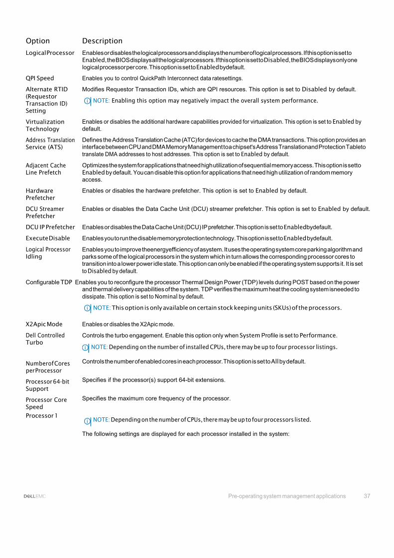
Processor Settingsdetails
The Processor Settings screen details are explained as follows:
Pre-operating system management applications 37
Option Description
Logical Processor Enables or disables the logical processors and displays the number of logical processors. If this option is set to Enabled, the BIOS displays all the logical processors. If this option is set to Disabled, the BIOS displays only one logical processor per core. This option is set to Enabled bydefault.
QPI Speed Enables you to control QuickPath Interconnect data ratesettings.
Alternate RTID (Requestor Transaction ID) Setting
Virtualization Technology
Address Translation Service (ATS)
Adjacent Cache Line Prefetch
Hardware Prefetcher
DCU Streamer Prefetcher
Modifies Requestor Transaction IDs, which are QPI resources. This option is set to Disabled by default.
NOTE: Enabling this option may negatively impact the overall system performance.
Enables or disables the additional hardware capabilities provided for virtualization. This option is set to Enabled by default.
Defines the Address Translation Cache (ATC) for devices to cache the DMA transactions. This option provides an interface between CPU and DMA Memory Management toa chipset's Address Translationand Protection Tableto translate DMA addresses to host addresses. This option is set to Enabled by default.
Optimizes the system for applications that need high utilization of sequential memory access. This option is setto Enabled by default. You can disable this option for applications that need high utilization of random memory access.
Enables or disables the hardware prefetcher. This option is set to Enabled by default.
Enables or disables the Data Cache Unit (DCU) streamer prefetcher. This option is set to Enabled by default.
DCU IP Prefetcher Enables or disables the Data Cache Unit (DCU) IP prefetcher. This option is set to Enabledbydefault.
Execute Disable Enables you to run the disable memoryprotection technology. This option is set to Enabled bydefault.
Logical Processor Idling
Enables you to improve theenergyefficiency of asystem. It uses the operating system core parking algorithm and parks some of the logical processors in the system which in turn allows the corresponding processor cores to transition into a lower power idle state. This option can only be enabled if the operating system supports it. It is set to Disabled by default.
Configurable TDP Enables you to reconfigure the processor Thermal Design Power (TDP) levels during POST based on the power and thermal delivery capabilities of the system. TDP verifies the maximum heat the cooling system isneeded to dissipate. This option is set to Nominal by default.
NOTE: This option is only available on certain stock keeping units (SKUs) of the processors.
X2Apic Mode Enables or disables the X2Apic mode.
Dell Controlled Turbo
Numberof Cores per Processor
Processor 64-bit Support
Processor Core Speed
Controls the turbo engagement. Enable this option only when System Profile is set to Performance.
NOTE: Depending on the number of installed CPUs, there may be up to four processor listings.
Controls the number of enabled cores in each processor. This option is set to All by default.
Specifies if the processor(s) support 64-bit extensions.
Specifies the maximum core frequency of the processor.
Processor 1 NOTE: Depending on the number of CPUs, there may be up to four processors listed.
The following settings are displayed for each processor installed in the system:

38 Pre-operating system management applications
Option Description
Option Description
Family-Model- Stepping
Specifies the family,model, and stepping of the processor as defined by Intel.
Brand Specifies the brand name.
Level 2 Cache Specifies the total L2 cache.
Level 3 Cache Specifies the total L3 cache.
Number of Cores Specifies the number of cores per processor.
Related links
Processor Settings
Viewing Processor Settings
SATA Settings
You can use the SATA Settings screen to view the SATA settings of SATA devices and enable RAID on your system.
Related links SATA Settings details
System BIOS
Viewing SATA Settings
Viewing SATA Settings
To view the SATA Settings screen, perform the following steps:
1 Turnon, or restart your system.
2 Press F2 immediately after you see the following message:
F2 = System Setup
NOTE: If your operating system begins to load before you press F2, wait for the system to finish booting, and then restart your systemandtryagain.
3 Onthe System Setup Main Menu screen, click System BIOS.
4 Onthe System BIOS screen, click SATASettings.
Related links SATA Settings
SATA Settings details
SATA Settingsdetails
The SATA Settings screen details are explained as follows:
Option Description
Embedded SATA Enables the embedded SATAoption to be set to Off, ATA, AHCI, or RAID modes. This option is set to AHCI by default.
Security Freeze Lock
Sends Security Freeze Lock command to the Embedded SATA drives during POST. This option is applicable only for ATA and AHCImodes.
Write Cache Enables or disables the command for Embedded SATA drives during POST.
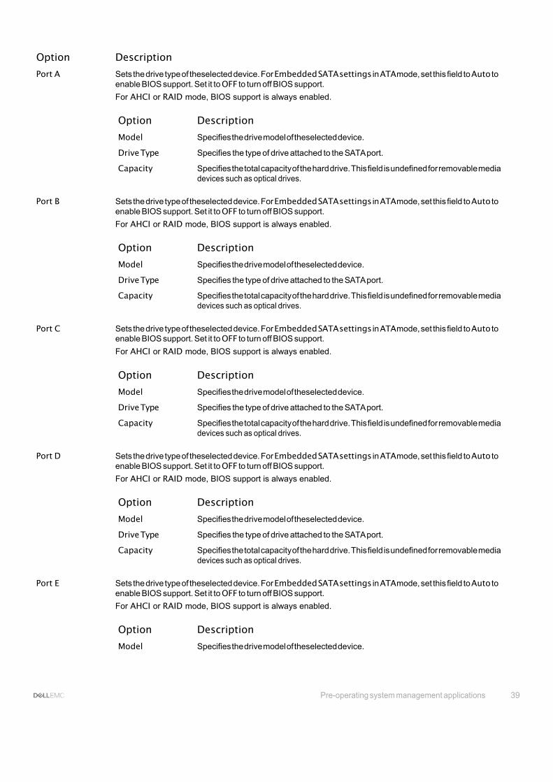
Pre-operating system management applications 39
Option Description
Port A Sets the drive type of theselected device. For Embedded SATA settings in ATA mode, set this field to Auto to enable BIOS support. Set it to OFF to turn off BIOS support.
For AHCI or RAID mode, BIOS support is always enabled.
Option Description
Model Specifies the drive model of theselected device.
Drive Type Specifies the type of drive attached to the SATA port.
Capacity Specifies the total capacity of the hard drive. This field is undefined for removable media devices such as optical drives.
Port B Sets the drive type of theselected device. For Embedded SATA settings in ATA mode, set this field to Auto to
enable BIOS support. Set it to OFF to turn off BIOS support.
For AHCI or RAID mode, BIOS support is always enabled.
Option Description
Model Specifies the drive model of theselected device.
Drive Type Specifies the type of drive attached to the SATA port.
Capacity Specifies the total capacity of the hard drive. This field is undefined for removable media devices such as optical drives.
Port C Sets the drive type of theselected device. For Embedded SATA settings in ATA mode, set this field to Auto to
enable BIOS support. Set it to OFF to turn off BIOS support.
For AHCI or RAID mode, BIOS support is always enabled.
Option Description
Model Specifies the drive model of theselected device.
Drive Type Specifies the type of drive attached to the SATA port.
Capacity Specifies the total capacity of the hard drive. This field is undefined for removable media devices such as optical drives.
Port D Sets the drive type of theselected device. For Embedded SATA settings in ATA mode, set this field to Auto to
enable BIOS support. Set it to OFF to turn off BIOS support.
For AHCI or RAID mode, BIOS support is always enabled.
Option Description
Model Specifies the drive model of theselected device.
Drive Type Specifies the type of drive attached to the SATA port.
Capacity Specifies the total capacity of the hard drive. This field is undefined for removable media devices such as optical drives.
Port E Sets the drive type of theselected device. For Embedded SATA settings in ATA mode, set this field to Auto to
enable BIOS support. Set it to OFF to turn off BIOS support.
For AHCI or RAID mode, BIOS support is always enabled.
Option Description
Model Specifies the drive model of theselected device.

40 Pre-operating system management applications
Option Description
Option Description
Drive Type Specifies the type of drive attached to the SATA port.
Capacity Specifies the total capacity of the hard drive. This field is undefined for removable media devices such as optical drives.
Port F Sets the drive type of theselected device. For Embedded SATA settings in ATA mode, set this field to Auto to
enable BIOS support. Set it to OFF to turn off BIOS support.
For AHCI or RAID mode, BIOS support is always enabled.
Option Description
Model Specifies the drive model of theselected device.
Drive Type Specifies the type of drive attached to the SATA port.
Capacity Specifies the total capacity of the hard drive. This field is undefined for removable media devices such as optical drives.
Port G Sets the drive type of theselected device. For Embedded SATA settings in ATA mode, set this field to Auto to
enable BIOS support. Set it to OFF to turn off BIOS support.
For AHCI or RAID mode, BIOS support is always enabled.
Option Description
Model Specifies the drive model of theselected device.
Drive Type Specifies the type of drive attached to the SATA port.
Capacity Specifies the total capacity of the hard drive. This field is undefined for removable media devices such as optical drives.
Port H Sets the drive type of theselected device. For Embedded SATA settings in ATA mode, set this field to Auto to
enable BIOS support. Set it to OFF to turn off BIOS support.
For AHCI or RAID mode, BIOS support is always enabled.
Option Description
Model Specifies the drive model of theselected device.
Drive Type Specifies the type of drive attached to the SATA port.
Capacity Specifies the total capacity of the hard drive. This field is undefined for removable media devices such as optical drives.
Port I Sets the drive type of theselected device. For Embedded SATA settings in ATA mode, set this field to Auto to
enable BIOS support. Set it to OFF to turn off BIOS support.
For AHCI or RAID mode, BIOS support is always enabled.
Option Description
Model Specifies the drive model of theselected device.
Drive Type Specifies the type of drive attached to the SATA port.
Capacity Specifies the total capacity of the hard drive. This field is undefined for removable media devices such as optical drives.

Pre-operating system management applications 41
Option Description
Port J Sets the drive type of theselected device. For Embedded SATA settings in ATA mode, set this field to Auto to enable BIOS support. Set it to OFF to turn off BIOS support.
For AHCI or RAID mode, BIOS support is always enabled.
Option Description
Model Specifies the drive model of theselected device.
Drive Type Specifies the type of drive attached to the SATA port.
Capacity Specifies the total capacity of the hard drive. This field is undefined for removable media devices such as optical drives.
Related links
SATA Settings
Viewing SATA Settings
Integrated Devices
Youcan use the Integrated Devicesscreen to viewand configure the settings of all integrated devices including the video controller, integrated RAID controller, and the USB ports. Related links
Integrated Devices details
System BIOS
Viewing Integrated Devices
Viewing Integrated Devices
To view the Integrated Devices screen, perform the following steps:
1 Turnon, or restart your system.
2 Press F2 immediately after you see the following message:
F2 = System Setup
NOTE: If your operating system begins to load before you press F2, wait for the system to finish booting, and then restart your systemandtryagain.
3 Onthe System Setup Main Menu screen, click System BIOS.
4 On the System BIOS screen, click Integrated Devices.
Related links Integrated Devices
Integrated Devices details
Integrated Devices details
The Integrated Devices screen details are explained as follows:
Option Description
USB 3.0 Setting Enables or disables the USB 3.0support. Enable this option only if youroperating system supports USB 3.0.If you disablethisoption, devicesoperateat USB2.0speed. USB3.0isenabledbydefault.
User Accessible USB Ports
Enables or disables the USB ports. Selecting Only Back Ports On disables the front USB ports, selecting All Ports Off disables all USB ports. The USB keyboard and mouse operate during boot process in certain operating systems. After the boot process is complete, the USB keyboard and mouse do not work if the ports are disabled.

42 Pre-operating system management applications
Option Description NOTE: Selecting Only Back Ports On and All Ports Off disables the USB management port and also restricts access to iDRAC features.
Internal USB Port Enables or disables the internal USB port. This option is set to Enabled by default.
Integrated RAID Controller
Integrated Network Card 1
Enables or disables the integrated RAID controller. This option is set to Enabled by default.
Enables or disables the integrated network card.
I/OAT DMA Engine Enables or disables the I/OAT option. Enable only if the hardware and software support the feature.
Embedded Video Controller
SR-IOV Global Enable
OS Watchdog Timer
Memory Mapped I/O above 4 GB
Mezzanine Slot Disablement
Related links Integrated Devices
Enables or disables the Embedded Video Controller option. This option is set to Enabled by default.
Enables or disables the BIOS configuration of Single Root I/O Virtualization (SR-IOV) devices. This option is set to Disabled by default.
If your system stops responding, this watchdog timer aids in the recovery of your operating system. When this option is set to Enabled, the operating system initializes the timer. When this option is set to Disabled (the default), the timer does not have any effect on the system.
Enables or disables the support for PCIe devices that need large amounts of memory. This option is set to Enabled by default.
The Slot Disablement feature controls the configuration of mezzanine cards installed in the specified slots. Only mezzanine card slots that are present on your system are available for control.
Viewing Integrated Devices
Serial Communication
You can use the Serial Communication screen to view the properties of the serial communication port. Related links
Serial Communication details
System BIOS
Viewing Serial Communication
Viewing Serial Communication
To view the Serial Communication screen, perform the following steps:
1 Turnon, or restart your system.
2 Press F2 immediately after you see the following message:
F2 = System Setup
NOTE: If your operating system begins to load before you press F2, wait for the system to finish booting, and then restart your systemandtryagain.
3 Onthe System Setup Main Menu screen, click System BIOS.
4 On the System BIOS screen, click Serial Communication.
Related links Serial Communication
Serial Communication details

Pre-operating system management applications 43
Serial Communication details
The Serial Communication screen details are explained as follows:
Option Description
Serial Communication
Enables the COM port or Console Redirection options. This option is set to Off by default.
Serial Port Address Enables you to set the port address for serial devices. This option is set to Serial Device 1=COM2, Serial Device 2=COM1by default.
NOTE: You can use only Serial Device 2 for the Serial Over LAN (SOL) feature. Touse console redirection by SOL, configure the same port address for console redirection and the serial device.
External Serial Connector
Enables you to associate the External Serial Connector to Serial Device 1.
Failsafe Baud Rate Specifies the failsafe baud ratefor console redirection. The BIOS attempts to determine the baud rate automatically. This failsafe baud rateis used onlyif the attempt fails, and the value must not be changed. This option is set to 115200 by default.
Remote Terminal Type
Redirection After Boot
Related links
Sets the remote console terminal type. This option is set to VT 100/VT 220 by default.
Enables or disables the BIOS console redirection when the operating system is loaded. This option is set to Enabled by default.
Serial Communication
Viewing Serial Communication
System Profile Settings
You can use the System Profile Settings screen to enable specific system performance settings such as power management. Related links
System Profile Settings details
System BIOS
Viewing System Profile Settings
Viewing System Profile Settings
To view the System Profile Settings screen, perform the following steps:
1 Turnon, or restart your system.
2 Press F2 immediately after you see the following message:
F2 = System Setup
NOTE: If your operating system begins to load before you press F2, wait for the system to finish booting, and then restart your systemandtryagain.
3 Onthe System Setup Main Menu screen, click System BIOS.
4 On the System BIOS screen, click System Profile Settings.
Related links System Profile Settings
System Profile Settings details

44 Pre-operating system management applications
System Profile Settings details
The System Profile Settings screen details are explained as follows:
Option Description
System Profile Sets the system profile. If you set the System Profile option to a mode other than Custom, the BIOS automatically sets the rest of the options. You can only change the rest of the options if the mode is set to Custom. This option issetto Performance Per Watt Optimized (DAPC) bydefault. DAPCis Dell Active Power Controller.
NOTE: All the parameters on the system profile setting screen are available only when the System Profile optionissetto Custom.
CPU Power Management
Sets the CPU power management. This option is set to System DBPM (DAPC) by default. DBPM is Demand- Based Power Management.
Memory Frequency Sets the speed of the system memory. You can select Maximum Performance, Maximum Reliability, or a specific speed.
Turbo Boost Enables or disables the processor to operate in the turbo boost mode. This option is set to Enabledbydefault.
Energy Efficient Turbo
Enables or disables the Energy Efficient Turbo option.
Energy Efficient Turbo (EET) is amode of operation where a processor’s core frequency is adjusted to be within
the turbo range based on workload.
C1E Enables or disables the processor to switch to aminimum performance state whenit is idle. This option is set to Enabled by default.
C States Enablesordisablestheprocessortooperatein allavailablepowerstates.Thisoptionissetto Enabledbydefault.
Collaborative CPU Performance Control
Memory Patrol Scrub
Memory Refresh Rate
Enables or disables the CPU power management option. When set to Enabled, the CPU power management is controlled bythe OS DBPM and the System DBPM (DAPC). This option is set to Disabled bydefault.
Sets thememory patrol scrub frequency. This option is set to Standard by default.
Sets the memory refresh rateto either 1x or 2x. This option is set to 1x by default.
Uncore Frequency Enables you to select the Processor Uncore Frequency option.
Dynamic mode enables the processor to optimize power resources across the cores and uncore during runtime. The optimization of the uncore frequency to either save power or optimize performance is influenced by the setting of the Energy Efficiency Policy option.
Energy Efficient Policy
Enables you to select the Energy Efficient Policy option.
The CPU uses the setting to manipulate the internal behavior of the processor and determines whether to target
higher performance or better power savings.
Number of Turbo Boot Enabled Cores for Processor 1
NOTE: If there are two processors installed in the system, you see an entry for Number of Turbo Boost Enabled Cores for Processor 2.
Controls the number of turbo boost enabled cores for processor 1. The maximum number of cores isenabled by default.
Monitor/Mwait Enables the Monitor/Mwait instructions in the processor. This option is set to Enabled for all system profiles, except Customby default.
NOTE: This option can be disabled only if the C States option in the Custom mode is set to disabled.

Pre-operating system management applications 45
Option Description NOTE: When C States is set to Enabled in the Custom mode, changing the Monitor/Mwait setting does notimpactthesystempowerorperformance.
Related links
System Profile Settings
Viewing System Profile Settings
Miscellaneous Settings
Youcan use the Miscellaneous Settings screen to perform specific functions such as updating the asset tagandchanging the system date and time. Related links
Miscellaneous Settings details
System BIOS
Viewing Miscellaneous Settings
Viewing Miscellaneous Settings
To view the Miscellaneous Settings screen, perform the following steps:
1 Turnon, or restart your system.
2 Press F2 immediately after you see the following message:
F2 = System Setup
NOTE: If your operating system begins to load before you press F2, wait for the system to finish booting, and then restart your systemandtryagain.
3 Onthe System Setup Main Menu screen, click System BIOS.
4 On the System BIOS screen, click Miscellaneous Settings.
Related links Miscellaneous Settings
Miscellaneous Settings details
Miscellaneous Settings details
The Miscellaneous Settings screen details are explained as follows:
Option Description
System Time Enables you to set the time on the system.
System Date Enables you to set the date on the system.
Asset Tag Specifies the asset tag and enables you to modify it for security and tracking purposes.
Keyboard NumLock Enables you to set whether the system boots with the NumLock enabled or disabled. This option is set to Onby default.
NOTE: This option does not apply to 84-key keyboards.
F1/F2 Prompt on Error
Load Legacy Video Option ROM
Enables or disables the F1/F2 prompt on error. This option is set to Enabledby default. The F1/F2 prompt also includeskeyboarderrors.
Enables you to determine whether the system BIOS loads the legacy video (INT 10H) option ROM from the video controller. Selecting Enabled in the operating system does not support UEFI video output standards. This field is available only for UEFI boot mode. You cannot set the option to Enabledif UEFISecure Boot mode is enabled.
46 Pre-operating system management applications
Option Description
In-System Characterization
Enables or disables In-System Characterization. This option is set to Disabled by default. The two other options are Enabled and Enabled - No Reboot.
NOTE: The default setting for In-System Characterization is subject to change in future BIOS releases.
When enabled, In-System Characterization (ISC) executes during POST upon detecting relevant change(s) in system configuration to optimize system power and performance. ISC takes about 20 seconds to execute, and system reset is needed for ISC results to be applied. The Enabled - No Reboot option executes ISC andcontinues without applying ISC results until the next time system reset occurs. The Enabled option executes ISC and forces an immediate system reset so that ISC results can be applied. It takes the system longer to be ready due to the forced system reset. When disabled, ISC does not execute.
Related links Miscellaneous Settings
Viewing Miscellaneous Settings
iDRAC Settings utility The iDRAC settings utilityis an interface to set up and configure the iDRAC parameters byusing UEFI. Youcan enable or disable various iDRAC parameters by using the iDRAC settings utility.
NOTE: Accessing some of the features on the iDRAC settings utility needs the iDRAC Enterprise License upgrade.
For more information about using iDRAC, see Dell Integrated Dell Remote Access Controller User's Guide at Dell.com/idracmanuals. Related links
Device Settings
System BIOS
Entering the iDRAC Settings utility
Changing the thermal settings
Entering the iDRAC Settings utility
1 Turn on or restart the managed system.
2 Press F2 during Power-on Self-test (POST).
3 OntheSystemSetupMain Menupage, click iDRACSettings.
The iDRAC Settings screen is displayed.
Related links iDRAC Settings utility
Changing the thermal settings
The iDRAC settings utility enables you to select and customize the thermal control settings for your system.
1 Click iDRAC Settings > Thermal.
2 Under SYSTEM THERMAL PROFILE > Thermal Profile, select one of the following options:
• Default Thermal Profile Settings
• Maximum Performance (Performance Optimized)
• Minimum Power (Performance per WattOptimized)
3 Under USERCOOLINGOPTIONS, setthe Fan Speed Offset, Minimum Fan Speed, and Custom Minimum Fan Speed.

Pre-operating system management applications 47
4 Click Back > Finish > Yes.
Related links iDRAC Settings utility
Device Settings Device Settings enables you to configure device parameters.
Related links System BIOS
Dell Lifecycle Controller Dell Lifecycle Controller (LC) provides advanced embedded systems management capabilities including system deployment, configuration, update, maintenance, and diagnosis. LC is delivered as part of the iDRAC out-of-band solution and Dell system embedded Unified Extensible Firmware Interface (UEFI) applications. Related links
Embedded system management
Embedded system management The Dell Lifecycle Controller provides advanced embedded systems management throughout the system’s lifecycle. The Dell Lifecycle Controller can bestarted during the boot sequence and can function independently of the operating system.
NOTE: Certain platform configurations may not support the full set of features provided by the Dell Lifecycle Controller.
For more information about setting up the Dell Lifecycle Controller, configuring hardware and firmware, and deploying the operating system, see the Dell Lifecycle Controller documentation at Dell.com/idracmanuals.
Related links
Dell Lifecycle Controller
Boot Manager The Boot Manager screen enables you to select boot options and diagnostic utilities. Related links
Boot Manager main menu
System BIOS
Viewing Boot Manager
Viewing Boot Manager To enter Boot Manager:
1 Turnon, or restart your system.
2 Press F11 when you see the following message:
F11 = Boot Manager
If your operating system begins to load before youpress F11, allow the system to complete the booting, and then restart your system and try again.

48 Pre-operating system management applications
Related links Boot Manager
Boot Manager main menu
Boot Managermainmenu Menu item Description
Continue Normal Boot
One-shot Boot Menu
Launch System Setup
Launch Lifecycle Controller
The system attempts to boot to devices starting with the first item in the boot order. If the boot attempt fails, the system continues with the next item in the boot order until the boot is successful or no more boot options are found.
Enables you to access boot menu, where you can select a one-time boot device to boot from.
Enables you to access System Setup.
Exits the Boot Manager and invokes the Dell Lifecycle Controller program.
System Utilities Enables you to launch System Utilities menu such as System Diagnostics and UEFI shell.
Related links Boot Manager
Viewing Boot Manager
One-shot BIOS boot menu
One-shot BIOS boot menu enables you to select a one-shot boot device to boot from the following options:
• Launch Diagnostics
• BIOS Update File Explorer
• Reboot System
Related links Boot Manager
System Utilities
System Utilities contains the following utilities that can be launched:
• Launch Diagnostics
• BIOS Update File Explorer
• Reboot System
Related links Boot Manager
PXE boot The Preboot Execution Environment (PXE) is an industry standard client or interface that allows networked computers that are not yet loaded withanoperatingsystem tobeconfiguredandbootedremotelybyanadministrator.
Installing and removing sled components 49
6
Installing and removing sled components This section provides information about installing and removing the sled components. For information about installing and removing the enclosurecomponents, seetheenclosure Owner's Manualat Dell.com/poweredgemanuals.
Topics:
• Safety instructions
• Recommended tools
• Sled
• Inside thesled
• Coolingshroud
• Processor blank and DIMM blank
• System memory
• PCIe mezzanine card
• Internal dual SD module (optional)
• rSPI card (optional)
• SD vFlash card
• Network Daughter Card
• Processors
• Hard drives or SSDs
• Hard drive backplane
• PERC H730P slim card
• Storage controller card
• NVRAM backup battery
• System board
• Trusted Platform Module
Safety instructions CAUTION: Many repairs may only be done by a certified service technician. Youshould only perform troubleshooting and simple repairsasauthorizedinyourproductdocumentation, orasdirectedbytheonlineortelephoneserviceandsupportteam. Damage due to servicing that is not authorized by Dell is not covered by your warranty. Read and follow the safety instructions thatareshippedwithyourproduct.
NOTE: Dell recommends that you always use an antistatic mat and antistatic wrist strap whileworking on components insidethe system.
NOTE: Toensureproper operation and cooling, all bays in the system must bepopulated always with eitherasystem component or with a blank.

50 Installing and removing sled components
Beforeworkinginside your system Follow the safety guidelines listed in safety instructions section.
1 Turnoff the sled byusing the Chassis Management Controller (CMC).
2 Remove the sled from the enclosure.
3 Install the I/O connector cover.
Related links Safety instructions
Removing the sled
After working inside your system Follow the safety guidelines listed in safety instructions section.
1 Install the sled in the enclosure.
2 Turn on the sled.
Related links Safety instructions
Installing the sled
Recommended tools You may need the following items to perform the procedures in this section:
• Phillips #1 and #2 screwdrivers
• T8 and T10 Torx drivers
• Wrist grounding strap
• Hex nut driver-5 mm
Sled
Removing the sled CAUTION: Many repairs may only be done by a certified service technician. Youshould only perform troubleshooting and simple repairsasauthorizedinyourproductdocumentation, orasdirectedbytheonlineortelephoneserviceandsupportteam. Damage due to servicing that is not authorized by Dell is not covered by your warranty. Read and follow the safety instructions that came with the product.
1 Follow the safety guidelines listed in safety instructions section.
2 Turnoff the sled using the operating system commands or the CMC, and ensure that the sled's front panel indicator is off.
1 Press the release button onthe sled handle to the unlock position.
2 Rotate the sled handle awayfrom the sled to disengage the sled from the midplane connectors.
3 Slide the sled out of the enclosure.
CAUTION: Toprotect the I/O connector pins, install the I/O connector cover every time a sled is removed from the enclosure.

Installing and removing sled components 51
4 Install the I/O connector cover over the I/O connector.
CAUTION: If you arepermanently removingthesled, install asledblank. Operatingthesystemfor extended periodsoftime withoutasled blankinstalled can cause theenclosure tooverheat.
Figure 7. Removing the I/O connector cover
1 I/O connectorcover

52 Installing and removing sled components
Figure 8. Removing the sled
1 FX2/FX2s enclosure 2 sled
3 sled handle 4 release button
Related links
Safety instructions
Installing the sled
Installing the sled CAUTION: Many repairs may only be done by a certified service technician. You should only perform troubleshooting and simple repairs as authorized in your product documentation, or as directed by the online or telephone service and support team. Damage due to servicing that is not authorized by Dell is not covered by your warranty. Read and follow the safety instructions that came with the product.
CAUTION: To prevent damage to the I/O connectors, do not touch the connectors or the connector pins.
NOTE: Before installing the sleds, place the enclosure in the location that you want.
Follow the safety guidelines listed in safety instructions section.
1 If you are installing a new sled, remove the plastic cover from the I/O connector(s) and store for future use.
2 Press the release button on the sled handle to release the sled handle.
3 Align the sled with the sled bay in the enclosure.
4 Slide the sled into the enclosure until the sled connectors are firmly engaged with the midplane connectors.
5 Press the sled handle until the release button clicks into place.

Installing and removing sled components 53
Figure 9. Installing the sled
1 I/O connectorcover
Turn on the sled.
Related links
Safety instructions
Removing the sled

54 Installing and removing sled components
Inside the sled
Figure 10. Inside the sled
1 rSPI card or IDSDM card 2 PCIe mezzanine card connector (2)
3 NDC 4 memory module (24)
5 cooling shroud 6 PERC H730P Slim card blank
7 hard drive or SSD backplane 8 processor 2
9 processor 1

Installing and removing sled components 55
Cooling shroud The cooling shroud has aerodynamically placed openings that directs the airflow across the entire system. The airflow passes through all the critical parts of the system, where the vacuum that pulls air across the entire surface area of the processor and heat sink allowing increased cooling.
Removing the cooling shroud CAUTION: Many repairs may only be done by a certified service technician. You should only perform troubleshooting and simple repairs as authorized in your product documentation, or as directed by the online or telephone service and support team. Damage due to servicing that is not authorized by Dell is not covered by your warranty. Read and follow the safety instructions that came with the product.
CAUTION: Neveroperateyoursystemwiththecoolingshroudremoved. Thesystemmaygetoverheatedquickly, resultingin shutdown and loss of data.
1 Follow the safety guidelines listed in safety instructions section.
2 Followthe procedure listed in the Beforeworking inside yoursystem section.
Pressing the release latches, hold both the edges of the cooling shroud and lift it up and away from the system.
Figure 11. Removing a cooling shroud
1 cooling shroud 2 release latch (2)
1 Install the cooling shroud. See the Installing the Cooling Shroud section.
2 Followthe procedure listed inthe After working inside your systemsection.
Related links Safety instructions
Installing the cooling shroud
Before working inside your system
After working inside your system
Installing the cooling shroud CAUTION: Many repairs may only be done by a certified service technician. Youshould only perform troubleshooting and simple repairsasauthorizedinyourproductdocumentation, orasdirectedbytheonlineortelephoneserviceandsupportteam. Damage due to servicing that is not authorized by Dell is not covered by your warranty. Read and follow the safety instructions that came with the product.

56 Installing and removing sled components
NOTE: You must remove the cooling shroud to service other components inside the system.
1 Followthesafetyguidelineslistedinthe Safetyinstructions section.
2 Followthe procedure listed in the Beforeworking inside yoursystem section.
3 Ensure that the cooling shroud is removed. See the Removing the Cooling Shroud section.
Pressing the release latches, lower the cooling shroud into the system until the tabs on the sides of the release latches engage with the slots onthe sled chassis.
Figure 12. Installing the cooling shroud
1 cooling shroud 2 release latch (2)
Follow the procedure listed in the After working inside your system section. Related links
Safety instructions
Removing the cooling shroud
Before working inside your system
After working inside your system
Processor blank and DIMM blank The processor blank and DIMM blank supplied with your system aids indirecting airflowover the unused processor sockets and DIMM slots.
CAUTION: If you are permanently removing a processor, you must install a socket protective cap and a processor blank and DIMM blank in the vacant socket to ensure proper system cooling. The processor blank and DIMM blank covers the vacant sockets for the DIMMs and the processor.
Removing a processor or DIMM blank CAUTION: Many repairs may only be done by a certified service technician. Youshould only perform troubleshooting and simple repairsasauthorizedinyourproductdocumentation, orasdirectedbytheonlineortelephoneserviceandsupportteam. Damage due to servicing that is not authorized by Dell is not covered by your warranty. Read and follow the safety instructions that came with the product.
1 Follow the safety guidelines listed in safety instructions section.
2 Followthe procedure listed in the Beforeworking inside yoursystem section.
Hold the processor/DIMM blank by its edges and lift it away from the system.
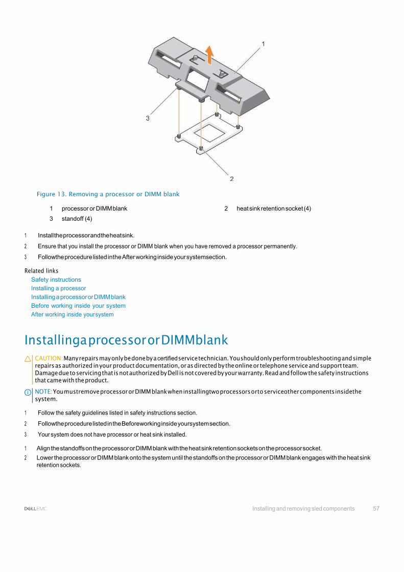
Installing and removing sled components 57
Figure 13. Removing a processor or DIMM blank
1 processor or DIMM blank 2 heat sink retention socket (4)
3 standoff (4)
1 Install the processor and the heat sink.
2 Ensure that you install the processor or DIMM blank when you have removed a processor permanently.
3 Followthe procedure listed inthe After working inside your systemsection.
Related links Safety instructions
Installing a processor
Installing a processor or DIMM blank
Before working inside your system
After working inside your system
Installinga processor or DIMMblank CAUTION: Many repairs may only be done by a certified service technician. You should only perform troubleshooting and simple repairs as authorized in your product documentation, or as directed by the online or telephone service and support team. Damage due to servicing that is not authorized by Dell is not covered by your warranty. Read and follow the safety instructions that came with the product.
NOTE: You mustremove processor or DIMM blank when installingtwo processors orto serviceother components insidethe system.
1 Follow the safety guidelines listed in safety instructions section.
2 Followthe procedure listed in the Beforeworking inside yoursystem section.
3 Your system does not have processor or heat sink installed.
1 Align the standoffs on the processor or DIMM blank with the heat sink retention sockets on the processor socket.
2 Lower the processor or DIMM blank onto the system until the standoffs on the processor or DIMM blank engages with the heat sink retention sockets.

58 Installing and removing sled components
Figure 14. Installing a processor/DIMM blank
1 processor or DIMM blank 2 heat sink retention socket (4)
3 standoff (4)
Follow the procedure listed in the After working inside your system section. Related links
Safety instructions
Installing a processor
Removing a processor or DIMM blank
Before working inside your system
After working inside your system
System memory Your system supports DDR4 registered DIMMs (RDIMMs) and load reduced DIMMs (LRDIMMs). It supports DDR4 voltage specifications.
NOTE: MT/s indicates DIMM speed in MegaTransfers per second.
Memory bus operating frequency can be 2400 MT/s, 2133 MT/s, or 1866 MT/s depending on:
• Number of DIMMs populated per channel
• System profile selected (for example, Performance Optimized, Custom, or Dense Configuration Optimized)
• Maximum supported DIMM frequency of the processors
The system contains 24 memory sockets split into two sets of 12 sockets, one set per processor. Each 12-socket set is organized into four channels. In each channel, the release levers of the first socket are marked white, the second socket black, andthe third socket green.
NOTE: DIMMs in sockets A1 to A12 are assigned to processor 1 and DIMMs in sockets B1 to B12 are assigned to processor 2.
The following table shows the memory populations and operating frequencies for the supported configurations.

Installing and removing sled components 59
Table 21. Memory population — operating frequency for supported configuration
DIMM Type DIMMs Populated Per Channel
Voltage Operating Frequency (in MT/s) Maximum DIMM Rank Per Channel
RDIMM 1 1.2 V 2400, 2133, 1866 Single rank or dual rank
2 2400, 2133, 1866
3 1866
LRDIMM 1 1.2 V 2400, 2133, 1866 Quad rank
2 2400, 2133, 1866
3 2133, 1866
Figure 15. Memory socket locations
Memory channels are organized as follows:
Processor 1 channel 0: memory sockets A1, A5, and A9
channel 1: memory sockets A2, A6, and A10
channel 2: memory sockets A3, A7, and A11
channel 3: memory sockets A4, A8, and A12
Processor 2 channel 0: memory sockets B1, B5, and B9
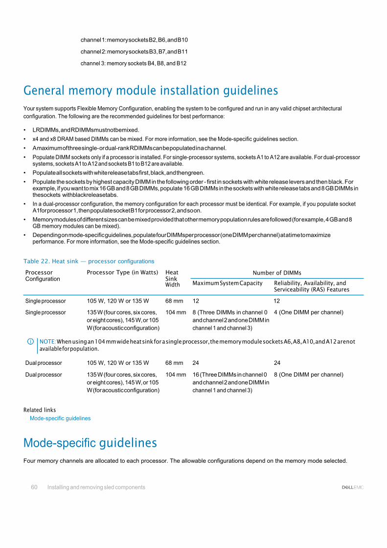
60 Installing and removing sled components
channel 1: memory sockets B2, B6, and B10
channel 2: memory sockets B3, B7, and B11
channel 3: memory sockets B4, B8, and B12
General memory module installation guidelines Your system supports Flexible Memory Configuration, enabling the system to be configured and run in any valid chipset architectural configuration. The following are the recommended guidelines for best performance:
• LRDIMMs, and RDIMMsmustnotbemixed.
• x4 and x8 DRAM based DIMMs can be mixed. For more information, see the Mode-specific guidelines section.
• A maximum of three single- or dual-rank RDIMMs can be populated ina channel.
• Populate DIMM sockets only if a processor is installed. For single-processor systems, sockets A1 to A12 are available. For dual-processor systems, sockets A1 to A12 and sockets B1 to B12 are available.
• Populate all sockets with white release tabs first, black, and thengreen.
• Populate the sockets by highest capacity DIMM in the following order - first in sockets with white release levers and then black. For example, if you want to mix 16 GB and 8 GB DIMMs, populate 16 GB DIMMs in the sockets with white release tabs and 8 GB DIMMs in thesockets withblackreleasetabs.
• In a dual-processor configuration, the memory configuration for each processor must be identical. For example, if you populate socket A1for processor 1, then populate socket B1 for processor 2, and so on.
• Memory modules of different sizes can be mixed provided that other memory population rules are followed (for example, 4 GB and 8 GB memory modules can be mixed).
• Depending on mode-specific guidelines, populate four DIMMsper processor (one DIMM per channel) at atime to maximize performance. For more information, see the Mode-specific guidelines section.
Table 22. Heat sink — processor configurations
Processor Configuration
Processor Type (in Watts) Heat Sink Width
Number of DIMMs
Maximum System Capacity Reliability, Availability, and Serviceability (RAS) Features
Single processor 105 W, 120 W or 135 W 68 mm 12 12
Single processor 135 W (four cores, six cores, or eight cores), 145 W, or 105 W (for acoustic configuration)
104 mm 8 (Three DIMMs in channel 0 and channel 2 and one DIMM in channel 1 and channel 3)
4 (One DIMM per channel)
NOTE: When using an 104 mm wide heat sink for a single processor, the memory module sockets A6, A8, A10, and A12 arenot available for population.
Dual processor 105 W, 120 W or 135 W 68 mm 24 24
Dual processor 135 W (four cores, six cores, or eight cores), 145 W, or 105 W (for acoustic configuration)
104 mm 16 (Three DIMMs in channel 0 and channel 2 and one DIMM in channel 1 and channel 3)
8 (One DIMM per channel)
Related links Mode-specific guidelines
Mode-specific guidelines Four memory channels are allocated to each processor. The allowable configurations depend on the memory mode selected.

Installing and removing sled components 65
Advanced Error Correction Code (lockstep)
Advanced Error Correction Code (ECC) mode extends SDDC from x4 DRAM based DIMMs to both x4 and x8 DRAMs. This protects against single DRAM chip failures during normal operation.
The installation guidelines for memory modules are as follows:
• Memory modules must be identical in size, speed, and technology.
• DIMMs installed in memorysockets with white release levers must be identical and the same ruleapplies for sockets with black release levers. This ensures that identical DIMMs are installed in matched pair —for example, A1 with A2, A3 with A4, A5 with A6, and so on.
Memory optimized (independent channel) mode
This mode supports Single Device Data Correction (SDDC) only for memory modules that usex4 device width. It does not impose any specific slot population requirements.
Memory sparing
NOTE: To use memory sparing, this feature must be enabled in System Setup.
In this mode, one rank per channel is reserved as a spare. If persistent correctable errors are detected onarank, the data from this rank is copied to the spare rank, and the failed rank isdisabled.
Withmemorysparingenabled,thesystemmemoryavailabletothe operating systemisreducedbyonerankperchannel. Forexample, ina dual-processor configuration with sixteen 4 GBsingle-rank memorymodules, the available system memory is: 3/4(ranks/channel) × 16 (memory modules) × 4 GB = 48 GB, and not 16 (memory modules) × 4 GB = 64 GB.
NOTE: Memory sparing does not offer protection against a multi-bit uncorrectable error.
NOTE: Both Advanced ECC/Lockstepand Optimizermodessupportmemorysparing.
Memory mirroring
Memory mirroring offers the strongest memory module reliability mode compared to all other modes, providing improved uncorrectable multi-bit failure protection. In amirrored configuration, the total available system memory is one half of the total installed physical memory. Half of the installed memory is used to mirror the active memory modules. In the event of an uncorrectable error, the system switches over to the mirrored copy.This ensures SDDC and multi-bit protection.
The installation guidelines for memory modules are as follows:
• Memory modules must be identical in size, speed, and technology.
• Memory modules installed inmemory modulesockets with white release levers must be identical and the same rule applies for sockets with black and green release tabs. This ensures that identical memory modules are installed in matched pairs—for example, A1 with A2, A3 with A4, A5 with A6, and so on.
Table 23. Processor configuration
Processor Configuration Memory population rules Memory population information
Single CPU Memory population order {1,2}, {3,4} See Memory mirroring note
Sample memory configurations The following tables show sample memory configurations that follow the appropriate memory guidelines stated in this section.

62 Installing and removing sled components
NOTE: 1R, 2R, and 4R in the following tables indicate single-, dual-, and quad-rank DIMMs respectively.
NOTE: When using an 104 mm wide heat sink for a single processor, the memory module sockets A6, A8, A10, and A12 are not available for population.
Table 24. Memory configurations – single processor
System Capacity (in DIMM Size (in Number of Organization and Speed DIMM Slot Population GB) GB) DIMMs
16 4 4 1R x8, 2133 MT/s A1, A2, A3, A4
1R x8, 2400 MT/s
2R x8, 2400 MT/s
24 4 6 1R x8, 2133 MT/s A1, A2, A3, A4, A5, A6
48 8 6 2R x8, 2133 MT/s A1, A2, A3, A4, A5, A6
96 16 6 2R x4, 2133 MT/s A1, A2, A3, A4, A5, A6
128 16 8 2R x4, 2133 MT/s A1, A2, A3, A4, A5, A6, A7, A8
256 32 8 4R x4, 2133 MT/s A1, A2, A3, A4, A5, A6, A7, A8
768 64 12 4R x4, 2400 MT/s A1, A2, A3, A4, A5, A6, A7, A8, A9, A10, A11, A12
NOTE: When using an 104 mm wide heat sink for a single processor, the memory module sockets A6, A8, A10, and A12 are not available for population.
Table 25. Memory configurations – two processors
System Capacity (in GB) DIMM Size (in GB) Number of DIMMs Organization and Speed DIMM Slot Population
32 4 8 1R x8, 2133 MT/s A1, A2, A3, A4, B1, B2, B3, B4
1R x8, 2400 MT/s
2R x8, 2400 MT/s
64 4 16 1R x8, 2133 MT/s A1, A2, A3, A4, A5, A6, A7, A8, B1, B2, B3, B4, B5, B6, B7, B8
64 8 8 2R x8, 2133 MT/s A1, A2, A3, A4, B1, B2, B3, B4
96 8 12 2R x8, 2133 MT/s A1, A2, A3, A4, A5, A6, B1, B2, B3, B4, B5, B6
128 8 16 2R x8, 2133 MT/s A1, A2, A3, A4, A5, A6, A7, A8, B1, B2, B3, B4, B5, B6, B7, B8
128 16 8 2R x4, 2133 MT/s A1, A2, A3, A4, B1, B2, B3, B4
160 16 and 8 12 2R x4, 2133 MT/s A1,A2, A3, A4,A5,A6,B1, B2,B3, B4, B5, B6
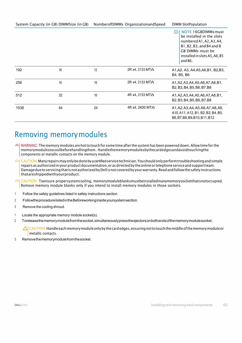
Installing and removing sled components 63
System Capacity (in GB) DIMM Size (in GB) NumberofDIMMs OrganizationandSpeed DIMM SlotPopulation
NOTE:16GBDIMMs must be installed in the slots numbered A1, A2, A3, A4, B1, B2, B3, and B4 and 8 GB DIMMs must be installed in slots A5, A6, B5 and B6.
192 16 12 2R x4, 2133 MT/s A1,A2, A3, A4,A5,A6,B1, B2,B3, B4, B5, B6
256 16 16 2R x4, 2133 MT/s A1, A2, A3, A4, A5, A6, A7, A8, B1, B2, B3, B4, B5, B6, B7,B8
512 32 16 4R x4, 2133 MT/s A1, A2, A3, A4, A5, A6, A7, A8, B1, B2, B3, B4, B5, B6, B7,B8
1536 64 24 4R x4, 2400 MT/s A1, A2, A3, A4, A5, A6, A7, A8, A9, A10, A11, A12, B1, B2, B3, B4, B5, B6, B7,B8, B9,B10, B11, B12
Removing memory modules WARNING: The memory modules are hot to touch for some time after the system has been powered down. Allow time for the memorymodulestocoolbeforehandlingthem. Handlethememorymodulesbythecardedgesandavoidtouchingthe components or metallic contacts on the memory module.
CAUTION: Many repairs may only be done by a certified service technician. You should only perform troubleshooting and simple repairs as authorized in your product documentation, or as directed by the online or telephone service and support team. Damage due to servicing that is not authorized by Dell is not covered by your warranty. Read and follow the safety instructions thatareshippedwithyourproduct.
CAUTION: Toensure propersystemcooling, memorymoduleblanksmustbeinstalledinanymemorysocketthatisnotoccupied. Remove memory module blanks only if you intend to install memory modules in those sockets.
1 Follow the safety guidelines listed in safety instructions section.
2 Followthe procedure listed in the Beforeworking inside yoursystem section.
3 Remove the cooling shroud.
1 Locate the appropriate memory module socket(s).
2 Torelease the memory module from the socket, simultaneously press the ejectors on both ends of the memory module socket.
CAUTION: Handle each memory module only by the card edges, ensuring not to touch the middle of the memory module or metallic contacts.
3 Remove the memorymodule from the socket.
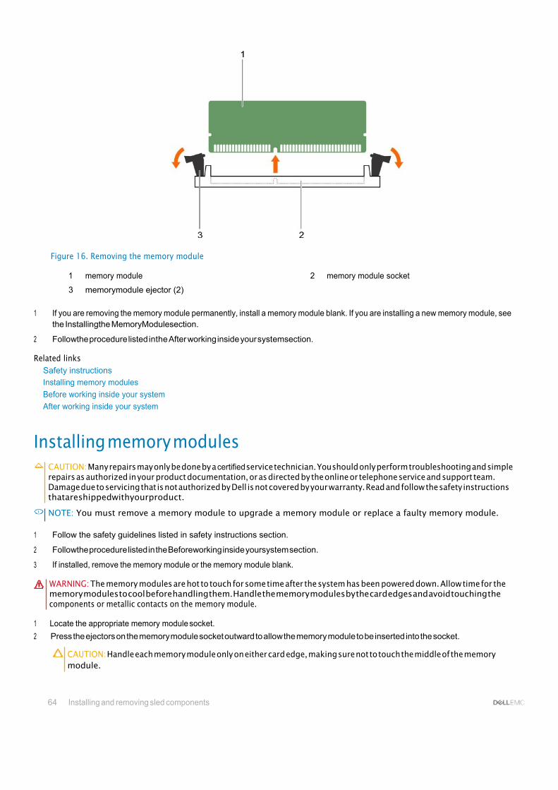
64 Installing and removing sled components
Figure 16. Removing the memory module
1 memory module 2 memory module socket
3 memorymodule ejector (2)
1 If you are removing the memory module permanently, install a memory module blank. If you are installing a new memory module, see the Installingthe MemoryModulesection.
2 Followthe procedure listed inthe After working inside your systemsection.
Related links Safety instructions
Installing memory modules
Before working inside your system
After working inside your system
Installing memory modules CAUTION: Many repairs may only be done by a certified service technician. You should only perform troubleshooting and simple repairs as authorized in your product documentation, or as directed by the online or telephone service and support team. Damage due to servicing that is not authorized by Dell is not covered by your warranty. Read and follow the safety instructions thatareshippedwithyourproduct.
NOTE: You must remove a memory module to upgrade a memory module or replace a faulty memory module.
Follow the safety guidelines listed in safety instructions section.
Followthe procedure listed in the Beforeworking inside yoursystem section.
If installed, remove the memory module or the memory module blank.
WARNING: The memory modules are hot to touch for some time after the system has been powered down. Allow time for the memory modules to cool before handling them. Handle the memory modules by the card edges and avoid touching the components or metallic contacts on the memory module.
1 Locate the appropriate memory module socket.
2 Press the ejectors on the memory module socket outward to allow the memory module to be inserted into the socket.
CAUTION: Handle each memory module only on either card edge, making sure not to touch the middle of the memory module.
1
2
3

Installing and removing sled components 65
3 Align the edge connector onthe memory module with the alignment key on the memory module socket, and insert the memory module in the socket.
NOTE: The memory module socket has an alignment key that allows you to install the memory module in the socket in only one orientation.
CAUTION: Topreventdamagetothememorymodulesocketduringinstallation, applypressureatboth endsofthememory moduleevenly. Do notapplypressuretothecenterofthememory module.
4 Press down on the memory module with your thumbs to lock the memory module into the socket.
NOTE: When the memory module is properly seated in the socket, the ejectors on the memory module socket align with the ejectorsontheothersocketsthathavememorymodulesinstalled.
5 Repeat step 4 through step 7 of this procedure toinstall the remaining memory modules.
Figure 17. Installing the memory module
1 memory module 2 memory module socket
3 memorymodule ejector (2)
1 Followthe procedure listed inthe After working inside your systemsection.
2 (Optional) Press F2 to enter the System Setup, and check the System Memorysetting.
The system should have already changed the value to reflect the newly installed memory.
NOTE: If the value is incorrect, one or more of the memory modules may not be installed properly. Check to ensure that the memory modules are firmly seated in their sockets.
3 Run the system memory test in the system diagnostics.
Related links Safety instructions
Before working inside your system
Removing memory modules
After working inside your system

66 Installing and removing sled components
PCIe mezzanine card Yoursystem supports x16 Gen 3 PCIe mezzanine card, which provides an interface between the sled andthe PCIe switches on the FX2s enclosure.
NOTE: Ensure that the PCIe mezzanine card is set to Enabled in System Setup.
Removing a PCIe mezzanine card CAUTION: Many repairs may only be done by a certified service technician. Youshould only perform troubleshooting and simple repairsasauthorizedinyourproductdocumentation, orasdirectedbytheonlineortelephoneserviceandsupportteam. Damage due to servicing that is not authorized by Dell is not covered by your warranty. Read and follow the safety instructions thatareshippedwithyourproduct.
1 Follow the safety guidelines listed in safety instructions section.
2 Followthe procedure listed in the Beforeworking inside yoursystem section.
1 Open the PCIe mezzanine card retention latch bypressing the release tab onthe retention latch.
2 Pull back and hold theretention bracket awayfrom the PCIe mezzanine card.
3 Lift the end of the retention latch until the two connectors on the PCIe mezzanine card disengage from connectors on the system board.
CAUTION: To prevent damage to the PCIe mezzanine card, you must hold the card only by its edges.
4 Lift the PCIe mezzanine card up and awayfrom the system.
5 Close the retention latch.
Figure 18. Removing a PCIe mezzanine card
1 PCIe mezzanine card 2 PCIe mezzanine card retention bracket
3 PCIe mezzanine card connector (2) 4 PCIe mezzanine card retention latch
1 Install the PCIe mezzanine card. See the Installing a PCIe mezzanine card section.

Installing and removing sled components 67
2 Followthe procedure listed inthe After working inside your systemsection.
Related links Safety instructions
Installing a PCIe mezzanine card
Before working inside your system
After working inside your system
Installinga PCIemezzaninecard CAUTION: Many repairs may only be done by a certified service technician. You should only perform troubleshooting and simple repairs as authorized in your product documentation, or as directed by the online or telephone service and support team. Damage due to servicing that is not authorized by Dell is not covered by your warranty. Read and follow the safety instructions thatareshippedwithyourproduct.
NOTE: You must remove the PCIe mezzanine card to replace a faulty PCIe mezzanine card or service other components inside the system.
1 Follow the safety guidelines listed in safety instructions section..
2 Remove the PCIe mezzanine card. See the Removing the PCIe mezzanine card section.
1 Open the PCIe mezzanine card retention latch by pressing the release tab on the retention latch and lift the end of the latch.
2 If present, remove the connector cover from the PCIe mezzanine card bay.
CAUTION: To prevent damage to the PCIe mezzanine card, you must hold the card only by its edges.
3 Align the two connectors on the PCIe mezzanine card with the connectors on the system board.
4 Press down the PCIe mezzanine card till the connectors on the card completely engage with thecorresponding connectors.
The retention bracket on the side of the chassis latches onto the PCIe mezzanine card.
5 Close the retention latch.
Figure 19. Installing a PCIe mezzanine card
1 PCIe mezzanine card 2 PCIe mezzanine card retention bracket

68 Installing and removing sled components
3 PCIe mezzanine card connector (2) 4 PCIe mezzanine card retention latch
Follow the procedure listed in the After working inside your system section. Related links
Safety instructions
Removing the sled
Installing the sled
Removing a PCIe mezzanine card
Before working inside your system
After working inside your system
Internal dual SDmodule(optional) The Internal Dual SD module (IDSDM) provides youwith a redundant SD card solution. Youcan configure the IDSDM for storage or asthe OS boot partition. In modular servers, you can choose either a redundant SD module mode or share one slot with the iDRAC module and the remaining slot can be used for storage or as the OS partition.
The Internal Dual SD Module (IDSDM) card provides two SDcard slots anda USB interface dedicated for the embedded hypervisor. This card offers the following features:
• Dual card operation—maintains a mirrored configuration by using SD cards in both slots and provides redundancy.
• Single card operation—single card operation is supported, but without redundancy.
Replacing an SD card CAUTION: Many repairs may only be done by a certified service technician. Youshould only perform troubleshooting and simple repairsasauthorizedinyourproductdocumentation, orasdirectedbytheonlineortelephoneserviceandsupportteam. Damage due to servicing that is not authorized by Dell is not covered by your warranty. Read and follow the safety instructions thatareshippedwithyourproduct.
1 Follow the safety guidelines listed in safety instructions section.
2 Followthe procedure listed in the Beforeworking inside yoursystem section.
3 Enter the System Setup and ensure that the Internal SDCard Port is enabled.
CAUTION: When an SD card failure occurs, and the Internal SD Card Redundancy option in the Integrated Devices screen of the System Setup is set to Mirror Mode, there may be loss of data. Toavoid data loss, follow step 4 through step 6 of the Troubleshooting an internal SD card section.
NOTE: The SD card in the lower card slot is the primary card (SD1) and the SD card in the upper card slot is the secondary card (SD2).
NOTE: When an SD card failure occurs, the Internal SD Card Redundancy option in the System Setup is set to Disabled and the internal dual SDmodulecontroller notifies the system. Onthe nextreboot, the systemdisplaysa messageindicatingthefailure.
NOTE: If the Internal SD Card Redundancy option is set to Disabled, replace the failed SD card with a new SD card.
1 Locate the SD card slot on the internal dual SD module (IDSDM) card.
2 Press inward on the card to release it from the slot, and remove the card.
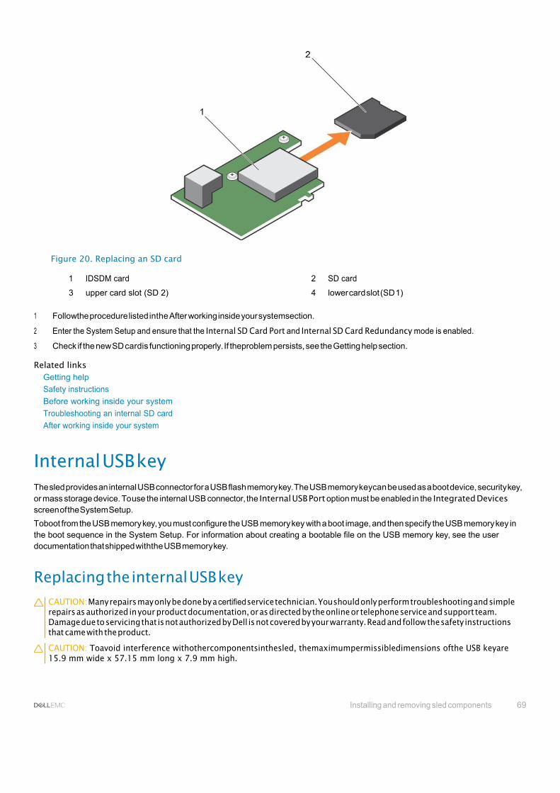
Installing and removing sled components 69
Figure 20. Replacing an SD card
1 IDSDM card 2 SD card
3 upper card slot (SD 2) 4 lower card slot (SD 1)
1 Followthe procedure listed inthe After working inside your systemsection.
2 Enter the System Setup and ensure that the Internal SD Card Port and Internal SD Card Redundancy mode is enabled.
3 Check if the new SD cardis functioning properly. If theproblem persists, see the Getting help section.
Related links Getting help
Safety instructions
Before working inside your system
Troubleshooting an internal SD card
After working inside your system
Internal USB key The sled provides an internal USB connector for a USB flash memory key. The USB memory keycan be used as a boot device, security key, or mass storage device. To use the internal USB connector, the Internal USB Port option must be enabled in the Integrated Devices screen of the System Setup.
Toboot from the USB memory key, you must configure the USB memory key with a boot image, and then specify the USB memory key in the boot sequence in the System Setup. For information about creating a bootable file on the USB memory key, see the user documentation that shipped withthe USB memory key.
Replacing the internal USB key
CAUTION: Many repairs may only be done by a certified service technician. You should only perform troubleshooting and simple repairs as authorized in your product documentation, or as directed by the online or telephone service and support team. Damage due to servicing that is not authorized by Dell is not covered by your warranty. Read and follow the safety instructions that came with the product.
CAUTION: Toavoid interference withothercomponentsinthesled, themaximumpermissibledimensions ofthe USB keyare 15.9 mm wide x 57.15 mm long x 7.9 mm high.

70 Installing and removing sled components
1 Follow the safety guidelines listed in safety instructions section.
2 Followthe procedure listed in the Beforeworking inside yoursystem section.
1 Locate the USB connector/USB key.
2 If installed, remove the USB key.
3 Insert the new USB memory key into the USB connector.
Figure 21. Replacing the USB memory key
1 USB memorykey 2 USB memory key connector
Figure 22. Installing the USB memory key
1 USB memorykey 2 USB memory key connector
1 Followthe procedure listed inthe After working inside your systemsection.
2 Enter the System Setup and ensure that the USB key is detected by the system.
Related links Safety instructions
Before working inside your system
After working inside your system
Removing the optional IDSDM card CAUTION: Many repairs may only be done by a certified service technician. Youshould only perform troubleshooting and simple repairsasauthorizedinyourproductdocumentation, orasdirectedbytheonlineortelephoneserviceandsupportteam. Damage due to servicing that is not authorized by Dell is not covered by your warranty. Read and follow the safety instructions that came with the product.

Installing and removing sled components 71
1 Follow the safety guidelines listed in safety instructions section.
2 Keep the Phillips #2 screwdriver ready.
3 FollowtheprocedurelistedinAfter workinginside yoursystem.
4 If installed, remove the internal USB key.
5 If installed, remove the SDcard(s).
1 Remove the two screws securing the IDSDM card to the system board.
2 Remove the SDcard slot bracket.
CAUTION: To prevent damage to the IDSDM card, you must hold the card only by its edges.
3 Lift the card up and away from the system.
Figure 23. Removing the optional IDSDM card
1 IDSDM card 2 screw (2)
3 SD card slot bracket 4 PCIe mezzanine card support bracket
5 IDSDM card connector on the system board 6 standoff (2)
1 Install the IDSDM card.
2 Followthe procedure listed inthe After working inside your systemsection.
Related links Safety instructions
Installing the optional IDSDM card
Before working inside your system
Replacing the internal USB key
Replacing an SD card
After working inside your system

72 Installing and removing sled components
Installingthe optional IDSDMcard CAUTION: Many repairs may only be done by a certified service technician. You should only perform troubleshooting and simple repairs as authorized in your product documentation, or as directed by the online or telephone service and support team. Damage due to servicing that is not authorized by Dell is not covered by your warranty. Read and follow the safety instructions that came with the product.
NOTE: You must remove the IDSDM card to replace a faulty IDSDM card or service other components inside the system.
Follow the safety guidelines listed in safety instructions section.
Keep the Phillips #2 screwdriver ready.
Remove the SD card.
Remove the IDSDM card.
CAUTION: To prevent damage to the IDSDM card, you must hold the card only by its edges.
1 Align the following:
• The slot on the card edge with the projection tabs on the PCIe mezzanine card support.
• The two screw holes on the IDSDM card with the standoffs on the system board.
• The hole on the SD card slot bracket with the screw hole on the IDSDM card.
2 Install the two screws to secure the SD card slot bracket and IDSDM card to the system board.
Figure 24. Installing the optional IDSDM card
1 IDSDM card 2 screw (2)
3 SD card slot bracket 4 PCIe mezzanine card support bracket
5 IDSDM card connector on the system board 6 standoff (2)
1 If applicable, install the SDcard(s)and the internal USB key.
2 Followthe procedure listed inthe After working inside your systemsection.
1
2
3
4

Installing and removing sled components 73
Related links Safety instructions
Removing the optional IDSDM card
Before working inside your system
Replacing the internal USB key
Replacing an SD card
After working inside your system
rSPI card(optional) rSPI (restoreSerial Peripheral Interface) is a SPI flash device to store information about the system Service Tag,system configuration, or iDRAC license.
Removing the optional rSPI card CAUTION: Many repairs may only be done by a certified service technician. Youshould only perform troubleshooting and simple repairsasauthorizedinyourproductdocumentation, orasdirectedbytheonlineortelephoneserviceandsupportteam. Damage due to servicing that is not authorized by Dell is not covered by your warranty. Read and follow the safety instructions that came with the product.
1 Follow the safety guidelines listed in safety instructions section.
2 Keep the Phillips #2 screwdriver ready.
3 Followthe procedure listed in the Beforeworking inside yoursystem section.
1 Remove the two screws securing the rSPI card to the system board.
CAUTION: To prevent damage to the rSPI card, you must hold the card only by its edges.
2 Lift the card up and away from the system.
Figure 25. Removing the optional rSPI card
1 screw (2) 2 rSPI card
3 standoff (2) 4 connector
1 Install the rSPI card.

74 Installing and removing sled components
2 Followthe procedure listed inthe After working inside your systemsection.
Related links Safety instructions
Before working inside your system
Installing the optional rSPI card
After working inside your system
Installing the optional rSPI card CAUTION: Many repairs may only be done by a certified service technician. You should only perform troubleshooting and simple repairs as authorized in your product documentation, or as directed by the online or telephone service and support team. Damage due to servicing that is not authorized by Dell is not covered by your warranty. Read and follow the safety instructions that came with the product.
NOTE: You must remove the rSPI card to replace a faulty rSPI card or service other components inside the system.
CAUTION: To prevent damage to the rSPI card, you must hold the card only by its edges.
1 Follow the safety guidelines listed in safety instructions section.
2 Keep the Phillips #2 screwdriver ready.
3 Remove the rSPI card.
1 Align the two screw holes on the rSPI card with the standoffs on the system board.
2 Install the two screws to secure the rSPI card to the system board.
Figure 26. Installing the optional rSPI card
1 screw (2) 2 rSPI card
3 standoff (2) 4 connector
Follow the procedure listed in the After working inside your system section. Related links
Safety instructions
Before working inside your system
Removing the optional rSPI card
After working inside your system

Installing and removing sled components 75
SD vFlash card AvFlash SDcardisa Secure Digital(SD) cardthatplugsinto the vFlash SD card slot in the system. It provides persistent on-demandlocal storage and a custom deployment environment that allows automation of server configuration, scripts, and imaging. It emulates USB devices. For more information, see the Integrated Dell Remote Access Controller User’s Guide at Dell.com/idracmanuals.
Youcan use an SD vFlash card with your system. The card slot is on the IDSDM card. Youcan remove and install the SDvFlash card.
Replacing the SD vFlash card CAUTION: Many repairs may only be done by a certified service technician. Youshould only perform troubleshooting and simple repairsasauthorizedinyourproductdocumentation, orasdirectedbytheonlineortelephoneserviceandsupportteam. Damage due to servicing that is not authorized by Dell is not covered by your warranty. Read and follow the safety instructions that came with the product.
1 Follow the safety guidelines listed in safety instructions section.
2 Followthe procedure listed in the Beforeworking inside yoursystem section.
1 If installed, remove the SD vFlash card from the card slot.
NOTE: The SD vFlash card slot is near below the NDC.
2 Insert the contact-pin end of the SD card into the card slot on the vFlash media unit.
NOTE: The slot is keyed to ensure correct insertion of the card.
3 Press inward on the card to lock it into the slot.

76 Installing and removing sled components
Figure 27. Replacing the SD vFlash card
1 SD vFlash card 2 SD vFlash card slot
3 SD vFlash card slot identification label

Installing and removing sled components 77
Figure 28. Installing the SD vFlash card
1 SD vFlash card 2 SD vFlash card slot
3 SD vFlash card slot identification label
Follow the procedure listed in the After working inside your system section. Related links
Safety instructions
Before working inside your system
After working inside your system
Network Daughter Card The Network Daughter Card (NDC) isa small, removable mezzanine card. The NDC provides you withaflexibilityof choosing different network connectivity option, for example—4 x 1GbE, 2 x 10GbEor 2 x Converged Network Adapter.
Removing the Network Daughter Card CAUTION: Many repairs may only be done by a certified service technician. Youshould only perform troubleshooting and simple repairsasauthorizedinyourproductdocumentation, orasdirectedbytheonlineortelephoneserviceandsupportteam. Damage due to servicing that is not authorized by Dell is not covered by your warranty. Read and follow the safety instructions that came with the product.
1 Follow the safety guidelines listed in safety instructions section.
2 Keep the Phillips #2 screwdriver ready.
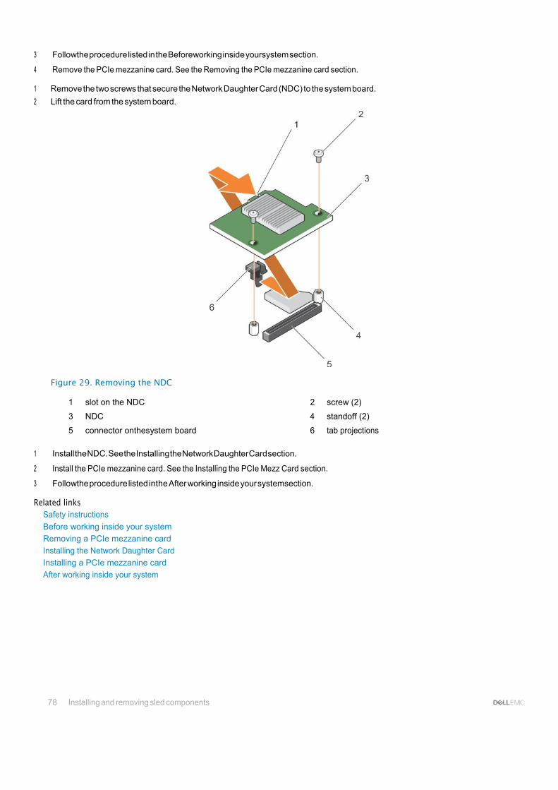
78 Installing and removing sled components
3 Followthe procedure listed in the Beforeworking inside yoursystem section.
4 Remove the PCIe mezzanine card. See the Removing the PCIe mezzanine card section.
1 Remove the two screws that secure the Network Daughter Card (NDC) to the system board.
2 Lift the card from the system board.
Figure 29. Removing the NDC
1 slot on the NDC 2 screw (2)
3 NDC 4 standoff (2)
5 connector onthesystem board 6 tab projections
1 Install the NDC. See the Installing the Network Daughter Card section.
2 Install the PCIe mezzanine card. See the Installing the PCIe Mezz Card section.
3 Followthe procedure listed inthe After working inside your systemsection. Related links
Safety instructions
Before working inside your system
Removing a PCIe mezzanine card
Installing the Network Daughter Card
Installing a PCIe mezzanine card
After working inside your system

Installing and removing sled components 79
Installing the Network Daughter Card CAUTION: Many repairs may only be done by a certified service technician. You should only perform troubleshooting and simple repairs as authorized in your product documentation, or as directed by the online or telephone service and support team. Damage due to servicing that is not authorized by Dell is not covered by your warranty. Read and follow the safety instructions that came with the product.
NOTE: You must remove the NDC to replace a faulty NDC card or service other components inside the system.
1 Follow the safety guidelines listed in safety instructions section.
2 Keep the Phillips #2 screwdriver ready.
3 Remove the PCIe mezzanine card. See the Removing the PCIe mezzanine card section.
4 Removethe NDC.Seethe Removingthe NetworkDaughterCardsection.
1 Align the following:
a The slots on the card edge with the projection tabs on the plastic bracket covering the PCIe mezzanine card slots. b Screw holes on the card with the standoffs on the system board.
CAUTION: To prevent damage to the NDC, you must hold the card only by its edges.
2 Lower the card into place until the card connector fits into the corresponding connector on the system board.
3 Secure the card with the two screws.
Figure 30. Installing the NDC
1 slot on the NDC 2 screw (2)
3 NDC 4 standoff (2)
5 connector onthesystem board 6 tab projections
1 Install the PCIe mezzanine card. See the Installing a PCIe Mezzanine card section.

80 Installing and removing sled components
2 Followthe procedure listed inthe After working inside your systemsection.
Related links Safety instructions
Removing a PCIe mezzanine card
Removing the Network Daughter Card
Installing a PCIe mezzanine card
After working inside your system
Processors Your system supports one or two Intel Xeon E5-2600 v3 or E5-2600 v4 product family processors.
CAUTION: For processors of 105 W, 120 W, or 135 W, use heat sinks of 68 mm width.
CAUTION: For processors of 105 W (for acoustic configuration), 135 W (four cores, six cores, or eight cores), or 145 W, use heat sinks of 104 mm width.
NOTE: Mixing processors of different wattages is not supported.
Use the following procedure when:
• Removing and installing a heat sink
• Installing an additional processor
• Replacingaprocessor
NOTE: To ensure proper system cooling, you must install a processor blank in any empty processor socket.
Related links Removing a heat sink
Removing a processor
Installing a processor
Installing a heat sink
Removingaheatsink CAUTION: Many repairs may only be done by a certified service technician. You should only perform troubleshooting and simple repairs as authorized in your product documentation, or as directed by the online or telephone service and support team. Damage due to servicing that is not authorized by Dell is not covered by your warranty. Read and follow the safety instructions that came with the product.
CAUTION: Never remove the heat sink from a processor unless you intend to remove the processor. The heat sink is necessary to maintain proper thermal conditions.
NOTE: The processor and heat sink can become extremely hot. Be sure the processor has had sufficient time to cool before handling.
1 Follow the safety guidelines listed in safety instructions section.
2 Keep the Phillips #2 screwdriver ready.
3 Followthe procedure listed in the Beforeworking inside yoursystem section.
4 Remove the cooling shroud.
1 Loosen the first screw that secures the heat sink to the system board.
Allow some time (around 30 seconds) for the heat sink to loosen from the processor.
2 Loosen the screw that is diagonally opposite the screw youfirst removed.
3 Repeat the procedure for the remaining two screws.
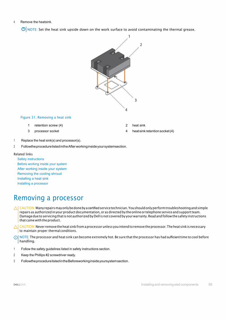
Installing and removing sled components 95
4 Remove the heatsink.
NOTE: Set the heat sink upside down on the work surface to avoid contaminating the thermal grease.
Figure 31. Removing a heat sink
1 retention screw (4) 2 heat sink
3 processor socket 4 heat sink retention socket (4)
1 Replace the heat sink(s) and processor(s).
2 Followthe procedure listed inthe After working inside your systemsection.
Related links Safety instructions
Before working inside your system
After working inside your system
Removing the cooling shroud
Installing a heat sink
Installing a processor
Removing a processor CAUTION: Many repairs may only be done by a certified service technician. You should only perform troubleshooting and simple repairs as authorized in your product documentation, or as directed by the online or telephone service and support team. Damage due to servicing that is not authorized by Dell is not covered by your warranty. Read and follow the safety instructions that came with the product.
CAUTION: Never remove the heat sink from a processor unless you intend to remove the processor. The heat sink is necessary to maintain proper thermal conditions.
NOTE: The processor and heat sink can become extremely hot. Be sure that the processor has had sufficient time to cool before handling.
1 Follow the safety guidelines listed in safety instructions section.
2 Keep the Phillips #2 screwdriver ready.
3 Followthe procedure listed in the Beforeworking inside yoursystem section.
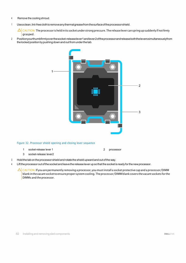
82 Installing and removing sled components
4 Remove the cooling shroud.
1 Use a clean, lint-free cloth to remove any thermal grease from the surface of the processor shield.
CAUTION: The processor is held in its socket under strong pressure. The release lever can spring up suddenly if not firmly grasped.
2 Positionyourthumbfirmlyover the socket-release lever1 and lever 2 of the processor and release both the levers simultaneouslyfrom the locked position by pushing down and out from under the tab.
Figure 32. Processor shield opening and closing lever sequence
1 socket-release lever 1 2 processor
3 socket-release lever2
3 Hold the tab on the processor shield and rotate the shield upward and out of the way.
4 Lift the processor out of the socket and leave the release lever up so that the socket is ready for the new processor.
CAUTION: If you are permanently removing a processor, you must install a socket protective cap and a processor/DIMM blank in the vacant socket to ensure proper system cooling. The processor/DIMM blank covers the vacant sockets for the DIMMs and the processor.

Installing and removing sled components 83
Figure 33. Installing and removing a processor
1 socket-release lever 1 2 pin–1corner of the processor
3 processor 4 slot (4)
5 processor shield 6 socket-release lever2
7 processor socket 8 tab (4)
Enter an example that illustrates the current task (optional).
1 Replace theprocessor(s).
2 Install the heatsink.
3 Reinstall the cooling shroud.
4 Followthe procedure listed inthe After working inside your systemsection.
Related links Safety instructions
Before working inside your system
Installing the cooling shroud
Removing a heat sink
Installing a processor
Installing a heat sink
Removing the cooling shroud
After working inside your system

84 Installing and removing sled components
Installing a processor CAUTION: Many repairs may only be done by a certified service technician. You should only perform troubleshooting and simple repairs as authorized in your product documentation, or as directed by the online or telephone service and support team. Damage due to servicing that is not authorized by Dell is not covered by your warranty. Read and follow the safety instructions that came with the product.
NOTE: If you are installing just one processor, it must be installed in socket CPU1.
NOTE: You must remove a processor to upgrade a processor or replace a faulty processor.
1 Follow the safety guidelines listed in safety instructions section.
2 Keep the Phillips #2 screwdriver ready.
3 Followthe procedure listed in the Beforeworking inside yoursystem section.
4 Remove the processor or processor blank or DIMM blank.
1 Unlatchandrotatethesocket-releaselevers90degreesupward andensurethatthesocket-releaseleverisfullyopen.
2 Hold the tab on the processor shield and rotate the shield upward and out of the way.
NOTE: It is recommended that you install or remove the socket protective cap from the processor shield with the processor shield in the open position.
3 If installed, remove the socket protective cap from the processor shield. Toremove the socket protective cap, push the cap from the inside of the processor shield and move it awayfrom the socket pins.
CAUTION: Positioning the processor incorrectly can permanently damage the system board or the processor. Be careful not to bend the pins in the socket.
CAUTION: Do not use force to seat the processor. When the processor is positioned correctly, it engages easily into the socket.
4 Install the processor in thesocket:
a Identify the pin-1 corner of the processor by locating the tiny gold triangle on one corner of the processor. Place this corner in the same corner of the ZIF socket identified byacorresponding triangle on the system board.
b Align the pin-1 corner of the processor with the pin-1 corner of the system board. c Set the processor lightly in the socket.
Because the system uses a ZIF processor socket, do not use force. When the processor is positioned correctly, it drops down into the socket with minimalpressure.
d Close the processor shield. e Rotate the socket-release lever 1 and lever 2 simultaneously until it is locked in position.
1 Install the heatsink.
2 While booting, press F2 to enter System Setup and verify that the processor information matches the new system configuration.
3 Run the system diagnostics to verify that the newprocessor operates correctly.
Related links Safety instructions
Before working inside your system
Removing the cooling shroud
Installing a heat sink
After working inside your system

Installing and removing sled components 85
Installing a heat sink CAUTION: Many repairs may only be done by a certified service technician. You should only perform troubleshooting and simple repairs as authorized in your product documentation, or as directed by the online or telephone service and support team. Damage due to servicing that is not authorized by Dell is not covered by your warranty. Read and follow the safety instructions that came with the product.
NOTE: If you are installing just one processor, it must be installed in socket CPU1.
NOTE: You must remove a processor to upgrade a processor or replace a faulty processor.
1 Follow the safety guidelines listed in safety instructions section.
2 Keep the Phillips #2 screwdriver ready.
3 Followthe procedure listed in the Beforeworking inside yoursystem section.
4 Remove the coolingshroud
.
5 Remove the processor or processor blank/DIMM blank.
Enter the context of your task here (optional). This is where introductory content goes.
To install the heat sink:
a If applicable, remove the existing thermal grease from the heat sink byusing aclean lint-free cloth. b Apply thermal grease on the top of the processor. Usethe thermal-grease syringe included with your processor kit to applythe
grease in a thin spiral on the top of the processor as shown in the figure.
Figure 34. Installing a heat sink
1 retention screw (4) 2 heat sink
3 processor socket 4 heat sink retention socket (4)
CAUTION: Applyingtoomuchthermalgreasecanresultinexcessgreasecomingincontactwithandcontaminating the processor socket.

86 Installing and removing sled components
Figure 35. Applying thermal grease on the top of the processor
1 processor 2 thermal grease
3 thermal-grease syringe
NOTE: The thermal-grease is intended for one-time use only. Dispose of the syringe after you use it.
c Place the heat sink onto the processor. d Tighten the four screws to secure the heat sink to the system board.
NOTE: Tighten the screws diagonally opposite to each other. Do not over-tighten the heat sink retention screws when installing the heat sink. Toprevent over-tightening, tighten the retention screw until resistance is felt, and stop after the screw is seated. The screw tension should be no more than 6 in-lb (6.9 kg-cm).
1 Install the cooling shroud.
2 Followthe procedure listed inthe After working inside your systemsection.
As the system boots, it detects the presence of the new processor and automatically changes the system configuration information in the System Setup.
3 Press F2 to enter the System Setup and check that the processor information matches the new system configuration.
4 Run the system diagnostics to verify that the newprocessor operates correctly.
5 Update the system BIOS. Related links
Safety instructions
Before working inside your system
Removing the cooling shroud
Installing a processor
Installing the cooling shroud
After working inside your system

Installing and removing sled components 87
Hard drives or SSDs Yoursystem supports up to two 2.5-inch SAS or SATAor PCIe SSDs or SAS or SATAhard drives and eight 1.8-inch SATASSDs. The hard drives or SSDs are supplied inspecial hot-swappable drive carriers that fit in the drive bays and these drives connect to the system board through the hard drive backplane board.
NOTE: Mixing of SSD or SAS or SATA hard drives is not supported.
Hard drive or SSD bay numbering
Figure 36. Hard drive or SSD bay numbering — 2.5-inch hard drive or SSD system
Figure 37. SSD bay numbering — 1.8-inch SSD system
Hard drive or SSD installation guidelines For single hard drive configuration, a hard drive blank must be installed in the other drive bay to maintain proper airflow.
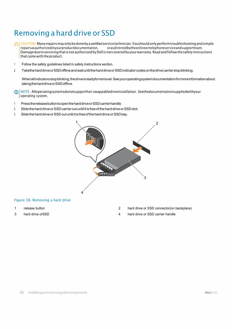
88 Installing and removing sled components
Removing a hard drive or SSD CAUTION: Many repairs may only be done by a certified service technician. Youshould only perform troubleshooting and simple repairsasauthorizedinyourproductdocumentation, orasdirectedbytheonlineortelephoneserviceandsupportteam. Damage due to servicing that is not authorized by Dell is not covered by your warranty. Read and follow the safety instructions that came with the product.
1 Follow the safety guidelines listed in safety instructions section.
2 Takethe hard drive or SSD offline and wait until the hard drive or SSD indicator codes on the drive carrier stop blinking.
When all indicators stop blinking, the drive is readyfor removal. See your operating system documentation for more information about taking the hard drive or SSD offline.
NOTE: Alloperatingsystemsdonotsupporthot-swappabledriveinstallation. Seethedocumentationsuppliedwithyour operating system.
1 Press the release button to open the hard drive or SSD carrier handle.
2 Slide the hard drive or SSD carrier out until it is free of the hard drive or SSD slot.
3 Slide the hard drive or SSD out until it is free of the hard drive or SSD bay.
Figure 38. Removing a hard drive
1 release button 2 hard drive or SSD connector(on backplane)
3 hard drive orSSD 4 hard drive or SSD carrier handle

Installing and removing sled components 89
Figure 39. Removing a SSD
1 release button 2 SSD
3 SSD carrier handle
1 If you are removing a hard drive or SSD permanently, install the hard drive or SSDblank. If youare installing a new harddrive or SSD,
see the Installing the hard drive or SSD section.
Installing a hard drive or SSD CAUTION: When a replacement hot-swappable hard drive or SSD is installed and the sled is turned on, the hard drive or SSD automatically begins to rebuild. Make absolutely surethat thereplacement hard driveor SSD is blank or contains data that you wishtohaveover-written. Anydataonthereplacementharddriveor SSDisimmediatelylostaftertheharddriveor SSDis installed.
NOTE: You must remove a hard drive or SSD to upgrade a hard drive or SSD or replace a faulty hard drive or SSD.
Follow the safety guidelines listed in safety instructions section.
Remove the harddrive or SSD or hard drive or SSD blank.
NOTE: Alloperatingsystemsdonotsupporthot-swappabledriveinstallation. Seethedocumentationsuppliedwithyour operating system.
1 Press the release button to open the hard drive or SSD carrier handle.
2 Slide the hard drive or SSD carrier into the drive bay. Carefully align the channel on the hard driveor SSD carrier with the appropriate drive slot on the sled.
3 Push the drive carrier into the slot until the handle makes contact with the sled.
4 Rotate the carrier handle to the closed position while pushing the carrier into the slot until it locks into place.
The status LED indicator displays asteady green light if the drive is installed correctly. The drive carrier LEDgreen indicator flashes as
the drive rebuilds.
1
2

90 Installing and removing sled components
Figure 40. Installing a hard drive
1 release button 2 hard drive(onbackplane)
3 hard drive 4 hard drive carrier handle
Figure 41. Installing a SSD
1 release button 2 SSD
3 SSD carrier handle
Related links Safety instructions
Removing a hard drive or SSD blank CAUTION: Many repairs may only be done by a certified service technician. You should only perform troubleshooting and simple repairs as authorized in your product documentation, or as directed by the online or telephone service and support team. Damage due to servicing that is not authorized by Dell is not covered by your warranty. Read and follow the safety instructions that came with the product.
CAUTION: Tomaintain proper system cooling, all empty hard drive or SSD slots must have hard drive or SSD blanks installed.

Installing and removing sled components 91
1 Follow the safety guidelines listed in safety instructions section.
Press the release latch and slide the hard drive or SSD blank out of the hard drive or SSD slot.
Figure 42. Removing a 2.5-inch hard drive
1 hard drive or SSD blank 2 release latch
Figure 43. Removing a 1.8-inch SSD blank
1 SSD blank 2 release latch
1 Install the hard drive or SSD.
Related links
Safety instructions
Installing a hard drive or SSD
Safety instructions
Removing a hard drive or SSD
Installing a hard drive or SSD blank 1 Follow the safety guidelines listed in safety instructions section.

92 Installing and removing sled components
2 Remove a hard drive or SSD.
Insert the hard drive or SSD blank into the hard drive or SSD slot until the release latch clicks into place.
Figure 44. Installing a 2.5-inch hard drive blank
1 hard drive or SSD blank 2 release latch
Figure 45. Installing a 1.8-inch SSD blank
1 SSD blank 2 release latch
Shutdown procedure for servicing a hard drive or SSD NOTE: This section applies only to situations where the sled must be powered down to service a hard drive or SSD.

Installing and removing sled components 93
If you need to service a hard drive or SSD, turn off the sled and before removing the hard drive or SSD wait for 30 seconds after the sled indicator turns off. Otherwise, the hard drive or SSD may not be recognized after it is reinstalled and the sled is turned on again.
Configuring the boot drive The drive or device from which the system boots is determined by the boot order specified in the System Setup.
Removing a 2.5-inch hard drive or SSD from a 2.5-inch hard drive or SSD carrier
CAUTION: Many repairs may only be done by a certified service technician. Youshould only perform troubleshooting and simple repairsasauthorizedinyourproductdocumentation, orasdirectedbytheonlineortelephoneserviceandsupportteam. Damage due to servicing that is not authorized by Dell is not covered by your warranty. Read and follow the safety instructions that came with the product.
1 Follow the safety guidelines listed in safety instructions section.
2 Keep the Phillips #1 screwdriver ready.
1 Remove the four screws from the slide rails on the hard drive or SSD carrier.
2 Slide the hard drive or SSD out of the hard drive or SSD carrier.
Figure 46. Removing a 2.5-inch hard drive or SSD in a 2.5-inch hard drive or SSD carrier
1 screw (4) 2 hard drive orSSD
3 hard drive or SSD carrier 4 screw hole (4)
Install a new 2.5-inch hard drive or SSD in a 2.5-inch hard drive or SSD carrier.

94 Installing and removing sled components
Related links Safety instructions
Installing a 2.5-inch hard drive or SSD in a 2.5-inch hard drive or SSD carrier
Installing a 2.5-inch hard drive or SSD in a 2.5-inch hard drive or SSDcarrier
CAUTION: Many repairs may only be done by a certified service technician. You should only perform troubleshooting and simple repairs as authorized in your product documentation, or as directed by the online or telephone service and support team. Damage due to servicing that is not authorized by Dell is not covered by your warranty. Read and follow the safety instructions that came with the product.
NOTE: You must remove the hard drive or SSD from a hard drive or SSD carrier to replace a faulty hard drive or SSD from a hard drive or SSD carrier.
1 Follow the safety guidelines listed in safety instructions section.
2 Keep the Phillips #1 screwdriver ready.
3 Remove the 2.5-inch hard drive or SSD from the 2.5-inch hard drive or SSD carrier.
1 Slide the hard drive or SSD into the hard drive or SSD carrier.
2 Align the screw holes on the hard drive or SSD with the holes on the hard drive or SSD carrier.
CAUTION: To avoid damaging the drive or the carrier, do not overtighten the screws.
3 Fasten the four screws to secure the hard drive or SSD to the hard drive or SSD carrier.
Figure 47. Installing a 2.5-inch hard drive or SSD in a 2.5-inch hard drive or SSD carrier
1 screw (4) 2 hard drive orSSD
3 hard drive or SSD carrier 4 screw hole (4)
Related links
Safety instructions
Removing a 2.5-inch hard drive or SSD from a 2.5-inch hard drive or SSD carrier

Installing and removing sled components 95
Removing a 1.8-inch SSD from a 1.8-inch SSD carrier CAUTION: Many repairs may only be done by a certified service technician. Youshould only perform troubleshooting and simple repairsasauthorizedinyourproductdocumentation, orasdirectedbytheonlineortelephoneserviceandsupportteam. Damage due to servicing that is not authorized by Dell is not covered by your warranty. Read and follow the safety instructions that came with the product.
Follow the safety guidelines listed in safety instructions section.
Pull the rails on the side of the carrier and lift the SSD out of the carrier.
Figure 48. Removing a 1.8-inch SSD in a 1.8-inch SSD carrier
1 SSD carrier 2 SSD
Install a 1.8-inch SSD in a 1.8-inch SSD carrier.
Related links Safety instructions
Installing a 1.8-inch SSD in a 1.8-inch SSD carrier
Installing a 1.8-inch SSD in a 1.8-inch SSD carrier CAUTION: Many repairs may only be done by a certified service technician. You should only perform troubleshooting and simple repairs as authorized in your product documentation, or as directed by the online or telephone service and support team. Damage due to servicing that is not authorized by Dell is not covered by your warranty. Read and follow the safety instructions that came with the product.
NOTE: You must remove the SSD from a SSD carrier to replace a faulty SSD from a SSD carrier.
1 Follow the safety guidelines listed in safety instructions section.
2 Remove a 1.8-inch SSD from a 1.8-inch SSD carrier.
Insert the SSD into the SSD carrier with the connector end of the SSD toward the back. When aligned correctly, the back of the SSD is flush with the back of the SSD carrier.

96 Installing and removing sled components
Figure 49. Installing a 1.8-inch SSD in a 1.8-inch SSD carrier
1 SSD carrier 2 SSD
Related links
Safety instructions
Removing a 1.8-inch SSD from a 1.8-inch SSD carrier
Removing the hard drive or SSD cage CAUTION: Many repairs may only be done by a certified service technician. Youshould only perform troubleshooting and simple repairsasauthorizedinyourproductdocumentation, orasdirectedbytheonlineortelephoneserviceandsupportteam. Damage due to servicing that is not authorized by Dell is not covered by your warranty. Read and follow the safety instructions that came with the product.
1 Follow the safety guidelines listed in safety instructions section.
2 Keep the Phillips #1 screwdriver ready.
3 Followthe procedure listed in the Beforeworking inside yoursystem section.
4 Remove the hard drive(s) orSSD(s).
5 Remove the hard drive or SSD backplane. See the Removing the Hard drive backplane section.
1 Remove the two screws securing the hard drive or SSD cage to the chassis.
2 Holding the hard drive or SSD cage by its edges, slide it toward the front of the system and remove it from the sled.
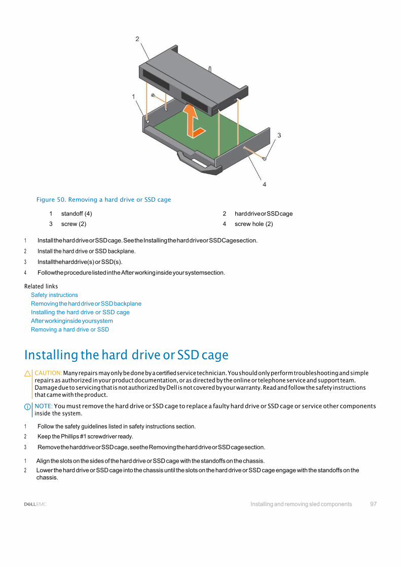
Installing and removing sled components 97
Figure 50. Removing a hard drive or SSD cage
1 standoff (4) 2 hard drive or SSD cage
3 screw (2) 4 screw hole (2)
1 Install the hard drive or SSD cage. See the Installing the hard driveor SSDCagesection.
2 Install the hard drive or SSD backplane.
3 Installtheharddrive(s) or SSD(s).
4 Followthe procedure listed inthe After working inside your systemsection.
Related links Safety instructions
Removing the hard drive or SSD backplane
Installing the hard drive or SSD cage
After workinginside yoursystem
Removing a hard drive or SSD
Installing the hard drive or SSD cage CAUTION: Many repairs may only be done by a certified service technician. You should only perform troubleshooting and simple repairs as authorized in your product documentation, or as directed by the online or telephone service and support team. Damage due to servicing that is not authorized by Dell is not covered by your warranty. Read and follow the safety instructions that came with the product.
NOTE: You must remove the hard drive or SSD cage to replace a faulty hard drive or SSD cage or service other components inside the system.
1 Follow the safety guidelines listed in safety instructions section.
2 Keep the Phillips #1 screwdriver ready.
3 Remove the harddrive or SSD cage, seethe Removing the hard drive or SSD cage section.
1 Align the slots on the sides of the hard drive or SSD cage with the standoffs on the chassis.
2 Lower the hard drive or SSD cage into the chassis until the slots on the hard drive or SSD cage engage with the standoffs on the chassis.
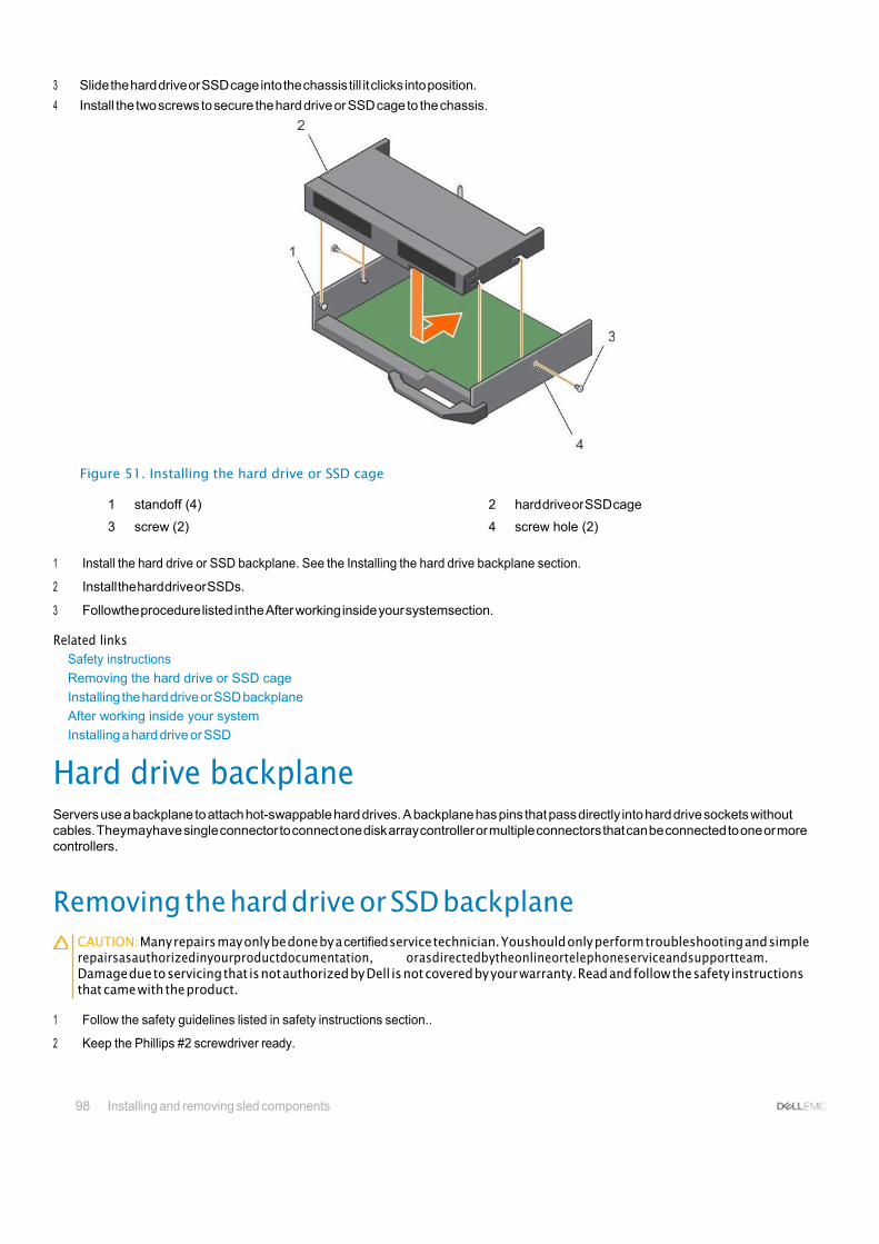
98 Installing and removing sled components
3 Slide the hard drive or SSD cage into the chassis till it clicks into position.
4 Install the two screws to secure the hard drive or SSD cage to the chassis.
Figure 51. Installing the hard drive or SSD cage
1 standoff (4) 2 hard drive or SSD cage
3 screw (2) 4 screw hole (2)
1 Install the hard drive or SSD backplane. See the Installing the hard drive backplane section.
2 Install the hard drive or SSDs.
3 Followthe procedure listed inthe After working inside your systemsection.
Related links Safety instructions
Removing the hard drive or SSD cage
Installing the hard drive or SSD backplane
After working inside your system
Installing a hard drive or SSD
Hard drive backplane Servers use a backplane to attach hot-swappable hard drives. A backplane has pins that pass directly into hard drive sockets without cables. Theymayhave single connector to connect one disk array controller or multiple connectors that can be connected to one or more controllers.
Removing the hard drive or SSD backplane CAUTION: Many repairs may only be done by a certified service technician. Youshould only perform troubleshooting and simple repairsasauthorizedinyourproductdocumentation, orasdirectedbytheonlineortelephoneserviceandsupportteam. Damage due to servicing that is not authorized by Dell is not covered by your warranty. Read and follow the safety instructions that came with the product.
1 Follow the safety guidelines listed in safety instructions section..
2 Keep the Phillips #2 screwdriver ready.

Installing and removing sled components 99
3 Follow the procedure listed in Before working inside your system section.
CAUTION: Toprevent damage to the hard drives or SSDs and the hard drive or SSD backplane, you must remove the hard drives or SSDs from the sled before removing the hard drive or SSD backplane.
CAUTION: You must note the number of each hard drive or SSD and temporarily label them before removal so that you can replacetheminthesamelocations.
4 Remove the hard drive(s) orSSD(s).
1 Loosen the two retention screws securing the hard drive or SSD backplane to the hard drive or SSD cage.
2 Lift the hard drive or SSD backplane by its edges till the guide pin on the hard drive or SSD cage disengages with the guide on the hard drive or SSD backplane.
3 Remove the hard drive or SSD cage. See the Removing the hard drive or SSD Cage section.
4 Loosen the two retention screws securing the hard drive or SSD backplanecableconnectortothesystemboard connector.
5 Lift the backplane up and away from the system.
Figure 52. Removing the hard drive or SSD backplane
1 hard drive or SSD backplane 2 hard drive or SSD backplane cable
3 retention screw (2) 4 screw hole on the hard drive or SSD cage (2)
5 guide pin 6 retention screw on the hard drive or SSD backplane cable connector (2)
7 connector
1 Install the hard drive or SSD backplane, see the Installing the hard drive backplane section.
2 Install the hard drive or SSD.
3 Followthe procedure listed inthe After working inside your systemsection.

100 Installing and removing sled components
Related links Safety instructions
Before working inside your system
Removing the hard drive or SSD cage
Installing the hard drive or SSD backplane
After working inside your system
Removing a hard drive or SSD
Installing the hard drive or SSD backplane CAUTION: Many repairs may only be done by a certified service technician. You should only perform troubleshooting and simple repairs as authorized in your product documentation, or as directed by the online or telephone service and support team. Damage due to servicing that is not authorized by Dell is not covered by your warranty. Read and follow the safety instructions that came with the product.
NOTE: You must remove the hard drive or SSD backplane to replace a faulty hard drive or SSD backplane or service other components inside the system.
1 Follow the safety guidelines listed in safety instructions section.
2 Keep the Phillips #2 screwdriver ready.
3 Remove the harddrive or SSD. See the Removing the hard drive or SSDsection.
4 Remove the hard drive or SSD backplane. See the Removing the hard drive backplane section.
1 Align the retention screws on the hard drive or SSD backplane cable connector withthe screw holes on the system board connector.
2 Tighten the two retention screws to secure the backplane cable conncetor on the system board.
3 Install the hard drive or SSD cage.
4 Align the following:
• Guide on the hard drive or SSD backplane with the guide pin on the hard drive or SSD cage.
• retention screws on the hard drive or SSD backplane with the screw holes on the hard drive or SSD cage.
5 Lower the hard drive or SSD backplane into place until the retention screws on the hard drive or SSD backplane engage with the screw holes on the hard drive or SSD cage.
6 Tighten the two retention screws to secure hard drive or SSD backplane on the hard drive or SSD cage.

Installing and removing sled components 101
Figure 53. Installing the hard drive or SSD backplane
1 hard drive or SSD backplane 2 hard drive or SSD backplane cable
3 retention screw (2) 4 screw hole on the hard drive or SSD cage (2)
5 guide pin 6 retention screw on the hard drive or SSD backplane cable connector (2)
7 connector
1 Install the hard drives or SSDs in their original locations.
2 Followthe procedure listed inthe After working inside your systemsection.
Related links Safety instructions
Removing a hard drive or SSD
Removing the hard drive or SSD backplane
After working inside your system
Installing the hard drive or SSD cage
Installing a hard drive or SSD
PERCH730Pslimcard The PERC H730P slim card is supported only on systems with eight 1.8-inch SSDs and two processors.
Removing a PERC H730P slim card CAUTION: Many repairs may only be done by a certified service technician. Youshould only perform troubleshooting and simple repairsasauthorizedinyourproductdocumentation, orasdirectedbytheonlineortelephoneserviceandsupportteam. Damage due to servicing that is not authorized by Dell is not covered by your warranty. Read and follow the safety instructions that came with the product.

102 Installing and removing sled components
1 Follow the safety guidelines listed in safety instructions section.
2 Keep the Phillips #2 screwdriver ready.
3 Followthe procedure listed in the Beforeworking inside yoursystem section.
4 Remove the cooling shroud.
1 Loosen the two retention screws on the PERC H730P slim-card cable connector.
2 Holding the pull tag, lift the PERC H730P slim-card cable connector from the system board connector.
3 Press the release latch on the side of the chassis to the unlock position and slide the PERC H730P slim card towardthe back of the system.
CAUTION: To prevent damage to the PERC H730P slim card, you must hold the card only by its edges.
4 Lift the card up and away from the system.
Figure 54. Removing a PERC H730P slim card
1 standoff (2) 2 PERC H730P slim-card cable connector
3 pull tag 4 PERC H730P slim card
5 PERC H730P release latch 6 lock and unlock icon on the PERC H730P slim card bracket
Related links
Safety instructions
Before working inside your system
Removing the cooling shroud

Installing and removing sled components 103
Installing a PERC H730P slim card CAUTION: Many repairs may only be done by a certified service technician. Youshould only perform troubleshooting and simple repairsasauthorizedinyourproductdocumentation, orasdirectedbytheonlineortelephoneserviceandsupportteam. Damage due to servicing that is not authorized by Dell is not covered by your warranty. Read and follow the safety instructions that came with the product.
1 Follow the safety guidelines listed in safety instructions section.
2 Keep the Phillips #2 screwdriver ready.
1 If installed, remove the PERC H730P slim card blank.
2 Press the release latch on the side of the chassis to the unlock position.
NOTE: Ensure that all the memory module ejectors are in the closed position.
3 Align the slots on the PERC H730P slim card with the standoffs on the side of the chassis.
4 Lower the PERC H730P slim card into the chassis until the slots on the card engage with the standoffs on the side of the chassis.
5 Press the release latch to the lock position to secure the card firmly on the chassis.
The PERC H730P slim card connects to the backplane connector.
6 Hold thepull tag on the PERC H730 slim-card cable connector and route the cable between the memory-module ejectors.
7 Align the retention screws on the PERC H730P slim-card cable connector with thescrewholes onthesystemboard connector.
8 Tighten the two retention screws to secure the PERC H730P slim-card cable connector on the system board.
Figure 55. Installing a PERC H730P slim card
1 PERC H730P slim card 2 PERC H730P release latch
3 lock and unlock icon on the PERC H730P slim card bracket
Follow the procedure listed in the After working inside your system section.

104 Installing and removing sled components
Related links Safety instructions
After working inside your system
Storage controller card Yoursystem includes adedicated expansion-card slot on the system board for a storage controller card that provides the integrated storage subsystem for your system’s hard drives. The storage controller card supports SSD or SAS or SATA hard drives.
NOTE: The storage controller card is located underneath the hard drive or SSD cage.
Removing the PCIe extender or storage controller card CAUTION: Many repairs may only be done by a certified service technician. You should only perform troubleshooting and simple repairs as authorized in your product documentation, or as directed by the online or telephone service and support team. Damage due to servicing that is not authorized by Dell is not covered by your warranty. Read and follow the safety instructions thatareshippedwithyourproduct.
NOTE: PCIe extender or storage controller card is supported on systems with the SAS backplanes.
1 Follow the safety guidelines listed in safety instructions section.
2 Keep the Phillips #2 screwdriver ready.
3 Followthe procedure listed in the Beforeworking inside yoursystemsection..
4 Remove the following:
a Hard drives or SSDs
b Hard drive or SSD backplane
c Hard drive or SSD cage
1 Loosen the two retention screws on the hard drive or SSD backplane cable connector and lift it away from the PCIe extender or storage controller card.
CAUTION: To prevent damage to the PCIe extender or storage controller card, you must hold the card only by its edges.
2 Lift the PCIe extender or storage controller card up and awayfrom the system.

Installing and removing sled components 105
Figure 56. Removing the PCIe extender or storage controller card
1 retention screw (2) 2 slot on the PCIe extender or storage controller card
3 tab on the PCIe extender or storage controller card support bracket
4 standoff (2)
1 Install the PCIe extender or storage controller card.
2 Install the following:
a Hard drive or SSD cage
b Hard drive or SSD backplane
c Hard drives or SSDs
3 Followthe procedure listed inthe After working inside your systemsection.
Related links Safety instructions
Before working inside your system
Installing the PCIe extender or storage controller card
After working inside your system
Removing a hard drive or SSD
Removing the hard drive or SSD backplane
Removing the hard drive or SSD cage

106 Installing and removing sled components
Installingthe PCIeextender or storagecontrollercard CAUTION: Many repairs may only be done by a certified service technician. You should only perform troubleshooting and simple repairs as authorized in your product documentation, or as directed by the online or telephone service and support team. Damage due to servicing that is not authorized by Dell is not covered by your warranty. Read and follow the safety instructions that came with the product.
NOTE: PCIe extender or storage controller card is supported on systems with the SAS backplanes.
NOTE: You must remove the PCIe extender or storage controller card to replace a faulty PCIe extender or storage controller card orserviceothercomponentsinsidethesystem.
1 Follow the safety guidelines listed in safety instructions section.
2 Keep the Phillips #2 screwdriver ready.
3 Remove the PCIe extender or storage controller card.
1 Align the slots on the PCIe extender or storage controller card edge with the tabs on the support bracket.
CAUTION: To prevent damage to the PCIe extender or storage controller card, you must hold the card only by its edges.
2 Lower the PCIe extender or storage controller card on to the connector on the system board.
3 Tighten the two retention screws on the hard drive or SSD backplane cable connector to secure the card on to the system board.
Figure 57. Installing the PCIe extender or storage controller card
1 retention screw (2) 2 slot on the PCIe extender or storage controller card
3 tab on the PCIe extender or storage controller card support bracket
4 standoff (2)
1 Install the following:
Installing and removing sled components 107
a Hard drives or SSDs
b Hard drive or SSD backplane
c Hard drive or SSD cage
2 Followthe procedure listed inthe After working inside yoursystemsection..
Related links Safety instructions
Removing the PCIe extender or storage controller card
After working inside your system
Installing a hard drive or SSD
Installing the hard drive or SSD backplane
Installing the hard drive or SSD cage
NVRAM backup battery The NVRAM backup battery installed in your system helps to retain the BIOS settings and configurations even if the power is switched off.
Replacing the NVRAM backup battery WARNING: There is a danger of a new battery exploding if it is incorrectly installed. Replace the battery only with the same or equivalenttyperecommendedbythemanufacturer. Discardusedbatteriesaccordingtothemanufacturer'sinstructions. Seethe safety instructions that came with your system for additional information.
CAUTION: Many repairs may only be done by a certified service technician. You should only perform troubleshooting and simple repairs as authorized in your product documentation, or as directed by the online or telephone service and support team. Damage due to servicing that is not authorized by Dell is not covered by your warranty. Read and follow the safety instructions thatareshippedwithyourproduct.
1 Follow the safety guidelines listed in safety instructions section.
2 Followthe procedure listed in the Beforeworking inside yoursystem section.
3 Remove the following:
a Hard drivesor SSDs
b Coolingshroud
c Hard drive or SSD backplane
d Hard drive or SSD cage
e PCIe mezzanine card
f NDC
g IDSDM or rSPI card
h System board
1 Locate the system battery on the system.
2 Toremove the battery, press down firmly on the positive side of the connector and lift the battery out of the securing tabs at the negative side of the connector.
3 Toinstall a new system battery:
a Support the battery connector by pressing down firmly on the positive side of the connector. b Hold the battery with the "+" facing up and slide it under the securing tabs at the positive side of the connector.
4 Press the battery straight down into the connector until it snaps into place.

108 Installing and removing sled components
Figure 58. Removing the NVRAM backup battery
1 positive side of battery 2 negative side of battery connector
Figure 59. Installing the NVRAM backup battery
1 positive side of battery 2 negative side of battery connector
1 Install the following:
a System board
b IDSDM or rSPI card
c NDC
d PCIemezzaninecards
e Hard drive or SSD cage
f Hard drive or SSD backplane
g Coolingshroud
h Hard drives or SSDs
2 Followthe procedure listed inthe After working inside your systemsection.
3 Enter the System Setup to confirm that the battery is operating properly.
4 Enter the correct time and date in the System Setup's Time and Date fields.
5 Exitthe System Setup.
6 Totest the newly installed battery, remove the sled for at least an hour.
7 Reinstall the sled after an hour.
8 Enter the System Setup and if the time and date are still incorrect, see the Getting help section.

Installing and removing sled components 109
Related links Getting help
Safety instructions
Before working inside your system
After working inside your system
Removing a hard drive or SSD
Removing the cooling shroud
Removing the hard drive or SSD backplane
Removing the hard drive or SSD cage
Removing a PCIe mezzanine card
Removing the Network Daughter Card
Removing the optional IDSDM card
Installing the optional IDSDM card
Removing the system board
Installing the system board
Installing the optional IDSDM card
Installing the optional rSPI card
Installing the Network Daughter Card
Installing a PCIe mezzanine card
Installing a hard drive or SSD
Installing the hard drive or SSD backplane
Installing the hard drive or SSD cage
Installing the cooling shroud
Removing the sled
Removing the sled
System board A system board (also known as the motherboard) is the main printed circuit board found in computers. The system board allows communication between many of the crucial electronic components of the computer, such as the central processing unit (CPU) and memory, and also provides connectors for other peripherals. Unlike a backplane, a system board contains significant number subsystems such as the processor expansion cards, and other components.
Removing the system board CAUTION: Many repairs may only be done by a certified service technician. You should only perform troubleshooting and simple repairs as authorized in your product documentation, or as directed by the online or telephone service and support team. Damage due to servicing that is not authorized by Dell is not covered by your warranty. Read and follow the safety instructions that came with the product.
CAUTION: If you are using Trusted Program Module (TPM) with an encryption key, you may be prompted to create a recovery key during program or System Setup. Be sure to create and safely store this recovery key. If you replace this system board, you must supply the recovery key when you restart your system or program before you can access the encrypted data on your hard drives.
CAUTION: Do not attempt to remove the TPM plug-in module from the motherboard. After the TPM plug-in module is installed, it is cryptographically bound to that specific motherboard. Any attempt to remove an installed TPM plug-in module breaks the cryptographic binding, and it cannot be reinstalled or installed on another motherboard.
1 Follow the safety guidelines listed in safety instructions section.
2 Keep the Phillips #2 screwdriver and the Hex nut driver-5 mm ready.
3 Followthe procedure listed in the Beforeworking inside yoursystem section.
4 Remove the following:

110 Installing and removing sled components
a Processor(s) and heat sink(s)
b Memory modules
c Coolingshroud
d Hard drive or SSDs
e Hard drive or SSD backplane
f Hard drive or SSD cage
g PCIe extender or storagecontroller card
h PCIe mezzanine card
i IDSDM or rSPI card
j NDC
k SD vFlash card
l Internal USB key
5 Install an I/O connector cover on the I/O connector(s) at the back of the board.
CAUTION: Do not lift the system board by holding a memory module, processor, or other components.
CAUTION: You must temporarily label the hard drive or SSD before removal so that you can replace them in their original locations.
WARNING: The processor and heat sink can become extremely hot. Be sure the processor has had sufficient time to cool before handling.
WARNING: The memory modules are hot to the touch for some time after the system has been turned off. Allow time for the memorymodulestocoolbeforehandlingthem. Handlethememorymodulesbythecardedgesandavoidtouchingthe components.
1 Remove the screws on the system board that secure the system board to the chassis
2 Lift the system board by its back end and angle it upward.
3 Remove the system board from the chassis by disengaging the USB connectors from the slots on the front wall of the chassis.
4 Ensure that the I/O connector cover is still in place on the I/O connector at the back of the board.

Installing and removing sled components 111
Figure 60. Removing the system board
1 hex nut screw (4) 2 system board
3 screw (10) 4 system board handle
1 Install the system board. See the Installing the system board section.
2 Followthe procedure listed inthe After working inside your systemsection.
112 Installing and removing sled components
Related links Safety instructions
Installing the system board
Installing the Trusted Platform Module
Trusted Platform Module
After working inside your system Restoring
the Service Tagbyusing the EasyRestore feature Entering
the system Service Tag by using System Setup
Initializing the TPM for BitLocker users
Initializing the TPM for TXT users
Replacing the internal USB key
Installing the optional IDSDM card
Installing the optional rSPI card
Installing the Network Daughter Card
Installing a PCIe mezzanine card
Installing the PCIe extender or storage controller card
Installing the hard drive or SSD cage
Installing the hard drive or SSD backplane
Installing a hard drive or SSD
Installing the cooling shroud
Installing memory modules
Installing a processor
Installing the system board CAUTION: Many repairs may only be done by a certified service technician. You should only perform troubleshooting and simple repairs as authorized in your product documentation, or as directed by the online or telephone service and support team. Damage due to servicing that is not authorized by Dell is not covered by your warranty. Read and follow the safety instructions that came with the product.
NOTE: You must remove the system board to replace a faulty system board.
Follow the safety guidelines listed in safety instructions section.
Keep the Phillips #2 screwdriver and the Hex nut driver-5 mm ready.
Remove the system board. See the Removing the System Board section.
Unpack the new system board assembly.
CAUTION: Do not lift the system board by holding a memory module, processor, or other components.
CAUTION: Take care not to damage the system identification button while placing the system board into the chassis.
1 Hold the system board by its edges and align the USB connectors with the slots on the front wall of the chassis.
2 Lower the system board until the system board is firmly seated on the chassis.
3 Install the screws to secure the system board to the chassis.
1
2
3
4

Installing and removing sled components 113
Figure 61. Installing the system board
1 hex nut screw (4) 2 system board
3 screw (10) 4 system board handle
1 Install the Trusted Platform Module (TPM). For information about how to install TPM, see the Installing the trusted platform modules section. For information about TPM, see the TrustedPlatform Module section.
2 Install the following:
a Internal USB key
b SD vFlash card
c IDSDM or rSPI card
d NDC or LOM riser card
e PCIe mezzanine card
f PCIe extender or storagecontroller card
g Hard drive or SSD cage
h Hard drive or SSD backplane
i Hard drive(s) or SSD(s)
NOTE: Ensure that you reinstall the hard drives or SSDs in their original locations.
j Coolingshroud
k Memory modules

114 Installing and removing sled components
l Processor(s) and heat sink(s)
3 Followthe procedure listed inthe After working inside your systemsection.
NOTE: If you are not installing the sled in the enclosure, install the I/O connector cover.
4 Import your new or existing iDRAC Enterprise license. See the iDRAC8 User's Guide at Dell.com/idracmanuals.
5 Ensure that you:
a Use the Easy Restore feature to restorethe Service Tag.For more information, see the Restoring the Service Tagusing Easy Restore section.
b If the Service Tagis not backed up in the backup flash device, enter the system Service Tagmanually. For more information, see the Entering the system Service Tagsection.
c Update the BIOS and iDRAC versions.
d Reenable the Trusted Platform Module (TPM). For more information, see the Reenabling the TPM for BitLocker users section or the Reenabling the TPM for Intel TXT users section.
Related links Safety instructions
Before working inside your system
Removing the system board
After workinginside yoursystem
Removing a heat sink
Removing memory modules
Removing the cooling shroud
Removing a hard drive or SSD
Removing the hard drive or SSD backplane
Removing the hard drive or SSD cage
Removing a PCIe mezzanine card
Removing the Network Daughter Card
Removing the optional IDSDM card
Removing the optional rSPI card
Replacing the SD vFlash card
Replacing the internal USB key
Restoring the Service Tag by using the Easy Restore feature
The Easy Restore feature enables you to restore your system’s Service Tag, license, UEFI configuration, and the system configuration data after replacing the system board. All data is automatically backed up in abackup flash device. If BIOS detects anewsystem boardandthe Service Tagin the backup flash device, BIOS prompts the user torestore the backup information.
1 Turn on the system.
If BIOS detects anewsystem board, and if the Service Tagis present in the backup flash device, BIOS displays the Service Tag, the status of the license, and the UEFIDiagnosticsversion.
2 Perform one of the following steps:
• Press Y to restore the Service Tag, license, and diagnostics information.
• Press N to navigate to the Dell Lifecycle Controller based restoreoptions.
• Press F10 to restore data from a previously created Hardware Server Profile.
After the restore process is complete, BIOS prompts to restore the system configuration data.
3 Perform one of the following steps:
• Press Y to restorethe system configuration data.
• Press N to use the default configuration settings.
After the restore process is complete, the system restarts.
Installing and removing sled components 115
Entering the system Service Tag by using System Setup
If Easy Restore fails to restore the Service Tag, use System Setup to enter the Service Tag.
1 Turn on the system.
2 Press F2 toenter System Setup.
3 Click Service TagSettings.
4 Enter the Service Tag.
NOTE: Youcanenterthe Service Tagonlywhenthe Service Tagfield isempty.Ensurethatyouenterthecorrect Service Tag. After the Service Tagis entered, it cannot be updated or changed.
5 Click Ok.
6 Import your new or existing iDRAC Enterprise license.
For more information, see the Integrated Dell Remote Access Controller User's Guide at Dell.com/idracmanuals.
Trusted Platform Module Trusted Platform Module (TPM) is a dedicated microprocessor designed to secure hardware by integrating cryptographic keys into devices. A software can use a Trusted Platform Module to authenticate hardware devices. As each TPM chip has a unique and secret RSA key burned in as it is produced, it can perform the platform authentication.
CAUTION: Do not attempt to remove the Trusted Platform Module (TPM) from the system board. After the TPM is installed, it is cryptographically bound to that specific system board. Any attempt to remove an installed TPM breaks the cryptographic binding, and it cannot be re-installed or installed on another system board.
NOTE: This is a Field Replaceable Unit (FRU). Removal and installation procedures must be performed only by Dell certified service technicians.
Installing the Trusted Platform Module CAUTION: Many repairs may only be done by a certified service technician. Youshould only perform troubleshooting and simple repairsasauthorizedinyourproductdocumentation, orasdirectedbytheonlineortelephoneserviceandsupportteam. Damage due to servicing that is not authorized by Dell is not covered by your warranty. Read and follow the safety instructions that came with the product.
1 Followthesafetyguidelineslistedinthe Safetyinstructions section.
2 Followthe procedure listed in the Beforeworking inside yoursystem section.
1 Locate the Trusted Platform Module (TPM) connector on the system board.
NOTE: To locate the TPM connector on the system board, see the System board connectors section.
2 Align the edge connectors on the TPM with the slot on the TPM connector.
3 Insert the TPM into the TPM connector such that the plastic bolt aligns with the slot on the system board.
4 Press the plastic bolt until the bolt snaps into place.
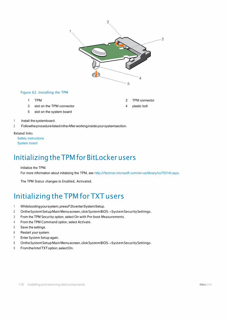
116 Installing and removing sled components
Figure 62. Installing the TPM
1 TPM 2 TPM connector
3 slot on the TPM connector 4 plastic bolt
5 slot on the system board
1 Install the systemboard.
2 Followthe procedure listed inthe After working inside your systemsection.
Related links Safety instructions
System board
Initializing the TPM for BitLocker users Initialize the TPM.
For more information about initializing the TPM, see http://technet.microsoft.com/en-us/library/cc753140.aspx.
The TPM Status changes to Enabled, Activated.
Initializing the TPM for TXT users 1 While booting your system, press F2to enter System Setup.
2 Onthe System Setup Main Menu screen, click System BIOS→System Security Settings.
3 From the TPM Security option, select On with Pre-boot Measurements.
4 From the TPM Command option, select Activate.
5 Save the settings.
6 Restart your system.
7 Enter System Setup again.
8 Onthe System Setup Main Menu screen, click System BIOS→System Security Settings.
9 From the Intel TXT option, select On.
Using systemdiagnostics 117
7
Using system diagnostics If youexperience aproblem with your system, run the system diagnostics before contacting Dell for technical assistance. The purpose of running system diagnostics is to test your system hardware without requiring additional equipment or risking data loss. If you are unable to fix the problem yourself, service and support personnel can use the diagnostics results to help you solve the problem.
Dell Embedded System Diagnostics NOTE: The Dell Embedded System Diagnostics is also known as Enhanced Pre-boot System Assessment (ePSA) diagnostics.
The Embedded System Diagnostics provides a set of options for particular device groups or devices allowing you to:
• Runtestsautomaticallyorinaninteractivemode
• Repeat tests
• Display or save test results
• Run thorough tests to introduce additional test options to provide extra information about the failed device(s)
• Viewstatus messages that inform you if tests are completed successfully
• View error messages that inform you of problems encountered during testing
Running the Embedded System Diagnostics Run the Embedded System Diagnostics (ePSA)if your system does not boot. The embedded system diagnostics program is run from the Dell Lifecycle Controller. If a major component ordevice in the system does not operate properly,running theembedded system diagnostics may indicate component failure.
CAUTION: Use the embedded system diagnostics to test only your system. Using this program with other systems may cause invalid results or error messages.
1 As the system boots, press F11.
2 Use the up and down arrow keys to select System Utilities > Launch Dell Diagnostics.
The ePSA Pre-boot System Assessment window is displayed, listing all devices detected in the system. The diagnostics starts running the tests on all the detected devices.
Running embedded system diagnostics from an external media 1 Format the external resource media (USB flash drive or CDROM) to emulate a hard drive.
See the documentation that came withthe resource media for instructions.
2 Configure the resource media to be a bootable device.
3 Createa directoryfor the system diagnostics onthe resource media.
4 Copy the system diagnostics files into the directory.
To download the Dell diagnostics utility, go to Dell.com/support/home.
5 Connect the resource media on your system.
6 As the system boots, press F11.

118 Using systemdiagnostics
7 When prompted, select themedia to perform a one-time boot.
If diagnostics does not start automatically after the diagnostic media is booted, enter psa at the command prompt.
System diagnostics controls Menu Description
Configuration Displays the configuration and status information of all detected devices.
Results Displays the results of all tests that are run.
System Health Provides the current overview of the system performance.
Event Log Displays a time-stamped log of the results of all tests run on the system. This is displayed if at least one event description isrecorded.
For information about embedded system diagnostics, see the Dell Enhanced Pre-boot System Assessment User Guide at Dell.com/ support/home.

Jumpers and connectors 119
8
Jumpers and connectors This topic provides specific information about the system jumpers. It also provides some basic information about jumpers and switches and describes the connectors on the various boards in the system. Jumpers on the system board help to disable system and setup passwords. Youmust know the connectors on the system board to install components and cables correctly.
Topics:
• System board jumpersettings
• System board connectors
• Disabling a forgotten password
System board jumper settings CAUTION: Many repairs may only be done by a certified service technician. Youshould only perform troubleshooting and simple repairsasauthorizedinyourproductdocumentation, orasdirectedbytheonlineortelephoneserviceandsupportteam. Damage due to servicing that is not authorized by Dell is not covered by your warranty. Read and follow the safety instructions that came with the product.
For information about resetting the password jumper to disable a password, see the Disabling A Forgotten Password section.
Table 26. System Board Jumper settings
Jumper Setting Description
PWRD_EN (default)
The password feature is enabled (pins 1–2).
The password feature is disabled (pins 2–3).
NVRAM_CLR (default)
The configuration settings are retained at system boot (pins 2–3).
The configuration settings arecleared at the next system boot. (pins 1– 2).
Related links Disabling a forgotten password

120 Jumpers and connectors
System board connectors
Figure 63. System board connectors Table 27. System board connectors
Item Connector Description
1 BATTERY Connector for the 3.0 V coin cell battery
2 STORAGE Storage controller card connector
3 B3, B7, B11, B4, B8, B12 Memory module sockets (processor 2)
4 CPU2 Processor socket 2
5 J_PCIE_SEARAY PERC H730P Slim PERC card connector
6 CPU1 Processor socket 1
7 A1, A5, A9, A2, A6, A10 Memory module sockets (processor 1)
8 IDSDM/rSPI IDSDM or rSPI card connector
9 MEZZ1_FAB_C PCIe mezzanine card connector for the expansion bus
10 MEZZ2_FAB_B PCIe mezzanine card connector for the expansion bus
11 VFLASH SD vFlash card connector
12 bNDC Network Daughter Card connector
13 A3, A7, A11, A4, A8, A12 Memory module sockets (processor 1)

Jumpers and connectors 121
Item Connector Description
14 PWRD_EN, NVRAM_CLR System configuration jumpers
NOTE: Access needs removal of system board.
15 B1, B5, B9, B2, B6, B10 Memory module sockets (processor 2)
16 USB2 USB connector
17 USB1 USB connector
18 TPM TPM connector
19 J_BP Hard drive backplane connector
Disabling a forgotten password The software security features of sled include a system password and a setup password. The password jumper enables these password features or disables them, and clears any password(s) currently in use.
CAUTION: Many repairs may only be done by a certified service technician. Youshould only perform troubleshooting and simple repairsasauthorizedinyourproductdocumentation, orasdirectedbytheonlineortelephoneserviceandsupportteam. Damage due to servicing that is not authorized by Dell is not covered by your warranty. Read and follow the safety instructions that came with the product.
1 Turnoff the sled using the operating system commands or the CMC.
2 Remove the sledfrom the enclosure to access the jumpers.
3 Move the jumper on the system-board jumper from pins 1 and 2 to pins 2 and 3.
4 Install the sled in the enclosure.
5 Turn on the sled.
When the sled is turn on, power indicator turns on to solid green. Allow the sled to finish booting.
The existing passwords are not disabled (erased) until the system boots with the password jumper on pins 2 and 3.
6 Turnoff the sled using the operating system commands or the CMC.
7 Remove the sledfrom the enclosure to access the jumpers.
8 Move the jumper on the system-board jumper from pins 2 and 3 to pins 1 and 2.
9 Install the sled in the enclosure.
10 Turn on the sled.
11 Assignanewsystemand/orsetuppassword.

126 Troubleshooting your system
9
Troubleshooting your system
Safety first — for you and your system CAUTION: Many repairs may only be done by a certified service technician. Youshould only perform troubleshooting and simple repairsasauthorizedinyourproductdocumentation, orasdirectedbytheonlineortelephoneserviceandsupportteam. Damage due to servicing that is not authorized by Dell is not covered by your warranty. Read and follow the safety instructions thatareshippedwithyourproduct.
NOTE: Solution validation was performed by using the factory shipped hardware configuration.
NOTE: Thischapterprovidestroubleshootinginformationforthe PowerEdge FX2 and FX2senclosuresonly. Fortroubleshooting information on the sleds, see the sled documentation at Dell.com/poweredgemanuals.
NOTE: For troubleshooting information about the PowerEdge FX2 enclosure components, see the Dell PowerEdge FX2 and FX2s Enclosure Owner's Manual at Dell.com/poweredgemanuals.
Topics:
• Troubleshooting system memory
• Troubleshooting harddrives
• Troubleshooting USBdevices
• Troubleshooting Solid State Drives
• Troubleshooting an internal SD card
• Troubleshooting processors
• Troubleshooting the system board
• Troubleshooting the NVRAM backup battery
Troubleshooting system memory CAUTION: Many repairs may only be done by a certified service technician. You should only perform troubleshooting and simple repairs as authorized in your product documentation, or as directed by the online or telephone service and support team. Damage due to servicing that is not authorized by Dell is not covered by your warranty. Read and follow the safety instructions thatareshippedwithyourproduct.
NOTE: Beforeperforming thefollowingprocedure, ensurethatyouhaveinstalledthememorymodulesaccordingtothememory installation guidelines for the sled.
1 Restart the sled:
a Press the power button after to turn off the sled. b Press the power button again to apply power to the sled.
If no error messages appear, go to step 8.
2 Enter the System Setup and check the system memory setting.
If the amount of memory installed matches the system memory setting, go to step 8.
3 Remove the sled from the enclosure.
4 Open the sled.
Troubleshooting your system 123
CAUTION: The memory modules are hot to touch for some time after the sled has been powered down. Allow time for the memory modules to cool before handling them. Handle the memory modules by the card edges and avoid touching the components.
5 Reseat the memory modules in their sockets.
6 Close thesled.
7 Install the sled in the enclosure.
8 Run the appropriate diagnostic test. For more information, see the Using system diagnostics section.
If the test fails, see the Getting help section.
Related links Getting help
Using system diagnostics
Removing the sled
Installing the sled
Troubleshooting hard drives CAUTION: Many repairs may only be done by a certified service technician. You should only perform troubleshooting and simple repairs as authorized in your product documentation, or as directed by the online or telephone service and support team. Damage due to servicing that is not authorized by Dell is not covered by your warranty. Read and follow the safety instructions thatareshippedwithyourproduct.
CAUTION: This troubleshooting procedure can destroy data stored on the hard drive. Before you proceed, back up all the files on the hard drive, if possible.
1 Run the appropriate controllers test and the harddrive tests in system diagnostics.
If the tests fail, go to step 3.
2 Takethe hard drive offline and wait until the hard drive indicator codes on the drive carrier signal that the drive may be removed safely, then remove andreseat the drive carrier in the sled.
3 Restart the sled, enter the System Setup and confirm that thedrive controller is enabled.
4 Ensure that any required device drivers are installed and are configured correctly.
NOTE: Installing a hard drive into another bay may break the mirror if the mirror state is optimal.
5 Remove the hard drive and install it in the other drive bay.
6 If the problem is resolved, reinstall the hard drive in the original bay.
If the hard drive functions properly in the original bay, the drive carrier could have intermittent problems. Replace the drive carrier.
7 If the hard drive is the boot drive, ensure that the drive is configured and connected properly.
8 Partition and logicallyformat the hard drive.
9 If possible, restore the files to the drive.
If the problem persists, see the Getting help section.
Related links Getting help Hard
drive or SSD indicator patterns
Removing a hard drive or SSD
Installing a hard drive or SSD
124 Troubleshooting your system
TroubleshootingUSB devices CAUTION: Many repairs may only be done by a certified service technician. Youshould only perform troubleshooting and simple repairsasauthorizedinyourproductdocumentation, orasdirectedbytheonlineortelephoneserviceandsupportteam. Damage due to servicing that is not authorized by Dell is not covered by your warranty. Read and follow the safety instructions thatareshippedwithyourproduct.
1 Ensure that the sled is turned on.
2 Check the USB device connection to the sled.
3 Swapthe USB device witha working USB device.
4 Connect the USB devices to the sled byusing a powered USB hub.
5 If another sled is installed, connect the USB device to that sled. If the USB device works with a different sled, the first sled’s USB ports may be faulty. See the Getting help section.
Related links Getting help
Troubleshooting Solid State Drives CAUTION: Many repairs may only be done by a certified service technician. You should only perform troubleshooting and simple repairs as authorized in your product documentation, or as directed by the online or telephone service and support team. Damage due to servicing that is not authorized by Dell is not covered by your warranty. Read and follow the safety instructions thatareshippedwithyourproduct.
CAUTION: This troubleshooting procedure can destroy data stored on the SSD. Before you proceed, back up all the files on the SSD, if possible.
1 Run the appropriate tests in system diagnostics.
If the tests fail, go to step 3.
2 Takethe SSD offline and wait until the indicator codes on the SSD carrier signal that the SSD may be removed safely, then remove and reseat the SSD carrier in the sled.
3 Restart the sled, enter the System Setup and confirm that thedrive controller is enabled.
4 Ensure that any required device drivers are installed and are configured correctly.
NOTE: Installing a SSD into another bay may break the mirror if the mirror state is optimal.
5 Remove the SSD and install it in the other SSD slot.
6 If the problem is resolved, reinstall the SSD intheoriginal slot.
If the SSD functions properly in the original slot, the SSD carrier could have intermittent problems. Replace the SSD carrier.
7 If the SSD is the boot drive, ensure that the SSD is configured and connected properly.
8 Partition and logically format the SSD.
9 If possible, restorethe files to the SSD.
If the problem persists, see the Getting help section.
Related links Getting help Hard
drive or SSD indicator patterns
Removing a hard drive or SSD
Installing a hard drive or SSD

Troubleshooting your system 125
Troubleshooting an internal SD card CAUTION: Many repairs may only be done by a certified service technician. Youshould only perform troubleshooting and simple repairsasauthorizedinyourproductdocumentation, orasdirectedbytheonlineortelephoneserviceandsupportteam. Damage due to servicing that is not authorized by Dell is not covered by your warranty. Read and follow the safety instructions thatareshippedwithyourproduct.
1 Enter the System Setup and ensure that the Internal SDCard Port is enabled.
2 Note the Internal SD Card Redundancy option is enabled in the Integrated Devices screen of the System Setup (Mirror or Disabled).
3 Turnoff the sled using the operating system commands or the CMC.
4 Remove the sled from the enclosure.
5 Ifthe Internal SDCard Redundancy option in the Integrated Devices screen of the System Setup is set to Mirror mode and SDcard 1 has failed:
a Remove the SD card from SD card slot 1. b Remove the SD card present in SD card slot 2 and insert it into SD card slot 1. c Install a new SD card in slot 2.
6 Ifthe Internal SDCard Redundancy option in the Integrated Devices screen of the System Setup is set to Mirror mode and SDcard 2 has failed, insert the new SD card into SD card slot 2.
7 IftheInternalSDCardRedundancyoptionin IntegratedDevicesscreenofthe System Setupissetto Disabled, replacethefailedSD card with a new SD card.
8 Install the sled in the enclosure.
9 Turn on the sled.
10 Enter the System Setup and ensure that the Internal SDCard Port option is enabled and Internal SDCard Redundancyoption is set to Mirror mode.
11 Check if the SD cardis functioning properly.
If the problem persists, see the Getting help section.
Related links Getting help
Removing a hard drive or SSD
Removing the sled
Installing the sled
Troubleshooting processors 1 Turnoff the sled using the operating system commands or the CMC.
2 Remove the sled from the enclosure.
3 Ensure that the processor(s) and heat sink(s) are properly installed.
4 If your system onlyhas oneprocessor installed, ensure that it is installed in the primaryprocessor socket (CPU1).
5 Install the sled in the enclosure.
6 Turn on the sled.
7 Run the appropriate diagnostic test. For more information, see Using System Diagnostics.
If the problem persists, see the Getting help section.
Related links Getting help
Removing the sled
Installing the sled

126 Troubleshooting your system
Troubleshooting the system board CAUTION: Many repairs may only be done by a certified service technician. Youshould only perform troubleshooting and simple repairsasauthorizedinyourproductdocumentation, orasdirectedbytheonlineortelephoneserviceandsupportteam. Damage due to servicing that is not authorized by Dell is not covered by your warranty. Read and follow the safety instructions thatareshippedwithyourproduct.
1 Turnoff the sled using the operating system commands or the CMC.
2 Remove the sled from the enclosure.
3 Clear the sled NVRAM.
4 If the problem persists, remove and reinstall the sled in the enclosure.
5 Turn on the sled.
6 Run the appropriate diagnostic test. For more information, see the Using System Diagnostics section.
If the tests fail, see the Getting help section.
Related links Getting help
Using system diagnostics
Removing the sled
Installing the sled
Troubleshooting the NVRAMbackup battery CAUTION: Many repairs may only be done by a certified service technician. Youshould only perform troubleshooting and simple repairsasauthorizedinyourproductdocumentation, orasdirectedbytheonlineortelephoneserviceandsupportteam. Damage due to servicing that is not authorized by Dell is not covered by your warranty. Read and follow the safety instructions thatareshippedwithyourproduct.
The battery maintains the sled configuration, date, and time information in the NVRAM when the sled is turned off. Youmayneed to replace the battery if an incorrect time or date is displayed during the boot routine.
You can operate the sled without a battery; however, the sled configuration information maintained bythe battery in NVRAM is erased each time you remove power supply unit from the sled. Therefore, you must reenter the system configuration information and reset the options each time the sled boots until you replace the battery.
1 Reenter the time and date through the System Setup.
2 Turnoff the sled using the operating system commands or the CMC.
3 Remove the sledfrom the enclosure for at least one hour.
4 Install the sled in the enclosure.
5 Turn on the sled.
6 Enter the System Setup.
If the date and time are not correct in the System Setup, replace the battery. If the problem is not resolved by replacing the battery, see the Getting help section.
NOTE: If the sled is turned off for long periods of time (for weeks or months), the NVRAM may lose its system configuration information. This situation is caused by a defective battery.
NOTE: Some software may cause the sled’s time to speed up or slow down. If the sled operates normally except for the time maintained by the System Setup, the problem may be caused by a software rather than by a defective battery.

Troubleshooting your system 127
Related links Getting help
Removing the sled
Installing the sled
Replacing the NVRAM backup battery

128 Getting help
10
Getting help
Topics:
• Contacting Dell
• Accessing system information by using QRL
Contacting Dell Dell provides several online and telephone-based support and service options. If you do not have an active internet connection, you can find contact information on your purchase invoice, packing slip, bill, or Dell product catalog. Availabilityvaries bycountryand product, and some services may not be available in your area. To contact Dell for sales, technical assistance, or customer-service issues:
1 Go to Dell.com/support.
2 Select your country from the drop-down menu on the bottom right corner of the page.
3 For customized support:
a Enter your system Service Tagin the Enter your Service Tag field. b Click Submit.
The support page that lists the various support categories is displayed.
4 For general support:
a Select your product category. b Select your product segment. c Select your product.
The support page that lists the various support categories is displayed.
5 For contact details of Dell Global Technical Support:
a Click Global TechnicalSupport.
b The Technical Support page is displayed with details to call, chat, or e-mail the Dell Global Technical Support team.
Accessing systeminformation byusing QRL Youcan use the Quick Resource Locator (QRL) to get immediate access to the information about your system. Ensure that yoursmartphone or tablet has the QR code scanner installed.
The QRL includes the following information about your system:
• How-to videos
• Reference materials, including the Owner’s Manual, LCD diagnostics, and mechanical overview
• Your system service tag to quickly access your specific hardware configuration and warranty information
• A direct link to Dell to contact technical assistance andsales teams
1 Goto Dell.com/QRL and navigate to your specific product or
2 Use your smartphone or tablet to scan the model-specific Quick Resource (QR) code onyour Dell PowerEdge system or in the Quick Resource Locatorsection.

Getting help 129
Quick Resource Locator for FC630
Figure 64. Quick Resource Locator for FC630

130 Getting help
Appendix. Supported processor for FC630
Processor Core Clock (GHz) Memory Speed(MHz)
TDP(W)
XeonE5-2603v3 6 1.6 1600 85
XeonE5-2603v4 6 1.7 1866 85
XeonE5-2609v3 6 1.9 1600 85
XeonE5-2609v4 8 1.7 1866 85
XeonE5-2620v3 6 2.4 1866 85
XeonE5-2620v4 8 2.1 2133 85
XeonE5-2623v3 4 3 1866 105
XeonE5-2623v4 4 2.6 2133 85
XeonE5-2630v3 8 2.4 1866 85
XeonE5-2630v4 10 2.2 2133 85
XeonE5-2630Lv3 8 1.8 1866 55
XeonE5-2630Lv4 10 1.8 2133 55
XeonE5-2637v3 4 3.5 2133 135
XeonE5-2637v4 4 3.5 2400 135
XeonE5-2640v3 8 2.6 1866 90
XeonE5-2640v4 10 2.4 2133 90
XeonE5-2643v3 6 3.4 2133 135
XeonE5-2643v4 6 3.4 2400 135
XeonE5-2650v3 10 2.3 2133 105
XeonE5-2650v4 12 2.2 2400 105
XeonE5-2650Lv3 12 1.8 2133 65
XeonE5-2650Lv4 14 1.7 2400 65
XeonE5-2660v3 10 2.6 2133 105
XeonE5-2660v4 14 2 2400 105
XeonE5-2667v3 8 3.2 2133 135
XeonE5-2667v4 8 3.2 2400 135
XeonE5-2670v3 12 2.3 2133 120
XeonE5-2680v3 12 2.5 2133 120
XeonE5-2680v4 14 2.4 2400 120
XeonE5-2683v3 14 2 2133 120
XeonE5-2683v4 16 2.1 2400 120
XeonE5-2690v3 12 2.6 2133 135
XeonE5-2690v4 14 2.6 2400 135
XeonE5-2695v3 14 2.3 2133 120
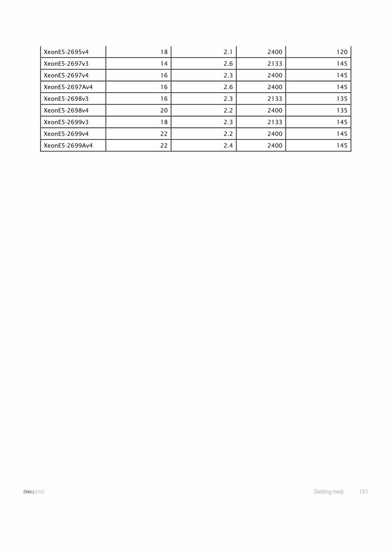
Getting help 131
XeonE5-2695v4 18 2.1 2400 120
XeonE5-2697v3 14 2.6 2133 145
XeonE5-2697v4 16 2.3 2400 145
XeonE5-2697Av4 16 2.6 2400 145
XeonE5-2698v3 16 2.3 2133 135
XeonE5-2698v4 20 2.2 2400 135
XeonE5-2699v3 18 2.3 2133 145
XeonE5-2699v4 22 2.2 2400 145
XeonE5-2699Av4 22 2.4 2400 145