Optimizing Seismic Capacity of Existing Masonry Buildings by ...
38
buildings Article Optimizing Seismic Capacity of Existing Masonry Buildings by Retrofitting Timber Floors: Wood-Based Solutions as a Dissipative Alternative to Rigid Concrete Diaphragms Michele Mirra * and Geert Ravenshorst Citation: Mirra, M.; Ravenshorst, G. Optimizing Seismic Capacity of Existing Masonry Buildings by Retrofitting Timber Floors: Wood- Based Solutions as a Dissipative Alternative to Rigid Concrete Diaphragms. Buildings 2021, 11, 604. https://doi.org/10.3390/buildings 11120604 Academic Editors: Jorge Manuel Branco and Beatrice Faggiano Received: 29 October 2021 Accepted: 24 November 2021 Published: 1 December 2021 Publisher’s Note: MDPI stays neutral with regard to jurisdictional claims in published maps and institutional affil- iations. Copyright: © 2021 by the authors. Licensee MDPI, Basel, Switzerland. This article is an open access article distributed under the terms and conditions of the Creative Commons Attribution (CC BY) license (https:// creativecommons.org/licenses/by/ 4.0/). Section of Bio-Based Structures and Materials, Delft University of Technology, 2600 GA Delft, The Netherlands; [email protected] * Correspondence: [email protected] Abstract: The inadequate seismic performance of existing masonry buildings is often linked to the excessively low in-plane stiffness of timber diaphragms and the poor quality of their connections to the walls. However, relevant past studies and seismic events have also shown that rigid diaphragms could be detrimental for existing buildings and do not necessarily lead to an increase in their seismic performance. Therefore, this work explores the opportunity of optimizing the retrofitting of existing timber floors by means of a dissipative strengthening option, consisting of a plywood panel overlay. On the basis of past experimental tests and previously formulated analytical and numerical models for simulating the in-plane response of these retrofitted diaphragms, in this work nonlinear incremental dynamic analyses were performed on three case–study buildings. For each structure three configurations were analyzed: an as-built one, one having floors retrofitted with concrete slabs and one having dissipative diaphragms strengthened with plywood panels. The results showed that the additional beneficial hysteretic energy dissipation of the optimized diaphragms is relevant and can largely increase the seismic performance of the analyzed buildings, while rigid floors only localize the dissipation in the walls. These outcomes can contribute to an efficient seismic retrofitting of existing masonry buildings, demonstrating once more the great potential of wood-based techniques in comparison to the use of reinforced concrete for creating rigid diaphragms. Keywords: seismic retrofitting; timber diaphragms; masonry buildings; reversible strengthening; energy dissipation 1. Introduction Existing unreinforced masonry (URM) constructions featuring timber diaphragms as floors and roofs often constitute a large part of the building stock and architectural heritage for several seismic-prone countries. The vulnerability of such buildings to earthquakes has been highlighted by numerous seismic events, mainly due to poor-quality masonry, excessive in-plane flexibility of timber floors, and the absence of effective connections among structural elements. In this framework, several retrofitting methods for timber diaphragms [1–12] and timber–masonry connections [13–16] have been developed in the recent years, progressively focusing on more reversible techniques [17]. With regard to the floors, the main proposed and tested retrofitting methods consisted of the traditional cast of a concrete slab on the existing floor, a widely adopted retrofitting in the last decades [1–4]; the superposition of a second layer of planks arranged at 45 ◦ [1,2,5,6] or 90 ◦ [4,7] with respect to the existing sheathing; the bracing of the floors with steel plates [1,2,5,6,9] or fiber-reinforced polymer (FRP) laminae [1,2,4]; and the superposition of cross-laminated timber (CLT) [7,8], oriented strand board (OSB) [8], or plywood panels [9–12]. The aim of all the techniques was to improve the in-plane stiffness of the floors, so that they could act as diaphragms and, along Buildings 2021, 11, 604. https://doi.org/10.3390/buildings11120604 https://www.mdpi.com/journal/buildings
-
Upload
khangminh22 -
Category
Documents
-
view
0 -
download
0
Transcript of Optimizing Seismic Capacity of Existing Masonry Buildings by ...

buildings
Article
Optimizing Seismic Capacity of Existing Masonry Buildings byRetrofitting Timber Floors: Wood-Based Solutions as aDissipative Alternative to Rigid Concrete Diaphragms
Michele Mirra * and Geert Ravenshorst
�����������������
Citation: Mirra, M.; Ravenshorst, G.
Optimizing Seismic Capacity of
Existing Masonry Buildings by
Retrofitting Timber Floors: Wood-
Based Solutions as a Dissipative
Alternative to Rigid Concrete
Diaphragms. Buildings 2021, 11, 604.
https://doi.org/10.3390/buildings
11120604
Academic Editors: Jorge Manuel
Branco and Beatrice Faggiano
Received: 29 October 2021
Accepted: 24 November 2021
Published: 1 December 2021
Publisher’s Note: MDPI stays neutral
with regard to jurisdictional claims in
published maps and institutional affil-
iations.
Copyright: © 2021 by the authors.
Licensee MDPI, Basel, Switzerland.
This article is an open access article
distributed under the terms and
conditions of the Creative Commons
Attribution (CC BY) license (https://
creativecommons.org/licenses/by/
4.0/).
Section of Bio-Based Structures and Materials, Delft University of Technology, 2600 GA Delft, The Netherlands;[email protected]* Correspondence: [email protected]
Abstract: The inadequate seismic performance of existing masonry buildings is often linked to theexcessively low in-plane stiffness of timber diaphragms and the poor quality of their connections tothe walls. However, relevant past studies and seismic events have also shown that rigid diaphragmscould be detrimental for existing buildings and do not necessarily lead to an increase in theirseismic performance. Therefore, this work explores the opportunity of optimizing the retrofitting ofexisting timber floors by means of a dissipative strengthening option, consisting of a plywood paneloverlay. On the basis of past experimental tests and previously formulated analytical and numericalmodels for simulating the in-plane response of these retrofitted diaphragms, in this work nonlinearincremental dynamic analyses were performed on three case–study buildings. For each structurethree configurations were analyzed: an as-built one, one having floors retrofitted with concrete slabsand one having dissipative diaphragms strengthened with plywood panels. The results showed thatthe additional beneficial hysteretic energy dissipation of the optimized diaphragms is relevant andcan largely increase the seismic performance of the analyzed buildings, while rigid floors only localizethe dissipation in the walls. These outcomes can contribute to an efficient seismic retrofitting ofexisting masonry buildings, demonstrating once more the great potential of wood-based techniquesin comparison to the use of reinforced concrete for creating rigid diaphragms.
Keywords: seismic retrofitting; timber diaphragms; masonry buildings; reversible strengthening;energy dissipation
1. Introduction
Existing unreinforced masonry (URM) constructions featuring timber diaphragms asfloors and roofs often constitute a large part of the building stock and architectural heritagefor several seismic-prone countries. The vulnerability of such buildings to earthquakeshas been highlighted by numerous seismic events, mainly due to poor-quality masonry,excessive in-plane flexibility of timber floors, and the absence of effective connectionsamong structural elements.
In this framework, several retrofitting methods for timber diaphragms [1–12] andtimber–masonry connections [13–16] have been developed in the recent years, progressivelyfocusing on more reversible techniques [17]. With regard to the floors, the main proposedand tested retrofitting methods consisted of the traditional cast of a concrete slab on theexisting floor, a widely adopted retrofitting in the last decades [1–4]; the superposition ofa second layer of planks arranged at 45◦ [1,2,5,6] or 90◦ [4,7] with respect to the existingsheathing; the bracing of the floors with steel plates [1,2,5,6,9] or fiber-reinforced polymer(FRP) laminae [1,2,4]; and the superposition of cross-laminated timber (CLT) [7,8], orientedstrand board (OSB) [8], or plywood panels [9–12]. The aim of all the techniques was toimprove the in-plane stiffness of the floors, so that they could act as diaphragms and, along
Buildings 2021, 11, 604. https://doi.org/10.3390/buildings11120604 https://www.mdpi.com/journal/buildings

Buildings 2021, 11, 604 2 of 38
with timber–masonry joints retrofitted for properly transferring seismic loads, enhance thebox behavior of the whole building.
Yet, experimental [18–20] and numerical studies [21–24], as well as evidence fromrecent seismic events in Italy [25–28], Greece [29], Croatia [30], and Albania [31], besideshighlighting the essential role of timber–masonry joints, have proven that excessively stifffloors can also be detrimental for masonry buildings, and they may not necessarily increasetheir seismic performance, because the in-plane strength of the walls is immediatelybrought into play. Yet, it is also well-known that floors too flexible in their plane may leadto out-of-plane collapses of masonry walls during an earthquake. Therefore, in between theexisting flexible floors and their transformation into rigid diaphragms (often by means ofconcrete slabs), a reversible, wood-based retrofitting intervention designed for optimizingthe seismic performance of a whole URM building could be realized.
This work examines the aforementioned opportunity, starting from the specific contextof the Groningen region in the northern part of the Netherlands. In that area, very frequent,human-induced earthquakes caused by gas extractions have taken place in recent years [32].The local building stock, composed for more than 50% of masonry buildings with timberdiaphragms [33], was not designed or realized by accounting for seismic events, since theProvince of Groningen has never been a (tectonic) seismic area before. Therefore, extensiveseismic characterizations have taken place since 2015 [34] for both masonry [35,36] andtimber [37–41] structural components.
With reference to timber diaphragms, given the poor seismic performance of theas-built floors, a retrofitting method enhancing the in-plane strength, stiffness, and energydissipation was developed [37]. The strengthening technique consisted of an overlay ofplywood panels screwed along their perimeter to the existing floor sheathing (Figure 1).The experimental results confirmed the great potential of this retrofitting method, whoseefficient design was enabled by formulating a detailed analytical model [38]. With thedeveloped procedure, the whole in-plane cyclic response of the strengthened floors canbe predicted, including peak strength, energy dissipation, and pinching phenomena [38].Considering the tested floors of Figure 1, the designed strengthening option with plywoodpanels is able to activate an equivalent hysteretic damping ratio of 15% [40], a value thatwas also confirmed by the analytical model [38].
This dissipative role of timber diaphragms could, therefore, be introduced in URMbuildings to optimize their seismic performance. Yet, for assessing the beneficial effects ofretrofitted floors, a detailed modeling of their in-plane response was necessary. Since, innumerical models, timber diaphragms are often considered as linear elastic orthotropicslabs [42] or as rigid elements after retrofitting [43], a macro-element modeling strategywas developed [41] featuring the implementation of a user-supplied subroutine in finiteelement software DIANA FEA version 10.4 (DIANA FEA BV, Delft, The Netherlands) [44]and enabling the accurate, global modeling of the nonlinear, dissipative in-plane responseof the retrofitted floors [41] (Figure 2).
In this work, all former experimental and analytical results are combined in the anal-ysis of three case–study URM buildings with timber diaphragms. The objective of theresearch study is to show how it is possible to optimize the seismic response of URMconstructions with a dissipative, wood-based retrofitting technique applied to the floorsin comparison to the traditional use of concrete slabs. To this end, nonlinear incrementaldynamic analyses were conducted on each case–study building, considering the as-builtcondition, a configuration having floors strengthened with concrete slabs, and a configura-tion featuring plywood panel retrofitting. The performance of the buildings was quantifiedin terms of the peak ground acceleration (PGA) at collapse, base shear-top roof displace-ment curves, and hysteretic energy dissipation. In connection to this latter aspect, theimpact of the strengthened diaphragms on the seismic capacity of the buildings was evalu-ated in terms of an equivalent damping ratio and, for the purpose of comparisons betweenretrofitted configurations, in terms of a behavior factor range. It should be noticed thatthe energy dissipation that can be activated by the diaphragms retrofitted with plywood

Buildings 2021, 11, 604 3 of 38
panels depends on the design of their strengthened configurations, and namely, by the sizeof the panels and the number of fasteners [38,41]; in this case, the strengthening solutionsactivating the maximum energy dissipation within masonry drift limits were designedand modeled.
Figure 1. Main characteristics and cyclic in-plane response of the timber diaphragms; floors tested parallel (a) andperpendicular to the joists (b) and roof pitch (c). More details on the retrofitting technique can be found in References [37,38].

Buildings 2021, 11, 604 4 of 38
Figure 2. Validation of the macro-element modeling strategy for timber diaphragms with the user-supplied subroutinebased on the formulated analytical model [38,41]: (a) experimental and (b) numerical responses of a sample tested parallelto the joists; (c) experimental and (d) numerical responses of a sample tested perpendicular to the joists; (e) experimentaland (f) numerical responses of a sample representing a roof pitch.

Buildings 2021, 11, 604 5 of 38
Section 2 provides an overview of the examined configurations of the case–studybuildings, as well as the methodology followed for analyzing their seismic response andquantifying the dissipative role of the timber diaphragms. In Section 3, the results ofthe time–history analyses are reported in detail, and the performance of the case–studybuildings is examined. Subsequently, Section 4 discusses these outcomes, with a specificfocus on the role of the (retrofitted) floors. Finally, the conclusions of this study are reportedin Section 5.
2. Analyzed URM Buildings Configurations and Adopted Methodology2.1. Overview of the Case–Study Buildings and Main Properties
In order to prove the dissipative, beneficial effects of efficiently retrofitted timberdiaphragms on the seismic performance of existing buildings, several configurations andmultiple contexts and earthquake types were covered in the numerical analyses (Figure 3).Due to the aforementioned specific situation of the Groningen region, two case–studybuildings presented characteristics typical of the Dutch context; therefore, both a detachedhouse and a more monumental building located in that area were modeled. In order togeneralize and extend the conclusions obtained for the Dutch framework, a third case–study building was considered—namely, an Italian country house typical of Po Valley andthe Venetian Plain (Province of Padua).
For all URM buildings, three configurations were considered: an as-built one withflexible timber diaphragms, a configuration having floors retrofitted with a concrete slab(widely applied until recently [1–4]), and a configuration featuring diaphragms strength-ened with a plywood panel overlay, designed considering the optimization of the seismiccapacity of the whole building. All case–study buildings were modeled in finite elementsoftware DIANA FEA [44], adopting the strategies presented in the following section.
2.2. Modeling Strategies
For all case–study buildings, the nonlinear seismic response of masonry was simulatedby means of the Engineering Masonry Model [45], assigned to the eight-node flat shellelements representing the walls.
As-built timber floors were modeled with linear elastic, orthotropic, eight-node flatshell elements following the modeling strategy already presented and validated in Refer-ence [41]; the properties of the shell elements were derived by considering separately thein-plane and out-of-plane properties of the floors. More specifically, the in-plane propertieswere represented by means of a (low) shear modulus Gxy derived from the equivalentshear stiffness (Gd = Gxy·t, with t thickness of the sheathing [37,39,41]) of the diaphragms.The out-of-plane properties were determined through an equivalence in the flexural prop-erties between the joists and the shell slab, defining an equivalent elastic modulus asEeq = EtimberIjoists/Islab, with Etimber = 10,000 MPa. The moment of inertia of the joists Ijoistsdepends on their total number in the floor and their cross-section, whereas the moment ofinertia of the equivalent slab Islab depends on its thickness (equal to that of the sheathing)and the length of its supported side. This implies that Eeq can result in very large values,because it represents a fictitious material concentrating the flexural properties of the joistswithin the small thickness of the shell elements. Then, similar to an actual timber-basedmaterial, the out-of-plane shear moduli were determined as Gxz = Gyz = Eeq/16 [41]. Thismodeling strategy involving equivalent properties had the advantage of representing thebehaviors of the diaphragms under both out-of-plane (e.g., vertical or static) and in-plane(e.g., seismic) loads, using only shell elements. Furthermore, the seismic masses pertainingto the floors could also be modeled in a more realistic, distributed way, as was the casewith the masonry.

Buildings 2021, 11, 604 6 of 38
Figure 3. Overview of the three analyzed case–study URM buildings and their configurations.
Concrete slabs were modeled with linear elastic isotropic eight-node plates, featuringthe material properties of reinforced concrete.
Diaphragms retrofitted with plywood panels were simulated by combining linear elas-tic, orthotropic, eight-node flat shell elements for their out-of-plane response and nonlinearmacro-elements for their in-plane, dissipative response (Figures 4 and 5), according to themodeling strategy reported in Reference [41]. The out-of-plane behavior was modeledin the same way as the as-built floors, yet considering the thickness of the slabs as thesum of that of the sheathing and that of the plywood panels [41]. Besides, the in-planeshear modulus Gxy of the shell elements was set to 0.1, since this type of response wasmodeled with macro-elements. These were composed of quadrilaterals of rigid trusselements surrounding two nonlinear diagonal truss elements, simulating the in-planedissipative response of the floor (see Figures 4 and 5 and Reference [41]). The diagonal

Buildings 2021, 11, 604 7 of 38
elements had constitutive laws determined on the basis of the strength and stiffness of theretrofitted floors and the geometry of the macro-element mesh. More specifically, once theretrofitting intervention is designed and the strength and stiffness of the floor are known, inthe model, the macro-element mesh can be arbitrarily chosen, and the load–slip response ofthe diagonal elements can be determined accordingly. In fact, the user-supplied subroutinefor creating the constitutive law of the nonlinear diagonal trusses requires three inputparameters [41]: the strain εmax at the peak stress σmax, the peak stress σmax itself, andthe initial elastic modulus K0. With reference to Figure 5, starting from the whole floordeflection δ, the displacement u of a single truss is given by u = (δ cosα)/m, with the α anglebetween the truss and the loading direction and the m number of macro-elements rowsparallel to the applied load in half of the floor (in the case of Figure 5, m = 2). The shear forceF/2 is then subdivided among the s trusses in one macro-elements row and transformedinto an axial force N on a single one with the equivalence N = F/(2scosα) [38,41]. Fromthe knowledge of the geometrical relations for N and u, the initial stiffness of the diagonaltrusses can also be calculated. For convenience, a unitary cross-section was adopted forthe truss elements, so that the force and stress could be coincident in their values, whereasthe strains (and εmax in particular) were calculated according to the length of the diagonalelements. For further details, the reader is referred to Reference [41], where a calculationand validation example is reported.
Figure 4. Adopted strategy for modeling in-plane response (macro-elements featuring the imple-mentation of the analytical model presented in Reference [38]) and out-of-plane behaviors (flexuralequivalent shell elements) of timber diaphragms (Reprinted from Reference [41]).
Figure 5. Example of model of a retrofitted diaphragm created for validating the modeling strategypresented in Reference [41] (Reprinted from Reference [41]).
Buildings 2021, 11, 604 8 of 38
With reference to the last retrofitting method, in all the buildings, the diaphragms weredesigned to activate energy dissipation with a limited in-plane deflection while keeping thedesired structural box behavior, similar to the preliminary analyses already presented inReference [41]. More specifically, after evaluating the base shear of each building by meansof a pushover analysis (considering rigid diaphragms), the horizontal loads at the floor androof levels were estimated through the lateral force method; the strength of each diaphragmwas thus designed in agreement with these floor shear forces, so that the in-plane strengthof the wall could be brought into play. At the same time, since the dissipative contributionof the retrofitting method is activated through the in-plane deflection of the floors, this waslimited, not to cause premature out-of-plane collapses in the masonry walls; therefore, thediaphragms were designed to reach their strength at an in-plane displacement equal to2% of the out-of-plane walls’ height. This drift refers to the near-collapse limit state and iscompatible with the wall thickness of each case–study building, since it always correspondsto a displacement value lower than half of the thickness itself [46,47]. An example of thisdesign strategy was also presented in Reference [41]. On the basis of the aforementionedconfigurations and retrofitting methods, the following sections will provide geometricaland material properties separately for each case–study building.
2.3. Properties of Building B1
A detached house typical of the Groningen area was selected as the first case–studybuilding (Figure 6). This URM low-rise house had a relatively simple structure, but someirregularities were present, such as the position and shape of the wall openings and thethickness of the walls, not constant along the height, with gables featuring a single-leaf wall(100 mm thick) instead of the ground floor double-wythe walls (210 mm thick). Besides,one more single-leaf wall was present, supporting one of the floors approximately at themidspan in correspondence to the staircase. This first building was already modeled andpreliminarily analyzed in Reference [41].
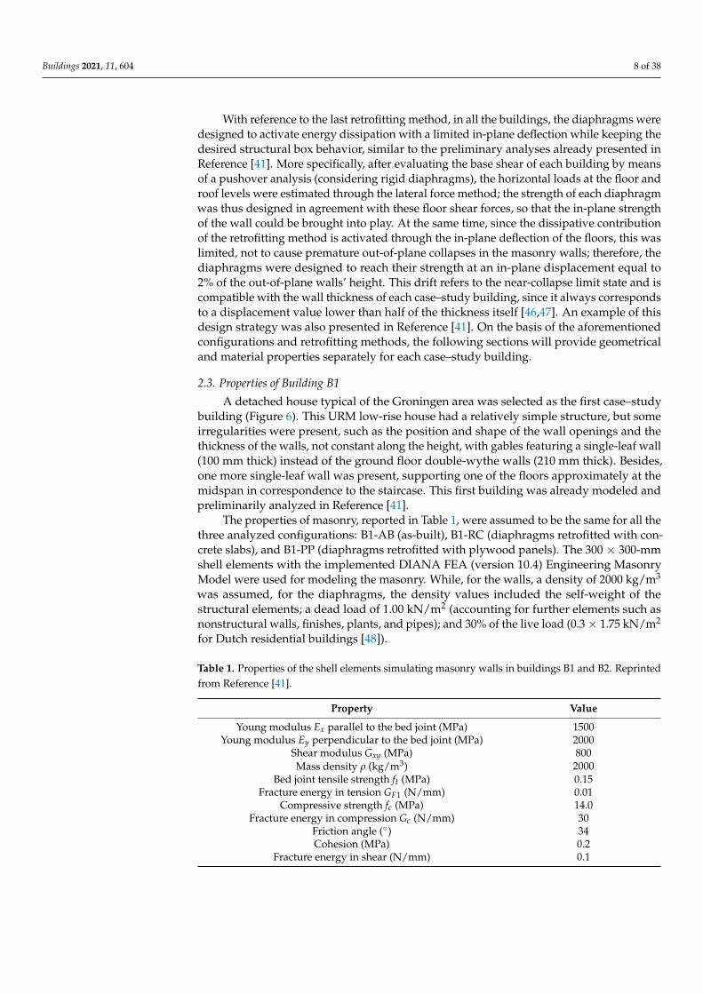
The properties of masonry, reported in Table 1, were assumed to be the same for all thethree analyzed configurations: B1-AB (as-built), B1-RC (diaphragms retrofitted with con-crete slabs), and B1-PP (diaphragms retrofitted with plywood panels). The 300 × 300-mmshell elements with the implemented DIANA FEA (version 10.4) Engineering MasonryModel were used for modeling the masonry. While, for the walls, a density of 2000 kg/m3
was assumed, for the diaphragms, the density values included the self-weight of thestructural elements; a dead load of 1.00 kN/m2 (accounting for further elements such asnonstructural walls, finishes, plants, and pipes); and 30% of the live load (0.3 × 1.75 kN/m2
for Dutch residential buildings [48]).
Table 1. Properties of the shell elements simulating masonry walls in buildings B1 and B2. Reprintedfrom Reference [41].
Property Value
Young modulus Ex parallel to the bed joint (MPa) 1500Young modulus Ey perpendicular to the bed joint (MPa) 2000
Shear modulus Gxy (MPa) 800Mass density ρ (kg/m3) 2000
Bed joint tensile strength ft (MPa) 0.15Fracture energy in tension GF1 (N/mm) 0.01
Compressive strength fc (MPa) 14.0Fracture energy in compression Gc (N/mm) 30
Friction angle (◦) 34Cohesion (MPa) 0.2
Fracture energy in shear (N/mm) 0.1

Buildings 2021, 11, 604 9 of 38
Figure 6. Main properties and geometry of the first case–study building B1 (dimensions in mm).
Configuration B1-AB featured flexible diaphragms, having the following characteris-tics with reference to Figure 6:
• the 4.0 × 4.6-m floor presented 75 × 180-mm joists at 800-mm spacing;• the 4.6 × 6.8-m floor had 60 × 160-mm joists arranged at 750-mm spacing;• the roof presented 50 × 105-mm rafters at 900-mm spacing; on the rafters, purlins
were arranged, supporting, in turn, the planks;• all diaphragms featured 18-mm-thick planks.
These structural properties of the diaphragms were translated in the numerical modelby following the aforementioned modeling strategy for as-built floors [41]; the diaphragmswere modeled with linear elastic orthotropic shell elements whose properties are reported inTable 2. The elastic moduli of the diaphragms were derived by considering the (equivalent)

Buildings 2021, 11, 604 10 of 38
in-plane and out-of-plane flexural properties of the planks or the joists [41]. Due to thealready good floor-to-wall joints, a continuous, hinged connection at the floor supportswas assumed for all cases; good interlocking among the masonry walls was consideredas well.
Table 2. Properties of the shell elements (thickness = 18 mm) representing the flexible diaphragms inconfiguration B1-AB. Reprinted from Reference [41].
PropertyValue
4.0 × 4.6-m Floor 4.6 × 6.8-m Floor Roof
Equivalent Young modulus Eeq (MPa) 978,000 620,000 405,000In-plane shear modulus Gxy (MPa) 12 7 6
Out-of-plane equivalent shear moduli Gxz,Gzy (MPa) 61,125 38,750 25,312
Mass density ρ (kg/m3) 9440 9270 6170
In configuration B1-RC, featuring diaphragms retrofitted by casting a concrete slabon them, the floors were modeled with linear elastic isotropic shell elements, having theproperties of structural reinforced concrete (Table 3). The thickness of the slab was 50 mm,as it would commonly be in practice [1–4].
Table 3. Properties of the shell elements (thickness = 68 mm) representing the concrete slabs inconfiguration B1-RC. Reprinted from Reference [41].
PropertyValue
4.0 × 4.6-m Floor 4.6 × 6.8-m Floor Roof
Young modulus (MPa) 30,000 30,000 30,000Shear modulus (MPa) 12,500 12,500 12,500
Mass density ρ (kg/m3) 4336 4290 4250
For configuration B1-PP, having floors retrofitted with plywood panels, the mod-eling strategy presented and discussed in Reference [41] was adopted: linear elastic or-thotropic shell elements simulated the out-of-plane response of the diaphragms, whilemacro-elements were used to represent their nonlinear, dissipative, in-plane response. Themacro-elements featured a user-implemented subroutine for DIANA FEA, able to capturethe pinching response of the floors, as presented in References [38,41]. Table 4 reportsthe properties of the macro- and shell elements simulating the retrofitted diaphragms.The strengthening interventions on the floors were designed on the basis of an estimatedbase shear of ≈450 kN; this corresponded to the following characteristics for the singlediaphragms, on which the properties reported in Table 4 are based:
• the 4.0 × 4.6-m floor had a strength of 130 kN reached at 54-mm in-plane deflectionand was meshed with 4 × 4 macro-elements;
• the 4.6 × 6.8-m floor had a strength of 200 kN reached at 60-mm in-plane deflectionand was meshed with 4 × 6 macro-elements;
• each roof pitch had a strength of 150 kN reached at 40-mm in-plane deflection andwas meshed with 3 × 8 macro-elements.

Buildings 2021, 11, 604 11 of 38
Table 4. Properties of the shell elements (thickness = 36 mm) and macro-elements representing thediaphragms retrofitted with plywood panels in configuration B1-PP. Reprinted from Reference [41].
PropertyValue
4.0 × 4.6-m Floor 4.6 × 6.8-m Floor Roof
Macro-elements (in-plane response)Young modulus of rigid trusses Et (MPa) 1010 1010 1010
Diagonal trusses max. strain εmax 0.027 0.019 0.012Diagonal trusses max. stress σmax (MPa) 12,700 21,200 13,700
Diagonal trusses initial stiffness K0 (MPa) 2,490,000 5,980,000 5,980,000
Shell elements (out-of-plane response)Equivalent Young modulus Eeq (MPa) 122,000 77,500 50,700
In-plane shear modulus Gxy (MPa) 0.1 0.1 0.1Out-of-plane equivalent shear moduli Gxz,
Gzy (MPa) 7640 4840 3170
Mass density ρ (kg/m3) 4940 4860 3310
2.4. Properties of Building B2
As the second case–study structure, a larger building was chosen, having somemonumental features and resembling the former post office building of Loppersum, NL(Figure 7). This URM building was overall quite regular and presented double-wytheclay brick masonry walls (210 mm thick). The properties of the masonry were assumed tobe identical for all configurations and were the same as adopted for the first case–studybuilding (Table 1); 400 × 400-mm shell elements were used. Similar to the previous case,for the walls, a density of 2000 kg/m3 was assumed, while, for the diaphragms, thedensity values included, once more, the self-weight of the structural elements, a deadload of 1.00 kN/m2, and 30% of the live load (0.3 × 1.75 kN/m2 for Dutch residentialbuildings [48]).
The first- and second-floor diaphragms presented 80 × 200-mm joists at 500-mmspacing and 18 × 165-mm planks. These structural properties of the diaphragms werealso, in this case, inserted into the numerical model by following the modeling strategypresented in Reference [41]; the linear elastic orthotropic shell elements simulating theas-built floors had the properties reported in Table 5. In the as-built state, the floors wereconnected at their supports, with a frictional interface (friction coefficient equal to 0.7) tosimulate the mortar pocket joint.
Table 5. Properties of the shell elements (thickness = 18 mm) representing the flexible diaphragms inconfiguration B2-AB.
PropertyValue
First Floor Top Floor
Equivalent Young modulus Eeq (MPa) 2,294,544 2,294,544In-plane shear modulus Gxy (MPa) 2 2
Out-of-plane equivalent shear moduli Gxz, Gzy (MPa) 143,409 143,409Mass density ρ (kg/m3) 9760 6840

Buildings 2021, 11, 604 12 of 38
Figure 7. Main properties and geometry of the second case–study building B2 (dimensions in mm).
In the configurations featuring diaphragms retrofitted by casting a concrete slabon them, the floors were modeled with linear elastic isotropic shell elements, havingthe properties of structural reinforced concrete (Table 6). The thickness of the slab wasonce more 50 mm, and a continuous, hinged connection to the walls was assumed afterretrofitting.

Buildings 2021, 11, 604 13 of 38
Table 6. Properties of the shell elements (thickness = 68 mm) representing the concrete slabs inconfiguration B2-RC.
PropertyValue
First Floor Top Floor
Young modulus (MPa) 30,000 30,000Shear modulus (MPa) 12,500 12,500
Mass density ρ (kg/m3) 4420 4420
For the configurations having floors retrofitted with plywood panels, the model-ing strategy discussed in Reference [41] was also adopted for this case. Linear elasticorthotropic shell elements simulated the out-of-plane response of the floors, while the non-linear macro-elements (1 × 1-m mesh), featuring the constitutive laws of the implementeduser-supplied subroutine (Table 7), represented their in-plane behavior. The retrofittinginterventions on the diaphragms were designed according to an estimated base shear of≈650 kN, corresponding to a strength of 330 kN for both the first floor (reached at 70-mmin-plane deflection) and roof (reached at 140-mm in-plane deflection). Additionally, in thiscase, a continuous hinged connection at the floor supports was assumed.
Table 7. Properties of the shell elements (thickness = 36 mm) and macro-elements representing thediaphragms retrofitted with plywood panels in configuration B2-PP.
PropertyValue
First Floor Top Floor
Macro-elements (in-plane response)Young modulus of rigid trusses Et (MPa) 1010 1010
Diagonal trusses max. strain εmax 0.0129 0.0258Diagonal trusses max. stress σmax (MPa) 8870 8880
Diagonal trusses initial stiffness K0 (MPa) 3,380,000 1,690,000
Shell elements (out-of-plane response)Equivalent Young modulus Eeq (MPa) 287,000 287,000
In-plane shear modulus Gxy (MPa) 0.1 0.1Out-of-plane equivalent shear moduli Gxz, Gzy (MPa) 17,900 17,900
Mass density ρ (kg/m3) 5100 3650
2.5. Properties of Building B3
The third case–study building was selected to generalize even more the obtainedresults by considering another architectural context. Therefore, an Italian country housetypical of Po Valley and located in the Province of Padua (Veneto) was chosen (Figure 8).This URM building had a regular structure and consisted of two units. In this case, thethickness of the walls was constant alongside the height and was equal to 380 mm, inagreement with past research studies on typical ancient Italian masonry [49,50]. Threeconfigurations were once more studied: one represented the as-built house with flexiblediaphragms (B3-AB); in the other two, the floors were retrofitted with plywood panels(B3-PP) or with a concrete slab (B3-RC).
The properties of the masonry reported in Table 8 were assumed to be the samefor the three configurations; the adopted values were retrieved from References [49,50],where they were identified as material properties of a medium-quality masonry. The400 × 400-mm shell elements were used for modeling the masonry. While, for the walls, adensity of 2000 kg/m3 was assumed, for the diaphragms, the density values included theself-weight of the structural elements, a dead load of 1.00 kN/m2, and 30% of the live load(0.3 × 2.00 kN/m2 for Italian residential buildings [51]).
All timber diaphragms presented 120 × 180-mm joists at 500-mm spacing and20 × 200-mm planks. The structural properties of the diaphragms were also, in this case,

Buildings 2021, 11, 604 14 of 38
translated in the numerical model by following the modeling strategy for as-built floorspreviously described in Reference [41]. The as-built diaphragms were modeled with linearelastic orthotropic shell elements whose properties are reported in Table 9.
In the configurations featuring diaphragms retrofitted by casting a concrete slab onthem, the floors were modeled with linear elastic isotropic shell elements having theproperties of structural reinforced concrete (Table 10). The thickness of the slab was 50 mm.
Table 8. Properties of the shell elements representing masonry walls in building B3 based on theexperimental studies reported in [49,50].
Property Value
Young modulus Ex parallel to the bed joint (MPa) 1875Young modulus Ey perpendicular to the bed joint (MPa) 2500
Shear modulus Gxy (MPa) 1000Mass density ρ (kg/m3) 2000
Bed joint tensile strength ft (MPa) 0.15Fracture energy in tension GF1 (N/mm) 0.01
Compressive strength fc (MPa) 8.0Fracture energy in compression Gc (N/mm) 35
Friction angle (◦) 34Cohesion (MPa) 0.2
Fracture energy in shear (N/mm) 0.1
Table 9. Properties of the shell elements (thickness = 18 mm) representing the flexible diaphragms inconfiguration B3-AB.
PropertyValue
First Floor Second Floor Roof
Equivalent Young modulus Eeq (MPa) 1,874,571 1,874,571 4,557,380In-plane shear modulus Gxy (MPa) 2 2 2
Out-of-plane equivalent shear moduli Gxz, Gzy (MPa) 117,161 117,161 284,836Mass density ρ (kg/m3) 9490 9490 6480
Table 10. Properties of the shell elements (thickness = 68 mm) representing the concrete slabs inconfiguration B3-RC.
PropertyValue
First Floor Second Floor Roof
Young modulus (MPa) 30,000 30,000 30,000Shear modulus (MPa) 12,500 12,500 12,500
Mass density ρ (kg/m3) 4500 4500 4390
For the configurations having floors retrofitted with plywood panels, the modelingstrategy discussed in Reference [41] was also, for this case, adopted; besides the linear elasticorthotropic shell elements, nonlinear macro-elements (1 × 1-m mesh) were also present(Table 11), featuring the constitutive laws of the implemented user-supplied subroutine.The retrofitting interventions on the diaphragms were designed according to an estimatedbase shear of ≈1000 kN, corresponding to a strength of 230 kN for the first floor (reachedat 60-mm in-plane deflection), 450 kN for the second floor (reached at 120-mm in-planedeflection), and 330 kN for the roof (reached at 180-mm in-plane deflection).

Buildings 2021, 11, 604 15 of 38
Figure 8. Main properties and geometry of the third case–study building B3 (dimensions in mm).
In all configurations, continuous, hinged connections at the floor supports wereassumed, as, in the as-built case, adequate floor-to-wall joints were also present.

Buildings 2021, 11, 604 16 of 38
Table 11. Properties of the shell elements (thickness = 36 mm) and macro-elements representing thediaphragms retrofitted with plywood panels in configurations B3-PP.
PropertyValue
First Floor Second Floor Roof
Macro-elements (in-plane response)Young modulus of rigid trusses Et (MPa) 1010 1010 1010
Diagonal trusses max. strain εmax 0.0186 0.0353 0.046Diagonal trusses max. stress σmax (MPa) 9870 19,600 11,800
Diagonal trusses initial stiffness K0 (MPa) 2,780,000 2,730,000 1,350,000
Shell elements (out-of-plane response)Equivalent Young modulus Eeq (MPa) 273,000 273,000 664,000
In-plane shear modulus Gxy (MPa) 0.1 0.1 0.1Out-of-plane equivalent shear moduli Gxz, Gzy (MPa) 17,100 17,100 41,500
Mass density ρ (kg/m3) 5210 5210 3620
2.6. Methodology Adopted for the Seismic Analysis2.6.1. Adopted Seismic Signals and Performance Indicators
For all case–study buildings, to retrieve a detailed picture of the seismic responsesof the analyzed configurations, nonlinear incremental dynamic analyses were performedseparately for the two plane directions: x and y (see Figures 6–8); an intrinsic Rayleighdamping of 2% was considered to account for the viscous dissipation additional to thehysteretic energy activated by the cyclic response of the structural components. The firsttwo case–study buildings, having Dutch features, were subjected to seven induced signalsrecorded in the Groningen area [52] and shown in Figure 9; for the third building, instead,seven recorded tectonic signals retrieved from REXEL version 3.5 [53] were used (Figure 10).Both signal types had a reference PGA of 0.17g.
The near-collapse seismic capacity of all the configurations was characterized bymeans of the following parameters:
• PGA at collapse, obtained when the in-plane shear or flexural failure of masonry piersis reached, when an out-of-plane failure occurs, or when the out-of-plane drift limit of2.0% of the wall height is reached. As the fundamental periods of the analyzed build-ings fell within the constant acceleration branch (plateau) of the response spectrum, ifthe spectral acceleration at the first mode period was also used as the performanceindicator, this would approximately correspond to the PGA amplified by a factorof 2.5;
• Base shear-top floor (or roof) displacement responses, along with damage in terms ofcracks opening in the masonry walls. The control nodes for all the curves correspondedto the center of mass of each building at the roof level, but also, other relevant referencenodes were considered for highlighting the role of the (retrofitted) floors in the seismicresponse of the analyzed buildings (Section 4);
• For the retrofitted cases, hysteretic energy was also considered, so that the dissipativecontribution of the diaphragms strengthened with plywood panels in the analyzedbuildings could be quantified in detail with respect to that of rigid concrete slabs.
Both PGA at collapse and hysteretic energy were adopted for assessing the energydissipation activated by the wood-based retrofitting: PGA for quantifying the dampingproduced by the diaphragms and hysteretic energy for determining the behavior factorranges, as presented in the following sections.

Buildings 2021, 11, 604 17 of 38
Figure 9. Induced seismic signals (a–g) and their average response spectrum (h, depicted in black) [41,52] adopted for thenumerical analyses on buildings B1 and B2.

Buildings 2021, 11, 604 18 of 38
Figure 10. Tectonic seismic signals (a–g) and their average response spectrum (h, depicted in black) [53] adopted for thenumerical analyses on building B3.

Buildings 2021, 11, 604 19 of 38
2.6.2. Equivalent Hysteretic Damping Ratio of the Floors Retrofitted with Plywood Panels
The values of PGA at collapse, besides identifying the seismic performance of thebuildings, were also used to assess the additional damping induced by the dissipativediaphragms retrofitted with plywood panels. More specifically, in References [38,40,41], anequivalent damping ratio ξ of 15% was quantified for these diaphragms when designed fortheir pertaining floor seismic shear and a maximum in-plane deflection within the masonrydrift limits. To assess whether this value was also activated in the analyzed URM buildings,the ratio was calculated between the average PGA at the collapse of the configurationshaving floors retrofitted with plywood panels and that of the cases with rigid diaphragms.In fact, if the floors were retrofitted with plywood panels, for a simplified modeling(e.g., a pushover analysis), they were assumed as stiff; their dissipative contributioncould be taken into account by considering an overdamped spectrum reduced by factorη = [10/(5 + ξ)]1/2 [54]. Since η can also be estimated by the aforementioned PGAs ratio,the corresponding value of ξ can be retrieved.
2.6.3. Hysteretic Energy and Quantification of Behavior Factors
The use of hysteretic energy as the performance indicator allowed us to compare interms of behavior factor values the results among the retrofitted configurations having rigidor dissipative diaphragms. More specifically, a procedure involving hysteretic energy andductility was adopted for characterizing the retrofitted buildings. First of all, at least forsufficiently regular buildings that could be treated as (equivalent) single-degree-of-freedom(SDOF) systems, the hysteretic energy Ed that is dissipated during ground motion can beexpressed as [55]:
Ed = ξmωn∆treS2
v(α2 + β2) (1)
In the former equation, ξ is the damping ratio of the system, m its mass, ωn its (natural)frequency, ∆tr
e the effective ground motion duration (in which 90% of the energy impartedto the system is dissipated [55]), Sv the spectral velocity, and (α2 + β2) a factor denotingthe mean value of the squares of the response displacement amplitudes [55]. FollowingReference [55], two simplified equations were proposed to evaluate ∆tr
e and (α2 + β2),depending on the (natural) period of the system Tn and on the seismic strong motionduration ∆te [55–58], reported for all the signals in Figures 9 and 10:
∆tre = ∆te + 3.3
Tn
6ξ(2)
α2 + β2 = 0.25T1/3n (3)
It should be noticed that Equation (1) has the advantage of being damping-insensitive,because an increase in damping would correspond to a decrease in the pseudo-velocityand effective duration [55]. This is an advantage when predicting the hysteretic energydissipated by the system, because this can be quantified by adopting directly the usualdesign response spectrum at ξ = 5% for a specific location [55]. Furthermore, since ∆tr
erefers to 90% of the dissipated energy, the derived expression should be multiplied by afactor of 10/9 [55].
For buildings sufficiently regular in plan and elevation [54], the combination of Equa-tions (1)–(3) enables the prediction of the dissipated hysteretic energy once the effectiveearthquake duration is known and an equivalent period for the system is defined, repre-senting the evolution from elastic to plastic or the damaged state. The equivalent periodTn,eff was calculated according to FEMA 440 [59,60], as a function of the ductility µ of thesystem and its initial period Tn and independently of the type of hysteretic behavior.
• For 1 < µ < 4:
Tn,eff =[0.167(µ − 1)2−0.031(µ − 1)3+1
]Tn (4)

Buildings 2021, 11, 604 20 of 38
• For 4 ≤ µ ≤ 6.5:Tn,eff = [0.283 + 0.129(µ − 1) + 1]Tn (5)
• For µ > 6.5:
Tn,eff =
{0.89
[√µ − 1
1 + 0.05(µ − 2)−1
]+1
}Tn (6)
The ductility was evaluated by means of the equation that relates it to the behaviorfactor q [54]:
q =√
2µ − 1 (7)
Thus, in this work, for the analyzed buildings with stiff diaphragms, the values ofµ were referred to as the usual range of q = 1.5–2.5 [54], since the dissipation was, inthis case, localized only in the masonry walls. Instead, to account for the additionaldissipative contribution of the floors strengthened with plywood panels in comparison torigid concrete diaphragms, the range could be increased and validated up to q = 2.5–3.5for the configurations featuring the wood-based retrofitting. It should be noticed that bothadopted ranges refer to very regular buildings featuring well-connected and homogeneousclay brick masonry. Yet, although the obtained results refer to almost ideal conditionsfor the existing buildings, they are still able to show the great potential and increaseddissipation of the wood-based retrofitting technique with respect to rigid floors.
By fixing the behavior factor ranges, the corresponding ductility values allowed tocalculate the relevant Tn,eff values, starting from the knowledge of the natural periodsalong the x and y directions, as determined by means of an eigenvalue analysis. Table 12reports the natural periods of the as-built configurations and Table 13 the obtained Tn,effvalues for the retrofitted configurations. Once Tn,eff was determined, this was used topredict the total hysteretic energy dissipated by the building, calculated with Equations(1)–(3) after determining the Sv from each signal’s response spectrum and inputting thepertaining strong motion duration ∆te. This procedure, novel for regular masonry buildings(but based on past analytical and empirical studies), allowed us to determine a range ofhysteretic energy values, which were then compared to the single value of hysteretic energycomputed by the numerical model. In this way, the use of both behavior factor rangescould be validated, as will be shown in the following sections.
Table 12. Values of the natural period for the as-built configurations.
As-Built Configuration Excited Seismic Mass (kg) Direction of the Seismic Action Tn (s)
B1-AB 41,355 x 0.25y 0.14
B2-AB 106,847 x 0.68y 0.26
B3-AB 140,579 x 0.24y 0.12
Table 13. Values of the equivalent period for the retrofitted configurations as a function of the behavior factor range.
Retrofitted Configuration Excited Seismic Mass (kg) Direction of the Seismic Action Tn,eff (s)
Concrete floors: q = 1.5 q = 2.0 q = 2.5
B1-RC 55,577 x 0.11 0.13 0.16y 0.06 0.07 0.09
B2-RC 131,302 x 0.18 0.22 0.27y 0.13 0.16 0.20
B3-RC 158,909 x 0.16 0.19 0.23y 0.13 0.15 0.19
Plywood floors: q = 2.5 q = 3.0 q = 3.5
B1-PP 43,267 x 0.22 0.25 0.28y 0.16 0.18 0.20
B2-PP 108,010 x 0.52 0.58 0.65y 0.22 0.25 0.28
B3-PP 141,485 x 0.32 0.36 0.41y 0.19 0.22 0.24

Buildings 2021, 11, 604 21 of 38
3. Results from the Analyses3.1. Results in Terms of PGA, Base Shear-Top Roof Displacement Graphs, and Crack Pattern
The seismic performance of the three analyzed case–study buildings was firstly char-acterized in terms of PGA at collapse for both loading directions. Figure 11 shows thisparameter for all the configurations, with both reference to each signal and on average.
Figure 11. PGA at collapse, displayed for each signal and on average, recorded for the three case–study buildings.
Starting from building B1, it can be noticed that as-built configuration B1-AB alreadycollapsed at a low level of intensity (average PGA = 0.18 g in the weakest loading direction)due to the out-of-plane failure of (portion of) walls or gables. On the contrary, with floorsstiffened with a concrete slab (configuration B1-RC), a great improvement in the capacity ofthe building was obtained (average PGA = 0.53 g in the weakest direction), mainly becauseof the enhanced box behavior, leading to the in-plane collapse of masonry walls. Yet, thebest performance was retrieved with the plywood panel overlay in both loading directions(configuration B1-PP, average PGA = 0.81 g in the weakest direction); the box behavior

Buildings 2021, 11, 604 22 of 38
and collapse of the in-plane walls were again activated but with the additional, beneficialcontribution of the dissipative retrofitting.
Similar outcomes were observed for building B2 but with a better performance of theas-built configuration; despite causing, once more, the out-of-plane collapse of masonrywalls, the average collapse PGA of 0.34 g in the weakest direction was now closer to that ofretrofitted building B2-RC (0.46 g), mainly because the flexible floors increased the periodof configuration B2-AB, resulting in lower accelerations transferred to the walls. Oncemore, configuration B2-PP provided the highest capacity among the three (0.73 g).
Building B3 confirmed these results but also showed that, interestingly, there was noradical improvement in the capacity between configurations B3-AB and B3-RC (averagePGA ≈ 0.5 g for both). The massive size of the walls, with respect to the other two buildings,contributed to in-plane collapses even in the as-built cases, yet with extensive damage onthe gables; thus, no premature out-of-plane collapse occurred. This seems to confirm anumber of past studies [18–24], highlighting that as-built floors might already be sufficientto retrieve the total base shear of the building, provided that the diaphragms are well-connected to the walls, and the seismic shear transfer is fully enabled. However, if thefloors are retrofitted in a dissipative way, as in configuration B3-PP, the seismic performancecan be increased even further (PGA = 0.73 g) because of the additional damping effect.
Besides the PGA at collapse, for a more detailed characterization of the seismicresponse of the analyzed buildings, their base shear-top roof displacement curves andcorresponding crack pattern and damage to the walls (in terms of the principal crackopening) are presented for all configurations in Figures 12–14 in the weakest loadingdirection and with reference to seismic signal 1 as an example. It should be noticed that theprincipal crack opening contour was reported to show (through heavily cracked elements)which piers were the most damaged and their types of failure.
Starting from building B1, configuration B1-AB showed a very flexible response: thefloors underwent large displacements at an already limited signal amplitude, and the in-plane walls were not brought into play, with the exception of the very slender pier next tothe staircase. Besides, the crack pattern (Figure 12a) showed a partial out-of-plane collapseof the 100-mm-thick central wall and of the north gable, probably due to torsional effects.A very different situation was noticeable in configuration B1-RC. In this case, the failureof the building was fully related to the in-plane walls, and a beneficial redistribution ofthe horizontal loads was achieved among the various walls; the force–displacement graphalso confirms a typical shear-related in-plane failure of the masonry (Figure 12b). A hybridresponse between the first two configurations was obtained with the floors retrofitted withplywood panels: a larger displacement capacity of the diaphragms, along with an in-planefailure of the walls, was noticeable (Figure 12c). The crack pattern was similar to thatobserved for the concrete slab configuration, with a slightly larger amount of damage inthe out-of-plane walls because of the lower stiffness of the floors.
With regards to building B2, configuration B2-AB displayed a very flexible behavior,and the strength of in-plane walls was not involved. Besides, extensive damage of theout-of-plane walls was noticeable due to their out-of-phase oscillation induced by thepoorly connected, flexible floors (Figure 13a). On the contrary, the strengthened floors wereable to guarantee a better redistribution of the seismic loads among the walls, leading to anin-plane global failure. Additionally, while, with concrete slabs (Figure 13b), the collapsewas mainly caused by the failure of the ground floor walls, with the floors strengthenedwith plywood panels (Figure 13c), the damage involved both story piers and spandrels,thus retrieving even more energy dissipation from the structure. In any case, the governingin-plane failure appeared to be shear diagonal cracking of the squat pier at the ground floor.
Building B3 showed an interesting difference compared to the previous case–studybuildings: the in-plane strength of the wall was also brought into play in the as-built configu-ration, even if the gables experienced extensive out-of-plane damage at their bottom as well(Figure 14a). This means that, in this specific case, the thick walls, as well as the regularityand compactness of the structure, allowed the floors of configuration B3-AB to appropriately

Buildings 2021, 11, 604 23 of 38
transfer shear loads because of the well-realized connections with masonry components. Thefact that the stiffness of the as-built diaphragms could already be sufficient for the building toretrieve its whole base shear was confirmed by the similar capacity of configuration B3-RC(Figure 14b), although the stiff floors enhanced the box behavior of the building. An optimalperformance was obtained with the designed light retrofitting intervention, which providedthe floors with an increased energy dissipation more than an enhancement in stiffness, as canbe noticed from the base shear–roof displacement curve (Figure 14c).
Figure 12. Base shear vs. top roof displacement response and damage level in terms of the principal crack opening (Ecw1)for the three configurations: B1-AB (a), B1-RC (b), and B1-PP (c) at a near-collapse state.

Buildings 2021, 11, 604 24 of 38
Figure 13. Base shear vs. top roof displacement response and damage level in terms of the principal crack opening (Ecw1)for the three configurations: B2-AB (a), B2-RC (b), and B2-PP (c) at a near-collapse state.

Buildings 2021, 11, 604 25 of 38
Figure 14. Base shear vs. top roof displacement response and damage level in terms of the principal crack opening (Ecw1)for the three configurations: B3-AB (a), B3-RC (b), and B3-PP (c) at a near-collapse state.

Buildings 2021, 11, 604 26 of 38
3.2. Results in Terms of Hysteretic Energy for the Retrofitted Configurations
As mentioned in Section 2.5, the retrofitted configurations of the three analyzedbuildings were also characterized in terms of the dissipated hysteretic energy and behaviorfactor ranges. Figure 15 shows the comparison between the hysteretic energy recordedfrom the numerical models and that predicted as a function of the assumed behavior factorrange for all configurations with rigid diaphragms and in both loading directions. As canbe noticed, the usual behavior factor range of 1.5–2.5 commonly adopted for masonrystructures appears to be appropriate and allows to predict, in most cases, conservativelythe hysteretic energy that can be brought into play by the buildings. Yet, the fact that rigiddiaphragms improve the box behavior of the buildings corresponds to a localization of thedissipated energy in the masonry piers.
If, instead, the diaphragms are also able to activate energy dissipation, a remark-able beneficial effect on the buildings can be observed (Figure 16); floors retrofittedwith plywood panels allow us to largely increase the hysteretic energy activated bythe buildings when compared to the configurations with rigid diaphragms. This isrelated to the fact that the buildings with rigid floors showed stiff behaviors, especiallyin the y direction, linked to the presence of squat piers (see, for instance, B1-RC, whichexhibited a very limited ductility). On the contrary, the increased displacement capacityand dissipation provided by the floors retrofitted with plywood panels, along witha higher fundamental period in both directions, allowed us to activate a much largerhysteretic energy and to subject the buildings to an increased amplitude of the seismicsignals. This larger amplitude, in combination with the higher fundamental periodcompared to the configurations with rigid floors, is also consistent with a larger valueof spectral velocity, on which the hysteretic energy depends through a quadratic rela-tion, justifying its increased values for the configurations featuring the wood-basedretrofitting.
Figure 17 highlights how relevant the contribution of the dissipative floors can bein terms of their activated hysteretic energy, with respect to a retrofitting with rigid di-aphragms. In all cases, the floors retrofitted with plywood panels are responsible for asignificant increase in the energy that can be dissipated by the building. This also explainsthe capacity of these floors to provide an increase in the behavior factor range for thespecific analyzed buildings, highlighting once more the great potential of well-designedwood-based retrofitting techniques. These outcomes, along with those of the precedingsection, will now be discussed more in detail in Section 4, with specific reference to the roleof (retrofitted) timber diaphragms.

Buildings 2021, 11, 604 27 of 38
Figure 15. Hysteretic energy from the numerical model and predicted with Equations (1)–(3) for the concrete slab retrofitting.

Buildings 2021, 11, 604 28 of 38
Figure 16. Hysteretic energy from the numerical model and predicted with Equations (1)–(3) for the plywood panelretrofitting.

Buildings 2021, 11, 604 29 of 38
Figure 17. Hysteretic energy vs. time for the retrofitted configurations at a near-collapse state. The dissipative role of thediaphragms retrofitted with plywood panels in comparison to the rigid concrete slabs is evident.

Buildings 2021, 11, 604 30 of 38
4. Discussion
The results of the three analyzed case–study buildings highlighted once more howthe role of timber diaphragms in the seismic response of URM buildings can be crucial.The effect of the in-plane stiffness of the floors is firstly discussed, taking into accountadditional control nodes with respect to those selected in Figures 12–14. Considering theout-of-plane seismic response of the front gable in building B1 (Figure 18), this can beregarded as one of its most vulnerable portions due to its reduced thickness (only 100 mm).The insufficient in-plane stiffness of the existing roof (Figure 18a) leads to a premature out-of-plane collapse of the gable, highlighted by the large, out-of-phase relative displacementbetween the two control nodes. This local collapse, if compared to the cases featuringstiffened diaphragms, occurs for a relatively low seismic acceleration, justifying the needof a retrofitting intervention. When the concrete slab retrofitting is applied (Figure 18b),the two control nodes display an identical displacement time–history, as expected witha rigid diaphragm system. The collapse of the building is, in this case, not related tothe gable, as in the as-built situation, but to the in-plane failure of the squat walls alongthe earthquake direction. This same failure type was observed for configuration B3-PP(Figure 18c), which displayed a hybrid response: the floors retrofitted with plywood panelsproved to be sufficiently stiff to activate the in-plane failure of the walls but also allowedfor a limited out-of-plane displacement in the gable, activating energy dissipation in thestrengthened roof.
The performed analyses also showed that the in-plane stiffness of the floors is re-sponsible for how quickly the masonry piers are brought into play; this is exemplified inFigure 19 for building B2, taking into account the displacements of a control node on theroof and of one on the lateral walls. When considering the existing floors (Figure 19a),on the one hand, their low stiffness and deflection capacities could positively prevent thein-plane walls from being excessively solicited; on the other hand, their flexibility led toout-of-plane collapses and to an independent movement of each floor without retrievingthe desired box behavior. With rigid concrete diaphragms (Figure 19b), the deflection ofthe floors is absent, and the diaphragms and walls undergo the same displacement. Thissolution guarantees the maximum redistribution of seismic shear forces and an excellentbox behavior but directly brings the walls’ strength into play. When an optimized, dissi-pative retrofitting is chosen (Figure 19c), it is possible to link the displacement capacityof the diaphragms, enabling their energy dissipation potential, with an in-plane stiffnesssufficient to redistribute seismic loads among the walls. Thus, similar to building B1-PP, thein-plane capacity of the piers is retrieved, but the damping effect of the floors can preventthis from occurring right at the beginning of the seismic signal, with an increase of theseismic capacity of the building.
The previously discussed results were again obtained in case–study B3 (Figure 20),subjected to tectonic earthquakes. Considering the control nodes at each floor level and atthe top and bottom of the gable, configuration B3-AB (Figure 20a) showed that the existingflexible floors are sufficient to retrieve the in-plane strength of the walls because of themassive structure of the piers. However, the as-built floors cause extensive damage tothe gables, where the largest relative displacements are recorded, and a dangerous out-of-phase movement of each floor level. In configuration B3-RC (Figure 20b), the observeddisplacements are all linked to the in-plane capacity of the walls because of the presenceof rigid diaphragms. The response also shows an improved box behavior, but the PGA atcollapse is interestingly the same as configuration B3-AB, as pointed out and discussedin Section 3.1. Finally, configuration B3-PP (Figure 20c) shows a combination of the twoprevious cases; as can be noticed, the presence of optimally designed retrofitted diaphragmsinduces an in-phase movement of the floor levels while reducing the dangerous relativedisplacement between the top and bottom of the gable and retrieves, at the same time,the in-plane capacity of the piers. This combination maximizes once more the hystereticenergy that can be activated and dissipated by the building, with a beneficial effect in itsseismic response.

Buildings 2021, 11, 604 31 of 38
Figure 18. Out-of-plane displacement time–histories of the front gable for configurations B1-AB (a), B1-RC (b), and B1-PP(c) at collapse.

Buildings 2021, 11, 604 32 of 38
Figure 19. Examples of top floor and in-plane wall displacement time–histories for configurations B2-AB (a), B2-RC (b), andB2-PP (c) at collapse.

Buildings 2021, 11, 604 33 of 38
Figure 20. Out-of-plane displacement time-histories of the front wall for configurations B3-AB (a), B3-RC (b), and B3-PP (c)at collapse.

Buildings 2021, 11, 604 34 of 38
The damping effect induced by the plywood panels retrofitting is also evident inFigure 21, comparing the response of the most solicited wall in building B1 when thediaphragms are retrofitted with concrete slabs or plywood panels; as can be noticed, underthe same signal, when concrete slabs are present, the pier reaches its capacity after ashear diagonal failure; with plywood panels retrofitting, a damping effect on the wall isnoticeable, and the maximum in-plane load for the pier is reached by further amplifyingthe signal to more than 35% compared to that applied to the B1-RC configuration. Yet, itis important to underline that, in order to be able to activate the dissipative potential ofthe floors, a dry screed made of loose materials (so that the diaphragms are not furtherstiffened by this component), as well as a continuous and resistant connection between thediaphragms and walls, has to be realized so that local collapses can be prevented and thebox behavior can still be enabled [41].
Figure 21. Comparison between the in-plane response of the most solicited wall under the application of signal 4 inconfigurations B1-RC (left) and B1-PP (right). When the concrete slab brings the wall to the in-plane capacity, for the samePGA, the dissipative plywood panel retrofitting prevents the pier from reaching its ultimate strength, which is retrieved at 0.76g.
With reference to the increase in seismic capacity, in Reference [40], a value of equiva-lent hysteretic damping ratio ξ = 15% was determined for the diaphragms retrofitted withplywood panels. From the performed analyses, it appears that the difference in PGA at col-lapse between the configurations with stiff floors and those having dissipative diaphragmswas, on average, approximately 30% (see Figure 11). This result thus confirms the obtained15% equivalent damping ratio value; if the floors were retrofitted with plywood panels,and for a simplified modeling (e.g., a pushover analysis), they were assumed as stiff; theirdissipative contribution could be taken into account by considering an overdamped spec-trum reduced by the factor η = [10/(5 + ξ)]1/2 [54]. It is interesting to notice that η = 0.707for ξ = 15%, a value suggesting that, when a dissipative retrofitting of the floors is designed,the demand response spectrum could indeed be reduced by approximately 30% in additionto the further nonlinear contributions of the in-plane masonry walls.
Furthermore, the largely increased hysteretic energy that can be activated in the URMbuildings because of the presence of retrofitted, dissipative timber diaphragms was alsolinked to a higher behavior factor range of q = 2.5–3.5. It should be noticed that thesevalues could be obtained considering very regular, low-rise buildings with homogeneousand well-connected masonry—thus, in almost ideal conditions when dealing with theseismic assessment and retrofitting of existing buildings; this was also confirmed by thelarge values of PGA obtained at collapse. Nevertheless, these same conditions of regularityand homogeneity of the masonry were applied for the configurations with concrete slabs.Therefore, by adopting the obtained behavior factor ranges as indicators for comparison,the increase in energy dissipation activated by the plywood panels retrofitting was tangibleand could be predicted and validated. As a recommendation for further studies, since past

Buildings 2021, 11, 604 35 of 38
shake table tests [61] highlighted that the use of the lower limit value of q = 1.5 should bepreferred for buildings with rigid diaphragms, similar (full-scale) experiments could beperformed to assess the potential increase in the behavior factor provided by an optimized,dissipative, wood-based strengthening of the timber floors in URM buildings.
5. Summary and Conclusions
In this work, the possibility of optimizing the seismic performance of URM buildingsthrough the retrofitting of timber diaphragms was investigated, transforming them intodissipative structural components. Numerical time–history analyses were conducted onthree case–study buildings, considering the as-built state with flexible floors, a retrofittingoption with concrete slabs (and, thus, rigid floors), and a dissipative strengthening methodconsisting of plywood panels screwed on the existing diaphragms.
It was shown that, in order to optimize the seismic response of URM buildings, theretrofitting of timber diaphragms can be designed based on the pertaining floor seismicshear and masonry out-of-plane drift limits. In this way, the diaphragms can undergo themaximum deflection without causing out-of-plane collapse, activating at the same time themaximum base shear of the building: thus, the maximum energy dissipation can also beretrieved from the diaphragms. Yet, in order for the floors to efficiently transfer the seismicshear loads and deflect without causing local masonry collapses, the timber–masonry jointshave to be effectively strengthened accordingly, as their role is paramount to efficientlyredistribute the actions on the URM structure. Instead, if the diaphragms are too flexible,severe out-of-plane damage or collapses are observed, while, with rigid floors, the boxbehavior of the building is improved, but the dissipative contribution of the diaphragmscannot be activated.
The relevant, dissipative effect of well-retrofitted, optimized timber floors was quanti-fied in terms of an equivalent hysteretic damping ratio of 15% additional to the dissipationalready provided by the masonry walls. Besides, in the presence of optimally designeddissipative diaphragms, an increased behavior factor range of q = 2.5–3.5 was observedin comparison to the range of q = 1.5–2.5 for rigid floors. Throughout the analysis, thisparameter was used to quantify the energy dissipation for the purpose of comparisonsamong the retrofitted configurations and refers to regular buildings featuring homogenousand well-connected clay brick masonry, as well as continuous floor-to-wall connections.Thus, it is expected that these values reflect almost ideal conditions when dealing with theseismic assessment and retrofitting of existing buildings; however, the obtained values stillprove the beneficial effect of an optimized strengthening of timber diaphragms with respectto rigid floors. Hence, further (experimental) studies for validating the dissipative roleof wood-based retrofitting techniques for timber floors in URM constructions are highlyencouraged and recommended, so that a possible increase in the behavior factor can beassessed for real building prototypes as well.
The obtained results can further support a more aware seismic retrofitting of exist-ing URM constructions, with specific references to the use of wood-based (dissipative)strengthening techniques as a more beneficial alternative to rigid concrete diaphragms, andcan contribute to the research framework supporting the conservation of the architecturalheritage of seismic-prone countries.
Author Contributions: Conceptualization, M.M. and G.R.; methodology, M.M.; software, M.M.;validation, M.M.; formal analysis, M.M. and G.R.; investigation, M.M. and G.R.; resources, G.R.;data curation, M.M.; writing—original draft preparation, M.M.; writing—review and editing, G.R.;visualization, M.M.; supervision, G.R.; project administration, G.R.; funding acquisition, G.R. Allauthors have read and agreed to the published version of the manuscript.
Funding: This research was funded by Nederlandse Aardolie Maatschappij, grant numbers C31B67and CS2B04. The APC was funded by Delft University of Technology.
Institutional Review Board Statement: Not applicable.
Informed Consent Statement: Not applicable.

Buildings 2021, 11, 604 36 of 38
Conflicts of Interest: The authors declare no conflict of interest.
References1. Piazza, M.; Baldessari, C.; Tomasi, R. The Role of In-Plane Floor Stiffness in the Seismic Behaviour of Traditional Buildings. In
Proceedings of the 14th World Conference on Earthquake Engineering, Beijing, China, 12–17 October 2008.2. Baldessari, C. In-Plane Behaviour of Differently Refurbished Timber Floors. Ph.D. Thesis, University of Trento, Trento, Italy, 2010.3. Piazza, M.; Turrini, G. Una tecnica di recupero statico dei solai in legno. In Recuperare; PEG Editrice: Milan, Italy, 1983; Volume 5.4. Corradi, M.; Speranzini, E.; Borri, A.; Vignoli, A. In-Plane Shear Reinforcement of Wood Beam Floors with FRP. Compos. Part B
Eng. 2006, 37, 310–319. [CrossRef]5. Valluzzi, M.R.; Garbin, E.; Dalla Benetta, M.; Modena, C. Experimental Assessment and Modelling of In-Plane Behaviour of
Timber Floors. In Proceedings of the 6th International Conference Structural Analysis of Historical Constructions, Bath, UK,2–4 July 2008; pp. 755–762.
6. Valluzzi, M.R.; Garbin, E.; Dalla Benetta, M.; Modena, C. In-Plane Strengthening of Timber Floors for the Seismic Improvement ofMasonry Buildings. In Proceedings of the 11th World Conference on Timber Engineering, Riva del Garda, Italy, 20–24 June 2010.
7. Branco, J.M.; Kekeliak, M.; Lourenço, P.B. In-Plane Stiffness of Timber Floors Strengthened with CLT. Eur. J. Wood Wood Prod.2015, 73, 313–323. [CrossRef]
8. Gubana, A.; Melotto, M. Experimental tests on wood-based in-plane strengthening solutions for the seismic retrofit of traditionaltimber floors. Constr. Build. Mater. 2018, 191, 290–299. [CrossRef]
9. Peralta, D.F.; Bracci, M.J.; Hueste, M.B.D. Seismic Behavior of Wood Diaphragms in Pre-1950s Unreinforced Masonry Buildings.J. Struct. Eng. 2004, 130, 2040–2050. [CrossRef]
10. Brignola, A.; Pampanin, S.; Podestà, S. Experimental Evaluation of the In-Plane Stiffness of Timber Diaphragms. Earthq. Spectra2012, 28, 1–23. [CrossRef]
11. Wilson, A.; Quenneville, P.J.H.; Ingham, J.M. In-Plane Orthotropic Behavior of Timber Floor Diaphragms in UnreinforcedMasonry Buildings. J. Struct. Eng. 2014, 140, 04013038. [CrossRef]
12. Giongo, I.; Dizhur, D.; Tomasi, R.; Ingham, J.M. In plane assessment of existing timber diaphragms in URM buildings via quasistatic and dynamic in situ tests. Adv. Mater. Res. 2013, 778, 495–502. [CrossRef]
13. Lin, T.-J.; LaFave, J.M. Experimental Structural Behavior of Wall-Diaphragm Connections for Older Masonry Buildings. Constr.Build. Mater. 2012, 26, 180–189. [CrossRef]
14. Moreira, S.; Oliveira, D.V.; Ramos, L.F.; Lourenço, P.B.; Fernandes, R.P.; Guerreiro, J. Experimental study on the seismic behaviorof masonry wall-to-floor connections. In Proceedings of the 15th World Conference on Earthquake Engineering, Lisbon, Portugal,24–28 September 2012.
15. Moreira, S.; Ramos, L.F.; Oliveira, D.V.; Lourenço, P.B.; Mateus, L. Developing a seismic retrofitting solution for wall-to-floorconnections of URM with wood diaphragms. In Proceedings of the 9th International Masonry Conference, Guimarães, Portugal,7–9 July 2014.
16. Dizhur, D.; Giaretton, M.; Ingham, J.M. URM wall-to-diaphragm and timber joist connection testing. In Proceedings of the 10thInternational Masonry Conference, Milan, Italy, 9–11 July 2018.
17. Gubana, A. State-of-the-Art Report on high reversible timber to timber strengthening interventions on wooden floors. Constr.Build. Mater. 2015, 97, 25–33. [CrossRef]
18. Magenes, G.; Penna, A.; Galasco, A. A full-scale shaking table test on a two-storey stone masonry building. In Proceedings of the14th European Conference on Earthquake Engineering, Ohrid, North Macedonia, 30 August–3 September 2010.
19. Magenes, G.; Penna, A.; Rota, M.; Galasco, A.; Senaldi, I. Shaking table test of a full scale stone masonry building withstiffened floor and roof diaphragms. In Proceedings of the 15th World Conference on Earthquake Engineering, Lisbon, Portugal,24–28 September 2012.
20. Senaldi, I.; Magenes, G.; Penna, A.; Galasco, A.; Rota, M. The Effect of Stiffened Floor and Roof Diaphragms on the ExperimentalSeismic Response of a Full-Scale Unreinforced Stone Masonry Building. J. Earthq. Eng. 2014, 18, 407–443. [CrossRef]
21. Scotta, R.; Trutalli, D.; Marchi, L.; Pozza, L. Effects of in-plane strengthening of timber floors in the seismic response of existingmasonry buildings. In Proceedings of the World Conference on Timber Engineering, Vienna, Austria, 22–25 August 2016.
22. Scotta, R.; Trutalli, D.; Marchi, L.; Pozza, L.; Mirra, M. Seismic response of masonry buildings with alternative techniques forin-plane strengthening of timber floors. Revista Portuguesa de Engenharia de Estruturas 2017, 4, 47–58.
23. Scotta, R.; Trutalli, D.; Marchi, L.; Pozza, L. Seismic performance of URM buildings with in-plane non-stiffened and stiffenedtimber floors. Eng. Struct. 2018, 167, 683–694. [CrossRef]
24. Trutalli, D.; Marchi, L.; Scotta, R.; Pozza, L. Seismic capacity of irregular unreinforced masonry buildings with timber floors. Proc.Inst. Civ. Eng.-Struct. Build. 2020, 174, 473–490. [CrossRef]
25. Decanini, L.; De Sortis, A.; Goretti, A.; Langenbach, R.; Mollaioli, F.; Rasulo, A. Performance of Masonry Buildings during the2002 Molise, Italy, Earthquake. Earthq. Spectra 2004, 20, S191–S220. [CrossRef]
26. Valluzzi, M.R. On the vulnerability of historical masonry structures: Analysis and mitigation. Mater. Struct. 2007, 40, 723–743.[CrossRef]
27. Modena, C.; Valluzzi, M.R.; da Porto, F.; Casarin, F. Structural Aspects of the Conservation of Historic Masonry Constructions inSeismic Areas: Remedial Measures and Emergency Actions. Int. J. Archit. Herit. 2011, 5, 539–558. [CrossRef]

Buildings 2021, 11, 604 37 of 38
28. Saretta, Y.; Sbrogiò, L.; Valluzzi, M.R. Seismic response of masonry buildings in historical centres struck by the 2016 Central Italyearthquake. Calibration of a vulnerability model for strengthened conditions. Constr. Build. Mater. 2021, 299, 123911. [CrossRef]
29. Vlachakis, G.; Vlachaki, E.; Lourenço, P.B. Learning from failure: Damage and failure of masonry structures, after the 2017 Lesvosearthquake (Greece). Eng. Fail. Anal. 2020, 117, 104803. [CrossRef]
30. Stepinac, M.; Lourenço, P.B.; Atalic, J.; Kišicek, T.; Uroš, M.; Banicek, M.; Šavor Novak, M. Damage classification of residentialbuildings in historical downtown after the ML5.5 earthquake in Zagreb, Croatia in 2020. Int. J. Disaster Risk Reduct. 2021,56, 102140. [CrossRef]
31. Bilgin, H.; Shkodrani, N.; Hysenlliu, M.; Baytan Ozmen, H.; Isik, E.; Harirchian, E. Damage and performance evaluation ofmasonry buildings constructed in 1970s during the 2019 Albania earthquakes. Eng. Fail. Anal. 2021, 131, 105824. [CrossRef]
32. van Eck, T.; Goutbeek, F.; Haak, H.; Dost, B. Seismic hazard due to small-magnitude, shallow-source, induced earthquakes inThe Netherlands. Eng. Geol. 2006, 87, 105–121. [CrossRef]
33. ARUP. Groningen 2013—Implementation Study; Document REP/229746/IS001, Issue Rev A, 29 November 2013; ARUP: Amsterdam,The Netherlands, 2013.
34. Messali, F.; Ravenshorst, G.J.P.; Esposito, R.; Rots, J.G. Large-scale testing program for the seismic characterization of Dutchmasonry walls. In Proceedings of the 16th World Conference on Earthquake Engineering (WCEE), Santiago, Chile, 9–13 January2017.
35. Jafari, S.; Rots, J.G.; Esposito, R.; Messali, F. Characterizing the Material Properties of Dutch Unreinforced Masonry. Procedia Eng.2017, 193, 250–257. [CrossRef]
36. Messali, F.; Esposito, R.; Ravenshorst, G.J.P.; Rots, J.G. Experimental investigation of the in-plane cyclic behaviour of calciumsilicate brick masonry walls. Bull. Earthq. Eng. 2020, 18, 3963–3994. [CrossRef]
37. Mirra, M.; Ravenshorst, G.J.P.; van de Kuilen, J.W.G. Experimental and analytical evaluation of the in-plane behaviour of as-builtand strengthened traditional wooden floors. Eng. Struct. 2020, 211, 10432. [CrossRef]
38. Mirra, M.; Ravenshorst, G.J.P.; de Vries, P.A.; van de Kuilen, J.W.G. An analytical model describing the in-plane behaviour oftimber diaphragms strengthened with plywood panels. Eng. Struct. 2021, 235, 112128. [CrossRef]
39. Mirra, M.; Ravenshorst, G.; van de Kuilen, J.-W. Comparing In-Plane Equivalent Shear Stiffness of Timber Diaphragms Retrofittedwith Light and Reversible Wood-Based Techniques. Pract. Period. Struct. Des. Constr. 2021, 26, 04021031. [CrossRef]
40. Mirra, M.; Ravenshorst, G.J.P.; van de Kuilen, J.W.G. Dissipative properties of timber diaphragms strengthened with plywoodpanels. In Proceedings of the World Conference on Timber Engineering, Santiago, Chile, 9–12 August 2021.
41. Mirra, M.; Sousamli, M.; Longo, M.; Ravenshorst, G.J.P. Analytical and numerical modelling of the in-plane response of timberdiaphragms strengthened with plywood panels. In Proceedings of the 8th ECCOMAS Thematic Conference on ComputationalMethods in Structural Dynamics and Earthquakes Engineering, Athens, Greece, 28–30 June 2021.
42. Lagomarsino, S.; Penna, A.; Galasco, A.; Cattari, S. TREMURI program: An equivalent frame model for the nonlinear seismicanalysis of masonry buildings. Eng. Struct. 2013, 56, 1787–1799. [CrossRef]
43. Giongo, I.; Piazza, M.; Tomasi, R. Pushover analysis of traditional masonry buildings: Influence of refurbished timber-floorsstiffness. In Proceedings of the SHATIS’11 International Conference on Structural Health Assessment of Timber Structures,Lisbon, Portugal, 16–17 June 2011.
44. Ferreira, D. (Ed.) DIANA—Finite Element Analysis. User’s Manual Release 10.4; DIANA FEA BV: Delft, The Netherlands, 2020.45. Schreppers, G.M.A.; Garofano, A.; Messali, F.; Rots, J.G. DIANA Validation Report for Masonry Modelling; DIANA FEA BV: Delft,
The Netherlands; Delft University of Technology: Delft, The Netherlands, 2017.46. Giongo, I.; Wilson, A.; Dizhur, D.; Derakhshan, H.; Tomasi, R.; Griffith, M.C.; Quenneville, P.; Ingham, J.M. Detailed seismic
assessment and improvement procedure for vintage flexible timber diaphragms. Bull. N. Z. Soc. Earthq. Eng. 2014, 47, 97–118.[CrossRef]
47. NZS 1170 Structural Design Actions Part 5 Earthquake Actions; Standards New Zealand: Wellington, New Zealand, 2004.48. NEN-EN 1990:2002+A1:2019+NB:2019. In Grondslagen Van Het Constructief Ontwerp (Dutch National Version of Eurocode 0);
Nederlands Normalisatie-Instituut (NEN): Delft, The Netherlands, 2002.49. Magenes, G.; Calvi, G.M. Cyclic Behaviour of Brick Masonry Walls. In Proceedings of the 10th World Conference on Earthquake
Engineering, Madrid, Spain, 19–24 July 1992.50. Magenes, G.; Calvi, G.M. In-plane seismic response of brick masonry walls. Earthq. Eng. Struct. Dyn. 1997, 26, 1091–1112.
[CrossRef]51. NTC 2018. Norme Tecniche per le Costruzioni (Italian Regulations for Structural Design); Ministry of Infrastructures and Transports:
Rome, Italy, 2018.52. Nederlands Normalisatie-Instituut (NEN). Webtool NPR 9998. 2021. Available online: https://seismischekrachten.nen.nl
(accessed on 27 November 2021).53. Iervolino, I.; Galasso, C.; Cosenza, E. REXEL: Computer aided record selection for code-based seismic structural analysis. Bull.
Earthq. Eng. 2009, 8, 339–362. [CrossRef]54. EN 1998-1:2004. Eurocode 8: Design of Structures for Earthquake Resistance—Part 1: General Rules, Seismic Actions and Rules for
Buildings; European Committee for Standardization: Brussels, Belgium, 2004.55. Nurtug, A.; Sucuoglu, H. Prediction of seismic energy dissipation in SDOF systems. Earthq. Eng. Struct. Dyn. 1995, 24, 1215–1223.
[CrossRef]

Buildings 2021, 11, 604 38 of 38
56. Trifunac, M.D.; Brady, A.G. A study on the duration of strong earthquake ground motion. Bull. Seismol. Soc. Am. 1975, 65,581–626.
57. Bommer, J.J.; Martínez-Pereira, A. The effective duration of earthquake strong motion. J. Earthq. Eng. 1999, 3, 127–172. [CrossRef]58. Bommer, J.J.; Magenes, G.; Hancock, J.; Penazzo, P. The influence of strong-motion duration on the seismic response of masonry
structures. Bull. Earthq. Eng. 2004, 2, 1–26. [CrossRef]59. Comartin, C.D.; Aschheim, M.; Guyader, A.; Hamburger, R.; Hanson, R.; Holmes, W.; Iwan, W.; Mahoney, M.; Miranda, E.;
Mohele, J.; et al. A summary of FEMA 440: Improvement of nonlinear static seismic analysis procedures. In Proceedings of the13th World Conference on Earthquake Engineering, Vancouver, BC, Canada, 1–6 August 2004.
60. FEMA 440. Improvement of Nonlinear Static Seismic Analysis Procedures; Federal Emergency Management Agency: Washington, DC,USA, 2005.
61. Tomaževic, M.; Bosiljkov, V.; Weiss, P. Structural Behaviour Factor for Masonry Structures. In Proceedings of the 13th WorldConference on Earthquake Engineering, Vancouver, BC, Canada, 1–6 August 2004.