Channel Quality Indicator Estimation for OFDMA Systems in the Downlink

Optimizing Bit Error Rate (BER) in WLAN IEEE standard 802.11a with Radio-Over-Fiber
(Rof) downlink system
Gaurav H Kankaria1, Shreyansh Jain 2, Anshul Chaudhary 3
1VIT University, Electronics and Communication, Vellore 632014, India.
2VIT University, Electronics and Communication, Vellore 632014, India.
3VIT University, Electronics and Communication, Vellore 632014, India.
ABSTRACT: In this paper, the system suggested for improvement of Bit Error Rate (BER) in WLAN IEEE
802.11a with Radio over Fiber (RoF) technology in
downlink system to increase reliability of the system and
to make it flexible and satisfy the future requirements.
The downlink blocks operating at 1550 nm using 50 Km
bidirectional Single Mode Fiber (SMF) with 64 QAM
modulations using RF modulated frequency 5.8 GHz
(UNII) and 54 Mbps data rate. The improvement of BER
of 802.11a is done by using QAM modulation and
components of RoF likes using SMF and Bessel filter. The
evaluation of performance of BER is done by using
OPTISYSTEM for simulation results.
Keywords: BER improvement,WLAN IEEE 802. 11 a, RoF, SMF, QAM, Bessel filter, OPTISYSTEM. 1. Introduction The rapid wireless communications growth is mainly because of their easy installation in comparison to fixed networks. To provide fixed data network extension and also to support the Mbps data transmission rates, WLANs was originally designed. The WLAN standard - IEEE 802.11, also known as WiFi, offers 2 Mbps. Since then, the standard has evolved several times responding to the sustained user demand for higher bit-rates. At present, WLANs can offer upto 54 Mbps for the IEEE 802.11a/g, and HiperLAN2 standards operating in the 2.4 GHz and 5 GHz. [1] However, WLANs do not offer the kind of mobility that is required.
In future, wireless networks will be requiring optical network to provide base station antenna with sufficient bandwidth so each individual user can have the required
bandwidth. For high data rates, the system should provide high carrier frequency to increase the capacity of the feeder network.
In RoF systems, optical fiber is used as low-loss and wide
bandwidth transmission medium which makes the distribution of the high frequency signals into many base stations very easy.
To realize networks with high performance, Radio-Over-
Fiber (RoF) techniques are very attractive. This requires realization of broadband distribution and access networks. The growth of mobile and wireless communications is fueling the increasing demands of the multimedia services with a guaranteed quality of service. Within this framework, (RoF) schemes can be applied for realizing seamless wireless networks since they allow easy distribution of microwaves and millimeter waves over long distances along optical fibers.
Some applications of RoF technology includes cellular
networks, multipoint video distribution services (MVDS), wireless LANs over optical networks, satellite communications etc.
The demonstration of IEEE 802.11 a downlink system is
done by using RoF technique using suitable parameters to improve the reliability of the system by calculating the Bit Error Rate (BER) using OPTISYSTEM software package to simulate and design the system.

2. Experimental Setup The fabrication of downlink system consists of four parts. They are:-
1. Headend 2. Single mode fiber 3. Remote antenna unit 4. The end user
At the starting point, the headend generates and modulate
the electrical signal and then this modulated electrical signal is again modulated with the optical signal and is passed through the optical link. Figure 1: shows the main block diagram of the headed for simulation. Figure 2: shows the electrical signal generation at the head
end. The source signal is generated by using the pseudo random bit sequence generator. The signal generated is a binary signal that has characteristics of the IEEE standard 802.11a, it’s about 54Mbps and represented by pseudo
random bit sequence (PRBS) with 2048 bits sequence length
having 64 bits per sample giving total of 131072 samples. [3]
This packet of signals is modulated by an RZ driving circuit.
The signal generated is then mapped to 64QAM sequence generator which generates 2 parallel M-ary symbols sequence from binary signal using quadrature amplitude modulation. The QAM modulator conveys two digital bit streams, by changing the amplitudes of two carrier waves, using the amplitude-shift keying (ASK) digital modulation scheme.
The Remote Antenna Unit (RAU) detects the electrical signal and sends it to the end user as shown in figure 3. Figure 4 showing the modulation of the electrical signal by the optical signal using intensity modulation direct detection (IMDD) which has a low dispersion.
The optical modulation scheme operating in this simulation at
the headend consist of a CW laser and the Mach Zehnder optical
modulator (MZM). The CW laser is radiating in the range of
1550nm with power of 10dBm. 1550nm is chosen because it
gives zero dispersion and the only dominant scattering occurs at
this wavelength is Rayleigh scattering. Thus, the loss will be minimized in the range of 1550nm. This modulation will convert the electrical signal into the optical signal and will enable the transmission via optical fiber. [4] The Mach-Zehnder modulator is an intensity modulator based on an interferometric principle. It consists of two 3 dB couplers which are connected by two waveguides of equal length. By means of an electro-optic effect, an externally applied voltage can be used to vary the refractive indices in the waveguide branches. [2] The different paths can lead to constructive and destructive

interference at the output, depending on the applied voltage. So the output intensity can be modulated according to the voltage applied. An optical fiber of length 50 km is used in this simulation because it gives a good estimation of macro cell radius that is
used in 802.11a. Single mode fiber is used because it doesn’t give any modal dispersion , modal noise and other effects that will be there in the multimode fiber. Also single mode fiber can carry signals at much higher speed than the multimode fiber. It is chosen as a standard for high data rates or long distance span communications in which laser diode based optic fiber euipment is used. The headend output is fed to RAU via single mode fiber.
The pin photo detector senses the light falling on it at the RAU and convert the optical power variations into corresponding electrical current variations. The photo detector must meet strict performance criteria because the optical signal is very weak and distorted when it emerges from the optical fiber end. High sensitivity to the emission wavelength, minimum signal noise addition and fast response speed to handle the desired data rates. In Figure 5, the electrical signal generated at the pin photodetector must meet the specifications required by the wireless LAN 802.11a. The photocurrent obtained from the photodiode is the replica of the modulating signal applied at the head end. This photocurrent undergoes transimpedence amplification that has a noise figure value of 50dB and a voltage gain of 600 Ohm by using TIA to get the voltage that in turns is used to excite the RF antenna.
This RF antenna has gain which is used in both the transmitting mode during downlink and the receiving mode at the remote station. To link the antenna and the remote station with a distance of 10 km and frequency of 5.8GHz, free space is used. Using the free space loss (FSL) equation, propagation loss can be calculated with a resulting loss of 127.7dB. [3] FSL=32.44+20l0g f (MHz) +20 log d (km)
The RF signal is recovered by the end user and fed it to the band pass filter of 4th order. Now, the signal is down converted to the 2.4GHz which is demodulated by using the QAM demodulator to obtain the desired information shown in Figure 6.
The parameters used in this simulation are shown in the table below.
In this simulation, attenuator is used to simulate the antenna function with its FSL.
The parameter algorithm defines the numerical method to to estimate the bit error rate (BER). Assume Gaussian noise with the standard deviations, alpha1 and alpha2, the BER is: [5] Where P0 and P1 are the probabilities of the symbols , N is the number of symbols for logical 1 (one) and M is the number of symbols for logical 0 (zero). Also the Pe1 and Pe0 are given by:-
Where μ1, μ2, α0, α1 are the average values and the
standard deviation of the sampled values respectively and
S is the threshold value. 3. Result and Discussion:
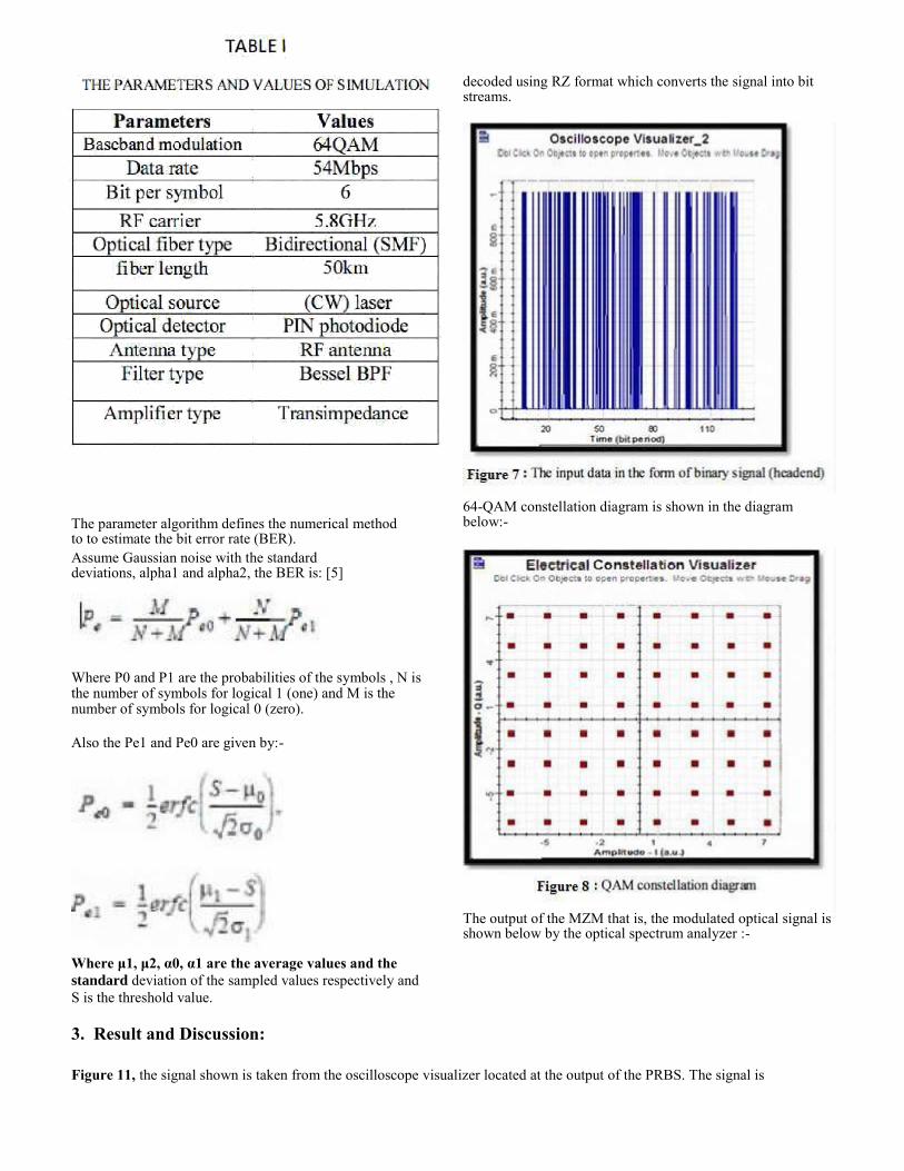
decoded using RZ format which converts the signal into bit streams.
64-QAM constellation diagram is shown in the diagram below:-
The output of the MZM that is, the modulated optical signal is shown below by the optical spectrum analyzer :-
Figure 11, the signal shown is taken from the oscilloscope visualizer located at the output of the PRBS. The signal is

At the RAU side, the signal that is distributed by the single mode fiber is amplified by the TIA (transimpedence amplifier) and then radiated by the RF antenna as shown in the diagram below :
After receiving the RF signal at the receiver side through the RF antenna, it is down converted from 5.8GHz to 2.4GHz
(ISM Band) and then it is demodulated by the QAM demodulator to obtain the desired information as shown in the diagram below : The user can calculate and obtain the bit error rate (BER) of an electrical signal automatically as shown in the figure below using the BER visualizer. We noticed that the minimum BER in dB is equal to -1000dBm which is very low as compared to (-20dBm to - 70dBm) in 802.11a without using the RoF technique. The BER that we obtained in this simulation is the result

of using the RoF technique and the QAM modulation and also the single mode fiber (SMF) and other components like Bessel filter which give significantly lower BER and a low insertion loss as compared to other filters.
4. Conclusion
The simulation design has combined the two important aspects i.e. the implementation of the RoF technology and the WLAN of IEEE standard 802.11a in the downlink system. The design shows that the 54 Mbps, 64 QAM with 5.8 GHz can be supported by the system that uses 50 km bidirectional optical fiber and the wireless distance of 10 km using RF modulated signal at 5.8 GHz. With high antenna gain, the system is suitable for longer distance point to point applications. Down conversion of the frequency at the receiver end has been implemented to ensure that the end user can connect to the WLAN at the downlink. The implementation of the RoF technology and the WLAN of IEEE standard 802.11a and also using the QAM modulation
provides more reliability by reducing the BER as compared to
the IEEE 802.11a standard with wireless feeder network .It also
provides more flexibility, in case if future requirements such as
extension of the system for more capacity and larger coverage
area are needed.
5. References
[I] Anthony Ng'oma," Radio-over-Fiber Technology for Broadband Wireless Communication System", Technische University Eindhoven, 2005. [2] Pardeep Kaur,R.S.Kaler," Radio over Fiber Networks ", Mandi Oobindgarh. March 23, 2007. [3] Chang-Soon Choi, Jun-Hyuk Seo, Woo-Young Choi, Hideki Kamitsuna, Minoru Ida, and Kenji Kurishima " 60-0HZ Bidirectional Radio-on-Fiber Links Based on Inp-Ingaas HPT Optoelectronic Mixers ", ieee photonics technology letters, vol. 17, no. 12, december 2005. [4] Betti, S. Carrozzo, V. Duca, E. Parca, O.," Radio-over-Fiber (RoF) Techniques for Broadband WLAN", Univ. degli Studi di Roma Tor Vergata, Roma, 2007. [5] Hamid AI-Raweshidy and Shozo Komaki," Radio Over Fiber Technologies for Mobile Communication Network." Artech House Publishers. 2002. [6] Hadj Bourdoucen and Amer Alhabsi," Improvement of Bit- Error Rate in Optical Fiber Receivers", International Journal of Electronics, Communications and Computer Engineering 2009. [7] Amer Alhabsi and Hadj Bourdoucen," Improvement of Bit- ErrorRate in Optical FiberData Transmission", international conference on communication, computer and power, February 15-18, 2009. [8] Ornelis Jan Kikkert," The Effect of Filter Type on BER Of WCDMAUMTS Mobile Radio Systems ", James Cook University. AUTHOR PROFILE:
1Gaurav H Kankaria is currently pursuing his B.Tech degree
in VIT University, Vellore majoring in the field of Electronics and Communication. 2Shreyansh Jain is currently pursuing his B.Tech (2011-
2015) from the department of Electronics and Communications Engineering at VIT University, Vellore, India. 3Anshul Chaudhary is currently pursuing his B.Tech from
VIT University, Vellore, India majoring in the field of Electronics and Communication.
Copyright © 2022 FDOKUMEN