Optimization of Aileron Spanwise Size and Shape to Minimize ...
47
Utah State University Utah State University DigitalCommons@USU DigitalCommons@USU All Graduate Theses and Dissertations Graduate Studies 8-2020 Optimization of Aileron Spanwise Size and Shape to Minimize Optimization of Aileron Spanwise Size and Shape to Minimize Induced Drag in Roll with Correlating Adverse Yaw Induced Drag in Roll with Correlating Adverse Yaw Joshua R. Brincklow Utah State University Follow this and additional works at: https://digitalcommons.usu.edu/etd Part of the Mechanical Engineering Commons Recommended Citation Recommended Citation Brincklow, Joshua R., "Optimization of Aileron Spanwise Size and Shape to Minimize Induced Drag in Roll with Correlating Adverse Yaw" (2020). All Graduate Theses and Dissertations. 7816. https://digitalcommons.usu.edu/etd/7816 This Thesis is brought to you for free and open access by the Graduate Studies at DigitalCommons@USU. It has been accepted for inclusion in All Graduate Theses and Dissertations by an authorized administrator of DigitalCommons@USU. For more information, please contact [email protected].
-
Upload
khangminh22 -
Category
Documents
-
view
2 -
download
0
Transcript of Optimization of Aileron Spanwise Size and Shape to Minimize ...

Utah State University Utah State University
DigitalCommons@USU DigitalCommons@USU
All Graduate Theses and Dissertations Graduate Studies
8-2020
Optimization of Aileron Spanwise Size and Shape to Minimize Optimization of Aileron Spanwise Size and Shape to Minimize
Induced Drag in Roll with Correlating Adverse Yaw Induced Drag in Roll with Correlating Adverse Yaw
Joshua R. Brincklow Utah State University
Follow this and additional works at: https://digitalcommons.usu.edu/etd
Part of the Mechanical Engineering Commons
Recommended Citation Recommended Citation Brincklow, Joshua R., "Optimization of Aileron Spanwise Size and Shape to Minimize Induced Drag in Roll with Correlating Adverse Yaw" (2020). All Graduate Theses and Dissertations. 7816. https://digitalcommons.usu.edu/etd/7816
This Thesis is brought to you for free and open access by the Graduate Studies at DigitalCommons@USU. It has been accepted for inclusion in All Graduate Theses and Dissertations by an authorized administrator of DigitalCommons@USU. For more information, please contact [email protected].

OPTIMIZATION OF AILERON SPANWISE SIZE AND SHAPE TO MINIMIZE
INDUCED DRAG IN ROLL WITH CORRELATING ADVERSE YAW
by
Joshua R. Brincklow
A thesis submitted in partial fulfillment
of the requirements for the degree
of
MASTER OF SCIENCE
in
Mechanical Engineering
Approved:
______________________ ____________________
Douglas Hunsaker, Ph.D. Geordie Richards, Ph.D.
Major Professor Committee Member
______________________ ____________________
David Geller, Ph.D. Richard S. Inouye, Ph.D.
Committee Member Vice Provost for Graduate Studies
UTAH STATE UNIVERSITY
Logan, Utah
2020

ii
Copyright © Joshua Brincklow 2020
All Rights Reserved

iii
ABSTRACT
Optimization of Aileron Spanwise Size and Shape to Minimize Induced Drag in Roll
with Correlating Adverse Yaw
by
Joshua R. Brincklow, Master of Science
Utah State University, 2020
Major Professor: Dr. Douglas Hunsaker, Ph.D.
Department: Mechanical and Aerospace Engineering
Most modern aircraft employ discrete ailerons for roll control. The induced drag,
rolling moment, and yawing moment for an aircraft is dictated in part by the location and
spanwise size of the ailerons. To quantify these forces and moments and relate them to
aileron design, a potential-flow lifting-line theory is used. This work explores a large
design space composed of linearly tapered wing planforms and aileron geometries. Lifting-
line theory shows that the optimum aileron location for minimizing induced drag always
extends to the wing tip. This aileron design is not influenced by lift and rolling moment
requirements. Changes to optimum aileron designs and their impacts to induced drag and
yawing moment are considered and provide context for benefits in future morphing aircraft.
Results are provided to give insight into aileron placement in the early design process. In
most cases, optimum discrete ailerons produce 5–20% more induced drag than a morphing
wing at the same rolling moment.
(46 pages)

iv
PUBLIC ABSTRACT
Optimization of Aileron Spanwise Size and Shape to Minimize Induced Drag in Roll
with Correlating Adverse Yaw
Joshua R. Brincklow
Most modern aircraft make use of modifying the main wing in flight to begin a roll.
In many cases, this is done with a discrete control surface known as an aileron. The lift,
drag, and moments for the wing are affected in part by the location and size of the ailerons
along the length of the wing. The lift, drag, and moments can be found using a lifting-line
theory that considers the circulation in airflow from many small sections of the wing. To
minimize the drag due to lift on the wing, the ailerons must be optimized for the best
location and size. In every case, the optimum aileron size extends to the wing tip. Results
are provided in plots that can be used during the early design process to select optimum
aileron size and location, as well as find the corresponding moments and drag due to lift.
Compared to morphing wings, or wings that can change their shape for a new lift
distribution along the wing, optimum discrete ailerons produce 5–20% more drag due to
lift at the same rolling moment.

v
To my wife and parents, who stand with me during these uncertain times.

vi
ACKNOWLEDGMENTS
This work was funded by the U.S. Office of Naval Research Sea-Based Aviation
program (Grant No. N00014-18-1-2502) with Brian Holm-Hansen as the program officer.
Completion of this work would not be possible without my advisor, as he provided
the guidance necessary to see the bigger picture and sidestep the pitfalls so common in
research.
Joshua R. Brincklow

vii
CONTENT
ABSTRACT ...................................................................................................................... iii
PUBLIC ABSTRACT ...................................................................................................... iv
ACKNOWLEDGMENTS ................................................................................................ vi
LIST OF FIGURES ........................................................................................................ viii
NOMENCLATURE ......................................................................................................... ix
1 INTRODUCTION ...................................................................................................1
1.1 Background .......................................................................................................1
1.2 Lifting-line Theory............................................................................................2
1.3 Optimum Twist Distributions ...........................................................................9
2 LIFTING-LINE ANALYSIS OF ROLL INITIATION ........................................12
2.1 Background .....................................................................................................12
2.2 Derivation of Novel Terms for Aileron Effects ..............................................12
3 APPLICATION OF THE NUMERICAL LIFTING-LINE METHOD.................17
3.1 Comparison of the Classical and Numerical Lifting-line Methods ................17
3.2 Case Setup .......................................................................................................20
3.3 Grid Convergence and Optimization ..............................................................21
4 EMPIRICAL RELATIONS FOR DESIGN BASED ON RESULTS ...................27
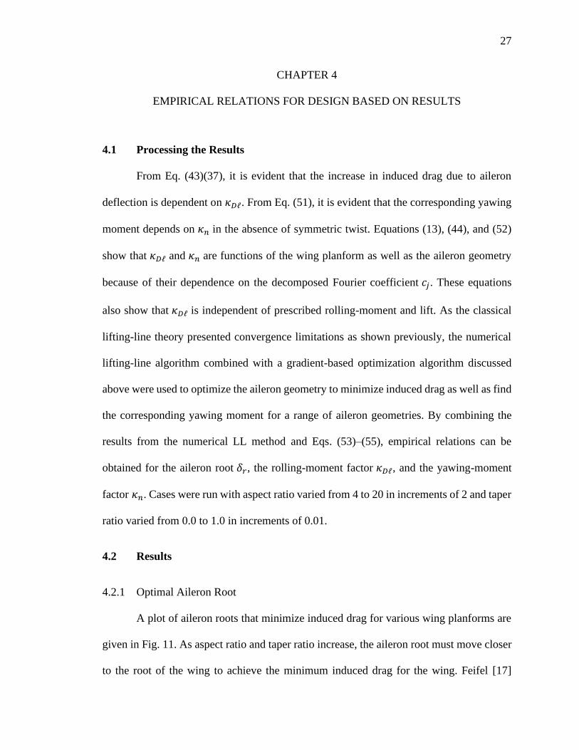
4.1 Processing the Results.....................................................................................27
4.2 Results .............................................................................................................27
4.2.1 Optimal Aileron Root ......................................................................27
4.2.2 Values of 𝜅𝐷ℓ ...................................................................................28
4.2.3 Values of 𝜅𝑛 .....................................................................................29
4.3 Application Example .......................................................................................30
5 CONCLUSION ......................................................................................................32
REFERENCES ..................................................................................................................37

viii
LIST OF FIGURES
Figure Page
1 Change in local section angle of attack due to pure rolling rate .........................4
2 Induced drag planform penalty factor for untwisted linearly tapered
wings ...................................................................................................................9
3 Rectangular planforms with varying methods of spanwise node
placement with a lifting-line along the quarter-chord .......................................18
4 Induced drag increment error between two lifting-line methods as a
function of nodes per semispan. ........................................................................19
5 Grid-convergence analysis of induced drag coefficient at several
prescribed rolling moment coefficients. ............................................................21
6 Aircraft properties as a function of grid density ...............................................22
7 Contour of induced drag coefficient at a rolling-moment coefficient of
0.04 ....................................................................................................................24
8 Contour of induced drag coefficient at a rolling-moment coefficient of
0.1 ......................................................................................................................24
9 Contour plot of deflection angle (in degrees) ...................................................25
10 Contour plot of yawing moment coefficient .....................................................25
11 Aileron root positions based on aspect ratio and taper ratio to achieve
minimum induced drag .....................................................................................28
12 Values of 𝜅𝐷ℓ using optimal aileron design as a function of taper ratio
for aspect ratios ranging from 4 to 20 ...............................................................29
13 Values of 𝜅𝑛 using optimal aileron design as a function of taper ratio
for aspect ratios ranging from 4 to 20 ...............................................................30

ix
NOMENCLATURE
𝐴𝑗 = Fourier coefficients in the lifting-line solution
𝑎𝑗 = decomposed Fourier coefficients related to planform
𝑏 = semispan of the wing
𝑏𝑗 = decomposed Fourier coefficients related to symmetric twist
𝐶𝐷𝑖 = induced drag coefficient
𝐶𝐷0 = simplified induced drag coefficient
�̃�𝐿,𝛼 = section-lift slope
𝐶ℓ = rolling-moment coefficient
𝐶𝑛 = yawing-moment coefficient
𝑐 = local section chord length
𝑐𝑗 = decomposed Fourier coefficients related to aileron deflection
𝑑𝑗 = decomposed Fourier coefficients related to rolling rate
�̃� = local section lift
𝑁 = number of terms retained in a truncated infinite series
𝑝 = angular rolling rate, positive right wing down
�̅� = dimensionless angular rolling rate
𝑅𝐴 = wing aspect ratio
𝑅𝑇 = wing taper ratio
𝑉∞ = freestream velocity magnitude
𝑧 = spanwise coordinate from mid-span, positive left
𝑧𝛿𝑟 = spanwise position of the aileron closest to the wing root

x
𝑧𝛿𝑡 = spanwise position of the aileron closest to the wing tip
𝛼 = local geometric angle of attack relative to the freestream
𝛼𝐿0 = local zero-lift angle of attack
Γ = local section circulation
Δ𝐶𝐷𝑖 = incremental change in induced-drag coefficient
𝛿𝑎 = aileron deflection angle in radians
𝛿𝑟 = semispan position of the aileron closest to the wing root
𝛿𝑡 = semispan position of the aileron closest to the wing tip
휀𝑓 = local airfoil-section flap effectiveness
휀Ω = twist effectiveness
𝜃 = change of variables for the spanwise coordinate
𝜅𝐷 = planform penalty factor in induced drag calculations
𝜅𝐷𝐿 = lift factor in induced drag calculations
𝜅𝐷ℓ = rolling-moment factor in induced drag calculations
𝜅𝐷Ω = twist factor in induced drag calculations
𝜅𝑛 = yawing-moment factor in yawing-moment calculations
𝜌 = air density
𝜒 = spanwise antisymmetric twist distribution function
Ω = negative of the twist value at the location of max magnitude twist
𝜔 = spanwise symmetric twist distribution function

CHAPTER 1
INTRODUCTION
1.1 Background
Discrete control surfaces are often used on a main wing for roll control and are
often referred to as ailerons. Aircraft performance, structure, and system configuration,
which vary with each airframe design, often determines the size and placement of the
ailerons [1–4]. In recent years, extensive studies have been made into morphing aircraft
that can deflect the wing trailing-edge continuously. For example, NASA has studied
morphing wing concepts such as the Variable-Camber Continuous Trailing Edge
(VCCTE) [5]. Flexsys is working on a continuous trailing-edge flap [6] for a Gulfstream
aircraft. The Utah State University Aerolab in partnership with AFRL has developed
and flight-tested a variable-camber continuous wing (VCCW) [7–11]. Often the main
benefit of morphing-wing technology over ailerons is minimizing drag for a range of
flight conditions [5,12–14]. Aileron deflection produces increased induced drag and
radar observability, and decreased roll-yaw coupling control compared to morphing
wings at a given rolling moment [15,16].
The location and spanwise size of the ailerons partially determine the magnitude
of the yawing moment and drag. An optimal aileron geometry is desired to compare
against morphing wings, as non-optimal solutions for discrete control surfaces
compared against optimal continuous trailing-edge surfaces will lead to incorrect
conclusions. Optimal aileron geometries are also desired for insight into aileron
placement during the early stages of aircraft design. A potential-flow vortex lattice
analysis for optimal aileron placement was performed by Feifel [17] for elliptic

2
planforms with a rolling moment requirement to minimize induced drag. This work
broadens the scope by considering linearly tapered wings with ailerons using potential-
flow lifting-line theory and gradient optimization. A relationship between aileron
placement, induced drag, rolling moment, and yawing moment is provided as part of
Prandtl’s classical lifting-line theory [18] and gives further insight into the conclusions
made from the numerical results.
1.2 Lifting-line Theory
The section-lift distribution and induced drag on a finite wing is expressed in a
Fourier sine series in Prandtl’s classical lifting-line (LL) theory [18,19]. The classical LL
solution for the circulation distribution can be expressed as
𝛤(𝜃) = 2𝑏𝑉∞∑𝐴𝑗 sin(𝑗𝜃)
𝑁
𝑗=1
(1)
where b represents the semispan of the wing, 𝑉∞ represents the freestream velocity, and 𝜃
represents a change of variables in the spanwise direction,
𝜃 ≡ cos−1(−2𝑧/𝑏) (2)
Combining Eq. (1) with the Kutta-Joukowski law [20,21] gives
�̃�(𝜃) = 2𝜌𝑉∞2𝑏∑𝐴𝑗 sin(𝑗𝜃)
𝑁
𝑗=1
(3)
The Fourier coefficients in Eqs. (1) and (3) are related to the distributions of the
chord-length and aerodynamic angle-of-attack. Prandtl’s LL equation can be used for any

3
wing planform and twist distribution to determine the spanwise section-lift distribution. To
obtain the Fourier coefficients 𝐴𝑗 in Eqs. (1) and (3), the LL equation must be satisfied at
𝑁 locations along the wing. This results in a linear system that can be solved to yield the
Fourier coefficients
∑𝐴𝑗 [4𝑏
�̃�𝐿,𝛼𝑐(𝜃)+
𝑗
sin(𝜃)] sin(𝑗𝜃)
𝑁
𝑗=1
= 𝛼(𝜃) − 𝛼𝐿0(𝜃) (4)
where 𝛼(𝜃) and 𝛼𝐿0(𝜃) are functions of spanwise location and represent the geometric and
aerodynamic angle of attack respectively. These can be used once the Fourier coefficients
have been obtained to solve for the integrated forces and moments on the wing. With rigid-
body roll effects included, the resultant lift, induced drag, rolling moment, and yawing
moment coefficients are
𝐶𝐿 = 𝜋𝑅𝐴𝐴1 (5)
𝐶𝐷𝑖 = 𝜋𝑅𝐴∑𝑗𝐴𝑗2
𝑁
𝑗=1
−𝜋𝑅𝐴�̅�
2𝐴2 (6)
𝐶ℓ = −𝜋𝑅𝐴4𝐴2 (7)
𝐶𝑛 =𝜋𝑅𝐴4∑(2𝑗 − 1)𝐴𝑗−1𝐴𝑗
𝑁
𝑗=2
−𝜋𝑅𝐴�̅�
8(𝐴1 + 𝐴3) (8)
where �̅� is the nondimensional roll rate about the stability axis, and is defined as
�̅� ≡ 𝑝𝑏/2𝑉∞ (9)

4
The stability axis is the axis parallel to the freestream and intersecting the center of gravity
as shown in Fig. 1.
Fig. 1 Change in local section angle of attack due to pure rolling rate.
Equations (4)–(8) have the disadvantage of requiring recalculation for each change in
operating condition, including angle of attack, control-surface deflection, and rolling rate.
A more useful form of the LL solution has been presented by Phillips and Snyder [22] and
allows for operating conditions to be solved for independently [23]. A similar approach is
applied here with the definition
𝐴𝑗 = 𝑎𝑗(𝛼 − 𝛼𝐿0)root − 𝑏𝑗𝛺 + 𝑐𝑗𝛿𝑎휀𝑓 + 𝑑𝑗�̅� (10)
where 𝑎𝑗 , 𝑏𝑗 , 𝑐𝑗 , 𝑑𝑗 are decomposed Fourier coefficients representing planform, twist,
aileron deflection, and roll rate, respectively. Here twist is defined to be spanwise
symmetric with scaling −Ω, and the roll control mechanism to be symmetric in magnitude
and opposite in sign, termed antisymmetric, with a magnitude of 𝛿𝑎. The symbol 휀𝑓 is the
aileron section flap effectiveness, which in this work is assumed to be constant across the
z
pV∞
–zp
V∞
zp
Dap
–Dap
V∞

5
span of the flap. The decomposed Fourier coefficients can be found by using the relations
∑𝑎𝑗 [4𝑏
�̃�𝐿,𝛼𝑐(𝜃)+
𝑗
sin(𝜃)] sin(𝑗𝜃) = 1
𝑁
𝑗=1
(11)
∑𝑏𝑗 [4𝑏
�̃�𝐿,𝛼𝑐(𝜃)+
𝑗
sin(𝜃)] sin(𝑗𝜃)
𝑁
𝑗=1
= 𝜔(𝜃) (12)
∑𝑐𝑗 [4𝑏
�̃�𝐿,𝛼𝑐(𝜃)+
𝑗
sin(𝜃)]
𝑁
𝑗=1
sin(𝑗𝜃) = 𝜒(𝜃) (13)
∑𝑑𝑗 [4𝑏
�̃�𝐿,𝛼𝑐(𝜃)−
𝑗
sin(𝜃)] sin(𝑗𝜃)
𝑁
𝑗=1
= cos(𝜃) (14)
where 𝜔(𝜃) is a symmetric twist distribution function, and 𝜒(𝜃) is a spanwise
antisymmetric twist distribution function, which can be represented as an indicator function
𝜒(𝑧) =
{
0, 𝑧 < −𝑧𝛿𝑡1, −𝑧𝛿𝑡 ≤ 𝑧 ≤ −𝑧𝛿𝑟0, −𝑧𝛿𝑟 < 𝑧 < 𝑧𝛿𝑟−1, 𝑧𝛿𝑟 ≤ 𝑧 ≤ 𝑧𝛿𝑡0, 𝑧 > 𝑧𝛿𝑡
(15)
where 𝑧𝛿𝑟 is the spanwise position of the aileron closest to the wing root and 𝑧𝛿𝑡 is the
spanwise position of the aileron closest to the wing tip. The aileron root and tip are here
defined as the spanwise edge position of the aileron closest to the wing root and tip,
respectively.
The normalized twist distribution functions 𝜔(𝜃) and 𝜒(𝜃) are multiplied by the
corresponding scalings −Ω and 𝛿𝑎휀𝑓 to give the resultant total twist distribution in the

6
wing. The total symmetric twist is −Ω𝜔(𝜃), and the total antisymmetric twist is 𝛿𝑎휀𝑓𝜒(𝜃).
For a given wing planform, symmetric twist distribution function, and antisymmetric
control deflection distribution, Eqs. (11)–(14) can be solved for the decomposed Fourier
coefficients. These coefficients along with angle-of-attack, symmetric twist scaling,
control deflection scaling, section flap effectiveness, and rolling rate can then be used in
Eq. (10) to compute the Fourier coefficients in Eqs. (5)–(8).
For a wing with symmetric planform and twist, the even terms of the 𝑎𝑗 and 𝑏𝑗
coefficients are zero. For any wing with an antisymmetric control surface distribution, the
odd terms of the 𝑐𝑗 coefficients are zero. The odd terms of the 𝑑𝑗 coefficients are also zero,
since the aerodynamic angle-of-attack changes antisymmetrically with rigid-body roll
about the stability axis. Equation (10) can then be expressed as
𝐴𝑗 = {𝑎𝑗(𝛼 − 𝛼𝐿0)root − 𝑏𝑗𝛺 j odd
𝑐𝑗𝛿𝑎휀𝑓 + 𝑑𝑗�̅� j even (16)
Using Eq. (16) in Eqs. (5)–(8) gives
𝐶𝐿 = 𝜋𝑅𝐴[𝑎1(𝛼 − 𝛼𝐿0)root − 𝑏1𝛺] (17)
𝐶𝐷𝑖 = 𝜋𝑅𝐴∑𝑗[𝑎𝑗(𝛼 − 𝛼𝐿0) − 𝑏𝑗𝛺]2+ 𝜋𝑅𝐴∑𝑗(𝑐𝑗𝛿𝑎휀𝑓 + 𝑑𝑗�̅�)
2𝑁
𝑗=2
𝑁
𝑗=1
−𝜋𝑅𝐴�̅�
2(𝑐2𝛿𝑎휀𝑓 + 𝑑2�̅�)
(18)
𝐶ℓ = −𝜋𝑅𝐴4(𝑐2𝛿𝑎휀𝑓 + 𝑑2�̅�) (19)

7
𝐶𝑛 = −𝜋𝑅𝐴�̅�
8(𝑎1(𝛼 − 𝛼𝐿0)root − 𝑏1Ω + 𝑎3(𝛼 − 𝛼𝐿0)root − 𝑏3Ω)
+𝜋𝑅𝐴4((∑(2𝑗 − 1)(𝑎𝑗−1(𝛼 − 𝛼𝐿0)root − 𝑏𝑗−1Ω)(𝑐𝑗𝛿𝑎휀𝑓 + 𝑑𝑗�̅�)
𝑁
𝑗=2
)
j even
+ (∑(2𝑗 − 1)(𝑐𝑗−1𝛿𝑎휀𝑓 + 𝑑𝑗−1�̅�)(𝑎𝑗(𝛼 − 𝛼𝐿0)root − 𝑏𝑗Ω)
𝑁
𝑗=3
)
j odd
)
(20)
Recognizing the last term in Eq. (18) is the same as Eq. (19), Eq. (18) can be expressed as
𝐶𝐷𝑖 = 𝜋𝑅𝐴∑𝑗[𝑎𝑗(𝛼 − 𝛼𝐿0) − 𝑏𝑗𝛺]2
𝑁
𝑗=1
+ 𝜋𝑅𝐴∑𝑗(𝑐𝑗𝛿𝑎휀𝑓 + 𝑑𝑗�̅�)2
𝑁
𝑗=2
− 2�̅�𝐶ℓ
(21)
In the absence of aileron deflection and rolling rate, the induced drag simplifies to
𝐶𝐷0 = 𝜋𝑅𝐴∑𝑗[𝑎𝑗(𝛼 − 𝛼𝐿0) − 𝑏𝑗𝛺]2
𝑁
𝑗=1
(22)
and the induced drag can be rearranged in the form [24]
𝐶𝐷0 =𝐶𝐿2(1 + 𝜅𝐷) − 𝜅𝐷𝐿𝐶𝐿𝐶𝐿,𝛼𝛺 + 𝜅𝐷𝛺(𝐶𝐿,𝛼𝛺)
2
𝜋𝑅𝐴 (23)
where
𝐶𝐿 = 𝐶𝐿,𝛼[(𝛼 − 𝛼𝐿0)root − 휀𝛺𝛺] (24)

8
𝐶𝐿,𝛼 = 𝜋𝑅𝐴𝑎1 =�̃�𝐿,𝛼
[1 + �̃�𝐿,𝛼/(𝜋𝑅𝐴)](1 + 𝜅𝐿) (25)
𝜅𝐿 ≡1 − (1 + 𝜋𝑅𝐴/�̃�𝐿,𝛼)𝑎1
(1 + 𝜋𝑅𝐴/�̃�𝐿,𝛼)𝑎1 (26)
휀𝛺 ≡𝑏1𝑎1
(27)
𝜅𝐷 ≡∑𝑗𝑎𝑗2
𝑎12
𝑁
𝑗=2
(28)
𝜅𝐷𝐿 ≡ 2𝑏1𝑎1∑𝑗
𝑎𝑗
𝑎1(𝑏𝑗
𝑏1−𝑎𝑗
𝑎1)
𝑁
𝑗=2
(29)
𝜅𝐷𝛺 ≡ (𝑏1𝑎1)2
∑𝑗(𝑏𝑗
𝑏1−𝑎𝑗
𝑎1)
2𝑁
𝑗=2
(30)
Here 𝑎𝑛 depends on planform as shown in Eq. (11) and 𝑏𝑛 depends on wing twist
as shown in Eq. (12), and therefore 𝜅𝐿, 휀Ω, 𝜅𝐷, 𝜅𝐷𝐿, and 𝜅𝐷Ω depend on planform and twist,
with examples shown by Phillips et. al. [25]. From these relationships, valuable
conclusions can be drawn about optimum taper ratio and symmetric twist design. For
example, in the absence of twist, Eq. (23) simplifies to
𝐶𝐷0 =𝐶𝐿2
𝜋𝑅𝐴(1 + 𝜅𝐷) (31)
The term 𝜅𝐷 represents the wing planform penalty factor in induced drag relative
to an untwisted elliptic wing. The wing planform penalty factor can be computed for any
planform from Eqs. (28) and (31). Glauert [26] was the first to visualize 𝜅𝐷, and more

9
recently, Phillips [27] produced a similar figure. Work by Phillips et. al [28] cleared up
misconceptions based on Glauert’s limited results. In Fig. 2, a visualization for 𝜅𝐷 as a
function of taper ratio and aspect ratio is given, similar to Phillips [27]. The common rule-
of-thumb that induced drag is minimized with a taper ratio of 0.4 comes from these types
of computations [26,27].
Fig. 2 Induced drag planform penalty factor for untwisted linearly tapered wings.
These types of design-space explorations are useful for providing intuition in the
early stages of aircraft design. Here, a similar approach is used to examine the influence of
aileron placement on induced drag. In order to evaluate the effect of discrete ailerons on
induced drag and find the correlated yawing moment, it is helpful to understand two
optimal twist distributions.
1.3 Optimum Twist Distributions
Phillips, et. al [14] and Phillips and Hunsaker [29] showed a normalized spanwise

10
twist distribution function that minimizes induced drag for any symmetric wing planform
in steady level flight. This can be written as
𝜔(𝜃) = 1 −𝑠𝑖𝑛(𝜃)
𝑐(𝜃)/𝑐𝑟𝑜𝑜𝑡 (32)
with the required symmetric twist scaling based on the lift coefficient
𝛺 =4𝑏𝐶𝐿
𝜋𝑅𝐴�̃�𝐿,𝛼𝑐𝑟𝑜𝑜𝑡 (33)
And the required angle of attack is
(𝛼 − 𝛼𝐿0)𝑟𝑜𝑜𝑡 =𝐶𝐿𝜋𝑅𝐴
(4𝑏
�̃�𝐿,𝛼𝑐𝑟𝑜𝑜𝑡+ 1) (34)
Any wing employing this twist distribution function at the angle of attack given in Eq. (34)
will produce an elliptic lift distribution and result in an induced drag of
𝐶𝐷𝑖 =𝐶𝐿2
𝜋𝑅𝐴 (35)
Similarly, a LL analysis by Hunsaker et. al [30] produced an antisymmetric twist
distribution function that minimizes induced drag for any symmetric wing planform and
prescribed rolling moment with zero rolling rate. This can be written as
𝜒(𝜃) = [1 +2𝑏 𝑠𝑖𝑛(𝜃)
�̃�𝐿,𝛼𝑐(𝜃)] 𝑐𝑜𝑠(𝜃) (36)
This twist distribution function provides the optimum continuous twist along the wingspan
to produce a given rolling moment and minimize induced drag in the absence of rolling
rate. For any wing geometry employing the optimal antisymmetric twist distribution

11
function from Hunsaker et. al [30] in Eq. (36), the corresponding induced drag increase
relative to steady level flight conditions is
(𝛥𝐶𝐷𝑖)ℓ = 32𝐶ℓ2
𝜋𝑅𝐴 (37)
Equation (37) gives the minimum increase in drag for any rolling moment. Most aileron
designs produce more induced drag than this. Using the antisymmetric twist distribution
function given by Eq. (36), the resulting yawing moment at roll initiation is given by
𝐶𝑛 = −3𝐶𝐿𝐶ℓ𝜋𝑅𝐴
− 5𝐶ℓ(𝑎3(𝛼 − 𝛼𝐿0)𝑟𝑜𝑜𝑡 − 𝑏3𝛺) (38)
With this LL formulation, the effect of discrete ailerons on induced drag can now be
considered.

12
CHAPTER 2
LIFTING-LINE ANALYSIS OF ROLL INITIATION
2.1 Background
Classical LL theory uses a Fourier sine series to represent the lift distribution along
a wing as shown in Eq. (3). Including more Fourier coefficients increases the number of
frequencies considered in the analysis as well as the rank of the linear system of equations
that must be solved. An aileron deflection represents a step change in twist distribution
along the wing, and therefore introduces many frequencies into the lift distribution.
Because solutions to this system of equations were obtained by hand in the early days of
aeronautics, they were limited in the number of Fourier coefficients that could be included.
Hence, it was difficult to use this method to accurately evaluate the effect of ailerons on
induced drag before the advent of the computer. Today, however, it is quite simple to solve
large systems of equations with little effort, so many more Fourier coefficients can be
included.
2.2 Derivation of Novel Terms for Aileron Effects
The change in induced drag based only on aileron deflection and rolling rate can be
obtained by subtracting Eq. (22) from Eq. (21). This gives
(𝛥𝐶𝐷𝑖)𝛿�̅� ≡ 𝐶𝐷𝑖 − 𝐶𝐷0 = 𝜋𝑅𝐴∑𝑗(𝑐𝑗𝛿𝑎휀𝑓 + 𝑑𝑗�̅�)2− 2�̅�𝐶ℓ
𝑁
𝑗=2
(39)
During roll initiation, the rolling rate is zero, while the aileron deflection and rolling

13
moment are nonzero. In this case, the rolling moment, yawing moment, and change in
induced drag can be found from Eqs. (19), (20), and (39) respectively by using �̅� = 0,
which gives
𝐶ℓ = −𝜋𝑅𝐴4𝑐2𝛿𝑎휀𝑓 (40)
𝐶𝑛 =𝜋𝑅𝐴𝛿𝑎휀𝑓
4((∑(2𝑗 − 1)(𝑎𝑗−1(𝛼 − 𝛼𝐿0)root − 𝑏𝑗−1Ω)(𝑐𝑗)
𝑁
𝑗=2
)
j even
+ (∑(2𝑗 − 1)(𝑐𝑗−1)(𝑎𝑗(𝛼 − 𝛼𝐿0)root − 𝑏𝑗Ω)
𝑁
𝑗=3
)
j odd
)
(41)
(𝛥𝐶𝐷𝑖)𝛿 = 𝜋𝑅𝐴𝛿𝑎2휀𝑓2∑𝑗𝑐𝑗
2
𝑁
𝑗=2
(42)
Using Eq. (40) in Eq. (42) to eliminate the aileron deflection magnitude 𝛿𝑎 gives
(𝛥𝐶𝐷𝑖)𝛿 =32𝐶ℓ
2(1 + 𝜅𝐷ℓ)
𝜋𝑅𝐴 (43)
where
𝜅𝐷ℓ ≡1
2∑𝑗 (
𝑐𝑗
𝑐2)2
𝑁
𝑗=4
(44)

14
From Eq. (43), it is shown that the increase in induced drag is a function of the aspect ratio,
rolling moment, and 𝜅𝐷ℓ. The decomposed Fourier coefficients 𝑐𝑗 depend on planform as
shown in Eq. (13), as well as the spanwise aileron edge positions as shown in Eq. (15).
Hence, the value for 𝜅𝐷ℓ is a function of planform, aileron position, and aileron spanwise
length. Note however that this analysis predicts that the increase in induced drag given in
Eq. (43) is independent of section flap effectiveness 휀𝑓, lift, and symmetric twist. It is also
interesting to note that for this case, the increase in induced drag is directly proportional to
the square of the rolling moment, much in the same way that the induced drag in the
absence of twist is proportional to the square of the lift coefficient, as shown in Eq. (31).
The induced drag of an untwisted wing of any planform with ailerons can be given as
𝐶𝐷𝑖 =𝐶𝐿2(1 + 𝜅𝐷) + 32𝐶ℓ
2(1 + 𝜅𝐷ℓ)
𝜋𝑅𝐴 (45)
If the symmetric twist distribution function given in Eqs. (32) and (33) is used, 𝜅𝐷 is zero.
If the optimal antisymmetric twist distribution function from Hunsaker et. al [30] given in
Eq. (36) is used, 𝜅𝐷ℓ is zero. If both twist distribution functions are used simultaneously,
the minimum induced drag for a given lift and rolling moment is [14]
𝐶𝐷𝑖 =𝐶𝐿2 + 32𝐶ℓ
2
𝜋𝑅𝐴 (46)
As a first step to understand aileron design, only wings without twist will be
considered, making Ω zero. This is similar to the approach Glauart [26] and Phillips [27]
employed, since they neglected twist in their initial studies on the effects of wing planform
on induced drag. Applying these simplifications to Eqs. (17) and (41) gives

15
𝐶𝐿 = 𝜋𝑅𝐴[𝑎1(𝛼 − 𝛼𝐿0)root] (47)
𝐶𝑛 =𝜋𝑅𝐴𝛿𝑎휀𝑓
4((∑(2𝑗 − 1)(𝑎𝑗−1(𝛼 − 𝛼𝐿0)root)(𝑐𝑗)
𝑁
𝑗=2
)
j even
+ (∑(2𝑗 − 1)(𝑐𝑗−1)(𝑎𝑗(𝛼 − 𝛼𝐿0)root)
𝑁
𝑗=3
)
j odd
)
(48)
Substituting Eq. (47) in Eq. (48) gives:
𝐶𝑛 =𝐶𝐿𝛿𝑎휀𝑓
4((∑(2𝑗 − 1) (
𝑎𝑗−1
𝑎1) (𝑐𝑗)
𝑁
𝑗=2
)
j even
+ (∑(2𝑗 − 1)(𝑐𝑗−1) (𝑎𝑗
𝑎1)
𝑁
𝑗=3
)
j odd
)
(49)
Equation (40) can be rearranged and used in Eq. (49) to eliminate the aileron deflection
magnitude 𝛿𝑎:
𝐶𝑛 = −𝐶𝐿𝐶ℓ𝜋𝑅𝐴
((∑(2𝑗 − 1) (𝑎𝑗−1
𝑎1) (𝑐𝑗
𝑐2)
𝑁
𝑗=2
)
j even
+ (∑(2𝑗 − 1) (𝑐𝑗−1
𝑐2) (𝑎𝑗
𝑎1)
𝑁
𝑗=3
)
j odd
)
(50)
This can be rearranged to give

16
𝐶𝑛 = −𝐶𝐿𝐶ℓ𝜅𝑛𝜋𝑅𝐴
(51)
where
𝜅𝑛 = 3 + (∑(2𝑗 − 1) (𝑐𝑗−1
𝑐2) (𝑎𝑗
𝑎1)
𝑁
𝑗=3
)
j odd
+ (∑(2𝑗 − 1) (𝑎𝑗−1
𝑎1) (𝑐𝑗
𝑐2)
𝑁
𝑗=4
)
j even
(52)

17
CHAPTER 3
APPLICATION OF THE NUMERICAL LIFTING-LINE METHOD
3.1 Comparison of the Classical and Numerical Lifting-line Methods
A current major drawback of using classical LL theory in the evaluation of the
effects of ailerons on induced drag is the inability to use grid clustering to achieve second-
order convergence. In the classical LL theory, traditionally nodes are clustered along the
wing using Eq. (2) with cosine-clustering near the wing tips by evenly spacing the nodes
in 𝜃. However, this method of clustering does not consider how the node clustering will
fall relative to the placement of the aileron. Figure 3(a) provides a visualization of the
traditional cosine-clustering with 80 nodes and symmetrically-placed ailerons. Note that
the edge of the aileron may be in a position between two nodes or directly on a node. As
the number of nodes used in the calculation increases, the accuracy of the induced drag and
yawing moment solutions will vary as the cosine-clustered nodes change position relative
to the location of the edge of the aileron. As a comparison, the clustering used in Fig. 3(b)
allows greater control over the placement of nodes relative to the aileron position, so that
the edge of an aileron falls directly on a node regardless of its span or spanwise location.
This clustering can be termed as aileron-sensitive clustering. Aileron-sensitive clustering
can be utilized in the classical LL theory, but because an aileron forces a step change in
twist along the span, an infinite number of frequencies are introduced, and the finite Fourier
series cannot accurately model the step change in twist. Finding mathematical workarounds
to use the classical LL method with aileron-sensitive clustering is a future topic of study.
Given the prior work in deriving the LL theory, the current inability to access a
working induced drag and yawing moment solution using discrete control surfaces may

18
seem a great discouragement. However, a numerical LL algorithm published by Phillips
and Snyder [22], which is a close numerical analog to the classical LL theory, can
effectively use aileron-sensitive clustering and accurately find the aerodynamic effects of
ailerons.
Fig. 3 Rectangular planforms with varying methods of spanwise node placement with
a lifting-line along the quarter-chord.
The numerical LL method differs from the vortex lattice method that Feifel [17]
used because the surface flow boundary condition is not required at the three-quarter-chord
[31] along the panel center line. Instead, the algorithm finds the local circulation at each
wing section with a relationship between the three-dimensional vortex lifting law [32] and
the section airfoil lift. This algorithm depends on a system of lifting surfaces connected by
discrete horseshoe vortices, creating a vorticity field [33]. This method can be applied to
multiple lifting surfaces with sweep and dihedral and gives accurate solutions for wings
with aspect ratios greater than about 4 [22]. This algorithm is applied in MachUp [14,34],
an open-source code available on GitHub1.
As an example, Fig. 4 shows the difference in convergence between MachUp and
1 https://github.com/usuaero/MachUp

19
the classical LL method with traditional cosine-clustering for an induced drag increment
caused by aileron deflection as a function of nodes per semispan. Error is calculated as the
difference in induced drag increment between a given number of nodes per semispan and
a significantly greater number of nodes per semispan, in this case 640 nodes, using the
same method. Note that the classical LL method does not consistently decrease in error as
the number of nodes is increased. The numerical LL algorithm is therefore a more
consistently accurate tool to explore the design space of aileron sizing and placement.
Fig. 4 Induced drag increment error between two lifting-line methods as a function
of nodes per semispan.
A downside of using the numerical lifting-line algorithm is that the results for the
decomposed Fourier coefficients cannot be found directly. The numerical lifting-line
algorithm provides integrated force and moment solutions for the complete wing, which
can be used to estimate 𝜅𝐷ℓ and 𝜅𝑛. Rearranging Eqs. (31), (43), and (51) gives
𝜅𝐷 =𝐶𝐷0𝜋𝑅𝐴
𝐶𝐿2 − 1 (53)

20
𝜅𝐷ℓ =(Δ𝐶𝐷𝑖)𝛿(𝜋𝑅𝐴)
32𝐶ℓ2 (54)
𝜅𝑛 = −𝜋𝐶𝑛𝑅𝐴𝐶𝐿𝐶ℓ
(55)
Results for the integrated induced-drag increment and yawing moment were then used in
Eqs. (53)–(55) to estimated 𝜅𝐷, 𝜅𝐷ℓ, and 𝜅𝑛 for a given planform and aileron geometry.
3.2 Case Setup
Each wing semispan is specified in 3 wing sections, with the center section
containing the aileron, and each wing section is cosine-clustered with a number of nodes
relative to section span, as shown in Fig. 3(b). The control surfaces are modeled with a
flap-chord fraction of 1.0 for the entire control surface length. As Feifel [5] notes, the
induced drag increment predicted by potential flow algorithms is independent of the
aileron flap-chord fraction and depends only on the prescribed rolling moment,
explained in detail by Phillips [15] as well as Abbott and Doenhoff [22]. A Newton-
Secant method is used to find the aileron deflection that would provide a target rolling
moment within machine precision at double-precision computing.
The angle of attack and rolling moment coefficient were adjusted iteratively to
arrive at the prescribed lift coefficient and rolling-moment coefficient for a given wing
planform and aileron geometry. Convergence criteria of 1.0 × 10⁻¹² and 1.0 × 10⁻¹⁶
were used for the lift coefficient and rolling-moment coefficient, respectively. Newton’s
method was used for each case as outlined by Phillips [25] with a convergence criterion
of 1.0 × 10⁻¹² to satisfy the Jacobian system of equations for the numerical lifting-line
algorithm. For the computations shown here, an airfoil section with a lift slope of 2π

21
and a zero-lift angle of attack of 0 were used, which corresponds to a thin airfoil with
zero camber.
3.3 Grid Convergence and Optimization
Multiple grid densities were analyzed to ensure fully grid-converged values from
the numerical LL algorithm. Figure 5 shows results for induced drag as a function of grid
density for several rolling-moment coefficients. Figure 6 shows the induced drag
coefficient, deflection angle, and yawing-moment coefficient predicted by the numerical
LL algorithm as a function of grid density given a rolling-moment coefficient of 0.1. The
values suggest grid convergence is achieved with 80 nodes over the semispan. A grid
density of 100 nodes over the semispan is used in the rest of the analysis to give a preferable
balance of accuracy and computational cost.
Fig. 5 Grid-convergence analysis of induced drag coefficient at several prescribed
rolling-moment coefficients.
The optimum spanwise size and location of ailerons for minimum induced drag is
found by using an open-source optimization algorithm, Optix, created and used by Hodson,

22
et al. [34], available on GitHub2. The algorithm makes use of the Broyden [35], Fletcher
[36], Goldfarb [37], and Shanno [38] (BFGS) method to iteratively find a minimum. For
the aileron root and tip, the optimization algorithm used decimal numbers out to machine
precision at double-precision computing. With a grid density of 100 nodes and small
changes to the span of the aileron section, the number of nodes assigned to the aileron
would change, changing the induced drag and presenting a similar convergence challenge
as the classical LL theory. To counter this issue, the optimization algorithm used two loops.
The inner loop could exclusively change the aileron geometry, while the outer loop could
exclusively change the redistribution of nodes so that the number of nodes assigned to a
section of the wing would remain proportional to the span of the section. In other words,
an aileron making up 50% of the semispan would contain 50 nodes after redistribution.
Fig. 6 Aircraft properties as a function of grid density.
2 https://github.com/usuaero/Optix

23
Figures 7 and 8 show induced drag contours for a wing with a prescribed rolling-
moment coefficient, lift coefficient, and aspect ratio. A diagonal line boundary defines the
limiting case of an infinitely small aileron at any location in the semispan. The (x,y)
coordinates on this plot represent the beginning spanwise location (x) and the ending
spanwise location (y) of the aileron. Contour lines extend to aileron deflections past 25
degrees to show data trends, even though this study only analyzes the inviscid case and
does not consider stall characteristics. Aileron deflections more than 25 degrees are
typically not practical for aircraft design. A circle at the top of the plots shows the minimum
induced drag, with the corresponding value shown in text at the bottom right. In Fig. 7,
which shows induced drag contours with a prescribed rolling-moment coefficient of 0.04,
lift coefficient of 0.5, and aspect ratio of 8, a low gradient near the minimum allows for
movement of the aileron tip between 10 and 40 percent of the wing semispan with less than
a 2% increase in induced drag above the minimum. Figure 8 changes the prescribed rolling-
moment coefficient to 0.1 while keeping all other parameters the same as Fig. 7, which
shows an increased sensitivity of the induced drag to aileron size and position based on
prescribed rolling moment. However, movement of the aileron tip between 10 and 40
percent of the wing semispan only increases the induced drag less than 4% above the
minimum.

24
Fig. 7 Contour of induced drag coefficient at a rolling-moment coefficient of 0.04.
Fig. 8 Contour of induced drag coefficient at a rolling-moment coefficient of 0.1.
Figures 9 and 10 show the contour plots for deflection angle and yawing moment,
respectively, matching the parameters used in Fig. 8. For the deflection angle, the minimum
is found at the point (0,100) in the plot, indicating an aileron extending from the wing root
to the wing tip. For the yawing moment, the minimum can be found by making the aileron
span small and close to the wing root. These minimums are consistently at the same edges
of the domain with each specified rolling moment, lift, aspect ratio, and taper ratio.

25
Fig. 9 Contour plot of deflection angle (in degrees).
Fig. 10 Contour plot of yawing moment coefficient.
Regardless of rolling moment or lift, the minimum induced drag in Figs. 7 and 8 is
found where the aileron tip meets the wing tip. Gradient-based optimization techniques
produce difficulties when the optimum is close to a boundary. With these difficulties in
mind, the aileron tip was limited to coincide with the wing tip for the following analysis,

26
or 𝛿𝑡 = 1. In other words, the wing section containing the wing tip is infinitely small, and
only the aileron root location could vary to minimize induced drag.
27
CHAPTER 4
EMPIRICAL RELATIONS FOR DESIGN BASED ON RESULTS
4.1 Processing the Results
From Eq. (43)(37), it is evident that the increase in induced drag due to aileron
deflection is dependent on 𝜅𝐷ℓ. From Eq. (51), it is evident that the corresponding yawing
moment depends on 𝜅𝑛 in the absence of symmetric twist. Equations (13), (44), and (52)
show that 𝜅𝐷ℓ and 𝜅𝑛 are functions of the wing planform as well as the aileron geometry
because of their dependence on the decomposed Fourier coefficient 𝑐𝑗. These equations
also show that 𝜅𝐷ℓ is independent of prescribed rolling-moment and lift. As the classical
lifting-line theory presented convergence limitations as shown previously, the numerical
lifting-line algorithm combined with a gradient-based optimization algorithm discussed
above were used to optimize the aileron geometry to minimize induced drag as well as find
the corresponding yawing moment for a range of aileron geometries. By combining the
results from the numerical LL method and Eqs. (53)–(55), empirical relations can be
obtained for the aileron root 𝛿𝑟, the rolling-moment factor 𝜅𝐷ℓ, and the yawing-moment
factor 𝜅𝑛. Cases were run with aspect ratio varied from 4 to 20 in increments of 2 and taper
ratio varied from 0.0 to 1.0 in increments of 0.01.
4.2 Results
4.2.1 Optimal Aileron Root
A plot of aileron roots that minimize induced drag for various wing planforms are
given in Fig. 11. As aspect ratio and taper ratio increase, the aileron root must move closer
to the root of the wing to achieve the minimum induced drag for the wing. Feifel [17]

28
reported that conventional single-segment ailerons are optimally sized for elliptical wings
at 70% semispan. Referencing Fig. 2, the closest tapered wing planform to an elliptical
planform is about a wing with a taper ratio of 0.4. The aileron root values at 𝑅𝑇 = 0.4 agree
closely with what Feifel [17] reported.
Fig. 11 Aileron root positions based on aspect ratio and taper ratio to achieve
minimum induced drag.
4.2.2 Values of 𝜅𝐷ℓ
A graph of 𝜅𝐷ℓ for optimal aileron design with changes in aspect ratio and taper
ratio is given in Fig. 12. Looking at Fig. 12 and Eq. (43), results for 𝜅𝐷ℓ can be seen as a
percent increase in the induced drag increase due to aileron geometry versus a wing using
the optimum twist distribution function given in Eq. (33), which would give a 𝜅𝐷ℓ of 0.
Since a variable-continuous trailing-edge wing could be designed to produce the optimum
twist distribution function given in Eq. (33), the results in Fig. 12 give insight into the
advantages of VCCTE and VCCW technology. As an example, a wing using discrete
ailerons with an aspect ratio of 8 and taper ratio of 0.4 would produce 10% more induced

29
drag than a variable-continuous trailing-edge wing. Note from Fig. 12 that the minimum
𝜅𝐷ℓ for any aspect ratio is found at a taper ratio of 1.0.
Fig. 12 Values of 𝜿𝑫𝓵 using optimal aileron design as a function of taper ratio for
aspect ratios ranging from 4 to 20.
4.2.3 Values of 𝜅𝑛
A graph of 𝜅𝑛 is given in Fig. 13 for multiple aspect ratios and taper ratios. Note at
a taper ratio of about 0.32, the value for 𝜅𝑛 is the same for all aspect ratios. At lower taper
ratios, 𝜅𝑛 is generally less, which decreases the adverse yawing moment. Note that in Eq.
(51), a 𝜅𝑛 less than 0 provides proverse yaw. Regardless of the wing planform, Fig. 12
shows that if zero twist is applied to the wing geometry, a wing with optimally-placed
ailerons to minimize induced drag will not produce proverse yaw.

30
Fig. 13 Values of 𝜿𝒏 using optimal aileron design as a function of taper ratio for
aspect ratios ranging from 4 to 20.
4.3 Application Example
An example of how to design a wing with optimally sized ailerons and find the
induced drag and correlated yawing moment is warranted. A designer with a previously
chosen aspect and taper ratio, in this example 14 and 0.6 respectively, could look at Fig.
11 and see that setting the aileron root at 26.5% of the wing semispan minimizes the
induced drag from the aileron. Figure 12 gives a corresponding 𝜅𝐷ℓ of about 0.11, while
Fig. 2 gives a 𝜅𝐷 of about 0.045. These values can be used along with a desired lift and
rolling moment in Eq. (45) to give the total induced drag for the wing. With a prescribed
lift coefficient of 0.5 and rolling moment coefficient of 0.05, the induced drag coefficient
is 7.99 × 10⁻³. Figure 13 gives a 𝜅𝑛 value of about 3.42, which can be used along with a
desired lift and rolling moment in Eq. (51) to give the yawing moment for the wing, which
in this case is -1.94 × 10⁻³. This methodology offers excellent estimates for initial wing
design.
An important note is that symmetric twist (washout) has not been considered in this

31
analysis, which would change the values for 𝜅𝑛. With symmetric twist, the values of 𝜅𝑛
could drop below 0 in certain conditions and the wing could then create proverse yaw
during roll. This is a topic of future work.

32
CHAPTER 5
CONCLUSION
Aileron geometry determines the induced drag produced by an aileron deflection
for a prescribed rolling moment. A potential flow lifting-line optimization for aileron
spanwise size and position can minimize the induced drag increase from ailerons. Prandtl's
classical LL theory is the foundation for this approach and allows for calculation of
spanwise section-lift distribution for any wing planform and twist distribution function. An
optimum normalized spanwise symmetric twist distribution function minimizes induced
drag for a symmetric wing planform in steady level flight, while an antisymmetric twist
distribution function minimizes induced drag for any symmetric wing planform and
prescribed rolling moment with zero rolling rate. Ailerons will typically produce more
induced drag than the optimum twist solution to produce a rolling moment. Results from
this theory show how the induced drag and yawing moment are related to planform, aileron
design, lift, and rolling moment. For this study, the yawing moment calculations neglected
symmetric wing twist (washout) effects.
This optimization made use of a numerical LL algorithm, as the classical lifting-
line theory had grid-clustering limitations. Based on the grid resolution and convergence
for the induced drag, deflection angle, and yawing moment, 100 nodes per semispan were
used in this analysis. A gradient-based optimization technique is used to find the aileron
spanwise size and position for minimum induced drag. The aileron tip for minimum
induced drag is found to meet the wing tip position, so the optimization was limited to
changing the aileron root while the aileron tip was locked to the wing tip. The optimization
produced results for aileron root positions for minimum induced drag, as well as

33
coefficients for finding the corresponding minimum induced drag and yawing moment.
Coefficients for finding the induced drag include 𝜅𝐷 and 𝜅𝐷ℓ , where 𝜅𝐷 can be
viewed as an increase in drag due to a deviation in wing planform from an elliptic wing,
and 𝜅𝐷ℓ can be viewed as a percent increase in induced drag due to a deviation from the
optimal twist distribution function through using aileron design. Coefficients for finding
the corresponding yawing moment include 𝜅𝑛 , where 𝜅𝑛 can be viewed as a
proportionality constant for adverse yaw. The minimum increase in induced drag from
ailerons is found with a taper ratio of 1.0, while the least adverse yaw can be found with a
taper ratio of 0. Regardless of the wing planform, if zero twist is applied to the wing
geometry, a wing with optimally-placed ailerons to minimize induced drag will not produce
proverse yaw.
Optimal aileron root results can be used in initial design work for aileron geometries
to minimize induced drag. Although optimal aileron solutions for induced drag in all cases
produce adverse yaw, theory suggests that wing symmetric twist (washout) can be used
such that aileron deflection would produce proverse yaw. This is a topic of future research.

37
REFERENCES
[1] Hoogervorst, J. E. K., and Elham, A. “Wing Aerostructural Optimization Using the
Individual Discipline Feasible Architecture.” Aerospace Science and Technology,
Vol. 65, 2017, pp. 90–99. https://doi.org/10.1016/j.ast.2017.02.012.
[2] Johnson, C. L. “Wing Loading, Icing and Associated Aspects of Modern Transport
Design.” Journal of the Aeronautical Sciences, Vol. 8, No. 2, 1940, pp. 43–54.
https://doi.org/10.2514/8.10478.
[3] Soinne, E. “Aerodynamically Balanced Ailerons for a Commuter Aircraft.”
Progress in Aerospace Sciences, Vol. 37, 2001, pp. 497–550.
[4] Masefield, O. L. P. “Design of a Manual Roll Control for a Trainer Aircraft.”
Loughborough University, 1990.
[5] Kaul, U. K., and Nguyen, N. T. Drag Optimization Study of Variable Camber
Continuous Trailing Edge Flap (VCCTEF) Using OVERFLOW. Presented at the
32nd AIAA Applied Aerodynamics Conference, Atlanta, GA, 2014.
[6] Hetrick, J., Osborn, R., Kota, S., Flick, P., and Paul, D. Flight Testing of Mission
Adaptive Compliant Wing. In 48th AIAA/ASME/ASCE/AHS/ASC Structures,
Structural Dynamics, and Materials Conference, American Institute of Aeronautics
and Astronautics.
[7] Joo, J. J., Marks, C. R., Zientarski, L., and Culler, A. J. Variable Camber Compliant
Wing - Design.
[8] Marks, C. R., Zientarski, L., Culler, A. J., Hagen, B., Smyers, B. M., and Joo, J. J.
Variable Camber Compliant Wing - Wind Tunnel Testing.
[9] Miller, S. C., Rumpfkeil, M. P., and Joo, J. J. Fluid-Structure Interaction of a
Variable Camber Compliant Wing. Presented at the 53rd AIAA Aerospace Sciences
Meeting, Kissimmee, Florida, 2015.
[10] Joo, J. J., Marks, C. R., and Zientarski, L. ACTIVE WING SHAPE
RECONFIGURATION USING A VARIABLE CAMBER COMPLIANT WING
SYSTEM. Presented at the 20th International Conference on Composite Materials,
Copenhagen, 2015.
[11] Marks, C. R., Zientarski, L., and Joo, J. J. Investigation into the Effect of Shape
Deviation on Variable Camber Compliant Wing Performance. In 24th AIAA/AHS
Adaptive Structures Conference, American Institute of Aeronautics and
Astronautics.
38
[12] Phillips, W. F., Fugal, S. R., and Spall, R. E. “Minimizing Induced Drag with Wing
Twist, Computational-Fluid-Dynamics Validation.” Journal of Aircraft, Vol. 43,
No. 2, 2006, pp. 437–444. https://doi.org/10.2514/1.15089.
[13] Lebofsky, S., Ting, E., Nguyen, N. T., and Trinh, K. V. Aeroelastic Modeling and
Drag Optimization of Flexible Wing Aircraft with Variable Camber Continuous
Trailing Edge Flap. Presented at the 32nd AIAA Applied Aerodynamics
Conference, Atlanta, GA, 2014.
[14] Hunsaker, D. F., Phillips, W. F., and Joo, J. J. Aerodynamic Shape Optimization of
Morphing Wings at Multiple Flight Conditions. Presented at the 55th AIAA
Aerospace Sciences Meeting, Grapevine, Texas, 2017.
[15] Montgomery, Z. S., Hunsaker, D. F., and Joo, J. J. A Methodology for Roll Control
of Morphing Aircraft. Presented at the AIAA Scitech 2019 Forum, San Diego,
California, 2019.
[16] Hunsaker, D. F., Montgomery, Z. S., and Joo, J. J. Control of Adverse Yaw During
Roll for a Class of Optimal Lift Distributions. Presented at the AIAA Scitech 2020
Forum, Orlando, FL, 2020.
[17] Feifel, W. M. “Combination of Aileron and Flap Deflection for Minimum Induced
Drag Roll Control.” Technical Soaring, Vol. 5, No. 4, 1980, pp. 15–23.
[18] Prandtl, L. Tragflügel Theorie. Nachricten von der Gesellschaft der Wissenschaften
zu Göttingen, Geschäeftliche Mitteilungen, Klasse, 1918.
[19] Prandtl, L. “Appplications of Modern Hydrodynamics to Aeronautics.” NACA TR-
116, 1921.
[20] Kutta, M. W. “Auftriebskräfte in Strömenden Flüssigkeiten.” Illustrierte
Aeronautische Mitteilungen, Vol. 6, No. 133, 1902, pp. 133–135.
[21] Joukowski, N. E. “Sur Les Tourbillons Adjionts.” Traraux de la Section Physique
de la Societé Imperiale des Amis des Sciences Naturales, Vol. 13, No. 2, 1906, pp.
261–284.
[22] Phillips, W. F., and Snyder, D. O. “Modern Adaptation of Prandtl’s Classic Lifting-
Line Theory.” Journal of Aircraft, Vol. 37, No. 4, 2000, pp. 662–670.
https://doi.org/10.2514/2.2649.
[23] Phillips, W. F., Alley, N. R., and Goodrich, W. D. “Lifting-Line Analysis of Roll
Control and Variable Twist.” Journal of Aircraft, Vol. 41, No. 5, 2004, pp. 1169–
1176.
[24] Phillips, W. F. “Analytical Decomposition of Wing Roll and Flapping Using Lifting-
Line Theory.” Journal of Aircraft, Vol. 51, No. 3, 2014, pp. 761–778.
https://doi.org/10.2514/1.C032399.

39
[25] Phillips, W. F. Overview of Aerodynamics. In Mechanics of Flight, Wiley,
Hoboken, NJ, 2010, pp. 66–82.
[26] Glauert, H. The Elements of Aerofoil and Airscrew Theory. Cambridge University
Press, London, 1926.
[27] Phillips, W. F. Mechanics of Flight. Wiley, Hoboken, NJ, 2010.
[28] Phillips, W. F., Miller, R., and Hunsaker, D. F. Decomposed Lifting-Line
Predictions and Optimization for Propulsive Efficiency of Flapping Wings.
Presented at the 31st AIAA Applied Aerodynamics Conference, San Diego, CA,
2013.
[29] Phillips, W. F., and Hunsaker, D. F. “Designing Wing Twist or Planform
Distributions for Specified Lift Distributions.” Journal of Aircraft, Vol. 56, No. 2,
2019, pp. 847–849. https://doi.org/10.2514/1.C035206.
[30] Hunsaker, D. F., Montgomery, Z. S., and Joo, J. J. “Analytic and Computational
Analysis of Wing Twist to Minimize Induced Drag during Roll.” Proceedings of the
Institution of Mechanical Engineers, Part G: Journal of Aerospace Engineering,
2019. https://doi.org/doi.org/10.1177/0954410019886939.
[31] Katz, J., and Plotkin, A. Low-Speed Aerodynamics: From Wing Theory to Panel
Methods. McGraw-Hill, 1991.
[32] Saffman, P. G. Vortex Dynamics. Cambridge University Press, Cambridge, 1992.
[33] Hunsaker, D. F. A Numerical Lifting-Line Method Using Horseshoe Vortex Sheets.
Presented at the Rocky Mountain Space Grant Consortium Meeting Proceedings,
2011.
[34] Hodson, J., Hunsaker, D. F., and Spall, R. Wing Optimization Using Dual Number
Automatic Differentiation in MachUp. Presented at the 55th AIAA Aerospace
Sciences Meeting, Grapevine, Texas, 2017.
[35] Broyden, C. G. “The Convergence of a Class of Double-Rank Minimization
Algorithms.” IMA Journal of Applied Mathematics, Vol. 6, No. 1, 1970, pp. 76–90.
https://doi.org/10.1093/imamat/6.1.76.
[36] Fletcher, R. “A New Approach to Variable Metric Algorithms.” Computer Journal,
Vol. 13, No. 3, 1970, pp. 317–322.
[37] Goldfarb, D. “A Family of Variable Metric Updates Derived by Variational Means.”
Mathematics of Computation, Vol. 24, No. 109, 1970, pp. 23–26.
[38] Shanno, D. “Conditional of Quasi-Newton Methods for Function Minimization.”
Mathematics of Computation, Vol. 24, No. 111, 1970, pp. 647–656.