Vibration based damage detection in a uniform strength beam using genetic algorithm
Upload
khangminh22Category
view
0download
0
Journal of Sound and Vibration 421 (2018) 111e131
Contents lists available at ScienceDirect
Journal of Sound and Vibration
journal homepage: www.elsevier .com/locate/ jsvi
Optimal design of a beam-based dynamic vibration absorberusing fixed-points theory
Yingyu Hua, Waion Wong*, Li ChengThe Hong Kong Polytechnic University, Department of Mechanical Engineering, Hong Kong, China
a r t i c l e i n f o
Article history:Received 25 April 2017Received in revised form 25 January 2018Accepted 30 January 2018
Keywords:Dynamic vibration absorberThe fixed-points theoryL shaped beam
* Corresponding author.E-mail address: [email protected] (W.
https://doi.org/10.1016/j.jsv.2018.01.0580022-460X/© 2018 Elsevier Ltd. All rights reserved.
a b s t r a c t
The addition of a dynamic vibration absorber (DVA) to a vibrating structure could providean economic solution for vibration suppressions if the absorber is properly designed andlocated onto the structure. A common design of the DVA is a sprung mass because of itssimple structure and low cost. However, the vibration suppression performance of thiskind of DVA is limited by the ratio between the absorber mass and the mass of the primarystructure. In this paper, a beam-based DVA (beam DVA) is proposed and optimized forminimizing the resonant vibration of a general structure. The vibration suppression per-formance of the proposed beam DVA depends on the mass ratio, the flexural rigidity andlength of the beam. In comparison with the traditional sprung mass DVA, the proposedbeam DVA shows more flexibility in vibration control design because it has more designparameters. With proper design, the beam DVA's vibration suppression capability canoutperform that of the traditional DVA under the same mass constraint. The generalapproach is illustrated using a benchmark cantilever beam as an example. The receptancetheory is introduced to model the compound system consisting of the host beam and theattached beam-based DVA. The model is validated through comparisons with the resultsfrom Abaqus as well as the Transfer Matrix method (TMM) method. Fixed-points theory isthen employed to derive the analytical expressions for the optimum tuning ratio anddamping ratio of the proposed beam absorber. A design guideline is then presented tochoose the parameters of the beam absorber. Comparisons are finally presented betweenthe beam absorber and the traditional DVA in terms of the vibration suppression effect. Itis shown that the proposed beam absorber can outperform the traditional DVA byfollowing this proposed guideline.
© 2018 Elsevier Ltd. All rights reserved.
1. Introduction
A Dynamic Vibration Absorber (DVA), also known as the tuned mass absorber, is a mechanical device designed to beattached to a primary dynamic structure in order to reduce its vibration or sound radiation. A traditional passive vibrationabsorber consists of a single degree-of-freedom (SDOF) mass-spring-damper system. The DVA can be used to reduce theunwanted vibration due to a resonant mode or the forced vibration of the primary structure. When properly tuned to dealwith the vibration at the targeted frequency, the vibration energy can be transmitted efficiently from the primary structure to
Wong).

Y. Hua et al. / Journal of Sound and Vibration 421 (2018) 111e131112
the DVA, leading to a reduction in the vibration of the primary structure. DVAs have been extensively applied in civil engi-neering [1e3] to strengthen the resistance of slender tall buildings subjected to wind loads or seismic excitation.
Many criteria can be found in the literature for the optimal design of tuning frequency and damping ratios of the DVA tomaximize its vibration suppression performance [4e7]. The most commonly used one is the H∞ criterion to minimize themaximum vibration amplitude of the primary structure. Commonways of achieving the H∞ optimal design of the traditionalDVA is to apply the fixed-points theory proposed by Den Hartog in 1928 [4]. The theory states that there exist two fixed points,independent of the damping, in the frequency response spectrum of an undamped SDOF primary system connected with thetraditional DVAs. The optimum tuning ratio is determined by making the two fixed points equally high in the spectrum andthe optimum damping ratio is determined by making the two fixed points to be the highest points in the response spectrum.The H∞ design strategy works well for the narrow band control. To tackle the broadband problem like the random excitation,the H2 optimization criterion can be applied.Warburton [5,6] derived the optimum tuning ratio and damping ratio in order tominimize the mean square values of the vibration displacement or kinetic energy over a frequency band under various typesof external excitations. Asami et al. [7] introduced the damped SDOF primary system and derived the series solution for theH∞ optimization and the analytical solution for the H2 optimization of the absorbers parameters. They confirmed that theirsolution of the optimal absorber parameters could be degenerated to the existing value by Den Hartog's method [4] when theprimary system's damping is assumed to be zero.
There are many research works done to extend the fixed-points theory for global vibration control of continuous struc-tures [8,9] and the optimization of variant design of DVA [10]. The limitations of the traditional mass spring DVA aremainly inthree aspects. a) Their vibration suppression performance is limited once the mass ratio is fixed. Without sufficient absorbermass, the vibration suppression effect is not significant. Due to physical or practical constraints, the absorber mass is seldomlarger than 20% of the mass of the primary structure. b) The stiffness of the spring can neither be too high or too low. Thespring stiffness can't be too low or else the static displacement will become very large, rendering it difficult to be imple-mented in practice. If the spring is too hard it can't achieve vibration control at low frequency. c) Their vibration controlperformance is undermined if the resonance frequency deviates from the targeted value for which they are designed (alsoknown as detuning effect). The solutions to the last question have been attempted bymany researchers. The methods includedeveloping active, semi-active or hybrid control devices [11e14] or adaptive vibration absorbers [15] whose stiffness varieswith the excitation frequency. These devices are usually bulky and need external energy input. Acar and Yilmaz [16]developed a adaptive absorber consisting of a string-mass system equipped with negative stiffness tension mechanism. Theirdesign allows the absorber's natural frequency to be varied within a certain frequency range by using a small tuning actuatorforce. This kind of device provides a solution for the bulky and energy-consuming problem in the design of adaptive absorber.However, most of the adaptive absorbers with other physical mechanisms still have the size and energy problems. Mean-while, strategies involving multiple tuned vibration dampers (MTVD) [17,18] are also investigated to overcome the detuningeffect.
As far as the authors know, there is still a lack of effort to address the challenges in a) and b). A beam type DVAwhich canhave better vibration suppression performance under the same mass constraint as compared to the traditional spring massDVA is proposed. Moreover, this type of DVA can easily control low frequency vibration by using a long beam as the absorber.Aida et al. [19] has reported the optimization of a beam type DVA connected to the host beam through spring and dampingelement. Under the same boundary constraints, the beamDVA and the host beam can be reduced to a 2-DOF system, and thenthe fixed-points theory is used to obtain the optimum tuning ratio and damping ratio. In their optimization method, thevibration control effect of the beam type DVA is still dependent on the mass ratio between the two beams. Moreover, thespring and damping element are required to be accurately manufactured to their optimum value. On the other hand, theproposed beam DVA of this paper doesn't require any extra stiffness element and its vibration control effect is not solelydependent on the mass ratio. The working principle of the proposed beam DVA is described in Sections 3 and 6 of this paper.
The idea of the beam-based dynamic vibration absorber proposed in this paper was inspired by the work of Tso et al. [14]as shown in Fig. 1, in which a hybrid DVA capable of achieving the global control in a broadband vibration of a primary beamstructure is established. This hybrid DVA has a passive control part consisting of a rotational beam structure with a lumped
Fig. 1. A cantilever beam carrying the proposed HVA at the end of the beam [14].

Y. Hua et al. / Journal of Sound and Vibration 421 (2018) 111e131 113
mass. Similarly, the passive dynamic vibration absorber used in this paper consists of a rotational beam structure with viscousdamping which is optimized based on the fixed-points theory. This basic configuration lays the foundation for developingmore complicated absorbers based on the continuous beam structure, by attaching a lumpedmass at the free end of the beam,adding constrained damping layer to the beam, etc.
The layout of this paper is arranged as follows. In Section 2, the receptance theory is introduced to derive the receptanceexpression of a general structure attached with a general DVA. To illustrate the verification of the receptance theory, thedetailed modeling of the L-shaped compound system is presented in Section 3. The receptance of beam absorber, is defined asthe ratio of the rotational angle from the attached point to the moment transferred to the primary beam. The continuousconditions at the connecting point include the equivalence of the rotation angle, shear force and moment at the connectingpoint. The receptance expression of the cantilever primary beam according to similar procedure in Section 2 can be derived. InSection 4, a specific case study is used to validate the modeling method by comparing the results with these from Abaqus andTransfer Matrix Method(TMM). In Section 5, the fixed points are shown to exist, which are independent of the damping ratioin the beam absorber. The fixed-points theory is then used to obtain the analytical formula of the optimum tuning ratio anddamping ratio. In Section 6, the relationship of the tuning ratio with the physical parameters of the compound system isdemonstrated. A guideline for designing the beam absorber is then given. In Section 7, a comparison of the beam absorber andthe traditional DVA in vibration suppression performance is conducted. It is shown that the beam absorber can outperformthe traditional DVAwhen the geometry is properly designed. Conclusions are presented with future work being discussed inSection 8.
2. Receptance theory of a general dynamic structure connected with a discrete DVA
In this Section, a brief review of the receptance theory is presented first and then the receptance theory is applied to obtainthe displacement response of a multimode system connected with a traditional DVA (i.e., mass-spring-damper) underexternal harmonic force excitation.
2.1. Modal receptance of a dynamic structure
When a system is subjected to a general harmonic unit excitation, its vibration response is called the receptance [20]. Theso-called response can be defined as the complex harmonic displacement or rotation due to a unit real harmonic force ormoment.
Consider a multimode system subjected to a single harmonic force F cos ut at ðxs; ysÞ as shown in Fig. 2a.The generalized equation of motion in the jth modal coordinate as shown in Fig. 2b is given by
mj €qj þ cj _qj þ kjqj ¼ Qj ¼ RehFfjðxs;ysÞeiut
i(1)
wheremj; cj; kj are the modal mass, damping loss coefficient, and stiffness, respectively, corresponding to the jth mode of the
dynamic system. The right-hand side of Eq. (1) represents the real part of the complex dynamic response. fjðx; yÞ is the jth
mode shape function. Ffjðxs;ysÞ is the magnitude of the general force Qj exerting on the jth mode. The receptance of the jth
mode represents the complex displacement due to a unit real force in the decoupled jth mode system written as
Fig. 2. (a) The general structure subjected to a harmonic external concentrated force (b) The mass-spring-damper system in the jth mode coordinate.

Y. Hua et al. / Journal of Sound and Vibration 421 (2018) 111e131114
ajj ¼1
mj
�U2j � u2 þ i2xjUju
� (2)
where Uj ¼ffiffiffiffiffiffiffiffiffiffiffiffikj=mj
q; xj ¼ cj=2
ffiffiffiffiffiffiffiffiffiffikjmj
qare the jth modal frequency and damping loss factor respectively.
Thus, the displacement at any point ðx; yÞ writes
wðx; y; tÞ ¼ Re
24X∞
j¼1
Ffjðx; yÞfjðxs;ysÞeiut�mju
2 þ cjuiþ kj
35 ¼ Re
24X∞
j¼1
Ffjðx; yÞfjðxs;ysÞeiut
mj
�U2j � u2 þ 2xjUjui
�35
¼ Re
24X∞
j¼1
Ffjðx; yÞfjðxs;ysÞeiut
kj�U2j � u2 þ 2xjUjui
�35 ¼ Re
24X∞
j¼1
Ffjðx; yÞajjfjðxs;ysÞeiut35
(3)
2.2. The receptance of a dynamic structure connected with a DVA under external force
Consider the case when a traditional DVA is connected to the primary structure at ðxs; ysÞ with a harmonic external forceReðFeeðiutÞÞ exerted at ðxe; yeÞ of the structure as shown in Fig. 3.
The reaction force of the DVA on the primary structure is �ReðFs exp iutÞ. Let aaux and Wðxs; ysÞ represent the receptanceof the DVA and the complex displacement at the connecting point ðxs; ysÞ, respectively. The displacement Wðxs; ysÞ can berelated to the magnitude of the reacting force Fs as
Wðxs; ysÞ ¼ �aauxFs (4)
According to Eq. (2), the displacement of the primary structure at point ðx; yÞ due to the reaction force of DVA, ReðFseiutÞ,and the external force ReðFeeiutÞ can be written as
Wðx; yÞ ¼X∞j¼1
fjðx; yÞajjfjðxs;ysÞFs þX∞j¼1
fjðx; yÞajjfjðxe;yeÞFe (5)
The complex displacement of the primary structure at the connecting point ðxs; ysÞ is therefore written as
Fig. 3. A dynamic structure connected with a mass-spring- damper.

Y. Hua et al. / Journal of Sound and Vibration 421 (2018) 111e131 115
Wðxs; ysÞ ¼X∞j¼1
fjðxs; ysÞajjfjðxs; ysÞFs þX∞j¼1
fjðxs; ysÞajjfjðxe;yeÞFe (6)
Substituting Eq. (4) to Eq. (6) gives the complex displacement at point ðxs; ysÞ written as
Wðxs; ysÞ ¼X∞j¼1
fjðxs; ysÞajjfjðxs; ysÞ��Wðxs; ysÞ
aaux
�þX∞j¼1
fjðxs; ysÞajjfjðxe;yeÞFe
¼
P∞j¼1
fjðxs; ysÞfjðxe;yeÞajj
1þP∞j¼1
�fjðxs; ysÞ
�2 ajjaaux
Fe
(7)
Substituting Eq. (7) to Eq. (6) gives the complex displacement at point ðx; yÞ written as
Wðx; yÞFe
¼8<:X∞j¼1
fjðx; yÞajjfjðxs;ysÞ�Wðxs;ysÞ
aaux
þX∞j¼1
fjðx; yÞajjfjðxe;yeÞFe
9=;,
Fe
¼X∞j¼1
fjðx; yÞajj
26664� fjðxs;ysÞ
P∞k¼1
fkðxs;ysÞfkðxe;yeÞakkaaux
1þP∞j¼1
½fkðxs;ysÞ�2akkaaux
þ fjðxe;yeÞ
37775Fe=Fe
¼
P∞j¼1
�fjðx; yÞfjðxe;yeÞajj � fjðx; yÞajjfjðxs;ysÞ
X∞k¼1
fkðxs;ysÞfkðxe;yeÞakkaaux
þ fjðx; yÞajjfjðxe;yeÞX∞k¼1
½fkðxs;ysÞ�2akkaaux
)
1þ P∞k¼1
½fkðxs;ysÞ�2akkaaux
(8)
From Eq. (8), it can be seen that the receptance of the primary structure connected with a DVA depends on both the modalcharacters of the primary structure and the receptance aaux of the DVA. It should also be noted that although the DVA isdepicted as the traditional SDOF mass-spring-damper design in Fig. 3, its design can be generalized to include the proposedcontinuous beam absorber as well. Hence, in the beam absorber case, the reaction force from the DVA is the turning moment.The receptance of Eq. (4) should become the rotational angle of the connecting point divided by the reactional moment fromthe DVA to the primary structure.
3. Analytical model of the L-shape beam system
Consider a L-shape beam system as shown in Fig. 4. The primary beam is excited by the distributed force rðtÞ covering areagðx1Þ of the beam. In the following analysis, subscripts 1 and 2 stand for the primary beam and the beam absorber,respectively. Coordinates x1 and x2 are along the axial directions of the primary beam and the beam absorber, respectively.
The equation of motion of the primary beam is written as
r1A1 €w1 þ E1I1w00001 ¼ rðtÞgðx1Þ (9)
Based on the damping mechanism of the beam [21], the beamwith viscous damping is used to model the beam absorberas:
E2I2v44ðx2; tÞ
vx42þ c
v4ðx2; tÞvt
þ r2A2v24ðx2; tÞ
vt2¼ �c _qðtÞx2 � r2A2
€qðtÞx2 (10)
The general flexural displacement of the beam absorber is
w2ðx2; tÞ ¼ qðtÞx2 þ 4ðx2; tÞ (11)
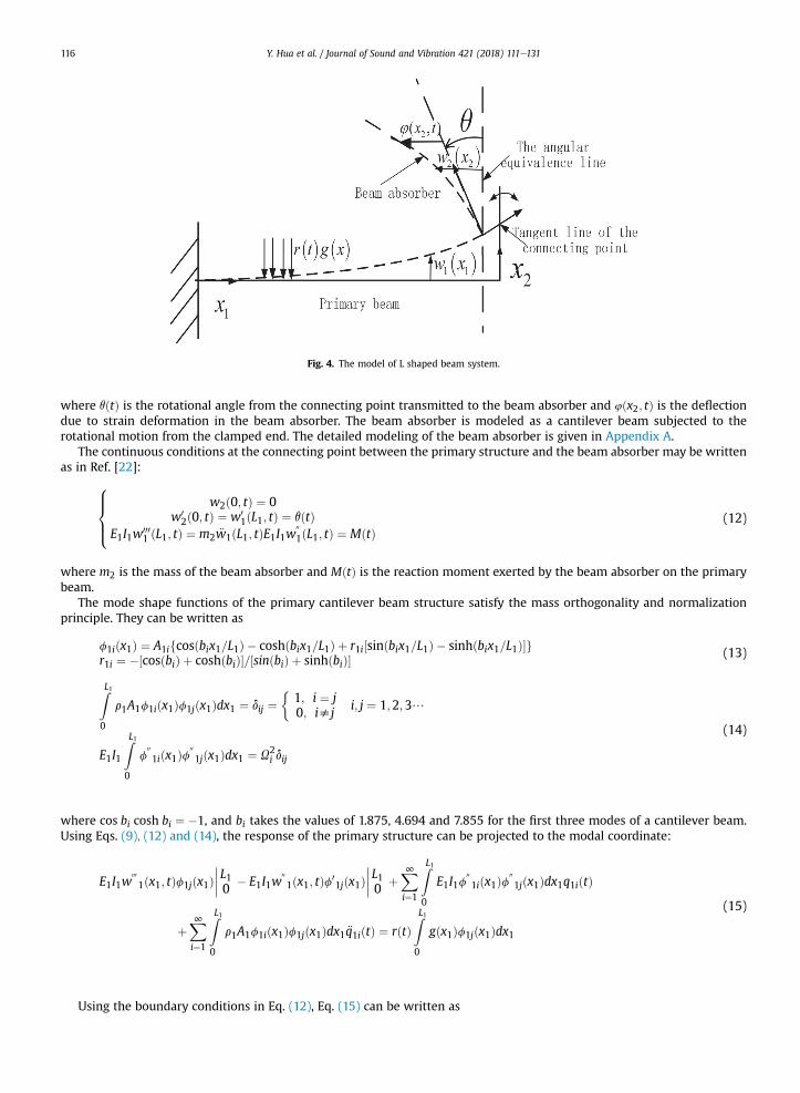
Fig. 4. The model of L shaped beam system.
Y. Hua et al. / Journal of Sound and Vibration 421 (2018) 111e131116
where qðtÞ is the rotational angle from the connecting point transmitted to the beam absorber and 4ðx2; tÞ is the deflectiondue to strain deformation in the beam absorber. The beam absorber is modeled as a cantilever beam subjected to therotational motion from the clamped end. The detailed modeling of the beam absorber is given in Appendix A.
The continuous conditions at the connecting point between the primary structure and the beam absorber may be writtenas in Ref. [22]:
8>><>>:
w2ð0; tÞ ¼ 0w0
2ð0; tÞ ¼ w01ðL1; tÞ ¼ qðtÞ
E1I1w0001 ðL1; tÞ ¼ m2 €w1ðL1; tÞE1I1w
001ðL1; tÞ ¼ MðtÞ
(12)
where m2 is the mass of the beam absorber and MðtÞ is the reaction moment exerted by the beam absorber on the primarybeam.
The mode shape functions of the primary cantilever beam structure satisfy the mass orthogonality and normalizationprinciple. They can be written as
f1iðx1Þ ¼ A1ifcosðbix1=L1Þ � coshðbix1=L1Þ þ r1i½sinðbix1=L1Þ � sinhðbix1=L1Þ�gr1i ¼ �½cosðbiÞ þ coshðbiÞ�=½sinðbiÞ þ sinhðbiÞ� (13)
ZL1 �
0r1A1f1iðx1Þf1jðx1Þdx1 ¼ dij ¼ 1; i ¼ j0; isj
i; j ¼ 1;2; 3/
E1I1
ZL10
f001iðx1Þf
001jðx1Þdx1 ¼ U2
i dij
(14)
where cos bi cosh bi ¼ �1, and bi takes the values of 1.875, 4.694 and 7.855 for the first three modes of a cantilever beam.Using Eqs. (9), (12) and (14), the response of the primary structure can be projected to the modal coordinate:
E1I1w0001ðx1; tÞf1jðx1Þ
L10 � E1I1w001ðx1; tÞf0
1jðx1Þ L10 þ
X∞i¼1
ZL10
E1I1f001iðx1Þf
001jðx1Þdx1q1iðtÞ
þX∞i¼1
ZL10
r1A1f1iðx1Þf1jðx1Þdx1 €q1iðtÞ ¼ rðtÞZL10
gðx1Þf1jðx1Þdx1
(15)
Using the boundary conditions in Eq. (12), Eq. (15) can be written as

Y. Hua et al. / Journal of Sound and Vibration 421 (2018) 111e131 117
X∞i¼1
ZL10
E1I1f001iðx1Þf
001jðx1Þdx1q1iðtÞ þ
X∞i¼1
ZL10
r1A1f1iðx1Þf1jðx1Þdx1 €q1iðtÞ
þm2
X∞i¼1
f1iðL1Þf1jðL1Þ€q1iðtÞ ¼ MðtÞf01jðL1Þ þ rðtÞ
ZL10
gðx1Þf1jðx1Þdx1
(16)
Applying Laplace transformation to Eq. (16) and making use of the orthogonality and the normalization conditions in Eq.(14), Eq. (16) may be written as
hU2i þ ð1þ miÞs2
iQ1iðsÞ ¼ ~MðsÞf0
1iðL1Þ þ RðsÞZL10
gðx1Þf1iðx1Þdx1
mi ¼ m2f21iðL1Þ
(17)
where ~MðsÞ ¼ LaplaceðMðtÞÞ (18)
The angular displacement of the DVA can be related to the reaction moment and written as
~qðsÞ ¼ aaux ~MðsÞ (19)
where ~qðsÞ ¼ LaplaceðqðtÞÞ (20)
Substituting Eq. (19) to Eq. (17), the flexural displacement of the primary beam can be written as
W1ðx1; sÞ ¼X∞j¼1
f1jðx1Þajjf01jðL1Þ ~M þ
X∞j¼1
f1jðx1ÞajjRðsÞZL10
gðx1Þf1jðx1Þdx1
¼X∞j¼1
f1jðx1Þajjf01jðL1Þ
~qðsÞaaux
þX∞j¼1
f1jðx1ÞajjRðsÞZL10
gðx1Þf1jðx1Þdx1
(21)
where a ¼ 1.h
U2 þ�1þ m
�s2i
(22)
jj j jThe rotational angle at the attached point of the beam absorber can be written as
~qðsÞ ¼ �W 01ðL1; sÞ
¼ �X∞j¼1
f01jðL1Þajjf0
1jðL1Þ~qðsÞaaux
�X∞j¼1
f01jðL1ÞajjRðsÞ
ZL10
gðx1Þf1jðx1Þdx1
¼ �
P∞j¼1
f01jðL1Þajj
Z L1
0gðx1Þf1jðx1Þdx1
1þP∞j¼1
f01jðL1Þ2
ajjaaux
RðsÞ
(23)
Substituting Eq. (23) to Eq. (21) gives
W1ðx1; sÞ~RðsÞ ¼
�P∞i¼1
"f1iðx1Þaiif
01iðL1Þ
aaux
P∞j¼1
ajjf01jðL1Þ � aiif1iðx1Þ
P∞j¼1
ajjf01jðL1Þ2aaux
� f1iðx1Þaii#Z L1
0gðx1Þf1iðx1Þdx1
1þP∞j¼1
f01jðL1Þ2 ajj
aaux
(24)
The term aaux depends on the specific physical configuration of the beam absorber. Using modal decomposition in Eq. (10)yields:

Y. Hua et al. / Journal of Sound and Vibration 421 (2018) 111e131118
u2i q2iðtÞ þ 2xiui _q2iðtÞ þ €q2iðtÞ ¼ �r2A2
ZL20
x2f2iðx2Þdx2�€qðtÞ þ 2xiui
_qðtÞ�
(25)
where f2iðx2Þ is the ith mode shape of the cantilever beam and satisfies the mass orthogonality and normalization condition
as followsf2iðx2Þ ¼ A2ifcosðbix2=L2Þ � coshðbix2=L2Þ þ r2i½sinðbix2=L2Þ � sinhðbix2=L2Þ�gr2i ¼ �½cosðbiÞ þ coshðbiÞ�=½sinðbiÞ þ sinhðbiÞ� (26)
ZL2 �
0r2A2f2iðx2Þf2jðx2Þdx2 ¼ dij ¼ 1; i ¼ j0; isj
i; j ¼ 1;2; 3/
E2I2
ZL20
f002iðx2Þf
002jðx2Þdx2 ¼ u2
i dij
(27)
The modal damping ratio xi is defined as
xi ¼ c=ð2r2A2uiÞ (28)
Applying Laplace transformation to Eq. (11), we may write
W2ðx2; sÞ ¼ ~qðsÞx2 þJðx2; sÞW2ðx2; sÞ ¼ Laplaceðw2ðx2; tÞÞ;Jðx2; sÞ ¼ Laplaceð4ðx2; tÞÞ
(29)
Applying Laplace transformation to Eq. (25), we may write
Jðx2; sÞ ¼X∞i¼1
f2iðx2Þgi�s2 þ 2xiuis
�s2 þ 2xiuisþ u2
i
~qðsÞ (30)
ZL2
where gi ¼ �r2A20
x2f2iðx2Þdx2 (31)
The receptance of the beam absorber can be written as
1.aaux ¼ ~M
.~q ¼ �E2I2W
002ð0; sÞ
.~q ¼ �E2I2J
00 ð0; sÞ.~q
¼X∞i¼1
�E2I2f002ið0Þ
gi�s2 þ 2xiuis
�s2 þ 2xiuisþ u2
i
(32)
4. Validation of the modeling method
A numerical case is presented in the following to validate the accuracy of the proposed modeling method by comparingthe results with the finite element analysis using Abaqus and the TMMmethod. The material and geometric properties of theprimary beam and beam absorber are listed in Table 1.
In this validation study, both the primary and absorber beam dampings are set to zero. So xi ¼ 0 in Eq. (32). The primarystructure is subjected to a white noise signal at the middle of the span. So gðxÞ ¼ dðx� 0:5L1Þ in Eq. (24). Consider the firstthree modes of the cantilever beam according to Eq. (24), the receptance at the end of the beam can be written as:
Table 1The material property and geometry size of the primary and beam absorber.
Density/kg/m3 Young's modulus/Gpa Length/mm Width/mm Thickness/mm
Primary beam 7890 206 515.75 12.7 4Beam absorber 2766 69 177.8 12.7 3.05
Y. Hua et al. / Journal of Sound and Vibration 421 (2018) 111e131 119
W1ðL1; sÞRðsÞ ¼
�P3i¼1
"f1iðL1Þaiif
01iðL1Þ
aaux
P3j¼1
ajjf01jðL1Þ � aiif1iðL1Þ
P3j¼1
ajjf01jðL1Þ2aaux
� f1iðL1Þaii#
1þP3j¼1
f01jðL1Þ2 ajj
aaux
f1ið0:5L1Þ (33)
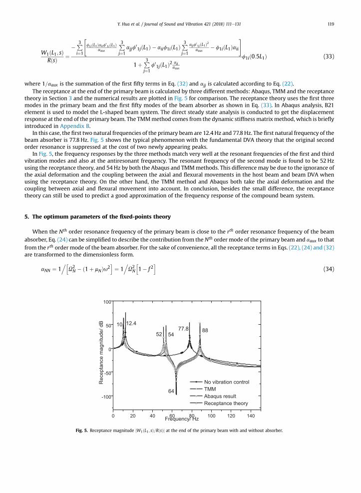
where 1=aaux is the summation of the first fifty terms in Eq. (32) and ajj is calculated according to Eq. (22).The receptance at the end of the primary beam is calculated by three different methods: Abaqus, TMM and the receptance
theory in Section 3 and the numerical results are plotted in Fig. 5 for comparison. The receptance theory uses the first threemodes in the primary beam and the first fifty modes of the beam absorber as shown in Eq. (33). In Abaqus analysis, B21element is used to model the L-shaped beam system. The direct steady state analysis is conducted to get the displacementresponse at the end of the primary beam. The TMMmethod comes from the dynamic stiffness matrixmethod, which is brieflyintroduced in Appendix B.
In this case, the first two natural frequencies of the primary beam are 12.4 Hz and 77.8 Hz. The first natural frequency of thebeam absorber is 77.8 Hz. Fig. 5 shows the typical phenomenon with the fundamental DVA theory that the original secondorder resonance is suppressed at the cost of two newly appearing peaks.
In Fig. 5, the frequency responses by the three methods match very well at the resonant frequencies of the first and thirdvibration modes and also at the antiresonant frequency. The resonant frequency of the second mode is found to be 52 Hzusing the receptance theory, and 54 Hz by both the Abaqus and TMMmethods. This difference may be due to the ignorance ofthe axial deformation and the coupling between the axial and flexural movements in the host beam and beam DVA whenusing the receptance theory. On the other hand, the TMM method and Abaqus both take the axial deformation and thecoupling between axial and flexural movement into account. In conclusion, besides the small difference, the receptancetheory can still be used to predict a good approximation of the frequency response of the compound beam system.
5. The optimum parameters of the fixed-points theory
When the Nth order resonance frequency of the primary beam is close to the rth order resonance frequency of the beamabsorber, Eq. (24) can be simplified to describe the contribution from the Nth order mode of the primary beam and aaux to thatfrom the rth order mode of the beam absorber. For the sake of convenience, all the receptance terms in Eqs. (22), (24) and (32)are transformed to the dimensionless form.
aNN ¼ 1.h
U2N � ð1þ mNÞu2
i¼ 1
.U2N
h1� f 2
i(34)
Fig. 5. Receptance magnitude jW1ðL1; sÞ=RðsÞj at the end of the primary beam with and without absorber.

Y. Hua et al. / Journal of Sound and Vibration 421 (2018) 111e131120
1.aaux ¼ ~M
.~q
¼ �E2I2f002rð0Þ
gr�� u2 þ 2xrurui
��u2 þ 2xiuiuiþ u2
i
¼ �E2I2f002rð0Þgr
�� f 2 þ i2xrlf�
�f 2 þ i2xrlf þ l2
(35)
W1ðx1; sÞ f1Nðx1ÞaNN
Hðx1; sÞ ¼RðsÞZ L1
0gðx1Þf1Nðx1Þdx1
¼1þ f0
1NðL1Þ2aNNaaux
¼ f1Nðx1ÞU2N
�l2 � f 2 þ i2xrlf
�h�1� f 2
��l2 � f 2
�� εf 2
iþ i2xrlf
�1þ ε� f 2
�(36)
where
U2N ¼ U2
N
.ð1þ mNÞ; f ¼ u
.UN ; l ¼ur
.UN (37)
ε ¼ �E I f00 ð0Þg f0 ðL Þ2
.U2
2 2 2r r 1N 1 N
¼ E2I2f002rð0Þf0
1NðL1Þ2r2A2
ZL20
x2f2rðx2Þdx2,
U2N
(38)
The dimensionless form of the receptance in Eq. (36) can be written as
~Hðf Þ ¼�l2 � f 2 þ i2xrlf
�h�1� f 2
��l2 � f 2
�� ε f 2
iþ i2xrlf
�1þ ε � f 2
� (39)
To study the effect of the damping xr on the receptance ~Hðf Þ, three values of xr (0, 0.3 and∞) with ε; l and mN calculated
from Table 1 are used to calculate ~Hðf Þ using Eq. (39) and its magnitude ~Hðf Þ is plotted in Fig. 6. It can be observed from Fig. 6
that the dimensionless magnitude ~Hðf Þ has two fixed points which are independent of the damping ratio. It shows that the
fixed-points theory can be employed to obtain the optimum tuning ratio and damping ratio of the proposed DVA.
Fig. 6. Dimensionless magnitude of receptance ~Hðf Þ versus frequency at different damping ratios.

Y. Hua et al. / Journal of Sound and Vibration 421 (2018) 111e131 121
l2 � f 2�1� f 2
��l2 � f 2
�� ε f 2
¼ ±1
1þ ε� f 2
~Hðf1Þ ¼ ~Hðf2Þ (40)
l ¼ffiffiffiffiffiffiffiffiffiffiffi1þ ε
p;
optf 21;2 ¼ εþ 1±ffiffiffiffiffiffiffiffiffiffiffiffiffiffiffiffiffiffiffiffiffiffiffi�ε2 þ ε
��2
q ~Hðf1Þ 2 ¼
~Hðf2Þ 2 ¼ 2.�
ε2 þ ε
� (41)
Thus the magnitudes of the two fixed points are made equal.
~Hbðf Þ 2 ¼
�l2 � f 2
�2 þ ð2xrlf Þ2h�1� f 2
��l2 � f 2
�� εf 2
i2 þ h2xrlf�1þ ε� f 2�i2 ¼ p
q
v ~Hbðf Þ
2vf 2
f1;f2
¼ 0⇔vp
vf 2� p
qvq
vf 2jf¼f1 ;f2 ¼ 0
(42)
2 3 u
xr jf1 ¼ 4 ðεþ 1Þ2 � ðεþ 1Þ ffiffiffiup
x2r jf2 ¼34
u
ðεþ 1Þ2 þ ðεþ 1Þ ffiffiffiu
p(43)
where u ¼�ε2 þ ε
�.2 (44)
For convenience, the optimum damping ratio is chosen to be the root mean square value x2r jf1 and x2r jf2 using Eq. (43) and itcan be written as
xr opt ¼ffiffiffiffiffiffiffiffiffiffiffiffiffiffi3ε
4εþ 8
r(45)
6. Design guideline of the beam absorber
The optimum tuning ratio of the beam absorber in Eq. (41) and the damping ratio in Eq. (45) depend on the term ε asshown in Eq. (38), which is different from the traditional discrete DVAs whose optimum tuning ratio and damping ratiodepend solely on the mass ratio [4]. In order to show the relationship of these optimum parameters with the physical pa-rameters (i.e., dimensions and material property of the beam absorber) the dimensionless mode shape functions ~fiðzÞ areintroduced as
~fiðzÞ ¼ fcosðbizÞ � coshðbizÞ þ ri½sinðbizÞ � sinhðbizÞ�g; z2½0;1�where ri ¼ �½cosðbiÞ þ coshðbiÞ�=½sinðbiÞ þ sinhðbiÞ�:
(46)
It should be noted that the dimensionless mode shape function ~fiðzÞ in Eq. (46) is different from the mode shapefunctions f1iðx1Þ and f2iðx2Þ defined in Eqs. (13), (14), (26) and (27). These mode shape functions are normalizedto the mass of the beam they belong to and thus they have the unit of kg�1/2. On the other hand, Eq. (46) isdimensionless.

Y. Hua et al. / Journal of Sound and Vibration 421 (2018) 111e131122
mN ¼ m2f21iðL1Þ ¼
r2A2L2r1A1L1
~f2Nð1ÞZ 1
0~f2NðzÞdz
where~f2Nð1ÞZ 1
0~f2NðzÞdz
¼
8>><>>:
4:001 N ¼ 1
3:995 N ¼ 2
4:001 N ¼ 3
(47)
2. 2 .
2 b4 E2I2=L2 r A1L1 L2
lopt ¼ u2r UN ¼u2r ð1þ mNÞ UN ¼ r
b4N E1I1=L11r2A2L2
1
L22ð1þ mNÞ ¼ 1þ ε (48)
02 00Z 1
ε ¼ E2I2=L2E1I1=L1
~f Nð1Þ~f rð0Þ0
z~frðzÞdz
b4N
0@Z 1
0~f2NðzÞdz
1A0@Z 1
0~f2r ðzÞdz
1A
where~f
00
rð0ÞZ 1
0z~frðzÞdz0
@Z 1
0~f2r ðzÞdz
1A
¼
8>><>>:
3:9999 r ¼ 1
4:0019 r ¼ 2
4:0072 r ¼ 3
and~f02Nð1Þ
b4N
0@Z 1
0~f2NðzÞdz
1A
¼
8>><>>:
0:6132 N ¼ 1
0:1883 N ¼ 2
0:0647 N ¼ 3
(49)
The relationship of mass ratio mN and ε can be derived by substituting of Eq. (47) and Eq. (49) to Eq. (48).
Coeff
L21L22
ð1þ mNÞmN
!¼ 1þ ε
ε
(50)
where
Coeff ¼~f2Nð1ÞZ 1
0~f2NðzÞdz
266666664
~f02Nð1Þ~f
00
rð0ÞZ 1
0z~frðzÞdz
b4N
0@Z 1
0~f2NðzÞdz
1A0@Z 1
0~f2r ðzÞdz
1A
377777775
�1
b4rb4N
¼b4r
0@Z 1
0~f2r ðzÞdz
1A
~f00
rð0ÞZ 1
0z~frðzÞdz
¼
8>><>>:
3:09 r ¼ 1
121:3 r ¼ 2
950:04 r ¼ 3
According to Eqs. (47)e(49), once the close resonant frequency orders N and r are determined, mN is proportional to themass ratio of the beam absorber. ε is proportional to the ratio of EI=L. From Eq. (48), the optimum tuning ratio square isdependent on the mass ratio, ratio of EI=L and the length ratio. The relationship of ε and mass ratio is more pronounced in Eq.(50). Under the samemass ratio, Eq. (50) has different sets of solutions of ε and L1=L2 that can be achieved by choosing propermaterial and geometry parameters of the beam DVA. The proper design procedure should be setting ε first according to thevibration reduction request. Then choose the materials for both beams. After that, put a chosen value of the mass ratio to Eq.(48) and the length ratio is hence derived. The order of obtaining the length ratio and mass ratio can be changed. The threevariables, namely the length, width and thickness of the beam absorber, can then be calculated by solving the linear algebraicequations (47)e(49). The detailed derivation of Eqs. (47)e(49) is presented in Appendix C.
7. Comparisons between the beam absorber and the traditional DVA
In this Section, the proposed beam absorber is compared with the traditional single degree-of-freedom spring-mass-damper system. The two types of absorbers are shown in Fig. 7. The same primary cantilever beam is used again here. The

Y. Hua et al. / Journal of Sound and Vibration 421 (2018) 111e131 123
geometry of the beam absorber is designed according to the guideline established in Section 6. The dimensionless magnitudeof the receptance of the primary beam attached to two types of absorbers are compared.
The receptance of the primary beam attached with a beam absorber as illustrated in Fig. 7a is written as
Wðx; sÞRðsÞ ¼ f1NðxÞf1NðL=2Þ
U2N
�l2 � f 2 þ i2xrlf
�h�1� f 2
��l2 � f 2
�� εf 2
iþ i2xrlf
�1þ ε� f 2
�
¼ f1NðxÞf1NðL=2ÞU2N
~Hðf Þ(51)
The dimensionless response magnitude at the two fixed points can be shown to be
~Hðf1Þ ¼ ~Hðf2Þ ¼ffiffiffiffiffiffiffiffiffiffiffiffiffiffiffiffiffi
2εðεþ 1Þ
s(52)
where ε is the ratio of EI=L between two beams as illustrated in Eq. (49).The receptance of the primary beam with a traditional DVA attached as illustrated in Fig. 7b is written as
Wtðx; sÞRðsÞ ¼ f1NðxÞf1NðL=2Þ
U2N
l2t � f 2t þ i2xlt ft��1� f 2t
��l2t � f 2t
�� mNl
2t f
2t
�þ i2xlt ft
�1� f 2t � mNf
2t
�
¼ f1NðxÞf1NðL=2ÞU2N
~HtðftÞ(53)
where
un ¼ffiffiffiffiffiffiffiffiffik=m
q; x ¼ c=ð2munÞ
lt ¼ un=UN ; ft ¼ u=UN ;mN ¼ mf21NðL1Þ
(54)
Fig. 7. (a) The primary beam connected with a beam absorber (b) The primary beam connected with a traditional DVA.

Y. Hua et al. / Journal of Sound and Vibration 421 (2018) 111e131124
un and x are resonance frequency and damping ratio of the traditional DVA, respectively. mN and UN have the same definitionas the case of beam absorber. Note lt and ft have different definitions from Eq. (37).
The optimum tuning ratio and damping ratio of the traditional DVA can be derived using the fixed-points theory as afunction of mN and written as [4].
lt opt ¼ 11þ mN
; xt opt ¼ffiffiffiffiffiffiffiffiffiffiffiffiffiffiffiffiffiffiffiffiffi
3mN8ð1þ mNÞ
s(55)
The maximum response amplitude may be approximated by the amplitude at the two fixed points written as
~Htðft1Þ ¼ ~Htðft2Þ
¼ffiffiffiffiffiffiffiffiffiffiffiffiffiffiffimN þ 2mN
s(56)
Using Eqs. (52) and (56), the condition required for the beam absorber to provide larger suppression than the traditionalDVA in the targeted mode can be written as
ffiffiffiffiffiffiffiffiffiffiffiffiffiffiffiffiffi2
εðεþ 1Þ
s<
ffiffiffiffiffiffiffiffiffiffiffiffiffiffiffimN þ 2mN
s(57)
Define the ratio of the maximum amplitude of the two types of DVA as f ðε;mNÞ written as
f ðε;mNÞ ¼ffiffiffiffiffiffiffiffiffiffiffiffiffiffiffiffiffiffiffiffiffiffiffiffiffiffiffiffiffiffiffiffiffiffiffi
2mNεðεþ 1ÞðmN þ 2Þ
s(58)
When f ðε;mNÞ<1, the effect of vibration suppression of the beam absorber outperforms that of the traditional DVA. Eq.(47) shows that mN varies from 0.04 to 0.6 when the mass ratio varies from 1% to 15%. The contour plot of f ðε;mNÞ is presentedin Fig. 8. It is evident that once the mass ratio is fixed, the traditional DVA has fixed optimum value whereas the beamabsorber outperforms the traditional DVA by choosing ε above the threshold value as shown by the curve of f ðε;mNÞ ¼ 1 inFig. 8.
Take the primary beam in Table 1 as an example. Themass ratio is 0.1, then mN ¼ 0:4. From Fig. 8, the threshold of ε is closeto 0.3. Choose ε ¼ 0:3;0:35;0:4. The beam absorber has the same material properties as in Table 1. The related dimensions ofthe beam absorber and the parameters of the traditional DVA are shown in Table 2. The dimensionless magnitude of primarybeam attached with the beam absorber and traditional DVA are shown in Fig. 9. The ratios of the maximum amplitude of thetwo types of DVA f ðε;mNÞ are calculated for the three sets of ε¼ 0.3, 0.35, 0.4 using Eq. (58) to be 0.92, 0.84 and 0.77,respectively. It can be seen that the proposed beam absorber offers further reduction of the resonant vibration of the primarybeam by 8%, 16% and 23% respectively, as compared to the traditional DVA. Eq. (50) shows that the higher ε is, the moresuppression can be achieved. Reviewing Eq. (48) or Eq. (50), it's fair to say the mass ratio is not a crucial factor in the design ofthe beam DVA. A better performance of the proposed beam DVA at a fixed mass ratio can be achieved by choosing a higher
Fig. 8. The contour plot of f ðε;mNÞ.

Table 2The optimum parameters of the beam absorber and the traditional DVA.
mN ¼ 0:4 Beam Absorber Traditional DVA
Length/mm Width/mm Thickness/mm modal damping ratio xopt Eq. (45) f ðε;mNÞ Eq. (58)ε ¼ 0:3 170.4 16.2 2.7 0.31 0.92
m ¼ 0:0207 Kg;k ¼ 2519:4 N=m;
c ¼ 4:725 N=ðms1Þε ¼ 0:35 180.6 13.4 3.1 0.33 0.84ε ¼ 0:4 189.6 11.4 3.5 0.35 0.77
Fig. 9. Dimensionless magnitudes of the receptance of the traditional DVA and that of the beam absorber with ε¼ 0.3, 0.35,0.4 and mN ¼ 0.4.
Y. Hua et al. / Journal of Sound and Vibration 421 (2018) 111e131 125
value of ε and satisfying Eq. (48). Eq. (48) or Eq. (50) reflects the advantage of the proposed DVA. The mass ratio, length ratioand ε of the beamDVA are related. Although the optimum tuning performance and parameters appear to be solely dependenton ε as shown in Eq. (41), they are actually related to the mass ratio and length ratio as well. To some degree, the length ratio,the bending stiffness ratio and the mass ratio involved in Eq. (48) all contribute to the optimum tuning performance by thebeam DVA. The presence of the other factors enhances the flexibility of the optimum tuning of the beam DVA. That's why thebeam DVA is superior to the traditional DVA under the same mass ratio constraint. Its optimum performance is not solelydependent on the mass ratio as in the case of the traditional DVA.
A further remark is that theoretically there is no limit for the value of ε when the mass ratio is fixed. However, from Eqs.(41) and (45) the higher the value of ε, the higher the damping ratio and tuning ratio will be. So in practice, the choice of εdepends on whether the tuning and the damping ratios can satisfy Eq. (48) and Eq. (45), respectively.
8. Conclusions
A beam-based DVA is proposed and compared to the traditional discrete type of DVA (i.e, the mass-spring-damper sys-tem). The proposed beam absorber can achieve more vibration reduction under the same mass ratio than the traditional DVAdue to the flexibility in the design of its geometry and physical properties. It can also address the vibration resonances at lowfrequencymore conveniently by changing its geometry shape to attain the target low frequency. By combining the receptancetheory with the fixed-points theory, analytical expressions of the optimum tuning ratio and damping ratio of the continuousbeam-based DVA are derived to guide the absorber design. The traditional mass spring damper's optimal performance isconstrained by the mass ratio. However, this study shows that there exists a set of optimal material and geometry parameterswhich allows the beam absorber to outperform its mass-spring-damper counterpart under the samemass ratio constraints. Adesign guideline is established to choose thematerial and geometry parameters of the beam absorber. The proposed absorbermay be applied to suppress resonant vibrations of flexible robotic arms in the future.
Acknowledgment
The author wishes to acknowledge the research funding support fromUniversity Grant Council of Hong Kong SAR (Project:B-Q47U) and The Hong Kong Polytechnic University of Hong Kong.

Y. Hua et al. / Journal of Sound and Vibration 421 (2018) 111e131126
Appendix A
This appendix develops the analytical model of cantilever beam with support rotation.The cantilever beam suffers from the support rotation is shown in Fig. A.1 and is modeled as a Euler-Bernoulli beam. E is
the elastic modulus, I is themoment of the beam,m is themass of per unit length, A is the cross-Section area and l is the lengthof the beam. The total displacement of one point on the cantilever beam under the base excitation is defined as:
wðx; tÞ ¼ qðtÞxþ 4ðx; tÞ (A.1)
where 4ðx; tÞ is the deflection curve, qðtÞ is the rotation angle from the ground.
Fig. A.1. Cantilever beam under base rotation.
Fig. A.2. A small segment of beam.
Fig. A.3. Force analysis on the cross Section.
As illustrated in Ref. [21], one types of damping force are taken into consideration: external damping force which isproportional to velocity and represented as�c vw
vt . Frommaterial mechanics, the bending strain and the deflection of the beamis:
εb ¼ �yv24ðx; tÞ
vx2(A.2)
Then the total bending moment of the small segment is:
M ¼ �EIv2wðx; tÞ
vx2¼ �EI
v24ðx; tÞvx2
(A.3)
The shear force and the moment has the following relationship:
V ¼ vMvx
¼v�� EI v
24ðx;tÞvx2
�vx
(A.4)
According to the force balance of the whole small segment, the dynamics equation of the small segment can be derived:

Y. Hua et al. / Journal of Sound and Vibration 421 (2018) 111e131 127
V þ vVvx
dx� V �"m
v2wðx; tÞvt2
þ cvwðx; tÞ
vt
#dx ¼ 0 (A.5)
Substituting the expression of wðx; tÞ in (A.1) into (A.5), Eq. (A.5) becomes:
vVvx
dx�"m
v24ðx; tÞvt2
þ cv4ðx; tÞ
vtþm
v2qðtÞvt2
xþ cvqðtÞvt
x
#dx ¼ 0 (A.6)
Substituting the expression of V in (A.4)e(A.6) can yield the movement equation of the small segment under the baserotational excitation and it is shown as:
EIv44ðx; tÞ
vx4þ c
v4ðx; tÞvt
þ rAv24ðx; tÞ
vt2¼ �c _qðtÞx� rA€qðtÞx (A.7)
Appendix B
This appendix presents the derivation of transfer matrix of Bernoulli-Euler Beam.The dynamic equation of motion of the beam may be written as
EIv4wvx4
þ rAv2wvt2
¼ 0 (B.1)
Assume that the solution of harmonic oscillation can be written as
wðx; tÞ ¼ WðxÞeiut (B.2)
The non-dimensional characteristic equation of the equation is�EID4
.L4 � rAu2
�WðxÞ ¼ 0;
D ¼ d=dx; x ¼ x=L(B.3)
Assume that the solution of WðxÞ can be written as
WðxÞ ¼X4i¼1
Rierix;QðxÞ ¼ vW
Lvx¼X4i¼1
RiriLerix; SðxÞ ¼ EI
v3W
L3vx3;MðxÞ ¼ �EI
v2W
L2vx2(B.4)
where ri is the root of the characteristic equation Eq. (B.5).
EIr4i.L4 � rAu2 ¼ 0 (B.5)
d ¼ fWð0Þ Qð0Þ Wð1Þ Qð1Þ g; d ¼ BR
F ¼ f Sð0Þ Mð0Þ Sð1Þ Mð1Þ g; F ¼ AR(B.6)
F ¼ AB�1d ¼ Kd (B.7)
8>>Wð1Þ9>> 8>>Wð0Þ9>> <>>:Qð1ÞSð1ÞMð1Þ
=>>; ¼ T
<>>:
Qð0ÞSð0ÞMð0Þ
=>>; (B.8)
T ¼ �K�1K ; T ¼ K�1
11 12 11 12 12T21 ¼ �K21 þ K22K�112 K11; T22 ¼ �K22K
�112
(B.9)
Similarly, the transfer matrix of axial vibration rod can be obtained.The dynamic equation of the axial vibration rod is

Y. Hua et al. / Journal of Sound and Vibration 421 (2018) 111e131128
rv2uvt2
� Ev2uvt2
¼ 0 (B.10)
The axial force in the rod is
F ¼ EAvuvx
(B.11)
The sameway as we derive the transfermatrix of the transverse vibration of the beam, we can obtain the transfermatrix of
the axial vibration written as�Uð1ÞFð1Þ
�¼ T
�Uð0ÞFð0Þ
�(B.12)
So we can get the transfer matrix of a Euler-Bernoulli beam by taking axial deformation into consideration.8>>>>>><>>>>>>:
UðLÞWðLÞQðLÞFðLÞSðLÞMðLÞ
9>>>>>>=>>>>>>;
¼ T
8>>>>>><>>>>>>:
Uð0ÞWð0ÞQð0ÞFð0ÞSð0ÞMð0Þ
9>>>>>>=>>>>>>;
(B.13)
Fig. B1. The displacement and force relationship of the two beams at the connecting point.
In the 90� rotational angle, the displacement and force of the two beam satisfies the following:8>>>>>><>>>>>>:
U2W2Q2F2S2M2
9>>>>>>=>>>>>>;
¼
26666664
0 1 0 0 0 0�1 0 0 0 0 00 0 1 0 0 00 0 0 0 1 00 0 0 �1 0 00 0 0 0 0 1
37777775
8>>>>>><>>>>>>:
U1W1Q1F1S1M1
9>>>>>>=>>>>>>;
(B.14)
So the whole transfer matrix in the L-shaped beam can be written as:8>>>>>><>>>>>>:
UWQFSM
9>>>>>>=>>>>>>;
free
¼ TabeamTrotTpbeam
8>>>>>><>>>>>>:
UWQFSM
9>>>>>>=>>>>>>;
fixed
(B.15)
So we can get the displacement response at any point of the beam using Eq. (B.15).
Appendix C
This appendix presents the detailed derivation of Eqs. (47)e(49).

Y. Hua et al. / Journal of Sound and Vibration 421 (2018) 111e131 129
f1iðx1Þ ¼ A1ifcosðbix1=L1Þ � coshðbix1=L1Þ þ r1i½sinðbix1=L1Þ � sinhðbix1=L1Þ�gr1i ¼ �½cosðbiÞ þ coshðbiÞ�=½sinðbiÞ þ sinhðbiÞ� (C.1)
ZL1
0r1A1f1iðx1Þf1jðx1Þdx1 ¼ dij (C.2)
bi correspond to 1.875, 4.694 and 7.855 for the first three modes.
f2iðx2Þ ¼ A2ifcosðbix2=L2Þ � coshðbix2=L2Þ þ r2i½sinðbix2=L2Þ � sinhðbix2=L2Þ�gr2i ¼ �½cosðbiÞ þ coshðbiÞ�=½sinðbiÞ þ sinhðbiÞ� (C.3)
ZL2
0r2A2f2iðx2Þf2jðx2Þdx2 ¼ dij (C.4)
Assume that the mode shape function without coefficient can be written in the following form:
~fiðzÞ ¼ fcosðbizÞ � coshðbizÞ þ ri½sinðbizÞ � sinhðbizÞ�gri ¼ �½cosðbiÞ þ coshðbiÞ�=½sinðbiÞ þ sinhðbiÞ�z2½0; 1�
(C.5)
Eq. (C.2) and Eq. (C.4) can be rewritten into the following form:
r1A1L1A21i
Z10
~fiðzÞ~fjðzÞdz ¼ dij (C.6)
Z1
r2A2L2A22i
0
~fiðzÞ~fjðzÞdz ¼ dij (C.7)
, ffiffiffiffiffiffiffiffiffiffiffiffiffiffiffiffiffiffiffiffiffiffiffiffiffiffiffiffiffiffiffiffiffiffiffiffiffiffiffiffiffiffiffiffiffiffi0 Z1 1vuu
A1i ¼ 1 @r1A1L10
~f2i ðzÞdzAut (C.8)
, ffiffiffiffiffiffiffiffiffiffiffiffiffiffiffiffiffiffiffiffiffiffiffiffiffiffiffiffiffiffiffiffiffiffiffiffiffiffiffiffiffiffiffiffiffiffi0 Z1 1vuu
A2i ¼ 1 @r2A2L20
~f2i ðzÞdzAut (C.9)
From Eq. (17), we can derive mN based on ~fN:
mN ¼ r2A2L2f21NðL1Þ ¼ r2A2L2A
21N
~f2Nð1Þ
¼ r2A2L2r1A1L1
~f2Nð1ÞZ 1
0~f2NðzÞdz
(C.10)
From Eq. (31), gi can be written based on ~fi:
gi ¼ �r2A2
ZL20
x2f2iðx2Þdx2 ¼ �r2A2L22
Z10
z~fiðzÞdz, ffiffiffiffiffiffiffiffiffiffiffiffiffiffiffiffiffiffiffiffiffiffiffiffiffiffiffiffiffiffiffiffiffiffiffiffiffiffiffiffiffiffiffiffiffiffi0
@r2A2L2
Z10
~f2i ðzÞdz
1A
vuuut (C.11)

Y. Hua et al. / Journal of Sound and Vibration 421 (2018) 111e131130
f01kðxÞ ¼ ~f
0kðx=L1Þ
,L1
ffiffiffiffiffiffiffiffiffiffiffiffiffiffiffiffiffiffiffiffiffiffiffiffiffiffiffiffiffiffiffiffiffiffiffiffiffiffiffiffiffiffiffiffiffiffi0@r1A1L1
Z10
~f2kðzÞdz
1A
vuuut (C.12)
, ffiffiffiffiffiffiffiffiffiffiffiffiffiffiffiffiffiffiffiffiffiffiffiffiffiffiffiffiffiffiffiffiffiffiffiffiffiffiffiffiffiffiffiffiffiffi0 Z1 1vuu
f002rðxÞ ¼ ~f
00
rðx=L2Þ L22 @r2A2L20
~f2r ðzÞdzAut (C.13)
The Nth order natural frequency of the primary beam and the rth order natural frequency of the beam absorber can bewritten as:
U2N ¼ b4NE1I1
.�r1A1L
41
�u2r ¼ b4r E2I2
.�r2A2L
42
� (C.14)
From Eq. (38), ε is obtained based on ~fk; ~fr:
ε ¼ E2I2f01NðL1Þgrf
002rð0Þ
.hU2N
i
¼E2I2~f
02N ð1Þ~f
00
rð0Þr2A2L22
Z 1
0z~frðzÞdz
�r1A1L
41
�
L21
0@r1A1L1
Z 1
0~f2NðzÞdz
1AL22
0@r2A2L2
Z 1
0~f2r ðzÞdz
1Ab4NE1I1
¼ E2I2=L2E1I1=L1
~f02Nð1Þ~f
00
rð0ÞZ 1
0z~frðzÞdz
b4N
0@Z 1
0~f2NðzÞdz
1A0@Z 1
0~f2r ðzÞdz
1A
(C.15)
From Eq. (48), we can derive the tuning ratio:
l2opt ¼ u2r
.U2N ¼u2
r ð1þ mNÞ.U2N
¼ b4rb4N
E2I2=L2E1I1=L1
r1A1L1r2A2L2
L21L22
ð1þ mNÞ ¼ 1þ ε
(C.16)
References
[1] C.L. Lee, Y.T. Chen, L.L. Chung, Y.P. Wang, Optimal design theories and applications of tuned mass dampers, Eng. Struct. 28 (2006) 43e53.[2] J.R. Sladek, R.E. Klingner, Effect of tuned-mass dampers on seismic response, J. Struct. Eng. 109 (1983) 2004e2009.[3] K. Tse, K. Kwok, Y. Tamura, Performance and cost evaluation of a smart tuned mass damper for suppressing wind-induced lateral-torsional motion of
tall structures, J. Struct. Eng. 138 (2012) 514e525.[4] J.P. Den Hartog, Mechanical Vibrations, Courier Corporation, 1985.[5] G. Warburton, Optimum absorber parameters for minimizing vibration response, Earthq. Eng. Struct. Dynam. 9 (1981) 251e262.[6] G. Warburton, Optimum absorber parameters for various combinations of response and excitation parameters, Earthq. Eng. Struct. Dynam. 10 (1982)
381e401.[7] T. Asami, O. Nishihara, A.M. Baz, Analytical Solutions to H infinity and H2 optimization of dynamic vibration absorbers attached to damped linear
systems, J. Vib. Acoust. 124 (2002) 284e295.[8] Y.L. Cheung, W.O. Wong, H∞ and H2 optimizations of a dynamic vibration absorber for suppressing vibrations in plates, J. Sound Vib. 320 (2009)
29e42.[9] J. Dayou, Fixed-points theory for global vibration control using vibration neutralizer, J. Sound Vib. 292 (2006) 765e776.
[10] Y.L. Cheung, W.O. Wong, H-infinity optimization of a variant design of the dynamic vibration absorberdrevisited and new results, J. Sound Vib. 330(2011) 3901e3912.
[11] Y.L. Cheung, W.O. Wong, L. Cheng, Optimization of a hybrid vibration absorber for vibration control of structures under random force excitation, J.Sound Vib. 332 (2013) 494e509.
[12] Y.L. Cheung, W.O. Wong, L. Cheng, Minimization of the mean square velocity response of dynamic structures using an active-passive dynamic vibrationabsorber, J. Acoust. Soc. Am. 132 (2012) 197e207.
[13] Y.L. Cheung, W.O. Wong, L. Cheng, Design optimization of a damped hybrid vibration absorber, J. Sound Vib. 331 (2012) 750e766.[14] M.H. Tso, J. Yuan, W.O. Wong, Suppression of random vibration in flexible structures using a hybrid vibration absorber, J. Sound Vib. 331 (2012)
974e986.

Y. Hua et al. / Journal of Sound and Vibration 421 (2018) 111e131 131
[15] E. Rustighi, M. Brennan, B. Mace, A shape memory alloy adaptive tuned vibration absorber: design and implementation, Smart Mater. Struct. 14 (2004)19.
[16] M.A. Acar, C. Yilmaz, Design of an adaptiveepassive dynamic vibration absorber composed of a stringemass system equipped with negative stiffnesstension adjusting mechanism, J. Sound Vib. 332 (2013) 231e245.
[17] C.L. Lee, Y.T. Chen, L.L. Chung, Y.P. Wang, Optimal design theories and applications of tuned mass dampers, Eng. Struct. 28 (2006) 43e53.[18] Chunxiang. Li, Performance of multiple tuned mass dampers for attenuating undesirable oscillations of structures under the ground acceleration,
Earthq. Eng. Struct. Dynam. 29 (2000) 1405e1421.[19] T. Aida, S. Toda, N. Ogawa, Y. Imada, Vibration control of beams by beam-type dynamic vibration absorbers, J. Eng. Mech. 118 (1992) 248e258.[20] D.J. Mead, Passive Vibration Control, John Wiley & Sons Inc, 1999.[21] H.T. Banks, D.J. Inman, On damping mechanisms in beams, ASME Journal of Applied Mechanics 58 (1991) 716e723.[22] H.A. Sodano, A. Erturk, J.M. Renno, D.J. Inman, Modeling of piezoelectric energy harvesting from an L-shaped beam-mass structure with an application
to UAVs, J. Intell. Mater. Syst. Struct. 20 (2009) 529e544.
Copyright © 2022 FDOKUMEN