Considering Transparency, Anonymity, and Pseudonymity as ...
Optimal Construction Site Layout Considering Safetyand Environmental Aspects
Haytham M. Sanad1; Mohammad A. Ammar2; and Moheeb E. Ibrahim3
Abstract: A good site layout is vital to ensure the safety of the working environment and effective and efficient operations. Site layoutplanning has significant impacts on productivity, costs, and duration of construction. Construction site layout planning involves identify-ing, sizing, and positioning temporary and permanent facilities within the boundary of the construction site. Site layout planning can beviewed as a complex optimization problem. Although construction site layout planning is a critical process, systematical analysis of thisproblem is always difficult because of the existence of a vast number of trades and interrelated planning constraints. The problem has beensolved using two distinct approaches: Optimization techniques and heuristics methods. Mathematical optimization procedures have beendeveloped to produce optimal solutions, but they are only applicable for small-size problems. Artificial intelligent techniques have beenused practically to handle real-life problems. On the other hand, heuristic methods have been used to produce good but not optimalsolutions for large problems. In this paper, an optimization model has been developed for solving the site layout planning problemconsidering safety and environmental issues and actual distance between facilities. Genetic algorithms are used as an optimization bed forthe developed model. In order to validate the performance of the developed model, a real-life construction project was tested. Theobtained results proved that satisfactory solutions were obtained.
DOI: 10.1061/�ASCE�0733-9364�2008�134:7�536�
CE Database subject headings: Construction sites; Occupational safety; Environmental issues; Optimization models; Computation.
Introduction
In the construction industry, site planning is the most overlookedaspect by site engineers. The attitude of the engineers has beenthat site layout planning will be done as the project progresses. Itis generally acknowledged that an efficient overall layout plays akey role in the operational efficiency, cost, and quality of con-struction. Site layout is routinely performed by managers on con-struction sites. Yet, project managers usually learn to accomplishthis task by trial and error in the course of years of fieldwork.
The site layout planning problem is generally defined as theproblem of identifying the number and size of temporary facilities�TFs� to be laid out, identifying constraints between facilities, anddetermining the relative positions of these facilities that satisfyconstraints between and allow them to function efficiently�Zouein et al. 2002�. TFs are those facilities that serve the con-struction site but are not being considered a physical part of the
1Assistant Lecturer, Structural Engineering Dept., Faculty of Engi-neering, Tanta Univ., Tanta 31521, Egypt. E-mail: [email protected]
2Associate Professor, Structural Engineering Dept., Faculty of Engi-neering, Tanta Univ., Tanta 31521, Egypt �corresponding author�. E-mail:[email protected]
3Professor, Structural Engineering Dept., Faculty of Engineering,Cairo Univ., Cairo, Egypt.
Note. Discussion open until December 1, 2008. Separate discussionsmust be submitted for individual papers. To extend the closing date byone month, a written request must be filed with the ASCE ManagingEditor. The manuscript for this paper was submitted for review and pos-sible publication on October 25, 2006; approved on January 22, 2008.This paper is part of the Journal of Construction Engineering and Man-agement, Vol. 134, No. 7, July 1, 2008. ©ASCE, ISSN 0733-9364/2008/
7-536–544/$25.00.536 / JOURNAL OF CONSTRUCTION ENGINEERING AND MANAGEMENT
structure that is required to be built. Examples of TFs are materialstores, fabrication yards, lay-down areas, parking lots, offices, andwarehouses. In current practice, site layout planning is often doneby adjusting previous plans based mainly on the project manag-er’s experience and common sense �Cheng and O’Connor 1996�.
Most construction sites involve some or all of the followingitems: Basic structures to be constructed, facilities that serve thewhole project, obstacles such as trees or old buildings, movement�internal� routes, and site boundaries, even there are no definitebarriers. Numerous techniques have been proposed to uncoversolutions for site layout problems, but it is very difficult to obtainthe optimal one by hand calculations. Therefore, optimizationtechniques are usually used to search for solutions for site layoutproblems.
In almost all optimization approaches for site layout planning,the layout goal to be attained is to minimize �interfacilities trans-portation cost�. One of the common formulas used to achieve thissite layout planning goal is
Min �i=1
n−1
�j=i+1
n
dijRij �1�
in which n�total number of TFs; dij�travel distance betweenfacilities i and j; and Rij�parameter that represents: �1� transpor-tation cost between facilities i and j or �2� a relative proximityweight that reflects the required closeness between facilities i andj.
Literature Review
Many research efforts have been made toward developing a real-istic model for the site layout planning problem. The problem has
been solved by researchers using two distinct techniques: Math-© ASCE / JULY 2008

ematical optimization and heuristic methods. Mathematical opti-mization procedures have been designed to produce optimumsolutions. Heuristic methods, on the other hand, used to producegood but not optimal solutions. Heuristic methods are based onknowledge-based expert system, and recently on artificial intelli-gent concepts. However, the first category cannot be adopted forlarge-scale projects because of the need for huge calculations andefforts. Therefore, the second category is the only practical avail-able means for handling complex real-life projects.
Cheng and O’Connor �1996� developed an automated site lay-out system called ArcSite, which is comprised of a geographicalinformation system integrated with a database management sys-tem. A knowledge-based expert system is used to model the spa-tial requirements of a TF on the construction site. A proximityindex is used to determine the optimal site layout, which is cal-culated based on the number of trips and the attract/repel relation-ships between two facilities. As a notable limitation to this model,ArcSite can locate only a limited number of facilities.
Zouein and Tommelein �1999� developed a model for dynamiclayout planning of construction facilities. They used a hybrid in-cremental solution method, which creates a sequence of layoutsthat span the entire project duration. The model is solved usinglinear programming to find out the optimal position so as to mini-mize transportation and relocation costs. The primary advantageof this method is the possibility of formulating and solving thelayout problem using linear programming without undue compu-tations. In addition, the quality of the layout based on travelingcost and relocation cost can be assessed. However, constructionfacilities can be represented as rectangles only. Also, they havefixed dimensions and can be positioned at 0° �or 90°� orientationsonly.
Li and Love �1998� introduced a genetic algorithm-based�GA-based� model to solve the facility layout problem. The ob-jective of the model is to minimize the total traveling distancebetween facilities. The problem is described as allocating a set ofpredetermined facilities into a set of predetermined places, simul-taneously satisfying layout constraints and requirements. How-ever, it is assumed that the size of each predetermined locationequals the area of the largest facility. Also, the predeterminedlocations are represented only as rectangles.
Hegazy and Elbeltagi �1999� developed a GA-based model fordynamic site layout planning. The model deals with any irregularuser-defined site using a two-dimensional grid. Each facility ismodeled as a number of grid units. The area of a single grid unitis calculated in advance for each site. The main advantages of thismodel are its applicability for any user-defined site shape and isnot limited to rectangular or square facilities. However, the modeldoes not consider safety considerations and environmental as-pects. Also, it considers Euclidean �center-to-center� distances be-tween facilities as a method for distance measurement.
Osman et al. �2003� developed an automated computer systemcalled EDSLP �Evolutionary Dynamic Site Layout Planner�. Thesystem was used for optimally assigning TFs, simultaneously tak-ing into consideration the dynamic nature of constructionprojects. EDSLP consists of a data input mean, a computer-aideddesign user interface, and an evolutionary optimization GA en-gine. The objective function is to minimize transportation andrelocation costs. A sequence of layouts spanning the entire projectduration is provided. However, the facilities are limited to rectan-gular shape only. Also, safety and environmental aspects are notconsidered.
Elbeltagi et al. �2004� introduced a model that considers both
safety and productivity issues. Also, parts of the constructed spaceJOURNAL OF CONSTRUCT
are utilized as TFs to relieve congestion on restricted sites. Whena safety concern rises between two facilities, a large negativevalue is assigned to the closeness weight. As such, the further thedistance between them, the lower the layout score �thus improv-ing the layout�. However, this method for dealing with safetyconsiderations does not suit all requirements of projects managersregarding safety issues, as will be discussed later. Moreover, theEuclidean distance method is used in measuring distances be-tween facilities.
In almost all models used for the site layout planning problem,safety considerations and environmental aspects have been ig-nored or at least not modeled in an appropriate manner. Also,distances between facilities are not measured properly. These twomain limitations lead to impractical modeling of the site layoutproblem, and hence need modifications to suit real-life situations.
In this paper, an optimization model has been developed forsolving the site layout planning problem considering safety andenvironmental issues. A new method for measuring distance be-tween facilities is used, which is named “actual route distance.”The developed model can also support the dynamic nature ofconstruction projects. Because GAs are adopted here as an opti-mization technique, basic features of GAs will be briefly re-viewed first.
Optimization by Genetic Algorithms
GAs are search algorithms that are based on the natural selectionand genetics to search through decision space for optimum solu-tions. GAs employ a random yet directed search for locating theglobally optimal solution. In addition, GAs perform an intelligentsearch for a solution from a nearly infinite number of possiblesolutions. Typically, GAs require a representation scheme to en-code feasible solutions for optimization problems. Usually, a so-lution is represented as a linear string called chromosome whoselength varies from one application to another. Some measuresof fitness �objective function� are applied to construct bettersolutions.
Once the chromosome structure and the objective function areset, the GA evolutionary procedure takes place on a population ofparent chromosomes. Three genetic operations are required: Re-production, crossover, and mutation. Reproduction is the processby which chromosomes with better fitness values receive corre-spondingly better copies in the new generation. As the total num-ber of chromosomes in each generation is kept constant,chromosomes with lower fitness values are eliminated. The sec-ond operator; crossover, is the process in which chromosomes areable to mix and match their desirable qualities in a random fash-ion. Crossover �marriage� is conducted by selecting two parentchromosomes, exchanging their information, and producing off-springs. The exchange of information between parent chromo-somes is done through a random process. Fig. 1 shows a case ofdouble-point crossover, but single-point crossover may also beused. As an opposite to crossover, mutation is a rare process thatresembles the process of a sudden generation of an odd offspringthat turns out to be genius �Goldberg 1989�. The benefit of themutation process is that it can break any stagnation in the evolu-tionary process, avoiding local optima.
Recently, research shows that GAs are robust and have thecapability to efficiently search complex solution space. The ro-bustness of GAs is due to their capabilities to locate the globaloptimal. Therefore, GAs are less likely to restrict the search to a
local optimum compared with point to point movement, or gradi-ION ENGINEERING AND MANAGEMENT © ASCE / JULY 2008 / 537
ent descent optimization technique �Forrest 1993�. However, themajor drawback of GA-based applications is that they requiremuch greater computational time than traditional methods.
Safety Considerations and Environmental Aspects
Safety is far more than craftsmen wearing hard hats on construc-tion sites. It is a philosophy that identifies and eliminates job sitehazards throughout the life cycle of a project. Accident statisticsshow that construction is one of the most dangerous industries inthe world. However, several easily overlooked factors, such aslack of preplanning, inadequate selection of contractors, and lazyattitudes are significant contributors to these statistics �Hislop1999�. On the other hand, a safe tidy site with good safety regu-lations is likely to be a site with high moral, few disputes, lessabsenteeism and labor turnover, and better team work.
Environmental planning is considered a proven tool for reduc-ing the impacts from any environmental risks. Typical examplesof environmental hazards that occur frequently are noisy work-shops and facilities that emit gases, vapors, fumes, dusts, mists,dangerous radiation, and any other harmfull substances �OSHA1987�. Both safety and environmental hazards have bad effects onhuman beings, and therefore their harmful effects should be pre-vented or at least mitigated.
Facilities of high harmful effects, which are positioned adja-cent to neighbors, present actual or potential health hazards, es-pecially when those neighbors are hospital, schools, or residentialbuildings. Therefore, a prespecified area adjacent to those neigh-bors becomes an essential requirement. These areas will be pre-vented from being allocated to any TF, and will be referred to as“prohibited area.”
Another consideration is the proper “safety zones” around con-struction areas. These zones protect workers and entities fromfalling objects. The Uniform Building Code UBC �1985� statesthat: “at least 10 ft clearance from buildings or structures shall bekept clear, driveways between and around open storage yardsshall be at least 15 ft wide and free from accumulation of rubbish,and material stored inside building under construction shall not beplaced within 6 ft of any hoist way or inside floor opening.”
The third issue regarding environmental consideration is thedangerous interaction between harmful facilities and sensitive fa-cilities. As discussed earlier, harmful facilities are noisy work-shops and those emit harmful substances. These types of facilitiesshould be kept a far distance away from sensitive facilities, suchas engineers’ offices, workers facilities, and any buildings con-taining humans. Therefore, a “minimum distance” should be as-signed between each two facilities having this action.
Because of the increase attention of safety and environmentalconsiderations mentioned before, it must be considered in the sitelayout planning problem. The important issues, which will beconsidered are: Prohibited area, safety zones around constructed
Fig. 1. Crossover operation to generate offsprings
facilities, and minimum distance between facilities.
538 / JOURNAL OF CONSTRUCTION ENGINEERING AND MANAGEMENT
Developed Site Layout Planning Model
In developing a site layout planning model, previously discussedsafety and environmental aspects are considered. Also, the dis-tances between facilities are modeled more practically. First, rep-resentation of site and facilities are outlined, and types offacilities are presented. Safety and environmental aspects and dis-tances between facilities are modeled in an appropriate manner.Closeness relationships between facilities are defined. Finally,coding site layout optimization in GAs format is presented.
Site and Facilities Representation
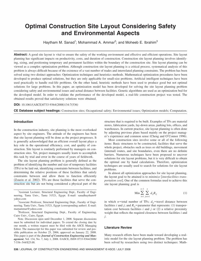
Site and facilities are modeled in the present study using a two-dimensional grid. Each grid unit is called a cell, the area of whichis user-defined. Hence, any irregular shape of the site can bemodeled, as shown in Fig. 2. A facility can be represented in thegrid as a number of grid units, which can be calculated using
Number of facility units =Facility area
Cell area�2�
For ease of modeling, each cell has a location reference that canbe calculated using
Location reference = �Row position − 1�
Total columns + Column position �3�
Location reference is an expression used to define the position ofany facility in the site �Elbeltagi 1999�. It is formulated using thecolumn and row boundaries of the whole site. A facility locationreference is defined by the location reference of the top-mostleft-hand cell of the facility. For example, the location referenceof Facility A in Fig. 2 is 23 ��3−1�9+5�. Also, location referencesof Facilities B and C are 52 and 2, respectively �Fig. 2�.
Facilities can be placed in a site in three ways, starting fromthe location reference of the facility: horizontal, vertical, and rect-angular. In horizontal and vertical arrangement, the user shouldspecify the width of the facility in a number of grid units. FacilityA, in Fig. 2, has an area of five cells, width of two cells, andarranged horizontally. Therefore, Facility A occupies four cells�2�2� starting from Location Reference 23 and the remainingcell �5-4� is arranged from the top-most right-hand side.
In Fig. 2, Facility B has an area of five cells and width of twocells, but arranged vertically. In this case, Facility B occupies fourcells starting from Location Reference 52 and the remaining cell
Fig. 2. Site and facilities representation
is arranged from the bottom-most left-hand side. In the rectangu-
© ASCE / JULY 2008

lar arrangement, the width of the facility is calculated as the in-teger of the square root of the facility area expressed in a numberof cell units. Facility C in Fig. 2 has four grid units and is ar-ranged as a rectangle starting from Location Reference 2.
Types of Facilities
In this study, the classification of facilities proposed by Elbeltagi�1999� will be adopted. Facilities are classified as temporary fa-cilities and obstacles. Temporary facilities are those facilities thatserve the site during construction. TFs may be fixed in place ornonfixed. Fixed facilities are positioned in a fixed location, suchas gates, security rooms, and parking lots. On the other hand,nonfixed facilities need to be optimally located in any emptyspace on the site. Both fixed and nonfixed facilities are maintain-ing defined closeness relationships with each other. Also, struc-tures or existing buildings will be referred to as permanent entity.Permanent entities are treated as fixed facilities because theymaintain defined closeness relationships with other facilities.
Obstacles are entities that are fixed in place and not maintain-ing any defined closeness relationships with other facilities, suchas trees or old buildings. Obstacles cannot be removed from thesite, so, spaces used by obstacles in the site cannot be allocated toany other type of facility.
Modeling Safety Considerations and EnvironmentalAspects
As discussed before, safety considerations and environmental as-pects that will be considered in this model are prohibited area,minimum distance, and safety zones. Modeling of these consid-erations will be discussed here.
Prohibited AreasFig. 3 shows a typical construction site adjacent to a hospital inthe bottom right-hand side. In this case, it is important to preventsome facilities that have harmful effects �such as noise, air pollu-tion, etc.� from being positioned adjacent or near to such sensitiveentities. Therefore, a prespecified area in the job site must beprevented from being allocated to facilities with harmful effects.In Fig. 3 a prohibited area is represented by dashed cells.
Minimum DistanceIf hazardous facilities have bad effects on users of other TFs, thena minimum distance between such facilities should be prespeci-fied. The distance between such facilities should satisfy the fol-
Fig. 3. Prohibited areas and shortest route distance
lowing relationship:
JOURNAL OF CONSTRUCT
dij � Dmin ij �4�
where dij�Euclidean �geometric� distance between Facilities iand j and Dmin ij�minimum euclidean distance between facilitiesi and j. The minimum distance is user-defined and shouldbe carefully chosen to prevent dangerous interaction betweenfacilities.
Safety ZonesSafety zones represent an additional area added to the physicalarea of the facilities to protect any person who might be injuredby the fall of materials, tools, or equipment being raised or low-ered. Safety zones should be specified in adequacy with respect torelevant regulations, such as OSHA �1987� and UBC �1985�. Forexample, if the actual area of the facility�50 m2 and the appro-priate safety zone�20 m2, then the facility area�50+20=70 m2.
Actual Route Distance between Facilities
As discussed in the literature, existing site layout models considera Euclidean distance between facilities. A Euclidean distance be-tween Facilities 1 and 3, in Fig. 3, is represented by the dashedline, which does not represent the actual traveling distance. Tospecify the actual route distance between facilities, a network ofcontinuous internal routes in the site should be specified first.These routes are usually used for the movement of equipment andlabor between facilities within the site. Internal routes are usuallyspecified by project managers, even if these movement routes arenot paved, cemented, covered, or lined. Internal routes are usuallycontinuous to facilitate movement of facilities, and hence measur-ing traveling distance between them.
To specify actual route distances between any two facilities,the nearest cell from the internal routes network for each facilityhas to be determined first. This cell will be referred to as therepresentative cell, which acts as a representative for that facility.The shortest route distance between Facilities i and j is calculatedby summing up the distance between Facility i and its represen-tative cell, Facility j and its representative cell, and the distancebetween these two representative cells through the internal routesnetwork. In Fig. 3, the shortest route distance between Facilities 1and 3 equals the summation of d1, d2, d3, and d4.
Facilities Closeness Relationships
The interrelationships among facilities are decided by the projectmanager’s preference and involve some degree of fuzziness andambiguity. Interrelationships between different facilities are usu-ally referred to as closeness relationships, which can be repre-sented by closeness �proximity� weights. A high proximity weightbetween two facilities means that they share a high level of inter-action and accordingly, the distance between them should besmall. Evaluation of these weights can be done using either quan-titative or qualitative methods.
The expertise or desirability of the project manager leads to asubjective verbal proximity relationship between any two facili-ties. Several attempts have been made to convert these verbalrepresentations to numeric proximity weights between facilities.One of the popular proximity weights used in construction isgiven in Table 1, as suggested by Elbeltagi �1999�. These prox-imity numbers are determined using fuzzy set theory. The prox-imity weights given in Table 1 express an exponential relationship
with desired closeness. So, if two facilities are required to beION ENGINEERING AND MANAGEMENT © ASCE / JULY 2008 / 539

close to each other, a high proximity weight is specified to forcethem to be close to each other in the optimization process, andvice versa.
Site Layout Optimization Using Genetic Algorithms
An optimization-search procedure has been developed using GAsto optimally locate nonfixed TFs on site. The procedure searchesfor the optimum location of each facility so that closeness rela-tionships and actual distances between facilities are optimallymaintained, simultaneously satisfying safety and environmentalconsiderations. Implementing the GAs technique for the problemat hand involves four primary steps: �1� setting the chromosomestructure; �2� deciding the chromosome evaluation criterion �ob-jective function�; �3� generating an initial population of chromo-somes; and �4� selecting an offspring generation mechanism.
Chromosome structure has been set as a string of elements;each corresponds to the location of a nonfixed facility, as shownin Fig. 4. In this case, the chromosome length equals the numberof nonfixed facilities �NF�, which will be arranged within the siteboundary. This formation is adopted in the present study.
Evaluating the total travel distance of a given site layout in-volves determining the centroids of all facilities, their representa-tive cells, and then calculating the actual distances between them.
Table 1. Closeness Relationship Values
Proximity weight Desired relationship
1 Undesirable
6 Unimportant
36 Ordinary
216 Important
1,296 Especially important
7,776 Absolutely important
Fig. 4. Chromosome formation
Fig. 5. General site pl
540 / JOURNAL OF CONSTRUCTION ENGINEERING AND MANAGEMENT
Then, the total weighted travel distances �objective function� of asite layout can be determined. To evaluate the goodness of apossible layout �chromosome�, Eq. �1� is used as a fitness func-tion, in which dij represents the actual distance between Facilitiesi and j and Rij�proximity weight between them. Once the chro-mosome structure and objective function are set, the genetic al-gorithm evolutionary procedure takes place on a population ofparent chromosomes. The simplest way to generate that popula-tion is randomly. Once the population is generated, the fitness ofeach chromosome in this population is evaluated using Eq. �1�.
The developed site layout planning model was implementedon a spreadsheet �Microsoft 2002� because of its simplicity in useand programmability features �Green et al. 2000�. A computerprogram was coded using the macrolanguage of Microsoft Excelto facilitate model application �Sanad 2006�. A full pseudocodefor the model procedure is shown in the Appendix.
Case Study
The case study selected for the application of the developedmodel and automated system is “Tanta University EducationalHospital” located in Tanta City, Egypt. The project involves theconstruction of three multistory buildings, with perimeter fencesand three gates as shown in Fig. 5. The site area is 28,500 m2
with an irregular shape. The construction plan of the project re-quires six permanent facilities �three buildings and three guardhouses� and eighteen TFs. These facilities and related data aregiven in Table 2. Note that the permanent facilities have blankentries in the last two columns.
No site layout plan was initially made to compare with. Thecontractor’s staff depended mainly on their experience in organiz-ing the facilities in site. Therefore, a disorganized site and mate-rial handling problems are expected during the progress of theproject. Also, the contractor set aside material storage areasaround each building to satisfy their individual needs. This, how-ever, resulted in excessive material waste, extra material handlingcost, and less maneuverability within the site.
The site location is critical because all adjacent buildings aresensitive to the harmful effects, such as noise and dust. Theseinclude Tanta University buildings, emergency hospitals, Al-
the case study project
an for© ASCE / JULY 2008

JOURNAL OF CONSTRUCT
moalmeen club, and some residential buildings located beside themain street.
Batch plant, carpentry shop, welding shop, and machine roomare considered dangerous facilities from the safety and environ-ment point of view and are designated by an asterisk beside thefacility name in Table 2. Therefore, these facilities are preventedfrom being located in the prohibited area.
The minimum distances between facilities are given in Table3. For example, the distance between batch plant and guardhouses should not be less than 80 m. Also, distances betweenoffices and welding shop should not be less than 40 m. The sug-gested closeness weights between facilities are given in Table 4. Itis recommended to use the values given in Table 1. For example,batch plant is absolutely important to be very close to Buildings1, 2, and 3.
The site was represented by spreadsheet cells, the area ofwhich is chosen to be 25 m2. Using symbols in the cells, the sitecan be easily drawn. Fig. 6 shows an Excel representation of thesite elements given in Fig. 5. Also, the prohibited areas adjacentto the neighbor sensitive buildings are shown. The safety zone foreach building is specified around its boundary, and fixed facilitiesare also located.
Having entered all the data, the optimization process can startafter specifying the required scheduling data. Three milestonedates can be specified to reflect the dynamic nature of the sitelayout planning problem. The first period starts at the project startdate and finishes August 1, 2000. Because the scheduling startdate of Building 3 �Facility No. 4� is after August 1, 2000, it is notconsidered in the site layout optimization for that period.
The population size and number of offspring chromosomesused are 400 and 200, respectively. The optimum solution for thesecond period is shown in Fig. 7. The obtained results and layoutswere discussed with the field engineer of the project. The discus-sion showed that the facilities were arranged in appropriate loca-tions which satisfy the closeness relationships and the minimumdistances between facilities. Also, these layouts maintain thesafety and environmental aspects, especially with the sensitiveneighbors to hazardous effects.
The case study on hand has been solved before by Elbeltagiet al. �2004� using the procedure discussed in the literature. Thecorresponding optimal site layout is shown in Fig. 8. Analysis ofFig. 8 shows that some drawbacks can be observed:• Welding shop �Facility 16�, which is safely dangerous, is po-
sitioned adjacent to Tanta University buildings. In the devel-
9 10 11 12 13 15 16 17
1 1 1 1 1 1 1 1
1 1 1 1 1 1 1 1
— 1 1 1 1 1 1 1
216 1 1 — 1 1 1 1
1 1 1 1 — 1 1 1
1,296 1 1 1 1 — 1 1
1 36 1 1 216 1 — 1
36 1 1 1 1 36 1 —
36 1 1 1 1 1 1 36
1 1 36 1 1 1 36 1
36 1 1 1 1 36 1 36
1 1 1 36 1 1 1 1
216 1 1 1 1 1 1 36
Table 2. Facilities Data for Case Study Project
Facilitynumber Name Type
Size�m2�
Width�cells� Arrangement
1 Building 1 Fixed 6,575 — —
2 Building 2 Fixed 2,950 — —
3 Building 3 Fixed 2,250 — —
4 Batch plant �*� Nonfixed 600 4 Vertical
5 Laydown area 1 Nonfixed 600 4 Horizontal
6 Cement warehouse Nonfixed 400 2 Horizontal
7 Laydown area 2 Nonfixed 400 2 Horizontal
8 Labor rest area Nonfixed 300 3 Horizontal
9 Offices Nonfixed 300 2 Vertical
10 Scaffold storage yard Nonfixed 300 3 Vertical
11 Carpentry shop �*� Nonfixed 200 2 Vertical
12 Parking Nonfixed 200 2 Vertical
13 Rebar fabrication yard Nonfixed 200 3 Horizontal
14 Warehouses Nonfixed 200 2 Horizontal
15 Toilets Nonfixed 120 2 Horizontal
16 Welding shop �*� Nonfixed 120 1 Horizontal
17 Site offices Nonfixed 80 1 Vertical
18 First aid Nonfixed 40 1 Vertical
19 Machine room �*� Nonfixed 40 1 Vertical
20 Tank Nonfixed 40 1 Vertical
21 Guard house 1 Fixed 40 — —
22 Guard house 2 Fixed 40 — —
23 Guard house 3 Fixed 40 — —
24 Laboratory Nonfixed 35 1 Vertical
Table 3. Minimum Distances between Facilities �m�
Facility number 4 8 9 11 16
8 60 — — — —
9 80 — — — —
11 — 60 40 — —
16 — 60 40 — —
17 80 — — 60 60
18 80 — — 60 60
21 80 — — 80 80
22 80 — — 80 80
23 80 — — 80 80
Table 4. Suggested Closeness Weights �Rij� for the Case Study Project
Facility number 1 2 3 4 8
4 7,776 7,776 7,776 — 1
6 1 1 1 7,776 1
9 36 36 36 1 1
12 1 1 1 1 1
13 1,296 1,296 1,296 1 1
15 1 1 1 1 1
16 36 36 36 1 1
17 216 216 216 1 1
18 36 36 36 1 36
19 1 1 1 1 1
20 1 1 1 216 36
21 1 1 1 1 1
24 1 1 1 216 1
ION ENGINEERING AND MANAGEMENT © ASCE / JULY 2008 / 541

oped model, this facility is prevented from being allocated insuch location using the prohibited area concept.
• Machine room �Facility 19�, which is safely dangerous, andoffices �Facility 9�, which are considered sensitive, are posi-tioned adjacent to each other. In the developed model, they arepositioned far from other using the minimum distance concept.
• No route is available to access parking �Facility 12�, except ifthe safety zone between Building 1 and Facility 10 is used,and this is considered in violation of the main function of thesafety zones. Also Facilities 8, 15, 17, 18, and 24 are locatedadjacent to each other and near Guard Gate 3 �Facility 23�.This arrangement prevents site access from Gate 3. These twoproblems are solved in the developed model using the internalroute concept.Other case studies were tested using the developed model. It is
observed that the well defined closeness weights for TFs amongeach others and with the permanent facilities greatly affect facili-ties positions. In addition, the integration of the schedule andlayout information makes it easy for the project manager to trackand update the layout of the site.
Fig. 9 shows the effect of the population size and number of
Fig. 6. Site map spre
Fig. 7. Site layout for
generations on the convergence of the optimum solution. It is
542 / JOURNAL OF CONSTRUCTION ENGINEERING AND MANAGEMENT
observed that the developed system performed poorly with smallpopulation sizes even when a big number of generations is used.A number of generations of 100 can be considered sufficient, asshown in Fig. 9. On the other hand, a big population size �200 ormore� tends to ensure optimal solutions.
et for the case study
d phase of case study
Fig. 8. Site layout in first phase for the case study �Elbeltagi et al.2004, ASCE�
adshe
secon
© ASCE / JULY 2008

Summary and Conclusions
In this paper, a developed optimization model for solving the sitelayout planning problem was presented. In developing the newmodel, two main features were introduced. Measuring distancebetween facilities in the site using actual route distance and in-corporating safety considerations and environmental aspects areconsidered. The developed model was implemented on a spread-sheet �Excel� because of its simplicity in use and programmabilityfeatures. The program was coded using the macrolanguage ofMicrosoft Excel, tested, and then experimented. Also, the dy-namic nature of the site layout planning problem is considered byintegrating the model with MS Project �Microsoft Corporation2000�. In order to validate the performance of the developedmodel, a real-life construction project with 28,500 m2 site areawas tested. The obtained results proved that satisfactory solutionswere obtained.
Appendix: Full Pseudocode for Model Procedure
Begin:
Enter facilities data;
For i=1 to number of facilities;
Enter facility code, name, and area
Enter fixed or nonfixed
If fixed
Next i
Else If nonfixed
Enter facility width, arrangement type, and prevented or notprevented form being allocated to prohibited areas
End if
Next i
Enter facilities closeness relationships;
n�number of facilities
For i=1 to n−1, j= i+1 to n
If facilities i and j are fixed
Next i
Else If
Enter closeness weight �Rij�End if
Next i
Enter minimum distances between facilities;
For i=1 to n−1, j= i+1 to n
Fig. 9. Effect of population size and number of generations
JOURNAL OF CONSTRUCT
Begin:
If facilities i and j are fixed
Next i
Else If
Enter minimum distance between facilities i and j �Dmin ij�End if
Next i
Draw site map;
Draw obstacles, internal route net, prohibited areas, safety zones andfixed facilities
Perform GA optimization;
Input population size �P� and number of generations �G�For each chromosome i: calculate fitness �i�;For j=1 to G
Randomly select an operation �crossover or mutation�;
If crossover
Select two parents at random
Generate offsprings
Else If mutation
Select one chromosome at random
Generate offspring
End if
Calculate fitness of offspring chromosome
If fitness of offspring chromosome is better than the worstchromosome then
Replace the worst chromosome by the offspring
Next j
Check if termination condition is reached
End
References
Cheng, M. Y., and O’Connor, J. T. �1996�. “ArcSite: Enhanced GIS forconstruction site layout.” J. Constr. Eng. Manage., 122�4�, 329–336.
Elbeltagi, E. �1999�. “Construction site management.” Ph.D. thesis, Man-soura Univ., Mansoura, Egypt.
Elbeltagi, E., Hegazy, T., and Eldosouky, A. �2004�. “Dynamic layout ofconstruction temporary facilities considering safety.” J. Constr. Eng.Manage., 130�4�, 534–541.
Green, J., Stephen, B., and Felipe, M. �2000�. Excel 2000 VBA program-mer’s reference, Wrox, Birmingham, Ala.
Forrest, S. �1993�. “Genetic algorithms: Principles of natural selectionapplied to computation.” Science, 261�5123�, 872–878.
Goldberg, D. E. �1989�. Genetic algorithm in search, optimization, andmachine learning, Addison–Wesley, New York.
Hegazy, T., and Elbeltagi, E. �1999�. “EvoSite: Evolution-based modelfor site layout planning.” J. Comput. Civ. Eng., 13�3�, 198–206.
Hislop, R. �1999�. Construction site safety: A guide for managing con-tractors, Lewis, New York.
Li, H., and Love, P. �1998�. “Site-level facilities layout using geneticalgorithms.” J. Comput. Civ. Eng., 12�4�, 227–231.
Microsoft Corporation. �2000�. Microsoft Project 2000, Redmond, Wash.Microsoft Corporation. �2002�. Excel reference manual. Redmond, Wash.Occupational Safety and Health Administration �OSHA�. �1987�. Occu-
pational Safety and Health Administrations, construction industry,USDOL, Washington, D.C., 19–26.
Osman, H., Georgy, M., and Ibrahim, M. �2003�. “An automated systemfor dynamic construction site layout planning.” 10th Int. Colloquiumon Structural and Geotechnical Engineering, Ain Shams Univ., Cairo,
Egypt, 1–13.ION ENGINEERING AND MANAGEMENT © ASCE / JULY 2008 / 543

Sanad, H., �2006�. “Optimal arrangement of temporary facilities in con-struction sites.” Ongoing MSc Research, Structural EngineeringDept., Tanta Univ., Tanta, Egypt.
Uniform building code �UBC�. �1985�. International Conf. of BuildingOfficials, 658–660.
Zouein, P., Harmanani, H., and Hajar, A. �2002�. “Genetic algorithm for
544 / JOURNAL OF CONSTRUCTION ENGINEERING AND MANAGEMENT
solving site layout problem with unequal-size and constrained facili-ties.” J. Comput. Civ. Eng., 16�2�, 143–151.
Zouein, P., and Tommelein, I. �1999�. “Dynamic layout planning using ahybrid incremental solution method.” J. Constr. Eng. Manage.,125�6�, 400–408.
© ASCE / JULY 2008
Copyright © 2022 FDOKUMEN