OPERATOR'S MANUAL - Union Farm Equipment
163
English (U.S.A.) Code No. 32821-1957-7 M62TL L47TL MODELS OPERATOR'S MANUAL 1HNADAAAP1200 L47TL·M62TL© KUBOTA Corporation 2015 PRINTED IN JAPAN READ AND SAVE THIS MANUAL
-
Upload
khangminh22 -
Category
Documents
-
view
0 -
download
0
Transcript of OPERATOR'S MANUAL - Union Farm Equipment
English (U.S.A.)Code No. 32821-1957-7
M62TLL47TLMODELS
OPERATOR'S MANUAL
1HNADAAAP1200
L47TL·M62TL
© KUBOTA Corporation 2015PRINTED IN JAPAN
READ AND SAVE THIS MANUAL

KUBOTA Corporation is ···Since its inception in 1890, KUBOTA Corporation has grown to rank as one of the major firms in Japan.
To achieve this status, the company has through the years diversified the range of its products and services to a remarkable extent. 30 plants and 35,000 employees produce over 1,000 different items, large and small.
All these products and all the services which accompany them, however, are unified by one central commitment. KUBOTA makes products which, taken on a national scale, are basic necessities. Products which are indispensable. Products which are intended to help individuals and nations fulfill the potential inherent in their environment. KUBOTA is the Basic Necessities Giant.
This potential includes water supply, food from the soil and from the sea, industrial development, architecture and construction, and transportation.
Thousands of people depend on KUBOTA's know-how, technology, experience and customer service. You too can depend on KUBOTA.
L47TL/M62TLAZ . H . 9 - 13 . 7 . AK
California Proposition 65
WARNING Engine exhaust, some of its constituents, certain vehicle components and fluids, contain or emit chemicals known to the State of California to cause cancer and birth defects or other reproductive harm.
Canadian Electromagnetic Compatibility (EMC):This machine complies with Industry Canada ICES-002.
Abbreviations Definitions
ABBREVIATION LIST
2 Wheel Drive
4 Wheel Drive
American Petroleum Institute
American Society of Agricultural and Biological Engineers, USA
American Society for Testing and Materials, USA
Deutsches Institut für Normung, GERMANY
Dual Traction [4WD]
Feet Per Minute
Glide Shift Transmission
High Speed-Low Speed
Hydrostatic Transmission
Meters Per Second
Power Take Off
Right-hand and left-hand sides are determined by facingin the direction of forward travel
Roll-Over Protective Structures
Revolutions Per Minute
Revolutions Per Second
Society of Automotive Engineers, USA
Slow Moving Vehicle
2WD
4WD
API
ASABE
ASTM
DIN
DT
fpm
GST
Hi-Lo
HST
m/s
PTO
RH/LH
ROPS
rpm
r/s
SAE
SMV

UNIVERSAL SYMBOLSAs a guide to the operation of your tractor, various universal symbols have been utilized on the instruments and controls. The symbols are shown below with an indication of their meaning.
Safety Alert Symbol Diesel Fuel Fuel-Level Engine-Rotational Speed Hourmeter/Elapsed Operating Hours Engine Coolant-Temperature Diesel Preheat/Glow Plugs (Low Temperature Start Aid) Parking Brake Engine Intake/Combustion Air-Filter Battery Charging Condition Engine Oil-Pressure Turn Signal Engine-Stop Engine-Run Starter Control Engine Shut-Off Control Power Take-Off Clutch Control-Off Position Power Take-Off Clutch Control-On Position Differential Lock Position Control-Raised Position Position Control-Lowered Position Draft Control-Shallow Position Draft Control-Deep Position 3-Point Lowering Speed Control Engine Warning Emission Control
Brake System Remote Cylinder-Retract Remote Cylinder-Extend Steering Wheel-Tilt Control Hazard Warning Lights Master Lighting Switch Position Lamps Headlight-Low Beam Headlight-High Beam Audible Warning Device 4-Wheel Drive-On 4-Wheel Drive-Off Fast Slow Creep Read Operator's Manual Tractor-Forward Movement-Overhead View of Machine Tractor-Rearward Movement-Overhead View of Machine Engine Speed Control Regeneration DPF INHIBIT (Switch) Regeneration (Switch) Parked Regeneration Engine RPM Increase

FOREWORD
SAFETY FIRST
IMPORTANT :
NOTE : Gives helpful information.
DANGER :
WARNING :
CAUTION :
Indicates an imminently hazardous situation which, if not avoided, will result in death or serious injury.
Indicates a potentially hazardous situation which, if not avoided, could result in death or serious injury.
Indicates a potentially hazardous situation which, if not avoided, could result in minor or moderate injury.
Indicates that equipment or property damage could result if instructions are not followed.
Thank you for the purchase of a Kubota product.Before using this product, read this manual carefully and use the product correctly. After reading, keep the manual in a safe and easy-to-access place for future reference. Note that product specifications are subject to change without prior notice. The product delivered to you may differ slightly from the product described in the manual.
This symbol, the industry's "Safety Alert Symbol", is used throughout this manual and on labels on the machine itself to warn of the possibility of personal injury. Read these instructions carefully. It is essential that you read the instructions and safety regulations before you attempt to assemble or use this unit.

CONTENTS
SAFE OPERATION ............................................................................................ -1TRACTOR................................................................................................................ 1LOADER .................................................................................................................. 8SERVICING................................................................................................................. 1
SPECIFICATIONS OF THE TRACTOR ...................................................................... 3SPECIFICATION TABLE ......................................................................................... 3DIMENSIONS .......................................................................................................... 4TRAVELING SPEEDS ............................................................................................. 5
SPECIFICATIONS OF THE LOADER......................................................................... 6LOADER SPECIFICATIONS ................................................................................... 6BUCKET SPECIFICATIONS.................................................................................... 6DIMENSIONAL SPECIFICATIONS ......................................................................... 6OPERATIONAL SPECIFICATIONS......................................................................... 7LOADER TERMINOLOGY....................................................................................... 8
IMPLEMENT LIMITATIONS ........................................................................................ 9
INSTRUMENT PANEL AND CONTROLS................................................................. 11
PRE-OPERATION CHECK OF THE TRACTOR....................................................... 14DAILY CHECK ....................................................................................................... 14
PRE-OPERATION CHECK OF THE LOADER ......................................................... 15PRE-OPERATION CHECKS ................................................................................. 15REAR BALLAST .................................................................................................... 15
Liquid Ballast in Rear Tires.............................................................................................15
OPERATING THE ENGINE....................................................................................... 16EXHAUST AFTERTREATMENT DEVICES........................................................... 16
Diesel Particulate Filter (DPF) Muffler ............................................................................16Handling Points...............................................................................................................17DPF Regeneration Process............................................................................................17Regeneration Operating Procedure................................................................................18PM Warning Level and Required Procedures ................................................................19Regeneration Operating Procedure................................................................................20PM Warning Level and Required Procedures ................................................................21Tips on Diesel Particulate Filter (DPF) Regeneration.....................................................23
STARTING THE ENGINE...................................................................................... 23Check Easy Checker(TM) Lamps:..................................................................................25IntelliPanel(TM) Message...............................................................................................26IntelliPanel(TM) Message...............................................................................................27
COLD WEATHER STARTING............................................................................... 27Antifrost Heater for Oil Separator (if equipped) ..............................................................28Block Heater (if equipped) ..............................................................................................28
STOPPING THE ENGINE...................................................................................... 28WARMING UP ....................................................................................................... 28
Warm-up Transmission Oil at Low Temperature Range ................................................28
CONTENTS
JUMP STARTING .................................................................................................. 29
OPERATING THE TRACTOR................................................................................... 30OPERATING NEW TRACTOR .............................................................................. 30
Do not Operate the Tractor at Full Speed for the First 50 Hours....................................30Changing Lubricating Oil for New Tractors.....................................................................30
BOARDING AND LEAVING THE TRACTOR ........................................................ 30STARTING............................................................................................................. 30
Operator's Seat...............................................................................................................31Glove Box .......................................................................................................................31Seat Belt .........................................................................................................................32Tilt Steering Adjustment..................................................................................................32Light switch .....................................................................................................................32Turn Signal / Hazard Light Switch ..................................................................................33Rear Work Light Switch ..................................................................................................33Horn Button.....................................................................................................................34Tractor Lights..................................................................................................................34Brake Pedals (Right and Left).........................................................................................35HST Response Control...................................................................................................37H-DS (Hydro Dual Speed) Lever ....................................................................................38HST Mode.......................................................................................................................39Throttle-Up Switch ..........................................................................................................41Range Gear Shift Lever (L-M-H).....................................................................................42Front Wheel Drive Lever.................................................................................................42Throttle Lever..................................................................................................................43Parking Brake .................................................................................................................43Speed Control Pedal.......................................................................................................44ATA (Auto Throttle Advance) Switch ..............................................................................45Crawl Control Lever ........................................................................................................45
STOPPING............................................................................................................. 45Stopping..........................................................................................................................45
INTELLIPANEL(TM)............................................................................................... 46Changing Display Mode..................................................................................................46Resetting the Trip Meter and Setting the Clock ..............................................................47SERVICE INSPECT mode displaying/resetting procedure ............................................48
CHECK DURING DRIVING ................................................................................... 49IntelliPanel(TM) Message...............................................................................................49Immediately Stop the Engine if: ......................................................................................49Easy Checker(TM)..........................................................................................................50Fuel Gauge.....................................................................................................................51Coolant Temperature Gauge..........................................................................................51Tachometer.....................................................................................................................52
PARKING............................................................................................................... 52Parking............................................................................................................................52
OPERATING TECHNIQUES ................................................................................. 52Differential Lock ..............................................................................................................52Operating the Tractor on a Road....................................................................................53Operating on Slopes and Rough Terrain ........................................................................53Transport the Tractor Safely ...........................................................................................54Instructions for towing the tractor....................................................................................54Directions for Use of Power Steering..............................................................................54
REVERSING THE SEAT ....................................................................................... 55

CONTENTS
OPERATING THE LOADER...................................................................................... 56CONTROL LEVER................................................................................................. 56OPERATING THE LOADER.................................................................................. 56FILLING THE BUCKET.......................................................................................... 56LIFTING THE LOAD .............................................................................................. 57CARRYING THE LOAD ......................................................................................... 57DUMPING THE BUCKET ...................................................................................... 58LOWERING THE BUCKET.................................................................................... 58OPERATING WITH FLOAT CONTROL................................................................. 58LOADING FROM A BANK ..................................................................................... 58PEELING AND SCRAPING ................................................................................... 59LOADING LOW TRUCKS OR SPREADERS FROM A PILE................................. 60BACKFILLING........................................................................................................ 60HANDLING LARGE HEAVY OBJECTS................................................................. 61VALVE LOCK......................................................................................................... 61BOOM LOCK ......................................................................................................... 61BUCKET LEVEL INDICATOR................................................................................ 62SELF LEVELING.................................................................................................... 62ATTACHING ATTACHMENTS .............................................................................. 66DETACHING ATTACHMENTS.............................................................................. 68
Hydraulic 2-lever Quick Coupler Switch (if equipped) ....................................................68
PTO ........................................................................................................................... 69PTO OPERATION.................................................................................................. 69
PTO Clutch Control Switch .............................................................................................69Stationary PTO ...............................................................................................................70IntelliPanel(TM) Message...............................................................................................70PTO shaft Cover and Shaft Cap.....................................................................................71
3-POINT HITCH & DRAWBAR.................................................................................. 723-POINT HITCH (if equipped) ................................................................................ 73
Selecting Category .........................................................................................................73Selecting the Top Link Mounting Holes ..........................................................................73Drawbar (if equipped) .....................................................................................................73Lifting Rod (Right)...........................................................................................................74Top Link..........................................................................................................................74Check Chains .................................................................................................................75Lower Link Holder...........................................................................................................75
DRAWBAR (if equipped)........................................................................................ 75Adjusting Drawbar Length ..............................................................................................75
REINSTALLING THE 3-POINT HITCH.................................................................. 76Lower Link ......................................................................................................................76Top Link and Lifting Rod.................................................................................................76
STORING THE 3-POINT HITCH (if equipped) ...................................................... 77Lower Link ......................................................................................................................77Top Link and Lifting Rod.................................................................................................78Installing the Lower Link .................................................................................................78
HYDRAULIC UNIT..................................................................................................... 793-POINT HITCH CONTROL SYSTEM................................................................... 79
Position Control ..............................................................................................................79Float Control ...................................................................................................................80
CONTENTS
3-point Hitch Lowering Speed.........................................................................................80Directional Valve Lever and Swing Lever .......................................................................80
REAR REMOTE HYDRAULIC CONTROL SYSTEM (if equipped)........................ 81Remote Control Valve Coupler Connecting and Disconnecting .....................................81Remote Control Valve Lever...........................................................................................81Remote Control Valve.....................................................................................................82
FRONT REMOTE HYDRAULIC CONTROL SYSTEM (if equipped) ..................... 82Install the Coupler...........................................................................................................82Control Switch.................................................................................................................83Remote Control Coupler Connecting and Disconnecting ...............................................83MULTI-COUPLER SYSTEM (if equipped)......................................................................84Hydraulic Control Unit Use Reference Chart ..................................................................87
TIRES, WHEELS AND BALLAST.............................................................................. 88TIRES..................................................................................................................... 88
Inflation Pressure............................................................................................................88Treads.............................................................................................................................88
BALLAST ............................................................................................................... 90Front Ballast....................................................................................................................90Rear Ballast ....................................................................................................................90
MAINTENANCE OF THE TRACTOR........................................................................ 92SERVICE INTERVALS .......................................................................................... 92LUBRICANTS, FUEL AND COOLANT .................................................................. 95BIODIESEL FUEL (BDF) ....................................................................................... 97
PERIODIC SERVICE OF THE TRACTOR................................................................ 99WASTE DISPOSAL ............................................................................................... 99HOW TO OPEN THE HOOD ................................................................................. 99
Hood ...............................................................................................................................99Side Cover ....................................................................................................................100Front Cover...................................................................................................................100Floor Seat Cover...........................................................................................................100
DAILY CHECK ..................................................................................................... 101Walk Around Inspection................................................................................................101Checking and Refueling................................................................................................101Checking Water Separator ...........................................................................................102Checking Engine Oil Level............................................................................................102Checking Transmission Fluid Level ..............................................................................103Checking Coolant Level................................................................................................103Cleaning Grill, Radiator Screen and Oil Cooler ............................................................104Checking Dust Indicator................................................................................................104Checking DPF Muffler...................................................................................................104Checking Brake Pedal ..................................................................................................105Checking Gauges, Meter and Easy Checker(TM) ........................................................105Checking Head Light, Hazard Light etc. .......................................................................105Checking Seat Belt, ROPS and FOPS .........................................................................105Checking Movable Parts...............................................................................................105
EVERY 50 HOURS.............................................................................................. 105Lubricating Grease Fittings...........................................................................................105Checking Engine Start System.....................................................................................107Checking Operator Presence Control...........................................................................107Checking Wheel Nut Torque.........................................................................................108

CONTENTS
EVERY 100 HOURS............................................................................................ 108Cleaning Air Cleaner Primary Element .........................................................................108Adjusting Fan Belt Tension...........................................................................................109Adjusting Brake Pedal ..................................................................................................110Adjusting Rear Parking Brake Lever.............................................................................110Checking Battery Condition ..........................................................................................111
EVERY 200 HOURS............................................................................................ 112Replacing Transmission Oil Filter [HST].......................................................................112Adjusting Toe-in............................................................................................................113
EVERY 400 HOURS............................................................................................ 114Cleaning Water Separator ............................................................................................114Replacing Engine Oil Filter ...........................................................................................115Changing Engine Oil.....................................................................................................115Changing Transmission Fluid / Replacing Hydraulic Oil Filter......................................116Replacing Fuel Filter.....................................................................................................117Changing Front Axle Case Oil ......................................................................................118
EVERY 600 HOURS............................................................................................ 118Adjusting Front Axle Pivot.............................................................................................118
EVERY 800 HOURS............................................................................................ 118Adjusting Engine Valve Clearance ...............................................................................118
EVERY 1000 HOURS or 1 YEAR........................................................................ 119Replacing Air Cleaner Primary Element and Secondary Element................................119
EVERY 1500 HOURS.......................................................................................... 119Checking Fuel Injection Nozzle Injection Pressure.......................................................119Replacing Oil Separator Element .................................................................................119Checking PCV (Positive Crankcase Ventilation) Valve ................................................119Checking and Cleaning EGR Cooler ............................................................................119
EVERY 2000 HOURS or 2 YEARS...................................................................... 119Flush Cooling System and Changing Coolant ..............................................................119Anti-Freeze ...................................................................................................................120
EVERY 3000 HOURS.......................................................................................... 121Checking Turbocharger [M62] ......................................................................................121Checking Supply Pump ................................................................................................121Checking and Cleaning EGR System...........................................................................121Cleaning DPF Muffler ...................................................................................................121
EVERY 1 YEAR ................................................................................................... 121Checking Fuel Line.......................................................................................................121Checking Radiator Hose and Clamp ............................................................................122Checking Intake Air Line...............................................................................................123Checking Oil Separator Hose .......................................................................................123Checking Antifrost Heater for Oil Separator .................................................................123Checking Oil Cooler Line / Checking Power Steering Line...........................................124Checking Exhaust Manifold ..........................................................................................124Checking DPF Differential Pressure Sensor Pipe ........................................................124Checking EGR Pipe......................................................................................................124
EVERY 2 YEARS................................................................................................. 124Replacing Rear Parking Brake Cable ...........................................................................124
EVERY 4 YEARS................................................................................................. 124Replacing Radiator Hose (Water pipes) .......................................................................124Replacing Power Steering Hose...................................................................................124Replacing Oil Cooler Line .............................................................................................124

CONTENTS
Replacing Fuel Lines ....................................................................................................124Replacing Intake Air Line..............................................................................................124Replacing Oil Separator Hose ......................................................................................124Replacing DPF Differential Pressure Sensor Hose ......................................................124
SERVICE AS REQUIRED.................................................................................... 125Bleeding Fuel System...................................................................................................125Draining Clutch Housing Water ....................................................................................125Replacing Fuse.............................................................................................................126Replacing Light Bulb.....................................................................................................127
MAINTENANCE OF THE LOADER......................................................................... 128DAILY CHECKS................................................................................................... 128LUBRICATION..................................................................................................... 129GENERAL TORQUE SPECIFICATION............................................................... 130
STORAGE OF THE TRACTOR............................................................................... 131TRACTOR STORAGE ......................................................................................... 131REMOVING THE TRACTOR FROM STORAGE................................................. 131
TROUBLESHOOTING............................................................................................. 132ENGINE TROUBLESHOOTING .......................................................................... 132TROUBLESHOOTING......................................................................................... 133
OPTIONS................................................................................................................. 135
APPENDICES.......................................................................................................... 136INDEX .................................................................................................................. 136

-1SAFE OPERATION
SAFE OPERATION
TRACTORCareful operation is your best insurance against anaccident.Read and understand this manual carefully beforeoperating the tractor.All operators, no matter how much experience they mayhave, should read this and other related manuals beforeoperating the tractor or any implement attached to it. It isthe owner's obligation to instruct all operators in safeoperation.1. Know your equipment and its limitations. Read thisentire manual before attempting to start and operatethe tractor.
2. Pay special attention to the safety labels on the tractor. 3. Do not operate the tractor or any implement attached
to it while under the influence of alcohol, medication,controlled substances or while fatigued.
4. Carefully check the vicinity before operating tractor orany implement attached to it. Do not allow anybystanders around or near tractor during operation.
5. Before allowing other people to use your tractor,explain how to operate and have them read thismanual before operation.
6. Never wear loose, torn, or bulky clothing aroundtractor. It may catch on moving parts or controls,leading to the risk of an accident. Use additional safetyitems, e.g. hard hat, safety boots or shoes, eye andhearing protection, gloves, etc., as appropriate orrequired.
7. Do not allow passengers to ride on any part of thetractor at anytime. The operator must remain in thetractor seat during operation.
8. Check brakes, clutch, linkage pins and othermechanical parts for improper adjustment and wear.Replace worn or damaged parts promptly. Check thetightness of all nuts and bolts regularly. (For furtherdetails, see "MAINTENANCE" section.)
9. Keep your tractor clean. Dirt, grease, and trash buildup may contribute to fires and lead to personal injury.
10.Use only implements meeting the specifications listedunder "IMPLEMENT LIMITATIONS" in this manual orimplements approved by KUBOTA.
11.Use proper weights on the front or rear of the tractor toreduce the risk of upsets. When using the front loader,put an implement or ballast on the 3-point hitch tomaintain proper balance and braking. Follow the safeoperating procedures specified in the implement orattachment manual.
12. The narrower the tread, the greater the risk of a tractorupset. For maximum stability, adjust the wheels to thewidest practical tread width for your application. (See"TIRES, WHEELS AND BALLAST" section.)
13.Do not modify the tractor. Unauthorized modificationmay affect the function of the tractor, which may resultin personal injury.
C CAB, ROPS1. KUBOTA recommends the use of a CAB or Roll Over
Protective Structures (ROPS) and seat belt in almostall applications. This combination will reduce the riskof serious injury or death, should the tractor be upset.Check for overhead clearance which may interferewith a CAB or ROPS.
2. If the CAB or ROPS is loosened or removed for anyreason, make sure that all parts are reinstalledcorrectly before operating the tractor.
3. Never modify or repair any structural member of aCAB or ROPS because welding, bending, drilling,grinding, or cutting may weaken the structure.
4. A damaged CAB or ROPS structure must be replaced,not repaired or revised.
5. If any structural member of the CAB or ROPS isdamaged, replace the entire structure at your localKUBOTA Dealer.
6. Always use the seat belt if the tractor has a CAB orROPS. Do not use the seat belt if there is no CAB orROPS. Check the seat belt regularly and replace iffrayed or damaged.
1. BEFORE OPERATING THE TRACTOR
(1) Rear wheels (A) Tread Width

SAFE OPERATION-2
Operator safety is a priority. Safe operation, specificallywith respect to overturning hazards, entails understandingthe equipment and environmental conditions at the time ofuse. Some prohibited uses which can affect overturninghazards include traveling and turning with implementsand loads carried too high etc. This manual sets forthsome of the obvious risks, but the list is not, and cannotbe, exhaustive. It is the operator's responsibility to be alertfor any equipment or environmental condition that couldcompromise safe operation.
C Starting1. Always sit in the operator's seat when starting engine
or operating levers or controls. Never start enginewhile standing on the ground.
2. Before starting the engine, make sure that all levers(including auxiliary control levers) are in their neutralpositions, that the parking brake is engaged, and thatboth the clutch and the Power Take-Off (PTO) aredisengaged or "OFF". Fasten the seat belt if the tractor has a CAB, a fixedROPS or a foldable ROPS in the upright and lockedposition.
3. Do not start engine by shorting across starterterminals or bypassing the safety start switch.Machine may start in gear and move if normal startingcircuitry is bypassed.
4. Do not operate or idle engine in a non-ventilated area.Carbon monoxide gas is colorless, odorless, anddeadly.
5. Check before each use that operator presencecontrols are functioning correctly. Test safety systems.(See "Checking Engine Start System" in "EVERY 50HOURS" in "PERIODIC SERVICE" section.)Do not operate unless they are functioning correctly.
C Working1. Pull only from the drawbar. Never hitch to axle housing
or any other point except drawbar; such arrangementswill increase the risk of serious personal injury or deathdue to a tractor upset.
2. For trailing PTO-driven implements, set the drawbar tothe towing position.
3. Attach pulled or towed loads to the drawbar only.4. Keep all shields and guards in place. Replace any that
are missing or damaged. 5. Avoid sudden starts. To avoid upsets, slow down
when turning, on uneven ground, and before stopping. 6. The tractor cannot turn with the differential locked and
attempting to do so could be dangerous. 7. Do not operate near ditches, holes, embankments, or
other ground surface features which may collapseunder the tractor's weight. The risk of tractor upset iseven higher when the ground is loose or wet. Tallgrass can hide obstacles, walk the area first to be sure.
8. Watch where you are going at all times. Watch for andavoid obstacles. Be alert at row ends, near trees, andother obstructions.
9. When working in groups, always let the others knowwhat you are going to do before you do it.
10.Never try to get on or off a moving tractor. 11.Always sit in the operator's seat when operating levers
or controls. 12.Do not stand between tractor and implement or trailed
vehicle unless parking brake is applied.13.Whenever the tractor is operated in reverse, confirm
visibility to the rear.
(1) ROPS(2) Seat belt
2. OPERATING THE TRACTOR (1) Drawbar (option)

-3SAFE OPERATION
C Safety for childrenTragedy can occur if the operator is not alert to thepresence of children. Children generally are attracted tomachines and the work they do.1. Never assume that children will remain where you last
saw them.2. Keep children out of the work area and under the
watchful eye of another responsible adult.3. Be alert and shut your machine down if children enter
the work area.4. Never carry children on your machine. There is no safe
place for them to ride. They may fall off and be runover or interfere with your control of the machine.
5. Never allow children to operate the machine evenunder adult supervision.
6. Never allow children to play on the machine or on theimplement.
7. Use extra caution when backing up. Look behind anddown to make sure area is clear before moving.
C Avoiding crystalline silica (quartz) dustTo avoid serious injury or death from silica dust:Avoid exposure to dust containing crystalline silicaparticles.This dust can cause serious injury to the lungs (silicosis).Because crystalline silica is a basic component of sandand granite, many activities at construction sites producedust containing crystalline silica.Trenching, sawing and boring of material containingcrystalline silica can produce dust containing crystallinesilica.
If dust which contains crystalline silica is present, thereare guidelines which should be followed:1. Be aware of the potential health effects of crystalline
silica and that smoking may add to the damage.2. Be aware of and follow OSHA (or other local, State or
Federal) guidelines for exposure to airborne crystallinesilica.
3. Know the work operations where exposure tocrystalline silica may occur.
4. Participate in air monitoring or training programsoffered by the employer.
5. Be aware of and use optional equipment controls suchas water sprays, local exhaust ventilation, andenclosed CABs with positive pressure air conditioning,if the machine has such equipment. Otherwiserespirators shall be worn.
6. Where respirators are required, wear a respiratorapproved for protection against crystalline silicacontaining dust. Do not alter the respirator in any way.Workers who use tight-fitting respirators cannot havebeards/mustaches which interfere with the respiratorseal to the face.
7. If possible, change into disposable or washable workclothes at the work site; shower and change into cleanclothing before leaving the work site.
8. Do not eat, drink, use tobacco products, or applycosmetics in areas where there is dust containingcrystalline silica.
9. Store food, drink and personal belongings away fromthe work area.
10.Wash hands and face before eating, drinking,smoking, or applying cosmetics after leaving theexposure area.
C Operating on slopesSlopes are a major factor related to loss-of-control and tip-over accidents, which can result in severe injury or death.All slopes require extra caution. 1. To avoid upsets, always back up steep slopes. If you
cannot back up the slope or if you feel uneasy on it, donot operate on it. Stay off slopes too steep for safeoperation.
2. Driving forward out of a ditch, mired condition or up asteep slope increases the risk of a tractor to be upsetbackward. Always back out of these situations. Extracaution is required with 4-wheel drive models becausetheir increased traction can give the operator falseconfidence in the tractor's ability to climb slopes.
3. Keep all movement on slopes slow and gradual. Donot make sudden changes in speed, direction or applybrake and make sudden motions of the steeringwheel.
4. Avoid changing gears speed when climbing or goingdown a slope. If on a slope changing gears to neutralcould cause loss of control.
5. Special attention should be made to the weight andlocation of implements and loads as such will affect thestability of the tractor.
6. To improve stability on slope, set widest wheel treadas shown in "TIRES, WHEELS AND BALLAST"section.Follow recommendations for proper ballasting.

SAFE OPERATION-4
C Driving the tractor on the road 1. Lock the 2 brake pedals together to help assure
straight-line stops. Uneven braking at road speedscould cause the tractor to tip over.
2. Check the front wheel engagement. The brakingcharacteristics are different between 2 and 4-wheeldrive. Be aware of the difference and use carefully.
3. Always slow the tractor down before turning. Turningat high speed may tip the tractor over.
4. Make sure that the Slow Moving Vehicle (SMV) sign isclean and visible. Use hazard lights and turn signals asrequired.
5. On public roads use the SMV emblem and hazardlights, if required by local traffic and safety regulations.
6. Observe all local traffic and safety regulations. 7. Turn the headlights on. Dim them when meeting
another vehicle.8. Drive at speeds that allow you to maintain control at all
times. 9. Do not apply the differential lock while traveling at road
speeds. The tractor may run out of control.
10.Avoid sudden motions of the steering wheel as theycan lead to a dangerous loss of stability. The risk isespecially great when the tractor is traveling at roadspeeds.
11.Do not operate an implement while the tractor is on theroad. Lock the 3-point hitch in the raised position.
12.When towing other equipment, use a safety chain andplace an SMV emblem on it as well.
13.Set the 3-point hitch lowering speed knob in the"LOCK" position to hold the implement in the raisedposition.
(1) Brake Pedal (LH)(2) Brake Pedal (RH)(3) Brake Pedal Lock
(A) Whenever travelling on the road
(1) SMV emblem(2) Bracket
(1) Safety chain
(1) 3-point hitch lowering speed knob (A) "FAST"(B) "SLOW"(C) "LOCK"

-5SAFE OPERATION
1. Disengage the PTO, lower all implements to theground, place all control levers in their neutralpositions, set the parking brake, stop the engine, andremove the key from the ignition and lock the cab door(if equipped). Leaving transmission in gear with theengine stopped will not prevent tractor from rolling.
2. Make sure that the tractor has come to a completestop before dismounting.
3. Avoid parking on steep slopes, if at all possible park ona firm and level surface; if not, park across a slope withchock the wheels.Failure to comply with this warning may allow thetractor to move and could cause injury or death.
1. Wait until all moving components have completelystopped before getting off the tractor, connecting,disconnecting, adjusting, cleaning, or servicing anyPTO driven equipment.
2. Keep the PTO shaft cover in place at all times.Replace the PTO shaft cap when the shaft is not inuse.
3. Before installing or using PTO driven equipment, readthe manufacturer's manual and review the safetylabels attached to the equipment.
4. When operating stationary PTO driven equipment,always apply the tractor parking brake and placechocks behind and in front of the rear wheels. Stayclear of all rotating parts. Never step over rotatingparts.
1. Use the 3-point hitch only with equipment designed forthe appropriate category of 3-point hitch usage.
2. When using a 3-point hitch mounted implement, besure to install the proper counterbalance weight on thetractor.
3. To avoid injury from separation (M62 only):Do not extend lift rod beyond the groove on thethreaded rod.
Before servicing the tractor, park it on a firm, flat and levelsurface, set the parking brake, lower all implements to theground, place the gear shift lever in neutral, stop theengine and remove the key. 1. Allow the tractor time to cool off before working on or
near the engine, muffler, radiator, etc. 2. Do not remove radiator cap while coolant is hot. When
cool, slowly rotate cap to the first stop and allowsufficient time for excess pressure to escape beforeremoving the cap completely. If the tractor has acoolant recovery tank, add coolant or water to therecovery tank, not the radiator. (See "CheckingCoolant Level" in "DAILY CHECK" in "PERIODICSERVICE" section.)
3. Always stop the engine before refueling. Avoid spillsand overfilling.
4. Do not smoke when working around battery or whenrefueling. Keep all sparks and flames away frombattery and fuel tank. The battery presents anexplosive hazard, because it gives off hydrogen andoxygen especially when recharging.
5. Before "jump starting" a dead battery, read and followall of the instructions. (See "JUMP STARTING" in"OPERATING THE ENGINE" section.)
6. Keep first aid kit and fire extinguisher handy at alltimes.
3. PARKING THE TRACTOR
4. OPERATING THE PTO
(1) PTO Shaft cover(2) PTO Shaft cap
(A) "NORMAL POSITION"(B) "RAISED POSITION"
5. USING 3-POINT HITCH
(1) Groove
6. SERVICING THE TRACTOR

SAFE OPERATION-6
7. Disconnect the battery's ground cable before workingon or near electric components.
8. To avoid the possibility of battery explosion, do not useor charge the refillable type battery if the fluid level isbelow the LOWER (lower limit level) mark. Check thefluid level regularly and add distilled water as requiredso that the fluid level is between the UPPER andLOWER levels.
9. To avoid sparks from an accidental short circuit,always disconnect the battery's ground cable (-) firstand reconnect it last.
10.Do not attempt to mount a tire on a rim. This should bedone by a qualified person with the proper equipment.
11.Always maintain the correct tire pressure. Do notinflate tires above the recommended pressure shownin the operator's manual.
12.Securely support the tractor when either changingwheels or adjusting the wheel tread width.
13.Make sure that wheel bolts have been tightened to thespecified torque.
14.Do not work under any hydraulically supporteddevices. They can settle, suddenly leak down, or beaccidentally lowered. If it is necessary to work undertractor or any machine elements for servicing oradjustment, securely support them with stands orsuitable blocking beforehand.
15.Escaping hydraulic fluid under pressure has sufficientforce to penetrate skin, causing serious personalinjury. Before disconnecting hydraulic lines, be sure torelease all residual pressure. Before applyingpressure to the hydraulic system, make sure that allconnections are tight and that all lines, pipes, andhoses are free of damage.
16.Fluid escaping from pinholes may be invisible. Do notuse hands to search for suspected leaks; use a pieceof cardboard or wood. Use of safety goggles or othereye protection is also highly recommended. If injuredby escaping fluid, see a medical doctor at once. Thisfluid will produce gangrene or severe allergic reaction.
17.Do not open high-pressure fuel system.High-pressure fluid remaining in fuel lines can causeserious injury. Do not disconnect nor attempt to repairfuel lines, sensors, or any other components betweenthe high-pressure fuel pump and injectors on engineswith high pressure common rail fuel system.
18.To avoid hazardous high voltage, turn the key switchto the OFF position if it is necessary to check to repairthe computer, harness or connectors.
(1) Battery
(1) Cardboard(2) Hydraulic line(3) Magnifying glass

-7SAFE OPERATION
19.During Diesel Particulate Filter (hereinafter calledDPF) regenerating operations, exhaust gases andexhaust filter components reach temperatures hotenough to burn people, or ignite or melt commonmaterials.
20.Keep the tractor away from people, animals orstructures which may be susceptible to harm ordamage from hot exhaust gases.
21.To prevent fires, keep the DPF muffler and itssurroundings clear of anything flammable and keepclean at all times.
22.During regeneration, white exhaust gas may bevisible. Do not allow regeneration in a non-ventilatedspace.
23.During regeneration, do not leave the tractor.24.The improper disposal or burning of waste causes
environmental pollution and can be punishable by yourlocal laws and regulations.A When draining fluids from the tractor, place a
container underneath the drain port.A Do not pour waste onto the ground, down a drain,
or into any water source (such as rivers, streams,lakes, marshes, seas and oceans).
A Waste products such as used oil, fuel, coolant,hydraulic fluid, urea aqueous solution (DEF/AdBlue®), refrigerant, solvent, filters, rubber,batteries and harmful substances, can harm theenvironment, people, pets and wildlife.Please dispose properly.See your local recycling center or KUBOTA Dealerto learn how to recycle or get rid of waste products.

SAFE OPERATION-8
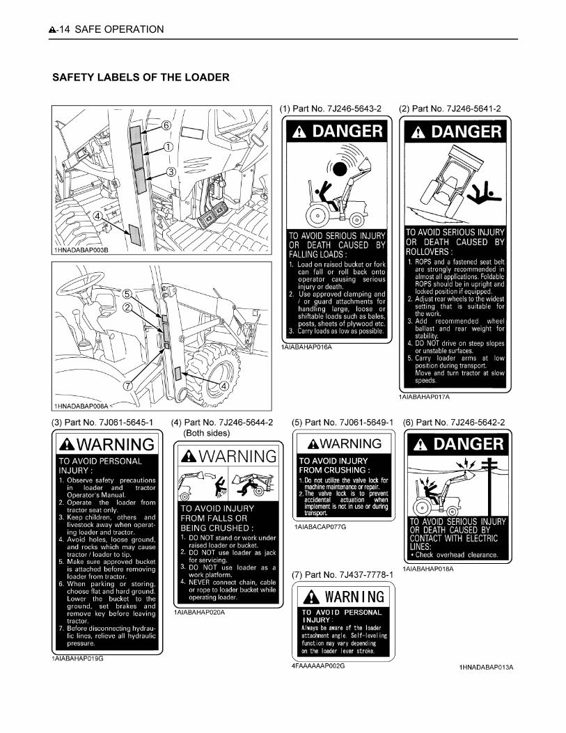
LOADERMost loader equipment accidents can be avoided by following simple safety precautions.These safety precautions, if followed at all times, will help you operate your loader safely.
1. Read and understand all instructions and precautionsfound in both the tractor and the loader operator'smanuals before using the loader.Lack of knowledge can lead to accidents.
2. It is the owner's responsibility to ensure that anyonewho will operate the loader reads this manual first andbecomes familiar with the safe operation of the loader.
3. For your safety, a ROPS with a seat belt is stronglyrecommended by KUBOTA in almost all applications.If the tractor is not equipped with ROPS, it should notbe operated in a situation where ROPS isrecommended. If you have any questions, consultyour local KUBOTA Dealer.Always use the seat belt when the tractor is equippedwith a ROPS. Never use the seat belt when the tractoris not equipped with a ROPS.
4. Visually check for hydraulic leaks and broken, missing,or malfunctioning parts.Make necessary repairs before operating.
5. Replace damaged or illegible safety labels. Seefollowing pages for required labels.
6. Enter and exit the operator's seat only from left side ofthe tractor.
7. Engage the loader control valve lock to preventaccidental actuation when the implement is not in useor during transport. Do not utilize the valve lock formachine maintenance or repair.
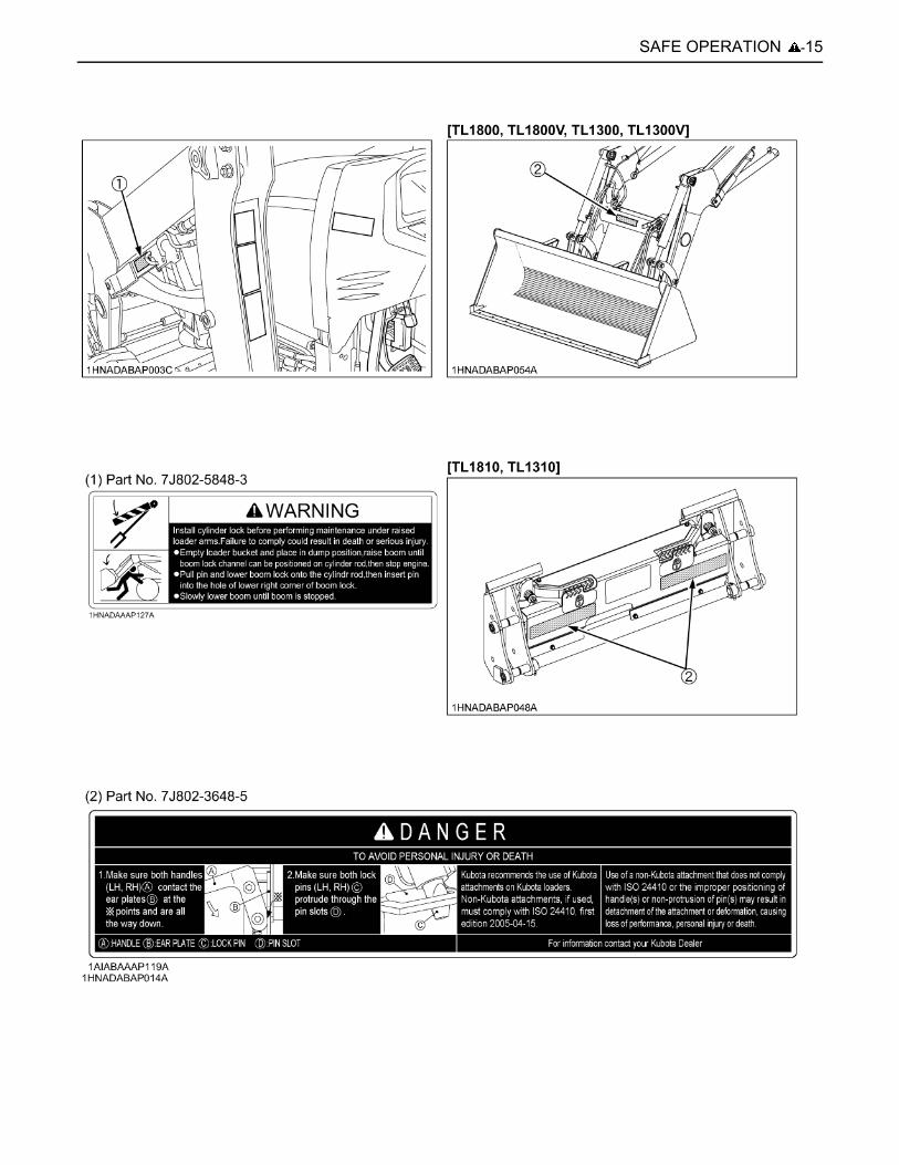
8. Follow the precautions below when attachingimplements.
A Make sure both handles (LH, RH) contact the earplates at the points (A) and are all the way down.
A Make sure both lock pins (LH, RH) protrude throughthe pin slots.
A Kubota recommends the use of Kubota attachmentson Kubota loaders. Non-Kubota attachments, if used,must comply with ISO 24410, first edition 2005-04-15.
A Use of a non-Kubota attachment that does not complywith ISO 24410 or the improper positioning ofhandle(s) or non-protrusion of pin(s) may result indetachment of the attachment or deformation, causingloss of performance, personal injury or death.
1. BEFORE OPERATING THE LOADER
(1) Handle(2) Ear plate(3) Pin slot(4) Lock pin
(A) The handle contacts the ear plate at the points.

-9SAFE OPERATION
1. Operate the loader only when properly seated at thecontrols. Do not operate from the ground.
2. Move and turn the tractor at low speeds.3. Never allow anyone to get under the loader bucket or
reach through the boom when the bucket is raised.4. Keep children, others and livestock away when
operating loader and tractor.5. Do not walk or work under a raised loader bucket or
attachment unless it is securely blocked and held inposition.
6. For tractor stability and operator safety, rear ballastmust be added to the 3-point hitch and to the rearwheels when using loader.
7. Exercise extra caution when operating the loader witha raised bucket or attachment.
8. Do not lift or carry any person on the loader, in thebucket, or other attachment.
9. Avoid loose fill, rocks and holes. They can bedangerous for loader operation or movement.
10.Avoid overhead wires and obstacles when the loaderis raised. Contacting electric lines can causeelectrocution.
11.Gradually stop the loader boom when lowering orlifting.
12.Use caution when handling loose or shiftable loads.13.Using loaders for handling large, heavy, or shiftable
objects is not recommended without proper handlingattachments.
14.Handling large heavy objects can be extremelydangerous due to :A Danger of rolling the tractor over.A Danger of upending the tractor.A Danger of the object rolling or sliding down the
loader boom onto the operator.15. If you must perform this sort of work (item 14), protect
yourself by :A Never lift the load higher than necessary to clear
the ground.A Add rear ballast to the tractor to compensate for the
load or use rear implement.A Never lift large objects with equipment that may
permit them to roll back onto the operator.A Move slowly and carefully, avoiding rough terrain.
16.Never lift or pull a load from any point on the loaderwith a chain, rope, or cable. Doing so could cause arollover or serious damage to the loader.
17.Be extra careful when operating the tractor on a slope,always operate up and down, never across the slope.Do not operate on steep slopes or unstable surfaces.
18.Carry loader boom at a low position during transport.(You should be able to see over the bucket.)
19.Allow for the loader length when making turns.
1. When loader work is complete and parking or storing,choose flat and hard ground. Lower the loader boomto the ground, stop the engine, set the brakes andremove the key before leaving the tractor seat.
1. Always wear safety goggles when servicing orrepairing the machine.
2. Do not modify the loader. Unauthorized modificationmay affect the function of the loader, which may resultin personal injury.
3. Do not use the loader as a work platform or a jack tosupport the tractor for servicing or maintenance.Securely support the tractor or any machine elementswith stands or suitable blocking before workingunderneath.For your safety, do not work under any hydraulicallysupported devices. They can settle or suddenly leakdown or be accidentally lowered.
4. Escaping hydraulic oil under pressure can havesufficient force to penetrate the skin, causing seriouspersonal injury. Do not use hands to search forsuspected leaks. If injured by escaping fluid, obtainmedical treatment immediately.
5. Do not tamper with the relief valve setting. The reliefvalve is pre-set at the factory. Changing the settingcan cause overloading of the loader and tractor whichmay result in serious personal injury.
6. When servicing or replacing pins in cylinder ends,bucket, etc., always use a brass drift and hammer.Failure to do so could result in injury from flying metalfragments.
2. OPERATING THE LOADER 3. AFTER OPERATING THE LOADER
4. SERVICING THE LOADER

SAFE OPERATION-10
SAFETY LABELS OF THE TRACTOR

-11SAFE OPERATION

SAFE OPERATION-12
[L47]

-13SAFE OPERATION
[M62]
SAFE OPERATION-14
SAFETY LABELS OF THE LOADER
-15SAFE OPERATION

SAFE OPERATION-16
CARE OF SAFETY LABELS1. Keep the safety labels clean and free from obstructing material.2. Clean the safety labels with soap and water, and dry the safety labels with a soft cloth.3. Do not spray high-pressure water directly on the safety labels, otherwise the safety labels may peel off.4. Replace damaged or missing safety labels with new safety labels from your local KUBOTA Dealer.5. If a component with safety label(s) attached is replaced with new component, make sure that new safety label(s) is (are)
attached in the same location(s) as the replaced component.6. Attach new safety labels by applying on a clean, dry surface and pressing any bubbles to outside edge.

1SERVICING
SERVICING
Your dealer is interested in your new machine and has thedesire to help you get the most value from it. After readingthis manual thoroughly, you will find that you can do someof the regular maintenance yourself.However, when in need of parts or major service, be sureto see your KUBOTA Dealer.For service, contact the KUBOTA Dealership from whichyou purchased your machine or your local KUBOTADealer.When in need of parts, be prepared to give your dealer theproduct identification number (PIN), and the CAB/ROPSand engine serial numbers.Locate the PIN and serial numbers now and record themin the space provided.To be filled in by purchaser
To be filled in by purchaser
C WarrantyThis tractor is warranted under the KUBOTA LimitedExpress Warranty, a copy of which may be obtained fromyour selling dealer. No warranty shall, however, apply ifthe tractor has not been handled according to theinstruction given in the Operator's Manual even it is withinthe warranty period.
C Scrapping the tractor and its procedureTo put the tractor out of service, correctly follow the localrules and regulations of the country or territory where youscrap it. If you have questions, consult your localKUBOTA Dealer.
[M62]
[L47]Date of purchase
Name of dealer
Type PIN/Serial No.
Tractor
CAB/ROPS
Engine
(1) Identification plate(2) Product identification number
(1) Engine serial number

SERVICING2
(1) Loader serial number
(1) ROPS identification plate (ROPS Serial No.)
(1) Diesel Particulate Filter (DPF) serial number

3SPECIFICATIONS OF THE TRACTOR
SPECIFICATIONS OF THE TRACTOR
SPECIFICATION TABLEModel L47 M62
Engine
Model V2403-CR-E4-TLB1 V2403-CR-TE4-TLB1
Type Direct injection vertical, water-cooled, 4-cycle diesel
No. of cylinders 4
Bore and stroke mm (in.) 87 x 102.4 (3.4 x 4.0)
PTO power (factory observed) kW (HP) 24.6 (33) 34.3 (46)
Net power (without fan) kW (HP) 34.6 (46.4) 46.3 (62.1) *
Total displacement L (cu. in.) 2.434 (148.5)
Rated revolution rpm 2700
Low idling revolution rpm 950 to 1000
Battery 12V, RC: 90 min, CCA: 550 A
12V, RC: 115 min, CCA: 650 A
Capacities
Fuel tank L (U.S.gals.) 67 (17.7)
Engine crankcase (with filter) L (U.S.qts.) 8.2 (8.7) 9.4 (9.9)
Engine coolant L (U.S.qts.) 8.2 (8.7)
Transmission case L (U.S.gals.) 46 (12.2)
Front axle case L (U.S.qts.) 7.0 (7.4) 12.5 (13.2)
TiresFront 27 x 10.5-15 R4 10-16.5 R4
Rear 15-19.5 R4 17.5L-24 R4
Dimensions
Min. ground clearance mm (in.) 365 (14.4) at transmission case
350 (13.8) at transmission case
TreadFront mm (in.) 1165 (45.9) 1440 (56.7)
Rear mm (in.) 1426 (56.1) 1462 (57.6)
Weight (with ROPS & FOPS, main frame) kg (lbs.) 1988 (4383) 2264 (4991)
PTO shaft Transmission case rear
Rear PTO SAE 1-3/8, 6 Spline
Steering Hydraulic power
Transmission Hydrostatic transmission(3 speeds)
Min. turning radius m (feet) 2.8 (9.2)** 3.3 (10.8) **
Brake Multiple wet disks operated by two foot pedalswhich can be locked together.
Differential Bevel gear
* Manufacturer's estimate** with brake
The company reserves the right to change the specifications without notice.

4 SPECIFICATIONS OF THE TRACTOR
DIMENSIONS
A Above dimensions are based on the machine with KUBOTA standard bucket.A The company reserves the right to change the specifications without notice.
Model L47 M62
A Overall length (without 3P & loader & backhoe, with front guard) mm (in.) 3075 (121.1) 3159 (124.4)
B Overall length (without 3P & backhoe, with front guard & loader) mm (in.) 4213 (165.9) 4536 (178.6)
C Overall width (without loader) mm (in.) 1809 (71.2) 1905 (75)
D Overall width (with loader) mm (in.) 1842 (72.5) 2154 (84.8)
E Overall height (with ROPS & FOPS) mm (in.) 2415 (95.1) 2594 (102.1)
F Wheel base mm (in.) 1841 (72.5) 2050 (80.7)

5SPECIFICATIONS OF THE TRACTOR
TRAVELING SPEEDS
The company reserves the right to change the specifications without notice.
(At rated engine rpm)
Model L47 M62
Tire size (Rear) 15-19.5 R4 17.5L-24 R4
Speed control pedal H-DS lever Range gear
shift lever km/h (mph)
Forward
L
L 3.3 (2.1) 3.6 (2.3)
M 6.6 (4.1) 7.3 (4.6)
H 13.7 (8.6) 15.3 (9.6)
H
L 5.3 (3.3) 6.0 (3.8)
M 10.7 (6.7) 12.1 (7.6)
H 22.5 (14.1) 25.1 (15.7)
Reverse
L
L 3.3 (2.1) 3.4 (2.1)
M 6.7 (4.2) 7.2 (4.5)
H 13.9 (8.7) 15.2 (9.5)
H
L 5.4 (3.4) 5.9 (3.7)
M 10.9 (6.8) 12.1 (7.6)
H 22.7 (14.2) 24.7 (15.4)

6 SPECIFICATIONS OF THE LOADER
SPECIFICATIONS OF THE LOADER
LOADER SPECIFICATIONSBUCKET SPECIFICATIONS
DIMENSIONAL SPECIFICATIONS
Loader model TL1300/TL1300V TL1800/TL1800V
Boom cylinderBore mm (in.) 55 (2.17) 65 (2.56)
Stroke mm (in.) 550 (21.65) 637.5 (25.1)
Bucket cylinderBore mm (in.) 60 (2.36) 70 (2.76)
Stroke mm (in.) 365 (14.37) 464 (18.27)
Control valve One Detent Float Position, Power Beyond Circuit,Hydraulic Dual Self-leveling Valve
Rated flow L/m (GPM) 43.4 (11.5) 60.5 (16)
Maximum pressure MPa (kg/cm , psi) 19.6 (200, 2845) 19.6 (200, 2845)
Net weight (approximate) kg (lbs.) 435 (960) 530 (1169)
Loader model TL1300/TL1300V TL1800/TL1800V
Model Round 72 Round 84
Width mm (in.) 1830 (72.0) 2135 (84.0)
Depth (L) mm (in.) 470 (18.5) 695 (27.4)
Height (M) mm (in.) 660 (26.0) 673 (26.5)
Length (N) mm (in.) 610 (24.0) 892 (35.1)
CapacityStruck m (CU.FT.) 0.36 (12.7) 0.54 (19.1)
Heaped m (CU.FT.) 0.44 (15.5) 0.66 (23.3)
Weight kg (lbs.) 190 (420) 244 (538)
Loader model TL1300/TL1300V TL1800/TL1800V
A Max. lift height (to bucket pivot pin) mm (in.) 2893 (113.9) 3203 (126.1)
B Max. lift height under level bucket mm (in.) 2694 (106.1) 2977 (117.2)
C Clearance with bucket dumped mm (in.) 2287 (90.0) 2412 (95)
D Reach at max. lift height (dumping reach) mm (in.) 422 (16.6) 612 (24.1)
E Max. dump angle deg. 44 43
F Reach with bucket on ground mm (in.) 1739 (68.5) 1821 (71.7)
G Bucket roll-back angle deg. 48 45
H Digging depth mm (in.) 89 (3.5) 69 (2.7)
J Overall height in carrying position mm (in.) 1402 (55.2) 1600 (63)

7SPECIFICATIONS OF THE LOADER
OPERATIONAL SPECIFICATIONSLoader model TL1300/TL1300V TL1800/TL1800V
U Lift capacity (bucket pivot pin, max. height) kg (lbs.) 1292 (2848) 1796 (3960)
V Lift capacity (500 mm (20 in.) forward, max. height) kg (lbs.) 936 (2063) -(800 mm (31.5 in.) forward, max. height) kg (lbs.) - 1120 (2469)
W Lift capacity (bucket pivot pin, 1500 mm (59 in.) height) kg (lbs.) 1535 (3384) 2129 (4694)
X Lift capacity (500 mm (20 in.), forward, 1500 mm (59 in.) height) kg (lbs.) 1232 (2716) -(800 mm (31.5 in.), forward, 1500 mm (59 in.) height) kg (lbs.) - 1548 (3413)
Y Breakout force (bucket pivot pin) N (lbf) 20153 (4531) 26654 (5992)
Z Breakout force (500 mm (20 in.) forward) N (lbf) 15563 (3499) -(800 mm (31.5 in.) forward) N (lbf) - 18064 (4061)
VV Bucket roll-back force at max. height N (lbf) 11650 (2619) 11768 (2646)XX Bucket roll-back force at 1.5 m (59 in.) N (lbf) 20613 (4634) 22496 (5057)ZZ Bucket roll-back force at ground level N (lbf) 23556 (5296) 23487 (5280)
Raising time sec. 3.2 (3.6) 3.9 (4.2)Lowering time Self level valve OFF (ON) sec. 2.9 (5.8) 3.1 (4.3)Bucket dumping time sec. 2.2 2.4Bucket rollback time sec. 1.9 2.4

8 SPECIFICATIONS OF THE LOADER
LOADER TERMINOLOGY
(1) Hydraulic control lever(2) Main frame(3) Boom cylinder(4) Bucket linkage
(5) Boom(6) Bucket cylinder(7) Bucket
9IMPLEMENT LIMITATIONS
IMPLEMENT LIMITATIONS
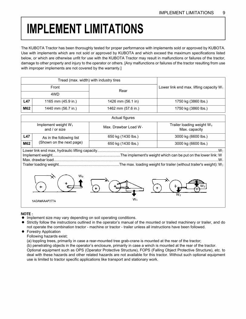
The KUBOTA Tractor has been thoroughly tested for proper performance with implements sold or approved by KUBOTA.Use with implements which are not sold or approved by KUBOTA and which exceed the maximum specifications listedbelow, or which are otherwise unfit for use with the KUBOTA Tractor may result in malfunctions or failures of the tractor,damage to other property and injury to the operator or others. [Any malfunctions or failures of the tractor resulting from usewith improper implements are not covered by the warranty.]A Implement size may vary depending on soil operating conditions.A Strictly follow the instructions outlined in the operator’s manual of the mounted or trailed machinery or trailer, and do
not operate the combination tractor - machine or tractor - trailer unless all instructions have been followed.A Forestry Application
Following hazards exist;(a) toppling trees, primarily in case a rear-mounted tree grab-crane is mounted at the rear of the tractor;(b) penetrating objects in the operator’s enclosure, primarily in case a winch is mounted at the rear of the tractor.Optional equipment such as OPS (Operator Protective Structure), FOPS (Falling Object Protective Structure), etc. todeal with these hazards and other related hazards are not available for this tractor. Without such optional equipmentuse is limited to tractor specific applications like transport and stationary work.
Tread (max. width) with industry tires
Lower link end max. lifting capacity WFrontRear
4WD
L47 1165 mm (45.9 in.) 1426 mm (56.1 in) 1750 kg (3860 lbs.)
M62 1440 mm (56.7 in.) 1462 mm (57.6 in.) 1750 kg (3860 lbs.)
Actual figures
Implement weight Wand / or size Max. Drawbar Load W Trailer loading weight W
Max. capacity
L47 As in the following list(Shown on the next page)
650 kg (1430 lbs.) 3000 kg (6600 lbs.)
M62 650 kg (1430 lbs.) 3000 kg (6600 lbs.)
Lower link end max, hydraulic lifting capacity..................................................................................................................WImplement weight................................................................The implement's weight which can be put on the lower link: WMax. drawbar load...........................................................................................................................................................WTrailer loading weight.........................................................The max. loading weight for trailer (without trailer's weight): W

10 IMPLEMENT LIMITATIONS
A Implement size may vary depending on soil operating conditions.
No. Implement Remarks L47 M62
1 Trailer Max. Load Capacity kg (lbs.) 3000 (6600) 3000 (6600)Max. Drawbar Load kg (lbs.) 650 (1430) 650 (1430)
2 Mower
Rotary-Cutter Max. Cutting Width mm (in.) 1829 (72) 1829 (72)Max. Weight kg (lbs.) 420 (926) 420 (926)
Flail Mower Max. Cutting Width mm (in.) 1524 (60) 1524 (60)Max. Weight kg (lbs.) 400 (880) 400 (880)
Sickle Bar Max. Cutting Width mm (in.) 2134 (84) 2134 (84)Max. Weight kg (lbs.) 500 (1100) 500 (1100)
3 Sprayer Rear mounted Max. tank capacity L (gal.) 400 (106) 400 (106)Pull type Max. tank capacity L (gal.) 1200 (317) 1200 (317)
4 Rotary Tiller Max. Tilling Width mm (in.) 1524 (60) 1524 (60)
5 Backhoe *Max. Digging Depth mm (ft) 3073 (10) 3652 (12)
Max. Weight kg (lbs.) 753 (1660) w/o Bucket
886 (1956) w/o Bucket
6 Disc-harrow(Pull type)
Max. Harrowing Width mm (in.) 1981 (78) 1981 (78)Max. Weight kg (lbs.) 400 (880) 400 (880)
7 Chisel Plow Max. Cutting Width mm (in.) 1829 (72) 1829 (72)Max. Weight kg (lbs.) 350 (770) 350 (770)
8 Broad Caster Max. Tank Capacity L (gals.) 300 (80) 300 (80)Max. Weight kg (lbs.) 100 (220) 100 (220)
9 Manure Spreader Max. Capacity kg (lbs.) 2000 (4400) 2000 (4400)
10 CultivatorMax. Width mm (in.) 2134 (84) 2134 (84)Number of rows 2 2Max. Weight kg (lbs.) 400 (880) 400 (880)
11 Rear Blade Max. Cutting Width mm (in.) 1829 (72) 1829 (72)Max. Oil Pressure kgf/cm (psi) 175 (2490) 175 (2490)
12 Front-end Loader ** Max. Lifting Capacity kg (lbs.) 1000 (2200) 1350 (2976)Max. Oil Pressure kgf/cm (psi) 195 (2770) 200 (2857)
13 Box Blade Max. Cutting Width mm (in.) 1829 (72) 2134 (84)Max. Weight kg (lbs.) 470 (1040) 550 (1200)
14 Snow Blade Max. width mm (in.) 1829 (72) 2134 (84)Max. weight kg (lbs.) 350 (770) 550 (1200)
* KUBOTA provides BT1000B Backhoe for L47 and BT1400 Backhoe for M62.No other Backhoe installed by 3-point hitch is permitted for L47, M62.
** KUBOTA provides TL1300/TL1300V Front-end Loader for L47 and TL1800/TL1800V Front-end Loader for M62.
11INSTRUMENT PANEL AND CONTROLS
INSTRUMENT PANEL AND CONTROLS
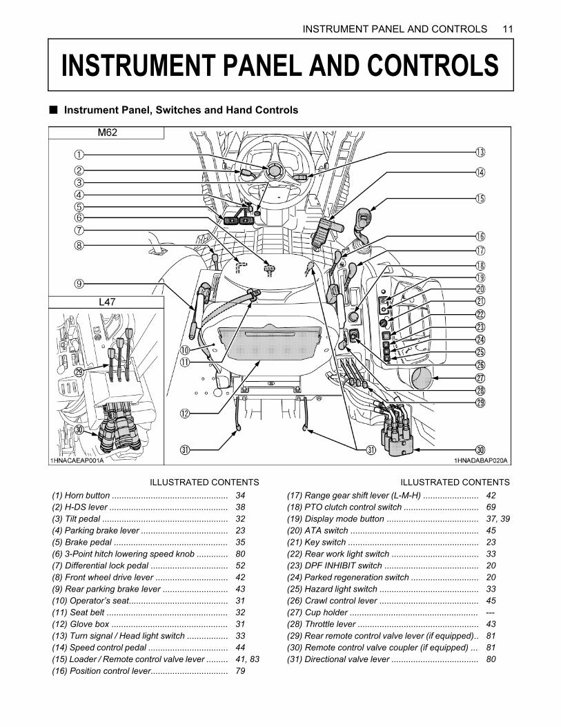
B Instrument Panel, Switches and Hand ControlsILLUSTRATED CONTENTS ILLUSTRATED CONTENTS(1) Horn button ................................................ 34 (17) Range gear shift lever (L-M-H) ....................... 42(2) H-DS lever ................................................. 38 (18) PTO clutch control switch ............................... 69(3) Tilt pedal .................................................... 32 (19) Display mode button ...................................... 37, 39(4) Parking brake lever .................................... 23 (20) ATA switch ..................................................... 45(5) Brake pedal ............................................... 35 (21) Key switch ...................................................... 23(6) 3-Point hitch lowering speed knob ............. 80 (22) Rear work light switch .................................... 33(7) Differential lock pedal ................................ 52 (23) DPF INHIBIT switch ....................................... 20(8) Front wheel drive lever .............................. 42 (24) Parked regeneration switch ............................ 20(9) Rear parking brake lever ........................... 43 (25) Hazard light switch ......................................... 33(10) Operator’s seat......................................... 31 (26) Crawl control lever ......................................... 45(11) Seat belt .................................................. 32 (27) Cup holder ..................................................... ---(12) Glove box ................................................ 31 (28) Throttle lever .................................................. 43(13) Turn signal / Head light switch ................. 33 (29) Rear remote control valve lever (if equipped).. 81(14) Speed control pedal ................................. 44 (30) Remote control valve coupler (if equipped) ... 81(15) Loader / Remote control valve lever ......... 41, 83 (31) Directional valve lever .................................... 80(16) Position control lever................................ 79
12 INSTRUMENT PANEL AND CONTROLS
ILLUSTRATED CONTENTS ILLUSTRATED CONTENTS(1) Tachometer .................................................... 52 (13) Glow plug indicator .......................................... 25, 27(2) Turn signal / hazard indicator .......................... 33 (14) Stall guard indicator [HST Type] ...................... 39(3) Master system warning indicator .................... 50 (15) ATA indicator [HST Type] ............................... 45(4) Electrical charge warning indicator ................. 50 (16) Auto H-DS indicator [HST Type] ...................... 39(5) Parking brake warning indicator ...................... 50 (17) H-DS Low speed range indicator [HST Type] .. 39(6) Engine oil pressure warning indicator ............. 50 (18) H-DS High speed range indicator [HST Type] . 39(7) Engine warning indicator ................................ 50 (19) Water separator indicator ................................ 50(8) IntelliPanel(TM) display .................................. 49 (20) Emission indicator ........................................... 50(9) Coolant temperature gauge ............................ 51 (21) Regeneration indicator .................................... 18(10) Fuel gauge ................................................... 51 (22) Engine RPM increase indicator ....................... 18(11) Rear parking brake indicator ......................... 43 (23) Parked regeneration indicator ......................... 20(12) PTO indicator ............................................... 42 (24) Fuel level indicator .......................................... 50

13INSTRUMENT PANEL AND CONTROLS
C IntelliPanel(TM) Display
No. Message Description Reference page
(1) "L", "H", "M" or "N" Display the position of the range gear shift that was selected with the Rangegear shift lever. 42
(2)
Appears when the time for an engine oil change has come. Change the engine oil with fresh one.
48, 49115
Stays displayed for 3 seconds or so after the engine has got started. Buckle up the seat belt. 32
Stays displayed while the cooling water temperature is too low and the glow plug is being activated. Wait until this symbol disappears and get the engine started.
27
Appears when the fuel has become less than 12 L (3.1 U.S.gals.) or so. Refuel as soon as possible. If the fuel tank becomes empty, air will enter the fuel system, thereby requiring a bleeding.
51
(3) 0.1 to 34 Displays the travel speed. (The actual speed is different from the displayed one if the tires slip in towing or other jobs.) ---
(4) 0:00 to 11:59 Displays the clock. When (― ― : ― ―) is displayed, make the time setting. Nothing is displayed if this is disabled. 47
(5) Lower IntelliPanel(TM) display
The hour meter, trip meter, mileage, PTO rpm, HST setting, PM volume status, time elapsed since the previous engine oil change and other data can be displayed.
48
14 PRE-OPERATION CHECK OF THE TRACTOR
PRE-OPERATION CHECK OF THE TRACTOR
DAILY CHECKTo prevent trouble from occurring, it is important to knowthe condition of the tractor well. Check it before starting.To avoid personal injury or death:A Be sure to check and service the tractor on a
level surface with the engine shut off and theparking brake "ON" and implement lowered tothe ground.
Check item- Walk around inspection- Check engine oil level- Check transmission oil level- Check coolant level- Check water separator- Clean grill, radiator screen and oil cooler- Clean oil cooler- Clean fuel cooler- Check DPF muffler- Check air cleaner dust indicator (When used in a dusty place)- Check brake pedal- Check indicators, gauges and meter- Check lights- Check seat belt and ROPS & FOPS- Check movable parts- Refuel (See "DAILY CHECK" in "PERIODIC SERVICE OF THE TRACTOR" section)- Care of safety labels (See "SAFETY LABELS" in "SAFE OPERATION" section)

15PRE-OPERATION CHECK OF THE LOADER
PRE-OPERATION CHECK OF THE LOADER
PRE-OPERATION CHECKSPrior to starting the engine, make pre-operation checksaccording to "MAINTENANCE OF THE TRACTOR"section.To avoid personal injury or death:A Read and understand "Safe Operation" section
in the front of this manual.A Read and understand the safety labels located
on the loader.
REAR BALLAST
To avoid serious injury or death:A For tractor stability and operator's safety, rear
ballast should be added to the rear of thetractor in the form of 3-point counter weightand rear wheel ballast. The amount of rearballast will depend on the application.
BLiquid Ballast in Rear TiresWater and calcium chloride solution provides a safe andeconomical ballast. Used properly, it will not damage tires,tubes or rims. The addition of calcium chloride isrecommended to prevent the water from freezing. Use ofthis method of weighting the wheels has full approval ofthe tire manufacturers. See your tire dealer for thisservice.
Liquid weight per tire (75 Percent filled)
A Do not fill tires with water or solution more than 75% offull capacity (to the valve stem level at 12 o'clockposition).
A When mounting a heavy rear implement, liquid in thetires may not be required.
A Do not add liquid ballast or any other weights to thefront tires.
Implement as Counter Weight
6' Box Scraper Approx. 470 kg (1040 lbs.)
Backhoe (BT1000B) Approx. 753 kg (1660 lbs.)
Backhoe (BT1400) Approx. 980 kg (2161 lbs.)
Tire sizesL47 M62
15-19.5R4 17.5L-24R4
Slush free at -10 (14 )Solid at -30 (-22 )[Approx. 1 kg (2 lbs.)CaCl per 4 L (1 gal.) of water]
142 kg (314 lbs.)
235 kg (515 lbs.)
Slush free at -24 (-11 )Solid at -47 (-52 )[Approx. 1.5 kg (3.5 lbs.)CaCl per 4 L (1 gal.) of water]
149 kg (329 lbs.)
250 kg (550 lbs.)
Slush free at -47 (-52 )Solid at -52 (-62 )[Approx. 2.25 kg (5 lbs.)CaCl per 4 L (1 gal.) of water]
159 kg (350 lbs.)
265 kg (585 lbs.)
(1) Air(2) Water
(A) Correct: 75% Full Air compresses like a cushion(B) Incorrect: 100% Full Water can not be compressed
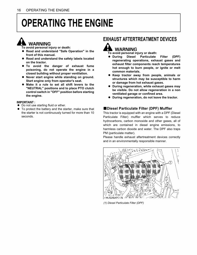
16 OPERATING THE ENGINE
OPERATING THE ENGINE
To avoid personal injury or death:A Read and understand "Safe Operation" in the
front of this manual.A Read and understand the safety labels located
on the tractor.A To avoid the danger of exhaust fume
poisoning, do not operate the engine in aclosed building without proper ventilation.
A Never start engine while standing on ground.Start engine only from operator's seat.
A Make it a rule to set all shift levers to the"NEUTRAL" positions and to place PTO clutchcontrol switch in "OFF" position before startingthe engine.
A Do not use starting fluid or ether.A To protect the battery and the starter, make sure that
the starter is not continuously turned for more than 10seconds.
EXHAUST AFTERTREATMENT DEVICES
To avoid personal injury or death:A During Diesel Particulate Filter (DPF)
regenerating operations, exhaust gases andexhaust filter components reach temperatureshot enough to burn people, or ignite or meltcommon materials.
A Keep tractor away from people, animals orstructures which may be susceptible to harmor damage from hot exhaust gases.
A During regeneration, white exhaust gases maybe visible. Do not allow regeneration in a nonventilated garage or confined area.
A During regeneration, do not leave the tractor.
BDiesel Particulate Filter (DPF) MufflerThis tractor is equipped with an engine with a DPF (DieselParticulate Filter) muffler which serves to reducehydrocarbons, carbon monoxide and other gases, all ofwhich are contained in diesel engine emissions, toharmless carbon dioxide and water. The DPF also trapsPM (particulate matter).Please handle exhaust aftertreatment devices correctlyand in an environmentally responsible manner.
(1) Diesel Particulate Filter (DPF)
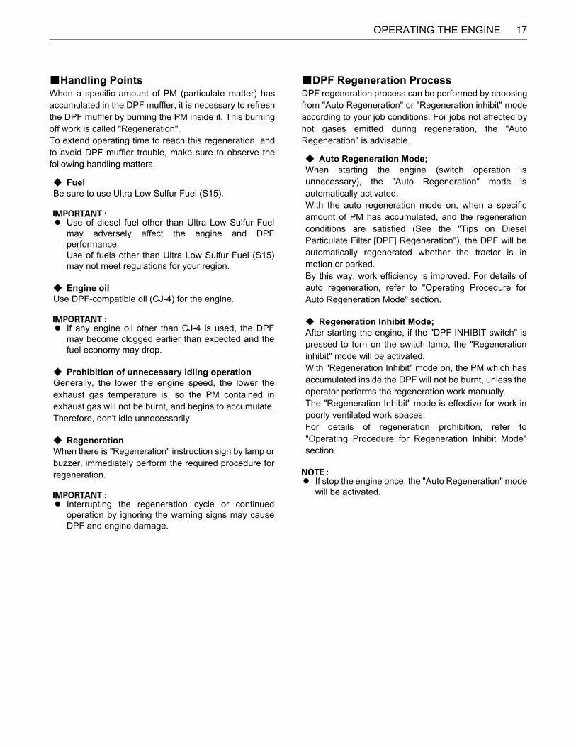
17OPERATING THE ENGINE
BHandling PointsWhen a specific amount of PM (particulate matter) hasaccumulated in the DPF muffler, it is necessary to refreshthe DPF muffler by burning the PM inside it. This burningoff work is called "Regeneration". To extend operating time to reach this regeneration, andto avoid DPF muffler trouble, make sure to observe thefollowing handling matters.
BDPF Regeneration ProcessDPF regeneration process can be performed by choosingfrom "Auto Regeneration" or "Regeneration inhibit" modeaccording to your job conditions. For jobs not affected byhot gases emitted during regeneration, the "AutoRegeneration" is advisable.
A If stop the engine once, the "Auto Regeneration" modewill be activated.
C FuelBe sure to use Ultra Low Sulfur Fuel (S15).
A Use of diesel fuel other than Ultra Low Sulfur Fuelmay adversely affect the engine and DPFperformance.Use of fuels other than Ultra Low Sulfur Fuel (S15)may not meet regulations for your region.
C Engine oilUse DPF-compatible oil (CJ-4) for the engine.
A If any engine oil other than CJ-4 is used, the DPFmay become clogged earlier than expected and thefuel economy may drop.
C Prohibition of unnecessary idling operation Generally, the lower the engine speed, the lower theexhaust gas temperature is, so the PM contained inexhaust gas will not be burnt, and begins to accumulate.Therefore, don't idle unnecessarily.
C RegenerationWhen there is "Regeneration" instruction sign by lamp orbuzzer, immediately perform the required procedure forregeneration.
A Interrupting the regeneration cycle or continuedoperation by ignoring the warning signs may causeDPF and engine damage.
C Auto Regeneration Mode;When starting the engine (switch operation isunnecessary), the "Auto Regeneration" mode isautomatically activated.With the auto regeneration mode on, when a specificamount of PM has accumulated, and the regenerationconditions are satisfied (See the "Tips on DieselParticulate Filter [DPF] Regeneration"), the DPF will beautomatically regenerated whether the tractor is inmotion or parked.By this way, work efficiency is improved. For details ofauto regeneration, refer to "Operating Procedure forAuto Regeneration Mode" section.
C Regeneration Inhibit Mode;After starting the engine, if the "DPF INHIBIT switch" ispressed to turn on the switch lamp, the "Regenerationinhibit" mode will be activated.With "Regeneration Inhibit" mode on, the PM which hasaccumulated inside the DPF will not be burnt, unless theoperator performs the regeneration work manually.The "Regeneration Inhibit" mode is effective for work inpoorly ventilated work spaces.For details of regeneration prohibition, refer to"Operating Procedure for Regeneration Inhibit Mode"section.

18 OPERATING THE ENGINE
BRegeneration Operating Procedure
Operating Procedure for Auto Regeneration Mode
(1) Parked regeneration switch(2) DPF INHIBIT switch
(3) Regeneration indicator(4) Parked regeneration indicator
(5) Engine RPM increase indicator(6) Engine warning indicator
1. Start the engine.(Make sure that the DPF INHIBIT switch lamp is "OFF".) Switch lamp OFF: Auto Regeneration Mode activated.Switch lamp ON: Regeneration Inhibit Mode activated.
A When the engine is started, the "Auto Regeneration" mode is automatically activated.A "Regeneration Inhibit" mode is activated, when the DPF INHIBIT switch is pushed after the engine is started.
2. When the regeneration indicator starts flashing: A specific amount of PM has built up in the DPF.Continue to operate the tractor, and the regeneration process will begin automatically, make sure the working placeis in a safe area as DPF and exhaust temperature will rise.
3. When the engine rpm increase indicator starts flashing: Keep on working and increase the engine rpm until the indicator turns "OFF".
A Even if the Auto Regeneration Mode is selected, DPF regeneration may not begin because system requirements havenot been satisfied.
A The engine rpm increase indicator is used as a guide to satisfy the regeneration conditions. If the engine load is tooheavy, the engine rpm increase indicator may continue to flash, even though regeneration system conditions aresatisfied and regeneration may begin automatically. (See the "Tips on Diesel Particulate Filter [DPF] Regeneration")

19OPERATING THE ENGINE
BPM Warning Level and Required ProceduresDuring Auto Regeneration Mode when the PM level has built up in the DPF, the regeneration cycle will begin automatically.If the regeneration cycle is interrupted or the regeneration conditions are not satisfied, the buzzer starts sounding and theindicator display changes in response to the PM level in order to prompt the operator to perform the required procedurelisted below.
A Once the regeneration level has been reached, immediately perform the required procedure for regeneration.Interrupting the regeneration cycle or continued operation by ignoring the warning signs may cause DPF and enginedamage.
Auto ModeDPF system status Required procedure
PM warning level: 1 The regeneration indicator starts flashing.
A specific amount of PM has accumulated in the DPF muffler.Continue to work the tractor to raise the DPF temperature.
Buzzer: Not sounding
The RPM increase indicator starts flashing.
Continue the work and increase the engine rpm until the indicator turns "OFF".
The regeneration indicator will stop flashing and remain "ON" constantly.
The regeneration cycle begins and continues until cycle is complete then the indicator will turn "OFF".
PM warning level: 2-1 If the regeneration cycle was interrupted or conditions are not satisfied for regeneration thenDPF system is now in Level 2.
Buzzer: Sounding every 5 seconds
The regeneration indicator starts flashing.
Start the regeneration, referring to PM warning level: 1 above.Now the parked regeneration indicator starts flashing, and the parked regeneration can also be started.If the regeneration conditions are not met, perform the parked regeneration.A For the procedure, refer to "Operating
Procedure for Parked Regeneration".
PM warning level: 2-2 The RPM increase indicator starts flashing.
Buzzer: Sounding every 3 seconds The parked regeneration indicator starts
flashing.
PM warning level: 3 If the regeneration fails in the warning level 2:The engine warning indicator starts flashing.
Immediately discontinue working the tractor and begin the parked regeneration cycle process.A For the procedure, refer to "Operating
Procedure for Parked Regeneration".At this PM warning level, the Auto Regeneration Mode does not function.If the tractor is operated further, the regeneration cycle will be disabled.
Buzzer: Sounding every 1 secondEngine output: 50%
The parked regeneration indicator starts flashing.
PM warning level: 4 If the parked regeneration is interrupted or the tractor is continuously operated in the warning level 3:
Buzzer: Sounding every 1 secondEngine output: 50%
The engine warning indicator remains constantly "ON".
Immediately move the tractor to a safe place and park it there and turn the engine "OFF".Contact your local KUBOTA Dealer.A At this level, never continue to operate
the tractor otherwise damage will resultto the DPF and engine.
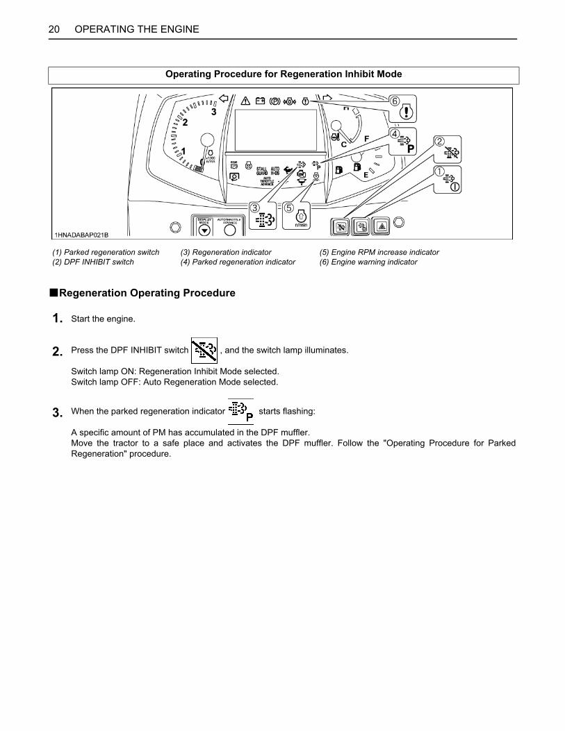
20 OPERATING THE ENGINE
BRegeneration Operating Procedure
Operating Procedure for Regeneration Inhibit Mode
(1) Parked regeneration switch(2) DPF INHIBIT switch
(3) Regeneration indicator(4) Parked regeneration indicator
(5) Engine RPM increase indicator(6) Engine warning indicator
1. Start the engine.
2. Press the DPF INHIBIT switch , and the switch lamp illuminates.
Switch lamp ON: Regeneration Inhibit Mode selected.Switch lamp OFF: Auto Regeneration Mode selected.
3. When the parked regeneration indicator starts flashing:
A specific amount of PM has accumulated in the DPF muffler.Move the tractor to a safe place and activates the DPF muffler. Follow the "Operating Procedure for ParkedRegeneration" procedure.

21OPERATING THE ENGINE
BPM Warning Level and Required ProceduresIn the Regeneration Inhibit Mode, the buzzer starts sounding and the indicator display changes in response to the PM levelin order to prompt the operator to perform the required procedure listed below.
A Once the regeneration level has been reached, immediately perform the required procedure for regeneration.Interrupting the regeneration cycle or continued operation by ignoring the warning signs may cause DPF and enginedamage.
Regeneration Inhibit ModeDPF system status Required procedure
PM warning level: 1 The regeneration indicator starts flashing.
A specific level of PM has built up in the DPF muffler.Continue with the operation as it is.Buzzer: Not sounding
At PM warning levels range from 1 to 2-2, it is also possible to change DPF INHIBIT switch to auto regeneration mode then perform regeneration.
PM warning level: 2-1 The regeneration indicator starts flashing.
Move the tractor to a safe area, then follow the "Operating Procedure for Parked Regeneration".
Buzzer: Sounding every 5 seconds
PM warning level: 2-2 The Parked regeneration indicator starts flashing.
Buzzer: Sounding every 3 seconds
PM warning level: 3 If the parked regeneration cycle is interrupted or the tractor is continuously operated in the PM warning level 2:
Buzzer: Sounding every 1 secondEngine output: 50%
The engine warning indicator starts flashing.
Immediately stop working the tractor, move the tractor to a safe area, then follow the "Operating Procedure for Parked Regeneration".If the tractor is operated further and the operator ignores the warning signs, then regeneration will be disabled.
The parked regeneration indicator starts flashing
PM warning level: 4 If the regeneration cycle is interrupted or the tractor is continuously operated ignoring the warning signs, in the PM warning level 3:
Buzzer: Sounding every 1 secondEngine output: 50%
The engine warning indicator remains constantly "ON".
Immediately move the tractor to a safe place and place in park, turn "OFF" engine.Contact your local KUBOTA Dealer.A At this level never continue to operate
the tractor, otherwise damage mayresult to the DPF and engine.

22 OPERATING THE ENGINE
Operating Procedure for Parked Regeneration
1. Park the tractor in a safe area away from buildings, people, and animals.
2. Apply the parking brake.
3. Set the speed control pedal to the neutral position.
4. Turn "OFF" the PTO clutch control switch or lever.
5. Return the engine rpm to the idle speed.
6. Lower the implement to the ground.Turn steering wheel so front wheels are in the straight ahead position.
7. Press the DPF INHIBIT switch , and the switch lamp turns "OFF".
8. When the regeneration conditions are satisfied (2 to 5 and 7 mentioned above),
the parked regeneration switch lamp start flashing.
9. Press the parked regeneration switch to start the regeneration cycle.
(The switch lamp will stop flashing and remain "ON" constantly during the cycle.)
10. The engine rpm will automatically rise, and the regeneration process will begin.
11. Both indicators stay "ON" while regenerating the DPF.
They turn "OFF" when the cycle is complete.
12. After the lamp turns "OFF", normal tractor work may resume.When driving in "Regeneration Inhibit" mode, press the DPF INHIBIT switch to turn on the switch lamp.
A During the regeneration cycle, do not touch the above levers, pedal and switches (in steps 2, 3, 4), nor change theengine rpm other than an emergency stop. Otherwise, the regeneration will be interrupted.
A Never leave the tractor when parked regeneration process is activated. A If the parked regeneration cycle is interrupted, the engine rpm is fixed at the idling level for about 30 seconds. For this
period, keep the hand throttle lever and foot throttle pedal at the idle position. Do not move them. They will functionagain in 30 seconds.

23OPERATING THE ENGINE
BTips on Diesel Particulate Filter (DPF) Regeneration
A OperationThe higher in speed or load the engine operates, thehigher the exhaust temperature rises. As a result,particulate matter (PM) inside the DPF is consumed,therefore the regeneration process is required lessfrequently over time.The lower in speed or load the engine operates, thelower the exhaust temperature. Accordingly, lessparticulate matter (PM) inside the DPF is consumed,therefore more accumulation of PM will occur, whichrequires frequent regeneration, therefore avoidprolonged idling if possible.
A Necessary conditions for "Regeneration"When conditions below are all satisfied, regenerationwill start. However, if even one condition is deviatedduring the process, the regeneration will beinterrupted.(1) The engine coolant temperature.(2) The DPF temperature.(3) The engine speed is 1200 rpm or higher.
A Usually it takes 15-20 minutes to complete theregeneration cycle.Actual regeneration time may depend on ambienttemperature, exhaust temperature and engine speed.
A It is recommended to do the regenerating while theengine is warm.
A Do not unnecessarily start and interrupt theregeneration process. Otherwise, a small amount offuel becomes mixed with the engine oil, whichdegrades the oil quality.
A While the DPF is being regenerated, the engine airflow rate is automatically limited to keep up theexhaust temperature. Because of this the engine maysound differently, this is normal for this engine.
A Just after the regeneration has ended, the DPF mufflerremains hot. It is advisable to keep the engine runningfor about 5 minutes to allow cooling of the exhaustcomponents.
STARTING THE ENGINE
1. To set the parking brake;(1) Interlock the brake pedals.(2) Depress the brake pedals.(3) Latch the brake pedals with the parking brake
lever.2. To release the parking brake, depress the brake
pedals again.
A To prevent damage to the parking brake lever, makesure that brake pedals are fully depressed beforepulling the parking brake lever up.
A The Parking brake indicator comes on while parkingbrake is applied and goes off when it is released.
Tractor Driving Position
1. Make sure the parking brake is set.
(1) Parking brake lever (A) Interlock the brake pedals(B) "DEPRESS"(C) "PULL"
(1) Parking brake indicator

OPERATING THE ENGINE24
A Step out the foot from speed control pedal, doing sothe pedal automatically returns to the neutral position.
2. Make sure the fuel shutoff-valve is in the open position.
(1) Fuel shutoff-valve (A) "CLOSE"(B) "OPEN"
3. Place the Speed control Pedal in "NEUTRAL" position.Place the range gear shift lever (L-M-H) in "NEUTRAL" position.
(1) Speed control pedal(2) Range gear shift lever (L-M-H)
(N) "NEUTRALPOSITION"
4. Place the PTO clutch control switch in "OFF" position.
(1) PTO clutch control switch "ON" "OFF"
5. Place the position control lever in "LOWEST" position.
(1) Position control lever (A) "DOWN"

25OPERATING THE ENGINE
BCheck Easy Checker(TM) Lamps:Turn the key to "ON" position and make sure the followingindicators light up or stay off.
C Indicators that light up:1. When the key is turned "ON", indicators(1)(3) should
come on. If trouble should occur at any location whilethe engine is running, the indicator corresponding tothat location comes on.
2. Suppose that the engine coolant temperature is nothigh enough yet. Glow plug indicator(5) also comes onwhen the key is turned "ON" to preheat the engine andgoes off automatically when preheat is completed.Illumination time of indicator varies according to thetemperature of coolant.
3. The parking brake indicator(2) comes on while parkingbrake is applied and goes off when it is released.
C Indicators that stay off:If the PTO indicator(4) stays on, disengage (OFF) thePTO.
A Daily checks with the Easy Checker(TM) only, are notsufficient. Never fail to conduct daily checks carefullyby referring to Daily Check. (See "DAILY CHECK" in"PERIODIC SERVICE" section)
A Some of the Easy Checker(TM) lamps may light updepending on the positions of the levers and switches.
A Turn on the key, and some of the indicators stay onabout 1 second.
6. Set the throttle lever to about 1/2 way.
(1) Throttle lever "INCREASE" "DECREASE"
7. Insert the key into the key switch and turn it "ON".
"OFF" "ON" "START"
(1) Electrical charge indicator(2) Parking brake indicator(3) Engine oil pressure indicator
(4) PTO indicator(5) Glow plug indicator(6) IntelliPanel(TM) display

OPERATING THE ENGINE26
BIntelliPanel(TM) MessageIf you try to start the engine but the following messagesappear alternately in the display, the engine fails to start.Follow the instructions shown on the display.
If the lamp is still on, immediately stop the engine anddetermine the cause.
1. To set the rear parking brake, pull up the rear parkingbrake lever.
2. To release the rear parking brake, push the releasebutton and push down the rear parking brake lever.
A The rear parking brake indicator comes on while rearparking brake is applied and goes off when it isreleased.
8. Turn the key to "START" position and release when the engine starts.
(1) Display
Disengage PTOSet HST Pedal to Neutral
Turn the PTO clutch control switch to "OFF" and foot off of the speed control pedal.
Disengage PTOTurn the PTO clutch control switch to "OFF".
Set HST Pedal to NeutralFoot off of the speed control pedal.
9. Check to see that all the lamps on theEasy Checker(TM) are "OFF".
Backhoe Operating Position
1. Make sure the rear parking brake is set.
(1) Rear parking brake lever
(1) Rear parking brake indicator
2. Make sure the fuel shut off-valve is in the open position.
3. Place the PTO clutch control switch in "OFF" position.
4. Set the throttle lever to about 1/2 way.

27OPERATING THE ENGINE
BIntelliPanel(TM) MessageIf you try to start the engine but the following messagesappear alternately in the display, the engine fails to start.Follow the instructions shown on the display.
COLD WEATHER STARTINGIf the ambient temperature is below -5 (23 ) and theengine is very cold, start it in the following manner:In the case of Tractor Driving Position, take steps 1through 8 in the procedure of Tractor Driving Position.In the case of Backhoe Operating Position, take steps 1through 5 in the procedure of Backhoe OperatingPosition. Then, take the following steps.
(If the engine fails to start after 10 seconds, turn off thekey for 30 seconds. Then repeat steps 1 and 2. To protectthe battery and the starter, make sure that the starter isnot continuously turned for more than 10 seconds.)
5. Insert the key into the key switch and turn it "ON".
6. Turn the key "START" position and release when the engine starts.
(1) Display
Disengage PTOSet HST Pedal to Neutral
Turn the PTO clutch control switch to "OFF" and foot off of the speed control pedal.
Disengage PTOTurn the PTO clutch control switch to "OFF".
Set HST Pedal to NeutralFoot off of the speed control pedal.
7. Check to see that all the lamps on the Easy Checker(TM) are "OFF"(See "Tractor driving position" in "STARTING THE ENGINE" )
1. Turn the key to "ON" (glow plug) and keep it there until glow plug indicator goes off.
(1) Glow plug indicator
2. Turn the key to the start position and the engine should start.

OPERATING THE ENGINE28
BAntifrost Heater for Oil Separator (if equipped)
The heater element operates continuously when the keyswitch is in run position.Due to high electrical draw, extended idle time oroperations will drain the battery and stop the tractor.
BBlock Heater (if equipped)A block heater is available as an option from your dealer.It will assist you in starting your tractor when the ambienttemperature is below -20 (-4 ).
STOPPING THE ENGINE
A If key does not stop the engine, consult your localKUBOTA Dealer.
WARMING UP
To avoid personal injury or death:A Be sure to set the parking brake during warm-
up.A Be sure to set all shift levers to the "NEUTRAL"
positions and to place PTO lever in "OFF"position during warm-up.
For 5 minutes after engine start-up, allow engine to warmup without applying any load, this is to allow oil to reachevery engine part. If load should be applied to the enginewithout this warm-up period, trouble such as seizure,breakage or premature wear may develop.
BWarm-up Transmission Oil at Low Temperature Range
Hydraulic oil serves as transmission fluid. In cold weather,the oil may be cold with increased viscosity. This cancause delayed oil circulation or abnormally low hydraulicpressure for some time after engine start-up. This in turncan result in trouble in the hydraulic system. To preventthe above, observe the following instructions:Warm up the engine at about 50% of rated rpm accordingto the table below:
A Do not operate the tractor under full load condition untilit is sufficiently warmed up.
(1) Heater (Oil separator, OUT 1)(2) Heater (Oil separator, OUT 2)(3) Heater (Oil separator, IN 1)(4) Heater (Oil separator, IN 2)
1. After slowing the engine to idle, wait 3 to 5 minutes for turbo to slow down then turn the key to "OFF".
2. Remove the key.
Ambient temperature Warm-up time requirement
Higher than -10 (14 ) Approx. 5 minutes
-15 to -10 (5 to 14 ) 5 to 10 minutes
-20 to -15 (-4 to 5 ) 10 to 20 minutes
Below -20 (-4 ) More than 20 minutes

29OPERATING THE ENGINE
JUMP STARTING
To avoid personal injury or death:A Battery gases can explode. Keep cigarettes,
sparks, and flames away from battery.A If tractor battery is frozen, do not jump start
engine.A Do not connect the other end of the negative
(-) jumper cable to the negative (-) terminal ofthe tractor battery.
When jump starting the engine, follow the instructionsbelow to safely start the engine.1. Bring the helper vehicle with a battery of the same
voltage as disabled tractor within easy cable reach."THE VEHICLES MUST NOT TOUCH".
2. Engage the parking brakes of both vehicles and putthe shift levers in neutral. Shut both engines off.
3. Wear eye protection and rubber gloves.4. Attach the red clamp to the positive (red, (+) or pos.)
terminal of the dead battery and clamp the other endof the same cable to the positive (red, (+) or pos.)terminal of the helper battery.
5. Clamp the other cable to the negative (black, (-) orneg.) terminal of the helper battery.
6. Clamp the other end to the engine block or frame ofthe disabled tractor as far from the dead battery aspossible.
7. Start the helper vehicle and let its engine run for a fewmoments. Start the disabled tractor.
8. Disconnect the jumper cables in the exact reverseorder of attachment. (Steps 6, 5 and 4)
A This machine has a 12 volt negative (-) ground startingsystem.
A Use only same voltage for jump starting.A Use of a higher voltage source on tractor's electrical
system could result in severe damage to tractor'selectrical system.Use only matching voltage source when "Jumpstarting" a low or dead battery condition.
A Do not operate the tractor with the battery cabledisconnected from the battery.
A Do not operate the tractor without the batterymounted.
A Do not operate the tractor with the battery dead.Charge the battery fully enough before operating thetractor.Otherwise the tractor might malfunction.
(1) Dead battery(2) Jumper cables(3) Helper battery

30 OPERATING THE TRACTOR
OPERATING THE TRACTOR
OPERATING NEW TRACTORHow a new tractor is handled and maintained determinesthe life of the tractor.A new tractor just off the factory production line has been,of course, tested, but the various parts are notaccustomed to each other, so care should be taken tooperate the tractor for the first 50 hours at a slower speedand avoid excessive work or operation until the variousparts become "broken-in." The manner in which thetractor is handled during the "breaking-in." period greatlyaffects the life of your tractor. Therefore, to obtain themaximum performance and the longest life of the tractor,it is very important to properly break-in your tractor. Inhandling a new tractor, the following precautions shouldbe observed.BDo not Operate the Tractor at Full Speed for the First 50 Hours
A Do not start quickly nor apply the brakes suddenly.A In winter, operate the tractor after fully warming up the
engine.A Do not run the engine at speeds faster than
necessary.A On rough roads, slow down to suitable speeds.
Do not operate the tractor at fast speed.The above precautions are not limited only to newtractors, but to all tractors. But it should be especiallyobserved in the case of new tractors.
BChanging Lubricating Oil for New TractorsThe lubricating oil is especially important in the case of anew tractor. The various parts are not "broken-in" and arenot accustomed to each other; small metal grit maydevelop during the operation of the tractor; and this maywear out or damage the parts. Therefore, care should betaken to change the lubricating oil a little earlier thanwould ordinarily be required.For further details of change interval hours.(See "MAINTENANCE OF THE TRACTOR" section)
BOARDING AND LEAVING THE TRACTOR1. Never try to get on or off a moving tractor or jump off
the tractor to exit.2. Face the tractor when getting into or out of the tractor.
Do not use the controls as hand holds to preventinadvertent machine movements.
3. Always keep steps and floor clean to avoid slipperyconditions.
STARTING
A The seat and suspension should be adjusted toensure that the controls are comfortably at hand for theoperator, ensuring that the operator maintains a goodposture and minimizes risks from whole bodyvibration.
1. Adjusting the driving position.
(A) "TRACTOR DRIVING POSITION"(B) "BACKHOE POSITION"

31OPERATING THE TRACTOR
BOperator's Seat
To avoid personal injury or death:A Make adjustments to the seat only while the
tractor is stopped.A Make sure that the seat is completely secured
after each adjustment.A Do not allow any person other than the
operator to ride on the tractor.
C Travel adjustmentPull the travel adjust lever and slide the seat backward orforward, as required. The seat will lock in position whenthe lever is released.
A The operator's seat base has a slope. When lifting thelever, be careful not to allow the seat to slide downforward.
C Suspension adjustment knobTurn the suspension adjust knob to achieve the optimumsuspension setting.
C Seat lock leverUnlock the seat lock lever and twist the seat right asrequired.
Using the swivel seatA Swivel the seat to the right to position yourself
comfortably for jobs in which you need to lookrearwards.
A After adjusting the operator's seat, be sure to check tosee that the seat is properly locked.
A See "REVERSING THE SEAT" in this section whenusing seat in backhoe position.
BGlove Box
(1) Travel adjust lever(2) Suspension adjust knob(3) Seat lock lever
(A) To decrease tension(B) To increase tension
(1) Seat lock lever (A) "UNLOCK"
(1) Glove box

OPERATING THE TRACTOR32
BSeat Belt
To avoid personal injury or death:A Always use the seat belt while driving tractors,
when the ROPS is installed.A Do not use the seat belt if the tractor is not
equipped with ROPS.
Adjust the seat belt for proper fit and connect the buckle.This seat belt is auto-locking retractable type.
BTilt Steering Adjustment
To avoid personal injury:A Do not adjust the steering wheel while the
tractor is in motion.
Press down the steering wheel tilt pedal, to release thelock so the steering wheel can be adjusted to one of sixdesired positions.
BLight switchTurn the light switch clockwise, and the following lights areactivated on the switch position.
A When the two head lights and the six work lights(including four option lights) are lit at the same time,run the engine above 2200 rpm.
(1) Seat belt
(1) Steering wheel tilt pedal (A) "PRESS DOWN"
2. Selecting light switch positions.
OFF...... Head lights OFF........ Head lights and front work lights on
(if equipped)
....... Head lights and front work lights on(if equipped)
(1) Head light switch

33OPERATING THE TRACTOR
BTurn Signal / Hazard Light SwitchC Hazard Light1. When the hazard light switch is pushed, the hazard
lights flash, along with the L/H and R/H indicators onthe instrument panel.
2. Push the hazard light switch again to turn off thehazard lights.
C Turn Signal with Hazard Light1. To indicate a right turn with the hazard lights already
flashing, turn the switch clockwise.2. To indicate a left turn with the hazard lights already
flashing, turn the switch counterclockwise.3. When the left or right turn signal is activated in
combination with the hazard lights, the indicatedturning light will flash and the other will stay on.
C Turn Signal without Hazard Light1. To indicate a right turn without hazard lights, turn the
switch clockwise.2. To indicate a left turn without hazard lights, turn the
switch counterclockwise.3. When the left or right turn signal is activated without
the hazard lights, the indicated turning light will flashand the other will stay on.
A The hazard light switch is operative when the keyswitch is in either the "ON" or "OFF" position.
A The turn signal light switch is only operative when thekey switch is in the "ON" position.
A Be sure to return the turn signal switch to centerposition after turning.
BRear Work Light SwitchWhen rear work light switch is pushed, the rear work lightsshould come on along with the rear work light switch.Press the rear work light switch again to turn off the light.
A When the two head lights and the six work lights(including four option lights) are lit at the same time,run the engine above 2200 rpm.
(1) Turn signal light switch(2) Hazard light switch(3) Hazard / Turn signal indicator
(A) "RIGHT TURN" (B) "LEFT TURN"
(1) Rear work light switch

OPERATING THE TRACTOR34
BHorn ButtonThe horn will sound when the key switch is in the "ON"position and the horn button pressed.
BTractor Lights(1) Head light(2) Side turn signal / Hazard light(3) Tail light(4) Rear turn signal / Hazard light(5) Rear work light
(1) Horn button (A) "PUSH"

35OPERATING THE TRACTOR
BBrake Pedals (Right and Left)
To avoid personal injury or death:A Be sure to interlock the right and left pedals.
Applying only one rear wheel brake at highspeeds could cause the tractor to swerve orroll-over.
A Be sure brake pedals have equal adjustmentwhen using locked together. Incorrect orunequal brake pedal adjustment can cause thetractor to swerve or roll-over.
To avoid personal injury or death:A Do not make brake suddenly.
An accident may occur as a result of a heavytowed load shifting forward or loss of control.
A To avoid skidding and loss of steering controlwhen driving on icy, wet, or loose surfaces,make sure the tractor is correctly ballasted,operated at reduced speed, operated with frontwheel drive engaged (if equipped).
A The braking characteristics are differentbetween 2 and 4-wheel drive. Be aware of thedifference and use carefully.
1. Before operating the tractor on the road or beforeapplying the parking brake, be sure to interlock theright and left pedals as illustrated below.
2. Use individual brakes to assist in making sharp turnsat slow speeds (Field Operation Only). Disengage thebrake pedal lock and depress only one brake pedal.
3. Be sure brake pedals have equal adjustment whenusing locked together.
A Do not raise the position control lever whenBACKHOE is installed.
3. Checking the brake pedal.
(1) Brake pedal lock (A) "LOCK"(B) "RELEASE"
4. Raise the implement.(See "HYDRAULIC UNIT" section)
(1) Position control lever (A) "UP"

OPERATING THE TRACTOR36
5. Selecting the Travel Speed.
(1) H-DS lever(2) Front wheel drive lever
(3) Speed control pedal(4) Range gear shift lever
(5) ATA switch(6) Crawl control lever

37OPERATING THE TRACTOR
BHST Response ControlHST response control is used to set the start-up responsewhen you step on the speed control pedal and the enginebrake effect when you release the pedal.Set the HST response control toward "FAST", and theresponse level gets quicker. Set it toward "SLOW" to havea slower response level.When you move the tractor forward and backwardrepeatedly, during loader operations, for example, set theHST response control toward "FAST". It helps improve theworking efficiency.When using "STALL GUARD" with PTO poweredimplements, the tractor automatically adjust for optimumresponse.
(1) IntelliPanel(TM) display(2) Display mode button
C Setting procedure
1. Press the Display mode button to select the display (A).
2. Hold down the Display mode button to highlight "HSTMODE [ ]".
3. Press the Display mode button to highlight"RESPONSE [ ]".
4. Hold down the Display mode button to switch to thedisplay (B).
5. Press the Display mode button to move on to the nextliquid crystal cell (black) toward "FAST" or "SLOW" upto a desired position.
6. Hold down the Display mode button, and the setting ismade and the display (A) is resumed.

OPERATING THE TRACTOR38
BH-DS (Hydro Dual Speed) LeverThis lever changes the tractor speed in 2 stages whetherthe tractor is moving or not.Pull up the lever to increase the speed, and push it downto decrease the speed. The selected speed can bechecked with the indicator on the meter panel.
(1) H-DS lever (A) "UP" (Hi)(B) "DOWN" (Lo)(C) " " (Hi)(D) " " (Lo)
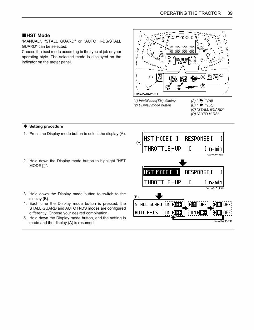
39OPERATING THE TRACTOR
BHST Mode"MANUAL", "STALL GUARD" or "AUTO H-DS/STALLGUARD" can be selected.Choose the best mode according to the type of job or youroperating style. The selected mode is displayed on theindicator on the meter panel.
(1) IntelliPanel(TM) display(2) Display mode button
(A) " " (Hi)(B) " " (Lo)(C) "STALL GUARD"(D) "AUTO H-DS"
C Setting procedure
1. Press the Display mode button to select the display (A).
2. Hold down the Display mode button to highlight "HSTMODE [ ]".
3. Hold down the Display mode button to switch to thedisplay (B).
4. Each time the Display mode button is pressed, theSTALL GUARD and AUTO H-DS modes are configureddifferently. Choose your desired combination.
5. Hold down the Display mode button, and the setting ismade and the display (A) is resumed.

OPERATING THE TRACTOR40
C STALL GUARD1. The "STALL GUARD" indicator lights up on the meter
panel, when:2. The tractor gets overloaded and the engine rpm drops,
the tractor automatically slows down in response tothe load, which prevents an engine stall.
3. Using PTO driven implements and the tractor is in"STALL GUARD" mode, the tractor speed willautomatically adjust with the loads on the engine.
C AUTO H-DS/STALL GUARD1. The "STALL GUARD" and "AUTO H-DS" indicators
light up on the meter panel, when:2. Setting the H-DS lever to the "UP" (Hi) position. Make
sure the " " (Hi) lamp lights up on the meter panel.3. Using PTO driven implements and the tractor is in
"STALL GUARD" mode, the tractor speed willautomatically adjust with the loads on the engine.
4. The tractor gets overloaded and the engine rpm drops,the tractor automatically slows down to the (Lo) lowspeed range.In this case, the " " (Hi) lamp goes out and the " "(Lo) lamp lights up instead.
5. The engine rpm has come up again, the tractorautomatically speeds up from the (Lo) low speedrange to the (Hi) high speed range. (The tractor speedincreases to match the speed control pedal.) If the loadis rather heavy and the engine rpm drops further,"STALL GUARD" will still prevent engine stall.
A When the H-DS lever is set at the "Lo" position, the"AUTO H-DS" system does not work. (If the " " (Lo)lamp stays on and the "AUTO H-DS" lamp is flashing,set the H-DS lever to the "Hi" position.)
A Even in the "AUTO H-DS/STALL GUARD" mode, theHi-Lo speed change can be made with this lever.Return the lever to the "Hi" position when there is nomore need to slow down.
A When "STALL GUARD" is on and the PTO is engaged,"STALL GUARD" switches to "STALL GUARD PLUS"mode."STALL GUARD PLUS" maintains engine speed at ahigher rate.
C MANUALWhen the "STALL GUARD" and "AUTO H-DS" indicatorsgo out on the meter panel, the unit is in manual mode.In this mode, automatic control in response to the loaddoes not activate.

41OPERATING THE TRACTOR
BThrottle-Up SwitchThe Throttle-Up switch allows the operator to easy raiseengine speed temporarily, on demand, to increasehydraulic pump output. When this switch is hold down,front attachment can operate faster.The Throttle-Up engine speed can be set through theIntellpanel(TM) display (see setting procedure). Releasethe switch to return engine speed to the throttle leversetting.Although the Throttle-Up switch increases engine speed,the traveling speed of the tractor does not change.
(1) Throttle-Up switch(2) Loader / Remote control valve lever
C Setting procedure
1. Press the Display mode button to select the display (A).
2. Hold down the Display mode button to highlight "HSTMODE [ ]".
3. Press the Display mode button to highlight"THROTTLE-UP [ ] n/min".
4. Hold down the Display mode button to switch to thedisplay (B).
5. Press the Display mode button to move on to the nextliquid crystal cell (black) to achieve a desired enginerpm.
6. Hold down the Display mode button, and the setting ismade and the display (A) is resumed.

OPERATING THE TRACTOR42
BRange Gear Shift Lever (L-M-H)The range gear shift can only be shifted when the tractoris completely stopped and the speed control pedal is inthe neutral position.
IMPORTANT:To avoid transmission and shift linkage damage whenshifting:A Completely stop the tractor using the brake pedals.A Do not force the range gear shift lever.A If it is difficult to shift the lever into L, M, or H from
neutral position:On slopes be sure to set the parking brake beforestarting the procedure.(1) Slightly depress the speed control pedal to rotate
the gears inside of the transmission.(2) Release the speed control pedal to the neutral
position.(3) Wait for a moment and then shift the lever.
A The range gear shift number being selected appearson the display.
BFront Wheel Drive LeverThe front wheel drive lever can be used to shift between2WD and 4WD.
To avoid personal injury or death:A Do not engage the front wheel drive when
traveling at road speed.A When driving on icy, wet or loose surfaces,
make sure the tractor is correctly ballasted toavoid skidding and loss of steering control.Operate at reduced speed and engage frontwheel drive.
A An accident may occur if the tractor issuddenly braked, such as by heavy towedloads shifting forward or loss of control.
A The braking characteristics are differentbetween 2 and 4-wheel drive. Be aware of thedifference and use carefully.
1. Make sure the tractor has come to a complete stopbefore shifting the front wheel drive lever.
2. Shift the front wheel drive lever.A Shift the lever to "ON" to engage the front wheel
drive.A Shift the lever to "OFF" to disengage the front
wheel drive.
A If there are difficulties shifting the front wheel drivelever, turn the steering wheel around and then shift thelever.
(1) Range gear shift lever (L-M-H) (H) "HIGH"(M) "MIDDLE"(L) "LOW"(N) "NEUTRAL POSITION"
(1) Range gear shift number (H-M-L) N: "NEUTRAL"
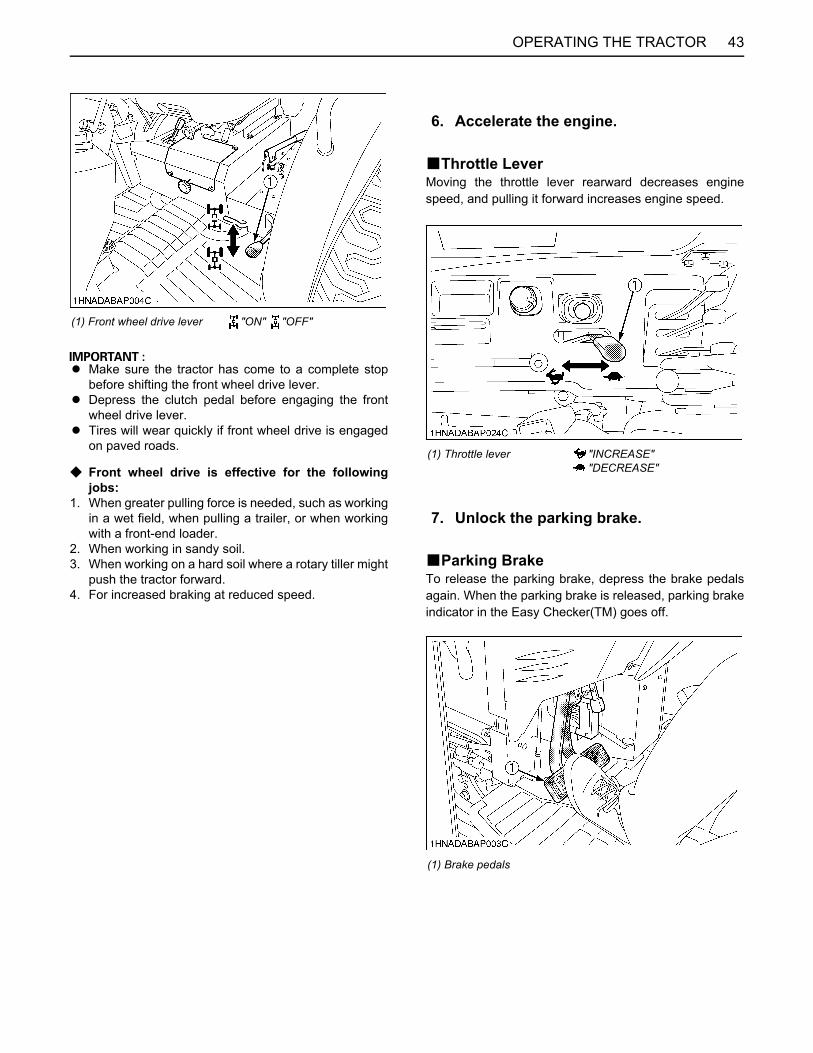
43OPERATING THE TRACTOR
A Make sure the tractor has come to a complete stopbefore shifting the front wheel drive lever.
A Depress the clutch pedal before engaging the frontwheel drive lever.
A Tires will wear quickly if front wheel drive is engagedon paved roads.
C Front wheel drive is effective for the followingjobs:
1. When greater pulling force is needed, such as workingin a wet field, when pulling a trailer, or when workingwith a front-end loader.
2. When working in sandy soil.3. When working on a hard soil where a rotary tiller might
push the tractor forward.4. For increased braking at reduced speed.
BThrottle LeverMoving the throttle lever rearward decreases enginespeed, and pulling it forward increases engine speed.
BParking BrakeTo release the parking brake, depress the brake pedalsagain. When the parking brake is released, parking brakeindicator in the Easy Checker(TM) goes off.
(1) Front wheel drive lever "ON" "OFF"
6. Accelerate the engine.
(1) Throttle lever "INCREASE""DECREASE"
7. Unlock the parking brake.
(1) Brake pedals

OPERATING THE TRACTOR44
A If the rear parking brake indicator comes on, releasethe rear parking brake.
To release the rear parking brake, push the release buttonand push down the rear parking brake lever. BSpeed Control Pedal
To avoid personal injury or death:A Do not operate if tractor moves on level ground
with foot off of Speed Control Pedal.A Consult your local KUBOTA Dealer.
Forward PedalDepress the speed control pedal with the toe of your rightfoot to move forward.Reverse PedalDepress the speed control pedal with the heel or toe ofyour right foot to move backward.
A To prevent serious damage to the HST, do not adjustthe stopper bolts.
A When you stand up from the seat with the speedcontrol pedal stepped, the engine will stop regardlessof whether the tractor is moving or not. This is becausethe tractor is equipped with Operator Presence Controlsystem (OPC).
A The buzzer sounds when moving backward.
(1) Rear parking brake indicator
(1) Rear parking brake lever
8. Depress the Speed Control Pedal.
(1) Speed control Pedal(2) Stopper bolt
(A) "FORWARD"(B) "REVERSE"

45OPERATING THE TRACTOR
BATA (Auto Throttle Advance) SwitchWhen this switch is pushed, ATA indicator will come on,and the tractor speed and the engine rpm can becontrolled with the speed control pedal. It assists whenpulling a trailer or the like more easily.Before pushing this switch, be sure to return the speedcontrol pedal to "NEUTRAL" position.Press the switch again to disable the ATA function. TheATA indicator will turn off.
BCrawl Control LeverThis lever enables the tractor to move at the "CREEP"speed.
If the following messages appear in the display, follow theappearing instructions.
STOPPINGBStopping1. Slow down the engine.2. Step on the brake pedal.3. After the tractor has stopped, disengage the PTO,
lower the implement to the ground, shift thetransmission to neutral, release the clutch pedal, andset the parking brake.
(1) ATA switch(2) Speed control pedal(3) ATA indicator
(1) Crawl control lever(2) Safety switch
(A) "FORWARD"(B) "REVERSE"
(1) Display
First: Safety SwitchSecond: Crawl Control Lever

OPERATING THE TRACTOR46
INTELLIPANEL(TM)BChanging Display Mode1. Pressing the Display mode button cycles the
IntelliPanel(TM) through 6 different display.2. When the key switch is set to "ON", the
IntelliPanel(TM) will return to the last display modeused.
(1) IntelliPanel(TM) display(2) Display mode button
Display 1:Hour meter / Trip meter mode
A [HOUR meter] Total operating hours are displayed.
A [TRIP meter] Total operating hours, counted from the previousresetting, is displayed.
A The hour meter indicates in 6 digits the hours the tractorhas been used; the last digit indicates 1/10 of an hour.
Refer-encepage
47
Display 2:Fuel consumption mode
A Average fuel consumption is measured per hour from theprevious resetting.
A Total fuel consumption is measured from the previousresetting.
A Hold down the Display mode button, and the setting isreset to "0".
---
Display 3:PTO speed mode
A The PTO speed is displayed when the PTO clutch controlswitch is in "ON" position.
A When the PTO clutch control switch is in "OFF" position,"OFF" is displayed.
70
Display 4:HST mode
A The HST mode, Response and Throttle-UP settings getdisplayed. 37
3941
Display 5:PM buildup mode
A Displays the PM buildup inside the DPF muffler.A Regeneration is needed when the 100% level has been
reached.A The more the bar is extended to the right, the more PM
builds up.
16
Display 6:Service inspect mode
A The time elapsed since the previous engine oil changegets displayed. 48
49102
A In cold weather the LCD meter response will normally be slower and the visibility be less, than in warmer weather.

47OPERATING THE TRACTOR
BResetting the Trip Meter and Setting the Clock
C Trip meter resetting procedure1. Press the Display mode button to select the display
(A).
2. Hold down the Display mode button to switch to thedisplay (B).
3. Press the Display mode button to highlight "Clear".
4. Hold down the Display mode button, the display (A)is resumed and the trip meter reads "0.0".
C Clock setting/displaying procedure1. Press the Display mode button to select the display
(A).
2. Hold down the Display mode button to switch to thedisplay (B).
3. Press the Display mode button to highlight "Set"
4. Hold down the Display mode button to switch to thedisplay (C).
5. Press the Display mode button to select "Adjust".

OPERATING THE TRACTOR48
BSERVICE INSPECT mode displaying/resetting procedure
6. Hold down the Display mode button to highlight the"hour" digits of the clock. Press the Display modebutton to enter a specified "hour".Hold down the Display mode button to highlight the"minute" digits of the clock.Press the Display mode button to enter a specified"minute". Hold down the Display mode button, andthe display (C) is resumed.
7. Press the Display mode button to select "Display".Hold down the Display mode button to highlight the"ON" indication.Each time the Display mode button is pressed, the"ON" and "OFF" indications are alternately switched.With "OFF" selected, the clock display disappearsfrom the IntelliPanel(TM).
8. Hold down the Display mode button to get back tothe display (C).Press the Display mode button to highlight "back"and hold down the Display mode button to get backto the display (B).Press the Display mode button to highlight "back"and hold down the Display mode button to get backto the display (A).
1. Press the Display mode button to select the display(A).
2. Hold down the Display mode button to switch to thedisplay (B).
3. Pressing the Display mode button cycles through thelist of maintenance items selected.Maintenance items that have reached theirmaintenance intervals are also highlighted.
A When using biodiesel, be sure to check themaintenance requirements of biodiesel fuel as theintervals will change for some of the items.

49OPERATING THE TRACTOR
CHECK DURING DRIVINGBIntelliPanel(TM) MessageIf any of the following messages appear during operation,immediately stop the machine and follow the message'sinstructions. If the cause of trouble has not beenpinpointed, consult your local KUBOTA Dealer.
C Engine over heatIf the engine gets overheated, the following messageappears.
1. Stop operation and set the engine to the idling speed.2. When the coolant temperature has dropped, the
following message appears instead.
3. Stop the engine, wait for 30 minutes until the machinecools down, and check the following points.(1) Check the reserve tank and radiator for cooling
water shortage or leak.(2) Check the insect screening and radiator for chaff
and dust deposits.(3) Check the fan belt for slack.
A If steam gushes out of the reserve tank's overflowpipe, take the measure discussed above.
C SERVICE INSPECT1. The service inspect indicator shows up when the time
for an engine oil change has come. Change the engineoil with fresh one.(See "Changing Engine Oil" in "EVERY 400 HOURS"in "PERIODIC SERVICE" section.)
2. After an engine oil change, reset the engine oil hourdisplay to zero on the Maintenance Log screen inservice inspect mode. The service inspect indicatorgoes out.(See "SERVICE INSPECT mode displaying/resettingprocedure" in "INTELLIPANEL(TM)" in "OPERATINGTHE TRACTOR" section.)
BImmediately Stop the Engine if:A The engine suddenly slows down or accelerates.A Unusual noises are suddenly heard.A Exhaust fumes suddenly become very dark.
4. With such item selected, hold down the Displaymode button, and the hours are reset to zero.
5. Press the Display mode button to highlight "back"and hold down the Display mode button to get backto the display (A).
(1) Service inspect indicator

OPERATING THE TRACTOR50
BEasy Checker(TM)If the indicators in the Easy Checker(TM) come on duringoperation, immediately stop the engine, and find thecause as shown below.Never operate the tractor while Easy Checker(TM) lamp ison.
Engine oil pressureIf the oil pressure in the engine goes below theprescribed level, the warning lamp in the EasyChecker(TM) will come on.If this should happen during operation, and it does notgo off when the engine is accelerated to more than1000 rpm, check level of engine oil.(See "Checking Engine Oil Level" in "DAILY CHECK"in "PERIODIC SERVICE" section.)
Electrical chargeIf the alternator is not charging the battery, the EasyChecker(TM) will come on.If this should happen during operation, check theelectrical charging system or consult your localKUBOTA Dealer.
Fuel levelIf the fuel in the tank goes below the prescribed level,the warning lamp in the Easy Checker(TM) will comeon. (less than 12 L.)If this should happen during operation, refuel as soonas possible.(See "Checking and Refueling" in "DAILY CHECK" in"PERIODIC SERVICE" section.)
This indicator serves the following two functions. If theindicator lights up, pinpoint the cause and take aproper measure.
1. Error with the engine control systemIf during operation the water temperature gauge readsan acceptable level but the warning lamp in the EasyChecker(TM) comes on, stop the engine and get itrestarted. If the error happens again, consult your localKUBOTA Dealer.
A If the warning indicator lights up, the followingphenomena may appear depending on the engine'strouble spot.A The engine stops unexpectedly.A The engine fails to start or gets interrupted just
after start.A The engine output is not enough.A The engine output is enough, but the warning
indicator stays on.If the engine output is not enough, immediatelyinterrupt the operation and move the tractor to a safeplace and stop the engine.
2. Engine overheatIf the water temperature gauge reads an unusual leveland the warning lamp in the Easy Checker(TM) comeson, the engine may have got overheated. Check thetractor by referring to "TROUBLESHOOTING" section.
Water separatorIf water or impurities collect in the water separator, theindicator in the Easy Checker(TM) will light up.If this should happen during operation, drain the waterfrom the water separator as soon as possible.(See "Checking Water Separator" in "DAILY CHECK"in "PERIODIC SERVICE" section.)
Emission indicatorIf this indicator lights up, take the steps to lower thewater temperature. This helps keep the emissionclean.
Master system warningIf trouble should occur at the engine, transmission orother control parts, the indicator flashes as a warning.If the trouble is not corrected by restarting the tractor,consult your local KUBOTA Dealer.
(1) Easy checker(TM)

51OPERATING THE TRACTOR
BFuel GaugeA needle indicates the amount of fuel left regardless of thekey position.Be careful not to empty the fuel tank. Otherwise air mayenter the fuel system.Should this happen, the system should be bled. (See"Bleeding Fuel System" in "SERVICE AS REQUIRED" in"PERIODIC SERVICE" section.)
A When the fuel has got shorter than 12 L (3.1 U.S.gals.)or so, the Fuel level indicator and the messageappears on the IntelliPanel(TM).If this should happen during operation, refuel as soonas possible. (See "Checking and Refueling" in "DAILYCHECK" in "PERIODIC SERVICE" section.)
BCoolant Temperature Gauge
To avoid personal injury or death:A Do not remove radiator cap until coolant
temperature is well below its boiling point.Then loosen cap slightly to the stop to relieveany pressure before removing cap completely.
1. With the key switch at "ON", this gauge indicates thetemperature of the coolant. "C" for "cold" and "H" for"hot".
2. If the indicator reaches the red zone position, enginecoolant is overheated. Check the tractor by referring to"TROUBLESHOOTING" section.
C Precaution at OverheatingTake the following actions in the event the coolanttemperature is nearly or more than the boiling point, whatis called "Overheating"1. Park the tractor in a safe place and keep the engine
unloaded idling.2. Don't stop the engine suddenly, but stop it after about
5 minutes of unloaded idling.3. Keep yourself well away from the machine for further
10 minutes or while the steam blows out.4. Check that there are no dangers such as burns. Get rid
of the causes of overheating according to the manual,see "TROUBLESHOOTING" section, and then, startagain the engine.
(1) Fuel gauge (A) "FULL"(B) "EMPTY"
(1) Coolant temperature gauge (A) "RED ZONE"

OPERATING THE TRACTOR52
BTachometerThe tachometer indicates the engine speed.
PARKINGBParking
To avoid personal injury or death:BEFORE DISMOUNTING TRACTORA ALWAYS SET PARKING BRAKE AND LOWER
ALL IMPLEMENTS TO THE GROUND.Leaving transmission in gear with the enginestopped will not prevent tractor with HSTtransmission from rolling.
A STOP THE ENGINE AND REMOVE THE KEY.
1. When parking, be sure to set the parking brake.To set the parking brake;(1) Interlock the brake pedals.(2) Depress the brake pedals.(3) Latch the brake pedals with the parking brake
lever.
A To prevent damage to the parking brake lever, makesure that brake pedals are fully depressed beforepulling the parking brake lever up.
2. Before getting off the tractor, disengage the PTO,lower all implements to the ground, place all controllevers in their neutral positions, set the parking brake,stop the engine and remove the key.
3. If it is necessary to park on an incline, be sure to chockthe wheels to prevent accidental rolling of themachine.
OPERATING TECHNIQUESBDifferential Lock
To avoid personal injury or death due to loss ofsteering control:A Do not operate the tractor at high speed with
differential lock engaged.A Do not attempt to turn with the differential lock
engaged.A Be sure to release the differential lock before
making a turn in field conditions.
If one of the rear wheels should slip, step on thedifferential lock pedal. Both wheels will turn together, thenreduce slippage.Differential lock is engaged only while the pedal isdepressed.
A When using the differential lock, always slow theengine down.
A To prevent damage to power train, do not engagedifferential lock when one wheel is spinning and theother is completely stopped.
A If the differential lock cannot be released, step lightlyon the brake pedals alternately.
(1) Engine revolution
(1) Parking brake lever (A) Interlock the brake pedals(B) "DEPRESS"(C) "PULL"
(1) Differential lock pedal (A) Press to "ENGAGE"(B) Release to "DISENGAGE"

53OPERATING THE TRACTOR
BOperating the Tractor on a Road
To avoid personal injury or death:A To help assure straight line stops when driving
at transport speeds, lock the brake pedalstogether. Uneven braking at road speeds couldcause the tractor to roll-over.
A When traveling on road with 3-point hitchmounted implement attached, be sure to havesufficient front weight on the tractor tomaintain steering ability.
Be sure SMV emblem and warning lamps are clean andvisible. If towed or rear-mounted equipment obstructsthese safety devices, install SMV emblem and warninglamps on equipment.Consult your local KUBOTA Dealer for further details.
BOperating on Slopes and Rough Terrain
To avoid personal injury or death:A Always back up when going up a steep slope.
Driving forward could cause the tractor to tipover backward. Stay off hills and slopes toosteep for safe operation.
A Avoid changing gears when climbing ordescending a slope.
A If operating on a slope, never disengage theclutch or shift levers to neutral. Doing so couldcause loss of control.
A Do not drive the tractor close to the edges ofditches or banks which may collapse under theweight of the tractor. Especially when theground is loose or wet.
1. Be sure wheel tread is adjusted to provide maximumstability.(See "Treads" in "TIRES, WHEELS AND BALLAST"section)
2. Slow down for slopes, rough ground, or sharp turns,especially when transporting heavy, rear mountedequipment.
3. Before descending a slope, shift to a gear low enoughto control speed without using brakes.
(1) SMV emblem(2) Bracket

OPERATING THE TRACTOR54
BTransport the Tractor Safely
To avoid personal injury or death:A When transporting, the tractor must be carried
on a truck. Pay attention to the points belowwhen transporting the tractor.
A Make sure the ramps used for loading are ofsufficient capacity and securely connected tosafely support the tractor throughout theloading/unloading process.
A Stop the engine, lower all implements, applythe parking brake and place chocks against thefront and rear tires.
A Secure the portions of the tractor which areshown in the figures below by using adequatestraps or chains.
A Adequate straps or chains should take intoaccount the weight of the unit, anticipatedloads or forces, required factors of safety andany other pertinent information.
A Always comply with Federal and/or Localregulations for securement and transport.
BInstructions for towing the tractorFollow the instruction below when towing the tractor:Otherwise, the tractor’s powertrain may get damaged.A Set the all shift levers to "NEUTRAL" position.A If possible, start engine and select 2WD, if creep
speed is fitted ensure that it is disengaged.A Tow the tractor using its front hitch or drawbar.A Never tow faster than "10 km/h (6.2 mph)".
BDirections for Use of Power Steering1. Power steering is activated only while the engine is
running. Slow engine speeds make the steering a littleheavier. While the engine is stopped, the tractorfunctions in the same manner as tractors withoutpower steering.
2. When the steering wheel is turned all the way to thestop, the relief valve is activated. Do not hold thesteering wheel in this position for a long period of time.
3. Avoid turning the steering wheel while the tractor isstopped, or tires may wear out sooner.
4. The power steering mechanism makes the steeringeasier. Be careful when driving on a road at highspeeds.
(1) Front guard(2) Heavy-duty strap
(1) Backhoe main frame(2) Heavy-duty strap

55OPERATING THE TRACTOR
REVERSING THE SEAT
The seat is reversible for backhoe operation. Follow theprocedure below to turn the seat around.1. Unlock the seat lock lever.
2. Turn the seat to counterclockwise for backhoeoperation.The seat is automatically locked at the backhoeposition.
A When rotating seat, do not hit any controls or levers.
3. For tractor driving position, unlock the seat lock leverand turn the seat clockwise.
A See "Operator's Seat" in "STARTING" when usingseat in driving position.
A To prevent damage to the lock lever or to release theseat lock properly, do not attempt to pull up the locklever with extreme force while sitting on the seat. Firstlift yourself from the seat, and then pull up the locklever.
(A) "TRACTOR DRIVING POSITION"(B) "BACKHOE POSITION"
(1) Seat lock lever (A) "UNLOCK"

56 OPERATING THE LOADER
OPERATING THE LOADER
CONTROL LEVERA When the lever is at each corner position marked byasterisk (*), boom and bucket cylinders work at thesame time. However, the blank position (Raise & Rollback) is not recommended for scooping because ofinsufficient lift force.
To begin a test operation, slightly move the control leverfrom the "N" position. Slowly raise the loader boom justenough for the bucket to clear the ground when fullydumped. Slowly work through the dump and roll backcycles.
A If the boom or bucket does not work in the directionsindicated on the label, lower the bucket to the ground,stop the engine, and relieve all hydraulic pressure.Recheck and correct all hydraulic connections.
OPERATING THE LOADERThe loader should be operated with the tractor enginespeed depending on the application and the operator'slevel of experience. Excessive speeds are dangerous,and may cause bucket spillage and unnecessary strain onthe tractor and loader.When operating in temperatures below -1 (30 ), runthe tractor engine below 1200 rpm until the oiltemperature exceeds -1 (30 ).The following text and illustrations offer suggested loaderand tractor operating techniques.
FILLING THE BUCKETApproach and enter the pile with a level bucket.
Ease control lever toward you and then left to rollback andlift the bucket.
The rollback and lifting of the bucket will increaseefficiency because a level bucket throughout the liftingcycle resists bucket lift and increases breakaway effort.

57OPERATING THE LOADER
A Do not be concerned if the bucket is not completelyfilled during each pass. Maximum productivity isdetermined by the amount of material loaded in agiven period of time. Time is lost if 2 or more attemptsare made to fill the bucket on each pass.
LIFTING THE LOADWhen lifting the load, keep the bucket positioned to avoidspillage.
To avoid personal injury or death:A Do not attempt to lift bucket loads in excess of
the loader capacity.A Before raising the bucket to full height, make
sure the tractor is on level ground. If not, it maytip over, even if the tractor is not moving.
CARRYING THE LOADPosition the bucket just below the level of the tractor hoodfor maximum stability and visibility, whether the bucket isloaded or empty.
Use extreme care when operating the loader on a slope.Keep the bucket as low as possible. This keeps the bucketand tractor center of gravity low and will provide maximumtractor stability.
To avoid personal injury or death:A Be extra careful when working on inclines.A When operating on a slope, always operate up
and down the slope, never across the slope.
When transporting a load, keep the bucket as low aspossible to avoid tipping, in case a wheel drops in a rut.

OPERATING THE LOADER58
DUMPING THE BUCKETLift the bucket just high enough to clear the side of thevehicle. Move the tractor in as close to the side of thevehicle as possible, then dump the bucket.
LOWERING THE BUCKETAfter the bucket is dumped, back away from the vehiclewhile lowering and rolling back the bucket.
OPERATING WITH FLOAT CONTROLDuring operation on hard surfaces, keep the bucket leveland put the lift control in the float position to permit thebucket to float on the working surface.If hydraulic down pressure is exerted on the bucket it willwear faster than normal.
The float position will also avoid mixing of surface materialwith stockpile material. The float position will reduce thechance of surface gouging while removing snow or othermaterial, or when working with a blade.
LOADING FROM A BANKChoose a forward gear that provides a safe ground speedand power for loading.
To avoid personal injury or death:A Be extra careful when working on inclines.A When operating on a slope, always operate up
and down the slope, never across the slope.
A Loader lift and break-away capacity diminish asloading height is increased.
Side cutting is a good technique for cutting down a bigpile. Wheel width should not exceed the bucket width forthis procedure.

59OPERATING THE LOADER
If the pile sides are too high and liable to cause cave-in,use the loader to break down the sides until a slot can becut over the top.
Another method for large dirt piles is to build a ramp toapproach the pile.
It is important to keep the bucket level when approachinga bank or pile. This will help avoid gouging the work area.
PEELING AND SCRAPINGUse a slight bucket down angle, travel forward, and holdthe lift control forward to start the cut. Make a short cutand break-out cleanly.
With the bucket level, start a cut at the notchapproximately 2 in. deep. Hold the depth by feathering thebucket control to adjust the cutting edge up or down.When the front tires enter the notch, adjust the boomcylinder to maintain proper depth.
Make additional passes until the desired depth is reached.During each pass, use only the bucket control while atworking depth. This will allow you to concentrate oncontrolling the bucket angle to maintain a precise cut.
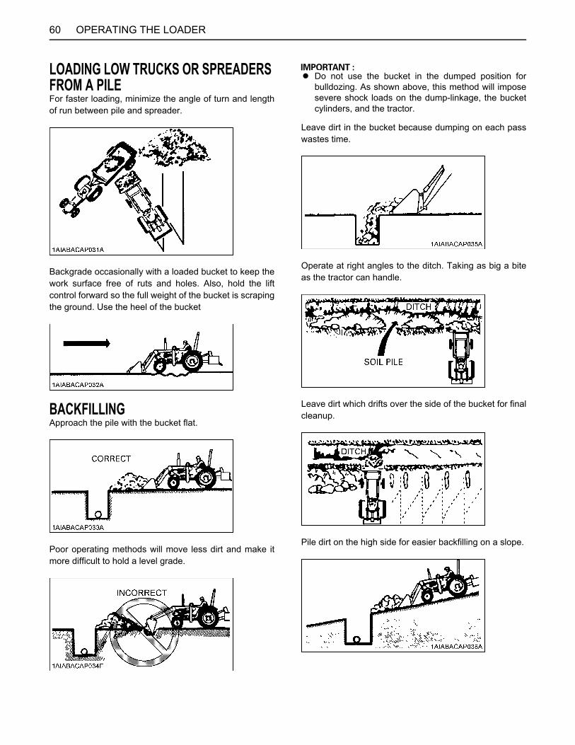
OPERATING THE LOADER60
LOADING LOW TRUCKS OR SPREADERS FROM A PILEFor faster loading, minimize the angle of turn and lengthof run between pile and spreader.
Backgrade occasionally with a loaded bucket to keep thework surface free of ruts and holes. Also, hold the liftcontrol forward so the full weight of the bucket is scrapingthe ground. Use the heel of the bucket
BACKFILLINGApproach the pile with the bucket flat.
Poor operating methods will move less dirt and make itmore difficult to hold a level grade.
A Do not use the bucket in the dumped position forbulldozing. As shown above, this method will imposesevere shock loads on the dump-linkage, the bucketcylinders, and the tractor.
Leave dirt in the bucket because dumping on each passwastes time.
Operate at right angles to the ditch. Taking as big a biteas the tractor can handle.
Leave dirt which drifts over the side of the bucket for finalcleanup.
Pile dirt on the high side for easier backfilling on a slope.

61OPERATING THE LOADER
HANDLING LARGE HEAVY OBJECTS
To avoid personal injury or death:A Handling large, heavy objects can be
dangerous due to:(A)Danger of rolling the tractor over.(B)Danger of upending the tractor.(C)Danger of the object rolling or sliding downthe loader boom onto the operator.
A If you must perform the above work, protectyourself by:(A)Not lifting the load higher than necessary toclear the ground when moving.(B)Adding rear ballast to the tractor tocompensate for the load.(C)Not lifting large objects with equipment thatdoes not have an anti-rollback device.(D)Moving slowly and carefully.(E)Avoiding rough terrain.(F)Keeping transport distance as short aspossible and carry the load as low as possibleduring transport.(G)Confirm loader/bucket are at proper heightand have stopped moving before transport.
VALVE LOCK
To avoid personal injury or death from crushing:A Do not utilize the valve lock for machine
maintenance or repair.A The valve lock is to prevent accidental
actuation when implement is not in use orduring transport.
The control valve is equipped with a valve lock feature.The control valve is locked in the neutral position.The lock is not intended and will not prevent a leak downof the implement during the period of storage.
BOOM LOCK
To avoid personal injury or death:A Before setting the boom lock
-empty the loader bucket and place in dumpposition,-park on a firm, flat and level surface,-set the parking brake,-stop the engine and remove the key,-set the valve lock.
The boom lock is used to prevent the loader lift arms fromfalling when servicing the machine, set as follows.1. Empty the loader bucket and place in dump position.2. Raise the boom until the boom lock can be positioned
on cylinder.3. Stop the engine and remove the key.4. Pull the lock pin and the boom lock onto the cylinder
rod.5. Insert the lock pin into the hole of lower right corner of
the boom lock.6. Slowly lower the boom is stopped and set the valve
lock lever is lock position.
(1) Lock lever (A) "LOCK"(B) "UNLOCK"

OPERATING THE LOADER62
BUCKET LEVEL INDICATORDepending on the front attachment, loosen the indicatorrod lock bolt and readjust the indicator rod length.
SELF LEVELING
To avoid personal injury or death:A Always be aware of the loader attachment
angle. Self-leveling function may varydepending on the loader lever stroke.
A Self-leveling feature is primarily designed for palletfork application. Therefore, variance may occur withother loader attachments.
A Recommended folk: K9058 42" Pallet ForkA Recommended engine revolution: above 1200 rpmA Warm up the tractor according to its instructions
before moving the loader in cold regions. This isneeded to prevent a valve malfunction.
In the self leveling modeA Boom lowering speed will be slower.A Boom cannot be lowered in the maximum roll back
position.A Boom cannot be raised in the maximum dump
position.
How to use Self LevelingUse the lever located on the loader control tower to selectthe self leveling mode.
(1) Boom lock(2) Lock pin
(1) Bolt(2) Indicator rod(3) Guide, Indicator rod
(1) Lever of self leveling select(2) Label of self leveling select
(A) Self leveling "ON"(B) Self leveling "OFF"

63OPERATING THE LOADER
Recommendations1. Self Leveling is "ON".
a) For pallet fork operationThe pallet fork can be raised up and loweredhorizontally.
b) For bucket operationThe bucket position can be controlled like Spill Guard.
2. Self Leveling is "OFF".Motion is same as the regular loader.a) For pallet fork operation
b) For bucket operation

OPERATING THE LOADER64
How to adjust Self Leveling
A When checking, park the tractor on flat and hardground, set the range shift lever in neutral, applyparking brake, stay clear of operating area whilesetting self-leveling.
1. Raise Leveling Adjustment1) Set the jig on the right side of the loader pallet forkas shown in the illustration.
2) Start the engine and set at 2000rpm.3) Set the pallet fork flat on the ground.
A When the pendulum indicates the vertical line of the jig(marked "V"), the pallet fork is flat.
4) Raise the boom to the maximum height.
5) If the pallet fork angle is not within the angle shownin the illustration, readjust the self-leveling.
A When the pendulum indicates the white range of thejig, the pallet fork angle is proper.
6) If the pallet fork angle is not within the angle shownin the illustration, lower the boom and loosen the locknut then adjust by setscrew as follows.*Pallet fork forward tilt: Screw "IN"*Pallet fork back tilt: Screw "Out"(Typically 1/2 turn is a good increment of change)7) Tighten the lock nut
(1) Jig (Not included in this kit)
*Tightening torque: 5.4 to 7.8 N·m4.0 to 5.7 lbf·ft

65OPERATING THE LOADER
8) Repeat the procedures mentioned above (from 3 to 7) until the raise self-leveling adjustment iswithin specification.
A The torque for the lock nut is very important. If the nutis over tightened the adjusting screw may break.
2. Lower Leveling Adjustment
1) Set the boom in the maximum raised position andthe bucket (or pallet fork) flat.
A When the pendulum indicates the vertical line of the jig(marked "V"), the bucket (or pallet fork) is flat.
2) Lower the boom until the bucket (or pallet fork)slightly contact to the ground.3) If the bucket (or pallet fork) angle is not within theangle shown in the illustration, readjust the self-leveling.
A When the pendulum indicates the white range of thejig, the bucket (or pallet fork) angle is proper.
4) If the bucket (or pallet fork) angle is not within theangle shown in the illustration, loosen the lock nut thenadjust by setscrew as follows.*Pallet fork forward tilt: Screw "OUT"*Pallet fork back tilt: Screw "IN"(Typically 1/2 turn is a good increment of change)*The cap, lock nut and set screw for lower levelingadjustment is shown below.5) Tighten the lock nut.
6) Repeat the procedures mentioned above (from 1 to 5) until the lower self-leveling adjustment iswithin specification.
*Tightening torque: 5.4 to 7.8 N·m4.0 to 5.7 lbf·ft

OPERATING THE LOADER66
A The torque for the lock nut is very important. If the nutis over tightened the adjusting screw may break.
ATTACHING ATTACHMENTSThis 2-lever quick coupler is designed to be used withKUBOTA attachments. Non-KUBOTA attachments, ifused, must comply with ISO 24410, first edition 2005-04-15. This 2-lever quick coupler allows the operator tochange easily without the use of tools.
To avoid personal injury or death:A Use of a non-KUBOTA attachment that does
not comply with ISO24410 or the improperpositioning of handle(s) or non-protrusion ofpin(s) may result in detachment of theattachment or deformation, causing loss ofperformance, personal injury or death.
A Attachments should be located on a flat, firm surfacewhen attaching and detaching them from the 2-leverquick coupler.
1. To mount an attachment, pull the handles of the 2-lever quick coupler latching pins to the unlatchedposition. The 2-lever quick coupler handles must be allthe way up to ensure that the latching pins are fullyretracted.
2. Position the tractor squarely in front of the attachmentand tilt the 2-lever quick coupler forward with thebucket cylinders.
3. Ease the 2-lever quick coupler mounting plate into thesaddle of the attachment.
4. Roll the 2-lever quick coupler back using the bucketcylinders and raise the boom slightly. The back of theattachment should rest against the front of the 2-leverquick coupler mounting plate and the weight of theattachment should be supported by the loader.
(1) 2-lever quick coupler

67OPERATING THE LOADER
5. When the attachment is properly seated in the saddleand against the front of the 2-lever quick couplermounting plate, turn off the engine and set the parkingbrake. Push the 2-lever quick coupler handles to thefully latched position. Verify both latching pins arecompletely engaged in the base of the attachment.
To avoid personal injury or death:A The following engagement points are critical.
1) The lock pins of the 2-lever quick coupler have to protrude into and through the pin slots of the attachment on both sides. It is critical that the pins are in good condition and without visible signs of wear or damage and that the operator align the loader 2-lever quick coupler with the attachment to allow the pins to go through the pin slots.2) Both handles have to be pushed down until the handles contact the ear plates near the points where the pin bolt goes through the handle (A).3) Do not operate the tractor or attachment unless all of the above conditions are met.
6. Visually verify when pushing the 2-lever quick couplerhandles into locked position that the latch pins rotatecompletely and are located underneath the stop of the2-lever quick coupler.
(1) 2-lever quick coupler
(1) Handle
(1) Handle(2) Ear plate(3) Lock pin(4) Pin slot
(A) The handle contacts the ear plate at the points.

OPERATING THE LOADER68
7. When attaching different attachments visually inspectfor broken or damaged pins. If broken or damagedpins are found, replace before using. Use of brokenpins may result in attachment detachment ordeformation, causing loss of performance, personalinjury or death.
8. You are now ready to use the attached attachment. Allcompatible attachments attach and detach using thesame method.
To avoid personal injury, death or machinedamage:
A Never operate or transport attachments which arenot attached completely.
A Always replace damaged hardware immediately.
DETACHING ATTACHMENTS1. Detaching attachments is done in the reverse of
attaching attachments. The procedure is below.2. Lower the attachment to ground level with the
attachment slightly in the rolled back position. Stop theengine and set the parking brake.
3. Pull the 2-lever quick coupler handles to the unlatchedposition to release the latching pins.
4. While sitting in the tractor operator's seat, start theengine and slowly move the loader control lever to the"DUMP" position until the attachment is pushed awayslightly from the 2-lever quick coupler.
5. Lower the loader boom so that the 2-lever quickcoupler mounting plate clears the attachment saddle.
6. Back away from the attachment slowly.7. If an attachment is not going to be attached to the 2-
lever quick coupler immediately, push the handles ofthe 2-lever quick coupler to the locked position toprevent damage to the handle assembly.
BHydraulic 2-lever Quick Coupler Switch (if equipped)
The switch is used to attach and detach an attachment byactivating the hydraulic 2-lever quick coupler.After pressing the selector switch to the "ON" position,move the switch to the " " (LOCK) mark to get the 2-leverquick coupler locked. After pressing the selector switch tothe "ON" position, move it to the " " (UNLOCK) markedposition to unlock the 2-lever quick coupler and detach thebucket, for example. After cylinder is moved to lockedposition, always check to be sure both pins are engagedto the attachment.
(1) Latch pins(2) Stopper
(1) Hydraulic 2-lever quick coupler switch(2) Selector switch
(A) "UNLOCK" position(B) "LOCK" position(C) "ON" position

69PTO
PTO
PTO OPERATIONTo avoid personal injury or death:A Disengage PTO, stop engine, and allow all
rotating components to come to a completestop before connecting, disconnecting,adjusting, or cleaning any PTO drivenequipment.
BPTO Clutch Control Switch1. The tractor has a 540 rpm speed position and 6-spline
shaft.2. The PTO clutch control switch engages or disengages
the PTO clutch which gives the PTO independentcontrol.
Turn the switch to "ON" to engage the PTO clutch. Turnthe switch to "OFF" to disengage the PTO clutch.
C PTO Clutch Control Switch
To turn ONWhile pushing the switch, turn clockwise to the " "position and release your hand. (In the ON position,switch slightly rises itself.)
To Turn OFFTap on top of the switch, and the switch will return to theOFF position.
A To avoid shock loads to the PTO, reduce enginespeed when engaging the PTO, then open the throttleto the recommended speed.
A To avoid damage of PTO clutch and implement,proper warm up is strongly recommended in coldweather.Do not continuously turn the PTO clutch controlswitch.
(1) PTO clutch control switch "ON" "OFF"
(A) "PUSH"

PTO70
A Tractor engine will not start if the PTO clutch controlswitch is in the engaged "ON" position.
BStationary PTOTo park the tractor and use the PTO system (for chipperor pump, for example), start the PTO system in thefollowing steps.1. Apply the parking brakes and place blocks at the tires.2. Make sure the shift levers are at NEUTRAL, and start
the engine.3. Set the PTO clutch control switch to engage "ON".4. Set the engine speed to provide recommended rear
PTO speed.5. Unlock the seat lock lever.6. Turn the seat counterclockwise. (for backhoe
operation)7. Dismount the seat.
A If the PTO system is engaged and you stand up fromthe seat before you turn the seat counterclockwise, theengine stops automatically after standing up.
BIntelliPanel(TM) Message1. The PTO rpm can be checked in the display.
(See "INTELLIPANEL(TM)" in "OPERATING THETRACTOR" section.)
2. When the PTO system gets engaged (ON), theindicator lights up.
A Rear PTO "ON"
Engine Speedrpm Shaft PTO Speed
rpm
2700 6-Spline 540
(1) PTO clutch control switch(2) Seat lock lever
(A) "ON"(B) "UNLOCK"
(1) Display(2) PTO indicator

71PTO
BPTO shaft Cover and Shaft Cap
To avoid personal injury or death:A Keep the PTO shaft cover in place at all times.A Put back the PTO shaft cap when the PTO is not
in use.A When connecting or disconnecting the joint to
PTO shaft, raise up the PTO shaft cover.
A The universal joint of the PTO drive shaft is technicallylimited in its moving angle. Refer to the PTO DriveShaft Instructions for proper use.
(1) PTO shaft cover(2) PTO shaft cap
(A) "NORMAL POSITION"(B) "RAISED POSITION"

72 3-POINT HITCH & DRAWBAR
3-POINT HITCH & DRAWBAR
(1) Top link [if equipped](2) Lifting rod (Left) [if equipped](3) Check chains [if equipped](4) Lower link [if equipped](5) Lifting rod (Right) [if equipped](6) Drawbar [if equipped](7) Fixed drawbar frame [if equipped]

733-POINT HITCH & DRAWBAR
3-POINT HITCH (if equipped)
BSelecting Category[L47]L47 has category 1 only.
[M62]M62 has category 1 & 2.
This three-point hitch can be used for both category 1 and2 implements.
[Category 1 type]
[Category 2 type]
BSelecting the Top Link Mounting HolesSelect the proper set of holes by referring to the"Hydraulic Control Unit Use Reference Chart" in"HYDRAULIC UNIT" section.
BDrawbar (if equipped)Remove the drawbar if close mounted implement is beingattached.
A When installing the drawbar frame, be sure to removethe plate first.
1. Make preparations for attaching implement.
(1) Top link(2) Lower link(3) Top link rear pin(4) Lynch pin(5) Top link collar(6) Lower link collar(7) Top link rear pin assy
(A) 19.3 mm I.D.(B) 25.7 mm I.D.(C) Tractor side(D) Implement side
(1) Plate (Do not use)(2) Brake support(3) Transmission case(4) Drawbar(5) Drawbar frame
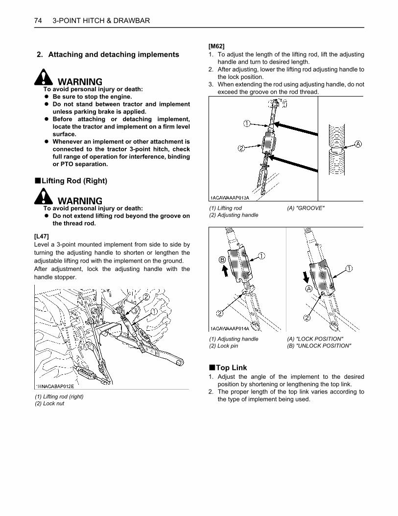
3-POINT HITCH & DRAWBAR74
To avoid personal injury or death:A Be sure to stop the engine.A Do not stand between tractor and implement
unless parking brake is applied.A Before attaching or detaching implement,
locate the tractor and implement on a firm levelsurface.
A Whenever an implement or other attachment isconnected to the tractor 3-point hitch, checkfull range of operation for interference, bindingor PTO separation.
BLifting Rod (Right)
To avoid personal injury or death:A Do not extend lifting rod beyond the groove on
the thread rod.
[L47]Level a 3-point mounted implement from side to side byturning the adjusting handle to shorten or lengthen theadjustable lifting rod with the implement on the ground.After adjustment, lock the adjusting handle with thehandle stopper.
[M62]1. To adjust the length of the lifting rod, lift the adjusting
handle and turn to desired length.2. After adjusting, lower the lifting rod adjusting handle to
the lock position.3. When extending the rod using adjusting handle, do not
exceed the groove on the rod thread.
BTop Link1. Adjust the angle of the implement to the desired
position by shortening or lengthening the top link.2. The proper length of the top link varies according to
the type of implement being used.
2. Attaching and detaching implements
(1) Lifting rod (right)(2) Lock nut
(1) Lifting rod(2) Adjusting handle
(A) "GROOVE"
(1) Adjusting handle(2) Lock pin
(A) "LOCK POSITION"(B) "UNLOCK POSITION"

753-POINT HITCH & DRAWBAR
BCheck ChainsRemove the snap pin and adjust the turnbuckle to controlhorizontal sway of the implement.After adjustment, re-set snap pin.
BLower Link HolderWhen operating the tractor without a 3-point hitchimplement, it is necessary to lock the lower links toprevent them from hitting the tractor rear wheels.
DRAWBAR (if equipped)
To avoid personal injury or death:A Never pull from the top link, the rear axle or any
point above the drawbar. Doing so could causethe tractor to tip over rearward causingpersonal injury or death.
BAdjusting Drawbar LengthWhen towing an implement, recommend use of (A) holesin drawbar.The drawbar load is referred to "IMPLEMENTLIMITATIONS" section.
(1) Turnbuckle(2) Snap pin
(1) PTO shaft(2) Drawbar(3) Drawbar pin
Holes: (A)

3-POINT HITCH & DRAWBAR76
REINSTALLING THE 3-POINT HITCHBLower Link[L47 and M62]
BTop Link and Lifting Rod[L47]
[M62]
(1) Lower link(2) Check chains(3) Pin(4) Bolt
(5) Clevis pin(6) Hair pin cotter(7) Plain washer
(1) Lifting rod (right)(2) Lifting rod (left)(3) Top link
(1) Lifting rod (right)(2) Lifting rod (left)(3) Top link

773-POINT HITCH & DRAWBAR
STORING THE 3-POINT HITCH (if equipped)The 3P storage holder is an option.[L47]
[M62]
When installing the backhoe, remove the 3-point hitch andstore it in the location indicated below.
BLower Link[L47]
[M62]
(1) 3P storage holder (1) Lower link(2) Check chains(3) Hair pin cotter(4) Clevis pin(5) 3P storage holder

3-POINT HITCH & DRAWBAR78
BTop Link and Lifting Rod[L47]
[M62]
C Top Link Pin[L47 and M62]
BInstalling the Lower Link[L47 and M62]
(1) Top link(2) Lifting rod (LH)
(3) Lifting rod (RH)(4) Lynch pin
(1) Top link pin(2) Lynch pin
(1) Lower link(2) Check chains(3) Pin(4) Bolt
(5) Clevis pin(6) Hair pin cotter(7) Plain washer

79HYDRAULIC UNIT
HYDRAULIC UNIT
A Do not operate until the engine is warmed up. Ifoperation is attempted when the engine is still cold, thehydraulic system may be damaged.
A If noises are heard when implement is lifting after thehydraulic control lever has been activated, thehydraulic mechanism is not adjusted properly. Unlesscorrected, the unit will be damaged. Contact yourKUBOTA Dealer for adjustment.
3-POINT HITCH CONTROL SYSTEM
To avoid personal injury or death:A Before using the 3-point hitch controls, ensure
that no person or object is in the area of theimplement or 3-point hitch. Do not stand on ornear the implement or between the implementand tractor when operating the 3-point hitchcontrols.
BPosition ControlThis will control the working depth of 3-point implementsregardless of the amount of pull required.
C Restricting PlateWhen installing the backhoe, lower the position controllever and place the lift arms in lowest position.Lock the position control lever in lowest position withrestricting plate.
(1) Position control lever (A) "UP"(B) "DOWN"(C) "FLOAT"
(1) Position control lever(2) Restricting plate(3) Lift arm
(A) "DOWN"
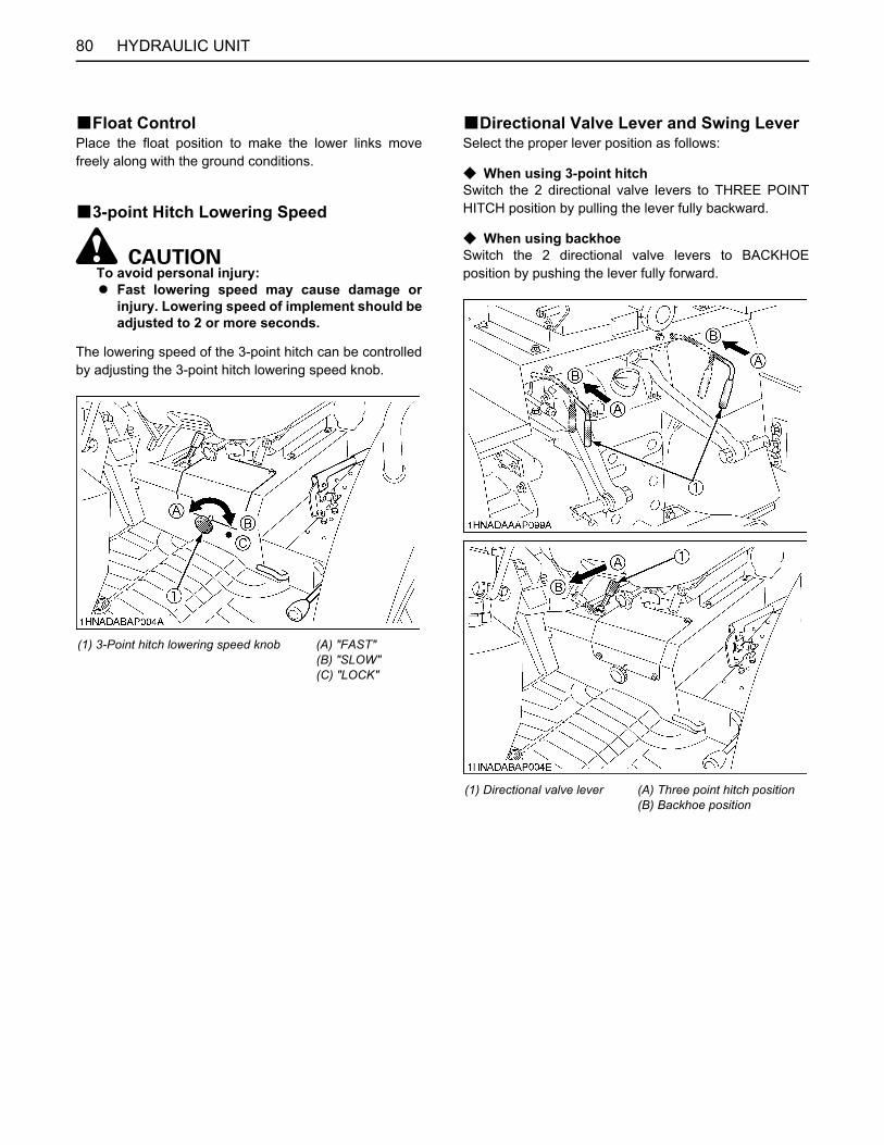
HYDRAULIC UNIT80
BFloat ControlPlace the float position to make the lower links movefreely along with the ground conditions.
B3-point Hitch Lowering Speed
To avoid personal injury:A Fast lowering speed may cause damage or
injury. Lowering speed of implement should beadjusted to 2 or more seconds.
The lowering speed of the 3-point hitch can be controlledby adjusting the 3-point hitch lowering speed knob.
BDirectional Valve Lever and Swing LeverSelect the proper lever position as follows:
C When using 3-point hitchSwitch the 2 directional valve levers to THREE POINTHITCH position by pulling the lever fully backward.
C When using backhoeSwitch the 2 directional valve levers to BACKHOEposition by pushing the lever fully forward.
(1) 3-Point hitch lowering speed knob (A) "FAST"(B) "SLOW"(C) "LOCK"
(1) Directional valve lever (A) Three point hitch position(B) Backhoe position

81HYDRAULIC UNIT
A After dismounting the backhoe, set the directionalvalve levers in "THREE-POINT HITCH POSITION(A)". If not, the tractor will not start.
A Do not forget to change the 2 directional valve levers,otherwise the hydraulic system may be damaged.
A When the hydraulic couplers at the right of the tractorare utilized as a hydraulic outlet, swing lever isswitched to "with backhoe" position.
REAR REMOTE HYDRAULIC CONTROL SYSTEM (if equipped)BRemote Control Valve Coupler
Connecting and Disconnecting
To avoid personal injury or deathA Stop the engine and relieve pressure before
connecting or disconnecting lines.A Do not use your hand to check for leaks.
C Connecting1. Clean both couplers.2. Remove dust plugs.3. Insert the implement coupler to the tractor hydraulic
coupler.4. Pull the implement coupler slightly to make sure
couplers are firmly connected.
C Disconnecting1. Lower the implement first to the ground to release
hydraulic pressure in the hoses.2. Clean the couplers.3. Relieve pressure by moving hydraulic control levers
with engine shut off. Pull the hose straight from thehydraulic coupler to release it.
4. Clean oil and dust from the coupler, then replace thedust plugs.
A Your local KUBOTA Dealer can supply parts to adaptcouplers to hydraulic hoses.
BRemote Control Valve LeverMove the lever up or down and hold. This will raise orlower the implement. Lever will return to neutral whenreleased.
A Do not hold the lever in the "pull" or "push" positiononce the remote cylinder has reached the end of thestroke, as this will cause oil to flow through the reliefvalve. Forcing oil through the relief valve for extendedperiods will overheat the oil.
A When using the tractor hydraulic system to power frontloader, do not operate boom and bucket cylinderssimultaneously.
(A) Lock(B) Unlock
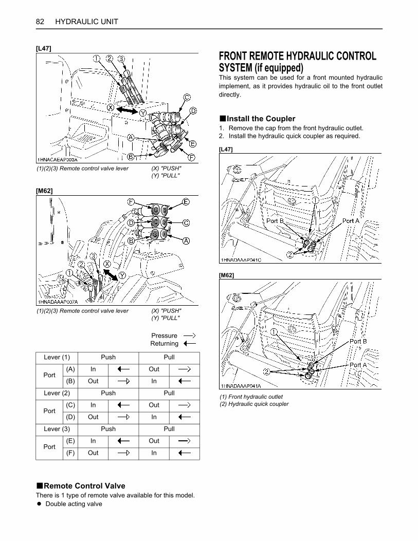
HYDRAULIC UNIT82
[L47]
[M62]
BRemote Control ValveThere is 1 type of remote valve available for this model.A Double acting valve
FRONT REMOTE HYDRAULIC CONTROL SYSTEM (if equipped)This system can be used for a front mounted hydraulicimplement, as it provides hydraulic oil to the front outletdirectly.
BInstall the Coupler1. Remove the cap from the front hydraulic outlet.2. Install the hydraulic quick coupler as required.
[L47]
[M62]
(1)(2)(3) Remote control valve lever (X) "PUSH"(Y) "PULL"
(1)(2)(3) Remote control valve lever (X) "PUSH"(Y) "PULL"
Pressure Returning
Lever (1) Push Pull
Port(A) In Out
(B) Out In
Lever (2) Push Pull
Port(C) In Out
(D) Out In
Lever (3) Push Pull
Port(E) In Out
(F) Out In
(1) Front hydraulic outlet(2) Hydraulic quick coupler

83HYDRAULIC UNIT
BControl Switch1. Front hydraulic valve main switch
Push the front hydraulic valve main switch (1) toengage the front hydraulic valve.A light on the switch will illuminate to indicate that thefront hydraulic valve is on, and to enable the activationswitch (2).
2. Activation switch(1) When pressing the "A" button, hydraulic oil will
come out of the port A and return through the portB as long as the switch is pressed.
(2) When pressing the "B" button hydraulic oil willcome out of the port B and return through the portA as long as the switch is pressed.
3. Push the front hydraulic valve main switch again todisengage the front hydraulic valve, and the light of thefront hydraulic valve main switch will turn off.
To avoid personal injury or death:A Valve lock does not lock out switch operated
third-function hydraulics, which are activewhen the key switch and the front hydraulicvalve main switch are ON.
BRemote Control Coupler Connecting and Disconnecting
To avoid personal injury or death:A Stop the engine and relieve pressure before
connecting or disconnecting lines.A Do not use your hand to check for leaks.
C Relieve Hydraulic Pressure1. Move the key switch to the "RUN" position.
A Don't start the engine.
2. Push the front hydraulic valve main switch "ON".3. Press the activation switch A and B several times.4. Push the front hydraulic valve main switch "OFF".5. Turn the key switch to the "OFF" position.
C Connecting1. Clean both couplers.2. Remove dust plugs.3. Insert the implement coupler to the tractor hydraulic
coupler.4. Pull the implement coupler slightly to make sure
couplers are firmly connected.
C Disconnecting1. Lower the implement first to the ground to release
hydraulic pressure in the hoses.2. Clean the couplers.3. Relieve hydraulic pressure.
Pull the hose straight from the hydraulic coupler torelease it.
4. Clean oil and dust from the coupler, and then replacethe dust plugs.
A Your local KUBOTA Dealer can supply parts to adaptcouplers to hydraulic hoses.
(1) Front hydraulic valve main switch(2) Activation switch
(C) Front hydraulic valve main switch "OFF"(D) Front hydraulic valve main switch "ON"

HYDRAULIC UNIT84
BMULTI-COUPLER SYSTEM (if equipped)This system is designed to easily connect and disconnectthe 2 hydraulic hoses simultaneously without oil leakwhen attaching and detaching the loader.
B How to use 2P-Multi-CouplerC Connecting1. Open the dust cover of the fixed part.2. Push the safety lock button and rotate the lever until it
stops.
3. Put the mobile part on the fixed part and engage thereference pins in the proper holes.
(1) Dust Cover(2) Safety Lock Button(3) Lever(4) Fixed part
(A) "UNLOCK"
(1) Mobile part(2) Reference pins
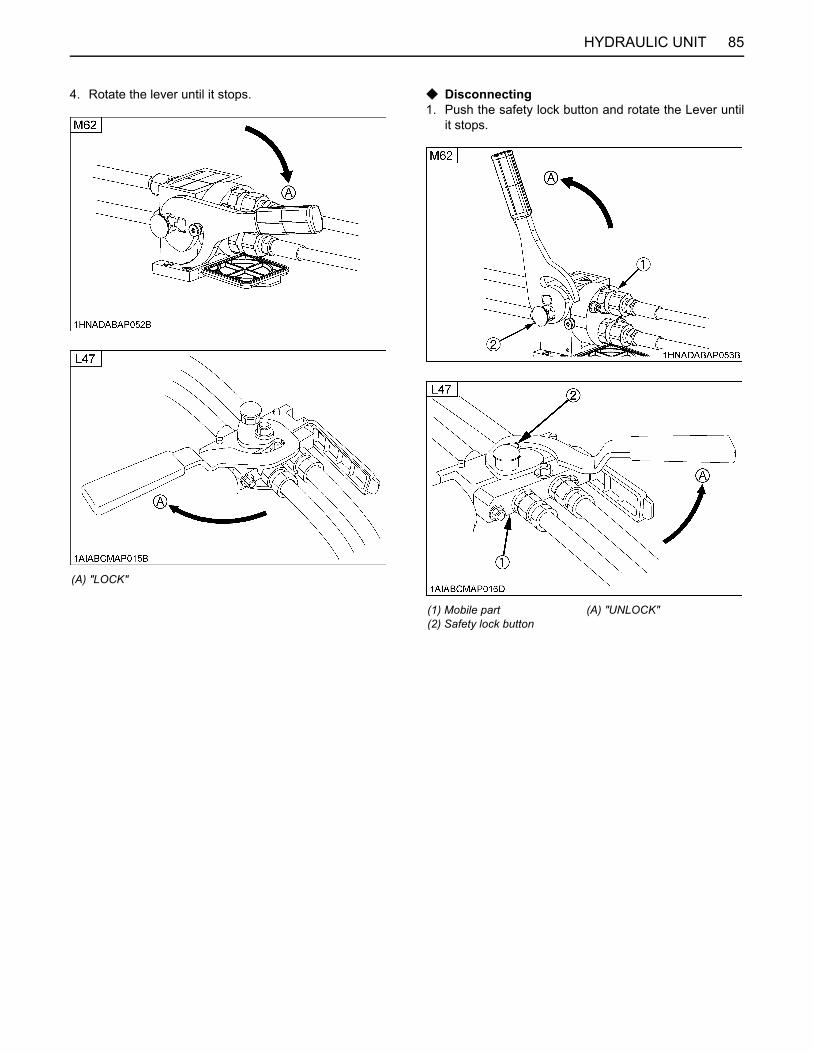
85HYDRAULIC UNIT
4. Rotate the lever until it stops. C Disconnecting1. Push the safety lock button and rotate the Lever until
it stops.
(A) "LOCK"
(1) Mobile part(2) Safety lock button
(A) "UNLOCK"

HYDRAULIC UNIT86
2. Remove the mobile part from the fixed part. 3. Rotate the lever until it stops and close the dust cover.
A Before connecting each, ensure to carefully clean themating surfaces of the fixed part, of the mobile partand the reference pins.
A Lubricate periodically all the moving components.A Once the mobile part is disconnected, please close the
dust cover to keep the flat surface of the fixed partclean.
A Whenever the loader is being used, always put thelever in the locked position.
(A) "LOCK"

87HYDRAULIC UNIT
BHydraulic Control Unit Use Reference ChartIn order to handle the hydraulics properly, the operator must be familiar with the following. Though this information may notbe applicable to all types of implements and soil conditions, it is useful for general conditions.
Implement
with Position control
Remarks
Soil condition Top link mounting holes
(1)Position controllever
Gauge wheel
Moldboard plow
Lightsoil
Mediumsoil
Heavysoil
1 or 2
2 or 3
3
Position control
YES/NO
Insert the set-pin through the slot on the outer tube that align with one of the holes on the inner bar.For implements with gauge wheels, lower the position control lever all way.
Disc plow --- 2 or 3
Harrow (spike, springtooth, disc type) ---
2 or 3Sub-soiler....................
Weeder, ridger.............
--- 3
YES Telescopic stabilizer should be tight enough to prevent excessive implement movement when implement is in raised position.
Earthmover, digger, scraper, manure fork, rear carrier...................
YES/NO
Mower (mid-and rear-mount type) NO

88 TIRES, WHEELS AND BALLAST
TIRES, WHEELS AND BALLAST
TIRESTo avoid personal injury or death:A Do not attempt to mount a tire on a rim. This
should be done by a qualified person with theproper equipment.
A Always maintain the correct tire pressure.Do not inflate tires above the recommendedpressure shown in the operator's manual.
A Do not use tires larger than specified.A When you intend to mount different size of tires from
equipped ones, consult your dealer about front drivegear ratio for detail.Excessive wear of tires may occur due to impropergear ratio.
BInflation PressureThough the tire pressure is factory-set to the prescribedlevel, it naturally drops slowly in the course of time. Thus,check it everyday and inflate as necessary.
BTreads[L47]
A Front wheel
Models (Tire sizes) Inflation Pressure
Front
L4727 x 10.5-15R4 275 kPa (2.8 kgf/cm , 40 psi)
M6210-16.5R4 275 kPa (2.8 kgf/cm , 40 psi)
Rear
L4715-19.5R4 207 kPa (2.1 kgf/cm , 30 psi)
M6217.5L-24R4 207 kPa (2.1 kgf/cm , 30 psi) (1) Nut
Front (185 N·m, 136 lbf·ft)

89TIRES, WHEELS AND BALLAST
A Rear wheel
[M62]
A Front wheel
A Rear wheel
A Front wheels with beveled or tapered holes:Use the tapered side of lug nut. (Except for rearwheels)
A Always attach tires as shown in the above illustration.A If not attached as illustrated, transmission parts may
be damaged.A Do not use tires larger than specified.A When re-fitting or adjusting a wheel, tighten the bolts
to the following torques and then recheck after drivingthe tractor 200 m (200 yards) and thereafter accordingto service interval.(See "MAINTENANCE OF THE TRACTOR" section.)
(1) Stud (99 to 112 N·m, 73 to 83 lbs·ft)(2) Nut (M16) (260 to 303 N·m, 192 to 244 lbs·ft)(3) Spring plate (for stud (M16))
(A) Direction of Spring plate
(1) Stud (73.6 N·m, 54.3 lbf·ft)(2) Nut (M14) (196.0 N·m, 145.0 lbf·ft)(3) Spring plate (for stud (M14))
(1) Stud (99 to 112 N·m, 73 to 83 lbs·ft)(2) Nut (M16) (260 to 303 N·m, 192 to 244 lbs·ft)(3) Spring plate (for stud (M16))
(A) Direction of Spring plate

TIRES, WHEELS AND BALLAST90
To avoid personal injury or death:A Before jacking up the tractor, park it on a firm
and level ground and chock the rear wheels.A Fix the front axle to keep it from pivoting.A Select jacks that withstand the machine weight
and set them up as shown below.
To avoid personal injury or death:A Before jacking up the tractor, park it on a firm
and level ground and chock the front wheels.A Fix the front axle to keep it from swinging.A Select a jack that withstands the machine
weight and set it up as shown below.
BALLAST
To avoid personal injury or death:A Additional ballast will be needed for
transporting heavy implements. When theimplement is raised, drive slowly over roughground, regardless of how much ballast isused.
A Do not fill the front wheels with liquid tomaintain steering control.
BFront BallastHeavy pulling and heavy rear mounted implements tendto lift front wheels. Therefore do not remove the loaderfrom the tractor at all times to maintain steering controland prevent tip over.
BRear BallastAdd weight to rear wheels if needed to improve traction orfor stability. The amount of rear ballast should be matchedto job and the ballast should be removed when it is notneeded.The weight should be added to the tractor in the form ofliquid ballast.A When the BT1000B (L47) or BT1400 (M62) backhoe is
installed to the tractor, rear ballast should be removed.
C Liquid Ballast in Rear TiresWater and calcium chloride solution provides safeeconomical ballast. Used properly, it will not damage tires,tubes or rims. The addition of calcium chloride isrecommended to prevent the water from freezing.Use of this method of weighting the wheels has the fullapproval of the tire companies. See your tire dealer forthis service.
(1) Jack points
(1) Jack point

91TIRES, WHEELS AND BALLAST
Liquid weight per tire (75 Percent filled)
A Do not fill tires with water or solution more than 75% offull capacity (to the valve stem level).
Tire sizesL47 M62
15L - 19.5R4
17.5L - 24R4
Slush free at -10 (14 )Solid at -30 (-22 )[Approx. 1 kg (2 lbs.)CaCl per 4 L (1 gal) of water]
142 kg(314 lbs.)
235 kg(515 lbs.)
Slush free at -24 (-11 )Solid at -47 (-52 )[Approx. 1.5 kg (3.5 lbs.)CaCl per 4 L (1 gal) of water]
149 kg(329 lbs.)
280 kg(610 lbs.)
Slush free at -47 (-52 )Solid at -52 (-62 )[Approx. 2.25 kg (5 lbs.)CaCl per 4 L (1 gal) of water]
159 kg(350 lbs.)
265 kg(585 lbs.)
(1) Air(2) Water
(A) Correct-75% Air compresses like a cushion(B) Incorrect-100% Full Water can not be compressed

92 MAINTENANCE OF THE TRACTOR
MAINTENANCE OF THE TRACTOR
SERVICE INTERVALSNo. ItemsIndication on hour meterInterval Ref.
page50 100 150 200 250 300 350 400 450 500 550 600 650 700
1 Greasing - every 50 Hr
105
2 Engine start system Check every 50 Hr
107
3 Wheel nut torque Check every 50 Hr
108
4 Battery condition Check every 100 Hr
111 *3
5
Air cleaner element [Double type]
Primary element
Clean every 100 Hr
108 *1
@Replace every 1000 Hr
or 1 year
119 *4
Secondary element Replace 119 *4
6 Fan belt Adjust every 100 Hr
109
7 Brake Adjust every 100 Hr
110
8 Rear parking brake (cable)
Adjust every 100 Hr
110
Replace every 2 years
124
9 Toe-in Adjust every 200 Hr
113
10 Transmission oil filter [HST]
Replace every 200 Hr
112
11 Water Separator Clean every 400 Hr
114
12 Engine oil Change every 400 Hr
115
13 Engine oil filter Replace every 400 Hr
115
14 Hydraulic oil filter Replace every 400 Hr
116
15 Transmission fluid Change every 400 Hr
116
16 Fuel filter Replace every 400 Hr
117 @
17 Front axle case oil Change every 400 Hr
118
18 Front axle pivot Adjust every 600 Hr
118
19 Engine valve clearance
Adjust every 800 Hr
118 *2
20 Fuel injection nozzle Injection pressure
Check every 1500 Hr
119 *2 @
21 Oil separator element Replace every 1500 Hr
119 @

93MAINTENANCE OF THE TRACTOR
22
PCV (Positive Crankcase Ventilation) valve (Oil separator)
Check every 1500 Hr 119 *2 @
23 EGR cooler CheckClean
every 1500 Hr
119 *2 @
24 Cooling system Flush every 2000 Hr
or 2 years
119 *5
25 Coolant Change 119 *5
26 EGR system CheckClean
every 3000 Hr
121 *2 @
27 Supply pump Check every 3000 Hr
121 *2
28 DPF muffler Clean every 3000 Hr
121 *2 @
29 Turbo charger [M62] Check every 3000 Hr
121 *2 @
30 Radiator hose and clamp
Check every 1 year
122 *6
Replace every 4 years
124
31Oil cooler line /Power steering oil line
Check every 1 year
124 *6
Replace every 4 years
124, 124
*2
32 Fuel lineCheck every
1 year121 *6
@Replace every
4 years124 *2
33 Intake air lineCheck every
1 year123 *6
@Replace every
4 years124 *2
34 Oil separator hoseCheck every
1 year123 *6
Replace every 4 years
124 *2
35 Exhaust manifold Check every 1 year
124 *2
36 DPF differential pressure sensor pipe
Check every 1 year
124 *2
37 EGR pipe Check every 1 year
124 *2
38Antifrost heater for Oil Separator(if equipped)
Check every 1 year 124 *2
39DPF differential pressure sensor hose
Check every 1 year 124 *6
Replace every 4 years 124 *2
40 Fuel system BleedService
as required
125
41 Clutch housing water Drain 125
42 Fuse Replace 126
43 Light bulb Replace 127
No. ItemsIndication on hour meter
Interval Ref.page50 100 150 200 250 300 350 400 450 500 550 600 650 700

94 MAINTENANCE OF THE TRACTOR
A The jobs indicated by must be done after the first 50 hours of operation.*1 Air cleaner should be cleaned more often in dusty conditions than in normal conditions.*2 Consult your local KUBOTA Dealer for this service.*3 When the battery is used for less than 100 hours per year, check the battery condition by reading the indicator annually.*4 Every in 1000 hours or every 1 year, whichever comes first.*5 Every in 2000 hours or every 2 years, whichever comes first.*6 Inspect every year; replace if any deterioration (crack, hardening, scar, or deformation) or damage occurred. However, must be replaced every 4 years regardless of the condition.A The items listed above (@ marked) are registered as emission related critical parts by KUBOTA in the U.S.EPA non-
road emission regulation. As the engine owner, you are responsible for the performance of the required maintenanceon the engine according to the above instruction.Please see Warranty Statement in detail.
A When using biodiesel, be sure to check the maintenance requirements of biodiesel fuel as the intervals will change forsome of the items.
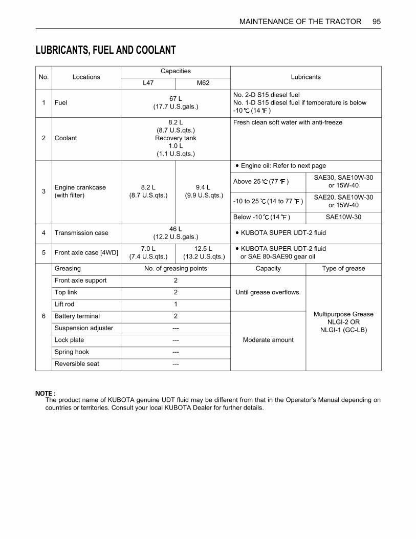
95MAINTENANCE OF THE TRACTOR
LUBRICANTS, FUEL AND COOLANT
The product name of KUBOTA genuine UDT fluid may be different from that in the Operator’s Manual depending oncountries or territories. Consult your local KUBOTA Dealer for further details.
No. LocationsCapacities
LubricantsL47 M62
1 Fuel 67 L(17.7 U.S.gals.)
No. 2-D S15 diesel fuelNo. 1-D S15 diesel fuel if temperature is below -10 (14 )
2 Coolant
8.2 L(8.7 U.S.qts.)Recovery tank
1.0 L(1.1 U.S.qts.)
Fresh clean soft water with anti-freeze
3 Engine crankcase(with filter)
8.2 L(8.7 U.S.qts.)
9.4 L (9.9 U.S.qts.)
Engine oil: Refer to next page
Above 25 (77 ) SAE30, SAE10W-30or 15W-40
-10 to 25 (14 to 77 ) SAE20, SAE10W-30or 15W-40
Below -10 (14 ) SAE10W-30
4 Transmission case 46 L(12.2 U.S.gals.) KUBOTA SUPER UDT-2 fluid
5 Front axle case [4WD] 7.0 L(7.4 U.S.qts.)
12.5 L (13.2 U.S.qts.)
KUBOTA SUPER UDT-2 fluid or SAE 80-SAE90 gear oil
6
Greasing No. of greasing points Capacity Type of grease
Front axle support 2
Until grease overflows.
Multipurpose GreaseNLGI-2 OR
NLGI-1 (GC-LB)
Top link 2
Lift rod 1
Battery terminal 2
Moderate amount
Suspension adjuster ---
Lock plate ---
Spring hook ---
Reversible seat ---

96 MAINTENANCE OF THE TRACTOR
C Engine Oil:A Oil used in the engine should have an American Petroleum Institute (API) service classification and Proper SAE
Engine Oil according to the ambient temperatures as shown above:
C Fuel:A Use the ultra low sulfur diesel fuel only [below 0.0015% (15 ppm)] for these engines.A Cetane number of 45 minimum. Cetane number greater than 50 is preferred, especially for temperatures below
-20 (-4 ) or elevations above 1500 m (5000 ft).A Diesel fuels specified to EN 590 or ASTM D975 are recommended.A No.2-D is a distillate fuel of lower volatility for engines in industrial and heavy mobile service. (SAE J313 JUN87)
C Transmission Oil:*KUBOTA Super UDT-2: For an enhanced ownership experience, we highly recommend Super UDT-2 to be usedinstead of standard hydraulic/transmission fluid.Super UDT-2 is a proprietary KUBOTA formulation that delivers superior performance and protection in all operatingconditions.Regular UDT is also permitted for use in this machine.
A Indicated capacities of water and oil are manufacturer's estimate.
A Refer to the following table for the suitable API classification engine oil according to the engine type (with DPF(Diesel Particulate Filter) type engines) and the fuel.
Fuel usedEngine oil classification (API classification)
Oil class for engines with DPF
Ultra Low Sulfur Fuel[<0.0015% (15 ppm)] CJ-4

97MAINTENANCE OF THE TRACTOR
BIODIESEL FUEL (BDF)B0-B20 Biodiesel fuels (BDF): mixed diesel fuels containing 20% or less biodiesel can be utilized under the followingconditions.
A Refueling and handling fuel should be done with caution in order to avoid contact with the fuel and spillage that couldcreate a potential environmental or fire hazard. Wear appropriate protective equipment when refueling.
C Applicable BDF:1. Blended diesel fuels containing 6% thru 20% BDF (B6 - B20) which comply with American Society for Testing and
Materials (ASTM) D7467 Standard, as revised, can be used without adversely affecting the performance and durabilityof the engine and fuel system components.
2. Any mineral oil diesel fuel, if used, must conform to ASTM D975 (or the European EN590) Standard, as revised.B100 fuel used to make Biodiesel blended fuels must meet ASTM D6751 (or EN14214) Standard, as revised.The final blended fuel B20 must conform to ASTM D7467 Standard, as revised. Straight vegetable oil is NOT allowedin any blended fuel.
3. Allowable blended fuel is mineral oil diesel fuel blended with B100 (i.e. 100% BDF). The blended fuel ratio shall be lessthan 20% B100 and 80% or more diesel fuel. The B100 source used for Biodiesel blends must be purchased from anaccredited BQ-9000 marketer or producer. More information about qualified marketer(s) and producer(s) can be foundat http://www.bq-9000.org .
C Preparation:1. Before using BDF concentrations greater than B5, you are advised to replace the engine oil, engine oil filter and fuel
filter with new oil and filters. For replacement procedures, refer to the "PERIODIC SERVICE" section.
C Product Warranty, Emission and Other Precautions:1. The engine emission control system was certified according to current regulations based on the use of non-BDF. When
using BDF, the owner is advised to check applicable local and federal emission regulations and comply with all of them.2. BDF may cause restricted or clogged fuel filters during cold weather conditions, resulting in the engine not operating
properly.3. BDF encourages the growth of microorganisms which may cause degradation of the fuel. This in turn may cause fuel
line corrosion or reduce fuel filter flow earlier than expected.4. BDF inherently absorbs moisture which may cause degradation of the fuel earlier than expected. To avoid this, drain
the water separator and fuel filter port often.5. Do not use Biodiesel concentrations higher than 20% (i.e. greater than B20). Engine performance and fuel consumption
will be affected, and degradation of the fuel system components may occur.6. Do not readjust the engine fuel control system as this will violate emission control levels for which the equipment was
approved.7. Compared with soybean-based and rapeseed-based feedstock, palm oil-based feedstock has a thicker consistency
(i.e. higher viscosity) at lower temperatures. Consequently, fuel filter performance may be reduced, particularly duringcold weather conditions.
8. The Kubota Warranty, as specified in the Owner's Warranty Information Guide, only covers defects in product materialsand workmanship. Accordingly, any problems that may arise due to the use of poor quality fuels that fail to meet theabove requirements, whether biodiesel or mineral oil based, are not covered by the Kubota Warranty.
C Routine handling:1. Avoid spilling BDF onto painted surfaces as this may damage the finish. If fuel is spilled immediately wipe clean and
flush with soapy water to avoid permanent damage.2. When using BDF, you are advised to maintain a full tank of fuel, especially overnight and during short term storage, to
reduce condensation within the tank. Be sure to tighten the fuel cap after refueling to prevent moisture build up withinthe tank. Water in the Biodiesel mixture will damage fuel filters and may damage engine components.

98 MAINTENANCE OF THE TRACTOR
C Maintenance Requirements when using BDF B0 through B5:Follow the oil change intervals recommended by referring to the "MAINTENANCE" section. Extended oil changeintervals may result in premature wear or engine damage.
C Maintenance Requirements when using BDF B6 through B20:The maintenance interval for fuel related parts changes.See the table below for the new maintenance interval.
C Long Term Storage:1. BDF easily deteriorates due to oxygen, water, heat and foreign substances. Do not store B6 thru B20 longer than 1
month and B5 longer than 3 months.2. When using B6 thru B20 and storing the machine longer than 1 month, drain the fuel from the tanks and replace with
light mineral oil diesel fuel. Subsequently, run the engine at least 30 minutes to remove all of the Biodiesel from the fuellines.
3. When using B5 fuel and storing machine longer than 3 months, drain the fuel from the tanks and replace with lightmineral oil diesel fuel. Subsequently, run the engine at least 30 minutes to remove all of the Biodiesel from the fuel lines.
Items Interval Remarks
Fuel filter Replace every 200 Hr
Fuel lineCheck every 6 months Replace if any deterioration (crack, hardening, scar or
deformation) or damage occurred.
Replace every 2 years Consult your local KUBOTA Dealer for this service.

99PERIODIC SERVICE OF THE TRACTOR
PERIODIC SERVICE OF THE TRACTOR
To avoid personal injury or death:A Do not work under any hydraulically supported
devices. They can settle, suddenly leak down,or be accidentally lowered. If necessary to workunder tractor or any machine elements forservicing or adjustment, securely support themwith stands or suitable blocking beforehand.
WASTE DISPOSALThe improper disposal or burning of waste causesenvironmental pollution and can be punishable by yourlocal laws and regulations.A When draining fluids from the tractor, place a
container underneath the drain port.A Do not pour waste onto the ground, down a drain, or
into any water source (such as rivers, streams, lakes,marshes, seas and oceans).
A Waste products such as used oil, fuel, coolant,hydraulic fluid, urea aqueous solution (DEF/AdBlue®), refrigerant, solvent, filters, rubber, batteriesand harmful substances, can harm the environment,people, pets and wildlife.Please dispose properly.See your local recycling center or KUBOTA Dealer tolearn how to recycle or get rid of waste products.
HOW TO OPEN THE HOOD
To avoid personal injury or death from contactwith moving parts:A Never open the hood while the engine is
running.A Do not touch muffler or exhaust pipes while
they are hot. Severe burns could result.A Support hood with other hand while unlocking
support link.
BHoodTo open the hood, pull the lever to release the latch andopen the hood.
A To close the hood, hold the hood and release thesupport link.
(1) Lever(2) Hood
(A) "OPEN"
(1) Support link (A) "HOLD"(B) "PULL"
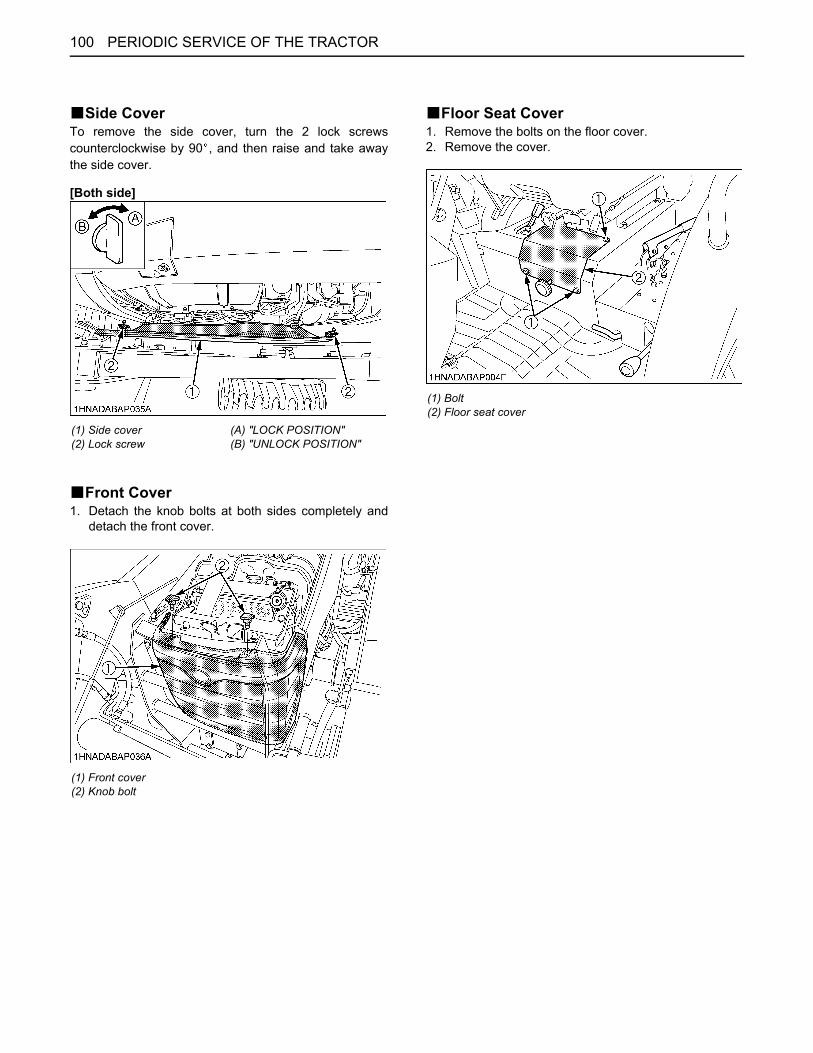
PERIODIC SERVICE OF THE TRACTOR100
BSide CoverTo remove the side cover, turn the 2 lock screwscounterclockwise by 90 , and then raise and take awaythe side cover.
[Both side]
BFront Cover1. Detach the knob bolts at both sides completely and
detach the front cover.
BFloor Seat Cover1. Remove the bolts on the floor cover.2. Remove the cover.
(1) Side cover(2) Lock screw
(A) "LOCK POSITION"(B) "UNLOCK POSITION"
(1) Front cover(2) Knob bolt
(1) Bolt(2) Floor seat cover

101PERIODIC SERVICE OF THE TRACTOR
DAILY CHECKFor your own safety and maximum service life of themachine, make a thorough daily inspection beforeoperating the machine to start the engine.
To avoid personal injury or death:Take the following precautions when checking thetractor.A Park the machine on firm and level ground.A Set the parking brake.A Lower the implement to the ground.A All residual pressure of the hydraulic system
released.A Stop the engine and remove the key.
BWalk Around InspectionLook around and under the tractor for such items as loosebolts, trash build-up, oil or coolant leaks, broken or wornparts.
BChecking and Refueling
To avoid personal injury or death:A Do not smoke while refueling.A Be sure to stop the engine before refueling.
1. Turn the key switch to "ON", check the amount of fuelby fuel gauge.
2. Fill fuel tank when fuel gauge shows 1/4 or less fuel intank.
3. Lock the cover with the key after filling the fuel tank.
A Be sure to use Ultra Low Sulfur Fuel (S15).A Do not permit dirt or trash to get into the fuel system.A Be careful not to let the fuel tank become empty,
otherwise air will enter the fuel system, necessitatingbleeding before next engine start.
A If the engine runs out of fuel and stalls, the enginecomponents may be damaged.
A Be careful not to spill during refueling. If a spill shouldoccur, wipe it off at once, or it may cause a fire.
A To prevent condensation (water) accumulation in thefuel tank, fill the tank before parking overnight.
(1) Fuel tank cap
Fuel tank capacity 67 L (17.8 U.S.gals.)

PERIODIC SERVICE OF THE TRACTOR102
BChecking Water Separator1. When the water has collected upper limit in the water
separator, the water separator indicator on theinstrument panel lights up and warning buzzersounding.
2. In such case, close the fuel shutoff-valve and loosenthe air plug and drain plug by several turns.
3. Allow water to drain. When no more water comes outand fuel starts to flow out, retighten the air plug anddrain plug.
4. Bleed the fuel system.(See "SERVICE AS REQUIRED" in "PERIODICSERVICE" section.)
A When the red float reaches near the upper limit level,start from step 2 in the above procedure to drain waterin the water separator.
A If water is drawn through to the fuel pump, extensivedamage will occur.
BChecking Engine Oil Level
To avoid personal injury or death:A Be sure to stop the engine before checking the
oil level.
1. Park the machine on a flat surface.2. Check engine oil before starting the engine or 5
minutes or more after the engine has stopped.3. To check the oil level, draw out the dipstick, wipe it
clean, replace it, and draw it out again. Check to seethat the oil level lies between the two notches.If the level is too low, add new oil to the prescribedlevel at the oil inlet.(See "LUBRICANTS" in "MAINTENANCE OF THETRACTOR" section.)
A When using an oil of different maker or viscosity fromthe previous one, remove all of the old oil.Never mix two different types of oil.
A If oil level is low, do not run engine.
(1) Water separator indicator
(1) Red float(2) Fuel shutoff-valve(3) Air plug(4) Cup(5) Drain plug
(A) "ON"(B) "OFF"(C) "FUEL"(D) "UPPER LIMIT"(E) "WATER"
(1) Oil inlet(2) Dipstick
(A) Oil level is acceptable within this range.
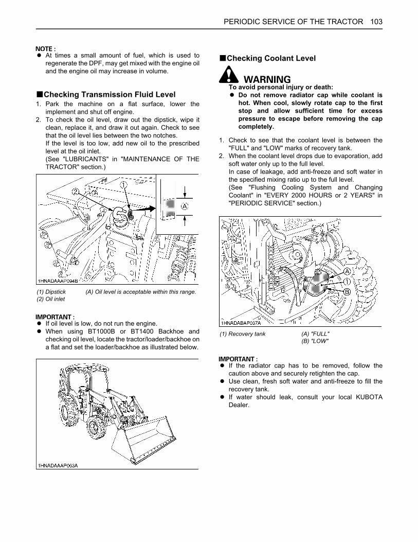
103PERIODIC SERVICE OF THE TRACTOR
A At times a small amount of fuel, which is used toregenerate the DPF, may get mixed with the engine oiland the engine oil may increase in volume.
BChecking Transmission Fluid Level1. Park the machine on a flat surface, lower the
implement and shut off engine.2. To check the oil level, draw out the dipstick, wipe it
clean, replace it, and draw it out again. Check to seethat the oil level lies between the two notches.If the level is too low, add new oil to the prescribedlevel at the oil inlet.(See "LUBRICANTS" in "MAINTENANCE OF THETRACTOR" section.)
A If oil level is low, do not run the engine.A When using BT1000B or BT1400 Backhoe and
checking oil level, locate the tractor/loader/backhoe ona flat and set the loader/backhoe as illustrated below.
BChecking Coolant Level
To avoid personal injury or death:A Do not remove radiator cap while coolant is
hot. When cool, slowly rotate cap to the firststop and allow sufficient time for excesspressure to escape before removing the capcompletely.
1. Check to see that the coolant level is between the"FULL" and "LOW" marks of recovery tank.
2. When the coolant level drops due to evaporation, addsoft water only up to the full level.In case of leakage, add anti-freeze and soft water inthe specified mixing ratio up to the full level.(See "Flushing Cooling System and ChangingCoolant" in "EVERY 2000 HOURS or 2 YEARS" in"PERIODIC SERVICE" section.)
A If the radiator cap has to be removed, follow thecaution above and securely retighten the cap.
A Use clean, fresh soft water and anti-freeze to fill therecovery tank.
A If water should leak, consult your local KUBOTADealer.
(1) Dipstick(2) Oil inlet
(A) Oil level is acceptable within this range.
(1) Recovery tank (A) "FULL"(B) "LOW"
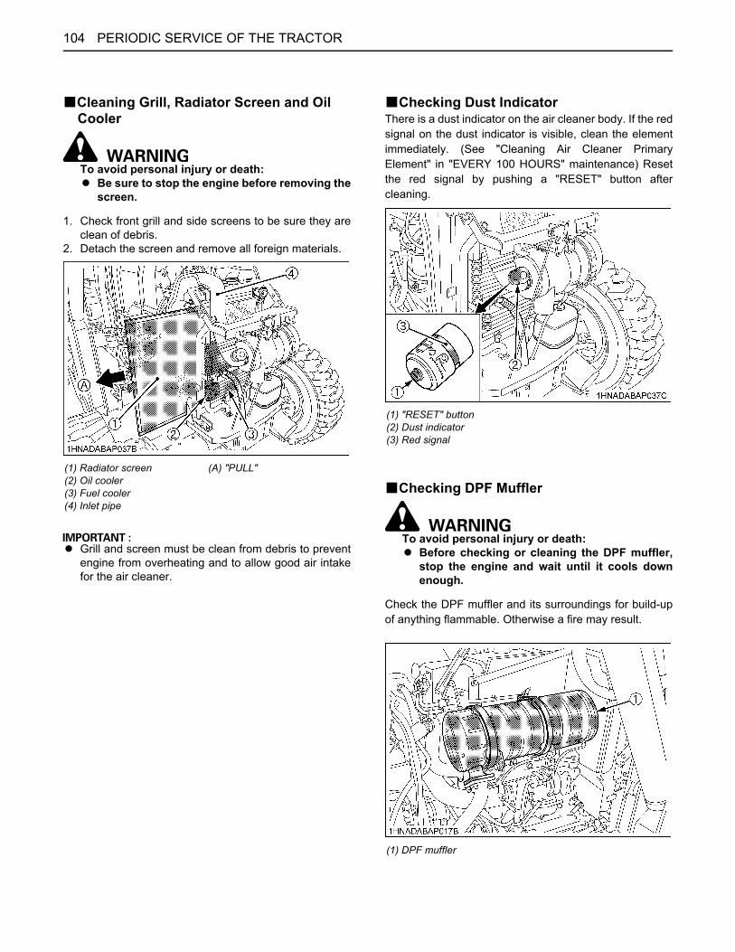
PERIODIC SERVICE OF THE TRACTOR104
BCleaning Grill, Radiator Screen and Oil Cooler
To avoid personal injury or death:A Be sure to stop the engine before removing the
screen.
1. Check front grill and side screens to be sure they areclean of debris.
2. Detach the screen and remove all foreign materials.
A Grill and screen must be clean from debris to preventengine from overheating and to allow good air intakefor the air cleaner.
BChecking Dust IndicatorThere is a dust indicator on the air cleaner body. If the redsignal on the dust indicator is visible, clean the elementimmediately. (See "Cleaning Air Cleaner PrimaryElement" in "EVERY 100 HOURS" maintenance) Resetthe red signal by pushing a "RESET" button aftercleaning.
BChecking DPF Muffler
To avoid personal injury or death:A Before checking or cleaning the DPF muffler,
stop the engine and wait until it cools downenough.
Check the DPF muffler and its surroundings for build-upof anything flammable. Otherwise a fire may result.
(1) Radiator screen(2) Oil cooler(3) Fuel cooler(4) Inlet pipe
(A) "PULL"
(1) "RESET" button(2) Dust indicator(3) Red signal
(1) DPF muffler

105PERIODIC SERVICE OF THE TRACTOR
BChecking Brake Pedal
To avoid personal injury or death:A Be sure brake pedals have equal adjustment
when using locked together. Incorrect orunequal brake pedal adjustment can cause thetractor to swerve or roll-over.
1. Inspect the brake pedals for free travel, and smoothoperation.
2. Adjust if incorrect measurement is found:(See "Adjusting Brake Pedal" in "EVERY 100 HOURS"in "PERIODIC SERVICE" section.)
BChecking Gauges, Meter and Easy Checker(TM)
1. Inspect the instrument panel for broken gauge(s),meter(s) and Easy Checker(TM) lamps.
2. Replace if broken.
BChecking Head Light, Hazard Light etc.1. Inspect the lights for broken bulbs and lenses,2. Replace if broken.
BChecking Seat Belt, ROPS and FOPS1. Always check condition of seat belt, ROPS and FOPS
attaching hardware before operating tractor.2. Replace if damaged.
BChecking Movable PartsIf any of the movable parts, such as levers and pedals, isnot smoothly moved because of rust or sticky material, donot attempt to force it into motion.In the above case, remove the rust or the sticky material,and apply oil or grease on the relevant spot.Otherwise, the machine may get damaged.
EVERY 50 HOURSBLubricating Grease FittingsApply a small amount of multipurpose grease to thefollowing points every 50 hours:If you operated the machine in extremely wet and muddyconditions, lubricate grease fittings more often.
When applying grease to forward front axle support,remove the breather plug and apply grease until greaseoverflows from breather plug port.After greasing reinstall the breather plug.[L47]
(1) Grease fitting (Front axle support)(2) Breather plug
(1) Grease fitting (Front axle gear case support) [RH, LH]

PERIODIC SERVICE OF THE TRACTOR106
[M62]
[L47 and M62]
[L47 and M62]
[L47 and M62]
(1) Grease fitting (Front axle support)
(1) Grease fitting (Front axle gear case support) [RH, LH]
(1) Grease fitting (Top link) [if equipped](2) Grease fitting (Lifting rod RH) [if equipped]
(1) Lock plate(2) Suspension adjuster(3) Spring hook(4) Reversible seat
(1) Battery terminals
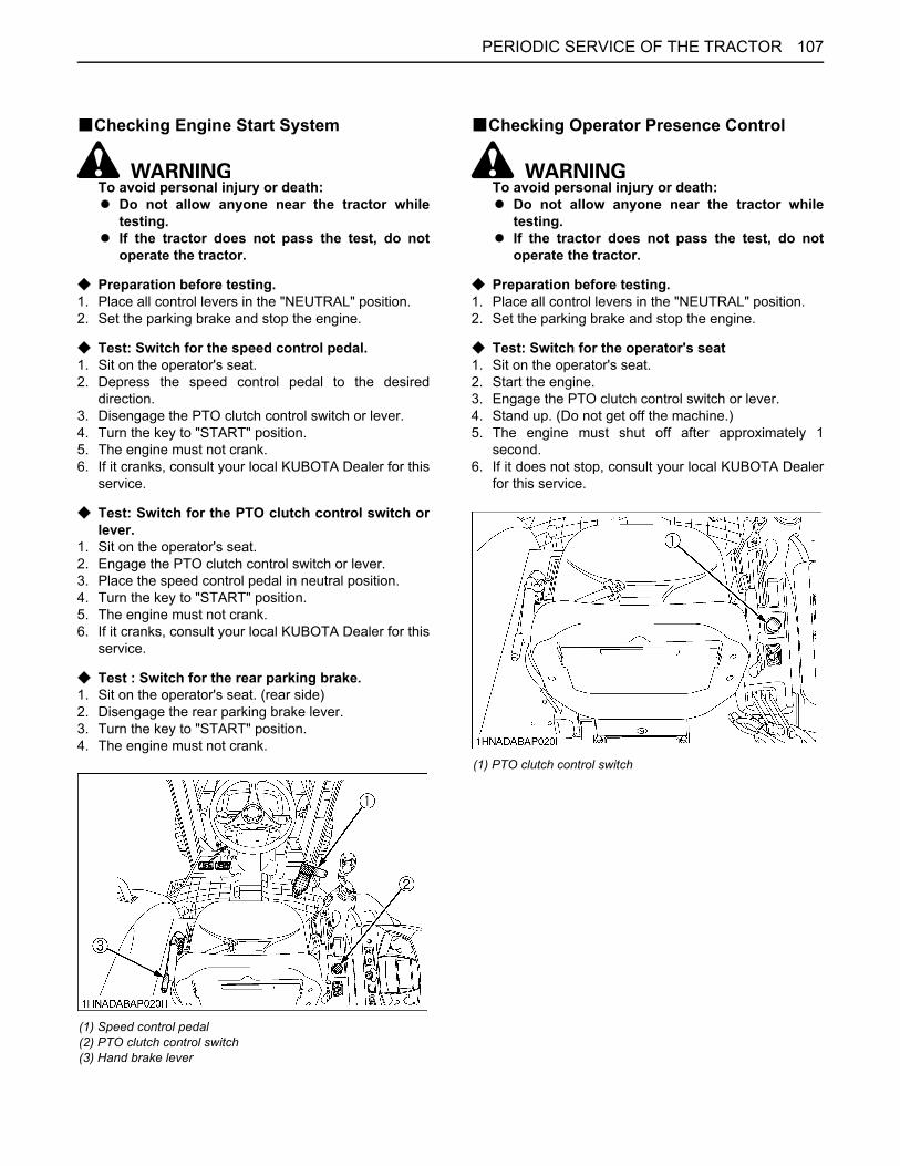
107PERIODIC SERVICE OF THE TRACTOR
BChecking Engine Start System
To avoid personal injury or death:A Do not allow anyone near the tractor while
testing.A If the tractor does not pass the test, do not
operate the tractor.
C Preparation before testing.1. Place all control levers in the "NEUTRAL" position.2. Set the parking brake and stop the engine.
C Test: Switch for the speed control pedal.1. Sit on the operator's seat.2. Depress the speed control pedal to the desired
direction.3. Disengage the PTO clutch control switch or lever.4. Turn the key to "START" position.5. The engine must not crank.6. If it cranks, consult your local KUBOTA Dealer for this
service.
C Test: Switch for the PTO clutch control switch orlever.
1. Sit on the operator's seat.2. Engage the PTO clutch control switch or lever.3. Place the speed control pedal in neutral position.4. Turn the key to "START" position.5. The engine must not crank.6. If it cranks, consult your local KUBOTA Dealer for this
service.
C Test : Switch for the rear parking brake.1. Sit on the operator's seat. (rear side)2. Disengage the rear parking brake lever.3. Turn the key to "START" position.4. The engine must not crank.
BChecking Operator Presence Control
To avoid personal injury or death:A Do not allow anyone near the tractor while
testing.A If the tractor does not pass the test, do not
operate the tractor.
C Preparation before testing.1. Place all control levers in the "NEUTRAL" position.2. Set the parking brake and stop the engine.
C Test: Switch for the operator's seat1. Sit on the operator's seat.2. Start the engine.3. Engage the PTO clutch control switch or lever.4. Stand up. (Do not get off the machine.)5. The engine must shut off after approximately 1
second.6. If it does not stop, consult your local KUBOTA Dealer
for this service.
(1) Speed control pedal(2) PTO clutch control switch(3) Hand brake lever
(1) PTO clutch control switch

PERIODIC SERVICE OF THE TRACTOR108
BChecking Wheel Nut Torque
To avoid personal injury or death:A Never operate tractor with a loose rim, wheel,
or axle.A Any time nuts are loosened, retighten to
specified torque.A Check all nuts frequently and keep them tight.
Check wheel nuts regularly especially when new. If theyare loose, tighten them as follows.
EVERY 100 HOURSBCleaning Air Cleaner Primary Element1. Open the hood and remove the air cleaner cover and
the primary element.2. Clean the primary element:
(1) When dry dust adheres to the element, blowcompressed air from the inside, turning theelement. Pressure of compressed air must beunder 205 kPa (2.1 kgf/cm , 30 psi).
(2) When carbon or oil adheres to the element, soakthe element in detergent for 15 minutes then washit several times in water, rinse with clean waterand dry it naturally. After element is fully dried,inspect inside of the element with a light andcheck if it is damaged or not.
3. Replace air cleaner primary element:Every 1000 hours or once yearly cleaning, whichevercomes first.
A Check to see if the evacuator valve is blocked withdust.
[L47]
[L47](1) 185 N·m (19 kgf·m, 136 lbf·ft)(2) 260 N·m (27 kgf·m, 192 lbf·ft)[M62](1) 196 N·m (20 kgf·m, 145 lbf·ft)(2) 260 N·m (27 kgf·m, 192 lbf·ft)

109PERIODIC SERVICE OF THE TRACTOR
[M62]
A The air cleaner uses a dry element, never apply oil.A Do not run the engine with filter element removed.A Be sure to refit the cover with the arrow (on the rear
of cover) upright. If the cover is improperly fitted,evacuator valve will not function and dust will adhereto the element.
A Do not touch the secondary element except in caseswhere replacing is required.(See "Replacing Air Cleaner Secondary Element" in"EVERY 1000 HOURS or 1 YEAR" maintenance)
C Evacuator ValveOpen the evacuator valve once a week under ordinaryconditions - or daily when used in a dusty place - to get ridof large particles of dust and dirt.
BAdjusting Fan Belt Tension
To avoid personal injury or death:A Be sure to stop the engine before checking belt
tension.
1. Stop the engine and remove the key.2. Apply moderate thumb pressure to belt between
pulleys.3. If tension is incorrect, loosen the alternator mounting
bolts and, using a lever placed between the alternatorand the engine block, pull the alternator out until thedeflection of the belt falls within acceptable limits.
4. Replace fan belt if it is damaged.
(1) Secondary (safety) element(2) Primary element(3) Cover(4) Evacuator valve
Proper fen belt tension
A deflection of between 7 to 9 mm (0.28 to 0.34 in.) when the belt is pressed in the middle of the span.
(1) Bolt (A) Check the belt tension(B) To tighten
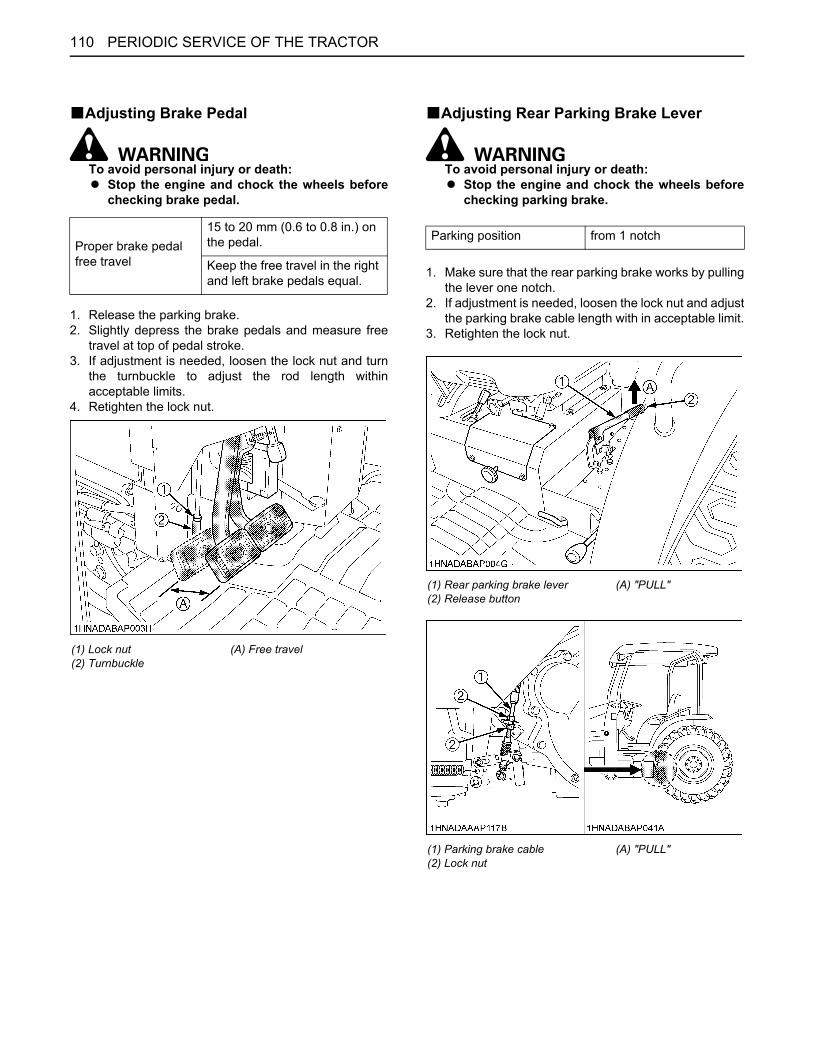
PERIODIC SERVICE OF THE TRACTOR110
BAdjusting Brake Pedal
To avoid personal injury or death:A Stop the engine and chock the wheels before
checking brake pedal.
1. Release the parking brake.2. Slightly depress the brake pedals and measure free
travel at top of pedal stroke.3. If adjustment is needed, loosen the lock nut and turn
the turnbuckle to adjust the rod length withinacceptable limits.
4. Retighten the lock nut.
BAdjusting Rear Parking Brake Lever
To avoid personal injury or death:A Stop the engine and chock the wheels before
checking parking brake.
1. Make sure that the rear parking brake works by pullingthe lever one notch.
2. If adjustment is needed, loosen the lock nut and adjustthe parking brake cable length with in acceptable limit.
3. Retighten the lock nut.
Proper brake pedal free travel
15 to 20 mm (0.6 to 0.8 in.) on the pedal.
Keep the free travel in the right and left brake pedals equal.
(1) Lock nut(2) Turnbuckle
(A) Free travel
Parking position from 1 notch
(1) Rear parking brake lever(2) Release button
(A) "PULL"
(1) Parking brake cable(2) Lock nut
(A) "PULL"

111PERIODIC SERVICE OF THE TRACTOR
BChecking Battery Condition
To avoid the possibility of battery explosion:For the refillable type battery, follow theinstructions below.A Do not use or charge the refillable type battery
if the fluid level is below the LOWER (lower limitlevel) mark. Otherwise, the battery componentparts may prematurely deteriorate, which mayshorten the battery's service life or cause anexplosion. Check the fluid level regularly andadd distilled water as required so that the fluidlevel is between the UPPER and LOWER levels.
To avoid personal injury or death: A Never remove the vent caps while the engine is
running.A Keep electrolyte away from eyes, hands and
clothes. If you are spattered with it, wash itaway completely with water immediately andget medical attention.
A Wear eye protection and rubber gloves whenworking around the battery.
Mishandling the battery shortens the service life and addsto maintenance costs.The original battery is maintenance free, but needs someservicing.If the battery is weak, the engine will be difficult to startand the lights will be dim. It is important to check thebattery periodically.
C How to read the indicator (if equipped)Check the battery condition by reading the indicator.
C Battery Charging
To avoid personal injury or death:A When the battery is being activated, hydrogen
and oxygen gases in the battery are extremelyexplosive. Keep open sparks and flames awayfrom the battery at all times, especially whencharging the battery.
A When charging the battery, ensure the ventcaps are securely in place (if equipped).
A When disconnecting the cable from the battery,start with the negative terminal first.When connecting the cable to the battery, startwith the positive terminal first.
A Never check battery charge by placing a metalobject across the posts.Use a voltmeter or hydrometer.
1. To slow charge the battery, connect the batterypositive terminal to the charger positive terminal andthe negative to the negative, then recharge in thestandard fashion.
The factory-installed battery is of non-refillable type. If the battery is weak, do not charge the battery but replace it with new one.
State of indicator display
Green Specific gravity of electrolyte and quality of electrolyte are both in good condition.
Black Needs charging battery.
White Needs changing battery.
(1) Battery(2) Indicator
(1) Battery

PERIODIC SERVICE OF THE TRACTOR112
2. A boost charge is only for emergencies. It will partiallycharge the battery at a high rate and in a short time.When using a boost-charged battery, it is necessary torecharge the battery as early as possible.Failure to do this will shorten the battery's service life.
3. The battery is charged if the indicator display turnsgreen from black.
4. When exchanging an old battery for a new one, usebattery of equal specification shown in table 1.
Table 1
C Direction for Storage1. When storing the tractor for a long period, remove the
battery from tractor, adjust the electrolyte to the properlevel and store in a dry place out of direct sunlight.
2. The battery self-discharges while it is stored.Recharge it once every 3 months in hot seasons andonce every 6 months in cold seasons.
EVERY 200 HOURSBReplacing Transmission Oil Filter [HST]
To avoid personal injury or death:A Be sure to stop the engine before changing the
oil filter cartridge.A Allow engine to cool down sufficiently, oil can
be hot and can burn.
1. Remove the drain plugs at the bottom of thetransmission case and drain the oil completely into theoil pan.
2. After draining reinstall the drain plugs.
3. Remove the oil filter.
4. Put a film of clean transmission oil on the rubber sealof the new filter.
5. Quickly tighten the filter until it contacts the mountingsurface, then tighten it by hand an additional 1/2 turnonly.
6. After the new filters have been replaced, fill thetransmission oil up to the upper notch on the dipstick.
Tractormodel
BatteryTYPE(BCI)
Volts (V)
L47 24 12
M62 24 12
Tractormodel
Reserve Capacity (min)
Cold Cranking Amps
L47 90 550
M62 115 650
(1) Drain plugs
(1) Transmission oil filter (HST)

113PERIODIC SERVICE OF THE TRACTOR
7. After running the engine for a few minutes, stop theengine and check the oil level again, add oil to theprescribed level.
8. Make sure that the transmission fluid doesn't leak pastthe seal on the filter.
A To prevent serious damage to the hydraulic system,use only a KUBOTA genuine filter.
A Do not operate the tractor immediately after changingthe transmission fluid.Run the engine at medium speed for a few minutes toprevent damage to the transmission.
BAdjusting Toe-in1. Park tractor on a flat place.2. Turn steering wheel so front wheels are in the straight
ahead position.3. Lower the implement, lock the park brake and stop the
engine.4. Measure distance between tire beads at front of tire,
hub height.5. Measure distance between tire beads at rear of tire,
hub height.6. Front distance should be 2 to 8mm (1/16 to 5/16 in.)
less than rear distance. If not, adjust tie rod length.
(1) Dipstick(2) Oil inlet
(A) Oil level is acceptable within this range.
(A) Wheel - to - wheel distance at rear(B) Wheel - to - wheel distance at front(C) "FRONT"

PERIODIC SERVICE OF THE TRACTOR114
C Adjusting procedures1. Detach the snap ring.2. Loosen the tie-rod nut.3. Turn the tie-rod joint to adjust the rod length until the
proper toe-in measurement is obtained.4. Retighten the tie-rod nut.5. Attach the snap ring of the tie-rod joint.
[L47]
[M62]
EVERY 400 HOURSBCleaning Water SeparatorThis job should not be done in the field, but in a cleanplace.1. Disconnect the connector of water sensor.2. Close the fuel shutoff-valve.3. Unscrew the cup and remove it, then rinse the inside
with kerosene.4. Take out the element and dip it in the kerosene to
rinse.5. After cleaning, reassemble the water separator,
keeping out dust and dirt.6. Connect the connector of water sensor.7. Bleed the fuel system.
(See "SERVICE AS REQUIRED" in "PERIODICSERVICE" section.)
(1) Snap ring(2) Tie-rod nut(3) Tie-rod joint
(1) Snap ring(2) Tie-rod nut(3) Tie-rod joint
(1) Water sensor connector(2) Fuel shutoff-valve(3) Cup
(A) "CLOSE"
(1) O ring(2) Element(3) Element cup(4) Red float(5) Cup(6) Drain plug(7) Water sensor connector

115PERIODIC SERVICE OF THE TRACTOR
A If the water separator and/or fuel filter is not wellmaintained, the supply pump and injector may bedamaged earlier than expected.
BReplacing Engine Oil Filter
To avoid personal injury or death:A Be sure to stop the engine before changing the
oil filter cartridge.A Allow engine to cool down sufficiently, oil can
be hot and can burn.
1. Remove the oil filter.2. Put a film of clean engine oil on the rubber seal of the
new filter.3. Tighten the filter quickly until it contacts the mounting
surface.Tighten filter by hand an additional 1/2 turn only.
4. After the new filter has been replaced, the engine oilnormally decreases a little. Make sure that the engineoil does not leak through the seal and be sure to checkthe oil level on the dipstick. Then, replenish the engineoil up to the prescribed level.
A To prevent serious damage to the engine, use only aKUBOTA genuine filter.
BChanging Engine Oil
To avoid personal injury or death:A Be sure to stop the engine before changing the
oil.A Allow engine to cool down sufficiently, oil can
be hot and can burn.
1. To drain the used oil, remove the drain plug at thebottom of the engine and drain the oil completely intothe oil pan.
2. After draining reinstall the drain plug.3. Fill with the new oil up to the upper notch on the
dipstick.(See "LUBRICANTS" in "MAINTENANCE" section)
(1) Engine oil filter
Oil capacity with filterL47 8.2 L (8.7 U.S.qts.)
M62 9.4 L (9.9 U.S.qts.)
(1) Oil inlet(2) Dipstick
(A) Oil level is acceptable within this range
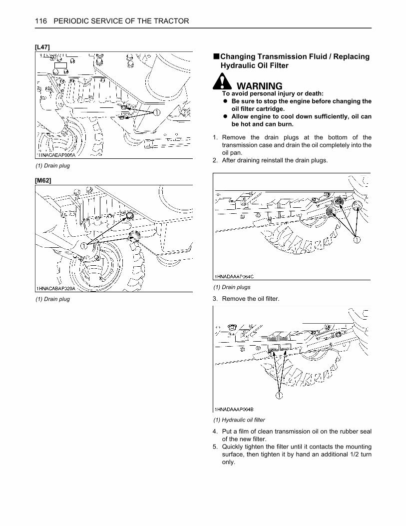
PERIODIC SERVICE OF THE TRACTOR116
[L47]
[M62]
BChanging Transmission Fluid / Replacing Hydraulic Oil Filter
To avoid personal injury or death:A Be sure to stop the engine before changing the
oil filter cartridge.A Allow engine to cool down sufficiently, oil can
be hot and can burn.
1. Remove the drain plugs at the bottom of thetransmission case and drain the oil completely into theoil pan.
2. After draining reinstall the drain plugs.
3. Remove the oil filter.
4. Put a film of clean transmission oil on the rubber sealof the new filter.
5. Quickly tighten the filter until it contacts the mountingsurface, then tighten it by hand an additional 1/2 turnonly.
(1) Drain plug
(1) Drain plug
(1) Drain plugs
(1) Hydraulic oil filter

117PERIODIC SERVICE OF THE TRACTOR
6. Fill with the new KUBOTA SUPER UDT fluid up to theupper notch on the dipstick.(See "LUBRICANTS, FUEL AND COOLANT" in"MAINTENANCE" section.)
7. After running the engine for a few minutes, stop theengine and check the oil level again, add oil to theprescribed level.
8. Make sure that the transmission fluid doesn't leak pastthe seal on the filter.
A To prevent serious damage to the hydraulic system,use only a KUBOTA genuine filter.
A Do not operate the tractor immediately after changingthe transmission fluid.Run the engine at medium speed for a few minutes toprevent damage to the transmission.
BReplacing Fuel Filter1. Remove the fuel filter.2. Put a film of clean fuel on rubber seal of new filter.3. Tighten the filter quickly until it contacts the mounting
surface.Tighten filter by hand an additional 1/2 turn only.
4. Bleed the fuel system.(See "Bleeding Fuel System" in "SERVICE ASREQUIRED" in "PERIODIC SERVICE" section.)
Oil Capacity 46 L (12.2 U.S.gals.)
(1) Dipstick(2) Oil inlet
(A) Oil level is acceptable within this range
(1) Fuel filter
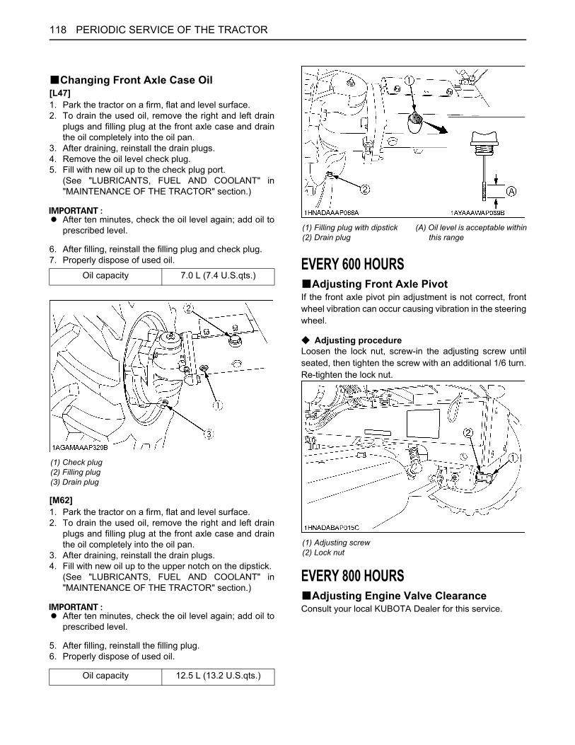
PERIODIC SERVICE OF THE TRACTOR118
BChanging Front Axle Case Oil[L47]1. Park the tractor on a firm, flat and level surface.2. To drain the used oil, remove the right and left drain
plugs and filling plug at the front axle case and drainthe oil completely into the oil pan.
3. After draining, reinstall the drain plugs.4. Remove the oil level check plug.5. Fill with new oil up to the check plug port.
(See "LUBRICANTS, FUEL AND COOLANT" in"MAINTENANCE OF THE TRACTOR" section.)
A After ten minutes, check the oil level again; add oil toprescribed level.
6. After filling, reinstall the filling plug and check plug.7. Properly dispose of used oil.
[M62]1. Park the tractor on a firm, flat and level surface.2. To drain the used oil, remove the right and left drain
plugs and filling plug at the front axle case and drainthe oil completely into the oil pan.
3. After draining, reinstall the drain plugs.4. Fill with new oil up to the upper notch on the dipstick.
(See "LUBRICANTS, FUEL AND COOLANT" in"MAINTENANCE OF THE TRACTOR" section.)
A After ten minutes, check the oil level again; add oil toprescribed level.
5. After filling, reinstall the filling plug. 6. Properly dispose of used oil.
EVERY 600 HOURSBAdjusting Front Axle PivotIf the front axle pivot pin adjustment is not correct, frontwheel vibration can occur causing vibration in the steeringwheel.
C Adjusting procedureLoosen the lock nut, screw-in the adjusting screw untilseated, then tighten the screw with an additional 1/6 turn.Re-tighten the lock nut.
EVERY 800 HOURSBAdjusting Engine Valve ClearanceConsult your local KUBOTA Dealer for this service.
Oil capacity 7.0 L (7.4 U.S.qts.)
(1) Check plug(2) Filling plug(3) Drain plug
Oil capacity 12.5 L (13.2 U.S.qts.)
(1) Filling plug with dipstick(2) Drain plug
(A) Oil level is acceptable within this range
(1) Adjusting screw(2) Lock nut

119PERIODIC SERVICE OF THE TRACTOR
EVERY 1000 HOURS or 1 YEAR
BReplacing Air Cleaner Primary Element and Secondary Element
(See "Cleaning Air Cleaner Primary Element" in "EVERY100 HOURS" section.)
EVERY 1500 HOURSBChecking Fuel Injection Nozzle Injection
PressureConsult your local KUBOTA Dealer for this service.
BReplacing Oil Separator Element
To avoid personal injury or death:A Be sure to stop the engine before replacing the
oil separator element.
1. Remove the cover and take out the element. Wipe offoil and the carbon in the case with a clean rag.
2. Fit a new oil separator element.3. Tighten the cover.
BChecking PCV (Positive Crankcase Ventilation) Valve
Consult your local KUBOTA Dealer for this service.
BChecking and Cleaning EGR CoolerConsult your local KUBOTA Dealer for this service.
EVERY 2000 HOURS or 2 YEARS
BFlush Cooling System and Changing Coolant
To avoid personal injury or death:A Do not remove radiator cap while coolant is
hot. When cool, slowly rotate cap to the firststop and allow sufficient time for excesspressure to escape before removing the capcompletely.
1. Stop the engine and let cool down.2. To drain the coolant, open the radiator drain plug and
remove radiator cap. The radiator cap must beremoved to completely drain the coolant.
3. After all coolant is drained, close the drain plug.4. Fill with clean soft water and cooling system cleaner.5. Follow directions of the cleaner instruction.6. After flushing, fill with clean soft water and anti-freeze
until the coolant level is just below the radiator cap.Install the radiator cap securely.
7. Fill with fresh water up to the "FULL" mark on thereserve tank.
8. Start and operate the engine for few minutes.9. Stop the engine and let cool.10.Check coolant level of recovery tank and add coolant
if necessary.
Be sure to do the following servicing once every 1 000hours or yearly, whichever comes first.
(1) Oil separator(2) Body(3) Oil separator element(4) Gasket(5) Cover
Be sure to do the following servicing once every 2 000hours or biennially, whichever comes first.
Coolant capacity 8.2 L (8.7 U.S.qts)
(1) Drain plug
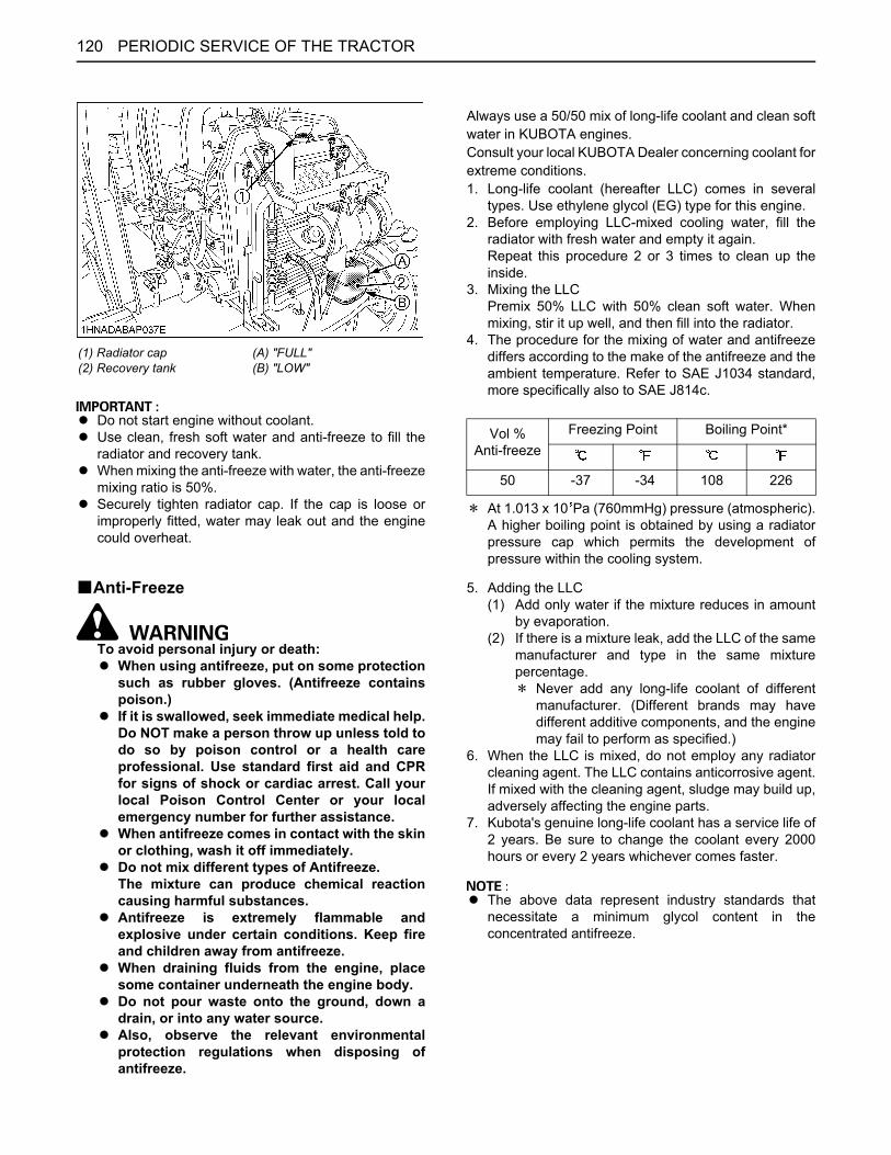
PERIODIC SERVICE OF THE TRACTOR120
A Do not start engine without coolant.A Use clean, fresh soft water and anti-freeze to fill the
radiator and recovery tank.A When mixing the anti-freeze with water, the anti-freeze
mixing ratio is 50%.A Securely tighten radiator cap. If the cap is loose or
improperly fitted, water may leak out and the enginecould overheat.
BAnti-Freeze
To avoid personal injury or death:A When using antifreeze, put on some protection
such as rubber gloves. (Antifreeze containspoison.)
A If it is swallowed, seek immediate medical help.Do NOT make a person throw up unless told todo so by poison control or a health careprofessional. Use standard first aid and CPRfor signs of shock or cardiac arrest. Call yourlocal Poison Control Center or your localemergency number for further assistance.
A When antifreeze comes in contact with the skinor clothing, wash it off immediately.
A Do not mix different types of Antifreeze.The mixture can produce chemical reactioncausing harmful substances.
A Antifreeze is extremely flammable andexplosive under certain conditions. Keep fireand children away from antifreeze.
A When draining fluids from the engine, placesome container underneath the engine body.
A Do not pour waste onto the ground, down adrain, or into any water source.
A Also, observe the relevant environmentalprotection regulations when disposing ofantifreeze.
Always use a 50/50 mix of long-life coolant and clean softwater in KUBOTA engines.Consult your local KUBOTA Dealer concerning coolant forextreme conditions.1. Long-life coolant (hereafter LLC) comes in several
types. Use ethylene glycol (EG) type for this engine.2. Before employing LLC-mixed cooling water, fill the
radiator with fresh water and empty it again.Repeat this procedure 2 or 3 times to clean up theinside.
3. Mixing the LLCPremix 50% LLC with 50% clean soft water. Whenmixing, stir it up well, and then fill into the radiator.
4. The procedure for the mixing of water and antifreezediffers according to the make of the antifreeze and theambient temperature. Refer to SAE J1034 standard,more specifically also to SAE J814c.
D At 1.013 x 10 Pa (760mmHg) pressure (atmospheric).A higher boiling point is obtained by using a radiatorpressure cap which permits the development ofpressure within the cooling system.
5. Adding the LLC(1) Add only water if the mixture reduces in amount
by evaporation.(2) If there is a mixture leak, add the LLC of the same
manufacturer and type in the same mixturepercentage.D Never add any long-life coolant of different
manufacturer. (Different brands may havedifferent additive components, and the enginemay fail to perform as specified.)
6. When the LLC is mixed, do not employ any radiatorcleaning agent. The LLC contains anticorrosive agent.If mixed with the cleaning agent, sludge may build up,adversely affecting the engine parts.
7. Kubota's genuine long-life coolant has a service life of2 years. Be sure to change the coolant every 2000hours or every 2 years whichever comes faster.
A The above data represent industry standards thatnecessitate a minimum glycol content in theconcentrated antifreeze.
(1) Radiator cap(2) Recovery tank
(A) "FULL"(B) "LOW"
Vol %Anti-freeze
Freezing Point Boiling Point*
50 -37 -34 108 226

121PERIODIC SERVICE OF THE TRACTOR
EVERY 3000 HOURSBChecking Turbocharger [M62]Consult your local KUBOTA Dealer for this service.
BChecking Supply PumpConsult your local KUBOTA Dealer for this service.
BChecking and Cleaning EGR SystemConsult your local KUBOTA Dealer for this service.
BCleaning DPF MufflerC Removal of ashThe longer the DPF operates, the more ash (burntresidue) is collected in the filter. Too much ash build-upadversely affects the DPF performance. Consult yourlocal KUBOTA Dealer to clean the filter.
A The DPF needs cleaning with a specific cleaningdevice. Do not clean the DPF by disassembling, andattempt by yourself, consult your local KUBOTADealer.
EVERY 1 YEARBChecking Fuel Line1. Check to see that all lines and hose clamps are tight
and not damaged.2. If hoses and clamps are found worn or damaged,
replace or repair them at once.
A If the fuel line is removed, be sure to properly bleed thefuel system.(See "Bleeding Fuel System" in "SERVICE ASREQUIRED" in "PERIODIC SERVICE OF THETRACTOR" section.)
(1) Fuel lines(2) Clamp bands
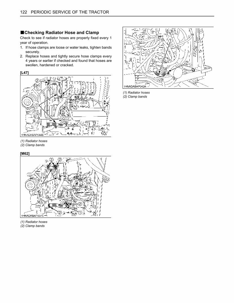
PERIODIC SERVICE OF THE TRACTOR122
BChecking Radiator Hose and ClampCheck to see if radiator hoses are properly fixed every 1year of operation.1. If hose clamps are loose or water leaks, tighten bands
securely.2. Replace hoses and tightly secure hose clamps every
4 years or earlier if checked and found that hoses areswollen, hardened or cracked.
[L47]
[M62]
(1) Radiator hoses(2) Clamp bands
(1) Radiator hoses(2) Clamp bands
(1) Radiator hoses(2) Clamp bands
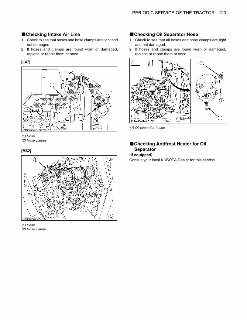
123PERIODIC SERVICE OF THE TRACTOR
BChecking Intake Air Line1. Check to see that hoses and hose clamps are tight and
not damaged.2. If hoses and clamps are found worn or damaged,
replace or repair them at once.
[L47]
[M62]
BChecking Oil Separator Hose1. Check to see that all hoses and hose clamps are tight
and not damaged.2. If hoses and clamps are found worn or damaged,
replace or repair them at once.
BChecking Antifrost Heater for Oil Separator
(if equipped)Consult your local KUBOTA Dealer for this service.
(1) Hose(2) Hose clamps
(1) Hose(2) Hose clamps
(1) Oil separator hoses

PERIODIC SERVICE OF THE TRACTOR124
BChecking Oil Cooler Line / Checking Power Steering Line
1. Check to see that all lines and hose clamps are tightand not damaged.
2. If hoses and clamps are found worn or damaged,replace or repair them at once.
BChecking Exhaust ManifoldConsult your local KUBOTA Dealer for this service.
BChecking DPF Differential Pressure Sensor Pipe
Consult your local KUBOTA Dealer for this service.
BChecking EGR PipeConsult your local KUBOTA Dealer for this service.
EVERY 2 YEARSBReplacing Rear Parking Brake CableReplace the cable.(See "Adjusting Rear Parking Brake Lever" in "EVERY100 HOURS" in "PERIODIC SERVICE OF THETRACTOR" section.)
EVERY 4 YEARSBReplacing Radiator Hose (Water pipes)Replace the hoses and clamps.(See "Checking Radiator Hose and Clamp" in "EVERY 1YEAR" in "PERIODIC SERVICE OF THE TRACTOR"section.)
BReplacing Power Steering HoseReplace the hoses and clamps.(See "Checking Power Steering line" in "EVERY 1 YEAR"maintenance)
BReplacing Oil Cooler LineReplace the hoses and clamps.(See "Checking Oil Cooler Line" in "EVERY 1 YEAR"maintenance)
BReplacing Fuel LinesReplace the hoses and clamps.(See "Checking Fuel line" in "EVERY 1 YEAR"maintenance)
BReplacing Intake Air LineConsult your local KUBOTA Dealer for this service.
BReplacing Oil Separator HoseConsult your local KUBOTA Dealer for this service.
BReplacing DPF Differential Pressure Sensor Hose
Consult your local KUBOTA Dealer for this service.
(1) Oil cooler line
(1) Power steering pressure hoses

125PERIODIC SERVICE OF THE TRACTOR
SERVICE AS REQUIREDBBleeding Fuel SystemAir must be removed:1. When the fuel filter or lines are removed.2. When water is drained from water separator.3. When tank is completely empty.4. After the tractor has not been used for a long period of
time.
C Bleeding procedure is as follows:1. Fill the fuel tank with fuel, and open the fuel shutoff-
valve.
2. Loosen the air vent plug on the fuel filter 2 turns or so.
3. Turn on the key switch and wait for about 1 minute.Then tighten up the air vent plug.
4. Set the hand throttle lever at the minimum speedposition and turn the key to "START" position.If the engine doesn't start, try it several times at 30second intervals.
A Do not hold key switch at engine start position for morethan 10 seconds continuously. If more engine crankingis needed, try again after 30 seconds.
5. Accelerate the engine to remove the small portion ofair left in the fuel system.
6. If air still remains and the engine stops, repeat theabove steps.
BDraining Clutch Housing WaterThe tractor is equipped with split pin plug under the clutchhousing.After operating in rain, snow or tractor has been washed,water may get into the clutch housing. Check it by pushingin the split pin.If water enters into the clutch housing, remove the plugand drain the water, then install the plug again.
(1) Fuel shutoff-valve (A) "CLOSE"(B) "OPEN"
(1) Air vent plug
(1) Split pin plugs

PERIODIC SERVICE OF THE TRACTOR126
BReplacing FuseThe tractor electrical system is protected from potentialdamage by fuses.A blown fuse indicates that there is an overload or shortsomewhere in the electrical system.If any of the fuses should blow, replace with a new one ofthe same capacity.
A Before replacing a blown fuse, determine why the fuseblew and make any necessary repairs. Failure tofollow this procedure may result in serious damage tothe tractor electrical system. Refer to the"TROUBLESHOOTING" section of this manual or yourlocal KUBOTA Dealer for specific information dealingwith electrical problems. C Protected circuit
FUSENo.
CAPACITY(A) Protected circuit
(1) 5 Meter (battery)
(2) 15 Flasher
(3) 5 Main ECU (battery)
(4) 15 ECU
(5) 10 Alternator
(6) 5 Work light switch
(7) 10 Combi switch
(8) 5 Engine ECU
(9) 10 Power outlet
(10) 30 Work light relay
(11) 30 Engine ECU relay
(12) 30 Head lamp relay
(13) 30 Starter relay
(14) Slow blow fuse Check circuit against wrong battery connection.

127PERIODIC SERVICE OF THE TRACTOR
BReplacing Light Bulb1. Head lights and rear combination lights:
Take the bulb out of the light body and replace with anew one.
2. Other lights:Detach the lens and replace the bulb.
[Oil separator Fuse]FuseNo.
Capacity(A) Protected circuit
(1) 15 Heater(2) 15 Heater(3) 15 Heater(4) 15 Heater(5) 5 Relay
Light CapacityHead lights 55WTail light 5WHazard and Turn signal light 27WHazard and Turn signal light (rear) 21WInstrument panel light 1.1W

128 MAINTENANCE OF THE LOADER
MAINTENANCE OF THE LOADER
To avoid personal injury or death:A Escaping hydraulic fluid under pressure can
have sufficient force to penetrate skin, causingserious personal injury. Before disconnectinglines, be sure to relieve all pressure.Before applying pressure to system, be sure allconnections are tight and that lines, tubes, andhoses are not damaged. Fluid escaping from avery small hole can be almost invisible. Use apiece of cardboard or wood, rather than yourhands, to search for suspected leaks.
If injured by escaping fluid, see a doctor atonce. Serious infection or allergic reaction willdevelop if proper medical treatment is notadministered immediately.
A When removing the engine side covers, becareful not to touch hot loader cylinders.Allow all surfaces to cool before performingmaintenance.
A Before servicing the loader or the tractor, besure to place the loader boom in contact withthe ground. If the loader boom must be raisedduring service or maintenance, support theboom as shown in the figure.
To avoid personal injury or death:A Be sure to check and service the tractor on a
flat place with the bucket on the ground, engineshut off, the key removed and the parkingbrake on.
DAILY CHECKS1. Check all hardware daily before operation.
Tighten hardware to torque values as specified in the"Tightening Torque Chart".
2. With the engine off and the bucket on the ground,inspect all hoses for cuts or wear. Check for signs ofleaks and make sure all fittings are tight.
(1) Cardboard(2) Hydraulic line(3) Magnifying glass

129MAINTENANCE OF THE LOADER
LUBRICATION1. Lubricate all grease fittings every 10 hours of
operation. Also, lubricate joints of control lever linkageevery 10 hours. High quality grease designating"extreme pressure" and containing Molybdenumdisulfide is recommended. This grease may specify"Moly EP" on its label.

130 MAINTENANCE OF THE LOADER
GENERAL TORQUE SPECIFICATIONIf the torque levels are specified in the text, follow that specification.
American standard screws, bolts and nuts with UNC or UNF threads Metric cap screws
SAE grade No. SAE GR.5 SAE GR.8 property class 8.8 Approx. SAE GR 5
1/4(N m)
(kgf m)(lbf ft)
11.7 to 15.81.19 to 1.61 8.6 to 11.6
16.3 to 19.81.66 to 2.0212.0 to 14.6
M6(N m)
(kgf m)(lbf ft)
9.8 to 11.21.0 to 1.17.2 to 8.3
5/16(N m)
(kgf m)(lbf ft)
23.1 to 27.82.35 to 2.8317.0 to 20.5
32.5 to 39.33.31 to 4.0124.0 to 29.0
M8(N m)
(kgf m)(lbf ft)
23.6 to 27.42.4 to 2.8
17.4 to 20.2
3/8(N m)
(kgf m)(lbf ft)
47.5 to 57.04.84 to 5.8135.0 to 42.0
61.0 to 73.26.22 to 7.4645.0 to 54.0
M10(N m)
(kgf m)(lbf ft)
48.1 to 55.84.9 to 5.7
35.5 to 41.2
1/2(N m)
(kgf m)(lbf ft)
108.5 to 130.211.06 to 13.28
80.0 to 96.0
149.2 to 179.015.21 to 18.25110.0 to 132.0
M12(N m)
(kgf m)(lbf ft)
77.5 to 90.17.9 to 9.2
57.2 to 66.5
9/16(N m)
(kgf m)(lbf ft)
149.2 to 179.015.21 to 18.25110.0 to 132.0
217.0 to 260.422.13 to 26.55160.0 to 192.0
M14(N m)
(kgf m)(lbf ft)
124 to 14712.6 to 15.0
91.5 to 108.4
5/8(N m)
(kgf m)(lbf ft)
203.4 to 244.120.74 to 24.89150.0 to 180.0
298.3 to 358.030.42 to 36.51220.0 to 264.0
M16(N m)
(kgf m)(lbf ft)
196 to 22520.0 to 23.0145 to 166

131STORAGE OF THE TRACTOR
STORAGE OF THE TRACTOR
To avoid personal injury or death:A Do not clean the machine while the engine is
running.A To avoid the danger of exhaust fume
poisoning, do not operate the engine in aclosed building without proper ventilation.
A When storing, remove the key from the keyswitch to avoid unauthorized persons fromoperating the tractor and getting injured.
TRACTOR STORAGEIf you intend to store your tractor for an extended periodof time, follow the procedures outlined below.These procedures will insure that the tractor is ready tooperate with minimum preparation when it is removedfrom storage.1. Check the bolts and nuts for looseness, and tighten if
necessary.2. Apply grease to tractor areas where bare metal will
rust also to pivot areas.3. Detach the weights from the tractor body.4. Inflate the tires to a pressure a little higher than usual.5. Change the engine oil and run the engine to circulate
oil throughout the engine block and internal movingparts for about five minutes.
6. Pull the engine stop knob all the way out.7. With all implements lowered to the ground, coat any
exposed hydraulic cylinder piston rods with grease.8. Remove the battery from the tractor. Store the battery
following the battery storage procedures.(See "Battery condition" in "EVERY 100 HOURS" in"PERIODIC SERVICE" section)
9. Keep the tractor in a dry place where the tractor issheltered from the elements. Cover the tractor.
10.Store the tractor indoors in a dry area that is protectedfrom sunlight and excessive heat. If the tractor must bestored outdoors, cover it with a waterproof tarpaulin.Jack the tractor up and place blocks under the frontand rear axles so that all four tires are off the ground.Keep the tires out of direct sunlight and extreme heat.
A When washing the tractor, be sure to stop the engine.Allow sufficient time for the engine to cool beforewashing.
A Do not spray high-pressure water directly on the safetylabels, otherwise the safety labels may peel off.
A Cover the tractor after the muffler and the engine havecooled down.
REMOVING THE TRACTOR FROM STORAGE1. Check the tire air pressure and inflate the tires if they
are low.2. Jack the tractor up and remove the support blocks
from under the front and rear axles.3. Install the battery. Before installing the battery, be sure
it is fully charged.4. Check the fan belt tension.5. Check all fluid levels (engine oil, transmission/
hydraulic oil, engine coolant and any attachedimplements).
6. Start the engine. Observe all gauges. If all gauges arefunctioning properly and reading normal, move thetractor outside. Once outside, park the tractor and letthe engine idle for at least 5 minutes. Shut the engineoff and walk around tractor and make a visualinspection looking for evidence of oil or water leaks.
7. With the engine fully warmed up, release the parkingbrake and test the brakes for proper adjustment as youmove forward. Adjust the brakes as necessary.

132 TROUBLESHOOTING
TROUBLESHOOTING
ENGINE TROUBLESHOOTINGIf something is wrong with the engine, refer to the table below for the cause and its corrective measure.If you have any questions, consult your local KUBOTA Dealer.
Trouble Cause Countermeasure
Engine is difficult to start or won't start.
A No fuel flow. A Check the fuel tank and the fuel filter.Replace filter if necessary.
A Air or water is in the fuel system. A Check to see if the fuel line coupler bolt andnut are tight.
A Bleed the fuel system(See "Bleeding Fuel System" in "SERVICE ASREQUIRED" in "PERIODIC SERVICE OFTHE TRACTOR" section.)
A In winter, oil viscosity increases,and engine revolution is slow.
A Use oils of different viscosities, depending onambient temperatures.
A Use engine block heater (Optional)
A Battery becomes weak and theengine does not turn over quickenough.
A Clean battery cables & terminals.A Charge the battery.A In cold weather, always remove the battery
from the engine, charge and store it indoors.Install it on the tractor only when the tractor isgoing to be used.
Insufficient engine power. A Insufficient or dirty fuel.A The air cleaner is clogged.
A Check the fuel system.A Clean or replace the element.
Engine stops suddenly. A Insufficient fuel. A Refuel.A Bleed the fuel system if necessary.
Exhaust fumes are colored.
BlackA Fuel quality is poor.A Too much oil.A The air cleaner is clogged.
A Change the fuel and fuel filter.A Check the proper amount of oil.A Clean or replace the element.
Bluewhite
A The inside of exhaust muffler isdamp with fuel.
A Injection nozzle trouble.A Fuel quality is poor.
A Heat the muffler by applying load to theengine.
A Check the injection nozzle.A Change the fuel and fuel filter.
Engine overheats
A Engine overloaded A Shift to lower gear or reduce load.
A Low coolant level A Fill cooling system to the correct level;check radiator and hoses for looseconnections or leaks.
A Loose or damaged fan belt A Adjust or replace fan belt.
A Dirty radiator core or grille screens A Remove all trash.
A Coolant flow route corroded A Flush cooling system.

133TROUBLESHOOTING
TROUBLESHOOTING
(A) Error message is displayed at here
Display on IntelliPanel(TM) Trouble Item (Affected Model) Operator's action
ERROR No. 20 CAN NG
Communication error between ECU and IntelliPanel(TM)
Contact your local KUBOTA Dealer.ERROR No. 30 ECU Memory DEVICE NG
ECU's memory device is in trouble
ERROR No. 40 Input Voltage NG
Input voltage of lever sensor from ECU is in trouble
ERROR No. 80 Range Shift SENSOR NG
Sensor for range gear shift lever is in trouble
Contact your local KUBOTA Dealer.The speed range (H, M and L) is not displayed in the LCD screen. The range gear shift lever still works to select the H, M and L speeds. In selecting M or L, however, the feeling is somewhat different at a start, stop and other actions.
ERROR No. 81 HST Pedal SENSOR NG
Sensor for speed control pedal is in trouble
Contact your local KUBOTA Dealer.The speed control pedal cannot be used to run the tractor.
ERROR No. 82 Swash Plate SENSOR NG
Sensor for swash plate of HST is in trouble
Contact your local KUBOTA Dealer.The tractor can travel both forward and backward, but with a drop in maximum speed.
ERROR No. 84 Throttle SENSOR NG
Sensor for engine throttle is in trouble
Contact your local KUBOTA Dealer.With the STALL GUARD or AUTO H-DS/STALL GUARD mode being selected, the tractor automatically gets in the MANUAL mode.ERROR No. 87
Engine Speed SENSOR NGSensor for engine revolution is in trouble
ERROR No. 90 HST-F SOLENOID NG
Proportional valve for forward is in trouble
Contact your local KUBOTA Dealer.The tractor cannot travel forward (backward only).
ERROR No. 91 HST-R SOLENOID NG
Proportional valve for reverse is in trouble
Contact your local KUBOTA Dealer.The tractor cannot travel backward (forward only).
ERROR No. 92 Hi-Lo SOLENOID NG
Motor for Hi-Lo shift is in trouble Contact your local KUBOTA Dealer.Using the H-DS lever, the Lo speed alone can be selected (Hi speed not selectable).In the HST mode, only the STALL GUARD and MANUAL modes can be selected.

134 TROUBLESHOOTING
ERROR No. 93 Starter RELAY NG
Relay for engine starter motor is in trouble
Contact your local KUBOTA Dealer.The engine cannot start.
ERROR No. 94 OPC NG
Relay for engine shut off is in trouble
Contact your local KUBOTA Dealer.The Operator Presence Control (OPC) system gets activated, and the engine stops itself.
ERROR No. 95 PTO SOLENOID NG
Solenoid (PTO) is in trouble Contact your local KUBOTA Dealer.The PTO shaft cannot rotate.
Display on IntelliPanel(TM) Trouble Item (Affected Model) Operator's action

135OPTIONS
OPTIONS
Consult your local KUBOTA Dealer for further details.A Engine Block HeaterFor extremely cold weather starting
A Work LightHigh visibility for night work
A Tool BoxA Double Acting Remote Hydraulic Control ValveA 3-point Hitch Storage HolderA 3-point HitchA DrawbarA 3rd function valveA Multi-Coupler SystemA Hydraulic 2-lever Quick Coupler

136 APPENDICES
APPENDICES
INDEX3-point Hitch Lowering Speed ........................80Air Cleaner Primary Element........................108Air Cleaner Primary Element and Secondary Element ......................................119Anti-Freeze...................................................120Antifrost Heater for Oil Separator .................123Antifrost Heater for Oil Separator (if equipped) ...................................................28ATA (Auto Throttle Advance) Switch..............45Battery Condition..........................................111Block Heater (if equipped)..............................28Brake Pedal..................................................105Brake Pedal..................................................110Brake Pedals (Right and Left) ........................35Check Chains .................................................75Check Easy Checker(TM) Lamps: .................25Clutch Housing Water ..................................125Control Switch ................................................83Coolant Level ...............................................103Coolant Temperature Gauge..........................51Crawl Control Lever........................................45Diesel Particulate Filter (DPF) Muffler............16Differential Lock..............................................52Directional Valve Lever and Swing Lever.......80Directions for Use of Power Steering .............54Display Mode..................................................46Do not Operate the Tractor at Full Speed for the First 50 Hours......................................30DPF Differential Pressure Sensor Hose.......124DPF Differential Pressure Sensor Pipe ........124DPF Muffler ..................................................104DPF Muffler ..................................................121DPF Regeneration Process............................17Drawbar (if equipped).....................................73Drawbar Length..............................................75Dust Indicator ...............................................104Easy Checker(TM) .........................................50EGR Cooler ..................................................119EGR Pipe .....................................................124EGR System.................................................121Engine Oil.....................................................115Engine Oil Filter............................................115Engine Oil Level ...........................................102Engine Start System.....................................107Engine Valve Clearance...............................118Exhaust Manifold..........................................124Fan Belt Tension ..........................................109Float Control .................................................. 80Floor Seat Cover ......................................... 100Flush Cooling System and Coolant ............. 119Front Axle Case Oil ..................................... 118Front Axle Pivot ........................................... 118Front Ballast .................................................. 90Front Cover.................................................. 100Front Wheel Drive Lever................................ 42Fuel Filter..................................................... 117Fuel Gauge.................................................... 51Fuel Injection Nozzle Injection Pressure ..... 119Fuel Line...................................................... 121Fuel Lines .................................................... 124Fuel System................................................. 125Fuse............................................................. 126Gauges, Meter and Easy Checker(TM)....... 105Glove Box ...................................................... 31Grill, Radiator Screen and Oil Cooler .......... 104Handling Points ............................................. 17H-DS (Hydro Dual Speed) Lever ................... 38Head Light, Hazard Light etc. ...................... 105Hood .............................................................. 99Horn Button ................................................... 34HST Mode ..................................................... 39HST Response Control.................................. 37Hydraulic 2-lever Quick Coupler Switch (if equipped)................................................... 68Hydraulic Control Unit Use Reference Chart ..................................... 87Immediately Stop the Engine if: ..................... 49Inflation Pressure........................................... 88Install the Coupler.......................................... 82Installing the Lower Link ................................ 78Instructions for towing the tractor .................. 54Intake Air Line.............................................. 123Intake Air Line.............................................. 124IntelliPanel(TM) Message.............................. 26IntelliPanel(TM) Message.............................. 27IntelliPanel(TM) Message.............................. 49IntelliPanel(TM) Message.............................. 70Lifting Rod (Right).......................................... 74Light Bulb..................................................... 127Light switch.................................................... 32Liquid Ballast in Rear Tires............................ 15Lower Link ..................................................... 76Lower Link ..................................................... 77Lower Link Holder.......................................... 75Lubricating Grease Fittings.......................... 105

137APPENDICES
Lubricating Oil for New Tractors.....................30Movable Parts ..............................................105MULTI-COUPLER SYSTEM (if equipped) .....84Oil Cooler Line..............................................124Oil Cooler Line / Power Steering Line ..........124Oil Separator Element ..................................119Oil Separator Hose.......................................123Oil Separator Hose.......................................124Operating on Slopes and Rough Terrain........53Operating the Tractor on a Road....................53Operator Presence Control ..........................107Operator's Seat ..............................................31Parking ...........................................................52Parking Brake.................................................43PCV (Positive Crankcase Ventilation) Valve ............................................................119PM Warning Level and Required Procedures .....................................19PM Warning Level and Required Procedures .....................................21Position Control ..............................................79Power Steering Hose ...................................124PTO Clutch Control Switch.............................69PTO shaft Cover and Shaft Cap.....................71Radiator Hose (Water pipes)........................124Radiator Hose and Clamp............................122Range Gear Shift Lever (L-M-H) ....................42Rear Ballast....................................................90Rear Parking Brake Cable............................124Rear Parking Brake Lever ............................110Rear Work Light Switch..................................33Refueling ......................................................101Regeneration Operating Procedure ...............18Regeneration Operating Procedure ...............20Remote Control Coupler Connecting and Disconnecting.................................................83Remote Control Valve ....................................82Remote Control Valve Coupler Connecting and Disconnecting..........................................81Remote Control Valve Lever ..........................81Resetting the Trip Meter and Setting the Clock ............................................47Seat Belt.........................................................32Seat Belt, ROPS and FOPS.........................105Selecting Category .........................................73SERVICE INSPECT mode displaying/resetting procedure .......................48Side Cover....................................................100Speed Control Pedal ......................................44Stationary PTO...............................................70Stopping .........................................................45Supply Pump................................................121
Tachometer ................................................... 52Throttle Lever ................................................ 43Throttle-Up Switch ......................................... 41Tilt Steering Adjustment ................................ 32Tips on Diesel Particulate Filter (DPF) Regeneration ................................................. 23Toe-in .......................................................... 113Top Link......................................................... 74Top Link and Lifting Rod................................ 76Top Link and Lifting Rod................................ 78Top Link Mounting Holes............................... 73Tractor Lights................................................. 34Transmission Fluid / Hydraulic Oil Filter ...... 116Transmission Fluid Level ............................. 103Transmission Oil Filter [HST]....................... 112Transport the Tractor Safely .......................... 54Treads ........................................................... 88Turbocharger [M62] ..................................... 121Turn Signal / Hazard Light Switch ................. 33Walk Around Inspection............................... 101Warm-up Transmission Oil at Low Temperature Range............................... 28Water Separator .......................................... 102Water Separator .......................................... 114Wheel Nut Torque ....................................... 108