
operator's manual - sm-abm-1218-fr - Steelmax
28
The tools of innovation. 112 Inverness Circle East Suite F Englewood, CO 80112 1– 87STEELMAX, FAX 303 – 690 – 9172 www.steelmax.com [email protected] OPERATOR’S MANUAL S S M M - - A A B B M M - - 1 1 2 2 1 1 8 8 - - F F R R BEVELING MACHINE
-
Upload
khangminh22 -
Category
Documents
-
view
14 -
download
0
Transcript of operator's manual - sm-abm-1218-fr - Steelmax

The tools of innovation.
112 Inverness Circle East Suite F Englewood, CO 80112
1– 87STEELMAX, FAX 303 – 690 – 9172
www.steelmax.com [email protected]
OPERATOR’S MANUAL
SSMM--AABBMM--11221188--FFRR
BEVELING MACHINE

Contents
1. GENERAL INFORMATION ............................................................................................... 3
1.1. Application ................................................................................................................. 3
1.2. Technical data............................................................................................................ 3
1.3. Equipment included ................................................................................................... 5
1.4. Dimensions ................................................................................................................ 6
1.5. Design ....................................................................................................................... 7
2. SAFETY PRECAUTIONS .................................................................................................. 8
3. STARTUP AND OPERATION ..........................................................................................10
3.1. Preparing for beveling plates .....................................................................................10
3.2. Preparing for beveling pipes......................................................................................11
3.3. Operating ..................................................................................................................12
3.4. Replacing the cutter ..................................................................................................14
3.5. Checking the oil level ................................................................................................15
3.6. Replacing the oil .......................................................................................................16
4. ACCESSORIES ...............................................................................................................17
4.1. Cutters ......................................................................................................................17
4.2. Guides ......................................................................................................................17
4.3. Carriage ....................................................................................................................20
5. EXPLODED VIEWS AND PARTS LIST ............................................................................22
6. WIRING DIAGRAM ..........................................................................................................26
7. DECLARATION OF CONFORMITY .................................................................................27
8. WARRANTY CARD ..........................................................................................................28

SM-ABM-1218-FR
SM-ABM-1218-FR Operator’s Manual
3
1. GENERAL INFORMATION
1.1. Application
The SM-ABM-1218-FR is a beveling machine designed to mill plates and pipes made
of carbon steel, alloy steel, stainless steel, or aluminum alloys. The machine can
bevel plates and pipes at the angle of 30°. The minimum plate width is 55 mm (2-
3/16″) and the minimum inner diameter of the pipe is 100 mm (4″). The maximum
bevel width is 14 mm (9/16″). The machine can bevel plates from the top and bottom.
Optional guides allow bevelling at the angle of 22.5°, 25°, 35°, 37.5°, or 45°.
1.2. Technical data
Voltage 3~ 460 V + PE, 50–60 Hz
3~ 240 V + PE, 50–60 Hz
Power 2.2 kW
Rotational speed 9 rpm (for 50 Hz)
11 rpm (for 60 Hz)
Milling speed 2.6 m/min (8.5 ft/min, for 50 Hz)
3.1 m/min (10.2 ft/min, for 60 Hz)
Bevel angle (ß, Fig. 1)
30°
22.5° *
25° *
35° *
37.5° *
45° *
Maximum bevel width (b, Fig. 1) 14 mm (9/16’’)
Workpiece thickness 6–40 mm (1/4–1-9/16’’)
Minimum plate width 55 mm (2-3/16’’)
Minimum pipe inner diameter 100 mm (4’’)
Protection level IP 44
Protection class I
Required ambient temperature 0–40 °C (34–104°F)
Weight 65 kg (144 lbs)
* When used with an optional guide.

SM-ABM-1218-FR
SM-ABM-1218-FR Operator’s Manual
4
Maximum bevel width/height in one pass
Carbon steel
Rm ≤ 392 MPa
(57,000 psi)
Rm = 392–490 MPa
(57,000–71,000 psi)
Rm = 490–588 MPa
(71,000–85,000 psi)
β b
[mm]
a [mm]
b [mm]
a [mm]
b [mm]
a [mm]
22.5° 12 11 10 9 8 7.5
30° 12 10 10 8.5 8 7
35° 12 9.5 10 8 8 6.5
37.5° 12 9 10 7.5 8 6
45° 12 8.5 10 7 8 5.5
Stainless/alloy steel
Rm ≤ 490 MPa (71,000 psi)
Rm = 490–588 MPa (71,000–85,000 psi)
Rm = 588–686 MPa (85,000–100,000 psi)
22.5° 6 5.5 5 4.5 4.2 3.8
30° 6 5 5 4.3 4.2 3.6
35° 6 5 5 4 4.2 3.5
37.5° 6 4.5 5 4 4.2 3.3
45° 6 4 5 3.5 4.2 3
Fig. 1. Bevel dimensions; maximum bevel width/height in one pass depending on the angle
and type/hardness of the material

SM-ABM-1218-FR
SM-ABM-1218-FR Operator’s Manual
5
1.3. Equipment included
1 Beveling machine with cutter for stainless steel 1 unit
2 Wooden box 1 unit
3 Cutter extraction tool 1 unit
4 12–13 mm flat wrench 1 unit
5 18–19 mm flat wrench 1 unit
6 24–26 mm flat wrench 1 unit
7 5 mm hex wrench 1 unit
8 6 mm hex wrench 1 unit
9 Shaft 1 unit
10 Washer 1 unit
– Operator’s Manual 1 unit
1
2
3
4
5
6
7
8
9
10

SM-ABM-1218-FR
SM-ABM-1218-FR Operator’s Manual
6
320
mm
(13’
’)
589
mm
(23’
’)
541 mm (21’’)
1.4. Dimensions

SM-ABM-1218-FR
SM-ABM-1218-FR Operator’s Manual
7
Scale
Clamp
Guide
Guide roller
Emergency
switch
Power switch
Rotation direction switch
Adjustment bolt
Cutter
Air vent valve
1.5. Design

SM-ABM-1218-FR
SM-ABM-1218-FR Operator’s Manual
8
2. SAFETY PRECAUTIONS
1. Before use, read this Operator’s Manual and complete a training in occupational
safety and health.
2. Use only in applications specified in this Operator’s Manual.
3. Make sure that the machine has all parts and they are genuine and not damaged.
4. Make sure that the specifications of the power source are the same as those
specified on the rating plate.
5. Let only qualified electrician do the connection to the power source.
6. Do not pull the cord. This can cause damage and electric shock.
7. Put the machine on a stable surface. An incorrectly prepared surface can cause
damage, incorrect machine work, and injuries to persons nearby.
8. Keep untrained bystanders away from the machine.
9. Before each use, ensure the correct condition of the machine, power source,
power cord, plug, and tools.
10. Before each use, make sure that no part is cracked or loose. Make sure to main-
tain correct conditions that can have an effect on the operation of the machine.
11. Keep the machine dry. Do not expose the machine to rain, snow, or frost.
12. Keep the worksite well lit, clean, and free of obstacles.
13. Make sure that the cutter is correctly attached by using the washer and the nut.
Remove wrenches and tools from the work area before you connect the machine
to the power source.
14. Do not use cutters that are dull or damaged.
15. If the cutter is dull or damaged, replace it with a new cutter specified in this
Operator’s Manual.
16. Do not make bevels or use workpieces which parameters differ from those speci-
fied in the technical data.
17. Do not use near flammable materials, or in explosive environments.
18. Use eye protection, gloves, and protective clothing. Do not use loose clothing.
19. Do not touch chips, moving parts, or hot parts. Do not let anything catch in mov-
ing parts. Some parts of the machine are hot during work.
20. After each use, clean the machine and the cutter with a cotton cloth and no
chemical agents. Do not remove chips with bare hands.

SM-ABM-1218-FR
SM-ABM-1218-FR Operator’s Manual
9
21. Maintain the machine and install/remove parts and tools only after you unplug the
machine from the power source.
22. Repair only in a service center appointed by the seller.
23. If the machine falls, is wet, or has any damage, stop the work and promptly send
the machine to the service center for check and repair.
24. Do not leave the machine when it operates.
25. If you are not going to use the machine for an extended period, put anti-corrosion
material on the steel parts.

SM-ABM-1218-FR
SM-ABM-1218-FR Operator’s Manual
10
1
3
2
5
4 7
6
3. STARTUP AND OPERATION
3.1. Preparing for beveling plates
Use the 24 mm flat wrench to loosen the nut (1, Fig. 2). Rotate the bolt (2) so that the
scale is set to the value of the plate thickness (3), and then tighten the nut. Next, put
the plate on the support roller (4), and then use the knob (5) so that the clamp rollers
are on the plate (6, 7).
Fig. 2. Adjusting the bevel height and the clamp

SM-ABM-1218-FR
SM-ABM-1218-FR Operator’s Manual
11
3.2. Preparing for beveling pipes
Use the 24 mm flat wrench to remove the nut (1, Fig. 3) and remove the guide (2).
Install the washer (3) to the position where the guide was, and lightly tighten the nut
(4). Rotate the bolt (5) so that the scale is set to the value of the pipe wall thickness
(6), and then tighten the nut (4) as much as possible. Next, attach the shaft (7) and
put the pipe onto the guide roller (8). Use the knob (9) so that the clamp rollers are
on the pipe (10, 11). Make sure that the rollers do not press the pipe firmly.
Fig. 3. Installing the washer and adjusting the bevel height and the clamp
1
2
3
4
7
8
9
10
11
5
6

SM-ABM-1218-FR
SM-ABM-1218-FR Operator’s Manual
12
3.3. Operating
Connect the machine to the power source and use the power switch to turn on the
power. Open the top air vent valve. Set the rotation direction switch to “1” and make
sure that the cutter rotates in direction (1, Fig. 4). If it rotates in the opposite direction,
set the switch to “2”. Next, put the plate (2) so that it is on the slide and the support
rollers (3). To bevel a pipe, put it on the guide roller, move it to the slide (4, 5), and
keep the pipe in this position.
Fig. 4. Beveling plates or pipes
2
1
3
1
4
5

SM-ABM-1218-FR
SM-ABM-1218-FR Operator’s Manual
13
After you start the milling, the workpiece moves automatically. To bevel the plate
from the bottom, put the machine upside down and move the plate to the direction
opposite to (2, Fig. 4).
Some parts of the machine are hot during work. Do not touch hot parts.
When you mill workpieces not made of carbon steel, that have larger hardness
(Rm ≥ 392 MPa), or at an angle larger than 30° (Fig. 1), set the scale to a value larger
than the workpiece thickness.
To decrease the bevel width/height, increase the value on the scale. To increase
the bevel width/height, decrease the value on the scale.
If needed, do multiple passes to get the required bevel width.
When the bevel width is too large for the type/hardness of material or when the
cutter is dull, the cutter can jam in the workpiece and the feed can stop. Then, do not
push the workpiece because this can cause damage to the machine. In such a case,
set the rotation direction switch to the opposite position to retract the workpiece. How-
ever, do not let the cutter jam in the workpiece. Thus, machine hard materials in
multiple passes and replace the cutter before it becomes dull.
In an emergency, press the emergency switch. To restart the machine, remove
the cause of the emergency. Then, unlock the emergency switch and press the power
switch.
After the work is finished, turn off the machine and close the top air vent valve.
Clean the machine with a cotton cloth and no chemical agents.

SM-ABM-1218-FR
SM-ABM-1218-FR Operator’s Manual
14
3.4. Replacing the cutter
Use the 6 mm hex wrench to remove the screws and remove the clamp assembly
(Fig. 5). Use the 24 mm flat wrench to remove the nut, and then remove the cutter. If
needed, use the cutter extraction tool.
Fig. 5. Replacing the cutter
Install in reverse sequence, and then attach the clamp assembly.

SM-ABM-1218-FR
SM-ABM-1218-FR Operator’s Manual
15
3.5. Checking the oil level
Use the 24 mm flat wrench to remove the oil plug. Then, start the machine and make
sure that oil flows through the top of the worm wheel.
If you cannot see the oil near the top of the worm wheel when the machine
operates, turn off the machine. Then, fill with some VERKOL WG oil and do the oil
level check again. Fill the oil up to 75% of the full volume.
Oil level required (do the check when the
machine operates)
Worm wheel

SM-ABM-1218-FR
SM-ABM-1218-FR Operator’s Manual
16
3.6. Replacing the oil
Replace oil every 10,000 work hours. To do this, put the machine upside down and
tilt it so that the body is level. Then, use the 24 mm flat wrench to remove the oil plug
and wait until the oil flows out. Put the machine the right way up and put 1.5 kg
(3.3 lbs) of VERKOL WG oil into the machine, and then attach the oil plug.

SM-ABM-1218-FR
SM-ABM-1218-FR Operator’s Manual
17
4. ACCESSORIES
4.1. Cutters
4.2. Guides
Allow you to bevel at the angle of 22.5°, 25°, 35°, 37.5°, or 45°. Each guide includes
a guide roller.
Part number Part name
FRZ-000586 Cutter for carbon steel
FRZ-000587 Cutter for aluminum
FRZ-000588 Cutter for stainless steel
Part number Part name
PRW-000100 Guide 22.5°
PRW-000101 Guide 25°
PRW-000102 Guide 35°
PRW-000103 Guide 37.5°
PRW-000104 Guide 45°
PRW-000105 Guide 30° (standard)

SM-ABM-1218-FR
SM-ABM-1218-FR Operator’s Manual
18
Use the 24 mm flat wrench to remove the nut, and then remove the guide and the
guide roller.
To bevel plates, install the guide roller and the guide, and then tighten the nut.

SM-ABM-1218-FR
SM-ABM-1218-FR Operator’s Manual
19
To bevel pipes, install the guide roller and the washer, and then tighten the nut and
attach the shaft.
SM-ABM-1218-FR
SM-ABM-1218-FR Operator’s Manual
20
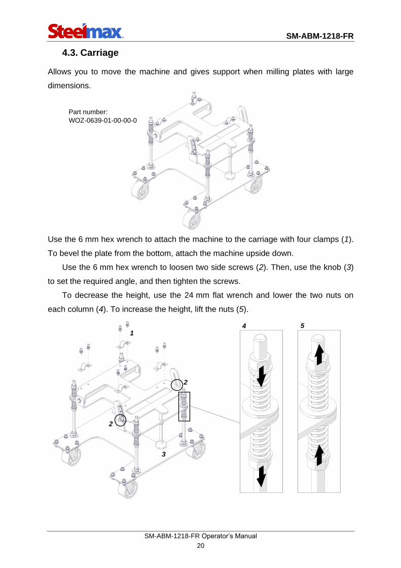
4.3. Carriage
Allows you to move the machine and gives support when milling plates with large
dimensions.
Use the 6 mm hex wrench to attach the machine to the carriage with four clamps (1).
To bevel the plate from the bottom, attach the machine upside down.
Use the 6 mm hex wrench to loosen two side screws (2). Then, use the knob (3)
to set the required angle, and then tighten the screws.
To decrease the height, use the 24 mm flat wrench and lower the two nuts on
each column (4). To increase the height, lift the nuts (5).
Part number:
WOZ-0639-01-00-00-0
2
3
4
2
5 1

SM-ABM-1218-FR
SM-ABM-1218-FR Operator’s Manual
21
Bevel in the directions shown in the figure. After you start the milling, the machine
moves automatically.
Top bevel
Bottom bevel

SM-ABM-1218-FR
SM-ABM-1218-FR Operator’s Manual
22
5. EXPLODED VIEWS AND PARTS LIST
1
2
3
4
5
6
7
8
9
ITEM PART NUMBER DESCRIPTION Q-TY
1 SCG-000002 MILLING CUTTER EXTRACTION TOOL 1
2 FRZ-000588 MILLING CUTTER FOR STAINLESS STEEL 1
3 KLC-000068 12-13 MM FLAT WRENCH 1
4 KLC-000069 18-19 MM FLAT WRENCH 1
5 KLC-000070 24-26 MM FLAT WRENCH 1
6 KLC-000008 5 MM HEX WRENCH 1
7 KLC-000009 6 MM HEX WRENCH 1
8 TRZ-000017 TUBE BEVELING SHAFT 1
9 PDK-000240 TUBE BEVELING WASHER 1

SM-ABM-1218-FR
SM-ABM-1218-FR Operator’s Manual
23
93
42
40
3231
92
17
91
90
89
88
87
94
86
85
84
83
73
72
74
67
7170
58
69
68
65
75
6364
62
66
61
82
60
81
38
3
59
37
56
57
55
8079
36
54
35
51
52
78
34
53
50
77
48
47
49
76
46
45
33
41
39
3029
28
15
18
43
19
2524
2726
14
44
16
20
2
1
21
13
2223
12
11
10
9
8
7
5
6
4

SM-ABM-1218-FR
SM-ABM-1218-FR Operator’s Manual
24
ITEM PART NUMBER DESCRIPTION Q-TY
1 SRB-000148 HEX SOCKET HEAD CAP SCREW M8x20 9
2 PDK-000051 SPRING WASHER 8.2 13
3 RMK-000021 LOWER SUPPORT FRAME 1
4 SRB-000155 HEX SOCKET HEAD CAP SCREW M8x30 4
5 PKT-000053 ADJUSTMENT WHEEL 1
6 KLK-000140 SPRING PIN 6x30 1
7 SRB-000436 ADJUSTMENT SPINDLE 1
8 NKR-000002 HEX NUT M10 2
9 PDK-000052 SPRING WASHER 10.2 2
10 SRB-000078 HEX SOCKET HEAD CAP SCREW M5x12 2
11 TLJ-000130 SPINDLE FASTENER BUSHING 2
12 WSP-000129 SUPPORT 1
13 PRW-000099 GUIDE 2
14 NKR-000184 NUT 1
15 KLK-000141 SPRING PIN 5x26 2
16 SRB-000061 HEX SOCKET HEAD CAP SCREW M4x10 3
17 OSL-000334 ROLLER HOLDER SUPPORT COVER 1
18 OPR-000028 ROLLER HOLDER SUPPORT 1
19 RLK-000015 SUPPORT ROLLER 5
20 KLK-000070 PIN 5
21 TLJ-000136 COVER BUSHING 3
22 OSL-000332 COVER 1
23 SRB-000064 HEX SOCKET HEAD CAP SCREW M4x16 3
24 NKR-000005 HEX NUT M16 1
25 PDK-000180 ROUND WASHER 17 1
26 NKR-000003 HEX NUT M12 2
27 PDK-000053 SPRING WASHER 12.2 2
28 WLK-000035 SECONDARY PULLEY SHAFT 2
29 KZK-000003 SECONDARY PULLEY 2
30 TLJ-000132 BUSHING 2
31 PDK-000039 ROUND WASHER 8.5 2
32 PDK-000051 SPRING WASHER 8.2 2
33 SRB-000203 FULL THREAD HEX HEAD SCREW M8x12 2
34 PDK-000239 PULLEY SPACER BUSHING 1
35 PRS-000035 INTERNAL RETAINING RING 62w 1
36 LOZ-000182 BALL BEARING 30x62x23.8 1
37 KZK-000002 GUIDE PULLEY 1
38 SWK-000004 VERTICAL SLIDE 1
39 NKR-000185 LOW HEX NUT M16 1
40 PDK-000241 MILLING CUTTER WASHER 1
41 SRB-000106 HEX SOCKET HEAD CAP SCREW M6x16 26
42 SRB-000061 HEX SOCKET HEAD CAP SCREW M4x10 4
43 PDK-000042 SPRING WASHER 4.1 4
44 OSL-000333 MILLING CUTTER COVER 1
45 PKR-000087 FRONT COVER 1
46 PRS-000362 LOCKING RING 1
47 PRS-000360 SEAL 35x75x6 2
48 TLJ-000135 CUTTER SPACER BUSHING 1
49 LOZ-000185 CONE BEARING 35x72x18.25 2
50 OPR-000027 BEARING HOLDING BUSHING 1
51 PRS-000361 O-RING 1

SM-ABM-1218-FR
SM-ABM-1218-FR Operator’s Manual
25
ITEM PART NUMBER DESCRIPTION Q-TY
52 WLK-000034 SHAFT 1
53 WPS-000004 KEY 6x6x40 2
54 SLM-000001 WORM WHEEL z=24 1
55 TLJ-000134 BEARING SPACER BUSHING 1
56 LOZ-000181 BALL BEARING 25x52x18 1
57 PRS-000017 EXTERNAL RETAINING RING 25z 1
58 PKR-000086 COVER II 1
59 ZWR-000034 BREATHING VALVE 2
60 KRK-000014 OIL FILLER CAP 1
61 PDK-000238 OIL CAP WASHER 1
62 SRB-000168 EYE BOLT M12 1
63 PKR-000085 COVER I 1
64 OBD-000080 BODY 1
65 SZP-000001 BOLT 4
66 SKL-000004 SCALE 1
67 SRB-000434 LOCKING SCREW 1
68 SRB-000435 ADJUSTMENT SPINDLE 1
69 NKR-000013 HEX NUT M4 8
70 PDK-000015 ROUND WASHER 4.3 7
71 WSP-000130 ELECTRIC BOX SUPPORT 1
72 WLC-000050 ELECTRIC BOX 1
73 SRB-000064 HEX SOCKET HEAD CAP SCREW M4x16 2
74 PDK-000046 SPRING WASHER 6.1 4
75 RZL-000019 SWITCH 1
76 PKR-000084 SIDE COVER 1
77 LOZ-000184 CONE BEARING 30x62x17.25 1
78 TLJ-000131 SPACER BUSHING 1
79 SLM-000002 WORM WHEEL z=26 1
80 WPS-000080 KEY 8x7x25 1
81 SLK-000002 WORM SHAFT 1
82 LOZ-000183 CONE BEARING 25x52x16.25 1
83 PRS-000358 SEAL 50x68x8-8.5 1
84 PRS-000357 INTERNAL RETAINING RING 70w 1
85 SRB-000119 HEX SOCKET HEAD CAP SCREW M6x30 1
86 PDK-000020 ROUND WASHER 6.4 1
87 TLJ-000133 BUSHING 1
88 PDK-000237 WASHER 1
89 SLK-000003 WORM 1
90 WPS-000086 PARALLEL KEY 8x7x32 1
91 PRS-000359 SEAL 25x47x7 1
92 SLN-000235 MOTOR 1
93 NKR-000019 HEX NUT M8 1
94 RMK-000020 SUPPORT FRAME 1
95* ZST-000094 SET OF SEALS 1
96* WLC-000051 SWITCH (3x480V) 1
96* WLC-000052 SWITCH (3x240V) 1
97* CWK-000008 FUSE (3x480V) 1
97* CWK-000006 FUSE (3x240V) 1
* not shown in the drawing
SM-ABM-1218-FR
SM-ABM-1218-FR Operator’s Manual
26
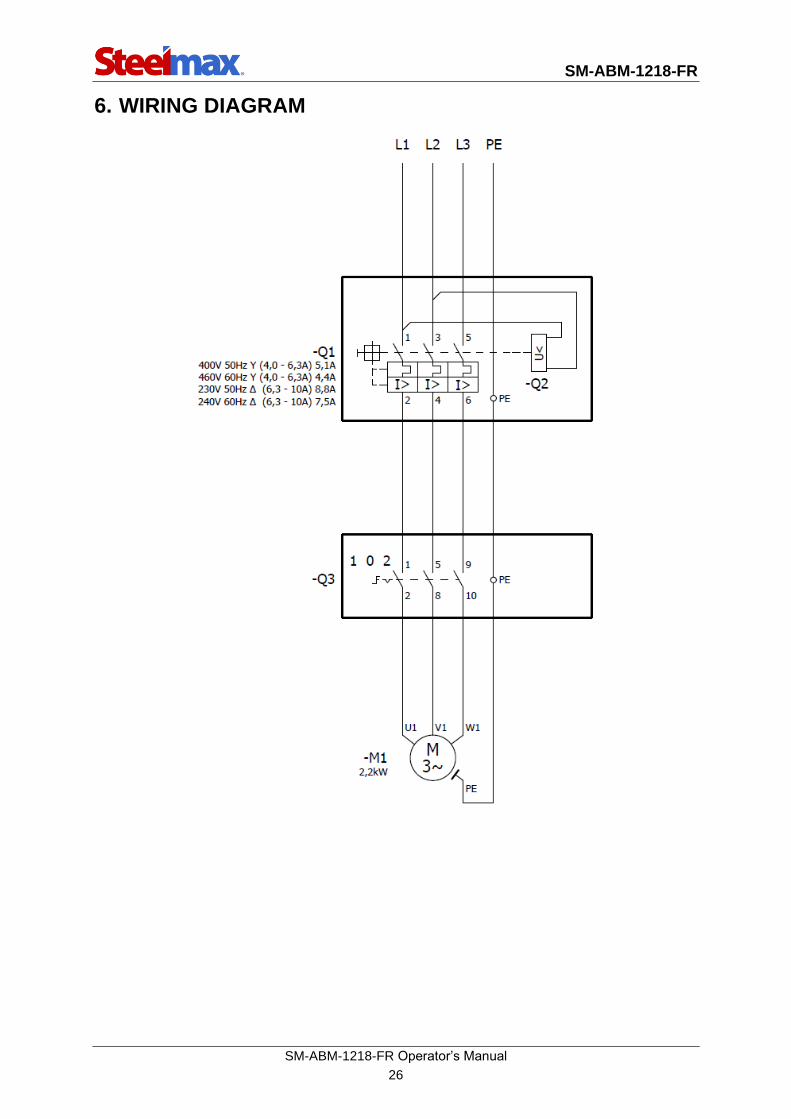
6. WIRING DIAGRAM

SM-ABM-1218-FR
SM-ABM-1218-FR Operator’s Manual
27
7. DECLARATION OF CONFORMITY
Declaration of Conformity
PROMOTECH sp. z o.o.
ul. Elewatorska 23/1
15-620 Białystok
Poland
We declare with full responsibility that:
SM-ABM-1218-FR Beveling Machine
is manufactured in accordance with the following standards:
• EN 60204-1
• EN ISO 12100
• EN ISO 13849-1
and satisfies regulations of the guidelines: 2006/95/EC, 2006/42/EC, 2004/108/EC.
Person authorized to compile the technical file:
Marek Siergiej, ul. Elewatorska 23/1, 15-620 Białystok, Poland
Białystok, 9 May 2017 ___________________________
Marek Siergiej
CEO

SM-ABM-1218-FR
SM-ABM-1218-FR Operator’s Manual
28
8. WARRANTY CARD
WARRANTY CARD No.............
........................................................................... in the name of Manufacturer warrants
the SM-ABM-1218-FR Beveling Machine to be free of defects in material and work-
manship under normal use for a period of 12 months from the date of sale.
This warranty does not cover cutters as well as damage or wear that arise from
misuse, accident, tempering, or any other causes not related to defects in workman-
ship or material.
Serial number ................................................................................................................
Date of sale ...................................................................................................................
Signature of seller ..........................................................................................................
1.07 / 6 November 2019
WE RESERVE THE RIGHT TO MAKE CHANGES IN THIS MANUAL WITHOUT NOTICE