
Operation Manual R-Series Powerlink 551657 RevA EN
52
R-Series Powerlink V2 Operation Manual Temposonics ® Magnetostrictive Linear Position Sensors
-
Upload
khangminh22 -
Category
Documents
-
view
6 -
download
0
Transcript of Operation Manual R-Series Powerlink 551657 RevA EN

R-Series Powerlink V2Operation Manual
Temposonics®
Magnetostrictive Linear Position Sensors

Temposonics® R-Series Powerlink V2Operation Manual
Table of contents
1. Introduction ..................................................................................................................................................... 31.1 Purpose and use of this manual ................................................................................................................................................................ 31.2 Used symbols and warnings ..................................................................................................................................................................... 3
2. Safety instructions ............................................................................................................................................. 32.1 Intended use .............................................................................................................................................................................................. 32.2 Forseeable misuse ..................................................................................................................................................................................... 32.3 Installation, commissioning and operation ................................................................................................................................................ 42.4 Safety instructions for use in explosion-hazardous areas .......................................................................................................................... 42.5 Warranty .................................................................................................................................................................................................... 42.6 Return ....................................................................................................................................................................................................... 4
3. Identification.................................................................................................................................................... 53.1 Order code of Temposonics® RP ............................................................................................................................................................... 53.2 Order code of Temposonics® RH ............................................................................................................................................................... 63.3 Order code of Temposonics® RD4 ............................................................................................................................................................. 73.4 Order code of Temposonics® RF ................................................................................................................................................................ 83.5 Nameplate ................................................................................................................................................................................................. 93.6 Approvals .................................................................................................................................................................................................. 93.7 Scope of delivery ....................................................................................................................................................................................... 9
4. Product description and commissioning ................................................................................................................... 94.1 Functionality and system design ............................................................................................................................................................... 94.2 Styles and installation of Temposonics® RP ............................................................................................................................................ 104.3 Styles and installation of Temposonics® RH ............................................................................................................................................ 114.4 Styles and installation of Temposonics® RD4 .......................................................................................................................................... 14
4.4.1 Installation of RD4 with threaded flange ............................................................................................................................................ 164.4.2 Installation of RD4 with pressure fit flange ....................................................................................................................................... 174.4.3 Installation of RD4's sensor electronic housing ................................................................................................................................ 17
4.5 Styles and installation of Temposonics® RF ............................................................................................................................................. 194.6 Magnet installation .................................................................................................................................................................................. 224.7 Replacement of sensor ............................................................................................................................................................................ 254.8 Electrical connections .............................................................................................................................................................................. 264.9 Frequently ordered accessories ............................................................................................................................................................... 27
5. Operation.......................................................................................................................................................305.1 Getting started ......................................................................................................................................................................................... 30
6. Node ID configuration ........................................................................................................................................306.1 Introduction of “MTS Powerlink Configurator” ........................................................................................................................................ 306.2 Introduction of “Automation Studio” ....................................................................................................................................................... 34
7. Integration in Automation Studio ...........................................................................................................................387.1 Programming and configuration ............................................................................................................................................................. 387.2 Communication Segement ..................................................................................................................................................................... 40
8. Set the LossSoC threshold for a R-Series Powerlink sensor ...........................................................................................438.1 Hardware setup ....................................................................................................................................................................................... 438.2 Defined data types ................................................................................................................................................................................... 438.3 Used variables ......................................................................................................................................................................................... 448.4 Program executed by PLC once after start-up ......................................................................................................................................... 448.5 Program executed by PLC cyclically ........................................................................................................................................................ 458.6 Variable watch after successful execution of the implemented state machine ......................................................................................... 46
9. Maintenance and troubleshooting .........................................................................................................................469.1 Error conditions, troubleshooting ............................................................................................................................................................ 469.2 Maintenance ............................................................................................................................................................................................ 469.3 Repair ...................................................................................................................................................................................................... 469.4 List of spare parts ................................................................................................................................................................................... 469.5 Transport and storage ............................................................................................................................................................................. 46
10. Removal from service / dismantling .....................................................................................................................4611. Technical data ...............................................................................................................................................4712. Appendix ......................................................................................................................................................51

Temposonics® R-Series Powerlink V2Operation Manual
I 3 I
1. Introduction
1.1 Purpose and use of this manual
Before starting the operation of Temposonics® position sensors, read this documentation thoroughly and follow the safety information. Keep the manual for future reference!
Symbol Meaning
NOTICE This symbol is used to point to situations that may lead to material damage, but not to personal injury.
1/ The term qualified technical personnel characterizes persons who:• are familiar with the safety concepts of automation technology applicable
to the particular project,• are competent in the field of electromagnetic compatibility (EMC),• have received adequate training for commissioning and service operations• are familiar with the operation of the device and know the information required
for correct operation provided in the product documentation.
2. Safety instructions
2.1 Intended use
This product may be used only for the applications defined under item 1 and only in conjunction with the third-party devices and components recommended or approved by MTS Sensors. As a prerequsite of proper and safe operation the product requires correct transport, storage, mounting and commissioning and must be operat ed with utmost care.
1. The sensor systems of all Temposonics® series are intended exclu sively for measurement tasks encountered in industrial, commercial and laboratory applications. The sensors are considered as system accessories and must be connected to suitable evaluation electron ics, e.g. a PLC, IPC, indicator or other electronic control unit.
Forseeable misuse Consequence
Wrong sensor connectionThe sensor will not work properly or will be destroyed
Operate the sensor out of the operating temperature range
No signal outputThe sensor can be damaged
Power supply is out of the defi ned range
Signal output is wrong /no signal output / the sensor will be damaged
Position measurement is infl uenced by an external magnetic fi eld
Signal output is wrong
Cables are damagedShort circuit – the sensor can be destroyed / sensor does not respond
Spacers are missing / are installed in a wrong order
Error in position measurement
Wrong connection of ground / shield
Signal output is disturbedThe electronics can be damaged
Use of a magnet that is not certifi ed by MTS Sensors
Error in position measurement
Do not reprocess the sensor afterwards. The sensor might be damaged.
Do not step on the sensor. The sensor might be damaged.
2.2 Forseeable misuse
The content of this technical documentation and of its appendix is intended to provide information on mounting, installation and commissioning by qualified automation personnel 1 or instructed service technicians who are familiar with the project planning and dealing with Temposonics® sensors.
1.2 Used symbols and warnings
Warnings are intended for your personal safety and for avoidance of damage to the described product or connected devices. In this documentation, safety information and warnings to avoid danger that might affect the life and health of operating or service personnel or cause material damage are highlighted by the preceding pictogram which is defined below.

Temposonics® R-Series Powerlink V2Operation Manual
I 4 I
2.3 Installation, commissioning and operation
The position sensors must be used only in technically safe condition. To maintain this condition and to ensure safe operation, installation, connection and service, work may be performed only by qualified technical personnel.If danger of injury to persons or of damage to operating equipment is caused by sensor failure or malfunction, additional safety measures such as plausibility checks, limit switches, EMERGENCY STOP systems, protective devices etc. are required. In the event of trouble, shut down the sensor and protect it against accidental operation.
Safety instructions for commissioningTo maintain the sensor operability, it is mandatory to follow the instructions given below.
1. Protect the sensor's against mechanical damage during installation and operation.
2. Do not open or dismantle the sensor. 3. Connect the sensor very carefully and pay attention to the
polarity of connections and power supply. 4. Use only approved power supplies. 5. It is indispensable to ensure that the specified permissible
limit values of the sensor for operating voltage, environmental conditions, etc. are met.
6. Check the function of the sensor regularly and provide documentation of the checks.
7. Before applying power, ensure that nobody’s safety is jeopardized by starting machines.
2.4 Safety instructions for use in explosion-hazardous areas
The sensor is not suitable for operation in explosion-hazardous areas.
2/ See also applicable MTS Sensors terms of sales and delivery on: www.mtssensors.com
2.5 Warranty
MTS Sensors grants a warranty period for the Temposonics® position sensors and supplied accessories relating to material defects and faults that occur despite correct use in accordance with the intended application 2. The MTS Sensors obligation is limited to repair or replacement of any defective part of the unit. No warranty can be provided for defects that are due to improper use or above average stress of the product, as well as for wear parts. Under no circumstances will MTS Sensors accept liability in the event of offense against the warranty rules, no matter if these have been assured or expected, even in case of fault or negligence of the company.MTS Sensors explicitly excludes any further warranties. Neither the company’s representatives, agents, dealers nor employees are authorized to increase or change the scope of warranty.
2.6 Return
For diagnostic purposes, the sensor can be returned to MTS Sensors. Any shipment cost is the responsibility of the sender 2. For a corresponding form, see chapter "12. Appendix" on page 51.

Temposonics® R-Series Powerlink V2Operation Manual
I 5 I
3.1 Order code of Temposonics® RP
*/ Non standard stroke lengths are available; must be encoded in 5 mm / 0.1 in. increments
3/ Note: Specify magnet number for your sensing application and order separately
a Sensor model
R P Profile
b Design
G Magnet slider, joint on top, backslash free (part no. 253 421)
M U-magnet, OD33 (part no. 251 416-2)
S Magnet slider, joint on top (part no. 252 182)
V Magnet slider, joint at front (part no. 252 184)
Optional:
g Magnet number for multi-position measurement 3
Z 0 2 2 magnets
Z 0 3 3 magnets
Z 0 4 4 magnets
d Connection type
D 5 6 2 × M12 female connectors (4 pin),1 × M8 male connector (4 pin)
e Operating voltage
1 +24 VDC (−15 / +20 %)
f Output
U 3 0 1 Powerlink V2
c Stroke length
X X X X M 0025…5080 mm
Standard stroke length (mm)* Ordering steps
25…500 mm 25 mm
500…2500 mm 50 mm
2500…5080 mm 100 mm
X X X X U 001.0…200.0 in.
Standard stroke length (in.)* Ordering steps
1…20 in. 1 in.
2…100 in. 2 in.
100…200 in. 4 in.
1 2 3 4 5 6 7 8 9 10 11 12 13 14 15 16 17 18 19
R P D 5 6 1 U 3 0 1
a b c d e f goptional
3. Identification
Temposonics® R-Series Powerlink V2Operation Manual
I 6 I
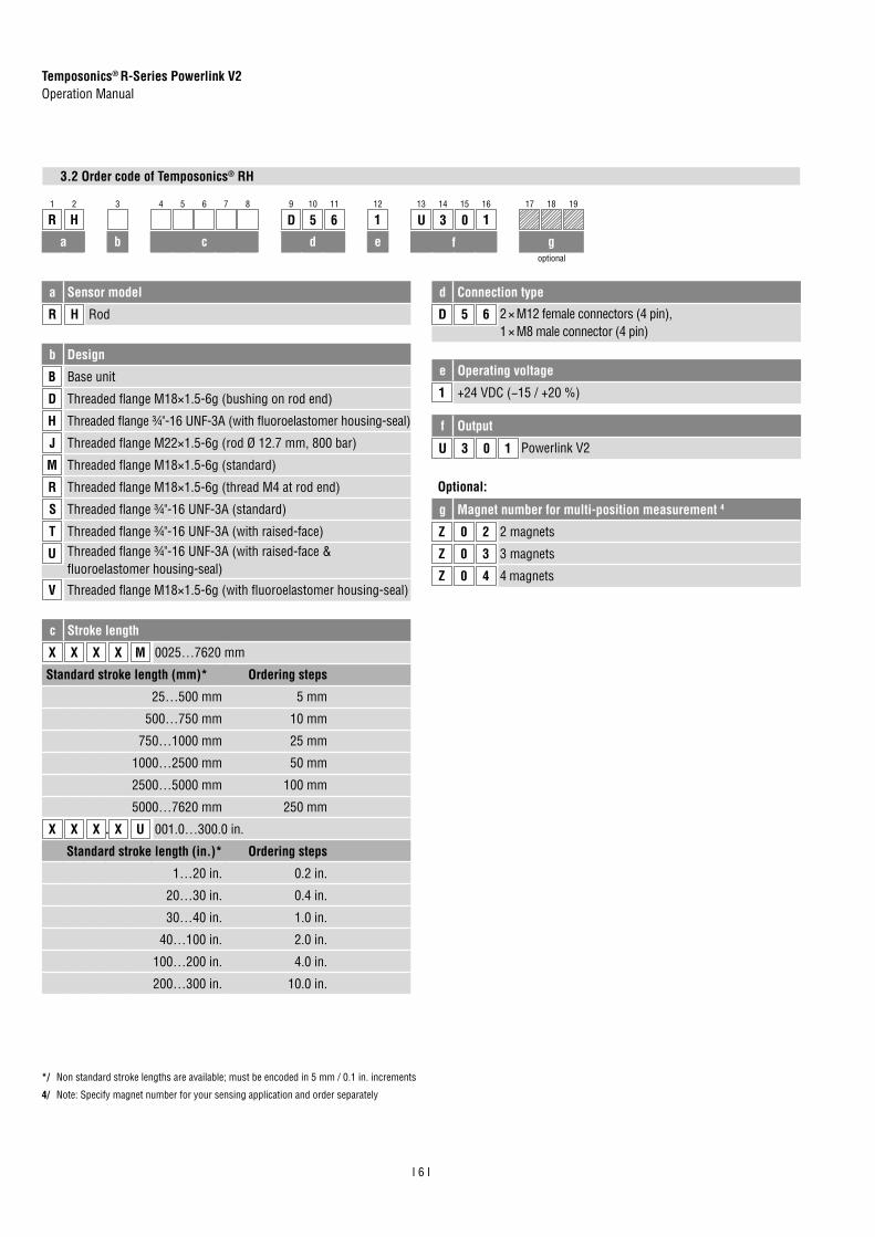
3.2 Order code of Temposonics® RH
*/ Non standard stroke lengths are available; must be encoded in 5 mm / 0.1 in. increments
4/ Note: Specify magnet number for your sensing application and order separately
1 2 3 4 5 6 7 8 9 10 11 12 13 14 15 16 17 18 19
R H D 5 6 1 U 3 0 1
a b c d e f goptional
a Sensor model
R H Rod
b Design
B Base unit
D Threaded flange M18×1.5-6g (bushing on rod end)
H Threaded flange ¾"-16 UNF-3A (with fluoroelastomer housing-seal)
J Threaded flange M22×1.5-6g (rod Ø 12.7 mm, 800 bar)
M Threaded flange M18×1.5-6g (standard)
R Threaded flange M18×1.5-6g (thread M4 at rod end)
S Threaded flange ¾"-16 UNF-3A (standard)
T Threaded flange ¾"-16 UNF-3A (with raised-face)
U Threaded flange ¾"-16 UNF-3A (with raised-face & fluoroelastomer housing-seal)
V Threaded flange M18×1.5-6g (with fluoroelastomer housing-seal)
Optional:
g Magnet number for multi-position measurement 4
Z 0 2 2 magnets
Z 0 3 3 magnets
Z 0 4 4 magnets
e Operating voltage
1 +24 VDC (−15 / +20 %)
f Output
U 3 0 1 Powerlink V2
d Connection type
D 5 6 2 × M12 female connectors (4 pin),1 × M8 male connector (4 pin)
c Stroke length
X X X X M 0025…7620 mm
Standard stroke length (mm)* Ordering steps
25…500 mm 5 mm
500…750 mm 10 mm
750…1000 mm 25 mm
1000…2500 mm 50 mm
2500…5000 mm 100 mm
5000…7620 mm 250 mm
X X X X U 001.0…300.0 in.
Standard stroke length (in.)* Ordering steps
1…20 in. 0.2 in.
20…30 in. 0.4 in.
30…40 in. 1.0 in.
40…100 in. 2.0 in.
100…200 in. 4.0 in.
200…300 in. 10.0 in.
.

Temposonics® R-Series Powerlink V2Operation Manual
I 7 I
3.3 Order code of Temposonics® RD4
*/ Non standard stroke lengths are available; must be encoded in 5 mm / 0.1 in. increments
5/ Note: Specify magnet number for your sensing application and order separately
1 2 3 4 5 6 7 8 9 10 11 12 13 14 15 16 17 18 19 20 21 22
R D 4 D 5 6 U 3 0 1
a b c d e f goptional
b Design
C Threaded flange M18×1.5-6g, A/F 46
D Threaded flange ¾"-16 UNF-3A, A/F 46
G Threaded flange M18×1.5-6g, A/F 24
M Threaded flange M18×1.5-6g, A/F 23
S Pressure fit flange Ø 26.9 mm f6
T Threaded flange ¾"-16 UNF-3A, A/F 23
a Sensor model
R D 4 Detached sensor electronics
c Integral cable of sensor rod
For side cable entry on sensor electronics housing
D 1 S PUR cable with M16 connector, length 250 mm (9.8 in.)
D 2 S PUR cable with M16 connector, length 400 mm (15.7 in.)
D 3 S PUR cable with M16 connector, length 600 mm (23.6 in.)
For bottom cable entry on sensor electronics housing
R 2 B PUR cable / wires with flat connector, length 65 mm (2.6 in.)
R 4 B PUR cable / wires with flat connector, length 170 mm (6.7 in.)
R 5 B PUR cable / wires with flat connector length 230 mm (9.1 in.)
R 6 B PUR cable / wires with flat connector, length 350 mm (13.8 in.)
Optional:
g Magnet number for multi-position measurement 5
Z 0 2 2 magnets
Z 0 3 3 magnets
Z 0 4 4 magnets
f Output
U 3 0 1 Powerlink V2
Operating voltage
+24 VDC (−15 / +20 %); Standard, not indicated in order code
e Connection type
D 5 6 2 × M12 female connectors (4 pin),1 × M8 male connector (4 pin)
d Stroke length
X X X X M Flange »C«, »D«, »G«, »M«, »T«: 0025…5080 mmFlange »S«: 0025…2540 mm
Standard stroke length (mm)* Ordering steps
25…500 mm 5 mm
500…750 mm 10 mm
750…1000 mm 25 mm
1000…2500 mm 50 mm
2500…5080 mm 100 mm
X X X X U Flange »C«, »D«, »G«, »M«, »T«: 001.0…200.0 in.Flange »S«: 001.0…100.0 in.
Standard stroke length (in.)* Ordering steps
1…20 in. 0.2 in.
20…30 in. 0.4 in.
30…40 in. 1.0 in.
40…100 in. 2.0 in.
100…200 in. 4.0 in.
200…300 in. 10.0 in.
.

Temposonics® R-Series Powerlink V2Operation Manual
I 8 I
3.4 Order code of Temposonics® RF
*/ Non standard stroke lengths are available; must be encoded in 5 mm / 0.1 in. increments
6/ Note: Specify magnet number for your sensing application and order separately
1 2 3 4 5 6 7 8 9 10 11 12 13 14 15 16 17 18 19 20
R F D 5 6 1 U 3 0 1
a b c d e f goptional
a Sensor model
R F Flexible sensor rod
b Design
C Base unit
M Threaded flange M18×1.5-6g
S Threaded flange ¾"-16 UNF-3A
e Operating voltage
1 +24 VDC (−15 / +20 %)
Optional:
g Magnet number for multi-position measurement 6
Z 0 2 2 magnets
Z 0 3 3 magnets
Z 0 4 4 magnets
f Output
U 3 0 1 Powerlink V2
d Connection type
D 5 6 2 × M12 female connectors (4 pin),1 × M8 male connector (4 pin)
c Stroke length (Longer strokes are available. Contact applications engineering for details.)
X X X X X M 00150…10060 mm
Standard stroke length (mm)* Ordering steps
150…1000 mm 50 mm
1000…5000 mm 100 mm
5000…10,060 mm 250 mm
X X X X X U 0006.0…0396.0 in.
Standard stroke length (in.)* Ordering steps
6…40 in. 2 in.
40…197 in. 4 in.
197…396 in. 10 in.
.

Temposonics® R-Series Powerlink V2Operation Manual
I 9 I
3.5 Nameplate
RPS0200M D561 U301MAC ID: 00-03-CA-00-2B-7FS/N: 90550176GRD: 9.2337 µS/In | 2750.79 m/s
Sensor model
Measuring range (e.g. 200 mm)Connection type
Output version
Order codeMAC adress
GradientSerial number
Fig. 1: Example of nameplate of an R-Series RP sensor
3.6 Approvals
• certified (RP / RH / RF)• UL/cUL certified (RP / RH)• GOST certified• Ethernet POWERLINK Standardization Group (EPSG) certified
3.7 Scope of delivery
RP (profile sensor):• Sensor• Position magnet• 2 mounting clamps up to 1250 mm (50 in.) stroke length +
1 mounting clamp for each 500 mm (20 in.) additional stroke length
RH (rod sensor): • RH-B: Base unit, 2 socket screws M4• RH-D / -H / -J / -M / -R / -S / -T / -U / -V: Sensor, O-ring
RD4 (detached sensor electronics):• RD4-C / -D / -G / -M / -T: Sensor, O-ring• RD4-S: Sensor, O-ring, back-up ring
RF (flexible sensor rod):• RF-C: Base unit• RF-M / -S: Sensor, O-ring
4. Product description and commissioning
4.1 Functionality and system design
Product designation• Position sensor Temposonics® R-Series
Sensor model• Temposonics® RP (profile sensor)• Temposonics® RH (rod sensor)• Temposonics® RD4 (detached sensor electronics)• Temposonics® RF (flexible sensor rod)
Stroke length• RP 25… 5080 mm (1…200 in.)• RH 25… 7620 mm (1…300 in.)• RD4 25… 5080 mm (1…200 in.)• RF 150…10060 mm (6…396 in.)
Output signal • Powerlink V2
ApplicationThe Temposonics® position sensors are used for measurement and conversion of the length (position) variable in the fields of automated systems and mechanical engineering.
Principle of operation and system constructionThe absolute, linear position sensors provided by MTS Sensors rely on the company’s proprietary Temposonics® magnetostrictive technology, which can determine position with a high level of precision and robustness. Each Temposonics® position sensor consists of a ferromagnetic waveguide, a position magnet, a strain pulse converter and supporting electronics. The magnet, connected to the object in motion in the application, generates a magnetic field at its location on the waveguide. A short current pulse is applied to the waveguide.
This creates a momentary radial magnetic field and torsional strain on the waveguide. The momentary interaction of the magnetic fields releases a torsional strain pulse that propagates the length of the waveguide. When the ultrasonic wave reaches the end of the waveguide it is converted into an electrical signal. Since the speed of the ultrasonic wave in the waveguide is precisely known, the time required to receive the return signal can be converted into a linear position measurement with both high accuracy and repeatability.
5
Sensing element (Waveguide)
Position magnet (Magnetic fi eld) Torsional strain pulse converter
4
Current pulse generates magnetic fi eld
Interaction with position magnet fi eld generates torsional strainpulse Torsional strain
pulse propagatesStrain pulse detected by converter
Time-of-fl ight converted into position
1
2
3
Fig. 2: Time-based magnetostrictive position sensing principle
Modular mechanical and electronic construction• The sensor rod or profile protects the inner sensor element.• The sensor electronics housing, a rugged aluminum construction,
contains the complete electronic interface with active signalconditioning.
• Double shielding ensures high safety of operation and optimumEMC (Electromagnetic Compatibility).
• The external position magnet is a permanent magnet. Mounted onthe mobile machine part, it travels along the sensor rod or profileand triggers the measurement through the sensor rod wall.
• The sensor can be connected directly to a control system.Its electronics generates a strictly position-proportional signaloutput between start and end position.

Temposonics® R-Series Powerlink V2Operation Manual
I 10 I
4.2 Styles and installation of Temposonics® RP
Fig. 3: Temposonics® RP-M with U-magnet
RP
Mag
net
18(0.71)50
(1.97)68
(2.68)
35.6(1.4)
2(0
.08)
45(1
.77)
Dead zone66 / 71*
(2.6 / 2.8*)
14.5(0.57)
Adjustable mounting clamp
28 (1.1
)
Sensor electronics housing129
(5.07)
Null zone28
(1.1)
Stroke length 25…5080(1…200)
49(1.93)
9(0
.36)
M5 or#10 screwØ 5.5(0.21)
* > 5000 mm (196.9 in.) stroke length
Controlling design dimensions are in millimeters and measurements in ( ) are in inches
Installation of RPThe position sensor can be installed in any position. Normally, the sensor is firmly installed and the position magnet is fastened to the mobile machine part. Thus it can travel along the sensor profile. The sensor is fitted on a flat machine surface using the mounting clamps (Fig. 4). A length-dependent number of these clamps are delivered with the sensor and must be distributed over the profile at regular distances. For fastening use M5×20 screws to DIN 6912 that should be tightened with a fastening torque of 5 Nm.
Fig. 4: Mounting clamps (part no. 400 802) with cylinder screw M5×20
Fig. 5: T-slot nut M5 (part no. 401 602)
NOTICE
Take care to mount the sensor in an axially parallel position to avoid damage to magnet and sensor.
≤ 5(≤ 0.2)
M5
Alternative: If only limited space is available, the profile sensor can be mounted also via the T-rail in the profile bottom using an T-slot nut M5 (part no. 401 602) or a sliding block (Fig. 5).
Fastening torque: 5 Nm
50(1.97)
9.5(0.38)
Bore Ø 5.5(Ø 0.27)
14.5(0.57)

Temposonics® R-Series Powerlink V2Operation Manual
I 11 I
4.3 Styles and installation of Temposonics® RH
Controlling design dimensions are in millimeters and measurements in ( ) are in inches
Fig. 6: Temposonics® RH with ring magnet part 1
RH-H / -M / -S / -V
18(0.71)
Null zone51
(2.01)10(0.4)
Dead zone63.5 / 66*
(2.5 / 2.6* )
Stroke length 25…7620(1…300)
Sensor electronics housing133
(5.24)
A/F 46
Ø 10
±0.
13(Ø
0.3
9 ±0
.01)
46(1
.81)
53(2.09)
25(0.98)
Flange »M« / »V«: M18×1.5-6gFlange »S« / »H«: ¾"-16 UNF-3A
Mag
net
* Stroke length > 5000 mm (196.9 in.)
RH-DDead zone63.5 / 66*(2.5 / 2.6*)
22(0.87)
15(0.59)
3(0.12)
8(0.31)
Ø 12
.8 ±
0.1
(Ø 0
.5 ±
0.00
4)
A/F 46
Ø 10(Ø 0.39)Flange: »D«
M18×1.5-6g
Mag
net
* Stroke length > 5000 mm (196.9 in.)
RH-T / -U
Mag
net
Flange »T« / »U«:¾"-16 UNF-3A
Null zone51
(2.01)7.11(0.28)
9.65(0.38)
Dead zone63.5 / 66*
(2.5 / 2.6* )
Stroke length 25…7620(1…300)
A/F 44.5
Ø 10
±0.
13(Ø
0.3
9 ±0
.01)
44.5
(1.7
5)
51.3(2.02)
* Stroke length > 5000 mm (196.9 in.)
Ø 25
.4(Ø
1)
RH-RDead zone70 / 72.5*
(2.76 / 2.85*)
3.5(0.14)
6(0.24)
M4 threadA/F 46
Ø 10
±0.
13(Ø
0.3
9 ±0
.01)
Flange: »R«M18×1.5-6g
Mag
net
* Stroke length > 5000 mm (196.9 in.)
Temposonics® R-Series Powerlink V2Operation Manual
I 12 I
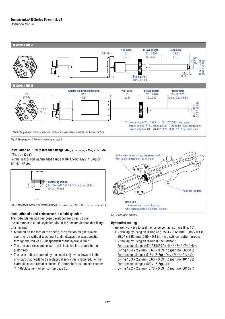
Hydraulics sealingThere are two ways to seal the flange contact surface (Fig. 10):
1. A sealing by using an O-ring (e.g. 22.4 × 2.65 mm (0.88 × 0.1 in.),25.07 × 2.62 mm (0.99 × 0.1 in.)) in a cylinder bottom groove.
2. A sealing by using an O-ring in the undercut.For threaded flange (¾"-16 UNF-3A) »H« / »S« / »T« / »U«:O-ring 16.4 × 2.2 mm (0.65 × 0.09 in.) (part no. 560 315)For threaded flange (M18×1.5-6g) »D« / »M« / »R«/ »V«:O-ring 15.3 × 2.2 mm (0.60 × 0.09 in.) (part no. 401 133)For threaded flange (M22×1.5-6g) »J«:O-ring 19.2 × 2.2 mm (0.76 × 0.09 in.) (part no. 561 337)
Installation of RH with threaded flange »D«, »H«, »J«, »M«, »R«, »S«, »T«, »U« & »V«Fix the sensor rod via threaded flange M18×1.5-6g, M22×1.5-6g or¾"-16 UNF-3A.
In the event of servicing, the sensor rod with flange remains in the cylinder
Position magnet
Base unit The sensor electronics housing with sensing element can be replaced
Fig. 7: Mounting example of threaded flange »D«, »H«, »J«, »M«, »R«, »S«, »T«, »U« & »V«
Fastening torque:RH-D/-H /-M / -R /-S / -T / -U / -V: 50 Nm RH-J: 125 Nm
Fig. 8: Sensor in cylinderInstallation of a rod-style sensor in a fluid cylinderThe rod-style version has been developed for direct stroke measurement in a fluid cylinder. Mount the sensor via threaded flange or a hex nut. • Mounted on the face of the piston, the position magnet travels
over the rod without touching it and indicates the exact positionthrough the rod wall – independent of the hydraulic fluid.
• The pressure resistant sensor rod is installed into a bore in thepiston rod.
• The base unit is mounted by means of only two screws. It is theonly part that needs to be replaced if servicing is required, i.e. thehydraulic circuit remains closed. For more information see chapter"4.7 Replacement of sensor" on page 25.
R-Series RH-JNull zone
51(2.01)
Dead zone73.6(2.9)
Ø 12
.7 ±
0.13
(Ø 0
.5 ±
0.01
)
4.6(0.18)
6.2
(0.2
4)
Stroke length 25…7620(1…300)
A/F 46
Flange: »J«M22×1.5-6g
Mag
net
R-Series RH-B
** Stroke length 25…1575 (1…62): 52 (2.05) dead zoneStroke length 1576…5000 (62.05…196.9): 54 (2.13) dead zoneStroke length 5001…7620 (196.9…300): 57 (2.24) dead zone
Null zone61
(2.4)
Dead zone52 / 54 / 57**
(2.05 / 2.13 / 2.24)
Stroke length 25…7620(1…300)
Sensor electronics housing123
(4.84 )
Ø 6.
8 ±0
.13
(Ø 0
.27
±0.0
1)
43.7
(1.7
2)
49(1.93)
Mag
net
Fig. 9: Temposonics® RH with ring magnet part 2
Controlling design dimensions are in millimeters and measurements in ( ) are in inches

Temposonics® R-Series Powerlink V2Operation Manual
I 13 I
In the case of threaded flange M18×1.5-6g or M22×1.5-6g, provide a screw hole based on ISO 6149-1 (Fig. 11). See ISO 6149-1 for further information.
Controlling design dimensions are in millimeters
Sealing via O-ringin the flange undercut
Sealing via O-ring in cylinder end cap groove
Notice for metric threaded flanges
Thread (d1×P)
d2 d3 d4 d5
+0.10
L1
+0.40
L2 L3 L4 Z°±1°
RH-M / -R / -VM18×1.5-6g 55 ≥ 13 24.5 19.8 2.4 28.5 2 26 15°RH-DM18×1.5-6g 55 ≥ 16 24.5 19.8 2.4 28.5 2 26 15°RH-JM22×1.5-6g 55 ≥ 16 27.5 23.8 2.4 28.5 2 26 15°
Ød5
Ra 3.2
Ra 3.2
Pitch diameter
A
A
Thread (d1 × P)Ød3(Reference)
A
Ød2
Ød4(Gauging)
This dimension applies when tap drill cannot pass throughentire boss.
≤ R0
.4
R0.3
R0.1
Z°
45° ±
5°
L 3
L 1
L 2 L 4
A0.1 A0.2
• Note the fastening torque of:RH-D/-H /-M / -R /-S / -T / -U / -V: 50 NmRH-J: 125 Nm
• Seat the flange contact surface completely on the cylinder mountingsurface.
• The cylinder manufacturer determines the pressure-resistant gasket(copper gasket, O-ring, etc.).
• The position magnet should not grind on the sensor rod.• The piston rod drilling
(RH-H/-M/-R/-S/-T/-U/-V: rod Ø 10 mm: ≥ Ø 13 mm (≥ Ø 0.51 in.);RH-D: rod Ø 10 mm: ≥ Ø 16 mm (≥ Ø 0.63 in.); RH-J: rod Ø 12.7 mm: ≥ Ø 16 mm (≥ Ø 0.63 in.)) depends on the pressure and piston speed.
• Adhere to the information relating to operating pressure.• Protect the sensor rod against wear.
Fig. 10: Possibilities of sealing
Fig. 11: Notice for metric threaded flange M18×1.5-6g / M22×1.5-6g based on DIN ISO 6149-1

Temposonics® R-Series Powerlink V2Operation Manual
I 14 I
4.4 Styles and installation of Temposonics® RD4
Controlling design dimensions are in millimeters and measurements in ( ) are in inches
Fig. 12: Temposonics® RD4 sensor electronics housings
Sensor electronics housing with bottom cable entry
45(1.77)
2(0.08)
Mounting block45
(1.77)
Sensor electronics housing123
(4.84)
Sensor electronics housing
18(0.71)
24.7(0.97)
26.5(1.04)
7.7(0.3)
Ø 6.2(Ø 0.24)
Ø 19(Ø 0.75)
49(1.93)
25(0.98)
41(1.61)
50(1.97)
38(1.5)
Recommendation: Use M6×45 (ISO 4762) screws for sensor fastening.Fastening torque: 6 Nm.
Sensor electronics housing with side cable entry
5 (0.2)
Mounting block45
(1.77)
Sensor electronics housing123
(4.84)18
(0.71)
24.7(0.97)
24.7(0.97)
8.2(0.32)
7.7(0.39
Ø 6.2(Ø 0.24)
49(1.93)
41(1.61)
45(1.77)
Ø 18(Ø 0.71)
45(1.77)
38(1.5)
Sensor electronics housing
Recommendation: Use M6×45 (ISO 4762) screws for sensor fastening.Fastening torque: 6 Nm.

Temposonics® R-Series Powerlink V2Operation Manual
I 15 I
Controlling design dimensions are in millimeters and measurements in ( ) are in inches
Fig. 13: Temposonics RD4 flanges with ring manget
Threaded flange »C« & »D« (for bottom or side entry)
Mag
net
Ø 10
±0.
13(Ø
0.4
±0.
01)
Cable for bottomcable entry
Cable for sidecable entry
4.5(0.18)
PUR-cable: Ø 6 (Ø 0.24)Bend radius: > 24 (> 0.94)Length for bottom cable entry: 65 / 170 / 230 / 350(2.6 / 6.7 / 9.1 / 13.8)Length for side cable entry:250 / 400 / 600(9.8 / 15.7 / 23.6)
26.9(1.1)
Null zone51
(2.01)32
(1.36)
Stroke length25…5080(1…200)
Dead zone63.5 / 66*(2.5 / 2.6)
Flange »C«: M18×1.5-6gFlange »D«: ¾"-16 UNF-3A
* > 5000 mm (196.85 in.) stroke length
A/F 46
Threaded flange »G« (for bottom or side entry)
Mag
net
Ø 10
±0.
13(Ø
0.4
±0.
01)
4.5(0.18)
32(1.36)
Null zone51
(2.01)
Stroke length25…5080(1…200)
Dead zone63.5 / 66*(2.5 / 2.6*)
26.9 (1.1)
* > 5000 mm (196.85 in.) stroke length
PUR-cable: Ø 6 (Ø 0.24)Bend radius: > 24 (> 0.94)Length for bottom cable entry: 65 / 170 / 230 / 350(2.6 / 6.7 / 9.1 / 13.8)Length for side cable entry:250 / 400 / 600(9.8 / 15.7 / 23.6)
Flange »G«: M18×1.5-6g25(1)
A/F 24
Cable for bottomcable entry
Cable for sidecable entry
Threaded flange »M« & »T« (for bottom or side entry)
Flange »M«: M18×1.5-6gFlange »T«: ¾"-16 UNF-3A
Mag
net
Ø 10
±0.
13(Ø
0.4
±0.
01)
25(1)
Cable for bottomcable entry
Cable for sidecable entry
4.5(0.18)
PUR-cable: Ø 6 (Ø 0.24)Bend radius: > 24 (> 0.94)Length for bottom cable entry: 65 / 170 / 230 / 350(2.6 / 6.7 / 9.1 / 13.8)Length for side cable entry:250 / 400 / 600(9.8 / 15.7 / 23.6)
Null zone51
(2.01)32
(1.36)26.9(1.1)
Stroke length25…5080(1…200)
Dead zone63.5 / 66*(2.5 / 2.6)
* > 5000 mm (196.85 in.) stroke length
A/F 23
Pressure fit flange »S« (for bottom or side entry)
Mag
net
Ø 10
±0.
13(Ø
0.4
±0.
01)
Null zone21.4
(0.84)32
(1.36)
12.7(0.5)
4.5(0.18)
Cable for bottomcable entry
Cable for sidecable entry
Stroke length25…2540(1…100)
PUR-cable: Ø 6 (Ø 0.24)Bend radius: > 24 (> 0.94)Length for bottom cable entry:65 / 170 / 230 / 350(2.6 / 6.7 / 9.1 / 13.8)Length for side cable entry:250 / 400 / 600(9.8 / 15.7 / 23.6)
Dead zone63.5(2.5)
26.9 f6(1.1)
Temposonics® R-Series Powerlink V2Operation Manual
I 16 I
Threaded flange »M« / »T«, »G«Threaded flange »C« / »D«
Fastening torque50 Nm
NOTICE
Mount the sensor as follows:1. Mount the flange with sensor rod2. Mount the sensor electronics housing3. Connect the cable between flange and the sensor electronics
housing
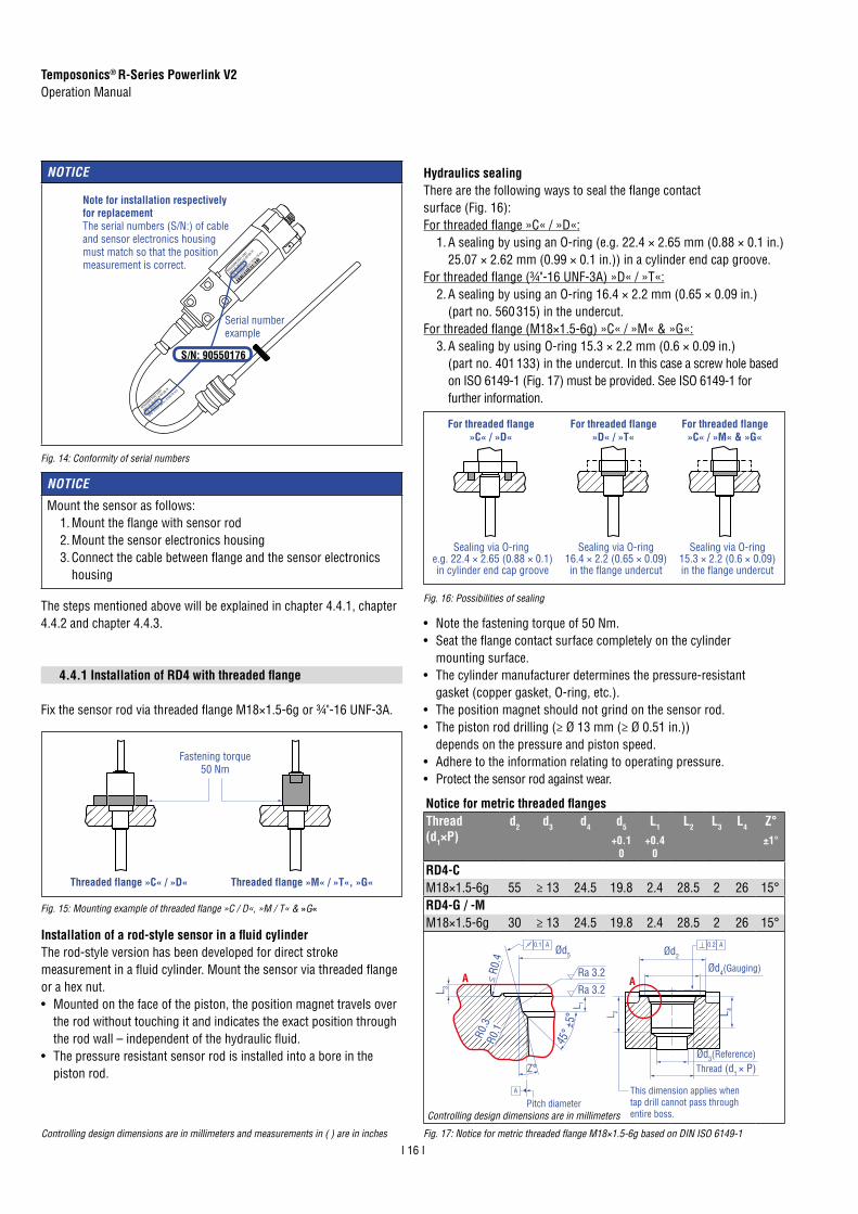
Fig. 14: Conformity of serial numbers
NOTICE
RPS0200
M D561 U
301
MAC ID: 0
0-03-C
A-00-2B
-7F
S/N: 9
0550
176
GRD: 9.23
37 µS
/In | 2
750.7
9 m/s
RPS0200
M D561 U
301
MAC ID: 0
0-03-C
A-00-2B
-7F
S/N: 905
5017
6
GRD: 9.23
37 µS/In
| 275
0.79 m
/s
S/N: 90550176
Note for installation respectively for replacementThe serial numbers (S/N:) of cable and sensor electronics housing must match so that the position measurement is correct.
Serial number example
4.4.1 Installation of RD4 with threaded flange
Fix the sensor rod via threaded flange M18×1.5-6g or ¾"-16 UNF-3A.
Sealing via O-ring e.g. 22.4 × 2.65 (0.88 × 0.1)in cylinder end cap groove
For threaded flange»C« / »D«
Sealing via O-ring16.4 × 2.2 (0.65 × 0.09)in the flange undercut
For threaded flange»D« / »T«
Sealing via O-ring15.3 × 2.2 (0.6 × 0.09)in the flange undercut
For threaded flange»C« / »M« & »G«
Fig. 15: Mounting example of threaded flange »C / D«, »M / T« & »G«
Hydraulics sealingThere are the following ways to seal the flange contact surface (Fig. 16):For threaded flange »C« / »D«:
1. A sealing by using an O-ring (e.g. 22.4 × 2.65 mm (0.88 × 0.1 in.)25.07 × 2.62 mm (0.99 × 0.1 in.)) in a cylinder end cap groove.
For threaded flange (¾"-16 UNF-3A) »D« / »T«:2. A sealing by using an O-ring 16.4 × 2.2 mm (0.65 × 0.09 in.)
(part no. 560 315) in the undercut.For threaded flange (M18×1.5-6g) »C« / »M« & »G«:
3. A sealing by using O-ring 15.3 × 2.2 mm (0.6 × 0.09 in.)(part no. 401 133) in the undercut. In this case a screw hole basedon ISO 6149-1 (Fig. 17) must be provided. See ISO 6149-1 forfurther information.
Fig. 16: Possibilities of sealing
Fig. 17: Notice for metric threaded flange M18×1.5-6g based on DIN ISO 6149-1Controlling design dimensions are in millimeters and measurements in ( ) are in inches
• Note the fastening torque of 50 Nm.• Seat the flange contact surface completely on the cylinder
mounting surface.• The cylinder manufacturer determines the pressure-resistant
gasket (copper gasket, O-ring, etc.).• The position magnet should not grind on the sensor rod.• The piston rod drilling (≥ Ø 13 mm (≥ Ø 0.51 in.))
depends on the pressure and piston speed.• Adhere to the information relating to operating pressure.• Protect the sensor rod against wear.
Notice for metric threaded flangesThread (d1×P)
d2 d3 d4 d5
+0.10
L1
+0.40
L2 L3 L4 Z°±1°
RD4-CM18×1.5-6g 55 ≥ 13 24.5 19.8 2.4 28.5 2 26 15°RD4-G / -M M18×1.5-6g 30 ≥ 13 24.5 19.8 2.4 28.5 2 26 15°
Ød5
Ra 3.2
Ra 3.2
Pitch diameter
A
A
Thread (d1 × P)Ød3(Reference)
A
Ød2
Ød4(Gauging)
This dimension applies when tap drill cannot pass throughentire boss.
≤ R0
.4
R0.3
R0.1
Z°
45° ±
5°
L 3
L 1
L 2 L 4
A0.1 A0.2
The steps mentioned above will be explained in chapter 4.4.1, chapter 4.4.2 and chapter 4.4.3.
Controlling design dimensions are in millimeters
Installation of a rod-style sensor in a fluid cylinder The rod-style version has been developed for direct stroke measurement in a fluid cylinder. Mount the sensor via threaded flange or a hex nut. • Mounted on the face of the piston, the position magnet travels over
the rod without touching it and indicates the exact position throughthe rod wall – independent of the hydraulic fluid.
• The pressure resistant sensor rod is installed into a bore in thepiston rod.

Temposonics® R-Series Powerlink V2Operation Manual
I 17 I
4.4.2 Installation of RD4 with pressure fit flange
Cylinder mountingInstall the rod using the pressure fit flange. Seal it off by means of the O-ring and the back-up ring. Block the pressure fit flange using a shoulder screw (Fig. 18). For details of the pressure fit flange »S« see Fig. 19. Also note the mounting examples in Fig. 20 and Fig. 21.
NOTICE
To fulfill the EMC standards for emission and immunity the following points are necessary:• The sensor electronics housing has to be connected to machine
ground.• The cable between the sensor and the electronics must be
integrated into a metallic housing.
32(1.26)5
(0.2)20.3(0.8)
20(0.79)
Bore27 H7(1.07)
15°
2.5(0.1)
For side cable entry: Ø 10…20 (Ø 0.39…0.79)bore for cable to electronics housing
For bottom cably entry: Ø 13…17 (Ø 0.51… 0.67)to push single wires through
14.7(0.58)
44.7(1.76)
4.8(0.2)
7.1(0.28)
26.9
+0.
03(1
.06
+0.0
01)
22.9
(0.9
)
12.7(0.5)
4.4(0.17)
10(0.4)
5.8(0.23)
Ø 22.9(Ø 0.9)
45°
Note for cylinder installation:• The position magnet should not grind on the sensor rod.• The piston rod drilling (≥ Ø 13 mm (≥ Ø 0.51 in.))
depends on the pressure and piston speed.• Adhere to the information relating to operating pressure.• Protect the sensor rod against wear.
Fig. 18: Example of mounting detail: Shoulder screw 8-M6 (ISO 7379) with internal hexagon
Controlling design dimensions are in millimeters and measurements in ( ) are in inches
4.4.3 Installation of RD4's sensor electronic housing
The following section explains the connection of a RD4 sensor with bottom cable entry (Fig. 20) and side cable entry (Fig. 21) based on RD4-S. The sensor electronics of RD4 sensors with threaded flange are mounted in the same way.
Sensor electronics with bottom cable entryConnect the rod via the connector to the sensor electronics. Mount the sensor electronics so that you can lead the cables below the bottom of the housing. Thus the sensor system including the connection cables is fully encapsulated and protected against external disturbances (Fig. 20). Note the bending radius of the cable if you run the cable between sensor electronics and rod (see Fig. 13).
Non-magneticmaterial
Included in delivery:O-ring 21.9 × 2.6 (part no. 560 705)Back-up ring (part no. 560 629)
Mag
net
O-ring 21.9 × 2.6 (part no. 560 705)Back-up ring (part no. 560 629)
Mag
net
Non-magneticmaterial
Connect the flange to the sensor electronics housing via the molex connectors for bottom cable entry respectively via the 6 pin cable for side cable entry.
Fig. 19: Pressure fit flange »S« details
Fig. 20: Mounting example of pressure fit flange »S« and sensor electronics with bottom cable entry
Fig. 21: Mounting example of pressure fit flange »S« and sensor electronics with side cable entry
Sensor electronics with side cable entryConnect the rod via the cable to the sensor electronics on the side. Encapsulate the sensor system including the connection cables (Fig. 21). Note the bending radius of the cable if you run the cable between sensor electronics and rod (see Fig. 13).

Temposonics® R-Series Powerlink V2Operation Manual
I 18 I
Fig. 22: Mounting of RD4‘s sensor electronics housing (example of bottom cable entry)
4 M6×45 (ISO 4762) screwsFastening torque: 6 Nm
Mounting block
Mounting of sensor electronics housingMount the sensor electronics housing with 4 M6×45 (ISO 4762) screws via the mounting block. Note the fastening torque of 6 Nm.

Temposonics® R-Series Powerlink V2Operation Manual
I 19 I
4.5 Styles and installation of Temposonics® RF
Note the following information when mounting a RF sensor:1. Always insert the flexible sensor rod in a support tube
(e.g. pressure rod HD / HL / HP or HFP profile). The supporttube with an inside diameter of 9.4 mm (0.37 in.) consists ofnon-magnetic material. The support tube can be straight orbent (note the bending radius in Fig. 25).
2. Use non-magnetic material for mounting support.
3. Do never bend beyond the minimum bending radius of250 mm (9.84 in.)
4. Note the minimum distance to a spatial limitation of 300 mm(11.81 in.), when mounting / dismounting the sensor (Fig. 25).
5. Note that the first 107 mm (4.21 in.) (for RF-C) respectively97 mm (3.82 in.) (for RF-M) of the sensor rod are not flexible.
Fig. 23: Temposonics® RF base unit with ring magnet (top) and RF with threaded flange with ring magnet (bottom)
RF-C
Stroke length 150…10060
(6…396)
Total lengthDead zonesee table
18(0.71)
43.7
(1.72)
49
(1.93)
34.6
(1.36)
Sensor electronics housing123
(4.84)7(0.28)
Null zone61
(2.4)
11.5(0.45)
Mag
net
Ø 8
± 0.
23(Ø
0.3
1 ±
0.01
)
Not flexible 107
(4.21)
Stroke lengthUp to 7620 mm (300.00 in.)Up to 10,000 mm (393.70 in.)Up to 15,000 mm (590.55 in.)Up to 20,000 mm (787.00 in.)
Tolerance of total length+8 mm (0.31 in.) / −5 mm (0.20 in.)
+15 mm (0.59 in.) / −15 mm (0.59 in.)+15 mm (0.59 in.) / −30 mm (1.18 in.)+15 mm (0.59 in.) / −45 mm (1.77 in.)
Dead zone94 mm (3.70 in.)
100 mm (3.94 in.)120 mm (4.72 in.)140 mm (5.51 in.)
Note: Tolerance of total length has no influence on the stroke length.
RF-M / -S
Null zone51
(2.01)
Stroke length 150…10060
(6…396)
Total lengthDead zonesee table
Sensor electronics housing133
(5.24)46
(1.81)
18(0.71)
53
(2.09)
Mag
net
Ø 8
± 0.
23(Ø
0.3
1 ±
0.01
)
Not flexible 97
(3.82)
25(0.98)
Flange »M«: M18×1.5-6gFlange »S«: ¾"-16 UNF-3A
A/F 46
Stroke lengthUp to 7620 mm (300.00 in.)Up to 10,000 mm (393.70 in.)Up to 15,000 mm (590.55 in.)Up to 20,000 mm (787.00 in.)
Tolerance of total length+8 mm (0.31 in.) / −5 mm (0.20 in.)
+15 mm (0.59 in.) / −15 mm (0.59 in.)+15 mm (0.59 in.) / −30 mm (1.18 in.)+15 mm (0.59 in.) / −45 mm (1.77 in.)
Dead zone94 mm (3.70 in.)
100 mm (3.94 in.)120 mm (4.72 in.)140 mm (5.51 in.)
Note: Tolerance of total length has no influence on the stroke length.
Position magnet
Non-magnetic support tube, inner-Ø 9.4 (0.37)
Fig. 24: Linear measurement
Controlling design dimensions are in millimeters and measurements in ( ) are in inches

Temposonics® R-Series Powerlink V2Operation Manual
I 20 I
NOTICE
Connect the sensor electronics housing to machine ground to fulfill the EMC standards for emission and immunity.
Installation of a RF sensor with pressure rod HD / HL / HP in a fluid cylinder:The rod-style version has been developed for direct stroke measurement in a fluid cylinder. Mount the sensor via threaded flange or a hex nut.• Mounted on the face of the piston, the position magnet travels over
the rod without touching it and indicates the exact position throughthe rod wall – independent of the hydraulic fluid.
• The pressure resistant sensor rod is installed into a bore in thepiston rod.
• The base unit is mounted by means of only two screws. It is theonly part that needs to be replaced if servicing is required, i.e. thehydraulic circuit remains closed. For more information see chapter"4.7 Replacement of sensor" on page 25.
Fastening torque50 Nm
Sensor design Mounting
RF-C • Insert the flexible sensor rod ina support tube.
• Mount the sensor electronics housingby means of two non-magnetic sockethead screws M4×90.Fastening torque: 2 Nm (see Fig. 26)Recommendation:Seal the sensor via flange.
RF-C with pressure rod HD / HL / HP or HFP profile(see accessories)
Advantage: The flexible sensor rod is inserted in a support tube.• Mount the sensor electronics housing
by means of two non-magnetic sockethead screws M4×59.Fastening torque: 2 Nm (see Fig. 26)
RF-M / RF-S • Insert the flexible sensor rod ina support tube.
• Mount the sensor via flange.
Installation of RF with threaded flange »M«, »S« respectively with pressure rod HD / HL / HPFix the sensor rod via threaded flange M18×1.5-6g or ¾"-16 UNF-3A
This is the way you mount the RF sensors:
Socket head screw M4×90
Fastening torque of socket head screw M4×90: 2 Nm
NOTICE
Smaller radiuses cause damage to the flexible sensor rod.
500 (20) recommended≥ 300 (≥ 11.81) Magnet
10(0.4)
AF46
Flange M18×1.5-6g¾"×16 UNF-3A
Customized support tuberequired, e.g. Ø 12.7 × 1.65(Ø 0.5 × 0.65), inside Ø 9.4 (Ø 0.37), non-magnetic
R > 250(R > 9.84)
Fig. 25: Clearances for installation
Fig. 26: Mounting with socket head screws M4×90
Fig. 27: Mounting example of threaded flange »M« / »S« or with pressure rod HD / HL / HP

Temposonics® R-Series Powerlink V2Operation Manual
I 21 I
Sealing via O-ringin the flange undercut
Sealing via O-ring in cylinder end cap groove
Fig. 29: Possibilities of sealing
For additional information about optional accessories see:• HFP Profile (document part number: 551 442)• Pressure rod HD / HL / HP (document part number: 551 770)
Hydraulics sealing when using a RF sensor in a pressure rod HD / HL / HPThere are two ways to seal the flange contact surface (Fig. 29):
1. A sealing by using an O-ring (e.g. 22.4 × 2.65 mm (0.88 × 0.1 in.),25.07 × 2.62 mm (0.99 × 0.1 in.)) in a cylinder end cap groove.
2. A sealing by unsing an O-ring in the undercut.For threaded flange (¾"-16 UNF-3A) »S«:O-ring 16.4 × 2.2 mm (0.65 × 0.09 in.)For threaded flange (M18×1.5-6g) »M«:O-ring 15.3 × 2.2 mm (0.60 × 0.09 in.)In this case, a screw hole based on ISO 6149-1 (Fig. 28)must be provided. See ISO 6149-1 for further information.
Fig. 28: Notice for metric threaded flange M18×1.5-6g based on DIN ISO 6149-1
Controlling design dimensions are in millimeters
Note the following points when using a RF-M / -S sensor or RF-C with pressure rod HD / HL / HP:• Note the fastening torque of 50 Nm.• Seat the flange contact surface completely on the cylinder
mounting surface.• The cylinder manufacturer determines the pressure-resistant
gasket (copper gasket, O-ring, etc.).• The position magnet should not grind on the sensor rod.• The piston rod drilling for RF sensors with pressure rod
(rod Ø 12.7 mm (0.5 in.)) is ≥ 16 mm (≥ 0.63 in.).The borehole depends on the pressure and piston speed.
• Adhere to the information relating to operating pressure.• Protect the sensor rod against wear.
Notice for metric threaded flangesThread (d1×P)
d2 d3 d4 d5
+0.10
L1
+0.40
L2 L3 L4 Z°±1°
RF-M / Optional pressure rod HDM18×1.5-6g 55 ≥ 13 24.5 19.8 2.4 28.5 2 26 15°
Ød5
Ra 3.2
Ra 3.2
Pitch diameter
A
A
Thread (d1 × P)Ød3(Reference)
A
Ød2
Ød4(Gauging)
This dimension applies when tap drill cannot pass throughentire boss.
≤ R0
.4
R0.3
R0.1
Z°
45° ±
5°
L 3
L 1
L 2 L 4
A0.1 A0.2

Temposonics® R-Series Powerlink V2Operation Manual
I 22 I
4.6 Magnet installation
Sensors with stroke lengths ≥ 1 meter (3.3 ft.)Support horizontally installed sensors with a stroke length from 1 meter (3.3 ft.) mechanically at the rod end. Without the use of a support, rod and position magnet may be damaged. A false measurement result is also possible. Longer rods require evenly distributed mechanical support over the entire length (e.g. part no. 561 481). Use an U-magnet (Fig. 34) for measurement.
NOTICE
Mount ring magnets and U-magnets concentrically.Mount block magnets centrically over the sensor rod or the sensor profile. Do not exceed the maximum acceptable gap.
Controlling design dimensions are in millimeters and measurements in ( ) are in inches
Fig. 30: Typical use of magnets
M4
2
1
8 ±2(0.31 ±0.08)
Sensor element
Air gap: 3 ±2(0.12 ±0.08)
Concentric mountingof block magnet
1 Block magnet2 Non-magnetic mounting plate
Magnet Typical sensors Benefits
Ring magnets Rod models(RH, RD4, RF)
• Rotationally symmetricalmagnetic field
U-magnets Profile & rod models(RP, RH, RD4, RF)
• Height tolerances can becompensated
Block magnets Profile & rod models(RP, RH, RF)
• The magnet can be lifted off• Height tolerances can be
compensated
Magnet sliders Profile models (RP)
• The magnet is guidedthrough the profile
• The distance between themagnet and the waveguideis strictly defined
• Easy coupling via theball joint
Mounting ring magnets, U-magnets & block magnetsInstall the magnet using non-magnetic material for mounting device, screws, spacers etc.. The magnet must not grind on the sensor rod. Alignment errors are compensated via the air gap.• Permissible surface pressure: Max. 40 N/mm2 (only for ring
magnets and U-magnets)• Fastening torque for M4 screws: 1 Nm; use washers, if necessary• Minimum distance between position magnet and any magnetic
material has to be 15 mm (0.6 in.) (Fig. 33).• If no other option exists and magnetic material is used,
observe the specified dimensions (Fig. 33).
Magnet mounting with magnetic materialWhen using magnetic material the dimensions of Fig. 33 must be observed.A. If the position magnet aligns with the drilled piston rodB. If the position magnet is set further into the drilled piston rod,
install another non-magnetic spacer (e.g. part no. 400 633) abovethe magnet.
Fig. 31: Mounting of U-magnet (part no. 251 416-2 or part no. 201 553)
Fig. 32: Mounting of block magnet (part no. 403 448)
Fig. 33: Installation with magnetic material
U-magnet
Sensor rod
Non-magnetic fixing clip
Magnet Magnet
1
2
3
A B
Magneticmaterial
3
1 Null zone, depends on sensor model (see Fig. 35 / 36 / 37)
2 Distance between position magnet and any magnetic material (≥ 15 mm (≥ 0.6 in.))
3 Non-magnetic spacer (≥ 5 mm (≥ 0.2 in.)) – Recommendation: 8 mm (0.31 in.)
M4 1
2
Air gap
Concentric mountingof U-magnet
Part no. 201 553:3 ±1 (0.12 ±0.04)
Part no. 251 416-2:1.75 ±1 (0.07 ±0.04)
1 U-magnet2 Non-magnetic mounting plate
Fig. 34: Example of sensor support (part no. 561 481)

Temposonics® R-Series Powerlink V2Operation Manual
I 23 I
Start- and end positions of the position magnetsConsider the start and end positions of the position magnets during the installation. To ensure that the entire stroke length is electrically
RP with U-magnet
Reference edge of mountingSensor electronics housing
Start position28 (1.1)
End position66 / 71* (2.6 / 2.8*)
* Stroke length > 5000 mm (196.9 in.)
RP with magnet slider “S”, “N”, “V”, “G”
Sensor electronics housingReference edge of mounting
Start position12 (0.47)
End position82 / 87* (3.23 / 3.43*)
* Stroke length > 5000 mm (196.9 in.)
RP with block magnet
Reference edge of mountingSensor electronics housing
* Stroke length > 5000 mm (196.9 in.)
End position68.5 / 73.5* (2.7 / 2.9*)
Start position25.5 (1)
RH with ring magnet & U-magnet
Sensor electronics housingReference edge of mounting
Start position51 (2.01)
End position63.5 / 66* (2.5 / 2.6*)
* Stroke length > 5000 mm (196.9 in.)
RH with block magnet
Sensor electronics housingReference edge of mounting
Start position48.5 (1.91)
End position66 / 68.5* (2.6 / 2.7*)
* Stroke length > 5000 mm (196.9 in.)
RD4-M / -T / -G with ring magnet & U-magnet
Reference edge of mounting
Start position51 (2.01)
End position63.5 / 66* (2.5 / 2.6*)
* Stroke length > 5000 mm (196.9 in.)
RD4-C / -D with ring magnet & U-magnet
End position63,5 / 66*
Reference edge of mounting
Start position51 (2.01)
* Stroke length > 5000 mm (196.9 in.)
RD4-S with ring magnet & U-magnet
Reference edge of mounting
Start position21.4 (0.84)
End position63.5 (2.5)
Fig. 35: Start- & end positions of magnets, part 1
Controlling design dimensions are in millimeters and measurements in ( ) are in inches
Fig. 36: Start- & end positions of magnets, part 2
usable, the position magnet must be mechanically mounted as follows.

Temposonics® R-Series Powerlink V2Operation Manual
I 24 I
NOTICE
On all sensors, the areas left and right of the active stroke length are provided for null and dead zone. These zones should not be used for measurement, but the active stroke length can be exceeded.
NOTICE
Use magnets of the same type (e.g. 2 ring magnets) for multi-position measurement.
Fig. 37: Start- and end positions of magnets (Part 3)
Controlling design dimensions are in millimeters and measurements in ( ) are in inches
Multi-position measurementThe minimum distance between the magnets is 75 mm (3 in.).
Profile models with U-magnets
≥ 75 (≥ 3)
Profile models with magnet sliders
≥ 75 (≥ 3)
Rod models with ring magnets & U-magnets
≥ 75 (≥ 3)
Profile models with block magnets
≥ 75 (≥ 3)
Rod models with block magnets
≥ 75 (≥ 3)
R-Series RF-M / -S with ring magnet & U-magnetSensor electronics housing
Reference edge of mounting
Start position51 (2.01)
End positionSee table
R-Series RF-M / -S with block magnetSensor electronics housing
Reference edge of mounting
Start position48.5 (1.91)
End positionSee table
R-Series RF-C with ring magnet & U-magnetSensor electronics housing
Reference edge of mounting
Start position61 (2.4)
End positionSee table
R-Series RF-C with block magnetSensor electronics housing
Reference edge of mounting
Start position58.5 (2.3)
End positionSee table
Fig. 38: Minimum distance for multi-position measurementStroke length RF
Tolerance of total length
End position of ring magnet / U-magnet
End position of block magnet
Up to 7620 mm(300 in.)
+8 mm (0.31 in.) /−5 mm (0.20 in.)
94 mm (3.70 in.)
96.5 mm(3.8 in.)
Up to 10,000 mm(393.70 in.)
+15 mm (0.59 in.) /−15 mm (0.59 in.)
100 mm (3.94 in.)
102.5 mm(4.04 in.)
Up to 10,060 mm(396 in.)
+15 mm (0.59 in.) / −30 mm (1.18 in.)
120 mm (4.72 in.)
122.5 mm(4.82 in.)

Temposonics® R-Series Powerlink V2Operation Manual
I 25 I
Fig. 39: Replacement of the base unit (e.g. RH sensor), part 1
NOTICE
• If necessary, the sensor electronics of sensor model RD4 can bereplaced. Contact MTS Sensors for further information.
• Secure the base unit screws, e.g. using Loctite 243, beforere-installing.
Base unit
Sensor electronics housing
Plastic tube with inner sensor element
Note:The base unit will be delivered without ground lug. Mount the ground lug at the base unit. Ground the sensor via the ground lug.
1. Loosen the screws
2 × socket head screwM4×2.5
2. Pull out the base unit
4.7 Replacement of sensor
The base unit of the sensor models RH (RH-B) and RF (RF-C) is replaceable as shown in Fig. 39 and Fig. 40. The sensor can be replaced without interrupting the hydraulic circuit.
3. Insert the new base unit.Mount the ground lug.Tighten the screws.
Fastening torque 1.3 Nm
Fig. 40: Replacement of the base unit (e.g. RH sensor), part 2

Temposonics® R-Series Powerlink V2Operation Manual
I 26 I
4.8 Electrical connections
Placement of installation and cabling have decisive influence on the sensor‘s electromagnetic compatibility (EMC). Hence correct installation of this active electronic system and the EMC of the entire system must be ensured by using suitable metal connectors, shielded cables and grounding. Overvoltages or faulty connections can damage its electronics despite protection against wrong polarity.
Instructions for connection• Use low-resistant twisted pair and shielded cables. Connect
the shield to ground externally via the controller equipment.• Keep control and signal leads separate from power cables and
sufficiently far away from motor cables, frequency inverters,valve lines, relays, etc..
• Use only connectors with metal housing and connect the shieldingto the connector housing.
• Keep the connection surface at both shielding ends as large as possible. Connect the cable clamps to function as a ground.
• Keep all non-shielded leads as short as possible.• Keep the earth connection as short as possible with a large
cross section. Avoid ground loops.• With potential differences between machine and electronics earth
connections, no compensating currents are allowed to flow acrossthe cable shielding.Recommendation:Install potential compensating leads with large cross section,or use cables with separate double shielding, and connect onlyone end of the shield.
• Use only stabilized power supplies in compliance with thespecified connecting values.
Grounding of profile and rod sensorsConnect the sensor electronics housing to machine ground. Ground sensor types RP, RH, RD4 and RF via ground lug as shown in Fig. 41. In addition you can ground the sensor type RH via thread.
Connector wiringConnect the sensor directly to the control system, indicator or other evaluating systems as follows:
Operating voltage
Bus
Bus
Fig. 41: Grounding via ground lug (e.g. profile sensor)
Fig. 42: Location of connections
Fig. 43: Connector wiring D56
NOTICE
1. Do not mount the sensors in the area of strong magnetic orelectric noise fields.
2. Never connect / disconnect the sensor when voltage is applied.
D56
Signal
M12 male connector (D-coded) Pin Function
2
1
3
4
2 4
1 3
View on sensor
1 Tx (+)
2 Rx (+)
3 Tx (−)
4 Rx (−)
M12 male connector (D-coded) Pin Function
2
1
3
4
2 4
1 3
View on sensor
1 Tx (+)
2 Rx (+)
3 Tx (−)
4 Rx (−)
Power supply
M8 male connector Pin Function
2 41 3
View on sensor
1 +24 VDC (−15 / +20 %)
2 Not connected
3 DC Ground (0 V)
4 Not connected

Temposonics® R-Series Powerlink V2Operation Manual
I 27 I
4.9 Frequently ordered accessories
Position magnets
M5
20(0.79)
43(1.69)
14(0.55)
40 (1.58)
18°
25.3
(1)
M5
40 (1.58)
18°
57 (2.24) 14 (0.55)
25.3
(1)
49 (1.93)
Ø 32.8(Ø 1.29)
Ø 23.8(Ø 0.94)
Ø 13.5(Ø 0.53)
Ø 4.3(Ø 0.17)
60°
140°
3 (0.1
2)
7.9(0.31)
Ø 32.8(Ø 1.29)
Ø 23.8(Ø 0.94)
Ø 13.5(Ø 0.53)
Ø 4.3(Ø 0.17)
7.9(0.31)
Magnet slider SPart no. 252 182
Magnet slider VPart no. 252 184
U-magnet OD33Part no. 251 416-2
Ring magnet OD33Part no. 201 542-2
For: RP For: RP For: RP, RH, RD4 For: RH, RD4, RF
Material: GFK, magnet hard ferriteWeight: Ca. 35 gOperating temperature: −40…+75 °C (−40…+167 °F)
Material: GFK, magnet hard ferriteWeight: Ca. 35 gOperating temperature: −40…+75 °C (−40…+167 °F)
Material: PA ferrite GF20Weight: Ca. 11 gSurface pressure: Max. 40 N/mm2
Fastening torque for M4 screws: 1 NmOperating temperature: −40…+105 °C (−40…+221 °F)
Material: PA ferrite GF20Weight: Ca. 14 gSurface pressure: Max. 40 N/mm2
Fastening torque for M4 screws: 1 NmOperating temperature: −40…+105 °C (−40…+221 °F)
Position magnets Magnet spacer
Ø 25.4(Ø 1)
Ø 13.5(Ø 0.53) 7.9
(0.31)Ø 19.8
(Ø 0.78)
Ø 30.5(Ø 1.2)
7.6(0.3)
19.5 (0.77)
1.5
(0.0
6)
33 (1.3)
14(0.55)
20.5
(0.8
1)
14.9
(0.5
9)
8 ± 2 (0.31 ± 0.08)Distance to sensor element
Ø 4.3(Ø 0.17)
Ø 14.3(Ø 0.56)
Ø 23.8(Ø 0.94)
Ø 31.8(Ø 1.25)
Ø 4.3(Ø 0.17)
3.2(0.13)
Ring magnet OD25.4Part no. 400 533
Ring magnetPart no. 402 316
Block magnetPart no. 403 448
Magnet spacerPart no. 400 633
For: RH, RD4 For: RH, RD4, RF For: RP, RH, RD4 For: RH, RD4
Material: PA ferriteWeight: Ca. 10 gSurface pressure: Max. 40 N/mm2
Operating temperature: −40…+105 °C (−40…+221 °F)
Material: PA ferrite coatedWeight: Ca. 13 gSurface pressure: 20 N/mm2
Operating temperature: −40…+100 °C (−40…+212 °F)
Material: Hard ferriteWeight: Ca. 20 gFastening torque for M4 screws: 1 NmOperating temperature: −40…+75 °C (−40…+167 °F)
Material: Aluminum Weight: Ca. 5 gSurface pressure: 20 N/mm2
Fastening torque for M4 screws: 1 Nm
Sealing
Ø 15.3(Ø 0.6)
Ø 2.2(Ø 0.09)
Ø 16.4(Ø 0.65)
Ø 2.2(Ø 0.09)
Ø 19.2(Ø 0.76)
Ø 2.2(Ø 0.09)
Ø 21.9(Ø 0.86)
Ø 2.6(Ø 0.1)
O-ring for fl ange M18×1.5-6gPart no. 401 133
O-ring for fl ange ¾"-16 UNF-3APart no. 560 315
O-ring for fl ange M22×1.5-6gPart no. 561 337
O-ring for pressure fi t fl angePart no. 560 705
For: RH, RD4, RF For: RH, RD4, RF For: RH For: RD4
Application: Flange M18×1.5Material: Fluoroelastomer 75 ± 5 durometer
Application: Flange ¾"-16 UNFMaterial: Fluoroelastomer 75 ± 5 durometer
Application: Flange M22×1.5Material: FPM
Application: Pressure fi t fl angeMaterial: Nitrile rubber
– Additional options available in our Accessories Guide 551 444
Controlling design dimensions are in millimeters and measurements in ( ) are in inches

Temposonics® R-Series Powerlink V2Operation Manual
I 28 I7/ Follow the manufacturer‘s mounting instructionsControlling design dimensions are in millimeters and measurements in ( ) are in inches
Sealing Accessory for M12 cable connector Cable connectors 7
Ø 27(Ø 1.06)
1.4(0.05)
2.2
(0.09)
M12
Ø 1
6(Ø
0.6
3)
16(0.63)
6(0.24)
52 (2.05)
Ø 19
.5
(Ø 0
.77)
M12
A/F 13A/F 17
~ 43(~ 1.7)
Ø 12
(Ø 0
.47)
M8
Cabl
e Ø
max
. 5 (0
.2)
Back-up ring for pressure fi t fl angePart no. 560 629
Connector end capPart no. 370 537
M12 male connector (4 pin), straight Part no. 370 523
M8 female connector (4 pin), straightPart no. 370 504
For: RD4 Female connectors M12 should be covered by this protective capMaterial: Brass nickel-platedIngress protection: IP67Fastening torque: 0.39…0.49 Nm
Material: Zinc nickel-platedTermination: Insulation-displacementCable Ø: 5.5…7.2 mm (0.2…0.28 in.)Operating temperature: −25…+85 °C (−13…+185 °F)Ingress protection: IP65 / IP67Fastening torque: 0.6 Nm
Material: CuZn nickel platedTermination: Solder 0.25 mm2
Cable Ø: 3.5…5 mm (0.14…0.28 in.)Operating temperature: −40…+85 °C (−40…+185 °F)Ingress protection: IP67
Application: Pressure fi t fl angeMaterial: Polymyte90 durometer
Cables
Cable (bus) with M12 male connector – M12, 5 m male connector (16.4 ft.)Part no. 530 064
Cable (bus) with M12 male connector – RJ45 male connector, 5 m (16.4 ft.)Part no. 530 065
Cable (bus cable)Pigtail – pigtailPart no. 530 125
Cable (power supply) M8 female connector – pigtailPart no. 530 066 (5 m (16.4 ft.))Part no. 530 096 (10 m (32.8 ft.))Part no. 530 093 (15 m (49.2 ft.))
Material: PUR jacket; greenFeatures: Cat 5e Cable length: 5 m (16.4 ft.)Cable Ø: 6.5 mm (0.26 in.)Operating temperature: −40…+70 °C (−40…+158 °F)
Material: PUR jacket; greenFeatures: Cat 5e Cable length: 5 m (16.4 ft.)Cable Ø: 6.5 mm (0.26 in.)Operating temperature: −40…+70 °C (−40…+158 °F)
Material: PUR jacket; greenFeatures: Cat 5Cable Ø: 6.5 mm (0.26 in.)Dimensions: 2×2×0.35 mm2 (22/7 AWG)
Material: PUR jacket; grayFeatures: ShieldedCable Ø: 8 mm (0.3 in.)Operating temperature: −40…+90 °C (−40…+194 °F)
Cable Hex nut Mounting hardware
M18×1.5-6g
A/F
27
8.7(0.34)
¾"-16 UNF-3A
A/F
28
11(0.43)
5.3(0.21) 28
(1.1)
9(0.35)
50(1.97)2
(0.08) 68(2.68)
9(0.35)
Mounting clamp width: 14.6 (0.57)
Cable (power supply)Pigtail – pigtailPart no. 530 108
Hex-jam nut M18Part no. 500 018
Hex-jam nut ¾"Part no. 500 015
Mounting clampPart no. 400 802
Material: PVC jacket; grayFeatures: ShieldedCable Ø: 4.9 mm (0.19 in.)Dimensions: 3 × 0.34 mm²Operating temperature:−30…+80 °C (−22…+176 °F)
For: RH, RD4, RF For: RH, RD4, RF For: RP
Application: M18×1.5 threadMaterial: Steel, 2 zinc, plated
Application: ¾"-16 UNF threadMaterial: Zinc plated with nylon insert
Material: Stainless steel (AISI 304)

Temposonics® R-Series Powerlink V2Operation Manual
I 29 I
Mounting hardware Pressure rods (RF)
4(0.16)
11.5(0.45)
4.5(1.8)
8(0.31)
M5 thread
20 (0
.79)
60 (2.36)16 (0.63)
12 (0
.47)
3.2 (0.13)
Ø 3.2 (Ø 0.13)M3 fastening screws (6×)
T-slot nutPart no. 401 602
Fixing clipPart no. 561 481
Pressure rod with fl ange M18×1.5-6g (fl at-faced fl ange) and O-ringHD [length mm: XXXX] MHD [length in.: XXX.X] U
Pressure rod with fl ange ¾"-16 UNF-3A (fl at-faced fl ange) and O-ringHL [length mm: XXXX] MHL [length in.: XXX.X] U
For: RP For: RH, RD4 For: RF-C For: RF-C
Fastening torque for M5 screw: 4.5 Nm Application: Used to secure sensor rods (Ø 10 mm (Ø 0.39 in.)) when using an U-magnetMaterial: Brass, non-magnetic
Pressure rod Ø: 12.7 mm (0.5 in.)Length: 255…7500 mm (10…295 in.)Operating pressure: 350 bar Material fl ange: Stainless steel 1.4305 (AISI 303)Material rod: Stainless steel 1.4301 (AISI 304)See technical bulletin “RF pressure housing pipe” (Document Part No.: 551 770) for further information
Pressure rod Ø: 12.7 mm (0.5 in.)Length: 255…7500 mm (10…295 in.)Operating pressure: 350 bar Material fl ange: Stainless steel 1.4305 (AISI 303)Material rod: Stainless steel 1.4301 (AISI 304)See technical bulletin “RF pressure housing pipe” (Document Part No.: 551 770) for further information
Pressure rod (RF) Flanges (RF) Profile (RF)
Pressure rod with fl ange ¾"-16 UNF-3A (raised-faced fl ange) and O-ring HP [length mm: XXXX] MHP [length in.: XXX.X] U
Flange M18×1.5-6gPart no. 402 704
Flange ¾"-16 UNF-3APart no. 402 641
Profi le with fl angeHFP [length mm: XXXXX] MHFP [length in.: XXXX.X] U
For: RF-C For: RF-C For: RF-C For: RF-C
Pressure rod Ø: 12.7 mm (0.5 in.)Length: 255…7500 mm (10…295 in.)Operating pressure: 350 bar Material fl ange: Stainless steel 1.4305 (AISI 303)Material rod: Stainless steel 1.4301 (AISI 304)See technical bulletin “RF pressure housing pipe” (Document Part No.: 551 770) for further information
Material: Stainless steel 1.4305 (AISI 303)
Material: Stainless steel 1.4305 (AISI 303)
Length: Max. 20 000 mm (max. 787 in.)Ingress protection: IP30Material: AluminumSee “Product Flash RF Profi le” (Document Part No.: 551 442) for further information
Controlling design dimensions are in millimeters and measurements in ( ) are in inches
Manuals & Software available at: www.mtssensors.com

Temposonics® R-Series Powerlink V2Operation Manual
I 30 I
5.1 Getting started
The sensor is factory-set to its order sizes and adjusted, i.e. the required output signal corresponds exactly to the selected stroke length.
Example: Output Powerlink V2 = 0…100 % stroke length
Diagnostic displayLEDs (red / green) in the sensor electronics housing lid provide information on the current sensor condition.
NOTICE
Observe during commissioning 1. Before initial switch-on, check carefully if the sensor has
been connected correctly. 2. Position the magnet in the measuring range of the sensor
during first commissioning and after replacement of the magnet.
3. Ensure that the sensor control system cannot react in an uncontrolled way when switching on.
4. Ensure that the sensor is ready and in operation mode after switching on. The bus status LED lights permanently green.
5. Check the preset span start and end values of the measuring range (see chapter 4) and correct them via the customer’s control system, if necessary.
Fig. 44: LED display
Powerlink LED status
Bus status
Green Red Information
ON OFF Connection established
Port 1
Green Red Information
ON OFF LINK activity on port 1
Flashing OFF Data activity on port 1
OFF ON Missing magnet
Port 2
Green Red Information
ON OFF LINK activity on port 2
Flashing OFF Data activity on port 2
Bus error
Green Red Information
OFF ON Fault detected
5. Operation
This chapter describes how to adjust the node ID of the sensor.There are two procedures available. Chapter 6.1 describes how to change the node ID with the MTS Powerlink software, and chapter 6.2 explains how to change the node ID via Automation Studio by B&R (Bernecker + Rainer Industrie-Elektronik Ges.m.b.H.).
6.1 Introduction of “MTS Powerlink Configurator”
These instructions describe the configuration of the node ID of a MTS Sensors Temposonics® R-Series Powerlink sensor using the MTS Powerlink software (download at www.mtssensors.com).
System requirements• Operating system:
Microsoft Windows 2000, XP, Vista, 7, 8• Network interface controller with RJ-45 LAN port
Fig. 45: Network connections
NOTICE
Never connect / disconnect the sensor when voltage is applied.
The Powerlink protocol uses a managing node (MN) that directs all traffic to the control nodes (CN). Only one active managing node is permitted on a Powerlink network. For configuration and service of the CNs, the basic ethernet mode is used. Data between the nodes is exchanged via UDP / IP protocol. During configuration, the status LED will be flickering. The sensor will connect to the computer by using an ethernet card or adapter.
IP addressingThe private class C Net ID 192.168.100.0 has been assigned to the Powerlink network. Each Powerlink CN is addressed by a node ID. The managing node ID has been designated as 240. Node IDs from 1…239 are valid for CNs. The last byte of the IP address (host ID) has the same value as the Powerlink node ID. Thus the IP address can easily be determined using the node ID of a Powerlink node.
6.1.1 Connection between sensor and computer
• Connect the sensor via in port or out port with the computer via ethernet cable (part no. 530 065)
• Connect the power supply of the sensor via power cable (part no. 530 066 / 530 096 / 530 093)
RJ-45
Power supply
6. Node ID configuration
Status LED

Temposonics® R-Series Powerlink V2Operation Manual
I 31 I
6.1.2 Network adapter set-up
Step 1: Network adapter set-up Step 2: Node ID configuration Step 3: Process data
1. Open the “Control Panel” > “Network and Internet” > “Network Connections” (Fig. 46).
Fig. 46: Network Connections
Fig. 47: LAN connections
Fig. 48: Disable TCP/IPv6
Fig. 49: Choose TCP/IPv4
2. Double click the LAN card which is connected with the sensor. A menu will open (Fig. 47).
3. Disable “Internet Procotol Version 6 (TCP/IPv6)” (Fig. 48).
4. Choose “Internet Procotol Version 4 (TCP/IPv4)” and click “Properties” (Fig. 49).

Temposonics® R-Series Powerlink V2Operation Manual
I 32 I
5. Click the radio button “Use the following IP address” and set an own static IP adress (Fig. 50).
Fig. 50: Static IP address
Fig. 51: Choose ethernet adapter
NOTICE
MTS Sensors recommends for the IP settings:Net ID: 192.168.100.XXXHost ID: 1 – 239Subnet mask: 255.255.255.0
Example (Fig. 50):IP: 192.168.100.230Subnet mask: 255.255.255.0
6. Reboot the computer.
6.1.3 Node ID configuration
Step 1: Network adapter set-up Step 2: Node ID configuration Step 3: Process data
Fig. 52: Search for node ID
2. Click on “Search for Node” to figure out which node ID the connected sensor has (Fig. 52). The default node ID is 32.
Fig. 53: Node ID found
3. The current node ID is displayed (Fig. 53).
1. Start the MTS Powerlink software (download at www.mtssensors.com). Choose the correct ethernet adapter from the drop-down menu (Fig. 51).

Temposonics® R-Series Powerlink V2Operation Manual
I 33 I
4. The node ID can be changed by “Change Address”. A window pops up. Fill in the new node address and click “Ok” (Fig. 54).
Fig. 54: Choose new node ID
5. An acknowledgement will be displayed after it (Fig. 55).
Fig. 55: Address change was successful
Fig. 56: Sensor parameters
Fig. 57: Process data
6. After software adjustment the sensor needs a hardware reboot to adapt the new node ID. Disconnect the power supply of the sensor and connect the power supply once again.
6.1.4 Process data
Step 1: Network adapter set-up Step 2: Node ID configuration Step 3: Process data
The tab “Parameters” on the right shows different attributes of the connected sensor (Fig. 56).
There is also the possibility to show the process data in figures and graphs.Click on the tab “Graph”, choose an update time and the prefered unit value and activate the checkbox “Process Data”.The box on the lower left side will show the figures of the magnet's position and the field on the right side will show the process graphically (Fig. 57).

Temposonics® R-Series Powerlink V2Operation Manual
I 34 I
Fig. 58: Hardware setup in “Automation Studio”
Fig. 59: Hardware setup in “Automation Studio”
Fig. 60: Defined data types
6.2 Introduction of “Automation Studio”
The following is a description how to set the node ID of a Temposonic® R-Series sensor with Powerlink interface using “Automation Studio”by B&R (Bernecker + Rainer Industrie-Elektronik Ges.m.b.H.).
6.2.1 Hardware setup
The sensor in this example is configured to node ID 32 (default value) and connected to a control system X20IF1082-2 which is mounted to a control system X20CP3485-1. The screenshot of the hardware setup in “Automation Studio” is shown in Fig. 58.
6.2.2 Defined data types
To implement a state machine an enumeration type has to be defined that contains all used states (Fig. 59 and Fig. 60).
Name Description
STATE_SEARCH_FOR_NODE This is the initial state in this project. In this state, PLC tries to read the vendor ID of controlled nodes starting from node ID 1 up to node ID 239 (all node IDs which are supposed to be controlled nodes) until it detects a controlled node with vendor ID 0x40 (MTS vendor ID).
STATE_SET_NODE_ID PLC enters into this state when the operations of STATE_SEARCH_FOR_NODE have been finished. In this example the node ID of the first controlled node found with vendor ID 0x40 is set to 1.
STATE_RESET_NODE PLC enters into this state when the operations of STATE_SET_NODE_ID have been finished. The sensor has to be reset in order to communicate using the new node ID. In this state a reset of the sensor is done.
STATE_CHECK_NODE_ID PLC enters into this state when the operations of STATE_RESET_NODE have been finished. The node ID of the sensor is read and stored to a local variable.
STATE_FINISHED PLC enters into this state when the operations of STATE_CHECK_NODE_ID have been finished.

Temposonics® R-Series Powerlink V2Operation Manual
I 35 I
6.2.3 Used variables
The following local variables are used to change the node ID (Fig. 61).
6.2.4 Program executed by PLC once after start-up (SdoAccessInit.c)
This program initializes the state of the implemented state machine as well as the node ID variable. It also sets the variable which is used to store the node ID of the first found MTS controlled node to a value which is invalid for a controlled node (source code below).
6.2.5 Program executed by PLC cyclically (SdoAccessCyclic.c)
This program implements the state machine and changes the node ID of R-Series Powerlink (source code on page 36).
Fig. 61: Screenshot of used variables
Fig. 62: Variables used
Name Description
fbSdoRead Predefined function block (AsEPL library) to execute read operations on Powerlink nodes.
fbSdoWrite Predefined function block (AsEPL library) to execute write operations on Powerlink nodes.
u8NodeFoundAt Unsigned 8 bit integer to store the node ID of the first controlled node with MTS vendor ID which has been found.
u8NodeIdToSet Constant unsigned 8 bit integer which contains the node ID that shall be set.
u8NmtResetNodeCmd Constant unsigned 8 bit integer for the command which has to be sent to the reset SDO in order to reset the sensor.
u32VendorID Unsigned 32 bit integer to store the vendor ID of the node which is currently checked in state STATE_SEARCH_FOR_NODE.
iState Integer variable which represents the current state of the implemented state machine.
Source Code “SdoAccessInit.c”
/******************************************************************** * COPYRIGHT -- ******************************************************************** * Program: SdoAccess * File: SdoAccessInit.c * Author: SSchumacher * Created: November 18, 2014 ******************************************************************** * Implementation of program SdoAccess ********************************************************************/
#include <bur/plctypes.h>#ifdef _DEFAULT_INCLUDES #include <AsDefault.h>#endif
void _INIT SdoAccessInit(void){ //initialize current state iState = STATE_SEARCH_FOR_NODE; //initialize node id currently using for search u8NodeId = 0; //set node id found to invalid node id u8NodeFoundAt = 255;}

Temposonics® R-Series Powerlink V2Operation Manual
I 36 I
/******************************************************************** * COPYRIGHT -- ******************************************************************** * Program: SdoAccess * File: SdoAccessCyclic.c * Author: SSchumacher * Created: November 18, 2014 ******************************************************************** * Implementation of program SdoAccess ********************************************************************/#include <bur/plctypes.h>#ifdef _DEFAULT_INCLUDES #include <AsDefault.h>#endifvoid _CYCLIC SdoAccessCyclic(void){ if (fbSdoRead.status != ERR_FUB_BUSY && fbSdoWrite.status != ERR_FUB_BUSY) { //currently there is no SDO operation in progress //initiate SDO operation switch (iState) { case STATE_SEARCH_FOR_NODE: if (u32VendorId == 0x40) { //go to next step u8NodeFoundAt = u8NodeId; iState++; break; } else { //search at next ID u8NodeId++; if (u8NodeId > 239) u8NodeId = 1; } fbSdoRead.pDevice = “SS1.IF1”; //interface sensor is connected to fbSdoRead.node = u8NodeId; //node id of sensor fbSdoRead.index = 0x1018; //index of vendor ID fbSdoRead.subindex = 1; //subindex of vendor ID fbSdoRead.pData = &u32VendorId; //variable to store value to fbSdoRead.datalen = sizeof(u32VendorId); //size of the variable to store value to fbSdoRead.enable = 1; //enable the read operation fbSdoWrite.enable = 0; //disable write operation break; case STATE_SET_NODE_ID: fbSdoWrite.pDevice = “SS1.IF1”; //interface sensor is connected to fbSdoWrite.node = u8NodeFoundAt; //node id of sensor fbSdoWrite.index = 0x1f93; //index of node ID fbSdoWrite.subindex = 3; //subindex of node ID fbSdoWrite.pData = &u8NodeIdToSet; //variable containing value to set fbSdoWrite.datalen = sizeof(u8NodeIdToSet); //size of the variable containing value to set fbSdoWrite.enable = 1; //enable write operation fbSdoRead.enable = 0; //disable read operation //go to next step iState++; break; case STATE_RESET_NODE: fbSdoWrite.pDevice = “SS1.IF1”; //interface sensor is connected to fbSdoWrite.node = u8NodeFoundAt; //node id of sensor fbSdoWrite.index = 0x1f9e; //index of nmt reset fbSdoWrite.subindex = 0; //subindex of nmt reset fbSdoWrite.pData = &u8NmtResetNodeCmd; //variable containing value to set fbSdoWrite.datalen = sizeof(u8NmtResetNodeCmd); //size of the variable containing value to set fbSdoWrite.enable = 1; //enable write operation fbSdoRead.enable = 0; //disable read operation //go to next step iState++; break; case STATE_CHECK_NODE_ID: fbSdoRead.pDevice = “SS1.IF1”; //interface sensor is connected to fbSdoRead.node = u8NodeIdToSet; //node id of sensor fbSdoRead.index = 0x1f93; //index of node ID fbSdoRead.subindex = 3; //subindex of node ID fbSdoRead.pData = &u8NodeId; //variable to store value to fbSdoRead.datalen = sizeof(u8NodeId); //size of the variable to store value to fbSdoRead.enable = 1; //enable the read operation fbSdoWrite.enable = 0; //disable write operation //go to next step iState++; break; default: fbSdoRead.enable = 0; //disable read operation fbSdoWrite.enable = 0; //disable write operation break; } } //execute SDO read if enabled EplSDORead(&fbSdoRead); //execute SDO write if enabled EplSDOWrite(&fbSdoWrite);}
Source Code “SdoAccessCyclic.c”

Temposonics® R-Series Powerlink V2Operation Manual
I 37 I
6.2.6 Variable watch after successful execution of the implemented state machine
As shown in the variable watch, a MTS controlled node has been found at node ID 32 (default node ID when sensors are shipped). The node ID has been successfully set to 1.
Fig. 63: Variable watch
Fig. 64: IO-Mapping of sensor with changed node ID
As shown at the IO-Mapping the sensor is working well using its new node ID.

Temposonics® R-Series Powerlink V2Operation Manual
I 38 I
Fig. 67: Integrate sensor in the network
7. Integration in Automation Studio
7.1 Programming and configuration
Project integrationThe project integration is described below using the example of a B&R (Bernecker + Rainer Industrie-Elektronik Ges.m.b.H.) controller and the “Automation Studio” project planning tool. In principle, you can integrate the device with any project planning tool and any hardware that uses a Powerlink network.
XDD fileA XDD file describes the properties and functions of the device, such as timing and configurable device parameters. The XDD file enables simple and easy integration of a Powerlink device into a project tool. The XDD file is available at www.mtssensors.com.
Importing the Temposonics® position sensor into the project toolIn the main menu “Tools”, select the entry “Import Fieldbus Device” as shown in the screenshot (Fig. 65).
NOTICE
Follow the information given in the controller operation manual.
Fig. 65: “Import Fieldbus Device”
Fig. 66: “Toolbox – Hardware Catalog”
Adding Temposonics® position sensor to a networkIn the right of the main view is the “Toolbox – Hardware Catalog” (Fig. 66). Choose the sensor in the “Toolbox – Hardware Catalog” and move the sensor via drag and drop in the physical view where the sensor should be integrated in the network (Fig. 67).

Temposonics® R-Series Powerlink V2Operation Manual
I 39 I
Fig. 68: Open “I/O Mapping”
Fig. 70: Configuration
Fig. 69: Powerlink parameters
I/O MappingAfter completing this configuration the newly added device (MTS Temposonics® R-Series Powerlink) is displayed in the left part of the window (physical view). Select this device with a right click, to open the option “I/O Mapping” (Fig. 68).
ConfigurationTo configure the Temposonics® position sensor, select the MTS Sensors R-Series Powerlink sensor on the left side (physical view) again. The right mouse button takes you to the menu entry “Configuration”. The Powerlink parameters are the following:
All available data of the sensor are divided in two groups:• Channels:
Parameters of the sensor, which are transferred cyclically. The position and speed values, which are mapped to the output data are shown. The mapping is fixed and a change is not possible.
• Device specific parameters:Parameters of the sensor, which are transferred in the startupphase. However, this is only the case if the configuration of theMTS Sensors R-Series Powerlink sensor has been changed, i.e.,if the configuration differs from the values in the project tool.
Name Description
Mode Operating mode of the Powerlink device
Response timeout For controlled nodes the response time can be adjusted in micro seconds.
Output in PResMN If this parameter is enabled the output data will be transferred in a global network frame
NOTICE
For detailed information see controller operation manual.
NOTICE
Make sure that the node ID, which is set in the “Automation Studio” project for the inserted sensor, matches the node ID of the sensor. To change the node ID of the sensor see page 30.

Temposonics® R-Series Powerlink V2Operation Manual
I 40 I
7.2 Communication Segement
Index Subindex Name Object type PDO mapping Attribute Data type Description
2000 Number of magnets Variable no rw Integer32 Indicates the number of magnets with which the sensor is operated (maximum 4 magnets)
2001 Measuring direction Variable no rw Integer32Measuring direction forward: Head to rod endMeasuring direction backward: Rod end to head
2002 Velocity window size Variable no rw Integer32 Number of position measurements between 2 sampling points for velocity calculation
2003 Supply voltage counts Variable no ro Integer32 Displays the supply voltage. This voltage needs to be divided by 100,000 be in units of volts
2005 Prediction buffer size Variable no ro Integer32Term which describes the relation between dynamic and resolution
2006 Firmware version Variable no ro Integer32 This object contains the running firmware version
2008 Resolution Variable no rw Unsigned32 Position measurement resolution: 1, 2, 5, 10, 50, 100 μm
6005 Linear encoder measuring step settings Array The parameter “Linear Encoder Measuring Step Settings” defines the measuring step settings for the position value(s) and the speed value(s) for linear encoders.Mandatory for C2 devices. Only mandatory for linear encoders.
0 Number of elements Variable no ro Unsigned8
1 Position measuring step Variable no rw Unsigned32
2 Speed measuring step Variable no rw Unsigned32
3 Speed acceleration step 0.1 m/s2 Variable no rw Unsigned32
4 Jerk step Variable no rw Unsigned32
6010 Preset value for multi-sensor devices Array This object supports adaption of the encoder zero point to the mechanical zero point of the system for multi-sensor devices. Mandatory for C2 devices.0 Number of available channels Variable no ro Unsigned8
1 Preset value channel 1 Variable no rw Integer32
2 Preset value channel 2 Variable no rw Integer32
3 Preset value channel 3 Variable no rw Integer32
4 Preset value channel 4 Variable no rw Integer32
6020 Position value for multi-sensor devices Array This object defines the output position value for multi-sensor devices. Mandatory for C1 devices.
0 Number of available channels Variable no ro Unsigned8
1 Position value channel 1 Variable default ro Integer32
2 Position value channel 2 Variable default ro Integer32
3 Position value channel 3 Variable default ro Integer32
4 Position value channel 4 Variable default ro Integer32
6030 Speed value Array This object is only mandatory for multi-sensor encoders (encoder type code 10). Mandatory for C2 devices.
0 Number of available channels Variable no ro Unsigned8
1 Speed value channel 1 Variable default ro Integer32
2 Speed value channel 2 Variable default ro Integer32
3 Speed value channel 3 Variable default ro Integer32
4 Speed value channel 4 Variable default ro Integer32
6200 Cyclic timer value Variable no rw Unsigned16
Table 1: Index 2000, 2001, 2002, 2003, 2005, 2006, 2008, 6005, 6010, 6020, 6030, 6200

Temposonics® R-Series Powerlink V2Operation Manual
I 41 I
Index Subindex Name Object type PDO mapping Attribute Data type Description
6300 Cam state register Array The parameter “Cam state register” defines the status bit of the cam in a cam channel. The status bit set to 1 defines “cam active”. The status bit set to 0 defines “cam inactive”.
0 Number of available channels Variable no ro Unsigned8
1 Cam state channel 1 Variable default ro Unsigned32
2 Cam state channel 2 Variable default ro Unsigned32
3 Cam state channel 3 Variable default ro Unsigned32
4 Cam state channel 4 Variable default ro Unsigned32
6301 Cam enable Array The parameter “Cam enable” enables the cam channels. The bit value 1 means “cam active”. The bit value 0 means “cam inactive”. 0 Number of available channels Variable no rw Unsigned8
1 Cam enable channel 1 Variable no rw Unsigned8
2 Cam enable channel 2 Variable no rw Unsigned8
3 Cam enable channel 3 Variable no rw Unsigned8
4 Cam enable channel 4 Variable no rw Unsigned8
6302 Cam polarity register Array If the polarity bit of a cam is set the actual cam state will be inverted.
0 Number of available channels Variable no ro Unsigned8
1 Cam polarity channel 1 Variable no rw Unsigned8
2 Cam polarity channel 2 Variable no rw Unsigned8
3 Cam polarity channel 3 Variable no rw Unsigned8
4 Cam polarity channel 4 Variable no rw Unsigned8
6310 Cam 1 low limit Array This object determines the lower limit of position for cam 1.
0 Number of available channels Variable no ro Unsigned8
1 Cam 1 low limit channel 1 Variable no rw Integer32
2 Cam 1 low limit channel 2 Variable no rw Integer32
3 Cam 1 low limit channel 3 Variable no rw Integer32
4 Cam 1 low limit channel 4 Variable no rw Integer32
6311 Cam 2 low limit Array This object determines the lower limit of position for cam 2.
0 Number of available channels Variable no ro Unsigned8
1 Cam 2 low limit channel 1 Variable no rw Integer32
2 Cam 2 low limit channel 2 Variable no rw Integer32
3 Cam 2 low limit channel 3 Variable no rw Integer32
4 Cam 2 low limit channel 4 Variable no rw Integer32
6312 Cam 3 low limit Array This object determines the lower limit of position for cam 3.
0 Number of available channels Variable no ro Unsigned8
1 Cam 3 low limit channel 1 Variable no rw Integer32
2 Cam 3 low limit channel 2 Variable no rw Integer32
3 Cam 3 low limit channel 3 Variable no rw Integer32
4 Cam 3 low limit channel 4 Variable no rw Integer32
6313 Cam 4 low limit Array This object determines the lower limit of position for cam 4.
0 Number of available channels Variable no ro Unsigned8
1 Cam 4 low limit channel 1 Variable no rw Integer32
2 Cam 4 low limit channel 2 Variable no rw Integer32
3 Cam 4 low limit channel 3 Variable no rw Integer32
4 Cam 4 low limit channel 4 Variable no rw Integer32
Table 2: Index 6300, 6301, 6302, 6310, 6311, 6312, 6313

Temposonics® R-Series Powerlink V2Operation Manual
I 42 I
Index Subindex Name Object type PDO mapping Attribute Data type Description
6320 Cam 1 high limit Array This object determines the higher limit of position for cam 1
0 Number of available channels Variable no ro Unsigned8
1 Cam 1 high limit channel 1 Variable no rw Integer32
2 Cam 1 high limit channel 2 Variable no rw Integer32
3 Cam 1 high limit channel 3 Variable no rw Integer32
4 Cam 1 high limit channel 4 Variable no rw Integer32
6321 Cam 2 high limit Array This object determines the higher limit of position for cam 2
0 Number of available channels Variable no ro Unsigned8
1 Cam 2 high limit channel 1 Variable no rw Integer32
2 Cam 2 high limit channel 2 Variable no rw Integer32
3 Cam 2 high limit channel 3 Variable no rw Integer32
4 Cam 2 high limit channel 4 Variable no rw Integer32
6322 Cam 3 high limit Array This object determines the higher limit of position for cam 3
0 Number of available channels Variable no ro Unsigned8
1 Cam 3 high limit channel 1 Variable no rw Integer32
2 Cam 3 high limit channel 2 Variable no rw Integer32
3 Cam 3 high limit channel 3 Variable no rw Integer32
4 Cam 3 high limit channel 4 Variable no rw Integer32
6323 Cam 4 high limit Array This object determines the higher limit of position for cam 4
0 Number of available channels Variable no ro Unsigned8
1 Cam 4 high limit channel 1 Variable no rw Integer32
2 Cam 4 high limit channel 2 Variable no rw Integer32
3 Cam 4 high limit channel 3 Variable no rw Integer32
4 Cam 4 high limit channel 4 Variable no rw Integer32
Index Subindex Name Object type PDO mapping Attribute Data type Description
6400 Area state register Array This object contains the actual area status of the encoder position. If the position is out of range, a bit will be set in the related position line.0 Number of available work areas Variable no ro Unsigned8
1 Work area state channel 1 Variable no ro Unsigned8
2 Work area state channel 2 Variable no ro Unsigned8
3 Work area state channel 3 Variable no ro Unsigned8
4 Work area state channel 4 Variable no ro Unsigned8
BitHex Description
7 6 5 4 3 2 1 0
0 0 0 0 0 1 0 0 0x4 If the position is lower than the position value set in object 6401h then bit 2 flags the underflow.
0 0 0 0 0 0 1 0 0x2 If the position is higher than the position value set in object 6402h then bit 1 flags the overflow.
0 0 0 0 0 0 0 1 0x1 If the manufacturer minimum position value or the manufacturer maximum position value (refer to object 650A-module identification) is reached, bit 0 flags “out of range”.
Table 3: Index 6320, 6321, 6322, 6323
Table 4: Index 6400

Temposonics® R-Series Powerlink V2Operation Manual
I 43 I
Index Subindex Name Object type PDO mapping Attribute Data type Description
6401 Work area low limit Array This object contains the position value, at which bit 2 of the according p406_work_area_state_channel in object 6400h flags the underflow of the related work area.0 Number of available work areas Variable no ro Unsigned8
1 Low limit work area 1 Variable no rw Integer32
2 Low limit work area 2 Variable no rw Integer32
6402 Work area high limit Array This object contains the position value, at which bit 1 of the according p406_work_area_state_channel in object 6400h flags the underflow of the related work area.
0 Number of available work areas Variable no ro Unsigned8
1 High limit work area 1 Variable no rw Integer32
2 High limit work area 2 Variable no rw Integer32
Table 5: Index 6401, 6402
8. Set the LossSoC threshold for a R-Series Powerlink sensor
The following description is an example of changing threshold LossSoC using SDO objects of a R-Series sensor with Powerlink interface.
8.1 Hardware setup
In this example the sensor is configured to node ID 1 and connected to a control system X20IF1082-2, which is mounted to a control system X20CP3485-1. The screenshot of the hardware setup in “Automation Studio” by B&R is shown in Fig. 71.
Fig. 71: Hardware setup in “Automation Studio”
Fig. 72: Enumeration type to implement the used state machine
Fig. 73: Description of enStates
8.2 Defined data types
To implement a state machine, an enumeration type has been defined that contains all used states (Fig. 72).
Name Description
STATE_READ_INITIAL_VALUE This is the initial state in this project. In this state PLC reads the current LossSoC threshold from the sensor and stores it to a local variable.
STATE_WRITE_NEW_VALUE PLC enters into this state when the operations of STATE_READ_INITIAL_VALUE have been finished. The LossSoC threshold value is set to the given value.
STATE_READ_CHANGED_VALUE PLC enters into this state when the operations of STATE_WRITE_NEW_VALUE have been finished. The current LossSoC threshold value is read by the PLC and stored to a local variable here.
STATE_FINISHED PLC enters into this state when the operations of STATE_READ_CHANGED_VALUE have been finished.
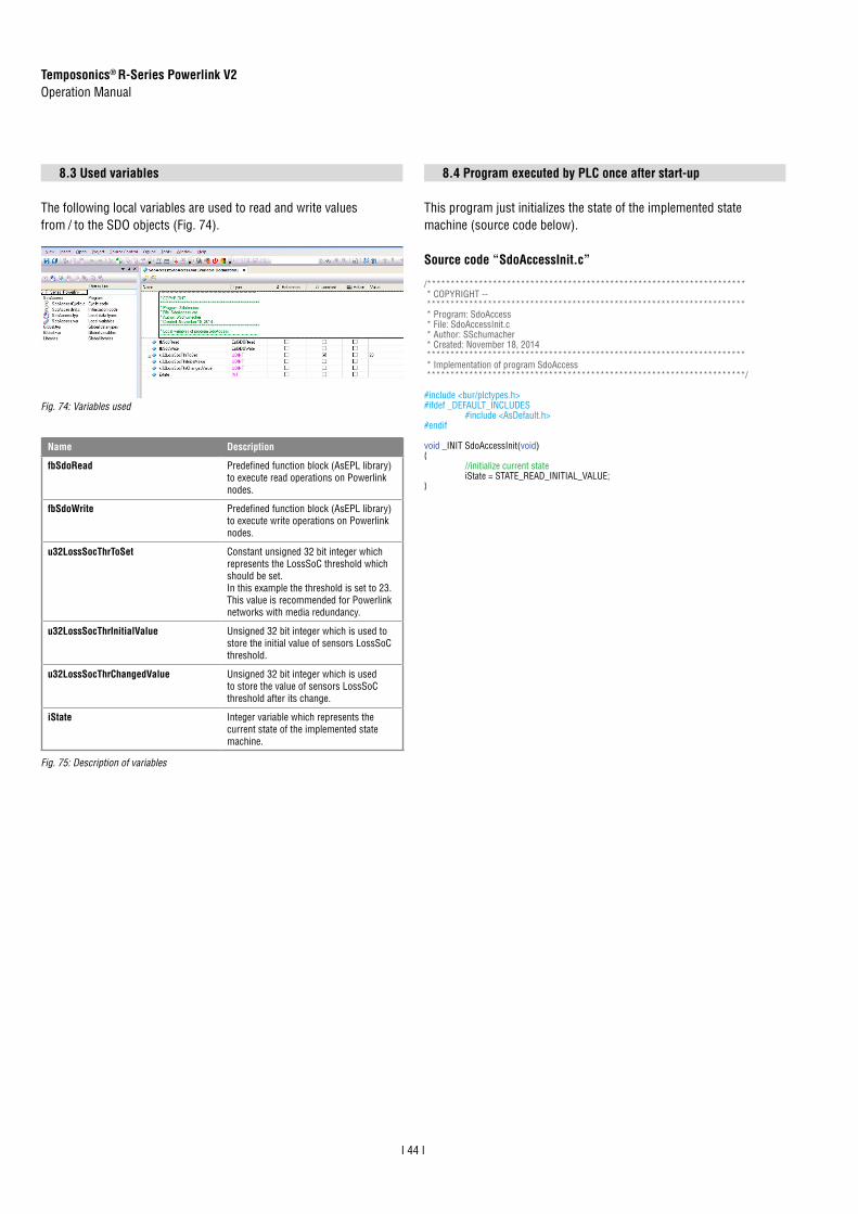
Temposonics® R-Series Powerlink V2Operation Manual
I 44 I
8.3 Used variables
The following local variables are used to read and write values from / to the SDO objects (Fig. 74).
8.4 Program executed by PLC once after start-up
This program just initializes the state of the implemented state machine (source code below).
Source code “SdoAccessInit.c”
Name Description
fbSdoRead Predefined function block (AsEPL library) to execute read operations on Powerlink nodes.
fbSdoWrite Predefined function block (AsEPL library) to execute write operations on Powerlink nodes.
u32LossSocThrToSet Constant unsigned 32 bit integer which represents the LossSoC threshold which should be set. In this example the threshold is set to 23. This value is recommended for Powerlink networks with media redundancy.
u32LossSocThrInitialValue Unsigned 32 bit integer which is used to store the initial value of sensors LossSoC threshold.
u32LossSocThrChangedValue Unsigned 32 bit integer which is used to store the value of sensors LossSoC threshold after its change.
iState Integer variable which represents the current state of the implemented state machine.
/******************************************************************** * COPYRIGHT -- ******************************************************************** * Program: SdoAccess * File: SdoAccessInit.c * Author: SSchumacher * Created: November 18, 2014 ******************************************************************** * Implementation of program SdoAccess ********************************************************************/
#include <bur/plctypes.h>#ifdef _DEFAULT_INCLUDES #include <AsDefault.h>#endif
void _INIT SdoAccessInit(void){ //initialize current state iState = STATE_READ_INITIAL_VALUE;}
Fig. 74: Variables used
Fig. 75: Description of variables

Temposonics® R-Series Powerlink V2Operation Manual
I 45 I
8.5 Program executed by PLC cyclically
This program implements the state machine and accesses the LossSoC threshold of R-Series Powerlink (source code below).
Source code “SdoAccessCyclic.c”
/******************************************************************** * COPYRIGHT -- ******************************************************************** * Program: SdoAccess * File: SdoAccessCyclic.c * Author: SSchumacher * Created: November 18, 2014 ******************************************************************** * Implementation of program SdoAccess ********************************************************************/
#include <bur/plctypes.h>#ifdef _DEFAULT_INCLUDES #include <AsDefault.h>#endif
void _CYCLIC SdoAccessCyclic(void){ if (fbSdoRead.status != ERR_FUB_BUSY && fbSdoWrite.status != ERR_FUB_BUSY) { //currently there is no SDO operation in progress //initiate SDO operation switch (iState) { case STATE_READ_INITIAL_VALUE: fbSdoRead.pDevice = “SS1.IF1”; //interface sensor is connected to fbSdoRead.node = 1; //node id of sensor fbSdoRead.index = 0x1c0b; //index of LossSoC Threshold fbSdoRead.subindex = 3; //subindex of LossSoC Threshold fbSdoRead.pData = &u32LossSocThrInitialValue; //variable to store value to fbSdoRead.datalen = sizeof(u32LossSocThrInitialValue); //size of the variable to store value to fbSdoRead.enable = 1; //enable the read operation fbSdoWrite.enable = 0; //disable write operation //go to next step iState++; break; case STATE_WRITE_NEW_VALUE: fbSdoWrite.pDevice = “SS1.IF1”; //interface sensor is connected to fbSdoWrite.node = 1; //node id of sensor fbSdoWrite.index = 0x1c0b; //index of LossSoC Threshold fbSdoWrite.subindex = 3; //subindex of LossSoC Threshold fbSdoWrite.pData = &u32LossSocThrToSet; //variable containing value to set fbSdoWrite.datalen = sizeof(u32LossSocThrToSet); //size of the variable containing value to set fbSdoWrite.enable = 1; //enable write operation fbSdoRead.enable = 0; //disable read operation //go to next step iState++; break; case STATE_READ_CHANGED_VALUE: fbSdoRead.pDevice = “SS1.IF1”; //interface sensor is connected to fbSdoRead.node = 1; //node id of sensor fbSdoRead.index = 0x1c0b; //index of LossSoC Threshold fbSdoRead.subindex = 3; //subindex of LossSoC Threshold fbSdoRead.pData = &u32LossSocThrChangedValue; //variable to store value to fbSdoRead.datalen = sizeof(u32LossSocThrChangedValue); //size of the variable to store value to fbSdoRead.enable = 1; //enable the read operation fbSdoWrite.enable = 0; //disable write operation //go to next step iState++; break; default: fbSdoRead.enable = 0; //disable read operation fbSdoWrite.enable = 0; //disable write operation break; } } //execute SDO read if enabled EplSDORead(&fbSdoRead); //execute SDO write if enabled EplSDOWrite(&fbSdoWrite);}

Temposonics® R-Series Powerlink V2Operation Manual
I 46 I
8.6 Variable watch after successful execution of the implemented state machine
As shown in the variable watch the LossSoC threshold value has been changed from 15 (default value) to 23 (recommended value for Powerlink networks with media redundancy).
Fig. 76: Variable watch
9.1 Error conditions, troubleshooting
See chapter "5. Operation" on page 30.
9.2 Maintenance
The sensor is maintenance-free.
9.3 Repair
Repairs of the sensor may be performed only by MTS Sensors or a repair facility explicitly authorized by MTS Sensors.
9. Maintenance and troubleshooting
10. Removal from service / dismantling
The product contains electronic components and must be disposed of in accordance with the local regulations.
9.4 List of spare parts
No spare parts are available for this sensor.
9.5 Transport and storage
The conditions of transport and storage of the sensor match the operating conditions mentioned in this document.

8/ With position magnet # 252 1829/ The IP rating is not part of the UL approval10/ Power supply must be able to provide current of 1A for power up process
11. Technical data
Output
Interface Ethernet POWERLINK
Data protocol POWERLINK V2 according to IEEE 802.3
Measured value Position, velocity / option: multi-position measurement (2…4 positions)
Measurement parameters
Resolution 1 μm, 2 μm, 5 μm, 10 μm, 50 μm or 100 μm (selectable)
Cycle time 1.0 ms up to 2400 mm stroke length,2.0 ms up to 4800 mm stroke length,4.0 ms up to 5080 mm stroke length
Linearity 8 < ±0.01 % F.S. (minimum ±50 µm)
Repeatability < ±0.001 % F.S. (minimum ±2.5 µm) typical
Hysteresis < 4 µm typical
Temperature coefficient < 15 ppm/K typical
Operating conditions
Operating temperature −40…+75 °C (−40…+167 °F)
Humidity 90 % rel. humidity, no condensation
Ingress protection 9 IP65 (if mating connectors are correctly fitted)
Shock test 100 g (single shock), IEC standard 60068-2-27
Vibration test 15 g (10…2000 Hz), IEC standard 60068-2-6 (resonance frequencies excluded)
EMC test Electromagnetic immunity EN 61000-6-2Electromagnetic emission EN 61000-6-3The sensor meets the requirements of the EC directives and is marked with
Magnet movement velocity Any (with magnet slider: max. 10 m/s)
Design / Material
Sensor electronics housing Aluminum
Sensor profile Aluminum
Stroke length 25…5080 mm (1…200 in.)
Mechanical mounting
Mounting position Any
Mounting instruction Please consult the technical drawings
Electrical connection
Connection type 2 × M12 female connector (4 pin), 1 × M8 male connector (4 pin)
Operating voltage 10 +24 VDC (−15 / +20 %); UL Recognition requires an approved power supply with energy limitation (UL 61010-1), or Class 2 rating according to the National Electrical Code (USA) / Canadian Electrical Code.
Ripple ≤ 0.28 VPP
Current consumption 10 110 mA typical
Dielectric strength 500 VDC (DC ground to machine ground)
Polarity protection Up to −30 VDC
Overvoltage protection Up to 36 VDC
11.1 Technical data of Temposonics® RP
Temposonics® R-Series Powerlink V2Operation Manual
I 47 I
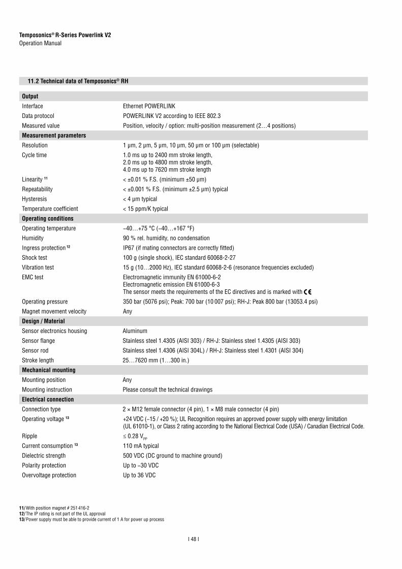
Output
Interface Ethernet POWERLINK
Data protocol POWERLINK V2 according to IEEE 802.3
Measured value Position, velocity / option: multi-position measurement (2…4 positions)
Measurement parameters
Resolution 1 μm, 2 μm, 5 μm, 10 μm, 50 μm or 100 μm (selectable)
Cycle time 1.0 ms up to 2400 mm stroke length, 2.0 ms up to 4800 mm stroke length, 4.0 ms up to 7620 mm stroke length
Linearity 11 < ±0.01 % F.S. (minimum ±50 µm)
Repeatability < ±0.001 % F.S. (minimum ±2.5 µm) typical
Hysteresis < 4 µm typical
Temperature coefficient < 15 ppm/K typical
Operating conditions
Operating temperature −40…+75 °C (−40…+167 °F)
Humidity 90 % rel. humidity, no condensation
Ingress protection 12 IP67 (if mating connectors are correctly fitted)
Shock test 100 g (single shock), IEC standard 60068-2-27
Vibration test 15 g (10…2000 Hz), IEC standard 60068-2-6 (resonance frequencies excluded)
EMC test Electromagnetic immunity EN 61000-6-2Electromagnetic emission EN 61000-6-3The sensor meets the requirements of the EC directives and is marked with
Operating pressure 350 bar (5076 psi); Peak: 700 bar (10 007 psi); RH-J: Peak 800 bar (13053.4 psi)
Magnet movement velocity Any
Design / Material
Sensor electronics housing Aluminum
Sensor flange Stainless steel 1.4305 (AISI 303) / RH-J: Stainless steel 1.4305 (AISI 303)
Sensor rod Stainless steel 1.4306 (AISI 304L) / RH-J: Stainless steel 1.4301 (AISI 304)
Stroke length 25…7620 mm (1…300 in.)
Mechanical mounting
Mounting position Any
Mounting instruction Please consult the technical drawings
Electrical connection
Connection type 2 × M12 female connector (4 pin), 1 × M8 male connector (4 pin)
Operating voltage 13 +24 VDC (−15 / +20 %); UL Recognition requires an approved power supply with energy limitation(UL 61010-1), or Class 2 rating according to the National Electrical Code (USA) / Canadian Electrical Code.
Ripple ≤ 0.28 VPP
Current consumption 13 110 mA typical
Dielectric strength 500 VDC (DC ground to machine ground)
Polarity protection Up to −30 VDC
Overvoltage protection Up to 36 VDC
11.2 Technical data of Temposonics® RH
11/ With position magnet # 251 416-212/ The IP rating is not part of the UL approval13/ Power supply must be able to provide current of 1 A for power up process
Temposonics® R-Series Powerlink V2Operation Manual
I 48 I

Output
Interface Ethernet POWERLINK
Data protocol POWERLINK V2 according to IEEE 802.3
Measured value Position, velocity / option: multi-position measurement (2…4 positions)
Measurement parameters
Resolution 1 μm, 2 μm, 5 μm, 10 μm, 50 μm or 100 μm (selectable)
Cycle time 1.0 ms up to 2400 mm stroke length,2.0 ms up to 4800 mm stroke length, 4.0 ms up to 5080 mm stroke length
Linearity 14 < ±0.02 % F.S. (minimum ±50 µm) 15
Repeatability < ±0.001 % F.S. (minimum ±2.5 µm) typical
Hysteresis < 4 µm typical
Operating conditions
Operating temperature electronics −40…+75 °C (−40…+167 °F)
Operating temperature rod −40…+100 °C (−40…+212 °F)
Humidity 90 % rel. humidity, no condensation
Ingress protection for sensor electronics 16 IP67
Ingress protection sensor rod with connecting cable for side cable entry 16
IP65
Ingress protection sensor rod with single wires and flat connector with bottom cable entry 16
IP30
Shock test 100 g (single shock), IEC standard 60068-2-27
Vibration test 10 g (10…2000 Hz), IEC standard 60068-2-6 (resonance frequencies excluded)
EMC test 17 Electromagnetic immunity EN 61000-6-2Electromagnetic emission EN 61000-6-3
Operating pressure 350 bar (5076 psi); Peak: 700 bar (10 152 psi)
Magnet movement velocity Any
Design / Material
Sensor electronics housing Aluminum
Sensor flange Stainless steel 1.4305 (AISI 303)
Sensor rod Stainless steel 1.4306 (AISI 304L)
Stroke length 25…5080 mm (1…200 in.)
Mechanical mounting
Mounting position Any
Mounting instruction Please consult the technical drawings
Electrical connection
Connection type 2 × M12 female connector (4 pin), 1 × M8 male connector (4 pin)
Operating voltage 18 +24 VDC (−15 / +20 %)
Ripple ≤ 0.28 VPP
Current consumption 18 110 mA typical
Dielectric strength 500 VDC (DC ground to machine ground)
Polarity protection Up to −30 VDC
Overvoltage protection Up to 36 VDC
11.3 Technical data of Temposonics® RD4
14/ With position magnet # 251 416-215/ For pressure fit flange »S« the linearity deviation can be higher in the first 30 mm (1.2 in.) of stroke length16/ The IP rating is not part of the UL approval17/ Sensor rod and connecting cable have to be mounted in a metal housing (e.g. in a cylinder)18/ Power supply must be able to provide current of 1 A for power up process
Temposonics® R-Series Powerlink V2Operation Manual
I 49 I

Output
Interface Ethernet POWERLINK
Data protocol POWERLINK V2 according to IEEE 802.3
Measured value Position, velocity / option: multi-position measurement (2…4 positions)
Measurement parameters
Resolution 1 μm, 2 μm, 5 μm, 10 μm, 50 μm or 100 μm (selectable)
Cycle time 1.0 ms up to 2400 mm stroke length, 2.0 ms up to 4800 mm stroke length, 4.0 ms up to 7620 mm stroke length
Linearity 19 < ±0.02 % F.S. (minimum ±100 µm)
Repeatability < ±0.001 % F.S. (minimum ±2.5 µm) typical
Hysteresis < 4 µm typical
Operating conditions
Operating temperature −40…+75 °C (−40…+167 °F)
Humidity 20 90 % rel. humidity, no condensation
Ingress protection 21 IP30 (IP65 rating only for professional mounted guide pipe and if mating connectors are correctly fitted)
Shock test 100 g (single shock), IEC standard 60068-2-27
Vibration test 5 g (10…150 Hz), IEC standard 60068-2-6 (resonance frequencies excluded)
EMC test Electromagnetic immunity EN 61000-6-2Electromagnetic emission EN 61000-6-3 The sensor meets the requirements of the EC directives and is marked with 22
Magnet movement velocity Any
Design / Material
Sensor electronics housing Aluminum
Sensor flange Stainless steel 1.4305 (AISI 303)
Sensor rod Stainless steel conduct with PTFE coating
Stroke length 150…10,060 mm (6…396 in.)
Mechanical mounting
Mounting position Any
Mounting instruction Please consult the technical drawings
Electrical connection
Connection type 2 × M12 female connector (4 pin), 1 × M8 male connector (4 pin)
Operating voltage 23 +24 VDC (−15 / +20 %)
Ripple ≤ 0.28 VPP
Current consumption 23 110 mA typical
Dielectric strength 500 VDC (DC ground to machine ground)
Polarity protection Up to −30 VDC
Overvoltage protection Up to 36 VDC
11.4 Technical data of Temposonics® RF
19/ With position magnet # 251 416-220/ For professional mounted guide pipe and if mating connectors are correctly fitted21/ The IP rating is not part of the UL approval22/ The conformity is fulfilled assumed the wave guide of the sensor is embedded in an EMC-sealed and grounded housing23/ Power supply must be able to provide current of 1 A for power up process
Temposonics® R-Series Powerlink V2Operation Manual
I 50 I

12. Appendix
Safety Declaration
Dear Customer,If you return one or several sensors for checking or repair, we need you to sign a safety declaration. The purpose of this declaration is to ensure that the returned items do not contain residues of harmful substances and / people handling these items will not be in danger.
MTS Sensors order number: ________________________________
Serial number(s): _________________________________________
Sensor type(s): _________________________________________
Sensor length(s): _________________________________________
The sensor has been in contact with the following materials:
In the event of suspected penetration of substances into the sensor, consult MTS Sensors to determine measures to be taken before shipment.
Do not specify chemical formulas.Please include safety data sheets of the substances, if applicable.
Short description of malfunction:
Corporate information
Company: _______________________________________________
Address: _______________________________________________
_______________________________________________________
Contact partner
Name: _______________________________________________
Phone: _______________________________________________
E-Mail: _______________________________________________
We hereby certify that the measuring equipment has been cleaned and neutralized. Equipment handling is safe. Personnel exposure to health risks during transport and repair is excluded.
DateSignatureStamp
Tel. + 49 - 23 51- 95 87 0Fax. + 49 - 23 51- 5 64 [email protected]
GERMANYMTS Sensor Technologie GmbH & Co.KGAuf dem Schüffel 958513 Lüdenscheid, Germany
USAMTS Systems CorporationSensors Division3001 Sheldon DriveCary, N.C. 27513, USA
Tel. +1 919 677-0100Fax +1 919 [email protected]
JAPANMTS Sensors Technology Corp.737 Aihara-machi, Machida-shi, Tokyo 194-0211, Japan
Tel. + 81 42 775-3838Fax + 81 42 775- [email protected]
Temposonics® R-Series Powerlink V2Operation Manual
I 51 I

UNITED STATESMTS Systems Corporation
Sensors Division
3001 Sheldon DriveCary, N.C. 27513Phone: +1 919 677-0100E-mail: [email protected]
GERMANYMTS Sensor Technologie
GmbH & Co. KG
Auf dem Schüffel 958513 LüdenscheidPhone: +49 2351 9587-0E-mail: [email protected]
ITALYBranch Offi ce
Phone: +39 030 988 3819E-mail: [email protected]
FRANCEBranch Offi ce
Phone: +33 1 58 4390-28E-mail: [email protected]
GREAT BRITAIN Branch Offi ce
Phone: +44 79 44 15 03 00E-mail: [email protected]
CHINABranch Offi ce
Phone: +86 21 6485 5800 E-mail: [email protected]
JAPANBranch Offi ce
Phone: +81 3 6416 1063E-mail: [email protected]
www.mtssensors.comMTS, Temposonics and Level Plus are registered trademarks of MTS Systems Corporation in the United States; MTS SENSORS and the MTS SENSORS logo are trademarks of MTS Systems Corporation within the United States. These trademarks may be protected in other countries. All other trademarks are the property of their respective owners. Copyright © 2018 MTS Systems Corporation. No license of any intellectual property rights is granted. MTS reserves the right to change the information within this document, change product designs, or withdraw products from availability for purchase without notice. Typographic and graphics errors or omissions are unintentional and subject to correction. Visit www.mtssensors.com for the latest product information.
Document Part Number: 551657 Revision B (EN) 10/2018
POWERLINKETHERNET