
AFX Series Power Source Operation Manual - PPST Solutions
499
Operation Manual AFX Series® – Rev 1.2.3 P/N 160620-10 AFX Series ® Programmable Power Source PACIFIC POWER SOURCE Worldwide Supplier of Precision Programmable Power Copyright 2018, Pacific Power Source, Inc. (PPS) • All Rights Reserved • No reproduction without written authorization from PPS.
-
Upload
khangminh22 -
Category
Documents
-
view
0 -
download
0
Transcript of AFX Series Power Source Operation Manual - PPST Solutions

Operation Manual AFX Series® – Rev 1.2.3 P/N 160620-10
AFX Series®
Programmable Power Source
PACIFIC POWER SOURCE Worldwide Supplier of Precision Programmable Power
Copyright 2018, Pacific Power Source, Inc. (PPS) • All Rights Reserved • No reproduction without written authorization from PPS.

AFX SERIES® OPERATION MANUAL CONTENTS
Entire Contents Copyright 2018 by Pacific Power Source, Inc. (PPS) • All Rights Reserved • No reproduction without written authorization from PPS.
AFX Series Power Source Operation Manual Page 2 of 499
PAGE LEFT INTENTIONALLY LEFT BLANK FOR HARDCOPY VERSIONS OF THIS DOCUMENT

AFX SERIES® OPERATION MANUAL CONTENTS
Entire Contents Copyright 2018 by Pacific Power Source, Inc. (PPS) • All Rights Reserved • No reproduction without written authorization from PPS.
AFX Series Power Source Operation Manual Page 3 of 499
Table of Contents 1 Contact Information ................................................................................................................. 15 2 Safety & Warranty Information ................................................................................................ 16
2.1 Limited Warranty .................................................................................................................................. 16 2.2 Service and Spare Parts Limited Warranty .......................................................................................... 16 2.3 Safety Information................................................................................................................................. 16 2.4 Safety Notices ........................................................................................................................................ 18
3 Product Overview ..................................................................................................................... 23 3.1 General Description ............................................................................................................................... 23 3.2 Product Features ................................................................................................................................... 24 3.3 Block Diagram ........................................................................................................................................ 25 3.4 Controller Description ........................................................................................................................... 26 3.5 Measurement Read-back ..................................................................................................................... 26 3.6 Accessories Included (Ship Kit) ............................................................................................................. 26 3.7 Remote Control Interfaces .................................................................................................................... 26
4 Technical Specifications ............................................................................................................ 27 4.1 Single Chassis Models............................................................................................................................ 27 4.2 Multiple Chassis Models ....................................................................................................................... 27 4.3 AC Output Mode ................................................................................................................................... 28
4.3.1 Programmable Output Impedance Ranges by Mode and Configuration ..................................................... 30 4.3.2 Extended Frequency Ranges – Supplemental specs ...................................................................................... 31 4.3.3 Temporary Current Overload .......................................................................................................................... 33 4.3.4 AC Voltage and Current Output Charts ........................................................................................................... 34 4.3.5 Extended AC Voltage Ranges – Supplemental specs ...................................................................................... 35
4.4 DC Output Mode ................................................................................................................................... 37 4.4.1 DC Voltage and Current Output Charts ........................................................................................................... 37
4.5 Protection Modes .................................................................................................................................. 38 4.6 Metering ................................................................................................................................................ 39 4.7 Other Measurements ............................................................................................................................ 40 4.8 Transients ............................................................................................................................................... 40 4.9 AC Input ................................................................................................................................................. 41 4.10 Dimensions & Weight ........................................................................................................................... 41 4.11 Environmental ....................................................................................................................................... 42 4.12 Safety & Regulatory ............................................................................................................................... 42 4.13 Digital Interfaces .................................................................................................................................... 43 4.14 Auxiliary I/O ........................................................................................................................................... 44 4.15 Transformer Output Voltage Range (T Option) ................................................................................... 45
4.15.1 Available T Option Rating Versions .................................................................................................................. 45 4.15.2 Technical Specifications 400V Range ............................................................................................................... 46
4.16 Series Output Voltage Range (S Option) .............................................................................................. 48 4.16.1 Series Mode AFSX description ......................................................................................................................... 48 4.16.2 AFXS Model output connector pin assignments............................................................................................. 48 4.16.3 Series versus Parallel Connection Modes ........................................................................................................ 49 4.16.4 SPMS Series Configuration switch option ....................................................................................................... 50 4.16.5 Standard Series Output Cabinet System Configurations ................................................................................ 51 4.16.6 Selecting the Series Mode Configuration ........................................................................................................ 52
4.17 IEC413 Option ........................................................................................................................................ 53 5 Unpacking and Installation ....................................................................................................... 54
5.1 Inspection .............................................................................................................................................. 54

AFX SERIES® OPERATION MANUAL CONTENTS
Entire Contents Copyright 2018 by Pacific Power Source, Inc. (PPS) • All Rights Reserved • No reproduction without written authorization from PPS.
AFX Series Power Source Operation Manual Page 4 of 499
5.2 Lifting and Carrying Instructions ........................................................................................................... 54 5.3 Verify Correct AC Input Line Voltage .................................................................................................... 56 5.4 AC Input Connections ............................................................................................................................ 57 5.5 Grounding Requirements ..................................................................................................................... 60
5.5.1 Chassis Ground Connection Required ............................................................................................................. 60 5.5.2 Output Neutral Grounding ............................................................................................................................... 61
5.6 AC Input Circuit Breaker ........................................................................................................................ 61 5.7 Bench Use .............................................................................................................................................. 62 5.8 Rack Mounting....................................................................................................................................... 62 5.9 Airflow .................................................................................................................................................... 62 5.10 Sound Levels .......................................................................................................................................... 63 5.11 Cleaning.................................................................................................................................................. 64 5.12 Air Intake Filter Removal and Cleaning ................................................................................................ 64
5.12.1 Air Filter Removal ............................................................................................................................................. 65 5.12.2 Filter Cleaning ................................................................................................................................................... 65 5.12.3 Air Filter Installation.......................................................................................................................................... 65
5.13 Liquids .................................................................................................................................................... 65 5.14 Load Connections .................................................................................................................................. 66
5.14.1 Output Wiring and Recommended Wire Sizing .............................................................................................. 66 5.14.2 Three Phase Wye Load Output Connection .................................................................................................... 67 5.14.3 Three Phase Delta Load Output Connection................................................................................................... 70 5.14.4 AFXS Series Output Load Connection .............................................................................................................. 73 5.14.5 Single Phase Load Output Connection ............................................................................................................ 73 5.14.6 External Voltage Sense Connections ............................................................................................................... 76 5.14.7 Powering Up ..................................................................................................................................................... 78 5.14.8 In Case of Malfunction ..................................................................................................................................... 78
5.15 Cabinet Systems Installation ................................................................................................................. 79 5.15.1 Standard Cabinet Sizes ..................................................................................................................................... 79 5.15.2 Tools Required .................................................................................................................................................. 79 5.15.3 Dimensions ....................................................................................................................................................... 80 5.15.4 Cabinet System AC Input Connections ............................................................................................................ 81 5.15.5 Recommended AC Input Wire Strip Lengths .................................................................................................. 81 5.15.6 Cabinet System AC Input Neutral .................................................................................................................... 83 5.15.7 Cabinet System Grounding .............................................................................................................................. 83 5.15.8 Recommended AC Output Wire Strip Lengths ............................................................................................... 84 5.15.9 Cabinet Load Connections – Three Phase WYE Loads .................................................................................... 84 5.15.10 Cabinet Load Connections – Three Phase Delta Loads................................................................................... 85 5.15.11 Cabinet Load Connections – Single Phase Loads ............................................................................................ 86
5.16 AFX Cabinet Systems Turn ON and Turn OFF Procedures .................................................................. 87 5.16.1 Cabinet Power Turn ON using Circuit Breakers .............................................................................................. 87 5.16.2 Cabinet Power Turn OFF using Circuit Breakers ............................................................................................. 87
5.17 Cabinet System Options ........................................................................................................................ 89 5.17.1 -OCS: Output Control Switch Option ............................................................................................................... 89 5.17.2 -EPO: Emergency Power Off Option ................................................................................................................ 90 5.17.3 -MRC: Mode Relay Control Option .................................................................................................................. 90 5.17.4 -28UX Option .................................................................................................................................................... 90 5.17.5 -Transformer Options for Cabinet Systems ..................................................................................................... 91
5.18 Interface Options ................................................................................................................................... 92 5.18.1 Rear Panel Connector Locations - “L” Versions............................................................................................... 92 5.18.2 Rear Panel Connector Locations - “A” Versions .............................................................................................. 93 5.18.3 Rear Panel Connector Locations - “AG” Versions ........................................................................................... 93 5.18.4 USB Device Interface ........................................................................................................................................ 93 5.18.5 RS232 Serial Interface ....................................................................................................................................... 94

AFX SERIES® OPERATION MANUAL CONTENTS
Entire Contents Copyright 2018 by Pacific Power Source, Inc. (PPS) • All Rights Reserved • No reproduction without written authorization from PPS.
AFX Series Power Source Operation Manual Page 5 of 499
5.18.6 GPIB Device Interface (Option G)..................................................................................................................... 96 5.18.7 Remote Inhibit or Enable Input ........................................................................................................................ 97 5.18.8 External MODE Relay Control .......................................................................................................................... 98 5.18.9 LAN Interface .................................................................................................................................................... 99 5.18.10 System Interface Bus Connectors .................................................................................................................... 99
5.19 Multi-Unit Parallel Operation ............................................................................................................. 100 5.19.1 Load Connections on Parallel Systems .......................................................................................................... 100 5.19.2 Parallel System Bus Connection ..................................................................................................................... 100 5.19.3 Master / Master Paralleling ........................................................................................................................... 101
5.20 Multi-Cabinet Parallel Operation Guidelines ..................................................................................... 102 5.20.1 Output Wiring ................................................................................................................................................. 102 5.20.2 System Grounding .......................................................................................................................................... 103
5.21 Transformer Options ........................................................................................................................... 104 5.21.1 T Option 4U Chassis ........................................................................................................................................ 104 5.21.2 Rack Mount T Option Installation .................................................................................................................. 105 5.21.3 Unpacking T Option Chassis ........................................................................................................................... 106 5.21.4 Cabinet Installation ......................................................................................................................................... 106 5.21.5 T Option Chassis Rear Panel Connectors ....................................................................................................... 107 5.21.6 AFX Power Source to T Option Connections ................................................................................................. 109
6 Front Panel Operation ............................................................................................................ 110 6.1 Front Panel Layout .............................................................................................................................. 110
6.1.1 Keyboard Buttons ........................................................................................................................................... 111 6.1.2 Shuttle Knob.................................................................................................................................................... 112 6.1.3 PC Monitor Output ......................................................................................................................................... 112 6.1.4 USB Host Ports ................................................................................................................................................ 112 6.1.5 SD Card Memory Slot ..................................................................................................................................... 112
6.2 OUTPUT ENABLE Button ..................................................................................................................... 113 6.2.1 OUTPUT State Indication ................................................................................................................................ 113 6.2.2 Energy Savings Modes .................................................................................................................................... 113 6.2.3 Output On Response Times ........................................................................................................................... 113
6.3 Menu Keys ........................................................................................................................................... 114 6.4 PROG – PROGRAM Screens ................................................................................................................ 115
6.4.1 Power On Settings .......................................................................................................................................... 116 6.4.2 PROGRAM Output Parameters...................................................................................................................... 116 6.4.3 Phase Rotation / Phase Sequence ................................................................................................................. 117 6.4.4 Direct Data Entry - Presets ............................................................................................................................. 118 6.4.5 Customizing Output Programming Preset Soft Key Values .......................................................................... 119 6.4.6 Changing Shuttle Programming Resolution .................................................................................................. 119 6.4.7 Phase Mode Selection .................................................................................................................................... 120 6.4.8 PROGRAM Soft Keys ....................................................................................................................................... 121 6.4.9 Peak Current Protection Minimum Setting ................................................................................................... 123 6.4.10 Available Waveforms ..................................................................................................................................... 125 6.4.11 Waveform Smoothing Filter........................................................................................................................... 127 6.4.12 AUTO RMS Function – Steady State .............................................................................................................. 128 6.4.13 Extended AC Voltage Range Operation ......................................................................................................... 130
6.5 MEAS – MEASUREMENTS Screens ..................................................................................................... 133 6.5.1 Measurements Screens .................................................................................................................................. 133 6.5.2 Scope Measurements .................................................................................................................................... 134 6.5.3 Harmonic Measurements .............................................................................................................................. 135 6.5.4 Measurement Screen Soft Keys ..................................................................................................................... 136 6.5.5 Measurement Data Logging........................................................................................................................... 138
6.6 TRAN- TRANSIENTS Screens ............................................................................................................... 139 6.6.1 LIST Mode ....................................................................................................................................................... 139 6.6.2 LIST Parameters .............................................................................................................................................. 140

AFX SERIES® OPERATION MANUAL CONTENTS
Entire Contents Copyright 2018 by Pacific Power Source, Inc. (PPS) • All Rights Reserved • No reproduction without written authorization from PPS.
AFX Series Power Source Operation Manual Page 6 of 499
6.6.3 LIST Transient Edit Mode ............................................................................................................................... 143 6.6.4 LIST Transient Execution Modes .................................................................................................................... 144 6.6.5 LIST Transient Entry Modes ........................................................................................................................... 146 6.6.6 Multiple User Waveforms in LIST Transients ................................................................................................ 147 6.6.7 STEP or RAMP Modes..................................................................................................................................... 148 6.6.8 STEP or RAMP Parameters ............................................................................................................................. 149 6.6.9 STEP or RAMP Transient Execution Modes ................................................................................................... 150 6.6.10 PULSE Mode .................................................................................................................................................... 151 6.6.11 PULSE Parameters .......................................................................................................................................... 152 6.6.12 PULSE Transient Execution Modes ................................................................................................................ 153 6.6.13 AUTO RMS Function – Transients .................................................................................................................. 154
6.7 CONF – CONFIGURATION Screens ..................................................................................................... 155 6.7.1 UNIT CONFIGURATION Screens ..................................................................................................................... 157 6.7.2 USER LIMITS SETTINGS Screen ....................................................................................................................... 161 6.7.3 RAMP TIME & SLEW RATE SETTINGS Screen ................................................................................................ 162 6.7.4 PROGRAM MEMORY Screen ......................................................................................................................... 164 6.7.5 CSC CONFIGURATION Screen ........................................................................................................................ 165 6.7.6 TRANSIENT SETTINGS Screen......................................................................................................................... 166 6.7.7 OUTPUT IMPEDANCE Screen ......................................................................................................................... 167 6.7.8 USER PRESETS Screen ..................................................................................................................................... 168
6.8 SYST – SYSTEM Screens ....................................................................................................................... 170 6.8.1 SYSTEM MENU 1 ............................................................................................................................................. 171 6.8.2 SYSTEM MENU 2 ............................................................................................................................................. 171 6.8.3 ERROR / EVENT QUEUE Screen ..................................................................................................................... 172 6.8.4 FAULT INFORMATION Screen ........................................................................................................................ 172 6.8.5 INTERFACE Screen .......................................................................................................................................... 173 6.8.6 UNIT INFORMATION Screen .......................................................................................................................... 184 6.8.7 PARALLEL UNITS Screen ................................................................................................................................. 185 6.8.8 SYSTEM SETTINGS Screen .............................................................................................................................. 186 6.8.9 EXTERNAL STORAGE MANAGEMENT Screen ............................................................................................... 187 6.8.10 CALIBRATION MENU Screen .......................................................................................................................... 189 6.8.11 FIRMWARE UPDATE Screen ........................................................................................................................... 190 6.8.12 REMOTE SUPPORT Screen ............................................................................................................................. 191
7 Rear Panel, Connectors and Protection .................................................................................. 192 7.1 OUTPUT Terminals .............................................................................................................................. 192
7.1.1 Output Power Connector Rating and Isolation ............................................................................................. 193 7.1.2 Wire Size .......................................................................................................................................................... 193 7.1.3 Connecting a UUT ........................................................................................................................................... 193
7.2 External Voltage Sense Input Terminals ............................................................................................ 194 7.2.1 External Voltage Sense Connector Rating and Isolation .............................................................................. 195 7.2.2 Load Connection without External Voltage Sense ........................................................................................ 195 7.2.3 Load Connection with External Voltage Sense. ............................................................................................ 195
7.3 Auxiliary I/O ......................................................................................................................................... 196 7.3.1 Auxiliary I/O Functions ................................................................................................................................... 196 7.3.2 DB25 Connector AUX I/O Pin locations ......................................................................................................... 197 7.3.3 I/O Signal Table by pin number...................................................................................................................... 198 7.3.4 I/O Signal Table by Function .......................................................................................................................... 199 7.3.5 Dedicated Function Digital Inputs .................................................................................................................. 200 7.3.6 Transient Trigger Input ................................................................................................................................... 201 7.3.7 External or Line Sync Input ............................................................................................................................. 202 7.3.8 Digital Output control signals ......................................................................................................................... 205 7.3.9 User Programmable Digital signals ................................................................................................................ 208 7.3.10 Analog I/O Descriptions .................................................................................................................................. 210 7.3.11 12 DC Power Supply ....................................................................................................................................... 212

AFX SERIES® OPERATION MANUAL CONTENTS
Entire Contents Copyright 2018 by Pacific Power Source, Inc. (PPS) • All Rights Reserved • No reproduction without written authorization from PPS.
AFX Series Power Source Operation Manual Page 7 of 499
7.3.12 RS232 Description ........................................................................................................................................... 212 7.3.13 Front Panel Operation of AUX I/O Functions ................................................................................................ 213
7.4 System Interface Bus Connectors ....................................................................................................... 220 8 Remote Control Programming ................................................................................................ 221
8.1 Overview .............................................................................................................................................. 221 8.1.1 Programming Conventions and Notations .................................................................................................... 221 8.1.2 Command Terminators .................................................................................................................................. 222
8.2 Remote Control Command Descriptions by Subsystem ................................................................... 223 8.3 Calibration Commands ........................................................................................................................ 224
8.3.1 AFX Calibration Commands ........................................................................................................................... 224 8.3.2 UPC Mode Specific commands. ..................................................................................................................... 226 8.3.3 AUX I/O Interface Calibration Commands .................................................................................................... 226
8.4 Measurement Commands .................................................................................................................. 227 8.4.1 Voltage Measurement Commands ............................................................................................................... 227 8.4.2 Frequency Measurement Commands .......................................................................................................... 228 8.4.3 Current Measurement Commands ............................................................................................................... 228 8.4.4 Power Measurement Commands ................................................................................................................. 230 8.4.5 KWh Measurement Commands .................................................................................................................... 230 8.4.6 Other Measurement Commands .................................................................................................................. 232 8.4.7 Measurement Data Logging Commands ...................................................................................................... 233 8.4.8 Waveform Capture Commands ..................................................................................................................... 236 8.4.9 Harmonic Measurements Commands .......................................................................................................... 238 8.4.10 Measurement Resolution Setting Commands .............................................................................................. 243
8.5 Output Control Commands ................................................................................................................ 245 8.6 Program Commands ........................................................................................................................... 250
8.6.1 Program Control Commands ......................................................................................................................... 250 8.6.2 Execution Commands..................................................................................................................................... 261 8.6.3 Transient Segments Commands .................................................................................................................... 262 8.6.4 Memory Management Commands ............................................................................................................... 267
8.7 Source Commands .............................................................................................................................. 270 8.7.1 Source Configuration Programming Commands .......................................................................................... 270 8.7.2 Voltage Programming Commands ................................................................................................................ 276 8.7.3 Frequency Programming Commands............................................................................................................ 283 8.7.4 Current Programming Commands ................................................................................................................ 285 8.7.5 Phase Programming Commands ................................................................................................................... 287 8.7.6 Waveform Programming Commands ........................................................................................................... 289 8.7.7 Voltage Protection Programming Commands .............................................................................................. 297 8.7.8 Current Protection Programming Commands .............................................................................................. 299 8.7.9 Power Protection Programming Commands ................................................................................................ 303 8.7.10 Impedance Programming Commands .......................................................................................................... 309 8.7.11 STEP Transient Commands ............................................................................................................................ 312 8.7.12 PULSE Transient Commands .......................................................................................................................... 332 8.7.13 IEC413 Option Interharmonics Commands .................................................................................................. 343
8.8 Status Commands ............................................................................................................................... 347 8.9 System Commands .............................................................................................................................. 349
8.9.1 System Error Commands ............................................................................................................................... 349 8.9.2 System Information Commands .................................................................................................................... 350 8.9.3 System Interface Commands ......................................................................................................................... 353 8.9.4 System Configuration Commands ................................................................................................................. 357 8.9.5 Parallel System Commands ............................................................................................................................ 359 8.9.6 System Sanitization Commands .................................................................................................................... 360 8.9.7 Communication LAN Commands .................................................................................................................. 360 8.9.8 Communication Serial Port Commands ........................................................................................................ 365 8.9.9 Communication USB Commands .................................................................................................................. 367

AFX SERIES® OPERATION MANUAL CONTENTS
Entire Contents Copyright 2018 by Pacific Power Source, Inc. (PPS) • All Rights Reserved • No reproduction without written authorization from PPS.
AFX Series Power Source Operation Manual Page 8 of 499
8.9.10 Communication GPIB Commands ................................................................................................................. 368 8.9.11 System Firmware Commands ........................................................................................................................ 370 8.9.12 System Remote Access Commands .............................................................................................................. 371 8.9.13 Miscellaneous System Commands ................................................................................................................ 373
8.10 Auxiliary I/O System Commands ........................................................................................................ 374 8.10.1 System Analog & Digital IO Commands ........................................................................................................ 374 8.10.2 SOURce:SYNChronize Commands ................................................................................................................. 387 8.10.3 PROGram:TRANsient Triggers Commands ................................................................................................... 390 8.10.4 AUX I/O Calibration Commands .................................................................................................................... 392
8.11 AFXS Series Mode Commands ............................................................................................................ 396 8.12 IEEE488.2 Common Commands ......................................................................................................... 399 8.13 Status and Events Registers ................................................................................................................ 402
8.13.1 Status Byte Register (STB) .............................................................................................................................. 403 8.13.2 Status Event Register (ESR) ............................................................................................................................ 405 8.13.3 SCPI Status Registers ...................................................................................................................................... 406
9 USB Driver Installation ............................................................................................................ 408 9.1 Overview .............................................................................................................................................. 408 9.2 Installation ........................................................................................................................................... 408
10 LAN Interface Configuration ................................................................................................... 410 10.1 Overview .............................................................................................................................................. 410 10.2 Web Browser Interface ....................................................................................................................... 410 10.3 Access Control ..................................................................................................................................... 412
10.3.1 Browser Access Control .................................................................................................................................. 413 10.3.2 Front Panel Access Control ............................................................................................................................ 416
10.4 Web Browser Interface ....................................................................................................................... 417 10.5 Available Web Interface Menu Tree .................................................................................................. 417 10.6 Home Screen ....................................................................................................................................... 418
10.6.1 SCPI Console Command Line Interface ......................................................................................................... 418 10.6.2 Status Byte Display ......................................................................................................................................... 419 10.6.3 Browser Status Bar ......................................................................................................................................... 419 10.6.4 Operation Manual PDF ................................................................................................................................... 419
10.7 Source Control Screens ....................................................................................................................... 420 10.7.1 Program ........................................................................................................................................................... 421 10.7.2 Protections ...................................................................................................................................................... 422 10.7.3 Transients ........................................................................................................................................................ 423 10.7.4 Program Memory ........................................................................................................................................... 429 10.7.5 Waveform ....................................................................................................................................................... 430 10.7.6 Waveform Editor ............................................................................................................................................ 431 10.7.7 SCPI Script ....................................................................................................................................................... 434
10.8 Measurement Screens ........................................................................................................................ 436 10.8.1 Monitor ........................................................................................................................................................... 437 10.8.2 Real-Time Plot ................................................................................................................................................. 438 10.8.3 V/I Plot ............................................................................................................................................................. 439 10.8.4 Data Logger ..................................................................................................................................................... 440 10.8.5 Scope ............................................................................................................................................................... 441 10.8.6 Harmonics ....................................................................................................................................................... 443
10.9 Configuration Screens ......................................................................................................................... 444 10.9.1 Unit Settings .................................................................................................................................................... 445 10.9.2 User Limits & Presets ...................................................................................................................................... 446 10.9.3 Ramp Time & Slew Rate ................................................................................................................................. 447
10.10 System Screens .................................................................................................................................... 448 10.10.1 Error/Event Queue ......................................................................................................................................... 449 10.10.2 Fault List .......................................................................................................................................................... 450

AFX SERIES® OPERATION MANUAL CONTENTS
Entire Contents Copyright 2018 by Pacific Power Source, Inc. (PPS) • All Rights Reserved • No reproduction without written authorization from PPS.
AFX Series Power Source Operation Manual Page 9 of 499
10.10.3 Error/Event List ............................................................................................................................................... 451 10.10.4 Interface Setup ............................................................................................................................................... 452 10.10.5 Access Control................................................................................................................................................. 453 10.10.6 Digital & Analog IO’s ....................................................................................................................................... 454 10.10.7 Unit Information ............................................................................................................................................. 458 10.10.8 Parallel Units ................................................................................................................................................... 459 10.10.9 Memory Browser ............................................................................................................................................ 460 10.10.10 Calibration ....................................................................................................................................................... 461 10.10.11 Remote Support ............................................................................................................................................. 462 10.10.12 Import / Export ............................................................................................................................................... 462 10.10.13 Firmware Update ............................................................................................................................................ 463 10.10.14 Sanitize and Reboot ........................................................................................................................................ 464
10.11 Additional Functions............................................................................................................................ 464 10.11.1 Sharing Options – FTP & SAMBA ................................................................................................................... 464
11 Calibration .............................................................................................................................. 465 11.1 Calibration Interval .............................................................................................................................. 465 11.2 Closed Case User Calibration .............................................................................................................. 465 11.3 Equipment Required ........................................................................................................................... 465 11.4 Calibration Procedures ........................................................................................................................ 466
11.4.1 Voltage Calibration - Offset ............................................................................................................................ 466 11.4.2 Current Calibration - Offset ............................................................................................................................ 467 11.4.3 Voltage Calibration - Gain .............................................................................................................................. 468 11.4.4 Current Gain Calibration Setup Diagrams ..................................................................................................... 469 11.4.1 Current Calibration Load Values .................................................................................................................... 470 11.4.2 Current Calibration - Gain .............................................................................................................................. 471 11.4.3 Exit Calibration Mode ..................................................................................................................................... 471
12 Warnings & Error Messages ................................................................................................... 472 12.1 Preface ................................................................................................................................................. 472 12.2 Errors & Warnings Messages in Numeric Order ................................................................................ 472
13 Service and Maintenance ....................................................................................................... 493 13.1 Warnings .............................................................................................................................................. 493 13.2 Authorized Service Centers ................................................................................................................. 494
14 CE MARK Declaration of Conformity....................................................................................... 495
Index ............................................................................................................................................. 496

AFX SERIES® OPERATION MANUAL CONTENTS
Entire Contents Copyright 2018 by Pacific Power Source, Inc. (PPS) • All Rights Reserved • No reproduction without written authorization from PPS.
AFX Series Power Source Operation Manual Page 10 of 499
Table of Tables Table 3-1: Included Accessories ........................................................................................................................... 26 Table 3-2: Remote Control Interface .................................................................................................................... 26 Table 4-1: Programmable Impedance Ranges as a function of Phase Mode and Configuration ......................... 30 Table 5-1: AC Input Wire Size Table ..................................................................................................................... 58 Table 5-2: Available AFX Cabinet Options ............................................................................................................ 89 Table 5-3: Remote Control Interface Connector Locations on Rear Panel ( A Versions)...................................... 93 Table 5-4: Remote Control Interface Connector Locations on Rear Panel (A Versions w GPIB) .......................... 93 Table 5-5: RS232 DB25 Tx and Rx Pin Locations ................................................................................................... 94 Table 5-6: Standard RS232 DB9 Pin Assignments ................................................................................................. 95 Table 5-7: GPIB Interface Connector Pin Assignments ......................................................................................... 96 Table 5-8: Transformer Option Chassis, Rear Panel Connectors ........................................................................ 108 Table 6-1: Available Menu Keys.......................................................................................................................... 114 Table 6-2: Available Output Parameters on PROGRAM screen .......................................................................... 116 Table 6-3: Changing Programming Resolution ................................................................................................... 119 Table 6-4: PROGRAM screen soft keys ............................................................................................................... 122 Table 6-5: Available Included AFX Series® Waveforms ...................................................................................... 126 Table 6-6: Measurement Screen Soft Keys ......................................................................................................... 137 Table 6-7: Available LIST Transient Parameters ................................................................................................. 140 Table 6-8: Voltage Transient List for Example 1 ................................................................................................. 141 Table 6-9: RTCA/DO160 Section 16 test number 16.5.2.1d ............................................................................... 142 Table 6-10: Voltage Transient List for Example 1 ............................................................................................... 142 Table 6-11: Available TRANSIENT EDIT screen soft keys .................................................................................... 144 Table 6-12: Available TRANSIENT DEBUG screen soft keys ................................................................................ 144 Table 6-13: Available TRANSIENT PROGRAM screen soft keys .......................................................................... 145 Table 6-14: Available STEP Transient Parameters .............................................................................................. 149 Table 6-15: Available STEP PROGRAM screen soft keys ..................................................................................... 149 Table 6-16: Available STEP EXECUTION screen soft keys ................................................................................... 150 Table 6-17: Available STEP Transient Parameters .............................................................................................. 152 Table 6-18: Available STEP PROGRAM screen soft keys ..................................................................................... 152 Table 6-19: Available STEP PROGRAM screen soft keys ..................................................................................... 153 Table 6-20: Available UNIT CONFIGURATION 1 screen soft keys ....................................................................... 159 Table 6-21: Available UNIT CONFIGURATION 2 screen soft keys ....................................................................... 160 Table 6-22: Available USER LIMITS SETTINGS screen soft keys .......................................................................... 161 Table 6-23: Available RAMP TIME & SLEW RATE SETTINGS screen soft keys .................................................... 163 Table 6-24: Available SLEW RATE SETTINGS screen soft keys ............................................................................ 165 Table 6-25: Available CSC CONFIGURATION screen soft keys ............................................................................ 165 Table 6-26: Available TRANSIENT SETTINGS screen soft keys ............................................................................ 166 Table 6-27: Available PROGRAMMABLE IMPEDANCE screen soft keys ............................................................. 167 Table 6-28: Available USER INTERFACE screen soft keys.................................................................................... 175 Table 6-29: Available USER INTERFACE screen soft keys.................................................................................... 176 Table 6-30: Available ETHERNET INTERFACE SETUP screen soft keys ................................................................ 178 Table 6-31: Available SERIAL INTERFACE SETUP screen soft keys ...................................................................... 179 Table 6-32: Available USB INTERFACE SETUP screen soft keys .......................................................................... 180 Table 6-33: Available GPIB INTERFACE SETUP screen soft keys ......................................................................... 181

AFX SERIES® OPERATION MANUAL CONTENTS
Entire Contents Copyright 2018 by Pacific Power Source, Inc. (PPS) • All Rights Reserved • No reproduction without written authorization from PPS.
AFX Series Power Source Operation Manual Page 11 of 499
Table 6-34: Available UNIT INFORMATION screen soft keys .............................................................................. 184 Table 6-35: Available PARALLEL UNITS screen soft keys .................................................................................... 185 Table 6-36: Available SYSTEM SETTINGS screen soft keys ................................................................................. 186 Table 6-37: Available CALIBRATION MENU screen soft keys.............................................................................. 189 Table 6-38: Available FIRMWARE UPDATE screen soft keys .............................................................................. 190 Table 6-39: Available LOGGING TOOL screen soft keys ...................................................................................... 191 Table 7-1: Auxiliary I/O DB25 Connector Pin numbers and Signals by DB25 pin number .................................. 198 Table 7-2: Auxiliary I/O DB25 Connector Pin numbers and Signals by Signal Name .......................................... 199 Table 7-3: Default Analog Output Functions ...................................................................................................... 211 Table 7-4: AUX I/O Analog Input assignable Commands .................................................................................... 214 Table 7-5: AUX I/O Digital Output assignable Events or Conditions ................................................................... 217 Table 8-1: Available SCPI Command Subsystems ............................................................................................... 223 Table 8-2: Available Included AFX Series® Waveforms ...................................................................................... 290 Table 8-3: Mandatory IEEE488.2 Common Commands ..................................................................................... 399 Table 8-4: Status Byte Register (STB) ................................................................................................................. 403 Table 8-5: Status Event Register (ESR) ................................................................................................................ 405 Table 10-1: Supported Script Entries .................................................................................................................. 434 Table 11-1: Required Calibration Equipment ..................................................................................................... 465 Table 11-2: Setup for Voltage Offset Calibration ............................................................................................... 466 Table 11-3: Calibration Load Values by Model and Phase Mode ....................................................................... 470 Table 12-1: Warnings and Error Messages Listing .............................................................................................. 492

AFX SERIES® OPERATION MANUAL CONTENTS
Entire Contents Copyright 2018 by Pacific Power Source, Inc. (PPS) • All Rights Reserved • No reproduction without written authorization from PPS.
AFX Series Power Source Operation Manual Page 12 of 499
Table of Figures Figure 2-1: EMI AC Input Filter Residual Voltage Check after disconnecting AC Mains power ............................ 21 Figure 3-1: AFX Series Model Number Decoder ................................................................................................... 23 Figure 3-2: AFX Series® Basic Block Diagram ........................................................................................................ 25 Figure 4-1: Output Voltage distortion into full R Load as a function of Frequency .............................................. 29 Figure 4-2: 1.00Hz ~ 15.00Hz Freq. Range Power Rating in 3 Phs Mode ............................................................. 32 Figure 4-3: 1200Hz ~ 3000Hz Freq. Range Voltage vs. Current- 3150AFX in 3 Phs Mode .................................... 32 Figure 4-4: 1200Hz ~ 3000Hz Extended Freq. Range Power - 3150AFX in 3 Phs Mode ....................................... 33 Figure 4-5: Current Overload vs. Time.................................................................................................................. 33 Figure 4-6: AC Mode Voltage/Current range, AFX Models - 3 or 2-phase mode. ................................................ 34 Figure 4-7: AC Mode Voltage/Current range, AFX Models – 1 phase mode. ....................................................... 34 Figure 4-8: Extended AC Voltage/Current Range, AFX Models – 3 or 2 phase mode .......................................... 36 Figure 4-9: Extended AC Voltage/Current Range, AFX Models – 1 phase mode .................................................. 36 Figure 4-10: DC Mode Voltage/Current range, AFX Models- 3 or 2 phase mode. ............................................... 37 Figure 4-11: DC Mode Voltage/Current range, AFX Models - 1 phase mode. ...................................................... 38 Figure 4-12: Dimension Drawing AFX Series® 15KW Model ................................................................................. 42 Figure 4-13: Rack Mount Chassis for 6kVA to 15kVA Transformer Option .......................................................... 45 Figure 4-14: Voltage vs Current Rating 400V Range – 3 Phase Mode .................................................................. 47 Figure 4-15: Voltage vs Current Rating 400V Range – 1 Phase Mode .................................................................. 47 Figure 4-16: 60KVA AFXS Series with SPMS Option.............................................................................................. 48 Figure 4-17: AFXS Model Ouput Connector vs Stadandar AFX ............................................................................. 48 Figure 4-18: Parallel Configuration – 30 kVA/kW 300Vac LN / 520Vac LL ........................................................... 49 Figure 4-19: Series Configuration – 30 kVA/kW 600Vac LN / 1040Vac LL ............................................................ 49 Figure 4-1: Model 5L18-36 VI Curve ..................................................................................................................... 54 Figure 5-2: Exploded view of AFX unit packaging ................................................................................................. 55 Figure 5-3: Rear Panel Layout ............................................................................................................................... 59 Figure 5-4: AC Input Terminal Block - Rear Panel ................................................................................................. 59 Figure 5-5: Grounding Floating Neutral Output ................................................................................................... 61 Figure 5-6: Air Intake Filter Removal .................................................................................................................... 64 Figure 5-7: Air Intake Filter and Filter Panel ......................................................................................................... 65 Figure 5-8: Three phase Wye Load Output Connections – Internal Voltage Sense .............................................. 68 Figure 5-9: Three phase Wye Load Output Connections – External Voltage Sense ............................................. 69 Figure 5-10: Three phase Delta Load Output Connections – Internal Voltage Sense .......................................... 71 Figure 5-11: Three phase Delta Load Output Connections – External Voltage Sense .......................................... 72 Figure 5-12: Optional AFX Single Phase Shorting Adaptor assembly ................................................................... 74 Figure 5-13: Single phase Load Output Connections ............................................................................................ 75 Figure 5-14: AFX A Version External Voltage Sense Connector ............................................................................ 77 Figure 5-15: AFX Cabinet Dimensions................................................................................................................... 80 Figure 5-16: AFX Cabinet AC Input Connection Diagram ...................................................................................... 82 Figure 5-17: WYE Load Connection Diagram ........................................................................................................ 84 Figure 5-18: Delta Load Connection Diagram ....................................................................................................... 85 Figure 5-19: Single Phase Load Connection Diagram ........................................................................................... 86 Figure 5-20: AFX Cabinet System Power ON and OFF Sequences ........................................................................ 88 Figure 5-21AFX “AG” Version Cabinet -OCS Option Wiring Diagram ................................................................... 89 Figure 5-22: AFX “L” Version Cabinet -OCS Option Wiring Diagram .................................................................... 90

AFX SERIES® OPERATION MANUAL CONTENTS
Entire Contents Copyright 2018 by Pacific Power Source, Inc. (PPS) • All Rights Reserved • No reproduction without written authorization from PPS.
AFX Series Power Source Operation Manual Page 13 of 499
Figure 5-23: Remote Control Interface Connector Locations on Rear Panel ( L Versions) ................................... 92 Figure 5-24: Remote Inhibit Control Screen ......................................................................................................... 97 Figure 5-25: Remote Inhibit Pins on DB9 for AFX-2L and AFX-4L Versions .......................................................... 97 Figure 5-26: AFX Series® Rear Panel Layout ......................................................................................................... 99 Figure 5-27: Parallel Mode Bus Connections using parallel bus cable ............................................................... 101 Figure 5-28: Multi-Cabinet Parallel Configuration Output Wiring - 3 Phase ...................................................... 102 Figure 5-29: Rack Mount Chassis for 6kVA to 15kVA Transformer Option ........................................................ 104 Figure 5-30: Interconnections between AFX Power Sourec and Transformer Option Chassis .......................... 109 Figure 6-1: AFX Series® Front Panel View ........................................................................................................... 110 Figure 6-2: PROGRAM Screen ............................................................................................................................. 116 Figure 6-3: Three Phase AC mode Default Phase Rotation ................................................................................ 117 Figure 6-4: Three Phase AC mode Reversed Phase Rotation ............................................................................. 118 Figure 6-5: Phase Mode Data Entry Status Field ................................................................................................ 120 Figure 6-6: Waveform with no Smoothing Filter Applied ................................................................................... 127 Figure 6-7: Same Waveform with maximum smoothing Filter Applied ............................................................. 127 Figure 6-8: Enable Vac extended operating range to 312Vac ............................................................................ 131 Figure 6-9: Three Phase Measurement Screens ................................................................................................. 133 Figure 6-10: Single Phase Measurement Screens for Phase A and B ................................................................. 133 Figure 6-11: Voltage Transient Example 1 .......................................................................................................... 141 Figure 6-12: RTCA/DO160 Section 16 test number 16.5.2.1d ............................................................................ 142 Figure 6-13: Blank TRANSIENT PROGRAM screen .............................................................................................. 143 Figure 6-14: TRANSIENT VIEW Edit Mode .......................................................................................................... 143 Figure 6-15: TRANSIENT Debug mode screen .................................................................................................... 144 Figure 6-16: Transient shown in STEP Entry Mode............................................................................................. 146 Figure 6-17: Transient shown in SEGMENT Entry Mode .................................................................................... 146 Figure 6-18: Available User Waveforms in Transients ........................................................................................ 147 Figure 6-19: USER LIMIT SETTINGS Screen ......................................................................................................... 161 Figure 6-20: RAMP TIME & SLEW RATE SETTINGS Screen .................................................................................. 162 Figure 6-21: PROGRAM MEMORY screen ........................................................................................................... 164 Figure 6-22: CSC CONFIGURATION screen ......................................................................................................... 165 Figure 6-23: SYSTEM MAIN MENU 1 .................................................................................................................. 170 Figure 6-24: SYSTEM MAIN MENU 2 .................................................................................................................. 170 Figure 6-25: ERROR & EVENT QUEUE Screen ..................................................................................................... 172 Figure 6-26: FAULT INFORMATION screen ......................................................................................................... 172 Figure 6-27: INTERFACE SETUP Screen ............................................................................................................... 173 Figure 6-28: ETHERNET INTERFACE SETUP Screen ............................................................................................. 177 Figure 6-29: SERIAL INTERFCE SETUP Screen ..................................................................................................... 179 Figure 6-30: USB INTERFACE SETUP Screen ....................................................................................................... 180 Figure 6-31: USB INTERFACE SETUP Screen ....................................................................................................... 181 Figure 6-32: REMOTE INHIBIT Setup Screen ....................................................................................................... 182 Figure 6-33: UNIT INFORMATION Screen ........................................................................................................... 184 Figure 6-34: PARALLEL UNITS Screen ................................................................................................................. 185 Figure 6-35: SYSTEM SETTINGS Screen ............................................................................................................... 186 Figure 6-36: EXTERNAL STORAGE MANAGMENT Screen ................................................................................... 187 Figure 6-37: CALIBRATION MENU Screen ........................................................................................................... 189 Figure 6-38: FIRMWARE UPDATE Screen ........................................................................................................... 190

AFX SERIES® OPERATION MANUAL CONTENTS
Entire Contents Copyright 2018 by Pacific Power Source, Inc. (PPS) • All Rights Reserved • No reproduction without written authorization from PPS.
AFX Series Power Source Operation Manual Page 14 of 499
Figure 6-39: REMOTE SUPPORT Screen .............................................................................................................. 191 Figure 6-40: Remote Support REPORT Screen .................................................................................................... 191 Figure 7-1: Rear Panel AUX I/O DB25 Connector Location ................................................................................. 196 Figure 7-2: DB25 Connector AUX I/O Pin Locations ........................................................................................... 197 Figure 7-3: External Trigger Input Timing ........................................................................................................... 202 Figure 7-4: External Sync Input Pulses ................................................................................................................ 203 Figure 7-5: External Sync Input Sync Status Indication ...................................................................................... 204 Figure 7-6: External Sync Input Sync Lost Status Indication ............................................................................... 204 Figure 7-7: Transient Trigger Output Pulse ........................................................................................................ 206 Figure 7-8: Function Strobe Output Pulse .......................................................................................................... 206 Figure 7-9: Phase A Zero Phase Sync Output Pulse ............................................................................................ 207 Figure 8-1: Energy Saving Modes and Output Commands State Diagram ......................................................... 245 Figure 8-2: OUTP:ZERO Command Ramp and Dwell settings ............................................................................. 249 Figure 8-3: Status Byte Logical Model ................................................................................................................ 404 Figure 8-4: Standard Event Register (ESR) Model .............................................................................................. 405 Figure 8-5: SCPI Status Registers Model ............................................................................................................. 407 Figure 9-1: PPST USB Drivers visible in Windows Device Manager .................................................................... 409 Figure 10-1: LXI Web Server Home Screen ......................................................................................................... 411 Figure 10-2: ACCESS CONTROL Dialog Screen .................................................................................................... 413 Figure 10-3: Remote Access Control Request Dialog ......................................................................................... 414 Figure 10-4: Remote Access Control IP Filter screen .......................................................................................... 415 Figure 10-5: Waveform Edit defined using 4 data points ................................................................................... 432 Figure 10-6: Waveform Edit defined using 16 data points ................................................................................. 432 Figure 11-1: Voltage Calibration Equipment Setup – 1 or 3 Phase Mode – Phase A .......................................... 468 Figure 11-2: Current Calibration Equipment Setup – 3 Phase Mode – Phase A ................................................. 469 Figure 11-3: Current Calibration Equipment Setup – 1 Phase Mode ................................................................. 470

AFX SERIES® OPERATION MANUAL SECTION 1: Contact Information
Entire Contents Copyright 2018 by Pacific Power Source, Inc. (PPS) • All Rights Reserved • No reproduction without written authorization from PPS.
AFX Series Power Source Operation Manual Page 15 of 499
1 Contact Information
AMERICA / CANADA Pacific Power Source 2802 Kelvin Avenue, Suite 100 Irvine, CA 92614 USA Phone: +1(949) 251-1800 Fax: +1 (949) 756-0756 Email: [email protected]
EUROPE Pacific Power Source Europe GmbH. Binzigstraße 21 77876 Kappelrodeck Germany Phone: +49(0)7842-99722-20 Fax: +49(0) 7842-99722-29 Email: [email protected]
CHINA PPST Shanghai Co. Ltd. 4 floors , building 2, No. 2185 Lai Fang Road Jiu Ting Town, Song Jiang District Shanghai 201615 Phone: +86-21-6763-9223 Fax: +86-21-5763-8240 Email: [email protected]
Web: https://pacificpower.com

AFX SERIES® OPERATION MANUAL SECTION 2: Safety & Warranty Information
Entire Contents Copyright 2018 by Pacific Power Source, Inc. (PPS) • All Rights Reserved • No reproduction without written authorization from PPS.
AFX Series Power Source Operation Manual Page 16 of 499
2 Safety & Warranty Information
2.1 Limited Warranty Pacific Power Source, Inc. (PPS) warrants each unit to be free from defects in material and workmanship. For the period of two (2) years from the date of shipment to the purchaser, PPS will either repair or replace, at its sole discretion, any unit returned to the PPS factory in Irvine, California or one of its designated service facilities. It does not cover damage arising from misuse of the unit or attempted field modifications or repairs. This warranty specifically excludes damage to other equipment connected to this unit.
Upon notice from the purchaser within (30) days of shipment of units found to be defective in material or workmanship, PPS will pay all shipping charges for the repair or replacement. If notice is received more than thirty (30) days from shipment, all shipping charges shall be paid by the purchaser. Units returned on debit memos will not be accepted and will be returned without repair.
This warranty is exclusive of all other warranties, expressed or implied.
2.2 Service and Spare Parts Limited Warranty PPS warrants repair work to be free from defects in material and workmanship for the period of ninety (90) days from the invoice date. This Service and Spare Parts Limited Warranty applies to replacement parts or to subassemblies only. All shipping and packaging charges are the sole responsibility of the buyer. PPS will not accept debit memos for returned power sources or for subassemblies. Debit memos will cause return of power sources or assemblies without repair.
This warranty is exclusive of all other warranties, expressed or implied.
2.3 Safety Information This chapter contains important information you should read BEFORE attempting to install and power-up PPS Equipment. The information in this chapter is provided for use by experienced operators. Experienced operators understand the necessity of becoming familiar with, and then observing, life-critical safety and installation issues. Topics in this chapter include:
• Safety Notices • Cautions • Preparation for Installation • Installation Instructions
Make sure to familiarize yourself with the SAFETY SYMBOLS shown on the next page. These symbols are used throughout this manual and relate to important safety information and issues affecting the end user or operator.

AFX SERIES® OPERATION MANUAL SECTION 2: FRONT MATTER
Entire Contents Copyright 2018 by Pacific Power Source, Inc. (PPS) • All Rights Reserved • No reproduction without written authorization from PPS.
AFX Series Power Source Operation Manual Page 17 of 499
AFX SERIES® OPERATION MANUAL SECTION 2: FRONT MATTER
Entire Contents Copyright 2018 by Pacific Power Source, Inc. (PPS) • All Rights Reserved • No reproduction without written authorization from PPS.
AFX Series Power Source Operation Manual Page 18 of 499
2.4 Safety Notices SAFETY SUMMARY
The following general safety precautions must be observed during all phases of operation, service, and repair of this instrument. Failure to comply with these precautions or with specific warnings elsewhere in this manual violates safety standards of design, manufacture, and intended use of the instrument. Pacific Power Source assumes no liability for the customer's failure to comply with these requirements.
CAUTION: CLASS 1 INSTRUMENT This product is a Safety Class 1 instrument (provided with a protective earth terminal). The protective features of this product may be impaired if it is used in a manner not specified in the operation instructions.
AVERTISSEMENT: APPAREIL CLASSE 1 Cet produit est un appareil Classe 1 (avec terre de protection). Les dispositifs de sécurité de ce produit peuvent être altérés si le produit est utilisé d´une manière non spécifiée dans le manuel d´utilisation.
CAUTION: ENVIRONMENTAL CONDITIONS This instrument is intended for indoor use in an installation category II, pollution degree 2 environments only. It is designed to operate at a maximum relative humidity of 80% for temperatures up to 40 °C and at altitudes of up to 2000 meters. Refer to the specifications tables for the ac mains voltage requirements and ambient operating temperature range.
AVERTISSEMENT: CONDITIONS ENVIRONNEMENTALES Cet appareil est destiné à une utilisation intérieure dans une installation de catégorie II, degré de pollution 2. Il est conçu pour fonctionner sous humidité relative maximale de 80%, pour des températures allant jusqu´à 40°C et à des altitudes allant jusqu´à 2000 m. Se reporter aux tableaux de spécifications pour les exigences en terme de tension secteur et plage de temperature ambiante de fonctionnement.
AFX SERIES® OPERATION MANUAL SECTION 2: FRONT MATTER
Entire Contents Copyright 2018 by Pacific Power Source, Inc. (PPS) • All Rights Reserved • No reproduction without written authorization from PPS.
AFX Series Power Source Operation Manual Page 19 of 499
CAUTION: BEFORE APPLYING POWER Verify that the product AC input specifications noted on the model tag matches the available utility line voltage and frequency.
ATTENTION: AVANT DE METTRE SOUS TENSION Vérifier que les spécifications de tension d´alimentation de l´équipement notées sur l´étiquette sont bien compatibles avec la tension et fréquence secteur disponibles.
SAFETY NOTICE: GROUNDING This product is a Safety Class 1 instrument (provided with a protective earth terminal). To minimize shock hazard, the instrument chassis or cabinet must be connected to an electrical safety ground. The instrument must be connected to the AC power supply mains through a properly rated three phase power cable with protective earth (L1-L2-L3-E). Any interruption of the protective (grounding) conductor or disconnection of the protective earth terminal will cause a potential shock hazard that could result in personal injury. This instrument is equipped with a line filter to reduce electromagnetic interference and must be properly grounded to minimize electric shock hazard. Operation at line voltages or frequencies in excess of those stated on the model type plate may cause leakage currents in excess of 5.0 mA peak.
REGLE DE SECURITE: MISE A LA TERRE Ce produit est un équipement de Classe 1 (muni d´une borne de mise à la terre). Pour minimiser le risque de choc électrique, le châssis de l´appareil ou de l´armoire/rack doit impérativement être relié à une terre de sécurité électrique. L´appareil doit être branché sur le secteur d'alimentation électrique à courant alternatif par un câble d'alimentation triphasé approprié avec terre de protection (L1-L2-L3-PE). Toute interruption de la mise à la terre de protection ou de déconnexion de la borne de terre causera un risque de choc électrique qui pourrait entraîner des blessures.
Cet appareil est équipé d'un filtre secteur pour réduire les interférences électromagnétiques et doit être correctement mis à la terre afin de minimiser le risque de choc électrique. Le fonctionnement sous tensions et fréquences supérieures à celles indiquées sur l´étiquette peut provoquer des courants de fuite de plus de 5,0 mA peak.

AFX SERIES® OPERATION MANUAL SECTION 2: FRONT MATTER
Entire Contents Copyright 2018 by Pacific Power Source, Inc. (PPS) • All Rights Reserved • No reproduction without written authorization from PPS.
AFX Series Power Source Operation Manual Page 20 of 499
CAUTION: DO NOT OPERATE IN AN EXPLOSIVE ATMOSPHERE Do not operate the instrument in the presence of flammable gases or fumes.
AVERTISSEMENT: NE PAS UTILISER SOUS ATMOSPHERE EXPLOSIVE Ne pas faire fonctionner l´appareil en presence de gaz ou vapeurs inflammables.
CAUTION
The AC input connections must include a disconnect device (an external switch or circuit-breaker) as part of the installation. The disconnect device must be suitably located and easily reached and must be marked as the disconnecting device for the equipment. The disconnect device must disconnect all line conductors simultaneously. An external overcurrent protection device must be provided (by, e.g., fuses or circuit breaker). The breaking capacity of the overcurrent protection device should be compatible with the current rating of the installation. A minimum of basic insulation is required between mains-connected parts of opposite polarity on the supply side of the overcurrent protection device. Overcurrent protection devices shall not be fitted in the protective conductor. Fuses or single pole circuit-breakers shall not be fitted in the neutral conductor of multi-phase equipment. Installation should be in accordance with ANSI/NFPA 70, NEC. After disconnecting grid power, ALWAYS wait at least 1 minute, then use a Digital Voltmeter (DMM) in VDC Mode to check for any residual DC voltage from each Line terminal to the Chassis ground stud to check for safe voltage levels (< 5 Vdc) before touching the unit or any terminal blocks or pins.
AVERTISSEMENT
Les connexions d'entrée AC doivent inclure un dispositif de déconnexion (un commutateur externe ou disjoncteur) dans le cadre de l'installation. Le dispositif de déconnexion doit être convenablement situé et facilement accessible et doit être marqué comme le dispositif de déconnexion de l'équipement. Le dispositif de déconnexion doit déconnecter tous les conducteurs de ligne simultanément. Un dispositif de protection de surintensité externe doit être fourni (par exemple, par des fusibles ou coupe-circuit). Le pouvoir de coupure du dispositif de protection contre les surintensités doit être compatible avec le courant nominal de l'installation.

AFX SERIES® OPERATION MANUAL SECTION 2: FRONT MATTER
Entire Contents Copyright 2018 by Pacific Power Source, Inc. (PPS) • All Rights Reserved • No reproduction without written authorization from PPS.
AFX Series Power Source Operation Manual Page 21 of 499
AVERTISSEMENT
Un minimum d'isolation de base est nécessaire entre les parties de réseau connecté de polarité opposée sur le côté d'alimentation du dispositif de protection contre les surintensités. Les dispositifs de protection contre les surintensités ne doivent pas être installés dans le conducteur de protection. Fusibles ou simples disjoncteurs ne doivent pas être installés dans le conducteur neutre des équipements multi-phasés. L'installation doit être conforme à la norme ANSI / NFPA 70, NEC. Après avoir débranché l'alimentation du réseau, attendez TOUJOURS au moins 1 minute, puis utilisez un voltmètre numérique (DMM) en mode VDC pour vérifier toute tension CC résiduelle de chaque borne de ligne sur le plot de masse du châssis pour vérifier les niveaux de tension sécurisés (<5 Vcc) avant de toucher l’unité ou des borniers ou des broches.
< 5 Vdc Line to GndCHECK ALL THREE INPUT
LINES POSITIONS Figure 2-1: EMI AC Input Filter Residual Voltage Check after disconnecting AC Mains power
CAUTION: DO NOT SUBSTITUTE PARTS OR MODIFY INSTRUMENT Because of the danger of introducing additional hazards, do not install substitute parts or perform any unauthorized modification to the instrument. Return the instrument to a Pacific Power Source Sales and Service Office for service and repair to ensure that safety features are maintained. Instruments that appear damaged or defective should be made inoperative and secured against unintended operation until they can be repaired by qualified service personnel.

AFX SERIES® OPERATION MANUAL SECTION 2: FRONT MATTER
Entire Contents Copyright 2018 by Pacific Power Source, Inc. (PPS) • All Rights Reserved • No reproduction without written authorization from PPS.
AFX Series Power Source Operation Manual Page 22 of 499
AVERTISSEMENT: NE PAS REMPLACER DE PIECES ET DE COMPOSANTS – NE PAS MODIFIER L´EQUIPEMENT
En raison d'introduction de dangers supplémentaires, ne pas installer des pièces de rechange et ne pas effectuer de modification de l´équipement non autorisés. Retourner l'appareil à un bureau de ventes et services Pacific Power Source pour le service et la réparation afin d´assurer le maintien des caractéristiques de sécurité. Les appareils qui semblent endommagés ou défectueux doivent être rendus inopérants et protégés contre le fonctionnement involontaire jusqu'à ce qu'ils puissent être réparés par un personnel qualifié.
CAUTION: INSTRUMENT LOCATION Do not position this instrument in such a way as to block easy access to any mains disconnect device or in any way that makes it difficult to operate the mains disconnect device.
ATTENTION: EMPLACEMENT DE L´APPAREIL Ne pas placer cet appareil de manière à bloquer l'accès facile à tout débranchement du réseau électrique ou d'une façon qui rende difficile l´opération de débranchement du réseau électrique.

AFX SERIES® OPERATION MANUAL SECTION 3: Product Overview
Entire Contents Copyright 2018 by Pacific Power Source, Inc. (PPS) • All Rights Reserved • No reproduction without written authorization from PPS.
AFX Series Power Source Operation Manual Page 23 of 499
3 Product Overview
This chapter provides an overview of the PPS AFX Series® programmable power sources. It introduces the reader to general operating characteristics of these power supplies.
3.1 General Description The Pacific Power Source (PPS) AFX Series® power source is designed to provide accurate, stable and clean AC or DC power to a unit under test. The PPS AFX Series® power supply can be operated from the front panel (manual mode) or using RS232, USB or LAN (Ethernet) remote control.
The performance of the AFX Series® power source models are detailed in section 4, “Technical Specifications”. Maximum voltage, current and power capability depends on the specific model. This manual covers standard AFX Series® models. Modified units are generally shipped with a manual addendum as a supplement to this manual. The manual addendum covers specific modifications from the standard model(s).
Model Number Decoder
All AFX Series models use a common model number scheme. The model decoder is shown in the diagram below.
Both “L” and “AG” versions of the AFX Series are covered by this user manual. The series designation letter is the first letter following the “-2” or “-4” input voltage designation on the type label.
60 = 6kVA/kW90 = 9kVA/kW
120 = 12kVA/kW150 = 15kVA/kW
T = Transformer OptionDelete for no T Option
2 = 208-230V AC input4 = 380-480V AC input
A = Master Unit (With Controller)NC = Auxiliary Unit (No Controller)
E = Export VersionDelete for non Export
3 = Three Phase Output
G = GPIB (Standard)
C = IEC413 Interharmonics OptionO = OCS Option
3 150 AFX T - 2 A C E - RSAccessories:RS = 19" Rack SlidesDelete if none
G
Not available on Aux (NC) unitsS = Series OptionDelete for no S Option
Figure 3-1: AFX Series Model Number Decoder

AFX SERIES® OPERATION MANUAL SECTION 3: PRODUCT OVERVIEW
Entire Contents Copyright 2018 by Pacific Power Source, Inc. (PPS) • All Rights Reserved • No reproduction without written authorization from PPS.
AFX Series Power Source Operation Manual Page 24 of 499
3.2 Product Features The following key characteristics apply to all AFX Series® models;
• Fully programmable electronic power source with advanced controller functions.
• AC, DC and AC+DC output modes.
• Single, Split and Three phase output modes.
• Fully remote control of all settings and metering read back.
• Constant power mode auto-voltage range eliminates the need to switch between high and low voltage ranges.
• Over voltage, over current and over power protection.
• External voltage sense.
• Programmable Output Impedance (R + L)
• Auxiliary I/O – Analog and Digital. (Only on “A” models)
• Optional additional High Voltage AC Range (Transformer Option)
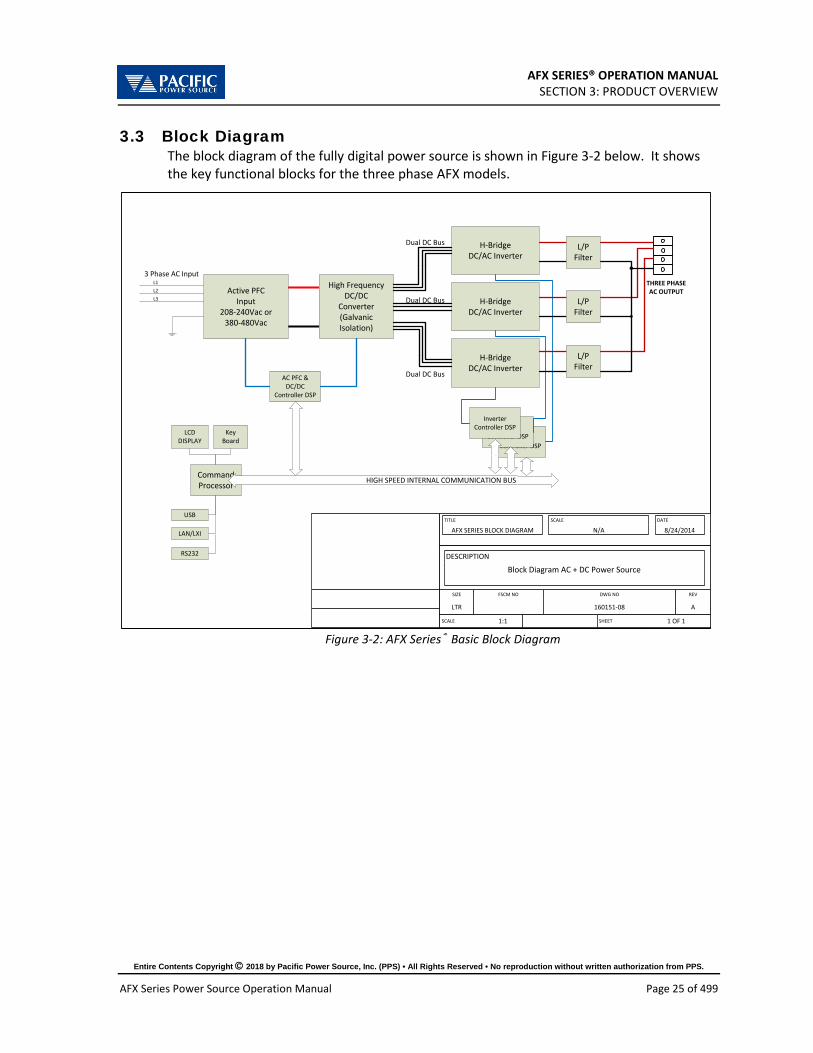
AFX SERIES® OPERATION MANUAL SECTION 3: PRODUCT OVERVIEW
Entire Contents Copyright 2018 by Pacific Power Source, Inc. (PPS) • All Rights Reserved • No reproduction without written authorization from PPS.
AFX Series Power Source Operation Manual Page 25 of 499
3.3 Block Diagram The block diagram of the fully digital power source is shown in Figure 3-2 below. It shows the key functional blocks for the three phase AFX models.
Inverter Controller DSP
Inverter Controller DSP
Active PFCInput
208-240Vac or380-480Vac
L1L2L3
High FrequencyDC/DC
Converter(Galvanic Isolation)
3 Phase AC Input
H-BridgeDC/AC Inverter
H-BridgeDC/AC Inverter
H-BridgeDC/AC Inverter
Dual DC Bus
Dual DC Bus
Dual DC Bus
Inverter Controller DSP
AC PFC &DC/DC
Controller DSP
CommandProcessor HIGH SPEED INTERNAL COMMUNICATION BUS
L/PFilter
L/PFilter
L/PFilter
THREE PHASEAC OUTPUT
LCDDISPLAY
KeyBoard
USB
LAN/LXI
SIZE FSCM NO DWG NO REV
LTR 160151-08 A
SCALE 1:1 SHEET 1 OF 1
TITLE
AFX SERIES BLOCK DIAGRAMSCALE
N/ADATE
8/24/2014
DESCRIPTION
Block Diagram AC + DC Power Source
RS232
Figure 3-2: AFX Series® Basic Block Diagram

AFX SERIES® OPERATION MANUAL SECTION 3: PRODUCT OVERVIEW
Entire Contents Copyright 2018 by Pacific Power Source, Inc. (PPS) • All Rights Reserved • No reproduction without written authorization from PPS.
AFX Series Power Source Operation Manual Page 26 of 499
3.4 Controller Description The AFX Series® power supplies use an advanced command processor that communicates with the internal power stages using several high speed communication buses and with the outside world through a variety of interfaces. One of these interfaces is the front panel keyboard and LCD display which supports manual operation of the AC power source. The command processor handles all user inputs as well as any analog or digital input provided to the unit. All power stages are operated autonomously and take input from the main command processor. For larger power configurations consisting for multiple chassis, the master unit command processor communicates to all chassis that are connected on the master/auxiliary interconnect bus.
3.5 Measurement Read-back The voltage, frequency and current limit settings of the AC power source can be set from the front panel or over any of the available digital remote control interfaces. During operation, the AC source output voltage, frequency, current and power can be read back for each of the available output phases.
3.6 Accessories Included (Ship Kit) The following accessories are included with each AFX Series® AC power source. If one or more of these is missing upon incoming inspection of the product, please contact Pacific Power Source customer service. Note that AC input and AC output wiring, grid connection devices or external terminal blocks are NOT included with the power source or source cabinet systems.
Item Quantity
Operation Manual in PDF Format Available from PPS website Mating Output Connector 1 Mating External Voltage Sense Connector AFX L version :1
AFX AG Version: N/A AC Input Terminal Safety Cover (metal) 1 Certificate of Conformance 1
Table 3-1: Included Accessories
3.7 Remote Control Interfaces Following options can be ordered at time of original purchase. It is possible to have up to three different remote control interfaces per unit. Note that RS232 is standard so two more additional interfaces may be ordered.
Available Interfaces Option Model No.
USB Interface Standard RS-232 Interface Standard LAN Interface Standard AUX I/O Standard on AFX-2AG/-4GA models Not available on -2L/-4L Models GPIB Standard on AFX-2AG/-4GA models Not available on -2L/-4L Models
Table 3-2: Remote Control Interface

AFX SERIES® OPERATION MANUAL SECTION 4: Technical Specifications
Entire Contents Copyright 2018 by Pacific Power Source, Inc. (PPS) • All Rights Reserved • No reproduction without written authorization from PPS.
AFX Series Power Source Operation Manual Page 27 of 499
4 Technical Specifications
Technical specifications shown here apply at an ambient temperature of 25° C ± 5° C.
4.1 Single Chassis Models Three and Two (split) Phase Mode
MODEL No. Rated Voltage Range Current / Phs Voltage Range Curr./Output1 No.
Outputs Power AC DC Chassis 360AFX 3 Phase 6 kW 300 V rms 16.7 A rms 425 Vdc 16.7 Adc 1 390AFX 3 Phase 9 kW 300 V rms 25.0 A rms 425 Vdc 21.0 Adc 1
3120AFX 3 Phase 12 kW 300 V rms 33.3 A rms 425 Vdc 21.0 Adc 1 3150AFX 3 Phase 15 kW 300 V rms 41.7 A rms 425 Vdc 21.0 Adc 1
Single Phase Mode MODEL No. Rated Voltage Range Current / Phs Voltage Range Curr./Output1 No.
Outputs Power AC DC Chassis 360AFX 1 Phase 6 kW 300 V rms 50.0 A rms 425 Vdc 50.0 Adc 1 390AFX 1 Phase 9 kW 300 V rms 75.0 A rms 425 Vdc 62.5 Adc 1
3120AFX 1 Phase 12 kW 300 V rms 100.0 A rms 425 Vdc 62.5 Adc 1 3150AFX 1 Phase 15 kW 300 V rms 125.0 A rms 425 Vdc 62.5 Adc 1
4.2 Multiple Chassis Models Multi chassis model configurations consist of a single master unit and one or more slave units connected through a high-speed parallel bus. Each unit requires its own three-phase AC input and must be turned on at the front panel using its individual circuit breaker. This avoids massive inrush current at power up of the system as each unit can be turned on one at a time. Multi chassis systems are installed in a suitable 19” cabinet from the factory with a common AC input terminal block and a single phase or three phase common output terminal block.
Three and Two (split) Phase Mode MODEL No. Rated Voltage Range Current / Phs Voltage Range Curr./Output1 No.
Outputs Power AC DC Chassis 3180AFX 3 Phase 18 kW 300 V rms 50.0 A rms 425 Vdc 41.7 Adc 2 3240AFX 3 Phase 24 kW 300 V rms 66.7 A rms 425 Vdc 41.7 Adc 2 3300AFX 3 Phase 30 kW 300 V rms 83.3 A rms 425 Vdc 41.7 Adc 2 3450AFX 3 Phase 45 kW 300 V rms 125.0 A rms 425 Vdc 62.5 Adc 3 3600AFX 3 Phase 60 kW 300 V rms 166.7 A rms 425 Vdc 83.3 Adc 4
Single Phase Mode MODEL No. Rated Voltage Range Current / Phs Voltage Range Curr./Output1 No.
Outputs Power AC DC Chassis 3180AFX 1 Phase 18 kW 300 V rms 150 A rms 425 Vdc 125.0 Adc 2 3240AFX 1 Phase 24 kW 300 V rms 200 A rms 425 Vdc 125.0 Adc 2 3300AFX 1 Phase 30 kW 300 V rms 250 A rms 425 Vdc 125.0 Adc 2 3450AFX 1 Phase 45 kW 300 V rms 375 A rms 425 Vdc 189.0 Adc 3 3600AFX 1 Phase 60 kW 300 V rms 500 A rms 425 Vdc 250.0 Adc 4
1 Note: Max. DC Current ratings shown require firmware revision 1.6.0 or higher.

AFX SERIES® OPERATION MANUAL SECTION 4: TECHNICAL SPECIFICATIONS
Entire Contents Copyright 2018 by Pacific Power Source, Inc. (PPS) • All Rights Reserved • No reproduction without written authorization from PPS.
AFX Series Power Source Operation Manual Page 28 of 499
4.3 AC Output Mode AC OUTPUT
Voltage AC Range 0 - 300 V L-N rms / 0 - 520V L-L rms, no VA or F restrictions
Extended Voltage Range1 0 - 333 V L-N rms / 0 – 576 V L-L rms, see Note 1 Transformer Option AC Range Up to 600 V L-N rms / 0 – 1000 V L-L rms (Requires AFXT + Transformer)
Series Output Option AC Range 600 V L-N rms / 0 – 1000 V L-L rms (Requires AFXS + Auxiliry AFX-NC Programming Resolution 0.01 V
Accuracy ± 0.25% F.S. Waveforms Sine wave, Clipped, Square, Triangle, Saw tooth, Arbitrary
Max. No. of waveforms: 200 DC Offset < 20 mV
Harmonic Distortion2 (Vthd) (Full, Resistive Load)
< 0.5% 15Hz – 400Hz, < 1.0% 400Hz-1000Hz, < 1.5% > 1000Hz See V THD Chart at bottom of page
Output Noise (DC – 300 kHz) < 150 mV rms Load Regulation ± 0.02% (CSC Mode on) Line Regulation ± 0.1% for 10% Line Change
External Voltage Sense External Sense, max. voltage drop 5% FS. Voltage Slew Rate At least 1.0 V/us (AC Mode)
Isolation 550 Vac Frequency
Range 15.00 – 1200.0 Hz Extended Frequency Ranges3 Ext. Low Freq. Range: 1.00 ~ 15.00 Hz, see Note 3
Ext. High Freq. Range: 1200 ~ 3000 Hz, see Note 3 Programming Resolution4 0.01 Hz
Accuracy ± 0.01% Current Limit
Range5 See model tables, Figure 4-6 and Figure 4-7. Values shown are supported for any period of time.
Current Overload Available 30% Current overload for up to 2.0 seconds when enabled. See Figure 4-5.
Crest Factor 2.5:1 @ 41.67 to 6.3:1 @ 16.67 (104Apk / phase for 3150AFX) Programming Resolution 0.01 A rms
Accuracy ± 0.5% F.S. Modes Constant Current Mode or Output Trip
Phase Angles (3 Phase Models) Phase Offsets6 A = 0°, B = 240°, C = 120° (programmable)
Accuracy ± 0.35° Phase Rotation in 3-Phs mode
(default) A, B, C = 0°, 120°, 240° (L1, L2, L3)
Consistent with Pacific Power UPC Controller products. Phase rotation default phase rotation selectable using “reversed phase polarity” setting if desired.
Programmable Impedance (Real-Time Mode) Resistance (R) Function of Phase Mode and No of units in parallel. See Table 4-1 Inductance (L)
Programmable Impedance (RMS Mode) Resistance (R) Function of Phase Mode and No of units in parallel. See Table 4-1 Inductance (L)
Note 1: Extended operation to 333V L-N / 576V L-L supported in Three and Split Phase mode up to 3.3kVA per phase
for frequency range 45Hz ~ 800Hz. Some specifications exceptions apply. .Requires firmware version 1.6.2 or higher. For AC voltage ranges higher than 333V L-N, see Sections 4.15 & 5.21, “T Option” on page 45 & 104.
Note 2: Refer to Figure 4-1, “Output Voltage distortion into full R Load as a function of Frequency” on next page.

AFX SERIES® OPERATION MANUAL SECTION 4: TECHNICAL SPECIFICATIONS
Entire Contents Copyright 2018 by Pacific Power Source, Inc. (PPS) • All Rights Reserved • No reproduction without written authorization from PPS.
AFX Series Power Source Operation Manual Page 29 of 499
AC OUTPUT
Note 3: Extended operation from 1Hz to 15Hz supported at reduced maximum power on 12kVA and 15kVA models. Refer to Figure 4-2 on page 32. Instantaneous peak power (Vpk * Ipk) limited to 7kVA/phase below 15Hz. Requires firmware 2.0.0 or higher. Extended operation from 1200Hz to 3000Hz supported at reduced maximum voltage. Some specifications exceptions apply. Requires firmware version 1.6.2 or higher. Refer to Figure 4-3 on page 32 and Figure 4-4 on page 33.
Note 4: FREQUENCY PROGRAM RESOLUTION FOR EXPORT MODELS (-4LE, -2LE, -4AGE, -2AGE): Per U.S.A. Bureau of Industry and Security, ECCN 3A225, frequency control is limited to no better than 0.2% at frequencies of 600 Hz. or more for unrestricted export products. To meet that requirement, frequency programming on all AFX-xxE models has three resolution ranges, which round the frequency to the nearest increment, as defined in the table below. Frequency Resolution for Export Models
Range Resolution 1.00 - 99.99 Hz 0.01 Hz 100-599.9 Hz 0.1 Hz 600 - 999 Hz 2.0 Hz 1000 - 3000 Hz 5.0 Hz
Note 5: Refer to AC Mode Voltage / Current rating charts Figure 4-6, Figure 4-10, Figure 4-7 and Figure 4-11 on following pages.
Note 6: Actual output phase angles may be slightly different from programmed values for highly unbalanced three phase load conditions, in particular at high frequency due to amplifier phase shift differences.
Figure 4-1: Output Voltage distortion into full R Load as a function of Frequency

AFX SERIES® OPERATION MANUAL SECTION 4: TECHNICAL SPECIFICATIONS
Entire Contents Copyright 2018 by Pacific Power Source, Inc. (PPS) • All Rights Reserved • No reproduction without written authorization from PPS.
AFX Series Power Source Operation Manual Page 30 of 499
4.3.1 Programmable Output Impedance Ranges by Mode and Configuration
The programmable range for output impedance varies based on model, phase mode setting and number of units connected in parallel in Master/Aux mode. The table below summarizes the available ranges as function of these.
Models Phase Mode Real Time R Real Time L RMS R RMS L 360AFX, 390AFX, 3120AFX, 3150AFX
Three Phase -100 to 100 Ω 0 to 50 uH -10 to 10 Ω 0 to 2 mH Split Phase -200 to 200 Ω 0 to 100 uH -20 to 20 Ω 0 to 4 mH Single Phase -33.3 to 33.3 Ω 0 to 16.7 uH -3.333 to 3.333 Ω 0 to 0.667 mH
3180AFX, 3240AFX, 3300AFX
Three Phase -50 to 50 Ω 0 to 25 uH -5 to 5 Ω 0 to 1 mH Split Phase -100 to 100 Ω 0 to 50 uH -10 to 10 Ω 0 to 2 mH Single Phase -16.7 to 16.7 Ω 0 to 8.3 uH -1.667 to 1.667 Ω 0 to 0.333 mH
3450AFX Three Phase -33.3 to 33.3 Ω 0 to 16.7 uH -3.333 to 3.333 Ω 0 to 0.667 mH Split Phase -66.67 to 66.67 Ω 0 to 33.33 uH -6.667 to 6.667 Ω 0 to 1.333 mH Single Phase -11.1 to 11.1 Ω 0 to 5.556 uH -1.111 to 1.111 Ω 0 to 0.222 mH
3600AFX Three Phase -25 to 25 Ω 0 to 12.5 uH -2.5 to 2.5 Ω 0 to 0.5 mH Split Phase -50 to 50 Ω 0 to 25 uH -5 to 5 Ohms 0 to 1 mH Single Phase -8.3 to 8.3 Ω 0 to 4.167 uH -0.833 to 0.833 Ω 0 to 0.167 mH
3750AFX Three Phase -20 to 20 Ω 0 to 10 uH -2 to 2 Ω 0 to 0.4 mH Split Phase -40 to 40 Ω 0 to 20 uH -4 to 4 Ω 0 to 0.8 mH Single Phase -6.67 to 6.67 Ω 0 to 3.334 uH -0667 to 0.667 Ω 0 to 0.133 mH
3900AFX Three Phase -16.7 to 16.7 Ω 0 to 8.3 uH -1.667 to 1.667 Ω 0 to 0.333 mH Split Phase -33.3 to 33.3 Ω 0 to 16.7 uH -3.333 to 3.333 Ω 0 to 0.667 mH Single Phase -5.55 to 5.55 Ω 0 to 2.778 uH -0.556 to 0.556 Ω 0 to 0.111 mH
31200AFX Three Phase -12.5 to 12.5 Ω 0 to 6.25 uH -1.25 to 1.25 Ω 0 to 0.25 mH Split Phase -25 to 25 Ω 0 to 12.5 uH -2.5 to 2.5 Ω 0 to 0.5 mH 31500AFX Three Phase -10 to 10 Ω 0 to 5 uH -1 to 1 Ω 0 to 0.2 mH Split Phase -20 to 20 Ω 0 to 10 uH -2 to 2 Ω 0 to 0.4 mH 31800AFX Three Phase -8.3 to 8.3 Ω 0 to 4.167 uH -0.833 to 0.833 Ω 0 to 0.167 mH Split Phase -16.7 to 16.7 Ω 0 to 8.3 uH -1.667 to 1.667 Ω 0 to 0.333 mH
Table 4-1: Programmable Impedance Ranges as a function of Phase Mode and Configuration

AFX SERIES® OPERATION MANUAL SECTION 4: TECHNICAL SPECIFICATIONS
Entire Contents Copyright 2018 by Pacific Power Source, Inc. (PPS) • All Rights Reserved • No reproduction without written authorization from PPS.
AFX Series Power Source Operation Manual Page 31 of 499
4.3.2 Extended Frequency Ranges – Supplemental specs
Extended frequency range operation is supported for applications that require less than 15 Hz or more then 1200Hz fundamental frequency output. With the extended frequency disabled, the regular AFX allows to increase the frequency user limit up to 3000 Hz (default is 1200 Hz) and consequently the frequency setpoint.
However, as the frequency increase above 1200Hz, the ac voltage setpoint, current limit, power limit and KVA limit are derated with the following formulas:
v_ac_max = 300*1200/frequency
current_limit_max = 41.67*parallel_inverters*1200/frequency
power_limit_max = 5*parallel_inverters*1200/frequency
kva_limit_max = 5*parallel_inverters*1200/frequency
If output form is three phase then parallel_inverters = parallel_units
If output form is single phase then parallel_inverters = 3*parallel_units
For example, a standalone 3150AFX in three phase mode at 3000 Hz allows up to 120 Vrms, 16.67 Arms, 2 kW and 2 kVA.
This derating is to protect the power stage output capacitor, the higher the frequency the higher the current on the capacitor.
Note that with the extended frequency mode enabled, the power source only derates the current limit not the Vac setpoint. This mode is useful for short periods of time or transients, if the load’s AC power is too high for too much time, then it will end up tripping a fault.
Charts below show graphical representation of extended frequency operation.

AFX SERIES® OPERATION MANUAL SECTION 4: TECHNICAL SPECIFICATIONS
Entire Contents Copyright 2018 by Pacific Power Source, Inc. (PPS) • All Rights Reserved • No reproduction without written authorization from PPS.
AFX Series Power Source Operation Manual Page 32 of 499
Figure 4-2: 1.00Hz ~ 15.00Hz Freq. Range Power Rating in 3 Phs Mode
Figure 4-3: 1200Hz ~ 3000Hz Freq. Range Voltage vs. Current- 3150AFX in 3 Phs Mode

AFX SERIES® OPERATION MANUAL SECTION 4: TECHNICAL SPECIFICATIONS
Entire Contents Copyright 2018 by Pacific Power Source, Inc. (PPS) • All Rights Reserved • No reproduction without written authorization from PPS.
AFX Series Power Source Operation Manual Page 33 of 499
Figure 4-4: 1200Hz ~ 3000Hz Extended Freq. Range Power - 3150AFX in 3 Phs Mode
4.3.3 Temporary Current Overload
Figure 4-5: Current Overload vs. Time

AFX SERIES® OPERATION MANUAL SECTION 4: TECHNICAL SPECIFICATIONS
Entire Contents Copyright 2018 by Pacific Power Source, Inc. (PPS) • All Rights Reserved • No reproduction without written authorization from PPS.
AFX Series Power Source Operation Manual Page 34 of 499
4.3.4 AC Voltage and Current Output Charts
AC VOLTAGE RANGES
Figure 4-6: AC Mode Voltage/Current range, AFX Models - 3 or 2-phase mode.
Figure 4-7: AC Mode Voltage/Current range, AFX Models – 1 phase mode.

AFX SERIES® OPERATION MANUAL SECTION 4: TECHNICAL SPECIFICATIONS
Entire Contents Copyright 2018 by Pacific Power Source, Inc. (PPS) • All Rights Reserved • No reproduction without written authorization from PPS.
AFX Series Power Source Operation Manual Page 35 of 499
4.3.5 Extended AC Voltage Ranges – Supplemental specs
The AFX provides three extended voltage ranges, 0 through 2. The maximum programmable Vrms AC limits for each of these extended ranges are:
• Range 0 312VLN • Range 1 320 VLN • Range 2 333 VLN
Range 0 is activated by setting the AC voltage user limit to a value between 300 and 312. More details on extended range 0 are provided in section 6.4.13, page 130.
Range 1 and 2 must be enabled using a bus command before they can be activated in a similar way. Refer to
Note: For voltage limits higher than 312V L-N, this mode must be enabled first. See “[SOURce:]VOLTage:EXTend” command in section 8.7.2 on page 276.
The following specification adjustments apply for each extended range mode.
Range 0: up to 312V
• Standard THD specs apply only from 45-100Hz • Only supported in three phase mode • Maximum output power is 3kW per phase
Range 1: up to 320V
• Max. current limited to 35Arms/phase • Limits maximum frequency set point to 800Hz • Does not guarantee THD specification but designed to have THD < 1.0% at
Pout<9kW
Range 2: up to 333V
• Max. current limited to 35Arms/phase • Limits maximum frequency set point to 800Hz • Does not guarantee THD. Control loop may saturate at V > 320, giving a THD of 2-3%
at 333V/9kW
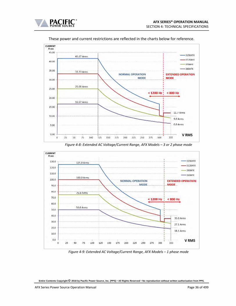
AFX SERIES® OPERATION MANUAL SECTION 4: TECHNICAL SPECIFICATIONS
Entire Contents Copyright 2018 by Pacific Power Source, Inc. (PPS) • All Rights Reserved • No reproduction without written authorization from PPS.
AFX Series Power Source Operation Manual Page 36 of 499
These power and current restrictions are reflected in the charts below for reference.
Figure 4-8: Extended AC Voltage/Current Range, AFX Models – 3 or 2 phase mode
Figure 4-9: Extended AC Voltage/Current Range, AFX Models – 1 phase mode

AFX SERIES® OPERATION MANUAL SECTION 4: TECHNICAL SPECIFICATIONS
Entire Contents Copyright 2018 by Pacific Power Source, Inc. (PPS) • All Rights Reserved • No reproduction without written authorization from PPS.
AFX Series Power Source Operation Manual Page 37 of 499
4.4 DC Output Mode DC OUTPUT
Voltage Range 0 – 425 Vdc
Refer to Figure 4-10 and Figure 4-11 for Voltage vs Current Constant Power Mode profile for 3 phase and 1 phase modes
Programming Resolution 0.01 V Accuracy ± 0.25% F.S.
Noise & Ripple < 150 mV rms Load Regulation ± 0.02% Line Regulation ± 0.1% for 10% Line Change
External Voltage Sense External Sense, max. voltage drop 5% FS. Voltage Slew Rate At least 3.0 V/us (DC Mode)
Isolation 750 Vdc Current Limit
Range See model tables, Figure 4-10 and Figure 4-11 Programming Resolution 0.01 Adc
Accuracy ± 0.5 Adc Modes Constant Current Mode or Output Trip
4.4.1 DC Voltage and Current Output Charts
Figure 4-10: DC Mode Voltage/Current range, AFX Models- 3 or 2 phase mode.
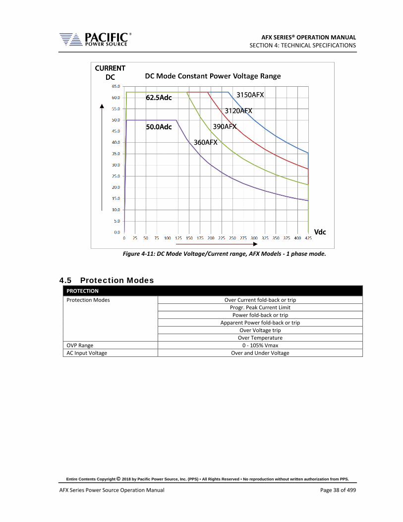
AFX SERIES® OPERATION MANUAL SECTION 4: TECHNICAL SPECIFICATIONS
Entire Contents Copyright 2018 by Pacific Power Source, Inc. (PPS) • All Rights Reserved • No reproduction without written authorization from PPS.
AFX Series Power Source Operation Manual Page 38 of 499
Figure 4-11: DC Mode Voltage/Current range, AFX Models - 1 phase mode.
4.5 Protection Modes PROTECTION Protection Modes Over Current fold-back or trip
Progr. Peak Current Limit Power fold-back or trip
Apparent Power fold-back or trip Over Voltage trip
Over Temperature OVP Range 0 - 105% Vmax AC Input Voltage Over and Under Voltage

AFX SERIES® OPERATION MANUAL SECTION 4: TECHNICAL SPECIFICATIONS
Entire Contents Copyright 2018 by Pacific Power Source, Inc. (PPS) • All Rights Reserved • No reproduction without written authorization from PPS.
AFX Series Power Source Operation Manual Page 39 of 499
4.6 Metering MEASUREMENTS
Voltage AC (1) Range L-N: 0 – 350 V rms; L-L: 0 – 600 V rms
Resolution FP: 0.01 V / Bus: 0.001 V Accuracy ± 0.25% F.S.
Frequency (AC Mode Only) Range 15 – 1200Hz
Resolution 0.01 Hz Accuracy ± 0.1% Reading
Current AC (2) Range See model table in section 4.1 or 4.2
Resolution FP: 0.01 A / Bus: 0.001 A Accuracy ± 0.5% F.S.
Peak Current Range 4 x RMS current
Resolution FP: 0.01 A / Bus: 0.001 A Accuracy ± 1.5% F.S.
Crest Factor Range 1.00 – 5.00
Resolution FP: 0.01 / Bus: 0.001 Accuracy ± 2.0% F.S.
True Power (2,) Range See model table in section 4.1 or 4.2
Resolution FP: 1 W / Bus: 0.1 W Accuracy ± 1.5% F.S.
Apparent Power (2) Range See model table in section 4.1 or 4.2
Resolution FP: 1 VA / Bus: 0.1 VA Accuracy ± 1.5% F.S.
Power Factor (3) Range 0.00 – 1.00
Resolution FP: 0.01 / Bus: 0.001 Voltage DC
Range 0- 440 Vdc Resolution FP: 0.01 V / Bus: 0.001 V
Accuracy ± 0.25% F.S. Current DC
Range See model table in section 4.1 or 4.2 Resolution FP: 0.01 A / Bus: 0.001 A
Accuracy ± 0.5% F.S. Note 1: AC Voltage measurement accuracy shown for Line to Neutral measurements. Line to Line voltage measurements are calculated based on VLN and phase angles and are < 0.5% F.S. and valid only for sinusoidal voltage waveforms with low levels of distortion and under balanced three phase load conditions.
Note 2: Measurement Accuracies for Current and Power apply for load currents of 2.0 A or more.
Note 3: For Power level above 100 W

AFX SERIES® OPERATION MANUAL SECTION 4: TECHNICAL SPECIFICATIONS
Entire Contents Copyright 2018 by Pacific Power Source, Inc. (PPS) • All Rights Reserved • No reproduction without written authorization from PPS.
AFX Series Power Source Operation Manual Page 40 of 499
4.7 Other Measurements Measurements
Waveform Capture Time Domain 1024 samples/period
Parameters VLN-A, VLN-B, VLN-C, VLL AB ,VLL AC ,VLL BC ,IA, IB, IC Samples/cycle 1024 (512 in UPC Compatibility mode) Record Length 1 Period of fundamental Frequency
Bandwidth 27.45 kHz Harmonics Measurements
Parameters VLN-A, VLN-B, VLN-C, VLL AB ,VLL AC ,VLL BC ,IA, IB, IC Harmonics Range H1 ~ H50
Accuracy – Amplitude ± 1.0 % of RMS Reading Phase Angle Range 0 ~ 359.9
Accuracy - Phase Angle < 20 µsec Bandwidth 27.45 kHz
Display Modes Table format, Graph Format
4.8 Transients Transients
Programming No. of Entries 200 Steps, 400 Segments Parameters Voltage, Frequency, Phase B &C, Ramp Time, Dwell Time Dwell Time Range 0.2 – 10,000,000 msec Ramp Time Range 0.2 – 10,000,000 msec Time Resolution 0.2 msec Edit Modes Add at End, Insert Before, Delete Execution Run Control Run from Step # to Step #
Run, Step, Restart, Stop Program Storage Non-Volatile 100, Programs + Transients

AFX SERIES® OPERATION MANUAL SECTION 4: TECHNICAL SPECIFICATIONS
Entire Contents Copyright 2018 by Pacific Power Source, Inc. (PPS) • All Rights Reserved • No reproduction without written authorization from PPS.
AFX Series Power Source Operation Manual Page 41 of 499
4.9 AC Input AC INPUT 6 kVA 9 kVA 12 kVA 15kVA
Frequency Range AC Input Frequency 47 - 63 Hz
Connection 4 Wire, (L1, L2, L3 and PE) -208 Input Version (-2)
Input Voltage Range 208 Vac – 240 Vac ± 10% Nominal Phase Current @ 208V 3ø 23 A rms 33 A rms 43 A rms 51 A rms
Max. Rated Phase Current, 3ø 25 A rms 37 A rms 48 A rms 55 A rms Peak Inrush Current2 < 1.5 x Irms
Input Power Factor > 0.9 Efficiency > 85 %
Internal Line Fuses -2 NOT USER SERVICEABLE Type FUSE, SEMICONDUCTOR,22X58MM
Rating 80A,600VAC -400 / -480 Input Version (-4)
Input Voltage Range 380 Vac – 480 Vac ± 10% Nominal Phase Current @ 380V 3ø 13 A rms 18 A rms 24 A rms 27 A rms
Max. Rated Phase Current 15 A rms 20 A rms 27 A rms 30 A rms Nominal Phase Current @ 480V 3ø 11 A rms 14 A rms 20 A rms 23 A rms
Max. Rated Phase Current 13 A rms 16 A rms 23 A rms 28 A rms Peak Inrush Current3 < 1.5 x Irms
Input Power Factor > 0.9 Efficiency > 85 %
Internal Line Fuses -4 NOT USER SERVICEABLE Type FUSE, SEMICONDUCTOR,22X58MM
Rating 63A,600VAC NOTE: For models consisting of multiple chassis, power input ratings apply to each chassis.
4.10 Dimensions & Weight DIMENSIONS & WEIGHT 6 kVA 9 kVA 12 kVA 15 kVA
Dimensions Height 7.0” / 178 mm / 4U Width 17.0” / 432 mm – w/o rack handles
19.0” / 483 mm - with attached rack handles Depth 25.0” / 635 mm
Weight Net 111.2lbs. / 50.4 kg
Shipping 130 lbs. / 59 kg NOTE: For models consisting of multiple chassis, multiply weight and height by the number of chassis.
See dimension drawing. 3D Step Models Available on request.
2 For nominal line input voltage 3 For nominal line input voltage

AFX SERIES® OPERATION MANUAL SECTION 4: TECHNICAL SPECIFICATIONS
Entire Contents Copyright 2018 by Pacific Power Source, Inc. (PPS) • All Rights Reserved • No reproduction without written authorization from PPS.
AFX Series Power Source Operation Manual Page 42 of 499
Figure 4-12: Dimension Drawing AFX Series® 15KW Model
4.11 Environmental ENVIRONMENTAL Cooling Fan Cooled Audible Noise (at 1 meter)
Standby: 46 dBA Full power: 85 dBA typical
Operating Temperature 0 to 40 °C / 32 to104 °F Storage Temperature -20 to 70 °C / -4 to 158 °F Humidity < 80%, non-condensing for temperatures up to 40° C Altitude (max.) 2000 m / 656Clas0 feet Equipment ingress protection rating per IEC 60529
IP20
4.12 Safety & Regulatory SAFETY & REGULATORY Safety Standard EN 61010-1;2010 (Edition 3) EMC Emissions EN 55011:2009+A1:2010 EMC Immunity EN 6100-4-2, -3, -4, -5, -6, -8, -11 Product Category EN61326-1:2010 (Measurement, Laboratory and Control Equipment) Approvals CE Mark, NTRL Nemko US/Canada

AFX SERIES® OPERATION MANUAL SECTION 4: TECHNICAL SPECIFICATIONS
Entire Contents Copyright 2018 by Pacific Power Source, Inc. (PPS) • All Rights Reserved • No reproduction without written authorization from PPS.
AFX Series Power Source Operation Manual Page 43 of 499
4.13 Digital Interfaces USB USB Standard USB 2 USB Class
Front Panel Type A USB Host (2) Connector Type A, standard Rear Panel Type A USB Host (1)
Type B USB Device (1) Connector Types
RS232 Baud rate: 9600, 14400, 19200, 38400, 57600, 62500, 115200 Parity: O = Odd = uneven parity
E = Even = even parity N = None = no parity bit
Number of data bits: 7 or 8 Number of stop bits: 1 or 2 Handshake: Xon/Xoff Signal Levels:
Inputs (RxD) Maximum input voltage: ± 25 V Input Impedance: 5 kΩ typical
Switching thresholds: VH < - 3 V, VL > + 3 V Outputs (TxD) Output voltage (at RLOAD > 3 kΩ): min ± 5 V, typical ± 5.4 V
Output Impedance: < 300Ω min., 10 MΩ typical in power off state Short circuit current: Typ. ± 35 mA typical
Ethernet (L) Protocol Ethernet TCP/IP, 100Mb/1000Mb Connector RJ45 Webserver Built-in LXI Compliance Core, version 1.4
GPIB IEEE Standard IEEE488,1, IEEE488.2 (2003 incl., NI HS488)
IEC 60488-1, IEC 60488-2 (2004) IEEE Functions Supported SH1, AH1, T6, L3, SR1, RL1, DC1, DT1 Connector Amphenol 24 pin, Micro ribbon connector. Rear Panel
Set screws: M3.5×0.6 metric threads. Available on Models 3xxxAFX-2AG or 3xxxAFX-4AG models only
Remote Inhibit Operation Contact closure enables Output On/Off control
Open circuit disables On/Off control Modes Disabled, Live or Latching (Configurable) Connector For 3xx0-2L / -4L models: DB9, Rear Panel
For 3xx0AFX-2AG / -4AG models: DB25, Rear Panel (See Auxiliary I/O)

AFX SERIES® OPERATION MANUAL SECTION 4: TECHNICAL SPECIFICATIONS
Entire Contents Copyright 2018 by Pacific Power Source, Inc. (PPS) • All Rights Reserved • No reproduction without written authorization from PPS.
AFX Series Power Source Operation Manual Page 44 of 499
4.14 Auxiliary I/O The Auxiliary I/O functions are only available on 3xx0AFX-2AG and 3xx0AFX-4AG version power source models.
The following technical specifications apply to the Auxiliary I/O functions.
AUX I/O SIGNAL SPECIFICATIONS
Digital Inputs Input Signals Remote Inhibit, External Trigger Input, Phase Sync, User Inputs (3)
Voltage Levels Logic low: Vin < 0.4 V Logic High: Vin > 2.0 V
Input Impedance 10 kΩ Absolute max. voltage 12V
Digital Outputs
Output Signals
Open Collector (0.5A max. protection): FORM Relay Control, Transformer Relay Control
Note: DO1 and DO2 are TTL outputs with 5.2V output and 200Ω output impedance. Into a 5kΩ load, the output voltage is ~5V. Note: DO3 and DO4 are open-drain outputs with internal pull-up of 1k to 5.5V with a diode protection. At no load, these outputs will measure 5.5V. With a 5kΩ impedance, these outputs will measure ~4.6V.
TTL Level: Relay State/Function Strobe / Trigger Out Phase Reference (sync output) User programmable outputs (2)
Voltage Levels @ 0.4 mA Logic low: Vin < 0.4 V Logic High: Vin > 4.6 V
Output impedance 200 Ω Analog Inputs
Signals Analog Inputs (4) Voltage Range -10V – 10V
Accuracy ± 0.1 % F.S. Sampling Rate 10 Hz or10 times/sec
Open Circuit Level 2 ~ 3 % of F.S. if analog input is left floating (no connection) Input Impedance 5 kΩ
Absolute max. voltage 12V Analog Outputs
Signals Analog Outputs (4) Voltage Range 0V – 10V
Accuracy ± 0.1 % F.S. (with 5 kΩ load or higher) Update Rate 10 Hz or10 times/sec
Output Impedance 5 kΩ Power
Output 12.0 Vdc Accuracy ± 0.1 Vdc
Max. Current 0.5 Adc RS232
Signals Tx, Rx Handshake Xon/ Xoff Baud rates 9600 – 460800 bps

AFX SERIES® OPERATION MANUAL SECTION 4: TECHNICAL SPECIFICATIONS
Entire Contents Copyright 2018 by Pacific Power Source, Inc. (PPS) • All Rights Reserved • No reproduction without written authorization from PPS.
AFX Series Power Source Operation Manual Page 45 of 499
4.15 Transformer Output Voltage Range (T Option) If more than 332Vac L-N is required in three-phase mode, the 400V Transformer option may be added to an AFX power source. This option provides an additional 400Vac L-N AC only voltage range. The standard 300Vac L-N voltage range as well as the DC mode and AC+DC modes remain available as the output transformer for this option are bypassed when not in use.
Figure 4-13: Rack Mount Chassis for 6kVA to 15kVA Transformer Option
4.15.1 Available T Option Rating Versions
The Transformer option is available in several power levels to match the AFX source configuration. The following transformer option ratings are available. Note that AFX models used with a Transformer option are designated by an “AFXT” series designation.
AFXT Models Transformer Rating 360AFXT-2AG/-4AG Rack Mount 19” Chassis, 4U (7”) height.
Rated for 15kVA max. ,0 -400VacLN / 0 – 692VacLL 390AFXT-2AG/-4AG 3120AFXT-2AG/-4AG 3150AFXT-2AG/-4AG 3180AFXT-2AG/-4AG Transformers are installed in 19” Cabinet Systems along with AFX power sources
Rated to 30kVA max ,0 -400VacLN / 0 – 692VacLL 3240AFXT-2AG/-4AG 3300AFXT-2AG/-4AG 3450AFXT-2AG/-4AG Transformers are installed in 19” Cabinet Systems along with AFX power sources
Rated to 45kVA max, 0 -400VacLN / 0 – 692VacLL 3600AFXT-2AG/-4AG Transformers are installed in 19” Cabinet Systems along with AFX power sources
Rated to 60kVA max, 0 -400VacLN / 0 – 692VacLL For higher power configurations, contact factory

AFX SERIES® OPERATION MANUAL SECTION 4: TECHNICAL SPECIFICATIONS
Entire Contents Copyright 2018 by Pacific Power Source, Inc. (PPS) • All Rights Reserved • No reproduction without written authorization from PPS.
AFX Series Power Source Operation Manual Page 46 of 499
4.15.2 Technical Specifications 400V Range
AC OUTPUT
Voltage AC Only Range 0 - 400 V L-N rms / 0 - 692V L-L rms
Programming Resolution 0.01 V Accuracy ± (0.25% + 0.25* f (kHz)) F.S.
Constant Power Range From 40% to 100% of Voltage Range: 160Vac L-N to 400Vac L-N
External Voltage Sense Automatically scaled for 400Vac Range Frequency
Range 45.00 – 1000.0 Hz Linear voltage derating from 45Hz to 15Hz.
Linear current derating from 1000Hz to 1200Hz. Extended Frequency Ranges are not available on T Option AC range
Programming Resolution1 0.01 Hz Accuracy ± 0.01%
Current2 Range Available RMS Current per phase is scaled by transformer ratio. E.g. for 3150AFX,
max current at 400Vac L-N is (41.7 * ¾) = 31.27Arms in 3 Phase mode Current Overload Available 30% Current overload for up to 2.0 seconds when enabled.
Note 1: FREQUENCY PROGRAM RESOLUTION FOR EXPORT MODELS (-4LE, -2LE -4AGE, -2AGE): Per U.S.A. Bureau of Industry and Security, ECCN 3A225, frequency control is limited to no better than 0.2% at frequencies of 600 Hz. or more for unrestricted export products. To meet that requirement, frequency programming in all AFX-xxE models has three resolution ranges, which round the frequency to the nearest increment, as defined in the table below. Frequency Resolution for Export Models
Range Resolution 15.00 - 99.99 Hz 0.01 Hz 100-599.9 Hz 0.1 Hz 600 - 999 Hz 2.0 Hz 1000 - 1200 Hz 5.0 Hz
Note 2: Refer to AC Mode Voltage / Current rating charts Figure 4-14 and Error! Reference source not found. on following pages.

AFX SERIES® OPERATION MANUAL SECTION 4: TECHNICAL SPECIFICATIONS
Entire Contents Copyright 2018 by Pacific Power Source, Inc. (PPS) • All Rights Reserved • No reproduction without written authorization from PPS.
AFX Series Power Source Operation Manual Page 47 of 499
TRANFORMER OPTION – 400V AC VOLTAGE RANGE
Figure 4-14: Voltage vs Current Rating 400V Range – 3 Phase Mode
Figure 4-15: Voltage vs Current Rating 400V Range – 1 Phase Mode

AFX SERIES® OPERATION MANUAL SECTION 4: TECHNICAL SPECIFICATIONS
Entire Contents Copyright 2018 by Pacific Power Source, Inc. (PPS) • All Rights Reserved • No reproduction without written authorization from PPS.
AFX Series Power Source Operation Manual Page 48 of 499
4.16 Series Output Voltage Range (S Option)
4.16.1 Series Mode AFSX description
If more than 300Vac L-N is required, the S version of the AFX or AFXS master can be connected in series with an AFX Auxiliary unit to double the available voltage range from 300Vac LN to 600Vac LN. The master unit MUST be an “S” version which has to be ordered from the factory as an AFXS.
AFXS masters are similar to a standard AFX master but implement the following changes:
• An isolated output neutral connections for phase A, B and C rather than a common neutral. Note that the output terminal pin orientation on an AFXS model differs from a standard AFX model. Tge Line and neutral output of each phase are adjacent to each other and the three neutrals are isolated. See figure Figure 4-17 below.
• A re-scaled External and Internal Voltage Sense to accommodate the higher output voltage created by the two units in series.
• The AUX I/O interface (DB25) is used to control the SPMS Option hardware. Interface cables & pass through DB25 included.
Since two AFX units are required for series operation, the lowest available series mode AFX power configuration consists of two 6kVA/6kW units to a total of 12kVA/kW.
The highest available power level for a two unit Series system consists of one 3150AFXS-xAG and one 3150AFX-xNC for a max power output of 30kVA/kW.
Two or three sets of Series AFX units can be parallel for higher power levels as needed. The maximum confirmation is thus 90kVA/kW.
Note: DO NOT turn on the SPMS controller located at the top of the cabinet while the AFSX system is in use.
4.16.2 AFXS Model output connector pin assignments
Figure 4-17: AFXS Model Ouput Connector vs Stadandar AFX
Figure 4-16: 60KVA AFXS Series with SPMS Option

AFX SERIES® OPERATION MANUAL SECTION 4: TECHNICAL SPECIFICATIONS
Entire Contents Copyright 2018 by Pacific Power Source, Inc. (PPS) • All Rights Reserved • No reproduction without written authorization from PPS.
AFX Series Power Source Operation Manual Page 49 of 499
4.16.3 Series versus Parallel Connection Modes
The following two figures show a Parallel mode two AFX sytem output connection diagram and a Series mode AFX output connection to illustrated the difference.
AC INPUT
AC INPUT
AC & DC OUTPUT3150AFX-4AG MASTER
3150AFX-4NC AUXILIARY
300VLNABC
N
ABC
N
ABC
N
SYSTI/F
Figure 4-18: Parallel Configuration – 30 kVA/kW 300Vac LN / 520Vac LL
AC INPUT
AC INPUT
AC & DC OUTPUT3150AFXS-4AG MASTER
3150AFX-4NC AUXILIARY
600VLNABC
N300VLN
300VLN
SYSTI/F
NANBNC
ABC
N
Figure 4-19: Series Configuration – 30 kVA/kW 600Vac LN / 1040Vac LL

AFX SERIES® OPERATION MANUAL SECTION 4: TECHNICAL SPECIFICATIONS
Entire Contents Copyright 2018 by Pacific Power Source, Inc. (PPS) • All Rights Reserved • No reproduction without written authorization from PPS.
AFX Series Power Source Operation Manual Page 50 of 499
4.16.4 SPMS Series Configuration switch option
Series systems can either be hardwired for series operation only. For applications where both 600Vac LN and 400Vac LN voltage ranges are required can be configured with the SPMS (Series Parallel Mode Switch) option. This switch reconfigures output wiring between series and parallel modes under software or front panel control. This allows both high voltage, lower current or lower voltage higher current configureation to be selected.
Series system are typically installed in a 19” instrument rack with all input and output wring and control interface cabling installed and tested. This applies to both Series only cabinet systems and SPMS Mode cabinet systems.
42 U
SPMS CONTROLLER
SPMS RELAY UNIT #1
AFXS-1H
AFX-NC-1L
SPMS RELAY UNIT #2
AFXS-NC-2H
AFX-NC-2L
SPMS RELAY UNIT #3
AFXS-NC-3H
AFX-NC-3L
MASTER
TB OUTCB
S/I IN
S/I OUT
S/I IN
S/I OUT
S/I IN
S/I OUT
S/I IN
S/I OUT
S/I IN
S/I OUT
S/I IN
S/I OUT
INTERFACE CABLINGSPMS Interface:
GreenAFX System Interface
Blue & Brown

AFX SERIES® OPERATION MANUAL SECTION 4: TECHNICAL SPECIFICATIONS
Entire Contents Copyright 2018 by Pacific Power Source, Inc. (PPS) • All Rights Reserved • No reproduction without written authorization from PPS.
AFX Series Power Source Operation Manual Page 51 of 499
4.16.5 Standard Series Output Cabinet System Configurations MODEL POWER V RANGE CONSISTS OF AC INPUT 19" CAB. 3180AFXS-2AG or 3180AFXS-4AG
18kVA 0 - 600 Vac LN 0 - 1040 Vac LL
1x 390AFXS-xAG Master 1x 390AFX-xNC Auxiliary
208Vac, 3ø or 380~480Vac, 3ø
28U
3240AFXS-2AG or 3240AFXS-4AG
24kVA 0 - 600 Vac LN 0 - 1040 Vac LL
1x 3120AFXS-xAG Master 1x 3120AFX-xNC Auxiliary
208Vac, 3ø or 380~480Vac, 3ø
28U
3300AFXS-2AG or 3300AFXS-4AG
30kVA 0 - 600 Vac LN 0 - 1040 Vac LL
1x 3150AFXS-xAG Master 1x 3150AFX-xNC Auxiliary
208Vac, 3ø or 380~480Vac, 3ø
28U
3600AFXS-4AG 60kVA 0 - 600 Vac LN 0 - 1040 Vac LL
1x 3150AFXS-4AG Master 1x 3150AFXS-4NC Auxiliary 2x 3150AFX-4NC Auxiliary
380~480Vac, 3ø
28U
3900AFXS-4AG 90kVA 0 - 600 Vac LN 0 - 1040 Vac LL
1x 3150AFXS-4AG Master 2x 3150AFXS-4NC Auxiliary 3x 3150AFX-4NC Auxiliary
380~480Vac, 3ø
36U
SPMS Option Automatic Series and Parallel Mode Configuration Switch allows switching between Series or Parallel modes without the need to reconfigure output wiring. Must be specified at the time of original order.

AFX SERIES® OPERATION MANUAL SECTION 4: TECHNICAL SPECIFICATIONS
Entire Contents Copyright 2018 by Pacific Power Source, Inc. (PPS) • All Rights Reserved • No reproduction without written authorization from PPS.
AFX Series Power Source Operation Manual Page 52 of 499
4.16.6 Selecting the Series Mode Configuration
If the SPMS option is installed, the mode of operation can be selected from the front panel or the remote control interface. From the front panel, select the CONF menu key and scroll to the bottom of CONFIGURATION SCREEN 1 to turn the series output configuration ON or OFF. When ON, the output of all AFXS/AFX-NC pairs will be connected in series mode. When OFF, they will be in parallel mode instead. The total output power remains the same either way.
The browser interface can also be used to change between series or parallel mode by selecting the CONFIGURATION -> UNIT SETTINGS menu entry. The Series connection state is shown in the lower right corner of the screen.
For remote control Series Mode command, refer to section 8.11, “AFXS Series Mode Commands” on page 396.

AFX SERIES® OPERATION MANUAL SECTION 4: TECHNICAL SPECIFICATIONS
Entire Contents Copyright 2018 by Pacific Power Source, Inc. (PPS) • All Rights Reserved • No reproduction without written authorization from PPS.
AFX Series Power Source Operation Manual Page 53 of 499
4.17 IEC413 Option This option ads inter harmonic generation to an AFX Master unit. Models with this option have the letter “C” in the model number desgination immediately following the –“AG” part. For example, 3150AFX-4AGCE.
This option removed to user programmable featurs from the standard AFX feature set:
• User programmable output OVP level. The OVP level is fixed at the maximum allowable setting.
• User programmable Peak output current protection. The peak level is fixed at the maximum level.
Note: Disabling of these features does not affect reliability of the power source.
Interharmonics control is available through SCPI bus commands only. No front panel user interface is included with this option.
This interharmonic waveform generator may be used to support IEC61000-4-13 harmonics and interharmonics immunity testing of an EUT. The IEC413 Test Sequence suite for PPSC Test Manager Windows 10 software is included with this option. This test sequence handles all harmonics and interhamonics frequency steps and amplitudes programming.
Technical Specifications:
IEC413 Option
Frequency Range 15.00 Hz to 10,000 Hz
Amplitude Range 0.00 Vac to 300.00 Vac
Phase Angle Programming 0.0° to 359.9° with respect to Phase fundamental
Available on Models 3xxxAFX-2AGC or 3xxxAFX-4AGC models only

AFX SERIES® OPERATION MANUAL SECTION 5: Unpacking and Installation
Entire Contents Copyright 2018 by Pacific Power Source, Inc. (PPS) • All Rights Reserved • No reproduction without written authorization from PPS.
AFX Series Power Source Operation Manual Page 54 of 499
5 Unpacking and Installation
5.1 Inspection The AFX Series® of AC power sources are carefully inspected before shipment. If instrument damage has occurred during transport, please inform Pacific Power Source’ nearest sales and service office or representative.
All AFX models require three-phase AC input and are furnished with a compression terminal block for AC input. A suitable line cord and power disconnect is required (but not included) to connect these power supplies to the mains.
Refer to "check line voltage" to check the line voltage selection and fuse type.
Note: For input and output connections to AFX cabinet systems, refer to Section 5.15, “Cabinet Systems” starting on page 79.
5.2 Lifting and Carrying Instructions
CAUTION
THIS UNIT IS HEAVY. Two persons are required to lift or carry this unit. DO NOT attempt to lift alone. DO NOT use the front panel rack handles alone to lift this unit. The unit must be supported in front and back when carrying.
AVERTISSEMENT
CET EQUIPEMENT EST LOURD. Deux personnes sont requises pour transporter ou soulever cet équipement. NE PAS tenter de soulever ou déplacer seul. NE PAS utiliser les poignées en face avant pour soulever l´appareil. L´équipement doit être pris en charge à l´avant et à l´arrière pour le transport.
This equipment weighs over 100 lbs. / 50 Kg and requires two persons to lift or carry. To remove the equipment from its packaging, use the provided handgrip openings on either side of the unit to lift the unit from its packaging and place it on a suitable surface that is rated to support the weight of the unit. Two persons are required to remove the AFX unit from its packaging, one on each long side of the box. Refer to Figure 5-2 for reference.

AFX SERIES® OPERATION MANUAL SECTION 5: UNPACKING AND INSTALLATION
Entire Contents Copyright 2018 by Pacific Power Source, Inc. (PPS) • All Rights Reserved • No reproduction without written authorization from PPS.
AFX Series Power Source Operation Manual Page 55 of 499
Figure 5-2: Exploded view of AFX unit packaging
If the unit is to be installed in an instrument rack, the straps may be removed. In that case, a suitable lift must be used to position the unit at the desired rack height and pushed in place using either rack slides or L-brackets (not included with the unit). The front panel handles may be used to pull or push the unit in or out of a rack space only.
Note: The front panel handles are not designed to carry the entire unit. It must be supported on front and back or both sides by two persons when being handled.
Hand Grip Openings

AFX SERIES® OPERATION MANUAL SECTION 5: UNPACKING AND INSTALLATION
Entire Contents Copyright 2018 by Pacific Power Source, Inc. (PPS) • All Rights Reserved • No reproduction without written authorization from PPS.
AFX Series Power Source Operation Manual Page 56 of 499
5.3 Verify Correct AC Input Line Voltage The AFX Series® power supply can be ordered with a range of 3 phase AC input voltage configurations. Prior to connecting the AC power source to the local mains, it is important to check the type label on the unit to verify that its AC input configuration matches the local utility power.
Do not connect the power supply to the mains if the AC input voltage, phasing and frequency does not match.
CAUTION
DO NOT CONNECT A 208 – 240 V AC INPUT AFX MODEL TO A 380V, 400V OR 480V OR HIGHER THREE PHASE UTILITY
LINE VOLTAGE AS DAMAGE TO THE UNIT MAY OCCUR.
DO NOT CONNECT A 380 – 480 V AC INPUT AFX MODEL TO A 208V TO 240V THREE PHASE UTILITY LINE VOLTAGE AS
THE UNIT WILL NOT OPERATE.
AVERTISSEMENT
NE PAS CONNECTER UNE 208-240 V AC ENTRÉE AFX MODÈLE À UN 380V, 400V OU 480V OU PLUS DE TROIS
PHASES UTILITAIRE TENSION EN PANNE QUI PEUT SE PRODUIRE.
NE PAS CONNECTER UNE 380 - 480 V AC ENTRÉE AFX
MODÈLE À UN 208V TO 240V TRIPHASE UTILITAIRE TENSION QUE L'APPAREIL NE FONCTIONNE PAS.
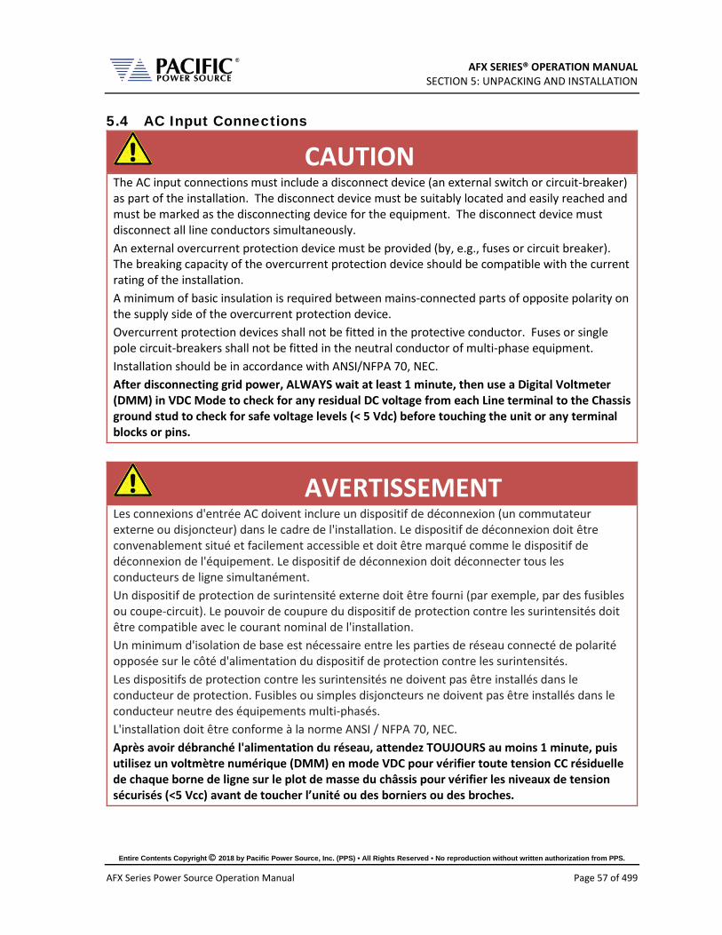
AFX SERIES® OPERATION MANUAL SECTION 5: UNPACKING AND INSTALLATION
Entire Contents Copyright 2018 by Pacific Power Source, Inc. (PPS) • All Rights Reserved • No reproduction without written authorization from PPS.
AFX Series Power Source Operation Manual Page 57 of 499
5.4 AC Input Connections
CAUTION
The AC input connections must include a disconnect device (an external switch or circuit-breaker) as part of the installation. The disconnect device must be suitably located and easily reached and must be marked as the disconnecting device for the equipment. The disconnect device must disconnect all line conductors simultaneously. An external overcurrent protection device must be provided (by, e.g., fuses or circuit breaker). The breaking capacity of the overcurrent protection device should be compatible with the current rating of the installation. A minimum of basic insulation is required between mains-connected parts of opposite polarity on the supply side of the overcurrent protection device. Overcurrent protection devices shall not be fitted in the protective conductor. Fuses or single pole circuit-breakers shall not be fitted in the neutral conductor of multi-phase equipment. Installation should be in accordance with ANSI/NFPA 70, NEC. After disconnecting grid power, ALWAYS wait at least 1 minute, then use a Digital Voltmeter (DMM) in VDC Mode to check for any residual DC voltage from each Line terminal to the Chassis ground stud to check for safe voltage levels (< 5 Vdc) before touching the unit or any terminal blocks or pins.
AVERTISSEMENT
Les connexions d'entrée AC doivent inclure un dispositif de déconnexion (un commutateur externe ou disjoncteur) dans le cadre de l'installation. Le dispositif de déconnexion doit être convenablement situé et facilement accessible et doit être marqué comme le dispositif de déconnexion de l'équipement. Le dispositif de déconnexion doit déconnecter tous les conducteurs de ligne simultanément. Un dispositif de protection de surintensité externe doit être fourni (par exemple, par des fusibles ou coupe-circuit). Le pouvoir de coupure du dispositif de protection contre les surintensités doit être compatible avec le courant nominal de l'installation. Un minimum d'isolation de base est nécessaire entre les parties de réseau connecté de polarité opposée sur le côté d'alimentation du dispositif de protection contre les surintensités. Les dispositifs de protection contre les surintensités ne doivent pas être installés dans le conducteur de protection. Fusibles ou simples disjoncteurs ne doivent pas être installés dans le conducteur neutre des équipements multi-phasés. L'installation doit être conforme à la norme ANSI / NFPA 70, NEC. Après avoir débranché l'alimentation du réseau, attendez TOUJOURS au moins 1 minute, puis utilisez un voltmètre numérique (DMM) en mode VDC pour vérifier toute tension CC résiduelle de chaque borne de ligne sur le plot de masse du châssis pour vérifier les niveaux de tension sécurisés (<5 Vcc) avant de toucher l’unité ou des borniers ou des broches.
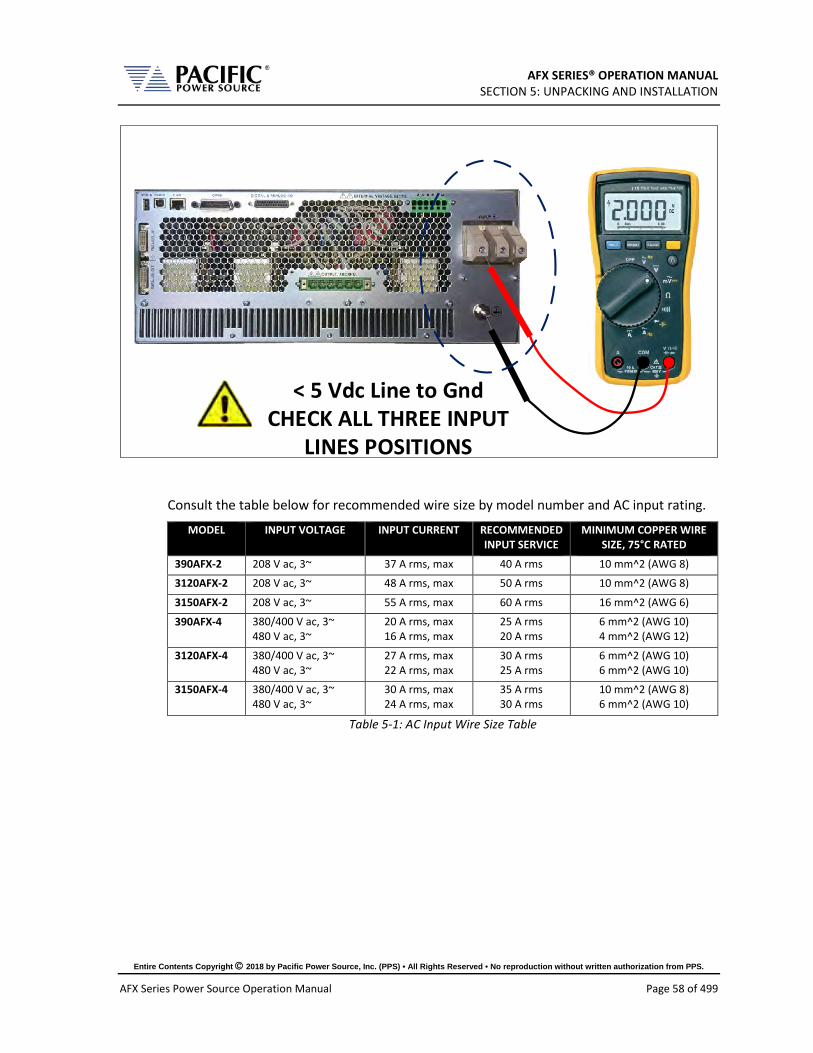
AFX SERIES® OPERATION MANUAL SECTION 5: UNPACKING AND INSTALLATION
Entire Contents Copyright 2018 by Pacific Power Source, Inc. (PPS) • All Rights Reserved • No reproduction without written authorization from PPS.
AFX Series Power Source Operation Manual Page 58 of 499
< 5 Vdc Line to GndCHECK ALL THREE INPUT
LINES POSITIONS
Consult the table below for recommended wire size by model number and AC input rating.
MODEL INPUT VOLTAGE INPUT CURRENT RECOMMENDED INPUT SERVICE
MINIMUM COPPER WIRE SIZE, 75°C RATED
390AFX-2 208 V ac, 3~ 37 A rms, max 40 A rms 10 mm^2 (AWG 8)
3120AFX-2 208 V ac, 3~ 48 A rms, max 50 A rms 10 mm^2 (AWG 8)
3150AFX-2 208 V ac, 3~ 55 A rms, max 60 A rms 16 mm^2 (AWG 6)
390AFX-4 380/400 V ac, 3~ 480 V ac, 3~
20 A rms, max 16 A rms, max
25 A rms 20 A rms
6 mm^2 (AWG 10) 4 mm^2 (AWG 12)
3120AFX-4 380/400 V ac, 3~ 480 V ac, 3~
27 A rms, max 22 A rms, max
30 A rms 25 A rms
6 mm^2 (AWG 10) 6 mm^2 (AWG 10)
3150AFX-4 380/400 V ac, 3~ 480 V ac, 3~
30 A rms, max 24 A rms, max
35 A rms 30 A rms
10 mm^2 (AWG 8) 6 mm^2 (AWG 10)
Table 5-1: AC Input Wire Size Table

AFX SERIES® OPERATION MANUAL SECTION 5: UNPACKING AND INSTALLATION
Entire Contents Copyright 2018 by Pacific Power Source, Inc. (PPS) • All Rights Reserved • No reproduction without written authorization from PPS.
AFX Series Power Source Operation Manual Page 59 of 499
The AC input connections must be made at the rear panel AC terminal block. This input block has a removable safety cover that must be installed when the instruments is used on a bench or is otherwise accessible at the rear. If mounted in a cabinet with a locked door or screen, the AC input safety cover may be omitted if needed.
The following wire strip lengths are required for the AC input wires listed.
L1, L2, L3 Wires: 11/16”, 17 mm
Neutral, Ground Wires: 3/4”, 19 mm
Figure 5-3: Rear Panel Layout
The AC input terminal phasing is marked on the rear panel and shown in the illustration below. A four wire mains connection is required. (L1, L2, L3 and Earth Ground). Ground connection is located directly below the AC Line input terminal block as shown in Figure 5-3 above.
Figure 5-4: AC Input Terminal Block - Rear Panel
EARTH GROUND

AFX SERIES® OPERATION MANUAL SECTION 5: UNPACKING AND INSTALLATION
Entire Contents Copyright 2018 by Pacific Power Source, Inc. (PPS) • All Rights Reserved • No reproduction without written authorization from PPS.
AFX Series Power Source Operation Manual Page 60 of 499
5.5 Grounding Requirements
5.5.1 Chassis Ground Connection Required
CAUTION
SHOCK HAZARD: Equipment must be grounded.
AVERTISSEMENT
RISQUE DE CHOC: l´équipement doit être mis à la terre.
The unit MUST be grounded via the AC Input. A line cord with proper Earth Ground must be used at all times. Correct grounding of your electrical system infrastructure according to applicable national standards must also be observed.

AFX SERIES® OPERATION MANUAL SECTION 5: UNPACKING AND INSTALLATION
Entire Contents Copyright 2018 by Pacific Power Source, Inc. (PPS) • All Rights Reserved • No reproduction without written authorization from PPS.
AFX Series Power Source Operation Manual Page 61 of 499
5.5.2 Output Neutral Grounding
The output neutral terminals of the power source are NOT connected to earth ground but rather floating. This allows the output of the power source to float with respect to ground. Some loads will have their neutral input grounded, which will result in the power source neutral being grounded through the load. Alternatively, the user may ground the output neutral terminals himself by running a suitable wire size from one of the output neutral terminals to the ground stud on the rear panel of the power source as shown in Figure 5-5.
Grounding the output neutral can help reduce common mode noise at the output of the power source.
L2 (B)
L3 (C)L1 (A)
N
NOTE: THREE NEUTRAL OUTPUT CONNECTOR PINS
(N N N) ARE INTERNALLY SHORTED TOGETHER.
USE EITHER ONE OR ALL FOR THREE PHASE WYE
LOADS.
USE PROVIDED MATING CONNECTOR TO CONNECT LOAD WIRES
AC INPUT 3ø
EarthGround
Figure 5-5: Grounding Floating Neutral Output
5.6 AC Input Circuit Breaker This product is fitted with a mains input circuit breaker on the left hand side of the front panel. The power off position of the circuit breaker handle is marked “O”. The power on position of the circuit breaker is marked “I”.

AFX SERIES® OPERATION MANUAL SECTION 5: UNPACKING AND INSTALLATION
Entire Contents Copyright 2018 by Pacific Power Source, Inc. (PPS) • All Rights Reserved • No reproduction without written authorization from PPS.
AFX Series Power Source Operation Manual Page 62 of 499
5.7 Bench Use
CAUTION
When placing this instrument on a workbench or table, ensure the maximum weight rating of the bench/table exceeds the actual weight of the unit.
ATTENTION
Lorsque l´appareil est placé sur un banc de travail ou une table, s´assurer que la capacité de charge maximale du banc / table dépasse le poids réel de l´appareil.
The AFX Series® chassis is not equipped with surface protection feet as it is intended primarily for 19” rack mount use. When used on a bench, use care not to damage bench surface by sliding AFX unit.
5.8 Rack Mounting The AFX Series® chassis is designed to be rack mounted in a standard 19-inch rack for system applications. Zero stacking with other units or test equipment is possible. The weight of the unit MUST be supported properly. Either use rack slides or L brackets of sufficient weight rating that are compatible with the dimensions of the cabinet used.
AFX Series® models with an output power rating above 15KVA are available as factory installed 19” instrument cabinet systems including input and output wiring to connection terminal blocks at the bottom rear of the cabinet.
Customers (i.e. System Integrators) preferring to install one or more AFX units in their own cabinet systems can order Master and multiple Auxiliary parallel systems as a KIT with no 19” cabinet or wiring included.
5.9 Airflow The AFX Series® of AC power sources are cooled by drawing in air through the front and out at the back of each unit. Do not AFX units install in a manner that blocks the free flow of air such as in a cabinet with a solid rear door. Allow a minimum of 6” (15 cm) free of obstructions behind the unit to prevent overheating.

AFX SERIES® OPERATION MANUAL SECTION 5: UNPACKING AND INSTALLATION
Entire Contents Copyright 2018 by Pacific Power Source, Inc. (PPS) • All Rights Reserved • No reproduction without written authorization from PPS.
AFX Series Power Source Operation Manual Page 63 of 499
5.10 Sound Levels
CAUTION
Sound pressure level from power source may exceed 85 dBA.
Sound pressure level should be measured both at the operator’s position in normal use and at whatever point 1 meter from the power source enclosure that has the highest sound pressure level.
The installer shall provide measures to reduce the sound pressure level at the operator’s point of use to a safe level. These measures may include the fitting of noise-reducing baffles or hoods or provision of protective earpieces.
AVERTISSEMENT
Le niveau sonore de l´appareil peut dépasser 85 dBA.
Le niveau sonore doit être mesuré à la fois à la position de l´opérateur en utilisation normale et quelque soit le point à 1 mètre de l´enceinte de l´appareil qui a le niveau sonore le plus élevé.
L´installateur doit prendre des mesures visant à réduire le niveau sonore au point d´utilisation de l´opérateur. Ces mesures peuvent inclure la mise en place de hottes antibruit, our la fourniture d´oreillettes de protection.
When the equipment is operated at or near full rated output power, fan speed will be at its highest and corresponding noise levels will be higher. Operators should wear ear protection while exposed to these levels of sound.

AFX SERIES® OPERATION MANUAL SECTION 5: UNPACKING AND INSTALLATION
Entire Contents Copyright 2018 by Pacific Power Source, Inc. (PPS) • All Rights Reserved • No reproduction without written authorization from PPS.
AFX Series Power Source Operation Manual Page 64 of 499
5.11 Cleaning
CAUTION
BEFORE you clean the unit, switch the unit off at the front panel breaker AND remove all mains power using the mains disconnect.
• Please do NOT use any organic solvent capable of changing the nature of the plastic such as benzene or acetone.
• Please ensure that no liquid is allowed to penetrate this product.
ATTENTION
AVANT de nettoyer l'appareil, mettez l'appareil hors tension au niveau du disjoncteur de face avant ET retirez tout cable d´alimentation secteur.
• Ne pas utiliser de solvant organique capable de changer la nature de la matière plastique tel que le benzène ou l'acétone.
• Veiller à ce qu'aucun liquide ne pénètre à l´intérieur de l´appareil
To clean this product, use a soft or slightly damp cloth.
5.12 Air Intake Filter Removal and Cleaning Units equipped with a removable air intake filter must have their filter material cleaned on a regular basis. A six-month cleaning interval is recommended. For units deployed in particularly dirty environments, this cleaning interval should be shortened to three months or less to prevent the air filter from clogging up with dirt. This applies to both Master units and Auxiliary units.
Figure 5-6: Air Intake Filter Removal

AFX SERIES® OPERATION MANUAL SECTION 5: UNPACKING AND INSTALLATION
Entire Contents Copyright 2018 by Pacific Power Source, Inc. (PPS) • All Rights Reserved • No reproduction without written authorization from PPS.
AFX Series Power Source Operation Manual Page 65 of 499
5.12.1 Air Filter Removal
To remove the air filter, proceed as follows:
1. Turn the unit off first. 2. Using a small Philips screwdriver, remove the four M3 Philips screws from each
corner of the filter panel on the front of the unit. 3. Pull the filter panel toward you carefully and remove the filter material.
Figure 5-7: Air Intake Filter and Filter Panel
5.12.2 Filter Cleaning
Use warm water and some mild detergent to rinse all dirt out of the filter material. Allow the filter do dry for 2 hours or more till fully dry before re-installing. If the filter material is too dirty to clean, replace with a new filter. Contact customer service for replacement filters.
5.12.3 Air Filter Installation
To reinstall the filter material, proceed as follows:
1. Place the cleaned filter material against the lower part of the units front panel. 2. Line up the filter materials so the corner cut-outs align with the four corners 3. Install the removable filter panel using the four M3 Philips screws.
5.13 Liquids The AFX Series® of AC power sources offer no protection against liquid spills. Do not install where chemicals are used or where liquids could spill into the unit.

AFX SERIES® OPERATION MANUAL SECTION 5: UNPACKING AND INSTALLATION
Entire Contents Copyright 2018 by Pacific Power Source, Inc. (PPS) • All Rights Reserved • No reproduction without written authorization from PPS.
AFX Series Power Source Operation Manual Page 66 of 499
5.14 Load Connections
CAUTION
HAZARDOUS OUTPUT: The power source output may be set to hazardous voltage levels. It provides basic isolation from the AC input mains. Therefore, the output must always be considered hazardous. Connections must be inaccessible to the operator in all situations when AC input mains voltage is applied.
Always disconnect power supply from the mains before connecting or disconnecting to the hazardous output terminals.
AVERTISSEMENT
SORTIE DANGEREUSE: La sortie de l´appareil peut être réglée à des niveaux de tension dangereux. L´appareil fournit une isolation de base du réseau d'entrée AC. Par conséquent, la sortie doit toujours être considérée comme dangereuse. Les connexions doivent être inaccessibles à l'opérateur dans toutes les situations où la tension d´entrée secteur est appliquée.
Toujours débrancher l'alimentation secteur avant de connecter ou déconnecter les bornes de sortie dangereuses.
The AC power source can be configured for either single-phase output or three-phase output.
Note: The External Voltage Sense connector always has three phase and three neutral connections but in single-phase mode of operation, only the A phase and one neutral connection are required.
5.14.1 Output Wiring and Recommended Wire Sizing
Connections from the AC source output terminal to the load should be made using the provided mating output connector. This connector is safety rated and does not require an output cover. It MUST be used when connecting load wires.
Load currents are a function of the load so care must be taken by the user to select appropriately size output wires in accordance with local electrical codes.
Note: Since local electrical codes vary by location, Pacific Power Source DOES NOT INCLUDE any AC input or AC output wires with its power sources.
Maximum output voltage and current ratings of the available power source models are shown in section 4, “Technical Specifications” and should be consulted when determining correct wire size. Also consider the voltage insulation rating of the load wires and External voltage sense wires used.

AFX SERIES® OPERATION MANUAL SECTION 5: UNPACKING AND INSTALLATION
Entire Contents Copyright 2018 by Pacific Power Source, Inc. (PPS) • All Rights Reserved • No reproduction without written authorization from PPS.
AFX Series Power Source Operation Manual Page 67 of 499
5.14.2 Three Phase Wye Load Output Connection
Connection of a three-phase load requires the mating connector provided in the AFX Series® ship kit. This six-pole connector uses a spring loaded wire attachment system. To unlock a position, use a small screwdriver or pin to push down in the square hole located directly above each connection. Once you push in, you will feel to spring unlatch. Now push the stripped wire end into the connector and pull out the small screwdriver or pin. This will release the spring locking down the wire. Use a pull test to make sure the wire is clamped down securely.
Repeat for the three phase wires and the neutral wire. Note that the three neutral positions on the rear panel output power connector are all shorted together inside the AFX. Thus, there is only one neutral, which is common for all output phases. For balanced three phase Wye loads, only one of these three neutral output positions has to be connected to the load’s neutral position.

AFX SERIES® OPERATION MANUAL SECTION 5: UNPACKING AND INSTALLATION
Entire Contents Copyright 2018 by Pacific Power Source, Inc. (PPS) • All Rights Reserved • No reproduction without written authorization from PPS.
AFX Series Power Source Operation Manual Page 68 of 499
The requisite WYE load output wiring is shown in Figure 5-8 using internal voltage sense and Figure 5-9 when using external voltage sense.
Note Load and sense wiring are NOT included with the power source and must be supplied by the end-user.
L2 (B)
L3 (C)L1 (A)
N
NOTE: THREE NEUTRAL OUTPUT CONNECTOR PINS
(N N N) ARE INTERNALLY SHORTED TOGETHER.
USE EITHER ONE OR ALL FOR THREE PHASE WYE
LOADS.
USE PROVIDED MATING CONNECTOR TO CONNECT LOAD WIRES
Figure 5-8: Three phase Wye Load Output Connections – Internal Voltage Sense
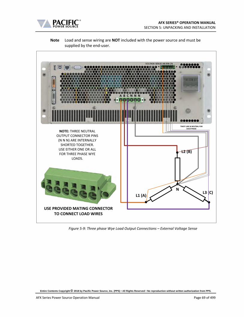
AFX SERIES® OPERATION MANUAL SECTION 5: UNPACKING AND INSTALLATION
Entire Contents Copyright 2018 by Pacific Power Source, Inc. (PPS) • All Rights Reserved • No reproduction without written authorization from PPS.
AFX Series Power Source Operation Manual Page 69 of 499
Note Load and sense wiring are NOT included with the power source and must be supplied by the end-user.
L2 (B)
L3 (C)L1 (A)
N
NOTE: THREE NEUTRAL OUTPUT CONNECTOR PINS
(N N N) ARE INTERNALLY SHORTED TOGETHER.
USE EITHER ONE OR ALL FOR THREE PHASE WYE
LOADS.
USE PROVIDED MATING CONNECTOR TO CONNECT LOAD WIRES
TWIST LINE & NEUTRAL FOR EACH PHASE
Figure 5-9: Three phase Wye Load Output Connections – External Voltage Sense

AFX SERIES® OPERATION MANUAL SECTION 5: UNPACKING AND INSTALLATION
Entire Contents Copyright 2018 by Pacific Power Source, Inc. (PPS) • All Rights Reserved • No reproduction without written authorization from PPS.
AFX Series Power Source Operation Manual Page 70 of 499
5.14.3 Three Phase Delta Load Output Connection
Connection of a three-phase load requires the mating connector provided in the AFX Series® ship kit. This six-pole connector uses a spring loaded wire attachment system. To unlock a position, use a small screwdriver or pin to push down in the square hole located directly above each connection. Once you push in, you will feel to spring unlatch. Now push the stripped wire end into the connector and pull out the small screwdriver or pin. This will release the spring locking down the wire. Use a pull test to make sure the wire is clamped down securely.
Note Load and sense wiring are NOT included with the power source and must be supplied by the end-user.
Repeat for the three phase wires. For Delta loads, there is no neutral connection.

AFX SERIES® OPERATION MANUAL SECTION 5: UNPACKING AND INSTALLATION
Entire Contents Copyright 2018 by Pacific Power Source, Inc. (PPS) • All Rights Reserved • No reproduction without written authorization from PPS.
AFX Series Power Source Operation Manual Page 71 of 499
The requisite DELTA load output wiring is shown in Figure 5-10 using internal voltage sense and Figure 5-11 when using external voltage sense.
Note Load and sense wiring are NOT included with the power source and must be supplied by the end-user.
L2 (B)
L3 (C)
L1 (A)
Vab Vac
Vbc
NOTE: THREE NEUTRAL OUTPUT CONNECTOR PINS
(N N N) ARE INTERNALLY SHORTED TOGETHER.
NO NEUTRAL CONNECTION TO DELTA
LOADS.
USE PROVIDED MATING CONNECTOR TO CONNECT LOAD WIRES
Figure 5-10: Three phase Delta Load Output Connections – Internal Voltage Sense

AFX SERIES® OPERATION MANUAL SECTION 5: UNPACKING AND INSTALLATION
Entire Contents Copyright 2018 by Pacific Power Source, Inc. (PPS) • All Rights Reserved • No reproduction without written authorization from PPS.
AFX Series Power Source Operation Manual Page 72 of 499
Note Load and sense wiring are NOT included with the power source and must be supplied by the end-user.
L2 (B)
L3 (C)
L1 (A)
Vab Vac
Vbc
NOTE: THREE NEUTRAL OUTPUT CONNECTOR PINS
(N N N) ARE INTERNALLY SHORTED TOGETHER.
NO NEUTRAL CONNECTION TO DELTA
LOADS.
USE PROVIDED MATING CONNECTOR TO CONNECT LOAD WIRES
Figure 5-11: Three phase Delta Load Output Connections – External Voltage Sense

AFX SERIES® OPERATION MANUAL SECTION 5: UNPACKING AND INSTALLATION
Entire Contents Copyright 2018 by Pacific Power Source, Inc. (PPS) • All Rights Reserved • No reproduction without written authorization from PPS.
AFX Series Power Source Operation Manual Page 73 of 499
5.14.4 AFXS Series Output Load Connection
The AFXS version differs from a standard AFX in that it has three separated isolated neutral on the output connector instead of three common nuetrals. This allows an AFXS power source to be connected in series with a standard AFX master or auxiliary unit.
See section 4.16, “Series Output Voltage Range (S Option)” on page 48 for more information on series operation.
5.14.5 Single Phase Load Output Connection
Connection of a single phase or DC load can be accomplished by using the three-phase mating connector provided in the AFX Series® ship kit. This requires shorting of the three phases or DC outputs. A power splicer terminal block like the one shown here may be used. Example of suitable splicer block is Marathon P/N 1322570, 600V, 175A.
Note Junction terminal blocks like the one shown above are NOT included with the power
source and must be supplied by the end-user.
Alternatively, the optionally available AFX Single Phase Shorting Adaptor may be used. (Part number 160086. Not included in AFX Series® ship kit but available through customer service).

AFX SERIES® OPERATION MANUAL SECTION 5: UNPACKING AND INSTALLATION
Entire Contents Copyright 2018 by Pacific Power Source, Inc. (PPS) • All Rights Reserved • No reproduction without written authorization from PPS.
AFX Series Power Source Operation Manual Page 74 of 499
Figure 5-12: Optional AFX Single Phase Shorting Adaptor assembly
Connect phase A+B+C output to the Line connection of the AC load or DC+ side for a DC load. Connect all three-phase output connections to the Neutral connection of the AC load or the DC- side for a DC load. Refer to Figure 5-13 for single-phase mode load connection diagram.

AFX SERIES® OPERATION MANUAL SECTION 5: UNPACKING AND INSTALLATION
Entire Contents Copyright 2018 by Pacific Power Source, Inc. (PPS) • All Rights Reserved • No reproduction without written authorization from PPS.
AFX Series Power Source Operation Manual Page 75 of 499
Note Load and sense wiring are NOT included with the power source and must be supplied by the end-user.
USE OPTIONAL ONE PHASE MATING CONNECTOR TO CONNECT LOAD
WIRES
L N
NOTE: THREE NEUTRAL OUTPUT CONNECTOR PINS
(N N N) ARE INTERNALLY SHORTED TOGETHER.
USE ALL THREE N CONTACTS TO CONNECT
TO ONE PHASE LOADS
Figure 5-13: Single phase Load Output Connections

AFX SERIES® OPERATION MANUAL SECTION 5: UNPACKING AND INSTALLATION
Entire Contents Copyright 2018 by Pacific Power Source, Inc. (PPS) • All Rights Reserved • No reproduction without written authorization from PPS.
AFX Series Power Source Operation Manual Page 76 of 499
5.14.6 External Voltage Sense Connections
CAUTION
HAZARDOUS OUTPUT: The power source output may be set to hazardous voltage levels. It provides basic isolation from the ac input mains. Therefore, the external voltage sense must also always be considered hazardous. Connections must be inaccessible to operator in all situations when ac input mains voltage is applied.
Always disconnect power supply from the mains before connecting or disconnecting to the hazardous external voltage sense terminals.
Note Load and sense wiring are NOT included with the power source and must be supplied by the end-user.
AVERTISSEMENT
SORTIE DANGEREUSE: La sortie de l´appareil peut être réglée à des niveaux de tension dangereux. L´appareil fournit une isolation de base du réseau d'entrée AC. Par conséquent, les connexions de sense externes doivent toujours être considérées comme dangereuses. Les connexions doivent être inaccessibles à l'opérateur dans toutes les situations où la tension d´entrée secteur est appliquée.
Toujours débrancher l'alimentation secteur avant de connecter ou déconnecter les bornes de connexions de sense externes.
TRANSFORMER OPTION
AFX Power Sources configured for use with the optional Transformer Option (T-Option) are marked as AFXT-xA on the type label MUST ALWAYS HAVE the external voltage sense connected to either the load or the output terminal. These models DO NOT have internal voltage sense connections.
TRANSFORMER OPTION
Les sources d'alimentation AFX configurées pour être utilisées avec l'option de transformateur en option (option T) sont marquées comme AFXT-xA sur l'étiquette de type DOIT TOUJOURS avoir le sens de tension externe connecté à la charge ou à la borne de sortie. Ces modèles N'ONT PAS de connexions de détection de tension internes.

AFX SERIES® OPERATION MANUAL SECTION 5: UNPACKING AND INSTALLATION
Entire Contents Copyright 2018 by Pacific Power Source, Inc. (PPS) • All Rights Reserved • No reproduction without written authorization from PPS.
AFX Series Power Source Operation Manual Page 77 of 499
When using external voltage sense, sense wires must be connected between the rear panel External voltage sense terminal and the load. These wires do not carry any load current so can be sized accordingly.
Note: If the external sense connections are not used, the power source will use the local (internal) sense points at the output terminals instead to sense the output voltage. This means the sensed voltage may be higher than the voltage at the load as load wire voltage drops is not compensated when using internal sense.
Note: For AFXT Models, the sense connector is normally connected to the Transformer Option chassis. In this case, the external sense connection is made rear panel of the Transformer option chassis. If the Transformer chassis is not present, the External Voltage sense inputs on the rear panel of the AFXT power source MUST be connected to either the output terminal or the load at all times or an open sense fault will occur.
Note: AFX-2L and AFX-4L Model Units (L version) are shipped with the mating External Voltage Sense connector installed and screwed in place to act as a safety cover. When the external voltage sense connection is not used, this connector should be left in place.
AFX(T)-2AG and AFX(T)-4AG Model units (AG version) use a Push-in spring connection type external voltage sense terminal that requires no mating connector. Use a small screwdriver4 to push in the locking mechanism, push in the stripped sense were ends and pull out the screwdriver to lock the wire in place. See for reference.
Figure 5-14: AFX A Version External Voltage Sense Connector
For three-phase sense connection wiring, refer to Figure 5-9 for 3 phase WYE load connections and Figure 5-11 for three phase DELTA load connections.
Note Load and sense wiring are NOT included with the power source and must be supplied by the end-user.
4 Actuation tool, bladed screwdriver, size: 0.6 x 3.5 x 100 mm

AFX SERIES® OPERATION MANUAL SECTION 5: UNPACKING AND INSTALLATION
Entire Contents Copyright 2018 by Pacific Power Source, Inc. (PPS) • All Rights Reserved • No reproduction without written authorization from PPS.
AFX Series Power Source Operation Manual Page 78 of 499
5.14.7 Powering Up
The following procedure should be followed before applying mains power:
1. Check that the front panel circuit breaker is in the OFF (O) position.
2. Verify that the model nameplate AC input specification match the local utility power.
3. Make sure that nothing is connected to any of the OUTPUT terminals on the rear panel.
4. Connect the correct AC mains line to the AFX Series® AC input terminal using a suitable three phase AC mains disconnect switch.
5. Close the AC mains disconnect to apply utility power.
6. Turn on the front panel circuit breaker by pulling the lever upward to the “I” position. Note: Allow about 3 to 5 seconds for the AFX unit to fully initialize.
7. If the instrument does not turn on for some reason, turn OFF the front panel circuit breaker and verify the presence of the correct AC line input voltage using appropriate safety measures.
Note: For information on turning on AFX cabinet systems, refer to Section 5.16, “AFX Cabinet Systems Turn ON and Turn OFF Procedures” instead.
5.14.8 In Case of Malfunction
In the unlikely event of an instrument malfunction or if the instrument does not turn on despite the presence of the correct AC line voltage, please attach a warning tag to the instrument to identify the owner and indicate that service or repair is required. Contact Pacific Power Source or its authorized representative to arrange for service.

AFX SERIES® OPERATION MANUAL SECTION 5: UNPACKING AND INSTALLATION
Entire Contents Copyright 2018 by Pacific Power Source, Inc. (PPS) • All Rights Reserved • No reproduction without written authorization from PPS.
AFX Series Power Source Operation Manual Page 79 of 499
5.15 Cabinet Systems Installation AFX Series® power sources above 15kVA output are available pre-installed and pre-wired in a 19-inch cabinet. These cabinet systems include all internal AC input and AC or DC output wiring. Several options can be added to these AFX cabinet systems as well.
Note AC input, AC Load and sense wiring are NOT included with the power source Cabinet and must be supplied by the end-user. Only internal cabinet wiring and terminal blocks are included.
5.15.1 Standard Cabinet Sizes
All standard AFX cabinet systems feature the same depth and width but height may vary by power level to accommodate more or less AFX units.
The following two sizes are currently offered.
• 15U For power levels of 18kVA, 24kVA, 30kVA or 45kVA
• 28U For power levels of 60kVA and higher
Note that alternative cabinet sizes and power levels may be supported for special requirements so this information applies to catalog models only.
Refer to cabinet dimension drawings shown below for the two available cabinet dimensions.
5.15.2 Tools Required
Installing AC Input and AC/DC Output cable connections to the terminal blocks furnished with AFX cabinet systems requires the use of a Phillips screwdriver to remove the rear panel screen and some Allen (Hex) wrenches for the terminal blocks.
#2 x 6 Phillips Screw driver. Not included in AFX Cabinet ship kit.
Allen Wrenches, 3/16” and 5/16” Size (SAE, non-metric). Included in AFX Cabinet ship kit.

AFX SERIES® OPERATION MANUAL SECTION 5: UNPACKING AND INSTALLATION
Entire Contents Copyright 2018 by Pacific Power Source, Inc. (PPS) • All Rights Reserved • No reproduction without written authorization from PPS.
AFX Series Power Source Operation Manual Page 80 of 499
5.15.3 Dimensions
Cab Size A A1 B B1
15U 31.562" 28.00" 29.875 26.25" / 15U
28U 31.562" 28.00" 52.625" 49" / 28U
Figure 5-15: AFX Cabinet Dimensions

AFX SERIES® OPERATION MANUAL SECTION 5: UNPACKING AND INSTALLATION
Entire Contents Copyright 2018 by Pacific Power Source, Inc. (PPS) • All Rights Reserved • No reproduction without written authorization from PPS.
AFX Series Power Source Operation Manual Page 81 of 499
5.15.4 Cabinet System AC Input Connections
All input and output connections are located at the lower rear of the back of the cabinet. To access the internal terminal blocks, the rear panel grid must be removed temporarily by removing the screws that hold it to the cabinet’s rear. Strain reliefs for both input and output cables are provided on the lower rear filler panel.
Note: Input and /or Output cables for grid power and load connections are NOT included with AFX cabinets.
AC input ratings for Cabinet systems are the same as for individual AFX units. The AC input rating is listed on the cabinet serial tag, which is located on the side of the cabinet. As sample AFX Cabinet System label is shown below. Maximum AC input current rating is shown per phase for the entire cabinet at low line conditions.
Note: The grid panel MUST be re-installed after all input and output wiring is installed.
INPUT VOLTAGE RATING ON SYSTEM LABEL
CAUTION: GRID DISCONNECT REQUIRED Note that a suitable grid power disconnect switch must be provided between the grid connection and the AFX Cabinet AC input terminal block. Consult an electrician to ensure proper local electrical codes are used at all times.
5.15.5 Recommended AC Input Wire Strip Lengths
The following wire strip lengths are required for the AC input wires listed.
L1, L2, L3 Wires: 11/16”, 17 mm
Neutral, Ground Wires: 3/4”, 19 mm

AFX SERIES® OPERATION MANUAL SECTION 5: UNPACKING AND INSTALLATION
Entire Contents Copyright 2018 by Pacific Power Source, Inc. (PPS) • All Rights Reserved • No reproduction without written authorization from PPS.
AFX Series Power Source Operation Manual Page 82 of 499
Note AC input, AC Load and sense wiring are NOT included with the power source Cabinet and must be supplied by the end-user. Only internal cabinet wiring and terminal blocks are included.
Connect AC power as shown in the diagram below.
AC INPUTDISCONNECT
L3L2L1
NeutralGround
UTILITY POWER
Figure 5-16: AFX Cabinet AC Input Connection Diagram

AFX SERIES® OPERATION MANUAL SECTION 5: UNPACKING AND INSTALLATION
Entire Contents Copyright 2018 by Pacific Power Source, Inc. (PPS) • All Rights Reserved • No reproduction without written authorization from PPS.
AFX Series Power Source Operation Manual Page 83 of 499
5.15.6 Cabinet System AC Input Neutral
The AFX power sources DO NOT require a neutral connection as they operate from a Delta AC input of either 208V L-L or 380 to 480V L-L. However, some available cabinet options may operate from Line to Neutral input voltage only. If so, a neutral must be brought into the cabinet (Wye). Refer to Section 5.17, “Cabinet System Options” for more details.
5.15.7 Cabinet System Grounding
All AFX cabinet systems MUST be properly grounded using the provided GROUND terminal on the AC Input terminal block located inside the cabinet.
SAFETY NOTICE: GROUNDING This product is a Safety Class 1 instrument (provided with a protective earth terminal). To minimize shock hazard, the instrument chassis or cabinet must be connected to an electrical safety ground. The instrument must be connected to the AC power supply mains through a properly rated three-phase power cable with protective earth (L1-L2-L3-E). Any interruption of the protective (grounding) conductor or disconnection of the protective earth terminal will cause a potential shock hazard that could result in personal injury. This instrument may be equipped with a line filter to reduce electromagnetic interference and must be properly grounded to minimize electric shock hazard. Operation at line voltages or frequencies in excess of those stated on the model type plate may cause leakage currents in excess of 5.0 mA peak.
REGLE DE SECURITE: MISE A LA TERRE Ce produit est un équipement de Classe 1 (muni d´une borne de mise à la terre). Pour minimiser le risque de choc électrique, le châssis de l´appareil ou de l´armoire/rack doit impérativement être relié à une terre de sécurité électrique. L´appareil doit être branché sur le secteur d'alimentation électrique à courant alternatif par un câble d'alimentation triphasé approprié avec terre de protection (L1-L2-L3-PE). Toute interruption de la mise à la terre de protection ou de déconnexion de la borne de terre causera un risque de choc électrique qui pourrait entraîner des blessures.
Cet appareil peut être équipé d'un filtre secteur pour réduire les interférences électromagnétiques et doit être correctement mis à la terre afin de minimiser le risque de choc électrique. Le fonctionnement sous tensions et fréquences supérieures à celles indiquées sur l´étiquette peut provoquer des courants de fuite de plus de 5,0 mA peak.

AFX SERIES® OPERATION MANUAL SECTION 5: UNPACKING AND INSTALLATION
Entire Contents Copyright 2018 by Pacific Power Source, Inc. (PPS) • All Rights Reserved • No reproduction without written authorization from PPS.
AFX Series Power Source Operation Manual Page 84 of 499
5.15.8 Recommended AC Output Wire Strip Lengths
The following wire strip lengths are required for the output wires listed.
Phase A, B & C Wires: 11/16”, 17 mm
Neutral Wire: 1 9/16”, 40 mm
Note AC input, AC Load and sense wiring are NOT included with the power source Cabinet and must be supplied by the end-user. Only internal cabinet wiring and terminal blocks are included.
5.15.9 Cabinet Load Connections – Three Phase WYE Loads
L2
L3L1N
Figure 5-17: WYE Load Connection Diagram

AFX SERIES® OPERATION MANUAL SECTION 5: UNPACKING AND INSTALLATION
Entire Contents Copyright 2018 by Pacific Power Source, Inc. (PPS) • All Rights Reserved • No reproduction without written authorization from PPS.
AFX Series Power Source Operation Manual Page 85 of 499
5.15.10 Cabinet Load Connections – Three Phase Delta Loads
Note AC input, AC Load and sense wiring are NOT included with the power source Cabinet and must be supplied by the end-user. Only internal cabinet wiring and terminal blocks are included.
L2
L3L1
Vab Vac
Vbc
Figure 5-18: Delta Load Connection Diagram

AFX SERIES® OPERATION MANUAL SECTION 5: UNPACKING AND INSTALLATION
Entire Contents Copyright 2018 by Pacific Power Source, Inc. (PPS) • All Rights Reserved • No reproduction without written authorization from PPS.
AFX Series Power Source Operation Manual Page 86 of 499
5.15.11 Cabinet Load Connections – Single Phase Loads
Note AC input, AC Load and sense wiring are NOT included with the power source Cabinet and must be supplied by the end-user. Only internal cabinet wiring and terminal blocks are included.
Note that the Neutral connection for single-phase loads will have to carry all the line current so the wire size must be chosen accordingly. Since AFX cabinets come standard with a three-phase output terminal block, the three output terminals A, B and C must be shorted together, either at the load or at the output terminal block as shown in the diagram below.
L
N
Figure 5-19: Single Phase Load Connection Diagram

AFX SERIES® OPERATION MANUAL SECTION 5: UNPACKING AND INSTALLATION
Entire Contents Copyright 2018 by Pacific Power Source, Inc. (PPS) • All Rights Reserved • No reproduction without written authorization from PPS.
AFX Series Power Source Operation Manual Page 87 of 499
5.16 AFX Cabinet Systems Turn ON and Turn OFF Procedures AFX Cabinet systems can be turned on or off using the front panel mounted circuit breakers on the master and auxiliary units. Turn On and Turn Off sequence recommendations are listed below and illustrated in Figure 5-20. The sequence is not critical as long as units are turned on within 15 seconds of each other. If more time elapses, an error may be displayed and the master/aux discovery process should be restarted from the PARALLEL UNITS screen in the SYSTEM menu. Refer to section 6.8.7, “PARALLEL UNITS Screen”.
Alternatively, the master grid power disconnect switch that is required for cabinet installation can be used to connect or disconnect all units from grid power at the same time.
5.16.1 Cabinet Power Turn ON using Circuit Breakers
The following turn on sequence is recommended:
1. Turn ON bottom auxiliary unit first by pulling its front panel circuit lever to the upward (ON) position.
2. Turn ON any additional auxiliary units between the bottom auxiliary unit and the top Master unit by pulling each front panel circuit lever to the upward (ON) position.
3. Turn ON the Master unit last by pulling its front panel circuit lever to the upward (ON) position.
This will ensure all auxiliary units are up and will be found when the master starts the discovery process.
5.16.2 Cabinet Power Turn OFF using Circuit Breakers
The turn off procedures is the reverse of the turn on one as follows:
1. First, turn OFF AFX System output using the OUTPUT button on the Master unit front panel first to make sure any load is powered down first.
2. Then, turn OFF the Master unit first by flipping its front panel circuit lever to the down (OFF) position.
3. Turn OFF the first auxiliary unit located below the master unit by flipping the front panel circuit lever to the down (OFF) position.
4. Turn OFF the bottom auxiliary unit last by flipping its front panel circuit lever to the down (OFF) position.
Note: Turning off all AFX units in a cabinet DOES NOT remove MAINS power from it. If any service is to be performed on the cabinet, make sure the MAINS power (grid power) is disconnected first.

AFX SERIES® OPERATION MANUAL SECTION 5: UNPACKING AND INSTALLATION
Entire Contents Copyright 2018 by Pacific Power Source, Inc. (PPS) • All Rights Reserved • No reproduction without written authorization from PPS.
AFX Series Power Source Operation Manual Page 88 of 499
Figure 5-20: AFX Cabinet System Power ON and OFF Sequences

AFX SERIES® OPERATION MANUAL SECTION 5: UNPACKING AND INSTALLATION
Entire Contents Copyright 2018 by Pacific Power Source, Inc. (PPS) • All Rights Reserved • No reproduction without written authorization from PPS.
AFX Series Power Source Operation Manual Page 89 of 499
5.17 Cabinet System Options The following cabinet options are available.
Option Description Available on
-OCS Output Control Switch
All AFX cabinets -EPO Emergency Power Off
-MRC Mode Relay Control
-27UX1 Expandable 3300AFX cabinet, prepped for one additional aux unit 3180AFX, 3240AFX
& 3300AFX -27UX2 Expandable 3300AFX cabinet, prepped for two additional aux units
Table 5-2: Available AFX Cabinet Options
Following sections cover operation or use of these available options. If your cabinet was not furnished with these options, you skip to Section 5.18, “Interface Options”.
5.17.1 -OCS: Output Control Switch Option
The output control switch option adds an output control selector switch on a 1U filler panel located directly below the master AFX unit of the cabinet. It also provides a terminal block located in the rear of the AFX cabinet that allows the user to wire in one or more series SPST switches as part of a text fixture safety interlock. Opening the front panel mounted switch will disable the output of the power source. The ON and OFF position of the OCS switch is silkscreened on the panel.
5.17.1.1 OCS Switch wiring for “A” Versions
TERMINAL STRIP
AFX MASTER DB25CONNECTOR
OFF POSITION
Panel Mounted OCS Switch
1
13
14
Pin 6
Pin 15
Figure 5-21AFX “AG” Version Cabinet -OCS Option Wiring Diagram

AFX SERIES® OPERATION MANUAL SECTION 5: UNPACKING AND INSTALLATION
Entire Contents Copyright 2018 by Pacific Power Source, Inc. (PPS) • All Rights Reserved • No reproduction without written authorization from PPS.
AFX Series Power Source Operation Manual Page 90 of 499
5.17.1.2 OCS Switch wiring for “L” Versions
OFF POSITION
Panel Mounted OCS Switch
TERMINAL STRIP
AFX MASTER DB9CONNECTOR
Figure 5-22: AFX “L” Version Cabinet -OCS Option Wiring Diagram
With this option installed, the Remote Inhibit function of the AFX master unit is permanently set to REMOTE INHIBIT. (Refer to Section 5.18.7 on page 97).
Note: For 45kVA systems, a taller cabinet will be required to accommodate the 1U panel for the Output Control switch or a remote switch may be used instead.
5.17.2 -EPO: Emergency Power Off Option
The Emergency Power Off option adds a mains input contactor to the cabinet system. This contactor is normally closed allowing the AFX system to power up. A mushroom style emergency OFF push button is located on a 1U panel directly below the master unit in the cabinet. When pushed, the AC power input contactor opens, removing AC input power from all AFX units installed in the cabinet. The Mushroom switch must be twisted and pulled out in order to re-connect input power.
Note: For 45kVA systems, a taller cabinet will be required to accommodate the 1U panel for the Emergency Off Mushroom switch.
5.17.3 -MRC: Mode Relay Control Option
The Mode Relay Control option adds contactors to the bottom of the cabinet that are controlled by the master AFX unit to short the three output phases together when the AFX system is placed in single phase output mode. This eliminates the need to manually short and separate output phase connections when toggling between single and multi-phase modes of operation.
5.17.4 -28UX Option
The 28UX option uses a taller than normal cabinet to allow for future expansion. Wiring for additional AFX units is already installed in AFX cabinets ordered with these options. This

AFX SERIES® OPERATION MANUAL SECTION 5: UNPACKING AND INSTALLATION
Entire Contents Copyright 2018 by Pacific Power Source, Inc. (PPS) • All Rights Reserved • No reproduction without written authorization from PPS.
AFX Series Power Source Operation Manual Page 91 of 499
option applies to standard 15U based AFX cabinet models only and substitutes a 28U cabinet with additional filler panels.
5.17.5 -Transformer Options for Cabinet Systems
Cabinet systems can be ordered with an optional AC only voltage range higher than 300Vac. Standard transformer coupled range is 400Vac L-N / 692V L-L. Other voltage range may be available on request.
Cabinet based transformer option systems have three step-up transformers installed at the bottom of the cabinet. As such, cabinet height may be taller than for the equivalent power rated AFX cabinet without the transformer option.
All controls and wiring between the AFX power sources and the optional transformers is installed inside the cabinet and operation is no different from a standard AFX cabinet system except there is another available AC only voltage range.
Refer to Section 6.4 for details on using the optional voltage range.

AFX SERIES® OPERATION MANUAL SECTION 5: UNPACKING AND INSTALLATION
Entire Contents Copyright 2018 by Pacific Power Source, Inc. (PPS) • All Rights Reserved • No reproduction without written authorization from PPS.
AFX Series Power Source Operation Manual Page 92 of 499
5.18 Interface Options All AFX Series® models supports three different remote control interface options; USB, LAN and RS232. AFX -2AG and -4AG models also support an optional GPIB interface.
All remote control interface connectors are located at the rear panel as shown in the illustration below.
5.18.1 Rear Panel Connector Locations - “L” Versions
Figure 5-23: Remote Control Interface Connector Locations on Rear Panel ( L Versions)
CAUTION
Do NOT connect the RJ45 LAN (Ethernet) connector of the power source to a PoE (Power over Ethernet) port, as the DC voltage will damage the LAN interface.

AFX SERIES® OPERATION MANUAL SECTION 5: UNPACKING AND INSTALLATION
Entire Contents Copyright 2018 by Pacific Power Source, Inc. (PPS) • All Rights Reserved • No reproduction without written authorization from PPS.
AFX Series Power Source Operation Manual Page 93 of 499
5.18.2 Rear Panel Connector Locations - “A” Versions
Table 5-3: Remote Control Interface Connector Locations on Rear Panel ( A Versions)
5.18.3 Rear Panel Connector Locations - “AG” Versions
Table 5-4: Remote Control Interface Connector Locations on Rear Panel (A Versions w GPIB)
5.18.4 USB Device Interface
The USB DEVICE interface (USB Type B connector on the rear panel) provides a virtual COM port for the PC. Via this port, the unit can be controlled as a normal RS232 interface, e. g. with a terminal program or user application program. Refer to the section 9, “USB Driver Installation” for further setup and configuration information.
Refer to the section 9, “USB Driver Installation” for further setup and configuration information.
Auxiliary I/O DB25 Connector
GPIB Option Connector
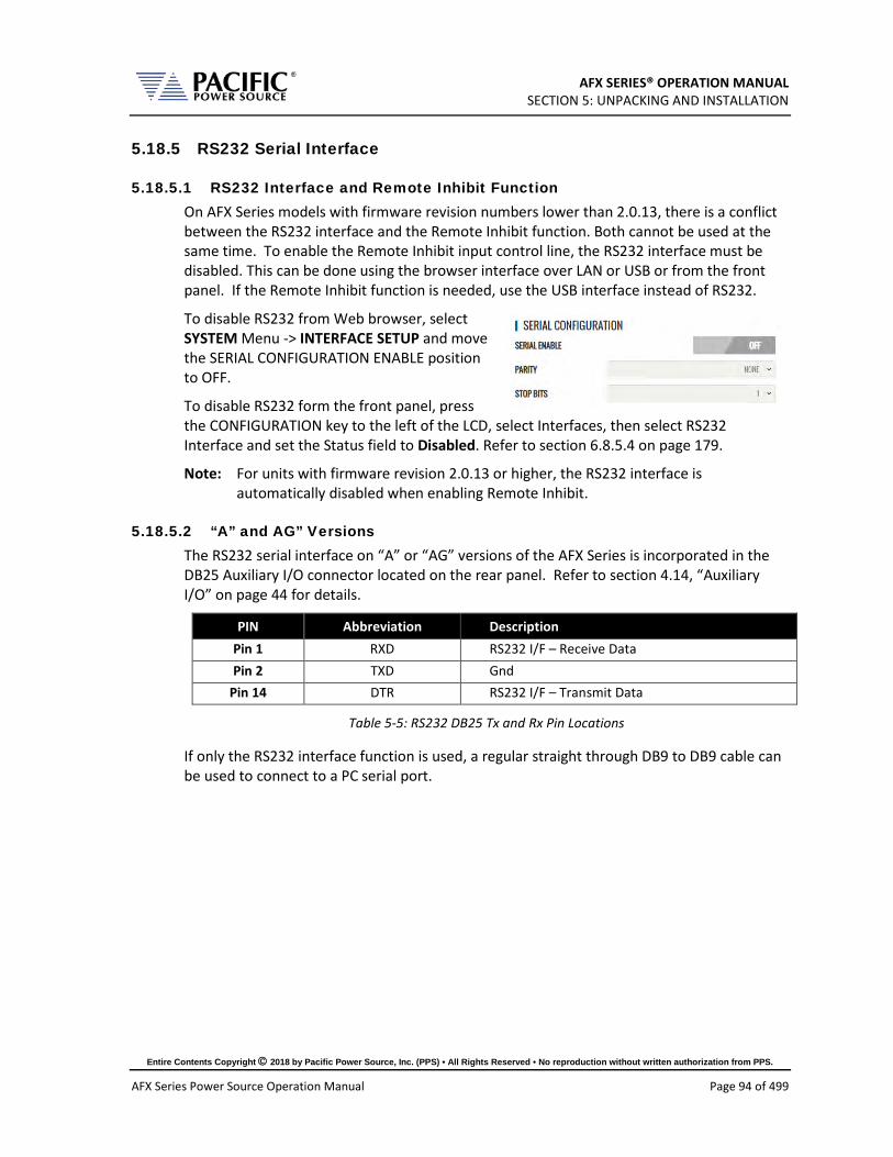
AFX SERIES® OPERATION MANUAL SECTION 5: UNPACKING AND INSTALLATION
Entire Contents Copyright 2018 by Pacific Power Source, Inc. (PPS) • All Rights Reserved • No reproduction without written authorization from PPS.
AFX Series Power Source Operation Manual Page 94 of 499
5.18.5 RS232 Serial Interface
5.18.5.1 RS232 Interface and Remote Inhibit Function On AFX Series models with firmware revision numbers lower than 2.0.13, there is a conflict between the RS232 interface and the Remote Inhibit function. Both cannot be used at the same time. To enable the Remote Inhibit input control line, the RS232 interface must be disabled. This can be done using the browser interface over LAN or USB or from the front panel. If the Remote Inhibit function is needed, use the USB interface instead of RS232.
To disable RS232 from Web browser, select SYSTEM Menu -> INTERFACE SETUP and move the SERIAL CONFIGURATION ENABLE position to OFF.
To disable RS232 form the front panel, press the CONFIGURATION key to the left of the LCD, select Interfaces, then select RS232 Interface and set the Status field to Disabled. Refer to section 6.8.5.4 on page 179.
Note: For units with firmware revision 2.0.13 or higher, the RS232 interface is automatically disabled when enabling Remote Inhibit.
5.18.5.2 “A” and AG” Versions The RS232 serial interface on “A” or “AG” versions of the AFX Series is incorporated in the DB25 Auxiliary I/O connector located on the rear panel. Refer to section 4.14, “Auxiliary I/O” on page 44 for details.
PIN Abbreviation Description Pin 1 RXD RS232 I/F – Receive Data Pin 2 TXD Gnd
Pin 14 DTR RS232 I/F – Transmit Data
Table 5-5: RS232 DB25 Tx and Rx Pin Locations
If only the RS232 interface function is used, a regular straight through DB9 to DB9 cable can be used to connect to a PC serial port.
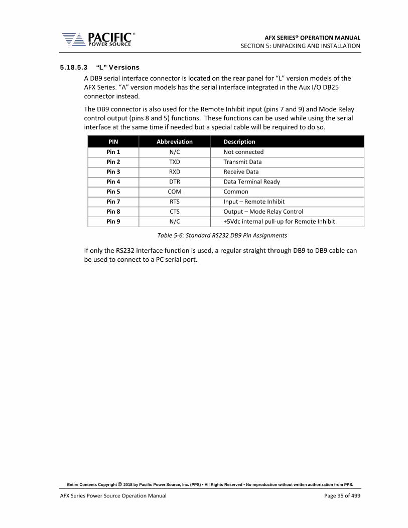
AFX SERIES® OPERATION MANUAL SECTION 5: UNPACKING AND INSTALLATION
Entire Contents Copyright 2018 by Pacific Power Source, Inc. (PPS) • All Rights Reserved • No reproduction without written authorization from PPS.
AFX Series Power Source Operation Manual Page 95 of 499
5.18.5.3 “L” Versions A DB9 serial interface connector is located on the rear panel for “L” version models of the AFX Series. “A” version models has the serial interface integrated in the Aux I/O DB25 connector instead.
The DB9 connector is also used for the Remote Inhibit input (pins 7 and 9) and Mode Relay control output (pins 8 and 5) functions. These functions can be used while using the serial interface at the same time if needed but a special cable will be required to do so.
PIN Abbreviation Description Pin 1 N/C Not connected Pin 2 TXD Transmit Data Pin 3 RXD Receive Data Pin 4 DTR Data Terminal Ready Pin 5 COM Common Pin 7 RTS Input – Remote Inhibit Pin 8 CTS Output – Mode Relay Control Pin 9 N/C +5Vdc internal pull-up for Remote Inhibit
Table 5-6: Standard RS232 DB9 Pin Assignments
If only the RS232 interface function is used, a regular straight through DB9 to DB9 cable can be used to connect to a PC serial port.

AFX SERIES® OPERATION MANUAL SECTION 5: UNPACKING AND INSTALLATION
Entire Contents Copyright 2018 by Pacific Power Source, Inc. (PPS) • All Rights Reserved • No reproduction without written authorization from PPS.
AFX Series Power Source Operation Manual Page 96 of 499
5.18.6 GPIB Device Interface (Option G)
The GPIB interface uses the IEEE488.1 standard 24-pin D-Shell Amphenol micro ribbon connector. Using a standard GPIB cable, the cable will break out to the left of the unit when facing the rear. This will typically obstruct USB and LAN interface connector access. Reverse GPIB cables are available but using these will obstruct the Auxiliary I/O connector.
The GPIB pin assignments are per the IEEE488.1 standard and listed in the table below.
PIN Signal Description Pin 1 DIO1 Data input/output bit. Pin 2 DIO2 Data input/output bit. Pin 3 DIO3 Data input/output bit. Pin 4 DIO4 Data input/output bit. Pin 5 EOI End-or-identify. Pin 6 DAV Data valid. Pin 7 NRFD Not ready for data. Pin 8 NDAC Not data accepted. Pin 9 IFC Interface clear.
Pin 10 SRQ Service request. Pin 11 ATN Attention. Pin 12 SHIELD Pin 13 DIO5 Data input/output bit. Pin 14 DIO6 Data input/output bit. Pin 15 DIO7 Data input/output bit. Pin 16 DIO8 Data input/output bit. Pin 17 REN Remote enable. Pin 18 GND (wire twisted with DAV) Pin 19 GND (wire twisted with NRFD) Pin 20 GND (wire twisted with NDAC) Pin 21 GND (wire twisted with IFC) Pin 22 GND (wire twisted with SRQ) Pin 23 GND (wire twisted with ATN) Pin 24 Logic ground
Table 5-7: GPIB Interface Connector Pin Assignments

AFX SERIES® OPERATION MANUAL SECTION 5: UNPACKING AND INSTALLATION
Entire Contents Copyright 2018 by Pacific Power Source, Inc. (PPS) • All Rights Reserved • No reproduction without written authorization from PPS.
AFX Series Power Source Operation Manual Page 97 of 499
5.18.7 Remote Inhibit or Enable Input
The remote inhibit may be used to provide output shut down if a rear panel rack door is opened while the output is on. A contact closure between pins 7 and 9 (or an external 5Vdc supply if MODE RELAY CONTROL is enabled) will allow control of the output relay from either the front panel or a remote control interface. . “A” version models have the remote inhibit function on the Aux I/O DB25 connector instead.
There are three modes of operation for this input:
1. Disable mode: In his mode, the Remote Inhibit inputs are not active so this function is turned off. No short between the RI pins is required to enable the output in this mode.
2. Remote Inhibit mode: The two pins have to be shorted for the output to be enabled from the front panel or remote command. This is a necessary but not a sufficient condition to enable the output. If the output is enabled and the remote inhibit connection is open, a fault is generated. This mode is recommended for interlock safety applications such safety cages and test fixture interlocks.
3. Remote Enable mode: The output can be enabled by shorting these two pins, regardless of the output enable command/button. It is a sufficient condition to enable the output.
The mode can be selected from the SYST (SYSTEM) menu screen using the Interfaces, Remote Inhibit selection as shown below.
Figure 5-24: Remote Inhibit Control Screen
Figure 5-25: Remote Inhibit Pins on DB9 for AFX-2L and AFX-4L Versions

AFX SERIES® OPERATION MANUAL SECTION 5: UNPACKING AND INSTALLATION
Entire Contents Copyright 2018 by Pacific Power Source, Inc. (PPS) • All Rights Reserved • No reproduction without written authorization from PPS.
AFX Series Power Source Operation Manual Page 98 of 499
RS232 Interface and Remote Inhibit Function
On AFX Series models with firmware revision numbers lower than 2.0.13, there is a conflict between the RS232 interface and the Remote Inhibit function. Both cannot be used at the same time. To enable the Remote Inhibit input control line, the RS232 interface must be disabled. This can be done using the browser interface over LAN or USB or from the front panel. If the Remote Inhibit function is needed, use the USB interface instead of RS232.
To disable RS232 from Web browser, select SYSTEM Menu -> INTERFACE SETUP and move the SERIAL CONFIGURATION ENABLE position to OFF.
To disable RS232 from the front panel, press the CONFIGURATION key to the left of the LCD, select Interfaces, then select RS232 Interface and set the Status field to Disabled. Refer to section 6.8.5.4 on page 179.
Note: For units with firmware revision 2.0.13 or higher, the RS232 interface is automatically disabled when enabling Remote Inhibit.
Note: If the Remote Inhibit function is enabled, the RS232 interface is still available but no hardware handshaking is available. (Xon/Xoff RS232 control only). Alternatively, the USB interface can be used instead.
Note: Units are shipped default with the Remote Inhibit state Disabled. Thus, no shorting jumper is needed to operate the power source. Changes to the remote inhibit configuration are retained after power down (Non-volatile).
Note: Master AFX units installed in cabinet systems shipped with the –OCS (Output Control Switch) option are configured with the RI function permanently set to Remote inhibit mode (mode 2). This prevents an operator from accidentally disabling this switch. The master AFX model number will show an “O” (letter O) postfix to indicate this configuration.
5.18.8 External MODE Relay Control
The RS232 connector also contains a relay control output pin that may be used in combination with suitable additional hardware to control a single phase mode shorting relay between phases A, B and C in cabinet systems.
“A” version models have the remote inhibit function on the Aux I/O DB25 connector instead.
This mode must be enabled in the SYSTEM screen. This control line (pin 8 and 5 on DB9 connector) puts out +5Vdc when the AFX is in FORM1 (single phase) and -5Vdc when the AFX is in FORM2 (split) or FORM3 (three phase) mode.

AFX SERIES® OPERATION MANUAL SECTION 5: UNPACKING AND INSTALLATION
Entire Contents Copyright 2018 by Pacific Power Source, Inc. (PPS) • All Rights Reserved • No reproduction without written authorization from PPS.
AFX Series Power Source Operation Manual Page 99 of 499
5.18.9 LAN Interface
The LAN interface connector is installed on the rear panel. The MAC address of the unit can be found near the LAN connector. When present, an “L” is appended to the models number, e.g. 3150AFX-2L.
CAUTION
Do NOT connect the RJ45 LAN (Ethernet) connector of the power source to a PoE (Power over Ethernet) port as the DC voltage will damage the LAN interface.
No special device drivers are required to use the LAN interface as it uses TCP/IP protocol but the IP address needs to be configured to operate on the user’s local area network or private network.
Figure 5-26: AFX Series® Rear Panel Layout
5.18.10 System Interface Bus Connectors
CAUTION
SHOCK HAZARD: DO NOT remove safety covers from the two System Interface DVI Connectors.
AVERTISSEMENT
RISQUE DE CHOC: NE PAS retirer les capots de sécurité des deux connecteurs d´interface DVI
The system interface bus is not user-accessible. It consists of two Digital Visual Interface (DVI-I dual link) connectors that are covered by a protective cover. There are no user
MAC Address

AFX SERIES® OPERATION MANUAL SECTION 5: UNPACKING AND INSTALLATION
Entire Contents Copyright 2018 by Pacific Power Source, Inc. (PPS) • All Rights Reserved • No reproduction without written authorization from PPS.
AFX Series Power Source Operation Manual Page 100 of 499
accessible signals on the system interface bus. It is used for system configuration cabinet systems only.
5.19 Multi-Unit Parallel Operation Two or more AFX units can be configured as a parallel system to create a high power system. This requires at least one Master AFX unit and one or more Auxiliary units or Master units that will be used as Auxiliaries to the first Master.
Note: Auxiliary units or Master units used in an auxiliary position must be of the same power output as the Master unit so each unit delivers the same amount of current /power into the load.
5.19.1 Load Connections on Parallel Systems
Paralleling two or more units requires that their outputs are tied together using equal length load cables from each unit to the load. A common coupling terminal block may be used to combine outputs in combination with larger size load wires to the load. Make sure the appropriate size wiring is used for the higher current levels obtained by paralleling two or more units.
5.19.2 Parallel System Bus Connection
For both units to operate correctly, the system bus connections between the master and auxiliary units MUST be made. This is done by daisy chaining the master to the first auxiliary and that auxiliary to the next one.
The system interface connectors are located on the left hand side of the rear panel and marked as follows:
PARALLEL IN On the MASTER unit, this connector is NOT CONNECTED. This causes the unit to become a master for other parallel units at power on. On an AUX unit, this connector is connected to a MASTER unit or an AUX unit that precedes this unit in the parallel chain.
PARALLEL OUT On the MASTER unit, this connector is connected to the first AUX unit. On the last AUX unit in the parallel chain, this connector is NOT CONNECTED signifying the end of the parallel chain.
The system bus uses a DVI-I Dual Link Male to Male interconnect cable with noise suppression ferrite beads. Cable length for paralleling units that are stacked in a 19” cabinet with no more than 1U space between units is 1 foot (0.3 m). Use of longer cables than 1 foot /30 cm is not recommended. If units cannot be installed in a cabinet, a longer DVI cable up to 3 feet in length may be used as an exception.
An example of the interconnect between one MASTER and one AUX is shown in the figure below.
Note: Any unused Parallel bus connector must be covered by the included safety covers.
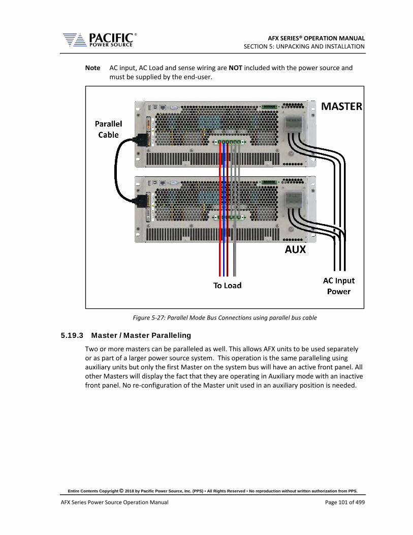
AFX SERIES® OPERATION MANUAL SECTION 5: UNPACKING AND INSTALLATION
Entire Contents Copyright 2018 by Pacific Power Source, Inc. (PPS) • All Rights Reserved • No reproduction without written authorization from PPS.
AFX Series Power Source Operation Manual Page 101 of 499
Note AC input, AC Load and sense wiring are NOT included with the power source and must be supplied by the end-user.
Figure 5-27: Parallel Mode Bus Connections using parallel bus cable
5.19.3 Master / Master Paralleling
Two or more masters can be paralleled as well. This allows AFX units to be used separately or as part of a larger power source system. This operation is the same paralleling using auxiliary units but only the first Master on the system bus will have an active front panel. All other Masters will display the fact that they are operating in Auxiliary mode with an inactive front panel. No re-configuration of the Master unit used in an auxiliary position is needed.

AFX SERIES® OPERATION MANUAL SECTION 5: UNPACKING AND INSTALLATION
Entire Contents Copyright 2018 by Pacific Power Source, Inc. (PPS) • All Rights Reserved • No reproduction without written authorization from PPS.
AFX Series Power Source Operation Manual Page 102 of 499
5.20 Multi-Cabinet Parallel Operation Guidelines Please adhere to the following guidelines when paralleling two or more AFX Cabinet Systems. Unless these guidelines are following, optimal current sharing between cabinets cannot be guaranteed.
5.20.1 Output Wiring
1. All output wires (Neutral, Phase A, Phase B and Phase C) from each cabinet must be paralleled. Each individual output wire from each Cabinet to the output load connection MUST BE THE SAME LENGTH AND WIRE SIZE.
2. DO NOT connect any power wiring between the cabinets. The output wiring from each cabinet must be brought to a common load termination point.
3. Keep all power connections between the AFX cabinet and the load termination point as short as possible.
Note AC input, AC Load, sense wiring and output junction terminal blocks are NOT included with the power source cabinet and must be supplied by the end-user. Only internal cabinet wiring and terminal blocks are included.
See diagram below for three phase output configuration parallel cabinets.
28 UAFX CABINET 1
MASTER
28 UAFX CABINET 2
SLAVE
BUNDLE PHASE WIRES WITH NEUTRAL WIRE(S)
BUNDLE PHASE WIRES WITH NEUTRAL WIRE(S)
ALL WIRES LENGTHSMUST BE EQUAL JUNCTION
TERMINALBLOCK
A B C N
OUTPUT AC INPUT OUTPUT AC INPUT
TO LOAD
PARALLELINGCABLE
From bottom unit inMaster Cabinet to top
unit in Slave Cabinet
CONNECT PROVIDED GROUNDING CABLE BETWEEN CABINETS
Figure 5-28: Multi-Cabinet Parallel Configuration Output Wiring - 3 Phase

AFX SERIES® OPERATION MANUAL SECTION 5: UNPACKING AND INSTALLATION
Entire Contents Copyright 2018 by Pacific Power Source, Inc. (PPS) • All Rights Reserved • No reproduction without written authorization from PPS.
AFX Series Power Source Operation Manual Page 103 of 499
5.20.2 System Grounding
1. All AFX Cabinet systems MUST be properly grounded to the local facility ground using the provided GROUND terminal on the AC input terminal block located inside the cabinet.
2. In addition to individual facility ground connections, Multi-Cabinet units must be grounded to each other. This may be accomplished by connecting a ground cable to the rear of the cabinet rack on the designated Master Cabinet, passing the cable through the Input / Output power strain reliefs, and terminating the cable on the rear of the cabinet rack of the designated Auxiliary cabinet.
Refer to diagram above for suggested ground wire routing between two cabinets.
NOTE: Each cabinet should still be ground to facility ground.

AFX SERIES® OPERATION MANUAL SECTION 5: UNPACKING AND INSTALLATION
Entire Contents Copyright 2018 by Pacific Power Source, Inc. (PPS) • All Rights Reserved • No reproduction without written authorization from PPS.
AFX Series Power Source Operation Manual Page 104 of 499
5.21 Transformer Options Standard AFX Series AC and DC power sources support output voltages up to 332V Line to Neutral. For higher output voltage applications, an optional set of step up transformers can be ordered to boost the output voltage. The available AFX Transformer option provides 400V L-L. Higher voltage options are available on request.
This section describes the installation and use of the 400V transformer option for either single AFX units up to 15kVA or for higher power AFX Series cabinet systems.
Figure 5-29: Rack Mount Chassis for 6kVA to 15kVA Transformer Option
5.21.1 T Option 4U Chassis
The rack mount transformer options can be used on a bench or installed in a standard 19” instrument rack. This model supports the following AFX models:
• 360AFXT-2AG, 360AFXT-4AG • 390AFXT-2AG, 390AFXT-4AG • 3120AFXT-2AG, 3120AFXT-4AG • 3150AFXT-2AG, 3150AFXT-4AG
Technical specifications can be found in Section 4.

AFX SERIES® OPERATION MANUAL SECTION 5: UNPACKING AND INSTALLATION
Entire Contents Copyright 2018 by Pacific Power Source, Inc. (PPS) • All Rights Reserved • No reproduction without written authorization from PPS.
AFX Series Power Source Operation Manual Page 105 of 499
5.21.2 Rack Mount T Option Installation
Whether used on a bench or installed in a cabinet, it is strongly recommended that the T option chassis be placed directly below the AFX unit it is used with as shown below. This allows for the shortest possible connections between the AFX and the transformer chassis.
Once interconnected, there is no need to change load connections or output wiring as the transformer option is automatically bypassed – removed from the output - when not in use. This allows it to remain in place at all times.

AFX SERIES® OPERATION MANUAL SECTION 5: UNPACKING AND INSTALLATION
Entire Contents Copyright 2018 by Pacific Power Source, Inc. (PPS) • All Rights Reserved • No reproduction without written authorization from PPS.
AFX Series Power Source Operation Manual Page 106 of 499
5.21.3 Unpacking T Option Chassis
CAUTION
THIS UNIT IS HEAVY. Two persons are required to lift or carry this unit. DO NOT attempt to lift alone. DO NOT use the front panel rack handles alone to lift this unit. The unit must be supported in front and back when carrying.
AVERTISSEMENT
CET EQUIPEMENT EST LOURD. Deux personnes sont requises pour transporter ou soulever cet équipement. NE PAS tenter de soulever ou déplacer seul. NE PAS utiliser les poignées en face avant pour soulever l´appareil. L´équipement doit être pris en charge à l´avant et à l´arrière pour le transport.
The AFX Transformer chassis weighs nearly 200 lbs so it is highly recommended that lifting aids be used to remove the unit from its packaging. To assist in removing the unit from its package, two flip-down grab handles are located on each side of the chassis towards the rear.
Note: These grab handles should be removed when installing the transformer option in a 19” cabinet. When using the chassis on a bench, they can be left in place.
5.21.4 Cabinet Installation
When installing this option in a 19” rack, either heavy-duty rack slides or heavy-duty L- brackets MUST be used to support the weight of the unit. Contact customer services for available slides and L-brackets.
Refer to the cabinet shown to the right for details.

AFX SERIES® OPERATION MANUAL SECTION 5: UNPACKING AND INSTALLATION
Entire Contents Copyright 2018 by Pacific Power Source, Inc. (PPS) • All Rights Reserved • No reproduction without written authorization from PPS.
AFX Series Power Source Operation Manual Page 107 of 499
5.21.5 T Option Chassis Rear Panel Connectors
There are several connectors located on the rear panel of the Transformer chassis that are used to route power and voltage sense as well as Auxiliary I/O signals used to control the transformer option. Refer to figure below.
Legend for rear panel connectors is shown in the table below.
Call Out LABEL Description 1 DIGITAL & ANALOG I/O Auxiliary I/O connector pass-through from Master
AFXT. This connector may be used to access any Auxiliary I/O connections that are not reserved for Transformer option control.
2 FROM MASTER Auxiliary I/O connection from master AFXT power source Auxiliary I/O connector. Use the provided DB25 Male-Female cable to connect the Master Aux I/O connector to the Transformer chassis.
3 EXTERNAL VOLTAGE SENSE - ANBNCN
External Voltage Sense Connector. Connect to load for external voltage sense. Note that the External Voltage sense connector on the master AFX unit is not accessible when the transformer option is installed.
4 EXTERNAL VOLTAGE SENSE - FROM MASTER
External Voltage Sense connection from master AFX External Voltage Sense connector. Use the sense wire harness to connect the Master AFXT External Voltage Sense to the Transformer chassis using this connector.
5 INPUT FROM MASTER Power input from Master AFX to Transformer Chassis. Connect the provided Power Wire Harness from the Master AFX output connector to the Transformer chassis using this connector.
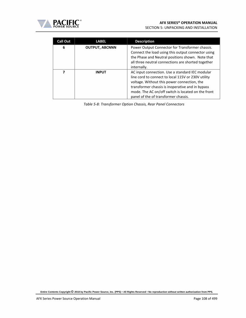
AFX SERIES® OPERATION MANUAL SECTION 5: UNPACKING AND INSTALLATION
Entire Contents Copyright 2018 by Pacific Power Source, Inc. (PPS) • All Rights Reserved • No reproduction without written authorization from PPS.
AFX Series Power Source Operation Manual Page 108 of 499
Call Out LABEL Description 6 OUTPUT, ABCNNN Power Output Connector for Transformer chassis.
Connect the load using this output connector using the Phase and Neutral positions shown. Note that all three neutral connections are shorted together internally.
7 INPUT AC input connection. Use a standard IEC modular line cord to connect to local 115V or 230V utility voltage. Without this power connection, the transformer chassis is inoperative and in bypass mode. The AC on/off switch is located on the front panel of the of transformer chassis.
Table 5-8: Transformer Option Chassis, Rear Panel Connectors

AFX SERIES® OPERATION MANUAL SECTION 5: UNPACKING AND INSTALLATION
Entire Contents Copyright 2018 by Pacific Power Source, Inc. (PPS) • All Rights Reserved • No reproduction without written authorization from PPS.
AFX Series Power Source Operation Manual Page 109 of 499
5.21.6 AFX Power Source to T Option Connections
The required connections between the AFX power source and the transformer option chassis are shown in Figure 5-30 below.
Note AC input, AC Load and sense wiring are NOT included with the power source and must be supplied by the end-user.
TO LOAD TO LOADAC Line Cord
DB25 Cable
AFX Power Source
Transformer Option
AC
INPU
T
Figure 5-30: Interconnections between AFX Power Sourec and Transformer Option Chassis
For operating information, refer to Section 6.4.

AFX SERIES® OPERATION MANUAL SECTION 6: Front Panel Operation
Entire Contents Copyright 2018 by Pacific Power Source, Inc. (PPS) • All Rights Reserved • No reproduction without written authorization from PPS.
AFX Series Power Source Operation Manual Page 110 of 499
6 Front Panel Operation
This Chapter provides an overview of front panel operation for the AFX Series® AC power sources. For remote control operation, refer to Section 8 “Remote Control Programming” of this manual for an overview of available programming commands.
6.1 Front Panel Layout The front panel layout is shown in Figure 6-1 below. The number of buttons is kept to a minimum to ensure simple front panel operation for casual and experienced users alike. The shuttle knob is used to slew parameter values and move through menus to make selections.
Figure 6-1: AFX Series® Front Panel View
A large backlit LCD display is located in the center. Most user controls are located directly to the right of the display. The power ON/OFF circuit breaker is located in the lower left corner of the front panel.

AFX SERIES® OPERATION MANUAL SECTION 6: Front Panel Operation
Entire Contents Copyright 2018 by Pacific Power Source, Inc. (PPS) • All Rights Reserved • No reproduction without written authorization from PPS.
AFX Series Power Source Operation Manual Page 111 of 499
6.1.1 Keyboard Buttons
There are several groupings of push buttons that make up the front panel. They are grouped as follows:
Group Function Menu Selection Keys These keys select the available top-level menus. Sub menus may be
accessible using any of the available soft keys within each top-level menu.
Soft Keys Soft keys change function as indicated by the decal directly to the left of the soft key on the LCD display.
Shuttle See next section for details on shuttle operation. Decimal Key Pad The decimal key pad is used to enter parameter values directly.
Values may also be set using any available soft key or the shuttle. ENTER Key The ENTER key confirms a selection or setting made with the
decimal key pad. Until confirmed by pressing the ENTER key, selections and values will be shown grayed out on the LCD display to indicate they have been edited/changed but have not yet taken effect. This allows multiple parameters in the same screen to be edited with all new setting values taking effect at once when the ENTER or UPDATE ALL soft key is pressed.
ESC Key The escape key backs out of a menu or selection and returns to a previous level.
Back Space Key ( ) This key backs up one position erasing the last digit value entered. OUTPUT ENABLE The OUTPUT ENABLE key is used to toggle the output on or off. If
the output is ON, this key will be lit. LOCAL Returns the instrument to local control mode allowing front panel
operation. This key may be disabled over one of the remote control interfaces. While in REMOTE, the keyboard is locked out. The LOCAL key can also be used to capture an LCD Image and store it as a .png image file in internal memory. To do so press and hold the LOCAL key, then press the 1 key. Screen images are saved in folder “internal/screenshots”.
PHASE The PHASE key is used to select a specific phase on three phase models. On single phase models, the selected phase is always A and this key has no function.
PROGRAM MENU MEASUREMENTS
TRANSIENTS MENU UTILITY MENU HELP SCREENS
OUTPUT ON/OFF LOCAL KEY PHASE SELECTION
MENU KEYS LCD DISPLAY SOFT KEYS SHUTTLE KEYPAD ENTER KEY

AFX SERIES® OPERATION MANUAL SECTION 6: Front Panel Operation
Entire Contents Copyright 2018 by Pacific Power Source, Inc. (PPS) • All Rights Reserved • No reproduction without written authorization from PPS.
AFX Series Power Source Operation Manual Page 112 of 499
6.1.2 Shuttle Knob
The shuttle knob or rotary digital encoder is used to navigate (scroll) through menus and select fields to modify settings. The shuttle knob also includes a SELECT push button function. Pushing in the shuttle knob (SELECT) while on a data field will allow the value to be slewed up or down.
NOTE: Unlike when using the decimal keypad to enter a value, the SELECT shuttle mode will cause the output to change immediately. This allows slewing of the actual output value.
Once the final value is reached, pressing the shuttle again will take it out of slew mode and back into scroll mode.
6.1.3 PC Monitor Output
A PC monitor output connector is located on the front panel’s left side. This connector is marked with a monitor icon as shown here. This allows connection of a computer monitor. When connected, the monitor will display the information otherwise shown on the front panel LCD screen and the LCD screen itself will be off.
This feature allows for the connection of a touch enabled LCD monitor to the Video Output the front panel as well. When detected by the AFX, a message will pop-up asking the operator to change to the external screen. If accepted, the front panel LCD will turn off and the AFX screen will be display on the monitor along with a touch panel to operate the unit. The actual front panel keypad will remain active as well. This feature is useful for operator training or in control rooms where being able to read the measurement screen from across the room is required. A USB connection to one of the AFX USB ports is required to use the monitor’s touch feature.
To return the display to the LCD screen, unplug the monitor.
6.1.4 USB Host Ports
Two USB host ports are located on the left hand side of the front panel. These ports will accept a USB memory device or a USB peripheral such as a mouse of keyboard. These USB ports are marked with the standard USB symbol as shown here.
6.1.5 SD Card Memory Slot
A SD Card memory device slot is located on the left hand side of the front panel. This slot will accept a standard SD memory card. The SD Card slot is marked with the symbol shown to the right here.

AFX SERIES® OPERATION MANUAL SECTION 6: Front Panel Operation
Entire Contents Copyright 2018 by Pacific Power Source, Inc. (PPS) • All Rights Reserved • No reproduction without written authorization from PPS.
AFX Series Power Source Operation Manual Page 113 of 499
6.2 OUTPUT ENABLE Button The circular Output Enable (On/Off) button is located on the right hand side of the front panel keypad. Its unique circular shape makes is easy to find so the output can be turned off quickly if needed.
6.2.1 OUTPUT State Indication
The state of the output is indicated by the back light color of the Output On/Off button. A blue color indicates the output is OFF, a green color indicates the output is ON.
6.2.2 Energy Savings Modes
The AFX Series® was designed to conserve energy when powered on but not in actual use to power a load. This situation is common as adjustments are being made to the setup or the load before any power is applied. This mode is controlled by the state of the Output. If the output is off, the AFX will enter one of two energy savings modes:
1. SLEEP MODE In sleep mode, all three inverter stages are switched off. If the internal heatsink is sufficiently cool, all fans are turned off as well. This essentially means the power source draws almost no power at all yet the front panel controls, displays and all digital control interfaces remain operational so any required program changes can be made.
2. STANDBY MODE In standby mode, only the output inverter stage for each phase is turned off. This means the first two stages remain on while the output is off. This means the fan will run at its lowest speed setting for quieter operation. This mode is considered a fast startup mode.
The desired energy savings mode can be selected from the front panel or via one of the remote control interfaces using the OUTP:FAST command (See section 8.7.1.).
6.2.3 Output On Response Times
Turning the output ON means that any power stage that was disabled for energy conservation purposes will be started and allowed to settle. This includes the output inverters. Once all power stages are up and running, the output relays are closed and whatever programmed output mode, voltage and frequency (if not in DC mode) will be applied to the load. If all stages were off – power source in sleep mode – this process can take up to 2.2 seconds. If the output control mode is set to FAST mode however, only the inverters are ever turned off and output can be applied within 200 msec, which is typical for older design power source with no energy saving features or sleep mode capability.

AFX SERIES® OPERATION MANUAL SECTION 6: Front Panel Operation
Entire Contents Copyright 2018 by Pacific Power Source, Inc. (PPS) • All Rights Reserved • No reproduction without written authorization from PPS.
AFX Series Power Source Operation Manual Page 114 of 499
6.3 Menu Keys The various menus and settings available to the user from the front panel are detailed in this section of the manual.
All available menus can be accessed using the Menu keys to the left of the LCD display. The following five keys are available.
MENU KEY MENU SCREEN Description PROG PROGRAM Programming of output parameters
MEAS MEASUREMENTS Measurements
TRAN TRANSIENTS Transient programming and execution
CONF CONFIGURATION Configuration Screens
SYST SYSTEM System Settings, Interface Configuration and Calibration
Table 6-1: Available Menu Keys
Following sections cover each aspect of the front panel screen and parameters in more detail.
AFX SERIES® OPERATION MANUAL SECTION 6: Front Panel Operation
Entire Contents Copyright 2018 by Pacific Power Source, Inc. (PPS) • All Rights Reserved • No reproduction without written authorization from PPS.
AFX Series Power Source Operation Manual Page 115 of 499
6.4 PROG – PROGRAM Screens All output parameters can set from the PROGRAM screen. This screen has a list of available parameters on the main PROGRAM screen. Each parameter can be changed by highlighting the field and either slewing the value using the shuttle knob or entering a value using the numeric key pad. The difference between these two data entry modes is that slewing causes the output to change as the knob is turned while using the keypad allows one or more parameters to be preset to a new value which won’t become active until the “Apply All” soft key or the ENTER key is pressed.
Thus, to slew a value, proceed as follows:
1. Use shuttle to move the active field to the parameter you want to slew.
2. Press the shuttle once to enter the slew mode. The selected field will be highlighted.
3. Use the shuttle to increment (clockwise) or decrement (counterclockwise) the selected parameter. Note that these changes take effect immediately resulting in the active output slewing up or down.
Note: This assumes the output is ON. If the output is OFF, the new value will be in effect and apply at the output as soon as the output is turned ON.
To slew a parameter while observing the MEASUREMENT screen, proceed as follows:
1. Use shuttle to move the selected field to the parameter you want to change.
2. While on the desired parameter (e.g. Voltage or Frequency), DOUBLE-PRESS the shuttle (similar to double clicking a mouse button).
3. The MEASUREMENT screen will appear with the parameter to be slewed visible in the header bar.
4. Use the Shuttle to slew the parameter up or down. The value will be displayed in the header bar of the measurement menu.
5. When done, press the PROGRAM key to return to the regular PROGRAM screen and exit this interactive mode.
With the parameter field selected, enter a new value using the numeric keypad.
To change one or more values but not change the actual output till all parameters are preset, proceed as follows:
6. Use shuttle to move the selected field to the parameter you want to change.
7. With the parameter field selected, enter a new value using the numeric keypad. Note that all fields are now shown with a gray background (Edit mode active)
8. Once satisfied with the new value, move to the next parameter you want to change.
9. Once all values are set to the new desired set value, press the ENTER key or the “Apply All” soft key.

AFX SERIES® OPERATION MANUAL SECTION 6: Front Panel Operation
Entire Contents Copyright 2018 by Pacific Power Source, Inc. (PPS) • All Rights Reserved • No reproduction without written authorization from PPS.
AFX Series Power Source Operation Manual Page 116 of 499
6.4.1 Power On Settings
The AFX Series will normally power up with the last settings in effect at turn-off for units with firmware revision 1.6.0 or higher. Older firmware units will come up with factory default settings.
Starting from firmware revision 1.6.0, this behavior is determined by the the “SOURce:INITial” command. This feature is active by default. This makes the AFX “remember” all the settings after cycling power.
This mode can be disabled by using the remote control command:
SOURce:INITial 0
This setting is retained in non-volatile (FLASH) memory.
6.4.2 PROGRAM Output Parameters
Figure 6-2: PROGRAM Screen
The two data entry methods described apply to the parameters on the main PROGRAM screen. This includes those shown in the table below.
PARAMETER Range Unit Description Frequency 15 - 1200 Hz Output frequency
Phase 0.0 – 359.0 Degrees Phase angles for phase B and C
Voltage AC 0 – 300 V rms AC output
Voltage DC 0 - 425 Vdc DC output
Current limit 0 to Max A rms RMS Current Limit
Power limit 0 to Max W True Power Limit
kVA limit 0 to Max VA Apparent Power Limit Table 6-2: Available Output Parameters on PROGRAM screen
Each screen has up to five soft keys on the right hand side of the display. These may change as the selected parameter changes. To move between parameter fields in any screen, use

AFX SERIES® OPERATION MANUAL SECTION 6: Front Panel Operation
Entire Contents Copyright 2018 by Pacific Power Source, Inc. (PPS) • All Rights Reserved • No reproduction without written authorization from PPS.
AFX Series Power Source Operation Manual Page 117 of 499
the shuttle knob. To change a parameter, press the shuttle knob and then adjust the value by turning the shuttle. When done, press the shuttle to exit edit mode.
6.4.3 Phase Rotation / Phase Sequence
Phase rotation(aka sequence) in three-phase mode is determined by the programmed phase angles for phase B and C. Phase A is always the 0° reference and this value can only be changed when an external phase sync. Input mode is used. For normal operation, the internal phase A is used as the phase reference for B and C so phase A is fixed at 0° and the field is disabled. (Light grey instead of black text).
The default phase rotation of the AFX is the same as that of legacy PPS UPC controllers. This phase rotation is positive so when driving AC motors, the motors will turn forward.
Figure 6-3: Three Phase AC mode Default Phase Rotation
Phase rotation in three-phase mode can be reversed if needed in one of three ways:
1. By swapping output connection wires B and C to the load.
2. By reprogramming the default phase setting for B to 240° and for C to 120°.
3. By selecting “Positive (Phase B leading A)” under “Phase Rotation” in the source configuration screen.
The reversed phase rotation is shown in the figure below for reference.
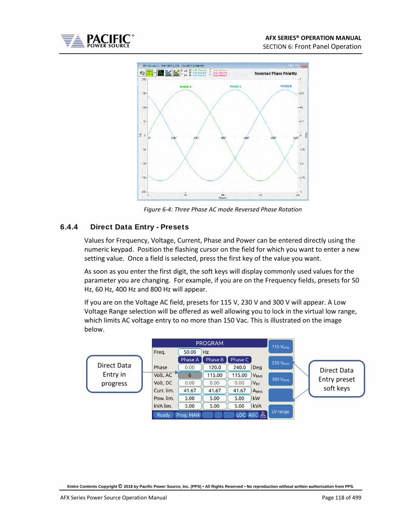
AFX SERIES® OPERATION MANUAL SECTION 6: Front Panel Operation
Entire Contents Copyright 2018 by Pacific Power Source, Inc. (PPS) • All Rights Reserved • No reproduction without written authorization from PPS.
AFX Series Power Source Operation Manual Page 118 of 499
Figure 6-4: Three Phase AC mode Reversed Phase Rotation
6.4.4 Direct Data Entry - Presets
Values for Frequency, Voltage, Current, Phase and Power can be entered directly using the numeric keypad. Position the flashing cursor on the field for which you want to enter a new setting value. Once a field is selected, press the first key of the value you want.
As soon as you enter the first digit, the soft keys will display commonly used values for the parameter you are changing. For example, if you are on the Frequency fields, presets for 50 Hz, 60 Hz, 400 Hz and 800 Hz will appear.
If you are on the Voltage AC field, presets for 115 V, 230 V and 300 V will appear. A Low Voltage Range selection will be offered as well allowing you to lock in the virtual low range, which limits AC voltage entry to no more than 150 Vac. This is illustrated on the image below.
Direct Data Entry preset
soft keys
Direct Data Entry in progress

AFX SERIES® OPERATION MANUAL SECTION 6: Front Panel Operation
Entire Contents Copyright 2018 by Pacific Power Source, Inc. (PPS) • All Rights Reserved • No reproduction without written authorization from PPS.
AFX Series Power Source Operation Manual Page 119 of 499
6.4.5 Customizing Output Programming Preset Soft Key Values
The power source allows the user to set up his own preferred or often used output programming values in place of the factory default selections. This can be done from the SYST menu by selecting the UNIT CONFIGURATION 2 OF 2 screen and pressing the “User Presets” soft key.
For details on change any available pre-set soft key value, refer to Section 6.7.8, “USER PRESETS Screen” on page 168.
6.4.6 Changing Shuttle Programming Resolution
Once entering EDIT mode on any programmable field – by double clicking the shuttle knob – the parameter value can be slewed by turning the knob. The setting resolution can be changed as needed. If a large value change is needed, a lower resolution will result in a faster change, e.g. changing voltage 10V per click or 1V per click. For a very small change, a 0.1V or 0.01V change per click may be more appropriate.
The selected resolution is reflected by the blinking character when in edit slew mode. To change the position and thus resolution, use the keypad numeric keys. The lowest number keys will select the smallest increment/decrement setting. The higher number keys will select a larger increment/decrement setting.
The table bellows maps the keypad keys to the resolution setting.
Key Pad Key # Position Resolution
1 or 2
0.01
3 0.1
4 1
5 10
6, 7, 8 or 9 100
7, 8, 9 1000
Table 6-3: Changing Programming Resolution

AFX SERIES® OPERATION MANUAL SECTION 6: Front Panel Operation
Entire Contents Copyright 2018 by Pacific Power Source, Inc. (PPS) • All Rights Reserved • No reproduction without written authorization from PPS.
AFX Series Power Source Operation Manual Page 120 of 499
6.4.7 Phase Mode Selection
Setting output parameters when the AC power source is in single-phase mode (FORM1) is straightforward as there is only one phase to program. Thus, all fields displayed in the PROGRAM screen apply to phase A.
In three-phase mode, there are two ways to program most parameters other than the Frequency:
• Coupled
• Uncoupled
Coupled mode means all phases are set and changed to the same value. Thus, Voltage AC when set or changed applies to all three output phases. This method ensures output phase voltages are always balanced and is convenient for driving normal three phase loads. Coupled mode is indicated by the “ABC” status indicator on the right hand side of the status bar as highlighted below.
Figure 6-5: Phase Mode Data Entry Status Field
Uncoupled means each phase can be set individually. To do so, the phase to be set or changed must be selected first using the PHASE key located on the right hand side of the front panel keyboard. The selected phase (A, B or C) is displayed in the status bar as either “A”, “B” or “C” when in SINGLE phase mode or “3ph” will be displayed when in THREE phase mode.

AFX SERIES® OPERATION MANUAL SECTION 6: Front Panel Operation
Entire Contents Copyright 2018 by Pacific Power Source, Inc. (PPS) • All Rights Reserved • No reproduction without written authorization from PPS.
AFX Series Power Source Operation Manual Page 121 of 499
6.4.8 PROGRAM Soft Keys
The following five soft keys are available on the main PROGRAM screen.
SOFT KEY Description Presets (SK1) Changes all soft keys to up to five preset values that may be used to
change the selected parameter to any of the preset values shown on the soft key labels. This provides a quick way to set commonly used values. On AFX models with firmware revision 2.0.0 or higher, it is also possible to reprogram these presets to user specific values. Refer to Section 6.4.5, “Customizing Output Programming Preset Soft Key Values” on page 119 for details. The following presets are offered for the parameters listed: Frequency 50Hz, 60Hz, 400Hz, 800Hz, 1200Hz Voltage AC 115V, 230V, 300V Voltage DC MAX, 200V, 0V, -200V, MIN Current limit MAX, 15A, 4A, PEAK CURRENT Power limit MAX, 4kW, 2kW, 1kW kVA limit MAX, 4kVA, 2kVA, 1kVA
Protection (SK2)
Displays the POWER AND CURRENT PROTECTIONS screen shown below.
There are two check box options and one data field on this screen that can be set as needed: Enable RMS current protection Activates the programmable
current limit function at the value set in the main program screen
Enable power protection Activates power protection at W and kVA set points.
Trip time: Determines how long the power source will allow the power level setting to be exceeded before tripping off.

AFX SERIES® OPERATION MANUAL SECTION 6: Front Panel Operation
Entire Contents Copyright 2018 by Pacific Power Source, Inc. (PPS) • All Rights Reserved • No reproduction without written authorization from PPS.
AFX Series Power Source Operation Manual Page 122 of 499
SOFT KEY Description Peak
Current (SK3) Displays the Peak Current protection screen. This protection function is separate from the RMS current limit function. By setting the peak current protection mode, the maximum peak current is limited by the power source to the programmed level. This is done on a cycle by cycle basis. Note that a minimum setting applies as described in section 6.4.9, next page.
The level can be set using the shuttle or key pad. To enable or disable this function, scroll to the “Enable peak current protection” check box and press the shuttle to toggle on or off.
Waveform (SK4)
Displays the Waveform selection screen. This function allows the active waveform shape to be changed. Available waveform selections are: Sinewave, Clipped Sinewave 1% THD, Clipped Sinewave 2% THD, Clipped Sinewave 5% THD, Clipped Sinewave 10% THD, Square and Triangle.
Select waveform using the shuttle. Each waveform can be previewed. With the desired waveform displayed, press the “Apply” soft key to confirm. This will take you back to the PROGRAM screen.
Apply All (SK5) The “Apply all” soft key is used to confirm all presets made to program parameters in the PROGRAM screen. When pressed, all newly set values are applied to the output and the parameter background colors revert back to white.
Table 6-4: PROGRAM screen soft keys

AFX SERIES® OPERATION MANUAL SECTION 6: Front Panel Operation
Entire Contents Copyright 2018 by Pacific Power Source, Inc. (PPS) • All Rights Reserved • No reproduction without written authorization from PPS.
AFX Series Power Source Operation Manual Page 123 of 499
6.4.9 Peak Current Protection Minimum Setting
The programmable peak current protection feature allows the user to limit the peak current that is applied to the EUT. In order to do this, the power source has to clamp the output voltage. The power source will do so when the set limit is exceeded on a switching cycle by switching cycle bases. There are some practical considerations to take into account as some of the current delivered by the power source can be absorbed by the internal output filters.
If the peak current limit value is set too low, it may prevent the power source from delivering the programmed output voltage at higher frequencies. Even if no load is connected to the power source, some reactive power is required to generate the output voltage. This reactive current will be limited by the peak protection level set point so a minimum value applies. The formula that determines the minimum set value for peak current protection is:
Ipk > 1 A + Vac_setpoint * 0.09 * Freq_setpoint (in kHz).
This formula applies in three phase mode for AFX models of 15kVA and below. For example, with an output AC voltage setting of 230Vac and a frequency setting of 1000 Hz, the minimum set value would be:
Ipk min = 1 + 230 * 0.09 * 1 = 21.7 Apeak
If the set value is below this level, the following two conditions will occur:
A) The voltage measured at the output will be less than desired.
Example 1:
• Frequency 400Hz. • Voltage 120Vac. • Peak current limit 1A. • The voltage measured at the output will be limited to 25.6Vrms
Example 2:
• Frequency 400Hz. • Voltage 120Vac. • Peak current limit 2A. • The voltage measured at the output will be 54.6Vrms
Example 3:
• Frequency 400Hz. • Voltage 120Vac. • Peak current limit 3A. • The voltage measured at the output will be 83.22Vrms
The higher the frequency and the AC voltage set points are, the lower the measured voltage at the output will be unless the peak current protection level is set high enough to prevent this condition.

AFX SERIES® OPERATION MANUAL SECTION 6: Front Panel Operation
Entire Contents Copyright 2018 by Pacific Power Source, Inc. (PPS) • All Rights Reserved • No reproduction without written authorization from PPS.
AFX Series Power Source Operation Manual Page 124 of 499
B) An Error event will be triggered in the error and event queue in order to notify the user. The error message is:
"Peak current limit setting is too low for the desired voltage and frequency."
as shown in the screen capture below.

AFX SERIES® OPERATION MANUAL SECTION 6: Front Panel Operation
Entire Contents Copyright 2018 by Pacific Power Source, Inc. (PPS) • All Rights Reserved • No reproduction without written authorization from PPS.
AFX Series Power Source Operation Manual Page 125 of 499
6.4.10 Available Waveforms
The AFX Series® is supplied with 10 pre-loaded waveforms but can hold a total of 200. The default content of the first 10 registers are shown in the table below. Also shown are the waveform number names and the waveform description each waveform.
For waveforms with high harmonic content – e.g. sharp transition or fast edges – the smoothing filter feature can be used to smooth out these high frequency events to reduce over/undershoot as needed. The value entered indicates the number of waveform data points that will be averaged to obtain a smoother wave shape. Preview of the resulting smoothed waveform is shown on the LCD screen.
Name Description Image Notes 1 SINE
Standard sine wave. No harmonic content1. This is also the default selected waveform at power on unless a power-on setup is recalled. Waveform 1 is fixed and CANNOT be changed! Note 1: See SOURce:WAVEFORM:SINEwave command
2 CLIPPED THD 1%
Clipped sine with 1% total harmonic voltage distortion due to flat topping of sinewave peaks.
3 CLIPPED THD 2%
Clipped sine with 2% total harmonic voltage distortion due to flat topping of sinewave peaks.
4 CLIPPED THD 5%
Clipped sine with 5% total harmonic voltage distortion due to flat topping of sinewave peaks.
5 CLIPPED THD 10%
Clipped sine with 10% total harmonic voltage distortion due to flat topping of sinewave peaks.

AFX SERIES® OPERATION MANUAL SECTION 6: Front Panel Operation
Entire Contents Copyright 2018 by Pacific Power Source, Inc. (PPS) • All Rights Reserved • No reproduction without written authorization from PPS.
AFX Series Power Source Operation Manual Page 126 of 499
Name Description Image Notes 6 SQUARE LF
Square wave. Consists of fundamental and all odd harmonics. The LF (low frequency) version is recommended for use below 100Hz.
7 SQUARE HF
Square wave. Consists of fundamental and all odd harmonics. The HF (high frequency) version is recommended for use above 100Hz.
8 SAWTOOTH LF
Saw tooth. Consist of fundamental and both odd and even harmonics. Note: Not recommended for conventional power applications. LF use < 100Hz.
9 SAWTOOTH HF
Saw tooth. Consist of fundamental and both odd and even harmonics. Note: Non-linear! Not recommended for conventional power applications. HF use > 100Hz.
10 TRIANGLE
Triangle. Similar to saw tooth but at same fundamental as a sine wave. Contains fundamental and odd harmonics with amplitudes that roll off as the inverse square of the harmonic number. (1/3, 1/9, 1/25 etc.).
11 ~ 200 User Defined Waveforms 17 through 200 can be added as needed.
Table 6-5: Available Included AFX Series® Waveforms

AFX SERIES® OPERATION MANUAL SECTION 6: Front Panel Operation
Entire Contents Copyright 2018 by Pacific Power Source, Inc. (PPS) • All Rights Reserved • No reproduction without written authorization from PPS.
AFX Series Power Source Operation Manual Page 127 of 499
6.4.11 Waveform Smoothing Filter
User defined or arbitrary waveforms can contain sudden transients, which equates to high order harmonics. Such types of waveforms can result in over or undershoot when applied at higher frequencies (i.e. 400Hz to 800Hz). An extreme example of this is a pure square wave, which would require infinite output bandwidth to accurately reproduce.
To mitigate this effect, the AFX Series® offers a smoothing filter feature (FW rev 1.3.3. or higher required) that may be used to smooth these transient. This filter using a moving average method over 1 to 101 samples to reduce the slew rates of these abrupt transitions. A value of 1 represents Disabled (default setting) so no smoothing takes place.
The two samples below show the same square waveform with no smoothing (disabled) and smoothing over 100 waveform data points (max.).
Figure 6-6: Waveform with no Smoothing Filter Applied
Figure 6-7: Same Waveform with maximum smoothing Filter Applied

AFX SERIES® OPERATION MANUAL SECTION 6: Front Panel Operation
Entire Contents Copyright 2018 by Pacific Power Source, Inc. (PPS) • All Rights Reserved • No reproduction without written authorization from PPS.
AFX Series Power Source Operation Manual Page 128 of 499
6.4.12 AUTO RMS Function – Steady State
The AUTO RMS mode, if enabled, causes the AC voltage output value to be calculated as a true RMS voltage of the waveform selected. This means the output RMS voltage will remain at the programmed level regardless of a change in waveform shape. This may or may not be what the user intends. For example, adding a transient spike on a sine wave as part of a user defined waveform will cause the overall RMS value to increase so the sinewave portion of this user defined waveform will be attenuated somewhat when used.
When AUTO RMS is disabled, RMS calculation of substituted waveforms does not occur so the output RMS voltage may change from the set value if the waveform selected for output is not a sine wave. This mode is preferred if switching to a user waveform that has a different mathematical RMS value from a sine wave should NOT result in the output voltage amplitude being adjusted to maintain the same RMS level as with a sine wave. As in the previous example, adding a spike or a dip in part of the sinewave will not affect the output amplitude of the sinewave portion.
Note: The setting of the AUTO RMS mode is important when CSC mode is used as CSC mode uses the measured output RMS voltage to adjust the output to maintain voltage regulation.
This mode can be set by sending the [SOURce:]WAVEFORM:AUTORMS command over one of the Digital control interfaces.

AFX SERIES® OPERATION MANUAL SECTION 6: Front Panel Operation
Entire Contents Copyright 2018 by Pacific Power Source, Inc. (PPS) • All Rights Reserved • No reproduction without written authorization from PPS.
AFX Series Power Source Operation Manual Page 129 of 499
The following examples illustrate the different behaviors between AUTO RMS mode ON and OFF.
6.4.12.1 AUTO RMS ON Mode: In the example below a, 100Vrms sine wave is swapped for a half wave rectified ac waveform. The RMS value of this non-sinusoidal waveform is 1.414x that of a sine wave so the peak value is increased to maintain a 100Vrms output voltage with this wave shape. Not that there is a considerable amount of DC offset present as well due to this non-symmetrical waveform.
6.4.12.2 AUTO RMS OFF Mode: Same waveform example but this time with AUTO RMS mode OFF results in no change to output peak voltage but the actual RMS voltage during these four cycles is only 70.7Vrms instead of the 100Vrms programmed setting.
Note: In UPC Compatibility mode, this mode is always enabled.

AFX SERIES® OPERATION MANUAL SECTION 6: Front Panel Operation
Entire Contents Copyright 2018 by Pacific Power Source, Inc. (PPS) • All Rights Reserved • No reproduction without written authorization from PPS.
AFX Series Power Source Operation Manual Page 130 of 499
6.4.13 Extended AC Voltage Range Operation
The standard AC voltage range maximum setting for line-to-neutral voltage programming is 300Vac rms. This setting is equivalent to 520V line-to-line in three-phase mode. However, keep in mind that some V/F combination limits will be in effect (both voltage and frequency cannot be high at the same time). For examples, the user can set a frequency user limit of 3000Hz if the programmed voltage is low enough. The same for the voltage, it can be set to 312Vrms if the frequency is low enough (800Hz or less).
For applications where a higher AC voltage is required, extended voltage operation up to 320V is supported with some restrictions. These restrictions are determined by the maximum voltage setting programmed:
6.4.13.1 300 – 305 V - Max Voltage 305VL-N / 528VL-L This setting reflects a 10% over voltage for 277VL-N / 480VL-L nominal voltage applications.
Restrictions
• Frequency Range: 45.00 – 100.00 Hz.
• Phase Mode: Available in single, split and three phase modes.
• Output Power:
o Three phase – Full power (no restriction).
o Single and Split phase – Maximum power 3kVA/kW per phase per AFX unit.
6.4.13.2 305 – 312 V - Max Voltage 312VL-N / 540VL-L This setting reflects a 30% over voltage for 240VL-N / 415VL-L nominal voltage applications.
Restrictions
• Frequency Range: 45.00 – 100.00 Hz.
• Phase Mode: Available in three-phase mode only.
• Output Power:
o Three phase – Maximum power 3kVA/kW per phase per AFX unit.
o Single and Split phase – Not available.
6.4.13.3 Higher Voltage Settings For applications requiring more than 312VL-N, refer to the “SOURce:VOLTage:EXTend” command in the programming section of this manual.
6.4.13.4 Extended Voltage Range Power Limit Setting Applicable output power restrictions as stated above will result in adjustment of the programmed kW and kVA power limits in the PROGRAM screen. This occurs automatically when programming an AC voltage value higher than 300 and is based on the value set and

AFX SERIES® OPERATION MANUAL SECTION 6: Front Panel Operation
Entire Contents Copyright 2018 by Pacific Power Source, Inc. (PPS) • All Rights Reserved • No reproduction without written authorization from PPS.
AFX Series Power Source Operation Manual Page 131 of 499
the standard available max. power level of the AFX model used. An Event Message is generated to notify the user of this restriction.
6.4.13.5 Accessing Extended Voltage Ranges To enable higher voltage operation, the user must first set the MAX USER LIMIT for Vac to more than 300.00V. Values from 300.00 to 312.00 will be accepted.
Figure 6-8: Enable Vac extended operating range to 312Vac
Once the Voltage AC MAX user limit has been set to a higher value, the PROGRAM screen will accept a Volt AC setting up to this new value as shown below.
When a value above 300 is entered in any of the available Vac setting fields, an Error & Event (E&E) message will be generated in the Error and Event Queue. The E&E field in the bottom status bar will blink to indicate a message is available. Note that the power limit fields will automatically update as needed to indicate the power limit.
For applications requiring more than 312V L-N, refer to the “SOURce:VOLTage:EXTend” command in the programming section of this manual.

AFX SERIES® OPERATION MANUAL SECTION 6: Front Panel Operation
Entire Contents Copyright 2018 by Pacific Power Source, Inc. (PPS) • All Rights Reserved • No reproduction without written authorization from PPS.
AFX Series Power Source Operation Manual Page 132 of 499
6.4.13.6 Power Limit Adjustment Notification Messages The message queue is accessible from the SYSTEM MENU.
A sample of the relevant Event Message is shown below. The “Webpage interface” indicates the setting change was trigger from a browser connection. Alternative sources are “Front Panel Interface” or “Remote Interface”.
Note: Disable extended AC voltage range access, set the voltage AC MAX user limit setting
back to 300.00 in the USER LIMITS screen.
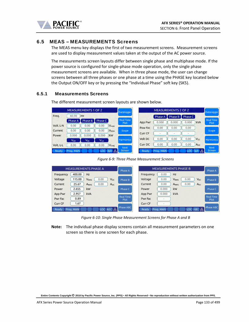
AFX SERIES® OPERATION MANUAL SECTION 6: Front Panel Operation
Entire Contents Copyright 2018 by Pacific Power Source, Inc. (PPS) • All Rights Reserved • No reproduction without written authorization from PPS.
AFX Series Power Source Operation Manual Page 133 of 499
6.5 MEAS – MEASUREMENTS Screens The MEAS menu key displays the first of two measurement screens. Measurement screens are used to display measurement values taken at the output of the AC power source.
The measurements screen layouts differ between single phase and multiphase mode. If the power source is configured for single-phase mode operation, only the single phase measurement screens are available. When in three phase mode, the user can change screens between all three phases or one phase at a time using the PHASE key located below the Output ON/OFF key or by pressing the “Individual Phase” soft key (SK5).
6.5.1 Measurements Screens
The different measurement screen layouts are shown below.
Figure 6-9: Three Phase Measurement Screens
Figure 6-10: Single Phase Measurement Screens for Phase A and B
Note: The individual phase display screens contain all measurement parameters on one screen so there is one screen for each phase.

AFX SERIES® OPERATION MANUAL SECTION 6: Front Panel Operation
Entire Contents Copyright 2018 by Pacific Power Source, Inc. (PPS) • All Rights Reserved • No reproduction without written authorization from PPS.
AFX Series Power Source Operation Manual Page 134 of 499
6.5.2 Scope Measurements
Scope measurements allow all voltage and current phases to be captured and displayed in the time domain. From one to four cycles of the fundamental frequency can be displayed. Display modes include all voltages, all currents, both voltage and current or individual phase selected voltage and current. Use the “Scope” soft key from the Measurement screen to select Scope measurements.
Note that voltage scope captures can be set for Line to Neutral voltage or Line to Line Voltage when in three phase mode. To select the desired mode, use the Select Channel soft key.

AFX SERIES® OPERATION MANUAL SECTION 6: Front Panel Operation
Entire Contents Copyright 2018 by Pacific Power Source, Inc. (PPS) • All Rights Reserved • No reproduction without written authorization from PPS.
AFX Series Power Source Operation Manual Page 135 of 499
6.5.3 Harmonic Measurements
Harmonic measurements for all phase voltages and currents can be measured and displayed in either chart or table format. Use the “Harmonics” soft key from the Measurement screen to select Harmonics measurements.
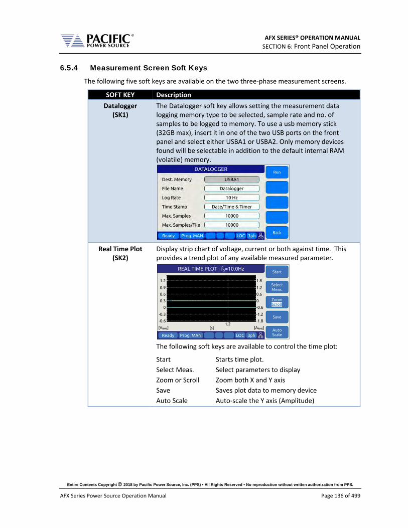
AFX SERIES® OPERATION MANUAL SECTION 6: Front Panel Operation
Entire Contents Copyright 2018 by Pacific Power Source, Inc. (PPS) • All Rights Reserved • No reproduction without written authorization from PPS.
AFX Series Power Source Operation Manual Page 136 of 499
6.5.4 Measurement Screen Soft Keys
The following five soft keys are available on the two three-phase measurement screens.
SOFT KEY Description Datalogger
(SK1) The Datalogger soft key allows setting the measurement data logging memory type to be selected, sample rate and no. of samples to be logged to memory. To use a usb memory stick (32GB max), insert it in one of the two USB ports on the front panel and select either USBA1 or USBA2. Only memory devices found will be selectable in addition to the default internal RAM (volatile) memory.
Real Time Plot
(SK2) Display strip chart of voltage, current or both against time. This provides a trend plot of any available measured parameter.
The following soft keys are available to control the time plot:
Start Starts time plot. Select Meas. Select parameters to display Zoom or Scroll Zoom both X and Y axis Save Saves plot data to memory device Auto Scale Auto-scale the Y axis (Amplitude)
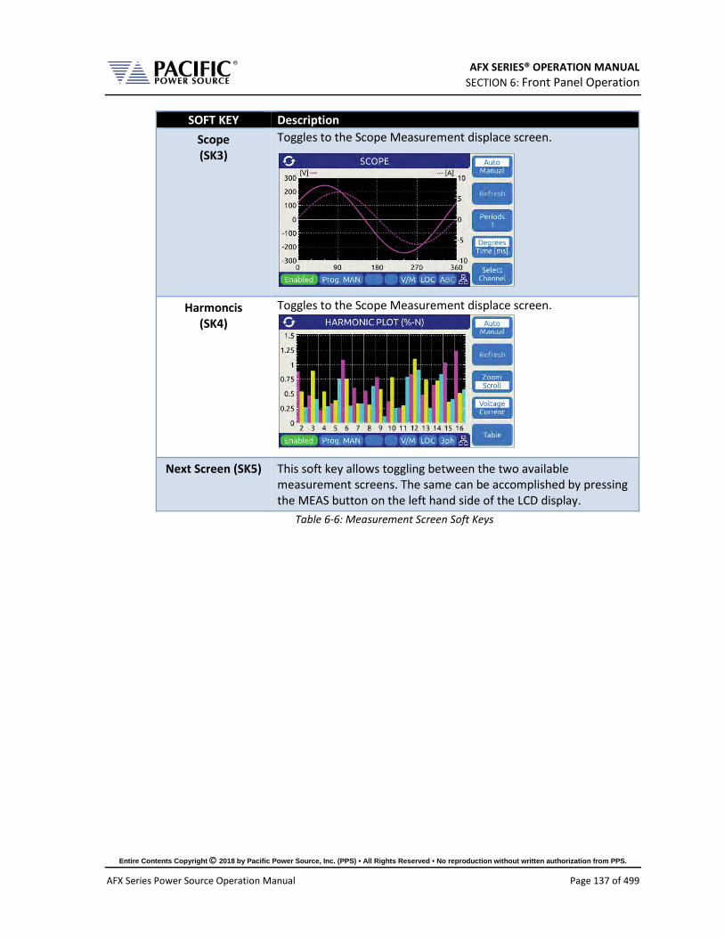
AFX SERIES® OPERATION MANUAL SECTION 6: Front Panel Operation
Entire Contents Copyright 2018 by Pacific Power Source, Inc. (PPS) • All Rights Reserved • No reproduction without written authorization from PPS.
AFX Series Power Source Operation Manual Page 137 of 499
SOFT KEY Description Scope (SK3)
Toggles to the Scope Measurement displace screen.
Harmoncis (SK4)
Toggles to the Scope Measurement displace screen.
Next Screen (SK5) This soft key allows toggling between the two available measurement screens. The same can be accomplished by pressing the MEAS button on the left hand side of the LCD display.
Table 6-6: Measurement Screen Soft Keys
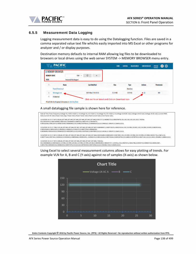
AFX SERIES® OPERATION MANUAL SECTION 6: Front Panel Operation
Entire Contents Copyright 2018 by Pacific Power Source, Inc. (PPS) • All Rights Reserved • No reproduction without written authorization from PPS.
AFX Series Power Source Operation Manual Page 138 of 499
6.5.5 Measurement Data Logging
Logging measurement data is easy to do using the Datalogging function. Files are saved in a comma separated value text file whichis easily imported into MS Excel or other programs for analyzer and / or display purposes.
Destination memory defautls to internal RAM allowing log files to be downloaded to browsers or local drives using the web server SYSTEM -> MEMORY BROWSER menu entry.
A small datalogging file sample is shown here for reference. Date & Time,Timer,Frequency,Voltage VLL ACDC A-B,B-C,C-A,Voltage VLL AC A-B,B-C,C-A,Voltage VLL DC A-B,B-C,C-A,Voltage LN ACDC A,B,C,Voltage LN AC A,B,C,Voltage LN DC A,B,C,Current RMS A,B,C,Current DC A,B,C,Power A,B,C,App. Power A,B,C,Power Factor A,B,C,Peak Current A,B,C,Crest Factor A,B,C,
21/4/2020 10:13:17.647,0.00,60,207.846,207.845,207.846,207.846,207.845,207.846,0.0015717,0.000892723,0.000678978,120,120,120,120,120,120,5.74293e-05,0.00162913,0.000736408,0.0961562,0.0658469,0.0389105,0.00917411,0.00100751,-0.00516246,0.00012973,0.000672549,0.00066903,0.0115388,0.00790161,0.00466924,0,0,0,0.249016,0.199247,0.126655,0,0,0,
21/4/2020 10:13:17.748,0.101,60,207.845,207.846,207.847,207.845,207.846,207.847,0.000484911,0.000716525,0.000231614,120,119.999,120.001,120,119.999,120.001,0.000291418,-0.000193493,0.000523032,0.0963041,0.0660525,0.0392375,0.00873799,0.000840356,-0.0050699,0.000142419,0.000692023,0.000528912,0.0115565,0.0079262,0.00470855,0,0,0,0.245361,0.199247,0.126651,0,0,0,
21/4/2020 10:13:17.847,0.200,60,207.845,207.843,207.844,207.845,207.843,207.844,0.00195489,0.000834307,0.0027892,120,119.999,119.998,120,119.999,119.998,0.00201776,6.2867e-05,-0.00077144,0.0957361,0.0658142,0.0392642,0.00805068,0.000924351,-0.00582215,0.000124226,0.000720164,0.000534704,0.0114883,0.00789763,0.00471161,0,0,0,0.249,0.195608,0.128863,0,0,0,
21/4/2020 10:13:17.947,0.300,60,207.844,207.847,207.846,207.844,207.847,207.846,7.05616e-05,0.000486062,0.000556624,119.998,119.999,120.002,119.998,119.999,120.002,0.000496289,0.000425727,-6.03351e-05,0.0967671,0.0652786,0.0393575,0.00906719,0.000913487,-0.0051749,0.000184154,0.00060259,0.00057676,0.0116118,0.00783339,0.00472296,0,0,0,0.252638,0.192,0.126645,0,0,0,
Using Excel to select several measurement columns allows for easy plotting of trends. For example VLN for A, B and C (Y-axis) against no of samples (X-axis) as shown below.
0
30
60
90
120
150
0 5 10 15 20 25 30
Chart Title
Voltage LN AC A B C

AFX SERIES® OPERATION MANUAL SECTION 6: Front Panel Operation
Entire Contents Copyright 2018 by Pacific Power Source, Inc. (PPS) • All Rights Reserved • No reproduction without written authorization from PPS.
AFX Series Power Source Operation Manual Page 139 of 499
6.6 TRAN- TRANSIENTS Screens Transient sequences allow precise time-controlled changes to be made to voltage (AC and DC mode) and frequency (AC mode only) under program control. A transient sequence consists of one or more list entries (or segments) that are executed in sequence.
There are three types of Transients modes:
• LIST Mode
• STEP and RAMP Mode
• PULSE Mode
Note that Step and Pulse transients can be accomplished using LIST mode as well but STEP and PULSE data entry is more intuitive.
Transients are created or edited in EDIT mode and can be saved to non-volatile memory as part of an instrument setup. They are executed in Execution mode.
The following sections cover all available transient modes.
6.6.1 LIST Mode
List mode is the most versatile transient data entry mode as it allows any of the other Transients types to be created as well. However, entering a long ramp or step transient consisting of many discrete steps in List mode is time consuming and tedious. It is also easier to make a mistake in LIST mode than using the STEP or RAMP mode. Same is true for PULSE transients which can be created with a short transient list as well.
LIST transients can be created from the front panel, using the LXI web server and a web browser or with Pacific’s PPCS Manager Windows software.
An example Transient LIST created from the front panel is shown below.

AFX SERIES® OPERATION MANUAL SECTION 6: Front Panel Operation
Entire Contents Copyright 2018 by Pacific Power Source, Inc. (PPS) • All Rights Reserved • No reproduction without written authorization from PPS.
AFX Series Power Source Operation Manual Page 140 of 499
6.6.2 LIST Parameters
The following parameters are available in each list transient list step.
PARAMETER Range Unit Description # 1 - 199 - Displays the row number in the
transient table. These numbers are generated automatically.
Ramp 0.2 - 9999 msec. Ramp time to slew from existing set point to new set point value. Applies to both Frequency and Voltage. If previous set value is the same as new value, the value is not slewed but rather stays at the same value for the duration of the ramp time.
Frequency 16 – 1200 Hz New frequency value
Voltage AC 0 – 300 V rms New AC voltage value
Voltage DC 0 – 425 V dc New DC voltage value
Dwell 0.2 - 9999 msec. Dwell time. At the end of the ramp time, the new set values remain in effect during the dwell period. At the end of the dwell time, the next list entry (if any) will be executed.
Table 6-7: Available LIST Transient Parameters

AFX SERIES® OPERATION MANUAL SECTION 6: Front Panel Operation
Entire Contents Copyright 2018 by Pacific Power Source, Inc. (PPS) • All Rights Reserved • No reproduction without written authorization from PPS.
AFX Series Power Source Operation Manual Page 141 of 499
Voltage LIST Transient Example 1
The table and associated figure below illustrates the operation of a transient. The blue line represents the RMS value of the phase A output voltage.
0.0 1.0 2.0 3.0 4.0 5.0 6.0 7.0 8.0
Time à
120.0
110.0
100.0
90.0
80.0
70.0
60.0
50.0
40.0
20.0
0.0
115Vac
Volt ACStep #1 Step #3#2 Step #4 Step #5 Step #6
Figure 6-11: Voltage Transient Example 1
To generate this voltage versus time output sequence, the following transient list entries are required. (Ramp and dwell times shown in milliseconds using STEP mode.)
# Ramp Freq Volt Dwell 1 1000 400 100.00 1000 2 0.2 400 0.00 100 3 0.2 400 100.00 900 4 1000 400 115.00 1000 5 500 400 80.00 1000 6 0.5 400 115.00 1.00
Table 6-8: Voltage Transient List for Example 1

AFX SERIES® OPERATION MANUAL SECTION 6: Front Panel Operation
Entire Contents Copyright 2018 by Pacific Power Source, Inc. (PPS) • All Rights Reserved • No reproduction without written authorization from PPS.
AFX Series Power Source Operation Manual Page 142 of 499
Voltage and Frequency LIST Transient Example 2
This example is based on an actual avionics test requirement from RTCA/DO160 Section 16 test number 16.5.2.1d. This is a single-phase abnormal voltage and frequency limit test for airborne equipment operated from 400Hz AC power.
The requirement from the test standard is shown in the table below:
TEST VOLTAGE (V rms) FREQUENCY (Hz) 1 122 430 2 100 430 3 122 370 4 100 370
Table 6-9: RTCA/DO160 Section 16 test number 16.5.2.1d
There are four tests, each runs for at least 5 minutes or 300 seconds. Each test step has a different voltage and frequency deviation from the nominal 115V and 400Hz. This is graphically illustrated by the image below.
Time à
120.0
110.0
100.0
90.0
0.0
115Vac
Volt ACStep #1 Step #3 Step #4 Step #5Step #2
Freq
400Hz
Figure 6-12: RTCA/DO160 Section 16 test number 16.5.2.1d
To generate this DO160 test sequence, the following transient list entries are required. Times shown in milliseconds.
# Ramp Freq Volt Dwell 1 0.2 430 122.00 300000 2 0.2 370 100.00 300000 3 0.2 430 122.00 300000 4 0.2 370 100.00 300000 5 1000 400 115.00 300000
Table 6-10: Voltage Transient List for Example 1

AFX SERIES® OPERATION MANUAL SECTION 6: Front Panel Operation
Entire Contents Copyright 2018 by Pacific Power Source, Inc. (PPS) • All Rights Reserved • No reproduction without written authorization from PPS.
AFX Series Power Source Operation Manual Page 143 of 499
6.6.3 LIST Transient Edit Mode
To create a new transient program, press the TRAN key to select the Transient screen and then select the preferred data entry mode, LIST, STEP/RAMP or PULSE. If no transients have been entered or recalled, the initial screen will be blank.
Figure 6-13: Blank TRANSIENT PROGRAM screen
The only available soft key is the “Create” key (SK1). Press the “Create” soft key to enter the Transient Edit mode. This will display the TRANSIENT VIEW screen.
Figure 6-14: TRANSIENT VIEW Edit Mode
In Edit mode, a number of soft keys are available to aid in editing new or existing transient lists. They are defined in the following table.
SOFT KEY Description Add at the end
(SK1) Adds a new row entry at the bottom of the transient list table. If there are no table entries yet (new), pressing this key will add the first line of a new transient table.
Insert before (SK2) Insert a new table row before the current selected row. The selected row and any rows below that are all pushed down one position.
Delete (SK3) Deletes the current selected row. Any rows below the selected row are pushed up one position. Note: This action cannot be undone.

AFX SERIES® OPERATION MANUAL SECTION 6: Front Panel Operation
Entire Contents Copyright 2018 by Pacific Power Source, Inc. (PPS) • All Rights Reserved • No reproduction without written authorization from PPS.
AFX Series Power Source Operation Manual Page 144 of 499
SOFT KEY Description Debug Mode (SK4) Displays the Debug Execution mode screen. See section 6.6.4
Run Screen (SK5) Returns to the regular TRANSIENT PROGRAM screen used for transient execution mode. See section 6.6.4.
Table 6-11: Available TRANSIENT EDIT screen soft keys
Once created, a transient sequence can be saved as part of the instrument setup. Refer to Section 6.7.4 for information on saving and recalling setups.
6.6.4 LIST Transient Execution Modes
Transients can be executed as soon as they have been entered. To execute a transient, the output must be ON. Sometimes it is best to debug a new transient sequence to make sure it performs the intended test and all values were entered correctly. To do so, the DEBUG mode is provided.
DEBUG MODE
The debug mode can be selected from the TRANSIENT VIEW screen by pressing the “Debug Mode” soft key (SK4). This changes the TRANSIENT VIEW screen from EDIT to DEBUG mode and displays a different set of soft keys to control execution.
Figure 6-15: TRANSIENT Debug mode screen
The following execution control soft keys are available.
SOFT KEY Description Run (SK1) Starts the transient from the currently selected row number
Step (SK2) Single steps one row at a time
Step Mode (SK3) Executes one step at a time
Edit Mode (SK4) Stops execution and reverts to Edit mode
Run Screen (SK5) Returns to the regular TRANSIENT PROGRAM screen used for transient execution mode. See section 6.6.4.
Table 6-12: Available TRANSIENT DEBUG screen soft keys
Note: The progress of the transient is indicated by the “Program” status bar at the bottom of the screen.

AFX SERIES® OPERATION MANUAL SECTION 6: Front Panel Operation
Entire Contents Copyright 2018 by Pacific Power Source, Inc. (PPS) • All Rights Reserved • No reproduction without written authorization from PPS.
AFX Series Power Source Operation Manual Page 145 of 499
NORMAL EXECUTION MODE
Transient execution is controlled from the TRANSIENT PROGRAM screen. If no transient data has been entered, no run mode soft key will be visible. In that case, you must use the “Create” soft key to create a new transient sequence table.
The TRANSIENT PROGRAM screen for LIST mode is shown below.
There are three user settable parameters that control execution of the transient sequence. They are:
1. Run from step # 2. Run to step # 3. Repeat times
Transients will be executed when the “Run” soft key (SK1) is pressed. If the output if OFF however, a message will appear indicating the output must be turned ON first.
The transient execution will start at the step # set and run until the Run to step value is reached. In the example above, from step #1 through step #6 inclusive.
The “Repeat times” field determines how many times the same sequence will be repeated. To run a sequence indefinitely or until manually stopped, use the shuttle to scroll down to zero or enter zero in this field using the keypad. This will set the repeat field to “indefinitely”.
The following soft keys are available on the TRANSIENT PROGRAM screen.
SOFT KEY Description Run (SK1) Starts the transient from the “Run from step#” row number
Edit (SK2) Displays the TRANSIENT VIEW edit mode screen. See section 6.6.3
Debug (SK3) Displays the TRANSIENT VIEW debug mode screen.
Stop (SK4) Only appears if “Repeat time” value is set to “indefinitely”. Press to stop execution manually
Table 6-13: Available TRANSIENT PROGRAM screen soft keys

AFX SERIES® OPERATION MANUAL SECTION 6: Front Panel Operation
Entire Contents Copyright 2018 by Pacific Power Source, Inc. (PPS) • All Rights Reserved • No reproduction without written authorization from PPS.
AFX Series Power Source Operation Manual Page 146 of 499
6.6.5 LIST Transient Entry Modes
The AFX Series® supports two types of transient entry modes:
• LIST STEP Entry
• LIST SEGMENT Entry
Step mode is commonly used on AC and DC power sources that support the SCPI command language as the SCPI standard defines a LIST, STEP and PULSE command syntax.
Segment mode is used on all Pacific Power sources with UPC controllers such as ASX and AMX Series. Both modes support the same capabilities however.
Note that in STEP mode, two segment entries are combined so each STEP mode entry requires two SEGMENT entries. The two transient examples below represent the same transient display in either mode.
Figure 6-16: Transient shown in STEP Entry Mode
Figure 6-17: Transient shown in SEGMENT Entry Mode

AFX SERIES® OPERATION MANUAL SECTION 6: Front Panel Operation
Entire Contents Copyright 2018 by Pacific Power Source, Inc. (PPS) • All Rights Reserved • No reproduction without written authorization from PPS.
AFX Series Power Source Operation Manual Page 147 of 499
6.6.6 Multiple User Waveforms in LIST Transients
Transient programs are very useful to deliver precisely controlled transitions between different waveforms to a unit under test. This means transitions from a normal AC sine wave to a non-sinusoidal or distorted waveform can be accomplished by using different waveform at different segment or step entries.
Waveforms are numbered from 1 through 200 with 1 being a fixed sine wave. All other waveform registers are user defined arbitrary waveforms.
When in AC mode, transient segments or steps can called out different waveform numbers on each of up to three phases5. For each segment, up to six different waveforms can be selected. The same waveform can be repeated as of often as needed within the same transient program.
In three or split phase mode, each phase in a transient program can use its own set of up to six user-defined waveform. Thus, up to 18 different waveforms are available when in three-phase mode.
Figure 6-18: Available User Waveforms in Transients
5 Requires Front Panel Firmware revision 1.3.3.
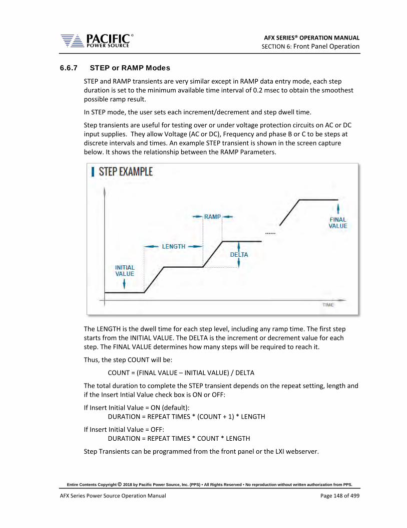
AFX SERIES® OPERATION MANUAL SECTION 6: Front Panel Operation
Entire Contents Copyright 2018 by Pacific Power Source, Inc. (PPS) • All Rights Reserved • No reproduction without written authorization from PPS.
AFX Series Power Source Operation Manual Page 148 of 499
6.6.7 STEP or RAMP Modes
STEP and RAMP transients are very similar except in RAMP data entry mode, each step duration is set to the minimum available time interval of 0.2 msec to obtain the smoothest possible ramp result.
In STEP mode, the user sets each increment/decrement and step dwell time.
Step transients are useful for testing over or under voltage protection circuits on AC or DC input supplies. They allow Voltage (AC or DC), Frequency and phase B or C to be steps at discrete intervals and times. An example STEP transient is shown in the screen capture below. It shows the relationship between the RAMP Parameters.
The LENGTH is the dwell time for each step level, including any ramp time. The first step starts from the INITIAL VALUE. The DELTA is the increment or decrement value for each step. The FINAL VALUE determines how many steps will be required to reach it.
Thus, the step COUNT will be:
COUNT = (FINAL VALUE – INITIAL VALUE) / DELTA
The total duration to complete the STEP transient depends on the repeat setting, length and if the Insert Intial Value check box is ON or OFF:
If Insert Initial Value = ON (default): DURATION = REPEAT TIMES * (COUNT + 1) * LENGTH
If Insert Initial Value = OFF: DURATION = REPEAT TIMES * COUNT * LENGTH
Step Transients can be programmed from the front panel or the LXI webserver.

AFX SERIES® OPERATION MANUAL SECTION 6: Front Panel Operation
Entire Contents Copyright 2018 by Pacific Power Source, Inc. (PPS) • All Rights Reserved • No reproduction without written authorization from PPS.
AFX Series Power Source Operation Manual Page 149 of 499
6.6.8 STEP or RAMP Parameters
Step transients can be used to create discrete stair step like voltage and/or frequency changes or smooth ramps. The default ramp time is 0.2 msec.
Ramps can be can be programmed in three modes: • INIDEL (0): Initial & Delta: Programmed by initial and delta values • FINDEL (1): Final & Delta: Programmed by final and delta values • INIFIN (2): Initial & Final: Programmed by initial and final values
Step transients can be used to step frequency, voltage AC, voltage DC, and phases.
The HOLD is ON, the last step values will be set as steady-state when the step execution ends. Duration of each step is determined by: LENGTH = WIDTH + RAMP TIME
The following parameters are available in a STEP VALUES screen. PARAMETER Range Unit Description
Program Mode Initial & Delta Final & Delta Initial & Final
- Program Entry Modes
Waveform 1 ~ 200 Waveform number
Voltage AC 0 ~ 300 Vrms AC Voltage
Voltage DC -425 ~ + 425 Vdc DC Voltage
Frequency 15 ~ 1200 Hz Frequency Table 6-14: Available STEP Transient Parameters
The following soft keys are available on the STEP PROGRAM screen. SOFT KEY Description
(SK1)
Run Screen(SK2) Displays the STEP EXECUTION screen.
Phase ABC (SK3) Toggles between phase A, B, C or Coupled ABC
Example (SK4) Displays a graphical representation of the STEP parameters
Back (SK5) Returns to previous screen Table 6-15: Available STEP PROGRAM screen soft keys
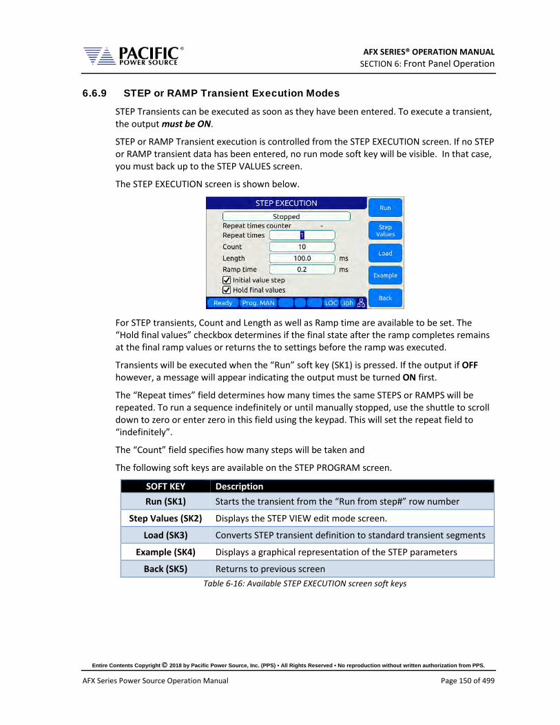
AFX SERIES® OPERATION MANUAL SECTION 6: Front Panel Operation
Entire Contents Copyright 2018 by Pacific Power Source, Inc. (PPS) • All Rights Reserved • No reproduction without written authorization from PPS.
AFX Series Power Source Operation Manual Page 150 of 499
6.6.9 STEP or RAMP Transient Execution Modes
STEP Transients can be executed as soon as they have been entered. To execute a transient, the output must be ON.
STEP or RAMP Transient execution is controlled from the STEP EXECUTION screen. If no STEP or RAMP transient data has been entered, no run mode soft key will be visible. In that case, you must back up to the STEP VALUES screen.
The STEP EXECUTION screen is shown below.
For STEP transients, Count and Length as well as Ramp time are available to be set. The “Hold final values” checkbox determines if the final state after the ramp completes remains at the final ramp values or returns the to settings before the ramp was executed.
Transients will be executed when the “Run” soft key (SK1) is pressed. If the output if OFF however, a message will appear indicating the output must be turned ON first.
The “Repeat times” field determines how many times the same STEPS or RAMPS will be repeated. To run a sequence indefinitely or until manually stopped, use the shuttle to scroll down to zero or enter zero in this field using the keypad. This will set the repeat field to “indefinitely”.
The “Count” field specifies how many steps will be taken and
The following soft keys are available on the STEP PROGRAM screen.
SOFT KEY Description Run (SK1) Starts the transient from the “Run from step#” row number
Step Values (SK2) Displays the STEP VIEW edit mode screen.
Load (SK3) Converts STEP transient definition to standard transient segments
Example (SK4) Displays a graphical representation of the STEP parameters
Back (SK5) Returns to previous screen Table 6-16: Available STEP EXECUTION screen soft keys

AFX SERIES® OPERATION MANUAL SECTION 6: Front Panel Operation
Entire Contents Copyright 2018 by Pacific Power Source, Inc. (PPS) • All Rights Reserved • No reproduction without written authorization from PPS.
AFX Series Power Source Operation Manual Page 151 of 499
6.6.10 PULSE Mode
PULSE transient mode provides a quick and easy way to enter repetitive pulsed output events. This applies to AC voltage, DC voltage and or Frequency. A sample of a PULSE transient definition is shown in the screen capture below.
The parameters that define a PULSE transient are dependent of each other so changing one may force another to change. The semantics used for setting PULSE transients is as follows:
Parameter Description
RAMP Up or down ramp time
WIDTH Duration of pulse including rising and failing ramp times
PERIOD Total time duration for a single pulse
DUTY Duty cycle of the pulse
The DUTY cycle is determined by the other three parameters as in:
DUTY = WIDTH x 100 / PERIOD

AFX SERIES® OPERATION MANUAL SECTION 6: Front Panel Operation
Entire Contents Copyright 2018 by Pacific Power Source, Inc. (PPS) • All Rights Reserved • No reproduction without written authorization from PPS.
AFX Series Power Source Operation Manual Page 152 of 499
6.6.11 PULSE Parameters
Pulse transients can be used to create repetitive events for endurance testing of AC and DC powered products.
The following parameters are available in a PULSE VALUES screen.
PARAMETER Range Unit Description Frequency 15 ~ 1200 Hz Frequency
Voltage AC 0 ~ 300 Vrms AC Voltage
Voltage DC -425 ~ + 425 Vdc DC Voltage
Waveform 1 ~ 200 Waveform number
Phase 0.0 ~ 359.9 Deg Phase angle for phases B & C Table 6-17: Available STEP Transient Parameters
The following soft keys are available on the PULSE VALUES screen.
SOFT KEY Description Use Setpoint (SK1) Starts the transient from the “Run from step#” row number
Run Screen(SK2) Displays the PULSE EXECUTION screen.
Link Phases (SK3) Toggles between phase A, B, C or Coupled ABC
Example (SK4) Displays a graphical representation of the STEP parameters
Back (SK5) Returns to previous screen Table 6-18: Available STEP PROGRAM screen soft keys

AFX SERIES® OPERATION MANUAL SECTION 6: Front Panel Operation
Entire Contents Copyright 2018 by Pacific Power Source, Inc. (PPS) • All Rights Reserved • No reproduction without written authorization from PPS.
AFX Series Power Source Operation Manual Page 153 of 499
6.6.12 PULSE Transient Execution Modes
PULSE Transients can be executed as soon as they have been entered. To execute a transient, the output must be ON.
PULSE transient execution is controlled from the PULSE EXECUTION screen. If no PULSE transient data has been entered, no run mode soft key will be visible. In that case, you must back up to the PULSE VALUES screen.
The PULSE EXECUTION screen is shown below.
For PULSE transients, there are three user settable parameters that control execution of the transient sequence. They are:
• P&W (0): Programmed by Period & Width • P&D (1): Programmed by Period & Duty Cycle • W&D (2): Programmed by Width & Duty Cycle
Depending on the data entry mode selected, one of the data entry fields will be disabled and calculated based on the other parameter settings.
Transients will be executed when the “Run” soft key (SK1) is pressed. If the output if OFF however, a message will appear indicating the output must be turned ON first.
The “Count” field determines how many pulses will be run. To run a sequence indefinitely or until manually stopped, use the shuttle to scroll down to zero or enter zero in this field using the keypad. This will set the repeat field to “Infinite”.
The following soft keys are available on the PULSE PROGRAM screen.
SOFT KEY Description Run (SK1) Starts the transient from the “Run from step#” row number
Pulse Values (SK2) Displays the PULSE edit mode screen.
Load (SK3) Converts PULSE transient definition to transient segments
Example (SK4) Displays a graphical representation of the PULSE parameters
Back (SK5) Returns to previous screen Table 6-19: Available STEP PROGRAM screen soft keys

AFX SERIES® OPERATION MANUAL SECTION 6: Front Panel Operation
Entire Contents Copyright 2018 by Pacific Power Source, Inc. (PPS) • All Rights Reserved • No reproduction without written authorization from PPS.
AFX Series Power Source Operation Manual Page 154 of 499
6.6.13 AUTO RMS Function – Transients
The AUTO RMS mode6, if enabled, causes all transient voltages to be calculated as true RMS voltage of the waveforms used in any Segment of the Transient. This means the output voltage RMS level will remain the same, regardless of the wave shape.
When disabled, RMS calculation of substituted waveforms does not occur. Disabling AUTO RMS facilitates constant amplitude transients such as partial cycle dropouts or sub-cycle spike transients.
This mode is set by sending the PROGram:TRANsient:AUTORMS command over one of the Digital control interfaces.
Note: In UPC Compatibility mode, this mode is always enabled but applies to steady state only.
6 Requires Front Panel Firmware revision 1.3.3.

AFX SERIES® OPERATION MANUAL SECTION 6: Front Panel Operation
Entire Contents Copyright 2018 by Pacific Power Source, Inc. (PPS) • All Rights Reserved • No reproduction without written authorization from PPS.
AFX Series Power Source Operation Manual Page 155 of 499
6.7 CONF – CONFIGURATION Screens The CONFIGURATION screens 1 & 2 allow setting of secondary parameters functions. These include the following operation aspects:
• Configuration
Pressing the CONF key will display the CONFIGURATION screen as shown on the left below. If the master unit is an AFXT model, the transformer coupled output mode selection will be displayed at the bottom of the configuration screen. If the master unit is an AFXS model, the Series connection will be displayed instead.

AFX SERIES® OPERATION MANUAL SECTION 6: Front Panel Operation
Entire Contents Copyright 2018 by Pacific Power Source, Inc. (PPS) • All Rights Reserved • No reproduction without written authorization from PPS.
AFX Series Power Source Operation Manual Page 156 of 499
All other system related screens can be accessed using the SYST menu key. (Refer to Section 6.7.7).
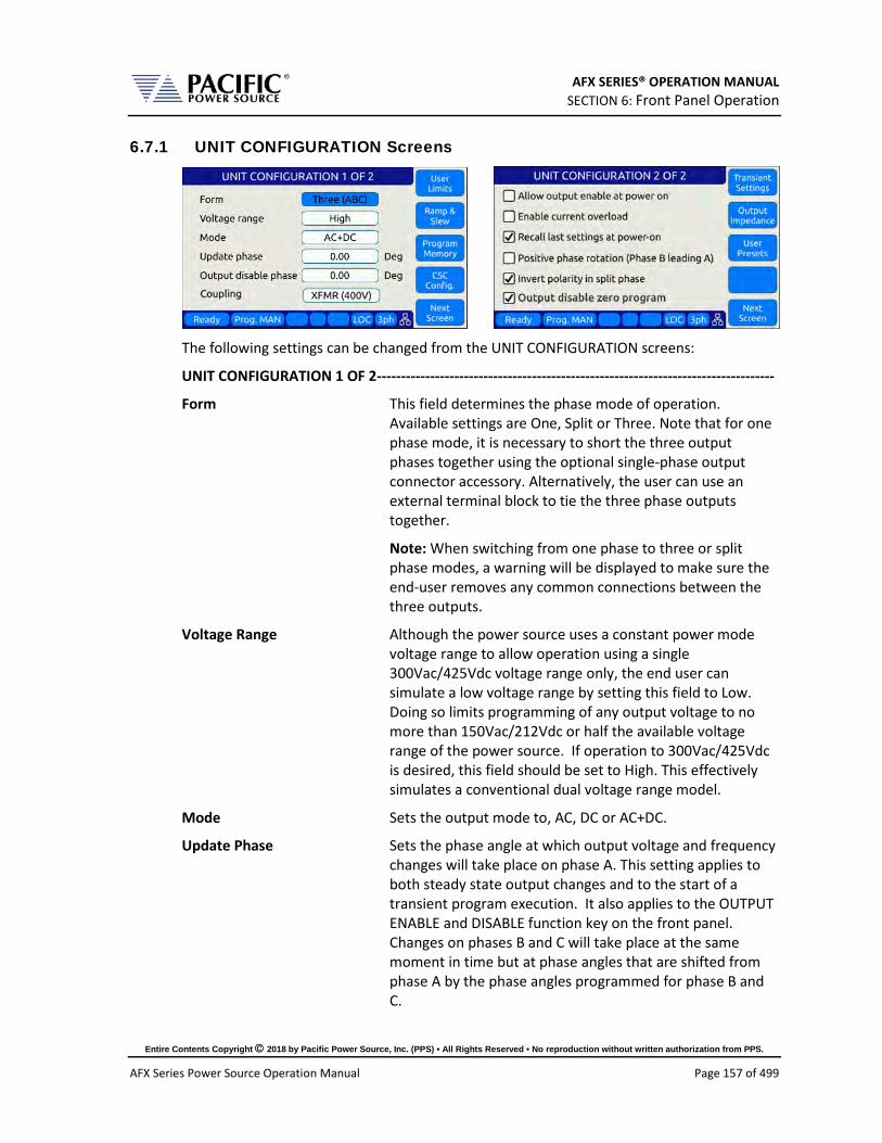
AFX SERIES® OPERATION MANUAL SECTION 6: Front Panel Operation
Entire Contents Copyright 2018 by Pacific Power Source, Inc. (PPS) • All Rights Reserved • No reproduction without written authorization from PPS.
AFX Series Power Source Operation Manual Page 157 of 499
6.7.1 UNIT CONFIGURATION Screens
The following settings can be changed from the UNIT CONFIGURATION screens:
UNIT CONFIGURATION 1 OF 2----------------------------------------------------------------------------------
Form This field determines the phase mode of operation. Available settings are One, Split or Three. Note that for one phase mode, it is necessary to short the three output phases together using the optional single-phase output connector accessory. Alternatively, the user can use an external terminal block to tie the three phase outputs together.
Note: When switching from one phase to three or split phase modes, a warning will be displayed to make sure the end-user removes any common connections between the three outputs.
Voltage Range Although the power source uses a constant power mode voltage range to allow operation using a single 300Vac/425Vdc voltage range only, the end user can simulate a low voltage range by setting this field to Low. Doing so limits programming of any output voltage to no more than 150Vac/212Vdc or half the available voltage range of the power source. If operation to 300Vac/425Vdc is desired, this field should be set to High. This effectively simulates a conventional dual voltage range model.
Mode Sets the output mode to, AC, DC or AC+DC.
Update Phase Sets the phase angle at which output voltage and frequency changes will take place on phase A. This setting applies to both steady state output changes and to the start of a transient program execution. It also applies to the OUTPUT ENABLE and DISABLE function key on the front panel. Changes on phases B and C will take place at the same moment in time but at phase angles that are shifted from phase A by the phase angles programmed for phase B and C.

AFX SERIES® OPERATION MANUAL SECTION 6: Front Panel Operation
Entire Contents Copyright 2018 by Pacific Power Source, Inc. (PPS) • All Rights Reserved • No reproduction without written authorization from PPS.
AFX Series Power Source Operation Manual Page 158 of 499
Output Disable Phase This setting determines if the output off event at a specific phase angle of phase A voltage or randomly when ever the user presses the Output On/Off button or sends an output off command.
Coupling This field selects the output coupling mode of the power source. Unless an optional output transformer is installed with the power source (T Option), this field is always fixed to DIRECT. Direct coupling output mode supports either AC mode, DC mode or a combination of AC and DC output to be programmed. If the optional transformer is installed, the AFX model number will show “AFXT” to indicate the presence of the output transformer. To use the output transformer coupled range, selected XFMR (xxxV) in this field. The voltage indication may vary based on the transformer ration of the installed output transformers. Note: While in XFMR coupled mode, only AC voltage programming is possible.
Series Connection Series connection selection is only available on AFX units
that are equipped with the Series Output mode option. These units will have an “S” appended after the AFX models numbe as in “AFXS”. This filed replaces the Coupling Field. If the Series/Paralllel Mode Swicth option is present in the AFXS system, the field can be used to switch between Paralllel Output Mode or Series Output Mode. If the SPMS option is not present, the AFXS system is hardwired for Series output mode only and this field will show ON and is disabled. In Series Output Mode, the output voltage range is two times the standard voltage range. Only available on multiples of two AFX units.
Access to other utility screens is available from the UNIT CONFIGURATION screen through the soft keys. The table below lists the available soft keys on the UNIT CONFIGURATION screen.

AFX SERIES® OPERATION MANUAL SECTION 6: Front Panel Operation
Entire Contents Copyright 2018 by Pacific Power Source, Inc. (PPS) • All Rights Reserved • No reproduction without written authorization from PPS.
AFX Series Power Source Operation Manual Page 159 of 499
SOFT KEY Description User Limits (SK1) Displays SETUP MENU screen. Refer to section 0
Ramp & Slew (SK3) Displays SLEW RATE MENU screen. Refer to section 6.7.3
Program Memory (SK2) Displays PROGRAM MEMORY screen. Refer to section 6.7.4
CSC Config. (SK4) Display CSC setting screen
Next Screen (SK5) Toggle to alternate UNIT CONFIGURATION screen Table 6-20: Available UNIT CONFIGURATION 1 screen soft keys
UNIT CONFIGURATION 2 OF 2 ----------------------------------------------------------------------------------
Allow output enable at power on This mode if set, causes the output to turn on at
power up.
Enable Current Overload Current Overload mode allows the power source to provide more than the nominal max. RMS current (around 30 percent more) for a short period (up to 2 seconds). When enabled, the user can set the CURR:LIM 30% higher than whit this mode off. For example in a stand-alone 3150AFX unit in three phase mode (FORM 3), RMS output current can be up to 55A when the continuous output limit is 41.7A. A warning message will be display notifying the user this mode is being enabled.
Recall last settings at power-on When checked, this mode will cause the last settings that
were in effect when the power source was last turned off to be recalled at power on. This allows a user to resume operation without having to set up again between power on/off events.
Positive phase rotation When checked, the phase rotation in three phase mode will be set to A -> C -> B corresponding to positive phase

AFX SERIES® OPERATION MANUAL SECTION 6: Front Panel Operation
Entire Contents Copyright 2018 by Pacific Power Source, Inc. (PPS) • All Rights Reserved • No reproduction without written authorization from PPS.
AFX Series Power Source Operation Manual Page 160 of 499
rotation for three phase AC motors. To select negative phase rotation, uncheck this option.
Invert polarity in split phase When checked, the AC waveform in split-phase mode of operation is shifted 180° (inverted).
Output disable zero program When checked, the programmed voltage is first set to zero voltage when pressing the Output Enable button or executing the OUTP OFF command. This allows any energy stored in the EUT to dissipate into the low impedance output of the power source before the relay disconnects the load.
Access to other utility screens is available from the UNIT CONFIGURATION screen through the soft keys. The table below lists the available soft keys on the UNIT CONFIGURATION screen.
SOFT KEY Description Transient Settings (SK1) Display Transient Configuration Settings
Output Impedance (SK2) Program Output Impedance R and L values.
User Presets (SK3) Access to user defined preset value settings for output programming soft keys
Next Screen (SK5) Toggle to alternate UNIT CONFIGURATION screen Table 6-21: Available UNIT CONFIGURATION 2 screen soft keys

AFX SERIES® OPERATION MANUAL SECTION 6: Front Panel Operation
Entire Contents Copyright 2018 by Pacific Power Source, Inc. (PPS) • All Rights Reserved • No reproduction without written authorization from PPS.
AFX Series Power Source Operation Manual Page 161 of 499
6.7.2 USER LIMITS SETTINGS Screen
This screen allows programming user defined voltage and frequency upper and lower limits to prevent an operator from accidentally programming output settings that could be damaging to a unit under test.
For example, when testing a 50 Hz transformer, a lower frequency limit setting of 47 would prevent output frequency programming of values that could cause the transformer to saturate.
The same applies to voltage where a high voltage value could damage a unit under test that was not designed to handle a high AC or DC input voltage.
Figure 6-19: USER LIMIT SETTINGS Screen
The following parameters can be set from this screen:
Voltage AC Lower and Upper Vrms set limits for AC programming.
Voltage DC Lower and Upper Vdc set limits for DC programming.
Frequency Lower and Upper limits for Frequency programming.
The soft keys on the USER LIMITS SETTINGS screen provide access to additional functionality as listed in the table below.
SOFT KEY Description Apply (SK1) Accepts new settings and returns to previous screen.
Cancel (SK2) Returns to the previous screen.
-
-
Back (SK5) Returns to the previous screen. Table 6-22: Available USER LIMITS SETTINGS screen soft keys

AFX SERIES® OPERATION MANUAL SECTION 6: Front Panel Operation
Entire Contents Copyright 2018 by Pacific Power Source, Inc. (PPS) • All Rights Reserved • No reproduction without written authorization from PPS.
AFX Series Power Source Operation Manual Page 162 of 499
6.7.3 RAMP TIME & SLEW RATE SETTINGS Screen
This screen allows programming of the update ramp time or individual voltage and frequency slew rates, which are applied when changing output settings. Ramp time and slew rate settings are mutually exclusive so Ramp time must be disabled in order to program individual voltage, frequency and phase update rates. Setting a slew rate other than the maximum value allows voltage and frequency changes to occur at a controlled rate of change. The Ramp time when enabled applies to any setting change equally.
Figure 6-20: RAMP TIME & SLEW RATE SETTINGS Screen
The following parameters can be set from this screen:
Ramp time Sets the time over which output changes will take place. For the time set, output changes will ramp from their previous set value to the new set value. When DISABLED, changes will occur at the programmed slew rate settings in the SLEW RATE SETTING screen, as both cannot be in effect at the same time. Settings Slew Rate settings provide control over individual parameters whereas the RAMP TIME setting applies to all parameters (F, Vac, Vdc and Phase) changes equally.
Voltage AC AC Voltage slew rate in Vrms per msec. Available range is 0.01 Vrms/ms through 300 Vrms/ms.
Voltage DC DC Voltage slew rate in Vdc per msec. Available range is 0.01 Vdc/ms through 850 Vdc/ms.
Frequency Frequency slew rate in Hz per msec. Available range is 0.01 Hz/ms through 1200 Hz/ms.
Phase Phase angle slew rate in Degrees per msec. Available range is 0.01 Deg/ms through 359.91 Deg/ms
NOTE: Programmed Slew Rate settings will only take effect when the RAMP TIME setting is DISABLED.
The soft keys on the SLEW RATE SETTINGS screen provide access to additional functionality as listed in the table below.

AFX SERIES® OPERATION MANUAL SECTION 6: Front Panel Operation
Entire Contents Copyright 2018 by Pacific Power Source, Inc. (PPS) • All Rights Reserved • No reproduction without written authorization from PPS.
AFX Series Power Source Operation Manual Page 163 of 499
SOFT KEY Description Apply All (SK1) Applies all changes made (highlighted in grey) and returns to
previous screen.
Cancel All (SK2) Cancels all changes (highlighted in grey), sets slew rates back to prior settings and returns to previous screen.
Enable Ramp T. Enables Ramp time, disables Slew rate settings
Enable Slew R. Enable Slew Rate settings, disables Ramp time
Back (SK5) Returns to the previous screen. Table 6-23: Available RAMP TIME & SLEW RATE SETTINGS screen soft keys

AFX SERIES® OPERATION MANUAL SECTION 6: Front Panel Operation
Entire Contents Copyright 2018 by Pacific Power Source, Inc. (PPS) • All Rights Reserved • No reproduction without written authorization from PPS.
AFX Series Power Source Operation Manual Page 164 of 499
6.7.4 PROGRAM MEMORY Screen
The Program Memory menu allows saving and recalling of instrument setups in non-volatile memory registers. Setups include all steady state parameters, limits, operating modes and transient list if programmed.
Figure 6-21: PROGRAM MEMORY screen
There are 10 setup registers numbered from 1 through 10. Use the shuttle to select either the Recall or Save field and press the shuttle to enter edit mode. Once the correct number is selected, press ENTER to confirm.
Recall from register # Recalls setup from selected register. If register is empty, an error message will be displayed and no setting will be recalled. Note: If a register location is empty, an error message will be displayed.
Save setup to register # Saves setup in effect to selected register number. If this
register already contained a saved setup, it will be over-written.
Power recall register # Determines which register number setup is recalled at power-up. Using this feature, the user can determine the power-on default settings of the power source.

AFX SERIES® OPERATION MANUAL SECTION 6: Front Panel Operation
Entire Contents Copyright 2018 by Pacific Power Source, Inc. (PPS) • All Rights Reserved • No reproduction without written authorization from PPS.
AFX Series Power Source Operation Manual Page 165 of 499
The soft keys on the PROGRAM MEMORY screen provide access to additional functionality as listed in the table below.
SOFT KEY Description Browse(SK1) Allows browsing for a particular register’s content.
Recall (SK2) Recalls selected Register setup content
Save (SK3) Saves setup to selected Register
Set (SK4) Sets output to selected Register content
Refresh (SK5) Return to previous screen Table 6-24: Available SLEW RATE SETTINGS screen soft keys
6.7.5 CSC CONFIGURATION Screen
The CSC CONFIGURATION menu allows the Continuous Self Calibration mode to be enabled. This feature is used to improve load regulation of the power source by continuous measurement of the output phase voltage(s) and adjusting the internal set points as needed to maintain close to zero load regulation. If the CSC is unable to get the output to the set point, an error will be generated. This error can be disabled by unchecking the “Fault on saturation” check box.
Figure 6-22: CSC CONFIGURATION screen
The soft keys on the CSC CONFIGURATION screen are listed in the table below
SOFT KEY Description -
-
-
-
Back (SK5) Return to previous screen Table 6-25: Available CSC CONFIGURATION screen soft keys

AFX SERIES® OPERATION MANUAL SECTION 6: Front Panel Operation
Entire Contents Copyright 2018 by Pacific Power Source, Inc. (PPS) • All Rights Reserved • No reproduction without written authorization from PPS.
AFX Series Power Source Operation Manual Page 166 of 499
6.7.6 TRANSIENT SETTINGS Screen
The TRANSIENT SETTINGS screen defines operation of transient execution.
Available settings are:
Continuous Self Calibration This CSC mode is similar to the CSC mode for steady state operation but applies to transient mode.
Auto RMS This field allows enabling or disabling of the Auto RMS mode for transient mode operation. Refer to section 6.6.13, “AUTO RMS Function – Transients” for further details.
Cycle Reset When enabled, the CYCLE RESET mode will cause repeated executions of the transient as determined by the repeat count or the continuous execution setting to re-sync to the start phase angle set for the start of each transient. When disabled, repeats of the transients start immediately after the previous execution completes with no resync. With Cycle Reset on, there may be up to one period of the AC frequency of delay added between successive runs. Note: In UPC Compatibility mode, Cycle Reset is default on.
The soft keys on the TRANSIENT SETTINGS screen are listed in the table below
SOFT KEY Description -
-
-
-
Back (SK5) Return to previous screen Table 6-26: Available TRANSIENT SETTINGS screen soft keys

AFX SERIES® OPERATION MANUAL SECTION 6: Front Panel Operation
Entire Contents Copyright 2018 by Pacific Power Source, Inc. (PPS) • All Rights Reserved • No reproduction without written authorization from PPS.
AFX Series Power Source Operation Manual Page 167 of 499
6.7.7 OUTPUT IMPEDANCE Screen
The OUTPUT IMPEDANCE screen allows the output impedance of the power source to be programmed.
Following parameters can be set from this screen:
Mode: Selects between Real time or RMS mode.
• Real time: Real-time mode uses a fast responding method to control output impedance. This mode is faster but has a more limited programming range. It works at the signal level implanting a digital filter, equivalent to a resistor and an inductor, in series with the output. It emulates a phase shift and waveform distortion similar to an actual LR impedance at frequencies within the bandwidth of the output amplifier (around 3kHz). CSC must be disabled to use this mode.
• RMS: RMS Mode is slower as it relies on the measured RMS output voltages and currents to make adjustments, but it has a wider programming range. It is based on steady state RMS measurements, not on real-time signals, so it does not affect output waveform and phase shift. It allows higher impedance ranges while keeping the output stable. It also allows the CSC mode to remain enabled, so at a steady state level it provides a very accurate voltage drop (on an RMS measurement level).
Resistance: Sets the Resistive value for the programmable impedance.
Impedance: Sets the Inductive value for the programmable impedance.
The soft keys on the OUTPUT IMPEDANCE screen are listed in the table below
SOFT KEY Description - - - -
Back (SK5) Return to previous screen Table 6-27: Available PROGRAMMABLE IMPEDANCE screen soft keys

AFX SERIES® OPERATION MANUAL SECTION 6: Front Panel Operation
Entire Contents Copyright 2018 by Pacific Power Source, Inc. (PPS) • All Rights Reserved • No reproduction without written authorization from PPS.
AFX Series Power Source Operation Manual Page 168 of 499
6.7.8 USER PRESETS Screen
The USER PRESETS screen allows the soft key set values for output programming that appear in the PROGRAM screen to be changed to setting values preferred by the user.
Presets can be defined for the following output settings:
• VOLTage[:AC] • VOLTage:DC • FREQuency • PHASe • CURRent:LIMit • POWer:LIMit • KVA:LIMit
6.7.8.1 AC and DC Voltage Soft keys
6.7.8.2 Frequency and Phase Soft keys

AFX SERIES® OPERATION MANUAL SECTION 6: Front Panel Operation
Entire Contents Copyright 2018 by Pacific Power Source, Inc. (PPS) • All Rights Reserved • No reproduction without written authorization from PPS.
AFX Series Power Source Operation Manual Page 169 of 499
6.7.8.3 Current Limit Soft keys
6.7.8.4 Power and VA Limit Soft keys
For each parameter, theuser will be prompted to confirm soft key value setting changes. See dialog to the right.
SOFT KEY Description Apply All (SK1) Applies values entered by user.
Cancel All (SK2) Cancel all changes made.
Default All (Sk3) Sets all soft key settings for selected parameter to factory defaults.
-
Back (SK5) Refreshes screen
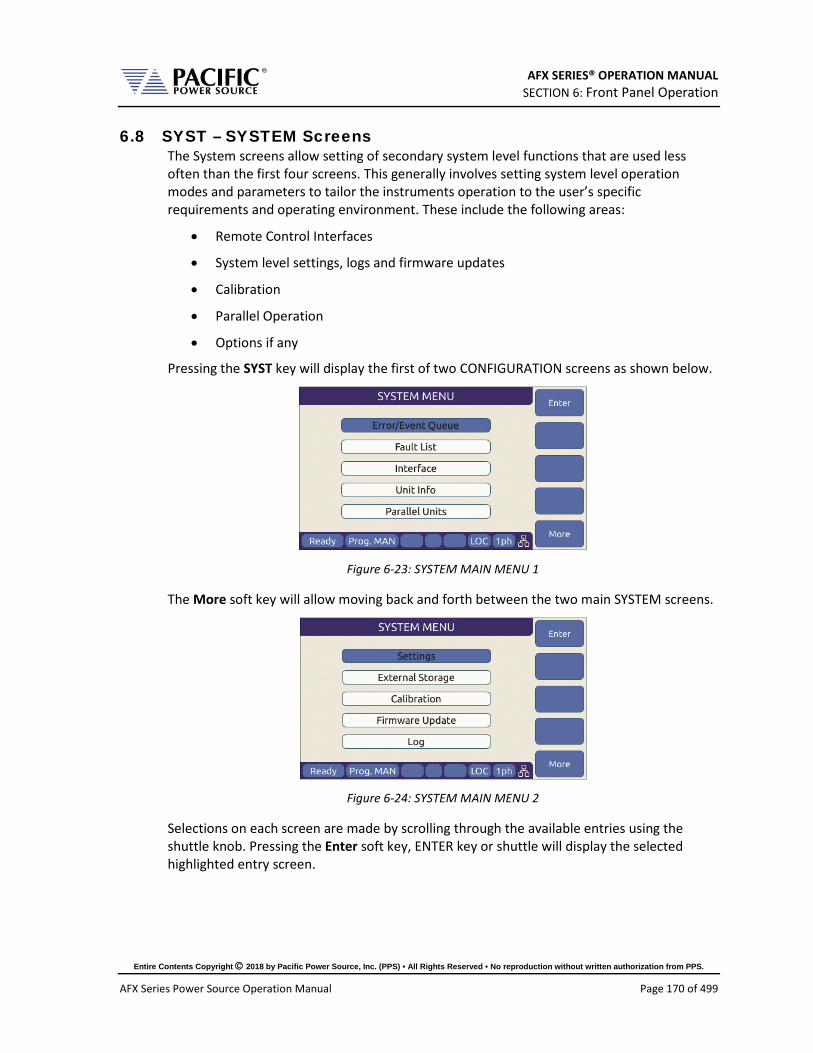
AFX SERIES® OPERATION MANUAL SECTION 6: Front Panel Operation
Entire Contents Copyright 2018 by Pacific Power Source, Inc. (PPS) • All Rights Reserved • No reproduction without written authorization from PPS.
AFX Series Power Source Operation Manual Page 170 of 499
6.8 SYST – SYSTEM Screens The System screens allow setting of secondary system level functions that are used less often than the first four screens. This generally involves setting system level operation modes and parameters to tailor the instruments operation to the user’s specific requirements and operating environment. These include the following areas:
• Remote Control Interfaces
• System level settings, logs and firmware updates
• Calibration
• Parallel Operation
• Options if any
Pressing the SYST key will display the first of two CONFIGURATION screens as shown below.
Figure 6-23: SYSTEM MAIN MENU 1
The More soft key will allow moving back and forth between the two main SYSTEM screens.
Figure 6-24: SYSTEM MAIN MENU 2
Selections on each screen are made by scrolling through the available entries using the shuttle knob. Pressing the Enter soft key, ENTER key or shuttle will display the selected highlighted entry screen.
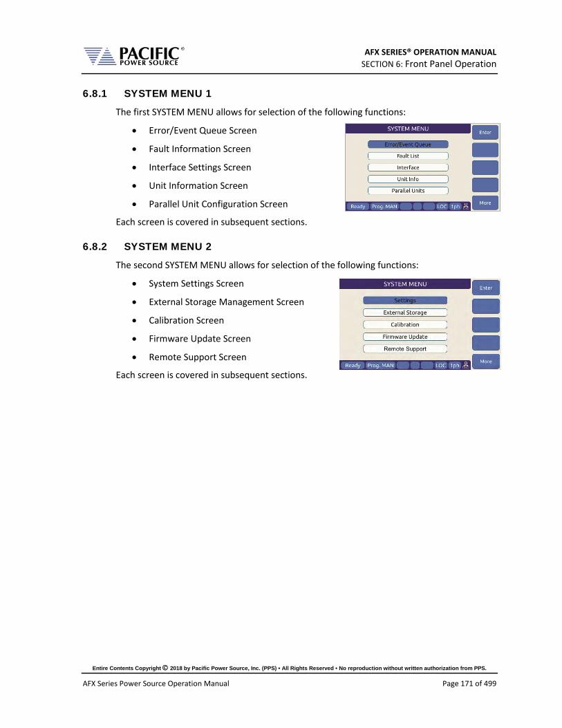
AFX SERIES® OPERATION MANUAL SECTION 6: Front Panel Operation
Entire Contents Copyright 2018 by Pacific Power Source, Inc. (PPS) • All Rights Reserved • No reproduction without written authorization from PPS.
AFX Series Power Source Operation Manual Page 171 of 499
6.8.1 SYSTEM MENU 1
The first SYSTEM MENU allows for selection of the following functions:
• Error/Event Queue Screen
• Fault Information Screen
• Interface Settings Screen
• Unit Information Screen
• Parallel Unit Configuration Screen
Each screen is covered in subsequent sections.
6.8.2 SYSTEM MENU 2
The second SYSTEM MENU allows for selection of the following functions:
• System Settings Screen
• External Storage Management Screen
• Calibration Screen
• Firmware Update Screen
• Remote Support Screen
Each screen is covered in subsequent sections.

AFX SERIES® OPERATION MANUAL SECTION 6: Front Panel Operation
Entire Contents Copyright 2018 by Pacific Power Source, Inc. (PPS) • All Rights Reserved • No reproduction without written authorization from PPS.
AFX Series Power Source Operation Manual Page 172 of 499
6.8.3 ERROR / EVENT QUEUE Screen
The Error and Event queue shows the history of any errors of events that have occurred since the last time the error queue was cleared.
The error queue can be cleared using a SCPI command over any of the remote control interfaces or by pressing the “Clear Queue” soft key while on this screen.
Figure 6-25: ERROR & EVENT QUEUE Screen
6.8.4 FAULT INFORMATION Screen
The fault list shows any logged internal operation faults. This information may be useful when trouble shooting any issues with the power source. In that even, customer service may request this information from the end user or request access to the instrument through the LAN interface for further diagnostics.
Figure 6-26: FAULT INFORMATION screen
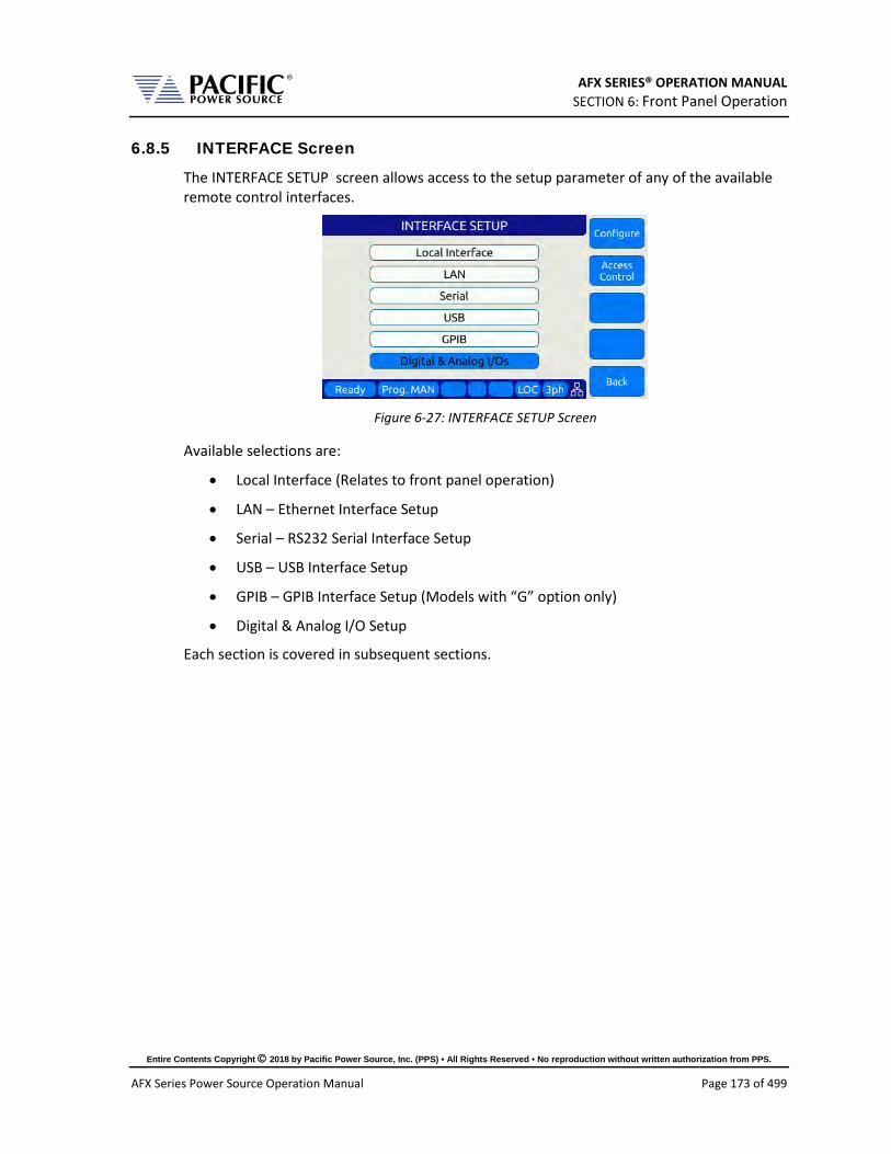
AFX SERIES® OPERATION MANUAL SECTION 6: Front Panel Operation
Entire Contents Copyright 2018 by Pacific Power Source, Inc. (PPS) • All Rights Reserved • No reproduction without written authorization from PPS.
AFX Series Power Source Operation Manual Page 173 of 499
6.8.5 INTERFACE Screen
The INTERFACE SETUP screen allows access to the setup parameter of any of the available remote control interfaces.
Figure 6-27: INTERFACE SETUP Screen
Available selections are:
• Local Interface (Relates to front panel operation)
• LAN – Ethernet Interface Setup
• Serial – RS232 Serial Interface Setup
• USB – USB Interface Setup
• GPIB – GPIB Interface Setup (Models with “G” option only)
• Digital & Analog I/O Setup
Each section is covered in subsequent sections.

AFX SERIES® OPERATION MANUAL SECTION 6: Front Panel Operation
Entire Contents Copyright 2018 by Pacific Power Source, Inc. (PPS) • All Rights Reserved • No reproduction without written authorization from PPS.
AFX Series Power Source Operation Manual Page 174 of 499
6.8.5.1 LOCAL INTERFACE 1 OF 2
Several aspects of front panel operation can be configured by the user from this screen. This relates primarily to the language selection and operation of the shuttle knob, which has three distinct functions:
1. Scrolling values up or down
2. Single Click push function
3. Double Click push function
Parameters available to set are as follows:
Language Available language selections are: - English (default factory setting) - Chinese. Language can be switched by pressing the shuttle while on the language field and scrolling between available selections. Press ENTER to confirm selection.
Single-Click Immediate Mode Enters Immediate Mode upon single depression
of shuttle knob. Immediate mode means value changes occur immediately on the output of the power source. When unchecked, a double click of the shuttle knob is required to enter this mode.

AFX SERIES® OPERATION MANUAL SECTION 6: Front Panel Operation
Entire Contents Copyright 2018 by Pacific Power Source, Inc. (PPS) • All Rights Reserved • No reproduction without written authorization from PPS.
AFX Series Power Source Operation Manual Page 175 of 499
Show Measurements in Immediate Mode When checked, entering immediate mode will result in the Measurement screen being display with the changing parameter showing in the title bar. This allows monitoring of all output measurements while slewing voltage, current of frequency.
Enable variable speed shuttle knob When selected, the speed of rotating the shuttle knob will increase the step size of the parameter being changed. If unchecked, changes occur at a fixed step size (resolution).
Set step with numeric keypad When set, the numeric keypad can be used to increment or decrement the step size of the shuttle knob. Digits 9 to 1 our use to change from largest step size (9) to smallest step size (1) and any step size in between.
The following soft keys are available from the LOCAL INTERFACE setup screen:
SOFT KEY Description Local Inter. Page 2.
(SK1) Toggle to LOCAL INTERFACE 2 OF 2 screen
-
-
-
Back (SK5) Returns to previous screen Table 6-28: Available USER INTERFACE screen soft keys

AFX SERIES® OPERATION MANUAL SECTION 6: Front Panel Operation
Entire Contents Copyright 2018 by Pacific Power Source, Inc. (PPS) • All Rights Reserved • No reproduction without written authorization from PPS.
AFX Series Power Source Operation Manual Page 176 of 499
6.8.5.2 LOCAL INTERFACE 2 OF 2
Several aspects of front panel operation can be configured by the user from this screen. These setting relate primarily to visual and audible user interface aspects:
1. LCD brightness
2. Keyboard Backlight
3. Sound Levels
Parameters available to set are as follows:
LCD brightness Adjusts the LCD display backlight brightness. Range is 0-9.
Keypad Backlight brightness Adjusts the keyboard backlight brightness. Range is 0-9.
Sound Volume Adjusts the loudness of the keyboard and message beeps.
Enable keypad sound Enables or Disables audible beeps when operating the keyboard.
The following soft keys are available from the LOCAL INTERFACE setup screen:
SOFT KEY Description Local Inter. Page 1.
(SK1) Toggle to LOCAL INTERFACE 1 OF 2 screen
-
-
-
Back (SK5) Returns to previous screen Table 6-29: Available USER INTERFACE screen soft keys

AFX SERIES® OPERATION MANUAL SECTION 6: Front Panel Operation
Entire Contents Copyright 2018 by Pacific Power Source, Inc. (PPS) • All Rights Reserved • No reproduction without written authorization from PPS.
AFX Series Power Source Operation Manual Page 177 of 499
6.8.5.3 LAN (ETHERNET) INTERFACE SETUP Screen The LAN INTERFACE SETUP screen allows configuring the Ethernet interface for use with your local area network (LAN) and is accessed from the INTERFACE SETUP screen.
CAUTION
Do NOT connect the RJ45 LAN (Ethernet) connector of the power source to a PoE (Power over Ethernet) port as the DC voltage will damage the LAN interface.
Figure 6-28: ETHERNET INTERFACE SETUP Screen
This screen is used to configure the Ethernet interface for your local area network.
Note: You may need to consult your network administrator to set up this interface correctly.
The following parameters can be set on this screen:
Automatic IP Configuration Select this mode if your network has a domain name server running. An IP address will be assigned by the DNS each time the power source is turned on.
IP IP address setting. This address must be unique to your network segment. Consult your network administrator if you are not sure about this setting.
Mask IP mask setting. This mask must be correct for your network. Consult your network administrator if you are not sure about this setting.
Gateway Gateway address setting. Consult your network administrator if you are not sure about this setting.
DNS Domain Name Server address setting. Consult your network administrator if you are not sure about this setting.
Port Port socket address. For message based instruments like this power source, this setting is typically 5025.

AFX SERIES® OPERATION MANUAL SECTION 6: Front Panel Operation
Entire Contents Copyright 2018 by Pacific Power Source, Inc. (PPS) • All Rights Reserved • No reproduction without written authorization from PPS.
AFX Series Power Source Operation Manual Page 178 of 499
The following soft keys are available from the ETHERNET INTERFACE SETUP screen:
SOFT KEY Description Apply (SK1) Accepts new settings and returns to previous screen.
Cancel (SK2) Returns to the previous screen.
Refresh (SK3)
-
Advanced (SK5) Access detailed LAN Interface Setting screen Table 6-30: Available ETHERNET INTERFACE SETUP screen soft keys

AFX SERIES® OPERATION MANUAL SECTION 6: Front Panel Operation
Entire Contents Copyright 2018 by Pacific Power Source, Inc. (PPS) • All Rights Reserved • No reproduction without written authorization from PPS.
AFX Series Power Source Operation Manual Page 179 of 499
6.8.5.4 SERIAL INTERFACE SETUP Screen The SERIAL INTERFACE SETUP screen allows configuring the RS232 serial interface and is accessed from the “INTERFACE SETUP” screen.
Figure 6-29: SERIAL INTERFCE SETUP Screen
The following parameters can be set on this screen:
Bits per second Sets the baud rate. Available settings are 9600, 14400, 19200, 38400, 57600 or 115200.
Data bits Sets the number of bits per frame. Available settings are 7 or 8 bits
Parity Sets parity check to either odd, even or none.
Stop bits Sets the number of stop bits as either 1 or 2.
Flow control Sets handshake mode to None or Xon/Xoff
The following soft keys are available from the SERIAL INTERFACE SETUP screen:
SOFT KEY Description Apply (SK1) Accepts new settings and returns to previous screen.
Cancel (SK2) Returns to the previous screen.
-
-
Back (SK5) Returns to the previous screen. Table 6-31: Available SERIAL INTERFACE SETUP screen soft keys

AFX SERIES® OPERATION MANUAL SECTION 6: Front Panel Operation
Entire Contents Copyright 2018 by Pacific Power Source, Inc. (PPS) • All Rights Reserved • No reproduction without written authorization from PPS.
AFX Series Power Source Operation Manual Page 180 of 499
6.8.5.5 USB INTERFACE SETUP Screen The USB INTERFACE SETUP screen allows configuring the USB interface and is accessed from the INTERFACE SETUP screen.
Figure 6-30: USB INTERFACE SETUP Screen
The following settings can be configured on this screen:
Enable Virtual Serial Port Enables or disables PC control using a virtual serial port driver.
Enable LAN Enables or disables the LAN (Ethernet) Interface IP emulation mode, which supports use of the embedded LXI web server. The virtual IP address of the USB-LAN emulation mode is fixed at 192.168.123.1.
Note: Any changes made to this screen will NOT take effect until the power source has been completely powered off and back on. (Re-boot).
The following soft keys are available from the USB INTERFACE SETUP screen:
SOFT KEY Description Enable All (SK1) Set all check boxes
Disable All (SK2) Clear all check boxes
-
-
Back (SK5) Returns to the previous screen. Table 6-32: Available USB INTERFACE SETUP screen soft keys

AFX SERIES® OPERATION MANUAL SECTION 6: Front Panel Operation
Entire Contents Copyright 2018 by Pacific Power Source, Inc. (PPS) • All Rights Reserved • No reproduction without written authorization from PPS.
AFX Series Power Source Operation Manual Page 181 of 499
6.8.5.6 GPIB INTERFACE SETUP Screen The GPIB INTERFACE SETUP screen allows configuring the GPIB interface and is accessed from the INTERFACE SETUP screen.
Figure 6-31: USB INTERFACE SETUP Screen
The following settings can be configured on this screen:
Status Enables or disables the GPIB interface. Disable when not in use to avoid erroneous interrupts.
Address Sets GPIB bus address. Available range is from 1 through 30. Default factory setting is address 1.
The following soft keys are available from the GPIB INTERFACE SETUP screen:
SOFT KEY Description Apply (SK1) Accepts new settings and returns to previous screen.
Cancel (SK2) Returns to the previous screen.
-
-
Back (SK5) Returns to the previous screen. Table 6-33: Available GPIB INTERFACE SETUP screen soft keys
6.8.5.7 DIGITAL & ANALOG I/Os SETUP Screen The Digital & Analog IOs SETUP screen allows configuring the auxiliary I/O interfaces and is accessed from the INTERFACE SETUP screen.
For further details, refer to Section 7.3, “Auxiliary I/O” on page 196.

AFX SERIES® OPERATION MANUAL SECTION 6: Front Panel Operation
Entire Contents Copyright 2018 by Pacific Power Source, Inc. (PPS) • All Rights Reserved • No reproduction without written authorization from PPS.
AFX Series Power Source Operation Manual Page 182 of 499
6.8.5.8 REMOTE INHIBIT SETUP Screen The REMOTE INHIBIT SETUP screen allows configuring the remote output control input for various modes of operation. Once set, this setting is retained in non-volatile memory so the selection persists between input power cycles.
Figure 6-32: REMOTE INHIBIT Setup Screen
There are three modes of operation for this input: remote inhibit and remote enable.
1. Disable mode: In his mode, the Remote Inhibit inputs are not active so this function is turned off. No short between the RI pins is required to enable the output in this mode.
2. Remote Inhibit mode: The two pins have to be shorted for the output to be enabled from the front panel or remote command. This is a necessary but not a sufficient condition to enable the output. If the output is enabled and the remote inhibit connection is open, a fault is generated. This mode is recommended for interlock safety applications such safety cages and test fixture interlocks.
3. Remote Enable mode: The output can be enabled by shorting these two pins, regardless of the output enable command/button. It is a sufficient condition to enable the output.
RS232 Interface and Remote Inhibit Function
On AFX Series models with firmware revision numbers lower than 2.0.13, there is a conflict between the RS232 interface and the Remote Inhibit function. Both cannot be used at the same time. To enable the Remote Inhibit input control line, the RS232 interface must be disabled. This can be done using the browser interface over LAN or USB or from the front panel. If the Remote Inhibit function is needed, use the USB interface instead of RS232.
To disable RS232 from Web browser, select SYSTEM Menu -> INTERFACE SETUP and move the SERIAL CONFIGURATION ENABLE position to OFF.
To disable RS232 form the front panel, press the CONFIGURATION key to the left of the LCD, select Interfaces, then select RS232 Interface and set the Status field to Disabled. Refer to section 6.8.5.4 on page 179.

AFX SERIES® OPERATION MANUAL SECTION 6: Front Panel Operation
Entire Contents Copyright 2018 by Pacific Power Source, Inc. (PPS) • All Rights Reserved • No reproduction without written authorization from PPS.
AFX Series Power Source Operation Manual Page 183 of 499
Note: For units with firmware revision 2.0.13 or higher, the RS232 interface is automatically disabled when enabling Remote Inhibit.
6.8.5.9 REMOTE SHARING Remote sharing of the power source is provided using one of two protocols:
Samba: Samba is a free software re-implementation of the SMB networking protocol. Server Message Block (SMB), also known as Common Internet File System (CIFS) operates as an application-layer network protocol for providing shared access to resources miscellaneous communications between nodes on a network.
FTP: File Transfer Protocol. FTP is built on a client-server model architecture using separate control and data connections between the client and the server.
Note: Either one or both may be chosen. It is strongly recommended to set a custom password to prevent unauthorized access to the power source.

AFX SERIES® OPERATION MANUAL SECTION 6: Front Panel Operation
Entire Contents Copyright 2018 by Pacific Power Source, Inc. (PPS) • All Rights Reserved • No reproduction without written authorization from PPS.
AFX Series Power Source Operation Manual Page 184 of 499
6.8.6 UNIT INFORMATION Screen
The UNIT INFORMATION screen is an information only screen that contains information about the power source and is accessed from the SYSTEM SETTINGS screen using the “Unit info” soft key (SK3).
Figure 6-33: UNIT INFORMATION Screen
The following information is provided on this screen:
Unit Number Shows the position of this unit in a string of paralleled power sources. For a stand-alone power source, the display will show 1 of 1.
Front panel status Shows the status of the front panel. Only the MASTER unit in a multi-unit system will have its front panel enabled.
Front panel FW ver. Firmware revision of the front panel control processor. Power stage FW ver. Firmware revision of the power stage processors. Hardware revision Hardware build revision. Serial number Unit Serial number. Model Model number, typically 3xxxAFX where xxx = power rating.
Note: This information is for information purposes only and cannot be changed by the operator.
The following soft keys are available from the UNIT INFORMATION screen:
SOFT KEY Description Next Unit (SK1) If this unit is part of a parallel system, information on the next unit
in the chain will be displayed.
Previous Unit (SK2)
If this unit is part of a parallel system, information on the previous unit in the chain will be displayed.
- -
Back (SK5) Returns to the previous screen. Table 6-34: Available UNIT INFORMATION screen soft keys
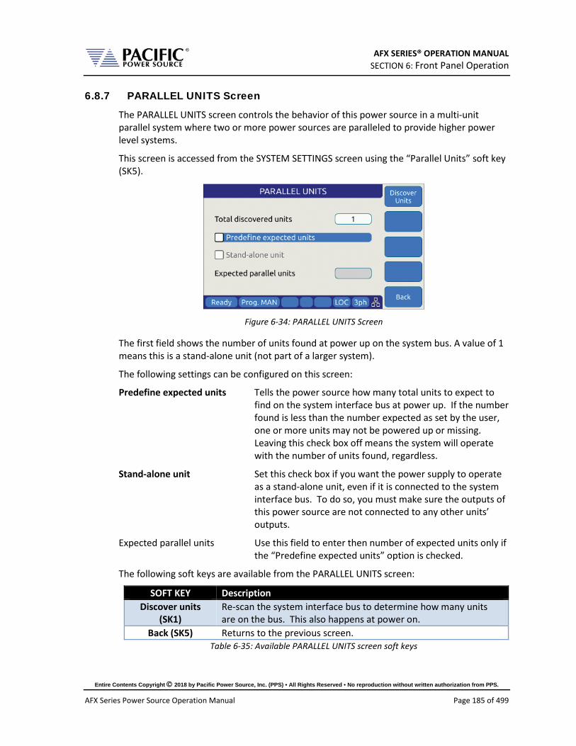
AFX SERIES® OPERATION MANUAL SECTION 6: Front Panel Operation
Entire Contents Copyright 2018 by Pacific Power Source, Inc. (PPS) • All Rights Reserved • No reproduction without written authorization from PPS.
AFX Series Power Source Operation Manual Page 185 of 499
6.8.7 PARALLEL UNITS Screen
The PARALLEL UNITS screen controls the behavior of this power source in a multi-unit parallel system where two or more power sources are paralleled to provide higher power level systems.
This screen is accessed from the SYSTEM SETTINGS screen using the “Parallel Units” soft key (SK5).
Figure 6-34: PARALLEL UNITS Screen
The first field shows the number of units found at power up on the system bus. A value of 1 means this is a stand-alone unit (not part of a larger system).
The following settings can be configured on this screen:
Predefine expected units Tells the power source how many total units to expect to find on the system interface bus at power up. If the number found is less than the number expected as set by the user, one or more units may not be powered up or missing. Leaving this check box off means the system will operate with the number of units found, regardless.
Stand-alone unit Set this check box if you want the power supply to operate as a stand-alone unit, even if it is connected to the system interface bus. To do so, you must make sure the outputs of this power source are not connected to any other units’ outputs.
Expected parallel units Use this field to enter then number of expected units only if the “Predefine expected units” option is checked.
The following soft keys are available from the PARALLEL UNITS screen:
SOFT KEY Description Discover units
(SK1) Re-scan the system interface bus to determine how many units are on the bus. This also happens at power on.
Back (SK5) Returns to the previous screen. Table 6-35: Available PARALLEL UNITS screen soft keys

AFX SERIES® OPERATION MANUAL SECTION 6: Front Panel Operation
Entire Contents Copyright 2018 by Pacific Power Source, Inc. (PPS) • All Rights Reserved • No reproduction without written authorization from PPS.
AFX Series Power Source Operation Manual Page 186 of 499
6.8.8 SYSTEM SETTINGS Screen
This screen allows system level settings such date and time to be changed. It also access to the UPC Compatibility mode setting.
Figure 6-35: SYSTEM SETTINGS Screen
The following parameters can be set from this screen:
Date Sets the date for the real-time clock.
Time Sets the time for the real-time clock.
Use Network Time Protocol When set, the time and date will be adjusted based on the NTP protocol. This requires the unit to be connected to a local area network.
Time zone UTC offset This parameter sets the number of time zone from UTC where the unit is located to reflect local time. Coordinated Universal Time (UTC) is the primary time standard by which the world regulates clocks and time. It does not observe daylight saving time.
The soft keys on the SYSTEM SETTINGS screen provide access to additional functionality as listed in the table below.
SOFT KEY Description Apply All (SK1) Applies all changes made to this screen.
Cancel All (SK2) Cancels any changes made and returns to previous screen
Sanitize Erases all user settings from the unit and returns it to its factory default state.
Reboot Reboot front panel controller without cycling AC input power.
Back (SK5) Returns to the previous screen. Table 6-36: Available SYSTEM SETTINGS screen soft keys
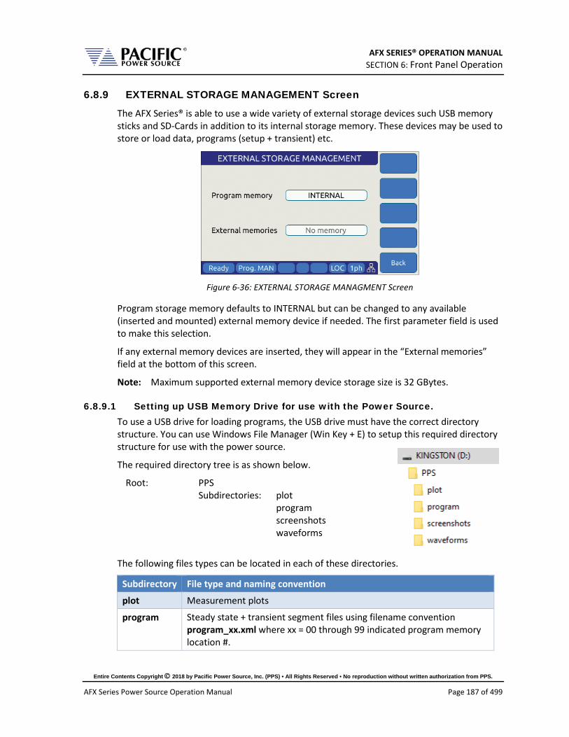
AFX SERIES® OPERATION MANUAL SECTION 6: Front Panel Operation
Entire Contents Copyright 2018 by Pacific Power Source, Inc. (PPS) • All Rights Reserved • No reproduction without written authorization from PPS.
AFX Series Power Source Operation Manual Page 187 of 499
6.8.9 EXTERNAL STORAGE MANAGEMENT Screen
The AFX Series® is able to use a wide variety of external storage devices such USB memory sticks and SD-Cards in addition to its internal storage memory. These devices may be used to store or load data, programs (setup + transient) etc.
Figure 6-36: EXTERNAL STORAGE MANAGMENT Screen
Program storage memory defaults to INTERNAL but can be changed to any available (inserted and mounted) external memory device if needed. The first parameter field is used to make this selection.
If any external memory devices are inserted, they will appear in the “External memories” field at the bottom of this screen.
Note: Maximum supported external memory device storage size is 32 GBytes.
6.8.9.1 Setting up USB Memory Drive for use with the Power Source. To use a USB drive for loading programs, the USB drive must have the correct directory structure. You can use Windows File Manager (Win Key + E) to setup this required directory structure for use with the power source.
The required directory tree is as shown below.
Root: PPS Subdirectories: plot program screenshots waveforms
The following files types can be located in each of these directories.
Subdirectory File type and naming convention
plot Measurement plots
program Steady state + transient segment files using filename convention program_xx.xml where xx = 00 through 99 indicated program memory location #.

AFX SERIES® OPERATION MANUAL SECTION 6: Front Panel Operation
Entire Contents Copyright 2018 by Pacific Power Source, Inc. (PPS) • All Rights Reserved • No reproduction without written authorization from PPS.
AFX Series Power Source Operation Manual Page 188 of 499
Subdirectory File type and naming convention
screenshots PNG image files captured from the LCD screen with filename convention screenshot_YYYY-MM-DD_HH-MM-SS.png where YYYY-MM-DD_HH-MM-SS is the time stamp.
waveforms CSV comma separated waveform data files with filename convention X.csv where X is a number form 2 through 200.
6.8.9.2 Loading Programs from a USB Drive. Programs stored on a USB drive using the directory structure shown in the previous section can be loaded using the Browser interface – see section 10.7.4 on page 429– or from the front panel.
To load from the front panel USB ports, store the program_xx.xml file in the program subdiretory and insert in one of the tow USB A ports on the front panel. After a short period of time, the drive will mount and will be visible in the CONF -> PROGRAM BROWSER screen.
Select the USBA1 drive in the upper right corner Memory field to see the available progam files on the USB drive. Scroll down with the shuttle to select the desired program file to load.
Then use the Recall Softkey to load the selected progam file. The program will now be available in the assigned program memory location as determined by the XML file name.
Note: program_xx.xml files must have a Steady State section to be valid. The Transient
section may be empty in which case no transient will be loaded.

AFX SERIES® OPERATION MANUAL SECTION 6: Front Panel Operation
Entire Contents Copyright 2018 by Pacific Power Source, Inc. (PPS) • All Rights Reserved • No reproduction without written authorization from PPS.
AFX Series Power Source Operation Manual Page 189 of 499
6.8.10 CALIBRATION MENU Screen
All power sources are shipped with a Certificate of Compliance to NIST traceable standards (“CoC”) from the factory. Output and Measurements are calibrated to an external reference DMM at the same time. A suitable current shunt or current transformer and a load will be required to perform calibration.
Figure 6-37: CALIBRATION MENU Screen
The following soft keys are available from the CALIBRATION MENU:
SOFT KEY Description Calibrate (SK1) Enters calibration state
Reset (SK2) Resets all calibration coefficients’ previous values.
-
-
Back (SK5) Returns to previous screen Table 6-37: Available CALIBRATION MENU screen soft keys
For details on calibration requirements and procedures, refer to the Calibration section towards the end of this manual. (Section 11, “Calibration”).

AFX SERIES® OPERATION MANUAL SECTION 6: Front Panel Operation
Entire Contents Copyright 2018 by Pacific Power Source, Inc. (PPS) • All Rights Reserved • No reproduction without written authorization from PPS.
AFX Series Power Source Operation Manual Page 190 of 499
6.8.11 FIRMWARE UPDATE Screen
Firmware updates may be distributed via different media such as SD-Card, USB memory stick or on-line through Pacific’s FTP site. The FIRMWARE UPDATE screen provides the means for the end user to perform a firmware update.
Figure 6-38: FIRMWARE UPDATE Screen
The following soft keys are available from the FIRMWARE UPDATE screen:
SOFT KEY Description Mount Drive (SK1) Mount media that contains new firmware revision.
-
-
From FTP (SK4) Install latest firmware from Pacific Power Sources’ FTP server.
Cancel (SK5) Exit firmware update screen Table 6-38: Available FIRMWARE UPDATE screen soft keys

AFX SERIES® OPERATION MANUAL SECTION 6: Front Panel Operation
Entire Contents Copyright 2018 by Pacific Power Source, Inc. (PPS) • All Rights Reserved • No reproduction without written authorization from PPS.
AFX Series Power Source Operation Manual Page 191 of 499
6.8.12 REMOTE SUPPORT Screen
The REMOTE SUPPORT feature cam be used to send information to customer support in case the user experiences an issue with the unit. It also provides a means to allow Pacific’s technical support team to access the unit remotely assuming it is connected to a network with Internet access.
Figure 6-39: REMOTE SUPPORT Screen
The Report soft keys will cause a detailed report to be generated and sent to Pacific Power Source customer support so we can assist in resolving any technical support issues.
Figure 6-40: Remote Support REPORT Screen
The following soft keys are available from the LOGGING TOOL screen:
SOFT KEY Description Connect (SK1) Connect to Pacific Power Support site
Disconnect (SK2) Disconnect from Pacific Power Support site
Report ( SK3) Generates a report for Customer Support Department
Log (SK4) Start Logging
Back (SK5) Returns to the previous screen. Table 6-39: Available LOGGING TOOL screen soft keys

AFX SERIES® OPERATION MANUAL SECTION 7: Rear Panel, Connectors and Protection
Entire Contents Copyright 2018 by Pacific Power Source, Inc. (PPS) • All Rights Reserved • No reproduction without written authorization from PPS.
AFX Series Power Source Operation Manual Page 192 of 499
7 Rear Panel, Connectors and Protection
This section describes the rear panel layout of the AFX Series® AC power source.
7.1 OUTPUT Terminals
CAUTION
HAZARDOUS OUTPUT: The power source output may be set to hazardous voltage levels. It provides basic isolation from the AC input mains. Therefore, the output must always be considered hazardous. Connections must be inaccessible to the operator in all situations when AC input mains voltage is applied.
Always disconnect power supply from the mains before connecting or disconnecting to the hazardous output terminals.
AVERTISSEMENT
SORTIE DANGEREUSE: La sortie de l´appareil peut être réglée à des niveaux de tension dangereux. L´appareil fournit une isolation de base du réseau d'entrée AC. Par conséquent, la sortie doit toujours être considérée comme dangereuse. Les connexions doivent être inaccessibles à l'opérateur dans toutes les situations où la tension d´entrée secteur est appliquée.
Toujours débrancher l'alimentation secteur avant de connecter ou déconnecter les bornes de sortie dangereuses.
The output terminal block for load connections is located near the center of the rear panel.
Note: Always refer to Section 2.3 “Safety Information” and Section 5.14, “Load Connections” on page 66.

AFX SERIES® OPERATION MANUAL SECTION 7: Rear Panel, Connectors and Protection
Entire Contents Copyright 2018 by Pacific Power Source, Inc. (PPS) • All Rights Reserved • No reproduction without written authorization from PPS.
AFX Series Power Source Operation Manual Page 193 of 499
Safety Notices” before making any load connections.
7.1.1 Output Power Connector Rating and Isolation
Maximum rated output voltage: 300V rms AC, 425Vdc
Maximum Current Rating: 60A
Connector Type: Phoenix Contact SPC 16/ 6-STF-10, 16 - 1711417
Designated Use: AC or DC Load Connection
Isolation Rating: 600V
Wire Stripping Length: 18 mm
7.1.2 Wire Size
A major consideration in making load connections is the wire size. The minimum wire size is required to prevent overheating and to maintain good regulation. It is recommended that the wires are sized large enough to limit the voltage drop at the maximum current rating of the AC power source to less than 0.5V per lead.
Wire size also depends on ambient temperature and total wires in the cable bundle. For example, for the full 41.7 amp current capability of a single output, at an ambient temperature of 30 °C, in a bundle of not more than three 75 °C rated wires, common electrical codes would recommend AWG 8 size (~10 mm^2).
7.1.3 Connecting a UUT
When setting up for a new test and connecting any equipment to the AC power source, proceed as follows:
1. Always make sure the AC power source is turned OFF at the POWER switch when making any wire connections.
2. Check that the output of the equipment under test is OFF. Note: Some power equipment’s output may still be energized even if the equipment has been turned off or its output is turned off. This is especially true for AC power sources. Note: When working with batteries, it is recommended to provide a suitable disconnect relay or switch so the AC power source can be physically disconnected from the battery for handling purposes.
3. Connect one end of the load wires to the output terminals on the rear panel. 4. Check the polarity of the connections and connect the other end of the load wires to
the input terminals of the equipment under test.

AFX SERIES® OPERATION MANUAL SECTION 7: Rear Panel, Connectors and Protection
Entire Contents Copyright 2018 by Pacific Power Source, Inc. (PPS) • All Rights Reserved • No reproduction without written authorization from PPS.
AFX Series Power Source Operation Manual Page 194 of 499
7.2 External Voltage Sense Input Terminals
CAUTION
HAZARDOUS OUTPUT: The power source output may be set to hazardous voltage levels. It provides basic isolation from the ac input mains. Therefore, the external voltage sense must also always be considered hazardous. Connections must be inaccessible to operator in all situations when ac input mains voltage is applied.
Always disconnect power supply from the mains before connecting or disconnecting to the hazardous external voltage sense terminals.
AVERTISSEMENT
SORTIE DANGEREUSE: La sortie de l´appareil peut être réglée à des niveaux de tension dangereux. L´appareil fournit une isolation de base du réseau d'entrée AC. Par conséquent, la sortie doit toujours être considérée comme dangereuse. Les connexions doivent être inaccessibles à l'opérateur dans toutes les situations où la tension d´entrée secteur est appliquée.
Toujours débrancher l'alimentation secteur avant de connecter ou déconnecter les bornes de sortie dangereuses.
This section covers external voltage sensing. This feature improves voltage accuracy at the point of load when used correctly.
Note: External Voltage sense is sometimes referred to as Remote Voltage sense and Internal Voltage sense is sometimes referred to as Local Voltage sense. Both definitions are used in the industry. For consistency, External Voltage Sense and Internal Voltage Sense are used in this manual.

AFX SERIES® OPERATION MANUAL SECTION 7: Rear Panel, Connectors and Protection
Entire Contents Copyright 2018 by Pacific Power Source, Inc. (PPS) • All Rights Reserved • No reproduction without written authorization from PPS.
AFX Series Power Source Operation Manual Page 195 of 499
7.2.1 External Voltage Sense Connector Rating and Isolation
Maximum rated voltage: 400V rms AC, 425Vdc
Maximum Current Rating: 1A
Connector Type: AFX L Version: Phoenix Contact P/N DFK-MSTBA 2,5 / 6-GF-5,08 – 1899029. Mating connector provided in ship kit is P/N FKC 2,5 / 6-STF-5,08 - 1873249
AFX A Version: Phoenix Contact P/N SPT 5 / 6-H-7,5-ZB - 1719231
Designated Use: AC or DC Load Connection
Isolation Rating: 600V
Wire Stripping Length: 10 mm
7.2.2 Load Connection without External Voltage Sense
AFX Series® power sources can be operated with internal voltage sense. For higher current loads, the voltage at the load will drop due to the load cable impedance. Using the proper wire gauge for the rated current of the AC source is required to minimize load cable impedance.
7.2.3 Load Connection with External Voltage Sense.
The following points must be considered, when existing sense cables are connected directly to the load or to the central load distribution point:
1. Minimize the distance between the AC power source and the load as much as possible to keep load wire length to a minimum.
2. Directly connect A, B, C and N with correct phasing to the load distribution point
3. Twist each phase sense wire with a neutral sense wire to minimize cross talk. Three neutral connection points are provided for this purpose.
4. Avoid overload of power wires

AFX SERIES® OPERATION MANUAL SECTION 7: Rear Panel, Connectors and Protection
Entire Contents Copyright 2018 by Pacific Power Source, Inc. (PPS) • All Rights Reserved • No reproduction without written authorization from PPS.
AFX Series Power Source Operation Manual Page 196 of 499
Note: External voltage sense connections are at the programmed output voltage when the output is on so DO NOT connect or disconnect the external voltage sense lines while the AC power source is in use.
AFX L Version units are shipped with the mating sense connector installed but no wires to prevent contact with the sense connections. AFX A Version units don’t require a mating connector.
7.3 Auxiliary I/O The Auxiliary I/O functions are only available on 3xx0AFX-2AG and 3xx0AFX-4AG version power source models.
7.3.1 Auxiliary I/O Functions
The Auxiliary I/O board when added to an AFX Series power source adds the following functions and features:
• Digital Inputs for trigger functions and control. • Digital Outputs for status indication and relay control. • Analog Inputs for control of power source parameters. • Analog Outputs for measurement monitoring. • A 12Vdc power output to power external circuits. • RS232 Serial Interface. • Optional embedded GPIB Control Interface
The analog, digital and RS232 ports are accessible on a female DB25 connector located on the rear panel of the AFX master unit. This connector is mounted upside down so pin 1 is located in the lower right-hand corner when facing the back of the AFX master unit.
The USB, LAN and optional GPIB connectors are located to the left of the AUX I/O connector on the rear panel when facing the power source from behind.
Figure 7-1: Rear Panel AUX I/O DB25 Connector Location

AFX SERIES® OPERATION MANUAL SECTION 7: Rear Panel, Connectors and Protection
Entire Contents Copyright 2018 by Pacific Power Source, Inc. (PPS) • All Rights Reserved • No reproduction without written authorization from PPS.
AFX Series Power Source Operation Manual Page 197 of 499
7.3.2 DB25 Connector AUX I/O Pin locations
The pin locations for the various I/O signals on the DB25 connectors are shown in Figure 7-2 below. Note that the connector is installed “Upside” down due to mounting constraints.
PIN# 1 2 3 4 5 6 7 8 9 10 11 12 13
PIN# 14 15 16 17 18 19 20 21 22 23 24 25
RS232 DIGITAL I/O ANALOG I/OGND GND
12VDC
Figure 7-2: DB25 Connector AUX I/O Pin Locations
Functional grouping of pins by I/O function is done as shown in the figure above. The left hand side groups all Analog I/O signals on top on bottom row. The middle section is reserved for all Digital I/O pins. The RS232 Transmit (Tx) and Receive (Rx) signals are located on the far left when facing the back of the unit.

AFX SERIES® OPERATION MANUAL SECTION 7: Rear Panel, Connectors and Protection
Entire Contents Copyright 2018 by Pacific Power Source, Inc. (PPS) • All Rights Reserved • No reproduction without written authorization from PPS.
AFX Series Power Source Operation Manual Page 198 of 499
7.3.3 I/O Signal Table by pin number
Pin assignments in order of pin number are shown in the table below.
Pin # Name Primary Function Alternate Use / Comment Type Direction 1 RxD RS232 Receive Data (Rx) RS232 Input 2 GND Chassis Ground Ground n/a 3 DI1 General Purpose Digital Input #1 Programmable Digital Input 4 DI2 General Purpose Digital Input #2 Programmable Digital Input 5 DI3 General Purpose Digital Input #3 Programmable Digital Input 6 RI Remote Inhibit Short to +12Vdc Pin 15 Digital Input 7 TT Transient Trigger Input Digital Input 8 Sync In Phase Sync Input Digital Input 9 GND Chassis Ground Ground n/a
10 AI1 Analog Input – Volt RMS Phase A Any set point Analog Input 11 AI2 Analog Input – Volt RMS Phase B Any set point Analog Input 12 AI3 Analog Input – Volt RMS Phase C Any set point Analog Input 13 AI4 Analog Input – Current Limit RMS all
phases Any set point Analog Input
14 TxD RS232 Transmit Data (Tx) RS232 Output 15 12V Output, 12Vdc 0.5 A max, current protected Power Output 16 DO3
/RC1 Relay Control #1 – FORM Programmable, Open
Collector, Current protected Digital Output
17 DO4 /RC2
Relay Control #2 - TRANSFORMER Programmable, Open Collector, Current protected
Digital Output
18 FS Trigger Output / Function Strobe Digital Output 19 Sync
Out Phase Sync Output Digital Output
20 DO1 General Purpose Digital Output #1 Programmable Digital Output 21 DO2 General Purpose Digital Output #2 Programmable Digital Output 22 AO1 Analog output #1 – Volt RMS
Measurements Phase A Any other measurement Analog Output
23 AO2 Analog output #2 – Volt RMS Measurements Phase B
Any other measurement Analog Output
24 AO3 Analog output #3 – Volt RMS Measurements Phase C
Any other measurement Analog Output
25 AO4 Analog output #4 – Total Power (all phases combined)
Any other measurement Analog Output
Table 7-1: Auxiliary I/O DB25 Connector Pin numbers and Signals by DB25 pin number

AFX SERIES® OPERATION MANUAL SECTION 7: Rear Panel, Connectors and Protection
Entire Contents Copyright 2018 by Pacific Power Source, Inc. (PPS) • All Rights Reserved • No reproduction without written authorization from PPS.
AFX Series Power Source Operation Manual Page 199 of 499
7.3.4 I/O Signal Table by Function
Pin assignments in order of pin number are shown in the table below.
Pin # Name Primary Function Alternate Use / Comment Type Direction 10 AI1 Analog Input – Volt RMS Phase A Any set point Analog Input 11 AI2 Analog Input – Volt RMS Phase B Any set point Analog Input 12 AI3 Analog Input – Volt RMS Phase C Any set point Analog Input 13 AI4 Analog Input – Current Limit RMS all
phases Any set point Analog Input
22 AO1 Analog output #1 – Volt RMS Measurements Phase A
Any other measurement Analog Output
23 AO2 Analog output #2 – Volt RMS Measurements Phase B
Any other measurement Analog Output
24 AO3 Analog output #3 – Volt RMS Measurements Phase C
Any other measurement Analog Output
25 AO4 Analog output #4 – Total Power (all phases combined)
Any other measurement Analog Output
3 DI1 General Purpose Digital Input #1 Programmable Digital Input 4 DI2 General Purpose Digital Input #2 Programmable Digital Input 5 DI3 General Purpose Digital Input #3 Programmable Digital Input
20 DO1 General Purpose Digital Output #1 Programmable Digital Output 21 DO2 General Purpose Digital Output #2 Programmable Digital Output 18 FS Trigger Output / Function Strobe Digital Output 16 DO3
/RC1 Relay Control #1 – FORM Programmable, Open
Collector, Current protected Digital Output
17 DO4 /RC2
Relay Control #2 - TRANSFORMER Programmable, Open Collector, Current protected
Digital Output
6 RI Remote Inhibit Short to +12Vdc Pin 15 Digital Input 8 Sync In Phase Sync Input Digital Input
19 Sync Out Phase Sync Output Digital Output 7 TT Transient Trigger Input Digital Input
15 12V Output, 12Vdc 0.5 A max, current protected Power Output 2 GND Chassis Ground Ground n/a 9 GND Chassis Ground Ground n/a 1 RxD RS232 Receive Data (Rx) RS232 Input
14 TxD RS232 Transmit Data (Tx) RS232 Output Table 7-2: Auxiliary I/O DB25 Connector Pin numbers and Signals by Signal Name
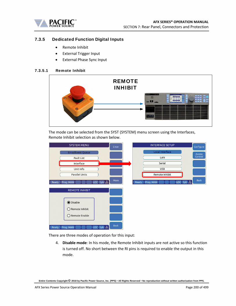
AFX SERIES® OPERATION MANUAL SECTION 7: Rear Panel, Connectors and Protection
Entire Contents Copyright 2018 by Pacific Power Source, Inc. (PPS) • All Rights Reserved • No reproduction without written authorization from PPS.
AFX Series Power Source Operation Manual Page 200 of 499
7.3.5 Dedicated Function Digital Inputs
• Remote Inhibit • External Trigger Input • External Phase Sync Input
7.3.5.1 Remote Inhibit
REMOTEINHIBIT
The mode can be selected from the SYST (SYSTEM) menu screen using the Interfaces, Remote Inhibit selection as shown below.
There are three modes of operation for this input:
4. Disable mode: In his mode, the Remote Inhibit inputs are not active so this function is turned off. No short between the RI pins is required to enable the output in this mode.
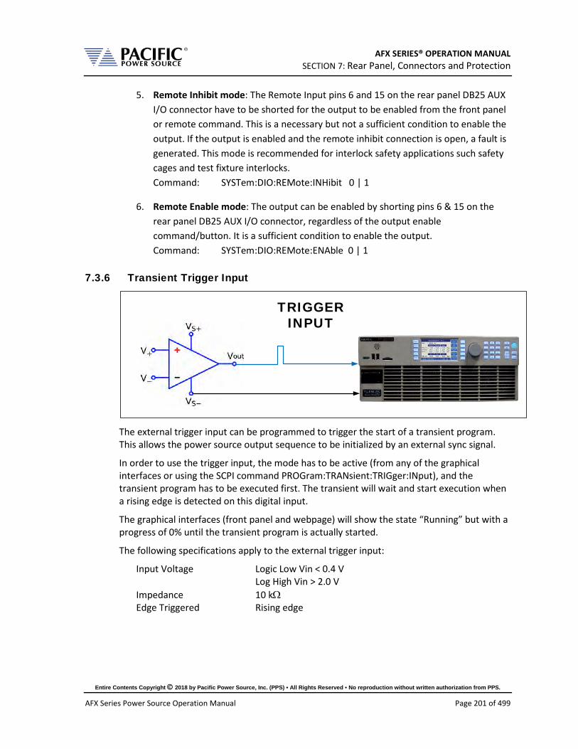
AFX SERIES® OPERATION MANUAL SECTION 7: Rear Panel, Connectors and Protection
Entire Contents Copyright 2018 by Pacific Power Source, Inc. (PPS) • All Rights Reserved • No reproduction without written authorization from PPS.
AFX Series Power Source Operation Manual Page 201 of 499
5. Remote Inhibit mode: The Remote Input pins 6 and 15 on the rear panel DB25 AUX I/O connector have to be shorted for the output to be enabled from the front panel or remote command. This is a necessary but not a sufficient condition to enable the output. If the output is enabled and the remote inhibit connection is open, a fault is generated. This mode is recommended for interlock safety applications such safety cages and test fixture interlocks. Command: SYSTem:DIO:REMote:INHibit 0 | 1
6. Remote Enable mode: The output can be enabled by shorting pins 6 & 15 on the rear panel DB25 AUX I/O connector, regardless of the output enable command/button. It is a sufficient condition to enable the output. Command: SYSTem:DIO:REMote:ENAble 0 | 1
7.3.6 Transient Trigger Input
TRIGGERINPUT
The external trigger input can be programmed to trigger the start of a transient program. This allows the power source output sequence to be initialized by an external sync signal.
In order to use the trigger input, the mode has to be active (from any of the graphical interfaces or using the SCPI command PROGram:TRANsient:TRIGger:INput), and the transient program has to be executed first. The transient will wait and start execution when a rising edge is detected on this digital input.
The graphical interfaces (front panel and webpage) will show the state “Running” but with a progress of 0% until the transient program is actually started.
The following specifications apply to the external trigger input:
Input Voltage Logic Low Vin < 0.4 V Log High Vin > 2.0 V Impedance 10 kΩ Edge Triggered Rising edge

AFX SERIES® OPERATION MANUAL SECTION 7: Rear Panel, Connectors and Protection
Entire Contents Copyright 2018 by Pacific Power Source, Inc. (PPS) • All Rights Reserved • No reproduction without written authorization from PPS.
AFX Series Power Source Operation Manual Page 202 of 499
Figure 7-3: External Trigger Input Timing
7.3.7 External or Line Sync Input
SYNCIN/OUT
The phase sync input can be used to synchronize in frequency and phase the internal waveform generation of the AFX to an external sync reference or to the AC mains. The reference must be within the specified frequency range of the power source and zero phase offset calibration for phase A may be required to compensate for any phase shifts. Note than Phase B and C are still phase related to A as programmed by B and C phase angles.
7.3.7.1 Principle of Operation In AC Line sync mode, the AFX uses the L-L AC input voltage to generate the internal sync signal. The goal of the phase sync is to provide precise frequency synchronization, and consistent phase at a given operating point, but the phase shift between AC input and AC output is not automatically zero. A phase adjustment for Phase A must be made by the user to time-align the power source’s phase A output voltage to the L1 leg of the actual three phase Grid voltage powering the AFX.
A couple of factors affect the phase shift:
• The internal AC sync circuits have some inherent delays. If more accuracy is required then the TTL input mode can be used instead using an external line sync circuit.

AFX SERIES® OPERATION MANUAL SECTION 7: Rear Panel, Connectors and Protection
Entire Contents Copyright 2018 by Pacific Power Source, Inc. (PPS) • All Rights Reserved • No reproduction without written authorization from PPS.
AFX Series Power Source Operation Manual Page 203 of 499
• Even if TTL input is used, there can be a phase shift that depends on the output load because of the finite bandwidth of the output inverter stages. This is particularly visible at higher frequencies. At 50Hz or 60Hz, the phase shift will be pretty small.
Note: When the sync input is enabled, the AFX frequency set point must be set to a value similar to the external sync signal. This minimizes the synchronization time and improves the stability of the generated frequency.
After the sync input is activated, or the external signal frequency/phase is changed, the Sync circuit’s Phase Lock Loop (PLL) requires a short time to “lock” to the external source. The AFX reports the status of the PLL in the external interfaces (front panel and webpage) by showing a “Synced” or “Unsynced” message in the status bars.
The status can also be queried with the SCPI command “SOURce:SYNChronize:STATe?”.
The sync circuit is able to synchronize to any signal with a frequency if FSETPOINT +/- FRANGE, where FSETPOINT is the normal frequency set point and FRANGE is a configurable value (default is 10Hz)
The following specifications apply to the phase sync input at the DB25 port:
Input Voltage Logic Low Vin < 0.4 V Log High Vin > 2.0 V Impedance 10 kΩ Frequency Range 15 Hz – 1200 Hz Edge Triggered Rising edge
Figure 7-4: External Sync Input Pulses

AFX SERIES® OPERATION MANUAL SECTION 7: Rear Panel, Connectors and Protection
Entire Contents Copyright 2018 by Pacific Power Source, Inc. (PPS) • All Rights Reserved • No reproduction without written authorization from PPS.
AFX Series Power Source Operation Manual Page 204 of 499
7.3.7.2 SYNC Status Display A “Synced” status field will be displayed in Green in the lower left corner of the LCD display. This field will toggle with the regular “Ready/Enabled/Fault” status field also shown in this location. The “Synced” status will be shown every 3 seconds for 1 second in place of the “Ready/Enabled/Fault” field. When the PLL is not locked to the external source, the unit will display an “Unsynced” status in Orange.
It is not recommended to enable the unit when it has not locked or synchronized to the external source because the frequency may be unknown.
Figure 7-5: External Sync Input Sync Status Indication
Figure 7-6: External Sync Input Sync Lost Status Indication
7.3.7.3 Sync Operation Settings The AFX allows precise configuration of the synchronization parameters to optimize performance for each application. The parameters are:
1 Phase shift: Defines a fixed phase shift between phase A waveform generation and the external sync source. Used to calibrate any phase difference between the sync signal and the power source output on phase A. Command: SOURce:SYNChronize:PHASEshift
2 Speed: Allows accelerating the speed of the internal synchronization engine (PLL) in case the external sync source is not constant and presents periodic or continuous

AFX SERIES® OPERATION MANUAL SECTION 7: Rear Panel, Connectors and Protection
Entire Contents Copyright 2018 by Pacific Power Source, Inc. (PPS) • All Rights Reserved • No reproduction without written authorization from PPS.
AFX Series Power Source Operation Manual Page 205 of 499
changes. A slower speed improves the stability of the waveform frequency, so it is recommended to use the smallest possible speed values. Command: SOURce:SYNChronize:SPeed
3 Range: Allows configuration of how much the synchronization engine is able to deviate from the AFX programmed frequency. This helps to keep the waveform frequency under control, even if the external source is not present all the time. The synchronization engine is limited to frequencies of FSETPOINT +/- FRANGE. Command: SOURce:SYNChronize:RANGe
7.3.8 Digital Output control signals
• External Relay Control #1 - FORM • External Relay Control #2 - TRANSFORMER • Trigger Output / Function Strobe • Phase Sync Output
7.3.8.1 Function Strobe / Trigger Out
TRIGGER OUT
The external trigger output can be programmed to generate an output pulse on the following events:
a. The start of a transient program (Transient Trigger)
b. Output Replay State Change
c. Any parameter change. Parameter changes that generate an output function strobe pulse are:
i. Voltage on any phase ii. Frequency
iii. Waveform on any phase iv. Phase angle

AFX SERIES® OPERATION MANUAL SECTION 7: Rear Panel, Connectors and Protection
Entire Contents Copyright 2018 by Pacific Power Source, Inc. (PPS) • All Rights Reserved • No reproduction without written authorization from PPS.
AFX Series Power Source Operation Manual Page 206 of 499
The mode can be set from the front panel or by using the following SCPI commands:
Transient start mode: SYSTem:DIO:STROBE:TRANsient 0/1 PROGram:TRANsient:TRIGger:OUTput 0/1 (alias)
Output Relay mode: SYSTem:DIO:STROBE:OUTPutstate 0/1
Program Change mode: SYSTem:DIO:STROBE:SOURce 0/1
The following specifications apply to the external trigger output:
Output Voltage @ 0.4 mA Logic Low Vout < 0.4 V Log High Vout > 4.6 V Max. Current ± 10 mA Output Impedance 100 Ω Pulse Width 190 us ± 10 us For Transient Trigger mode 2.0 msec ± 10 µs For OUTPutstate & SOURce
modes
Figure 7-7: Transient Trigger Output Pulse
Figure 7-8: Function Strobe Output Pulse

AFX SERIES® OPERATION MANUAL SECTION 7: Rear Panel, Connectors and Protection
Entire Contents Copyright 2018 by Pacific Power Source, Inc. (PPS) • All Rights Reserved • No reproduction without written authorization from PPS.
AFX Series Power Source Operation Manual Page 207 of 499
7.3.8.2 Phase Sync Output
SYNCIN/OUT
The phase sync output signal can be programmed to generate an output pulse at each zero crossing of the phase A voltage. This indicates the 0° phase angle output on Phase A.
The mode can be set from the front panel or by using the following SCPI commands:
The following specifications apply to the external trigger output:
Output Voltage @ 0.4 mA Logic Low Vout < 0.4 V Log High Vout > 4.6 V Max. Current ± 10 mA Output Impedance 100 Ω Pulse Width 100 us ± 10 us
Figure 7-9: Phase A Zero Phase Sync Output Pulse

AFX SERIES® OPERATION MANUAL SECTION 7: Rear Panel, Connectors and Protection
Entire Contents Copyright 2018 by Pacific Power Source, Inc. (PPS) • All Rights Reserved • No reproduction without written authorization from PPS.
AFX Series Power Source Operation Manual Page 208 of 499
7.3.9 User Programmable Digital signals
Available user defined digital input and outputs are provided as part of the I/O feature. These signals may be assigned different purposes under software control.
DIGITALI/O
PLC
User Programmable Digital Input signals functions are:
• DIO:INput1 - Digital Input #1 • DIO:INput2 - Digital Input #2 • DIO:INput3 - Digital Input #3
User Programmable Digital Output control signals are:
• DIO:OUTput1 - Digital Output – TTL level • DIO:OUTput2 - Digital Output – TTL level • DIO:OUTput3 - Digital Output – Open drain • DIO:OUTput4 - Digital Output – Open drain
Digital outputs 3 and 4 are open drain with internal +5Vdc pull-ups.
7.3.9.1 Relay Control Outputs
RELAYCONTROL
The external relay control output signals DO3 and DO4 can be used to control external relays. These control lines are user programmable for difference functions such as FORM relay control and Transformer Option control.

AFX SERIES® OPERATION MANUAL SECTION 7: Rear Panel, Connectors and Protection
Entire Contents Copyright 2018 by Pacific Power Source, Inc. (PPS) • All Rights Reserved • No reproduction without written authorization from PPS.
AFX Series Power Source Operation Manual Page 209 of 499
These relays are used to either short all outputs together for single-phase output mode or to connect and disconnect and external transformer for a higher voltage AC output range.
• Relay signal #3 is normally used for the FORM (Mode Change) Relay option on AFX cabinet systems.
• Relay signal #4 is normally used for the Transformer Option. • A 12V dc output is provided as well to drive a small signal relay to operate a large
contactor.
7.3.9.2 Digital User Inputs The digital inputs allow any action to be executed at the rising and/or falling edge of the signal, by simply assigning a SCPI command for execution to that event.
For example, a digital input can be configured to enable the output at the rising edge and disable it at the falling edge of the signal. Alternatively, it can be configured to change any set point and either of those 2 events.
A total of three digital inputs are available. These following input characteristics can be programmed for each digital input (1, 2 and 3):
• Command to execute (a SCPI command string) at each edge. Rising and falling edges can have different commands.
• Filter Setting, to reduce sensitivity to short pulses that can be caused by electrical noise or some mechanical switches.
See SCPI command section 8.10.1.3 for commands that configure and read digital inputs.
7.3.9.3 Digital User Outputs There are four programmable digital outputs (1 to 4), which can be configured to change state based on different conditions:
• 1=ON, 0=OFF it is used as general-purpose digital output, with the value set with a SCPI command.
• OUTPUT_STATE indicates output enabled (1) or disabled (0). • FORM indicates single (1) or split/three (0). • FAULT indicates fault (1) or no fault (0). • TRANSIENT indicates when a transient is running/paused/stepping (1) or stopped
(0). • PROGRAM indicates when a program is in execution at steady state level (1) or
manual mode (0). • REMOTE indicates remote (1) or local (0).
• XFMR_COUPLING indicates direct (0) or transformer (1) coupling. This output is relevant only when an output transformer option is installed and configured.
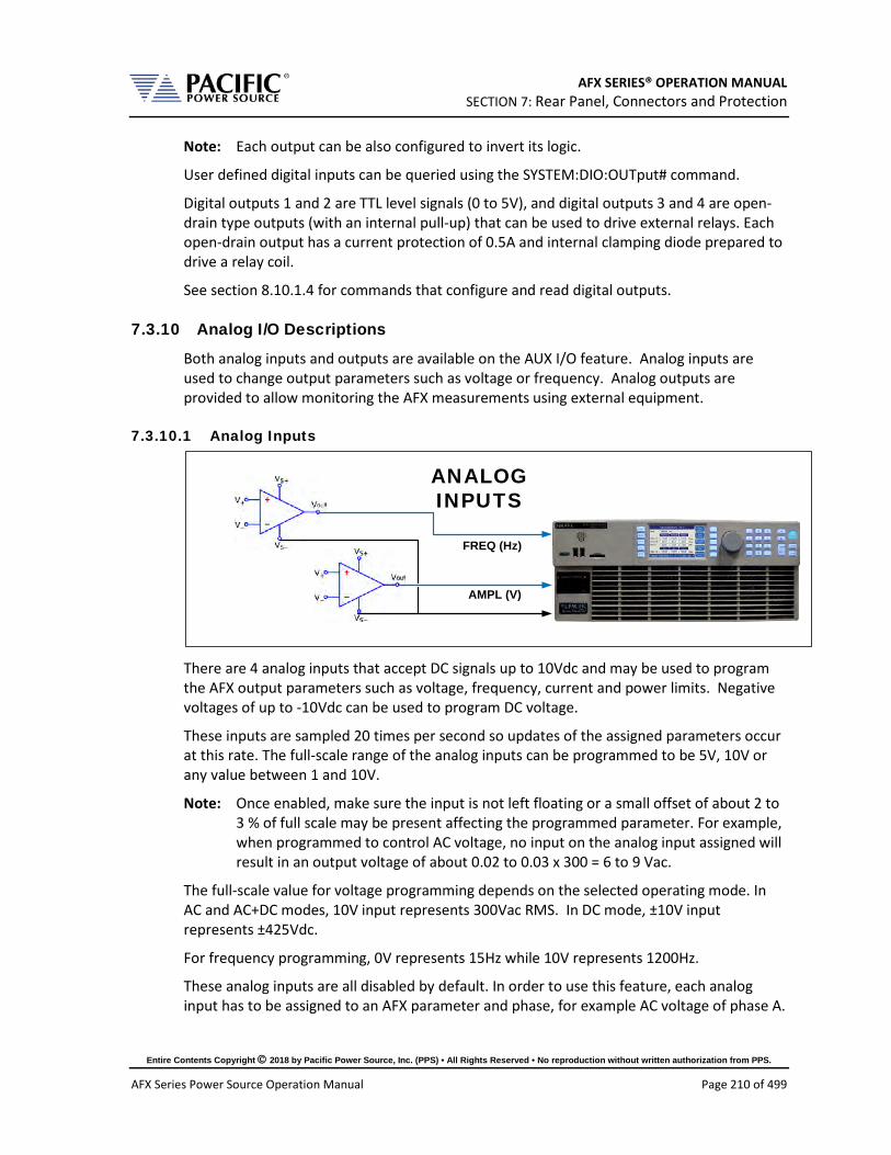
AFX SERIES® OPERATION MANUAL SECTION 7: Rear Panel, Connectors and Protection
Entire Contents Copyright 2018 by Pacific Power Source, Inc. (PPS) • All Rights Reserved • No reproduction without written authorization from PPS.
AFX Series Power Source Operation Manual Page 210 of 499
Note: Each output can be also configured to invert its logic.
User defined digital inputs can be queried using the SYSTEM:DIO:OUTput# command.
Digital outputs 1 and 2 are TTL level signals (0 to 5V), and digital outputs 3 and 4 are open-drain type outputs (with an internal pull-up) that can be used to drive external relays. Each open-drain output has a current protection of 0.5A and internal clamping diode prepared to drive a relay coil.
See section 8.10.1.4 for commands that configure and read digital outputs.
7.3.10 Analog I/O Descriptions
Both analog inputs and outputs are available on the AUX I/O feature. Analog inputs are used to change output parameters such as voltage or frequency. Analog outputs are provided to allow monitoring the AFX measurements using external equipment.
7.3.10.1 Analog Inputs
ANALOGINPUTS
FREQ (Hz)
AMPL (V)
There are 4 analog inputs that accept DC signals up to 10Vdc and may be used to program the AFX output parameters such as voltage, frequency, current and power limits. Negative voltages of up to -10Vdc can be used to program DC voltage.
These inputs are sampled 20 times per second so updates of the assigned parameters occur at this rate. The full-scale range of the analog inputs can be programmed to be 5V, 10V or any value between 1 and 10V.
Note: Once enabled, make sure the input is not left floating or a small offset of about 2 to 3 % of full scale may be present affecting the programmed parameter. For example, when programmed to control AC voltage, no input on the analog input assigned will result in an output voltage of about 0.02 to 0.03 x 300 = 6 to 9 Vac.
The full-scale value for voltage programming depends on the selected operating mode. In AC and AC+DC modes, 10V input represents 300Vac RMS. In DC mode, ±10V input represents ±425Vdc.
For frequency programming, 0V represents 15Hz while 10V represents 1200Hz.
These analog inputs are all disabled by default. In order to use this feature, each analog input has to be assigned to an AFX parameter and phase, for example AC voltage of phase A.

AFX SERIES® OPERATION MANUAL SECTION 7: Rear Panel, Connectors and Protection
Entire Contents Copyright 2018 by Pacific Power Source, Inc. (PPS) • All Rights Reserved • No reproduction without written authorization from PPS.
AFX Series Power Source Operation Manual Page 211 of 499
7.3.10.2 Programming Analog Inputs The range of the analog inputs can be changed with two parameters for each input, gain and offset. For example if an input is assigned to AC voltage programming the default gain is 300V and the offset is 0V. This means that 10V at the analog input port represents a programmed voltage of 300Vrms and 0V represents 0Vrms.
Different gain and offset combinations can be used to customize the range of the analog programming input, being the “gain” the programmed value that represents the maximum input at the analog port, and “offset” the value at 0V. For example, a gain of 150V and offset of 50V produce an output of 50V to 200V for analog programming signals of 0V to 10V.
Note: Different AFX parameters have different units (Volts, Amperes, Watts, Hertz, etc.), so when an analog input parameter is changed, the gain and offset are reset to default values (zero for offset and max full-scale values for gain).
7.3.10.3 Analog Outputs
ANALOGOUTPUTS
Analog outputs are available to monitor output values for voltage, current or power using external measurement equipment. A total of four analog outputs are provided, with an output voltage range of 0 to 5V. Output scaling is fully programmable for each measurement with an offset and gain.
For example, for RMS voltage measurements the default gain is 300V and offset is 0V. This means that measurements of 0 to 300V generate monitoring voltages of 0 to 5V. An offset of 50V and a gain of 150V will mean that measurements in the range of 50 to 200V will be mapped to the analog output range of 0 to 5V.
Analog outputs are available to monitor output values for voltage, current or power using external measurement equipment. A total of four analog outputs are provided. Output scaling is from 0 to 10V for zero to full scale.
Pin # Signal Programs 22 AO1 Volt RMS Measurements Phase A 23 AO2 Volt RMS Measurements Phase B 24 AO3 Volt RMS Measurements Phase C 25 AO4 Total Power (all phases combined)
Table 7-3: Default Analog Output Functions

AFX SERIES® OPERATION MANUAL SECTION 7: Rear Panel, Connectors and Protection
Entire Contents Copyright 2018 by Pacific Power Source, Inc. (PPS) • All Rights Reserved • No reproduction without written authorization from PPS.
AFX Series Power Source Operation Manual Page 212 of 499
7.3.11 12 DC Power Supply
A pin in the DB25 port provides a current limited, regulated 12V supply. The maximum current capability is 0.5Adc.
There are no menus or commands associated with this output, as it is always active.
7.3.12 RS232 Description
The Tx and Rx signal on the AUX I/O connector may be used to connect to a serial port. Only Xon/Xoff handshake mode is supported on this RS232 port. For most situations, it is recommended to use the USB Device port for remote serial control applications.

AFX SERIES® OPERATION MANUAL SECTION 7: Rear Panel, Connectors and Protection
Entire Contents Copyright 2018 by Pacific Power Source, Inc. (PPS) • All Rights Reserved • No reproduction without written authorization from PPS.
AFX Series Power Source Operation Manual Page 213 of 499
7.3.13 Front Panel Operation of AUX I/O Functions
The auxiliary I/O functions can be configured and programmed from the front panel using the SYSTEM menu (Press SYST key to left of the LCD screen). This section describes the available AUX I/O program screens and parameters for each function.
7.3.13.1 Accessing AUX I/O Screens. From the SYSTEM MENU, scroll to the INTERFACE entry and press the shuttle or ENTER key as indicated below. If the Interface selection is not visible, press the “More” soft key to display the second System Menu screen.
Next, scroll to the “Digital & Analog I/Os” entry at the bottom of the INTERFACE SETUP screen.
This will display a list of available Auxiliary I/O functions and features. To display the second of two DIGITAL & ANALOG I/Os screens, use the “More” soft key.
To select the desired function, use the knob to scroll up or down. Once selected, press the Shuttle know or ENTER key to open the relevant I/O control screen.
Each screen is covered in the following sections in more detail.
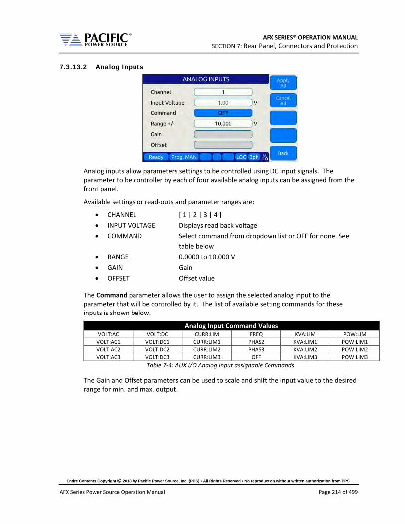
AFX SERIES® OPERATION MANUAL SECTION 7: Rear Panel, Connectors and Protection
Entire Contents Copyright 2018 by Pacific Power Source, Inc. (PPS) • All Rights Reserved • No reproduction without written authorization from PPS.
AFX Series Power Source Operation Manual Page 214 of 499
7.3.13.2 Analog Inputs
Analog inputs allow parameters settings to be controlled using DC input signals. The parameter to be controller by each of four available analog inputs can be assigned from the front panel.
Available settings or read-outs and parameter ranges are:
• CHANNEL [ 1 | 2 | 3 | 4 ] • INPUT VOLTAGE Displays read back voltage • COMMAND Select command from dropdown list or OFF for none. See
table below • RANGE 0.0000 to 10.000 V • GAIN Gain • OFFSET Offset value
The Command parameter allows the user to assign the selected analog input to the parameter that will be controlled by it. The list of available setting commands for these inputs is shown below.
Analog Input Command Values VOLT:AC VOLT:DC CURR:LIM FREQ KVA:LIM POW:LIM
VOLT:AC1 VOLT:DC1 CURR:LIM1 PHAS2 KVA:LIM1 POW:LIM1 VOLT:AC2 VOLT:DC2 CURR:LIM2 PHAS3 KVA:LIM2 POW:LIM2 VOLT:AC3 VOLT:DC3 CURR:LIM3 OFF KVA:LIM3 POW:LIM3
Table 7-4: AUX I/O Analog Input assignable Commands
The Gain and Offset parameters can be used to scale and shift the input value to the desired range for min. and max. output.

AFX SERIES® OPERATION MANUAL SECTION 7: Rear Panel, Connectors and Protection
Entire Contents Copyright 2018 by Pacific Power Source, Inc. (PPS) • All Rights Reserved • No reproduction without written authorization from PPS.
AFX Series Power Source Operation Manual Page 215 of 499
7.3.13.3 Analog Outputs
Analog outputs allow external equipment to monitor power source output values using an analog DC output signal. The assignment of measurement functions to each of four available outputs can be configured from the front panel.
Available settings are:
• CHANNEL [ 1 | 2 | 3 | 4 ] • OUTPUT VOLTAGE Output setting • MEASUREMENT Select measurement to be assigned to output • RANGE 0.0000 to 5.000 V • GAIN 0.000 to 1000 • OFFSET – 1000 to +1000

AFX SERIES® OPERATION MANUAL SECTION 7: Rear Panel, Connectors and Protection
Entire Contents Copyright 2018 by Pacific Power Source, Inc. (PPS) • All Rights Reserved • No reproduction without written authorization from PPS.
AFX Series Power Source Operation Manual Page 216 of 499
7.3.13.4 Digital Inputs
Digital Inputs allow external equipment such as PLCs. to control the power source operation. The assignment functions to each available input can be configured from the front panel.
Available settings are:
• CHANNEL [ 1 | 2 | 3 ] • STATE Displays input state • RISING CMD Set command string to execute on rising edge • FALLING CMD Set command string to execute on falling edge • FILTER SIZE 0 to 10,000,000 msec
7.3.13.5 Digital Outputs
Digital Outputs can be used to trigger or control external equipment. The events assignable to each digital output can be selected using the Function field.
Available settings are:
• CHANNEL [ 1 | 2 | 3 | 4 ] • STATE Displays current state • FUNCTION Assigns state to selected channel. Available states are: • INV. LOGIC [ ON | OFF ] Reverses polarity

AFX SERIES® OPERATION MANUAL SECTION 7: Rear Panel, Connectors and Protection
Entire Contents Copyright 2018 by Pacific Power Source, Inc. (PPS) • All Rights Reserved • No reproduction without written authorization from PPS.
AFX Series Power Source Operation Manual Page 217 of 499
Events that can be assigned to digital outputs are listed in the table below and can be set using the Function field.
Digital Output Assignable Events EVENT Description Indication FAULT Output goes high on fault event 1 = Fault occurred, 0 = No Fault
FORM Output FORM state 1 = SINGLE, 0 = SPLIT/THREE
HIGH Fixed Output high 1 = ON
LOW Fixed Output low 0 = OFF
OUTPUT STATE Output Relay State 1 = ON (enabled), 0 = OFF (disabled)
PROGRAM Output goes high when Program is selected 1 = Steady State Program, 0 = Manual mode
REMOTE Output goes high when unit is in REMOTE state 1 = REMOTE state, -0 = LOCAL state
TRANSIENT Output goes high when transient is running 1 = Running/Paused/Stepping, 0 = Stopped
XFMR_COUPLING Indicates output coupling mode 1 = Transformer Coupled, 0 = Direct Coupled
Table 7-5: AUX I/O Digital Output assignable Events or Conditions
7.3.13.6 Polarity Selection for DO3 and DO4 vs DO1 and DO2 The two open drain outputs DO3 and DO4 have internal 1 kΩ pull-up resistors to +5.5V. These outputs can be used as regular digital outputs (open-drain type) if needed. However, the logic will be inverted because a “direct” logic for the relay drive means an “inverted” logic for the open drain output. The FET being on means the relay coil active, but with a pull-up the output goes to low.
DO3 and DO4 use direct logic for the relay drive, which means that if the inverting logic is not active and there is a “1” written to the digital output, an internal FET will be activated causing a “low” in the open drain output.
Each digital output can be configured to have separate inverting logic, so the user can configure these 2 to be inverting and have the normal direct logic when used as open-drain outputs.
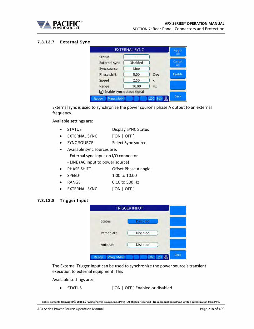
AFX SERIES® OPERATION MANUAL SECTION 7: Rear Panel, Connectors and Protection
Entire Contents Copyright 2018 by Pacific Power Source, Inc. (PPS) • All Rights Reserved • No reproduction without written authorization from PPS.
AFX Series Power Source Operation Manual Page 218 of 499
7.3.13.7 External Sync
External sync is used to synchronize the power source’s phase A output to an external frequency.
Available settings are:
• STATUS Display SYNC Status • EXTERNAL SYNC [ ON | OFF ] • SYNC SOURCE Select Sync source • Available sync sources are:
- External sync input on I/O connector - LINE (AC input to power source)
• PHASE SHIFT Offset Phase A angle • SPEED 1.00 to 10.00 • RANGE 0.10 to 500 Hz • EXTERNAL SYNC [ ON | OFF ]
7.3.13.8 Trigger Input
The External Trigger Input can be used to synchronize the power source’s transient execution to external equipment. This
Available settings are:
• STATUS [ ON | OFF ] Enabled or disabled

AFX SERIES® OPERATION MANUAL SECTION 7: Rear Panel, Connectors and Protection
Entire Contents Copyright 2018 by Pacific Power Source, Inc. (PPS) • All Rights Reserved • No reproduction without written authorization from PPS.
AFX Series Power Source Operation Manual Page 219 of 499
• IMMEDIATE [ ON | OFF ] Ignore phase update setting if ON • AUTORUN [ ON | OFF ] No RUN command required if ON
7.3.13.9 Strobe Output
The Strobe Output is used to synchronize or trigger external equipment to an event occurring on the AC power source.
Available settings are:
• TRANSIENT ON = Strobe output on transient start • OUTPUT STATE ON = Strobe output on relay close • SOURCE ON = Strobe output on any program parameter change
7.3.13.10 Remote Control
The remote control input is used to control operation of the output relay.
Available settings are:
• DISABLED No remote output control • REMOTE INHIBIT Contact closure needed to close output relay • REMOTE ENABLE Contact closure or front panel can control output relay
See Section 6.8.5.6.

AFX SERIES® OPERATION MANUAL SECTION 7: Rear Panel, Connectors and Protection
Entire Contents Copyright 2018 by Pacific Power Source, Inc. (PPS) • All Rights Reserved • No reproduction without written authorization from PPS.
AFX Series Power Source Operation Manual Page 220 of 499
7.4 System Interface Bus Connectors
CAUTION
SHOCK HAZARD: DO NOT remove safety covers from the two System Interface DVI Connectors.
AVERTISSEMENT
RISQUE DE CHOC: NE PAS retirer les capots de sécurité des deux connecteurs d´interface DVI
The system interface bus is not user-accessible. It consists of two Digital Visual Interface (DVI-I dual link) connectors that are covered by a protective cover. There are no user accessible signals on the system interface bus. It is used for system configuration cabinet systems only.

AFX SERIES® OPERATION MANUAL SECTION 8: Remote Control Programming
Entire Contents Copyright 2018 by Pacific Power Source, Inc. (PPS) • All Rights Reserved • No reproduction without written authorization from PPS.
AFX Series Power Source Operation Manual Page 221 of 499
8 Remote Control Programming
8.1 Overview If your unit is fitted with a computer interface option then RS232, USB or LAN connector will be present on the rear panel based on the order configuration. The interface allows the power source settings to be configured remotely and measurement data to be retrieved for analysis and test report generation.
The front panel LOCAL key allows the user to restore LOCAL CONTROL unless the Bus controller has sent a LOCAL LOCKOUT (LLO) message. The Bus Controller may restore LOCAL CONTROL by sending a GOTO LOCAL (GTL) message.
8.1.1 Programming Conventions and Notations
The following conventions and notations are used in this section of the manual:
1. COMMANDS are shown in the left hand column in BOLD with NO underline.
2. Command DESCRIPTIONS appear in the right hand column.
3. SCPI is "Standard Commands for Programmable Instruments -1992". Refer to the SCPI 1992 standard for more information. The full standard publication is available from the IVI Foundation at http://www.ivifoundation.org/
4. Some SCPI keywords are optional, and are ignored by the device. Optional keywords are enclosed in [ ] brackets.
5. Lowercase letters of commands shown are also optional.
6. The SCPI standard requires uppercase text in all SCPI commands (start with : ), however, the command parser is not case sensitive and will accept commands sent in lower case. It is recommended that programming formats follow the SCPI standard.
7. Some SCPI commands have query command counterparts as noted. A query command consists of the command with a question mark ( ? ) appended at the end. Parameters cannot be sent with a query. IEEE-488.2 commands do not have query counterparts unless explicitly shown with a question mark appended.
8. IEEE488.2 common commands start with an asterisk ( * ) and are not case sensitive.
9. All required Functional Elements for devices are implemented.
10. All numerical values are ASCII encoded decimal strings consisting of 1 or more ASCII digits. 8 and 16 bit register values are binary weighted values represented by an ASCII string of 1 or more decimal digits. One exception, the Serial Poll byte, is an 8 bit hexadecimal byte.
11. Multiple Commands and Queries may be sent in one Program Message but each must be separated by a semicolon ( ; ). The term 'Program Message' refers to one or more commands and/or queries sent to the controller as one continuous string and is not to be confused with Stored Programs (1-99) within the controller.

AFX SERIES® OPERATION MANUAL SECTION 8: Remote Control Programming
Entire Contents Copyright 2018 by Pacific Power Source, Inc. (PPS) • All Rights Reserved • No reproduction without written authorization from PPS.
AFX Series Power Source Operation Manual Page 222 of 499
12. Multiple data parameter names and values must be separated by commas.
13. Voltage and Waveform parameter names without a channel number suffix (1,2,3) may be used to set all 3 channels (phases) simultaneously, as an alternative to setting each separately to the same value.
14. Multiple keyword messages may be sent without duplicating the first level SCPI keyword i.e., SOURce). e.g., :SOURce:VOLTage1,120; FREQuency,60 A keyword is a single word beginning with a colon (:).
15. Program Messages MUST be terminated with a LINE FEED (0Ahex, 10dec) or END (EOI) signal. This is referred to as an end-of-string <eos>. A Carriage Return character (0Dhex, 13dec) is converted to a LINE FEED by the power source. Further SCPI commands shall begin with a first level keyword (i.e.,:SOURce:).
16. All values shown in angle brackets <> are examples of real values used with commands but labels are sometimes used to indicate a variable which is not known until actual time of use. e.g., <AMPS meter range> might actually be <50>. Units such as AAC, Hz. or % shown after the angle bracketed value are not to be included inside the value, but are shown as a reference to the units. The angle brackets are not part of the value.
17. The controller data input buffer is 8k bytes, as is its data output buffer. No program message may exceed this length.
18. All :SOURce: commands also support queries. An alternate method of writing or reading the presently active :SOURce:FORM, COUPLing, VOLTage, FREQuency, and CURRent:LIMit values is to use PROGram 0 (see examples). PROGram 0 contains the MANUAL MODE parameters. NOTE: Sending any :SOURce: command invokes MANUAL MODE and REMOTE CONTROL.
19. Command strings may contain spaces.
20. The controller interface accepts IEEE-488.2 <nr1>, <nr2> and <nr3> numeric formats. Most query responses are <nr1> or <nr2> types. i.e., <nr1>=120, <nr2>=120.0, <nr3>=1.2E+02.
21. Follow any command (in the same Program Message) with *OPC to detect completion of the command or termination of a Transient event. An SRQ occurs when the command or Transient is complete (if ESB bit is set in SRE and OPC bit is set in ESE). *OPC? may be used in the same manner.
8.1.2 Command Terminators
Allowable terminator characters are:
Character ASCII Dec value Hex value
Carriage Return <CR> 13 0x0d

AFX SERIES® OPERATION MANUAL SECTION 8: Remote Control Programming
Entire Contents Copyright 2018 by Pacific Power Source, Inc. (PPS) • All Rights Reserved • No reproduction without written authorization from PPS.
AFX Series Power Source Operation Manual Page 223 of 499
Line Feed <LF> 10 0x0a
8.2 Remote Control Command Descriptions by Subsystem This section covers detailed description of the available commands by category. The following command categories are defined.
Command Subsystem Description
CALIBRATE These commands perform calibration functions MEASURE These commands are used to measure voltage, current,
power and any other measurement parameters from the instrument.
OUTPUT These command control the power source output PROGRAM These commands control programmed settings and
transient segments SENSE These commands control the voltage sense modes SOURCE These commands are used to set instrument settings STATUS These commands are used to control or query status and
error messages. SYSTEM These commands are used to control system level setting
such as interfaces, special operating modes or other special instrument specific functions.
Table 8-1: Available SCPI Command Subsystems

AFX SERIES® OPERATION MANUAL SECTION 8: Remote Control Programming
Entire Contents Copyright 2018 by Pacific Power Source, Inc. (PPS) • All Rights Reserved • No reproduction without written authorization from PPS.
AFX Series Power Source Operation Manual Page 224 of 499
8.3 Calibration Commands Calibration commands allow for fully automated calibration of the power source.
Note: It is not recommended for the end user to use these command unless calibration must be automated. Any errors in using these commands could invalidate user calibration data. Pacific Power Source recommends the use of a competent and authorized calibration lab to perform routine calibration.
The following calibration commands are supported. Commands marked “UPC” are provided for backward compatibility with UPC controller based PPS power sources.
8.3.1 AFX Calibration Commands Command Syntax CALibrate:COEFFicients:OFFSET:VOLTage Description Calibrates output DC voltage offset to lowest possible level. Parameters None Parameter Format n/a Example CAL:OFFSET:VOLT
Command Syntax CALibrate:COEFFicients:OFFSET:CURRent Description Calibrates output DC current offset to lowest possible level Parameters None Parameter Format n/a Example CAL:OFFSET:CURR
Command Syntax CALibrate:COEFFicients:NOISE:VOLTage Description Calibrates output voltage noise to lowest possible level. Parameters None Parameter Format n/a Example n/a
Command Syntax CALibrate:COEFFicients:NOISE:CURRent Description Calibrates output current noise to lowest possible level. Parameters None Parameter Format n/a Example n/a
Command Syntax CALibrate:COEFFicients:GAIN:VOLTage[:AC] <cr> Description Loads values measured with an external DVM for calibration of AC
voltage output and metering. The first 3 values are Voltages measured at the output relay of the power source for each phase. The second set of 3 values are Voltages measured at the external voltage sense points (at the load) for each phase.
Parameters External reference voltage readings for each phase Parameter Format n/a Example n/a

AFX SERIES® OPERATION MANUAL SECTION 8: Remote Control Programming
Entire Contents Copyright 2018 by Pacific Power Source, Inc. (PPS) • All Rights Reserved • No reproduction without written authorization from PPS.
AFX Series Power Source Operation Manual Page 225 of 499
Command Syntax CALibrate:COEFFicients:GAIN:CURRent[:AC] <cr> Description Loads values measured with an external shunt and DVM for
calibration of AC current metering. The first 3 values are currents measured at the output of the power source for each phase.
Parameters External reference current reading Parameter Format n/a Example n/a Query Format No Returned Data Format n/a Query Example n/a
Command Syntax CALibrate:COEFFicients:GAIN:VOLTage:DC <cr> Description Loads values measured with an external DVM for calibration of DC
voltage output and metering. The first 3 values are Voltages measured at the output relay of the power source for each phase. The second set of 3 values are Voltages measured at the EXTernal Sense point (at the load) for each phase
Parameters None Parameter Format n/a Example n/a
Command Syntax CALibrate:COEFFicients:GAIN:CURRent:DC <cr> Description Loads values measured with an external shunt and DVM for
calibration of DC current metering. The first 3 values are currents measured at the output of the power source for each phase.
Parameters None Parameter Format n/a Example n/a
Command Syntax CALibrate:RESET Description Clears all calibration coefficients. Sending this command resets all
calibration factors to defaults. After sending this command, programming and metering remains functional and will still meet spec.
Parameters None Parameter Format n/a Example CAL:RESET
Query Format CALibrate:COEFFicients:ALL? Description Returns all eighteen calibration factors as a comma delimited list. Returned Data Format <nr1>,…,<nr1> Query Example CAL:FACT:ALL?
0,0,0,0,0,0,0,0,0,0,0,0,0,0,0,0,0,0
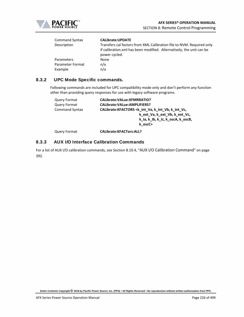
AFX SERIES® OPERATION MANUAL SECTION 8: Remote Control Programming
Entire Contents Copyright 2018 by Pacific Power Source, Inc. (PPS) • All Rights Reserved • No reproduction without written authorization from PPS.
AFX Series Power Source Operation Manual Page 226 of 499
Command Syntax CALibrate:UPDATE Description Transfers cal factors from XML Calibration file to NVM. Required only
if calibration.xml has been modified. Alternatively, the unit can be power cycled.
Parameters None Parameter Format n/a Example n/a
8.3.2 UPC Mode Specific commands. Following commands are included for UPC compatibility mode only and don’t perform any function other than providing query responses for use with legacy software programs.
Query Format CALibrate:VALue:XFMRRATIO? Query Format CALibrate:VALue:AMPLIFIERS? Command Syntax CALibrate:KFACTORS <k_int_Va, k_int_Vb, k_int_Vc,
k_ext_Va, k_ext_Vb, k_ext_Vc, k_Ia, k_Ib, k_Ic, k_oscA, k_oscB, k_oscC>
Query Format CALibrate:KFACTors:ALL?
8.3.3 AUX I/O Interface Calibration Commands
For a list of AUX I/O calibration commands, see Section 8.10.4, “AUX I/O Calibration Command” on page 392.
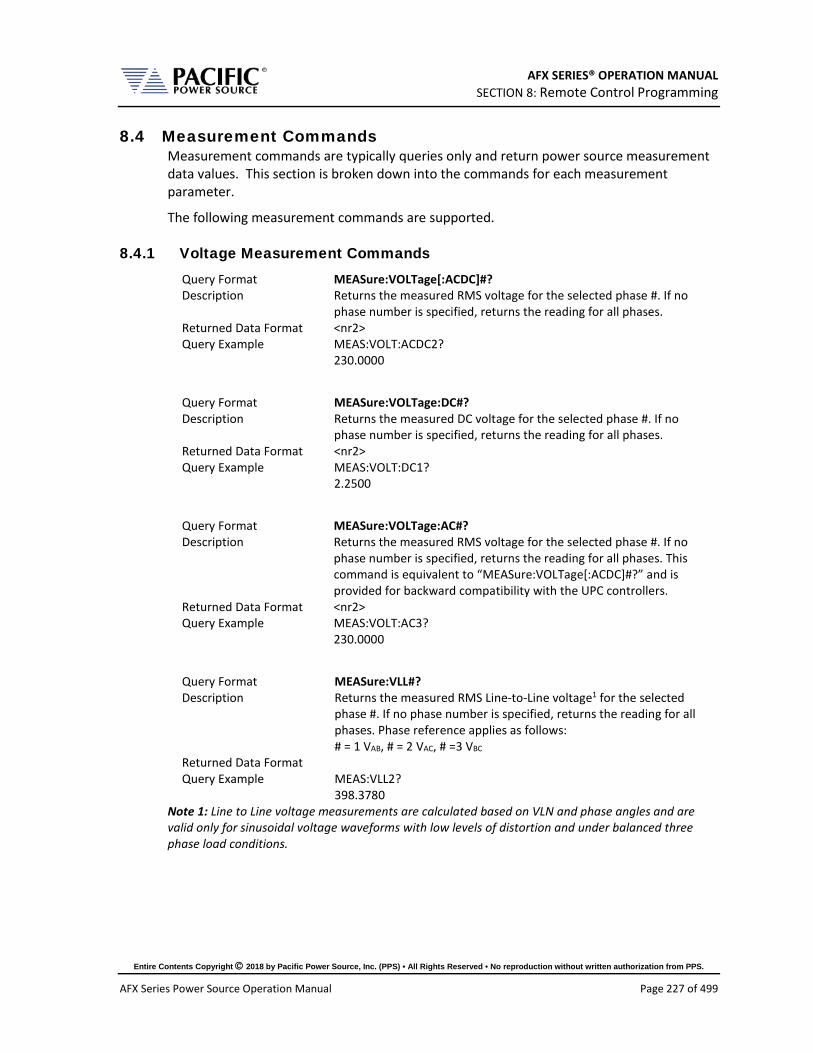
AFX SERIES® OPERATION MANUAL SECTION 8: Remote Control Programming
Entire Contents Copyright 2018 by Pacific Power Source, Inc. (PPS) • All Rights Reserved • No reproduction without written authorization from PPS.
AFX Series Power Source Operation Manual Page 227 of 499
8.4 Measurement Commands Measurement commands are typically queries only and return power source measurement data values. This section is broken down into the commands for each measurement parameter.
The following measurement commands are supported.
8.4.1 Voltage Measurement Commands Query Format MEASure:VOLTage[:ACDC]#? Description Returns the measured RMS voltage for the selected phase #. If no
phase number is specified, returns the reading for all phases. Returned Data Format <nr2> Query Example MEAS:VOLT:ACDC2?
230.0000
Query Format MEASure:VOLTage:DC#? Description Returns the measured DC voltage for the selected phase #. If no
phase number is specified, returns the reading for all phases. Returned Data Format <nr2> Query Example MEAS:VOLT:DC1?
2.2500
Query Format MEASure:VOLTage:AC#? Description Returns the measured RMS voltage for the selected phase #. If no
phase number is specified, returns the reading for all phases. This command is equivalent to “MEASure:VOLTage[:ACDC]#?” and is provided for backward compatibility with the UPC controllers.
Returned Data Format <nr2> Query Example MEAS:VOLT:AC3?
230.0000
Query Format MEASure:VLL#? Description Returns the measured RMS Line-to-Line voltage1 for the selected
phase #. If no phase number is specified, returns the reading for all phases. Phase reference applies as follows: # = 1 VAB, # = 2 VAC, # =3 VBC
Returned Data Format Query Example MEAS:VLL2?
398.3780 Note 1: Line to Line voltage measurements are calculated based on VLN and phase angles and are valid only for sinusoidal voltage waveforms with low levels of distortion and under balanced three phase load conditions.

AFX SERIES® OPERATION MANUAL SECTION 8: Remote Control Programming
Entire Contents Copyright 2018 by Pacific Power Source, Inc. (PPS) • All Rights Reserved • No reproduction without written authorization from PPS.
AFX Series Power Source Operation Manual Page 228 of 499
8.4.2 Frequency Measurement Commands Query Format MEASure:FREQuency? Description Returns the fundamental frequency. Returned Data Format <nr2> Query Example MEAS:FREQ?
50.0000
8.4.3 Current Measurement Commands Query Format MEASure:CURRent[:ACDC]#? Description Returns the measured RMS current for the selected phase #. If no
phase number is specified, returns the reading for all phases. Returned Data Format <nr2> Query Example MEAS:CURR:ACDC1?
21.1587
Query Format MEASure:CURRent:PEAK#[:ABSolute]? Description Returns the measured peak current value for the selected phase #. If
no phase number is specified, returns the reading for all phases. Returned Data Format <nr2> Query Example MEAS:CURR:PEAK?
45.5845, 47.3213, 48,2234
Query Format MEASure:CURRent:PEAK#[:ABSolute]:HOLD? Description Returns the measured peak hold current value for the selected phase
#. If no phase number is specified, returns the reading for all phases. This reading accumulates the highest recorded absolute peak current until reset using the MEASure:CURRent:PEAK#:RESet command.
Returned Data Format <nr2> Query Example MEAS:CURR:PEAK:HOLD?
58.5845, 57.3213, 58,2234
Query Format MEASure:CURRent:PEAK#:MINimum? Description Returns the lowest measured peak current value for the selected
phase #. If no phase number is specified, returns the reading for all phases.
Returned Data Format <nr2> Query Example MEAS:CURR:PEAK:MIN?
1.0001, 0.8451, 0.4871
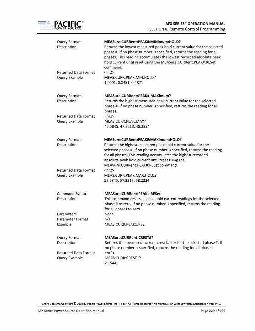
AFX SERIES® OPERATION MANUAL SECTION 8: Remote Control Programming
Entire Contents Copyright 2018 by Pacific Power Source, Inc. (PPS) • All Rights Reserved • No reproduction without written authorization from PPS.
AFX Series Power Source Operation Manual Page 229 of 499
Query Format MEASure:CURRent:PEAK#:MINimum:HOLD? Description Returns the lowest measured peak hold current value for the selected
phase #. If no phase number is specified, returns the reading for all phases. This reading accumulates the lowest recorded absolute peak hold current until reset using the MEASure:CURRent:PEAK#:RESet command.
Returned Data Format <nr2> Query Example MEAS:CURR:PEAK:MIN:HOLD?
1.0001, 0.8451, 0.4871
Query Format MEASure:CURRent:PEAK#:MAXimum? Description Returns the highest measured peak current value for the selected
phase #. If no phase number is specified, returns the reading for all phases.
Returned Data Format <nr2> Query Example MEAS:CURR:PEAK:MAX?
45.5845, 47.3213, 48,2234
Query Format MEASure:CURRent:PEAK#:MAXimum:HOLD? Description Returns the highest measured peak hold current value for the
selected phase #. If no phase number is specified, returns the reading for all phases. This reading accumulates the highest recorded absolute peak hold current until reset using the MEASure:CURRent:PEAK#:RESet command.
Returned Data Format <nr2> Query Example MEAS:CURR:PEAK:MAX:HOLD?
58.5845, 57.3213, 58,2234
Command Syntax MEASure:CURRent:PEAK#:RESet Description This command resets all peak hold current readings for the selected
phase # to zero. If no phase number is specified, returns the reading for all phases.to zero.
Parameters None Parameter Format n/a Example MEAS:CURR:PEAK1:RES
Query Format MEASure:CURRent:CREST#? Description Returns the measured current crest factor for the selected phase #. If
no phase number is specified, returns the reading for all phases. Returned Data Format <nr2> Query Example MEAS:CURR:CREST1?
2.1544

AFX SERIES® OPERATION MANUAL SECTION 8: Remote Control Programming
Entire Contents Copyright 2018 by Pacific Power Source, Inc. (PPS) • All Rights Reserved • No reproduction without written authorization from PPS.
AFX Series Power Source Operation Manual Page 230 of 499
Query Format MEASure:CURRent:DC#? Description Returns the measured DC current for the selected phase #. If no
phase number is specified, returns the reading for all phases. Returned Data Format <nr2> Query Example MEAS:CURR:DC1?
0.0000
Query Format MEASure:CURRent:AC#?" Description Returns the measured RMS current for the selected phase #. If no
phase number is specified, returns the reading for all phases. This command is equivalent to “MEASure:CURRent[:ACDC]#?” and is provided for backward compatibility with the UPC controllers.
Returned Data Format <nr2> Query Example MEAS:CURR:AC1?
21.1587
8.4.4 Power Measurement Commands Query Format MEASure:POWer#? Description Returns the true power for the selected phase # in kW. If no phase
number is specified, returns the reading for all phases. Returned Data Format <nr2> Query Example MEAS:POWer1?
4.4203
Query Format MEASure:KVA#? Description Returns the true apparent for the selected phase # in kVA. If no
phase number is specified, returns the reading for all phases. Returned Data Format <nr2> Query Example MEAS:KVA1?
4.8665
Query Format MEASure:PF#? Description Returns the true apparent for the selected phase # in kVA. If no
phase number is specified, returns the reading for all phases. Returned Data Format <nr2> Query Example MEAS:PF1?
0.9083
8.4.5 KWh Measurement Commands Query Format MEASure:KWHour#? Description Returns the accumulated energy measurement for the selected
phase # in kWh. If no phase number is specified, returns the total summed KWh for all phases.
Returned Data Format <nr2> Query Example MEASure:KWHour?
12.4203
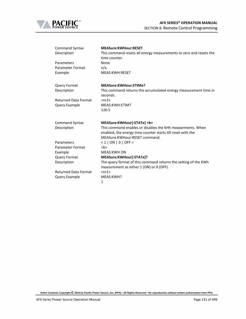
AFX SERIES® OPERATION MANUAL SECTION 8: Remote Control Programming
Entire Contents Copyright 2018 by Pacific Power Source, Inc. (PPS) • All Rights Reserved • No reproduction without written authorization from PPS.
AFX Series Power Source Operation Manual Page 231 of 499
Command Syntax MEASure:KWHour:RESET Description This command resets all energy measurements to zero and resets the
time counter. Parameters None Parameter Format n/a Example MEAS:KWH:RESET
Query Format MEASure:KWHour:ETIMe? Description This command returns the accumulated energy measurement time in
seconds. Returned Data Format <nr2> Query Example MEAS:KWH:ETIM?
120.5
Command Syntax MEASure:KWHour[:STATe] <b> Description This command enables or disables the KHh measerments. When
enabled, the energy time counter starts till reset with the MEASure:KWHour:RESET command.
Parameters < 1 | ON | 0 | OFF > Parameter Format <b> Example MEAS:KWH ON Query Format MEASure:KWHour[:STATe]? Description The query format of this command returns the setting of the KWh
measurement as either 1 (ON) or 0 (OFF). Returned Data Format <nr1> Query Example MEAS:KWH?
1

AFX SERIES® OPERATION MANUAL SECTION 8: Remote Control Programming
Entire Contents Copyright 2018 by Pacific Power Source, Inc. (PPS) • All Rights Reserved • No reproduction without written authorization from PPS.
AFX Series Power Source Operation Manual Page 232 of 499
8.4.6 Other Measurement Commands Query Format MEASure:TEMPerature:AMBient? Description Returns the ambient temperature of the power source in degrees
celcius. Returned Data Format <nr1> Query Example MEAS:TEMP:AMB?
24
Query Format MEASure:ALL#? Description Returns 14 parametric measurements for the selected phase # as a
comma delimited string. The # is used to specify phase A, B or C using 1, 2 or 3 respectively. If phase reference is omitted, measurement data for all three phases is returned. Value order for each phase is:
All Firmware Revisions 1. Frequency (repeats for each phase)
2. VLL AC+DC
3. VLL AC RMS 4. VLL DC 5. VLN AC+DC 6. VLN AC 7. VLN DC 8. I AC 9. I DC 10. POWER 11. APP POWER 12. I PEAK 13. PF 14. CF FW Rev 2.0.0 ~ 2.2.15 15. PEAK CURRENT 16. kWH 17. Elapsed Time for KWH FW Rev 3.3.12 15. PEAK CURRENT 16. VOLTAGE THD 17. CURRENAT THD 18. PF Angle 19.DISPLACEMENT FACTOR 20. DISTORTION FACTOR 21. kWH 22. Elapsed Time for KWH
Thus, each phase data set consists of 14 values. For all phases, a total of 42 comma separated values are returned.
Returned Data Format <nr2>,<nr2>,….,<nr2>,<nr2> Query Example MEAS:ALL1?
1200.0000,519.5981,519.5981,0.0028,299.9990,299.9989,-0.0007,0.1711,-0.0016,0.0000,0.0513,0.4849,0.0000,0.0000
Query Format MEASure:ALL:CATALOG? Description Returns a comma-separated human-readable list of available
measurements in the same order as the command returns it. See MEASure:ALL#? Command for parameter list as a function of Firmware revision. Note: Available in FW Revisions 2.2.16 / 3.3.13 or higher.

AFX SERIES® OPERATION MANUAL SECTION 8: Remote Control Programming
Entire Contents Copyright 2018 by Pacific Power Source, Inc. (PPS) • All Rights Reserved • No reproduction without written authorization from PPS.
AFX Series Power Source Operation Manual Page 233 of 499
Query Format MEASure:ALL#? <OPTIONAL: List of measurements to return> Description Same as MEASure:ALL#? Command with optional user specified
parameters list. Query command returns measurement parameters as included in list in the order they are specified by the list. Note: Available in FW Revisions 2.2.16 / 3.3.13 or higher.
8.4.7 Measurement Data Logging Commands Command Syntax MEASure:LOGger:START Description Starts the logging of measurements process. The process consists of
taking measurements and saving them in a file. The log file can be found in the “datalogger” folder and is a comma separated value format (.csv) file. Measurements will be taken while the output is enabled only.
Parameters None Parameter Format n/a Example MEAS:LOG:START Query Format None
Command Syntax MEASure:LOGger:STOP Description Stops the logging process that was started with
MEASure:LOGger:START. Parameters None Parameter Format n/a Example MEAS:LOG:STOP Query Format None
Query Format MEASure:LOGger:STATe? Description Returns the state of the measurement data logging process as a
number as follows: 0 – Stopped 1 – Running 2 – Paused
Returned Data Format <nr1> Query Example MEAS:LOG:STAT?
1

AFX SERIES® OPERATION MANUAL SECTION 8: Remote Control Programming
Entire Contents Copyright 2018 by Pacific Power Source, Inc. (PPS) • All Rights Reserved • No reproduction without written authorization from PPS.
AFX Series Power Source Operation Manual Page 234 of 499
Command Syntax MEASure:LOGger:LIMit <cr> Description Sets the number of samples to get. Once the logging process reach
this limit it will stop.If the limit is set as OFF or 0 it will not stop unless MEAS:LOG:STOP is executed. The limit can be specified as a number of samples or in seconds if a character “S” is added to the number. If the limit is passed as seconds, the command will compute the number of samples based on the logging rate. The formula is: number of samples = seconds / rate. The rate can be set with: MEASure:LOGger:RATE <nr1> or queried with: MEASure:LOGger:RATE?.
Parameters < OFF | 0 > XS where X is a time limit in seconds X where X is the limit in number of samples
Parameter Format <cr> Examples MEAS:LOG:LIM OFF
MEAS:LOG:LIM 20S MEAS:LOG:LIM 100
Query Format MEASure:LOGger:LIMit? Returned Data Format 0 Query Example MEAS:LOG:LIM?
10000
Command Syntax MEASure:LOGger:FILELimit <nr1> Description Sets the limit of samples to save in the file. If the limit is reached and
the logging process continues, a new file will be created. Parameters Limit in number of samples. Parameter Format <nr1> Example MEAS:LOG:FILEL 100 Query Format MEASure:LOGger:FILELimit? Returned Data Format <nr1> Query Example MEAS:LOG:FILEL?
10000
Command Syntax MEASure:LOGger:FILEName <cr> Description Sets the data logging file name Parameters Filename between double quotes Parameter Format <cr> Example MEAS:LOG:FILEN “Measurement-AC+DC” Query Format MEASure:LOGger:FILEName? Returned Data Format <cr> Query Example MEAS:LOG:FILEN?
Measurement-AC+DC

AFX SERIES® OPERATION MANUAL SECTION 8: Remote Control Programming
Entire Contents Copyright 2018 by Pacific Power Source, Inc. (PPS) • All Rights Reserved • No reproduction without written authorization from PPS.
AFX Series Power Source Operation Manual Page 235 of 499
Command Syntax MEASure:LOGger:MEMory <cr> Description Select the memory where the logging files will be saved. By default it
is RAM unless a memory stick or USB drive was inserted and selected with this command: MEAS:LOG:MEM:CAT? can be used to get the available memories.
Parameters Memory name between double quotes. Parameter Format <cr> Example MEAS:LOG:MEM “USBA” Query Format MEASure:LOGger:MEMory? Returned Data Format <cr> Query Example MEAS:LOG:MEM?
USBA
Query Format MEASure:LOGger:MEMory:CATalog? Description Returns the catalog of available memory names. Returned Data Format <cr> Query Example MEAS:LOG:MEM:CAT?
RAM, USBA
Command Syntax MEASure:LOGger:RATE Description Sets the frequency at which the logging process will take
measurements. Parameters Frequency in Hz. Range is 1 Hz through 10 Hz. Parameter Format <nr1> Example MEAS:LOG:RATE 5 Query Format MEASure:LOGger:RATE? Returned Data Format <nr1> Query Example MEAS:LOG:RATE?
5
Command Syntax MEASure:LOGger:TIMEstamp <cr> Description Sets the time stamp format that will be attached to every
measurement record in the measurement log file. Parameters < DATE | 0 | TIME | 1 | ALL | 2 > Parameter Format <cr> Example MEAS:LOG:TIME ALL Query Format MEASure:LOGger:TIMEstamp? Returned Data Format <nr1> Query Example MEAS:LOG:TIME?
2

AFX SERIES® OPERATION MANUAL SECTION 8: Remote Control Programming
Entire Contents Copyright 2018 by Pacific Power Source, Inc. (PPS) • All Rights Reserved • No reproduction without written authorization from PPS.
AFX Series Power Source Operation Manual Page 236 of 499
8.4.8 Waveform Capture Commands Waveform capture commands may be used to retrieve time domain voltage and current waveform captures similar to those of a digital oscilloscope.
Query Format FETCH:WAVEform:VOLTage#? Description Returns time domain data for voltage on selected phase #. # = 1, 2 or
3. Returns a string of <nr2> type numbers, comma delimited. Only a single waveform may be queried in a command. Note: In UPC Compatibility mode, a total of 512 data points are returned. In AFX mode, 1024 data points are returned.
Returned Data Format <nr2>, <nr2>, <nr2>,……, <nr2> Query Example FETCH:WAVE:VOLT1?
0.000, 0.0001, 0.0003…., 0.000
Query Format FETCH[:WAVEform]:VLL#? Description Returns time domain data for voltage on selected Line to Line voltage
#. # = 1, 2 or 3. Returns a string of <nr2> type numbers, comma delimited. Only a single waveform may be queried in a command. Note: In UPC Compatibility mode, a total of 512 data points are returned. In AFX mode, 1024 data points are returned.
Returned Data Format <nr2>, <nr2>, <nr2>,……, <nr2> Query Example FETCH:WAVE:VLL1?
0.000, 0.0001, 0.0003…., 0.000
Query Format FETCH:WAVEform:CURRent#? Description Returns time domain data for current on selected phase #. # = 1, 2 or
3. Returns a string of <nr2> type numbers, comma delimited. Only a single waveform may be queried in a command. Note: In UPC Compatibility mode, a total of 512 data points are returned. In AFX mode, 1024 data points are returned.
Returned Data Format <nr2>, <nr2>, <nr2>,……, <nr2> Query Example FETCH:WAVE:CURR?
0.000, 0.0001, 0.0003…., 0.000
Query Format FETCH:WAVEform:INFO? Description Returns the output measurement frequency, date and time of
capture for the last waveform data fetched. Returned Data Format <nr2>, <dd/mm/yyyy>, <hh:mm:ss> Query Example FETCH:WAVE:INFO?
400.000, “05/21/2018”, “14:34:20”

AFX SERIES® OPERATION MANUAL SECTION 8: Remote Control Programming
Entire Contents Copyright 2018 by Pacific Power Source, Inc. (PPS) • All Rights Reserved • No reproduction without written authorization from PPS.
AFX Series Power Source Operation Manual Page 237 of 499
Query Format FETCH:WAVEform:PERIOD? Description Returns the number of periods captured. Minimum period is 1, max
no. of periods is 4. Returned Data Format <nr2>, <dd/mm/yyyy>, <hh:mm:ss> Query Example FETCH:WAVE:PERIOD?
400.000, “05/21/2018”, “14:34:20”
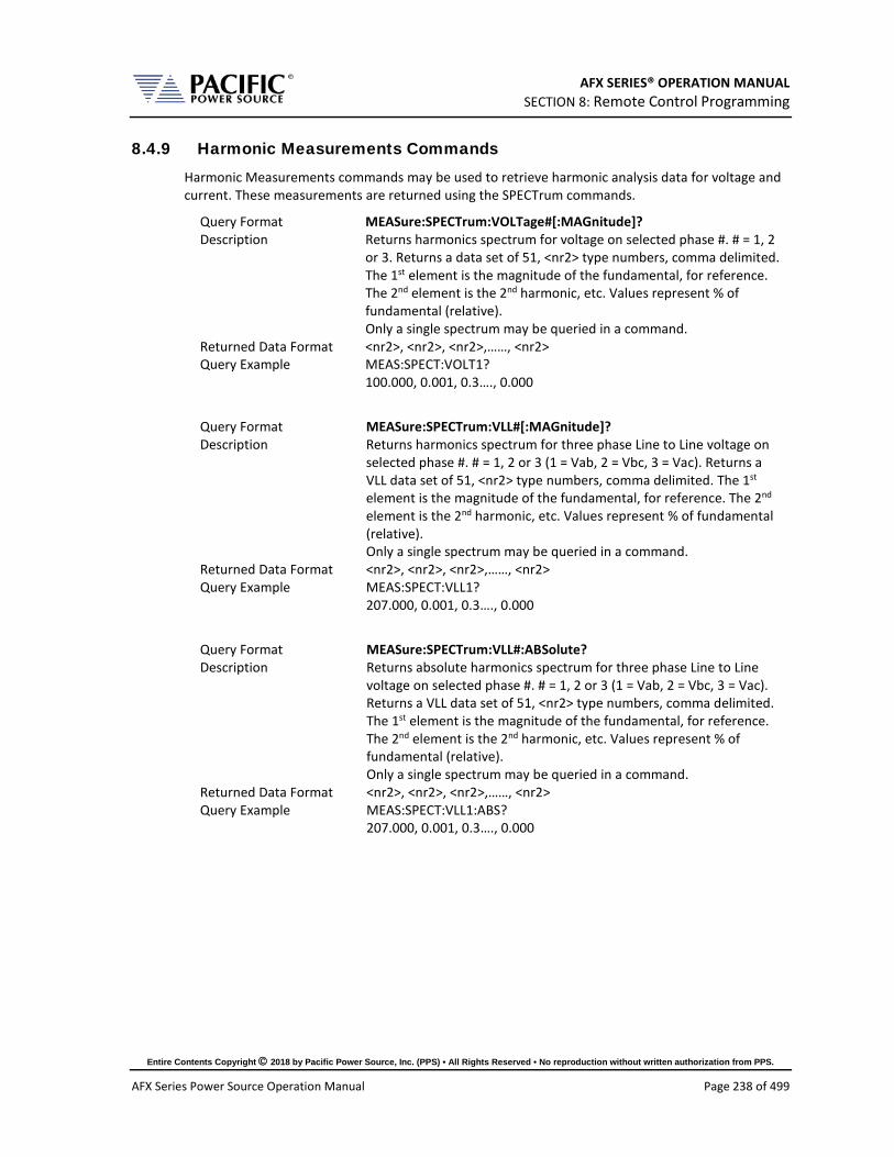
AFX SERIES® OPERATION MANUAL SECTION 8: Remote Control Programming
Entire Contents Copyright 2018 by Pacific Power Source, Inc. (PPS) • All Rights Reserved • No reproduction without written authorization from PPS.
AFX Series Power Source Operation Manual Page 238 of 499
8.4.9 Harmonic Measurements Commands Harmonic Measurements commands may be used to retrieve harmonic analysis data for voltage and current. These measurements are returned using the SPECTrum commands.
Query Format MEASure:SPECTrum:VOLTage#[:MAGnitude]? Description Returns harmonics spectrum for voltage on selected phase #. # = 1, 2
or 3. Returns a data set of 51, <nr2> type numbers, comma delimited. The 1st element is the magnitude of the fundamental, for reference. The 2nd element is the 2nd harmonic, etc. Values represent % of fundamental (relative). Only a single spectrum may be queried in a command.
Returned Data Format <nr2>, <nr2>, <nr2>,……, <nr2> Query Example MEAS:SPECT:VOLT1?
100.000, 0.001, 0.3…., 0.000
Query Format MEASure:SPECTrum:VLL#[:MAGnitude]? Description Returns harmonics spectrum for three phase Line to Line voltage on
selected phase #. # = 1, 2 or 3 (1 = Vab, 2 = Vbc, 3 = Vac). Returns a VLL data set of 51, <nr2> type numbers, comma delimited. The 1st element is the magnitude of the fundamental, for reference. The 2nd element is the 2nd harmonic, etc. Values represent % of fundamental (relative). Only a single spectrum may be queried in a command.
Returned Data Format <nr2>, <nr2>, <nr2>,……, <nr2> Query Example MEAS:SPECT:VLL1?
207.000, 0.001, 0.3…., 0.000
Query Format MEASure:SPECTrum:VLL#:ABSolute? Description Returns absolute harmonics spectrum for three phase Line to Line
voltage on selected phase #. # = 1, 2 or 3 (1 = Vab, 2 = Vbc, 3 = Vac). Returns a VLL data set of 51, <nr2> type numbers, comma delimited. The 1st element is the magnitude of the fundamental, for reference. The 2nd element is the 2nd harmonic, etc. Values represent % of fundamental (relative). Only a single spectrum may be queried in a command.
Returned Data Format <nr2>, <nr2>, <nr2>,……, <nr2> Query Example MEAS:SPECT:VLL1:ABS?
207.000, 0.001, 0.3…., 0.000

AFX SERIES® OPERATION MANUAL SECTION 8: Remote Control Programming
Entire Contents Copyright 2018 by Pacific Power Source, Inc. (PPS) • All Rights Reserved • No reproduction without written authorization from PPS.
AFX Series Power Source Operation Manual Page 239 of 499
Query Format MEASure:SPECTrum:CURRent#[:MAGnitude]? Description Returns harmonics spectrum for current on selected phase #. # = 1, 2
or 3. Returns a data set of 51, <nr2> type numbers, comma delimited. The 1st element is the magnitude of the fundamental, for reference. The 2nd element is the 2nd harmonic, etc. Values represent % of fundamental (relative). Only a single spectrum may be queried in a command.
Returned Data Format <nr2>, <nr2>, <nr2>,……, <nr2> Query Example MEAS:SPECT:CURR1?
4.6300, 0.001, 0.23…., 0.000
Command Syntax MEASure:SPECTrum:PHASe:REFerence Description This command sets the phase reference for the harmonic analysis
measurement function. Parameters Available settings are:
0 None. 1 (DEFAULT) All phases measurements are referenced to
phase A voltage. 2 Voltage and current phases measurements are referenced
to the voltage of the same phase (A, B or C) 3 Voltage phase measurements are referenced to the voltage
of the same phase (A, B or C). Current phase measurements are referenced to the current of the same phase (A, B or C)
Parameter Format <nr1> Example MEAS:SPECT:PHAS:REF 2 Query Format MEASure:SPECTrum:PHASe:REFerence? Returned Data Format <nr1> Query Example MEAS:SPECT:PHAS:REF?
2
Query Format MEASure:SPECTrum:PHASe? Description Returns phase angles in degrees for the most recent voltage or
current spectrum query. Returns a data set of 51, <nr2> type numbers, comma delimited. The 1st element is the phase angle of the fundamental, for reference. The 2nd element is the phase angle of the 2nd harmonic, etc.
Returned Data Format <nr2>, <nr2>, <nr2>,……, <nr2> Query Example MEAS:SPECT:PHAS?
0.000, 20.000, 30.000…., 0.000

AFX SERIES® OPERATION MANUAL SECTION 8: Remote Control Programming
Entire Contents Copyright 2018 by Pacific Power Source, Inc. (PPS) • All Rights Reserved • No reproduction without written authorization from PPS.
AFX Series Power Source Operation Manual Page 240 of 499
Query Format MEASure:SPECTrum:VOLTage#:PHASe? Description Same as “MEASure:SPECTrum:PHASe?” but selects voltage and phase
#. Returns phase angles in degrees for the most recent voltage spectrum query. Returns a data set of 51, <nr2> type numbers, comma delimited. The 1st element is the phase angle of the fundamental, for reference. The 2nd element is the phase angle of the 2nd harmonic, etc.
Returned Data Format <nr2>, <nr2>, <nr2>,……, <nr2> Query Example MEAS:SPECT:VOLT1:PHAS?
0.000, 20.000, 30.000…., 0.000
Query Format MEASure:SPECTrum:VLL#:PHASe? Description Same as “MEASure:SPECTrum:PHASe?” but selects Line to Line
voltage and phase #. Returns phase angles in degrees for the most recent voltage spectrum query. Returns a data set of 51, <nr2> type numbers, comma delimited. The 1st element is the phase angle of the fundamental, for reference. The 2nd element is the phase angle of the 2nd harmonic, etc.
Returned Data Format <nr2>, <nr2>, <nr2>,……, <nr2> Query Example MEAS:SPECT:VLL1:PHAS?
0.000, 20.000, 30.000…., 0.000
Query Format MEASure:SPECTrum:CURRent#:PHASe? Description Same as “MEASure:SPECTrum:PHASe?” but selects current and phase
#. Returns phase angles in degrees for the most recent current spectrum query. Returns a data set of 51, <nr2> type numbers, comma delimited. The 1st element is the phase angle of the fundamental, for reference. The 2nd element is the phase angle of the 2nd harmonic, etc.
Returned Data Format <nr2>, <nr2>, <nr2>,……, <nr2> Query Example MEAS:SPECT:CURR:PHAS?
0.000, 20.000, 30.000…., 0.000
Query Format MEASure:SPECTrum:THD? Description Returns Total Harmonic Distortion of the most recent
:MEASure:SPECTrum:parameter command Returned Data Format <nr2> Query Example MEAS:SPECT:THD?
2.5600
Query Format MEASure:SPECTrum:VOLTage#:THD? Description Same as “MEASure:SPECTrum:THD?” but selects voltage and phase
#.Returns Total Harmonic Distortion of the selected phase voltage. Returned Data Format <nr2> Query Example MEAS:SPECT:VOLT1:THD?
2.5600

AFX SERIES® OPERATION MANUAL SECTION 8: Remote Control Programming
Entire Contents Copyright 2018 by Pacific Power Source, Inc. (PPS) • All Rights Reserved • No reproduction without written authorization from PPS.
AFX Series Power Source Operation Manual Page 241 of 499
Query Format MEASure:SPECTrum:VLL#:THD? Description Same as “MEASure:SPECTrum:THD?” but selects Line to Line voltage
#.Returns Total Harmonic Distortion of the selected Line to Line voltage.
Returned Data Format <nr2> Query Example MEAS:SPECT:VLL1:THD?
2.5600
Query Format MEASure:SPECTrum:CURRent#:THD? Description Same as “MEAS:SPECTrum:THD?” but selects current and phase
#.Returns Total Harmonic Distortion of the selected phase currebt. Returned Data Format <nr2> Query Example MEAS:SPECT:CURR1:THD?
2.5600
Query Format MEASure:SPECTrum:EHD? Description Returns Even Harmonic Distortion of the most recent
:MEASure:SPECTrum:parameter command Returned Data Format <nr2> Query Example MEAS:SPECT:EHD?
3.5690
Query Format MEASure:SPECTrum:VOLTage#:EHD? Description Same as “MEAS:SPECTrum:EHD?” but selects voltage and phase
#.Returns Even Harmonic Distortion of the selected phase voltage. Returned Data Format <nr2> Query Example MEAS:SPECT:VOLT1:EHD?
10.5891
Query Format MEASure:SPECTrum:VLL#:EHD? Description Same as “MEAS:SPECTrum:EHD?” but selects Line to Line voltage
#.Returns Even Harmonic Distortion of the selected Line to Line voltage.
Returned Data Format <nr2> Query Example MEAS:SPECT:VLL1:EHD?
10.5891
Query Format MEASure:SPECTrum:CURRent#:EHD? Description Same as “MEAS:SPECTrum:EHD?” but selects current and phase
#.Returns Even Harmonic Distortion of the selected phase currebt. Returned Data Format <nr2> Query Example MEAS:SPECT:CURR1:EHD?
22.5948

AFX SERIES® OPERATION MANUAL SECTION 8: Remote Control Programming
Entire Contents Copyright 2018 by Pacific Power Source, Inc. (PPS) • All Rights Reserved • No reproduction without written authorization from PPS.
AFX Series Power Source Operation Manual Page 242 of 499
Query Format MEASure:SPECTrum:OHD? Description Returns Odd Harmonic Distortion of the most recent
:MEASure:SPECTrum:parameter command Returned Data Format <nr2> Query Example MEAS:SPECT:OHD?
3.5690
Query Format MEASure:SPECTrum:VOLTage#:OHD? Description Same as “MEAS:SPECTrum:OHD?” but selects voltage and phase
#.Returns Odd Harmonic Distortion of the selected phase voltage. Returned Data Format <nr2> Query Example MEAS:SPECT:VOLT1:OHD?
10.5891
Query Format MEASure:SPECTrum:VLL#:OHD? Description Same as “MEAS:SPECTrum:OHD?” but selects Line to Line voltage
#.Returns Odd Harmonic Distortion of the selected Line to Line voltage.
Returned Data Format <nr2> Query Example MEAS:SPECT:VOLT1:OHD?
10.5891
Query Format MEASure:SPECTrum:CURRent#:OHD? Description Same as “MEAS:SPECTrum:OHD?” but selects current and phase
#.Returns Odd Harmonic Distortion of the selected phase currebt. Returned Data Format <nr2> Query Example MEAS:SPECT:CURR1:OHD?
22.5948

AFX SERIES® OPERATION MANUAL SECTION 8: Remote Control Programming
Entire Contents Copyright 2018 by Pacific Power Source, Inc. (PPS) • All Rights Reserved • No reproduction without written authorization from PPS.
AFX Series Power Source Operation Manual Page 243 of 499
8.4.10 Measurement Resolution Setting Commands All SCPI measurement commands return measurement data in a format with a specific resolution, i.e. a certain number of digits after the decimal point. The default resolution (number of positions after the decimal point) for each parameter is chosen based on the dimension (VA or KVA) and measurement accuracy of that specific parametmer.
The user can increase of decrease the number of digits for each measurement parameter if so desired by used the RESolution commands listed in this section7.
Note: Increasing the resolution of a measurement for any parameter does NOT improve the specified measurement’s accuracy specification. As such, digits added for to any measurement may not represent meaningful information.
The generic format for this command is:
MEASure:MMMnnn:RESolution <RESOLUTION>
MEASure:MMMnnn:RESolution?
Where MMMnnn is the measurement command syntax of the measurement for which the resolution is to be set. The Query command can be used to query a commands active resolution setting.
<RESOLUTION> is a formatted number than specifies the number of digits to include in the query response. For example:
0.1 Only one digit behind the decimal point 0.0001 4 digits behind the decimal point 0.00001 6 digits behind the decimal point
Example:
MEASure:POWer:RESolution 0.00001
This changes the number of digits for True Power measurements from the default 4 to 5. Since Power measurements are reported in KW, this is equivalent to changing the measurement resolution from 0.1 W /10mW to 0.01W / 10mW. All these settings are indepent of each other so only the specified measurement command’s resolution will be changed. To change multiple commands, send this command for each one.
Note: Changing the resolution for any measurement command does NOT affect the displayed resolution of measurements in any of the power sources’ front panel display screen. This command only affects remote control bus measurement queries.
Note: Once a commands resolution has been changed using the MEASure:MMMnnn:RESolution <RESOLUTION> command, the new resolution format is persistent, i.e. it remains in effect between power on/off cycles. To change it back, a new RESolution command must be sent.
7 Requires Firmware Revision 2.2.11 or higher

AFX SERIES® OPERATION MANUAL SECTION 8: Remote Control Programming
Entire Contents Copyright 2018 by Pacific Power Source, Inc. (PPS) • All Rights Reserved • No reproduction without written authorization from PPS.
AFX Series Power Source Operation Manual Page 244 of 499
The following table shows the available RESolution commands.
Measurement Resolution Commad Query Format
MEASure:VOLTage:RESolution <RESOLUTION> MEASure:VOLTage:RESolution?
MEASure:VLL:RESolution <RESOLUTION> MEASure:VLL:RESolution?
MEASure:FREQuency:RESolution <RESOLUTION> MEASure:FREQuency:RESolution?
MEASure:CURRent:RESolution <RESOLUTION> MEASure:CURRent:RESolution?
MEASure:CURRent:CREST:RESolution <RESOLUTION> MEASure:CURRent:CREST:RESolution?
MEASure:POWer:RESolution <RESOLUTION> MEASure:POWer:RESolution?
MEASure:KVA:RESolution <RESOLUTION> MEASure:KVA:RESolution?
MEASure:PF:RESolution <RESOLUTION> MEASure:PF:RESolution?
MEASure:TEMPerature:RESolution <RESOLUTION> MEASure:TEMPerature:RESolution?
MEASure:SPECTrum:VOLTage:RESolution <RESOLUTION> MEASure:SPECTrum:VOLTage:RESolution?
MEASure:SPECTrum:VLL:RESolution <RESOLUTION> MEASure:SPECTrum:VLL:RESolution?
MEASure:SPECTrum:CURRent:RESolution <RESOLUTION> MEASure:SPECTrum:CURRent:RESolution?
MEASure:SPECTrum:PHASe:RESolution <RESOLUTION> MEASure:SPECTrum:PHASe:RESolution?
MEASure:SPECTrum:THD:RESolution <RESOLUTION> MEASure:SPECTrum:THD:RESolution?
MEASure:SPECTrum:OHD:RESolution <RESOLUTION> MEASure:SPECTrum:OHD:RESolution?
MEASure:SPECTrum:EHD:RESolution <RESOLUTION> MEASure:SPECTrum:EHD:RESolution?
MEASure:KWHour:RESolution <RESOLUTION> MEASure:KWHour:RESolution?
FETCH[:WAVEform]:VOLTage:RESolution <RESOLUTION> FETCH[:WAVEform]:VOLTage:RESolution?
FETCH[:WAVEform]:VLL:RESolution <RESOLUTION> FETCH[:WAVEform]:VLL:RESolution?
FETCH[:WAVEform]:CURRent:RESolution <RESOLUTION> FETCH[:WAVEform]:CURRent:RESolution?

AFX SERIES® OPERATION MANUAL SECTION 8: Remote Control Programming
Entire Contents Copyright 2018 by Pacific Power Source, Inc. (PPS) • All Rights Reserved • No reproduction without written authorization from PPS.
AFX Series Power Source Operation Manual Page 245 of 499
8.5 Output Control Commands The output command subsystem is used to control the output state of the power source. The following measurement commands are supported.
Command Syntax OUTPut:FAST Description Enable or disable fast energy savings startup mode (STANDBY mode)
when output is closed. This mode does not completely shut down all inverters for energy savings while the output is off. This allows near immediate application of output to the load when the output command is received. When disabled, there is delay of 2.2 seconds to allow all power stages to start up and settle in.
Parameters < 0 | OFF | 1 | ON > Parameter Format <b> Example OUTP:FAST ON Query Format OUTPut:FAST? Returned Data Format <b> Query Example OUTP:FAST?
1
OUTPUTON
STANDY MODEOUTPUT OFF
SLEEP MODEOUTPUT OFF
PRIMARY STAGES OFFSECONDARY STAGES OFF
PRIMARY STAGES ONSECONDARY STAGES OFF
PRIMARY STAGES ONSECONDARY STAGES ON
OUTPut[:STATe]:ALL OFFor
5 MINUTES if OUTP:FAST? = 0
Figure 8-1: Energy Saving Modes and Output Commands State Diagram

AFX SERIES® OPERATION MANUAL SECTION 8: Remote Control Programming
Entire Contents Copyright 2018 by Pacific Power Source, Inc. (PPS) • All Rights Reserved • No reproduction without written authorization from PPS.
AFX Series Power Source Operation Manual Page 246 of 499
Command Syntax OUTPut[:STATe] Description Enables or Disables power output. When enabled, all output relays
are closed. When disabled, all output relays are open. The time it takes for the output to turn on is determined by the status of the OUTP:FAST setting. If the power source is in sleep mode (all power stages are off), it will take about 2.2 seconds before the output relays are closed. This is required to let all stages settle. If the power source is in standby mode, it will only take 200 msec to close the output relay as only the second (inverter) stage needs to settle. Note: Sending the OUTP OFF command will only cause the second stage to be turned off. The primary stages remain on and thus the AC source will be in standby mode. If OUTP:FAST = 0, the primary stages will turn off after 5 minutes of non-use and the AC source will enter sleep mode. Refer to section 6.2.2, “Energy Savings Modes” for more details.
Parameters < 0 | OFF | 1 | ON > Parameter Format <b> Example OUTP ON Query Format OUTPut[:STATe]? Returned Data Format <b> Query Example OUTP?
1
Command Syntax OUTPut[:STATe]:ALL Description This command enables or disables the output and is similar to the
OUTPut[:STATe] command but always turns off all power stages, regardless of the energy savings mode set with the OUTP:FAST command. Thus, the OUTP:ALL OFF command will turn off all power stages and put the AC source in sleep mode. Note: The OUTP:ALL ON command has the same effect as the OUTP ON command.
Parameters < 0 | OFF | 1 | ON > Parameter Format <b> Example OUTP:ALL OFF

AFX SERIES® OPERATION MANUAL SECTION 8: Remote Control Programming
Entire Contents Copyright 2018 by Pacific Power Source, Inc. (PPS) • All Rights Reserved • No reproduction without written authorization from PPS.
AFX Series Power Source Operation Manual Page 247 of 499
Command Syntax OUTPut[:STATe]:AUTO Description This commands determines the state of the OUTPUT when the power
source is turned on (powered on). OUTPut:AUTO = ON The output will be enabled at power on IF it was ON at the time the
front panel circuit breaker of the unit was switched off. Thus, the output state will revert to the last state before power-off. This command in combination with the “[SOURce:]INITial” command allows the unattended resumption of a test station after a power failure. Note: This condition is potentially hazardous and should be used with caution.
OUTPut:AUTO = OFF The output will always come up in the OFF state. Parameters < 0 | OFF | 1 | ON > Parameter Format <b> Example OUTP:AUTO ON Query Format OUTPut[:STATe]:AUTO? Returned Data Format <b> Query Example OUTP:AUTO?
1
Command Syntax OUTPut:DISABLEPHase Description This command sets the disable phase angle. This is the phase angle
on phase A at which the power source output will be disabled. Available range is 0 ~ 360. Also allows a negative number that indicates a RANDOM phase angle/ Note: Available in units with Firmware revision 1.6.6 or higher. Refer also to the OUTPut:ZEROprogram command.
Parameters 0.0 ~ 360.0 or negative number Parameter Format <nr2> Example OUTPDISABLEPH 90.0
OUTPDISABLEPH -1 Query Format OUTPut:DISABLEPHase? Returned Data Format <nr2> Query Example OUTP:DISABLEPH?
90.000

AFX SERIES® OPERATION MANUAL SECTION 8: Remote Control Programming
Entire Contents Copyright 2018 by Pacific Power Source, Inc. (PPS) • All Rights Reserved • No reproduction without written authorization from PPS.
AFX Series Power Source Operation Manual Page 248 of 499
Query Syntax OUTPut:DISABLEPHase:MINimum OUTPut:DISABLEPHase:MAXimum OUTPut:DISABLEPHase:DEFault
Description These query commands return minimum, maximum and default Output Disable Phase values respectively. Available range is -0.01 (Random) through 360.0. Note: Available in units with Firmware revision 1.6.6 or higher.
Returned Data Format <nr2> Query Example OUTP:DISABLEPH:MIN?
-0.010 OUTP:DISABLEPH:MAX? 360.000 OUTP:DISABLEPH:DEF? 0.000
Command Syntax OUTPut:ZEROprogram Description This command sets the programmed output voltage to zero before
opening the output relay when the OUTP OFF | 0 command is sent. This feature is disabled by default but can be enabled be sending OUTP:ZERO ON | 1. In this mode, the output of the power source goes to a low impedance state for 100 msec before disconnecting the load (output relay open) unless RAMP and DELAY are changed. Note: Available in units with Firmware revision 1.6.6 or higher. Refer also to the OUTPut:DISABLEPHase command.
Parameters < 0 | OFF | 1 | ON > Parameter Format <b> Example OUTP:ZERO 1 Query Format OUTPut:ZEROprogram? Returned Data Format <b> Query Example OUTP:ZERO?
1
Command Syntax OUTPut:ZEROprogram:RAMP <nr1> Description This command sets the voltage ramp down to zero time before
opening the output relay when the OUTP OFF | 0 command is sent. See Figure for reference. Default value is 0 msec. This command is intended for uses with XFMR units but configurable for both couplings. XFMR and direct parameters are independent. For direct coupling delay is 100ms and ramp 0ms by default but can be changed to any value. The ramp allows the voltage to reduce slowly, useful for reducing the magnetization of the transformer so at the next turn on, there is no excessive peak current due to remaining magnetization. Note: Available in units with Firmware revision 2.2.12 or higher.
Parameters Time in msecs. Parameter Format <nr1> Example OUTP:ZERO:RAMP? 50

AFX SERIES® OPERATION MANUAL SECTION 8: Remote Control Programming
Entire Contents Copyright 2018 by Pacific Power Source, Inc. (PPS) • All Rights Reserved • No reproduction without written authorization from PPS.
AFX Series Power Source Operation Manual Page 249 of 499
Query Format OUTPut:ZEROprogram:RAMP? Returned Data Format <nr1> Query Example OUTP:ZERO:RAMP?
50
Command Syntax OUTPut:ZEROprogram:DWELL <nr1> Description This command sets the voltage dwell time before opening the output
relay when the OUTP OFF | 0 command is sent. See Figure for reference. Default value is 100 msec. Note: Available in units with Firmware revision 2.2.12 or higher.
Parameters Time in msecs. Parameter Format <nr1> Example OUTP:ZERO:DWELL? 20 Query Format OUTPut:ZEROprogram:DWELL? Returned Data Format <nr1> Query Example OUTP:ZERO:DWELL?
20
Figure 8-2: OUTP:ZERO Command Ramp and Dwell settings

AFX SERIES® OPERATION MANUAL SECTION 8: Remote Control Programming
Entire Contents Copyright 2018 by Pacific Power Source, Inc. (PPS) • All Rights Reserved • No reproduction without written authorization from PPS.
AFX Series Power Source Operation Manual Page 250 of 499
8.6 Program Commands Program commands allow management and programming of stored program segments for steady state and Transients. These commands are grouped by the following subsystems.
• Program Control Commands • Execution Commands • Transient Segment Commands • Memory Management Commands
The Program commands are similar to those found on the Pacific Power UPC controllers used for other PPS AC power source models.
8.6.1 Program Control Commands
The following commands allow recall of stored programs and transient segments. Programs are selected and recalled using their memory location reference ranging from 1 through 99. Program location zero (0) is reserved for the Manual Mode setup. Optionally, a memory source may be specified. If none is provided, INTERNAL memory is used as a default.
Command Syntax PROGram:NAME [<nr1>,] [<cr>,] <cr> Description This command selects program <nr1> for execution deletion or
copying. Parameters Option: PROGRAM, NUMBER [,<cr> or [,<nr1>] - 0 through 99
Option: MEMORY [,<cr>] – Available are: INTERNAL | RAM | USB Parameter list define string <cr>,<cr>,….,<cr>
Parameter Format <nr1> [,<cr>] Example PROG:NAME 4, USB Query Format PROGram:NAME? Description The query format of this command returns the value of last program
selected. Returned value range is 0 through 99. Returned Data Format <nr1> Query Example PROG:NAME?
4

AFX SERIES® OPERATION MANUAL SECTION 8: Remote Control Programming
Entire Contents Copyright 2018 by Pacific Power Source, Inc. (PPS) • All Rights Reserved • No reproduction without written authorization from PPS.
AFX Series Power Source Operation Manual Page 251 of 499
Command Syntax PROGram[:SELected]:DEFine [<nr1>,] [<cr>,] <cr> Description This command programs all values stored in the selected program
number. Both steady-state and transient segment parameter names and values may be sent. Program parameters are defined in the following sections. NOTE: Only commas may separate the values, NO Carriage Returns or Line Feeds may separate the values within a single command message.
Parameters Option: PROGRAM, NUMBER [,<cr> or [,<nr1>] Option: MEMORY [,<cr>] – Available are: INTERNAL | RAM | USB Parameter list define string <cr>,<cr>,….,<cr>
Steady State list FORM,<n>, COUPLing,<s>, XFMRRATIO,<n.nn>, FREQuency,<n>, VOLTage,<n>, see Convention #13. VOLTage1,<n>, VOLTage2,<n>, VOLTage3,<n>, CURRent:LIMit,<n>, CURRent:PROTect:LEVel,<n> CURRent:PROTect:TOUT,<n> PHASe2,<n>, PHASe3,<n>, WAVEFORM,<n>, see Convention #13. WAVEFORM1,<n>, WAVEFORM2,<n>, WAVEFORM3,<n>, EVENTS,<n>, AUTORMS,<n> NSEGS, <n>
Optional Transient Segment list
SEGment,<n>, Multiple segments per Program Message may be sent, see Convention 17
FSEG,<n>, VSEG,<n>, see Convention #13. VSEG1,<n>, VSEG2,<n>, VSEG3,<n>, WFSEG,<n> see Convention #13. WFSEG1,<n>, WFSEG2,<n>, WFSEG3,<n>, TSEG,<n>, Time based in secs if n > 0
Cycle based in no. of cycles if n < 0 LAST Sent only if this is the LAST segment.
Parameter Format <cr>,<cr>,….,<cr>,<cr> Example Query Format PROGram[:SELected]:DEFine? [<nr1>,] [<cr>,] Description The Query format returns steady-state values of selected program and
segment values of most recently selected segment or multiple segments if specified by a previous NSEGS parameter. "LAST" is returned with segment data if the segment is the last segment in the program.
Returned Data Format Refer to parameter lists shown above Query Example PROG:DEF? 6
<nr1>, <cr>,….,<cr>

AFX SERIES® OPERATION MANUAL SECTION 8: Remote Control Programming
Entire Contents Copyright 2018 by Pacific Power Source, Inc. (PPS) • All Rights Reserved • No reproduction without written authorization from PPS.
AFX Series Power Source Operation Manual Page 252 of 499
Example Program String:
FORM,3,COUPL,DIRECT,VOLT:MODE,0,CONFIG,1,RANG,1,FREQ,395.000,VOLT1,115.000,VOLT2,115.000,VOLT3,115.000,VOLT:ALC:STAT,1,CURR:OV,0,CURR:LIM1,41.670,CURR:LIM2,41.670,CURR:LIM3,41.670,IPROT:STAT,0,CURR:PROT:LEV,40.000,IPEAK:LIM,104.000,PHAS2,120.000,PHAS3,240.000,WAVEFORM1,1,WAVEFORM2,1,WAVEFORM3,1,VOLT:DC1,0.000,VOLT:DC2,0.000,VOLT:DC3,0.000,POW:LIM1,5.000,POW:LIM2,5.000,POW:LIM3,5.000,KVA:LIM1,5.000,KVA:LIM2,5.000,KVA:LIM3,5.000,PPROT:STAT,0,POW:PROT:LEV,5.000,KVA:PROT:LEV,5.000,PROT:TDELAY,1,FREQ:SLEW,5.000,VOLT:SLEW,10.000,VOLT:DC:SLEW,10.000,UPDATEPH,0.000,RAMP,1.0000,VPEAK:MARG,100.000,EVENTS,0,AUTORMS,1,NSEGS,3,SEG,3,FSEG,395.00,VSEG1,115.00,VSEG2,115.00,VSEG3,115.00,VDCSEG1,0.00,VDCSEG2,0.00,VDCSEG3,0.00,PSEG2,120.00,PSEG3,240.00,WFSEG1,1,WFSEG2,1,WFSEG3,1,TSEG,2.0000,LAST

AFX SERIES® OPERATION MANUAL SECTION 8: Remote Control Programming
Entire Contents Copyright 2018 by Pacific Power Source, Inc. (PPS) • All Rights Reserved • No reproduction without written authorization from PPS.
AFX Series Power Source Operation Manual Page 253 of 499
8.6.1.1 Steady State Output Parameter List Table The following table details the available parameters for the steady state program definitions.
Parameter Description FORM,<n> sets Output Power Form of selected program
n = <1>Single Ф, <2>Split Ф, or <3>Three Ф COUPLing,<s> sets Output coupling of selected program
s = <DIRECT> <0> or <XFMR> <1> XFMRRATIO,<n.nn> sets Output XFMR ratio (n.nn:1) of selected program
n.nn = <0.0100> to <5.1111> FREQuency,<n> sets Output Frequency of selected program
n = <:SOUR:FREQ:LIM:MIN> to <:SOUR:FREQ:LIM:MAX> Hz VOLTage,<n> sets Output VOLTAGE ФA,B,C of selected program
n = <0> to <300 x XFMRRATIO> Volts VOLTage1,<n> sets Output VOLTAGE ФA of selected program
n = <0> to <300 x XFMRRATIO> Volts VOLTage2,<n> sets Output VOLTAGE ФB of selected program
n = <0> to <300 x XFMRRATIO> Volts VOLTage3,<n> sets Output VOLTAGE ФC of selected program
n = <0> to <300 x XFMRRATIO> Volts CURRent:LIMit,<n> sets Output Current Limit of selected program
n = <0> to <AMPS meter range> Amps CURRent:PROTect:LEVel,<n> sets Output Current level that triggers Current Protect mode
n = <0> to <AMPS meter range> Amps CURRent:PROTect:TOUT,<n> sets time that the Output Current must exceed the Current Protect
level before Current Protect disables the power source output. n = <1> to <65535>, 1 = 100mSec.
PHASe2,<n> sets Output Phase Angle B of selected program n = <0> to <359> degrees
PHASe3,<n> sets Output Phase Angle C of selected program n = <0> to <359> degrees
WAVEFORM,<n> sets Output Waveform ФA, ФB, ФC of selected program n = <1> to <16>
WAVEFORM1,<n> sets Output Waveform ФA of selected program n = <1> to <16>
WAVEFORM2,<n> sets Output Waveform ФB of selected program n = <1> to <16>
WAVEFORM3,<n> sets Output Waveform ФC of selected program n = <1> to <16>
EVENTS,<n> sets number of times to repeat the transient portion of the selected program when the Transient is executed n = 0-65535. A value of 0 specifies continuous operation
AUTORMS,<n> program Transient Waveform Auto RMS mode (4.5.2) n = 0, use program steady-state waveform RMS factor n = 1, calculate RMS factor based on transient waveform
NSEGS,<n> Command: Specifies the number of Transient segments (all parameters) to return in a subsequent :PROG:DEFine? query. If NSEGS is not specified, 1 segment is returned by :PROG:DEFine? EXAMPLE: :PROG:DEF SEG,3,NSEGS,4;PROG:DEF? will return 4 transient segments, starting with Segment 3. NOTE: The value will revert back to 1 after each query.

AFX SERIES® OPERATION MANUAL SECTION 8: Remote Control Programming
Entire Contents Copyright 2018 by Pacific Power Source, Inc. (PPS) • All Rights Reserved • No reproduction without written authorization from PPS.
AFX Series Power Source Operation Manual Page 254 of 499
8.6.1.2 Transient Segment Output Parameter List Table The following table details the available parameters for the transient segment program definitions.
Parameters Description
SEGment,<n> Transient segment n of the selected program to be edited. Also the starting segment when querying multiple segments (see NSEGS) n = <1> to <100>
FSEG,<n> sets objective Frequency of selected segment n = <:SOUR:FREQ:LIM:MIN> to <:SOUR:FREQ:LIM:MAX> Hz
VSEG,<n> sets objective voltage ФA, ФB, ФC of selected segment n = <0> to <300 x XFMRRATIO> Volts
VSEG1,<n> sets objective voltage ФA of selected segment n = <0> to <300 x XFMRRATIO> Volts
VSEG2,<n> sets objective voltage ФB of selected segment n = <0> to <300 x XFMRRATIO> Volts
VSEG3,<n> sets objective voltage ФC of selected segment n = <0> to <300 x XFMRRATIO> Volts
WFSEG,<n> sets Waveform ФA, ФB, ФC of selected segment n = <1> to <16>
WFSEG1,<n> sets Waveform ФA of selected segment n = <1> to <16>
WFSEG2,<n> sets Waveform ФB of selected segment n = <1> to <16>
WFSEG3,<n> sets Waveform ФC of selected segment n = <1> to <16>
TSEG,<n> sets execution time (to reach objective Voltage and Frequency) of selected segment n = <0> or <0.0002> to <300> seconds. Setting n to a negative value such as -5 selects cycle-based transient operation, i.e., each segment time is equal to the period of 5 cycles (1 cycle = 1/FREQ secs)
LAST sets selected segment to be the last segment of selected transient
Query: The NSEGS parameter of a :PROG:DEF? query returns total number of Transient segments defined in the selected program
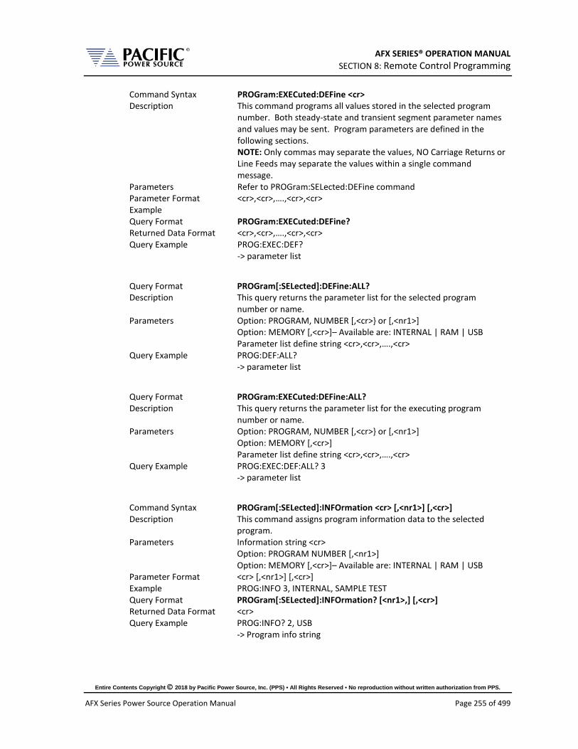
AFX SERIES® OPERATION MANUAL SECTION 8: Remote Control Programming
Entire Contents Copyright 2018 by Pacific Power Source, Inc. (PPS) • All Rights Reserved • No reproduction without written authorization from PPS.
AFX Series Power Source Operation Manual Page 255 of 499
Command Syntax PROGram:EXECuted:DEFine <cr> Description This command programs all values stored in the selected program
number. Both steady-state and transient segment parameter names and values may be sent. Program parameters are defined in the following sections. NOTE: Only commas may separate the values, NO Carriage Returns or Line Feeds may separate the values within a single command message.
Parameters Refer to PROGram:SELected:DEFine command Parameter Format <cr>,<cr>,….,<cr>,<cr> Example Query Format PROGram:EXECuted:DEFine? Returned Data Format <cr>,<cr>,….,<cr>,<cr> Query Example PROG:EXEC:DEF?
-> parameter list
Query Format PROGram[:SELected]:DEFine:ALL? Description This query returns the parameter list for the selected program
number or name. Parameters Option: PROGRAM, NUMBER [,<cr> or [,<nr1>]
Option: MEMORY [,<cr>]– Available are: INTERNAL | RAM | USB Parameter list define string <cr>,<cr>,….,<cr>
Query Example PROG:DEF:ALL? -> parameter list
Query Format PROGram:EXECuted:DEFine:ALL? Description This query returns the parameter list for the executing program
number or name. Parameters Option: PROGRAM, NUMBER [,<cr> or [,<nr1>]
Option: MEMORY [,<cr>] Parameter list define string <cr>,<cr>,….,<cr>
Query Example PROG:EXEC:DEF:ALL? 3 -> parameter list
Command Syntax PROGram[:SELected]:INFOrmation <cr> [,<nr1>] [,<cr>] Description This command assigns program information data to the selected
program. Parameters Information string <cr>
Option: PROGRAM NUMBER [,<nr1>] Option: MEMORY [,<cr>]– Available are: INTERNAL | RAM | USB
Parameter Format <cr> [,<nr1>] [,<cr>] Example PROG:INFO 3, INTERNAL, SAMPLE TEST Query Format PROGram[:SELected]:INFOrmation? [<nr1>,] [,<cr>] Returned Data Format <cr> Query Example PROG:INFO? 2, USB
-> Program info string

AFX SERIES® OPERATION MANUAL SECTION 8: Remote Control Programming
Entire Contents Copyright 2018 by Pacific Power Source, Inc. (PPS) • All Rights Reserved • No reproduction without written authorization from PPS.
AFX Series Power Source Operation Manual Page 256 of 499
Command Syntax PROGram:EXECuted:INFOrmation <cr> [,<nr1>] [,<cr>] Description This command assigns program information data to the executing
program. Parameters Information string <cr>
Option: PROGRAM NUMBER [,<nr1>] Option: MEMORY [,<cr>]– Available are: INTERNAL | RAM | USB
Parameter Format <cr> [,<nr1>] [,<cr>] Example PROG:EXEC:INFO 3, INTERNAL, SAMPLE TEST Query Format PROGram:EXECuted:INFOrmation? [,<nr1>] [,<cr>] Returned Data Format <cr> Query Example PROG:EXEC:INFO? 2, USB
-> Program info string
Command Syntax PROGram[:SELected]:ALIAS <cr> [,<nr1>] [,<cr>] Description This command assigns a user provided alias string name to the
selected program. Program number and memory type are optional parameters.
Parameters Alias String <cr> Option: PROGRAM NUMBER [,<nr1>] Option: MEMORY [,<cr>]– Available are: INTERNAL | RAM | USB
Parameter Format <cr> [,<nr1>] [,<cr>] Example PROG:ALIAS TEST1 Query Format PROGram[:SELected]:ALIAS? [,<nr1>] [,<cr>] Returned Data Format <cr> Query Example PROG:ALIAS?
TEST1
Command Syntax PROGram:EXECuted:ALIAS <cr> [,<nr1>] [,<cr>] Description This command assigns a user provided alias string name to the
executing program. Program number and memory type are optional parameters.
Parameters Alias String <cr> Option: PROGRAM NUMBER [,<nr1>] Option: MEMORY [,<cr>]– Available are: INTERNAL | RAM | USB
Parameter Format <cr> [,<nr1>] [,<cr>] Example PROG:EXEC:ALIAS TEST2 Query Format PROGram:EXECuted:ALIAS? [,<nr1>] [,<cr>] Returned Data Format <cr> Query Example PROG:EXEC:ALIAS?
TEST2

AFX SERIES® OPERATION MANUAL SECTION 8: Remote Control Programming
Entire Contents Copyright 2018 by Pacific Power Source, Inc. (PPS) • All Rights Reserved • No reproduction without written authorization from PPS.
AFX Series Power Source Operation Manual Page 257 of 499
Query Format PROGram[:SELected]:SST? [,<nr1>] [,<cr>] Description This command returns the Steady State Table settings of the selected
program only. The transient table data is not returned. Parameters Option: PROGRAM NUMBER [,<nr1>]
Option: MEMORY [,<cr>]– Available are: INTERNAL | RAM | USB Returned Data Format <cr> Query Example PROG:SST? 2, USB
-> steady state table program data
Query Format PROGram:EXECuted:SST? [,<nr1>] [,<cr>] Description This command returns the Steady State Table settings of the
executing program only. The transient table data is not returned. Parameters Option: PROGRAM NUMBER [,<nr1>]
Option: MEMORY [,<cr>]– Available are: INTERNAL | RAM | USB Returned Data Format <cr> Query Example PROG:EXEC:SST?
-> steady state table program data

AFX SERIES® OPERATION MANUAL SECTION 8: Remote Control Programming
Entire Contents Copyright 2018 by Pacific Power Source, Inc. (PPS) • All Rights Reserved • No reproduction without written authorization from PPS.
AFX Series Power Source Operation Manual Page 258 of 499
Query Format PROGram:TT? [<nr1>][,<nr1>] [,<cr>] Description This command returns the Transient Table settings of the program
number specified. The format in which the data is returned can be specified with the first parameter. If no program number is passed as a parameter, the selected program data is returned. See PROG:NAME for the selected program. The steady state table data is not returned. If no memory type is specified, the transient table stored in the selected memory type is returned. See PROG:MEMORY for the selected memory type.
Parameters Option: STYLE [,<nr1] 0 = Human readable Style A (default if omitted) 1 = Human readable Style B 2 = Binary Data Format. Can be more useful to search for differences between programs. Option: PROGRAM NUMBER [,<nr1>] Option: MEMORY [,<cr>]– Available are: INTERNAL | RAM | USB
Returned Data Format <cr> Query Example PROG:TT? 1,2
-> transient table program data Formats for transient table shown below are: Style A: 3,1,1,100.0,100.0,60.000,0.000,1.000|2.000|3.000,1,0.0|120.0|240.0Style B: 3,1,1,100.0,100.0,60.000,0.000,0.000,0.000,0.000,1.000,1.000,2.000,3.000,1,1,1,1,0.0,120.0,240.0 Binary: 000070420000000000000000000000000000803F00000040000040400000F0420000704301010100F4010000000070420000000000000000000000000000803F00000040000040400000F0420000704301010100F4010000
Query Format PROGram[:SELected]:TT? [,<nr1>] [,<cr>] Description This command returns the Transient Table settings of the selected
program only. The steady state table data is not returned. Parameters Option: STYLE [,<nr1]
0 = Human readable Style A (default if omitted) 1 = Human readable Style B 2 = Binary Data Format. Can be more useful to search for differences between programs. See PROGram:TT? Command for formats Option: PROGRAM NUMBER [,<nr1>] Option: MEMORY [,<cr>]– Available are: INTERNAL | RAM | USB
Returned Data Format <cr> Query Example PROG:TT? 1
-> transient table program data

AFX SERIES® OPERATION MANUAL SECTION 8: Remote Control Programming
Entire Contents Copyright 2018 by Pacific Power Source, Inc. (PPS) • All Rights Reserved • No reproduction without written authorization from PPS.
AFX Series Power Source Operation Manual Page 259 of 499
Query Format PROGram:EXECuted:TT? [,<nr1>] [,<cr>] Description This command returns the Transient Table settings of the executing
program only. The steady state table data is not returned. Parameters Option: STYLE [,<nr1]
0 = Human readable Style A (default if omitted) 1 = Human readable Style B 2 = Binary Data Format. Can be more useful to search for differences between programs. See PROGram:TT? Command for formats Option: PROGRAM NUMBER [,<nr1>] Option: MEMORY [,<cr>]– Available are: INTERNAL | RAM | USB
Returned Data Format <cr> Query Example PROG:EXEC:TT? 2
-> transient table program data
Query Format PROGram[:SELected]:CHECK? [,<nr1>] [,<cr>] Description This command performs a check on the selected program steady
state and transient tables looking for the following conditions: • Hardware Limit violations • User Limit violations • Saturation limits.
If no violations are present, this command returns OK and the program can be executed without generating any errors. If the selected program cannot be run due to one or more issues with its content, one or more errors detailing the issues will be returned. For example, if the upper voltage user limit is set to 100V and the program contains a setting of 300V, a “Cannot load program, Run PROGRAM:CHECK?” error will be generated when attempting to execute this program. When sending the PROGRAM:CHECK? Query, the response will be “VOLT1 AC voltage set point cannot change due to user limit”.
Parameters Option: PROGRAM NUMBER [,<nr1>] Option: MEMORY [,<cr>]– Available are: INTERNAL | RAM | USB
Returned Data Format <cr> Query Example PROG:CHECK?
VOLT1 AC voltage set point cannot change due to user limit
Query Format PROGram:EXECuted:CHECK? [,<nr1>] [,<cr>] Description This command serves the same purpose as the PROG:CHECK?
Command but applies to a program that is executing. Parameters Option: PROGRAM NUMBER [,<nr1>]
Option: MEMORY [,<cr>]– Available are: INTERNAL | RAM | USB Returned Data Format <cr> Query Example PROG:EXEC:CHECK?
VOLT1 AC voltage set point cannot change due to user limit

AFX SERIES® OPERATION MANUAL SECTION 8: Remote Control Programming
Entire Contents Copyright 2018 by Pacific Power Source, Inc. (PPS) • All Rights Reserved • No reproduction without written authorization from PPS.
AFX Series Power Source Operation Manual Page 260 of 499
Command Syntax PROGram[:SELected]:DELete Description This command deletes the selected program. Attempting to DELete
an EXECuting Program will result in an Error. Parameters Program number Parameter Format <nr1> Example PROG:DEL 9
Query Format PROGram[:SELected]:CHANges? <nr1>, <cr> Description This command compares the program that is executing with another
program stored in the memory type and location passed as parameters. The results of the comparison is returned as a decimal number ranging from 0 to 15 representing a four bit binary value. This result can be decoded as shown below.
Parameters Option: PROGRAM NUMBER [,<nr1>] Option: MEMORY [,<cr>]– Available are: INTERNAL | RAM | USB
Returned Data Format <nr>1 Decoding Bit 0: If set to 1, there are differences in the steady state table (SST)
Bit 1: If set to 1, there are differences in the transient table (TT) Bit 2: If set to 1, there are differences in the ALIAS of the program Bit 3: If set to 1, there are differences in INFOrmation of the program
Query Example PROG:CHAN? 16
Example If the query returns zero (0), the program executing is identical to the stored program referenced. If the command returns three (3), the program executing has differences with the referenced program in both the steady state table and the transient table.
Command Syntax PROGram[:SELected]:COPY <nr1> [,<cr>] Description This command copies the selected program as previously specified by
the PROG:NAME <nr1> command to destination program number. NOTE: The destination Program specified cannot be currently executing.
Parameters DESTINATION PROGRAM NUMBER <nr1> Option: MEMORY [,<cr>]– Available are: INTERNAL | RAM | USB
Parameter Format <nr1>, [,<cr.] Example PROG:COPY 2, USB
Command Syntax PROGram:EXECuted:COPY <nr1> [,<cr>] Description This command copies the executed program to destination program
number. Parameters DESTINATION PROGRAM NUMBER <nr1>
Option: MEMORY [,<cr>]– Available are: INTERNAL | RAM | USB Parameter Format <nr1>, [,<cr.] Example PROG:EXEC:COPY 2, USB

AFX SERIES® OPERATION MANUAL SECTION 8: Remote Control Programming
Entire Contents Copyright 2018 by Pacific Power Source, Inc. (PPS) • All Rights Reserved • No reproduction without written authorization from PPS.
AFX Series Power Source Operation Manual Page 261 of 499
8.6.2 Execution Commands
The following commands may be used to control stored program executions.
Command Syntax PROGram[:SELected]:EXECute [<nr1> [,<cr>] Description This command executes the selected program (default) or the
program number passed as the first parameter. Parameters Option: PROGRAM NUMBER [,<nr1>]
Option: MEMORY [,<cr>]– Available are: INTERNAL | RAM | USB Parameter Format [<nr1> [,<cr>] Example PROG:EXEC 2 Query Format PROGram[:SELected]:EXECute ? Description The query format returns the number of the program that is in effect. Parameter Format <nr1> Example PROG:EXEC?
23
Command Syntax PROGram:EXECute:TRANS [<nr1> [,<cr>] Description This command executes the selected program’s (default) transient
table or the program number passed as the first parameter. Parameters Option: PROGRAM NUMBER [,<nr1>]
Option: MEMORY [,<cr>]– Available are: INTERNAL | RAM | USB Parameter Format [<nr1> [,<cr>] Example PROG:EXEC:TRANS 2
Command Syntax PROGram:EXECute:TRANS:RESET Description This command serves the same purpose as the “PROGram:TRANsient
STOP” command. See next. This command resets the active transient execution. This command is included to support UPC compatibility mode although it is not documented in the UPC manual. Not recommended for new programs.
Parameters None Parameter Format n/a Example PROG:EXEC:TRANS:RESET

AFX SERIES® OPERATION MANUAL SECTION 8: Remote Control Programming
Entire Contents Copyright 2018 by Pacific Power Source, Inc. (PPS) • All Rights Reserved • No reproduction without written authorization from PPS.
AFX Series Power Source Operation Manual Page 262 of 499
8.6.3 Transient Segments Commands
The following commands may be used to control stored transient program executions.
Command Syntax PROGram:TRANsient Description This command controls transient execution Parameters RUN | STOP | PAUSe | STEP | RESTart Parameter Format <cr> Example PROG:TRAN RUN Query Format PROGram:TRANsient? Description Query format returns the transient execution state as either RUN,
STOP, PAUS, STEP or REST Returned Data Format <cr> Query Example PROG:TRAN?
RUN
Command Syntax PROGram:TRANsient:AUTORMS <BOOLEAN> Description If enabled, the value of any waveform used in a transient segment is
normalized in order to match the RMS set point. If disabled, the waveform is reproduced without any normalization. This function is useful for waveform substitution at the steady state level. Note: This function is related to the AUTORMS function in the steady state segment.
Parameters [ 0 | OFF | 1 | ON ] Parameter Format <b> Example PROG:TRAN:AUTORMS 1 Query Format PROGram:TRANsient:AUTORMS? Returned Data Format <b> Query Example PROG:TRAN:AUTORMS?
1
Command Syntax PROGram:TRANsient:CR <BOOLEAN> Description This command enables or disables the Cycle Reset mode during
transient execution. When on, Cycle Reset will resync each transient run in repeat mode to the start phase angle.
Parameters [ 0 | OFF | 1 | ON ] Parameter Format <b> Example PROG:TRAN:CR 1 Query Format PROGram:TRANsient:CR? Returned Data Format <nr1> Query Example PROG:TRAN:CR?
0

AFX SERIES® OPERATION MANUAL SECTION 8: Remote Control Programming
Entire Contents Copyright 2018 by Pacific Power Source, Inc. (PPS) • All Rights Reserved • No reproduction without written authorization from PPS.
AFX Series Power Source Operation Manual Page 263 of 499
Command Syntax PROGram:TRANsient:HOLD <ON|OFF> Description This commands turns the Transient HOLD mode on or off. If ON, the
power source holds the last segment values at steady state after the transient ends. If OFF, the output of the power source returns to the steady state settings in effect before the transient segment ran.
Parameters [ 0 | OFF| 1 | ON] Parameter Format <cr> | <b> Example PROG:TRAN:HOLD ON Query Format PROGram:TRANsient:HOLD? Returned Data Format <b> Query Example PROG:TRAN:MODE?
1
Command Syntax PROGram:TRANsient:MODE Description This commands selected between legacy UPC controller mode
SEGMENT transient mode or STEP mode. Segment mode is backward compatible with PPS UPC controllers and use a steady state table and a transient table for each segment. A total of 99 segments can be programmed. STEP mode uses the conventional SCPI LIST system of a list of transient steps executed sequentially.
Parameters [ 0 | SEGMENT | 1 | STEP] Parameter Format <cr> Example PROG:TRAN:MODE STEP Query Format PROGram:TRANsient:MODE? Returned Data Format <nr1> Query Example PROG:TRAN:MODE?
1
Query Format PROGram:TRANsient:PROGress? Description This command returns the progress status of a running transient.
The response data content depends on the selected transient mode, SEGMENT or STEP. (Refer to the “PROGram:TRANsient:MODE” command) The following information is returned in the order shown below. Values are separated by a “/” character:
Return Data Format A. Progress as a percent of the total between 0 to 100. B. Current element progress. A percent between 0 and 100 of
the element executing. C. Active step or segment in execution. D. Active step or segment time. In multiples of 0.2 ms. E. Total time. In multiples of 0.2 ms. F. Total number of steps or segments.
Returned Data Format <nr1> / <nr1> / <nr1> / <nr1> / <nr1> / <nr1> Query Example PROG:TRAN:PROG?
57/31/3/1554/20000/4 Continues next page

AFX SERIES® OPERATION MANUAL SECTION 8: Remote Control Programming
Entire Contents Copyright 2018 by Pacific Power Source, Inc. (PPS) • All Rights Reserved • No reproduction without written authorization from PPS.
AFX Series Power Source Operation Manual Page 264 of 499
Example Return data for transient table shown above in STEP mode would
be 57/31/3/1554/20000/4
A. Progress = 57% of total time or 0.57 * 4000 ms = 2280 ms B. Current element progress = 31% or 0.31 * 1000 ms = 310 ms C. Active step = 3 D. Active step time = 1554 * 0.2 ms = 310.8 ms E. Total time = 20000 * 0.2 ms = 4000 ms F. Total number of steps =4.
Relationship between data fields
A = (((Summing of the element times between 1 and C-1) / 0.2 +D ) / E ) * 100 For the example A = ((1000+1000)/0.2+1554)/20000 = 57%
B = ( D / (Time of the element C / 0.2) ) * 100 For the example B = (1554/(1000/0.2))*100 = 31%
Query Format PROGram:TRANsient:EIE? Description This query command returns the active Element In Execution. An
element is either a STEP when in transient STEP mode or a SEGMENT when in transient SEGMENT mode. Note: the data returned on this query is the same as the “C” data retuned by the “PROGram:TRANsient:PROGress?” command.
Returned Data Format <nr1> Query Example PROG:TRAN:EIE?
3
Query Format PROGram:TRANsient:ETE? Description This query command returns the active Element To Execute. An
element is either a STEP when in transient STEP mode or a SEGMENT when in transient SEGMENT mode. The ETE query is useful when a transient execution has been PAUSED by the “PROGram:TRANsient PAUSe” command. For example, if the execution is paused in the middle of an element (step or segment) execution for element “n”, the ETE value will be “n”. If it is paused at the end of element “n”, the ETE value will be “n+1”.
Returned Data Format <nr1> Query Example PROG:TRAN:ETE?
4

AFX SERIES® OPERATION MANUAL SECTION 8: Remote Control Programming
Entire Contents Copyright 2018 by Pacific Power Source, Inc. (PPS) • All Rights Reserved • No reproduction without written authorization from PPS.
AFX Series Power Source Operation Manual Page 265 of 499
Command Syntax PROGram:TRANsient:MODE Description This commands selected between legacy UPC controller mode
SEGMENT transient mode or STEP mode. Segment mode is backward compatible with PPS UPC controllers and use a steady state table and a transient table for each segment. A total of 99 segments can be programmed. STEP mode uses the conventional SCPI LIST system of a list of transient steps executed sequentially.
Parameters < 0 | SEGMENT | 1 | STEP > Parameter Format <cr> Example PROG:TRAN:MODE STEP Query Format PROGram:TRANsient:MODE? Returned Data Format <cr> Query Example PROG:TRAN:MODE?
1
Command Syntax PROGram:TRANsient:CSC Description This command turns the CSC Mode during transient execution on (1)
or off (0). This allows load regulation adjustment during transient execution. However, keep in mind that CSC adjustments are based on RMS voltage measurement, which take several cycles to run so turning on CSC on fast changing voltage transients is not recommended as the CSC may interfere with the programmed transient voltages.
Note 1: In UPC compatibility mode, the CSC is always off during transient execution regardless of this setting to match the UPC controller operation.
Note 2: This command is available on units with firmware revision 1.3.0 or higher.
Parameters < 0 | OFF | 1 | ON > Parameter Format <cr> Example PROG:TRAN:CSC ON Query Format PROGram:TRANsient:CSC? Returned Data Format <cr> Query Example PROG:TRAN:CSC?
1

AFX SERIES® OPERATION MANUAL SECTION 8: Remote Control Programming
Entire Contents Copyright 2018 by Pacific Power Source, Inc. (PPS) • All Rights Reserved • No reproduction without written authorization from PPS.
AFX Series Power Source Operation Manual Page 266 of 499
Command Syntax PROGram:TRANsient:FROM Description This command sets the first transient step number at which step
mode execution is to begin. The step specified must exist or an error message will be generated.
Parameters STEP number from 1 ~ 99 Parameter Format <nr1> Example PROG:TRAN:FROM 5 Query Format PROGram:TRANsient:FROM? Returned Data Format <nr1> Query Example PROG:TRAN:FROM?
5
Command Syntax PROGram:TRANsient:TO Description This command sets the transient step number at which step mode
execution is to end. The step specified must exist or an error message will be generated.
Parameters STEP number from 1 ~ 99 Parameter Format <nr1> Example PROG:TRAN:TO 25 Query Format PROGram:TRANsient:TO? Returned Data Format <nr1> Query Example PROG:TRAN:TO?
25
Command Syntax PROGram:TRANsient:EVENts <nr1> Description This command sets the number of repetitions for executing the
selected transient. A zero value is equivalent to infinite execution until aborted by “PROG:TRAN STOP” command.
Parameters Repetition, range is 0 ~ 99999 Parameter Format <nr1> Example PROG:TRAN:EVEN 5 Query Format PROGram:TRANsient:EVENts? Returned Data Format <nr1> Query Example PROG:TRAN:EVEN?
5
Command Syntax PROGram:TRANsient:GOTO <nr1> Description This command forces transient execution to move to the element
argument passed (STEP in STEP mode or SEGMENT in segment mode).
Parameters ELEMENT Parameter Format <nr1> Example PROG:TRAN:GOTO 3

AFX SERIES® OPERATION MANUAL SECTION 8: Remote Control Programming
Entire Contents Copyright 2018 by Pacific Power Source, Inc. (PPS) • All Rights Reserved • No reproduction without written authorization from PPS.
AFX Series Power Source Operation Manual Page 267 of 499
8.6.4 Memory Management Commands
The Program memory subsystem commands allow management of Program memory contents.
Command Syntax PROGram:MEMory <cr> Description This command selects the specific program memory type for storing
and retrieving programs. Default is INTERNAL memory. Alternatives are RAM and USB devices. The memory type can also be specified as an optional parameter with several PROGram commands where indicated in this manual.
Parameters Memory types: INTERNAL | RAM | USB. For a complete list of available memory types, use the “PROGram:MEMory:CATalog?” Command.
Parameter Format <cr> Example PROG:MEM USB Query Format PROGram:MEMory? Returned Data Format <cr> Query Example PROG:MEM?
USB
Query Format PROGram:MEMory:CATalog? Description This query command returns a comma separated list of available
memory types that can be selected for storage of steady state and transient table information.
Returned Data Format INTERNAL, RAM, SD1, SD2, SD3, USB Memory Types INTERNAL = Internal Flash Memory. (Default selection)
RAM = Internal RAM. Content will be lost when power source is turned off. USB[X][Y] = USB memory stick devices. X = port number, Y = partition number SD[Y] = SC Card, Y = partition number X = symbolizes different memory sticks connected to various available USB ports. Y = symbolizes different logical partitions on a USB memory stick or SD card. INTERNAL and RAM are always available. INTERNAL is default selection. Use the “PROGram:MEMory <cr>” command to select active memory selection.
Query Example PROG:MEM:CAT? INTERNAL,RAM,USBA1

AFX SERIES® OPERATION MANUAL SECTION 8: Remote Control Programming
Entire Contents Copyright 2018 by Pacific Power Source, Inc. (PPS) • All Rights Reserved • No reproduction without written authorization from PPS.
AFX Series Power Source Operation Manual Page 268 of 499
Query Format PROGram:EXECuted:MEMory? Description This command selects the specific program memory type for storing
and retrieving programs. Default is INTERNAL memory. Alternatives are RAM and USB devices. The memory type can also be specified as an optional parameter with several PROGram commands where indicated in this manual.
Parameters Memory types: INTERNAL | RAM | USB Parameter Format <cr> Example PROG:EXEC:MEM USB Query Format PROGram:EXECuted:MEMory? Returned Data Format <cr> Query Example PROG:EXEC:MEM?
USB
Command Syntax PROGram:POWOn <nr1> Description Returns the number of the stored program that will be recalled at
power on. Parameters Program number Parameter Format <nr1> Example PROG:POWO 1 Query Format PROGram:POWOn? Returned Data Format <nr1> Query Example PROG:POWO?
1
Command Syntax PROGram:DELete:ALL <cr> Description This command deletes all programs, waveforms and setup values,
performs device RESET, loads Program #1 with *RST default values, executes MANUAL MODE with *RST values. Waveforms (1-16) are re-loaded from internal Flash memory. Attempting to DELete an EXECuting Program will result in an error message.
Parameters Optional: Memory type: INTERNAL | RAM | USB Parameter Format <cr> Example PROG:DEL:ALL USB
Query Format PROGram:CATalog? <cr> Description This query returns a comma separated list of <nr1> values
representing stored programs (e.g. 1,2,7…). If the MANUAL MODE program setup exists, the list will include 0. If no programs are stored at all, this query returns a 1
Parameters Optional: Memory type: INTERNAL | RAM | USB Parameter Format <cr> Returned Data Format <nr1>,<nr1>,….,<nr1>,<nr1> Query Example PROG:CAT?
0,1,2,9,12 PROG:CAT? INTERNAL 0

AFX SERIES® OPERATION MANUAL SECTION 8: Remote Control Programming
Entire Contents Copyright 2018 by Pacific Power Source, Inc. (PPS) • All Rights Reserved • No reproduction without written authorization from PPS.
AFX Series Power Source Operation Manual Page 269 of 499
Query Format PROGram:CRC? <cr> Description This query command calculates and returns the checksum value of
the selected program. This CRC may be used to verify the program data integrity is intact. This command is provided for UPC compatibility mode and not recommended for new programs.
Parameters Optional: Memory type: INTERNAL | RAM | USB Parameter Format <cr> Returned Data Format <nr1> Query Example PROG:CRC? RAM
08ad55
Query Format PROGram:BROWse? Description This command returns the list of available programs stored in the
memory selected or passed as a parameter. Parameters Optional: Memory type: INTERNAL | RAM | USB Parameter Format <cr> Returned Data Format <nr1>, <nr1>,….,<nr1> Query Example PROG:BROW?
1,8,9,23
Query Format PROGram:WFBANK? Description This query command returns the waveform bank number. It is
provided for UPC compatibility mode and not recommended for new programs. It always returns a minus one (-1) response.
Returned Data Format -1 Query Example PROG:WFBANK?
-1
Query Format PROGram:WFCRC? Description This query command calculates and returns the checksum value of all
waveforms. The CRC may be used to verify the waveform data integrity is intact. This command is provided for UPC compatibility mode and not recommended for new programs.
Returned Data Format <nr1> Query Example PROG:WFCRC?
-31893,18622,25404,-20201,15032,-2662,-28577,-5178,-3736,-23017,-19989,-25093,-2813,3096,-32131,4403

AFX SERIES® OPERATION MANUAL SECTION 8: Remote Control Programming
Entire Contents Copyright 2018 by Pacific Power Source, Inc. (PPS) • All Rights Reserved • No reproduction without written authorization from PPS.
AFX Series Power Source Operation Manual Page 270 of 499
8.7 Source Commands Source commands control the settings of the power source. This includes all operating modes, voltages, frequency, current and power limits and phase angles as well as transient operation. Since the SOURCE subsystem is the primary system, the SOURce portion of these commands is optional. The following status commands are supported broken down by SOURCE sub groups.
8.7.1 Source Configuration Programming Commands Command Syntax [SOURce:]CONFIG <b> Description Selects alternative loop compensation mode for improved transient
response. The effect of this command depends on the selected output mode as follows: AC Mode: Changes the AC loop compensation DC Mode: Changes the DC loop compensation AC+DC Mode: Changes both the AC and DC loop compensations Note: The alternative compensation configuration setting is saved separately saved for DC and AC (only and +DC). When changed to off while in DC mode, it will be saved as off for DC only. Also if you are in AC only (or AC+DC) and you change it to 1, it is saved separately.
Parameters < 0 | 1 > ( 0 = Normal loop, 1 = Faster Loop ) Parameter Format <b> Example SOUR:CONFIG 1 Query Format [SOURce:]CONFIG? Returned Data Format <b> Query Example CONFIG?
0
Command Syntax [SOURce:]CONFIG:AC <b> Description Selects alternative AC loop compensation mode for improved AC
transient response. The effect of this command depends on the selected output mode as follows: AC Mode: Changes the AC loop compensation DC Mode: No effect AC+DC Mode: Changes the AC loop compensations Note: Available in units with Firmware revision 1.6.0 or higher.
Parameters < 0 | 1 > ( 0 = Normal loop, 1 = Faster Loop ) Parameter Format <b> Example SOUR:CONFIG:AC 1 Query Format [SOURce:]CONFIG:AC? Returned Data Format <b> Query Example CONFIG:AC?
0

AFX SERIES® OPERATION MANUAL SECTION 8: Remote Control Programming
Entire Contents Copyright 2018 by Pacific Power Source, Inc. (PPS) • All Rights Reserved • No reproduction without written authorization from PPS.
AFX Series Power Source Operation Manual Page 271 of 499
Command Syntax [SOURce:]CONFIG:DC <b> Description Selects alternative DC loop compensation mode for improved DC
transient response. The effect of this command depends on the selected output mode as follows: AC Mode: No effect DC Mode: Changes the DC loop compensation AC+DC Mode: No effect Note: Available in units with Firmware revision 1.6.0 or higher.
Parameters < 0 | 1 > ( 0 = Normal loop, 1 = Faster Loop ) Parameter Format <b> Example SOUR:CONFIG:DC 1 Query Format [SOURce:]CONFIG:DC? Returned Data Format <b> Query Example CONFIG:DC?
0
Command Syntax [SOURce:]CONFIG:HFreq <b> Description This command enables high-frequency output current protection
extension mode. In this mode, the protection for high frequency content at the output of the power source is held off for up to 2 seconds to allow short time events to ride through without tripping the normal protection mode. Note: Available in units with Firmware revision 1.6.6 or higher.
Parameters < 0 | OFF | 1 | ON > ( 0 = Off, 1 = On) Parameter Format <b> Example SOUR:CONFIG:HF 1 Query Format [SOURce:]CONFIG:HFreq? Returned Data Format <b> Query Example CONFIG:HF?
1

AFX SERIES® OPERATION MANUAL SECTION 8: Remote Control Programming
Entire Contents Copyright 2018 by Pacific Power Source, Inc. (PPS) • All Rights Reserved • No reproduction without written authorization from PPS.
AFX Series Power Source Operation Manual Page 272 of 499
Command Syntax [SOURce:]COUPLing <cr> Description Selects the output coupling mode. On AFX Series®, this command
only accepts DIRECT as a setting unless the optional output transformer is connected and configured. The output voltage ratio of the transformer can be queried using the “SYSTem:XFMRRATIO?” command. The output voltage range is 300Vac x Ratio full scale Line to Neutral. If no transformer option is installed and configured, selecting XMFR coupling will generate a 2019 Error code. Do not select XMFR coupling if the SYSTem:XFMRRATIO? query returns a 0.0000 value.
Parameters < DIRECT | 0 | XMFR | 1 > 0 = DIRECT 1 = XMFR
Parameter Format <cr> Example COUPL DIRECT Query Format [SOURce:]COUPLing? Returned Data Format <cr> Query Example COUPL?
0

AFX SERIES® OPERATION MANUAL SECTION 8: Remote Control Programming
Entire Contents Copyright 2018 by Pacific Power Source, Inc. (PPS) • All Rights Reserved • No reproduction without written authorization from PPS.
AFX Series Power Source Operation Manual Page 273 of 499
Command Syntax [SOURce:]INITial <n> Description Sets source output settings initialization mode. This command in
combination with the “OUTPut[:STATe]:AUTO” command allows the unattended resumption of a test station after a power failure. Note: This condition is potentially hazardous and should be used with caution.
[SOURce:]INITial? = ON Set points of the unit at power on will be the last set after power off. The set points affected by this command are: - Frequency - Voltage AC1 - Voltage AC2 - Voltage AC3 - Voltage DC1 - Voltage DC2 - Voltage DC3 - Form (THREE , SPLIT or SINGLE) - Range (High or Low) - Compatibility Mode (UPC or NORMAL)
[SOURce:]INITial? = OFF Set points of the unit at power on will have a default value of: - Frequency = 60Hz - Voltage AC1 = 0V - Voltage AC2 = 0V - Voltage AC3 = 0V - Voltage DC1 = 0V - Voltage DC2 = 0V - Voltage DC3 = 0V - Form = THREE - Range = HIGH - Compatibility = NORMAL
Parameters < 0 | OFF | 1 | ON > Parameter Format <b> Example :INIT ON Query Format [SOURce:]INITial? Returned Data Format <b> Query Example INIT?
0
Command Syntax [SOURce:]FORM <nr1> Description Set phase mode or FORM. Allowable arguments are 1, 2 or 3. Parameters < 1 | 2 | 3 > Parameter Format <nr1> Example FORM 3 Query Format [SOURce:]FORM? Returned Data Format <nr1> Query Example FORM?
3

AFX SERIES® OPERATION MANUAL SECTION 8: Remote Control Programming
Entire Contents Copyright 2018 by Pacific Power Source, Inc. (PPS) • All Rights Reserved • No reproduction without written authorization from PPS.
AFX Series Power Source Operation Manual Page 274 of 499
Command Syntax [SOURce:]RANGe Description Selects high or low voltage range. Although the AFX Series® has only
a single voltage range, this commands allows simulation of a dual range AC voltage source which is more familiar to some users. Despite this virual low range capability, no actual physical range change takes places so the output is never interrupted. Note: When switching from HIGH to LOW range, the output voltage may be reduced to the highest available voltage on the low range.
Parameters < 0 | LOW | 1 | HIGH > Parameter Format <b> Example RANG HIGH Query Format [SOURce:]RANGe? Returned Data Format <b> Query Example RANG?
1
Command Syntax [SOURce:]RAMP# Description Sets voltage slew rate for selected phase number or for all phases if
no phase number is specified. Parameters Slew rate Parameter Format <nr2> Example SOUR:RAMP3 10.5 Query Format [SOURce:]RAMP#? Description Returns voltage slew rate setting for specified phase (1, 2 or 3) or for
phase 1 (A) if no phase number is specified. Returned Data Format Query Example SOUR:RAMP3?
10.5000
Command Syntax [SOURce:]SERIES Description Changes output configuration to series connection on AFXS units
when set to ON. Requires the SPMS (Series parallel Mode Stich) hardware option. Returns to parallel output connection mode when OFF.
Parameters < 0 | OFF | 1 | ON > Parameter Format <nr1> Example SERIES ON Query Format [SOURce:]SERIES? Description Returns Series Mode setting on AFXS models. Returned Data Format Query Example SOUR:SERIES?
1

AFX SERIES® OPERATION MANUAL SECTION 8: Remote Control Programming
Entire Contents Copyright 2018 by Pacific Power Source, Inc. (PPS) • All Rights Reserved • No reproduction without written authorization from PPS.
AFX Series Power Source Operation Manual Page 275 of 499
Command Syntax [SOURce:]UPDATEPHase Description Set the phase angle at which programmed voltage changes on phase
A will take place. This applies to output on and off phase angle placement as well. Available range is from 0° through 360.0° inclusive. Values higher than 360.0° will be truncated to 360.0000° automatically.
Parameters < 0.0000 - 360.0000 > Parameter Format <nr2> Example UPDATEPH 90.00 Query Format [SOURce:]UPDATEPHase? Returned Data Format <nr2> Query Example SOURce:UPDATEPH?
90.0000

AFX SERIES® OPERATION MANUAL SECTION 8: Remote Control Programming
Entire Contents Copyright 2018 by Pacific Power Source, Inc. (PPS) • All Rights Reserved • No reproduction without written authorization from PPS.
AFX Series Power Source Operation Manual Page 276 of 499
8.7.2 Voltage Programming Commands
Note that most of the voltage programming commands are phase specific so in three or split phase mode, each phase voltage can be individually programmed. This is done by appending 1, 2 or 3 for the “#” symbol shown in the syntax below. If the “#” value is omitted, all available phase (1, 2 or 3 in single, split or three phase mode respectively) will be set to the same amplitude. This allows the same program code to be used for any phase mode as long as the phase amplitudes need to be balanced.
The following command sets each phase to a different amplitude when in three phase mode.
SOUR:VOLT:AC1 15;:SOUR:VOLT:AC2 30;:SOURCE:VOLT:AC3 45
This command sets all phases to the same amplitude, regardless of phase mode:
SOUR:VOLT:AC 100
The query format for these phase specific commands will return the value for the phase number appended to the command. If the phase number reference is omitted, the setting for phase 1 (A) is returned.
Command Syntax [SOURce:]VOLTage:MODE Description Results voltage mode as 0 for AC, 1 for DC or 2 for ACDC.
Note: In UPC compatibility mode, only AC mode is available Parameters < 0 | AC | 1 | DC | 2 | ACDC > Parameter Format <nr1> Example VOLT:MODE DC Query Format [SOURce:]VOLTage:MODE? Returned Data Format <nr1> Query Example VOLT:MODE?
1
Command Syntax [SOURce:]VOLTage:CSC[:STATE] Description Turns the Continuous Source Calibration (CSC) mode on or off. Parameters <0 | OFF | 1 | ON> Parameter Format <b> Example VOLT:CSC ON Query Format [SOURce:]VOLTage:CSC[:STATE]? Returned Data Format <nr1> Query Example VOLT:CSC?
1
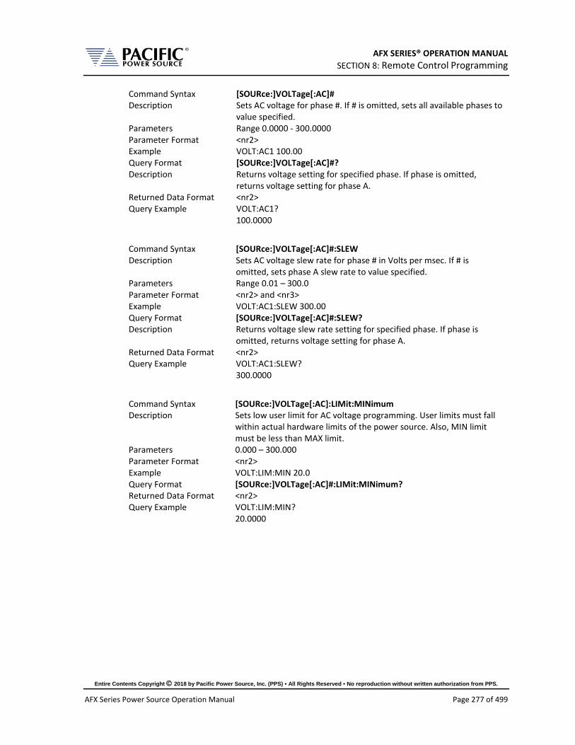
AFX SERIES® OPERATION MANUAL SECTION 8: Remote Control Programming
Entire Contents Copyright 2018 by Pacific Power Source, Inc. (PPS) • All Rights Reserved • No reproduction without written authorization from PPS.
AFX Series Power Source Operation Manual Page 277 of 499
Command Syntax [SOURce:]VOLTage[:AC]# Description Sets AC voltage for phase #. If # is omitted, sets all available phases to
value specified. Parameters Range 0.0000 - 300.0000 Parameter Format <nr2> Example VOLT:AC1 100.00 Query Format [SOURce:]VOLTage[:AC]#? Description Returns voltage setting for specified phase. If phase is omitted,
returns voltage setting for phase A. Returned Data Format <nr2> Query Example VOLT:AC1?
100.0000
Command Syntax [SOURce:]VOLTage[:AC]#:SLEW Description Sets AC voltage slew rate for phase # in Volts per msec. If # is
omitted, sets phase A slew rate to value specified. Parameters Range 0.01 – 300.0 Parameter Format <nr2> and <nr3> Example VOLT:AC1:SLEW 300.00 Query Format [SOURce:]VOLTage[:AC]#:SLEW? Description Returns voltage slew rate setting for specified phase. If phase is
omitted, returns voltage setting for phase A. Returned Data Format <nr2> Query Example VOLT:AC1:SLEW?
300.0000
Command Syntax [SOURce:]VOLTage[:AC]:LIMit:MINimum Description Sets low user limit for AC voltage programming. User limits must fall
within actual hardware limits of the power source. Also, MIN limit must be less than MAX limit.
Parameters 0.000 – 300.000 Parameter Format <nr2> Example VOLT:LIM:MIN 20.0 Query Format [SOURce:]VOLTage[:AC]#:LIMit:MINimum? Returned Data Format <nr2> Query Example VOLT:LIM:MIN?
20.0000
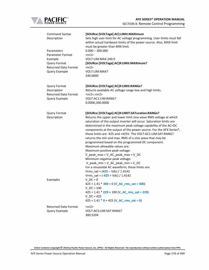
AFX SERIES® OPERATION MANUAL SECTION 8: Remote Control Programming
Entire Contents Copyright 2018 by Pacific Power Source, Inc. (PPS) • All Rights Reserved • No reproduction without written authorization from PPS.
AFX Series Power Source Operation Manual Page 278 of 499
Command Syntax [SOURce:]VOLTage[:AC]:LIMit:MAXimum Description Sets high user limit for AC voltage programming. User limits must fall
within actual hardware limits of the power source. Also, MAX limit must be greater than MIN limit.
Parameters 0.000 – 300.000 Parameter Format <nr2> Example VOLT:LIM:MAX 240.0 Query Format [SOURce:]VOLTage[:AC]#:LIMit:MAXimum? Returned Data Format <nr2> Query Example VOLT:LIM:MAX?
240.0000
Query Format [SOURce:]VOLTage[:AC]#:LIMit:RANGe? Description Returns available AC voltage range low and high limits. Returned Data Format <nr2>,<nr2> Query Example VOLT:AC1:LIM:RANG?
0.0000,300.0000
Query Format [SOURce:]VOLTage[:AC]#:LIMIT:SATuration:RANGe? Description Returns the upper and lower limit sine wave RMS voltage at which
saturation of the output inverter will occur. Saturation limits are determined in the maximum peak voltage capability of the AC+DC components at the output of the power source. For the AFX Series®, these limits are -425 and +425V. The VOLT:AC1:LIM:SAT:RANG? returns the min and max. RMS of a sine wave that may be programmed based on the programmed DC component. Maximum allowable values are: Maximum positive peak voltage: V_peak_max = V_AC_peak_max + V_DC Minimum negative peak voltage: V_peak_min = V_AC_peak_min + V_DC For a sinusoidal AC waveform, these limits are: Vrms_sat = (425 – Vdc) / 1.4142 Vrms_sat = (-425 + Vdc) / 1.4142
Examples V_DC = 0 425 = 1.41 * 300 + 0 (V_AC_rms_sat = 300) V_DC = 100 425 = 1.41 * 229 + 100 (V_AC_rms_sat = 229) V_DC = 425 425 = 1.41 * 0 + 425 (V_AC_rms_sat = 0)
Returned Data Format <nr2> Query Example VOLT:AC3:LIM:SAT:RANG?
300.5204

AFX SERIES® OPERATION MANUAL SECTION 8: Remote Control Programming
Entire Contents Copyright 2018 by Pacific Power Source, Inc. (PPS) • All Rights Reserved • No reproduction without written authorization from PPS.
AFX Series Power Source Operation Manual Page 279 of 499
Query Format [SOURce:]VOLTage[:AC]#:LIMIT:SATuration:MAXimum? Description Returns maximum sine wave RMS voltage at which saturation of the
output inverter will occur. See [SOURce:]VOLTage[:AC]#:LIMIT:SATuration:RANGe? for details.
Returned Data Format <nr2> Query Example VOLT:AC3:LIM:SAT:MAX?
301.154
Query Format [SOURce:]VOLTage[:AC]#:LIMIT:SATuration:MINimum? Description Returns minimum sine wave RMS voltage at which saturation of the
output inverter will occur. See [SOURce:]VOLTage[:AC]#:LIMIT:SATuration:RANGe? for details.
Returned Data Format <nr2> Query Example VOLT:AC3:LIM:SAT:MIN?
0.000
Command Syntax [SOURce:]VOLTage[:AC]:INITial Description This command is equivalent to the “[SOURce:]INITial <n>” command
but applies only to the AC1, AC2 and AC3 parameters. VOLT:INIT? = ON Set points of the unit at power on will be the last set after power off.
The set points affected by this command are: - Voltage AC1 - Voltage AC2 - Voltage AC3
VOLT:INIT? = OFF Set points of the unit at power on will have a default value of: - Voltage AC1 = 0V - Voltage AC2 = 0V - Voltage AC3 = 0V
Parameters < 0 | OFF | 1 | ON > Parameter Format <b> Example VOLT:AC:INIT OFF Query Format [SOURce:]VOLTage[:AC]:INITial? Returned Data Format <b> Query Example VOLT:AC:INIT?
0
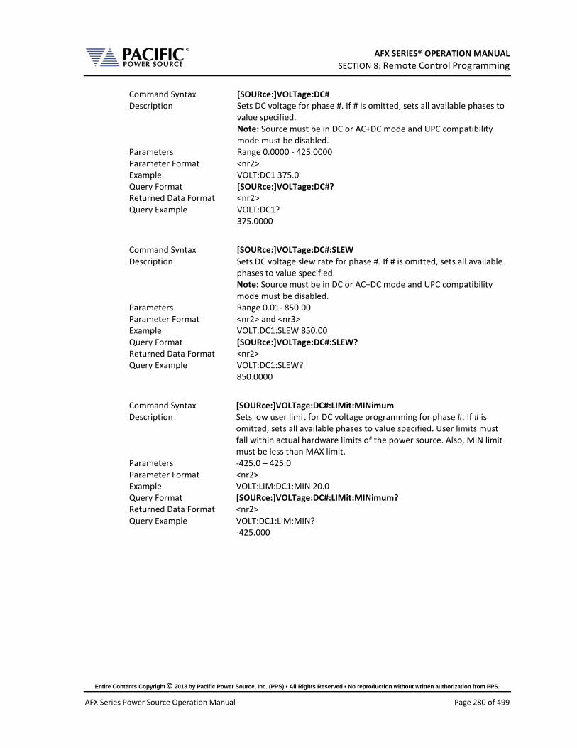
AFX SERIES® OPERATION MANUAL SECTION 8: Remote Control Programming
Entire Contents Copyright 2018 by Pacific Power Source, Inc. (PPS) • All Rights Reserved • No reproduction without written authorization from PPS.
AFX Series Power Source Operation Manual Page 280 of 499
Command Syntax [SOURce:]VOLTage:DC# Description Sets DC voltage for phase #. If # is omitted, sets all available phases to
value specified. Note: Source must be in DC or AC+DC mode and UPC compatibility mode must be disabled.
Parameters Range 0.0000 - 425.0000 Parameter Format <nr2> Example VOLT:DC1 375.0 Query Format [SOURce:]VOLTage:DC#? Returned Data Format <nr2> Query Example VOLT:DC1?
375.0000
Command Syntax [SOURce:]VOLTage:DC#:SLEW Description Sets DC voltage slew rate for phase #. If # is omitted, sets all available
phases to value specified. Note: Source must be in DC or AC+DC mode and UPC compatibility mode must be disabled.
Parameters Range 0.01- 850.00 Parameter Format <nr2> and <nr3> Example VOLT:DC1:SLEW 850.00 Query Format [SOURce:]VOLTage:DC#:SLEW? Returned Data Format <nr2> Query Example VOLT:DC1:SLEW?
850.0000
Command Syntax [SOURce:]VOLTage:DC#:LIMit:MINimum Description Sets low user limit for DC voltage programming for phase #. If # is
omitted, sets all available phases to value specified. User limits must fall within actual hardware limits of the power source. Also, MIN limit must be less than MAX limit.
Parameters -425.0 – 425.0 Parameter Format <nr2> Example VOLT:LIM:DC1:MIN 20.0 Query Format [SOURce:]VOLTage:DC#:LIMit:MINimum? Returned Data Format <nr2> Query Example VOLT:DC1:LIM:MIN?
-425.000
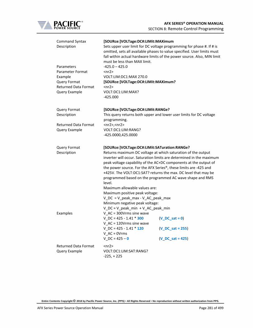
AFX SERIES® OPERATION MANUAL SECTION 8: Remote Control Programming
Entire Contents Copyright 2018 by Pacific Power Source, Inc. (PPS) • All Rights Reserved • No reproduction without written authorization from PPS.
AFX Series Power Source Operation Manual Page 281 of 499
Command Syntax [SOURce:]VOLTage:DC#:LIMit:MAXimum Description Sets upper user limit for DC voltage programming for phase #. If # is
omitted, sets all available phases to value specified. User limits must fall within actual hardware limits of the power source. Also, MIN limit must be less than MAX limit.
Parameters -425.0 – 425.0 Parameter Format <nr2> Example VOLT:LIM:DC1:MAX 270.0 Query Format [SOURce:]VOLTage:DC#:LIMit:MAXimum? Returned Data Format <nr2> Query Example VOLT:DC1:LIM:MAX?
-425.000
Query Format [SOURce:]VOLTage:DC#:LIMit:RANGe? Description This query returns both upper and lower user limits for DC voltage
programming. Returned Data Format <nr2>,<nr2> Query Example VOLT:DC1:LIM:RANG?
-425.0000,425.0000
Query Format [SOURce:]VOLTage:DC#:LIMit:SATuration:RANGe? Description Returns maximum DC voltage at which saturation of the output
inverter will occur. Saturation limits are determined in the maximum peak voltage capability of the AC+DC components at the output of the power source. For the AFX Series®, these limits are -425 and +425V. The VOLT:DC1:SAT? returns the max. DC level that may be programmed based on the programmed AC wave shape and RMS level. Maximum allowable values are: Maximum positive peak voltage: V_DC = V_peak_max - V_AC_peak_max Minimum negative peak voltage: V_DC = V_peak_min + V_AC_peak_min
Examples V_AC = 300Vrms sine wave V_DC = 425 - 1.41 * 300 (V_DC_sat = 0) V_AC = 120Vrms sine wave V_DC = 425 - 1.41 * 120 (V_DC_sat = 255) V_AC = 0Vrms V_DC = 425 – 0 (V_DC_sat = 425)
Returned Data Format <nr2> Query Example VOLT:DC1:LIM:SAT:RANG?
-225, + 225

AFX SERIES® OPERATION MANUAL SECTION 8: Remote Control Programming
Entire Contents Copyright 2018 by Pacific Power Source, Inc. (PPS) • All Rights Reserved • No reproduction without written authorization from PPS.
AFX Series Power Source Operation Manual Page 282 of 499
Query Format [SOURce:]VOLTage:DC#:LIMit:SATuration:MAXimum? Description Returns maximum sine wave RMS voltage at which saturation of the
output inverter will occur. See [SOURce:]VOLTage:DC#:LIMIT:SATuration:RANGe? for details.
Returned Data Format <nr2> Query Example VOLT:DC3:LIM:SAT:MAX?
254.946
Query Format [SOURce:]VOLTage:DC#:LIMit:SATuration:MINimum? Description Returns minimum sine wave RMS voltage at which saturation of the
output inverter will occur. See [SOURce:]VOLTage:DC#:LIMIT:SATuration:RANGe? for details.
Returned Data Format <nr2> Query Example VOLT:DC3:LIM:SAT:MIN?
-254.946
Command Syntax [SOURce:]VOLTage:EXTend Description This command grants access to a higher voltage range extension
mode. When enabled, AC voltage settings up to 333V L-N are supported.
Parameters [ 0 | OFF | 1 | 2 ] 0 = Off, 312Vac max. 1 = 320Vac max 2 = 333Vac max
Parameter Format <bool> Example VOLT:EXT 1 Query Format [SOURce:]VOLTage:EXTend? Returned Data Format <nr1> Query Example VOLT:EXT?
1
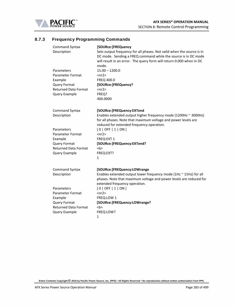
AFX SERIES® OPERATION MANUAL SECTION 8: Remote Control Programming
Entire Contents Copyright 2018 by Pacific Power Source, Inc. (PPS) • All Rights Reserved • No reproduction without written authorization from PPS.
AFX Series Power Source Operation Manual Page 283 of 499
8.7.3 Frequency Programming Commands Command Syntax [SOURce:]FREQuency Description Sets output frequency for all phases. Not valid when the source is in
DC mode. Sending a FREQ command while the source is in DC mode will result in an error. The query form will return 0.000 when in DC mode.
Parameters 15.00 – 1200.0 Parameter Format <nr2> Example FREQ 400.0 Query Format [SOURce:]FREQuency? Returned Data Format <nr2> Query Example FREQ?
400.0000
Command Syntax [SOURce:]FREQuency:EXTend Description Enables extended output higher frequency mode (1200Hz ~ 3000Hz)
for all phases. Note that maximum voltage and power levels are reduced for extended frequency operation.
Parameters [ 0 | OFF | 1 | ON ] Parameter Format <nr2> Example FREQ:EXT 1 Query Format [SOURce:]FREQuency:EXTend? Returned Data Format <b> Query Example FREQ:EXT?
1
Command Syntax [SOURce:]FREQuency:LOWrange Description Enables extended output lower frequency mode (1Hz ~ 15Hz) for all
phases. Note that maximum voltage and power levels are reduced for extended frequency operation.
Parameters [ 0 | OFF | 1 | ON ] Parameter Format <nr2> Example FREQ:LOW 1 Query Format [SOURce:]FREQuency:LOWrange? Returned Data Format <b> Query Example FREQ:LOW?
1

AFX SERIES® OPERATION MANUAL SECTION 8: Remote Control Programming
Entire Contents Copyright 2018 by Pacific Power Source, Inc. (PPS) • All Rights Reserved • No reproduction without written authorization from PPS.
AFX Series Power Source Operation Manual Page 284 of 499
Command Syntax [SOURce:]FREQuency:LIMit:MINimum Description Sets the lower user limit for frequency programming. Not that the
lower limit set value must be less than the upper limit set value or an error will be generated and no change to the set value will take place. The lower limit set value must fall within the source specified frequency range capability.
Parameters 1.00 – 1200.0 Parameter Format <nr2> Example FREQ:LIM:MIN 47.0 Query Format [SOURce:]FREQuency:LIMit:MINimum? Returned Data Format <nr2> Query Example FREQ:LIM:MIN?
47.0000
Command Syntax [SOURce:]FREQuency:LIMit:MAXimum Description Sets the upper user limit for frequency programming. Note that the
upper limit set value must be greater than the lower limit set value or an error will be generated and no change to the set value will take place. The upper limit set value must fall within the source specified frequency range capability.
Parameters 15.00 – 3000.0 Parameter Format <nr2> Example FREQ:LIM:MAX 63.0 Query Format [SOURce:]FREQuency:LIMit:MAXimum? Returned Data Format <nr2> Query Example FREQ:LIM:MAX?
63.0000
Query Format [SOURce:]FREQuency:LIMit:RANGe? Description This command returns the lower and upper frequency user limit set
value.s Returned Data Format <nr2>, <nr2> Query Example FREQ:LIM:RANG?
53.0000,63.0000
Command Syntax [SOURce:]FREQuency:SLEW Description Sets the frequency slew rate in Hz/msec. This command is not valid
when in DC mode. Parameters 0.01 – 1200.00 Parameter Format <nr2> Example FREQ:SLEW 100.0 Query Format [SOURce:]FREQuency:SLEW? Returned Data Format <nr2> Query Example FREQ:SLEW?
100.0000

AFX SERIES® OPERATION MANUAL SECTION 8: Remote Control Programming
Entire Contents Copyright 2018 by Pacific Power Source, Inc. (PPS) • All Rights Reserved • No reproduction without written authorization from PPS.
AFX Series Power Source Operation Manual Page 285 of 499
Query Format [SOURce:]FREQuency:SPAN? Description This command is provided to support backward compatibility with
Pacific Power UPC controllers. Refer also to the “SYSTem:COMPatible” command. For AFX Series®, this query always returns 1200.0000
Returned Data Format <nr2> Query Example FREQ:SPAN?
1200.0000
8.7.4 Current Programming Commands Command Syntax [SOURce:]CURRent:LIMit# Description This command sets the programmable current level for the selected
phase #. If # is omitted, sets all phases to current level specified. The value set cannot exceed the maximum current capability of the power source as returned by the “[SOURce:]CURRent:LIMit#:MAX?” command. If the load current exceeds the current limit set point, the source will go into constant current mode to maintain the load current at the set limit level.
Parameters 0.00 – MAX Parameter Format <nr2> Example CURR:LIM 20.5 Query Format [SOURce:]CURRent:LIMit#? Returned Data Format <nr2> Query Example CURR:LIM?
41.667,41.667,41.667
Query Format [SOURce:]CURRent:LIMit#:MAX? Description This command returns the maximum available programmable current
limit setting. Note that the returned value is a function of the “SYSTem:COMPatible” setting
UPC If UPC mode is enabled, this command always returns 2000.0000 to emulate the UPC controllers
DISABLED With UPC mode disabled, this command returns the max. available current output per phase. This value is a function of the AFX model and the number of units that are connected in parallel.
Returned Data Format <nr2> Query Example CURR:LIM:MAX?
41.6667
Query Format [SOURce:]CURRent:LIMit#:DEFault? Description This command returns the default current limit setting at power up
for the referenced phase. Returned Data Format <nr2> Query Example CURR:LIM1:DEF?
41.67

AFX SERIES® OPERATION MANUAL SECTION 8: Remote Control Programming
Entire Contents Copyright 2018 by Pacific Power Source, Inc. (PPS) • All Rights Reserved • No reproduction without written authorization from PPS.
AFX Series Power Source Operation Manual Page 286 of 499
Query Format [SOURce:]CURRent:LIMit#:MAXimum? Description This command returns the maximum current limit setting available
for the referenced phase. Returned Data Format <nr2> Query Example CURR:LIM:MAX1?
41.67
Query Format [SOURce:]CURRent:LIMit#:MINimum? Description This command returns the minimum current limit setting available for
the referenced phase. Returned Data Format <nr2> Query Example CURR:LIM:MIN1?
0.000
Command Syntax [SOURce:]CURRent:LIMit:AUTO Description This commands enables or disables the Auto Current Limit function.
This function automatically adjusts the programmed current limit level as a function of programmed voltage along the constant power curve of the voltage range. For example: On a 3150AFX model in three phase mode, if VOLT = 0 and CURR:LIM = 41.67 and voltage is changed to V = 300, the CURR:LIM will change to: 5000 VA / 300 Vac = 16.0. If CURR:LIM:AUTO = OFF then the CURR:LIM setting will remain at 41.67A and the power source will power limit at 5000VA instead if the load draws more than 16Aac.
Parameters < 0 | OFF | 1 | ON > Parameter Format <b> Example CURR:LIM:AUTO ON Query Format [SOURce:]CURRent:LIMit:AUTO? Returned Data Format <b> Query Example CURR:LIM:AUTO?
1
Command Syntax [SOURce:]CURRent:OVerload Description This command turns the overload current mode on or off Parameters [ 0 | OFF | 1 | ON ] Parameter Format <b> Example SOUR:CURR:OV ON Query Format [SOURce:]CURRent:OVerload? Returned Data Format <b> Query Example CURR:OV?
1

AFX SERIES® OPERATION MANUAL SECTION 8: Remote Control Programming
Entire Contents Copyright 2018 by Pacific Power Source, Inc. (PPS) • All Rights Reserved • No reproduction without written authorization from PPS.
AFX Series Power Source Operation Manual Page 287 of 499
8.7.5 Phase Programming Commands Command Syntax [SOURce:]PHASe# Description This command programs the phase angle for the selected phase. A
phase reference (#) must be specified. Note that unless external sync mode is used, the A phase (# = 1) cannot be programmed is fixed at 0 degrees.
Parameters 0.0 – 359.9 Parameter Format <nr2> Example PHAS2 122.5 Query Format [SOURce:]PHASe#? Returned Data Format <nr2> Query Example PHAS2?
122.5
Command Syntax [SOURce:]PHASe#:SLEW Description This command sets slew rate for the phase angle for the selected
phase. A phase reference (#) must be specified. Note that unless external sync mode is used, the A phase (# = 1) slew rate cannot be programmed is fixed at 0 degrees.
Parameters 0.01 – 359.91 Parameter Format <nr2> Example PHAS3:SLEW 10.25 Query Format [SOURce:]PHASe#:SLEW? Returned Data Format <nr2> Query Example PHAS3:SLEW?
10.2500
Command Syntax [SOURce:]PHASe:ROTation <b> Description This command sets default phase rotation at power on. Available
settings are POSITIVE (1) or NEGATIVE (0). This setting effectively swaps phases B and C and may be used to set the required phase rotation for AC motors.
Parameters [ 0 | NEGative | 1 | POSitive] 0 = NEGATIVE 1 = POSITIVE
Parameter Format <b> Example PHAS:ROT POS Query Format [SOURce:]PHASe:ROTation? Returned Data Format <b> Query Example PHAS:ROT?
1
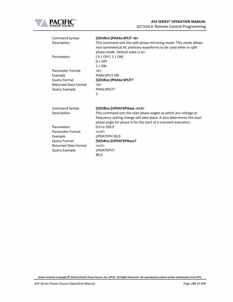
AFX SERIES® OPERATION MANUAL SECTION 8: Remote Control Programming
Entire Contents Copyright 2018 by Pacific Power Source, Inc. (PPS) • All Rights Reserved • No reproduction without written authorization from PPS.
AFX Series Power Source Operation Manual Page 288 of 499
Command Syntax [SOURce:]PHASe:SPLIT <b> Description This command sets the split phase mirroring mode. This mode allows
non-symmetrical AC arbitrary waveforms to be used when in split phase mode. Default state is on.
Parameters [ 0 | OFF| 1 | ON] 0 = OFF 1 = ON
Parameter Format <b> Example PHAS:SPLIT ON Query Format [SOURce:]PHASe:SPLIT? Returned Data Format <b> Query Example PHAS:SPLIT?
1
Command Syntax [SOURce:]UPDATEPHase <nr2> Description This command sets the start phase angles at which any voltage or
frequency setting change will take place. It also determines the start phase angle for phase A for the start of a transient execution.
Parameters 0.0 to 359.9 Parameter Format <nr2> Example UPDATEPH 90.0 Query Format [SOURce:]UPDATEPHase? Returned Data Format <nr2> Query Example UPDATEPH?
90.0

AFX SERIES® OPERATION MANUAL SECTION 8: Remote Control Programming
Entire Contents Copyright 2018 by Pacific Power Source, Inc. (PPS) • All Rights Reserved • No reproduction without written authorization from PPS.
AFX Series Power Source Operation Manual Page 289 of 499
8.7.6 Waveform Programming Commands
Waveform Storage
The AFX Series® offers full arbitrary waveform programming capability in addition to the standard waveforms that are provided. A total of 16 waveform registers are available. The default content of these registers is shown in the table below. Also shown are the waveform number names and the waveform description each waveform.
Name Description Image Notes 1 SINE
Standard sine wave. No harmonic content. This is also the default selected waveform at power on unless a power-on setup is recalled.
2 CLIPPED THD 1%
Clipped sine with 1% total harmonic voltage distortion due to flat topping of sinewave peaks.
3 CLIPPED THD 2%
Clipped sine with 2% total harmonic voltage distortion due to flat topping of sinewave peaks.
4 CLIPPED THD 5%
Clipped sine with 5% total harmonic voltage distortion due to flat topping of sinewave peaks.
5 CLIPPED THD 10%
Clipped sine with 10% total harmonic voltage distortion due to flat topping of sinewave peaks.
6 SQUARE LF
Square wave. Consists of fundamental and all odd harmonics. The LF (low frequency) version is recommended for use below 100Hz.

AFX SERIES® OPERATION MANUAL SECTION 8: Remote Control Programming
Entire Contents Copyright 2018 by Pacific Power Source, Inc. (PPS) • All Rights Reserved • No reproduction without written authorization from PPS.
AFX Series Power Source Operation Manual Page 290 of 499
Name Description Image Notes 7 SQUARE HF
Square wave. Consists of fundamental and all odd harmonics. The HF (high frequency) version is recommended for use above 100Hz.
8 SAWTOOTH LF
Saw tooth. Consist of fundamental and both odd and even harmonics. Note: Not recommended for conventional power applications. LF use < 100Hz.
9 SAWTOOTH HF
Saw tooth. Consist of fundamental and both odd and even harmonics. Note: Non-linear! Not recommended for conventional power applications. HF use > 100Hz.
10 TRIANGLE
Triangle. Similar to saw tooth but at same fundamental as a sine wave. Contains fundamental and odd harmonics with amplitudes that roll off as the inverse square of the harmonic number. (1/3, 1/9, 1/25 etc).
11~200 USER DEFINED Number, ALIAS User defined waveforms Table 8-2: Available Included AFX Series® Waveforms
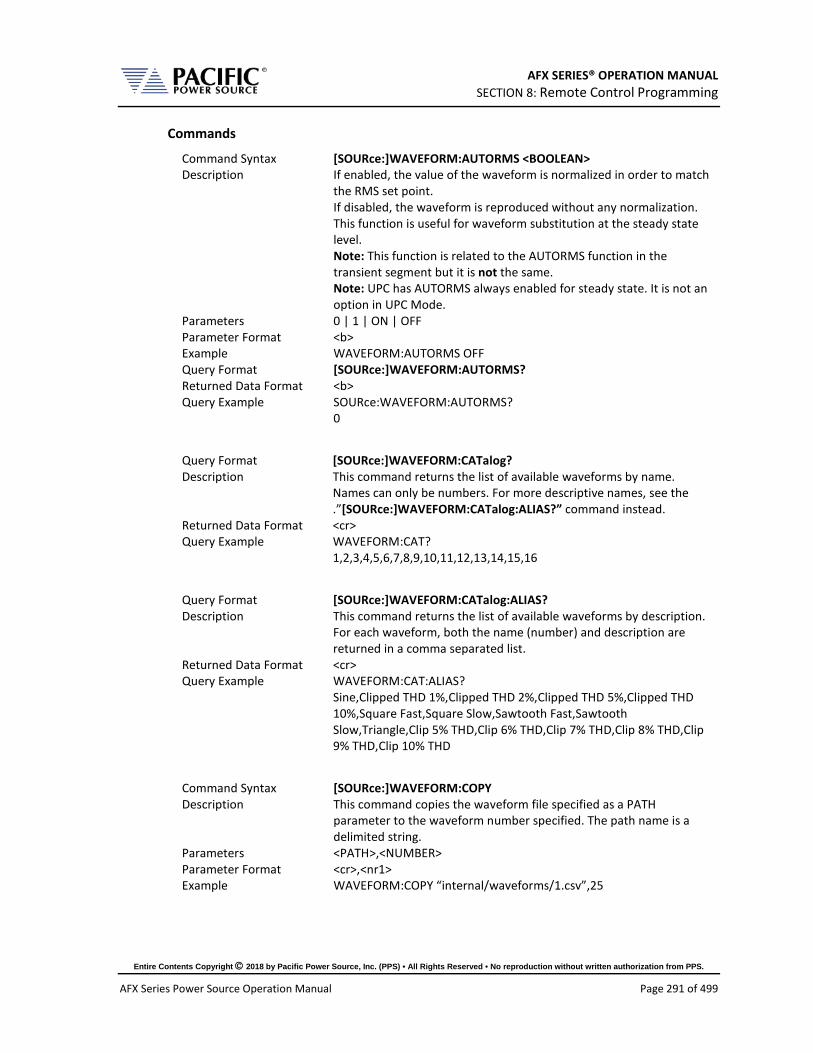
AFX SERIES® OPERATION MANUAL SECTION 8: Remote Control Programming
Entire Contents Copyright 2018 by Pacific Power Source, Inc. (PPS) • All Rights Reserved • No reproduction without written authorization from PPS.
AFX Series Power Source Operation Manual Page 291 of 499
Commands
Command Syntax [SOURce:]WAVEFORM:AUTORMS <BOOLEAN> Description If enabled, the value of the waveform is normalized in order to match
the RMS set point. If disabled, the waveform is reproduced without any normalization. This function is useful for waveform substitution at the steady state level. Note: This function is related to the AUTORMS function in the transient segment but it is not the same. Note: UPC has AUTORMS always enabled for steady state. It is not an option in UPC Mode.
Parameters 0 | 1 | ON | OFF Parameter Format <b> Example WAVEFORM:AUTORMS OFF Query Format [SOURce:]WAVEFORM:AUTORMS? Returned Data Format <b> Query Example SOURce:WAVEFORM:AUTORMS?
0
Query Format [SOURce:]WAVEFORM:CATalog? Description This command returns the list of available waveforms by name.
Names can only be numbers. For more descriptive names, see the .”[SOURce:]WAVEFORM:CATalog:ALIAS?” command instead.
Returned Data Format <cr> Query Example WAVEFORM:CAT?
1,2,3,4,5,6,7,8,9,10,11,12,13,14,15,16
Query Format [SOURce:]WAVEFORM:CATalog:ALIAS? Description This command returns the list of available waveforms by description.
For each waveform, both the name (number) and description are returned in a comma separated list.
Returned Data Format <cr> Query Example WAVEFORM:CAT:ALIAS?
Sine,Clipped THD 1%,Clipped THD 2%,Clipped THD 5%,Clipped THD 10%,Square Fast,Square Slow,Sawtooth Fast,Sawtooth Slow,Triangle,Clip 5% THD,Clip 6% THD,Clip 7% THD,Clip 8% THD,Clip 9% THD,Clip 10% THD
Command Syntax [SOURce:]WAVEFORM:COPY Description This command copies the waveform file specified as a PATH
parameter to the waveform number specified. The path name is a delimited string.
Parameters <PATH>,<NUMBER> Parameter Format <cr>,<nr1> Example WAVEFORM:COPY “internal/waveforms/1.csv”,25

AFX SERIES® OPERATION MANUAL SECTION 8: Remote Control Programming
Entire Contents Copyright 2018 by Pacific Power Source, Inc. (PPS) • All Rights Reserved • No reproduction without written authorization from PPS.
AFX Series Power Source Operation Manual Page 292 of 499
Command Syntax [SOURce:]WAVEFORM:DEFine Description This command sends a string of 1024 data points that constitute a
single period of an arbitrary waveform. The data is sent as a comma separated list of <nr2> values. The waveform name to which to apply the new data values is the first parameter in the list and can be from 1 through 16. Note: Data values are scaled based on an RMS value of 1 so for a sine wave, the max data value is 1.414 and the min data value is -1.414
Parameters 1024 data values separated by commas Parameter Format <nr1>,<nr2>, <nr2>,…….,<nr2> Example WAVEFORM:DEF 16,0.0000,0.0068,0.0135,0.0203,...,-0.0203,-
0.0135,-0.0068 Query Format [SOURce:]WAVEFORM:DEFine? <nr1> Returned Data Format <nr2>, <nr2>,…….,<nr2> Query Example SOURce:WAVEFORM:DEF? 16
0.0000,0.0068,0.0135,0.0203, …. ,-0.0203,-0.0135,-0.0068
Command Syntax [SOURce:]WAVEFORM:DELete <nr1> Description This command deletes a user defined waveform from any location
higher than 1. Parameters Waveform number Parameter Format <nr1> Example WAVEFORM:DEL 16
Query Format [SOURce:]WAVEFORM:EXIST? <nr1> Description This command returns a 1 if the waveform location referenced
contains waveform data or a 0 is the waveform location is empty (No waveform exists).
Returned Data Format <nr1> Query Example WAVEFORM:EXIST? 34
0
Command Syntax [SOURce:]WAVEFORM#:LOAD Description This command loads the currently selected waveform to the actual
output register of the controller causing it output the waveform on the selected phase #.
Parameters 1, 2, 3 Parameter Format <nr1> Example WAVEFORM1:LOAD Query Format [SOURce:]WAVEFORM#:LOAD? <nr1> Returned Data Format <nr1>, <cr> Query Example SOURce:WAVEFORM1:LOAD? 1
1, Sine

AFX SERIES® OPERATION MANUAL SECTION 8: Remote Control Programming
Entire Contents Copyright 2018 by Pacific Power Source, Inc. (PPS) • All Rights Reserved • No reproduction without written authorization from PPS.
AFX Series Power Source Operation Manual Page 293 of 499
Command Syntax [SOURce:]WAVEFORM:RESTORE Description This command restores the first 16 waveforms registers by replacing
waveform 1 to 16 with the factory defaults. See section 8.7.6. Note: This command is useful if waveforms 2 through 15 were overwritten with user-defined waveforms.
Parameters None Parameter Format n/a Example WAVEFORM:RESTORE Query Format None
Command Syntax [SOURce:]WAVEFORM#:SELect Description This command selects a waveform by alias (name) or number. When
using the WAVEFORM:x commands, the ALIAS|NUMBER is not passed as it uses the selected one. This is to avoid passing the waveform number to every command
Parameters <ALIAS|NUMBER, OPT: ALIAS|NUMBER , OPT: ALIAS|NUMBER > The first parameter is required. Additional optional waveforms or numbers may be added when operating the source in 2 or 3 phase mode. The waveform selection sequence by phase is A, B, C.
Parameter Format <cr> or <nr1> Example WAVEFORM:SEL SINE
WAVEFORM:SEL 1,2,3 WAVEFORM:SEL 5
Query Format [SOURce:]WAVEFORM#:SELect? Returned Data Format <cr> or <nr1> Query Example WAVEFORM:SEL?
1,1,1 (FORM 3) WAVEFORM:SEL? 1,1 (FORM 2) WAVEFORM:SEL? 1 (FORM 1)

AFX SERIES® OPERATION MANUAL SECTION 8: Remote Control Programming
Entire Contents Copyright 2018 by Pacific Power Source, Inc. (PPS) • All Rights Reserved • No reproduction without written authorization from PPS.
AFX Series Power Source Operation Manual Page 294 of 499
Command Syntax [SOURce:]WAVEFORM:SINEwave Description This command modifies the #1 Sinewave harmonic content to reduce
voltage distortion at lower frequencies (< 100Hz). It does so by disabling the 3rd Harmonic component that is normally included to improve voltage distortion at high frequencies. Turning this OFF (0) is recommended for Harmonics and Flicker system applications at 50 and 60 Hz. For Avionics and Defense applications at 400Hz or higher, this mode should re-enabled (1). Not that this setting is saved in non-volatile memory and is retained between power on/off cycles of the power source.
Parameters <b> Parameter Format n/a Example SOUR:WAVEFORM:SINE 0 Query Format SOURce:WAVEFORM:SINEwave? Query Example SOUR:WAVEFORM:SINE?
0
Command Syntax [SOURce:]WAVEFORM:SMOOTHen <NUMBER> Description This command Sets the smoothing filter size that is applied to the
waveform, in sample counts. A value of 1 makes the filter have no effect (Disabled) and the maximum value is 101. Only odd numbers are considered. The type of filter used is a moving-average-filter, or MAF. The smoothing filter is used to reduce slew rates of waveform edges. This is useful in certain applications to make the waveform reproduction more consistent and reduce potential distortion due to the sampling rate of the controller, especially when reproducing waveforms at high frequency.
Parameters NUMBER Parameter Format <nr1> Example WAVEFORM:SMOOTH 33 Query Format [SOURce:]WAVEFORM:SMOOTHen? Returned Data Format <nr1> Query Example WAVEFORM:SMOOTH?
33

AFX SERIES® OPERATION MANUAL SECTION 8: Remote Control Programming
Entire Contents Copyright 2018 by Pacific Power Source, Inc. (PPS) • All Rights Reserved • No reproduction without written authorization from PPS.
AFX Series Power Source Operation Manual Page 295 of 499
Command Syntax [SOURce:]WAVEFORM#:NAME Description Set waveform for selected phase to the waveform name passed as a
parameter. If no waveform name parameter is specified, the query format returns the name of the selected waveform. See WAVEFORM#[:NAME] command.
Parameters 1 – 16 Parameter Format <nr1> Example WAVEFORM1 4 Query Format [SOURce:]WAVEFORM#:NAME? Returned Data Format <nr1> Query Example SOUR:WAVEFORM1?
4
Command Syntax [SOURce:]WAVEFORM#:ALIAS Description Analogous to the WAVEFORM#[:NAME] command but in place of the
waveform name, the waveform description is passed as a quoted string.
Parameters Waveform description as quoted string. Parameter Format <cr> Example WAVEFORM1:NAME:ALIAS “Triangle” Query Format [SOURce:]WAVEFORM#:ALIAS? Description Analogous to the WAVEFORM#[:NAME]? query command but in
place of the waveform name, the alias is returned as a string. Returned Data Format <cr> Query Example WAVEFORM1:ALIAS?
Triangle
Command Syntax [SOURce:]WAVEFORM#:LOAD Description Sets the waveform name (1 – 16) to be loaded for the selected phase
# for the next SWITCH command. If # is omitted, sets all available phases to waveform name specified. Note: The waveform LOAD command loads the selected phase’s waveform registers with the waveform data for the specified waveform name but does not cause it to appear at the output until the WAVEFORM:SWITCH command is received.
Parameters 1 – 16 Parameter Format <nr1> Example WAVEFORM2:LOAD 12 Query Format [SOURce:]WAVEFORM#:LOAD? Returned Data Format <nr1> or <nr1>,<nr1>,nr1> Query Example WAVEFORM:LOAD?
1,12,1

AFX SERIES® OPERATION MANUAL SECTION 8: Remote Control Programming
Entire Contents Copyright 2018 by Pacific Power Source, Inc. (PPS) • All Rights Reserved • No reproduction without written authorization from PPS.
AFX Series Power Source Operation Manual Page 296 of 499
Command Syntax [SOURce:]WAVEFORM#:SWITCH Description When sent for the selected phase, the output waveform is switched
over to the new waveform name that was last set with the WAVEFORM#:LOAD command. . If # is omitted, sets all available phases’ waveforms are switched.
Parameters None other than phase selected in command string Parameter Format n/a Example WAVEFORM1:SWITCH
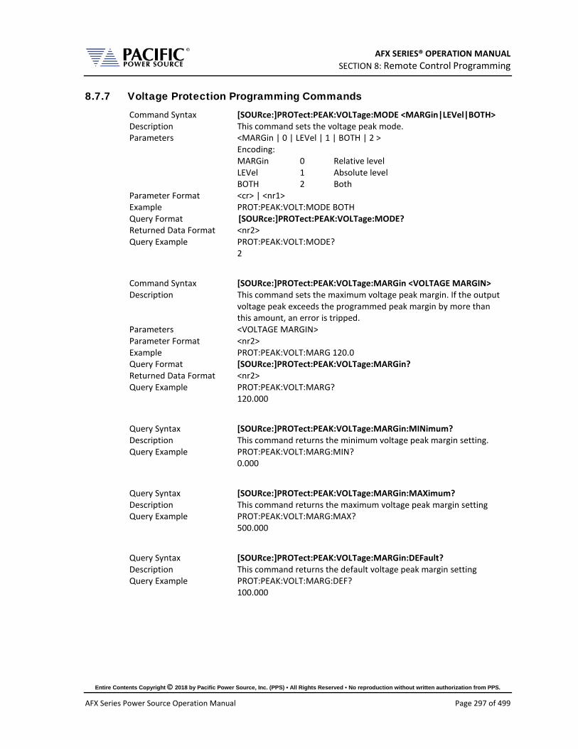
AFX SERIES® OPERATION MANUAL SECTION 8: Remote Control Programming
Entire Contents Copyright 2018 by Pacific Power Source, Inc. (PPS) • All Rights Reserved • No reproduction without written authorization from PPS.
AFX Series Power Source Operation Manual Page 297 of 499
8.7.7 Voltage Protection Programming Commands Command Syntax [SOURce:]PROTect:PEAK:VOLTage:MODE <MARGin|LEVel|BOTH> Description This command sets the voltage peak mode. Parameters <MARGin | 0 | LEVel | 1 | BOTH | 2 >
Encoding: MARGin 0 Relative level LEVel 1 Absolute level BOTH 2 Both
Parameter Format <cr> | <nr1> Example PROT:PEAK:VOLT:MODE BOTH Query Format [SOURce:]PROTect:PEAK:VOLTage:MODE? Returned Data Format <nr2> Query Example PROT:PEAK:VOLT:MODE?
2
Command Syntax [SOURce:]PROTect:PEAK:VOLTage:MARGin <VOLTAGE MARGIN> Description This command sets the maximum voltage peak margin. If the output
voltage peak exceeds the programmed peak margin by more than this amount, an error is tripped.
Parameters <VOLTAGE MARGIN> Parameter Format <nr2> Example PROT:PEAK:VOLT:MARG 120.0 Query Format [SOURce:]PROTect:PEAK:VOLTage:MARGin? Returned Data Format <nr2> Query Example PROT:PEAK:VOLT:MARG?
120.000
Query Syntax [SOURce:]PROTect:PEAK:VOLTage:MARGin:MINimum? Description This command returns the minimum voltage peak margin setting. Query Example PROT:PEAK:VOLT:MARG:MIN?
0.000
Query Syntax [SOURce:]PROTect:PEAK:VOLTage:MARGin:MAXimum? Description This command returns the maximum voltage peak margin setting Query Example PROT:PEAK:VOLT:MARG:MAX?
500.000
Query Syntax [SOURce:]PROTect:PEAK:VOLTage:MARGin:DEFault? Description This command returns the default voltage peak margin setting Query Example PROT:PEAK:VOLT:MARG:DEF?
100.000

AFX SERIES® OPERATION MANUAL SECTION 8: Remote Control Programming
Entire Contents Copyright 2018 by Pacific Power Source, Inc. (PPS) • All Rights Reserved • No reproduction without written authorization from PPS.
AFX Series Power Source Operation Manual Page 298 of 499
Command Syntax [SOURce:]PROTect:PEAK:VOLTage:LEVel <VOLTAGE LEVEL> Description This command sets the maximum voltage peak level. If the output
voltage peak exceeds the programmed peak level by more than this amount, an error is tripped.
Parameters <VOLTAGE LEVEL> Parameter Format <nr2> Example PROT:PEAK:VOLT:LEV 120.0 Query Format [SOURce:]PROTect:PEAK:VOLTage:LEVel? Returned Data Format <nr2> Query Example PROT:PEAK:VOLT:LEV?
500.000
Query Syntax [SOURce:]PROTect:PEAK:VOLTage:LEVel:MINimum? Description This command returns the minimum voltage peak level setting. Query Example PROT:PEAK:VOLT:LEV:MIN?
0.000
Query Syntax [SOURce:]PROTect:PEAK:VOLTage:LEVel:MAXimum? Description This command returns the maximum voltage peak level setting Query Example PROT:PEAK:VOLT:LEV:MAX?
500.000
Query Syntax [SOURce:]PROTect:PEAK:VOLTage:LEVel:DEFault? Description This command returns the default voltage peak level setting Query Example PROT:PEAK:VOLT:LEV:DEF?
500.000
Query Syntax [SOURce:]PROTect:PEAK:VOLTage:TRIPped? Description This command returns 1 if the voltage peak protection has been
tripped or 0 if no trip occurred. Query Example PROT:PEAK:VOLT:TRIP?
0.000
Command Syntax [SOURce:]PROTect:PEAK:VOLTage:TRIPped:CLEar Description This command clears the peak voltage protection trip status. Once
cleared, the power source output can be re-enabled. Parameters <VOLTAGE LEVEL> Parameter Format <nr2> Example PROT:PEAK:VOLT:TRIP:CLE

AFX SERIES® OPERATION MANUAL SECTION 8: Remote Control Programming
Entire Contents Copyright 2018 by Pacific Power Source, Inc. (PPS) • All Rights Reserved • No reproduction without written authorization from PPS.
AFX Series Power Source Operation Manual Page 299 of 499
8.7.8 Current Protection Programming Commands Command Syntax [SOURce:]PROTect[:RMS]:CURRent[:STATe] <ON|OFF> Description This command enables or disables the rms current protection. If the
protection is tripped the power source output is disabled. Parameters < ON | 1 | OFF | 0 > Parameter Format <nr1> | <cr> Example PROTect:CURRent ON Query Format [SOURce:]PROTect[:RMS]:CURRent[:STATe]? Returned Data Format <nr2> Query Example PROTect:CURRent?
1
Command Syntax [SOURce:]PROTect[:RMS]:CURRent:LEVel <LEVEL> Description This command sets the rms current protection level. Parameters < LEVEL > Parameter Format <nr2> Example PROT:CURR:LEVel 40.0 Query Format [SOURce:]PROTect[:RMS]:CURRent:LEVel? Returned Data Format <nr2> Query Example PROT:CURR:LEV?
40.000
Query Syntax [SOURce:]PROTect[:RMS]:CURRent:LEVel:MINimum? Description This command returns the minimum rms current protection level
setting. Query Example PROT:CURR:LEV:MIN?
0.000
Query Syntax [SOURce:]PROTect[:RMS]:CURRent:LEVel:MAXimum? Description This command returns the maximum rms current protection level
setting. Query Example PROT:CURR:LEV:MAX?
41.667
Query Syntax [SOURce:]PROTect[:RMS]:CURRent:LEVel:DEFault? Description This command returns the default rms current protection level
setting. This value will be a function of the power source model. Query Example PROT:CURR:LEV:DEF?
41.667

AFX SERIES® OPERATION MANUAL SECTION 8: Remote Control Programming
Entire Contents Copyright 2018 by Pacific Power Source, Inc. (PPS) • All Rights Reserved • No reproduction without written authorization from PPS.
AFX Series Power Source Operation Manual Page 300 of 499
Command Syntax [SOURce:]PROTect[:RMS]:CURRent:TDELAY <DELAY> Description This command sets the rms current protection trip delay in 100
msecs increments, i.e. as setting of 5 means 500 msec. Parameters < DELAY > Parameter Format <nr1> Example PROTect:CURR:TDELAY 5 Query Format [SOURce:]PROTect[:RMS]:CURRent:TDELAY? Returned Data Format <nr1> Query Example PROT:CURR:LEV?
5
Query Syntax [SOURce:]PROTect[:RMS]:CURRent:TDELAY:MINimum? Description This command returns the minimum rms current protection trip
delay setting. Query Example PROT:CURR:TDELAY:MIN?
0
Query Syntax [SOURce:]PROTect[:RMS]:CURRent:TDELAY:MAXimum? Description This command returns the maximum rms current protection trip
delay setting. Query Example PROT:CURR:TDELAY:MAX?
3000
Query Syntax [SOURce:]PROTect[:RMS]:CURRent:TDELAY:DEFault? Description This command returns the default rms current protection trip delay
setting. Query Example [SOURce:]PROTect[:RMS]:CURRent:TDELAY:DEFault?
41.667
Query Syntax [SOURce:]PROTect[:RMS]:CURRent:TRIPped? Description This command returns rms current protection trip status. Returns 1 if
tripped or 0 if not. Query Example PROT:CURR:TRIP?
41.667
Command Syntax [SOURce:]PROTect[:RMS]:CURRent:TRIPped:CLEar Description This command clears the rms current protection trip status. Once
cleared, the power source output can be enabled. Parameters None Parameter Format n/a Example PROT:CURR:TRIP:CLE

AFX SERIES® OPERATION MANUAL SECTION 8: Remote Control Programming
Entire Contents Copyright 2018 by Pacific Power Source, Inc. (PPS) • All Rights Reserved • No reproduction without written authorization from PPS.
AFX Series Power Source Operation Manual Page 301 of 499
Command Syntax [SOURce:]PEAK:CURRent:LIMit <nr2> Description This command set the user programmable peak current protection
limit. (Not available in models with -413 Option). Parameters Peak current Parameter Format <nr2> Example PEAK:CURR:LIM 80.0 Query Format [SOURce:]PEAK:CURRent:LIMit? Returned Data Format <nr2> Query Example PEAK:CURR?
80.0000
Query Syntax [SOURce:]PEAK:CURRent:LIMit:MAXIMUM? Description This query command returns the maximum allowable setting for the
user programmable peak current protection limit. (Not available in models with -413 Option).
Returned Data Format <nr2> Query Example PEAK:CURR:LIM:MAX?
104.0000
Query Syntax [SOURce:]PEAK:CURRent:LIMit:MINIMUM? Description This query command returns the minimum allowable setting for the
user programmable peak current protection limit. (Not available in models with -413 Option).
Returned Data Format <nr2> Query Example PEAK:CURR:LIM:MIN?
0.0000
Query Syntax [SOURce:]PEAK:CURRent:LIMit:DEFault? Description This query command returns the default setting for the user
programmable peak current protection limit. (Not available in models with -413 Option).
Returned Data Format <nr2> Query Example PEAK:CURR:LIM:DEF?
104.0000
Command Syntax [SOURce:]PROTect:PEAK:CURRent[:STATe] <ON|OFF> Description This command enables or disables the peak current protection
function. Parameters < ON | 1 | OFF | 0 > Parameter Format <cr> | <b> Example PROT:PEAK:CURR ON Query Format [SOURce:]PROTect:PEAK:CURRent[:STATe]? Returned Data Format <b> Query Example PROT:PEAK:CURR?
1

AFX SERIES® OPERATION MANUAL SECTION 8: Remote Control Programming
Entire Contents Copyright 2018 by Pacific Power Source, Inc. (PPS) • All Rights Reserved • No reproduction without written authorization from PPS.
AFX Series Power Source Operation Manual Page 302 of 499
Command Syntax [SOURce:]PROTect:PEAK:CURRent:LEVel <LEVEL> Description This command sets the peak current protection level. Parameters < LEVEL > Parameter Format <nr2> Example PROT:PEAK:CURR:LEV 95.0 Query Format [SOURce:]PROTect:PEAK:CURRent:LEVel? Returned Data Format <b> Query Example PROT:PEAK:CURR:LEV?
95.0000
Query Syntax [SOURce:]PROTect:PEAK:CURRent:LEVel:MAXIMUM? Description This query command returns the maximum allowable setting for the
peak current protection level. Returned Data Format <nr2> Query Example PROT:PEAK:CURR:LEV:MAX?
104.0000
Query Syntax [SOURce:]PROTect:PEAK:CURRent:LEVel:MINIMUM? Description This query command returns the minimum allowable setting for the
peak current protection level. Returned Data Format <nr2> Query Example PROT:PEAK:CURR:LEV:MIN?
104.0000
Query Syntax [SOURce:]PROTect:PEAK:CURRent:LEVel:DEFault? Description This query command returns the default setting for the peak current
protection level. Returned Data Format <nr2> Query Example PROT:PEAK:CURR:LEV:DEF?
104.0000
Query Syntax [SOURce:]PROTect:PEAK:CURRent:TRIPped? Description This query command returns tripped state of the peak current
protection level funtion. Return 1 if tripped, 0 if not. Returned Data Format <b> Query Example PROT:PEAK:CURR:TRIP?
1
Command Syntax [SOURce:]PROTect:PEAK:CURRent:TRIPped:CLEar Description This command clears the the peak current protection protection
tripped status. Parameters None Parameter Format n/a Example PROT:PEAK:CURR:TRIP:CLE

AFX SERIES® OPERATION MANUAL SECTION 8: Remote Control Programming
Entire Contents Copyright 2018 by Pacific Power Source, Inc. (PPS) • All Rights Reserved • No reproduction without written authorization from PPS.
AFX Series Power Source Operation Manual Page 303 of 499
8.7.9 Power Protection Programming Commands Command Syntax [SOURce:]POWer:LIMit# Description This command sets the programmable true power limit level in kW
for phase #. If # is omitted, all available phases are set to the value specified. The max available power for a phase can be obtained using the [SOURce:]POWer:LIMit#:MAX? query command.
Parameters Limit value in kW Parameter Format <nr2> Example POW:LIM 2.5 Query Format [SOURce:]POWer:LIMit#? Returned Data Format <nr2> Query Example POW:LIM1?
2.5000
Query Format [SOURce:]POWer:LIMit#:MAX? Description Returns maximum available true power capability for the specified
phase # in kW. If # is omitted, returns maximum available power level for all phases. Typically, this value will be the same for all phases.
Returned Data Format <nr2> Query Example POW:LIM1:MAX?
5.0000
Command Syntax [SOURce:]KVA:LIMit# Description This command sets the programmable apparent power limit level in
kVA for phase #. If # is omitted, all available phases are set to the value specified. The max available apparent power for a phase can be obtained using the [SOURce:]KVA:LIMit#:MAX? query command.
Parameters Limit value in kVA Parameter Format <nr2> Example KVA:LIM 2.5 Query Format [SOURce:]KVA:LIMit#? Returned Data Format <nr2> Query Example POW:LIM1?
2.5000
Query Format [SOURce:]KVA:LIMit#:MAX? Description Returns maximum available apparent power capability for the
specified phase # in kVA. If # is omitted, returns maximum available apparent power levels for all phases. Typically, this value will be the same for all phases.
Returned Data Format <nr2> Query Example KVA:LIM1:MAX?
5.0000

AFX SERIES® OPERATION MANUAL SECTION 8: Remote Control Programming
Entire Contents Copyright 2018 by Pacific Power Source, Inc. (PPS) • All Rights Reserved • No reproduction without written authorization from PPS.
AFX Series Power Source Operation Manual Page 304 of 499
Query Format [SOURce:]MODE#? Description Returns protection mode for the selected phase # (# = 1, 2, or 3). If #
is omitted, returns protection mode for all phases in comma separated format. Note: When the phase suffix is 1, 2 or 3 the possible return categories are from 0 to 4. With suffix is omitted, this command will return MIXED(5) if modes for each phase are not the same. For example, if in split phase mode phase A (suffix 1) is in VOLTAGE mode but phase B (suffix 2) is in CURRENT mode, the query SOUR:MODE? you will return MIXED: SOUR:MODE1? = VOLTAGE and SOUR:MODE2? = CURRENT -> SOUR:MODE? = MIXED If both or phases are set to the same mode, the actual mode will be returned: SOUR:MODE1? = VOLTAGE and SOUR:MODE2? = VOLTAGE -> SOUR:MODE? = VOLTAGE
Returned Data Format <cr> Available protection modes: 0 = NONE 1 = VOLTAGE 2 = CURRENT 3 = POWER 4 = KVA 5 = MIXED
Query Example SOUR:MODE? VOLTAGE, VOLTAGE, VOLTAGE
Command Syntax [SOURce:]PROTect[:RMS]:POWer[:STATe] <ON|OFF> Description This command turns the true power protection on or off. Parameters < 0 | OFF | 1 | ON > Parameter Format <b> | <cr> Example PROT:POW ON Query Format [SOURce:]PROTect[:RMS]:POWer[:STATe]? Returned Data Format <b> Query Example PROT:POW?
1
Command Syntax [SOURce:]PROTect[:RMS]:POWer:LEVel <LEVEL> Description This command sets the true power protection trip level. Setting is in
KW. Parameters < LEVEL > Parameter Format <nr2> Example PROT:POW:LEV 5 Query Format [SOURce:]PROTect[:RMS]:POWer:LEVel? Returned Data Format <b> Query Example PROT:POW:LEV?
5.000
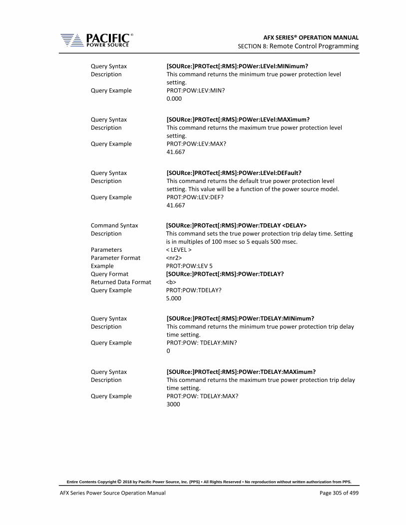
AFX SERIES® OPERATION MANUAL SECTION 8: Remote Control Programming
Entire Contents Copyright 2018 by Pacific Power Source, Inc. (PPS) • All Rights Reserved • No reproduction without written authorization from PPS.
AFX Series Power Source Operation Manual Page 305 of 499
Query Syntax [SOURce:]PROTect[:RMS]:POWer:LEVel:MINimum? Description This command returns the minimum true power protection level
setting. Query Example PROT:POW:LEV:MIN?
0.000
Query Syntax [SOURce:]PROTect[:RMS]:POWer:LEVel:MAXimum? Description This command returns the maximum true power protection level
setting. Query Example PROT:POW:LEV:MAX?
41.667
Query Syntax [SOURce:]PROTect[:RMS]:POWer:LEVel:DEFault? Description This command returns the default true power protection level
setting. This value will be a function of the power source model. Query Example PROT:POW:LEV:DEF?
41.667
Command Syntax [SOURce:]PROTect[:RMS]:POWer:TDELAY <DELAY> Description This command sets the true power protection trip delay time. Setting
is in multiples of 100 msec so 5 equals 500 msec. Parameters < LEVEL > Parameter Format <nr2> Example PROT:POW:LEV 5 Query Format [SOURce:]PROTect[:RMS]:POWer:TDELAY? Returned Data Format <b> Query Example PROT:POW:TDELAY?
5.000
Query Syntax [SOURce:]PROTect[:RMS]:POWer:TDELAY:MINimum? Description This command returns the minimum true power protection trip delay
time setting. Query Example PROT:POW: TDELAY:MIN?
0
Query Syntax [SOURce:]PROTect[:RMS]:POWer:TDELAY:MAXimum? Description This command returns the maximum true power protection trip delay
time setting. Query Example PROT:POW: TDELAY:MAX?
3000

AFX SERIES® OPERATION MANUAL SECTION 8: Remote Control Programming
Entire Contents Copyright 2018 by Pacific Power Source, Inc. (PPS) • All Rights Reserved • No reproduction without written authorization from PPS.
AFX Series Power Source Operation Manual Page 306 of 499
Query Syntax [SOURce:]PROTect[:RMS]:POWer:TDELAY:DEFault? Description This command returns the default true power protection trip delay
time setting. Query Example PROT:POW:TDELAY:DEF?
5
Query Syntax [SOURce:]PROTect[:RMS]:POWer:TRIPped? Description This command returns the true power protection trip status. Returns
1 if tripped or 0 if not. Query Example PROT:POW:TRIP?
41.667
Command Syntax [SOURce:]PROTect[:RMS]:POWer:TRIPped:CLEar Description This command clears the true power protection trip status. Once
cleared, the power source output can be enabled. Parameters None Parameter Format n/a Example PROT:POW:TRIP:CLE
Command Syntax [SOURce:]PROTect[:RMS]:KVA[:STATe] <ON|OFF> Description This command turns the apparent power protection on or off. Parameters < 0 | OFF | 1 | ON > Parameter Format <b> | <cr> Example PROT:POW ON Query Format [SOURce:]PROTect[:RMS]:KVA[:STATe]? Returned Data Format <b> Query Example PROT:KVA?
1
Command Syntax [SOURce:]PROTect[:RMS]:KVA:LEVel <LEVEL> Description This command sets the apparent power protection trip level. Setting
is in KW. Parameters < LEVEL > Parameter Format <nr2> Example PROT:POW:LEV 5 Query Format [SOURce:]PROTect[:RMS]:KVA:LEVel? Returned Data Format <b> Query Example PROT:KVA:LEV?
5.000
Query Syntax [SOURce:]PROTect[:RMS]:KVA:LEVel:MINimum? Description This command returns the minimum apparent power protection level
setting. Query Example PROT:KVA:LEV:MIN?
0.000
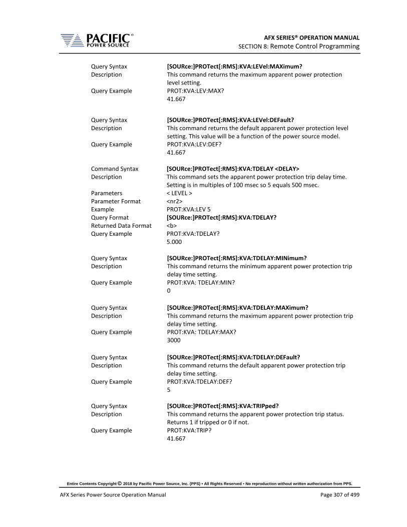
AFX SERIES® OPERATION MANUAL SECTION 8: Remote Control Programming
Entire Contents Copyright 2018 by Pacific Power Source, Inc. (PPS) • All Rights Reserved • No reproduction without written authorization from PPS.
AFX Series Power Source Operation Manual Page 307 of 499
Query Syntax [SOURce:]PROTect[:RMS]:KVA:LEVel:MAXimum? Description This command returns the maximum apparent power protection
level setting. Query Example PROT:KVA:LEV:MAX?
41.667
Query Syntax [SOURce:]PROTect[:RMS]:KVA:LEVel:DEFault? Description This command returns the default apparent power protection level
setting. This value will be a function of the power source model. Query Example PROT:KVA:LEV:DEF?
41.667
Command Syntax [SOURce:]PROTect[:RMS]:KVA:TDELAY <DELAY> Description This command sets the apparent power protection trip delay time.
Setting is in multiples of 100 msec so 5 equals 500 msec. Parameters < LEVEL > Parameter Format <nr2> Example PROT:KVA:LEV 5 Query Format [SOURce:]PROTect[:RMS]:KVA:TDELAY? Returned Data Format <b> Query Example PROT:KVA:TDELAY?
5.000
Query Syntax [SOURce:]PROTect[:RMS]:KVA:TDELAY:MINimum? Description This command returns the minimum apparent power protection trip
delay time setting. Query Example PROT:KVA: TDELAY:MIN?
0
Query Syntax [SOURce:]PROTect[:RMS]:KVA:TDELAY:MAXimum? Description This command returns the maximum apparent power protection trip
delay time setting. Query Example PROT:KVA: TDELAY:MAX?
3000
Query Syntax [SOURce:]PROTect[:RMS]:KVA:TDELAY:DEFault? Description This command returns the default apparent power protection trip
delay time setting. Query Example PROT:KVA:TDELAY:DEF?
5
Query Syntax [SOURce:]PROTect[:RMS]:KVA:TRIPped? Description This command returns the apparent power protection trip status.
Returns 1 if tripped or 0 if not. Query Example PROT:KVA:TRIP?
41.667

AFX SERIES® OPERATION MANUAL SECTION 8: Remote Control Programming
Entire Contents Copyright 2018 by Pacific Power Source, Inc. (PPS) • All Rights Reserved • No reproduction without written authorization from PPS.
AFX Series Power Source Operation Manual Page 308 of 499
Command Syntax [SOURce:]PROTect[:RMS]:KVA:TRIPped:CLEar Description This command clears the apparent power protection trip status. Once
cleared, the power source output can be enabled. Parameters None Parameter Format n/a Example PROT:KVA:TRIP:CLE

AFX SERIES® OPERATION MANUAL SECTION 8: Remote Control Programming
Entire Contents Copyright 2018 by Pacific Power Source, Inc. (PPS) • All Rights Reserved • No reproduction without written authorization from PPS.
AFX Series Power Source Operation Manual Page 309 of 499
8.7.10 Impedance Programming Commands
These commands control the output impedance of the power source. This function requires firmware version 2.0.0 or higher.
The programmable output impedance is defined by a resistive component ( R ) and and inductive component ( L ).
Note: To enable the programmable impedance function, the output of the power source must be turned OFF first. Trying to enable this function while the output is ON will result in an error message.
Command Syntax [SOURce:]IMPEDance[:R] Description This command sets the R value for the output impedance. Available
programming range depends on the mode (Real-time or RMS). Parameters <R> Parameter Format <nr2> Example IMPED 0.2 Query Format [SOURce:]IMPEDance[:R]? Returned Data Format <nr2> Query Example IMPED:R?
0.200
Query Syntax [SOURce:]IMPEDance[:R][:LIMit]:MAXimum? Description This command return the maximum allowable setting value for the R
component of the output impedance. Parameters None Parameter Format N/A Query Example IMPED:R:MAX?
1.000
Query Syntax [SOURce:]IMPEDance[:R][:LIMit]:MINimum? Description This command return the minimum allowable setting value for the R
component of the output impedance. Parameters None Parameter Format N/A Query Example IMPED:R:MIN?
-1.000

AFX SERIES® OPERATION MANUAL SECTION 8: Remote Control Programming
Entire Contents Copyright 2018 by Pacific Power Source, Inc. (PPS) • All Rights Reserved • No reproduction without written authorization from PPS.
AFX Series Power Source Operation Manual Page 310 of 499
Command Syntax [SOURce:]IMPEDance:L Description This command sets the L value for the output impedance. Available
programming range is -0.00000000 ~ 0.00005000 (Henry). Parameters <L> Parameter Format <nr2> Example IMPED:L 0.00002 Query Format [SOURce:]IMPEDance:L? Returned Data Format <nr2> Query Example IMPED:L?
0.00002
Query Syntax [SOURce:]IMPEDance:L[:LIMit]:MAXimum? Description This command return the maximum allowable setting value for the L
component of the output impedance. Parameters None Parameter Format N/A Query Example IMPED:L:MAX?
0.00005000
Query Syntax [SOURce:]IMPEDance:L[:LIMit]:MINimum? Description This command return the minimum allowable setting value for the L
component of the output impedance. Parameters None Parameter Format N/A Query Example IMPED:L:MIN?
0.00000000
Command Syntax [SOURce:]IMPEDance:MODE Description This command sets the programmable impedance mode to either
Real-Time mode (0) or RMS Mode (1). See page 167 for a description of both impedance modes.
0 Real mode. 1 RMS mode.
Note: To change programmable impedance modes, the output of the power source must be turned OFF first. Trying to change modes while the output is ON will result in an error message.
Parameters < 0 | 1 > Parameter Format <b> Example IMPED:MODE 1 Query Format [SOURce:]IMPEDance:MODE? Returned Data Format <b> Query Example IMPED:MODE?
1

AFX SERIES® OPERATION MANUAL SECTION 8: Remote Control Programming
Entire Contents Copyright 2018 by Pacific Power Source, Inc. (PPS) • All Rights Reserved • No reproduction without written authorization from PPS.
AFX Series Power Source Operation Manual Page 311 of 499
Command Syntax [SOURce:]IMPEDance:STATe Description This command sets the programmable impedance state to either Off
(0) or On (1). Note: To enable the programmable impedance function, the output of the power source must be turned OFF first. Trying to enable this function while the output is ON will result in an error message.
Parameters < 0 | 1 > Parameter Format <b> Example IMPED:STAT 1 Query Format [SOURce:]IMPEDance:STATe? Returned Data Format <b> Query Example IMPED:STAT?
1
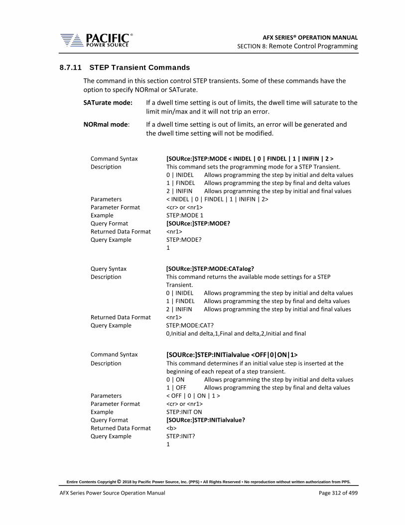
AFX SERIES® OPERATION MANUAL SECTION 8: Remote Control Programming
Entire Contents Copyright 2018 by Pacific Power Source, Inc. (PPS) • All Rights Reserved • No reproduction without written authorization from PPS.
AFX Series Power Source Operation Manual Page 312 of 499
8.7.11 STEP Transient Commands
The command in this section control STEP transients. Some of these commands have the option to specify NORmal or SATurate.
SATurate mode: If a dwell time setting is out of limits, the dwell time will saturate to the limit min/max and it will not trip an error.
NORmal mode: If a dwell time setting is out of limits, an error will be generated and the dwell time setting will not be modified.
Command Syntax [SOURce:]STEP:MODE < INIDEL | 0 | FINDEL | 1 | INIFIN | 2 > Description This command sets the programming mode for a STEP Transient.
0 | INIDEL Allows programming the step by initial and delta values 1 | FINDEL Allows programming the step by final and delta values 2 | INIFIN Allows programming the step by initial and final values
Parameters < INIDEL | 0 | FINDEL | 1 | INIFIN | 2> Parameter Format <cr> or <nr1> Example STEP:MODE 1 Query Format [SOURce:]STEP:MODE? Returned Data Format <nr1> Query Example STEP:MODE?
1
Query Syntax [SOURce:]STEP:MODE:CATalog? Description This command returns the available mode settings for a STEP
Transient. 0 | INIDEL Allows programming the step by initial and delta values 1 | FINDEL Allows programming the step by final and delta values 2 | INIFIN Allows programming the step by initial and final values
Returned Data Format <nr1> Query Example STEP:MODE:CAT?
0,Initial and delta,1,Final and delta,2,Initial and final
Command Syntax [SOURce:]STEP:INITialvalue <OFF|0|ON|1> Description This command determines if an initial value step is inserted at the
beginning of each repeat of a step transient. 0 | ON Allows programming the step by initial and delta values 1 | OFF Allows programming the step by final and delta values
Parameters < OFF | 0 | ON | 1 > Parameter Format <cr> or <nr1> Example STEP:INIT ON Query Format [SOURce:]STEP:INITialvalue? Returned Data Format <b> Query Example STEP:INIT?
1

AFX SERIES® OPERATION MANUAL SECTION 8: Remote Control Programming
Entire Contents Copyright 2018 by Pacific Power Source, Inc. (PPS) • All Rights Reserved • No reproduction without written authorization from PPS.
AFX Series Power Source Operation Manual Page 313 of 499
The impact of inserting the initial value (ON) or not (OFF) is illustrated in the figure below.
• The top sequence shows a STEP transient repeated 3 times with STEP:INIT set ot OFF. The output will not return to the initial output setting between repetitions.
• The bottom sequence is the same STEP transient with STEP:INIT set to ON. Each repeat will start from the initial set value so each repititon produces the same output levels.
Command Syntax [SOURce:]STEP:DWELL <time>, <opt> Description This command sets the dwell time of the step in seconds
Minimum time set value allowed is 0.0002 sec. (0.2 msec) Parameters Time in seconds, Option: < NORmal | SATurate >
Default is NORmal if optional second parameter is omitted. Parameter Format <nr2>, <cr> Example STEP:MODE:DWELL 10, SAT Query Format [SOURce:]STEP:MODE? Returned Data Format <nr2> Query Example STEP:MODE:DWELL?
10.0000, SAT
Query Syntax [SOURce:]STEP:DWELL:MINimum? Description This command returns lowest permissible set value for the STEP
dwell time setting. Returned Data Format <nr2> Query Example STEP:DWELL:MIN?
Query return values for MINimim, MAXimum and DEFault are dependent on MODE and interdependent parameter value settings

AFX SERIES® OPERATION MANUAL SECTION 8: Remote Control Programming
Entire Contents Copyright 2018 by Pacific Power Source, Inc. (PPS) • All Rights Reserved • No reproduction without written authorization from PPS.
AFX Series Power Source Operation Manual Page 314 of 499
Query Syntax [SOURce:]STEP:DWELL:MAXimum? Description This command returns highest permissible set value for the STEP
dwell time setting. Returned Data Format <nr2> Query Example STEP:DWELL:MAX?
Query return values for MINimim, MAXimum and DEFault are dependent on MODE and interdependent parameter value settings
Query Syntax [SOURce:]STEP:DWELL:DEFault? Description This command returns default set value for the STEP dwell time
setting. Returned Data Format <nr2> Query Example STEP:DWELL:DEF?
0.0998
Command Syntax [SOURce:]STEP:RAMP <time>, <opt> Description This command sets the ramp time of the step in seconds
Minimum time set value allowed is 0.0002 sec. (0.2 msec) Parameters Time in seconds, Option: < NORmal | SATurate >
Default is NORmal if optional second parameter is omitted. Parameter Format <nr2>, <cr> Example STEP:MODE:RAMP 5, SAT Query Format [SOURce:]STEP:RAMP? Returned Data Format <nr2> Query Example STEP:RAMP?
5.0000, SAT
Query Syntax [SOURce:]STEP:RAMP:MINimum? Description This command returns lowest permissible set value for the STEP ramp
time setting. Returned Data Format <nr2> Query Example STEP:RAMP:MIN?
Query return values for MINimim, MAXimum and DEFault are dependent on MODE and interdependent parameter value settings
Query Syntax [SOURce:]STEP:RAMP:MAXimum? Description This command returns highest permissible set value for the STEP
ramp time setting. Returned Data Format <nr2> Query Example STEP:RAMP:MAX?
Query return values for MINimim, MAXimum and DEFault are dependent on MODE and interdependent parameter value settings

AFX SERIES® OPERATION MANUAL SECTION 8: Remote Control Programming
Entire Contents Copyright 2018 by Pacific Power Source, Inc. (PPS) • All Rights Reserved • No reproduction without written authorization from PPS.
AFX Series Power Source Operation Manual Page 315 of 499
Query Syntax [SOURce:]STEP:RAMP:DEFault? Description This command returns default set value for the STEP ramp time
setting. Returned Data Format <nr2> Query Example STEP:RAMP:DEF?
Query return values for MINimim, MAXimum and DEFault are dependent on MODE and interdependent parameter value settings
Command Syntax [SOURce:]STEP:LENGth <time>, <opt> Description This command sets the ramp time of the step in seconds
Minimum time set value allowed is 0.0002 sec. (0.2 msec) Parameters Time in seconds, Option: < NORmal | SATurate >
Default is NORmal if optional second parameter is omitted. Parameter Format <nr2>, <cr> Example STEP:MODE:LENG 5, SAT Query Format [SOURce:]STEP:LENGth? Returned Data Format <nr2> Query Example STEP:LENG?
5.0000, SAT
Query Syntax [SOURce:]STEP:LENGth:MINimum? Description This command returns lowest permissible set value for the STEP
length time setting. Returned Data Format <nr2> Query Example STEP:LENG:MIN?
Query return values for MINimim, MAXimum and DEFault are dependent on MODE and interdependent parameter value settings
Query Syntax [SOURce:]STEP:LENGth:MAXimum? Description This command returns highest permissible set value for the STEP
length time setting. Returned Data Format <nr2> Query Example STEP:LENG:MAX?
Query return values for MINimim, MAXimum and DEFault are dependent on MODE and interdependent parameter value settings
Query Syntax [SOURce:]STEP: LENGth:DEFault? Description This command returns default set value for the STEP length time
setting. Returned Data Format <nr2> Query Example STEP:LENG:DEF?
Query return values for MINimim, MAXimum and DEFault are dependent on MODE and interdependent parameter value settings

AFX SERIES® OPERATION MANUAL SECTION 8: Remote Control Programming
Entire Contents Copyright 2018 by Pacific Power Source, Inc. (PPS) • All Rights Reserved • No reproduction without written authorization from PPS.
AFX Series Power Source Operation Manual Page 316 of 499
Command Syntax [SOURce:]STEP:REPeat <no, opt> Description This command sets the number of repeat times for the ramp of the
step Parameters No of repeats, Option: < NORmal | SATurate >
Default is NORmal if optional second parameter is omitted. Parameter Format <nr1>, <cr> Example STEP:MODE:REP 100 Query Format [SOURce:]STEP:REP? Returned Data Format <nr2> Query Example STEP:REP?
100, NOR
Query Syntax [SOURce:]STEP:REPeat:MINimum? Description This command returns lowest permissible set value for the STEP
length time setting. Returned Data Format <nr1> Query Example STEP:REP:MIN?
0
Query Syntax [SOURce:]STEP:REPeat:MAXimum? Description This command returns highest permissible set value for the STEP
length time setting. Returned Data Format <nr1> Query Example STEP:REP:MAX?
65535
Query Syntax [SOURce:]STEP:REPeat:DEFault? Description This command returns default set value for the STEP length time
setting. Returned Data Format <nr2> Query Example STEP:REP:DEF?
1
Command Syntax [SOURce:]STEP:COUNT <no, opt> Description This command sets the number of steps count. Parameters No of step count, Option: < NORmal | SATurate >
Default is NORmal if optional second parameter is omitted. Parameter Format <nr1>, <cr> Example STEP:MODE:REP 12 Query Format [SOURce:]STEP:COUNT? Returned Data Format <nr2> Query Example STEP:REP?
12, NOR

AFX SERIES® OPERATION MANUAL SECTION 8: Remote Control Programming
Entire Contents Copyright 2018 by Pacific Power Source, Inc. (PPS) • All Rights Reserved • No reproduction without written authorization from PPS.
AFX Series Power Source Operation Manual Page 317 of 499
Query Syntax [SOURce:]STEP:COUNT:MINimum? Description This command returns lowest permissible set value for the STEP
count setting. Returned Data Format <nr1> Query Example STEP:COUNT:MIN?
1
Query Syntax [SOURce:]STEP:COUNT:MAXimum? Description This command returns highest permissible set value for the STEP
count setting. Returned Data Format <nr1> Query Example STEP:COUNT:MAX?
200
Query Syntax [SOURce:]STEP:COUNT:DEFault? Description This command returns default set value for the STEP count setting. Returned Data Format <nr2> Query Example STEP:COUNT:DEF?
10
Command Syntax [SOURce:]STEP:HOLD < 0 | OFF 1 | ON > Description This command determines what happens to the source output after
the step transient finishes. If ON, the last step value will be set as the steady state output when the step execution ends. If OFF, the output will revert to the original steady state setting in effect before the step transient execution.
Parameters < 0 | OFF | 1 | ON > Parameter Format <cr> Example STEP:HOLD ON Query Format [SOURce:]STEP:HOLD? Returned Data Format <b> Query Example STEP:HOLD?
1
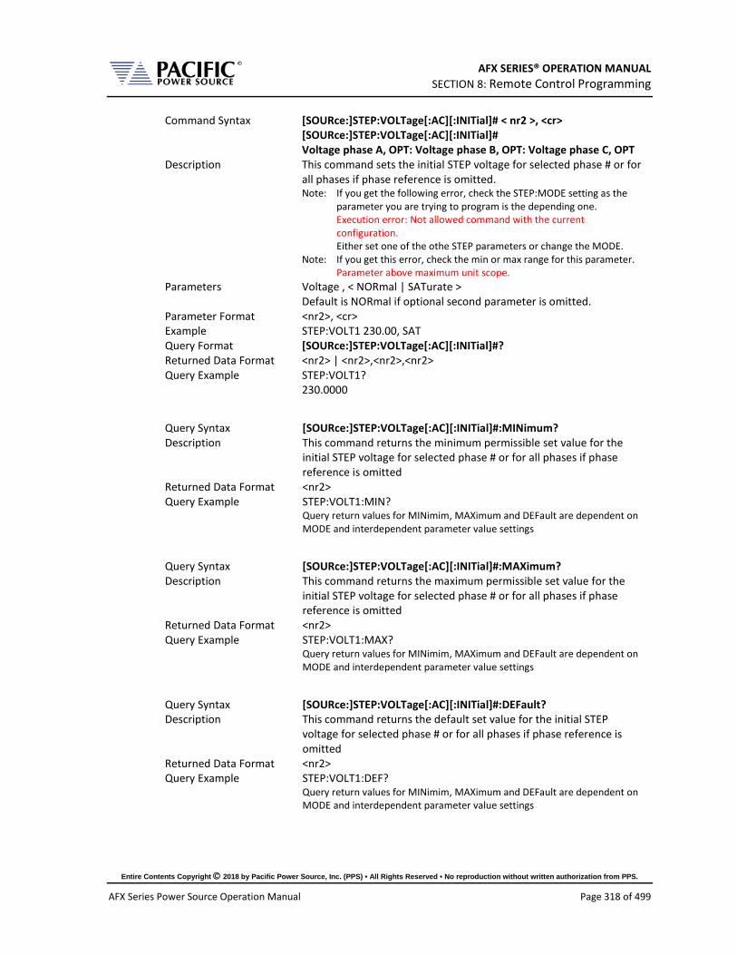
AFX SERIES® OPERATION MANUAL SECTION 8: Remote Control Programming
Entire Contents Copyright 2018 by Pacific Power Source, Inc. (PPS) • All Rights Reserved • No reproduction without written authorization from PPS.
AFX Series Power Source Operation Manual Page 318 of 499
Command Syntax [SOURce:]STEP:VOLTage[:AC][:INITial]# < nr2 >, <cr> [SOURce:]STEP:VOLTage[:AC][:INITial]#
Voltage phase A, OPT: Voltage phase B, OPT: Voltage phase C, OPT Description This command sets the initial STEP voltage for selected phase # or for
all phases if phase reference is omitted. Note: If you get the following error, check the STEP:MODE setting as the
parameter you are trying to program is the depending one. Execution error: Not allowed command with the current configuration. Either set one of the othe STEP parameters or change the MODE.
Note: If you get this error, check the min or max range for this parameter. Parameter above maximum unit scope.
Parameters Voltage , < NORmal | SATurate > Default is NORmal if optional second parameter is omitted.
Parameter Format <nr2>, <cr> Example STEP:VOLT1 230.00, SAT Query Format [SOURce:]STEP:VOLTage[:AC][:INITial]#? Returned Data Format <nr2> | <nr2>,<nr2>,<nr2> Query Example STEP:VOLT1?
230.0000
Query Syntax [SOURce:]STEP:VOLTage[:AC][:INITial]#:MINimum? Description This command returns the minimum permissible set value for the
initial STEP voltage for selected phase # or for all phases if phase reference is omitted
Returned Data Format <nr2> Query Example STEP:VOLT1:MIN?
Query return values for MINimim, MAXimum and DEFault are dependent on MODE and interdependent parameter value settings
Query Syntax [SOURce:]STEP:VOLTage[:AC][:INITial]#:MAXimum? Description This command returns the maximum permissible set value for the
initial STEP voltage for selected phase # or for all phases if phase reference is omitted
Returned Data Format <nr2> Query Example STEP:VOLT1:MAX?
Query return values for MINimim, MAXimum and DEFault are dependent on MODE and interdependent parameter value settings
Query Syntax [SOURce:]STEP:VOLTage[:AC][:INITial]#:DEFault? Description This command returns the default set value for the initial STEP
voltage for selected phase # or for all phases if phase reference is omitted
Returned Data Format <nr2> Query Example STEP:VOLT1:DEF?
Query return values for MINimim, MAXimum and DEFault are dependent on MODE and interdependent parameter value settings

AFX SERIES® OPERATION MANUAL SECTION 8: Remote Control Programming
Entire Contents Copyright 2018 by Pacific Power Source, Inc. (PPS) • All Rights Reserved • No reproduction without written authorization from PPS.
AFX Series Power Source Operation Manual Page 319 of 499
Command Syntax [SOURce:]STEP:VOLTage[:AC]:FINal# < nr2 >, <cr> [SOURce:]STEP:VOLTage[:AC]:FINal#
Voltage phase A, OPT: Voltage phase B, OPT: Voltage phase C, OPT Description This command sets the final STEP voltage for selected phase # or for
all phases if phase reference is omitted. Parameters Voltage , < NORmal | SATurate >
Default is NORmal if optional second parameter is omitted. Parameter Format <nr2>, <cr> Example STEP:VOLT:FIN 180.00, SAT Query Format [SOURce:]STEP:VOLTage[:AC]:FINal#? Returned Data Format <nr2> | <nr2>,<nr2>,<nr2> Query Example STEP:VOLT:FIN?
180.000,180.000,180.000
Query Syntax [SOURce:]STEP:VOLTage[:AC]:FINal#:MINimum? Description This command returns the minimum permissible set value for the
final STEP voltage for selected phase # or for all phases if phase reference is omitted
Returned Data Format <nr2> Query Example STEP:VOLT:FIN1:MIN?
Query return values for MINimim, MAXimum and DEFault are dependent on MODE and interdependent parameter value settings
Query Syntax [SOURce:]STEP:VOLTage[:AC]:FINal#:MAXimum? Description This command returns the maximum permissible set value for the
final STEP voltage for selected phase # or for all phases if phase reference is omitted
Returned Data Format <nr2> Query Example STEP:VOLT:FIN1:MAX?
Query return values for MINimim, MAXimum and DEFault are dependent on MODE and interdependent parameter value settings
Query Syntax [SOURce:]STEP:VOLTage[:AC]:FINal#:DEFault? Description This command returns the default set value for the final STEP voltage
for selected phase # or for all phases if phase reference is omitted Returned Data Format <nr2> Query Example STEP:VOLT:FIN1:DEF?
Query return values for MINimim, MAXimum and DEFault are dependent on MODE and interdependent parameter value settings

AFX SERIES® OPERATION MANUAL SECTION 8: Remote Control Programming
Entire Contents Copyright 2018 by Pacific Power Source, Inc. (PPS) • All Rights Reserved • No reproduction without written authorization from PPS.
AFX Series Power Source Operation Manual Page 320 of 499
Command Syntax [SOURce:]STEP:VOLTage[:AC]:DELTa# < nr2 >, <cr> [SOURce:]STEP:VOLTage[:AC]:DELTa#
Voltage phase A, OPT: Voltage phase B, OPT: Voltage phase C, OPT Description This command sets the delta STEP voltage for selected phase # or for
all phases if phase reference is omitted. Parameters Voltage , < NORmal | SATurate >
Default is NORmal if optional second parameter is omitted. Parameter Format <nr2>, <cr> Example STEP:VOLT:DELT1 10.00, SAT Query Format [SOURce:]STEP:VOLTage[:AC]:DELTa#? Returned Data Format <nr2> | <nr2>,<nr2>,<nr2> Query Example STEP:VOLT:DELT?
10.000,10.000,10.000
Query Syntax [SOURce:]STEP:VOLTage[:AC]:DELTa#:MINimum? Description This command returns the minimum permissible set value for the
delta STEP voltage for selected phase # or for all phases if phase reference is omitted
Returned Data Format <nr2> Query Example STEP:VOLT:DELT1:MIN?
Query return values for MINimim, MAXimum and DEFault are dependent on MODE and interdependent parameter value settings
Query Syntax [SOURce:]STEP:VOLTage[:AC]:DELTa#:MAXimum? Description This command returns the maximum permissible set value for the
delta STEP voltage for selected phase # or for all phases if phase reference is omitted
Returned Data Format <nr2> Query Example STEP:VOLT:DELT1:MAX?
Query return values for MINimim, MAXimum and DEFault are dependent on MODE and interdependent parameter value settings
Query Syntax [SOURce:]STEP:VOLTage[:AC]:DELTa#:DEFault? Description This command returns the default set value for the delta STEP
voltage for selected phase # or for all phases if phase reference is omitted
Returned Data Format <nr2> Query Example STEP:VOLT:DELT1:DEF?
Query return values for MINimim, MAXimum and DEFault are dependent on MODE and interdependent parameter value settings

AFX SERIES® OPERATION MANUAL SECTION 8: Remote Control Programming
Entire Contents Copyright 2018 by Pacific Power Source, Inc. (PPS) • All Rights Reserved • No reproduction without written authorization from PPS.
AFX Series Power Source Operation Manual Page 321 of 499
Command Syntax [SOURce:]STEP:VOLTage:DC[:INITial]# < nr2 >, <cr> [SOURce:]STEP:VOLTage:DC[:INITial]#
Voltage phase A, OPT: Voltage phase B, OPT: Voltage phase C, OPT Description This command sets the initial STEP DC voltage for selected phase # or
for all phases if phase reference is omitted. Parameters Voltage , < NORmal | SATurate >
Default is NORmal if optional second parameter is omitted. Parameter Format <nr2>, <cr> Example STEP:VOLT:DC1 230.00, SAT Query Format [SOURce:]STEP:VOLTage:DC[:INITial]#? Returned Data Format <nr2> | <nr2>,<nr2>,<nr2> Query Example STEP:VOLT:DC?
0.000,0.000,0.000
Query Syntax [SOURce:]STEP:VOLTage:DC[:INITial]#:MINimum? Description This command returns the minimum permissible set value for the
initial STEP DC voltage for selected phase # or for all phases if phase reference is omitted
Returned Data Format <nr2> Query Example STEP:VOLT:DC1:MIN?
Query return values for MINimim, MAXimum and DEFault are dependent on MODE and interdependent parameter value settings
Query Syntax [SOURce:]STEP:VOLTage:DC[:INITial]#:MAXimum? Description This command returns the maximum permissible set value for the
initial STEP DC voltage for selected phase # or for all phases if phase reference is omitted
Returned Data Format <nr2> Query Example STEP:VOLT:DC1:MAX?
Query return values for MINimim, MAXimum and DEFault are dependent on MODE and interdependent parameter value settings
Query Syntax [SOURce:]STEP:VOLTage:DC[:INITial]#:DEFault? Description This command returns the default set value for the initial STEP DC
voltage for selected phase # or for all phases if phase reference is omitted
Returned Data Format <nr2> Query Example STEP:VOLT:DC1:DEF?
Query return values for MINimim, MAXimum and DEFault are dependent on MODE and interdependent parameter value settings

AFX SERIES® OPERATION MANUAL SECTION 8: Remote Control Programming
Entire Contents Copyright 2018 by Pacific Power Source, Inc. (PPS) • All Rights Reserved • No reproduction without written authorization from PPS.
AFX Series Power Source Operation Manual Page 322 of 499
Command Syntax [SOURce:]STEP:VOLTage:DC:FINal# < nr2 >, <cr> [SOURce:]STEP:VOLTage:DC:FINal#
Voltage phase A, OPT: Voltage phase B, OPT: Voltage phase C, OPT Description This command sets the final STEP DC voltage for selected phase # or
for all phases if phase reference is omitted. Parameters Voltage , < NORmal | SATurate >
Default is NORmal if optional second parameter is omitted. Parameter Format <nr2>, <cr> Example STEP:VOLT:DC:FIN 187.00, SAT Query Format [SOURce:]STEP:VOLTage:DC:FINal#? Returned Data Format <nr2> | <nr2>,<nr2>,<nr2> Query Example STEP:VOLT:DC:FIN?
187.000,187.000,187.000
Query Syntax [SOURce:]STEP:VOLTage:DC:FINal#:MINimum? Description This command returns the minimum permissible set value for the
final STEP DC voltage for selected phase # or for all phases if phase reference is omitted
Returned Data Format <nr2> Query Example STEP:VOLT:DC:FIN1:MIN?
Query return values for MINimim, MAXimum and DEFault are dependent on MODE and interdependent parameter value settings
Query Syntax [SOURce:]STEP:VOLTage:DC:FINal#:MAXimum? Description This command returns the maximum permissible set value for the
final STEP DC voltage for selected phase # or for all phases if phase reference is omitted
Returned Data Format <nr2> Query Example STEP:VOLT:DC:FIN1:MAX?
Query return values for MINimim, MAXimum and DEFault are dependent on MODE and interdependent parameter value settings
Query Syntax [SOURce:]STEP:VOLTage:DC:FINal#:DEFault? Description This command returns the default set value for the final STEP DC
voltage for selected phase # or for all phases if phase reference is omitted
Returned Data Format <nr2> Query Example STEP:VOLT:DC:FIN1:DEF?
Query return values for MINimim, MAXimum and DEFault are dependent on MODE and interdependent parameter value settings

AFX SERIES® OPERATION MANUAL SECTION 8: Remote Control Programming
Entire Contents Copyright 2018 by Pacific Power Source, Inc. (PPS) • All Rights Reserved • No reproduction without written authorization from PPS.
AFX Series Power Source Operation Manual Page 323 of 499
Command Syntax [SOURce:]STEP:VOLTage:DC:DELTa# < nr2 >, <cr> [SOURce:]STEP:VOLTage:DC:DELTa#
Voltage phase A, OPT: Voltage phase B, OPT: Voltage phase C, OPT Description This command sets the delta STEP DC voltage for selected phase # or
for all phases if phase reference is omitted. Parameters Voltage , < NORmal | SATurate >
Default is NORmal if optional second parameter is omitted. Parameter Format <nr2>, <cr> Example STEP:VOLT:DC:DELT1 10.00, SAT Query Format [SOURce:]STEP:VOLTage:DC:DELTa#? Returned Data Format <nr2> | <nr2>,<nr2>,<nr2> Query Example STEP:VOLT:DC:DELT?
10.0000
Query Syntax [SOURce:]STEP:VOLTage:DC:DELTa#:MINimum? Description This command returns the minimum permissible set value for the
delta STEP DC voltage for selected phase # or for all phases if phase reference is omitted
Returned Data Format <nr2> Query Example STEP:VOLT:DC:DELT1:MIN?
Query return values for MINimim, MAXimum and DEFault are dependent on MODE and interdependent parameter value settings
Query Syntax [SOURce:]STEP:VOLTage:DC:DELTa#:MAXimum? Description This command returns the maximum permissible set value for the
delta STEP DC voltage for selected phase # or for all phases if phase reference is omitted
Returned Data Format <nr2> Query Example STEP:VOLT:DC:DELT1:MAX?
Query return values for MINimim, MAXimum and DEFault are dependent on MODE and interdependent parameter value settings
Query Syntax [SOURce:]STEP:VOLTage:DC:DELTa#:DEFault? Description This command returns the default set value for the delta STEP DC
voltage for selected phase # or for all phases if phase reference is omitted
Returned Data Format <nr2> Query Example STEP:VOLT:DC:DELT1:DEF?
Query return values for MINimim, MAXimum and DEFault are dependent on MODE and interdependent parameter value settings

AFX SERIES® OPERATION MANUAL SECTION 8: Remote Control Programming
Entire Contents Copyright 2018 by Pacific Power Source, Inc. (PPS) • All Rights Reserved • No reproduction without written authorization from PPS.
AFX Series Power Source Operation Manual Page 324 of 499
Command Syntax [SOURce:]STEP:FREQuency[:INITial] <nr2 >, <cr> Description This command sets the initial STEP frequency. Parameters Frequency, < NORmal | SATurate >
Default is NORmal if optional second parameter is omitted. Parameter Format <nr2>, <cr> Example STEP:FREQ 50.0, SAT Query Format [SOURce:]STEP:FREQuency[:INITial]? Returned Data Format <nr2> Query Example STEP:FREQ?
50.0000
Query Syntax [SOURce:]STEP:FREQuency[:INITial]:MINimum? Description This command returns the minimum permissible set value for the
initial STEP frequency. Returned Data Format <nr2> Query Example STEP:FREQ:MIN?
Query return values for MINimim, MAXimum and DEFault are dependent on MODE and interdependent parameter value settings
Query Syntax [SOURce:]STEP:FREQuency[:INITial]:MAXimum? Description This command returns the maximum permissible set value for the
initial STEP frequency. Returned Data Format <nr2> Query Example STEP:FREQ:MAX?
Query return values for MINimim, MAXimum and DEFault are dependent on MODE and interdependent parameter value settings
Query Syntax [SOURce:]STEP:FREQuency[:INITial]:DEFault? Description This command returns the default set value for the initial STEP
frequency. Returned Data Format <nr2> Query Example STEP:FREQ:DEF?
Query return values for MINimim, MAXimum and DEFault are dependent on MODE and interdependent parameter value settings
Command Syntax [SOURce:]STEP:FREQuency:FINal <nr2 >, <cr> Description This command sets the final STEP frequency. Parameters Frequency, < NORmal | SATurate >
Default is NORmal if optional second parameter is omitted. Parameter Format <nr2>, <cr> Example STEP:FREQ:FIN 55.0, SAT Query Format [SOURce:]STEP:FREQuency:FINal? Returned Data Format <nr2> Query Example STEP:FREQ:FIN?
55.0000

AFX SERIES® OPERATION MANUAL SECTION 8: Remote Control Programming
Entire Contents Copyright 2018 by Pacific Power Source, Inc. (PPS) • All Rights Reserved • No reproduction without written authorization from PPS.
AFX Series Power Source Operation Manual Page 325 of 499
Query Syntax [SOURce:]STEP:FREQuency:FINal:MINimum? Description This command returns the minimum permissible set value for the
final STEP frequency. Returned Data Format <nr2> Query Example STEP:FREQ:FIN:MIN?
15.0000
Query Syntax [SOURce:]STEP:FREQuency:FINal:MAXimum? Description This command returns the maximum permissible set value for the
final STEP frequency. Returned Data Format <nr2> Query Example STEP:FREQ:FIN:MAX?
1200.0000
Query Syntax [SOURce:]STEP:FREQuency:FINal:DEFault? Description This command returns the default set value for the final STEP
frequency. Returned Data Format <nr2> Query Example STEP:FREQ:FIN:DEF?
60.0000
Command Syntax [SOURce:]STEP:FREQuency:DELTa <nr2 >, <cr> Description This command sets the delta frequency. Parameters Frequency, < NORmal | SATurate >
Default is NORmal if optional second parameter is omitted. Parameter Format <nr2>, <cr> Example STEP:FREQ:DELT 5.0, SAT Query Format [SOURce:]STEP:FREQuency:DELTa? Returned Data Format <nr2> Query Example STEP:FREQ:DELT?
5.0000
Query Syntax [SOURce:]STEP:FREQuency:DELTa:MINimum? Description This command returns the minimum permissible set value for the
delta STEP frequency. Returned Data Format <nr2> Query Example STEP:FREQ:DELT:MIN?
Query return values for MINimim, MAXimum and DEFault are dependent on MODE and interdependent parameter value settings

AFX SERIES® OPERATION MANUAL SECTION 8: Remote Control Programming
Entire Contents Copyright 2018 by Pacific Power Source, Inc. (PPS) • All Rights Reserved • No reproduction without written authorization from PPS.
AFX Series Power Source Operation Manual Page 326 of 499
Query Syntax [SOURce:]STEP:FREQuency:DELTa:MAXimum? Description This command returns the maximum permissible set value for the
delta STEP frequency. Returned Data Format <nr2> Query Example STEP:FREQ:DELT:MAX?
Query return values for MINimim, MAXimum and DEFault are dependent on MODE and interdependent parameter value settings
Query Syntax [SOURce:]STEP:FREQuency:DELTa:DEFault? Description This command returns the default set value for the delta STEP
frequency. Returned Data Format <nr2> Query Example STEP:FREQ:DELT:DEF?
Query return values for MINimim, MAXimum and DEFault are dependent on MODE and interdependent parameter value settings
Command Syntax [SOURce:]STEP:WAVEFORM# <nr1 > Description This command sets the selected waveform using the wavefrom
number. Parameters Waveform number Parameter Format <nr1>, <cr> Example STEP:WAVEFORM 1 Query Format [SOURce:]STEP: WAVEFORM#? Returned Data Format <nr1> Query Example STEP:WAVEFORM#?
1.0000
Query Syntax [SOURce:]STEP:WAVEFORM#:MINimum? Description This command returns the minimum permissible set value for the
STEP waveform. Returned Data Format <nr1> Query Example STEP:WAVEFORM#:MIN?
1
Query Syntax [SOURce:]STEP:WAVEFORM#:MAXimum? Description This command returns the maximum permissible set value for the
STEP waveform. Returned Data Format <nr1> Query Example STEP:WAVEFORM#:MAX?
200
Query Syntax [SOURce:]STEP:WAVEFORM:DEFault? Description This command returns the default set value for the STEP waveform. Returned Data Format <nr1> Query Example STEP:WAVEFORM:DEF?
1
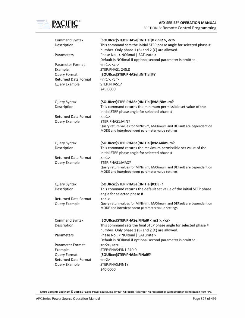
AFX SERIES® OPERATION MANUAL SECTION 8: Remote Control Programming
Entire Contents Copyright 2018 by Pacific Power Source, Inc. (PPS) • All Rights Reserved • No reproduction without written authorization from PPS.
AFX Series Power Source Operation Manual Page 327 of 499
Command Syntax [SOURce:]STEP:PHASe[:INITial]# < nr2 >, <cr> Description This command sets the initial STEP phase angle for selected phase #
number. Only phase 1 (B) and 2 (C) are allowed. Parameters Phase No., < NORmal | SATurate >
Default is NORmal if optional second parameter is omitted. Parameter Format <nr1>, <cr> Example STEP:PHAS1 245.0 Query Format [SOURce:]STEP:PHASe[:INITial]#? Returned Data Format <nr1>, <cr> Query Example STEP:PHAS1?
245.0000
Query Syntax [SOURce:]STEP:PHASe[:INITial]#:MINimum? Description This command returns the minimum permissible set value of the
initial STEP phase angle for selected phase # Returned Data Format <nr1> Query Example STEP:PHAS1:MIN?
Query return values for MINimim, MAXimum and DEFault are dependent on MODE and interdependent parameter value settings
Query Syntax [SOURce:]STEP:PHASe[:INITial]#:MAXimum? Description This command returns the maximum permissible set value of the
initial STEP phase angle for selected phase # Returned Data Format <nr1> Query Example STEP:PHAS1:MAX?
Query return values for MINimim, MAXimum and DEFault are dependent on MODE and interdependent parameter value settings
Query Syntax [SOURce:]STEP:PHASe[:INITial]#:DEF? Description This command returns the default set value of the initial STEP phase
angle for selected phase # Returned Data Format <nr1> Query Example Query return values for MINimim, MAXimum and DEFault are dependent on
MODE and interdependent parameter value settings
Command Syntax [SOURce:]STEP:PHASe:FINal# < nr2 >, <cr> Description This command sets the final STEP phase angle for selected phase #
number. Only phase 1 (B) and 2 (C) are allowed. Parameters Phase No., < NORmal | SATurate >
Default is NORmal if optional second parameter is omitted. Parameter Format <nr2>, <cr> Example STEP:PHAS:FIN1 240.0 Query Format [SOURce:]STEP:PHASe:FINal#? Returned Data Format <nr2> Query Example STEP:PHAS:FIN1?
240.0000

AFX SERIES® OPERATION MANUAL SECTION 8: Remote Control Programming
Entire Contents Copyright 2018 by Pacific Power Source, Inc. (PPS) • All Rights Reserved • No reproduction without written authorization from PPS.
AFX Series Power Source Operation Manual Page 328 of 499
Query Syntax [SOURce:]STEP:PHASe:FINal#:MINimum? Description This command returns the minimum permissible set value of the final
STEP phase angle for selected phase # Returned Data Format <nr1> Query Example STEP:PHAS:FIN1:MIN?
Query return values for MINimim, MAXimum and DEFault are dependent on MODE and interdependent parameter value settings
Query Syntax [SOURce:]STEP:PHASe:FINal#:MAXimum? Description This command returns the maximum permissible set value of the
final STEP phase angle for selected phase # Returned Data Format <nr1> Query Example STEP:PHAS:FIN1:MAX?
Query return values for MINimim, MAXimum and DEFault are dependent on MODE and interdependent parameter value settings
Query Syntax [SOURce:]STEP:PHASe:FINal#:DEF? Description This command returns the default set value of the final STEP phase
angle for selected phase # Returned Data Format <nr1> Query Example STEP:PHAS:FIN1:DEF?
Query return values for MINimim, MAXimum and DEFault are dependent on MODE and interdependent parameter value settings
Command Syntax [SOURce:]STEP:PHASe:DELTa# < nr2 >, <cr> Description This command sets the delta STEP phase angle for selected phase #
number. Only phase 1 (B) and 2 (C) are allowed. Parameters Phase No., < NORmal | SATurate >
Default is NORmal if optional second parameter is omitted. Parameter Format <nr1>, <cr> Example STEP:PHAS:DELT1 240.0 Query Format [SOURce:]STEP:PHASe:DELTa#? Returned Data Format <nr1>, <cr> Query Example STEP:PHAS:DELT1?
240.0000
Query Syntax [SOURce:]STEP:PHASe:DELTa#:MINimum? Description This command returns the minimum permissible set value of the
delta STEP phase angle for selected phase # Returned Data Format <nr1> Query Example STEP:PHAS:DELT1:MIN?
Query return values for MINimim, MAXimum and DEFault are dependent on MODE and interdependent parameter value settings

AFX SERIES® OPERATION MANUAL SECTION 8: Remote Control Programming
Entire Contents Copyright 2018 by Pacific Power Source, Inc. (PPS) • All Rights Reserved • No reproduction without written authorization from PPS.
AFX Series Power Source Operation Manual Page 329 of 499
Query Syntax [SOURce:]STEP:PHASe:DELTa#:MAXimum? Description This command returns the maximum permissible set value of the
delta STEP phase angle for selected phase # Returned Data Format <nr1> Query Example STEP:PHAS:DELT1:MAX?
Query return values for MINimim, MAXimum and DEFault are dependent on MODE and interdependent parameter value settings
Query Syntax [SOURce:]STEP:PHASe:DELTa#:DEF? Description This command returns the default set value of the delta STEP phase
angle for selected phase # Returned Data Format <nr1> Query Example Query return values for MINimim, MAXimum and DEFault are dependent on
MODE and interdependent parameter value settings
Command Syntax [SOURce:]STEP <cr> >>> Alias for PROGram:TRANsient command. <<<
Description This command controls step transient execution Parameters < RUN | STOP | PAUSe | STEP | RESTart > Parameter Format <cr> Example STEP RUN Query Format [SOURce:]STEP? Description Query format returns the step transient execution state as either
RUN, STOP, PAUS, STEP or REST Returned Data Format <nr1>
Return values respresent running state as follows: 0 Stopped 1 Running 2 Paused 3 Stepping 4 Waiting for trigger
Query Example STEP? 1

AFX SERIES® OPERATION MANUAL SECTION 8: Remote Control Programming
Entire Contents Copyright 2018 by Pacific Power Source, Inc. (PPS) • All Rights Reserved • No reproduction without written authorization from PPS.
AFX Series Power Source Operation Manual Page 330 of 499
Command Syntax [SOURce:]STEP:LOAD Description This command converts the step transient definition to the power
source’s regular transient segment format and loads it in the controller real-time memory for execution.
Parameters None Parameter Format n/a Example STEP RUN Query Format [SOURce:]STEP:LOAD? Description Query format returns a 1 if the step transient load operation was
successful, otherwise returns 0. Returned Data Format <nr1>
Return values respresent: 0 Load Failed 1 Load completed
Query Example STEP? 1
Query Syntax [SOURce:]STEP:PROGress? >>> Alias for PROGram:TRANsient:PROGress command. <<<
Description This query command returns the status of the step being executed. Parameters None Parameter Format n/a Description Query returns the step transient execution state as either RUN, STOP,
PAUS, STEP or REST Returned Data Format <cr>
The response is a comma-separated value string representing: PROGRESS, CURRENT SEGMENT PROGRESS, CURRENT SEGMENT, CURRENT SEGMENT TIME, TOTAL TIME, TOTAL SEGMENTS, REPEAT TIME COUNTER
Query Example STEP:PROG? 1, 45, 2, 1.2300, 2.0000, 4, 5
Query Syntax [SOURce:]STEP:CHECK? Description This query command returns the result of a check on the
programmined step parameters to determine if they are ok to run. Parameters None Parameter Format n/a Description Query returns result of STEP parameters integrity check Returned Data Format <cr>
The response is either OK or if not, a string containing the error. Query Example STEP:PROG?
OK

AFX SERIES® OPERATION MANUAL SECTION 8: Remote Control Programming
Entire Contents Copyright 2018 by Pacific Power Source, Inc. (PPS) • All Rights Reserved • No reproduction without written authorization from PPS.
AFX Series Power Source Operation Manual Page 331 of 499
Query Syntax [SOURce:]STEP:ALL? Description This query command returns a comma-separated values string of the
entire step parameters, settings, and limits. Each set value is preceded by a tag identifying the parameter. This same data structure is used for front panel display and by the web server. The advantage is that this commands returns all step related information using just one query command.
Parameters None Parameter Format n/a Description Returns complete STEP setup as a comma separed value string. Returned Data Format <cr> Query Example STEP:ALL? form,3,loaded,0,status,0,progress,0,current element progress,0,current element,0,current element time,0,total time,0,total elements,0,repeat times,0,hold,1,init,1,mode,0,mode max,2,mode min,0,dwell,0,dwell max,10000,dwell min,0,ramp,0,ramp max,10000,ramp min,0,length,0,length max,10000,length min,0,repeat,1,repeat max,65535,repeat min,0,count,10,count max,200,count min,1,count min reason,0,count max reason,0,waveform all,1,waveform all exist,1,waveform a,1,waveform a exist,1,waveform b,1,waveform b exist,1,waveform c,1,waveform c exist,1,waveform max,200,waveform min,1,initial frequency,0.0000,initial frequency min,0.0000,initial frequency max,0.0000,initial frequency min reason,4,initial frequency max reason,4,initial voltage ac all,0.0000,initial voltage ac all max,0.0000,initial voltage ac all min,0.0000,initial voltage ac all max reason,4,initial voltage ac all min reason,4,initial voltage ac a,0.0000,initial voltage ac a max,0.0000,initial voltage ac a min,0.0000,initial voltage ac a max reason,4,initial voltage ac a min reason,4,initial voltage ac b,0.0000,initial voltage ac b max,0.0000,initial voltage ac b min,0.0000,initial voltage ac b max reason,4,initial voltage ac b min reason,4,initial voltage ac c,0.0000,initial voltage ac c max,0.0000,initial voltage ac c min,0.0000,initial voltage ac c max reason,4,initial voltage ac c min reason,4,initial voltage dc all,0.0000,initial voltage dc all max,425.0000,initial voltage dc all min,-425.0000,initial voltage dc all max reason,0,initial voltage dc all min reason,0,initial voltage dc a,0.0000,initial voltage dc a max,425.0000,initial voltage dc a min,-425.0000,initial voltage dc a max reason,0,initial voltage dc a min reason,0,initial voltage dc b,0.0000,initial voltage dc b max,425.0000,initial voltage dc b min,-425.0000,initial voltage dc b max reason,0,initial voltage dc b min reason,0,initial voltage dc c,0.0000,initial voltage dc c max,425.0000,initial voltage dc c min,-425.0000,initial voltage dc c max reason,0,initial voltage dc c min reason,0,initial phase b,120.0000,initial phase c,240.0000,initial phase max,99999.0000,initial phase min,-99999.0000,final frequency,0.0000,final frequency min,0.0000,final frequency max,0.0000,final frequency min reason,4,final frequency max reason,4,final voltage ac all,0.0000,final voltage ac all max,0.0000,final voltage ac all min,0.0000,final voltage ac all max reason,4,final voltage ac all min reason,4,final voltage ac a,0.0000,final voltage ac a max,0.0000,final voltage ac a min,0.0000,final voltage ac a max reason,4,final voltage ac a min reason,4,final voltage ac b,0.0000,final voltage ac b max,0.0000,final voltage ac b min,0.0000,final voltage ac b max reason,4,final voltage ac b min reason,4,final voltage ac c,0.0000,final voltage ac c max,0.0000,final voltage ac c min,0.0000,final voltage ac c max reason,4,final voltage ac c min reason,4,final voltage dc all,0.0000,final voltage dc all max,425.0000,final voltage dc all min,-425.0000,final voltage dc all max reason,0,final voltage dc all min reason,0,final voltage dc a,0.0000,final voltage dc a max,425.0000,final voltage dc a min,-425.0000,final voltage dc a max reason,0,final voltage dc a min reason,0,final voltage dc b,0.0000,final voltage dc b max,425.0000,final voltage dc b min,-425.0000,final voltage dc b max reason,0,final voltage dc b min reason,0,final voltage dc c,0.0000,final voltage dc c max,425.0000,final voltage dc c min,-425.0000,final voltage dc c max reason,0,final voltage dc c min reason,0,final phase b,120.0000,final phase c,240.0000,final phase max,99999.0000,final phase min,-99999.0000,delta frequency,0.0000,delta frequency min,0.0000,delta frequency max,0.0000,delta frequency min reason,4,delta frequency max reason,4,delta voltage ac all,0.0000,delta voltage ac all max,0.0000,delta voltage ac all min,0.0000,delta voltage ac all max reason,4,delta voltage ac all min reason,4,delta voltage ac a,0.0000,delta voltage ac a max,0.0000,delta voltage ac a min,0.0000,delta voltage ac a max reason,4,delta voltage ac a min reason,4,delta voltage ac b,0.0000,delta voltage ac b max,0.0000,delta voltage ac b min,0.0000,delta voltage ac b max reason,4,delta voltage ac b min reason,4,delta voltage ac c,0.0000,delta voltage ac c max,0.0000,delta voltage ac c min,0.0000,delta voltage ac c max reason,4,delta voltage ac c min reason,4,delta voltage dc all,0.0000,delta voltage dc all max,42.5000,delta voltage dc all min,-42.5000,delta voltage dc all max reason,0,delta voltage dc all min reason,0,delta voltage dc a,0.0000,delta voltage dc a max,42.5000,delta voltage dc a min,-42.5000,delta voltage dc a max reason,0,delta voltage dc a min reason,0,delta voltage dc b,0.0000,delta voltage dc b max,42.5000,delta voltage dc b min,-42.5000,delta voltage dc b max reason,0,delta voltage dc b min reason,0,delta voltage dc c,0.0000,delta voltage dc c max,42.5000,delta voltage dc c min,-42.5000,delta voltage dc c max reason,0,delta voltage dc c min reason,0,delta phase b,0.0000,delta phase c,0.0000,delta phase max,99999.0000,delta phase min,-99999.0000

AFX SERIES® OPERATION MANUAL SECTION 8: Remote Control Programming
Entire Contents Copyright 2018 by Pacific Power Source, Inc. (PPS) • All Rights Reserved • No reproduction without written authorization from PPS.
AFX Series Power Source Operation Manual Page 332 of 499
8.7.12 PULSE Transient Commands
The command in this section control PULSE transients. Some of these commands have the option to specify NORmal or SATurate.
SATurate mode: If a dwell time setting is out of limits, the dwell time will saturate to the limit min/max and it will not trip an error.
NORmal mode: If a dwell time setting is out of limits, an error will be generated and the dwell time setting will not be modified.
Command Syntax [SOURce:]PULSe:COUNT <nr1>, <opt> Description This command sets the pulse count or the number of pulses to
execute. Minimum time set value allowed is 1. Parameters Count, Option: < NORmal | SATurate >
Default is NORmal if optional second parameter is omitted. Parameter Format <nr1>, <cr> Example PULS:COUNT 5 Query Format [SOURce:]PULSe:COUNT? Returned Data Format <nr1> Query Example PULS:COUNT?
5.0000
Query Syntax [SOURce:]PULSe:COUNT:MINimum? Description This command returns the minimum permissible set value for the
PULSE count. Returned Data Format <nr1> Query Example PULS:COUNT:MIN?
0
Query Syntax [SOURce:]PULSe:COUNT:MAXimum? Description This command returns the maximum permissible set value for the
PULSE count. Returned Data Format <nr1> Query Example PULS:COUNT:MAX?
65535
Query Syntax [SOURce:]PULSe:COUNT:DEFault? Description This command returns the default set value for the PULSE count. Returned Data Format <nr1> Query Example PULS:COUNT:DEF?
1

AFX SERIES® OPERATION MANUAL SECTION 8: Remote Control Programming
Entire Contents Copyright 2018 by Pacific Power Source, Inc. (PPS) • All Rights Reserved • No reproduction without written authorization from PPS.
AFX Series Power Source Operation Manual Page 333 of 499
Command Syntax [SOURce:]PULSe:DCYCle <nr1>, <opt> Description This command sets the pulse duty cycle in percent. Minimum set
value allowed is 1, max is 99. Parameters Duty Cycle %, Option: < NORmal | SATurate >
Default is NORmal if optional second parameter is omitted. Parameter Format <nr1>, <cr> Example PULS:DCYC 50 Query Format [SOURce:]PULSe:DCYCle? Returned Data Format <nr1> Query Example PULS:DCYC?
50.0000
Query Syntax [SOURce:]PULSe:DCYCle:MINimum? Description This command returns the minimum permissible set value for the
PULSE duty cycle. Returned Data Format <nr2> Query Example PULS:DCYC:MIN?
0.0000
Query Syntax [SOURce:]PULSe:DCYCle:MAXimum? Description This command returns the maximum permissible set valuefor the
PULSE duty cycle. Returned Data Format <nr2> Query Example PULS:DCYC:MAX?
100.0000
Query Syntax [SOURce:]PULSe:DCYCle:DEFault? Description This command returns the default set value for the PULSE duty cycle. Returned Data Format <nr2> Query Example PULS:DCYC:DEF?
50.0000
Command Syntax [SOURce:]PULSe:PERiod <nr2>, <opt> Description This command sets the pulse period in seconds. Parameters Period, Option: < NORmal | SATurate >
Default is NORmal if optional second parameter is omitted. Parameter Format <nr2>, <cr> Example PULS:PER 12.8 Query Format [SOURce:]PULSe:PERiod? Returned Data Format <nr2> Query Example PULS:PER?
12.8000
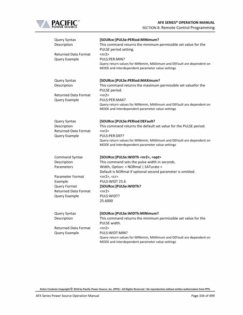
AFX SERIES® OPERATION MANUAL SECTION 8: Remote Control Programming
Entire Contents Copyright 2018 by Pacific Power Source, Inc. (PPS) • All Rights Reserved • No reproduction without written authorization from PPS.
AFX Series Power Source Operation Manual Page 334 of 499
Query Syntax [SOURce:]PULSe:PERiod:MINimum? Description This command returns the minimum permissible set value for the
PULSE period setting. Returned Data Format <nr2> Query Example PULS:PER:MIN?
Query return values for MINimim, MAXimum and DEFault are dependent on MODE and interdependent parameter value settings
Query Syntax [SOURce:]PULSe:PERiod:MAXimum? Description This command returns the maximum permissible set valuefor the
PULSE period. Returned Data Format <nr2> Query Example PULS:PER:MAX?
Query return values for MINimim, MAXimum and DEFault are dependent on MODE and interdependent parameter value settings
Query Syntax [SOURce:]PULSe:PERiod:DEFault? Description This command returns the default set value for the PULSE period. Returned Data Format <nr2> Query Example PULS:PER:DEF?
Query return values for MINimim, MAXimum and DEFault are dependent on MODE and interdependent parameter value settings
Command Syntax [SOURce:]PULSe:WIDTh <nr2>, <opt> Description This command sets the pulse width in seconds. Parameters Width, Option: < NORmal | SATurate >
Default is NORmal if optional second parameter is omitted. Parameter Format <nr2>, <cr> Example PULS:WIDT 25.6 Query Format [SOURce:]PULSe:WIDTh? Returned Data Format <nr2> Query Example PULS:WIDT?
25.6000
Query Syntax [SOURce:]PULSe:WIDTh:MINimum? Description This command returns the minimum permissible set value for the
PULSE width. Returned Data Format <nr2> Query Example PULS:WIDT:MIN?
Query return values for MINimim, MAXimum and DEFault are dependent on MODE and interdependent parameter value settings

AFX SERIES® OPERATION MANUAL SECTION 8: Remote Control Programming
Entire Contents Copyright 2018 by Pacific Power Source, Inc. (PPS) • All Rights Reserved • No reproduction without written authorization from PPS.
AFX Series Power Source Operation Manual Page 335 of 499
Query Syntax [SOURce:]PULSe:WIDTh:MAXimum? Description This command the returns maximum permissible set value for the
PULSE width. Returned Data Format <nr2> Query Example PULS:WIDT:MAX?
Query return values for MINimim, MAXimum and DEFault are dependent on MODE and interdependent parameter value settings
Query Syntax [SOURce:]PULSe:WIDTh:DEFault? Description This command returns the default set value for the PULSE width. Returned Data Format <nr2> Query Example PULS:WIDT:DEF?
Query return values for MINimim, MAXimum and DEFault are dependent on MODE and interdependent parameter value settings
Command Syntax [SOURce:]PULSe:MODE <nr2>, <opt> Description This command sets the pulse width in seconds. Parameters < 0 | PW | 1 | PD | 2 | WD >
Encoding: 0 | PW program pulse by period and width 1 | PD program pulse by period and duty cycle 2 | WD program pulse by width and duty cycle
Parameter Format <nr1> or <cr> Example PULS:MODE WD Query Format [SOURce:]PULSe:MODE? Returned Data Format <nr1> Query Example PULS:MODE?
2
Query Syntax [SOURce:]PULSe:MODE:CATalog? Description This command returns the available programming modes: "0,Period
and width,1,Period and duty cycle,2,Width and duty cycle". Parameters None Returned Data Format <cr> Query Example PULS:MODE:CAT?
0,Period and width,1,Period and duty cycle,2,Width and duty cycle
Command Syntax [SOURce:]PULSe:RAMP <nr2>, <opt> Description This command sets the pulse ramp time in seconds. Parameters Ramp time, Option: < NORmal | SATurate >
Default is NORmal if optional second parameter is omitted. Parameter Format <nr2>, <cr> Example PULS:RAMP 0.2 Query Format [SOURce:]PULSe:RAMP? Returned Data Format <nr2> Query Example PULS:RAMP?
0.2

AFX SERIES® OPERATION MANUAL SECTION 8: Remote Control Programming
Entire Contents Copyright 2018 by Pacific Power Source, Inc. (PPS) • All Rights Reserved • No reproduction without written authorization from PPS.
AFX Series Power Source Operation Manual Page 336 of 499
Query Syntax [SOURce:]PULSe:RAMP:MINimum? Description This command returns the minimum permissible set value for the
PULSE ramp time. Returned Data Format <nr2> Query Example PULS:RAMP:MIN?
Query return values for MINimim, MAXimum and DEFault are dependent on MODE and interdependent parameter value settings
Query Syntax [SOURce:]PULSe:RAMP:MAXimum? Description This command returns the maximum permissible set value for the
PULSE ramp time. Returned Data Format <nr2> Query Example PULS:RAMP:MAX?
Query return values for MINimim, MAXimum and DEFault are dependent on MODE and interdependent parameter value settings
Query Syntax [SOURce:]PULSe:RAMP:DEFault? Description This command returns the default setting for the PULSE ramp time. Returned Data Format <nr2> Query Example PULS:RAMP:DEF?
Query return values for MINimim, MAXimum and DEFault are dependent on MODE and interdependent parameter value settings
Command Syntax [SOURce:]PULSe:VOLTage[:AC]# < nr2 >, <cr> [SOURce:]PULSe:VOLTage[:AC] #
Voltage phase A, OPT: Voltage phase B, OPT: Voltage phase C, OPT Description This command sets the PULSE voltage for selected phase # or for all
phases if phase reference is omitted. Parameters Voltage , < NORmal | SATurate >
Default is NORmal if optional second parameter is omitted. Parameter Format <nr2>, <cr> Example PULS:VOLT1 230.00, SAT Query Format [SOURce:]PULSe:VOLTage[:AC]#? Returned Data Format <nr2> Query Example PULS:VOLT1?
230.0000
Query Syntax [SOURce:]PULSe:VOLTage[:AC]#:MINimum? Description This command returns the minimum permissible set value for the
PULSE voltage for selected phase # or for all phases if phase reference is omitted
Returned Data Format <nr2> Query Example PULS:VOLT1:MIN?
0.0000

AFX SERIES® OPERATION MANUAL SECTION 8: Remote Control Programming
Entire Contents Copyright 2018 by Pacific Power Source, Inc. (PPS) • All Rights Reserved • No reproduction without written authorization from PPS.
AFX Series Power Source Operation Manual Page 337 of 499
Query Syntax [SOURce:]PULSe:VOLTage[:AC]#:MAXimum? Description This command returns the maximum permissible set value for the
PULSE voltage for selected phase # or for all phases if phase reference is omitted
Returned Data Format <nr2> Query Example PULS:VOLT:MAX?
300.0000
Query Syntax [SOURce:]PULSe:VOLTage[:AC]#:DEFault? Description This command returns the default set value for the PULSE voltage for
selected phase # or for all phases if phase reference is omitted Returned Data Format <nr2> Query Example PULS:VOLT:DEF?
0.000,0.000,0.000 PULE:VOLT1:DEF? 0.000
Command Syntax [SOURce:]PULSe:VOLTage:DC# < nr2 >, <cr> [SOURce:]PULSe:VOLTage:DC#
Voltage phase A, OPT: Voltage phase B, OPT: Voltage phase C, OPT Description This command sets the PULSE DC voltage for selected phase # or for
all phases if phase reference is omitted. Parameters Voltage , < NORmal | SATurate >
Default is NORmal if optional second parameter is omitted. Parameter Format <nr2>, <cr> Example PULS:VOLT:DC1 270.00 Query Format [SOURce:]PULSe:VOLTage:DC#? Returned Data Format <nr2> Query Example PULS:VOLT:DC1?
270.0000
Query Syntax [SOURce:]PULSe:VOLTage:DC#:MINimum? Description This command returns the minimum permissible set value for the
initial PULSE DC voltage for selected phase # or for all phases if phase reference is omitted
Returned Data Format <nr2> Query Example PULS:VOLT:DC1:MIN?
-425.0000
Query Syntax [SOURce:]PULSe:VOLTage:DC#:MAXimum? Description This command returns the maximum permissible set value for the
initial PULSE DC voltage for selected phase # or for all phases if phase reference is omitted
Returned Data Format <nr2> Query Example PULS:VOLT:DC1:MAX?
425.0000

AFX SERIES® OPERATION MANUAL SECTION 8: Remote Control Programming
Entire Contents Copyright 2018 by Pacific Power Source, Inc. (PPS) • All Rights Reserved • No reproduction without written authorization from PPS.
AFX Series Power Source Operation Manual Page 338 of 499
Query Syntax [SOURce:]PULSe:VOLTage:DC#:DEFault? Description This command returns the default set value for the initial PULSE
voltage for selected phase # or for all phases if phase reference is omitted
Returned Data Format <nr2> Query Example PULS:VOLT:DC1:DEF?
0.000,0.000,0.000
Command Syntax [SOURce:]PULSe:FREQuency < nr2 >, <cr> Description This command sets the PULSE frequency. Parameters Voltage , < NORmal | SATurate >
Default is NORmal if optional second parameter is omitted. Parameter Format <nr2>, <cr> Example PULS:FREQ 50.00 Query Format [SOURce:]PULSe:FREQuency? Returned Data Format <nr2> Query Example PULS:FREQ?
60.0000
Query Syntax [SOURce:]PULSe:FREQuency:MINimum? Description This command returns the minimum permissible set value for the
PULSE frequency. Returned Data Format <nr2> Query Example PULS:FREQ:MIN?
15.0000
Query Syntax [SOURce:]PULSe:FREQuency:MAXimum? Description This command returns the maximum permissible set value for the
PULSE frequency. Returned Data Format <nr2> Query Example PULS:FREQ:MIN?
1200.0000
Query Syntax [SOURce:]PULSe:FREQuency:DEFault? Description This command returns the default set value for the initial PULSE
frequency. Returned Data Format <nr2> Query Example PULS:FREQ:DEF?
60.0000

AFX SERIES® OPERATION MANUAL SECTION 8: Remote Control Programming
Entire Contents Copyright 2018 by Pacific Power Source, Inc. (PPS) • All Rights Reserved • No reproduction without written authorization from PPS.
AFX Series Power Source Operation Manual Page 339 of 499
Command Syntax [SOURce:]PULSe:WAVEFORM# <nr1 > Description This command sets the selected waveform using the wavefrom
number. Parameters Waveform number Parameter Format <nr1>, <cr> Example PULS:WAVEFORM 1 Query Format [SOURce:]PULSe:WAVEFORM#? Returned Data Format <nr1> Query Example PULS:WAVEFORM#?
1.0000
Query Syntax [SOURce:]PULSe:WAVEFORM#:MINimum? Description This command returns the minimum permissible set value for the
PULSE waveform. Returned Data Format <nr1> Query Example PULS:WAVEFORM#:MIN?
1
Query Syntax [SOURce:]PULSe:WAVEFORM#:MAXimum? Description This command returns the maximum permissible set value for the
PULSE waveform. Returned Data Format <nr1> Query Example PULS:WAVEFORM#:MAX?
200
Query Syntax [SOURce:]PULSe:WAVEFORM:DEFault? Description This command returns the default set value for the PULSE waveform. Returned Data Format <nr1> Query Example PULS:WAVEFORM:DEF?
1
Command Syntax [SOURce:]PULSe:PHASe# < nr2 >, <cr> Description This command sets the initial PULSE phase angle for selected phase #
number. Only phase 2 (B) and 3 (C) are allowed. Parameters Phase No., < NORmal | SATurate >
Default is NORmal if optional second parameter is omitted. Parameter Format <nr1>, <cr> Example PULS:PHAS1 245.0 Query Format [SOURce:]PULSe:PHASe#? Returned Data Format <nr1>, <cr> Query Example PULS:PHAS1?
245.0000

AFX SERIES® OPERATION MANUAL SECTION 8: Remote Control Programming
Entire Contents Copyright 2018 by Pacific Power Source, Inc. (PPS) • All Rights Reserved • No reproduction without written authorization from PPS.
AFX Series Power Source Operation Manual Page 340 of 499
Query Syntax [SOURce:]PULSe:PHASe#:MINimum? Description This command returns the minimum permissible set value of the
initial PULSE phase angle for selected phase # Returned Data Format <nr1> Query Example PULS:PHAS1:MIN?
0.0000
Query Syntax [SOURce:]PULSe:PHASe#:MAXimum? Description This command returns the maximum permissible set value of the
initial PULSE phase angle for selected phase # Returned Data Format <nr1> Query Example PULS:PHAS1:MAX?
360.000
Query Syntax [SOURce:]PULSe:PHASe#:DEF? Description This command returns the default set value of the initial PULSE phase
angle for selected phase # Returned Data Format <nr1> Query Example PULS:PHAS2:DEF?
120.0000 PULS:PHAS3:DEF? 240.0000
Command Syntax [SOURce:]PULSe <cr> >>> Alias for PROGram:TRANsient command. <<<
Description This command controls pulse transient execution Parameters < RUN | STOP | PAUSe | STEP | RESTart > Parameter Format <cr> Example PULS RUN Query Format [SOURce:]PULSe? Description Query format returns the pulse transient execution state as either
RUN, STOP, PAUS, STEP or REST Returned Data Format <nr1>
Return values respresent running state as follows: 0 Stopped 1 Running 2 Paused 3 Stepping 4 Waiting for trigger
Query Example PULS? 1

AFX SERIES® OPERATION MANUAL SECTION 8: Remote Control Programming
Entire Contents Copyright 2018 by Pacific Power Source, Inc. (PPS) • All Rights Reserved • No reproduction without written authorization from PPS.
AFX Series Power Source Operation Manual Page 341 of 499
Command Syntax [SOURce:]PULSe:LOAD Description This command converts the pulse transient definition to the power
source’s regular transient segment format and loads it in the controller real-time memory for execution.
Parameters None Parameter Format n/a Example STEP RUN Query Format [SOURce:]PULSe:LOAD? Description Query format returns a 1 if the pulse transient load operation was
successful, otherwise returns 0. Returned Data Format <nr1>
Return values respresent: 0 Load Failed 1 Load completed
Query Example STEP? 1
Query Syntax [SOURce:]PULSe:PROGress? >>> Alias for PROGram:TRANsient:PROGress command. <<<
Description This query command returns the status of the step being executed. Parameters None Parameter Format n/a Description Query returns the step transient execution state as either RUN, STOP,
PAUS, STEP or REST Returned Data Format <cr>
The response is a comma-separated value string representing: PROGRESS, CURRENT SEGMENT PROGRESS, CURRENT SEGMENT, CURRENT SEGMENT TIME, TOTAL TIME, TOTAL SEGMENTS, REPEAT TIME COUNTER
Query Example PULS:PROG? 1, 45, 2, 1.2300, 2.0000, 4, 5
Query Syntax [SOURce:]PULSe:CHECK? Description This query command returns the result of a check on the
programmined pulse parameters to determine if they are ok to run. Parameters None Parameter Format n/a Description Query returns result of PULSE parameters integrity check Returned Data Format <cr>
The response is either OK or if not, a string containing the error. Query Example PULS:PROG?
OK

AFX SERIES® OPERATION MANUAL SECTION 8: Remote Control Programming
Entire Contents Copyright 2018 by Pacific Power Source, Inc. (PPS) • All Rights Reserved • No reproduction without written authorization from PPS.
AFX Series Power Source Operation Manual Page 342 of 499
Query Syntax [SOURce:]PULSe:ALL? Description This query command returns a comma-separated values string of the
entire pulse parameters, settings, and limits. Each set value is preceded by a tag identifying the parameter. This same data structure is used for front panel display and by the web server. The advantage is that this commands returns all pulse related information using just one query command.
Parameters None Parameter Format n/a Description Returns complete PULSE setup as a comma separed value string. Returned Data Format <cr> Query Example PULS:ALL?
form,3,loaded,0,status,0,progress,0,current element progress,0,current element,0,current element time,0,total time,0,total elements,0,repeat times,0,count,1,count max,65535,count min,0,dcycle,50.0000,dcycle max,100.0000,dcycle max,0.0000,period,0,period max,50000,period min,0,width,0,width max,50000,width min,0,ramp,0,ramp max,0,ramp min,0,mode,0,mode max,2,mode min,0,frequency,60.000,frequency min,15.000,frequency max,1200.000,frequency min reason,1,frequency max reason,2,waveform all,1,waveform all exist,1,waveform a,1,waveform a exist,1,waveform b,1,waveform b exist,1,waveform c,1,waveform c exist,1,waveform max,200,waveform min,1,voltage ac all,0.000,voltage ac all max,300.000,voltage ac all min,0.000,voltage ac all max reason,2,voltage ac all min reason,0,voltage ac a,0.000,voltage ac a max,300.000,voltage ac a min,0.000,voltage ac a max reason,2,voltage ac a min reason,0,voltage ac b,0.000,voltage ac b max,300.000,voltage ac b min,0.000,voltage ac b max reason,2,voltage ac b min reason,0,voltage ac c,0.000,voltage ac c max,300.000,voltage ac c min,0.000,voltage ac c max reason,2,voltage ac c min reason,0,voltage dc all,0.000,voltage dc all max,425.000,voltage dc all min,-425.000,voltage dc all max reason,0,voltage dc all min reason,0,voltage dc a,0.000,voltage dc a max,425.000,voltage dc a min,-425.000,voltage dc a max reason,0,voltage dc a min reason,0,voltage dc b,0.000,voltage dc b max,425.000,voltage dc b min,-425.000,voltage dc b max reason,0,voltage dc b min reason,0,voltage dc c,0.000,voltage dc c max,425.000,voltage dc c min,-425.000,voltage dc c max reason,0,voltage dc c min reason,0,phase b,120.000,phase c,240.000,phase max,360.000,phase min,0.000

AFX SERIES® OPERATION MANUAL SECTION 8: Remote Control Programming
Entire Contents Copyright 2018 by Pacific Power Source, Inc. (PPS) • All Rights Reserved • No reproduction without written authorization from PPS.
AFX Series Power Source Operation Manual Page 343 of 499
8.7.13 IEC413 Option Interharmonics Commands
The following SCPI commands apply only to AFX models with the -413 Option installed. The presence of this option can be checked using the *IDN? Query to check for the letter “C” in the AXF Model number. Examples: 3150AFX-4AGC”. See section 4.16 on page 48 for more details.
Command Syntax [SOURce:]INTHarmonic:FREQuency Description Sets the frequency of the interharmonic voltage component for all
phases. The query format returns the active setting Parameters Frequency Parameter Format <nr2> Example INTH:FREQ 470 Query Format [SOURce:]INTHarmonic:FREQuency? Description Query format returns theinterharmonic frequency setting. Returned Data Format <nr2> Query Example INTH:FREQ?
470.0000
Command Syntax [SOURce:]INTHarmonic:FREQuency:DEFault Description Sets the default frequency of theinter harmonic voltage component
for all phases. The factory default setting is 1800 Hz. Parameters Frequency Parameter Format <nr2> Example INTH:FREQ:DEF 90 Query Format [SOURce:]INTHarmonic:FREQuency:DEFault? Description Query format returns the interharmonic frequency setting. Returned Data Format <nr2> Query Example INTH:FREQ:DEF?
90.0000
Query Format [SOURce:]INTHarmonic:FREQuency:MAXimum? Description Returns the maximum value for the interharmonic frequency setting
which is 10,000 Hz.. Returned Data Format <nr2> Query Example INTH:FREQ:MAX?
10000.0000
Query Format [SOURce:]INTHarmonic:FREQuency:MINimum? Description Returns the minimum value for the interharmonic frequency setting
which is 15 Hz.. Returned Data Format <nr2> Query Example INTH:FREQ:MIN?
15.0000

AFX SERIES® OPERATION MANUAL SECTION 8: Remote Control Programming
Entire Contents Copyright 2018 by Pacific Power Source, Inc. (PPS) • All Rights Reserved • No reproduction without written authorization from PPS.
AFX Series Power Source Operation Manual Page 344 of 499
Command Syntax [SOURce:]INTHarmonic:VOLTage[:AC#] Description Sets the inter harmonic voltage amplitude for the selected phase (1 =
A, 2 = B, 3 = C) or for all three phases if the phase selection is omitted in Vac RMS
Parameters Voltage Parameter Format <nr2> Example INTH:VOLT:AC1 12.00 Query Format [SOURce:]INTHarmonic:VOLTage[:AC#]? Description Query format returns the interharmonic amplitude setting. Returned Data Format <nr2> Query Example INTH:VOLT?
12.0000, 0.0000, 0.0000
Command Syntax [SOURce:]INTHarmonic:VOLTage:AC#:DEFault Description Sets the default amplitude of the interharmonic voltage component
for all phases. The factory default setting is 0.000 Vrms. Parameters Frequency Parameter Format <nr2> Example INTH:VOLT:AC:DEF 5 Query Format [SOURce:]INTHarmonic:VOLTage:AC#:DEFault? Description Query format returns the interharmonic default amplitude setting. Returned Data Format <nr2> Query Example INTH:VOLT:AC:DEF?
5.0000, 5.0000, 5.0000
Query Format [SOURce:]INTHarmonic:VOLTage:AC#:MAXimum? Description Returns the maximum value for the interharmonic amplitude setting
which is 300.0000 Vac RMS. Returned Data Format <nr2> Query Example INTH:VOLT:AC:MAX?
300.0000
Query Format [SOURce:]INTHarmonic:VOLTage:AC#:MINimum? Description Returns the minimum value for the interharmonic amplitude setting
which is 0.0000 Vac RMS. Returned Data Format <nr2> Query Example INTH:VOLT:AC:MIN?
0.0000

AFX SERIES® OPERATION MANUAL SECTION 8: Remote Control Programming
Entire Contents Copyright 2018 by Pacific Power Source, Inc. (PPS) • All Rights Reserved • No reproduction without written authorization from PPS.
AFX Series Power Source Operation Manual Page 345 of 499
Command Syntax [SOURce:]INTHarmonic:PHASe# Description This command sets the interharmonic voltage phase angle with
respect to the phase A interharmonic fundamental for the selected phase (2 = B, 3 = C) or for both phases if the phase selection is omitted in degrees.
Parameters Phase Parameter Format <nr2> Example INTH:PHAS2 45.00 Query Format [SOURce:]INTHarmonic:PHASe? Description Query format returns the interharmonic voltage phase angle with
respect to the phase A setting. Returned Data Format <nr2> Query Example INTH:PHAS2?
45.0000
Command Syntax [SOURce:]INTHarmonic:PHASe#:DEFault Description The default interharmonic voltage phase angle for each phase or all
phases can be selected using the following command: Factory default is 0.000° for phase A, 120.000° for phase B and 240.000° for phase C.
Parameters Frequency Parameter Format <nr2> Example INTH:PHAS2:DEF 90 Query Format [SOURce:]INTHarmonic:PHASe#:DEFault? Description Query format returns the interharmonic default voltage phase angle
setting. Returned Data Format <nr2> Query Example INTH:PHAS:DEF?
0.0000, 120.0000, 240.0000
Query Format [SOURce:]INTHarmonic:PHASe#:MAXimum? Description Returns the upper interharmonic voltage phase angle setting range
for each phase or all phases. The Maximum set values in 360.000°. Returned Data Format <nr2> Query Example INTH:PHAS:MAX?
360.0000
Query Format [SOURce:]INTHarmonic:PHASe#:MINimum? Description Returns the lower interharmonic voltage phase angle setting range
for each phase or all phases. Minimum set value is 0.000°. Returned Data Format <nr2> Query Example INTH:PHAS:MIN?
0.0000

AFX SERIES® OPERATION MANUAL SECTION 8: Remote Control Programming
Entire Contents Copyright 2018 by Pacific Power Source, Inc. (PPS) • All Rights Reserved • No reproduction without written authorization from PPS.
AFX Series Power Source Operation Manual Page 346 of 499
Command Syntax [SOURce:]INTHarmonic:STATe <b> Description This command enables (1) or disables Inter Harmonics mode. When
off, no interharmonics are generated. This command can only be sent while the OUTPUT is OFF. If the OUTPUT is ON, an error is generated and no change of state occurs. (“Unable to execute this action with output enabled”).
Parameters < 0 | OFF | 1 | ON > Parameter Format <b> Example INTH:STAT ON Query Format [SOURce:]INTHarmonic:STATe? Description Query format returns the interharmonic state setting. Returned Data Format <b> Query Example INTH:STAT?
1

AFX SERIES® OPERATION MANUAL SECTION 8: Remote Control Programming
Entire Contents Copyright 2018 by Pacific Power Source, Inc. (PPS) • All Rights Reserved • No reproduction without written authorization from PPS.
AFX Series Power Source Operation Manual Page 347 of 499
8.8 Status Commands Status commands control status and event registers. These commands are aliases for some of the IEEE488.2 common commands and may be used interchangeably. Refer to section 8.12, “Status and Events Registers” for details on status and event register configurations.
The following status commands are supported.
Command Description STATus:OPERation[:EVENt]? Queries the Operation Status Event Register STATus:OPERation:CONDition? Queries the Operation Status Condition Register STATus:OPERation:ENABle <nr1> Sets the Operation Status Enable Register STATus:OPERation:ENABle? Queries the Operation Status Enable Register STATus:QUEStionable[:EVENt]? Queries the Questionable Status Event Register STATus:QUEStionable:CONDition? Queries the Questionable Status Condition Register STATus:QUEStionable:ENABle <nr1> Sets the Questionable Status Enable Register STATus:QUEStionable:ENABle? Queries the Questionable Status Enable Register STATus:PRESet Presets the Status Registers
Query Format STATus:OPERation[:EVENt]? Description Queries the Operation Status Event Register. Returned Data Format <nr1> Query Example STAT:OPER?
0
Query Format STATus:OPERation:CONDition? Description Queries the Operation Status Condition Register. Returned Data Format <nr1> Query Example STAT:OPER:COND?
0
Command Syntax STATus:OPERation:ENABle <nr1> Description Sets the content Operation Status Enable Register. Parameters 0-32767 Parameter Format <nr1> Example STAT:OPER:ENAB 255 Query Format STATus:OPERation:ENABle? Returned Data Format <nr1> Query Example STAT:OPER:ENAB?
6144
Query Format STATus:QUEStionable[:EVENt]? Description Queries the Questionable Status Event Register. Returned Data Format <nr1> Query Example STAT:QUES?
0

AFX SERIES® OPERATION MANUAL SECTION 8: Remote Control Programming
Entire Contents Copyright 2018 by Pacific Power Source, Inc. (PPS) • All Rights Reserved • No reproduction without written authorization from PPS.
AFX Series Power Source Operation Manual Page 348 of 499
Query Format STATus:QUEStionable:CONDition? Description Queries the Questionable Status Condition Register. Returned Data Format <nr1> Query Example STAT:QUES:COND?
0
Command Syntax STATus:QUEStionable:ENABle Description Sets the content of the Questionable Status Enable Register. Parameters 0-32767 Parameter Format <nr1> Example STAT:QUES:ENAB 255 Query Format STATus:QUEStionable:ENABle? Returned Data Format <nr1> Query Example STAT:QUES:ENAB?
255
Command Syntax STATus:PRESet Description The Status Preset command presets the Status Registers. The
Operational Status. Enable Register is set to 0 and the Questionable Status Enable Register is set to 0.
Parameters None Parameter Format n/a Example STAT:PRES

AFX SERIES® OPERATION MANUAL SECTION 8: Remote Control Programming
Entire Contents Copyright 2018 by Pacific Power Source, Inc. (PPS) • All Rights Reserved • No reproduction without written authorization from PPS.
AFX Series Power Source Operation Manual Page 349 of 499
8.9 System Commands Systems commands control system level functions or return model and revision information on the connected unit. The following system commands are supported.
8.9.1 System Error Commands Query Format SYSTem:ERRor[:NEXT]? Description This command returns next available error message from the error
queue. If no more error messages are available, returns 0,”NO ERROR” result. Available error messages are:
Returned Data Format ERROR Description -0, "No error" No error detected -100,"Command error" indicates invalid command or query
received -102,"Command error: Syntax error.”
Incorrect command syntax
-200,"Execution error" indicates can't execute command with parameters received
-222,"Command error: Data out of range.'
Data exceeds available parameter range
-300,"Device-specific error" indicates UPC not properly configured
-400,"Query error" indicates query aborted
Query Example SYST:ERR?
-102,"Command error: Syntax error.”
Query Format SYSTem:ERRor:ALL? Description Returns all available error messages as a of error numbers and clears
the error message queue. Returned Data Format <nr1>,<nr1>,…..<nr1> Query Example SYST:ERR:ALL?
-222,-201,0
Command Syntax SYSTem:ERRor:ALL:CLEAR Description This command clears the error message queue. Parameters None Parameter Format n/a Example SYST:ERR:ALL:CLEAR
SYSTem:ERRor:ALL:NOCLEAR? Description Returns all available error messages as a single unterminated string
but does not clear the error message queue. Returned Data Format <nr1>,<nr1>,…..<nr1> Query Example SYST:ERR:ALL:NOCLEAR?
2018/05/29,14:29:53,1207438.903668873,0,1,0

AFX SERIES® OPERATION MANUAL SECTION 8: Remote Control Programming
Entire Contents Copyright 2018 by Pacific Power Source, Inc. (PPS) • All Rights Reserved • No reproduction without written authorization from PPS.
AFX Series Power Source Operation Manual Page 350 of 499
Command Syntax SYSTem:ERRor:POE Description This command sets the Power on Error reporting mode. Returns
status of Power on Error setting as 1 (enabled) or 0 (disabled). Parameters < 0 | OFF | 1 | ON > Parameter Format <b> Example SYST:ERR:POE ON Query Format SYSTem:ERRor:POE? Returned Data Format <b> Query Example SYST:ERR:POE?
1
8.9.2 System Information Commands Command Syntax SYSTem:BEEP Description This command generates an audible beep at the front panel of the
power source. Parameters None Parameter Format n/a Example SYST:BEEP
Query Format SYSTem:FW:FRONTPANEL:VERsion? Description Returns the firmware revision for the front panel processor. Returned Data Format <cr> Query Example SYST:FW:FRONTPANEL:VER?
2.0.0
Query Format SYSTem:FW:FRONTPANEL:APPS:VERsion? Description Returns the firmware revision for the front panel application
program. Returned Data Format <cr> Query Example SYST:FW:FRONTPANEL:APPS:VER?
2.0.0
Query Format SYSTem:FW:IO:VERsion? Description Returns the firmware revision for the Auxiliary I/O board processor
on AFX-xA version power sources. Returned Data Format <cr> Query Example SYST:FW:IO?
1.0.4
Query Format SYSTem:FW:POWER:VERsion? Description Returns the revision number of the power source’s power stages. Returned Data Format <nr2>-<nr2> Query Example SYST:FW:POWER:VER?
81.0.0-77.1.0
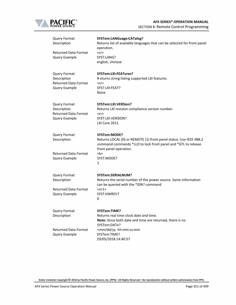
AFX SERIES® OPERATION MANUAL SECTION 8: Remote Control Programming
Entire Contents Copyright 2018 by Pacific Power Source, Inc. (PPS) • All Rights Reserved • No reproduction without written authorization from PPS.
AFX Series Power Source Operation Manual Page 351 of 499
Query Format SYSTem:LANGuage:CATalog? Description Returns list of available languages that can be selected for front panel
operation. Returned Data Format <cr> Query Example SYST:LANG?
english, chinese
Query Format SYSTem:LXI:FEATures? Description R eturns string listing supported LXI features. Returned Data Format <cr> Query Example SYST:LXI:FEAT?
None
Query Format SYSTem:LXI:VERSion? Description Returns LXI revision compliance version number. Returned Data Format <cr> Query Example SYST:LXI:VERSION?
LXI Core 2011
Query Format SYSTem:MODE? Description Returns LOCAL (0) or REMOTE (1) front panel status. Use IEEE 488.2
command commands *LLO to lock front panel and *GTL to release front panel operation.
Returned Data Format <b> Query Example SYST:MODE?
1
Query Format SYSTem:SERIALNUM? Description Returns the serial number of the power source. Same information
can be queried with the *IDN? command Returned Data Format <nr1> Query Example SYST:HWREV?
0
Query Format SYSTem:TIME? Description Returns real time clock date and time.
Note: Since both date and time are returned, there is no SYSTem:DATe?
Returned Data Format <mm/dd/yy hh:mm:ss:mm Query Example SYSTem:TIME?
29/05/2018 14:40:57

AFX SERIES® OPERATION MANUAL SECTION 8: Remote Control Programming
Entire Contents Copyright 2018 by Pacific Power Source, Inc. (PPS) • All Rights Reserved • No reproduction without written authorization from PPS.
AFX Series Power Source Operation Manual Page 352 of 499
Query Format SYSTem:TIME:SOURce? Description Queries source of date and time information. Returned Data Format <cr> Query Example SYST:TIME:SOUR?
NTP Note: NTP stands for “Network Time Protocol”. A protocol built on
top of TCP/IP that assures accurate local timekeeping with reference to radio, atomic or other clocks located on the Internet. This protocol is capable of synchronizing distributed clocks within milliseconds over long time periods. It is defined in STD 12, RFC 1119 (RFC = Request for comment. RFCs are used by the Internet Engineering Task Force (IETF) and other standards bodies.
Query Format SYSTem:VERSion? Description Returns SCPI standard revision version. Returned Data Format <nr2> Query Example SYST:VERS?
1992.0
Query Format SYSTem:XFMRRATIO? Description Returns the transformer option (T Option) voltage ratio.
If no transformer option is installed and configured, this query will return a value of 0.000. See also the [SOURce:]COUPLing command.
Returned Data Format <nr2> Query Example SYSTem:XFMRRATIO?
1.3333

AFX SERIES® OPERATION MANUAL SECTION 8: Remote Control Programming
Entire Contents Copyright 2018 by Pacific Power Source, Inc. (PPS) • All Rights Reserved • No reproduction without written authorization from PPS.
AFX Series Power Source Operation Manual Page 353 of 499
8.9.3 System Interface Commands
These commands allow programming front panel user interface controls and functions of the power source, including the output programming preset soft key values. The same can be accomplished by the user from the front panel. Using a program to set these value can ensure they are always set to a known value if this is important for operator use of the power source in a specific test situation.
8.9.3.1 Preset Syntax The syntax for all these commands is very similar. Prefix is always “SYSTem:INTERFace:PRESET:” followed by the parameter. Available soft key preset parameters are:
• VOLTage[:AC] • VOLTage:DC • FREQuency • PHASe • CURRent:LIMit • POWer:LIMit • KVA:LIMit
To program or query a specific soft key number (1 ~ 5), append “SK#” to the command where # is a value from 1 through 5 for soft key 1 through 5. (Top soft key =1, bottom soft key = 5).
8.9.3.2 Command parameters Available softkey parameters are:
• MIN MIN is the preset value for the min allowable setting based on the power source model
• MAX MAX is the the preset value for the max allowable setting based on the power source model
• DEF DEF sets the preset value to factory default • Value A <nr1> value between MIN and MAX may be specified instead.
Up to five sets of parameters can be appended to these commands to program more than one soft key for the same parameter setting with a single command string.
Example:
SYST:INTERF:PRESET:VOLT MAX, MIN, 108, 140
Programs the voltage AC soft keys as follows:
SK1 = MAX or 300, SK2 = MIN or 0, SK3 = 108, SK4 = 140.

AFX SERIES® OPERATION MANUAL SECTION 8: Remote Control Programming
Entire Contents Copyright 2018 by Pacific Power Source, Inc. (PPS) • All Rights Reserved • No reproduction without written authorization from PPS.
AFX Series Power Source Operation Manual Page 354 of 499
8.9.3.3 Preset Commands Listing The following lists shows all available soft key preset programming commands.
Voltage AC
SYSTem:INTERFace:PRESET:VOLTage[:AC] <REQ: MIN|MAX|DEF|Value, OPT: MIN|MAX|DEF|Value, OPT: MIN|MAX|DEF|Value, OPT: MIN|MAX|DEF|Value, OPT: MIN|MAX|DEF|Value>
SYSTem:INTERFace:PRESET:VOLTage[:AC]? <OPT: ALL|DEF> <OPT: ALL|DEF>
SYSTem:INTERFace:PRESET:VOLTage[:AC]:SK# <REQ: MIN|MAX|DEF|Value>
SYSTem:INTERFace:PRESET:VOLTage[:AC]:SK#?
Voltage DC
SYSTem:INTERFace:PRESET:VOLTage:DC <REQ: MIN|MAX|DEF|Value, OPT: MIN|MAX|DEF|Value, OPT: MIN|MAX|DEF|Value, OPT: MIN|MAX|DEF|Value, OPT: MIN|MAX|DEF|Value>
SYSTem:INTERFace:PRESET:VOLTage:DC? <OPT: ALL|DEF> <OPT: ALL|DEF>
SYSTem:INTERFace:PRESET:VOLTage:DC:SK# <REQ: MIN|MAX|DEF|Value>
SYSTem:INTERFace:PRESET:VOLTage:DC:SK#?
Frequency
SYSTem:INTERFace:PRESET:FREQuency <REQ: MIN|MAX|DEF|Value, OPT: MIN|MAX|DEF|Value, OPT: MIN|MAX|DEF|Value, OPT: MIN|MAX|DEF|Value, OPT: MIN|MAX|DEF|Value>
SYSTem:INTERFace:PRESET:FREQuency? <OPT: ALL|DEF> <OPT: ALL|DEF>
SYSTem:INTERFace:PRESET:FREQuency:SK# <REQ: MIN|MAX|DEF|Value>
SYSTem:INTERFace:PRESET:FREQuency:SK#?
Phase Angle
SYSTem:INTERFace:PRESET:PHASe <REQ: MIN|MAX|DEF|Value, OPT: MIN|MAX|DEF|Value, OPT: MIN|MAX|DEF|Value, OPT: MIN|MAX|DEF|Value, OPT: MIN|MAX|DEF|Value>
SYSTem:INTERFace:PRESET:PHASe? <OPT: ALL|DEF> <OPT: ALL|DEF>
SYSTem:INTERFace:PRESET:PHASe:SK# <REQ: MIN|MAX|DEF|Value>
SYSTem:INTERFace:PRESET:PHASe:SK#?
Current Limit
SYSTem:INTERFace:PRESET:CURRent:LIMit <REQ: MIN|MAX|DEF|Value, OPT: MIN|MAX|DEF|Value, OPT: MIN|MAX|DEF|Value, OPT: MIN|MAX|DEF|Value, OPT: MIN|MAX|DEF|Value>
SYSTem:INTERFace:PRESET:CURRent:LIMit? <OPT: ALL|DEF> <OPT: ALL|DEF>
SYSTem:INTERFace:PRESET:CURRent:LIMit:SK# <REQ: MIN|MAX|DEF|Value>
SYSTem:INTERFace:PRESET:CURRent:LIMit:SK#?
Power Limit
SYSTem:INTERFace:PRESET:POWer:LIMit <REQ: MIN|MAX|DEF|Value, OPT: MIN|MAX|DEF|Value, OPT: MIN|MAX|DEF|Value, OPT: MIN|MAX|DEF|Value, OPT: MIN|MAX|DEF|Value>
SYSTem:INTERFace:PRESET:POWer:LIMit? <OPT: ALL|DEF> <OPT: ALL|DEF>
SYSTem:INTERFace:PRESET:POWer:LIMit:SK# <REQ: MIN|MAX|DEF|Value>
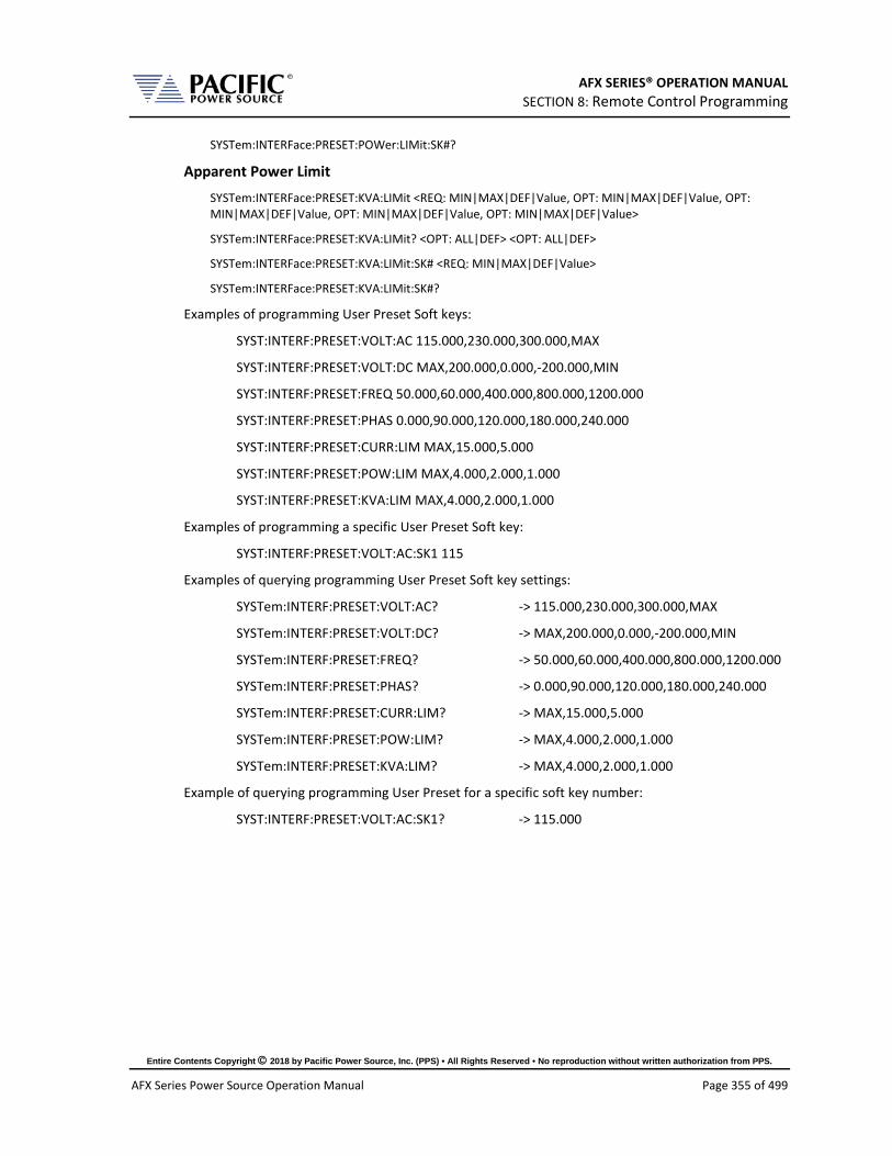
AFX SERIES® OPERATION MANUAL SECTION 8: Remote Control Programming
Entire Contents Copyright 2018 by Pacific Power Source, Inc. (PPS) • All Rights Reserved • No reproduction without written authorization from PPS.
AFX Series Power Source Operation Manual Page 355 of 499
SYSTem:INTERFace:PRESET:POWer:LIMit:SK#?
Apparent Power Limit
SYSTem:INTERFace:PRESET:KVA:LIMit <REQ: MIN|MAX|DEF|Value, OPT: MIN|MAX|DEF|Value, OPT: MIN|MAX|DEF|Value, OPT: MIN|MAX|DEF|Value, OPT: MIN|MAX|DEF|Value>
SYSTem:INTERFace:PRESET:KVA:LIMit? <OPT: ALL|DEF> <OPT: ALL|DEF>
SYSTem:INTERFace:PRESET:KVA:LIMit:SK# <REQ: MIN|MAX|DEF|Value>
SYSTem:INTERFace:PRESET:KVA:LIMit:SK#?
Examples of programming User Preset Soft keys:
SYST:INTERF:PRESET:VOLT:AC 115.000,230.000,300.000,MAX
SYST:INTERF:PRESET:VOLT:DC MAX,200.000,0.000,-200.000,MIN
SYST:INTERF:PRESET:FREQ 50.000,60.000,400.000,800.000,1200.000
SYST:INTERF:PRESET:PHAS 0.000,90.000,120.000,180.000,240.000
SYST:INTERF:PRESET:CURR:LIM MAX,15.000,5.000
SYST:INTERF:PRESET:POW:LIM MAX,4.000,2.000,1.000
SYST:INTERF:PRESET:KVA:LIM MAX,4.000,2.000,1.000
Examples of programming a specific User Preset Soft key:
SYST:INTERF:PRESET:VOLT:AC:SK1 115
Examples of querying programming User Preset Soft key settings:
SYSTem:INTERF:PRESET:VOLT:AC? -> 115.000,230.000,300.000,MAX
SYSTem:INTERF:PRESET:VOLT:DC? -> MAX,200.000,0.000,-200.000,MIN
SYSTem:INTERF:PRESET:FREQ? -> 50.000,60.000,400.000,800.000,1200.000
SYSTem:INTERF:PRESET:PHAS? -> 0.000,90.000,120.000,180.000,240.000
SYSTem:INTERF:PRESET:CURR:LIM? -> MAX,15.000,5.000
SYSTem:INTERF:PRESET:POW:LIM? -> MAX,4.000,2.000,1.000
SYSTem:INTERF:PRESET:KVA:LIM? -> MAX,4.000,2.000,1.000
Example of querying programming User Preset for a specific soft key number:
SYST:INTERF:PRESET:VOLT:AC:SK1? -> 115.000

AFX SERIES® OPERATION MANUAL SECTION 8: Remote Control Programming
Entire Contents Copyright 2018 by Pacific Power Source, Inc. (PPS) • All Rights Reserved • No reproduction without written authorization from PPS.
AFX Series Power Source Operation Manual Page 356 of 499
8.9.3.4 Oher Front Panel Function Commands These commands are equivalent to some of the functions available in the LOCAL INTERFACE settings.
Beeper Volume - Range is 0 through 10:
SYSTem:INTERFace:VOLume <VOLUME>
SYSTem:INTERFace:VOLume?
LCD Brightness - Range is 0 through 10:
SYSTem:INTERFace:LCD[:BRIGHTness] <BRIGHTNESS>
SYSTem:INTERFace:LCD[:BRIGHTness]?
Keypad Backlit Brightness - Range is 0 through 10:
SYSTem:INTERFace:KEYS:BRIGHTness <BRIGHTNESS>
SYSTem:INTERFace:KEYS:BRIGHTness?
Key Press Sounds:
SYSTem:INTERFace:KEYS:SOUNDS <ON|OFF>
SYSTem:INTERFace:KEYS:SOUNDS?
Set Resolution Step Size wih the numeric keypad
SYSTem:INTERFace:KEYS:STEPset <ON|OFF>
SYSTem:INTERFace:KEYS:STEPset?
Single Click Update Mode:
SYSTem:INTERFace:IMMEDIATEupdate:SINGLEclick <ON|OFF>
SYSTem:INTERFace:IMMEDIATEupdate:SINGLEclick?
Show Measurements in Immediate Update:
SYSTem:INTERFace:IMMEDIATEupdate:SHOWMEASurements <ON|OFF>
SYSTem:INTERFace:IMMEDIATEupdate:SHOWMEASurements?
Variable Shuttle Knob Speed - Range is 0 through 10:
SYSTem:INTERFace:KNOB:SPeed <SPEED>
SYSTem:INTERFace:KNOB:SPeed?

AFX SERIES® OPERATION MANUAL SECTION 8: Remote Control Programming
Entire Contents Copyright 2018 by Pacific Power Source, Inc. (PPS) • All Rights Reserved • No reproduction without written authorization from PPS.
AFX Series Power Source Operation Manual Page 357 of 499
8.9.4 System Configuration Commands Query Format SYSTem:MAXKVA? Description Returns maximum available kVA output capability of the power
source. Example for 3150AFX model = 15.0000 Returned Data Format <nr2> Query Example SYST:MAXKVA?
15.000
Query Format SYSTem:MAXCURRent? Description Returns maximum available RMS or DC output current capability of
the power source. Example for 3150AFX model = 41.6667. Returned Data Format <nr2> Query Example SYST:MAXCURR?
41.6667
Query Format SYSTem:MAXVOLTage? Description Returns maximum available RMS or DC voltage output capability of
the power source. Example for 3150AFX model = 300. Returned Data Format <nr1> Query Example SYST:MAXVOLT?
300
Command Syntax SYSTem:COMPatible Description Sets Pacific Power Source UPC controller compatibility mode. This
mode allows use of the power source with legacy software. Parameters < 0 | DISABLE | 1 | UPC > Parameter Format Example SYST:COMP UPC Query Format SYSTem:COMPatible? Returned Data Format <b> Query Example SYST:COMP?
1
Query Format SYSTem:HWREVision? Description Returns the hardware revision letter of the power source Returned Data Format <cr> Query Example SYST:HWREV?
A

AFX SERIES® OPERATION MANUAL SECTION 8: Remote Control Programming
Entire Contents Copyright 2018 by Pacific Power Source, Inc. (PPS) • All Rights Reserved • No reproduction without written authorization from PPS.
AFX Series Power Source Operation Manual Page 358 of 499
Command Syntax SYSTem:LANGuage Description Sets Pacific Power Source UPC controller compatibility mode. This
mode allows use of the power source with legacy software. Parameters < english |Chinese >
Note: Refer to SYSTem:LANGuage:CATalog? query command for list of supported languages.
Parameter Format <cr> Example SYST:LANG chinese Query Format SYSTem:LANGuage? Returned Data Format <b> Query Example SYST:LANG?
chinese
These commands allow complete system configurations to be exported or imported.
Command Syntax SYSTem:EXPOrt <OPT: CONFIGURATION, OPT: WAVEFORMS, OPT: PROGRAMS, OPT: SETPOINTS, OPT: [NAME, NAMEFILE]>
Description Exports complete record of system configuration of the power source to a compressed file. If argument name is omitted it is stored in temporal/DATE—TIME.7z otherwise in temporal/NAMEFILE.7z. The others arguments indicate what is going to be exported, if none of them are passed all is going to be exported.
Parameters <OPT: CONFIGURATION, OPT: WAVEFORMS, OPT: PROGRAMS, OPT: SETPOINTS, OPT: [NAME, NAMEFILE]>
Parameter Format <cr> Example SYST:EXPORT
SYST:EXPORT NAME,TEST SYST:EXPORT SETPOINTS,NAME,TEST2 SYST:EXPORT SETPOINTS, WAVEFORMS,NAME,TEST3
Command Syntax SYSTem:IMPOrt <OPT: CONFIGURATION, OPT: WAVEFORMS, OPT: PROGRAMS, OPT: SETPOINTS, [NAME, NAMEFILE]>
Description Imports complete system configuration records of the power source. The compressed file has to be in /temporal/NAMEFILE.7z. The other others arguments indicate what will be imported, if none of them are passed all is going to be imported.
Parameters <OPT: CONFIGURATION, OPT: WAVEFORMS, OPT: PROGRAMS, OPT: SETPOINTS, [NAME, NAMEFILE]>
Parameter Format <cr> Example SYST:IMPORT NAME,TEST
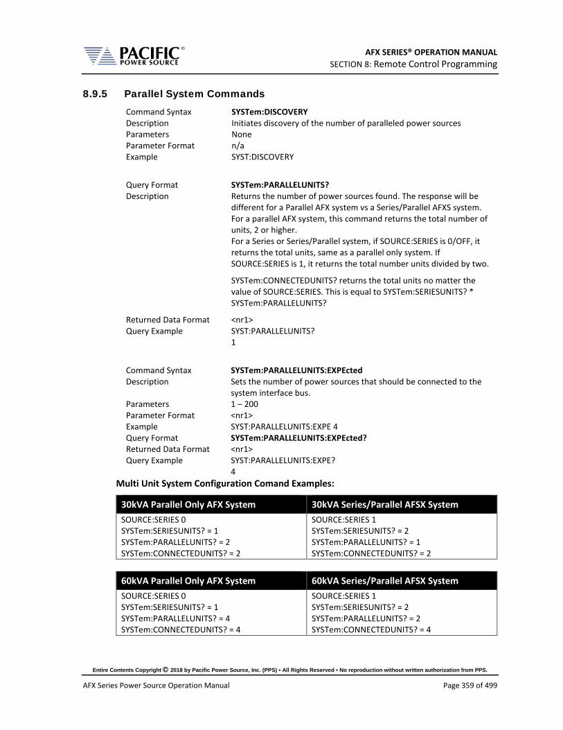
AFX SERIES® OPERATION MANUAL SECTION 8: Remote Control Programming
Entire Contents Copyright 2018 by Pacific Power Source, Inc. (PPS) • All Rights Reserved • No reproduction without written authorization from PPS.
AFX Series Power Source Operation Manual Page 359 of 499
8.9.5 Parallel System Commands Command Syntax SYSTem:DISCOVERY Description Initiates discovery of the number of paralleled power sources Parameters None Parameter Format n/a Example SYST:DISCOVERY
Query Format SYSTem:PARALLELUNITS? Description Returns the number of power sources found. The response will be
different for a Parallel AFX system vs a Series/Parallel AFXS system. For a parallel AFX system, this command returns the total number of units, 2 or higher. For a Series or Series/Parallel system, if SOURCE:SERIES is 0/OFF, it returns the total units, same as a parallel only system. If SOURCE:SERIES is 1, it returns the total number units divided by two.
SYSTem:CONNECTEDUNITS? returns the total units no matter the value of SOURCE:SERIES. This is equal to SYSTem:SERIESUNITS? * SYSTem:PARALLELUNITS?
Returned Data Format <nr1> Query Example SYST:PARALLELUNITS?
1
Command Syntax SYSTem:PARALLELUNITS:EXPEcted Description Sets the number of power sources that should be connected to the
system interface bus. Parameters 1 – 200 Parameter Format <nr1> Example SYST:PARALLELUNITS:EXPE 4 Query Format SYSTem:PARALLELUNITS:EXPEcted? Returned Data Format <nr1> Query Example SYST:PARALLELUNITS:EXPE?
4 Multi Unit System Configuration Comand Examples:
30kVA Parallel Only AFX System 30kVA Series/Parallel AFSX System SOURCE:SERIES 0 SYSTem:SERIESUNITS? = 1 SYSTem:PARALLELUNITS? = 2 SYSTem:CONNECTEDUNITS? = 2
SOURCE:SERIES 1 SYSTem:SERIESUNITS? = 2 SYSTem:PARALLELUNITS? = 1 SYSTem:CONNECTEDUNITS? = 2
60kVA Parallel Only AFX System 60kVA Series/Parallel AFSX System SOURCE:SERIES 0 SYSTem:SERIESUNITS? = 1 SYSTem:PARALLELUNITS? = 4 SYSTem:CONNECTEDUNITS? = 4
SOURCE:SERIES 1 SYSTem:SERIESUNITS? = 2 SYSTem:PARALLELUNITS? = 2 SYSTem:CONNECTEDUNITS? = 4

AFX SERIES® OPERATION MANUAL SECTION 8: Remote Control Programming
Entire Contents Copyright 2018 by Pacific Power Source, Inc. (PPS) • All Rights Reserved • No reproduction without written authorization from PPS.
AFX Series Power Source Operation Manual Page 360 of 499
8.9.6 System Sanitization Commands Query Format SYSTem:SANITIZE:CODE? Description Returns sanitization password string. Returned Data Format <nr1> Query Example SYSTem:SANITIZE:CODE?
0659
Command Syntax SYSTem:SANITIZE <code> Description Erases all user data stored in non-volatile memory settings including
settings and custom waveforms if required. The code is obtained by the query command above.
Parameters None Parameter Format n/a Example SYST:SANITIZE 0659
8.9.7 Communication LAN Commands Command Syntax SYSTem:COMMunicate:LAN[:ENABle] Description This command turns remote control via LAN on or off. To control the
power source through its LAN interface, this state has to on (1). Parameters < 0 | OFF | 1 ON > Parameter Format <b> Example SYST:COMM:LAN ON Query Format SYSTem:COMMunicate:LAN[:ENABle]? Returned Data Format Query Example SYST:COMM:LAN?
1
Command Syntax SYSTem:COMMunicate:LAN:RESPonse Description This command allows the termination character for LAN
communication to be defined by the user. Parameters 0 (AUTO) 1 (\r\n) 2 (\n) 3 (\r) Parameter Format <nr1> Example SYST:COMM:LAN:REPSONSE 1 Query Format SYSTem:COMMunicate:LAN:RESPonse? Returned Data Format <nr1> Query Example SYST:COMM:LAN:RESP?
1
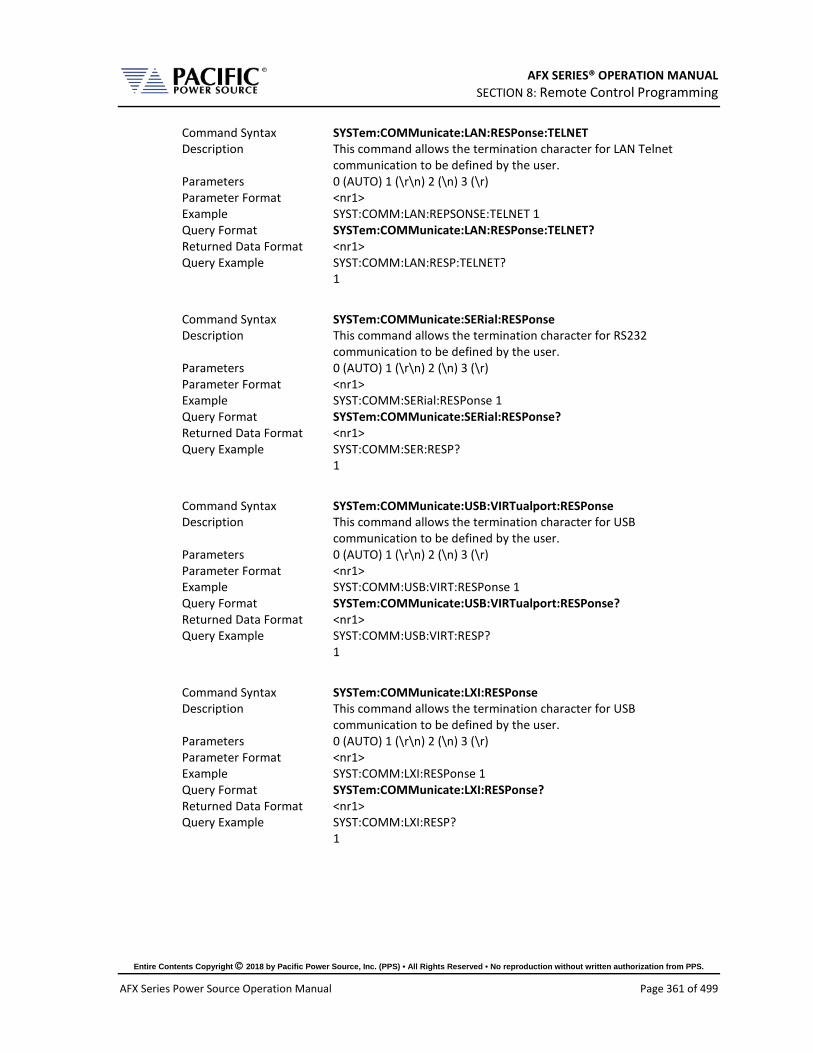
AFX SERIES® OPERATION MANUAL SECTION 8: Remote Control Programming
Entire Contents Copyright 2018 by Pacific Power Source, Inc. (PPS) • All Rights Reserved • No reproduction without written authorization from PPS.
AFX Series Power Source Operation Manual Page 361 of 499
Command Syntax SYSTem:COMMunicate:LAN:RESPonse:TELNET Description This command allows the termination character for LAN Telnet
communication to be defined by the user. Parameters 0 (AUTO) 1 (\r\n) 2 (\n) 3 (\r) Parameter Format <nr1> Example SYST:COMM:LAN:REPSONSE:TELNET 1 Query Format SYSTem:COMMunicate:LAN:RESPonse:TELNET? Returned Data Format <nr1> Query Example SYST:COMM:LAN:RESP:TELNET?
1
Command Syntax SYSTem:COMMunicate:SERial:RESPonse Description This command allows the termination character for RS232
communication to be defined by the user. Parameters 0 (AUTO) 1 (\r\n) 2 (\n) 3 (\r) Parameter Format <nr1> Example SYST:COMM:SERial:RESPonse 1 Query Format SYSTem:COMMunicate:SERial:RESPonse? Returned Data Format <nr1> Query Example SYST:COMM:SER:RESP?
1
Command Syntax SYSTem:COMMunicate:USB:VIRTualport:RESPonse Description This command allows the termination character for USB
communication to be defined by the user. Parameters 0 (AUTO) 1 (\r\n) 2 (\n) 3 (\r) Parameter Format <nr1> Example SYST:COMM:USB:VIRT:RESPonse 1 Query Format SYSTem:COMMunicate:USB:VIRTualport:RESPonse? Returned Data Format <nr1> Query Example SYST:COMM:USB:VIRT:RESP?
1
Command Syntax SYSTem:COMMunicate:LXI:RESPonse Description This command allows the termination character for USB
communication to be defined by the user. Parameters 0 (AUTO) 1 (\r\n) 2 (\n) 3 (\r) Parameter Format <nr1> Example SYST:COMM:LXI:RESPonse 1 Query Format SYSTem:COMMunicate:LXI:RESPonse? Returned Data Format <nr1> Query Example SYST:COMM:LXI:RESP?
1

AFX SERIES® OPERATION MANUAL SECTION 8: Remote Control Programming
Entire Contents Copyright 2018 by Pacific Power Source, Inc. (PPS) • All Rights Reserved • No reproduction without written authorization from PPS.
AFX Series Power Source Operation Manual Page 362 of 499
Query Format SYSTem:COMMunicate:LAN:STATus? Description This command returns all LAN settings in a single comma delimited
string of values. Returned Data Format <cr>, <cr>,…..,<cr>,<cr> Query Example SYSTem:COMMunicate:LAN:STATus?
192.168.14.22,255.255.254.0,192.168.15.254,192.168.15.208,AFX-106378937,AFX-106378889,0,1,0
Command Syntax SYSTem:COMMunicate:LAN:DHCP[:ENABle] Description This command turns DHCP mode for the LAN interface on or off.
DHCP = Dynamic Host Configuration Protocol”. This protocol automatically provides an IP address and other related information such as the subnet mask and default gateway. When turned off, a static IP address must be assigned by the user instead.
Parameters < 0 | OFF | 1 | ON > Parameter Format <b> Example SYST:COMM:LAN:DHCP ON Query Format SYSTem:COMMunicate:LAN:DHCP[:ENABle]? Returned Data Format <b> Query Example SYST:COMM:LAN:DHCP?
1
Command Syntax SYSTem:COMMunicate:LAN:DHCP:RENEW Description This command renews the lease of an IP address assigned through
the DCHP protocol. This may be necessary if the power source has not been used in a while and its IP address lease has expired. If not renewed, a different IP address may be assigned.
Parameters None Parameter Format n/a Example SYST:COMM:LAN:DHCP:RENEW
Command Syntax SYSTem:COMMunicate:LAN:ADDress Description This command is used to assign a fixed IP address to the power
source for LAN communication. Parameters ddd.ddd.ddd.ddd (four octets ranging in value from 0 to 255
representing one 16 bit unsigned integer value each. Parameter Format <cr> Example SYST:COMM:LAN:ADD 132.18.21.105 Query Format SYSTem:COMMunicate:LAN:ADDress? Returned Data Format <cr> Query Example SYST:COMM:LAN:ADD?
132.18.21.105

AFX SERIES® OPERATION MANUAL SECTION 8: Remote Control Programming
Entire Contents Copyright 2018 by Pacific Power Source, Inc. (PPS) • All Rights Reserved • No reproduction without written authorization from PPS.
AFX Series Power Source Operation Manual Page 363 of 499
Query Format SYSTem:COMMunicate:LAN:MACaddress? Description This query returns the MAC address of the connected power source.
The Media Access Control address or MAC address is also referred to as physical address as it is fix and unique to any device on the network. The MAC address for the power source is also printed on the rear panel near the LAN interface connector. It consists of 8 sets of hexadecimal 16 bit unsigned integer values.
Returned Data Format <cr> Query Example SYST:COMM:LAN:MAC?
3A.3F.00.4C.DE.AA.39.8F
Query Format SYSTem:COMMunicate:LAN:VISA? Description Queries the VISA resource name / address string Returned Data Format <cr> Query Example TCPIP::AFX-1003::INSTR
Command Syntax SYSTem:COMMunicate:LAN:APPly Description Applies all changes send using the COMM:LAN commands. Parameters None Parameter Format n/a Example SYST:COMM:LAN:APP
Command Syntax SYSTem:COMMunicate:LAN:MASK Description This command sets the IP mark value for the power source LAN
interface. It is normally obtained through DCHP. If a static IP must be used, the mask has to set as well.
Parameters ddd.ddd.ddd.ddd (four octets ranging in value from 0 to 255 representing one 16 bit unsigned integer value each.
Parameter Format <cr> Example SYST:COMM:LAN:MASK 255.255.254.0 Query Format SYSTem:COMMunicate:LAN:MASK? Returned Data Format <cr> Query Example SYST:COMM:LAN:MASK?
255.255.254.0
Command Syntax SYSTem:COMMunicate:LAN:DNSaddress Description Sets the IP address for the DNS server Parameters ddd.ddd.ddd.ddd (four octets ranging in value from 0 to 255
representing one 16 bit unsigned integer value each. Parameter Format <cr> Example SYST:COMM:LAN:DNS 132.18.21.208 Query Format SYSTem:COMMunicate:LAN:DNSaddress? Returned Data Format <cr> Query Example SYST:COMM:LAN:DNS?
132.18.21.208

AFX SERIES® OPERATION MANUAL SECTION 8: Remote Control Programming
Entire Contents Copyright 2018 by Pacific Power Source, Inc. (PPS) • All Rights Reserved • No reproduction without written authorization from PPS.
AFX Series Power Source Operation Manual Page 364 of 499
Command Syntax SYSTem:COMMunicate:LAN:GWADdress Parameters Sets the IP address for the Network Gateway. A default gateway is
the node on the computer network that the network software uses when an IP address does not match any other routes in the routing table
Parameter Format <cr> Example SYST:COMM:LAN:GWAD 132.18.21.254 Query Format SYSTem:COMMunicate:LAN:GWADdress? Returned Data Format <cr> Query Example SYST:COMM:LAN:GWAD?
132.18.21.254
Command Syntax SYSTem:COMMunicate:LAN:HOST:CONFigured Description Sets the network host address. The host address is the portion of the
address used to identify hosts (any device requiring a Network Interface Card, such as a PC or networked printer) on the network. The network ID, by contrast, is the portion of the address that refers to the network itself.
Parameters ddd.ddd.ddd.ddd (four octets ranging in value from 0 to 255 representing one 16 bit unsigned integer value each.
Parameter Format <cr> Example SYST:COMM:LAN:HOST 132.18.21.0 Query Format SYSTem:COMMunicate:LAN:HOST:CONFigured? Returned Data Format <cr> Query Example SYST:COMM:LAN:HOST:CONF?
132.18.21.0
Command Syntax SYSTem:COMMunicate:LAN:PASSword Description Assign a password to enable or disable LAN communications. This
feature allows the owner/operator to disable or enable remote LAN access or limit functionality over LAN. Note: There is no query format for this command so the password code cannot be queried back.
Parameters Four digit passcode Parameter Format <nr1? Example SYST:COMM:LAN:PASS 1234
Command Syntax SYSTem:COMMunicate:LAN:PORT Description Sets LAN interface port address. For SCPI message communications,
the standard port number is 5025. Parameters 1024–49151, default = 5025 Parameter Format <nr1> Example SYST:COMM:LAN:PORT 5025 Query Format SYSTem:COMMunicate:LAN:PORT? Returned Data Format <nr1> Query Example SYST:COMM:LAN:PORT?
5025

AFX SERIES® OPERATION MANUAL SECTION 8: Remote Control Programming
Entire Contents Copyright 2018 by Pacific Power Source, Inc. (PPS) • All Rights Reserved • No reproduction without written authorization from PPS.
AFX Series Power Source Operation Manual Page 365 of 499
Command Syntax SYSTem:COMMunicate:LAN:PORT:TELNET Description Sets the port address for TELNET protocol Parameters 1024–49151, default = 5024 Parameter Format <nr1> Example SYST:COMM:LAN:PORT:TELNET 5024 Query Format SYSTem:COMMunicate:LAN:PORT:TELNET? Returned Data Format <nr1> Query Example SYST:COMM:LAN:PORT:TELNET?
5024
8.9.8 Communication Serial Port Commands Command Syntax SYSTem:COMMunicate:SERial[:ENABle] Description This command is used to turn the RS232 serial interface on or off. To
use this interface for remote control of the power source, it must be set to ON.
Parameters < 0 | OFF | 1 | ON > Parameter Format <b> Example SYST:COMM:SER ON Query Format SYSTem:COMMunicate:SERial[:ENABle]? Returned Data Format <b> Query Example SYST:COMM:SER?
1
Query Format SYSTem:COMMunicate:SERial:STATus? Description This command returns all serial port settings Returned Data Format Baud rate, status,data bits, stop bits, parity, flow control Query Example SYST:COMM:SER:STAT?
921600,0,8,1,0,0
Command Syntax SYSTem:COMMunicate:SERial:BAUD Description This command sets the baud rate for the serial port. Parameters < 1200 | 1800 | 2400 | 4800 | 9600 | 14400 | 19200 | 38400 | 57600 |
62500 | 115200 |230400 | 460800 |500000 | 576000 | 921600 > Parameter Format <nr1> Example SYST:COMM:SER:BAUD 115200 Query Format SYSTem:COMMunicate:SERial:BAUD? Returned Data Format <cr1> Query Example SYST:COMM:SER:BAUD?
115200
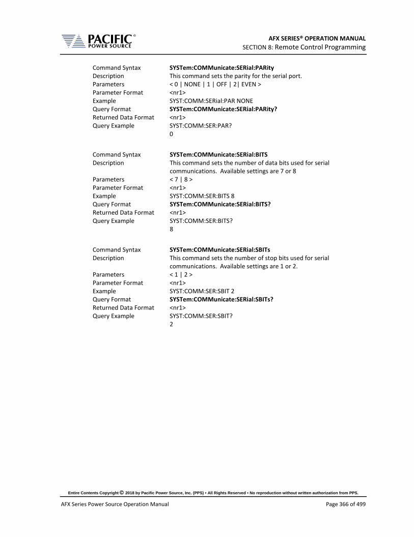
AFX SERIES® OPERATION MANUAL SECTION 8: Remote Control Programming
Entire Contents Copyright 2018 by Pacific Power Source, Inc. (PPS) • All Rights Reserved • No reproduction without written authorization from PPS.
AFX Series Power Source Operation Manual Page 366 of 499
Command Syntax SYSTem:COMMunicate:SERial:PARity Description This command sets the parity for the serial port. Parameters < 0 | NONE | 1 | OFF | 2| EVEN > Parameter Format <nr1> Example SYST:COMM:SERial:PAR NONE Query Format SYSTem:COMMunicate:SERial:PARity? Returned Data Format <nr1> Query Example SYST:COMM:SER:PAR?
0
Command Syntax SYSTem:COMMunicate:SERial:BITS Description This command sets the number of data bits used for serial
communications. Available settings are 7 or 8 Parameters < 7 | 8 > Parameter Format <nr1> Example SYST:COMM:SER:BITS 8 Query Format SYSTem:COMMunicate:SERial:BITS? Returned Data Format <nr1> Query Example SYST:COMM:SER:BITS?
8
Command Syntax SYSTem:COMMunicate:SERial:SBITs Description This command sets the number of stop bits used for serial
communications. Available settings are 1 or 2. Parameters < 1 | 2 > Parameter Format <nr1> Example SYST:COMM:SER:SBIT 2 Query Format SYSTem:COMMunicate:SERial:SBITs? Returned Data Format <nr1> Query Example SYST:COMM:SER:SBIT?
2

AFX SERIES® OPERATION MANUAL SECTION 8: Remote Control Programming
Entire Contents Copyright 2018 by Pacific Power Source, Inc. (PPS) • All Rights Reserved • No reproduction without written authorization from PPS.
AFX Series Power Source Operation Manual Page 367 of 499
Command Syntax SYSTem:COMMunicate:SERial:FLOWcontrol Description This command sets the method of handshaking used for serial
communications. Available settings are Xon/Xoff or Hardware handshake.
Parameters < 0 | OFF | 1 | ON > Parameter Format <b> Example SYST:COMM:SER:FLOW ON Query Format SYSTem:COMMunicate:SERial:FLOWcontrol? Returned Data Format <nr1> Query Example SYST:COMM:SER:FLOW?
1
8.9.9 Communication USB Commands Command Syntax SYSTem:COMMunicate:USB:VIRTualport[:ENABle] Description This command enables USB device control using virtual comm driver. Parameters < 0 | OFF | 1 | ON > Parameter Format <b> Example SYST:COMM:USB:VIRT ON Query Format SYSTem:COMMunicate:USB:VIRTualport[:ENABle]? Returned Data Format <b> Query Example SYST:COMM:USB:VIRT?
1
Command Syntax SYSTem:COMMunicate:USB:LAN[:ENABle] Description Enables access to embedded webserver using virtual IP Address
through USB interface. Parameters < 0 | OFF | 1 | ON > Parameter Format <b> Example SYST:COMM:USB:ETH ON Query Format SYSTem:COMMunicate:USB:LAN[:ENABle]? Returned Data Format <b> Query Example SYST:COMM:USB:LAN?
1
Command Syntax SYSTem:COMMunicate:USB:LAN:ADDress Description Sets the embedded webserver virtual IP Address for USB interface. Parameters < 0 | OFF | 1 | ON > Parameter Format <b> Example SYST:COMM:USB:LAN ON Query Format SYSTem:COMMunicate:USB:LAN:ADD? Returned Data Format <b> Query Example SYST:COMM:USB:LAN:ADD?
192.168.123.1
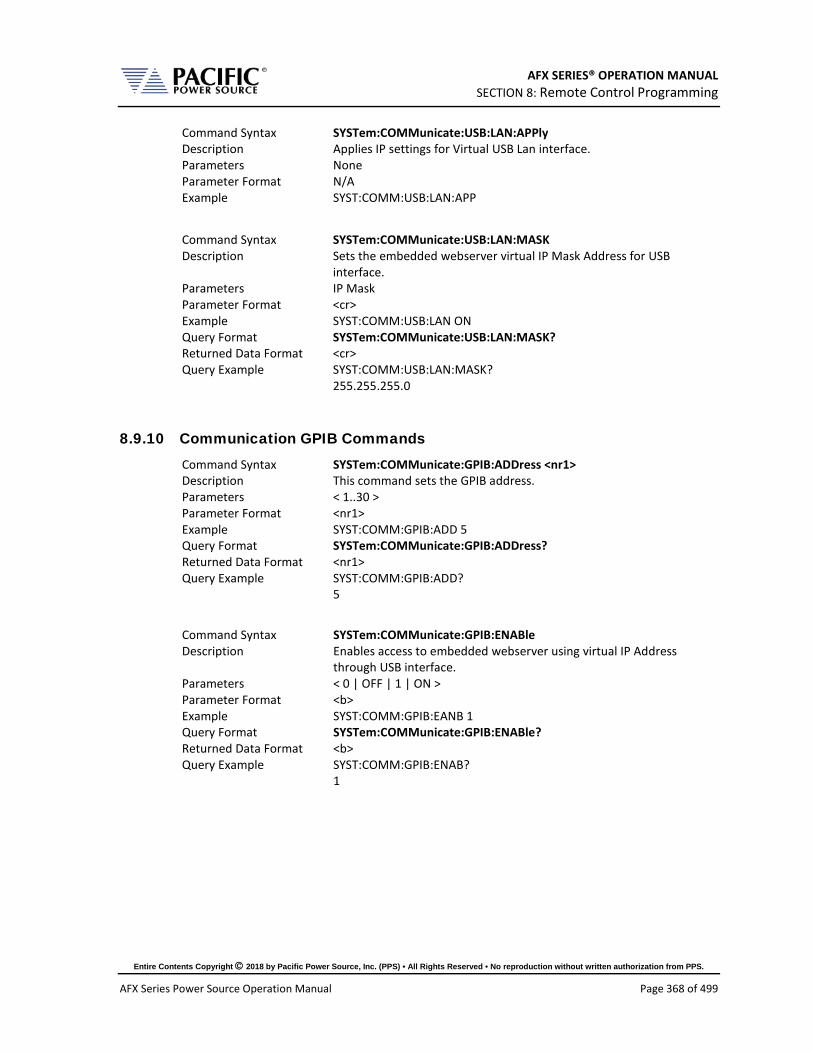
AFX SERIES® OPERATION MANUAL SECTION 8: Remote Control Programming
Entire Contents Copyright 2018 by Pacific Power Source, Inc. (PPS) • All Rights Reserved • No reproduction without written authorization from PPS.
AFX Series Power Source Operation Manual Page 368 of 499
Command Syntax SYSTem:COMMunicate:USB:LAN:APPly Description Applies IP settings for Virtual USB Lan interface. Parameters None Parameter Format N/A Example SYST:COMM:USB:LAN:APP
Command Syntax SYSTem:COMMunicate:USB:LAN:MASK Description Sets the embedded webserver virtual IP Mask Address for USB
interface. Parameters IP Mask Parameter Format <cr> Example SYST:COMM:USB:LAN ON Query Format SYSTem:COMMunicate:USB:LAN:MASK? Returned Data Format <cr> Query Example SYST:COMM:USB:LAN:MASK?
255.255.255.0
8.9.10 Communication GPIB Commands Command Syntax SYSTem:COMMunicate:GPIB:ADDress <nr1> Description This command sets the GPIB address. Parameters < 1..30 > Parameter Format <nr1> Example SYST:COMM:GPIB:ADD 5 Query Format SYSTem:COMMunicate:GPIB:ADDress? Returned Data Format <nr1> Query Example SYST:COMM:GPIB:ADD?
5
Command Syntax SYSTem:COMMunicate:GPIB:ENABle Description Enables access to embedded webserver using virtual IP Address
through USB interface. Parameters < 0 | OFF | 1 | ON > Parameter Format <b> Example SYST:COMM:GPIB:EANB 1 Query Format SYSTem:COMMunicate:GPIB:ENABle? Returned Data Format <b> Query Example SYST:COMM:GPIB:ENAB?
1
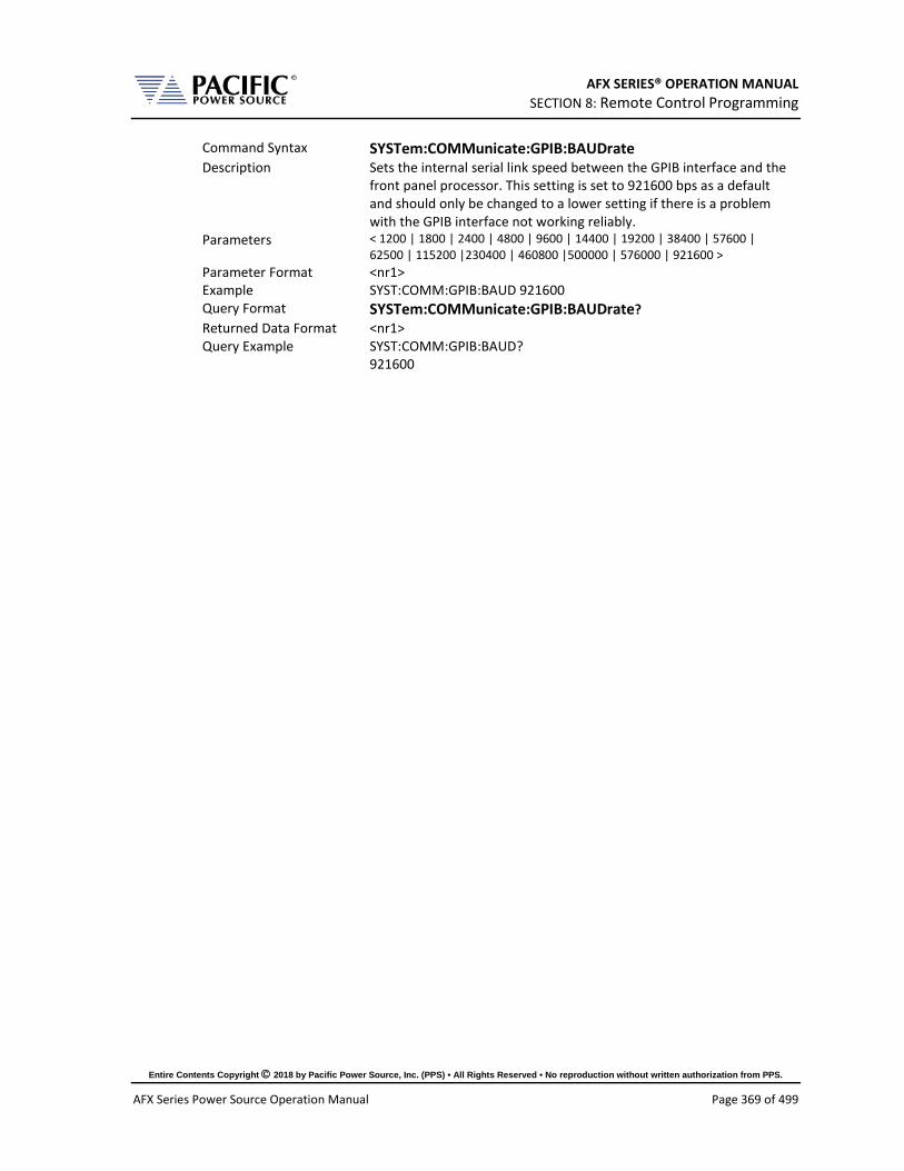
AFX SERIES® OPERATION MANUAL SECTION 8: Remote Control Programming
Entire Contents Copyright 2018 by Pacific Power Source, Inc. (PPS) • All Rights Reserved • No reproduction without written authorization from PPS.
AFX Series Power Source Operation Manual Page 369 of 499
Command Syntax SYSTem:COMMunicate:GPIB:BAUDrate Description Sets the internal serial link speed between the GPIB interface and the
front panel processor. This setting is set to 921600 bps as a default and should only be changed to a lower setting if there is a problem with the GPIB interface not working reliably.
Parameters < 1200 | 1800 | 2400 | 4800 | 9600 | 14400 | 19200 | 38400 | 57600 | 62500 | 115200 |230400 | 460800 |500000 | 576000 | 921600 >
Parameter Format <nr1> Example SYST:COMM:GPIB:BAUD 921600 Query Format SYSTem:COMMunicate:GPIB:BAUDrate? Returned Data Format <nr1> Query Example SYST:COMM:GPIB:BAUD?
921600
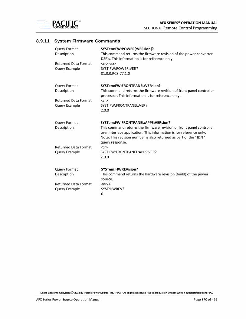
AFX SERIES® OPERATION MANUAL SECTION 8: Remote Control Programming
Entire Contents Copyright 2018 by Pacific Power Source, Inc. (PPS) • All Rights Reserved • No reproduction without written authorization from PPS.
AFX Series Power Source Operation Manual Page 370 of 499
8.9.11 System Firmware Commands Query Format SYSTem:FW:POWER[:VERsion]? Description This command returns the firmware revision of the power converter
DSP’s. This information is for reference only. Returned Data Format <cr>-<cr> Query Example SYST:FW:POWER:VER?
81.0.0.RC8-77.1.0
Query Format SYSTem:FW:FRONTPANEL:VERsion? Description This command returns the firmware revision of front panel controller
processor. This information is for reference only. Returned Data Format <cr> Query Example SYST:FW:FRONTPANEL:VER?
2.0.0
Query Format SYSTem:FW:FRONTPANEL:APPS:VERsion? Description This command returns the firmware revision of front panel controller
user interface application. This information is for reference only. Note: This revision number is also returned as part of the *IDN? query response.
Returned Data Format <cr> Query Example SYST:FW:FRONTPANEL:APPS:VER?
2.0.0
Query Format SYSTem:HWREVision? Description This command returns the hardware revision (build) of the power
source. Returned Data Format <nr2> Query Example SYST:HWREV?
0

AFX SERIES® OPERATION MANUAL SECTION 8: Remote Control Programming
Entire Contents Copyright 2018 by Pacific Power Source, Inc. (PPS) • All Rights Reserved • No reproduction without written authorization from PPS.
AFX Series Power Source Operation Manual Page 371 of 499
8.9.12 System Remote Access Commands Command Syntax SYSTem:REMote:ACCESS Description Sets remote access permission. Parameters <0 | DISABLED | 1 | ENABLED> Parameter Format <b> Example SYST:REM:ACCESS 1 Query Format SYSTem:REMote:ACCESS? Returned Data Format <cr> Query Example SYST:REM:ACCESS?
1
Command Syntax SYSTem:REMote:ACCESS:REQuest Description This commands results in a pop up dialog on the front panel display
requesting the local user to ACCEPT. Confirms presence of a person at the location of the instrument.
Parameters Alias name. (This argument is optional) Parameter Format <cr> Example SYSTem:REMote:ACCESS:REQuest Query Format None
Command Syntax SYSTem:REMote:ACCESS:LOGIN Description This command uses a password as an argument to request access to
the instrument. The password can be set on the front panel or using the SYSTem:REMote:PASSword command
Parameters Password Parameter Format <nr1> Example SYSTem:REMote:ACCESS:LOGIN 1234 Query Format None
Command Syntax SYSTem:REMote:FTP:ENAble Description Enable/disable the FTP service. Parameters <0 | OFF | 1 | ON> Parameter Format <b> Example SYST:REM:FTP:ENA 1 Query Format SYSTem:REMote:FTP:ENAble? Returned Data Format <b> Query Example SYST:REM:FTP:ENA?
1

AFX SERIES® OPERATION MANUAL SECTION 8: Remote Control Programming
Entire Contents Copyright 2018 by Pacific Power Source, Inc. (PPS) • All Rights Reserved • No reproduction without written authorization from PPS.
AFX Series Power Source Operation Manual Page 372 of 499
Command Syntax SYSTem:REMote:FTP:PASSword Description Sets remote FTP access permission password. Parameters password Parameter Format <cr> Example SYST:REM:FTP:PASS temporal Query Format SYSTem:REMote:FTP:PASSword? Returned Data Format <cr> Query Example SYST:REM:FTP:PASS?
temporal
Command Syntax SYSTem:REMote:SMB:ENAble Description Enable/disable the samba service. Parameters <0 | OFF | 1 | ON> Parameter Format <b> Example SYST:REM:FTP:ENA 1 Query Format SYSTem:REMote:SMB:ENAble? Returned Data Format <b> Query Example SYST:REM:SMB:ENA?
temporal
Command Syntax SYSTem:REMote:SMB:PASSword Description Sets remote Samba services access permission password Parameters password Parameter Format <cr> Example SYST:REM:SMB:PASS temporal Query Format SYSTem:REMote:SMB:PASSword? Returned Data Format <cr> Query Example SYST:REM:SMB:PASS?
temporal

AFX SERIES® OPERATION MANUAL SECTION 8: Remote Control Programming
Entire Contents Copyright 2018 by Pacific Power Source, Inc. (PPS) • All Rights Reserved • No reproduction without written authorization from PPS.
AFX Series Power Source Operation Manual Page 373 of 499
8.9.13 Miscellaneous System Commands Command Syntax SYSTem:BEEP Description This command generates a beep from the front panel speaker. May
be used in ATE programs to get operator’s attention. Make sure the beep volume is not set to 0. See SYSTem:INTERFace:VOLume cmd.
Returned Data Format <cr>,…,<cr> Query Format None
Query Format SYSTem:MEMory:CATalog? Description This command returns the available memory types catalog. Returned Data Format <cr>,…,<cr> Query Example SYST:MEM:CAT?
INTERNAL, RAM
Command Syntax SYSTem:MEMory:REMove Description This command unmounts system memory. Returned Data Format <cr>,…,<cr> Query Format None
Command Syntax SYSTem:DELete <PATH> Description This command deletes a file or folder. The path or filename can be
between double quotation marks or not. Parameters PATH or FILE Parameter Format <cr> Example SYST:DEL internal/program/program_1.xml
SYST:DEL “internal/program/program_1.xml” SYST:DEL temporal/program/program_1.xml SYST:DEL “temporal/program/program_1.xml”
Query Format none
Query Format SYSTem:FILE:TYPE? <MEM> Description This command returns the file type in numeric available memory
types catalog. Returned Data Format <nr1> Query Example SYST:FILE:TYPE? RAM
0 SYST:FILE:TYPE? INTERNAL 0
Command Syntax SYSTem:SCREENshot Description This command takes a screen shot of the LCD display. The LCD image
is saved as a “.png” format image file to folder “internal/screenshots” Parameters None Parameter Format N/A Example SYST:SCREEN Query Format none

AFX SERIES® OPERATION MANUAL SECTION 8: Remote Control Programming
Entire Contents Copyright 2018 by Pacific Power Source, Inc. (PPS) • All Rights Reserved • No reproduction without written authorization from PPS.
AFX Series Power Source Operation Manual Page 374 of 499
8.10 Auxiliary I/O System Commands Commands specific to the auxiliary I/O functions are listed in this section.
8.10.1 System Analog & Digital IO Commands SYSTem:AIO :INput[1 | 2 | 3 |.4][?] :CATalog? :GAIN[?] :DEFault? :MAXimum? :MINimum?
: OFFSET[?] :DEFault? :MAXimum? :MINimum? :RANGe[?] :DEFault? :MAXimum? :MINimum? :UNITs? :VOLTage? :OUTput[1 | 2 | 3 |.4][?] :CATalog? :GAIN[?] :DEFault? :MAXimum? :MINimum? :OFFSET[?] :DEFault? :MAXimum? :MINimum? :RANGe[?] :DEFault? :MAXimum? :MINimum? :UNITs? :VOLTage?

AFX SERIES® OPERATION MANUAL SECTION 8: Remote Control Programming
Entire Contents Copyright 2018 by Pacific Power Source, Inc. (PPS) • All Rights Reserved • No reproduction without written authorization from PPS.
AFX Series Power Source Operation Manual Page 375 of 499
SYSTem:DIO :INput[1 | 2 | 3 |.4][?] :FALLing[?] :FILtersize[?] :DEFault? :MAXimum? :MINimum? :RISing[?] :OUTput[1 | 2 | 3 |.4][?] :CATalog? :INVert[?] :STATe? :REMote :ENAble[?] :INHibit[?] :STROBE :OUTPutstate[?] :SOURce[?] :TRANsient[?]
8.10.1.1 SYSTem:AIO:Input Command Syntax SYSTem:AIO:INput[n] <cr> Description Sets the AFX parameter to be controlled by the analog input. Parameters [ CURR:LIM | CURR:LIM1 | CURR:LIM2 | CURR:LIM3 | FREQ |
KVA:LIM | KVA:LIM1 | KVA:LIM2 | KVA:LIM3 | OFF | PHAS2 | PHAS3 | POW:LIM | POW:LIM1 | POW:LIM2 | POW:LIM3 | VOLT:AC | VOLT:AC1 | VOLT:AC2 | VOLT:AC3 | VOLT:DC | VOLT:DC1 | VOLT:DC2 | VOLT:DC3 ] See the “SYSTem:AIO:INput:CATalog?” command response for a list of supported parameters.
Parameter Format <cr> Example SYST:AIO:IN1 VOLTAGE Query Format SYSTem:AIO:INput[n]? Returned Data Format <cr> Query Example SYST:AIO:IN1?
VOLTAGE
Query Format SYSTem:AIO:INput:CATalog? Description Returns list of available analog inputs Returned Data Format <cr> Query Example SYST:AIO:IN:CAT?
CURR:LIM,CURR:LIM1,CURR:LIM2,CURR:LIM3,FREQ,KVA:LIM,KVA:LIM1,KVA:LIM2,KVA:LIM3,OFF,PHAS2,PHAS3,POW:LIM,POW:LIM1,POW:LIM2,POW:LIM3,VOLT:AC,VOLT:AC1,VOLT:AC2,VOLT:AC3,VOLT:DC,VOLT:DC1,VOLT:DC2,VOLT:DC3

AFX SERIES® OPERATION MANUAL SECTION 8: Remote Control Programming
Entire Contents Copyright 2018 by Pacific Power Source, Inc. (PPS) • All Rights Reserved • No reproduction without written authorization from PPS.
AFX Series Power Source Operation Manual Page 376 of 499
Command Syntax SYSTem:AIO:INput[n]:GAIN <nr2> Description Sets the full-scale gain of the AFX parameter controlled by the analog
input. Parameters Full scale value Parameter Format <nr2> Example SYST:AIO:IN1:GAIN 230.0 Query Format SYSTem:AIO:INput[n]:GAIN? Returned Data Format <nr2> Query Example SYST:AIO:IN1:GAIN?
230.00
Query Format SYSTem:AIO:INput[n]:GAIN:DEFault? Description Returns the default full-scale gain for the specified analog input. Parameters None Returned Data Format <nr2> Query Example SYST:AIO:IN1:GAIN:DEF?
300.0
Query Format SYSTem:AIO:INput[n]:GAIN:MAXimum? Description Returns the maximum full-scale gain for the specified analog input. Parameters None Returned Data Format n/a Query Example SYST:AIO:IN1:GAIN:MAX?
100000.000000
Query Format SYSTem:AIO:INput[n]:GAIN:MINimum? Description Returns the minimum full-scale gain for the specified analog input. Parameters None Returned Data Format n/a Query Example SYST:AIO:IN1:GAIN:MIN?
-100000.000000
Command Syntax SYSTem:AIO:INput[n]:OFFSET <nr2> Description Sets the offset of the AFX parameter controlled by the analog input. Parameters Offset Parameter Format <nr2> Example SYST:AIO:IN1:OFFSET 50.0 Query Format SYSTem:AIO:INput[n]:OFFSET? Returned Data Format <nr2> Query Example SYST:AIO:IN1:OFFSET?
15.00

AFX SERIES® OPERATION MANUAL SECTION 8: Remote Control Programming
Entire Contents Copyright 2018 by Pacific Power Source, Inc. (PPS) • All Rights Reserved • No reproduction without written authorization from PPS.
AFX Series Power Source Operation Manual Page 377 of 499
Query Format SYSTem:AIO:INput[n]:OFFSET:DEFault? Description Returns the default offset for the specified analog input. Parameters None Returned Data Format n/a Query Example SYST:AIO:IN1:OFFSET:DEF?
15.0
Query Format SYSTem:AIO:INput[n]:OFFSET:MAXimum? Description Returns the maximum offset for the specified analog input. Parameters None Returned Data Format n/a Query Example SYST:AIO:IN1:OFFSET:MAX?
100000.000000
Query Format SYSTem:AIO:INput[n]:OFFSET:MINimum? Description Returns the minimum offset for the specified analog input. Parameters None Returned Data Format n/a Query Example SYST:AIO:IN1:OFFSET:MIN?
-100000.000000
Command Syntax SYSTem:AIO:INput[n]:RANGe <nr2> Description Sets the range of the specified analog input.
Available range is 0.0 ~ 10. Parameters Offset Parameter Format <nr2> Example SYST:AIO:IN1:RANG 50.0 Query Format SYSTem:AIO:INput[n]:RANGe? Returned Data Format <nr2> Query Example SYST:AIO:IN1:RANG?
10.00
Query Format SYSTem:AIO:INput[n]:RANGe:DEFault? Description Returns the default range for the specified analog input. Parameters None Returned Data Format n/a Query Example SYST:AIO:IN1:RANG:DEF?
0.0
Query Format SYSTem:AIO:INput[n]:RANGe:MAXimum? Description Returns the maximum range for the specified analog input. Parameters None Returned Data Format n/a Query Example SYST:AIO:IN1:RANG:MAX?
10.0
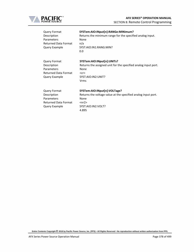
AFX SERIES® OPERATION MANUAL SECTION 8: Remote Control Programming
Entire Contents Copyright 2018 by Pacific Power Source, Inc. (PPS) • All Rights Reserved • No reproduction without written authorization from PPS.
AFX Series Power Source Operation Manual Page 378 of 499
Query Format SYSTem:AIO:INput[n]:RANGe:MINimum? Description Returns the minimum range for the specified analog input. Parameters None Returned Data Format n/a Query Example SYST:AIO:IN1:RANG:MIN?
0.0
Query Format SYSTem:AIO:INput[n]:UNITs? Description Returns the assigned unit for the specified analog input port. Parameters None Returned Data Format <cr> Query Example SYST:AIO:IN2:UNIT?
Vrms
Query Format SYSTem:AIO:INput[n]:VOLTage? Description Returns the voltage value at the specified analog input port. Parameters None Returned Data Format <nr2> Query Example SYST:AIO:IN2:VOLT?
4.895

AFX SERIES® OPERATION MANUAL SECTION 8: Remote Control Programming
Entire Contents Copyright 2018 by Pacific Power Source, Inc. (PPS) • All Rights Reserved • No reproduction without written authorization from PPS.
AFX Series Power Source Operation Manual Page 379 of 499
8.10.1.2 SYSTem:AIO:OUTput Command Syntax SYSTem:AIO:OUTput[n] <cr> Description Sets the AFX measurement that is mapped to each analog output
port. Parameters [ MEAS:CURR1? | MEAS:CURR2? | MEAS:CURR3? |
MEAS:CURR:CREST1? | MEAS:CURR:CREST2? | MEAS:CURR:CREST3? | MEAS:CURR:CREST? | MEAS:CURR:DC1? | MEAS:CURR:DC2? | MEAS:CURR:DC3? | MEAS:CURR:DC? | MEAS:CURR:PEAK1? | MEAS:CURR:PEAK2? | MEAS:CURR:PEAK3? | MEAS:CURR:PEAK? | MEAS:CURR? | MEAS:FREQ? | MEAS:KVA1? | MEAS:KVA2? | MEAS:KVA3? | MEAS:KVA? | MEAS:PF1? | MEAS:PF2? | MEAS:PF3? | MEAS:PF? | MEAS:POW1? | MEAS:POW2? | MEAS:POW3? | MEAS:POW? | MEAS:VLL:AC1? | MEAS:VLL:AC2? | MEAS:VLL:AC3? | MEAS:VLL:AC? | MEAS:VLL:ACDC1? | MEAS:VLL:ACDC2? | MEAS:VLL:ACDC3? | MEAS:VLL:ACDC? | MEAS:VLL:DC1? | MEAS:VLL:DC2? | MEAS:VLL:DC3? | MEAS:VLL:DC? | MEAS:VOLT:AC1? | MEAS:VOLT:AC2? | MEAS:VOLT:AC3? | MEAS:VOLT:AC? | MEAS:VOLT:ACDC1? | MEAS:VOLT:ACDC2? | MEAS:VOLT:ACDC3? | MEAS:VOLT:ACDC? | MEAS:VOLT:DC1? | MEAS:VOLT:DC2? | MEAS:VOLT:DC3? | MEAS:VOLT:DC? See the “SYSTem:AIO:OUTput:CATalog?” command for a list of available paremeters.
Parameter Format <cr> Example SYST:AIO:OUT1 VRMS Query Format SYSTem:AIO:OUTput[n]? Returned Data Format <cr> Query Example SYST:AIO:OUTP?
VRMS
Query Format SYSTem:AIO:OUTput:CATalog? Description Returns list of available analog outputs Returned Data Format <cr> Query Example SYST:AIO:OUT:CAT?
MEAS:CURR1?,MEAS:CURR2?,MEAS:CURR3?,MEAS:CURR:CREST1?,MEAS:CURR:CREST2?,MEAS:CURR:CREST3?,MEAS:CURR:CREST?,MEAS:CURR:DC1?,MEAS:CURR:DC2?,MEAS:CURR:DC3?,MEAS:CURR:DC?,MEAS:CURR:PEAK1?,MEAS:CURR:PEAK2?,MEAS:CURR:PEAK3?,MEAS:CURR:PEAK?,MEAS:CURR?,MEAS:FREQ?,MEAS:KVA1?,MEAS:KVA2?,MEAS:KVA3?,MEAS:KVA?,MEAS:PF1?,MEAS:PF2?,MEAS:PF3?,MEAS:PF?,MEAS:POW1?,MEAS:POW2?,MEAS:POW3?,MEAS:POW?,MEAS:VLL:AC1?,MEAS:VLL:AC2?,MEAS:VLL:AC3?,MEAS:VLL:AC?,MEAS:VLL:ACDC1?,MEAS:VLL:ACDC2?,MEAS:VLL:ACDC3?,MEAS:VLL:ACDC?,MEAS:VLL:DC1?,MEAS:VLL:DC2?,MEAS:VLL:DC3?,MEAS:VLL:DC?,MEAS:VOLT:AC1?,MEAS:VOLT:AC2?,MEAS:VOLT:AC3?,MEAS:VOLT:AC?,MEAS:VOLT:ACDC1?,MEAS:VOLT:ACDC2?,MEAS:VOLT:ACDC3?,MEAS:VOLT:ACDC?,MEAS:VOLT:DC1?,MEAS:VOLT:DC2?,MEAS:VOLT:DC3?,MEAS:VOLT:DC?

AFX SERIES® OPERATION MANUAL SECTION 8: Remote Control Programming
Entire Contents Copyright 2018 by Pacific Power Source, Inc. (PPS) • All Rights Reserved • No reproduction without written authorization from PPS.
AFX Series Power Source Operation Manual Page 380 of 499
Command Syntax SYSTem:AIO:OUTput[n]:GAIN <nr2> Description Sets the full-scale gain of the AFX measurement mapped to the
analog input. Parameters Full scale value Parameter Format <nr2> Example SYST:AIO:OUT1:GAIN 230.0 Query Format SYSTem:AIO:OUTput[n]:GAIN? Returned Data Format <nr2> Query Example SYST:AIO:OUT1:GAIN?
425.0000
Query Format SYSTem:AIO:OUTput[n]:GAIN:DEFault? Description Returns the default full-scale gain for the specified analog output
port. Parameters None Returned Data Format n/a Query Example SYST:AIO:OUT1:GAIN:DEF?
425.0000
Query Format SYSTem:AIO:OUTput[n]:GAIN:MAXimum? Description Returns the maximum gain for the specified analog output port. Parameters None Returned Data Format n/a Query Example SYST:AIO:OUT1:GAIN:MAX?
100000.00000
Query Format SYSTem:AIO:OUTput[n]:GAIN:MINimum? Description Returns the minimum gain for the specified analog output port. Parameters None Returned Data Format n/a Query Example SYST:AIO:OUT1:GAIN:MIN?
-100000.00000
Command Syntax SYSTem:AIO:OUTput[n]:OFFSET <nr2> Description Sets the offset of the specified analog output port. Parameters Offset Parameter Format <nr2> Example SYST:AIO:OUT1:OFFSET 50.0 Query Format SYSTem:AIO:OUTput[n]:OFFSET? Returned Data Format <nr2> Query Example SYST:AIO:OUT1:OFFSET?
50.00

AFX SERIES® OPERATION MANUAL SECTION 8: Remote Control Programming
Entire Contents Copyright 2018 by Pacific Power Source, Inc. (PPS) • All Rights Reserved • No reproduction without written authorization from PPS.
AFX Series Power Source Operation Manual Page 381 of 499
Query Format SYSTem:AIO:OUTput[n]:OFFSET:DEFault? Description Returns the default offset for the specified analog output port. Parameters None Returned Data Format n/a Query Example SYST:AIO:OUT1:OFFSET:DEF?
0.00000
Query Format SYSTem:AIO:OUTput[n]:OFFSET:MAXimum? Description Returns the maximum gain for the specified analog output port. Parameters None Returned Data Format n/a Query Example SYST:AIO:OUT1:GAIN:MAX?
100000.00000
Query Format SYSTem:AIO:OUTput[n]:OFFSET:MINimum? Description Returns the minimum gain for the specified analog output port. Parameters None Returned Data Format n/a Query Example SYST:AIO:OUT1:GAIN:MIN?
-100000.00000
Command Syntax SYSTem:AI:OUTput[n]:GAIN <nr2> Description Sets the full-scale gain of the specified analog output port. Parameters Full scale value Parameter Format <nr2> Example SYST:AIO:OUT1:GAIN 230.0 Query Format SYSTem:AIO:OUTput[n]:GAIN? Returned Data Format <nr2> Query Example SYST:AIO:OUT1:GAIN?
230.00
Query Format SYSTem:AIO:OUTput[n]:GAIN:DEFault? Description Returns the default full-scale gain for the specified analog output. Parameters None Returned Data Format <nr2> Query Example SYST:AIO:OUT1:GAIN:DEF?
425.00000
Query Format SYSTem:AIO:OUTput[n]:GAIN:MAXimum? Description Returns the maximum full-scale gain for the specified analog output. Parameters None Returned Data Format n/a Query Example SYST:AIO:OUT1:GAIN:MAX?
100000.00000

AFX SERIES® OPERATION MANUAL SECTION 8: Remote Control Programming
Entire Contents Copyright 2018 by Pacific Power Source, Inc. (PPS) • All Rights Reserved • No reproduction without written authorization from PPS.
AFX Series Power Source Operation Manual Page 382 of 499
Query Format SYSTem:AIO:OUTput[n]:GAIN:MINimum? Description Returns the minimum full-scale gain for the specified analog output. Parameters None Returned Data Format n/a Query Example SYST:AIO:OUT1:GAIN:MIN?
-100000.00000
Query Format SYSTem:AIO:OUTput[n]:UNITs? Description Returns the assigned unit for the specified analog output port. Parameters None Returned Data Format <cr> Query Example SYST:AIO:OUT2:UNIT?
Vrms
Query Format SYSTem:AIO:OUTput[n]:VOLTage? Description Returns the voltage at the analog output port. Parameters None Returned Data Format <nr2> Query Example SYST:AIO:OUT2:VOLT?
7.2590
8.10.1.3 SYSTem:DIO:Input Query Format SYSTem:DIO:INput[n]? Description Queries status of Digital Input 1, 2 or 3. If I/O number is omitted, all
three input values are returned. n = 1, 2 or 3. Parameters none Returned Data Format <cr> Parameter Format <nr1> Query Example SYST:DIO:IN2?
0

AFX SERIES® OPERATION MANUAL SECTION 8: Remote Control Programming
Entire Contents Copyright 2018 by Pacific Power Source, Inc. (PPS) • All Rights Reserved • No reproduction without written authorization from PPS.
AFX Series Power Source Operation Manual Page 383 of 499
Command Syntax SYSTem:DIO:INput[n]:FALLing <cr> SYSTem:DIO:INput[n]:RISing <cr>
Description Sets the SCPI command to be executed at the rising or falling event of that digital input [n]. n = 1, 2 or 3.
Parameters SPCI command string Parameter Format <cr> Example SYST:DIO:IN1:FALL “OUTP 0”
SYST:DIO:IN1:RIS “OUTP 1” These settings will enable the output at the rising edge of the pulse and disable it at the falling edge.
Query Format SYSTem:DIO:INput[n]:FALLing? SYSTem:DIO:Input[n]:RISing?
Returned Data Format <cr> Query Example SYST:DIO:IN1:RIS?
OUTP 1 SYST:DIO:IN1:FALL? -
Command Syntax SYSTem:DIO:INput[n]:FILtersize <nr1> Description Defines the time in ms (milliseconds) that the digital input has to
keep the state after a transition in order to generate the event. If filtersize is zero, then the event is immediately generated, otherwise the specified time will prevent short pulses from generating events. This is useful in noisy environments and also if the digital signal is controlled by a switch or a mechanical actuator.
Parameters 0 – 1000 Parameter Format <nr1> Example SYST:DIO:IN1:FIL 8 Query Format SYSTem:DIO:INput[n]:FILtersize? Returned Data Format <nr1> Query Example SYST:DIO:IN1:FIL?
8
Query Format SYSTem:DIO:INput[n]:FILtersize:DEFault? Description Returns the default filter size value. Returned Data Format <nr1> Query Example SYST:DIO:IN1:FIL:DEF?
0
Query Format SYSTem:DIO:INput[n]:FILtersize:MAXimum? Description Returns the maximum allowed filter size value. Returned Data Format <nr1> Query Example SYST:DIO:IN1:FIL:MAX?
1000
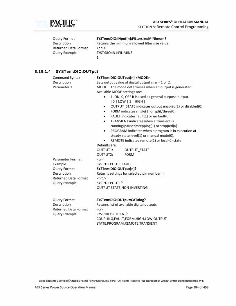
AFX SERIES® OPERATION MANUAL SECTION 8: Remote Control Programming
Entire Contents Copyright 2018 by Pacific Power Source, Inc. (PPS) • All Rights Reserved • No reproduction without written authorization from PPS.
AFX Series Power Source Operation Manual Page 384 of 499
Query Format SYSTem:DIO:INput[n]:FILtersize:MINimum? Description Returns the minimum allowed filter size value. Returned Data Format <nr1> Query Example SYST:DIO:IN1:FIL:MIN?
1
8.10.1.4 SYSTem:DIO:OUTput Command Syntax SYSTem:DIO:OUTput[n] <MODE> Description Sets output value of digital output n. n = 1 or 2. Parameter 1 MODE The mode determines when an output is generated.
Available MODE settings are: • 1, ON, 0, OFF it is used as general purpose output.
[ 0 | LOW | 1 | HIGH ] • OUTPUT_STATE indicates output enabled(1) or disabled(0). • FORM indicates single(1) or split/three(0). • FAULT indicates fault(1) or no fault(0). • TRANSIENT indicates when a transient is
running/paused/stepping(1) or stopped(0). • PROGRAM indicates when a program is in execution at
steady state level(1) or manual mode(0). • REMOTE indicates remote(1) or local(0) state
Defaults are: OUTPUT1: OUTPUT_STATE OUTPUT2: FORM
Parameter Format <cr> Example SYST:DIO:OUT1 FAULT Query Format SYSTem:DIO:OUTput[n]? Description Returns settings for selected pin number n Returned Data Format <nr1> Query Example SYST:DIO:OUT1?
OUTPUT STATE,NON-INVERTING
Query Format SYSTem:DIO:OUTput:CATalog? Description Returns list of available digital outputs Returned Data Format <cr> Query Example SYST:DIO:OUT:CAT?
COUPLING,FAULT,FORM,HIGH,LOW,OUTPUT STATE,PROGRAM,REMOTE,TRANSIENT

AFX SERIES® OPERATION MANUAL SECTION 8: Remote Control Programming
Entire Contents Copyright 2018 by Pacific Power Source, Inc. (PPS) • All Rights Reserved • No reproduction without written authorization from PPS.
AFX Series Power Source Operation Manual Page 385 of 499
Command Syntax SYSTem:DIO:OUTput[n]:INVert Description Inverts the logic polarity of the selected digital output. Parameters [ 0 | NORMAL | 1 | INVERT ] Example SYST:DIO:OUT1 1 Query Format SYSTem:DIO:OUTput[n]:INVert? Description Returns logic inversion setting Returned Data Format <nr1> Query Example SYST:DIO:OUT1:INV?
1
Query Format SYSTem:DIO:OUTput[n]:STATe? Description Returns logic level of selected output pin. Returned Data Format <b> Query Example SYST:DIO:OUT1:STAT?
1
8.10.1.5 SYSTem:DIO:REMote Command Syntax SYSTem:DIO:REMote:ENAble <b> Description Turns the remote enable state on or off Parameters < 0 | OFF | 1 | ON > Parameter Format <b> Example SYST:DIO:REMote:ENAble 1 Query Format SYSTem:DIO:REMote:ENAble? Returned Data Format <b> Query Example SYST:DIO:REM:ENA?
1
Command Syntax SYSTem:DIO:REMote:INHibit <b> Description Turns the remote inhibit state on or off Parameters < 0 | OFF | 1 | ON > Parameter Format <b> Example SYST:DIO:REMote:INHibit 1 Query Format SYSTem:DIO:REMote:INHibit? Returned Data Format <b> Query Example SYST:DIO:REM:INH?
1
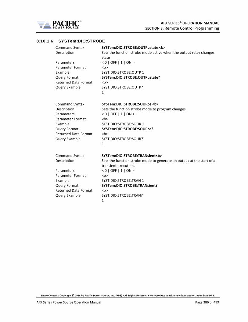
AFX SERIES® OPERATION MANUAL SECTION 8: Remote Control Programming
Entire Contents Copyright 2018 by Pacific Power Source, Inc. (PPS) • All Rights Reserved • No reproduction without written authorization from PPS.
AFX Series Power Source Operation Manual Page 386 of 499
8.10.1.6 SYSTem:DIO:STROBE Command Syntax SYSTem:DIO:STROBE:OUTPustate <b> Description Sets the function strobe mode active when the output relay changes
state Parameters < 0 | OFF | 1 | ON > Parameter Format <b> Example SYST:DIO:STROBE:OUTP 1 Query Format SYSTem:DIO:STROBE:OUTPustate? Returned Data Format <b> Query Example SYST:DIO:STROBE:OUTP?
1
Command Syntax SYSTem:DIO:STROBE:SOURce <b> Description Sets the function strobe mode to program changes. Parameters < 0 | OFF | 1 | ON > Parameter Format <b> Example SYST:DIO:STROBE:SOUR 1 Query Format SYSTem:DIO:STROBE:SOURce? Returned Data Format <b> Query Example SYST:DIO:STROBE:SOUR?
1
Command Syntax SYSTem:DIO:STROBE:TRANsient<b> Description Sets the function strobe mode to generate an output at the start of a
transient execution. Parameters < 0 | OFF | 1 | ON > Parameter Format <b> Example SYST:DIO:STROBE:TRAN 1 Query Format SYSTem:DIO:STROBE:TRANsient? Returned Data Format <b> Query Example SYST:DIO:STROBE:TRAN?
1

AFX SERIES® OPERATION MANUAL SECTION 8: Remote Control Programming
Entire Contents Copyright 2018 by Pacific Power Source, Inc. (PPS) • All Rights Reserved • No reproduction without written authorization from PPS.
AFX Series Power Source Operation Manual Page 387 of 499
8.10.2 SOURce:SYNChronize Commands SOURce:SYNChronize [:INput][?] :PHASEshift[? :RANGE[? :SOURCE[? :SPeed[? :STATe?
SOURce:SYNChronize :OUTPut[?]
8.10.2.1 SOURce:SYNChronize[:INput] Command Syntax SOURce:SYNChronize[:INput] Description This command enables or disables the external sync input mode. Parameters [ 0 | OFF | 1 | ON ] Parameter Format <b> Example SOUR:SYNC 1 Query Format SOURce:SYNChronize[:INput]? Returned Data Format <b> Query Example SOUR:SYNC?
1
Command Syntax SOURce:SYNChronize[:Input]:PHASEshift <nr2> Description Defines a fixed phase shift between phase A waveform generation
and the external sync source. Used to calibrate any phase difference between the sync signal and the power source output on phase A.
Parameters Phase shift Parameter Format <nr> Example SOUR:SYNC:PHASE 2.8 Query Format SOURce:SYNChronize[:Input]:PHASEshift? Returned Data Format <nr2> Query Example SOUR:SYNC:PHASE?
0.5

AFX SERIES® OPERATION MANUAL SECTION 8: Remote Control Programming
Entire Contents Copyright 2018 by Pacific Power Source, Inc. (PPS) • All Rights Reserved • No reproduction without written authorization from PPS.
AFX Series Power Source Operation Manual Page 388 of 499
Command Syntax SOURce:SYNChronize[:Input]:RANGe <nr2> Description Allows configuration of how much the synchronization engine is able
to deviate from the AFX programmed frequency. This helps to keep the waveform frequency under control, even if the external source is not present all the time. The synchronization engine is limited to frequencies of FSETPOINT +/- FRANGE.
Parameters Range in Hz Parameter Format <nr2> Example SOUR:SYNC:RANG 5.0 Query Format SOURce:SYNChronize[:Input]:RANGe? Returned Data Format <nr2> Query Example SOUR:SYNC:RANGe?
10.000
Command Syntax SOURce:SYNChronize[:Input]:SOURce <cr> Description This command selects either the external sync TTL (1) or the internal
AC line sync (0) mode. The internal AC sync signal is derived from the power sources three phase L-L voltages so a phase adjustment for Phase A output will be needed using the SOURce:SYNChronize[:Input]:PHASEshift command.
Parameters [ 0 |AC | 1 | TTL ] Parameter Format <cr> Example SOUR:SYNC:SOUR TTL Query Format SOURce:SYNChronize[:Input]:SOURce? Returned Data Format <cr> Query Example SOUR:SYNC:SOUR?
1
Command Syntax SOURce:SYNChronize[:Input]:SPeed <nr2> Description Allows accelerating the speed of the internal synchronization engine
(PLL) in case the external sync source is not constant and presents periodic or continuous changes. A slower speed improves the stability of the waveform frequency, so it is recommended to keep use the smallest possible speed values.
Parameters Speed (multiplier value) Parameter Format <nr1> Range is 1.000 ~ 10.000 Example SOUR:SYNC:SP 0.50 Query Format SOURce:SYNChronize[:Input]:SPeed? Returned Data Format <nr2> Query Example SOUR:SYNC:SP?
2.500

AFX SERIES® OPERATION MANUAL SECTION 8: Remote Control Programming
Entire Contents Copyright 2018 by Pacific Power Source, Inc. (PPS) • All Rights Reserved • No reproduction without written authorization from PPS.
AFX Series Power Source Operation Manual Page 389 of 499
Query Command SOURce:SYNChronize[:Input]:STATe? Description This query only command returns the status of the Phase Lock Loop
(PLL). A “0” response indicates the PLL has not locked on to the sync input yet. A 1 response indicates the PLL is locked.
Returned Data Format <b> Returned Data 0 = PLL is not locked
1 = PLL is locked Query Example SOUR:SYNC:STAT?
1
8.10.2.2 SOURce:SYNChronize[:OUTput] Command Syntax SOURce:SYNChronize:OUTput Description This command enables the SYNC output Query Format SOURce:SYNChronize:OUTput? Returned Data Format <b> Returned Data 0 = SYNC output off
1 = SYNCoutput on Query Example SOUR:SYNC:OUT?
1
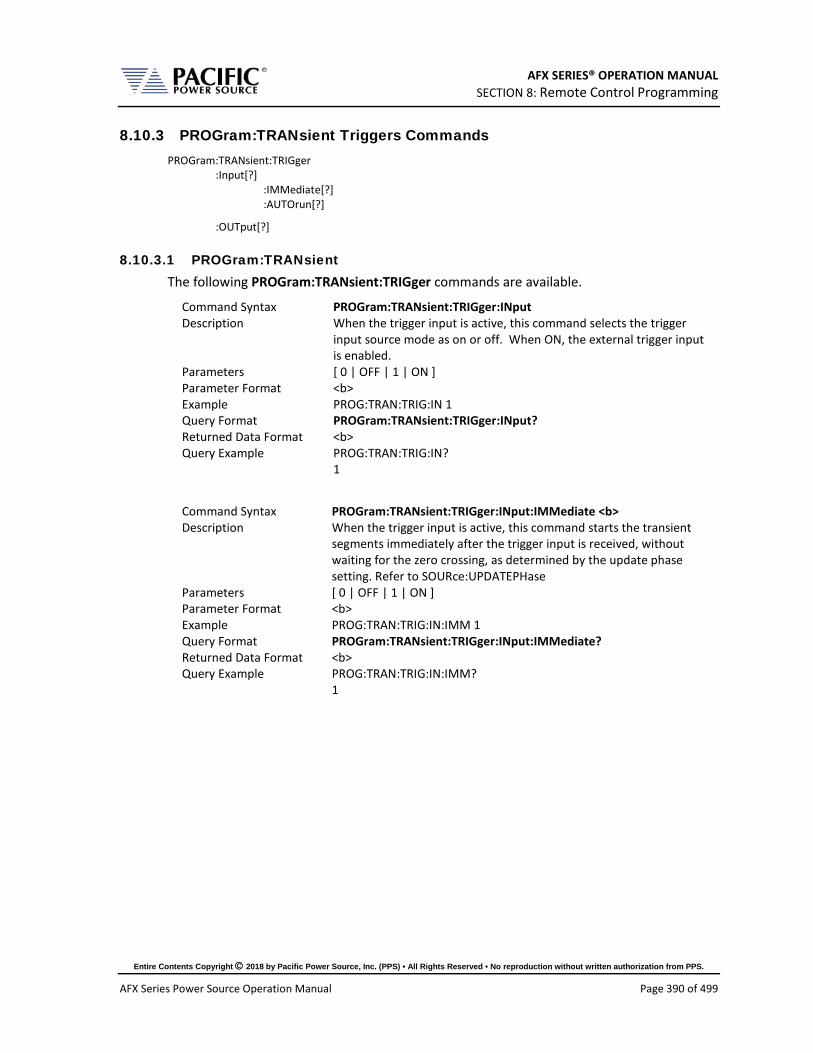
AFX SERIES® OPERATION MANUAL SECTION 8: Remote Control Programming
Entire Contents Copyright 2018 by Pacific Power Source, Inc. (PPS) • All Rights Reserved • No reproduction without written authorization from PPS.
AFX Series Power Source Operation Manual Page 390 of 499
8.10.3 PROGram:TRANsient Triggers Commands PROGram:TRANsient:TRIGger :Input[?] :IMMediate[?] :AUTOrun[?]
:OUTput[?]
8.10.3.1 PROGram:TRANsient The following PROGram:TRANsient:TRIGger commands are available.
Command Syntax PROGram:TRANsient:TRIGger:INput Description When the trigger input is active, this command selects the trigger
input source mode as on or off. When ON, the external trigger input is enabled.
Parameters [ 0 | OFF | 1 | ON ] Parameter Format <b> Example PROG:TRAN:TRIG:IN 1 Query Format PROGram:TRANsient:TRIGger:INput? Returned Data Format <b> Query Example PROG:TRAN:TRIG:IN?
1
Command Syntax PROGram:TRANsient:TRIGger:INput:IMMediate <b> Description When the trigger input is active, this command starts the transient
segments immediately after the trigger input is received, without waiting for the zero crossing, as determined by the update phase setting. Refer to SOURce:UPDATEPHase
Parameters [ 0 | OFF | 1 | ON ] Parameter Format <b> Example PROG:TRAN:TRIG:IN:IMM 1 Query Format PROGram:TRANsient:TRIGger:INput:IMMediate? Returned Data Format <b> Query Example PROG:TRAN:TRIG:IN:IMM?
1

AFX SERIES® OPERATION MANUAL SECTION 8: Remote Control Programming
Entire Contents Copyright 2018 by Pacific Power Source, Inc. (PPS) • All Rights Reserved • No reproduction without written authorization from PPS.
AFX Series Power Source Operation Manual Page 391 of 499
Command Syntax PROGram:TRANsient:TRIGger:INput:AUTOrun <b> Description When the trigger input is active and segments are running state, each
trigger event (pulse) will automatically start a new sequence, without the need of a new RUN command before each trigger. The RUN command has to be executed only once, and then each subsequence trigger input event will cause a new segment sequence to run. Note: the trigger signal is level-sensitive; hence if it is kept high, it will continuously issue a trigger.
Parameters [ 0 | OFF | 1 | ON ] Parameter Format <b> Example PROG:TRAN:TRIG:IN:AUTO 1 Query Format PROGram:TRANsient:TRIGger:INput:AUTOrun? Returned Data Format <b> Query Example PROG:TRAN:TRIG:IN:AUTO?
1
Command Syntax PROGram:TRANsient:TRIGger:OUTput Description This command causes a trigger output pulse to be generated when a
transient execution is started. Note that this output is used as a function strobe during steady state operation.
Parameters [ 0 | OFF | 1 | ON ] Parameter Format <b> Example PROG:TRAN:TRIG:OUT 1 Query Format PROGram:TRANsient:TRIGger:OUTput? Returned Data Format <b> Query Example PROG:TRAN:TRIG:OUT?
1

AFX SERIES® OPERATION MANUAL SECTION 8: Remote Control Programming
Entire Contents Copyright 2018 by Pacific Power Source, Inc. (PPS) • All Rights Reserved • No reproduction without written authorization from PPS.
AFX Series Power Source Operation Manual Page 392 of 499
8.10.4 AUX I/O Calibration Commands SYSTem:AIO :INPut# :CALibration :GAIN?] :DEFault[?] :MAXimum :MINinimum :OFFset?] :DEFault[?] :MAXimum :MINinimum :OUTput# :CALibration :GAIN?] :DEFault[?] :MAXimum :MINinimum :OFFset?] :DEFault[?] :MAXimum :MINinimum
8.10.4.1 SYSTem:AIO:INPUT#:CALibration Command Syntax SYSTem:AIO:INput[n]:CALibration:GAIN <nr2> Description Calibrates the full scale gain of the AFX parameter controlled
by the analog input. Parameters Reference Parameter Format <nr2> Example SYST:AIO:IN1:CAL:GAIN 100.0 Query Format SYSTem:AIO:INput[n]:CALibration:GAIN? Returns calibration coefficient Returned Data Format <nr2> Query Example SYST:AIO:IN1:CAL:GAIN?
1.000
Query Command SYSTem:AIO:INput[n]:CALibration:GAIN:DEFault? Returns default calibration coefficient value Returned Data Format <nr2> Query Example SYST:AIO:IN1:CAL:GAIN:DEF?
1.000
Query Command SYSTem:AIO:INput[n]:CALibration:GAIN:MAXimum? Returns upper limit of calibration coefficient value Returned Data Format <nr2> Query Example SYST:AIO:IN1:CAL:GAIN:MAX?
1.000
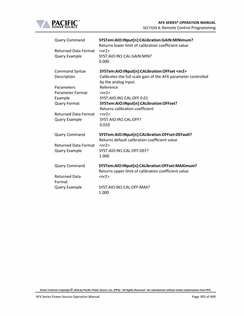
AFX SERIES® OPERATION MANUAL SECTION 8: Remote Control Programming
Entire Contents Copyright 2018 by Pacific Power Source, Inc. (PPS) • All Rights Reserved • No reproduction without written authorization from PPS.
AFX Series Power Source Operation Manual Page 393 of 499
Query Command SYSTem:AIO:INput[n]:CALibration:GAIN:MINimum? Returns lower limit of calibration coefficient value Returned Data Format <nr2> Query Example SYST:AIO:IN1:CAL:GAIN:MIN?
0.000
Command Syntax SYSTem:AIO:INput[n]:CALibration:OFFset <nr2> Description Calibrates the full scale gain of the AFX parameter controlled
by the analog input. Parameters Reference Parameter Format <nr2> Example SYST:AIO:IN1:CAL:OFF 0.01 Query Format SYSTem:AIO:INput[n]:CALibration:OFFset? Returns calibration coefficient Returned Data Format <nr2> Query Example SYST:AIO:IN1:CAL:OFF?
0.010
Query Command SYSTem:AIO:INput[n]:CALibration:OFFset:DEFault? Returns default calibration coefficient value Returned Data Format <nr2> Query Example SYST:AIO:IN1:CAL:OFF:DEF?
1.000
Query Command SYSTem:AIO:INput[n]:CALibration:OFFset:MAXimum? Returns upper limit of calibration coefficient value Returned Data Format
<nr2>
Query Example SYST:AIO:IN1:CAL:OFF:MAX? 1.000

AFX SERIES® OPERATION MANUAL SECTION 8: Remote Control Programming
Entire Contents Copyright 2018 by Pacific Power Source, Inc. (PPS) • All Rights Reserved • No reproduction without written authorization from PPS.
AFX Series Power Source Operation Manual Page 394 of 499
Query Command SYSTem:AIO:INput[n]:CALibration:OFFset:MINimum? Returns lower limit of calibration coefficient value Returned Data Format <nr2> Query Example SYST:AIO:IN1:CAL:OFF:MIN?
1.000
8.10.4.2 SYSTem:AIO:OUTput#:CALibration Command Syntax SYSTem:AIO:OUTput[n]:CALibration:GAIN <nr2> Description Calibrates the full scale gain of the AFX parameter controlled by
the analog output. Parameters Reference Parameter Format <nr2> Example SYST:AIO:OUT1:CAL:GAIN 100.0 Query Format SYSTem:AIO:OUTput[n]:CALibration:GAIN? Returns calibration coefficient Returned Data Format <nr2> Query Example SYST:AIO:OUT1:CAL:GAIN?
1.000
Query Command SYSTem:AIO:OUTput[n]:CALibration:GAIN:DEFault? Returns default calibration coefficient value Returned Data Format <nr2> Query Example SYST:AIO:OUT1:CAL:GAIN:DEF?
1.000
Query Command SYSTem:AIO:OUTput[n]:CALibration:GAIN:MAXimum? Returns upper limit of calibration coefficient value Returned Data Format
<nr2>
Query Example SYST:AIO:OUT1:CAL:GAIN:MAX? 1.000
Query Command SYSTem:AIO:OUTput[n]:CALibration:GAIN:MINimum? Returns lower limit of calibration coefficient value Returned Data Format
<nr2>
Query Example SYST:AIO:OUT1:CAL:GAIN:MIN? 0.000

AFX SERIES® OPERATION MANUAL SECTION 8: Remote Control Programming
Entire Contents Copyright 2018 by Pacific Power Source, Inc. (PPS) • All Rights Reserved • No reproduction without written authorization from PPS.
AFX Series Power Source Operation Manual Page 395 of 499
Command Syntax SYSTem:AIO:OUTput[n]:CALibration:OFFset <nr2> Description Calibrates the full scale gain of the AFX parameter controlled by
the analog output. Parameters Reference Parameter Format <nr2> Example SYST:AIO:OUT1:CAL:OFF 0.01 Query Format SYSTem:AIO:OUTput[n]:CALibration:OFFset? Returns calibration coefficient Returned Data Format <nr2> Query Example SYST:AIO:OUT1:CAL:OFF?
0.010
Query Command SYSTem:AIO:OUTput[n]:CALibration:OFFset:DEFault? Returns default calibration coefficient value Returned Data Format <nr2> Query Example SYST:AIO:OUT1:CAL:OFF:DEF?
1.000
Query Command SYSTem:AIO:OUTput[n]:CALibration:OFFset:MAXimum? Returns upper limit of calibration coefficient value Returned Data Format
<nr2>
Query Example SYST:AIO:OUT1:CAL:OFF:MAX? 1.000
Query Command SYSTem:AIO:OUTput[n]:CALibration:OFFset:MINimum? Returns lower limit of calibration coefficient value Returned Data Format
<nr2>
Query Example SYST:AIO:OUT1:CAL:OFF:MIN? 1.000

AFX SERIES® OPERATION MANUAL SECTION 8: Remote Control Programming
Entire Contents Copyright 2018 by Pacific Power Source, Inc. (PPS) • All Rights Reserved • No reproduction without written authorization from PPS.
AFX Series Power Source Operation Manual Page 396 of 499
8.11 AFXS Series Mode Commands These commands apply to AFXS Model master power source models only. The “S” option designation is part of the Model number returned by the *IDN? Query command. Standard units return 3150AFX whereas units configured with the Series mode option return “3150AFXS”.
Command Syntax SOURce:SERIES < 0 | OFF | 1 | ON > Description Turns Series output mode ON or OFF. This command can be
changed as long as the series modes was configured with SYSTem:SERIESconnection 600. This command allows switching between high voltage/low current or low voltage/high current modes if the SPMS is present.
• OFF or 0 = All AFXs in parallel • ON or 1 = AFXs in series
Without the SPMS option, the user has to ensure that this command matches the wiring (parallel or series depending on customer requirement) before changing modes.
Parameters < 0 | OFF | 1 | ON > Parameter Format <b> or <cr> Example SOUR:SERIES ON Query Format SOURce:SERIES? Returns series setting mode Returned Data Format <nr1> Query Example SOUR:SERIES?
1

AFX SERIES® OPERATION MANUAL SECTION 8: Remote Control Programming
Entire Contents Copyright 2018 by Pacific Power Source, Inc. (PPS) • All Rights Reserved • No reproduction without written authorization from PPS.
AFX Series Power Source Operation Manual Page 397 of 499
Command Syntax SOURce:SERIES:PROTection < 0 | OFF | 1 | ON > Description Useful only with external SPMS switch circuit. Without, it
cannot be set to 1. The default for this is ON when the series unit is configured with the SPMS switch. When ON and the inhibit input state (digital input 3) is a logical 1, it does not allow to the "SOURCE:SERIES 1" command. When OFF, it allows it, no matter the value of the digital input 3. In this case, the digital input 3 can be used for any other purpose by the user. If ON, digital input 3 cannot be used for other purposes, it’s function is fixed to series inhibit.
Parameters < 0 | OFF | 1 | ON > Parameter Format <b> or <cr> Example SOUR:SERIES:PROT ON Query Format SOURce:SERIES:PROT? Returns protection setting Returned Data Format <nr1> Query Example SOUR:SERIES:PROT?
1
Query Command SYSTem:SERIESUNITS? This command returns 1 if SOURCE:SERIES is set to 0/OFF. It returns 2
if SOURCE:SERIES is set 1/ON. No matter the number of units. Note: This command does NOT return the number of AFX’s connected in series. To determine the actual number of units, use the SYSTem:CONNECTEDUNITS? Command instead.
For a Series or Series/Parallel system, if SOURCE:SERIES is 0/OFF, it returns the total units, same as a parallel only system. If SOURCE:SERIES is 1, it returns the total number units divided by two. Refer also to the SYSTem:PARALLELUNITS? Command.
SYSTem:CONNECTEDUNITS? returns the total units no matter the value of SOURCE:SERIES?. This is equal to SYSTem:SERIESUNITS? * SYSTem:PARALLELUNITS?
Returned Data Format <nr1> Query Example SYST:SERIESUNITS?
2

AFX SERIES® OPERATION MANUAL SECTION 8: Remote Control Programming
Entire Contents Copyright 2018 by Pacific Power Source, Inc. (PPS) • All Rights Reserved • No reproduction without written authorization from PPS.
AFX Series Power Source Operation Manual Page 398 of 499
Command Syntax SYSTem:SERIESconnection <VOLTAGE, OPT: OPTIONS > Description This is used to configure the AFXS system. For AFXS systems with the
SPMS option, this in done at the factory. For system integrators that connect their own AFXS system, contact factory for support. VOLTAGE should be 600 for series capable systems and 0 for non-series capable systems. OPTIONS is a 32 bits word, for now only the first 2 bits are used: • Bit 0 is used to indictate the SPMS option is present. 1 = indicates
SPMS option, 0 = no SPMS opton. • Bit 1 is for protection blocked, when set to 1, this will force the
SOURce:SERIES:PROTection command to always ON so it cannot be set to OFF.
• All other bits are reserved. For example for an AFXS system with external SPMS circuit, set "SYSTem:SERIESconnection 600,1" For manual output wiring changes (i.e. no SPMS hardware), set to "SYSTem:SERIESconnection 600" or "SYSTem:SERIESconnection 600,0" The external circuits are contained in the SPMS Option and allow automatic parallel or series connection changes via SCPI command or GUI.
Parameters <VOLTAGE, OPT: OPTIONS> Parameter Format <b> or <cr> Example SYST:SERIES 600,1 Query Format SYSTem:SERIESconnection? Returns protection setting Returned Data Format <nr1> Query Example SYST:SERIES?
600.000,0,0.0000000000,0
Multi Unit System Configuration Comand Examples:
30kVA Parallel Only AFX System 30kVA Series/Parallel AFSX System SOURCE:SERIES 0 SYSTem:SERIESUNITS? = 1 SYSTem:PARALLELUNITS? = 2 SYSTem:CONNECTEDUNITS? = 2
SOURCE:SERIES 1 SYSTem:SERIESUNITS? = 2 SYSTem:PARALLELUNITS? = 1 SYSTem:CONNECTEDUNITS? = 2
60kVA Parallel Only AFX System 60kVA Series/Parallel AFSX System SOURCE:SERIES 0 SYSTem:SERIESUNITS? = 1 SYSTem:PARALLELUNITS? = 4 SYSTem:CONNECTEDUNITS? = 4
SOURCE:SERIES 1 SYSTem:SERIESUNITS? = 2 SYSTem:PARALLELUNITS? = 2 SYSTem:CONNECTEDUNITS? = 4

AFX SERIES® OPERATION MANUAL SECTION 8: Remote Control Programming
Entire Contents Copyright 2018 by Pacific Power Source, Inc. (PPS) • All Rights Reserved • No reproduction without written authorization from PPS.
AFX Series Power Source Operation Manual Page 399 of 499
8.12 IEEE488.2 Common Commands The following IEEE488.2 common commands (a.k.a. star commands) are supported by the AC power source. These commands are provided for compatibility with the IEEE488.2 standard. They are aliases to the relevant proprietary command and can be used interchangeably. Commands are shown in alphabetical order.
IEEE488.2 Command Description Group Mandatory *CLS Clear Status Status and Event Yes *DCL Device Clear Internal Operations *ESE <n> Event Status Register Enable Status and Event Yes *ESE? ESE Query Status and Event Yes *ESR? Event Status Register Query Status and Event Yes *GTL Goto Local Control *IDN? Identify System Data Yes *LLO Local Lock Out Control Yes *OPC Operation Complete Synchronization Yes *OPC? OPC Status Query Synchronization Yes *RST Reset Internal Operations Yes *SRE Service Request Enable Status and Event Yes *SRE? SRE Query Status and Event Yes *STB? Status Byte Query Status and Event Yes *TRG Trigger Synchronization *WAI Wait Synchronization Yes
Table 8-3: Mandatory IEEE488.2 Common Commands
Command Syntax *CLS Description Clear Status. The Clear Status (CLS) command clears the status byte
by emptying the error queue and clearing all the event registers including the Data Questionable Event Register, the Standard Event Status Register, the Standard Operation Status Register and any other registers that are summarized in the status byte.
Command Syntax *DCL Description Device Clear. Resets the instrument to a default state. Parameters None Parameter Format n/a

AFX SERIES® OPERATION MANUAL SECTION 8: Remote Control Programming
Entire Contents Copyright 2018 by Pacific Power Source, Inc. (PPS) • All Rights Reserved • No reproduction without written authorization from PPS.
AFX Series Power Source Operation Manual Page 400 of 499
Command Syntax *ESE<nr1> Description Selects the desired bits from the standard event status enable
register. The variable <nr1> represents the sum of the bits that will be enabled. This register monitors I/O errors and synchronization conditions such as operation complete, request control, query error, device dependent error, status execution error, command error and power on. The selected bits are OR’d to become a summary bit (bit 5) in the byte register which can be queried. The setting by this command is not affected by *RST. However, cycling the power will reset this register to zero. Refer to section 8.12 for register bit values.
Parameters Range 0-255 Parameter Format <nr1> Example *ESE 128 Query Format *ESE? Returned Data Format <nr1> Query Example *ESE?
193
Query Format *ESR? Description Event Status Register Query. Reads the contents of the Status Event
Register (ESR). After this query, the content of the ESR register is reset. Refer to section 8.12 for register bit values.
Returned Data Format <nr1> Query Example *ESR?
0
Command Syntax *GTL Description Goto Local. Releases lock of front panel controls. Returned Data Format N/A Query Example N/A
Query Format *IDN? Description Identification Query. Returns the unit’s Identity string. The IDN string
response contains several fields separated by a comma. Query response: Manufacturer, model, serial number, firmware revision.
Returned Data Format <cr>,<cr>,<nr1>,<nr2> Query Example *IDN?
PPSC,3150AFX-2AG,106378889,2.0.0
Command Syntax *LLO Description Local Lock out. Locks out front panel LOCAL function. Parameters None Parameter Format n/a

AFX SERIES® OPERATION MANUAL SECTION 8: Remote Control Programming
Entire Contents Copyright 2018 by Pacific Power Source, Inc. (PPS) • All Rights Reserved • No reproduction without written authorization from PPS.
AFX Series Power Source Operation Manual Page 401 of 499
Command Syntax *OPC Description The Operation Complete (OPC) command sets bit 0 in the Standard
Event Status Register when all pending operations have finished. Parameters Optional: < BLOCK | 0 | NOBLOCK | 1> Example *OPC Query Format *OPC? < BLOCK | 0 | NOBLOCK | 1> Description IEEE488.2 standard command. The parameter is optional.
The argument is optional, if it is not sent: • In UPC compatible mode default argument will be NONBLOCK or
1. • In normal mode default argument will be BLOCK or 0.
*OPC? BLOCK | 0 Returns 1 when all pending overlapped operations have been
completed. It can be used to cause the controller to wait for commands to complete.
*OPC? NOBLOCK | 1 Returns 1 if all pending overlapped operations have been completed
or 0 if there are pending overlapped operations. It will not cause the controller to wait for commands to complete. Pending overlapped operations can be a transient or a soft start using ramp time/slew rates.
Returned Data Format <b> Query Example *OPC?
1
Command Syntax *RST Description RESET. The *RST command (reset) has the same effect as an IEEE-488
Device Clear bus command but can be used over the RS232C, USB or LAN interface as well. This command resets the unit to its power on default state. User defined waveforms or programs are not erased but the mode is set to manual and the transient list table is cleared. (Unless there is a power-on program configured using the [SOURce:]INITial command)
Parameters None Parameter Format n/a RESET STATE FORM 3 VOLT:MODE AC VOLT:AC 0.0000 COUPLING DC VOLT:DC 0.0000 RANGE AC CURR:AC 41.6667 CURR:DC 20.8333

AFX SERIES® OPERATION MANUAL SECTION 8: Remote Control Programming
Entire Contents Copyright 2018 by Pacific Power Source, Inc. (PPS) • All Rights Reserved • No reproduction without written authorization from PPS.
AFX Series Power Source Operation Manual Page 402 of 499
Command Syntax *SRE <nr1> Description Before reading a status register, bits must be enabled. This command
enables bits in the service request register. The current setting is saved in non-volatile memory.
Parameters 0-255 Parameter Format <nr1> Example *SRE 255 Query Format *SRE? Description Reads the current state of the service request enable register. The
register is cleared after reading it. Refer to section 8.12 for register bit values.
Returned Data Format <nr1> Query Example *SRE?
255
Query Format *STB? Description Status Byte Query. The *STB? query returns the contents of the
status byte register (STB). After this query, the content of the STB register is reset. Refer to section 8.12 for register bit values.
Returned Data Format <nr1> Query Example *STB?
4
Command Syntax *TRG Description Triggers pending operation. Parameters None Parameter Format n/a
Command Syntax *WAI Description Prohibits the instrument from executing any new commands until all
pending overlapped commands have been completed. Parameters None Parameter Format n/a
8.13 Status and Events Registers The IEEE488.2 standard defines a standardized status and events register system. Refer to the ANSI/IEEE-488.2 1987 standard for more information. This section provides an overview of these registers and bit positions for various status and error events.

AFX SERIES® OPERATION MANUAL SECTION 8: Remote Control Programming
Entire Contents Copyright 2018 by Pacific Power Source, Inc. (PPS) • All Rights Reserved • No reproduction without written authorization from PPS.
AFX Series Power Source Operation Manual Page 403 of 499
8.13.1 Status Byte Register (STB)
The status register content is returned on a *STB? query. It contains 8 bits as shown in the table below. The return value represents the 8 bits positions and can range from 0-255. A *CLS command will clear the Status Byte Register (STB) and the Event Status Register (ESR). Refer to Figure 8-2,”Status Byte Logical Model”.
BIT NAME DEFINITION 7 SOS :STATus:OPERation register bit summary 6 MSS/RQS - MASTER SUMMARY
summarizes all STATUS BYTE bits (except bit 6) for *STB?, or, - REQUEST SERVICE indicates this device requested service when a Serial Poll was performed.
5 ESB STANDARD EVENT STATUS REGISTER bit summary 4 MAV MESSAGE AVAILABLE indicates Query response data is available 3 SQS :STATus:QUEStionable register bit summary 2 EEQ ERROR/EVENT QUEUE indicates an SCPI Error/Event message is available 1 BUSY indicates UPC front panel not in V/I mode 0 FAULT indicates Power Source FAULT
Table 8-4: Status Byte Register (STB)
Note: Setting a SERVICE REQUEST ENABLE (SRE) bit true unmasks the STATUS bit in the STB. Bit 6 of the SRE is not applicable as the MASTER SUMMARY bit of the STB cannot be masked. The STB, SRE, ESR and ESE registers are 8 bits each.

AFX SERIES® OPERATION MANUAL SECTION 8: Remote Control Programming
Entire Contents Copyright 2018 by Pacific Power Source, Inc. (PPS) • All Rights Reserved • No reproduction without written authorization from PPS.
AFX Series Power Source Operation Manual Page 404 of 499
The status byte logical model is shown in the figure below.
Figure 8-3: Status Byte Logical Model

AFX SERIES® OPERATION MANUAL SECTION 8: Remote Control Programming
Entire Contents Copyright 2018 by Pacific Power Source, Inc. (PPS) • All Rights Reserved • No reproduction without written authorization from PPS.
AFX Series Power Source Operation Manual Page 405 of 499
8.13.2 Status Event Register (ESR)
Events reported by the STANDARD EVENT STATUS register may be queried via the *ESR? command. Reading the ESR register clears it. The EVENT STATUS summary bit in the STATUS BYTE (STB) will be set when an unmasked EVENT STATUS bit goes true.
BIT NAME DEFINITION 7 PON POWER ON indicates Input power was just applied 6 URQ USER REQUEST indicates "LOCAL" key was just pressed 5 CME COMMAND ERROR indicates invalid command or query received 4 EXE EXECUTION ERROR indicates can't execute command with data received 3 DDE DEVICE DEPENDANT ERROR indicates UPC not properly configured 2 QYE QUERY ERROR indicates cannot respond with data 1 RQC REQUEST CONTROL - not used 0 OPC OPERATION COMPLETE indicates previous operation complete
Table 8-5: Status Event Register (ESR)
Setting an EVENT STATUS ENABLE (ESE) bit true unmasks the EVENT bit in the ESR. Also see :SYSTem:ERRor? query for relevant information.
Figure 8-4: Standard Event Register (ESR) Model
AFX SERIES® OPERATION MANUAL SECTION 8: Remote Control Programming
Entire Contents Copyright 2018 by Pacific Power Source, Inc. (PPS) • All Rights Reserved • No reproduction without written authorization from PPS.
AFX Series Power Source Operation Manual Page 406 of 499
8.13.3 SCPI Status Registers
The STATus:OPERation and STATus:QUEStionable registers provide information about the present mode of operation.
• Transition of a CONDition bit to the true state causes the EVENt bit to be set true.
• Unmasked ENABle bits allow an EVENt bit to be reported in the summary bit for that EVENt register in the STATUS BYTE register.
• Setting an ENABLe bit true, unmasks the corresponding EVENt bit.
• Reading an EVENt register clears it.
• All :STATUS registers are 16 bits (Figure 5.3).
The STATus:OPERation register provides information about the present mode of operation.
Relevant commands for the STATus:OPERation register are:
:STATus:OPERation:CONDition?
:STATus:OPERation:ENABle
:STATus:OPERation:ENABle?
:STATus:OPERation:EVENt?
The STATUS:QUESTIONABLE register provides information about errors and questionable measurements.
Relevant commands for the STATUS:QUESTIONABLE register are:
:STATus:QUEStionable:CONDition?
:STATus:QUEStionable:ENABle
:STATus:QUEStionable:ENABle?
:STATus:QUEStionable:EVENt?
Refer to Figure 8-4, “SCPI Status Registers Model” for details on registers.

AFX SERIES® OPERATION MANUAL SECTION 8: Remote Control Programming
Entire Contents Copyright 2018 by Pacific Power Source, Inc. (PPS) • All Rights Reserved • No reproduction without written authorization from PPS.
AFX Series Power Source Operation Manual Page 407 of 499
Figure 8-5: SCPI Status Registers Model
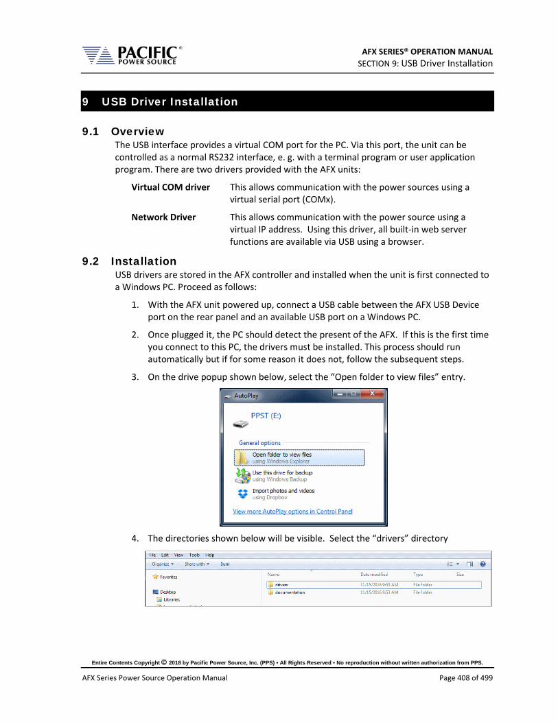
AFX SERIES® OPERATION MANUAL SECTION 9: USB Driver Installation
Entire Contents Copyright 2018 by Pacific Power Source, Inc. (PPS) • All Rights Reserved • No reproduction without written authorization from PPS.
AFX Series Power Source Operation Manual Page 408 of 499
9 USB Driver Installation
9.1 Overview The USB interface provides a virtual COM port for the PC. Via this port, the unit can be controlled as a normal RS232 interface, e. g. with a terminal program or user application program. There are two drivers provided with the AFX units:
Virtual COM driver This allows communication with the power sources using a virtual serial port (COMx).
Network Driver This allows communication with the power source using a virtual IP address. Using this driver, all built-in web server functions are available via USB using a browser.
9.2 Installation USB drivers are stored in the AFX controller and installed when the unit is first connected to a Windows PC. Proceed as follows:
1. With the AFX unit powered up, connect a USB cable between the AFX USB Device port on the rear panel and an available USB port on a Windows PC.
2. Once plugged it, the PC should detect the present of the AFX. If this is the first time you connect to this PC, the drivers must be installed. This process should run automatically but if for some reason it does not, follow the subsequent steps.
3. On the drive popup shown below, select the “Open folder to view files” entry.
4. The directories shown below will be visible. Select the “drivers” directory

AFX SERIES® OPERATION MANUAL SECTION 9: USB Driver Installation
Entire Contents Copyright 2018 by Pacific Power Source, Inc. (PPS) • All Rights Reserved • No reproduction without written authorization from PPS.
AFX Series Power Source Operation Manual Page 409 of 499
5. Next, select the “Windows” directory
6. Run the”Driver_Installer.exe” located in this directory as shown below.,
7. Allow the installation to complete.
At the end of this process, you should be able to see the two PPST USB drivers in the Windows Device Manager window under “Network Adaptors” and “Ports (COM & LPT)” respectively. The USB interface is now ready for use.
Figure 9-1: PPST USB Drivers visible in Windows Device Manager
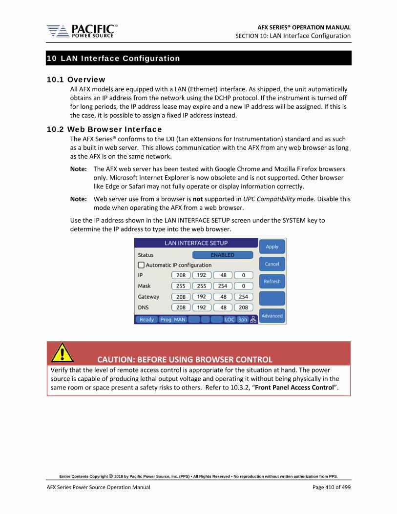
AFX SERIES® OPERATION MANUAL SECTION 10: LAN Interface Configuration
Entire Contents Copyright 2018 by Pacific Power Source, Inc. (PPS) • All Rights Reserved • No reproduction without written authorization from PPS.
AFX Series Power Source Operation Manual Page 410 of 499
10 LAN Interface Configuration
10.1 Overview All AFX models are equipped with a LAN (Ethernet) interface. As shipped, the unit automatically obtains an IP address from the network using the DCHP protocol. If the instrument is turned off for long periods, the IP address lease may expire and a new IP address will be assigned. If this is the case, it is possible to assign a fixed IP address instead.
10.2 Web Browser Interface The AFX Series® conforms to the LXI (Lan eXtensions for Instrumentation) standard and as such as a built in web server. This allows communication with the AFX from any web browser as long as the AFX is on the same network.
Note: The AFX web server has been tested with Google Chrome and Mozilla Firefox browsers only. Microsoft Internet Explorer is now obsolete and is not supported. Other browser like Edge or Safari may not fully operate or display information correctly.
Note: Web server use from a browser is not supported in UPC Compatibility mode. Disable this mode when operating the AFX from a web browser.
Use the IP address shown in the LAN INTERFACE SETUP screen under the SYSTEM key to determine the IP address to type into the web browser.
CAUTION: BEFORE USING BROWSER CONTROL Verify that the level of remote access control is appropriate for the situation at hand. The power source is capable of producing lethal output voltage and operating it without being physically in the same room or space present a safety risks to others. Refer to 10.3.2, “Front Panel Access Control”.

AFX SERIES® OPERATION MANUAL SECTION 10: LAN Interface Configuration
Entire Contents Copyright 2018 by Pacific Power Source, Inc. (PPS) • All Rights Reserved • No reproduction without written authorization from PPS.
AFX Series Power Source Operation Manual Page 411 of 499
If the unit is on the same network or reachable through the internet, the home screen of the AFX web server will appear.
Figure 10-1: LXI Web Server Home Screen
When permitted, the browser interface allows monitoring of measurements and/or full control of the power source. If the operator is not near the actual instruments being controlled, care must be taken to the appropriate access control limits.

AFX SERIES® OPERATION MANUAL SECTION 10: LAN Interface Configuration
Entire Contents Copyright 2018 by Pacific Power Source, Inc. (PPS) • All Rights Reserved • No reproduction without written authorization from PPS.
AFX Series Power Source Operation Manual Page 412 of 499
10.3 Access Control Since the power source is capable of producing hazardous voltages at its output terminals, remote operation of the product over a LAN connection or any other available remote control interface can be restricted by the user to include only monitoring functions rather than full programming controls.
This feature is provided to ensure the safety of anyone near the unit in its actual physical location. This access control mechanism requires granting specific access to certain functions and features from the front panel by a person present at the location of the power source and requesting permission first trying to access a unit remotely.
These access control functions can be set from the SYSTEM Menu, INTERFACE screen or via the webserver using any browser.
CAUTION
All AFX Units are shipped from the factory with ACCESS CONTROL DISABLED. It is the instrument’s
owner’s responsibility to enable these features.

AFX SERIES® OPERATION MANUAL SECTION 10: LAN Interface Configuration
Entire Contents Copyright 2018 by Pacific Power Source, Inc. (PPS) • All Rights Reserved • No reproduction without written authorization from PPS.
AFX Series Power Source Operation Manual Page 413 of 499
10.3.1 Browser Access Control
When connecting to the power source via a browser on which access has been restricted, the following message will appear:
The browser Access dialog is shown below.
Figure 10-2: ACCESS CONTROL Dialog Screen
If the operator knows the four-digit access password that was set on the actual unit, he can enter the password code and gain full control of the source.
If the operator does not know the password, he can request access. Such a request can only be granted by a person who is in front of the actual unit however. This prevents unauthorized access from a remote location and protects the local user from possible harm. An Access Request will result in a Pop-Up message on the power source LCD screen.
The access control password can be set/changed only by the person(s) present at the physical location of the unit. Factory default password is “1234” but it is strongly advised the end user changes this to his own code after receipt of the unit.
If access is denied, the browser interface will enter MONITOR only mode in which measurements and settings can be viewed remotely but control is possible. When in this mode, a user with knowledge of the access password can enter FULL CONTROL mode by supplying the correct password or request full access from a local operator that is present at the unit’s location.
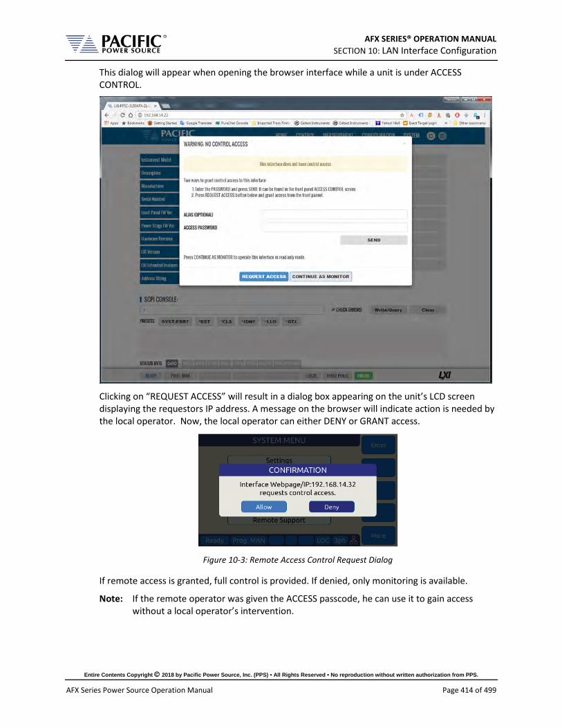
AFX SERIES® OPERATION MANUAL SECTION 10: LAN Interface Configuration
Entire Contents Copyright 2018 by Pacific Power Source, Inc. (PPS) • All Rights Reserved • No reproduction without written authorization from PPS.
AFX Series Power Source Operation Manual Page 414 of 499
This dialog will appear when opening the browser interface while a unit is under ACCESS CONTROL.
Clicking on “REQUEST ACCESS” will result in a dialog box appearing on the unit’s LCD screen displaying the requestors IP address. A message on the browser will indicate action is needed by the local operator. Now, the local operator can either DENY or GRANT access.
Figure 10-3: Remote Access Control Request Dialog
If remote access is granted, full control is provided. If denied, only monitoring is available.
Note: If the remote operator was given the ACCESS passcode, he can use it to gain access without a local operator’s intervention.

AFX SERIES® OPERATION MANUAL SECTION 10: LAN Interface Configuration
Entire Contents Copyright 2018 by Pacific Power Source, Inc. (PPS) • All Rights Reserved • No reproduction without written authorization from PPS.
AFX Series Power Source Operation Manual Page 415 of 499
When granted, the requestor’s IP address will be added to the whitelist IP. The operator can remove any of the white listed IP address at any time if needed. This will lock out remote access for that PC until access is re-granted anew.
Figure 10-4: Remote Access Control IP Filter screen

AFX SERIES® OPERATION MANUAL SECTION 10: LAN Interface Configuration
Entire Contents Copyright 2018 by Pacific Power Source, Inc. (PPS) • All Rights Reserved • No reproduction without written authorization from PPS.
AFX Series Power Source Operation Manual Page 416 of 499
10.3.2 Front Panel Access Control
Setting remote control access levels and interface types is accomplished from the SYSTEM menu under Interfaces.
Scroll down to the INTERFACE entry and press Enter to access the available INTERFACE SETUP screen.
The second soft key is labelled “Access Control” and brings up the access control screen shown below.
The IP Filter list will provide access to the list of IP addresses that have been granted access by the local operator. This list can be erased if it is necessary to deny future access to the power source.
AFX SERIES® OPERATION MANUAL SECTION 10: LAN Interface Configuration
Entire Contents Copyright 2018 by Pacific Power Source, Inc. (PPS) • All Rights Reserved • No reproduction without written authorization from PPS.
AFX Series Power Source Operation Manual Page 417 of 499
10.4 Web Browser Interface The AFX Series® conforms to the LXI (Lan eXtensions for Instrumentation) standard and features a built-in web server with a greatly expanded feature set. This allows communication with the AFX from any web browser as long as the AFX is reachable through the network or internet. The expanded feature set of the web server often eliminates the need to use additional Windows or other platform based software.
10.5 Available Web Interface Menu Tree The following areas of control, monitoring and configuration of the AFX power source are available through a web browser.
• Home Screen – Required for LXI compliance • Home Screen SCPI Console Command Line Interface • SOURCE CONTROL
PROGRAM PROTECTIONS TRANSIENTS PROGRAM MEMORY WAVEFORM WAVEFORM EDITOR SCPI SCRIPT
• MEASUREMENTS MONITOR REAL-TIME PLOT V/I PLOT DATALOGGER SCOPE HARMONICS
• CONFIGURATION UNIT SETTINGS USER LIMITS & PRESETS RAMP & SLEW
• SYSTEM ERROR/EVENT QUEUE FAULT LIST INTERFACE SETUP ACCESS CONTROL DIGITAL & ANALOG IOS UNIT INFORMATION PARALLEL UNITS MEMORY MANAGER CALIBRATION REMOTE SUPPORT IMPORT/EXPORT FIRMWARE UPDATE SANITIZE & REBOOT
Following sections provide an overview of each page of the web browser interface.
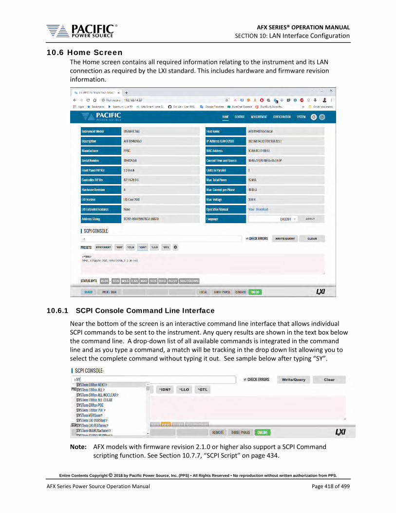
AFX SERIES® OPERATION MANUAL SECTION 10: LAN Interface Configuration
Entire Contents Copyright 2018 by Pacific Power Source, Inc. (PPS) • All Rights Reserved • No reproduction without written authorization from PPS.
AFX Series Power Source Operation Manual Page 418 of 499
10.6 Home Screen The Home screen contains all required information relating to the instrument and its LAN connection as required by the LXI standard. This includes hardware and firmware revision information.
10.6.1 SCPI Console Command Line Interface
Near the bottom of the screen is an interactive command line interface that allows individual SCPI commands to be sent to the instrument. Any query results are shown in the text box below the command line. A drop-down list of all available commands is integrated in the command line and as you type a command, a match will be tracking in the drop down list allowing you to select the complete command without typing it out. See sample below after typing “SY”.
Note: AFX models with firmware revision 2.1.0 or higher also support a SCPI Command
scripting function. See Section 10.7.7, “SCPI Script” on page 434.

AFX SERIES® OPERATION MANUAL SECTION 10: LAN Interface Configuration
Entire Contents Copyright 2018 by Pacific Power Source, Inc. (PPS) • All Rights Reserved • No reproduction without written authorization from PPS.
AFX Series Power Source Operation Manual Page 419 of 499
10.6.2 Status Byte Display
At the very bottom of the Home Screen, the status byte register value and decoded fields are displayed for reference. Status byte fields are described in section 8.12.1, “Status Byte Register (STB)” on page 403.
10.6.3 Browser Status Bar
The browser status bar shows configuration information about the instrument. This includes any error or event flags, remote or local status, phase mode selection and on or off line status.
The first field will display while the power source output is OFF and when it is ON (enabled).
10.6.4 Operation Manual PDF
The AFX Operation Manual is stored on the AFX’s internal memory and available for download to the user’s PC (“Download”) or for viewing using a suitable browser of PDF viewer (“View”).

AFX SERIES® OPERATION MANUAL SECTION 10: LAN Interface Configuration
Entire Contents Copyright 2018 by Pacific Power Source, Inc. (PPS) • All Rights Reserved • No reproduction without written authorization from PPS.
AFX Series Power Source Operation Manual Page 420 of 499
10.7 Source Control Screens The CONTROL menu provides access to several screens that allow programming of the power source. Control Menu entries are as follows:
• PROGRAM • PROTECTIONS • TRANSIENT • PROGRAM MEMORY • WAVEFORM • WAVEFORM EDITOR • SCPI SCRIPT
Each is described in subsequent sections.

AFX SERIES® OPERATION MANUAL SECTION 10: LAN Interface Configuration
Entire Contents Copyright 2018 by Pacific Power Source, Inc. (PPS) • All Rights Reserved • No reproduction without written authorization from PPS.
AFX Series Power Source Operation Manual Page 421 of 499
10.7.1 Program
The program control screen allows programming of all output parameters, operating modes etc. It also displays measurement data for all available phases in the lower part of the screen. In three or two phase mode, Line-to-Line voltage measurements are displayed at the bottom of the screen. The Output can be enabled using the “OUTPUT ENABLE” controls in the upper PROGRAM screen. The Output can also be turned OFF from any screen using the RED On/Off symbol in the menu bar, which is accessible from all screens. This allows quick opening of the output relay if needed from any screen without have to first select the PROGRAM screen. Note that the output can only be turned ON (or OFF) from the PROGRAM screen however.

AFX SERIES® OPERATION MANUAL SECTION 10: LAN Interface Configuration
Entire Contents Copyright 2018 by Pacific Power Source, Inc. (PPS) • All Rights Reserved • No reproduction without written authorization from PPS.
AFX Series Power Source Operation Manual Page 422 of 499
10.7.2 Protections
The Protections screen may be used to change protection modes and threshold values. This includes RMS current, Peak Current, True Power and Apparent Power protection modes. Modes can be toggled on or off individually.

AFX SERIES® OPERATION MANUAL SECTION 10: LAN Interface Configuration
Entire Contents Copyright 2018 by Pacific Power Source, Inc. (PPS) • All Rights Reserved • No reproduction without written authorization from PPS.
AFX Series Power Source Operation Manual Page 423 of 499
10.7.3 Transients
The transient control screen allows programming of new transients or execution control of new or stored transient programs. The power source supports LIST, STEP and PULSE transient modes.

AFX SERIES® OPERATION MANUAL SECTION 10: LAN Interface Configuration
Entire Contents Copyright 2018 by Pacific Power Source, Inc. (PPS) • All Rights Reserved • No reproduction without written authorization from PPS.
AFX Series Power Source Operation Manual Page 424 of 499
10.7.3.1 LIST Transients For LIST transients, both STEP mode and SEGMENT mode is supported. The bottom part of the screen shows the editable transient table. Execution controls are located in the top part of the screen.
Data entry mode can be selected as either STEP or SEGMENT. Dwell times can be entered using msec (TIME BASED) or cycles (CYCLE BASED). A sample TIME BASED Segment mode list is shown below.
Continued on next page…
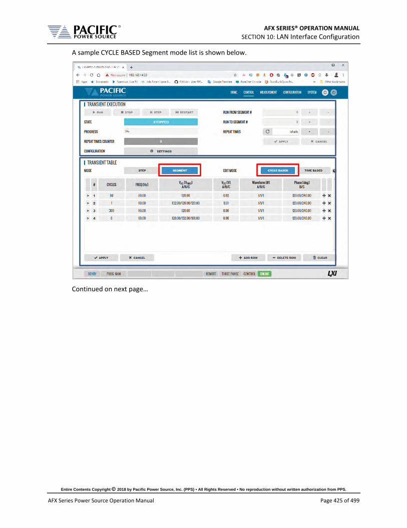
AFX SERIES® OPERATION MANUAL SECTION 10: LAN Interface Configuration
Entire Contents Copyright 2018 by Pacific Power Source, Inc. (PPS) • All Rights Reserved • No reproduction without written authorization from PPS.
AFX Series Power Source Operation Manual Page 425 of 499
A sample CYCLE BASED Segment mode list is shown below.
Continued on next page…

AFX SERIES® OPERATION MANUAL SECTION 10: LAN Interface Configuration
Entire Contents Copyright 2018 by Pacific Power Source, Inc. (PPS) • All Rights Reserved • No reproduction without written authorization from PPS.
AFX Series Power Source Operation Manual Page 426 of 499
A sample TIME BASED STEP mode list is shown below. (Not to be confused with STEP Transient mode, see next section.)
During transient execution, a progress indicator is visible showing percent completion.

AFX SERIES® OPERATION MANUAL SECTION 10: LAN Interface Configuration
Entire Contents Copyright 2018 by Pacific Power Source, Inc. (PPS) • All Rights Reserved • No reproduction without written authorization from PPS.
AFX Series Power Source Operation Manual Page 427 of 499
10.7.3.2 STEP Transients STEP transients allow a ramp or stairstep output profile to be programmed without creating LIST transients with multiple entries. In STEP transient mode, the user enters initial value, end value, delta step size, step duration, step count and no of repeats.
The STEP EXAMPLE shows the relationship between the various parameters.
This information is transformed to a standard Segment based transient list by the power source when the LOAD button is pressed.
During transient execution, a progress indicator is visible showing percent completion.

AFX SERIES® OPERATION MANUAL SECTION 10: LAN Interface Configuration
Entire Contents Copyright 2018 by Pacific Power Source, Inc. (PPS) • All Rights Reserved • No reproduction without written authorization from PPS.
AFX Series Power Source Operation Manual Page 428 of 499
10.7.3.3 PULSE Transients PULSE transients allow series of pulsed output levels to be programmed without creating LIST transients with repetive entries. In PULSE transient mode, the user enters Level, dutyt cycle, ramp time, periodinitial value and pulse count. This mode is useful for high and low line testing for voltage and frequency operating limits of an EUT.
The PULSE EXAMPLE shows the relationship between the various parameters.
This information is transformed to a standard Segment based transient list by the power source when the LOAD button is pressed.
During transient execution, a progress indicator is visible showing percent completion.
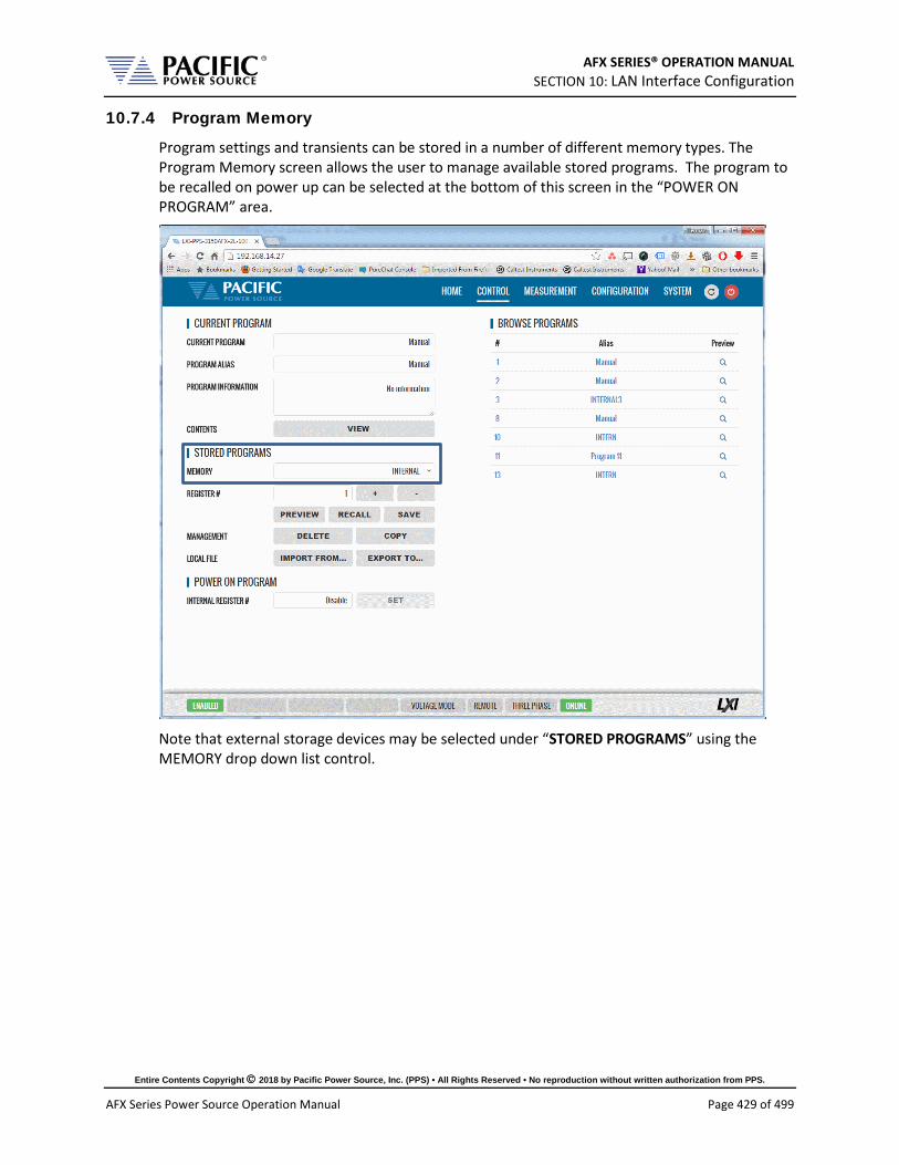
AFX SERIES® OPERATION MANUAL SECTION 10: LAN Interface Configuration
Entire Contents Copyright 2018 by Pacific Power Source, Inc. (PPS) • All Rights Reserved • No reproduction without written authorization from PPS.
AFX Series Power Source Operation Manual Page 429 of 499
10.7.4 Program Memory
Program settings and transients can be stored in a number of different memory types. The Program Memory screen allows the user to manage available stored programs. The program to be recalled on power up can be selected at the bottom of this screen in the “POWER ON PROGRAM” area.
Note that external storage devices may be selected under “STORED PROGRAMS” using the MEMORY drop down list control.

AFX SERIES® OPERATION MANUAL SECTION 10: LAN Interface Configuration
Entire Contents Copyright 2018 by Pacific Power Source, Inc. (PPS) • All Rights Reserved • No reproduction without written authorization from PPS.
AFX Series Power Source Operation Manual Page 430 of 499
10.7.5 Waveform
The power source supports a number of waveforms, most of which are user programmable arbitrary waveforms. The Waveform screen may be used to preview, select and download any of the waveforms stored in internal memory for output on one or more phases. The phase selection “ABC” or separate “A:”, “B” and “C” buttons on the upper right hand side are used to select all or an individual phase. The WAVEFORM drop down list will show all available waveforms.
In addition to selecting the active waveform for output, the following controls are available to manage waveforms:
CONTROL Purpose IMPORT…. Import csv format waveform data files. EXPORT… Export selected waveform to csv format file EDIT… Access Waveform Edit screen to edit selected waveform. Also available from the
CONTROL pull-down menu. DELETE Delete selected waveform. Note: Waveform 1-SINE cannot be deleted. NEW… Access the Waveform Edit screen to create a new waveform in the browser.
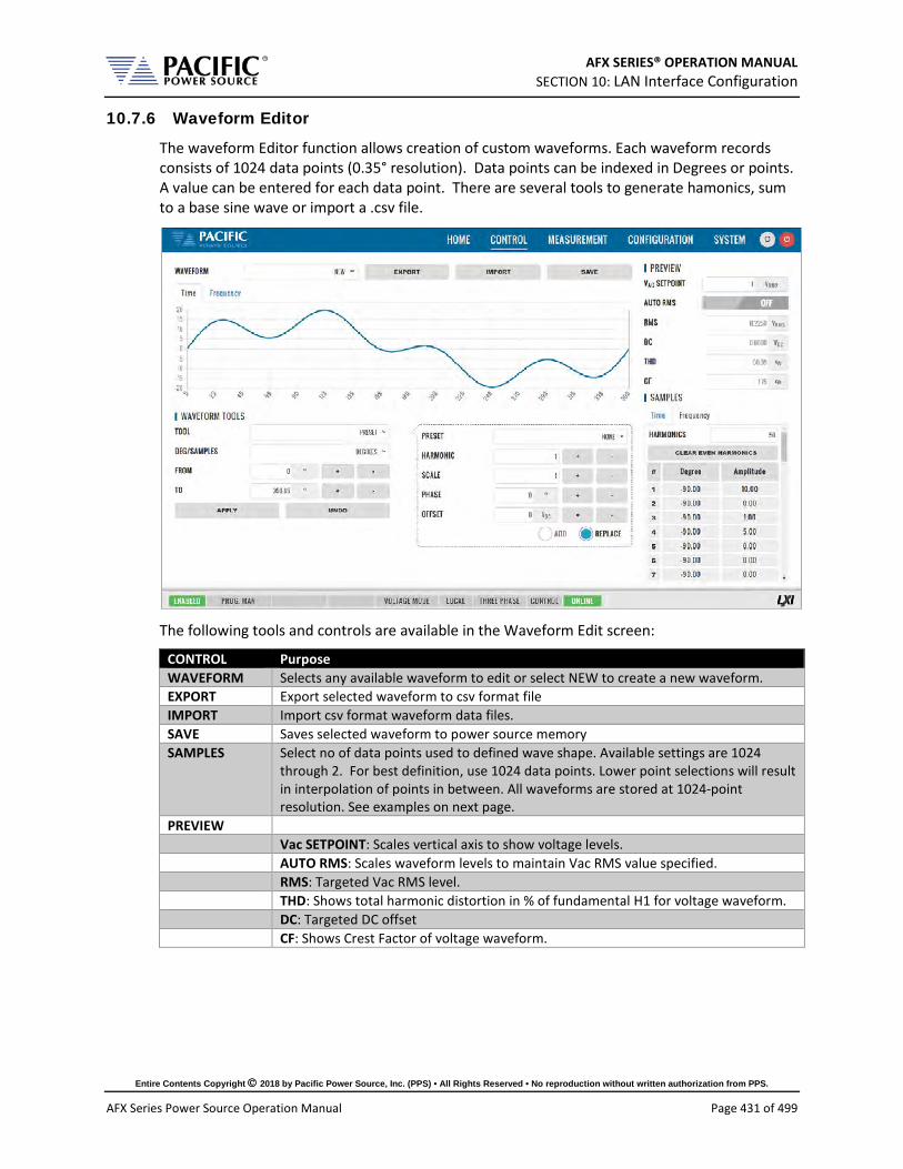
AFX SERIES® OPERATION MANUAL SECTION 10: LAN Interface Configuration
Entire Contents Copyright 2018 by Pacific Power Source, Inc. (PPS) • All Rights Reserved • No reproduction without written authorization from PPS.
AFX Series Power Source Operation Manual Page 431 of 499
10.7.6 Waveform Editor
The waveform Editor function allows creation of custom waveforms. Each waveform records consists of 1024 data points (0.35° resolution). Data points can be indexed in Degrees or points. A value can be entered for each data point. There are several tools to generate hamonics, sum to a base sine wave or import a .csv file.
The following tools and controls are available in the Waveform Edit screen:
CONTROL Purpose WAVEFORM Selects any available waveform to edit or select NEW to create a new waveform. EXPORT Export selected waveform to csv format file IMPORT Import csv format waveform data files. SAVE Saves selected waveform to power source memory SAMPLES Select no of data points used to defined wave shape. Available settings are 1024
through 2. For best definition, use 1024 data points. Lower point selections will result in interpolation of points in between. All waveforms are stored at 1024-point resolution. See examples on next page.
PREVIEW Vac SETPOINT: Scales vertical axis to show voltage levels. AUTO RMS: Scales waveform levels to maintain Vac RMS value specified. RMS: Targeted Vac RMS level. THD: Shows total harmonic distortion in % of fundamental H1 for voltage waveform. DC: Targeted DC offset CF: Shows Crest Factor of voltage waveform.
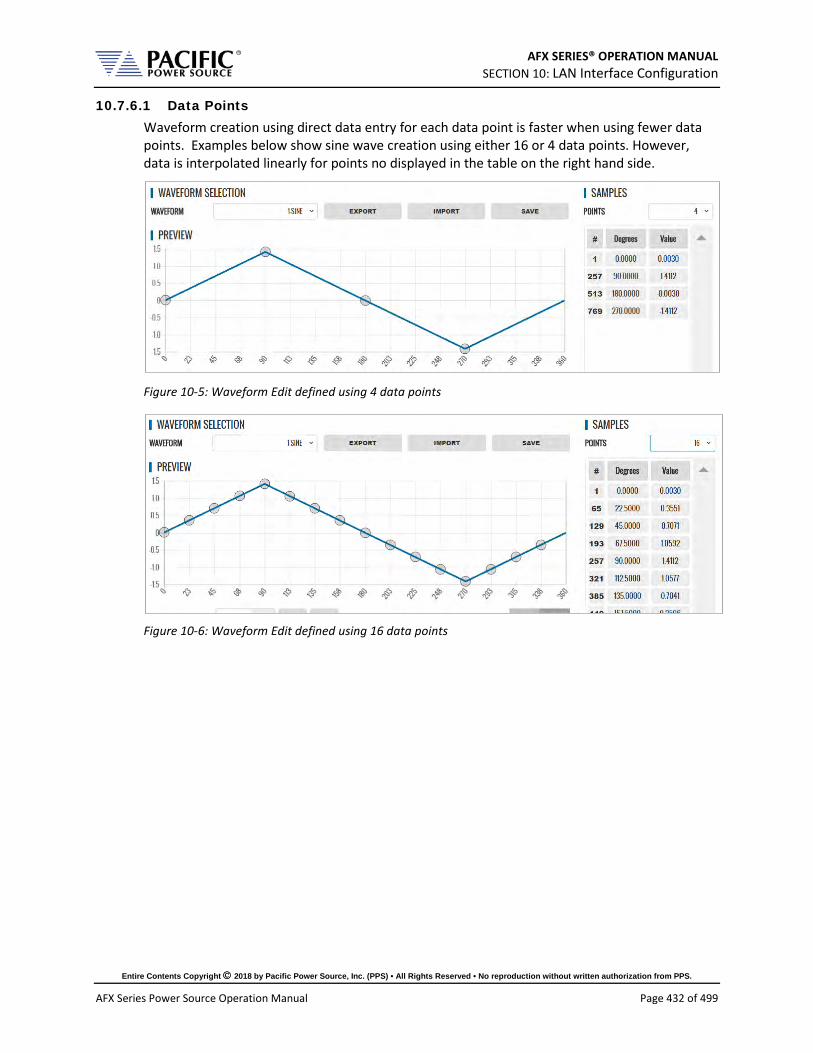
AFX SERIES® OPERATION MANUAL SECTION 10: LAN Interface Configuration
Entire Contents Copyright 2018 by Pacific Power Source, Inc. (PPS) • All Rights Reserved • No reproduction without written authorization from PPS.
AFX Series Power Source Operation Manual Page 432 of 499
10.7.6.1 Data Points Waveform creation using direct data entry for each data point is faster when using fewer data points. Examples below show sine wave creation using either 16 or 4 data points. However, data is interpolated linearly for points no displayed in the table on the right hand side.
Figure 10-5: Waveform Edit defined using 4 data points
Figure 10-6: Waveform Edit defined using 16 data points

AFX SERIES® OPERATION MANUAL SECTION 10: LAN Interface Configuration
Entire Contents Copyright 2018 by Pacific Power Source, Inc. (PPS) • All Rights Reserved • No reproduction without written authorization from PPS.
AFX Series Power Source Operation Manual Page 433 of 499
10.7.6.2 Waveform Tools The following Waveform Tools are available:
CONTROL Purpose TOOLS These selections created specific waveform types without having to define data values
manually. Following functions are available from this drop-down: NORMALIZE Normalizes waveform for zero DC offset. RECTIFY Rectifies the waveform. Only positive data points remain. This implies a
DC offset which is shown in the DC display field below the graph. FREQ MULTIPLY Creates specified number of periods to multiply fundamental frequency.
Use caution with resulting higher frequency waveforms as power source has a finite bandwidth and output may fault if too much high frequency content is present.
OFFSET Applies specified DC offset. SCALE Multiplies all data points by scale factor value. VERTICAL FLIP Flips waveform vertically. HORIZONTAL FLIP Flips waveform horizontally. SMOOTHING FILTER Smooths sharp edges to reduce bandwidth requirements. PRESET Selects built-in waveform types based on user parameters.
PRESETS The following PRESET waveforms are available: NONE Default or no selection made. SINE, TRIANGLE, SQUARE, 6 STEPS, 12 STEPS, SINE POWER, CLIPPED SINE, SAWTOOTH,
PULSE, IMPORTED WAVEFORM PARAMETERS The following parameters are settable for each PRESET selection:
HARMONIC H1 through H32 SCALE Vertical Scale Multiplier PHASE Start phase angle OFFSET DC Offset EXPONENT 1 through 51. Applies to SINE POWER present only. THD 0% through 100%. Applies to CLIPPED SINE only. RISE TIME 0° through 360°. Applies to PULSE preset only. PULSE WIDTH 0° through 360°. Applies to PULSE preset only. FALL TIME 0° through 360°. Applies to PULSE preset only. LOAD FROM FILE Available for IMPORTED WAVEFORM preset only. ADD Add to existing waveform (summation) REPLACE Replace existing waveform with selected PRESET

AFX SERIES® OPERATION MANUAL SECTION 10: LAN Interface Configuration
Entire Contents Copyright 2018 by Pacific Power Source, Inc. (PPS) • All Rights Reserved • No reproduction without written authorization from PPS.
AFX Series Power Source Operation Manual Page 434 of 499
10.7.7 SCPI Script
The SCPI Script menu entry displays the command scripting screen. These user generated scripts can contain any sequence of SCPI commands, comments and output statements to automate simple repetitive tasks. Scripts may be used to automate repetitive tasks more quickly and are simpler to write than an actual application program.
A script can be saved to the PC or tablet on which the browser runs.
10.7.7.1 Supported Keywords and Commands The following script entries are supported:
Entry Type Description USER COMMENT // Any test preceded by a two forward slash characters PRINT Sends text strings after PRINT key word to the OUTPUT window located at the
bottom half of the browser window. WAIT Pauses script execution by no of msecs specified. SCPI COMMAND Any support SCPI command. Data returned by a query command (?) will be
printed in the output window. Table 10-1: Supported Script Entries
10.7.7.2 Script Execution Control To run a script, click the RUN button in the upper left corner of the Editor window. You can also single step through a script during development using the | STEP button. The STOP button will abort execution of a running script. To run a script multiple times, set the REPEAT TIMES value to a value higher than the default 1 (one). Max. repeat count is 1e+54.

AFX SERIES® OPERATION MANUAL SECTION 10: LAN Interface Configuration
Entire Contents Copyright 2018 by Pacific Power Source, Inc. (PPS) • All Rights Reserved • No reproduction without written authorization from PPS.
AFX Series Power Source Operation Manual Page 435 of 499
10.7.7.3 Managing multiple script files. Script files can be saved to the PC or device on which the browser runs, i.e. Windows PC, Tablet, or Smartphone. Use the OPEN and SAVE buttons in the upper right corner of the Editor window to save and retrieve scripts. Scripts are saved in Comma Separated File format, which can be edited in Excel or any text editor like Notepad. The sample script csv file content (scpi_script.cvs) is shown below. When saving a new script, replace the default scpi_script file name with a more descriptive file name.
// Available commands are: // - WAIT MILISECONDS, example -> WAIT 2000 // - PRINT "TEXT", example -> PRINT "Test started" // - SCPI COMMAND/s, example -> OUTP OFF; VOLT 0 // Comments starts with // as this line // The following is an example // Add a mark in the log PRINT "Test started" // Turn off output and set voltage to 0 OUTP OFF; VOLT 0 // Turn on output OUTP 1 // Wait three seconds WAIT 3000 // Set output voltage to 10 volts VOLT 10 // Get output voltage measurement MEAS:VOLT? // Turn off OUTP OFF PRINT "Test completed
10.7.7.4 Script Execution Output The OUTPUT window located in the bottom half of the browser window shows all script output, including any user comments, events like script start and stop as well as any PRINT commands. Each output entry is date and time stamped.
The content of the OUTPUT window can be saved to a Rich Text File using the SAVE button in the upper right corner of the OUTPUT window. (Do not confuse with the SAVE button in the script EDITOR window.) The default output file name is “scpi_script_output.rtf”. A sequence number (1), (2) etc will be appended each time the output window content is saved.
A sample RFT file is shown below.
8/21/2019 8:48:02.172 AM: Test started 8/21/2019 8:48:02.184 AM: Waiting 3000ms. 8/21/2019 8:48:05.190 AM: MEAS:VOLT? 8/21/2019 8:48:05.260 AM: 120.143,118.176,122.147 8/21/2019 8:48:05.262 AM: OUTP OFF 8/21/2019 8:48:05.579 AM: Test completed
Note: All output files are saved to the default Download directory determined by the Browser setting.

AFX SERIES® OPERATION MANUAL SECTION 10: LAN Interface Configuration
Entire Contents Copyright 2018 by Pacific Power Source, Inc. (PPS) • All Rights Reserved • No reproduction without written authorization from PPS.
AFX Series Power Source Operation Manual Page 436 of 499
10.8 Measurement Screens The MEASUREMENT menu provides access to several measurement screens. Measurement screens available are:
• MONITOR • REAL TIME PLOT • WAVEFORMS • V/I PLOT • HARMONICS • DATALOGGER • SCOPE • HARMONICS
Each is described in subsequent sections.
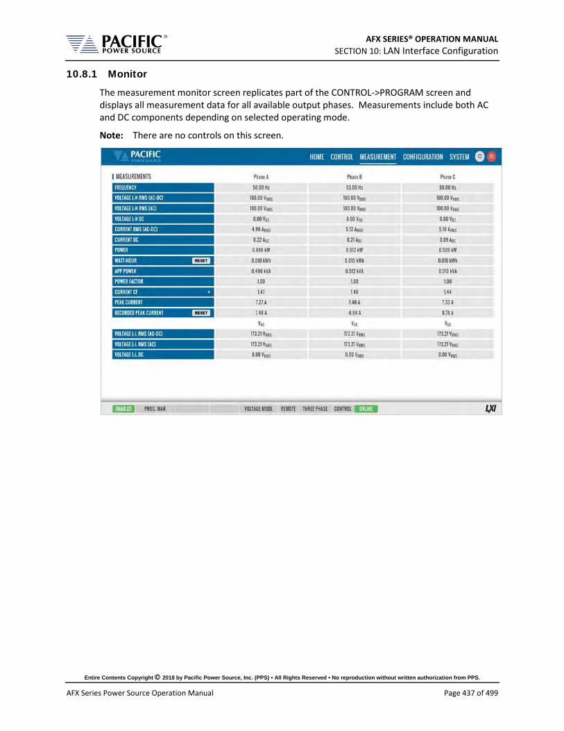
AFX SERIES® OPERATION MANUAL SECTION 10: LAN Interface Configuration
Entire Contents Copyright 2018 by Pacific Power Source, Inc. (PPS) • All Rights Reserved • No reproduction without written authorization from PPS.
AFX Series Power Source Operation Manual Page 437 of 499
10.8.1 Monitor
The measurement monitor screen replicates part of the CONTROL->PROGRAM screen and displays all measurement data for all available output phases. Measurements include both AC and DC components depending on selected operating mode.
Note: There are no controls on this screen.
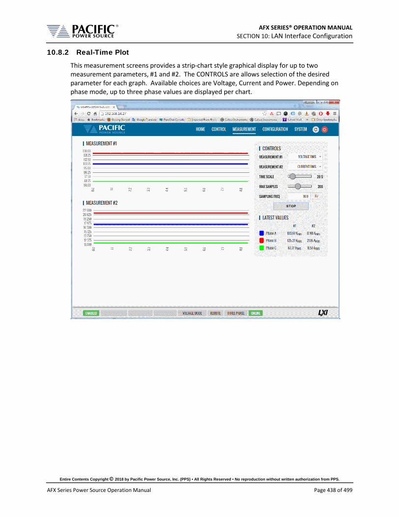
AFX SERIES® OPERATION MANUAL SECTION 10: LAN Interface Configuration
Entire Contents Copyright 2018 by Pacific Power Source, Inc. (PPS) • All Rights Reserved • No reproduction without written authorization from PPS.
AFX Series Power Source Operation Manual Page 438 of 499
10.8.2 Real-Time Plot
This measurement screens provides a strip-chart style graphical display for up to two measurement parameters, #1 and #2. The CONTROLS are allows selection of the desired parameter for each graph. Available choices are Voltage, Current and Power. Depending on phase mode, up to three phase values are displayed per chart.

AFX SERIES® OPERATION MANUAL SECTION 10: LAN Interface Configuration
Entire Contents Copyright 2018 by Pacific Power Source, Inc. (PPS) • All Rights Reserved • No reproduction without written authorization from PPS.
AFX Series Power Source Operation Manual Page 439 of 499
10.8.3 V/I Plot
The V/I plot shows the power operating point at any moment in time by plotting measured Voltage as a function of measured Current. This plot has a persistence mode so the user can observe power fluctuations and changes over a set period.
Available selections in this measurement screen are:
• Persistence Time: 1 ~ 60 sec
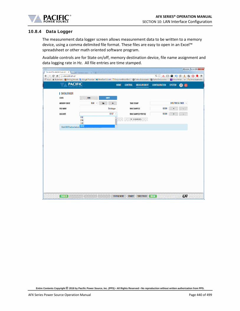
AFX SERIES® OPERATION MANUAL SECTION 10: LAN Interface Configuration
Entire Contents Copyright 2018 by Pacific Power Source, Inc. (PPS) • All Rights Reserved • No reproduction without written authorization from PPS.
AFX Series Power Source Operation Manual Page 440 of 499
10.8.4 Data Logger
The measurement data logger screen allows measurement data to be written to a memory device, using a comma delimited file format. These files are easy to open in an Excel™ spreadsheet or other math oriented software program.
Available controls are for State on/off, memory destination device, file name assignment and data logging rate in Hz. All file entries are time stamped.
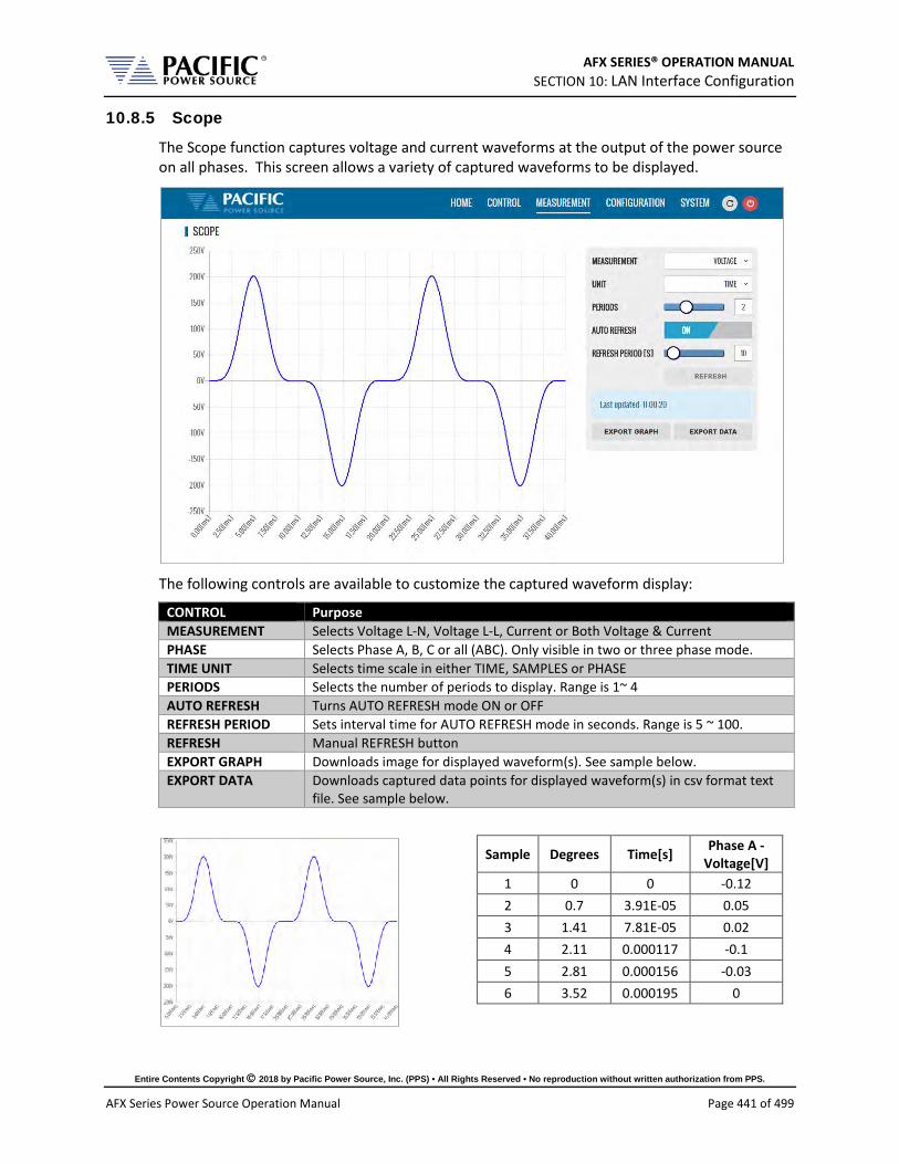
AFX SERIES® OPERATION MANUAL SECTION 10: LAN Interface Configuration
Entire Contents Copyright 2018 by Pacific Power Source, Inc. (PPS) • All Rights Reserved • No reproduction without written authorization from PPS.
AFX Series Power Source Operation Manual Page 441 of 499
10.8.5 Scope
The Scope function captures voltage and current waveforms at the output of the power source on all phases. This screen allows a variety of captured waveforms to be displayed.
The following controls are available to customize the captured waveform display:
CONTROL Purpose MEASUREMENT Selects Voltage L-N, Voltage L-L, Current or Both Voltage & Current PHASE Selects Phase A, B, C or all (ABC). Only visible in two or three phase mode. TIME UNIT Selects time scale in either TIME, SAMPLES or PHASE PERIODS Selects the number of periods to display. Range is 1~ 4 AUTO REFRESH Turns AUTO REFRESH mode ON or OFF REFRESH PERIOD Sets interval time for AUTO REFRESH mode in seconds. Range is 5 ~ 100. REFRESH Manual REFRESH button EXPORT GRAPH Downloads image for displayed waveform(s). See sample below. EXPORT DATA Downloads captured data points for displayed waveform(s) in csv format text
file. See sample below.
Sample Degrees Time[s] Phase A - Voltage[V]
1 0 0 -0.12 2 0.7 3.91E-05 0.05 3 1.41 7.81E-05 0.02 4 2.11 0.000117 -0.1 5 2.81 0.000156 -0.03 6 3.52 0.000195 0

AFX SERIES® OPERATION MANUAL SECTION 10: LAN Interface Configuration
Entire Contents Copyright 2018 by Pacific Power Source, Inc. (PPS) • All Rights Reserved • No reproduction without written authorization from PPS.
AFX Series Power Source Operation Manual Page 442 of 499
Line to Line Capture for all phases.
Voltage and Current can be displayed in one scope screen:

AFX SERIES® OPERATION MANUAL SECTION 10: LAN Interface Configuration
Entire Contents Copyright 2018 by Pacific Power Source, Inc. (PPS) • All Rights Reserved • No reproduction without written authorization from PPS.
AFX Series Power Source Operation Manual Page 443 of 499
10.8.6 Harmonics
Harmonics measurements for voltage and current on all phases can be displayed using the Harmonics display screen as illustrated below. Both Bar Chart and Table displays are shown. The distortion values for the parameter selected (Voltage or Current) are display in a table directly below the Bar chart area.
Available selections in this measurement screen are:
CONTROL Purpose SELECTED PHASE MEASUREMENT TYPE Selects Voltage L-N, Voltage L-L, Current or Both Voltage & Current FROM Selects the first harmonic number to display. Range is 1 ~ 49 TO Selects the last harmonic number to display. Range is 2 ~ 50 AUTO REFRESH Turns AUTO REFRESH mode ON or OFF REFRESH PERIOD Sets interval time for AUTO REFRESH mode in seconds. Range is 5 ~ 100. REFRESH Manual REFRESH button EXPORT GRAPH Downloads image for displayed Bar chart. See sample below. EXPORT DATA Downloads captured harmonics data in csv format text file. See sample
below.
Measurement Phase A[%]
THD 455.98 OHD 354.89 EHD 286.32
# Freq.[Hz] Phase A Mag.[%]
Phase A Phase.[Deg]
1 50 100 75.89 2 100 51.72 60.61 3 150 76.38 70.94 4 200 30.75 329.44 5 250 80.49 243.12 6 300 70.33 18.6 7 350 72.99 257.95 8 400 59.41 268.51

AFX SERIES® OPERATION MANUAL SECTION 10: LAN Interface Configuration
Entire Contents Copyright 2018 by Pacific Power Source, Inc. (PPS) • All Rights Reserved • No reproduction without written authorization from PPS.
AFX Series Power Source Operation Manual Page 444 of 499
10.9 Configuration Screens The CONFIGURATION menu provides access to secondary power source settings that are less frequency changed than those on the PROGRAM screen. Configuration screens available are:
• UNIT SETTINGS • USER LIMITS & PRESETS • RAMP & SLEW
Each is described in subsequent sections.

AFX SERIES® OPERATION MANUAL SECTION 10: LAN Interface Configuration
Entire Contents Copyright 2018 by Pacific Power Source, Inc. (PPS) • All Rights Reserved • No reproduction without written authorization from PPS.
AFX Series Power Source Operation Manual Page 445 of 499
10.9.1 Unit Settings
Unit settings determine the mode of operation of the power source. This includes phase mode, voltage range, output mode, update phase angle and ramp time for any output value changes made.
• Output enable at power on allows the unit to power up with the output enabled. • The Enable Current Overload setting allows short duration overloads up to 30% over the
normal continuous mode current limit set point. • Phase Rotation selection changes output phasing between positive (leading) and
negative (lagging) phase rotation in three phase output mode. • The maximum adjustment limit for continuous self-calibration mode and fault
generation on saturation can be set from this screen as well. • The right hand side of the screen contains Transient mode execution settings, Output
Impedance settings and Series Connection enable / disable (Series mode is only available on AFXS models).
• Language selections are either ENGLIGH or CHINESE.
These can all be set from the CONFIGURATION -> UNIT SETTINGS screen shown below.

AFX SERIES® OPERATION MANUAL SECTION 10: LAN Interface Configuration
Entire Contents Copyright 2018 by Pacific Power Source, Inc. (PPS) • All Rights Reserved • No reproduction without written authorization from PPS.
AFX Series Power Source Operation Manual Page 446 of 499
10.9.2 User Limits & Presets
User limits can be used to minimize operator error by setting upper and/or lower limits on programmable parameter ranges.
Limits can be set for Voltage AC, Voltage DC and Frequency.
Note: When changing user limits, make sure programmed parameter settings in effect are not outside the new upper and lower limits entered.
All user limits can be set from the CONFIGURATION -> USER LIMITS& PRESETS screen shown below.
Extended range for voltage and frequency may be selected as needed. Some restrictions apply when operating in extended range mode.
User programmable presets can be set to define the set values of the Soft keys in the program screens. This allows commonly used setting values to be selected by an operator by just pressing a single soft key. See image above for samples.
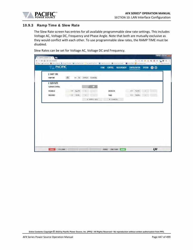
AFX SERIES® OPERATION MANUAL SECTION 10: LAN Interface Configuration
Entire Contents Copyright 2018 by Pacific Power Source, Inc. (PPS) • All Rights Reserved • No reproduction without written authorization from PPS.
AFX Series Power Source Operation Manual Page 447 of 499
10.9.3 Ramp Time & Slew Rate
The Slew Rate screen has entries for all available programmable slew rate settings. This includes Voltage AC, Voltage DC, Frequency and Phase Angle. Note that both are mutually exclusive as they would conflict with each other. To use programmable slew rates, the RAMP TIME must be disabled.
Slew Rates can be set for Voltage AC, Voltage DC and Frequency.

AFX SERIES® OPERATION MANUAL SECTION 10: LAN Interface Configuration
Entire Contents Copyright 2018 by Pacific Power Source, Inc. (PPS) • All Rights Reserved • No reproduction without written authorization from PPS.
AFX Series Power Source Operation Manual Page 448 of 499
10.10 System Screens The SYSTEM menu provides access to system level settings. System setting screens available are:
• ERROR/EVENT QUEUE • FAULT LIST • ERROR/EVENT LIST • INTERFACE SETUP • ACCESS CONTROL • DIGITAL & ANALOG IOS (Note: on A version AFX Models only) • UNIT INFORMATION • PARALLEL UNITS • MEMORY BROWSER • CALIBRATION • REMOTE SUPPORT • IMPORT/EXPORT • FIRMWARE UPDATE • SANITIZE & REBOOT
Each is described in subsequent sections.
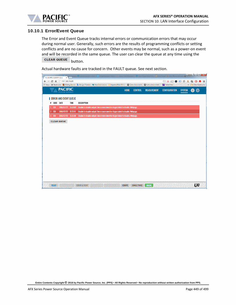
AFX SERIES® OPERATION MANUAL SECTION 10: LAN Interface Configuration
Entire Contents Copyright 2018 by Pacific Power Source, Inc. (PPS) • All Rights Reserved • No reproduction without written authorization from PPS.
AFX Series Power Source Operation Manual Page 449 of 499
10.10.1 Error/Event Queue
The Error and Event Queue tracks internal errors or communication errors that may occur during normal user. Generally, such errors are the results of programming conflicts or setting conflicts and are no cause for concern. Other events may be normal, such as a power-on event and will be recorded in the same queue. The user can clear the queue at any time using the
button.
Actual hardware faults are tracked in the FAULT queue. See next section.
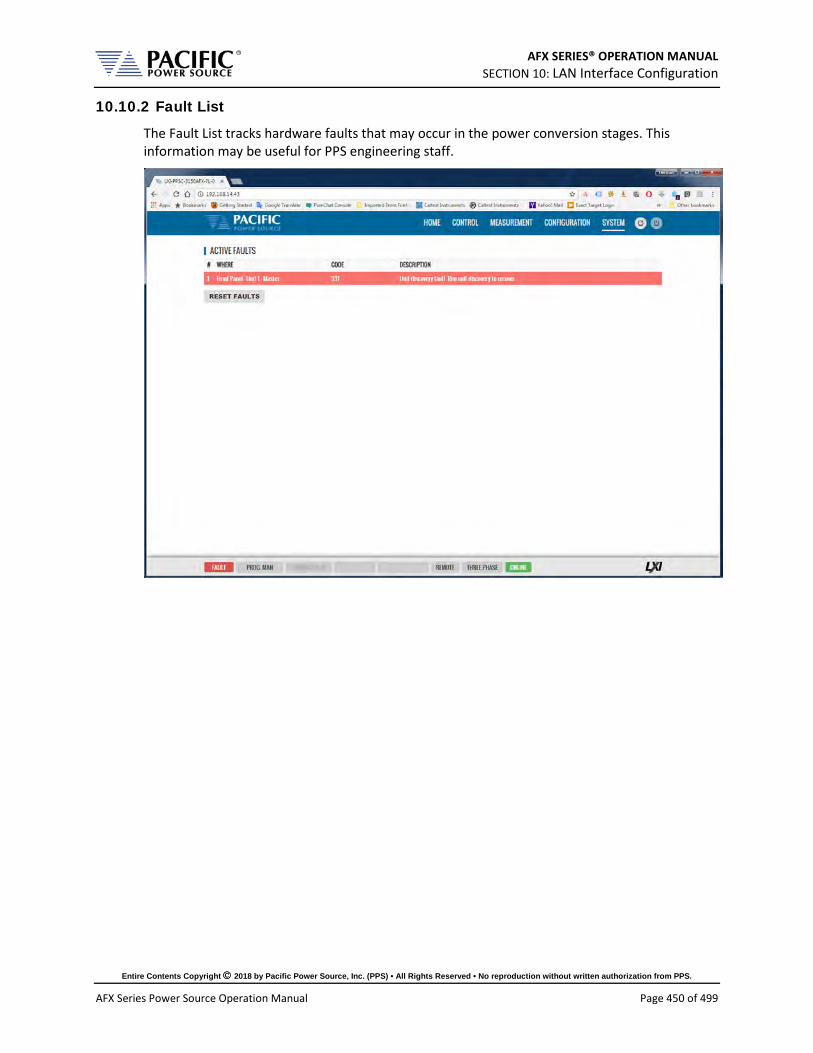
AFX SERIES® OPERATION MANUAL SECTION 10: LAN Interface Configuration
Entire Contents Copyright 2018 by Pacific Power Source, Inc. (PPS) • All Rights Reserved • No reproduction without written authorization from PPS.
AFX Series Power Source Operation Manual Page 450 of 499
10.10.2 Fault List
The Fault List tracks hardware faults that may occur in the power conversion stages. This information may be useful for PPS engineering staff.

AFX SERIES® OPERATION MANUAL SECTION 10: LAN Interface Configuration
Entire Contents Copyright 2018 by Pacific Power Source, Inc. (PPS) • All Rights Reserved • No reproduction without written authorization from PPS.
AFX Series Power Source Operation Manual Page 451 of 499
10.10.3 Error/Event List
The Error Event list provides a complete listing of all possible error and event messages. The description may include possible troubleshooting hints to resolve any error conditions.
Errors are listed in numerical order.

AFX SERIES® OPERATION MANUAL SECTION 10: LAN Interface Configuration
Entire Contents Copyright 2018 by Pacific Power Source, Inc. (PPS) • All Rights Reserved • No reproduction without written authorization from PPS.
AFX Series Power Source Operation Manual Page 452 of 499
10.10.4 Interface Setup
The Interface setup screen allows enabling or disabling of several available interfaces and operating modes. The interfaces are arranged by type:
• LAN • USB • RS232 Serial • GPIB (Note: on A version AFX Models only)
Interfaces that are not used can be turned off to avoid conflicts caused by multiple active interfaces at the user’s discretion.

AFX SERIES® OPERATION MANUAL SECTION 10: LAN Interface Configuration
Entire Contents Copyright 2018 by Pacific Power Source, Inc. (PPS) • All Rights Reserved • No reproduction without written authorization from PPS.
AFX Series Power Source Operation Manual Page 453 of 499
10.10.5 Access Control
The access control screen allows restricting access to the power source over the LAN interface. This is an important requirement for power sources connected to a company wide Ethernet network. Without access restrictions, persons not present where the power source is located could inadvertently cause a dangerous condition by either enabling the OUTPUT or changing programmed settings.
Access control can limit access from specific IP addresses only and requires someone physically present where the power source is to grant access to anyone else.
For more details, refer to section 10.3, “Access Control” on page 412 of this manual.

AFX SERIES® OPERATION MANUAL SECTION 10: LAN Interface Configuration
Entire Contents Copyright 2018 by Pacific Power Source, Inc. (PPS) • All Rights Reserved • No reproduction without written authorization from PPS.
AFX Series Power Source Operation Manual Page 454 of 499
10.10.6 Digital & Analog IO’s
The Digital and Analog IO screen allows configuration of the available Auxiliary I/O functions. Note that this feature is not available on AFX-2L and AFX-4L models.
10.10.6.1 Function Groups There are eight groups of functions that are available to be configured with the selectable settings listed in the table below.

AFX SERIES® OPERATION MANUAL SECTION 10: LAN Interface Configuration
Entire Contents Copyright 2018 by Pacific Power Source, Inc. (PPS) • All Rights Reserved • No reproduction without written authorization from PPS.
AFX Series Power Source Operation Manual Page 455 of 499
Grouping Controls
Analog Inputs:
CHANNEL [ 1 | 2 | 3 | 4 ] INPUT VOLTAGE Displays read back voltage COMMAND Select command from dropdown list
or OFF for none RANGE 0.0000 – 10.000 V GAIN Gain OFFSET Offset value
Analog Outputs:
CHANNEL [ 1 | 2 | 3 | 4 ] OUTPUT VOLTAGE Output setting MEASUREMENT Select measurement to be assigned
to output RANGE 0.0000 – 5.000 V GAIN Gain 0.000 - 1000 OFFSET Offset value – 1000 ~+1000
Digital Inputs:
CHANNEL [ 1 | 2 | 3 ] STATE Displays input state RISING CMD Set command string to execute on
rising edge FALLING CMD Set command string to execute on
falling edge FILTER SIZE 0 – 10,000,000 msec
Digital Outputs:
CHANNEL [ 1 | 2 | 3 | 4 ] STATE Displays current state FUNCTION Assigns state to selected channel.
Available states are: FAULT FORM HIGH LOW OUTPUT STATE PROGRAM REMOTE TRANSIENT
INV. LOGIC [ ON | OFF ] Reverses polarity

AFX SERIES® OPERATION MANUAL SECTION 10: LAN Interface Configuration
Entire Contents Copyright 2018 by Pacific Power Source, Inc. (PPS) • All Rights Reserved • No reproduction without written authorization from PPS.
AFX Series Power Source Operation Manual Page 456 of 499
Grouping Controls
Trigger Input:
STATUS [ ON | OFF ] Enabled or disabled IMMEDIATE [ ON | OFF ] Ignore phase update
setting if ON AUTORUN [ ON | OFF ] No RUN command
required if ON
––Strobe Output:
TRANSIENT ON = Strobe output on transient start
OUTPUT STATE ON = Strobe output on relay close SOURCE ON = Strobe output on any program
parameter change
External Sync:
STATUS Display SYNC Status EXTERNAL SYNC [ ON | OFF ] SYNC SOURCE Select Sync source
Available sources are: - External sync input on I/O connector - LINE (AC input to power source)
PHASE SHIFT Offset Phase A angle SPEED 1.00 ~ 10.00 RANGE 0.10 ~ 500 Hz EXTERNAL SYNC [ ON | OFF ]
Remote Controls:
DISABLED No remote output control REMOTE INHIBIT Contact closure needed to close
output relay REMOTE ENABLE Contact closure or front panel can
control output relay

AFX SERIES® OPERATION MANUAL SECTION 10: LAN Interface Configuration
Entire Contents Copyright 2018 by Pacific Power Source, Inc. (PPS) • All Rights Reserved • No reproduction without written authorization from PPS.
AFX Series Power Source Operation Manual Page 457 of 499
10.10.6.2 On-line Analog and Digital I/O help screens. To aid in configuring and using the many I/O capabilities of the power source, a series of on-line help screens containing formulas and graphs for digital and analog I/Os settings are provided.
Some screens are shown below for reference.
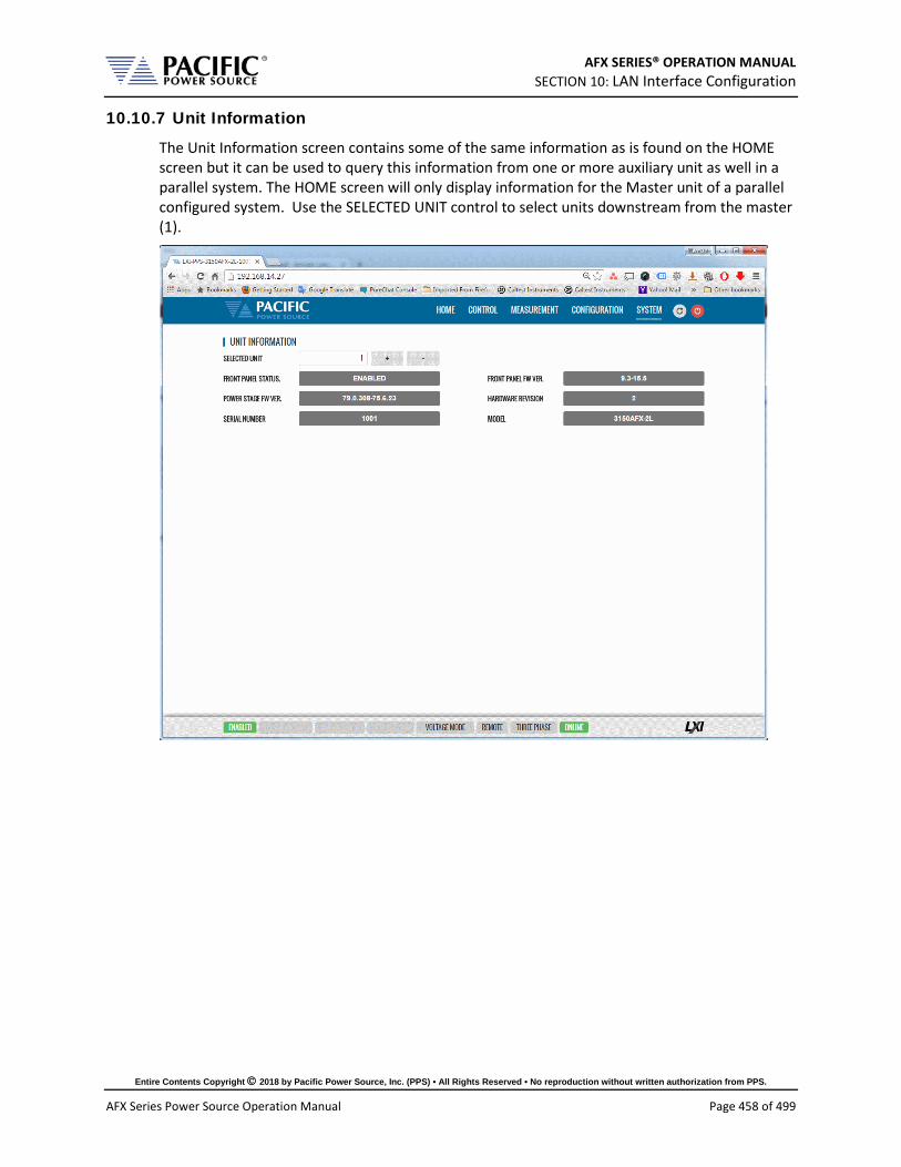
AFX SERIES® OPERATION MANUAL SECTION 10: LAN Interface Configuration
Entire Contents Copyright 2018 by Pacific Power Source, Inc. (PPS) • All Rights Reserved • No reproduction without written authorization from PPS.
AFX Series Power Source Operation Manual Page 458 of 499
10.10.7 Unit Information
The Unit Information screen contains some of the same information as is found on the HOME screen but it can be used to query this information from one or more auxiliary unit as well in a parallel system. The HOME screen will only display information for the Master unit of a parallel configured system. Use the SELECTED UNIT control to select units downstream from the master (1).

AFX SERIES® OPERATION MANUAL SECTION 10: LAN Interface Configuration
Entire Contents Copyright 2018 by Pacific Power Source, Inc. (PPS) • All Rights Reserved • No reproduction without written authorization from PPS.
AFX Series Power Source Operation Manual Page 459 of 499
10.10.8 Parallel Units
The Parallel Units screen displays the number of powered on units in a parallel system. It also allows the expected number of units to be set so the master can determine if all connected units are indeed turned on before starting operation.
The MANUAL DISCOVERY can be run to refresh the parallel confirmation is a unit has been turned on or off without power cycling the master.

AFX SERIES® OPERATION MANUAL SECTION 10: LAN Interface Configuration
Entire Contents Copyright 2018 by Pacific Power Source, Inc. (PPS) • All Rights Reserved • No reproduction without written authorization from PPS.
AFX Series Power Source Operation Manual Page 460 of 499
10.10.9 Memory Browser
The Memory Browser screen shows available memory devices connected to the instrument including internal memory and available directories and files. All data and setup files are in XML format. Waveform files are stored in CSV format. Screen captures are stored in PNG image format.
Available MEMORY DRIVES are INTERNAL, RAM and any USB or SD-Card memory devices that are mounted. Files can be copied or move from other drives by using drag & drop or by selecting them. Files can also be uploading using a file selection window dialog.
Useful directories for the user are:
DIRECTOR FILES IN THIS DIRECTORY plot/ Data logger plots in csv file format with date and time stamp program/ Power source program settings screenshots/ Screen capture image files in .png format with date and time stamp. To
capture any LCD display, press the LOCAL key and the number 1 key on the decimal keypad at the same time.
waveforms/ User waveform data points in csv file format.
10.10.9.1 Screenshots Screenshots of the LDC display saved by pressing the LOCAL + 1 key simultaneously are saved in the screenshots subdirectory. The controls in the Actions column allow the user to:
Delete Download Preview

AFX SERIES® OPERATION MANUAL SECTION 10: LAN Interface Configuration
Entire Contents Copyright 2018 by Pacific Power Source, Inc. (PPS) • All Rights Reserved • No reproduction without written authorization from PPS.
AFX Series Power Source Operation Manual Page 461 of 499
10.10.10 Calibration
The Calibration screen shows all user accessible calibration coefficients. It also allows for user calibration of voltage and current to be performed. The Web Browser user interface is specific but the procedures and equipment are the same as calibration from the front panel. Refer to Section 11.4, “Calibration Procedures” for details.

AFX SERIES® OPERATION MANUAL SECTION 10: LAN Interface Configuration
Entire Contents Copyright 2018 by Pacific Power Source, Inc. (PPS) • All Rights Reserved • No reproduction without written authorization from PPS.
AFX Series Power Source Operation Manual Page 462 of 499
10.10.11 Remote Support
The Remote Control screen allows Pacific Power’s technical support staff to access the unit remotely if granted permission. Internet access is required for this feature.
10.10.12 Import / Export
A compressed file containing complete system configuration data for the power source can be exported to a file and imported back into the unit as needed. Files are .7z compressed to maximize storage space. Use the Export button on the right to export (save) current configuration data. Use the Browse button to select and import (load) a previously saved configuration file.

AFX SERIES® OPERATION MANUAL SECTION 10: LAN Interface Configuration
Entire Contents Copyright 2018 by Pacific Power Source, Inc. (PPS) • All Rights Reserved • No reproduction without written authorization from PPS.
AFX Series Power Source Operation Manual Page 463 of 499
10.10.13 Firmware Update
The Firmware update screen can be used to install new firmware for a file. New firmware may be distributed by email or from Pacific’s FTP site. Note that the OUTPUT of the unit must be OFF to perform a firmware update.
If you received a firmware image file (.img extension):
• Use the button to select it from the drive location you saved it to.
• Then use the button to upload new firmware to the power source.
To install new firmware from the Pacific Power FTP server:
• Click the button.

AFX SERIES® OPERATION MANUAL SECTION 10: LAN Interface Configuration
Entire Contents Copyright 2018 by Pacific Power Source, Inc. (PPS) • All Rights Reserved • No reproduction without written authorization from PPS.
AFX Series Power Source Operation Manual Page 464 of 499
10.10.14 Sanitize and Reboot
This screen allows the unit to be cleared of all user settings. This applies to waveforms, settings, transients etc. The unit will be reset to factory default conditions.
The Reboot allows the power source to be rebooted (reset) without cycling AC input power.
10.11 Additional Functions Additional function may be added over time through firmware updates that may not be covered by this user manual revision. If so, check the Pacific Power website for update manual versions. ( www.pacificpower.com ).
10.11.1 Sharing Options – FTP & SAMBA
Units with firmware revision 2.1.0 or higher support a network based sharing feature. Two protocols. These can be enabled from the Sharing Options screen. For more details, refer to Section 6.8.5.9, “REMOTE SHARING” on page 183.

AFX SERIES® OPERATION MANUAL SECTION 11: Calibration
Entire Contents Copyright 2018 by Pacific Power Source, Inc. (PPS) • All Rights Reserved • No reproduction without written authorization from PPS.
AFX Series Power Source Operation Manual Page 465 of 499
11 Calibration
11.1 Calibration Interval All units are shipped new from the factory with NIST traceable calibration. It is recommended to perform an annual calibration check to ensure performance to specifications. Under normal circumstances, no adjustment will be needed but can be made as part of the user calibration coefficients.
11.2 Closed Case User Calibration This section covers routine calibration that can be performed by the user. User calibration does not affect the factory set calibration coefficients that were determined and set at the time of shipment to ensure compliance with published specifications. Rather, user calibration can be used to obtain enhanced performance at typical operating conditions by adjusting these user coefficients at these conditions. For example, if the unit is used primary for testing 400Hz, three phase 115V L-N three phase operation, calibrating the user coefficients to these operating conditions against an external precision reference can provide enhanced performance versus published specifications (See Section 4, “Technical Specifications”).
Since user calibration does not affect factory calibration settings, resetting all user calibration coefficients does not invalidate the units specified performance and it can be used with all user coefficients reset as needed.
Note: There are no analog adjustment pots in this instrument and all calibration can be performed from the front panel or over one of the digital control interfaces.
11.3 Equipment Required The following list of equipment or equivalent is required to perform routine annual calibration of the instrument. Current sensor options are determined by need for AC, DC or both.
Item Make Model Notes 1 Keysight 34465A 6 ½ Digit DMM or equivalent 2 Current Transformer
(AC Only) Pearson Model 110, 65 Arms Max. 5000Apk Max. 0.1V/A +1/-
0%, Rout = 50 Ohms http://www.pearsonelectronics.com/products/current-monitors
3 Current Sensor (AC and DC)
LEM IT 200-S ULTRASTAB, 200 A, ± 0.0086% Accuracy, 50 kHz BW or equivalent. http://www.lem.com/hq/en/component/option,com_catalog/task,displaymodel/id,71.36.44.000.0/ Requires precision burden resistor for direct DMM measurements, i.e. Reidon, P/N SM10-100RX, 0.01% 100 Ohm, 0.3W, qty 2 or 3 in parallel for 50 Ohm or 33.3 Ohm burden https://www.digikey.com/product-detail/en/riedon/SM10-100RX/696-1568-ND/4832952
4 Current Shunt (DC)
Ohm-Labs CS-200, Shunt, 1 mOhm, 0.02% Accuracy @ DC to 50/60 Hz or equivalent http://www.ohm-labs.com
Table 11-1: Required Calibration Equipment

AFX SERIES® OPERATION MANUAL SECTION 11: Calibration
Entire Contents Copyright 2018 by Pacific Power Source, Inc. (PPS) • All Rights Reserved • No reproduction without written authorization from PPS.
AFX Series Power Source Operation Manual Page 466 of 499
11.4 Calibration Procedures Calibration of output and measurements is performed by a single procedure so there is no need to calibrate each separately. Calibration involves voltage and current full scale and offset on each phase. For three-phase mode, this means there are twelve calibration points, for single-phase mode, there are four.
The calibration can be performed manually using the Calibration menu (refer to Section 6.8.9 for the location of the Calibration menu) or through the build-in web server using the web browser interface. Refer to Section 10.10.10, “Calibration” for access to the Web based calibration screens.
11.4.1 Voltage Calibration - Offset
AC LineInput
DMM (optional)
A B C N N N
Short A, B & C to N for Voltage Offset
Calibration
Table 11-2: Setup for Voltage Offset Calibration
The procedure to calibrate voltage offset is:
1. Select the Calibration entry from the “System” menu
2. Press the “Calibrate” soft key to enter calibration mode

AFX SERIES® OPERATION MANUAL SECTION 11: Calibration
Entire Contents Copyright 2018 by Pacific Power Source, Inc. (PPS) • All Rights Reserved • No reproduction without written authorization from PPS.
AFX Series Power Source Operation Manual Page 467 of 499
3. Short all phases to neutral using a shorting jumper
4. You can connect the DMM to the output of phase A as shown in the figure above but it is not required for this calibration step.
5. IMPORTANT: Program both AC and DC voltage (depending on voltage mode) to all zero volts to avoid any current from flowing into the shorted outputs. Use PROGRAM screen to make sure both AC and DC settings are zero.
6. Enable the Output with the output shored.
7. Press "Cal V. offset" soft key
8. Wait for the V offset coefficients for all phases to be calculated and displayed
9. Remove the shorting jumper when done
Note: The Mode, Voltage and Current edit boxes do not affect this function.
11.4.2 Current Calibration - Offset
The procedure to calibrate current offset is:
1. Select the Calibration entry from the “System” menu
2. Press the “Calibrate” soft key to enter calibration mode
3. Do not connect any load to the output
4. Enable the Output with no load connected
5. Press "Cal I. offset" soft key
6. Wait for the I offset coefficients for all phases to be calculated and displayed
Note: The Mode, Voltage and Current edit boxes do not affect this function.

AFX SERIES® OPERATION MANUAL SECTION 11: Calibration
Entire Contents Copyright 2018 by Pacific Power Source, Inc. (PPS) • All Rights Reserved • No reproduction without written authorization from PPS.
AFX Series Power Source Operation Manual Page 468 of 499
11.4.3 Voltage Calibration - Gain
AC LineInput
DMM Figure 11-1: Voltage Calibration Equipment Setup – 1 or 3 Phase Mode – Phase A
The procedure to calibrate voltage gain is:
1. Select the Calibration entry from the “System” menu
2. Press the “Calibrate” soft key to enter calibration mode
3. Do not connect any load to the output
4. Program AC voltage to full scale 300.0 Vrms L-N for AC mode calibration or 425Vdc for DC mode calibration on all phases. Use the PROGRAM screen for this.
5. For AC mode calibration, set the Frequency to the most commonly used value depending on typical applications
6. NOTE: If the user calibration is targeted for specific operating conditions, for example Vac = 115V L-N and Freq = 400 Hz, use these settings instead of those suggested in steps 4 and 5

AFX SERIES® OPERATION MANUAL SECTION 11: Calibration
Entire Contents Copyright 2018 by Pacific Power Source, Inc. (PPS) • All Rights Reserved • No reproduction without written authorization from PPS.
AFX Series Power Source Operation Manual Page 469 of 499
7. Enable the Output with no load connected
8. Enter the DMM VAC readings for all three phase in the respective Voltage data entry text boxes in the Calibration screen. Move the DMM probe from phase A, to B to C respectively to obtain each phase reading.
9. Press "Cal V. gain" soft key
10. Wait for the V gain coefficients for all phases to be calculated and displayed
Note: Voltage gain can be calibrated in DC mode as well if this is the predominant mode of use. Use the MODE fields at the top to select the desired mode.
11.4.4 Current Gain Calibration Setup Diagrams
For current calibration, a resistive load equivalent to 90% of maximum available RMS phase current for the phase mode selected is recommended. It is permissible to use only one load and move it between phases for three-phase mode calibration. For single-phase mode current calibration, a load capable of supporting 90% of maximum available single-phase current is recommended. The A, B and C outputs must be shorted together for single-phase mode operation. The optional Single Phase Shorting Connecter (P/N 160086) can be used to accomplish this.
Note: To guarantee that the current doesn’t change during the calibration process, it is recommended that the unit is operated at current limit, but reducing its set point to the desired value. It is also recommended to use a stable load that provides a constant linear impedance to the unit.
A suitable current shunt must be connected in series with the load as shown below for three-phase mode. The sense terminals of the current shunt must be connected to the DMM Voltage input.
Three Phase Mode Setup
AC LineInput
DMM
Hi Sense
Lo Sense
R Load
A B C N N N
Figure 11-2: Current Calibration Equipment Setup – 3 Phase Mode – Phase A

AFX SERIES® OPERATION MANUAL SECTION 11: Calibration
Entire Contents Copyright 2018 by Pacific Power Source, Inc. (PPS) • All Rights Reserved • No reproduction without written authorization from PPS.
AFX Series Power Source Operation Manual Page 470 of 499
Single Phase Mode Setup
For Single-phase mode current Calibration, the load must have the appropriate size. See next section for recommended load value by model and phase mode.
AC LineInput
DMM
Hi Sense
Lo Sense
Use optional P/N 160086 Single Phase Mode Shorting Connector
R Load
A B C N N N
Figure 11-3: Current Calibration Equipment Setup – 1 Phase Mode
11.4.1 Current Calibration Load Values
Full-scale current gain calibration is best performed at current levels that are around 90% of full scale current. Since the AFX Series® has only a single voltage range, maximum RMS current is available at 120Vrms L-N for each phase. For single-phase mode, the current is three times higher. Thus, to obtain 90% of load current, resistor value that is sized to draw this current level at around 120Vrms is required. Since the maximum current varies by model and phase mode, the table below shows the recommended resistor values or resistive load bank settings.
Three & Two Phase Mode Single Phase Mode
Model Rating/phs
VA/W Max.
Irms/phs
Calibration Current (90%)
Recommended R Load (Ohm)
Max/ Irms
Calibration Current (90%)
Recommended R Load (Ohm)
360AFX 2000 16.7 15 8.00 50 45 2.67
390AFX 3000 25.0 23 5.33 75 68 1.78
3120AFX 4000 33.3 30 4.00 100 90 1.33
3150AFX 5000 41.7 38 3.20 125 113 1.07
3180AFX 6000 50.0 45 2.67 150 135 0.89
3240AFX 8000 66.7 60 2.00 200 180 0.67
3300AFX 10000 83.3 75 1.60 250 225 0.53
3450AFX 15000 125.0 113 1.07 375 338 0.36
3600AFX 20000 166.7 150 0.80 500 450 0.27 Table 11-3: Calibration Load Values by Model and Phase Mode

AFX SERIES® OPERATION MANUAL SECTION 11: Calibration
Entire Contents Copyright 2018 by Pacific Power Source, Inc. (PPS) • All Rights Reserved • No reproduction without written authorization from PPS.
AFX Series Power Source Operation Manual Page 471 of 499
11.4.2 Current Calibration - Gain
The procedure to calibrate current gain is:
1. Select the Calibration entry from the “System” menu
2. Press the “Calibrate” soft key to enter calibration mode
3. Connect the required resistive load value to the output of phase A or all three outputs if three loads are available.
4. Program AC voltage to 120.0 Vrms L-N on all phases
5. Set the Frequency to the most commonly used value depending on typical applications
6. Enable the Output
7. Allow the load current to stabilize by monitoring the DMM current reading for each phase.
8. Enter the DMM VAC readings for all three phase in the respective Current data entry text boxes in the Calibration screen. If only one shunt and load is available, repeat the above steps for phase B and C making sure to turn OFF the output before moving the load and shunt to the next phase.
9. Press "Cal I. gain" soft key
10. Wait for the I gain coefficients for all phases to be calculated and displayed
Note: Current gain can be calibrated in DC mode as well if this is the predominant mode of use. Use the MODE fields at the top to select the desired mode.
11.4.3 Exit Calibration Mode
To exit the calibration mode once done, press the “Back” software.

AFX SERIES® OPERATION MANUAL SECTION 13: Service and Maintenance
Entire Contents Copyright 2018 by Pacific Power Source, Inc. (PPS) • All Rights Reserved • No reproduction without written authorization from PPS.
AFX Series Power Source Operation Manual Page 472 of 499
12 Warnings & Error Messages
12.1 Preface During normal operation, a series of error and/ or warning messages may be displayed on the front panel LCD display or reported by the error queue over one of the remote control interfaces. This section of the manual lists available warning and error messages in numerical order and provided some additional information on their meaning and possible causes. Where relevant, suggested remedies to resolve any conditions are included as well.
Note: There are some Error and Warning messages that may appear in the Errors & Events that are NOT listed in the next section. In case you encounter an unlisted error or warning message and code, contact Pacific Power customer service ([email protected]) and describe the number and description to obtain further information. After reporting such an event, try rebooting the power sources by cycling power as most of these conditions will clear up with a reboot.
12.2 Errors & Warnings Messages in Numeric Order Error Source Code Category Error Message Possible Cause Resolution Front panel -500 SCPI event Event: Power ON. Power on event detected.
Normal after power on Not needed
Front panel -360 SCPI error Communication error with an interface.
Internal Communication Error between front panel and power stage. Bad connection
Try recycling power. If error persists, contact customer service
Front panel -350 SCPI event Error & Event (E&E) queue overflow.
Events and Error queue is full. Too many errors or events
Clear the Error & Event (E&E) Queue
Front panel -320 SCPI error Storage fault. Memory error detected by front panel processor. Memory Checksum error
Try recycling power. If error persists, contact customer service
Front panel -310 SCPI error System error Unknown System Error. Cause Undetermined
Try recycling power. If error persists, contact customer service
Front panel Error
-290 SCPI error Execution error: Memory use error.
Incorrect Memory Access. Cause Undetermined
Try recycling power. If error persists, contact customer service
Front panel Error
-286 SCPI error Execution error: Not allowed command with the current configuration.
Configuration setting related conflict.
Check configuration settings
Front panel Error
-285 SCPI error Execution error: Program syntax error.
Incorrect command syntax
Check syntax
Front panel Error
-284 SCPI error Execution error: Program is currently running.
Trying to start a program that is already running
Front panel Error
-282 SCPI error Execution error: Invalid program name.
Invalid program name passed. Special characters are not allowed in program names
Use names containing letters and numbers only
Front panel Error
-281 SCPI error Execution error: Cannot create program.
Request to create new program rejected. Program data sent is not correct
Check program content

AFX SERIES® OPERATION MANUAL SECTION 13: Service and Maintenance
Entire Contents Copyright 2018 by Pacific Power Source, Inc. (PPS) • All Rights Reserved • No reproduction without written authorization from PPS.
AFX Series Power Source Operation Manual Page 473 of 499
Error Source Code Category Error Message Possible Cause Resolution Front panel Error
-256 SCPI error Execution error: File not found.
File specified does not exist
Check for correct file name
Front panel Error
-253 SCPI error Execution error: Media is corrupted.
Media used has been corrupted
Reformat or replace media
Front panel Error
-240 SCPI error Execution error: Hardware error.
Unspecified Hardware Error detected. Cause unknown
Try recycling power. If error persists, contact customer service
Front panel Error
-224 SCPI error Execution error: Illegal parameter value.
Invalid parameter value Check value
Front panel Error
-222 SCPI error Execution error: Argument out of range.
Argument passed exceeds allowable range
Adjust parameter to be within valid range
Front panel Error
-221 SCPI error Execution error: Conflict in configuration setting.
Configuration setting conflict
Check configuration settings
Front panel Error
-203 SCPI error Execution error: Permission denied.
Read or Write access to memory selected denied. Some memory areas are off limits
Check memory type or permissions
Front panel Error
-158 SCPI error Command error: String data is not allowed.
Passing string data when string type is not supported
Pass correct data type
Front panel Error
-138 SCPI error Command error: Numeric suffix is invalid.
Number suffix not valid Check value
Front panel Error
-131 SCPI error Command error: Numeric suffix is out of range.
Suffix number passed exceeds allowable range
Adjust suffix to be within valid range
Front panel Error
-113 SCPI error Command error: Undefined header.
Command Header not defined
Check command
Front panel Error
-109 SCPI error Command error: Invalid number of parameters.
Invalid number of parameters. Too few or too many parameters are being passed
Check for correct no. of parameters
Front panel Error
-108 SCPI error Command error: Parameters error.
Errors in parameters Check parameter values
Front panel Error
-103 SCPI error Command error: Invalid separator.
Separator used is invalid Use correct separator character
Front panel Error
-102 SCPI error Command error: Syntax error.
Syntax Error Check syntax
Front panel Error
53 Error Error during firmware update.
Firmware Update Error. Update may have failed
Check for correct firmware image file and version.
Front panel Error
54 Error Calibration coefficient cannot be negative.
Negative Calibration Coefficients are not allowed
Make sure cal coefficients are positive values
Front panel Error
56 Error Waveform name is not available.
Waveform name requested does not exist
Use existing waveform name from waveform library
Front panel Error
57 Error Waveform file is not available.
Waveform register selected is empty
Download valid waveform data to selected register
Front panel Error
58 Error Waveforms lengths are different between inverter controllers.
Waveforms lengths are not equal between three phases
Check waveform data for correct length
Front panel Error
59 Error Unit does not exist. Unit selected cannot be found
Try recycling power. If error persists, contact customer service
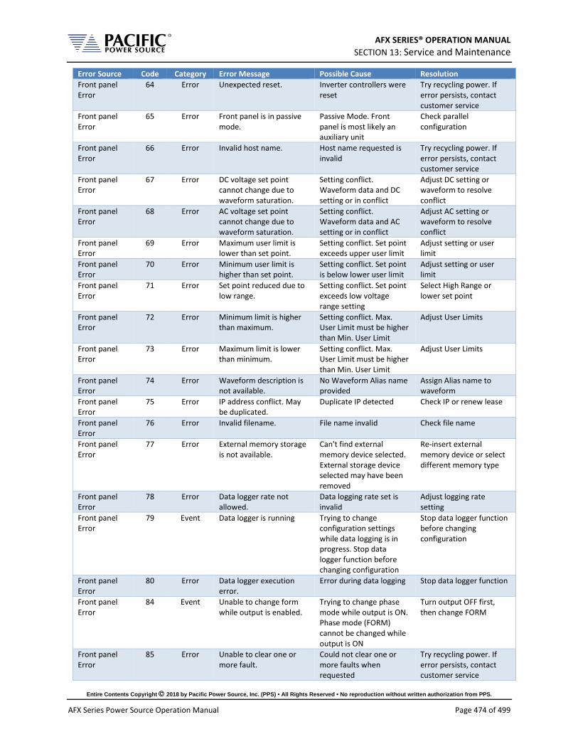
AFX SERIES® OPERATION MANUAL SECTION 13: Service and Maintenance
Entire Contents Copyright 2018 by Pacific Power Source, Inc. (PPS) • All Rights Reserved • No reproduction without written authorization from PPS.
AFX Series Power Source Operation Manual Page 474 of 499
Error Source Code Category Error Message Possible Cause Resolution Front panel Error
64 Error Unexpected reset. Inverter controllers were reset
Try recycling power. If error persists, contact customer service
Front panel Error
65 Error Front panel is in passive mode.
Passive Mode. Front panel is most likely an auxiliary unit
Check parallel configuration
Front panel Error
66 Error Invalid host name. Host name requested is invalid
Try recycling power. If error persists, contact customer service
Front panel Error
67 Error DC voltage set point cannot change due to waveform saturation.
Setting conflict. Waveform data and DC setting or in conflict
Adjust DC setting or waveform to resolve conflict
Front panel Error
68 Error AC voltage set point cannot change due to waveform saturation.
Setting conflict. Waveform data and AC setting or in conflict
Adjust AC setting or waveform to resolve conflict
Front panel Error
69 Error Maximum user limit is lower than set point.
Setting conflict. Set point exceeds upper user limit
Adjust setting or user limit
Front panel Error
70 Error Minimum user limit is higher than set point.
Setting conflict. Set point is below lower user limit
Adjust setting or user limit
Front panel Error
71 Error Set point reduced due to low range.
Setting conflict. Set point exceeds low voltage range setting
Select High Range or lower set point
Front panel Error
72 Error Minimum limit is higher than maximum.
Setting conflict. Max. User Limit must be higher than Min. User Limit
Adjust User Limits
Front panel Error
73 Error Maximum limit is lower than minimum.
Setting conflict. Max. User Limit must be higher than Min. User Limit
Adjust User Limits
Front panel Error
74 Error Waveform description is not available.
No Waveform Alias name provided
Assign Alias name to waveform
Front panel Error
75 Error IP address conflict. May be duplicated.
Duplicate IP detected Check IP or renew lease
Front panel Error
76 Error Invalid filename. File name invalid Check file name
Front panel Error
77 Error External memory storage is not available.
Can't find external memory device selected. External storage device selected may have been removed
Re-insert external memory device or select different memory type
Front panel Error
78 Error Data logger rate not allowed.
Data logging rate set is invalid
Adjust logging rate setting
Front panel Error
79 Event Data logger is running Trying to change configuration settings while data logging is in progress. Stop data logger function before changing configuration
Stop data logger function before changing configuration
Front panel Error
80 Error Data logger execution error.
Error during data logging Stop data logger function
Front panel Error
84 Event Unable to change form while output is enabled.
Trying to change phase mode while output is ON. Phase mode (FORM) cannot be changed while output is ON
Turn output OFF first, then change FORM
Front panel Error
85 Error Unable to clear one or more fault.
Could not clear one or more faults when requested
Try recycling power. If error persists, contact customer service

AFX SERIES® OPERATION MANUAL SECTION 13: Service and Maintenance
Entire Contents Copyright 2018 by Pacific Power Source, Inc. (PPS) • All Rights Reserved • No reproduction without written authorization from PPS.
AFX Series Power Source Operation Manual Page 475 of 499
Error Source Code Category Error Message Possible Cause Resolution Front panel Error
86 Error Unable to enable output. One or more primary stages failed to enable.
Output ON failed due to power input stage fault
Try recycling power. If error persists, contact customer service
Front panel Error
89 Error Digital I/O interface conflict: Remote inhibit is active.
Conflict between front panel and Remote Inhibit input level
Resolve conflict. Check input to Remote Inhibit
Front panel Error
90 Error Digital I/O interface conflict: Remote enable is active.
Conflict between front panel and Remote Enable input level
Resolve conflict. Check input to Remote Enable
Front panel Error
91 Error Internal error: Unknown phase mode.
Selected Phase Mode (FORM) is unknown
Try recycling power. If error persists, contact customer service
Front panel Error
92 Error Unable to disable output. One or more primary stages failed to disable.
Output OFF failed. Attempt to disable one or more inverter stages failed
Turn Unit off with Circuit Breaker
Front panel Error
93 Error Internal error: Cannot configure timer.
Timer Configuration Error Reset front panel
Front panel Error
94 Error Internal error: Cannot create timer.
Timer Creation Error Reset front panel
Front panel Error
95 Error Digital I/Os interface conflict: Serial interface flow control is active.
RS232 or USB interface error
Check RS232 or USB settings
Front panel Error
96 Error Data logger storage error. Error saving measurement data to selecting memory device. Memory device may have been removed
Check for Memory device presence
Front panel Error
97 Error Output enable in progress.
Waiting to turn output off. Changing from Output ON to Output OFF state
Wait for power stages and inverters to fully engage
Front panel Error
98 Error DC Voltage not allowed in "AC mode".
Setting conflict. Setting does not match mode
Check setting
Front panel Error
99 Error AC Voltage not allowed in "DC mode".
Setting conflict. Setting does not match mode
Check setting
Front panel Error
100 Error DC voltage set point cannot change due to user limit.
Setting conflict. Setting outside of User Limits
Check setting
Front panel Error
101 Error AC voltage set point cannot change due to user limit.
Setting conflict. Setting outside of User Limits
Check setting
Front panel Error
102 Error DC voltage set point cannot change due to low range.
Setting conflict. Setting outside of User Limits
Check setting
Front panel Error
103 Error AC voltage set point cannot change due to low range.
Setting conflict. Setting outside of User Limits
Check setting
Front panel Error
104 Error Waveform change in progress.
Waveform change in progress
Wait
Front panel Error
105 Error Error changing service name
Internal Service Error. Could not change service
Try recycling power. If error persists, contact customer service
Front panel Error
106 Error Error getting service name
Internal Service Error. Could not get service name
Try recycling power. If error persists, contact customer service

AFX SERIES® OPERATION MANUAL SECTION 13: Service and Maintenance
Entire Contents Copyright 2018 by Pacific Power Source, Inc. (PPS) • All Rights Reserved • No reproduction without written authorization from PPS.
AFX Series Power Source Operation Manual Page 476 of 499
Error Source Code Category Error Message Possible Cause Resolution Front panel Error
107 Error Redundant segments were combined.
Optimization. Segment data received contained redundant segments which were removed
Not needed
Front panel Error
108 Error Redundant steps were combined.
Optimization. List Step data received contained redundant steps which were removed
Not needed
Front panel Error
109 Error Transient step mode not available on UPC compatible mode.
Setting conflict. Step mode only supported in AFX mode.
Switch to AFX mode or use Segments
Front panel Error
110 Error System is about to reboot.
Warning, Reboot imminent
Wait
Front panel Error
111 Error Cannot reboot system. Soft reboot failed. Front panel could not reboot itself.
Try recycling power. If error persists, contact customer service
Front panel Error
115 Error Unable to renew the DHCP lease. Changing to Auto-IP mode.
LAN Error. IP address lease from DHCP expired
Renew IP lease of use Auto IP mode
Front panel Error
116 Error Failed starting firmware update.
Firmware Update Error. Unable to start firmware update
Check for correct firmware image file and version.
Front panel Error
117 Error Unable to execute this action with output enable.
Setting conflict. Requested action not possible with output ON
Turn output OFF
Front panel Error
118 Error Frequency set point cannot change due to waveform saturation.
Setting conflict. In extended voltage range, frequency range is restricted. Max peak voltage is reduced outside this range and if there is a DC offset programmed, the peak of the voltage exceeds the max. limit.
Reduce programmed RMS and/or DC value.
Front panel Error
119 Error Frequency set point cannot change due to user limit.
Setting conflict. Frequency set point outside User Limits
Change User Limits or frequency setting
Front panel Error
120 Error Frequency not allowed in "DC mode".
Setting conflict. No frequency setting applies in DC mode
Change to AC or AC+DC mode
Front panel Error
121 Error Waveform set point cannot change due to waveform saturation.
Setting conflict. The crest factor of the waveform selected would result in a peak voltage that exceeds the max peak voltage supported. Or combined AC peak + DC programmed exceeds max peak voltage
Reduce waveform crest factor ratio or reduce programmed RMS and/or DC value.
Front panel Error
122 Error Cannot load program. Run PROG:CHECK? for more information.
Setting conflict Use PROG:CHECK? Command to query conflict details
Front panel Error
124 Error LAN interface not available.
LAN Error. No LAN connection
Check connection to LAN
Front panel Error
125 Error Remote inhibit cannot be disabled in this model.
Remote Inhibit always enabled. Unit was bought
Connect Remote Inhibit input as needed.

AFX SERIES® OPERATION MANUAL SECTION 13: Service and Maintenance
Entire Contents Copyright 2018 by Pacific Power Source, Inc. (PPS) • All Rights Reserved • No reproduction without written authorization from PPS.
AFX Series Power Source Operation Manual Page 477 of 499
Error Source Code Category Error Message Possible Cause Resolution with Output Control Switch (OCS) option which always enables Remote Inhibit
Front panel Error
126 Error Line to line measurements only available with sinewaves.
Measurement not available. Line to Line voltage measurements can be calculated from L-N and Phase Angles only when all phase waveforms are Sine
Set all phases to use SINE waveform #1.
Front panel Error
127 Error Digital I/O interface conflict: Single-Phase relay control is active.
Setting conflict
Front panel Error
128 Error Digital I/O interface conflict: Single-Phase relay cannot change with output enable.
Setting conflict. Changing Phase mode only allowed when Output is OFF
Turn Output OFF
Front panel Error
129 Error Digital I/O interface conflict: Single-Phase relay cannot change due relay closed.
Setting conflict
Front panel Error
130 Error Unable to disable output. One or more inverter stages failed to disable.
Output OFF failed as one of more inverters could not be disabled
Turn Unit off with Circuit Breaker
Front panel Error
144 Error Internal battery needs to be replaced.
Warning. Front panel controller battery low.
Error could be result of reverting to older firmware version. If so, use SANITIZE command to clear this error.
Front panel Error
148 Error Serial number mismatch: Front panel does not match power stages.
Setting conflict. Front panel does not match power stages serial number
Contact customer service
Front panel Error
150 Error Suffix not allowed in single form.
Setting conflict. Command suffix invalid for Single Phase mode
Change phase mode
Front panel Error
151 Error Suffix not allowed in split form.
Setting conflict. Command suffix invalid for Split Phase mode
Change phase mode
Front panel Error
152 Error Peak current limit setting is too low for the desired voltage and frequency.
Setting conflict. Peak current limit setting too low to support requested voltage and frequency. AFX has a minimum peak limit because it affects output inductor current and at high frequencies, a circulating current proportional to the voltage and frequency occurs.
Increase the peak current limit setting
Front panel Error
153 Error Program transient trigger input is disabled.
Setting conflict. External Trigger Input disabled
Enable External Trigger Input
Front panel Error
154 Error Steady state not yet stabilized.
?? ??

AFX SERIES® OPERATION MANUAL SECTION 13: Service and Maintenance
Entire Contents Copyright 2018 by Pacific Power Source, Inc. (PPS) • All Rights Reserved • No reproduction without written authorization from PPS.
AFX Series Power Source Operation Manual Page 478 of 499
Error Source Code Category Error Message Possible Cause Resolution Front panel Error
155 Error Trigger output not available in this model.
Trigger Output not supported. Feature not available
Requires AUX I/O board
Front panel Error
156 Error Trigger input not available in this model.
Trigger Input not supported. Feature not available
Requires AUX I/O board
Front panel Error
157 Error Filter size must be an odd number.
Invalid Filter Number. Filter size must be odd number
Change filter parameter to even number
Front panel Error
158 Error Voltage mode not available in UPC compatible mode.
Setting conflict. UPC mode only supports AC Mode
Change to AFX Mode
Front panel Error
159 Error Waveform is unique in UPC compatible mode.
Setting conflict. Requested waveform supported in UPC mode only
Change to UPC Mode
Front panel Error
160 Error Phase is 180 for split in UPC compatible mode.
Setting conflict. Phase angle 180 reserved for Split phase mode in UPC Mode
Change to AFX Mode
Front panel Error
161 Error Voltage AC is unique in UPC compatible mode.
Setting conflict. UPC mode only supports AC Mode
Change to AFX Mode
Front panel Error
162 Error CSC is always disabled during transient in UPC compatible mode.
Setting conflict. CSC mode cannot be enabled during transients
Change to AFX Mode
Front panel Error
163 Error Auto RMS is always enabled in UPC compatible mode.
Setting conflict. Auto RMS mode cannot be disable in UPC mode
Change to AFX Mode
Front panel Error
164 Event Warning: CSC is enabled and Auto-RMS is disabled. Output RMS may not be regulated properly.
Notification. Load regulation may be off
Change to AFX Mode
Front panel Error
165 Event Maximum AC voltage limit was reduced due to extended voltage range.
Notification. Extended AC voltage range derating implemented
Front panel Error
166 Error Unable to set extended voltage because frequency is outside the allowed range.
Setting conflict. Extended AC voltage mode available over limited frequency range
Adjust frequency to within available range
Front panel Error
167 Error Power limits were reduced due to extended voltage range.
Setting conflict. Extended AC voltage mode available over limited power range
Adjust load to within available power range
Front panel Error
168 Error AC voltage set points and/or AC voltage maximum limit were reduced due to extended voltage range.
Notification. Extended AC voltage range derating implemented
Front panel Error
169 Error Unable to update set point because it is outside the allowed range of extended voltage mode
Notification. Extended AC voltage range derating implemented
Front panel Error
171 Error Warning: Repeated waveform alias.
Duplicate waveform Alias name. Waveform alias name already exists
Use different Alias

AFX SERIES® OPERATION MANUAL SECTION 13: Service and Maintenance
Entire Contents Copyright 2018 by Pacific Power Source, Inc. (PPS) • All Rights Reserved • No reproduction without written authorization from PPS.
AFX Series Power Source Operation Manual Page 479 of 499
Error Source Code Category Error Message Possible Cause Resolution Front panel Error
172 Error Command not allowed during power stage firmware update.
Notification. Firmware update for Power Stage in progress. Command not allowed during this time.
Wait for all firmware updates to be completed
Front panel Error
173 Error Cannot change Current RMS Overload mode with output enable.
Setting conflict. Current RMS overload mode can only be enabled with output OFF
Turn output OFF, then enable Current RMS Overload mode
Front panel Error
174 Error Strobe feature not available in this model.
Function Strobe Output not supported. Feature not available
Requires AUX I/O board
Front panel Error
175 Error Feature not available in this model.
Feature not available. Requires AUX I/O board
Front panel Error
176 Error Set points cannot be changed while transient program is running.
Setting conflict. Attempting to change setting while transient execution is in progress
Abort Transient Run or wait for transient execution to complete
Front panel Error
180 Error Unknown processor type detected. Run unit discovery to recover.
Auxiliary unit not recognized. One of more auxiliary units were not recognized during discovery
Check all parallel cables between units. Run parallel unit discovery from System menu to recover
Front panel Error
181 Error Undiscovered node detected. Run unit discovery to recover.
An inconsistency was detected in the unit internal communication network.
Turn unit off, check parallel cables if they exist, and then turn unit on. If problem recurs contact customer service.
Front panel Error
182 Error Incorrect parallel unit count
Setting conflict. Auxiliary unit count does not match expected count setting
Check all parallel cables between units. Run parallel unit discovery from System menu to recover or adjust expected count to match actual no of units
Front panel Error
183 Error Invalid processor type Auxiliary unit not recognized
Check all parallel cables between units. Run parallel unit discovery from System menu to recover
Front panel Error
184 Error Daisy chain invalid type Error during discovery Check all parallel cables between units. Run parallel unit discovery from System menu to recover
Front panel Error
185 Error Undiscovered controller node was detected.
An inconsistency was detected in the power source's internal communication network.
Turn unit off, check parallel cables if they exist, and then turn unit on. If problem recurs contact customer service.
Front panel Error
186 Error No master front panel was detected.
Error during discovery. No Master found
Check all parallel cables between units. Run parallel unit discovery from System menu to recover
Front panel Error
187 Error More than enabled master controller is was
Error during discovery. Too many masters
Check all parallel cables between units. Run parallel unit discovery

AFX SERIES® OPERATION MANUAL SECTION 13: Service and Maintenance
Entire Contents Copyright 2018 by Pacific Power Source, Inc. (PPS) • All Rights Reserved • No reproduction without written authorization from PPS.
AFX Series Power Source Operation Manual Page 480 of 499
Error Source Code Category Error Message Possible Cause Resolution detected. Going to inactive state.
from System menu to recover
Front panel Error
188 Error One or more units are not energized or have a failure.
Error during discovery. Error with one or more Auxiliary units found during discovery
Check all parallel cables between units. Make sure all units are powered on. Run parallel unit discovery from System menu to recover
Front panel Error
189 Error Incompatible node detected.
Error during discovery. Error with one or more Auxiliary units found during discovery
Turn unit off, check parallel cables if they exist, and then turn unit on. If problem recurs contact customer service.
Front panel Error
190 Error Master unit nodes not found.
Error during discovery. One or more nodes in Master unit not found
Turn unit off, check parallel cables if they exist, and then turn unit on. If problem recurs contact customer service.
Front panel Error
191 Error Fast scan failed. Error during discovery. Fast scan discovery failed
Check all parallel cables between units. Run parallel unit discovery from System menu to recover
Front panel Error
192 Error Undetectable node exists. An inconsistency was detected in the power source's internal communication network.
Turn unit off, check parallel cables if they exist, and then turn unit on. If problem recurs contact customer service.
Front panel Error
193 Error An invalid firmware type exists.
Firmware Error. One or more nodes report invalid firmware type
Check for correct firmware image file and version.
Primary Fault 200 Error LLC primary/auxiliary current peak limit exceeded.
Primary Fault 201 Error LLC/PFC gate driver fault or hardware OVP.
Primary Fault 202 Error Controller missed heartbeats from master front panel.
Primary Fault 203 Error LLC primary current average limit exceeded.
Primary Fault 204 Error LLC auxiliary current average limit exceeded.
Primary Fault 205 Error PFC current peak limit exceeded.
Primary Fault 206 Error PFC DC bus voltage limit exceeded.
Primary Fault 207 Error Gate driver fault Gate driver fault occurred in Input Buck Converter.
Check for correct AC input voltage connection.
Primary Fault 208 Error Input buck switching time.
Primary Fault 209 Error AC input current exceeded RMS limit for too long.
Primary Fault 210 Error Unbalanced current in PFC boost converters.
Primary Fault 211 Error PFC efficiency protection.

AFX SERIES® OPERATION MANUAL SECTION 13: Service and Maintenance
Entire Contents Copyright 2018 by Pacific Power Source, Inc. (PPS) • All Rights Reserved • No reproduction without written authorization from PPS.
AFX Series Power Source Operation Manual Page 481 of 499
Error Source Code Category Error Message Possible Cause Resolution Primary Fault 212 Error AC input: voltage is below
minimum.
Primary Fault 213 Error AC input: missing phase.
Primary Fault 214 Error PFC DC bus voltage regulation lost.
Primary Fault 215 Error PFC DC bus voltage limit exceeded. CLA OVP Trip
Primary Fault 216 Error Temperature 1 protection (input stage)
AC Input Stage heatsink temperature exceeded maximum limit.
Check for possible air flow obstructions and ambient temperature
Primary Fault 217 Error Temperature 1 protection (input stage)
AC Input Stage heatsink temperature exceeded maximum limit.
Check for possible air flow obstructions and ambient temperature
Primary Fault 218 Error Temperature 2 protection (PFC/LLC)
PFC and DC/DC Converter heatsink temperature exceeds maximum limit.
Check for possible air flow obstructions and ambient temperature
Primary Fault 219 Error Temperature 2 protection (PFC/LLC)
PFC and DC/DC Converter heatsink temperature exceeds maximum limit.
Check for possible air flow obstructions and ambient temperature
Primary Fault 220 Error Temperature 3 protection (PFC/LLC)
PFC and DC/DC Converter heatsink temperature exceeds maximum limit.
Check for possible air flow obstructions and ambient temperature
Primary Fault 221 Error Temperature 3 protection (PFC/LLC) exceeded minimum limit.
PFC and DC/DC Converter heatsink temperature exceeds minimum limit.
Primary Fault 222 Error Temperature 4 protection (main transformer)
High Frequency Transformer temperature exceeds maximum limit.
Check for possible air flow obstructions and ambient temperature
Primary Fault 223 Error Temperature 4 protection (main transformer)
High Frequency Transformer temperature exceeds minimum limit.
Primary Fault 224 Error Internal bias supply fault. Internal Bias Supply fault occurred
Check for correct AC input voltage connection.
Primary Fault 226 Error Hardware does not match input voltage setting.
Incorrect AC input voltage detected
Check for correct AC input voltage rating.
Primary Fault 227 Error Primary capacitor board not detected.
An inconsistency was detected in the power source's internal communication network.
Turn unit off, check parallel cables if they exist, and then turn unit on. If problem recurs contact customer service.
Primary Fault 228 Error Invalid node ID. Run unit discovery to recover.
An inconsistency was detected in the power source's internal communication network.
Turn unit off, check parallel cables if they exist, and then turn unit on. If problem recurs contact customer service.
Primary Fault 229 Error Incorrect DSP type detected. Cycle-power to re-try.
Unable to detect correct DSP type.
Try cycling AC input power.
Primary Fault 230 Error PFC output current peak protection.
PCF stage output current exceeded maximum peak level.
Possible overload on one or more output inverters.
Primary Fault 231 Error PFC output current slow protection
Primary Fault 232 Error AC input: voltage is above maximum.
Incorrect AC input voltage detected
Check for correct AC input voltage rating.

AFX SERIES® OPERATION MANUAL SECTION 13: Service and Maintenance
Entire Contents Copyright 2018 by Pacific Power Source, Inc. (PPS) • All Rights Reserved • No reproduction without written authorization from PPS.
AFX Series Power Source Operation Manual Page 482 of 499
Error Source Code Category Error Message Possible Cause Resolution Primary Fault 233 Error Invalid constants loaded
from EEPROM. Calibration Coefficients found are invalid.
SANITIZE unit to restore factory defaults
Primary Fault 261 Error Controller is not in operational node.
An inconsistency was detected in the power source's internal communication network.
Turn unit off, check parallel cables if they exist, and then turn unit on. If problem recurs contact customer service.
Primary Fault 262 Error Missing controller node. An inconsistency was detected in the power source's internal communication network.
Turn unit off, check parallel cables if they exist, and then turn unit on. If problem recurs contact customer service.
Primary Fault 263 Error Cannot read fault information.
Internal Communication Error. Unable to read fault info
Contact customer service
Inverter Fault 265 Error Inverter gate driver fault. Gate fault detected in output inverter. Possible overload or load kickback
Reduce Load
Inverter Fault 266 Error Internal bias supply fault. Bias supply fault. Internal Bias Supply fault occurred
Check for correct AC input voltage connection.
Inverter Fault 267 Error No waveform loaded. Load waveform before enabling arbitrary waveform mode.
Setting conflict. Trying to select unavailable arbitrary waveform register for output
Load waveform before enabling arbitrary waveform mode.
Inverter Fault 268 Error Exceeded RMS current limit.
Overload condition. Output inverter RMS current exceeded maximum limit.
Check load.
Inverter Fault 269 Error Exceeded active power limit.
Overload condition. Output inverter real power output exceeded maximum limit.
Check load.
Inverter Fault 270 Error Exceeded apparent power limit.
Overload condition. Output inverter apparent power output exceeded maximum limit.
Check load.
Inverter Fault 271 Error Internal SCIA communication error.
Internal Communication Error
Contact customer service
Inverter Fault 272 Error Internal McBSP communication CRC error.
Internal Communication Error
Contact customer service
Inverter Fault 273 Error Inverter current negative peak protection.
Overload condition. Output inverter negative peak current exceeded maximum limit.
Check load.
Inverter Fault 274 Error Inverter current positive peak protection.
Overload condition. Output inverter positive peak current exceeded maximum limit.
Check load.
Inverter Fault 275 Error DC bus voltage minimum limit exceeded.
Overload condition. Internal DC Bus under voltage protection
Possible energy from load being pushed back into inverters.
Inverter Fault 276 Error DC bus voltage maximum limit exceeded.
Overload condition. Internal DC Bus overvoltage protection
Possible energy from load being pushed back into inverters.
Inverter Fault 277 Error Temperature protection Over Temperature. Output inverter stage
Check load levels or ambient temperature

AFX SERIES® OPERATION MANUAL SECTION 13: Service and Maintenance
Entire Contents Copyright 2018 by Pacific Power Source, Inc. (PPS) • All Rights Reserved • No reproduction without written authorization from PPS.
AFX Series Power Source Operation Manual Page 483 of 499
Error Source Code Category Error Message Possible Cause Resolution heatsink temperature exceeds maximum limit.
Inverter Fault 278 Error Temperature protection Over Temperature. Output inverter stage heatsink temperature exceeds minimum limit.
Check load levels or ambient temperature
Inverter Fault 279 Error Output relay voltage protection
Overload condition. Output relay voltage minimum limit.
Possible inductive kick back from Load
Inverter Fault 280 Error Output relay voltage protection
Overload condition. Output relay voltage maximum limit.
Possible inductive kick back from Load
Inverter Fault 281 Error Output terminals common mode voltage protection
Overload condition. Common mode voltage below minimum limit
Inverter Fault 282 Error Output terminals common mode voltage protection
Overload condition. Common mode voltage above maximum limit
Inverter Fault 283 Error Inductor current RMS protection
Overload condition. Output Filter Inductor AC current levels exceeded maximum limit for too long
Reduce frequency, voltage or load
Inverter Fault 284 Error Inductor current DC protection
Overload condition. Output Filter Inductor DC current levels exceeded maximum limit for too long
Reduce frequency, voltage or load
Inverter Fault 286 Error Fan under voltage protection.
Fan Related Issue. Fan voltage too low
Contact customer service
Inverter Fault 287 Error Inductor current cycle-by-cycle protection trip limit.
Overload condition. Output frequency components too high for output inductor
Reduce frequency, voltage or load
Inverter Fault 288 Error Fan current consumption is abnormal
Fan Related Issue. Fan may be blocked
Contact customer service
Inverter Fault 289 Error Hardware revision does not match expected by firmware. Firmware must be reloaded.
Firmware Error. Firmware revision mismatch between front panel and power stages
Check for correct firmware image file and version.
Inverter Fault 290 Error Invalid node ID. Run unit discovery to recover.
An inconsistency was detected in the power source's internal communication network.
Turn unit off, check parallel cables if they exist, and then turn unit on. If problem recurs contact customer service.
Inverter Fault 291 Error Incorrect DSP type detected. Cycle-power to re-try.
Internal Communication Error. Incorrect DSP type reported
Try recycling power. If error persists, contact customer service
Inverter Fault 292 Error Output current has too much high frequency content
Overload condition. Possible oscillation. RQ monitor fault.
Reduce frequency, voltage or load
Inverter Fault 293 Error Controller missed heartbeats from master front panel.
Power stage has lost communication with front panel controller. Front panel processor may have locked up
Contact customer service

AFX SERIES® OPERATION MANUAL SECTION 13: Service and Maintenance
Entire Contents Copyright 2018 by Pacific Power Source, Inc. (PPS) • All Rights Reserved • No reproduction without written authorization from PPS.
AFX Series Power Source Operation Manual Page 484 of 499
Error Source Code Category Error Message Possible Cause Resolution Inverter Fault 294 Error Output over-voltage
protection. High voltage protection tripped. Output voltage too high
Possible oscillation with load. Reduce load
Inverter Fault 295 Error Invalid constants loaded from EEPROM.
Inverter Fault 296 Error Output current peak protection.
Overload condition. Load current peak level exceeds peak level protection setting
Reduce Load
Inverter Fault 297 Error Remote voltage sensing fault.
External Voltage Sense. Problem with external/remote sense
Check external voltage sense connection
Inverter Fault 298 Error Internal capacitors over-current protection.
Overload condition
Inverter Fault 299 Error Internal bus over-voltage protection. Possible regenerative load.
Overload condition. Internal DC Bus Voltage is being pumped up
Possible regenerative Load connected
Inverter Fault 300 Error CSC loop has saturated CSC Error. CSC correction out of range. Could not regulate voltage to set point
Increase saturation range
Inverter Fault 301 Error Output current overload. RMS current exceeded limit.
Overload condition. Load current RMS level exceeds RMS level protection setting
Reduce load
Inverter Fault 326 Error Controller is not in operational node.
An inconsistency was detected in the power source's internal communication network.
Turn unit off, check parallel cable connections if present and then turn unit back on. If problem recurs, contact customer service.
Inverter Fault 327 Error Missing controller node. An inconsistency was detected in the power source's internal communication network.
Turn unit off, check parallel cable connections if present and then turn unit back on. If problem recurs, contact customer service.
Inverter Fault 328 Error Cannot read fault information.
Internal Communication Error. Unable to read fault info
Contact customer service
Front panel Fault
330 Error Global fault detected. Possible un-energized unit or node.
An inconsistency was detected in the power source's internal communication network.
Turn unit off, check parallel cable connections if present and then turn unit back on. If problem recurs, contact customer service.
Front panel Fault
331 Error Unit discovery fault. Run unit discovery to recover.
Error during discovery. Discovery of parallel units failed
Check all parallel cables between units. Run parallel unit discovery from System menu to recover
Front panel Fault
332 Error Undiscovered unit/node detected. Run unit discovery to recover.
An inconsistency was detected in the power source's internal communication network.
Turn unit off, check parallel cable connections if present and then turn unit back on. If problem recurs, contact customer service.

AFX SERIES® OPERATION MANUAL SECTION 13: Service and Maintenance
Entire Contents Copyright 2018 by Pacific Power Source, Inc. (PPS) • All Rights Reserved • No reproduction without written authorization from PPS.
AFX Series Power Source Operation Manual Page 485 of 499
Error Source Code Category Error Message Possible Cause Resolution Front panel Fault
333 Error Node in non-operational mode. Run unit discovery to recover.
An inconsistency was detected in the power source's internal communication network.
Turn unit off, check parallel cable connections if present and then turn unit back on. If problem recurs, contact customer service.
Front panel Fault
334 Error Power failure.
Check AC input voltage. If error persists, contact customer service
Front panel Fault
335 Error Remote inhibit was issued from remote interface.
Setting conflict. Remote inhibit conflicts with Output state
Check Remote inhibit mode setting and connections
Front panel Fault
336 Error System about to reboot. Notification. Reboot imminent. Normal after completing front panel firmware update
Wait for all firmware updates to be completed
Front panel Fault
337 Error Missed node. An inconsistency was detected in the power source's internal communication network.
Try recycling power. If error persists, contact customer service
Front panel Fault
338 Error One or more inverters did not get enabled.
Failed to enable one or more output power stages
Try recycling power. If error persists, contact customer service
Front panel Fault
339 Error One or more primaries did not get enabled.
Failed to enable one or more input power stages
Try recycling power. If error persists, contact customer service
Front panel Fault
340 Error Firmware version mismatch
Firmware Error. Power stage firmware version is older than expected
Check for correct firmware image file and version.
Front panel Fault
341 Error Firmware version mismatch. Front panel version is older than expected. Contact technical support.
Firmware Error. Front panel firmware version is older than expected
Check for correct firmware image file and version.
Front panel Fault
342 Error Mismatch between hardware revisions of units in parallel.
Error during discovery. Not all paralleled units are of same hardware revision
Contact customer service
Front panel Fault
343 Error Power stage firmware update failed.
Send command: SYSTem:FW:POWER:UPDATE:STAT? for more information
Run unit discovery to recover.
Front panel Fault
344 Error Firmware update was interrupted
Recovery is needed
Front panel Fault
345 Error GPIB hardware not found in this unit.
Configuration Error. GPIB Interface option not found
Check model type tag for installed options
Front panel Fault
346 Error GPIB hardware detected Configuration Error. GPIB Interface found but not configured
Check model type tag for installed options
Front panel Fault
347 Error IO hardware not found in this unit.
Configuration Error. Aux I/O hardware missing
Check model type tag for installed options
Front panel Fault
348 Error IO hardware detected Configuration Error. Aux I/O hardware found but not configured
Check model type tag for installed options

AFX SERIES® OPERATION MANUAL SECTION 13: Service and Maintenance
Entire Contents Copyright 2018 by Pacific Power Source, Inc. (PPS) • All Rights Reserved • No reproduction without written authorization from PPS.
AFX Series Power Source Operation Manual Page 486 of 499
Error Source Code Category Error Message Possible Cause Resolution Front panel Fault
349 Error Analog inputs cannot be read.
Configuration Error. No data received from analog inputs
Check connections to AUX I/O connector and pin assignments
Front panel 350 Error Transformer hardware detected.
Unit model mismatch.
Front panel 351 Error Ambient temperature exceeded maximum limit.
Front panel 352 Error Mismatch between models of units in parallel.
Front panel 353 Error Unit model mismatch. Front panel 354 Internal
Error Digital inputs cannot be read.
Front panel 355 Internal Error
Did not receive MDO 1 - Inverter A.
An inconsistency was detected in the power source's internal communication network.
Turn unit off, check parallel cable connections if present and then turn unit back on. If problem recurs, contact customer service.
Front panel 356 Internal Error
Did not receive MDO 2 - Controller A.
An inconsistency was detected in the power source's internal communication network.
Turn unit off, check parallel cable connections if present and then turn unit back on. If problem recurs, contact customer service.
Front panel 357 Internal Error
Did not receive MDO 3 - Controller A.
An inconsistency was detected in the power source's internal communication network.
Turn unit off, check parallel cable connections if present and then turn unit back on. If problem recurs, contact customer service.
Front panel 358 Internal Error
Did not receive MDO 4 - Controller A.
An inconsistency was detected in the power source's internal communication network.
Turn unit off, check parallel cable connections if present and then turn unit back on. If problem recurs, contact customer service.
Front panel 359 Internal Error
Did not receive MDO 5 - Controller A.
An inconsistency was detected in the power source's internal communication network.
Turn unit off, check parallel cable connections if present and then turn unit back on. If problem recurs, contact customer service.
Front panel 360 Internal Error
Did not receive MDO 6 - Controller A.
An inconsistency was detected in the power source's internal communication network.
Turn unit off, check parallel cable connections if present and then turn unit back on. If problem recurs, contact customer service.
Front panel 361 Internal Error
Did not receive MDO 7 - Controller A.
An inconsistency was detected in the power source's internal communication network.
Turn unit off, check parallel cable connections if present and then turn unit back on. If problem recurs, contact customer service.
Front panel 362 Internal Error
Did not receive MDO 8 - Controller A.
An inconsistency was detected in the power
Turn unit off, check parallel cable connections
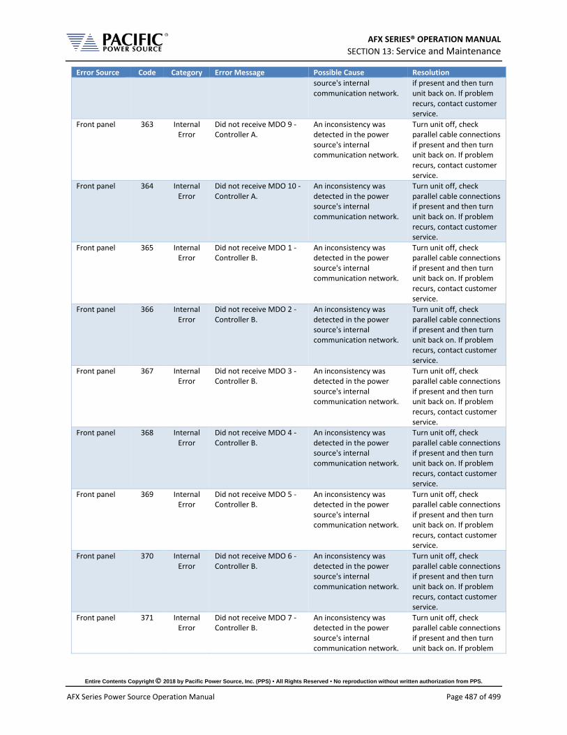
AFX SERIES® OPERATION MANUAL SECTION 13: Service and Maintenance
Entire Contents Copyright 2018 by Pacific Power Source, Inc. (PPS) • All Rights Reserved • No reproduction without written authorization from PPS.
AFX Series Power Source Operation Manual Page 487 of 499
Error Source Code Category Error Message Possible Cause Resolution source's internal communication network.
if present and then turn unit back on. If problem recurs, contact customer service.
Front panel 363 Internal Error
Did not receive MDO 9 - Controller A.
An inconsistency was detected in the power source's internal communication network.
Turn unit off, check parallel cable connections if present and then turn unit back on. If problem recurs, contact customer service.
Front panel 364 Internal Error
Did not receive MDO 10 - Controller A.
An inconsistency was detected in the power source's internal communication network.
Turn unit off, check parallel cable connections if present and then turn unit back on. If problem recurs, contact customer service.
Front panel 365 Internal Error
Did not receive MDO 1 - Controller B.
An inconsistency was detected in the power source's internal communication network.
Turn unit off, check parallel cable connections if present and then turn unit back on. If problem recurs, contact customer service.
Front panel 366 Internal Error
Did not receive MDO 2 - Controller B.
An inconsistency was detected in the power source's internal communication network.
Turn unit off, check parallel cable connections if present and then turn unit back on. If problem recurs, contact customer service.
Front panel 367 Internal Error
Did not receive MDO 3 - Controller B.
An inconsistency was detected in the power source's internal communication network.
Turn unit off, check parallel cable connections if present and then turn unit back on. If problem recurs, contact customer service.
Front panel 368 Internal Error
Did not receive MDO 4 - Controller B.
An inconsistency was detected in the power source's internal communication network.
Turn unit off, check parallel cable connections if present and then turn unit back on. If problem recurs, contact customer service.
Front panel 369 Internal Error
Did not receive MDO 5 - Controller B.
An inconsistency was detected in the power source's internal communication network.
Turn unit off, check parallel cable connections if present and then turn unit back on. If problem recurs, contact customer service.
Front panel 370 Internal Error
Did not receive MDO 6 - Controller B.
An inconsistency was detected in the power source's internal communication network.
Turn unit off, check parallel cable connections if present and then turn unit back on. If problem recurs, contact customer service.
Front panel 371 Internal Error
Did not receive MDO 7 - Controller B.
An inconsistency was detected in the power source's internal communication network.
Turn unit off, check parallel cable connections if present and then turn unit back on. If problem

AFX SERIES® OPERATION MANUAL SECTION 13: Service and Maintenance
Entire Contents Copyright 2018 by Pacific Power Source, Inc. (PPS) • All Rights Reserved • No reproduction without written authorization from PPS.
AFX Series Power Source Operation Manual Page 488 of 499
Error Source Code Category Error Message Possible Cause Resolution recurs, contact customer service.
Front panel 372 Internal Error
Did not receive MDO 8 - Controller B.
An inconsistency was detected in the power source's internal communication network.
Turn unit off, check parallel cable connections if present and then turn unit back on. If problem recurs, contact customer service.
Front panel 373 Internal Error
Did not receive MDO 1 - Controller C.
An inconsistency was detected in the power source's internal communication network.
Turn unit off, check parallel cable connections if present and then turn unit back on. If problem recurs, contact customer service.
Front panel 374 Internal Error
Did not receive MDO 2 - Controller C.
An inconsistency was detected in the power source's internal communication network.
Turn unit off, check parallel cable connections if present and then turn unit back on. If problem recurs, contact customer service.
Front panel 375 Internal Error
Did not receive MDO 3 - Controller C.
An inconsistency was detected in the power source's internal communication network.
Turn unit off, check parallel cable connections if present and then turn unit back on. If problem recurs, contact customer service.
Front panel 376 Internal Error
Did not receive MDO 4 - Controller C.
An inconsistency was detected in the power source's internal communication network.
Turn unit off, check parallel cable connections if present and then turn unit back on. If problem recurs, contact customer service.
Front panel 377 Internal Error
Did not receive MDO 5 - Controller C.
An inconsistency was detected in the power source's internal communication network.
Turn unit off, check parallel cable connections if present and then turn unit back on. If problem recurs, contact customer service.
Front panel 378 Internal Error
Did not receive MDO 6 - Controller C.
An inconsistency was detected in the power source's internal communication network.
Turn unit off, check parallel cable connections if present and then turn unit back on. If problem recurs, contact customer service.
Front panel 379 Internal Error
Did not receive MDO 7 - Controller C.
An inconsistency was detected in the power source's internal communication network.
Turn unit off, check parallel cable connections if present and then turn unit back on. If problem recurs, contact customer service.
Front panel 380 Internal Error
Did not receive MDO 8 - Controller C.
An inconsistency was detected in the power source's internal communication network.
Turn unit off, check parallel cable connections if present and then turn unit back on. If problem recurs, contact customer service.

AFX SERIES® OPERATION MANUAL SECTION 13: Service and Maintenance
Entire Contents Copyright 2018 by Pacific Power Source, Inc. (PPS) • All Rights Reserved • No reproduction without written authorization from PPS.
AFX Series Power Source Operation Manual Page 489 of 499
Error Source Code Category Error Message Possible Cause Resolution I/O Board 393 Internal
Error Global fault detected.
I/O Board 394 Error Internal board fault. Hardware Fault Try recycling power. If error persists, contact customer service
I/O Board 395 Error Invalid node ID. Run unit discovery to recover.
An inconsistency was detected in the power source's internal communication network.
Turn unit off, check parallel cable connections if present and then turn unit back on. If problem recurs, contact customer service.
I/O Board 396 Error Incorrect DSP type detected. Cycle-power to re-try.
Internal Communication Error. AUX I/O processor not responding
Try recycling power. If error persists, contact customer service
I/O Board 397 Error Invalid constants loaded from EEPROM.
Configuration Error. Coefficients found are invalid.
SANITIZE unit to restore factory defaults
I/O Board 398 Error Controller is not in operational node.
An inconsistency was detected in the power source's internal communication network.
Turn unit off, check parallel cable connections if present and then turn unit back on. If problem recurs, contact customer service.
I/O Board 399 Error Transformer coupling circuits hardware fault.
I/O Board 400 Error Transformer coupling circuits not detected.
I/O Board 401 Error Remote inhibit was issued from remote interface.
I/O Board 454 Error Controller is not in operational node.
An inconsistency was detected in the power source's internal communication network.
Turn unit off, check parallel cable connections if present and then turn unit back on. If problem recurs, contact customer service.
I/O Board 455 Error Missing controller node. An inconsistency was detected in the power source's internal communication network.
Turn unit off, check parallel cable connections if present and then turn unit back on. If problem recurs, contact customer service.
I/O Board 456 Error Cannot read fault information.
An inconsistency was detected in the power source's internal communication network.
Turn unit off, check parallel cable connections if present and then turn unit back on. If problem recurs, contact customer service.
Front panel 500 Warning AC voltage setpoint was automatically reduced to 0 Vrms.
Front panel 501 Error Frequency is too high to enable xfmr coupling.
Front panel 502 Error Extended voltage range is not allowed when

AFX SERIES® OPERATION MANUAL SECTION 13: Service and Maintenance
Entire Contents Copyright 2018 by Pacific Power Source, Inc. (PPS) • All Rights Reserved • No reproduction without written authorization from PPS.
AFX Series Power Source Operation Manual Page 490 of 499
Error Source Code Category Error Message Possible Cause Resolution overload modes are enabled.
Front panel 503 Error Frequency is too high for extended voltage mode.
Front panel 504 Error Cannot change extended voltage mode with output enabled.
Front panel 505 Error Cannot enable current overload mode when extended voltage range is enabled.
Front panel 506 Error Cannot enable extended frequency when extended voltage range is enabled.
Front panel 507 Warning Power limits were reduced due to extended frequency mode.
Front panel 508 Warning Current limits were reduced due to extended frequency mode.
Front panel 509 Error Setpoint out of range due to extended frequency mode."
Front panel 510 Error Unable to update setpoint because it is outside the allowed range of extended frequency mode.
Front panel 511 Error Error during power stage firmware update.
Front panel 512 Error Phase rotation is always negative in UPC compatible mode.
Front panel 513 Error Cannot change split phase mode with output enabled.
Front panel 514 Error Serial port flow control not available in this unit.
Front panel 515 Error Too many commands per line.
Front panel 516 Warning Resistive impedance was automatically reduced.
Front panel 517 Warning Inductive impedance was automatically reduced.

AFX SERIES® OPERATION MANUAL SECTION 13: Service and Maintenance
Entire Contents Copyright 2018 by Pacific Power Source, Inc. (PPS) • All Rights Reserved • No reproduction without written authorization from PPS.
AFX Series Power Source Operation Manual Page 491 of 499
Error Source Code Category Error Message Possible Cause Resolution Front panel 518 Error Cannot change output
impedance state with output enabled.
Front panel 519 Error Cannot change output impedance mode with output enabled.
Front panel 520 Error Inductive impedance not available in UPC compatible mode.
Front panel 521 Error Read only file or folder.
Front panel 522 Error Argument requires more decimals.
Front panel 523 Warning Warning: Ambient temperature approaching limit.
Front panel 524 Error Digital I/Os interface conflict: Serial interface is active.
Front panel 525 Error New IO firmware available. Must split system in two to perform update.
Front panel 526 Error Cannot export configurations.
Front panel 527 Error Cannot import configurations.
Front panel 528 Error Version mismatch error.
Front panel 529 Error Internal connection error with the power stage.
Front panel 530 Error Fault during output enable.
Front panel 531 Error Incorrect password.
Front panel 532 Warning Frontpanel firmware image model do not match frontpanel model.
Front panel 533 Error This setpoint is being set by an analog input.
Front panel 534 Error Image model not compatible.
Front panel 535 Error Frontpanel not compatible.
Front panel 536 Error Cannot convert cycle based transient to time based.
Front panel 537 Error Cannot load pulse.

AFX SERIES® OPERATION MANUAL SECTION 13: Service and Maintenance
Entire Contents Copyright 2018 by Pacific Power Source, Inc. (PPS) • All Rights Reserved • No reproduction without written authorization from PPS.
AFX Series Power Source Operation Manual Page 492 of 499
Error Source Code Category Error Message Possible Cause Resolution Front panel 539 Error Parameter below
minimum saturation.
Front panel 540 Error Parameter below minimum range.
Front panel 541 Error Parameter below minimum unit scope.
Front panel 542 Error Parameter below minimum user limit.
Front panel 543 Error Parameter below voltage mode.
Front panel 544 Error Parameter above maximum saturation.
Front panel 545 Error Parameter above maximum range.
Front panel 546 Error Parameter above maximum unit scope.
Front panel 547 Error Parameter above maximum user limit.
Front panel 548 Error Parameter above voltage mode.
Table 12-1: Warnings and Error Messages Listing

AFX SERIES® OPERATION MANUAL SECTION 13: Service and Maintenance
Entire Contents Copyright 2018 by Pacific Power Source, Inc. (PPS) • All Rights Reserved • No reproduction without written authorization from PPS.
AFX Series Power Source Operation Manual Page 493 of 499
13 Service and Maintenance
13.1 Warnings
CAUTION
THIS EQUIPMENT CONTAINS HIGH ENERGY, LOW IMPEDANCE CIRCUITS! LETHAL POTENTIALS ARE CONTAINED WITHIN THIS UNIT.
CARE MUST BE EXERCISED WHEN SERVICING THIS EQUIPMENT IN ORDER TO PREVENT SERIOUS SERVICE PERSONNEL INJURY OR EQUIPMENT DAMAGE.
OBSERVE THE FOLLOWING WHEN SERVICE OR MAINTENANCE ARE REQUIRED:
1. REMOVE ALL JEWELRY FROM ARMS AND NECK WHEN SERVICING THIS EQUIPMENT. THIS PREVENTS THE POSSIBILITY OF SHORTING THROUGH THE JEWELRY AND CAUSING BURNS TO SERVICE PERSONNEL.
2. WEAR SAFETY GLASSES WHEN SERVICING THIS EQUIPMENT TO PREVENT EYE INJURY DUE TO FLYING PARTICLES CAUSED BY ACCIDENTAL SHORT CIRCUIT CONDITIONS.
3. DO NOT REMOVE ANY PANEL OR COVER WITHOUT FIRST REMOVING THE INPUT SERVICE BY OPENING ALL CIRCUIT BREAKERS.
4. DO NOT REMOVE ANY PANEL OR COVER WITHOUT FIRST WAITING 20 MINUTES FOR ALL INTERNAL CHARGES TO DISSIPATE TO A SAFE LEVEL.
5. SERVICE OTHER THAN EXTERNAL CLEANING SHOULD BE REFERRED TO PERSONNEL AUTHORIZED BY THE FACTORY TO SERVICE THIS EQUIPMENT.

AFX SERIES® OPERATION MANUAL SECTION 13: Service and Maintenance
Entire Contents Copyright 2018 by Pacific Power Source, Inc. (PPS) • All Rights Reserved • No reproduction without written authorization from PPS.
AFX Series Power Source Operation Manual Page 494 of 499
13.2 Authorized Service Centers There are NO end-user serviceable parts in this product. In case of a problem or malfunction, DO NOT ATTEMPT TO REPAIR! Instead, contact one of Pacific Power Source’s authorized service centers or your local Pacific Power Source distributor. For a list of authorized service centers, refer to section 1, “Contact Information”.

AFX SERIES® OPERATION MANUAL SECTION 14: CE MARK Declaration of Conformity
Entire Contents Copyright 2018 by Pacific Power Source, Inc. (PPS) • All Rights Reserved • No reproduction without written authorization from PPS.
AFX Series Power Source Operation Manual Page 495 of 499
14 CE MARK Declaration of Conformity
The Manufacturer hereby declares that the products:
Product Name: AFX Series & ADF Series® Power Sources, All Models in Series
Conforms to the following standards or other normative documents: RoHS (DIRECTIVE 2011/65/EU)
Standard applied EN 50581:2012 SAFETY (DIRECTIVE 2014/35/EC):
Standard applied EN 61010–1: 2010; ED3/A1:2019 EMC (DIRECTIVE 2014/30/EU):
Standard applied EN 61326-1: 2013 Reference Standards:
ELECTROMAGNETIC EMISSIONS: Radiated Emissions CISPR 11/22, CLASS A LIMITS Conducted Emissions CISPR 11/22, CLASS A LIMITS
ELECTROMAGNETIC IMMUNITY: RF Electromagnetic Field IEC 61000-4-3:2006+A1:2007+A2:2010 80 – 1000 MHz, 10 V/m 1 Khz sinewave (80% AM) 1.4 – 2 GHz, 3 V/m 2.0 – 2.7 GHz, 1 V/m Conducted RF Immunity IEC 61000-4-6:2013 Conducted RF Immunity 0.15 – 80 MHz @ 3 Vrms Electrostatic Discharge IEC 61000-4-2:2008 ± 4 kV contact discharge ± 8 kV air discharge Electrical Fast Transient/Burst IEC 61000-4-4:2004+A1:2010 AC or DC power ports, ± 2.0 kV Signal and I/O ports, ± 1.0 kV Surge IEC 61000-4-5:2006 AC or DC power ports, ± 2.0 kV Line to ground and ± 1.0 kV Line to Line Power Frequency Magnetic Field IEC 61000-4-8:2009 30 A/m
Supplemental Information:
When and Where Issued September 17, 2019 Irvine, California, USA
Authorized Signatory Mitchel Orr, Quality Manager, acting Pacific Power Source
Responsible Person Joe Abranko, Pacific Power Source, Inc. 17692 Fitch, Irvine CA, 92614
Mark of Compliance
AFX SERIES® OPERATION MANUAL INDEX
Entire Contents Copyright 2018 by Pacific Power Source, Inc. (PPS) • All Rights Reserved • No reproduction without written authorization from PPS.
AFX Series Power Source Operation Manual Page 496 of 499
Index
A AC input ........................................................................... 56 AC Input .................................................................... 41, 60 AC terminal block ............................................................ 59 accessories
included ................................................................... 26 Accessories ..................................................................... 26 AFXS system ................................................................ 158 air filter ............................................................................. 65 Airflow .............................................................................. 62
B Browser ......................................................................... 410
C Cabinet
Options .................................................................... 89 Calibration ..................................................................... 465
Commands ............................................................ 224 CE MARK ...................................................................... 495 Circuit Breaker ................................................................ 61 CONFIGURATION
Screens ................................................................. 155 Configuration Settings................................................... 157 Connections .................................................................. 192 Contact .............................................................. 15, 78, 494 Contents .............................................................................3 CSC Configuration ........................................................ 165 Cycle Reset ................................................................... 166
E E Version ................................................................... 29, 46 Emergency
Power Off option ..................................................... 90 Energy Savings Modes................................................. 113 equipment weight ............................................................ 54 Error and Event queue.................................................. 172 Error Messages ............................................................. 472 Ethernet ........................................................................... 99
Access Control ...................................................... 412 Export Version ........................................................... 29, 46 External Storage ........................................................... 187 External Voltage Sense ................................................ 194
F Fault Queue .................................................................. 172 Features .......................................................................... 24 Filter
Air Intake ................................................................. 65 Firmware Update .......................................................... 190 FORM ............................................................................ 120 front panel operation ..................................................... 110
G Grounding
Cabinet Systems ..................................................... 83
I Installation .......................................................... 16, 54, 408 Interface
Ethernet ................................................................... 99 Ethernet Browser ................................................... 410 GPIB Settings ........................................................ 181 I/O Settings ............................................................ 181 LAN 99 Monitor ................................................................... 112 Remote Inhibit Settings ......................................... 182 RS232 Settings ...................................................... 179 Screens .................................................................. 173 USB Settings ......................................................... 180
K Keyboard ....................................................................... 111 KIT 62
L LAN 99
Access Control....................................................... 412 Browser Interface .................................................. 410 Configuration ......................................................... 410 Setup ...................................................................... 177
LAN Configuration ......................................................... 410 LCD Image
capture to image file .............................................. 111 Logging measurement data .......................................... 138
M Maintenance
Air Filter Cleaning .................................................... 64 Manual ........................................................................... 419 Measurement Command
Resolution Setting ................................................. 243 Measurements
Datalogger ............................................................. 136 MEASUREMENTS
Logging .................................................................. 191 Screen .................................................................... 133 Soft Keys ................................................................ 136
Memory SD Card ................................................................. 112 USB 112
Menus ............................................................................ 114
O optional output transformer ........................................... 158 options ............................................................................. 26 Output

AFX SERIES® OPERATION MANUAL INDEX
Entire Contents Copyright 2018 by Pacific Power Source, Inc. (PPS) • All Rights Reserved • No reproduction without written authorization from PPS.
AFX Series Power Source Operation Manual Page 497 of 499
Control Switch ......................................................... 89 Enable Button ........................................................ 111 Impedance............................................................. 167 Relay Control ........................................................... 98 Remote Inhibit ......................................................... 97 Response Time ..................................................... 113
Output Enable ............................................................... 113 Output Impedance ........................................................ 167
P Parallel Operation ................................................... 99, 100 Phase Angle
Control ................................................................... 157 Phase Mode .................................................................. 120 phase rotation
positive or negative ............................................... 159 Phase rotation ............................................................... 117 Powering Up .................................................................... 78 Presets
Output Parameters ................................................ 118 Program
Impedance............................................................. 167 PROGRAM
Screen ................................................................... 115 Soft Keys ............................................................... 121
Program Data Entry ...................................................... 118 Program Memory .......................................................... 164 Programming ........................................................ 110, 221
Conventions .......................................................... 221 Terminators ........................................................... 222
Protection ........................................................................ 38
R Rear Panel
Connector Locations ............................................... 92 Recommended Wire Sizing ............................................ 66 Remote Control ............................................................. 221 RS232
Interface ................................................................. 179
S safety information ............................................................ 16 Safety Information ........................................................... 16 Safety Notices ................................................................. 18 Screen capture
LCD Image ............................................................ 460 SD Card ......................................................................... 112 Sense Terminals ........................................................... 194 Series Connection
AFXS Models .................................................. 48, 158
Service ........................................................................... 493 Shuttle ............................................................................ 111 Size 193 Slew Rates..................................................................... 162 Specifications ................................................................... 27 Start Phase .................................................................... 157 Stop Phase .................................................................... 158 SYSTEM
Screens .................................................................. 170 system bus ..................................................................... 100 system interface .............................................................. 99 System Interface ............................................................ 220
T T Option ......................................................................... 158 Terminals ....................................................................... 192 Terminator Characters .................................................. 222 Tools Required
Cabinets ................................................................... 79 Transformer
Option .......................................................76, 272, 352 Transient Settings .......................................................... 166 TRANSIENTS
Screens .................................................................. 139 Turn on ............................................................................. 78
U UNIT INFORMATION ................................................... 184 unpacking ........................................................................ 54 Update Phase ................................................................ 157 USB 93
Drivers .................................................................... 408 User Limits ..................................................................... 161 User Presets .................................................................. 168
V Video Monitor ................................................................ 112 voltage sense
External .................................................................... 77 Internal ..................................................................... 77
W Warranty .......................................................................... 16 Waveform
Library .................................................................... 125 Weight .............................................................................. 41 Wire Size........................................................................ 193 Wire Sizing
Recommended ........................................................ 66


Pacific Power Source The Power of Expertise
Copyright 2018, Pacific Power Source, Inc. (PPS) • All Rights Reserved • No reproduction without written authorization from PPS.