Operating Systems (Comp-231) (Theory) Level – 6
123
Operating Systems (Comp-231) (Theory) Level – 6 Academic Year 1437 – 38 Spring Semester Compiled by: Mr. Syed Ziauddin (Course Coordinator) (Feb 2017 - May 2017) Department of Computer Science Faculty of Computer and Information Science Jazan University, Jazan, KSA
-
Upload
khangminh22 -
Category
Documents
-
view
2 -
download
0
Transcript of Operating Systems (Comp-231) (Theory) Level – 6

Operating Systems (Comp-231) (Theory) Level – 6
Academic Year 1437 – 38 Spring Semester
Compiled by: Mr. Syed Ziauddin (Course Coordinator)
(Feb 2017 - May 2017)
Department of Computer Science Faculty of Computer and Information Science
Jazan University, Jazan, KSA

Contents
Chapter One: Operating System Overview
Objective and Functions
Services provided by OS, and Evolution of OS
Major Achievements
Development Leading to Modern Operating System, and System Calls
Chapter Two: File Management
Files, File Systems, and File Management Systems
File Organization and Access
File Directories and Structure
File Sharing and Secondary Storage Management
Chapter Three: Processes and Threads
Process, PCB, Process States
Process Description and Process Control
Processes and Threads, Multithreading, Thread Functionality
ULT & KLT, Microkernel and Thread States
Chapter Four: CPU Scheduling
Types of Scheduling
Scheduling Algorithms (FCFS and SJF)
Scheduling Algorithms (Priority and RR)
Comparison of All
Chapter Five: Deadlocks
System Model, Deadlock Characterization
Deadlock prevention, avoidance
Deadlock detection using banker’s algorithm
Recovery from deadlock
Chapter Six: Memory Management
Address Binding, Logical Vs Physical Address, Dynamic Loading
Linking, Swapping, Fixed and Dynamic partitioning
Paging, Segmentation
Page Replacement Algorithms (FIFO,ORA,LRU)
Thrashing

Chapter One:
Operating System Overview
Objective and Functions
Services provided by OS, and Evolution of OS
Major Achievements
Development Leading to Modern Operating
System, and System Calls

CHAPTER
OPERATING SYSTEM OVERVIEW2.1 Operating System Objectives and Functions
The Operating System as a User/Computer InterfaceThe Operating System as Resource ManagerEase of Evolution of an Operating System
2.2 The Evolution of Operating SystemsSerial ProcessingSimple Batch SystemsMultiprogrammed Batch SystemsTime-Sharing Systems
2.3 Major AchievementsThe ProcessMemory ManagementInformation Protection and SecurityScheduling and Resource ManagementSystem Structure
2.4 Developments Leading to Modern Operating Systems2.5 Microsoft Windows Overview
HistorySingle-User MultitaskingArchitectureClient/Server ModelThreads and SMPWindows Objects
2.6 Traditional UNIX SystemsHistoryDescription
2.7 Modern UNIX SystemsSystem V Release 4 (SVR4)BSDSolaris 10
2.8 LinuxHistoryModular StructureKernel Components
2.9 Recommended Reading and Web Sites
2.10 Key Terms, Review Questions, and Problems50
M02_STAL6329_06_SE_C02.QXD 2/28/08 3:33 AM Page 50

2.1 / OPERATING SYSTEM OBJECTIVES AND FUNCTIONS 51
We begin our study of operating systems (OSs) with a brief history.This history is it-self interesting and also serves the purpose of providing an overview of OS princi-ples. The first section examines the objectives and functions of operating systems.Then we look at how operating systems have evolved from primitive batch systemsto sophisticated multitasking, multiuser systems.The remainder of the chapter looksat the history and general characteristics of the two operating systems that serve asexamples throughout this book. All of the material in this chapter is covered ingreater depth later in the book.
2.1 OPERATING SYSTEM OBJECTIVES AND FUNCTIONS
An OS is a program that controls the execution of application programs and acts asan interface between applications and the computer hardware. It can be thought ofas having three objectives:
• Convenience: An OS makes a computer more convenient to use.• Efficiency: An OS allows the computer system resources to be used in an ef-
ficient manner.• Ability to evolve: An OS should be constructed in such a way as to permit the
effective development, testing, and introduction of new system functions with-out interfering with service.
Let us examine these three aspects of an OS in turn.
The Operating System as a User/Computer Interface
The hardware and software used in providing applications to a user can be viewed ina layered or hierarchical fashion, as depicted in Figure 2.1. The user of those applica-tions, the end user, generally is not concerned with the details of computer hardware.Thus, the end user views a computer system in terms of a set of applications. An ap-plication can be expressed in a programming language and is developed by an appli-cation programmer. If one were to develop an application program as a set ofmachine instructions that is completely responsible for controlling the computerhardware, one would be faced with an overwhelmingly complex undertaking.To easethis chore, a set of system programs is provided. Some of these programs are referredto as utilities. These implement frequently used functions that assist in program cre-ation, the management of files, and the control of I/O devices. A programmer willmake use of these facilities in developing an application, and the application, while itis running, will invoke the utilities to perform certain functions. The most importantcollection of system programs comprises the OS. The OS masks the details of thehardware from the programmer and provides the programmer with a convenient in-terface for using the system. It acts as mediator, making it easier for the programmerand for application programs to access and use those facilities and services.
Briefly, the OS typically provides services in the following areas:
• Program development: The OS provides a variety of facilities and services,such as editors and debuggers, to assist the programmer in creating programs.Typically, these services are in the form of utility programs that, while not
M02_STAL6329_06_SE_C02.QXD 2/22/08 7:02 PM Page 51
ziauddin
Highlight
Edited by Foxit Reader Copyright(C) by Foxit Software Company,2005-2008 For Evaluation Only.
admin
ziauddin
Highlight
ziauddin
Highlight

52 CHAPTER 2 / OPERATING SYSTEM OVERVIEW
strictly part of the core of the OS, are supplied with the OS and are referred toas application program development tools.
• Program execution: A number of steps need to be performed to execute aprogram. Instructions and data must be loaded into main memory, I/O devicesand files must be initialized, and other resources must be prepared. The OShandles these scheduling duties for the user.
• Access to I/O devices: Each I/O device requires its own peculiar set of instruc-tions or control signals for operation.The OS provides a uniform interface thathides these details so that programmers can access such devices using simplereads and writes.
• Controlled access to files: For file access, the OS must reflect a detailed under-standing of not only the nature of the I/O device (disk drive, tape drive) butalso the structure of the data contained in the files on the storage medium. Inthe case of a system with multiple users, the OS may provide protection mech-anisms to control access to the files.
• System access: For shared or public systems, the OS controls access to the sys-tem as a whole and to specific system resources. The access function must pro-vide protection of resources and data from unauthorized users and mustresolve conflicts for resource contention.
• Error detection and response: A variety of errors can occur while a computersystem is running.These include internal and external hardware errors, such asa memory error, or a device failure or malfunction; and various softwareerrors, such as division by zero, attempt to access forbidden memory location,
Enduser
Programmer
Operatingsystem
designer
Application programs
Utilities
Operating system
Computer hardware
Figure 2.1 Layers and Views of a Computer System
M02_STAL6329_06_SE_C02.QXD 2/22/08 7:02 PM Page 52
ziauddin
Highlight
ziauddin
Highlight
ziauddin
Highlight
ziauddin
Highlight
ziauddin
Highlight
ziauddin
Highlight
ziauddin
Highlight

2.1 / OPERATING SYSTEM OBJECTIVES AND FUNCTIONS 53
and inability of the OS to grant the request of an application. In each case, theOS must provide a response that clears the error condition with the least im-pact on running applications. The response may range from ending the pro-gram that caused the error, to retrying the operation, to simply reporting theerror to the application.
• Accounting: A good OS will collect usage statistics for various resources andmonitor performance parameters such as response time. On any system, thisinformation is useful in anticipating the need for future enhancements and intuning the system to improve performance. On a multiuser system, the infor-mation can be used for billing purposes.
The Operating System as Resource Manager
A computer is a set of resources for the movement, storage, and processing of data andfor the control of these functions. The OS is responsible for managing these resources.
Can we say that it is the OS that controls the movement, storage, and process-ing of data? From one point of view, the answer is yes: By managing the computer’sresources, the OS is in control of the computer’s basic functions. But this control isexercised in a curious way. Normally, we think of a control mechanism as somethingexternal to that which is controlled, or at least as something that is a distinct andseparate part of that which is controlled. (For example, a residential heating systemis controlled by a thermostat, which is separate from the heat-generation and heat-distribution apparatus.) This is not the case with the OS, which as a control mecha-nism is unusual in two respects:
• The OS functions in the same way as ordinary computer software; that is, it is aprogram or suite of programs executed by the processor.
• The OS frequently relinquishes control and must depend on the processor toallow it to regain control.
Like other computer programs, the OS provides instructions for the processor.The key difference is in the intent of the program. The OS directs the processor inthe use of the other system resources and in the timing of its execution of other pro-grams. But in order for the processor to do any of these things, it must cease execut-ing the OS program and execute other programs. Thus, the OS relinquishes controlfor the processor to do some “useful” work and then resumes control long enoughto prepare the processor to do the next piece of work. The mechanisms involved inall this should become clear as the chapter proceeds.
Figure 2.2 suggests the main resources that are managed by the OS. A portionof the OS is in main memory. This includes the kernel, or nucleus, which contains themost frequently used functions in the OS and, at a given time, other portions of theOS currently in use. The remainder of main memory contains user programs anddata. The allocation of this resource (main memory) is controlled jointly by the OSand memory management hardware in the processor, as we shall see.The OS decideswhen an I/O device can be used by a program in execution and controls access to anduse of files. The processor itself is a resource, and the OS must determine how muchprocessor time is to be devoted to the execution of a particular user program. In thecase of a multiple-processor system, this decision must span all of the processors.
M02_STAL6329_06_SE_C02.QXD 2/22/08 7:02 PM Page 53
ziauddin
Highlight
ziauddin
Highlight
ziauddin
Highlight
ziauddin
Highlight

54 CHAPTER 2 / OPERATING SYSTEM OVERVIEW
Ease of Evolution of an Operating System
A major operating system will evolve over time for a number of reasons:
• Hardware upgrades plus new types of hardware: For example, early versionsof UNIX and the Macintosh operating system did not employ a paging mech-anism because they were run on processors without paging hardware.1 Subse-quent versions of these operating systems were modified to exploit pagingcapabilities. Also, the use of graphics terminals and page-mode terminals in-stead of line-at-a-time scroll mode terminals affects OS design. For example, agraphics terminal typically allows the user to view several applications at thesame time through “windows” on the screen. This requires more sophisticatedsupport in the OS.
• New services: In response to user demand or in response to the needs of sys-tem managers, the OS expands to offer new services. For example, if it is foundto be difficult to maintain good performance for users with existing tools, newmeasurement and control tools may be added to the OS.
• Fixes: Any OS has faults. These are discovered over the course of time andfixes are made. Of course, the fix may introduce new faults.
Memory
Computer system
I/O devices
Operatingsystem
software
Programsand data
ProcessorProcessor
OSPrograms
Data
Storage
I/O controller
I/O controller
I/O controller Printers,keyboards,digital camera,etc.
Figure 2.2 The Operating System as Resource Manager
1Paging is introduced briefly later in this chapter and is discussed in detail in Chapter 7.
M02_STAL6329_06_SE_C02.QXD 2/22/08 7:02 PM Page 54

2.2 / THE EVOLUTION OF OPERATING SYSTEMS 55
The need to change an OS regularly places certain requirements on its design.An obvious statement is that the system should be modular in construction, withclearly defined interfaces between the modules, and that it should be well docu-mented. For large programs, such as the typical contemporary OS, what might be re-ferred to as straightforward modularization is inadequate [DENN80a]. That is, muchmore must be done than simply partitioning a program into modules. We return tothis topic later in this chapter.
2.2 THE EVOLUTION OF OPERATING SYSTEMS
In attempting to understand the key requirements for an OS and the significance ofthe major features of a contemporary OS, it is useful to consider how operating sys-tems have evolved over the years.
Serial Processing
With the earliest computers, from the late 1940s to the mid-1950s, the programmer inter-acted directly with the computer hardware; there was no OS.These computers were runfrom a console consisting of display lights, toggle switches, some form of input device,and a printer. Programs in machine code were loaded via the input device (e.g., a cardreader). If an error halted the program, the error condition was indicated by the lights. Ifthe program proceeded to a normal completion, the output appeared on the printer.
These early systems presented two main problems:
• Scheduling: Most installations used a hardcopy sign-up sheet to reserve com-puter time. Typically, a user could sign up for a block of time in multiples of ahalf hour or so. A user might sign up for an hour and finish in 45 minutes; thiswould result in wasted computer processing time. On the other hand, the usermight run into problems, not finish in the allotted time, and be forced to stopbefore resolving the problem.
• Setup time: A single program, called a job, could involve loading the compilerplus the high-level language program (source program) into memory, saving thecompiled program (object program) and then loading and linking together theobject program and common functions. Each of these steps could involve mount-ing or dismounting tapes or setting up card decks. If an error occurred, the hap-less user typically had to go back to the beginning of the setup sequence. Thus, aconsiderable amount of time was spent just in setting up the program to run.
This mode of operation could be termed serial processing, reflecting the factthat users have access to the computer in series. Over time, various system softwaretools were developed to attempt to make serial processing more efficient. These in-clude libraries of common functions, linkers, loaders, debuggers, and I/O driver rou-tines that were available as common software for all users.
Simple Batch Systems
Early computers were very expensive, and therefore it was important to maxi-mize processor utilization. The wasted time due to scheduling and setup time wasunacceptable.
M02_STAL6329_06_SE_C02.QXD 2/22/08 7:02 PM Page 55
ziauddin
Highlight
ziauddin
Highlight
ziauddin
Highlight

2.2 / THE EVOLUTION OF OPERATING SYSTEMS 59
Multiprogrammed Batch Systems
Even with the automatic job sequencing provided by a simple batch operating sys-tem, the processor is often idle. The problem is that I/O devices are slow comparedto the processor. Figure 2.4 details a representative calculation. The calculationconcerns a program that processes a file of records and performs, on average, 100machine instructions per record. In this example the computer spends over 96%of its time waiting for I/O devices to finish transferring data to and from the file.Figure 2.5a illustrates this situation, where we have a single program, referred to
Run Wait WaitRun
Time
Run Wait WaitRun
RunA
RunA
Run WaitWait WaitRun
RunB Wait Wait
RunB
RunA
RunA
RunB
RunB
RunC
RunC
(a) Uniprogramming
Time
(b) Multiprogramming with two programs
Time
(c) Multiprogramming with three programs
Program A
Program A
Program B
Run Wait WaitRun
Run WaitWait WaitRun
Program A
Program B
Wait WaitCombined
Run WaitWait WaitRunProgram C
Combined
Figure 2.4 System Utilization Example
Read one record from file 15 Execute 100 instructions 1 Write one record to file 15 Total 31
Percent CPU Utilization = 131
= 0.032 = 3.2%
msmsmsms
Figure 2.5 Multiprogramming Example
M02_STAL6329_06_SE_C02.QXD 2/22/08 7:02 PM Page 59
ziauddin
Highlight
ziauddin
Highlight

60 CHAPTER 2 / OPERATING SYSTEM OVERVIEW
as uniprogramming. The processor spends a certain amount of time executing,until it reaches an I/O instruction. It must then wait until that I/O instruction con-cludes before proceeding.
This inefficiency is not necessary. We know that there must be enough memoryto hold the OS (resident monitor) and one user program. Suppose that there is roomfor the OS and two user programs.When one job needs to wait for I/O, the processorcan switch to the other job, which is likely not waiting for I/O (Figure 2.5b). Further-more, we might expand memory to hold three, four, or more programs and switchamong all of them (Figure 2.5c). The approach is known as multiprogramming, ormultitasking. It is the central theme of modern operating systems.
To illustrate the benefit of multiprogramming, we give a simple example. Con-sider a computer with 250 Mbytes of available memory (not used by the OS), a disk,a terminal, and a printer.Three programs, JOB1, JOB2, and JOB3, are submitted forexecution at the same time, with the attributes listed in Table 2.1. We assume mini-mal processor requirements for JOB2 and JOB3 and continuous disk and printeruse by JOB3. For a simple batch environment, these jobs will be executed in se-quence. Thus, JOB1 completes in 5 minutes. JOB2 must wait until the 5 minutes areover and then completes 15 minutes after that. JOB3 begins after 20 minutes andcompletes at 30 minutes from the time it was initially submitted. The average re-source utilization, throughput, and response times are shown in the uniprogram-ming column of Table 2.2. Device-by-device utilization is illustrated in Figure 2.6a.It is evident that there is gross underutilization for all resources when averaged overthe required 30-minute time period.
Table 2.1 Sample Program Execution Attributes
JOB1 JOB2 JOB3
Type of job Heavy compute Heavy I/O Heavy I/O
Duration 5 min 15 min 10 minMemory required 50 M 100 M 75 MNeed disk? No No YesNeed terminal? No Yes No
Need printer? No No Yes
Table 2.2 Effects of Multiprogramming on Resource Utilization
Uniprogramming Multiprogramming
Processor use 20% 40%Memory use 33% 67%Disk use 33% 67%Printer use 33% 67%Elapsed time 30 min 15 minThroughput 6 jobs/hr 12 jobs/hrMean response time 18 min 10 min
M02_STAL6329_06_SE_C02.QXD 2/22/08 7:02 PM Page 60
ziauddin
Highlight

62 CHAPTER 2 / OPERATING SYSTEM OVERVIEW
Now suppose that the jobs are run concurrently under a multiprogrammingoperating system. Because there is little resource contention between the jobs, allthree can run in nearly minimum time while coexisting with the others in the com-puter (assuming that JOB2 and JOB3 are allotted enough processor time to keeptheir input and output operations active). JOB1 will still require 5 minutes to com-plete, but at the end of that time, JOB2 will be one-third finished and JOB3 half fin-ished. All three jobs will have finished within 15 minutes. The improvement isevident when examining the multiprogramming column of Table 2.2, obtained fromthe histogram shown in Figure 2.6b.
As with a simple batch system, a multiprogramming batch system must rely oncertain computer hardware features.The most notable additional feature that is use-ful for multiprogramming is the hardware that supports I/O interrupts and DMA(direct memory access). With interrupt-driven I/O or DMA, the processor can issuean I/O command for one job and proceed with the execution of another job whilethe I/O is carried out by the device controller. When the I/O operation is complete,the processor is interrupted and control is passed to an interrupt-handling programin the OS. The OS will then pass control to another job.
Multiprogramming operating systems are fairly sophisticated compared tosingle-program, or uniprogramming, systems.To have several jobs ready to run, theymust be kept in main memory, requiring some form of memory management. In ad-dition, if several jobs are ready to run, the processor must decide which one to run,this decision requires an algorithm for scheduling. These concepts are discussedlater in this chapter.
Time-Sharing Systems
With the use of multiprogramming, batch processing can be quite efficient. How-ever, for many jobs, it is desirable to provide a mode in which the user interacts di-rectly with the computer. Indeed, for some jobs, such as transaction processing, aninteractive mode is essential.
Today, the requirement for an interactive computing facility can be, and oftenis, met by the use of a dedicated personal computer or workstation. That option wasnot available in the 1960s, when most computers were big and costly. Instead, timesharing was developed.
Just as multiprogramming allows the processor to handle multiple batchjobs at a time, multiprogramming can also be used to handle multiple interactivejobs. In this latter case, the technique is referred to as time sharing, becauseprocessor time is shared among multiple users. In a time-sharing system, multipleusers simultaneously access the system through terminals, with the OS interleav-ing the execution of each user program in a short burst or quantum of computa-tion. Thus, if there are n users actively requesting service at one time, each userwill only see on the average 1/n of the effective computer capacity, not countingOS overhead. However, given the relatively slow human reaction time, the re-sponse time on a properly designed system should be similar to that on a dedi-cated computer.
Both batch processing and time sharing use multiprogramming. The key dif-ferences are listed in Table 2.3.
M02_STAL6329_06_SE_C02.QXD 2/22/08 7:02 PM Page 62
ziauddin
Highlight
ziauddin
Highlight

2.2 / THE EVOLUTION OF OPERATING SYSTEMS 63
One of the first time-sharing operating systems to be developed was theCompatible Time-Sharing System (CTSS) [CORB62], developed at MIT by a groupknown as Project MAC (Machine-Aided Cognition, or Multiple-Access Computers).The system was first developed for the IBM 709 in 1961 and later transferred to anIBM 7094.
Compared to later systems, CTSS is primitive. The system ran on a computerwith 32,000 36-bit words of main memory, with the resident monitor consuming5000 of that.When control was to be assigned to an interactive user, the user’s pro-gram and data were loaded into the remaining 27,000 words of main memory. Aprogram was always loaded to start at the location of the 5000th word; this simpli-fied both the monitor and memory management. A system clock generated inter-rupts at a rate of approximately one every 0.2 seconds. At each clock interrupt, theOS regained control and could assign the processor to another user. This tech-nique is known as time slicing. Thus, at regular time intervals, the current userwould be preempted and another user loaded in. To preserve the old user programstatus for later resumption, the old user programs and data were written out todisk before the new user programs and data were read in. Subsequently, the olduser program code and data were restored in main memory when that programwas next given a turn.
To minimize disk traffic, user memory was only written out when the incomingprogram would overwrite it. This principle is illustrated in Figure 2.7. Assume thatthere are four interactive users with the following memory requirements, in words:
• JOB1: 15,000• JOB2: 20,000• JOB3: 5000• JOB4: 10,000
Initially, the monitor loads JOB1 and transfers control to it (a). Later, the mon-itor decides to transfer control to JOB2. Because JOB2 requires more memory thanJOB1, JOB1 must be written out first, and then JOB2 can be loaded (b). Next, JOB3is loaded in to be run. However, because JOB3 is smaller than JOB2, a portion ofJOB2 can remain in memory, reducing disk write time (c). Later, the monitor decidesto transfer control back to JOB1.An additional portion of JOB2 must be written outwhen JOB1 is loaded back into memory (d).When JOB4 is loaded, part of JOB1 andthe portion of JOB2 remaining in memory are retained (e). At this point, if eitherJOB1 or JOB2 is activated, only a partial load will be required. In this example, itis JOB2 that runs next. This requires that JOB4 and the remaining resident portionof JOB1 be written out and that the missing portion of JOB2 be read in (f).
Table 2.3 Batch Multiprogramming versus Time Sharing
Batch Multiprogramming Time Sharing
Principal objective Maximize processor use Minimize response time
Source of directives tooperating system
Job control language commandsprovided with the job
Commands entered at theterminal
M02_STAL6329_06_SE_C02.QXD 2/29/08 11:21 PM Page 63
ziauddin
Highlight

64 CHAPTER 2 / OPERATING SYSTEM OVERVIEW
The CTSS approach is primitive compared to present-day time sharing, but itworked. It was extremely simple, which minimized the size of the monitor. Becausea job was always loaded into the same locations in memory, there was no need forrelocation techniques at load time (discussed subsequently). The technique of onlywriting out what was necessary minimized disk activity. Running on the 7094, CTSSsupported a maximum of 32 users.
Time sharing and multiprogramming raise a host of new problems for the OS.If multiple jobs are in memory, then they must be protected from interfering witheach other by, for example, modifying each other’s data. With multiple interactiveusers, the file system must be protected so that only authorized users have access toa particular file. The contention for resources, such as printers and mass storage de-vices, must be handled.These and other problems, with possible solutions, will be en-countered throughout this text.
2.3 MAJOR ACHIEVEMENTS
Operating systems are among the most complex pieces of software ever developed.This reflects the challenge of trying to meet the difficult and in some cases compet-ing objectives of convenience, efficiency, and ability to evolve. [DENN80a] proposesthat there have been five major theoretical advances in the development of operat-ing systems:
• Processes• Memory management
Monitor
FreeFree Free
JOB 1
0
32000
5000
20000
20000
(a)
Monitor
JOB 2
0
32000
5000
25000 25000
(b)
Free
Monitor
JOB 2
0
32000
5000
25000
(f)
Monitor
JOB 3
(JOB 2)
0
32000
5000
10000
(c)
Free25000
Monitor
JOB 1
(JOB 2)
0
32000
5000
(d)
20000
15000
Free25000
Monitor
JOB 4
(JOB 2)
(JOB 1)
0
32000
5000
(e)
Figure 2.7 CTSS Operation
M02_STAL6329_06_SE_C02.QXD 2/22/08 7:02 PM Page 64
ziauddin
Highlight
ziauddin
Highlight
ziauddin
Highlight
ziauddin
Highlight

2.3 / MAJOR ACHIEVEMENTS 65
• Information protection and security• Scheduling and resource management• System structure
Each advance is characterized by principles, or abstractions, developed tomeet difficult practical problems. Taken together, these five areas span many of thekey design and implementation issues of modern operating systems. The brief re-view of these five areas in this section serves as an overview of much of the rest ofthe text.
The Process
The concept of process is fundamental to the structure of operating systems. Thisterm was first used by the designers of Multics in the 1960s [DALE68]. It is a some-what more general term than job. Many definitions have been given for the termprocess, including
• A program in execution• An instance of a program running on a computer• The entity that can be assigned to and executed on a processor• A unit of activity characterized by a single sequential thread of execution, a
current state, and an associated set of system resources
This concept should become clearer as we proceed.Three major lines of computer system development created problems in tim-
ing and synchronization that contributed to the development of the concept of theprocess: multiprogramming batch operation, time sharing, and real-time transactionsystems. As we have seen, multiprogramming was designed to keep the processorand I/O devices, including storage devices, simultaneously busy to achieve maxi-mum efficiency. The key mechanism is this: In response to signals indicating thecompletion of I/O transactions, the processor is switched among the various pro-grams residing in main memory.
A second line of development was general-purpose time sharing. Here, thekey design objective is to be responsive to the needs of the individual user and yet,for cost reasons, be able to support many users simultaneously.These goals are com-patible because of the relatively slow reaction time of the user. For example, if a typ-ical user needs an average of 2 seconds of processing time per minute, then close to30 such users should be able to share the same system without noticeable interfer-ence. Of course, OS overhead must be factored into such calculations.
Another important line of development has been real-time transaction pro-cessing systems. In this case, a number of users are entering queries or updatesagainst a database. An example is an airline reservation system. The key differencebetween the transaction processing system and the time-sharing system is that theformer is limited to one or a few applications, whereas users of a time-sharing sys-tem can engage in program development, job execution, and the use of various ap-plications. In both cases, system response time is paramount.
The principal tool available to system programmers in developing the earlymultiprogramming and multiuser interactive systems was the interrupt. The activity
M02_STAL6329_06_SE_C02.QXD 2/22/08 7:02 PM Page 65
ziauddin
Highlight
ziauddin
Highlight
ziauddin
Highlight

68 CHAPTER 2 / OPERATING SYSTEM OVERVIEW
we will see a number of examples where this process structure is employed to solvethe problems raised by multiprogramming and resource sharing.
Memory Management
The needs of users can be met best by a computing environment that supports mod-ular programming and the flexible use of data. System managers need efficient andorderly control of storage allocation. The OS, to satisfy these requirements, has fiveprincipal storage management responsibilities:
• Process isolation: The OS must prevent independent processes from interfer-ing with each other’s memory, both data and instructions.
• Automatic allocation and management: Programs should be dynamically allo-cated across the memory hierarchy as required.Allocation should be transpar-ent to the programmer. Thus, the programmer is relieved of concerns relatingto memory limitations, and the OS can achieve efficiency by assigning memoryto jobs only as needed.
Context
Data
Program(code)
Context
Data
i
Process index
PC
Baselimit
Otherregisters
i
bh
j
b
hProcess
B
ProcessA
Mainmemory
Processorregisters
Processlist
Program(code)
Figure 2.8 Typical Process Implementation
M02_STAL6329_06_SE_C02.QXD 2/22/08 7:02 PM Page 68
ziauddin
Highlight
ziauddin
Highlight

2.3 / MAJOR ACHIEVEMENTS 69
• Support of modular programming: Programmers should be able to defineprogram modules, and to create, destroy, and alter the size of modulesdynamically.
• Protection and access control: Sharing of memory, at any level of the memoryhierarchy, creates the potential for one program to address the memory spaceof another. This is desirable when sharing is needed by particular applications.At other times, it threatens the integrity of programs and even of the OS itself.The OS must allow portions of memory to be accessible in various ways byvarious users.
• Long-term storage: Many application programs require means for storing in-formation for extended periods of time, after the computer has been powereddown.
Typically, operating systems meet these requirements with virtual memory andfile system facilities. The file system implements a long-term store, with informationstored in named objects, called files. The file is a convenient concept for the pro-grammer and is a useful unit of access control and protection for the OS.
Virtual memory is a facility that allows programs to address memory from alogical point of view, without regard to the amount of main memory physicallyavailable. Virtual memory was conceived to meet the requirement of having multi-ple user jobs reside in main memory concurrently, so that there would not be a hia-tus between the execution of successive processes while one process was writtenout to secondary store and the successor process was read in. Because processesvary in size, if the processor switches among a number of processes, it is difficult topack them compactly into main memory. Paging systems were introduced, whichallow processes to be comprised of a number of fixed-size blocks, called pages. Aprogram references a word by means of a virtual address consisting of a page num-ber and an offset within the page. Each page of a process may be located anywherein main memory. The paging system provides for a dynamic mapping between thevirtual address used in the program and a real address, or physical address, in mainmemory.
With dynamic mapping hardware available, the next logical step was to elimi-nate the requirement that all pages of a process reside in main memory simultane-ously. All the pages of a process are maintained on disk. When a process isexecuting, some of its pages are in main memory. If reference is made to a page thatis not in main memory, the memory management hardware detects this andarranges for the missing page to be loaded. Such a scheme is referred to as virtualmemory and is depicted in Figure 2.9.
The processor hardware, together with the OS, provides the user with a “virtualprocessor” that has access to a virtual memory. This memory may be a linear addressspace or a collection of segments, which are variable-length blocks of contiguous ad-dresses. In either case, programming language instructions can reference programand data locations in the virtual memory area. Process isolation can be achieved bygiving each process a unique, nonoverlapping virtual memory. Memory sharing canbe achieved by overlapping portions of two virtual memory spaces. Files are main-tained in a long-term store. Files and portions of files may be copied into the virtualmemory for manipulation by programs.
M02_STAL6329_06_SE_C02.QXD 2/22/08 7:02 PM Page 69
ziauddin
Highlight
ziauddin
Highlight

2.3 / MAJOR ACHIEVEMENTS 71
Information Protection and Security
The growth in the use of time-sharing systems and, more recently, computer net-works has brought with it a growth in concern for the protection of information.The nature of the threat that concerns an organization will vary greatly dependingon the circumstances. However, there are some general-purpose tools that can bebuilt into computers and operating systems that support a variety of protection andsecurity mechanisms. In general, we are concerned with the problem of controllingaccess to computer systems and the information stored in them.
Much of the work in security and protection as it relates to operating systemscan be roughly grouped into four categories:
• Availability: Concerned with protecting the system against interruption• Confidentiality: Assures that users cannot read data for which access is
unauthorized• Data integrity: Protection of data from unauthorized modification• Authenticity: Concerned with the proper verification of the identity of users
and the validity of messages or data
Scheduling and Resource Management
A key responsibility of the OS is to manage the various resources available to it(main memory space, I/O devices, processors) and to schedule their use by the vari-ous active processes. Any resource allocation and scheduling policy must considerthree factors:
• Fairness: Typically, we would like all processes that are competing for the useof a particular resource to be given approximately equal and fair access to that
ProcessorVirtualaddress
Realaddress
Diskaddress
Memory-management
unit
Mainmemory
Secondarymemory
Figure 2.10 Virtual Memory Addressing
M02_STAL6329_06_SE_C02.QXD 2/22/08 7:02 PM Page 71
ziauddin
Highlight
ziauddin
Highlight
ziauddin
Highlight
ziauddin
Highlight

72 CHAPTER 2 / OPERATING SYSTEM OVERVIEW
resource. This is especially so for jobs of the same class, that is, jobs of similardemands.
• Differential responsiveness: On the other hand, the OS may need to discrimi-nate among different classes of jobs with different service requirements. TheOS should attempt to make allocation and scheduling decisions to meet thetotal set of requirements. The OS should also make these decisions dynami-cally. For example, if a process is waiting for the use of an I/O device, the OSmay wish to schedule that process for execution as soon as possible to free upthe device for later demands from other processes.
• Efficiency: The OS should attempt to maximize throughput, minimize re-sponse time, and, in the case of time sharing, accommodate as many users aspossible. These criteria conflict; finding the right balance for a particular situa-tion is an ongoing problem for operating system research.
Scheduling and resource management are essentially operations-researchproblems and the mathematical results of that discipline can be applied. In addition,measurement of system activity is important to be able to monitor performance andmake adjustments.
Figure 2.11 suggests the major elements of the OS involved in the scheduling ofprocesses and the allocation of resources in a multiprogramming environment. TheOS maintains a number of queues, each of which is simply a list of processes waitingfor some resource.The short-term queue consists of processes that are in main mem-ory (or at least an essential minimum portion of each is in main memory) and areready to run as soon as the processor is made available. Any one of these processes
Servicecall
handler (code)
Pass controlto process
Interrupthandler (code)
Short-Termscheduler
(code)
Long-term
queue
Short-term
queue
I/Oqueues
Operating system
Service callfrom process
Interruptfrom process
Interruptfrom I/O
Figure 2.11 Key Elements of an Operating System for Multiprogramming
M02_STAL6329_06_SE_C02.QXD 2/22/08 7:02 PM Page 72
ziauddin
Highlight
ziauddin
Highlight
ziauddin
Highlight

2.4 /DEVELOPMENTS LEADING TO MODERN OPERATING SYSTEMS 77
2.4 DEVELOPMENTS LEADING TO MODERNOPERATING SYSTEMS
Over the years, there has been a gradual evolution of OS structure and capabili-ties. However, in recent years a number of new design elements have been intro-duced into both new operating systems and new releases of existing operatingsystems that create a major change in the nature of operating systems. Thesemodern operating systems respond to new developments in hardware, new appli-cations, and new security threats. Among the key hardware drivers are multi-processor systems, greatly increased processor speed, high-speed networkattachments, and increasing size and variety of memory storage devices. In theapplication arena, multimedia applications, Internet and Web access, andclient/server computing have influenced OS design. With respect to security, In-ternet access to computers has greatly increased the potential threat and increas-ingly sophisticated attacks, such as viruses, worms, and hacking techniques, havehad a profound impact on OS design.
The rate of change in the demands on operating systems requires not justmodifications and enhancements to existing architectures but new ways of organiz-ing the OS. A wide range of different approaches and design elements has beentried in both experimental and commercial operating systems, but much of the workfits into the following categories:
• Microkernel architecture• Multithreading• Symmetric multiprocessing• Distributed operating systems• Object-oriented design
Most operating systems, until recently, featured a large monolithic kernel.Most of what is thought of as OS functionality is provided in these large kernels, in-cluding scheduling, file system, networking, device drivers, memory management,and more. Typically, a monolithic kernel is implemented as a single process, with allelements sharing the same address space. A microkernel architecture assigns only afew essential functions to the kernel, including address spaces, interprocess commu-nication (IPC), and basic scheduling. Other OS services are provided by processes,sometimes called servers, that run in user mode and are treated like any other appli-cation by the microkernel.This approach decouples kernel and server development.Servers may be customized to specific application or environment requirements.The microkernel approach simplifies implementation, provides flexibility, and iswell suited to a distributed environment. In essence, a microkernel interacts withlocal and remote server processes in the same way, facilitating construction of dis-tributed systems.
Multithreading is a technique in which a process, executing an application, is di-vided into threads that can run concurrently. We can make the following distinction:
• Thread: A dispatchable unit of work. It includes a processor context (whichincludes the program counter and stack pointer) and its own data area for a
M02_STAL6329_06_SE_C02.QXD 2/22/08 7:02 PM Page 77
ziauddin
Highlight
ziauddin
Highlight
ziauddin
Highlight

78 CHAPTER 2 / OPERATING SYSTEM OVERVIEW
stack (to enable subroutine branching). A thread executes sequentially and isinterruptable so that the processor can turn to another thread.
• Process: A collection of one or more threads and associated system resources(such as memory containing both code and data, open files, and devices). Thiscorresponds closely to the concept of a program in execution. By breaking a sin-gle application into multiple threads, the programmer has great control over themodularity of the application and the timing of application-related events.
Multithreading is useful for applications that perform a number of essentiallyindependent tasks that do not need to be serialized.An example is a database serverthat listens for and processes numerous client requests. With multiple threads run-ning within the same process, switching back and forth among threads involves lessprocessor overhead than a major process switch between different processes.Threads are also useful for structuring processes that are part of the OS kernel asdescribed in subsequent chapters.
Until recently, virtually all single-user personal computers and workstationscontained a single general-purpose microprocessor. As demands for performanceincrease and as the cost of microprocessors continues to drop, vendors have intro-duced computers with multiple microprocessors. To achieve greater efficiency andreliability, one technique is to employ symmetric multiprocessing (SMP), a termthat refers to a computer hardware architecture and also to the OS behavior that ex-ploits that architecture. A symmetric multiprocessor can be defined as a standalonecomputer system with the following characteristics:
1. There are multiple processors.2. These processors share the same main memory and I/O facilities, interconnected
by a communications bus or other internal connection scheme.3. All processors can perform the same functions (hence the term symmetric).
In recent years, systems with multiple processors on a single chip have becomewidely used, referred to as chip multiprocessor systems. Many of the design issuesare the same, whether dealing with a chip multiprocessor or a multiple-chip SMP.
The OS of an SMP schedules processes or threads across all of the processors.SMP has a number of potential advantages over uniprocessor architecture, includ-ing the following:
• Performance: If the work to be done by a computer can be organized so thatsome portions of the work can be done in parallel, then a system with multipleprocessors will yield greater performance than one with a single processor ofthe same type. This is illustrated in Figure 2.12. With multiprogramming, onlyone process can execute at a time; meanwhile all other processes are waitingfor the processor.With multiprocessing, more than one process can be runningsimultaneously, each on a different processor.
• Availability: In a symmetric multiprocessor, because all processors can per-form the same functions, the failure of a single processor does not halt the sys-tem. Instead, the system can continue to function at reduced performance.
• Incremental growth: A user can enhance the performance of a system byadding an additional processor.
M02_STAL6329_06_SE_C02.QXD 2/22/08 7:02 PM Page 78
ziauddin
Highlight
ziauddin
Highlight
ziauddin
Highlight

82 CHAPTER 2 / OPERATING SYSTEM OVERVIEW
update for Server 2003, Microsoft introduced support for the AMD64 processor ar-chitecture for both desktops and servers.
In 2007, the latest desktop version of Windows was released, known asWindows Vista. Vista supports both the Intel x86 and AMD x64 architectures. Themain features of the release were changes to the GUI and many security improve-ments. The corresponding server release is Windows Server 2008.
Single-User Multitasking
Windows (from Windows 2000 onward) is a significant example of what has becomethe new wave in microcomputer operating systems (other examples are Linux andMacOS). Windows was driven by a need to exploit the processing capabilities oftoday’s 32-bit and 64-bit microprocessors, which rival mainframes of just a few yearsago in speed, hardware sophistication, and memory capacity.
One of the most significant features of these new operating systems is that, al-though they are still intended for support of a single interactive user, they are multi-tasking operating systems. Two main developments have triggered the need formultitasking on personal computers, workstations, and servers. First, with the in-creased speed and memory capacity of microprocessors, together with the supportfor virtual memory, applications have become more complex and interrelated. Forexample, a user may wish to employ a word processor, a drawing program, and aspreadsheet application simultaneously to produce a document. Without multitask-ing, if a user wishes to create a drawing and paste it into a word processing docu-ment, the following steps are required:
1. Open the drawing program.
2. Create the drawing and save it in a file or on a temporary clipboard.
3. Close the drawing program.
4. Open the word processing program.
5. Insert the drawing in the correct location.
If any changes are desired, the user must close the word processing program,open the drawing program, edit the graphic image, save it, close the drawing pro-gram, open the word processing program, and insert the updated image. This be-comes tedious very quickly. As the services and capabilities available to usersbecome more powerful and varied, the single-task environment becomes moreclumsy and user unfriendly. In a multitasking environment, the user opens each ap-plication as needed, and leaves it open. Information can be moved around among anumber of applications easily. Each application has one or more open windows, anda graphical interface with a pointing device such as a mouse allows the user to navi-gate quickly in this environment.
A second motivation for multitasking is the growth of client/server computing.With client/server computing, a personal computer or workstation (client) and a hostsystem (server) are used jointly to accomplish a particular application. The two arelinked, and each is assigned that part of the job that suits its capabilities. Client/servercan be achieved in a local area network of personal computers and servers or bymeans of a link between a user system and a large host such as a mainframe. An
M02_STAL6329_06_SE_C02.QXD 2/22/08 7:02 PM Page 82
ziauddin
Highlight
ziauddin
Highlight

90 CHAPTER 2 / OPERATING SYSTEM OVERVIEW
Windows is not a full-blown object-oriented OS. It is not implemented in anobject-oriented language. Data structures that reside completely within one Execu-tive component are not represented as objects. Nevertheless, Windows illustratesthe power of object-oriented technology and represents the increasing trend towardthe use of this technology in OS design.
2.6 TRADITIONAL UNIX SYSTEMS
History
The history of UNIX is an oft-told tale and will not be repeated in great detail here.Instead, we provide a brief summary.
UNIX was initially developed at Bell Labs and became operational on a PDP-7in 1970. Some of the people involved at Bell Labs had also participated in the time-sharing work being done at MIT’s Project MAC. That project led to the developmentof first CTSS and then Multics. Although it is common to say that the original UNIXwas a scaled-down version of Multics, the developers of UNIX actually claimed to bemore influenced by CTSS [RITC78]. Nevertheless, UNIX incorporated many ideasfrom Multics.
Work on UNIX at Bell Labs, and later elsewhere, produced a series of versionsof UNIX.The first notable milestone was porting the UNIX system from the PDP-7to the PDP-11. This was the first hint that UNIX would be an operating system forall computers. The next important milestone was the rewriting of UNIX in the pro-gramming language C. This was an unheard-of strategy at the time. It was generallyfelt that something as complex as an operating system, which must deal with time-critical events, had to be written exclusively in assembly language. Reasons for thisattitude include the following:
• Memory (both RAM and secondary store) was small and expensive by today’sstandards, so effective use was important. This included various techniques foroverlaying memory with different code and data segments, and self-modifyingcode.
• Even though compilers had been available since the 1950s, the computer in-dustry was generally skeptical of the quality of automatically generated code.With resource capacity small, efficient code, both in terms of time and space,was essential.
• Processor and bus speeds were relatively slow, so saving clock cycles couldmake a substantial difference in execution time.
The C implementation demonstrated the advantages of using a high-level lan-guage for most if not all of the system code. Today, virtually all UNIX implementa-tions are written in C.
These early versions of UNIX were popular within Bell Labs. In 1974, theUNIX system was described in a technical journal for the first time [RITC74]. Thisspurred great interest in the system. Licenses for UNIX were provided to commer-cial institutions as well as universities. The first widely available version outside BellLabs was Version 6, in 1976.The follow-on Version 7, released in 1978, is the ancestor
M02_STAL6329_06_SE_C02.QXD 2/22/08 7:02 PM Page 90
ziauddin
Highlight

2.6 / TRADITIONAL UNIX SYSTEMS 91
of most modern UNIX systems.The most important of the non-AT&T systems to bedeveloped was done at the University of California at Berkeley, called UNIX BSD(Berkeley Software Distribution), running first on PDP and then VAX computers.AT&T continued to develop and refine the system. By 1982, Bell Labs had combinedseveral AT&T variants of UNIX into a single system, marketed commercially asUNIX System III. A number of features was later added to the operating system toproduce UNIX System V.
Description
Figure 2.14 provides a general description of the classic UNIX architecture. The un-derlying hardware is surrounded by the OS software. The OS is often called the sys-tem kernel, or simply the kernel, to emphasize its isolation from the user andapplications. It is the UNIX kernel that we will be concerned with in our use ofUNIX as an example in this book. UNIX also comes equipped with a number ofuser services and interfaces that are considered part of the system. These can begrouped into the shell, other interface software, and the components of the C com-piler (compiler, assembler, loader).The layer outside of this consists of user applica-tions and the user interface to the C compiler.
A closer look at the kernel is provided in Figure 2.15. User programs can in-voke OS services either directly or through library programs. The system call inter-face is the boundary with the user and allows higher-level software to gain access tospecific kernel functions. At the other end, the OS contains primitive routines thatinteract directly with the hardware. Between these two interfaces, the system is di-vided into two main parts, one concerned with process control and the other con-cerned with file management and I/O. The process control subsystem is responsible
Hardware
Kernel
System callinterface
UNIX commandsand libraries
User-writtenapplications
Figure 2.14 General UNIX Architecture
M02_STAL6329_06_SE_C02.QXD 2/22/08 7:02 PM Page 91
ziauddin
Highlight
ziauddin
Highlight

2.7 / MODERN UNIX SYSTEMS 93
2.7 MODERN UNIX SYSTEMS
As UNIX evolved, the number of different implementations proliferated, each pro-viding some useful features. There was a need to produce a new implementationthat unified many of the important innovations, added other modern OS design fea-tures, and produced a more modular architecture. Typical of the modern UNIX ker-nel is the architecture depicted in Figure 2.16. There is a small core of facilities,written in a modular fashion, that provide functions and services needed by a num-ber of OS processes. Each of the outer circles represents functions and an interfacethat may be implemented in a variety of ways.
We now turn to some examples of modern UNIX systems.
System V Release 4 (SVR4)
SVR4, developed jointly by AT&T and Sun Microsystems, combines features fromSVR3, 4.3BSD, Microsoft Xenix System V, and SunOS. It was almost a total rewrite
Commonfacilities
Virtualmemory
framework
Blockdeviceswitch
execswitch
a.out
File mappings
Disk driver
Tape driver
Networkdriver
ttydriver
Systemprocesses
Time-sharingprocesses
RFS
s5fs
FFS
NFS
Anonymousmappings
coff
elf
Streams
vnode/vfsinterface
Schedulerframework
Devicemappings
Figure 2.16 Modern UNIX Kernel
M02_STAL6329_06_SE_C02.QXD 2/22/08 7:02 PM Page 93
ziauddin
Highlight
ziauddin
Highlight
ziauddin
Highlight

100 CHAPTER 2 / OPERATING SYSTEM OVERVIEW
Table 2.7 Some Linux System Calls
Filesystem related
close Close a file descriptor.
link Make a new name for a file.
open Open and possibly create a file or device.
read Read from file descriptor.
write Write to file descriptor
Process related
execve Execute program.
exit Terminate the calling process.
getpid Get process identification.
setuid Set user identity of the current process.
prtrace Provides a means by which a parent process my observe and control the execu-tion of another process, and examine and change its core image and registers.
Scheduling related
sched_getparam Sets the scheduling parameters associated with the scheduling policy for theprocess identified by pid.
sched_get_priority_max Returns the maximum priority value that can be used with the scheduling algo-rithm identified by policy.
sched_setscheduler Sets both the scheduling policy (e.g., FIFO) and the associated parametersfor the process pid.
sched_rr_get_interval Writes into the timespec structure pointed to by the parameter tp the roundrobin time quantum for the process pid.
sched_yield A process can relinquish the processor voluntarily without blocking via this sys-tem call. The process will then be moved to the end of the queue for its staticpriority and a new process gets to run.
Interprocess Communication (IPC) related
msgrcv A message buffer structure is allocated to receive a message. The system callthen reads a message from the message queue specified by msqid into the newlycreated message buffer.
semctl Performs the control operation specified by cmd on the semaphore set semid.
semop Performs operations on selected members of the semaphore set semid.
shmat Attaches the shared memory segment identified by shmid to the data segmentof the calling process.
shmctl Allows the user to receive information on a shared memory segment, set the owner,group, and permissions of a shared memory segment, or destroy a segment.
• System calls: The system call is the means by which a process requests a specifickernel service. There are several hundred system calls, which can be roughlygrouped into six categories: filesystem, process, scheduling, interprocess com-munication, socket (networking), and miscellaneous.Table 2.7 defines a few ex-amples in each category.
M02_STAL6329_06_SE_C02.QXD 2/22/08 7:02 PM Page 100
ziauddin
Highlight
ziauddin
Highlight

Chapter Two:
File Management
Files, File Systems, and File Management Systems
File Organization and Access
File Directories and Structure
File Sharing and Secondary Storage Management

FILE MANAGEMENT12.1 Overview
Files and File systemsFile StructureFile Management Systems
12.2 File Organization and AccessThe PileThe Sequential FileThe Indexed Sequential FileThe Indexed FileThe Direct or Hashed File
12.3 File DirectoriesContentsStructureNaming
12.4 File SharingAccess RightsSimultaneous Access
12.5 Record Blocking12.6 Secondary Storage Management
File AllocationFree Space ManagementVolumesReliability
12.7 File System Security
12.8 UNIX File ManagementInodesFile AllocationDirectoriesVolume StructureTraditional UNIX File
Access ControlAccess Control Lists in
UNIX12.9 LINUX Virtual File System
The Superblock ObjectThe Inode ObjectThe Dentry ObjectThe File Object
12.10 Windows File SystemKey Features of NTFSNTFS Volume and File
StructureRecoverability
12.11 Summary12.12 Recommended Reading12.13 Key Terms, Review Questions,
and Problems
551
CHAPTER
M12_STAL6329_06_SE_C12.QXD 2/21/08 9:40 PM Page 551

552 CHAPTER 12 / FILE MANAGEMENT
In most applications, the file is the central element.With the exception of real-time ap-plications and some other specialized applications, the input to the application is bymeans of a file, and in virtually all applications, output is saved in a file for long-termstorage and for later access by the user and by other programs.
Files have a life outside of any individual application that uses them for inputand/or output. Users wish to be able to access files, save them, and maintain the in-tegrity of their contents. To aid in these objectives, virtually all operating systems pro-vide file management systems. Typically, a file management system consists of systemutility programs that run as privileged applications. However, at the very least, a filemanagement system needs special services from the operating system; at the most, theentire file management system is considered part of the operating system.Thus, it is ap-propriate to consider the basic elements of file management in this book.
We begin with an overview, followed by a look at various file organizationschemes.Although file organization is generally beyond the scope of the operating sys-tem, it is essential to have a general understanding of the common alternatives to ap-preciate some of the design tradeoffs involved in file management. The remainder ofthis chapter looks at other topics in file management.
12.1 OVERVIEW
Files and File Systems
From the user’s point of view, one of the most important parts of an operating sys-tem is the file system.The file system provides the resource abstractions typically as-sociated with secondary storage. The file system permits users to create datacollections, called files, with desirable properties, such as
• Long-term existence: Files are stored on disk or other secondary storage anddo not disappear when a user logs off.
• Sharable between processes: Files have names and can have associated accesspermissions that permit controlled sharing.
• Structure: Depending on the file system, a file can have an internal structurethat is convenient for particular applications. In addition, files can be orga-nized into hierarchical or more complex structure to reflect the relationshipsamong files.
Any file system provides not only a means to store data organized as files, buta collection of functions that can be performed on files. Typical operations includethe following:
• Create: A new file is defined and positioned within the structure of files.• Delete: A file is removed from the file structure and destroyed.• Open: An existing file is declared to be “opened” by a process, allowing the
process to perform functions on the file.• Close: The file is closed with respect to a process, so that the process no longer
may perform functions on the file, until the process opens the file again.
M12_STAL6329_06_SE_C12.QXD 2/21/08 9:40 PM Page 552
snafis
Highlight
snafis
Highlight
snafis
Highlight

12.1 / OVERVIEW 553
• Read: A process reads all or a portion of the data in a file.• Write: A process updates a file, either by adding new data that expands the
size of the file or by changing the values of existing data items in the file.
Typically, a file system maintains a set of attributes associated with the file.These include owner, creation time, time last modified, access privileges, and so on.
File Structure
Four terms are in common use when discussing files:
• Field• Record• File• Database
A field is the basic element of data. An individual field contains a single value,such as an employee’s last name, a date, or the value of a sensor reading. It is charac-terized by its length and data type (e.g., ASCII string, decimal). Depending on thefile design, fields may be fixed length or variable length. In the latter case, the fieldoften consists of two or three subfields: the actual value to be stored, the name ofthe field, and, in some cases, the length of the field. In other cases of variable-lengthfields, the length of the field is indicated by the use of special demarcation symbolsbetween fields.
A record is a collection of related fields that can be treated as a unit by someapplication program. For example, an employee record would contain such fields asname, social security number, job classification, date of hire, and so on. Again, de-pending on design, records may be of fixed length or variable length. A record willbe of variable length if some of its fields are of variable length or if the number offields may vary. In the latter case, each field is usually accompanied by a field name.In either case, the entire record usually includes a length field.
A file is a collection of similar records. The file is treated as a single entity byusers and applications and may be referenced by name. Files have file names andmay be created and deleted. Access control restrictions usually apply at the filelevel.That is, in a shared system, users and programs are granted or denied access toentire files. In some more sophisticated systems, such controls are enforced at therecord or even the field level.
Some file systems are structured only in terms of fields, not records. In thatcase, a file is a collection of fields.
A database is a collection of related data. The essential aspects of a databaseare that the relationships that exist among elements of data are explicit and that thedatabase is designed for use by a number of different applications. A database maycontain all of the information related to an organization or project, such as a busi-ness or a scientific study. The database itself consists of one or more types of files.Usually, there is a separate database management system that is independent of theoperating system, although that system may make use of some file managementprograms.
M12_STAL6329_06_SE_C12.QXD 2/21/08 9:40 PM Page 553
snafis
Highlight
snafis
Highlight
snafis
Highlight
snafis
Highlight
ziauddin
Highlight

554 CHAPTER 12 / FILE MANAGEMENT
Users and applications wish to make use of files. Typical operations that mustbe supported include the following:
• Retrieve_All: Retrieve all the records of a file.This will be required for anapplication that must process all of the information in the file at one time. Forexample, an application that produces a summary of the information in the filewould need to retrieve all records. This operation is often equated with theterm sequential processing, because all of the records are accessed in sequence.
• Retrieve_One: This requires the retrieval of just a single record. Interac-tive, transaction-oriented applications need this operation.
• Retrieve_Next: This requires the retrieval of the record that is “next” insome logical sequence to the most recently retrieved record. Some interactiveapplications, such as filling in forms, may require such an operation. A pro-gram that is performing a search may also use this operation.
• Retrieve_Previous: Similar to Retrieve_Next, but in this case therecord that is “previous” to the currently accessed record is retrieved.
• Insert_One: Insert a new record into the file. It may be necessary that thenew record fit into a particular position to preserve a sequencing of the file.
• Delete_One: Delete an existing record. Certain linkages or other data struc-tures may need to be updated to preserve the sequencing of the file.
• Update_One: Retrieve a record, update one or more of its fields, and rewritethe updated record back into the file. Again, it may be necessary to preservesequencing with this operation. If the length of the record has changed, the up-date operation is generally more difficult than if the length is preserved.
• Retrieve_Few: Retrieve a number of records. For example, an applicationor user may wish to retrieve all records that satisfy a certain set of criteria.
The nature of the operations that are most commonly performed on a file willinfluence the way the file is organized, as discussed in Section 12.2.
It should be noted that not all file systems exhibit the sort of structure dis-cussed in this subsection. On UNIX and UNIX-like systems, the basic file structureis just a stream of bytes. For example, a C program is stored as a file but does nothave physical fields, records, and so on.
File Management Systems
A file management system is that set of system software that provides services tousers and applications in the use of files. Typically, the only way that a user or appli-cation may access files is through the file management system. This relieves the useror programmer of the necessity of developing special-purpose software for each ap-plication and provides the system with a consistent, well-defined means of control-ling its most important asset. [GROS86] suggests the following objectives for a filemanagement system:
• To meet the data management needs and requirements of the user, which in-clude storage of data and the ability to perform the aforementioned operations
• To guarantee, to the extent possible, that the data in the file are valid
M12_STAL6329_06_SE_C12.QXD 2/21/08 9:40 PM Page 554
snafis
Highlight
snafis
Highlight
snafis
Highlight
snafis
Highlight

12.1 / OVERVIEW 555
• To optimize performance, both from the system point of view in terms of over-all throughput and from the user’s point of view in terms of response time
• To provide I/O support for a variety of storage device types• To minimize or eliminate the potential for lost or destroyed data• To provide a standardized set of I/O interface routines to user processes• To provide I/O support for multiple users, in the case of multiple-user systems
With respect to the first point, meeting user requirements, the extent of suchrequirements depends on the variety of applications and the environment in whichthe computer system will be used. For an interactive, general-purpose system, thefollowing constitute a minimal set of requirements:
1. Each user should be able to create, delete, read, write, and modify files.2. Each user may have controlled access to other users’ files.3. Each user may control what types of accesses are allowed to the user’s files.4. Each user should be able to restructure the user’s files in a form appropriate to
the problem.5. Each user should be able to move data between files.6. Each user should be able to back up and recover the user’s files in case of dam-
age.7. Each user should be able to access his or her files by name rather than by nu-
meric identifier.
These objectives and requirements should be kept in mind throughout our discus-sion of file management systems.
File System Architecture One way of getting a feel for the scope of file man-agement is to look at a depiction of a typical software organization, as suggestedin Figure 12.1. Of course, different systems will be organized differently, but this
Logical I/O
Basic I/O supervisor
Basic file system
Disk device driver Tape device driver
IndexedsequentialPile Sequential Indexed Hashed
User program
Figure 12.1 File System Software Architecture
M12_STAL6329_06_SE_C12.QXD 2/21/08 9:40 PM Page 555
snafis
Highlight
snafis
Highlight
snafis
Highlight

558 CHAPTER 12 / FILE MANAGEMENT
12.2 FILE ORGANIZATION AND ACCESS
In this section, we use the term file organization to refer to the logical structuring ofthe records as determined by the way in which they are accessed. The physical orga-nization of the file on secondary storage depends on the blocking strategy and thefile allocation strategy, issues dealt with later in this chapter.
In choosing a file organization, several criteria are important:
• Short access time• Ease of update• Economy of storage• Simple maintenance• Reliability
The relative priority of these criteria will depend on the applications that willuse the file. For example, if a file is only to be processed in batch mode, with all ofthe records accessed every time, then rapid access for retrieval of a single record isof minimal concern.A file stored on CD-ROM will never be updated, and so ease ofupdate is not an issue.
These criteria may conflict. For example, for economy of storage, there should beminimum redundancy in the data. On the other hand, redundancy is a primary meansof increasing the speed of access to data.An example of this is the use of indexes.
The number of alternative file organizations that have been implemented orjust proposed is unmanageably large, even for a book devoted to file systems. In thisbrief survey, we will outline five fundamental organizations. Most structures used inactual systems either fall into one of these categories or can be implemented with acombination of these organizations. The five organizations, the first four of whichare depicted in Figure 12.3, are as follows:
• The pile• The sequential file• The indexed sequential file• The indexed file• The direct, or hashed, file
Table 12.1 summarizes relative performance aspects of these five organizations.1
The Pile
The least-complicated form of file organization may be termed the pile. Data arecollected in the order in which they arrive. Each record consists of one burst of data.The purpose of the pile is simply to accumulate the mass of data and save it. Recordsmay have different fields, or similar fields in different orders. Thus, each field shouldbe self-describing, including a field name as well as a value. The length of each field
1The table employs the “big-O” notation, used for characterizing the time complexity of algorithms. Ap-pendix D explains this notation.
M12_STAL6329_06_SE_C12.QXD 2/21/08 9:40 PM Page 558
snafis
Highlight
snafis
Highlight
snafis
Highlight
snafis
Highlight
ziauddin
Highlight

12.2 / FILE ORGANIZATION AND ACCESS 559
must be implicitly indicated by delimiters, explicitly included as a subfield, or knownas default for that field type.
Because there is no structure to the pile file, record access is by exhaustivesearch. That is, if we wish to find a record that contains a particular field with a par-ticular value, it is necessary to examine each record in the pile until the desiredrecord is found or the entire file has been searched. If we wish to find all recordsthat contain a particular field or contain that field with a particular value, then theentire file must be searched.
Pile files are encountered when data are collected and stored prior to process-ing or when data are not easy to organize. This type of file uses space well when thestored data vary in size and structure, is perfectly adequate for exhaustive searches,
(a) Pile file
(c) Indexed sequential file
(d) Indexed file
Variable-length recordsVariable set of fieldsChronological order
(b) Sequential file
Fixed-length recordsFixed set of fields in fixed orderSequential order based on key field
Main file
Overflowfile
Indexlevels
Exhaustiveindex
Exhaustiveindex
Partialindex
Primary file(variable-length records)
Index
12
n
Figure 12.3 Common File Organizations
M12_STAL6329_06_SE_C12.QXD 2/21/08 9:40 PM Page 559
ziauddin
Highlight
ziauddin
Highlight
ziauddin
Highlight
ziauddin
Highlight
ziauddin
Highlight
ziauddin
Highlight
ziauddin
Highlight

560 CHAPTER 12 / FILE MANAGEMENT
and is easy to update. However, beyond these limited uses, this type of file is unsuit-able for most applications.
The Sequential File
The most common form of file structure is the sequential file. In this type of file, afixed format is used for records. All records are of the same length, consisting of thesame number of fixed-length fields in a particular order. Because the length and po-sition of each field are known, only the values of fields need to be stored; the fieldname and length for each field are attributes of the file structure.
One particular field, usually the first field in each record, is referred to as thekey field. The key field uniquely identifies the record; thus key values for differentrecords are always different. Further, the records are stored in key sequence: alpha-betical order for a text key, and numerical order for a numerical key.
Sequential files are typically used in batch applications and are generally opti-mum for such applications if they involve the processing of all the records (e.g., abilling or payroll application).The sequential file organization is the only one that iseasily stored on tape as well as disk.
For interactive applications that involve queries and/or updates of individualrecords, the sequential file provides poor performance. Access requires the sequentialsearch of the file for a key match. If the entire file, or a large portion of the file, can bebrought into main memory at one time, more efficient search techniques are possible.Nevertheless, considerable processing and delay are encountered to access a record in alarge sequential file. Additions to the file also present problems. Typically, a sequential
Table 12.1 Grades of Performance for Five Basic File Organizations [WIED87]
Space UpdateAttributes Record Size Retrieval
File SingleMethod Variable Fixed Equal Greater record Subset Exhaustive
Pile A B A E E D B
Sequential F A D F F D A
Indexed F B B D B D Bsequential
Indexed B C C C A B D
Hashed F B B F B F E
A ! Excellent, well suited to this purpose ! O(r)
B ! Good ! O(o " r)
C ! Adequate ! O(r log n)
D ! Requires some extra effort ! O(n)
E ! Possible with extreme effort ! O(r " n)
F ! Not reasonable for this purpose ! O(n#1)
where
r ! size of the result
o ! number of records that overflow
n ! number of records in file
M12_STAL6329_06_SE_C12.QXD 2/21/08 9:40 PM Page 560
ziauddin
Highlight

12.2 / FILE ORGANIZATION AND ACCESS 561
file is stored in simple sequential ordering of the records within blocks.That is, the phys-ical organization of the file on tape or disk directly matches the logical organization ofthe file. In this case, the usual procedure is to place new records in a separate pile file,called a log file or transaction file. Periodically, a batch update is performed that mergesthe log file with the master file to produce a new file in correct key sequence.
An alternative is to organize the sequential file physically as a linked list. One ormore records are stored in each physical block. Each block on disk contains a pointerto the next block.The insertion of new records involves pointer manipulation but doesnot require that the new records occupy a particular physical block position. Thus,some added convenience is obtained at the cost of additional processing and overhead.
The Indexed Sequential File
A popular approach to overcoming the disadvantages of the sequential file is the in-dexed sequential file.The indexed sequential file maintains the key characteristic of thesequential file: records are organized in sequence based on a key field.Two features areadded: an index to the file to support random access, and an overflow file. The indexprovides a lookup capability to reach quickly the vicinity of a desired record.The over-flow file is similar to the log file used with a sequential file but is integrated so that arecord in the overflow file is located by following a pointer from its predecessor record.
In the simplest indexed sequential structure, a single level of indexing is used.The index in this case is a simple sequential file. Each record in the index file con-sists of two fields: a key field, which is the same as the key field in the main file, anda pointer into the main file. To find a specific field, the index is searched to find thehighest key value that is equal to or precedes the desired key value. The search con-tinues in the main file at the location indicated by the pointer.
To see the effectiveness of this approach, consider a sequential file with 1 millionrecords. To search for a particular key value will require on average one-half millionrecord accesses. Now suppose that an index containing 1000 entries is constructed,with the keys in the index more or less evenly distributed over the main file. Now itwill take on average 500 accesses to the index file followed by 500 accesses to the mainfile to find the record.The average search length is reduced from 500,000 to 1000.
Additions to the file are handled in the following manner: Each record in themain file contains an additional field not visible to the application, which is a pointerto the overflow file. When a new record is to be inserted into the file, it is added tothe overflow file. The record in the main file that immediately precedes the newrecord in logical sequence is updated to contain a pointer to the new record in theoverflow file. If the immediately preceding record is itself in the overflow file, thenthe pointer in that record is updated. As with the sequential file, the indexed se-quential file is occasionally merged with the overflow file in batch mode.
The indexed sequential file greatly reduces the time required to access a singlerecord, without sacrificing the sequential nature of the file.To process the entire file se-quentially, the records of the main file are processed in sequence until a pointer to theoverflow file is found, then accessing continues in the overflow file until a null pointeris encountered, at which time accessing of the main file is resumed where it left off.
To provide even greater efficiency in access, multiple levels of indexing canbe used. Thus the lowest level of index file is treated as a sequential file and ahigher-level index file is created for that file. Consider again a file with 1 million
M12_STAL6329_06_SE_C12.QXD 2/21/08 9:40 PM Page 561
ziauddin
Highlight
ziauddin
Highlight

562 CHAPTER 12 / FILE MANAGEMENT
records. A lower-level index with 10,000 entries is constructed. A higher-levelindex into the lower level index of 100 entries can then be constructed. The searchbegins at the higher-level index (average length = 50 accesses) to find an entrypoint into the lower-level index. This index is then searched (average length = 50)to find an entry point into the main file, which is then searched (average length = 50).Thus the average length of search has been reduced from 500,000 to 1000 to 150.
The Indexed File
The indexed sequential file retains one limitation of the sequential file: effectiveprocessing is limited to that which is based on a single field of the file. For example,when it is necessary to search for a record on the basis of some other attribute thanthe key field, both forms of sequential file are inadequate. In some applications, theflexibility of efficiently searching by various attributes is desirable.
To achieve this flexibility, a structure is needed that employs multiple indexes,one for each type of field that may be the subject of a search. In the general indexedfile, the concept of sequentiality and a single key are abandoned. Records are ac-cessed only through their indexes. The result is that there is now no restriction onthe placement of records as long as a pointer in at least one index refers to thatrecord. Furthermore, variable-length records can be employed.
Two types of indexes are used. An exhaustive index contains one entry forevery record in the main file. The index itself is organized as a sequential file forease of searching.A partial index contains entries to records where the field of inter-est exists. With variable-length records, some records will not contain all fields.When a new record is added to the main file, all of the index files must be updated.
Indexed files are used mostly in applications where timeliness of informationis critical and where data are rarely processed exhaustively. Examples are airlinereservation systems and inventory control systems.
The Direct or Hashed File
The direct, or hashed, file exploits the capability found on disks to access directly anyblock of a known address.As with sequential and indexed sequential files, a key fieldis required in each record. However, there is no concept of sequential ordering here.
The direct file makes use of hashing on the key value. This function was ex-plained in Appendix 8A. Figure 8.27b shows the type of hashing organization withan overflow file that is typically used in a hash file.
Direct files are often used where very rapid access is required, where fixed-length records are used, and where records are always accessed one at a time. Exam-ples are directories, pricing tables, schedules, and name lists.
12.3 FILE DIRECTORIES
Contents
Associated with any file management system and collection of files is a file direc-tory. The directory contains information about the files, including attributes, loca-tion, and ownership. Much of this information, especially that concerned with
M12_STAL6329_06_SE_C12.QXD 2/21/08 9:40 PM Page 562
ziauddin
Highlight
ziauddin
Highlight
ziauddin
Highlight
ziauddin
Highlight
ziauddin
Highlight

12.3 / FILE DIRECTORIES 563
storage, is managed by the operating system. The directory is itself a file, accessibleby various file management routines. Although some of the information in directo-ries is available to users and applications, this is generally provided indirectly by sys-tem routines.
Table 12.2 suggests the information typically stored in the directory for eachfile in the system. From the user’s point of view, the directory provides a mappingbetween file names, known to users and applications, and the files themselves.Thus, each file entry includes the name of the file. Virtually all systems deal withdifferent types of files and different file organizations, and this information is alsoprovided. An important category of information about each file concerns its stor-age, including its location and size. In shared systems, it is also important to pro-vide information that is used to control access to the file. Typically, one user is theowner of the file and may grant certain access privileges to other users. Finally,
Table 12.2 Information Elements of a File Directory
Basic Information
File Name Name as chosen by creator (user or program). Must be unique within a specificdirectory.
File Type For example: text, binary, load module, etc.
File Organization For systems that support different organizations
Address Information
Volume Indicates device on which file is stored
Starting Address Starting physical address on secondary storage (e.g., cylinder, track, and blocknumber on disk)
Size Used Current size of the file in bytes, words, or blocks
Size Allocated The maximum size of the file
Access Control Information
Owner User who is assigned control of this file. The owner may be able to grant/denyaccess to other users and to change these privileges.
Access Information A simple version of this element would include the user’s name and passwordfor each authorized user.
Permitted Actions Controls reading, writing, executing, transmitting over a network
Usage Information
Date Created When file was first placed in directory
Identity of Creator Usually but not necessarily the current owner
Date Last Read Access Date of the last time a record was read
Identity of Last Reader User who did the reading
Date Last Modified Date of the last update, insertion, or deletion
Identity of Last Modifier User who did the modifying
Date of Last Backup Date of the last time the file was backed up on another storage medium
Current Usage Information about current activity on the file, such as process or processes thathave the file open, whether it is locked by a process, and whether the file hasbeen updated in main memory but not yet on disk
M12_STAL6329_06_SE_C12.QXD 2/21/08 9:40 PM Page 563
ziauddin
Highlight

564 CHAPTER 12 / FILE MANAGEMENT
usage information is needed to manage the current use of the file and to recordthe history of its usage.
Structure
The way in which the information of Table 12.2 is stored differs widely among vari-ous systems. Some of the information may be stored in a header record associatedwith the file; this reduces the amount of storage required for the directory, making iteasier to keep all or much of the directory in main memory to improve speed.
The simplest form of structure for a directory is that of a list of entries, one foreach file. This structure could be represented by a simple sequential file, with thename of the file serving as the key. In some earlier single-user systems, this tech-nique has been used. However, it is inadequate when multiple users share a systemand even for single users with many files.
To understand the requirements for a file structure, it is helpful to consider thetypes of operations that may be performed on the directory:
• Search: When a user or application references a file, the directory must besearched to find the entry corresponding to that file.
• Create file: When a new file is created, an entry must be added to the directory.• Delete file: When a file is deleted, an entry must be removed from the directory.• List directory: All or a portion of the directory may be requested. Generally,
this request is made by a user and results in a listing of all files owned by thatuser, plus some of the attributes of each file (e.g., type, access control informa-tion, usage information).
• Update directory: Because some file attributes are stored in the directory, achange in one of these attributes requires a change in the corresponding direc-tory entry.
The simple list is not suited to supporting these operations. Consider the needsof a single user. The user may have many types of files, including word-processingtext files, graphic files, spreadsheets, and so on.The user may like to have these orga-nized by project, by type, or in some other convenient way. If the directory is a sim-ple sequential list, it provides no help in organizing the files and forces the user to becareful not to use the same name for two different types of files. The problem ismuch worse in a shared system. Unique naming becomes a serious problem. Fur-thermore, it is difficult to conceal portions of the overall directory from users whenthere is no inherent structure in the directory.
A start in solving these problems would be to go to a two-level scheme. In thiscase, there is one directory for each user, and a master directory. The master direc-tory has an entry for each user directory, providing address and access control infor-mation. Each user directory is a simple list of the files of that user.This arrangementmeans that names must be unique only within the collection of files of a single user,and that the file system can easily enforce access restriction on directories. How-ever, it still provides users with no help in structuring collections of files.
A more powerful and flexible approach, and one that is almost universallyadopted, is the hierarchical, or tree-structure, approach (Figure 12.4).As before, there
M12_STAL6329_06_SE_C12.QXD 2/21/08 9:40 PM Page 564
ziauddin
Highlight
ziauddin
Highlight

12.4 / FILE SHARING 567
12.4 FILE SHARING
In a multiuser system, there is almost always a requirement for allowing files to beshared among a number of users.Two issues arise: access rights and the managementof simultaneous access.
Access Rights
The file system should provide a flexible tool for allowing extensive file sharingamong users. The file system should provide a number of options so that the way inwhich a particular file is accessed can be controlled. Typically, users or groups ofusers are granted certain access rights to a file. A wide range of access rights hasbeen used.The following list is representative of access rights that can be assigned toa particular user for a particular file:
• None: The user may not even learn of the existence of the file, much less ac-cess it. To enforce this restriction, the user would not be allowed to read theuser directory that includes this file.
• Knowledge: The user can determine that the file exists and who its owner is.The user is then able to petition the owner for additional access rights.
• Execution: The user can load and execute a program but cannot copy it. Pro-prietary programs are often made accessible with this restriction.
• Reading: The user can read the file for any purpose, including copying and ex-ecution. Some systems are able to enforce a distinction between viewing andcopying. In the former case, the contents of the file can be displayed to theuser, but the user has no means for making a copy.
• Appending: The user can add data to the file, often only at the end, but cannotmodify or delete any of the file’s contents.This right is useful in collecting datafrom a number of sources.
• Updating: The user can modify, delete, and add to the file’s data. This nor-mally includes writing the file initially, rewriting it completely or in part, andremoving all or a portion of the data. Some systems distinguish among differ-ent degrees of updating.
• Changing protection: The user can change the access rights granted to otherusers.Typically, this right is held only by the owner of the file. In some systems,the owner can extend this right to others. To prevent abuse of this mechanism,the file owner will typically be able to specify which rights can be changed bythe holder of this right.
• Deletion: The user can delete the file from the file system.
These rights can be considered to constitute a hierarchy, with each right imply-ing those that precede it. Thus, if a particular user is granted the updating right for aparticular file, then that user is also granted the following rights: knowledge, execu-tion, reading, and appending.
M12_STAL6329_06_SE_C12.QXD 2/21/08 9:40 PM Page 567
ziauddin
Highlight
ziauddin
Highlight
ziauddin
Highlight
ziauddin
Highlight
ziauddin
Highlight
ziauddin
Highlight
ziauddin
Highlight
ziauddin
Highlight
ziauddin
Highlight
ziauddin
Highlight
ziauddin
Highlight

570 CHAPTER 12 / FILE MANAGEMENT
the size of records. However, this technique is difficult to implement. Records thatspan two blocks require two I/O operations, and files are difficult to update, regard-less of the organization. Variable-length unspanned blocking results in wasted spaceand limits record size to the size of a block.
The record-blocking technique may interact with the virtual memory hard-ware, if such is employed. In a virtual memory environment, it is desirable to makethe page the basic unit of transfer. Pages are generally quite small, so that it is im-practical to treat a page as a block for unspanned blocking. Accordingly, some sys-tems combine multiple pages to create a larger block for file I/O purposes. Thisapproach is used for VSAM files on IBM mainframes.
12.6 SECONDARY STORAGE MANAGEMENT
On secondary storage, a file consists of a collection of blocks. The operating systemor file management system is responsible for allocating blocks to files. This raisestwo management issues. First, space on secondary storage must be allocated to files,and second, it is necessary to keep track of the space available for allocation.We willsee that these two tasks are related; that is, the approach taken for file allocationmay influence the approach taken for free space management. Further, we will seethat there is an interaction between file structure and allocation policy.
We begin this section by looking at alternatives for file allocation on a singledisk. Then we look at the issue of free space management, and finally we discussreliability.
File Allocation
Several issues are involved in file allocation:
1. When a new file is created, is the maximum space required for the file allo-cated at once?
2. Space is allocated to a file as one or more contiguous units, which we shall refer toas portions.That is, a portion is a contiguous set of allocated blocks.The size of aportion can range from a single block to the entire file. What size of portionshould be used for file allocation?
3. What sort of data structure or table is used to keep track of the portions as-signed to a file? An example of such a structure is a file allocation table (FAT),found on DOS and some other systems.
Let us examine these issues in turn.
Preallocation versus Dynamic Allocation A preallocation policy requiresthat the maximum size of a file be declared at the time of the file creation request.In a number of cases, such as program compilations, the production of summarydata files, or the transfer of a file from another system over a communications net-work, this value can be reliably estimated. However, for many applications, it is dif-ficult if not impossible to estimate reliably the maximum potential size of the file. Inthose cases, users and application programmers would tend to overestimate file size
M12_STAL6329_06_SE_C12.QXD 2/21/08 9:40 PM Page 570
ziauddin
Highlight
ziauddin
Highlight
ziauddin
Highlight
ziauddin
Highlight
ziauddin
Highlight

12.6 / SECONDARY STORAGE MANAGEMENT 571
so as not to run out of space. This clearly is wasteful from the point of view of sec-ondary storage allocation. Thus, there are advantages to the use of dynamic alloca-tion, which allocates space to a file in portions as needed.
Portion Size The second issue listed is that of the size of the portion allocatedto a file. At one extreme, a portion large enough to hold the entire file is allocated.At the other extreme, space on the disk is allocated one block at a time. In choosinga portion size, there is a tradeoff between efficiency from the point of view of a sin-gle file versus overall system efficiency. [WIED87] lists four items to be consideredin the tradeoff:
1. Contiguity of space increases performance, especially for Retrieve_Nextoperations, and greatly for transactions running in a transaction-oriented op-erating system.
2. Having a large number of small portions increases the size of tables needed tomanage the allocation information.
3. Having fixed-size portions (for example, blocks) simplifies the reallocation of space.4. Having variable-size or small fixed-size portions minimizes waste of unused
storage due to overallocation.
Of course, these items interact and must be considered together. The result isthat there are two major alternatives:
• Variable, large contiguous portions: This will provide better performance.Thevariable size avoids waste, and the file allocation tables are small. However,space is hard to reuse.
• Blocks: Small fixed portions provide greater flexibility. They may requirelarge tables or complex structures for their allocation. Contiguity has beenabandoned as a primary goal; blocks are allocated as needed.
Either option is compatible with preallocation or dynamic allocation. In thecase of variable, large contiguous portions, a file is preallocated one contiguousgroup of blocks. This eliminates the need for a file allocation table; all that is re-quired is a pointer to the first block and the number of blocks allocated. In the caseof blocks, all of the portions required are allocated at one time. This means that thefile allocation table for the file will remain of fixed size, because the number ofblocks allocated is fixed.
With variable-size portions, we need to be concerned with the fragmentationof free space. This issue was faced when we considered partitioned main memory inChapter 7. The following are possible alternative strategies:
• First fit: Choose the first unused contiguous group of blocks of sufficient sizefrom a free block list.
• Best fit: Choose the smallest unused group that is of sufficient size.• Nearest fit: Choose the unused group of sufficient size that is closest to the
previous allocation for the file to increase locality.
It is not clear which strategy is best. The difficulty in modeling alternativestrategies is that so many factors interact, including types of files, pattern of file
M12_STAL6329_06_SE_C12.QXD 2/21/08 9:40 PM Page 571
ziauddin
Highlight
ziauddin
Highlight
ziauddin
Highlight
ziauddin
Highlight

598 CHAPTER 12 / FILE MANAGEMENT
BOVE03 Bovet, D., and Cesati, M. Understanding the Linux Kernel. Sebastopol, CA:O’Reilly, 2003.
CUST94 Custer, H. Inside the Windows NT File System. Redmond, WA: Microsoft Press,1994.
FOLK98 Folk, M., and Zoellick, B. File Structures: An Object-Oriented Approach withC++. Reading, MA: Addison-Wesley, 1998.
GROS86 Grosshans, D. File Systems: Design and Implementation. Englewood Cliffs, NJ:Prentice Hall, 1986.
LIVA90 Livadas, P. File Structures: Theory and Practice. Englewood Cliffs, NJ: PrenticeHall, 1990.
LOVE05 Love, R. Linux Kernel Development. Waltham, MA: Novell Press, 2005.NAGA97 Nagar, R. Windows NT File System Internals. Sebastopol, CA: O’Reilly, 1997.RUBI97 Rubini, A. “The Virtual File System in Linux.” Linux Journal, May 1997.WIED87 Wiederhold, G. File Organization for Database Design. New York: McGraw-
Hill, 1987.
file allocationfile allocation tablefile directoryfile management systemfile namehashed fileindexed fileindexed file allocation
indexed sequential fileinodekey fieldpathnamepilerecordsequential fileworking directory
access methodbit tableblockchained file allocationcontiguous file allocationdatabasedisk allocation tablefieldfile
12.13 KEY TERMS, REVIEW QUESTIONS,AND PROBLEMS
Key Terms
Review Questions
12.1 What is the difference between a field and a record?12.2 What is the difference between a file and a database?12.3 What is a file management system?12.4 What criteria are important in choosing a file organization?
processing of files, addressing such issues as maintenance, searching and sorting, andsharing.
The Linux file system is examined in detail in [LOVE05] and [BOVE03].A good overviewis [RUBI97].
[CUST94] provides a good overview of the NT file system. [NAGA97] covers the materialin more detail.
M12_STAL6329_06_SE_C12.QXD 2/21/08 9:40 PM Page 598

12.13 / KEY TERMS, REVIEW QUESTIONS,AND PROBLEMS 599
12.5 List and briefly define five file organizations.12.6 Why is the average search time to find a record in a file less for an indexed sequential
file than for a sequential file?12.7 What are typical operations that may be performed on a directory?12.8 What is the relationship between a pathname and a working directory?12.9 What are typical access rights that may be granted or denied to a particular user for a
particular file?12.10 List and briefly define three blocking methods.12.11 List and briefly define three file allocation methods.
Problems
12.1 Define:B ! block sizeR ! record sizeP ! size of block pointerF ! blocking factor; expected number of records within a block
Give a formula for F for the three blocking methods depicted in Figure 12.6.12.2 One scheme to avoid the problem of preallocation versus waste or lack of contiguity
is to allocate portions of increasing size as the file grows. For example, begin with aportion size of one block, and double the portion size for each allocation. Consider afile of n records with a blocking factor of F, and suppose that a simple one-level indexis used as a file allocation table.a. Give an upper limit on the number of entries in the file allocation table as a func-
tion of F and n.b. What is the maximum amount of the allocated file space that is unused at any
time?12.3 What file organization would you choose to maximize efficiency in terms of speed of
access, use of storage space, and ease of updating (adding/deleting/modifying) whenthe data area. updated infrequently and accessed frequently in random order?b. updated frequently and accessed in its entirety relatively frequently?c. updated frequently and accessed frequently in random order?
12.4 Ignoring overhead for directories and file descriptors, consider a file system in whichfiles are stored in blocks of 16K bytes. For each of the following file sizes, calculate thepercentage of wasted file space due to incomplete filling of the last block: 41,600bytes; 640,000 bytes; 4.064,000 bytes.
12.5 What are the advantages of using directories?12.6 Directories can be implemented either as “special files” that can only be accessed in
limited ways, or as ordinary data files. What are the advantages and disadvantages ofeach approach?
12.7 Some operating systems have a tree-structured file system but limit the depth of thetree to some small number of levels. What effect does this limit have on users? Howdoes this simplify file system design (if it does)?
12.8 Consider a hierarchical file system in which free disk space is kept in a free spacelist.a. Suppose the pointer to free space is lost. Can the system reconstruct the free
space list?b. Suggest a scheme to ensure that the pointer is never lost as a result of a single
memory failure.12.9 In UNIX System V, the length of a block is 1 Kbyte, and each block can hold a total of
256 block addresses. Using the inode scheme, what is the maximum size of a file?
M12_STAL6329_06_SE_C12.QXD 2/21/08 9:40 PM Page 599

600 CHAPTER 12 / FILE MANAGEMENT
12.10 Consider the organization of a UNIX file as represented by the inode (Figure 12.14).Assume that there are 12 direct block pointers, and a singly, doubly, and triply indirectpointer in each inode. Further, assume that the system block size and the disk sectorsize are both 8K. If the disk block pointer is 32 bits, with 8 bits to identify the physicaldisk and 24 bits to identify the physical block, thena. What is the maximum file size supported by this system?b. What is the maximum file system partition supported by this system?c. Assuming no information other than that the file inode is already in main
memory, how many disk accesses are required to access the byte in position13,423,956?
M12_STAL6329_06_SE_C12.QXD 2/21/08 9:40 PM Page 600

Chapter Three:
Processes and Threads
Process, PCB, Process States
Process Description and Process Control
Processes and Threads, Multithreading, Thread
Functionality
ULT & KLT, Microkernel and Thread States

CHAPTER
PROCESS DESCRIPTIONAND CONTROL
3.1 What Is a Process?BackgroundProcesses and Process Control Blocks
3.2 Process StatesA Two-State Process ModelThe Creation and Termination of ProcessesA Five-State ModelSuspended Processes
3.3 Process DescriptionOperating System Control StructuresProcess Control Structures
3.4 Process ControlModes of ExecutionProcess CreationProcess Switching
3.5 Execution of the Operating SystemNonprocess KernelExecution within User ProcessesProcess-Based Operating System
3.6 Security IssuesSystem Access ThreatsCountermeasures
3.7 Unix SVR4 Process ManagementProcess StatesProcess DescriptionProcess Control
3.8 Summary
3.9 Recommended Reading
3.10 Key Terms, Review Questions, and Problems
107
M03_STAL6329_06_SE_C03.QXD 2/13/08 2:26 PM Page 107

3.1 / WHAT IS A PROCESS? 109
a. Numerous applications can be developed for the same platform.Thus, it makessense to develop common routines for accessing the computer’s resources.
b. The processor itself provides only limited support for multiprogramming.Software is needed to manage the sharing of the processor and otherresources by multiple applications at the same time.
c. When multiple applications are active at the same time, it is necessary toprotect the data, I/O use, and other resource use of each application fromthe others.
4. The OS was developed to provide a convenient, feature-rich, secure, and con-sistent interface for applications to use. The OS is a layer of software betweenthe applications and the computer hardware (Figure 2.1) that supports appli-cations and utilities.
5. We can think of the OS as providing a uniform, abstract representation ofresources that can be requested and accessed by applications. Resources in-clude main memory, network interfaces, file systems, and so on. Once the OShas created these resource abstractions for applications to use, it must alsomanage their use. For example, an OS may permit resource sharing andresource protection.
Now that we have the concepts of applications, system software, and resources,we are in a position to discuss how the OS can, in an orderly fashion, manage the ex-ecution of applications so that
• Resources are made available to multiple applications.• The physical processor is switched among multiple applications so all will
appear to be progressing.• The processor and I/O devices can be used efficiently.
The approach taken by all modern operating systems is to rely on a model inwhich the execution of an application corresponds to the existence of one or moreprocesses.
Processes and Process Control Blocks
Recall from Chapter 2 that we suggested several definitions of the term process,including
• A program in execution• An instance of a program running on a computer• The entity that can be assigned to and executed on a processor• A unit of activity characterized by the execution of a sequence of instructions,
a current state, and an associated set of system resources
We can also think of a process as an entity that consists of a number of elements.Two essential elements of a process are program code (which may be shared withother processes that are executing the same program) and a set of data associatedwith that code. Let us suppose that the processor begins to execute this program
M03_STAL6329_06_SE_C03.QXD 2/13/08 2:26 PM Page 109
ziauddin
Highlight

110 CHAPTER 3 / PROCESS DESCRIPTION AND CONTROL
code, and we refer to this executing entity as a process. At any given point in time,while the program is executing, this process can be uniquely characterized by anumber of elements, including the following:
• Identifier: A unique identifier associated with this process, to distinguish itfrom all other processes.
• State: If the process is currently executing, it is in the running state.• Priority: Priority level relative to other processes.• Program counter: The address of the next instruction in the program to be
executed.• Memory pointers: Includes pointers to the program code and data associated
with this process, plus any memory blocks shared with other processes.• Context data: These are data that are present in registers in the processor
while the process is executing.• I/O status information: Includes outstanding I/O requests, I/O devices (e.g., tape
drives) assigned to this process, a list of files in use by the process, and so on.• Accounting information: May include the amount of processor time and clock
time used, time limits, account numbers, and so on.
The information in the preceding list is stored in a data structure, typicallycalled a process control block (Figure 3.1), that is created and managed by the OS.The significant point about the process control block is that it contains sufficient
Identifier
State
Priority
Program Counter
Memory Pointers
Context Data
I/O StatusInformation
AccountingInformation
Figure 3.1 Simplified Process Control Block
M03_STAL6329_06_SE_C03.QXD 2/13/08 2:26 PM Page 110
ziauddin
Highlight
ziauddin
Highlight

3.2 / PROCESS STATES 111
information so that it is possible to interrupt a running process and later resume ex-ecution as if the interruption had not occurred. The process control block is the keytool that enables the OS to support multiple processes and to provide for multipro-cessing. When a process is interrupted, the current values of the program counterand the processor registers (context data) are saved in the appropriate fields ofthe corresponding process control block, and the state of the process is changed tosome other value, such as blocked or ready (described subsequently).The OS is nowfree to put some other process in the running state. The program counter and con-text data for this process are loaded into the processor registers and this processnow begins to execute.
Thus, we can say that a process consists of program code and associated dataplus a process control block. For a single-processor computer, at any given time, atmost one process is executing and that process is in the running state.
3.2 PROCESS STATES
As just discussed, for a program to be executed, a process, or task, is created for thatprogram. From the processor’s point of view, it executes instructions from its reper-toire in some sequence dictated by the changing values in the program counter reg-ister. Over time, the program counter may refer to code in different programs thatare part of different processes. From the point of view of an individual program, itsexecution involves a sequence of instructions within that program.
We can characterize the behavior of an individual process by listing the se-quence of instructions that execute for that process. Such a listing is referred to as atrace of the process. We can characterize behavior of the processor by showing howthe traces of the various processes are interleaved.
Let us consider a very simple example. Figure 3.2 shows a memory layout ofthree processes. To simplify the discussion, we assume no use of virtual memory;thus all three processes are represented by programs that are fully loaded inmain memory. In addition, there is a small dispatcher program that switches theprocessor from one process to another. Figure 3.3 shows the traces of each of theprocesses during the early part of their execution.The first 12 instructions executedin processes A and C are shown. Process B executes four instructions, and we as-sume that the fourth instruction invokes an I/O operation for which the processmust wait.
Now let us view these traces from the processor’s point of view. Figure 3.4shows the interleaved traces resulting from the first 52 instruction cycles (for conve-nience, the instruction cycles are numbered). In this figure, the shaded areas repre-sent code executed by the dispatcher.The same sequence of instructions is executedby the dispatcher in each instance because the same functionality of the dispatcheris being executed. We assume that the OS only allows a process to continue execu-tion for a maximum of six instruction cycles, after which it is interrupted; thisprevents any single process from monopolizing processor time. As Figure 3.4 shows,the first six instructions of process A are executed, followed by a time-out and theexecution of some code in the dispatcher, which executes six instructions before
M03_STAL6329_06_SE_C03.QXD 2/13/08 2:26 PM Page 111
ziauddin
Highlight

3.2 / PROCESS STATES 115
We can describe the behavior of the dispatcher in terms of this queuing dia-gram. A process that is interrupted is transferred to the queue of waiting processes.Alternatively, if the process has completed or aborted, it is discarded (exits thesystem). In either case, the dispatcher takes another process from the queue toexecute.
The Creation and Termination of Processes
Before refining our simple two-state model, it will be useful to discuss the creationand termination of processes; ultimately, and regardless of the model of processbehavior that is used, the life of a process is bounded by its creation andtermination.
Process Creation When a new process is to be added to those currently beingmanaged, the OS builds the data structures that are used to manage the process andallocates address space in main memory to the process. We describe these datastructures in Section 3.3. These actions constitute the creation of a new process.
Four common events lead to the creation of a process, as indicated in Table 3.1.In a batch environment, a process is created in response to the submission of a job.In an interactive environment, a process is created when a new user attempts to logon. In both cases, the OS is responsible for the creation of the new process. An OSmay also create a process on behalf of an application. For example, if a user requeststhat a file be printed, the OS can create a process that will manage the printing. Therequesting process can thus proceed independently of the time required to com-plete the printing task.
Traditionally, the OS created all processes in a way that was transparent to theuser or application program, and this is still commonly found with many contempo-rary operating systems. However, it can be useful to allow one process to cause thecreation of another. For example, an application process may generate anotherprocess to receive data that the application is generating and to organize those datainto a form suitable for later analysis. The new process runs in parallel to the origi-nal process and is activated from time to time when new data are available. Thisarrangement can be very useful in structuring the application. As another example,a server process (e.g., print server, file server) may generate a new process for eachrequest that it handles. When the OS creates a process at the explicit request of an-other process, the action is referred to as process spawning.
Table 3.1 Reasons for Process Creation
New batch job The OS is provided with a batch job control stream, usually on tape ordisk. When the OS is prepared to take on new work, it will read thenext sequence of job control commands.
Interactive logon A user at a terminal logs on to the system.
Created by OS to provide a service The OS can create a process to perform a function on behalf of a userprogram, without the user having to wait (e.g., a process to controlprinting).
Spawned by existing process For purposes of modularity or to exploit parallelism, a user programcan dictate the creation of a number of processes.
M03_STAL6329_06_SE_C03.QXD 2/29/08 11:44 PM Page 115
ziauddin
Highlight

116 CHAPTER 3 / PROCESS DESCRIPTION AND CONTROL
When one process spawns another, the former is referred to as the parentprocess, and the spawned process is referred to as the child process. Typically, the“related” processes need to communicate and cooperate with each other.Achieving thiscooperation is a difficult task for the programmer; this topic is discussed in Chapter 5.
Process Termination Table 3.2 summarizes typical reasons for process termina-tion. Any computer system must provide a means for a process to indicate its com-pletion. A batch job should include a Halt instruction or an explicit OS service callfor termination. In the former case, the Halt instruction will generate an interrupt toalert the OS that a process has completed. For an interactive application, the actionof the user will indicate when the process is completed. For example, in a time-sharingsystem, the process for a particular user is to be terminated when the user logs off orturns off his or her terminal. On a personal computer or workstation, a user mayquit an application (e.g., word processing or spreadsheet). All of these actions ulti-mately result in a service request to the OS to terminate the requesting process.
Table 3.2 Reasons for Process Termination
Normal completion The process executes an OS service call to indicate that it has completedrunning.
Time limit exceeded The process has run longer than the specified total time limit. There are anumber of possibilities for the type of time that is measured. These includetotal elapsed time (“wall clock time”), amount of time spent executing, and,in the case of an interactive process, the amount of time since the user lastprovided any input.
Memory unavailable The process requires more memory than the system can provide.
Bounds violation The process tries to access a memory location that it is not allowed to access.
Protection error The process attempts to use a resource such as a file that it is not allowedto use, or it tries to use it in an improper fashion, such as writing to a read-only file.
Arithmetic error The process tries a prohibited computation, such as division by zero, or triesto store numbers larger than the hardware can accommodate.
Time overrun The process has waited longer than a specified maximum for a certain eventto occur.
I/O failure An error occurs during input or output, such as inability to find a file, failureto read or write after a specified maximum number of tries (when, for exam-ple, a defective area is encountered on a tape), or invalid operation (such asreading from the line printer).
Invalid instruction The process attempts to execute a nonexistent instruction (often a result ofbranching into a data area and attempting to execute the data).
Privileged instruction The process attempts to use an instruction reserved for the operating system.
Data misuse A piece of data is of the wrong type or is not initialized.
Operator or OS intervention For some reason, the operator or the operating system has terminated theprocess (for example, if a deadlock exists).
Parent termination When a parent terminates, the operating system may automatically termi-nate all of the offspring of that parent.
Parent request A parent process typically has the authority to terminate any of its offspring.
M03_STAL6329_06_SE_C03.QXD 2/13/08 2:26 PM Page 116
ziauddin
Highlight

3.2 / PROCESS STATES 117
Additionally, a number of error and fault conditions can lead to the termina-tion of a process. Table 3.2 lists some of the more commonly recognized conditions.3
Finally, in some operating systems, a process may be terminated by the processthat created it or when the parent process is itself terminated.
A Five-State Model
If all processes were always ready to execute, then the queuing discipline suggestedby Figure 3.5b would be effective.The queue is a first-in-first-out list and the proces-sor operates in round-robin fashion on the available processes (each process in thequeue is given a certain amount of time, in turn, to execute and then returned to thequeue,unless blocked).However,even with the simple example that we have described,this implementation is inadequate: some processes in the Not Running state areready to execute, while others are blocked, waiting for an I/O operation to complete.Thus, using a single queue, the dispatcher could not just select the process at the oldestend of the queue. Rather, the dispatcher would have to scan the list looking for theprocess that is not blocked and that has been in the queue the longest.
A more natural way to handle this situation is to split the Not Running stateinto two states: Ready and Blocked. This is shown in Figure 3.6. For good measure,we have added two additional states that will prove useful. The five states in thisnew diagram are as follows:
• Running: The process that is currently being executed. For this chapter, wewill assume a computer with a single processor, so at most one process at atime can be in this state.
• Ready: A process that is prepared to execute when given the opportunity.• Blocked/Waiting:4 A process that cannot execute until some event occurs, such
as the completion of an I/O operation.
3A forgiving operating system might, in some cases, allow the user to recover from a fault without termi-nating the process. For example, if a user requests access to a file and that access is denied, the operatingsystem might simply inform the user that access is denied and allow the process to proceed.4Waiting is a frequently used alternative term for Blocked as a process state. Generally, we will useBlocked, but the terms are interchangeable.
Dispatch
Timeout
New Ready
Blocked
Running ExitAdmit Release
Eventwait
Eventoccurs
Figure 3.6 Five-State Process Model
M03_STAL6329_06_SE_C03.QXD 2/13/08 2:26 PM Page 117
ziauddin
Highlight
ziauddin
Highlight
ziauddin
Highlight
ziauddin
Highlight
ziauddin
Highlight

118 CHAPTER 3 / PROCESS DESCRIPTION AND CONTROL
• New: A process that has just been created but has not yet been admitted to thepool of executable processes by the OS. Typically, a new process has not yetbeen loaded into main memory, although its process control block has beencreated.
• Exit: A process that has been released from the pool of executable processesby the OS, either because it halted or because it aborted for some reason.
The New and Exit states are useful constructs for process management. TheNew state corresponds to a process that has just been defined. For example, if a newuser attempts to log onto a time-sharing system or a new batch job is submitted forexecution, the OS can define a new process in two stages. First, the OS performs thenecessary housekeeping chores. An identifier is associated with the process. Anytables that will be needed to manage the process are allocated and built. At thispoint, the process is in the New state. This means that the OS has performed thenecessary actions to create the process but has not committed itself to the executionof the process. For example, the OS may limit the number of processes that may bein the system for reasons of performance or main memory limitation. While aprocess is in the new state, information concerning the process that is needed by theOS is maintained in control tables in main memory. However, the process itself isnot in main memory. That is, the code of the program to be executed is not in mainmemory, and no space has been allocated for the data associated with that program.While the process is in the New state, the program remains in secondary storage,typically disk storage.5
Similarly, a process exits a system in two stages. First, a process is terminatedwhen it reaches a natural completion point, when it aborts due to an unrecoverableerror, or when another process with the appropriate authority causes the process toabort. Termination moves the process to the exit state. At this point, the process isno longer eligible for execution. The tables and other information associated withthe job are temporarily preserved by the OS, which provides time for auxiliary orsupport programs to extract any needed information. For example, an accountingprogram may need to record the processor time and other resources utilized by theprocess for billing purposes. A utility program may need to extract informationabout the history of the process for purposes related to performance or utilizationanalysis. Once these programs have extracted the needed information, the OS nolonger needs to maintain any data relating to the process and the process is deletedfrom the system.
Figure 3.6 indicates the types of events that lead to each state transition for aprocess; the possible transitions are as follows:
• Null S New: A new process is created to execute a program.This event occursfor any of the reasons listed in Table 3.1.
• New S Ready: The OS ! will move a process from the New state to the Readystate when it is prepared to take on an additional process. Most systems setsome limit based on the number of existing processes or the amount of virtual
5In the discussion in this paragraph, we ignore the concept of virtual memory. In systems that support vir-tual memory, when a process moves from New to Ready, its program code and data are loaded into virtualmemory. Virtual memory was briefly discussed in Chapter 2 and is examined in detail in Chapter 8.
M03_STAL6329_06_SE_C03.QXD 2/13/08 2:26 PM Page 118
ziauddin
Highlight
ziauddin
Highlight

126 CHAPTER 3 / PROCESS DESCRIPTION AND CONTROL
Timing considerations may also lead to a swapping decision. For example, if aprocess is to be activated periodically but is idle most of the time, then it should beswapped out between uses.A program that monitors utilization or user activity is anexample.
Finally, a parent process may wish to suspend a descendent process. For exam-ple, process A may spawn process B to perform a file read. Subsequently, process Bencounters an error in the file read procedure and reports this to process A. ProcessA suspends process B to investigate the cause.
In all of these cases, the activation of a suspended process is requested by theagent that initially requested the suspension.
3.3 PROCESS DESCRIPTION
The OS controls events within the computer system. It schedules and dispatchesprocesses for execution by the processor, allocates resources to processes, and re-sponds to requests by user processes for basic services. Fundamentally, we can thinkof the OS as that entity that manages the use of system resources by processes.
This concept is illustrated in Figure 3.10. In a multiprogramming environment,there are a number of processes (P1, . . ., Pn,) that have been created and exist invirtual memory. Each process, during the course of its execution, needs access tocertain system resources, including the processor, I/O devices, and main memory. Inthe figure, process P1 is running; at least part of the process is in main memory, andit has control of two I/O devices. Process P2 is also in main memory but is blockedwaiting for an I/O device allocated to P1. Process Pn has been swapped out and istherefore suspended.
We explore the details of the management of these resources by the OS onbehalf of the processes in later chapters. Here we are concerned with a more funda-mental question:What information does the OS need to control processes and man-age resources for them?
Operating System Control Structures
If the OS is to manage processes and resources, it must have information about thecurrent status of each process and resource. The universal approach to providingthis information is straightforward: The OS constructs and maintains tables of
Processor I/O I/O I/O Mainmemory
Computerresources
Virtualmemory
P2 PnP1
Figure 3.10 Processes and Resources (resource allocation at one snapshot in time)
M03_STAL6329_06_SE_C03.QXD 2/13/08 2:26 PM Page 126
ziauddin
Highlight
ziauddin
Highlight

3.3 / PROCESS DESCRIPTION 127
information about each entity that it is managing.A general idea of the scope of thiseffort is indicated in Figure 3.11, which shows four different types of tables main-tained by the OS: memory, I/O, file, and process.Although the details will differ fromone OS to another, fundamentally, all operating systems maintain information inthese four categories.
Memory tables are used to keep track of both main (real) and secondary(virtual) memory. Some of main memory is reserved for use by the OS; the remainderis available for use by processes. Processes are maintained on secondary memoryusing some sort of virtual memory or simple swapping mechanism.The memory tablesmust include the following information:
• The allocation of main memory to processes• The allocation of secondary memory to processes• Any protection attributes of blocks of main or virtual memory, such as which
processes may access certain shared memory regions• Any information needed to manage virtual memory
We examine the information structures for memory management in detail in PartThree.
Memory
Devices
Files
Processes
Process 1
Memory tables
Processimage
Process1
Processimage
Processn
I/O tables
File tables
Primary process table
Process 2
Process 3
Process n
Figure 3.11 General Structure of Operating System Control Tables
M03_STAL6329_06_SE_C03.QXD 2/13/08 2:26 PM Page 127
ziauddin
Highlight
ziauddin
Highlight
ziauddin
Highlight
ziauddin
Highlight

3.4 / PROCESS CONTROL 135
• A design change in the structure or semantics of the process control blockcould affect a number of modules in the OS.
These problems can be addressed by requiring all routines in the OS to gothrough a handler routine, the only job of which is to protect process control blocks,and which is the sole arbiter for reading and writing these blocks.The tradeoff in theuse of such a routine involves performance issues and the degree to which theremainder of the system software can be trusted to be correct.
3.4 PROCESS CONTROL
Modes of Execution
Before continuing with our discussion of the way in which the OS manages processes,we need to distinguish between the mode of processor execution normally associatedwith the OS and that normally associated with user programs. Most processorssupport at least two modes of execution. Certain instructions can only be executedin the more-privileged mode. These would include reading or altering a control reg-ister, such as the program status word; primitive I/O instructions; and instructionsthat relate to memory management. In addition, certain regions of memory can onlybe accessed in the more-privileged mode.
The less-privileged mode is often referred to as the user mode, because userprograms typically would execute in this mode. The more-privileged mode is re-ferred to as the system mode, control mode, or kernel mode.This last term refers tothe kernel of the OS, which is that portion of the OS that encompasses the impor-tant system functions. Table 3.7 lists the functions typically found in the kernel ofan OS.
Table 3.7 Typical Functions of an Operating System Kernel
Process Management
• Process creation and termination• Process scheduling and dispatching• Process switching• Process synchronization and support for interprocess communication• Management of process control blocks
Memory Management
• Allocation of address space to processes• Swapping• Page and segment management
I/O Management
• Buffer management• Allocation of I/O channels and devices to processes
Support Functions
• Interrupt handling• Accounting• Monitoring
M03_STAL6329_06_SE_C03.QXD 2/13/08 2:26 PM Page 135
ziauddin
Highlight
ziauddin
Highlight
ziauddin
Highlight

CHAPTER
THREADS, SMP, ANDMICROKERNELS
4.1 Processes and ThreadsMultithreadingThread FunctionalityExample—Adobe PageMakerUser-Level and Kernel-Level ThreadsOther Arrangements
4.2 Symmetric MultiprocessingSMP ArchitectureSMP OrganizationMultiprocessor Operating System Design Considerations
4.3 MicrokernelsMicrokernel ArchitectureBenefits of a Microkernel OrganizationMicrokernel PerformanceMicrokernel Design
4.4 Windows Thread and SMP ManagementProcess and Thread ObjectsMultithreadingThread StatesSupport for OS SubsystemsSymmetric Multiprocessing Support
4.5 Solaries Thread and SMP ManagementMultithreaded ArchitectureMotivationProcess StructureThread ExecutionInterrupts as Threads
4.6 Linux Process and Thread ManagementLinux TasksLinux Threads
4.7 Summary
4.8 Recommended Reading
4.9 Key Terms, Review Questions, and Problems160
M04_STAL6329_06_SE_C04.QXD 2/13/08 2:02 PM Page 160

This chapter examines some more advanced concepts related to process management,which are found in a number of contemporary operating systems. First, we show thatthe concept of process is more complex and subtle than presented so far and in factembodies two separate and potentially independent concepts: one relating to resourceownership and one relating to execution.This distinction has led to the development, inmany operating systems, of a construct known as the thread. After examining threads,we look at symmetric multiprocessing (SMP). With SMP, the OS must be able tosimultaneously schedule different processes on multiple processors. Finally, we intro-duce the concept of the microkernel, which is an effective means of structuring the OSto support process management and its other tasks.
4.1 PROCESSES AND THREADS
The discussion so far has presented the concept of a process as embodying twocharacteristics:
• Resource ownership: A process includes a virtual address space to hold theprocess image; recall from Chapter 3 that the process image is the collection ofprogram, data, stack, and attributes defined in the process control block. Fromtime to time, a process may be allocated control or ownership of resources,such as main memory, I/O channels, I/O devices, and files. The OS performs aprotection function to prevent unwanted interference between processes withrespect to resources.
• Scheduling/execution: The execution of a process follows an execution path(trace) through one or more programs (e.g., Figure 1.5 and Figure 1.26). Thisexecution may be interleaved with that of other processes. Thus, a process hasan execution state (Running, Ready, etc.) and a dispatching priority and is theentity that is scheduled and dispatched by the OS.
Some thought should convince the reader that these two characteristics are in-dependent and could be treated independently by the OS. This is done in a numberof operating systems, particularly recently developed systems.To distinguish the twocharacteristics, the unit of dispatching is usually referred to as a thread or lightweightprocess, while the unit of resource ownership is usually still referred to as a processor task.1
Multithreading
Multithreading refers to the ability of an OS to support multiple, concurrent paths ofexecution within a single process.The traditional approach of a single thread of exe-cution per process, in which the concept of a thread is not recognized, is referred to
1Alas, even this degree of consistency cannot be maintained. In IBM’s mainframe operating systems, theconcepts of address space and task, respectively, correspond roughly to the concepts of process andthread that we describe in this section.Also, in the literature, the term lightweight process is used as either(1) equivalent to the term thread, (2) a particular type of thread known as a kernel-level thread, or (3) inthe case of Solaris, an entity that maps user-level threads to kernel-level threads.
4.1 / PROCESSES AND THREADS 161
M04_STAL6329_06_SE_C04.QXD 2/13/08 2:02 PM Page 161
ziauddin
Highlight
ziauddin
Highlight
ziauddin
Highlight
ziauddin
Highlight
ziauddin
Highlight
ziauddin
Highlight

162 CHAPTER 4 / THREADS, SMP,AND MICROKERNELS
as a single-threaded approach. The two arrangements shown in the left half ofFigure 4.1 are single-threaded approaches. MS-DOS is an example of an OS thatsupports a single user process and a single thread. Other operating systems, such assome variants of UNIX, support multiple user processes but only support onethread per process. The right half of Figure 4.1 depicts multithreaded approaches. AJava run-time environment is an example of a system of one process with multiplethreads. Of interest in this section is the use of multiple processes, each of which sup-port multiple threads.This approach is taken in Windows, Solaris, and many modernversions of UNIX, among others. In this section we give a general description ofmultithreading; the details of the Windows, Solaris, and Linux approaches are dis-cussed later in this chapter.
In a multithreaded environment, a process is defined as the unit of resourceallocation and a unit of protection. The following are associated with processes:
• A virtual address space that holds the process image• Protected access to processors, other processes (for interprocess communica-
tion), files, and I/O resources (devices and channels)
Within a process, there may be one or more threads, each with the following:
• A thread execution state (Running, Ready, etc.).• A saved thread context when not running; one way to view a thread is as an in-
dependent program counter operating within a process.
One processOne thread
One processMultiple threads
Multiple processesOne thread per process
= Instruction trace
Multiple processesMultiple threads per process
Figure 4.1 Threads and Processes [ANDE97]
M04_STAL6329_06_SE_C04.QXD 2/13/08 2:02 PM Page 162
ziauddin
Highlight
ziauddin
Highlight
ziauddin
Highlight
ziauddin
Highlight
ziauddin
Highlight

4.1 / PROCESSES AND THREADS 163
• An execution stack.• Some per-thread static storage for local variables.• Access to the memory and resources of its process, shared with all other
threads in that process.
Figure 4.2 illustrates the distinction between threads and processes from thepoint of view of process management. In a single-threaded process model (i.e., thereis no distinct concept of thread), the representation of a process includes its processcontrol block and user address space, as well as user and kernel stacks to managethe call/return behavior of the execution of the process. While the process is run-ning, it controls the processor registers. The contents of these registers are savedwhen the process is not running. In a multithreaded environment, there is still a sin-gle process control block and user address space associated with the process,but now there are separate stacks for each thread, as well as a separate control blockfor each thread containing register values, priority, and other thread-related stateinformation.
Thus, all of the threads of a process share the state and resources of thatprocess. They reside in the same address space and have access to the same data.When one thread alters an item of data in memory, other threads see the results ifand when they access that item. If one thread opens a file with read privileges, otherthreads in the same process can also read from that file.
The key benefits of threads derive from the performance implications:
1. It takes far less time to create a new thread in an existing process than to cre-ate a brand-new process. Studies done by the Mach developers show thatthread creation is ten times faster than process creation in UNIX [TEVA87].
2. It takes less time to terminate a thread than a process.
Single-threadedprocess model
Processcontrolblock
Useraddressspace
Userstack
Kernelstack
Multithreadedprocess model
Processcontrolblock
Useraddressspace
Userstack
Kernelstack
Userstack
Kernelstack
Userstack
Kernelstack
Threadcontrolblock
Thread Thread Thread
Threadcontrolblock
Threadcontrolblock
Figure 4.2 Single Threaded and Multithreaded Process Models
M04_STAL6329_06_SE_C04.QXD 2/13/08 2:02 PM Page 163
ziauddin
Highlight
ziauddin
Highlight
ziauddin
Highlight
ziauddin
Highlight

4.1 / PROCESSES AND THREADS 165
thread-level data structures. There are, however, several actions that affect all of thethreads in a process and that the OS must manage at the process level. For example,suspension involves swapping the address space of one process out of main memoryto make room for the address space of another process. Because all threads in aprocess share the same address space, all threads are suspended at the same time.Similarly, termination of a process terminates all threads within that process.
Thread Functionality
Like processes, threads have execution states and may synchronize with one another.We look at these two aspects of thread functionality in turn.
Thread States As with processes, the key states for a thread are Running, Ready,and Blocked. Generally, it does not make sense to associate suspend states withthreads because such states are process-level concepts. In particular, if a process isswapped out, all of its threads are necessarily swapped out because they all sharethe address space of the process.
There are four basic thread operations associated with a change in thread state[ANDE04]:
• Spawn: Typically, when a new process is spawned, a thread for that process isalso spawned. Subsequently, a thread within a process may spawn anotherthread within the same process, providing an instruction pointer and argu-ments for the new thread. The new thread is provided with its own registercontext and stack space and placed on the ready queue.
• Block: When a thread needs to wait for an event, it will block (saving its userregisters, program counter, and stack pointers).The processor may now turn tothe execution of another ready thread in the same or a different process.
• Unblock: When the event for which a thread is blocked occurs, the thread ismoved to the Ready queue.
• Finish: When a thread completes, its register context and stacks are deallocated.
A significant issue is whether the blocking of a thread results in the blocking ofthe entire process. In other words, if one thread in a process is blocked, does this pre-vent the running of any other thread in the same process even if that other thread isin a ready state? Clearly, some of the flexibility and power of threads is lost if theone blocked thread blocks an entire process.
We return to this issue subsequently in our discussion of user-level versus kernel-level threads, but for now let us consider the performance benefits of threads thatdo not block an entire process. Figure 4.3 (based on one in [KLEI96]) shows a pro-gram that performs two remote procedure calls (RPCs)2 to two different hosts toobtain a combined result. In a single-threaded program, the results are obtained insequence, so that the program has to wait for a response from each server in turn.Rewriting the program to use a separate thread for each RPC results in a substantial
2An RPC is a technique by which two programs, which may execute on different machines, interact usingprocedure call/return syntax and semantics. Both the called and calling program behave as if the partnerprogram were running on the same machine. RPCs are often used for client/server applications and arediscussed in Chapter 16.
M04_STAL6329_06_SE_C04.QXD 2/13/08 2:02 PM Page 165
ziauddin
Highlight
ziauddin
Highlight
ziauddin
Highlight
ziauddin
Highlight
ziauddin
Highlight

166 CHAPTER 4 / THREADS, SMP,AND MICROKERNELS
(a) RPC using single thread
(b) RPC using one thread per server (on a uniprocessor)
Time
Process 1
Blocked, waiting for response to RPC
Blocked, waiting for processor, which is in use by Thread B
Running
Thread A (Process 1)
Thread B (Process 1)
Server Server
Server
Server
RPCrequest
RPCrequest
RPCrequest
RPCrequest
Figure 4.3 Remote Procedure Call (RPC) Using Threads
3In this example, thread C begins to run after thread A exhausts its time quantum, even though thread Bis also ready to run. The choice between B and C is a scheduling decision, a topic covered in Part Four.
speedup. Note that if this program operates on a uniprocessor, the requests must begenerated sequentially and the results processed in sequence; however, the programwaits concurrently for the two replies.
On a uniprocessor, multiprogramming enables the interleaving of multiplethreads within multiple processes. In the example of Figure 4.4, three threads in twoprocesses are interleaved on the processor. Execution passes from one thread toanother either when the currently running thread is blocked or its time slice isexhausted.3
Thread Synchronization All of the threads of a process share the sameaddress space and other resources, such as open files.Any alteration of a resource byone thread affects the environment of the other threads in the same process. It istherefore necessary to synchronize the activities of the various threads so that theydo not interfere with each other or corrupt data structures. For example, if twothreads each try to add an element to a doubly linked list at the same time, oneelement may be lost or the list may end up malformed.
The issues raised and the techniques used in the synchronization of threadsare, in general, the same as for the synchronization of processes. These issues andtechniques are the subject of Chapters 5 and 6.
M04_STAL6329_06_SE_C04.QXD 2/13/08 2:02 PM Page 166
ziauddin
Highlight

168 CHAPTER 4 / THREADS, SMP,AND MICROKERNELS
systems). Three threads are always active: an event-handling thread, a screen-re-draw thread, and a service thread.
Generally, OS/2 is less responsive in managing windows if any input messagerequires too much processing. The OS/2 guidelines state that no message shouldrequire more than 0.1 s processing time. For example, calling a subroutine to print apage while processing a print command would prevent the system from dispatchingany further message to any applications, slowing performance.To meet this criterion,time-consuming user operations in PageMaker—printing, importing data, and flow-ing text—are performed by a service thread. Program initialization is also largelyperformed by the service thread, which absorbs the idle time while the user invokesthe dialogue to create a new document or open an existing document. A separatethread waits on new event messages.
Synchronizing the service thread and event-handling thread is complicated be-cause a user may continue to type or move the mouse, which activates the event-handling thread, while the service thread is still busy. If this conflict occurs, PageMakerfilters these messages and accepts only certain basic ones, such as window resize.
The service thread sends a message to the event-handling thread to indicatecompletion of its task. Until this occurs, user activity in PageMaker is restricted.The program indicates this by disabling menu items and displaying a “busy” cursor.The user is free to switch to other applications, and when the busy cursor is moved toanother window, it will change to the appropriate cursor for that application.
The screen redraw function is handled by a separate thread. This is done fortwo reasons:
1. PageMaker does not limit the number of objects appearing on a page; thus,processing a redraw request can easily exceed the guideline of 0.1 s.
2. Using a separate thread allows the user to abort drawing. In this case, when theuser rescales a page, the redraw can proceed immediately. The program is lessresponsive if it completes an outdated display before commencing with a dis-play at the new scale.
Dynamic scrolling—redrawing the screen as the user drags the scroll indicator—is also possible. The event-handling thread monitors the scroll bar and redraws themargin rulers (which redraw quickly and give immediate positional feedback to theuser). Meanwhile, the screen-redraw thread constantly tries to redraw the page andcatch up.
Implementing dynamic redraw without the use of multiple threads places agreater burden on the application to poll for messages at various points. Multi-threading allows concurrent activities to be separated more naturally in the code.
User-Level and Kernel-Level Threads
There are two broad categories of thread implementation: user-level threads(ULTs) and kernel-level threads (KLTs).5 The latter are also referred to in the liter-ature as kernel-supported threads or lightweight processes.
5The acronyms ULT and KLT are nor widely used but are introduced for conciseness.
M04_STAL6329_06_SE_C04.QXD 2/13/08 2:02 PM Page 168

4.1 / PROCESSES AND THREADS 169
User-Level Threads In a pure ULT facility, all of the work of thread manage-ment is done by the application and the kernel is not aware of the existence ofthreads. Figure 4.6a illustrates the pure ULT approach. Any application can be pro-grammed to be multithreaded by using a threads library, which is a package ofroutines for ULT management. The threads library contains code for creating anddestroying threads, for passing messages and data between threads, for schedulingthread execution, and for saving and restoring thread contexts.
By default, an application begins with a single thread and begins running inthat thread.This application and its thread are allocated to a single process managedby the kernel. At any time that the application is running (the process is in the Run-ning state), the application may spawn a new thread to run within the same process.Spawning is done by invoking the spawn utility in the threads library. Control ispassed to that utility by a procedure call.The threads library creates a data structurefor the new thread and then passes control to one of the threads within this processthat is in the Ready state, using some scheduling algorithm. When control is passedto the library, the context of the current thread is saved, and when control is passedfrom the library to a thread, the context of that thread is restored. The context es-sentially consists of the contents of user registers, the program counter, and stackpointers.
All of the activity described in the preceding paragraph takes place in userspace and within a single process. The kernel is unaware of this activity. The kernelcontinues to schedule the process as a unit and assigns a single execution state(Ready, Running, Blocked, etc.) to that process.The following examples should clar-ify the relationship between thread scheduling and process scheduling. Suppose thatprocess B is executing in its thread 2; the states of the process and two ULTs that arepart of the process are shown in Figure 4.7a. Each of the following is a possibleoccurrence:
P P
Userspace
Threadslibrary
Kernelspace
P
P
Userspace
Kernelspace
P
Userspace
Threadslibrary
Kernelspace
(c) Combined(b) Pure kernel-level(a) Pure user-level
User-level thread Kernel-level thread Process
Figure 4.6 User-Level and Kernel-Level Threads
M04_STAL6329_06_SE_C04.QXD 2/13/08 2:02 PM Page 169
ziauddin
Highlight

172 CHAPTER 4 / THREADS, SMP,AND MICROKERNELS
2. In a pure ULT strategy, a multithreaded application cannot take advantage ofmultiprocessing. A kernel assigns one process to only one processor at a time.Therefore, only a single thread within a process can execute at a time. In effect,we have application-level multiprogramming within a single process. Whilethis multiprogramming can result in a significant speedup of the application,there are applications that would benefit from the ability to execute portionsof code simultaneously.
There are ways to work around these two problems. For example, both prob-lems can be overcome by writing an application as multiple processes rather thanmultiple threads. But this approach eliminates the main advantage of threads: eachswitch becomes a process switch rather than a thread switch, resulting in muchgreater overhead.
Another way to overcome the problem of blocking threads is to use a tech-nique referred to as jacketing. The purpose of jacketing is to convert a blocking sys-tem call into a nonblocking system call. For example, instead of directly calling asystem I/O routine, a thread calls an application-level I/O jacket routine. Within thisjacket routine is code that checks to determine if the I/O device is busy. If it is, thethread enters the Blocked state and passes control (through the threads library) toanother thread. When this thread later is given control again, the jacket routinechecks the I/O device again.
Kernel-Level Threads In a pure KLT facility, all of the work of thread manage-ment is done by the kernel. There is no thread management code in the applicationlevel, simply an application programming interface (API) to the kernel thread facil-ity. Windows is an example of this approach.
Figure 4.6b depicts the pure KLT approach. The kernel maintains context in-formation for the process as a whole and for individual threads within the process.Scheduling by the kernel is done on a thread basis. This approach overcomes thetwo principal drawbacks of the ULT approach. First, the kernel can simultaneouslyschedule multiple threads from the same process on multiple processors. Second, ifone thread in a process is blocked, the kernel can schedule another thread of thesame process.Another advantage of the KLT approach is that kernel routines them-selves can be multithreaded.
The principal disadvantage of the KLT approach compared to the ULTapproach is that the transfer of control from one thread to another within the sameprocess requires a mode switch to the kernel. To illustrate the differences, Table 4.1shows the results of measurements taken on a uniprocessor VAX computer runninga UNIX-like OS. The two benchmarks are as follows: Null Fork, the time to create,schedule, execute, and complete a process/thread that invokes the null procedure(i.e., the overhead of forking a process/thread); and Signal-Wait, the time for a
Table 4.1 Thread and Process Operation Latencies (!s)
Operation User-Level Threads Kernel-Level Threads Processes
Null Fork 34 948 11,300Signal-Wait 37 441 1,840
M04_STAL6329_06_SE_C04.QXD 2/13/08 2:02 PM Page 172
ziauddin
Highlight

4.3 / MICROKERNELS 179
• Reliability and fault tolerance: The OS should provide graceful degradation inthe face of processor failure. The scheduler and other portions of the OS mustrecognize the loss of a processor and restructure management tables accordingly.
Because multiprocessor OS design issues generally involve extensions to solu-tions to multiprogramming uniprocessor design problems, we do not treat multi-processor operating systems separately. Rather, specific multiprocessor issues areaddressed in the proper context throughout this book.
4.3 MICROKERNELS
A microkernel is a small OS core that provides the foundation for modular exten-sions. The term is somewhat fuzzy, however, and there are a number of questionsabout microkernels that are answered differently by different OS design teams.These questions include how small a kernel must be to qualify as a microkernel, howto design device drivers to get the best performance while abstracting their func-tions from the hardware, whether to run nonkernel operations in kernel or userspace, and whether to keep existing subsystem code (e.g., a version of UNIX) orstart from scratch.
The microkernel approach was popularized by its use in the Mach OS, which isnow the core of the Macintosh Mac OS X operating system. In theory, this approachprovides a high degree of flexibility and modularity. A number of products nowboast microkernel implementations, and this general design approach is likely to beseen in most of the personal computer, workstation, and server operating systemsdeveloped in the near future.
Microkernel Architecture
Operating systems developed in the mid to late 1950s were designed with little con-cern about structure. No one had experience in building truly large software sys-tems, and the problems caused by mutual dependence and interaction were grosslyunderestimated. In these monolithic operating systems, virtually any procedure cancall any other procedure. Such lack of structure was unsustainable as operating sys-tems grew to massive proportions. For example, the first version of OS/360 con-tained over a million lines of code; Multics, developed later, grew to 20 million linesof code [DENN84]. As we discussed in Section 2.3, modular programming tech-niques were needed to handle this scale of software development. Specifically,layered operating systems8 (Figure 4.10a) were developed in which functions areorganized hierarchically and interaction only takes place between adjacent layers.With the layered approach, most or all of the layers execute in kernel mode.
Problems remain even with the layered approach. Each layer possesses con-siderable functionality. Major changes in one layer can have numerous effects, manydifficult to trace, on code in adjacent layers (above and below). As a result, it is
8As usual, the terminology in this area is not consistently applied in the literature. The term monolithicoperating system is often used to refer to both of the two types of operating systems that I have referredto as monolithic and layered.
M04_STAL6329_06_SE_C04.QXD 2/13/08 2:02 PM Page 179
ziauddin
Highlight
ziauddin
Highlight
ziauddin
Highlight

180 CHAPTER 4 / THREADS, SMP,AND MICROKERNELS
difficult to implement tailored versions of a base OS with a few functions added orsubtracted. And security is difficult to build in because of the many interactions be-tween adjacent layers.
The philosophy underlying the microkernel is that only absolutely essentialcore OS functions should be in the kernel. Less essential services and applicationsare built on the microkernel and execute in user mode. Although the dividing linebetween what is in and what is outside the microkernel varies from one design tothe next, the common characteristic is that many services that traditionally havebeen part of the OS are now external subsystems that interact with the kernel andwith each other; these include device drivers, file systems, virtual memory manager,windowing system, and security services.
A microkernel architecture replaces the traditional vertical, layered stratifi-cation of an OS with a horizontal one (Figure 4.10b). OS components external tothe microkernel are implemented as server processes; these interact with eachother on a peer basis, typically by means of messages passed through the microker-nel. Thus, the microkernel functions as a message exchange: It validates messages,passes them between components, and grants access to hardware. The microkernelalso performs a protection function; it prevents message passing unless exchange isallowed.
For example, if an application wishes to open a file, it sends a message to thefile system server. If it wishes to create a process or thread, it sends a message to theprocess server. Each of the servers can send messages to other servers and can in-voke the primitive functions in the microkernel. This is a client/server architecturewithin a single computer.
Benefits of a Microkernel Organization
A number of advantages for the use of microkernels have been reported in the lit-erature (e.g., [FINK04], [LIED96a], [WAYN94a]). These include
HARDWAREHARDWARE
Primitive process management Microkernel
Virtual memory
I/O and device management
Interprocess communication
File system
Users
(a) Layered kernel (b) Microkernel
Usermode
Kernelmode
Usermode
Kernelmode
Client process
Device drivers
File server
Process server
Virtual
memory
Figure 4.10 Kernel Architecture
M04_STAL6329_06_SE_C04.QXD 2/13/08 2:02 PM Page 180
ziauddin
Highlight
ziauddin
Highlight
ziauddin
Highlight

4.3 / MICROKERNELS 181
• Uniform interfaces• Extensibility• Flexibility• Portability• Reliability• Distributed system support• Support for object-oriented operating systems (OOOSS)
Microkernel design imposes a uniform interface on requests made by aprocess. Processes need not distinguish between kernel-level and user-level servicesbecause all such services are provided by means of message passing.
Any OS will inevitably need to acquire features not in its current design, asnew hardware devices and new software techniques are developed.The microkernelarchitecture facilitates extensibility, allowing the addition of new services as well asthe provision of multiple services in the same functional area. For example, theremay be multiple file organizations for diskettes; each organization can be imple-mented as a user-level process rather than having multiple file services available inthe kernel. Thus, users can choose from a variety of services the one that providesthe best fit to the user’s needs. With the microkernel architecture, when a new fea-ture is added, only selected servers need to be modified or added.The impact of newor modified servers is restricted to a subset of the system. Further, modifications donot require building a new kernel.
Related to the extensibility of the microkernel architecture is its flexibility.Not only can new features be added to the OS, but also existing features can be sub-tracted to produce a smaller, more efficient implementation. A microkernel-basedOS is not necessarily a small system. Indeed, the structure lends itself to adding awide range of features. But not everyone needs, for example, a high level of securityor the ability to do distributed computing. If substantial (in terms of memoryrequirements) features are made optional, the base product will appeal to a widervariety of users.
Intel’s near monopoly of many segments of the computer platform market isunlikely to be sustained indefinitely. Thus, portability becomes an attractive featureof an OS. In the microkernel architecture, all or at least much of the processor-specific code is in the microkernel.Thus, changes needed to port the system to a newprocessor are fewer and tend to be arranged in logical groupings.
The larger the size of a software product, the more difficult it is to ensure itsreliability.Although modular design helps to enhance reliability, even greater gainscan be achieved with a microkernel architecture. A small microkernel can be rigor-ously tested. Its use of a small number of application programming interfaces(APIs) improves the chance of producing quality code for the OS services outsidethe kernel. The system programmer has a limited number of APIs to master andlimited means of interacting with and therefore adversely affecting other systemcomponents.
The microkernel lends itself to distributed system support, including clusterscontrolled by a distributed OS. When a message is sent from a client to a serverprocess, the message must include an identifier of the requested service. If a distributed
M04_STAL6329_06_SE_C04.QXD 2/13/08 2:02 PM Page 181
ziauddin
Highlight
ziauddin
Highlight
ziauddin
Highlight
ziauddin
Highlight
ziauddin
Highlight
ziauddin
Highlight
ziauddin
Highlight
182 CHAPTER 4 / THREADS, SMP,AND MICROKERNELS
system (e.g., a cluster) is configured so that all processes and services have uniqueidentifiers, then in effect there is a single system image at the microkernel level. Aprocess can send a message without knowing on which computer the target serviceresides.We return to this point in our discussion of distributed systems in Part Six.
A microkernel architecture works well in the context of an object-oriented operat-ing system. An object-oriented approach can lend discipline to the design of themicrokernel and to the development of modular extensions to the OS. As a result, anumber of microkernel design efforts are moving in the direction of object orientation[WAYN94b]. One promising approach to marrying the microkernel architecture withOOOS principles is the use of components [MESS96]. Components are objects withclearly defined interfaces that can be interconnected to form software in a buildingblock fashion. All interaction between components uses the component interface.Other systems, such as Windows, do not rely exclusively or fully on object-orientedmethods but have incorporated object-oriented principles into the microkernel design.
Microkernel Performance
A potential disadvantage of microkernels that is often cited is that of performance.It takes longer to build and send a message via the microkernel, and accept and de-code the reply, than to make a single service call. However, other factors come intoplay so that it is difficult to generalize about the performance penalty, if any.
Much depends on the size and functionality of the microkernel. [LIED96a]summarizes a number of studies that reveal a substantial performance penalty forwhat might be called first-generation microkernels. These penalties persisted de-spite efforts to optimize the microkernel code. One response to this problem was toenlarge the microkernel by reintegrating critical servers and drivers back into theOS. Prime examples of this approach are Mach and Chorus. Selectively increasingthe functionality of the microkernel reduces the number of user-kernel modeswitches and the number of address-space process switches. However, this workaroundreduces the performance penalty at the expense of the strengths of microkernel design:minimal interfaces, flexibility, and so on.
Another approach is to make the microkernel not larger but smaller.[LIED96b] argues that, properly designed, a very small microkernel eliminates theperformance penalty and improves flexibility and reliability. To give an idea of thesizes involved, a typical first-generation microkernel consists of 300 Kbytes of codeand 140 system call interfaces. An example of a small second-generation microker-nel is L4 [HART97, LIED95], which consists of 12 Kbytes of code and 7 system calls.Experience with these systems indicates that they can perform as well or better thana layered OS such as UNIX.
Microkernel Design
Because different microkernels exhibit a range of functionality and size, no hard-and-fast rules can be stated concerning what functions are provided by the micro-kernel and what structure is implemented. In this section, we present a minimal setof microkernel functions and services, to give a feel for microkernel design.
The microkernel must include those functions that depend directly on thehardware and those functions needed to support the servers and applications
M04_STAL6329_06_SE_C04.QXD 2/13/08 2:02 PM Page 182
ziauddin
Highlight

4.4 / WINDOWS THREAD AND SMP MANAGEMENT 187
Process IDSecurity descriptorBase priorityDefault processor affinityQuota limitsExecution timeI/O countersVM operation countersException/debugging portsExit status
Create processOpen processQuery process informationSet process informationCurrent processTerminate process
ProcessObject type
Object bodyattributes
Services
Thread IDThread contextDynamic priorityBase priorityThread processor affinityThread execution timeAlert statusSuspension countImpersonation tokenTermination portThread exit status
Create threadOpen threadQuery thread informationSet thread informationCurrent threadTerminate threadGet contextSet contextSuspendResumeAlert threadTest thread alertRegister termination port
ThreadObject type
Object bodyattributes
Services
(a) Process object
(b) Thread object
Figure 4.13 Windows Process and Thread Objects
Multithreading
Windows supports concurrency among processes because threads in differentprocesses may execute concurrently. Moreover, multiple threads within the sameprocess may be allocated to separate processors and execute simultaneously.A mul-tithreaded process achieves concurrency without the overhead of using multipleprocesses. Threads within the same process can exchange information through theircommon address space and have access to the shared resources of the process.Threads in different processes can exchange information through shared memorythat has been set up between the two processes.
An object-oriented multithreaded process is an efficient means of implementinga server application. For example, one server process can service a number of clients.
Thread States
An existing Windows thread is in one of six states (Figure 4.14):
• Ready: May be scheduled for execution. The Kernel dispatcher keeps track ofall ready threads and schedules them in priority order.
M04_STAL6329_06_SE_C04.QXD 2/13/08 2:02 PM Page 187
ziauddin
Highlight
ziauddin
Highlight

188 CHAPTER 4 / THREADS, SMP,AND MICROKERNELS
• Standby: A standby thread has been selected to run next on a particularprocessor. The thread waits in this state until that processor is made available.If the standby thread’s priority is high enough, the running thread on thatprocessor may be preempted in favor of the standby thread. Otherwise, thestandby thread waits until the running thread blocks or exhausts its time slice.
Table 4.4 Windows Thread Object Attributes
Thread ID A unique value that identifies a thread when it calls a server.
Thread context The set of register values and other volatile data that defines the execution stateof a thread.
Dynamic priority The thread’s execution priority at any given moment.
Base priority The lower limit of the thread’s dynamic priority.
Thread processor affinity The set of processors on which the thread can run, which is a subset or all of theprocessor affinity of the thread’s process.
Thread execution time The cumulative amount of time a thread has executed in user mode and inkernel mode.
Alert status A flag that indicates whether a waiting thread may execute an asynchronous pro-cedure call.
Suspension count The number of times the thread’s execution has been suspended without beingresumed.
Impersonation token A temporary access token allowing a thread to perform operations on behalf ofanother process (used by subsystems).
Termination port An interprocess communication channel to which the process manager sends amessage when the thread terminates (used by subsystems).
Thread exit status The reason for a thread’s termination.
Table 4.3 Windows Process Object Attributes
Process ID A unique value that identifies the process to the operating system.
Security Descriptor Describes who created an object, who can gain access to or use the object, andwho is denied access to the object.
Base priority A baseline execution priority for the process’s threads.
Default processor affinity The default set of processors on which the process’s threads can run.
Quota limits The maximum amount of paged and nonpaged system memory, paging filespace, and processor time a user’s processes can use.
Execution time The total amount of time all threads in the process have executed.
I/O counters Variables that record the number and type of I/O operations that the process’sthreads have performed.
VM operation counters Variables that record the number and types of virtual memory operations thatthe process’s threads have performed.
Exception/debugging ports Interprocess communication channels to which the process manager sends amessage when one of the process’s threads causes an exception. Normallythese are connected to environment subsystem and debugger processes,respectively.
Exit status The reason for a process’s termination.
M04_STAL6329_06_SE_C04.QXD 2/13/08 2:02 PM Page 188
ziauddin
Highlight

4.4 / WINDOWS THREAD AND SMP MANAGEMENT 189
• Running: Once the Kernel dispatcher performs a thread switch, the standbythread enters the Running state and begins execution and continues executionuntil it is preempted by a higher priority thread, exhausts its time slice, blocks,or terminates. In the first two cases, it goes back to the ready state.
• Waiting: A thread enters the Waiting state when (1) it is blocked on an event(e.g., I/O), (2) it voluntarily waits for synchronization purposes, or (3) an envi-ronment subsystem directs the thread to suspend itself. When the waiting con-dition is satisfied, the thread moves to the Ready state if all of its resources areavailable.
• Transition: A thread enters this state after waiting if it is ready to run but the re-sources are not available. For example, the thread’s stack may be paged out ofmemory. When the resources are available, the thread goes to the Ready state.
• Terminated: A thread can be terminated by itself, by another thread, or whenits parent process terminates. Once housekeeping chores are completed, thethread is removed from the system, or it may be retained by the executive9 forfuture reinitialization.
Support for OS Subsystems
The general-purpose process and thread facility must support the particular processand thread structures of the various OS clients. It is the responsibility of each OS
Runnable
Not runnable
Pick torun Switch
Preempted
Block/suspend
Unblock/resumeResource available
Resourceavailable
UnblockResource not available
Terminate
Standby
Ready Running
Transition Waiting Terminated
Figure 4.14 Windows Thread States
9The Windows executive is described in Chapter 2. It contains the base operating system services, such asmemory management, process and thread management, security, I/O, and interprocess communication.
M04_STAL6329_06_SE_C04.QXD 2/13/08 2:02 PM Page 189
ziauddin
Highlight
ziauddin
Highlight
ziauddin
Highlight
ziauddin
Highlight
ziauddin
Highlight

4.5 / SOLARIS THREAD AND SMP MANAGEMENT 191
Multithreaded Architecture
Solaris makes use of four separate thread-related concepts:
• Process: This is the normal UNIX process and includes the user’s addressspace, stack, and process control block.
• User-level threads: Implemented through a threads library in the addressspace of a process, these are invisible to the OS. A user-level thread (ULT)10 isa user-created unit of execution within a process.
• Lightweight processes: A lightweight process (LWP) can be viewed as a map-ping between ULTs and kernel threads. Each LWP supports ULT and maps toone kernel thread. LWPs are scheduled by the kernel independently and mayexecute in parallel on multiprocessors.
• Kernel threads: These are the fundamental entities that can be scheduled anddispatched to run on one of the system processors.
Figure 4.15 illustrates the relationship among these four entities. Note that thereis always exactly one kernel thread for each LWP. An LWP is visible within a processto the application. Thus, LWP data structures exist within their respective processaddress space. At the same time, each LWP is bound to a single dispatchable kernelthread, and the data structure for that kernel thread is maintained within the kernel’saddress space.
A process may consists of a single ULT bound to a single LWP. In this case, thereis a single thread of execution, corresponding to a traditional UNIX process. Whenconcurrency is not required within a single process, an application uses this processstructure. If an application requires concurrency, its process contains multiple threads,each bound to a single LWP, which in turn are each bound to a single kernel thread.
10Again, the acronym ULT is unique to this book and is not found in the Solaris literature.
Hardware
Kernel
System calls
syscall()syscall()
Process
Kernelthread
Kernelthread
Lightweightprocess (LWP)
Lightweightprocess (LWP)
Userthread
Userthread
Figure 4.15 Processes and Threads in Solaris [MCDO07]
M04_STAL6329_06_SE_C04.QXD 2/13/08 2:02 PM Page 191
ziauddin
Highlight
ziauddin
Highlight
ziauddin
Highlight
ziauddin
Highlight

196 CHAPTER 4 / THREADS, SMP,AND MICROKERNELS
• Scheduling information: Information needed by Linux to schedule processes.A process can be normal or real time and has a priority. Real-time processesare scheduled before normal processes, and within each category, relative pri-orities can be used. A counter keeps track of the amount of time a process isallowed to execute.
• Identifiers: Each process has a unique process identifier and also has user andgroup identifiers.A group identifier is used to assign resource access privilegesto a group of processes.
• Interprocess communication: Linux supports the IPC mechanisms found inUNIX SVR4, described in Chapter 6.
• Links: Each process includes a link to its parent process, links to its siblings(processes with the same parent), and links to all of its children.
• Times and timers: Includes process creation time and the amount of processortime so far consumed by the process. A process may also have associated oneor more interval timers. A process defines an interval timer by means of a sys-tem call; as a result a signal is sent to the process when the timer expires. Atimer may be single use or periodic.
• File system: Includes pointers to any files opened by this process, as well aspointers to the current and the root directories for this process.
• Address space: Defines the virtual address space assigned to this process.• Processor-specific context: The registers and stack information that constitute
the context of this process.
Figure 4.18 shows the execution states of a process. These are as follows:
• Running: This state value corresponds to two states. A Running process iseither executing or it is ready to execute.
• Interruptible: This is a blocked state, in which the process is waiting for anevent, such as the end of an I/O operation, the availability of a resource, or asignal from another process.
• Uninterruptible: This is another blocked state. The difference between thisand the Interruptible state is that in an uninterruptible state, a process is wait-ing directly on hardware conditions and therefore will not handle any signals.
• Stopped: The process has been halted and can only resume by positive actionfrom another process. For example, a process that is being debugged can beput into the Stopped state.
• Zombie: The process has been terminated but, for some reason, still must haveits task structure in the process table.
Linux Threads
Traditional UNIX systems support a single thread of execution per process, whilemodern UNIX systems typically provide support for multiple kernel-level threadsper process. As with traditional UNIX systems, older versions of the Linux kerneloffered no support for multithreading. Instead, applications would need to bewritten with a set of user-level library functions, the most popular of which is
M04_STAL6329_06_SE_C04.QXD 2/13/08 2:02 PM Page 196
ziauddin
Highlight
ziauddin
Highlight

4.6 / LINUX PROCESS AND THREAD MANAGEMENT 197
11POSIX (Portable Operating Systems based on UNIX) is an IEEE API standard that includes a stan-dard for a thread API. Libraries implementing the POSIX Threads standard are often named Pthreads.Pthreads are most commonly used on UNIX-like POSIX systems such as Linux and Solaris, butMicrosoft Windows implementations also exist.
known as pthread (POSIX thread) libraries, with all of the threads mapping into asingle kernel-level process.11 We have seen that modern versions of UNIX offerkernel-level threads. Linux provides a unique solution in that it does not recognizea distinction between threads and processes. Using a mechanism similar to thelightweight processes of Solaris, user-level threads are mapped into kernel-levelprocesses. Multiple user-level threads that constitute a single user-level processare mapped into Linux kernel-level processes that share the same group ID. Thisenables these processes to share resources such as files and memory and to avoidthe need for a context switch when the scheduler switches among processes in thesame group.
A new process is created in Linux by copying the attributes of the currentprocess. A new process can be cloned so that it shares resources, such as files, signalhandlers, and virtual memory. When the two processes share the same virtual mem-ory, they function as threads within a single process. However, no separate type ofdata structure is defined for a thread. In place of the usual fork() command, processesare created in Linux using the clone() command. This command includes a set offlags as arguments, defined in Table 4.5. The traditional fork() system call is imple-mented by Linux as a clone() system call with all of the clone flags cleared.
Figure 4.18 Linux Process/Thread Model
Runningstate
CreationScheduling
Termination
SignalSignal
EventSignal
orevent
Stopped
Ready Executing Zombie
Uninterruptible
Interruptible
M04_STAL6329_06_SE_C04.QXD 2/13/08 2:02 PM Page 197
ziauddin
Highlight
ziauddin
Highlight
ziauddin
Highlight
ziauddin
Highlight

200 CHAPTER 4 / THREADS, SMP,AND MICROKERNELS
4.9 KEY TERMS, REVIEW QUESTIONS,AND PROBLEMS
Key Terms
multithreadingportprocesssymmetric multiprocessor
(SMP)
taskthreaduser-level thread (ULT)
kernel-level thread (KLT)lightweight processmessagemicrokernelmonolithic operating system
Review Questions4.1 Table 3.5 lists typical elements found in a process control block for an unthreaded OS.
Of these, which should belong to a thread control block and which should belong to aprocess control block for a multithreaded system?
4.2 List reasons why a mode switch between threads may be cheaper than a mode switchbetween processes.
4.3 What are the two separate and potentially independent characteristics embodied inthe concept of process?
4.4 Give four general examples of the use of threads in a single-user multiprocessing system.4.5 What resources are typically shared by all of the threads of a process?4.6 List three advantages of ULTs over KLTs.4.7 List two disadvantages of ULTs compared to KLTs.4.8 Define jacketing.4.9 Briefly define the various architectures named in Figure 4.8.
4.10 List the key design issues for an SMP operating system.4.11 Give examples of services and functions found in a typical monolithic OS that may be
external subsystems to a microkernel OS.4.12 List and briefly explain seven potential advantages of a microkernel design compared
to a monolithic design.4.13 Explain the potential performance disadvantage of a microkernel OS.4.14 List three functions you would expect to find even in a minimal microkernel OS.4.15 What is the basic form of communications between processes or threads in a micro-
kernel OS?
Problems4.1 It was pointed out that two advantages of using multiple threads within a process are
that (1) less work is involved in creating a new thread within an existing process thanin creating a new process, and (2) communication among threads within the sameprocess is simplified. Is it also the case that a mode switch between two threads with-in the same process involves less work than a mode switch between two threads in dif-ferent processes?
4.2 In the discussion of ULTs versus KLTs, it was pointed out that a disadvantage ofULTs is that when a ULT executes a system call, not only is that thread blocked, butalso all of the threads within the process are blocked. Why is that so?
4.3 In OS/2, what is commonly embodied in the concept of process in other operating sys-tems is split into three separate types of entities: session, processes, and threads.A ses-sion is a collection of one or more processes associated with a user interface(keyboard, display, mouse). The session represents an interactive user application,
M04_STAL6329_06_SE_C04.QXD 2/13/08 2:02 PM Page 200
Chapter Four:
CPU Scheduling
Types of Scheduling
Scheduling Algorithms (FCFS and SJF)
Scheduling Algorithms (Priority and RR)
Comparison of All

UNIPROCESSOR SCHEDULING9.1 Types of Professor Scheduling
Long-Term SchedulingMedium-Term SchedulingShort-Term Scheduling
9.2 Scheduling AlgorithmsShort-Term Scheduling CriteriaThe Use of PrioritiesAlternative Scheduling PoliciesPerformance ComparisonFair-Share Scheduling
9.3 Traditional UNIX Scheduling
9.4 Summary
9.5 Recommended Reading
9.6 Key Terms, Review Questions, and Problems
APPENDIX 9A Response Time
APPENDIX 9B Queuing SystemsWhy Queuing Analysis?The Single-Server QueueThe Multiserver QueuePoisson Arrival Rate
CHAPTER
405
M09_STAL6329_06_SE_C09.QXD 2/21/08 9:32 PM Page 405

406 CHAPTER 9 / UNIPROCESSOR SCHEDULING
In a multiprogramming system, multiple processes exist concurrently in main memory.Each process alternates between using a processor and waiting for some event tooccur, such as the completion of an I/O operation.The processor or processors are keptbusy by executing one process while the others wait.
The key to multiprogramming is scheduling. In fact, four types of scheduling aretypically involved (Table 9.1). One of these, I/O scheduling, is more conveniently ad-dressed in Chapter 11, where I/O is discussed.The remaining three types of scheduling,which are types of processor scheduling, are addressed in this chapter and the next.
This chapter begins with an examination of the three types of processor schedul-ing, showing how they are related.We see that long-term scheduling and medium-termscheduling are driven primarily by performance concerns related to the degree of mul-tiprogramming.These issues are dealt with to some extent in Chapter 3 and in more de-tail in Chapters 7 and 8.Thus, the remainder of this chapter concentrates on short-termscheduling and is limited to a consideration of scheduling on a uniprocessor system.Because the use of multiple processors adds additional complexity, it is best to focus onthe uniprocessor case first, so that the differences among scheduling algorithms can beclearly seen.
Section 9.2 looks at the various algorithms that may be used to make short-termscheduling decisions.
9.1 TYPES OF PROCESSOR SCHEDULING
The aim of processor scheduling is to assign processes to be executed by theprocessor or processors over time, in a way that meets system objectives, such as re-sponse time, throughput, and processor efficiency. In many systems, this schedulingactivity is broken down into three separate functions: long-, medium-, and short-term scheduling. The names suggest the relative time scales with which these func-tions are performed.
Figure 9.1 relates the scheduling functions to the process state transition dia-gram (first shown in Figure 3.9b). Long-term scheduling is performed when a newprocess is created. This is a decision whether to add a new process to the set ofprocesses that are currently active. Medium-term scheduling is a part of the swappingfunction.This is a decision whether to add a process to those that are at least partiallyin main memory and therefore available for execution. Short-term scheduling is theactual decision of which ready process to execute next. Figure 9.2 reorganizes the statetransition diagram of Figure 3.9b to suggest the nesting of scheduling functions.
Table 9.1 Types of Scheduling
Long-term scheduling The decision to add to the pool of processes to be executed
Medium-term scheduling The decision to add to the number of processes that are partially or fully in main memory
Short-term scheduling The decision as to which available process will be executed by the processor
I/O scheduling The decision as to which process’s pending I/O request shall behandled by an available I/O device
M09_STAL6329_06_SE_C09.QXD 2/21/08 9:32 PM Page 406
ziauddin
Highlight
ziauddin
Highlight

408 CHAPTER 9 / UNIPROCESSOR SCHEDULING
Scheduling affects the performance of the system because it determineswhich processes will wait and which will progress. This point of view is presented inFigure 9.3, which shows the queues involved in the state transitions of a process.1
Fundamentally, scheduling is a matter of managing queues to minimize queuingdelay and to optimize performance in a queuing environment.
Long-Term Scheduling
The long-term scheduler determines which programs are admitted to the system forprocessing. Thus, it controls the degree of multiprogramming. Once admitted, a jobor user program becomes a process and is added to the queue for the short-termscheduler. In some systems, a newly created process begins in a swapped-out condi-tion, in which case it is added to a queue for the medium-term scheduler.
In a batch system, or for the batch portion of a general-purpose operating sys-tem, newly submitted jobs are routed to disk and held in a batch queue.The long-termscheduler creates processes from the queue when it can. There are two decisions in-volved here. First, the scheduler must decide when the operating system can take onone or more additional processes. Second, the scheduler must decide which job or jobsto accept and turn into processes. Let us briefly consider these two decisions.
The decision as to when to create a new process is generally driven by the de-sired degree of multiprogramming. The more processes that are created, the smaller
1For simplicity, Figure 9.3 shows new processes going directly to the Ready state, whereas Figures 9.1 and9.2 show the option of either the Ready state or the Ready/Suspend state.
Event wait
Timeout
ReleaseReady queue Short-termscheduling
Medium-termscheduling
Medium-termscheduling
Interactiveusers
Batchjobs
Processor
Ready, suspend queue
Eventoccurs
Blocked, suspend queue
Blocked queue
Long-termscheduling
Figure 9.3 Queuing Diagram for Scheduling
M09_STAL6329_06_SE_C09.QXD 2/21/08 9:32 PM Page 408
ziauddin
Highlight

9.1 / TYPES OF PROCESSOR SCHEDULING 409
is the percentage of time that each process can be executed (i.e., more processes arecompeting for the same amount of processor time). Thus, the long-term schedulermay limit the degree of multiprogramming to provide satisfactory service to the cur-rent set of processes. Each time a job terminates, the scheduler may decide to addone or more new jobs. Additionally, if the fraction of time that the processor is idleexceeds a certain threshold, the long-term scheduler may be invoked.
The decision as to which job to admit next can be on a simple first-come-first-served basis, or it can be a tool to manage system performance. The criteria usedmay include priority, expected execution time, and I/O requirements. For example, ifthe information is available, the scheduler may attempt to keep a mix of processor-bound and I/O-bound processes.2 Also, the decision may be made depending onwhich I/O resources are to be requested, in an attempt to balance I/O usage.
For interactive programs in a time-sharing system, a process creation requestcan be generated by the act of a user attempting to connect to the system. Time-sharing users are not simply queued up and kept waiting until the system can acceptthem. Rather, the operating system will accept all authorized comers until the sys-tem is saturated, using some predefined measure of saturation. At that point, a con-nection request is met with a message indicating that the system is full and the usershould try again later.
Medium-Term Scheduling
Medium-term scheduling is part of the swapping function. The issues involved arediscussed in Chapters 3, 7, and 8. Typically, the swapping-in decision is based on theneed to manage the degree of multiprogramming. On a system that does not use vir-tual memory, memory management is also an issue. Thus, the swapping-in decisionwill consider the memory requirements of the swapped-out processes.
Short-Term Scheduling
In terms of frequency of execution, the long-term scheduler executes relatively in-frequently and makes the coarse-grained decision of whether or not to take on anew process and which one to take. The medium-term scheduler is executed some-what more frequently to make a swapping decision. The short-term scheduler, alsoknown as the dispatcher, executes most frequently and makes the fine-grained deci-sion of which process to execute next.
The short-term scheduler is invoked whenever an event occurs that may lead tothe blocking of the current process or that may provide an opportunity to preempt acurrently running process in favor of another. Examples of such events include
• Clock interrupts• I/O interrupts• Operating system calls• Signals (e.g., semaphores)
2A process is regarded as processor bound if it mainly performs computational work and occasionallyuses I/O devices. A process is regarded as I/O bound if the time it takes to execute the process dependsprimarily on the time spent waiting for I/O operations.
M09_STAL6329_06_SE_C09.QXD 2/21/08 9:32 PM Page 409
ziauddin
Highlight
ziauddin
Highlight
ziauddin
Highlight
ziauddin
Highlight

Chapter Five:
Deadlocks
System Model, Deadlock Characterization
Deadlock prevention, avoidance
Deadlock detection using banker’s algorithm
Recovery from deadlock

7.1
CH ER
In a multiprogramming environment, several processes may compete for a finite number of resources. A process requests resources; if the resources are not available at that time, the process enters a waiting state. Sometimes, a waiting process is never again able to change state, because the resources it has requested are held by other waiting processes. This situation is called a deadlock We discussed this issue briefly in Chapter 6 in cmmection with semaphores.
Perhaps the best illustration of a deadlock can be drawn from a law passed by the Kansas legislature early in the 20th century. It said, in part: "When two trains approach each other at a crossing, both shall come to a full stop and neither shall start up again until the other has gone."
In this chapter, we describe methods that an operating system can use to prevent or deal with deadlocks. Although some applications can identify programs that may deadlock, operating systems typically do not provide deadlock-prevention facilities, and it remains the responsibility of programmers to ensure that they design deadlock-free programs. Deadlock problems can only become more common, given current trends, including larger numbers of processes, multithreaded programs, many more resources withirt a system, and an emphasis on long-lived file and database servers rather than batch systems.
To develop a description of deadlocks, which prevent sets of concurrent processes from completing their tasks.
To present a number of different methods for preventing or avoiding deadlocks in a computer system.
A system consists of a finite number of resources to be distributed among a number of competing processes. The resources are partitioned into several
283

284 Chapter 7
types, each consisting of some number of identical instances. Memory space, CPU cycles, files, and I/0 devices (such as printers and DVD drives) are examples of resource types. If a system has two CPUs, then the resource type CPU has two instances. Similarly, the resource type printer may have five instances.
If a process requests an instance of a resource type, the allocation of any instance of the type will satisfy the request. If it will not, then the instances are not identical, and the resource type classes have not been defined properly. For example, a system may have two printers. These two printers may be defined to be in the same resource class if no one cares which printer prints which output. However, if one printer is on the ninth floor and the other is in the basement, then people on the ninth floor may not see both printers as equivalent, and separate resource classes may need to be defined for each printer.
A process must request a resource before using it and must release the resource after using it. A process may request as many resources as it requires to carry out its designated task. Obviously, the number of resources requested may not exceed the total number of resources available in the system. In other words, a process cannot request three printers if the system has only two.
Under the normal mode of operation, a process may utilize a resource in only the following sequence:
Request. The process requests the resource. If the request cannot be granted immediately (for example, if the resource is being used by another process), then the requesting process must wait until it can acquire the resource.
Use. The process can operate on the resource (for example, if the resource is a printer, the process can print on the printer).
Release. The process releases the resource.
The request and release of resources are system calls, as explained in Chapter 2. Examples are the request() and release() device, open() and close() file, and allocate() and free() memory system calls. Request and release of resources that are not managed by the operating system can be accomplished through the wait() and signal() operations on semaphores or through acquisition and release of a mutex lock. For each use of a kernelmanaged resource by a process or thread, the operating system checks to make sure that the process has requested and has been allocated the resource. A system table records whether each resource is free or allocated; for each resource that is allocated, the table also records the process to which it is allocated. If a process requests a resource that is currently allocated to another process, it can be added to a queue of processes waiting for this resource.
A set of processes is in a deadlocked state when every process in the set is waiting for an event that can be caused only by another process in the set. The events with which we are mainly concerned here are resource acquisition and release. The resources may be either physical resources (for example, printers, tape drives, memory space, and CPU cycles) or logical resources (for example, files, semaphores, and monitors). However, other types of events may result in deadlocks (for example, the IPC facilities discussed in Chapter 3).
To illustrate a deadlocked state, consider a system with three CD RW drives. Suppose each of three processes holds one of these CD RW drives. If each process
ziauddin
Highlight
ziauddin
Highlight
ziauddin
Highlight

7.2
7.2 285
now requests another drive, the three processes will be in a deadlocked state. Each is waiting for the event "CD RW is released," which can be caused only by one of the other waiting processes. This example illustrates a deadlock involving the same resource type.
Deadlocks may also involve different resource types. For example, consider a system with one printer and one DVD drive. Suppose that process P; is holding the DVD and process Pi is holding the printer. If P; requests the printer and P1 requests the DVD drive, a deadlock occurs.
A programmer who is developing multithreaded applications must pay particular attention to this problem. Multithreaded programs are good candidates for deadlock because multiple threads can compete for shared resources.
In a deadlock, processes never finish executing, and system resources are tied up, preventing other jobs from starting. Before we discuss the various methods for dealing with the deadlock problem, we look more closely at features that characterize deadlocks.
7.2.1 Necessary Conditions
A deadlock situation can arise if the following four conditions hold simultaneously in a system:
Mutual exclusion. At least one resource must be held in a nonsharable mode; that is, only one process at a time can use the resource. If another
DEADLOCK WITH MUTEX LOCKS
Let's see how deadlock can occur in a multithreaded Pthread program using mutex locks. The pthread....mutex_ini t () function initializes an unlocked mutex. Mutex locks are acquired and released using pthread....mutex_lock() and pthread....mutex_unlock (), respectively. If a thread attempts to acquire a locked mutex, the call to pthread....mutex_lock 0 blocks the thread until the owner of the mutex lock invokes pthread....mutex_unlock ().
Two mutex locks are created in the following code example:
I* Create and initialize the mutex locks *I pthread....mutex_t first....mutex; pthread....mutex_t second_nmtex;
pthread....mutex_ini t (&first....mutex, NULL) ; pthread....mutex_ini t (&second....mutex, NULL) ;
Next, two threads-thread_one and thread_two-'-are created, and both these threads have access to both mutex locks. thread_one and thread_ two run in the functions do_work_one () and do_work_two (), respectively, as shown in Figure 7.1.
ziauddin
Highlight
ziauddin
Highlight

286 Chapter 7
DEADLOCK WITH MUTEX LOCKS (Continued)
I* thread_one runs in this function *I void *do_work_one(void *param) {
}
pthread_mutex_lock(&first_mutex); pthread_mutex_lock(&second_mutex);
I** * Do some work
*I pthread_mutex:_unlock (&second_mutex) ; pthread_mutex_unlock(&first_mutex);
pthread_exit ( 0) ;
I* thread_two runs in this function *I void *do_work_two(void *param) {
}
pthread_mutex_lock (&second_mutex) ; pthread_mutex_lock(&first_mutex);
I** * Do some work *I
pthread_mutex_unlock (&first_mutex) ; pthread_mutex_unlock (&second_mutex) ;
pthread_exi t ( 0) ;
Figure 7.1 Deadlock example.
In this example, thread_one attempts to acquire the mutex locks in the order (1) first_mutex, (2) second_mutex, while thread_two attempts to acquire the mutex locks in the order (1) second__mutex, (2) first_mutex. Deadlock is possible if thread_one acquires first __mutex while thread_ two aacquites second__mutex.
Note that, even though deadlock is possible, it will not occur if thread_one is able to acquire and release the mutex locks for first_mutex and second_mutex before thread_two attemptsto acquire the locks. This example illustrates a problem with handling deadlocks: it is difficult to identify and test for deadlocks that may occur only under certain circumstances.
process requests that resource, the requesting process must be delayed until the resource has been released.
Hold and wait. A process must be holding at least one resource and waiting to acquire additional resources that are cmrently being held by other processes.
ziauddin
Highlight

7.2 287
No preemption. Resources cannot be preempted; that is, a resource can be released only voluntarily by the process holding it, after that process has completed its task.
Circular wait. A set { P0 , Pl, ... , P11 } of waiting processes must exist such that Po is waiting for a resource held by P1, P1 is waiting for a resource held by P2, ... , Pn-1 is waiting for a resource held by P,v and P11 is waiting for a resource held by Po.
We emphasize that all four conditions must hold for a deadlock to occur. The circular-wait condition implies the hold-and-wait condition, so the four conditions are not completely independent. We shall see in Section 7.4, however, that it is useful to consider each condition separately.
7.2.2 Resource-Allocation Graph
Deadlocks can be described more precisely in terms of a directed graph called a graph. This graph consists of a set of vertices V and a set of edges E. The set of vertices Vis partitioned into two different types of nodes: P == { P1, P2, ... , Pn}, the set consisting of all the active processes in the system, and R == {R1, R2, ... , RmL the set consisting of all resource types in the system.
A directed edge from process g to resource type Rj is denoted by P; -+ Rj; it signifies that process P; has requested an instance of resource type Rj and is currently waiting for that resource. A directed edge from resource type Rj to process P; is denoted by R1 -+ P;; it signifies that an instance of resource type R1 has been allocated to process P;. A directed edge P; -+ Rj is called a
edge; a directed edge R1 -+ P; is called an Pictorially we represent each process P; as a circle and each resource type
Rj as a rectangle. Since resource type Ri may have more than one instance, we represent each such instance as a dot within the rectangle. Note that a request edge points to only the rectangle R1, whereas an assignment edge must also designate one of the dots in the rectangle.
When process P; requests an instance of resource type Ri, a request edge is inserted in the resource-allocation graph. When this request can be fulfilled, the request edge is instantaneously transformed to an assignment edge. When the process no longer needs access to the resource, it releases the resource; as a result, the assignment edge is deleted.
The resource-allocation graph shown in Figure 7.2 depicts the following situation.
The sets P, K and E:
o P == {P1, P2, P3}
oR== {R1, R2, R3, ~}
0 E == {Pl-+ RlF p2-+ R3F Rl-+ p2F R2-+ p2F R2-+ Pl, R3-+ P3}
Resource instances:
o One instance of resource type R1
o Two instances of resource type R2
ziauddin
Highlight
ziauddin
Highlight
ziauddin
Highlight

288 Chapter 7
Figure 7.2 Resource-allocation graph.
o One instance of resource type R3
o Three instances of resource type ~
Process states:
o Process P1 is holding an instance of resource type R2 and is waiting for an instance of resource type R1 .
o Process P2 is holding an instance of R1 and an instance of R2 and is waiting for an instance of R3.
o Process P3 is holding an instance of R3 .
Given the definition of a resource-allocation graph, it can be shown that, if the graph contains no cycles, then no process in the system is deadlocked. If the graph does contain a cycle, then a deadlock may exist.
If each resource type has exactly one instance, then a cycle implies that a deadlock has occurred. If the cycle involves only a set of resource types, each of which has only a single instance, then a deadlock has occurred. Each process involved in the cycle is deadlocked. In this case, a cycle in the graph is both a necessary and a sufficient condition for the existence of deadlock.
If each resource type has several instances, then a cycle does not necessarily imply that a deadlock has occurred. In this case, a cycle in. the graph is a necessary but not a sufficient condition for the existence of deadlock.
To illustrate this concept, we return to the resource-allocation graph depicted in Figure 7.2. Suppose that process P3 requests an instance of resource type R2 . Since no resource instance is currently available, a request edge P3 ---+
R2 is added to the graph (Figure 7.3). At this point, two minimal cycles exist in the system:
P1 ---+ R 1 ---+ P2 ---+ R3 ---+ P3 ---+ R2 ---+ P1 P2 ---+ R3 ---+ P3 ---+ R2 ---+ P2
ziauddin
Highlight

7.2 Deadlock Characterization 289
Figure 7.3 Resource-allocation graph with a deadlock.
Processes P1, Pz, and P3 are deadlocked. Process Pz is waiting for the resource R3, which is held by process P3. Process P3 is waiting for either process P1 or process Pz to release resource R2 . In addition, process P1 is waiting for process Pz to release resource R1.
Now consider the resource-allocation graph in Figure 7.4. In this example, we also have a cycle:
However, there is no deadlock. Observe that process P4 may release its instance of resource type R2. That resource can then be allocated to P3, breaking the cycle.
In summary, if a resource-allocation graph does not have a cycle, then the system is not in a deadlocked state. If there is a cycle, then the system may or may not be in a deadlocked state. This observation is important when we deal with the deadlock problem.
Figure 7.4 Resource-allocation graph with a cycle but no deadlock.
ziauddin
Highlight

290 Chapter 7
7.3
Generally speaking, we can deal with the deadlock problem in one of three ways:
We can use a protocol to prevent or avoid deadlocks, ensuring that the system will never enter a deadlocked state.
We can allow the system to enter a deadlocked state, detect it, and recover.
We can ignore the problem altogether and pretend that deadlocks never occur in the system.
The third solution is the one used by most operating systems, including UNIX and Windows; it is then up to the application developer to write programs that handle deadlocks.
Next, we elaborate briefly on each of the three methods for handling deadlocks. Then, in Sections 7.4 through 7.7, we present detailed algorithms. Before proceeding, we should mention that some researchers have argued that none of the basic approaches alone is appropriate for the entire spectrum of resource-allocation problems in operating systems. The basic approaches can be combined, however, allowing us to select an optimal approach for each class of resources in a system.
To ensure that deadlocks never occur, the prevention or a deadlock-avoidance scheme. provides a set of methods for ensuring that at least one of the necessary conditions (Section 7.2.1) cannot hold. These methods prevent deadlocks by constraining how requests for resources can be made. We discuss these methods in Section 7.4.
requires that the operating system be given in advance additional information concerning which resources a process will request and use during its lifetime. With this additional knowledge, it can decide for each request whether or not the process should wait. To decide whether the current request can be satisfied or must be delayed, the system must consider the resources currently available, the resources currently allocated to each process, and the future requests and releases of each process. We discuss these schemes in Section 7.5.
If a system does not employ either a deadlock-prevention or a deadlockavoidance algorithm, then a deadlock situation may arise. In this environment, the system can provide an algorithm that examines the state of the system to determine whether a deadlock has occurred and an algorithm to recover from the deadlock (if a deadlock has indeed occurred). We discuss these issues in Section 7.6 and Section 7.7.
In the absence of algorithms to detect and recover from deadlocks, we may arrive at a situation in which the system is in a deadlock state yet has no way of recognizing what has happened. In this case, the undetected deadlock will result in deterioration of the system's performance, because resources are being held by processes that cannot run and because more and more processes, as they make requests for resources, will enter a deadlocked state. Eventually, the system will stop functioning and will need to be restarted manually.
ziauddin
Highlight
ziauddin
Highlight
ziauddin
Highlight

7.4
7.4 291
Although this method may not seem to be a viable approach to the deadlock problem, it is nevertheless used in most operating systems, as mentioned earlier. In many systems, deadlocks occur infrequently (say, once per year); thus, this method is cheaper than the prevention, avoidance, or detection and recovery methods, which must be used constantly. Also, in some circumstances, a system is in a frozen state but not in a deadlocked state. We see this situation, for example, with a real-time process running at the highest priority (or any process running on a nonpreemptive scheduler) and never returning control to the operating system. The system must have manual recovery methods for such conditions and may simply use those techniques for deadlock recovery.
As we noted in Section 7.2.1, for a deadlock to occur, each of the four necessary conditions must hold. By ensuring that at least one of these conditions cannot hold, we can prevent the occurrence of a deadlock. We elaborate on this approach by examining each of the four necessary conditions separately.
7.4.1 Mutual Exclusion
The mutual-exclusion condition must hold for nonsharable resources. For example, a printer cannot be simultaneously shared by several processes. Sharable resources, in contrast, do not require mutually exclusive access and thus cannot be involved in a deadlock. Read-only files are a good example of a sharable resource. If several processes attempt to open a read-only file at the same time, they can be granted simultaneous access to the file. A process never needs to wait for a sharable resource. In general, however, we cannot prevent deadlocks by denying the mutual-exclusion condition, because some resources are intrinsically nonsharable.
7.4.2 Hold and Wait
To ensure that the hold-and-wait condition never occurs in the system, we must guarantee that, whenever a process requests a resource, it does not hold any other resources. One protocol that can be used requires each process to request and be allocated all its resources before it begins execution. We can implement this provision by requiring that system calls requesting resources for a process precede all other system calls.
An alternative protocol allows a process to request resources only when it has none. A process may request some resources and use them. Before it can request any additional resources, however, it must release all the resources that it is currently allocated.
To illustrate the difference between these two protocols, we consider a process that copies data from a DVD drive to a file on disk, sorts the file, and then prints the results to a printer. If all resources must be requested at the beginning of the process, then the process must initially request the DVD drive, disk file, and printer. It will hold the printer for its entire execution, even though it needs the printer only at the end.
The second method allows the process to request initially only the DVD drive and disk file. It copies from the DVD drive to the disk and then releases
ziauddin
Highlight
ziauddin
Highlight
ziauddin
Highlight

292 Chapter 7
both the DVD drive and the disk file. The process must then again request the disk file and the printer. After copying the disk file to the printer, it releases these two resources and terminates.
Both these protocols have two main disadvantages. First, resource utilization may be low, since resources may be allocated but unused for a long period. In the example given, for instance, we can release the DVD drive and disk file, and then again request the disk file and printe1~ only if we can be sure that our data will remain on the disk file. Otherwise, we must request all resources at the beginning for both protocols.
Second, starvation is possible. A process that needs several popular resources may have to wait indefinitely, because at least one of the resources that it needs is always allocated to some other process.
7.4.3 No Preemption
The third necessary condition for deadlocks is that there be no preemption of resources that have already been allocated. To ensure that this condition does not hold, we can use the following protocol. If a process is holding some resources and requests another resource that cannot be immediately allocated to it (that is, the process must wait), then all resources the process is currently holding are preempted. In other words, these resources are implicitly released. The preempted resources are added to the list of resources for which the process is waiting. The process will be restarted only when it can regain its old resources, as well as the new ones that it is requesting.
Alternatively, if a process requests some resources, we first check whether they are available. If they are, we allocate them. If they are not, we check whether they are allocated to some other process that is waiting for additional resources. If so, we preempt the desired resources from the waiting process and allocate them to the requesting process. If the resources are neither available nor held by a waiting process, the requesting process must wait. While it is waiting, some of its resources may be preempted, but only if another process requests them. A process can be restarted only when it is allocated the new resources it is requesting and recovers any resources that were preempted while it was waiting.
This protocol is often applied to resources whose state can be easily saved and restored later, such as CPU registers and memory space. It cannot generally be applied to such resources as printers and tape drives.
7 .4.4 Circular Wait
The fourth and final condition for deadlocks is the circular-wait condition. One way to ensure that this condition never holds is to impose a total ordering of all resource types and to require that each process requests resources in an increasing order of enumeration.
To illustrate, we let R = { R1, R2, ... , Rm} be the set of resource types. We assign to each resource type a unique integer number, which allows us to compare two resources and to determine whether one precedes another in our ordering. Formally, we define a one-to-one hmction F: R ___,. N, where N is the set of natural numbers. For example, if the set of resource types R includes tape drives, disk drives, and printers, then the function F might be defined as follows:
ziauddin
Highlight
ziauddin
Highlight

7.5 Deadlock Avoidance 295
currently available, the resources currently allocated to each process, and the future requests and releases of each process.
The various algorithms that use this approach differ in the amount and type of information required. The simplest and most useful model requires that each process declare the maximum number of resources of each type that it may need. Given this a priori information, it is possible to construct an algorithm that ensures that the system will never enter a deadlocked state. Such an algorithm defines the deadlock-avoidance approach. A deadlock-avoidance algorithm dynamically examines the resource-allocation state to ensure that a circularwait condition can never exist. The resource-allocation state is defined by the number of available and allocated resources and the maximum demands of the processes. In the following sections, we explore two deadlock-avoidance algorithms.
7.5.1 Safe State
A state is safe if the system can allocate resources to each process (up to its maximum) in some order and still avoid a deadlock. More formally, a system is in a safe state only if there exists a safe sequence. A sequence of processes <P1, P2, ... , Pn> is a safe sequence for the current allocation state if, for each Pi, the resource requests that Pi can still make can be satisfied by the currently available resources plus the resources held by all Pj, with j < i. In this situation, if the resources that Pi needs are not immediately available, then Pi can wait until all Pj have finished. When they have finished, Pi can obtain all of its needed resources, complete its designated task, return its allocated resources, and terminate. When Pi terminates, Pi+l can obtain its needed resources, and so on. If no such sequence exists, then the system state is said to be unsafe.
A safe state is not a deadlocked state. Conversely, a deadlocked state is an unsafe state. Not all unsafe states are deadlocks, however (Figure 7.5). An unsafe state may lead to a deadlock. As long as the state is safe, the operating system can avoid unsafe (and deadlocked) states. In an unsafe state, the operating system cannot prevent processes from requesting resources in such a way that a deadlock occurs. The behavior of the processes controls unsafe states.
Figure 7.5 Safe, unsafe, and deadlocked state spaces.
ziauddin
Highlight
ziauddin
Highlight
ziauddin
Highlight

298 Chapter 7
7.5.3 Banker's Algorithm
The resource-allocation-graph algorithm is not applicable to a resourceallocation system with multiple instances of each resource type. The deadlockavoidance algorithm that we describe next is applicable to such a system but is less efficient than the resource-allocation graph scheme. This algorithm is commonly known as the banker's algorithm. The name was chosen because the algorithm. could be used in a banking system to ensure that the bank never allocated its available cash in such a way that it could no longer satisfy the needs of all its customers.
When a new process enters the system, it must declare the maximum number of instances of each resource type that it may need. This nun1.ber may not exceed the total number of resources in the system. When a user requests a set of resources, the system must determine whether the allocation of these resources will leave the system in a safe state. If it will, the resources are allocated; otherwise, the process must wait until some other process releases enough resources.
Several data structures must be maintained to implement the banker's algorithm. These data structures encode the state of the resource-allocation system. We need the following data structures, where n is the number of processes in the system and m is the number of resource types:
Available. A vector of length m indicates the number of available resources of each type. If Available[j] equals k, then k instances of resource type Ri are available.
Max. An n x m matrix defines the maximum demand of each process. If Max[i] [j] equals k, then process P; may request at most k instances of resource type Ri.
Allocation. An 11 x m matrix defines the number of resources of each type currently allocated to each process. If Allocation[i][j] equals lc, then process P; is currently allocated lc instances of resource type Rj.
Need. An n x m matrix indicates the remaining resource need of each process. If Need[i][j] equals k, then process P; may need k more instances of resource type Ri to complete its task. Note that Need[i][j] equals Max[i][j] - Allocation [i][j].
These data structures vary over time in both size and value. To simplify the presentation of the banker's algorithm, we next establish
some notation. Let X andY be vectors of length 11. We say that X::= Y if and only if X[i] ::= Y[i] for all i = 1, 2, ... , n. For example, if X = (1,7,3,2) and Y = (0,3,2,1), then Y ::=X. In addition, Y < X if Y ::=X andY# X.
We can treat each row in the matrices Allocation and Need as vectors and refer to them as Allocation; and Need;. The vector Allocation; specifies the resources currently allocated to process P;; the vector Need; specifies the additional resources that process P; may still request to complete its task.
7.5.3.1 Safety Algorithm
We can now present the algorithm for finding out whether or not a systern is in a safe state. This algorithm can be described as follows:
ziauddin
Highlight

7.5 299
Let Work and Finish be vectors of length m and n, respectively. Initialize Work= Available and Finish[i] =false for i = 0, 1, ... , n - 1.
Find an index i such that both
a. Finish[i] ==false
b. Need; ::; Work
If no such i exists, go to step 4.
Work = Work + Allocation; Finish[i] = true Go to step 2.
If Finish[i] ==true for all i, then the system is in a safe state.
This algorithm may require an order of m x n2 operations to determine whether a state is safe.
7.5.3.2 Resource-Request Algorithm
Next, we describe the algorithm for determining whether requests can be safely granted.
Let Request; be the request vector for process P;. If Request; [j] == k, then process P; wants k instances of resource type Rj. When a request for resources is made by process P;, the following actions are taken:
If Request; ::::; Need;, go to step 2. Otherwise, raise an error condition, since the process has exceeded its maximum claim.
If Request; ::; Available, go to step 3. Otherwise, P; must wait, since the resources are not available.
Have the system pretend to have allocated the requested resources to process P; by modifyil1.g the state as follows:
Available= Available- Request;; Allocation; =Allocation; +Request;; Need; =Need;- Request;;
If the resulting resource-allocation state is safe, the transaction is completed, and process P; is allocated its resources. However, if the new state is unsafe, then P; must wait for Request;, and the old resource-allocation state is restored.
7.5.3.3 An Illustrative Example
To illustrate the use of the banker's algorithm, consider a system with five processes Po through P4 and three resource types A, B, and C. Resource type A has ten instances, resource type B has five instances, and resource type C has seven instances. Suppose that, at time T0 , the following snapshot of the system has been taken:

304 Chapter 7
7.7
If deadlocks occur frequently, then the detection algorithm should be invoked frequently. Resources allocated to deadlocked processes will be idle until the deadlock can be broken. In addition, the number of processes involved in the deadlock cycle may grow.
Deadlocks occur only when some process makes a request that cannot be granted immediately. This request may be the final request that completes a chain of waiting processes. In the extreme, then, we can invoke the deadlockdetection algorithm every time a request for allocation cannot be granted immediately. In this case, we can identify not only the deadlocked set of processes but also the specific process that "caused" the deadlock (In reality, each of the deadlocked processes is a link in the cycle in the resource graph, so all of them, jointly, caused the deadlock) If there are many different resource types, one request may create many cycles in the resource graph, each cycle completed by the most recent request and "caused" by the one identifiable process.
Of course, invoking the deadlock-detection algorithm for every resource request will incur considerable overhead in computation time. A less expensive alternative is simply to invoke the algorithm at defined intervals-for example, once per hour or whenever CPU utilization drops below 40 percent. (A deadlock eventually cripples system throughput and causes CPU utilization to drop.) If the detection algorithm is invoked at arbitrary points in time, the resource graph may contain many cycles. In this case, we generally cannot tell which of the many deadlocked processes "caused" the deadlock
When a detection algorithm determines that a deadlock exists, several alternatives are available. One possibility is to inform the operator that a deadlock has occurred and to let the operator deal with the deadlock manually. Another possibility is to let the system recover from the deadlock automatically. There are two options for breaking a deadlock One is simply to abort one or more processes to break the circular wait. The other is to preempt some resources from one or more of the deadlocked processes.
7.7.1 Process Termination
To eliminate deadlocks by aborting a process, we use one of two methods. In both methods, the system reclaims all resources allocated to the terminated processes.
Abort all deadlocked processes. This method clearly will break the deadlock cycle, but at great expense; the deadlocked processes may have computed for a long time, and the results of these partial computations must be discarded and probably will have to be recomputed later.
Abort one process at a time until the deadlock cycle is eliminated. This method incurs considerable overhead, since after each process is aborted, a deadlock-detection algorithnc rnust be invoked to determine whether any processes are still deadlocked.
ziauddin
Highlight
ziauddin
Highlight
ziauddin
Highlight
ziauddin
Highlight
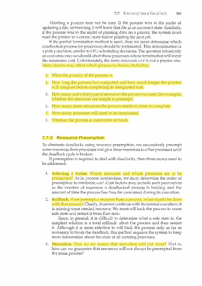
7.7 305
Aborting a process may not be easy. If the process was in the midst of updating a file, terminating it will leave that file in an incorrect state. Similarly, if the process was in the midst of printing data on a printer, the system must reset the printer to a correct state before printing the next job.
If the partial termination method is used, then we must determine which deadlocked process (or processes) should be terminated. This determination is a policy decision, similar to CPU-scheduling decisions. The question is basically an economic one; we should abort those processes whose termination will incur the minimum cost. Unfortunately, the term minimum cost is not a precise one. Many factors may affect which process is chosen, including:
1. What the priority of the process is
2. How long the process has computed and how much longer the process will compute before completing its designated task
How many and what types of resources the process has used (for example, whether the resources are simple to preempt)
How many more resources the process needs in order to complete
5. How many processes will need to be terminated
Whether the process is interactive or batch
7.7.2 Resource Preemption
To eliminate deadlocks using resource preemption, we successively preempt some resources from processes and give these resources to other processes 1-m til the deadlock cycle is broken.
If preemption is required to deal with deadlocks, then three issues need to be addressed:
Selecting a victim. Which resources and which processes are to be preempted? As in process termil<ation, we must determine the order of preemption to minimize cost. Cost factors may include such parameters as the number of resources a deadlocked process is holding and the amount of time the process has thus far consumed during its execution.
Rollback. If we preempt a resource from a process, what should be done with that process? Clearly, it cannot contil<ue with its normal execution; it is missing some needed resource. We must roll back the process to some safe state and restart it from that state.
Since, in general, it is difficult to determine what a safe state is, the simplest solution is a total rollback: abort the process and then restart it. Although it is more effective to roll back the process only as far as necessary to break the deadlock, this method requires the system to keep more information about the state of all running processes.
Starvation. How do we ensure that starvation will not occur? That is, how can we guarantee that resources will not always be preempted from the same process?
ziauddin
Highlight
ziauddin
Highlight
ziauddin
Highlight
ziauddin
Highlight

Chapter Six:
Memory Management
Address Binding, Logical Vs Physical Address,
Dynamic Loading
Linking, Swapping, Fixed and Dynamic partitioning
Paging, Segmentation
Page Replacement Algorithms (FIFO,ORA,LRU)
Thrashing

8.1
c
In Chapter 5, we showed how the CPU can be shared by a set of processes. As a result of CPU scheduling, we can improve both the utilization of the CPU and the speed of the computer's response to its users. To realize this increase in performance, however, we must keep several processes in memory; that is, we must share memory.
In this chapter, we discuss various ways to manage memory. The memorymanagement algorithms vary from a primitive bare-machine approach to paging and segmentation strategies. Each approach has its own advantages and disadvantages. Selection of a memory-management method for a specific system depends on many factors, especially on the hardware design of the system. As we shall see, many algorithms require hardware support, although recent designs have closely integrated the hardware and operating system.
To provide a detailed description of various ways of organizing memory hardware.
To discuss various memory-management techniques, including paging and segmentation.
To provide a detailed description of the Intel Pentium, which supports both pure segmentation and segmentation with paging.
As we saw in Chapter 1, memory is central to the operation of a modern computer system. Memory consists of a large array of words or bytes, each with its own address. The CPU fetches instructions from memory according to the value of the program counter. These instructions may cause additional loading from and storing to specific memory addresses.
A typical instruction-execution cycle, for example, first fetches an instruction from memory. The instruction is then decoded and may cause operands to be fetched from memory. After the instruction has been executed on the
315

316 Chapter 8
operands, results may be stored back in memory. The mernory unit sees only a stream of memory addresses; it does not know how they are generated (by the instruction counter, indexing, indirection, literal addresses, and so on) or what they are for (instructions or data). Accordingly, we can ignore hozu a program generates a memory address. We are interested only in the sequence of memory addresses generated by the running program.
We begin our discussion by covering several issues that are pertinent to the various techniques for managing memory. This coverage includes an overview of basic hardware issues, the binding of symbolic memory addresses to actual physical addresses, and the distinction between logical and physical addresses. We conclude the section with a discussion of dynamically loading and linking code and shared libraries.
8.1.1 Basic Hardware
Main memory and the registers built into the processor itself are the only storage that the CPU can access directly. There are machine instructions that take memory addresses as arguments, but none that take disk addresses. Therefore, any instructions in execution, and any data being used by the instructions, must be in one of these direct-access storage devices. If the data are not in memory, they must be moved there before the CPU can operate on them.
Registers that are built into the CPU are generally accessible within one cycle of the CPU clock. Most CPUs can decode instructions and perform simple operations on register contents at the rate of one or more operations per clock tick The same cannot be said of main memory, which is accessed via a transaction on the memory bus. Completing a memory access may take many cycles of the CPU clock. In such cases, the processor normally needs to stall, since it does not have the data required to complete the instruction that it is executing. This situation is intolerable because of the frequency of memory accesses. The remedy is to add fast memory between the CPU and
0 "
operating system
""
256000
process
300040 i soa(?LJ.o "I
process base
420940 I 120!1GO I I"" .
limit process
880000
1024000
Figure 8.1 A base and a limit register define a logical address space.
ziauddin
Highlight

318 Chapter 8
dump out those programs in case of errors, to access and modify parameters of system calls, and so on.
8.1.2 Address Binding
Usually, a program resides on a disk as a binary executable file. To be executed, the program must be brought into memory and placed within a process. Depending on the memory management in use, the process may be moved between disk and memory during its execution. The processes on the disk that are waiting to be brought into memory for execution form the
The normal procedure is to select one of the processes in the input queue and to load that process into memory. As the process is executed, it accesses instructions and data from memory. Eventually, the process terminates, and its memory space is declared available.
Most systems allow a user process to reside in any part of the physical memory. Thus, although the address space of the computer starts at 00000, the first address of the user process need not be 00000. This approach affects the addresses that the user program can use. In most cases, a user program will go through several steps-some of which may be optional-before bein.g executed (Figure 8.3). Addresses may be represented in different ways during these steps. Addresses in the source program are generally symbolic (such as count). A compiler will typically bind these symbolic addresses to relocatable addresses (such as "14 bytes from the beginning of this module"). The lin.kage editor or loader will in turn bind the relocatable addresses to absolute addresses (such as 74014). Each binding is a mapping from one address space to another.
Classically, the binding of instructions and data to memory addresses can be done at any step along the way:
Compile time. If you know at compile time where the process will reside in memory, then can be generated. For example, if you krww that a user process will reside starting at location R, then the generated compiler code will start at that location and extend up from there. If, at some later time, the starting location changes, then it will be necessary to recompile this code. The MS-DOS .COM-format programs are bound at compile time.
Load time. If it is not known at compile time where the process will reside in memory, then the compiler must generate In this case, final binding is delayed until load time. If the starting address changes, we need only reload the user code to incorporate this changed value.
Execution time. If the process can be moved during its execution from one memory segment to another, then binding must be delayed until run time. Special hardware must be available for this scheme to work, as will be discussed in Section 8.1.3. Most general-purpose operating systems 11se this method.
A major portion of this chapter is devoted to showing how these various bindings can be implemented effectively in a computer system and to discussing appropriate hardware support.
ziauddin
Highlight
ziauddin
Highlight
ziauddin
Highlight
ziauddin
Highlight

8.1
compile time
load time
} execution time (run time)
Figure 8.3 Multistep processing of a user program.
8.1.3 Logical versus Physical Address Space
An address generated by the CPU is commonly referred to as a
319
whereas an address seen by the memory unit-that is, the one loaded into the of the memory-is commonly referred to as a
The compile-time and load-time address-binding methods generate identical logical and physical addresses. However, the execution-time address-binding scheme results in differing logical and addresses. In this case, we usually refer to the logical address as a We use logical address and virtual address interchangeably in this text. The set of all logical addresses generated by a program is a logical the set of all physical addresses corresponding to these logical addresses is a physical Thus, in_ the execution-time address-binding scheme, the logical and physical address spaces differ.
The run-time mapping from virtual to physical addresses is done by a hardware device called the We can choose from many different methods to accomplish such mapping, as we discuss in
ziauddin
Highlight

320 Chapter 8
Figure 8.4 Dynamic relocation using a relocation register.
Sections 8.3 through 8.7. For the time being, we illustrate this mapping with a simple MMU scheme that is a generalization of the base-register scheme described in Section 8.1.1. The base register is now called a The value in the relocation register is added to every address generated by a user process at the time the address is sent to memory (see Figure 8.4). For example, if the base is at 14000, then an attempt by the user to address location 0 is dynamically relocated to location 14000; an access to location 346 is mapped to location 14346. The MS-DOS operating system running on the Intel 80x86 family of processors used four relocation registers when loading and running processes.
The user program never sees the real physical addresses. The program can create a pointer to location 346, store it in memory, manipulate it, and compare it with other addresses-all as the number 346. Only when it is used as a memory address (in an indirect load or store, perhaps) is it relocated relative to the base register. The user program deals with logical addresses. The memory-mapping hardware converts logical addresses into physical addresses. This form of execution-time binding was discussed in Section 8.1.2. The final location of a referenced memory address is not determined until the reference is made.
We now have two different types of addresses: logical addresses (in the range 0 to max) and physical addresses (in the rangeR+ 0 toR+ max for a base valueR). The user generates only logical addresses and thinks that the process runs in locations 0 to max. The user program generates only logical addresses and thinks that the process runs in locations 0 to max. However, these logical addresses must be mapped to physical addresses before they are used.
The concept of a logical address space that is bound to a separate physical address space is central to proper memory management.
8.1.4 Dynamic Loading
In our discussion so far, it has been necessary for the entire program and all data of a process to be in physical memory for the process to execute. The size of a process has thus been limited to the size of physical memory. To obtain better memory-space utilization, we can use dynamic With dynancic
ziauddin
Highlight
ziauddin
Highlight

8.1 321
loading, a routine is not loaded until it is called. All routines are kept on disk in a relocatable load format. The main program is loaded into memory and is executed. When a routine needs to call another routine, the calling routine first checks to see whether the other routine has been loaded. If it has not, the relocatable linking loader is called to load the desired routine into menwry and to update the program's address tables to reflect this change. Then control is passed to the newly loaded routine.
The advantage of dynamic loading is that an unused routine is never loaded. This method is particularly useful when large amounts of code are needed to handle infrequently occurring cases, such as error routines. In this case, although the total program size may be large, the portion that is used (and hence loaded) may be much smaller.
Dynamic loading does not require special support from the operating system. It is the responsibility of the users to design their programs to take advantage of such a method. Operating systems may help the programmer, however, by providing library routines to implement dynamic loading.
8.1.5 Dynamic Linking and Shared Libraries
Figure 8.3 also shows Some operating systems support only linking, in system language libraries are treated like any other object module and are combined by the loader into the binary program image. Dynamic linking, in contrast, is similar to dynamic loading. Here, though, linking, rather than loading, is postponed until execution time. This feature is usually used with system libraries, such as language subroutine libraries. Without this facility, each program on a system must include a copy of its language library (or at least the routines referenced by the program) in the executable image. This requirement wastes both disk space and main memory.
With dynamic linking, a stub is included in the image for each libraryroutine reference. The stub is a small piece of code that indicates how to locate the appropriate memory-resident library routine or how to load the library if the routine is not already present. When the stub is executed, it checks to see whether the needed routine is already in memory. If it is not, the program loads the routine into memory. Either way, the stub replaces itself with the address of the routine and executes the routine. Thus, the next time that particular code segment is reached, the library routine is executed directly, incurring no cost for dynamic linking. Under this scheme, all processes that use a language library execute only one copy of the library code.
This feature can be extended to library updates (such as bug fixes). A library may be replaced by a new version, and all programs that reference the library will automatically use the new version. Without dynamic linking, all such programs would need to be relinked to gain access to the new library. So that programs will not accidentally execute new, incompatible versions of libraries, version information is included in both the program and the library. More than one version of a library may be loaded into memory, and each program uses its version information to decide which copy of the library to use. Versions with minor changes retain the same version number, whereas versions with major changes increment the number. Thus, only programs that are compiled with the new library version are affected by any incompatible changes incorporated
ziauddin
Highlight
ziauddin
Highlight
ziauddin
Highlight
ziauddin
Highlight
ziauddin
Highlight

322 Chapter 8
8.2
in it. Other programs linked before the new library was installed will continue using the older library. This system is also known as "'H•"-"='""
Unlike dynamic loading, dynamic linking generally requires help from the operating system. If the processes in memory are protected from one another, then the operating system is the only entity that can check to see whether the needed routine is in another process's memory space or that can allow multiple processes to access the same memory addresses. We elaborate on this concept when we discuss paging in Section 8.4.4.
A process must be in memory to be executed. A process, however, can be temporarily out of memory to a and then brought
into memory for continued execution. For example, assume a multiprogramming environment with a round-robin CPU-scheduling algorithm. When a quantum expires, the memory manager will start to swap out the process that just finished and to swap another process into the memory space that has been freed (Figure 8.5). In the meantime, the CPU scheduler will allocate a time slice to some other process in memory. When each process finishes its quantum, it will be swapped with another process. Ideally, the memory manager can swap processes fast enough that some processes will be in memory, ready to execute, when the CPU scheduler wants to reschedule the CPU. In addition, the quantum must be large enough to allow reasonable amounts of computing to be done between swaps.
A variant of this swapping policy is used for priority-based scheduling algorithms. If a higher-priority process arrives and wants service, the memory manager can swap out the lower-priority process and then load and execute the higher-priority process. When the higher-priority process finishes, the
@swap out
@swap in
backing store
main memory
Figure 8.5 Swapping of two processes using a disk as a backing store.
ziauddin
Highlight
ziauddin
Highlight
ziauddin
Highlight

8.3 325
In. contiguous memory allocation, each process is contained in a single contiguous section of memory.
8.3.1 Memory Mapping and Protection
Before discussing memory allocation further, we must discuss the issue of memory mapping and protection. We can provide these features by using a relocation register, as discussed in Section 8.1.3, together with a limit register, as discussed in Section 8.1.1. The relocation register contaiTlS the value of the smallest physical address; the limit register contains the range of logical addresses (for example, relocation= 100040 and limit= 74600). With relocation and limit registers, each logical address must be less than the limit register; the MMU maps the logical address dynamically by adding the value in the relocation register. This mapped address is sent to memory (Figure 8.6).
When the CPU scheduler selects a process for execution, the dispatcher loads the relocation and limit registers with the correct values as part of the context switch. Because every address generated by a CPU is checked against these registers, we can protect both the operating system and the other users' programs and data from being modified by this running process.
The relocation-register scheme provides an effective way to allow the operating system's size to change dynamically. This flexibility is desirable in many situations. For example, the operating system contains code and buffer space for device drivers. If a device driver (or other operating-system service) is not commonly used, we do not want to keep the code and data in memory, as we might be able to use that space for other purposes. Such code is sometimes called transient operating-system code; it comes and goes as needed. Thus, using this code changes the size of the operating system during program execution.
8.3.2 Memory Allocation
Now we are ready to turn to memory allocation. One of the simplest methods for allocating memory is to divide memory into several fixed-sized
Each partition may contain exactly one process. Thus, the degree
no
trap: addressing error
Figure 8.6 Hardware supportfor relocation and limit registers.
ziauddin
Highlight

326 Chapter 8
of multiprogramming is bound by the number of partitions. In this when a partition is free, a process is selected from the input
queue and is loaded into the free partition. When the process terminates, the partition becomes available for another process. This method was originally used by the IBM OS/360 operating system (called MFT); it is no longer in use. The method described next is a generalization of the fixed-partition scheme (called MVT); it is used primarily in batch environments. Many of the ideas presented here are also applicable to a time-sharing environment in which pure segmentation is used for memory management (Section 8.6).
In the scheme, the operating system keeps a table indicating which parts of memory are available and which are occupied. Initially, all memory is available for user processes and is considered one large block of available memory a Eventually as you will see, memory contains a set of holes of various sizes.
As processes enter the system, they are put into an input queue. The operating system takes into account the memory requirements of each process and the amount of available memory space in determining which processes are allocated memory. When a process is allocated space, it is loaded into memory, and it can then compete for CPU time. When a process terminates, it releases its memory which the operating system may then fill with another process from the input queue.
At any given time, then, we have a list of available block sizes and an input queue. The operating system can order the input queue according to a scheduling algorithm. Memory is allocated to processes untit finally, the memory requirements of the next process cannot be satisfied -that is, no available block of memory (or hole) is large enough to hold that process. The operating system can then wait until a large enough block is available, or it can skip down the input queue to see whether the smaller memory requirements of some other process can be met.
In generat as mentioned, the memory blocks available comprise a set of holes of various sizes scattered throughout memory. When a process arrives and needs memory, the system searches the set for a hole that is large enough for this process. If the hole is too large, it is split into two parts. One part is allocated to the arriving process; the other is returned to the set of holes. When a process terminates, it releases its block of memory, which is then placed back in the set of holes. If the new hole is adjacent to other holes, these adjacent holes are merged to form one larger hole. At this point, the system may need to check whether there are processes waiting for memory and whether this newly freed and recombined memory could satisfy the demands of any of these waiting processes.
This procedure is a particular instance of the general which concerns how to satisfy a request of size n from a
There are many solutions to this problem. The and strategies are the ones most commonly used to select a free hole from the set of available holes.
First fit. Allocate the first hole that is big enough. Searching can start either at the beginning of the set of holes or at the location where the previous first-fit search ended. We can stop searching as soon as we find a free hole that is large enough.
ziauddin
Highlight
ziauddin
Highlight
ziauddin
Highlight

8.3 327
Best fit. Allocate the smallest hole that is big enough. We must search the entire list, unless the list is ordered by size. This strategy produces the smallest leftover hole.
Worst fit. Allocate the largest hole. Again, we must search the entire list, unless it is sorted by size. This strategy produces the largest leftover hole, which may be more useful than the smaller leftover hole from a best-fit approach.
Simulations have shown that both first fit and best fit are better than worst fit in terms of decreasing time and storage utilization. Neither first fit nor best fit is clearly better than the other in terms of storage utilization, but first fit is generally faster.
8.3.3 Fragmentation
Both the first-fit and best-fit strategies for memory allocation suffer from external As processes are loaded and removed from memory, the free memory space is broken into little pieces. External fragmentation exists when there is enough total memory space to satisfy a request but the available spaces are not contiguous; storage is fragmented into a large number of small holes. This fragmentation problem can be severe. In the worst case, we could have a block of free (or wasted) memory between every two processes. If all these small pieces of memory were in one big free block instead, we might be able to run several more processes.
Whether we are using the first-fit or best-fit strategy can affect the amount of fragmentation. (First fit is better for some systems, whereas best fit is better for others.) Another factor is which end of a free block is allocated. (Which is the leftover piece-the one on the top or the one on the bottom?) No matter which algorithm is used, however, external fragmentation will be a problem.
Depending on the total amount of memory storage and the average process size, external fragmentation may be a minor or a major problem. Statistical analysis of first fit, for instance, reveals that, even with some optimization, given N allocated blocks, another 0.5 N blocks will be lost to fragmentation. That is, one-third of memory may be unusable! This property is known as the
Memory fragmentation can be internal as well as external. Consider a multiple-partition allocation scheme with a hole of 18,464 bytes. Suppose that the next process requests 18,462 bytes. If we allocate exactly the requested block, we are left with a hole of 2 bytes. The overhead to keep track of this hole will be substantially larger than the hole itself. The general approach to avoiding this problem is to break the physical memory into fixed-sized blocks and allocate memory in units based on block size. With this approach, the memory allocated to a process may be slightly larger than the requested memory. The difference between these two numbers is internal memory that is internal to a partition.
One solution to the problem of external fragmentation is The goal is to shuffle the memory contents so as to place all free n'lemory together in one large block. Compaction is not always possible, however. If relocation is static and is done at assembly or load time, compaction cannot be done; compaction is possible only if relocation is dynamic and is done at execution
ziauddin
Highlight
ziauddin
Highlight
ziauddin
Highlight
ziauddin
Highlight

328 Chapter 8
8.4
time. If addresses are relocated dynamically, relocation requires only moving the program and data and then changing the base register to reflect the new base address. When compaction is possible, we must determine its cost. The simplest compaction algorithm is to move all processes toward one end of memory; all holes move in the other direction, producing one large hole of available memory. This scheme can be expensive.
Another possible solution to the external-fragmentation problem is to permit the logical address space of the processes to be noncontiguous, thus allowing a process to be allocated physical memory wherever such memory is available. Two complementary techniques achieve this solution: paging (Section 8.4) and segmentation (Section 8.6). These techniques can also be combined (Section 8.7).
is a memory-management scheme that permits the physical address space a process to be noncontiguous. Paging avoids external fragmentation and the need for compaction. It also solves the considerable problem of fitting memory chunks of varying sizes onto the backin.g store; most memorymanagement schemes used before the introduction of paging suffered from this problem. The problem arises because, when some code fragments or data residing in main memory need to be swapped out, space must be fmmd on the backing store. The backing store has the same fragmentation problems discussed in connection with main memory, but access is much slower, so compaction is impossible. Because of its advantages over earlier methods, paging in its various forms is used in most operating systems.
physical address fOOOO •.. 0000
f1111 ... 1111
page table
Figure 8.7 Paging hardware.
1---------1
physical memory
ziauddin
Highlight
ziauddin
Highlight

8.4 329
Traditionally, support for paging has been handled by hardware. However, recent designs have implemented paging by closely integrating the hardware and operating system, especially on 64-bit microprocessors.
8.4.1 Basic Method
The basic method for implementing paging involves breaking physical memory into fixed-sized blocks called harnes and breaking logical memory into blocks of the same size called When a process is to be executed, its pages are loaded into any available memory frames from their source (a file system or the backing store). The backing store is divided into fixed-sized blocks that are of the san1.e size as the memory frames.
The hardware support for paging is illustrated in Figure 8.7. Every address generated the CPU is divided into two parts: a {p) and a
. The page number is used as an index into a The page table contains the base address of each page in physical memory. This base address is combined with the page offset to define the physical memory address that is sent to the memory unit. The paging model of memory is shown in Figure 8.8.
The page size (like the frame size) is defined by the hardware. The size of a page is typically a power of 2, varying between 512 bytes and 16 MB per page, depending on the computer architecture. The selection of a power of 2 as a page size makes the translation of a logical address into a page number and page offset particularly easy. If the size of the logical address space is 2m, and a page size is 271 addressing units (bytes or wordst then the high-order m- n bits of a logical address designate the page number, and the n low-order bits designate the page offset. Thus, the logical address is as follows:
logical memory
~w page table
frame number
physical memory
Figure 8.8 Paging model of logical and physical memory.
ziauddin
Highlight
ziauddin
Highlight
ziauddin
Underline

subroutine
symbol table
·.
main program
logical address
8.6
Figure 8.18 User's view of a program.
343
the purpose of the segment in the program. Elements within a segment are identified by their offset from the begim1.ing of the segment: the first statement of the program, the seventh stack frame entry in the stack, the fifth instruction of the Sqrt (), and so on.
is a memory-management scheme that supports this user view of memory. A logical address space is a collection of segments. Each segment has a name and a length. The addresses specify both the segment name and the offset within the segment. The user therefore specifies each address by two quantities: a segment name and an offset. (Contrast this scheme with the paging scheme, in which the user specifies only a single address, which is partitioned by the hardware into a page number and an offset, all invisible to the programmer.)
For simplicity of implementation, segments are numbered and are referred to by a segn"lent number, rather than by a segment name. Thus, a logical address consists of a two tuple:
<segment-number, offset>.
Normally, the user program is compiled, and the compiler automatically constructs segments reflecting the input program.
A C compiler might create separate segments for the following:
The code
Global variables
The heap, from which memory is allocated
The stacks used by each thread
The standard C library
ziauddin
Highlight
ziauddin
Highlight
ziauddin
Highlight
ziauddin
Highlight

9.2
9.2 361
Consider how an executable program might be loaded from disk into n'lemory. One option is to load the entire program in physical memory at program execution time. However, a problent with this approach is that we may not initially need the entire program in memory. Suppose a program starts with a list of available options from which the user is to select. Loading the entire program into memory results in loading the executable code for all options, regardless of whether an option is ultimately selected by the user or not. An alternative strategy is to load pages only as they are needed. This technique is known as paging and is commonly used in virtual memory systems. With demand-paged virtual memory, pages are only loaded when they are demanded during program execution; pages that are never accessed are thus never loaded into physical memory.
A demand-paging system is similar to a paging system with swapping (Figure 9.4) where processes reside in secondary memory (usually a disk). When we want to execute a process, we swap it into memory. Rather than swapping the entire process into memory, however, we use a A lazy swapper never swaps a page into memory unless that page will be needed. Since we are now viewing a process as a sequence of pages, rather than as one large contiguous address space, use of the term swapper is technically incorrect. A swapper manipulates entire processes, whereas a is concerned with the individual pages of a process. We thus use pager, rather than swapper, in connection with demand paging.
program A
program B
main memory
swap out
so 90100110
120130140150
swap in 16017
Figure 9.4 Transfer of a paged memory to contiguous disk space.
ziauddin
Highlight
ziauddin
Highlight
ziauddin
Highlight

362 Chapter 9
9.2.1 Basic Concepts
When a process is to be swapped in, the pager guesses which pages will be used before the process is swapped out again. Instead of swapping in a whole process, the pager brings only those pages into memory. Thus, it avoids reading into memory pages that will not be used anyway, decreasing the swap time and the amount of physical memory needed.
With this scheme, we need some form of hardware support to distinguish between the pages that are in memory and the pages that are on the disk. The valid -invalid bit scheme described in Section 8.4.3 can be used for this purpose. This time, however, when this bit is set to "valid/' the associated page is both legal and in n1.emory. If the bit is set to "invalid/' the page either is not valid (that is, not in the logical address space of the process) or is valid but is currently on the disk. The page-table entry for a page that is brought into memory is set as usuat but the page-table entry for a page that is not currently in memory is either simply marked invalid or contains the address of the page on disk. This situation is depicted in Figure 9.5.
Notice that marking a page invalid will have no effect if the process never attempts to access that page. Hence, if we guess right and page in all and only those pages that are actually needed, the process will run exactly as though we had brought in all pages. While the process executes and accesses pages that are execution proceeds normally.
0
2
3
4
5
6
7
valid-invalid frame bit
'\. I 0 4 v
logical memory
physical memory
DOD D
[1J
[.@JtB]
ODD
Figure 9.5 Page table when some pages are not in main memory.
ziauddin
Highlight

operating system
reference
(,;\, page is on \.:V backing store
® trap
restart instruction
page table
® reset page
table
physical memory
9.2
0 bring in
missing page
Figure 9.6 Steps in handling a page fault.
363
But what happens if the process tries to access a page that was not brought into memory? Access to a page marked invalid causes a The paging hardware, in translating the address through the page table, will notice that the invalid bit is set, causing a trap to the operating system. This trap is the result of the operating system's failure to bring the desired page into memory. The procedure for handling this page fault is straightforward (Figure 9.6):
We check an internal table (usually kept with the process control block) for this process to determine whether the reference was a valid or an invalid memory access.
If the reference was invalid, we terminate the process. If it was valid, but we have not yet brought in that page, we now page it in.
We find a free frame (by taking one from the free-frame list, for example).
We schedule a disk operation to read the desired page into the newly allocated frame.
When the disk read is complete, we modify the internal table kept with the process and the page table to indicate that the page is now in memory.
We restart the instruction that was interrupted by the trap. The process can now access the page as though it had always been in memory.
In the extreme case, we can start executing a process with no pages in memory. When the operating system sets the instruction pointer to the first
ziauddin
Highlight
ziauddin
Highlight

370 Chapter 9
valid-invalid
PC--::"-_='-~~==: !came f il logical memory
for user 1 page table for user 1
valid-invalid 0
frame ~bi~
r---~ v v
~-------'--'
2
3
logical memory for user 2
page table for user 2
0 monitor
2
3
4
5 J
6 A
7 E
physical memory
Figure 9.9 Need for page replacement
Over-allocation of memory manifests itself as follows. While a user process is executing, a page fault occurs. The operating system determines where the desired page is residing on the disk but then finds that there are no free frames on the free-frame list; all memory is in use (Figure 9.9).
The operating system has several options at this point. It could terminate the user process. However, demand paging is the operating system's attempt to improve the computer system's utilization and throughput. Users should not be aware that their processes are running on a paged system-paging should be logically transparent to the user. So this option is not the best choice.
The operating system could instead swap out a process, freeing all its frames and reducing the level of multiprogramming. This option is a good one in certain circumstances, and we consider it further in Section 9.6. Here, we discuss the most common solution:
9.4.1 Basic Page Replacement
Page replacement takes the following approach. If no frame is free, we find one that is not currently being used and free it. We can free a frame by writing its contents to swap space and changing the page table (and all other tables) to indicate that the page is no longer in memory (Figure 9.10). We can now use the freed frame to hold the page for which the process faulted. We modify the page-fault service routine to include page replacement:
Find the location of the desired page on the disk.
Find a free frame:
a. If there is a free frame, use it.
ziauddin
Highlight
ziauddin
Highlight
ziauddin
Highlight

9.4 371
b. If there is no free frame, use a page-replacement algorithnc to select a
c. Write the victim frame to the disk; change the page and frame tables accordingly.
Read the desired page into the newly freed frame; change the page and frame tables.
Restart the user process.
Notice that, if no frames are free, two page transfers (one out and one in) are required. This situation effectively doubles the page-fault service time and increases the effective access time accordingly.
We can reduce this overhead by using a (or When this scheme is used, each page or frame has a modify bit associated with it in the hardware. The modify bit for a page is set by the hardware whenever any word or byte in the page is written into, indicating that the page has been modified. When we select a page for replacement, we examine its modify bit. If the bit is set, we know that the page has been modified since it was read in from the disk. In this case, we must write the page to the disk. If the modify bit is not set, however, the page has not been modified since it was read into memory. In this case, we need not write the memory page to the disk: it is already there. This technique also applies to read-only pages (for example, pages of binary code). Such pages cannot be modified; thus, they may be discarded when desired. This scheme can significantly reduce the time required to service a page fault, since it reduces I/O time by one-half if the page has not been modified.
frame valid-invalid bit
'\. /
physical memory
Figure 9.10 Page replacement
ziauddin
Highlight

9.4 373
16
g) 14 :::J
.;2 12 Q) Ol 10 cO 0..
0 8 '-Q)
..0 6 E :::J c 4
2
2 3 4 5 6
number of frames
Figure 9.1 i Graph of page faults versus number of frames.
To determine the number of page faults for a particular reference string and page-replacement algorithm, we also need to know the number of page frames available. Obviously, as the number of frames available increases, the number of page faults decreases. For the reference stril'lg considered previously, for example, if we had three or more frames, we would have only three faultsone fault for the first reference to each page. In contrast, with only one frame available, we would have a replacement with every reference, resulting in eleven faults. In general, we expect a curve such as that in Figure 9.11. As the number of frames increases, the number of page faults drops to some minimal level. Of course, adding physical memory increases the number of frames.
We next illustrate several page-replacement algorithms. In doing so, we use the reference string
for a memory with three frames.
9.4.2 FIFO Page Replacement
The simplest page-replacement algorithm is a first-in, first-out (FIFO) algorithm. A FIFO replacement algorithm associates with each page the time when that page was brought into memory. When a page must be replaced, the oldest page is chosen. Notice that it is not strictly necessary to record the time when a page is brought in. We can create a FIFO queue to hold all pages in memory. We replace the page at the head of the queue. When a page is brought into memory, we insert it at the tail of the queue.
For our example reference string, our three frames are initially empty. The first three references (7, 0, 1) cause page faults and are brought into these empty frames. The next reference (2) replaces page 7, because page 7 was brought in first. Since 0 is the next reference and 0 is already in memory, we have no fault for this reference. The first reference to 3 results in replacement of page 0, since
ziauddin
Highlight

374 Chapter 9
reference string
7 0 2 0 3 0 4 2 3 0 3 2 2 0 7 0
page frames
Figure 9.12 FIFO page-replacement algorithm.
it is now first in line. Because of this replacement, the next reference, to 0, will fault. Page 1 is then replaced by page 0. This process continues as shown in Figure 9.12. Every time a fault occurs, we show which pages are in our three frames. There are fifteen faults altogether.
The FIFO page-replacement algorithm is easy to Lmderstand and program. However, its performance is not always good. On the one hand, the page replaced may be an initialization module that was used a long time ago and is no longer needed. On the other hand, it could contain a heavily used variable that was initialized early and is in constant use.
Notice that, even if we select for replacement a page that is in active use, everything still works correctly. After we replace an active page with a new one, a fault occurs almost immediately to retrieve the active page. Some other page must be replaced to bring the active page back into memory. Thus, a bad replacement choice increases the page-fault rate and slows process execution. It does not, however, cause incorrect execution.
To illustrate the problems that are possible with a FIFO page-replacement algorithm, we consider the following reference string:
1, 2, 3, 4, 1, 2, 5, 1, 2, 3, 4, 5
Figure 9.13 shows the curve of page faults for this reference string versus the number of available frames. Notice that the number of faults for four frames (ten) is greater than the number of faults for three frames (nine)! This most unexpected result is known as . for some page-replacement algorithms, the page-fault rate may increase as the number of allocated frames increases. We would expect that giving more memory to a process would improve its performance. In some early research, investigators noticed that this assumption was not always true. Belady's anomaly was discovered as a result.
9.4.3 Optimal Page Replacement
of Belady's anomaly was the search for an which has the lowest page-fault rate of all
algorithms and will never suffer from Belady's anomaly. Such an algorithm does exist and has been called OPT or MIN. It is simply this:
Replace the page that will not be used for the longest period of time.
ziauddin
Highlight
ziauddin
Highlight
ziauddin
Highlight
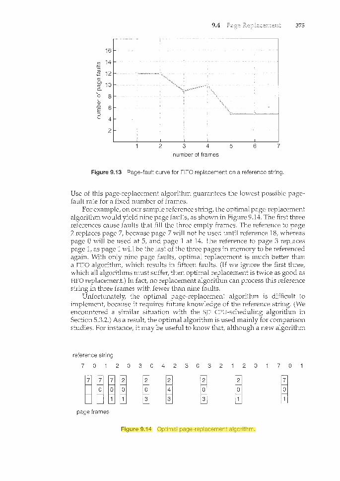
9.4 375
16
~ :::5
2 12 CJ) OJ 10 m 0..
0 8 CJ
_o 6 E :::5 c 4
2
number of frames
Figure 9.13 Page-fault curve for FIFO replacement on a reference string.
Use of this page-replacement algorithm guarantees the lowest possible pagefault rate for a fixed number of frames.
For example, on our sample reference string, the optimal page-replacement algorithm would yield nine page faults, as shown in Figure 9.14. The first three references cause faults that fill the three empty frames. The reference to page 2 replaces page 7, because page 7 will not be used until reference 18, whereas page 0 will be used at 5, and page 1 at 14. The reference to page 3 replaces page 1, as page 1 will be the last of the three pages in memory to be referenced again. With only nine page faults, optimal replacement is much better than a FIFO algorithm, which results in fifteen faults. (If we ignore the first three, which all algorithms must suffer, then optimal replacement is twice as good as FIFO replacement.) Irt fact, no replacement algorithm can process this reference string in three frames with fewer than nine faults.
Unfortunately, the optimal page-replacement algorithm is difficult to implement, because it requires future knowledge of the reference string. (We encountered a similar situation with the SJF CPU-schedulin.g algorithm in Section 5.3.2.) As a result, the optimal algorithm is used mainly for comparison studies. For instance, it may be useful to know that, although a new algorithm
reference string
7 0 2 0 3 0 4 2 3 0 3 2 2 0 7 0
page frames
Figure 9.14 Optimal page-replacement algorithm.
ziauddin
Highlight

376 Chapter 9
is not optimat it is within 12.3 percent of optimal at worst and within 4.7 percent on average.
9.4.4 LRU Page Replacement
lf the optimal algorithm is not feasible, perhaps an approximation of the optimal algorithm is possible. The key distinction between the FIFO and OPT algorithms (other than looking backward versus forward in time) is that the FIFO algorithm uses the time when a page was brought into memory, whereas the OPT algorithm uses the time when a page is to be used. If we use the recent past as an approximation of the near future, then we can replace the
that has not been used for the longest period of time. This approach is the
LRU replacement associates with each page the time of that page's last use. When a page must be replaced, LRU chooses the page that has not been used for the longest period of time. We can think of this strategy as the optimal page-replacement algorithm looking backward in time, rather than forward. (Strangely, if we let sR be the reverse of a reference stringS, then the page-fault rate for the OPT algorithm on Sis the same as the page-fault rate for the OPT algorithm on SR. Similarly, the page-fault rate for the LRU algorithm on Sis the same as the page-fault rate for the LRU algorithm on sR.)
The result of applying LRU replacement to our example reference string is shown in Figure 9.15. The LRU algorithm produces twelve faults. Notice that the first five faults are the same as those for optimal replacement. When the reference to page 4 occurs, however, LRU replacement sees that, of the three frames in memory, page 2 was used least recently. Thus, the LRU algorithm replaces page 2, not knowing that page 2 is about to be used. When it then faults for page 2, the LRU algorithm replaces page 3, since it is now the least recently used of the three pages in memory. Despite these problems, LRU replacement with twelve faults is much better than FIFO replacement with fifteen.
The LRU policy is often used as a page-replacement algorithm and is considered to be good. The major problem is how to implement LRU replacement. An LRU page-replacement algorithm may require substantial hardware assistance. The problem is to determine an order for the frames defined by the time of last use. Two implementations are feasible:
Counters. In the simplest case, we associate with each page-table entry a time-of-use field and add to the CPU a logical clock or counter. The clock is
reference string
7 0 2 0 3 0 4 2 3 0 3 2 2 0 7 0
page frames
Figure 9.15 LRU page-replacement algorithm.
ziauddin
Highlight
ziauddin
Highlight
386 Chapter 9
9.6
If the number of frames allocated to a low-priority process falls below the minimum number required by the computer architecture, we must suspend that process's execution. We should then page out its remaining pages, freeing all its allocated frames. This provision introduces a swap-in, swap-out level of intermediate CPU scheduling.
In fact, look at any process that does not have "enough" frames. If the process does not have the num.ber of frames it needs to support pages in active use, it will quickly page-fault. At this point, it must replace some page. However, since all its pages are in active use, it must replace a page that will be needed again right away. Consequently, it quickly faults again, and again, and again, replacing pages that it must back in immediately.
This high paging activity is called A process is thrashing if it is spending more time paging than executing.
9.6.1 Cause of Thrashing
Thrashing results in severe performance problems. Consider the following scenario, which is based on the actual behavior of early paging systems.
The operating system monitors CPU utilization. If CPU utilization is too low, we increase the degree of multiprogramming by introducing a new process to the system. A global page-replacement algorithm is used; it replaces pages without regard to the process to which they belong. Now suppose that a process enters a new phase in its execution and needs more frames. It starts faulting and taking frames away from other processes. These processes need those pages, however, and so they also fault, taking frames from other processes. These faulting processes must use the pagin.g device to swap pages in and out. As they queue up for the paging device, the ready queue empties. As processes wait for the paging device, CPU utilization decreases.
The CPU scheduler sees the decreasing CPU utilization and increases the degree of multiprogramming as a result. The new process tries to get started by taking frames from running processes, causing more page faults and a longer queue for the paging device. As a result, CPU utilization drops even further, and the CPU scheduler tries to increase the degree of multiprogramming even more. Thrashing has occurred, and system throughput plunges. The pagefault rate increases tremendously. As a result, the effective m.emory-access time increases. No work is getting done, because the processes are spending all their time paging.
This phenomenon is illustrated in Figure 9.18, in which CPU utilization is plotted against the degree of multiprogramming. As the degree of multiprogramming increases, CPU utilization also ilccreases, although more slowly, until a maximum is reached. If the degree of multiprogramming is increased even further, thrashing sets in, and CPU utilization drops sharply. At this point, to increase CPU utilization and stop thrashing, we must decrease the degree of multiprogramming.
We can limit the effects of thrashing by using a (or With local replacement, if one process starts thrashing, it cannot frames from another process and cause the latter to thrash as well. However, the problem is not entirely solved. If processes are
ziauddin
Highlight
ziauddin
Highlight
ziauddin
Highlight

9.6 387
degree of multiprogramming
Figure 9.18 Thrashing.
thrashing, they will be in the queue for the paging device most of the time. The average service time for a page fault will increase because of the longer average queue for the paging device. Thus, the effective access time will increase even for a process that is not thrashing.
To prevent thTashing, we must provide a process with as many frames as it needs. But how do we know how many frames it "needs"? There are several teclmiques. The working-set strategy (Section 9.6.2) starts by looking at how
frames a process is actually using. This approach defines the locality of process execution.
The locality model states that, as a process executes, it moves from locality to locality. A locality is a set of pages that are actively used together (Figure 9.19). A program is generally composed of several different localities, which may overlap.
For example, when a function is called, it defines a new locality. In this locality, memory references are made to the instructions of the function call, its local variables, and a subset of the global variables. When we exit the function, the process leaves this locality, since the local variables and instructions of the function are no longer in active use. We may return to this locality later.
Thus, we see that localities are defined by the program structure and its data structures. The locality model states that all programs will exhibit this basic memory reference structure. Note that the locality model is the unstated principle behind the caching discussions so far in this book If accesses to any types of data were random rather than patterned, caching would be useless.
Suppose we allocate enough frames to a process to accommodate its current locality. It will fault for the pages in its locality until all these pages are in memory; then, it will not fault again until it changes localities. If we do not allocate enough frames to accommodate the size of the current locality, the process will thrash, since it cannot keep in memory all the pages that it is actively using.
9.6.2 Working-Set Model
As mentioned, the is based on the assumption of locality. This model uses a paramete1~ /':,, to define the vrindovv. The idea
ziauddin
Highlight