operating manual lift controller system david 613 functions ...
255
OPERATING MANUAL LIFT CONTROLLER SYSTEM DAVID 613 FUNCTIONS START-UP INSTRUCTIONS
-
Upload
khangminh22 -
Category
Documents
-
view
0 -
download
0
Transcript of operating manual lift controller system david 613 functions ...

OPERATING MANUAL
LIFT CONTROLLER SYSTEM DAVID 613
FUNCTIONS START-UP INSTRUCTIONS

KW Aufzugstechnik GmbH OPERATING MANUAL DAVID-613
DAVID-D613-V118-E 02.07.2019 Page - 2 -

KW Aufzugstechnik GmbH OPERATING MANUAL DAVID-613
DAVID-D613-V118-E 02.07.2019 Page - 3 -
KW Aufzugstechnik GmbH Mikroprozessorsystem DAVID-613 Ver-sion V1.18 from 02.07.2019 All rights reserved. No part of this publication may be reproduced, stored in a retrieval system, or trans-mitted in any form or by any means, electronic, mechanical, photocopying, recording, or otherwise, without the prior written permission of KW Aufzugstechnik GmbH. The information contained herein is designed only for use with this lift controller system. Neither KW Aufzugstechnik GmbH nor ist affiliates shall be liable to the purchaser of this product or third parties for damages, losses, costs, or expenses incurred by the purchaser or third parties as a result of: accident, misuse, or abuse of this product or unauthorized modifications, repairs, or alterations to this product, or ( excluding the U.S.) failure to strictly comply with KW Aufzugstechnik GmbH’s operating and maintenance instructions. KW Aufzugstechnik GmbH shall not be liable for any damages or problems arising from the use of any options or any consumable products other than those designated as Original KW Aufzugstechnik GmbH Products. General Notice: Other product names used herein are for identification purposes only and may be trademarks of their respective owners. All rights 2001 – 2019 by KW Aufzugstechnik GmbH, Oberursel, Germany
KW AUFZUGSTECHNIK GmbH Zimmersmühlenweg 69 D-61440 Oberursel / Germany Tel. +49 (0) 6171-9895-0 Fax. +49 (0) 6171-9895-19 Int. www.kw-aufzugstechnik.de Mail. [email protected] Hotline Tel. +49 (0) 6171-9895-12

KW Aufzugstechnik GmbH OPERATING MANUAL DAVID-613
DAVID-D613-V118-E 02.07.2019 Page - 4 -
Content 1. SYSTEM DESCRIPTION 7 1.1 PRODUCT LIABILITY AND WARRANTY ........................................................... 7 1.2 SAFETY CONDITIONS ...................................................................................... 7 1.3 EU DECLARATION OF CONFORMITY & EMC TEST REPORT ........................ 8 1.4 DESCRIPTION OF SAFETY CIRCUIT EU-Declaration of Conformity TÜV Rheinland 10 1.5 SELF-MONITORING OF THE BRAKING ELEMENTS after EN81- 20 14
1.5.1 - Function-Description - Monitoring of the Braking Elements ......................... 14
1.5.2 - Digital Inputs ................................................................................................. 15
1.5.3 - Teach in of the Monitoring Times .................................................................. 15
1.5.4 - Fault clearance and Reset ............................................................................ 16
1.5.5 - Function Test – Monitoring of the Braking Elements after EN81-20 .......…… 17
1.5.6 - EG-Declaration of Conformity - LIFTINSTITUUT .......................................... 18
1.6 DESCRIPTION OF TEMPERATURE MONITOR ZR ..................….................... 19 1.7 DESCRIPTION OF ENERGY EFFIVIENCY VDI 4707 ........................................ 20 2. PERFORMANCE FEATURES 21 2.1 PERFORMANCE FEATURES OF THE MC SYSTEM DAVID-613............ 21 2.2 DESCRIPTION CENTRAL UNIT ZR ...................... 21 2.3 DESCRIPTION EXPANSION-UNIT CENTRAL UNIT ZG32..…….…..... 26 2.4 DESCRIPTION EXPANSION-UNIT CAR UNIT ZG24F…….…..... 27 2.5 DESCRIPTION SENSOR-102…….…..... 28 2.6 DESCRIPTION SECURITY CIRCUIT A3 SIS-16 ................ 29 2.7 DESCRIPTION CAR CONTROLLER FKR ................... 33 2.8 DESCRIPTION CAR CALLING PCB EIT .................... 35 2.9 DESCRIPTION REMOTE STATION ER-2014 ............ 38 2.10 DESCRIPTION REMOTE STATION ER-2013 ............ 40 2.11 DESCRIPTION HYDRAULIC CONTROL-VALVE RV-60 & NGV60 42 2.12 DESCRIPTION HANGING WIRE EHK-40 .............. 43 2.13 DESCRIPTION HANDPROGRAMMING UNIT HPG60 ............... 44 2.14 DESCRIPTION MODEM GSM GSM-60 ............... 45 2.15 DESCRIPTION EXTERNAL EMERGENCY CALL & MODEM UNITS GSM 110 & SL-6 45 2.16 DESCRIPTION SOFTWARE KW-LiftControl 46 2.17 DESCRIPTION SOFTWARE KW-Monitoring 47 3. MENU DESCRIPTION 48 3.1 MENU AND PARAMETER STRUCTURE .......................................................... 48 4. PARAMETER DESCRIPTION 65 4.1 GENERAL WORKING WITH THE HPG60 & NAVIGATION ........................... 65 4.2 SERIAL INTERFACES 1 AND 2 .................................................................... 67 4.3 USB INTERFACES 1 AND 2............................................................................ 68 4.4 CAN OPEN INTERFACE ................................................................................. 68 4.5 WLAN / WiFi Transeiver .................................................................................... 68 A1 LIFTTYPE .................................................................................................. 69 A2 CONTROLLER ............................................................................................... 69 A3 SHAFT ........................................................................................................... 71 A4 CANopen lift ...................................................................................................... 71 B1 DOOR PARAMETER ...................................................................................... 73 B10 DOORS IN GENERAL .................................................................................... 74 B11 TABLE OF ENTRANCE .................................................................................. 76 B12 SAFETY PHOTOCELL ................................................................................... 76 B13 NUDGING FUNCTION ................................................................................... 77 B14 ENTRANCE MONITOR ................................................................................... 77 B15 MECHANICAL LOCK ...................................................................................... 78 B16 SAFETY-CIRCUIT ....................................................................................... 78 B17 RELEVELING .............................................................................................. 78 B2 CALL OPTIONS 79 B21 CAR CALLS ................................................................................................... 79

KW Aufzugstechnik GmbH OPERATING MANUAL DAVID-613
DAVID-D613-V118-E 02.07.2019 Page - 5 -
B22 LANDING CALLS ............................................................................................ 80 B23 CAR PRIORITY .......................................................................................... 81 B24 LANDIND PRIORITY....................................................................................... 82 B25 GROUPCONTROLLER ................................................................................... 84 B3 DRIVE 91 B30 HYDRAULIC DRIVES .................................................................................... 91 B31 HYDRAULIC REGULATED ........................................................................ 92 B32 HYDRAULIC FREQUENCY INVERTER ........................................................ 94 B33 ROPE 2 SPEEDS .......................................................................................... 95 B34 ROPE VARIABLE VOLTAGE ......................................................................... 95 B35 ROPE FREQUENCY INVERTER .................................................................... 97 B4 SHAFT COPY SYSTEMS 99 B41 STANDARD COPY ...................................................................................... 99 B42 RELATIVE COPY ......................................................................................... 100 B43 ABSOLUTE COPY.......................................................................................... 103 B44 MOTOR COPY ......................................................................................... 114 B45 MINIMUM COPY ........................................................................................ 117 B46 R&S COPY …….............................................................................................. 119 B5 INDICATION 120 B501 CAR INDICATION ........................................................................................... 120 B502 CAR ARROW ................................................................................................ 121 B503 FLOOR ARROW.............................................................................................. 121 B504 GONG AT THE CAR .....................................................................………....... 122 B505 GONG AT THE FLOOR ............................................................................... 123 B506 LED-MATRIX ................................................................................................ 124 B507 FLOORS .................................................................................................... 125 B508 MESSAGES …................................................................................................ 125 B509 TFT/LCD – Kabine ............................................................................................ 125 B510 TFT/LCD – Etage ….......................................................................................... 129 B6 FUNCTIONS 132 B600 MONITOR-FUNCTIONS ................................................................................ 132 B601 INSPECTION TRAVEL ………….................................................................... 135 B602 EMERGENCY UNIT ........................................................................................ 137 B603 CAR FAN ................................................................................................... 138 B604 LOAD MEASURE ........................................................................................... 138 B605 STAND-BY-DRIVE .......................................................................................... 139 B606 PARKING TRAVEL ........................................................................................ 139 B607 FLOOR BLOCKING ..................................................................................... 140 B608 ENERGY SAVE MODE .................................................................................. 141 B609-14 PRIORITIES OF SPECIAL DRIVES ....................................................... 142
B609 EMERGENCY-POWER SERVICE................................................................... 143 B610 EMERGENCY-FIRE SERVICE ....................................................................... 144 B611 FIRE FIGHTER TRAVEL .......................................................................... 145 B612 RESCUE TRAVEL ......................................................................................... 147 B613 GUIDE MODE ................................................................................................. 147 B614 HOTEL STOPPING ........................................................................................ 147 B615 TIME RELAYS ..........................................................................………...... 148 B616 ELEVATOR-CHECK ......................................................................……......... 149 B617 BOLT ............................................................................................……......... 149 B618 CODELOCK CALLS .......................................................................……......... 151 B619 ATTENDANT MODE ......................................................................……......... 152 B620 DEADMAN MODE ...........................................................................……......... 152 B621 FAX-MODEM-DUN .........................................................................……......... 153 B622 UCM MONITORING ........................................................................……......... 154 B623 OSKAR INTERFACE ......................................................................……......... 155 B624 PARKING GARAGE ........................................................................……......... 155 B625 TRAFFIC CAPTURE ......................................................................………...... 156 B626 WLAN ………………………………………………………………………………… 156

KW Aufzugstechnik GmbH OPERATING MANUAL DAVID-613
DAVID-D613-V118-E 02.07.2019 Page - 6 -
B627 SABBAT-CONTROL ……………………………………………………………… 157 B628 B629
PENTHOUSE-CONTROL ………………………………………………………… REMOTE DIAGNOSTICS………………………………………………………….
158 160
B7 INPUTS / OUTPUTS 161 B71 ASSOCIATION OUTPUTS ............................................................................. 161 B72 ASSOCiATION INPUTS .................................................................................. 171 B73 ASSIGNMENT ER-EAx 186 B74 PULSE BUFFER DELAY ................................................................................ 186 5. DIAGNOSIS AND FAULT HANDLING 187 I1 ACTUAL VALUE MENU: CALLS FOR FLOOR 01 TO 16 …..……………......... 187 I2 ACTUAL VALUE MENU: CALLS FOR FLOOR 17 TO 32 …..……………......... 187 I3 ACTUAL VALUE MENU: CAR POSITION ……………………………................ 187 I4 ACTUAL VALUE MENU: DOORS, DOOR SWITCHES …...............……..…... 188 I5 ACTUAL VALUE MENU: SAFETY CIRCUIT ………........................……..…... 188 I6 ACTUAL VALUE MENU: COMMANDS ……………......................................... 188 I7 ACTUAL VALUE MENU: MODEM ….............................................................. 188 C0 CONTROLLER RESET ………………………………......................................... 189 C1 GIVE CALLS …………………………………………………................................. 189 C2 IN / OUTPUT SIGNALS ................................................................................ 189 C3 FAULT LOG ................................................................................................. 190 C4 MOT-APPROVAL ........................................................................................... 190 C5 LEVELING CONTROL...................................................................................... 192 C6 MODUL MONITOR ......................................................................................... 192 C7 DRIVE ASSEMBLY ……................................................................................... 192 C8 EVENT LOG ... ............................................................................................... 192 C9 FAULT DESCRIPTION ................................................................................... 194 F01 CHANGE OF THE CPU-CARD OF THE CENTRAL UNIT ZR ........................ 195 W01 DIAGNOSIS AND FAULT HANDLING 205 6. INFORMATION 205 D1 IN / OUTPUT ................................................................................................... 205 D2 TRIP COUNTER ............................................................................................. 205 D3 RUN-TIME COUNTER .................................................................................... 206 D4 DOOR-MOVE COUNTER ............................................................................... 206 D5 D6 Umweltbedingungen …..................................................................................... 189 D7 Wartungsmenü …..................................................................................... 190 D8 Geschwindigkeit …........................................................................................... 194
D9
CAR- SPEED ENVIRONMENT CONDITION ........................................................................ MAINTENANCE MENUE ................................................................................ SPEED …........................................................................................................
Safe Copy…………………………………………………………………………….
206 207 208 212 213
7. START UP 215 I00 DRIVE ASSEMBLY .......................................................................................... 215 I01 COMMISSIONING THE DIGITAL SHAFT COPY ………………........................ 215 I02 COMMISSIONING THE ABSOLUTE SHAFT COPY WITH SWITCHES 218 I03 COMMISSIONING THE ABSOLUTE SHAFT COPY WITH ONE SWITCHES 220 I04 COMMISSIONING THE ABSOLUTE SHAFT COPY ANTS SAFE 221 I05 COMMISSIONING THE ABSOLUTE SHAFT COPY ELGO CP33 234 I06 Function Test – Monitoring of the Braking Elements ....................................... 243 I07a ANTS-SAFE instruction for ANTS-ASA2-ASE 244 I07b ELGO LIMAX CP33 Instructions 245 I07c Function Test – Bypass of the Door- and bolt magnet 246 I08 Function Test – Detection of an unintended car movement EN 81-120:2014-11 247 I09 Function Test – Mech. Brake-Opening when the car door is not in closed position 249 I10 COMMISSIONING THE INSPECTOR FUNCTIONS C40 to C422 ............ 250 8. INDEX 255

KW Aufzugstechnik GmbH OPERATING MANUAL DAVID-613
DAVID-D613-V118-E 02.07.2019 Page - 7 -
1.0 SYSTEM DESCRIPTION 1.1 PRODUCT LIABILITY AND WARRANTY All work on this microprocessor system must only be performed by qualified personnel (electrician or electrically trained person). Please note the safety instructions in this manual. This manual is therefore directed to the elevator technician who installed the control and putting it into service, as well as to control the farmer who installs the device in the control panel and performs the necessary wiring. We guarantee the accuracy of product and not a product that we publish this information and operating instructions. There is no guarantee, legal responsibility, nor any liability for the cost-or error-free opera-tion for a purpose other than the grants defined in Section 1.2.
WARRANTY CONDITIONS The function of the device according to this manual are guaranteed for 12 months. Prerequisite for the free shipment of spare parts are the demonstrated compliance with the operating instructions for stor-age, transportation, installation, commissioning and operation, and maintenance. The General Terms and Conditions of KW AUFZUGSTECHNIK GmbH.
1.2 SAFETY CONDITIONS
IN GENERAL
Running the controller system DAVID-613 without casing is forbidden, because of the high voltage in there. If you do runing without casing, there could be personal damage. Disregard of this provision is a risk of serious personal injury and property damage. All work on the microprocessor system may be performed only by qualified personnel. The following safety rules are observed: DIN VDE 0100, DIN VDE 0110, IEC 364, IEC-664. People who are familiar with the installation and commissioning of Microprocessor Systems DAVID-613, respecting the national accident prevention regulations and demonstrate appropriate professional qual-ifications are properly qualified personnel in accordance with this manual.
USE OF THE CONTROLLER SYSTEM DAVID-613 The controller system DAVID-613 is device for the use in elevators. Other using is forbitten without the prior written consent of KW Aufzugstechnik GmbH. The following laws must be considered, when you are build in the inverter:
- EG-Richtlinie 89/392/EWG (Maschinenrichtlinie) . - EN 60204. - Niederspannungsrichtlinie 73/23/EWG - EMV-Richtlinie (89/336/EWG) - prEN 50178/DIN VDE 0160. - EN 60439-1/DIN VDE 0660 Teil 500
- EN 60146/DIN VDE 0558.
TRANSPORT AND MOUNTING The microprocessor system DAVID-613 contains electrostatically sensitive components which can be easily damaged by improper handling. Electrical components must not be mechanically damaged or destroyed. To connect the device it is not necessary to remove the appliance lid.The installation and cooling of equipment must be carried out in accordance with the provisions of the manual. The control computer must be protected from excessive strain during transport and handling. The elec-tronic components and contacts must be avoided. SERVICE Only parts of manufacturer are allowed to use. The lead gel accumulator is aging between the lifetime. With demand for highest availability a preventive exchange is recommended after one year. The clean-ing is permissible only with halogeneous-free means.

KW Aufzugstechnik GmbH OPERATING MANUAL DAVID-613
DAVID-D613-V118-E 02.07.2019 Page - 8 -
1.3 EU DECLARATION OF CONFORMITY & EMC TEST REPORT Product Controller for Elevators Type Microprocessor System DAVID -613 We confirm that the a.m. product complies with the applicable EG-guidelines men-tioned below, and that it has been designed and manufactured in accordance with these standards. A operating instruction is issued with each unit.The safety advices must be studied in detail, before operating the unit.
Perform the test according to EN 12015: 2005 Emissions and EN12016: 2008 Immunity
The test was performed according to the following individual standards:
EN 61000-4-2 : 2009-12
EN 61000-4-3 : 2008-06
EN 61000-4-4 : 2005-07
EN 61000-4-5 : 2007-06
EN 61000-4-6 : 2008-04
EN 55011 : 2007-11
Oberursel, 28.09.2013
Hans-Werner Walbert
•
KW Aufzugstechnik GmbH OPERATING MANUAL DAVID-613
DAVID-D613-V118-E 02.07.2019 Page - 9 -

KW Aufzugstechnik GmbH OPERATING MANUAL DAVID-613
DAVID-D613-V118-E 02.07.2019 Page - 10 -
1.4 DESCRIPTION OF PROCESSOR INQUIRY - SAFETY CIRUIT Product Control system for elevator systems Type Microprocessorsystem DAVID-613 – Centralunit ZR Description Prozessor Monitoring Safety-Circuit controlsystem DAVID- 613 ZR, based on EN 81-1: 1998 + A3:2009, EN 81-2: 1998 + A3:2009 und EN 81-20: 2014, EN81-50: 2014 clause 5.15 USAGE The polling circuit is to inform the processor system of the states of the individual taps in the safety circuit.
FUNCTION The Central Processing Unit contains a function through which the voltage level in the safety circuit of the elevator system is monitored.The safety circuit voltage is divided through X2 ca-pacitors and resistors and then forwarded to the input of the opto-couplers. Further processing of these signals is executed through the connected electronic circuits, under potential separa-tion. ENVIRONMENT CONDITIONS The ambient temperature range of the processor system including the interrogation circuit is 0 ° C - 45 ° C in the control cabinet. The input voltage range for each sample input is 230VAC + 5%, -15%. The input impedance of the individual sample inputs is approx. 10KOhm, the power consump-tion per sample input is approx. 20mA. FUNCTION TEST All safety-relevant contactors must only use the N1-potential as zero potential.For the purpose of testing, the N1-potential can be disconnected. This must cause all safety-relevant contactors to trip. DECRIPTION OF TERMINAL CONNECTIONS For the inquiry of voltage levels in the safety circuit, 12 input terminals (U1 up to U12) are available.These terminals are plug-in terminals in the 7,62 mm standard. The N and N1 poten-tial are also connected to these terminals. The wiring diagram shown below represents the actual circuit layout as tested and executed.

KW Aufzugstechnik GmbH OPERATING MANUAL DAVID-613
DAVID-D613-V118-E 02.07.2019 Page - 11 -

KW Aufzugstechnik GmbH OPERATING MANUAL DAVID-613
DAVID-D613-V118-E 02.07.2019 Page - 12 -

KW Aufzugstechnik GmbH OPERATING MANUAL DAVID-613
DAVID-D613-V118-E 02.07.2019 Page - 13 -

KW Aufzugstechnik GmbH OPERATING MANUAL DAVID-613
DAVID-D613-V118-E 02.07.2019 Page - 14 -
1.5 SELF-MONITORING OF THE BRAKING ELEMENTS after EN81- 1/2:1998+A3:2009
1.5.1 Function description Monitoring of the Braking Elements In General In gearless drives the service brakes have been used as a protective device for the car moving against overspeed. The braking devices are therefore redundant and are monitored by a micro-switch / proximity switch per circuit. These switches are used to monitor the braking elements for protection against inadvertent movement of the car. With traction elevator systems to EN81-1 with certified braking devices to the new standard EN 81-1:1998 + A3: 2009, like e.g. the types MAYER, Warner, ..., as a operating brake on the drives of the companies Wittur-SAD, Thyssenkrupp-Liftequipe, Ziehl-Abegg, Tornado, Sassi,..., or with A3 Certifi-cation brake control unit on the driving wheel, like the types of MAYER, Warner, ..., on the drives of Thyssenkrupp-Liftequipe-NBS, Sassi,...., the monitoring is done by independent input channels of brake control elements monitoring of the regulation unit. At hydraulic lifts of the company ALGI and the types AZRS and AZFR , according to the new standard EN 81-2:1998 + A3: 2009, the Down Travel is initiatet with two series-connected hydraulic valves, which have a monitoring of the open and closed position. The monitoring is done by independent input chan-nels of brake control elements monitoring of the regulation unit. The following description is part of the manual.
Function steps A) Before Starting - Motor and Controller are in standby state
In the standby state is expected that the brake element is not active and the brake switch elements have the following signal levels:
Brake element monitoring input Expected status
Configured as Closer (NO) 0V Signal level at the monitoring input
Configured as Opener (NC) +24V Signal level at the monitoring input
Is no expected signal levels at the control DAVID-606/613/2005, it lock with the error messages "F51 brake element function" or "F54 brake element synchronization". Only by RESET in menu C0 or a reset pulse at an input to the programmed input function can control DAVID E506-606/613/2005 will be unlocked. B) Start – Braking elements are opening
With activation of the braking element is "open brake element monitoring" period started. Within this time window, it is expected that the braking element is activated and the signal change is performed on the brake element monitoring switches:
Brake element monitoring input Expected status
Configured as Closer (NO) 0V Signal level at the monitoring input
Configured as Opener (NC) +24V Signal level at the monitoring input
If the signal change within the time frame, or the synchronization of input channels is not guaranteed, the control DAVID-606/613/2005 lock with the error message "F51 brake element function" or "F54 brake element synchronization". Only by RESET in menu C0, the controller DAVID-606/613/2005 will be unlocked. Solely through the on / off switching of the controller, the controller is not unlocked, ie If the error mes-sage F51 or F54 is applied and the system shuts off and then switched on again, the control with the appropriate error message locked.

KW Aufzugstechnik GmbH OPERATING MANUAL DAVID-613
DAVID-D613-V118-E 02.07.2019 Page - 15 -
C) End of Travel - Braking elements are closing With drop in braking element, the monitoring time "Close monitoring braking element" starts. Within this time window, it is expected that the braking element is deactivated and the signal exchange is performed on the brake element monitoring switches:
Brake element monitoring input Expected status
Configured as Closer (NO) 0V Signal level at the monitoring input
Configured as Opener (NC) +24V Signal level at the monitoring input
If the signal change within the time frame, or the synchronization of input channels is not guaranteed, the control DAVID-606/613/2005 lock with the error message "F51 brake element function" or "F54 brake element synchronization". Only by RESET in menu C0, the controller DAVID-606/613/2005 will be unlocked. Solely through the on / off switching of the controller, the controller is not unlocked, ie If the error mes-sage F51 or F54 is applied and the system shuts off and then switched on again, the control with the appropriate error message locked.
1.5.2 Digital Inputs
All these channels can be Inputs-, but also Output-channels. The channels are potentialfree about opto-couplers and designed for +24V DC. The inputs can used with the +24V DC Voltage of the inverter or the +24V DC Voltage of the lift controller ( pay attention to the GND connetion to the lift controller !). The inputs and outputs are freely programmable. The desired input function can be found in the menu B72 assignment inputs. For the brake elements are monitoring up to 3 input functions, ie It can monitor up to 3 braking circuits.
Programming of the Digital Inputs
When the brake release up to 3 independent brake coils can be monitored. The choice of inputs is free, should the appropriate input functions to be occupied (E25, E438-E439 menu B72). Assignment of the inputs menu B72 All inputs can be used in principle, and are assigned to the features listed below. Assign menu B72 just as many input channels with features as you have brake circuits.
No. Display-Layout Function E25 E25 - Brake Monitoring Coil-1 Input function for Brake Monitoring Coil 1
E438 E438- Brake Monitoring Coil -2 Input function for Brake Monitoring Coil 2 E439 E439- Brake Monitoring Coil -3 Input function for Brake Monitoring Coil 3
1.5.3 Teach in of the Monitoring Times
In the Menu B600 monitoring the brake members shall be activated. In addition, the switch type (NO or NC) are defined. With the help of monitoring times, the behavior of the respective braking element type to be adapted.
Brake Monitoring
At the Brake monitoring you can look over three brake coils
Brake Monitoring Input
Here you can put the switch-behaviour.There are two possibilities, like NC-Normally Closed and NO-Normally Open. Standart value is NC.
Brake Monitoring Opening
The time needed for the operation of the brake opening a window of up to 2000 ms can be clamped.
Brake Monitoring Closing
The time needed for the process of dropping the maximum brake a time window of 2000 ms are clamped.

KW Aufzugstechnik GmbH OPERATING MANUAL DAVID-613
DAVID-D613-V118-E 02.07.2019 Page - 16 -
Brake Monitoring Synchronization
The brake elements are monitored for synchronization. The default value for this tolerance time is 500ms.
1.5.4 Fault clearance and Reset Depending on the number of connected brake circuits may appear in the event of an error of up to 4 errors. In the Menu C3 all error messages are marked present.
ERROR 51 Brake element monitor
There is no expected signal levels at the monitoring braking inputs of the control DAVID-606/613/2005.
ERROR 54
Brake element synchronization The monitoring of the braking elements has been activated. One of the monitor inputs is out of order or it is slower than the other (s) channel. Please check it.
After remedying the lack of the brake elements / or the external wiring, the drive can be unlocked by selecting the error menu C0 RESET memory.
E506 E506 RESET Brake Element Possibility of the external reset for brake monitoring elements
It is also possible to program a free entrance to the input function E506. By connecting a bowl button it is possible to unlock the system via a pulse on this input. Solely through the on / off of the controller, the control is not unlocked, ie If the error message F51 or F54 is applied and the system shuts off and then switched on again, the control with the appropriate error message locked.

KW Aufzugstechnik GmbH OPERATING MANUAL DAVID-613
DAVID-D613-V118-E 02.07.2019 Page - 17 -
1.5.5 Function test – Self-Monitoring of the Braking Elements after EN81-
1/2:1998+A3:2009
Generally Due to the development of the software, the function of the brake elements in-plant monitoring at KW Aufzugstechnik GmbH in the testing, as well as in the on-site commissioning of the lift system must be examined. The description of the functional test is part of the manual.
Test cable break - Monitoring Input 1 1.) Switch off the Signal line at the monitoring input channel 1. 2.) Return Motion Drive UP or DOWN 3.) The Controller DAVID 606/613/2005 gives the error mes-sage "F54 – Brake Element Synchronization” and locks. More trips are not possible! 4.) Switch on the Signal line at the monitoring input channel 1. 5.) With the Return-Drive to try to take a ride. A drive may be not possible! 6.) In the menu C0 the Controller DAVID 606/613/2005 can be unlocked in the fault memory by selecting the error. The elevator system is ready to start again.
Removing the monitoring channel 1
Test cable bridge - Monitoring Input 1 1.) Switch off the Signal line at the monitoring input channel 1 and put in a jumper between terminal 200 (+24 V DC) and channel 1. 2.) Return Motion Drive UP or DOWN 3.) The Controller DAVID 606/613/2005 gives the error message "F51 – Brake Element Function” and locks. More trips are not possible! 4.) Put off the jumper between the terminal 200 and channel 1. Switch on the Signal line at the monitoring input channel 1. 5.) With the Return-Drive to try to take a ride. A drive may be not possible! 6.) In the menu C0 the Controller DAVID 606/613/2005 can be unlocked in the fault memory by selecting the error. The elevator system is ready to start again.
Setting the jumper between 20o and Chan-nel 1
Repeat the test steps After the two test steps were carried out for the monitoring braking element 1, then for all other brake circuits have now equivalent to the test steps are carried out!

KW Aufzugstechnik GmbH OPERATING MANUAL DAVID-613
DAVID-D613-V118-E 02.07.2019 Page - 18 -
1.5.6 EG-Declaration of Conformity

KW Aufzugstechnik GmbH OPERATING MANUAL DAVID-613
DAVID-D613-V118-E 02.07.2019 Page - 19 -
1.6 DESCRIPTION OF TEMPERATURE MONITOR ZR Product Controller for Elevators Type Microprocessorsystem DAVID-2001/2005/613 – Main Unit ZR The central unit ZR has an electronic circuit for the collection of the temperature within the equipment. In the software the temperature thresold can for the cycle non-repeat function of the plant can between 30 degrees Celsius and 100 degrees Celius be adjusted. During factory setting the temperature thresold was specified on 60 degrees Celsius. Stopping the plant means an entry with a rope elevator into the next stop and/or with a hydraulic elevator the execution of an emergency sinking in the lowest stop and re-fusal of call acceptance to the swichgear cabinet temperature below the limit value threshold sinks. Oberursel, 01.03.2006
Hans-Werner Walbert
•

KW Aufzugstechnik GmbH OPERATING MANUAL DAVID-613
DAVID-D613-V118-E 02.07.2019 Page - 20 -
1.7 DESCRIPTION OF ENERGY EFFIVIENCY VDI 4707
The control system 613 DAVID supports all 4 modes of operation according to VDI 4707.
DAVID 613 OPERATING-MODE
DESCRIPTION WAKE UP TIME ACTIVE POWER (Watt)
TRAVEL DEMAND
P0
The component is in function.
38 Watt
DOWNTIME REQUIRED
S0 This component is ready for use.
0 Sec. 38 Watt
S1 Simplest sleep mode. All dis-plays are completed off.
< = 250 ms. 36 Watt
S2 Soft-Off mode (deep sleep) doors are closed. The car con-troller FKR is turned off .
< = 1 Sec. 25 Watt,
VDI 4707 Page 2
BASICS: THE FIVE USE CATEGORIES Depending on frequency of use with the help of the five categories can use the downtime and travel needs of an elevator system in an energy efficiency rating to be converted. USE CATEGORIES
1 2 3 4 5
FREQUENCY OF USE
VERY RARE RARE OCCASIONALLY OFTEN VERY OFTEN
AVERAGE DOWNTIME
23,8 23,5 22,5 21 18
TYPICAL BUILDING
House to 6 flats House to 10 flats, Small office building
House to 20 flats, Mediator Office and administrative building
Residential apart-ment building with more than 50 apart-ments,high office and administration building, small to medium hospital
office and admin-istration building, > 100m Great hospital, Freight elevator in the production pro-cess for multi-shift operation
VDI 4707 Page 1
BASICS: WEIGHTING OF THE FIVE USE CATEGORIES
Calculation of stagnation energy demand according to VDI 4707 with emphasis on operational modes S0, S1 and S2. USE CATEGORIES 1 2 3 4 5
WEIGHTING S0 1 % 2 % 5 % 7 % 10 %
WEIGHTING S1 24 % 33 % 60 % 73 % 85 %
WEIGHTING S2 75 % 65 % 35 % 20 % 5 %
VDI 4707 Page 1

KW Aufzugstechnik GmbH OPERATING MANUAL DAVID-613
DAVID-D613-V118-E 02.07.2019 Page - 21 -
2. PERFORMANCE FEATURES 2.1 PERFORMANCE FEATURES - MICROPROCESSORSYSTEM DAVID-613 The microprocessorsystem DAVID-613 is a very high flexible controller system for rope- and hydraulic elevators with maximal 32 floors. You can chooose a very high number of controller types, like Send-controlling, attendant-controlling, no-collecting, One-button down, one button up & down, Two buttons aud the group function with an optional pcb-card. Fundamentally all door types can be used with this controller, like automatic with limitswitch / without limitswitch, or handdoors with or without cardoor by choosing the right parameters. There are 5 systems of shaft copy in the controller software. If you are working only with magnets you can choose between Standard and minimum copy. If you are prefering digital shaft copy systems you have three possibilities like relative- , absolute digital copy and the system which use the pulses of the motor encoder. For functions, like pre-opening doors or releveling, you can use our security ciruit. The microprosseor-units in the casing, on the car, in the car panel and in the floor can show the position of the car by car indicators in different codes (1 of N, binär & graycode). For the direction arrows and the hall lantern are also output channels at the units, the gong-function is a stanard-function of the system. You have only to connect a loudspeaker at output-terminals. The controller have a lot of special functions, like fire evacuation service, emergency power service, fire fighter service,.. in the software. With the help of the mobil handterminal HPG-60 with LCD-Display and clear sentence working in two langunges, you can make the commissioning and monitoring at the car and perhaps inside the car though the car panel. There is a Event / Fault Log with a depht of 100 entries.
2.2 DESCRIPTION CENTRAL UNIT ZR The central-unit in a full casing of aluminium metal with an integrate power supply of 24V DC 2,5A and a emergency power supply of 12V DC 1,2A. You do not need a optional power supply. The system has the following in- & output channel and interfaces:
The multifunctionsindicator on the top side of the casing shows you a lot of typical in-formations about the running system:
- Actual carposition - Safety-ciruit (red LED -> Open green LED-> closed ) - Monitorfunction about the voltage and running of the ZR- and FKR-
controllersystem - Four LEDs about the emergency supply - Indication about the speeeds and the direction - Switching position of the shaft copy - Doorfunctions
The handheld terminal HPG-60 can be left, or be connected to the cover plate. Each DAVID-613-ZR-Unit get a serial number, as characteristic of existed climatic and function tests. In the lower part of casing cover is a connection of the hanging wire. (Plug and Play).

KW Aufzugstechnik GmbH OPERATING MANUAL DAVID-613
DAVID-D613-V118-E 02.07.2019 Page - 22 -
Left Side Part: (from left to right side ) Higher Floor: 3x Groupebus-RJ45, Encoder-Absolute Shaft Copy System, 2x USB-Master Middle Floor: 1x Shaftbus-RJ45, 1x Liftbus-RJ45, Encoder-Digital Shaft Copy System, 1x USB-Slave, 2x Serial interface, 6 free relay exits ( K300 to K315) Lower Floor: Mains connections for phase Processor & Emergency ( N, L6,L5,PE)
Right Side Part: (from. Left to right side) 24 free programmable Inputs & Outputs ZA0..7, ZB0..7, ZC0..7, ZD0..7 2 230V-AC Inputs for Emergency power evac-uation & Cab light Connector Inspection contactor K60, 2x Intercom, 5 free hanging wire cores
Bottom Side Part: (from Left to right side) 12 pcs. 230V-AC Inputs safery circuit inquiry (U1 to U12)
Upstairs Side Part: (from Left to right side) Two Terminals (1y 8 In-& Outputs, Motor-ptc 151,152.. ) Connector Bus-display RJ12 Type KW; Button Call lowest stop, Button Call highest stop, But-
ton Care Doors close for 15 min., Setpoints-9P (driving commands and directions)

KW Aufzugstechnik GmbH OPERATING MANUAL DAVID-613
DAVID-D613-V118-E 02.07.2019 Page - 23 -
H01- Terminal -Description Main Controller Rope
L
CD
– H
PG
-60
LED
-Mat
rix
Input M
oto
r P
TC
Input M
oto
r P
TC
Input
+24V
Mo
tort
em
p.
Input A
lert
Push b
utt
on
Zo
ne 2
Zo
ne 1
Swit
ch f
or
mai
nte
nan
ce
Star
t SI
S-1
6 Zo
ne
S72
Byp
ass
acti
ve
Fire
Det
ecto
r Fl
oo
r 2
/Pr2
Fi
re D
etec
tor
Flo
or
1
/Pr1
ZE7
ZE6
ZE5
ZE4
ZE3
ZE2
ZE1
ZE0
RJ1
2 RJ
152
151
150
103
72
71
ZD7
ZD6
ZD5
ZD4
ZD3
ZD2
ZD1
ZD0
Shaftbus RJ45
ZC-7
RJ45 Groupebus 3
ZC-6
ZC-5 Evacuation Message
ZC-4 Error Message
Liftbus RJ45
ZC-3 Emergency Power Follow
RJ45 Groupebus 2
DISPLAY ZC-2 E69 Bypass
ZC-1 Contactor Monitoring NO
ZC-0 Contactor Monitoring NC.
Earth - Shield PE
Encoder Channel A + 83
RJ45 Groupebus 1
ZB-7 Inspection Pit Down
Encoder Channel B + 84 ZB-6 Inspection Pit Up
Encoder Channel A - 85 ZB-5 Inspection Pit ON / OFF
Encoder Channel B - 86
O p t i o n a l e
A B S - K a r t e
Fire emergency floor 1
ZB-4 Bolt magnet
0V DC Ground 500 PE PE
Earth - Shield ZB-3 Controller & Light OFF
+5V DC Voltage 050 93 83
+ Clock ZB-2 Overload Input
+24V DC Voltage 200 94 - Clock ZB-1 Landing Control OFF
95 + Data ZB-0 Push button Remote speed
96 - Data
USB-Bus – 1 Slave USB
500 0V Ground ZA-7 Re-Send Down
050 +5V DC ZA-6 Re-Send Up
200 +24V DC ZA-5 RE-Send On/Off
ZA-4 A3-Test Message
GND 83 81 83
CAN-2 GND
Bre
msl
üft-
überwa
ch/
Softsta
rt
Bre
msl
üft-
überw
ach
/Softs-
tart
ZA-3 A3-Quick Start / Test
Serial Interface-1 HPG / PC RS232
C-L 82
CAN-2 Low
Na
chho-
lun
g
ZA-2 Releveling
C-H 83
CAN-2 High DAVID-613 ZR
ZA-1 Safetey Circuit Zone
PE 84
CAN-2 Earth ZA-0 Safety Circuit State
Serial Interface-2 HPG / PC RS232
GND 83 81 83
CAN-1 GND
RS
-23
2 f
or
HP
G AK+ Akku +
C-L 82
CAN-1 Low AK- Akku -
C-H 83
CAN-1 High 240 Voltage +24V
PE 84
CAN-1 Eath 200 Controller Voltage +24V
Absence Prevension A3 305a Control-ler Voltage +24V
200 Controller Voltage +24V
Absence Prevension A3 305b USB 2 & 3 .Master
GND
500 Ground 0V
Remote Speedlimiter RESET 304a HK-1 GND
500 Ground 0V
Remote Speedlimiter RESET 304b Alert Output
242 Output Alert Buzzer
Remote Speedlimiter 303a
Remote Speedlimiter 303b Free Hanging w 20
ZH7 Free Hanging w 20
Free Hanging w 19
ZH6 Free Hanging w 19
302a Free Hanging w 18
ZH5 Free Hanging w 18
Relay Speedlimit V>0,2 302b Free Hanging w 17
ZH4 Free Hanging w 17
Relay Speedlimit V>0,2 302c Free Hanging w 16
ZH3 Free Hanging w 16
301a Telephone
603 Intercom
301b Telephone
602 Intercom
301c pection-conduc-tor
60D Inspectioncontactor
Car Light closer L52 N Zero Power
Car Light com L5 Emergency Power Evac.
401 Emergency Power Evac.
Car Light opener L51 30V AC Car Light
S30 Input 230V AC Car Light
SU
3
SU
2
SU
1
N
U1
U2
U3
U4
U5
U6
U7
U8
U9
U1
0
U1
1
U1
2
N1
Conta
cto
r M
onitor
3
Conta
cto
r M
onitor
2
Conta
cto
r M
onitor
1
Ze
ro
S
afe
ry-C
ircuit U
1
Safe
ry-C
ircuit U
2
Safe
ry-C
ircuit U
3
Safe
ry-C
ircuit U
4
Safe
ry-C
ircuit U
5
Safe
ry-C
ircuit U
6
Safe
ry-C
ircuit U
7
Safe
ry-C
ircuit U
8
Safe
ry-C
ircuit U
9
Safe
ry-C
ircuit U
10
Safe
ry-C
ircuit U
11
Safe
ry-C
ircuit U
12
Ze
ro C
onducto
r

KW Aufzugstechnik GmbH OPERATING MANUAL DAVID-613
DAVID-D613-V118-E 02.07.2019 Page - 24 -
H02- Terminal -Description Main Controller Hydraulic
Sp
eed
Vi
Spee
d V
2 /
Qu
ick
Do
wn
Sp
eed
V1
/Sp
eed
-In
teri
m
Sp
eed
V2
/ Q
uic
k U
p
Do
wn
/ S
low
Do
wn
Up
/ S
low
Up
LC
D –
HP
G-6
0
LED
-Mat
rix
Input M
oto
r P
TC
Input M
oto
r P
TC
Input
+24V
Mo
tort
em
p.
Input A
lert
Push b
utt
on
Zo
ne 2
Zo
ne 1
Swit
ch f
or
mai
nte
nan
ce
Star
t SI
S-1
6 Zo
ne
S72
Byp
ass
acti
ve
Fire
Det
ecto
r Fl
oo
r 2
/Pr2
Fi
re D
etec
tor
Flo
or
1
/Pr1
ZE7
ZE6
ZE5
ZE4
ZE3
ZE2
ZE1
ZE0
RJ1
2 RJ
152
151
150
103
72
71
ZD7
ZD6
ZD5
ZD4
ZD3
ZD2
ZD1
ZD0
Shaftbus RJ45
ZC-7
RJ45 Groupebus 3
ZC-6
ZC-5 Evacuation Message
ZC-4 Error Message
Liftbus RJ45
ZC-3 Emergency Power Follow
RJ45 Groupebus 2
DISPLAY ZC-2 E69 Bypass
ZC-1 Contactor Monitoring NO
ZC-0 Contactor Monitoring NC.
Earth - Shield PE
Encoder Channel A + 83
RJ45 Groupebus 1
ZB-7 Inspection Down
Encoder Channel B + 84 ZB-6 Inspection Up
Encoder Channel A - 85 ZB-5 Inspection ON / OFF
Encoder Channel B - 86
O p t i o n a l e
A B S - K a r t e
Fire emergency floor 1
ZB-4 Bolt magnet
0V DC Ground 500 PE PE
Earth - Shield ZB-3 Controller & Light OFF
+5V DC Voltage 050 93 83
+ Clock ZB-2 Overload Input
+24V DC Voltage 200 94 - Clock ZB-1 Push button Remote speed
95 + Data ZB-0 Landing Control OFF
96 - Data
USB-Bus – 1 Slave USB
500 0V Ground ZA-7 Re-Send Down
050 +5V DC ZA-6 Re-Send Up
200 +24V DC ZA-5 RE-Send On/Off
ZA-4 A3-Test Message
GND 83 81 83
CAN-2 GND
Bre
msl
üft-
überwa
ch/
Softsta
rt
Bre
msl
üft-
überw
ach
/Softs-
tart
ZA-3 A3-Test
Serial Interface-1 HPG / PC RS232
C-L 82
CAN-2 Low
Na
chho-
lun
g
ZA-2 Releveling
C-H 83
CAN-2 High DAVID-613 ZR
ZA-1 Safetey Circuit Zone
PE 84
CAN-2 Earth ZA-0 Safety Circuit State
Serial Interface-2 HPG / PC RS232
GND 83 81 83
CAN-1 GND
RS
-23
2 f
or
HP
G AK+ Akku +
C-L 82
CAN-1 Low AK- Akku -
C-H 83
CAN-1 High 240 Voltage +12V
PE 84
CAN-1 Eath 200 Controller Voltage +24V
Drive 305a Control-ler Voltage +24V
200 Controller Voltage +24V
Drive 305b USB 2 & 3 .Master
GND
500 Ground 0V
Valve Quick V2 304a HK-1 GND
500 Ground 0V
Valve Quick V2 304b Alert Output
242 Output Alert Buzzer
Valve Slow V0 303a
Valve Slow V0 303b Free Hanging w 20
ZH7 Free Hanging w 20
Free Hanging w 19
ZH6 Free Hanging w 19
Absence Prevension A3/Drive 302a Free Hanging w 18
ZH5 Free Hanging w 18
Absence Prevension A3/Drive 302b Free Hanging w 17
ZH4 Free Hanging w 17
302c Free Hanging w 16
ZH3 Free Hanging w 16
Remote Speedlimiter K31 301a Telephone
603 Intercom
Remote Speedlimiter K31 301b Telephone
602 Intercom
301c 60D Inspectioncontactor
Car Light closer L52 N Zero Power
Car Light com L5 Emergency Power Evac.
401 Emergency Power Evac.
Car Light opener L51 S30 Input 230V AC Car Light
SU
3
SU
2
SU
1
N
U1
U2
U3
U4
U5
U6
U7
U8
U9
U1
0
U1
1
U1
2
N1
Conta
cto
r M
onitor
3
Conta
cto
r M
onitor
2
Conta
cto
r M
onitor
1
Ze
ro
S
afe
ry-C
ircuit U
1
Safe
ry-C
ircuit U
2
Safe
ry-C
ircuit U
3
Safe
ry-C
ircuit U
4
Safe
ry-C
ircuit U
5
Safe
ry-C
ircuit U
6
Safe
ry-C
ircuit U
7
Safe
ry-C
ircuit U
8
Safe
ry-C
ircuit U
9
Safe
ry-C
ircuit U
10
Safe
ry-C
ircuit U
11
Safe
ry-C
ircuit U
12
Ze
ro C
onducto
r

KW Aufzugstechnik GmbH OPERATING MANUAL DAVID-613
DAVID-D613-V118-E 02.07.2019 Page - 25 -
U1 Safery-Circuit U1
Indicator Car Position
11A 11A Brakept. Up
U2 Safery-Circuit U2 11B 11B Brakept.Down
U3 Safery-Circuit U3 12A 12A Level Up
U4 Safery-Circuit U4 12B 12B Level Down
U5 Safery-Circuit U5 13B 13A Correction Top
U6 Safery-Circuit U6 13A 13B Correction Bot
U7 Safery-Circuit U7 71 71 Zone 1
U8 Safery-Circuit U8 72 72 Zone 2
U9 Safery-Circuit U9 Pulses Pulses
U10 Safery-Circuit U10 D1 Open Door 1 Open
U11 Safery-Circuit U11 Auf Direction Up D1 Close Door 1 Close
U12 Safery-Circuit U12 Ab Direction Down D1 Lg Door 1 Photocell Active
ZR-Run Run ZR-CPU V0 Speed V0 D1 Rev Door 1 Reverse Motion
ZR-Spg Power-ZR-CPU V1 Speed V1 D2 Open Door 2 Open
FKR-Run Run FKR-CPU V2 Speed V2 D2 Close Door 2 Close
FKR-Spg Power-FKR-CPU V3 Speed V3 D2 Lg Door 2 Photocell Active
NSG-Spg NSG-Under voltage Vi1 Speed Vi1 D2 Rev Door 2 Reverse Motion
NSG-Alarm NSG-Alert Vi2 Speed Vi1 D3 Open Door 3 Open
NSG-Lad. NSG-Accu Loading Vna Speed Vna D3 Close Door 3 Close
NSG-Akku NSG-Accu Drive FS Error memory D3 Lg Door 3 Photocell Active
WLAN HPG WiFi Operation Active Fault Error in drive D3 Rev Door 3 Reverse Motion
INSPECT Inspection Operation GRP.MS Groupp Master-Slave NH Releveling
RÜCKHOL Re-Send Operation MODEM Modem Operation EoT Pre-Open Door
Indicator witg LEDs and Carpostion matrix indicator
Technial Dimensions of the Central-Unit ZR

KW Aufzugstechnik GmbH OPERATING MANUAL DAVID-613
DAVID-D613-V118-E 02.07.2019 Page - 26 -
2.3 DESCRIPTION EXPANSION DEVICE DAVID-ZG-32
The expansion unit ZG-32 offers 32 additional inputs and outputs. The ZG-32 is connected to a bus cable RJ45, the voltage supply (200 and 500) at the central unit ZR. The input and output assignment is freely selectable. Up to 4 additional groups of type ZG32 can be operated in a control system D613. Adress-switching of the Expansion Unit:
DIPP-0 DIPP-1 DIPP-3
1. ZG32 OFF OFF
2. ZG32 ON OFF
3. ZG32 OFF ON
4. ZG32 ON ON KW-Nr. 1100059
On the last ZG32 module in the chain, the Dipp-4 switch is set to ON and serves as termination of the line.
Activation takes place: 1.) Insert the module on the ZR computer 2.) By activating the I /O’s in the B7 menu:
Terminal -Description Expansion Unit DAVID-ZG-32
Busconnection
RJ-45 200 +24V DC Voltage
500 0V GND
Busconnection 200 +24V DC Voltage
RJ-45 500 0V GND
DIPP-SWITCH
Free In-/ Output ZJ0 ZG0 Free In-/ Output
Free In-/ Output ZJ1 3 2 1 0 ON
ZG1 Free In-/ Output
Free In-/ Output ZJ2 ZG2 Free In-/ Output
Free In-/ Output ZJ3
ZG3 Free In-/ Output
Free In-/ Output ZJ4 ZG4 Free In-/ Output
Free In-/ Output ZJ5 ZG5 Free In-/ Output
Free In-/ Output ZJ6 ZG6 Free In-/ Output Free In-/ Output ZJ7 ZG7 Free In-/ Output
Free In-/ Output ZI0 ZH0 Free In-/ Output
Free In-/ Output ZI1 ZH1 Free In-/ Output
Free In-/ Output ZI2 ZH2 Free In-/ Output Free In-/ Output ZI3 DAVID-ZG-32 ZH3 Free In-/ Output
Free In-/ Output ZI4 Expansion Unit ZH4 Free In-/ Output
Free In-/ Output ZI5 ZH5 Free In-/ Output
Free In-/ Output ZI6 ZH6 Free In-/ Output
Free In-/ Output ZI7 ZH7 Free In-/ Output

KW Aufzugstechnik GmbH OPERATING MANUAL DAVID-613
DAVID-D613-V118-E 02.07.2019 Page - 27 -
2.4 DESCRIPTION EXPANSION DEVICE ON THE CAR DAVID-ZG-24F
The expansion unit ZG-24F offers 24 additional inputs and outputs. The ZG-24F is connected to the car cal-culator FKR with a 10-pole flat-wire cable. The input and output assignment is freely selectable. Up to 5 additional groups of type ZG24F can be oper-ated in a control system D613. Adress switching on the Expansion Unit:
DIPP-0 DIPP-1 DIPP-3
1. ZG24F OFF OFF OFF
2. ZG24F ON OFF OFF
3. ZG24F OFF ON OFF
4. ZG24F ON ON OFF
5. ZG24F OFF OFF ON
KW-Nr. 1100060
On the last ZG24F module in the chain, the Dipp-4 switch is set to ON and serves as termina-tion of the line.
On each ZG24F, there are 2 34-pin flat connectors to which an EIT module can be connected. This allows the call lines to be connected to the internal control at 64 stops.
Activation takes place:
1.) Insert the module on the FKR computer 2.) By activating in the B21 menu: Three settings are selectable: A. Without FKR + EIT B. With FKR + EIT (IC .. IE) -> Standard without ZG24F C. With FKR + EIT (IC .. IU) -> With ZG24F Expansion Units!
Terminal -Description Expansion Unit DAVID-ZG-24F
Emergency Power+24V 240 34P Flatwire To EIT
Emergency Light 242
Alert 243
Intercom Wire 605 34P Flatwire To EIT
Intercom Wire 604
Intercom Wire 603
Intercom Wire 602 3 on Voltage +24V DC 200 2 GND / 0V 500 1
0
DIPP-SWITCH
10P Flatwire To FKR
DAVID-ZG-24F
Expansion Unit Fahrkorb

KW Aufzugstechnik GmbH OPERATING MANUAL DAVID-613
DAVID-D613-V118-E 02.07.2019 Page - 28 -
2.5 Device description Environmental module SENSOR-102 for elevator car and shaft
The environmental module SENSOR-102 provides the current values for temperature, humidity and air pressure. The environ-mental module is connected to the car with a 10-pin ribbon ca-ble on the FKR613 car computer. Environmental modules can also be used at various points (pit / head / engine room) for the lift shaft. Up to 4 environmental modules can be operated on the expansion bus in a D613 con-trol system. Address setting of the environmental module in the shaft:
DIPP-0 DIPP-1
1. SENSOR-102 OFF OFF
2. SENSOR-102 ON OFF
3. SENSOR-102 OFF ON
4. SENSOR-102 ON ON
KW-Nr. 1100060
The SENSOR-102 module can be equipped with a Huckpack conductor plate, which has two PTC inputs that allow tempera-ture measurement. Thus, the outside temperature of motor housings can be grasped.
Activation takes place: 1.) By plugging in the 10 pin ribbon connection of the module at the FKR computer resp 2.) By plugging the RJ-45 cable into the expansion bus.
Klemmenbeschreibung Umweltmodul SENSOR-102
RJ45 RJ45 RJ45 Expansionbus
10P Flatwire to FKR DIPP-
SCHALTER
ON ON
1 2
SENSOR-102
Umweltmodul Fahrkorb

KW Aufzugstechnik GmbH OPERATING MANUAL DAVID-613
DAVID-D613-V118-E 02.07.2019 Page - 29 -
2.6 DESCRIPTION SECURITY CIRCUIT SIS-16-101
The Safety Circuit SIS16-101 has 4 safety re-lays and a small relay for the level-indicator. Screw terminals are on the right and on the left of the Safety Circuit. SIS16-101 is preparatory for the Mounting-rail- assembly. To the test of normal function of protection cir-cuit is necessary to set the Jumper! The security circuit has a type-examination certificate for the EN.81-1/2-A3.
Relay- and Indicating elements: K71= Zone Relays 71 with red LED-Display LED1
K72= Zone Relays 72 with red LED-Display LED2 K73=Controll Relay 73 with red LED-Display LED3 K74=Start Relay Drive/Releveling with red LED-Display LED4 K75=Concise Relay with red LED-Display LED 6 LED Status= Color green, Control display LED 5
Dimensions ( with basin): (L x B x H) 157,7mm x 77,2mm x 65,0mm
Weight: Approx. 700 Gram
Voltage Supply: Terminals 5,7 - 250V AC / 4A Terminals 71,72 - +24V DC / 50mA Terminals 200 - +24V DC / 100mA Terminals 24 - +12V bis +24V DC / 250mA source of emergency power Akku Terminals 26 - +12V bis +24V DC / 250mA Concise announcement
Switching Cycles: Ca. 1.000.000 Switching cycles
Protective Class IP 43
Ambient temperature: 0ºC to +65 °C
Reaction time from departure of the zone to switch off maincon-tactor
Worst-Case: 0,021 Seconds
KW Aufzugstechnik GmbH OPERATING MANUAL DAVID-613
DAVID-D613-V118-E 02.07.2019 Page - 30 -
TYPE EXAMINATION CERTIFICATE TÜV Thüringen EN 81-1/2 A3

KW Aufzugstechnik GmbH OPERATING MANUAL DAVID-613
DAVID-D613-V118-E 02.07.2019 Page - 31 -

KW Aufzugstechnik GmbH OPERATING MANUAL DAVID-613
DAVID-D613-V118-E 02.07.2019 Page - 32 -

KW Aufzugstechnik GmbH OPERATING MANUAL DAVID-613
DAVID-D613-V118-E 02.07.2019 Page - 33 -
2.7 Gerätebeschreibung Fahrkorbrechner FKR
The liftcontrolsystem DAVID-613 is a distributed control system. The information is serially transmitted from the cen-tral unit to the car controller unit FKR. In the figure on the left of the box with complete inspection is FKR (middle right), terminal block X11 (below), power outlet, power supply and alarm horn. The FKR coordinates the shaft copy, load meas-urement, cabin-gong, and door control. Up to three inside panels, as well as matrix, LCD and TFT dis-plays can be connected. All connections for the system components, in or on the cabin are pre-assembled.
Connection options on the car controller FKR 613
3 Controller - Voltage
2 Gong-output
1 Load-sensor-input
28 +24V DC Inputs
1 Digital Encoder-inputs
1 Absolutevalue Encoder-inputs
16 +24V DC Outputs
7 Relay outputs
2 RJ-12-Interface for Carposition- and Drive Indicator
2 Flatwire Interface 34 pole for two Car-paneel-Interfaces
3 Serial Interface RS 232 / RS 485
2 Car-Panel-Interfaces f0r EIT
1 CANOpen Interface
1 RJ-12-Interfacefor TFT-Graficdisplays
1 Hanging wire interface
1 Expansionport

KW Aufzugstechnik GmbH OPERATING MANUAL DAVID-613
DAVID-D613-V118-E 02.07.2019 Page - 34 -
H02- Terminal Description Car-Controller FKR 613
RS-232 RXD RXD 11A Brakepoint Up
RS-232 TXD TXD RJ-12
Indicator RJ-12
Indicator Car Panel -1 34-pole
11B Brakepoint DOWN
RS-232 GND 0V Car Panel -2 34-pole
12A Level UP
RS-485-2 A A Le-vel Down
12B Level DOWN
RS-485-2 B B
Correc-tion Top
13A Correction Top
RS-485-2 Eath PE Correc-tion Bottom
D-SUB 9p HPG60
Zone 1
13B Correction Bottom
FKR - 613 71 Zone 1
RS-485-1 GND 0V
Zone 2
72 Zone 2
RS-485-1 A A Ground 0V
500 Ground 0V
RS-485-1 B B Vol-tage +24V
Voltage +24V
200 Voltage +24V
RS-485-1 Earth PE 60 Inspection ON/ OFF
RJ-12 for Grafic- RJ- TFT
60A Inspection UP
TFT-Display 45
Expansionport 10P
60B Inspection DOWN
60C Fast Button
Ground 0V 500
60D Inspectioncontactor
Intercom 602 500 GND
Intercom ZH2 200 Voltage +24V
Free hanging wire 16 ZH3 103 Alert Button
Free hanging wire 17 ZH4 Hängekabel HK2 240 Voltage +24V
Free hanging wire 18 ZH5
Free hanging wire 19 ZH6 103 Input Alert Message
Free hanging wire 20 ZH7 100 +12 DC
Free hanging wire P2
Free hanging wire P1 333 Gong 2B
332 Gong 2A
Shield PE
331 Gong 1B
SSI-Clock + 91 330 Gong 1A
SSI-Clockt - 92 SSI-Data + 93 352 Loadsensor P3
SSI-Data - 94 351 Loadsensor P2
Ground 0V 500 350 Loadsensor P1
Voltage +5 050 PE Shield
Voltage +24 200 500 Ground 0V
G
round 0
V
P
hoto
cell
D1
Revers
e D
1
Doore
ndsw
.Clo
Doore
ndsw
.ope
P
hoto
cell
D2
Revers
e D
2
Doore
ndsw
.Clo
Doore
ndsw
.ope
Voltage +
24V
152 Input Motor PTC
Shield PE 153 Input Motor PTC
Channel A + 81
Channel B + 82 0V Ground 0V FKR
Channel A - 83 PE Earth
Channel B - 84 5
00
FF
1
FF
2
FF
3
FF
4
FF
5
FF
6
FF
7
FF
8
200
24V +24V DC FKR
Ground 0V 500
Voltage +5 050
Gro
und
0V
Input
Overla
od
Input S
afe
-
tyP
hoto
cell
Input
Nom
iallo
ad
Voltage +
24V
Voltage +24 200
CAN-3 GND 0V
CAN-3 Low-Channel C-L
CAN-3 High-Channel C-H 500
FE
0
FE
1
FE
2
FE
3
FF
4
FF
5
FE
6
FE
7
200
CAN-3 Earth PE
500
701
702
703
704
705
706
200
707
708
709
710
711
712
L51
L54
781
782
GN
D
DoorC
om
. O
pen D
1
DoorC
om
. C
lose D
1
Com
. D
oor
D1
DoorC
om
. O
pen D
1
DoorC
om
. C
lose D
1
Com
. D
oor
D1
Voltage +
24V
DoorC
om
. O
pen D
3
Com
. D
oor
D3
DoorC
om
. C
lose D
3
Com
. D
oor
D3
Carlig
ht
Opener
Carlig
ht
Opener
Ale
rt-F
lash-L
ight
Ale
rt-F
lash-L
ight

KW Aufzugstechnik GmbH OPERATING MANUAL DAVID-613
DAVID-D613-V118-E 02.07.2019 Page - 35 -
2.8 DESCRIPTION CAR CALLING INTERFACE EIT The car calling interface EIT ( actual version MK 106) is the Interface for the call- & indicator de-vices of the car panel. The in- & output channels are programable freely.
Car interface EIT-MK106-indicator K, with screw terminals for mounting the call- & indicator devices: A) Version: 8x car-calls with car indicator 1 of N
202 Switch.Voltage +24V
IE0 Arrow UP 97
IE1 Arrow DOWN 98
IE2 Overload Indicator 63
IE3 Car Fan
IE4 Door-2 OPEN
IE5 Door-1 CLOSE
IE6 Door-1 OPEN
IE7 Car Priority S36
500 0V GND
500 GND
IC7 Car postion 28h
IC6 Car postion 27h
IC5 Car postion 26h
IC4 Car postion 25h
IC3 Car postion 24h
IC2 Car postion 23h
IC1 Car postion 22h
IC0 Car postion 21h
200 Voltage +24V
243 Alert Message
241 Emergency Light +24V
202 Switch.Voltage +24V ->Bridge to Pin 200
200 Voltage +24V
30C Alert Contact
30B Alert Contact
30A Alert Contact
ZH4 Intercom optional
ZH3 Intercom optional
603 Intercom
602 Intercom
240 Accu Voltage +24V
500 GND 0V
ID7 Car Call Floor 08
ID6 Car Call Floor 07
ID5 Car Call Floor 06
ID4 Car Call Floor 05
ID3 Car Call Floor 04
ID2 Car Call Floor 03
ID1 Car Call Floor 02
ID0 Car Call Floor 01
200 Voltage +24V
B) Version: 12x car-calls car indicator binärx / gray 202 Switch.Voltage +24V
IE0 Car Call Floor 09
IE1 Car Call Floor 10
IE2 Car Call Floor 11
IE3 Car Call Floor 012
IE4 Door-2 OPEN
IE5 Door-1 CLOSE
IE6 Door-1 OPEN
IE7 Car Priority S36
500 0V GND
500 GND 0V
IC7 Ount Of Order 65
IC6 Overload Indi. 63
IC5 Arrow UP 97
IC4 Arrow DOWN 98
IC3 Car postion 24h
IC2 Car postion 23h
IC1 Car postion 22h
IC0 Car postion 21h
200 Voltage +24V
Car interface EIT-MK106-indicator M, with push terminals for Pushbuttons of the serie of KW 40, KB44, KI44..
200
200
200
200
200
200
200
200
100
100
100
240
602
603
ZH
3
ZH
4
30A
30B
30C
200
202
500
500
500
500
500
500
500
500
500
500
500
IC0
IC
1
IC2
IC3
IC4
IC5
IC6
IC7
103
103
603
IC0
IC
1
IC2
IC3
IC4
IC5
IC6
IC7
101
101
602
Terminal of a 34 pole Flatwire / EIT-106 M with push terminals
200
200
200
200
200
200
200
200
200
200
200
200
200
200
200
200
500
500
500
500
500
500
500
500
500
500
500
500
500
500
500
500
ID
0
ID
1
ID2
ID3
ID4
ID5
ID6
ID7
IE0
IE1
IE2
IE3
IE4
IE5
IE6
IE7
ID
0
ID
1
ID2
ID3
ID4
ID5
ID6
ID7
IE0
IE1
IE2
IE3
IE4
IE5
IE6
IE7

KW Aufzugstechnik GmbH OPERATING MANUAL DAVID-613
DAVID-D613-V118-E 02.07.2019 Page - 36 -
2.0 Technical Mountingof the PCB EIT-105 Full Version for KW-Carpanels
Kl. Function Function Kl.
200 +24V DC Voltage
21h – Carposition Floor 01 IC0
500 0V DC GND 22h - Carposition Floor 02 IC1
ID0 – Carcall Floor 01 ( high aktive ) 23h - Carposition Floor 03 IC2
ID1 – Carcall Floor 02 ( high aktive ) 24h - Carposition Floor 04 IC3
ID2 – Carcall Floor 03 ( high aktive ) 25h - Carposition Floor 05 IC4
ID3 – Carcall Floor 04 ( high aktive ) 26h - Carposition Floor 06 IC5
ID4 – Carcall Floor 05 ( high aktive ) 27h - Carposition Floor 07 IC6
ID5 – Carcall Floor 06 ( high aktive ) 28h - Carposition Floor 08 IC7
ID6 – Carcall Floor 07 ( high aktive ) S103 – Alert Button 103
ID7 – Carcall Floor 08 ( high aktive ) E101 – Emergency Light 101
200 +24V DC Voltage +24V DC Voltage 200
500 0V DC GND 0V DC GND 500
IE0 S43A – Door 1-Open Button 100 +12V Voltage 100
IE1 S44A – Door 1-Close Button 603 - Intercom 602
IE2 S43B – Door 2-Open Button 602 - Intercom 603
IE3 E63 - Overload Indicator 604 - ZH3 – Free HK-PIN 604
IE4 S150 – Carfan Button 605 - ZH4 – Free HK-PIN 605
IE5 S36 – Priority Operation Alert Relay 30A
IE6 Arrow – Traveldirection UP Alert Relay 30B
IE7 Arrow – Traveldirection DOWN Alert Relay 30C
B-S Please Speak Indicator Please Wait Indicator B-W
B-S Please Speak Indicator Please Wait Indicator B-W
3.0 Technical Mountingof the PCB EIT-105 Light Version for KW-Carpanels
Kl. Function Function Kl.
200 +24V DC Voltage
21h – Carposition Floor 01 IC0
500 0V DC GND 22h - Carposition Floor 02 IC1
ID0 – Carcall Floor 01 ( high aktive ) 23h - Carposition Floor 03 IC2
ID1 – Carcall Floor 02 ( high aktive ) 24h - Carposition Floor 04 IC3
ID2 – Carcall Floor 03 ( high aktive ) 25h - Carposition Floor 05 IC4
ID3 – Carcall Floor 04 ( high aktive ) 26h - Carposition Floor 06 IC5
ID4 – Carcall Floor 05 ( high aktive ) 27h - Carposition Floor 07 IC6
ID5 – Carcall Floor 06 ( high aktive ) 28h - Carposition Floor 08 IC7
ID6 – Carcall Floor 07 ( high aktive ) S103 – Alert Button 103
ID7 – Carcall Floor 08 ( high aktive ) E101 – Emergency Light 101
200 +24V DC Voltage +24V DC Voltage 200
500 0V DC GND 0V DC GND 500
IE0 S43A – Door 1-Open Button 100 +12V Voltage 100
IE1 S44A – Door 1-Close Button 603 - Intercom 602
IE2 S43B – Door 2-Open Button 602 - Intercom 603
IE3 E63 - Overload Indicator 604 - ZH3 – Free HK-PIN 604
IE4 S150 – Carfan Button 605 - ZH4 – Free HK-PIN 605
IE5 S36 – Priority Operation Alert Relay 30A
IE6 Arrow – Traveldirection UP Alert Relay 30B
IE7 Arrow – Traveldirection DOWN Alert Relay 30C
B-S Please Speak Indicator Please Wait Indicator B-W
B-S Please Speak Indicator Please Wait Indicator B-W

KW Aufzugstechnik GmbH OPERATING MANUAL DAVID-613
DAVID-D613-V118-E 02.07.2019 Page - 37 -
Option-1: Functionset to 8 Floors and use of a 1 of N-Indicator PIN Type Term Function Function Term Type PIN
1 EA ID0 – Car Call HS 01 ( high aktiv ) 21h – Car Position Indicator HS01 IC0 EA 2
3 EA ID1 – Car Call HS 02 ( high aktiv ) 22h - Car Position Indicator HS02 IC1 EA 4
5 EA ID2 – Car Call HS 03 ( high aktiv ) 23h - Car Position Indicator HS03 IC2 EA 6
7 EA ID3 – Car Call HS 04 ( high aktiv ) 24h - Car Position Indicator HS04 IC3 EA 8
9 EA ID4 – Car Call HS 05 ( high aktiv ) 21h - Car Position Indicator HS05 IC4 EA 10
11 EA ID5 – Car Call HS 06 ( high aktiv ) 22h - Car Position Indicator HS06 IC5 EA 12
13 EA ID6 – Car Call HS 07 ( high aktiv ) 23h - Car Position Indicator HS07 IC6 EA 14
15 EA ID7 – Car Call HS 08 ( high aktiv ) 24h - Car Position Indicator HS08 IC7 EA 16
17 EA IE0 S43A– Door Open Push Button D1 open 100 +12V Voltage (Akku-puffer) 100 A 18
19 EA IE1 S44A– Door Close Push Button –D1 close E101 – Emergency Light +12V DC 101 A 20
21 EA IE2 S43B– Door Open Push Button – D2 Open S103 - Alarmtaster 103 E 22
23 EA IE3 E63 - Overload Indicator 603 - Telephone 602 S 24
25 EA IE4 S150 –Car fan Button Open 602 - Telephone 603 S 26
27 EA IE5 S36 – Landing Calls (opener ) 604 - ZH3 – Free Hanging Wire 604 S 28
29 EA IE6 Car Errow Indicator–Direction Up 605 - ZH4 – Free Hanging Wire 605 S 30
31 EA IE7 Car Errow Indicator –Direction Down Pieco Signal - A 32
33 A 200 200 +24V DC Controller Voltage GND 500 A 34
If you need new functions, you must erase the input- and output channels IE1, IE2, IE4.
Option-2: Functionset to 12 Floors and use of codable Indicators ( Binar or Gray-Code) PIN Type Term Function Function Term Type PIN
1 EA ID0 – Car Call HS 01 ( high aktiv ) – Car Call HS 09 ( high aktiv ) IE0 EA 2
3 EA ID1 – Car Call HS 02 ( high aktiv ) – Car Call HS 10 ( high aktiv ) IE1 EA 4
5 EA ID2 – Car Call HS 03 ( high aktiv ) – Car Call HS 11 ( high aktiv ) IE2 EA 6
7 EA ID3 – Car Call HS 04 ( high aktiv ) – Car Call HS 12 ( high aktiv ) IE3 EA 8
9 EA ID4 – Car Call HS 05 ( high aktiv ) 21h - Car Position Indicator HS01cod. IE4 EA 10
11 EA ID5 – Car Call HS 06 ( high aktiv ) 22h - Car Position Indicator HS02cod. IE5 EA 12
13 EA ID6 – Car Call HS 07 ( high aktiv ) 23h - Car Position Indicator HS03cod. IE6 EA 14
15 EA ID7 – Car Call HS 08 ( high aktiv ) 24h - Car Position Indicator HS04cod. IE7 EA 16
17 EA IE0 S43A - Door Open Push Button –D1 Open 100 +12V Spannung (Akku-puffer 100 A 18
19 EA IE1 S44A- Door Close Push Button –D1 Close E101 – Notlicht +12V DC 101 A 20
21 EA IE2 S43B- Door Open Push Button – D2 Open S103 - Alarmtaster 103 E 22
23 EA IE3 E63 - Overload Indicator 603 - Telephone 602 S 24
25 EA IE4 S150 - Car fan Button Open 602 - Telephone 603 S 26
27 EA IE5 S36 – Landing Calls (opener ) 604 - ZH3 – Free Hanging Wire 604 S 28
29 EA IE6 Car Errow Indicator –Direction Up 605 - ZH4 – Free Hanging Wire 605 S 30
31 EA IE7 Car Errow Indicator –Direction Down Pieco Signal (high aktiv) - A 32
33 A 200 200 +24V DC Controller Voltage GND 500 A 34
If you need new functions, you must erase the input- and output channels IE1, IE2, IE4.
Option-3: Functionset to 16 Floors and use of Bus-Matrix-Indicator of Type KW Ader Typ Kl. Function Function Kl. Typ Ader
1 EA ID0 – Car Call HS 01 ( high aktiv ) – Car Call HS 09 ( high aktiv ) IE0 EA 2
3 EA ID1 – Car Call HS 02 ( high aktiv ) – Car Call HS 10 ( high aktiv ) IE1 EA 4
5 EA ID2 – Car Call HS 03 ( high aktiv ) – Car Call HS 11 ( high aktiv ) IE2 EA 6
7 EA ID3 – Car Call HS 04 ( high aktiv ) – Car Call HS 12 ( high aktiv ) IE3 EA 8
9 EA ID4 – Car Call HS 05 ( high aktiv ) – Car Call HS 13 ( high aktiv ) IE4 EA 10
11 EA ID5 – Car Call HS 06 ( high aktiv ) – Car Call HS 14 ( high aktiv ) IE5 EA 12
13 EA ID6 – Car Call HS 07 ( high aktiv ) – Car Call HS 15 ( high aktiv ) IE6 EA 14
15 EA ID7 – Car Call HS 08 ( high aktiv ) – Car Call HS 16 ( high aktiv ) IE7 EA 16
17 EA IE0 S43A-Door Open PushButton–Door1 Open 100 +12V Voltage (Akku-puffer 100 A 18
19 EA IE1 S44A-Door Close PushButton–Door1 Close E101 – Emergency Light +12V DC 101 A 20
21 EA IE2 S43B-Door OpenPushButton–Door2 Open S103 – Alert Push Button 103 E 22
23 EA IE3 E63 - Overload Indicator 603 - Sprechanlage 602 S 24
25 EA IE4 S150 - Car fan Button Open 602 - Sprechanlage 603 S 26
27 EA IE5 S36 – Landing Calls (opener ) 604 - ZH3 – Free Hanging Wire 604 S 28
29 EA IE6 Car Errow Indicator –Direction of Travel Up 605 - ZH4 – Free Hanging Wire 605 S 30
31 EA IE7 Car Errow Indicator –Direction of Travel Down
Pieco Signal (high aktiv) - A 32
33 A 200 200 +24V DC Controller Voltage GND 500 A 34
If you need new functions, you must erase the input- and output channels IE1, IE2, IE4.

KW Aufzugstechnik GmbH OPERATING MANUAL DAVID-613
DAVID-D613-V118-E 02.07.2019 Page - 38 -
2.9 DESCRIPTION REMOTE STATION ER-2014
The remote station ER-2014 provides 16 inputs and outputs, including 6 free inputs and outputs. There are 2 pieco-outputs for the call messaging of bus-matrix-indicator. The remote station have all necessary call-channels and arrow-outputs (even for se-lective door-controlling). For group are operating according 4 outputs for displaying car position and 2 arrows per elevator. In addition, there are 2 Outputs for landing operation and special trip per elevator. You connect 2 speacers (8 ohms impedance) for the gong of the floor. You can modulate your gong signal at the options (volume, peach,repetition and trips I which it sounds. ( Car Call Up and Down, Landing Call Up and Down, Special trip…) The lower 7-pin plug with the call-messaging 2xA & 2xB is responsible for the Door 1, the upper plug with 2xC & 2xD for the Door 2. The matrix-indicator with RJ-12 cable are to put in the 2 black jacks The yellow marked RJ-12 jack for high-quality TFT graphic displays with KW-bus con-nection.
Pow
erw
ire
Pow
erw
ire
RJ12-B
us G
rey L
ED
Ma
trix
Contr
olle
r V
oltage +
24V
Carp
ositio
n
Carp
ositio
n
Carp
ositio
n
Carp
ositio
n
GN
D
Contr
olle
r V
oltage +
24V
Carp
ositio
n
Carp
ositio
n
Carp
ositio
n
Carp
ositio
n
GN
D
RJ12-B
us G
rey L
ED
Ma
trix
Pow
erw
ire
Pow
erw
ire
Bus- RJ-45 Blue RJ45
+24
0V
RJ12
200
21h
22h
23h
24h
500
200
25h
26h
27h
28h
500
RJ12
+24
0V
RJ45 Bus- RJ-45 Blue
RJ12
GND 0V 500 200 Controler Voltage +24V
Landing Call D1 Up 2xA RJ-12 for TFT
PZ2 Piezo Buzzer D2 / A2
Landing Call D1 Down 2xB
REMOTE STATION ER-2014
98B Arrow Indicat. A2 Down
Arrow Indicat. A1 Up 97A 97B Arrow Indicat. A2 Up
Arrow Indicat. A1 Down 98A 2xD Landing Call D2 Down
Piezo Buzzer D1 / A1 PZ1 2xC Landing Call D2 Up
Controler Voltage +24V 200 500 GND 0V
500
EA
1
EA
2
EA
3
EA
4
EA
5
EA
6
EA
7
EA
8
200
330
331
332
333
GN
D
Prio
rity
Call
A1,
D1
Prio
rity
Call
A2,
D1
Out
of O
rder
Indic
. A
1
Out
of O
rder
Indic
. A
2
Spezia
l D
rive in
dic
ato
r A
1, T
1
Spezia
l D
rive in
dic
ato
r A
2, T
2
Prio
rity
Call
A1,
D2
Prio
rity
Call
A2,
D2
Contr
olle
r V
oltage +
24V
Loundspeaker
1+
Loundspeaker
1-
Loundspeaker
2+
Loundspeaker
2-
Terminal Function 2xA Landing Call Door 1 Up
2xB Landing Call Door 1 Down
2xC Free: for example Landing Call Door 2 Up at selective Door
2xD Free: for example Landing Call Door 2 Down at selective Door
97A Free: for example Level Arrow Door 1 Up
98A Free: for example Level Arrow Door 1 Down
97B Free: for example Level Arrow Door 2 Up
98B Free: for example Level Arrow Door 2 Down
500 GND
200 Controller Voltage +24V

KW Aufzugstechnik GmbH OPERATING MANUAL DAVID-613
DAVID-D613-V118-E 02.07.2019 Page - 39 -
FUNCTION-VISUALISATION
When the ER-2013/2014 connected with bus line and the controll is aktive, the green LED is blinking. In short circuit on the busline or mal-function expires or shine the LED. You can controll the Remote Sta-tion in Menu C6 Modul Monitor/ Remote Station ER01-16 and Remote Station ER 17-32. For every remote station which function is ok, there will be shown an „E“ in the display of the HPG-60. From left to right, you can see in the display all remote stations from the first floor to the hightest floor which are recognized in the system.
ADRESS SETTING All ER-2014 preset for the individual floors. The bottom floor has al-ways marked “Floor 01”. The setting of floors is no longer adress switch on the Remote Station, like ER-2005, but by setting software.
1. STEP: Switch off the controller ( Main Switch Q1, and Fuses
F6 & F7 switch off ).
2. STEP: The Remote Station programmed with the RJ-45 cable
with the central unit. All other Remote Stations may not be connected.
3. STEP: It must be set a jumper on the 5-pin socket Print be-
tween pins 2 and 3 (-> see picture left). Then, the system can be put under power (main switch Q1, Q6 is switched on).
4. STEPt: You can regulating the parameter “ Remote Station
Adress programming” in menu C6 Modul Monitor. The ER-2014 gets his adress with the selection of the number of floors. (01-64). Then the ER-2014 can be installed in the corresponding floor.
TERMINAL: MATRIX-INDICATOR TYPE ANZ-xx The connection of the Matrix-indicator of type ANZ-XX (ANZ-22, ANZ-32, ANZ.-33, ANZ-52 & ANZ-53) takes place on the black RJ-12 jack with the black RJ-12 cable. Don`t do the RJ-12 in the silber RJ-45 jack!
Connection of a TFT-Displays at a ER-2014 The connection of TFT displays is done by the yel-low RJ-12 jack with the included RJ-12 cable. The RJ-12 cable is not allowed to be plugged into the RJ-45 jack silver or in one of the two RJ12 sock-ets for matrix display! Connection of several TFT-Displays at a ER-2014 Several TFT displays can be operated at a terminal by means of a RJ-12 splitter. This is necessary in elevator installations with sev-eral door sides, or in elevator groups.
On the remote station ER-2014 is a 2-pole DIL switch for activating functions. 1. Switch-1 can be used to switch on termination. The termination is only to be activated for the last floor computer on the bus. 2.The passive bus is activated on switch-2. A passive bus can only output information, e.g. Arrows and cabin stand. It therefore operates in the same address space as the Shaftbus-1.

KW Aufzugstechnik GmbH OPERATING MANUAL DAVID-613
DAVID-D613-V118-E 02.07.2019 Page - 40 -
2.10 DESCRIPTION REMOTE STATION ER-2013
The remote station ER-2013 provides 8 inputs and outputs, including 6 free inputs and outputs. There are 2 pieco-outputs for the call messaging of bus-matrix-indicator. The remote station have all necessary call-channels and arrow-outputs (even for selective door-controlling) The installation of Remote Station is in the standart shaft cable channel 90x40. You combinate the Bus and Power only with blue connection cable RJ-45-Cable. The lower 7-pin plug with the call-messaging 2xA & 2xB is responsible for the Door 1, the upper plug with 2xC & 2xD for the Door 2. The two 10 pin ribbon cable connector have the same functional assignments, such as the green plug. The matrix-indicator with RJ-12 cable are to put in the 2 black jacks. The yellow marked RJ-12 jack for high-quality TFT graphic displays with KW-bus connection.
RJ12-Bus Grey LEDMatrix
Bus- RJ-45 Blue
Bus- RJ-45 Blue
GND 0V 500 TFT 200 Controler Voltage +24V
Landing Call D1 Up 2xA RJ-12
PZ2 Piezo Buzzer D2 / A2
Landing Call D1 Down 2xB 98B Arrow Indicat. A2 Down
Arrow Indicat. A1 Up 97A Remote Station ER-2013 97B Etagenpfeil T2 Auf
Arrow Indicat. A1 Down 98A 2xD Landing Call D2 Down
Piezo Buzzer D1 / A1 PZ1 2xC Landing Call D2 Up
Controler Voltage +24V 200 500 GND 0V
Terminal Function 2xA Landing Call Door 1 Up
2xB Landing Call Door 1 Down
2xC Free: for example Landing Call Door 2 Up at selective Door
2xD Free: for example Landing Call Door 2 Down at selective Door
97A Free: for example Level Arrow Door 1 Up
98A Free: for example Level Arrow Door 1 Down
97B Free: for example Level Arrow Door 2 Up
98B Free: for example Level Arrow Door 2 Down
500 GND
200 Controller Voltage +24V
On the remote station ER-2014 is a 2-pole DIL switch for activating functions. 1. Switch-1 can be used to switch on termination. The termination is only to be activated for the last floor computer on the bus. 2.The passive bus is activated on switch-2. A passive bus can only output information, e.g. Arrows and cabin stand. It therefore operates in the same address space as the Shaftbus-1.

KW Aufzugstechnik GmbH OPERATING MANUAL DAVID-613
DAVID-D613-V118-E 02.07.2019 Page - 41 -
FUNCTION-VISUALISATION
When the ER-2013/2014 connected with bus line and the controll is aktive, the green LED is blinking. In short circuit on the busline or malfunction expires or shine the LED. You can controll the Re-mote Station in Menu C6 Modul Monitor/ Remote Station ER01-16 and Remote Station ER 17-32. For every remote station which function is ok, there will be shown an „E“ in the display of the HPG-60. From left to right, you can see in the display all remote stations from the first floor to the hightest floor which are recognized in the system.
ADRESS SETTING All ER-2013 preset for the individual floors. The bottom floor has always marked “Floor 01”. The setting of floors is no longer adress switch on the Remote Station, like ER-2005, but by setting soft-ware.
1. STEP: Switch off the controller ( Main Switch Q1, and
Fuses F6 & F7 switch off ).
2. STEP: The Remote Station programmed with the RJ-45 cable
with the central unit. All other Remote Stations may not be con-nected.
3. STEP: It must be set a jumper on the 5-pin socket Print be-
tween pins 2 and 3 (-> see picture left). Then, the system can be put under power (main switch Q1, Q6 is switched on).
4. STEPt: You can regulating the parameter “ Remote Station
Adress programming” in menu C6 Modul Monitor. The ER-2013 gets his adress with the selection of the number of floors. (01-64). Then the ER-2014 can be installed in the corresponding floor.
TERMINAL: MATRIX-INDICATOR TYPE ANZ-xx The connection of the Matrix-indicator of type ANZ-XX (ANZ-22, ANZ-32, ANZ.-33, ANZ-52 & ANZ-53) takes place on the black RJ-12 jack with the black RJ-12 cable.
Don`t do the RJ-12 in the silber RJ-45 jack!
Connection of a TFT-Displays at a ER-2013 The connection of TFT displays is done by the yellow RJ-12 jack with the included RJ-12 cable. The RJ-12 cable is not allowed to be plugged into the RJ-45 jack silver or in one of the two RJ12 sockets for matrix display!
Connection of several TFT-Displays at a ER-2013 Several TFT displays can be operated at a terminal by means of a RJ-12 splitter. This is necessary in elevator installations with several door sides, or in elevator groups.

KW Aufzugstechnik GmbH OPERATING MANUAL DAVID-613
DAVID-D613-V118-E 02.07.2019 Page - 42 -
2.11 DESCRIPTION CONTROLLING-VALVE RV-60-102 & NGV60-101
RV-60-102 The assembly RV-60-102 is used to control the control chart of the type AZRS company ALGI and LRV-DELCON the company Bucher. The configuration is done through the insertion of the relay K34A for ALGI and set the jumper for Bucher. The connection to the cenral-unit ZR is done by a 9-pole D-Sub-cable. Also the module has the outputs for the drive commands and directions.
NGV60-101 The module NGV60-101 is used to control the control block GMV Oildynamic NGV A3. The configuration is done by setting the DAVID control system. The connection to the ZR-DAVID unit is done by a 9 pin D-sub-assembly Cable. The module provides the driving command, direction, feedback and UCM-valve control.
Eart
h
Speed
-Rele
velin
g
Run-I
n S
peed V
o
Half S
peed V
1
Half S
peed V
2
Fu
ll S
peed V
3
Speed In
spektio
n
Directio
n
Up
Directio
n
Dow
n
0V
GN
D
PE
Vn
V0
V1
V2
V3
Vi
AF
AB
0V
Half Speed Ö6
Half Speed B6 Delay Up-Command S2 Delay Up-Command S1
D-Sub-9 Controlling Valve RV60-102 Run-In Speed G0
0V GND B12 Quick Up B1 Slow Up B2 Quick Down B3 Slow Down B4 Bucher Inspection B5 ALGI Inspection G5
K31A
K32A
K33A
K35A
K34A
K36A
LE
D U
p
LE
D D
ow
n
LE
D Q
uic
k
LE
D Inspectio
n
LE
D S
low
LE
D H
alf S
ppeed
U
CM
-Sta
tus 1
UC
M-S
tatu
s 2
Less P
ressure
Overp
ressure
Overlo
ad
fre
e p
rogra
ma
ble
Conro
ller
Voltage +
24V
VS
MA
-V
alv
e
VM
D D
ow
n V
alv
e
VS
MA
-V
alv
e
VM
D D
ow
n V
alv
e
161
162
171
172
173
174
200
721
722
723
724
D-Sub-9 Controlling Valve NGV60-101
161 200 162 200 171 172 173 174
0V
Auf
V2
V1
Vi
200
500
721
722
723
724
0V
G
ND
Directio
n U
p
Speed V
2
Speed V
1
Speed V
i
Contr
olle
r V
oltage +
24V
0V
G
ND
VS
MA
-V
alv
e
VM
D D
ow
n-V
alv
e
VS
MA
-V
alv
e
VM
D D
ow
n-
Valv
e

KW Aufzugstechnik GmbH OPERATING MANUAL DAVID-613
DAVID-D613-V118-E 02.07.2019 Page - 43 -
2.12 DEVICE DESCRIPTION HANGING WIRE EHK40 & 48
The Hanging wire EHK40 is the physical connec-tion between the central-unit-controller and the car-controller. You can use it for elevators witg 32 Floors and a height of 100m.
It is always the same pining. There is no differ-ence in a 2 or a 32 Floor elevator system. The Hanging wire has three shield twisted pairs of wires . With this pairs, you can do the multiprocessor-communication, the telephoneconnection, the encoder channels for the shaft encoder on the top of the car. The Hanging Wire EHK 48 has optional a Cat-7 element inside.
White hanging wire pins with black numbers
Bennenn. Ader Funktion
Black Hanging wire pins with white numbers
Bennenn. Ader Funktion
Pin-socket Name Pinr Function Pin-socket Name Pin Function
1 PE Shield = Earth 1 3 1 Safety Ciruit Safety gear
2 PE Shield = Earth 5 3A 2 Safety Ciruit Inspection
3 PE Shield = Earth 9 4A 3 Safety Ciruit Re-Send
4 PE Shield = Earth 13 5 4 Safety Ciruit Inspection
5 Sbus-S 1 Data wire RS485-A S 17 6 5 Safety Ciruit Car Door
9 Sbus-S 2 Data wire RS485-B S 21 6C 6 Safety Ciruit Car Door
6 Sbus-E 3 Data wire RS485-A E 22 L20 7 Doorengine 230V/
10 Sbus-E 4 Data wire RS485-B E 23 N4 8 Neutral N4
7 CAN-Bus 5 CAN-Bus Low 24 N6 9 Neutral N6
11 CAN-Bus 6 CAN-Bus High 20 710 10 Doorengine 400V
8 602 - P4 7 Telephone 16 711 11 Doorengine 400V
12 603 - P4 8 Telephone 12 712 12 Doorengine 400V
13 500 9 GND 8 L40 13 Socket 230V AC Car Top 10A
14 100 10 Voltage +12V DC 4 L41 14 Button Shaft Light
15 101 11 Emergency Light Car 3 L51 15 Car Light 10A
16 103 12 Alert Button Car 2 L6 16 Phase uProzessor 10A
17 71 13 Zone 1 71 6 N 17 Neutral N
18 72 14 Zone 2 72 10 715 18 Mechanical Lock
19 60D 15 Inspection Contactor 14 716 19 Mechanical Lock
20 RA16 16 free 18 PE PE Earth
21 RA17 17 free
22 RA18 18 free
23 RA19 19 free
24 RA20 20 free

KW Aufzugstechnik GmbH OPERATING MANUAL DAVID-613
DAVID-D613-V118-E 02.07.2019 Page - 44 -
2.13 DESCRIPTION HANDPROGRMMING UNIT HPG60
Structure Of The Display:
Parametername Parameter And Value Controler Mode Function Of The Push-Buttons Yellow Push-Buttons: Push-Button To Increase The Value / Name Push-Button To Decrease The Value / Name
Red Push-Buttons:
Menu Direction Up Quit Of The Menu Enter Of The Value
Menu Direction Down
The handprogramming unit HPG60 is a universal In- and Output device for the controller- and inverter-system. It has 6 Buttons, a four line LCD-Display, a red LED, and also a 9-pol. RS232-Interface. With the HPG-60 you have a look on all parameters and you can change it. Actual messages are indi-cate on the display about the happening in the microcontroller system. There is a memory, in which is a lot of place for 100 entries. You can give calls and make a RESET about the HPG-60, too. There are three positions, in which you can connect the HPG-60 in order to communicate micropro-cessorsystem:
1) Cenral Unit Controller ZR (Casing) 2) Car Controller FKR (At the top of the car)
NORMAL MENU In the normal menu are among the four main groups of LIFTPARAMETERS / CONTROL PARAMETERS / DIAGNOSIS / INFORMATION stored the parameters of the elevator. Navigation through the red button takes you to the submenu. The change in the values of the parameters using the yellow buttons.
ISTWERT MENU If you are in the normal menu, so you can (about 1 sec activity.) By pressing the red button to get into the left Istwermenü. Use the yellow buttons you can scroll through the menu of I1 calls to I9, the modem display. In this menu, the current actions, such as existing calls, car position, door movements, state of the safety circuit shown. The return to the normal menu by pressing the red button to the left.
MENU OF THE REGULATOR-UNIT By pressing the red button to the left, and the lower red button you can access the menu of the Regulator unit. Precondition is the use of KW Liftbaus. Due to the fast data link with a cycle time of 2 ms, the display of parameters and response to key operation in real time. In a DCP-3 connection, e.g. Ziehl-Abegg frequency-inverter, it is also possible to enter the menu of the controller. The screen display is a bit slower, cycle time due to the 17ms. The return to the normal menu is controlled in turn by pressing the red button to the left, and the lower red button.
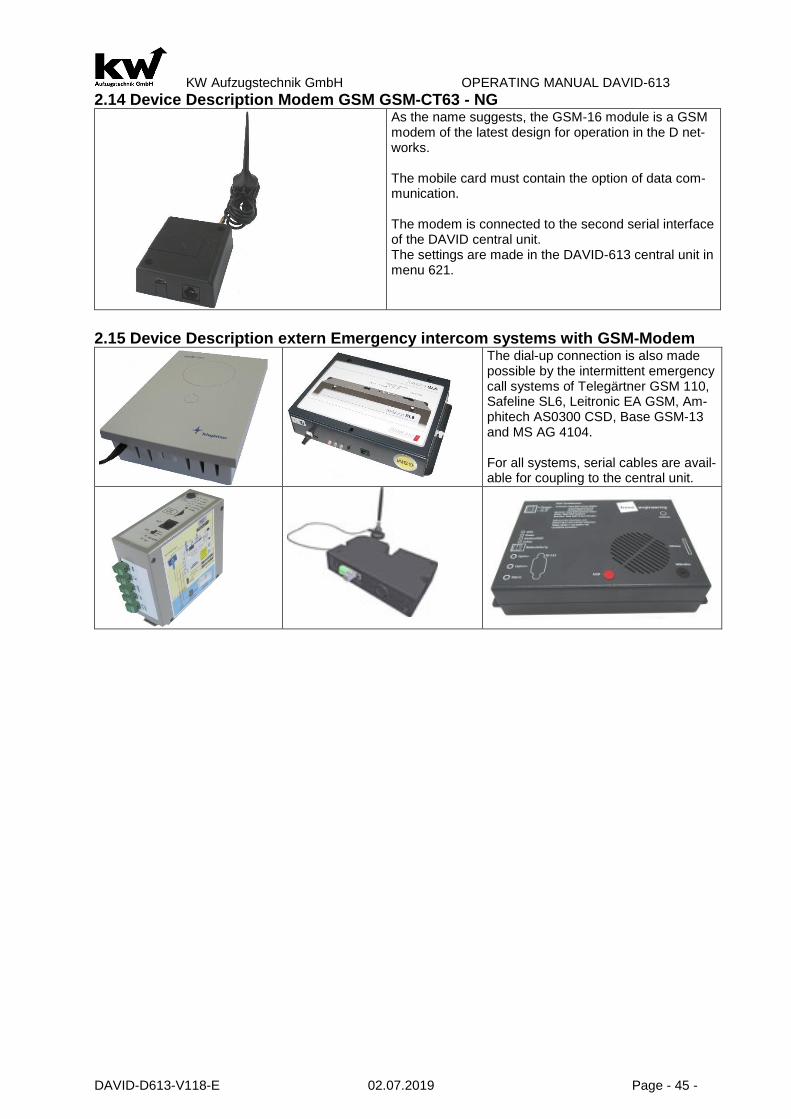
KW Aufzugstechnik GmbH OPERATING MANUAL DAVID-613
DAVID-D613-V118-E 02.07.2019 Page - 45 -
2.14 Device Description Modem GSM GSM-CT63 - NG
As the name suggests, the GSM-16 module is a GSM modem of the latest design for operation in the D net-works. The mobile card must contain the option of data com-munication. The modem is connected to the second serial interface of the DAVID central unit. The settings are made in the DAVID-613 central unit in menu 621.
2.15 Device Description extern Emergency intercom systems with GSM-Modem
The dial-up connection is also made possible by the intermittent emergency call systems of Telegärtner GSM 110, Safeline SL6, Leitronic EA GSM, Am-phitech AS0300 CSD, Base GSM-13 and MS AG 4104. For all systems, serial cables are avail-able for coupling to the central unit.

KW Aufzugstechnik GmbH OPERATING MANUAL DAVID-613
DAVID-D613-V118-E 02.07.2019 Page - 46 -
2.16 Software Description KW-LiftControl View of In- and Outputs
1.Publication of internal calls 2.Offering outside calls 3.View the inputs and outputs on the EIT (Innentableauplatine) 4.Characteristics: - Cabin height in mm - Total travel meter - Trip counter Up - Trip counter Down 5.View the inputs and outputs on the FKR (car unit) and X11 6.View the inputs and outputs on the ZR (central unit)
Administration of elevators
With the help of the software it is pos-sible to manage all elevator systems on a computer. Thanks to the user-friendly interface, all relevant data of a lift system appear at a glance and can be conveniently processed. A sorting function makes it easier to search for specific lift systems. Among other things, the import and export of several controls from or into an Excel table is possible. This can be used to create regular backups of the stored databases.
Electronic elevator Testing
The electronic elevator cradle function can now be initi-ated by a PC. The cabin light, the flush, the pushbutton door open and the emergency call button can be checked. There are two options for initiating the trip. The manually controlled and time controlled elevator maintenance function. On-site presence is no longer necessary. The result of the elevator maintenance journey is automatically docu-mented and can be viewed or printed out at any time. Up to 10 elevator heaters can be tested per hour with differ-ent locations.
View of HPG-60

KW Aufzugstechnik GmbH OPERATING MANUAL DAVID-613
DAVID-D613-V118-E 02.07.2019 Page - 47 -
2.17 Software Description KW-Monitoring Software
Groups/ Elevator View
The KW Monitoring Soft-ware enables the monitor-ing of all active elevator sys-tems in one property. Data from all lift facilities are collected and graphically processed to identify trends in availability and mainte-nance. The overall overview of the elevators is made with the help of the building outline, in which the locations of the elevator systems are dis-played. Each elevator group / system is color-coded, as an indication of their availa-bility.
By selecting, a detail view can be called up, which provides further information and views. Data is evaluated, saved and made available to the operator in different report types (user behavior, events, ca-pacity utilization, performance fulfillment).
Operator figures
How often is the elevator and how often is it used? When is mainte-nance really necessary? The software records every plant condition and the process times of the elevator systems. Trends such as door movements, number of trips and electricity con-sumption can be used to generate trends. From these it is then apparent when really a maintenance is nec-essary and, above all, which wear components should be replaced in advance.
Electronic Elevator attendant
Each individual elevator control requires a gateway GW60-101. This gateway communicates with the elevator con-troller DAVID D613 via a serial cable. The power supply of the gateway requires 24V DC of the elevator control. On-site, the gateway is connected to the PC via a network cable of the CAT 6 standard or higher via the RJ-45 plug via the switch
View Gateway GW60-101
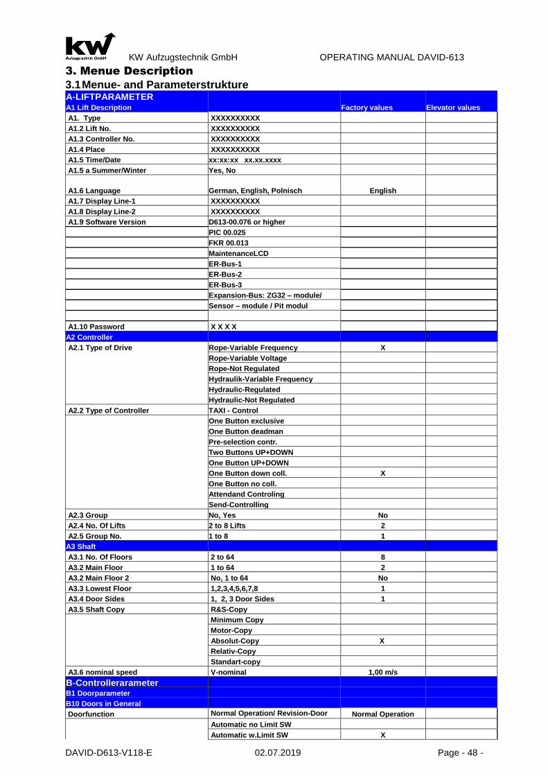
KW Aufzugstechnik GmbH OPERATING MANUAL DAVID-613
DAVID-D613-V118-E 02.07.2019 Page - 48 -
3. Menue Description
3.1 Menue- and Parameterstrukture A-LIFTPARAMETER
A1 Lift Description Factory values Elevator values
A1. Type XXXXXXXXXX
A1.2 Lift No. XXXXXXXXXX
A1.3 Controller No. XXXXXXXXXX
A1.4 Place XXXXXXXXXX
A1.5 Time/Date xx:xx:xx xx.xx.xxxx
A1.5 a Summer/Winter Yes, No
A1.6 Language German, English, Polnisch English
A1.7 Display Line-1 XXXXXXXXXX
A1.8 Display Line-2 XXXXXXXXXX
A1.9 Software Version D613-00.076 or higher
PIC 00.025
FKR 00.013
MaintenanceLCD
ER-Bus-1
ER-Bus-2
ER-Bus-3
Expansion-Bus: ZG32 – module/
Sensor – module / Pit modul
A1.10 Password X X X X
A2 Controller
A2.1 Type of Drive Rope-Variable Frequency X
Rope-Variable Voltage
Rope-Not Regulated
Hydraulik-Variable Frequency
Hydraulic-Regulated
Hydraulic-Not Regulated
A2.2 Type of Controller TAXI - Control
One Button exclusive
One Button deadman
Pre-selection contr.
Two Buttons UP+DOWN
One Button UP+DOWN
One Button down coll. X
One Button no coll.
Attendand Controling
Send-Controlling
A2.3 Group No, Yes No
A2.4 No. Of Lifts 2 to 8 Lifts 2
A2.5 Group No. 1 to 8 1
A3 Shaft
A3.1 No. Of Floors 2 to 64 8
A3.2 Main Floor 1 to 64 2
A3.2 Main Floor 2 No, 1 to 64 No
A3.3 Lowest Floor 1,2,3,4,5,6,7,8 1
A3.4 Door Sides 1, 2, 3 Door Sides 1
A3.5 Shaft Copy R&S-Copy
Minimum Copy
Motor-Copy
Absolut-Copy X
Relativ-Copy
Standart-copy
A3.6 nominal speed V-nominal 1,00 m/s
B-Controllerarameter
B1 Doorparameter
B10 Doors in General
Doorfunction Normal Operation/ Revision-Door closed/ Door sluice
Normal Operation
Automatic no Limit SW
Automatic w.Limit SW X

KW Aufzugstechnik GmbH OPERATING MANUAL DAVID-613
DAVID-D613-V118-E 02.07.2019 Page - 49 -
Handdoor w. Cardoor no Limit SW
Handdoor w. Cardoor with Limit SW
Handdoor no Cardoor
No Door
Automatic + SW Open
Automatik + SW Close
Hand/Cargo. + SW Open
Hand/Cargo. + SW Close
Door-1 End-switch Inverted/ Not Inverted Inverted
Door type Door-2 ( Only 2/3 Doorsides Like Doorside -1 X
Automatic no Limit SW
Automatic w.Limit SW
Handdoor w. Cardoor no Limit SW
Handdoor w. Cardoor with Limit SW
Handdoor no Cardoor
No Door
Automatic + SW Open
Automatik + SW Close
Hand/Cargo. + SW Open
Hand/Cargo. + SW Close
Door type Door-3 ( Only 3 Doorsides Like Doorside -1 X
Automatic no Limit SW
Automatic w.Limit SW
Handdoor w. Cardoor no Limit SW
Handdoor w. Cardoor with Limit SW
Handdoor no Cardoor
No Door
Automatic + SW Open
Automatik + SW Close
Hand/Cargo. + SW Open
Hand/Cargo. + SW Close
Door-2 End-switch Inverted/ Not Inverted Inverted
Door-3 End-switch Inverted/ Not Inverted Inverted
Doorengine active Always on / standby off Standby off
Doorengine 2 active Always on / standby off Standby off
Doorengine 3 active Always on / standby off Standby off
Shaftdoor Waiting 0,1 to 2,0 Sek. 0,5 sec
Cardoor Waiting 0,1 to 2,0 Sek. 0,5 sec
Later Door Opening 0,0 to 2,0 Sek. 0,5 sec
Limited Door Opening No, Yes 1,0 to 10 Sek. 6 sec
Door Open Timeout No, Yes 1,0 to 60 Sek. 13 sec
Door Close Timeout No, Yes 1,0 to 60 Sek. 20 sec
Further Travel Delay Car Call Selektiv, Generell 1,0 bis 20 7 sec
Further Travel Delay Landing Call Selektiv, Generell 1,0 bis 20 9 sec
F. Del. C-C mainf Selektiv, Generell 1,0 bis 20 7 sec
F. Del. L-C mainf Selektiv, Generell 1,0 bis 20 9 sec
Further-Time-Trigger No,Yes No
Door Rev. Delay Selektive, Generel 50 to 1000 ms 500 ms
Dooreng. Stb. off Selektive, Generel 1 to 60 sec 10 sec
Dooringine-2 stand-by off Selektive, Generell 1 to 60 sec 10 sec
Dooringine-3 stand-by off Selektive, Generell 1 to 60 sec 10 sec
Door standy Open, Close 1 to 60 sec open
Door stby. Main. Open, Close 1 to 60 sec open
Door Control Inspection Yes, No Yes
Button Door op. Individual, Together, Selective Together
Button Holdtime No, Yes 1,0 to 600 Sec No
Button Holdtime Function Individuel, Together No
Button Door Close Function Individual, Together, Selective Together
Button Door Close Reaction 0,0 to 5,0 sec 2 sec
Door Control Atemps 1 to 10 efforts 3
Door Open Time 1 to 60 sec 2 sec
Door-Opening Normal-Function /Only Door Open B Normal Function
Door-Closing Normal-Function /Only Door Close B Normal Function
B11 Table of Entrance Door-1 Door-2 Door-3 Door-1 Door-2 Door-3

KW Aufzugstechnik GmbH OPERATING MANUAL DAVID-613
DAVID-D613-V118-E 02.07.2019 Page - 50 -
Floor -01 Existing Yes or No …............../…............. …............../….............
Floor -02 Existing Yes or No …............../…............. …............../….............
Floor -03 Existing Yes or No …............../…............. …............../….............
Floor -04 Existing Yes or No …............../…............. …............../….............
Floor -05 Existing Yes or No …............../…............. …............../….............
Floor -06 Existing Yes or No …............../…............. …............../….............
Floor -07 Existing Yes or No …............../…............. …............../….............
Floor -08 Existing Yes or No …............../…............. …............../….............
Floor -09 Existing Yes or No …............../…............. …............../….............
Floor -10 Existing Yes or No …............../…............. …............../….............
Floor -11 Existing Yes or No …............../…............. …............../….............
Floor -12 Existing Yes or No …............../…............. …............../….............
Floor -13 Existing Yes or No …............../…............. …............../….............
Floor - Existing Yes or No …............../…............. …............../….............
Floor -64 Existing Yes or No …............../…............. …............../….............
B12-Safety Photocell
Safety Photosell Off/ On / CEDES Off
Photocell- Monitor Off, On 1 to 80 sec 60 sec
Ramp Travel Off,ON Off
Door Close del. Off, On 1 to 10 sec 2 sec
Photocell Input Not Inverted/Inverted Inverted
Reverse Contact Not Inverted/Inverted Inverted
B13-Nudging Function
Nudging Off, On 1 to 180 sec Off
Nudging Signal Door-close & A192/193 / only A192/3 Door-close & A192/193
B14-Entrance Monitor
Entrance Monitor No,Yes No
Time a. st. Door-1 0,5 to 10 sec 2 sec
Time a. st. Door-2 0,5 to 10 sec 2 sec
Time a. st. Door-3 0,5 to 10 sec 2 sec
Entrance Monitor Not Inverted/Inverted Inverted
B15-Mech. Lock
Pulse Buf. Delay 50 ms to 2000 ms 500 ms
Lock Delay ON 0,0 to 5,0 sec 0 sec
Lock Delay OFF 0,0 to 9,9 sec 0 sec
Lock Handdoor After Cardoor, Before Cardoor After Cardoor
Open after lock 0,0 to 9,9 sec 0 sec
Mechanical Lock-OFF 10 to 720 Seconds 30 Seconds
Bolt-Control Normal / Inverted Normal
Additional delay 0,5 to 5,0 sec 1,0 sec
B16-Safety-Circuit
Pre-Opening Doors No,Yes No
Early Premagn. No,Yes No
Safety Circuit SIS-60 / SIS-16 SIS-16 (KW)
B17 Releveling
Releveling No,Yes No
No Releveling Distance 5 to 50mm 10 mm
Max. Releveling Distance 10 to 250mm 100 mm
Leveling-UP 10 to 50mm 0 mm
Leveling-DOWN 10 to 50mm 0 mm
Time Limit 3 to 25 sec 20 sec
Attempt Limit 5 to 25 20
Limit at Level 1 Releveling, No Releveling No Limit
Overload Releveling, No Releveling Releveling
Fault Handling Block, Go Down & Block X
Only error message
Finereleveling No,Yes, ALGI, BUCHER No
Piezo-Alarm, not flush No, Yes Yes
B2-Call Options B21 Car Calls Door Reverse Car Call Off,On Off
Selectiv Car Calls No,Yes No
Callreset/ Error directly, 1 to 40 sec 4 sec
Car Call CPU EIT / ITR-1 aktiv / ITR-1 & ITR-2 aktiv EIT aktiv
Car Call Limit OFF, 2 to max.floor call erase Off

KW Aufzugstechnik GmbH OPERATING MANUAL DAVID-613
DAVID-D613-V118-E 02.07.2019 Page - 51 -
Misure Defence No
Button-Buzzer Off,On Off
Car Call Range Off, 1-2/ 1-3/ 1-4/ 1-5/ 1-6/ 1-7/ Off
Automatic Car Call Vehicle Off / ON Off
B22-Landing Calls
Door Reverse Landing Call Off,On Off
Modul ZR,ER ZR
Selectiv Landing Calls No,Yes No
Erase operative Calls No,Yes No
Save Travel 0 to 20 sec 5 sec
Floor Indicator Blinking Off / ON Off
Button-Buzzer Off,On Off
Button-Buzzer Off,On Off
Page separation of the exterior calls Off, On Off
Page separation External call storage Off, On Off
Beep when acknowledgement on Off, On Off
Abuse protection 2KS Off, On Off
B23-Car Priority
Floor Calls erase, save erase
Mail Travel Off, On off
Entrancelogin entrance E186 negative / positive negative
Door position 1 open, 2 open, 3 open, 1+2 open 1+2 open
B24-Landing Priority
Time call Input 1 to 30 sec 20 sec
Floor Calls erase,save erase
Priority Car Call individual / collective / soft individual
Priority Car Floor Call 5 sec. Off, On Off
Hazardous Material Transport Off,On Off
Hazardous Material Transport Cabin Off, On Off
B25 Groupcontroller
Door Failure 10 to 60 sec After 60 sec
ER-IN/OUT 2xC Free programmable Groupfunction G01 Call Door-2 UP
ER-IN/OUT 2xD Free programmable Groupfunction G02 Call Door-2 DOWN
ER-IN/OUT 97A Free programmable Groupfunction G04 priority A1-3-5-7
ER-IN/OUT 98A Free programmable Groupfunction G05 priority A2-4-6-8
ER-IN/OUT 97B Free programmable Groupfunction G04 priority A1-3-5-7
ER-IN/OUT 98B Free programmable Groupfunction G05 priority A2-4-6-8
Parking Zone-1: to Parking Zone-5 Off, ON, Priority 1,.. Priority 5 Off
Parking Zone-1: to Parking Zone-5 Always active/ Timer 1/ Timer 5 Always
Parking Zone-1: Lowest Floor 1 to n
Parking Zone-1: Highest Floor 1 to n
Parking Zone-5: Lowest Floor 1 to n
Parking Zone-5: Highest Floor 1 to n
Group Dynamic Travel Time Floor 0 to 20 sec 3,0 Sec.
Group Dynamic Stop Time Floor 0 to 20 sec 8,0 Sec.
Group Dynamic Call Changing Dynamic / Engery Safe Dynamic
Output HEX5-Code ER-EA7/8 Off / On Off
B3-DRIVE B30 Hydraulic Not Regulated Start Star/Delta , Softstart Softstart
S/D-Reverse Time 0,1 to 4,0 sec 2 sec
Direction Up Delayed On No,Yes –1 to 300 ms. 100 ms
Direction Up Delayed Off No,Yes –1 to 2000 ms. 400 ms
Start with Door Controlling No,Yes –1 to 3 sek. Verzögert No
Inspection Speed Slow, Quick slow
Time to go Down 1 to 15 Minuten 10 Min.
Fault Handling No,Yes –Abbruch & Absenken No
Travel down at Overload No,Yes No
Signal Top of Ramp No,Yes Yes
Command Down Delay. On No,Yes Yes
Command Down Delay. Off Yes, No Yes
Lock after End-Switch Top No, Yes Yes
Liftbus OFF, KW-Bus, DCP-3, KW-2 Bus KW BUS
Warm Up travel OFF, Always active, active on E492 OFF
Warm Up travel after Time Minutes to 1250

KW Aufzugstechnik GmbH OPERATING MANUAL DAVID-613
DAVID-D613-V118-E 02.07.2019 Page - 52 -
B31 Hydraulic Regulated
Start Star/Delta , Softstart Softstart
S/D-Reverse Time 0,1 to 4,0 Sek. 2 sec
Direction Up Delayed On No,Yes –10 to 300 ms. 100 ms
Direction Up Delayed Off No,Yes –10 to 900 ms. No
Start with Door Controlling No,Yes –10 to 2000 ms. 400 ms
Start with Door Controlling No,Yes –1 to 3 sek. Verzögert No
Inspection Speed Slow, Quick, Vinsp Vi
Time to Go Down 1 to 15 Minutes 10 Min.
Fault Handling No, Interrupt, Block, Block & Go Down
Yes, Interrrupt
Travel Down at Overload No,Yes No
Signal Top Of Ramp No,Yes Yes
Command Down Delay. On No,Yes No
Command Down Delay. Off No,Yes No
Lock after End-Switch Top No, Yes Yes
Liftbus OFF, KW-Bus, DCP-3, KW-2 Bus KW BUS
Warm Up travel OFF, Always active, active on E492 OFF
Warm Up travel after Time Minutes to 1250
Commands Output Standart, Oildynamic NGV-A3 Standart
B32 Hydraulic Variable Frequency
V0 Delayed Off No,Yes -10 to 300 ms. No
Main Conductor Delayed Off No,Yes -10 to 2000 ms. 600 ms
Direction Delayed Off No,Yes -10 to 2000 ms. 1500 ms
Releveling Speed Vn, V0 Vn
Inspektion Speed Vo, Vinsp. Vinsp.
Time to Go Down 1 to 15 Minutes 15 Min.
Fault Handling No, Interrupt, Block, Block & Go Down
No
Travel Down at Overload No,Yes No
Lock after Top-End-switch No,Yes Yes
Command Output Bucher / ALGI FRHZ / ALGI FRHZ Vi Bucher
C. Down Delay. On No,Yes No
Liftbus OFF, KW-Bus, DCP-3, KW-2 Bus KW BUS
Warm Up travel OFF, Always active, active on E492 OFF
Warm Up travel after Time Minutes to 1250
B33 Rope 2 Speeds
Motorventilation No, Yes - 1 to 600 sec No
Direction Contactor Delayed On No,Yes -10 to 300 ms. 100 ms
Inspection Speed Slow, Quick slow
Reverse Time out No,Yes, 1 to 100 ms. No
B34 Rope Variable Voltage
Liftbus Off, KW-Liftbus, DCP-3 Off
Mono Fan No,Yes -1 to 600 sek. No
V0 Delayed Off No,Yes -10 to 3000 ms. No
Direction Delayed Off No,Yes -10 to 3000 ms. 1900 ms
Main Constructor Delayed off No,Yes -10 to 3000 ms. 2500 ms
Reveling Speed Command Vn / Command V0 Vn
Fault Handling Abbruch/Sperre-1.Stör/“-“2.Stör/“-“3.Stör Abbruch
Command Output Standard-GOLIATH/ DIETZ-Freigabe Standard-GOLIATH
B 35 Rope Variable Frequency
Liftbus Mono Fan
Off, KW-Liftbus, DCP-3 KW-Liftbus
Mono Fan No,Yes -1 to 600 sek. No
V0 Delayed Off No,Yes -10 to 3000 ms. No
Direction Delayed Off No,Yes -10 to 3000 ms. 1900 ms
Main Conductor Delayed Off No,Yes -10 to 3000 ms. 2500 ms
Releveling Speed Command Vn / Command V0 Vn
Fault Handling Abbruch/Sperre-1.Stör/“-“2.Stör/“-“3.Stör Abbruch
Command Output
Standard-GOLIATH / Release-DIETZ Standard-GOLIATH
V3 delayed No / Yes No
V0 delayed No / Yes No
UP/ Down delayed No / Yes No
B4-Shaft Copy B41 Standart-Copy Pulse Buffer Delay 2 to 50 ms 50 ms
Correction Travel After call/ automatic After call
B42 Relativ Copy

KW Aufzugstechnik GmbH OPERATING MANUAL DAVID-613
DAVID-D613-V118-E 02.07.2019 Page - 53 -
Pulse Buffer Delay 2 to 50 ms 2 ms
Correction Travel to After call/automatic After call
2nd Prel. SW bot No,Yes No
2nd Prel. SW top No,Yes No
Short travels No/1 short tr./2 short tr. No
If 1 Short-drive-> Short-drive-1 between 1<->2, 2<->3, 3<->4 ,......
If 2 Short-drive-> Short-drive-2 between 1<->2, 2<->3, 3<->4 ,......
Distance Prel. SW-ZSW To Measure in mm 1000 mm
Decel. Spd V0=>0 Travel up Distance in mm 5 mm
Decel. Spd V0=>0 Travel down Distance in mm 5 mm
Decel. Spd V1 Travel up Distance in mm 500 mm
Decel. Spd V1 Travel down Distance in mm 500 mm
Decel. Spd V2 Travel up Distance in mm 1000 mm
Decel. Spd V2 Travel down Distance in mm 1000 mm
Decel. Spd V3 Travel up Distance in mm 1500 mm
Decel. Spd V3 Travel down Distance in mm 1500 mm
Learn Drive V1, V2, V3 execute V1
Encoder Termin. At ZR/FKR ZR
Lern Drive Activate No,Yes No
Switch Hysteres Overlapping Xxx mm 0 mm
Level. Floor-01 lev. Value Bündigwert: 000,000 m 000,000 m
Level. Floor-32 lev. Value Bündigwert: xxx,xxx m xxx,xxx m
B43 Absolut Copy
Pulse Buffer Delay 2 to 50 ms 2 ms
Distance-system Schmersal-USP / Wachendorff Schmersal-USP
Floorswitches no/ Vorend+Zone No Floorswitches
Short travels No/1 short tr./2 short tr. No
If 1 Short-drive-> Short-drive-1 between 1<->2, 2<->3, 3<->4 ,......
If 2 Short-drive-> Short-drive-2 between 1<->2, 2<->3, 3<->4 ,......
Decel. Spd V0=>0 Travel up Distance in mm 5 mm
Decel. Spd V0=>0 Travel down Distance in mm 5 mm
Decel. Spd V1 Travel up Distance in mm 500 mm
Decel. Spd V1 Travel down Distance in mm 500 mm
Decel. Spd V2 Travel up Distance in mm 1000 mm
Decel. Spd V2 Travel down Distance in mm 1000 mm
Decel. Spd V3 Travel up Distance in mm 1500 mm
Decel. Spd V3 Travel down Distance in mm 1500 mm
Countdirection Negativ / positiv Negativ
Learn Drive V1, V2, V3 execute V1
Learn Drive activate No,Yes No
Synchronisation Floor-1 No,Yes No
Level Mode Floor level// floor distance
Level. Floor-01 lev. Value Bündigwert: 000,000 m 000,000 m
Level. Floor-64 lev. Value Bündigwert: xxx,xxx m xxx,xxx m
B44 Motor Copy
Pulse Buf. Delay 2 bis 50 ms 2 ms
Correct. Travel After call / automatic After call
2nd Prel. SW bot No,Yes No
2nd Prel. SW top No,Yes No
Short travels No/1 short tr./2 short tr. No
If 1 Short-drive-> Short-drive-1 between 1<->2, 2<->3, 3<->4 ,......
If 2 Short-drive-> Short-drive-2 between 1<->2, 2<->3, 3<->4 ,......
Distance Prel. SW-ZSW To Measure in mm 1000 mm
Decel. Spd V0=>0 Travel up Distance in mm 5 mm
Decel. Spd V0=>0 Travel down Distance in mm 5 mm
Decel. Spd V1 Travel up Distance in mm 500 mm
Decel. Spd V1 Travel down Distance in mm 500 mm
Decel. Spd V2 Travel up Distance in mm 1000 mm
Decel. Spd V2 Travel down Distance in mm 1000 mm
Decel. Spd V3 Travel up Distance in mm 1500 mm
Decel. Spd V3 Travel down Distance in mm 1500 mm
Learn Drive V1, V2, V3 execute V1
Encoder Termin. At ZR/FKR ZR
Learn Drive activate No,Yes No
Swiching-hysterese

KW Aufzugstechnik GmbH OPERATING MANUAL DAVID-613
DAVID-D613-V118-E 02.07.2019 Page - 54 -
Level. Floor-01 lev. Value Bündigwert: 000,000 m 000,000 m
Level. Floor-64 lev. Value Bündigwert: xxx,xxx m xxx,xxx m
B45 Minimum Copy
Pulse Buf. Delay 2 to 50 ms 50 ms
Correct. Travel After call / automatic After call
B46 R&S copy
Pulse Buf. Delay 2 to 50 ms 50 ms
Correct. Travel After call / automatic After call
B5-Indicate B501 Car Indicate Cabine Gray / 1 of N / Binär/ 7-Seg / free 1 of N
Main-CPU Gray / 1 of N / Binär/ 7-Seg / free 1 of N
Floor-CPU Gray-Code / 1 of N / Binär 1 of N
Code 7-Segment Setup for every Floor U,E,1,2,3,4,5,6,7,..
Code select Setup for every Floor 0000 0000 b
Special Mode Inspect./ manual ON / OFF ON
Special Mode error case ON / OFF ON
Special Mode spezial travel ON / OFF ON
Special Mode Attendant Mode ON / OFF ON
B502 Car Arrow
Description Only direction, Direction+ move on
M-Arrow-OFF No,Yes 1 to 60 sec No
M-A.Door close No,Yes Yes
B503 Floor Arrow
Arrows No,Yes – ZR , ER, EAT No
ZR: Description Only direction, Direction+ move on
ZR:M-Arrow-Off No,Yes 1 to 60 sec No
ER: Description Only direction X
Direction+ move on
Only move on
ER: ER:M-Arrow-Off No,Yes 1 to 60 sec No
M-A. Door close No,Yes Yes
B504 Gong At The Car
Gongfunction No,Yes No
Car Call UP No,one ring,double ring,trible ring No
Car Call DOWN No,one ring,double ring,trible ring No
Floor Call UP No,one ring,double ring,trible ring One ring
Floor Call DOWN No,one ring,double ring,trible ring Double ring
Priority Call UP No,one ring,double ring,trible ring No
Priority Call DOWN No,one ring,double ring,trible ring No
Fire Fighter Tr. No,one ring,double ring,trible ring No
Special Travel No,one ring,double ring,trible ring No
Gongfunction Volume 1 to 15 7
Gongfunction Tone 1 to 15 7
B505 Gongfunction
Gongfunction No,Yes No
Car Call UP No,one ring,double ring,trible ring No
Car Call DOWN No,one ring,double ring,trible ring No
Floor Call UP No,one ring,double ring,trible ring One ring
Floorcall DOWN No,one ring,double ring,trible ring Double ring
Priority Call UP No,one ring,double ring,trible ring No
Priority Call DOWN No,one ring,double ring,trible ring No
Fire Fighter TR. No,one ring,double ring,trible ring No
Special Travel No,one ring,double ring,trible ring No
Gongfunction Volume 1 to 15 7
Gongfunction Tone 1 to 15 7
Gongimpuls Short puls, 1sec, 2 sec Short puls
B506 LED-Matrix
Car Display Errow No,Yes,Scroll Scroll
Car Floor Animation Fixed / Scroll / Trick 1 Scroll
Car Display Segments 2 / 3 3
Floor Display Errow No,Yes,Scroll Scroll
Floor Floor Animation Fixed / Scroll / Trick 1 Scroll
Floor Segments 2 / 3 2

KW Aufzugstechnik GmbH OPERATING MANUAL DAVID-613
DAVID-D613-V118-E 02.07.2019 Page - 55 -
FLOOR INDICATOR LIGHT Off / out of order / spezial travel No
Zentralrechner Anzeige 1 bis 32 oder „wie Kabine“ 1 to 64
B507 Floor Display
Floor-01 Display:
HS-01 HS-17 HS-33 HS-49
Floor-02 Display: HS-02 HS-18 HS-34 HS-50
Floor-03 Display: HS-03 HS-19 HS-35 HS-51
Floor-04 Display: HS-04 HS-20 HS-36 HS-52
Floor-05 Display: HS-05 HS-21 HS-37 HS-53
Floor-06 Display: HS-06 HS-22 HS-38 HS-54
Floor-07 Display: HS-07 HS-23 HS-39 HS-55 Floor-08 Display: HS-08 HS-24 HS-40 HS-56
Floor-09 Display: HS-09 HS-25 HS-41 HS-57
HS-10 HS-26 HS-42 HS-58
HS-11 HS-27 HS-43 HS-59
HS-12 HS-28 HS-44 HS-60
HS-13 HS-29 HS-45 HS-61
HS-14 HS-30 HS-46 HS-62
……… HS-15 HS-31 HS-47 HS-63
Floor-64 Display:
HS-16 HS-32 HS-48 HS-64
B508 Messages
Overload Car: * Floor: - Car: Floor:
Evacuation Car: * Floor: - Car: Floor: Fire Evacuation Car: * Floor: - Car: Floor: Emergency Power Car: * Floor: - Car: Floor: Fire Fighter Travel Car: * Floor: - Car: Floor: Special travel Car: * Floor: - Car: Floor: Bed Travel Car: * Floor: - Car: Floor: Guide Mode Car: * Floor: - Car: Floor: Out of Order Car: * Floor: - Car: Floor: Maintenance Car: * Floor: - Car: Floor: Loadingtime Aktive Car: * Floor: - Car: Floor: Door Opening Car: * Floor: - Car: Floor: Door Closing Car: * Floor: - Car: Floor: Please Leave Car Car: * Floor: - Car: Floor: Please Wait Car: * Floor: - Car: Floor: Please Speak Car: * Floor: - Car: Floor: B509 TFT/LCD-Kabine
Backgroundpicture Fixed, changing Fixed
Persons in car
Loadweight
Text-1 Manufacture Manufacture
Text-2 Factory-No. Factory-No.
Text-3 Build Year Build Year
Text-4 CE-Sign CE-Sign
Floor Indicator Fixed, Rolling, Animation Fixed
Arrow Indicator Fixed, Rolling, Animation Fixed
Display String-1 ON / OFF ON
Display String-2 ON / OFF ON
Display String-3 ON / OFF ON
Display String-4 ON / OFF ON
Display Persons ON / OFF ON
Display Load ON / OFF ON
Emergency light ON / OFF ON
Displaytext Symbol fixed/Blink Buzzer-S Buzzer-L Gong Voice An.
Overload
Evacuation
Fire Evacuation
Emergency Power
Fire Fighter Travel
Special travel
Bed Travel
Guide Mode
Out of Order
Maintenance
Loadingtime Aktive

KW Aufzugstechnik GmbH OPERATING MANUAL DAVID-613
DAVID-D613-V118-E 02.07.2019 Page - 56 -
Door Opening
Door Closing
Please Leave Car
Please Wait
Please Speak
Buzzer Short 2 to 255 ms 2 ms
Buzzer Long 1 to 3 Sekunden 1 Sek.
Gong-Signal
Display- Format Automatic / Landscape / Upright / Quer Automatic
Display- Brightness 1% to 100 % 90 %
Volume Speech 1% to 100 % 50 %
Tone pitch speech 1% to100 % 50 %
Volume Musik 1% to 100 % 50 %
Bachgroundmusic ON / OFF OFF
Floor Message ON / OFF OFF
B510 TFT/LCD-Etage
Loadweight
Text-1 Manufacture Manufacture
Text-2 Factory-No. Factory-No.
Text-3 Build Year Build Year
Floor Indicator Fixed, Rolling, Animation Fixed
Arrow Indicator Fixed, Rolling, Animation Fixed
Display String-1 ON / OFF ON
Display String-2 ON / OFF ON
Display String-3 ON / OFF ON
Display String-4 ON / OFF ON
Displaytext Symbol fixed/Blink Buzzer-S Buzzer-L Gong Voice An.
Overload
Evacuation
Fire Evacuation
Emergency Power
Fire Fighter Travel
Special travel
Bed Travel
Guide Mode
Out of Order
Maintenance
Loadingtime Aktive
Door Opening
Door Closing
Please Leave Car
Please Wait
Please Speak
Buzzer Short 2 to 255 ms 2 ms
Buzzer Long 1 to 3 Sekunden 1 Sek.
Gong-Signal
Display- Format Automatic / Landscape / Upright / Quer Automatic
Display- Brightness 1% to 100 % 90 %
Volume Speech 1% to 100 % 50 %
Tone pitch speech 1% to 100 % 50 %
Volume Musik 1% to 100 % 50 %
Bachgroundmusic ON / OFF OFF
B6-Functions
B600 Monitorfunctions Contactor Monitor OFF, On 500 to 4000 ms on
Contactor Moninot Insp. On,Off on
Contactor Monitor Reaction Stop+Delet Calls, Stop+Block Stop + Block
Contactor Monitor Contact Type NC., NC.+NO., NC. + SAS NC.
Carlight Monitor Off / Current light / Input E525 on
Starttime Monitor 1 to 60 sec 20 sec
Journey Time Monitor 1 to 60 sec 40 sec
Decelation Time Monitor 1 to 60 sec 20 sec
Stop Time Monitor 1 to 60 sec 10 sec
Fault Handling Stop+ block, Rope
Stop+ delete Calls

KW Aufzugstechnik GmbH OPERATING MANUAL DAVID-613
DAVID-D613-V118-E 02.07.2019 Page - 57 -
Go down
Go down+ block Hydraulic
BRAKE SHOE MONITOR Off,On OFF
BRAKE MONITOR Off,On
Stop+ delete Calls X
Stop+ Block
BRAKE MONITOR INPUT Not inverted / inverted Not inverted
BRAKE MONITOR DELAY 0 to 6000 ms 2000 ms
BRAKE MONITOR SYNCHRONISATION
0 to 6000 ms 2000 ms
SWITCH-CABINET T-Max No, Yes – 30 to 99°C 60 °C
SWITCH-CABINET T-Min No, Yes - 0 to 25°C 3 °C
PTC-Motortemperature Off, imput 1, imput 2, 1 + 2 Imput 1
Door motor thermistor Off, On Off
DSK-Pulses Off, On On
ROPE STRETCH Off, On OFF
Batterymonitor Off, E507, E507 & E508 OFF
Monitoring A3-CASE ON, OFF ON
AW-60 Monitoring ON, OFF ON
Monitoring shaft door U10 Off On ON
Monitoring Switch U10 / U11 ON, OFF ON
Monitoring DSK-Direction ON, OFF ON
Monitoring Nominal Speed ON, OFF ON
Monitoring Door switch Close ON, OFF ON
Monitoring U11 Cabin door OFF, ON ON
Monitoring U12 bar OFF, ON ON
Monitoring USV OFF, ON ON
B601 Inspection Travel
Restart locking No,Yes No
Restart locking Door No,Yes No
Speed Button No,Yes Yes
Inspection-Stopp TOP Floor level to -500 mm -20 mm
Inspection-Decrease TOP -100mm to -3000 mm -500 mm
Inspection-Stopp BOTTOM Floor level to +500 mm +20 mm
Inspection-Decrease BOTTOM +100mm to +3000 mm +500 mm
Inspectionbulb pit No / YES No
Inspectionbulb pit Reset No / YES No
Inspections call No / YES / Lowering for 3000mm max 3000mm
Monitoring of Manual speed No to 1,00 m/s 0,30 m/s
Monitoring of Inspection speed No to 1,00 m/s 0,50 m/s
B602 Emergency Unit B602 Emergency Unit
Alert Push Button Delay 0 to 5 Sec Alert Push Button Delay
B603 Car Fan B603 Car Fan
Start Of Fan Push Button, Travel-Start Start Of Fan
Fan Delay 0 to 600 sec Fan Delay
B604 Load Mearement B604 Load Meare-ment
Overload imput Not inverted/inverted Overload imput
Load Measurem. Loadsensor FKR No,Yes Load Measurem. Loadsensor FKR
Overload 120% Overload
Full Load 100% Full Load
Half Load 50% Half Load
Under Load 10% Under Load
Save Full Load No,Yes Save Full Load
Save Zero Load No,Yes Save Zero Load
Underload evaluation No,Yes / 1 / 2 / 3 / 4 Calls Underload evalua-tion
Volllastauswertung No,Yes Volllastauswer-tung
B605 Standby Travel
Standby Travel No,Yes Yes
Standby Trvl. 1 Floor Next Floor, Floor1 to max. Next Floor
Standby Trvl. 1 OFFSET OFF, +/- xxxx mm
Standby Trvl. 2 Floor Next Floor, Floor1 to max. Next Floor
Standby Trvl. 2 OFFSET OFF, +/- xxxx mm
Standby Travel Door Open/close open
Standby Travel Floor Indicator ON/OFF ON
Standby Travel Car Indicator ON/OFF ON
B606 Parking Travel

KW Aufzugstechnik GmbH OPERATING MANUAL DAVID-613
DAVID-D613-V118-E 02.07.2019 Page - 58 -
Parking Travel No, Yes No
Parking Level Floor 1 to max. Floor Etage 2
Start Parking Travel 1 to 15 Min. 1 min
Door Open, Close Open
B607 Floor Blocking
Floor Blocking Input of a blocked Floors No
Dynam. Blocking No, only carcalls
only floorcalls, carcalls+floorcalls No
B608 Energy saving
Car Light Automatik off No,Yes No
Delay 1 to 6500 sec 60 sec
Car Indicator No,Yes No
Delay 1 to 6500 sec 120 sec
Floor Indicator No,Yes No
Delay 1 to 6500 sec 180 sec
FU Standby No,Yes No
Delay 1 to 6500 sec 60 sec
FU Switch Off No,Yes No
Delay 1 to 6500 sec 60 sec
Door Drive Automatic Off No,Yes No
Delay 1 to 6500 sec 60 sec
Mode S1 No,Yes No
Mode S2 No,Yes No
B609 Emergency Power service
Emergency Power Service No/yes, generator, accupower,brake No
Emergency Power Service floor 1 Next floor, 1 to 32 1
Entrance Open 1, 2, 1+2 1
Follow-Circuit No,Yes No
Piezo Buzzer Off / on off
Follow Circuit Deadtime 10 to 360 sec 360 sec
Direction specification FU No / Yes No
B610 Emergency Fire Service
Emergency Fire Service No, Yes-1, Yes-2, Yes-3, dynamic No
1. Priority 1 to max. 2
1. P. Entrance open 1, 2, 1+2 1
2. Priority 1 to max. 2
2.P. Entrance open 1, 2, 1+2 1
3. Priority 1 to max. 3
3.P. Entrance open 1, 2, 1+2 1
Piezo Buzzer Off , on off
Emergency Fire Service Input Not inverted/ inverted Not inverted
Emergency Fire Service Swiss Version No,Yes No
Door status Always open / close to x s. Always open
Schindler ID Normal inverted Normal
B611 Fire Fighter service
Firefighter Travel No,Yes No
1. Priority 1 to max. 2
1.P. Entrance open 1, 2, 1+2 1
2. Priority 1 to max. 2
2.P. Entrance open 1, 2, 1+2 1
3. Priority 1 to max. 2
3.P. Entrance open 1, 2, 1+2 1
Firefighter Travel Input Not inverted/ inverted Not inverted
Firefighter Travel Model German / English / Australian / EN 81-72 EN 81-72
Buzzer on leveling Active /deactive deactive
B612 Rescue Travel
Rescue Travel No, Yes No
Collection Floor 1 to max. 1
Collection Floor Wait Time 1 to 720 sec. 600 sec.
Rescue Floor 1 to max. 2
Rescue Floor Wait Time 1 to 720 sec. 120 sec.
Rescue Travel Repeat travel 1 to 10 1
B613 Guide Mode
Attandent Travel No,Yes No
B614 Hotel Stopping

KW Aufzugstechnik GmbH OPERATING MANUAL DAVID-613
DAVID-D613-V118-E 02.07.2019 Page - 59 -
Main Floor No/Up/Down/Up+Down No
B615 Time relay
Time Relay-1 Off/switch-on delay/off delay/off puls Off
Delaytime 0,5 to 300 sec 0,5
Pulstime 0,5 to 300 sec 0,5
Time Relay-2 Off/switch-on delay/off delay/off puls Off
Delaytime 0,5 to 300 sec 0,5
Pulstime 0,5 to 300 sec 0,5
Speed-threshold Vx 0,1 m/s to Vmax 0,8 m/s
Start-1 Timer-1 to 10 00:00 Clock
Stopt-1 Timer-1 to 10 00:00 Clock
Start-2 Timer-1 to 10 00:00 Clock
Stop-2 Timer-1 to 10 00:00 Clock
Day Timer-1 to 10 MO TU WE TH FR SA SU
Fan Switching Cabinet Temperature limit 30 to 60 grad C 30 Grad C
B616 Elevator Check
Interval Off Modem //ev. Week/ ev 2 weeks Modem
Weekday MO TU WE TH FR SA SU
Start time xx : xx CLOCK
Test Action leveling No,Yes Yes
Test Action Car Light No,Yes Yes
Test Action Alarm Button No,Yes Yes
Test Action Door Open Button No,Yes Yes
Reaction Only message//m. and vblock Only message
Floorblocking No notice/notice blocked floor/ only fixed Blocking
No notice
Result Check is o.k./ x failure
B617 Bolt
Bolt Off/ Static/ Mobil off
Floor Static Stop
Bolt Releveling No,Yes No
Bolt Raising Distance in mm 64 mm
Bolt Final Leg In ms 1000 ms
Bolt Preassure Leg In ms 4000 ms
Bolt GoDown Travel No,Yes Yes
B618 Codelock calls floor
Car Calls No, Floor 01 to max. NO
Codeeinput floor 01 to Max. 4 digit code
B619 Attendant Mode
Attendant Mode OFF / ON OFF
Attendant Mode Deactive After 1 to15 Minutes 10 Min.
B620 Daedman Mode
Deadman Mode Release By Over E327 / Car Call E327
Photocell Supervice OFF / ON OFF
Floorcall with Carcall OFF / ON OFF
Deadman Chimmey-Mode OFF / ON OFF
B621 FAX-MODEM-DUN
Type ReimannLPT,Fax, Modem, Gateway
KW-Gateway
Own Number
Fax Number 1
Fax Number2
MODEM Number 1
MODEM Number 2
MODEM Password
RS232-1: HPG / PC , HPG / PC & Reimann HPG / PC
Error message On / Off OFF
Gateway-IP Static / Dynamic Static
Gateway-IP 192.168.001.200 192.168.001.200
Gateway-Port 10000 10000
Gateway Passwort ON / OFF OFF
Gateway Passwort xxxxxxxxxxxxxxxxxxxxxxxxxx
B622 UCM - Monitoring
UCM- Type OFF, KW-UCM, Wittur EOS, GB OFF
UCM - Monitoring No, Oildynamik-NGV, Bucher iValve No
B623 OSKAR - Interface
Oskar - Interface OFF , ON OFF

KW Aufzugstechnik GmbH OPERATING MANUAL DAVID-613
DAVID-D613-V118-E 02.07.2019 Page - 60 -
Call - Deadtime OFF, 1 ... 120 Seonds OFF
B624 Parking Garage
Parking Garage - Function OFF , ON OFF
Deadtime –Fill Mode OFF, 1 ... 60 Seonds 30 Sec.
Deadtime –Clear Mode OFF, 1 ... 60 Seonds 30 Sec.
B625 Traffic Capture
Traffic Capture - Function ON / OFF OFF
Calm Traffic 1 ... 60 Minutes 10 Min.
Calm Traffic Off after 3... 10 calls 3 calls
Calm Traffic slow drive ON / OFF OFF
Calm Traffic door slow ON / OFF OFF
B626 WLAN
WLAN Access Point ON / OFF OFF
AP-Password Free
AP-SSID Free Steuerung-D613-1
AP-Channel WLAN-Channel-No. 01 to 15 01
B627 Sabbat Control
Sabbat Control ON / OFF OFF
Further Travel Delay Mainfloor 5 to 240 Sec. 60 Sec.
Further Travel Delay floor 5 to 240 Sec. 30 Sec.
Floor-UP 1-16 Setting of the Stopp-Points
Floor-UP 17-32 Setting of the Stopp-Points
Floor-DOWN 1-16 Setting of the Stopp-Points
Floor-DOWN 17-32 Setting of the Stopp-Points
B628 Penthouse Control
Penthouse-1 OFF / Floors 1 to 64 OFF
Penthouse-1 Door 1 / 2 / 3 Doorsides
Penthouse-1 Visitor Call Button / Call Automatic
….
Penthouse-8 OFF / Floors 1 to 64 OFF
Penthouse-8 Door 1 / 2 / 3 Doorsides
Penthouse-8 Visitor Call Button / Call Automatic
B629 Remote diagnostics
Function OFF / DB OFF
Reference run OFF / Every day OFF
Time of day Start at 00:00 UHR
B7 Inputs / Outputs
B71 Outputs
B72 Inputs
B73 Assignment ER – Eax
B74 Debouncing
Debouncing ZR 30 ms
Debouncing FKR 30 ms
Debouncing ER 30 ms
Debouncing ZG 30 ms

KW Aufzugstechnik GmbH OPERATING MANUAL DAVID-613
DAVID-D613-V118-E 02.07.2019 Page - 61 -
C-Diagnosis
C0-Controller Reset
Reset Yes,No C1-Give Calls C10-Give Calls Car Calls
C11-Floor Calls Input of Floor Calls
C12-Random Car Calls Off/ On Off
Off after :0,5 to 48,0 hours 8,0 hours
C13-Random Floor Calls Off, On Off
Off after :0,5 to 48,0 hours 8,0 hours
C2-In/Output Signals
All In/Outputs ZR,FKR,ITR,ER - = no Signal / * = +24V Signal Exxx = Input Signall Axx= Output Signal
C3-Event/Fault Log
C30 Event/Fault Log Fault Count C31 Logposition Fault Position xxx Number of Fault Errowtext Time xx:xx:xx Date xx.xx.xxxx C4-INSECTOR C40 Run Time Test All running times are set on 1.0 seconds for the next trip:
C41 Buffer Trip With the resend drive speed can be driven downward without delay 13B
C42 Seat Sample With the resend drive speed can be driven upward without delay 13A
werden C43 Catch Sample Disconnection of the short-circuit protection with the catch sample
C44 Driving Abillity For the driving ability examination with MRL processor
C45 Break Test For MRL with electrical manual brake operation
C46 Remote Trigger Start up the function remote trigger
C47 Reset Remote Trigger Start up function resets remote trigger
C48 Remote Trigger Counterweight Start up the function remote trigger Counterweight
C49 Reset Remote Tri. Start up the function reset remote trigger
C410 Shaft-Endswitch Top Limit switch trip UP with reduction of the V. but over driving concisely Top
C411 Shaft-Endswitch Bottom Limit switch trip Down with reduction of the V. but over driving concisely Bottom
C412 Temperature-Casing-Test Lower the temperature minimum trigger level to immediate reasing
C413 Motor-PTC-Test
C414 DSK-Encoder-Test
C415 Test Sink - Prevention Excessive switching off the sink - prevention for immediate release
C416 Test UCM drive Off Level Simulation of the journey from the zone with the door open to EN81-1 / 2-A3
C417 Test Brake Monitor Excessive disconnection of the braking element software for instant monitoring trigger Auslösen C418 Carrying out brake test Activation of the brake test and output of the braking distance in mm
C419 Test direction change counter Test for triggering the direction change counter for suspension ropes & belts
C420 Test rope wear counter Test for triggering the rope wear counter for carrying ropes & belts
C421 Test brake element brake 2 Software-based triggering of brake element monitoring on drive-2
C422 Test RESET GB pre-shutdown Resetting the override of the overspeed governor
C5-Compactness Cotrol
Expenditure of the current driving cab hoising depth in mm; Consise become with+ or- at over or under drive
C6-modul Monitor
Shaftbus 1 to 16
Shaftbus 17 to 32
DSC-Pulses
Revision Number
ER-Adress prog. Adress
C7 –Assembly Trip
Ignoring the SiKr entrances U3 to U12 resent option at assembly option
C8 – EVENT LOG
Messages & Events
C9 -Türsteuerung - Manuell
C91 Tür - 1
C92 Tür – 2
C93 Tür - 3

KW Aufzugstechnik GmbH OPERATING MANUAL DAVID-613
DAVID-D613-V118-E 02.07.2019 Page - 62 -
D-Information
D1-In/Output
D2-Trip Counter
All Trips
Reset Tripcounter
Tripcounter UP
Tripcounter DOWN
Reset Tripcounter
Floorcounter Floor 1
Floorcounter Floor max.
Reset Floorcounter
D3-Run-Time Counter
Mainpowercounter
Travel Time
Reset Travel Time
Reset Counter
Operating Time
Delate operating time
Length hours counter
Delate length hours counter
Normal running time
Delate normal running time
Special travel time
Delate special travel time
Rest time
Delate rest time
D4-Doormove Counter
Doorside 1
Reset Doormove- Counter
Disp. Doormaintan Expenditure of message over A126 maintenance counter doors
D5-Car Speed
Speed of the Car in m/s
Speed of the motor in ups
D6-environmental conditions
Temperature D613-ZR Current temperature in the central computer in Grad Celsius
Temperature D613-ZR Max Max. temperature reached in the central computer in Grad Celsius
Temperature D613-ZR Min Min. temperature reached in the central computer in Grad Celsius
Temperature D613-FKR Current temperature of the elevator car in Grad Celsius
Temperature D613-FKR Max Max. temperature of the elevator car in Grad Celsius
Temperature D613-FKR Min Min. temperature reached of the elevator car in Grad Celsius
Temperature control cabinet Current temperature in the control cabinet in Grad Celsius
Temperature control cabinet Max Max. temperatue reached in the control cabinet in Grad Celsius
Temperature control cabinet Min Min. temperature reached in the control cabinet in Grad Celsius
Temperature pit-brow Current temperature in the pit-brow in Grad Celsius
Temperature pit-brow Max Max. temperatue reached in the pit-brow in Grad Celsius
Temperature pit-brow Min Min. temperature reached in the pit-brow in Grad Celsius
Temperature shaft pit Current temperatue in the shaft pit in Grad Celsius
Temperature shaft pit Max Max. temperature reached in the shaft pit in Grad Celsius
Temperature shaft pit Min Min. temperature reached in the shaft pit in Grad Celsius
Humidity control cabinet Current humidity in the control cabinet in %
Humidity control cabinet Max Max. humidity achieved in the control cabinet in %
Humidity control cabinet Min Min. humidity achieved in the control cabinet in %
Humidity pit-brow Current humidity in the pit-brow in %
Humidity pit-brow Max Max. humidity achieved in the pit-brow in %
Humidity pit-brow Min Min. humidity achieved in the pit brow in %
Humidity shaft pit Current humidity in the shaft pit in %
Humidity shaft pit Max Max. humidity achieved in the shaft pit in %
Humidity shaft pit Min Min. humidity achieved in the shaft pit in %
Min / Max memory reset?

KW Aufzugstechnik GmbH OPERATING MANUAL DAVID-613
DAVID-D613-V118-E 02.07.2019 Page - 63 -
D7-Maintenance menu
Maintenance counter activated Yes / No
Maintenance in xxx Days
Delete maintenance counter Yes / No
Drive per month xxxx
Spezial environmental conditions Yes / No
Spezial conditions of use Yes / No
Availability Less important / Very important
Age 63ft he facilities < 10 years / > 10 years
Location Priority-1 / Priority-2 / Priority-3 / Priority 4
Maintenance display line 01 - Travel counter
- Travel counter erasable
- Travel counter up
- Travel counter down
- Change of direction counter
- Power hour meter
- Operating-hours meter
- Operating-hours meter erasable
- Failure hour counter
- Door count T1
- Door count T2
- Door count T3
- Energy reference counter
- Energy feedback meter
- Temperatur D613-ZR
- Max. temperature D613-ZR
- Min. temperature D613-ZR
- Temperature D613-FKR
- Max. temperature D613-FKR
- Min. temperature D613-FKR
- Temperature control cabinet
- Max. temperature contro cabinet
- Min. temperature control cabinet
- Temperature pit-brow
- Max. temperature pit-brow
- Min. temperature pit-brow
- Temperature shaft pit
- Max. temperature shaft pit
- Min. temperature shaft pit
- Humidity control cabinet
- Max. humidity control cabinet
- Min. humidity control cabinet
- Humidity pit-brow
- Max. Humidity pit-brow
- Min. Humidity pit-brow
- Humidity shaft pit
- Max. humidity shaft pit
- Min. humidity shaft pit
Maintenance display line 02 - As with display line 01
Maintenance display line 03 - As with display line 01
Maintenance display line 04 - As with display line 01
Maintenance display line 05 - As with display line 01
Maintenance display line 06 - As with display line 01
……
Maintenance display line 21 - As with display line 01
D8-Speed
Speed of the cabin in m/s
Speed of U/min Motor
D9- Safe Copy
Status: - Normal operation
Relais: - Sikr*Zone*Door 1:
State bits: - -**- ---- ---- -**--

KW Aufzugstechnik GmbH OPERATING MANUAL DAVID-613
DAVID-D613-V118-E 02.07.2019 Page - 64 -
Zone - Length: 400mm
Inspection - Only speed control monitoring
Monitoring - Nominal speed: 1,2 m/s
Limit switch Position
- UP - 010,888m
Limit switch Position
- DOWN - 0,079m
Delay control Control up:
- DOWN - OFF
Delay control Control down:
- UP - OFF
Floors ANTSAFE: Floors D613:
- 04 - 04
ANTSAFE-Software: - CRC: 7950DE2A

KW Aufzugstechnik GmbH OPERATING MANUAL DAVID-613
DAVID-D613-V118-E 02.07.2019 Page - 65 -
4. FUNCTION DESCRIPTION
4.1 GENERAL WORKING WITH THE HPG60 & NAVIGATION
The Hand-held Programming Unit HPG-60 is the universal programming tool for the entire control sys-tem. It is equipped with 6 keys, a four-lined LCD-display, one red LED, and a 9-pole RS232-Interface.
The serial cable which is supplied with the unit, has to be connected with the 9-pole interface socket of the HPG-60, and the corresponding socket of the CPU, the FKR, or the ITR. If the access authorization of the HPG-60 is accepted by the CPU, the display will show „A1 Anlagedaten “. The six keys are separated in two groups.The four red keys are working as a two-axis control, i.e. the upper and the lower key are used to scroll through the menu. There are eight main menus, between which you can change by using the keys „left arrow“ and „right arrow“.The right and the left red buttons will select the individual parameters.The values of the parameters appear on the right side. The yellow keys are used if parameters are to be changed.The upper yellow key will increase the pa-rameter value, through the lower yellow key the parameter value is reduced.After adjustment, the pa-rameter value will flash on the display.The right, red key (ENTER) must be pressed to store the new setting. In case that the new value is to be disregarded, the left red key must be pressed ESCAPE). The current key allocation is displayed on the fourth line of the display. Parameters can only be changed in standstill condition, and only if no command has been entered. Mistakes are indicated by flashing of the display. The display is composed as follows:
1.Line MENU e.g. B10 Door General
2.Line Menu Element Parameter Value e.g. Shaft Door Bounce Suppression 100 ms
3.Line Status Mode „Regular Operation“
4.Line Error Messages Error 41: Operating Time Surveillance
Switching between menus A up to C and menue D is done by simultaneous pressing of the right red button, and the two yellow buttons.

KW Aufzugstechnik GmbH OPERATING MANUAL DAVID-613
DAVID-D613-V118-E 02.07.2019 Page - 66 -
NAVIGATION WITH THE HPG-60

KW Aufzugstechnik GmbH OPERATING MANUAL DAVID-613
DAVID-D613-V118-E 02.07.2019 Page - 67 -
4.2 Serial Interface 1 and 2 The serial interface 1 used to connect the Handprogramming Unit HPG60, and to connect a PC with parametersoftware or Flash software. The second serial interface is reserved for the DFÜ. The software supports the protocol-files of the Reimann company. You have the access to all data parameters groups A to D. Optional there two different modems for connections over telephone or Internet TCP/IP. Optional are two different gateways (LON / BACnet / Profibus / S-bus) as well, via a connection modes (Analog / GSM), respectively, by allowing bus based on TCP / IP. Example: Gateway TCP/IP
SerielleVerb.
D-SUB 9P
SerielleVerb-2
D-SUB 9P
RJ-12
Telefon
+24V0V
200500
GW Gateway Netzwerk
Klemme A
21
Notru
f
1 2
Test N
otru
f
3 4
Tür 1
öffn
en
5 6 7 8
ST
G A
us
9 10
Klemme C: Ausgänge Aufzugswärter
Tür 2
öffn
en
31 2HiLo Sh.
CAN-Bus
1 2 3 4 5 6 7 8 9
Klemme B: Eingänge Aufzugswärt.
GN
D 0
V D
C
+24V
DC
Notru
f
FT
est Q
uittu
ng
Bündig
Level
Tür 1
offe
n
Tür 2
offe
n
Stö
rung
Fahrk
orb
licht
2Sh.
CAN-Bus
3Hi
1Lo
Notru
f
1 2
Test N
otru
f
3 4
Tür 1
öffn
en
5 6 7 8
ST
G A
us
9 10
Klemme C: Ausgänge Aufzugswärter
Tür 2
öffn
en
1 2 3 4 5 6 7 8 9
Klemme B: Eingänge Aufzugswärt.
GN
D 0
V D
C
+24V
DC
Notru
f
FT
est Q
uittu
ng
Bündig
Level
Tür 1
offe
n
Tür 2
offe
n
Stö
rung
Fahrk
orb
licht
+24V0V
200500
Klemme A
212Sh.
CAN-Bus
3Hi
1Lo
31 2HiLo Sh.
CAN-BusRJ-45
Netz-
Werk
SerielleVerb.
D-SUB 9P
SerielleVerb-2
D-SUB 9P
RJ-12
Telefon
RJ-45
Netz-
Werk
KW DAVID-606 ZR KW DAVID-606 ZR
Aufzugssteuerung P1 Aufzugssteuerung P2
2 x 0.25
Schirm &
Twisted Pair
GW Gateway Netzwerk
SerielleVerb.
D-SUB 9P
SerielleVerb-2
D-SUB 9P
RJ-12
Telefon
+24V0V
200500
GW Gateway Netzwerk
Klemme A
21
Notru
f
1 2
Test N
otru
f
3 4
Tür 1
öffn
en
5 6 7 8
ST
G A
us
9 10
Klemme C: Ausgänge Aufzugswärter
Tür 2
öffn
en
31 2HiLo Sh.
CAN-Bus
1 2 3 4 5 6 7 8 9
Klemme B: Eingänge Aufzugswärt.
GN
D 0
V D
C
+24V
DC
Notru
f
FT
est Q
uittu
ng
Bündig
Level
Tür 1
offe
n
Tür 2
offe
n
Stö
rung
Fahrk
orb
licht
2Sh.
CAN-Bus
3Hi
1Lo
RJ-45
Netz-
Werk
KW DAVID-606 ZR
Aufzugssteuerung P3
SWITCH
Netzwerk-
Kabel CAT6
oder höher-
wertig
Netzwerk-
Kabel CAT6
oder höher-
wertig
PC-System (Server)mit Betriebssystem
W2003 &
Parallel-Interface &
Netzwerkanschluß &
Monitoring-Programm
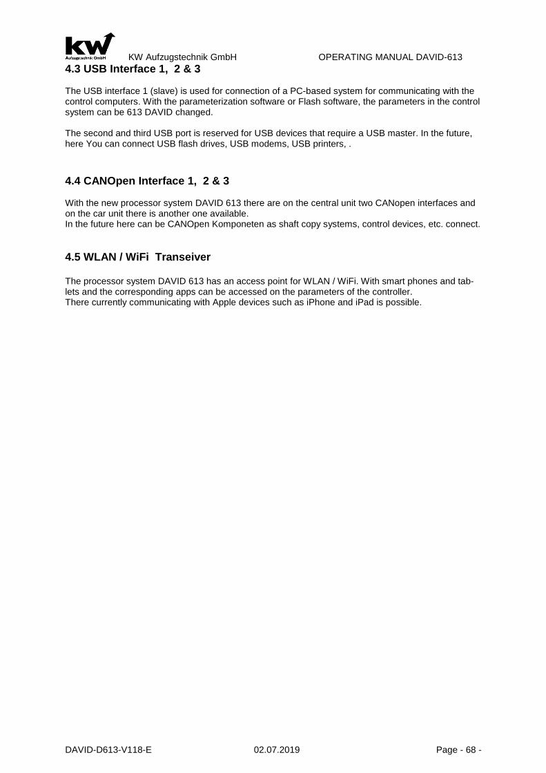
KW Aufzugstechnik GmbH OPERATING MANUAL DAVID-613
DAVID-D613-V118-E 02.07.2019 Page - 68 -
4.3 USB Interface 1, 2 & 3 The USB interface 1 (slave) is used for connection of a PC-based system for communicating with the control computers. With the parameterization software or Flash software, the parameters in the control system can be 613 DAVID changed. The second and third USB port is reserved for USB devices that require a USB master. In the future, here You can connect USB flash drives, USB modems, USB printers, . 4.4 CANOpen Interface 1, 2 & 3 With the new processor system DAVID 613 there are on the central unit two CANopen interfaces and on the car unit there is another one available. In the future here can be CANOpen Komponeten as shaft copy systems, control devices, etc. connect.
4.5 WLAN / WiFi Transeiver The processor system DAVID 613 has an access point for WLAN / WiFi. With smart phones and tab-lets and the corresponding apps can be accessed on the parameters of the controller. There currently communicating with Apple devices such as iPhone and iPad is possible.

KW Aufzugstechnik GmbH OPERATING MANUAL DAVID-613
DAVID-D613-V118-E 02.07.2019 Page - 69 -
A-LIFTPARAMETER
A1- LIFT TYPE 1 PARAMETER: A1.1 TYPE There is a place of 20 characters to put in the name of the type or the company. The whole character-set is 95 characters. 2 3 PARAMETER: A1.2 LIFT NUMBER There is a place of 20 characters to put in the lift number. The whole character-set is 95 characters.
4 PARAMETER: A1.3 CONTROLLER NUMBER There is a place of 20 characters to put in the controller-number. The whole character-set is 95 char-acters.
5 PARAMETER: A1.4 PLACE There is a place of 20 characters to put in the name of the place. The whole character-set is 95 charac-ters. 6 PARAMETER: A1.5 TIME/DATE You must use the form xx:xx:xx = time & yy.yy.yyyy = Date to put in the time and the date. 7 PARAMETER: A1.5a Summer/Wintertimeswitching You can make a automaticly or manual switching. 8 PARAMETER: A1.6 LANGUAGE There are two languages,which you can choose German and Englisch. The standart is German. 9 PARAMETER: A1.7 & A1.8 - DISPLAYLINE 1 AND 2 There is a place of 20 characters in every line to put in the name of the Building, or the company. These two lines are visible at the start on the HPG-60. The whole character-set is 95 characters. 10 PARAMETER: A1.9 SOFTWARE VERSION In this menu the software version will be shown.
- DAVID-613 ZR – 00.076 or higher - DAVID-613 PIC – 00.025 or higher - DAVID-613 FKR – 00.013 or higher - Maintenance-LCD – 00.01 oder higher - ER-Bus-1 to ER-Bus-3 All ER-Schachtbusrechner - Expansionbus ZG32 / Sensormodule / Shaft pit calculator
11 PARAMETER: A1.10 CODEWORD INPUT If the Code-word is >< 0000, then it is active, e.g. after switch off the D613 ZR or put off the HPG-60. If the parameter code-word is active, you must put in the right code-word, before you can change the others parameters. In four waye, the code-word protection is active:
- Unit is switched off - At 00:00 clock - A wrong code-word is put in - A new code-word is put in
The following unit are without code-word protection:
- To give car calls - To give landig calls - Error memory
A2- Controller PARAMETER: A2.1 TYPE OF DRIVE In this parameter, you have to choose the type of drive:
- Hydraulic-Not regulated - Hydraulic- regulated

KW Aufzugstechnik GmbH OPERATING MANUAL DAVID-613
DAVID-D613-V118-E 02.07.2019 Page - 70 -
- Hydraulic-Variable Frequency - Rope- 2 Speeds - Rope- Variable Voltage - Rope- Variable Frequency
PARAMETER: A2.2 TYPE OF CONTROLLER With this parameter you can specify the following basic types of controls:
- One Button Exclusive - One Buttoon Deadmean - Preselection Controlling - Two Button Collection - One Button Up and Down Collection - One Button Down Collection - One Button No Collection - Attendard Controlling - Send-Controlling - Taxi Controlls
PARAMETER: A2.3 GROUP In this parameter, you can activate the Group-drive. Please look at the points A2.4 and A2.5.
PARAMETER: A2.4 NO. OF LIFTS In this parameter, you can put in the numbers of the lifts in the group. The maximum number is 8.
PARAMETER: A2.5 GROUP NO. Each lift in the group has ist own number. You can give the lift a number between 1 and 8.
A3- Shaft
PARAMETER: A3.1 NO. OF FLOORS In this parameter, you can put in the value, how many floors the elevator has. The maximum is eight floors.
PARAMETER : A3.2 MAIN FLOOR In this parameter, you can put in the value, of the main floor.
PARAMETER : A3.3 MAIN FLOOR-2 In this parameter, you can put in the value, of the main floor.
PARAMETER: A3.4 LOWEST FLOOR If you have a groupe with a different number of floors, you must put in the number of the floor, which is the lowest floor of the elevator.
PARAMETER: A3.5 DOOR SIDES In this parameter, you can put in the value, how many door sides the elevator has. The maximum is three door sides. PARAMER: A3.6 SHAFT-COPY In this parameter, you have to choose the type of shaft-copies:
- Standart-Copy - Relativ-Copy - Absolut-Copy - Motor-Copy - Minimum-Copy - R&S-Copy
PARAMETER: A3.7 NOMINAL SPEED In this parameter, you can put in the value of the nominal speed of the elevator in m/s. In principle It is possible to combine two elevator shafts (telescopic shaft). The hydraulic unit 1 of shaft 1 moves the elevator car. The unit-2 moves the elevator shaft 1. This function is available from software version 00.072.

KW Aufzugstechnik GmbH OPERATING MANUAL DAVID-613
DAVID-D613-V118-E 02.07.2019 Page - 71 -
If this function has been activated, the controller may only be operated with absolute value copying. Learning the floors is only possible via a shaft table NORMAL OPERATION: The output function A623 selects aggregate-1 (inner duct, A623 = 0) or aggregate-gat- (outer duct, A623 = 1). The setting A3.7 selects the floor at which switching from shaft 1 to shaft 2 takes place. Rides between the lowest floor to the changeover days are done with Aggre-gat-1 (A623 = 0). Rides from the change-over days to higher floors are carried out with the Ag-gregat-2 (A623 = 1). If the elevator is in the change-over days always with Ag-gregat-1 is made up. When driving over the switchover days, the lift will always make a stopover in the switchover days to switch over the units. INSPECTION SERVICE In inspection mode, only drive with unit-1. Inspection operation only works until the transfer date. Return mode In return mode, after learning the floor, depending on the position, it is driven with unit 1 or unit 2. Be-low the switchover days, drive until the changeover days with unit-1. With Bündig the STOP occurs in the changeover day. Thereafter, when driving up to the Aggre-gat-2 is switched. Downwards, the pro-cess is reversed.
A4- CANopen lift A401 CAN-1 Monitor The D613 system provides physically two CAN buses. The CAN-1 monitor is used to view the CAN devices on the CAN bus. In this case, the state of the device is illustrated as being "operational", ie. The device works in the CAN community, resp. "-------------". The device is not connected. The following CAN devices show their status: ID1 Controller - This is the central unit D613 ID4 Encodersystem 1 - These are absolute shaft copying systems that operate on the basis of the
CANopen lift protocol. ID7 Doorcontroller 1 - The state of the CANopen door control device of the door 1, e.g. Wittur ECO is
shown here. ID8 Doorcontroller 2 - The state of the CANopen door control device of the door 2, e.g. Wittur ECO is
shown here. ID9 Doorcontroller 3 - The state of the CANopen door control device of the door 3, e.g. Wittur ECO is
shown here. ID13 Loadmeasurement - The state of the load measuring system, e.g. Henning is shown here.
A402 CAN-1 Devices
The D613 system offers the possibility to operate control and control components with the most diverse buses. If CANopen devices are used, they are activated in menu item A402 CAN-1 devices so that they are available to the controller. ID4 Encodersystem 1 - If a CANopen lift encoder system is to be used, it should be activated in this
menu. The special type of the bay coiling system is still set in menu B43 Abso-lute value copying.
ID7 Doorcontroller 1 - If a CANopen door control unit for door 1 is to be used, it should be activated here.
ID8 Doorcontroller 2 - If a CANopen door control unit for door 2 is to be used, it should be activated here.
ID9 Doorcontroller 3 - If a CANopen door control unit for door 3 is to be used, it should be activated here.
ID13 Loadmeasurement - If a CANopen load measuring system is used, it is activated here.

KW Aufzugstechnik GmbH OPERATING MANUAL DAVID-613
DAVID-D613-V118-E 02.07.2019 Page - 72 -
A403 CAN-1 Configuration
The fact that the CANopen bus runs on a D613 system and can operate its devices requires a few points. Activate the CAN bus - In order to be able to transport data on the CAN bus, on must be switched on.
This is done by a clear YES in this menu item. The green LED on the interface is switched on as a sign of the operation. If the red LED is lit, you have a fault on the CAN bus.
Activate NMT-Function - As on any real boat or ship there must be one who has the say. In the case of
an elevator control, this is usually the control, which is the master and gives thdevices the command to drive upBaudrate - In order for all bus users to be able to communicate well, the "speech speed" must be set. The baud rate is adjustable from 10 kBaud to 1 MBaud. A good factory setting rep-resents the value of 250 kBaud.
Note-ID - In order for the boss (master) to be accessible in a system, he needs an address
as in real life. In our CANopen system, the master therefore has the address 001.
Heartbeat - As the term is already associated, it is about the heartbeat. In humans, as in the
CANopen system, this is a sign that he is still alive. We send this signal, accord-ing to the factory setting, every 500 milliseconds, so that the peripherals are soothed.
CAN bus termination
The term "termination" in bus systems describes the necessary use of a terminating resistor (in the high-frequency technique, also the wave resistance) at the end of the bus line in order to avoid reflections at the open end of the data line. These reflections can lead to corruption of the data bits and thus to the loss of the data. Both CAN-Bus interfaces on the central computer ZR and on the car calculator FKR offer the option of activating terminating resistors by means of a DIL switch as standard. In our factory setting, all DIL switches have already been set to ON on both CAN bus interfaces. CAN bus chain - If the topology of the chain is used when connecting the CAN bus devices, i.
The devices are connected in series, the last device in the chain should have the connected terminating resistor.
CAN bus star - If the topology of the star is used when connecting the CAN bus devices, i. Each device is connected to the computer interface, a terminating resistor should be connected to all devices.
CAN-Bus Token ring - An annular wiring of the devices must be rejected!
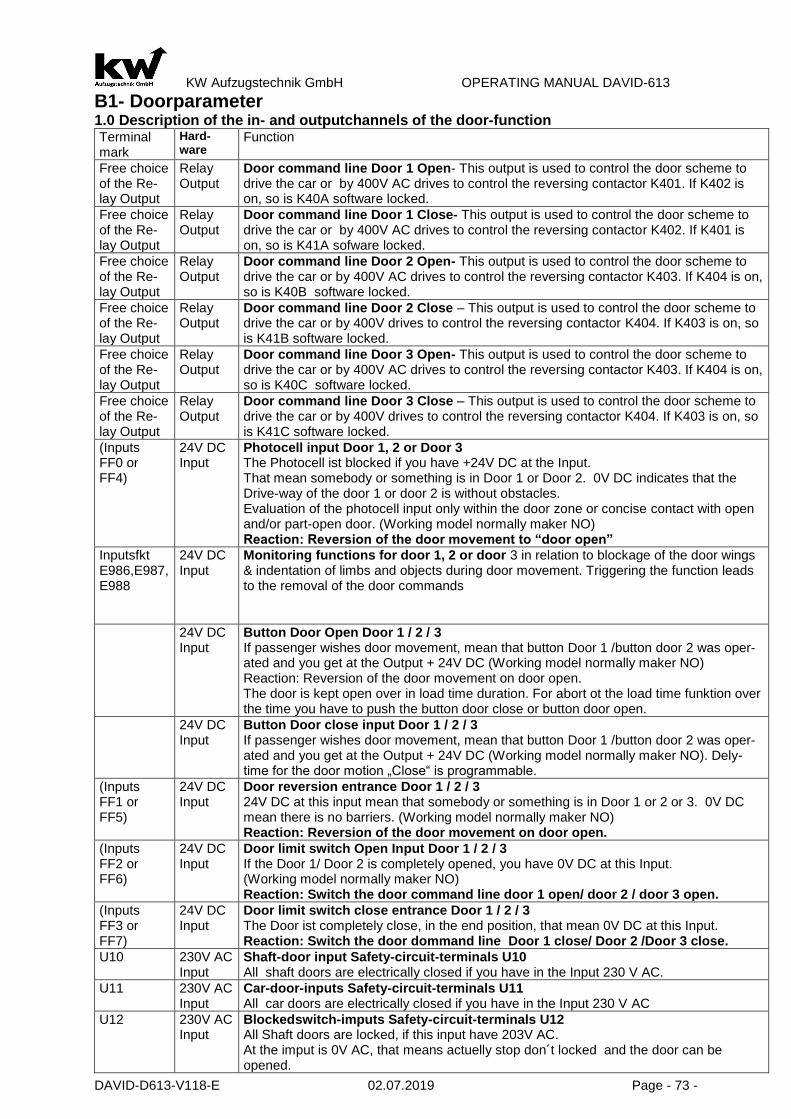
KW Aufzugstechnik GmbH OPERATING MANUAL DAVID-613
DAVID-D613-V118-E 02.07.2019 Page - 73 -
B1- Doorparameter 1.0 Description of the in- and outputchannels of the door-function Terminal mark
Hard-ware
Function
Free choice of the Re-lay Output
Relay Output
Door command line Door 1 Open- This output is used to control the door scheme to drive the car or by 400V AC drives to control the reversing contactor K401. If K402 is on, so is K40A software locked.
Free choice of the Re-lay Output
Relay Output
Door command line Door 1 Close- This output is used to control the door scheme to drive the car or by 400V AC drives to control the reversing contactor K402. If K401 is on, so is K41A sofware locked.
Free choice of the Re-lay Output
Relay Output
Door command line Door 2 Open- This output is used to control the door scheme to drive the car or by 400V AC drives to control the reversing contactor K403. If K404 is on, so is K40B software locked.
Free choice of the Re-lay Output
Relay Output
Door command line Door 2 Close – This output is used to control the door scheme to drive the car or by 400V drives to control the reversing contactor K404. If K403 is on, so is K41B software locked.
Free choice of the Re-lay Output
Relay Output
Door command line Door 3 Open- This output is used to control the door scheme to drive the car or by 400V AC drives to control the reversing contactor K403. If K404 is on, so is K40C software locked.
Free choice of the Re-lay Output
Relay Output
Door command line Door 3 Close – This output is used to control the door scheme to drive the car or by 400V drives to control the reversing contactor K404. If K403 is on, so is K41C software locked.
(Inputs FF0 or FF4)
24V DC Input
Photocell input Door 1, 2 or Door 3 The Photocell ist blocked if you have +24V DC at the Input. That mean somebody or something is in Door 1 or Door 2. 0V DC indicates that the Drive-way of the door 1 or door 2 is without obstacles. Evaluation of the photocell input only within the door zone or concise contact with open and/or part-open door. (Working model normally maker NO) Reaction: Reversion of the door movement to “door open”
Inputsfkt E986,E987, E988
24V DC Input
Monitoring functions for door 1, 2 or door 3 in relation to blockage of the door wings & indentation of limbs and objects during door movement. Triggering the function leads to the removal of the door commands
24V DC Input
Button Door Open Door 1 / 2 / 3 If passenger wishes door movement, mean that button Door 1 /button door 2 was oper-ated and you get at the Output + 24V DC (Working model normally maker NO) Reaction: Reversion of the door movement on door open. The door is kept open over in load time duration. For abort ot the load time funktion over the time you have to push the button door close or button door open.
24V DC Input
Button Door close input Door 1 / 2 / 3 If passenger wishes door movement, mean that button Door 1 /button door 2 was oper-ated and you get at the Output + 24V DC (Working model normally maker NO). Dely-time for the door motion „Close“ is programmable.
(Inputs FF1 or FF5)
24V DC Input
Door reversion entrance Door 1 / 2 / 3 24V DC at this input mean that somebody or something is in Door 1 or 2 or 3. 0V DC mean there is no barriers. (Working model normally maker NO) Reaction: Reversion of the door movement on door open.
(Inputs FF2 or FF6)
24V DC Input
Door limit switch Open Input Door 1 / 2 / 3 If the Door 1/ Door 2 is completely opened, you have 0V DC at this Input. (Working model normally maker NO) Reaction: Switch the door command line door 1 open/ door 2 / door 3 open.
(Inputs FF3 or FF7)
24V DC Input
Door limit switch close entrance Door 1 / 2 / 3 The Door ist completely close, in the end position, that mean 0V DC at this Input. Reaction: Switch the door dommand line Door 1 close/ Door 2 /Door 3 close.
U10 230V AC Input
Shaft-door input Safety-circuit-terminals U10 All shaft doors are electrically closed if you have in the Input 230 V AC.
U11 230V AC Input
Car-door-inputs Safety-circuit-terminals U11 All car doors are electrically closed if you have in the Input 230 V AC
U12 230V AC Input
Blockedswitch-imputs Safety-circuit-terminals U12 All Shaft doors are locked, if this input have 203V AC. At the imput is 0V AC, that means actuelly stop don´t locked and the door can be opened.

KW Aufzugstechnik GmbH OPERATING MANUAL DAVID-613
DAVID-D613-V118-E 02.07.2019 Page - 74 -
B10- General PARAMETER: DOOR FUNCTION For the software used in this system, the term „Automatic Door“ refers to a telescopic shaft door in connection with a telescopic cabin door, which are jointly operated by an electric system. PARAMETER: TYPE OF DOOR In this parameter you can choose the type of the door. The following door types are in the software:
- No Door - Handdoor no Cardoor - Hand/Cardoor with 2 Endswitch - Hand/Cardoor with Door-Open-Endswitch - Hand/Cardoor with Door-Close-Endswitch - Hand/Cardoor without Endswitch - Automaticdoor with Door-Open-Endswitch - Automaticdoor with Door-Close-Endswitch - Automaticdoor without Endswitch
In menu A3.4 you can activate “Door 2” and apply the setup “like Door 1”.The doors 1 and 2 have the same setups. But you can change the setup for door 2. The term of the automatic door mean for the implemented software a telescope shaft door in connection with a telescope car and door car those to be together coupled. For the automatic door without door limit switches in principle the same description is valid, as with door limit switch. The door instructions Open and Close remain in the final positions. Some door engines have however no cyclic duration of 100%. Therefore the parameter must be acti-vated” Door engine in standby Off” The term of the turning door mean for the implemented software a turning door as shaft door in connec-tion with a telescope driving car door or /and a folding door . The closing of the shaftdoors hapens with the blockedswitch. The control of the blockedswitch can take place again mechanically or with solenoid operated bolt magnet.
PARAMETER: DOOR LIMIT SWITCH At this parameter you can choose between 2 options. ( Opener/ Closer) This parameter come out only if the kind of door with door limit switch are chosen. The standart value is Opener.
PARAMETER: DOOR ENGINE 1 ACTIVE / DOOR ENGINE 2 / DOOR ENGINE 3 ACTIVE At this parameter, you can choose between two values, namely „always“ and „standby off“. The door-engines, which have no switch-on-time of 100%, you must be choose the value “standby off”.
PARAMETER: SHAFTDOOR WAITING The use of this parameter is to have a delay-time for the shaft-door-contacts in the safety-circuit. When the time is over, the is a interpretation, if the door is open or closed. If you have old doorcontacs in the safety circuit of the shaftdoor, you must set the time high. The best way is always to use new doorcon-tacts. The standart value is 0,5 seconds.
PARAMETER: CAR DOOR WAITING The use of this parameter is to have a delay-time for the car-door-contacts in the safety-circuit. When the time is over, the is a interpretation, if the door is open or closed. If you have old doorcontacs in the safety circuit of the cardoor, you must set the time high. The best way is always to use new doorcontacts. The standart value is 0,5 seconds. PARAMETER: LATER DOOR OPENING The start of opening the door has a delay-time. The standart value is 0,5 seconds. The maxvalue is 8.0 seconds. PARAMETER: LIMITED DOOR OPENING Default value is 6.0 seconds. PARAMETER: DOOR MONITOR OPEN Within the watch dog time the door must be opened. If this does not take place, then the door is re-versed and closes again. The procedure is repeated dependent on the entered number of door at-temps. The universal time for the monitoring amounts to 13.0 seconds.

KW Aufzugstechnik GmbH OPERATING MANUAL DAVID-613
DAVID-D613-V118-E 02.07.2019 Page - 75 -
PARAMETER: DOOR MONITOR CLOSE Within watch dog time the door must be closed. If this does not take place, then the door is reversed and openes again. The procedure is repeated dependent on the entered number of door attemps. The universal time for the monitoring amounts to 13.0 seconds.
PARAMETER: FURTHER TRAVEL DELAY CAR CALL If the elevator holds at the stop with car call and other severel calls are present, then this time starts after opening the door. Passengers are to able to leave the cab in this time. Upon the expiration of the driving on time inside the door is closed and driven to the next stop. The standart value is 7,0 sec.
PARAMETER: FURTHER DELAY LANDING CALL If the elevator holds at the stop with landing call and other severel calls are present, then this time starts after opening the door. Passengers are to able to entry the cab in this time. Upon the expiration of the driving on time outside the door is closed and driven to the next stop. The standart value is 7,0 sec.
PARAMETER: FURTHER DELAY TIME TRIGGER At expiration of the driving on time the door is closed. If the door is blocked, then it can be decided in this parameter whether after the door reversion the driving on time is started again.The standart value is NO.
PARAMETER: DOOR RESERVE DELAY If the door is in motion to close and she should be reverse, this means she should be open, then you need a delay time to prevent a mechanical demage of the door. The standart value is 0,5 seconds.
PARAMETER: DOOR ENGINE 1/2/3 AT STANDBY OFF In Parameter you can selected the time if the door engine don´t work and the cab stand with closed door. You can use this preference if you choose the parameter„ Door engine“ was selected actively the attitude „always“. ( Parks-Standby-Ready)
PARAMETER:DOOR STANDBY MAIN If there are no car- and landing-calls present in the elevator controller, then the lift is in the Stand-By for future calls. In this condition you can choose for the door between open or close. The standart value is open.
PARAMETER: DOOR ENGINE INSPECTION In this parameter you can choose whether with manipulation of the inspection controller the door is headed for. However you can operate the door controller over separate control.
PARAMETER: DOOR OPEN Selective together Both buttons are parallel. If you push of a button ( Button1/ Button2), so opens the last running up to door. When both doors are closed and you push the button ( Button1/ Button2) so opens only that door, which are last closed. Together Both buttons are parallel. Both doors open by the pushing of the button ( Button1/ Button2) Single Button-1 opens Door-1, Button-2 opens Door-2 Selectively individually Both buttons are running individually. If you push of a button ( Button1/ Button2) , so opens the last running up to door. When both doors are closed and you push the button ( Button1/ Button2) so opens only that door, which are last closed.

KW Aufzugstechnik GmbH OPERATING MANUAL DAVID-613
DAVID-D613-V118-E 02.07.2019 Page - 76 -
PARAMETER: BUTTON HOLDTIME With this parameter if a time is registered, and the load time tracer operates, then the door can run not for the adjusted time. During the load time if the load time tracer be pushed, then the load time is inter-ruped and the door is closing. The range of values for the load time extends between 1 and 600 seconds. PARAMETER : HOLDTIME FUNCTION In that parameter you can choose between ”single” and “ together”. Together means that a load time tracer is responsible for both door sides. Single means that two load time tracers, which react separately for the two door sides. PARAMETER: BUTTON DOOR CLOSE FUNCTION In that parameter you can choose between single, together and selective. Together mean that the Door-close-button, which connected on Input of the EIT-device ,is responsible for both door sides. Single mean that you need 2 Door-close-buttons, which react seperately for the two door sides. During the attitude selective is only one door button attached during a selective door control. The re-action of the button is always arranged the last door movemant at Door 1 / Door 2. The standart value is together. PARAMETER: BUTTON DOOR CLOSE REACTION At this parameter you can choose the delay-time, when the push-button Door-close is active. PARAMETER: DOOR CONTROL ATTEMPS At this parameter you can choose how many attemps you can make to close or open the door , before there would be show a door-fault. The standart value is 3 attemps. PARAMTER: DOOR OPEN TIME If you have a car-door without endswitches, you can choose in this parameter the time, when the ZR-Unit shows you that the door is open. Please measure the time, whitch the doors needs to open. PARAMTER:DOOR OPEN There two possibilities – automaticly -> Normal Function or Only with Door Open-Push-Button. PARAMETER: DOOR CLOSE There two possibilities – automaticly -> Normal Function or Only with Door Close-Push-Button.
B11- Table of Entrance
Menu B11 is active only if you choose in menu “ A Liftparameter/ A3 Shaft/ A3.4 Door Sides” the option “3 Door Sides”. For every floor, there are three sides prepared. Now you can decide, which door realy exists.
B11 Table of Entrance B11 Door-1 E01-16
****************
^
Esc Enter Value
Here the existing doors are set by the star, or by the - away. ( * Door exist, - No door )
.
B12- Safery Photocell
PARAMETER: SAFETY PHOTOCELL Setting Saftey Photocell: At an elevator with shaft door without car door the entrance “safety photocell” can be. In the stop or standart drive, i.e. the jets of the safety photocell are not interrrupted, that mean landing and car calls are accepted and progressed. Is there an interruption of the safety photocell, then the input safety photocell is deactivated at the FKR. As a result all calling are erased. The drive is possible only be car calls. The landing calls are not possible. Setting CEDES: In this setting, you can support the system CEDES LI. A. Testing the saftey photocell also before lowering travel B. No lowering travel, if before there was a break in the journey of the saftey photocell. Only possible after reset at the input channel of function E254. C. No releveling, if before there was a break in the journey of the saftey photocell. Only possible
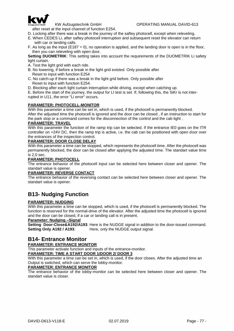
KW Aufzugstechnik GmbH OPERATING MANUAL DAVID-613
DAVID-D613-V118-E 02.07.2019 Page - 77 -
after reset at the input channel of function E254. D. Locking after there was a break in the journey of the saftey photocell, except when releveling. E. When CEDES Li, after saftey photocell interruption and subsequent reset the elevator can return with car or landing calls. F. As long as the input (E187 = 0), no operation is applied, and the landing door is open is in the floor, then you can releveling with open door. Setting DUOMETRIK: This setting takes into account the requirements of the DUOMETRIK Li safety light curtain. A. Test the light grid with each ride. B. No lowering, if before a break in the light grid existed. Only possible after Reset to input with function E254 C. No catch-up if there was a break in the light grid before. Only possible after Reset to input with function E254. D. Blocking after each light curtain interruption while driving, except when catching up. E. Before the start of the journey, the output for LI test is set. If, following this, the SiKr is not inter-rupted in U11, the error "Li error" occurs.
PARAMETER: PHOTOCELL-MONITOR With this parameter a time can be set in, which is used, if the photocell is permanently blocked. After the adjusted time the photocell is ignored and the door can be closed , if an instruction to start for the park stop or a command comes for the disconnection of the control and the cab light . PARAMETER: TRAVEL With this parameter the function of the ramp trip can be selected. If the entrance IE0 goes on the ITR controller on +24V DC, then the ramp trip is active, i.e. the cab can be positioned with open door over the entrances of the inspection control. PARAMETER: DOOR CLOSE DELAY With this parameter a time can be stopped, which represents the photocell time. After the photocell was permanently blocked, the door can be closed after applying the adjusted time. The standart value time is 2,0 sec. PARAMETER: PHOTOCELL The entrance behavior of the photocell input can be selected here between closer and opener. The standart value is opener. PARAMETER: REVERSE CONTACT The entrance behavior of the reversing contact can be selected here between closer and opener. The standart value is opener.
B13- Nudging Function
PARAMETER: NUDGING With this parameter a time can be stopped, which is used, if the photocell is permanently blocked. The function is reserved for the normal-drive of the elevator. After the adjusted time the photocell is ignored and the door can be closed, if a car or landing call is in present. Parameter: Nudging –Signal Setting Door-Close&A192/A193: Here is the NUDGE signal in addition to the door-issued command. Setting Only A192 / A193: Here, only the NUDGE output signal.
B14- Entrance Monitor
PARAMETER: ENTRANCE MONITOR This parameter activate function and inputs of the entrance-monitor. PARAMETER: TIME A START DOOR 1/DOOR 2/ DOOR 3 With this parameter a time can be set in, which is used, if the door closes. After the adjusted time an Output is switched, which can serve the lobby-monitor. PARAMETER: ENTRANCE MONITOR The entrance behavior of the lobby-monitor can be selected here between closer and opener. The standart value is closer.

KW Aufzugstechnik GmbH OPERATING MANUAL DAVID-613
DAVID-D613-V118-E 02.07.2019 Page - 78 -
B15- Mechanical Lock PARAMETER: PULSE BUF. DELAY With this parameter you can choose the delay-time of the lock-magnet in order to compensate contact difficulties of the safety-contacts. The standard value is 500 ms. PARAMETER: LOCK DELAY ON This parameter allow delayed on the locked magnet. The standart value is without delay. PARAMETER: LOCK DELAY OFF With this parameter you can realize an delay-off-function of the lock-magnet. If you have horizontal car doors, you need this function. The standart value is without delay. PARAMTER: LOCK HANDDOOR If you have a handdoor and a horizontal car door, you must pay attention at this parameter. You can choose between the following values „Before the car door“ and „After the car door. The standart value is „After the car door“. PARAMETER: OPEN AFTER LOCK At the use of automatic shaft- and car doors with lock-magnet ( electric sword ), it is nessecary to switch off the lock-magnet, before you try to open the car door. The delay-time for the car door is free program-mable. PARAMETER: MECHANICAL LOCK-OFF This is the maximum time for activating the bold magnet without travel.The standart value is 30 seconds. PARAMETER: Additional bolt delay For cabin door locks you can program a delay here. This is required in conjunction with the control of the car door. The factory setting has no delay. A possible average would be the setting of 1,0 seconds.
B16- Safety-Circuit PARAMETER: PRE-OPENING DOORS If the lift-controller have a integrated safety-circuit-pcb, yon can activate the function for drive into the floor with open door. During the drive into the floor, you need the message of the frequency inverter, if the speed is below V < 0,3 m/s. Then the door can be opened. PARAMETER: EARLY PREMAGN. When this parameter is actice and the frequency inverter in use support this function, the motor can be set under voltage during the door-close-motion. After the safety circuit is closed, the can start without time-delay. With this function the floor-delay-time can reduced very powerful. Activation and commis-sioning of the function only after consultation with the technical hotline. PARAMETER: EARLY PREMAGN.DELAY You can choose a delaytime between 0.8 and 10 seconds. The standart value is 0, 8 seconds. PARAMTER: SAFETY CIRCIUTS In this parameter you can choose the type of the safety-circuit-pcb. Ths standard value is the safety-circuit-pcb SIS-16. For very old controller-systems, like DAVID-2001 you need the SIS-60 (Rekoba).
B17- Releveling
PARAMETER: RELEVELING If the elevator controller has the option of a safety-circuit-pcb, you can switch on the function releveling in the software. Depends on the shaft-copy-system in use, you can make it in a digital system with the programming unit HPG-60 in mm stepps, or you have a magnet-system, you have to move the magnets. PARAMETER: NO REVELING DISTANCE This option is only necessary by a digital shaft copy system in use. If you have a standard- or simple-shaft-copy the length of the no releveling distance depends on the overcut of the level-distance 12A and 12B. The standard value for this parameter is 5 mm. The tolerance in the way is 2,5mm over and 2,5mm under the level mark. The exacty value is depending of the art of ropes and the art of use of the elevator. PARAMETER: MAX. RELEVELING DISTANCE This option is only necessary by a digital shaft copy system in use. If you have a standard- or simple-shaft-copy the length of the releveling distance depends of the lenght of level-distance 12A or 12B. The length of the level-distance 12A and 12B must be shorter than the zone area. The standard value for this parameter is 100mm. This is the releveing-way for one direction. Please look at the lenght of the door-sword! PARAMETER: LEVELING UP/DOWN

KW Aufzugstechnik GmbH OPERATING MANUAL DAVID-613
DAVID-D613-V118-E 02.07.2019 Page - 79 -
This option is only possible by a digital shaft copy system in use. PARAMETER: TIME LIMIT The parameter of the time limit is crucial for a retrieving procedure. The standart value is 20 sec. In this time interval if the retrieving procedure is not successfully brought to end, then it is brocken. PARAMETER: NUMBER OF ATTEMPS With this parameter the number of attemps can be limited with the regulation, in order to so e.g. protect the hydraulic aggregate against overheating. The standart value is 20 efforts. PARAMETER: LIMIT AT LEVEL 1 When car is in bottom level, you can choose in this parameter if the number of the releveling-attemps is reduced, like in parameter before or the is no limit. PARAMETER: OVERLOAD With this parameter you can choose, if the releveing-function is aktive when the overload procedure is present. The standart value is the active releveling, according to the EN81. PARAMETER: FAULT HANDLING If there is an error at the releveling-function, the following reactions are possible:
- “Lowering & Block”- This value can be used for hydraulic elevators. The car is lowered into the lowest stop place, in order to avoid an uncontrolled lowering.
- „Block Immeadedly“ – This value can be used for rope elevators. - „Next Floor & Block“ – This value can be used for rope elevators. - Only “Fault Entry” – no blocking.
PARAMETER: FINE –RELEVELING The releveling will be handled by an external hydraulic-aggregate. Made the following settings:
1) ALGI - fine releveling 2) BUCHER - fine releveling
B2 Call Options B21 Car Calls PARAMETER: DOOR REVERSE CAR CALL With activation of this function, the closing of the door will be reversed if the control button in the car is pushed at the current landing, i.e. the door stops and reopens.
PARAMETER: SELECTIV CAR CALLS In this parameter the selective door control activate with a second car call strand. At the Floor with front and back door in each case 2 call buttons are present. Button 1/ 2 opens Door1/ 2.
PARAMETER: SELECTIV CAR CALLS In this parameter you choose the time after which the car calls are deleted, if an error happens. The standart value is 4,0 sec.

KW Aufzugstechnik GmbH OPERATING MANUAL DAVID-613
DAVID-D613-V118-E 02.07.2019 Page - 80 -
PARAMETER:CAR PANEL CONTROLLER In this parameter you can indicate whether the selective car calls realise with one or two car controller ITR. To 8 stops the realization you can use an car calling controller, and/or can alternatively second car calling controller ITR. PARAMETER: MISUSE PROTECTION The car calls deletes with the next stop ,if 2 following each stops no light barrier interruption takes place. PARAMETER: BUTTON BUZZER In this parmeter you can indicate wherther an acoustic messaging at the push button movement. PARAMETER: CAR CALL RANGE In this parameter the lift can be divided into two ranges, which will not leave by car calling. PARAMETER: CAR CALL LIMIT Car call border: > xx calls delete Function: If elevator drive into the floor and more car calls indicated than in the parameter is set in, then the car calls will be automically deleted. Parameter: Automatic Carcall Vehicle At carelevator with two stops, you can set thecarcalls automaticly.
B22- Landing Calls GENERAL Since spring 2007 all controls are delivered with remote station for the external control. According to standard selective 2-KS control is present (2xA,2xB,2xC and 2xD) , as well as further four in- and out-put channels, which are free provable. Later you can funktions realize like landing prioritys and other. The advantage consists of the fact that practically no hardware re-tooling expenditure exists, since all missing functions can be modulated by software. Standard Setting: In- and Output channels at the Remotestations ER-2007 / 2009: Term Function at Terminal Output Menu B71 Input Menu B72
2xA Fix: Landing Call Up
2xB Fix: Landing Call Down
2xC Free programabel -> Standard: Landing Call Door 2 Up A199 c. mess.-D2 Up E248 l.call-D2 Up
2xD Free programabel -> Standard: Landing Call Door 2 Down A200 c.mess.-D2 Down E249 l.call-D2 Up
97A Free programabel -> Standard: Floor arrow Door side 1 Up A201 ER Arrow D1 Up E00 no function
98A Free programabel -> Standard: Floor arrow Door side 1 Down A202 ER Arrow D1 Down E00 no function
97B Free programabel -> Standard: Floor arrow Door side 2 Up A203 ER Arrow D2 Up E00 no function
98B Free programabel -> Standard: Floor arrow Door side 2 Down A203 ER Arrow D2 Down E00 no function
RJ-12 KW-Bus-Matrix-indicator, free programable Characterset, Scroll of signs & arrows, A1
RJ-12 KW-Bus-Matrix-indicator, free programable Characterset, Scroll of signs & arrows, A2
PZ1 Piezo Bruzzer for doorside 1
PZ2 Piezo Bruzzer for doorside 2
In the use of remotestation ER-2005 there are more In- and output functions and floor gongs. Specialparameterset: In- and Output at the Send-and Resend Controller: Term Function at Terminal Output Menu B71 Input Menu B72
2xA Fix: Landing Call Up
2xB Fix: Landing Call Down
2xC Free programabel -> Standard: Landing Call Door 2 Up A199 c.mess.-T2 Up E248 l.call-D2 Up
2xD Free programabel -> Standard: Landing Call Door 2 Down A200 c.mess.-T2 Down E249 l.call-D2 Down
97A Fix: Landing Call HS 01
98A Fix: Landing Call HS 02
97B Fix: Landing Call HS 03
98B Fix: Landing Call HS 04
RJ-12 KW-Bus-Matrix-indicator, free programable Characterset, Scroll of signs & arrows, A1
RJ-12 KW-Bus-Matrix-indicator, free programable Characterset, Scroll of signs & arrows, A2
PZ1 Piezo Bruzzer for doorside 1
PZ2 Piezo Bruzzer for doorside 2

KW Aufzugstechnik GmbH OPERATING MANUAL DAVID-613
DAVID-D613-V118-E 02.07.2019 Page - 81 -
PARAMETER: DOOR REVERSE LEADING CALL If the door revision is active with landing call, the door movement reverse with pushing the landing call button at the current stop, then the door continues and open.
PARAMETER: MODUL In this parameter you can indicate if landing calls are received at the central unit ZR or remote station
ER-XXXX. PARAMETER: SELECTIVE LANDING CALLS In this parameter the selective door control activates with a second landing call strand. At the Floor with front and back door 2 call buttons are present in each case at the two external call sides. Depending on which of the two door sides the extrenal call pushers are operated, there the door opened. The realization is made by the two call entrances 2xC and 2xD at the Remote Station ER-2007 and/or ER-2005.
PARAMETER: ERASE UP AND DOWN CALLS During the attitude 2KS Up call and Down call can be given faulty operations both calls, i.e. although only one trip desire is present. Thus it comes to unnecessary movements of the lift. If the parameter oportunity call erasement 2KS is active, then the second call, which is given within a short time interval, is suppressed. With entry into the goalstop both calls are deleted. The standart value for this function is off. PARAMETER: SAVE TRAVEL During the attitude 2KS you can select, how long is the driving move on direction.
B23- Car Priority PARAMETER: CAR CALL HANDLING At this parameter you can choose between Save or Delete as landing call handling at car priority mode. If deletion is present, after start car priority mode all external calls delete. After switch off this mode, new landing calls can put in. With the mode operation “save”, all landing calls remains. PARAMETER: MAIL TRAVEL Switch on for the function: Door-open-button+Numeric code input over car calls 4-7-1-1 (Messaging: long beep tone). Now the elevator is in the mode “post office trip” and is take out of the group enterprise. As announcement SPEZIAL TRIP appears as scrolling text on the cab condition announcement. A trip can be release now only if you press at the Door-Close+1 Car call. Now the elevator drives into the desired floor and waits there the next call input or scolded after 15 min automatically again into normal operation. Switch off the function: After 15 min this mode is deactivated automatically, if no trip took place. The mail travel mode can be deactivated however purposefully by the following code input: Door-Open-button + Numeric code input over car calls 4-7-1-2( Messaging: short beep tone)

KW Aufzugstechnik GmbH OPERATING MANUAL DAVID-613
DAVID-D613-V118-E 02.07.2019 Page - 82 -
B24- Landing Priority PARAMETER: TIME CALL INPUT In order to take the lift not for a long time from normal operation, the time for the input of the priority car calls is limited. The standard value is 20 seconds.
PARAMETER: FLOOR CALLS At this parameter you can choose between Save or Delete as landing call handling at car priority mode. If deletion is present, after start car priority mode all external calls delete. With the mode operation “save”, all landing calls remains
PARAMETER: PRIORITY CAR CALL You can choose between Separately, Collectively, Seperately softly and Separately emptying. During the attitude separately comes the car, with assigne which the landing priority button. The car comes immediately. Car calls are deleted. Both external flash in the case of the time window call input. With the mode of operation collective is needed only a landing priority button for 2 group of elevators. With the first manipulation the next car comes. With a second manipulation the second cab comes. With separately soft a certain elevator comes, the car and landing controller stay. This function used at unequal groups,the cab drive in all floors. In the case of separately emptying a certain elevator comes, but the lift goes out of the external control and the car calls is processed. The input of new car calls is not possible, until the floor is reached the landing priority. This function is used in order to introduce an hindrance drive without reducing the traffic capacity of the group drastically.
Parameter: Forced overtaking – 5-second outgoing call (handicaped ride) If the setting has been selected and a corresponding long press on an outside call is made, an external priority call will be made. The prerequisite is that the setting "Single" has been selected in parameter B24 Forced recovery. In the parameter, the elevator system can be selected, which serves the outside priority call. A shaft bus can serve up to 2 elevator systems. Therefore, it can be decided by the settings A1 or A2 which elevator operates the priority outside call. Disadvantage: Since the priority call is triggered by an outside call button, it can possibly happen that a second elevator enters this level. Parameters: Dangerous goods transport via key switch in the outer panel In this parameter, the function of the dangerous goods transport can be activated via the recall by the external control. The input functions E518 to E521 enable manual door control, even with two door sides and selective doors. Via the input function E522, the geogood transport function can be switched on or off by means of an external key switch in the external deflection. In the corresponding floor, the elevator is brought over external preference. The elevator goes to the floor and the door opens. Now the elevator is in "Dangerous goods transport" mode. The door can only be controlled manually via the input functions E518..E521. An interior call to the finish day must be pressed. This inner call can be corrected by pressing again on another target floor. Now the door must be closed manually via E519. If the door is closed, the elevator will move to the destination floor. There is the elevator with closed door. The door must now be opened manually E518. Now the mode "dangerous goods transport" can be terminated via a pulse at input E522 or a further transport of dangerous goods can be carried out.
As long as the mode "Hazardous goods transport" is active, "SPECIAL TRIP" is displayed.

KW Aufzugstechnik GmbH OPERATING MANUAL DAVID-613
DAVID-D613-V118-E 02.07.2019 Page - 83 -
Parameter: Dangerous goods transport via key switch in the interior panel
The functional sequences is as follows:
1. The elevator is called via the normal call button or key switch in the outside panel of the spe-cial drive control.
2. The special trip is triggered by the key-operated switch "Dangerous goods transport" in the panel of the car by briefly pressing the key-operated switch. As a result, the input function E985 becomes active, and the output function A625 is set, as well as the output EA4 at the floor computer ER-2014.
3. A visual indication follows as confirmation of the activation (display in the external tableau). The lift is exclusively available for this transport (outside calls of the lift system and the auto-matic door closing functions are switched off).
4. Then the elevator can be loaded with the dangerous goods. 5. By pressing the "door to" button in the outer call panel of the special drive control of the load-
ing stop, the elevator door closes. The push-button must be pressed until the door is com-pletely closed - visual acknowledgment by lighting the quit ring on the "door-to-door" button. (Entrance EA7 on ER-2014: door-close, exit 28h on ER-2014 will be 1 if door closed)
6. The operator goes to the destination stop. At the destination stop, the key switch "Dangerous goods transport" is actuated in the external call panel. Only now does the elevator arrive at the destination floor and after reaching it, the door opens automatically. (EA6 on ER-2014).
7. The elevator can be unloaded. 8. By closing the key switch in the car panel, the special trip is ended and the elevator is availa-
ble for normal use.

KW Aufzugstechnik GmbH OPERATING MANUAL DAVID-613
DAVID-D613-V118-E 02.07.2019 Page - 84 -
B25- Group FUNCTION The group control works according to the principle „flying of the master“ to take over the group control that means that each central computer (ZR) is able to take over the group control. It is possible to interconnect maximally 8 central computers by the group bus and to realize thus groups of eights. One of the central computer takes over the function of the master, where ZR is the master is unimportent. The group master fail or be switched off, so automatically another central computer takes over this function. By the group bus all branches of landing call, at which the remote station are tied up, are connected with all central computers. Thus all ZR has each other the full access to all remote station independently of. The elevator bus is ased physically on that kind of industrial condition RS485 on one high-speed minutes runs.
INFORMATION EXCHANGE: The lining up landing calls are read in by the group master and distributed to the central computers ( elevators) the available distributes. With the distribution information about door times, track curves and floor distances of the individual lifts is considered. The master knows exactly, how long a trip lasts the door in the started goal stop from floor X to floor Y, how long it lasts, to itself opens and additionally the master knows the average driving on the time in this stop place. Further are well-known the master all lying close interior and other calls well as the loading condition of all elevators. All these information makes an intelligent, optimal traffic management possible.
CALL DISTRIBUTION: A new landing call is accepted, the group master with the above mentioned information from all lifts the available will measure exactly, which elevator this landing call in the indicated driving direction fastest to serve can pass and the landing call on to this elevator. A fully loaded elevater will start e.g. no landing call, if in these goal floor the elevator has no car calls. The landing call distribution as well as the exchange of all above mentioned information about the status of the group elevators in real time 10 times per second one updates. That means the fact that landing call this already assigned is e.g. removed from the elevator No.1 again and is assigned to the elevator No.2, if the elevator will be longer No.1 due to a longer driving on time or new interior calls than originally computed on the way. The driving on direction for each floor is spend on each elevator at the remote station ER. This should be absolutely represented for each elevator optically, so that the passengers can go before the arrival of the cab to the correct elevator. ADVANTAGES OF THE STRATEGY A direct entry and a mechanism of kind of snapping ( premagnetion last to the door close motion) the group concept can be supported by the regulation. The advantages of an optimized call dispatching under consideration of the condition model of the single elevators result in the thereby:
- Even extent of utilization of all elevators and balanced energy balance of the individual lifts - Shorter waiting periods in the individual floors and dynamic adjustment to the call arising - High availability of the group system
- Optimized processing of the external calls guarantees shortest drives PARAMETER: DOOR DISTURBANCE AFTER If door handicaps in a stop of the lift arise, e.g. to photoelectric cell blockings, then the plant goes to applying the adjusted time out of the group enterprise. Other lifts can take over the processing of the available calls and start the blocked stop.
PARAMENTER: ALLOCATION OF THE ENTRANCES AND EXITS FOR THE GROUP ENTERPRISE Two lifts divide a remote station. On the remote station there are free programmable in- and outputs channels:

KW Aufzugstechnik GmbH OPERATING MANUAL DAVID-613
DAVID-D613-V118-E 02.07.2019 Page - 85 -
Term Function at Terminal Output Menu B71 Input Menu B72
2xA Fix: Landing Call Up
2xB Fix: Landing Call Down
2xC Free programabel -> Standard: Landing Call Door 2 Up A199 Mess.LCall-T2 UP E248 LCall-T2 UP
2xD Free programabel -> Standard: Landing Call Door 2 Down A200 Mess.LCall-T2 Dn E249 LCall-T2 Down
97A Free programabel -> Standard: Arrow Up, A1 A201 ER Arrow A1 Up E00 No Function
98A Free programabel -> Standard: Arrow Down, A1 A201 ER Arrow A1 DW E00 No Function
97B Free programabel -> Standard: Arrow Up, A2 A201 ER Arrow A2 Up E00 No Function
98B Free programabel -> Standard: Arrow Down, A2 A201 ER Arrow A2 DW E00 No Function
RJ-12 KW-Bus-Matrix-indicator, free programable Characterset, Scroll of signs & arrows, A1
RJ-12 KW-Bus-Matrix-indicator, free programable Characterset, Scroll of signs & arrows, A2
PZ1 Piezo Bruzzer for doorside 1
PZ2 Piezo Bruzzer for doorside 2
In the case of use the remote station ER-2009 are free in- and outputs channels and integrated floor gong outputs. Term Function an the terminal Output Menu B71 Input Menu B72
EA1 Fix: Priority Call A1 Door 1
EA2 Fix: Priority Call A2 Door 1
EA3 Fix: Indicator Out of Order elevator A1
EA4 Fix: Indicator Out of Order elevator A2
EA5 Fix: Indicator Spezial Drive elevator A1
EA6 Fix: Indicator Spezial Drive elevator A2
EA7 Fix: Priority Call A1 Door 2 Setting at 09-2013 Version 1.14g
EA8 Fix: Priority Call A2 Door 2 Setting at 09-2013 Version 1.14g
330-31 Piezo Bruzzer for elevator A1
332-33 Piezo Bruzzer for elevator A2
These channels can be assigned with certain group functions, and / or determine lifts with their own in- and output functions. G00 no function
G01 Landing call door 2 Up Selective landing call up Door 2
G02 Landing call door 2 Down Selective landing call down Door 2
G03 Collective priority call To call the next elevator with priority
G04 Priority landing call elevator 1 To call elevator 1 with priority
G05 Priority landing call elevator 2 To call elevator 2 with priority
G06 Priority landing call elevator 3 To call elevator 3 with priority
G07 Priority landing call elevator 4 To call elevator 4 with priority
G08 Priority landing call elevator 5 To call elevator 5 with priority
G09 Priority landing call elevator 6 To call elevator 6 with priority
G10 Priority landing call elevator 7 To call elevator 7 with priority
G11 Priority landing call elevator 8 To call elevator 8 with priority
G12 Arrow elevator-1 Up Arrow output Up for elevator 1
G13 Arrow elevator-1 Down Arrow output Down for elevator 1
G14 Arrow elevator-2 Up Arrow output Up for elevator 2
G15 Arrow elevator-2 Down Arrow output Down for elevator 2
G16 Arrow elevator-3 Up Arrow output Up for elevator 3
G17 Arrow elevator-3 Down Arrow output Down for elevator 3
G18 Arrow elevator-4 Up Arrow output Up for elevator 4
G19 Arrow elevator-4 Down Arrow output Down for elevator 4
G20 Arrow elevator-5 Up Arrow output Up for elevator 5
G21 Arrow elevator-5 Down Arrow output Down for elevator 5
G22 Arrow elevator-6 Up Arrow output Up for elevator 6
G23 Arrow elevator-6 Down Arrow output Down for elevator 6
G24 Arrow elevator-7 Up Arrow output Up for elevator 7
G25 Arrow elevator-7 Down Arrow output Down for elevator 7
G26 Arrow elevator-8 Up Arrow output Up for elevator 8
G27 Arrow elevator-8 Down Arrow output Down for elevator 8
G28 In-Output Elevator-1 Free function at elevator 1
G29 In-Output Elevator-2 Free function at elevator 2
G30 In-Output Elevator-3 Free function at elevator 3
G31 In-Output Elevator-4 Free function at elevator 4
G32 In-Output Elevator-5 Free function at elevator 5
G33 In-Output Elevator-6 Free function at elevator 6
G34 In-Output Elevator-7 Free function at elevator 7
G35 In-Output Elevator-8 Free function at elevator 8

KW Aufzugstechnik GmbH OPERATING MANUAL DAVID-613
DAVID-D613-V118-E 02.07.2019 Page - 86 -
PARAMETER PARKINGZONE In the menu B25-Groupcontroler it is possible to have above 5 different verschiedene Parkingzonen. For each Parkingzone you can put in the priority. The Parkingzone with the highest priority ( lowest number) has the quickest drive in.
- Parkingzone-1: OFF / ON, Priority-1/ ON, Priority-2 ….ON, Priority-5/ ON - Parkingzone-2: OFF / ON, Priority-1/ ON, Priority-2 ….ON, Priority-5/ ON - Parkingzone-3: OFF / ON, Priority-1/ ON, Priority-2 ….ON, Priority-5/ ON - Parkingzone-4: OFF / ON, Priority-1/ ON, Priority-2 ….ON, Priority-5/ ON - Parkingzone-5: OFF / ON, Priority-1/ ON, Priority-2 ….ON, Priority-5/ ON
For each active Parkingzone you can put in the day and the time, if the parkingzone is active or tilt for a certain time. For the controlling, you can use certains Timers (Timer-01 to 10). The Timer program-ming happens in the menu B615-TIMERELAYS.
- Parkingzone-1: always active / Timer-01 / Timer-02…. Timer-10 - Parkingzone-2: always active / Timer-01 / Timer-02…. Timer-10 - .....
Also, you must put in, which floors are members of the parkingzone. The way it is, you must put in the lowest floor and the highest floor of the parkingzone. Has the Parkingzone only one floor, you must put in the same value in the lowest and highest floor. e.g.:
- Parkingzone-1: lowest floor: 02 - Parkingzone-1: highest floor: 04 - …
Function: If there is no elevator in the Parkingzone, then the next free elevator which has no travel, will drive into the parkingzone and will wait until there is a call.,If a elevator has a active function Prakin Travel, then he cannot choose for the function Parkingzone. This elevator will drive to his Parkingfloor, if he has no calls. The door-constellation (open or closed) will be changed in the menu B606.
Pow
erw
ire
Pow
erw
ire
RJ12-B
us G
rey L
ED
Ma
trix
Contr
olle
r V
oltage +
24V
Carp
ositio
n
Carp
ositio
n
Carp
ositio
n
Carp
ositio
n
GN
D
Contr
olle
r V
oltage +
24V
Carp
ositio
n
Carp
ositio
n
Carp
ositio
n
Carp
ositio
n
GN
D
RJ12-B
us G
rey L
ED
Ma
trix
P
ow
erw
ire
Pow
erw
ire
Bus- RJ-45 Blue RJ45
+24
0V
RJ12
200
21h
22h
23h
24h
500
200
25h
26h
27h
28h
500
RJ12
+24
0V
RJ45 Bus- RJ-45 Blue
GND 0V 500 200 Controler Voltage +24V
Landing Call D1 Up 2xA PZ2 Piezo Buzzer D2 / A2
Landing Call D1 Down 2xB
Etagenrechner ER-2014
98B Etagenpfeil A2
Arrow Indicat. A1 Up 97A 97B Etagenpfeil A2
Arrow Indicat. A1 Down
98A 2xD Landing Call D2 Down
Piezo Buzzer D1 / A1 PZ1 2xC Landing Call D2 Up
Controler Voltage +24V
200 500 GND 0V
500
EA
1
EA
2
EA
3
EA
4
EA
5
EA
6
EA
7
EA
8
200
330
331
332
333
GN
D Prio
rity
Call
A1
Door
1
Prio
rity
Call
A2
Door
1
Out
of O
rder
Indic
. A
1
Out
of O
rder
Indic
. A
2
Spezia
l D
rive in
dic
ato
r A
1, T
1
Spezia
l D
rive in
dic
ato
r A
2, T
2
Prio
rity
Call
A1
Door
2
Prio
rity
Call
A2
Door
2
Contr
olle
r V
oltage +
24V
Loundspeaker
1+
Loundspeaker
1-
Loundspeaker
2+
Loundspeaker
2-
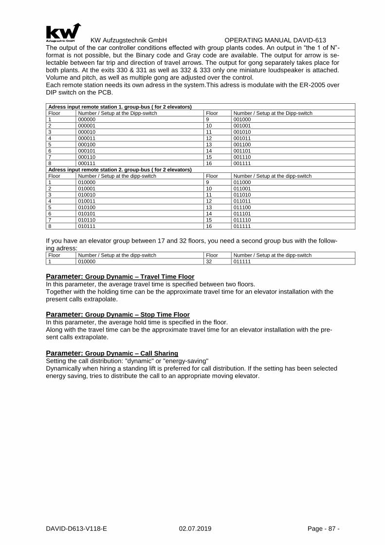
KW Aufzugstechnik GmbH OPERATING MANUAL DAVID-613
DAVID-D613-V118-E 02.07.2019 Page - 87 -
The output of the car controller conditions effected with group plants codes. An output in “the 1 of N”- format is not possible, but the Binary code and Gray code are available. The output for arrow is se-lectable between far trip and direction of travel arrows. The output for gong separately takes place for both plants. At the exits 330 & 331 as well as 332 & 333 only one miniature loudspeaker is attached. Volume and pitch, as well as multiple gong are adjusted over the control. Each remote station needs its own adress in the system.This adress is modulate with the ER-2005 over DIP switch on the PCB. Adress input remote station 1. group-bus ( for 2 elevators)
Floor Number / Setup at the Dipp-switch Floor Number / Setup at the Dipp-switch
1 000000 9 001000
2 000001 10 001001
3 000010 11 001010
4 000011 12 001011
5 000100 13 001100
6 000101 14 001101
7 000110 15 001110
8 000111 16 001111
Adress input remote station 2. group-bus ( for 2 elevators)
Floor Number / Setup at the dipp-switch Floor Number / Setup at the dipp-switch
1 010000 9 011000
2 010001 10 011001
3 010010 11 011010
4 010011 12 011011
5 010100 13 011100
6 010101 14 011101
7 010110 15 011110
8 010111 16 011111
If you have an elevator group between 17 and 32 floors, you need a second group bus with the follow-ing adress: Floor Number / Setup at the dipp-switch Floor Number / Setup at the dipp-switch
1 010000 32 011111
Parameter: Group Dynamic – Travel Time Floor In this parameter, the average travel time is specified between two floors. Together with the holding time can be the approximate travel time for an elevator installation with the present calls extrapolate.
Parameter: Group Dynamic – Stop Time Floor In this parameter, the average hold time is specified in the floor. Along with the travel time can be the approximate travel time for an elevator installation with the pre-sent calls extrapolate.
Parameter: Group Dynamic – Call Sharing Setting the call distribution: "dynamic" or "energy-saving" Dynamically when hiring a standing lift is preferred for call distribution. If the setting has been selected energy saving, tries to distribute the call to an appropriate moving elevator.

KW Aufzugstechnik GmbH OPERATING MANUAL DAVID-613
DAVID-D613-V118-E 02.07.2019 Page - 88 -
Shaft bus wiring with remote station ER-2013 with a double group with common shaft:
Shaft bus wiring with remote station ER-2013 with a double group with separate shafts:

KW Aufzugstechnik GmbH OPERATING MANUAL DAVID-613
DAVID-D613-V118-E 02.07.2019 Page - 89 -
Shaft bus wiring with remote station ER-2013 with a 3- or 4-member group with com-mon shafts to 32 floors:

KW Aufzugstechnik GmbH OPERATING MANUAL DAVID-613
DAVID-D613-V118-E 02.07.2019 Page - 90 -
Shaft bus wiring with remote station ER-2013 with a 3- or 4-member group with sepa-rate / very large shafts to 32 floors:

KW Aufzugstechnik GmbH OPERATING MANUAL DAVID-613
DAVID-D613-V118-E 02.07.2019 Page - 91 -
B3 Drive
Contactor switching and Drive-diagram of hydraulic elevators In principle three pre-signals are sufficient for the hydraulic elevator control, because with the direc-tions also the slow speed V0 is published. Des. Pre Controlling Hydraulics Robe Frequency Robe Unregulated
5 K31 K11/K11A Up-Contactor K3 Drive Contactor K1 Up-Contactor
3 K32 K2/K2A Down-Contactor K3 Drive Contactor K2 Down-Contactor
7 K33 K5 Main Contactor K3 Quick-Contactor
9 K34 K12/K13 Changeover S-D K7-Brake Contactor K4 Slow-Contactor
Compare of the contactor switching of different types of drives.
Des. Drive Instructions Hydraulics Rope Frequency Regulated
Down Direction Down Direction Down
Up Direction Up Direction Up
Vins Speed Vi Speed Vins
Vn Speed Vn Speed Vna
V0 Speed V0 Speed V0
V1 Speed V1 Speed V1
V2 Speed V2 Speed V2
V3 Drive K73 Speed V3
Compare of the drive commands of different types of drives.
B30 – Hydraulic – Drives
PARAMETER: START In this parameter, you can choose two values, namely „ Star/ Delta “ and “ Softstart”. PARAMETER: S/D-REVERSE TIME This parameter represents the reverse time between star-protection and triangle-protection. The standard value is 2 seconds. PARAMETER: COMMAND UP DELAYED ON If you activate this parameter, you can switch on the up-command with a delay-time. The standard value is 100 ms. You need this function in connection with Bucher-LRV-Regelkarten. PARAMETER: DIRECTION UP DELAYED The parameter have a option to switch on retarded the up direction. The standart value is NO. PARAMETER: COMMAND UP DELAYED If you activate this parameter, you can switch off the up-command with a delay-time. The standard value is 400 ms. PARAMETER: START WITH DOOR CONTROLLING If you activate the parameter, you can start the hydraulic-pump in the same time how the motion to close the door begins. In the standard-parameter set the function is not activated. PARAMETER: INSPECTION SPEED Speed:
1.) SPEED SLOW
2.) SPEED HIGH
PARAMETER: TIME TO GO DOWN The hydraulic elevator must lower late after first of all 15 minutes to the lowest stop place. The time is adjustable by this parameter. PARAMETER: FAULT HANDLING By the menu attitude can be selected, as the control has to react to error messages of the regulation.
a. “NO”- regulation does not have a disturbance exit. b. “STOP + LOWERING”- If there is an error in the regulation, the driving instructions are
taken back and the calls are deleted. The car is lowered into the lowest stop place. PARAMETER: TRAVEL DOWN AT OVERLOAD Is Overload in the car it must be decided at expiration of the sinking time whether lower or not. The standart value is NO. PARAMETER: SIGNAL TOP OF RAMP After reaching „the Top Of the Ramp“ on the softstart unit approach equipment this further announced to the regulation. During the attitude of kind of condition this parameter is active. PARAMTER: COMMAND DOWN DELAYED ON/OFF The parameter contains the alternative to switch strainghtening on retarded. This is needed with the employment of a return flow prevention valve ( e.g.ALGI-S5). The standart value is NO. PARAMETER: DETENT END SWITCH TOP

KW Aufzugstechnik GmbH OPERATING MANUAL DAVID-613
DAVID-D613-V118-E 02.07.2019 Page - 92 -
In this parameter you can choose if elevator blocks after leaving upper end switcher and the following emergency sinking. Default value is JES. PARAMETER : ELEVATOR BUS After market introduction of the device SAG-90 it is possible that the controller communicates by bus with control. PARAMETER : WARM UP DRIVE With this parameter you can operate the termpetature input ( Assigned with function E492 temperatur Warm Up Drive ). A drive starts to warm up the oil. PARAMETER : WARM UP DRIVE AFTER XX MINUTS In this parameter you can choose the start time of the Warm Up Drive. Start time is always after lower drive. The maximum time is 1250 minutes.
B31 – Hydraulic Regulated PARAMETER: START In this parameter, you can choose two values, namely „ Star/ Delta “ and “ Softstart”. PARAMETER: S/D-REVERSE TIME This parameter represents the reverse time between star-protection and triangle-protection. The standard value is 2 seconds. PARAMETER: COMMAND UP DELAYED ON If you activate this parameter, you can switch on the up-command with a delay-time. The standard value is 100 ms. You need this function in connection with Bucher-LRV-Regelkarten. PARAMETER: DIRECTION UP DELAYED The parameter have a option to switch on retarded the up direction. The standart value is NO. PARAMETER: COMMAND UP DELAYED If you activate this parameter, you can switch off the up-command with a delay-time. The standard value is 400 ms. PARAMETER: START WITH DOOR CONTROLLING If you activate the parameter, you can start the hydraulic-pump in the same time how the motion to close the door begins. In the standard-parameter set the function is not activated. PARAMETER: INSPECTION SPEED Speed:
1- Speed slow 2- Speed Vi 3- Speed high
PARAMETER: TIME TO GO DOWN The hydraulic elevator must lower late after first of all 15 minutes to the lowest stop place. The time is adjustable by this parameter. PARAMETER: FAULT HANDLING By the menu attitude can be selected, as the control has to react to error messages of the regulation.
a) “NO”- regulation does not have a disturbance exit. b) “STOP + LOWERING”- If there is an error in the regulation, the driving instructions are
taken back and the calls are deleted. The car is lowered into the lowest stop place. PARAMETER: TRAVEL DOWN AT OVERLOAD Is overload in the car it must be decided at expiration of the sinking time whether lower or not. The standart value is NO. PARAMETER: SIGNAL TOP OF RAMP After eaching „the Top Of the Ramp“ on the softstart unit approach equipment this further announced to the regulation. During the attitude of kind of condition this parameter is active. PARAMETER: COMMAND DOWN DELAYED ON/OFF The parameter contains the alternative to switch strainghtening on retarded. This is needed with the employment of a return flow prevention valve ( e.g.ALGI-S5). The standart value is NO. PARAMETER: DETENT END SWITCH TOP In this parameter you can choose if elevator blocks after leaving upper end switcher and the following emergency sinking. Default value is JES. PARAMETER: ELEVATOR BUS After market introduction of the device SAG-90 it is possible that the controller communicates by bus with control.

KW Aufzugstechnik GmbH OPERATING MANUAL DAVID-613
DAVID-D613-V118-E 02.07.2019 Page - 93 -
Parameter: Warm Up Drive With this parameter you can operate the termperature input ( Assigned with function E492 temperature Warm Up Drive ). A drive starts to warm up the oil. Parameter: Warm Up Drive after XX minuts In this parameter you can choose the start time of the Warm Up Drive. Start time is always after lower drive. The maximum time is 1250 minutes. Parameter : Command Output
In this parameter can be selected between Standard NGV-A3 attitude and Oildynamic NGV-A3 attitude. If Oildynamic is selected then pilot control will be printed only if input E494 is on. In the case of the Bucher-iValve setting, all commands with a high level + 24V are output (-> note the setting on the iCon!):
Pin Bucher iCon
BUCHER iValve Function DAVID D613 output function PIN-D613 (Default)
X7.6 Command K1 Fast UP A181 UP Fast ZE 2
X7.5 Command K2 Slowly UP A176 Down Slowly, UP catch up ZE 0
X7.4 Command K3 Fast Down A182 Down Fast ZE 4
X7.3 Command K4 Slowly Down A175 Down Slowly, Down catch up ZE 1
X7.2 Command K5 Inspection A177 Inspection ZE 5
X6.4 Command K6 intermediate speed A180 intermediate speed ZE 3
X7.2 0V GND mass 0V GND mass 500
The following output messages of the Bucher iCon are reported to the D613 (all messages with high level + 24V):
Pin Bucher iCon
BUCHER iValve Function DAVID D613 input function PIN-D613 (Default)
X2.1 Relais Error SIU E008 Controller fault ZC 3
X2.2 Relais Error SIU Control voltage +24V DC 200
X2.5 Relais s1 Overload E011 Overload ZB 2
X2.6 Relais s1 Overload Control voltage +24V DC 200
X2.8 Relais s2 Reduced pressure E434 Reduced pressure ZE 7
X2.7 Relais s2 Reduced pressure Control voltage +24V DC 200
The following output messages of the Bucher iCon are reported to the D613 (all messages with high level + 24V):
Pin Bucher iCon
BUCHER iValve Function DAVID D613 input function PIN-D613 (Default)
X10 +SMA Monitoring emergency stop Down UCM
E495 UCM Status ZE 6
X10 GND 0V GND mass 0V GND mass 500
Parameter Feedforward K32 delayed OFF The SAG-90 is switched off with a delay. The possible time range is 10 to 3000 ms.

KW Aufzugstechnik GmbH OPERATING MANUAL DAVID-613
DAVID-D613-V118-E 02.07.2019 Page - 94 -
B32 – Hydraulic Variable Frequency
PARAMETER : V0 DELAYED OFF The parameter contains the attitude to switch the speed V0 off retarded. The standart value is NO. PARAMETER : MAIN CONDUCTOR DELAYED OFF The parameter contains the attitude to switch off the main contactors retarded. The standart value is 600 ms. PARAMETER: DIRECTION DELAYED OFF Time-delayed will the removal of the driving direction, in order to ensure stopping without jerking. The deceleration time is adjustable in the menu. As default value are deposited 1500 ms. PARAMETER : RELEVELING SPEED Some regulation connot display speed Vn for post-correction. It can be selected by the menu attitude whether the releveling time is accomplished with the speed Vn or V0. PARAMETER: INSPECTION SPEED Some regulation have no inspection speed Vi. It can be selected by the menu attitude whether the inspection speed is accomplished with the speed Vi or V0. PARAMETER: TIME TO GO DOWN The hydraulic elevator must lower after 15 minutes to the lowest stop place. The time is adjustable by this parameter. PARAMETER: FAULT HANDLING By the menu attitude can be selected, as the control has to react to error messages of the regulation.
a) “NO”- regulation does not have a disturbance exit. b) “STOP + LOWERING”- If there is an error in the regulation, the driving instructions are
taken back and the calls are deleted. The car is lowered into the lowest stop place. PARAMETER: TIME TO GO DOWN AT OVERLOAD Is overload in the car, it must be decided at expiration of the sinking time whether lower or not. The standart value is NO. PARAMETER: BLOCKING UPPER LIMIT-SWITCH If the car was in the upper limit switch in normal operation, then the car is lowered and closed into the lowest floor. During the attitude of kind of condition this paramenter is active. PARAMETER: COMMAND OUTPUT With this parameter can be adjusted, as the expenditure for command takes place to the regulation. Two variants are available:
1) With hydraulic BUCHER SATURN -Alpha 2) With hydraulic ALGI AZFR (code output) PARAMETER: COMMAND DOWN DELAY ON The parameter has the opportunity to swich on delayed Down Direction. This needed for usage of reflow preventing valve (ALGI-S5). Default value is NO. PARAMETER: ELEVATOR BUS After market introduction of the device SAG-90 it is possible that the controller communicates by bus with control. PARAMETER: WARM UP DRIVE With this parameter you can operate the termperature input ( Assigned with function E492 temperature Warm Up Drive ). A drive starts to warm up the oil. PARAMETER: WARM UP DRIVE AFTER XX MINUTS In this parameter you can choose the start time of the Warm Up Drive. Start time is always after lower drive. The maximum time is 1250 minutes.

KW Aufzugstechnik GmbH OPERATING MANUAL DAVID-613
DAVID-D613-V118-E 02.07.2019 Page - 95 -
B33- Robe 2 Speeds
CONTACTOR SWITCHING In general you need four signals for switching.
Term Pre-Switching Rope Variable Frequency Rope 2 Speeds
5 K31 K3 Main Contactor K1 Up Contactor
3 K32 K3 Main Contactor K2 Down Contactor
7 K33 K5 Main Contactor K3 Quick Contactor
9 K34 K7-Brake Contactor K4 Slow Contactor
1.0 EXPERATION OF TRIP The trip begins with the control of the high-speed contactor K3 in order to put the current to the fast coil. Time-delayed the up or down contactor activates. The deceleration time is adjustable in the menu. The standard value is 100ms. If the point of delay is reached then that drops high-speed contactor and the slow contactor is activated. With reaching the concise signal become both contactors breaked. PARAMETER : MOTORVENTILATION Here you can activate the motor ventilation and put in the time. The standart value is off. PARAMETER : CONTACTOR DELAYED ON Time-delayed activates the up or down contactor. The deceleration time is adjustable in the menu. The standard value is 100 ms. PARAMETER : INSPECTION SPEED In this parameter you can put in the speed for inspection. You can choose quick or slow speed. PARAMETER : REVERSE TIME OUT The switching break is adjustable from the change-over of the high-speed contactor to the slow contac-tor. Factory setting does not plan a break.
B34- Robe Variable Voltage
Contactor Switching In general you need four signals for switching.
Term Pre-switching Rope Variable Fre-quency
Rope Variable Voltage
3 K31 K3 Drive contactor K1 Up contactor
5 K32 K3 Drive contactor K2 Down Contactor
7 K33 K5 Main contactor K5 Main contactor
9 K34 K7 Brake contactor K7 Brake contactor
Type Rope Variable Frequency Rope Variable Voltage
Up Direction Up Direction Up
Down Direction Down Direction Down
Vins Speed Vins Speed Vins
Vn Speed Vn Speed Vn
V0 Speed V0 Speed V0
V1 Speed V1 Speed V1
V2 Speed V2 Speed V2
V3 Speed V3 Speed V3
PARAMETER: MOTOR VENTILATION An free-provable exit of t he central unit and logic unit forthe engine ventilation van be selected. The attitude for time can be selected in menu.

KW Aufzugstechnik GmbH OPERATING MANUAL DAVID-613
DAVID-D613-V118-E 02.07.2019 Page - 96 -
PARAMETER: DIRECTION DELAYED ON Time-delayed activates the up or down contactor. The deceleration time is adjustable in the menu. The standard value is 100 ms. PARAMETER: MAIN CONSTRUCTOR DELAYED OFF In order to ensure a stopping without jeking, the direction contactors and net contactor retarded break. The standard value is 600 ms. PARAMETER: RELEVELING SPEED In this parameter you can put in the speed for releveling. You can chosse speed VN or V0.
PARAMETER: FAULT HANDING In this parameter you can choose the reaction of the controller, if there is a fault in the inverter-part.
1.) „Interrupt“ – If there is a fault in inverter, drive-orders and calls will be erased. If there is a new call, the controller tries again to start.
2.) „Block“ – If there is a fault in inverter, drive-orders and calls will be erased. The controller is blocked. Only a RESET-signal can turn on the controller.
3.) „Block at 2.Fault“ – If there are two faults in a serie in inverter, drive-orders and calls will be erased. The controller is blocked. Only a RESET-signal can turn on the controller.
4.) „Block at 3.Fault“ – If there are three faults in a serie in the inverter, drive-orders and calls will be erased. The controller is blocked. Only a RESET-signal can turn on the controller.
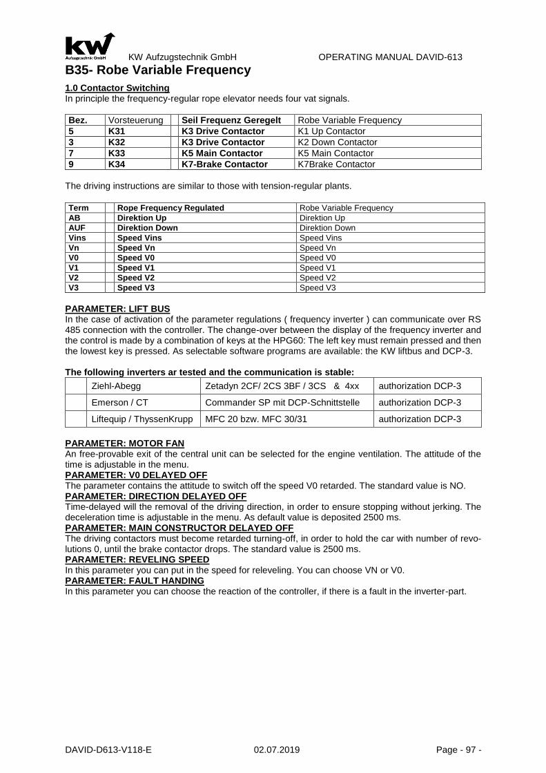
KW Aufzugstechnik GmbH OPERATING MANUAL DAVID-613
DAVID-D613-V118-E 02.07.2019 Page - 97 -
B35- Robe Variable Frequency
1.0 Contactor Switching In principle the frequency-regular rope elevator needs four vat signals.
Bez. Vorsteuerung Seil Frequenz Geregelt Robe Variable Frequency
5 K31 K3 Drive Contactor K1 Up Contactor
3 K32 K3 Drive Contactor K2 Down Contactor
7 K33 K5 Main Contactor K5 Main Contactor
9 K34 K7-Brake Contactor K7Brake Contactor
The driving instructions are similar to those with tension-regular plants.
Term Rope Frequency Regulated Robe Variable Frequency
AB Direktion Up Direktion Up
AUF Direktion Down Direktion Down
Vins Speed Vins Speed Vins
Vn Speed Vn Speed Vn
V0 Speed V0 Speed V0
V1 Speed V1 Speed V1
V2 Speed V2 Speed V2
V3 Speed V3 Speed V3
PARAMETER: LIFT BUS In the case of activation of the parameter regulations ( frequency inverter ) can communicate over RS 485 connection with the controller. The change-over between the display of the frequency inverter and the control is made by a combination of keys at the HPG60: The left key must remain pressed and then the lowest key is pressed. As selectable software programs are available: the KW liftbus and DCP-3. The following inverters ar tested and the communication is stable:
Ziehl-Abegg Zetadyn 2CF/ 2CS 3BF / 3CS & 4xx authorization DCP-3
Emerson / CT Commander SP mit DCP-Schnittstelle authorization DCP-3
Liftequip / ThyssenKrupp MFC 20 bzw. MFC 30/31 authorization DCP-3
PARAMETER: MOTOR FAN An free-provable exit of the central unit can be selected for the engine ventilation. The attitude of the time is adjustable in the menu. PARAMETER: V0 DELAYED OFF The parameter contains the attitude to switch off the speed V0 retarded. The standard value is NO. PARAMETER: DIRECTION DELAYED OFF Time-delayed will the removal of the driving direction, in order to ensure stopping without jerking. The deceleration time is adjustable in the menu. As default value is deposited 2500 ms. PARAMETER: MAIN CONSTRUCTOR DELAYED OFF The driving contactors must become retarded turning-off, in order to hold the car with number of revo-lutions 0, until the brake contactor drops. The standard value is 2500 ms. PARAMETER: REVELING SPEED In this parameter you can put in the speed for releveling. You can choose VN or V0. PARAMETER: FAULT HANDING In this parameter you can choose the reaction of the controller, if there is a fault in the inverter-part.

KW Aufzugstechnik GmbH OPERATING MANUAL DAVID-613
DAVID-D613-V118-E 02.07.2019 Page - 98 -
1.) „Interrupt“ – If there is a fault in inverter, drive-orders and calls will be erased. If there is a new
call, the controller tries again to start. 2.) „Block“ – If there is a fault in inverter, drive-orders and calls will be erased. The controller is
blocked. Only a RESET-signal can turn on the controller. 3.) „Block at 2.Fault“ – If there are two faults in a serie in inverter, drive-orders and calls will be
erased. The controller is blocked. Only a RESET-signal can turn on the controller. 4.) „Block at 3.Fault“ – If there are three faults in a serie in the inverter, drive-orders and calls will
be erased. The controller is blocked. Only a RESET-signal can turn on the controller. PARAMETER: COMMAND OUTPUT With this parameter can be adjusted, as the expenditure for command takes place to the regulation. Two variants are available:
1) With On and Off command (standart GOLIATH) 2) With release and a direction command (DIETZ)
Submenu Speeds ( Only with setting CANopen & FU ) This parameter can be used to set how the command output for regulation takes place. There are two variants to choose from: Parameter „Speed catching up Vn Here you can set the speed Vn. Factory setting Vn: 00,123m/s“ Parameter „Speed inspection Vi1 Here, the speed is set Vi1. Factory setting Vi1: 00,123m/s“ Parameter „Speed inspection Vi2 Here, the speed is set Vi2. Factory setting Vi2: 00,123m/s“ Parameter „Speed return motion VR Here the speed is set VR. Factory setting VR: 00,123m/s“ Parameter „Speed evacuation VE Here the speed is set VE. Factory setting VE: 00,123m/s“ Parameter „Speed entrance V0 Here the speed is set V0. Factory setting V0: 00,123m/s“ Parameter „Speed Between V1 Here the speed is set V1. Factory setting: V1: 00,123m/s“ Parameter „Speed Between V2 Here the speed is set V2. Factory setting: V2: 00,123m/s“ Parameter „Speed end V3 Here the speed is set V3. Factory setting: V3: 00,123m/s“

KW Aufzugstechnik GmbH OPERATING MANUAL DAVID-613
DAVID-D613-V118-E 02.07.2019 Page - 99 -
B4 – Shaft Copy
B41 – Standart Copy
1.0 General The standart-copy is a shaft-copy method, which needs six switches in the shaft.
S11A Brakepoint Up S11B Brakepoint Down S12A Level Up S12B Level Down S13A Correctionswitch Top S13B Correctionswitch Bottom
All magnet-switches are biposition-switches with the corresponding round-magnet. For the pinning of the magnets you must use the elevator-rail and shaft-flags.
2.0 Leveling The leveling depends on the direction. With rope-elevators without pre-opening the door the stopping in direction up is with the magnet-switch 12B, and in direction down with the magnet-switch 12A. ATTENTION! There may be a partial overlap of the consice magnet fields with consice position. From bottom to top magnet 12B seen always before 12A. Control recognizes the direction ,with injury to this rule it comes to the fact that floors are counted wrongly by control. On hydraulic lifts and cable systems with entrance door is open or readjustment is maintained with the stopping of the counter-aligned. As long as both consice signals overlap themselves,no post-correction is necessary. As soon as car more deeply sinks or rises more highly so the consice signal lost and the car is after –adjusted into the opposite direction.
3.0 Brakepoints and Correction The magnet switches 11A and 11B are the brake-switches to drive into the destination floor. If you are driving from the second floor to the first floor you doesn’t need a brake magnet! You are braking with the correction switch 13B. The same story is the drive to the last floor. You are braking with the correction switch 13B. PARAMETER : PULSE BUFER DELAY Depend on the assigned solenoids and the switching gap the pulse delay-time must be selected. Factory setting at height of 30 ms represents a good average value. PARAMETER: CORRECTION TRAVEL If it comes in the shaft copying to false countings, a correction trip goes on. The time of execution can take place ”after call input” or immediately in “automatic“ mode.

KW Aufzugstechnik GmbH OPERATING MANUAL DAVID-613
DAVID-D613-V118-E 02.07.2019 Page - 100 -
B42 Relative-Copy
1.0 General The relative-copy is a digital shaft-copy method, which only needs three switches in the shaft.
S72 Zone 1 S72 Zone 2 (Only in case of releveling or pre-opening-doors)
S13A Correctionswitch Top S13B Correctionswitch Bottom
All magnet-switches are biposition-switches with the corresponding round-magnet. For the pinning of the magnets you must use the elevator-rail. The pulses for the shaft-copy are coming from a decoder.
2.0 Releveling After the learn-drive the middle of the Zone-way is the value of the floor-level. This can be correct by the parameter “Leveling” for each floor. A change of the position of the zone-magnets is forbidden. A very concret description is in the chapter I01-Activation of the digital shaft presentation.
3.0 Deceleration and Correction switches The deceleration for the drive into the destination-floor will be managed by digital shaft-copy. The cor-rection switches are used only for synchronize shaft-copy-system and for a safe deceleration in end-floors in a emergency-situation, like a failure in digital shaft-copy. A change of the position of the cor-rectionswitches-magnets is forbidden. A very concret description is in the chapter I01- Activation of the digital shaft presentation.

KW Aufzugstechnik GmbH OPERATING MANUAL DAVID-613
DAVID-D613-V118-E 02.07.2019 Page - 101 -
4.0 Shaftcopy System with UCM Zone
HSK-90 / HSK46 System The shaft copy system HSK-90 consists of the shaft and the shaft ESF16 flags flags SFH16 holders of the respective magnets and mounting hardware. On the flag, the North magnets are always on top! Each 4 round magnets of a track-form an exterior and an interior zone. The outer zone is responsible for the driveway with the door open, the interior area for catching up / UCM detection. The shaft resolution approximation HSK-90 panel is mounted on the cab roof us-ing the mounting bracket.
At the HSK46-System the magnets are mounted directly on the rail.
The pre-limit up / top S13A correction is turned on by a magnet south. The magnet must be between the penultimate and last floor! The pre-limit down / bottom correction S13A is turned on a north magnet. The mag-net must be between the 2 - and are lowest floor! At a higher Speed than 2.0 m/s, or short travel stops, respectively, a second pre-limit switch is necessary. The second pre-limit up / top S15A turned off-a South magnet. The magnet must be lo-cated between the pre-penultimate and pe-nultimate floor. The second pre-limit down / bottom S15B is turned on a north magnet. The magnet must be between the 3rd and 2nd Floor there.

KW Aufzugstechnik GmbH OPERATING MANUAL DAVID-613
DAVID-D613-V118-E 02.07.2019 Page - 102 -
PARAMETER: PULSE BUFFER DELAY There is a pulse buffer-delay-time between 2 and 150ms. Its depends on the type of magnets, you are using. The KW-magnets only needs a delay-time of 2ms.
PARAMETER: CORRECTION TRAVEL If it comes in the shaft copying to false countings, a correction trip goes on. The time of execution can take place ”after callinput” or immediately in “automatic“ mode.
PARAMETER: 2.PRE- END- SWITCH BOTTOM There is a golden rule that the pre-end switch bottom must be between 1 and 2. stop. If the 2 stop is a short trip stop, then the distance pre-end switch would not be sufficient down to the zone of the 1 stop with a faulty measure-ment to brake the carconcisely.
PARAMETER: 2.PRE –END- SWITCH TOP There is a golden rule that the pre-end switch bottom must be between last and pre-last stop. If the pre-last stop is a short trip stop, then the distance pre-end switch would not be sufficient down to the zone of the last stop with a faulty measurement to brake the carconcisely. In this situation the 2. pre-end-switch can be placed between the pre-last- and pre-pre-last-floor.
PARAMETER: SHORT TRAVELS With extreme short trip stops is appropriate for two stops within a zone. With this parameter it is adjusted whether this case is present and if like many of these short trip stops is present.
PARAMETER: DISTANCE PRE-END-SWITCH-ZONE BOTTOM In this parameter the distance center magnet pre-end switch is registered down to the highest magnet of the lowest zone in mm. This value must be determined absolutely accurately. It is important for perfect functioning of the digital shaft copying. Attention! With hydraulic, unsetteled rope and variable voltage rope plants the input the delay way of both direction takes place. (UP and DOWN-Direction)! With hydraulic and there however only V0 and V-fast are unsetteled rope plants to stop!
PARAMETER: DECELERATION SPEED V0->0 This parameter is the brake-way from the drive-in speed V0 to the stop (0). The value comes automaticly by the learn drive. Nevertheless the value can be change per hand.
PARAMETER: DECELERATION V1 This parameter is the brake-way from the speed V1 to the drive-in speed V0. This value depends on the speed V1 and the deceleration in the inverter. The standart value is 500 mm.
PARAMETER: DECELERATION V2 This parameter is the brake-way from the speed V2 to the drive-in speed V0. This value depends on the speed V2 and the deceleration in the inverter. The standart value is 1000 mm.
PARAMETER: DECELERATION V3 This parameter is the brake-way from the speed V3 to the drive-in speed V0. This value depends on the speed V3 and the deceleration in the inverter. The standart value is 1500 mm.
PARAMETER: LEARN DRIVE WITH For the learn drive you can choose three speeds like, V1, V2, and V3. If you have a drive with a short distance, you should chosse speed V1. The standart value is speed V1.
PARAMETER: ENCODER INPUT The encoder for the shaft copying can attache on the Car (FKR) or the machine room (ZR). The location is to be registered in this parameter. As default value ZR is deposited.
PARAMETER: DRIVE ACTIVATE If the electrical installation is ok and the software-parameters like number of floors,..., is put in, the learn-drive can be started. The car should be in a position between the first and second floor, but it must stand above the correction switch bottom. Then the learn-drive should be started. A very concret description is in the chapter I01-Activation of the digital shaft presentation.
PARAMETER: SWITCH HYSTERES OVERLAPPING After successful learning trip the value of the hysteress was determined for the shaft switches.
PARAMETER: EVELING-FLOOR-XX After a learn-drive, you must put in this parameter in the level-values for each floor. Here you can corrigate un-levels for every floor.

KW Aufzugstechnik GmbH OPERATING MANUAL DAVID-613
DAVID-D613-V118-E 02.07.2019 Page - 103 -
B43 – Absolut Copy
1.0 General The absolute copying represents a digital shaft copying which is operated either without magnet control or with 3-4 magnet control: 2.0 With one shaft switch / HSK-10 & V-shaft-flag In this method, the Hall switch HSK01 is used for the detection of zone 71. The second zone 72 is generated via the absolute value encoder system. After assembly of the ABS sensor system, the car is parked between floors 1 and 2. After the start of the learning journey, counting direction and the zones of the floors are learned. With one shaft switch
After learning, the center of the zone area is assumed to be flush. A correction can be carried out by entering the difference values for the Flattening correction parameter. A change in the position of the zones must not be carried out after the learning run. A detailed description can be found in chapter I02-Startup absolute copying of the control manual or the installation instructions. Delay and pre-limit switch The delay to enter the station is made using absolute shaft copying.
Type 1: Connector at ZR-613: SSI-Encoder Type Schmersal UPS SSI
Terminal Function Colour Pin 1: PE Erde Shield Pin 2: 91 Clock + 14 Pin 3: 92 Clock - 7 Pin 4: 93 Data + 13 Pin 5: 94 Data - 6 Pin 6: 500 0 V DC 8 Pin 7: 050 +5V DC Pin 8 : 200 +24V DC 9
Type 2: Connector at FKR-613: SSI-Encoder Type p Wachendorff WDG-SL00 – ALT
Terminal Function Colour Pin 1: PE Erde Shield Pin 2: 91 Clock + Lila Pin 3: 92 Clock - Yellow Pin 4: 93 Data + Gray Pin 5: 94 Data - Pink Pin 6: 500 0 V DC White Pin 7: 050 +5V DC Pin 8: 200 +24V DC Brown

KW Aufzugstechnik GmbH OPERATING MANUAL DAVID-613
DAVID-D613-V118-E 02.07.2019 Page - 104 -
Type 3: Connector at FKR-613: SSI-Encoder Type ELGO-LIMAX-2 SSI – bin
Terminal Function Colour Pin 1: PE Erde Shield Pin 2: 91 Clock + Green Pin 3: 92 Clock - Yellow Pin 6: 83 Data + Gray Pin 7: 84 Data - Pink Pin 4: 500 0 V DC White Pin 7: 050 +5V DC Pin 5: 200 +24V DC Brown
Type 4: Connector atZR-613: SSI-Encoder Type Windtscheid & Wendel W+W 10EX – SSI –bin
Terminal Function Colour Pin 1: PE Erde Shield Pin 2: 81 Clock + Green Pin 3: 82 Clock - Yellow Pin 4: 83 Data + Black Pin 5: 84 Data - Red Pin 6: 500 0 V DC Blue Pin 7: 050 +5V DC Pin 8: 200 +24V DC Lila
Type 5: Connector at FKR-613: SSI-Encoder Type Wachendorff WDG-SL00 G
Terminal Function Colour Pin 1: PE Erde Shield Pin 2: 81 Clock + Lila Pin 3: 82 Clock - Yellow Pin 4: 83 Data + Grey Pin 5: 84 Data - Pink Pin 6: 500 0 V DC White Pin 7: 050 +5V DC Pin 8: 200 +24V DC Brown
Type 6: Connector at FKR-613: SSI-Encoder Type Wachendorff WDG-MZS 100 G
Terminal Function Colour Pin 1: PE Erde Shield Pin 2: 81 Clock + Lila Pin 3: 82 Clock - Yellow Pin 4: 83 Data + Gray Pin 5: 84 Data - Pink Pin 6: 500 0 V DC White Pin 7: 050 +5V DC Pin 8: 200 +24V DC Brown
Type 7: Connector at FKR-613: SSI-Encoder Type Kübler LM2 LM3 SSI
Terminal r Function Colour Pin 1: PE Erde Shield Pin 2: 81 Clock + Lila Pin 3: 82 Clock - Yellow Pin 4: 83 Data + Gray Pin 5: 84 Data - Pink Pin 6: 500 0 V DC White Pin 7: 050 +5V DC Pin 8: 200 +24V DC Brown
Type 8: Connector at FKR-613: SSI-Encoder Type Wachendorff WDG-MEMN
Terminal Function Colour Pin 1: PE Erde Shield Pin 2: 81 Clock + Lila Pin 3: 82 Clock - Yellow Pin 4: 83 Data + Gray Pin 5: 84 Data - Pink Pin 6: 500 0 V DC White Pin 7: 050 +5V DC Pin 8: 200 +24V DC Brown
Type 9: Connector at FKR-613: SSI-Encoder Type Variotech ANTS SSI-Protocol
Terminal Function Colour Pin 1: PE Earth Shield Pin 2: 91 Clock + White Pin 3: 92 Clock - Yellow Pin 4: 93 Data + Grey Pin 5: 94 Data - Pink Pin 6: 500 0 V DC Brown Pin 7: 050 +5V DC Pin 8: 200 +24V DC Green

KW Aufzugstechnik GmbH OPERATING MANUAL DAVID-613
DAVID-D613-V118-E 02.07.2019 Page - 105 -
Type 10: Connector at ZR-613: SSI- actuated encoder Type ECN10TL-03 SSI-Protocol
Termina Function ECN10TL-03 Pin 1: PE Earth Pin 2: 91 Clock + Pin 3: 92 Clock - Pin 4: 93 Data + Pin 5: 94 Data - Pin 6: 500 0 V DC Pin 7: 050 +5V DC Pin 8: 200 +24V DC
Type 11: Connector at ZR-613: SSI- actuated encoder Type ECN10TL-05 SSI-Protocol
Termina Function ECN10TL-05 Pin 1: PE Earth Pin 2: 91 Clock + Pin 3: 92 Clock - Pin 4: 93 Data + Pin 5: 94 Data - Pin 6: 500 0 V DC Pin 7: 050 +5V DC Pin 8: 200 +24V DC
Type 12: Connector at ZR-613: SSI- actuated encoder Type ECN10TL10 SSI-Protocol
Termina Function ECN10TL-10 Pin 1: PE Earth Pin 2: 91 Clock + Pin 3: 92 Clock - Pin 4: 93 Data + Pin 5: 94 Data - Pin 6: 500 0 V DC Pin 7: 050 +5V DC Pin 8: 200 +24V DC
Type 13: Connector at FKR-613-CAN: CAN-Absolutvalueencoder CanOpen-protocol
only visible if absolute copying (Menu-A3) as well as CAN-Bus + CAN-encoder activated A402 / A403) encoder system : Connection on FKR-613: Canopen-interface Typ Variotech ANTS CanOpen -protocol
encoder system : Connection on FKR-613: Canopen-interface Typ Variotech ANTS SAFE CanOpen -protocol
encoder system : Connection on FKR-613: Canopen-interface Typ ELGO LIMAX33CP SAFE CanOpen -protocol
encoder system : Connection on FKR-613: Canopen-interface Typ --- encoder CanOpen -protocol

KW Aufzugstechnik GmbH OPERATING MANUAL DAVID-613
DAVID-D613-V118-E 02.07.2019 Page - 106 -
4.0 Shaftcopysystem with V-Shaft-Flag Nominal Speed < 1,60 m/s
V- Flag-mounting
HSK01 – Magnetmounting with V-flag or mounting on the rail The shaft copying system HSK01 consists of the shaft copying panel HSK01, the V-flags and the respective magnets. On the V-flag or the rail, the North Magnet are always up, South Magnet (red) always down! Four round magnets of each track form an outer and an inner zone. The outer zone is responsible for the entrance with open door, the inner zone for the catch / UCM detection. The HSK01 shaft coping spoiler is mounted on the cab roof.
The switching distance between the mag-net and the HSK01 is 7-9mm! The adjustment is made by loosening the two M4 nuts and controlled sliding of the sensor. (Look at the picture at the bottom left).
The electrical connection of the HSK01 is done with a prefabricated round cable with connector on the FKR-613.
Rail-mounting
HSK01
V-Shaft-Flag-V101

KW Aufzugstechnik GmbH OPERATING MANUAL DAVID-613
DAVID-D613-V118-E 02.07.2019 Page - 107 -
Shaftcopysystem with UCM-Zone Nominal Speed >= 1,60 m/s
V- Flag-mounting
HSK01 – Magnetmounting with V-flag or mounting on the rail Vnomianl >= 1,60 m/s The shaft copying system HSK01 consists of the shaft copying panel HSK01, the V-flags and the respec-tive magnets. In addition, two HSK01 are required for the upper forced deceleration S11A and the lower forced decelera-tion S11B! On the V-flag or the rail, the North Magnet are always up, South Magnet (red) always below! Four round magnets of each track form an outer and an inner zone. The outer zone is responsible for the entrance with open door, the inner zone for the catch / UCM detection. The HSK01 shaft coping spoiler is mounted on the cab roof.
The switching distance between the magnet and the HSK01 is 7-9mm! The adjustment is made by loos-ening the two M4 nuts and con-trolled sliding of the sensor. (Look at the picture at the bottom left). The distance X is to be set to the de-celeration value at the speed V3 (menu B4).
Rail-mounting
Approximate guideline X: 1,6 m/s -> 3000 mm 2,0 m/s -> 3500 mm 2,5 m/s -> 4500 mm 3,0 m/s -> 5500 mm 4,0 m/s -> 7000 mm

KW Aufzugstechnik GmbH OPERATING MANUAL DAVID-613
DAVID-D613-V118-E 02.07.2019 Page - 108 -
Shaftcopy System with UCM Zone
HSK-90 / HSK46 System The shaft copy system HSK-90 consists of the shaft and the shaft ESF16 flags flags SFH16 holders of the respective magnets and mounting hardware. On the flag, the North magnets are always on top! Each 4 round magnets of a track-form an exterior and an interior zone. The outer zone is responsible for the driveway with the door open, the interior area for catching up / UCM detection. The shaft resolution approximation HSK-90 panel is mounted on the cab roof us-ing the mounting bracket.
At the HSK46-System the magnets are mounted directly on the rail.
The pre-limit up / top S13A correction is turned on by a magnet south. The magnet must be between the penultimate and last floor! The pre-limit down / bottom correction S13A is turned on a north magnet. The mag-net must be between the 2 - and are lowest floor! At a higher Speed than 2.0 m/s, or short travel stops, respectively, a second pre-limit switch is necessary. The second pre-limit up / top S15A turned off-a South magnet. The magnet must be lo-cated between the pre-penultimate and pe-nultimate floor. The second pre-limit down / bottom S15B is turned on a north magnet. The magnet must be between the 3rd and 2nd Floor there.

KW Aufzugstechnik GmbH OPERATING MANUAL DAVID-613
DAVID-D613-V118-E 02.07.2019 Page - 109 -
3.0 SSI-Encodersystems or CANopen-Encodersystems If a CANopen shadow copying system has been activated under menu A402 / A403, you can find it in the menu for CANopen shaft bus systems. Otherwise, you are automatically at the SSI shaft bus systems, which then follow:
3.1 SSI-Bussystems
PARAMETER: PULSE BUFFER DELAY There is a pulse buffer-delay-time between 2 and 150 ms. Its depends on the type of magnets, you are using. The KW-magnets only needs a delay-time of 2ms. PARAMETER DISTANCE MEASUREMENT In this parameter the used absolute-value-system can be selected.
- Wachendorff-MZS100 G - Wachendorff-SL 00 G - W+W 10EX SSI – Bin - ELGO LIMAX2 SSI – Bin - Wachendorff-SL 00 ALT - SCMERSAL UPS
PARAMETER: SHAFT SWITCHES In this parameter you can choose, if you want to use shaft switches or not. It depends of the settings, if some parameter menus are not invisible. Attention! With hydraulic, unsetteled rope and variable voltage rope plants the input the delay way of both direction takes place. (UP and DOWN-Direction)! With hydraulic and there however only V0 and V-fast are unsetteled rope plants to stop! PARAMETER : SHORT TRAVELS With extreme short trip, stops is appropriate for two stops within a zone. With this parameter it is adjusted whether this case is present, and if like many of these short trip stops is present. PARAMETER: DECELERATION SPEED V0 -> 0 This parameter is the brake-way from the drive-in speed V0 to the stop (0). The value comes automaticly by the learn drive. Nevertheless the value can be change per hand. PARAMETER: DECELERATION SPEED V1 This parameter is the brake-way from the speed V1 to the drive-in speed V0. This value depends on the speed V1 and the deceleration in the inverter. The standart value is 500 mm. PARAMETER: DECELERATION SPEED V2 This parameter is the brake-way from the speed V2 to the drive-in speed V0. This value depends on the speed V2 and the deceleration in the inverter. The standart value is 1000 mm. PARAMETER: DECELERATION SPEED V3 This parameter is the brake-way from the speed V3 to the drive-in speed V0. This value depends on the speed V3 and the deceleration in the inverter. The standart value is 1500 mm. PARAMETER: LEARN DRIVE ( ONLY WITH SHAFT-SWITCHES: PRE-END- & ZONE-SWITCHES) For the learn drive you can choose three speeds like, V1, V2, and V3. If you have a drive with a short distance, you should choose speed V1. The standart value is speed V1. PARAMETER: LEARN DRIVE ACTIVATE ( ONLY WITH SHAFT-SWITCHES: PRE-END- & ZONE-SWITCHES) If the electrical installation is ok and the software-parameters like number of floors,..., is put in, the learn-drive can be started. The car should be in a position between the first and second floor, but it must stand above the corrections witch bottom. Then the learn-drive should be started. A very concret description is in the chapter I02-Activation of the digital shaft presentation. PARAMETER: COUNT DIRECTION ( ONLY WITH SETUP: WITHOUT SHAFT-SWITCHES ) After installed ABS-encoder-system the counting direction must be determined. In addition the parameter is set to start and with beckgets or inspection drive will be driven downward. PARAMETER: SYNCHRONISATION COUNT DIRECTION FLOOR ( ONLY: WITHOUT SHAFT-SWITCHES ) After way collection learn, the car in the lowest floor are concise-placed and this parameter activated. Thus the control recognizes the level value of the lowest stop. PARAMETER: UNCORRECTION ( ONLY WITH SETUP: WITHOUT SHAFT-SWITCHES ) In this parameter can be decided between two input procedures for the level table. On the one hand the attitude “ floor height” with which for each floor the value in the millimeter are registered, on the other hand the attitude ”level correction” with which millimeter-uncorrection can be corrected.

KW Aufzugstechnik GmbH OPERATING MANUAL DAVID-613
DAVID-D613-V118-E 02.07.2019 Page - 110 -
PARAMETER: LEVELING FLOOR-XX After a learn-drive, you must put in this parameter in the level-values for each floor. Here you can corrigate un-levels for every floor. If the consice position was chosen , than the value for every floor can be registered in mm. ( For Example Floor1 -0000mm, Floor2 -3000mm….)

KW Aufzugstechnik GmbH OPERATING MANUAL DAVID-613
DAVID-D613-V118-E 02.07.2019 Page - 111 -
3.2 CANopen-Shaftcopysystems without SAFE
Parameter: displacement measuring system In this parameter, the used CANopen absolute value encoder system can be selected.
- Variotech-ANTS - Variotech-ANTS SAFE - LIMAX-33CP SAFE - Drehgeber
Parameter: shaft switch This parameter is only visible if no SAFE system has been selected. The following settings are available::
- No shaft switch - Pre-end & zone switch - Only zone switch
Parameter: shaft switch zones This parameter is only visible if no SAFE system has been selected. The following settings are available::
- zone 71 & 72 externally, i. via zone switch in the shaft - zone-72 Simulation, i.e. Zone 71 via a zone switch in the shaft, zone 72 is generated via the
absolute value encoder system. Parameter: short trips This parameter is only visible if no SAFE system has been selected. The following settings are available::
- No short stay - 1 to 8 short stay stops
Parameter: Delay V0 => 0 – Drive UP The deceleration value is entered in mm. The factory setting is 100 mm. Parameter: Delay V0 => 0 – Drive Down The deceleration value is entered in mm. The factory setting is 100 mm. Parameter: Delay bei V1 – Drive UP & Down The deceleration value is entered in mm. The factory setting is 500 mm.
Parameter: Delay bei V2 – Drive UP & Down The deceleration value is entered in mm. The factory setting is 1000 mm. Parameter: Delay bei V3 – Drive UP & Down The deceleration value is entered in mm. The factory setting is 1500 mm. Parameter: Learning trip: The following settings are available:
- Execute with V1 (factory setting) - Execute with V2 - Execute with V3
Parameter: Forced delay Down auf V1 The decleeration value ist entered in mm. The following settings are available:
- OFF, no forced delay - From 100 mm to 15.000 mm
Parameter: Forced delay UP auf V1 The deceleration value is entered in mm. The following settings are available:
- OFF, no forced delay - From 100 mm to 15.000 mm
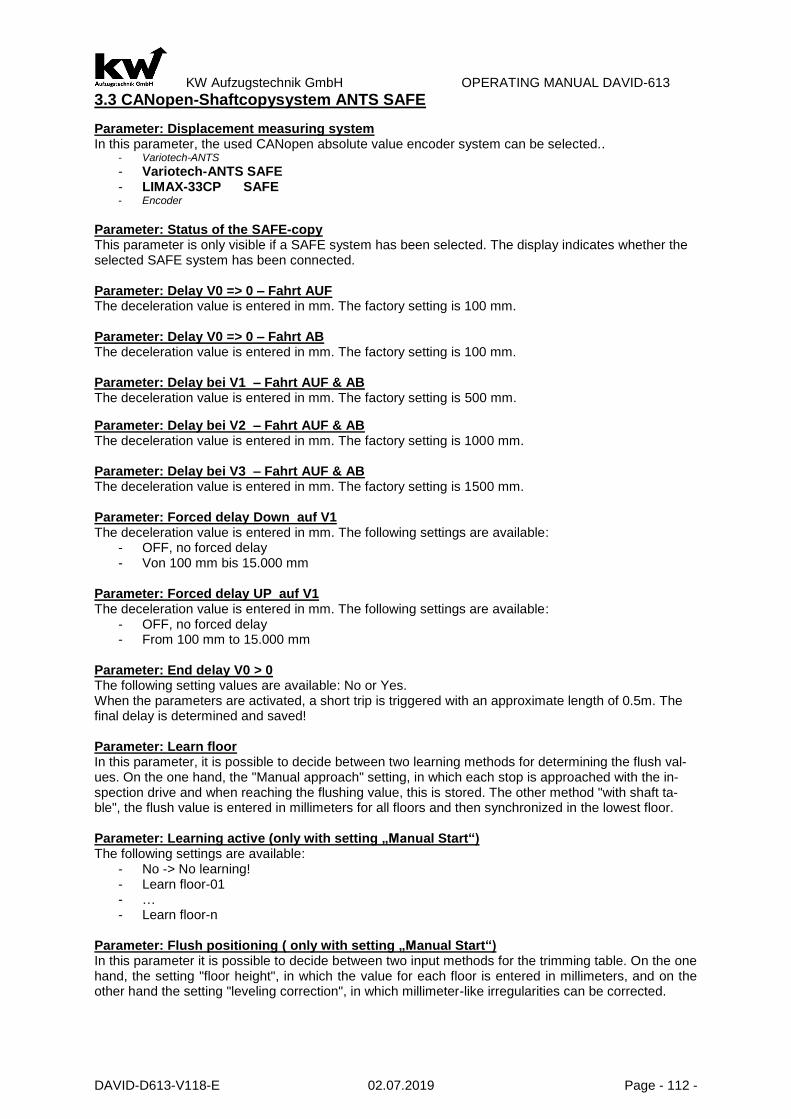
KW Aufzugstechnik GmbH OPERATING MANUAL DAVID-613
DAVID-D613-V118-E 02.07.2019 Page - 112 -
3.3 CANopen-Shaftcopysystem ANTS SAFE
Parameter: Displacement measuring system In this parameter, the used CANopen absolute value encoder system can be selected..
- Variotech-ANTS
- Variotech-ANTS SAFE - LIMAX-33CP SAFE - Encoder
Parameter: Status of the SAFE-copy This parameter is only visible if a SAFE system has been selected. The display indicates whether the selected SAFE system has been connected. Parameter: Delay V0 => 0 – Fahrt AUF The deceleration value is entered in mm. The factory setting is 100 mm. Parameter: Delay V0 => 0 – Fahrt AB The deceleration value is entered in mm. The factory setting is 100 mm. Parameter: Delay bei V1 – Fahrt AUF & AB The deceleration value is entered in mm. The factory setting is 500 mm.
Parameter: Delay bei V2 – Fahrt AUF & AB The deceleration value is entered in mm. The factory setting is 1000 mm. Parameter: Delay bei V3 – Fahrt AUF & AB The deceleration value is entered in mm. The factory setting is 1500 mm. Parameter: Forced delay Down auf V1 The deceleration value is entered in mm. The following settings are available:
- OFF, no forced delay - Von 100 mm bis 15.000 mm
Parameter: Forced delay UP auf V1 The deceleration value is entered in mm. The following settings are available:
- OFF, no forced delay - From 100 mm to 15.000 mm
Parameter: End delay V0 > 0 The following setting values are available: No or Yes. When the parameters are activated, a short trip is triggered with an approximate length of 0.5m. The final delay is determined and saved! Parameter: Learn floor In this parameter, it is possible to decide between two learning methods for determining the flush val-ues. On the one hand, the "Manual approach" setting, in which each stop is approached with the in-spection drive and when reaching the flushing value, this is stored. The other method "with shaft ta-ble", the flush value is entered in millimeters for all floors and then synchronized in the lowest floor. Parameter: Learning active (only with setting „Manual Start“) The following settings are available:
- No -> No learning! - Learn floor-01 - … - Learn floor-n
Parameter: Flush positioning ( only with setting „Manual Start“) In this parameter it is possible to decide between two input methods for the trimming table. On the one hand, the setting "floor height", in which the value for each floor is entered in millimeters, and on the other hand the setting "leveling correction", in which millimeter-like irregularities can be corrected.

KW Aufzugstechnik GmbH OPERATING MANUAL DAVID-613
DAVID-D613-V118-E 02.07.2019 Page - 113 -
Parameter: Synchronize HS01 (only with settings “With shaft table“) After the route has been detected, the car in the bottom floor is flushed and this parameter is activated. As a result, the controller recognizes the flush value of the lowest station. Parameter: Flush-Level-XX After a successful learning run or entry of the stands in the menu item Flush input, the flattening levels are stored in millimeters for the individual levels in this parameter. Unbündikeiten can be corrected in millimeters with minus and plus on the HPG-60. If the value Floor height has been selected in the Flush input menu, the value in millimeters can be entered for each floor (for example HS01-0000mm, HS02-3000mm).
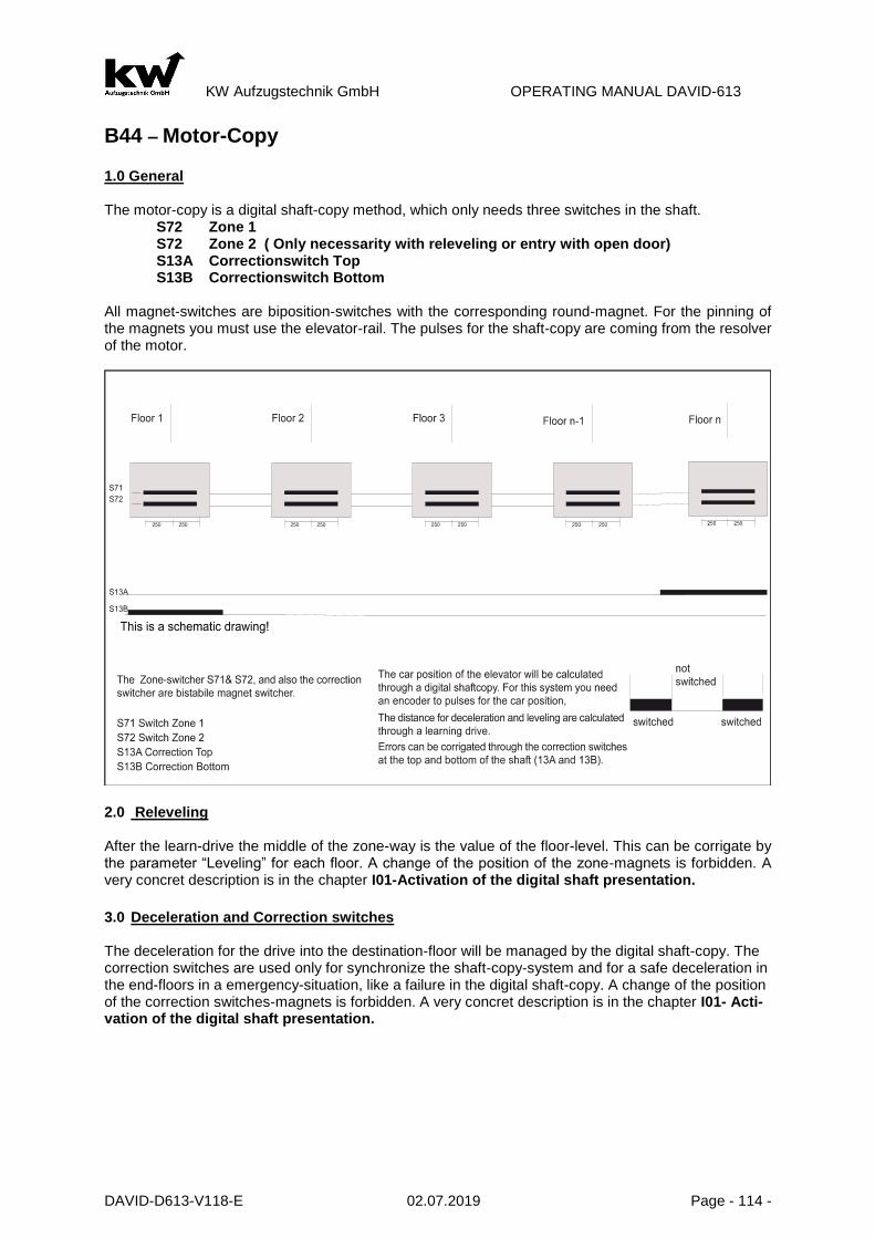
KW Aufzugstechnik GmbH OPERATING MANUAL DAVID-613
DAVID-D613-V118-E 02.07.2019 Page - 114 -
B44 – Motor-Copy 1.0 General The motor-copy is a digital shaft-copy method, which only needs three switches in the shaft.
S72 Zone 1 S72 Zone 2 ( Only necessarity with releveling or entry with open door) S13A Correctionswitch Top S13B Correctionswitch Bottom
All magnet-switches are biposition-switches with the corresponding round-magnet. For the pinning of the magnets you must use the elevator-rail. The pulses for the shaft-copy are coming from the resolver of the motor.
2.0 Releveling After the learn-drive the middle of the zone-way is the value of the floor-level. This can be corrigate by the parameter “Leveling” for each floor. A change of the position of the zone-magnets is forbidden. A very concret description is in the chapter I01-Activation of the digital shaft presentation. 3.0 Deceleration and Correction switches The deceleration for the drive into the destination-floor will be managed by the digital shaft-copy. The correction switches are used only for synchronize the shaft-copy-system and for a safe deceleration in the end-floors in a emergency-situation, like a failure in the digital shaft-copy. A change of the position of the correction switches-magnets is forbidden. A very concret description is in the chapter I01- Acti-vation of the digital shaft presentation.

KW Aufzugstechnik GmbH OPERATING MANUAL DAVID-613
DAVID-D613-V118-E 02.07.2019 Page - 115 -
5.0 Shaftcopy System with UCM Zone
HSK-90 / HSK46 System The shaft copy system HSK-90 consists of the shaft and the shaft ESF16 flags flags SFH16 holders of the respective magnets and mounting hardware. On the flag, the North magnets are always on top! Each 4 round magnets of a track-form an exterior and an interior zone. The outer zone is responsible for the driveway with the door open, the interior area for catching up / UCM detection. The shaft resolution approximation HSK-90 panel is mounted on the cab roof us-ing the mounting bracket.
At the HSK46-System the magnets are mounted directly on the rail.
The pre-limit up / top S13A correction is turned on by a magnet south. The magnet must be between the penultimate and last floor! The pre-limit down / bottom correction S13A is turned on a north magnet. The mag-net must be between the 2 - and are lowest floor! At a higher Speed than 2.0 m/s, or short travel stops, respectively, a second pre-limit switch is necessary. The second pre-limit up / top S15A turned off-a South magnet. The magnet must be lo-cated between the pre-penultimate and pe-nultimate floor. The second pre-limit down / bottom S15B is turned on a north magnet. The magnet must be between the 3rd and 2nd Floor there.
KW Aufzugstechnik GmbH OPERATING MANUAL DAVID-613
DAVID-D613-V118-E 02.07.2019 Page - 116 -
Parameter: Pulse Buffer Delay There is a pulse buffer-delay-time between 2 and 150ms. Its depends on the type of magnets, you are using. The KW-magnets only needs a delay-time of 2ms.
PARAMETER: CORRECT TRAVEL If it comes in the shaft copying to false counting a correction trip is starts. The time of execution can take place “after call input” or immediately in “automatic” mode.
PARAMETER: 2.PRE-END-SWITCH BOTTOM There is a golden rule that the pre-end switch bottom must be between 1 and 2. stop. If the 2 stop is a short trip stop, then the distance pre-end switch would not be sufficient down to the zone of the 1 stop with a faulty measure-ment to brake the carconcisely.
PARAMETER: 2.PRE-END-SWITCH TOP There is a golden rule that the pre-end switch bottom must be between last and pre-last stop. If the pre-last stop is a short trip stop, then the distance pre-end switch would not be sufficient down to the zone of the last stop with a faulty measurement to brake the carconcisely. In this situation the 2. pre-end-switch can be placed between the pre-last- and pre-pre-last-floor.
PARAMETER: SHORT TRAVELS With extreme short trip stops is appropriate for two stops within a zone. With this parameter it is adjusted whether this case is present and if like many of these short trip stops is present.
PARAMETER: DISTANCE PRE-END-SWITCH-ZONE BOTTOM In this parameter the distance center magnet pre-end switch is registered down to the highest magnet of the lowest zone in mm. This value must be determined absolutely accurately. It is important for perfect functioning of the digital shaft copying. Attention! With hydraulic, unsetteled rope and variable voltage rope plants the input the delay way of both direction takes place. (UP and DOWN-Direction)! With hydraulic and there however only V0 and V-fast are unsetteled rope plants to stop!
PARAMETER: DECELERATION SPEED V0 This parameter is the brake-way from the drive-in speed V0 to the stop (0). The value comes automaticly by the learn drive. Nevertheless the value can be change per hand.
PARAMETER: DECELERATION SPEED V1 This parameter is the brake-way from the speed V1 to the drive-in speed V0. This value depends on the speed V1 and the deceleration in the inverter. The standart value is 500 mm.
PARAMETER: DECELERATION SPEED V2 This parameter is the brake-way from the speed V2 to the drive-in speed V0. This value depends on the speed V2 and the deceleration in the inverter. The standart value is 1000 mm.
PARAMETER: DECELERATION SPEED V3 This parameter is the brake-way from the speed V3 to the drive-in speed V0. This value depends on the speed V3 and the deceleration in the inverter. The standart value is 1500 mm.
PARAMETER: LEARN DRIVE WITH For the learn drive you can choose three speeds like, V1, V2, and V3. If you have a drive with a short distance, you should choose speed V1. The standart value is speed V1.
PARAMETER: ENCODER INPUT The encoder for the shaft copying can attache on the Car (FKR) or the machine room (ZR). The location is to be registered in this parameter. As default value ZR is deposited.
PARAMETER: LERN DRIVE ACTIVE If the electrical installation is ok and the software-parameters like number of floors,..., is put in, the learn-drive can be started. The car should be in a position between the first and second floor, but it must stand above the correc-tionswitch bottom. Then the learn-drive should be started. A very concret description is in the chapter I01-Activation of the digital shaft presentation.
PARAMETER : SWITCH HYSTERES OVERLAPPING After successful learning trip the value of the hysteress was determined for the shaft switches.
PARAMETER: LEVELING-FLOOR-XX After a learn-drive, you must put in this parameter in the level-values for each floor. Here you can corrigate un-levels for every floor.

KW Aufzugstechnik GmbH OPERATING MANUAL DAVID-613
DAVID-D613-V118-E 02.07.2019 Page - 117 -
B45 – Minimum-Copy General In principle 6 magnet counter are necessary with minimum copying. If the plant does not have releveling function or no entry with open door a magnet counter can be omitted i.e. S72. The concise position takes place related to the direction. All magnet counter are bistabile block switches with the appropriate round magnets. As attachment for the magnets the guide rail, as also the pit flag system can serve ESK04.
1.0 Leveling The leveling depends on the direction. With rope-elevators without pre-opening the door the stopping in direction up is with the magnet-switch 12B, and in direction down with the magnet-switch 12A. ATTENTION! There may be a partial overlap of the consice magnet fields with consice position. From bottom to top magnet 12B seen always before 12A. Control recognizes the direction ,with injury ot this rule it comes to the fact that floors are counted wrongly by control. On hydraulic lifts and cable systems with entrance door is open or readjustment is maintained with the stopping of the counter-aligned. As long as both consice signals overlap themselves, no post-correction is necessary. As soon as car more deeply sinks or rises more highly so the consice signal lost and the car is after –adjusted into the opposite direction.
2.0 Brakepoints and Correction The magnet switches 12A and 12B are also the brake-switches to drive into the destination floor. If you are driving from the second floor to the first floor you doesn’t need a brake magnet! You are braking with the correction switch 13B. The same story is the drive to the last floor. You are braking with the correction switch 13B. Nevertheless if the delay impulses are set this leads to copying work errors. PARAMETER: PULSE BUFFER DELAY There is a pulse buffer-delay-time between 2 and 150 ms. Its depends on the type of magnets, you are using. The KW-magnets only needs a delay-time of 2 ms.
PARAMETER: CORRECTION TRAVEL If it comes in the shaft copying to false countings, a correction trip goes on. The time of execution can take place ”after call input” or immediately in “automatic“ mode.

KW Aufzugstechnik GmbH OPERATING MANUAL DAVID-613
DAVID-D613-V118-E 02.07.2019 Page - 118 -
Unit shaft copying system

KW Aufzugstechnik GmbH OPERATING MANUAL DAVID-613
DAVID-D613-V118-E 02.07.2019 Page - 119 -
B 46-R&S-Copy 1.0 General For R&S copying are needed 5 magnet switcher. If the elevator does not have a releveling function or the entry with open door you can omitted the magnet counters S71 and S72. The concise position takes place related to the direction. All magnet counter are instabile block switches with the appropriate round magnets. As attachment for the magnets the guide rail also the shaft flag system can serve ESK16.
4.0 Consice Position The consice position is dependent on direction. With rope elevator systems without entering an open door or readjusting the stop is in an upward di-rection with magnetic switch S12B, in the downward direction with the magnetic switch S12A.
ATTENTION! There may be a partial overlap of the consice magnet fields with consice position. From bottom to top magnet 12B seen always before 12A. Control recognizes the direction, with injury ot this rule it comes to the fact that floors are counted wrongly by control. On hydraulic lifts and cable systems with entrance door is open or readjustment is maintained with the stopping of the counter-aligned. As long as both consice signals overlap themselves, no post-correction is necessary. As soon as car more deeply sinks or rises more highly so the consice signal lost and the car is after –adjusted into the opposite direction.
5.0 Brakepoints and Correction The magnet switches 12A and 12B are also the brake-switches to drive into the destination floor. If you are driving from the second floor to the first floor you doesn’t need a brake magnet! You are braking with the correction switch 13B. The same goes for ride from penultimate to last stop (S13A). Switching be-havoir of S11A is falling edge (turn-off). In this way only one switch is necessary in shaft. The speed of this method is a limit to the deceleration. Half of distance of the floor is the possible smallest stopping distance.

KW Aufzugstechnik GmbH OPERATING MANUAL DAVID-613
DAVID-D613-V118-E 02.07.2019 Page - 120 -
B5 Indicate
B501- Car Indicators General The car-position of the elevator has two output-devicels, namely ZR and ITR. In both of the following parameters you can choose the output of the car-position:
Parameter Car Indicate ZR - Parameter Car Indicate EIT - Description Remote Station ER There are always 8 output-channels on both of the two units. You can choose the following codes to show the car-position: 1 of N-Code, Binary-Code, Graycode, Digits-Indicator and User-defined char-acter set.
1 of N Code The 1 of N code has always one output-channel for one floor indicator. Is the car in the first floor so channel 21 h is active ( +24V DC). All other outputs have 0V DC. Lift systems with o1 till 8 stops can be represented in this way. If there more stops are used, so it must be converted to an encoded representation.
Binarycode In the binarycode, the floors are a combination of some output channels. Active channels have a “1”. This means that there is a +24V DC level.
Stop 25h 24h 23h 22h 21h
1.Floor 0 0 0 0 1
2.Floor 0 0 0 1 0
3.Floor 0 0 0 1 1
4.Floor 0 0 1 0 0
5.Floor 0 0 1 0 1
6.Floor 0 0 1 1 0
7.Floor 0 0 1 1 1
8.Floor 0 1 0 0 0
9.Floor 0 1 0 0 1
10.Floor 0 1 0 1 0
11.Floor 0 1 0 1 1
12.Floor 0 1 1 0 0
13.Floor 0 1 1 0 1
14.Floor 0 1 1 1 0
15.Floor 0 1 1 1 1
16.Floor 1 0 0 0 0
17.Floor 1 0 0 0 1
Graycode In the graycode, the floors are a combination of some output channels. Active channels have a “1”. This means that there is a +24V DC level.
Stop 25h 24h 23h 22h 21h
1.Floor 0 0 0 0 1
2.Floor 0 0 0 1 1
3.Floor 0 0 0 1 0
4. Floor 0 0 1 1 0
5.Floor 0 0 1 1 1
6.Floor 0 0 1 0 1
7.Floor 0 0 1 0 0
8.Floor 0 1 1 0 0
9.Floor 0 1 1 0 1
10.Floor 0 1 1 1 1
11.Floor 0 1 1 1 0
12.Floor 0 1 0 1 0
13.Floor 0 1 0 1 1
14.Floor 0 1 0 0 1
15.Floor 0 1 0 0 0
16.Floor 1 1 0 0 0
17.Floor 1 1 0 0 1
12

KW Aufzugstechnik GmbH OPERATING MANUAL DAVID-613
DAVID-D613-V118-E 02.07.2019 Page - 121 -
7-Digits-Indicator In the 7-Digits-code, the floors are a combination of some output channels. Active channels have a “1”. This means that there is a +24V DC level.
Output
21h Segment a
22h Segment b
23h Segment c
24h Segment d
25h Segment e
26h Segment f
27h Segment g
For each floor you can choose the signs of the floor. The size of the characters and numbers is lim-ited: -> A, b, c, d, E, F, H, U, 0, 1, 2, 3, 4, 5, 6, 7, 8, 9 Programmable characterset On the output channels 21h to 28h with ZR and ITR the active output channels can be determined freely. Indication of the car position in spezial drivers With the modes of operation inspection, releveling, spezial trip and case of error, it can will decide whether the car permament spend all or does nothing spend.
B502- Car Arrows
PARAMETER ARROWS The output-channel of the car-arrows are at the carpanel-unit ITR. Here you can choose the following type of arrows:
a) Only Direktion Arrows b) Direction Arrow and move-on Arrow c) Only move-on Arrows d)
DISCONNECTION OF THE MOVE ON ARROWS You can switch off the driving on arrows on two ways.
A) Disconnection by expiration of an adjusted time. B) Disconnection by closes of the doors.
B503- Floor Indicators
ZR: PARAMETER ARROWS The output-channel of the car-arrows are at the car panel-unit ITR. Here you can choose the following type of arrows:
a) Only Direktion Arrows b) Direction Arrow and move-on Arrow c) Only move-on Arrows
ZR: SWITCHING OFF THE ARROWS You can switch off the driving on arrows on two ways.
A) Disconnection by expiration of an adjusted time. B) Disconnection by closes of the doors.
ER: PARAMETER ARROWS The output-channel of the car-arrows are at the car panel-unit ITR. Here you can choose the following type of arrows:
a) Only Direktion Arrows b) Direction Arrow and move-on Arrow c) Only move-on Arrows

KW Aufzugstechnik GmbH OPERATING MANUAL DAVID-613
DAVID-D613-V118-E 02.07.2019 Page - 122 -
ER: SWITCHING OFF THE ARROWS You can switch off the driving on arrows on two ways.
A) Disconnection by expiration of an adjusted time. B) Disconnection by closes of the doors.
ARROW-VIEW BY CLOSED DOOR You can choose if the arrows are switched on by closed door.
B504- Gong at the Car
In the first parameter of this menu you can activate the car gong function. You can attache a miniature loudspeaker with an impedance by 8 ohms at the clamps 330 and 331 for the door side 1, as well as at the clamps 332 and 333 for the door side 2 of the FKR unit. You can select between accord, two-sound and triad gong. Additionally you can select a different sound function for the up and downwards. The following trip modes can be switched on:
A) Car calls B) Landing calls C) Priority calls D) Fire fighter service E) Special trips
Gong Function Here, you can select whether the floor gong is activated. Car Call UP Here it can be selected whether the floor gong is active on an internal call with direction of travel UP, and how often is gonged. The choice is balanced, double and triangle. Car Call DOWN Here, you can choose whether the floor gong is activated for an internal call with direction AB, and how often is gonged. The choice is balanced, double and triangle. Landing Call UP Here, you can choose whether the floor garnish is activated on an outside call with direction of travel UP, and how often is gonged. The choice is balanced, double and triangle. Landing Call DOWN Here it can be selected whether the floor garnish is active on an exit call with direction AB, and how often is gonged. The choice is balanced, double and triangle. Priority Call UP Here, it can be selected whether the floor garnish is active on a priority call with direction of travel UP, and how often is gonged. The choice is balanced, double and triangle. Priority Call DOWN Here it can be selected whether the floor garnish is activated by a priority call with direction AB, And how often is gonged. The choice is balanced, double and triangle. Fire Fighter Service Here, you can choose whether the floor gong is active on a fire fighter trip, and how often is gonged. The choice is balanced, double and triangle. Special Trip Here, you can choose whether the floor gong is active on a special trip, and how often you will be gonged. The choice is balanced, double and triangle. Gong function – volume Here the volume of the gong can be adjusted to the environment. The value range is from 1% to 100%. The factory setting is 50%. Gong function – pitch Here the pitch of the gong can be adjusted to the environment. The value range is from 1% to 100%. The factory setting is 50%.

KW Aufzugstechnik GmbH OPERATING MANUAL DAVID-613
DAVID-D613-V118-E 02.07.2019 Page - 123 -
B505- Gong at the Floor
Like the car controller unit FKR, then also the remote station ER 2005 offer the possibility of activating the gong function. You can attache a miniature loudspeaker with an impedance by 8 ohms at the clamps 330 and 331 for the door side 1, as well as at the clamps 332 and 333 for the door side 2 of the FKR unit. You can select between accord, two-sound and triad gong. Additionally you can select a different sound function for the up and downwards. The following trip modes can be switched on:
A) Car calls B) Landing calls C) Priority calls D) Fire Fighter Service E) Special trip
Gong Function Here, you can select whether the floor gong is activated. Car Call UP Here it can be selected whether the floor gong is active on an internal call with direction of travel UP, and how often is gonged. The choice is balanced, double and triangle. Car Call DOWN Here, you can choose whether the floor gong is activated for an internal call with direction AB, and how often is gonged. The choice is balanced, double and triangle. Landing Call UP Here, you can choose whether the floor garnish is activated on an outside call with direction of travel UP, and how often is gonged. The choice is balanced, double and triangle. Landing Call DOWN Here it can be selected whether the floor garnish is active on an exit call with direction AB, and how often is gonged. The choice is balanced, double and triangle. Priority Call UP Here, it can be selected whether the floor garnish is active on a priority call with direction of travel UP, and how often is gonged. The choice is balanced, double and triangle. Priority Call DOWN Here it can be selected whether the floor garnish is activated by a priority call with direction AB, And how often is gonged. The choice is balanced, double and triangle. Fire Fighter Service Here, you can choose whether the floor gong is active on a fire fighter trip, and how often is gonged. The choice is balanced, double and triangle. Special Trip Here, you can choose whether the floor gong is active on a special trip, and how often you will be gonged. The choice is balanced, double and triangle. Gong function – volume Here the volume of the gong can be adjusted to the environment. The value range is from 1% to 100%. The factory setting is 50%. Gong function – pitch Here the pitch of the gong can be adjusted to the environment. The value range is from 1% to 100%. The factory setting is 50%. OUTPUT ER GONG PULSE Pulse length for gong impulse on ER adjustable: pulse, 1…10 seconds.

KW Aufzugstechnik GmbH OPERATING MANUAL DAVID-613
DAVID-D613-V118-E 02.07.2019 Page - 124 -
B506- LED-Matrix
The car panel pcb EIT and remote station ER-2007 have RJ-12 ( 10-pole socket strips) sockets for the control of the matrix displays ANZ-22,-32, -33, -52 and 53. FLOOR DISPLAY CAR & REMOTE STATION ER For each stop a designation can be selected. The range of the letters and numbers is limited. ARROR DISPLAY CAR You can choose between:
- No (No expenditure for arrow) - Yes (Standing arrow) - Scroll (Current arrow)
SEGMENTS CAR Depending upon selected matrix unit it can be selected whether 2 or 3 segment matrix display is to be headed for. ARROR DISPLAY REMOTE STATION You can choose between:
- No (No expenditure for arrow) - Yes (Standing arrow) - Scroll (Current arrow)
INDICATOR FIELD REMOTE STATION Depending upon selected matrix unit an indicator field present, which can assigned for a type-output . SEGEMENTS REMOTE STATION Depending upon selected matrix unit it can be selected whether 2 or 3 segment matrix display is to be headed for. CENTRAL UNIT DISPLAY You can choose between:
- Display 1 to 64 - Display like in the car
.

KW Aufzugstechnik GmbH OPERATING MANUAL DAVID-613
DAVID-D613-V118-E 02.07.2019 Page - 125 -
B507- Floor Displays
In this menu are the names of the individual floors, registered by the First up to the 64th floor. There are up to 3 points and the entire bandwidth of the ASCII character propositions for each stop are avail-able. The setting begins at the first stop with the two yellow editing keys. Right red button the three digits of the display to be approached, and then jumped on the next floor. This ends up in the 64th floor. The left red key (Escape), the process can be left and to jump back to the floor. 1 This setting is binding on all bus displays, like the matrix LCD and TFT displays.
B507 Floor Displays-Menue B507 floor display
Floor-01 display: -2
^
Esc Enter Value
For each floor an up to three-digit name can be entered.
B508- Messages
When KW ads protocol up to 16 special messages can be transmitted serially. This menu can be set for each message whether it is visualized in the display booth or on the floor indicator.
B508 Message-Menue B508 Overload:
Car:* floor:-
Menue Value
This menu can be selected for the cabin display and the floor in-dicator, whether the special mes-sage is displayed. (* Display ON, - Display OFF)
Messages: -> Overload -> Evacuation -> Fire Evacuation -> Emergency Power Evac. -> Fire Fighter Travel -> Special Travel -> Bed Travel -> Guide Mode -> Out Of Order -> Maintenance -> Loadingtime Aktive -> Door Opening -> Door Closing -> Please Leave Car -> Please Wait -> Please Speak
B509- TFT/LCD - Car
This menu is made for the settings for the TFT-car indicator. Backgroundpicture In the "fixed" setting the background image for all floors is the same. "Switch" setting, each floor its own wallpaper. Persons in Car Here the number of persons for the labeling in the inner panel of the cabin is determined.

KW Aufzugstechnik GmbH OPERATING MANUAL DAVID-613
DAVID-D613-V118-E 02.07.2019 Page - 126 -
Loadweight Here the indication of the load on the labeling in the inner panel of the cabin is determined. Text-1 Manufacture Here the indication of the manufacture for the labeling in the inner panel of the cabin is determined. Text-2 Factory-No. Here is the specification of the serial number on the labeling in the inner panel of the cabin is determined. Text-3 Build Year Here, the year of manufacture on the labeling in the inner panel of the cabin is determined. Text-4 CE-Sign Here is the specification of the CE-No., or the rebuilding year for the labeling in the inner panel of the cabin is determined. Floor Indicator There are three visualization modes: fixed, rolling and as an animation. Arrow Indicator There are three visualization modes: fixed, rolling and as an animation. Display String-1 Here it is determined whether the string-1 is displayed on the TFT display. Display String -2 Here it is determined whether the string-2 is displayed on the TFT display. Display String -3 Here it is determined whether the string-3 is displayed on the TFT display. Display String -4 Here it is determined whether the string-4 is displayed on the TFT display. Display Persons Here it is determined whether the number of persons indication is displayed on the TFT display. Display Load Here it is determined whether the load indication is displayed on the TFT display. Emergency Light Here it is determined whether the TFT display serves as an emergency light source. Physically required the TFT display, the 12V DC power supply (terminals 100 & 500). Message Overload … Please Speak When KW display protocol up to 16 special messages can be transmitted serially. In this menu the fol-lowing settings can be defined for each message:
B509 Displaytext Overload:
Imaging:**-*--* Dis-
playtext-^
Esc Enter Wert
Here, the Displaytext is activated by the star, will appear on the TFT dis-play of the special text. (* Display ON, - Display OFF)
Messages: -> Overload -> Evacuation -> Fire Evacuation -> Emergency Power Evac. -> Fire Fighter Travel -> Special Travel -> Bed Travel -> Guide Mode -> Out Of Order -> Maintenance -> Loadingtime Aktive -> Door Opening -> Door Closing -> Please Leave Car -> Please Wait

KW Aufzugstechnik GmbH OPERATING MANUAL DAVID-613
DAVID-D613-V118-E 02.07.2019 Page - 127 -
-> Please Speak
B509 Symbol Overload:
Imaging:**-*--*
Symbol-^
Esc Enter Value
Here, the Symbol activated by the star, so the logo will appear on the TFT display. (* Display ON, - Display OFF)
Messages: -> Overload -> Evacuation -> Fire Evacuation -> Emergency Power Evac. -> Fire Fighter Travel -> Special Travel -> Bed Travel -> Guide Mode -> Out Of Order -> Maintenance -> Loadingtime Aktive -> Door Opening -> Door Closing -> Please Leave Car -> Please Wait -> Please Speak
B509 Fixed / blink Overload:
Imaging:**-*--*
….fixed/blink-^
Esc Enter Value
Here is the "fixed" by the star is acti-vated, appears on the TFT screen of the special text as a fixed bar. The other option is to flash the message. (* Display ON, - Display OFF)
Messages: -> Overload -> Evacuation -> Fire Evacuation -> Emergency Power Evac. -> Fire Fighter Travel -> Special Travel -> Bed Travel -> Guide Mode -> Out Of Order -> Maintenance -> Loadingtime Aktive -> Door Opening -> Door Closing -> Please Leave Car -> Please Wait -> Please Speak
B509 Buzzer short Overload:
Imaging:**-*--*
…….Buzzer short-^
Esc Enter Value
Here the Buzzer Short option acti-vated by the star, as heard in the TFT display, the buzzer as long or lasting momentum.
(* Display ON, - Display OFF)
Messages: -> Overload -> Evacuation -> Fire Evacuation -> Emergency Power Evac. -> Fire Fighter Travel -> Special Travel -> Bed Travel -> Guide Mode -> Out Of Order -> Maintenance -> Loadingtime Aktive -> Door Opening -> Door Closing -> Please Leave Car -> Please Wait -> Please Speak
B509 Buzzer Long Overload:
Imaging:**-*--*
……...Buzzer long-^
Esc Enter Value
Here the Buzzer Long option acti-vated by the star, as heard in the TFT display, the buzzer as long or lasting momentum.
(* Display ON, - Display OFF)
Messages: -> Overload -> Evacuation -> Fire Evacuation -> Emergency Power Evac. -> Fire Fighter Travel -> Special Travel -> Bed Travel -> Guide Mode -> Out Of Order -> Maintenance -> Loadingtime Aktive -> Door Opening -> Door Closing -> Please Leave Car -> Please Wait -> Please Speak

KW Aufzugstechnik GmbH OPERATING MANUAL DAVID-613
DAVID-D613-V118-E 02.07.2019 Page - 128 -
B509 Gong Overload:
Imaging:**-*--*
…………………………… ……….Gong-^
Esc Enter Value
Here, the "Gong" option is enabled by the star, as heard in the TFT dis-play of Gong pulse. (* Display ON, - Display OFF)
Messages: -> Overload -> Evacuation -> Fire Evacuation -> Emergency Power Evac. -> Fire Fighter Travel -> Special Travel -> Bed Travel -> Guide Mode -> Out Of Order -> Maintenance -> Loadingtime Aktive -> Door Opening -> Door Closing -> Please Leave Car -> Please Wait -> Please Speak
B509 Voice Announcer Overload:
Imaging:**-*--*
… Voice Announcer-^
Esc Enter Value
Here is the "voice announcement" by the star activated, sounds the TFT display of the voice message text for the message. (* Display ON, - Display OFF)
Messages: -> Overload -> Evacuation -> Fire Evacuation -> Emergency Power Evac. -> Fire Fighter Travel -> Special Travel -> Bed Travel -> Guide Mode -> Out Of Order -> Maintenance -> Loadingtime Aktive -> Door Opening -> Door Closing -> Please Leave Car -> Please Wait -> Please Speak
Buzzer Short Here, the pulse duration of the Summer-short signal is determined. The value is adjustable from 2 to 255 milliseconds. The factory setting is 100 ms. The factory setting is 1 second. Buzzer Long Here, the pulse duration of the Summer-long signal is set. The value is adjustable between 1, 2, 3 seconds, and permanently. The factory setting is 1 second. Gong-Signal Here the number of Gong signals is determined. The value is adjustable between 1, 2 and 3x Gong pulse. The factory setting is 1x Gong pulse.
Display- Format Here, the orientation of the display is set: - Automatic (by tilt sensor of the TFTs) - Vertical - cross Display-Brightness Here the brightness of the display can be adapted to the environment. The range extends from 1% to 100%. The factory setting is 90%. Volume Speech Here the volume of the display can be adapted to the environment. The range extends from 1% to 100%. The factory setting is 50%. Tone Pitch Speech Here, the pitch of the display can be adapted to the environment. The range extends from 1% to 100%. The factory setting is 50%. Volume Music Here the volume of the background music of the display can be adapted to the environment. The range extends from 1% to 100%. The factory setting is 50%. Backgroundmusic Here you can choose whether the background music is played. A prerequisite is that the desired music loaded in the TFT module.

KW Aufzugstechnik GmbH OPERATING MANUAL DAVID-613
DAVID-D613-V118-E 02.07.2019 Page - 129 -
Floor Message Here you can choose whether a voice message for each floor will be played. A prerequisite is that the voice message texts were loaded for each floor in the TFT module. Time Here you can set whether the time is displayed to the TFT module. Date Here you can set whether the date is displayed to the TFT module. Time in Line Here you can set whether and in which text line (1 to 4) the time is displayed.
B510- TFT/LCD – Floor
This menu is made for the settings on the TFT display floor. Text-1 Manufacture Here the indication of the manufacture for the labeling in the inner panel of the cabin is determined. Text-2 Factory-No. Here is the specification of the serial number on the labeling in the inner panel of the cabin is determined. Text-3 Build Year Here, the year of manufacture on the labeling in the inner panel of the cabin is determined. Text-4 CE-Sign Here is the specification of the CE-No., or the rebuilding year for the labeling in the inner panel of the cabin is determined. Floor Indicator There are three visualization modes: fixed, rolling and as an animation. Arrow Indicator There are three visualization modes: fixed, rolling and as an animation. Display String-1 Here it is determined whether the string-1 is displayed on the TFT display. Display String -2 Here it is determined whether the string-2 is displayed on the TFT display. Display String -3 Here it is determined whether the string-3 is displayed on the TFT display. Display String -4 Here it is determined whether the string-4 is displayed on the TFT display. Message Overload … Please Speak When KW display protocol up to 16 special messages can be transmitted serially. In this menu the fol-lowing settings can be defined for each message:
B509 Displaytext Overload:
Imaging:**-*--* Dis-
playtext-^
Esc Enter Wert
Here, the Displaytext is activated by the star, will appear on the TFT dis-play of the special text. (* Display ON, - Display OFF)
Messages: -> Overload -> Evacuation -> Fire Evacuation -> Emergency Power Evac. -> Fire Fighter Travel -> Special Travel -> Bed Travel -> Guide Mode -> Out Of Order -> Maintenance -> Loadingtime Aktive -> Door Opening -> Door Closing -> Please Leave Car -> Please Wait -> Please Speak

KW Aufzugstechnik GmbH OPERATING MANUAL DAVID-613
DAVID-D613-V118-E 02.07.2019 Page - 130 -
B509 Symbol Overload:
Imaging:**-*--*
Symbol-^
Esc Enter Value
Here, the Symbol activated by the star, so the logo will appear on the TFT display. (* Display ON, - Display OFF)
Messages: -> Overload -> Evacuation -> Fire Evacuation -> Emergency Power Evac. -> Fire Fighter Travel -> Special Travel -> Bed Travel -> Guide Mode -> Out Of Order -> Maintenance -> Loadingtime Aktive -> Door Opening -> Door Closing -> Please Leave Car -> Please Wait -> Please Speak
B509 Fixed / blink Overload:
Imaging:**-*--*
….fixed/blink-^
Esc Enter Value
Here is the "fixed" by the star is acti-vated, appears on the TFT screen of the special text as a fixed bar. The other option is to flash the message. (* Display ON, - Display OFF)
Messages: -> Overload -> Evacuation -> Fire Evacuation -> Emergency Power Evac. -> Fire Fighter Travel -> Special Travel -> Bed Travel -> Guide Mode -> Out Of Order -> Maintenance -> Loadingtime Aktive -> Door Opening -> Door Closing -> Please Leave Car -> Please Wait -> Please Speak
B509 Buzzer short Overload:
Imaging:**-*--*
…….Buzzer short-^
Esc Enter Value
Here the Buzzer Short option acti-vated by the star, as heard in the TFT display, the buzzer as long or lasting momentum.
(* Display ON, - Display OFF)
Messages: -> Overload -> Evacuation -> Fire Evacuation -> Emergency Power Evac. -> Fire Fighter Travel -> Special Travel -> Bed Travel -> Guide Mode -> Out Of Order -> Maintenance -> Loadingtime Aktive -> Door Opening -> Door Closing -> Please Leave Car -> Please Wait -> Please Speak
B509 Buzzer Long Overload:
Imaging:**-*--*
……...Buzzer long-^
Esc Enter Value
Here the Buzzer Long option acti-vated by the star, as heard in the TFT display, the buzzer as long or lasting momentum.
(* Display ON, - Display OFF)
Messages: -> Overload -> Evacuation -> Fire Evacuation -> Emergency Power Evac. -> Fire Fighter Travel -> Special Travel -> Bed Travel -> Guide Mode -> Out Of Order -> Maintenance -> Loadingtime Aktive -> Door Opening -> Door Closing -> Please Leave Car -> Please Wait -> Please Speak

KW Aufzugstechnik GmbH OPERATING MANUAL DAVID-613
DAVID-D613-V118-E 02.07.2019 Page - 131 -
B509 Gong Overload:
Imaging:**-*--*
…………………………… ……….Gong-^
Esc Enter Value
Here, the "Gong" option is enabled by the star, as heard in the TFT dis-play of Gong pulse. (* Display ON, - Display OFF)
Messages: -> Overload -> Evacuation -> Fire Evacuation -> Emergency Power Evac. -> Fire Fighter Travel -> Special Travel -> Bed Travel -> Guide Mode -> Out Of Order -> Maintenance -> Loadingtime Aktive -> Door Opening -> Door Closing -> Please Leave Car -> Please Wait -> Please Speak
B509 Voice Announcer Overload:
Imaging:**-*--*
… Voice Announcer-^
Esc Enter Value
Here is the "voice announcement" by the star activated, sounds the TFT display of the voice message text for the message. (* Display ON, - Display OFF)
Messages: -> Overload -> Evacuation -> Fire Evacuation -> Emergency Power Evac. -> Fire Fighter Travel -> Special Travel -> Bed Travel -> Guide Mode -> Out Of Order -> Maintenance -> Loadingtime Aktive -> Door Opening -> Door Closing -> Please Leave Car -> Please Wait -> Please Speak
Buzzer Short Here, the pulse duration of the Summer-short signal is determined. The value is adjustable from 2 to 255 milliseconds. The factory setting is 100 ms. The factory setting is 1 second. Buzzer Long Here, the pulse duration of the Summer-long signal is set. The value is adjustable between 1, 2, 3 seconds, and permanently. The factory setting is 1 second. Gong-Signal Here the number of Gong signals is determined. The value is adjustable between 1, 2 and 3x Gong pulse. The factory setting is 1x Gong pulse.
Display- Format Here, the orientation of the display is set:
- Automatic (by tilt sensor of the TFTs) – Vertical - cross Display-Brightness Here the brightness of the display can be adapted to the environment. The range extends from 1% to 100%. The factory setting is 90%. Volume Speech Here the volume of the display can be adapted to the environment. The range extends from 1% to 100%. The factory setting is 50%. Tone Pitch Speech Here, the pitch of the display can be adapted to the environment. The range extends from 1% to 100%. The factory setting is 50%. Volume Music Here the volume of the background music of the display can be adapted to the environment. The range extends from 1% to 100%. The factory setting is 50%. Backgroundmusic Here you can choose whether the background music is played. A prerequisite is that the desired music loaded in the TFT module. Time Here you can set whether the time is displayed to the TFT module. Date Here you can set whether the date is displayed to the TFT module.
KW Aufzugstechnik GmbH OPERATING MANUAL DAVID-613
DAVID-D613-V118-E 02.07.2019 Page - 132 -
B6 Special Functions B600 Monitor Functions PARAMETER: CONTACTOR MONITOR Is the contactor-monitor active, the main- and brake contactors will be controlled on two ways: a) At the start of the travel, after a call, the main- and brake contactors will be controlled, if they switch on. If they do not switch on after a delay-time, which is in the parameter „Start Time Monitor“, this means input-channel has a high-level, the car stopped immediately. b) After a travel, the main- and brake contactors will be also controlled, if they have switched off. If they do not switch off, the car is blocked for the next travel. The is available between 500 ans 4000 ms. Once the travel is over, i.e. the contactor pilot control is disabled, but the main and brake contactors are not dropped, it is stopped after the elapse of a specified grace period, the system immediately. If the system is blocked, you can only can turn on the system, when you switch off / on the central unit ZR or activate the parameter C00 „Controller-RESET“. PARAMETER: MONITOR INSPECTION If the special-mode “inspection-drive” or “re-send-drive” active, the monitor functions are not active. PARAMETER: MONITOR REACTION Select between emergency stom & Locking or emergency stop & calls. PARAMETER: CONTAKTOR MONITOR CHAIN Select between version with opener chain or the extended version with opener and normally open con-tact chain.In addition altogether needs two opener entrance monitoring functions (E14 & E356) as well as a normally open contact input function (E474). PARAMETER: CAR LIGHT MONITOR Setting Off: There is no car light monitor. Setting Current Sensor: If the fuse of the carlight is falling out or the light of the car is going out, this means the elektrical power is sinking under 40W at 230V AC, there is a failture in the car light. Setting Input E525: A light sensor which is connected at the input with the function E525, detects the failure of the cabin illumination. Reaction: A rope elevator stops in the next floor and it will be blocked with open doors, until the light is going on. If the special-mode “inspection-drive” or “re-send-drive” active, the monitor functions are not active. With a hydraulic elevator an emergency sinking takes place into the lowest stop and the car stay with open doors until the error condition not change. If the special trip modes “inspection trip” or “ return trip” are active then cab light monitoring is deac-tivated. PARAMETER: START TIME MONITOR At the start of the travel, after a call, the main- and brake contactors will be controlled, if they switch on. If they do not switch on after a delay-time, which is in the parameter „Start Time Monitor“,the car stopped immediately. If the special-mode “inspection-drive” or “re-send-drive” active, the monitor func-tions are not active. PARAMETER: JOURNEY TIME MONITOR If in the time, which you can put in in this parameter, no pulses are coming from the digital shaft-copy or there is no calculate brake-point of the floors on the way, the system will be blocked. If the special-mode “inspection-drive” or “re-send-drive” active, the monitor functions are not active. PARAMETER: DECELATION TIME MONITOR If in the time, which you can put in in this parameter, no zone-switch is coming from the destination-floor, the system will be blocked. If the special-mode “inspection-drive” or “re-send-drive” active, the monitor functions are not active. PARAMETER: STOP TIME MONITOR If in the time, which you can put in in this parameter, no stopping is coming after the zone-switch of the destination-floor, the system will be blocked. If the special-mode “inspection-drive” or “re-send-drive” active, the monitor functions are not active. PARAMETER: FAULT HANDLING

KW Aufzugstechnik GmbH OPERATING MANUAL DAVID-613
DAVID-D613-V118-E 02.07.2019 Page - 133 -
In this parameter there are two possibilities for the fault handling: a) “Stop and block” – This means, if the system is blocked, you can only turn on the system,
when you switch off / on the central unit ZR or activate the parameter C1 „Controller-RESET“. b) “Stop and delete calls” – this means, after stopping and clear the calls, you can give new calls
and system tries to start. PARAMETER: TEMPERATUR MONITOR MOTOR If the input-motor PTC becomes active, an entry is made into the next stop. The car remains in this stop until the motor PTC is deactivated. With a hydraulic elevator an emergency sinking takes place in the lowest stop and following bolting device of plant, until the input-motor PTC is deactivated. If the special trip modes are active “inspection trip” or “resent drive” then the drive break and stay in this condition, until the input-motor PTC is deactivated. PARAMETER: BRAKESHOE MONITOR If the processor-input for a brake-shoe-monitor becomes active, an entry is made into the next stop with a rope lift. The car remains in this stop until the error condition is repaired. If the special trip modes are active “ inspection trip” or “ resend drive”, then the drive clear and remain in this condition, until the error condition is repaired. PARAMETER: BRAKE MONITOR For the protection of unintended car movement away from the landing with the landing door not in the locked position and the car door not in the closed position according to the new standard EN 81-1:1998 + A3: 2009 resp. EN 81-2:1998 + A3: 2009 is done by the security circuit SIS16-101. The security circuit SIS16-101 causes the interruption of the safety circuit and thus acts directly on the drive contactors. Based on the Position paper of the NB-L ( CO-ORDINATION OF NOTIFIED BODIES LIFTS DIRECTIVE 95/16/EC) from 20.07.2011, Version 07, can be omitted in the external monitoring device of the brake control elements on a SIL 3 level. The monitoring is done by independent input channels of brake control elements monitoring of the control unit, or the regulation unit. The operation of the brake release can be monitored by a processor input. It is expected for a closed brake a +24 V DC level. Now, if the brake contactor is activated, is expected to set a tolerance time that the processor has a 0V input DC level. Likewise, the applying the brake is monitored. Each brake ele-ment is a processor input required.
At hydraulic lifts of the company ALGI and the types AZRS and AZFR , according to the new standard EN 81-2:1998 + A3: 2009, the Down Travel is initiatet with two series-connected hydraulic valves, which have a monitoring of the open and closed position. The monitoring is done by independent input chan-nels of brake control elements monitoring of the control unit, or the regulation unit. With traction elevator systems to EN81-1 with certified braking devices to the new standard EN 81-1:1998 + A3: 2009, by the monitoring is done by independent input channels of brake control elements monitoring of the control unit, or the regulation unit. If the elevator system shut down, they can only reset the parameter C00 "RESET CONTROL" of the control systems DAVID D613 / D2005 / D912 be activated again. PARAMETER: BRAKE MONITOR REACTION The reaction is adjustable, an immediate emergency stop with following barriers of the elevator or only one emergency stop with deletion of the calls. PARAMETER: BRAKE MONITOR INPUT The Input of the brake open monitor is switchable between the function not inverted (high active) or the inverted ( low active). PARAMETER: BRAKE SHOE MONITOR DELAY The time for the procedure of the brake open can be supervised maximally 6000 milliseconds. PARAMETER: BRAKE MONITOR SYNCHRONISM The time for the procedure of the brake open can be supervised maximally 6000 milliseconds.

KW Aufzugstechnik GmbH OPERATING MANUAL DAVID-613
DAVID-D613-V118-E 02.07.2019 Page - 134 -
PARAMETER: SWITCH CABINET T-MAX The central unit ZR has an electronic circuit for the collection of the temperature. The temperaure thresh-old for the blocking the elevator can be placed between 30 degrees Celsius and 100 degrees Celsius. The standart value is 60 degrees Celsius. Stopping the plant means an entry with a rope elevator into the next stop. With a hydraulic elevator the execution of an emergency sinking in the lowest stop and refusal of call acceptance to the switchgear cabinet temperature below the limit value threshold sinks. PARAMETER: SWITCH CABINET T-MIN Also the minimum temperature can be evaluated with the theshold value. PARAMETER: MOTOR TEMPERATURE The entrance for the input-monitor PTC resistor can be adjusted as follows:
1) OFF 2) Input 1 active 3) Input 2 active 4) Input 1 + 2 active
PARAMETER: Monitoring Door-Engine-PTC When the function is activated, the PTC thermistor of the door motor is evaluated. The two inputs are located on the D613-FKR and have the designation 151 and 152. PARAMETER: DSK-IMPULSE The impulses of the digital shaft copying are supervised in normal operation, i.e. with missing impulses of A or B-trace the lift is stopped and locked. This impuls monitoring is disconnectable. PARAMETER: ROPE Streching In this menu it is possible to evaluate the input functions E475 elongation of the error message from Henning to Loadmeasure system. PARAMETER: BATTERYMONITOR In this menu it is possible to monitor the input functions or E507 / E508 and the battery-OK messages from Wittur EOS system or over Local emergency systems. PARAMETER: Monitoring A3-Case In this Parameter is it possible zo switch ON / OFF the EN-81 A3-case monitoring. The default value is ON. PARAMETER: AW60-Monitoring In this parameter the monitoring of the release buttons of the AW-60 elevator release terminal is acti-vated. PARAMETER: Monitoring U10 Shaftdoor According to EN81-20 / 50, it is necessary to detect whether the safety circuit is still closed, even though the shaft door has been opened (monitoring for falsely bridge). If this is the case, the error message F34 "U10 shaft door" appears for a bridge in the area of the shaft doors. PARAMETER: Monitoring-DSK-Direction On the basis of the EM81-20 / 50, the actual direction of travel of the hoisting cabin with respect to the selected direction of the elevator control is monitored. The tolerance range is 100mm. This is neces-sary in order to prevent an erroneous switch-off due to the turning of the area during the starting pro-cess of a suboptimal control setting. In the event of a fault, the error message F83 "DSK direction" is output. PARAMETER: Monitoring Nominal Speed Due to the requirement of the EN81-20 / 50, the elevator system is monitored for compliance with the nominal speed. Exceeding the nominal speed by 15% leads to the shutdown of the take-off system and the output of the error message F255 "Over-speed". Prerequisite is the correct entry of the nominal speed of the elevator system in parameter A3.6. The factory setting must be adapted before LOCATION! PARAMETER: Monitoring Door-End-Switch Close When the function is activated, the door limit switch is evaluated to the door drive or the car doors, re-gardless of the door drive set. A drive with the bypass function according to EN81-20 / 50 is only pos-sible when the car door is closed with the door limit switch closed and the function activated. PARAMETER: Monitoring U11 Cabin-door According to EN81-20 / 50, it is necessary to detect whether the safety circuit is still closed, even though the cabin door has been opened (monitoring for falsely bridge). If this is the case, the error message F35 "U11-Cabin door" appears for a bridge in the area of the car door.

KW Aufzugstechnik GmbH OPERATING MANUAL DAVID-613
DAVID-D613-V118-E 02.07.2019 Page - 135 -
B601- Inspection Travel Description Inputs and Outputs of the inspection control
Terminal Hardware Function
60 24V DC Input
Inspection control On/Off - This entrance serves for recognizing whether the inspection control switched on. In normal operation rests against this input +24V. Becomes those inspection control switch on then there is a 0V DC.
60A 24V DC In-put
It means inspection trip UP +24V DC at this entrance that the trip desire UP lies on. This entrance is locked mutually to hardware and software with the entrance 60B. If both entrances are activated, this trip desire and/or immediate cancelling of the driving or door instructions does not have to the consequence.
60B 24V DC In-put
It means inspection trip DOWN +24V DC at this entrance that the trip desire UP lies on. This entrance is locked mutually to hardware and software with the entrance 60A. If both entrances are activated, this trip desire and/or immediate cancelling of the driving or door instructions does not have to the consequence.
60C 24V DC In-put
Hurry button- only with hydraulic elevators- with hurry button with hydraulic elevators the high-speed valve ( on or off) is activated with inspection enterprise, if we do not drive on a pre-end switcher into final stop direction. Key can be considered only in con-nection with inspection of the processor.
60D 24V DC Signal to the activation of the inspection contactor K60.
Description Inputs and Outputs of the resend control
Terminal Hardware Function
61 24V DC Input
Return motion control On/Off - This entrance serves for recognizing whether the return motion control switched on. In normal operation rests against this entrance +24V. Be-comes those remote motion control switch on then lies 0V DC.
61A 24V DC Input
It means return motion trip UP +24V DC at this entrance that the trip desire UP lies on. This entrance is locked mutually to hardware and software with the entrance 61B. If both entrances are activated, this trip desire and/or immediate cancelling of the driving or door instructions does not have to the consequence.
61B 24V DC Input
It means return motion trip DOWN +24V DC at this entrance that the trip desire UP lies on. This entrance is locked mutually to hardware and software with the entrance 61A. If both entrances are activated, this trip desire and/or immediate cancelling of the driv-ing or door instructions does not have to the consequence.
61D 24V DC Signal for activation the inspection contactor K60.
PARAMETER: RESTART LOCKING If this parameter is activated, then the lift stops and the inspection control is off. A start-up of the control can take place either via activation of the back getting control or via RESET of the controller. PARAMETER: RESTART LOCKING DOOR Is this parameter active, then the lift move in normal operation only, when the switching doors are opened before the inspection control is switched off.
PARAMETER: SPEED BUTTON If this parameter is activated, then the speed-push-button in the inspection case can be used. PARAMETER: Inspectionsstop TOP This parameter defines the shut-off point for the inspection speed in the shaft head. In early software revisions, the cut-off point was determined by the position of the upper magnet of the zone of the up-permost stop. In the version for the EN81-20 / 50, the cut-off point can be defined in millimeters. The factory value is - 20mm, i.e. 20mm below the level of the top stop. For shortened shaft heads, a factory setting of - 500mm is selected, which must be adjusted on site!
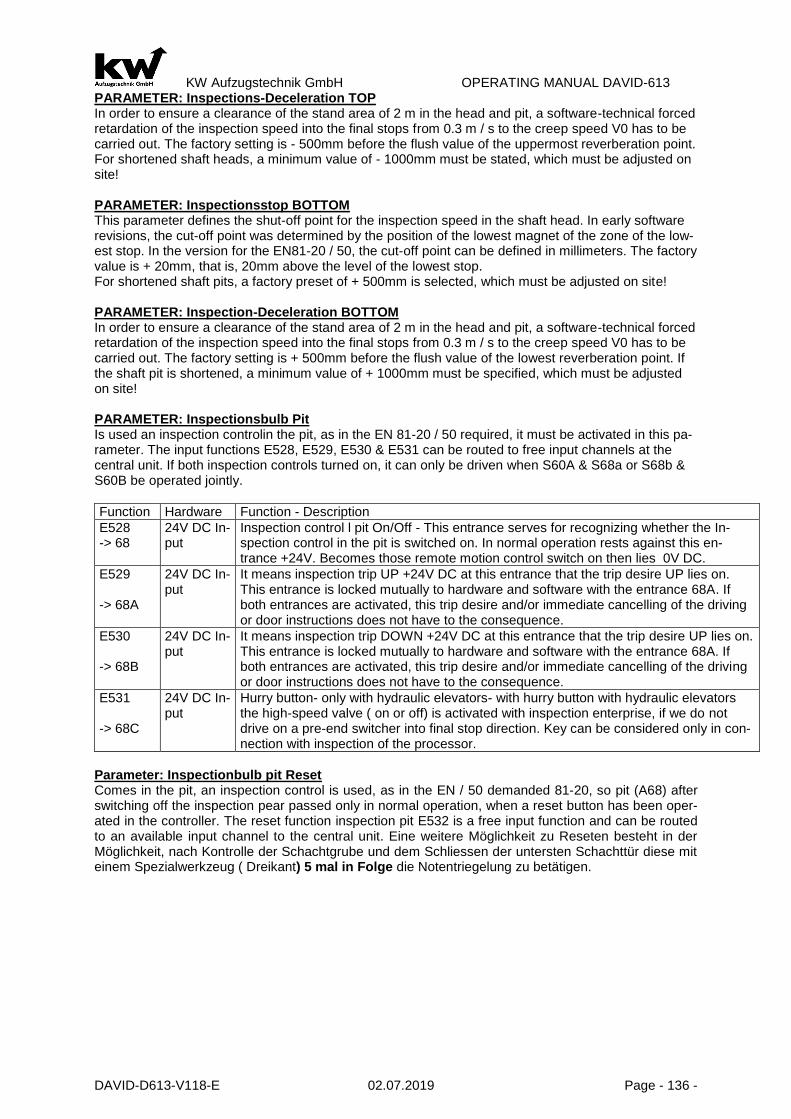
KW Aufzugstechnik GmbH OPERATING MANUAL DAVID-613
DAVID-D613-V118-E 02.07.2019 Page - 136 -
PARAMETER: Inspections-Deceleration TOP In order to ensure a clearance of the stand area of 2 m in the head and pit, a software-technical forced retardation of the inspection speed into the final stops from 0.3 m / s to the creep speed V0 has to be carried out. The factory setting is - 500mm before the flush value of the uppermost reverberation point. For shortened shaft heads, a minimum value of - 1000mm must be stated, which must be adjusted on site! PARAMETER: Inspectionsstop BOTTOM This parameter defines the shut-off point for the inspection speed in the shaft head. In early software revisions, the cut-off point was determined by the position of the lowest magnet of the zone of the low-est stop. In the version for the EN81-20 / 50, the cut-off point can be defined in millimeters. The factory value is + 20mm, that is, 20mm above the level of the lowest stop. For shortened shaft pits, a factory preset of + 500mm is selected, which must be adjusted on site! PARAMETER: Inspection-Deceleration BOTTOM In order to ensure a clearance of the stand area of 2 m in the head and pit, a software-technical forced retardation of the inspection speed into the final stops from 0.3 m / s to the creep speed V0 has to be carried out. The factory setting is + 500mm before the flush value of the lowest reverberation point. If the shaft pit is shortened, a minimum value of + 1000mm must be specified, which must be adjusted on site! PARAMETER: Inspectionsbulb Pit Is used an inspection controlin the pit, as in the EN 81-20 / 50 required, it must be activated in this pa-rameter. The input functions E528, E529, E530 & E531 can be routed to free input channels at the central unit. If both inspection controls turned on, it can only be driven when S60A & S68a or S68b & S60B be operated jointly.
Function Hardware Function - Description
E528 -> 68
24V DC In-put
Inspection control l pit On/Off - This entrance serves for recognizing whether the In-spection control in the pit is switched on. In normal operation rests against this en-trance +24V. Becomes those remote motion control switch on then lies 0V DC.
E529 -> 68A
24V DC In-put
It means inspection trip UP +24V DC at this entrance that the trip desire UP lies on. This entrance is locked mutually to hardware and software with the entrance 68A. If both entrances are activated, this trip desire and/or immediate cancelling of the driving or door instructions does not have to the consequence.
E530 -> 68B
24V DC In-put
It means inspection trip DOWN +24V DC at this entrance that the trip desire UP lies on. This entrance is locked mutually to hardware and software with the entrance 68A. If both entrances are activated, this trip desire and/or immediate cancelling of the driving or door instructions does not have to the consequence.
E531 -> 68C
24V DC In-put
Hurry button- only with hydraulic elevators- with hurry button with hydraulic elevators the high-speed valve ( on or off) is activated with inspection enterprise, if we do not drive on a pre-end switcher into final stop direction. Key can be considered only in con-nection with inspection of the processor.
Parameter: Inspectionbulb pit Reset Comes in the pit, an inspection control is used, as in the EN / 50 demanded 81-20, so pit (A68) after switching off the inspection pear passed only in normal operation, when a reset button has been oper-ated in the controller. The reset function inspection pit E532 is a free input function and can be routed to an available input channel to the central unit. Eine weitere Möglichkeit zu Reseten besteht in der Möglichkeit, nach Kontrolle der Schachtgrube und dem Schliessen der untersten Schachttür diese mit einem Spezialwerkzeug ( Dreikant) 5 mal in Folge die Notentriegelung zu betätigen.

KW Aufzugstechnik GmbH OPERATING MANUAL DAVID-613
DAVID-D613-V118-E 02.07.2019 Page - 137 -
PARAMETER: Inspection Call This parameter is activated by entering a lowering value of the cabin. The procedure for retrieving the cabin for inspection is as follows: 1.) Lift the elevator cabin by call. 2.) In the cabin, the DOOR-UP button, the INTERIOR button on the current floor, and the INTERIOR buttons on the floor below are simultaneously pressed for 2 seconds until a piezoton sounds for the active Qutation. 3.) Now the cabin has to be left. After completion of the piezotone, the lift control closes the cabin & shaft doors and lowers the cabin. 4.) After completion of the lowering process, the piezotone sounds again for 30 seconds and the oper-ator has the possibility to unlock the door and initiate the inspection drive. 5.) If the 30-second duration is not used, or if a passenger is placed in the cab using an indoor com-mand, the cabin flushes again, opens the door and goes into normal operation. PARAMETER: Monitoring Manual Speed according EN81-20/50 According to EN81-20 / 50 the return speed of max. 0.63 m / s to 0.3 m / s and must not be exceeded. By setting the monitoring threshold to 0.3 m / s on the factory side, travel is interrupted if the distance is exceeded, but no blocking occurs. The error message F253 "Over speed return travel" appears. Prerequisite is the correct entry of the nominal speed of the elevator system in parameter A3.6. The factory setting must be adapted before LOCATION! PARAMETER: Monitoring Inspection Speed according EN81-20/50 According to EN81-20 / 50 the inspection speed must be monitored. Normal inspection speed is set to 0.3 m / s. The inspection speed can be increased to 0.5 m / s by pressing the rapid button on the in-spection bobbin. In this way the factory setting of the monitoring threshold must be corrected on site. If the threshold is exceeded, the trip is interrupted, but no blocking occurs. The error message F254 "Over-speed inspection travel" appears. Prerequisite is the correct entry of the nominal speed of the elevator system in parameter A3.6. The factory setting must be adapted before LOCATION! PARAMETER: Inspections-Pit-Reset by 5-Times Shaftdoor With active parameters, a reset can be carried out by operating the door release 5 times after using the inspection pit and after leaving the pit.
B602- EMERGENCY LIGHT SYSTEM General The emergency power equipment is integrated in that central unit controller makes with 12V a maximum river available of 1,2A. This power serves 1.1 AH Akkus, as well as for the supply of the intercom, for the supply of the 12V the alert tracer, the alert horn, the concise announcement and the emergency light.
PARAMETER: ALERT PUSH BUTTON DELAY The alarm tracer activation can be retarded in the menu option delay alarm from one to five seconds, so that abuse and erroneous manipulation can be mostly prevented. If an error enters the lift, then the alarm delay becomes ineffective, and the notification of emergency imparted. PARAMETER: ALERT PUSH BUTTON MISUSE PROTECTION If Off: Alarm is released after deceleration time If On: Alarm is not released under the following conditions:
- Elevator is located concisely in floor - Door is open - Elevator stands on “ normal operation” ( no inspection/ resend drive enterprise) - There is no arror
If one of these conditions is not full filled, the alarm is release.

KW Aufzugstechnik GmbH OPERATING MANUAL DAVID-613
DAVID-D613-V118-E 02.07.2019 Page - 138 -
B603- CAR FAN
Description of the In- & Output channels
terminal Hardware Function
A24 Relay common Phase L5, to supply the car fan
E24 24V DC Input Input push-button car fan; A level of +24V DC means that the car fan is startet.
A24 24V DC output If there is a level of +24V DC, is this the indicator for the running car fan.
PARAMETER: START OF FAN To activate the car fan, there are two possibilities:
A) „Push-button“ – If you use the push-button of the car fan, the relay switch off and the car fan will be started. The car fan is running, until the delay time is over, or there is a second push on the button of the car fan.
B) „Travel“ – If you choose this value, the car fan starts automaticly at the start of a travel. The fan switch off after the delay time.
PARAMETER: CAR FAN DELAY This parameter determines the length of the hunting time of the car fan. Response time up to max. 240 seconds.
B604- LOAD MEASUREMENT
General In principle you can selected between two load transmitter systems. On the one hand the load sensor of the company KW can be used, on the other hand is present free- provable entrances, at which other makes can be attached by load measuring sensors. PARAMETER: OVERLOAD IMPUT The entrances of the overload message are switchable between the function of not inverted ( high ac-tively) or inverted ( low actively). Load Measurem. Laodsensor FKR The KW load measuring sensor has a red ousing and has three coloured marked connection. The lines are to be presented as follows:
Color of the connecting cable Terminal at Car-controller
Connecting cable green Terminal 350
Connecting cable red Terminal 351
Conneciting cable yellow Terminal 352
The parameter Input FKR must be activated. Load conditions are learned over two load points. On the one hand the condition sized with empty car by activation of the menu option zero-load store. On the other hand the load point full load activated by the activation of the menu option full load store. In addition however the car must be loaded with test weights at height of the full load. The two load points 0% and 100% are now fixed. In the menu options overload, full load and less load can be individually stopped now from 0% to 150%. FREE ENTRANCES FOR LOAD MEASURING SENSORS Are used other load measuring sensors must the parameter entrance FKR be placed off .On the car controller FKR now the free entrance FE0 can be occupied as overload entrance and the other en-trances than full load entrance, and/ or less load entrance. Switching attitude (normally open contact or opener) was specified in the first menu option. LESS LOAD EVALUATION If this parameter is activated a call threshold can be adjusted from 1 to 4 calls, during whose excess the car calls are deleted an / or ignored. An activation of this parameter is naturally only reasonable, if a less vice identification is attached. FULL LOAD EVALUATION If this parameter is activated, landing calls are ignored. ( deletion or storage). An activation of this pa-rameter is naturally only reasonable, if a full vice identification is attached.

KW Aufzugstechnik GmbH OPERATING MANUAL DAVID-613
DAVID-D613-V118-E 02.07.2019 Page - 139 -
B605- STANDBY TRAVEL
PARAMETER: STANDBY TRAVEL In this parameter, you can activate the standby travel. To use the standby-travel, you must put a +24V DC voltage at the input channel. Takes place during the rest ride a ride reversing, the door remains closed in the standby floor. PARAMETER: STANDBY TRAVEL 1 FLOOR One quiescent level can select at rope lifts. At the standart value is regulating the next level. That is the fact that if while driving the +24V DC entrance for the control and light disconnection becomes active. The cab continues and open the doors and switches after a certain time the light off at the next stop. The door position is reely selectable. If the cab is not in full speed, then it remais in the stop and implements the functions described a while ago. Naturally also a certain quiescent level can be indi-cated. Hydraulic lifts always lower into the lowest level.
Parameter: Standby Travel 1 - Offset You have the possibility to move up (+) or down (-) the car with xxx mm in the floor. zusenken (-).The speed is the V0. PARAMETER: STANDBY TRAVEL 2 FLOOR Like the function before, you choose a second floor.
Parameter: Standby Travel 2 - Offset You have the possibility to move up (+) or down (-) the car with xxx mm in the floor. zusenken (-).The speed is the V0. PARAMETER: DOOR Here you can choose, if the doors are open or closed in the standby travel floor.
1.) Door 1-2 open 2.) Door 1+2 open/close 3.) Door 1 open 4.) Door 2 open 5.) Door 1 open/close 6.) Door 2 open/close 7.) Door 1+2 always close
Parameter: Standby Travel – Floor Indicator Here you have the possibilty to switch ON or OFF the floor indicator. Parameter: Standby Travel – Car Indicator Here you have the possibilty to switch ON or OFF the car indicator.
B606 – PARKING TRAVEL
General The mechanism of park levels at a lift serves to position or the cab / cabs to locally or temporally it can be better reacted changed flow of traffic and so the mechanical handling capacity increase. A position of cabs can be made on two ways:
1) Temporal definition of park levels
During the mechanism of a general park level is met the following paramenter attitudes.
- Parameter: Park Trip -> Yes - Parameter: Floor -> 1 up to max. number of stops
- Parameter: Park after -> Adjustable from 1 to 15 minutes, up to the departure - Parameter: Door position -> Open/Close
2) Definition of the park levels by input signals In the menu B72 of inputs an be specified on the free-provale entrances park stop functions for certain levels. On an input with this function tension is applied, then this even is started as park stop, as long
as the input is active.

KW Aufzugstechnik GmbH OPERATING MANUAL DAVID-613
DAVID-D613-V118-E 02.07.2019 Page - 140 -
- Parameter: Park Trip -> Dynamic
- Parameter: Parks after -> Adjustable from 1 to 15 minutes, up to the departure
- Parameter: Door position -> Open /Close
PARAMETER: DOOR POSITION PARKING In the parameter B606 if the park trip was activated, then the door position can be put in the park level in this parameter. The attitudes “ open” and “ closed” are present, whereby “ open” represents the standart value. Temporal blockage of floors takes place with the timers from the menu B615
B607 – FLOOR BLOCKING General In order to regulate teh flow of traffic to ensure and/or an access control it is possible to close certrain levels. BLOCKAGE OF FLOORS BY PARAMENTER ATTITUDE The permanent blockage of levels can be met by the parameter attitudes. Landing- and car calls are
erased for this floors. PARAMETER: FLOOR BLOCKING This parameter activated through to set the indication „*“ on certain floors. These floors are closed in the further enterprise, in those determined floors closed. PARAMETER: DYNAMIC BLOCKING If this parameter is activated, the normal landing call handling must take place over the remote station ER. Then the call entrances at the ZR can be used for the floor blockade. The following attitudes exist:
- Only car calls - Only landing calls - Car calls and landing calls
PARAMETER: DYNAMIC BLOCKAGE ENTRANCE You can choose between: 1) Normally With plants of a +24V of level the floor is closed 2) Inverted With plants of a 0V of level the floor is closed Temporal blockage of floors takes place with the timers from the menu B615.

KW Aufzugstechnik GmbH OPERATING MANUAL DAVID-613
DAVID-D613-V118-E 02.07.2019 Page - 141 -
B608- ENERGY SAVING PARAMETER: CAR LIGHT AUTOMATIC OFF Car light can be off if car stands in pease in the stop place without calls or the car is in park stop. This can be deactivated in the paramenter automatic off. PARAMETER: CARLIGHT DELAY In order to avoid unnecessary in and turn-off processes of the car light one time interval should be selected in the parameter which it can be proceeded that no more calls are present. One time interval is adjustable from 0 to 6500 seconds. Default value is 60 seconds.
PARAMETER: CAR INDICATOR AUTOMATIC OFF Car indicater can be off if car stands in pease in the stop place without calls or the car is in park stop. This can be deactivated in the paramenter automatic off. PARAMETER: CAR INDICATER DELAY Time interval from 0 to 6500 seconds is adjusable. As default value is 120 seconds selected. PARAMETER: FLOOR INDICATER AUTOMATIC OFF Floor indicater can be off if car stands in pease in the stop place without calls or the car is in park stop. This can be deactivated in the paramenter automatic off. PARAMETER: FLOOR INDICATER DELAY Time interval from 0 to 6500 seconds is adjusable. As default value is 300 seconds selected. PARAMETER: FREQUENCY INVERTER STANDBY Frequency inverter can be in standby modus if teh car stands inoperative in stop place. The electronics boards are shifted into sleep modus and intermediate circuit are unloaded. This can be activated in the parameter Automatic off. PARAMETER: FREQUENCY INVERTER STANDBY DELAY Time interval from 0 to 6500 seconds is adjusable. As default value is 600 seconds selected. PARAMETER: FREQUENCY INVERTER SWICH OFF To the standby mode the frequency inverter becomes additional completely without tension. The proce-dure is intoduced over the elevator bus. This can be deactivated in the paramenter automatic off. PARAMETER: FREQUENCY INVERTER SWITCH OFF DELAY Time interval from 0 to 6500 seconds is adjusable. As default value is 900 seconds selected. PARAMETER: DOOR DRIVE TRAIN AUTOMATIC OFF Door Drive Train can be off if car stands in pease in the stop place without calls or the car is in park stop. This can be deactivated in the paramenter automatic off. PARAMETER: DOOR DRIVE TRAIN DELAY Time interval from 0 to 6500 seconds is adjusable. As default value is 60 seconds selected. PARAMETER: MODUS S1 Operation mode S1( sleep mode ) is here activatable for the prozessor system. PARAMETER: MODUS S2 Operation mode S2( deep sleep mode) is here activatable for the processor system.

KW Aufzugstechnik GmbH OPERATING MANUAL DAVID-613
DAVID-D613-V118-E 02.07.2019 Page - 142 -
B609-614 – SPECIAL FUNCTIONS
Titel Rang Function Description
B611 1 Fire-brigade control The fire-brigade control is devided into two functional moduls: a) Fire-brigade priority in the 1st, 2nd or 3nd fire-brigade level. b) Fire-brigade trip in the cab with dead man door control
B609 2 Emergency power evacuation
The emergency power evacuation is devided in principle into two variants:
a) Emergency power evacuation with single investments without sequence circuit
b) Emergency power evacuation at a plant group with se-quence circuit
B610 3 Fire drop evacuations With the case of the elevators evacuate at the same time. The fire drop evacuation is divided philosophy conditionally into two rages:
a) Until three fire drop levels with different priority. Start to the levels dependently of the active alarms.
b) Dynamic fire drop avacuations, which do not drive through the fire source and the car over/ unter the fire level position.
B612 5 Rescue Travel If the floor the obstruction rescue entrance is set actively. The car drives immediately to the stop. The car is occupied with the VIPs and drive to special level . Afterwards the car returns to the de-parture level.
6 Landing control OFF In the car the advantages entrance is set actively. ( term-low) The landing and car calls are deleted and all acknowledgements of the car call aster flash up to the call input.( no time limit) After effected call input; start for this stop; afterwards again flash the achnowledgement up to the call input on switch off the code switch.
B613 7 Leader operation In the car the entrance for the leader enterprise is set activety ( duration High). The landing and car calls are deleted, new set landing calls let the acknowledgements of the car calling aster flash up to the call input. After effected call input, start for this stop; Delete acknowledgement.
B23 8 Car Priority In the car the advantages entrance is set actively ( Impuls) The landing calls are stored and car calls deleted; all acknowl-edgements of the car calls aster to flash and a call input within 20 seconds are expected. After effected call input, start for this stop; afterwards the plant is again in normal operation.
B24 9 Landing Priority In the floor the landing priority input is set actively. The car starts immediately the stop. The landing calls are stored; all car calls deleted; all acknowledgements of the car calls aster to flash and a call input within 20 seconds are expected. After effected call in-put; start for this stop; afterwards the plant is again in normal op-eration.
B614 10 Obligation Stop/ hotel function
There is one main entrance level with obligation stop with pas-sage ( selectable in Up, Down & Up direction , Down direction)
11 Normal Operation Interior and exterior actively, no special trips.

KW Aufzugstechnik GmbH OPERATING MANUAL DAVID-613
DAVID-D613-V118-E 02.07.2019 Page - 143 -
B609 – EMERGENCY POWER SERVICE
Emergency evacuation in case of individual drivers Is the emergency evacuation activated for a single driver, only the 230 signal at input 401 is evaluated. 230V AC means normal operating level, 0V is the AC mains failure, the car moves to the preset emer-gency level and set the door of the door opening side. Exterior and interior control is disabled. More actions only after ranking. Come on the 230V AC level again to the input 401, the system automatically returns to normal operation. The input 401 has been assigned before-standard input function with the E01-emergency oper-ation. You can also program any other input to this function.
Emergency evacuation of sequential circuit Is the emergency evacuation activated with sequential circuit, so only the 230V AC signal at input 401 and evaluated at the entrance to 402nd Input. Input 401 is again the message line. Input 402 is the entrance for the beginning of the emergency trip. The level at 230V AC input 401 means normal operation. 0V is the AC mains failure and only then is the input evaluated 402nd The 230V AC level at input 402 is the start of the emergency drive. this means when the input 401 is energized. 0V AC means waiting for the emergency trip. The emergency operation begins when input 401 is energized. Lies on a 230V AC input 402 then level at, so the car goes into the emergency level set and opens the door to the set side door. Exterior and interior control is disabled. After reaching the emergency level, the relay 403, the voltage 402 continues to the next elevator, so that it can reach the evacuation level. Did our elevator, the signal 402 received at the beginning of the emergency trip, but as any errors the door does not close, then after a set time the relay is activated 403, to give other elevators the chance to evacuate. More actions only after ranking. Come on the 230V AC level at the input 401 again, the system auto-matically returns to normal operation. The input 401 "A08-emergency level reached" standard with the input function "E01-emergency mode", the input 402 with the "E02-emergency travel" and the output relay K307 with the preset function. You can also program any other input and output of these functions. PARAMETER: ENERGENCY POWER SERVICE In this parameter you can activate the function of the emergency power service. The options are:
1.) Power generator ( with emergency diesel generators, UPS or onsite ). 2.) Accu Power ( With an evacuation unit specifically for the elevator system ) 3.) With brake open ( UPS opens and closes the brakes again when they reach the zone area by
car ) PARAMETER: FLOOR The floor of the emergency power service is freely chosen. The standart value is the first floor. PARAMETER: ENTRANCE OPEN In this parameter the door open can be adjusted after arrival at the evacuation level. With only one side of the door basically the door is always open. On two sides of existing door can be decided whether only the door-side or only one side of the door-2 or both doors are open. PARAMETER: FOLLOW-CIRCUIT If this parameter is enabled, it waits before starting the evacuation trip to the input function E02-emer-gency travel. PARAMETER: PIECO BUZZER If you activate this parameters the piezo buzzer of the carpanel-unit ITR can switch on, if there is an emergency power service travel. PARAMETER: FOLLOW-CIRCUIT-DEADTIME The set time is available to the elevator to reach the emergency level. If it is not him, it is locked and the output 403 (A08-output function emergency level reached), the voltage switches to the input 402 of the next lift.

KW Aufzugstechnik GmbH OPERATING MANUAL DAVID-613
DAVID-D613-V118-E 02.07.2019 Page - 144 -
B610 – EMERGENCY FIRE SERVICE Emergency Fire Service There are the following modes:
A) Fire drop evacuation with one fire evacuation floor ( Priority-1) B) Fire drop evacuation with two fire evacuation floor ( Priority-2) C) Fire drop evacuation with three fire evacuation floor ( Priority-3) D) Dynamic fire drop evacuation with passage of the fire source E) Dynamic fire drop evacuation without passage of the fire source
UNTIL THREE FIRE DROP LEVELS WITH DIFFERENT PRIORITY With fire drop evacuations it turned out that 3 fire drop floors with different priority meet the requirements with plants up to 16 stops. If the first drop entrance is active ( +24V DC level) then the cab drives into the adjusted 1 fire evacuation floor and the door of the adjusted door side opens. Outside and interior control is deactivated. Further actions only after order of rank. If the +24V DC level leaves at all fire drop entrances then the plant returns automatically to normal operation. If the second fire drop entrance is active, or first and second fire drop entrance actively then into the second fire drop floor one drives. After with all fire drop entrances the + 24V DC level leaves, the plant returnes automatically to normal oper-ation. During the 3 Fire evacuation entrance equivalent is acted. All entrances for the fire drop evacula-tion know High actively ( normally open contacts or as Low actively ( openers) o be adjusted. DYNAMIC FIRE DROP EVACUATION During the dynamic fire drop evaclation floor fire alarms are present in each stop. It is present a main evacuation floor, into which in principle one evacuates. The exceptions consists of the fact that it burns in the main evacuation floor or on the trip to the main evacuation floor the fire source to be driven. In the sofware two are present dynamic fire drop evacuations. Those can driven through the fire source the oter one stops above the fire source.
Fire evacuation under emergency conditions In case of a fire evacuation, in the case comes to the emergency, the fire-evacuation levels are ap-proached, in accordance with the priorities. For a composite of several plants, can be disposed of power capacity of emergency diesel to be evacuated as a rule only in succession. A special case is the emergency evacuation with UPS dar. On hydraulic elevators with single-phase UPS can take place only in the downward direction of evacuation. There is no evacuation level in the lowest level, education levels should be avoided in the evacuation level by using a One-Way-Blocked-Valve. As an example of a 4-stop hydraulic system may be the response of the system in case of fire emergency condition shown below:
Floor FLOOR FUNCTION Actuel Car-posi-tion
Active Evacuation- alert
Reaction
2
2 Main Evacuation floor Drive to the main floor( 0 )
Second Evacuation floor Drive to Second Evacuation floor ( 1 )
1 Second Evacuation floor
1 Main Evacuation floor Drive to the main floor ( 0 )
Second Evacuation floor Blocked in Second Evacuation floor (1)
0 Main Evacuation floor
0 Main Evacuation floor Blocked in the main floor( 0 )
Second Evacuation floor Blocked in the main floor( 0 )
- 1
- 1 Main Evacuation floor Blocked in the floor -1
Second Evacuation floor Blocked in the floor -1
PARAMETER: OPEN DOORSIDE In this parameter the door position is adjustable after arrival in the evacuation level. With only door side in principle the door is opened always. With two existing door sides it can be decided whether only the door side 1 or only the door side 2 or both doors are open. PARAMETER: PIECO BUZZER If you activate this parameters the piezo buzzer of the carpanel-unit ITR can switch on, if there is an emergency fire service travel.

KW Aufzugstechnik GmbH OPERATING MANUAL DAVID-613
DAVID-D613-V118-E 02.07.2019 Page - 145 -
PARAMETER: INPUT The entrances of the evacuation levels and/ or the floor fire alarm are switchable between the function of a normally closer(high actively) or the opener ( low actively).
Parameter: Emergency Fire Servive Swiss version The Swiss version of the fire evacuation can be activated here. Parameter: Emergency Fire Servive Door Condition For the door position in the fire trap level after successful evacuation, the following settings are possi-ble: - Always open - Closes after 1.0 to 60 seconds (adjustable). Parameter: Fire trap evacuation Schindler ID The signal characteristics can be defined for the evaluation of the fire alarm messages and transmis-sion to the Schindler ID speed dial control
- - normal - - Inverted
Parameter: RWA-Shaft smoke extraction Activation of RWA shaft smoke extraction and determination of the evacuation stop. The input function E983 "RWA shaft smoke extraction" gives the control of the RWA system the message for the evacua-tion operation. This function is active at 0V DC (-> normally closed operation & line break monitored). The output function A624 "Shaft smoke extraction active" can be used to control an output message
B611 FIRE FIGHTER SERVICE
PARAMETER: FIREFIGHTER TRAVEL In this parameter you can activate the function of the firefighter travel. MAIN ENTRANCE PLACE Pressing of the FW-code switch into on position the FW-elevator is called immediately into the main entrance place. The fire-brigade level is freely selectable in the software. The elevator is located in a floor in stand-by ( with closed doors) a direct trip to the main entrance place is automatically introduced. If the elevator stands on a floor with open doors and the doors close immediately ( Door-reverse devices are ineffective with exception of the cosing force limiter) and the elevator drives into direct trip to the main entrance place. If the elevator is in full speed the trip is continued directly to the main entrance place. If a drive direction change is necessarity this takes place via stopping in the next possible floor without door opening. The door open racer is ineffective. After arrival in the main entrance place the elevator open door and switches on driving basket light remains blocked. After engagement of the FW code switch the announcement shines “ for EVACUATION REQUEST ELEVATOR LEAVING” at the same time sounds a buzzer in the car. With reaching the buzzer grows silent to the main entrance place. FIRE BRIGADE PRICE INCREASE IN THE CAR The manipulation of the fire brigade code switch in the cab in on position causes:
A) The announcement ” EVACUATION-REQUEST ELEVATOR LEAVING” expires B) The announcement “ FIRE BRIGADE TRIP” lighs up C) An unhindered input of driving instuctions is possible. D) The tracers “DOOR OPEN” and “DOOR CLOSE” are again activated.
A trip can be introduced by the input of a driving instruction. After input of a driving instruction the driving direction is determined. The door closes automatically and the trip is implemented. Only one driving instruction is accepted and impented. An incorrent driving instruction input can be erased through OFF/ON-switching on of the FW code switch. Afer arrival into the goal floor the door remains closed. The arrival gong sounds on the car. The door opening takes place after continuing pressing to the door up tracer. When releasing the tracer the door in its momentary position stops. The door closes as long as the door tracer is operated. During input of a driving instruction the door closes automatically. The reversal of the automatically closing door is possible for registered driving

KW Aufzugstechnik GmbH OPERATING MANUAL DAVID-613
DAVID-D613-V118-E 02.07.2019 Page - 146 -
instructions due to only by pressing the door open tracer, whereby the registered driving instruction is deleted. In the car adjusted that FW key into on position i.e. the car can leave and enter in the goal stop by the FW investigation trip. The car cannot be affected from the outside e.g. the main entrance place. During the resetting of FW code switch into the position “OUT” the car drives automatically into the main en-trance place. BRITISH FIRE BRIGADE MODEL Deviating to the German model the British model has only in use the door button “OPEN” . Into the goal floor the door can be driven only pressing of “DOOR OPEN BUTTON”. If the the push button “door open” is released off during the door opening, then the door drives automatically close. This is always the case, until the door drove open completely. The car door close by car call. AUSTRALIAN FIRE BRIGADE MODEL The Ausralian model has a fire brigade lock with three positions in the elevator car. The third position of the lock must be connected with an entrance which is occupied with the function E21 “fire brigade in-struction” EN81-72:2003 FIRE BRIGADE MODEL According European-Law EN81-72:2003.
EN 81-72:2003 Frankfurt/Main FIRE BRIGADE MODEL Modified by the Feuerwehr Frankfurt/Main, Stand 06 / 2011. In the interior of the car call control with the door open is stored. By changing the internal call while driving, new car call is stored until the destination floor is reached. If FW-interior-OFF, but FW calling still active, no elevator moves away from Anholung FW → + must be turned on. Falls from car call for set-power source, the car call is stored, and re mains supply reset. FIRE BRIGADE MODEL – Light Version Like EN81-72 Frankfurt, but the door runs automatically with internal call as in the "German model". EN 81-72:2003 Düsseldorf FIRE BRIGADE MODEL Modified by the Feuerwehr Düsseldorf, Stand 09 / 2011. EN 81-72: Frankfurt/Main FIRE BRIGADE MODEL - 2 Like EN81-72 Frankfurt, but the door in moving close automaticly, like in the “German Model“. EN 81-72: Airport Stuttgart FIRE BRIGADE MODEL Door closes according to call and 1x push buttonTürZu. Automatic door opening. EN 81-72: Munich

KW Aufzugstechnik GmbH OPERATING MANUAL DAVID-613
DAVID-D613-V118-E 02.07.2019 Page - 147 -
B612 Rescue Travel In the Menue B612 you can activate the rescur drive. This function is used, among other things, to rescue people with walking difficulties in case of fire. In a collective level, the elevator for a certain duration provided and then goes to the rescue plane. Parameter Rescue Travel In this Parameter you can activate the rescue drive. Parameter Collective Floor The connection floor is in the software free chooseable. At this level, the saving of people the opportunity to enter the elevator car. Parameter Collective Floor Wait Time This time period allows the boarding of persons to be rescued in the elevator car. The dwell time is adjustable between 1 and up to 15 minutes. Five seconds before closing the door will sound the buzzer on the inner panel computer EIT / ITR. The photocell is not observed, only the reverse-contact of the door. Parameter Rescue Floor The rescue floor is mainly the main floor. There should be a barrier-free and rapid evacuation of persons must be guaranteed. Parameter Rescue Floor Wait Time This time period allows the outboarding of persons to be rescued in the elevator car. The dwell time is adjustable between 1 and up to 15 minutes. Five seconds before closing the door will sound the buzzer on the inner panel computer EIT / ITR. The photocell is not observed, only the reverse-contact of the door. Parameter Rescue Travel Repeat Travel By entering a number between 1 and 10 in this parameter, it is possible to repeat the process of recovery journey.
B613 GUIDE MODE In the menu B613 the guide mode can also be authorized. When the signal of the input function E23 is high, then guide mode is activated. The output function A37 at the same time, the output function of the feedback "Guide mode active" is issued. If the leader is selected, the external call requests according to the type you will see flashing on the landing call signalization as well as the corresponding car call signalization. The elevator operator can now trigger a reputation as required by entering the corresponding call button in the attachments requested floor. Now before flashing permanently acknowledgment is acknowledged. In the menu B613 you can also be adjusted, whether the door should be automatic or manual control. With automatic door control system closes the door automatically after entering an car call, with manual door control needs to enter a door close buttonn, which is being pressed to complete closing of the door. The photocell is not evaluated here. If the door close button is release, before completely closing the door is released, so the door opens again. In addition, can be set in the menu area B613, if the external call requests after a certain time (1-60 minutes) deleted if they were not approached at this time.
B614 HOTEL OBLIGATION STOP PARAMETER: HOTEL-OBLIGATION STOP You can choose between:
- Upward During all upward trips which were started below the main entrance level an obligation stop is operated in the main entrance level. At expiration of the driving on time on car call the trip continues to goal floor.
- Downward During all downward trips which were started below the main entrance level an obligation stop is operated in the main entrance level. At expiration of the driving on time on car call the trip continues to goal floor.
- Upward and Downward Functions like by upward and downward
The interior advantages code switch is operated in the car ist the function hotel obligation stop despite activation out of operation.

KW Aufzugstechnik GmbH OPERATING MANUAL DAVID-613
DAVID-D613-V118-E 02.07.2019 Page - 148 -
B615 TIME REALY
PARAMETER: TIME RELAY 1 By attutude of the operating kind Time relay 1 and definition of the activation entrance Entrance time relay-1 and switching exit Exit time relay-1 in the easily programmable entrances and exits of the menu B7) it is possible to solve further auxiliary functions at elevators . You can choose between:
- Suit-retarded The switch-on delay is adjusable in its time.
- Waste-retarded The switch-off delay is adjustable in its time.
- Suit-retarded with impulse The switch-on delay and the length of the impulse are adjustable
- Waste-retarded with impulse The switch-off delay and the length of the impulse are adjustable.
DECELERATION TIME RELAY- 1 In this parameter the deceleration time can be stopped the suit and/or the waste of the time relay 1. The range of adjustment extends from 0,5 to 600 sec. IMPULSE TIME RELAY-1 In this parameter can be positioned the temporal pulse time delay relay 1. The range of adjustment extends from 05, to 600 sec.
PARAMETER TIME RELAY-2 Equivalent one to the function under the time relay-1. DECELERATION TIME RELAY- 1 Equivalent one to the function under the time relay-1. IMPULSE TIME RELAY-2 Equivalent one to the function under the time relay-1. SPEEDLIMIT Vx You can put a speedlimit Vx at which a output function goes active. TIMER 1-10 You can choose up to 10 timers. Timer-1: Switch-on time-1 Start-1 at xx:xx h Switch-off time-1 Stop-1 at xx:xx h Switch-on time-2 Start-2 at xx:xx h
Switch-off time-2 Stop-2 at xx:xx h Weekdays: Mo Tu We Thu Fr Sa Su
The timers are assigned in with the appropriate functions / e.g. park trip; base functions) MENU A1 SUMMER/WINTER TIME In the menu A1 it can be adjusted whether the summer and winter time are to be set automatically. The following rules are valid for the time conversion: For the summer time is valid: The time conversion takes place on last Sunday in March. Around 2:00 AM the clock is introduced around one hour. That means: “ The night is more briefly one hour”. For the winter time ( standart time) is valid:
The time conversion takes place on last Sunday in October. Around 3:00 AM is reset the clock around one hour.
That means: “ The night is longer one hour”

KW Aufzugstechnik GmbH OPERATING MANUAL DAVID-613
DAVID-D613-V118-E 02.07.2019 Page - 149 -
B616 ELEVATOR CHECK PARAMETER: EXECUTION In this parameter it can be adjusted whether the elevator attendant examination is activated and when it is accomplished.
- Immediately The elevator attendant examination is accomplished immediately.
- Every week The elevator attendant examination is accomplished each week.
- Every 2 weeks The elevator attendant examination is accomplished every 2 weeks.
- Every 3 weeks The elevator attendant examination is accomplished every 3 weeks.
- Every 4 weeks The elevator attendant examination is accomplished every 4 weeks.
PARAMETER: WEEKDAY In this parameter the weekday of execution can be positioned. PARAMETER: TIME In this parameter the time of the start of execution can be positioned. PARAMETER: ACTION You can choose between: 1. Test trip Elevator drives first into the lowest floor. Afterwards all car calls are released upward.
- If the elevator reached the highest floor all car calls is released downward. - If the elevator achieved the lowest floor, the AW is terminated. Elevator opens The doors
in lowest floor. 2. Alarm button test Control electromagnets of the alarm racer in expectation of the notification of emergency.
- All doors remain fundamental closed during the AW - It does not sound a gong - AW indicated as special trip
PARAMETER: REACTION In this parameter with incorrect result of the elevator attendant examination the following reaction is determined. To the selection stand: 1) Only message - The incorrect elevator attendant examination is noted in the error memory. 2) Message & Blockade PARAMETER: FLOOR BLOCKADE During the elevator attendant examination all floors are started and checked for it is not ok. In this pa-rameter it can be determined whether closed floors are also started. PARAMETER: RESULT
In this parameter you can see the result of the last Car locking.
B617 BOLT PARAMETER: BOLT You can choose between:
A) Statically- i.e. the pin boling devise is installed in the shaft and when activation can certain stops below the pin bolting device not to be started.
B) Mobil- i.e. the pin bolting device is appropriate at the car. PARAMETER: BOLT STATIC In the parameter pin bolting device is deposited statically the stop in which the pin bolting device is ef-fective. PARAMETER : BOLT MOBIL In the parameter pin bolting device mobilety the stops places registered the pin bolting device is ac-tive.

KW Aufzugstechnik GmbH OPERATING MANUAL DAVID-613
DAVID-D613-V118-E 02.07.2019 Page - 150 -
PARAMETER: BOLT RETRIEVING In this parameter you can decide, the releveling is active ( static ). PARAMETER: BOLT WAKE LOWERING In this parameter you can adjust the wake. Worth 1000ms. PARAMETER: BOLT PRESSING WAKE In this parameter you can adjust the pressing wake. Worth 4000ms. PARAMETER: BOLT SINKING TRIP In this parameter you can choose the sinking trip. The following functions must be programmed: Input options: E328: if “1” then pin bolting device actively E329: Feedback ” pins driven out” E330: Feedback “ pins driven in” E364: Button- pins bring in manually (only by Resend/ Inspection and mobile mode) E365: Button- pins manually drive out (only by Resend/ Inspection and mobile mode) E366: Negative pressure ( If the value is „0“, the pump must bestartet in order to generate pres-sure) E367: Pressure switch off by lowering onto the bolts (mobile), at low level „0“ switch off Output options: A286: if „1“ then pin drive out A287: if “1” then pin drive in A313: Pins move: if A286 or A287 = “1” A314: Pin feedback driven out ( = limit switch E329 ) A315: Pin feedback driven in ( = limit switch E330 )
1.Statically The bolting device pins are in a firm floor in the shaft. This floor is specified in the menu. If the bolt is activated as the first it is examined whether the elevator is located in a floor above the pins. Otherwise a trip is released there and waited until elevator is located in this floor. Now no further calls more ac-cepted. The bolts are drive out. Afterwards the calls are again acepted. All floor underneath the bolts are not any longer started is valid also for the sinking trip. With inspection and back getting enterprise the driving commends in driving direction STARTING FROM with reaching the zone switches in the bolt floor are switched off as long as the bolt is active. The bolting device can be activated or deactivated only in the image mode.
2. Mobil
Conditions: 1) Only with DSK absolute shaft copying. 2) The zone S71 must be present
Characteristics: 1. If pit bolding device actively then none „ bringing in with open Door” + no releveling
2. If actively and pins bolts given out then no sinking trip except in the case of error. With the parameter B617- wake lowering knows the disconnection after lowering retarded become. By the fact it is possible that the rope is easily eased if the cab touches down on the bolts. The bolting device bolts are a the car and can be driven out in each floor. If the elevator brings in from downside (putting up) into the floor the elevator holds above concise at the end of zone. Then the bolts are driven out and the elevator lower with retrieving speed into the floor. If the elevator comes from above ( Down direction) in into the floor, it holds above concise at the begin-ning of the zone. Then the bolt are driven out ant the elevator lower with retrieving speed into the floor. With hydraulic elevator the sinking trip is terminated if the point of concise is reached and run off the time.Before if the pressing switching off entrance becomes “LOW” ( negative pressure) then also switches off, too. If the pressing switching off entrance is used then the follow-up time should be adjusted on approx 1-2 seconds ( functions then only as watchdog time).

KW Aufzugstechnik GmbH OPERATING MANUAL DAVID-613
DAVID-D613-V118-E 02.07.2019 Page - 151 -
With each start the elevator with retrieving speed drives to zone-ends upward. It is all the same whether the goal stop is above or below the floor. The elevator stops there and the bolts drive in. Afterwards the trip is started into the goal floor. Elevator stands and there are calls in the system: 1) If bolt is outside then the door and DSK shift-ON -> Elevator drive 50mm high 2) Bolt is brought in 3) If BZ-ON, then DSK shift-ON and trip to next floor 4) If BZ-OFF the DSK shift –OFF and trip to next door 5) If bolts brought in and BZ-ON, then DSK shift and start Elevator drives into floor and the bolts are into the shelter: 1) The elevator stops about the floor in a 50 mm distance, the door remains close 2) The bolts drive out
1. 3) DSK Shift-OFF, elevator drives concisely, door opens
Sicherheitshinweis – Haftungsausschluß If the car is in "Return Control" or "Inspection Control" operating modes, the bolts can be manually re-tracted and retracted using the two E364 and E365 programmable input functions (see buttons on the return control).
If the bolts have been extended manually and not retracted completely, it may happen that after switching back to normal operating mode, the bolt limit switches are checked by extending and retract-ing. However, as long as the bolt is not fully retracted, the car can not move.
B618 CODELOCK CALLS Car Calls: In every Floor you can enter only four Number (0-1-2-3-4-5-6-7-8-9 ) The code becomes with programable input function E334-E344 entered. For the input of the code as the latter “ #”-button is pressed. If the code was entered correctly an interior call is realeased to the ap-propriate and one time pieco buzzer. If the code entered wrong, so is beeped 3 times. Per depressing the key the place counter is increased. If longer than 5 seconds no depressing the key taken place or if the input is pressed then the place counter is put back. PARAMETER: CAR CALLS With activated parameter can be specified for how much floors a coding is necessary. PARAMETER: CODE INPUT FLOORS 01 UP TO MAX With activated parameter a numeric code ( with four digits) fo the car call can be deposited for each floor. The following Inputfunctions are needed:
E334 Code-key Car Call 1 Code- Push-button-1
E335 Code-key Car Call 2 Code- Push-button-2
E336 Code-key Car Call 3 Code- Push-button-3
E337 Code-key Car Call 4 Code- Push-button-4
E338 Code-key Car Call 5 Code- Push-button-5
E339 Code-key Car Call 6 Code- Push-button-6
E340 Code-key Car Call 7 Code- Push-button-7
E341 Code-key Car Call 8 Code- Push-button-8
E342 Code-key Car Call 9 Code- Push-button-9
E343 Code-key Car Call 0 Code- Push-button-0
E344 Code-key Call # Enter Command

KW Aufzugstechnik GmbH OPERATING MANUAL DAVID-613
DAVID-D613-V118-E 02.07.2019 Page - 152 -
B619 ATTENDANT MODE In the menu B619 you can acivate the Attendant Mode (C&A) and the activation-time. With a pulse at the input-function E463 (Attendant Mode ON) the attendant mode will be activated. With a pulse at the input-function E464 (Attendant Mode OFF) the attendant mode will be switched off and all car calls will be erased. An other way to switch off the attendant mode is the ending time in menu B619 (time parameter). If the attendant mode is active, the output function A371 is high and the photocells are passiv. All floor blocking is shwitched off. All calls are indicated. They are savedbut not in work. When the input-function E465 (Attendant Mode UP) or E466 (Attendant Mode DOWN) is going high, then the door is closing, until the push-button of the input-function is activated. The elevator begins his travel in this direction, if there is a call. When the push-button is switch off, before the door is closed, then the door opens again. With a pulse at the input-function E467 (Attendant Mode Landing calls OFF), all landingcalls will be erased and the landingcontrol is switched off. The indicator “OUT OF ORDER” is activated. With a second pulse at the input-function E467 the landing-control is switched on. Until the landing-control is not active, there is a back-message to the output-function A372 (Attendant Mode Landing calls OFF).
B620 DEADMAN MODE In general you must acivate the Deadman Mode in the menu A2.2 controler Type with the parameter „1K-Deadman“. In the menu B620 Deadman Mode you can switch on the Deadman Mode on two ways, namely there is used a „One-Hand-Operation“ or a „Two-Hand-Operation“. If the Parameterinput „Switch on over car calls“ is choosed, you have the „One-Hand-Operation-Mode“, because the car-priority-key is active and the car-call push-button must switch on, until the destination floor is arrived. If the car call is switched off during the travel, the elevator stops and the call is erased. If the Parameterinput „Switch on over E327“ is choosed, you have the „Two-Hand-Operation-Mode“ activated. If you want to begin a travel, you must switch on the key für car –priority. After that you can push a car call and in the same time, the input-channel E327 (Ready for travel) must be switched on. The indicators of the car-call are switched off (no output-function). If the input-function E327 is switched off during the travel, the elevator stops and the call is erased. If the car-priority active at the end of the travel, it will be determed with a time delay of 10 seconds. When the hand-shaft-door will be opened, then the time-delay will be soon stopped. You can avoid with this methode that the elevator will be started with a landing call. In the menu B620 Photocell monitoring you can switch on or off the work with the photocells. If the parameter is active, there is only a reaction, if the car priority is active ( travel with car calls). If the light of the photocell is broken, the travel will be stopped, or the travel will not be started The in-put-functions are „E345 Photocell Door 1“ and „E349 Photocell Door 2“. The input-functions are at the input-channels FE0 and FE4 of the FKR.
In the menu on B620 Landing Calls over car call, the external calls via the car call functions are han-dled -> platform lifts with landing call-dead man. In Menu mode, the B620 deadman fireplace special function to be activated for fire service lifts. -> Landing call-dead man with temporary activation, depending on the position of the cabin.

KW Aufzugstechnik GmbH OPERATING MANUAL DAVID-613
DAVID-D613-V118-E 02.07.2019 Page - 153 -
B621 Fax-Modem-DUN
In this menu you have the possibility of determining the kind of the monitoring and of specifying the most important attitudes.
Control menu B621 Settings for unit type
With help of HPG-60 at DAVID-613 you can reach the menu B621. The following attitudes are possible: 1.) OFF 2.) REIMANN LTP 3.) FAX 4.) MODEM 5.) FAX + MODEM 6.) GSM-MODEM 7.) SAFELINE SL6 8.) TELEGÄRTNER GSM11 9.) LEITRONIC EA GSM 10.) AMPHITECH GSM AS0300 11.) MS-AG 4104
12.) GSM-MODEM CT63 -NG
Settings Telefonnumbers
The following attitudes are possible: 1.) Settings: MODEM 2.) Please register tepephone number locally. 3.) First telefon number of fax which should be in-formed. 4.) Second telefon number of fax which should be informed. 5.) First telefon number of modem which should be informed. 6.) Second telefon number of modem which should be informed. The second number serves in each case as alterna-tive number, if first connection cannot be developed.
Input of the code word
Finally assign a code word from the modem ac-cess. Only with valid codeword a telecommunications ac-cess from the distance can take place.
Settings for RS 232-1
The following attitudes are possible: 1.) HPG/PC 2.) HPG/PC & REIMANN LTP

KW Aufzugstechnik GmbH OPERATING MANUAL DAVID-613
DAVID-D613-V118-E 02.07.2019 Page - 154 -
B622 UCM MONITORING
B622 UCM Monitoring is based on the standard EN 81 1/ 2 –A3 which controlling unintentional move-ment of the car with open doors in stop.
UCM-Device The following settings are possible: 1.) OFF 2.) KW-UCM-Circuit 3.) WITTUR EOS 4.) Speed Limiter with Anti-Creep
WITTUR EOS-UCM Signal Input Output Menu
ACD-Feedback E495 UCM Staus-3 --
Batterymonitor E507 Batteriymonitor -- ➔ Menu B600
Reaction: If the ACD reporting and feedback comes in the safety circuit interrupts U5 (speed Limiter), the case of Motion of the car with the door open is provided from the bus stop. It depends on the er-ror message "F60 A3-case". Does the battery monitoring of the EOS system counts, it the error message "F42 battery monitor-ing." A rope elevator keeps the next stop, a hydraulic elevator drives to the bottom floor.
Speed Limiter with Anti-Creep * Signal Input Output Menu
Message kontact E495 UCM Staus-3 --
Reaction: If after the expiration of the trip thecoil do not fall off, this is reported via the read-back contact and prevent the next ride. It depends on the error message "F60 A3-case".
* Fabr. Bode Componentes, Jungblutt, Dyntec Star, Liftequipe-ThyssenKrupp
UCM-Monitoring The following attitudes with A3 are possible: 1.) NO MONITORING 2.) OILDYNAMIC NGV A3 3.) BUCHER iValve
GMV-Oildynamic: Safety Valve NGV-A3 Signal Input Output Menu
READY E493 UCM Staus-1 --
RUN E494 UCM Staus-2 --
Reaction: If the sequence is wrong, the case of the traveling motion of the car with the door open. It depends on the error message "F30 UCM check valve".
BUCHER iValve – Integrated Emergency Stop – Down- Valve Signal Input Output Menu
+SMA E493 UCM Staus-1 --
Reaktion: If the sequence is wrong, the case of the traveling motion of the car with the door open. It depends on the error message "F30 UCM check valve".
Three different ways to Reset of the error “F60 A3-Case”: 1.) In the menu C0 Controller Reset 2.) Simultaneously press the three buttons maintenance call top-down call on the central unit ZR. 3.) De-energizing the FKR in the inspection box.

KW Aufzugstechnik GmbH OPERATING MANUAL DAVID-613
DAVID-D613-V118-E 02.07.2019 Page - 155 -
B623 OSKAR INTERFACE
Safty related parts interface OSKAR was developed on the defaults of the FRAPORT AG for elevators at airport Frankfurt/Main. Interface supply four input functions and a connection to a LON-net. PARAMETER OSKAR INTERFACE ON/OFF Parameter to swich on and off the interface Oskar. PARAMETER OSKAR CALL DEAD TIME Parameter are adjustable for allowable time for call input.
B624 PARKING GARAGE
This parking garage funktion allows rationally enterprice for a parking garage of several lifts. Filling enterprise or empty enterprice can assigned to indivudual lifts. The call algorithm is based on FIFO principle. PARAMETER PARKING GARAGE FUNCTION By switching on the parking garage function the existing call algorith will be disabled. Modes filling enterprise and empty enterprice are selecable about the entry functions E502 and E503. 1.) Filling Mode: active, if the input function E502 is active. 2.) Empty Mode: active, if the input function E503 is active 3.) Filling- and Empty Mode together, if E502+E503 are active Parameter Filling Mode The call on the door side-1 is the main access level triggered by landing call door side-1 on the ER. The destination call is made by the driver on the keypad to input functions E334 ..E341. Upon arrival of the car and then opened the door and break the light barrier car (E440.. E442) of the dialed destination floor as a car call side of the door 2 is passed. After completion of the auto-positioning (E442 active photocells, E440 + E441 is not active) the door will be closed after a waiting time of 5 seconds, and started the ride. At the end of the ride when the car left the cabin, is automatically started up again, the main access level. Parameter Empty Mode If the call is on the door side-2 is given, is raised in the appropriate parking levels of the landing call door side-2. The car moves to the appropriate floor and opens door-2. If the car is positioned, the journey is automatically triggered in the exit floor (main entrance level). After leaving the car the next landing call is served. The order of operation of the landing calls is determined by a FIFO function, ie triggered the first landing call is served first. Filling- and Empty Mode: If empty and filling Mode are enabled at the same time, the filling operation is carried out only if all the Empty mode runs were completed. Funktion Special Drive: If at least 5 seconds, there is no Empty or Filling Mode request (no outside calls empty or filling opera-tions, elevator waiting), then brought over the entrances outside preferred side of the door-1 (E250) or door-2 (E251) for the elevator to the appropriate floor be. Subsequently, a car call can be performed. During this process, the parking garage function Empty or Filling Mode is disabled. At the end of the voyage of the special parking operation is resumed.

KW Aufzugstechnik GmbH OPERATING MANUAL DAVID-613
DAVID-D613-V118-E 02.07.2019 Page - 156 -
B625 TRAFFIC CAPTURE
The traffic capture function offer the energy-save-mode on an elevator. Parameter Traffic capture function In this parameter you can activate the traffic capture function. Parameter Calm traffic ON after If a traffic calming in elevator operation is detected, can be transferred in a traffic mode. The adjustable tolerance-time is up to 60 minutes. The factory setting beträt 10 minutes. Parameter Calm traffic OFF after If an increased requirement for Call detected in the calm traffic mode, the calm traffic mode is abandoned and transferred to normal operation. In this parameter, the number of calls that serve as limit is adjust-able. Parameter Calm traffic slow drive In response to the calm traffic time, a slower travel speed can be selected.
Parameter Calm traffic door slow In response to the calm traffic time, a slower door speed can be selected.
B626 WLAN
The D613 allows the connection of an access point for WLAN use. Parameter ON / OFF The access point can be activated in this parameter. Parameter Access Point Password The code word for the access point is entered here. There are 10 digits for a code word. Parameter Access Point SSID The SSID is defined in this menu item. Parameter Access Point Channel Setting the AP channel between 01 and 14. Factory setting is channel 01.
Attention! The WLAN access point code is assigned once in the test field and must be changed on site, so that no unauthorized third party has the opportunity to change the parameterization of the lift system!

KW Aufzugstechnik GmbH OPERATING MANUAL DAVID-613
DAVID-D613-V118-E 02.07.2019 Page - 157 -
B627 SABBAT CONTROL
The D613 allows switching to Sabbat operation. There are two input functions, "Sabbat Control" and "Sabbat Clock", for activating the Sabbat control. Both input functions are controlled externally. When the "Sabbat Control" input is activated, the existing calls are still processed. However, no new calls are accepted. The cabin moves into the main access area and remains open with open doors when there are no calls. After setting the "Sabbat Clock", the sabbath journey is started. The output function for the Sabbat op-eration is activated when both input functions are set. Parameter ON / OFF In this parameter the usage Sabbat control can be activated. Parameter Time of travel Main Floor The continuation time for the main plane can be entered separately from the other levels. The default value is 60 seconds. Parameter Time of travel Floors The continuation time for the floors can be entered separately from the main entrance level. The default value is 30 seconds. Parameter Stops Floors UP 1 to 16 In this parameter, the stops can be defined, namely for the upward travel in the region of the stops 1 to 16. Parameter Stops Floors UP 17 to 32 In this parameter, the stops can be defined, namely for the upward travel in the region of the stops 17 to 32. Parameter Stops Floors DOWN 1 to 16 In this parameter, the stops can be defined, namely for the downward travel in the region of the stops 1 to 16. Parameter Stops Floors DOWN 17 to 32 In this parameter, the stops can be defined, namely for the downward travel in the region of the stops 17 to 32.

KW Aufzugstechnik GmbH OPERATING MANUAL DAVID-613
DAVID-D613-V118-E 02.07.2019 Page - 158 -
B628 Penthouse Control General: The penthouse control unit in development 03-2017 serves 8 penthouse residential units. All an-nouncements for penthouse control are evaluated with the central computer D613 in the machine room. The interior calls for the penthouse floor are encrypted (e.g., via a card reader or 10-key key-board). Car-Call Penthouse-Apartment: In general, the car call of the penthouse floor via the input function E368 ... E431, E765 ... E956 (call blocking in-car call, setting B606: Dynam. Lockout: only intercom calls) is blocked and is released by the penthouse resident via a key switch or access control (eg RFID) if he wants to drive to his apart-ment. Visitor-Control: The cabin will only be sent in the floor if it is empty ->(E437 = 1). Priority-Call in the Apartment: The cabin will only be sent in the floor if it is empty ->(E437 = 1) In the menu "B628 penthouse control" all settings of the penthouse control are made. At present, a maximum of 8 penthouse apartments are planned (Penthouse-X: 1 ... .8). For each penthouse apart-ment the following settings are available: B628 Penthouse-X: -OFF- / Floor: XY B628 Penthouse-X: Doorside-1/2/3 B628 Penthouse-X: Visitor: Calls / automatic For each of the existing Penthouseapartment first the corresponding floor and the door side must be set.. Furthermore, there is the choice of whether in the visitor attention of the car call in the pent-house floor manually (released floor flashes) or automatically (by interrupting the light barrier, the interior call is set to the penthouse) is triggered. The car calls to the corresponding penthouse floors must be coded using the input functions "Call Bar-ring Internal Calls TX HSxy" (input functions E368 - E399, E765 - E860). The corresponding car calls can be released via a key-operated switch or a reader (when the visitor picks up, the internal call is released by the control in the main access level). In the menu "B607 Car call release feedback: off / flashing" it can be selected whether the enabled internal call to the identification flashes. In general, the controller must be in normal operation. By activating a pent-up call described below, the landing calls are blocked, the car calls are canceled (if available) and then the selected penthouse call is carried out. After completion of the recovery either another penthouse recovery is carried out (if it was triggered in another penthouse apartment) or switched back to normal operation. There is an internal FIFO memory which internally stores all penthouse requirements (currently 8 penthouse apartments) and processes them in sequence. The following penthouse modes are provided: 1. Penthouse-Priority-call of the Penthouseapartment A. The apartment owner presses the call for recovery of the cabin in his apartment:
Inputfunction E742 – Priority-call Penthouse -1 Inputfunction E745 – Priority-call Penthouse -2 Inputfunction E748 – Priority-call Penthouse -3 Inputfunction E751 – Priority-call Penthouse -4 Inputfunction E754 – Priority-call Penthouse -5 Inputfunction E757 – Priority-call Penthouse -6 Inputfunction E760 – Priority-call Penthouse -7 Inputfunction E763 – Priority-call Penthouse -8
B. The call in indicated over:
Outputfunktion A575 Indication Penthouse-1 Outputfunktion A577 Indication Penthouse-2 Outputfunktion A579 Indication Penthouse-3 Outputfunktion A581 Indication Penthouse-4

KW Aufzugstechnik GmbH OPERATING MANUAL DAVID-613
DAVID-D613-V118-E 02.07.2019 Page - 159 -
Outputfunktion A583 Indication Penthouse-5 Outputfunktion A585 Indication Penthouse-6 Outputfunktion A587 Indication Penthouse-7 Outputfunktion A589 Indication Penthouse-8
No further calls are accepted. The stored landing calls are deleted and the stored car calls are pro-cessed. C. When the cabin is empty, the elevator is sent to the penthouse floor. D. After reaching the penthouse floor the door opens (B628 Penthouse-X: door side-Y). E. The owner now has the opportunity to give an exclusive call and drives the finish floor without stop-ping. After reaching the destination floor, the elevator returns to normal operation. If no call is made within the set time (factory setting 30 seconds), the elevator returns to normal operation. 2. Penthouse visitor control from the penthouse apartment A. The visitor contacts the property owner by phone call or via the interphone. B. The homeowner sends the elevator to the main access level, but this is only possible when the cabin is empty. Here all car- and landing calls are blocked. The stored outside calls are deleted and the stored intercom calls are processed before the car moves to the main level. For this purpose, the homeowner presses the call for visitors:
Inputfunction E741 – Visitor Priority-call Penthouse -1 Inputfunction E744 – Visitor Priority-call Penthouse -2 Inputfunction E747 – Visitor Priority-call Penthouse -3 Inputfunction E750 – Visitor Priority-call Penthouse -4 Inputfunction E753 – Visitor Priority-call Penthouse -5 Inputfunction E756 – Visitor Priority-call Penthouse -6 Inputfunction E759 – Visitor Priority-call Penthouse -7 Inputfunction E762 – Visitor Priority-call Penthouse -8
C. The call in indicated over:
Outputfunktion A575 Indication Penthouse-1 Outputfunktion A577 Indication Penthouse-2 Outputfunktion A579 Indication Penthouse-3 Outputfunktion A581 Indication Penthouse-4 Outputfunktion A583 Indication Penthouse-5 Outputfunktion A585 Indication Penthouse-6 Outputfunktion A587 Indication Penthouse-7 Outputfunktion A589 Indication Penthouse-8
No further calls are accepted. The stored landing calls are deleted and the stored car calls are pro-cessed. D. When the cabin is empty, the elevator is sent to the penthouse floor. E. After reaching the penthouse floor the door opens (B628 Penthouse-X: door side-Y). F. The owner now has the opportunity to give an exclusive call and drives the finish floor without stop-ping. After reaching the destination floor, the elevator returns to normal operation. If no call is made within the set time (factory setting 30 seconds), the elevator returns to normal operation.

KW Aufzugstechnik GmbH OPERATING MANUAL DAVID-613
DAVID-D613-V118-E 02.07.2019 Page - 160 -
B629 Remote diagnostics Parameter FUNCTION DB / OFF In this parameter, the function of the remote diagnosis DB is activated. Parameter Reference run ON / OFF A reference travel can be made to determine the sensor data. Parameter Start Reference run The start time for the reference travel can be entered here.

KW Aufzugstechnik GmbH OPERATING MANUAL DAVID-613
DAVID-D613-V118-E 02.07.2019 Page - 161 -
B7 Input/ Output
General In- and Output-channels at the control system DAVID-613 are easily programmable, i. e. the entrances are exits of the computer units ZR, ZG , FKR , EIT and ITR can be occupied freely with the most different in and base functions. In order not hae o occupy with this control system also over 350 input- and otput functions each channel separately, preemption frameworks were introduces which make a preempition possible of the channels. Nevertheless each free-programable entrance and exit with another function can be occupied. In the menu B73 I/O preemption, preemption frameworks are to you at the disposal. A fundamental proceed is to be planned as follows:
1. In menu B73 I/O preemption selects after the needs fitting preemption-frame. 2. Afterwards the entrances and exits are adapted after the control needs. This happen in the
menus B71 preemption Outputs and B72 preemption Inputs.
B71 Allocation Outputs The outputs ZR-, ZG-, FKR-, and ITR-unit can be occupied in principle with the functions specified down.
No. Display represenation Function A0 A00- no function No function is assigned to the exit/relay.
A1 A01-Door movement The relay tightens during a door movement.
A2 A02-Nudging The relay tightens active function nudging with dorr latches.
A3 A03-EVACUATION The relay energizes emergency power evacuation or fire drop evacuation.
A4 A04-CASE OF FIRE-EVACUATION
The relay energizes the case of fire evacuation.
A5 A05-EMERGENCY POWER The relay energizes the emergency power.
A6 A06-FIRE-BRIGADE PRIORITY The relay energizes the fire- brigade priority.
A7 A07-CASE OF FIRE LEVEL The relay energizes if the case of fire level is reached.
A8 A08-EMERGENCY POWER LEVEL
The relay energizes if the emrgency power level is reached.
A9 A09-FIRE-BRIGADE LEVEL The relay energizes if the fire brigade level is reached.
A10 A10-DOOR FAULT The relay falls if door fault is present.
A11 A11-OUT OF OPERATION The relax falls if out of operation is present.
A12 A12-COLLECTIVE FAULT The relay falls if motor temperature fault is present.
A13 A13-MOTOR TEMPERATURE The relay falls if the motor temperature is present.
A14 A14-INSPECTION Output if inspection service is on.
A15 A15-RESENT Output if resent service is on.
A16 A16-NORMAL OPERATION Output if normal operation service is on.
A17 A17-FULL LOAD Output if full load is on.
A18 A18-OVERLOAD Output if overload is on.
A19 A19-LESS LOAD Output if less load is on.
A20 A20-PREFERENCE INSIDE Output if preference inside is on.
A21 A21-PREFERENCE OUTSIDE Output if preference outside is on.
A22 A22-PREFERENCE TOTAL Output if preference total is on.
A23 A23-MOTOR FAN Output at aktivated motor fan function.
A24 A24-CAR FAN Output at aktivated car fan function.
A25 A25-CABINET FAN Output at aktivated cabinet fan function.
A26 A26-ARROW UP Arrow output Upward.
A27 A27-ARROW DOWN Arrow output Downward.
A28 A28-HOLD INDICATOR Output hold indicator.
A29 A29-ENTRY SIGNAL Output entry signal ( Impuls 500ms).
A30 A30-LOCKED Output locked.
A31 A31-DOOR CONTROL 1 OPEN Output door control door 1 open.
A32 A32-DOOR CONTROL 1 CLOSE Output door control door 1 close.
A33 A33-DOOR CONTROL 2 OPEN Output door control door 2 open.
A34 A34-DOOR CONTROL 2 CLOSE Output door control door 2 close.
A35 A35-SPECIAL TRIP Output of the message spezial trip.
A36 A36-RESCUE TRIP Output of the message rescue trip.
A37 A37-LEADER ENTERPRISE Output of the message leader enterprise.
A38 A38-LOBBY MONITORING The relay energizes with expiration of the adjusted time in the parameter B12.
A39 A39- Shaft door close The relay energizes if at U 10 tension lies on. ( shaft door close)
A40 A40- Car door close The relay energizes if at U 11 tension lies on. ( car door close)
A41 A41-out of operation invers Output if the elevator is out of operation.

KW Aufzugstechnik GmbH OPERATING MANUAL DAVID-613
DAVID-D613-V118-E 02.07.2019 Page - 162 -
A42 A42-collective fault invers Expenditure, if the plant shows a collecting fault signal.
A43 A43-releveling Expenditure to control of the protection circuit.
A44 A44-parking level reach Expenditure if the parking level is reached.
A45 A45 call messagering car fan Expenditure call messagering at active car fan
A46 A46 nudging door 1 Expenditure of the nudging command for door 1 unter ignoring photoelectric cell
A47 A47 nudging door 2 Expenditure of the nudging command for door 2 unter ignoring photoelectric cell
A48 A48 Car Light Expenditure for heading for the cab light
A49 A49 Car Position Indicator ZR1 Expenditure of the cab conditions at the central unit ZR channel 1
A50 A50 Car Position Indicator ZR2 Expenditure of the cab conditions at the central unit ZR channel 2
A51 A51 Car Position Indicator ZR3 Expenditure of the cab conditions at the central unit ZR channel 3
A52 A52 Car Position Indicator ZR4 Expenditure of the cab conditions at the central unit ZR channel 4
A53 A53 Car Position Indicator ZR5 Expenditure of the cab conditions at the central unit ZR channel 5
A54 A54 Car Position Indicator ZR6 Expenditure of the cab conditions at the central unit ZR channel 6
A55 A55 Car Position Indicator ZR7 Expenditure of the ca bconditions at the central unit ZR channel 7
A56 A56 Car Position Indicator ZR8 Expenditure of the cab conditions at the central unit ZR channel 8
A57 A57 Car Position Indicator ITR1 Expenditure of the car position at the car calling controller ITR channel 1 A58 A58 Car Position Indicator ITR2 Expenditure of the car position at the car calling controller ITR channel 2 A59 A59 Car Position Indicator ITR3 Expenditure of the car position at the car calling controller ITR channel 3 A60 A60 Car Position Indicator ITR4 Expenditure of the car position at the car calling controller ITR channel 4 A61 A61 Car Position Indicator ITR5 Expenditure of the car position at the car calling controller ITR channel 5 A62 A62 Car Position Indicator ITR6 Expenditure of the car position at the car calling controller ITR channel 6 A63 A63 Car Position Indicator ITR7 Expenditure of the car position at the car calling controller ITR channel 7 A64 A64 Car Position Indicator ITR8 Expenditure of the car position at the car calling controller ITR channel 8
A65 A65 Drive Arrow Ind. Up Stop01 Output of the Journey-Arrow–Up for the Stop 01
A66 A66 Drive Arrow Ind. Up Stop02 Output of the Journey-Arrow–Up for the Stop 02
A67 A67 Drive Arrow Ind. Up Stop03 Output of the Journey-Arrow–Up for the Stop 03
A68 A68 Drive Arrow Ind. Up Stop04 Output of the Journey-Arrow–Up for the Stop 04
A69 A69 Drive Arrow Ind. Up Stop05 Output of the Journey-Arrow–Up for the Stop 05
A70 A70 Drive Arrow Ind. Up Stop06 Output of the Journey-Arrow–Up for the Stop 06
A71 A71 Drive Arrow Ind. Up Stop07 Output of the Journey-Arrow–Up for the Stop 07
A72 A72 Drive Arrow Ind. Up Stop08 Output of the Journey-Arrow–Up for the Stop 08
A73 A73 Drive Arrow Ind. Up Stop09 Output of the Journey-Arrow–Up for the Stop 09
A74 A74 Drive Arrow Ind. Up Stop10 Output of the Journey-Arrow–Up for the Stop 10
A75 A75 Drive Arrow Ind. Up Stop11 Output of the Journey-Arrow–Up for the Stop 11
A76 A76 Drive Arrow Ind. Up Stop12 Output of the Journey-Arrow–Up for the Stop 12
A77 A77 Drive Arrow Ind. Up Stop13 Output of the Journey-Arrow–Up for the Stop 13
A78 A78 Drive Arrow Ind. Up Stop14 Output of the Journey-Arrow–Up for the Stop 14
A79 A79 Drive Arrow Ind. Up Stop15 Output of the Journey-Arrow–Up for the Stop 15
A80 A80 Drive Arrow Ind. Down St.02 Output of the Journey-Arrow–Up for the Stop 02
A81 A81 Drive Arrow Ind. Down St.03 Output of the Journey-Arrow–Up for the Stop 03
A82 A82 Drive Arrow Ind. Down St.04 Output of the Journey-Arrow–Up for the Stop 04
A83 A83 Drive Arrow Ind. Down St.05 Output of the Journey-Arrow–Up for the Stop 05
A84 A84 Drive Arrow Ind. Down St.06 Output of the Journey-Arrow–Up for the Stop 06
A85 A85 Drive Arrow Ind. Down St.07 Output of the Journey-Arrow–Up for the Stop 07
A86 A86 Drive Arrow Ind. Down St.08 Output of the Journey-Arrow–Up for the Stop 08
A87 A87 Drive Arrow Ind. Down St.09 Output of the Journey-Arrow–Up for the Stop 09
A88 A88 Drive Arrow Ind. Down St.10 Output of the Journey-Arrow–Up for the Stop 10
A89 A89 Drive Arrow Ind. Down St.11 Output of the Journey-Arrow–Up for the Stop 11
A90 A90 Drive Arrow Ind. Down St.12 Output of the Journey-Arrow–Up for the Stop 12
A91 A91 Drive Arrow Ind. Down St.13 Output of the Journey-Arrow–Up for the Stop 13
A92 A92 Drive Arrow Ind. Down St.14 Output of the Journey-Arrow–Up for the Stop 14
A93 A93 Drive Arrow Ind. Down St.15 Output of the Journey-Arrow–Up for the Stop 15
A94 A94 Drive Arrow Ind. Down St.16 Output of the Journey-Arrow–Up for the Stop 16
A95 A95 Call Messaging Up St01 Expenditure of the receipt for the landing call up for Stop 01
A96 A96 Call Messaging Up St.02 Expenditure of the receipt for the landing call up for Stop 02
A97 A97 Call Messaging Up St.03 Expenditure of the receipt for the landing call up for Stop 03
A98 A98 Call Messaging Up St.04 Expenditure of the receipt for the landing call up for Stop 04
A99 A99 Call Messaging Up St.05 Expenditure of the receipt for the landing call up for Stop 05
A100 A100 Call Messaging Up St.06 Expenditure of the receipt for the landing call up for Stop 06
A101 A101 Call Messaging Up St.07 Expenditure of the receipt for the landing call up for Stop 07
A102 A102 Call Messaging Up St.08 Expenditure of the receipt for the landing call up for Stop 08
A103 A103 Call Messaging Up St.09 Expenditure of the receipt for the landing call up for Stop 09
A104 A104 Call Messaging Up St.10 Expenditure of the receipt for the landing call up for Stop 10
A105 A105 Call Messaging Up St.11 Expenditure of the receipt for the landing call up for Stop 11
A106 A106 Call Messaging Up St.12 Expenditure of the receipt for the landing call up for Stop 12
A107 A107 Call Messaging Up St.13 Expenditure of the receipt for the landing call up for Stop 13
A108 A108 Call Messaging Up St.14 Expenditure of the receipt for the landing call up for Stop 14
A109 A109 Call Messaging Up St.15 Expenditure of the receipt for the landing call up for Stop 15

KW Aufzugstechnik GmbH OPERATING MANUAL DAVID-613
DAVID-D613-V118-E 02.07.2019 Page - 163 -
A110 A110 Call Messaging Down St.01 Expenditure of the receipt for the landing call down for Stop 01
A111 A111 Call Messaging Down St.02 Expenditure of the receipt for the landing call down for Stop 02
A112 A112 Call Messaging Down St.03 Expenditure of the receipt for the landing call down for Stop 03
A113 A113 Call Messaging Down St.04 Expenditure of the receipt for the landing call down for Stop 04
A114 A114 Call Messaging Down St.05 Expenditure of the receipt for the landing call down for Stop 05
A115 A115 Call Messaging Down St.06 Expenditure of the receipt for the landing call down for Stop 06
A116 A116 Call Messaging Down St.07 Expenditure of the receipt for the landing call down for Stop 07
A117 A117 Call Messaging Down St.08 Expenditure of the receipt for the landing call down for Stop 08
A118 A118 Call Messaging Down St.09 Expenditure of the receipt for the landing call down for Stop 09
A119 A119 Call Messaging Down St.10 Expenditure of the receipt for the landing call down for Stop 10
A120 A120 Call Messaging Down St.11 Expenditure of the receipt for the landing call down for Stop 11
A121 A121 Call Messaging Down St.12 Expenditure of the receipt for the landing call down for Stop 12
A122 A122 Call Messaging Down St.13 Expenditure of the receipt for the landing call down for Stop 13
A123 A123 Call Messaging Down St.14 Expenditure of the receipt for the landing call down for Stop 14
A124 A124 Call Messaging Down St.15 Expenditure of the receipt for the landing call down for Stop 15
A125 A125 Call Messaging Down St.16 Expenditure of the receipt for the landing call down for Stop 16
A126 A126 maintenance doors Output function for message maintenance doors
A127 A127 car arrow up Output function for car arrows up
A128 A128 car errow down Output function for car arrows up
A129 A129 Fire brigade evacuation Output function until the Fire brigade evacuation floor is reached
A130 A130 Call Messaging D2 Up F01 Receipt of the landing call Up for the selective door side 2 the Stop 01
A131 A131 Call Messaging D2 Up F02 Receipt of the landing call Up for the selective door side 2 the Stop 02
A132 A132 Call Messaging D2 Up F03 Receipt of the landing call Up for the selective door side 2 the Stop 03
A133 A133 Call Messaging D2 Up F04 Receipt of the landing call Up for the selective door side 2 the Stop 04
A134 A134 Call Messaging D2 Up F05 Receipt of the landing call Up for the selective door side 2 the Stop 05
A135 A135 Call Messaging D2 Up F06 Receipt of the landing call Up for the selective door side 2 the Stop 06
A136 A136 Call Messaging D2 Up F07 Receipt of the landing call Up for the selective door side 2 the Stop 07
A137 A137 Call Messaging D2 Up F08 Receipt of the landing call Up for the selective door side 2 the Stop 08
A138 A138 Call Messaging D2 Up F09 Receipt of the landing call Up for the selective door side 2 the Stop 09
A139 A139 Call Messaging D2 Up F10 Receipt of the landing call Up for the selective door side 2 the Stop 10
A140 A140 Call Messaging D2 Up F11 Receipt of the landing call Up for the selective door side 2 the Stop 11
A141 A141 Call Messaging D2 Up F12 Receipt of the landing call Up for the selective door side 2 the Stop 12
A142 A142 Call Messaging D2 Up F13 Receipt of the landing call Up for the selective door side 2 the Stop 13
A143 A143 Call Messaging D2 Up F14 Receipt of the landing call Up for the selective door side 2 the Stop 14
A144 A144 Call Messaging D2 Up F15 Receipt of the landing call Up for the selective door side 2 the Stop 15
A145 A145 Call Messaging D2 Dn F01 Receipt of the landing call Down for the selective door side 2 the Stop 01
A146 A146 Call Messaging D2 Dn F02 Receipt of the landing call Down for the selective door side 2 the Stop 02
A147 A147 Call Messaging D2 Dn F03 Receipt of the landing call Down for the selective door side 2 the Stop 03
A148 A148 Call Messaging D2 Dn F04 Receipt of the landing call Down for the selective door side 2 the Stop 04
A149 A149 Call Messaging D2 Dn F05 Receipt of the landing call Down for the selective door side 2 the Stop 05
A150 A150 Call Messaging D2 Dn F06 Receipt of the landing call Down for the selective door side 2 the Stop 06
A151 A151 Call Messaging D2 Dn F07 Receipt of the landing call Down for the selective door side 2 the Stop 07
A152 A152 Call Messaging D2 Dn F08 Receipt of the landing call Down for the selective door side 2 the Stop 08
A153 A153Call Messaging D2 Dn F09 Receipt of the landing call Down for the selective door side 2 the Stop 09
A154 A154 Call Messaging D2 Dn F10 Receipt of the landing call Down for the selective door side 2 the Stop 10
A155 A155 Call Messaging D2 Dn F11 Receipt of the landing call Down for the selective door side 2 the Stop 11
A156 A156 Call Messaging D2 Dn F12 Receipt of the landing call Down for the selective door side 2 the Stop 12
A157 A157 Call Messaging D2 Dn F13 Receipt of the landing call Down for the selective door side 2 the Stop 13
A158 A158 Call Messaging D2 Dn F14 Receipt of the landing call Down for the selective door side 2 the Stop 14
A159 A159 Call Messaging D2 Dn F15 Receipt of the landing call Down for the selective door side 2 the Stop 15
A160 A160 Call Messaging D2 Dn F16 Receipt of the landing call Down for the selective door side 2 the Stop 16
A161 A161 Universal Output-1 Exit of the universal channel 1
A162 A162 Universal Output -2 Exit of the universal channel 2 A163 A163 Universal Output -3 Exit of the universal channel 3 A164 A164 Universal Output -4 Exit of the universal channel 4 A165 A165 Output time relay-1 Switching exit of the time relay-1
A166 A166 Output time relay-2 Switching exit of the time relay-2
A167 A167 messaging loadtime button1 Receipt load time tracers 1 during the active phase
A168 A168 messaging loadtime button2 Receipt load time tracers 2 during the active phase
A169 A169 pre-control K31 The exit for the pre-end relay K31 UP is set
A170 A170 pre-control K32 The exit for the pre-end relay K32 DOWN is set
A171 A171 pre-control K33 The exit for the pre-end relay K33 Quick / Main is set
A172 A172 pre-control K34 The exit for the pre-end relay K34 Brake/Slow/S-D is set
A173 A173 V03 from car Expenditure signal of the V<V03 ( entry with open door)
A174 A174 V08 from car Expenditure signal of the V<V08 ( entry with open door)
A175 A175 Drive Commands Down Expenditure of the driving command DOWN
A176 A176 Drive Commands Up Ependiture of the driving command UP
A177 A177 Drive Commands Vi Expenditure of the driving command speed of Vi

KW Aufzugstechnik GmbH OPERATING MANUAL DAVID-613
DAVID-D613-V118-E 02.07.2019 Page - 164 -
A178 A178 Drive Commands Vn Expenditure of the driving command speed of Vn
A179 A179 Drive Commands V0 Expenditure of the driving command speed of V0
A180 A180 Drive Commands V1 Expenditure of the driving command speed of V1
A181 A181 Drive Commands V2 Expenditure of the driving command speed of V2
A182 A182 Drive Commands V3 Expenditure of the driving command speed of V3
A183 A183 normal operation inverts Expenditure of the status message normal operation inverts= out of operation
A184 A 184 Pre-end switcher Up Expenditure of the entrance pre-end switcher UP aktive.
A185 A185 Pre-end switcher Down Expenditure of the entrance pre-end switcher DOWN aktive.
A186 A186 Door closes Expenditure of the message that the door closes
A187 A187 Door opens Expenditure of the message that the door openes
A188 A188 car driving Up Expendure of the message taht teh car move UP
A189 A189 car driving Down Expendure of the message taht teh car move DOWN
A190 A190 trip counter impulse Expenditure of an impulse for the trip counter
A191 A191 Drive Expenditure of the message that the elevatorin is in full swing.
A192 A192 Nudging Door 1 Expenditure of the door instruction to obligation latches of the door 1
A193 A193 Nudging Door 2 Expenditure of the door instruction to obligation latches of the door 2
A194 A194 ready for use Ready for use it means that no blockade is present.
A195 A195 Calls lie close Car or landing calls are worked
A196 A196 Trip without Door opening Correction or park trip is present
A197 A197 Door and Block contacts ac-tive
Die safety circuit contacts Shaft-& Car Door, Block (U10,11&12) are closed
A198 A198 Safety circuit actave Die safety circuit contacts (U2 bis U9) are closed
A199 A199 ER achnowledgement land-ing call Up Door 2
Expenditure on the remote station; Acknowledgement of the external call UP at D2
A200 A199 ER achnowledgement land-ing call Down Door 2
Expenditure on the remote station; Acknowledgement of the external call DOWN at D2
A201 A201 ER Arrow Up Door 1 Expenditure of the Up-arrow on the remote station for door side 1
A202 A202 ER Arrow Down Door 1 Expenditure of the Down-arrow on the remote station for door side 1
A203 A203 ER Arrow Up Door 2 Expenditure of the Up-arror on the remote station for door side 2
A204 A203 ER Arrow Down Door 2 Expenditure of the Down-arror on the remote station for door side 2
A205 A205 light barrier blocks Expenditure of the message taht the light barrier is blocked
A206 A206 test SI light lattice Base function to the test of the Cedes left safety light lattice
A207 A207 safety photo cell interrupt Base function for the expenditure of a break with the cedes left safety light lattice
A208 A208DSK overspeed Base function for the overspeed ( only functional during digital shaft copying)
A209 A209 DSK V> 0,2m/s Base function for the speed threshold V=0,2 m/s ( only functional during digital shaft copying)
A210 A210 DSK V<Vx (m/s) Base function for the speed threshold Vx ( only functional during digital shaft copying)
A211 A211 elevator attendant: Tracer Door Up
Base function for the activation of the electromagnet in the alarm tracer
A212 A212 elevator attendant: Tracer Alarm
Base functions to the activation of the electromagnet in the door-Up-Tracer
A213 A213 elevator attendant: Control OK
Base function elevator attendant examination in order
A214 A214 elevator attendant: Monitor error
Base function elevator attendant examination incorrectly
A215 A215 Remote switcher Car Base function for the remote release of the car
A216 A216 Reset speed limiter Base functions for the resetting release of the car A217 A217 Remote switcher Counter-
balance Base functions for the release of the remote release of the counterweight
A218 A218 Reset speed limiter counter-balance
Base functions for the reserting release of the remote release of the counter-weight
A219 A219 Car-Call-M.Door.1 St.01 Base function acknowledgement car call door side 1 Stop 1
A220 A220 Car-Call-M.Door.1 St.02 Base function acknowledgement car call door side 1 Stop 2 A221 A221 Car-Call-M.Door.1 St.03 Base function acknowledgement car call door side 1 Stop 3 A222 A222 Car-Call-M.Door.1 St.04 Base function acknowledgement car call door side 1 Stop 4 A223 A223 Car-Call-M.Door.1 St.05 Base function acknowledgement car call door side 1 Stop 5 A224 A224 Car-Call-M.Door.1 St.06 Base function acknowledgement car call door side 1 Stop 6 A225 A225 Car-Call-M.Door.1 St.07 Base function acknowledgement car call door side 1 Stop 7 A226 A226 Car-Call-M.Door.1 St.08 Base function acknowledgement car call door side 1 Stop 8 A227 A227 Car-Call-M.Door.1 St.09 Base function acknowledgement car call door side 1 Stop 9 A228 A228 Car-Call-M.Door.1 St.10 Base function acknowledgement car call door side 1 Stop 10 A229 A229 Car-Call-M.Door.1 St.11 Base function acknowledgement car call door side 1 Stop 11 A230 A230 Car-Call-M.Door.1 St.12 Base function acknowledgement car call door side 1 Stop 12 A231 A231 Car-Call-M.Door.1 St.13 Base function acknowledgement car call door side 1 Stop 13 A232 A232 Car-Call-M.Door.1 St.14 Base function acknowledgement car call door side 1 Stop 14 A233 A233 Car-Call-M.Door.1 St.15 Base function acknowledgement car call door side 1 Stop 15 A234 A234 Car-Call-M.Door.1 St.16 Base function acknowledgement car call door side 1 Stop 16

KW Aufzugstechnik GmbH OPERATING MANUAL DAVID-613
DAVID-D613-V118-E 02.07.2019 Page - 165 -
A235 A235 Car-Call-M.Door.1 St.17 Base function acknowledgement car call door side 1 Stop 17 A236 A236 Car-Call-M.Door.1 St.18 Base function acknowledgement car call door side 1 Stop 18 A237 A237 Car-Call-M.Door.1 St.19 Base function acknowledgement car call door side 1 Stop 19 A238 A238 Car-Call-M.Door.1 St.20 Base function acknowledgement car call door side 1 Stop 20 A239 A239 Car-Call-M.Door.1 St.21 Base function acknowledgement car call door side 1 Stop 21 A240 A240 Car-Call-M.Door.1 St.22 Base function acknowledgement car call door side 1 Stop 22 A241 A241 Car-Call-M.Door.1 St.23 Base function acknowledgement car call door side 1 Stop 23 A242 A242 Car-Call-M.Door.1 St.24 Base function acknowledgement car call door side 1 Stop 24 A243 A243 Car-Call-M.Door.1 St.25 Base function acknowledgement car call door side 1 Stop 25 A244 A244 Car-Call-M.Door.1 St.26 Base function acknowledgement car call door side 1 Stop 26 A245 A245 Car-Call-M.Door.1 St.27 Base function acknowledgement car call door side 1 Stop 27 A246 A246 Car-Call-M.Door.1 St.28 Base function acknowledgement car call door side 1 Stop 28 A247 A247 Car-Call-M.Door.1 St.29 Base function acknowledgement car call door side 1 Stop 29 A248 A248 Car-Call-M.Door.1 St.30 Base function acknowledgement car call door side 1 Stop 30 A249 A249 Car-Call-M.Door.1 St.31 Base function acknowledgement car call door side 1 Stop 31 A250 A250 Car-Call-M.Door.1 St.32 Base function acknowledgement car call door side 1 Stop 32 A251 A251 Car-Call-M.Door.2 St.01 Base function acknowledgement car call door side 2 Stop 1
A252 A252 Car-Call-M.Door.2 St.02 Base function acknowledgement car call door side 2 Stop 2 A253 A253 Car-Call-M.Door.2 St.03 Base function acknowledgement car call door side 2 Stop 3 A254 A254 Car-Call-M.Door.2 St.04 Base function acknowledgement car call door side 2 Stop 4 A255 A255 Car-Call-M.Door.2 St.05 Base function acknowledgement car call door side 2 Stop 5 A256 A256 Car-Call-M.Door.2 St.06 Base function acknowledgement car call door side 2 Stop 6 A257 A257 Car-Call-M.Door.2 St.07 Base function acknowledgement car call door side 2 Stop 7 A258 A258 Car-Call-M.Door.2 St.08 Base function acknowledgement car call door side 2 Stop 8 A259 A259 Car-Call-M.Door.2 St.09 Base function acknowledgement car call door side 2 Stop 9 A260 A260 Car-Call-M.Door.2 St.10 Base function acknowledgement car call door side 2 Stop 10 A261 A261 Car-Call-M.Door.2 St.11 Base function acknowledgement car call door side 2 Stop 11 A262 A262 Car-Call-M.Door.2 St.12 Base function acknowledgement car call door side 2 Stop 12 A263 A263 Car-Call-M.Door.2 St.13 Base function acknowledgement car call door side 2 Stop 13 A264 A264 Car-Call-M.Door.2 St.14 Base function acknowledgement car call door side 2 Stop 14 A265 A265 Car-Call-M.Door.2 St.15 Base function acknowledgement car call door side 2 Stop 15 A266 A266 Car-Call-M.Door.2 St.16 Base function acknowledgement car call door side 2 Stop 16 A267 A267 Car-Call-M.Door.2 St.17 Base function acknowledgement car call door side 2 Stop 17 A268 A268 Car-Call-M.Door.2 St.18 Base function acknowledgement car call door side 2 Stop 18 A269 A269 Car-Call-M.Door.2 St.19 Base function acknowledgement car call door side 2 Stop 19 A270 A270 Car-Call-M.Door.2 St.20 Base function acknowledgement car call door side 2 Stop 20 A271 A271 Car-Call-M.Door.2 St.21 Base function acknowledgement car call door side 2 Stop 21 A272 A272 Car-Call-M.Door.2 St.22 Base function acknowledgement car call door side 2 Stop 22 A273 A273 Car-Call-M.Door.2 St.23 Base function acknowledgement car call door side 2 Stop 23 A274 A274 Car-Call-M.Door.2 St.24 Base function acknowledgement car call door side 2 Stop 24 A275 A275 Car-Call-M.Door.2 St.25 Base function acknowledgement car call door side 2 Stop 25 A276 A276 Car-Call-M.Door.2 St.26 Base function acknowledgement car call door side 2 Stop 26 A277 A277 Car-Call-M.Door.2 St.27 Base function acknowledgement car call door side 2 Stop 27 A278 A278 Car-Call-M.Door.2 St.28 Base function acknowledgement car call door side 2 Stop 28 A279 A279 Car-Call-M.Door.2 St.29 Base function acknowledgement car call door side 2 Stop 29 A280 A280 Car-Call-M.Door.2 St.30 Base function acknowledgement car call door side 2 Stop 30 A281 A281 Car-Call-M.Door.2 St.31 Base function acknowledgement car call door side 2 Stop 31 A282 A282 Car-Call-M.Door.2 St.32 Base function acknowledgement car call door side 2 Stop 32 A283 A283 Fine releveling Up To the control of a fine retrieving aggregate driving direction Up
A284 A284 Fine releveling Up To the control of a fine retrieving aggregate driving direction down
A285 A285 Brake monitor Aktiv of error lies close
A286 A286 Bolt drive out Pit bolting device
A287 A287 Bolt drive out Pit bolting device
A288 A288 Elevator at the lowest stop Active if t he elevator is in the lowest stop
A289 A289 elevator drive in the lowest stop
Active by driving in the lowest drive
A290 A290 Time to go Down Output channel is high (+24V), if thecar is lowering.
A291 A291 Door 2 Closes OTIS-REM 5.0
A292 A292 Door 2 Opens OTIS-REM 5.0
A293 A293 Car Position Indicator ZR9 Exediture for driving car condition Stop9 for 1 of N
A294 A294 Car Position Indicator ZR10 Exediture for driving car condition Stop10 for 1 of N
A295 A295 Car Position Indicator ZR11 Exediture for driving car condition Stop11 for 1 of N
A296 A296 Car Position Indicator ZR12 Exediture for driving car condition Stop12 for 1 of N
A297 A297 Position motor close drive (Hyd-OTIS)
Exit is deleted set if on high speed away and if E355= “1”
A298 A298 level is OK if concise then „1“
A299 A299 Trafic light inside D1 Green= if the door open
A300 A300 Trafic light inside D2 Green= if the door open

KW Aufzugstechnik GmbH OPERATING MANUAL DAVID-613
DAVID-D613-V118-E 02.07.2019 Page - 166 -
A301 A301 Trafic light outside E01 D1 Green= if the door open + Car empty
A302 A301 Trafic light outside E01 D2 Green= if the door open + Car empty A303 A301 Trafic light outside E02 D1 Green= if the door open + Car empty A304 A301 Trafic light outside E02 D2 Green= if the door open + Car empty A305 A301 Trafic light outside E03 D1 Green= if the door open + Car empty A306 A301 Trafic light outside E03 D2 Green= if the door open + Car empty A307 A301 Trafic light outside E04 D1 Green= if the door open + Car empty A308 A301 Trafic light outside E04 D2 Green= if the door open + Car empty A309 ☺A309 Door 1 closes IMPULS voice output
A310 ☺A310 Door 1 opens IMPULS voice output A311 ☺A311 Door 2 closes IMPULS voice output A312 ☺A312 Door 2 opens IMPULS voice output A313 A313 Bolt move To control the contactor of the hydraulic motor
A314 A314 bolt drive out Feedback
A315 A315 Bolt drive in Feedback
A316 A316 Timer-1 Time switch clock with 2 thresholds
A317 A317 Timer-2 Time switch clock with 2 thresholds A318 A318 Timer-3 Time switch clock with 2 thresholds A319 A319 Timer-4 Time switch clock with 2 thresholds A320 A320 Timer-5 Time switch clock with 2 thresholds A321 A321 Timer-6 Time switch clock with 2 thresholds A322 A322 Timer-7 Time switch clock with 2 thresholds A323 A323 Timer-8 Time switch clock with 2 thresholds A324 A324 Timer-9 Time switch clock with 2 thresholds A325 A325 Timer-10 Time switch clock with 2 thresholds A326 A326 Catch rescue
A327 A327 Car Indication 1 of N Floor 13
A328 A328 Car Indication 1 of N Floor 14
A329 A329 Car Indication 1 of N Floor 15
A330 A330 Car Indication 1 of N Floor 16
A331 A331 Car Indication 1 of N Floor 17
A332 A332 Car Indication 1 of N Floor 18
A333 A333 Car Indication 1 of N Floor 19
A334 A334 Car Indication 1 of N Floor 20
A335 A335 Car Indication 1 of N Floor 21
A336 A336 Car Indication 1 of N Floor 22
A337 A337 Car Indication 1 of N Floor 23
A338 A338 Car Indication 1 of N Floor 24
A339 A339 Car Indication 1 of N Floor 25
A340 A340 Car Indication 1 of N Floor 26
A341 A341 Car Indication 1 of N Floor 27
A342 A342 Car Indication 1 of N Floor 28
A343 A343 Car Indication 1 of N Floor 29
A344 A344 Car Indication 1 of N Floor 30
A345 A345 Car Indication 1 of N Floor 31
A346 A346 Car Indication 1 of N Floor 32
A347 A347 Watchdog timing Expenditure of the message in the case of active error watching timing
A348 A348 Emergency Stop U9 Expenditure of the message in the case of active emergency stop.
A349 A349 NBS Drive signale to control the NBS-TSBrake with 1 Sec. delaytime
A350 A350 Door Open Button Expenditure of the active door up tracer during the door play.
A351 A351 2 Seconds pulse Codekey
A352 A352 Door-Closed and Drive
A353 A353 Hydr.Insp.-Down Inspection-Down at ALGI AZFR
A354 A354 Missbrauch aktiv Back-message Missbrauchschutz active
A355 A355 Car Elevator D1 AHEAD Indicator Ahead Doorside 1
A356 A356 Car Elevator D1 STOP Indicator Stop Doorside 1
A357 A357 Car Elevator D1 RETURN Indicator Return Doorside 1
A358 A358 Car Elevator D2 AHEAD Indicator Ahead Doorside 2
A359 A359 Car Elevator D2 STOP Indicator Stop Doorside 2
A360 A360 Car Elevator D1 RETURN Indicator Return Doorside 2
A361 A361 Sink Avoiding Speedlimiter on the car, Always “1”“, without Testing
A362 A362 Controler Cabinet Controlercabinet Light E459, E460
A363 A363 Traffic Light F05 Door-1 Green=1, if the Door is open and the car is empty
A364 A364 Traffic Light F05 Door-2 Green=1, if the Door is open and the car is empty A365 A365 Traffic Light F06 Door-1 Green=1, if the Door is open and the car is empty A366 A366 Traffic Light F06 Door-2 Green=1, if the Door is open and the car is empty A367 A367 Traffic Light F07 Door-1 Green=1, if the Door is open and the car is empty A368 A368 Traffic Light F07 Door-2 Green=1, if the Door is open and the car is empty

KW Aufzugstechnik GmbH OPERATING MANUAL DAVID-613
DAVID-D613-V118-E 02.07.2019 Page - 167 -
A369 A369 Traffic Light F08 Door-1 Green=1, if the Door is open and the car is empty A370 A370 Traffic Light F08 Door-2 Green=1, if the Door is open and the car is empty A371 A371 Attendant Mode ON High, if the Attendant Mode is switched on
A372 A372 Attendant Mode Landing Control OFF
High, if the Attendant Mode for landing control is switched off
A373 A373 Attendant Mode Landing UP Call UP
High, if there are car calls above the car
A374 A374 Attendant Mode Landing Call DOWN
High, if there are car calls below the car
A375 A375 Preparing Bolt Back-message: nächste Aktion: Bolzen werden ausgefahren
A376 A376 Lift deceleration Message about the braking elevator
A377 A377 Flash Output Blinking through the input-function E471
A378 A378 Carlight OFF Message about the Car light -> off
A379 A379 Flap COP Output for the bolt magnet of the car-panel
A380 A380 DSC V < Vy (m/s) Second speed-limit
A381 A381 Standby: Frequency. OFF Switch off the frequency inverter and door engine after time x
A382 A382 Door Drive OFF Energy saving mode for Switch Off the Door Drive
A383 A383 Universal-Output -5 Is driven by unallocated input
A384 A384 Universal- Output -6 Is driven by unallocated input
A385 A385 Universal- Output -7 Is driven by unallocated input
A386 A386 Universal- Output -8 Is driven by unallocated input
A387 A387 Universal- Output -9 Is driven by unallocated input
A388 A388 Universal- Output -10 Is driven by unallocated input
A389 A389 Universal- Output -11 Is driven by unallocated input
A390 A390 Universal- Output -12 Is driven by unallocated input
A391 A391 Universal- Output -13 Is driven by unallocated input
A392 A392 Universal- Output -14 Is driven by unallocated input
A393 A393 Universal- Output -15 Is driven by unallocated input
A394 A394 Photocell Door 1 Message Photocell Door 1 is active
A395 A395 Photocell Door 2 Message Photocell Door 2 is active A396 A396 Reverse Contact 1 Message Reverse Contact Door 1 is active A397 A397 Reverse Contact 2 Message Reverse Contact Door 2 is active
A398 A398 Drive Lock Output function for EN81-A3 Function
A399 A399 S2 FKR OFF Energy saving mode S2 to cut off the FKR
A400 A400 Door-2 is opening Function for the position indicator, active already in drive into the floor
A401 A401 Quickstart Door Function for the quickstart of the lift
A402 A402 A.F.cl-D1 UP Floor 16 Attendant Function: Visualisation Landing Call UP Door-1 Floor 16
A403 A403 A.F.cl-D1 UP Floor 17 Attendant Function: Visualisation Landing Call UP Door-1 Floor 17
A404 A404 A.F.cl-D1 UP Floor 18 Attendant Function: Visualisation Landing Call UP Door-1 Floor 18
A405 A405 A.F.cl-D1 UP Floor 19 Attendant Function: Visualisation Landing Call UP Door-1 Floor 19
A406 A406 A.F.cl-D1 UP Floor 20 Attendant Function: Visualisation Landing Call UP Door-1 Floor 20
A407 A407 A.F.cl-D1 UP Floor 21 Attendant Function: Visualisation Landing Call UP Door-1 Floor 21
A408 A408 A.F.cl-D1 UP Floor 22 Attendant Function: Visualisation Landing Call UP Door-1 Floor 22
A409 A409 A.F.cl-D1 UP Floor 23 Attendant Function: Visualisation Landing Call UP Door-1 Floor 23
A410 A410 A.F.cl-D1 UP Floor 24 Attendant Function: Visualisation Landing Call UP Door-1 Floor 24
A411 A411 A.F.cl-D1 UP Floor 25 Attendant Function: Visualisation Landing Call UP Door-1 Floor 25
A412 A412 A.F.cl-D1 UP Floor 26 Attendant Function: Visualisation Landing Call UP Door-1 Floor 26
A413 A413 A.F.cl-D1 UP Floor 27 Attendant Function: Visualisation Landing Call UP Door-1 Floor 27
A414 A414 A.F.cl-D1 UP Floor 28 Attendant Function: Visualisation Landing Call UP Door-1 Floor 28
A415 A415 A.F.cl-D1 UP Floor 29 Attendant Function: Visualisation Landing Call UP Door-1 Floor 29
A416 A416 A.F.cl-D1 UP Floor 30 Attendant Function: Visualisation Landing Call UP Door-1 Floor 30
A417 A417 A.F.cl-D1 UP Floor 31 Attendant Function: Visualisation Landing Call UP Door-1 Floor 31
A418 A418 A.F.cl-D1 DOWN Floor 17 Attendant Function: Visualisation Landing Call DOWN Door-1 Floor 17 A419 A419 A.F.cl-D1 DOWN Floor 18 Attendant Function: Visualisation Landing Call DOWN Door-1 Floor 18 A420 A420 A.F.cl-D1 DOWN Floor 19 Attendant Function: Visualisation Landing Call DOWN Door-1 Floor 19 A421 A421 A.F.cl-D1 DOWN Floor 20 Attendant Function: Visualisation Landing Call DOWN Door-1 Floor 20 A422 A422 A.F.cl-D1 DOWN Floor 21 Attendant Function: Visualisation Landing Call DOWN Door-1 Floor 21 A423 A423 A.F.cl-D1 DOWN Floor 22 Attendant Function: Visualisation Landing Call DOWN Door-1 Floor 22 A424 A424 A.F.cl-D1 DOWN Floor 23 Attendant Function: Visualisation Landing Call DOWN Door-1 Floor 23 A425 A425 A.F.cl-D1 DOWN Floor 24 Attendant Function: Visualisation Landing Call DOWN Door-1 Floor 24 A426 A426 A.F.cl-D1 DOWN Floor 25 Attendant Function: Visualisation Landing Call DOWN Door-1 Floor 25 A427 A427 A.F.cl-D1 DOWN Floor 26 Attendant Function: Visualisation Landing Call DOWN Door-1 Floor 26 A428 A428 A.F.cl-D1 DOWN Floor 27 Attendant Function: Visualisation Landing Call DOWN Door-1 Floor 27 A429 A429 A.F.cl-D1 DOWN Floor 28 Attendant Function: Visualisation Landing Call DOWN Door-1 Floor 28 A430 A430 A.F.cl-D1 DOWN Floor 29 Attendant Function: Visualisation Landing Call DOWN Door-1 Floor 29 A431 A431 A.F.cl-D1 DOWN Floor 30 Attendant Function: Visualisation Landing Call DOWN Door-1 Floor 30 A432 A432 A.F.cl-D1 DOWN Floor 31 Attendant Function: Visualisation Landing Call DOWN Door-1 Floor 31 A433 A433 A.F.cl-D1 DOWN Floor 32 Attendant Function: Visualisation Landing Call DOWN Door-1 Floor 32

KW Aufzugstechnik GmbH OPERATING MANUAL DAVID-613
DAVID-D613-V118-E 02.07.2019 Page - 168 -
A434 A434 A.F.cl-D2 UP Floor 16 Attendant Function: Visualisation Landing Call UP Door-2 Floor 16
A435 A435 A.F.cl-D2 UP Floor 17 Attendant Function: Visualisation Landing Call UP Door-2 Floor 17
A436 A436 A.F.cl-D2 UP Floor 18 Attendant Function: Visualisation Landing Call UP Door-2 Floor 18
A437 A437 A.F.cl-D2 UP Floor 19 Attendant Function: Visualisation Landing Call UP Door-2 Floor 19
A438 A438 A.F.cl-D2 UP Floor 20 Attendant Function: Visualisation Landing Call UP Door-2 Floor 20
A439 A439 A.F.cl-D2 UP Floor 21 Attendant Function: Visualisation Landing Call UP Door-2 Floor 21
A440 A440 A.F.cl-D2 UP Floor 22 Attendant Function: Visualisation Landing Call UP Door-2 Floor 22
A441 A441 A.F.cl-D2 UP Floor 23 Attendant Function: Visualisation Landing Call UP Door-2 Floor 23
A442 A442 A.F.cl-D2 UP Floor 24 Attendant Function: Visualisation Landing Call UP Door-2 Floor 24
A443 A443 A.F.cl-D2 UP Floor 25 Attendant Function: Visualisation Landing Call UP Door-2 Floor 25
A444 A444 A.F.cl-D2 UP Floor 26 Attendant Function: Visualisation Landing Call UP Door-2 Floor 26
A445 A445 A.F.cl-D2 UP Floor 27 Attendant Function: Visualisation Landing Call UP Door-2 Floor 27
A446 A446 A.F.cl-D2 UP Floor 28 Attendant Function: Visualisation Landing Call UP Door-2 Floor 28
A447 A447 A.F.cl-D2 UP Floor 29 Attendant Function: Visualisation Landing Call UP Door-2 Floor 29
A448 A448 A.F.cl-D2 UP Floor 30 Attendant Function: Visualisation Landing Call UP Door-2 Floor 30
A449 A449 A.F.cl-D2 UP Floor 31 Attendant Function: Visualisation Landing Call UP Door-2 Floor 31
A450 A450 A.F.cl-D2 DOWN Floor 17 Attendant Function: Visualisation Landing Call DOWN Door-2 Floor 17 A451 A451 A.F.cl-D2 DOWN Floor 18 Attendant Function: Visualisation Landing Call DOWN Door-2 Floor 18 A452 A452 A.F.cl-D2 DOWN Floor 19 Attendant Function: Visualisation Landing Call DOWN Door-2 Floor 19 A453 A453 A.F.cl-D2 DOWN Floor 20 Attendant Function: Visualisation Landing Call DOWN Door-2 Floor 20 A454 A454 A.F.cl-D2 DOWN Floor 21 Attendant Function: Visualisation Landing Call DOWN Door-2 Floor 21 A455 A455 A.F.cl-D2 DOWN Floor 22 Attendant Function: Visualisation Landing Call DOWN Door-2 Floor 22 A456 A456 A.F.cl-D2 DOWN Floor 23 Attendant Function: Visualisation Landing Call DOWN Door-2 Floor 23 A457 A457 A.F.cl-D2 DOWN Floor 24 Attendant Function: Visualisation Landing Call DOWN Door-2 Floor 24 A458 A458 A.F.cl-D2 DOWN Floor 25 Attendant Function: Visualisation Landing Call DOWN Door-2 Floor 25 A459 A459 A.F.cl-D2 DOWN Floor 26 Attendant Function: Visualisation Landing Call DOWN Door-2 Floor 26 A460 A460 A.F.cl-D2 DOWN Floor 27 Attendant Function: Visualisation Landing Call DOWN Door-2 Floor 27 A461 A461 A.F.cl-D2 DOWN Floor 28 Attendant Function: Visualisation Landing Call DOWN Door-2 Floor 28 A462 A462 A.F.cl-D2 DOWN Floor 29 Attendant Function: Visualisation Landing Call DOWN Door-2 Floor 29 A463 A463 A.F.cl-D2 DOWN Floor 30 Attendant Function: Visualisation Landing Call DOWN Door-2 Floor 30 A464 A464 A.F.cl-D2 DOWN Floor 31 Attendant Function: Visualisation Landing Call DOWN Door-2 Floor 31 A465 A4653 A.F.cl-D2 DOWN Floor 32 Attendant Function: Visualisation Landing Call DOWN Door-2 Floor 32
A466 A466 Traffic Light Flash Function for Car-Elevators
A467 A467 A3-Case Active If you have an A3-Case ( Error F60 ) it is active
A468 A468 Piezo Buzzer Active at FirefighterFunction or Inspection or Door blocking after 2 minutes
A469 A469 OSCAR activ If Level = „1“, than active
A470 A470 Brake Open If Level = „1“, than Brake open ( Depends on E25 invert.).
A471 A471 Error Shaft-Door-Heating Error Shaft-Door Floor-Heating
A472 A472 Impuls Main-Hour-Counter Impulslenght 1 Sec.
A473 A473 Impuls Operation-Counter Impulslenght 1 Sec A474 A474 Impuls Door-Counter-1 Impulslenght 1 Sec A475 A475 Impuls Door-Counter-2 Impulslenght 1 Sec A476 A476 Error Car-Fan-Monitoring
A477 A477 Error Car-Light-Monitoring
A478 A478 Error Endswitch Top
A479 A479 Error Endswitch Bottom
A480 A480 Error Leveling
A481 A481 Error Electric Socket
A482 A482 Stand-by If Level = „1“, than Stand-by-Operation (Message)
A483 A483 Maintenance If Level = „1“, than E258 active (Message)
A484 A484 Calmed Operation If Level = „1“, than Calm traffic (Message)
A485 A485 A.C.cl-D1 Floor 33 Visualisation of the Car call – Door-1
A486 A486 A.C.cl-D1 Floor 34 Visualisation of the Car call – Door-1
A487 A487 A.C.cl-D1 Floor 35 Visualisation of the Car call – Door-1
A488 A488 A.C.cl-D1 Floor 36 Visualisation of the Car call – Door-1
A489 A489 A.C.cl-D1 Floor 37 Visualisation of the Car call – Door-1
A490 A490 A.C.cl-D1 Floor 38 Visualisation of the Car call – Door-1
A491 A491 A.C.cl-D1 Floor 39 Visualisation of the Car call – Door-1
A492 A492 A.C.cl-D1 Floor 40 Visualisation of the Car call – Door-1
A493 A493 A.C.cl-D1 Floor 41 Visualisation of the Car call – Door-1
A494 A494 A.C.cl-D1 Floor 42 Visualisation of the Car call – Door-1
A495 A495 A.C.cl-D1 Floor 43 Visualisation of the Car call – Door-1
A496 A496 A.C.cl-D1 Floor 44 Visualisation of the Car call – Door-1
A497 A497 A.C.cl-D1 Floor 45 Visualisation of the Car call – Door-1
A498 A498 A.C.cl-D1 Floor 46 Visualisation of the Car call – Door-1
A499 A499 A.C.cl-D1 Floor 47 Visualisation of the Car call – Door-1
A500 A500 A.C.cl-D1 Floor 48 Visualisation of the Car call – Door-1
A501 A501 A.C.cl-D1 Floor 49 Visualisation of the Car call – Door-1

KW Aufzugstechnik GmbH OPERATING MANUAL DAVID-613
DAVID-D613-V118-E 02.07.2019 Page - 169 -
A502 A502 A.C.cl-D1 Floor 50 Visualisation of the Car call – Door-1
A503 A503 A.C.cl-D1 Floor 51 Visualisation of the Car call – Door-1
A504 A504 A.C.cl-D1 Floor 52 Visualisation of the Car call – Door-1
A505 A505 A.C.cl-D1 Floor 53 Visualisation of the Car call – Door-1
A506 A506 A.C.cl-D1 Floor 54 Visualisation of the Car call – Door-1
A507 A507 A.C.cl-D1 Floor 55 Visualisation of the Car call – Door-1
A508 A508 A.C.cl-D1 Floor 56 Visualisation of the Car call – Door-1
A509 A509 A.C.cl-D1 Floor 57 Visualisation of the Car call – Door-1
A510 A510 A.C.cl-D1 Floor 58 Visualisation of the Car call – Door-1
A511 A511 A.C.cl-D1 Floor 59 Visualisation of the Car call – Door-1
A512 A512 A.C.cl-D1 Floor 60 Visualisation of the Car call – Door-1
A513 A513 A.C.cl-D1 Floor 61 Visualisation of the Car call – Door-1
A514 A514 A.C.cl-D1 Floor 62 Visualisation of the Car call – Door-1
A515 A515 A.C.cl-D1 Floor 63 Visualisation of the Car call – Door-1
A516 A516 A.C.cl-D1 Floor 64 Visualisation of the Car call – Door-1
A517 A517 A.C.cl-D2 Floor 33 Visualisation of the Car call – Door-2
A518 A518 A.C.cl-D2 Floor 34 Visualisation of the Car call – Door-2
A519 A519 A.C.cl-D2 Floor 35 Visualisation of the Car call – Door-2
A520 A520 A.C.cl-D2 Floor 36 Visualisation of the Car call – Door-2
A521 A521 A.C.cl-D2 Floor 37 Visualisation of the Car call – Door-2
A522 A522 A.C.cl-D2 Floor 38 Visualisation of the Car call – Door-2
A523 A523 A.C.cl-D2 Floor 39 Visualisation of the Car call – Door-2
A524 A524 A.C.cl-D2 Floor 40 Visualisation of the Car call – Door-2
A525 A525 A.C.cl-D2 Floor 41 Visualisation of the Car call – Door-2
A526 A526 A.C.cl-D2 Floor 42 Visualisation of the Car call – Door-2
A527 A527 A.C.cl-D2 Floor 43 Visualisation of the Car call – Door-2
A528 A528 A.C.cl-D2 Floor 44 Visualisation of the Car call – Door-2
A529 A529 A.C.cl-D2 Floor 45 Visualisation of the Car call – Door-2
A530 A530 A.C.cl-D2 Floor 46 Visualisation of the Car call – Door-2
A531 A531 A.C.cl-D2 Floor 47 Visualisation of the Car call – Door-2
A532 A532 A.C.cl-D2 Floor 48 Visualisation of the Car call – Door-2
A533 A533 A.C.cl-D2 Floor 49 Visualisation of the Car call – Door-2
A534 A534 A.C.cl-D2 Floor 50 Visualisation of the Car call – Door-2
A535 A535 A.C.cl-D2 Floor 51 Visualisation of the Car call – Door-2
A536 A536 A.C.cl-D2 Floor 52 Visualisation of the Car call – Door-2
A537 A537 A.C.cl-D2 Floor 53 Visualisation of the Car call – Door-2
A538 A538 A.C.cl-D2 Floor 54 Visualisation of the Car call – Door-2
A539 A539 A.C.cl-D2 Floor 55 Visualisation of the Car call – Door-2
A540 A540 A.C.cl-D2 Floor 56 Visualisation of the Car call – Door-2
A541 A541 A.C.cl-D2 Floor 57 Visualisation of the Car call – Door-2
A542 A542 A.C.cl-D2 Floor 58 Visualisation of the Car call – Door-2
A543 A543 A.C.cl-D2 Floor 59 Visualisation of the Car call – Door-2
A544 A544 A.C.cl-D2 Floor 60 Visualisation of the Car call – Door-2
A545 A545 A.C.cl-D2 Floor 61 Visualisation of the Car call – Door-2
A546 A546 A.C.cl-D2 Floor 62 Visualisation of the Car call – Door-2
A547 A547 A.C.cl-D2 Floor 63 Visualisation of the Car call – Door-2
A548 A548 A.C.cl-D2 Floor 64 Visualisation of the Car call – Door-2
A549 A549 FireFighter Level in Floor Level-Indicator for FireFighter-Operation in the Car
A550 A550 Bypass aktive
A551 A551 Zone-72 Simulation of the Zone, only at ABS-Shaft Copying
A552 A552 Start SIS16
A553 A553 Sabbatsteuerung aktiv „1“ if Input E720 + E721 (Timer) aktive
A554 A554 Ramp opening Scanclimber
A555 A555 Ramp closing Scanclimber
A556 A556 Ramp Overflow Valve Scanclimber
A557 A557 Ramp open Scanclimber
A558 A558 Ramp closed Scanclimber
A559 A559 Motorprotection active Scanclimber
A560 A560 Piezo Firefighter Operation Aktive if Piezo aktive
A561 A561 Oiler controlling For Scanclimber
A562 A562 Blinking output 2 0,41 Hz, if input 471 „1“than blinking output
A563 A563 Door Control Door-3 openin. Door command Open
A564 A564 Door Control Door-3 closing Door command Close
A565 A565 Thrusting Door-3
A566 A566 Indication Loading Time D-3
A567 A567 Door-3 closing State message
A568 A568 Door-3 opening State message
A569 A569 Door-3 closing pulse

KW Aufzugstechnik GmbH OPERATING MANUAL DAVID-613
DAVID-D613-V118-E 02.07.2019 Page - 170 -
A570 A570 Door-3 opening pulse
A571 A571 Light Monitor Door-3 active
A572 A572 Reversiercontakt Door-3
A573 A573 Pulse Doorcounter-3
A574 A574-Penthouse-1 Visitor Penthouse -No.1 Calling for visitor (Indication)
A575 A575-Penthouse-1 Residents Penthouse -No.1 Calling for Residents (Indication)
A576 A576-Penthouse-2 Visitor Penthouse -No.2 Calling for visitor (Indication)
A577 A577-Penthouse-2 Residents Penthouse -No.2 Calling for Residents (Indication)
A578 A578-Penthouse-3 Visitor Penthouse -No.3 Calling for visitor (Indication)
A579 A579-Penthouse-3 Residents Penthouse -No.3 Calling for Residents (Indication)
A580 A580-Penthouse-4 Visitor Penthouse -No.4 Calling for visitor (Indication)
A581 A581-Penthouse-4 Residents Penthouse -No.4 Calling for Residents (Indication)
A582 A582-Penthouse-5 Visitor Penthouse -No.5 Calling for visitor (Indication)
A583 A583-Penthouse-5 Residents Penthouse -No.5 Calling for Residents (Indication)
A584 A584-Penthouse-6 Visitor Penthouse -No.6 Calling for visitor (Indication)
A585 A585-Penthouse-6 Residents Penthouse -No.6 Calling for Residents (Indication)
A586 A586-Penthouse-7 Visitor Penthouse -No.7 Calling for visitor (Indication)
A587 A587-Penthouse-7 Residents Penthouse -No.7 Calling for Residents (Indication)
A588 A588-Penthouse-8 Visitor Penthouse -No.8 Calling for visitor (Indication)
A589 A589-Penthouse-8 Residents Penthouse -No.8 Calling for Residents (Indication)
A590 A590-Door blockes Aktiv, wenn Außenruf betätigt & Drehtüre od. Lichtschranke blockiert
A591 A591-Controller OFF Indication, if Controller & Light OFF
A592 A592 Portallight Floor 01 Active when lift enters Fl. 01 or door open in Fl.01
A593 A593 Portallight Floor HS02 Active when lift enters Fl. 02 or door open in Fl.02 A594 A594 Portallight Floor HS03 Active when lift enters Fl. 03 or door open in Fl.03 A595 A595 Portallight Floor HS04 Active when lift enters Fl. 04 or door open in Fl.04 A596 A596 Portallight Floor HS05 Active when lift enters Fl. 05 or door open in Fl.05 A597 A597 Portallight Floor HS06 Active when lift enters Fl. 06 or door open in Fl.06 A598 A598 Portallight Floor HS07 Active when lift enters Fl. 07 or door open in Fl.07 A599 A599 Portallight Floor HS08 Active when lift enters Fl. 08 or door open in Fl.08 A600 A600 Portallight Floor HS09 Active when lift enters Fl. 09 or door open in Fl.09 A601 A601 Portallight Floor HS10 Active when lift enters Fl. 10 or door open in Fl.10 A602 A602 Portallight Floor HS11 Active when lift enters Fl. 11 or door open in Fl.11 A603 A603 Portallight Floor HS12 Active when lift enters Fl. 12 or door open in Fl.12 A604 A604 Portallight Floor HS13 Active when lift enters Fl. 13 or door open in Fl.13 A605 A605 Portallight Floor HS14 Active when lift enters Fl. 14 or door open in Fl.14 A606 A606 Portallight Floor HS15 Active when lift enters Fl. 15 or door open in Fl.15 A607 A607 Portallight Floor HS16 Active when lift enters Fl. 16 or door open in Fl.16 A608 A608 Magnet Door-1 Is active when door-1 opens, door command door-1-up is delayed for 1 sec
A609 A609 Magnet Door-2 Is active when door-2 opens, door command door-2-up is delayed for 1 sec A610 A610 Magnet Door-3 Is active when door-3 opens, door command door-3-up is delayed for 1 sec A611 A611 Reset Safe Shaftcopy Function high, then the powersupply is OFF
A612 A612 Door-1 open Function high, then endswitch is open or open without endswitch
A613 A613 Door-2 open Function high, then endswitch is open or open without endswitch A614 A614 Door-3 open Function high, then endswitch is open or open without endswitch A615 A615 Door-1 close Function high, then endswitch is closed or closed without endswitch
A616 A616 Door-2 close Function high, then endswitch is closed or closed without endswitch A617 A617 Door-3 close Function high, then endswitch is closed or closed without endswitch A618 A618 Puls Drive - Up Puls for 2 Sek für Speech-Output
A619 A619 Puls Drive - Down Puls for 2 Sek für Speech-Output
A620 A620 Pushbuttoon Door Open-afer Drive Down
Signal is ON, until the door is close
A621 A621 Call at floor lock „1“ if interior call pressed but floor lock in this floor
A622 A622 Break release-2 Active if there is an error
A623 A623 Shaft ½ „0“=Shaft-1, „1“=Shaft-2
A624 A624 Shaft smoke extraction active If „1“ then is the shaft smoke extraction active
A625 A625 Transport of dangerous goods If “1” the dangerous goods transport is active
A626 A626 Reset GB preschutdown For GB with pre-shutdown contact, these can be set with the output Be re-set

KW Aufzugstechnik GmbH OPERATING MANUAL DAVID-613
DAVID-D613-V118-E 02.07.2019 Page - 171 -
B72 Allocation Inputs The Inputs ZR-, ZG-, FKR-, and ITR-unit can be occupied in principle with the functions speci-fied down.
No. Display Representation Function E0 E00- NO FUNCTION No function is assigned to the entrance.
E1 E01- EMERGENCY POWER OPERATION
Entrance for the message of the emergency power operation
E2 E02- EMERGENCY POWER DRIVE Entrance for the beginning of the emergency power trip
E3 E03- START LOCKING Entrance for the barrier of the restart
E4 E04-AGAIN IN ENTERPRISE Entrance for the restarting operation of the system
E5 E05- CAB LIGHT OFF Entrance for the disconnection of the cab light
E6 E06-Release regulation Entrance for the automatic controller message release
E7 E07-Stop regulation Entrance for the automatic controller message stop
E8 E08-Disturbance regulation Entrance for the automatic controller message distrubance.
E9 E09-Si-circuit zone Entrance for the message of the protection circuit - the zone is active
E10 E10-Si-Circuit status Entrance for the message of the protection circuit over your status
E11 E11-Overload Entrance for the overload message
E12 E12-Full load Entrance for the full load message
E13 E13-Less load Entrance for the less message
E14 E14- Contact monitoring Entrance for the contactor feedback
E15 E15- External control off Entrance for switching the external control off
E16 E16-/control & Light off/ Entrance for switching the control and teh cab light off
E17 E17-Fire brigade outside 1 Priorität Entrance for the FW lock for landing call 1.th floor
E18 E18-Fire brigade outside 2 Priorität Entrance for the FW lock for landing call 2.th floor E19 E19-Fire brigade outside 3 Priorität Entrance for the FW lock for landing call 3.th floor E20 E20-Fire-brigade inside Entrance for the FW lock in the cab
E21 E21-Fire-brigade instruction Entrance for the KW control after Australien model
E22 E22-Ramp trip Entrance for the ramp trip
E23 E23- Leader enterprise Entrance for the switch for the leader enterprise
E24 E24- Traser ventilator Entrance for the tracer for the activation of the cab exhaust
E25 E25- Brake ventilating monitoring Entrance for the brakeventilation monitoring opening & Latches brake
E26 E26-Brake wear monitoring Entrance for the monitoring of the brake lining
E27 E27-maintenance doors close Entrance for the activation of the catch of the doors for 15 minutes
E28 E-28 Call lowest HS Entrance for the call of the lowest floor
E29 E29- Call highest HS Entrance for the call of the highest floor
E30 E30-Rescue trip Entrance for teh rescue trip
E31 E31-Lobby control D1 Entrance of the lobby monitor of the door 1
E32 E32-Lobby control D1 Entrance of the lobby monitor of the door 2
E33 E33-Button Door 1 Open Entrance for the tracer door 1 open
E34 E34-Button Door 1 Close Entrance for the tracer door 1 close
E35 E35-Button Door 2 Open Entrance for the tracer door 2 open
E36 E36-Button Door 2 Close Entrance for the tracer door 2 close
E37 E37-Load time tracer door 1 Entrance for the load time tracer door 1
E38 E38Load time tracer door 2 Entrance for the load time tracer door 2
E39 E39- Disconnection group Entrance for extracting an elevator from the groop > own landing calls
E40 E40- Fire drop level Prioritat 1 Entrance for the fire drop evaclation into the first evacuation level
E41 E41- Fire drop level Prioritat 2 Entrance for the fire drop evaclation into the second evacuation level
E42 E42- Fire drop level Prioritat 3 Entrance for the fire drop evaclation into the third evacuation level
E43 E43- Fire Detector St.01 Entrance for floor fire alarms of the Stop 01
E44 E44- Fire Detector St.02 Entrance for floor fire alarms of the Stop 02
E45 E45- Fire Detector St.03 Entrance for floor fire alarms of the Stop 03
E46 E46- Fire Detector St.04 Entrance for floor fire alarms of the Stop 04
E47 E47- Fire Detector St.05 Entrance for floor fire alarms of the Stop 05
E48 E48- Fire Detector St.06 Entrance for floor fire alarms of the Stop 06
E49 E49- Fire Detector St.07 Entrance for floor fire alarms of the Stop 07
E50 E50- Fire Detector St.08 Entrance for floor fire alarms of the Stop 08
E51 E51- Fire Detector St.09 Entrance for floor fire alarms of the Stop 09
E52 E52- Fire Detector St.10 Entrance for floor fire alarms of the Stop 10
E53 E53- Fire Detector St.11 Entrance for floor fire alarms of the Stop 11
E54 E54- Fire Detector St.12 Entrance for floor fire alarms of the Stop 12
E55 E55- Fire Detector St.13 Entrance for floor fire alarms of the Stop 13
E56 E56- Fire Detector St.14 Entrance for floor fire alarms of the Stop 14
E57 E57- Fire Detector St.15 Entrance for floor fire alarms of the Stop 15
E58 E58- Fire Detector St.16 Entrance for floor fire alarms of the Stop 16
E59 E59- Fire Detector St.17 Entrance for floor fire alarms of the Stop 17

KW Aufzugstechnik GmbH OPERATING MANUAL DAVID-613
DAVID-D613-V118-E 02.07.2019 Page - 172 -
E60 E60- Fire Detector St.18 Entrance for floor fire alarms of the Stop 18
E61 E61- Fire Detector St.19 Entrance for floor fire alarms of the Stop 19
E62 E62- Fire Detector St.20 Entrance for floor fire alarms of the Stop 20
E63 E63- Fire Detector St.21 Entrance for floor fire alarms of the Stop 21
E64 E64- Fire Detector St.22 Entrance for floor fire alarms of the Stop 22
E65 E65- Fire Detector St.23 Entrance for floor fire alarms of the Stop 23
E66 E66- Fire Detector St.24 Entrance for floor fire alarms of the Stop 24
E67 E67- Fire Detector St.25 Entrance for floor fire alarms of the Stop 25
E68 E68- Fire Detector St.26 Entrance for floor fire alarms of the Stop 26
E69 E69- Fire Detector St.27 Entrance for floor fire alarms of the Stop 27
E70 E70- Fire Detector St.28 Entrance for floor fire alarms of the Stop 028
E71 E71- Fire Detector St.29 Entrance for floor fire alarms of the Stop 29
E72 E72- Fire Detector St.30 Entrance for floor fire alarms of the Stop 30
E73 E73- Fire Detector St.31 Entrance for floor fire alarms of the Stop 31
E74 E74- Fire Detector St.32 Entrance for floor fire alarms of the Stop 32
E75 E75- Floor Blockade St.01 Entrance for the flor blockade of the Stop 01
E76 E76- Floor Blockade St.02 Entrance for the flor blockade of the Stop 02
E77 E77- Floor Blockade St.03 Entrance for the flor blockade of the Stop 03
E78 E78- Floor Blockade St.04 Entrance for the flor blockade of the Stop 04
E79 E79- Floor Blockade St.05 Entrance for the flor blockade of the Stop 05
E80 E80- Floor Blockade St.06 Entrance for the flor blockade of the Stop 06
E81 E81- Floor Blockade St.07 Entrance for the flor blockade of the Stop 07
E82 E82- Floor Blockade St.08 Entrance for the flor blockade of the Stop 08
E83 E83- Floor Blockade St.09 Entrance for the flor blockade of the Stop 09
E84 E84- Floor Blockade St.10 Entrance for the flor blockade of the Stop 10
E85 E85- Floor Blockade St.11 Entrance for the flor blockade of the Stop 11
E86 E86- Floor Blockade St.12 Entrance for the flor blockade of the Stop 12
E87 E87- Floor Blockade St.13 Entrance for the flor blockade of the Stop 13
E88 E88- Floor Blockade St.14 Entrance for the flor blockade of the Stop 14
E89 E89- Floor Blockade St.15 Entrance for the flor blockade of the Stop 15
E90 E90- Floor Blockade St.16 Entrance for the flor blockade of the Stop 16
E91 E91- Floor Blockade St.17 Entrance for the flor blockade of the Stop 17
E92 E92- Floor Blockade St.18 Entrance for the floor blockade of the Stop 18
E93 E93- Floor Blockade St.19 Entrance for the floor blockade of the Stop 19
E94 E94- Floor Blockade St.20 Entrance for the floor blockade of the Stop 20
E95 E95- Floor Blockade St.21 Entrance for the floor blockade of the Stop 21
E96 E96- Floor Blockade St.22 Entrance for the floor blockade of the Stop 22
E97 E97- Floor Blockade St.23 Entrance for the floor blockade of the Stop 23
E98 E98- Floor Blockade St.24 Entrance for the floor blockade of the Stop 24
E99 E99- Floor Blockade St.25 Entrance for the floor blockade of the Stop 25
E100 E100- Floor Blockade St.26 Entrance for the floor blockade of the Stop 26
E101 E101- Floor Blockade St.27 Entrance for the floor blockade of the Stop 27
E102 E102- Floor Blockade St.28 Entrance for the floor blockade of the Stop 28
E103 E103- Floor Blockade St.29 Entrance for the floor blockade of the Stop 29
E104 E104- Floor Blockade St.30 Entrance for the floor blockade of the Stop 30
E105 E105- Floor Blockade St.31 Entrance for the floor blockade of the Stop 31
E106 E106- Floor Blockade St.32 Entrance for the floor blockade of the Stop 32
E107 E107- Parking Floor St.01 Entrance for start to the park Stop 01
E108 E108- Parking Floor St.02 Entrance for start to the park Stop 02
E109 E109- Parking Floor St.03 Entrance for start to the park Stop 03
E110 E110- Parking Floor St.04 Entrance for start to the park Stop 04
E111 E111- Parking Floor St.05 Entrance for start to the park Stop 05
E112 E112- Parking Floor St.06 Entrance for start to the park Stop 06
E113 E113- Parking Floor St.07 Entrance for start to the park Stop 07
E114 E114- Parking Floor St.08 Entrance for start to the park Stop 08
E115 E115- Parking Floor St.09 Entrance for start to the park Stop 09
E116 E116- Parking Floor St.10 Entrance for start to the park Stop 01
E117 E117- Parking Floor St.11 Entrance for start to the park Stop 11
E118 E118- Parking Floor St.12 Entrance for start to the park Stop 12
E119 E119- Parking Floor St.13 Entrance for start to the park Stop 13
E120 E120- Parking Floor St.14 Entrance for start to the park Stop 14
E121 E121- Parking Floor St.15 Entrance for start to the park Stop 15
E122 E122- Parking Floor St.16 Entrance for start to the park Stop 16
E123 E123- Parking Floor St.17 Entrance for start to the park Stop 17
E124 E124- Parking Floor St.18 Entrance for start to the park Stop 18
E125 E125- Parking Floor St.19 Entrance for start to the park Stop 19
E126 E126- Parking Floor St.20 Entrance for start to the park Stop 20
E127 E127- Parking Floor St.21 Entrance for start to the park Stop 21

KW Aufzugstechnik GmbH OPERATING MANUAL DAVID-613
DAVID-D613-V118-E 02.07.2019 Page - 173 -
E128 E128- Parking Floor St.22 Entrance for start to the park Stop 22
E129 E129- Parking Floor St.23 Entrance for start to the park Stop 23
E130 E130- Parking Floor St.24 Entrance for start to the park Stop 24
E131 E131- Parking Floor St.25 Entrance for start to the park Stop 25
E132 E132- Parking Floor St.26 Entrance for start to the park Stop 26
E133 E133- Parking Floor St.27 Entrance for start to the park Stop 27
E134 E134- Parking Floor St.28 Entrance for start to the park Stop 28
E135 E135- Parking Floor St.29 Entrance for start to the park Stop 29
E136 E136- Parking Floor St.30 Entrance for start to the park Stop 30
E137 E137- Parking Floor St.31 Entrance for start to the park Stop 31
E138 E138- Parking Floor St.32 Entrance for start to the park Stop 32
E139 E139- Landing Priority St.01 Entrance for the landing priority in the Stop 01
E140 E140- Landing Priority St.02 Entrance for the landing priority in the Stop 02
E141 E141- Landing Priority St.03 Entrance for the landing priority in the Stop 03
E142 E142- Landing Priority St.04 Entrance for the landing priority in the Stop 04
E143 E143- Landing Priority St.05 Entrance for the landing priority in the Stop 05
E144 E144- Landing Priority St.06 Entrance for the landing priority in the Stop 06
E145 E145- Landing Priority St.07 Entrance for the landing priority in the Stop 07
E146 E146- Landing Priority St.08 Entrance for the landing priority in the Stop 08
E147 E147- Landing Priority St.09 Entrance for the landing priority in the Stop 09
E148 E148- Landing Priority St.10 Entrance for the landing priority in the Stop 10
E149 E149- Landing Priority St.11 Entrance for the landing priority in the Stop 11
E150 E150- Landing Priority St.12 Entrance for the landing priority in the Stop 12
E151 E151- Landing Priority St.13 Entrance for the landing priority in the Stop 13
E152 E152- Landing Priority St.14 Entrance for the landing priority in the Stop 14
E153 E153- Landing Priority St.15 Entrance for the landing priority in the Stop 15
E154 E154- Landing Priority St.16 Entrance for the landing priority in the Stop 16
E155 E155- Landing Call Up St.01 Input for the landing call Up in the Stop 1
E156 E156- Landing Call Up St.02 Input for the landing call Up in the Stop 2
E157 E157- Landing Call Up St.03 Input for the landing call Up in the Stop 3
E158 E158- Landing Call Up St.04 Input for the landing call Up in the Stop 4
E159 E159- Landing Call Up St.05 Input for the landing call Up in the Stop 5
E160 E160- Landing Call Up St.06 Input for the landing call Up in the Stop 6
E161 E161- Landing Call Up St.07 Input for the landing call Up in the Stop 7
E162 E162- Landing Call Up St.08 Input for the landing call Up in the Stop 8
E163 E163- Landing Call Up St.09 Input for the landing call Up in the Stop 9
E164 E164- Landing Call Up St.10 Input for the landing call Up in the Stop 10
E165 E165- Landing Call Up St.11 Input for the landing call Up in the Stop 11
E166 E166- Landing Call Up St.12 Input for the landing call Up in the Stop 12
E167 E167- Landing Call Up St.13 Input for the landing call Up in the Stop 13
E168 E168- Landing Call Up St.14 Input for the landing call Up in the Stop 14
E169 E169- Landing Call Up St.15 Input for the landing call Up in the Stop 15
E170 E170- Landing Call Down St.01 Input for the landing call Down in the Stop 1
E171 E171- Landing Call Down St.02 Input for the landing call Down in the Stop 2
E172 E172- Landing Call Down St.03 Input for the landing call Down in the Stop 3
E173 E173- Landing Call Down St.04 Input for the landing call Down in the Stop 4
E174 E174- Landing Call Down St.05 Input for the landing call Down in the Stop 5
E175 E175- Landing Call Down St.06 Input for the landing call Down in the Stop 6
E176 E176- Landing Call Down St.07 Input for the landing call Down in the Stop 7
E177 E177- Landing Call Down St.08 Input for the landing call Down in the Stop 8
E178 E178- Landing Call Down St.09 Input for the landing call Down in the Stop 9
E179 E179- Landing Call Down St.10 Input for the landing call Down in the Stop 10
E180 E180- Landing Call Down St.11 Input for the landing call Down in the Stop 11
E181 E181- Landing Call Down St.12 Input for the landing call Down in the Stop 12
E182 E182- Landing Call Down St.13 Input for the landing call Down in the Stop 13
E183 E183- Landing Call Down St.14 Input for the landing call Down in the Stop 14
E184 E184- Landing Call Down St.15 Input for the landing call Down in the Stop 15
E185 E185- Landing Call Down St.16 Input for the landing call Down in the Stop 16
E186 E186 /Car priority/ Input function for the car priorty
E187 E187 Safety photo cell Input function for safety photo cell with special switching
E188 E188 - Landing Priority D.2 St.01 Entrance landing priority the selective door 2 in the stop 01
E189 E189 - Landing Priority D.2 St.02 Entrance landing priority the selective door 2 in the stop 02 E190 E190 - Landing Priority D.2 St.03 Entrance landing priority the selective door 2 in the stop 03 E191 E191 - Landing Priority D.2 St.04 Entrance landing priority the selective door 2 in the stop 04 E192 E192 - Landing Priority D.2 St.05 Entrance landing priority the selective door 2 in the stop 05 E193 E193 - Landing Priority D.2 St.06 Entrance landing priority the selective door 2 in the stop 06 E194 E194 - Landing Priority D.2 St.07 Entrance landing priority the selective door 2 in the stop 07 E195 E195 - Landing Priority D.2 St.08 Entrance landing priority the selective door 2 in the stop 08

KW Aufzugstechnik GmbH OPERATING MANUAL DAVID-613
DAVID-D613-V118-E 02.07.2019 Page - 174 -
E196 E196 - Landing Priority D.2 St.09 Entrance landing priority the selective door 2 in the stop 09 E197 E197 - Landing Priority D.2 St.10 Entrance landing priority the selective door 2 in the stop 10 E198 E198 - Landing Priority D.2 St.11 Entrance landing priority the selective door 2 in the stop 11 E199 E199 - Landing Priority D.2 St.12 Entrance landing priority the selective door 2 in the stop 12 E200 E200 - Landing Priority D.2 St.13 Entrance landing priority the selective door 2 in the stop 13 E201 E201 - Landing Priority D.2 St.14 Entrance landing priority the selective door 2 in the stop 14 E202 E202 - Landing Priority D.2 St.15 Entrance landing priority the selective door 2 in the stop 15 E203 E203 - Landing Priority D.2 St.16 Entrance landing priority the selective door 2 in the stop 16 E204 E204 - Landing Call D.2 Open St.01 Entrance car call up at the selective door 2 in the stop 01
E205 E205 - Landing Call D.2 Open St.02 Entrance car call up at the selective door 2 in the stop 02 E206 E206 - Landing Call D.2 Open St.03 Entrance car call up at the selective door 2 in the stop 03 E207 E207 - Landing Call D.2 Open St.04 Entrance car call up at the selective door 2 in the stop 04 E208 E208 - Landing Call D.2 Open St.05 Entrance car call up at the selective door 2 in the stop 05 E209 E209 - Landing Call D.2 Open St.06 Entrance car call up at the selective door 2 in the stop 06 E210 E210 - Landing Call D.2 Open St.07 Entrance car call up at the selective door 2 in the stop 07 E211 E211 - Landing Call D.2 Open St.08 Entrance car call up at the selective door 2 in the stop 08 E212 E212 - Landing Call D.2 Open St.09 Entrance car call up at the selective door 2 in the stop 09 E213 E213 - Landing Call D.2 Open St.10 Entrance car call up at the selective door 2 in the stop 10 E214 E214 - Landing Call D.2 Open St.11 Entrance car call up at the selective door 2 in the stop 11 E215 E215 - Landing Call D.2 Open St.12 Entrance car call up at the selective door 2 in the stop 12 E216 E216 - Landing Call D.2 Open St.13 Entrance car call up at the selective door 2 in the stop 13 E217 E217 - Landing Call D.2 Open St.14 Entrance car call up at the selective door 2 in the stop 14 E218 E218 - Landing Call D.2 Open St.15 Entrance car call up at the selective door 2 in the stop 15 E219 E219 - Landing Call D.2 Open St.01 Entrance landing call down at the selective door 2 in the stop 01 E220 E220 - Landing Call D.2 Open St.02 Entrance landing call down at the selective door 2 in the stop 02 E221 E221 - Landing Call D.2 Open St.03 Entrance landing call down at the selective door 2 in the stop 03 E222 E222 - Landing Call D.2 Open St.04 Entrance landing call down at the selective door 2 in the stop 04 E223 E223 - Landing Call D.2 Open St.05 Entrance landing call down at the selective door 2 in the stop 05 E224 E224 - Landing Call D.2 Open St.06 Entrance landing call down at the selective door 2 in the stop 06 E225 E225 - Landing Call D.2 Open St.07 Entrance landing call down at the selective door 2 in the stop 07 E226 E226 - Landing Call D.2 Open St.08 Entrance landing call down at the selective door 2 in the stop 08 E227 E227 - Landing Call D.2 Open St.09 Entrance landing call down at the selective door 2 in the stop 09 E228 E228 - Landing Call D.2 Open St.10 Entrance landing call down at the selective door 2 in the stop 10 E229 E229 - Landing Call D.2 Open St.11 Entrance landing call down at the selective door 2 in the stop 11 E230 E230 - Landing Call D.2 Open St.12 Entrance landing call down at the selective door 2 in the stop 12 E231 E231 - Landing Call D.2 Open St.13 Entrance landing call down at the selective door 2 in the stop 13 E232 E232 - Landing Call D.2 Open St.14 Entrance landing call down at the selective door 2 in the stop 14 E233 E233 - Landing Call D.2 Open St.15 Entrance landing call down at the selective door 2 in the stop 15 E234 E234 - Landing Call D.2 Open St.16 Entrance landing call down at the selective door 2 in the stop 16 E235 E235 Universal Input-1 Entrance of the universal channel 1
E236 E236 Universal Input-2 Entrance of the universal channel 2
E237 E237 Universal Input-3 Entrance of the universal channel 3
E238 E238 Universal Input-4 Entrance of the universal channel 4
E239 E239 Entrance delay relay 1 Activation entrance the time delay relay1
E240 E239 Entrance delay relay 2 Activation entrance the time delay relay1
E241 E241-Obligation Delay V1 up Opener contact interrupted , speed of V1 up taken away
E242 E242-Obligation Delay V1 up pener contact interrupted , speed of V2 up taken away
E243 E243-Obligation Delay V1 up Opener contact interrupted , speed of V3 up taken away
E244 E244-Obligation Delay V1 down Opener contact interrupted , speed of V4 down taken away
E245 E245-Obligation Delay V1 down Opener contact interrupted , speed of V5 down taken away
E246 E246-Obligation Delay V1 down Opener contact interrupted , speed of V6 down taken away
E247 E247-Selection Door If the opener-contact is interrupted, Stop at the next floor
E248 E248-ER landing call up D2 Input function at the remote station; Landing call Up Door 2
E249 E249-ER landing call down D2 Input function at the remote station; Landing call Down Door 2
E250 E250-Priority Call D1 Input function at the remote station ER: Priority call at doorside 1
E251 E251- Priority Call D1 Input function at the remote station ER: Priority call at doorside 2
E252 E252 Blockade Door side 1 In the case of activation of the entrance-> Door side 1 not opened. ( fire drop gate)
E253 E253 Blockade Door side 2 In the case of activation of the entrance-> Door side 2 not opened. ( fire drop gate)
E254 E254 Reset Safety Photo Cell Input function for the Reset-button for CEDES LI-Safety photocell
E255 E255 Monitor Safety Photo Cell Input function for the contactor monitor for CEDES LI-Safety photocell
E256 E256 HYD Top of the ramp If there is a high level (+24V) the input channel is activated. If there is no input channel, the output geginns after 7 seconds.
E257 AW emergency call function Input function for the activation of the alarm horn
E258 E258 Service Button Output messages will be delated
E259 E259 Swing apron If the swing apron is closed, the level is „1“
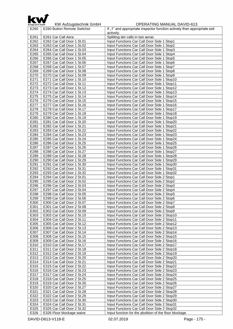
KW Aufzugstechnik GmbH OPERATING MANUAL DAVID-613
DAVID-D613-V118-E 02.07.2019 Page - 175 -
E260 E260 Button Remote Switcher If „1“ and appropriate inspector function actively then appropriate exit actively.
E261 E261 Car Call Aera Splitting der calls in two aeras
E262 E262 Car Call Door 1 St.01 Input Functions Car Call Door Side 1 Stop1
E263 E263 Car Call Door 1 St.02 Input Functions Car Call Door Side 1 Stop2 E264 E264 Car Call Door 1 St.03 Input Functions Car Call Door Side 1 Stop3 E265 E265 Car Call Door 1 St.04 Input Functions Car Call Door Side 1 Stop4 E266 E266 Car Call Door 1 St.05 Input Functions Car Call Door Side 1 Stop5 E267 E267 Car Call Door 1 St.06 Input Functions Car Call Door Side 1 Stop6 E268 E268 Car Call Door 1 St.07 Input Functions Car Call Door Side 1 Stop7 E269 E269 Car Call Door 1 St.08 Input Functions Car Call Door Side 1 Stop8 E270 E270 Car Call Door 1 St.09 Input Functions Car Call Door Side 1 Stop9 E271 E271 Car Call Door 1 St.10 Input Functions Car Call Door Side 1 Stop10 E272 E272 Car Call Door 1 St.11 Input Functions Car Call Door Side 1 Stop11 E273 E273 Car Call Door 1 St.12 Input Functions Car Call Door Side 1 Stop12 E274 E274 Car Call Door 1 St.13 Input Functions Car Call Door Side 1 Stop13 E275 E275 Car Call Door 1 St.14 Input Functions Car Call Door Side 1 Stop14 E276 E276 Car Call Door 1 St.15 Input Functions Car Call Door Side 1 Stop15 E277 E277 Car Call Door 1 St.16 Input Functions Car Call Door Side 1 Stop16 E278 E278 Car Call Door 1 St.17 Input Functions Car Call Door Side 1 Stop17 E279 E279 Car Call Door 1 St.18 Input Functions Car Call Door Side 1 Stop18 E280 E280 Car Call Door 1 St.19 Input Functions Car Call Door Side 1 Stop19 E281 E281 Car Call Door 1 St.20 Input Functions Car Call Door Side 1 Stop20 E282 E282 Car Call Door 1 St.21 Input Functions Car Call Door Side 1 Stop21 E283 E283 Car Call Door 1 St.22 Input Functions Car Call Door Side 1 Stop22 E284 E284 Car Call Door 1 St.23 Input Functions Car Call Door Side 1 Stop23 E285 E285 Car Call Door 1 St.24 Input Functions Car Call Door Side 1 Stop24 E286 E286 Car Call Door 1 St.25 Input Functions Car Call Door Side 1 Stop25 E287 E287 Car Call Door 1 St.26 Input Functions Car Call Door Side 1 Stop26 E288 E288 Car Call Door 1 St.27 Input Functions Car Call Door Side 1 Stop27 E289 E289 Car Call Door 1 St.28 Input Functions Car Call Door Side 1 Stop28 E290 E290 Car Call Door 1 St.29 Input Functions Car Call Door Side 1 Stop29 E291 E291 Car Call Door 1 St.30 Input Functions Car Call Door Side 1 Stop30 E292 E292 Car Call Door 1 St.31 Input Functions Car Call Door Side 1 Stop31 E293 E293 Car Call Door 1 St.32 Input Functions Car Call Door Side 1 Stop32 E294 E294 Car Call Door 2 St.01 Input Functions Car Call Door Side 2 Stop1
E295 E295 Car Call Door 2 St.02 Input Functions Car Call Door Side 2 Stop2 E296 E296 Car Call Door 2 St.03 Input Functions Car Call Door Side 2 Stop3 E297 E297 Car Call Door 2 St.04 Input Functions Car Call Door Side 2 Stop4 E298 E298 Car Call Door 2 St.05 Input Functions Car Call Door Side 2 Stop5 E299 E299 Car Call Door 2 St.06 Input Functions Car Call Door Side 2 Stop6 E300 E300 Car Call Door 2 St.07 Input Functions Car Call Door Side 2 Stop7 E301 E301 Car Call Door 2 St.08 Input Functions Car Call Door Side 2 Stop8 E302 E302 Car Call Door 2 St.09 Input Functions Car Call Door Side 2 Stop9 E303 E303 Car Call Door 2 St.10 Input Functions Car Call Door Side 2 Stop10 E304 E304 Car Call Door 2 St.11 Input Functions Car Call Door Side 2 Stop11 E305 E305 Car Call Door 2 St.12 Input Functions Car Call Door Side 2 Stop12 E306 E306 Car Call Door 2 St.13 Input Functions Car Call Door Side 2 Stop13 E307 E307 Car Call Door 2 St.14 Input Functions Car Call Door Side 2 Stop14 E308 E308 Car Call Door 2 St.15 Input Functions Car Call Door Side 2 Stop15 E309 E309 Car Call Door 2 St.16 Input Functions Car Call Door Side 2 Stop16 E310 E310 Car Call Door 2 St.17 Input Functions Car Call Door Side 2 Stop17 E311 E311 Car Call Door 2 St.18 Input Functions Car Call Door Side 2 Stop18 E312 E312 Car Call Door 2 St.19 Input Functions Car Call Door Side 2 Stop19 E313 E313 Car Call Door 2 St.20 Input Functions Car Call Door Side 2 Stop20 E314 E314 Car Call Door 2 St.21 Input Functions Car Call Door Side 2 Stop21 E315 E315 Car Call Door 2 St.22 Input Functions Car Call Door Side 2 Stop22 E316 E316 Car Call Door 2 St.23 Input Functions Car Call Door Side 2 Stop23 E317 E317 Car Call Door 2 St.24 Input Functions Car Call Door Side 2 Stop24 E318 E318 Car Call Door 2 St.25 Input Functions Car Call Door Side 2 Stop25 E319 E319 Car Call Door 2 St.26 Input Functions Car Call Door Side 2 Stop26 E320 E320 Car Call Door 2 St.27 Input Functions Car Call Door Side 2 Stop27 E321 E321 Car Call Door 2 St.28 Input Functions Car Call Door Side 2 Stop28 E322 E322 Car Call Door 2 St.29 Input Functions Car Call Door Side 2 Stop29 E323 E323 Car Call Door 2 St.30 Input Functions Car Call Door Side 2 Stop30 E324 E324 Car Call Door 2 St.31 Input Functions Car Call Door Side 2 Stop31 E325 E325 Car Call Door 2 St.32 Input Functions Car Call Door Side 2 Stop32 E326 E326 Floor blockage waive Input function for the abolition of the floor blockage

KW Aufzugstechnik GmbH OPERATING MANUAL DAVID-613
DAVID-D613-V118-E 02.07.2019 Page - 176 -
E327 E327 Totman Car call ON Input function for activation the car calls of a Totman controlling
E328 E328 bolt device activate Entrance for pin bolting device
E329 E329 Bolt driven out Feedback that tha bolts drove out
E330 E330 Bolt drive in Feedback that the bolt drove in
E331 E331 Resend control E/A If „ 0 „ then resend operation
E332 E332 Resend control UP If „ 1“ then UP
E333 E333 Resend control Down If „1“ than DOWN
E334 Code key of car call 1 Code- button-1
E335 Code key of car call 2 Code- button-2
E336 Code key of car call 3 Code- button-3
E337 Code key of car call 4 Code- button-4
E338 Code key of car call 5 Code- button-5
E339 Code key of car call 6 Code- button-6
E340 Code key of car call 7 Code- button-7
E341 Code key of car call 8 Code- button-8
E342 Code key of car call 9 Code- button-9
E343 Code key of car call 0 Code- button-0
E344 E344 Code lock of car calls # Input confirming
E345 E345 Light barrier Door 1 Entrance function light barrier Door 1
E346 E346 Reversing contact Door 1 Entrance function reversing Door 1
E347 E347 Limit switch open Door 1 Entrance function limit switch open Door 1 E348 E348 Limit switch close Door 1 Entrance function limit switch close Door 1 E349 E349 Light barrier Door 2 Entrance function limit barrier Door 2 E350 E350 Reversing contact Door 2 Entrance function reversing contact Door 2
E351 E351 Limit switch open Door 2 Entrance function limit switch open Door 2 E352 E352 Limit switch close Door 2 Entrance function limit switch close Door 2 E353 E353 Case of fire reset Function of the Swiss fire drop evacuation, BF-> normal operation
E354 E354 floor gong off Function for external switching of the floor gong, high gong off
E355 E355 position motor off (Hydr OTIS) Switch off for position motors of OTIS hydraulic
E356 E356-Contactor Monitor No.2 Is a AND contection with Input E13
E357 E357 Group off
E358 E358 Emgine temperature rise If „1“ than OK
E359 E359 Door 1 open If „1“ then the door opens (Auxiliary entrance for traffic light circuit)
E360 E360 Door 2 open If „1“ then the door opens (Auxiliary entrance for traffic light circuit)
E361 E361 slowly drive V1 If „1“ then drives elevator only with V1
E362 E362-Control & Light off #2 Rest-Driven, like E16
E363 E363 Gas trip If „ but wait 1 „ then gas trip, like interior preference/ advantage to light barrier
E364 E364 Bolt manually drive in Only with Insp/ releveling+ mobile bolting device
E365 E365 Bolt manually drive out Only with Insp/ releveling+ mobile bolting device
E366 E366 Bolt Under pressure If „ 0 „ then negative pressure
E367 E367 Bolt pressure swich off If „0 „ then negative pressure
E368 E368 Call Blockade Inside D1 St.01
E369 E369 Call Blockade Inside D1 St.01
E370 E370 Call Blockade Inside D1 St.01
E371 E371Call Blockade Inside D1 St.01
E372 E372Call Blockade Inside D1 St.01
E373 E373Call Blockade Inside D1 St.01
E374 E374Call Blockade Inside D1 St.01
E375 E375Call Blockade Inside D1 St.01
E376 E376Call Blockade Inside D1 St.01
E377 E377Call Blockade Inside D1 St.01
E378 E378Call Blockade Inside D1 St.01
E379 E379Call Blockade Inside D1 St.01
E380 E380Call Blockade Inside D1 St.01
E381 E381Call Blockade Inside D1 St.01
E382 E382Call Blockade Inside D1 St.01
E383 E383Call Blockade Inside D1 St.01
E384 E384Call Blockade Inside D2 St.01
E385 E385Call Blockade Inside D2 St.02
E386 E386Call Blockade Inside D2 St.03
E387 E387Call Blockade Inside D2 St.04
E388 E388Call Blockade Inside D2 St.05
E389 E389Call Blockade Inside D2 St.06
E390 E390Call Blockade Inside D2 St.07
E391 E391Call Blockade Inside D2 St.08
E392 E392Call Blockade Inside D2 St.09
E393 E393Call Blockade Inside D2 St.10

KW Aufzugstechnik GmbH OPERATING MANUAL DAVID-613
DAVID-D613-V118-E 02.07.2019 Page - 177 -
E394 E394Call Blockade Inside D2 St.11
E395 E395Call Blockade Inside D2 St.12
E396 E396Call Blockade Inside D2 St.13
E397 E397Call Blockade Inside D2 St.14
E398 E398Call Blockade Inside D2 St.15
E399 E399Call Blockade Inside D2 St.16
E400 E400Call Blockade Outside D1St.01
E401 E401Call Blockade Outside D1 St.02
E402 E400Call Blockade Outside D1 St.03
E403 E403Call Blockade Outside D1 St.04
E404 E404Call Blockade Outside D1 St.05
E405 E405Call Blockade Outside D1 St.06
E406 E406Call Blockade Outside D1 St.07
E407 E407Call Blockade Outside D1 St.08
E408 E408Call Blockade Outside D1 St.09
E409 E409Call Blockade Outside D1 St.10
E410 E410Call Blockade Outside D1 St.11
E411 E411Call Blockade Outside D1 St.12
E412 E412Call Blockade Outside D1 St.13
E413 E413Call Blockade Outside D1 St.14
E414 E414Call Blockade Outside D1 St.15
E415 E415Call Blockade Outside D1 St.16
E416 E416Call Blockade Outside D2 St.01
E417 E417Call Blockade Outside D2 St.02
E418 E418Call Blockade Outside D2 St.03
E419 E419Call Blockade Outside D2 St.04
E420 E420Call Blockade Outside D2 St.05
E421 E421Call Blockade Outside D2 St.06
E422 E422Call Blockade Outside D2 St.07
E423 E423Call Blockade Outside D2 St.08
E424 E424Call Blockade Outside D2 St.09
E425 E425Call Blockade Outside D2 St.10
E426 E426Call Blockade Outside D2 St.11
E427 E427Call Blockade Outside D2 St.12
E428 E428Call Blockade Outside D2 St.13
E429 E429Call Blockade Outside D2 St.14
E430 E430Call Blockade Outside D2 St.15
E431 E431Call Blockade Outside D2 St.16
E432 E432 Pahse reversal monitoring If „1“ ok, if “0” then errors
E433 E433 Brake- & Blockvoltage If „1“ ok, if “0” then errors
E434 E433 Less pressure If „1“ ok, if “0” then errors
E435 E435 Landing call off During active entrance to ER is switched off external control
E436 E436 LED matrix out of operation During active entrance LED matrix becomes to ER powr down
E437 E437 Car Person Senor
E438 E438 Brake open monitor 2. coil
E439 E439 Brake open monitor 3. coil
E440 E440 Car Elevator Photocell D1 Car Elevator Photocell in the car for Car position
E441 E441 Car Elevator Photocell D2 Car Elevator Photocell in the car for Car position E442 E442 Car Elevator Photocell Middle Car Elevator Photocell in the car for Car position E443 E443- Lobbymonitor D1-F 01
E444 E444- Lobbymonitor D1-F 02
E445 E445- Lobbymonitor D1-F 03
E446 E446- Lobbymonitor D1-F 04
E447 E447- Lobbymonitor D1-F 05
E448 E448- Lobbymonitor D1-F 06
E449 E449- Lobbymonitor D1-F 07
E450 E450- Lobbymonitor D1-F 08
E451 E451- Lobbymonitor D2-F 01
E452 E452- Lobbymonitor D2-F 02
E453 E453- Lobbymonitor D2-F 03
E454 E454- Lobbymonitor D2-F 04
E455 E455- Lobbymonitor D2-F 05
E456 E456- Lobbymonitor D2-F 06
E457 E457- Lobbymonitor D2-F 07
E458 E458- Lobbymonitor D2-F08
E459 E459-Controlercabinet Door Open High signal, if the door is open
E460 E460 Controlercabinet Door Open Invers
Low signal, if the door is open

KW Aufzugstechnik GmbH OPERATING MANUAL DAVID-613
DAVID-D613-V118-E 02.07.2019 Page - 178 -
E461 E461 Startdelay UP High signal for Waiting (Door Open Command)
E462 E462 Battery-evacuation Normal Travel with Battery / USV are possible
E463 E463 Attendant Mode ON If there is a pulse, then switch ON
E464 E464 Attendant Mode OFF If there is a pulse, then switch OFF
E465 E465 Attendant Mode UP During the High signal, the door is closing and after that ist starts up.
E466 E466 Attendant Mode DOWN During the High signal, the door is closing and after that ist starts down.
E467 E467 Attendant Mode Land.Con.Off Toggle-Input for switching off the landing Control
E468 E468 Send Controler When the input is high, then Send-Controlling
E469 E469 Reset all calls When "1" then all adjacent calls cleared
E470 E470 Door Slice-OFF When "1" then the door lock function is turned off, if active
E471 E471 Flash Output Highsignal for the Blink Output
E472 E472 Release Door
E473 E473 Flap COP
E474 E474 Main Contactor No. Additional contactor monitoring chain via normally open contacts
E475 E 475 Rope Stretching By using the Weight Watcher Henning loadmeasuresystems the error rope stretching can be evaluated by the controller.
E476 E 476 Startdelay UP & Down Function for the Acceleration
E477 E 477 Deadman Mode If the input is active the controller is transferred to the dead man mode.
E478 E478 Universal-input -5 Input for Universal-Output-5
E479 E479 Universal-input –6 Input for Universal-Output -6
E480 E480 Universal-input –7 Input for Universal-Output -7
E481 E481 Universal-input –8 Input for Universal-Output -8
E482 E482 Universal-input –9 Input for Universal-Output -9
E483 E483 Universal-input –10 Input for Universal-Output -10
E484 E484 Universal-input -11 Input for Universal-Output -11
E485 E485 Universal-input –12 Input for Universal-Output -12
E486 E486 Universal-input –13 Input for Universal-Output -13
E487 E487 Universal-input -14 Input for Universal-Output -14
E488 E488 Universal-input -15 Input for Universal-Output -15
E489 E489 Timerrelay 1 Reset Input for Reset the timerelay 1
E490 E490 Timerrelay 2 Reset Input for Reset the timerelay 2
E491 E491 Floorcalls OFF Landing calls are not accepted
E492 E492 Temerature Heat Travel Thermostat input for the heating function
E493 E493 UCM Status 1 Input channel for the EN81-A3 Function for UCM-Status 1
E494 E494 UCM Status 2 Input channel for the EN81-A3 Function for UCM-Status 2
E495 E495 UCM Status 3 Input channel for the EN81-A3 Function for UCM-Status 3
E496 E496 TV60-1 Synchronous monitoring channel 1 of the TV60-1
E497 E497 TV60-2 Synchronous monitoring channel 2 of the TV60-1
E498 E498 OSKAR Release FRAPORT – Safety system OSKAR
E499 E498 OSKAR Wait FRAPORT – Safety system OSKAR E500 E500 OSKAR Block FRAPORT – Safety system OSKAR E501 E501 OSKAR OFF FRAPORT – Safety system OSKAR E502 E502 Parking Fill When the level is „1“ then the fill-operation is active.
E503 E503 Parking Empty When the level is „1“ then the empty-operation is active.
E504 E504 TV60-3 Synchronous monitoring channel 1 of the TV60-2
E505 E505 TV60-4 Synchronous monitoring channel 2 of the TV60-2
E506 E506 RESET Brake monitoring Possibility of external reset during braking control elements and A3 case.
E507 E507 Batterymonitoring 1 Monitoring of the battery of EOS or other units
E508 E508 Batterymonitoring 2 Monitoring of the battery of EOS or other units
E509 E509 Rubber Skirt Function for Monitoring the rubber skirt
E510 E510 Fire Sensor Floor 01 Door 2 Input for Fire Evaquation - Fire Sensor Floor 01 Door 2
E511 E511 Fire Sensor Floor 02 Door 2 Input for Fire Evaquation - Fire Sensor Floor 02 Door 2
E512 E512 Fire Sensor Floor 03 Door 2 Input for Fire Evaquation - Fire Sensor Floor 03 Door 2
E513 E513 Fire Sensor Floor 04 Door 2 Input for Fire Evaquation - Fire Sensor Floor 04 Door 2
E514 E514 Fire Sensor Floor 05 Door 2 Input for Fire Evaquation - Fire Sensor Floor 05 Door 2
E515 E515 Fire Sensor Floor 06 Door 2 Input for Fire Evaquation - Fire Sensor Floor 06 Door 2
E516 E516 Fire Sensor Floor 07 Door 2 Input for Fire Evaquation - Fire Sensor Floor 07 Door 2
E517 E517 Fire Sensor Floor 08 Door 2 Input for Fire Evaquation - Fire Sensor Floor 08 Door 2
E518 E518 Door 1 Manual Opening Input channel for Door 1 Manual Opening
E519 E519 Door 1 Manual Closing Input channel for Door 1 Manual Closing
E520 E520 Door 2 Manual Opening Input channel for Door 2 Manual Opening
E521 E521 Door 2 Manual Closing Input channel for Door 2 Manual Closing
E522 E522 Hazardous Transport Off Input function to switch off the Hazardous Transport
E523 E523 Reset Door is Ready Input channel for Reset funktion Door is Ready
E524 E524 Quickstart Monitor Input channel for monitoring the relay function of K69
E525 E525 Car Light Sensor Input channel for the car light sensor to monitor the car light
E526 E526 Car Preference Call Pulse

KW Aufzugstechnik GmbH OPERATING MANUAL DAVID-613
DAVID-D613-V118-E 02.07.2019 Page - 179 -
E527 E527 Car Preference Call Release
E528 E528 Inspection E-A 68 Inspection ON / OFF in the pit, „0“=ON / „1“ = OFF
E529 E529 Inspection UP 68A Inspection UP in the pit, „1“ = UP
E530 E531 Inspection DOWN 68B Inspection DOWN in the pit, „1“ = DOWN
E531 E532 Inspection FAST 68C Inspection Schnelltaster in the pit, „1“ = FAST
E532 E532 Inspection Pit: Reset Reset fort he Shaft-Door Bottom (EN81-20/50) „1“ = Reset
E533 E533 Automatic Car-Call If the level is „1“, than the automatic Car-Call is OFF in the Menü B21
E534 E534 Puls Energy Counterlevel Energy-Counter is increasing for 1 KWh
E535 E535 Puls Recover Energy Counterlevel Recover Energy-Counter is increasing for 1 KWh
E536 E536 Overvoltage Monitor If the level is „1“, than there is Message Overvoltage of the Monitoring
E537 E537 Fan Monitor If the level is „0“, than Errormessage of the Cabinet-fan
E538 E538 Light Monitor If the level is „0“, than Errormessage of the Carlight ( One Light is Out-of-order)
E539 E539 Doorstep-Heating-1 If the level is „0“, than Error
E540 E540 Doorstep-Heating -2 If the level is „0“, than Error
E541 E541 Doorstep-Heating -3 If the level is „0“, than Error
E542 E542 Doorstep-Heating -4 If the level is „0“, than Error
E543 E543 Electric Socket Monitoring If the level is „0“, than Error
E544 E444 Fan Monitoring Active If the level is „1“,than Monitoring-function E537 is active
E545 E545 Carfan Monitoring If the level is „0“, than Error
E546 E546 Carfan Monitoring Active If the level is „1“, than Monitoring-function E545 is active
E547 E547-Controler & Light OFF-3 Like Standby travel E16, but with errormessage
E548 E548- Controler & Light OFF t Aus-4 Like Standby travel E362, but with errormessage
E549 E549-USV-System If the level is „1“, than ok
E550 E550-USV Accu If the level is „1“, than ok
E551 E551 FF CarCall Reset FireFighter: Erase the Carcalls (FW-Düsseldorf)
E552 E552 Car call D1-HS33
E553 E553 Car call D1-HS34
E554 E554 Car call D1-HS35
E555 E555 Car call D1-HS36
E556 E556 Car call D1-HS37
E557 E557 Car call D1-HS38
E558 E558 Car call D1-HS39
E559 E559 Car call D1-HS40
E560 E560 Car call D1-HS41
E561 E561 Car call D1-HS42
E562 E562 Car call D1-HS43
E563 E563 Car call D1-HS44
E564 E564 Car call D1-HS45
E565 E565 Car call D1-HS46
E566 E566 Car call D1-HS47
E567 E567 Car call D1-HS48
E568 E568 Car call D1-HS49
E569 E569 Car call D1-HS50
E570 E570 Car call D1-HS51
E571 E571 Car call D1-HS52
E572 E572 Car call D1-HS53
E573 E573 Car call D1-HS54
E574 E574 Car call D1-HS55
E575 E575 Car call D1-HS56
E576 E576 Car call D1-HS57
E577 E577 Car call D1-HS58
E578 E578 Car call D1-HS59
E579 E579 Car call D1-HS60
E580 E580 Car call D1-HS61
E581 E581 Car call D1-HS62
E582 E582 Car call D1-HS63
E583 E583 Car call D1-HS64
E584 E584 Car call D2-HS33
E585 E585 Car call D2-HS34
E586 E586 Car call D2-HS35
E587 E587 Car call D2-HS36
E588 E588 Car call D2-HS37
E589 E589 Car call D2-HS38
E590 E590 Car call D2-HS39
E591 E591 Car call D2-HS40
E592 E592 Car call D2-HS41
E593 E593 Car call D2-HS42
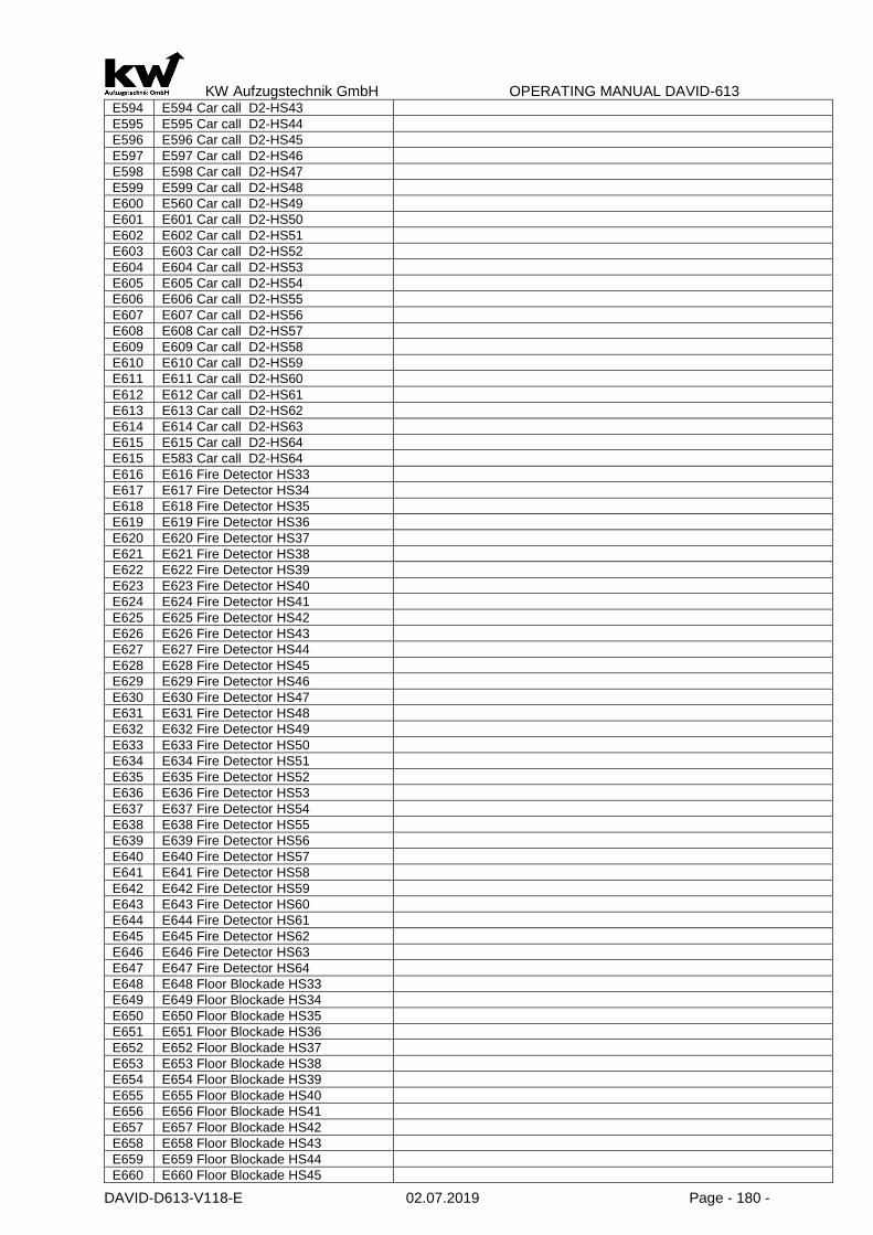
KW Aufzugstechnik GmbH OPERATING MANUAL DAVID-613
DAVID-D613-V118-E 02.07.2019 Page - 180 -
E594 E594 Car call D2-HS43
E595 E595 Car call D2-HS44
E596 E596 Car call D2-HS45
E597 E597 Car call D2-HS46
E598 E598 Car call D2-HS47
E599 E599 Car call D2-HS48
E600 E560 Car call D2-HS49
E601 E601 Car call D2-HS50
E602 E602 Car call D2-HS51
E603 E603 Car call D2-HS52
E604 E604 Car call D2-HS53
E605 E605 Car call D2-HS54
E606 E606 Car call D2-HS55
E607 E607 Car call D2-HS56
E608 E608 Car call D2-HS57
E609 E609 Car call D2-HS58
E610 E610 Car call D2-HS59
E611 E611 Car call D2-HS60
E612 E612 Car call D2-HS61
E613 E613 Car call D2-HS62
E614 E614 Car call D2-HS63
E615 E615 Car call D2-HS64
E615 E583 Car call D2-HS64
E616 E616 Fire Detector HS33
E617 E617 Fire Detector HS34
E618 E618 Fire Detector HS35
E619 E619 Fire Detector HS36
E620 E620 Fire Detector HS37
E621 E621 Fire Detector HS38
E622 E622 Fire Detector HS39
E623 E623 Fire Detector HS40
E624 E624 Fire Detector HS41
E625 E625 Fire Detector HS42
E626 E626 Fire Detector HS43
E627 E627 Fire Detector HS44
E628 E628 Fire Detector HS45
E629 E629 Fire Detector HS46
E630 E630 Fire Detector HS47
E631 E631 Fire Detector HS48
E632 E632 Fire Detector HS49
E633 E633 Fire Detector HS50
E634 E634 Fire Detector HS51
E635 E635 Fire Detector HS52
E636 E636 Fire Detector HS53
E637 E637 Fire Detector HS54
E638 E638 Fire Detector HS55
E639 E639 Fire Detector HS56
E640 E640 Fire Detector HS57
E641 E641 Fire Detector HS58
E642 E642 Fire Detector HS59
E643 E643 Fire Detector HS60
E644 E644 Fire Detector HS61
E645 E645 Fire Detector HS62
E646 E646 Fire Detector HS63
E647 E647 Fire Detector HS64
E648 E648 Floor Blockade HS33
E649 E649 Floor Blockade HS34
E650 E650 Floor Blockade HS35
E651 E651 Floor Blockade HS36
E652 E652 Floor Blockade HS37
E653 E653 Floor Blockade HS38
E654 E654 Floor Blockade HS39
E655 E655 Floor Blockade HS40
E656 E656 Floor Blockade HS41
E657 E657 Floor Blockade HS42
E658 E658 Floor Blockade HS43
E659 E659 Floor Blockade HS44
E660 E660 Floor Blockade HS45

KW Aufzugstechnik GmbH OPERATING MANUAL DAVID-613
DAVID-D613-V118-E 02.07.2019 Page - 181 -
E661 E661 Etagensperrung HS46
E662 E662 Floor Blockade HS47
E663 E663 Floor Blockade HS48
E664 E664 Floor Blockade HS49
E665 E665 Floor Blockade HS50
E666 E666 Floor Blockade HS51
E667 E667 Floor Blockade HS52
E668 E668 Floor Blockade HS53
E669 E669 Floor Blockade HS54
E670 E677 Floor Blockade HS55
E671 E671 Floor Blockade HS56
E672 E672 Floor Blockade HS57
E673 E673 Floor Blockade HS58
E674 E674 Floor Blockade HS59
E675 E675 Floor Blockade HS60
E676 E676 Floor Blockade HS61
E677 E677 Floor Blockade HS62
E678 E678 Floor Blockade HS63
E679 E679 Floor Blockade HS64
E680 E680 Parking Floor HS33
E681 E681 Parking Floor HS34
E682 E682 Parking Floor HS35
E683 E683 Parking Floor HS36
E684 E684 Parking Floor HS37
E685 E685 Parking Floor HS38
E686 E686 Parking Floor HS39
E687 E687 Parking Floor HS40
E688 E688 Parking Floor HS41
E689 E689 Parking Floor HS42
E690 E690 Parking Floor HS43
E691 E691 Parking Floor HS44
E692 E692 Parking Floor HS45
E693 E693 Parking Floor HS46
E694 E694 Parking Floor HS47
E695 E695 Parking Floor HS48
E696 E696 Parking Floor HS49
E697 E697 Parking Floor HS50
E698 E698 Parking Floor HS51
E699 E699 Parking Floor HS52
E700 E700 Parking Floor HS53
E701 E701 Parking Floor HS54
E702 E702 Parking Floor HS55
E703 E703 Parking Floor HS56
E704 E704 Parking Floor HS57
E705 E705 Parking Floor HS58
E706 E706 Parking Floor HS59
E707 E707 Parking Floor HS60
E708 E708 Parking Floor HS61
E709 E709 Parking Floor HS62
E710 E710 Parking Floor HS63
E711 E711 Parking Floor HS64
E712 E712 Vmax-UP = V1 If the Bit is „0“ than the speed will reduced to V1
E713 E713 Vmax-Down = V1 If the Bit is „0“ than the speed will reduced to V1
E714 E714 Hotelzwangshalt-aus If „1“ then the function Hotelstop is not active
E715 E715 AW60-Überwachung If „0“ then error
E716 E716 S69 Bypass aktiv If „0“ then active
E717 E717 Überdruck If „0“ then error
E718 E718 Notrufüberwachung If „0“ then error
E719 E719 Bed-travel If "1" then output message "bed travel" instead of "special trip" with inner ad-vantage. Active, as long as the internal advantage is active, even if E719 is no longer present.
E720 E720 Sabbat control If „1“ then prepareing the Sabbat-control
E721 E721 Sabbattimer If „1“ then Sabbat-control active
E722 E722 Ramp 30° open Scanclimber
E723 E723 Ramp open Scanclimber
E724 E724 Ramp closed Scanclimber
E725 E725 Ramp manual Operation Scanclimber
E726 E726 Ramp manuell öffnen Scanclimber

KW Aufzugstechnik GmbH OPERATING MANUAL DAVID-613
DAVID-D613-V118-E 02.07.2019 Page - 182 -
E727 E727 Ramp manuell schliessen Scanclimber
E728 E728 Stopp next Floor Scanclimber
E729 E729 Motorprotection Scanclimber
E730 E730 Inspection message There is the possibility to initiate a ramp drive -0 during the interruption of the in-
spection trip. E731 E731 Vorraumüberwachung Türe-3 Eingang Vorraumüberwachung Türe 3 Über Kabinentüre
E732 E732 Taster Türe-3 AUF Eingang für Taster AUF Tür 3
E733 E733 Taster Türe-3 ZU Eingang für Taster ZU Tür 3 E734 E734 Ladezeittaster Türe-3 Eingang für Taster Ladezeit Tür 3 E735 E735 Lichtschranke Türe-3 Eingang für Lichtschranke Tür 3 E736 E736 Reversierkontakt Türe-3 Eingang für Reverierkontakt Tür 3 E737 E737 Endschalter AUF Türe-3 Eingang für Endschalter Tür AUF Tür 3 E738 E738 Endschalter ZU Türe-3 Eingang für Endschalter Tür ZU Tür 3 E739 E739-Tür-3 manuell AUF Eingang für Taster Tür AUF Manuel Tür 3 E740 E740-Tür-3 manuell ZU Eingang für Taster Tür ZU Manuel Tür 3 E741 E741-Penthaus-1 Anholung Besucher
E742 E742-Penthaus-1 Anholung Penthaus
E743 E743-Penthaus-1 Anholung Aussen
E744 E744-Penthaus-2 Anholung Besucher
E745 E745-Penthaus-2 Anholung Penthaus
E746 E746-Penthaus-2 Anholung Aussen
E747 E747-Penthaus-3 Anholung Besucher
E748 E748-Penthaus-3 Anholung Penthaus
E749 E749-Penthaus-3 Anholung Aussen
E750 E750-Penthaus-4 Anholung Besucher
E751 E751-Penthaus-4 Anholung Penthaus
E752 E752-Penthaus-4 Anholung Aussen
E753 E753-Penthaus-5 Anholung Besucher
E754 E754-Penthaus-5 Anholung Penthaus
E755 E755-Penthaus-5 Anholung Aussen
E756 E756-Penthaus-6 Anholung Besucher
E757 E757-Penthaus-6 Anholung Penthaus
E758 E758-Penthaus-6 Anholung Aussen
E759 E759-Penthaus-7 Anholung Besucher
E760 E760-Penthaus-7 Anholung Penthaus
E761 E761-Penthaus-7 Anholung Aussen
E762 E762-Penthaus-8 Anholung Besucher
E763 E763-Penthaus-8 Anholung Penthaus
E764 E764-Penthaus-8 Anholung Aussen
E765 E765-Rufsperrung Innenruf T1 HS17 Sperrung des Innenrufes der Türseite-1 – Haltestelle 17
E766 E766-Rufsperrung Innenruf T1 HS18 Sperrung des Innenrufes der Türseite-1 – Haltestelle 18
E767 E767-Rufsperrung Innenruf T1 HS19 Sperrung des Innenrufes der Türseite-1 – Haltestelle 19
E768 E768-Rufsperrung Innenruf T1 HS20 Sperrung des Innenrufes der Türseite-1 – Haltestelle 20
E769 E769-Rufsperrung Innenruf T1 HS21 Sperrung des Innenrufes der Türseite-1 – Haltestelle 21
E770 E770-Rufsperrung Innenruf T1 HS22 Sperrung des Innenrufes der Türseite-1 – Haltestelle 22
E771 E771-Rufsperrung Innenruf T1 HS23 Sperrung des Innenrufes der Türseite-1 – Haltestelle 23
E772 E772-Rufsperrung Innenruf T1 HS24 Sperrung des Innenrufes der Türseite-1 – Haltestelle 24
E773 E773-Rufsperrung Innenruf T1 HS25 Sperrung des Innenrufes der Türseite-1 – Haltestelle 25
E774 E774-Rufsperrung Innenruf T1 HS26 Sperrung des Innenrufes der Türseite-1 – Haltestelle 26
E775 E775-Rufsperrung Innenruf T1 HS27 Sperrung des Innenrufes der Türseite-1 – Haltestelle 27
E776 E776-Rufsperrung Innenruf T1 HS28 Sperrung des Innenrufes der Türseite-1 – Haltestelle 28
E777 E777-Rufsperrung Innenruf T1 HS29 Sperrung des Innenrufes der Türseite-1 – Haltestelle 29
E778 E778-Rufsperrung Innenruf T1 HS30 Sperrung des Innenrufes der Türseite-1 – Haltestelle 30
E779 E779-Rufsperrung Innenruf T1 HS31 Sperrung des Innenrufes der Türseite-1 – Haltestelle 31 E780 E780-Rufsperrung Innenruf T1 HS32 Sperrung des Innenrufes der Türseite-1 – Haltestelle 32 E781 E781-Rufsperrung Innenruf T1 HS33 Sperrung des Innenrufes der Türseite-1 – Haltestelle 33 E782 E782-Rufsperrung Innenruf T1 HS34 Sperrung des Innenrufes der Türseite-1 – Haltestelle 34 E783 E783-Rufsperrung Innenruf T1 HS35 Sperrung des Innenrufes der Türseite-1 – Haltestelle 35 E784 E784-Rufsperrung Innenruf T1 HS36 Sperrung des Innenrufes der Türseite-1 – Haltestelle 36 E785 E785-Rufsperrung Innenruf T1 HS37 Sperrung des Innenrufes der Türseite-1 – Haltestelle 37 E786 E786-Rufsperrung Innenruf T1 HS38 Sperrung des Innenrufes der Türseite-1 – Haltestelle 38 E787 E787-Rufsperrung Innenruf T1 HS39 Sperrung des Innenrufes der Türseite-1 – Haltestelle 39 E788 E788-Rufsperrung Innenruf T1 HS40 Sperrung des Innenrufes der Türseite-1 – Haltestelle 40 E789 E789-Rufsperrung Innenruf T1 HS41 Sperrung des Innenrufes der Türseite-1 – Haltestelle 41 E790 E790-Rufsperrung Innenruf T1 HS42 Sperrung des Innenrufes der Türseite-1 – Haltestelle 42 E791 E791-Rufsperrung Innenruf T1 HS43 Sperrung des Innenrufes der Türseite-1 – Haltestelle 43 E792 E792-Rufsperrung Innenruf T1 HS44 Sperrung des Innenrufes der Türseite-1 – Haltestelle 44 E793 E793-Rufsperrung Innenruf T1 HS45 Sperrung des Innenrufes der Türseite-1 – Haltestelle 45

KW Aufzugstechnik GmbH OPERATING MANUAL DAVID-613
DAVID-D613-V118-E 02.07.2019 Page - 183 -
E794 E794-Rufsperrung Innenruf T1 HS46 Sperrung des Innenrufes der Türseite-1 – Haltestelle 46 E795 E795-Rufsperrung Innenruf T1 HS47 Sperrung des Innenrufes der Türseite-1 – Haltestelle 47 E796 E796-Rufsperrung Innenruf T1 HS48 Sperrung des Innenrufes der Türseite-1 – Haltestelle 48 E797 E797-Rufsperrung Innenruf T1 HS49 Sperrung des Innenrufes der Türseite-1 – Haltestelle 49 E798 E798-Rufsperrung Innenruf T1 HS50 Sperrung des Innenrufes der Türseite-1 – Haltestelle 50 E799 E799-Rufsperrung Innenruf T1 HS51 Sperrung des Innenrufes der Türseite-1 – Haltestelle 51 E800 E800-Rufsperrung Innenruf T1 HS52 Sperrung des Innenrufes der Türseite-1 – Haltestelle 52 E801 E801-Rufsperrung Innenruf T1 HS53 Sperrung des Innenrufes der Türseite-1 – Haltestelle 53
E802 E802-Rufsperrung Innenruf T1 HS54 Sperrung des Innenrufes der Türseite-1 – Haltestelle 54
E803 E803-Rufsperrung Innenruf T1 HS55 Sperrung des Innenrufes der Türseite-1 – Haltestelle 55
E804 E804-Rufsperrung Innenruf T1 HS56 Sperrung des Innenrufes der Türseite-1 – Haltestelle 56
E805 E805-Rufsperrung Innenruf T1 HS57 Sperrung des Innenrufes der Türseite-1 – Haltestelle 57
E806 E806-Rufsperrung Innenruf T1 HS58 Sperrung des Innenrufes der Türseite-1 – Haltestelle 58
E807 E807-Rufsperrung Innenruf T1 HS59 Sperrung des Innenrufes der Türseite-1 – Haltestelle 59
E808 E808-Rufsperrung Innenruf T1 HS60 Sperrung des Innenrufes der Türseite-1 – Haltestelle 60
E809 E809-Rufsperrung Innenruf T1 HS61 Sperrung des Innenrufes der Türseite-1 – Haltestelle 61
E810 E810-Rufsperrung Innenruf T1 HS62 Sperrung des Innenrufes der Türseite-1 – Haltestelle 62
E811 E811-Rufsperrung Innenruf T1 HS63 Sperrung des Innenrufes der Türseite-1 – Haltestelle 63
E812 E812-Rufsperrung Innenruf T1 HS64 Sperrung des Innenrufes der Türseite-1 – Haltestelle 64
E813 E813-Rufsperrung Innenruf T2 HS17 Sperrung des Innenrufes der Türseite-2 – Haltestelle 17
E814 E814-Rufsperrung Innenruf T2 HS18 Sperrung des Innenrufes der Türseite-2 – Haltestelle 18
E815 E815-Rufsperrung Innenruf T2 HS19 Sperrung des Innenrufes der Türseite-2 – Haltestelle 19
E816 E816-Rufsperrung Innenruf T2 HS20 Sperrung des Innenrufes der Türseite-2 – Haltestelle 20
E817 E817-Rufsperrung Innenruf T2 HS21 Sperrung des Innenrufes der Türseite-2 – Haltestelle 21
E818 E818-Rufsperrung Innenruf T2 HS22 Sperrung des Innenrufes der Türseite-2 – Haltestelle 22
E819 E819-Rufsperrung Innenruf T2 HS23 Sperrung des Innenrufes der Türseite-2 – Haltestelle 23
E820 E820-Rufsperrung Innenruf T2 HS24 Sperrung des Innenrufes der Türseite-2 – Haltestelle 24
E821 E821-Rufsperrung Innenruf T2 HS25 Sperrung des Innenrufes der Türseite-2 – Haltestelle 25
E822 E822-Rufsperrung Innenruf T2 HS26 Sperrung des Innenrufes der Türseite-2 – Haltestelle 26
E823 E823-Rufsperrung Innenruf T2 HS27 Sperrung des Innenrufes der Türseite-2 – Haltestelle 27
E824 E824-Rufsperrung Innenruf T2 HS28 Sperrung des Innenrufes der Türseite-2 – Haltestelle 28
E825 E825-Rufsperrung Innenruf T2 HS29 Sperrung des Innenrufes der Türseite-2 – Haltestelle 29
E826 E826-Rufsperrung Innenruf T2 HS30 Sperrung des Innenrufes der Türseite-2 – Haltestelle 30
E827 E827-Rufsperrung Innenruf T2 HS31 Sperrung des Innenrufes der Türseite-2 – Haltestelle 31 E828 E828-Rufsperrung Innenruf T2 HS32 Sperrung des Innenrufes der Türseite-2 – Haltestelle 32 E829 E829-Rufsperrung Innenruf T2 HS33 Sperrung des Innenrufes der Türseite-2 – Haltestelle 33 E830 E830-Rufsperrung Innenruf T2 HS34 Sperrung des Innenrufes der Türseite-2 – Haltestelle 34 E831 E831-Rufsperrung Innenruf T2 HS35 Sperrung des Innenrufes der Türseite-2 – Haltestelle 35 E832 E832-Rufsperrung Innenruf T2 HS36 Sperrung des Innenrufes der Türseite-2 – Haltestelle 36 E833 E833-Rufsperrung Innenruf T2 HS37 Sperrung des Innenrufes der Türseite-2 – Haltestelle 37 E834 E834-Rufsperrung Innenruf T2 HS38 Sperrung des Innenrufes der Türseite-2 – Haltestelle 38 E835 E835-Rufsperrung Innenruf T2 HS39 Sperrung des Innenrufes der Türseite-2 – Haltestelle 39 E836 E836-Rufsperrung Innenruf T2 HS40 Sperrung des Innenrufes der Türseite-2 – Haltestelle 40 E837 E837-Rufsperrung Innenruf T2 HS41 Sperrung des Innenrufes der Türseite-2 – Haltestelle 41 E838 E838-Rufsperrung Innenruf T2 HS42 Sperrung des Innenrufes der Türseite-2 – Haltestelle 42 E839 E839-Rufsperrung Innenruf T2 HS43 Sperrung des Innenrufes der Türseite-2 – Haltestelle 43 E840 E840-Rufsperrung Innenruf T2 HS44 Sperrung des Innenrufes der Türseite-2 – Haltestelle 44 E841 E841-Rufsperrung Innenruf T2 HS45 Sperrung des Innenrufes der Türseite-2 – Haltestelle 45 E842 E842-Rufsperrung Innenruf T2 HS46 Sperrung des Innenrufes der Türseite-2 – Haltestelle 46 E843 E843-Rufsperrung Innenruf T2 HS47 Sperrung des Innenrufes der Türseite-2 – Haltestelle 47 E844 E844-Rufsperrung Innenruf T2 HS48 Sperrung des Innenrufes der Türseite-2 – Haltestelle 48 E845 E845-Rufsperrung Innenruf T2 HS49 Sperrung des Innenrufes der Türseite-2 – Haltestelle 49 E846 E846-Rufsperrung Innenruf T2 HS50 Sperrung des Innenrufes der Türseite-2 – Haltestelle 50 E847 E847-Rufsperrung Innenruf T2 HS51 Sperrung des Innenrufes der Türseite-2 – Haltestelle 51 E848 E848-Rufsperrung Innenruf T2 HS52 Sperrung des Innenrufes der Türseite-2 – Haltestelle 52 E849 E849-Rufsperrung Innenruf T2 HS53 Sperrung des Innenrufes der Türseite-2 – Haltestelle 53
E850 E850-Rufsperrung Innenruf T2 HS54 Sperrung des Innenrufes der Türseite-2 – Haltestelle 54
E851 E851-Rufsperrung Innenruf T2 HS55 Sperrung des Innenrufes der Türseite-2 – Haltestelle 55
E852 E852-Rufsperrung Innenruf T2 HS56 Sperrung des Innenrufes der Türseite-2 – Haltestelle 56
E853 E853-Rufsperrung Innenruf T2 HS57 Sperrung des Innenrufes der Türseite-2 – Haltestelle 57
E854 E854-Rufsperrung Innenruf T2 HS58 Sperrung des Innenrufes der Türseite-2 – Haltestelle 58
E855 E855-Rufsperrung Innenruf T2 HS59 Sperrung des Innenrufes der Türseite-2 – Haltestelle 59
E856 E856-Rufsperrung Innenruf T2 HS60 Sperrung des Innenrufes der Türseite-2 – Haltestelle 60
E857 E857-Rufsperrung Innenruf T2 HS61 Sperrung des Innenrufes der Türseite-2 – Haltestelle 61
E858 E858-Rufsperrung Innenruf T2 HS62 Sperrung des Innenrufes der Türseite-2 – Haltestelle 62
E859 E859-Rufsperrung Innenruf T2 HS63 Sperrung des Innenrufes der Türseite-2 – Haltestelle 63
E860 E860-Rufsperrung Innenruf T2 HS64 Sperrung des Innenrufes der Türseite-2 – Haltestelle 64
E861 E861-Rufsperrung Außenruf T1 HS17 Sperrung des Außenrufes der Türseite-1 – Haltestelle 17

KW Aufzugstechnik GmbH OPERATING MANUAL DAVID-613
DAVID-D613-V118-E 02.07.2019 Page - 184 -
E862 E862-Rufsperrung Außenruf T1 HS18 Sperrung des Außenrufes der Türseite-1 – Haltestelle 18
E863 E863-Rufsperrung Außenruf T1 HS19 Sperrung des Außenrufes der Türseite-1 – Haltestelle 19
E864 E864-Rufsperrung Außenruf T1 HS20 Sperrung des Außenrufes der Türseite-1 – Haltestelle 20
E865 E865-Rufsperrung Außenruf T1 HS21 Sperrung des Außenrufes der Türseite-1 – Haltestelle 21
E866 E866-Rufsperrung Außenruf T1 HS22 Sperrung des Außenrufes der Türseite-1 – Haltestelle 22
E867 E867-Rufsperrung Außenruf T1 HS23 Sperrung des Außenrufes der Türseite-1 – Haltestelle 23
E868 E868-Rufsperrung Außenruf T1 HS24 Sperrung des Außenrufes der Türseite-1 – Haltestelle 24
E869 E869-Rufsperrung Außenruf T1 HS25 Sperrung des Außenrufes der Türseite-1 – Haltestelle 25
E870 E870-Rufsperrung Außenruf T1 HS26 Sperrung des Außenrufes der Türseite-1 – Haltestelle 26
E871 E871-Rufsperrung Außenruf T1 HS27 Sperrung des Außenrufes der Türseite-1 – Haltestelle 27
E872 E872-Rufsperrung Außenruf T1 HS28 Sperrung des Außenrufes der Türseite-1 – Haltestelle 28
E873 E873-Rufsperrung Außenruf T1 HS29 Sperrung des Außenrufes der Türseite-1 – Haltestelle 29
E874 E874-Rufsperrung Außenruf T1 HS30 Sperrung des Außenrufes der Türseite-1 – Haltestelle 30
E875 E875-Rufsperrung Außenruf T1 HS31 Sperrung des Außenrufes der Türseite-1 – Haltestelle 31 E876 E876-Rufsperrung Außenruf T1 HS32 Sperrung des Außenrufes der Türseite-1 – Haltestelle 32 E877 E877-Rufsperrung Außenruf T1 HS33 Sperrung des Außenrufes der Türseite-1 – Haltestelle 33 E878 E878-Rufsperrung Außenruf T1 HS34 Sperrung des Außenrufes der Türseite-1 – Haltestelle 34 E879 E879-Rufsperrung Außenruf T1 HS35 Sperrung des Außenrufes der Türseite-1 – Haltestelle 35 E880 E880-Rufsperrung Außenruf T1 HS36 Sperrung des Außenrufes der Türseite-1 – Haltestelle 36 E881 E881-Rufsperrung Außenruf T1 HS36 Sperrung des Außenrufes der Türseite-1 – Haltestelle 37 E882 E882-Rufsperrung Außenruf T1 HS36 Sperrung des Außenrufes der Türseite-1 – Haltestelle 38 E883 E883-Rufsperrung Außenruf T1 HS36 Sperrung des Außenrufes der Türseite-1 – Haltestelle 39 E884 E884-Rufsperrung Außenruf T1 HS36 Sperrung des Außenrufes der Türseite-1 – Haltestelle 40 E885 E885-Rufsperrung Außenruf T1 HS36 Sperrung des Außenrufes der Türseite-1 – Haltestelle 41 E886 E886-Rufsperrung Außenruf T1 HS36 Sperrung des Außenrufes der Türseite-1 – Haltestelle 42 E887 E887-Rufsperrung Außenruf T1 HS36 Sperrung des Außenrufes der Türseite-1 – Haltestelle 43 E888 E888-Rufsperrung Außenruf T1 HS36 Sperrung des Außenrufes der Türseite-1 – Haltestelle 44 E889 E889-Rufsperrung Außenruf T1 HS36 Sperrung des Außenrufes der Türseite-1 – Haltestelle 45 E890 E890-Rufsperrung Außenruf T1 HS46 Sperrung des Außenrufes der Türseite-1 – Haltestelle 46 E891 E891-Rufsperrung Außenruf T1 HS47 Sperrung des Außenrufes der Türseite-1 – Haltestelle 47 E892 E892-Rufsperrung Außenruf T1 HS48 Sperrung des Außenrufes der Türseite-1 – Haltestelle 48 E893 E893-Rufsperrung Außenruf T1 HS49 Sperrung des Außenrufes der Türseite-1 – Haltestelle 49 E894 E894-Rufsperrung Außenruf T1 HS50 Sperrung des Außenrufes der Türseite-1 – Haltestelle 50 E895 E895-Rufsperrung Außenruf T1 HS51 Sperrung des Außenrufes der Türseite-1 – Haltestelle 51 E896 E896-Rufsperrung Außenruf T1 HS52 Sperrung des Außenrufes der Türseite-1 – Haltestelle 52 E897 E897-Rufsperrung Außenruf T1 HS53 Sperrung des Außenrufes der Türseite-1 – Haltestelle 53 E898 E898-Rufsperrung Außenruf T1 HS54 Sperrung des Außenrufes der Türseite-1 – Haltestelle 54 E899 E899-Rufsperrung Außenruf T1 HS55 Sperrung des Außenrufes der Türseite-1 – Haltestelle 55 E900 E900-Rufsperrung Außenruf T1 HS56 Sperrung des Außenrufes der Türseite-1 – Haltestelle 56 E901 E901-Rufsperrung Außenruf T1 HS57 Sperrung des Außenrufes der Türseite-1 – Haltestelle 57 E902 E902-Rufsperrung Außenruf T1 HS58 Sperrung des Außenrufes der Türseite-1 – Haltestelle 58 E903 E903-Rufsperrung Außenruf T1 HS59 Sperrung des Außenrufes der Türseite-1 – Haltestelle 59 E904 E904-Rufsperrung Außenruf T1 HS60 Sperrung des Außenrufes der Türseite-1 – Haltestelle 60 E905 E905-Rufsperrung Außenruf T1 HS61 Sperrung des Außenrufes der Türseite-1 – Haltestelle 61 E906 E906-Rufsperrung Außenruf T1 HS62 Sperrung des Außenrufes der Türseite-1 – Haltestelle 62 E907 E907-Rufsperrung Außenruf T1 HS63 Sperrung des Außenrufes der Türseite-1 – Haltestelle 63 E908 E908-Rufsperrung Außenruf T1 HS64 Sperrung des Außenrufes der Türseite-1 – Haltestelle 64 E909 E909-Rufsperrung Außenruf T2 HS17 Sperrung des Außenrufes der Türseite-2 – Haltestelle 17
E910 E910-Rufsperrung Außenruf T2 HS18 Sperrung des Außenrufes der Türseite-2 – Haltestelle 18 E911 E911-Rufsperrung Außenruf T2 HS19 Sperrung des Außenrufes der Türseite-2 – Haltestelle 19 E912 E912-Rufsperrung Außenruf T2 HS20 Sperrung des Außenrufes der Türseite-2 – Haltestelle 20 E913 E913-Rufsperrung Außenruf T2 HS21 Sperrung des Außenrufes der Türseite-2 – Haltestelle 21 E914 E914-Rufsperrung Außenruf T2 HS22 Sperrung des Außenrufes der Türseite-2 – Haltestelle 22 E915 E915-Rufsperrung Außenruf T2 HS23 Sperrung des Außenrufes der Türseite-2 – Haltestelle 23 E916 E916-Rufsperrung Außenruf T2 HS24 Sperrung des Außenrufes der Türseite-2 – Haltestelle 24 E917 E917-Rufsperrung Außenruf T2 HS25 Sperrung des Außenrufes der Türseite-2 – Haltestelle 25 E918 E918-Rufsperrung Außenruf T2 HS26 Sperrung des Außenrufes der Türseite-2 – Haltestelle 26 E919 E919-Rufsperrung Außenruf T2 HS27 Sperrung des Außenrufes der Türseite-2 – Haltestelle 27 E920 E920-Rufsperrung Außenruf T2 HS28 Sperrung des Außenrufes der Türseite-2 – Haltestelle 28 E921 E921-Rufsperrung Außenruf T2 HS29 Sperrung des Außenrufes der Türseite-2 – Haltestelle 29 E922 E922-Rufsperrung Außenruf T2 HS30 Sperrung des Außenrufes der Türseite-2 – Haltestelle 30 E923 E923-Rufsperrung Außenruf T2 HS31 Sperrung des Außenrufes der Türseite-2 – Haltestelle 31 E924 E924-Rufsperrung Außenruf T2 HS32 Sperrung des Außenrufes der Türseite-2 – Haltestelle 32 E925 E925-Rufsperrung Außenruf T2 HS33 Sperrung des Außenrufes der Türseite-2 – Haltestelle 33 E926 E926-Rufsperrung Außenruf T2 HS34 Sperrung des Außenrufes der Türseite-2 – Haltestelle 34 E927 E927-Rufsperrung Außenruf T2 HS35 Sperrung des Außenrufes der Türseite-2 – Haltestelle 35 E928 E928-Rufsperrung Außenruf T2 HS36 Sperrung des Außenrufes der Türseite-2 – Haltestelle 36 E929 E929-Rufsperrung Außenruf T2 HS37 Sperrung des Außenrufes der Türseite-2 – Haltestelle 37

KW Aufzugstechnik GmbH OPERATING MANUAL DAVID-613
DAVID-D613-V118-E 02.07.2019 Page - 185 -
E930 E930-Rufsperrung Außenruf T2 HS38 Sperrung des Außenrufes der Türseite-2 – Haltestelle 38 E931 E931-Rufsperrung Außenruf T2 HS39 Sperrung des Außenrufes der Türseite-2 – Haltestelle 39 E932 E932-Rufsperrung Außenruf T2 HS40 Sperrung des Außenrufes der Türseite-2 – Haltestelle 40 E933 E933-Rufsperrung Außenruf T2 HS41 Sperrung des Außenrufes der Türseite-2 – Haltestelle 41 E934 E934-Rufsperrung Außenruf T2 HS42 Sperrung des Außenrufes der Türseite-2 – Haltestelle 42 E935 E935-Rufsperrung Außenruf T2 HS43 Sperrung des Außenrufes der Türseite-2 – Haltestelle 43 E936 E936-Rufsperrung Außenruf T2 HS44 Sperrung des Außenrufes der Türseite-2 – Haltestelle 44 E937 E937-Rufsperrung Außenruf T2 HS45 Sperrung des Außenrufes der Türseite-2 – Haltestelle 45 E938 E938-Rufsperrung Außenruf T2 HS46 Sperrung des Außenrufes der Türseite-2 – Haltestelle 46 E939 E939-Rufsperrung Außenruf T2 HS47 Sperrung des Außenrufes der Türseite-2 – Haltestelle 47 E940 E940-Rufsperrung Außenruf T2 HS48 Sperrung des Außenrufes der Türseite-2 – Haltestelle 48 E941 E941-Rufsperrung Außenruf T2 HS49 Sperrung des Außenrufes der Türseite-2 – Haltestelle 49 E942 E942-Rufsperrung Außenruf T2 HS50 Sperrung des Außenrufes der Türseite-2 – Haltestelle 50 E943 E943-Rufsperrung Außenruf T2 HS51 Sperrung des Außenrufes der Türseite-2 – Haltestelle 51 E944 E944-Rufsperrung Außenruf T2 HS52 Sperrung des Außenrufes der Türseite-2 – Haltestelle 52 E945 E945-Rufsperrung Außenruf T2 HS53 Sperrung des Außenrufes der Türseite-2 – Haltestelle 53 E946 E946- Block landigcall D2 Fl. 54 Blocking of door call-2 outside call - bus stop 54 E947 E947- Block landigcall D2 Fl. 55 Blocking of door call-2 outside call - bus stop 55 E948 E948- Block landigcall D2 Fl. 56 Blocking of door call-2 outside call - bus stop 56 E949 E949- Block landigcall D2 Fl. 57 Blocking of door call-2 outside call - bus stop 57 E950 E950- Block landigcall D2 Fl. 58 Blocking of door call-2 outside call - bus stop 58 E951 E951- Block landigcall D2 Fl. 59 Blocking of door call-2 outside call - bus stop 59 E952 E952- Block landigcall D2 Fl. 60 Blocking of door call-2 outside call - bus stop 60 E953 E953- Block landigcall D2 Fl. 61 Blocking of door call-2 outside call - bus stop 61 E954 E954- Block landigcall D2 Fl. 62 Blocking of door call-2 outside call - bus stop 62 E955 E955- Block landigcall D2 Fl. 63 Blocking of door call-2 outside call - bus stop 63 E956 E956- Block landigcall D2 Fl. 64 Blocking of door call-2 outside call - bus stop 64 E957 E957- Monitoring Lightcurtain-1 Monitoring oft he Light curtain Doorside-1
E958 E958- Monitoring Lightcurtain-2 Monitoring oft he Light curtain Doorside-2 E959 E959- Monitoring Lightcurtain-3 Monitoring oft he Light curtain Doorside-3 E960 E960- Braketesting Brake 1 Inputfunction for brake-coil 1 at the TÜV-Braketest
E961 E961- Braketesting Brake 2 Inputfunction for brake-coil 2 at the TÜV-Braketest E962 E962- Braketesting Brake 3 Inputfunction for brake-coil 3 at the TÜV-Braketest E963 E963-Controller & Light OFF Pulse operation for shutt-off the controller & light
E964 E964 UCM-Zone-1 Monitoring UCM-relais Zone-71
E965 E965 UCM-Zone-2 Monitoring UCM-relais Zone-72
E966 E966 Reset Travelcounter
E967 E967 Reset Directioncounter Up
E968 E968 Reset Directioncounter Down
E969 E969 Reset Directioncounter
E970 E970 Reset Linecounter
E971 E971 Reset OutOfOrderCounter
E972 E972 Reset Door Movementcounter
E973 E973 Reset Energycounter
E974 E974 Flood evacution Aktive if „0-level“. If active then drive to level-02. Thereafter door-up & error message-F258
E975 E975 Call vorbidden TOP If the function is high, then there is no call above the floors
E976 E976 Car priority with Call vorbidden Like E186, but there is no car call possible
E977 ☺E977-Brake fan monitoring-E1 Inputs for 2nd aggregate with Brake elements monitoring E1
E978 ☺E978-Brake fan monitoring-E2 Inputs for 2nd aggregate with Brake elements monitoring E2
E979 ☺E979-Brake fan monitoring-E3 Inputs for 2nd aggregate with Brake elements monitoring E3
E980 E980 USV-Monitoring If „1“ then no mistake, if „0“ then error F82 USV defect
E981 E981 Glass breakage sensor Cabin If „0“ then error
E982 E982 Glass breakage sensor Shaft If „0“ then error
E983 E983 RWA-shaft smoke extraction If „0“ then active => evacuation journey
E984 E984 External call encryption OFF By applying a control voltage of + 24V DC to an input with input function E984 "External call encryption OFF", the external call encryption can be canceled.
E985 E985 Hazardous goods transport If the Fkt.=„1“, the Fkt. „Hazardous goods transport“ becomes activ
E986 E986 Door-1 emergency stop If the Fkt.=„1“, then takes a removal of all door commands Door1
E987 E987 Door-2 emergency stop If the Fkt.=„1“, then takes a removal of all door commands Door2
E988 E988 Door-3 emergency stop If the Fkt.=„1“, then takes a removal of all door commands Door3

KW Aufzugstechnik GmbH OPERATING MANUAL DAVID-613
DAVID-D613-V118-E 02.07.2019 Page - 186 -
B73- Assignment ER - EAx In this menu area, various functions can be assigned to the two inputs EA1 and EA2 of the floor com-puter ER-2014, as well as to the serial external display computers SAT601 and SAT602. The assign-ment of the functions only works in the configuration as a single driver. The following functions are available:
Function Description
Landing call preference Door1 or/& 2
The forced recovery modes described and set in menu item B24, such as single, collective, single soft and single drain-ing are available.
Call encryption Call encryption, i. by pressing the outside call button, no external call is made, but only by additional actuation of the key switch. By applying a control voltage of + 24V DC to an input with input function E984 "External call encryption OFF", the external call encryption can be canceled.
Control & Light OFF By activating the parameter Quiet motion in menu B608 and se-lecting the corresponding settings, the car can be moved to a rest plane and the control and the driving light can be switched off by actuating the key switch at input EAx.
RESET Shaft pit After leaving the shaft pit and closing the lower shaft door, a re-set of the controller can be reset by operating the reset key but-ton. Normal operation is possible again.
B74- PULSE BUFFER DELAY Times for debouncing of entrances can be changed by this menu range.Following four ranges are available: 1. Times for debouncing ZR. Default value for central processing unit amounts to 30 ms. 2. Times for debouncing FKR. Default value for car controler amounts to 30 ms. 3. Times for debouncing ER. Default value for remote station amounts to 30 ms. 4. Times for debouncing ZG. Default value for expansion unit amounts to 30 ms.

KW Aufzugstechnik GmbH OPERATING MANUAL DAVID-613
DAVID-D613-V118-E 02.07.2019 Page - 187 -
5.0 Actual value menu, Diagnosis and fault handling
Actual value menu The new actual menu is the fastest possibility to get informations about lift system “in Motion”. Seven several menus give a comprehensive overview. The menu switching from normal menu to actual menu takes place via keypress the left key (QUIT-red) longer than 0.8 seconds. The return into the normal menu takes place via a short keypress the left key (QIUT- red).
I1-Actual value menu Calls for floors 1 to 16 I1 1.....Calls....16
I: ----------------
A: ----------------
Floor:01 ^ ^ZZ
In this actual menu car calls and priority calls for the floors 1 to 16 are indicated. In the 4th line are indicated the current Stop, the driving di-rection and information for concisely Up/Down and two zones.
I2-Actual value menu Calls for floors 17 to 32 I1 17....Calls... 32
I: ----------------
A: ----------------
Floor:01 ^ ^ZZ
In this actual menu car calls and priority calls for the floors 17 to 32 are indicated. In the 4th line are indicated the current Stop, the driving di-rection and information for concisely Up/Down and two zones.
I3-Actual value menu Car Position I3 car: +xxxxxxmm
Conc: +xxxxxmm
<I>
Floor:01 Drive:V
In this actual value menu the current cab position is indi-cated in mm. The second value indicates the learned con-cise value in mm. In the 4th line are indicated the current Stop and the driving direction up and down.

KW Aufzugstechnik GmbH OPERATING MANUAL DAVID-613
DAVID-D613-V118-E 02.07.2019 Page - 188 -
I4-Actual value menu door position, door switch, door controller, safety photocell I4 Door1:<> LRV AZ az
Door2:>< LRV AZ az
U10:- U11:- U12:-
Floor:01
1./2.line : L: safety photocell Door1/2 R: reverse contact Door 1/2 V: entrance monitor Door 1/2 A: door command-Open Door 1/2 Z: door command ZU Door 1/2 a: end switcher open Door 1/2 z: end switch close Door 1/2 3.line : safety circuit Doors: U10/U11/U12
I5-Actual value menu safety circuit I5 Safety circuit
U1..........U12
------------
Floor:01
In this actual value menu the current cab position is indi-cated in mm. The second value indicates the learned con-cise value in mm. In the 4th line are indicated the current Stop and the driving direction up and down.
I6-Actual value menu car command I6 Commands
VAin01234
K31 K32 K33 K34
Floor:01
2.line: Drive commands 3.line: pilot control K31..K34
I7-Actual value menu Modem; aktive, availa-ble, standby, communication.. I7 Modem: ready
Sig:050% T-Mobile D
Floor:01
1.line: Condition Modem (off/ready/search/online/connection clearing) 2.line (only GSM-Modem): Reception intensity – network provider run command

KW Aufzugstechnik GmbH OPERATING MANUAL DAVID-613
DAVID-D613-V118-E 02.07.2019 Page - 189 -
C0 Controller reset In submenu CO RESET is possible to put bach the controller unit. If during assemby enterprise or error tracing come to a condition that the controller locked, so a control reset can be released by the HPG60. For example it is possible by settings car calls to move car again.
C1 Give calls In submenu C1 give calls is possible to call C10 car calls. Car calls can be set with the help of teh two right keys and enter key. Car calls are processed by control. Because the HPG60 can be put in central computer, car computer and car calling controller . So one has the possibility to admit car calls from different places. Menu option C11 priority calls is not activalbe now. In menu C12 random calls inside the random number generator can be activated for car calls. The function can be sheduled temporally by input of a temporal upper limit of up to 48 hours. In menu C13 random calls car the random number generator can be activated for priority calls. The function can be sheduled temporally by input of a temporal upper limit of up to 48 hours.
C2 In / Output Signals In the submenu C2 of In/Out Signals it is possible to regard lining up signals to regonize as well as the progreammed output and input functions on this clamp!
The desired plugin can be selected by upper and lower red-key. The bits can be selected with two right yellow keys.
In alternating representation the bit and deposited out-put and input function are represented. For example terminal ZA0 has no output function but a input function. “Safety Circuit off”. Terminal ZA0 has no tension.
Plug Device Bit 0 to 7
ZA ZR ZA0 to ZA7 legend: „- „ no tension on terminal „* “ tension +24V on terminal
ZB ZR ZB0 to ZB7
ZC ZR ZC0 to ZC7
ZD ZR ZD0 to ZD7
FE FKR FE0 to FE7
FF FKR FF0 to FF7
IC EIT IC0 to IC7
ID EIT ID0 to ID7
IE EIT IE0 to IE7

KW Aufzugstechnik GmbH OPERATING MANUAL DAVID-613
DAVID-D613-V118-E 02.07.2019 Page - 190 -
C3 FAULT LOG Error memory is accommodated in submenu C3 in C 31. Error memory prossesses a depth of 100 possible error registrations. The most current entry always stands on position one and shifts all follow-ing entries on a deeper position. After return the highest error position, the error memory can be cleared by menu C30.Error memory is stored in Akku RAM of the clock component and is secured against power failure. Following additional information for error situation can be called up through push of a yellow key up-ward:
Line top Floor and drive direction Shaft switch ( Top & Buttom, consice Top & Down, Zone 1 & Zone 2 )
Line bottom Ausgabe der Kommandos (Auf, Ab, Vi, Vn,V0,V1,V2,V3)
Output of contactor control ( Up, Down, K5, K7 )
C4 Mot-approval This chapter describe briefly all individual Mot functions. A specification and execution of the function
find in the chapter: „I04 - COMMISSIONING THE INSPECTOR FUNCTIONS C40 to C418 “. In submenu C40 run time test it is possible to limit all running times for the next rrip on 1.0 secondes. In the submenu C41 buffer trip is possible to drive with the back getting control downward. (without obligation delay by the before-finalswitched 13B on the cab buffers) But only if the limit switch down by technical personal at the strip of passing pressed. In the submenu C42 seat sample is possible to drive with the back getting control downward. (without obligation delay by the before-finalswitched 13B on the counterweight buffers) But only if the limit switch down by technical personal at the strip of passing pressed. The speed for this trip is to be positioned in the regulation. In the submenu C43 catch sample is possible it the sort-circuit protection and the monitoring function V<0,2 m/s to deactivate. In the submenu C44 driving abillity will spend the speed of the car as well as the number of revolutions of drive. In the submenu C45 break test the processor system DAVID-613 is possible during switched resent control the short-circuit protection and the monitoring function V<0,2 m/s. to deactivate. Security the monitoring function becomes V>Vnenn activates which braked with exceeding of the nom-inal speed terminated.( both brake coils become without tension) In the submenu C46 remote trigger of the processor system DAVID-613 is possible switching on of the function remote release for the cab over the tracer the S50 on operates. After releas in tracer the S50 is again deactivated the function. In the submenu C47 Reset remote trigger of the processor system DAVID-613 is possible to put back by switching on of the function on with ramble remote releases for the cab with resetting coil over the tracer S50 for these. In the submenu C48 remote trigger Counterweight of the processor system DAVID-613 is possible by switching on of the function remote release for the counterweight over the tracer the S50 on to oper-ation. After releasing tracer the S50 is again deactivated the function. In the submenu C49 reset remote trigger of the proseccor system DAVID-613 is possible it to put back by switching on of the function on with racable remote releases for the counterweight with resetting tracer the S50 is again deacivated the function.

KW Aufzugstechnik GmbH OPERATING MANUAL DAVID-613
DAVID-D613-V118-E 02.07.2019 Page - 191 -
In the submenu C410 limit switch trip up the processor system DAVID-613 is possible above it o over-drive by switching on of the function on for the upper concise and drive in such a way on the upper limit swich. The submenu C411 limit switch trip down the processor system DAVID-613 is possible it to over-drive by switching on of the function on for the lower concise and drive in such a way on the lower limit switch. In submenu C412 switchgear cabinet temperature test of the processor system DAVID-613. You can lower through contactors of the function the threshold value of the temperature monitoring in such a way that error registration takes place immediately. In the submenu C414 DSK encoder test of the processor system DAVID-613 it is possible to switch off the encoder of the shaftcopy for one travel. The shaft copying software technically produce an error response. A condition is natural that in the menu B600 monitoring functions is the DSK monitoring active. In the submenu C415 test Sink Prevention of the processor system DAVID-613 is possible to activate the function Test Sink Prevention over the Switch S50 on the operating panel of the controlercabinet in order to switch off the coil of the speedlimiter. After put off the switch S50, the function is switched off.
In the submenu C416 Test UCM-drive of the processor system DAVID-613 is possible to activate the function to test by turning on the emergency operation function and the UCM-zone trip, the area leav-ing the door with the door open to EN 81-1/2 A3 - 9.13.2 simulated.
In the submenu C417 Test braking element brake-1 of the DAVID-613 processor system, it is possi-ble to switch off the monitoring of the braking element of drive 1 for software purposes in order to gen-erate an error response. This corresponds to a physical interruption of the line of the respective brake element. This is required for brake components requiring monitoring, in order to simulate a failure of a brake element according to EN 81-20. In the submenu C418 Test brake test of the DAVID-613 processor system, it is possible to activate the brake test for one trip. After pressing the corresponding key switch S82A or S82B, the stopping distance in mm is displayed after stopping the elevator car. This function can only be used in conjunc-tion with a GOLIATH-90 inverter.
In the submenu C419 Test direction change counter, it is possible to simulate a triggering of the direction change counter for the suspension cables / carrying straps by test activation. In the submenu C420 Test rope wear counter, a triggering of the rope wear counter for the suspen-sion ropes / straps can be simulated by test activation.
In the submenu C421 Test brake element brake-2 of the DAVID-613 processor system, it is possi-ble to switch off the monitoring of the braking element of drive 2 for software purposes in order to gen-erate an error response. This corresponds to a physical interruption of the line of the respective brake element. This is required for brake components requiring monitoring, in order to simulate a failure of a brake element according to EN 81-20. In submenu C422 Test Reset GB pre-shutdown of the DAVID-613 processor system, it is possible to reset this by activating the function in the case of a lockable pre-shutdown of the Gb for the car with reset coil via pushbutton S50. After releasing the button S50, the function is deactivated again.
SAFE shaft copy system: When using SAFE shaft copying, the settings can be viewed in menu D9.

KW Aufzugstechnik GmbH OPERATING MANUAL DAVID-613
DAVID-D613-V118-E 02.07.2019 Page - 192 -
C5 Leveling control
In the submenu C5 Leveling control is spent the current position of the car in mm. If the car is located concisely in the stop additionally a second numerical value provided with a sign is spent. A minus means that the car is located in purchase to the measured position too low. A plus means that it stands too highly.
C6 Modul Monitor
In the menu C60 equipment control is spend in the sub-item ER 00 to 16 and ER16 to 32 the condition of all de-vices at the pit bus i.e. all floor computers and auxiliary`s groups. Legend: “-“ it is not missing a remote station at this address “*” remote station at this adress is correct “?” remote station at this adress has a defect
In addition the pulse conditions can be regarded during digital shaft copying. For normal counting it is necessary that the impulse conditions increase in the one direction and decrease in the other direction. In addition finds the revision number of the individual operating system of blocks there. For the programming of the ER-2007 remote station serves the parameter remote station adress program. The remote station ER-2007 which can be programmed is connected with the RJ-45 cable with the central unit. All other floor computers may not be connected. Those program-bends at the ER-2007 must be set. By the choise of the floor number ( 01 to 32) ER-2007 gets its adress. Afterwards the ER-2007 is installed into the appropriate floor.
C7 ASSEMBLING TRAVEL
In the submenu C7 point C70 Assembly travel can be ac-tivated during active resend control of these parameters. When the assembling of a lift switches of the safety circuit are not yet set at the beginning. This function makes alt-hough the safety entrances are U3 to U12 tension a move-ment possible with the resend control. A condition is that against U1 and U2 clamping rests. This reaches automatically use of a KW assembly pear. Becomes if the resend control break this parameter is au-tomatically deactivated.
C8 EVENT LOG
In the submenu C8, point C81 Event Log Event Log with the last 30 Events messages:
- Message -00: Power -ON - Message -10: Emergency Evacuation ON - Message -11: Emergency Evacuation Floor - Message -12: Emergency Evacuation OFF
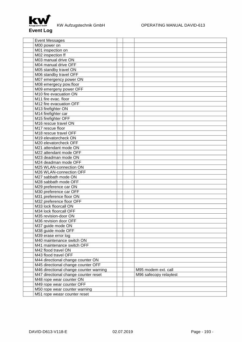
KW Aufzugstechnik GmbH OPERATING MANUAL DAVID-613
DAVID-D613-V118-E 02.07.2019 Page - 193 -
Event Log
Event Messages
M00 power on
M01 inspection on
M02 inspection ff
M03 manual drive ON
M04 manual drive OFF
M05 standby travel ON
M06 standby travel OFF
M07 emergency power ON
M08 emergecy pow.floor
M09 emergeny power OFF
M10 fire evacuation ON
M11 fire evac. floor
M12 fire evacuation OFF
M13 firefighter ON
M14 firefighter car
M15 firefighter OFF
M16 rescue travel ON
M17 rescue floor
M18 rescue travel OFF
M19 elevatorcheck ON
M20 elevatorcheck OFF
M21 attendant mode ON
M22 attendant mode OFF
M23 deadman mode ON
M24 deadman mode OFF
M25 WLAN-connection ON
M26 WLAN-connection OFF
M27 sabbath mode ON
M28 sabbath mode OFF
M29 preference car ON
M30 preference car OFF
M31 preference floor ON
M32 preference floor OFF
M33 lock floorcall ON
M34 lock floorcall OFF
M35 revision-door ON
M36 revision door OFF
M37 guide mode ON
M38 guide mode OFF
M39 erase error log
M40 maintenance switch ON
M41 maintenance switch OFF
M42 flood travel ON
M43 flood travel OFF
M44 directional change counter ON
M45 directional change counter OFF
M46 directional change counter warning M95 modem ext. call
M47 directional change counter reset M96 safecopy relaytest
M48 rope wear counter ON
M49 rope wear counter OFF
M50 rope wear counter warning
M51 rope weasr counter reset

KW Aufzugstechnik GmbH OPERATING MANUAL DAVID-613
DAVID-D613-V118-E 02.07.2019 Page - 194 -
D9 Im Untermenü D9 Safekopierung werden Informationen zu den PESRAL / SIL-3 Geräten zur Verfü-gung gestellt.
D9 Status:
D9 Status:
Normalbetrieb
Normalbetrieb
Menü
Anzeige des Zustandes der Safe-Kopierung.
Anzeige des Zustandes der Safe-Kopierung.
D9 Relais
D9 Relais:
SiKr:* Zone:* Tür:-
Normalbetrieb
Menü
* =: Geschlossen/ Aktiv - =: Offen / Deaktiv
Anzeige der Schaltstellung folgen-der Relais SiKr, Türzone & Tür-überbrückung.
D9 Zustandbits
D9 Zustandbits:
-**- ---- ---- --*-
Normalbetrieb
Menü
Anzeige der internen Kommunka-tion zwischen der SAFE-Kopierung und der D613-Steuerung.
Anzeige der internen Kommunka-tion zwischen der SAFE-Kopierung und der D613-Steue-rung.
D9 ANTSSAFE - Zonen
D9 Zone:
Länge: 400mm
Normalbetrieb
Menü
Anzeige der Türzonenlänge in mm.
Anzeige der Türzonenlänge in mm.
D9 ANTSSAFE - Inspektion
D9 Inspektion:
nur Geschw.überwach.
Normalbetrieb
Menü
Anzeige der Überwachung der In-spektionsgeschwindigkeit.
Anzeige der Überwachung der In-spektionsgeschwindigkeit. (-> Anzeige der Einstellungen)
Überwachung Nenngeschw.
Überwachung Nennge-
schwindigk.:5,000m/s
Normalbetrieb
Menü
Anzeige der überwachten Nennge-schwindigkeit in m/s.
Anzeige der überwachten Nenn-geschwindigkeit in m/s. (-> Anzeige der Einstellungen)

KW Aufzugstechnik GmbH OPERATING MANUAL DAVID-613
DAVID-D613-V118-E 02.07.2019 Page - 195 -
Endschalter OBEN
Endschalter-OBEN
Position: xxx,000m
Normalbetrieb
Menü
Anzeige der Enschalterposition Oben in m.
Anzeige der Enschalterposition Oben. (-> Anzeige der Einstellungen)
Endschalter UNTEN
Endschalter-UNTEN
Position: xxx,000m
Normalbetrieb
Menü
Anzeige der Enschalterposition Un-ten in m.
Anzeige der Enschalterposition Unten. (-> Anzeige der Einstellungen)
Verzögerungskontrolle Unten
Verz-Kontrolle-UNTEN
Kontroll.oben: Aus/Ein
Normalbetrieb
Menü
Anzeige, ob die Verzögerungskon-trolle Unten aktiviert wurde.
Anzeige, ob die Verzögerungs-kontrolle Unten aktiviert wurde. (-> Anzeige der Einstellungen)
Verzögerungskontrolle Oben
Verz-Kontrolle-OBEN
Kontroll.oben: Aus/Ein
Normalbetrieb
Menü
Anzeige, ob die Verzögerungskon-trolle Oben aktiviert wurde.
Anzeige, ob die Verzögerungs-kontrolle Oben aktiviert wurde. (-> Anzeige der Einstellungen)
Etagen - ANTSSAFE
Etagen ANTSSAFE: 04
Etagen D613: 04
Normalbetrieb
Menü
Hier wird im Vergleich die Etagen-anzahl der SAFE-Kopierung und die Etagenanzahl der Steuerung D613 angezeigt.
Hier wird im Vergleich die Etagen-anzahl der SAFE-Kopierung und die Etagenanzahl der Steuerung angezeigt. Beide Etagenwerte müssen den gleichen Wert aufweisen!
D9 ANTSSAFE - Software
ANTSSAFE-Software:
CRC: xxxxxxxx
Normalbetrieb
Menü
Hier wird die CRC -Summe des si-cheren Kerns der Sil-3 Software an-gezeigt.
Hier wird die CRC -Summe des si-cheren Kerns der Sil-3 Software angezeigt. Diese Summe sollte übereinstimmen mit dem Wert aus dem Zertifikat der Baumusterprüf-bescheinigung. Durch Aus & Ein-Schalter wird der CRC-Wert neu eingelesen.
F01 Error messages - description Controller
Code- Error entry Description

KW Aufzugstechnik GmbH OPERATING MANUAL DAVID-613
DAVID-D613-V118-E 02.07.2019 Page - 196 -
No.
F00 Phase Emergency Unit The power line for the cabin light resp. the emergency power supply is missing. Either circuit breaker F5 is activated or L2 of the main power connection is missing.
F02 Security Circuit U1 Safety Circuit power is missing. Either circuit breaker F7 is acti-vated or L1 of the main power connection is missing.
F03 Security Circuit U2 The emergency stop has been activated and thus the safety cir-cuit was opened.
F04 Security Circuit U3 The shaft door has been opened or the contact of the control strain weight was activated, which opens the safety circuit.
F05 Security Circuit U4 The maintenance door has been opened or the contact of the rope loose switch was activated, which opens the safety circuit.
F06 Security Circuit U5 The contact of the speed limiter has been activated, which opens the safety circuit.
F07 Security Circuit U6 The emergency stop switch Top or Bottom has been activated, which opens the safety circuit.
F08 Security Circuit U7 One of the buffer contacts has been activated and opened the safety circuit.
F09 Security Circuit U8 The catch contact on the cabin has been activated, which opens the safety circuit.
F10 Security Circuit U9 The contact of the rope loose contact cabin, the hatchway contact or the emergency stop cabin has been activated and opened the safety circuit.
F11 Security Circuit U10 One of the shaft doors has been opened during travel, which opens the safety circuit.
F12 Security Circuit U11 One of the cabin doors has been opened during the travel, which opens the safety loop.
F13 Security Circuit U12 One locking device contact has opened during travel and opened the safety circuit.
F14 Voltage 24V ZR The ZKR’s +24V DC power supply is in overload conditions, resp. shorted in the system.
F16 Voltage 24V FKR The FKR’s +24V DC power supply is in overload conditions, resp. shorted in the system.
F18 Carlight defect The carlight in the cabin is out of order
F20 Correction switch Top and Bot-tom activated - locking
Both pre-end switches are activated. Either one of both switches is defect or one is mounted incorrectly. The installation is locked.
F21 Correction switch Up defect The top pre-end-switch S13A is not switching, although the car has reached the top floor.
F22 Correction switch Down defect The bottom pre-end-switch S13B is not switching, although the car has reached the lowest floor.
F23 Correction switch Up and Down defect
The top pre-end-switch S13A and the bottom pre-end-switch S13B are not switching, although the car is driven to both end floors.
F24 2. Correction switch Up and Down aktive-Blockade
Both second pre-end switches are activated. Either one of both switches is defect or one is mounted incorrectly. The installation is locked.
F25 2. Correction switch Up and Down defect
The second top pre-end-switch S15A is not switching, although the car has reached the top floor.
F26 2.Pre-end switch Down defect The second bottom pre-end-switch S15B is not switching, alt-hough the car has reached the lowest floor.
F27 2. Correction switch Down and Up defect
The second bottom pre-end-switch S15A is not switching, alt-hough the car has reached the highest floor.
F28 Bolt – End switch OFF The bolt loader is expected to deactivate the limit switch (s)
F29 Bolt – End switch ON The bolt loader is expected to activate the limit switch (s)
F30 UCM Error Block Valve Error Message of Bucher ivalve or Oildynamic NGV-A3
F31 UCM - KW When leaving the inner zone with open door> A3 case -> blocking the system.
F32 UCM - Monitoring When leaving the inner zone with open door> A3 case -> blocking the system.
F33 UCM – SL-Sink Protection When leaving the inner zone with open door> A3 case speed lim-iter -> blocking the system.

KW Aufzugstechnik GmbH OPERATING MANUAL DAVID-613
DAVID-D613-V118-E 02.07.2019 Page - 197 -
F34 U10 - Shaftdoor The error message F34 "U10 shaft door" indicates a selected bridge in the area of the shaft doors. Check at the clamping list X6 pit pit and X1 shaft cabinet, as well as the shaft door contacts on bridges!
F35 U11 - Cardoors The error message F35 "U11-Cardoors" indicates a limited bridge in the area of the cabin doors. Check the X11 inspection box and the X1 manhole cupboard, as well as the cabinet door contacts on bridges!
F36 Releveling distance
With the releveling the releveling area was left.
F37 Releveling- time With the releveling the maximum releveling time wasexceeded.
F38 Releveling Attemps With the releveling the maximum number of attempts was ex-ceeded.
F39 Quick Start This message is entered, if the Quick Launch the feedback E524 is not right. Only fault entry, no interruption of movement. The journey starts in case of error without quick start.
F41 Regulation Fault The regulation ( inverter) has a problem
F42 Batterymonitor The Battery of EOS or other external Units is too low
F43 Temperature Switchcabinet 1 The switchcabinet temperature is too cold –> limit 1
F44 Temperature Switchcabinet 2 The switchcabinet temperature is too hot –> limit 2
F45 Motor temperature The PTC of the engine has activated. Reaction according config-uration.
F46 Journey Time Start The configured delay for the Start Time Monitor has elapsed. Af-ter a configured number of trials, the installation is locked.
F47 Journey Time Travel The configured delay for the Journey Time Monitor has elapsed. Reaction according configuration.
F48 Journey Time Deceleration The configured delay for the Deceleration Time Monitor has elapsed. Reaction according configuration.
F49 Journey Time Stop The configured delay for the Stop Time Monitor has elapsed. Re-action according configuration.
F50 U12-bar An error has occurred at tap U12 of the SiKr - erroneous bridging of the blocking means circuit
F51 Brake opening monitor There is no expected signal levels at the monitoring braking in-puts of the control DAVID-613
F52 Brake shoe monitor The monitor for the brake wear has been activated. Reaction ac-cording configuration.
F53 Contactor Stop The monitor for the main and brake relay has been activated. Re-action according configuration.
F54 Brake opening synchronization The monitoring of the braking elements has been activated. One of the monitor inputs is out of order or it is slower than the other (s) channel. Please check it.
F55 Contactor Travel The monitor for the main and brake relay has been activated. Re-action according configuration.
F56 Phase Change The ranking of the phases U,V,W is wrong
F57 Brake & Bolt Voltage The voltage monitor of the brake & bolt has send an error
F58 Low Pressure The pressure of the hydraulic is too low
F59 Rope Stretching Error message loadmeasurement-systemes about an uneven stretching of a rope.
F60 A3 - Case The car has left the floor with the door open and the lift was blocked. (Even in Simmulation!) Three different ways to Reset of the error “F60 A3-Case”: 1.) In the menu C0 Controller Reset 2.) Simultaneously press the three buttons maintenance call top-down call on the central unit ZR. 3.) De-energizing the FKR in the inspection box.
F61 Door Close The door could not be closed within the configured time.
F62 Separation Door The door could not be opened within the configured time.
F63 Flap Apron The folding apron does not drive although the lowest Stop be-came to leave.
F65 Push-Button landing call up Tracer landing call up wedges
F66 Push-Button landing call down Tracer landing call down wedges

KW Aufzugstechnik GmbH OPERATING MANUAL DAVID-613
DAVID-D613-V118-E 02.07.2019 Page - 198 -
F67 Push-Button Door open It takes place an entry if the tracer is operated longer than 45 seconds in the stop and/ or in normal operation.
F68 Photocell blocked It takes place an entry if the lght barrier is operated longer than 45 seconds in the Stop and/ or in normal operation.
F69 Revers Contact blocked It takes place an entry if the contact is operated longer than 45 secods in the Stop and/or in normal operation
F70 Blocked – Endswitch
The hydraulic elevator is driven into the top end-switch. After leaving the top-end-switch the elevator has lowered and blocked in the lowest Stop.
F71 Blocked Journey time The hydraulic elevator lowered after the occurance of a run time arror
F72 Blocked- TV60-1 Two inputs channels of the TV60-1 are monitored for synchro-nization.
F73 Blocked- TV60-2 Two inputs channels of the TV60-2 are monitored for synchro-nization.
F78 DSC 2. Pre-switch Bottom The digital shaft copying started that the counted impulse con-ditions do not agree with the impulse conditions at the pre-end switcher down. A correction was implemented.
F79 DSC 2. Pre-switch Top The digital shaft copying started that the counted impulse con-ditions do not agree with the impulse conditions at the pre-end switcher up. A correction was implemented.
F80 Communication I/O CPU The central unit and logic unit is internally disturbed. Ask cus-tomer service- reasonable.
F81 Communication I/O FKR Communication to the car controller is disturbed. That is 15 pole. D-Subkabel correctly put or damages?
F82 USV Defect / empty The UPS for emergency rescue is defective, or the charge status is empty.
F83 DSC Change Puls The encoder pulses of the shaft encoder must be exchanged. ( Input 81 and 82)
F84 DSC No pulses From the pulse generator of the digital pit copying no impuses come. Are the giver and impuls entry correct?
F85 DSC Floornumber The floor number determined by the learning trip does not agree with the registered. Examine please enty in the software and zone switch fpr switching gap and function.
F86 Correction ZONE Correction trip released by counter deviation the zone.
F87 Correction Pre-Switch Down Correction trip released by counter deviation Pre-end-switch down
F88 Correction Pre-Switch Top There is a difference between the counter of the digital shaft-copy and the position of the Pre-switch top. The counter was corrigate.
F90 Watchdog-Reset Internal reset – damage in the hardware
F91 Reset-Groupbus Interner Reset durch Fehler auf dem Gruppenbus
F92 Security circuit The security circuit has send an error. A cause a missing or retarded zone.
F93 Liftbus Communication On the Liftbus ( communication regulation STG) an error was send.
F94 Test Safety Photocell An error was announced of the safety Photocell which was de-termined with the self check.
F95 Interrupt Safety Photocell An error was announced of the safety Photocell which was de-termined during the travel.
F97 Zone Switches The Contacts of the Zone switches have a lot of switching acts
F98 Prelevel-Switch-UP The Contact of the Prelevel-switch UP has a lot of switching acts.
F99 Prelevel-Switch-DOWN The Contact of the Prelevel-switch Down has a lot of switching acts
F101 IPM -Overcurrent – Error message caused through wrong motor datas (Nominalspeed – Motor datas )! – Error message caused through wrong motor datas (Nominalcurrent – Motor datas )! – Old machines: Please switch off the possition regulator! Or change the settings ! – Gearless: Is the motorwire correctly installed ( U – V – W ) ? – Overcurrent because there is a shortcut in the motorwire ? – Is the encoder wire right connected? Perhaps you must change the channels A and B ?
- Is the car easily running ? Have the fixing shoes enough oil ? Is the half-load OK ?

KW Aufzugstechnik GmbH OPERATING MANUAL DAVID-613
DAVID-D613-V118-E 02.07.2019 Page - 199 -
F102 Overcurrent U - Overcurrent because there are wrong motor datas or oscillations of the car – Error message caused through wrong motor datas (Nominalspeed – Motor datas )! – Error message caused through wrong motor datas (Nominalcurrent – Motor datas )! – Old machines: Please switch off the possition regulator! Or change the settings ! – Gearless: Is the motorwire correctly installed ( U – V – W ) ? – Overcurrent because there is a shortcut in the motorwire ? – Is the encoder wire right connected? Perhaps you must change the channels A and B ?
- Is the car easily running ? Have the fixing shoes enough oil ? Is the half-load OK ?
F103 Overcurrent V - Overcurrent because there are wrong motor datas or oscillations of the car – – Error message caused through wrong motor datas (Nominalspeed – Motor datas )! – Error message caused through wrong motor datas (Nominalcurrent – Motor datas )! – Old machines: Please switch off the possition regulator! Or change the settings ! – Gearless: Is the motorwire correctly installed ( U – V – W ) ? – Overcurrent because there is a shortcut in the motorwire ? – Is the encoder wire right connected? Perhaps you must change the channels A and B ?
- Is the car easily running ? Have the fixing shoes enough oil ? Is the half-load OK ?
F104 Overcurrent W - Overcurrent because there are wrong motor datas or oscillations of the car – Error message caused through wrong motor datas (Nominalspeed – Motor datas )! – Error message caused through wrong motor datas (Nominalcurrent – Motor datas )! – Old machines: Please switch off the possition regulator! Or change the settings ! – Gearless: Is the motorwire correctly installed ( U – V – W ) ? – Overcurrent because there is a shortcut in the motorwire ? – Is the encoder wire right connected? Perhaps you must change the channels A and B ?
- Is the car easily running ? Have the fixing shoes enough oil ? Is the half-load OK ?
F105 Dissipator Temperature: Temperature Dissipator too high – - The Inverter is overloaded or the controller casing is too hot. Is the power class of the inverter
in according to the motor ?
- Has the controller cabinet an air ventilation? Is above the inverter casing enough air room? - Ate the fans of the inverter OK?
- Are there any dirt on the pcb-board or in the heatsink ?
F106 DC-Overvoltage: – There is no brake resistor connected or the type is wrong -> Please measure the Ohm-value! – Main supply voltage too high -> Please check it – you must have a voltage of 400V AC! – There are voltage peaks on the main supply ?
- Is the frequency inverter connected with the earth ?
F107 DC-Undervoltage:–The supply voltage is too low or the maincontactor is switched off during the travel:
- The DC voltage is too low –> Please control the supply voltage ! - The maincontactors are switched off during the travel -> A phase of the supply voltage is miss-
ing ! - The power class of the inverter is too low for the motor !
F108 Main Contactor-Start: - At the start, the maincontactors do not switch ON -> The power supply is too low ?
- At the start, the maincontactors do not switch ON -> The safety circuit is interrupted (Doorcon-tacts)
- At the start, the maincontactors do not switch ON -> The Fuse is switched OFF ?
F109 Main-Contactor-Travel: - During the travel, the maincontactors switch OFF -> The power supply is too low ?
- During the travel, the maincontactors switch OFF -> The safety circuit is interrupted (Doorcon-tacts)
During the travel, the maincontactors switch OFF -> The Fuse is switched OFF ?
F110 No Release: - Drive direction UP or DOWN is missing at the end of the travel
o Controller: Delay for switch off the direction! - Drive direction UP or DOWN is missing at the end of the travel
o Safety circuit, check the door mangement ! - Drive direction UP or DOWN is missing at the end of the travel
–> Delay time for switching off the contactors to 1500 ms.
F111 Release UP + DOWN You must have only one drive direction -> In case of certain controller, which works only with one di-rection, please change the parametersetting in the inverter!

KW Aufzugstechnik GmbH OPERATING MANUAL DAVID-613
DAVID-D613-V118-E 02.07.2019 Page - 200 -
F112 Wrong Direction - Please change the encoder channels A/B, because the machine rotates in the wrong direction! - Perhaps it is the wrong type of encoder? -> Menu A4 Motor/Gearbox -> Encodersystem - The number of pulses are wrong? -> Menu A4 Motor/Gearbox -> Encoder Pulses - The encoderwire is out of order or too long ( >30m) ! -> Please increase the encoder voltage ! - The encoder-shield is not connected on both sides -> Change it immedately! - The encoderwire is parallel to the motorwire -> Change it immedately!
- The encoder coupling or the encoder is not mechanical fixed with the Motorwave -> Please check it!
F113 Speed Variance – The motor works, but the encoder is out of order or wrong connected. -> Control the pining!
- Perhaps it is the wrong type of encoder? -> Menu A4 Motor/Gearbox -> Encodersystem - The number of pulses are wrong? -> Menu A4 Motor/Gearbox -> Encoder Pulses - The encoderwire is out of order or too long ( >30m) ! -> Please increase the encoder voltage ! - The encoder-shield is not connected on both sides -> Change it immedately! - The encoderwire is parallel to the motorwire -> Change it immedately! - The motor and his metal socket is grounded very bad -> Change it immedately! - The frequency inverter is not connected with the earth -> Change it immedately! - The motorwire-shield is not connected on both sides -> Change it immedately! - The brakeresistorrwire-shield is not connected on both sides -> Change it immedately! - The encoder coupling or the encoder is not mechanical fixed with the Motorwave -> Please
check it! - The frequency inverter has a current limit (full power) -> Power class too low
- Is the car easily running ? Have the fixing shoes enough oil ? Is the half-load OK ?
F114 No Encoder Pulse - The motor works, but the encoder is out of order or wrong connected. -> Control the pining!
- Perhaps it is the wrong type of encoder? -> Menu A4 Motor/Gearbox -> Encodersystem - The number of pulses are wrong? -> Menu A4 Motor/Gearbox -> Encoder Pulses - The encoderwire is out of order or too long ( >30m) ! -> Please increase the encoder voltage ! - The encoder-shield is not connected on both sides -> Change it immedately! - The encoderwire is parallel to the motorwire -> Change it immedately! - The motor and his metal socket is grounded very bad -> Change it immedately! - The frequency inverter is not connected with the earth -> Change it immedately! - The motorwire-shield is not connected on both sides -> Change it immedately! - The brakeresistorrwire-shield is not connected on both sides -> Change it immedately!!
- The encoder coupling or the encoder is not mechanical fixed with the Motorwave -> Please check it
F115 DC Precharge: - After switch ON the inverter, the DC-voltage is too low -> Earth connection of the brake resistor
wire - After switch ON the inverter, the DC-voltage is too low -> Earth connection of the brake resistor
wire - After switch ON the inverter, the DC-voltage is too low -> The little two fuses into the inverter are out of order !
F116 Release Change during the travel – Lift controller error – Error of the lift controller or wrong settings in the parameter oft the controller / inverter!
F117 Liftbus communiction during the travel is out of: - Wrong Liftbus parameter !
- Wrong Liftbuscable or the shield not connected
F118 SSI-Communication: - Is there really SSI-encoder connected? -> Menu A4 Motor/Gearbox -> Encodersystem
- The encoder is out of order, e.g. after the test of the safetygear ? - The encoder is wrong connected -> Please check the pining -> Do you use the right adapter ? - The encoderwire is out of order or too long ( >30m) ! -> Please increase the encoder voltage ! - The encoderwire is parallel to the motorwire -> Change it immedately!
- The encoder coupling or the encoder is not mechanical fixed with the Motorwave -> Please check it!
F119 EnDat-Communication: - Is there really EnDat-encoder connected? -> Menu A4 Motor/Gearbox -> Encodersystem
- The encoder is out of order, e.g. after the test of the safetygear ? - The encoder is wrong connected -> Please check the pining -> Do you use the right adapter ? - The encoderwire is out of order or too long ( >30m) ! -> Please increase the encoder voltage ! - The encoderwire is parallel to the motorwire -> Change it immedately!
The encoder coupling or the encoder is not mechanical fixed with the Motorwave -> Please check it!

KW Aufzugstechnik GmbH OPERATING MANUAL DAVID-613
DAVID-D613-V118-E 02.07.2019 Page - 201 -
F120 Hiperface Communication: - Is there really Hiperface-encoder connected? ->Menu A4 Motor/Gearbox-> Encodersystem
- The encoder is out of order, e.g. after the test of the safetygear ? - The encoder is wrong connected -> Please check the pining -> Do you use the right adapter ? - The encoderwire is out of order or too long ( >30m) ! -> Please increase the encoder voltage ! - The encoderwire is parallel to the motorwire -> Change it immedatly!
- The encoder coupling or the encoder is not mechanical fixed with the Motorwave -> Please check it!
F121 Sin/Cos Communication: - Is there really Sin/Cos-encoder connected? -> Menu A4 Motor/Gearbox -> Encodersystem
- The encoder is out of order, e.g. after the test of the safetygear ? - The encoder is wrong connected -> Please check the pining -> Do you use the right adapter ? - The encoderwire is out of order or too long ( >30m) ! -> Please increase the encoder voltage ! - The encoderwire is parallel to the motorwire -> Change it immedatly!
- The encoder coupling or the encoder is not mechanical fixed with the Motorwave -> Please check it!
F122 Angle Variance: - The number of pulses are wrong -> Please change the setting - The encoder channels are out of order -> Please change the encoder ! ?
- The encoder is wrong connected -> Please check the pining -> Do you use the right adapter ?
F123 Encoder Voltage-too low: - Short cut at the encoder terminal -> Please check the pining -> Do you use the right adapter ? - The encoder is out of order, e.g. after the test of the safetygear ? - The encoder is wrong connected -> Please check the pining -> Do you use the right adapter ? - The encoderwire is out of order or too long ( >30m) ! -> Please increase the encoder voltage !
- Is the right type of encoder connected? -> Menu A4 Motor/Gearbox -> Encodersystem
F124 Motor Temperature-too high: - The temperature of the area is too high - The motor is overloaded
- The motor fan is out of order
F125 Command Voltage-too low: Short cut at the 24V-Terminal, 24V-Terminal is overloaded: - Short cut at the output terminal +24V -> Please check soon as possible !
- The output channel +24V is overloaded -> please use an external power supply !
F126 24V Output Driver - Short cut at the output terminal -> Please check the pining
The output channels EA1 to EA8 are overloaded -> Perhags the is a short cut or the current is too high -> Please check it, pherhaps you must use external relays!
F127 Relay Monitor-1: Internal Relay-1 is out of order or the open-contact is clewing -> The switching load is too big (Induc-tive)! Please use a contactor to switch big loads, like the brake-magnet!
F128 Relay Monitor -2: Internal Relay-2 is out of order or the open-contact is clewing -> The switching load is too big (Induc-tive)! Please use a contactor to switch big loads, like the brake-magnet!
F129 Relay Monitor -3: Internal Relay-3 is out of order or the open-contact is clewing -> The switching load is too big (Induc-tive)! Please use a contactor to switch big loads, like the brake-magnet!
F130 Monitor Brake-1: - Brake-circuit-1 do not open / close during the travel -> Are the settings OK? Do you have
opener or closer-contacts? 0V (NPN-Thyssen ) or+24V (z.B. Ziehl-Abegg,..) - Do have connected the brakewires rightly? - Do you have observed, if the brakes open ? -> Brakewires ?
- Are the brake-contacts OK ? -> If you have any douts, make a measurement !
F131 Monitor Brake-2: - Brake-circuit-2 do not open / close during the travel -> Are the settings OK? Do you have
opener or closer-contacts? 0V (NPN-Thyssen ) or+24V (z.B. Ziehl-Abegg,..) - Do have connected the brakewires rightly? - Do you have observed, if the brakes open ? -> Brakewires ?
Are the brake-contacts OK ? -> If you have any douts, make a measurement !
F132 Monitor Brake-3: - Brake-circuit-3 do not open / close during the travel -> Are the settings OK? Do you have
opener or closer-contacts? 0V (NPN-Thyssen ) or+24V (z.B. Ziehl-Abegg,..) - Do have connected the brakewires rightly? - Do you have observed, if the brakes open ? -> Brakewires ?
- Are the brake-contacts OK ? -> If you have any douts, make a measurement !

KW Aufzugstechnik GmbH OPERATING MANUAL DAVID-613
DAVID-D613-V118-E 02.07.2019 Page - 202 -
F133 Monitor Brake-4: - Brake-circuit-4 do not open / close during the travel -> Are the settings OK? Do you have
opener or closer-contacts? 0V (NPN-Thyssen ) or+24V (z.B. Ziehl-Abegg,..) - Do have connected the brakewires rightly? - Do you have observed, if the brakes open ? -> Brakewires ?
- Are the brake-contacts OK ? -> If you have any douts, make a measurement !
F134 Monitor Main Contactor: - One of the main contactor can not be switched ON -> Please control the contactors!
- Please check the opener-contacts, clean it or change it! - Are the opener-contacts for 24V DC ? -> Please look at the data sheet!
F135 ADC1-Zero-Offset: - The currentsensor-U is out of order. It is an internal Error. Please contact our Hotline.
F136 ADC2-Zero-Offset: - The currentsensor-V is out of order. It is an internal Error. Please contact our Hotline.
F137 ADC1-Offset: - The AD-Changer-V is out of order. It is an internal Error. Please contact our Hotline.
F138 ADC2-Offset: - The AD-Changer-U is out of order. It is an internal Error. Please contact our Hotline.
F139 Eart Fault: - The motor ist out of order, please measure each coil of the motor and compare it! - Please check, if the motorwire or resistorwire have any connection to earth!
F140 IPM-Error: or Supply voltage to low: - Overtemperature in the IGBT-Chip -> Are there any dirt on the pcb-board or in the heatsink ?
- The voltage of board is too low! -> Is the main supply voltage OK ?
F141 Position Regulation: - The difference at the start handling is too high, wrong Parameter ( Nominalspeed -> motor-
datas,..)! - The motor works, but the encoder is out of order or wrong connected. -> Control the pining! - Perhaps it is the wrong type of encoder? -> Menu A4 Motor/Gearbox -> Encodersystem - The number of pulses are wrong? -> Menu A4 Motor/Gearbox -> Encoder Pulses - The encoderwire is out of order or too long ( >30m) ! -> Please increase the encoder voltage ! - The encoderwire is parallel to the motorwire -> Change it immedately! - The encoder-shield is not connected on both sides -> Change it immedately!
Old machines: Please switch off the possition regulator! Or change the settings!
F142 NTC-Dissipator :: - The Temperature sensor deliever the wrong value: Please check the connection!
- The Temperature sensor is out of order. Please contact our Hotline.
F143 DC Battery Voltage: At the evaquation-travel with battery, the voltage of the battery was too low. Please check the battery voltage!
F144 Watchdog-Reset There is an internal Reset by the Watchdog. Please contact our Hotline.
F145 Monitor Brake wear-1: The input channel for the Brake wear monitor is active.You need a new brake shoe or brake is not exactly adjust!
F146 Monitor Brake wear-2: The input channel for the Brake wear monitor is active.You need a new brake shoe or brake is not exactly adjust!
F147 Monitor Brake wear-3: The input channel for the Brake wear monitor is active.You need a new brake shoe or brake is not exactly adjust!
F148 Monitor Brake wear-4: The input channel for the Brake wear monitor is active.You need a new brake shoe or brake is not exactly adjust!
F149 Offset measure Pole Number: There is a difference between the parameter motor type and the actual type!
F150 Offset measur Brake: During the offset measure, the motor do not rotate – please check the brake, because it is not open!
F151 Offset measure Invalid : The measured offset angle is not valid – check electric wiring and make the offset measure a second time!
F152 Brake Resistor: There is a short cut at the brake resistor!

KW Aufzugstechnik GmbH OPERATING MANUAL DAVID-613
DAVID-D613-V118-E 02.07.2019 Page - 203 -
F153 Hydraulic – Pressure Sensor: The input channel for Pressure Sensor is low.Please check the wire to the Pressure Sensor.
F154 Hydraulic – Turbine: The input channel for Turbine is low.Please check the wire to the Turbine.
F155 Hydraulic – Low Pressure: If the low Pressure-Function is activate, there is an error. The pressure is too low, because there is a problem in the hydraulic system or the limit-setting of the parameter is too high.
F156 Resolver Fault: Error on resolver in drive machines with resolver
F157 SAS blocked: The SAS module of the G90 frequency inverter has been disabled.
F158 SAS Fault: The SAS module of the frequency inverter G90 gives an error. Check door contacts!
F159 V< 0,2 m/s: The speed threshold V> 0.2 at the UCM (crawl with open door in the HS) was exceeded!
F160 BISS-C Communication: The absolute encoder with the BISS-C protocol has an error. Connection and, if necessary, PIN control necessary
F161 IPM-Modulsafety: Current value is exceeded. Safety shutdown of the module.
F201 Mains Frequency: - The softstart unit can not synchronizice with the power supply ! - Wrong Power frequency? -> Has the power supply a frequency of 50 Herz ?
- If there is a power supply with 60 Hz Netz – Please chang the parameter B6 to 60 Hz !
F202 Phase Failure: - There are not all three phases at the power input !
- One phase is missing ! -> Please check voltage and current !
F203 Phase Sequence: - The phase sequence at the power input is wrong !
- Right: L1 – L2 – L3 Wrong: L2 – L3 – L1 or..L3 – L1 – L2
F204 Phase Rotation: - The phase rotation at the power input is no right-rotation-field!
Right: L1 – L2 – L3 Wrong: L2 – L1 – L3 or.. -> Please check it and make a right rotation field !
F205 Dissipator Temperature too High: - The softstart is overloaded, is the power class of the unit ok? - The Temperature sensor deliever the wrong value: Please check the connection!
The Temperature sensor is out of order. Please contact our Hotline.
F206 Motor Temperature - Motor and oil too hot: - The temperature of the area is too high ! - The motor is overloaded !
- The number of travels is too high ? -> Do you need an oil-cooling?
F207 Relay-1 Contactor: Internal Relay-1 is out of order or the open-contact is clewing -> The switching load is too big (Induc-tive)! Please use a contactor to switch big loads, like the valve-magnet!
F208 Relay-2 Contactor: Internal Relay-2 is out of order or the open-contact is clewing -> The switching load is too big (Induc-tive)! Please use a contactor to switch big loads, like the valve-magnet!
F209 Main Contactor Monitoring: - One of the main contactor can not be switched ON -> Please control the contactors!
- Please check the opener-contacts, clean it or change it! - Are the opener-contacts for 24V DC ? -> Please look at the data sheet!
F210 Liftbus Communication is interrupted: - Wrong Liftbus parameter ! - Wrong Liftbuscable or the shield not connected!
F240 Fan Monitoring Controller-Cabinet The fan of the controller-cabinet is out of order. Please check the Fuse, Wiring & the Fan.
F241 Carlight Monitoring One of the lights of the carlights is out of order. Please check the Fuse, Wiring & Light
F243 Monitoring Doorstep Heating – 1 The heating of the shaft-doorstep is out of order. Please check the Fuse, Wiring & the Heating
F244 Monitoring Doorstep Heating – 2 The heating of the shaft-doorstep is out of order. Please check the Fuse, Wiring & the Heating
F245 Monitoring Doorstep Heating – 3 The heating of the shaft-doorstep is out of order. Please check the Fuse, Wiring & the Heating
F246 Monitoring Doorstep Heating – 4 The heating of the shaft-doorstep is out of order. Please check the Fuse, Wiring & the Heating

KW Aufzugstechnik GmbH OPERATING MANUAL DAVID-613
DAVID-D613-V118-E 02.07.2019 Page - 204 -
F247 Carfan Monitoring The fan of the car is out of order. Please check the Fuse, Wiring & the Fan.
F248 Electric Socket Monitoring The electric socket in the pit is out of order. Please check the Fuse, Wiring & the socket.
F250 Light Curtain Door-1 Door-1 light cutain outputs error message and is therefore defective.
F251 Light Curtain Door-2 Door-2 light cutain outputs error message and is therefore defective.
F252 Light Curtain Door-3 Door-3 light cutain outputs error message and is therefore defective.
F253 Overspeed – Manual Speed If the return travel of 0.3 m / s is exceeded, the journey is interrupted. Possible causes: 1.) Incorrect setting of the return speed in the control unit. 2.) Wrong setting of the nominal speed in menu A3.6. 3.) Incorrect setting of the return speed in menu B601.
F254 Overspeed – Inspection Speed If the inspection distance of 0.5 m / s is exceeded, the journey is interrupted. Possible causes: 1.) Incorrect setting of the inspection speed in the control unit. 2.) Wrong setting of the nominal speed in menu A3.6. 3.) Incorrect setting of the inspection speed in menu B601
F255 Overspeed – Nominal Speed If the nominal run of 15% is exceeded, the journey is interrupted. Possible causes: 1.) Incorrect setting of the nominal speed in the control unit. 2.) Wrong setting of the nominal speed in menu A3.6.
F256 UCM-Zone-1 Relay-contact of UCM-Zone-1 is not switching
F257 UCM-Zone-2 Relay-contact of UCM-Zone-2 is not switching
F288 Flood in pit Watersenor is active, because water is in the pit
F300 CAN1-Bus – REC Warning
F301 CAN1-Bus – TEC Warning
F302 CAN1-Bus – REC Passing
F303 CAN1-Bus – TEC Passing
F304 CAN1-Bus – Bus-Off Der CAN1-Bus is switched OFF
F305 CAN1-Bus – ID02-Heartbeat missing At the CANbus Device ID02 there is no Heartbeat-Signal
F306 CAN1-Bus – ID04-Heartbeat missing At the CANbus Device ID04 there is no Heartbeat-Signal
F307 CAN1-Bus – ID07-Heartbeat missing At the CANbus Device ID05 there is no Heartbeat-Signal
F308 CAN1-Bus – ID08-Heartbeat missing At the CANbus Device ID06 there is no Heartbeat-Signal
F309 CAN1-Bus – ID09-Heartbeat missing At the CANbus Device ID09 there is no Heartbeat-Signal
F310 CAN1-Bus – ID13-Heartbeat missing At the CANbus Device ID13 there is no Heartbeat-Signal
F311 CAN1-Bus – ID16-Heartbeat missing At the CANbus Device ID16 there is no Heartbeat-Signal
F312 CAN1-Bus – ID17-Heartbeat missing At the CANbus Device ID17 there is no Heartbeat-Signal
F313 CAN1-Bus – ID18-Heartbeat missing At the CANbus Device ID18 there is no Heartbeat-Signal
F314 CAN1-Bus – ID19-Heartbeat missing At the CANbus Device ID19 there is no Heartbeat-Signal
F315 CAN1-Bus – ID20-Heartbeat missing At the CANbus Device ID20 there is no Heartbeat-Signal
F400 F400 SAFE end switch top SAFE Schachtkopierung hat den SiKr unterbrochen – Die Position des End-schalters Oben wurde erreicht.
F401 F401 SAFE end switch bottom SAFE Schachtkopierung hat den SiKr unterbrochen – Die Position des End-schalters Oben wurde erreicht.
F402 F402 SAFE UCM SAFE Schachtkopierung hat den SiKr unterbrochen – Ein Verlassen des Fahrkorbes mit offener Tür wurde am Zonenende erkannt und unterbunden.
F403 F403 SAFE end switch top inspection SAFE Schachtkopierung hat den SiKr unterbrochen – Die Position des End-schalters Oben für den Inspektionsbetrieb bei verkürztem Schachtkopf wurde erreicht. Nur Inspektionsbetrieb nach unten möglich.
F404 F404 SAFE end switch bottom inspection SAFE Schachtkopierung hat den SiKr unterbrochen – Die Position des End-schalters Unten für den Inspektionsbetrieb bei verkürzter Schachtgrube wurde erreicht. Nur Inspektionsbetrieb nach oben möglich.
F405 F405 SAFE deceleration monitor SAFE Schachtkopierung hat den SiKr unterbrochen – Am Kontrollpunkt für die Verzögerungskontrolle war die Geschwindigkeit zu hoch. -> Abbruch der Fahrt.
F406 F406 SAFE overspeed SAFE Schachtkopierung hat den SiKr unterbrochen – Der Geschwindigkeits-wert der Nachholgeschwindigkeit wurde überschritten.
F407 F407 SAFE inspection speed SAFE Schachtkopierung hat den SiKr unterbrochen – Der Geschwindigkeits-wert der Nachholgeschwindigkeit wurde überschritten.
F408 F408 SAFE system SAFE Schachtkopierung hat den SiKr unterbrochen, weil ein Systemfehler aufgetreten ist.
F409 F409 SAFE system off SAFE Schachtkopierung hat den SiKr unterbrochen weil das System ausge-schalten ist.
F410 F410 SAFE overspeed releveling SAFE Schachtkopierung hat den SiKr unterbrochen – Der Geschwindigkeits-wert der Nachholgeschwindigkeit wurde überschritten.
F411 F411 SAFE overspeed leveling SAFE Schachtkopierung hat den SiKr unterbrochen – Der Geschwindigkeits-wert der Nachholgeschwindigkeit wurde überschritten.

KW Aufzugstechnik GmbH OPERATING MANUAL DAVID-613
DAVID-D613-V118-E 02.07.2019 Page - 205 -
W01 Exchange of the processor map Before you proceed to replace the CPU card, all fuses and switches are turned off. Set the car at the lowest level flush, with activated emergency operation (car doors closed).
For the change of the CPU map the cover of the ZR-unit must be opened. The map is left down in the body.
Do not affect other parts on the lare printed circuit board. With two finers you can loosen the prited cir-cuit board.
Take new CPU map from the ESD protective plastic film
Use the new CPU map care-fully. Convince yourselves that the map sits correctly. Close afterwards the cover again.
6.0 Information
D1 IN / OUTPUT The submenu D1 is not realized yet.
D2 Trip counter In the submenu D2 the trip counter is realized. Two trip counters are available:
Total trip counter Not erasable
Total trip counter erasable Erasable for the statistics evaluation
Delete trip counter ? No - Yes
Trip counter Up erasable Erasable for the statistics evaluation
Trip counter Up delete ? No - Yes
Travel counter down erasable ? Erasable for the statistics evaluation
Trip counter down delete ? No - Yes
Change of direction counter See below
Rope wear counter See below
Floor trip counter for each floor Erasable for the statistics evaluation
Delete trip counter? No - Yes
Menü D2 Change of direction counter
Submenu password
In order to make or change outputs in the direction of the change counter, a password entry is neces-
sary.
Submenu change of direction OFF / ON“
Here the direction change counter can be switched on or off.
Submenu change direction value: NO / YES
Due to the importance of the counter, another request is implemented, setting a new value.
Submenu reset value
Based on the documentation of the rope manufacturer, the final value can be entered in journeys
Submenu warning threshold

KW Aufzugstechnik GmbH OPERATING MANUAL DAVID-613
DAVID-D613-V118-E 02.07.2019 Page - 206 -
In order to have the possibility of reaction, a prewarning threshold can be established. It should be sized so that it does not come to a standstill of the plant.
Menü D2 Rope wear counter Submenu password In order to make or change outputs on the rope wear counter, a password entry is necessary. Submenu Rope wear counter OFF / ON Here the rope welding counter can be switched on or off. Set the rope wear submenu value: NO / YES Due to the importance of the counter, another request is implemented, setting a new value. Submenu Residual value Based on the documentation of the rope manufacturer, the final value can be entered in journeys. Submenu warning threshold In order to have the possibility of reaction, a pre warning threshold can be established. It should be sized so that it does not come to a standstill of the plant.
D3 Run time counter In the submenu D3 the hour meter is realized. Two hour meters are available:
Network hour meter
Operating-hours meter
Operating-hours meter erasable
Operating-hour meter clear?
Length hour erasable
Length hours clear?
Fault counter erasable
Fault counter clear?
Operation time Delete operation time Failure hour counter Delete Failure hour counter Normal running time Delete normal travel time Special driving time Delete special driving time Rest time Delete rest time
D4 Door motion counter In the submenu D4 the door transaction counter is realized. Two door transaction counters are availa-ble for 2 door sides:
Indicate the door movements door 1 Activity count, erasable
Indicate the door movements door 2 Activity count, erasable
Indicate the door movements door 3 Activity count, erasable
Delete door transaction counters Erasable, for the statisics evaluation
Indicate door maintenance Adjust the number of the door movements, starting from one
Message takes place. Range of adjustment from 100 to 100.000
D5 energy counter The energy counter is implemented in submenu D5. There are two energy meters available for the supply of energy as well as for energy recovery:
Display of the energy purchase Erasable, display of the related energy
Display of energy recovery Erasable, display oft he supplied energy
Delate energy meter? No - Yes

KW Aufzugstechnik GmbH OPERATING MANUAL DAVID-613
DAVID-D613-V118-E 02.07.2019 Page - 207 -
Energy reference Number of pulse per KWh
000x pulses / KWh
Energy recovery pulse number per KWh 000x pulses / KWh
D6 environmental conditions In the submenu D6 parameters of the environmental conditions are displayed:
Temperature ZR current Temperature in degrees Celsius
Temperature ZR max Temperature in degrees Celsius
Temperature ZR min Temperature in degrees Celsius
Temperature FKR aktuell Temperature in degrees Celsius
Temperature FKR max Temperature in degrees Celsius
Temperature FKRf min Temperature in degrees Celsius
Temperature control cabinet current Temperature in degrees Celsius
Temperature control cabinet max Temperature in degrees Celsius
Temperature control cabinet min Temperature in degrees Celsius
Temperature pit-brow current Temperature in degrees Celsius
Temperature pit-brow max Temperature in degrees Celsius
Temperature pit-brow min Temperature in degrees Celsius
Temperature shaft pit current Temperature in degrees Celsius
Temperature shaft pit max Temperature in degrees Celsius
Temperature shaft pit min Temperature in degrees Celsius
Humidity control cabinet current From 20% to 80%
Humidity control cabinet max From 20% to 80%
Humidity control cabinet min From 20% to 80%
Humidity pit-brow current From 20% to 80%
Humidity pit-brow max From 20% to 80%
Humidity pit-brow min From 20% to 80%
Humidity shaft pit current From 20% to 80%
Humidity shaft pit max From 20% to 80%
Humidity shaft pit min From 20% to 80%
For resetting with a button of the resettable counter functions there are input functions: Exxx - Reset journey counter Exxx - Reset journey counter up Exxx - Reset journey counter down Exxx - Reset Floor crossing counter Exxx - Reset operating- hours meter Exxx - Reset Failure hour counter Exxx - Reset malfunction counter Exxx - Reset motor hour meter Exxx - Reset Door movement counters Exxx - Reset Energy meters

KW Aufzugstechnik GmbH OPERATING MANUAL DAVID-613
DAVID-D613-V118-E 02.07.2019 Page - 208 -
Maintenance menu D7
General
The elevator control system determines the time of maintenance for the elevator installation in order to ensure preventive maintenance. On the basis of the statistical maintenance interval calculation, the wear of the system components, which is detected by the sensors, is compared to the statistical value in order to generate the optimum maintenance time. Parameter: Maintenance counter If the generation of the maintenance interval is activated in the parameter Maintenance coun-ter By calculating the frequency of use of an elevator installation according to EN 13015, TRBS1312 & VDI3810, a use category (NK) was determined, which serves for the theoretical calculation of the annual maintenance intervals.
Use category NK = A + B + C + D + E
Parameter: Maintenance after xxx days In this parameter, the result of the utilization type is converted using a matrix to obtain the annual maintenance interval. The output of the maintenance time is in days.
Priorities
NK 1 2 3 4
NK 1 – 2
4 3 2 1
NK 3 – 4
6 4 3 2
NK 5 – 6
8 6 4 -
NK > 6
12 8 - -
Parameter: Delete maintenance counter A reset of the maintenance counter after maintenance is carried out in this menu. Parameter: Number of trips per month The start value is an estimate of the number of trips per month of the elevator system. The
value is refined during the lifetime of the plant by the data obtained
Summand A 1 2 3 4 5 Number oft rips per month
< 500 501 - 3000 3001 - 6000 6001 - 40000 > 40000
Average durations per 24 hours
< 1 1 - 2 3 5 6

KW Aufzugstechnik GmbH OPERATING MANUAL DAVID-613
DAVID-D613-V118-E 02.07.2019 Page - 209 -
Parameter: Spezial environmental conditions Special environmental conditions of manhole and machine room (control), such as moisture,
dust and dirt, glass shaft, machine room position increase the maintenance effort. They can
be weighted in this parameter
Summand B 0 1
Spezial environmental conditions No Ja
Parameter: Spezial conditions of use Special conditions of use such as public transport, vandalism and problem areas increase
the maintenance effort. They can be weighted in this parameter.
Summand C 0 1
Spezial conditions of use No Ja
Parameter: Availability The availability of the lift system can be weighted in the calculation of the use category:
Summand D 0 1
Availability of the plant Less important Very important
Parameter: Age of the facilities The age of the elevator system also plays an important role in the calculation of the usage category:
Summand E 0 1
Age of the facilities < 10 years >= 10 years
Parameter: Location In order to be able to weight the gained use category, it is important to enter the location of the lift installation:
Priorities 1 2 3 4
Location Hospital Nursing facility
Industry
Commercial building Public area hotel > 4 HS
residential building >5HS
administration <=4HS
hotel <= 4 HS residential building
<=5HS
Private sector, Limited user
group
Parameter: Maintenance display line-01
This parameter defines the content of the first display line. The following table lists the availa-ble messages:
- Journey counter - Min. temperature control cabinet
- Journey counter erasable - Temperature pit-brow
- Journey counter up - Max. temperature pit-brow
- Journey counter down - Min. temperature pit-brow
- Change of direction counter - Temperature shaft pit
- Power hour meter - Max. temperature shaft pit
- Operating-hours meter -
- Min. temperature shaft pit
- Operating-hours meter erasable - Humidity control cabinet
- Failure hour counter - Max. humidity control cabinet
- Door count T1 - Min. humidity control cabinet
- Door count T2 - Luftfeuchtigkeit Schachtkopf
- Door count T3 - Max.humidity pit-brow
- Energy reference counter - Min. humidity pit-brow
- Energy feedback meter - Humidity shaft pit
- Temperature D613-ZR - Max. humidity shaft pit

KW Aufzugstechnik GmbH OPERATING MANUAL DAVID-613
DAVID-D613-V118-E 02.07.2019 Page - 210 -
- Max. temperature D613-ZR - Min. humidity shaft pit
- Min. temperature D613-ZR -
- Temperature D613-FKR -
- Max. temperature D613-FKR -
- Min. temperature D613-FKR -
- Temperature control cabinet -
- Max. temperature control cabinet -
Parameter: Maintenance display – line-02 This parameter defines the content of the 2nd display line. Messages see display line-01. Parameter: Maintenance display – line-03 This parameter defines the content of the 3rd display line. Messages see display line-01. Parameter: Maintenance display – line-04
This parameter defines the content of the 4th display line. Messages see display line-01.
to Parameter: Maintenance display – line-21
This parameter defines the content of the 21st display line. Messages see display line-01.
A2 Calculation of additional wear events
1. Conditions of the doors The door guides and the door guide rails are subject to wear or contamination. With a high number of door reversals associated with high contamination, maintenance may be required prematurely, prior to reaching the door movement limit. Four criteria are available: - Measuring the door running times and determining a tendency. - Türreversierungen The door reversal leads to increased wear of the door guide due to the forced change of di-rection with high braking torque (inertia through the mass of the door leaf). A drive of the ele-vator car generally has 4 door movements without responding to the monitoring devices (light grid, vestibule monitoring and closing force limiter). If 5 reversals occur on 10 elevator trips, this represents a limit value.
Formula for door movement OK: 1 drive <= 5 door movements Observation period 30 days
- Door error If at least one door error "door opening - time monitoring" occurs every day for an observa-tion period of 7 days, it is time for the door to be checked, and probably for maintenance. - Evaluation of the door movement by the accelerometer at the FKR A continuous recording of the acceleration values (shocks) during door-to-door operation can indicate a deterioration in the door operation. If the limit value is exceeded, the message "Maintenance doors" is output. 2. Condition of the suspension ropes Suspension cables are subject to wear and reach the Able-maturity after a number of trips x. The variable variable "number of trips" is defined by the carrying ropes on the change of di-rection of travel. An uphill journey from E to 1 and then from 1 to 2 is only possible

KW Aufzugstechnik GmbH OPERATING MANUAL DAVID-613
DAVID-D613-V118-E 02.07.2019 Page - 211 -
to an increase of the count by 1. A subsequent change of direction, i. a journey from 2 to E leads to an additional meter reading increase. Programmtechnisch the entry of the life cycle level of the supporting rope is to be combined with a code word query. Also the date of the entry should be stored here. The meter itself is programmed as a down counter. When reaching level "0", drive to the main access level and shut down the system. For indirect hydraulic lifts, the lowest level must be approached! Out-put of the corresponding error message. A warning message "Maintenance ropes" must be issued 30 days before the discard condi-tion is reached. 3. Condition of the rail guide We differentiate between roller and sliding guides for rail guides. The sliding guides are sub-divided into lubricated and unlubricated versions. We have 2 criteria available:
- Current values of the frequency converter High friction values in the cab guidance (sliding guides) lead to "Losreisen" the cabin during take-off and increased current values while driving. - Evaluation of the cabin movement by the accelerometer at the FKR A continuous recording of the acceleration values (shocks) when accelerating the cabin can indicate a worsening cab guidance. If the limit value is exceeded, the message "Maintenance rail guidance" is output.
4. Temperature profile inside the control cabinet An increased temperature profile in the interior of the control cabinet can have several causes. A.) The ambient temperature in the vicinity of the control cabinet does not allow temperature sen ke B.) The threshold temperature threshold of the control cabinet fan is set too high. C.) The inlet filter mats of the cabinet filter are dirty and the filter passage is inhibited. The temperature monitoring of the David central units allows for indirect temperature moni-toring of the control cabinet. The limit value is 45 degrees Celcius. As a monitoring period, the rush hour is set over 7 days. If the limit value is exceeded, the message "Maintenance control cabinet" is output. 5. Temperature profile of the frequency converter
An increased temperature profile in the frequency converter can have several causes. A.) The ambient temperature around the frequency converter leaves no temperature valley to B.) The inverter is dimensioned too small. C.) The fins of the heat sink are dirty and the air passage is inhibited. The heat sink temperature monitoring of the frequency converter allows for indirect tempera-ture monitoring. The limit value is 70 degrees Celcius. As a monitoring period, the rush hour is set over 7 days. If the limit value is exceeded, the message "Maintenance frequency inverter" is output. 6. Condition of the door contacts In detail, this is about the Schachtür-, Kabinentür-, and blocking agent contacts. If at least 1x of the above door contact errors occur per day, with an observation period of 7 days, it is time to check the door contacts, and probably for maintenance. If the limit value is exceeded, the message "Maintenance door contacts" is output.

KW Aufzugstechnik GmbH OPERATING MANUAL DAVID-613
DAVID-D613-V118-E 02.07.2019 Page - 212 -
A3 Output oft he system status
Conclusions: The calculated maintenance cycle may be extended or shortened based on the actual num-
ber of trips. In addition, by occurrence of other events, the condition of the hoist can be de-
graded. The time to the next maintenance can therefore be shortened.
The calculated maintenance interval will be displayed visibly in the maintenance menu.
In addition, the remaining time is displayed in days until the next maintenance date. If
maintenance is not carried out, the time will continue, but with a negative sign.
After maintenance, this counter is reset. It begins a new era counting down the days.
A4 Ways of visualization 1. HPG-60 In der vierten Zeile des HPG-Displays im Standmodus werden die Wartungsmeldungen an-gezeigt. 3. Maintenance display The maintenance display in the control cabinet door / or inside the control cabinet has the fol-lowing structure:
1.Zeil Number of journeys.: xxxxxxxxx
2.Zeile Operating hours.: xxxxxx:xx:xx
3.Zeile Door movement.:
4.Zeile Messages e.G. Maintenance in xxx Days
3. Gateway The parameter set is transmitted via the serial connection to the gateways
4. operator app The operator app, which is being planned, makes it possible to transfer the maintenance messages to the smartphone via the WLAN gateway of the controller.
D8 speeds Submenu D8 shows the speeds of the car and the machine.
Speed elevator car In m/s
Speed of the drive In U/min
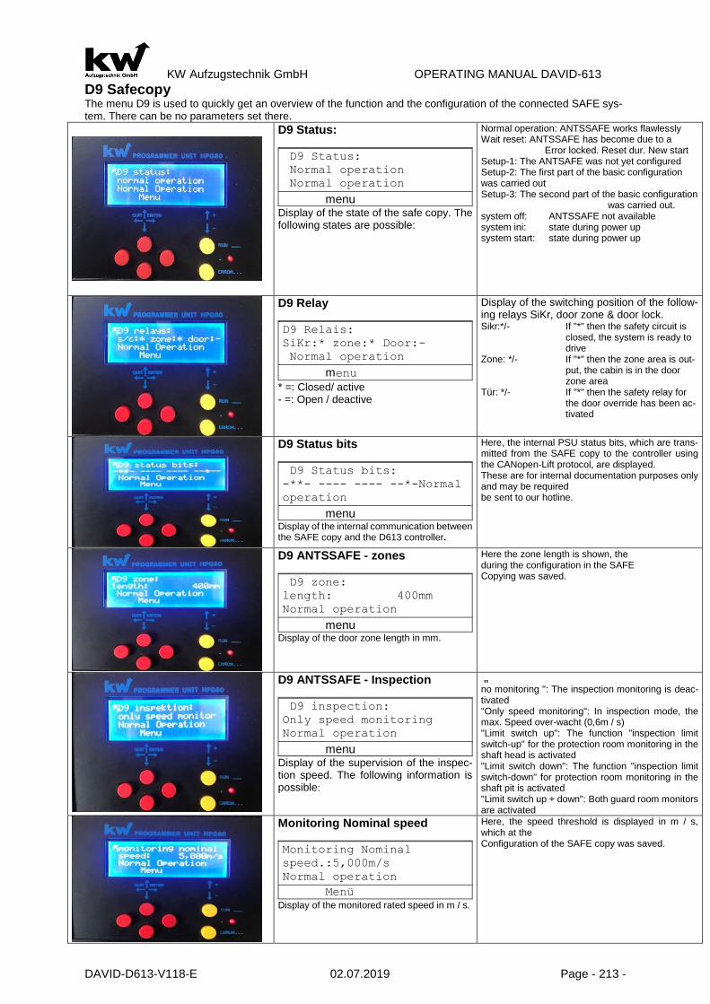
KW Aufzugstechnik GmbH OPERATING MANUAL DAVID-613
DAVID-D613-V118-E 02.07.2019 Page - 213 -
D9 Safecopy The menu D9 is used to quickly get an overview of the function and the configuration of the connected SAFE sys-tem. There can be no parameters set there.
D9 Status:
D9 Status:
Normal operation
Normal operation
menu Display of the state of the safe copy. The following states are possible:
Normal operation: ANTSSAFE works flawlessly Wait reset: ANTSSAFE has become due to a Error locked. Reset dur. New start Setup-1: The ANTSAFE was not yet configured Setup-2: The first part of the basic configuration was carried out Setup-3: The second part of the basic configuration
was carried out. system off: ANTSSAFE not available system ini: state during power up system start: state during power up
D9 Relay
D9 Relais:
SiKr:* zone:* Door:-
Normal operation
menu
* =: Closed/ active - =: Open / deactive
Display of the switching position of the follow-ing relays SiKr, door zone & door lock. Sikr:*/- If "*" then the safety circuit is
closed, the system is ready to drive
Zone: */- If "*" then the zone area is out-put, the cabin is in the door zone area
Tür: */- If "*" then the safety relay for the door override has been ac-tivated
D9 Status bits
D9 Status bits:
-**- ---- ---- --*-Normal
operation
menu Display of the internal communication between the SAFE copy and the D613 controller.
Here, the internal PSU status bits, which are trans-mitted from the SAFE copy to the controller using the CANopen-Lift protocol, are displayed. These are for internal documentation purposes only and may be required be sent to our hotline.
D9 ANTSSAFE - zones
D9 zone:
length: 400mm
Normal operation
menu Display of the door zone length in mm.
Here the zone length is shown, the during the configuration in the SAFE Copying was saved.
D9 ANTSSAFE - Inspection
D9 inspection:
Only speed monitoring
Normal operation
menu Display of the supervision of the inspec-tion speed. The following information is possible:
„ no monitoring ": The inspection monitoring is deac-tivated "Only speed monitoring": In inspection mode, the max. Speed over-wacht (0,6m / s) "Limit switch up": The function "inspection limit switch-up" for the protection room monitoring in the shaft head is activated "Limit switch down": The function "inspection limit switch-down" for protection room monitoring in the shaft pit is activated "Limit switch up + down": Both guard room monitors are activated
Monitoring Nominal speed
Monitoring Nominal
speed.:5,000m/s
Normal operation
Menü Display of the monitored rated speed in m / s.
Here, the speed threshold is displayed in m / s, which at the Configuration of the SAFE copy was saved.

KW Aufzugstechnik GmbH OPERATING MANUAL DAVID-613
DAVID-D613-V118-E 02.07.2019 Page - 214 -
end switch- TOP
end switch-TOP
position: xxx,000m
Normal operation
menu Display of the switch position Top in m.
Position: xx, xxxm The absolute position of the upper, taught-in limit switch is displayed here.
end switch-BOTTOM
end switch-BOTTOM
position: xxx,000m
Normal operation
menu Display of the switch position Down in m.
Position: xx, xxxm The absolute position of the lower taught-in limit switch is displayed here
dec. monitor BOTTOM
Dec. monitor-BOTTOM
Control above: Off/On
Normal operation
menu Indication of whether the deceleration control was activated below.
Off / Position: xx, xxxm Here you can see if the delay check below when configuring the SAFE copy disabled or enabled. If this has been ac-tivated stands there the absolute position of the monitoring point.
decel. Monitor TOP
decel-monitor-TOP
Control above: Off/On
Normal operation
menu Indicates whether the delay control has been activated above.
Off / Position: xx, xxxm Here you can see if the delay control above in the configuration of the SAFE copy disabled or enabled. If this has been activated stands there the absolute position of the monitoring point.
floors - ANTSSAFE
floors ANTSSAFE: 04
floors D613: 04
Normal operation
menu Here, the number of floors of the SAFE copy and the floor number of the control D613 is dis-played in comparison.
Here, the number of taught-in levels of the SAFE copy after the Learning trip and the specified number of floors in the shaft shown. Both floor values must have the same value after commissioning!
D9 ANTSSAFE - Software
ANTSSAFE-Software:
CRC: xxxxxxxx
Normal operation
menu Here, the CRC sum of the safe core of the Sil-3 software is displayed.
Here, the CRC sum of the safe core of the Sil-3 soft-ware is displayed. This sum should match the value of the certificate of the type examination certificate. Off and On switches rewatch the CRC value. The CRC sum may vary depending on the software ver-sion.

KW Aufzugstechnik GmbH OPERATING MANUAL DAVID-613
DAVID-D613-V118-E 02.07.2019 Page - 215 -
7.0 Start-up the lift I00 Assembling Travel In the submenu C7 assembly trip can be activated during active back getting control of these parame-ters. At the beginning at the assembling of a lift the switches of the safety circuit are not yet set. This function makes although the safety entrances are U3 to U12 without tension, a movement possible with the back getting control. A condition is that against U1 and U2 tension rests. Becomes if the back getting control break this parameter is automatically deactivated.
I01- Teach-In with digital relative/motor copying w. incremental encoder 1.0 General The fundamental operational sequence of the start-up of digital copying runs off in the following stepps:
2.0 Examination oft the electrical installations and attitude of the pre-end-switch
- All contact switches in the safety circuit should be attached. - The incremental giver should be functionally installed. You can install the incremental giver at the
car or at the speed limiter. The entrances are at the central unit as also at the car controller available. The linesare to be presented as follows:
Incremental encoder Controller Description
UB oder UVer Terminal 200 Voltage +24V DC
GND oder Masse Terminal 500 GND 0V
Kanal A Terminal 83 Channel A
Kanal B Terminal 84 Channel B
- The zone switches S71 and S72 ( for EoT & Releveling) and /or S 71 should be functionally installed. The length of the zone should be symmetrical to the concise line maximally 250 mm into both directions to extend. The more accurately the concise line is met the smaller fails later the concise correction.
- The pre-emd-switch 13A and 13B is to be adjusted on the that braking distance of the learning trip maximally which can be expected. The function of the pre-end-switcher should be examined with the inspection trip. As approximate reference point one can take the values specified down which can naturally differ by the adjusted delay values.
Approximate braking distance with 0,8 m/s2 delay Maximum driving speed
1000 mm 0,63 m/s
1200 mm 1,00 m/s
1800 mm 1,20 m/s
2300 mm 1,60 m/s
3000 mm 2,00 m/s
The bringing in way may be longer than in normal operation, since the Pre-end-switch is bridged there and the brake point by digital copying is spent. The pre-end switcher is not however synchro-nization points for the control and may after learning trip any more not be changed. The pre-end switcher down 13B must lie however between the 1st and 2nd stop. Equivalent one is to be placed the pre-end switcher above 13A between the next to last and last floor. This rule is to be kept also with short trip stop!
) Examination of the software attitudes and input of teh ranking distance of the lower pre-end switch.
) Examination of the electrical installations and attitude of pre-end switch.
) Execution of the leaning trip.
) Choise of the driving speeds by adjusting the braking distances.
) Fairs of the level is not ok and correction oft the concise values.
) Optionally: Attitude of the releveling.
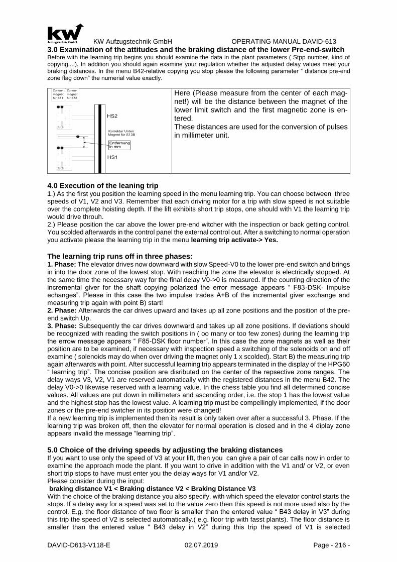
KW Aufzugstechnik GmbH OPERATING MANUAL DAVID-613
DAVID-D613-V118-E 02.07.2019 Page - 216 -
3.0 Examination of the attitudes and the braking distance of the lower Pre-end-switch Before with the learning trip begins you should examine the data in the plant parameters ( Stpp number, kind of copying,...). In addition you should again examine your regulation whether the adjusted delay values meet your braking distances. In the menu B42-relative copying you stop please the following parameter “ distance pre-end zone flag down“ the numerial value exactly.
Here (Please measure from the center of each mag-net!) will be the distance between the magnet of the lower limit switch and the first magnetic zone is en-tered. These distances are used for the conversion of pulses in millimeter unit.
4.0 Execution of the leaning trip 1.) As the first you position the learning speed in the menu learning trip. You can choose between three speeds of V1, V2 and V3. Remember that each driving motor for a trip with slow speed is not suitable over the complete hoisting depth. If the lift exhibits short trip stops, one should with V1 the learning trip would drive throuh. 2.) Please position the car above the lower pre-end witcher with the inspection or back getting control. You scolded afterwards in the control panel the external control out. After a switching to normal operation you activate please the learning trip in the menu learning trip activate-> Yes.
The learning trip runs off in three phases: 1. Phase: The elevator drives now downward with slow Speed-V0 to the lower pre-end switch and brings in into the door zone of the lowest stop. With reaching the zone the elevator is electrically stopped. At the same time the necessary way for the final delay V0->0 is measured. If the counting direction of the incremental giver for the shaft copying polarized the error message appears “ F83-DSK- Impulse echanges”. Please in this case the two impulse trades A+B of the incremental giver exchange and measuring trip again with point B) start! 2. Phase: Afterwards the car drives upward and takes up all zone positions and the position of the pre-end switch Up. 3. Phase: Subsequently the car drives downward and takes up all zone positions. If deviations should be recognized with reading the switch positions in ( oo many or too few zones) during the learning trip the errow message appears “ F85-DSK floor number”. In this case the zone magnets as well as their position are to be examined, if necessary with inspection speed a switching of the solenoids on and off examine ( solenoids may do when over driving the magnet only 1 x scolded). Start B) the measuring trip again afterwards with point. After successful learning trip appears terminated in the display of the HPG60 “ learning trip”. The concise position are disributed on the center of the repsective zone ranges. The delay ways V3, V2, V1 are reserved automatically with the registered distances in the menu B42. The delay V0->0 likewise reserved with a learning value. In the chess table you find all determined concise values. All values are put down in millimeters and ascending order, i.e. the stop 1 has the lowest value and the highest stop has the lowest value. A learning trip must be compellingly implemented, if the door zones or the pre-end switcher in its position were changed! If a new learning trip is implemented then its result is only taken over after a successful 3. Phase. If the learning trip was broken off, then the elevator for normal operation is closed and in the 4 diplay zone appears invalid the message “learning trip”. 5.0 Choice of the driving speeds by adjusting the braking distances If you want to use only the speed of V3 at your lift, then you can give a pair of car calls now in order to examine the approach mode the plant. If you want to drive in addition with the V1 and/ or V2, or even short trip stops to have must enter you the delay ways for V1 and/or V2. Please consider during the input: braking distance V1 < Braking distance V2 < Braking Distance V3 With the choice of the braking distance you also specify, with which speed the elevator control starts the stops. If a delay way for a speed was set to the value zero then this speed is not more used also by the control. E.g. the floor distance of two floor is smaller than the entered value “ B43 delay in V3” during this trip the speed of V2 is selected automatically.( e.g. floor trip with fasst plants). The floor distance is smaller than the entered value “ B43 delay in V2” during this trip the speed of V1 is selected

KW Aufzugstechnik GmbH OPERATING MANUAL DAVID-613
DAVID-D613-V118-E 02.07.2019 Page - 217 -
automatically.( e.g. short trip stop) The foor distance is smaller than the entered value “ B42 delay in V1” during this trip the speed of V0 is selected automatically.( extreme short trip stop, few cm) The parameters delay V0-> 0 and delay V3 must always exhibit a value.
6.0 Fairs of the level is not ok and correction of te concise values. The control was now examined i.e. the car not overdrive the stops and drive in the cab is possible. Connect yours HPG60 with the car calling in the car. From there out comfortably the “level is not ok” can measured and directly into the system will enter. Go with the car into the first stop and select your-selves you the parameter concise value level 1. Retaining inaccuracies be stopped by operation of the yellow Plus or Minus-Buttons. If your car stands too highly then you register the millimeter value which your car stands too highly by manipulation of the Minus-Button. If your car stands too low then by manipulation of the plus button the millimeter value is regis-tered which your car stands too low. The determined concise value is corected automatically. Repeat the procedure for the other stops.
7.0 Setting the releveling Before you enable the releveling, you must meet the following parameter setting in the B17- releveling:
1) The parameter max. Releveling Distance adjust the length of the road to catch up. The Releveling Distance should always be shorter than the half-zone area. Please also note the following facts: The zone area must be set so that it is shorter, as the door bar length. 2) The releveling-tolerance parameters set the starting point for the beginning of the catch-. As a default, you should not be less than 5 - 10mm go, because otherwise lead to unnecessary Releveling Operations any cable vibrations.Have the entries made above, the parameter can be catch-activated.

KW Aufzugstechnik GmbH OPERATING MANUAL DAVID-613
DAVID-D613-V118-E 02.07.2019 Page - 218 -
I02-Teach-In with digital Absolute copying with zone -switch
1.0 General
The fundamental operational sequence of the start-up of absolute copying with pre-end & zone switch runs off in the following steps: Examination of the electrical installations and atti-tude of the pre-end switch.
2.0 Examination of the electrical installations and attitude of the pre-end switcher - All contact switches in the safery circuit should be attached. - The absolute value device system should be functionally installed. This can be on the
car or at the switchboard. The entrances are represented in the connection diagram. - ( Page 7).
- The zone switches S71 and S72 ( for EoT & releveling) and /or S71 should be function-ally. The length of the zone should be symmetrical to the concise line maximally 250 mm into both directions to extend. The more accurately the concise line is met the smaller fails later the concise correction.
- The pre-end switcher 13A and 13B is to be set to that braking distance of the learning trip maximally which can be expected. The function of the pre-end switcher should be examined with the inspection trip. As approximate value one can take the value speci-fied down, which can naturally differ by the adjusted delay values.
Approximate braking distance with 0,8 m/s2 delay Maximum driving speed
1000 mm 0,63 m/s
1200 mm 1,00 m/s
1800 mm 1,20 m/s
2300 mm 1,60 m/s
3000 mm 2,00 m/s
The bringing in way may be longer than in normal operation, since the pre-end switch is bridged there and the brake point by digital copying is spent. The pre-end-switch is not however synchronization points for the control and may after learning trip any more not be changed. The pre-end switcher down 13B must lie however between the 1st and 2nd stop. Equivalent one is to be placed the pre-end-switch above 13A between the next to last and last floor. This rule is to be kept also with short trip stop!
3.0 Examination of the attitudes and the braking distance of the lower pre-end-switch Before with the learning trip begins you should examine the data in the plant parameters ( Stop number, kind of copying,...). In addition you should again examine your regulation whether the adjusted delay values meet your braking distances. In the menu B42-relative copying you stop please the following parameter “ distance pre-end zone flag down“ the numerial value exactly.
4.0 Execution of the leaning trip
1.0 As the first you position the learning speed in the menu learning trip . You can choose between three speeds of V1, V2 and V3. Remember that each driving motor for a trip with slow speed is not suitable over the complete hoisting depth. If the lift exhibits short trip stops, one should with V1 the learning trip would drive throuh.
2.0 Please position the car above the lower pre-end switcher with the inspection or back getting control. You scolded afterwards in the control panel the external control out. After a switching to normal operation you activate please the learning trip in the menu learning trip activate-> Yes.
The learning trip runs off in three phases: 1. Phase: The elevator drives now downward with slow Speed-V0 to the lower pre-end switch and brings in into the door zone of the lowest stop. With reaching the zone the elevator is electrically stopped. At the same time the necessary way for the final delay V0->0 is measured. If the counting direction of the incremental giver for the shaft copying polarized the error message appears “ F83-DSK- Impulse echanges”. Please in this case the two impulse trades A+B of the incremental giver exchange and measuring trip again with point B) start!
) Examination of the software attitudes and input of the raking distance of the lower pre-end switch.
) Examination of the electrical installations and attitude of the pre-end switch.
) Execution of the leaning trip.
) Choice of the driving speeds by adjusting the braking distances.
) Fairs of the level is not ok and correction of the concise values.
) Optionally: Attitude of the releveling.

KW Aufzugstechnik GmbH OPERATING MANUAL DAVID-613
DAVID-D613-V118-E 02.07.2019 Page - 219 -
2. Phase: Afterwards the car drives upward and takes up all zone positions and the position of the pre-end switch Up. 3. Phase: Subsequently the car drives downward and takes up all zone positions. If deviations should be recognized with reading the switch positions in ( oo many or too few zones) during the learning trip the errow message appears “ F85-DSK floor number”. In this case the zone magnets as well as their position are to be examined, if necessary with inspection speed a switching of the solenoids on and off examine ( solenoids may do when over driving the magnet only 1 x scolded). Start B) the measuring trip again afterwards with point. After successful learning trip appears terminated in the display of the HPG60 “ learning trip”. The concise position are disributed on the center of the respective zone ranges. The delay ways V3, V2, V1 are reserved automatically with the registered distances in the menu B42. The delay V0->0 likewise reserved with a learning value. In the chess table you find all determined concise values. All values are put down in millimeters and ascending order, i.e. the stop 1 has the lowest value and the highest stop has the lowest value. A learning trip must be compellingly implemented, if the door zones or the pre-end-switcher in its position were changed! If a new learning trip is implemented then its result is only taken over after a successful 3. Phase. If the learning trip was broken off, then the elevator for normal operation is closed and in the 4 diplay zone appears invalid the message “learning trip”. 5.0 Choice of the driving speeds by adjusting the braking distances If you want to use only the speed of V3 at your lift, then you can give a pair of car calls now in order to examine the approach mode the plant. If you want to drive in addition with the V1 and/ or V2, or even short trip stops to have must enter you the delay ways for V1 and/or V2. Please consider during the input: braking distance V1 < Braking distance V2 < Braking Distance V3 With the choice of the braking distance you also specify, with which speed the elevator control starts the stops. If a delay way for a speed was set to the value zero then this speed is not more used by the control. E.g. the floor distance of two floor is smaller than the entered value “ B43 delay in V3” during this trip the speed of V2 is selected automatically.( e.g. floor trip with fast plants). The floor distance is smaller than the entered value “ B43 delay in V2” during this trip the speed of V1 is selected automati-cally.( e.g. short trip stop) The foor distance is smaller than the entered value “ B42 delay in V1” during this trip the speed of V0 is selected automatically.( extreme short trip stop, few cm) The parameters delay V0-> 0 and delay V3 must always exhibit a value.
6.0 Measurement of the level is not ok and correction of the concise values. The control was now examined i.e. the car not overdrive the stops and drive in the cab is possible. Connect yours HPG60 with the car calling in the car. From there out comfortably the “level is not ok” can measured and directly into the system will enter. Go with the car into the first stop and select your-selves you the parameter concise value level 1. Retaining inaccuracies be stopped by operation of the yellow Plus or Minus-Buttons. If your car stands too highly then you register the millimeter value which your car stands too highly by manipulation of the Minus-Button. If your car stands too low then by manipulation of the plus button the millimeter value is regis-tered which your car stands too low. The determined concise value is corected automatically. Repeat the procedure for the other stops.
7.0 Attitude of the releveling Before you activate the releveling you must meet following parameter attitude in the menu B17-relev-eling: 1) In the parameter you stop max. retriving the length of the retrieving way. The retrieving way should be ever shorter than he half zone range. Consider please the following circumstances: The zone range must be adjusted that it is shorter as the door sword length. 2) In the parameter you stop tolerance retrieving starting point for the beginning of retrieving. As default value you should go unter 5-10 mm since otherwise existing rope oscillations lead to unnecessary relev-eling procedures. If the inputs described above were transacted the parameter releveling can be acti-vated.

KW Aufzugstechnik GmbH OPERATING MANUAL DAVID-613
DAVID-D613-V118-E 02.07.2019 Page - 220 -
I03- Commissioning with digital absolute copying without shaft switches
1.0 Examination the electrical installations and attitude of the pre-end switch All switches in the safety circuit should be attached. The absolute value device system should be func-tionally installed. This can be on the car or at the switchboard. The entrances are presented in the connection diagram. (Page S-07).
2.0 Allocation of the compactness You scolded “consice input” in the menu on the attitude floor height. Now you can be registered for each floor the value in the millimeter (e.g. HS01-0000mm, HS02-3000mm..). After all floors were reserved you scolded back on the attitude concise correction.
3.0 Execution of the determination of the „ counter direction“ The control does not know yet the counting direction of the ABS-absolute-value-encoder. The factory setting value of the parameter counter direction is “negative”. Set from there the value to “lerning: Drive Downward” and proceed the car with the manual control ( releveling control or inspection control) a small piece more deeply until the control terminates the trip.The control learned the counting direction now.
4.0 Execution of the synchronisation in the lowest stop Now the ABS-absolute-value-encoder with the control must be synchronize, that mean the controller has to allocate the announced impulse conditions of the abs giver of the individual floors. In addition you drive the car with the manual control ( releveling control or inspection control) into the lowest floor concisely and activate the menu option synchronizing HS01.
5.0 Choice of the driving speeds by adjusting the braking distances If you want to use only the speed of V3 at your lift, then you can give a pair of car calls now in order to examine the approach mode the plant. If you want to drive in addition with the V1 and/ or V2, or even short trip stops to have must enter you the delay ways for V1 and/or V2. Please consider during the input: braking distance V1 < Braking distance V2 < Braking Distance V3 With the choice of the braking distance you also specify, with which speed the elevator control starts the stops. If a delay way for a speed was set to the value zero then this speed is not more used by the control. E.g. the floor distance of two floor is smaller than the entered value “ B43 delay in V3” during this trip the speed of V2 is selected automatically.( e.g. floor trip with fast plants). The floor distance is smaller than the entered value “ B43 delay in V2” during this trip the speed of V1 is selected automati-cally.( e.g. short trip stop) The foor distance is smaller than the entered value “ B42 delay in V1” during this trip the speed of V0 is selected automatically.( extreme short trip stop, few cm) The parameters delay V0-> 0 and delay V3 must always exhibit a value.
Braking distance at 0,8 m/s2 Deceleration Maximum Speed
1000 mm 0,63 m/s
1200 mm 1,00 m/s
1800 mm 1,25 m/s
2300 mm 1,60 m/s
3000 mm 2,00 m/s
6.0 Measurement of the level is not ok and correction of the concise values. The control was now examined i.e. the car not overdrive the stops and drive in the cab is possible. Connect your HPG60 with the car calling in the car. From there out comfortably the “level is not ok” can measured and directly into the system will enter. Go with the car into the first stop and select yourselves you the parameter concise value level 1. Retaining inaccuracies be stopped by operation of the yellow plus or Minus-Buttons. If your car stands too highly then you register the millimeter value which your car stands too highly by manipulation of t he Minus-Button. If your car stands too low then by manipulation of the plus button the millimeter value is regis-tered which your car stands too low. The determined concise value is corected automatically. Repeat the procedure for the other stops.

KW Aufzugstechnik GmbH OPERATING MANUAL DAVID-613
DAVID-D613-V118-E 02.07.2019 Page - 221 -
13 Assembly of the Variotech-ANTS System
The Variotech ANTS is an absolute measuring system for determining the position of the elevator car, consisting of the reading head, the steel band and the mounting set. The steel strip is fixed in the upper and lower part of the shaft by means of shaft flag holders. Pay attention to the correct spring preload. The reader can be placed on the steel strip by means of a lateral open-ing. The position of the large & small holes in the steel strip must be observed when inserting! Please also note the Variotech ANTS installation instructions!
Mounting kit complete: 1 Shaft holder straight and angled 2 Screws & Clamps 3 Tension spring mounting at the bottom 4 K-hook tape mounting on top 5 Steel tape 6 Holder for reader-unit with attachment 7 Reader-unit with cable & plug
8 Stainless Steel Band
1. Mount the shaft flag holder in the shaft head in compliance with legal and company-related safety regulations. Depending on whether you are installing a central rail or backsack system, use the shaft flag holder straight or angled and fasten it with the fastening set 2. 2. Attach the upper end of the belt by inserting the carabiner hook 4 into the shaft flag holder 1. Before doing this, please check the orienta-tion of the tape using the large & small holes! 3. Drive down with the inspection and rewind the tape directly. Please provide personal protective equipment recommended for use. 4. Further assembly takes place in the shaft pit. Before entering the pit, ensure that the car is secured against uncontrolled downward move-ment. For work longer than 15 minutes, the car must be supported in compliance with the safety regulations of the assembly company! 5. Equivalent to steps 1 and 2, the lower shaft flag holder 1 and the holder 2 for the magnetic tape are to be mounted. A tension spring 3 is to be installed and it must be saved with a stainless steel band! Deci-sive for the functionality is the spring preload. It should be 170mm!

KW Aufzugstechnik GmbH OPERATING MANUAL DAVID-613
DAVID-D613-V118-E 02.07.2019 Page - 222 -
6. Mount the reader-unit 7 on the holder 6 provided for this purpose. 7. Insert the steel tape through the side opening on the reader. Use the markers on the reader to check the correct alignment of the holes.
8. Push the sliding block with the notch provided for the steel strip through the opening. 9. Insert the aluminum strip from the top downwards as far as it will go into the slot pro-vided for this purpose.
10. Mount the holder with the reading head using the 4 screws provided on the cab roof. 11. Check the correct mounting. The tape should be mounted vertically and straight. Deviations and angular misa-lignment must be corrected.
12. Switch the car computer off with the switch S37 FKR at the inspection box. 13. This allows the plug of the Variotech ANTS reading head to be plugged in without volt-age. Subsequently, the switch S37 can be switched on again.
14.
For proper operation of the CANopen bus, a termination resistor is required.
If there is only one SIL-3 shaft copying system in the CANo-penstandart, it is sufficient that all Dil switches are ON, as in the adjacent picture with switch position down!

KW Aufzugstechnik GmbH OPERATING MANUAL DAVID-613
DAVID-D613-V118-E 02.07.2019 Page - 223 -
2.0 Check the software settings
Before starting the teach-in, you should read the specifications in the attachment parameters A4 and the shaft copying menu B43.
2.1
The CANopen shaft copying system must be functionally installed. Subsequently, the activation takes place in the CANopen menu A402, in which a YES is entered for en-coder 1 activated.
2.2
In menu A403 the CAN bus must be switched on. This is done by activating in the menu item CAN bus: a YES.
2.3
In the B43 CANopen encoder menu a SAFE shaft copying system should be set. The choices are: 1.) Variotech ANTS SAFE 2.) LIMAX-33CP SAFE ( in preparation)
3.0 Teach-In Setup-1
After the SIL 3 shaft copying system has been recognized, the Setup 1 parameter is dis-played in the Status Safe parameter. By press-ing the Enter key one enters the input routine.
3.1 Enter the zone length This parameter is used to enter the zone length. Later, the zone length can be shortened, but not increased!
Change value and enter default value of 200 mm.
The entry is completed with the ENTER key. When the value is accepted, the saved mes-sage appears.
3.2 Entering the inspection limit switch (protection mode) With shortened pit or / and shortened pit head, inspection switches can be set. The dis-tance to the upper or lower limit switch is 1.2m. These positions are fixed. In order to make it possible to leave the shaft head / pit, the car is already stopped at a distance of 1.4 m!
Shaft pit and pit brow have normal height. attitude -> No limit switch and confirm with enter.
Shaft pit have reduced depth. attitude -> Limit switch down and confirm with enter.
Pit brow have recuced height. attitude -> Limit switch up and confirm with enter.
Shaft pit and pit brow are reduced. attitude -> Limit switch up+down and con-firm with enter.

KW Aufzugstechnik GmbH OPERATING MANUAL DAVID-613
DAVID-D613-V118-E 02.07.2019 Page - 224 -
After confirmation with ENTER the saved message appears.
3.3 Enter the nominal speed The SIL-3 shaft copying system can detect overspeed at 115% of nominal speed. For this, the nominal speed must be entered.
The default value is 5,00 m/s. This value must be on the Nominal speed of the eleva-tor system to be adjusted.
The entry is completed with the ENTER-Key. When the value ist accepted, the saved mes-sage appears.
3.4 Teaching the limit swich UP
3.4a Normal pit-brow 3.4b Reduced pit-brow
Key down:
Key down:
Set to YES with yellow keys.

KW Aufzugstechnik GmbH OPERATING MANUAL DAVID-613
DAVID-D613-V118-E 02.07.2019 Page - 225 -
1.) Move the limit switch position UP (100mm above flushing) with the backflow regulator. Eleva-tor car stops, when reaching the position. 2.) Enter yes in the menu.
The ANTSsafe limit switch UP position is automati-cally saved!
Reach top level landing position (1400 mm under flush) with the return contro and enter YES in the menu.
Move limit switch position UP ( 100mm over flush) with the return control. Elevator car stops on reaching the position.
The ANTSsafe limit switch UP position is automati-cally safed!
3.5 Learning the lower limit switch
1.)Enter YES in the menu.
2.) Move the limit switch position DOWN (100mm over flush) with the return control. Elevator stops on reaching the positon.
Die ANTSsafe limit switch DOWN position is auto-matically saved!
Note: From now on the SiKr is closed, if the elevator is not in the limit switch!
3.6 Entry Distance – Lower Delay Control Point
Enter and change the value, OFF, 2 to 500 cm; Can be changed later -. possible in inspection mode or return to safe state Vnenn: 1,6 m/s -> 300 cm Vnenn: 2,0 m/s -> 350 cm Vnenn: 2,5 m/s -> 400 cm
ANTSsafe Deley control down was stored.

KW Aufzugstechnik GmbH OPERATING MANUAL DAVID-613
DAVID-D613-V118-E 02.07.2019 Page - 226 -
3.7 Entry Distance – Upper delay control point
Enter value and change OFF, 2 to 500 cm; Can be changed later - possible in inspection mode or re-turn to safe condition Vnenn: 1,6 m/s -> 300 cm Vnenn: 2,0 m/s -> 350 cm Vnenn: 2,5 m/s -> 400 cm
ANTSsafe Delay Contro Top has been saved!
Note: (setup-3 means that all ASA parameters have been configured but no floors have been learned into the ASA) Note: If DSK is active, i. the floors have already been taught-in in the D613 and the flush levels are set then: ENTER ->STEP-3 key otherwise: DOWN key

KW Aufzugstechnik GmbH OPERATING MANUAL DAVID-613
DAVID-D613-V118-E 02.07.2019 Page - 227 -
3.8 STEP-2: D613-Learn leves and adjust levels
Two methods can be selected for learning floors, in the B43 menu Learning floors:
All, except for the top Floor be approached with inspection. The car is leveled and the position is learned and accepted with the red button on the HPG-60 or the quick but-ton on the inspection control
All flush values in mm were entered into the shaft table of the control system on the ba-sis of the floor height. The car is driven flush with inspection in the lowest floor and with the help of the HPG-60 this floor is synchronized. As a result, all floors are learned!

KW Aufzugstechnik GmbH OPERATING MANUAL DAVID-613
DAVID-D613-V118-E 02.07.2019 Page - 228 -
3.8A Learn floors with the method „ Manually start“
With the push button down the setting „manually start“ choose.
Use the yellow keys to set the value "Yes".
.. and press the enter key!
The display now indicates that the lowest floor is to be taught-in.
ODER
Therefore, the bottom floor will start manually (INSPECTION OR RETURN CONTROL) Now press the red "UP" button in the HPG or press the QUICK button on the inspection bulb
Result: The piezo sounds in the cabin for 1 second and in the 3rd line the text „Floor saved“ is displayed as confirmation!
Learn next floor by: Pressing the UP-button on the Inspection Onbulb or if the HPG-60 is being used, press the ENTER button. 3rd line activitated: Display 3rd line: „Input: UP button“
1.) The floor-02 with start inspection (or return). 2.). Press the QUICK button on the inspection bulb, or press the UP button if the HPG-60 is being used
Note: If the penultimate floor is reached, then the top floor is automatically occupied (end-switch TOP: - 100mm). Result: The piezo sounds in the cabin for 1 second & in the 3rd line the text „Floor stored“ is dis-played as confirmation!
Now switch the elevator to normal opera-tion Go to STEP 3.9

KW Aufzugstechnik GmbH OPERATING MANUAL DAVID-613
DAVID-D613-V118-E 02.07.2019 Page - 229 -
3.8B OPTIONAL: Learning floors with the mehod„ With shaft table“
Assignment of the shaft table
In the menu item "Flush input", switch to the "Floor height" setting. Now you can enter the value in mil-limeters for each floor, e.g. HS01-0000mm, HS02-3000mm.). After all floors have been preset, switch back to the setting Flush Correction.
Performing the synchronization in the lowest floor Now the ABS encoder must be synchronized with the controller, i. The control must assign the individ-ual pulses to the reported impulse levels of the ABS encoder. To do this, drive the drive basket with the manual control (return control or inspection control) to the lowest level flush and activate the Syn-chronize HS01 menu item.
3.9 Setting the final delay V0 > 0 In the menu End delay V0> 0 learn to activate the point. The elevator drives about 0.5m with the speed V0. After that, the delaying pain is learned and stored.
Note: Zones are not yet issued from SAFE copying, doors open at standstill on the approached floor
3.10 Choice of travel speeds by adjusting the braking distances
If you only want to use speed V3 on your lift system, you can now give a couple of intercom calls to check the entry behavior of the system. However, if you also want to drive with the V1 or / and V2, or even have short-stay stops, you must enter the delay paths for V1 or V2. Please note when entering: braking distance V1 <braking distance V2 <braking distance V3.By selecting the braking distance, you also specify the speed with which the elevator con-trol approaches the stops. If a delay path for a speed has been set to the value zero, then this speed is also no longer used by the controller. Is e.g. If the two-storey floor space is smaller than the entered value "B43 Delay at V3", the speed V2 is automatically selected during this drive (for example, floor drive for fast sys-tems). If the floor distance is less than the entered value "B43 Delay at V2", the speed V1 is automatically selected during this drive (for example, short landing stop). If the floor distance is smaller than the entered value "B43 delay at V1", the speed V0 is au-tomatically selected during this drive (extreme short stay, a few cm).
The parameter delay V3 must always have a value!
3.11 Measuring the irregularities and correcting the flush values
6.1 After checking from the controller that the elevator car does not override the stops and that it is possible to drive from the cab, please bring your HPG60 and, if possible, connect it to the FKR (car computer) on the car roof.
6.2 Take the elevator car to the first stop and select the Flush Level 1 parameter. Press the yellow plus or minus buttons to set the hold inaccuracies.
->
If your elevator car is too high, press the minus button to enter the millimeter value that your elevator car is too high.
->
If it is too low, pressing the plus button will enter the millimeter value that your elevator car is too low. The calculated flush value is automatically cor-rected
6.3 Repeat the procedure for the other stops.

KW Aufzugstechnik GmbH OPERATING MANUAL DAVID-613
DAVID-D613-V118-E 02.07.2019 Page - 230 -
4.0 STEP-3: Safekopierung – teach zones
Navigate with arrow keys and select the menu item with ENTER.
Navigate with yellow keys and enter "yes"
Note: Elevator moves 2x all floors. Afterwards, the status of the ANTS safe system is in "normal mode" and all zones are output and monitored
Warning! If the Step-3 is not closed successfully, there is a message like „Out of Order“ in the displays and all 25 Seconds a warning-signals appeares! A Normal-operation is NOT possible!
4.1 Adjustment of releveling
Before you activate readjustment, you must make the following parameter set-tings in menu B17 readjustment:
7.1 In parameter Max. Catch-up distance you set the length of the catch-up path. The distance should always be shorter than half the zone area. Please also note the following facts: The zone area must be set so that it is shorter than the length of the door.
7.2 In parameter Tolerance Recall you set the starting point for the start of the retrieval. By default, you should not go below 5 - 10mm, as otherwise existing rope vibrations lead to unnecessary readjustment. If the above entries have been made, the parameter Recall can be activated.
4.2 ANTS- SAFE – copy – error handling If the ANTSsafe detects a serious fault and locks itself, this condition can only be reset for safety rea-sons by deactivating the power supply and switching on the 24VDC on the ANTSsafe again. This can be done on the D613 by briefly changing the state of the inspection or return switch. This will set the output function A611 for 2 sec. The function A611 should control a relay, which will break the 24V supply voltage at the ANTSsafe.

KW Aufzugstechnik GmbH OPERATING MANUAL DAVID-613
DAVID-D613-V118-E 02.07.2019 Page - 231 -
Assembly of the ELGO-LIMAX-SAFE-CP33
The ELGO LIMAX CP33 is an absolute measuring system for determining the position of the elevator car, consisting of the reading head, the steel belt and the fixing set. The measuring system can work at a shaft height of up to 100m and a maximum speed of 4.0 m / s with a millimeter resolution. The magnetic tape is fixed with shaft tab holders in the upper and lower part of the shaft. Above the below shaft flag holder a shaft flag holder is attached to the belt breaker. It is important to pay attention to the correct spring preload. Passed through a gap in the reader on the magnetic tape Please also note the ELGO-LIMAX installation instructions!
Montage-Set
Assembly kit complete:
0 Reader with mounting bracket
1 2x Shaft flag holder for top & bottom
2 1x Shaft flag holder for
Bandabrissschalter
3 Bandolder below for Bandabrissschalter
4 Top band holder
5 Tension spring
6 2x cable ties
7 6x screws, u-washer, nuts & Clamping claws
8 Tape breaker with cable and attachment
9 Magnetic tape
1. Mount the shaft flag holder 1 in the shaft head in compli-ance with the legal and company-related safety regula-tions. With fastening set 4 (clamps) with a tightening torque of 20 Nm. 2. Attach the top end of the tape by inserting the holder 4 into the shaft flag holder 1. Before inserting the magnetic tape, please check the orientation of the tape. The printed arrows on the magnetic tape must point to the shaft head! The image to the right shows you how to insert the tape into the holder. Finally, the band end is secured with a cable tie 6. 3. Go down with inspection and unwind the tape directly. Please wear the personal protective equipment recom-mended for use. Avoid damage to the tape.
4. Drive the cabin into the middle of the shaft and let the en-tire belt into the shaft pit so that it hangs freely.

KW Aufzugstechnik GmbH OPERATING MANUAL DAVID-613
DAVID-D613-V118-E 02.07.2019 Page - 232 -
5. The freely suspended magnetic tape shows you the position where you have to mount the sensor on the cabin. The mounting bracket is already pre-mounted on the ELGO-CP33 sensor and the screw mounting is included. Check again whether the cho-sen mounting position is suitable. 6. Now pass the tape through the sensor. When us-ing the tape as a reference, align the sensor in the middle. 7. Now adjust the distance between the tape and the sensor. For lifting heights up to 50 meters we recommend a distance of approx. 15mm. This off-set ensures that the strip is correctly guided on the steel side during operation. Make sure that the sen-sor head is mounted vertically. Deviations lead to increased wear
8. Further assembly takes place in the shaft pit. Be-fore entering the pit, ensure that the car is secured against uncontrolled downward movement. When working for more than 15 minutes, be sure to wear the car while observing the safety regulations of the company! 9. Equivalent to steps 1 and 2, the lower shaft flag holder 1 and the holder 3 for the magnetic tape to be mounted. Please note that deviating from step 2 the space for a tension spring 5 must be provided! See right pic-ture! You need a space of 295mm. 10. Before you attach the spring, you must mount the shaft flag holder 2 with the belt breaker 8. The final location will be determined later. 11. Now you can hook in the spring 5. Decisive for the functionality is the spring preload. It should be 295mm! 12. Now it goes on with the exact installation of the strip breaker 8: The tape breaker is used to detect a tearing of the magnetic tape. The plunger of the switch is pushed in by the lower band holder and locks in this position. As a result, the safety circuit is permanently interrupted.

KW Aufzugstechnik GmbH OPERATING MANUAL DAVID-613
DAVID-D613-V118-E 02.07.2019 Page - 233 -
13. The belt breaker 8 is operated by the groove in the lower belt holder 3. Please fasten the belt breaker on the shaft lug holder. The shaft flag holder with the belt breaker is now positioned so that a mark on the belt clip is visible upwards and one downwards. The shaft flag holder is to be tightened at a 90 degree angle with a tight-ening torque of 20 Nm.
14.Subsequently, the band breaker 8 is set sharp. To do this, carefully remove the plunger (actuator) with a screw-driver
15. In the shaft pit / shaft pit box: Inserting the belt breaker cable with the wires 1-> 2D and 2-> 2E.
16. On the elevator car / inspection box: Plug in the SCA cable with the 715-PE-716 plug and the 2Z-3 plug.
17. In the inspection box: Plug in the POI cable with the pre-ex-tended plugs.
18.
For proper operation of the CANopen bus, a termination re-sistor is required.
If there is only one SIL-3 shaft copying system in the CANo-
pen standard, it is sufficient that all Dil switches are ON, as shown in the picture with switch position down!
Attention! 18. Ground the sensor with the grounding cable provided by mounting the sensor with the flat plug and the other end in the inspection box on PE!
20. Check the correct installation. Deviations and angular misalignment must be cor-rected. An inspection trip through the shaft is the best way to do this. 21. Check the correct installation. Deviations and angular misalignment must be cor-rected. An inspection trip through the shaft is the best way to do this.

KW Aufzugstechnik GmbH OPERATING MANUAL DAVID-613
DAVID-D613-V118-E 02.07.2019 Page - 234 -
2.0 Check the Software Settings
Before starting the teach-in, you should read the specifications in the attachment parameters A4 and the shaft copying menu B43.
2.1
The CANopen shaft copying system must be in-stalled properly. The activation then takes place in the CANopen menu A402, in which a YES is en-tered for encoder 1 activated.
2.2
In menu A403 the CAN bus must be switched on. This is done by activating in the menu item CAN bus: a YES.
2.3
A SAFE shaft copying system should be set in menu B43 CANopen encoder. The following selection is made:
LIMAX-33CP SAFE
3.0Teach-In Setup-1
Setup-1 config. means that the LIMAX33CP has not yet done a basic configuration. The basic configuration is only possible once and is usually carried out before delivery!
3.1 Input – electromagnetic safety gear? The option "yes" is only required if an electrical catch is to be controlled directly by the electronic output eSGC on the LIMAX33CP.
Normally (Stand2019-02) this is not the case. Therefore the following entry:
No
3.2 Input - Monitoring the Inspection ? The LIMAX CP33 offers the options for inspection operation: monitoring / no ca-bling. The monitoring mode monitors the inspection speed and the optional in-spection limit switches.
Basically, we always select monitoring mode to comply with EN81-20. The follow-
ing entry: Monitoring
3.3 Input - Nominal Speed ? The SIL-3 shaft copying system is capable of detecting overspeed at 115% of rated speed. For this it is necessary to enter the rated speed.
Entering the rated speed of the Elevator system in:
…. m/s
3.4 Input - Delay control? If there is a reduced pit head and / or a reduced pit, the delay control ETSL must be switched on.

KW Aufzugstechnik GmbH OPERATING MANUAL DAVID-613
DAVID-D613-V118-E 02.07.2019 Page - 235 -
Normal shaft -> OFF
Reduced head / pit -> ON
3.4a Input – Delay Control -> Braking delay Each brake element has its characteristic delay value. The value of the brak-ing system of the drive system is stated in the certificate. Value range from 0.1 to 10 m / s2.
Entering the braking deceleration of the elevator system in:
…. m/s2
3.4b Input – Delay Control -> Time delay Each control system has runtimes due to switching elements. Here, the time delay is to be entered until the brake element responds. Value range from 20 to 500 ms.
Enter the time delay until the brake element responds:
100 ms
3.4c Input - Delay Control -> buffer speed Here, the value for the speed is entered, with which the buffer can be maxi-mally opened. Range of values from 0.0 to 2.5 m / s.
Entering the maximum buffer speed of the elevator system
…. m/s
3.4d Input – Delay Control -> Offset UP Offset distance in mm of the calculated distance s (shelter) in the upwards direction. Value range from 0 to 1000 mm.
Input of the offset value in the up-wards direction:
100 mm

KW Aufzugstechnik GmbH OPERATING MANUAL DAVID-613
DAVID-D613-V118-E 02.07.2019 Page - 236 -
3.4e Input – Delay Control -> Offset Down Offset distance in mm of the calculated distance s (shelter) in the downward direction. Value range from 0 to 1000 mm.
Input of the offset value in the downward direction:
100 mm
To save, select "yes" with + or - and
press ENTER.
The message LIMAX33 Confi guration saved appears: ok
The basic configuration is now stored in the LIMAX33CP. This can not be changed!
3.5 Teach-In Setup-2
3.5 Enter the zone length This parameter is used to enter the zone length. Later, the zone length can be changed!
Change value and enter default value of 200 mm (maximum value). This value can be changed again later!
3.6 Input oft he inspection limit switch For shortened shaft pit and/or shortended pit-brow, inspection switches can be set. The following options exist:
Shaft pit and pit-brow have normal height. Setting -> No limit switch
Shaft pit has reduced depth. Setting -> Limit switch down
Pit-brow has a reduced height. Setting -> Limit switch top
Shaft pit and pit-brow are reduced. Setting -> Limit switch top + bottom

KW Aufzugstechnik GmbH OPERATING MANUAL DAVID-613
DAVID-D613-V118-E 02.07.2019 Page - 237 -
3.7 Learning the upper limit switch
1.) Approach the limit switch position UP with the return control. Stop the elevator car when reaching position.
2.) A YES is entered in the menu. The LIMAX CP33 limit switch TOP position is saved!
3.8 Learning the lower limit switch
1.) Approach limit switch position DOWN with the return control. Stop the elevator car when reaching position.
2.) A YES is entered in the menu. The LIMAX CP33 limit switch DOWN position is stored!
From now on, the safety circuit is now closed if the lift-cab is inside the limit switch.

KW Aufzugstechnik GmbH OPERATING MANUAL DAVID-613
DAVID-D613-V118-E 02.07.2019 Page - 238 -
3.9 STEP-2: D613-Learn floors and adjust Precision
There are two ways to learn the floors, in the B43 menu Learning floors
All, except for the top Halltestelle be ap-proached with inspection. The car is lev-eled and the position is learned and ac-cepted with the red button on the HPG-60 or the quick button on the inspection con-trol.
All flush values in mm were entered into the manhole table of the control system on the basis of the manhole height. The elevator car is driven flush with inspec-tion in the lowest stop and with the help of the HPG-60, this stop is synchronized. As a result, all floors are learned!

KW Aufzugstechnik GmbH OPERATING MANUAL DAVID-613
DAVID-D613-V118-E 02.07.2019 Page - 239 -
3.9A Floors learn with the method„ Manually start“
Use the maintenance key downwards to se-lect the setting "manually approach".
Use the yellow buttons to set the value "Yes".
.. and press the ENTER key! Display now indicates that the lowest floor should be installed…
OR
Therefore, the lowest floor will start manu-ally (INSPECTION OR RETURN CONTROL) Now press the red "UP" button in the HPG or press the QUICK button on the in-spection bulb
Sequence:! The piezo will sound in the cabin for 1 second and the text "Floor stored" will be displayed as confirmation in the 3rd line
Learn next floor by: Pressing the UP-button on the inspection bulb or if the HPG-60 is being used, press the ENTER button. The 3rd line is activated: Display 3rd line: “Input: UP button”.
1.) The floor-02 with start inspection (or re-turn). 2.) Press the QUICK button on the inspec-tion bulb, or press the UP button if the HPG-60 is being used.
Note: If the penultimate floor is reached, then the top floor is automatically occupied (limit switch TOP:-100mm) Result: The piezo sounds in the cabin for 1 second and in the 3rd line the text “Floor saved” is displayed as confirmation
Now switch the elevator to normal opera-tion
Go to STEP 3.10

KW Aufzugstechnik GmbH OPERATING MANUAL DAVID-613
DAVID-D613-V118-E 02.07.2019 Page - 240 -
3.9B OPTIONAL: Floors learn with the method „With shaft table“
Assignment of the flush positioning
In the menu item "Flush input", switch to the "Floor height" setting. Now you can enter the value in millimeters for each floor, e.g. HS01-0000mm, HS02-3000mm.). After all floors have been preset, switch back to the setting Flush Correction
Performing the synchronization in the lowest stop Now the ABS encoder must be synchronized with the controller, i. the controller must assign the indi-vidual pulses to the reported impulse levels of the ABS encoder. To do this, drive the drive basket with the manual control (return control or inspection control) to the lowest level flush and activate the Syn-chronize HS01 menu item.
3.10 Setting the Final deceleration V0 > 0 In the menu Final deceleration V0>0 learn to activate the point. The elevator moves about 0.5m at the speed V0. After that, the delaying pain is learned and stored.
Note: There are still no zones issued by the SAFE copy, doors open at standstill in the approached floor
3.11 Choice of travel speeds by adjusting the braking distances If you only want to use the V3 speed on your lift system, you can now give a couple of intercom calls to check the entry behavior of the system. However, if you also want to drive with the V1 or / and V2, or even have short-stay stops, you must enter the delay paths for V1 or V2. Please note when entering: braking distance V1 <braking distance V2 <braking distance V3 By choosing the braking distance, you also specify the speed with which the elevator control approaches the stops. If a delay path for a speed has been set to the value zero, then this speed is also no longer used by the controller. Is e.g. If the floor level of two floors is smaller than the entered value "B43 Delay at V3", then the speed V2 is automatically selected during this drive (for example floor drive for fast systems). If the floor distance is less than the entered value "B43 Delay at V2", the speed V1 is automatically selected during this drive (for example, short landing stop). If the floor distance is smaller than the entered value "B43 delay at V1", the speed V0 is automatically selected during this drive (extreme short stay, a few cm).
The parameter delay V3 must always have a value!
3.12 Measuring the irregularities and correction der Bündigwerte
1 After checking from the controller that the car does not override the stops and that it is possible to drive from the cab, please bring your HPG60 and, if possible, connect it to the FKR (car computer) on the car roof
2 Take the car to the first stop and select the parameter Flush Level 1. Press the yellow plus or minus buttons to seat the stop inaccuracies.
->
If your elvator car is too high, press the minus button to enter the millimeter value that your elevator car is too high.
->
If it is too low, pressing the plus button will enter the millimeter value that your elevator car is too low. The calculated flush value is automatically cor-rected.
3 Repeat the procedure for the other stops.

KW Aufzugstechnik GmbH OPERATING MANUAL DAVID-613
DAVID-D613-V118-E 02.07.2019 Page - 241 -
4.0 STEP-3: Safecopying – Teach Zones
Navigate with arrow keys and select the menu item with ENTER.
Use yellow keys + or - to navigate and enter "yes"
Note: Elevator moves 2x all floors. After-wards, the status of the LIMAX-CP33 sys-tem is in "normal operation" and all zones are output and monitored.
Warning! If the Step-3 is not closed successfully, there is a message like „Out of Order“ in the displays and all 25 Seconds a warning-signals appeares! A Normal-operation is NOT possible!
4.1 Setting the readjustment
Before activating readjustment, you must make the following pa-rameter settings in menu B17 readjustment:
7.1 In the parameter Max. Catch-up distance you set the length of the catch-up path. The catch-up distance should always be shorter than half the zone area. Please also note the following facts: The zone area must be set so that it is shorter, such as the length of the door sash.
7.2 In the Parameter Tolerance Recalculate you set the starting point for the beginning of the retrieval. As a default, you should not go below 5 - 10mm, as otherwise existing rope vibra-tions lead to unnecessary readjustment. If the above entries have been made, the parameter Nachholung can be activated.
4.2 ELGO LIMAX CP33 -Copy – Error handling
If the LIMAX33 detects a serious error and locks, this state can only be reset by a RESET command for safety reasons. This can be done on the D613 by briefly changing the state of the inspection or return switch. This will send a RESET command to the LIMAX33CP via the CANopen protocol and this will reboot.

KW Aufzugstechnik GmbH OPERATING MANUAL DAVID-613
DAVID-D613-V118-E 02.07.2019 Page - 242 -
4.3 ELGO LIMAX CP33 – Brief summary of commissioning
Status LIMAX33CP: Setup-1-Konfig. (only possible if LIMAX33CP still without basic configuration)
Possible settings: 1. LIMAX33 Exit: eSGC Elevator arrestor activ: no 2. LIMAX33 Inspection: Monitoring/No cabling 3. LIMAX33 Nominal speed: 1,000m/s 4. LIMAX33 Delay control ETSL: off / on
If delay control=yes: a. LIMAX33 ETSL Delay brake: 01,400m/s² b. LIMAX ETSL Delay: 100ms c. LIMAX33 ETSL Buffer speed: 0,600m/s d. LIMAX33 ETSL Offset up: 0010mm e. LIMAX33 ETSL Offset down: 0010mm
5. LIMAX33 Configuration to save: no/yes Status LIMAX33CP: Setup-2
Possible settings: 1. LIMAX33 Zone: Length= +-200mm 2. (if in setup-1 „Inspection: Monitoring“ activated) LIMAX33 Inspection: none 3. End switch/End switch up/End switch down/End switch up+down 4. LIMAX33 End switch UP learn: no/yes 5. LIMAX33 End switch DOWN learn: no/yes
➔Status LIMAX33CP: Setup-3 Status LIMAX33CP: Setup-3
Possible settings: 1. LIMAX33 Etagen: Learning trip start: no/yes 2. LIMAX33 End switch UP learn: no 3. LIMAX33 End switch DOWN learn: no
Status LIMAX33CP: Normal Operation
Possible settings: (Insp/Return motion must be activated) 1. LIMAX33 Zone: can be changed in the range +-10 bis +-200mm. 2. LIMAX33 Inspection (If Inspection monitoring activ): Inspection limit switches can
be activated or deactivated. 3. LIMAX33 End switch UP push: Can be moved in the range 0 bis -980mm com-
pared to the learned limit switch point UP. 4. LIMAX33 End switch DOWN push: can be moved in the range 0 to + 980mm op-
posite to the learned limit switch point DOWN. 5. LIMAX33 Learn new floors: no/yes: A new floor learning drive for the safecopy
can be carried out (Insp/Return motion must be disabled). 6. LIMAX33 End switch UP learn: The limit switch Point UP can be taught-in again.
To do this, the cab must be moved manually to the desired limit switch position, then confirm with YES. New limit switch position must be above the lower limit switch position.
7. LIMAX33 End switch DOWN learn: The limit switch Point DOWN can be taught in again. To do this, the cabin must be moved manually to the desired limit switch position below, then confirm with YES. New limit switch position must be below the upper limit switch position.

KW Aufzugstechnik GmbH OPERATING MANUAL DAVID-613
DAVID-D613-V118-E 02.07.2019 Page - 243 -
I06 Function test – Self-Monitoring of the Braking Elements after EN81-
1/2:1998+A3:2009
Generally Due to the development of the software, the function of the brake elements in-plant monitoring at KW Aufzugstechnik GmbH in the testing, as well as in the on-site commissioning of the lift system must be examined. The description of the functional test is part of the manual.
Test cable break - Monitoring Input 1 1.) Switch off the Signal line at the monitoring input channel 1. 2.) Return Motion Drive UP or DOWN 3.) The Controller DAVID 606/613/2005 gives the error mes-sage "F54 – Brake Element Synchronization” and locks. More trips are not possible! 4.) Switch on the Signal line at the monitoring input channel 1. 5.) With the Return-Drive to try to take a ride. A drive may be not possible! 6.) In the menu C0 the Controller DAVID 606/613/2005 can be unlocked in the fault memory by selecting the error. The elevator system is ready to start again.
Removing the monitoring channel 1
Test cable bridge - Monitoring Input 1 1.) Switch off the Signal line at the monitoring input channel 1 and put in a jumper between terminal 200 (+24 V DC) and channel 1. 2.) Return Motion Drive UP or DOWN 3.) The Controller DAVID 606/613/2005 gives the error message "F51 – Brake Element Function” and locks. More trips are not possible! 4.) Put off the jumper between the terminal 200 and channel 1. Switch on the Signal line at the monitoring input channel 1. 5.) With the Return-Drive to try to take a ride. A drive may be not possible! 6.) In the menu C0 the Controller DAVID 606/613/2005 can be unlocked in the fault memory by selecting the error. The elevator system is ready to start again.
Setting the jumper between 20o and Chan-nel 1
Repeat the test steps After the two test steps were carried out for the monitoring braking element 1, then for all other brake circuits have now equivalent to the test steps are carried out!

KW Aufzugstechnik GmbH OPERATING MANUAL DAVID-613
DAVID-D613-V118-E 02.07.2019 Page - 244 -
I07A ANTS-SAFE instruction for ANTS-ASA2-ASE: The ANTSSAFE shaft copying system with the ANTS-ASA2-ASE evaluation unit is a safe position evaluation according to SIL-3 for implementing the functions of limit switches, inspection limit switches, deceleration limit switches, Unintended Car Movement (UCM) as well as for safe bridging of the safety circuit in the area of the doors in the event of premature failure Door opening / retrieval of elevator systems according to EN81-20. The complete system consists of two devices, the ANTS-SAFE encoder and the ANTS-SAFE evaluation unit (ASA2) described here. In contrast to a conventional shaft copying with safety limit switches, as well as redundant zone switches with a safety circuit for door bridging, safe-copying no longer exists! The position detection takes place exclusively via a coded band, as well as a redundant evaluation unit. Thus, it is not possible to test non-existent switches! In a learning sequence, the positions of the limit switches and the floors must be taught-in. Thereafter, the taught-in limit switch positions and the zones around the taught-in levels are emulated. The functioning of the emulated switches is not tested, since the safe system (SIL-3) already performs all self-tests
ST
EP
- 1
>
Checking the opening of the safety circuit: To ensure that an ANTS-SAFE fault actually opens the safety circuit, the XTS connector can be disconnected at the ANTS-ASA-2-ASE evaluation unit.
As a result, the safety circuit of the elevator control is in-terrupted. This can be visually checked on the D613, all LEDs of the safety circuit from U8 must now light up red.
ST
EP
- 2
>
Checking the limit switches above: The limit switch position can be approached in the D613 control via the "C410 limit switch travel up" menu.
When passing this position, the safety circuit on the ANTS-ASA2-ASE is opened at connector X5. At the D613 control, all LEDs of the safety circuit now glow red starting at U8. At the same time an error entry appears in the control.
ST
EP
- 3
>
Checking the limit switches below: In the D613 control, the limit switch position can be approached via the "C411 limit switch travel down" menu.
When passing this position, the safety circuit on the ANTS-ASA2-ASE is opened at connector X5. At the D613 control, all LEDs of the safety circuit now glow red starting at U8. At the same time an error entry appears in the control.
ST
EP
- 4+
5
Check the zone switch: First of all, in menu D9 floors ANTSSAFE: xy "/" floors D613: xy "it can be checked that the ANTSSAFE and the D613 control board have learned the same number of floors.
The zone areas can be identified on the D613 using the two green ZONE LEDs. Only in the area of the zones around the respective floors may these LEDs light up. The zone information is from the ANTS ASA2 ASE.
ST
EP
- 6+
(7)
The function of the door override can be checked by activating in the menu "B16 retraction with open door". When traveling up to the floor, the door lock is activated only in the zone area, which is indicated by the rapid flashing of the LED "Drive O.T in the D613. independently and permanently and thus, e.g. the permitted door lockout complies with the standards.
In addition (OPTIONAL), the function "C416 Test UCM zone travel" can be checked on every floor so that the UCM case is triggered when leaving the zone when door lock is activated.

KW Aufzugstechnik GmbH OPERATING MANUAL DAVID-613
DAVID-D613-V118-E 02.07.2019 Page - 245 -
I07B – ELGO LIMAX CP33 Test Instructions
The shaft copying system ELGO LIMAX CP33 is a safe position evaluation according to SIL-3 for the implementation of the functions of limit switches, inspection limit switches, deceleration limit switches, Unintended Car Movement (UCM) as well as for safe bridging of the safety circuit in the area of the doors in the case of premature door opening / retrieval of Lift systems according to EN81-20. The complete system consists of the central unit LIMAX CP33 and the corresponding magnetic tape. In contrast to a conventional shaft copying with safety limit switches, as well as redundant zone switches with a safety circuit to bridge the door, safe-copying no longer exists! Position detection takes place exclusively via a coded band as well as a redundant evaluation unit. Thus, it is not possible to test non-existent switches! In a learning sequence, the positions of the limit switches and the floors must be taught-in. Thereafter, the taught-in limit switch positions and the zones around the taught-in levels are emulated. The functioning of the emulated switches is not tested, since the safe system (SIL-3) already performs all self-tests independently and permanently and thus, e.g. the permitted door lockout complies with standards.
ST
EP
-0
System Reboot Some self-diagnostic checks of the LIMAX33CP-00 are only performed when the system is restarted. Therefore, it is absolutely necessary to restart the LIMAX33CP-00 at the annual check. This can be done either via the RESET button, by a RESET com-mand from CAN or by disconnecting / reconnecting the main power supply Magnet Tape For the magnetic tape, tape guide and tape presence sensor, observe the maintenance instructions in the manual for the magnetic tape.
Configuration Set The configurable parameters / features of the LIMAX33CP-00 are noted on the information sheet enclosed with the lift documenta-tion. They must correspond to the conditions of the elevator.
ST
EP
- 1
>
Checking the opening of the safety circuit: To ensure that a fault of the LIMAX CP33 actually opens the safety circuit, the connector 2Z-3 can be removed from the FKR.
On the LIMAX CP33, the safety circuit is opened at the OC / terminal 2Z - 3 SiKr output. All LEDs of the safety circuit from U8 on the D613 control now light up red.
ST
EP
- 2
>
Check the limit switch above: The limit switch position can be approached in the D613 control via the "C410 limit switch travel up" menu.
When crossing this position, the safety circuit on the LIMAX CP33 at the OC / terminal 2Z - 3 SiKr output is opened. At the D613 control, all LEDs of the safety circuit now glow red start-ing at U8. At the same time, a fault entry appears in the con-trol.
ST
EP
- 3
>
Checking the limit switches below: In the D613 control, the limit switch position can be ap-proached via the "C411 limit switch travel down" menu.
When crossing this position, the safety circuit on the LIMAX CP33 at the OC / terminal 2Z - 3 SiKr output is opened. At the D613 control, all LEDs of the safety circuit now glow red start-ing at U8. At the same time, a fault entry appears in the con-trol.
ST
EP
- 4+
5
Check the zone switch: First of all, in menu D9 floors ANTSSAFE: xy "/" floors D613: xy ", it can be checked that the ANTSSAFE and the D613 controller have learned the same number of floors
The zone areas can be identified by the two green ZONE LEDs on the D613. Only in the area of the zones around the corre-sponding floors may these LEDs light up. The zone information comes from the LIMAX CP33

KW Aufzugstechnik GmbH OPERATING MANUAL DAVID-613
DAVID-D613-V118-E 02.07.2019 Page - 246 -
ST
EP
- 6+
(7)
The function of the door override can be checked by acti-vating in the menu "B16 retraction with open door". When traveling to the floor, the door override is activated only in the zone area, which is indicated by the rapid flashing of the LED "Einf.O.T in the D613.
Additionally (OPTIONAL) the function "C416 Test UCM zone travel" can be checked on every floor to trigger the UCM case when leaving the zone when the door lock is activated.
ST
EP
- 8
The function of checking the inspection direction is initiated by activating the inspection. The examiner drives the elevator up and down half a meter to see if it is moving in the right di-rection. In the event of deviations in this test, the wiring of the inspec-tion inspection is checked and, if necessary, corrected. If the elevator first moves in the right direction but is then stopped by an open OC, the UP and DOWN signals are incorrectly connected to the LIMAX33CP-00.
On the LIMAX CP33, the safety circuit is opened at the OC / terminal
2Z - 3 SiKr output. At the D613 control, all LEDs of the safety circuit now glow red starting at U8.
ST
EP
- 9
The function of checking the inspection limit switches is initi-ated by activating the inspection. When approaching the in-spection limit switches at normal inspection speed, due to the open OC, the cab should come to a stop before the pre-set stop system triggers. Otherwise a man would be trapped on the roof or in the pit. The inspector carries out an inspection trip at normal inspec-tion speed upwards. OC opens when the upper limit switch position is overrun and the vehicle comes to style. Control: Standstill is reached before the position of the The same thing happens in the down direction. After the cab has come to the style stand, it should be possible to move the vehicle in the safe direction to push the correct direction but-ton.
On the LIMAX CP33, the safety circuit is opened at the OC / terminal 2Z - 3 SiKr output. At the D613 control, all LEDs of the safety circuit now glow red starting at U8.
ST
EP
- 10
Function of overspeed V-rated (advance solution) The tester adjusts the elevator control / inverter so that over-speed can be achieved. It moves in both upward and down-ward direction and at a speed slightly above the speed ahead. Check: OC opens when the pre-trip speed is reached and the engine brake stops the lift.
On the LIMAX CP33, the safety circuit is opened at the OC / terminal
2Z - 3 SiKr output. At the D613 control, all LEDs of the safety circuit now glow red starting at U8.
ST
EP
- 11
Function of overspeed V-inspection The inspector carries out an inspection run at an inspection speed higher than the prefeeling speed in inspection of the LIMAX33CP-00. To check: OC opens on reaching the "advance speed inspec-tion" and the engine brake stops the elevator.
On the LIMAX CP33, the safety circuit is opened at the OC / terminal
2Z - 3 SiKr output. At the D613 control, all LEDs of the safety circuit now glow red starting at U8.

KW Aufzugstechnik GmbH OPERATING MANUAL DAVID-613
DAVID-D613-V118-E 02.07.2019 Page - 247 -
Illustration: Security circuit SIS16-101 with the two con-
tacts strips T71 and T72, and one Jumper. Here you can set a Jumper for permanently activation of the safety-relais for the zone 71 or zone S72 in order to simulate a no open-ing contact set of a zone-switch.
Definition An independent switching element for the zone, also referred to as a zone switch, may be a magnetic switch, a Hall switch, a forked light barrier, an inductive switch, a capacitive switch, a roller switch, a "sensor" which according to the prior art can detect a zone , Likewise, a zone can be output via an ab-solute position measuring system in cooperation with the control computers. In conjunction with one of the switching elements described above (S71 via discrete switching element, S72 via absolute value encoder & control computer output), this results in a higher level of safety. In order to guarantee a per-fect speech regulation we talk about zone sensors (devices), which generate a zone signal! General The zone switches S71 and S72 are installed after the defaults in the solenoid plan and the switching contacts are closed, i. E. the car is within the zone range. Experation Give a call to any floor and keep you closed with the start of the car the zone switch to S71. In addition you push a Jumper over the upper Dil-contact strip T71 with the clamp 71. At the entry into the finish level now no bypass of the door contacts and the check central switch take place. The green LED „status“ does not shine any longer and the next trip remains closed. Procedure for systems with external Servicepaneel Give you a call in any floor and hold it at the start of the car closed the zone switch S71. This is the terminal to 71 to 200 bridges. At the entrance to the destination floor now takes no bridging de door contacts and the locking means switch instead. In the HPG, the error message “F92 – safety ciruit”. Properties With elevators with hydraulic drive and adjusted sinking trip an error of the protection circuit 16-101 leads not to an immediate blockage during the next trip, but only after the emergency sinking and reach-ing the sinking level. With rope elevator plants the reaction is adjustable in the menu production circuit. Unblocking Ater you removed the Jumper over the Dil contact strip T71 you must switching off and on the controller. The accumulator buffering must be interrupted however likewise at short notice( to take off emergency powe akkus). Repetition The same procedure must be repeated now for the zone switch S72. Therefore the Dil contact strip T72 is to you at the disposal. The further operational sequence the reaction as well as the unblocking is an equivalent procedure.
Attention! Remote the put Jumper in any case after the functional test!

KW Aufzugstechnik GmbH OPERATING MANUAL DAVID-613
DAVID-D613-V118-E 02.07.2019 Page - 248 -
I08 Functional test – Detection of an unintended car movement EN 81-20:2014-11
To initiate the journey from the zone, note the following:
1.) Stopping the elevator car flush with the bottom landing (top stop) . 2.) Turning the Return Motion Drive -> Close the doors. 3.) Function “UCM-zone drive” in the TÜV Menue-C416 activate 4.) Return Motion Drive UP (DOWN), until the security circuit SIS16-101 interrupt. 5.) Open the shaft door and measure the stopping distance. 6.) Close the shaft door 7.) In the C0 RESET menu error „F60 A3-case“ reset 8.) Cabin with Return Motion Drive downwards (top down) drive. 9.) Return Motion Drive off -> door opens -> normal operation 10.) Repeated process for the top stop on your way down zone -> () note entries!
General According to the new standard EN 81-20: 2014-11 “protection of unintended car movement away from the landing
with the landing door not in the locked position and the car door not in the closed position” the car must leave the door zone and must come to a halt within the legal stopping distance. As a worst-case scenario here, the “Motor-driven exit” door opener in the zone with acceleration values of the normal operation is considered.
Basically, the simulation of the process never done with an open door! To facilitate this, a separation in the control terminal,is availabel a Relay “K69”, the safety circuit of the door lock of SIS16-101 / feedforward separates drive contactors in the simulation case. In order to allow the elevator to the start of the journey, is a software function in TüV menu of the control computer of the series D606, D912 and D2005 activates the security circuit for a drive, so that the drive and braking elements contactors are energized until they leave the zone. After leaving the zone, the drive is disconnected and so the car comes to a stop. You can now open the landing door with the emergency release and determine the stopping distance, based on the hatch door to the cabin doorway clamp.
Experation The elevator car is parked in the lowest landing floor and turned on the Return Motion Drive. This will be the landing and car door closed and a Call input over indoor and outdoor control is suppressed. Please listen in with the local intercom in the cabin, if there are people in it. You can take the handheld terminal HPG-60 in the control computer to the TÜV menu 416th UCM-zone drive. The UCM-zone drive is set to ON. Now you can start with the Return Motion Drive Switch UP holt the drive, which ends when you leave the zone. Auto-matically increase the speed to rated speed and the acceleration was increased to 100% (in conjunction with GOLIATH inverter). The stopping distance is displayed in mm on the display. The system is locked with the error “F60 A3-case”. Op-tionally, you can open the Landing door chess with the emergency release and measure the stopping distance (Chess doorway to the cabin door threshold). After re-closing the landing door and turning off the safety circuit fuse F7. Before switching on the safety fuse F7 in the circuit, C0 RESET menu must be reset the A3 error then you can drive with the Return Motion Drive Switch DOWN, the elevator car in the lowest station. Repetition
The same process must now be repeated for the top stop. Therefore, the elevator car at the top station is placed flush with the zone and performs way down.

KW Aufzugstechnik GmbH OPERATING MANUAL DAVID-613
DAVID-D613-V118-E 02.07.2019 Page - 249 -
I09 Functional test – Mech. Brake-Opening in landing and the car door is not in the closed position EN 81-20: 2014-11 According to the new standard EN 81-20: 2014-11 “protection of unintended car movement away from the landing with the landing door not in the locked position and the car door not in the closed position” the car must leave the
door zone and must come to a halt within the legal stopping distance. Basically, the simulation of the pro-cess never done with an open door!
1.) Stopping the elevator car aligned in a middle floor. 2.) Listening-with the phone, if there are people in the ele-
vator car.
3.) If there any persons, then push the service-button on the upper left of the central unit D606/ D613/ D2005 to close the doors.
4.) All the doors are closed, when all the LED lights are green of the Safety-Circuit-Positions U1 to U12!
5.) Switch off the landing control via the switch S36 in the
service panel in right position.
6.) Please switch off the fuse F7 of Safety-Circuit. 7.) Please put away the wire X1/6 Number 6.
8.) Please isolate the wire!
9.) Please switch on the fuse F7 of Safety-Circuit.
10.) Now the LEDs are red for the Safety-Circuit-Positions
of the doors, but in reality are the doors closed!
11.) Mechanical press brake lever until the safety circuit SIS16-101 interrupts the journey when leaving the zone, or at a safety device with anti-creep until the catch engages.
12.) The Communicator HPG-60 shows the error F60 A3 case. The elevator system is locked!
13.) Please open the shaft door and possibly measure the stopping distance. Then close shaft door again.
14.) Please switch off the fuse F7 of Safety-Circuit.
15.) Please put in the wire X1/6 with the designations 6.
16.) Please switch on the fuse F7 of Safety-Circuit.
17.) Reset the error "F60 A3-case" in the C0-RESET menu. 18.) Switch on the landing control via the switch S36 in the
service panel in right position.

KW Aufzugstechnik GmbH OPERATING MANUAL DAVID-613
DAVID-D613-V118-E 02.07.2019 Page - 250 -
I10 Inspector-session
4.0 Execution of the Watchdog Timing In the submenu C40 run time test of the processor system DAVID-613 is possible it to limit all running times for the next trip on 1,0 seconds.
1 The car is in a stop concisely place
2 Adjust the menu C-Diagnosis/ Inspection-session, C40 run time test in the processor DAVID-613. All run-ning times are set on one second
3 Call input by lowest/ highest call at the top side of the DAVID-613 central processing unit in the menu C-Di-agnosis /C- Call input
4 The plant opposes with run time error when going away from the stop
5 Unblocking the plant by In-/ Offswitching the switch S33 or releasing of the reset in the menu C-Diagnosis / C0-Reset
6 The system is again in normal operation
4.1 Execution of the buffer trip In the submenu C41 buffer trip is to be driven it possible with the back getting control downward. without obligation delay by the before-finalswitched 13B on the cab buffers) But only if the limit switch down by technical personal at the strip of passing pressed.
1 The back getting control S61 switch on
2 Adjust the menu C-Diagnosis/ Inspection-session, C41 buffer trip in the processor DAVID-613. the pre-end switch Down S13B is not considered.
3 Switch over hand terminal ( HPG-60) into the parameters of the frequency changer ( Goliath-60). Increace the parameter “speed Vi” in the menu “ desired value” to the desigred worth.
4 The protection F7 switch off and emergency limit switch down bridge. Protection F7 restart.
5 The car drive with the releveling control upwards on the buffer.
6 After examination the car drive upward from the buffer. Bridge from the safety circuit remove and the speed back of Vi put to the the regular value .
7 The releveling control S61 switch off. The control returns to normal operation.
4.2 Execution of the seat sample
In the submenu C42 seat sample is to be driven it possible with the back getting control downward. (without obligation delay by the before-final-switched 13B on the counterweight buffers) But only if the limit switch down by technical personal at the strip of passing pressed. The speed for this trip is to be positioned in the regulation.
1 The back getting control S61 switch on
2 Adjust the menu C-Diagnosis/ Inspection-session, C42 seat sample in the processor DAVID-613. the pre-end switch Up S13A is not considered.
3 Switch over hand terminal ( HPG-60) into the parameters of the frequency changer ( Goliath-60). Increace the parameter “speed Vi” in the menu “ desired value” to the desigred worth.
4 The protection F7 switch off and emergency limit switch down bridge. Protection F7 restart.
5 The car drive with the releveling control upwards on the buffer.
6 After examination the car drive upward from the buffer. Bridge from the safety circuit remove and the speed back of Vi put to the the regular value .
7 The releveling control S61 switch off. The control returns to normal operation.

KW Aufzugstechnik GmbH OPERATING MANUAL DAVID-613
DAVID-D613-V118-E 02.07.2019 Page - 251 -
4.3 Execution of the Claw Test of the elevator car In order to implement the catch sample with the elevator car the car must arrive into the overspeed. This is only possible if that short-circuit protection and the monitoring function V<0,2 m/s deactivated.
1 The car in the center and/or in the upper half of the pit concisely place.
2 Invite the test weights into the elevator car.
3 The releveling control S61 switch on.
4 Adjust the menu C-Diagnosis/ Inspector-session, C43 Claw Test in the processor system DAVID-613. By this parameter that becomes short-circuit protection in frequenz inverter of the series Goliath-60. The monitoring function is waived which prevents the brake opening at a speed of more largely 0,2 m/s.
5 The emergency freeing switch S80 activate and the brake opening key S81 press unto the car has impris-oned.
6 Switch over the hand terminal the HPG-60 into the parameter frequence inverter Goliath-60. In the menu drive out /stop the parameter catch freeing activate. Thus for short time the current is increased on 2.0 sub-ject of the rated current.
7 The car with the releveling control in upward direction from the catch pull.
8 The back getting control S61 switch off. The control returns to normal operation.
4.4 Driving abillity with fixed counterbalance 1 The car is in a highest stop concisely place
2 The back getting control S61 switch on
3 Adjust the menu C-Diagnosis/ Inspection-session, C44 speed in the processor DAVID-613. In this menu are spend the speed of the car and the number of revolutions of the drive.
4 The car move upward with the releeling control. If the car comes to short time to a halt, evidently at the speed of 0 m/s but the number of revolutions of the drive larger 0 rpm is waived the driving ability and the examination successfully terminates. If the speed does not drop to 0 m/s the driving ability is too high.
5 The car with the releeling control upwards from the upper emergency limit awitch move.
6 The releveling control S61 switch off. The control returns to normal operation.
4.5 Brake test In the submenu C45 break test the processor system DAVID-2005-613 is possible during switched resent control the short-circuit protection and the monitoring function V<0,2 m/s to deactivate. Security the monitoring function becomes V>Vnenn activates which bracked with exceeding of the nominal speed terminated( both brake coils become without tension).
Attention! The following activities may be accomplished only by authorized technical personal. Thus all irregu-laties and disturbances can when assembling and with operated a lift to be recognized and repaired. Regardless of the safety regulation specified in this guidance in the user country valid laws regula-tions are to keep guidelines and standarts.
1 The car must be at least two floors below the highest stop
2 Please pay attention of the empty car. You scolded the resend control S61 and drive the cab outside of the door zone. The doors remain closed.
3 Adjust the menu C-Diagnosis/Inspector-session, C45 brake test. By this parameter that becomes short contactor power down in the frequency inverter of the series Goliath-60. The monitoring function is waived (those the brake opening at a speed of more largely 0,2 m/s prevented).
4 Give an car call with the HPG-60 or press at the central unit the calling button for the lowest stop place.
5 After the car has started moving you must activate the break-test key button S82 by a rotation to the right. Press the brake opening racer S 82A. Now the brake is opened permanently.
6 Operate now the brake opening tracer S81A. The security circle interrupted the brake coil A is still under tension and remains open, but the brake coil B drops.
7 The brake coil B which can be examined closes, rake coil A is still unter tension. The minimum delay value for a brake circuit amounts to 0.4 m/s2, and/or the maximum stopping distance with Vnenn= 1.0 m/s amounts to 1,8 m and/or with Vnenn= 1. m/s of 3,5m!
8 Test procedure for the second brake circuit repeat!
9 After successful braking code switch S82 braked switches off and keys off takes.

KW Aufzugstechnik GmbH OPERATING MANUAL DAVID-613
DAVID-D613-V118-E 02.07.2019 Page - 252 -
4.6 Execution of the Remote Trigger Car In the submenu C46 Remote Trigger Car of the processor system DAVID-613 is possible to activate the function Remote Trigger Car over the Switch S50 on the operating panel of the controlercabinet in order to switch on the coil of the speedlimiter. After put off the switch S50, the function is switched off. 4.7 Execution of the Reset Remote Trigger Car In the submenu C47 Reset Remote Trigger Car of the processor system DAVID-613 is possible to activate the function ResetRemote Trigger Car over the Switch S50 on the operating panel of the con-trolercabinet in order to switch on the Reset-coil of the speedlimiter. After put off the switch S50, the function is switched off. 4.8 Execution Remote Trigger Counterweight In the submenu C48 Remote Trigger Counterweight of the processor system DVID-613 is possible to activate the function Remote Trigger Counterweight over the Switch S50 on the operating panel of the controlercabinet in order to switch on the coil of the speedlimiter of the counterweight. After put off the switch S50, the function is switched off. 4.9 Execution Reset Remote Trigger Counterweight In the submenu C49 Reset Remote Trigger Counterweight of the proseccor system DAVID-613 is possible to activate the function Reset Remote Trigger Counterweight over the Switch S50 on the op-erating panel of the controlercabinet in order to switch on the Reset-coil of the speedlimiter of the coun-terweight. After put off the switch S50, the function is switched off. 4.10 Execution Endswitch Travel Top In the submenu C410 Endswitch Travel Top of the processor system DAVID-613 it is possible to over-drive the highest Levelpoint by switching on the function. The travel ends in the Endswitch Top. 4.11 Execution Endswitch Travel Bottom The submenu C411 Endswitch Travel Bottom of the processor system DAVID-613 it is possible to over-drive the lowest Levelpoint by switching on the function. The travel ends in the Endswitch Bottom. 4.12 Execution Switchcabinet Temperature Test In submenu C412 switchcabinet temperature test of the processor system DAID-613. You can decrease the temperature limit, inorder to produce an error message. It is very important that the switchcabinet temperature function is active in the menu B600 monitoring functions. 4.13 Execution Motor-PTC Test In the submenu C413 motor PTC test of the processor system DAVID-613 it is possible to simulate a motor PTC error for one travel, inorder to generate an error in the controllersystem. It is very important that the PTC-function is active in the menu B600 monitoring functions.
4.14 Execution DSC-Pulse-Encoder Test In the submenu C414 DSK encoder test of the processor system DAVID-613 it is possible to switch off the encoder of the shaftcopy for one travel. The shaft copying software technically produce an error response. A condition is natural that in the menu B600 monitoring functions is the DSK monitoring active. 4.15 Execution test Sink-prevention In the submenu C415 test Sink Prevention of the processor system DAVID-613 is possible to activate the function Test Sink Prevention over the Switch S50 on the operating panel of the controlercabinet in order to switch off the coil of the speedlimiter. After put off the switch S50, the function is switched off.

KW Aufzugstechnik GmbH OPERATING MANUAL DAVID-613
DAVID-D613-V118-E 02.07.2019 Page - 253 -
4.16 Functional test –Detection of an unintended car movement EN 81-20:2014-11
To initiate the journey from the zone, note the following:
1.) Stopping the elevator car flush with the bottom landing (top stop) . 2.) Turning the Return Motion Drive -> Close the doors. 3.) Function “UCM-zone drive” in the TÜV Menue-C416 activate 4.) Return Motion Drive UP (DOWN), until the security circuit SIS16-101 interrupt. 5.) Open the shaft door and measure the stopping distance. 6.) Close the shaft door 7.) In the C0 RESET menu error „F60 A3-case“ reset 8.) Cabin with Return Motion Drive downwards (top down) drive. 9.) Return Motion Drive off -> door opens -> normal operation 10.) Repeated process for the top stop on your way down zone -> () note entries!
General According to the new standard EN 81-20: 2014-11 “protection of unintended car movement away from the landing
with the landing door not in the locked position and the car door not in the closed position” the car must leave the door zone and must come to a halt within the legal stopping distance. As a worst-case scenario here, the “Motor-driven exit” door opener in the zone with acceleration values of the normal operation is considered.
Basically, the simulation of the process never done with an open door! To facilitate this, a separation in the control terminal,is availabel a Relay “K69”, the safety circuit of the door lock of SIS16-101 / feedforward separates drive contactors in the simulation case. In order to allow the elevator to the start of the journey, is a software function in TüV menu of the control computer of the series D613, D912 and D2005 activates the security circuit for a drive, so that the drive and braking elements contactors are energized until they leave the zone. After leaving the zone, the drive is disconnected and so the car comes to a stop. You can now open the landing door with the emergency release and determine the stopping distance, based on the hatch door to the cabin doorway clamp.
Experation The elevator car is parked in the lowest landing floor and turned on the Return Motion Drive. This will be the landing and car door closed and a Call input over indoor and outdoor control is suppressed. Please listen in with the local intercom in the cabin, if there are people in it. You can take the handheld terminal HPG-60 in the control computer to the TÜV menu 416th UCM-zone drive. The UCM-zone drive is set to ON. Now you can start with the Return Motion Drive Switch UP holt the drive, which ends when you leave the zone. Auto-matically increase the speed to rated speed and the acceleration was increased to 100% (in conjunction with GOLIATH inverter). The stopping distance is displayed in mm on the display. The system is locked with the error “F60 A3-case”. Op-tionally, you can open the Landing door chess with the emergency release and measure the stopping distance (Chess doorway to the cabin door threshold). After re-closing the landing door and turning off the safety circuit fuse F7. Before switching on the safety fuse F7 in the circuit, C0 RESET menu must be reset the A3 error then you can drive with the Return Motion Drive Switch DOWN, the elevator car in the lowest station. Repetition
The same process must now be repeated for the top stop. Therefore, the elevator car at the top station is placed flush with the zone and performs way down.

KW Aufzugstechnik GmbH OPERATING MANUAL DAVID-613
DAVID-D613-V118-E 02.07.2019 Page - 254 -
Basics about brake control elements monitoring to the new standard EN 81-1:1998 + A3: 2009 resp. EN 81-2:1998 + A3: 2009 For the protection of unintended car movement away from the landing with the landing door not in the locked position and the car door not in the closed position according to the new standard EN 81-1:1998 + A3: 2009 resp. EN 81-2:1998 + A3: 2009 is done by the security circuit SIS16-101. The security circuit SIS16-101 causes the interruption of the safety circuit and thus acts directly on the drive contactors. Based on the Position paper of the NB-L ( CO-ORDINATION OF NOTIFIED BODIES LIFTS DIRECTIVE 95/16/EC) from 20.07.2011, Version 07, can be omitted in the external monitoring device of the brake control elements on a SIL 3 level. The monitoring is done by independent input channels of brake control elements monitoring of the control unit, or the regulation unit. At hydraulic lifts of the company ALGI and the types AZRS and AZFR , according to the new standard EN 81-2:1998 + A3: 2009, the Down Travel is initiatet with two series-connected hydraulic valves, which have a monitoring of the open and closed position. The monitoring is done by independent input chan-nels of brake control elements monitoring of the control unit, or the regulation unit. With traction elevator systems to EN81-1 with certified braking devices to the new standard EN 81-1:1998 + A3: 2009, like e.g. the types MAYER, Warner, ..., as a operating brake on the drives of the companies Wittur-SAD, Thyssenkrupp-Liftequipe, Ziehl-Abegg, Tornado, Sassi,..., or with A3 Certifica-tion brake control unit on the driving wheel, like the types of MAYER, Warner, ..., on the drives of Thyssenkrupp-Liftequipe-NBS, Sassi,...., the monitoring is done by independent input channels of brake control elements monitoring of the control unit, or the regulation unit. If the elevator system shut down, so they can be unlocked only by reset ( Menu C00 RESET )
4.17 Carrying out simulation failure of brake element-1 in accordance with EN81-20
In submenu C417 Test braking element brake-1 of the DAVID-613 processor system, it is possible to switch off the monitoring of the braking element of drive 1 for software purposes in order to generate an error response. This corresponds to a physical interruption of the line of the respective brake ele-ment. This is required for brake components requiring monitoring, in order to simulate a failure of a brake element according to EN 81-20..
4.18 Carrying out the brake test In submenu C418 Test brake test of the DAVID-613 processor system, it is possible to activate the brake test for one trip. After pressing the corresponding key switch S82A or S82B, the stopping distance in mm is displayed after stopping the elevator car. This function can only be used in conjunction with a GOLIATH-90 inverter.
4.19 Test direction change counter In submenu C419 Test direction change counter, it is possible to simulate a triggering of the direction change counter for the suspension cables / carrying straps by test activation. 4.20 Test rope wear counter
In the submenu C420 Test rope wear counter, it is possible to simulate a triggering of the rope wear counter for the suspension ropes / carrying straps by test activation. 4.21 Test brake element brake-2
In submenu C421 Test brake element brake-2 of the DAVID-613 processor system, it is possible to switch off the monitoring of the braking element of drive 2 for software purposes in order to generate an error response. This corresponds to a physical interruption of the line of the respective brake ele-ment. This is required for brake components requiring monitoring, in order to simulate a failure of a brake element according to EN 81-20. 4.22 Resetting the speed limiter pre-shutdown
In submenu C422 Test Reset GB pre-shutdown of the DAVID-613 processor system, it is possible to reset this by activating the function in the case of a lockable pre-shutdown of the Gb for the car with reset coil via pushbutton S50. After releasing the button S50, the function is deactivated again.
SAFE shaft copy system: When using SAFE shaft copying, the settings can be viewed in menu D9.

KW Aufzugstechnik GmbH OPERATING MANUAL DAVID-613
DAVID-D613-V118-E 02.07.2019 Page - 255 -
INDEX A G R Absolute dig. copy
85 General working with the
HPG60 60
Relative Digital Copy 93
Actual Value Menu 147 Gong at the Floor 98 Releveling 72 Gong in the Car 98 Remote Station 37 B Group Control 78 Resend-Drive 121 Brake-open-monitor 120 Rescue Travel 132 Brake-shoe-Monitor 119 H Rope Frequency Inverter 90 Handprogramm. Unit HPG60 43 Rope 2 Speeds 89 C Hanging Wire 42 Rope Variable Voltage 89 Car calls 46 Hotel Stop 132 Run Time Counter 179 Car controller FKR 32 Hydraulic Drives 85 Random Calls 166 Car fan 122 Hydraulic Regulated 86 S Car light 118 Hydraulic Regulate valve RV 41 Safety circuit-parameter 72 Car locking 63 Hydraulic Frequency Inverter 87 Safety circuit PCB 28 Car priority 66 Safety Condition 7 Car position indicator 96 I Serial Interfaces 61 Central Unit ZR 21 Input Functions 152 Shaft Copy system 80 Code-key 136 Input & Output Signal 152 - Absolute Digital Copy 96 Teach In Absolutecopy w. Switshes
164 Inspection Travel 121 - Minimum Copy
103
Teach In Absolutecopy without Switches
165 Inspection Session
167 - Motor Digital Copy
100
Inspector Functions 167 - Relativ Digital Copy 93 Controller Reset 166 L - Standart Copy 92 CANopen bus 65 Landing Calls 74 D Landing Priority 77 Deviations Language 37 Start Up / Teach In 161 - Central Unit ZR 21 Leader / Guide Function 114 - Car controller FKR 32 Liftparameter 56 T - Safety Circuit 28 Load Measurement 123 Table of Entrance 70 Diagnose 149 Locked Magnet 72 Transfer 7 DFU 138 Temperature monitor casing 120 Doors in general 68 M Temperature monitor motor 119 Door Move Counter 179 Menu Description 46 Time Relays 179 Door Nudging 71 Minimum Copy 103 Trip Counter 179 Door Parameter 67 Monitoring Drive Process 116 Type of Drive 74 Drive Hydraulic Regulated 86 Monitor Functions 118 U Drive Hydraulic Frequen. 87 Motor Digital Copy 100 Units / Modul Controlling 158 Drive in with open Door 63 N W E Nominal Speed 64 EU-Declaration 8 Winter & Sommer Time 65 Elevator indication 98 O Weektimer 139 Energy Safe Mode 125 Output Functions 143 Emergency power service 128 Emergency fire service 112 Event Messages 164 P Expansion Unit ZG32 26 Parking Travel 146 F Password 56 Fault Description 171 Photocell 70 Fire fighter Service 130 Priority Calls 77 Fire Evacuation 129 Fire Static 129 H Fire Dynamic 129 Hanging Wire 42 Hotel Stop 132