Operating Instructions and Parts Manual - Spindle Shaper
32
WMH TOOL GROUP 2420 Vantage Drive Part No. M-0460249 Elgin, Illinois 60123 Revision G 10/04 Ph.: 800-274-6848 Copyright WMH Tool Group www.wmhtoolgroup.com Operating Instructions and Parts Manual Spindle Shaper Model 25A C
-
Upload
khangminh22 -
Category
Documents
-
view
0 -
download
0
Transcript of Operating Instructions and Parts Manual - Spindle Shaper

WMH TOOL GROUP
2420 Vantage Drive Part No. M-0460249Elgin, Illinois 60123 Revision G 10/04Ph.: 800-274-6848 Copyright WMH Tool Groupwww.wmhtoolgroup.com
Operating Instructions and Parts ManualSpindle ShaperModel 25A
C
Thomas A Gauger
This Manual is Bookmarked

This manual has been prepared for the owner and operators of a Powermatic Model 25A SpindleShaper. Its purpose, aside from machine operation, is to promote safety through the use ofaccepted correct operating and maintenance procedures. Completely read the safety and main-tenance instructions before operating or servicing the machine. To obtain maximum life andefficiency from your shaper, and to aid in using the machine safely, read this manual thoroughlyand follow all instructions carefully.
Warranty & ServiceWMH Tool Group warrants every product it sells. If one of our tools needs service or repair, one of our Autho-rized Repair Stations located throughout the United States can give you quick service.
In most cases, any one of these WMH Tool Group Repair Stations can authorize warranty repair, assist you inobtaining parts, or perform routine maintenance and major repair on your JET, Powermatic, Performax, orWilton tools.
For the name of an Authorized Repair Station in your area, call 1-800-274-6848.
More InformationWMH Tool Group is consistently adding new products to the line. For complete, up-to-date product information,check with your local WMH Tool Group distributor or visit wmhtoolgroup.com.
Limited WarrantyWMH Tool Group makes every effort to assure that its products meet high quality and durability standards andwarrants to the original retail consumer/purchaser of our products that each product be free from defects inmaterials and workmanship as follows: 1 YEAR LIMITED WARRANTY ON ALL PRODUCTS UNLESSSPECIFIED OTHERWISE. This warranty does not apply to defects due directly or indirectly to misuse, abuse,negligence or accidents, normal wear-and-tear, repair or alterations outside our facilities, or to a lack of mainte-nance.
WMH TOOL GROUP LIMITS ALL IMPLIED WARRANTIES TO THE PERIOD SPECIFIED ABOVE, FROM THEDATE THE PRODUCT WAS PURCHASED AT RETAIL. EXCEPT AS STATED HEREIN, ANY IMPLIEDWARRANTIES OR MERCHANTIBILITY AND FITNESS ARE EXCLUDED. SOME STATES DO NOT ALLOWLIMITATIONS ON HOW LONG THE IMPLIED WARRANTY LASTS, SO THE ABOVE LIMITATION MAY NOTAPPLY TO YOU. WMH TOOL GROUP SHALL IN NO EVENT BE LIABLE FOR DEATH, INJURIES TO PER-SONS OR PROPERTY, OR FOR INCIDENTAL, CONTINGENT, SPECIAL, OR CONSEQUENTIAL DAMAGESARISING FROM THE USE OF OUR PRODUCTS. SOME STATES DO NOT ALLOW THE EXCLUSION ORLIMITATION OF INCIDENTAL OR CONSEQUENTIAL DAMAGES, SO THE ABOVE LIMITATION OR EXCLU-SION MAY NOT APPLY TO YOU.
To take advantage of this warranty, the product or part must be returned for examination, postage prepaid, to anAuthorized Repair Station designated by our office. Proof of purchase date and an explanation of the complaintmust accompany the merchandise. If our inspection discloses a defect, WMH Tool Group will either repair orreplace the product, or refund the purchase price if we cannot readily and quickly provide a repair or replace-ment, if you are willing to accept a refund. WMH Tool Group will return repaired product or replacement at ourexpense, but if it is determined there is no defect, or that the defect resulted from causes not within the scopeof our warranty, then the user must bear the cost of storing and returning the product. This warranty gives youspecific legal rights, you may also have other rights which vary from state to state.
WMH Tool Group sells through distributors only. WMH Tool Group reserves the right to effect at any time,without prior notice, those alterations to parts, fittings, and accessory equipment which they may deem neces-sary for any reason whatsoever.

TABLE OF CONTENTS
Safety:General Rules ........................................................................................................................... 4Specific Rules ........................................................................................................................... 5
Receiving the Shaper ........................................................................................................................ 6Installation ......................................................................................................................................... 6
Electrical Connections .............................................................................................................. 6Assembly ........................................................................................................................................... 6Adjustments:
Changing Cutter Speed ............................................................................................................ 6Spindle Installation and Removal ............................................................................................. 7Collet Installation ....................................................................................................................... 8Shaper Cutter Installation ......................................................................................................... 8Spindle Vertical Travel .............................................................................................................. 8Table Inserts .............................................................................................................................. 8Adjusting the Fence .................................................................................................................. 8Work Hold-Down Guides .......................................................................................................... 9
Operating the Shaper:Electrical Controls ..................................................................................................................... 9Using the Fence ........................................................................................................................ 9Shaping with Collars ............................................................................................................... 10Position of Collars ................................................................................................................... 10Starting Pin ...............................................................................................................................11
Maintenance .....................................................................................................................................11Troubleshooting.......................................................................................................................... 12-13Parts Lists & Exploded Views:
Base Assembly ................................................................................................................... 14-15Table Assembly .................................................................................................................. 16-17Spindle Seat Assembly ...................................................................................................... 18-19Spindle Assembly ............................................................................................................... 20-21Motor Bracket Assembly .................................................................................................... 22-23Fence Frame Assembly ..................................................................................................... 24-25Spindle Assemblies ............................................................................................................ 26-27
Electrical Schematic ....................................................................................................................... 28
Table size ...........................................................................29-1/4" x 25-1/2"Table opening .................................................................................... 6-3/16"Insert opening ..................................................................................... 3-1/4"Spindle size ............................................................................ 1/2" , 3/4", 1"Table height ..............................................................................................34"Undernut capacity ..........................1/2" x 3-1/2", 3/4" x 3-1/2", 1" x 3-1/2"Spindle speeds ...........................................................7,500 & 10,000 RPMSpindle rotation .............................................................. forward or reverseSpindle travel ...................................................................................... 3-3/4"Collet router bit adaptor (standard) ........................................... 1/4" & 1/2"Dust chute diameter ..................................................................................4"Overall dimensions .............................................................. 37" x 29" x 25"Motor ...............................3 HP, 1 Ph, 230V only, or 5 HP, 3 Ph, 230V onlyWeight .............................................................................................. 400 lbs.
SPECIFICATIONS

4
SAFETY: General Rules
As with all power tools there is a certain amount ofhazard involved with the operation and use of thetool. Use the tool with the respect and caution de-manded where safety precautions are concerned.This will considerably lessen the possibility of per-sonal injury. When normal safety precautions areoverlooked or completely ignored, personal injuryto the operator can result.
KNOW YOUR TOOL. Read the owner’s manualcarefully. Learn the tools applications and limita-tions, as well as the specific potential hazards pe-culiar to it.
KEEP GUARDS IN PLACE and maintained inworking order.
GROUND ALL TOOLS. If tool is equipped withthree-prong plug, it should be plugged into a three-hole electrical receptacle. If an adapter is used toaccommodate a two-prong receptacle, the adapterplug must be attached to a known ground. Neverremove the third prong.
REMOVE ADJUSTING KEYS AND WRENCHES.Form habit of checking to see that keys and ad-justing wrenches are removed from tool beforeturning it on.
KEEP WORK AREA CLEAN. Cluttered areas andbenches invite accidents.
AVOID DANGEROUS ENVIRONMENT. Don’t usepower tools in damp or wet locations, or exposethem to rain. Keep work area well lighted.
KEEP CHILDREN AND VISITORS AWAY. All chil-dren and visitors should be kept a safe distancefrom work area.
MAKE WORKSHOP CHILDPROOF - with pad-locks, master switches, or by removing starterkeys.
DON’T FORCE TOOL. It will do the job better andbe safer at the rate for which it was designed.
USE RIGHT TOOL. Don’t force tool or attachmentto do a job it was not designed for.
WEAR PROPER APPAREL. Do not wear looseclothing, gloves, neckties, or jewelry that can getcaught in moving parts. Nonslip footwear is rec-ommended. Wear protective hair covering to con-tain long hair.
USE SAFETY GLASSES. Also use face or dustmask if cutting operation is dusty.
SECURE WORK. Use clamps or a vise to holdwork when practical. It’s safer than using your handand frees both hands to operate tool.
DON’T OVERREACH. Keep your proper footingand balance at all times.
MAINTAIN TOOLS IN TOP CONDITION. Keeptools sharp and clean for best and safest perfor-mance. Follow instructions for lubricating andchanging accessories.
DISCONNECT TOOLS before servicing and whenchanging accessories such as chisel and bit.
USE RECOMMENDED ACCESSORIES. Consultthe owner’s manual for recommended accessories.The use of improper accessories may cause haz-ards.
AVOID ACCIDENTAL STARTING. Make sureswitch is in “OFF” position before plugging in cord.
NEVER STAND ON TOOL. Serious injury couldoccur if the tool is tipped or if the cutting tool isaccidentally contacted.
CHECK DAMAGED PARTS. Before further useof the tool, a guard or other part that is damagedshould be carefully checked to ensure that it willoperate properly and perform its intended function- check for alignment of moving parts, binding ofmoving parts, breakage of parts, mounting, andany other conditions that may affect its operation.A guard or other part that is damaged should beproperly repaired or replaced.
NEVER LEAVE TOOL RUNNING UNATTENDED.TURN POWER OFF. Don’t leave tool until it comesto a complete stop.
DRUGS, ALCOHOL, MEDICATION. Do not oper-ate tool while under the influence of drugs, alco-hol, or any medication.
ADDITIONAL HEALTH HAZARDS: Some dust cre-ated by power sanding, sawing, grinding, drilling andother construction activities contains chemicals knownto cause cancer, birth defects or other reproductiveharm. Some examples of these chemicals are:* lead from lead-based paint.* crystalline silica from bricks and cement and othermasonry products.
5
* arsenic and chromium from chemically-treated lum-ber.Your risk from these exposures varies, depending onhow often you do this type of work. To reduce yourexposure to these chemicals, work in a well-venti-lated area, and work with approved safety equipment,such as those dust masks that are specifically de-signed to filter out microscopic particles.
SAFETY: Specific Rules
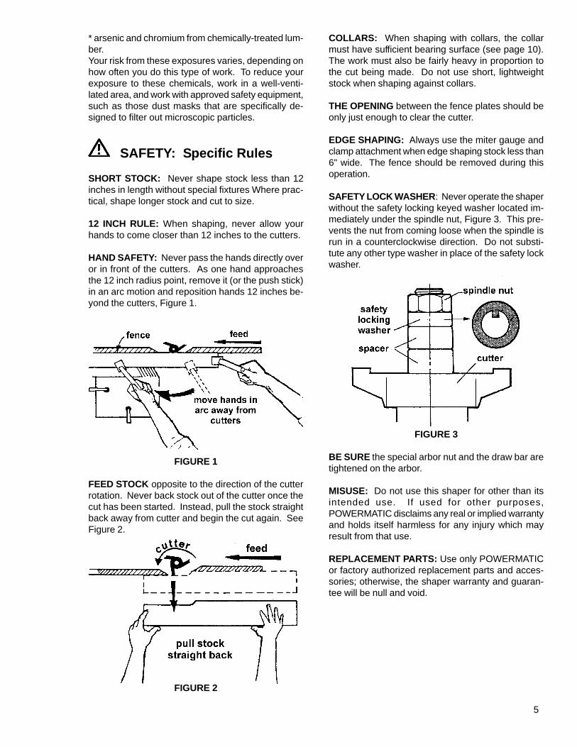
SHORT STOCK: Never shape stock less than 12inches in length without special fixtures Where prac-tical, shape longer stock and cut to size.
12 INCH RULE: When shaping, never allow yourhands to come closer than 12 inches to the cutters.
HAND SAFETY: Never pass the hands directly overor in front of the cutters. As one hand approachesthe 12 inch radius point, remove it (or the push stick)in an arc motion and reposition hands 12 inches be-yond the cutters, Figure 1.
FIGURE 1
FEED STOCK opposite to the direction of the cutterrotation. Never back stock out of the cutter once thecut has been started. Instead, pull the stock straightback away from cutter and begin the cut again. SeeFigure 2.
FIGURE 2
COLLARS: When shaping with collars, the collarmust have sufficient bearing surface (see page 10).The work must also be fairly heavy in proportion tothe cut being made. Do not use short, lightweightstock when shaping against collars.
THE OPENING between the fence plates should beonly just enough to clear the cutter.
EDGE SHAPING: Always use the miter gauge andclamp attachment when edge shaping stock less than6" wide. The fence should be removed during thisoperation.
SAFETY LOCK WASHER: Never operate the shaperwithout the safety locking keyed washer located im-mediately under the spindle nut, Figure 3. This pre-vents the nut from coming loose when the spindle isrun in a counterclockwise direction. Do not substi-tute any other type washer in place of the safety lockwasher.
FIGURE 3
BE SURE the special arbor nut and the draw bar aretightened on the arbor.
MISUSE: Do not use this shaper for other than itsintended use. If used for other purposes,POWERMATIC disclaims any real or implied warrantyand holds itself harmless for any injury which mayresult from that use.
REPLACEMENT PARTS: Use only POWERMATICor factory authorized replacement parts and acces-sories; otherwise, the shaper warranty and guaran-tee will be null and void.

6
RECEIVING THE SHAPER
Remove shaper and any loose items from theirshipping containers. Check for damage and en-sure all parts are intact. Any damage should bereported immediately to your distributor and ship-ping agent. Before assembling, read the manualthoroughly, familiarizing yourself with correct as-sembly and maintenance procedures and propersafety precautions.
Contents of shipping container:1 shaper1 fence assembly (mounted)1 mitre gauge (mounted)1 dust chute (shipped inside base)Contents of accessory package:4 box wrenches2 Allen wrenches1 spindle wrench1 wheel handle3 spindles (1/2", 3/4" and 1")2 collets (1/4" and 1/2")1 collet nut1 starting pin
INSTALLATION
Clean all rust-protected surfaces with a mild sol-vent or kerosene. DO NOT use paint thinner, lac-quer thinner or gasoline as these will damagepainted surfaces.Install the shaper in a level, well-lit area where itwill have enough room on all sides to be serviced,and you can move long stock pieces freely.
ELECTRICAL CONNECTIONS
WARNING: All electrical connections mustbe done by a qualified electrician. Failure to com-ply may result in serious injury.
The 25A Shaper is rated at 3 HP, 1 Ph, 230V only,or 5 Hp, 3 Ph, 230V only. Confirm that the powersource at your site is identical to the rated powerfor the shaper.Consult the wiring diagram on page 28.
ASSEMBLY
1. Attach handle to hand wheel on front ofshaper.2. Remove three hex cap bolts from fence as-sembly.3. Attach dust collector hood (A), Figure 4, tofence assembly.
FIGURE 4
4. Using a level placed both side-to-side andfront-to-back on the table top, level the shaper us-ing shims under each corner as necessary.5. If the shaper will not be bolted to the floor,make sure it rests solidly after leveling.
ADJUSTMENTS
CHANGING CUTTER SPEED
Your shaper is equipped with pulleys that allow youto change the spindle speed. The upper pulleyprovides 7,500 RPM spindle speed, and the lowerpulley provides 10,000 RPM spindle speed.1. Disconnect machine from power source.2. Open door of cabinet.3. Loosen two hex cap bolts (A), Figure 5.4. Turn the tensioning knob (B) counter-clock-wise to release belt tension. Move the belts to theother set of grooves.
FIGURE 5

7
5. Turn the tensioning knob clockwise to adjusttension. Adjust tension until light finger pressuredeflects the belts 1/4" midway between the pul-leys. See Figure 6.6. Tighten the two hex cap bolts (A).
FIGURE 6
SPINDLE INSTALLATIONAND REMOVAL
The spindle is mounted to the main shaft with adraw bar and a nut. Use the following procedureto install the spindle. Reverse the order to removethe spindle.1. Disconnect machine from power source.2. Use the locking mandrel on the right side ofthe machine (A), Figure 7, to lock the shaft in place.Follow the instructions on the label next to the man-drel.
FIGURE 7
3. Select the proper size spindle (B) and installthe arbor nut (C), Figure 8, by slipping nut overtapered end of arbor and threading the spindle untilhand tight.4. Clean the spindle shank and bore of the mainshaft.
FIGURE 8
5. Place spindle onto the main shaft and threadthe arbor nut onto the shaft. Tighten the nut usingthe supplied spanner wrench.6. Place the draw bar into the bottom of the mainshaft and tighten the nut (D), Figure 10, with thespanner wrench.7. Pull the locking mandrel out and turn to re-lease the main shaft.8. Check all around the cabinet for tools, rags,and parts. Close and latch cabinet door.9. Reconnect machine to the power source.10. To remove a spindle, loosen the arbor nut (C),Figure 8, then take down the nut on the draw bar(D), Figure 9. Loosen the draw bar by turning 2 or3 times and use a hammer or other hard materialto strike the base of the draw bar to unseat thespindle.
FIGURE 9

8
COLLET INSTALLATION
1. Disconnect machine from power source.2. To set up the shaper for collet use, removethe arbor and clean the spindle taper.3. Install adaptor in spindle opening by pushingtapered end into spindle followed by the collet andspecial nut. NOTE: Special nut upper internalopening is tapered to mate with the tapered sur-face of the collet.
SHAPER CUTTER INSTALLATION
Use the following procedure to install the shapercutter. Reverse the order to remove the cutter.
1. Disconnect machine from power source.2. Engage the locking mandrel (A-Figure 7) tolock the main shaft.3. Place the cutter (A), Figure 10, onto thespindle, orientated in the proper direction.4. Place the spacers (B), and keyed collar (C)onto the spindle.5. Place the washers and nuts (D) onto thespindle.6. Tighten the nuts securely.7. Pull the locking mandrel and turn to releasethe main shaft.8. Connect the machine to the power source.
FIGURE 10
SPINDLE VERTICAL TRAVEL
Spindle height is adjustable to set proper cuttingheight.To change the spindle height, loosen the clampinghandwheel (A), Figure 11, and turn handwheel (B)to raise or lower the spindle. Tighten the clampinghandwheel after the spindle is at the desired height.
FIGURE 11
TABLE INSERTS
Two table inserts (A), Figure 12, are included foruse with your shaper. The two inserts have open-ings of 3-1/4" and 2". The smaller insert also hasa guide shoulder for shaping without using a col-lar.
FIGURE 12
ADJUSTING THE FENCE
Have a scrap workpiece available to allow properpositioning of the fence and hold-down guides.
Adjust both fence ends to support yourworkpiece before and after passing the cutter.
To move the fence forward or back, loosen the lockknob (A), Figure 13, and turn adjuster knob (B) tomove the fence to the desired position. Tightenthe lock knob to lock the fence in position.
Adjust both infeed and outfeed fences as closeto the cutter as possible but without interfer-ing with cutter rotation.
To move a fence end left or right, loosen the hexcap bolt (C), turn knob (D) to move fence into po-sition, and tighten the hex cap bolt.

9
FIGURE 13
WORK HOLD-DOWN GUIDES
1. Loosen the hex cap bolts (A), Figure 14, turnthe spring plate (B) to the desired angle, and tightenthe hex cap bolts.2. Loosen the locking lever (C), adjust the jackstay to put moderate pressure on the workpiece,and tighten the locking lever.
FIGURE 14
3. On the auxiliary support assembly, Figure 15,loosen the locking knob (D), slide the spring guideplates (E) to put moderate pressure on theworkpiece, and tighten the locking knob.
FIGURE 15
OPERATING THE SHAPER
ELECTRICAL CONTROLS
The shaper is equipped with a push-button controlsystem (A) and reversing switch (B), Figure 16.The green "start" and red "stop" buttons aremounted in a control enclosure on the front of themachine.To reverse the rotation of the spindle, shut off themotor, allow it to come to a complete stop, andturn the reversing switch.
CAUTION: Do not operate the reversingswitch while the motor is running as this may dam-age your machine! Wait until motor comes to acomplete stop before reversing.
FIGURE 16
Use the following as a guide to using the shaper,fence, collars, and starting pin.
USING THE FENCE
Using the fence is the safest and most satisfac-tory method of shaping, and should always be usedwhen the work permits. Almost all straight workcan be used with the fence.1. For average work, where a portion of the origi-nal edge of the work is not to be touched by thecutter, both the front and rear fences are set in astraight line as shown in Figure 17.
FIGURE 17
10
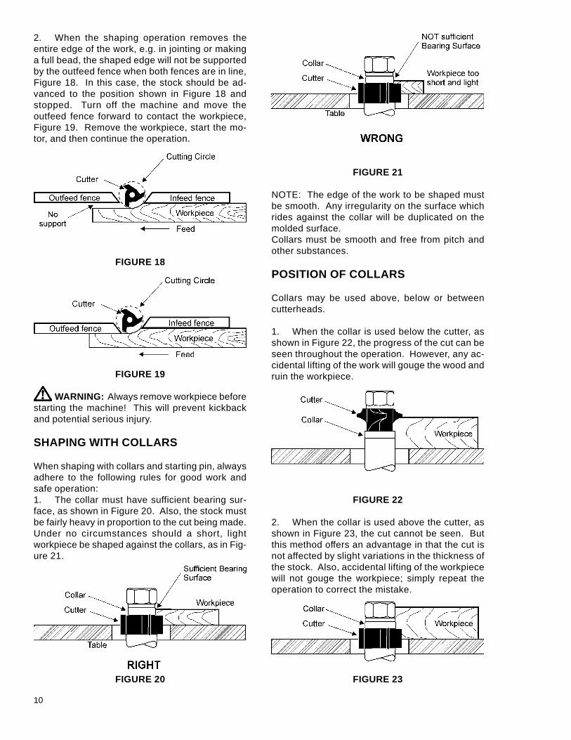
2. When the shaping operation removes theentire edge of the work, e.g. in jointing or makinga full bead, the shaped edge will not be supportedby the outfeed fence when both fences are in line,Figure 18. In this case, the stock should be ad-vanced to the position shown in Figure 18 andstopped. Turn off the machine and move theoutfeed fence forward to contact the workpiece,Figure 19. Remove the workpiece, start the mo-tor, and then continue the operation.
FIGURE 18
FIGURE 19
WARNING: Always remove workpiece beforestarting the machine! This will prevent kickbackand potential serious injury.
SHAPING WITH COLLARS
When shaping with collars and starting pin, alwaysadhere to the following rules for good work andsafe operation:1. The collar must have sufficient bearing sur-face, as shown in Figure 20. Also, the stock mustbe fairly heavy in proportion to the cut being made.Under no circumstances should a short, lightworkpiece be shaped against the collars, as in Fig-ure 21.
FIGURE 20
FIGURE 21
NOTE: The edge of the work to be shaped mustbe smooth. Any irregularity on the surface whichrides against the collar will be duplicated on themolded surface.Collars must be smooth and free from pitch andother substances.
POSITION OF COLLARS
Collars may be used above, below or betweencutterheads.
1. When the collar is used below the cutter, asshown in Figure 22, the progress of the cut can beseen throughout the operation. However, any ac-cidental lifting of the work will gouge the wood andruin the workpiece.
FIGURE 22
2. When the collar is used above the cutter, asshown in Figure 23, the cut cannot be seen. Butthis method offers an advantage in that the cut isnot affected by slight variations in the thickness ofthe stock. Also, accidental lifting of the workpiecewill not gouge the workpiece; simply repeat theoperation to correct the mistake.
FIGURE 23

11
3. Using the collar between the two cutters hasthe advantages and disadvantages of the first twoprocedures, and is frequently used where bothedges of the work are to be molded, Figure 24.
FIGURE 24
NOTE: It is advisable to place the cutter as low aspossible on the spindle to reduce spindle deflec-tion and ensure the best possible finish. Also makesure that the contacting surfaces of the cutter aresmooth, clean and without dents.
STARTING PIN
WARNING: Use of the starting pin should onlybe attempted by advanced users. If you have neverused this method, it is recommended you get train-ing from a qualified person. Failure to comply mayresult in serious injury.
The starting pin is used to support the work whenstarting the cut.1. The work should be placed in the first posi-tion, Figure 25, using the starting pin as a support.
FIGURE 25
2. Swing the work into the cutter as shown inthe second position. The work is now supportedby the starting pin and the collar.3. After the cut has been started, the work isswung free of the starting pin and only rides againstthe collar, Figure 26. Always feed against thecutterhead rotation.
FIGURE 26
MAINTENANCE
Periodically lubricate the following components:Spindle Cartridge (daily - SAE 30W machine oil)Elevating Shaft (bi-weekly - SAE 30W machine oil)Adjusting Plate (monthly) - #2 Tube Grease, lithium
based)
FIGURE 27
FIGURE 28
FIGURE 29

12
MELBORP ESUACELBISSOP YDEMER
.tratstonlliwrepahS rekaerbtiucricronwolbesuF.1.deppirt
.degamaddroC.2rewopehtmorfdeggulpnudroC.3
.ecruosFFOehtnisihctiwsgnisreveR.4
.noitisop.deppirtdaolrevO.5
tiucricteserroesufecalpeR.1.rekaerb
.drocecalpeR.2.drocrewopnigulP.3
.esreverrodrawrofothctiwsnruT.4
dergnisserpedybdaolrevoteseR.5.nottubpots
tuoskcikdaolrevO.yltneuqerf
etauqedanigniriwrodrocnoisnetxE.1.ezis
.tsafootkcotsgnideeF.2.lludsidaehrettuC.3
reporphtiwgniriwrodrocecalpeR.1.eriweguag
.etardeefkcotsecudeR.2.srettucprahsylnoesU.3
emoctonseodrettuC.deepsllufotpu
.llamsootsieguageriwpohS.1
.gnolootrothgilootdrocnoisnetxE.2.etauqedatonsiecruosrewoP.3
.egatlovtcerrocrofderiwtonrotoM.4
.revellerdnamhtiwdekcolsieldnipS.5
reporphtiwgniriwrodrocecalpeR.1.eriweguag
.drocezisetauqedahtiwecalpeR.2.ytilitulacirtcelelacoltcatnoC.3rofetalpemanrotomotrefeR.4
.gniriwtcerrocottxenlebalees-eldnipskcolnU.5
.esabnorevel
.yrotcafsitasnuerastuC .rettuclluD.1.rettucnohctipromuG.2
gnorwnignitatordaehrettuC.3.noitcerid
.noitceridgnorwehtnikrowgnideeF.4
.rettucecalpeR.1htiwnaelcdnarettucevomeR.2
.tnevlos.putratstanoitatorreporprofkcehC.3
rettucehttsniagakrowdeeF.4.noitator
setarbivenihcaM .degamaddaehrettuC.1.ecafrusnevenunodnatS.2
.tleb-VevitcefeD.3.denoisnetyltcerrocnitleb-V.4
.yelluptneB.5.ylreporpmidetnuomrotoM.6
.daehrettucecalpeR.1levelnoyldilostsertsumdnatS.2
.yrassecenfiroolfottlob,ecafrus.tleb-VecalpeR.3
.noisnetreporpylppA.4.yellupecalpeR.5
detnuomylreporpebtsumrotoM.6.stlobdnastungunshtiw
ssorcnoffostilpsegdE.tucniarg
.tucfoepytsihtfocitsiretcarahC.1 neht,tsrifstucniargssorcekaM.1parcsesU.niargehthtiwtuchsinif
.tucfodnetroppusotkcolb
nosaeradesiaR.egdedepahs
krowgnidloherusserpfonoitairaV.1.rettuctsniaga
dnaelbattsniagaylmrifkrowdloH.1skcitshsupdnasnwoddlohesU.ecnef
.dnahmorfdellupkroW .noitceridgnorwnikrowgnideeF.1 ehttsniagakrowdeefsyawlA.1.daehrettucehtfonoitator
tontucfohtpeD.mrofinu
.tnemngilasimecneF.1.mrofinutonerusserpediS.2
.ecnefdeeftuongilA.1tnatsnocpeek;snwoddlohesU.2
hsupesudnaecneftsniagaerusserp.skcits
TROUBLE SHOOTING

13
MELBORP ESUACELBISSOP YDEMER
.snrubkroW .ssapenonopeedootgnittuC.1.krowgnicroF.2
niatta;stucthgilekatsdoowdrahnO.1.sessaplareveshtiwhtpedlluf
.ylidaetsdnaylwolskrowdeeF.2
.mrofinutonthgiehtuC otkrowgnidloherusserpninoitairaV.1.elbat
.ssaptuohguorhtmriferusserppeeK.1ylwolsssapekaM.snwoddlohesU
rettucrednukrowpeeK.ylidaetsdna.elbissoprevenehw
.htoomstonstuC .M.P.RgnorW.1.tsafootdeeF.2
.niargehttsniagagnikroW.3.ssapenonopeedootgnittuC.4
.deepsretsafesU.1
.deepsdeefwolS.2revenehwniargehthtiwkroW.3
.elbissoppeedyrevnosessaplarevesekaT.4
.stuc
esiartonseodeldnipS.yleerf
gnisiarnitridrotsudwaS.1.msinahcem
.tsudwasdnatridtuowolbrohsurB.1.ylralugeretacirbuL
TROUBLE SHOOTING (cont.)

14
PARTS LIST: Base Assembly (Model 25A)
NO. PART NO. DESCRIPTION
1 6295368 Base2 6295369 Plate3 6295370 Flange4 6295371 Handle Catch5 6295372 Catch6 6295373 Handwheel7 6295374 Handle8 6295375 For/Rev Switch, 5 HP 3 Ph
6295390 For/Rev Switch, 3 HP 1 Ph9 6295376 Washer 1/4"10 6295377 Hex Head Bolt, 1/4" x 1/2"11 6295378 Screw, 3/16" x 1/2"12 6295379 Hex Head Bolt, 5/16" x 3/4"13 6295380 Hex Screw, 1/4" x 3"14 6295381 Hex Nut, 1/4"15 6295382 Spring Washer, 3/8"
NO. PART NO. DESCRIPTION
16 6295383 Hex Head Screw, 3/8" x 1-1/4"17 6295384 Bar18 6295385 Knob19 6295386 Spring20 6295387 Bolt22 6295548 Crosshead Bolt, M4 x 80mm23 6295389 Hex Head Screw, 3/8" x 1"24 6295391 Switch Assembly, 5HP, 3Ph
6295549 Magnetic Control, 3 HP, 1 Ph25 6295392 Crosshead Bolt, M6 x 15mm26 6295542 Door29 6295543 Index Plate
6295521 On-Off Switch Box Only6295523 Thermal Relay

15
EXPLODED VIEW: Base Assembly (Model 25A)

16
PARTS LIST: Table Assembly (Model 25A)
NO. PART NO. DESCRIPTION
1 6295393 Table2 6295394 Table Ring3 6295395 Table Ring
6295525 Auxiliary Support Assembly(Items 4 & 5, 7 thru 11)
4 6295396 Spring Washer, 3/8"5 6295397 Hex Head Screw, 3/8" x 1"6 6295398 Starting Pin7 6295399 Spring Plate8 6295400 Knob9 6295401 Hex Head Bolt, 1/4" x 3/8"10 6295402 Rod
NO. PART NO. DESCRIPTION
11 6295403 Bracket Support6295524 Mitre Gauge Assembly (Items 12
thru 20)12 6295404 Mitre Gauge13 6295405 Washer, 5/16"14 6295406 Lock Knob15 6295407 Guide Bar16 6295535 Index Pointer17 6295536 Screw19 6295538 Washer20 6295539 Screw

17
EXPLODED VIEW: Table Assembly (Model 25A)

18
PARTS LIST: Spindle Seat Assembly (Model 25A)
NO. PART NO. DESCRIPTION
1 6295408 Housing2 6295409 Worm Gear Housing3 6295410 Bushing4 6295411 Sleeve5 6295412 Set Screw6 6295413 Shaft
NO. PART NO. DESCRIPTION
7 6295414 Bushing8 6295415 Helical Gear9 6295416 Hex Cap Bolt10 6295417 Spring Washer, 1/2"11 6295418 Hex Screw, 1/2"12 6295419 Worm

19
EXPLODED VIEW: Spindle Seat Assembly (Model 25A)

20
PARTS LIST: Spindle Assembly (Model 25A)
NO. PART NO. DESCRIPTION
6295527 Quill & Spindle Assembly,(Items 1 thru 7, 11 thru 15)
1 6295420 Quill2 6295421 Main Spindle3 6290751 Bearing 6205Z4 6295423 Bearing 6206Z5 6295424 Spindle Collar6 6295425 Down Spindle Collar7 6295426 Front Spindle Collar8 6295427 Pulley9 6295428 Tie Rod10 6295429 Nut
NO. PART NO. DESCRIPTION
11 6295430 Screw, 3/16" x 1/2"12 6295431 C Retainer Ring13 6295432 C Ring14 6295433 Lock Nut15 6295434 Spring Band
6295526 Rod Assembly (Items 16 thru 21)16 6295435 Spring Pin17 6295436 Set Screw, 1/4" x 1/4"18 6295437 Rod Sleeve19 6295438 Brake Casing20 6295439 Rod21 6295440 Spring

21
EXPLODED VIEW: Spindle Assembly (Model 25A)

22
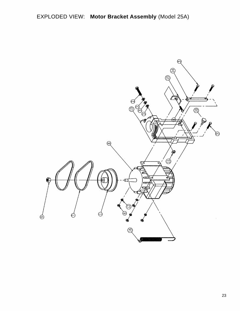
PARTS LIST: Motor Bracket Assembly (Model 25A)
NO. PART NO. DESCRIPTION
6295528 Motor Bracket Assembly,(Items 1 thru 16)
1 6295441 Motor Pulley2 6295442 Hex Head Bolt, 1/2" x 2-1/2"3 6295443 Spring Washer4 6295444 Hex Screw, 3/8" x 1-1/2"5 6295445 Hex Head Bolt, 3/8" x 1-3/4"6 6295446 Hex Nut, 3/8"7 6295447 V-Belt8 6295448 Motor, 3 HP, 1 Ph
6295449 Motor, 5 HP, 3 Ph
NO. PART NO. DESCRIPTION
9 6295450 Hex Nut, 3/4"10 6295451 Knob 3/8" x 2-1/2"11 6295452 Hex Nut, 1/2"12 6295453 Spring Washer, 3/8"13 6295454 Motor Bracket14 6295455 Rod Truss15 6295456 L-Bracket16 6295457 Spring
23
EXPLODED VIEW: Motor Bracket Assembly (Model 25A)

24
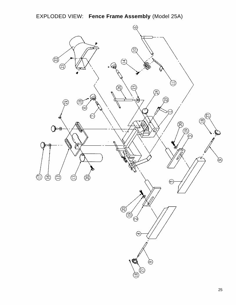
PARTS LIST: Fence Frame Assembly (Model 25A)
NO. PART NO. DESCRIPTION
6295529 Fence Assembly (Items 1 thru 5,7 thru 9, 12, 13, and 15 thru 27)
1 6295458 Fence Frame2 6295459 Fence (L)3 6295460 Fence (R)4 6295461 Guide Plate (L)5 6295462 Guide Plate (R)
6295530 Work Hold-Down Assembly(Items 6, 10, 11, 14)
6 6295463 Rod7 6295464 Screw8 6295465 Adjustment Knob9 6295466 Rod10 6295467 Slide Block11 6295468 Guide Plate12 6295469 Fence Frame Plate
NO. PART NO. DESCRIPTION
13 6295470 Spindle Guard14 6295471 Hex Head Bolt, 5/16" x 3/4"15 6295472 Washer, 1/2"16 6295473 Washer, 5/16"17 6295474 Knob, 5/16" x 1"18 6295475 Set Screw, 1/4" x 1/4"19 6295476 Washer, 3/8"20 6295477 Hex Head Screw, 3/8" x 1-1/4"21 6295478 Wing Nut, 3/8"22 6295479 Dust Hood23 6295480 Hex Head Bolt, 1/4" x 3/8"24 6295481 Lock Knob, 5/16" x 7/8"25 6295482 Locking Handle26 6295483 Lock Rod27 6295484 Knob, 1/2"
25
EXPLODED VIEW: Fence Frame Assembly (Model 25A)

26
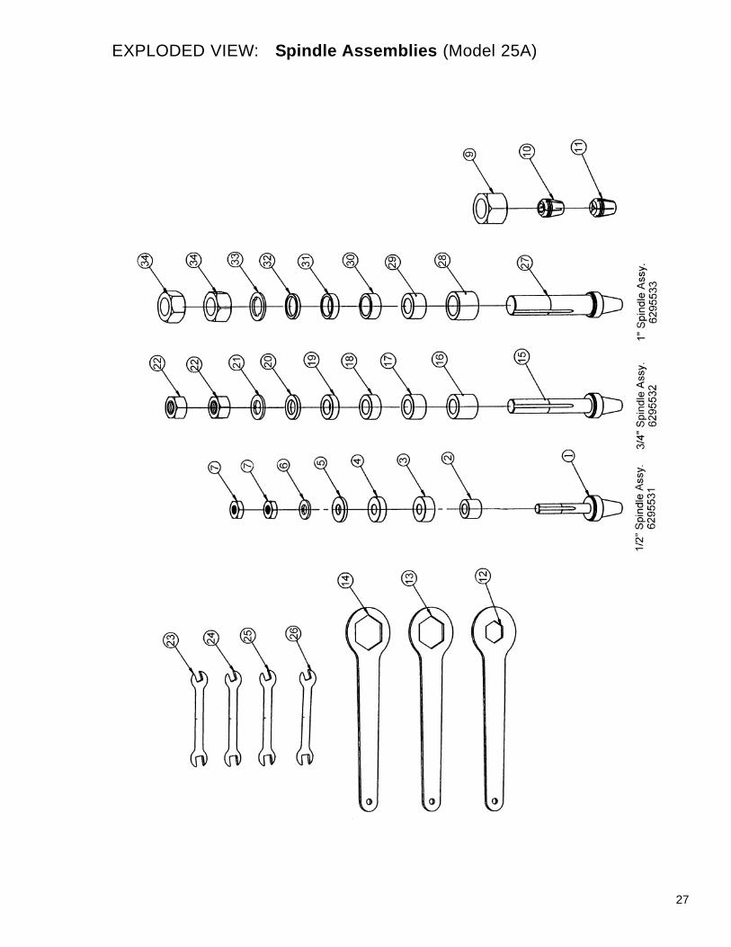
PARTS LIST: Spindle Assemblies (Model 25A)
NO. PART NO. DESCRIPTION
6295531 1/2" Spindle Assembly (Items 1thru 8)
1 6295513 Spindle, 1/2"2 6295487 Spacer Washer, 1/2" x 20mm3 6295488 Spacer Washer, 1/2" x 15mm4 6295489 Spacer Washer, 1/2" x 10mm5 6295490 Spacer Washer 1/2" x 5mm6 6295491 Lock Washer7 6295492 Hex Nut, 1/2"9 6295493 Router Nut10 6295494 Router Collet, 1/2"11 6295495 Router Collet, 1/4"12 6295496 Spanner Wrench, 26mm13 6295497 Spanner Wrench, 38mm14 6295498 Spanner Wrench, 41mm
6295532 3/4" Spindle Assembly (Items 15thru 22)
15 6295485 Spindle, 3/4"16 6295499 Spacer Washer, 3/4" x 30mm17 6295504 Spacer Washer, 3/4" x 20mm
NO. PART NO. DESCRIPTION
18 6295500 Spacer Washer, 3/4" x 15mm19 6295501 Spacer Washer, 3/4" x 10mm20 6295502 Spacer Washer, 3/4" x 5mm21 6295503 Lock Washer22 6295505 Hex Nut, 3/4"23 6295506 Spanner Wrench, 10-1224 6295507 Spanner Wrench, 12-1425 6295508 Spanner Wrench, 17-1926 6295509 Spanner Wrench, 19-21
6295533 1" Spindle Assembly (Items 27thru 34)
27 6295486 Spindle, 1"28 6295512 Spacer Washer, 1" x 30mm29 6295515 Spacer Washer, 1" x 15mm30 6295514 Spacer Washer, 1" x 20mm31 6295519 Spacer Washer, 1" x 10mm32 6295516 Spacer Washer, 1" x 5mm33 6295517 Lock Washer34 6295518 Hex Nut, 1"
27
EXPLODED VIEW: Spindle Assemblies (Model 25A)

28
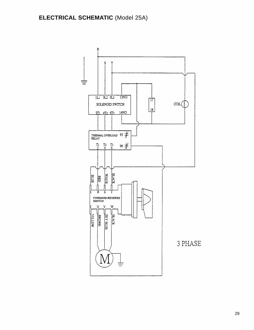
ELECTRICAL SCHEMATIC (Model 25A)
29
ELECTRICAL SCHEMATIC (Model 25A)

30

31
To order parts or reach our service department, please call our toll free number between 7:00 A.M. and 6:00P.M. (CST), Monday through Friday. Having the Model Number and Serial Number of your machine availablewhen you call will allow us to serve you quickly and accurately. Locating the stock number of the part(s)required from your parts manual will also expedite your order.
Phone: (800) 274-6848Website: www.wmhtoolgroup.com

WMH Tool Group2420 Vantage DriveElgin, Illinois 60123
Phone: 800-274-6848www.wmhtoolgroup.com