
OpenML V1.0 Specification 19 July 2001 - Khronos Group
248
OpenML V1.0 Specification 19 July 2001 Editor: Steve Howell Copyright © 2001 3Dlabs Inc., ATI Technologies Inc., Discreet Logic Inc., Evans and Sutherland Computer Corporation, Intel Corporation, NVIDIA Corporation, Silicon Graphics, Inc., Sun Microsystems, Inc.
-
Upload
khangminh22 -
Category
Documents
-
view
0 -
download
0
Transcript of OpenML V1.0 Specification 19 July 2001 - Khronos Group

OpenML V1.0 Specification19 July 2001
Editor: Steve Howell
Copyright © 2001 3Dlabs Inc., ATI Technologies Inc., Discreet Logic Inc., Evans and SutherlandComputer Corporation, Intel Corporation, NVIDIA Corporation, Silicon Graphics, Inc.,
Sun Microsystems, Inc.

OpenGL is a registered trademark of Silicon Graphics, Inc.OpenML is a trademark of Silicon Graphics, Inc., used with permission by the Khronos Special Interest
Group.*Other brands and names are the property of their respective owners.
i i O p e n M L S p e c i f i c a t i o n R e v i s i o n 1 . 0

Contents
I Introduction and Overview of OpenML™ 1
1 Introduction 3Motivation . . . . . . . . . . . . . . . . . . . . . . . . . . . . . . . . . . . . . . . . . . . . . . . . . . . . . . . . . . 3Objective of the Specification . . . . . . . . . . . . . . . . . . . . . . . . . . . . . . . . . . . . . . . . . . . 3Scope of the Document. . . . . . . . . . . . . . . . . . . . . . . . . . . . . . . . . . . . . . . . . . . . . . . . 4Document Organization. . . . . . . . . . . . . . . . . . . . . . . . . . . . . . . . . . . . . . . . . . . . . . . . 4
2 Background 5Goals of the Khronos Group . . . . . . . . . . . . . . . . . . . . . . . . . . . . . . . . . . . . . . . . . . . . 5The Application Space . . . . . . . . . . . . . . . . . . . . . . . . . . . . . . . . . . . . . . . . . . . . . . . . 5Feature List . . . . . . . . . . . . . . . . . . . . . . . . . . . . . . . . . . . . . . . . . . . . . . . . . . . . . . . . . 6OS Invariance . . . . . . . . . . . . . . . . . . . . . . . . . . . . . . . . . . . . . . . . . . . . . . . . . . . . . . . 6
3 Architectural Overview 9Synchronizing Audio, Video and Graphics . . . . . . . . . . . . . . . . . . . . . . . . . . . . . . . . 10ML Features . . . . . . . . . . . . . . . . . . . . . . . . . . . . . . . . . . . . . . . . . . . . . . . . . . . . . . . 10OpenGL Features . . . . . . . . . . . . . . . . . . . . . . . . . . . . . . . . . . . . . . . . . . . . . . . . . . . 12Video Back-end Device Control. . . . . . . . . . . . . . . . . . . . . . . . . . . . . . . . . . . . . . . . . 12The Future. . . . . . . . . . . . . . . . . . . . . . . . . . . . . . . . . . . . . . . . . . . . . . . . . . . . . . . . . 12
II Digital Media Input/Output Programming 13Description . . . . . . . . . . . . . . . . . . . . . . . . . . . . . . . . . . . . . . . . . . . . . . . . . . . . . . . . 13
4 Overview of ML 15Components of ML . . . . . . . . . . . . . . . . . . . . . . . . . . . . . . . . . . . . . . . . . . . . . . . . . . 15Capability Tree. . . . . . . . . . . . . . . . . . . . . . . . . . . . . . . . . . . . . . . . . . . . . . . . . . . . . . 15
Physical Devices. . . . . . . . . . . . . . . . . . . . . . . . . . . . . . . . . . . . . . . . . . . . . . . . . . 16Logical Devices . . . . . . . . . . . . . . . . . . . . . . . . . . . . . . . . . . . . . . . . . . . . . . . . . . 16Buffers . . . . . . . . . . . . . . . . . . . . . . . . . . . . . . . . . . . . . . . . . . . . . . . . . . . . . . . . . 16Jacks . . . . . . . . . . . . . . . . . . . . . . . . . . . . . . . . . . . . . . . . . . . . . . . . . . . . . . . . . . 17Paths . . . . . . . . . . . . . . . . . . . . . . . . . . . . . . . . . . . . . . . . . . . . . . . . . . . . . . . . . . 17Transcoders . . . . . . . . . . . . . . . . . . . . . . . . . . . . . . . . . . . . . . . . . . . . . . . . . . . . . 17Pipes. . . . . . . . . . . . . . . . . . . . . . . . . . . . . . . . . . . . . . . . . . . . . . . . . . . . . . . . . . . 18Parameters . . . . . . . . . . . . . . . . . . . . . . . . . . . . . . . . . . . . . . . . . . . . . . . . . . . . . . 18
Messages and Communication . . . . . . . . . . . . . . . . . . . . . . . . . . . . . . . . . . . . . . . . . 18Opening a Jack. . . . . . . . . . . . . . . . . . . . . . . . . . . . . . . . . . . . . . . . . . . . . . . . . . . 18Constructing a Message. . . . . . . . . . . . . . . . . . . . . . . . . . . . . . . . . . . . . . . . . . . . 18Sending a Message . . . . . . . . . . . . . . . . . . . . . . . . . . . . . . . . . . . . . . . . . . . . . . . 19Receiving Reply Messages . . . . . . . . . . . . . . . . . . . . . . . . . . . . . . . . . . . . . . . . . 19
O p e n M L S p e c i f i c a t i o n R e v i s i o n 1 . 0 i i i

Closing a Jack . . . . . . . . . . . . . . . . . . . . . . . . . . . . . . . . . . . . . . . . . . . . . . . . . . . 19Out-of-Band and In-Band Messages . . . . . . . . . . . . . . . . . . . . . . . . . . . . . . . . . . 20
Queue Model. . . . . . . . . . . . . . . . . . . . . . . . . . . . . . . . . . . . . . . . . . . . . . . . . . . . . . . 20Queuing Messages. . . . . . . . . . . . . . . . . . . . . . . . . . . . . . . . . . . . . . . . . . . . . . . . 20Path Example . . . . . . . . . . . . . . . . . . . . . . . . . . . . . . . . . . . . . . . . . . . . . . . . . . . . 21Opening a Logical Path . . . . . . . . . . . . . . . . . . . . . . . . . . . . . . . . . . . . . . . . . . . . 21Sending In-Band Messages . . . . . . . . . . . . . . . . . . . . . . . . . . . . . . . . . . . . . . . . . 21Processing In-Band Messages. . . . . . . . . . . . . . . . . . . . . . . . . . . . . . . . . . . . . . . 22Receiving In-Band Reply Messages. . . . . . . . . . . . . . . . . . . . . . . . . . . . . . . . . . . 23Processing Exceptional Events . . . . . . . . . . . . . . . . . . . . . . . . . . . . . . . . . . . . . . 24Beginning Transfers . . . . . . . . . . . . . . . . . . . . . . . . . . . . . . . . . . . . . . . . . . . . . . . 25Closing a Logical Path . . . . . . . . . . . . . . . . . . . . . . . . . . . . . . . . . . . . . . . . . . . . . 25
Pipes and Transcoders . . . . . . . . . . . . . . . . . . . . . . . . . . . . . . . . . . . . . . . . . . . . . . . 26Finding a Suitable Transcoder . . . . . . . . . . . . . . . . . . . . . . . . . . . . . . . . . . . . . . . 26Controlling the Transcoder . . . . . . . . . . . . . . . . . . . . . . . . . . . . . . . . . . . . . . . . . . 26Sending Buffers . . . . . . . . . . . . . . . . . . . . . . . . . . . . . . . . . . . . . . . . . . . . . . . . . . 27Starting a Transfer . . . . . . . . . . . . . . . . . . . . . . . . . . . . . . . . . . . . . . . . . . . . . . . . 27Changing Controls During a Transfer . . . . . . . . . . . . . . . . . . . . . . . . . . . . . . . . . . 27Receiving a Reply Message . . . . . . . . . . . . . . . . . . . . . . . . . . . . . . . . . . . . . . . . . 28Transcoder Work Functions . . . . . . . . . . . . . . . . . . . . . . . . . . . . . . . . . . . . . . . . . 28Multi-Stream Transcoders. . . . . . . . . . . . . . . . . . . . . . . . . . . . . . . . . . . . . . . . . . . 28Ending Transfers. . . . . . . . . . . . . . . . . . . . . . . . . . . . . . . . . . . . . . . . . . . . . . . . . . 28Closing a Transcoder . . . . . . . . . . . . . . . . . . . . . . . . . . . . . . . . . . . . . . . . . . . . . . 29
Synchronization. . . . . . . . . . . . . . . . . . . . . . . . . . . . . . . . . . . . . . . . . . . . . . . . . . . . . 29
5 ML Parameters 31Param/Value Pairs . . . . . . . . . . . . . . . . . . . . . . . . . . . . . . . . . . . . . . . . . . . . . . . . . . . 31
Scalar Parameters . . . . . . . . . . . . . . . . . . . . . . . . . . . . . . . . . . . . . . . . . . . . . . . . 33Array Parameters . . . . . . . . . . . . . . . . . . . . . . . . . . . . . . . . . . . . . . . . . . . . . . . . . 33Pointer Parameters . . . . . . . . . . . . . . . . . . . . . . . . . . . . . . . . . . . . . . . . . . . . . . . . 34User Parameters. . . . . . . . . . . . . . . . . . . . . . . . . . . . . . . . . . . . . . . . . . . . . . . . . . 35
6 ML Capabilities 37Accessing Capabilities . . . . . . . . . . . . . . . . . . . . . . . . . . . . . . . . . . . . . . . . . . . . . . . 38
System Capabilities . . . . . . . . . . . . . . . . . . . . . . . . . . . . . . . . . . . . . . . . . . . . . . . 39Physical Device Capabilities. . . . . . . . . . . . . . . . . . . . . . . . . . . . . . . . . . . . . . . . . 39Jack Logical Device Capabilities . . . . . . . . . . . . . . . . . . . . . . . . . . . . . . . . . . . . . 40Path Logical Device Capabilities . . . . . . . . . . . . . . . . . . . . . . . . . . . . . . . . . . . . . 41Transcoder Logical Device Capabilities . . . . . . . . . . . . . . . . . . . . . . . . . . . . . . . . 42Pipe Logical Device Capabilities . . . . . . . . . . . . . . . . . . . . . . . . . . . . . . . . . . . . . 44
Finding a Parameter in a Capabilities List . . . . . . . . . . . . . . . . . . . . . . . . . . . . . . . . . 44Obtaining Parameter Capabilities . . . . . . . . . . . . . . . . . . . . . . . . . . . . . . . . . . . . . . . 44Freeing Capabilities Lists . . . . . . . . . . . . . . . . . . . . . . . . . . . . . . . . . . . . . . . . . . . . . 46
7 ML Video Parameters 47Video Jack and Path Control Parameters . . . . . . . . . . . . . . . . . . . . . . . . . . . . . . . . . 47
ML_VIDEO_TIMING_INT32 . . . . . . . . . . . . . . . . . . . . . . . . . . . . . . . . . . . . . . . . . 47ML_VIDEO_SAMPLING_INT32 . . . . . . . . . . . . . . . . . . . . . . . . . . . . . . . . . . . . . . 53
i v O p e n M L S p e c i f i c a t i o n R e v i s i o n 1 . 0

ML_VIDEO_COLORSPACE_INT32 . . . . . . . . . . . . . . . . . . . . . . . . . . . . . . . . . . . 53ML_VIDEO_PRECISION_INT32 . . . . . . . . . . . . . . . . . . . . . . . . . . . . . . . . . . . . . 54ML_VIDEO_SIGNAL_PRESENT_INT32 . . . . . . . . . . . . . . . . . . . . . . . . . . . . . . . 54ML_VIDEO_GENLOCK_SOURCE_TIMING_INT32 . . . . . . . . . . . . . . . . . . . . . . 54ML_VIDEO_GENLOCK_TYPE _INT32 . . . . . . . . . . . . . . . . . . . . . . . . . . . . . . . . 54ML_VIDEO_GENLOCK_SIGNAL_PRESENT_INT32 . . . . . . . . . . . . . . . . . . . . . 54ML_VIDEO_BRIGHTNESS_INT32 . . . . . . . . . . . . . . . . . . . . . . . . . . . . . . . . . . . 54ML_VIDEO_CONTRAST_INT32 . . . . . . . . . . . . . . . . . . . . . . . . . . . . . . . . . . . . . 54ML_VIDEO_HUE_INT32 . . . . . . . . . . . . . . . . . . . . . . . . . . . . . . . . . . . . . . . . . . . 54ML_VIDEO_SATURATION_INT32 . . . . . . . . . . . . . . . . . . . . . . . . . . . . . . . . . . . . 54ML_VIDEO_RED_SETUP_INT32 . . . . . . . . . . . . . . . . . . . . . . . . . . . . . . . . . . . . 55ML_VIDEO_GREEN_SETUP_INT32. . . . . . . . . . . . . . . . . . . . . . . . . . . . . . . . . . 55ML_VIDEO_BLUE_SETUP_INT32 . . . . . . . . . . . . . . . . . . . . . . . . . . . . . . . . . . . 55ML_VIDEO_ALPHA_SETUP_INT32 . . . . . . . . . . . . . . . . . . . . . . . . . . . . . . . . . . 55ML_VIDEO_H_PHASE_INT32. . . . . . . . . . . . . . . . . . . . . . . . . . . . . . . . . . . . . . . 55ML_VIDEO_V_PHASE_INT32 . . . . . . . . . . . . . . . . . . . . . . . . . . . . . . . . . . . . . . . 55ML_VIDEO_FLICKER_FILTER_INT32 . . . . . . . . . . . . . . . . . . . . . . . . . . . . . . . . 55ML_VIDEO_DITHER_FILTER_INT32 . . . . . . . . . . . . . . . . . . . . . . . . . . . . . . . . . 55ML_VIDEO_NOTCH_FILTER_INT32. . . . . . . . . . . . . . . . . . . . . . . . . . . . . . . . . . 55ML_VIDEO_OUTPUT_DEFAULT_SIGNAL_INT64 . . . . . . . . . . . . . . . . . . . . . . . 55
Video Path Control Parameters. . . . . . . . . . . . . . . . . . . . . . . . . . . . . . . . . . . . . . . . . 56ML_VIDEO_START_X_INT32 . . . . . . . . . . . . . . . . . . . . . . . . . . . . . . . . . . . . . . . 56ML_VIDEO_START_Y_F1_INT32 . . . . . . . . . . . . . . . . . . . . . . . . . . . . . . . . . . . . 56ML_VIDEO_START_Y_F2_INT32 . . . . . . . . . . . . . . . . . . . . . . . . . . . . . . . . . . . . 56ML_VIDEO_WIDTH_INT32 . . . . . . . . . . . . . . . . . . . . . . . . . . . . . . . . . . . . . . . . . 56ML_VIDEO_HEIGHT_F1_INT32 . . . . . . . . . . . . . . . . . . . . . . . . . . . . . . . . . . . . . 56ML_VIDEO_HEIGHT_F2_INT32 . . . . . . . . . . . . . . . . . . . . . . . . . . . . . . . . . . . . . 56ML_VIDEO_OUTPUT_REPEAT_INT32. . . . . . . . . . . . . . . . . . . . . . . . . . . . . . . . 56ML_VIDEO_FILL_Y_REAL32 . . . . . . . . . . . . . . . . . . . . . . . . . . . . . . . . . . . . . . . 57ML_VIDEO_FILL_Cr_REAL32 . . . . . . . . . . . . . . . . . . . . . . . . . . . . . . . . . . . . . . . 57ML_VIDEO_FILL_Cb_REAL32 . . . . . . . . . . . . . . . . . . . . . . . . . . . . . . . . . . . . . . 57ML_VIDEO_FILL_RED_REAL32 . . . . . . . . . . . . . . . . . . . . . . . . . . . . . . . . . . . . . 57ML_VIDEO_FILL_GREEN_REAL32 . . . . . . . . . . . . . . . . . . . . . . . . . . . . . . . . . . 57ML_VIDEO_FILL_BLUE_REAL32 . . . . . . . . . . . . . . . . . . . . . . . . . . . . . . . . . . . . 57ML_VIDEO_FILL_ALPHA_REAL32 . . . . . . . . . . . . . . . . . . . . . . . . . . . . . . . . . . . 57
Examples. . . . . . . . . . . . . . . . . . . . . . . . . . . . . . . . . . . . . . . . . . . . . . . . . . . . . . . . . . 58
8 ML Image Parameters 59Introduction . . . . . . . . . . . . . . . . . . . . . . . . . . . . . . . . . . . . . . . . . . . . . . . . . . . . . . . . 59Image Buffer Parameters . . . . . . . . . . . . . . . . . . . . . . . . . . . . . . . . . . . . . . . . . . . . . 60
ML_IMAGE_BUFFER_POINTER. . . . . . . . . . . . . . . . . . . . . . . . . . . . . . . . . . . . . 60ML_IMAGE_WIDTH_INT32 . . . . . . . . . . . . . . . . . . . . . . . . . . . . . . . . . . . . . . . . . 60ML_IMAGE_HEIGHT_1_INT32 . . . . . . . . . . . . . . . . . . . . . . . . . . . . . . . . . . . . . . 60ML_IMAGE_HEIGHT_2_INT32 . . . . . . . . . . . . . . . . . . . . . . . . . . . . . . . . . . . . . . 60ML_IMAGE_DOMINANCE_INT32 . . . . . . . . . . . . . . . . . . . . . . . . . . . . . . . . . . . . 61ML_IMAGE_ROW_BYTES_INT32. . . . . . . . . . . . . . . . . . . . . . . . . . . . . . . . . . . . 61ML_IMAGE_SKIP_PIXELS_INT32 . . . . . . . . . . . . . . . . . . . . . . . . . . . . . . . . . . . 61ML_IMAGE_SKIP_ROWS_INT32 . . . . . . . . . . . . . . . . . . . . . . . . . . . . . . . . . . . . 61ML_IMAGE_TEMPORAL_SAMPLING_INT32. . . . . . . . . . . . . . . . . . . . . . . . . . . 61
O p e n M L S p e c i f i c a t i o n R e v i s i o n 1 . 0 v

ML_IMAGE_INTERLEAVE_MODE_INT32 . . . . . . . . . . . . . . . . . . . . . . . . . . . . . 62ML_IMAGE_ORIENTATION_INT32 . . . . . . . . . . . . . . . . . . . . . . . . . . . . . . . . . . . 62ML_IMAGE_COMPRESSION_INT32 . . . . . . . . . . . . . . . . . . . . . . . . . . . . . . . . . 62ML_IMAGE_BUFFER_SIZE_INT32. . . . . . . . . . . . . . . . . . . . . . . . . . . . . . . . . . . 63ML_IMAGE_COMPRESSION_FACTOR_REAL32 . . . . . . . . . . . . . . . . . . . . . . . 63ML_IMAGE_PACKING_INT32 . . . . . . . . . . . . . . . . . . . . . . . . . . . . . . . . . . . . . . . 63ML_IMAGE_COLORSPACE_INT32. . . . . . . . . . . . . . . . . . . . . . . . . . . . . . . . . . . 65ML_IMAGE_SAMPLING_INT32. . . . . . . . . . . . . . . . . . . . . . . . . . . . . . . . . . . . . . 65ML_IMAGE_SWAP_BYTES_INT32 . . . . . . . . . . . . . . . . . . . . . . . . . . . . . . . . . . . 67
9 ML Audio Parameters 69Audio Buffer Layout . . . . . . . . . . . . . . . . . . . . . . . . . . . . . . . . . . . . . . . . . . . . . . . . . . 69Audio Parameters . . . . . . . . . . . . . . . . . . . . . . . . . . . . . . . . . . . . . . . . . . . . . . . . . . . 70
ML_AUDIO_BUFFER_POINTER. . . . . . . . . . . . . . . . . . . . . . . . . . . . . . . . . . . . . 70ML_AUDIO_FRAME_SIZE_INT32. . . . . . . . . . . . . . . . . . . . . . . . . . . . . . . . . . . . 70ML_AUDIO_SAMPLE_RATE_REAL64 . . . . . . . . . . . . . . . . . . . . . . . . . . . . . . . . 70ML_AUDIO_PRECISION_INT32 . . . . . . . . . . . . . . . . . . . . . . . . . . . . . . . . . . . . . 71ML_AUDIO_FORMAT_INT32. . . . . . . . . . . . . . . . . . . . . . . . . . . . . . . . . . . . . . . . 71ML_AUDIO_GAINS_REAL64_ARRAY. . . . . . . . . . . . . . . . . . . . . . . . . . . . . . . . . 72ML_AUDIO_CHANNELS_INT32 . . . . . . . . . . . . . . . . . . . . . . . . . . . . . . . . . . . . . 72ML_AUDIO_COMPRESSION_INT32. . . . . . . . . . . . . . . . . . . . . . . . . . . . . . . . . . 72
Uncompressed Audio Buffer Size Computation . . . . . . . . . . . . . . . . . . . . . . . . . . . . 73
10 ML Processing 75ML Program Structure . . . . . . . . . . . . . . . . . . . . . . . . . . . . . . . . . . . . . . . . . . . . . . . . 75Parameter Access Controls. . . . . . . . . . . . . . . . . . . . . . . . . . . . . . . . . . . . . . . . . . . . 77Opening a Jack, Path, or Transcoder . . . . . . . . . . . . . . . . . . . . . . . . . . . . . . . . . . . . 78Transcoder Component Selection . . . . . . . . . . . . . . . . . . . . . . . . . . . . . . . . . . . . . . . 81Set Controls. . . . . . . . . . . . . . . . . . . . . . . . . . . . . . . . . . . . . . . . . . . . . . . . . . . . . . . . 82Get Controls . . . . . . . . . . . . . . . . . . . . . . . . . . . . . . . . . . . . . . . . . . . . . . . . . . . . . . . 82Send Controls . . . . . . . . . . . . . . . . . . . . . . . . . . . . . . . . . . . . . . . . . . . . . . . . . . . . . . 83Send Buffers . . . . . . . . . . . . . . . . . . . . . . . . . . . . . . . . . . . . . . . . . . . . . . . . . . . . . . . 83Query Controls . . . . . . . . . . . . . . . . . . . . . . . . . . . . . . . . . . . . . . . . . . . . . . . . . . . . . 84Get Wait Handle . . . . . . . . . . . . . . . . . . . . . . . . . . . . . . . . . . . . . . . . . . . . . . . . . . . . 85Begin Transfer . . . . . . . . . . . . . . . . . . . . . . . . . . . . . . . . . . . . . . . . . . . . . . . . . . . . . . 85Transcoder Work . . . . . . . . . . . . . . . . . . . . . . . . . . . . . . . . . . . . . . . . . . . . . . . . . . . . 86Get Message Count . . . . . . . . . . . . . . . . . . . . . . . . . . . . . . . . . . . . . . . . . . . . . . . . . 86Receive Message . . . . . . . . . . . . . . . . . . . . . . . . . . . . . . . . . . . . . . . . . . . . . . . . . . . 87End Transfer . . . . . . . . . . . . . . . . . . . . . . . . . . . . . . . . . . . . . . . . . . . . . . . . . . . . . . . 89Close Processing . . . . . . . . . . . . . . . . . . . . . . . . . . . . . . . . . . . . . . . . . . . . . . . . . . . 90Utility Functions . . . . . . . . . . . . . . . . . . . . . . . . . . . . . . . . . . . . . . . . . . . . . . . . . . . . . 90
Get Version. . . . . . . . . . . . . . . . . . . . . . . . . . . . . . . . . . . . . . . . . . . . . . . . . . . . . . 90Status Name. . . . . . . . . . . . . . . . . . . . . . . . . . . . . . . . . . . . . . . . . . . . . . . . . . . . . 90Message Name . . . . . . . . . . . . . . . . . . . . . . . . . . . . . . . . . . . . . . . . . . . . . . . . . . 91MLpv String Conversion routines . . . . . . . . . . . . . . . . . . . . . . . . . . . . . . . . . . . . . 91
11 Synchronization in ML 93UST . . . . . . . . . . . . . . . . . . . . . . . . . . . . . . . . . . . . . . . . . . . . . . . . . . . . . . . . . . . . . . 93
v i O p e n M L S p e c i f i c a t i o n R e v i s i o n 1 . 0

MSC . . . . . . . . . . . . . . . . . . . . . . . . . . . . . . . . . . . . . . . . . . . . . . . . . . . . . . . . . . . . . 94UST/MSC/ASC Parameters . . . . . . . . . . . . . . . . . . . . . . . . . . . . . . . . . . . . . . . . . . . 94
ML_AUDIO_UST_INT64, ML_VIDEO_UST_INT64 . . . . . . . . . . . . . . . . . . . . . . . 94ML_AUDIO_MSC_INT64, ML_VIDEO_MSC_INT64 . . . . . . . . . . . . . . . . . . . . . . 94ML_AUDIO_ASC_INT64, ML_VIDEO_ASC_INT64. . . . . . . . . . . . . . . . . . . . . . . 95
UST/MSC Example . . . . . . . . . . . . . . . . . . . . . . . . . . . . . . . . . . . . . . . . . . . . . . . . . . 95UST/MSC For Input. . . . . . . . . . . . . . . . . . . . . . . . . . . . . . . . . . . . . . . . . . . . . . . . . . 95UST/MSC For Output . . . . . . . . . . . . . . . . . . . . . . . . . . . . . . . . . . . . . . . . . . . . . . . . 96Predicate Controls. . . . . . . . . . . . . . . . . . . . . . . . . . . . . . . . . . . . . . . . . . . . . . . . . . . 97
ML_WAIT_FOR_AUDIO_MSC_INT64, ML_WAIT_FOR_VIDEO_MSC_INT64. . 97ML_WAIT_FOR_AUDIO_UST_INT64, ML_WAIT_FOR_VIDEO_UST_INT64 . . 97ML_IF_VIDEO_UST_LT, ML_IF_AUDIO_UST_LT . . . . . . . . . . . . . . . . . . . . . . . . 98
III OpenGL Requirements and Extensions 99
12 Integration of OpenGL and ML 101Video Image Formats . . . . . . . . . . . . . . . . . . . . . . . . . . . . . . . . . . . . . . . . . . . . . . . 101
Color Space Conversion. . . . . . . . . . . . . . . . . . . . . . . . . . . . . . . . . . . . . . . . . . . 101Upsampled and Downsampled Images . . . . . . . . . . . . . . . . . . . . . . . . . . . . . . . 101Interlaced Images. . . . . . . . . . . . . . . . . . . . . . . . . . . . . . . . . . . . . . . . . . . . . . . . 102
Synchronization. . . . . . . . . . . . . . . . . . . . . . . . . . . . . . . . . . . . . . . . . . . . . . . . . . . . 102Stream / Buffer Swap Synchronization . . . . . . . . . . . . . . . . . . . . . . . . . . . . . . . . 102
Rasterization and Texturing. . . . . . . . . . . . . . . . . . . . . . . . . . . . . . . . . . . . . . . . . . . 104Imaging Functions . . . . . . . . . . . . . . . . . . . . . . . . . . . . . . . . . . . . . . . . . . . . . . . 104Texture Border Clamping . . . . . . . . . . . . . . . . . . . . . . . . . . . . . . . . . . . . . . . . . . 105Texture Color Mask. . . . . . . . . . . . . . . . . . . . . . . . . . . . . . . . . . . . . . . . . . . . . . . 105Texture Level of Detail Bias . . . . . . . . . . . . . . . . . . . . . . . . . . . . . . . . . . . . . . . . 105
IV MLdc Video Display Inquiry and Control 107Description . . . . . . . . . . . . . . . . . . . . . . . . . . . . . . . . . . . . . . . . . . . . . . . . . . . . . . . 107
13 Overview of MLdc 109Components of the MLdc . . . . . . . . . . . . . . . . . . . . . . . . . . . . . . . . . . . . . . . . . . . . 110Terminology. . . . . . . . . . . . . . . . . . . . . . . . . . . . . . . . . . . . . . . . . . . . . . . . . . . . . . . 110
Video Output Device. . . . . . . . . . . . . . . . . . . . . . . . . . . . . . . . . . . . . . . . . . . . . . 110Display area . . . . . . . . . . . . . . . . . . . . . . . . . . . . . . . . . . . . . . . . . . . . . . . . . . . . 110Channels . . . . . . . . . . . . . . . . . . . . . . . . . . . . . . . . . . . . . . . . . . . . . . . . . . . . . . 110Gamma Correction . . . . . . . . . . . . . . . . . . . . . . . . . . . . . . . . . . . . . . . . . . . . . . . 110Genlock . . . . . . . . . . . . . . . . . . . . . . . . . . . . . . . . . . . . . . . . . . . . . . . . . . . . . . . 111
Initialization . . . . . . . . . . . . . . . . . . . . . . . . . . . . . . . . . . . . . . . . . . . . . . . . . . . . . . . 111Communication . . . . . . . . . . . . . . . . . . . . . . . . . . . . . . . . . . . . . . . . . . . . . . . . . . . . 112
Events and Messages . . . . . . . . . . . . . . . . . . . . . . . . . . . . . . . . . . . . . . . . . . . . 112Errors . . . . . . . . . . . . . . . . . . . . . . . . . . . . . . . . . . . . . . . . . . . . . . . . . . . . . . . . . 112
O p e n M L S p e c i f i c a t i o n R e v i s i o n 1 . 0 v i i

Monitor Communication . . . . . . . . . . . . . . . . . . . . . . . . . . . . . . . . . . . . . . . . . . . 113Extensions to MLdc . . . . . . . . . . . . . . . . . . . . . . . . . . . . . . . . . . . . . . . . . . . . . . . . . 113
14 Initialization 115Initializing MLdc. . . . . . . . . . . . . . . . . . . . . . . . . . . . . . . . . . . . . . . . . . . . . . . . . . . . 115
mldcConnect. . . . . . . . . . . . . . . . . . . . . . . . . . . . . . . . . . . . . . . . . . . . . . . . . . . . 115Freeing Memory Allocated by MLdc . . . . . . . . . . . . . . . . . . . . . . . . . . . . . . . . . . . . 116
mldcFree. . . . . . . . . . . . . . . . . . . . . . . . . . . . . . . . . . . . . . . . . . . . . . . . . . . . . . . 116Finding MLdc Video Output Devices . . . . . . . . . . . . . . . . . . . . . . . . . . . . . . . . . . . . 116
mldcQueryAvailableDevices . . . . . . . . . . . . . . . . . . . . . . . . . . . . . . . . . . . . . . . . 116Opening and Closing an MLdc Video Output Device . . . . . . . . . . . . . . . . . . . . . . . 117
mldcOpen . . . . . . . . . . . . . . . . . . . . . . . . . . . . . . . . . . . . . . . . . . . . . . . . . . . . . . 117mldcClose. . . . . . . . . . . . . . . . . . . . . . . . . . . . . . . . . . . . . . . . . . . . . . . . . . . . . . 117
Checking the MLdc Version. . . . . . . . . . . . . . . . . . . . . . . . . . . . . . . . . . . . . . . . . . . 118mldcQueryVersion . . . . . . . . . . . . . . . . . . . . . . . . . . . . . . . . . . . . . . . . . . . . . . . 118
Acquiring Information About the Video Output Device . . . . . . . . . . . . . . . . . . . . . . 118mldcQueryVideoDeviceInfo . . . . . . . . . . . . . . . . . . . . . . . . . . . . . . . . . . . . . . . . 119mldcQueryMonitorCapabilities . . . . . . . . . . . . . . . . . . . . . . . . . . . . . . . . . . . . . . 120
15 Setting and Querying Video Parameters 121Setting Parameters . . . . . . . . . . . . . . . . . . . . . . . . . . . . . . . . . . . . . . . . . . . . . . . . . 121Querying Video Parameters . . . . . . . . . . . . . . . . . . . . . . . . . . . . . . . . . . . . . . . . . . 122Freeing Query Return Buffers . . . . . . . . . . . . . . . . . . . . . . . . . . . . . . . . . . . . . . . . . 122
16 Receiving MLdc Event Messages 123Selecting the Event Messages to Receive . . . . . . . . . . . . . . . . . . . . . . . . . . . . . . . 123
mldcSetEventMask. . . . . . . . . . . . . . . . . . . . . . . . . . . . . . . . . . . . . . . . . . . . . . . 123mldcQueryEventMask . . . . . . . . . . . . . . . . . . . . . . . . . . . . . . . . . . . . . . . . . . . . 124
Receiving an Event Message . . . . . . . . . . . . . . . . . . . . . . . . . . . . . . . . . . . . . . . . . 124mldcSetEventModel . . . . . . . . . . . . . . . . . . . . . . . . . . . . . . . . . . . . . . . . . . . . . . 124
Receiving MLdc Events Through Native Windowing Systems . . . . . . . . . . . . . . . . 125mldcQueryEventId . . . . . . . . . . . . . . . . . . . . . . . . . . . . . . . . . . . . . . . . . . . . . . . 125
Receiving MLdc Events Via the X Window System. . . . . . . . . . . . . . . . . . . . . . . . . 126Receiving an Event Message Via Windows Messages. . . . . . . . . . . . . . . . . . . . . . 126
mldcSetWindowsMessageQueue. . . . . . . . . . . . . . . . . . . . . . . . . . . . . . . . . . . . 126Receiving An Event Message Via MLdc Messaging . . . . . . . . . . . . . . . . . . . . . . . . 127
mldcGetReceiveQueueWaitHandle . . . . . . . . . . . . . . . . . . . . . . . . . . . . . . . . . . 127mldcReceiveMessage . . . . . . . . . . . . . . . . . . . . . . . . . . . . . . . . . . . . . . . . . . . . 127
MLdc Event Message Structures . . . . . . . . . . . . . . . . . . . . . . . . . . . . . . . . . . . . . . 128Receiving Error Events . . . . . . . . . . . . . . . . . . . . . . . . . . . . . . . . . . . . . . . . . . . . . . 130
17 Channels 131Channel Structures . . . . . . . . . . . . . . . . . . . . . . . . . . . . . . . . . . . . . . . . . . . . . . . . . 131
MLDCrectangle. . . . . . . . . . . . . . . . . . . . . . . . . . . . . . . . . . . . . . . . . . . . . . . . . . 131MLDCchannelSyncInfo. . . . . . . . . . . . . . . . . . . . . . . . . . . . . . . . . . . . . . . . . . . . 132MLDCfieldInfo. . . . . . . . . . . . . . . . . . . . . . . . . . . . . . . . . . . . . . . . . . . . . . . . . . . 133MLDCvideoFormatInfo . . . . . . . . . . . . . . . . . . . . . . . . . . . . . . . . . . . . . . . . . . . . 134
v i i i O p e n M L S p e c i f i c a t i o n R e v i s i o n 1 . 0

MLDCvideoFormat . . . . . . . . . . . . . . . . . . . . . . . . . . . . . . . . . . . . . . . . . . . . . . . 135MLDCchannelInfo. . . . . . . . . . . . . . . . . . . . . . . . . . . . . . . . . . . . . . . . . . . . . . . . 136
Querying Channel Parameters . . . . . . . . . . . . . . . . . . . . . . . . . . . . . . . . . . . . . . . . 138mldcQueryChannelInfo. . . . . . . . . . . . . . . . . . . . . . . . . . . . . . . . . . . . . . . . . . . . 138
Enabling and Disabling Channels . . . . . . . . . . . . . . . . . . . . . . . . . . . . . . . . . . . . . . 139mldcEnableChannel . . . . . . . . . . . . . . . . . . . . . . . . . . . . . . . . . . . . . . . . . . . . . . 139
Channel Input Rectangles . . . . . . . . . . . . . . . . . . . . . . . . . . . . . . . . . . . . . . . . . . . . 139mldcSetChannelInputRectangle . . . . . . . . . . . . . . . . . . . . . . . . . . . . . . . . . . . . . 140mldcQueryBestChannelRectangle . . . . . . . . . . . . . . . . . . . . . . . . . . . . . . . . . . . 140
18 Video Formats 143Video Format Names . . . . . . . . . . . . . . . . . . . . . . . . . . . . . . . . . . . . . . . . . . . . . . . 143Querying Video Formats . . . . . . . . . . . . . . . . . . . . . . . . . . . . . . . . . . . . . . . . . . . . . 144Listing Available Video Formats . . . . . . . . . . . . . . . . . . . . . . . . . . . . . . . . . . . . . . . 144
mldcListVideoFormats . . . . . . . . . . . . . . . . . . . . . . . . . . . . . . . . . . . . . . . . . . . . 144Match Monitor Query . . . . . . . . . . . . . . . . . . . . . . . . . . . . . . . . . . . . . . . . . . . . . 146
Loading Video Formats . . . . . . . . . . . . . . . . . . . . . . . . . . . . . . . . . . . . . . . . . . . . . . 146mldcLoadVideoFormat . . . . . . . . . . . . . . . . . . . . . . . . . . . . . . . . . . . . . . . . . . . . 147mldcLoadVideoFormatByName . . . . . . . . . . . . . . . . . . . . . . . . . . . . . . . . . . . . . 148
19 Blanking 151mldcSetOutputBlanking . . . . . . . . . . . . . . . . . . . . . . . . . . . . . . . . . . . . . . . . . . . 151mldcQueryOutputBlanking . . . . . . . . . . . . . . . . . . . . . . . . . . . . . . . . . . . . . . . . . 152
20 Gamma Correction Tables and Output Gain 153Gamma Correction . . . . . . . . . . . . . . . . . . . . . . . . . . . . . . . . . . . . . . . . . . . . . . . . . 153
mldcQueryGammaMaps . . . . . . . . . . . . . . . . . . . . . . . . . . . . . . . . . . . . . . . . . . 154mldcQueryGammaMap . . . . . . . . . . . . . . . . . . . . . . . . . . . . . . . . . . . . . . . . . . . 154mldcQueryGammaColors. . . . . . . . . . . . . . . . . . . . . . . . . . . . . . . . . . . . . . . . . . 155mldcStoreGammaColors16, mldcStoreGammaColors8. . . . . . . . . . . . . . . . . . . 157mldcSetChannelGammaMap . . . . . . . . . . . . . . . . . . . . . . . . . . . . . . . . . . . . . . . 158mldcQueryChannelGammaMap. . . . . . . . . . . . . . . . . . . . . . . . . . . . . . . . . . . . . 159
Output Gain . . . . . . . . . . . . . . . . . . . . . . . . . . . . . . . . . . . . . . . . . . . . . . . . . . . . . . . 159mldcSetOutputGain . . . . . . . . . . . . . . . . . . . . . . . . . . . . . . . . . . . . . . . . . . . . . . 159mldcQueryOutputGain . . . . . . . . . . . . . . . . . . . . . . . . . . . . . . . . . . . . . . . . . . . . 160
21 External Synchronization (Lock and Genlock) 163Terminology and Operation . . . . . . . . . . . . . . . . . . . . . . . . . . . . . . . . . . . . . . . . . . . 163Usage . . . . . . . . . . . . . . . . . . . . . . . . . . . . . . . . . . . . . . . . . . . . . . . . . . . . . . . . . . . 163Lock Quality. . . . . . . . . . . . . . . . . . . . . . . . . . . . . . . . . . . . . . . . . . . . . . . . . . . . . . . 164External Sync Sources . . . . . . . . . . . . . . . . . . . . . . . . . . . . . . . . . . . . . . . . . . . . . . 164External Sync Functions . . . . . . . . . . . . . . . . . . . . . . . . . . . . . . . . . . . . . . . . . . . . . 164
mldcSetInputSyncSource . . . . . . . . . . . . . . . . . . . . . . . . . . . . . . . . . . . . . . . . . . 164mldcQueryInputSyncSource. . . . . . . . . . . . . . . . . . . . . . . . . . . . . . . . . . . . . . . . 165mldcSetExternalSyncSource . . . . . . . . . . . . . . . . . . . . . . . . . . . . . . . . . . . . . . . 166mldcQueryExternalSyncSource . . . . . . . . . . . . . . . . . . . . . . . . . . . . . . . . . . . . . 167mldcQueryExternalSyncSourceName . . . . . . . . . . . . . . . . . . . . . . . . . . . . . . . . 167
O p e n M L S p e c i f i c a t i o n R e v i s i o n 1 . 0 i x
mldcSetOutputPhaseH. . . . . . . . . . . . . . . . . . . . . . . . . . . . . . . . . . . . . . . . . . . . 168mldcQueryOutputPhaseH . . . . . . . . . . . . . . . . . . . . . . . . . . . . . . . . . . . . . . . . . 169mldcSetOutputPhaseV . . . . . . . . . . . . . . . . . . . . . . . . . . . . . . . . . . . . . . . . . . . . 169mldcQueryOutputPhaseV. . . . . . . . . . . . . . . . . . . . . . . . . . . . . . . . . . . . . . . . . . 170mldcSetOutputPhaseSCH . . . . . . . . . . . . . . . . . . . . . . . . . . . . . . . . . . . . . . . . . 171mldcQueryOutputPhaseSCH . . . . . . . . . . . . . . . . . . . . . . . . . . . . . . . . . . . . . . . 171
22 Output Sync 173Terminology. . . . . . . . . . . . . . . . . . . . . . . . . . . . . . . . . . . . . . . . . . . . . . . . . . . . . . . 173Configurations . . . . . . . . . . . . . . . . . . . . . . . . . . . . . . . . . . . . . . . . . . . . . . . . . . . . . 173
mldcSetOutputSync . . . . . . . . . . . . . . . . . . . . . . . . . . . . . . . . . . . . . . . . . . . . . . 174mldcQueryOutputSync . . . . . . . . . . . . . . . . . . . . . . . . . . . . . . . . . . . . . . . . . . . . 174
23 Output Pedestal 177Introduction . . . . . . . . . . . . . . . . . . . . . . . . . . . . . . . . . . . . . . . . . . . . . . . . . . . . . . . 177
mldcSetOutputPedestal . . . . . . . . . . . . . . . . . . . . . . . . . . . . . . . . . . . . . . . . . . . 177mldcQueryOutputPedestal . . . . . . . . . . . . . . . . . . . . . . . . . . . . . . . . . . . . . . . . . 178
24 Monitor Commands 179Introduction . . . . . . . . . . . . . . . . . . . . . . . . . . . . . . . . . . . . . . . . . . . . . . . . . . . . . . . 179
mldcInitMonitorBaseProtocol . . . . . . . . . . . . . . . . . . . . . . . . . . . . . . . . . . . . . . . 179mldcQueryMonitorBaseProtocol. . . . . . . . . . . . . . . . . . . . . . . . . . . . . . . . . . . . . 180mldcQueryMonitorName . . . . . . . . . . . . . . . . . . . . . . . . . . . . . . . . . . . . . . . . . . 180mldcSendMonitorCommand. . . . . . . . . . . . . . . . . . . . . . . . . . . . . . . . . . . . . . . . 181mldcSendMonitorQuery . . . . . . . . . . . . . . . . . . . . . . . . . . . . . . . . . . . . . . . . . . . 181
25 Extending MLdc 183Introduction . . . . . . . . . . . . . . . . . . . . . . . . . . . . . . . . . . . . . . . . . . . . . . . . . . . . . . . 183Functions. . . . . . . . . . . . . . . . . . . . . . . . . . . . . . . . . . . . . . . . . . . . . . . . . . . . . . . . . 184
mldcQueryExtensionNames. . . . . . . . . . . . . . . . . . . . . . . . . . . . . . . . . . . . . . . . 184mldcIsExtensionSupported. . . . . . . . . . . . . . . . . . . . . . . . . . . . . . . . . . . . . . . . . 184mldcQueryExtensionFuncPtr . . . . . . . . . . . . . . . . . . . . . . . . . . . . . . . . . . . . . . . 185
V Appendices 187
A OpenML Programming Environment RequirementsWindow System Independent OpenGL Requirements . . . . . . . . . . . . . . . . . . . . . . 189X Window System Requirements . . . . . . . . . . . . . . . . . . . . . . . . . . . . . . . . . . . . . . 209
GLX Requirements . . . . . . . . . . . . . . . . . . . . . . . . . . . . . . . . . . . . . . . . . . . . . . . 209Microsoft Windows Requirements. . . . . . . . . . . . . . . . . . . . . . . . . . . . . . . . . . . . . . 217
WGL Requirements . . . . . . . . . . . . . . . . . . . . . . . . . . . . . . . . . . . . . . . . . . . . . . 217
B Recommended Practices
x O p e n M L S p e c i f i c a t i o n R e v i s i o n 1 . 0

Pixel Array Color Formats . . . . . . . . . . . . . . . . . . . . . . . . . . . . . . . . . . . . . . . . . . . . 225Image Orientation. . . . . . . . . . . . . . . . . . . . . . . . . . . . . . . . . . . . . . . . . . . . . . . . 225Scan Line Alignment. . . . . . . . . . . . . . . . . . . . . . . . . . . . . . . . . . . . . . . . . . . . . . 225Correspondence Between ML and OpenGL Pixel Formats . . . . . . . . . . . . . . . . 226RGB and RGBA Pixel Formats. . . . . . . . . . . . . . . . . . . . . . . . . . . . . . . . . . . . . . 227RGB vs BGR component ordering . . . . . . . . . . . . . . . . . . . . . . . . . . . . . . . . . . . 227Greater Than 8 Bits Per Component Pixel Formats . . . . . . . . . . . . . . . . . . . . . . 227
Pixel Format/Visual Selection Criteria . . . . . . . . . . . . . . . . . . . . . . . . . . . . . . . . . . . 228Color Space Conversion with OpenGL Extensions . . . . . . . . . . . . . . . . . . . . . . . . . 229
Chroma Upsampling. . . . . . . . . . . . . . . . . . . . . . . . . . . . . . . . . . . . . . . . . . . . . . 229Color Space Conversion. . . . . . . . . . . . . . . . . . . . . . . . . . . . . . . . . . . . . . . . . . . 229
O p e n M L S p e c i f i c a t i o n R e v i s i o n 1 . 0 x i

x i i O p e n M L S p e c i f i c a t i o n R e v i s i o n 1 . 0

List of Figures
3.1The OpenML Programming Environment. . . . . . . . . . . . . . . . . . . . . . . . . . . . . . . . . . . . . . . . . . . . . . . 93.2Data Flow in the OpenML Environment . . . . . . . . . . . . . . . . . . . . . . . . . . . . . . . . . . . . . . . . . . . . . . . 114.1Capability Tree Overview . . . . . . . . . . . . . . . . . . . . . . . . . . . . . . . . . . . . . . . . . . . . . . . . . . . . . . . . . . 164.2Logical Flow of Media Data. . . . . . . . . . . . . . . . . . . . . . . . . . . . . . . . . . . . . . . . . . . . . . . . . . . . . . . . . 174.3Queue Model . . . . . . . . . . . . . . . . . . . . . . . . . . . . . . . . . . . . . . . . . . . . . . . . . . . . . . . . . . . . . . . . . . . 214.4Sending In-Band Messages . . . . . . . . . . . . . . . . . . . . . . . . . . . . . . . . . . . . . . . . . . . . . . . . . . . . . . . . 224.5Processing In-Band Messages. . . . . . . . . . . . . . . . . . . . . . . . . . . . . . . . . . . . . . . . . . . . . . . . . . . . . . 234.6Receiving Reply Messages . . . . . . . . . . . . . . . . . . . . . . . . . . . . . . . . . . . . . . . . . . . . . . . . . . . . . . . . 244.7Processing Exceptional Events . . . . . . . . . . . . . . . . . . . . . . . . . . . . . . . . . . . . . . . . . . . . . . . . . . . . . 246.1The Capabilities Tree . . . . . . . . . . . . . . . . . . . . . . . . . . . . . . . . . . . . . . . . . . . . . . . . . . . . . . . . . . . . . 377.1525/60 Timing (NTSC) . . . . . . . . . . . . . . . . . . . . . . . . . . . . . . . . . . . . . . . . . . . . . . . . . . . . . . . . . . . . 497.2625/50 Timing (PAL) . . . . . . . . . . . . . . . . . . . . . . . . . . . . . . . . . . . . . . . . . . . . . . . . . . . . . . . . . . . . . 507.31080i Timing (High Definition) . . . . . . . . . . . . . . . . . . . . . . . . . . . . . . . . . . . . . . . . . . . . . . . . . . . . . . 517.4720p Timing (High Definition). . . . . . . . . . . . . . . . . . . . . . . . . . . . . . . . . . . . . . . . . . . . . . . . . . . . . . . 528.1General Image Buffer Layout . . . . . . . . . . . . . . . . . . . . . . . . . . . . . . . . . . . . . . . . . . . . . . . . . . . . . . . 598.2A Simple Image Buffer Layout . . . . . . . . . . . . . . . . . . . . . . . . . . . . . . . . . . . . . . . . . . . . . . . . . . . . . . 608.3Field Dominance . . . . . . . . . . . . . . . . . . . . . . . . . . . . . . . . . . . . . . . . . . . . . . . . . . . . . . . . . . . . . . . . 618.4 Mapping Colorspace representation Parameters . . . . . . . . . . . . . . . . . . . . . . . . . . . . . . . . . . . . . . . 659.1Different Audio Sample Frames . . . . . . . . . . . . . . . . . . . . . . . . . . . . . . . . . . . . . . . . . . . . . . . . . . 699.2Layout of an Audio Buffer With 4 Channels . . . . . . . . . . . . . . . . . . . . . . . . . . . . . . . . . . . . . . . . 7013.1MLdc and Video Output Devices . . . . . . . . . . . . . . . . . . . . . . . . . . . . . . . . . . . . . . . . . . . . . . . . . . 10913.2A Video Output Device with a Display Area, Channels, Genlock and Gamma Correction . . . . . . 11113.3Communication Between the Application and MLdc . . . . . . . . . . . . . . . . . . . . . . . . . . . . . . . . . . . 11317.1The MLDCrectangle Structure . . . . . . . . . . . . . . . . . . . . . . . . . . . . . . . . . . . . . . . . . . . . . . . . . . . . 13117.2The MLDCchannelSyncInfo Structure . . . . . . . . . . . . . . . . . . . . . . . . . . . . . . . . . . . . . . . . . . . . . . 13217.3The MLDCfieldInfo Structure . . . . . . . . . . . . . . . . . . . . . . . . . . . . . . . . . . . . . . . . . . . . . . . . . . . . . 13317.4The MLDCvideoFormatInfo Structure . . . . . . . . . . . . . . . . . . . . . . . . . . . . . . . . . . . . . . . . . . . . . . 13417.6The MLDCvideoFormat Structure . . . . . . . . . . . . . . . . . . . . . . . . . . . . . . . . . . . . . . . . . . . . . . . . . 13517.7The MLDCchannelInfo Structure . . . . . . . . . . . . . . . . . . . . . . . . . . . . . . . . . . . . . . . . . . . . . . . . . . 136O p e n M L S p e c i f i c a t i o n R e v i s i o n 1 . 0 xiii

x i v O p e n M L S p e c i f i c a t i o n R e v i s i o n 1 . 0

List of Tables
2.1 The Current OpenML Programming Environment . . . . . . . . . . . . . . . . . . . . . . . . . . . . . . . . . . . . . 65.1 Correspondence Between param Type and value Interpretation . . . . . . . . . . . . . . . . . . . . . . . . . 326.1 System Capabilities . . . . . . . . . . . . . . . . . . . . . . . . . . . . . . . . . . . . . . . . . . . . . . . . . . . . . . . . . . . 396.2 Physical Device Capabilities. . . . . . . . . . . . . . . . . . . . . . . . . . . . . . . . . . . . . . . . . . . . . . . . . . . . . 396.3 Jack Logical Device Capabilities . . . . . . . . . . . . . . . . . . . . . . . . . . . . . . . . . . . . . . . . . . . . . . . . . 406.4 Path Logical Device Capabilities . . . . . . . . . . . . . . . . . . . . . . . . . . . . . . . . . . . . . . . . . . . . . . . . . 416.5 Transcoder Logical Device Capabilities . . . . . . . . . . . . . . . . . . . . . . . . . . . . . . . . . . . . . . . . . . . . 426.6 Pipe Logical Device Capabilities . . . . . . . . . . . . . . . . . . . . . . . . . . . . . . . . . . . . . . . . . . . . . . . . . 446.7 Parameters returned by mlPvGetCapabilities . . . . . . . . . . . . . . . . . . . . . . . . . . . . . . . . . . . . . . . 458.1 Effect of Sampling and Colorspace on Component Definitions . . . . . . . . . . . . . . . . . . . . . . . . . . 668.2 Effect of ML_IMAGE_SWAP_BYTES_INT32 on Image Bit Reordering. . . . . . . . . . . . . . . . . . . . 6710.1 Parameter Access Control Values . . . . . . . . . . . . . . . . . . . . . . . . . . . . . . . . . . . . . . . . . . . . . . . . 7710.2 mlOpen Options for Jacks . . . . . . . . . . . . . . . . . . . . . . . . . . . . . . . . . . . . . . . . . . . . . . . . . . . . . . 7810.3 mlOpen Options for Paths . . . . . . . . . . . . . . . . . . . . . . . . . . . . . . . . . . . . . . . . . . . . . . . . . . . . . . 7910.4 mlOpen Options for Transcoders . . . . . . . . . . . . . . . . . . . . . . . . . . . . . . . . . . . . . . . . . . . . . . . . . 8010.5 mlSendControls Reply Message Types . . . . . . . . . . . . . . . . . . . . . . . . . . . . . . . . . . . . . . . . . . . . 8810.6 mlSendBuffers Reply Message Types . . . . . . . . . . . . . . . . . . . . . . . . . . . . . . . . . . . . . . . . . . . . . 8910.7 mlQueryControls Reply Message Types . . . . . . . . . . . . . . . . . . . . . . . . . . . . . . . . . . . . . . . . . . . 8910.8 Exception Message Types . . . . . . . . . . . . . . . . . . . . . . . . . . . . . . . . . . . . . . . . . . . . . . . . . . . . . . 8912.1 Subsampled Pixel Formats and Corresponding Host Memory Data Formats . . . . . . . . . . . . . . 10115.1 MLdc Event Message Types . . . . . . . . . . . . . . . . . . . . . . . . . . . . . . . . . . . . . . . . . . . . . . . . . . . 12116.1 Event Model Types. . . . . . . . . . . . . . . . . . . . . . . . . . . . . . . . . . . . . . . . . . . . . . . . . . . . . . . . . . . 12517.1 Sync Port Selection Constants . . . . . . . . . . . . . . . . . . . . . . . . . . . . . . . . . . . . . . . . . . . . . . . . . . 13217.2 Sync Type Selection Constants . . . . . . . . . . . . . . . . . . . . . . . . . . . . . . . . . . . . . . . . . . . . . . . . . 13217.5 Possible Format Flags for Video Formats . . . . . . . . . . . . . . . . . . . . . . . . . . . . . . . . . . . . . . . . . 13517.8 Channel Flag Descriptions . . . . . . . . . . . . . . . . . . . . . . . . . . . . . . . . . . . . . . . . . . . . . . . . . . . . 13718.1 Industry Standard Video Format Name Suffixes . . . . . . . . . . . . . . . . . . . . . . . . . . . . . . . . . . . . 14318.2 Video Format Query Mask Bits. . . . . . . . . . . . . . . . . . . . . . . . . . . . . . . . . . . . . . . . . . . . . . . . . . 14520.1 Gamma Map Attribute Bits . . . . . . . . . . . . . . . . . . . . . . . . . . . . . . . . . . . . . . . . . . . . . . . . . . . . . 15525.1 OpenGL Feature Requirements . . . . . . . . . . . . . . . . . . . . . . . . . . . . . . . . . . . . . . . . . . . . . . . . . 18925.2 GLX feature requirements . . . . . . . . . . . . . . . . . . . . . . . . . . . . . . . . . . . . . . . . . . . . . . . . . . . . . 20925.3 WGL Feature Requirements. . . . . . . . . . . . . . . . . . . . . . . . . . . . . . . . . . . . . . . . . . . . . . . . . . . . 21825.4 Correspondance Between ML and OpenGL Pixel Formats . . . . . . . . . . . . . . . . . . . . . . . . . . . . 226
x v O p e n M L S p e c i f i c a t i o n R e v i s i o n 1 . 0

x v i O p e n M L S p e c i f i c a t i o n R e v i s i o n 1 . 0

S E C T I O N
IINTRODUCTION AND OVERVIEW OF OPENML™
OpenML is a standard, cross-platform interface that supports the creation and playback of digital media(including audio, video and graphics). This specification is not intended to be a programmer’s guide. Thespecification instead strives to accomplish two objectives: provide guidance to developers regarding thefunctionalities that are important to digital media applications, and define a set of application programminginterfaces that are guaranteed to exist in an OpenML environment. Stated more succinctly, the goal of thespecification is to provide for developers an interface to which applications should be written.
O p e n M L S p e c i f i c a t i o n R e v i s i o n 1 . 0 1

2 O p e n M L S p e c i f i c a t i o n R e v i s i o n 1 . 0

C H A P T E R
1INTRODUCTION
MotivationThe development of media authoring and playback systems has evolved from early, highly customized,monolithic approaches. Today’s systems are assembled from a diverse set of standard components. How-ever while the burden of hardware development has been eased, system-level software problems havebeen compounded, especially when the system is required to interoperate with other media devices.There are numerous examples of how the establishment of an industry standard has helped to acceleratemarket growth and acceptance of new technology. Industry standards exist for many technologies, such as3D graphics programming APIs, web page programming APIs, network protocols, and high speed businterfaces.Standards are defined to establish a common ground for developers looking at a problem from two or moredirections. For instance, a standard for 3D graphics programming benefits both 3D graphics applicationdevelopers and 3D graphics hardware developers by defining a common interface to which both sides canimplement. When completed, a 3D graphics application written to this interface will run on any hardwarethat supports the interface. Conversely, hardware developed to support the interface can support any appli-cation written to the standard interface. In a similar manner, both computer manufacturers and peripheralmanufacturers benefit from having a common interconnection standard and bus protocol. Finally, endusers benefit from standards as the market grows and costs decline.The members of the Khronos Group SIG believe that a standard is necessary to accelerate the develop-ment of both digital media hardware and application software.
Objective of the SpecificationThis document defines Version 1.0 of the OpenML (Open Media Library) programming environment. Anarchitectural overview is included in order to present a broad overview of the entire OpenML environmentand describe how various OpenML components are interrelated and interact with one another. This docu-ment also precisely specifies the various programming interfaces that comprise the OpenML programmingenvironment, and it enumerates and defines each of the function calls that comprise those interfaces. It isassumed that implementors will use the API definition sections to properly develop a conforming OpenMLimplementation, and application programmers will use these sections to determine how to developOpenML-based multimedia application programs. Some of the intent of the OpenML design team is alsocommunicated through a “recommended practices” section. This section includes topics that are notreflected directly in the design of the APIs themselves, but are presented to provide additional guidance toOpenML implementors and application programmers.
O p e n M L S p e c i f i c a t i o n R e v i s i o n 1 . 0 3

The specification is also intended to be forward looking. No hardware that exists at this moment incorpo-rates all of the functionality contained in Version 1.0 of this specification. However, the specificationattempts to provide guidance to hardware developers regarding the design of future generations of multi-media hardware.The overall goal of this specification is to enable digital media devices to interoperate in an open architec-ture. In the future it is expected that the specification will be implemented on a wide range of device typesfrom high end workstations for professional content authoring through portable PCs to dedicated playbackappliances such as set-top boxes and game devices, as well as on servers dedicated to serving streamingmedia content.
Scope of the DocumentThis document is targeted at both programmers and implementors, although, as stated in the overview, it isnot meant to serve as a programmer’s guide. To the programmer, the API describes a set of commands forcreation and playback of complex digital media streams. To the implementor, OpenML describes a concep-tual machine which creates, manages, and consumes streams of digital content. OpenML defines only thesemantic nature of the conceptual machine, allowing for a wide range of implementations.
Document OrganizationThe basic layout for this document is as follow:• Section I provides an overview for all readers.• Section II contains detailed technical information defining the ML Digital Media I/O API.• Section III addresses the specifics of OpenGL as they pertain to the OpenML environment.• Section IV defines the MLdc API for the control of video display devices• Section V contains the appendix for this document.
4 O p e n M L S p e c i f i c a t i o n R e v i s i o n 1 . 0

C H A P T E R
2BACKGROUND
Goals of the Khronos GroupThe goal of the Khronos Group is to develop and manage OpenML, a standard set of open application pro-gramming interfaces (APIs) for media content creation and playback.It is the intent of the Khronos Group to:• Foster a cross-platform, cross-OS development environment. The group will drive open standards
between platform, hardware, and application vendors to enable a seamless interoperability tocustomers for transparent migration of content creation and playback across a variety of platforms anddevices.
• Enable integration and synchronization of video, audio and 2D/3D graphics to deliver compellingcontent through media-rich interactive applications.
• Enable hardware and software providers to produce a larger number of standardized, transportable, andcompelling media products to be brought to market in a more timely fashion. This in turn will foster useracceptance and market growth with customers benefiting from a larger selection of systems,applications, and peripherals to choose from.
• Establish synergy to multi-purpose and re-purpose content for a variety of distribution mediums such asbroadcast and the Internet.
• Build on the strengths of OpenGL® and work with the OpenGL Architecture Review Board to strengthenOpenGL.
The Application SpaceIn developing a cross-platform programming environment for capturing, transporting, processing, display-ing and synchronizing digital media, there are certain technical goals to be considered:• The standard must provide support for audio, video, 2D graphics and 3D graphics at the lowest level
that provides the desired functionality and unification (i.e., the thinnest possible layer on top of thehardware).
• The standard must support a range of operating environments, from embedded systems to high-endworkstations.
• Existing standards should be utilized wherever possible.
O p e n M L S p e c i f i c a t i o n R e v i s i o n 1 . 0 5

• At a minimum, comparable functionality must exist across operating environments, but the desirablecase is to support the exact same API across multiple environments.
• Conformance and performance tests need to be developed to not only certify implementations, but toallow for comparison as well.
Although there are certainly many target application spaces for OpenML, it is expected that the first imple-mentations will be in the desktop and workstation environments.
Feature ListThe OpenML environment provides many powerful features to the programmer, among them:• support for asynchronous communication between an application and media devices such as video
input, audio output, and graphics• synchronization primitives that give applications the ability to correlate multiple digital media streams
and coordinate their presentation to an end user• processing capabilities (transcoders) for digital media streams• device control and device capability queries• buffering mechanisms that support the smooth delivery of digital media and obtain the best possible
performance on a given system• reading and writing of interlaced video images• control of video back-end features• direct OpenGL support for video pixel formats such as CbYCr• extended texturing functionality in support of compositing
OS InvarianceOpenML is intended to be a cross-platform standard environment for the creation and display of digital con-tent. However, due to the often substantial differences between various OS environments, it is inevitablethat OpenML implementations will vary from one OS environment to another.It is intended that, to the extent possible, the OpenML programming environment is syntactically andsemantically identical between various OS environments. Where it is not possible to make the environmentidentical, OpenML defines APIs that are semantically identical. Thus, applications can count on the samefunctionality being present in all OS environments, even though some function calls may not have the exactsame syntax.OpenML is not meant to be a pixel-exact specification. Thus, there is no guarantee of an exact matchbetween images that are produced by different OpenML implementations. Aside from external events, aconforming OpenML implementation shall produce the same results on the same machine each time aspecific set of commands is given from the same initial conditions.
Table 2.1 The Current OpenML Programming Environment
OperatingEnvironment
WindowSystem
WindowSystem‘Glue’
2DGraphics
3DGraphics
Audio,Video I/O
DigitalMedia
Transcoding
DisplayControl
Windows Windows wgl OpenGL/Win32 OpenGL ML ML MLdcLinux/Unix X11 GLX OpenGL/X11 OpenGL ML ML MLdc
6 O p e n M L S p e c i f i c a t i o n R e v i s i o n 1 . 0

As a programmer or implementor surveys the landscape of the target OS and system, there are varioussegmentations within the system itself to consider. For instance, are there separate 2D and 3D APIs? Whatare the given capabilities of those systems? And in the ultimate goal of producing an OpenML compliantapplication, what API is used to influence those separate pieces of the system? Table 2.1 represents ouranswers to this question based on implementations of OpenML that we expect to become available. Itstrives to show a clear picture of which APIs are utilized in specific portions of the target environment. It isexpected that in the future the OpenML programming environment will be available on additional targetoperating systems.
O p e n M L S p e c i f i c a t i o n R e v i s i o n 1 . 0 7

8 O p e n M L S p e c i f i c a t i o n R e v i s i o n 1 . 0

C H A P T E R
3ARCHITECTURAL OVERVIEW
The OpenML programming environment provides standard APIs for dealing with video, graphics, and audioand it is expected that the standard OpenML APIs will be supported on major operating environments,including Microsoft Windows*, Linux*, and UNIX*.
Figure 3.1 The OpenML Programming Environment
Applications
ThirdParty Libraries (Quicktime*, MPEG-4*,...)
OpenML APIsML Digital Media I/O API
MLdcVideoDeviceControl
API
OpenM
LE
xtensions to O
penGL
UST Device Driver
Video D
eviceM
odule
Video D
eviceM
odule
::
Audio D
eviceM
odule
Audio D
eviceM
odule
OpenGL API
OpenG
L D
eviceD
river
OpenG
L D
eviceD
river
OpenG
L D
eviceD
river
OpenGL UtilityLibraries
OpenGL UtilityLibraries
Audioand Video
Devices
GraphicsDevices
O p e n M L S p e c i f i c a t i o n R e v i s i o n 1 . 0 9

Figure 3.1 is a pictorial representation of the OpenML environment from a programmer’s perspective. Itidentifies the major components of the OpenML environment.The three main APIs available in the OpenML environment are OpenGL, ML, and MLdc. OpenGL is thenatural choice for a cross-platform standard for 3D graphics because it is a mature API that is supported onevery major operating system.ML is an API that fills the need for a cross-platform standard dealing with media input, output, and devicecontrol. ML and OpenGL communicate with each other through shared buffers in system memory. It is theintention of the Khronos Group that future versions of OpenML will support communication between MLand OpenGL at the device control level in order to efficiently utilize system resources, and to achieve max-imum performance and throughput, particularly for devices which integrate video and graphics.MLdc is an application programming interface meant to control the display of video streams in a system. Itprovides application developers with a portable and powerful API to control system display devices thatmay not be available through the native windowing environment. The display may be a desktop screen oranother device such as a special studio monitor. The native windowing system may or may not possessknowledge of the display device controlled by MLdc. Parameters controlled through MLdc include refreshrate, pixel resolution, external synchronization (genlock), and gamma correction lookup tables.
Synchronizing Audio, Video and GraphicsOpenML also defines facilities that provide precise timing and synchronization information. The UnadjustedSystem Time or UST is a high-resolution, 64-bit, monotonically increasing counter that is available through-out the system. In addition, each media channel in the OpenML environment maintains a Media StreamCounter or MSC that is incremented at the sampling rate of the channel. Thus the MSC of a video channelis incremented at the frame rate of the corresponding device. The MSC of a graphics accelerator is incre-mented for each vertical retrace on the device. By using UST/MSC pairs, an application can accuratelycontrol and synchronize media streams between different devices in the system.In addition, each OpenGL device maintains a per-window Swap Buffer Counter (SBC) that is incrementedat each buffer swap on the corresponding window. UST, MSC and SBC values are available to applicationsthrough the ML API and through extensions to OpenGL.
ML FeaturesML is a new API based on dmSDK* 2.0 from SGI. It represents the culmination of several generations ofAPI development aimed at supporting digital media in a hardware and OS-independent fashion. ML is alow-level API in the same sense that OpenGL is considered a low-level API; it exposes the capabilities ofthe underlying hardware in a way that imposes little policy. Policy decisions can be made by higher-levelsoftware such as utility libraries or toolkits, or left up to the application itself.The primary functions of ML are to:• Support asynchronous communication between an application and media devices such as video input,
audio output, and graphics.• Provide synchronization primitives that give applications the ability to correlate multiple digital media
streams and coordinate their presentation to an end user.• Provide processing capabilities (transcoders) for digital media streams.• Provide device control and device capability queries.• Provide buffering mechanisms that support the smooth delivery of digital media and obtain the best
possible performance on a given system.
1 0 O p e n M L S p e c i f i c a t i o n R e v i s i o n 1 . 0

An underlying paradigm of ML is the concept of a path, which is a directed connection between a deviceand a buffer, or between two (2) devices. A path may operate on data as it is moved from the source todestination.In OpenML 1.0, a buffer is a user-allocated and managed region of system memory. It is the intent of theKhronos Group that, in future versions of OpenML, such buffers may be located in the local memory of avideo/graphics combination device. This will allow video frames to be streamed directly to or from OpenGLwhere they can be used as textures or otherwise operated on (for example to perform transcoding opera-tions). Using video images as texture images in OpenGL is the basis for the implementation of the compos-iting operations common to digital content creation and playback.Figure 3.2 is a simplified representation of the possible data flow paths in the OpenML environment.
Figure 3.2 Data Flow in the OpenML Environment
ML Digital Media I/O API OpenGL API
Audio Processing
Audio Buffersin SystemMemory
Video Buffersin SystemMemory
VideoDevices
AudioDevices
Video Processing Compositing
Pbuffersin Graphics
Memory
Graphics Devices
O p e n M L S p e c i f i c a t i o n R e v i s i o n 1 . 0 1 1

OpenGL FeaturesOpenGL is known as an API with a rich and robust set of features for 3D graphics programming. OpenGLalso has an extensive set of capabilities for dealing with pixel data (images), both on their way into and outof the frame buffer and textures. OpenGL has achieved a level of standardization and popularity that noother 3D graphics API has ever achieved. This makes it a natural choice as the API that provides graphicsand access to the frame buffer. OpenML compliance requires support of OpenGL 1.2. OpenML compliancealso requires the OpenGL 1.2 Imaging Subset.OpenGL has a well-defined extension mechanism that has led to the definition of more than 200 uniqueextensions. Some of these extensions were developed to address the needs of multimedia applicationdevelopers. The existing OpenGL extensions that address the needs of digital media creation have beenevaluated for their applicability to the OpenML environment. Certain of these extensions are a required partof an OpenML-compliant environment. In addition, as part of OpenML V1.0, the Khronos Group has devel-oped new OpenGL extensions to strengthen OpenGL’s rendering and video integration capabilities. Thisset of extensions is an integral part of OpenML and is required as part of an OpenML compliant contentauthoring implementation.The list of OpenGL extensions required for OpenML V1.0 content authoring provides:• synchronization using UST/MSC/SBC information• reading and writing of interlaced video images• direct support for video pixel formats such as CbYCr• asynchronous behavior for certain OpenGL operations
Video Back-end Device ControlMLdc is an API that allows applications to control the video back-end of graphics devices. It is based onXdc, an extension to the X Window System designed by SGI. MLdc is a platform-independent API that canbe used to obtain information about the monitor, set gamma correction tables, provide genlock notification,load video formats, set video output gain, set pedestal, and change H-phase (horizontal genlock phase).
The FutureOpenML is intended for use in a range of application scenarios, from professional content authoringthrough playback on desktops, in set-top boxes, and even in such devices as PDAs. We believe that all ofthese domains require similar functionality but with different performance profiles. For example, profes-sional content authoring typically requires substantial bandwidth, the ability to composite several layers inreal time, and hardware support for full scene anti-aliasing, among other requirements. Playback usuallyinvolves only modest bandwidth utilization, compositing of just one or two layers and simple renderingprimitives but may require sophisticated full scene anti-aliasing so that the image will look acceptable on avery small display.The Khronos Group is looking at ways to create small-footprint APIs to bring dynamic media capabilities toa wide variety of appliances and embedded devices. Efforts will focus on producing API profiles to meet therequirements of a range of market segments such as safety-critical automotive and avionics displays,handheld and line-powered appliances and rich-media devices such as advanced digital TVs, set topboxes and game consoles. Embedded applications typically have strong requirements for a few key graph-ics capabilities. For instance, the smaller screens that will be typical of handheld devices demand high-quality anti-aliasing for text and graphics.Finally, the Khronos Group intends to develop both conformance tests and performance benchmarks. Con-formance tests will allow implementors to demonstrate compliance with the OpenML specification. Thebenchmarks will be designed to provide performance information for a variety of application profiles.
1 2 O p e n M L S p e c i f i c a t i o n R e v i s i o n 1 . 0

S E C T I O N
IIDIGITAL MEDIA INPUT/OUTPUT PROGRAMMING
DescriptionThis section provides an overview of the OpenML Media Library (ML) as well as detailed descriptions of itsstructure, components and capabilities. The Application Programming Interface (API) is also presented.The section is composed of the following chapters:
• Chapter 4: “Overview of ML.”A global look at ML and how its various parts fit together. The concepts pertaining to Systems, Devices,Jacks, Paths and Transcoders (Xcoders) are discussed, as well as key components of ML, including themessage and buffer queue model.
• Chapter 5: “ML Parameters.”How parameters are constructed and the various types of parameters are described.
• Chapter 6: “ML Capabilities.”An important concept of ML is the ability of an application to discover the capabilities of the system, itsdevices, and those jacks, paths and transcoders attached to the devices (as well as software onlytranscoders).
• Chapter 7: “ML Video Parameters.”Video parameters are those that refer to the video signal as it enters or exits via a jack. Video parametersare common to Video Jacks and Video Paths.
• Chapter 8: “ML Image Parameters.”Image parameters describe how the various parts of an image are represented while in memory. Aspectssuch as size, color space, and pixel packing are discussed. Image parameters are common to both VideoPaths and Video Transcoders.
O p e n M L S p e c i f i c a t i o n R e v i s i o n 1 . 0 1 3

• Chapter 9: “ML Audio Parameters.”Audio parameters describe various aspects and components of an audio stream as it exists as a set ofaudio samples. These include the layout of an Audio Buffer as well as the precision, format, sample rate,etc. Audio parameters are common to Audio Jacks, Audio Paths, and Audio Xcodes.
• Chapter 10: “ML Processing.”The API functions needed to interact with ML are presented.
• Chapter 11: “Synchronization in ML.”Another powerful concept in ML is the ability to synchronize simultaneous streams of digital media such asa video and audio stream. This chapter describes the ML synchronization methods.
1 4 O p e n M L S p e c i f i c a t i o n R e v i s i o n 1 . 0

C H A P T E R
4OVERVIEW OF ML
The OpenML Media Library (ML) provides an application programming interface to the digital media I/O,digital media data conversion, and digital media synchronization facilities in an OpenML programming envi-ronment.
Components of MLML is based on the following components
• A capability tree of the system’s media devices, their parameters, and methods of transforming data.• Messages, passed between the application and media devices.• A queuing system for buffering messages, both to and from devices.• Synchronization for media streams.
An overview of each of these components is given in the sections below, along with some simple examplesfor controlling and buffering media data.
Capability TreeA capability tree is a hierarchy of all ML devices in the system, and contains information about each MLdevice (see Figure 4.1). An application may search a capability tree to find suitable media devices for oper-ations it wishes to perform. Capability trees always have a computer system as their root. The root’sdescendents are the system’s physical media devices. Under the physical devices are logical devices,which are ML’s abstraction of media devices: jacks as sources and destinations of media data, plus paths,pipes, and transcoders to move and operate on the data between jacks. Finally, each logical device has aset of parameters that can be used to query and set the device’s controls.Access to a capability tree is via two functions:mlGetCapabilities returns the capabilities of a particular ML object.mlPvGetCapabilities returns the capabilities for a parameter on a given device.The root of the tree for the local system can be found using the name ML_SYSTEM_LOCALHOST.
O p e n M L S p e c i f i c a t i o n R e v i s i o n 1 . 0 1 5

See Chapter 6, ”ML Capabilities” for details on traversing and using the capability tree. The objects in thetree are described in more detail below.
Figure 4.1 Capability Tree Overview
Physical DevicesML physical devices are exposed by the device-dependent modules provided for the devices in a system.Typically, each device-dependent module supports a set of software transcoders, or a single piece of hard-ware. Examples of devices are audio cards on a PCI bus, DV camcorders on an IEEE 1394 bus, or soft-ware Digital Video (DV) transcoder modules.It is possible for a single ML physical device to be built from multiple devices as seen by the hardware oroperating system. For example, a single graphical display shown on two monitors through two graphicscards could be presented to ML as a single physical device by using an appropriate device-dependentmodule.
Logical DevicesLogical devices are created by software layered on top of the physical devices. These are the key devicesthat applications will use to manipulate media data. Typically, a single physical device will be used toexpose multiple logical devices. The ML abstractions of jacks, paths, transcoders, and pipes are all logicaldevices.
BuffersA buffer is a block of host memory, described by a single virtual address and a length. ML applications donot manipulate media data as a continuous stream, but instead as discrete segments stored in buffers.Buffers don’t appear in the ML capability tree, as they are allocated and managed by the application.
Logical
Parameter
System
PhysicalDevice
PhysicalDevice
DeviceLogicalDevice
LogicalDevice
(control)Parameter(control)
1 6 O p e n M L S p e c i f i c a t i o n R e v i s i o n 1 . 0

Figure 4.2 Logical Flow of Media Data.
JacksA jack is a logical device that represents an input or output interface to the system. Examples of jacks arecomposite video connectors and microphone jacks. Jacks often, but not always, correspond to a physicalconnector, and it is possible for a single ML jack to refer to several such connectors. It is also possible for asingle physical connector to appear as several logical devices. Jacks have associated controls that areused to filter or otherwise manipulate the signal. Such controls might include contrast, brightness, volume,etc.
PathsA path is a logical device that provides logical connections between buffers and jacks. For example, avideo output path transports data from buffers to a video output jack. A single path can have more than oneinstance. Depending on the device, it is possible for several instances of a path to be open and in use con-currently. Controls for a path deal with data formats and image quality, including any compression if avail-able.
TranscodersA transcoder is a logical device that performs an operation on a stream of data. Example transcoders areDV compression, or JPEG decompression. Pipes, described next, are used to provide the input data to thetranscoder and deliver the output data from the transcoder.
Jack JackBuffer Buffer
Source
Path
Destination
Transcoder
Application
Path
Pipe Pipe
O p e n M L S p e c i f i c a t i o n R e v i s i o n 1 . 0 1 7

PipesA pipe is a logical device that connects a transcoder to buffers. A source pipe connects a buffer to the inputof a transcoder. A destination pipe connects the output of a transcoder to a buffer. Jacks, paths andtranscoders are all explicitly opened for use. Pipes, on the other hand, are opened for use as a side effectof opening the transcoder with which they are associated.
ParametersAll devices have a set of parameters that the application can read and possibly modify. These parametersinclude any controls the device may have. All parameters for all devices are described in the API with thesame format. As we'll see in the section on messages, arrays of parameters are built up to form messages.
Messages and CommunicationThe fundamental unit of communication between application and device is the message. Messages arecomposed of arrays of parameters, where the last parameter is always ML_END. The term “parameter” isused in ML to refer to both the components of a message and the device controls which these componentsmay affect. Parameters may define control values (e.g. the frame rate, or the size of an image) or they maydescribe the location of data (perhaps a single video frame, or some Vertical Interval Time Code data).Some simple examples will be used to show how to construct and send a message.
Opening a JackMessages can be used to set the controls of a jack. Before sending messages to a jack, a connection mustbe opened. This is done by calling mlOpen. The ID of the object to open is passed in, and an openId isreturned as a handle to use when referring to the jack in later calls.Applications will use mlSetControls or mlGetControls calls to send messages that manipulate the jack’scontrols.
Constructing a MessageA message is an array of parameters. All parameters (or digital media parameters, or MLpv’s) have anidentical structure, containing four items:
param
A unique numeric tag identifying the parameter. An example is ML_IMAGE_WIDTH_INT32. Bits withinthe name indicate the type and size of the parameter (including which member of the value union touse).
value
The value of the named parameter. This is a union of several basic types, including 64-bit integers, 32-bit integers and pointers to basic types.
length
The number of valid elements in the value array. It is ignored when the value is a scalar (single basictype). If length is set to -1, after a mlSetControls or mlSendControls call, it indicates the arrayparameter encountered an error.
1 8 O p e n M L S p e c i f i c a t i o n R e v i s i o n 1 . 0

maxLength
The maximum number of elements in the value array. It is ignored for scalars. If maxLength is set to 0on a mlGetControls or mlGetCapabilities call then the size of the array is returned.
Every piece of information in the ML API is represented in the same, consistent manner. Every message isconstructed from MLpv’s, every video buffer is described using MLpv’s, every control parameter is anMLpv.Messages are arrays of parameters, where the last parameter is always ML_END. For example, the flickerand notch filters can be adjusted with a message such as the following:
MLpv message[3];
message[0].param = ML_VIDEO_FLICKER_FILTER_INT32;message[0].value.int32 = 1;message[1].param = ML_VIDEO_NOTCH_FILTER_INT32;message[1].value.int32 = 1;message[2].param = ML_END;
Sending a MessageHere is an example of how the genlock vertical and horizontal phase can be obtained:
MLpv message[3];
message[0].param = ML_VIDEO_H_PHASE_INT32;message[1].param = ML_VIDEO_V_PHASE_INT32;message[2].param = ML_END;
if (!mlGetControls(aJackConnection, message) )handleError();
elseprintf("Horizontal offset is %d, Vertical offset is %d\n",
message[0].value.int32, message[1].value.int32);
mlSetControls and mlGetControls are blocking calls: when the call returns, the message has been pro-cessed. Note that not all controls may be set via mlSetControls. The access privilege in the param capa-bilities can be used to verify when and how controls can be modified.
Receiving Reply MessagesSome jacks support sending asynchronous messages such as sync lost or acquired. To receive a replymessage from a device, use mlReceiveMessage. This routine returns back to the application with the old-est unread message sent from the device. More detail about managing the flow of the messages from adevice is given in the Queue Model section.
Closing a JackWhen an application has finished using a jack it may close it with mlClose. All controls previously set bythis application normally remain in effect though they may be modified by other applications.
O p e n M L S p e c i f i c a t i o n R e v i s i o n 1 . 0 1 9

Out-of-Band and In-Band MessagesML supports two types of communication between application and device. The simpler mechanism isbased on out-of-band delivery and receipt of messages. The term “out-of-band” is borrowed from commu-nications. These messages are sent using mlSetControls and mlGetControls as in the example above.Calls to send out-of-band messages block until the message has been processed. Out-of-band messagesare only used for setting and inquiring the control state of a device, as in the above example.In-band messages are queued and non-blocking. Thus, calls to send them typically return before the mes-sage has been processed. In-band messages are mostly used to send buffers to logical devices, usingmlSendBuffers. Such buffers may contain data to be output to the device or may serve as a repository fordata that the device receives. Like out-of-band messages, in-band messages can also be used to set thecontrol state of a device using mlSendControls. Messages sent from a device to the application will bereceived by calling mlReceiveMessage.Out-of-band messages are not buffered or enqueued and are treated as higher priority than messages thathave been buffered or queued up.
Queue ModelBecause a typical system has unpredictable latencies due to interrupts and context switches for multi-task-ing, a buffering mechanism is needed to ensure the continuous flow of data through a jack. In ML, queuesof messages serve this purpose. Queues provide delivery of in-band, buffered messages between anapplication and a logical device. The queue model is designed to minimize the effects of latency as well asprovide an abstraction between the producer and consumer of buffers. Care is taken to ensure that theownership of messages and buffers is well defined.Two queues are used to connect an application with a logical device. The send queue is used for mes-sages going from the application to the device, and the receive queue is used for messages going from thedevice to the application.
Queuing MessagesFour areas of memory are allocated and managed by ML to handle queued messages. The payload areakeeps copies of messages sent by the application, two queues of headers point to the messages, and anexception area stores exceptional event messages sent asynchronously from a device. The application hascontrol over the sizes of these areas, but otherwise they are maintained by ML.When an in-band message is sent to a logical device, a copy of the message is placed in the payload areaand a small header is placed on the send header queue for eventual processing by a device.The bulk of media data itself is not contained within a message, but within buffers, which messages canpoint to. Buffers are not copied to the payload when a message is sent.Sending an in-band message eventually results in the logical device sending a reply back to the applica-tion, using the receive header queue.All of the messages sent to a queue observe a strictly ordered relationship. All messages on a send queueare processed by the associated device in the order in which they are enqueued. Each message is com-pletely processed before the processing of the next message begins, and if message A is sent before mes-sage B, then the reply to A must arrive before the reply to B.
2 0 O p e n M L S p e c i f i c a t i o n R e v i s i o n 1 . 0

Figure 4.3 Queue Model
Path ExampleML is concerned with three types of interfaces: Jacks for control of external adjustments, Paths for audioand video through jacks in or out of the machine, and Pipes to or from transcoders. All share common con-trol, buffer, and queuing mechanisms. In this section these mechanisms are described in the context ofoperating on a jack and its associated path. In subsequent sections, the application of these mechanismsto transcoders and pipes is discussed.Paths for audio and video through jacks in or out of the machine deal with the transfer of data; usuallyaccompanied by some processing. For example, extensive controls are available to adjust the size ofimages as well as the packing, colorspace, and encoding of the individual pixels. Images may be invertedto accommodate special hardware or placed inside of other images.
Opening a Logical PathBefore sending messages to a device, a connection to some processing path through the device must beopened. This is done by calling mlOpen, which will return an openId for future use. A path is a logicaldevice; a physical device (e.g. a PCI card) may simultaneously support several such paths. A side effect ofopening a path is that space is allocated for the send and receive header queues for messages betweenthe application and the path.
Sending In-Band MessagesOut-of-band messages are appropriate for simple control changes, but they provide no buffering betweenthe application and the device. For most applications, processing real-time data will require using a queu-ing communication model. ML supports this with the mlSendControls, mlSendBuffers andmlReceiveMessage calls.
Send Header Queue
PAYLOAD
Receive Header Queue
APPLICATIONLOGICALDEVICE
QUEUE MODEL
OUT-OF-BAND
IN-BAND
IN-BAND
Exception Data
O p e n M L S p e c i f i c a t i o n R e v i s i o n 1 . 0 2 1

Figure 4.4 Sending In-Band Messages
For example, a controls message is sent to a device send queue using mlSendControls:MLstatus mlSendControls(MLopenid openId, MLpv* message);
Devices interpret messages in the order in which they are enqueued. Because of this, the time relationshipis explicit between, for example, video buffers and changes in video modes. Note that the Send calls,mlSendControls and mlSendBuffers, do not wait for a device to process the message. Rather, they copythe message to the device send queue and then return. A primary difference between mlSendControlsand mlSendBuffers is that control processing may be deferred until a buffer is enqueued. This allows adevice driver to optimize its access to the send queue, and to also collapse differing control settings to sin-gle values. For this reason, reply messages might not be generated for a set of mlSendControls until thenext mlSendBuffers is enqueued. On start-up the application should avoid completely filling the sendqueue with controls such that a buffer can not be enqueued.When an application successfully sends a message, it is copied into the payload area and a small headeris placed on the send header queue.Sometimes there is not enough space in the payload or send queue for a new message. In that case, thereturn code indicates that the message was not enqueued. As a rule, a full send queue is not a problem --it simply indicates that the application is generating messages faster than the device can process them.
Processing In-Band MessagesA device processes a message as follows: 1. remove the message header from the send header queue, 2. process the message and write any response into the payload area, 3. place a reply header on the receive header queue.
The application must allow space in the message for any reply that it expects the device to return. Noticethat the device performs no memory allocation, but rather uses the memory allocated when the applicationenqueued the message. This is important because it guarantees there will never be any need for thedevice to block because it didn't have enough space for the reply.
APPLICATIONLOGICALDEVICE
Receive Header
2 2 O p e n M L S p e c i f i c a t i o n R e v i s i o n 1 . 0

Figure 4.5 Processing In-Band Messages
Receiving In-Band Reply MessagesEach message sent successfully is guaranteed to result in at least one reply message from the device. Thereply messages can be used to determine when the sent message was interpreted and what the resultwas.• The reply message for an mlSendControls indicates the success of the control, and should be checked
by the application to ensure that the control executed correctly.• The reply message for an mlSendBuffers call indicates that the device has completed the request. The
application is then free to reuse the buffer.In addition to these reply messages, some devices can send messages to advise the application of impor-tant events (for example some video devices can notify the application of every vertical retrace). However,it is guaranteed that no such notification messages will be generated until the application explicitly asks forthem.To receive a reply message from a device, an application calls mlReceiveMessage:
MLstatus mlReceiveMessage(MLopenid openId, MLint32* messageType, MLpv** reply);
This routine returns the oldest unread message sent from the device back to an application. The message-Type parameter indicates why this reply was generated. It could result from a call to mlSendControls ormlSendBuffers, or it could have been generated spontaneously by the device as the result of an event.The reply pointer is guaranteed to remain valid until an application attempts to receive a subsequent mes-sage. This allows the application to overwrite a value in a reply message and then send that as a new mes-sage.The application must read its receive queue frequently enough to prevent the device from running out ofspace for messages which it was asked to enqueue.
APPLICATION
Receive Header
O p e n M L S p e c i f i c a t i o n R e v i s i o n 1 . 0 2 3

Figure 4.6 Receiving Reply Messages
Processing Exceptional EventsIn some cases an exceptional event occurs which requires that the device pass a message back to theapplication. Examples of such events include ML_EVENT_VIDEO_SYNC_LOST or ML_EVENT_VIDEO_VERTICAL_RETRACE. The application must explicitly ask for such events.
Figure 4.7 Processing Exceptional Events
APPLICATION
APPLICATION
!Exceptions
2 4 O p e n M L S p e c i f i c a t i o n R e v i s i o n 1 . 0

Here’s an example of how to request video sequence loss and vertical retrace events in a message:
MLpv message[2];MLint32 myEvents[2];
myEvents[0] = ML_EVENT_VIDEO_SEQUENCE_LOST;myEvents[1] = ML_EVENT_VIDEO_VERTICAL_RETRACE;message[0].param = ML_DEVICE_EVENTS_INT32_ARRAY;message[0].value.pInt32 = myEvents;message[0].length = sizeof(myEvents)/sizeof(MLint32);message[0].maxLength=sizeof(myEvents)/sizeof(MLint32);message[1].param = ML_END;
mlSetControls( someOpenPath, message);
If the application does ask for exceptional events, it must read its receive queue frequently enough to pre-vent the device from running out of space for messages which it is asked to enqueue. If the queue starts tofill up, then the device will enqueue an event message advising that it is stopping notification of exceptionalevents.The device never needs to allocate space in the payload area for reply messages. It will automatically stopsending notifications of events if the receive queue starts to fill up. Space is reserved in the receive queuefor a reply to every message the application enqueues. If there is insufficient payload space, then anyattempt by the application to send new messages will fail.
Beginning TransfersOn both paths and pipes, messages containing buffers are treated in a special way. The very first call tomlSendBuffers will cause the device send queue to stall. That message, and subsequent messages, willnot be processed until an application issues an mlBeginTransfer call.
MLstatus mlBeginTransfer(MLopenid openId);
This call frees the device to begin processing messages containing buffers. It also commands the device tobegin generating exceptional events. Typically, an application will open a device, enqueue several buffers(priming the send queue) and then call mlBeginTransfer. In this way, the application avoids the underflowwhich could otherwise occur if the application were swapped out immediately after enqueuing the firstbuffer to the device.
Closing a Logical PathWhen an application has finished using a device it may close it with mlClose.
MLstatus mlClose(MLopenid openId);
This causes an implicit mlEndTransfer on the specified device. It then frees any resources consumed bythe device. To process all pending messages prior to closing a device, an application may uniquely identifya message, perhaps by adding a piece of userdata (See “User Parameters” on page 35.) or rememberingits MSC number (See “Synchronization in ML” on page 93.) as the last message that it expects to enqueue.When that message appears on the receive queue, all messages have been processed and the applicationmay close the device.
O p e n M L S p e c i f i c a t i o n R e v i s i o n 1 . 0 2 5

Pipes and TranscodersAn ML transcoder device is composed of:• a transcoder engine that performs the actual processing• a number of source pipes and destination pipesThe engine takes data from buffers in the source pipes, processes the data, and stores the results in buff-ers in the destination pipes. Each pipe acts much like a path: source pipes provide a way for the applicationto send buffers containing data to be processed, and destination pipes provide a way to send empty buffersto hold the results of the processing.
Finding a Suitable TranscodermlGetCapabilities is used to obtain details of all transcoders on the system. The selected transcoder ID isthen used as the objectid parameter to mlOpen. A side effect of opening a transcoder is that it creates anyrequired source and destination pipes. The opened transcoder openId is a logical entity. A single physicaldevice may support several transcoders simultaneously.
Controlling the TranscoderThe transcoder engine is controlled indirectly by using controls on the source and destination pipes:• controls on the source pipe describe what an application will be sending the transcoder for input.• controls on the destination pipe describe the desired output format.The difference between the source and destination controls dictates what operations the transcoder shouldperform.For example, if the ML_IMAGE_CODING_INT32 is ML_CODING_UNCOMPRESSED on the source andML_CODING_DVCPRO_50 on the destination, then an application is requesting the transcoder to:• take uncompressed data from the source pipe• apply a DVCPRO_50 compression• write the results to the destination pipe.To set controls on a transcoder, a controls message is constructed just as for a path. The only difference isthat an application must explicitly direct controls to a particular pipe. This is achieved using the ML_SELECT_ID_INT64 parameter, which directs all following controls to a particular ID (in this case, the ID ofa pipe on the transcoder).For example, here is a code fragment to set image width and height on both the source and destinationspipes:
MLpv msg[7];
msg[0].param = ML_SELECT_ID_INT64;msg[0].value.int64 = ML_XCODE_SRC_PIPE;msg[1].param = ML_IMAGE_WIDTH_INT32;msg[1].value.int32 = 1920;msg[2].param = ML_IMAGE_HEIGHT_INT32;msg[2].value.int32 = 1080;msg[3].param = ML_SELECT_ID_INT64;msg[3].value.int64 = ML_XCODE_DST_PIPE;msg[4].param = ML_IMAGE_WIDTH_INT32;msg[4].value.int32 = 1920;
2 6 O p e n M L S p e c i f i c a t i o n R e v i s i o n 1 . 0

msg[5].param = ML_IMAGE_HEIGHT_INT32;msg[5].value.int32 = 1280;msg[6].param = ML_END;
mlSetControls(someOpenXcode, msg);
Sending BuffersOnce the controls on a pipe have been set, an application may begin to send buffers to it for processing.Do this with the mlSendBuffers call.
MLstatus mlSendBuffers(MLopenid openId, MLpv* buffers);
Call mlSendBuffers once for all the buffers corresponding to a single instant in time. For example, if thetranscoder expects both an image buffer and an audio buffer, an application must send both in a singlemlSendBuffers call.For example, here is a code fragment to send a source buffer to the source pipe, and a destination buffer tothe destination pipe:
MLpv msg[5];
msg[0].param = ML_SELECT_ID_INT64;msg[0].value.int64 = ML_XCODE_SRC_PIPE;msg[1].param = ML_IMAGE_BUFFER_POINTER;msg[1].value.pByte = srcBuffer;msg[1].length = srcImageSize;msg[2].param = ML_SELECT_ID_INT64;msg[2].value.int64 = ML_XCODE_DST_PIPE;msg[3].param = ML_IMAGE_BUFFER_POINTER;msg[3].value.pByte = dstBuffer;msg[3].maxLength = dstImageSize;msg[4].param = ML_END;
mlSendBuffer(someOpenXcode, msg);
Starting a TransferThe mlSendBuffers call places buffer messages on a pipe queue to the device. An application must thencall mlBeginTransfer to tell the transcoder engine to start processing messages. The mlBeginTransfercall may fail if the source and destination pipe settings are inconsistent.
Changing Controls During a TransferDuring a transfer, an application could attempt to change controls by using mlSetControls, but this is oftenundesirable since the effect of the control change on buffers currently being processed is undefined. A bet-ter method is to send control changes in the same queue as the buffer messages. This is performed withthe same mlSendControls call as on a path, again using ML_SELECT_ID to direct particular controls to aparticular pipe.
O p e n M L S p e c i f i c a t i o n R e v i s i o n 1 . 0 2 7

Note that parameter changes sent with mlSendControls are guaranteed to only affect buffers sent withsubsequent send calls.
Note also that some hardware transcoders may be unable to accommodate control changes during a trans-fer. If in doubt, examine the capabilities of a particular parameter to determine if it may be changed while atransfer is in progress.
Receiving a Reply MessageWhenever an application passes buffer pointers to the transcoder (by calling mlSendBuffers) the applica-tion gives up all rights to that memory until the transcoder has finished using it. As the transcoder finishesprocessing each buffer’s message, it will enqueue a reply message back to the application. An applicationmay read these reply messages in exactly the same way as on a path by calling mlReceiveMessage.The transcoder queue maintains a strict first-in, first-out ordering. If buffer A is sent before buffer B, thenthe reply to A will come before the reply to B. This is guaranteed even on transcoders which parallelizeacross multiple physical processors.By examining the reply to each message, an application can determine whether or not it was successfullyprocessed.
Transcoder Work FunctionsIn most cases, the difference between hardware and software transcoders is transparent to an application.Software transcoders may have more options and may run more slowly, but for many applications thesedifferences are not significant.One notable difference between hardware and software transcoders is that software transcoders willattempt to use as much of the available processor time as possible. This may be undesirable for someapplications. To counter this, an application has the option to do the work of the transcoder itself, in its ownthread. This is achieved with the mlXcodeWork function.
MLstatus mlXcodeWork(MLopenid openId);
If a software transcoder is opened with the ML_XCODE_MODE_SYNCHRONOUS option, the transcoderwill not spawn any threads and will not do any processing on its own. To perform a unit of transcodingwork, the application must now call the mlXcodeWork function.
Multi-Stream TranscodersThis chapter has described the operation of a single-stream transcoder (one in which all controls/bufferscan be sent to the transcoder engine using the ML_SELECT_ID parameter). Some transcoders, however,particularly those which need to consume source and destination buffers at different rates, will not workefficiently with this programming model. For those cases, it is possible to access each transcoder pipe indi-vidually, sending/receiving buffers on the source pipe at a different rate than on the destination pipe. It isexpected that this capability will be supported in a future revision of OpenML.
Ending TransfersTo stop a transfer, call mlEndTransfer.
MLstatus mlEndTransfer(MLopenid openId);This causes the device to flush its send queue, to stop processing messages containing buffers, and tostop notification of exceptional events.It is also acceptable to call mlEndTransfer before mlBeginTransfer has been called. In that case anymessages in the queue are aborted and returned to the application. If an application is not interested in the
2 8 O p e n M L S p e c i f i c a t i o n R e v i s i o n 1 . 0

result of any pending buffers, the application can simply close the transcoder without bothering to first endthe transfer.
Closing a TranscoderAn application calls mlClose when it has finished using a transcoder. This causes an implicit call tomlEndTransfer. mlClose then frees any resources used by the device.
SynchronizationNormal operating system methods of synchronization fail when multiple streams of media must stay “insync” with each other. Each stream, as has been described in this chapter, is broken into a set of buffersand put into a queue to avoid the large (and unpredictable) processing delays that frequently occur on non-real time operating systems. However, a new problem is introduced by now having multiple independentqueues of buffers that need to be synchronized.To solve this problem, ML provides feedback to the application about when each buffer actually startedpassing through its jack. By looking at the returned time-stamps, the application can see how much twostreams of buffers are drifting from each other, relative to how far apart they should be. It can then makeany corrections, for example skipping a video frame, to reduce the drift.ML models this time-stamp feedback after the existing media industry practice of using a global UST, orUnadjusted System Time, and a per-device MSC, or Media Stream Count.See Chapter 11, ”Synchronization in ML” for the specification of the ML UST and MSC architecture.
O p e n M L S p e c i f i c a t i o n R e v i s i o n 1 . 0 2 9

3 0 O p e n M L S p e c i f i c a t i o n R e v i s i o n 1 . 0

C H A P T E R
5ML PARAMETERS
This chapter describes the semantics of ML parameters. These parameters may define control values (theframe rate, or the width of an image) or they may describe the location of data (perhaps a single videofield). Applications communicate with digital media devices by passing arrays of param/value pairs.
Param/Value PairsThe fundamental building block of ML is the param/value pair, also referred to as a parameter. The paramof the param/value pair is a unique identifier that determines the usage of the parameter and is used by MLto interpret the value component. The C-language binding of the param/value pair is the MLpv structure:
typedef struct __MLpv{MLint64 param;typedef union {
MLbyte byte; /* 8-bit unsigned byte value */MLint32 int32; /* 32-bit signed integer value */MLint64 int64; /* 64-bit signed integer value */MLreal32 real32 /* 32-bit floating point value */MLreal64 real64; /* 64-bit floating point value */MLbyte* pByte; /* pointer to an array of bytes */MLint32* pInt32; /* pointer to an array of 32-bit signed integer values */MLint64* pInt64; /* pointer to an array of 64-bit signed integer values */MLreal32* pReal32; /* pointer to an array of 32-bit floating point values */MLreal64* pReal64; /* pointer to an array of 64-bit floating point values */struct __MLpv* pPv; /* pointer to a message of param/value pairs */struct __MLpv** ppPv; /* pointer to an array of messages */
} MLvalue value;MLint32 length;MLint32 maxLength;
} MLpv;
O p e n M L S p e c i f i c a t i o n R e v i s i o n 1 . 0 3 1

The param of MLpv is a unique 64-bit numeric tag. The value, length and maxLength components com-prise the remainder of the param/value pair. The value is a union of several possible types.Every param has a type that determines how ML will interpret the value of a param/value pair. Bits withinthe name indicate the type and size of the parameter (including which member of the value union to use).The following table shows the correspondence between param type and value interpretation:
Similarly, each parameter has an ID of the form ML_parameterID_type where the type suffix is one ofINT32, INT64, REAL32, REAL64, BYTE_POINTER, BYTE_ARRAY, INT32_POINTER, INT32_ARRAY,INT64_POINTER, INT64_ARRAY, REAL32_POINTER, REAL32_ARRAY, REAL64_POINTER,REAL64_ARRAY, MSG and MSG_ARRAY. These suffixes indicate the same value interpretation asshown in the preceding table.ML is described in terms of capabilities (sometimes referred to as capability lists) and messages. Capabili-ties and messages have different uses but each is realized as a list of param/value pairs, terminated withan ML_END param/value pair. The C-language implementation of such a list is as an array of param/valuepairs.Applications obtain the capabilities of an ML object by querying the capabilities tree (discussed in the nextchapter).Applications communicate with ML devices by sending messages. Such messages contain param/valuepairs that are used to set or query the state of a device. Messages can also be used to deliver buffers ofdata to a device.For example, the image width can be set to 720 and the image height to 486 using a message such as thefollowing:
MLpv message[3];
message[0].param = ML_IMAGE_WIDTH_INT32;message[0].value.int32 = 720;message[1].param = ML_IMAGE_HEIGHT_INT32;message[1].value.int32 = 486;
param type value interpretationML_TYPE_BYTE byteML_TYPE_INT32 int32ML_TYPE_INT64 int64ML_TYPE_REAL32 real32ML_TYPE_REAL64 real64ML_TYPE_BYTE_POINTERML_TYPE_BYTE_ARRAY
pByte
ML_TYPE_INT32_POINTERML_TYPE_INT32_ARRAY
pInt32
ML_TYPE_INT64_POINTERML_TYPE_INT64_ARRAY
pInt64
ML_TYPE_REAL32_POINTERML_TYPE_REAL32_ARRAY
pReal32
ML_TYPE_REAL64_POINTERML_TYPE_REAL64_ARRAY
pReal64
ML_TYPE_MSG pPvML_TYPE_MSG_ARRAY ppPv
Table 5.1 Correspondence Between param Type and value Interpretation
3 2 O p e n M L S p e c i f i c a t i o n R e v i s i o n 1 . 0

message[2].param = ML_END;
Scalar ParametersSome parameters take only a scalar value, for example a single integer or floating point number. Such sca-lar values are placed directly in the value component of MLpv. For such parameters, the length and max-Length components are ignored except that on return (mlReceiveMessage) a length parameter thatequals -1 indicates that this parameter was in error. For example, the following code fragment shows how aparameter might be initialized for use in setting video timing:
MLpv message[2];
message[0].param = ML_VIDEO_TIMING_INT32;message[0].value.int32 = ML_TIMING_525;message[1].param = ML_END;
If in the message returned, message[0].length == -1, it indicates that the device does not support a timingof 525 for that jack, path, or xcode.To obtain the value of a scalar parameter, the application needs only to initialize the param component.The following code fragment shows how a parameter might be initialized for use in querying video timing:
MLpv message[2];
message[0].param = ML_VIDEO_TIMING_INT32;message[1].param = ML_END;
Array ParametersSome ML parameters have a value that is an array. In such a case, the value component of the MLpv is apointer to the first element of the array, the length component is the number of valid elements in the array,and the maxLength component is the total length of the array. In general, an application sets thelength component when setting an array parameter, and specifies the maxLength component when get-ting an array parameter. In this latter case, ML sets the length component to the number of valid elementsreturned.To set the value of an array parameter, the application fills out the param, value, maxLength and lengthfields. The returned length will be unaltered if the values are valid. An error status will be returned andlength will be set to -1 if the values are invalid or if the parameter is not recognized at all by the device.During the execution of a routine that passes an array parameter to ML (e.g. mlSetControl,mlSendControl), ML makes a copy of the contents of the parameter including the array data. Thus theapplication is free to modify or delete an array except during the execution of such a routine.The following code fragment shows how a parameter might be initialized for use in setting a look-up table:
MLreal64 data[] = { 0, 0.2, 0.4, 0.6, 1.0};MLpv message[2];
message[0].param = ML_PATH_LUT_REAL64_ARRAY;message[0].value.pReal64 = data;message[0].length = sizeof(data)/sizeof(MLreal64);message[1].param = ML_END;
O p e n M L S p e c i f i c a t i o n R e v i s i o n 1 . 0 3 3

The following code fragment shows how a parameter might be initialized for use in getting a look-up table:
MLint32 data[10];MLpv message[2];
message[0].param = ML_PATH_LUT_INT32_ARRAY;message[0].value.pInt32 = data;message[0].length = 0;message[0].maxLength = 10;message[1].param = ML_END;
ML will return at most maxLength array elements and will set length to the number of elements returned.In this same case, if the application sets maxLength to 0, ML will change maxLength to the minimal arraylength needed to contain the array parameter. No data is transferred in this case.
Pointer ParametersA pointer parameter is a special type of array parameter that is used to send and receive data buffers (asarrays of bytes). The application sends a buffer by calling mlSendBuffer. mlSendBuffer places the con-trols and buffer pointer in the data payload area and inserts a header on the send queue for the device.After the device processes the buffer, it places the reply on the receive queue. Because a data buffer canbe arbitrarily large, ML does not copy the buffer contents to the payload area.This method of enqueuing buffers imposes an additional restriction on pointer parameters: after giving apointer parameter to a device, the application may not touch the memory pointed to until the device has fin-ished processing it.The following code fragment shows how a pointer parameter might be initialized to send a buffer to a videoinput path for receiving data:
MLpv message[2];
message[0].param = ML_IMAGE_BUFFER_POINTER;message[0].value.pByte = someBuffer;message[0].length = 0;message[0].maxLength = sizeof(someBuffer);message[1].param = ML_END;
Similarly, the following code fragment shows how a pointer parameter might be initialized to send an imagebuffer to a video output path:
MLpv message[2];
message[0].param = ML_IMAGE_BUFFER_POINTER;message[0].value.pByte = someBuffer;message[0].length = sizeof(someBuffer);message[1].param = ML_END;
3 4 O p e n M L S p e c i f i c a t i o n R e v i s i o n 1 . 0

User ParametersThe user parameter is a facility to allow the definition of unique user parameters. These parameters may beuseful for example in communicating information in a message from one thread to another. A user parame-ter might also be used by an application to mark a location in a sequence of messages submitted to somesend queue. The parameter ML_VIDEO_ASC_INT64 is an example of a pre-defined user parameter. TheML_USERDATA_DEFINED macro is provided to construct a parameter name from the type specificationand an index value. The following code fragment shows how unique user parameters might be defined fora special set of module controls:
enum UniqueControls {UNIQUE_CONTROL_1 = ML_USERDATA_DEFINED(ML_TYPE_INT32, 1);UNIQUE_CONTROL_2 = ML_USERDATA_DEFINED(ML_TYPE_INT64, 2);
};
The ML_USERDATA_DEFINED macro defines the parameter with the type and index value supplied (“1”and “2” in the above example), but it adds a “base value” to prevent conflicts with internally defined USERparameters.
O p e n M L S p e c i f i c a t i o n R e v i s i o n 1 . 0 3 5

3 6 O p e n M L S p e c i f i c a t i o n R e v i s i o n 1 . 0

C H A P T E R
6ML CAPABILITIES
This chapter describes the ML capabilities tree, the repository of information on all installed ML devices.The capabilities tree forms a hierarchy that describes the installed ML devices in the following order fromtop to bottom: 1. physical system 2. physical devices 3. logical devices 4. supported parameters on the logical devices
Figure 6.1 The Capabilities TreeAll ML objects and parameter types have identification numbers (IDs). There are three types of ID numbersin ML.Constant IDs have defined names and may be hard-coded in an application. They are system-indepen-dent. Examples of constant IDs are ML_SYSTEM_LOCALHOST, and ML_IMAGE_WIDTH_INT32.
PhysicalDevice
Paths Jacks Xcodes
PVsSFreq
PVsNchans
PVsCspace
PVsComp
PhysicalSystem
O p e n M L S p e c i f i c a t i o n R e v i s i o n 1 . 0 3 7

Static IDs are allocated by the ML system as new hardware is added. They are machine-dependent andmay change after reboot.The static ID of a device may change if it is removed from the system and thenreconnectedExamples of static IDs are the physical and logical device IDs returned in calls to mlGetCapabilities. If anapplication needs to share such information between machines, the application should use the text names(system-independent) that correspond to the static IDs.Open IDs are allocated when logical devices are opened. They are machine-dependent, and have a lim-ited lifetime -- from when mlOpen is called until mlClose is called.
Accessing CapabilitiesEach ML object has an associated set of capabilities. These capabilities are represented as a list of param/value pairs. The set of capabilities is object dependent and device dependent. The order of param/valuepairs within a list of capabilities is undefined, but a list is always terminated by an ML_END entry.Access to ML capabilities is via several functions:
All objects in ML are referred to via 64-bit identifying numbers. For example, the 64-bit ID number for thesystem on which the application is running is ML_SYSTEM_LOCALHOST.The capabilities of all ML objects are obtained using:
MLstatus mlGetCapabilities(MLint64 objectId, MLpv** capabilities);
objectId is the 64-bit identifier for the object whose capabilities are being queried. The status ML_STATUS_INVALID_ID is returned if objectId is invalid. On return, capabilities is the pointer to the head ofthe resulting capabilities list. This list should be treated as read-only by the application. The status ML_STATUS_INVALID_ARGUMENT is returned if the capabilities pointer capabilities is invalid. If the call wassuccessful, then ML_STATUS_NO_ERROR is returned.Capabilities are queried in a hierarchical fashion. The capabilities of a physical system are queried usingan ID to identify the system. The resulting capabilities list will include ID numbers for all physical devices onthe system. mlGetCapabilities is called with a physical device ID to obtain the ID's for all its logicaldevices. Logical devices include paths, jacks and transcoders. mlGetCapabilities is called with a logicaldevice ID to obtain its capabilities.mlGetCapabilities may be called with either a static object identifier, obtained from a previous call tomlGetCapabilities, or an open ID, obtained from a call to mlOpen. Querying the capabilities of an openedobject is identical to querying the capabilities of the corresponding static object.The following sections describe the capabilities of each type of ML object. The capabilities are not neces-sarily in the order shown. In these tables, the string in the Parameter column is a shortened form of the fullparameter name. The full parameter name is of the form ML_parameter_type, where parameter and typeare the strings listed in the Parameter and Type columns respectively. For example, the full name of ID isML_ID_INT64.
Function Call DescriptionmlGetCapabilities returns the capabilities for an ML objectmlPvFind finds a parameter in a capabilities listmlPvGetCapabilities returns the capabilities for a parameter on a given devicemlFreeCapabilities releases a set of capability descriptions
3 8 O p e n M L S p e c i f i c a t i o n R e v i s i o n 1 . 0

System CapabilitiesCurrently, the only defined physical system ID is ML_SYSTEM_LOCALHOST. When a system ID is que-ried, the resulting capabilities list contains the following parameters:
Physical Device CapabilitiesThe capabilities list for a physical device contains the following parameters:
Parameter Type DescriptionID INT64 Resource ID for this systemNAME BYTE_ARRAY NULL-terminated ASCII string containing the
hostname for this system.SYSTEM_DEVICE_IDS INT64_ARRAY Array of physical device IDs (these need not
be sorted or sequential). For more details on aparticular device ID call mlGetCapabilities.This array could be of length zero.
Table 6.1 System Capabilities
Parameter Type DescriptionID INT64 Resource ID for this physical device.NAME BYTE_ARRAY NULL-terminated ASCII description of this
physical device (e.g. “HD Video I/O” or "AVC/1394").
PARENT_ID INT64 Resource ID for the system to which this phys-ical device is attached.
DEVICE_VERSION INT32 Version number for this particular physicaldevice.
DEVICE_INDEX BYTE_ARRAY Index string for this physical device. This isused to distinguish multiple identical physicaldevices - indexes are generated with a consis-tent algorithm - identical machine configura-tions will have identical indexes - e.g. plugginga particular card into the first 64-bit, 66MHzPCI slot in any system will give the same indexnumber. Uniquely identifying a device in a sys-tem-independent way requires using both thename and index.
DEVICE_LOCATION BYTE_ARRAY Physical hardware location of this physicaldevice (on most platforms this is the hardwaregraph entry). Makes it possible to distinguishbetween two devices on the same i/o bus, andtwo devices each with its own i/o bus.
DEVICE_JACK_IDS INT64_ARRAY Array of jack IDs. For more details on a partic-ular jack ID call mlGetCapabilities. This arraycould be of length zero.
DEVICE_PATH_IDS INT64_ARRAY Array of path IDs. For more details on a partic-ular path ID call mlGetCapabilities. This arraycould be of length zero.
Table 6.2 Physical Device Capabilities
O p e n M L S p e c i f i c a t i o n R e v i s i o n 1 . 0 3 9

Jack Logical Device CapabilitiesThe capabilities list for a jack logical device contains the following parameters:
DEVICE_XCODE_IDS INT64_ARRAY Array of transcoder device IDs. For moredetails on a particular transcoder ID callmlGetCapabilities. This array could be oflength zero.
Parameter Type DescriptionID INT64 Resource ID for this jackNAME BYTE_ARRAY NULL-terminated ASCII description of this jack
(e.g. “Purple S-video").PARENT_ID INT64 Resource ID for the physical device to which
this jack is attached.JACK_TYPE INT32 Type of logical jack. Possible values are:
ML_JACK_TYPE_AUDIOML_JACK_TYPE_VIDEOML_JACK_TYPE_COMPOSITEML_JACK_TYPE_SVIDEOML_JACK_TYPE_SDIML_JACK_TYPE_DUALLINKML_JACK_TYPE_GENLOCKML_JACK_TYPE_GPIML_JACK_TYPE_SERIALML_JACK_TYPE_ANALOG_AUDIOML_JACK_TYPE_AESML_JACK_TYPE_GFXML_JACK_TYPE_AUXML_JACK_TYPE_ADATWhere:AUDIO is a generic audio jack,VIDEO is a generic video jack,COMPOSITE is a composite video jack,SVIDEO is an S-video jack,SDI is a Serial Digital Interface jack,DUALLINK is an SDI dual link jack,GENLOCK is a genlock jack,GPI is a General Purpose Interface jack,SERIAL is a generic serial control jack,ANALOG_AUDIO is an analog audio jack,AES is a digital AES standard jack,GFX is a digital graphics jack,AUX is a generic auxiliary jack, andADAT is a digital ADAT standard jack.
Table 6.3 Jack Logical Device Capabilities
Parameter Type Description
Table 6.2 Physical Device Capabilities
4 0 O p e n M L S p e c i f i c a t i o n R e v i s i o n 1 . 0

Path Logical Device CapabilitiesThe capabilities list for a path logical device contains the following parameters:
JACK_DIRECTION INT32 Direction of data flow through this jack. Maybe:ML_JACK_DIRECTION_INML_JACK_DIRECTION_OUTWhere:IN is an input jack with data for memory andOUT is an output jack with data from memory.
JACK_COMPONENT_SIZE INT32 Maximum number of bits of resolution percomponent for the signal through this jack.Stored as an integer, so 8 means 8 bits of res-olution.
JACK_PATH_IDS INT64_ARRAY Array of path IDs which may use this jack. Formore details on a particular path ID call mlGet-Capabilities. This array could be of lengthzero.
PARAM_IDS INT64_ARRAY List of resource IDs for parameters which maybe set and/or queried on this jack.
OPEN_OPTION_IDS INT64_ARRAY List of resource IDs for option parameterswhich may be used when this jack is opened.
JACK_FEATURES BYTE_ARRAY Double-NULL terminated list of ASCII featurestrings. Each string represents a specific fea-ture supported by this jack. Entries are sepa-rated by NULL characters (there are 2 NULLsafter the last string).
Parameter Type DescriptionID INT64 Resource ID for this path.NAME BYTE_ARRAY NULL-terminated ASCII description of this path
(e.g., "Memory to S-video Out").PARENT_ID INT64 Resource ID for the physical device on which
this path resides.PARAM_IDS INT64_ARRAY List of resource IDs for parameters which may
be set and/or queried on this path.OPEN_OPTION_IDS INT64_ARRAY List of resource IDs for option parameters
which may be used when this path is opened.PRESET MSG_ARRAY Each entry in the array is a message pointer (a
pointer to the head of an MLpv list, where thelast entry in the list is ML_END). Each mes-sage provides a single valid combination of allsetable parameters on this path. In particular, itshould be possible to call mlSetControlsusing any of the entries in this array as thecontrol’s message. Each path is required toprovide at least one preset.
Table 6.4 Path Logical Device Capabilities
Parameter Type Description
Table 6.3 Jack Logical Device Capabilities
O p e n M L S p e c i f i c a t i o n R e v i s i o n 1 . 0 4 1

Transcoder Logical Device CapabilitiesThe capabilities list for a transcoder logical device contains the following parameters:
PATH_TYPE INT32 Type of this path:ML_PATH_TYPE_MEM_TO_DEVML_PATH_TYPE_DEV_TO_MEMML_PATH_TYPE_DEV_TO_DEVWhere:MEM_TO_DEV is a path from memory to adevice, DEV_TO_MEM is a path from deviceto memory and DEV_TO_DEV is a path fromdevice to another device.
PATH_COMPONENT_ALIGNMENT INT32 The location in memory of the first byte of acomponent (either an audio sample or a videoline), must meet this alignment. Stored as aninteger in units of bytes.
PATH_BUFFER_ALIGNMENT INT32 The location in memory of the first byte of anaudio or video buffer must meet this alignment.Stored as an integer in units of bytes.
PATH_SRC_JACK_ID INT64 Resource ID for the jack which is the source ofdata for this path (unused if path is of type ML_PATH_TYPE_MEM_TO_DEV). For details onthe jack ID call mlGetCapabilities.
PATH_DST_JACK_ID INT64 Resource ID for the jack which is the destina-tion for data from this path (unused if path is oftype ML_PATH_TYPE_DEV_TO_MEM). Fordetails on the jack ID call mlGetCapabilities.
PATH_FEATURES BYTE_ARRAY Double-NULL terminated list of ASCII featuresstrings. Each string represents a specific fea-ture supported by this path. Entries are sepa-rated by NULL characters (there are 2 NULLsafter the last string).
Parameter Type DescriptionID INT64 Resource ID for this transcoder.NAME BYTE_ARRAY NULL-terminated ASCII description of this
transcoder (e.g. "Software DV and DV25").PARENT_ID INT64 Resource ID for the physical device on which
this transcoder resides.PARAM_IDS INT64_ARRAY List of resource IDs for parameters which may
be set and/or queried on this transcoder (Maybe of length 0).
OPEN_OPTION_IDS INT64_ARRAY List of resource IDs for option parameterswhich may be used when this transcoder isopened.
Table 6.5 Transcoder Logical Device Capabilities
Parameter Type Description
Table 6.4 Path Logical Device Capabilities
4 2 O p e n M L S p e c i f i c a t i o n R e v i s i o n 1 . 0

PRESET MSG_ARRAY Each entry in the array is a message pointer (apointer to the head of a MLpv list, where thelast entry in the list is ML_END). Each mes-sage provides a single valid combination of allsetable parameters on a transcoder. In particu-lar, it should be possible to call mlSetControlsusing any of the entries in this array as thecontrols message. Each transcoder is requiredto provide at least one preset for eachtranscoder.
XCODE_ENGINE_TYPE INT32 Type of the engine in this transcoder. At thistime the only defined engine type is: ML_XCODE_ENGINE_TYPE_NULL.
XCODE_IMPLEMENTATION_TYPE INT32 How this transcoder is implemented:ML_XCODE_IMPLEMENTATION_TYPE_SWML_XCODE_IMPLEMENTATION_TYPE_HWThe implementation of the transcoder could bein either software (SW) or hardware (HW).
XCODE_COMPONENT_ALIGNMENT INT32 The location in memory of the first byte of acomponent (either an audio sample or a videoline), must meet this alignment. Stored as aninteger in units of bytes.
XCODE_BUFFER_ALIGNMENT INT32 The location in memory of the first byte of anaudio or video buffer must meet this alignment.Stored as an integer in units of bytes.
XCODE_FEATURES BYTE_ARRAY Double-NULL terminated list of ASCII featuresstrings. Each string represents a specific fea-ture supported by this transcoder. Entries areseparated by NULL characters (there are 2NULLs after the last string).
XCODE_SRC_PIPE_IDS INT64_ARRAY List of pipe IDs from which the transcodeengine may obtain buffers to be processed.
XCODE_DEST_PIPE_IDS INT64_ARRAY List of pipe IDs from which the transcodeengine may obtain buffers to be filled with theresult of its processing.
Parameter Type Description
Table 6.5 Transcoder Logical Device Capabilities
O p e n M L S p e c i f i c a t i o n R e v i s i o n 1 . 0 4 3

Pipe Logical Device CapabilitiesThe capabilities list for a pipe logical device contains the following parameters:
Finding a Parameter in a Capabilities ListA parameter within a message or capabilities list may be found using:
MLpv* mlPvFind(MLpv* msg, MLint64 param);
msg points to the first parameter in an ML_END terminated array of parameters and param is the 64-bitunique identifier of the parameter to be found. mlPvFind returns the address of the parameter if success-ful; otherwise it returns NULL.
Obtaining Parameter CapabilitiesDetails on the interpretation of a particular device dependent parameter are obtained using:
MLstatus mlPvGetCapabilities(MLint64 objectId, MLint64 parameterId, MLpv** capabilities);
objectId is the 64-bit unique identifier for the object whose parameter is being queried. An example is theopenId returned from a call to mlOpen. The status ML_STATUS_INVALID_ID is returned if the specifiedobject ID was invalid. parameterId is the 64-bit unique identifier for the parameter whose capabilities arebeing queried. The status ML_STATUS_INVALID_ARGUMENT is returned if the capabilities pointer isinvalid. capabilities is a pointer to the head of the resulting capabilities list. This list should be treated asread-only by the application. If the call was successful, then the status ML_STATUS_NO_ERROR isreturned.objectid may be either a static ID (obtained from a previous call to mlGetCapabilities) or an open ID(obtained by calling mlOpen). Querying the capabilities of an opened object is identical to querying thecapabilities of the corresponding static object.It is also possible to get the capabilities of the capabilities parameters themselves. Those parameters arenot tied to any particular object and so the objectId should be 0.
Parameter Type DescriptionID INT64 Resource ID for this path.NAME BYTE_ARRAY NULL-terminated ASCII description of this
pipe (“DV Codec Input Pipe”).PARENT_ID INT64 Resource ID for the transcoder on which this
pipe resides.PARAM_IDS INT64_ARRAY List of resource IDs for parameters which
may be set and/or queried on this transcoder(May be of length 0).
PIPE_TYPE INT32 Type of this pipe:ML_PIPE_TYPE_MEM_TO_ENGINEML_PIPE_TYPE_ENGINE_TO_MEM
MEM_TO_ENGINE is the trancoder inputpipe with data flow from memory to engine.ENGINE_TO_MEM is the trancoder outputpipe with data flow from engine to memory.
Table 6.6 Pipe Logical Device Capabilities
4 4 O p e n M L S p e c i f i c a t i o n R e v i s i o n 1 . 0

The list returned in capabilities contains the following parameters, though not necessarily in this order. Thestring in the Parameter column is a shortened form of the full parameter name. The full parameter name isof the form ML_parameter_type, where parameter and type are the strings listed in the Parameter andType columns respectively. For example, the full name of ID is ML_ID_INT64.
Parameter Type DescriptionID INT64 Resource ID for this parameter.NAME BYTE_ARRAY NULL-terminated ASCII name of this parame-
ter. This is identical to the enumerated value.For example, if the value is ML_XXX, then thename is "ML_XXX".
PARENT_ID INT64 Resource ID for the logical device (video pathor transcoder pipe) on which this parameter isused.
PARAM_TYPE INT32 Type of this parameter:ML_TYPE_INT32ML_TYPE_INT32_POINTERML_TYPE_INT32_ARRAYML_TYPE_INT64ML_TYPE_INT64_POINTERML_TYPE_INT64_ARRAYML_TYPE_REAL32ML_TYPE_REAL32_POINTERML_TYPE_REAL32_ARRAYML_TYPE_REAL64ML_TYPE_REAL64_POINTERML_TYPE_REAL64_ARRAYML_TYPE_BYTE_POINTERML_TYPE_BYTE_ARRAY
PARAM_ACCESS INT32 Access control flags that describe when andhow this parameter can be used. Bitwise "or"of the following flags:ML_ACCESS_READML_ACCESS_WRITEML_ACCESS_PASS_THROUGHML_ACCESS_OPEN_OPTIONML_ACCESS_IMMEDIATEML_ACCESS_QUEUEDML_ACCESS_SEND_BUFFERML_ACCESS_DURING_TRANSFERRefer to Chapter 10,”ML Processing” fordetails.
PARAM_DEFAULT same type asparam
Default value for this parameter, of type indi-cated by ML_PARAM_TYPE. (If the lengthcomponent of this parameter is 0, there is nodefault).
Table 6.7 Parameters returned by mlPvGetCapabilities
O p e n M L S p e c i f i c a t i o n R e v i s i o n 1 . 0 4 5

Freeing Capabilities ListsA capabilities list capabilities obtained from either mlGetCapabilities or mlPvGetCapabilities is returnedto the system using
MLstatus mlFreeCapabilities(MLpv* capabilities);
The status ML_STATUS_INVALID_ARGUMENT is returned if the capabilities pointer is invalid. The ML_STATUS_NO_ERROR is returned if the call was successful.
PARAM_MINS array of same typeas param
Array of minimum values for this parameter(may be missing if there are no specified mini-mum values). Each set of min/max valuesdefines one allowable range of values. If minequals max then the allowable range is a sin-gle value. If the length component is one,there is only one legal range of values. Thelength component will be 0 if there are nospecified minimum values.
PARAM_MAXS array of same typeas param
Array of maximum values for this parameter .There must be one entry in this array for eachentry in the PARAM_MINS array.
PARAM_INCREMENT same type asparam
Legal param values go from min to max insteps of increment. The length will be 0 ifthere are no specified minimum values. Other-wise, length will be non-zero.
PARAM_ENUM_VALUES array of same typeas param
Array of enumerated values for this parameter.The length component will be 0 if there are noenumeration values.
PARAM_ENUM_NAMES BYTE_ARRAY Array of enumeration names for this parameter(must have the same length as the PARAM_ENUM_VALUES array). The array is a double-NULL terminated list of ASCII strings. Eachstring represents a specific enumeration namecorresponding to the enumerated value in thesame position in the PARAM_ENUM_VALUES array. Entries are separated byNULL characters (there are 2 NULLs after thelast string).
Parameter Type Description
Table 6.7 Parameters returned by mlPvGetCapabilities
4 6 O p e n M L S p e c i f i c a t i o n R e v i s i o n 1 . 0

C H A P T E R
7ML VIDEO PARAMETERS
This chapter covers parameters for describing the source of a video input path, or the destination of a videooutput path.The complete processing of a video path is described by three sets of parameters. For input or outputpaths: video parameters on jacks are generally used to adjust external hardware processing of the videosignal, video parameters on paths describe how to interpret or generate the signal as it arrives or leaves,and image parameters describe how to write or read the resulting bits to or from memory. 1
Each of the subsections in this chapter is devoted to a single video parameter. The subsection describeswhich aspect of the video jack or input or output path the parameter controls, as well as the accepted val-ues of the parameter.Not all parameters may be supported on a particular video jack or path. Note that some parameters may beadjusted on both a path and a jack, or may be adjustable on just one or the other. Use mlGetCapabilitiesto obtain a list of parameters supported by a jack or path. In addition, not all values may be supported on aparticular parameter. Use mlPvGetCapabilities to obtain a list of the values supported by the parameter.For information on image parameters see the chapter “ML Image Parameters”.
Video Jack and Path Control ParametersThe jack and path control parameters are set immediately in a call to mlSetControls, queried immediatelyusing mlGetControls, or sent on a path (only) in a call to mlSendControls. Once set, video controls for ajack are persistent while those controls on a path that describe data transfer persist for at least the life ofthe path. Typically, an application will set several controls in a single message before beginning to processany buffers.
ML_VIDEO_TIMING_INT32Sets or queries the timing on an input or output video path. Not all timings may be supported on all devices.On devices which can auto-detect, the timing may be read-only on input. In this case ML_PARAM_ACCESS is ML_ACCESS_READ. (Details of supported timings may be obtained by calling mlPvGetCa-pabilites on this parameter).
1.This chapter, as well as the chapter “ML Image Parameters” assumes a working knowledge of digital video concepts. For a morethorough explanation, readers may wish to consult a text devoted to this subject. A good resource is A Technical Introduction to DigitalVideo, by Charles Poynton, published by John Wiley & Sons, 1996 (ISBN 0-471-12253-X, hardcover).
O p e n M L S p e c i f i c a t i o n R e v i s i o n 1 . 0 4 7

Standard definition (SD) timings are:ML_TIMING_525 (NTSC)
ML_TIMING_525_SQ_PIX
ML_TIMING_625 (PAL)
ML_TIMING_625_SQ_PIX
High definition (HD) timings are:ML_TIMING_1125_1920x1080_60p
ML_TIMING_1125_1920x1080_5994p
ML_TIMING_1125_1920x1080_50p
ML_TIMING_1125_1920x1080_60i
ML_TIMING_1125_1920x1080_5994i
ML_TIMING_1125_1920x1080_50i
ML_TIMING_1125_1920x1080_30p
ML_TIMING_1125_1920x1080_2997p
ML_TIMING_1125_1920x1080_25p
ML_TIMING_1125_1920x1080_24p
ML_TIMING_1125_1920x1080_2398p
ML_TIMING_1250_1920x1080_50p
ML_TIMING_1250_1920x1080_50i
ML_TIMING_1125_1920x1035_60i
ML_TIMING_1125_1920x1035_5994i
ML_TIMING_750_1280x720_60p
ML_TIMING_750_1280x720_5994p
ML_TIMING_525_720x483_5994p
ML_TIMING_1125_1920x1080_24PsF
ML_TIMING_1125_1920x1080_2398PsF
ML_TIMING_1125_1920x1080_30PsF
ML_TIMING_1125_1920x1080_2997PsF
ML_TIMING_1125_1920x1080_25PsF
Details of the 601 standard timings are illustrated in Figure 7.1 and Figure 7.2. Details of high definitionstandard timings are illustrated in Figure 7.3 and Figure 7.4.Note, all HD timing values follow the naming convention:
ML_TIMING_TotalRasterLines_ActivePixelsWidthxActiveLinesHeight_FieldorFrameRate{i | p | PsF}where:
i = interlaced framesp = progressive framesPsF = Progressive Segmented Frames
4 8 O p e n M L S p e c i f i c a t i o n R e v i s i o n 1 . 0

Figure 7.1 525/60 Timing (NTSC)For more information on 525 and 625 timing systems, see SMPTE 259M Television - 10-Bit 4:2:2 Compo-nent and 4fsc Composite Digital Signals - Serial Digital Interface specification.
12
910
1920
263264
273274
282283
525
Blanking
OptionalBlanking
Field F1active video244 lines
Blanking
OptionalBlanking
Field F2active video243 lines
Horizontalblanking
720 active pixels
O p e n M L S p e c i f i c a t i o n R e v i s i o n 1 . 0 4 9

Figure 7.2 625/50 Timing (PAL)
12
2223
310311
335336
623
Blanking
Field F1active video288 lines
Blanking
Field F2active video288 lines
Horizontalblanking
720 active pixels
Blanking624625
5 0 O p e n M L S p e c i f i c a t i o n R e v i s i o n 1 . 0

Figure 7.3 1080i Timing (High Definition)
For more information on 1080i timing systems, see SMPTE 274M Television - 1920 x 1080 Scanning andInterface specification.
12
2021
560561
583584
1123
Blanking
Field F1active video540 lines
Blanking
Field F2active video540 lines
Horizontalblanking
1920 active pixels
Blanking11241125
O p e n M L S p e c i f i c a t i o n R e v i s i o n 1 . 0 5 1

Figure 7.4 720p Timing (High Definition)For more information on 720p systems, see SMPTE 296M Television - 1280 x 720 Scanning, Analog andDigital Representation and Analog Interface specification.
12
2526
748
Blanking
Horizontalblanking
1280 active pixels
749750
747746745
Field F1active video720 lines
Blanking
5 2 O p e n M L S p e c i f i c a t i o n R e v i s i o n 1 . 0

ML_VIDEO_SAMPLING_INT32Sets the sampling at the video jack for RGB and CbYCr colorspaces.For all RGB colorspaces, the legal samplings are:• ML_SAMPLING_444 indicates that the R, G and B components are each sampled once per pixel, and
only the first 3 channels are used. If used with an image packing that provides space for a 4th channel,those bits should have value 0 on an input path and will be ignored on an output path.
• ML_SAMPLING_4444 indicates that the R, G, B and A components are sampled once per pixel.For all CbYCr colorspaces, the legal samplings are:• ML_SAMPLING_444 indicates that the Cb, Y, and Cr components are each sampled once per pixel and
only the first 3 channels are used. If used with an image packing that provides space for a 4th channel,those bits should have value 0 on an input path and will be ignored on an output path.
• ML_SAMPLING_4444 indicates that the Cb, Y, Cr and Alpha components are each sampled once perpixel.
• ML_SAMPLING_422 indicates that the Y component is sampled once per pixel and the Cb and Crcomponents are sampled once per pair of pixels. In this case, Cb and Cr are interleaved on the 1stchannel (Cb is first, Cr is second), and the Y component occupies the 2nd channel. If used with animage packing that provides space for a 3rd or 4th channel, those bits should have value 0 on an inputpath and will be ignored on an output path.
• ML_SAMPLING_4224 indicates that the Y and Alpha components are sampled once per pixel and theCb and Cr components are sampled once per pair of pixels. In this case, Cb and Cr are interleaved onthe 1st channel (Cb is first, Cr is second), Y is on the second channel, and Alpha is on the 3rd channel.If used with an image packing that provides space for a 4th channel, those bits should have value 0 onan input path and will be ignored on an output path.
ML_VIDEO_COLORSPACE_INT32Sets the colorspace at the video jack. For input paths, this is the expected colorspace of the input jack. Foroutput paths, it is the desired colorspace at the output jack. Commonly supported values include:
ML_COLORSPACE_RGB_601_FULL,
ML_COLORSPACE_RGB_601_HEAD,
ML_COLORSPACE_CbYCr_601_FULL,
ML_COLORSPACE_CbYCr_601_HEAD,
ML_COLORSPACE_RGB_240M_FULL,
ML_COLORSPACE_RGB_240M_HEAD,
ML_COLORSPACE_CbYCr_240M_FULL,
ML_COLORSPACE_CbYCr_240M_HEAD,
ML_COLORSPACE_RGB_709_FULL,
ML_COLORSPACE_RGB_709_HEAD,
ML_COLORSPACE_CbYCr_709_FULL,
ML_COLORSPACE_CbYCr_709_HEAD.
For more information on the colorspace parameter see ML_IMAGE_COLORSPACE_INT32 in the “MLImage Parameters” chapter.
O p e n M L S p e c i f i c a t i o n R e v i s i o n 1 . 0 5 3

ML_VIDEO_PRECISION_INT32Sets the precision (number of bits of resolution) of the signal at the jack. A precision value of 10, means a10-bit signal. A value of 8 means an 8-bit signal.
ML_VIDEO_SIGNAL_PRESENT_INT32Used to query the incoming signal on an input path. Not all devices may be able to sense timing, but thosewhich do will support this parameter. Common values match those for ML_VIDEO_TIMING, with two addi-tions: ML_TIMING_NONE (there is no signal present) ML_TIMING_UNKNOWN (the timing of the inputsignal cannot be determined)
ML_VIDEO_GENLOCK_SOURCE_TIMING_INT32Describes the genlock source timing. Only accepted on output paths. Each genlock source is specified asan output timing on the path and corresponds to the same timings as available with ML_VIDEO_TIMING_INT32.
ML_VIDEO_GENLOCK_TYPE _INT32Describes the genlock signal type. Only accepted on output paths. Each genlock type is specified as eithera 32-bit resource ID or ML_VIDEO_GENLOCK_TYPE_INTERNAL.
ML_VIDEO_GENLOCK_SIGNAL_PRESENT_INT32Used to query the incoming genlock signal for an output path. Not all devices may be able to sense genlocktiming, but those that do will support this parameter. Common values match those for ML_VIDEO_TIMING,with two additions: ML_TIMING_NONE (there is no signal present) and ML_TIMING_UNKNOWN (the tim-ing of the genlock signal cannot be determined).
ML_VIDEO_BRIGHTNESS_INT32Set or get the video signal brightness.
ML_VIDEO_CONTRAST_INT32Set or get the video signal contrast.
ML_VIDEO_HUE_INT32Set or get the video signal HUE.
ML_VIDEO_SATURATION_INT32Set or get the video signal color saturation.
5 4 O p e n M L S p e c i f i c a t i o n R e v i s i o n 1 . 0

ML_VIDEO_RED_SETUP_INT32Set or get the video signal RED channel setup.
ML_VIDEO_GREEN_SETUP_INT32Set or get the video signal GREEN channel setup.
ML_VIDEO_BLUE_SETUP_INT32Set or get the video signal BLUE channel setup.
ML_VIDEO_ALPHA_SETUP_INT32Set or get the video signal ALPHA channel setup.
ML_VIDEO_H_PHASE_INT32Set or get the video signal horizontal phase genlock offset.
ML_VIDEO_V_PHASE_INT32Set or get the video signal vertical phase genlock offset.
ML_VIDEO_FLICKER_FILTER_INT32Set or get the video signal flicker filter.
ML_VIDEO_DITHER_FILTER_INT32Set or get the video signal dither filter.
ML_VIDEO_NOTCH_FILTER_INT32Set or get the video signal notch filter.
ML_VIDEO_OUTPUT_DEFAULT_SIGNAL_INT64Sets the default signal at the video jack when there is no active output. The only allowable values are:• ML_SIGNAL_NOTHING indicates that output signal shall cease without generation of sync.• ML_SIGNAL_BLACK indicates that output shall generate a black picture complete with legal sync
values.• ML_SIGNAL_COLORBARS indicates that output should use an internal colorbar generator.• ML_SIGNAL_INPUT_VIDEO indicates that output should use the default input signal as a pass
through.
O p e n M L S p e c i f i c a t i o n R e v i s i o n 1 . 0 5 5

Video Path Control ParametersThe following video path controls specify the clipping region (the region of the video signal to capture oninput, or fill on output). For standard definition video, these numbers are in Rec601 coordinates. For inter-laced signals, the two fields may have different heights. For progressive signals, only the values for field 1are used.
ML_VIDEO_START_X_INT32Sets the start horizontal location on each line of the video signal.
ML_VIDEO_START_Y_F1_INT32Sets the start vertical location on F1 fields of the video signal. For progressive signals it specifies the startof every frame.
ML_VIDEO_START_Y_F2_INT32Sets the start vertical location on F2 fields of the video signal. Ignored for progressive timing signals.
ML_VIDEO_WIDTH_INT32Sets the horizontal width of the clipping region on each line of the video signal.
ML_VIDEO_HEIGHT_F1_INT32Sets the vertical height for each F1 field of the video signal. For progressive signals it specifies the height ofevery frame.
ML_VIDEO_HEIGHT_F2_INT32Sets the vertical height for each F2 field of the video signal. Ignored for progressive timing signals.
ML_VIDEO_OUTPUT_REPEAT_INT32If the application is doing output and fails to provide buffers fast enough (the queue to the device under-flows), this control determines the device behavior. Allowable options are:• ML_VIDEO_REPEAT_NONE the device does nothing, usually resulting in black output.• ML_VIDEO_REPEAT_FIELD the device repeats the last field. For progressive signals or interleaved
formats, this is the same as ML_VIDEO_REPEAT_FRAME.• ML_VIDEO_REPEAT_FRAME the device repeats the last two fields.This output capability is device dependent and the allowable settings should be queried via the get capabil-ities of the ML_VIDEO_OUTPUT_REPEAT_INT32 parameter.
On input, any signal outside the clipping region is simply ignored. On output, the following parameters con-trol the generated signal:
5 6 O p e n M L S p e c i f i c a t i o n R e v i s i o n 1 . 0

ML_VIDEO_FILL_Y_REAL32The luminance value for any pixel outside the clipping region. This is a real number: a value of 0.0 is theminimum legal value (black), 1.0 is the maximum legal value. Default is 0.
ML_VIDEO_FILL_Cr_REAL32The Cr value for any pixel outside the clipping region. This is a real number: a value of 0.0 is the minimumlegal value, 1.0 is the maximum legal value. Default is 0.
ML_VIDEO_FILL_Cb_REAL32The Cb value for any pixel outside the clipping region. This is a real number: a value of 0.0 is the minimumlegal value, 1.0 is the maximum legal value. Default is 0.
ML_VIDEO_FILL_RED_REAL32The red value for any pixel outside the clipping region. This is a real number: a value of 0.0 is the minimumlegal value (black), 1.0 is the maximum legal value. Default is 0.
ML_VIDEO_FILL_GREEN_REAL32The green value for any pixel outside the clipping region. This is a real number: a value of 0.0 is the mini-mum legal value, 1.0 is the maximum legal value. Default is 0.
ML_VIDEO_FILL_BLUE_REAL32The blue value for any pixel outside the clipping region. This is a real number: a value of 0.0 is the minimumlegal value, 1.0 is the maximum legal value. Default is 0.
ML_VIDEO_FILL_ALPHA_REAL32The alpha value for any pixel outside the clipping region. This is a real number: a value of 0.0 is the mini-mum (fully transparent), 1.0 is the maximum (fully opaque). Default is 1.0.
O p e n M L S p e c i f i c a t i o n R e v i s i o n 1 . 0 5 7

ExamplesHere is an example that sets the video timing and colorspace for an HDTV signal:
MLpv message[3];
message[0].param = ML_VIDEO_TIMING_INT32;message[0].value.int32 = ML_TIMING_1125_1920x1080_5994i;message[1].param = ML_VIDEO_COLORSPACE_INT32;message[1].value.int32 = ML_COLORSPACE_CbYCr_709_HEAD;message[2].param = ML_END;
mlSetControls(device, message);
5 8 O p e n M L S p e c i f i c a t i o n R e v i s i o n 1 . 0

C H A P T E R
8ML IMAGE PARAMETERS
This chapter describes in detail the ML image parameters and gives examples of the resulting in-memorypixel formats.
IntroductionAn image buffer is required for a frame or field of pixels. The memory for image buffers is allocated andmanaged by the application. Once a buffer has been created, a pointer to the buffer is passed to ML viathe parameter ML_IMAGE_BUFFER_POINTER. The way ML maps memory bits into colored pixels isuniquely determined by the colorspace, packing, sampling and swap-bytes parameters. The colorspacedescribes what each component represents, the packing describes how the components are laid out inmemory, and the sampling describes how often each component is stored.Figure 8.1 illustrates a general image buffer layout with its associated image parameters. Figure 8.2shows the more common simple image buffer layout..
Figure 8.1 General Image Buffer Layout
Height
Width
SKIP_ROWS
SKIP_PIXELS
ROW_BYTES
Image Buffer
Pixels
Image
00
O p e n M L S p e c i f i c a t i o n R e v i s i o n 1 . 0 5 9

Figure 8.2 A Simple Image Buffer Layout
Image Buffer Parameters
ML_IMAGE_BUFFER_POINTERPointer to the first byte of an image buffer in memory. The buffer address must comply with the alignmentconstraints for buffers on the particular path or transcoder to which it is being sent. See mlGetCapabilitiesfor details on determining alignment requirements with ML_PATH_BUFFER_ALIGNMENT_INT32. Forexample if ML_PATH_BUFFER_ALIGNMENT_INT32 is 8, this means that the value of the buffer pointermust be a multiple of 8 bytes. The same applies to ML_PATH_COMPONENT_ALIGNMENT_INT32 wherethe beginning of each line (the first pixel of each line) must be a multiple of the value of the ML_PATH_COMPONENT_ALIGNMENT_INT32 parameter.
ML_IMAGE_WIDTH_INT32The width of the image in pixels.
ML_IMAGE_HEIGHT_1_INT32For progressive or interleaved buffers (depending on parameter ML_IMAGE_INTERLEAVE_MODE_INT32), this represents the height of each frame. For interlaced and non-interleaved signals, this repre-sents the height of each F1 field. Measured in pixels.
ML_IMAGE_HEIGHT_2_INT32The height of each F2 field in an interlaced non-interleaved signal. Otherwise it has value 0.
Height
Width
PixelsImage buffer = image
SKIP_PIXELS=0
SKIP_ROWS=0
ROW_BYTES=0
0
0
6 0 O p e n M L S p e c i f i c a t i o n R e v i s i o n 1 . 0

ML_IMAGE_DOMINANCE_INT32Sets the dominance of the video signal. Allowable values are ML_DOMINANCE_F1 and ML_DOMINANCE_F2. The default dominance is ML_DOMINANCE_F1. Ignored for progressive signals.
Figure 8.3 Field DominanceField dominance defines the order of fields in a frame and can be either F1-dominant or F2-dominant. F1-dominant specifies a frame as an F1 field followed by an F2 field. F2-dominant specifies a frame as an F2field followed by an F1 field.
ML_IMAGE_ROW_BYTES_INT32Only used for the general image buffer layout. The number of bytes along one row of the image buffer. Ifthis value is 0, each row is exactly ML_IMAGE_WIDTH_INT32 pixels wide. Default is 0.Note that in physical memory there is no notion of two dimensions, the end of the first row continuesdirectly at the beginning of the second row. For interlaced image data the two fields can be stored in twoseparate image buffers or they can be stored in interleaved form in one image buffer.
ML_IMAGE_SKIP_PIXELS_INT32Only used for the general image buffer layout. The number of pixels to skip at the start of each row in theimage buffer. Default is 0. Must be 0 if ML_IMAGE_ROW_BYTES_INT32 is 0. Default is 0.
ML_IMAGE_SKIP_ROWS_INT32Only used for the general image buffer layout. The number of rows to skip at the start of each image buffer.Default is 0.
ML_IMAGE_TEMPORAL_SAMPLING_INT32Specifies whether the image temporal sampling is progressive or interlaced. May be one of:• ML_TEMPORAL_SAMPLING_FIELD_BASED• ML_TEMPORAL_SAMPLING_PROGRESSIVE
Time
F1 F2 F1 F2 F1 F2 F1 F2F1 dominant:
F2 dominant:
O p e n M L S p e c i f i c a t i o n R e v i s i o n 1 . 0 6 1

ML_IMAGE_INTERLEAVE_MODE_INT32Only used for interlaced images. This parameter specifies whether the two fields have been interleavedinto a single image (and reside in a single buffer) or are stored in two separate fields (hence in two sepa-rate buffers). This is ignored for signals with progressive timing.• ML_INTERLEAVED_MODE_INTERLEAVED the two fields are interleaved into a single image (and
reside in a single buffer).• ML_INTERLEAVED_MODE_SINGLE_FIELD the two fields are stored separately and the ML_IMAGE_
HEIGHT_1_INT32 and ML_IMAGE_HEIGHT_2_INT32 parameters specify the height of the two imagebuffers (F1 and F2).
ML_IMAGE_ORIENTATION_INT32The orientation of the image.• ML_ORIENTATION_TOP_TO_BOTTOM “natural video order” pixel [0,0] is at the top left of the image.• ML_ORIENTATION_BOTTOM_TO_TOP “natural graphics order” pixel [0,0] is at the bottom left of the
image.
ML_IMAGE_COMPRESSION_INT32An image can be stored in a buffer in a compressed form, as in the case of the output of a codec. For animage being transferred into a buffer, this parameter controls the type of compression to be applied. For animage being transferred out of a buffer, this parameter describes the compression format of the storedimage. Common compression formats are:
ML_COMPRESSION_UNCOMPRESSEDML_COMPRESSION_BASELINE_JPEGML_COMPRESSION_LOSSLESS_JPEGML_COMPRESSION_DV_625ML_COMPRESSION_DV_525ML_COMPRESSION_DVCPRO_625ML_COMPRESSION_DVCPRO_525ML_COMPRESSION_DVCPRO50_625ML_COMPRESSION_DVCPRO50_525ML_COMPRESSION_MPEG2ML_COMPRESSION_UNKNOWN
If the image data is in uncompressed format, the value of this parameter is ML_COMPRESSION_UNCOMPRESSED. If a transcoder is unable to determine the type of compression ML_COMPRESION_UNKNOWN is returned for ML_IMAGE_COMRESSION_INT32.When an image is compressed, some of the parameters that normally describe the image data (that is,height, width, color space, etc.) may not be meaningful or known. The only parameters that are alwaysknown are the compression type, ML_IMAGE_COMPRESSION_INT32, and the size of the compressedimage, ML_IMAGE_SIZE_INT32. Thus the image buffer layout parameters (ML_IMAGE_SKIP_ROWS,ML_IMAGE_SKIP_PIXELS, and ML_IMAGE_ROW_BYTES) typically do not apply to compressedimages.For more information on JPEG compression, refer to W. B. Pennebaker and J. L. Mitchell, JPEG: StillImage Data Compression Standard, New York, NY: Van Nostrand Reinhold, 1993.For more information on DV compression, refer to Specification of Consumer-Use Digital VCRs using6.3mm magnetic tape, HD Digitial VCR Conference, December 1990.
6 2 O p e n M L S p e c i f i c a t i o n R e v i s i o n 1 . 0

For more information on DVCPRO and DVCPRO50 compression, refer to SMPTE 314M, Television - DataStructure for DV-Based Audio, Data and Compressed Video - 25 and 50 Mb/s.For more information on MPEG2, refer to ISO/IEC 13818-2, Generic Coding of Moving Pictures and Asso-ciated Audio Systems.
ML_IMAGE_BUFFER_SIZE_INT32Size of the image buffer in bytes. This is a read-only parameter and is computed in the device using thecurrent path control settings. This value represents the worst-case buffer size.
ML_IMAGE_COMPRESSION_FACTOR_REAL32For compressed images only, this parameter describes the desired compression factor. A value of 1 indi-cates no compression, a value of x indicates that approximately x compressed buffers require the samespace as 1 uncompressed buffer. The size of the uncompressed buffer depends on image width, height,packing and sampling.The default value is implementation-dependent, but should represent a reasonable trade-off between com-pression time, quality and bandwidth. The specified compression factor should be a number larger than 1.
ML_IMAGE_PACKING_INT32The image packing parameter describes, in detail, how a single pixel or group of pixels is stored in mem-ory. In the following discussion, fields in corner brackets <> are optional. Fields in square brackets [] arerequired.ML_PACKING_<type>[bitPacking]• type is the base type of each component. Leave blank for an unsigned integer, use S for a signed, 2’s
complement integer.• bitPacking defines the number of bits per component. bitPacking may refer to simple, padded, or
complex packings.• For the simplest formats, every component is the same size and there is no additional space
between components. Here, where a single numeric value specifies the number of bits percomponent, bitPacking takes the form: [size]<_order>. The first component consumes the first sizebits, the next consumes the next size bits, and so on. Space is only allocated for components whichare in use (that depends on the sampling mode, see later). For these formats the data must alwaysbe interpreted as a sequence of bytes. For example, ML_PACKING_8 describes a packing in whicheach component is an unsigned 8-bit quantity. ML_PACKING_S8 describes the same packingexcept that each component is a signed, 2’s complement, 8-bit quantity.
order is the order of the components in memory. Leave blank for natural ordering (1,2,3,4), use R forreversed ordering (4,3,2,1). For all other orderings, specify the component order explicitly. Forexample, 4123 indicates that the fourth component is stored first in memory, followed by theremaining three components. Here, we compare a normal, a reversed, and a 4123 packing:
31 int 0Packing +------------------------------+8 111111112222222233333333444444448_R 444444443333333322222222111111118_4123 44444444111111112222222233333333
where 1 is the first component, 2 is the second component, and so on.• For padded formats, each component is padded to a wider total size. In this case, bitPacking takes
the form: [bits]in[space][alignment] where:
bits is the number of bits of information per component
O p e n M L S p e c i f i c a t i o n R e v i s i o n 1 . 0 6 3
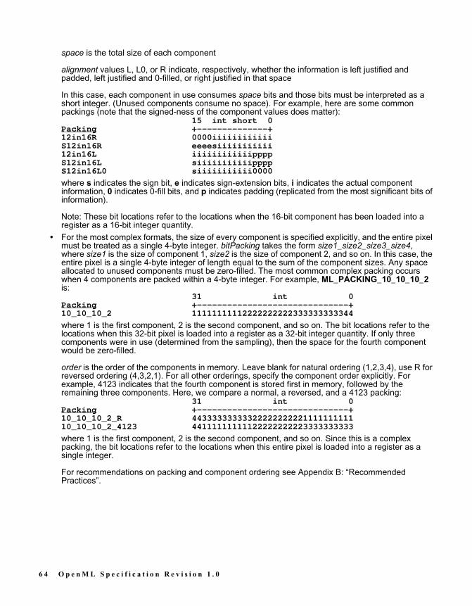
space is the total size of each component
alignment values L, L0, or R indicate, respectively, whether the information is left justified andpadded, left justified and 0-filled, or right justified in that space
In this case, each component in use consumes space bits and those bits must be interpreted as ashort integer. (Unused components consume no space). For example, here are some commonpackings (note that the signed-ness of the component values does matter):
15 int short 0Packing +--------------+12in16R 0000iiiiiiiiiiiiS12in16R eeeesiiiiiiiiiii12in16L iiiiiiiiiiiippppS12in16L siiiiiiiiiiippppS12in16L0 siiiiiiiiiii0000
where s indicates the sign bit, e indicates sign-extension bits, i indicates the actual componentinformation, 0 indicates 0-fill bits, and p indicates padding (replicated from the most significant bits ofinformation).
Note: These bit locations refer to the locations when the 16-bit component has been loaded into aregister as a 16-bit integer quantity.
• For the most complex formats, the size of every component is specified explicitly, and the entire pixelmust be treated as a single 4-byte integer. bitPacking takes the form size1_size2_size3_size4,where size1 is the size of component 1, size2 is the size of component 2, and so on. In this case, theentire pixel is a single 4-byte integer of length equal to the sum of the component sizes. Any spaceallocated to unused components must be zero-filled. The most common complex packing occurswhen 4 components are packed within a 4-byte integer. For example, ML_PACKING_10_10_10_2is:
31 int 0Packing +------------------------------+10_10_10_2 11111111112222222222333333333344
where 1 is the first component, 2 is the second component, and so on. The bit locations refer to thelocations when this 32-bit pixel is loaded into a register as a 32-bit integer quantity. If only threecomponents were in use (determined from the sampling), then the space for the fourth componentwould be zero-filled.
order is the order of the components in memory. Leave blank for natural ordering (1,2,3,4), use R forreversed ordering (4,3,2,1). For all other orderings, specify the component order explicitly. Forexample, 4123 indicates that the fourth component is stored first in memory, followed by theremaining three components. Here, we compare a normal, a reversed, and a 4123 packing:
31 int 0Packing +------------------------------+10_10_10_2_R 4433333333332222222222111111111110_10_10_2_4123 44111111111122222222223333333333
where 1 is the first component, 2 is the second component, and so on. Since this is a complexpacking, the bit locations refer to the locations when this entire pixel is loaded into a register as asingle integer.
For recommendations on packing and component ordering see Appendix B: “RecommendedPractices”.
6 4 O p e n M L S p e c i f i c a t i o n R e v i s i o n 1 . 0

ML_IMAGE_COLORSPACE_INT32The colorspace parameters describe how to interpret each component. The full colorspace parameter is:ML_COLORSPACE_representation_standard_rangewhere:• representation is either RGB or CbYCr.
This controls how to interpret each component. The following table shows this mapping (assuming fornow that every component is sampled once per pixel):
The packing dictates the size and order of the components in memory, while the colorspace describeswhat each component represents. For example, here we show the effect of colorspace and packingcombined; assuming a 4444 sampling.
Color 31 0Space Packing +------------------------------+RGB 8 RRRRRRRRGGGGGGGGBBBBBBBBAAAAAAAARGB 8_R AAAAAAAABBBBBBBBGGGGGGGGRRRRRRRRRGB 10_10_10_2 RRRRRRRRRRGGGGGGGGGGBBBBBBBBBBAARGB 10_10_10_2_R AABBBBBBBBBBGGGGGGGGGGRRRRRRRRRRCbYCr 10_10_10_2 bbbbbbbbbbYYYYYYYYYYrrrrrrrrrrAACbYCr 10_10_10_2_R AArrrrrrrrrrYYYYYYYYYYbbbbbbbbbb
• standard indicates how to interpret particular values as actual colors. Choosing a different standardalters the way the system converts between different color representations. Defined values of standardare 601, 709, and 240 which designate the Rec. 601, Rec. 709 and SMPTE 240M standardsrespectively.
• range is either FULL, where the smallest and largest values are limited only by the available packingsize, or HEAD, where the smallest and largest values are somewhat less than the theoretical min/maxvalues to allow some "headroom". Full range is common in computer graphics. Headroom range iscommon in video, particularly when sending video signals over a wire (for example, values outside thelegal component range may be used to mark the beginning or end of a video frame). When constructinga colorspace, an application must specify a representation, a standard and a range.
For example, ML_COLORSPACE_CbYCr_601_HEAD indicates a Rec. 601 standard CbYCr colorspacewith headroom range.
ML_IMAGE_SAMPLING_INT32The sampling parameters take their names from common terminology in the video industry. They describehow often each component is sampled for each pixel. In computer graphics, its normal for every compo-nent to be sampled once per pixel, but in video that need not be the case.For all RGB colorspaces, the legal samplings are:• ML_SAMPLING_444 indicates that the R, G and B components are each sampled once per pixel, and
only the first 3 channels are used. If used with an image packing that provides space for a 4th channel,those bits should have value 0 on an input path and will be ignored on an output path.
• ML_SAMPLING_4444 indicates that the R, G, B and A components are sampled once per pixel.
Colorspace Rep-resentation
Component 1 Component 2 Component 3 Component 4
RGB Red Green Blue AlphaCbYCr Cb Y Cr Alpha
Figure 8.4 Mapping Colorspace representation Parameters
O p e n M L S p e c i f i c a t i o n R e v i s i o n 1 . 0 6 5

For all CbYCr colorspaces, the legal samplings are:• ML_SAMPLING_444 indicates that the Cb, Y, and Cr components are each sampled once per pixel and
only the first 3 channels are used. If used with an image packing that provides space for a 4th channel,those bits should have value 0 on an input path and will be ignored on an output path.
• ML_SAMPLING_4444 indicates that the Cb, Y, Cr and Alpha components are each sampled once perpixel.
• ML_SAMPLING_422 indicates that the Y component is sampled once per pixel and the Cb and Crcomponents are sampled once per pair of pixels. In this case, Cb and Cr are interleaved on the 1stchannel (Cb is first, Cr is second), and Y occupies the 2nd channel. If used with an image packing thatprovides space for a 3rd or 4th channel, those bits should have value 0 on an input path and will beignored on an output path.
• ML_SAMPLING_4224 indicates that the Y and Alpha components are sampled once per pixel and theCb and Cr components are sampled once per pair of pixels. In this case, Cb and Cr are interleaved onthe 1st channel, Y is on the 2nd channel, and Alpha is on the 3rd channel. If used with an image packingthat provides space for a 4th channel, those bits should have value 0 on an input path and will beignored on an output path.
• ML_SAMPLING_411 indicates that the Y component is sampled once per pixel and the Cb and Crcomponents are sampled once per 4 pixels. In this case, Cb is component 1, Cr is component 2 and Yoccupies component 3. If used with an image packing that provides space for a 4th component thenthose bits should have value 0 on an input path and will be ignored on an output path.
• ML_SAMPLING_420 indicates that the Y component is sampled once per pixel and the Cb or Crcomponent is sampled once per pair of pixels on alternate lines. In this case, Cb or Cr is interleaved onthe 1st channel, and Y occupies the 2nd channel. If used with an image packing that provides space fora 3rd or 4th channel, those bits should have value 0 on an input path and will be ignored on an outputpath.
• ML_SAMPLING_400 indicates that only the Y component is sampled per pixel (a greyscale image). Ifused with an image packing that provides space for additional channels, those bits should have value 0on an input path and will be ignored on an output path.
• ML_SAMPLING_0004 indicates that only the Alpha component is sampled per pixel. If used with animage packing that provides space for additional channels, those bits should have value 0 on an inputpath and will be ignored on an output path.
The following table shows the combined effect of sampling and colorspace on the component definition:
*: Cb and Cr components are multiplexed with Y on alternate lines (not pixels).
Sampling ColorspaceRepresentation
Comp 1 Comp 2 Comp 3 Comp 4
4444 RGB Red Green Blue Alpha444 RGB Red Green Blue0004 RGB Alpha4444 CbYCr Cb Y Cr Alpha444 CbYCr Cb Y Cr4224 CbYCr Cb/Cr Y Alpha422 CbYCr Cb/Cr Y400 CbYCr Y420 CbYCr Cb/Cr* Y411 CbYCr Cb Cr Y0004 CbYCr Alpha
Table 8.1 Effect of Sampling and Colorspace on Component Definitions
6 6 O p e n M L S p e c i f i c a t i o n R e v i s i o n 1 . 0

ML_IMAGE_SWAP_BYTES_INT32Parameter ML_IMAGE_SWAP_BYTES_INT32 may be available on some devices. When set to 0 (thedefault) this has no effect. When set to 1, the device reorders bytes as a first step when reading data frommemory, and as a final step when writing data to memory. The exact reordering depends on the packingelement size. For simple and padded packing formats, the element size is the size of each component. Forcomplex packing formats, the element size is the sum of the four component sizes.The ML_IMAGE_SWAP_BYTES_INT32 parameter reorders bits as follows:
Element Size Default ordering Modified ordering16 bit [15..0] [7..0][15..8]32 bit [31..0] [7..0][15..8][23..16][31..24]other [n..0] [n..0] (no change)
Table 8.2 Effect of ML_IMAGE_SWAP_BYTES_INT32 on Image Bit Reordering
O p e n M L S p e c i f i c a t i o n R e v i s i o n 1 . 0 6 7

6 8 O p e n M L S p e c i f i c a t i o n R e v i s i o n 1 . 0

C H A P T E R
9ML AUDIO PARAMETERS
Audio Buffer LayoutThe digital representation of an audio signal is generated by periodically sampling the amplitude (voltage)of the signal. The samples represent periodic "snapshots" of the signal amplitude. The sampling rate spec-ifies the number of samples per second. The audio buffer pointer points to the source or destination data inan audio buffer for processing a fragment of a media stream. For audio signals, a fragment typically corre-sponds to between 10 milliseconds and 1 second of audio data. An audio buffer is a collection of sampleframes. A sample frame is a set of audio samples that are coincident in time. A sample frame for monodata is a single sample. A sample frame for stereo data consists of a left-right sample pair.Stereo samples are interleaved; left-channel samples alternate with right-channel samples. 4-channel sam-ples are also interleaved, with each frame usually having two left/right sample pairs, but there can be otherarrangements.
Figure 9.1 Different Audio Sample Frames
This illustration shows the relationship between the number of channels and the frame size of audio sam-ple data.
1-channel data
2-channel data
4-channel data
n-channel data
Frame
Frame
Frame
Frame
L R L R
1 2 3 4
1 2 3 n...
O p e n M L S p e c i f i c a t i o n R e v i s i o n 1 . 0 6 9

Figure 9.2 Layout of an Audio Buffer With 4 ChannelsThis illustration shows the layout of an audio buffer in memory.
Audio ParametersThe following parameters are defined for audio data:
ML_AUDIO_BUFFER_POINTERA pointer to the first byte of an in-memory audio buffer. The buffer address must comply with the alignmentconstraints for buffers on the particular path to which it is being sent. (See mlGetCapabilities for details ofdetermining alignment requirements).
ML_AUDIO_FRAME_SIZE_INT32The size of an audio sample frame in bytes. This is a read-only parameter and is computed in the deviceusing the current path control settings.
ML_AUDIO_SAMPLE_RATE_REAL64The sample rate of the audio data in Hz. The sample rate is the frequency at which samples are taken fromthe analog signal on input or pass out of the audio jack on output. Sample rates are measured in hertz (Hz).A sample rate of 1 Hz is equal to one sample per second. For example, when a mono analog audio signalis digitized at a 44.1 kilohertz (kHz) sample rate, 44100 digital samples are generated for every second of
1 432
4 Audio Channels
Audio Frame
Audio Sample
Audio Buffer
Time Period T
7 0 O p e n M L S p e c i f i c a t i o n R e v i s i o n 1 . 0

the signal. Sample rates are dependent on the hardware, but are usually between 8000 and 96000. Thedefault is hardware-specific. Common sample rates are 8000, 16000, 32000, 44100, 48000 and 96000.
ML_AUDIO_PRECISION_INT32The maximum width in bits for an audio sample at the input or output jack. For example, a value of 16 indi-cates a 16-bit audio signal. ML_AUDIO_PRECISION_INT32 specifies the precision at the Audio I/O jack,whereas ML_AUDIO_FORMAT_INT32 specifies the packing of the audio samples in the audio buffer. IfML_AUDIO_FORMAT_INT32 is different than ML_AUDIO_PRECISION_INT32, the system will convertbetween the two formats. Such a conversion might include padding and/or truncation.
ML_AUDIO_FORMAT_INT32Specifies the format in which audio samples are stored in memory. The interpretation of format values is:ML_AUDIO_FORMAT_[type][bits]• [type] is U for unsigned integer samples, S for signed (2's compliment) integer samples, R for real
(floating point) samples• [bits] is the number of significant bits per sample.For sample formats in which the number of significant bits is less than the number of bits in which the sam-ple is stored, the format of the values is:ML_AUDIO_FORMAT_[type][bits]in[size][alignment]• [size] is the total size used for the sample in memory, in bits.• [alignment] is either R or L depending on whether the significant bits are right- or left-shifted within the
sample. For example, here are three of the most common audio buffer formats:
ML_AUDIO_FORMAT_U8 7 char 0+------+iiiiiiii
ML_AUDIO_FORMAT_S16 15 short int 0+--------------+iiiiiiiiiiiiiiii
ML_AUDIO_FORMAT_S24in32R 31 int 0+------------------------------+ssssssssiiiiiiiiiiiiiiiiiiiiiiii
where s indicates sign-extension, and i indicates the actual component information. The bit locationsrefer to the locations when the 8-, 16-, or 32-bit sample has been loaded into a register as an integerquantity. If the audio data compression parameter ML_AUDIO_COMPRESSION_INT32 indicates thatthe audio data is in compressed form, the ML_AUDIO_FORMAT_INT32 indicates the data type of thesamples after decoding. Common formats are:
ML_FORMAT_U8ML_FORMAT_S16ML_FORMAT_S24in32RML_FORMAT_R32
Default is hardware-specific.
O p e n M L S p e c i f i c a t i o n R e v i s i o n 1 . 0 7 1

ML_AUDIO_GAINS_REAL64_ARRAYThe gain factor in decibels (dB) on the given path. There will be a value for each audio channel. Negativevalues represent attenuation. Zero represents no change of the signal. Positive values amplify the signal. Again of negative infinity indicates infinite attenuation (mute).
ML_AUDIO_CHANNELS_INT32The number of channels of audio data in the buffer. Multi-channel audio data is always stored interleaved,with the samples for each consecutive audio channel following one another in sequence. For example, a 4-channel audio stream will have the form:
123412341234...where 1 is the sample for the first audio channel, 2 is the sample for the second audio channel, and so on.Common values include the following:
ML_CHANNELS_MONOML_CHANNELS_STEREOML_CHANNELS_4ML_CHANNELS_8
ML_AUDIO_COMPRESSION_INT32This parameter specifies the compression format of the data. The compression format may be an industrystandard such as MPEG-1 audio or a device dependent format.Common values include the following:
ML_COMPRESSION_MU_LAWML_COMPRESSION_A_LAWML_COMPRESSION_IMA_ADPCMML_COMPRESSION_MPEG1ML_COMPRESSION_MPEG2ML_COMPRESSION_AC3
When the data is uncompressed, the value of this parameter is ML_COMPRESSION_UNCOMPRESSED.
7 2 O p e n M L S p e c i f i c a t i o n R e v i s i o n 1 . 0

Uncompressed Audio Buffer Size ComputationThe following equation shows how to calculate the number of bytes for an uncompressed audio buffergiven the sample frame size, sampling rate and the time period that the audio buffer represents:
where:
Example 8-1 Buffer Size ComputationIf:• is 4 bytes (if format is S16 and there are two channels)• (sampling rate) is 44,100 Hz• = 40 ms = 0.04 s.then the resulting buffer size is 7056 bytes.
audio buffer size in bytes
the number of bytes per audio sample frame (ML_AUDIO_FRAMESIZE_INT32)
the sampling rate in Hz (ML_AUDIO_SAMPLE_RATE_REAL64)
the time period the audio buffer represents in seconds
N F R T⋅ ⋅=
N
F
R
T
FRT
N
O p e n M L S p e c i f i c a t i o n R e v i s i o n 1 . 0 7 3

7 4 O p e n M L S p e c i f i c a t i o n R e v i s i o n 1 . 0

C H A P T E R
10ML PROCESSING
ML is concerned with two types of interfaces: paths for digital media through jacks into and out of themachine, and pipes for digital media to and from transcoders. Both share common control, buffer, andqueueing mechanisms. These mechanisms are first described in the context of a complete program exam-ple. Subsequently, the individual functions are presented.
ML Program StructureML programs are composed of the following structure. Each of the functions are described later in thischapter (except where noted).
// get list of available media devices// (See Chapter 6: “ML Capabilities” for function description)mlGetCapabilities( systemid, &capabilities );
// search the devices to find the desired jack, path, or transcoder to open// (See Chapter 6: “ML Capabilities” for function description)mlGetCapabilities( deviceid, &capabilities );
// query the jack, path, or transcoder to discover allowable open options and parameters// (See Chapter 6: “ML Capabilities” for function description)mlGetCapabilities( objectid, &capabilities );
// query for individual parameter characteristics// (See Chapter 6: “ML Capabilities” for function description)mlPvGetCapabilities( deviceid, &capabilities );
// free memory associated with any of the above get capabilities:// (See Chapter 6: “ML Capabilities” for function description)mlFreeCapabilities( capabilities );
O p e n M L S p e c i f i c a t i o n R e v i s i o n 1 . 0 7 5

// open a logical connection to the desired objectmlOpen( objectId, options, &openid );
// get and set any necessary immediate controlsmlGetControls( openid, controls );mlSetControls( openid, controls );
// send any synchronous controlsmlSendControls( openid, controls );
// pre-roll buffersmlSendBuffers( openid, buffers );
// prepare for asynchronous processing by getting a wait handlemlGetWaitHandle( openid, &WaitHandle );
// start the path or transcoder transferringmlBeginTransfer( openid );
// perform synchronous workmlXcodeWork( openid );
// check on the status of the queuesmlGetSendMessageCount( openid, &messageCount );mlGetReceiveMessageCount( openid, &messageCount );
// process return messagesmlReceiveMessage( openid, &messageType, &receiveMessage );
// find specific returned parametersmlPvFind( msg, param );
// repeat mlSendControls, mlSendBuffers, mlXcodeWork, etc. as required
// stop the transfermlEndTransfer( openid );
// close the logical connectionmlClose( openid );
// other useful functions:mlGetVersion( &majorVersion, &minorVersion );mlGetSystemUST( systemId, &returnedUST );mlStatusName( status );mlMessageName( messageType );
7 6 O p e n M L S p e c i f i c a t i o n R e v i s i o n 1 . 0

Parameter Access ControlsParameter access control flags describe when and how each parameter can be used. The set of parameteraccess control flags associated with a parameter is returned by mlPvGetCapabilities as ML_PARAM_ACCESS_INT32. This value is a bitwise “or” of one or more such flags.These values are an intrinsic aspect of each parameter and cannot be changed by the application. Theyare available to help the application use each parameter correctly. If a parameter is used in a manner thatis not consistent with its access control flags, then an error will be reported.The parameter access control flags are described in the following table where the string in the Access Con-trol column is a shortened form of the full name. The full name is of the form ML_ACCESS_access, whereaccess is the string listed in the Access Control column. For example, the full name of READ is ML_ACCESS_READ.
Note that buffer pointer parameters such as ML_IMAGE_BUFFER_POINTER and ML_AUDIO_BUFFER_POINTER do not have the ML_ACCESS_SEND_BUFFER flag. For these kinds of parameters, this accessis implicit.
Access Control DescriptionREAD The parameter can be used in an mlGetControls or mlQuery-
Controls message to retrieve a device control value.WRITE The parameter can be used in an mlSendControls, mlSetCon-
trols, or mlSendBuffers message to set a device control value.PASS_THROUGH The value of the param/value pair will not be changed by the
device, nor will any device controls be changed as a result of thisparameter. This flag is typically applied to parameters that areenqueued; such parameters may be used by an application asmarkers in the queue of messages. User parameters created withthe ML_USERDATA_DEFINED macro (refer to Chapter 5: “MLParameters”) are given PASS_THROUGH access so that theycan be used for this purpose.
OPEN_OPTION The parameter can be set when the corresponding device isopened by mlOpen. All parameters in the mlOpen options mes-sage must have this access.
IMMEDIATE The parameter can be used to set or retrieve a device controlvalue “out of band”. If the parameter has READ access, then theparameter can be included in a message passed to mlGetCon-trols. If the parameter has WRITE access, then the parametercan be included in a message passed to mlSetControls.
QUEUED The parameter can be used to set or retrieve a device controlvalue “in band”. If the parameter has READ access, then theparameter can be included in a message enqueued by mlQuery-Controls. If the parameter has WRITE access, then the parame-ter can be included in a message enqueued by mlSendControls.
SEND_BUFFER The parameter can be included in an “in band” messageenqueued by mlSendBuffers. If the parameter also has WRITEaccess then it can be used to set a device control.
DURING_TRANSFER The parameter can be used to set or retrieve a control value dur-ing buffer transfers...after the application has called mlBegin-Transfer. A device control that takes a long time to set (andtherefore could compromise real time buffer transfers) might nothave this access control.
Table 10.1 Parameter Access Control Values
O p e n M L S p e c i f i c a t i o n R e v i s i o n 1 . 0 7 7

Opening a Jack, Path, or TranscoderIn order to communicate with a Jack, Path, or Transcoder, a connection must be opened. A physical device(e.g. a PCI card) may simultaneously support several such connections. These connections are made bycalling mlOpen:
MLstatus mlOpen (const MLint64 objectId, MLpv* options, MLopenid* openid);
objectId is the 64-bit unique identifier for the object (jack, path or transcoder) to be opened. options is anML_END terminated list of param/value pairs that specify the initial configuration of the device to beopened. These parameters are described in Tables 10.2, 10.3, and 10.4.On successful completion, the handle of the open instance of the object is returned in openid and ML_STATUS_NO_ERROR is returned. The status value ML_STATUS_INVALID_ID is returned if the objectidis invalid.The mlOpen operation can fail because of an incorrectly structured options list. ML_STATUS_INVALID_PARAMETER is returned if one of the param values in the options list is invalid. ML_STATUS_INVALID_VALUE is returned if one of the value components in the options list is invalid. If the options list specifiesan open access mode that is not available on the device, then ML_STATUS_ACCESS_DENIED isreturned. In addition, ML_STATUS_INVALID_ARGUMENT is returned if one of the arguments to mlOpenis otherwise invalid.Resources are allocated or reserved as a side effect of mlOpen. ML_STATUS_OUT_OF_MEMORY isreturned if there is insufficient memory available to perform the operation, such as the space needed toallocate the queues for messages between the application and the device. ML_STATUS_INSUFFICIENT_RESOURCES is returned if some other required resource is not available, possibly by being already in useby this or another application.A device may not be available, perhaps from being powered off, or removed from the system. In such acase, ML_STATUS_DEVICE_UNAVAILABLE is returned. Finally, ML_STATUS_INTERNAL_ERROR isreturned if the operation fails due to a system or device I/O error.The following tables lists the mlOpen options defined for jacks, paths, and transcoders. For a particulardevice, only some of the options might be available. The set of available open options is returned in theML_OPEN_OPTIONS_IDS param/value pair returned by mlGetCapabilities. The allowable values associ-ated with one of these options can then be determined using mlPvGetCapabilities.In these tables, the string in the Parameter column is a shortened form of the full parameter name, which isof the form ML_parameter_type, where the parameter and type are the strings listed in the Parameter andType columns respectively. For example, the full parameter name of OPEN_MODE is ML_OPEN_MODE_INT32.Following are the mlOpen options parameters for jacks:
Parameter Type DescriptionOPEN_MODE INT32 Application’s intended use for the device.
Defined values are:• ML_MODE_RO for read only access• ML_MODE_RWS for shared read/write
access• ML_MODE_RWE for exclusive accessThe default is defined by the device’s capa-bilities.
Table 10.2 mlOpen Options for Jacks
7 8 O p e n M L S p e c i f i c a t i o n R e v i s i o n 1 . 0

lFollowing are the mlOpen options parameters for paths:
OPEN_RECEIVE_QUEUE_COUNT INT32 Application’s preferred size (number of mes-sages) for the receive queue. This influ-ences the amount of memory allocated forthis queue when the device is opened.Default is device-dependent. A null valueindicates that the application does notexpect to receive any events from the jack.
OPEN_EVENT_PAYLOAD_COUNT INT32 Application's preferred size (number of mes-sages) for the queue event payload area.This payload area holds the contents ofevent messages on the receive queue.Default is device-dependent. A null valueindicates that the application does notexpect to receive any events from the jack.
Parameter Type DescriptionOPEN_MODE INT32 Application’s intended use for the device.
Defined values are:• ML_MODE_RO for read only access• ML_MODE_RWS for shared read/write
access• ML_MODE_RWE for exclusive accessThe default is defined by the device’s capa-bilities.
OPEN_SEND_QUEUE_COUNT INT32 Application's preferred size (number of mes-sages) for the send header queue. Thisinfluences the amount of memory allocatedfor this queue when the device is opened.Default is device-dependent.
OPEN_RECEIVE_QUEUE_COUNT INT32 Applications' preferred size (number of mes-sages) for the receive header queue. Thisinfluences the amount of memory allocatedfor this queue when the device is opened.Default is device-dependent
OPEN_MESSAGE_PAYLOAD_SIZE INT32 Application's preferred size (in bytes) for thequeue message payload area. The payloadarea holds messages on both the send andreceive queues. Default is device-depen-dent.
OPEN_EVENT_PAYLOAD_COUNT INT32 Application's preferred size (number of mes-sages) for the queue event payload area.This payload area holds the contents ofevent messages on the receive queue.Default is device-dependent.
Table 10.3 mlOpen Options for Paths
Parameter Type Description
Table 10.2 mlOpen Options for Jacks
O p e n M L S p e c i f i c a t i o n R e v i s i o n 1 . 0 7 9

Following are the mlOpen options parameters for transcoders:
OPEN_SEND_SIGNAL_COUNT INT32 Application's preferred low-water level(number of empty message slots) in thesend queue. When the device dequeues amessage and causes the number of emptyslots to exceed this level, then the devicewill signal the send queue event. Default isdevice-dependent.
Parameter Type DescriptionOPEN_MODE INT32 Application’s intended use for the device.
Defined values are:• ML_MODE_RO for read only access• ML_MODE_RWS for shared read/write
access• ML_MODE_RWE for exclusive accessThe default is defined by the device’s capa-bilities.
OPEN_SEND_QUEUE_COUNT INT32 Application's preferred size (number of mes-sages) for the send queue. This influencesthe amount of memory allocated for thisqueue when the device is opened. Default isdevice-dependent.
OPEN_RECEIVE_QUEUE_COUNT INT32 Applications' preferred size (number of mes-sages) for the receive queue. This influ-ences the amount of memory allocated forthis queue when the device is opened.Default is device-dependent
OPEN_MESSAGE_PAYLOAD_SIZE INT32 Application's preferred size (in bytes) for thequeue message payload area. The payloadarea holds messages on both the send andreceive queues. Default is device-depen-dent.
OPEN_EVENT_PAYLOAD_COUNT INT32 Application's preferred size (number of mes-sages) for the queue event payload area.This payload area holds the contents ofevent messages on the receive queue.Default is device-dependent.
OPEN_SEND_SIGNAL_COUNT INT32 Application's preferred low-water level(number of empty message slots) in thesend queue. When the device dequeues amessage and causes the number of emptyslots to exceed this level, then the devicewill signal the send queue event. Default isdevice-dependent.
Table 10.4 mlOpen Options for Transcoders
Parameter Type Description
Table 10.3 mlOpen Options for Paths
8 0 O p e n M L S p e c i f i c a t i o n R e v i s i o n 1 . 0

Transcoder Component SelectionTo set or retrieve the controls of a pipe, a message is sent to the transcoder which owns the pipe. Atranscoder has at least two pipes, a source pipe and a destination pipe. A message to a transcoder caninclude parameters for the source pipe, for the destination pipe and for the transcode itself. The ML_SELECT_ID_INT64 parameter sets a device control in the transcoder which determines to which compo-nent of the transcoder subsequent parameters are applied.If ML_SELECT_ID_INT64 has value 0, then subsequent parameters are applied to the transcoder itself.Values of ML_XCODE_SRC_PIPE and ML_XCODE_DST_PIPE cause subsequent parameters to beapplied to the source and destination pipes respectively.By default, parameters in a message to a transcoder are applied to the transcoder itself. That is, the valueof the SELECT_ID device control is effectively set to 0 at the start of each message to a transcoder.If a transcoder does not recognize an ML_SELECT_ID_INT64 value, it will ignore subsequent parametersuntil the next valid ML_SELECT_ID_INT64 value or until the end of the message.
OPEN_XCODE_MODE INT32 Application's preferred mode for controllinga software transcoder. This parameter doesnot apply to paths. Defined values are:• ML_XCODE_MODE_SYNCHRONOUS
when processing by a softwaretranscoder is to be initiated by theapplication.
• ML_XCODE_MODE_AYNCHRONOUSwhen processing by a softwaretranscoder is to be initiated by ML
Default is ML_XCODE_MODE_ASYN-CHRONOUS
OPEN_XCODE_STREAM INT32 Selects between single and multi-streamtranscoders. In single stream mode, sourceand destination buffers are processed at thesame rate. In multi-stream mode, the sourceand destination pipes each have their ownqueue of buffers and may run at differentrates (this is more complicated to program,but may be more efficient for some intra-frame codecs). Defined values are:• ML_XCODE_STREAM_SINGLE• ML_XCODE_STREAM_MULTIDefault is ML_XCODE_STREAM_SINGLEOnly ML_XCODE_STREAM_SINGLE iscurrently supported. It is expected that ML_XCODE_STREAM_MULTI will be sup-ported in a future release of OpenML.
Parameter Type Description
Table 10.4 mlOpen Options for Transcoders
O p e n M L S p e c i f i c a t i o n R e v i s i o n 1 . 0 8 1

Set ControlsControls on a logical connection that do not affect the buffer size needed for a media I/O operation may beperformed asynchronously to an ongoing data transfer. For example, changing the packing of a videoimage (ML_IMAGE_PACKING_IN32) can affect the buffer size needed to contain an image, while chang-ing the video brightness (ML_VIDEO_BRIGHTNESS_INT32) does not. These controls may be set in an“out of band” message using the mlSetControls operation:
MLstatus mlSetControls( MLopenid openid, MLpv* controls );
openid is the identifier, returned by mlOpen, of the jack, path or transcoder whose parameters are to beset. The status value ML_STATUS_INVALID_ID is returned if the openid is invalid.The controls parameter is a message consisting of parameter values to be set. The mlSetControls opera-tion can fail because of an incorrectly structured controls message. ML_STATUS_INVALID_PARAME-TER is returned if one of the param values in the controls message is not recognized. ML_STATUS_INVALID_VALUE is returned if one of the value components in the controls message is invalid. ML_STATUS_INVALID_CONFIGURATION is returned if the resulting set of parameter values would be incon-sistent if the operation were performed. For all of these failure cases, the length component of the firstinvalid param/value pair is set to -1.The mlSetControls operation sends a message containing a list of control parameters directly to a previ-ously-opened digital media device. The controls message is not enqueued on the send queue but insteadis sent directly to the device. The device will attempt to process the message "as soon as possible".This call blocks until the device has processed the controls message. This means that, on return, theparameters have been validated and sent to the device (i.e. in most cases this means that they reside inregisters)Other than to identify an invalid param/value pair by setting its length to -1, the controls message will notbe altered in any way and may be reused.All the control changes within a single controls message are considered to occur atomically. If any one con-trol change in the message fails, then the entire message has no effectOn successful completion, ML_STATUS_NO_ERROR is returned.
Get ControlsControls on a logical connection may be queried asynchronously to an ongoing data transfer:
MLstatus mlGetControls( MLopenid openid, MLpv* controls );
openid is the identifier, returned by mlOpen, of the jack, path or transcoder whose parameters are to bequeried. The status value ML_STATUS_INVALID_ID is returned if the openid is invalid.The controls parameter is a message consisting of parameters to be queried. The mlGetControls opera-tion can fail because of an incorrectly structured controls message. ML_STATUS_INVALID_PARAME-TER is returned if one of the param values in the controls message is not recognized. In this case, thelength component corresponding to the first invalid param value is set to -1. In this case all returned val-ues must be considered invalid.The mlGetControls operation sends a message containing a list of control parameters to be querieddirectly to a previously-opened digital media device. The controls message is not enqueued on the sendqueue but instead is sent directly to the device. The device will attempt to process the message "as soonas possible".This call blocks until the device has processed the controls message. This means that, on return, theparameters have been validated and the controls message contains the values obtained.On successful completion, ML_STATUS_NO_ERROR is returned.
8 2 O p e n M L S p e c i f i c a t i o n R e v i s i o n 1 . 0

Send ControlsOther controls on a logical connection must be applied “synchronously” because they affect the buffer sizethat is needed in a data transfer. Changes to these controls should be set in an “in band” message usingthe mlSendControls operation. Note that controls that can be sent using mlSetControls can also be setusing mlSendControls.
MLstatus mlSendControls( MLopenid openid, MLpv* controls );
openid is the identifier, returned by mlOpen, of the path or transcoder whose parameters are to be set.Thestatus value ML_STATUS_INVALID_ID is returned if the openid is invalid.The controls argument is a message containing various parameters as described in the preceding chap-ters. The mlSendControls operation can fail because of an incorrectly structured controls message. ML_STATUS_INVALID_PARAMETER is returned if one of the param values in the controls message is notrecognized. ML_STATUS_INVALID_VALUE is returned if one of the value components in the controlsmessage is invalid. ML_STATUS_INVALID_CONFIGURATION is returned if the resulting set of parame-ter values would be inconsistent if the operation were performed. For all of these failure cases, the lengthcomponent of the first invalid param/value pair is set to -1.The mlSendControls operation sends a message containing a list of control parameters to a previously-opened digital media device. This message is enqueued on the send queue in sequence with any othermessages to that device. Any control changes are thus guaranteed not to have any effect until all previ-ously enqueued messages have been processed. ML_STATUS_SEND_QUEUE_OVERFLOW is returnedif there is not enough space on the send queue for this message and ML_STATUS_RECEIVE_QUEUE_OVERFLOW is returned if there is not enough room on the receive queue for a reply to this message.mlSendControls returns as soon as the controls message has been enqueued to the send queue. It doesnot wait until the message has actually taken effect.All the control changes within a single message are considered to occur atomically. If any one controlchange in the message fails, then the entire message has no effectEnqueueing entails a copy operation, so the application is free to delete/alter the message array as soonas the call returns. Any error return value indicates the control change has not been enqueued and will thushave no effect.On successful completion, ML_STATUS_NO_ERROR is returned. A successful return does not guaranteethat resources will be available to support the requested control change at the time it is processed by thedevice.When the device has completed processing the enqueued controls message, it enqueus a reply messagefor return to the application. By examining that reply, the application may obtain the result of processing therequested controls. Note that a device may take an arbitrarily long time to generate a reply (it may, forexample, wait for several messages before replying to the first).
Send BuffersmlSendBuffers enqueues buffers for subsequent processing by a previously opened path or transcoder:
MLstatus mlSendBuffers( MLopenid openid, MLpv* buffers );
openid is the identifier, returned by mlOpen, of the path or transcoder to which buffers are being sent. Thestatus value ML_STATUS_INVALID_ID is returned if the openid is invalid.buffers is a message consisting of a list of buffer parameters. It can include only a single buffer of any giventype (audio or image) but can include a buffer of each different type.
O p e n M L S p e c i f i c a t i o n R e v i s i o n 1 . 0 8 3

buffers is enqueued on the send queue in sequence with other messages to that device. All the bufferswithin a single message are considered to apply to the same point in time. For example, a single messagecould contain image and audio buffers, each specified with its own buffer parameter in the buffers mes-sage. ML_STATUS_SEND_QUEUE_OVERFLOW is returned if there is not enough space on the sendqueue for this message and ML_STATUS_RECEIVE_QUEUE_OVERFLOW is returned if there is notenough room on the receive queue for a reply to this message.The mlSendBuffers operation can fail because of an incorrectly structured buffers message. ML_STATUS_INVALID_PARAMETER is returned if one of the param values in the buffers message is notrecognized. ML_STATUS_INVALID_VALUE is returned if one of the value components in the buffersmessage is invalid or if the resulting set of parameter values would be inconsistent if the operation wereperformed. For both of these failure cases, the length component of the first invalid param/value pair is setto -1 and the entire message is ignored.mlSendBuffers returns as soon as the buffers message has been enqueued to the send queue. It doesnot wait until the message has been processed by the device. Any error return value indicates the messagehas not been enqueued and will thus have no effect. Processing of messages enqueued by mlSend-Buffers is deferred if buffer transfers are not enabled (cf. mlBeginTransfer).Enqueueing entails a copy operation, so the application is free to delete/alter the message array as soonas the call returns. Any error return value indicates the control change has not been enqueued and will thushave no effect.The memory for the buffers is designated by the ML_IMAGE_BUFFER_POINTER or ML_AUDIO_BUFFER_POINTER value, and is always owned by the application. However, after a buffer has been sent,it is “on loan” to the system and must not be touched by the application. After the buffer has been returnedvia mlReceiveMessage or if mlSendBuffers fails, the application is again free to modify or delete it.When sending a buffer to be output, the application must set the buffer length to indicate the number ofvalid bytes in the buffer. In this case maxLength is ignored by the device (it doesn’t matter how muchlarger the buffer may be, since the device won’t read past the last valid byte).When sending a buffer to be filled (on input), the application must set the buffer maxLength to indicate themaximum number of bytes which may be written by the device to the buffer. As the device processes thebuffer, it will write no more than the maxLength bytes and then set the returned length to indicate the lastbyte written. The maxLength is returned without change.It is acceptable to send the same buffer multiple times to an output device. If the device is unable to get abuffer while transferring, the device will generate and send a SEQUENCE_LOST exception event to theapplication.On successful completion, ML_STATUS_NO_ERROR is returned. A successful return value from themlSendBuffers guarantees only that the message has been enqueued. A successful return does not guar-antee that processing of the message by the device will succeed.When the device has completed processing the enqueued buffers message, it enqueus a reply messagefor return to the application. By examining that reply, the application may obtain the result of processing thebuffers.
Query ControlsTo obtain the control values on a logical connection that are synchronous with other commands, an “inband” operation, mlQueryControls, is used:
MLstatus mlQueryControls( MLopenid openid, MLpv* controls );
openid is the identifier, returned by mlOpen, of the device whose parameters are to be set. The statusvalue ML_STATUS_INVALID_ID is returned if the openid is invalid.The controls argument is a message containing various parameters as described in the preceding chap-ters. The mlQueryControls operation can fail because of an incorrectly structured controls message. ML_
8 4 O p e n M L S p e c i f i c a t i o n R e v i s i o n 1 . 0

STATUS_INVALID_PARAMETER is returned if one of the param values in the controls message is notrecognized. In this case, the length component of the first invalid param/value pair is set to -1.The mlQueryControls operation sends a message containing a list of control parameters to a previously-opened digital media device. This message is enqueued on the send queue in sequence with any othermessages to that device.The control values return are thus guaranteed to reflect the effects of all previ-ously enqueued messages. ML_STATUS_SEND_QUEUE_OVERFLOW is returned if there is not enoughspace on the send queue for this message and ML_STATUS_RECEIVE_QUEUE_OVERFLOW isreturned if there is not enough room on the receive queue for a reply to this message.mlQueryControls returns as soon as the controls message has been enqueued to the send queue. It doesnot wait until the message has actually taken effect.Enqueueing entails a copy operation, so the application is free to delete/alter the message array as soonas the call returns. Any error return value indicates the message has not been enqueued and will thus haveno effect.On successful completion, ML_STATUS_NO_ERROR is returned. A successful return does not guaranteethat processing of the message by the device will succeed.When the device has completed processing the enqueued controls message, it enqueus a reply messagefor return to the application. By examining that reply, the application may obtain the result of processing thequeried controls. Note that a device may take an arbitrarily long time to generate a reply (it may, for exam-ple, wait for several messages before replying to the first).
Get Wait HandleWhen processing a number of digital media streams asynchronously, there exists a need for the applica-tion to know when processing is required on each individual stream. The mlGetSendWaitHandle andmlGetReceiveWaitHandle functions are provided to facilitate this processing:
MLstatus mlGetSendWaitHandle( MLopenid openid, MLwaitable* waitHandle );
MLstatus mlGetReceiveWaitHandle( MLopenid openid, MLwaitable* waitHandle );
openid is the identifier, returned by mlOpen, of a path or transcoder. The status value ML_STATUS_INVALID_ID is returned if the openid is invalid.The requested wait handle, on which an application may wait, is returned in waitHandle. On IRIX, UNIXand Linux, MLwaitable is a file descriptor for use in select(). On Windows, MLwaitable is a HANDLEwhich may be used in the win32 functions WaitForSingleObject or WaitForMultipleObjects.The send queue handle is signaled whenever the device dequeues a message and the number of emptymessage slots exceeds a preset level (set by the parameter ML_OPEN_SEND_SIGNAL_COUNT_INT32specified when the object was opened). Thus, if the send queue is full, an application may wait on this han-dle for notification until space is available for additional messages.The receive queue handle is signaled whenever the device enqueues a reply message. Thus, if the receivequeue is empty, the application may wait on this handle for notification that additional reply messages areready.The returned handles were created when the device was opened and are automatically destroyed whenthe path is closed.On successful completion, ML_STATUS_NO_ERROR is returned.
Begin TransfermlBeginTransfer enables the transferring of buffers to the logical media connection:
O p e n M L S p e c i f i c a t i o n R e v i s i o n 1 . 0 8 5

MLstatus mlBeginTransfer( MLopenid openid );
openid is the identifier, returned by mlOpen, of the path or transcoder. The status value ML_STATUS_INVALID_ID is returned if the openid is invalid.mlBeginTransfer enables the processing of buffer messages, that is, messages enqueued on the sendqueue by mlSendBuffers.Processing of buffer messages, messages enqueued by mlSendBuffers, can be enabled or disabled.When processing of buffer messages is disabled, a message enqueued by mlSendControls or mlQuery-Controls can be processed when it reaches the head of the queue. However, a buffer message thatreaches the head of the send queue will stall processing until such processing is enabled again. mlBegin-Transfer enables the processing of buffer messages.When a path or transcoder logical device is opened, processing of buffer messages is disabled. Typicallyapplications will open a device, send several buffers (“pre-rolling” the queue) and then call mlBeginTrans-fer.This call returns as soon as the device has begun processing transfers. It does not block until the firstbuffer has been processed. The status ML_STATUS_NO_OPERATION is returned if processing of buffermessages was already enabled, otherwise ML_STATUS_NO_ERROR is returned.The delay between a call to mlBeginTransfer and the transfer of the first buffer is implementation depen-dent. To begin sending data at a particular time, an application should start the transfer early (enqueueingblank buffers) and use the UST/MSC mechanism to synchronize the start of real data.
Transcoder WorkAn application can control exactly when and in which thread the processing for a software transcoder isperformed using:
MLstatus mlXcodeWork( MLopenid openid );
openid is the identifier, returned by mlOpen, of a previously opened transcoder. The status value ML_STATUS_INVALID_ID is returned if the openid is invalid.The default behavior of transcoders is for processing of buffer messages to occur automatically as a sideeffect of enqueueing messages to the device. mlXcodeWork only applies to software transcoders that areopened with the ML_XCODE_MODE_SYNCHRONOUS open option.This function performs one unit of processing for the specified codec. The processing is done in the threadof the calling process and the call does not return until the processing is complete.For most codecs a "unit of work" is the processing of a single buffer from the source queue and the writingof a single resulting buffer on the destination queue. If there were no buffers to be processed, ML_STATUS_NO_OPERATION is returned.On completion of a unit of work ML_STATUS_NO_ERROR is returned. This does not mean that the unit ofwork completed successfully. The application must examine the reply message to determine whether suchprocessing was successful.
Get Message CountDuring the processing of messages it is sometimes necessary to inquire as to the “fullness” of the messagequeues. These functions provide that capability:
MLstatus mlGetSendMessageCount ( MLopenid openid, MLint32* messageCount);MLstatus mlGetReceiveMessageCount ( MLopenid openid, MLint32* messageCount );
8 6 O p e n M L S p e c i f i c a t i o n R e v i s i o n 1 . 0

openid is the identifier, returned by mlOpen, of a path or pipe. The status value ML_STATUS_INVALID_IDis returned if the openid is invalid.The count of the number of messages in the send or receive queues of a device is returned in message-Count. The send queue contains messages queued by the application for processing by the device whilethe receive queue holds messages which have been processed and are waiting to be read by the applica-tion. A message is considered to reside in the send queue from the moment it is enqueued by the applica-tion until the moment the device begins processing it. A message resides in the receive queue from themoment the device enqueues it, until the moment the application dequeues the corresponding reply mes-sage. The message counts are intended to aid load-balancing in sophisticated applications. They are not areliable method for predicting UST/MSC pairs.Some devices can begin processing one or more subsequent messages before the processing of a previ-ous message has completed. Thus, the sum of the send and receive queue counts may be less than thedifference between the number of messages which have been enqueued and dequeued by the application.Note also that the time lag between a message being removed from the send queue, and the time at whichit affects data passing through a physical jack, is implementation dependent. The message counts are nota reliable method for timing or synchronizing media streams.On successful completion, ML_STATUS_NO_ERROR is returned.
Receive MessageIn order for applications to obtain the results of previous digital media requests, the mlReceiveMessagefunction is used.
MLstatus mlReceiveMessage( MLopenid openid, MLint32* messageType, MLpv *message );
openid is the identifier, returned by mlOpen, of a path or transcoder. The status value ML_STATUS_INVALID_ID is returned if the openid is invalid.A message on the receive queue can be the result of processing a message sent by mlSendControls,mlSendBuffers, or mlQueryControls; we call such messages reply messages. For each message placedon the send queue, a single reply message will be placed on the receive queue. Alternatively, a messageon the receive queue can have been generated spontaneously by the device to advise the application ofsome exceptional event; we call such messages event messages. mlReceiveMessage returns the oldestmessage on the receive queue regardless of whether it is a reply message or an exception message.For reply messages, the value returned in messageType indicates not only the initiating function, mlSend-Controls, mlSendBuffers, or mlQueryControls, but also whether processing of the sent message wassuccessful. The message returned by message has the same list of params as the sent message. Thevalue, length, and maxLength components may have been changed as described for each of the initiat-ing functions.For exception messages, the value returned in messageType indicates the event that is being reported.The message returned in message is event and device specific. It is the application’s responsibility to parseand decode the message.The contents of a message returned by message are guaranteed to remain valid until the next call to mlRe-ceiveMessage. Thus an application may modify the reply message and then send it to the same device orto another device by calling mlSendControls, mlSendBuffers, or mlQueryBuffers.ML_STATUS_RECEIVE_QUEUE_EMPTY is returned if the receive queue is empty. On some devices,triggering of the receive wait handle does not guarantee that a message is waiting on the receive queue.Thus applications should always check for the ML_STATUS_RECEIVE_QUEUE_EMPTY return status.On successful completion, ML_STATUS_NO_ERROR is returned.The following tables describe the values that are returned in messageType for replies to mlSendControls,mlSendBuffers, and mlQueryBuffers:
O p e n M L S p e c i f i c a t i o n R e v i s i o n 1 . 0 8 7

Following are the message types for replies to mlSendControls:
Following are the message types for replies to mlSendBuffers:
Message type DescriptionML_CONTROLS_COMPLETE The controls were processed without error.ML_CONTROLS_ABORTED Processing of the controls was aborted due
to some asynchronous event such as exe-cution of mlEndTransfer on this device.
ML_CONTROLS_FAILED Processing of controls failed because thevalues were not accepted at the time of pro-cessing. This can occur both becauseparameters in the buffers message wereinvalid or because, due to the current controlsettings at the time of processing (becauseof previous mlSendControls messages),the processing of buffers would be invalid.Since preceding control messages may beincomplete, but each of the individual set orsend controls may be valid, there still existsa point in time where the processing of buff-ers must be accomplished using thoseaggregate controls. If for some reason, the“combination of controls” is invalid, the pro-cessing is aborted and the event ML_BUFFERS_FAILED is returned. The lengthcomponent of the first invalid param/valuepair is set to -1
Table 10.5 mlSendControls Reply Message Types
Message type DescriptionML_BUFFERS_COMPLETE The buffers were processed without error.ML_BUFFERS_ABORTED Processing of the buffers was aborted due
to some asynchronous event such as exe-cution of mlEndTransfer on this device.
ML_BUFFERS_FAILED Processing of buffers failed because the val-ues were not accepted at the time of pro-cessing. This can occur both becauseparameters in the buffers message wereinvalid or because, due to the current controlsettings at the time of processing (becauseof previous mlSendControls messages),the processing of buffers would be invalid.Since preceding control messages may beincomplete, but each of the individual set orsend controls may be valid, there still existsa point in time where the processing of buff-ers must be accomplished using thoseaggregate controls. If for some reason, the“combination of controls” is invalid, the pro-cessing is aborted and the event ML_BUFFERS_FAILED is returned. The lengthcomponent of the first invalid param/valuepair is set to -1
8 8 O p e n M L S p e c i f i c a t i o n R e v i s i o n 1 . 0

Table 10.6 mlSendBuffers Reply Message Types
Following are the message types for replies to mlQueryControls:
Table 10.7 mlQueryControls Reply Message Types
Following are the message types for exception messages
Table 10.8 Exception Message Types
End TransferFor an application to invoke an orderly shutdown of a digital media stream, the mlEndTransfer functionshould be issued.
MLstatus* mlEndTransfer( MLopenid openid );
openid is the identifier, returned by mlOpen, of a path or transcoder. The status value ML_STATUS_INVALID_ID is returned if the openid is invalid.mlEndTransfer disables the transferring of buffers on the specified path or transcoder. This call advisesthe device to stop processing buffers and aborts any remaining messages on its input queue. This is ablocking call. It does not return until transfers have stopped and any messages remaining on the deviceinput queue have been aborted and reply messages placed on the receive queue. Calling mlEndTransferon a device on which transfers are already disabled will cause the send queue to be flushed. Any mes-
Message type DescriptionML_QUERY_CONTROLS_COMPLETE The query controls were processed without
error.ML_QUERY_CONTROLS_ABORTED Processing of the query controls was
aborted due to some asynchronous eventsuch as execution of mlEndTransfer on thisdevice.
Message type DescriptionML_EVENT_DEVICE_ERROR Device encountered an error and is unable
to recover.ML_EVENT_DEVICE_UNAVAILABLE The device is not available for use.ML_EVENT_VIDEO_SEQUENCE_LOST A video buffer was not available for an I/O
transfer.ML_EVENT_VIDEO_SYNC_LOST Device lost output genlock sync signal.ML_EVENT_VIDEO_SYNC_GAINED Device detected valid output genlock.ML_EVENT_VIDEO_SIGNAL_LOST Device lost input video signal.ML_EVENT_VIDEO_SIGNAL_GAINED Device detected valid input video signal.ML_EVENT_VIDEO_VERTICAL_RETRACE A video vertical retrace occurred.ML_EVENT_AUDIO_SEQUENCE_LOST An audio buffer was not available for an I/O
transfer.ML_EVENT_AUDIO_SAMPLE_RATE_CHANGED The audio input sampling frequency
changed.
O p e n M L S p e c i f i c a t i o n R e v i s i o n 1 . 0 8 9

sages which are flushed will be marked to indicate they were aborted. Buffer messages are marked ML_BUFFERS_ABORTED, while control messages are marked ML_CONTROLS_ABORTED.On successful completion, ML_STATUS_NO_ERROR is returned.
Close ProcessingAfter an application is finished with a digital media connection, it should terminate that connection. ThemlClose function is provided for that use. Note that an mlClose call is implied if an application terminates(for any reason) before an mlClose function is explicitly called.
MLstatus mlClose(MLopenid openid);
openid is the identifier, returned by mlOpen, of the device to be closed. The status value ML_STATUS_INVALID_ID is returned if the openid is invalid.When a digital media object is closed, all messages in the message queues of the device are discarded.The device handle openid becomes invalid; any subsequent attempt to use it to refer to the closed objectwill result in an error.The pipes opened as a side-effect of opening a transcoder are also closed as a side-effect of closing atranscoder. Pipes should not be closed explicitly.mlClose is a blocking call that returns only after the device has been closed and associated resourceshave been freed.On successful completion, ML_STATUS_NO_ERROR is returned.
Utility FunctionsThere are a number of other useful functions available in the ML API. They are described here.
Get VersionMLstatus mlGetVersion( MLint32 *majorVersion, MLint32 *minorVersion );
mlGetVersion returns the ML version number. The major version number is returned in majorVersionwhile the minor version number is returned in minorVersion. ML_STATUS_INVALID_ARGUMENT isreturned if either majorVersion or minorVersion is a NULL pointer. The version number is of the formmajorVersion.minorVersion, for example 1.0. Changes in major numbers indicate a potential incompatibil-ity, while changes in minor numbers indicate small backward-compatible enhancements. Major versionnumbers start at 1 and increase monotonically. Within a particular major version, the minor version num-bers will start at 0 and increase monotonically.Note that this is the version number of the ML core library; the version numbers for device-dependent mod-ules are available in the capabilities list for each physical device.On successful completion, ML_STATUS_NO_ERROR is returned.
Status Nameconst char *mlStatusName( MLstatus status );
Intended mainly as an aid in debugging, mlStatusName accepts an ML status value and returns the corre-sponding string. For example, the value ML_STATUS_NO_ERROR, is converted to the string “ML_STATUS_NO_ERROR”. NULL is returned if status is an invalid status value.
9 0 O p e n M L S p e c i f i c a t i o n R e v i s i o n 1 . 0

Message Nameconst char *mlMessageName( MLint32 messageType );
Intended mainly as an aid in debugging, mlMessageName accepts an ML message type and returns thecorresponding string. For example, the value ML_CONTROLS_FAILED, is converted to the string "ML_CONTROLS_FAILED". NULL is returned if status is an invalid status value.
MLpv String Conversion routinesThese routines convert between MLpv param/value pairs and strings. They are of benefit to applicationswriting lists of parameters to or from files, but are most commonly used as an aid to debugging.
MLstatus mlPvValueToString(MLint64 objectId, MLpv* pv,char* buffer, MLint32* bufferSize);
MLstatus mlPvParamToString(MLint64 objectId, MLpv* pv,char* buffer, MLint32* bufferSize);
MLstatus mlPvToString(MLint64 objectId, MLpv* pv,char* buffer, MLint32* bufferSize);
MLstatus mlPvValueFromString(MLint64 objectId, const char* buffer,MLint32* bufferSize, MLpv* pv,MLbyte* arrayData, MLint32 arraySize);
MLstatus mlPvParamFromString(MLint64 objectId, const char* buffer,MLint32* bufferSize, MLpv* pv);
MLstatus mlPvFromString(MLint64 objectId, const char* buffer,MLint32* bufferSize, MLpv* pv,MLbyte* arrayData, MLint32 arraySize);
These routines make use of parameter capability data (see mlPvGetCapabilities) to generate and inter-pret human-readable ASCII strings. The interpretation of a param/value pair depends on the parameter, itsvalue, and the device on which it will be used. Thus, all these functions require a 64-bit device identifier,supplied in objectid.objectid may be a static id (obtained from a call to mlGetCapabilities), the open id of a jack, path ortranscoder (obtained from a call to mlOpen), or it may be the id of an open pipe (obtained by callingmlGetCapabilities on a transcoder). The status value ML_STATUS_INVALID_ID is returned if the openidis invalid.mlPvParamToString converts pv->param to a string representation.mlPvValueToString converts pv->value to a string representation.mlPvToString converts pv into a string representation composed of the parameter name and value sepa-rated by ’=’.In the preceding routines, the resulting string is returned in *buffer. On input, bufferSize specifies the size ofthe buffer in bytes. On return, bufferSize is the length of the resulting string (excluding the terminating ’\0’).
O p e n M L S p e c i f i c a t i o n R e v i s i o n 1 . 0 9 1

ML_STATUS_INVALID_PARAMETER is returned if pv->param is invalid, and ML_STATUS_INVALID_VALUE is returned if pv->value is invalid.In all the following routines, the string to be converted is given in buffer and its length (in bytes andexcluding the terminating ‘\0’) is given in bufferSize. pv points to a structure to receive the conversionresults.mlPvParamFromString interprets a string as a param ID and writes the result in pv->param. It expectsthe string to be as created by mlPvParamToString.In the following routines, arrayData points to buffer owned by the application whose length (in bytes) isgiven in arraySize.mlPvValueFromString interprets a string as the value of a param/value pair. For scalar values, the resultis written to pv->value; *arrayData and arraySize are unchanged. For array values, the string is convertedto an array of data values and the results are returned in *arrayData; arraySize is set to the number ofbytes written. It expects the string was created by mlPvValueToString.mlPvFromString interprets a string as a param/value pair and writes the resulting param value to pv->param. For scalar values, the result is written to pv->value; *arrayData and arraySize are unchanged. Forarray values, the string is converted to an array of data values and the results are returned in *arrayData;arraySize is set to indicate the number of bytes written.It expects the string was created by mlPvToString.Each of the mlxxxFromString routines expects the string to be interpreted to have a format as if generatedby the corresponding mlxxxToString routine. ML_STATUS_INVALID_PARAMETER is returned if thestring does not convert to a valid parameter ID, and ML_STATUS_INVALID_VALUE is returned if thestring does not convert to a valid value.ML_STATUS_INVALID_ARGUMENT is returned if an arguments could not be interpreted correctly, per-haps because the bufferSize or arraySize are too small to hold the result of the operation. On successfulcompletion, ML_STATUS_NO_ERROR is returned.This example prints the interpretation of a video timing parameter by a previously-opened video path. Notethat the calls could fail if that path did not accept the particular timing value we have chosen here. Note alsothat, since the interpretation is coming from the device, this will work for device-specific parameters.
char buffer[200];MLpv control;
control.param = ML_VIDEO_TIMING_INT32;control.value = ML_TIMING_1125_1920x1080_5994i;
mlPvParamToString(someOpenPath, &control, buffer, sizeof(buffer));printf("control.param is %s\n", buffer);mlPvValueToString(someOpenPath, &control, buffer, sizeof(buffer));printf("control.value is %s\n", buffer);mlPvToString(someOpenPath, &control, buffer, sizeof(buffer));printf("control is %s\n", buffer);
The output created by this example would be:
control.param is ML_VIDEO_TIMING_INT32 control.value is ML_TIMING_1125_1920x1080_5994i control is ML_VIDEO_TIMING_INT32 = ML_TIMING_1125_1920x1080_5994i
9 2 O p e n M L S p e c i f i c a t i o n R e v i s i o n 1 . 0

C H A P T E R
11SYNCHRONIZATION IN ML
This chapter describes ML support for synchronizing digital media streams. The described techniques aredesigned to enable accurate synchronization even when there are large (and possibly unpredictable) pro-cessing delays.
USTTo timestamp each media stream, some convenient representation for time is needed. In ML, time is repre-sented by the Unadjusted System Time (UST) counter. The UST counter increases approximately linearlywith respect to time during periods that OpenML is actively being used. It is guaranteed to never be setback to a smaller value, even when system clocks are set back. It is also guaranteed to not wrap back tozero during an ML session of any conceivable duration (likely taking hundreds of years to wrap). Its initialvalue at boot will be close enough to zero to ensure this last constraint.The accuracy of the UST depends on how frequently it is updated and is in general system dependent. Theunits will always be nanoseconds, but how frequently it is updated will vary from system to system, and canvary within a system. Because applications will depend on it for measuring drift between media streams,the average frequency at which the UST counter is updated must be at least 5 (five) times faster than thehighest media device slot count (MSC) frequency the system intends to support. It is possible that consec-utive reads of the UST observe the same value.While the UST counter is well defined as guaranteed above, observing such well-defined behavior is moredifficult. This is due to inherent varying latencies involved in querying the UST counter, especially on non-real-time systems. ML and ML drivers will provide "views" of the UST counter, which are recent copies ofits value. These views may compensate for known latencies, but cannot always be guaranteed correct.Most commonly, views of the UST counter must differ from the UST counter, and from each other, by lessthan the highest frequency MSC rate the system supports. However, context switches and long interruptsprevent guarantees for all cases.It is expected that the UST time-stamp for a slot corresponds to the value of the UST counter when the slotstarted. However, it is device dependent precisely what is meant by "when the slot started". Note that whilethere is one global UST, the multiple device views of the UST differ not due just to random error, but alsobecause of different slot lengths and positions.ML UST timestamps are signed 64-bit integers with units of nanoseconds, representing a view of the USTcounter. A recent view of the system UST is obtained by using the mlGetSystemUST function call:
O p e n M L S p e c i f i c a t i o n R e v i s i o n 1 . 0 9 3

MLstatus mlGetSystemUST(MLint64 systemId, MLint64* ust);
Currently systemId must be ML_SYSTEM_LOCALHOST, otherwise the status ML_STATUS_INVALID_IDis returned. The resulting UST value is placed at the address ust. The status ML_STATUS_INVALID_ARGUMENT is returned if ust is invalid. The status ML_STATUS_NO_ERROR is returned on a successfulexecution.
MSCEach logical media device capable of time-stamping must partition time into a sequence of slots. Slots arespans of time used to partition the data stream coming through a jack. For video, a slot typically corre-sponds to a field or a frame. For audio, a slot typically corresponds to a single audio sample. These slotsexist whether or not data is being transferred.Devices keep a Media Stream Counter (MSC). MSCs are incremented once per slot. This is true evenwhen the application is not currently transferring data to or from the device. Hence, MSC values for partic-ular slots can be used to detect underflow or to schedule data to go through a jack at a particular slot in thefuture. Just how to do this will be described later in this chapter.
UST/MSC/ASC ParametersBasic support for synchronization requires that the application know when video or audio buffers passedthrough a jack. In ML this is achieved with the UST/MSC buffer parameters:
ML_AUDIO_UST_INT64, ML_VIDEO_UST_INT64The unadjusted system time (UST) is used as the timestamp for the most recently processed slot in theaudio or video stream. For video devices, the UST time corresponds to the time at which the field/framestarted to pass through the jack. For audio devices, the UST time corresponds to the time at which the firstsample in the buffer passed through the jack.Typically, an application will pass mlSendBuffers a video message containing an ML_IMAGE_BUFFER_POINTER, an ML_VIDEO_MSC and an ML_VIDEO_UST (and possibly an ML_VIDEO_ASC - see below),or an audio message containing an ML_AUDIO_IMAGE_POINTER, an ML_AUDIO_UST and an ML_AUDIO_MSC. In some cases, a message may contain both audio and video parameters.Each message is processed as a single unit, and a reply is returned to the application via mlReceiveMes-sage. That reply will contain the completed buffers and the UST/MSC(/ASC) corresponding to the time atwhich the data in the buffers passed in or out of the jack. Note that, due to hardware buffering on somecards, it is possible to receive a reply message before the data has finished flowing through an output jack,but never before it has started.
ML_AUDIO_MSC_INT64, ML_VIDEO_MSC_INT64The media stream count (MSC) is the most recently processed slot in the audio or video stream. This issnapped at the same instant as the UST time described above. Note that MSC increases by one for eachpotential slot in the media stream through the jack. For interlaced video timings, each slot contains onevideo field, for progressive timings, each slot contains one video frame. This means that when 2 fields areinterlaced into one frame and sent as one buffer, then the MSC will increment by 2 (once for each field).
9 4 O p e n M L S p e c i f i c a t i o n R e v i s i o n 1 . 0

Furthermore, the system guarantees that the least significant bit of the MSC will reflect the state of theField Bit; 0 for Field 1 and 1 for Field 2. For audio, each slot contains one audio frame.
ML_AUDIO_ASC_INT64, ML_VIDEO_ASC_INT64The application stream count (ASC) is provided to aid the developer in predicting when the audio or videodata will pass through an output jack. See the “UST/MSC for Output” section below for further informationon the use of the ASC parameter.
UST/MSC ExampleFor example, here we send an audio buffer and video buffer to an I/O path and request both UST and MSCstamps:
MLpv message[7];
message[0].param = ML_IMAGE_BUFFER_POINTER;message[0].value.pByte = someImageBuffer;message[0].length = sizeof(someImageBuffer);message[0].maxLength = sizeof(someImageBuffer);message[1].param = ML_VIDEO_UST_INT64;message[2].param = ML_VIDEO_MSC_INT64;message[3].param = ML_AUDIO_BUFFER_POINTER;message[3].value.pByte = someAudioBuffer;message[3].length = sizeof(someAudioBuffer);message[3].maxLength = sizeof(someAudioBuffer);message[4].param = ML_AUDIO_UST_INT64;message[5].param = ML_AUDIO_MSC_INT64;message[6].param = ML_END;
mlSendBuffers(device, message);
After the device has processed the buffers, it will enqueue a reply message back to the application. Thatreply will be an exact copy of the message sent in, with the exception that the MSC and UST values will befilled in. (For input, the buffer parameter length will also be set to the number of bytes written into it).
UST/MSC For InputOn input the application can detect if any data is missing by examining the MSC value of frames that itreceives. If MSC has incremented by one for each frame received, then no data is missing. Data will be lostif an application does not provide buffers fast enough to capture all of the signal which arrived at the jack.(An alternative to detecting breaks in the MSC sequence of frames, is to turn on the events ML_AUDIO_SEQUENCE_LOST or ML_VIDEO_SEQUENCE_LOST. Those will fire whenever the send queue under-flows.)
O p e n M L S p e c i f i c a t i o n R e v i s i o n 1 . 0 9 5

Given the UST/MSC stamps for two different buffers (UST1,MSC1) and (UST2,MSC2), the input samplerate in samples per nanosecond can be computed as:
One common technique for synchronizing different input streams is to start recording early, stop recordinglate, and then use the UST/MSC stamps in the recorded data to find exact points for trimming the inputdata.An alternative way to start recording several streams simultaneously is to use predicate controls (see later).
UST/MSC For OutputOn output, the actual output sample rate can be computed in exactly the same way as the input samplerate:
Some applications must determine exactly when the next buffer sent to the device actually goes out thejack. Doing this requires two steps. First, the application must maintain its own field/frame count. Thisparameter is called the ASC. The ASC may start at any desired value and should increase by one for everyaudio frame or video field enqueued. (For convenience, the application may wish to associate the ASC withthe buffer by embedding it in the same message. The parameters ML_AUDIO_ASC_INT64 and ML_VIDEO_ASC_INT64 are provided for this use.)Now, assume the application knows the (UST,MSC,ASC) for two previously-output buffers, then the appli-cation can detect if there was any underflow by comparing the number of slots the application thought ithad output, with the number of slots which the system actually output. If (ASC2 - ASC1) == (MSC2 - MSC1)then underflow has not occurred.Assuming all is well, and that the application knows the current ASC, then the next data the applicationenqueues may be predicted to have a system sequence count of:
and may be predicted to hit the output jack at time:
Note that the application should periodically recompute the actual sample rate based on measured MSC/UST values. It is not sufficient to rely on a nominal sample rate since the actual rate may drift over time.So, in summary: given the above mechanism, the application knows the UST/MSC pair for every pro-cessed buffer. Using the UST/MSC's for several processed buffers it can compute the frame rate. Given aUST/MSC pair in the past, a prediction of the current MSC, and the frame rate, the application can predictthe UST at which the next buffer to be enqueued will hit the jack.
sampleRate MSC2 MSC1–( )UST2 UST1–( )------------------------=
sampleRate MSC2 MSC1–( )UST2 UST1–( )------------------------=
currentMSC currentASC MSC2 ASC2–( )+=
currentUST UST2 currentASC ASC2–( )sampleRate
--------------------------------+=
9 6 O p e n M L S p e c i f i c a t i o n R e v i s i o n 1 . 0

Predicate ControlsPredicate controls allow an application to insert conditional commands into the queue to the device. Usingthese controls, the application can pre-program actions, allowing the device to respond immediately, with-out needing to wait for a round-trip through the application.Unlike the UST/MSC timestamps, predicate controls are not required to be supported on all audio andvideo devices. To see if they are supported on any particular device, the application can look for thedesired parameter in the list of supported parameters on each path. (see mlGetCapabilities).The simplest predicate controls are:
ML_WAIT_FOR_AUDIO_MSC_INT64, ML_WAIT_FOR_VIDEO_MSC_INT64When a message containing this control reaches the head of the queue it causes the queue to stall until thespecified MSC value has passed. Then that message, and subsequent messages, are processed as nor-mal.For example, here is code which uses WAIT_FOR_AUDIO_MSC to send a particular buffer out after aspecified stream count:
MLpv message[3];
message[0].param = ML_WAIT_FOR_AUDIO_MSC_INT64;message[0].value.int64 = someMSCInTheFuture;message[1].param = ML_AUDIO_BUFFER_POINTER;message[1].value.pByte = someBuffer;message[1].value.length = sizeof(someBuffer);message[2].param = ML_END;
mlSendBuffers(someOpenPath, message);
This places a message on the queue to the path and then immediately returns control to the application. Asthe device processes that message, it will pause until the specified media MSC value has passed beforeallowing the buffer to flow through the jack.Note, if both ML_IMAGE_DOMINANCE and ML_WAIT_FOR_VIDEO_MSC controls are set and do notcorrespond to the same starting output field order, the ML_WAIT_FOR_VIDEO_MSC_INT64 control willoverride ML_IMAGE_DOMINANCE_INT32 control settings.Another set of synchronization predicate controls are:
ML_WAIT_FOR_AUDIO_UST_INT64, ML_WAIT_FOR_VIDEO_UST_INT64When the message containing this control reaches the head of the queue it causes the queue to stall untilthe specified UST value has passed. Then that message, and subsequent messages, are processed asnormal. Note that the accuracy with which the system is able to implement the WAIT_FOR_UST commandis device-dependent - see device-specific documentation for limitations.For example, here is code which uses WAIT_FOR_AUDIO_UST to send a particular buffer out after aspecified time:
O p e n M L S p e c i f i c a t i o n R e v i s i o n 1 . 0 9 7

MLpv message[3];
message[0].param = ML_WAIT_FOR_AUDIO_UST_INT64;message[0].value.int64 = someUSTtimeInTheFuture;message[1].param = ML_AUDIO_BUFFER_POINTER;message[1].value.pByte = someBuffer;message[1].value.length = sizeof(someBuffer);message[2].param = ML_END;
mlSendBuffers(someOpenPath, message);
This places a message on the queue to the path and then immediately returns control to the application. Asthe device processes that message, it will pause until the specified video UST time has passed beforeallowing the buffer to flow through the jack.Using this technique an application can program several media streams to start in-sync by simply choosingsome UST time in the future and program each to start at that time.
ML_IF_VIDEO_UST_LT, ML_IF_AUDIO_UST_LTWhen included in a message, this control will cause the following logical test: If the UST is less than thespecified time then the entire message is processed as normal. Otherwise, the entire message is skipped.Regardless of the outcome, any following messages are processed as normal. Skipping over a messagetakes time, and so there is a limit to how many messages a device can skip before the delay starts tobecome noticeable.
9 8 O p e n M L S p e c i f i c a t i o n R e v i s i o n 1 . 0

S E C T I O N
IIIOPENGL REQUIREMENTS AND EXTENSIONS
OpenGL is not a part of OpenML per se, but is a key component of the OpenML Programming Environ-ment. OpenML compliance requires an OpenGL implementation that also supports certain OpenGL exten-sions. Some of these extensions are defined by external sources such as the OpenGL Architecture ReviewBoard (ARB) or individual vendors, and some are defined in the OpenML specification itself.The revision of OpenGL required for OpenML compliance and the set of required extensions are enumer-ated in Appendix A, “OpenML Programming Environment Requirements”.A high level overview of the required OpenGL extensions is provided in the following chapter. The exten-sions fall into three broad categories:• Extensions that facilitate integration of OpenGL with components of OpenML, principally with its media
input/output facilities.• Extensions that provide improved rendering quality.• Extensions that provide enhanced control of OpenGL facilities.
O p e n M L S p e c i f i c a t i o n R e v i s i o n 1 . 0 9 9

1 0 0 O p e n M L S p e c i f i c a t i o n R e v i s i o n 1 . 0

C H A P T E R
12INTEGRATION OF OPENGL AND ML
Video Image FormatsThe OpenGL extensions described here provide mechanisms for upsampling and deinterlacing externalpixel data, converting them into OpenGL’s internal representation, and for the inverse downsampling andinterlacing operations when reading pixel data back from the OpenGL pipeline. These mechanisms easeinterchange of pixel data between ML and OpenGL.
Color Space ConversionOpenML does not mandate mechanisms for converting between color spaces in the OpenGL pixel pipe-line. However, using the OpenGL color matrix and other features of the OpenGL 1.2 imaging subset, arbi-trary conversions can be programmed by applications. Refer to the “Color Space Conversion with OpenGLExtensions” section in Appendix B for further details.
Upsampled and Downsampled ImagesThe GL_OML_subsample and GL_OML_resample extensions add support for 4:2:2 and 4:2:2:4 pixeldata in host memory. This is commonly used for YCrCb and YCrCbA video data.To draw pixels or download texels in subsampled formats, use a pixel format corresponding to the actualformat of data in application memory. Possible values are:
To read pixels or texels in subsampled formats, use a pixel format corresponding to the desired format ofdata in host memory after readback. The same subsampled formats may be used on readback.
Pixel Format Host memorydata format
Comments
GL_FORMAT_SUBSAMPLE_24_24_OML CbY / CrY 4:2:2 subsamplingGL_FORMAT_SUBSAMPLE_244_244_OML CbYA / CrYA 4:2:2:4 subsampling
Table 12.1 Subsampled Pixel Formats and Corresponding Host Memory Data Formats
O p e n M L S p e c i f i c a t i o n R e v i s i o n 1 . 0 1 0 1

When using a subsampled pixel format, not all possible pixel types are supported; using a packed pixeltype other than GL_UNSIGNED_INT_10_10_10_2 will cause an INVALID_OPERATION error.Subsampled pixel formats are only supported by glDrawPixels, glReadPixels, glTexImage, glTexSub-Image, and glGetTexImage.When upsampling data, component values must be generated for lower frequency components on pixelswhere they are not given. Three of the many possible means of generating these values may be specifiedby setting the glPixelStore parameter GL_UNPACK_RESAMPLE_OML. Possible values are:GL_RESAMPLE_REPLICATE_OML - Generated components are replicated from supplied components ofthe previous pixel in a scanline.GL_RESAMPLE_ZERO_FILL_OML - Generated components are set to 0.GL_RESAMPLE_AVERAGE_OML - Components are generated using a simple hat filter.More flexible filtering algorithms for generating upsampled component values may be implemented byusing GL_RESAMPLE_ZERO_FILL_OML followed by convolution in the imaging pipeline using an applica-tion-defined filter kernel.The full OpenGL extension specifications for GL_OML_subsample and GL_OML_resample are includedin Appendix A.
Interlaced ImagesThe GL_OML_interlace extension adds support for scanline interlaced data in host memory.To draw pixels or download texels in interlaced format, enable the parameter GL_INTERLACE_OML usingglEnable. When enabled, each row m of an image is treated as if it belongs to row 2m, effectively doublingthe specified height of the image. When drawing pixels, only these rows are converted to fragments; whenuploading textures, only these rows are written to texture memory. GL_INTERLACE_OML only affects theoperation of glDrawPixels, glCopyPixels, glTexImage, glTexSubImage, glCopyTexImage, andglCopyTexSubImage.To read pixels in interlaced format, enable the parameter GL_INTERLACE_READ_OML using glEnable. Whenenabled, each row m of the destination image in host memory is obtained from row 2m of the source imagein the frame buffer. GL_INTERLACE_READ_OML only affects the operation of glReadPixels, glCopyPixels,glCopyTexImage, glCopyTexSubImage, and glCopyConvolutionFilter; it does not affect glGetTexIm-age.The full OpenGL extension specification for GL_OML_interlace is included in Appendix A.
SynchronizationThe WGL, GLX, and OpenGL extensions described here provide mechanisms for synchronizing OpenGLoperations with ML operations, as well as for initiating asynchronous OpenGL operations.
Stream / Buffer Swap SynchronizationIn addition to the UST and MSC counters described previously in the ML specification, a new counter, theSwap Buffer Counter or SBC, is defined by OpenGL. The SBC is a per-window quantity initialized to zeroand incremented when a buffer swap is initiated by the graphics driver.The MSC is incremented by the graphics driver at the time the first scan line of the display begins passingthrough the video output port. For a non-interlaced display, this means that the MSC value is incrementedat the beginning of each frame. For an interlaced display, it means that the MSC value is incremented atthe beginning of each field.Mechanisms are provided for querying the UST, MSC, and SBC counters; scheduling buffer swaps when aspecified MSC value is reached (e.g. synchronizing buffer swaps to vertical retrace); and blocking execu-
1 0 2 O p e n M L S p e c i f i c a t i o n R e v i s i o n 1 . 0

tion until a specified MSC value is reached. These functions are implemented via the WGL_OML_sync_control extension for OpenML implementations running under Microsoft Windows, and via the GLX_OML_sync_control extension for OpenML implementations running under the X Window System.
Querying UST, MSC, and SBCTo query the current UST / MSC / SBC triple under Windows, call
BOOL wglGetSyncValuesOML(HDC hdc, INT64 *ust, INT64 *msc, INT64 *sbc)
Under X, call
Bool glXGetSyncValuesOML(Display *dpy, GLXDrawable drawable, int64_t *ust, int64_t *msc,int64_t *sbc)
Getting the MSC RateTo query the MSC rate for the OpenGL display device under Windows, call
BOOL wglGetMscRateOML(HDC hdc, INT32 *numerator, INT32 *denominator)
Under X, call
Bool glXGetMscRateOML(Display *dpy, GLXDrawable drawable, int32_t *numerator, int32_t*denominator)
These functions return the rate at which the MSC will be incremented for the OpenGL display device.. Therate is expressed in Hertz as numerator / denominator. If the MSC rate in Hertz is an integer, then denomi-nator will be 1 and numerator will be the MSC rate.
Scheduling Buffer SwapsTo schedule buffer swaps at a specified MSC value under Windows, call
INT64 wglSwapBuffersMscOML(HDC hdc, INT64 target_msc, INT64 divisor, INT64 remainder)
Under X, call
int64_t glXSwapBuffersMscOML(Display *dpy, GLXDrawable drawable, int64_t target_msc,int64_t divisor, int64_t remainder)
These swap buffer functions do not perform an implicit glFlush. Instead, the indicated swap will not occuruntil all prior rendering commands affecting the buffer have been completed. Then, if the current MSC isless than target_msc, the buffer swap will occur when the MSC value becomes equal to target_msc. Alter-natively, if the current MSC is greater than or equal to target_msc, the buffer swap will occur the next timethe MSC value is incremented to a value such that MSC mod divisor = remainder. If divisor = 0, the swapwill occur when MSC becomes greater than or equal to target_msc.Under Windows (but not X), an additional scheduling function is defined
INT64 wglSwapLayerBuffersMscOML(HDC hdc, INT fuPlanes, INT64 target_msc, INT64 divisor,INT64 remainder)
The behavior of wglSwapLayerBuffersMscOML is identical to wglSwapBuffersMscOML, except thatonly the layers of the window specified by fuPlanes are swapped. fuPlanes has the same meaning as thecorresponding parameter of wglSwapLayerBuffers.
Blocking on MSCTo block execution until a specified MSC value under Windows, call
O p e n M L S p e c i f i c a t i o n R e v i s i o n 1 . 0 1 0 3

BOOL wglWaitForMscOML(HDC hdc, INT64 target_msc, INT64 divisor, INT64 remainder, INT64*ust, INT64 *msc, INT64 *sbc)
Under X, call
Bool glXWaitForMscOML(Display *dpy, GLXDrawable drawable, int64_t target_msc, int64_tdivisor, int64_t remainder, int64_t *ust, int64_t *msc, int64_t *sbc)
target_msc, divisor, and remainder have the same meaning as when scheduling buffer swaps. However,instead of swapping buffers, these functions simply wait until the specified MSC value has been reachedand then return the current values of UST, MSC, and SBC.
Blocking on SBCTo block execution until a specified SBC value under Windows, call
BOOL wglWaitForSbcOML(HDC hdc, INT64 target_sbc, INT64 *ust, INT64 *msc, INT64 *sbc)
Under X, call
Bool glXWaitForSbcOML(Display* dpy, GLXDrawable drawable, int64_t target_sbc, int64_t *ust,int64_t *msc, int64_t *sbc)
These functions wait until the target_sbc value for the specified window has been reached and then returnthe current values of UST, MSC, and SBC. If the current SBC is already greater than or equal to target_sbc, they return immediately. If target_sbc is 0, they wait until all previous swaps requested with wglSwap-BuffersMscOML or glXSwapBuffersMscOML for the specified window have completed, then return.The full WGL and GLX extension specifications for WGL_OML_sync_control and GLX_OML_sync_con-trol are included in Appendix A.
Rasterization and TexturingThe OpenGL functionality described here provides extended control over the pixel transfer pipeline, as wellas control over certain aspects of texturing behavior.
Imaging FunctionsThe optional GL_ARB_imaging functionality of OpenGL 1.2, referred to as the imaging subset, adds oper-ations enabling simple image processing operations in the pixel transfer pipeline. These functions include:• RGBA color table lookup near the start of pixel transfer operations.• Convolutions using either one-dimensional, separable, or two-dimensional filter kernels. Convolution
border modes controlling filtering behavior at image borders.• RGBA color table lookup following convolution.• Arbitrary 4x4 color matrix transformation of pixel color components, useful for reassigning and
duplicating components, as well as performing simple color space conversions.• RGBA color table lookup following color matrix transformation.• Histogram and min/max statistics gathering following all other pixel transfer operations.The imaging subset also adds new fragment blending functions including a constant blend color inputparameter specified by the application, min/max functions, and functions to subtract one blend color fromanother.The imaging subset specification is included in the OpenGL 1.2 Specification.
1 0 4 O p e n M L S p e c i f i c a t i o n R e v i s i o n 1 . 0

Texture Border ClampingThe GL_ARB_texture_border_clamp extension enables additional control of texture filtering behavior attexture borders.To change filtering behavior, call
void glTexParameteri(GLenum target, GLenum pname, GL_CLAMP_TO_BORDER_ARB)
Where target specifies the texture target and pname specifies the texture coordinate to affect (GL_TEXTURE_WRAP_S, GL_TEXTURE_WRAP_T, or GL_TEXTURE_WRAP_R). Afterwards, texture coordinates will beclamped such that the texture filter always samples border texels for fragments whose corresponding tex-ture coordinate is sufficiently far outside the range [0,1]. The color returned when clamping is derived onlyfrom the border texels of the texture image, or from the constant border color if the texture image does nothave a border.The full OpenGL extension specification for GL_ARB_texture_border_clamp is referenced in AppendixA.
Texture Color MaskThe GL_SGIS_texture_color_mask extension allows applications to update a subset of components in anexisting texture during texture downloads, just as glColorMask allows applications to update only a subsetof components in the frame buffer during rendering.To change the texture color mask, call:
GLvoid glTextureColorMaskSGIS(GLboolean r, GLboolean g, GLboolean b, GLboolean a)
The r, g, b, and a parameters indicate whether R, G, B, and A texture components, respectively, are writ-ten. A value of GL_TRUE means the component is written; a value of GL_FALSE means it is not. Initially eachmask value is GL_TRUE. If the base internal format of the texture has a luminance component instead ofRGB components, then the r parameter controls whether the luminance component is written.The full OpenGL extension specification for GL_SGIS_texture_color_mask is referenced in appendix A.
Texture Level of Detail BiasThe GL_EXT_texture_lod_bias extension affects texturing by adding an additional, user specified offsetto the calculated level of detail prior to selecting the mipmap level(s) to be used for texture filtering.To change the bias, call
glTexEnvf(TEXTURE_FILTER_CONTROL_EXT, TEXTURE_LOD_BIAS_EXT, GLfloat bias)
bias specifies the offset (positive or negative) to be added to the calculated level of detail.The full OpenGL extension specification for GL_EXT_texture_lod_bias is referenced in Appendix A.
O p e n M L S p e c i f i c a t i o n R e v i s i o n 1 . 0 1 0 5

1 0 6 O p e n M L S p e c i f i c a t i o n R e v i s i o n 1 . 0

S E C T I O N
IVMLDC VIDEO DISPLAY INQUIRY AND CONTROL
DescriptionMLdc stands for “ML Display Control”. MLdc is an application programming interface meant to control thedisplay of video streams in a system. It is a key component of the OpenML interface standard and providesapplication developers a portable and powerful control API over video output devices, some of which maynot be available through the native windowing environment. The display may be a desktop screen oranother device such as a special studio monitor. The control of such devices includes setting the refreshrate, setting the pixel resolution, setting the external synchronization (genlock), and setting gamma correc-tion lookup tables.
O p e n M L S p e c i f i c a t i o n R e v i s i o n 1 . 0 1 0 7

1 0 8 O p e n M L S p e c i f i c a t i o n R e v i s i o n 1 . 0

C H A P T E R
13OVERVIEW OF MLDC
The OpenML Display Control API (MLdc) provides an interface to initialize, set and change parameters tocontrol video output devices (see Figure 13.1). A video output device generates and controls the videostreams coming out its video output ports. Such a video stream is usually meant for immediate display, typ-ically on a physical monitor. The video output device controlled by MLdc may or may not be known aboutby the native windowing system. MLdc also facilitates communication to and from monitors capable ofsending and receiving commands.
Figure 13.1 MLdc and Video Output Devices
Application
MLdc library
video driver 1 video driver 2
video output
devicevideo output
device devicevideo output
monitor monitormonitor monitor
channelchannels
O p e n M L S p e c i f i c a t i o n R e v i s i o n 1 . 0 1 0 9

Components of the MLdcThe MLdc is based on the following components:
• A mechanism to query the presence of MLdc controlled video output devices in a system, andinitialize them.
• A mechanism to set and query controls of the video output device.• Messages, passed from the video device to the application.• A queuing system for buffering messages received from the video output device.• A mechanism to communicate with a monitor that has the capability to send and receive commands.• An extension mechanism that enables vendors to write their own API extensions to MLdc.• A remote protocol that allows applications to connect to a video output device on a different system
than the one the application is running on.
TerminologyVarious MLdc concepts and terminology used in later chapters are explained in this section.
MLdc organizes a system’s video topology into two levels, video output devices and channels. There areone or more channels per video output device (see Figure 13.1).
Video Output DeviceA video output device generates and controls video streams. Each video output device controls one ormore channels (see Figure 13.2). What MLdc enumerates as a single video output device does not neces-sarily correlate to an OS or native windowing system view of the same hardware, especially in multi-moni-tor configurations.
Display areaA display area is associated with each video output device. It is the source for all the video streams that asingle video output device generates and controls (see Figure 13.2). A display area is addressable using asingle rectangular coordinate system.
ChannelsMLdc associates one channel with each output of a video output device. A channel carries a rectangularsubregion of the display area for its video device, called a channel input rectangle (see Figure 13.2). Multi-ple channels can exist within the display area, each potentially running with independent video formats,gamma ramps, and synchronization sources. Channel input rectangles can overlap, either partially orentirely, in display area space. Currently, MLdc only supports one monitor per channel.
Gamma CorrectionMany video output devices have color lookup tables associated with them that allow the application to pro-grammatically adjust for differences in monitor color phosphor response (see Figure 13.2). These color
1 1 0 O p e n M L S p e c i f i c a t i o n R e v i s i o n 1 . 0
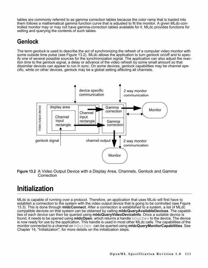
tables are commonly referred to as gamma correction tables because the color ramp that is loaded intothem follows a mathematical gamma function curve that is adjusted to fit the monitor. A given MLdc-con-trolled monitor may or may not have gamma-correction tables available for it. MLdc provides functions forsetting and querying the contents of such tables.
GenlockThe term genlock is used to describe the act of synchronizing the refresh of a computer video monitor withsome outside time pulse (see Figure 13.2). MLdc allows the application to turn genlock on/off and to spec-ify one of several possible sources for the synchronization signal. The application can also adjust the reac-tion time to the genlock signal, a delay or advance of the video refresh by some small amount so thatdissimilar devices can appear to run in sync. On some devices, genlock capabilities may be channel spe-cific, while on other devices, genlock may be a global setting affecting all channels.
Figure 13.2 A Video Output Device with a Display Area, Channels, Genlock and GammaCorrection
InitializationMLdc is capable of running over a protocol. Therefore, an application that uses MLdc will first have toestablish a connection to the system with the video output device that is going to be controlled (see Figure13.3). This is done through mldcConnect. After a connection is established to a system, a list of MLdccompatible devices on that system can be obtained by calling mldcQueryAvailableDevices. The capabili-ties of each device can then be queried using mldcQueryVideoDeviceInfo. Once a suitable device isfound, it needs to be opened using mldcOpen, which returns a handle hOutDev to the device. The deviceis now ready for use by the application. This handle is used in most other MLdc calls. The capabilities of themonitor connected to a channel on hOutDev can be queried using mldcQueryMonitorCapabilities. SeeChapter 14, "Initialization", for more details on the initialization steps.
2 way monitorcommunication
Channel
display area
Gammacorrection
Vid
eo o
utpu
t dev
ice
Monitor
GammacorrectionChannel
Monitor
2 way monitorcommunication
device specificcommunication
genlock signal
inputinput
channel output
rectanglerectangle
O p e n M L S p e c i f i c a t i o n R e v i s i o n 1 . 0 1 1 1

CommunicationSet calls are used to change video display parameters of the video output device. These calls are notqueued. However, the device’s completion of the set call is asynchronous, and may take a few seconds tocomplete. For example, changing the screen resolution. For this reason, the set functions initiate theparameter change, and then return, potentially before the change actually happens. All of the video displayparameters that can be set can also be queried (see Figure 13.3). Querying is done synchronously and thequery information is returned in one or more arguments of the query function. Most of the query functionsallocate the memory in which information is to be returned. The application is responsible for freeing thememory, by calling mldcFree¸ once the information is no longer needed.
Events and MessagesWhen the application asks MLdc to set video display parameters, the system will eventually complete therequest, and asynchronously send a completion message (or event or event message) back to the applica-tion (see Figure 13.3). The message is usually one of success or failure. Event messages are queued up ina receive queue by the video output device. The application can select which event messages, if any, itwants to receive, by calling mldcSetEventMask. It reads the event message from the queue using mld-cReceiveMessage. OS and windowing specific mechanisms are used to indicate if the receive queue hasany event messages in it. In addition, the system may also send special "genlock acquired" or "genlocklost" messages to the application. These are not necessarily the direct result of an MLdc function call, butare the result of activities on the system outside of the control of the application.
ErrorsMLdc functions return an immediate MLDCstatus value. If the function returns without encountering anerror the function will return MLDC_STATUS_NO_ERROR. In the event that a function encounters anerror before returning, then the return code will indicate an error.Several error status values are implicit for many or all MLdc routines: MLDC_STATUS_INVALID_ARGUMENT is returned if any arguments are invalid pointers. MLDC_STATUS_INVALID_SYSTEM_HANDLE is returned if a system handle is invalid. MLDC_STATUS_INVALID_DEVICE is returned if adevice handle is invalid. MLDC_STATUS_INVALID_CHANNEL is returned if a channel number is invalid.Some MLdc functions set in motion changes to the hardware state that will occur after the function returns.If an error occurs as part of this asynchronous processing then an error event message will be returned tothe application via the event messaging mechanism. Error events may not be masked off by the applica-tion. Therefore, the application will always have to monitor the receive queue. The various possible errorevent messages are also described with each individual function in later chapters.
1 1 2 O p e n M L S p e c i f i c a t i o n R e v i s i o n 1 . 0

Figure 13.3 Communication Between the Application and MLdc
Monitor CommunicationMLdc facilitates communication between the application and a physical monitor (see Figure 13.3). Applica-tions are responsible for assembling the commands, and parsing the result from the monitor. MLdc acts asa transport layer only. Commands are sent using mldcSendMonitorCommand. If a response is expected,applications should use mldcSendMonitorQuery, which sends a command and waits for an answer.
For more information, see Chapter 15, "Setting and Querying Video Parameters", Chapter 16, "ReceivingMLdc Event Messages" and Chapter 24, "Monitor Commands".
Extensions to MLdcMLdc can be extended by vendor specific API entry points. This allows vendors to expose unique function-ality through the MLdc API in a consistent way. The naming of extensions and querying of the existence ofa particular extension is analogous to the OpenGL model. mldcQueryExtensionNames returns a space-seperated list of extension names. mldcQueryExtensionPtr returns the address of the extension. Addi-tionally, MLdc provides a convenience function, mldcIsExtensionSupported¸ which can be used to deter-mine if a particular extension is supported on the specified video out device.
querycontrols events
setcontrols Init
Application
MLdc library MLdc libraryremote
protocol
System A System B
querycontrols events
setcontrols Init
Video driver
video output device
monitor
monitorcommunication
video signal
device specificcommunication
monitorcommunication
monitorcomm
O p e n M L S p e c i f i c a t i o n R e v i s i o n 1 . 0 1 1 3

1 1 4 O p e n M L S p e c i f i c a t i o n R e v i s i o n 1 . 0

C H A P T E R
14INITIALIZATION
Initializing MLdcAll applications that use the MLdc library to control a video output device on a specified host system mustfirst initialize the library for that system by calling mldcConnect. This function performs any internal setupnecessary, and must be called first before calling any other MLdc function. mldcConnect must be calledonce for each host system that has video output devices that the application wishes to control.
mldcConnectMLDCstatus mldcConnect(MLDCchar *hostID,
MLDChandle *systemHandle)
hostIDThe hostID argument is a character string that has the format host:display.screen. On Unixsystems, host:display specifies the X Server to connect to. The additional screen field specifies aparticular screen of the desired X Server. If the host name is omitted, i.e hostID is NULL, thedefault display on the local host is initialized. Examples of valid hostID strings on Unix systems are“myhost:1”, “foo:0.1”, “:2”, and “:0.0”. On Windows systems, hostID must be the local host, i.e.NULL.
systemHandleThis is a return argument. If MLdc can be successfully initialized for the target system defined by thehostID argument then a valid system handle is returned in systemHandle.
When the function succeeds, the return value is MLDC_STATUS_NO_ERROR. If the function fails it maymean that the versions of internal software do not match and the function will return one of the following. Ifthe version of the device independent library is not compatible with the device dependent library or with thedevice driver, the function will return MLDC_STATUS_INVALID_LIBRARY_VERSION. If the version ofthe device dependent library is not compatible with the device driver, then the function will return MLDC_STATUS_INVALID_DRIVER_VS_DDLIB_VERSION. If the function was not able to establish a connectionto the device specified by hostID, then the function will return MLDC_STATUS_CONNECTION_FAIL-URE.
O p e n M L S p e c i f i c a t i o n R e v i s i o n 1 . 0 1 1 5

The function mldcConnect must be the first MLdc function that is called by the application. If any otherMLdc function call is made first, the results will be undefined.On X Windows systems running multiple MLdc-compliant X servers, an application can use mldcConnectto connect with any MLdc-compliant X server. The resulting systemHandle can then be passed to mldc-QueryAvailableDevices, which will return a list of all MLdc devices on the system. The set of devices inthe list will be the same, regardless of which MLdc-compliant X server the connection is made through. Theorder of the devices may be different for different X server connections, but the first entry in the arrayreturned by mldcQueryAvailableDevices will always match the string used in the call to mldcConnect.
Freeing Memory Allocated by MLdcSeveral MLdc functions and operations generate messages or information, the memory for which is allo-cated by MLdc. The application is responsible for freeing the allocated memory by using the following func-tion:
mldcFreeMLDCstatus mldcFree(void *memPtr);
The memPtr argument is a pointer to the memory to be freed. If the function is successful, it will returnMLDC_STATUS_NO_ERROR. If the memPtr argument is not a valid pointer the function will returnMLDC_STATUS_INVALID_ARGUMENT.
Finding MLdc Video Output DevicesIn order to obtain a list of the devices that are available and controlled by MLdc on a given system, thefunction mldcQueryAvailableDevices is called.
mldcQueryAvailableDevicesMLDCstatus mldcQueryAvailableDevices(MLDChandle systemHandle,
MLDCint32 *numOutDevs,MLDCchar ***outDevNames)
systemHandleThis argument is a system handle obtained from a call to mldcConnect.
numOutDevsReturns the number of available video output devices on the system that are controllable via MLdc.
outDevNamesReturns an array of character strings giving a name to each video output device. The first entry in thearray will always match the string that is used in the call to mldcConnect. Subsequent names onthe list will follow the following convention. If the device is known about by the windowing system,then the device name will be the same name used to initialize the device in the call to mldcConnectby following the “hostname:display” convention. If the device is not known about by the windowingsystem, then the name is vendor-specific and may be any descriptive string.
The memory allocated for outDevNames is allocated by the function and should be freed by the applica-tion by calling mldcFree when the information is no longer needed.
1 1 6 O p e n M L S p e c i f i c a t i o n R e v i s i o n 1 . 0

When the function succeeds, the return value is MLDC_STATUS_NO_ERROR. If the systemHandleargument if not a valid system handle, the function will return MLDC_STATUS_INVALID_SYSTEM_HAN-DLE. If any of the other arguments are invalid pointers, the function will return MLDC_STATUS_INVALID_ARGUMENT.If no errors are encountered, but there are no MLdc devices on the system, numOutDevs will be 0 and*outDevNames will be NULL, and the function will return MLDC_STATUS_NO_ERROR.Note that on any given system there may be several video output devices that are controllable via MLdc.These video output devices may be from different vendors. It is possible that not all of these video outputdevices are known about by the windowing system.
Opening and Closing an MLdc Video Output DeviceIn order to set or query any video parameters for a given video output device, the application must firstopen the device for communication with it. This is accomplished by calling the function mldcOpen.
mldcOpenMLDCstatus mldcOpen(MLDCchar *outDevName,
MLDChandle *hOutDev)
outDevNamePoints to a string containing the name of the video output device to open. The name is one of thestrings returned from the mldcQueryAvailableDevices function, and may be vendor-specific.
hOutDevA pointer to a handle for the video output device that was named in outDevName.
This function opens the named device and returns a handle to be used in all further MLdc function calls toaccess the device. When the function succeeds, the return value is MLDC_STATUS_NO_ERROR. IfoutDevName is not a valid name for an available device, the function will return MLDC_INVALID_DEVICE_NAME. If hOutDev is not a valid pointer, the function will return MLDC_STATUS_INVALID_ARGUMENT. The function may also fail with MLDC_STATUS_INVALID_LIBRARY_VERSION if the DIand DD library versions are not compatible, or with MLDC_STATUS_INVALID_DRIVER_VS_LIB_VER-SION if either library version is not compatible with the device driver version.
mldcCloseWhen the application is finished with a given video output device, the device should be closed using the fol-lowing function:
MLDCstatus mldcClose(MLDChandle hOutDev)
hOutDevA handle to the video output device to be closed.
The function mldcClose closes the specified device.When the function succeeds, the return value is MLDC_STATUS_NO_ERROR. When the function fails,the return value will be MLDC_STATUS_INVALID_DEVICE.
O p e n M L S p e c i f i c a t i o n R e v i s i o n 1 . 0 1 1 7

Checking the MLdc VersionAfter initializing MLdc, all applications should verify that each video output device of interest has MLdcproperly installed at the correct version level. The function mldcQueryVersion will return the major andminor library revision for MLdc. This specification defines version 1.0 of MLdc, major version 1, minor ver-sion 0.
mldcQueryVersionMLDCstatus mldcQueryVersion(MLDChandle hOutDev,
MLDCint32 *di_major,MLDCint32 *di_minor,MLDCint32 *dd_major,MLDCint32 *dd_minor,MLDCint32 *driver_major,MLDCint32 *driver_minor)
hOutDevGives the handle to the video output device in question.
di_majorReturns the MLdc major version number of the device independent library.
di_minorReturns the minor number of the device independent library.
dd_majorReturns the MLdc major version number of the device dependent library.
dd_minorReturns the minor number of the device dependent library.
driver_majorReturns the MLdc major version number of the device driver.
driver_minorReturns the minor number of the device driver.
If this function succeeds, MLDC_STATUS_NO_ERROR will be returned. If hOutDev is not a valid devicehandle, this function will return MLDC_STATUS_INVALID_DEVICE. If any of the other arguments areinvalid pointers, the function will return MLDC_STATUS_INVALID_ARGUMENT.
Acquiring Information About the Video Output DeviceBefore doing any control of the video display, the application will need to query the video display hardwarefor its abilities. There are two functions that supply video hardware display information at the video outputdevice level:
mldcQueryVideoDeviceInfo returns the number of supported channels, external sync ports, andgenlock capabilities.mldcQueryMonitorCapabilities returns the VESA standard E-EDID string from the physicalmonitor.
1 1 8 O p e n M L S p e c i f i c a t i o n R e v i s i o n 1 . 0

mldcQueryVideoDeviceInfoThis function returns a structure containing information about the video output device and its capabilities.
MLDCstatus mldcQueryVideoDeviceInfo(MLDChandle hOutDev,MLDCvideoDeviceInfo *sinfo_return)
hOutDevHandle of an MLdc video output device.
sinfo_returnA pointer to the MLDCvideoDeviceInfo structure that is to receive the corresponding information.
DescriptionmldcQueryVideoDeviceInfo returns in *sinfo_return an MLDCvideoDeviceInfo structure contain-ing video device information for a specified video output device, shown below:
typedef struct {MLDCint32 numChannels; /* Number of output channels */MLDCboolean lockOp; /* mldcSetInputSyncSource usable */MLDCchar graphicsType[MLDC_NAME_SIZE]; /* Name of gfx hw */MLDCint32 numExternalSync; /* Num of external sync ports */
} MLDCvideoDeviceInfo;
In the above structure, the fields are defined as follows:numChannels
Specifies the number of output channels on this video output device. The caller may use set or queryoperations on channels numbering 0 to numChannels - 1.
lockOpDescribes whether the video output device has the capability to lock to external sync sources via themldcSetInputSyncSource function.
graphicsTypeContains a null-terminated ASCII string containing the name of the graphics hardware type. Thename is unique for each type of graphics hardware.
numExternalSyncContains the number of external sync sources.
This function returns MLDC_STATUS_NO_ERROR if successful. If hOutDev is an invalid device handle,this function will return MLDC_STATUS_INVALID_DEVICE. If sinfo_return is not a valid pointer, thisfunction will return MLDC_STATUS_INVALID_ARGUMENT.
O p e n M L S p e c i f i c a t i o n R e v i s i o n 1 . 0 1 1 9
mldcQueryMonitorCapabilitiesThis function returns information about the physical monitor and its capabilities.
MLDCstatus mldcQueryMonitorCapabilities(MLDChandle hOutDev,MLDCint32 channel,void **monitorCaps)
hOutDevSpecifies the handle for the MLdc video output device.
channelSpecifies the channel number.
monitorCapsReturned address of a structure that gives the capabilities of the physical monitor in question. Theinformation is in the format specified by the document “VESA Enhanced Extended DisplayIdentification Data Standard” available from the VESA standards body. The specification is alsoreferred to as the “E-EDID Standard”. A description of the standard and the data in the structure canbe obtained from VESA (the Video Electronics Standards Association).
DescriptionThis function will allocate and return to the client application a structure giving the capabilities of the spe-cific physical monitor in question. The video output device is specified by passing the MLdc video outputdevice handle and channel number that the physical monitor is connected to. Once the information hasbeen received, the application should free the memory by calling mldcFree.When the function succeeds, the return value is MLDC_STATUS_NO_ERROR. If hOutDev is an invaliddevice handle this function will return MLDC_STATUS_INVALID_DEVICE. If channel is not a validchannel number this function will return MLDC_STATUS_INVALID_CHANNEL. If monitorCaps is not avalid pointer this function will return MLDC_STATUS_INVALID_ARGUMENT.
1 2 0 O p e n M L S p e c i f i c a t i o n R e v i s i o n 1 . 0
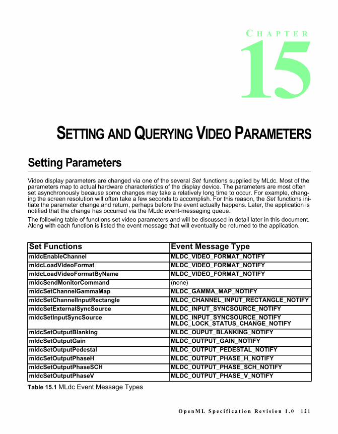
C H A P T E R
15SETTING AND QUERYING VIDEO PARAMETERS
Setting ParametersVideo display parameters are changed via one of the several Set functions supplied by MLdc. Most of theparameters map to actual hardware characteristics of the display device. The parameters are most oftenset asynchronously because some changes may take a relatively long time to occur. For example, chang-ing the screen resolution will often take a few seconds to accomplish. For this reason, the Set functions ini-tiate the parameter change and return, perhaps before the event actually happens. Later, the application isnotified that the change has occurred via the MLdc event-messaging queue.The following table of functions set video parameters and will be discussed in detail later in this document.Along with each function is listed the event message that will eventually be returned to the application.
Set Functions Event Message TypemldcEnableChannel MLDC_VIDEO_FORMAT_NOTIFYmldcLoadVideoFormat MLDC_VIDEO_FORMAT_NOTIFYmldcLoadVideoFormatByName MLDC_VIDEO_FORMAT_NOTIFYmldcSendMonitorCommand (none)mldcSetChannelGammaMap MLDC_GAMMA_MAP_NOTIFYmldcSetChannelInputRectangle MLDC_CHANNEL_INPUT_RECTANGLE_NOTIFYmldcSetExternalSyncSource MLDC_INPUT_SYNCSOURCE_NOTIFYmldcSetInputSyncSource MLDC_INPUT_SYNCSOURCE_NOTIFY
MLDC_LOCK_STATUS_CHANGE_NOTIFYmldcSetOutputBlanking MLDC_OUPUT_BLANKING_NOTIFYmldcSetOutputGain MLDC_OUTPUT_GAIN_NOTIFYmldcSetOutputPedestal MLDC_OUTPUT_PEDESTAL_NOTIFYmldcSetOutputPhaseH MLDC_OUTPUT_PHASE_H_NOTIFYmldcSetOutputPhaseSCH MLDC_OUTPUT_PHASE_SCH_NOTIFYmldcSetOutputPhaseV MLDC_OUTPUT_PHASE_V_NOTIFY
Table 15.1 MLdc Event Message Types
O p e n M L S p e c i f i c a t i o n R e v i s i o n 1 . 0 1 2 1

Querying Video ParametersAll of the video display parameters that can be Set can also be Queried. Unlike the Set process, the Queryprocess is done synchronously and the query information is returned in one or more arguments of theQuery function.
Freeing Query Return BuffersMost of the Query functions allocate memory in which to return information. The application is responsiblefor freeing the memory once the information has been copied or is no longer needed by calling the functionmldcFree.
mldcSetOutputSync MLDC_OUTPUT_SYNC_NOTIFYmldcStoreGammaColors16 MLDC_GAMMA_MAP_NOTIFYmldcStoreGammaColors8 MLDC_GAMMA_MAP_NOTIFY
Set Functions Event Message Type
Table 15.1 MLdc Event Message Types
1 2 2 O p e n M L S p e c i f i c a t i o n R e v i s i o n 1 . 0

C H A P T E R
16RECEIVING MLDC EVENT MESSAGES
Selecting the Event Messages to ReceiveThe application may not be interested in receiving each of the event messages that are possible when set-ting video parameters. The default is that none of the event messages will be sent back to the application.The application must choose the events that it is interested in via a call to mldcSetEventMask:
mldcSetEventMask MLDCstatus mldcSetEventMask(MLDChandle hOutDev,
MLDCbitfield message_mask)
hOutDevSpecifies the handle of the MLdc video output device.
message_maskSpecifies a mask of values OR’d together to produce a value giving the events of interest to theapplication.
In this function the application indicates the messages that it is interested in receiving for a given video out-put device. The video output device of interest is specified by the hOutDev argument. The message_mask argument is a mask of bits OR’d together from the following constants:
MLDC_NONE_MASKMLDC_VIDEO_FORMAT_NOTIFY_MASKMLDC_CHANNEL_INPUT_RECTANGLE_NOTIFY_MASKMLDC_INPUT_SYNCSOURCE_NOTIFY_MASKMLDC_LOCK_STATUS_CHANGE_NOTIFY_MASKMLDC_OUPUT_BLANKING_NOTIFY_MASKMLDC_OUTPUT_GAIN_NOTIFY_MASKMLDC_OUTPUT_PEDESTAL_NOTIFY_MASKMLDC_OUTPUT_PHASE_H_NOTIFY_MASKMLDC_OUTPUT_PHASE_SCH_NOTIFY_MASKMLDC_OUTPUT_PHASE_V_NOTIFY_MASK
O p e n M L S p e c i f i c a t i o n R e v i s i o n 1 . 0 1 2 3

MLDC_OUTPUT_SYNC_NOTIFY_MASKMLDC_GAMMA_MAP_NOTIFY_MASK
Each call to mldcSetEventMask replaces the previous settings for the specified video output device. Thatis, the results of calling this function multiple times are not cumulative.If the function is successful, it will return MLDC_STATUS_NO_ERROR. Otherwise, the function will returnMLDC_STATUS_INVALID_DEVICE.
mldcQueryEventMask MLDCstatus mldcQueryEventMask(MLDChandle hOutDev,
MLDCbitfield *messageMask)
hOutDevSpecifies the handle for the MLdc video output device.
messageMaskSpecifies a pointer to a variable that will receive the current event mask as an output of this function.
If the function is successful, it will return MLDC_STATUS_NO_ERROR. If hOutDev is an invalid devicehandle, this function will return MLDC_STATUS_INVALID_DEVICE. If messageMask is not a validpointer, this function will return MLDC_STATUS_INVALID_ARGUMENT.
Receiving an Event MessageThere are two available methods of receiving MLdc events within an application. First, the application mayreceive the events via the native windowing system event handling mechanism. In this method, MLdcevents are integrated with the native windowing system events, and native windowing system functions areused to wait for and retrieve the events. In the second method, the application may receive MLdc eventsvia the MLdc event queue using window system independent MLdc functions. The application can choosewhich method to use by calling the mldcSetEventModel function. Application writers concerned with max-imizing application portability should use the window system independent MLdc functions.
mldcSetEventModelMLDCstatus mldcSetEventModel(MLDCeventModel eventModel)
eventModelThis argument sets the event model to either MLDC_NATIVE_EVENTS or MLDC_MLDC_EVENTS:
1 2 4 O p e n M L S p e c i f i c a t i o n R e v i s i o n 1 . 0

Note that this function call sets the MLdc event-handling method for the application for all devices and sys-tems that it is interacting with. It therefore takes no system handle argument or device handle argument.The default setting for the method is MLDC_NATIVE_EVENTS.If the function is successful, it will return MLDC_STATUS_NO_ERROR. Otherwise, the function will returnMLDC_STATUS_INVALID_EVENT_MODEL.
Receiving MLdc Events Through Native WindowingSystemsIf the application desires to handle MLdc events via the native windowing system event message mecha-nism there are some differences in MLdc setup functions between Windows and the X Window System.However, both of these windowing systems return MLdc event messages using a single MLdc event mes-sage type with the MLdc specific events seen as sub-types of the MLdc event. To get the MLdc event typean application will need to call the following function:
mldcQueryEventIdThis function will return the native windowing system’s event ID that will be the message type for all MLdcevents that are returned to the application. When the application reads messages from the windowingsystem’s message queue it will need to look for this ID as the message type for all MLdc events. EachMLdc event message will additionally contain the MLdc message structure described below which includesthe MLdc message type.
MLDCstatus mldcQueryEventId(MLDCeventId *eventId)
eventIdThis argument will return the native windowing system’s message ID for all MLdc events that arereturned to the application.
Event Model DescriptionMLDC_NATIVE_EVENTS The events generated by MLdc are integrated with the
native windowing system. The user must use the nativewindowing toolkit to wait for and retrieve the events. Notethat mldcSetEventMask() must still be used to selectwhich events will be sent by MLdc. Applications using theWindows native messaging queues for MLdc events willneed to call one or more special MLdc functions to set upmessaging parameters, described below. Applicationsthat use the native X Window System event mechanism willneed no additional MLdc function calls to setup the X Win-dow System event mechanism.
MLDC_MLDC_EVENTS MLdc will create its own event loop to capture events andreturn them to the application in a windowing system inde-pendent fashion.
Table 16.1 Event Model Types
O p e n M L S p e c i f i c a t i o n R e v i s i o n 1 . 0 1 2 5

This function is only viable when MLDC_NATIVE_EVENTS has been previously chosen in a call to mldc-SetEventModel. Otherwise, this function call will have no effect and will always return MLDC_STATUS_INVALID_EVENT_MODEL. If this function is successful in returning a valid event Id, it will return MLDC_STATUS_NO_ERROR.
Receiving MLdc Events Via the X Window SystemThe X client will need to first make the MLdc function calls mldcSetEventModel and mldcQueryEventIddescribed above. Following those calls, the X Window System mechanism can be used without any extrafunction support from MLdc. MLdc event types given above in Table 15.1 (the table of MLdc Set functionsand the events that they return) are treated as subtypes and found in the event-specific fields that are partof the X event structure. Specifically, the MLdc type is found in the mldcType field of each MLdc eventstructure. MLdc event structures are defined and appended to the XEvent structure for each particularevent. The individual structures are described in the specific description of MLdc events given below.
Receiving an Event Message Via Windows MessagesWindows applications will need to first make the MLdc function calls mldcSetEventModel and mldcQue-ryEventId described above. When an MLdc event is received on the Windows message queue, the MLdcevent message structure will be pointed at by the “lparam” pointer in the Windows MSG message structure.To use the Windows native messaging mechanism an extra function is required:
mldcSetWindowsMessageQueueWhen using the Windows messaging queue to receive MLdc events on Windows systems, the followingfunction is necessary to provide a way for the application to give MLdc the window handle of the windowmessage queue that the application wants MLdc events delivered to.
MLDCstatus mldcSetWindowsMessageQueue(HWND hwnd)
hwndThe handle of the window whose message queue MLdc events will be returned to on Windowssystems.
If the application never makes this function call then all MLdc messages will be sent to the thread messagequeue of the thread that called mldcConnect.This function is only viable on a Windows system. On a system using another windowing system this func-tion call will have no effect and will always return MLDC_INVALID_EVENT_MODEL.If this function is successful in returning a valid event ID, it will return MLDC_STATUS_NO_ERROR. Ifhwnd is not a valid window handle, it will return MLDC_INVALID_WINDOW.
1 2 6 O p e n M L S p e c i f i c a t i o n R e v i s i o n 1 . 0

Receiving An Event Message Via MLdc Messaging
mldcGetReceiveQueueWaitHandleIn order to receive an event message on the MLdc event queue the application must first obtain an eventhandle upon which it can wait to receive a message from the message queue. This event handle isobtained by calling mldcGetReceiveQueueWaitHandle:
MLDCstatus mldcGetReceiveQueueWaitHandle(MLDChandle *hEvent)
hEventSpecifies a pointer to a handle where the function can return an event handle that can be used towait for an event message.
The hEvent argument will return the handle of an event that can be used in a call to WaitForMultipleOb-jects on Windows systems or select on Unix systems.When an event message is waiting to be read on a given video output device’s message queue, the videooutput device will signal the event. The application will then return from the call to WaitForMultipleObjectsor select.This function should only be called when receiving MLdc event messages via the MLdc event messagequeue. If this function is called when the application has declared that it desires to use the windowing sys-tem native event handling mechanism, then this function will have no effect and will return MLDC_STATUS_INVALID_EVENT_MODEL. If the function succeeds, it will return MLDC_STATUS_NO_ERROR.
After an application has been notified that an event message has arrived in the MLdc event messagequeue the application can then obtain the event message by calling mldcReceiveMessage:
mldcReceiveMessageMLDCstatus mldcReceiveMessage(MLDCgenericEvent **ppMsg)
ppMSGSpecifies the address of a pointer to an MLDCgenericEvent message structure.
The memory needed for the message itself is allocated by MLdc and should be freed by the application bycalling mldcFree. The structure MLDCgenericEvent is defined below.
O p e n M L S p e c i f i c a t i o n R e v i s i o n 1 . 0 1 2 7

MLdc Event Message Structures
/* The MLDCGenericEvent event structure is used to examine** the mldcType field so that the event's real type can be** determined.*/typedef struct _MLDCgenericEvent{MLDCint32 mldcType; /* Event type */
MLDChandle hOutDev; /* video output device of the event */ MLDCint32 channel; /* channel of the event */} MLDCgenericEvent
mldcType is one of the event types in Table 15.1. An application can obtain additional information aboutthe event by casting to one of the following event message data types according to the event type returnedin mldcType. As such, mldcGenericEvent is used as a proxy structure whose fields are identical withthe first few fields of all other event message structures.The other message structures that are available are as follows:
typedef struct{ MLDCint32 mldcType; /* MLDC_VIDEOFORMAT_NOTIFY */ MLDChandle hOutDev; /* video output device of the event */ MLDCint32 channel; /* channel of the event */} MLDCvideoFormatEvent;
typedef struct{ MLDCint32 mldcType; /* MLDC_CHANNEL_INPUTRECTANGLE_NOTIFY */ MLDChandle hOutDev; /* video output device of the event */ MLDCint32 channel; /* channel of the event */ MLDCrectangle rct; /* set rectangle */} MLDCchannelInputRectangleEvent;
typedef struct{ MLDCint32 mldcType; /* MLDC_INPUT_SYNCSOURCE_NOTIFY */ MLDChandle hOutDev; /* video output device of the event */ MLDCint32 channel; /* channel of the event */ MLDCint32 voltage; /* nominal video voltage or TTL-level sync */ MLDCint32 source; /* internal or external genlock source */} MLDCinputSyncSourceEvent;
typedef struct{ MLDCint32 mldcType; /* MLDC_BLANKING_NOTIFY */ MLDChandle hOutDev; /* video output device of the event */ MLDCint32 channel; /* channel of the event */ MLDCboolean enable; /* TRUE if blanking enabled */} MLDCblankingEvent;
1 2 8 O p e n M L S p e c i f i c a t i o n R e v i s i o n 1 . 0

/* In the following event, the graphics device may not be able to** report intervening instances of rapidly changing lock state** and therefore may report two consecutive instances of the same** state; client programs must check the value of the status** variable to determine the state of the lock.*/
typedef struct{ MLDCint32 mldcType; /* MLDC_LOCK_STATUS_CHANGED_NOTIFY */ MLDChandle hOutDev; /* video output device of the event */ MLDCint32 channel; /* channel of the event */ MLDCint32 status; /* achieved or lost genlock */} MLDClockStatusChangedEvent;
typedef struct{ MLDCint32 mldcType; /* MLDC_OUTPUT_GAIN_NOTIFY */ MLDChandle hOutDev; /* video output device of the event */ MLDCint32 channel; /* channel of the event */ MLDCint32 component; /* RGBA component */ MLDCint32 value; /* new gain value */} MLDCoutputGainEvent;
typedef struct{ MLDCint32 mldcType; /* MLDC_PEDESTAL_NOTIFY */ MLDChandle hOutDev; /* video output device of the event */ MLDCint32 channel; /* channel of the event */ MLDCboolean enable; /* TRUE if pedestal is enabled */} MLDCpedestalEvent;
typedef struct{ MLDCint32 mldcType; /* MLDC_PHASE_H_NOTIFY */ MLDChandle hOutDev; /* video output device of the event */ MLDCint32 channel; /* channel of the event */ MLDCint32 value; /* horizontal phase new value */} MLDCphaseHEvent;
typedef struct{ MLDCint32 mldcType; /* MLDC_PHASE_SCH_NOTIFY */ MLDChandle hOutDev; /* video output device of the event */ MLDCint32 channel; /* channel of the event */ MLDCint32 value; /* subcarrier horizontal phase new value */} MLDCphaseSCHEvent;
typedef struct{ MLDCint32 mldcType; /* MLDC_PHASE_V_NOTIFY */ MLDChandle hOutDev; /* video output device of the event */ MLDCint32 channel; /* channel of the event */ MLDCint32 value; /* subcarrier vertical phase new value */} MLDCphaseVEvent;
O p e n M L S p e c i f i c a t i o n R e v i s i o n 1 . 0 1 2 9

typedef struct{ MLDCint32 mldcType; /* MLDC_OUTPUT_SYNC_NOTIFY */ MLDChandle hOutDev; /* video output device of the event */ MLDCint32 channel; /* channel of the event */ MLDCint32 syncPortIndex; /* port index */ MLDCint32 syncType; /* sync type */} MLDCoutputSyncEvent;
typedef struct{ MLDCint32 mldcType; /* MLDC_PLATFORM_PARAM_NOTIFY */ MLDChandle hOutDev; /* video output device of the event */ MLDCint32 channel; /* channel of the event */ MLDCint32 parameterId; /* Id of the device specif parameter */} MLDCplatformParamEvent;
typedef struct{ MLDCint32 mldcType; /* MLDC_GAMMA_MAP_NOTIFY */ MLDChandle hOutDev; /* video output device of the event */ MLDCint32 channel; /* channel of the event */ MLDCint32 mapId; /* gamma map Id number */} MLDCgammaMapEvent;
Receiving Error EventsError event messages are a special case of event message and require some explanation. Error eventsare generated asynchronously as MLdc commands are processed by the video output device or its attend-ing device-specific software. While an MLdc function to set a video parameter may have been called andthen successfully executed, the actual setting of the parameter in hardware may occur much later. Duringthis delayed processing, an error may occur. The error event message provides a vehicle to report the errorback to the application. While other event messages may be masked off by setting the event mask, errormessages may not be masked off and will always be sent to the application.Each event message has within it two fields for reporting a device channel and a device gamma map forwhich the error occurred. Not all errors will involve one of these objects. If an error has no associated chan-nel or gamma map, then these fields will be set to MLDC_NOT_APPLICABLE.Each event message also includes an errorCode field that returns an error code for the given error.Specific error codes are documented with the functions that can cause them.Finally, each event message includes the name of the function that generated the original command thateventually experienced the error if this name is available to the implementation. The name is given as anull-terminated string in the funcName field of the error event message. If the name is not available thenthe field will be returned as a null string.
typedef struct{ MLDCint32 mldcType; /* MLDC_ERROR_NOTIFY */ MLDChandle hOutDev; /* video output device of the event */ MLDCint32 channel; /* channel of the event, if applicable */ MLDCint32 gammaMap; /* gamma map of the event, if applicable */ MLDCint32 errorCode; /* error code of the error. */ MLDCchar *funcName[MLDC_NAME_SIZE]; /* function name */} MLDCerrorEvent;
1 3 0 O p e n M L S p e c i f i c a t i o n R e v i s i o n 1 . 0

C H A P T E R
17CHANNELS
Channel StructuresThe following structures are used when querying and setting channel parameters and channel video for-mats.
MLDCrectangle
The fields of the MLDCrectangle structure are defined as follows:x, y
The location of the upper-left corner of the rectangle in video memory.height, width
The width and height of the rectangle in pixels.
typedef struct{ MLDCreal32 x, y; MLDCreal32 height, width;} MLDCrectangle;
Figure 17.1 The MLDCrectangle Structure
O p e n M L S p e c i f i c a t i o n R e v i s i o n 1 . 0 1 3 1

MLDCchannelSyncInfo
The fields of the MLDCchannelSyncInfo structure are defined as follows:syncPort
Identifies the sync port. This can be one of the following:
syncTypeListThis is a pointer to an array of sync types. Each item represents one of the different sync outputmodes to which this sync port can be set, and contains one of the following:
syncTypeListCountThe number of items in the syncTypeList array
typedef struct{ MLDCint32 syncPort; /* Identifies the sync port */ MLDCint32 *syncTypeList; /* Identifies the sync type */ MLDCint32 syncTypeListCount; /* Cnt of items in syncTypeList */} MLDCchannelSyncInfo;
Figure 17.2The MLDCchannelSyncInfo Structure
MLDC_SP_RED Enable sync on the red channel output connectorMLDC_SP_GREEN Enable sync on the green channel output connectorMLDC_SP_BLUE Enable sync on the blue channel output connectorMLDC_SP_ALPHA Enable sync on the alpha channel output connectorMLDC_SP_AUX0 Enable sync on the auxiliary channel 0 connectorMLDC_SP_AUX1 Enable sync on the auxiliary channel 1 connectorMLDC_SP_AUX2 Enable sync on the auxiliary channel 2 connector
Table 17.1 Sync Port Selection Constants
MLDC_SF_NONE No syncMLDC_SF_HORIZONTAL_VIDEO Horizontal sync video levelMLDC_SF_VERTICAL_VIDEO Vertical sync video levelMLDC_SF_COMPOSITE_VIDEO Composite sync video levelMLDC_SF_HORIZONTAL_TTL Horizontal sync, TTL levelMLDC_SF_VERTICAL_TTL Vertical sync, TTL levelMLDC_SF_COMPOSITE_TTL Composite sync, TTL levelMLDC_SF_HORIZONTAL_TRILEVEL Horizontal sync, tri-levelMLDC_SF_VERTICAL_TRILEVEL Vertical sync, tri-levelMLDC_SF_COMPOSITE_TRILEVEL Composite sync, tri-level
Table 17.2 Sync Type Selection Constants
1 3 2 O p e n M L S p e c i f i c a t i o n R e v i s i o n 1 . 0

MLDCfieldInfo
The fields of the MLDCfieldInfo structure are defined as follows:offset
Line where this field starts.stride
y-increment to next line.backPorch
Duration in pixels of the vertical back porch.sync
Duration in pixels of vertical sync.syncPulse
Duration in pixels of vertical sync pulse.frontPorch
Duration in pixels of the vertical frontPorch.active
Duration in pixels of the vertical active region.colorActive
The color channels that are active in this field. This is a bit field that may have one or more of thefollowing bits set: MLDC_FI_COLOR_ACTIVE_RED, MLDC_FI_COLOR_ACTIVE_GREEN,MLDC_FI_COLOR_ACTIVE_BLUE, or MLDC_FI_COLOR_ACTIVE_ALPHA.
eyeActiveFor stereo video formats, this field will indicate which eye is active for a given field. This is a bit fieldthat may have one of the following bits set: MLDC_FI_EYE_ACTIVE_LEFT or MLDC_FI_EYE_ACTIVE_RIGHT.
typedef struct{MLDCint32 offset; /* Line where this field starts */
MLDCint32 stride; /* y-increment to next line */ struct { MLDCint32 backPorch; /* Duration in pixels */ MLDCint32 sync; /* Duration in pixels */ MLDCint32 syncPulse; /* Duration in pixels */ MLDCint32 frontPorch; /* Duration in pixels */ MLDCint32 active; /* Duration in pixels */ } vertical;MLDCbitfield colorActive; /* Colors this field; MLDC_FI..*/
MLDCbitfield eyeActive; /* Eye this field; MLDC_FI... */} MLDCfieldInfo;
Figure 17.3 The MLDCfieldInfo Structure
O p e n M L S p e c i f i c a t i o n R e v i s i o n 1 . 0 1 3 3

MLDCvideoFormatInfo
The fields of the MLDCvideoFormatInfo structure are defined as follows:name
The name of the video format.height, width
The height and width of the active pixels.totalHeight, totalWidth
The total height and width in pixels of the video format, including non-viewable data.verticalRetraceRate
The field or frame rate, in hertz, of the video format.swapBufferRate
The rate at which multi-buffered viewing rectangles are swapped. This can be different from theframe rate.
pixelClockThe duration in pixels of the pixel clock.
backPorchThe duration of the horizontal back porch of the format.
syncThe duration in pixels of the horizontal sync.
frontPorchThe duration in pixels of the horizontal front porch.
activeThe size in pixels of the active horizontal pixel region.
fieldCountThe number of fields in the format.
fieldInfoA pointer at an array of MLDCfieldInfo structures with information regarding each field. The size ofthe array is equal to fieldCount.
typedef struct{ MLDCchar name[MLDC_FORMATNAME_MAX]; /* Video format name */ MLDCint32 height, width; /* Active pixels */ MLDCint32 totalHeight; /* Includes blanking */ MLDCint32 totalWidth; /* Includes blanking */ MLDCreal32 verticalRetraceRate;/* field or frame rate, in Hz */ MLDCreal32 swapBufferRate; /* Can be diff from frame rate */ MLDCint32 pixelClock; /* Pixels/second */ struct { MLDCint32 backPorch; /* Duration in pixels */ MLDCint32 sync; /* Duration in pixels */ MLDCint32 frontPorch; /* Duration in pixels */ MLDCint32 active; /* Duration in pixels */ } horizontal; MLDCint32 fieldCount; MLDCfieldInfo *fieldInfo; /* Array, size=fieldCount */ MLDCbitfield formatFlags; /* See MLDC_VFI... fields */} MLDCvideoFormatInfo;
Figure 17.4 The MLDCvideoFormatInfo Structure
1 3 4 O p e n M L S p e c i f i c a t i o n R e v i s i o n 1 . 0

formatFlagsA set of flags defined as follows:
MLDCvideoFormatBefore documenting the MLDCvideoFormat structure, the concept of video combination formats must beexplained.
Video Format Combinations
On some video output devices it is possible that output channels may only be loaded with video formatsthat are compatible with each other. For example, the device may require that all channels be loaded withformats that have the same refresh rate. These allowable compatible video formats are referred to as com-bination formats. Combination formats consist of multiple MLDCvideoFormatInfo structures. They have acombination format name. The following MLDCvideoFormat structure provides a container that candescribe either a combination format capable of being loaded into multiple channels, or a single format forloading into a single channel.
The fields of the MLDCvideoFormat structure are defined as follows:name
The name of this format. If this structure is being used to define a combination format, then this fieldwill be the name of the combination, but each member format of the combination will have its ownname found in the name field of the single MLDCvideoFormatInfo structure. If this structure is beingused to define a single format, then this name will match the name that is given in the name field ofthe single MLDCvideoFormatInfo structure.
formatsA pointer to an array of MLDCvideoFormatInfo structures. In the case where this is a combinationformat, this array will hold two or more MLDCvideoFormatInfo structures detailing formats that arecompatible. Otherwise, this array will hold a single MLDCvideoFormatInfo structure.
Flag DescriptionMLDC_VFI_STEREO This is a stereo video format.MLDC_VFI_FIELD_SEQUENTIAL_COLOR The color for this format differs from field to
field.MLDC_VFI_FULL_SCREEN_STEREO The stereo format is full screen (this is an old
SGI stereo format.)
Table 17.5 Possible Format Flags for Video Formats
typedef struct{
MLDCchar name[MLDC_FORMATNAME_MAX];/* Name of format */MLDCvideoFormatInfo *formats; /* Array of formats */MLDCint32 numFormats; /* Elements in formats
array */MLDCint32 height, width; /* Display surface
size */} MLDCvideoFormat;
Figure 17.6 The MLDCvideoFormat Structure
O p e n M L S p e c i f i c a t i o n R e v i s i o n 1 . 0 1 3 5

numFormatsGives the number of elements in the formats array. If this number is one, then this is a single videoformat. If this number is greater than one, then this field is a combination video format.
height, widthThe total height and width, in pixels, of the display surface that will be output to the video formatchannels.
MLDCchannelInfoThe MLDCchannelInfo structure defines attributes unique to a single channel, including a pointer to theMLDCvideoFormatInfo structure that describes the video format for the channel:
The fields of the MLDCchannelInfo structure are defined as follows:active
Field is TRUE if the queried channel is operational. Graphics devices with multiple channels may beprogrammed to run only some of the output channels. If the value of this field is FALSE, theremaining fields in the structure are undefined.
sourceIs an MLDCrectangle structure that contains the portion of the display area that this channeldisplays. The MLDCrectangle structure describes a rectangle whose origin is at x,y and whose sizeis described by height and width. On graphics hardware platforms with only one channel, this sourcerectangle is frequently the entire managed area of the video output device. However, on graphicshardware platforms that have more than one channel for output, each channel may display a differentportion of the display area.
typedef struct{MLDCboolean active; /* channel is operating */MLDCrectangle source; /* Position on display surface */MLDCrectangle outputRegion; /* Rectangular output region*/MLDCvideoFormatInfo vfinfo; /* Video format details */MLDCbitfield channelFlags; /* See MLDC_CIF... masks */MLDCint32 *gammaMaps; /* Assignable gamma maps
(ptr to array) */MLDCint32 gammaCount; /* Returned count of gammaMaps */MLDCboolean blankingOp; /* mldcSetOutputBlanking usable */MLDCboolean gainOp; /* mldcSetOutputGain usable */MLDCboolean pedestalOp; /* mldcSetOutputPedestal usable */MLDCboolean phaseHOp; /* mldcSetOutputPhaseH usable */MLDCint32 phaseHMin; /* Range of OutputPhaseH */MLDCint32 phaseHMax;MLDCboolean phaseVOp; /* mldcSetOutputPhaseV usable */MLDCint32 phaseVMin; /* Range of OutputPhaseV */MLDCint32 phaseVMax;MLDCboolean phaseSCHOp; /* mldcSetOutputPhaseSCH usable */MLDCint32 phaseSCHMin; /* Range of OutputPhaseSCH */MLDCint32 phaseSCHMax;MLDCboolean syncOp; /* mldcSetOutputSync usable */MLDCint32 syncPortCount; /* Number of sync ports */MLDCchannelSyncInfo *syncInfo; /* Info on all sync ports */MLDCint32 physicalID; /* Physical port */
} MLDCchannelInfo;
Figure 17.7 The MLDCchannelInfo Structure
1 3 6 O p e n M L S p e c i f i c a t i o n R e v i s i o n 1 . 0

outputRegionThe rectangular region within the output channel that will be used for output. The dimensions of theoutputRegion generally match the output video format height and width. It is possible for anoutput video device to introduce a scaler which may change the offset or size of theoutputRegion.
vfinfoContains the detailed information that describes the video format. This information is valid only ifactive is TRUE.
channelFlagsIs a set of flags that indicates information about the channel.
gammaMapsIs a pointer to an array of indexes; each index identifies a gamma map that may be assigned to thischannel. The number of items is returned in gammaCount.
gammaCountThe number of elements in the gammaMaps array.
blankingOpIs TRUE if the operations of the function mldcSetOutputBlanking are supported on this channel.
gainOpIs TRUE if the operations of the function mldcSetOutputGain are supported on this channel.
phaseHMinReturnReturns the minimum value to which horizontal phase may be set.
phaseHMaxReturnReturns the maximum value to which horizontal phase may be set.
phaseVMinReturnReturns the minimum value to which vertical phase may be set.
phaseVMaxReturnReturns the maximum value to which vertical phase may be set.
phaseSCHMinReturnReturns the minimum value to which SCH phase may be set.
phaseSCHMaxReturnReturns the maximum value to which SCH phase may be set.
syncOpTRUE if operations to set output sync are permitted on this channel. See the functionmldcSetOutputSync.
syncPortCountIs the number of sync ports available for this channel. This count includes the standard sync ports ofMLDC_SP_RED, MLDC_SP_GREEN, MLDC_SP_BLUE, and MLDC_SP_ALPHA (if the ports arepresent and their output can be altered) as well as the auxiliary ports.
syncInfoThis is a pointer to an array of MLDCchannelSyncInfo structures. Each channel may have zero,one, or more sync ports for which the sync may be altered; each mutable sync port is represented byone MLDCchannelSyncInfo structure in the array. There are syncPortCount items in the array.All ports that can have their sync characteristics altered are included.
Flag Name DescriptionMLDC_CIF_COMPOSITE_VIDEO This channel uses composite video output.MLDC_CIF_PER_COMPONENT_GAIN Channel is capable of independent gain adjust-
ment.
Table 17.8 Channel Flag Descriptions
O p e n M L S p e c i f i c a t i o n R e v i s i o n 1 . 0 1 3 7

physicalIDThis identifies the physical port number of this channel. This is the number as labeled on the chassisor cable of the video output. Graphics devices may take liberties in numbering output ports that arenot strictly numbered (e.g., an encoder channel) such as using negative numbers or impossibly highnumbers. This value is to be used only as a correlation to chassis number. Applications should usethe other values in this structure to determine channel characteristics instead of relying on a specialdecoding of physical channel number.
Querying Channel Parameters
mldcQueryChannelInfoThe current parameters for a given video output device and channel can be queried via a call to this func-tion.
MLDCstatus mldcQueryChannelInfo(MLDChandle hOutDev,MLDCint32 channel,MLDCchannelInfo **cinfo_return)
hOutDevSpecifies the handle of the MLdc video output device.
channelSpecifies the channel number. Channels are assigned numbers starting at zero. Subsequentchannel numbers increase monotonically by one; thus, each channel number is unique for a givenvideo output device. Because of this ordering constraint, the channel number may not correspond tophysical channel numbers as labeled on the hardware chassis. The physicalID field of theMLDCchannelInfo structure contains the number of the physical channel.
cinfo_returnReturns a pointer to an MLDCchannelInfo structure that is allocated by MLdc.
The mldcGetChannelInfo function returns MLDC_STATUS_NO_ERROR upon success. If hOutDev isan invalid device handle, this function will return MLDC_STATUS_INVALID_DEVICE. If channel is not avalid channel number, this function will return MLDC_STATUS_INVALID_CHANNEL. If cinfo_returnis not a valid pointer, this function will return MLDC_STATUS_INVALID_ARGUMENT.
1 3 8 O p e n M L S p e c i f i c a t i o n R e v i s i o n 1 . 0

Enabling and Disabling ChannelsA Channel is either enabled or disabled. The active flag of the MLDCchannelInfo structure returned frommldcQueryChannelInfo can be used to determine the current state of a channel. A channel that isenabled will output a video signal on its physical jack. A disabled channel will not output a video signal.
mldcEnableChannelThis function enables a specific channel.
MLDCstatus mldcEnableChannel(MLDChandle hOutDev,MLDCint32 channel,MLDCboolean enable)
hOutDevSpecifies the handle of the MLdc video output device.
channelSpecifies the channel number.
enableIf TRUE, enables the channel’s video output. If FALSE, disables a channel’s video output. This mayhave the effect of reducing overall demand on the video device while terminating output. It is notnecessary to disable a channel before loading a new video format.
The function mldcEnableChannel returns MLDC_STATUS_NO_ERROR if successful. If hOutDev is aninvalid device handle, this function will return MLDC_STATUS_INVALID_DEVICE. If channel is not avalid channel number, this function will return MLDC_STATUS_INVALID_CHANNEL. If enable is not avalid boolean, this function will return MLDC_STATUS_INVALID_ARGUMENT.
EventsWhen the channel’s output condition has been changed from enabled to disabled, or from disabled toenabled, MLdc generates an MLDC_VIDEO_FORMAT_NOTIFY event.
Channel Input RectanglesEach channel has a rectangular region in the display area, that it uses as its source for display, called thechannel input rectangle. Rectangles are defined in terms of horizontal and vertical pixel coordinates. Thechannel input rectangle can be set using the following functions:
O p e n M L S p e c i f i c a t i o n R e v i s i o n 1 . 0 1 3 9

mldcSetChannelInputRectangleThis function allows the application to set the channel’s input rectangle location and size.
MLDCstatus mldcSetChannelInputRectangle(MLDChandle hOutDev,MLDCint32 channel,MLDCrectangle *rectangle)
hOutDevSpecifies the handle of the MLdc video output device.
channelSpecifies the channel number.
rectangleDefines the rectangle in the display area that the channel will display from. Refer to Figure 17.1, “TheMLDCrectangle Structure”
The pixel location of the rectangle is given in display area coordinates and assumes that the “upper left”corner of the display area is (0,0).If a video device permits changes to the input rectangle, the video device may impose restrictions on thevalues of both size and origin. That is, the final size of the rectangle may not be exactly as requested, butwill be the “closest” size and location that the device is capable of supporting.If this function can successfully set the input rectangle to the requested size and location, it will return aMLDC_STATUS_NO_ERROR. If hOutDev is an invalid device handle, this function will return MLDC_STATUS_INVALID_DEVICE. If channel is not a valid channel number, this function will return MLDC_STATUS_INVALID_CHANNEL. If rectangle is not a valid pointer, this function will return MLDC_STATUS_INVALID_ARGUMENT.
EventsWhen the channel’s input rectangle has been changed MLdc generates an MLDC_CHANNEL_INPUT_RECTANGLE_NOTIFY event.
mldcQueryBestChannelRectangleThe mldcQueryBestChannelRectangle function provides a means to determine the nearest valid rectan-gle to the size and origin desired by the application. Determination of the best rectangle is device-depen-dent, and different situations may yield different results.
MLDCstatus mldcQueryBestChannelRectangle(MLDChandle hOutDev,MLDCint32 channel,MLDCrectangle *rct,MLDCrectangle *rrct)
hOutDevSpecifies the handle of the MLdc video output device.
channelSpecifies the channel number.
rctAn input argument that specifies a rectangle that the application would like to use.
1 4 0 O p e n M L S p e c i f i c a t i o n R e v i s i o n 1 . 0

rrctAn output argument pointing to an MLDCrectangle structure allocated by the application. Returnsthe best rectangle that is supported that approximates the input rectangle, rct.
mldcQueryBestChannelRectangle returns MLDC_STATUS_NO_ERROR if a rectangle is found of avalid supported size and origin (the size of which is found in the returned variables). This function returnsMLDC_STATUS_NO_VALID_RECTANGLE when no valid rectangle was found (among which is the casewhen the video device does not support change of size or origin). If hOutDev is an invalid device handle,this function will return MLDC_STATUS_INVALID_DEVICE. If channel is not a valid channel number,this function will return MLDC_STATUS_INVALID_CHANNEL. If rct or rrct are not valid pointers, thisfunction will return MLDC_STATUS_INVALID_ARGUMENT.
O p e n M L S p e c i f i c a t i o n R e v i s i o n 1 . 0 1 4 1

1 4 2 O p e n M L S p e c i f i c a t i o n R e v i s i o n 1 . 0

C H A P T E R
18VIDEO FORMATS
Video Format NamesThe video industry has adopted a standard naming convention for video formats even though the namescan be ambiguous: the name itself is not always descriptive enough to distinguish between two differentformats. The convention for standard video format names is:
WidthxHeight_FrameRate
where Height and Width specify the active portion of the format (i.e., the visible portion of the frame dis-playing pixels exclusive of the blanking regions). FrameRate specifies the field or frame rate in hertz,rounded to the nearest integer.
The name of the format may be appended by a single-character identifier. This suffix is a hint to theintended use of the format; detailed information can be derived from the MLDCvideoFormatInfo structure.Some suffix characters are:
Thus, for example, 1920x1080_60i, describes an interlaced high-definition video format.Note that such a video format name is a general convention. For detailed information regarding the timingspecifications of a format, consult the returned structure.Note that some graphics devices may alter the structure of the video format to conform to hardware restric-tions. Also, not all graphics devices may have the capability to display all formats. Some graphics devicesmay list the same format under both a conventional name and an alias.
f The format is a variant of the standard format that can lock to a dissimilarformat.
i The format is interlaced.
k Special alternative format.
p The format is progressive
q The format has its colors displayed in serial fields (color field sequential).
s The format is a stereo format.
Table 18.1 Industry Standard Video Format Name Suffixes
O p e n M L S p e c i f i c a t i o n R e v i s i o n 1 . 0 1 4 3

Querying Video FormatsThe current video format for a given video output device and channel can be queried by calling the functionmldcQueryChannelInfo previously described.
Listing Available Video FormatsA list of available video formats is returned by calling mldcListVideoFormats.
mldcListVideoFormatsmldcListVideoFormats returns a list of available video formats that match a specified pattern.
MLDCstatus *mldcListVideoFormats(MLDChandle hOutDev,MLDCint32 *channelArray,const MLDCvideoFormat *pattern,MLDCbitfield *querymaskArray,MLDCboolean matchMonitor,MLDCboolean nonvolatile,MLDCint32 maxformats,MLDCint32 *actual_count_return,MLDCvideoFormat **retFormatArray)
hOutDevSpecifies the handle of the MLdc video output device.
channelArraySpecifies an array of channel numbers. The array must have the number of elements that arespecified in the numFormats field of the pattern argument. If the number of channels is greaterthan one, this function will return a list of combination formats that could be used for the multiplechannels listed in channelArray. By convention, the channel numbers in the array must appearin the array in ascending order. However, channel numbers may skipped. For example, the arraycould hold the channel numbers 1,3,4.
patternSpecifies an MLDCvideoFormat structure that provides attributes to match when listing the videoformats. The numFormats field in the structure gives the number of formats in the pattern. IfnumFormats is equal to one, this is a search for single formats to be applied to a single channel. Ifsearching for a combination format, the value of numFormats will be greater than one. The numberof formats given in numFormats also determines the number of channels in the channelArrayargument and the number of query masks in the querymaskArray argument. All video formatsthat match the query will be returned (up to maxformats).
querymaskArrayAn array of masks that specify, as the bitwise inclusive OR of any of the manifest constants that havea prefix of MLDC_QVF (see Table 18.2), which fields in pattern are to be used for the query. If thequerymaskArray is NULL, all video formats will be returned. The querymaskArray musthave the number of elements specified in the numFormats field of the pattern argument. Ifsearching for combination formats, the i th element of the querymaskArray is applied to the i th
format in the formats array of the pattern argument when doing the search for a suitable formatfor the i th channel given in channelArray.
1 4 4 O p e n M L S p e c i f i c a t i o n R e v i s i o n 1 . 0

matchMonitorIf TRUE, restricts queries to those formats which are within the operating range of the monitor foreach channel. If FALSE, no constraint check is made.
nonvolatileIf TRUE, restricts queries to those formats which can only be changed through a nonvolatile load. IfFALSE, only formats that can be changed dynamically are returned.
maxformatsSpecifies the maximum number of MLDCvideoFormat structures to be returned.
actual_count_returnReturns the actual number of MLDCvideoFormat structures that are returned.
retFormatArrayReturns the list of formats that have been found. The array of MLDCvideoFormatInfo structures thatare returned in the MLDCvideoFormat structure are in a particular order to match the channelnumbers given in the channelArray argument. The first format in the first element of the formatarray corresponds to the first channel given in the channelArray.
The mldcListVideoFormats function returns in retFormatArray an array of available MLDCvideo-Format video format descriptions that match a pattern specification.When listing the video formats that are available for a single channel, the caller gives only one MLD-CvideoFormatInfo structure in the formats array of the pattern argument and only one element ofthe querymaskArray argument. The query mask is applied to the given format to find all available for-mats that meet the requirements for a single channel.When listing the combination video formats that are available for a group of n channels the caller gives nchannels in the channelArray argument, n MLDCvideoFormatInfo structures in the formats arrayof the pattern argument, and n elements of the querymaskArray argument. Available matchingcombination formats are found by using the i th format in the formats array of the pattern argument inconjunction with the i th element of the querymaskArray to search for a suitable format for the channelfound in the i th element in the channelArray argument.If no video formats match the query specification, the value 0 (zero) is returned in actual_count_return.Fields that are not represented in the querymaskArray are not used to constrain the search (i.e.,unconstrained fields are "don't care"). All query-constrained fields must be an exact match. For example, iffieldCount is specified as 2 and the querymaskArray element has the MLDC_QVF_FIELD_COUNT bit set, this function will return only those video formats that have two fields.To return every video format available, specify the value NULL for querymaskArray. Queries may bespecified using combinations of the following bits in each element of the querymaskArray:
Mask Bit PurposeMLDC_QVF_HEIGHT Match the height in lines of the active region of the for-
mat.
MLDC_QVF_WIDTH Match the width in pixels of the active region of the for-mat.
MLDC_QVF_TOTAL_HEIGHT Match the total number of lines of the format, includingblanking lines.
MLDC_QVF_TOTAL_WIDTH Match the total number of pixels in each line of the for-mat, including blanking pixels.
Table 18.2 Video Format Query Mask Bits
O p e n M L S p e c i f i c a t i o n R e v i s i o n 1 . 0 1 4 5

Note that the pixelClock and horizontal components of MLDCvideoFormatInfo are ignored when queryingand setting video format, as are other components. There may not be corresponding bits for all fields.
Match Monitor QueryThe field matchMonitor is a special constraint that specifies that MLdc should return only those videoformats whose timing requirements fall within the range supported by the monitors connected to the chan-nels listed in channelArray (see the function mldcQueryMonitorName).While this constraint gives some assurance that a returned format will operate successfully on the monitorconnected to the channel, it cannot be guaranteed. Nor can one be certain that the connected monitor candisplay all formats returned. The specification of the range of operation of a monitor and the description ofthe parameters of a video format are not sufficiently exact to reliably predict a proper match. Instead, con-sider this constraint to provide a high likelihood that the returned formats are the best matches for reliableoperation.The matchMonitor constraint further restricts the query specified in querymask.The mldcListVideoFormats function returns a list of MLDCvideoFormat structures.The client should call mldcFree when finished with the result to free the memory that was allocated andreturned in retFormatArray.When the function succeeds, the return value is MLDC_STATUS_NO_ERROR. If hOutDev is an invaliddevice handle, this function will return MLDC_STATUS_INVALID_DEVICE. If channel is not a validchannel number, this function will return MLDC_STATUS_INVALID_CHANNEL. If any other argumentsare not valid values or valid pointers, this function will return MLDC_STATUS_INVALID_ARGUMENT. Ifno match is found, the function will return MLDC_STATUS_NO_FORMAT_MATCH.
Loading Video FormatsVideo formats can be loaded by specifying a pattern, a video format name, or the name of a file which con-tains a video format specification.
MLDC_QVF_RETRACE_RATE Match the retrace rate of the format. Note this value isspecified as a floating-point number; however, all com-parisons are integer-based. For this comparison, the val-ues are rounded to int by adding 0.5 and truncating. Forexample, 59.94Hz will be rounded to 60 before compar-ing.
MLDC_QVF_SWAP_BUFFER_RATE Match the swapbuffer rate of the format. This can be dif-ferent from the retrace rate in some video formats. Notethis value is specified as a floating-point number; how-ever, all comparisons are integer-based. For this com-parison, the values are rounded to int by adding 0.5 andtruncating. For example, 29.97Hz will be rounded to 30before comparing.
MLDC_QVF_FIELD_COUNT Match the number of interlaced or stereo fields in the for-mat.
MLDC_QVF_FLAGS Match the formatFlags field of the format.
Table 18.2 Video Format Query Mask Bits
1 4 6 O p e n M L S p e c i f i c a t i o n R e v i s i o n 1 . 0

Video formats can be loaded dynamically (which means that the new format will take place as soon aspossible) or in a nonvolatile fashion (which means that the new format will take effect only after the graph-ics subsystem has been restarted). On Windows systems, restarting the graphics subsystem may requirerebooting the system. On X Window Systems, restarting the graphics subsystem means that the X Servermust be restarted.
mldcLoadVideoFormatThis function will load a video format that matches a pattern given as an argument. If more than one videoformat matches the pattern the first one that matches will be loaded. This function is equivalent to mld-cListVideoFormats, except that it will load the first format that matches the query instead of returning thefull list of formats.
MLDCstatus mldcLoadVideoFormat(MLDChandle hOutDev,MLDCint32 *channelArray,const MLDCvideoFormat *pattern,MLDCbitfield *querymaskArray,MLDCboolean matchMonitor,MLDCboolean nonvolatile)
hOutDevThe handle of the MLdc video output device.
channelArraySpecifies an array of channel numbers. The array must have the number of elements that arespecified in the numFormats field of the pattern argument. If the number of channels is greaterthan one, then this function will load the first combination format that could be used for the multiplechannels listed in channelArray. By convention, the channel numbers in the array must appearin the array in ascending order. However, channel numbers may skipped. For example, the arraycould hold the channel numbers 1,3,4.
patternSpecifies an MLDCvideoFormat structure that provides attributes to match when loading the videoformat. The numFormats field in the structure gives the number of formats in the pattern. IfnumFormats is equal to one, this function will match a single format and load it into a singlechannel. If matching a combination format, the value of numFormats will be greater than one. Thenumber of formats given in numFormats also determines the number of channels in thechannelArray argument and the number of query masks in the querymaskArray argument.
querymaskArrayAn array of masks that specify, as the bitwise inclusive OR of any of the manifest constants that havea prefix of MLDC_QVF (see Table 18.2), which fields in pattern are to be used for the query. If thequerymaskArray is NULL, the first video format found will be loaded. The querymaskArraymust have the number of elements specified in the numFormats field of the pattern argument. Ifmatching a combination format, the i th element of the querymaskArray is applied to the i th
format in the formats array of the pattern argument, when doing the search for a suitableformat for the i th channel given in channelArray.
matchMonitorIf TRUE, restricts loads to those formats which are within the operating range of the monitor. IfFALSE, no constraint check is made.
nonvolatileIf the requested format is capable of being loaded dynamically, it will be loaded dynamically,regardless of the value of this argument. However, if the requested format is not capable of beingloaded dynamically, and if this argument is set to TRUE, then the requested format will be scheduledto be loaded in a nonvolatile fashion after the graphics system has been restarted.
O p e n M L S p e c i f i c a t i o n R e v i s i o n 1 . 0 1 4 7

DescriptionThe mldcLoadVideoFormat function loads a video format into the specified channel, or a combination for-mat into the specified channels. The newly loaded formats completely replace the channels’ current videoformat.
The method by which the video format is specified is similar to the query performed in the function mldc-ListVideoFormats. The desired video format is described by populating the pattern structure, specify-ing the meaningful fields (query constraints) via the querymaskArray parameter. When more than onevideo format meets the query requirements, the first format is loaded. To unambiguously specify a videoformat, use mldcLoadVideFormatsByName. See mldcListVideoFormats for more information on speci-fying the arguments to this function.
Restrictions When LoadingOn some systems certain video formats may require that the graphics system be restarted after loading.
Note: On some platforms, the user cannot request a nonvolatile load without root or administrator permis-sions. On other systems, loading any format may need root or administrator authorization.
EventsWhen the format changes, MLdc generates an MLDC_VIDEO_FORMAT_NOTIFY event. If no format canbe found by device-dependent software that matches the criteria, an MLDC_ERROR_NOTIFY event isgenerated and the error code given in the event is MLDC_STATUS_NO_FORMAT_MATCH.
When the function succeeds, the return value is MLDC_STATUS_NO_ERROR. If hOutDev is an invaliddevice handle, this function will return MLDC_STATUS_INVALID_DEVICE. If channel is not a validchannel number, this function will return MLDC_STATUS_INVALID_CHANNEL. If any other argument isnot a valid value or a valid pointer, this function will return MLDC_STATUS_INVALID_ARGUMENT.
mldcLoadVideoFormatByNameWhen the format name of the desired video format is known, either apriori through external means or bychoosing a format from an mldcListVideoFormats query, then mldcLoadVideoFormatByName may beused to load that video format:
MLDCstatus mldcLoadVideoFormatByName(MLDChandle hOutDev,MLDCint32 numChannels,MLDCint32 *channelArray,const MLDCchar *name,MLDCboolean nonvolatile)
hOutDevThe handle of the MLdc video output device.
numchannelsThe number of channels in the channelArray argument. If the number is one, then the format tobe loaded is a single format loading into a single channel. If the number is greater than one, then theformat to be loaded is a combination format.
channelArraySpecifies an array of channel numbers to load a named format into. If the array holds only onechannel, then the format is a single format. If the array has more than one channel, then the formatname must be the name of a combination format. By convention, the channel numbers must appearin the array in ascending order, though the channel numbers need not be sequential.
1 4 8 O p e n M L S p e c i f i c a t i o n R e v i s i o n 1 . 0

nameThe name of the format to load; a null-terminated string.
nonvolatileIf the requested format is capable of being loaded dynamically, then it will be loaded dynamically,regardless of the value of this argument. However, if the requested format is not capable of beingloaded dynamically, and if this argument is set to TRUE, then the requested format will be scheduledto be loaded in a nonvolatile fashion after the graphics system has been restarted.
DescriptionThe mldcLoadVideoFormatByName function loads a new video format into the specified channel, or acombination format into the specified channels. The newly loaded formats completely replace the channels’current video format.
The name of the format to load is normally taken as an internal implementation-dependent name. If a fully-qualified absolute path is supplied instead of a format name, that path will be used as the location of avideo format file instead of as a format name. It is up to the caller to ensure that the path points to a validvideo format file. The format files are implementation-dependent and beyond the scope of this document.
Restrictions When LoadingOn some systems certain video formats may require that the graphics system be restarted after loading.
Note: On some platforms, the user cannot request a nonvolatile load without root or administrator permis-sions. On other systems, loading any format may need root or administrator authorization.
EventsWhen the format changes, MLdc generates an MLDC_VIDEO_FORMAT_NOTIFY event. If no format canbe found by device-dependent software that matches the criteria, an MLDC_ERROR_NOTIFY event isgenerated and the error code given in the event is MLDC_STATUS_NO_FORMAT_MATCH.
When the function succeeds, the return value is MLDC_STATUS_NO_ERROR. If hOutDev is an invaliddevice handle, this function will return MLDC_STATUS_INVALID_DEVICE. If channel is not a validchannel number, this function will return MLDC_STATUS_INVALID_CHANNEL. If any other argument isnot a valid value or a valid pointer, this function will return MLDC_STATUS_INVALID_ARGUMENT.
O p e n M L S p e c i f i c a t i o n R e v i s i o n 1 . 0 1 4 9

1 5 0 O p e n M L S p e c i f i c a t i o n R e v i s i o n 1 . 0

C H A P T E R
19BLANKING
When a channel is blanked the active video portion of the signal is disabled. However, normal video syn-chronization signals persist so that the video output device can remain locked. When blanking is disabled,the active video is restored and the video output device once again displays pictures.
mldcSetOutputBlankingThis function will enable or disable blanking on a channel.
MLDCstatus mldcSetOutputBlanking(MLDChandle hOutDev,MLDCint32 channel,MLDCboolean enable)
hOutDevSpecifies the handle for the MLdc video output device.
channelSpecifies the channel number.
enableSpecifies whether blanking should be enabled.
DescriptionmldcSetOutputBlanking enables and disables blanking on a channel. The value may be TRUE orFALSE.
Interaction with Screen SaverSome screen saver programs will simply blank the screen as part or all of their function. The function ofmldcSetOutputBlanking may be independent of that supplied by the screen saver, and may use a differ-ent mechanism to enable and disable output. The interaction between the screen saver and the mecha-nism used by this function is system-dependent and is not specified.
EventsWhen this control is altered, the MLdc library generates an MLDC_OUTPUT_BLANKING_NOTIFY event.
O p e n M L S p e c i f i c a t i o n R e v i s i o n 1 . 0 1 5 1

When the function succeeds, the return value is MLDC_STATUS_NO_ERROR. If hOutDev is an invaliddevice handle, this function will return MLDC_STATUS_INVALID_DEVICE. If channel is not a validchannel number, this function will return MLDC_STATUS_INVALID_CHANNEL. If any other argument isnot a valid value or a valid pointer, this function will return MLDC_STATUS_INVALID_ARGUMENT.
mldcQueryOutputBlankingThis function will query the current state of blanking for a channel.
MLDCstatus mldcQueryOutputBlanking(MLDChandle hOutDev,MLDCint32 channel,MLDCboolean *enableReturn)
hOutDevSpecifies the handle for the MLdc video output device.
channelSpecifies the channel number.
enableReturnReturns whether blanking is enabled.
DescriptionmldcQueryOutputBlanking returns in the enableReturn argument the current settings for blanking ona channel. The value may be TRUE or FALSE.When the function succeeds, the return value is MLDC_STATUS_NO_ERROR. If hOutDev is an invaliddevice handle, this function will return MLDC_STATUS_INVALID_DEVICE. If channel is not a validchannel number, this function will return MLDC_STATUS_INVALID_CHANNEL. If any other argument isnot a valid value or a valid pointer, this function will return MLDC_STATUS_INVALID_ARGUMENT.
1 5 2 O p e n M L S p e c i f i c a t i o n R e v i s i o n 1 . 0

C H A P T E R
20GAMMA CORRECTION TABLES AND OUTPUT GAIN
Gamma CorrectionMany computer video display devices have color lookup tables associated with them that allow the applica-tion to programmatically adjust for differences in monitor color phosphor response. These color tables arecommonly referred to as gamma correction tables because the color ramp that is loaded into them typicallyfollows a mathematical gamma function curve that is adjusted to fit the monitor. A given MLdc-controlledvideo output device may or may not have gamma-correction tables available to it.Cathode ray tubes (CRT’s) have the characteristic that their display is non-linear: the intensity of light dis-played at a pixel is not strictly proportional to the voltage supplied to the CRT at that pixel. Gamma correc-tion is used to compensate for that non-linearity so the monitor does produce the proper intensity.A video device may contain one or more gamma maps, each of which may perform an independent correc-tion by serving as a color look-up.
TerminologyA gamma map has the following distinguishing features:• A set of tables. There is one table for each color component that is handled by the map. There may be
up to four tables, one each for red, green, blue, and alpha.• A size for each table. The table for each component has a size, or a number of entries.• A width for each table. The entries in each table have a certain width in bits or precision.
Graphics devices may assign a permanent gamma map to a channel, restrict channels to a subset of allmaps, permit a channel to use one of all shared maps, or some combination thereof, depending on hard-ware configuration. If two channels share the same gamma map, changing the colors in that gamma mapwill affect both channels.
O p e n M L S p e c i f i c a t i o n R e v i s i o n 1 . 0 1 5 3

mldcQueryGammaMapsThis function returns the number of gamma maps that are available on a video output device.
MLDCstatus mldcQueryGammaMaps(MLDChandle hOutDev,MLDCint32 *gammaMapsReturn)
hOutDevSpecifies the handle for the MLdc video output device.
gammaMapsReturnThe address of a variable to receive the number of gamma maps available on the video device.
DescriptionmldcQueryGammaMaps returns the number of separate gamma maps supported. Video output deviceswith no writable gamma map return zero (0).When the function succeeds, the return value is MLDC_STATUS_NO_ERROR. If hOutDev is an invaliddevice handle, this function will return MLDC_STATUS_INVALID_DEVICE. If gammaMapsReturn is nota valid pointer, this function will return MLDC_STATUS_INVALID_ARGUMENT.
mldcQueryGammaMapThis function will return the sizes of a given gamma map’s tables and their precision and attributes.
MLDCstatus mldcQueryGammaMap(MLDChandle hOutDev,MLDCint32 gammaMap,MLDCint32 *gammaSizeReturn,MLDCint32 *gammaPrecisionReturn,MLDCint32 *gammaMapAttributes)
hOutDevSpecifies the handle for the MLdc video output device.
gammaMapSpecifies the gamma map to be queried. Gamma map IDs are numbered implicitly, starting with 0.
gammaSizeReturnSpecifies the location of a four-element array that is to receive the number of entries or size of eachcomponent table in the gamma map. The order of component tables represented in the array is red,green, blue, and alpha.
gammaPrecisionReturnSpecifies the location of a four-element array that is to receive the precision in bits of each table inthe gamma map. For example, if each entry in a table is 10 bits long, the call returns 10 for thatcomponent. The order of component tables represented in the array is red, green, blue, and alpha.
gammaMapAttributesSpecifies the location of a variable to receive a bitmask describing attributes of the gamma map. Thebitmask may contain zero or more of the following attributes described below:
1 5 4 O p e n M L S p e c i f i c a t i o n R e v i s i o n 1 . 0

DescriptionmldcQueryGammaMap returns information regarding a specified gamma map's configuration.When the function succeeds, the return value is MLDC_STATUS_NO_ERROR. If hOutDev is an invaliddevice handle, this function will return MLDC_STATUS_INVALID_DEVICE. If gammaMap is not a validgamma map number, this function will return MLDC_STATUS_INVALID_GAMMA_MAP. If any otherargument is not a valid value or a valid pointer, this function will return MLDC_STATUS_INVALID_ARGU-MENT.
mldcQueryGammaColorsOccasionally an application may want to inquire the contents of a given gamma map. The query can beaccomplished with the following function. Note: Some devices will report bigger tables than they really haveand then interpolate values as the tables are loaded. If an application loads a table and then reads it back,the table being returned may not be exactly what was loaded. Also, see the MLDC_GM_HARDWARE_APPROXIMATION flag that can come back from mldcQueryGammaMap.
MLDCstatus mldcQueryGammaColors(MLDChandle hOutDev,MLDCint32 gammaMap,MLDCint32 requestedComponent,MLDCint32 *itemCountReturn,MLDCuint16 **gammaValueReturn)
hOutDevSpecifies the handle for the MLdc video output device.
MLDC_GM_ALPHA_PRESENT The gamma map has an alpha component in addi-tion to the red, green, and blue components.
MLDC_GM_HARDWARE_APPROXIMATION The video device hardware may use private tech-niques to approximate the stated size and precisionof the gamma map, substituting a less thorough rep-resentation. In most cases when a gamma-shapedcurve is loaded, the visual result will closely approxi-mate the specified curve. Queries of the value of thecolors of this gamma map will return the values aspreviously stored, not of the internal approximation.The techniques used to approximate the gammamap are implementation dependent.
MLDC_GM_WRITE_LOCK The gamma map cannot be modified programmati-cally. The video device hardware may have a fixedgamma map or the video device does not implementalteration of this map.
MLDC_GM_READ_LOCK The gamma map cannot be queried programmati-cally. The video device hardware may not permitreadback or the video device does not implementreadback of this map.
Table 20.1 Gamma Map Attribute Bits
O p e n M L S p e c i f i c a t i o n R e v i s i o n 1 . 0 1 5 5

gammaMapSpecifies the gamma map whose color table is to be returned. Gamma map ID’s are numberedimplicitly, starting with 0.
requestedComponentSpecifies the tables or color components that should be returned. The constants MLDC_COMPONENT_RED, MLDC_COMPONENT_GREEN, MLDC_COMPONENT_BLUE, and MLDC_COMPONENT_ALPHA may be Or-ed together to select the table(s) to be returned. The videodevice may ignore MLDC_COMPONENT_ALPHA if the gamma map does not have an alpha table;see mldcQueryGammaMap.
itemCountReturnSpecifies a pointer to an array of four integers where MLdc returns the number of elements in each ofthe tables. The order of the array is red, green, blue, and alpha. If a table is not selected, its count isset to zero.
gammaValueReturnSpecifies a pointer to an array where MLdc returns pointers to the arrays containing the tableelements. The order of the array is red, green, blue, and alpha. If a table is not selected, its pointer isset to NULL.
DescriptionmldcQueryGammaColors returns the values for the specified component table. The number of items inthe requested color component is returned in itemCountReturn. Use mldcFree to free the memoryallocated in gammaValueReturn.
Operations on Colors During QueryThe mldcQueryGammaColors function implicitly returns 16-bit quantities, irrespective of the precision ofthe underlying hardware. If the table's precision is less than 16 bits, the video device will return the signifi-cant bits of the precision in the uppermost bits of the returned 16-bit quantity; the least significant bits of thereturned quantity will contain replicated copies of the table's MSB’s.This operation is similar and complementary to the actions taken during store operations. For example, ifthe hardware table has 11 significant bits, the 16-bit value returned to the client will contain the hardware'svalue in the upper 11 bits. The most significant five bits of the hardware's value will be replicated in thelower five bits of the returned value.In general, the significant bits of the returned value may be determined via the following C-language state-ment (given precision as the width of the entry and gammaValueReturn as the returned value):
unsigned short sigBits;...sigBits = (gammaValueReturn >> (16 - precision));
Applications can use the function mldcStoreGammaColors16 as a complementary store operation; thatfunction expects a value with the significant bits similarly shifted into the MSB’s.When the function succeeds, the return value is MLDC_STATUS_NO_ERROR. If hOutDev is an invaliddevice handle, this function will return MLDC_STATUS_INVALID_DEVICE. If gammaMap is not a validgamma map number, this function will return MLDC_STATUS_INVALID_GAMMA_MAP. If any otherargument is not a valid value or a valid pointer, this function will return MLDC_STATUS_INVALID_ARGU-MENT.
1 5 6 O p e n M L S p e c i f i c a t i o n R e v i s i o n 1 . 0

mldcStoreGammaColors16, mldcStoreGammaColors8The following functions are used to set the values in a gamma correction lookup table:
MLDCstatus mldcStoreGammaColors8(MLDChandle hOutDev,MLDCint32 gammaMap,MLDCbitfield loadTables,MLDCint32 *itemCount,MLDCuint8 **gammaValue)
MLDCstatus mldcStoreGammaColors16(MLDChandle hOutDev,MLDCint32 gammaMap,MLDCbitfield loadTables,MLDCint32 *itemCount,MLDCuint16 **gammaValue)
hOutDevSpecifies the handle for the MLdc video output device.
gammaMapSpecifies the gamma map whose color table (or tables) is to be loaded. Gamma map ID’s arenumbered implicitly, starting with 0.
loadTablesSpecifies the tables or color components that should be returned. The constants MLDC_COMPONENT_RED, MLDC_COMPONENT_GREEN, MLDC_COMPONENT_BLUE, and MLDC_COMPONENT_ALPHA may be Or-ed together to select the table(s) to be loaded
itemCountA 4-element array that contains the number of elements in each table to be loaded. The order of thearray is red, green, blue, and alpha. Note that the count of the number of entries to be loaded in eachtable must exactly equal the length of the table (returned via the parameter gammaSizeReturn in thefunction mldcQueryGammaMap).
gammaValueA 4-element array containing pointers to each of the tables to be loaded. The order of the pointers inthe array is red, green, blue, and alpha.
DescriptionThe mldcStoreGammaColors8 and mldcStoreGammaColors16 functions change the gamma map tableentries for the specified tables to the specified values, the former function loading 8-bit entries and the latterloading 16-bit entries. To load a gamma map, pass an array of table pointers via gammaValue and anarray of table lengths via itemCount. The value of loadTables indicates which tables of the gammamap that will be changed.Note: The hardware of some video devices may require the video device to load all components simulta-neously in an encoded (packed) manner, so choosing a single color component may require the videodevice to query the gamma table to encode the component before writing it; thus, the most efficient use ofthis function may be to store all color components simultaneously.The function mldcStoreGammaColors8 is provided as an economy to the functionmldcStoreGammaColors16 because it minimizes traffic between the client and the video device. Use theoperation that best suits the need: for rapid animations, an application may prefer the 8-bit function; forgreater accuracy, the 16-bit function.
Operations on Colors During StoreIf a gamma map's colors are stored using a function whose width is different than the width of the gammamap, the video device will alter the values when loading the gamma hardware. This alteration occurs foreach color value specified.
O p e n M L S p e c i f i c a t i o n R e v i s i o n 1 . 0 1 5 7

If a function is used whose width is larger than that of the table, the video device will truncate, using onlythe most-significant bits (MSB’s) of the values; for example, if the mldcStoreGammaColors8 function isused to store values into a table that contains only five bits, the video device will use only the upper fiveMSB’s of the color values, discarding the lower three bits.If a function is used whose width is narrower than the table, the video device will use the stored values forthe most-significant bits (MSB’s), and store into the not-supplied least-significant bits (LSB’s) a copy of themost significant bits; for example, if the mldcStoreGammaColors8 function is used to store values into atable that contains 12 bits, the video device will store the values into the eight MSB’s, copying the upperfour bits of each of the values into each entry's LSB’s.When this control is altered, the video device generates a MLDC_GAMMA_MAP_NOTIFY event.When the function succeeds, the return value is MLDC_STATUS_NO_ERROR. If hOutDev is an invaliddevice handle this function will return MLDC_STATUS_INVALID_DEVICE. If gammaMap is not a validgamma map number this function will return MLDC_STATUS_INVALID_GAMMA_MAP. If any other argu-ment is not a valid value or a valid pointer this function will return MLDC_STATUS_INVALID_ARGU-MENT.
mldcSetChannelGammaMapThis function will choose which of the available gamma maps to apply to the given channel.
MLDCstatus mldcSetChannelGammaMap(MLDChandle hOutDev,MLDCint32 channel,MLDCint32 gammaMap)
hOutDevSpecifies the handle for the MLdc video output device.
channelSpecifies the channel number.
gammaMapReturnSpecifies which of the gamma maps within the video device should be affected. Gamma map ID’sare numbered implicitly, starting with 0.
DescriptionmldcSetChannelGammaMap selects which gamma map to use for the specified channel. Some videodevices do not have multiple gamma maps available, and one gamma map is applied to all channels. Othervideo output devices have gamma maps that are only available for a specific channel. In these cases, thegamma map assignments cannot be altered via this function. The assignment of gamma maps to channelsat video device startup is not defined, and is vendor-specific.
When this control is altered, the video device generates a MLDC_GAMMA_MAP_NOTIFY event.
mldcQueryChannelGammaMap returns the gamma map ID associated with the specified channel.
When the function succeeds, the return value is MLDC_STATUS_NO_ERROR. If hOutDev is an invaliddevice handle, this function will return MLDC_STATUS_INVALID_DEVICE. If channel is not a validchannel number, this function will return MLDC_STATUS_INVALID_CHANNEL. If gammaMap is not avalid gamma map number, this function will return MLDC_STATUS_INVALID_GAMMA_MAP.
1 5 8 O p e n M L S p e c i f i c a t i o n R e v i s i o n 1 . 0

mldcQueryChannelGammaMapThis function will return the gamma map ID of the gamma map that is associated with the given video out-put device and channel.
MLDCstatus mldcQueryChannelGammaMap(MLDChandle hOutDev,MLDCint32 channel,MLDCint32 *gammaMapReturn)
hOutDevSpecifies the handle for the MLdc video output device.
channelSpecifies the channel number.
gammaMapReturnSpecifies which of the gamma maps within the video device is being used for the given channel.
DescriptionmldcQueryChannelGammaMap returns the current gamma map ID associated with the specified chan-nel.
When the function succeeds, the return value is MLDC_STATUS_NO_ERROR. If hOutDev is an invaliddevice handle, this function will return MLDC_STATUS_INVALID_DEVICE. If channel is not a validchannel number, this function will return MLDC_STATUS_INVALID_CHANNEL. If gammaMapReturn isnot a valid pointer, this function will return MLDC_STATUS_INVALID_ARGUMENT.
Output GainAn application can control the modulation of colors by setting the output gain, which applies a modulation toall colors as they are displayed. Some video devices support the specification of a separate gain value foreach color component. On other devices, a single gain value is applied to all color components. TheMLDC_CIF_PER_COMPONTENT_GAIN in the channelFlag value returned by mldecQueryChan-nelInfo indicates the capability of the device. This value is TRUE when the video device supports indepen-dent gain adjustment of each color component.
mldcSetOutputGainThis function allows alteration of video gain values and is intended for use by color correction and gammamanagement tools. Arbitrary use of this control may conflict with these tools.
MLDCstatus mldcSetOutputGain(MLDChandle hOutDev,MLDCint32 channel,MLDCint32 componentID,MLDCreal32 *gain)
hOutDevSpecifies the handle for the MLdc video output device.
channelSpecifies the channel number.
O p e n M L S p e c i f i c a t i o n R e v i s i o n 1 . 0 1 5 9

componentIDThe constants MLDC_COMPONENT_RED, MLDC_COMPONENT_GREEN, MLDC_COMPONENT_BLUE, and MLDC_COMPONENT_ALPHA may be OR-ed together to select whichcolor components are to be set.
gainA 4-element array of gain values. The order of the array is red, green, blue, and alpha.
DescriptionmldcSetOutputGain sets the video output gain of the components of a channel.The gain values are specified in arbitrary units, where the following are points of interest:
0.0 Lowest useful value1.0 Nominal value10.0 Highest possible value
Precision depends upon the video device implementation, and although it is monotonically increasing, it isnot guaranteed to be uniform across the full range. Applications should use mldcQueryOutputGain toretrieve the current settings from the video device after a set operation to determine the values to which thevideo device is set. For video devices that permit independent adjustment, any combination of MLDC_COMPONENT_RED, MLDC_COMPONENT_GREEN, MLDC_COMPONENT_BLUE, or MLDC_COMPONENT_ALPHA may be specified. For other video devices that have a single, common gain con-trol, use MLDC_COMPONENT_RED.When this control is altered, the MLdc library generates an MLDC_OUTPUT_GAIN_NOTIFY event.When the function succeeds, the return value is MLDC_STATUS_NO_ERROR. If hOutDev is an invaliddevice handle, this function will return MLDC_STATUS_INVALID_DEVICE. If channel is not a validchannel number, this function will return MLDC_STATUS_INVALID_CHANNEL. If any other argument isnot a valid value or a valid pointer, this function will return MLDC_STATUS_INVALID_ARGUMENT.
mldcQueryOutputGainThis function will return the color gains being used for a given channel.
MLDCstatus mldcQueryOutputGain(MLDChandle hOutDev,MLDCint32 channel,MLDCint32 componentID,MLDCreal32 *gainReturn)
hOutDevSpecifies the handle for the MLdc video output device.
channelSpecifies the channel number.
componentIDThe constants MLDC_COMPONENT_RED, MLDC_COMPONENT_GREEN, MLDC_COMPONENT_BLUE, and MLDC_COMPONENT_ALPHA may be OR-ed together to select whichcolor components are to be returned.
1 6 0 O p e n M L S p e c i f i c a t i o n R e v i s i o n 1 . 0

gainReturnA 4-element array that is to receive the returned gain values. The order of the array elements is red,green, blue, and alpha. Elements which are not selected by the componentID parameter are setto 0.0.
DescriptionmldcQueryOutputGain returns the current settings for each of the selected components of a channel. Thegain values returned are specified in arbitrary units, where the following are points of interest:
0.0 Lowest useful value1.0 Nominal value10.0 Highest possible value
Precision depends upon video device implementation and although it is monotonically increasing it is notguaranteed to be uniform across the full range. Applications should use mldcQueryOutputGain to retrievethe current settings from the video device after a set operation to determine the values to which the videodevice is set.For video devices that permit independent adjustment, any combination of MLDC_COMPONENT_RED,MLDC_COMPONENT_GREEN, MLDC_COMPONENT_BLUE, or MLDC_COMPONENT_ALPHA may bespecified. For video devices that support only a single, common gain value, use MLDC_COMPONENT_RED.When the function succeeds, the return value is MLDC_STATUS_NO_ERROR. If hOutDev is an invaliddevice handle, this function will return MLDC_STATUS_INVALID_DEVICE. If channel is not a validchannel number, this function will return MLDC_STATUS_INVALID_CHANNEL. If any other argument isnot a valid value or a valid pointer, this function will return MLDC_STATUS_INVALID_ARGUMENT.
O p e n M L S p e c i f i c a t i o n R e v i s i o n 1 . 0 1 6 1

1 6 2 O p e n M L S p e c i f i c a t i o n R e v i s i o n 1 . 0

C H A P T E R
21EXTERNAL SYNCHRONIZATION (LOCK AND
GENLOCK)
Terminology and OperationThe concept of locking refers to the ability of a video system to evaluate the synchronization portion of avideo signal of an external source and produce a signal that is at the same rate as that external signal.Locking the video device to an external source is needed in environments where the video device's videooutput must be synchronized with other video or film sources in order to be mixed externally.The term genlock describes a particular type of lock: one in which both horizontal and vertical synchroni-zation signals are locked. It is often used as a general term for locking in environments where all videodevices generate and use the same video formats; in this circumstance, the term genlock is correct. Seethe discussion of Lock Quality below.A video device may operate in a stand-alone environment in the absence of a stable external locking sig-nal. By using this internal lock, the video device locks to a clock generated within the video device hard-ware. With external lock, the video device locks to a signal supplied externally, either on an external syncconnector or other means, such as internally connected special video hardware.When the video device is instructed to use external sync (external lock), the video device examines thesynchronization signal provided on the external input sync port. If the video device hardware recognizesthe signal's pattern, the video device locks the rate to that of the signal. After the video device's rates havebeen set successfully, the video device is said to be locked to the external signal.When the application specifies that the video device should use internal lock, the video device will disre-gard any external signal. Because internal lock allows the video device to produce video at a rate indepen-dent of any external source, it is often described as being "not locked" or has disabled lock.
UsageIf the video device is used in a stand-alone environment, it is not necessary to set the sync source to any-thing but the internal source; the video device will produce its output locked to its own reference. However,in applications where the video output must be synchronized to an external source, the application candirect the video device to use the external source as lock reference.
O p e n M L S p e c i f i c a t i o n R e v i s i o n 1 . 0 1 6 3

Lock QualityDifferent video devices have different capabilities when locking to an external source, and the quality ofsynchronization may vary depending on the input source and the generated output format.Under some circumstances, the video device may be able to lock to both horizontal and vertical rates of theexternal signal: the most stable lock, commonly known as genlock. Some circumstances may permit thevideo device to lock to only the vertical rate of the incoming signal. In other cases, the video device may beable to provide a reference at multiple instances within a frame, a quality between those two extremes.Finally, some combination of input and output format or some video devices may not permit any lock. Referto your video device's documentation to determine the qualities of lock available.
External Sync SourcesSome video devices have more than one external sync source. For example, a video device may havemore than one connector on which sync can be provided; or, a video device's hardware might have anoption board that can also provide a sync source. Because of the nature of locking (see Terminology andOperation above), only one sync source may be selected at a time. The application must choose whetherthe sync source is internal or external, and if it is external, then the application must choose which of thepossible external sync sources to use.
External Sync Functions
mldcSetInputSyncSourceThis function controls whether a video device channel uses an internal or an external sync source. If thechannel is set to use an external source, then external locking or genlock is enabled.
MLDCstatus mldcSetInputSyncSource(MLDChandle hOutDev,MLDCint32 channel,MLDCint32 syncVoltage,MLDCint32 syncSource)
hOutDevSpecifies the handle of the MLdc video output device.
channelSpecifies the channel number.
syncVoltageSpecifies the voltage. Should be specified as one of MLDC_SYNC_VOLTAGE_VIDEO (for nominalvideo voltage level) or MLDC_SYNC_VOLTAGE_TTL (for TTL-level sync). Not all video deviceshave the capability to accept both voltage levels; check documentation for the specific hardwarebeing used.
syncSourceUse MLDC_SYNC_SOURCE_EXTERNAL to specify the external sync source, MLDC_SYNC_SOURCE_INTERNAL to specify the internal sync source.
1 6 4 O p e n M L S p e c i f i c a t i o n R e v i s i o n 1 . 0

DescriptionThis function controls the source of input sync to the video subsystem. The input sync is used as a refer-ence to which the video device can genlock. The information returned from the function mldcQueryVid-eoDeviceInfo can help determine whether the video device currently has the capability to lock to anexternal source.
EventsThe sync source state change event reports dynamic input sync source state changes. The video devicegenerates an MLDC_LOCK_STATUS_CHANGED_NOTIFY event when the video device achieves orloses lock. This allows an application to determine when a video device achieves lock. The video devicemay not be able to report intervening instances of rapidly changing lock state and therefore may report twoconsecutive instances of the same state; client programs must check the value of the status variablereported in the event to determine the state of the lock.When this control is altered, the video device generates an MLDC_INPUT_SYNC_SOURCE_NOTIFYevent.When the function succeeds, the return value is MLDC_STATUS_NO_ERROR. If hOutDev is an invaliddevice handle, this function will return MLDC_STATUS_INVALID_DEVICE. If channel is not a validchannel number, this function will return MLDC_STATUS_INVALID_CHANNEL. If any other argument isnot a valid value or a valid pointer, this function will return MLDC_STATUS_INVALID_ARGUMENT.
mldcQueryInputSyncSourceThis function returns the current settings of the sync source for the video output device. This function alsoreturns the current state of the lock.
MLDCstatus mldcQueryInputSyncSource(MLDChandle hOutDev,MLDCint32 channel,MLDCint32 *syncVoltageReturn,MLDCint32 *syncSourceReturn,MLDCboolean *lockAchievedReturn)
hOutDevSpecifies the handle of the MLdc video output device.
channelSpecifies the channel number.
syncVoltageReturnReturns the current sync voltage.
syncSourceReturnReturns the current sync source.
lockAchievedReturnReturns the state of lock (TRUE if lock achieved, FALSE if lock not achieved). See terminology,below, for explanation.
DescriptionThis function queries the source of input sync to the video subsystem. The input sync is used as a refer-ence to which the video device can genlock. The information returned from the function mldcQueryVid-eoDeviceInfo can help determine whether the video device currently has the capability to lock to anexternal source.
O p e n M L S p e c i f i c a t i o n R e v i s i o n 1 . 0 1 6 5

mldcQueryInputSyncSource returns the current settings of the sync source for the video output device.This function also returns the current state of the lock.When the function succeeds, the return value is MLDC_STATUS_NO_ERROR. If hOutDev is an invaliddevice handle, this function will return MLDC_STATUS_INVALID_DEVICE. If channel is not a validchannel number, this function will return MLDC_STATUS_INVALID_CHANNEL. If any other argument isnot a valid value or a valid pointer, this function will return MLDC_STATUS_INVALID_ARGUMENT.
mldcSetExternalSyncSourceThis function selects which external source is to be used for locking for video devices with more than oneexternal sync source.
MLDCstatus mldcSetExternalSyncSource(MLDChandle hOutDev,MLDCint32 channel,MLDCint32 externalSyncSource)
hOutDevSpecifies the handle of the MLdc video output device.
channelSpecifies the channel number.
externalSyncSourceSpecifies the external sync source. The values range from 0 to one less than the value returned inthe syncPortCount field of the MLDCchannelInfo structure that is returned frommldcQueryChannelInfo.
DescriptionThis function controls the source of external input sync to the video subsystem. The input sync is used as areference to which the video device can genlock.See the description in the section External Synchronization above for a detailed description of genlockfunctionality.
External Sync SourcesSome video devices have more than one external sync source. For example, a video device may havemore than one connector on which sync can be provided; or, a video device's hardware might have anoption board that can also provide a sync source. Because of the nature of locking, only one sync sourcemay be selected at a time.For video devices with more than one external sync source, mldcSetExternalSyncSource selects whichexternal source is to be used for locking. Selecting an external sync source with mldcSetExternalSync-Source does not switch from the internal to the external sync source; it is still necessary to use the functionmldcSetInputSyncSource to switch from internal to external sync source.
EventsWhen this control is altered, the video device generates an MLDC_INPUT_SYNC_SOURCE_NOTIFYevent.When the function succeeds, the return value is MLDC_STATUS_NO_ERROR. If hOutDev is an invaliddevice handle, this function will return MLDC_STATUS_INVALID_DEVICE. If channel is not a validchannel number, this function will return MLDC_STATUS_INVALID_CHANNEL. If externalSync-Source is not a valid value, this function will return MLDC_STATUS_INVALID_ARGUMENT.
1 6 6 O p e n M L S p e c i f i c a t i o n R e v i s i o n 1 . 0

mldcQueryExternalSyncSourceThis function returns the currently selected external sync source.
MLDCstatus mldcQueryExternalSyncSource(MLDChandle hOutDev,MLDCint32 channel,MLDCint32 *externalSyncSourceReturn)
hOutDevSpecifies the handle of the MLdc video output device.
channelSpecifies the channel number.
externalSyncSourceReturnReturns the current external sync source.
DescriptionThis function queries the source of external input sync to the video subsystem.When the function succeeds, the return value is MLDC_STATUS_NO_ERROR. If hOutDev is an invaliddevice handle, this function will return MLDC_STATUS_INVALID_DEVICE. If channel is not a validchannel number, this function will return MLDC_STATUS_INVALID_CHANNEL. If externalSync-SourceReturn is not a valid pointer, this function will return MLDC_STATUS_INVALID_ARGUMENT.
mldcQueryExternalSyncSourceNameThis function returns the textual name associated with the sync source for convenience in presenting infor-mation to a user.
MLDCstatus mldcQueryExternalSyncSourceName(MLDChandle hOutDev,MLDCint32 channel,MLDCint32 externalSyncSource,MLDCchar **retSyncSourceName)
hOutDevSpecifies the handle of the MLdc video output device.
channelSpecifies the channel number.
externalSyncSourceSpecifies the external sync source. The values range from 0 to one less than the value returned inthe syncPortCount field of the MLDCchannelInfo structure that is returned frommldcQueryChannelInfo.
retSyncSourceNameReturns the name of the sync source as a null-terminated string.
DescriptionFor convenience in presenting information to a user, mldcQueryExternalSyncSourceName queries thename of the external source of input sync to the video subsystem. The input sync is used as a reference towhich the video device can genlock. The application should free the returned string with mldcFree.When the function succeeds, the return value is MLDC_STATUS_NO_ERROR. If hOutDev is an invaliddevice handle, this function will return MLDC_STATUS_INVALID_DEVICE. If channel is not a valid
O p e n M L S p e c i f i c a t i o n R e v i s i o n 1 . 0 1 6 7

channel number, this function will return MLDC_STATUS_INVALID_CHANNEL. If any other argument isnot a valid value or a valid pointer, this function will return MLDC_STATUS_INVALID_ARGUMENT.
mldcSetOutputPhaseHSets a value to use as a horizontal sync delay.
MLDCstatus mldcSetOutputPhaseH(MLDChandle hOutDev,MLDCint32 channel,MLDCint32 phaseH)
hOutDevSpecifies the handle of the MLdc video output device.
channelSpecifies the channel number.
phaseHThe value to which the horizontal phase should be set.
DescriptionThis function allows alteration of the horizontal phase relationship to genlock input (also known as genlockdelay). This control is only active when the graphics device is locked to an external source. The units arespecified in terms of pixels, such that:
1 unit = 0.01 pixelsAccuracy is not guaranteed because of variations in hardware, but will be close to the value specified. Pre-cision depends upon graphics device implementation and is not guaranteed to be uniform across the fullrange. Applications should get the current setting from the video device after a set operation to determinethe value to which the video device is set.The function mldcQueryChannelInfo returns the range of values that are valid for this channel.Note that this function is valid only when the video device is genlocked to an external source; it is not validwhen the video device is framelocked or is in frame reset mode.
EventsWhen this control is altered, the MLdc library generates an MLDC_OUTPUT_PHASE_H_NOTIFY event.When the function succeeds, the return value is MLDC_STATUS_NO_ERROR. If hOutDev is an invaliddevice handle, this function will return MLDC_STATUS_INVALID_DEVICE. If channel is not a validchannel number, this function will return MLDC_STATUS_INVALID_CHANNEL. If phaseH is not a validvalue, this function will return MLDC_STATUS_INVALID_ARGUMENT.
1 6 8 O p e n M L S p e c i f i c a t i o n R e v i s i o n 1 . 0

mldcQueryOutputPhaseHThis function returns the value currently used as a horizontal sync delay.
MLDCstatus mldcQueryOutputPhaseH(MLDChandle hOutDev,MLDCint32 channel,MLDCint32 *phaseHReturn)
hOutDevSpecifies the handle of the MLdc video output device.
channelSpecifies the channel number.
phaseHReturnReturns the value to which the horizontal phase is set.
DescriptionThis function allows querying of the horizontal phase relationship to genlock input (also known as genlockdelay). The units are specified in terms of pixels, such that:
1 unit = 0.01 pixelsThe function mldcQueryChannelInfo returns the range of values that are valid on this channel.Note that this function is valid only when the video device is genlocked to an external source; it is not validwhen the video device is framelocked or is in frame reset mode.When the function succeeds, the return value is MLDC_STATUS_NO_ERROR. If hOutDev is an invaliddevice handle, this function will return MLDC_STATUS_INVALID_DEVICE. If channel is not a validchannel number, this function will return MLDC_STATUS_INVALID_CHANNEL. If phaseHReturn isnot a valid pointer, this function will return MLDC_STATUS_INVALID_ARGUMENT.
mldcSetOutputPhaseVThis function sets a value to use as a vertical sync delay.
MLDCstatus mldcSetOutputPhaseV(MLDChandle hOutDev,MLDCint32 channel,MLDCint32 phaseV)
hOutDevSpecifies the handle for the MLdc video output device.
channelSpecifies the channel number.
phaseVThe value to which the vertical phase should be set.
DescriptionThis function allows alteration of the vertical phase relationship to genlock input (also known as genlockdelay). This control is only active when the video device refresh is locked to an external source. The unitsare specified in terms of lines, such that:
1 unit = 1 line
O p e n M L S p e c i f i c a t i o n R e v i s i o n 1 . 0 1 6 9

Accuracy is not guaranteed because of variations in hardware, but will be close to the value specified. Pre-cision depends upon video device implementation and is not guaranteed to be uniform across the fullrange. Applications should get the current setting from the physical monitor device after a set operation todetermine the value to which the video device is set.The function mldcQueryChannelInfo returns the range of values that are valid on this channel.
EventsWhen this control is altered, the video output device generates an MLDC_OUTPUT_PHASE_V_NOTIFYevent.When the function succeeds, the return value is MLDC_STATUS_NO_ERROR. If hOutDev is an invaliddevice handle, this function will return MLDC_STATUS_INVALID_DEVICE. If channel is not a validchannel number, this function will return MLDC_STATUS_INVALID_CHANNEL. If phaseV is not a validvalue, this function will return MLDC_STATUS_INVALID_ARGUMENT.
mldcQueryOutputPhaseVThis function returns the value currently used as a vertical sync delay.
MLDCstatus mldcQueryOutputPhaseV(MLDChandle hOutDev,MLDCint32 channel,MLDCint32 *phaseVReturn)
hOutDevSpecifies the handle for the MLdc video output device.
channelSpecifies the channel number.
phaseVReturnReturns the value to which the vertical phase is set.
DescriptionThis function allows query of the vertical phase relationship to genlock input (also known as genlock delay).This control is only active when the video device refresh is locked to an external source. The units arespecified in terms of lines, such that:
1 unit = 1 lineThe function mldcQueryChannelInfo returns the range of values that are valid on this channel.When the function succeeds, the return value is MLDC_STATUS_NO_ERROR. If hOutDev is an invaliddevice handle, this function will return MLDC_STATUS_INVALID_DEVICE. If channel is not a validchannel number, this function will return MLDC_STATUS_INVALID_CHANNEL. If phaseVReturn isnot a valid pointer, this function will return MLDC_STATUS_INVALID_ARGUMENT.
1 7 0 O p e n M L S p e c i f i c a t i o n R e v i s i o n 1 . 0

mldcSetOutputPhaseSCHThis function sets a value to use as a subcarrier horizontal phase delay for composite video.
MLDCstatus mldcSetOutputPhaseSCH(MLDChandle hOutDev,MLDCint32 channel,MLDCint32 phaseSCH)
hOutDevSpecifies the handle for the MLdc video output device.
channelSpecifies the channel number.
phaseSCHThe value to which the SCH phase should be set.
DescriptionThis function sets a value to use as the subcarrier horizontal phase delay for composite video. The value isspecified in degrees:
1 unit = 0.1 degreesAccuracy is not guaranteed because of variations in hardware, but will be close to the value specified. Pre-cision depends upon physical monitor device implementation and is not guaranteed to be uniform acrossthe full range. Applications should get the current setting from the video output device after a set operationto determine the value to which the video output device is set.The function mldcQueryChannelInfo returns the range of values that are valid on this channel.
EventsWhen this control is altered MLdc generates an MLDC_OUTPUT_PHASE_SCH_NOTIFY event.When the function succeeds, the return value is MLDC_STATUS_NO_ERROR. If hOutDev is an invaliddevice handle, this function will return MLDC_STATUS_INVALID_DEVICE. If channel is not a validchannel number, this function will return MLDC_STATUS_INVALID_CHANNEL. If phaseSCH is not avalid value, this function will return MLDC_STATUS_INVALID_ARGUMENT.
mldcQueryOutputPhaseSCHThis function returns the value currently used as a subcarrier horizontal phase delay.
MLDCstatus mldcQueryOutputPhaseSCH(MLDChandle hOutDev,MLDCint32 channel,MLDCint32 *phaseSCHReturn)
hOutDevSpecifies the handle for the MLdc video output device.
channelSpecifies the channel number.
phaseSCHReturnReturns the value to which the SCH phase is set.
O p e n M L S p e c i f i c a t i o n R e v i s i o n 1 . 0 1 7 1

DescriptionThis function allows query of subcarrier to horizontal phase. This function is used on composite video chan-nels. The value returned is in degrees:
1 unit = 0.1 degreesThe function mldcQueryChannelInfo returns the range of values that are valid on this channel.When the function succeeds, the return value is MLDC_STATUS_NO_ERROR. If hOutDev is an invaliddevice handle, this function will return MLDC_STATUS_INVALID_DEVICE. If channel is not a validchannel number, this function will return MLDC_STATUS_INVALID_CHANNEL. If phaseSCHReturn isnot a valid pointer, this function will return MLDC_STATUS_INVALID_ARGUMENT.
1 7 2 O p e n M L S p e c i f i c a t i o n R e v i s i o n 1 . 0

C H A P T E R
22OUTPUT SYNC
TerminologyThe synchronization signal (or sync signal) is a series of pulses that communicate raster geometry to a dis-play device. The horizontal sync (or H-sync) pulse typically indicates the termination of one scan line andthe start of another, visually lower, line. The vertical sync (or V-sync) pulse typically indicates that the dis-play device should reset its downward drawing of lines and start the next horizontal line at the top of thescreen. When horizontal and vertical sync are combined in the same signal, the result is called compositesync (sometimes referred to as H + V-sync).A synchronization pulse is a variation from one level to another. The output voltage can be generated at dif-ferent voltages: nominal video level or TTL levels. In some video formats (e.g., some HDTV formats) a thirdlevel of excursion is required during some sync pulse sequences; this third level is employed in tri-levelsync.
ConfigurationsThese functions deal with the synchronization signal's presence on one of the channel's sync output ports.Different video devices may have different hardware available for sync output: some ports may be separateconnectors (auxiliary sync outputs) on which sync is delivered; the red, green, and blue color componentsignals may contain sync; some video devices provide an alpha channel output connector, and sync mayalso be available on that port. Sync output may be unique to a channel - and video devices may not providesync outputs uniformly, so each channel's ports must be considered separately.Sync is available in different forms, depending on video device hardware. Video devices may permit a spe-cific port to generate none, one, or both of horizontal and vertical sync; capabilities of the ports may not beuniform among channels, or even among ports for a single channel.Especially for sync on the color components, a video device may support independent adjustment of eachcomponent's sync, or may support only a global change such that sync is enabled or disabled for all colorcomponents simultaneously. Refer to hardware documentation for information on video device support.Applications written for use on more than one type of hardware should query all color component valuesafter setting one to determine whether the sync change was independently adjusted.The entire set of all sync ports and sync types available for that port may be determined from the structurereturned from the function mldcQueryChannelInfo.
O p e n M L S p e c i f i c a t i o n R e v i s i o n 1 . 0 1 7 3

mldcSetOutputSyncThis function enables and disables sync on one of the sync output ports.
MLDCstatus mldcSetOutputSync(MLDChandle hOutDev,MLDCint32 channel,MLDCint32 syncPortIndex,MLDCint32 syncType)
hOutDevSpecifies the handle for the MLdc video output device.
channelSpecifies the channel number.
syncPortIndexSpecifies which sync port. Use one of the following constants for the color components sync outputs:MLDC_SP_RED, MLDC_SP_GREEN, MLDC_SP_BLUE, and MLDC_SP_ALPHA. For the auxiliarysync ports, use one of the following constants: MLDC_SP_AUX0, MLDC_SP_AUX1, and MLDC_SP_AUX2. Alternatively, for the auxiliary sync ports, applications may use one of the constantsdefined in an include file that may be supplied that is specific to a particular hardware platform. Notall sync ports have uniform characteristics; use the function mldcQueryChannelInfo to determinecharacteristics for each sync port. The sync ports are summarized in Table 17.1
syncTypeThe sync type to enable on this port. The possible values are listed in Table 17.2
DescriptionThis function enables and disables sync on one of the sync output ports for the given video output deviceand channel.
EventsWhen this control is altered, the video device generates an MLDC_OUTPUT_SYNC_NOTIFY event.If this function succeeds it will return MLDC_STATUS_NO_ERROR. If hOutDev is an invalid device han-dle, this function will return MLDC_STATUS_INVALID_DEVICE. If channel is not a valid channel num-ber, this function will return MLDC_STATUS_INVALID_CHANNEL. If any other argument is not a validvalue or a valid pointer, this function will return MLDC_STATUS_INVALID_ARGUMENT.
mldcQueryOutputSyncReturns the current settings for sync on one of the output ports.
MLDCstatus mldcQueryOutputSync(MLDChandle hOutDev,MLDCint32 channel,MLDCint32 syncPortIndex,MLDCint32 *syncTypeReturn)
hOutDevSpecifies the handle for the MLdc video output device.
channelSpecifies the channel number.
1 7 4 O p e n M L S p e c i f i c a t i o n R e v i s i o n 1 . 0

syncPortIndexSpecifies which sync port. Use one of the following constants for the color components sync outputs:MLDC_SP_RED, MLDC_SP_GREEN, MLDC_SP_BLUE, and MLDC_SP_ALPHA. For the auxiliarysync ports, use one of the following constants: MLDC_SP_AUX0, MLDC_SP_AUX1, and MLDC_SP_AUX2. The defined sync port types are summarized in Table 17.1. Alternatively, for the auxiliarysync ports, applications may use one of the constants defined in an include file that may be suppliedthat is specific to a particular hardware platform. Not all sync ports have uniform characteristics; usethe function mldcQueryChannelInfo to determine characteristics for each sync port.
syncTypeReturnThe sync type enabled on this port. Returns one of the values summarized in Table 17.2
DescriptionmldcQueryOutputSync returns the current settings for sync on one of the output ports.If this function succeeds it will return MLDC_STATUS_NO_ERROR. If hOutDev is an invalid device han-dle, this function will return MLDC_STATUS_INVALID_DEVICE. If channel is not a valid channel num-ber, this function will return MLDC_STATUS_INVALID_CHANNEL. If syncPortIndex is not a validport number, this function will return MLDC_STATUS_INVALID_PORT. If syncTypeReturn is not avalid pointer, this function will return MLDC_STATUS_INVALID_ARGUMENT.
O p e n M L S p e c i f i c a t i o n R e v i s i o n 1 . 0 1 7 5

1 7 6 O p e n M L S p e c i f i c a t i o n R e v i s i o n 1 . 0

C H A P T E R
23OUTPUT PEDESTAL
IntroductionVideo systems that use analog voltage signals may have a 7.5-percent setup, also called a pedestal.Included in this category are composite 525/59.94 systems such as NTSC, and computer video systemsthat conform to the levels of the EIA RS-343-A standard. The setup level of 7.5 refers to the percentage ofthe voltage range that is used to designate reference black. If connecting to one of these types of monitorsthe application will want to enable the use of the setup or pedestal. Newer analog video standards such asHDTV have zero setup and will not need this parameter. Setup has also been abolished from componentdigital video. Also, many 525/59.94 component analog systems have adopted zero setup.There are two functions that deal with setup or pedestal:
mldcSetOutputPedestalThis function will enable or disable the output pedestal for composite video.
MLDCstatus mldcSetOutputPedestal(MLDChandle hOutDev,MLDCint32 channel,MLDCboolean enable)
hOutDevSpecifies the handle of the MLdc video output device.
channelSpecifies the channel number.
enableSpecifies whether pedestal should be enabled.
DescriptionThus function deals with video pedestal, also known as setup. This operation is typically available only oncomposite NTSC channels. mldcSetOutputPedestal enables and disables pedestal on a channel. Thevalue may be TRUE (enable) or FALSE (disable).
O p e n M L S p e c i f i c a t i o n R e v i s i o n 1 . 0 1 7 7

EventsWhen this control is altered, the graphics device generates an MLDC_OUTPUT_PEDESTAL_NOTIFYevent.If this function succeeds it will return MLDC_STATUS_NO_ERROR. If hOutDev is an invalid device han-dle, this function will return MLDC_STATUS_INVALID_DEVICE. If channel is not a valid channel num-ber, this function will return MLDC_STATUS_INVALID_CHANNEL. If enable is not a valid boolean, thisfunction will return MLDC_STATUS_INVALID_ARGUMENT.
mldcQueryOutputPedestalThis function will query the current state (on or off) of the composite video pedestal.
MLDCstatus mldcQueryOutputPedestal(MLDChandle hOutDev,MLDCint32 channel,MLDCboolean *enableReturn)
hOutDevSpecifies the handle of the MLdc video output device.
channelSpecifies the channel number.
enableReturnReturns whether pedestal is enabled.
DescriptionThis function returns the current settings for pedestal on a channel. The value may be TRUE or FALSE.Video pedestal, also known as setup, is typically available only on composite NTSC channels.If this function succeeds it will return MLDC_STATUS_NO_ERROR. If hOutDev is an invalid device han-dle, this function will return MLDC_STATUS_INVALID_DEVICE. If channel is not a valid channel num-ber, this function will return MLDC_STATUS_INVALID_CHANNEL. If enableReturn is not a validpointer, this function will return MLDC_STATUS_INVALID_ARGUMENT.
1 7 8 O p e n M L S p e c i f i c a t i o n R e v i s i o n 1 . 0

C H A P T E R
24MONITOR COMMANDS
IntroductionThese functions allow an application to communicate with a physical monitor that has the capability to sendand receive commands. Applications are responsible for composing monitor commands and for parsing theresults; the video device simply transports strings between the application and the monitor.The following functions provide inquiry and control of physical monitors.
mldcInitMonitorBaseProtocolThis function initializes the protocol the video device is going to use to communicate with the physical mon-itor before any commands or queries are sent to the physical monitor.
MLDCstatus mldcInitMonitorBaseProtocol(MLDChandle hOutDev,MLDCint32 channel)
hOutDevSpecifies the handle of the MLdc video output device.
channelSpecifies the channel number.
DescriptionThe mldcInitMonitorBaseProtocol function must be called to initialize the protocol the video device isgoing to use to communicate with the physical monitor before any commands or queries are sent to thephysical monitor. This function reinitializes the physical monitor protocol each time it is called, and may becalled at any time.If this function succeeds it will return MLDC_STATUS_NO_ERROR. If hOutDev is an invalid device han-dle, this function will return MLDC_STATUS_INVALID_DEVICE. If channel is not a valid channel num-ber, this function will return MLDC_STATUS_INVALID_CHANNEL.
O p e n M L S p e c i f i c a t i o n R e v i s i o n 1 . 0 1 7 9

mldcQueryMonitorBaseProtocolThis function may be called to find out if the protocol has already been initialized.
MLDCstatus mldcQueryMonitorBaseProtocol(MLDChandle hOutDev,MLDCint32 channel)
hOutDevSpecifies the handle of the MLdc video output device.
channelSpecifies the channel number.
DescriptionmldcQueryMonitorBaseProtocol may be called to find out if the protocol has already been initialized.When the base protocol has been initialized successfully, MLDC_STATUS_NO_ERROR is returned. If thebase protocol has not been initialized, MLDC_STATUS_BASE_PROTOCOL_NOT_INITIALIZED isreturned. MLDC_STATUS_INVALID_DEVICE is returned if hOutDev is an invalid device handle. MLDC_STATUS_INVALID_CHANNEL is returned if channel is not a valid channel number.
mldcQueryMonitorNameThis function returns the name of the physical monitor connected to an output video channel.
MLDCstatus mldcQueryMonitorName(MLDChandle hOutDev,MLDCint32 channel,MLDCchar **mname_return)
hOutDevSpecifies the handle of the MLdc video output device.
channelSpecifies the channel number.
mname_returnA pointer to variable that is to receive the NULL-terminated character string. Use mldcFree to freethe memory for the string when it is no longer needed.
DescriptionmldcQueryMonitorName returns the name of the monitor connected to the specified channel.When the function succeeds, the return value is MLDC_STATUS_NO_ERROR. If hOutDev is an invaliddevice handle, this function will return MLDC_STATUS_INVALID_DEVICE. If channel is not a validchannel number, this function will return MLDC_STATUS_INVALID_CHANNEL. If no monitor is con-nected to the channel or the monitor does not support this function, the function will return MLDC_STATUS_NO_MONITOR_NAME, and mname_return will be set to NULL.
1 8 0 O p e n M L S p e c i f i c a t i o n R e v i s i o n 1 . 0

mldcSendMonitorCommandThis function sends a command to the physical monitor of the specified MLdc video output device andchannel.
MLDCstatus mldcSendMonitorCommand(MLDChandle hOutDev,MLDCint32 channel,const MLDCchar *monitorCommand,MLDCint32 commandLength)
hOutDevSpecifies the handle of the MLdc video output device.
channelSpecifies the channel number.
monitorCommandThe command to be sent to the monitor. The command string will be sent to the monitor exactly asspecified.
commandLengthThe length, in bytes, of monitorCommand.
DescriptionThis function allows an application to communicate with a physical monitor that has the capability to sendand receive commands. Applications are responsible for composing monitor commands and for parsing theresults; the video device simply transports strings between the application and monitor.mldcSendMonitorCommand sends a command -- for which no response is expected -- to the physicalmonitor of the specified MLdc video output device and channel.If this function succeeds, it will return MLDC_STATUS_NO_ERROR. If hOutDev is an invalid device han-dle, this function will return MLDC_STATUS_INVALID_DEVICE. If channel is not a valid channel num-ber, this function will return MLDC_STATUS_INVALID_CHANNEL. If any other argument is not a validvalue or a valid pointer, this function will return MLDC_STATUS_INVALID_ARGUMENT.
mldcSendMonitorQueryThis function sends a command to the physical monitor of the specified channel and waits for a responsebefore continuing.
MLDCstatus mldcSendMonitorQuery(MLDChandle hOutDev,MLDCint32 channel,const MLDCchar *monitorCommand,MLDCint32 commandLength,MLDCchar **monitorResponse,MLDCint32 *responseLength)
hOutDevSpecifies the handle of the MLdc video output device.
channelSpecifies the channel number.
monitorCommandThe command to be sent to the monitor. The command sequence must be a valid command packetthat will be sent unprocessed to the monitor connected to channel.
O p e n M L S p e c i f i c a t i o n R e v i s i o n 1 . 0 1 8 1

commandLengthThe length, in bytes, of monitorCommand.
monitorResponseReturns a pointer to a buffer containing the response returned from the monitor. This response willbe returned unprocessed.
responseLengthThe length, in bytes, of monitorResponse.
DescriptionThis function sends a command to the physical monitor of the specified channel and waits for a responsebefore continuing. The response is placed in a buffer whose address is returned in monitorResponse.The client is responsible for calling mldcFree on the memory allocated by the library for monitorRe-sponse.If this function succeeds it will return MLDC_STATUS_NO_ERROR. If hOutDev is an invalid device han-dle this function will return MLDC_STATUS_INVALID_DEVICE. If channel is not a valid channel num-ber this function will return MLDC_STATUS_INVALID_CHANNEL. If any other argument is not a validvalue or a valid pointer this function will return MLDC_STATUS_INVALID_ARGUMENT.
1 8 2 O p e n M L S p e c i f i c a t i o n R e v i s i o n 1 . 0

C H A P T E R
25EXTENDING MLDC
IntroductionAn implementation of MLdc can extend the MLdc interface to provide special customized functionality. Themechanism for extending the API is patterned after the OpenGL extension mechanism under Windows.The goal of this mechanism is to allow the interface to be flexible, expandable and to provide for new fea-tures in a standardized way.Extensions are identified by character string names provided by vendors and should follow the followingnaming convention. MLdc extension names should be null-terminated character strings. The name shouldnot contain any blanks. Each extension name should begin with a prefix denoting the vendor that devel-oped the extension, followed by an underscore. Like OpenGL extension names, if more than one companysupports a given extension, the prefix can be promoted to "EXT". If the extension becomes generally sup-ported and is endorsed by the Khronos SIG then the prefix can be promoted to "OML". Function entrypoints that are part of an extension use the same prefix characters as a suffix. For example, if “XYZ” is tobe use as the extension identifier, then each extension name should be of the form "XYZ_some_extensions_name". Similarly a function name should be of the form "mldcSomeFunctionNameXYZ.”The application can query the API for a list of extension names that are supported for a given device.Extensions may introduce new functions or new video attributes or video abilities. Extension functions arecalled through function pointers that are obtained from the API by passing it a string holding the functionname. For extensions that add additional structures or named constants to the API, an implementation willneed to supply developers with header files with structure and constant definitions. However, once a givenextension has been accepted by multiple vendors or by the Khronos SIG, the new structures and constantscan be added by Khronos to header files that are delivered with the device-independent portion of MLdc.When multiple MLdc-controlled devices are present on a system, not all of the devices will necessarily sup-port the same extensions. Therefore applications must be careful not to assume that an extension for onevideo output device will also work for another.
O p e n M L S p e c i f i c a t i o n R e v i s i o n 1 . 0 1 8 3

FunctionsThere are three functions that deal with supporting MLdc extensions.
mldcQueryExtensionNamesThis function returns an array of character strings that name the available MLdc extensions for a givenvideo output device.
MLDCstatus mldcQueryExtensionNames(MLDChandle hOutDev,MLDCchar **extNames)
hOutDevSpecifies the handle of the MLdc video output device.
extNamesReturns a space-separated list of character strings that contain the names of all of the extensionsthat are supported for the given video output device. The memory needed for the character strings isallocated internally by MLdc. When the application no longer needs the extension name strings, itshould free the memory by calling mldcFree.
DescriptionThis function will return in extNames a string that names all of the extensions that are supported by MLdcon this video output device.If the function can find extension names to return in extNames, then the function will return the names inextNames, otherwise it will return a NULL in extNames.The function will return MLDC_STATUS_NO_ERROR whether there are any extension strings to report ornot. If hOutDev is an invalid device handle, this function will return MLDC_STATUS_INVALID_DEVICE.If extNames is not a valid pointer, this function will return MLDC_STATUS_INVALID_ARGUMENT.
mldcIsExtensionSupportedThis function returns a MLDC_STATUS_NO_ERROR or MLDC_STATUS_INVALID_DEVICE indicatingwhether a named extension is supported for a given video output device.
MLDCstatus mldcIsExtensionSupported(MLDChandle hOutDev,MLDCchar *extName)
hOutDevSpecifies the handle of the MLdc video output device.
extNameSpecifies a null-terminated character string that contains the name of an extension. The name mustmatch an MLdc extension name exactly, including case.
DescriptionThis function returns a MLDC_STATUS_NO_ERROR if an extension named by extName is supported forthe video output device specified by hOutDev. The extension name must be exactly given in a null-termi-nated string pointed at by extName. Upper and lower case characters must also match.
1 8 4 O p e n M L S p e c i f i c a t i o n R e v i s i o n 1 . 0

If hOutDev is an invalid device handle, this function will return MLDC_STATUS_INVALID_DEVICE. IfextName is not a valid extension name, this function will return MLDC_STATUS_INVALID_ARGUMENT.
mldcQueryExtensionFuncPtrThis function returns a pointer to a named function for a given video output device.
MLDCstatus mldcQueryExtensionFuncPtr(MLDChandle hOutDev,MLDCchar *functionName,MLDCproc *functionPtr)
hOutDevSpecifies the handle of the MLdc video output device.
functionNameSpecifies the name of the function for which a function pointer will be returned in functionPtr.
functionPtrThe address of a function pointer where the function pointer will be returned.
DescriptionThis function will return to the application a pointer to a function whose name is passed in a null-terminatedcharacter string pointed to by functionName. The name of the function and the extension must beexactly given and are case-sensitive.If more than one device supports a given MLdc extension, mldcQueryExtensionFuncPtr will returna pointer to a device-independent function. That is, the function pointer will point to the same function for alldevices supporting the extension. Applications will therefore not need to keep track of different pointers forthe same extension function on different devices.If this function succeeds, it will return MLDC_STATUS_NO_ERROR and the address of the extensionfunction will be returned in functionPtr. If hOutDev is an invalid device handle, this function willreturn MLDC_STATUS_INVALID_DEVICE. If any other argument is not a valid value or a valid pointer,this function will return MLDC_STATUS_INVALID_ARGUMENT.
O p e n M L S p e c i f i c a t i o n R e v i s i o n 1 . 0 1 8 5

1 8 6 O p e n M L S p e c i f i c a t i o n R e v i s i o n 1 . 0

S E C T I O N
VAPPENDICES
O p e n M L S p e c i f i c a t i o n R e v i s i o n 1 . 0 1 8 7

1 8 8 O p e n M L S p e c i f i c a t i o n R e v i s i o n 1 . 0

A P P E N D I X
AOPENML PROGRAMMING ENVIRONMENT
REQUIREMENTS
Window System Independent OpenGL RequirementsOpenML requires a large number of OpenGL extensions in addition to core OpenGL 1.2. The complete setof OpenGL features required for OpenML is documented in the following table.Where existing extensions have been adopted for OpenML, they are defined by reference to the OpenGLExtension Registry. The registry contains specification of extensions in the form of changes to the coreOpenGL Specification, and is maintained by SGI on the Web at URL
http://oss.sgi.com/projects/ogl-sample/registry/
OpenGL extension specifications that were created by the Khronos SIG are included in their entirety follow-ing the list of features.
Requirement Where Documented Comments
OpenGL 1.2 OpenGL 1.2.1 Specification
http://www.opengl.org
Baseline features
GL_ARB_imaging OpenGL 1.2.1 Specification Imaging pipeline functionality is anoptional part of OpenGL 1.2
GL_ARB_texture_border_clamp Registry Additional texture border filteringmode
GL_EXT_texture_lod_bias Registry Texture LOD bias control
GL_OML_subsample,
GL_OML_resample
OpenML Specification 4:2:2 and 4:2:2:4 image formats
GL_OML_interlace OpenML Specification Interlaced image formats
GL_SGIS_texture_color_mask Registry Selective texture color componentupdates
Table 25.1 OpenGL Feature Requirements
O p e n M L S p e c i f i c a t i o n R e v i s i o n 1 . 0 1 8 9

Identifying OpenML OpenGL ExtensionsIn addition to identifying all required OpenGL extensions individually in the OpenGL extension string, anOpenML implementation must also include the symbol GL_OML_openml1_0 in the extension string returnedby glGetString(GL_EXTENSIONS). This symbol does not correspond to a specific OpenGL extension, butrather identifies the presence of all required OpenML 1.0 OpenGL functionality as a group.
GL_OML_subsample Extension SpecificationName
OML_subsample
Name Strings
GL_OML_subsample
Contact
Jon Leech, Silicon Graphics (ljp 'at' sgi.com)
Status
Complete. Approved by the Khronos SIG on July 19, 2001.
Version
Last Modified Date: 07/23/2001Author Revision: $Header: //depot/main/doc/registry/extensions/OML/subsam-
ple.spec#10 $
Number
240
Dependencies
This extension is written against the OpenGL 1.2.1 Specification,
Overview
Many video image formats and compression techniques utilize variouscomponent subsamplings, so it is necessary to provide a mechanism tospecify the up- and down-sampling of components as pixel data isdrawn from and read back to the client. Though subsampled componentsare normally associated with the video color space, YCrCb, use ofsubsampling in OpenGL does not imply a specific color space. Colorspace conversion may be performed using other extensions or corecapabilities such as the color matrix.
1 9 0 O p e n M L S p e c i f i c a t i o n R e v i s i o n 1 . 0

This extension defines two new pixel storage formats representingsubsampled data on the client. It is loosely based on theSGIX_subsample extension, but specifies subsampling with the dataformat parameter rather than pixel packing parameters. It alsoadds support for CYA subsampled data.
When pixel data is received from the client and an unpackingupsampling mode other than PIXEL_SUBSAMPLE_NONE_OML is specified,upsampling is performed via replication, unless otherwise specifiedby UNPACK_RESAMPLE_OML.
Similarly, when pixel data is read back to the client and a packingdownsampling mode other than PIXEL_SUBSAMPLE_NONE_OML is specified,downsampling is performed via simple component decimation (pointsampling), unless otherwise specified by PACK_RESAMPLE_OML.
Issues
* Which subsampled component orderings should be supported?
Only CY and CYA component ordering, since this matches contemporaryvideo hardware. YC and YCA ordering will require a separateextension defining new formats.
* The new enumerant naming scheme gives the component frequencies inthe same order as the components themselves; that is,FORMAT_SUBSAMPLE_24_24_OML corresponds to CY 4:2:2, andFORMAT_SUBSAMPLE_244_244_OML corresponds to CYA 4:2:2:4. This makesnaming YC and YCA orderings easier.
* Should subsampling be specified with new pixel storage parameters,like the SGIX_subsample extension, or with new formats, like theEXT_422 extension?
With new formats. There are many invalid format/type combinationswhen specifying subsampling with a pixel storage parameter. Also,there's an ambiguity when doing this because the <format> parameterrepresents the after-upsampling data format, not the host format.
* Because subsampled data is inherently pixel / texture oriented, thisextension only supports the new formats for pixel and textureoperations; it does not support them for convolution filters,histograms, minmax, or color tables.
* The only packed pixel type supported is 10_10_10_2, since this isneeded for video data interoperability. It would be possible tosupport many other packed pixel formats, but most are unused inpractice.
O p e n M L S p e c i f i c a t i o n R e v i s i o n 1 . 0 1 9 1

Is support for other packed pixels types, particularly2_10_10_10_REV, required?
* Should readbacks of non-even widths be allowed when downsampling?
No. This is not consistent with draw operations, where thisconstraint already exists. It also makes OML_resample more complexwhen using an AVERAGE filter, since the edge cases may also apply toeven pixel coordinates. The spec may need to be more explicit aboutthis restriction.
IP Status
No known issues.
New Procedures and Functions
None.
New Tokens
Accepted by the <format> parameter of DrawPixels, ReadPixels,TexImage1D, TexImage2D, TexImage3D, TexSubImage1D, TexSubImage2D,TexSubImage3D, and GetTexImage
FORMAT_SUBSAMPLE_24_24_OML 0x8982FORMAT_SUBSAMPLE_244_244_OML 0x8983
Additions to Chapter 2 of the OpenGL 1.2.1 Specification (OpenGL Operation)
None.
Additions to Chapter 3 of the OpenGL 1.2.1 Specification (Rasterization)
- (3.6.4, p. 88 "Rasterization of Pixel Rectangles")
Add prior to the "Unpacking" subsection on page 90:
If <format> is FORMAT_SUBSAMPLE_24_24_OML orFORMAT_SUBSAMPLE_244_244_OML, and <type> is one of the packed pixelformats in table 3.8 other than UNSIGNED_INT_10_10_10_2, then theerror INVALID_OPERATION occurs; if <width> is not a multiple of 2pixels, or if the value of the UNPACK_SKIP_PIXELS orUNPACK_ROW_LENGTH parameters is not a multiple of 2 pixels, then theerror INVALID_OPERATION occurs.
- Add new entries to table 3.6:
1 9 2 O p e n M L S p e c i f i c a t i o n R e v i s i o n 1 . 0

Format Name Element Meaning and Order Target Buffer----------- ------------------------- -------------FORMAT_SUBSAMPLE_24_24_OML CbY / CrY ColorFORMAT_SUBSAMPLE_244_244_OML CbYA / CrYA Color
- Append to the caption of table 3.6:
Subsampled formats yield components that are further modified duringconversion to uniform sampling. The subsampled components aredenoted as Cb, Y, Cr, and A, although subsampled data is not definedto be in any specific color space.
- Modify table 3.8:
<type> Parameter GL Data Number of MatchingToken Name Type Components Pixel Formats----------------------- ------- ---------- -------------UNSIGNED_INT_10_10_10_2 uint 2, 3, 4 RGBA, BGRA,
FORMAT_SUBSAMPLE_24_24_OML,FORMAT_SUBSAMPLE_244_244_OML
- Append to the caption of table 3.8:
Subsampled formats may pack components from multiple groups into asingle uint.
- Modify table 3.11's UNSIGNED_INT_10_10_10_2 entry:
UNSIGNED_INT_10_10_10_2, <format>s RGBA and BGRA:
(use existing 4-component diagram)
UNSIGNED_INT_10_10_10_2, <format> SUBSAMPLE_24_24_OML:
31 22 21 12 11 2 1 0| pixel 0/comp. 0 | pixel 0/comp. 1 | pixel 1/comp. 0 | xx || pixel 1/comp. 1 | pixel 2/comp. 0 | pixel 2/comp. 1 | xx |
UNSIGNED_INT_10_10_10_2, <format> SUBSAMPLE_244_244_OML:
31 22 21 12 11 2 1 0| 1st comp. | 2nd comp. | 3rd comp. | xx |
- Change caption of table 3.11:
Table 3.11: UNSIGNED_INT formats. Subsampled formats are packed intowords, so components from a group may lie in different words. ``xx''fields are unused.
O p e n M L S p e c i f i c a t i o n R e v i s i o n 1 . 0 1 9 3

- Add new subsection before "Conversion to RGB" on page 99:
Conversion to Uniform Sampling
This step is applied only to subsampled data. If <format> isFORMAT_SUBSAMPLE_24_24_OML, then the number of components per pixelis increased from two to three. If <format> isFORMAT_SUBSAMPLE_244_244_OML. then the number of components perpixel is increased from three to four.
After conversion to uniform sampling (see figure 3.9). pixels arethereafter treated as though they were RGB (three component) or RGBA(four component) format.
In the remainder of this section, the j'th component of the i'thpixel in a row is denoted by S_i,j (for source pixels in clientmemory) and D_i,j (for destination pixels in the color buffer).
Destination component values are defined as:
For even pixels ((i mod 2) == 0):
D_i,0 = S_i,0D_i,1 = S_i,1D_i,2 = S_i+1,0D_i,3 = S_i,2
For odd pixels ((i mod 2) == 1):
D_i,0 = S_i-1,0D_i,1 = S_i,1D_i,2 = S_i,0D_i,3 = S_i,2
- Add new figure 3.9 (renumber following figures):
FORMAT_SUBSAMPLE_24_24_OML:<Cb0,Y0> <Cr0,Y1> <Cb2,Y2> <Cr2, Y3>
| | | | | | | || | ____/ \__|__ | | ____/ \__|__| | / | \ | | / | \|\_|__|_____ | | |\__|__|_____ | || | | \ | | | | | \ | |V V V V V V V V V V V V
<Cb0,Y0,Cr0> <Cb0,Y1,Cr0> <Cb2,Y2,Cr2> <Cb2,Y3,Cr2>< R0,G0,B1 > < R0,G1,B1 > < R2,G2,B3 > < R2,G3,B3 >
FORMAT_SUBSAMPLE_244_244_OML:<Cb0,Y0,A0> <Cr0,Y1,A1> <Cb2,Y2,A2> <Cr2,Y3,A3>
1 9 4 O p e n M L S p e c i f i c a t i o n R e v i s i o n 1 . 0

| | \ | | \ | | \ | | \| | _\_____/ \__|__ \ | | _\_____/ \__|__ \| | / \ | \ \ | | / \ | \ \|\_|__|___\____ | | \ |\__|__|___\____ | | \| | | | \ | | | | | | | \ | | |V V V V V V V V V V V V V V V V
<Cb0,Y0,Cr0,A0> <Cb0,Y1,Cr0,A1> <Cb2,Y2,Cr2,A2> <Cb2,Y3,Cr2,A3>< R0,G0,B1,A0 > < R0,G1,B1,A1 > < R2,G2,B3,A2 > < R2,G3,B3,A3 >
Figure 3.9: Upsampling with component replication of subsampled datafrom client memory to form RGB or RGBA pixels.
Additions to Chapter 4 of the OpenGL 1.2.1 Specification (Per-FragmentOperations and the Frame Buffer)
4.3.2 Reading Pixels
- Add new subsection before "Final Conversion" on page 160:
Conversion to Subsampled Form
This step is applied only if <format> is FORMAT_SUBSAMPLE_24_24_OMLor FORMAT_SUBSAMPLE_244_244_OML.
In the remainder of this section, the j'th component of the i'thpixel in a row is denoted by S_i,j (for source pixels in the colorbuffer) and D_i,j (for destination pixels in client memory).
If <format> is FORMAT_SUBSAMPLE_24_24_OML, then the resulting pixelshave 2 components; if <format> is FORMAT_SUBSAMPLE_244_244_OML, thenthe resulting pixels have 3 components (see figure 4.3). Destinationcomponent values are defined as:
For even pixels ((i mod 2) == 0):
D_i,0 = S_i,0D_i,1 = S_i,1D_i,2 = S_i,3 (only for FORMAT_SUBSAMPLE_244_244_OML)
For odd pixels ((i mod 2) == 1):
D_i,0 = S_i-1,2D_i,1 = S_i,1D_i,2 = S_i,3 (only for FORMAT_SUBSAMPLE_244_244_OML)
- Add new figure 4.3 (renumber following figures):
FORMAT_SUBSAMPLE_24_24_OML:
O p e n M L S p e c i f i c a t i o n R e v i s i o n 1 . 0 1 9 5

<R0,G0,B0,A0> <R1,G1,B1,A1> <R2,G2,B2,A2> <R3,G3,B3,A3>| | | | | | | | | | | | | | | || | \ * * | * * | | \ * * | * *| | | | | | | |V V V V V V V V
<Cb0,Y0><Cr0, Y1> <Cb2,Y2><Cr2, Y3><--- pixel pair ----> <--- pixel pair ---->
FORMAT_SUBSAMPLE_244_244_OML:<R0,G0,B0,A0> <R1,G1,B1,A1> <R2,G2,B2,A2> <R3,G3,B3,A3>
| | | | | | | | | | | | | | | || | \__|__ * | * | | | \__|__ * | * || | | \ | | | | | \ | || | / | | / | | / | | /V V V V V V V V V V V V
<Cb0,Y0,A0> <Cr0,Y1,A1> <Cb2,Y2,A2> <Cr2,Y3,A3><--- pixel pair ----> <--- pixel pair ---->
Figure 4.3: Downsampling of RGB or RGBA pixels to form subsampleddata in host memory.
- Add prior to the last sentence of subsection "Placement in ClientMemory" on page 162:
If <format> is FORMAT_SUBSAMPLE_24_24_OML, then only thecorresponding two elements (first two components of each group) arewritten. If <format> is FORMAT_SUBSAMPLE_244_244_OML, then only thecorresponding three elements (first three components of each group)are written.
Additions to Chapter 5 of the OpenGL 1.2.1 Specification (Special Functions)
None.
Additions to Chapter 6 of the OpenGL 1.2.1 Specification (State and StateRequests)
None.
Additions to the GLX 1.3 Specification
TBD. Discussion of image formats in the GLX Protocol Specificationmay need to be expanded.
Errors
See above.
1 9 6 O p e n M L S p e c i f i c a t i o n R e v i s i o n 1 . 0

New State
None.
New Implementation Dependent State
None.
Revision History
* Revision 10, 07/23/2001 - Finalized Status for OpenML 1.0.* Revision 9, 07/16/2001 - Fix label in 24_24 packed pixel diagram.* Revisions 7-8, 07/11/2001 - Assign enum values and extension number
for the registry. * Revision 6 - Correct errors in the equations describing subsampling.* Revision 5 - Formatting changes for OpenML Specification.* Revision 4 - Rewrite to use the <format> parameter, rather than a
pixel storage mode, to specify subsampled data. Specify whichformat/type combinations are allowed for subsampled data, and definethe representation of 10-bit component subsampled packed pixel data.
* Revision 3 - Removed support for YC component orders. Renamed CY andCYA enumerants more sensibly. Changed text descriptions of samplingto equations. Made enum values undefined until we've determined ifthis extension is backwards compatible with SGIX_subsample.
* Revision 2 - Corrected 4224 upsampling and downsampling figures.Moved discussion of errors for non-even image widths from theOML_resample specification.
* Revision 1 - Derived from SGIX_subsample.
GL_OML_resample Extension SpecificationName
OML_resample
Name Strings
GL_OML_resample
Contact
Jon Leech, Silicon Graphics (ljp 'at' sgi.com)
Status
Complete. Approved by the Khronos SIG on July 19, 2001.
O p e n M L S p e c i f i c a t i o n R e v i s i o n 1 . 0 1 9 7

Version
Last Modified Date: 07/23/2001Author Revision: $Header: //depot/main/doc/registry/extensions/OML/resam-
ple.spec#10 $
Number
241
Dependencies
OML_subsample is required.This extension is written against the OpenGL 1.2.1 Specification,
Overview
This extension enhances the resampling capabilities of theOML_subsample extension. It is loosely based on the SGIX_resampleextension.
When converting data from subsampled to uniform sampling, upsamplingmay be performed by one of three methods: component replication,zero fill, or adjacent neighbor averaging.
When converting data from uniform sampling to subsampled form,downsampling may be performed only by component decimation (pointsampling) or averaging.
Upsampling and downsampling filters other than those defined by thisextension may be performed by appropriate use of convolution andother pixel transfer operations. The zero fill unpacking mode isincluded to assist applications wanting to define their own filters.
Issues
* Should RESAMPLE_xxx enums be renamed to PIXEL_RESAMPLE_xxx?
IP Status
No known issues.
New Procedures and Functions
None.
New Tokens
1 9 8 O p e n M L S p e c i f i c a t i o n R e v i s i o n 1 . 0

Accepted by the <pname> parameter of PixelStoref, PixelStorei,GetBooleanv, GetIntegerv, GetFloatv and GetDoublev:
PACK_RESAMPLE_OML 0x8984UNPACK_RESAMPLE_OML 0x8985
Accepted by the <param> parameter of PixelStoref and PixelStoreiwhen the <pname> parameter is UNPACK_RESAMPLE_OML:
RESAMPLE_REPLICATE_OML 0x8986RESAMPLE_ZERO_FILL_OML 0x8987RESAMPLE_AVERAGE_OML 0x8988
Accepted by the <param> parameter of PixelStoref and PixelStoreiwhen the <pname> parameter is PACK_RESAMPLE_OML:
RESAMPLE_DECIMATE_OML 0x8989RESAMPLE_AVERAGE_OML 0x8988
Additions to Chapter 2 of the OpenGL 1.2.1 Specification (OpenGL Operation)
None.
Additions to Chapter 3 of the OpenGL 1.2.1 Specification (Rasterization)
- (3.6.1, p. 75 "Pixel Storage Modes")
Add to table 3.1 (p. 76):
Parameter Name Type Initial Value Valid Range-------------- ---- ------------- -----------UNPACK_RESAMPLE_OML integer RESAMPLE_REPLICATE_OML RESAMPLE_REPLICATE_OML
RESAMPLE_ZERO_FILL_OMLRESAMPLE_AVERAGE_OML
PACK_RESAMPLE_OML integer RESAMPLE_DECIMATE_OML RESAMPLE_DECIMATE_OMLRESAMPLE_AVERAGE_OML
- (3.6.4, p. 88 "Rasterization of Pixel Rectangles")
- Modify the new subsection "Conversion to Uniform Sampling"(introduced by OML_subsample) to read:
Conversion to Uniform Sampling
This step is applied only to subsampled data. If <format> isFORMAT_SUBSAMPLE_24_24_OML, then the number of components per pixel
O p e n M L S p e c i f i c a t i o n R e v i s i o n 1 . 0 1 9 9

is increased from two to three. If <format> isFORMAT_SUBSAMPLE_244_244_OML. then the number of components perpixel is increased from three to four. The upsampling method used isdetermined by the value of the PixelStore parameterUNPACK_RESAMPLE_OML.
After conversion to uniform sampling (see figure 3.9). pixels arethereafter treated as though they were RGB (three component) or RGBA(four component) format.
In the remainder of this section, the j'th component of the i'thpixel in a row is denoted by S_i,j (for source pixels in clientmemory) and D_i,j (for destination pixels in the color buffer).
Replication
If the value of UNPACK_RESAMPLE_OML is RESAMPLE_REPLICATE_OML (seefigure 3.9), destination component values are defined as:
For even pixels ((i mod 2) == 0):
D_i,0 = S_i,0D_i,1 = S_i,1D_i,2 = S_i+1,0D_i,3 = S_i,2
For odd pixels ((i mod 2) == 1):
D_i,0 = S_i-1,0D_i,1 = S_i,1D_i,2 = S_i,0D_i,3 = S_i,2
- (figure 3.9, introduced by OML_subsample, is unchanged)
Zero Fill
If the value of UNPACK_RESAMPLE_OML is RESAMPLE_ZERO_FILL_OML (seefigure 3.10), destination component values are defined as:
For even pixels ((i mod 2) == 0):
D_i,0 = S_i,0D_i,1 = S_i,1D_i,2 = S_i+1,0D_i,3 = S_i,2
For odd pixels ((i mod 2) == 1):
2 0 0 O p e n M L S p e c i f i c a t i o n R e v i s i o n 1 . 0

D_i,0 = 0D_i,1 = S_i,1D_i,2 = 0D_i,3 = S_i,2
- Add new figure 3.10, following the new figure 3.9 defined in theOML_subsample extension:
FORMAT_SUBSAMPLE_24_24_OML:<Cb0,Y0> <Cr0,Y1> <Cb2,Y2> <Cr2, Y3>
| | | | | | | || | ____/ | | | ____/ || | / | | | / || | | 0.0 | 0.0 | | | 0.0 | 0.0| | | | | | | | | | | |V V V V V V V V V V V V
<Cb0,Y0,Cr0> <Cb0,Y1,Cr0> <Cb2,Y2,Cr2> <Cb2,Y3,Cr2>< R0,G0,B1 > < R0,G1,B1 > < R2,G2,B3 > < R2,G3,B3 >
FORMAT_SUBSAMPLE_244_244_OML:<Cb0,Y0,A0> <Cr0,Y1,A1> <Cb2,Y2,A2> <Cr2,Y3,A3>
| | \ | | \ | | \ | | \| | _\_____/ | \ | | _\_____/ | \| | / \ | \ | | / \ | \| | | \ 0.0 | 0.0 \ | | | \ 0.0 | 0.0 \| | | | | | | | | | | | | | | |V V V V V V V V V V V V V V V V
<Cb0,Y0,Cr0,A0> <Cb0,Y1,Cr0,A1> <Cb2,Y2,Cr2,A2> <Cb2,Y3,Cr2,A3>< R0,G0,B1,A0 > < R0,G1,B1,A1 > < R2,G2,B3,A2 > < R2,G3,B3,A3 >
Figure 3.10: Upsampling with zero fill of subsampled data from hostmemory to form RGB or RGBA pixels.
Averaging
If the value of UNPACK_RESAMPLE_OML is RESAMPLE_AVERAGE_OML (seefigure 3.11), destination component values are defined as:
For even pixels:
D_i,0 = S_i,0D_i,1 = S_i,1D_i,2 = S_i+1,0D_i,3 = S_i,2
(No special case for D_i,2 can arise when i is the last pixel,
O p e n M L S p e c i f i c a t i o n R e v i s i o n 1 . 0 2 0 1

because of the restriction to even image widths).
For odd pixels:
D_i,0 = S_i,0 i == <width>-1 (last pixel)= 1/2 S_i-1,0 + 1/2 S_i+1,0 otherwise
D_i,1 = S_i,1D_i,2 = S_i,0 i == <width>-1 (last pixel)
= 1/2 S_i,0 + 1/2 S_i+2,0 otherwiseD_i,3 = S_i,2
- Add new figure 3.11, following the new figure 3.10:
FORMAT_SUBSAMPLE_24_24_OML:<Cb0,Y0> <Cr0,Y1> <Cb2,Y2> <Cr2, Y3>
| | | | | | | || | ____/ \__|__ ____|___|_______/ \__|__ _| | / | \/ | | / | \/|\_|__|_____ __|__|___ /|\__|__|_____ __|__|__| | | \/ | | | | | \/ | |V V V V V V V V V V V V
<Cb0,Y0,Cr0> <Cb0,Y1,Cr0> <Cb2,Y2,Cr2> <Cb2,Y3,Cr2>< R0,G0,B1 > < R0,G1,B1 > < R2,G2,B3 > < R2,G3,B3 >
FORMAT_SUBSAMPLE_244_244_OML:<Cb0,Y0,A0> <Cr0,Y1,A1> <Cb2,Y2,A2> <Cr2,Y3,A3>
| | \ | | \ | | \ | | \| | _\_____/ \__|__ \______|___|____\______/ \__|__ \___| | / \ | \/ \ | | / \ | \/ \|\_|__|___\____ __|__|___\___/|\__|__|___\_____ __|__|___\_| | | | \/ | | | | | | | \/ | | |V V V V V V V V V V V V V V V V
<Cb0,Y0,Cr0,A0> <Cb0,Y1,Cr0,A1> <Cb2,Y2,Cr2,A2> <Cb2,Y3,Cr2,A3>< R0,G0,B1,A0 > < R0,G1,B1,A1 > < R2,G2,B3,A2 > < R2,G3,B3,A3 >
Figure 3.11: Upsampling with averaging of subsampled data from hostmemory to form RGB or RGBA pixels.
Additions to Chapter 4 of the OpenGL 1.2.1 Specification (Per-FragmentOperations and the Frame Buffer)
- Modify the new section "Conversion to Subsampled Form" (introducedby OML_subsample) to read:
Conversion to Subsampled Form
This step is applied only if <format> is FORMAT_SUBSAMPLE_24_24_OMLor FORMAT_SUBSAMPLE_244_244_OML. A filter operation specified by the
2 0 2 O p e n M L S p e c i f i c a t i o n R e v i s i o n 1 . 0

value of PACK_RESAMPLE_OML is applied prior to the subsampling step.
In the remainder of this section, the j'th component of the i'thpixel in a row is denoted by S_i,j (for source pixels in the colorbuffer) and D_i,j (for destination pixels in client memory).
If <format> is FORMAT_SUBSAMPLE_24_24_OML, then the resulting pixelshave 2 components (see figure 4.3); if <format> isFORMAT_SUBSAMPLE_244_244_OML, then the resulting pixels have 3components (see figure 4.4).
Decimation
If the value of PACK_RESAMPLE_OML is RESAMPLE_DECIMATE_OML, thendestination component values are defined as:
For even pixels ((i mod 2) == 0):
D_i,0 = S_i,0D_i,1 = S_i,1D_i,2 = S_i,3 (only for FORMAT_SUBSAMPLE_244_244_OML)
For odd pixels ((i mod 2) == 1):
D_i,0 = S_i-1,2D_i,1 = S_i,1D_i,2 = S_i,3 (only for FORMAT_SUBSAMPLE_244_244_OML)
- Add new figure 4.3 (renumber following figures):
FORMAT_SUBSAMPLE_24_24_OML:<R0,G0,B0,A0> <R1,G1,B1,A1> <R2,G2,B2,A2> <R3,G3,B3,A3>
| | | | | | | | | | | | | | | || | \ * * | * * | | \ * * | * *| | | | | | | |V V V V V V V V
<Cb0,Y0><Cr0, Y1> <Cb2,Y2><Cr2, Y3><--- pixel pair ----> <--- pixel pair ---->
FORMAT_SUBSAMPLE_244_244_OML:<R0,G0,B0,A0> <R1,G1,B1,A1> <R2,G2,B2,A2> <R3,G3,B3,A3>
| | | | | | | | | | | | | | | || | \__|__ * | * | | | \__|__ * | * || | | \ | | | | | \ | || | / | | / | | / | | /V V V V V V V V V V V V
<Cb0,Y0,A0> <Cr0,Y1,A1> <Cb2,Y2,A2> <Cr2,Y3,A3><--- pixel pair ----> <--- pixel pair ---->
O p e n M L S p e c i f i c a t i o n R e v i s i o n 1 . 0 2 0 3

Figure 4.3: Downsampling with decimation of RGB or RGBA pixels toform subsampled data in host memory.
Averaging
If the value of PACK_RESAMPLE_OML is RESAMPLE_AVERAGE_OML, thendestination component values are defined as:
For even pixels:
D_i,0 = 3/4 S_i,0 + 1/4 S_i+1,0 i == 0 (first pixel)= 1/4 S_i-1,0 + 3/4 S_i,0 i == <width>-1 (last pixel)= 1/4 S_i-1,0 + otherwise
1/2 S_i,0 +1/4 S_i+1,0
D_i,1 = S_i,1D_i,2 = S_i,3
For odd pixels:
D_i,0 = 3/4 S_i-1,2 + 1/4 S_i,2 i == <width>-1 (last pixel)= 1/4 S_i-1,2 + otherwise
1/2 S_i,2 +1/4 S_i+1,2
D_i,1 = S_i,1D_i,2 = S_i,3
XXX Note that the "last pixel" case is only needed for readbacks whereXXX <width> is not even, so may be removable.
- Add new figure 4.4 (renumber following figures):
FORMAT_SUBSAMPLE_24_24_OML:<R0,G0,B0,A0> <R1,G1,B1,A1> <R2,G2,B2,A2> <R3,G3,B3,A3>
| _|_|_______/\_|__|______ | _|__|_______/\_|__|_______|/ | | | | \|/ | \_______ | || | \______ _|_/ \______|__|_________ \ _|_/ \______| | \/ | | | \|/ |V V V V V V V V
<Cb0,Y0> <Cr0,Y1> <Cb2,Y2> <Cr2,Y3>
FORMAT_SUBSAMPLE_244_244_OML:<R0,G0,B0,A0> <R1,G1,B1,A1> <R2,G2,B2,A2> <R3,G3,B3,A3>
| _|_|___|___/\_|__|___|__ | _|__|___|___/\_|__|___|___|/ | | | | | | \|/ | \___|___ | | || | \__|___ _|_/ \__|___|__|______|__ \ _|_/ \__|___| | | \/ | | | | | \|/ | |V V V V V V V V V V V V
2 0 4 O p e n M L S p e c i f i c a t i o n R e v i s i o n 1 . 0

<Cb0,Y0, A0><Cr0,Y1, A1><Cb2,Y2, A2><Cr2,Y3, A3>
Figure 4.4: Downsampling with averaging of RGB or RGBA pixels toform subsampled data in host memory.
Additions to Chapter 5 of the OpenGL 1.2.1 Specification (Special Functions)
None.
Additions to Chapter 6 of the OpenGL 1.2.1 Specification (State and StateRequests)
None.
Additions to the GLX 1.3 Specification
None.
Errors
See above.
New State
(table 6.17, p. 207)Get Value Type Get Command Initial Value--------- ---- ----------- -------------UNPACK_RESAMPLE_OML Z3 GetIntegerv RESAMPLE_REPLICATE_OMLPACK_RESAMPLE_OML Z2 GetIntegerv RESAMPLE_DECIMATE_OML
(continued columns)Get Value Description Sec Attribute--------- ----------- --- ---------UNPACK_RESAMPLE_OML Pixel upsampling mode 3.6 pixel-storePACK_RESAMPLE_OML Pixel downsampling mode 4.3 pixel-store
New Implementation Dependent State
None.
Revision History
* Revision 10, 07/23/2001 - Finalized Status for OpenML 1.0.* Revision 9, 07/16/2001 - Remove erroneous redefinition of
RESAMPLE_AVERAGE enumerant value.* Revisions 7-8, 07,11,2001 - Assign enum values and extension number
for the registry.* Revision 6 - Correct errors in the equations describing subsampling.* Revision 5 - Formatting changes for OpenML Specification.
O p e n M L S p e c i f i c a t i o n R e v i s i o n 1 . 0 2 0 5

* Revision 4, 03/27/2001 - Rewrite to use the <format> parameter,rather than a pixel storage mode, to specify subsampled data.
* Revision 3 - Removed support for YC component orders. Renamed CY andCYA enumerants more sensibly. Added Discreet's RESAMPLE_AVERAGEresampling mode. Changed text descriptions of sampling to equations.Made enum values undefined until we've determined if this extensionis backwards compatible with SGIX_resample.
* Revision 2 - Corrected 4224 upsampling and downsampling figures.Moved discussion of errors for non-even image widths to theOML_subsample specification.
* Revision 1 - Derived from SGIX_resample.
GL_OML_interlace Extension SpecificationName
OML_interlace
Name Strings
GL_OML_interlace
Contact
Jon Leech, Silicon Graphics (ljp 'at' sgi.com)
Status
Complete. Approved by the Khronos SIG on July 19, 2001.
Version
Last Modified Date: 07/23/2001Author Revision: $Header: //depot/main/doc/registry/extensions/OML/inter-
lace.spec#5 $
Number
239
Dependencies
None.
Overview
This extension provides a way to interlace rows of pixels whendrawing, reading, or copying pixel rectangles or texture images. Inthis context, interlacing means skiping over rows of pixels ortexels in the destination. This is useful for dealing with videodata since a single frame of video is typically composed from twoimages or fields: one image specifying the data for even rows of theframe and the other image specifying the data for odd rows of the
2 0 6 O p e n M L S p e c i f i c a t i o n R e v i s i o n 1 . 0

frame.
The functionality provided by this extension is a combinationof the older SGIX_interlace and INGR_interlace_read extensions,with changes applying interlacing to texture image queries.
Issues
* Should there be a single enumerant controlling both draw and readoperations? For the moment, we continue using separate enums, forbackwards compatibility with SGIX_interlace and INGR_interlace_read.
* Can we use the same enum values as the older extensions? Possibly,depending on the resolution of issues of exactly which operationsinterlacing is applied to. For the moment we assume the samevalues cannot be used.
* Are there any GLX protocol issues relating to the actual vs.specified size of the image being transferred? Probably not, sinceunlike the effects of convolution, the image being transferred overthe wire is always the specified size; all that changes is where thepixels are positioned in the frame buffer.
* Discreet requested that INTERLACE_READ_OML apply to GetTexImage. Theextension does not support this because there's no easy way tosupport it with any generality: with only the binaryINTERLACE_READ_OML setting available, the implementation couldreturn only the even rows, but would have no way of indicating thatonly the odd rows should be returned. This is non-orthogonalprobably more frustrating than useful; a generic solution wouldrequire creation of a GetTexSubImage call.
* We may need to be more precise about exactly which operationsinterlacing is and is not applied to. Currently it must be inferredfrom other parts of the OpenGL Specification, and differentimplementations are likely to disagree on this. Some language hasbeen added to section 6.1.4 to deal explicitly with GetTexImage, butmay be needed elsewhere as well.
IP Status
No known issues.
New Procedures and Functions
None.
New Tokens
Accepted by the <cap> parameter of Enable, Disable, and IsEnabled,and by the <pname> parameter of GetBooleanv, GetIntegerv, GetFloatv,and GetDoublev:
INTERLACE_OML 0x8980INTERLACE_READ_OML 0x8981
Additions to Chapter 2 of the OpenGL 1.2.1 Specification (OpenGL Operation)
None.
O p e n M L S p e c i f i c a t i o n R e v i s i o n 1 . 0 2 0 7

Additions to Chapter 3 of the OpenGL 1.2.1 Specification (Rasterization)
- (3.6.4, p. 99) Insert the following subsection between "PixelTransfer Operations" and "Final Conversion"
Interlacing
This step applies only if INTERLACE_OML is enabled. All of thegroups which belong to a row m in the source image are treated as ifthey belonged to the row 2 * m. If the source image has a height ofh rows, this effectively expands the height of the image to 2 * h -1 rows. After interlacing, only every other row of the image isdefined. If the interlaced pixel rectangle is rasterized to theframebuffer, then only these rows are converted to fragments. If theinterlaced pixel rectangle is a texture image, then only these rowsare written to texure memory.
In cases where errors can result from the specification of invalidimage dimensions, it is the resulting dimensions that are tested,not the dimensions of the source image. (A specific example isTexImage2D, which specifies constraints for image dimensions. Evenif TexImage2D is called with a null pixel pointer, the dimensions ofthe resulting texture image are those that would result from theeffective expansion of the specified image due to interlacing.)
Additions to Chapter 4 of the OpenGL 1.2.1 Specification (Per-FragmentOperations and the Frame Buffer)
- (4.3.2, p. 157) Modify the 5th paragraph of "Obtaining Pixels fromthe Framebuffer" to read
If INTERLACE_READ_OML is disabled, then ReadPixels obtains valuesfrom the selected buffer for each pixel with lower left hand cornerat (x+i, y+j) for 0 <= i < width and 0 <= j < height; this pixel issaid to be the ith pixel in the jth row.
If INTERLACE_READ_OML is enabled, then ReadPixels obtains valuesfrom the selected buffer for each pixel with lower left hand cornerat (x+i, y+(j*2)) for 0 <= i < width and 0 <= j < height; this pixelis said to be the ith pixel in the jth row.
If any of these pixels lies outside of the window...
Additions to Chapter 5 of the OpenGL 1.2.1 Specification (Special Functions)
None.
Additions to Chapter 6 of the OpenGL 1.2.1 Specification (State and StateRequests)
- (6.1.4, p. 184) Insert in the second paragraph, following "... andfrom the first image to the last for three-dimensional textures."
The value of INTERLACE_READ_OML has no effect on the operation ofGetTexImage.
Additions to the GLX 1.3 Specification
None.
2 0 8 O p e n M L S p e c i f i c a t i o n R e v i s i o n 1 . 0

Errors
See above.
New State
Get Value Type Get Command Initial Value Attribute--------- ---- ----------- ------------- ---------INTERLACE_OML B IsEnabled False pixel/enableINTERLACE_READ_OML B IsEnabled False pixel/enable
New Implementation Dependent State
None.
Revision History
* Revision 5, 07/23/2001 - Finalized Status for OpenML 1.0.* Revision 4, 07/11/2001 - Assign enum values and extension number
for the registry.* Revision 3 - Formatting changes for OpenML Specification.* Revision 2 - Expanded description of why GetTexImage doesn't support
interlaced readbacks.* Revision 1 - Derived from SGIX_interlace and INGR_interlace_read.
X Window System Requirements
GLX RequirementsGLX binds OpenGL to the X Window System. OpenML requires several GLX extensions in addition to coreGLX 1.3. The complete set of GLX features required for OpenML is documented in the following table.Where existing extensions have been adopted for OpenML, they are defined by reference to the OpenGLExtension Registry.GLX extension specifications that were created by the Khronos SIG are included in their entirety followingthe list of features.
Requirement Where Documented Comments
GLX 1.3 GLX 1.3 Specification
http://www.opengl.org
Baseline features. In addition, GLXprotocol support is required for allcore OpenGL extensions used inOpenML.
GLX_OML_swap_method OpenML Specification Buffer swap method control
GLX_OML_sync_control OpenML Specification UST/MSC/SBC synchronization
Table 25.2 GLX feature requirements
O p e n M L S p e c i f i c a t i o n R e v i s i o n 1 . 0 2 0 9

Identifying OpenML GLX ExtensionsIn addition to identifying all required GLX extensions individually in the GLX extension strings, an OpenMLimplementation must also include the symbol GLX_OML_openml1_0 in the extension strings returned byglXQueryExtensionsString, glXGetClientString, and glXQueryServerString. This symbol does not cor-respond to a specific GLX extension, but rather identifies the presence of all required OpenML 1.0 GLXfunctionality as a group.
GLX_OML_swap_method Extension SpecificationName
GLX_OML_swap_method
Name Strings
GLX_OML_swap_method
Contact
Jon Leech, SGI (ljp 'at' sgi.com)
Status
Complete. Approved by the Khronos SIG on July 19, 2001.
Version
Last Modified Date: 07/23/2001Revision: $Header: //depot/main/doc/registry/extensions/OML/glx_swap_
method.spec#4 $
Number
237
Dependencies
GLX 1.3 is required.
Overview
This extension adds a new attribute, GLX_SWAP_METHOD, for aGLXFBConfig. The GLX_SWAP_METHOD indicates how front and backbuffers are swapped when the GLXFBConfig is double-buffered.
IP Status
No known issues.
2 1 0 O p e n M L S p e c i f i c a t i o n R e v i s i o n 1 . 0

Issues and Notes
* Some hardware supports different swap methods in full screen modevs. windowed mode. How should this be handled? This is not handledby this extension. GLX does not support the notion of fullscreen vs.windowed mode. A separate extension is required to properly supportfullscreen mode.
New Procedures and Functions
None.
New Tokens
Accepted in the <attrib_list> parameter array of glXChooseFBConfigand as the <attribute> parameter for glXGetFBConfigAttrib:
GLX_SWAP_METHOD_OML 0x8060
Accepted as a value in the <attrib_list> parameter of glXChooseFBConfigand returned in the <value> parameter of glXGetFBConfig:
GLX_SWAP_EXCHANGE_OML 0x8061GLX_SWAP_COPY_OML 0x8062GLX_SWAP_UNDEFINED_OML 0x8063
Additions to the OpenGL 1.2.1 Specification
None
Additions to the GLX 1.3 Specification
- (3.3.3, p. ?? "Configuration Management")
Add to table 3.1:
Attribute Type Notes--------- ---- -----GLX_SWAP_METHOD_OML enum method used to swap front and back color buffers
The GLX_SWAP_METHOD_OML attribute may be set to one of the followingvalues: GLX_SWAP_EXCHANGE_OML, GLX_SWAP_COPY_OML orGLX_SWAP_UNDEFINED_OML. If this attribute is set toGLX_SWAP_EXCHANGE_OML then swapping exchanges the front and backbuffer contents; if the attribute is set to GLX_SWAP_COPY_OML thenswapping copies the back buffer contents to the front buffer,preserving the back buffer contents; if it is set toGLX_SWAP_UNDEFINED_OML then the back buffer contents are copied to
O p e n M L S p e c i f i c a t i o n R e v i s i o n 1 . 0 2 1 1

the front buffer but the back buffer contents are undefined afterthe operation. If the GLXFBConfig does not support a back buffer,then the value of GLX_SWAP_METHOD_OML is set toGLX_SWAP_UNDEFINED_OML.
Add to table 3.4:
Attribute Default Selection and Sorting Sort PriorityCriteria
--------- ------- --------------------- -------------GLX_SWAP_METHOD_OML GLX_DONT_CARE Exact ???
New State
None
New Implementation Dependent State
None
Revision History
* Revision 4, 07/23/2001 - Finalized Status for OpenML 1.0.* Revision 3, 07/11/2001 - Assign enum values.* Revision 2, 07/11/2001 - Assign extension numbers for the registry.* Revision 1 - Change Paula's draft to use OML affix.
GLX_OML_sync_control Extension SpecificationName
OML_sync_control
Name Strings
GLX_OML_sync_control
Contact
Randi Rost, 3Dlabs (rost 'at' 3dlabs.com)
Status
Complete. Approved by the Khronos SIG on July 19, 2001.
Version
Last Modified Date: 07/23/2001 Revision: 6.0
Based on WGL_OML_sync_control Revision 17.0
Number
2 1 2 O p e n M L S p e c i f i c a t i o n R e v i s i o n 1 . 0

238
Dependencies
The extension is written against the OpenGL 1.2.1 Specificationand the GLX 1.3 Specification, although it should work on previousversions of these specifications.
Overview
This extension provides the control necessary to ensuresynchronization between events on the graphics card (such asvertical retrace) and other parts of the system. It provides supportfor applications with real-time rendering requirements by providingprecise synchronization between graphics and streaming video oraudio.
This extension incorporates the use of three counters that providethe necessary synchronization. The Unadjusted System Time (or UST)is a 64-bit monotonically increasing counter that is availablethroughout the system. UST is not a resource that is controlledby OpenGL, so it is not defined further as part of this extension.The graphics Media Stream Counter (or graphics MSC) is a counterthat is unique to the graphics subsystem and increments for eachvertical retrace that occurs. The Swap Buffer Counter (SBC) is anattribute of a GLXDrawable and is incremented each time a swapbuffer action is performed on the associated drawable.
The use of these three counters allows the application tosynchronize graphics rendering to vertical retraces and/or swapbuffer actions, and to synchronize other activities in the system(such as streaming video or audio) to vertical retraces and/orswap buffer actions.
Functions are provided to allow an application to detect when anMSC or SBC has reached a certain value. This function will blockuntil the specified value has been reached. Applications that wantto continue other processing while waiting are expected to callthese blocking functions from a thread that is separate from themain processing thread(s) of the application.
This extension carefully defines the observable order in whichthings occur in order to allow implementations to performoptimizations and avoid artifacts such as tearing, while at thesame time providing a framework for consistent behavior from thepoint of view of an application.
Issues
None.
IP Status
No known issues.
New Procedures and Functions
Bool glXGetSyncValuesOML(Display* dpy,GLXDrawable drawable,
O p e n M L S p e c i f i c a t i o n R e v i s i o n 1 . 0 2 1 3

int64_t* ust,int64_t* msc,int64_t* sbc)
Bool glXGetMscRateOML(Display* dpy,GLXDrawable drawable,int32_t* numerator,int32_t* denominator)
int64_t glXSwapBuffersMscOML(Display* dpy,GLXDrawable drawable,int64_t target_msc,int64_t divisor,int64_t remainder)
Bool glXWaitForMscOML(Display* dpy,GLXDrawable drawable,int64_t target_msc,int64_t divisor,int64_t remainder,int64_t* ust,int64_t* msc,int64_t* sbc)
Bool glXWaitForSbcOML(Display* dpy,GLXDrawable drawable,int64_t target_sbc,int64_t* ust,int64_t* msc,int64_t* sbc)
New Tokens
None
Additions to Chapter 2 of the OpenGL 1.2.1 Specification (OpenGL Operation)
None
Additions to Chapter 3 of the OpenGL 1.2.1 Specification (Rasterization)
None
Additions to Chapter 4 of the OpenGL 1.2.1 Specification (Per-FragmentOperations and the Framebuffer)
None
Additions to Chapter 5 of the OpenGL 1.2.1 Specification (Special Functions)
None
Additions to Chapter 6 of the OpenGL 1.2.1 Specification (State andState Requests)
None
Additions to the GLX 1.3 Specification
glXGetSyncValuesOML returns the current UST/MSC/SBC triple. A UST
2 1 4 O p e n M L S p e c i f i c a t i o n R e v i s i o n 1 . 0

timestamp is obtained each time the graphics MSC is incremented.If this value does not reflect the value of the UST at the time thefirst scan line of the display begins passing through the videooutput port, it will be adjusted by the graphics driver to do soprior to being returned by any of the functions defined by thisextension.
This UST timestamp, together with the current graphics MSC and thecurrent SBC, comprise the current UST/MSC/SBC triple. The UST,graphics MSC, and SBC values are not part of the render contextstate. These values cannot be pushed or popped. The graphics MSCvalue is initialized to 0 when the graphics device is initialized.The SBC is per-window state and is initialized to 0 when theGLXDrawable data structure is initialized.
The SBC value is incremented by the graphics driver at the completionof each buffer swap (e.g., the pixel copy has been completed or thehardware register that swaps memory banks has been written). For pixelformats that do not contain a back buffer, the SBC will always bereturned as 0.
The graphics MSC value is incremented once for each screen refresh.For a non-interlaced display, this means that the graphics MSC valueis incremented for each frame. For an interlaced display, it meansthat it will be incremented for each field. For a multi-monitorsystem, the monitor used to determine MSC is screen 0 of <display>.
glXGetMscRateOML returns the rate at which the MSC will be incrementedfor the display associated with <hdc>. The rate is expressed in Hertzas <numerator> / <denominator>. If the MSC rate in Hertz is aninteger, then <denominator> will be 1 and <numerator> will bethe MSC rate.
glXSwapBuffersMscOML has the same functionality as glXSwapBuffers,except for the following. The swap indicated by a call toglXSwapBuffersMscOML does not perform an implicit glFlush. Theindicated swap will not occur until all prior rendering commandsaffecting the buffer have been completed. Once prior renderingcommands have been completed, if the current MSC is less than<target_msc>, the buffer swap will occur when the MSC value becomesequal to <target_msc>. Once prior rendering commands have completed,if the current MSC is greater than or equal to <target_msc>, thebuffer swap will occur the next time the MSC value is incrementedto a value such that MSC % <divisor> = <remainder>. If <divisor> = 0,the swap will occur when MSC becomes greater than or equal to<target_msc>.
Once glXSwapBuffersMscOML has been called, subsequent OpenGL commandscan be issued immediately. If the thread's current context is madecurrent to another drawable, or if the thread makes another contextcurrent on another drawable, rendering can proceed immediately.
If there are multiple outstanding swaps for the same window, at mostone such swap can be satisfied per increment of MSC. The order ofsatisfying outstanding swaps of a window must be the order they wereissued. Each window that has an outstanding swap satisfied by the samecurrent MSC should have one swap done.
If a thread issues a glXSwapBuffersMscOML call on a window, thenissues OpenGL commands while still current to this window (which now
O p e n M L S p e c i f i c a t i o n R e v i s i o n 1 . 0 2 1 5

has a pending glXSwapBuffersMscOML call), the commands will be executedin the order they were received, subject to implementation resourceconstraints. Furthermore, subsequent commands that would affectthe back buffer will only affect the new back buffer (that is, theback buffer after the swap completes). Such commands do not affectthe current front buffer.
If the graphics driver utilizes an extra thread to perform the wait,it is expected that this thread will have a high priority so thatthe swap will occur at the earliest possible moment once all theconditions for swapping have been satisfied.
glXSwapBuffersMscOML will return the value that will correspond tothe value of the SBC when the buffer swap actually occurs (in otherwords, the return value will be the current value of the SBC + thenumber of pending buffer swaps + 1). It will return a value of -1if the function failed because of errors detected in the inputparameters. glXSwapBuffersMscOML is a no-op and will always return0 if the specified drawable was created with a non-double-bufferedGLXFBConfig or if the specified drawable is a GLXPixmap.
glXWaitForMscOML can be used to cause the calling thread to waituntil a specific graphics MSC value has been reached. If the currentMSC is less than the <target_msc> parameter for glXWaitForMscOML,glXWaitForMscOML will block until the MSC value becomes equal to<target_msc> and then will return the current values for UST, MSC,and SBC. Otherwise, the function will block until the MSC value isincremented to a value such that MSC % <divisor> = <remainder> andthen will return the current values for UST, MSC, and SBC. If<divisor> = 0, then the wait will return as soon as MSC >= <target_msc>.
glXWaitForSbcOML can be used to cause the calling thread to waituntil a specific SBC value has been reached. This function will blockuntil the SBC value for <hdc> becomes equal to <target_sbc> and thenwill return the current values for UST, MSC, and SBC. If the SBCvalue is already greater than or equal to <target_sbc>, the functionwill return immediately with the current values for UST, MSC, andSBC. If <target_sbc> = 0, the function will block until all previousswaps requested with glXSwapBuffersMscOML for that window havecompleted. It will then return the current values for UST, MSC,and SBC.
When glXSwapBuffersMscOML has been called to cause a swap at aparticular MSC, an application process would observe the followingorder of execution for that MSC:
1. The window for which a glXSwapBuffersMscOML call has beenissued has been completely scanned out to the display forthe previous MSC
2. The swap buffer action for that window begins3. All the swap buffer actions for all the windows for the
application process are completed4. SBC and MSC values are atomically incremented5. Any calls to glXWaitForMscOML or glXWaitForSbcOML that
are satisfied by the new values for SBC and graphicsMSC are released
The functions glXGetSyncValuesOML, glXGetMscRateOML, glXWaitForMscOML,and glXWaitForSbcOML will each return TRUE if the function completedsuccessfully, FALSE otherwise.
2 1 6 O p e n M L S p e c i f i c a t i o n R e v i s i o n 1 . 0

The following Attribute/Type/Notes triple is added to Table 3.1,GLXFBConfig attributes:
GLX_SBC integer Swap buffer count
Errors
Each of the functions defined by this extension will generate aGLX_BAD_CONTEXT error if there is no current GLXContext.
glXWaitForMscOML and glXWaitForSbcOML will each generate aGLX_BAD_CONTEXT error if the current context is not direct.
glXSwapBuffersMscOML and glXWaitForMscOML will each generatea GLX_BAD_VALUE error if <divisor> is less than zero, or if<remainder> is less than zero, or if <remainder> is greaterthan or equal to a non-zero <divisor>, or if <target_msc> isless than zero.
glXWaitForSbcOML will generate a GLX_BAD_VALUE error if<target_sbc> is less than zero.
GLX Protocol
TBD
New State
Get Value Get Command Type Initial Value--------- ----------- ---- -------------
[UST] glXGetSyncValuesOML Z unspecified[MSC] glXGetSyncValuesOML Z 0[SBC] glXGetSyncValuesOML Z 0
New Implementation Dependent State
None
Microsoft Windows Requirements
WGL RequirementsWGL binds OpenGL to Microsoft Windows. OpenML requires several WGL extensions in addition to coreWGL. The complete set of WGL features required for OpenML is documented in the following table.Where existing extensions have been adopted for OpenML, they are defined by reference to the OpenGLExtension Registry.
O p e n M L S p e c i f i c a t i o n R e v i s i o n 1 . 0 2 1 7

WGL extension specifications that were created by the Khronos SIG are included in their entirety followingthe list of features.
Identifying OpenML WGL ExtensionsIn addition to identifying all required WGL extensions individually in the WGL extension string, an OpenMLimplementation must also include the symbol WGL_OML_openml1_0 in the extension string returned bywglGetExtensionsStringARB. This symbol does not correspond to a specific WGL extension, but ratheridentifies the presence of all required OpenML 1.0 WGL functionality as a group.
WGL_OML_sync_control Extension SpecificationName
OML_sync_control
Name Strings
WGL_OML_sync_control
Contact
Randi Rost, 3Dlabs (rost 'at' 3dlabs.com)
Status
Complete. Approved by the Khronos SIG on July 19, 2001.
Version
Last Modified Date: 07/23/2001 Revision: 17.0
Number
Requirement Where Documented Comments
WGL Microsoft Developer’sNetwork Help Files
Baseline features. No formal WGLSpecification exists
WGL_ARB_extensions_string Registry WGL extension query mechanism
WGL_ARB_pixel_format Registry Extended pixel format attributespecification
WGL_ARB_pbuffer Registry Accelerated rendering to offscreenpixel buffers
WGL_ARB_make_current_read Registry Separate read and draw drawables
WGL_OML_sync_control OpenML Specification UST/MSC/SBC synchronization
Table 25.3 WGL Feature Requirements
2 1 8 O p e n M L S p e c i f i c a t i o n R e v i s i o n 1 . 0

242
Dependencies
The extension is written against the OpenGL 1.2.1 Specificationalthough it should work on any previous OpenGL specification.
WGL_ARB_extensions_string is required.
Overview
This extension provides the control necessary to ensuresynchronization between events on the graphics card (such asvertical retrace) and other parts of the system. It provides supportfor applications with real-time rendering requirements by providingprecise synchronization between graphics and streaming video oraudio.
This extension incorporates the use of three counters that providethe necessary synchronization. The Unadjusted System Time (or UST)is a 64-bit monotonically increasing counter that is availablethroughout the system. UST is not a resource that is controlledby OpenGL, so it is not defined further as part of this extension.The graphics Media Stream Counter (or graphics MSC) is a counterthat is unique to the graphics subsystem and increments for eachvertical retrace that occurs. The Swap Buffer Counter (SBC) is aper-window value that is incremented each time a swap bufferaction is performed on the window.
The use of these three counters allows the application tosynchronize graphics rendering to vertical retraces and/or swapbuffer actions, and to synchronize other activities in the system(such as streaming video or audio) to vertical retraces and/orswap buffer actions.
Functions are provided to allow an application to detect when anMSC or SBC has reached a certain value. This function will blockuntil the specified value has been reached. Applications that wantto continue other processing while waiting are expected to callthese blocking functions from a thread that is separate from themain processing thread(s) of the application.
This extension carefully defines the observable order in whichthings occur in order to allow implementations to performoptimizations and avoid artifacts such as tearing, while at thesame time providing a framework for consistent behavior from thepoint of view of an application.
O p e n M L S p e c i f i c a t i o n R e v i s i o n 1 . 0 2 1 9

Issues
None.
IP Status
No known issues.
New Procedures and Functions
BOOL wglGetSyncValuesOML(HDC hdc, INT64 *ust, INT64 *msc, INT64 *sbc)
BOOL wglGetMscRateOML(HDC hdc, INT32 *numerator, INT32 *denominator)
INT64 wglSwapBuffersMscOML(HDC hdc, INT64 target_msc, INT64 divisor,INT64 remainder)
INT64 wglSwapLayerBuffersMscOML(HDC hdc, INT fuPlanes, INT64 target_msc,INT64 divisor, INT64 remainder)
BOOL wglWaitForMscOML(HDC hdc, INT64 target_msc, INT64 divisor,INT64 remainder, INT64 *ust, INT64 *msc,INT64 *sbc)
BOOL wglWaitForSbcOML(HDC hdc, INT64 target_sbc, INT64 *ust, INT64 *msc,INT64 *sbc)
New Tokens
None
Additions to Chapter 2 of the OpenGL 1.2.1 Specification (OpenGL Operation)
None
Additions to Chapter 3 of the OpenGL 1.2.1 Specification (Rasterization)
None
Additions to Chapter 4 of the OpenGL 1.2.1 Specification (Per-FragmentOperations and the Framebuffer)
None
Additions to Chapter 5 of the OpenGL 1.2.1 Specification (Special Functions)
None
Additions to Chapter 6 of the OpenGL 1.2.1 Specification (State and
2 2 0 O p e n M L S p e c i f i c a t i o n R e v i s i o n 1 . 0

State Requests)
None
Additions to the WGL Specification
wglGetSyncValuesOML returns the current UST/MSC/SBC triple. A USTtimestamp is obtained each time the graphics MSC is incremented.If this value does not reflect the value of the UST at the time thefirst scan line of the display begins passing through the videooutput port, it will be adjusted by the graphics driver to do soprior to being returned by any of the functions defined by thisextension.
This UST timestamp, together with the current graphics MSC and thecurrent SBC, comprise the current UST/MSC/SBC triple. The UST,graphics MSC, and SBC values are not part of the render contextstate. These values cannot be pushed or popped. The graphics MSCvalue is initialized to 0 when the graphics device is initialized.The SBC is per-window state and is initialized to 0 when the windowis initialized.
The SBC value is incremented by the graphics driver at the completionof each buffer swap (e.g., the pixel copy has been completed or thehardware register that swaps memory banks has been written). For pixelformats that do not contain a back buffer, the SBC will always bereturned as 0.
The graphics MSC value is incremented once for each screen refresh.For a non-interlaced display, this means that the graphics MSC valueis incremented for each frame. For an interlaced display, it meansthat it will be incremented for each field. For a multi-monitorsystem, the monitor used to determine MSC is the one Windowsassociates with <hdc> (i.e., the primary monitor).
wglGetMscRateOML returns the rate at which the MSC will be incrementedfor the display associated with <hdc>. The rate is expressed in Hertzas <numerator> / <denominator>. If the MSC rate in Hertz is aninteger, then <denominator> will be 1 and <numerator> will bethe MSC rate.
wglSwapBuffersMscOML has the same functionality as SwapBuffers,except for the following. The swap indicated by a call towglSwapBuffersMscOML does not perform an implicit glFlush. Theindicated swap will not occur until all prior rendering commandsaffecting the buffer have been completed. Once prior renderingcommands have been completed, if the current MSC is less than<target_msc>, the buffer swap will occur when the MSC value becomesequal to <target_msc>. Once prior rendering commands have completed,
O p e n M L S p e c i f i c a t i o n R e v i s i o n 1 . 0 2 2 1

if the current MSC is greater than or equal to <target_msc>, thebuffer swap will occur the next time the MSC value is incrementedto a value such that MSC % <divisor> = <remainder>. If <divisor> = 0,the swap will occur when MSC becomes greater than or equal to<target_msc>.
Once wglSwapBuffersMscOML has been called, subsequent OpenGL commandscan be issued immediately. If the thread's current context is madecurrent to another drawable, or if the thread makes another contextcurrent on another drawable, rendering can proceed immediately.
If there are multiple outstanding swaps for the same window, at mostone such swap can be satisfied per increment of MSC. The order ofsatisfying outstanding swaps of a window must be the order they wereissued. Each window that has an outstanding swap satisfied by the samecurrent MSC should have one swap done.
If a thread issues a wglSwapBuffersMscOML call on a window, thenissues OpenGL commands while still current to this window (which nowhas a pending wglSwapBuffersMscOML call), the commands will be executedin the order they were received, subject to implementation resourceconstraints. Furthermore, subsequent commands that would affectthe back buffer will only affect the new back buffer (that is, theback buffer after the swap completes). Such commands do not affectthe current front buffer.
If the graphics driver utilizes an extra thread to perform the wait,it is expected that this thread will have a high priority so thatthe swap will occur at the earliest possible moment once all theconditions for swapping have been satisfied.
wglSwapLayerBuffersMscOML works identically to wglSwapBuffersMscOML,except that the specified layers of a window are swapped when thebuffer swap occurs, as defined in wglSwapLayerBuffers. The <planes>parameter has the same definition as it has in thewglSwapLayerBuffers function, and it indicates whether to swapbuffers for the overlay, underlay, or main planes of the window.
Both wglSwapBuffersMscOML and wglSwapLayerBuffersMscOML return thevalue that will correspond to the value of the SBC when the bufferswap actually occurs (in other words, the return value will be thecurrent value of the SBC + the number of pending buffer swaps + 1).Both functions will return a value of -1 if the function failedbecause of errors detected in the input parameters. Both functionsare no-ops if the current pixel format for <hdc> does not includea back buffer.
wglWaitForMscOML can be used to cause the calling thread to waituntil a specific graphics MSC value has been reached. If the current
2 2 2 O p e n M L S p e c i f i c a t i o n R e v i s i o n 1 . 0

MSC is less than the <target_msc> parameter for wglWaitForMscOML,wglWaitForMscOML will block until the MSC value becomes equal to<target_msc> and then will return the current values for UST, MSC,and SBC. Otherwise, the function will block until the MSC value isincremented to a value such that MSC % <divisor> = <remainder> andthen will return the current values for UST, MSC, and SBC. If<divisor> = 0, then the wait will return as soon as MSC >= <target_msc>.
wglWaitForSbcOML can be used to cause the calling thread to waituntil a specific SBC value has been reached. This function will blockuntil the SBC value for <hdc> becomes equal to <target_sbc> and thenwill return the current values for UST, MSC, and SBC. If the SBCvalue is already greater than or equal to <target_sbc>, the functionwill return immediately with the current values for UST, MSC, andSBC. If <target_sbc> = 0, the function will block until all previousswaps requested with wglSwapBuffersMscOML or wglSwapLayerBuffersMscOMLfor that window have completed. It will then return the current valuesfor UST, MSC, and SBC.
When wglSwapBuffersMscOML or wglSwapLayerBuffersMscOML has beencalled to cause a swap at a particular MSC, an application processwould observe the following order of execution for that MSC:
1. The window for which a wglSwapBuffersMscOML call has beenissued has been completely scanned out to the display forthe previous MSC
2. The swap buffer action for that window begins3. All the swap buffer actions for all the windows for the
application process are completed4. SBC and MSC values are atomically incremented5. Any calls to wglWaitForMscOML or wglWaitForSbcOML that
are satisfied by the new values for SBC and graphicsMSC are released
The functions wglGetSyncValuesOML, wglGetMscRateOML, wglWaitForMscOML,and wglWaitForSbcOML will each return TRUE if the function completedsuccessfully, FALSE otherwise.
Dependencies on WGL_ARB_extensions_string
Because there is no way to extend wgl, these calls are defined inthe ICD and can be called by obtaining the address withwglGetProcAddress. Because this is not a GL extension, it is notincluded in the GL_EXTENSIONS string. If this extension is supportedby the implementation, its name will be returned in the extensionstring returned by wglGetExtensionString.
Errors
O p e n M L S p e c i f i c a t i o n R e v i s i o n 1 . 0 2 2 3

To get extended error information, call GetLastError. Each of thefunctions defined by this extension may generate the following error:
ERROR_DC_NOT_FOUND The <hDC> parameter was not valid.
The following error will be generated for the functionswglSwapBuffersMscOML, wglSwapLayerBuffersMscOML, andwglWaitForMscOML, if <divisor> is less than zero, or if <remainder>is less than zero, or if <remainder> is greater than or equal toa non-zero <divisor>, or if <target_msc> is less than zero; andfor the function wglWaitForSbcOML if <target_sbc> is less than zero:
ERROR_INVALID_DATA A parameter is incorrect.
New State
Get Value Get Command Type Initial Value--------- ----------- ---- -------------
[UST] wglGetSyncValuesOML Z unspecified[MSC] wglGetSyncValuesOML Z 0[SBC] wglGetSyncValuesOML Z 0
New Implementation Dependent State
None
2 2 4 O p e n M L S p e c i f i c a t i o n R e v i s i o n 1 . 0

A P P E N D I X
BRECOMMENDED PRACTICES
This section identifies functional areas where good performance is considered to be particularly important.
Pixel Array Color FormatsThis section discusses some issues relating to pixel color formats and how these can affect the perfor-mance of an OpenML compliant system, and in particular how pixels can be efficiently transferred betweenML video devices, transcoders and OpenGL graphics adapters.
Image OrientationThe natural scanline orientation for video devices is from top to bottom, left to right, which corresponds tothe order in which scanlines are displayed on a CRT display device. On the other hand, the default scanlineorder in OpenGL is from bottom to top, left to right. By setting the ML_IMAGE_ORIENTATION_INT32image buffer parameter to ML_ORIENTATION_BOTTOM_TO_TOP, it is possible to tell ML video devicesto accept/produce pixels in OpenGL-compatible orientation. Similarly, it is possible to get OpenGL toaccept images in top to bottom scanline orientation by specifying a negative value for the Y zoom factor ofglPixelZoom: for instance, a call to glPixelZoom(1.0,-1.0). But since glPixelZoom only applies to calls toglDrawPixels and glCopyPixels, this approach can only be used when sending pixels from an ML deviceto an OpenGL graphics device: if the application needs to read pixels from OpenGL using glReadPixels tosend to an ML video device, it would have to do an additional glCopyPixels to first flip the image.
Whether done by the ML video device or the OpenGL graphics device, this scanline flipping should be sup-ported efficiently and not require host CPU copying of pixel scanlines. Also, if CPU-based processing of thedata stream between the video and graphics devices is required, this may impose scanline orientationrequirements, making it desirable for image flipping to be efficiently supported by both the video and graph-ics devices.
Scan Line AlignmentML specifies that there should be no alignment restrictions on scanlines of images stored in memory: theend of a scanline should be adjacent to the beginning of the next scanline, without the need for
O p e n M L S p e c i f i c a t i o n R e v i s i o n 1 . 0 2 2 5

padding at the end of each scanline. On the other hand, the default values for the GL_PACK_ALIGN-MENT and GL_UNPACK_ALIGNMENT parameters to the glPixelStorei function is 4, which means thatby default, OpenGL expects the beginning of pixel scanlines to be aligned on 4 byte boundaries. For somecombinations of pixel and scanline size, this might not be the case, so it might be necessary for the applica-tion to call glPixelStorei to remove this restriction by setting these parameters to 1, allowing arbitrary align-ment of pixel scanlines. Preferably, this should not affect performance of pixel transfers to and from theOpenGL graphics device.
Correspondence Between ML and OpenGL Pixel FormatsIn ML, the format of pixels in a memory buffer is specified by a combination of the ML_IMAGE_PACKING_INT32, ML_IMAGE_COLORSPACE_INT32 and ML_IMAGE_SAMPLING_INT32 image buffer parame-ters. When pixels are to be transferred between ML and OpenGL devices, it will be preferable for an appli-cation to use ML image buffer formats which directly correspond to OpenGL pixel formats to avoid havingto reformat image buffers in software. Some of the more common pixel formats which have direct counter-parts in ML and OpenGL are:
ML OpenGLML_IMAGE_PACKING_INT32,ML_IMAGE_PACKING_RGB,ML_IMAGE_COLORSPACE_INT32,ML_REPRESENTATION_RGB |ML_STANDARD_601 |ML_RANGE_FULL,ML_IMAGE_SAMPLING_INT32,ML_SAMPLING_444
GL_RGB,GL_UNSIGNED_BYTE
ML_IMAGE_PACKING_INT32,ML_IMAGE_PACKING_RGB(A),ML_IMAGE_COLORSPACE_INT32,ML_REPRESENTATION_RGB |ML_STANDARD_601 |ML_RANGE_FULL,ML_IMAGE_SAMPLING_INT32,ML_SAMPLING_444
GL_RGBA,GL_UNSIGNED_BYTE,(alpha channel contains 0)
ML_IMAGE_PACKING_INT32,ML_IMAGE_PACKING_RGBA,ML_IMAGE_COLORSPACE_INT32,ML_REPRESENTATION_RGB |ML_STANDARD_601 |ML_RANGE_FULL,ML_IMAGE_SAMPLING_INT32,ML_SAMPLING_4444
GL_RGBA,GL_UNSIGNED_BYTE,(alpha channel contains valid data)
Table 25.4 Correspondance Between ML and OpenGL Pixel Formats
2 2 6 O p e n M L S p e c i f i c a t i o n R e v i s i o n 1 . 0

RGB and RGBA Pixel FormatsML and OpenGL specify both RGB and RGBA pixel formats. With 8 bits per component formats, RGBApixels will line up naturally with 4-byte or 32-bit boundaries, whereas RGB pixels will take up 3 bytes, whichcan create alignment issues as discussed above. To simplify hardware design, it might be tempting to onlysupport RGBA formats in hardware and fallback to a slower software path when dealing with RGB formats.For applications where there is no use for the alpha channel, this additional overhead can be unacceptable.For instance, if video data is to be stored on hard drives, it will be difficult to justify storing an additional 33%of useless data: instead of storing four hours of video, a storage subsystem might only be able to storethree hours. If the video has to be sent over a network, it will take 33% longer to send a clip of RGBA ratherthan RGB pixels. And even internally to a system, a stream of 1920x1080 HDTV video at 30 frames persecond requires 180MB/sec of bandwidth with RGB pixels and 240MB/sec with RGBA pixels, which canmake the difference between realtime and non-realtime operation.
RGB vs BGR component orderingML and OpenGL specify both RGB/RGBA and BGR/ABGR/BGRA component orderings. When integratingvideo and graphics devices from different vendors, it is important that color component orderings should becompatible. As much as possible, devices should support these orderings without a performance penalty,and be able to swizzle components on the fly during image transfers. This is especially important whenconnecting multiple computer systems through networks or shared storage: a common storage format forimages will typically be required, and it would be problematic if some of the devices were penalized bybeing unable to efficiently deal with this common component ordering.
Greater Than 8 Bits Per Component Pixel FormatsDigital media applications often have to deal with pixel formats which have more than 8 bits per color com-ponent. For instance, digital video often uses 10 bits of luma and chroma components in YCrCb colorspace, digital film applications often require 12 or 16 bits per RGB color coefficient to capture the dynamicrange of film. It is desirable for ML video devices and OpenGL graphics devices to support pixel formats
ML_IMAGE_PACKING_INT32,ML_IMAGE_PACKING_RGB_10_10_10_2,ML_IMAGE_COLORSPACE_INT32,ML_REPRESENTATION_RGB |ML_STANDARD_601 |ML_RANGE_FULL,ML_IMAGE_SAMPLING_INT32,ML_SAMPLING_444
GL_RGBA,GL_UNSIGNED_INT_10_10_10_2,(alpha channel contains 0)
ML_IMAGE_PACKING_INT32,ML_IMAGE_PACKING_RGB_12_in_16_L,ML_IMAGE_COLORSPACE_INT32,ML_REPRESENTATION_RGB |ML_STANDARD_601 |ML_RANGE_FULL,ML_IMAGE_SAMPLING_INT32,ML_SAMPLING_444
GL_RGB,GL_UNSIGNED_SHORT
ML OpenGL
Table 25.4 Correspondance Between ML and OpenGL Pixel Formats
O p e n M L S p e c i f i c a t i o n R e v i s i o n 1 . 0 2 2 7

with more than 8 bits per color component for such applications. ML image buffer parameters can be usedto specify pixel formats with 10 or 12 bits per color component. OpenGL pixel types such as GL_UNSIGNED_INT_10_10_10_2 or GL_UNSIGNED_SHORT can be used to transfer these pixels to andfrom graphics devices. Even if the device does not support processing all of the bits of precision in theseformats, they should still be supported efficiently for pixel transfer operations in order to maintain compati-bility with the other devices in the system.
Pixel Format/Visual Selection CriteriaAn OpenML compliant system must support a baseline of OpenGL functionality, including a number ofOpenGL extensions. Yet the functionality offered by an OpenGL implementation greatly depends on thesupported visuals/pixel formats. This is especially true for a digital media application which expects to usean OpenGL implementation to preview or even completely render result images. Such an application willmost likely need to query OpenGL for supported visuals/pixel formats, pick the ones which most closelymatch its requirements, and perhaps have to fall back to software algorithms in the absence of requiredfunctionality.It is expected that most digital media applications will work with RGBA rather than color index visuals; inte-grating true-color images with 2D and 3D geometry usually cannot be done in color index mode. An excep-tion to this is hardware overlay bitplanes. It is usually sufficient to have only a few different colors in colorindex mode to support things like grids, crosshair cursors, and masks.To provide smooth animation, double-buffering is usually preferred. To avoid tearing artifacts, it is desirablethat buffer swaps occur during the vertical blanking interval. This also allows video applications to synchro-nize buffer swaps and screen refreshes to an external synchronization signal (a process known as genlock-ing or framelocking).8 bits per color component is usually considered a minimum for rendering high quality images, with higherbit depths (10, 12 or even 16 bits per component) being desirable for applications requiring a largerdynamic range (for instance, more than 8 bits per component is required to capture the dynamic range ofprint film in a linear color space). Blending and masking techniques can take advantage of destinationalpha bitplanes. So a double-buffered RGB or RGBA visual/pixel format with at least 8 bits per componentis likely to be a minimum requirement for digital media applications.A Z buffer is often useful, but in many cases not required for 2D-only applications. If a hardware implemen-tation places an upper limit on the memory size of a pixel, it might be useful to offer double-buffered visu-als/pixel formats without a Z buffer which can be used in those cases where a Z buffer is not required, butwhere the application can take advantage of the greater bit depth. The application might be able to manageseveral different visuals/pixel formats depending on its current needs. Similarly, stencil bitplanes can beuseful, but the application might decide to use a visual/pixel format without stencil bitplanes, but with someadditional functionality depending on its priorities.OpenGL implementations are required to support visuals/pixel formats with an accumulation buffer. Theaccumulation buffer is useful for a number of digital media operations, including 2D operations such asaveraging and temporal filtering, and for 3D rendering techniques such as anti-aliasing, motion blur anddepth of field. Yet in many cases this functionality is implemented in software, and the application can oftenget better performance by implementing this functionality on its own, either by providing a parallelizedimplementation which takes advantage of multiple CPUs, or by using different rendering algorithms.Although there is no generalized mechanism for determining whether specific OpenGL functionality isimplemented in hardware or software, the application will probably try to determine this based on the num-ber of bits per component supported by the accumulation or by benchmarking the performance of accumu-lation buffer operations.Finally, if the OpenGL implementation supports it, hardware anti-aliasing mechanisms such as multi-sam-pling require that the application select a visual/pixel format which supports this capability. Although multi-sampling may not provide sufficient anti-aliasing quality for a final image render, it can be used to providefast interactive previews, and can be combined with other anti-aliasing techniques to shorten final rendertimes.
2 2 8 O p e n M L S p e c i f i c a t i o n R e v i s i o n 1 . 0
Color Space Conversion with OpenGL ExtensionsThe OpenGL pipeline usually deals with pixels in the RGB colorspace. Yet in most cases digital videodevices expect pixels to be in the Y’CrCb colorspace. Furthermore, although luma (the Y’ component) isusually provided on a per-pixel basis, the chroma components (the Cr, Cb components) are usually sub-sampled. 4:2:2 sampling is one of the most frequent sampling patterns found in professional video applica-tions: each horizontal pair of adjacent pixels share a set of Cr, Cb components, which means that thechroma signals have half the horizontal bandwidth of the luma signal.Chroma subsampling is a form of data compression, and is based on the observation that the human eyetends to be less sensitive to variations in color than to variations in intensity. Such an observation does notapply to pixels in the RGB colorspace, so it makes no sense to attempt to decimate one of the R,G,B com-ponents. Thus if a digital media application obtains 4:2:2 Y’CrCb images from a digital video source, it willhave to convert these to 4:4:4 RGB (where a 4:4:4 sampling pattern means that all of the color componentsare provided for each pixel). This is a two-step process involving an upsampling of the chroma coefficientsto obtain a 4:4:4 Y’CrCb signal, followed by a color space conversion from Y’CrCb to RGB colorspace.
Chroma UpsamplingIn an OpenML-compliant system, the OML_resample OpenGL extension can be used to implement thechroma upsampling step. This extension defines three different ways in which this chroma resampling canbe performed.
glPixelStorei(GL_UNPACK_RESAMPLE_OML, GL_RESAMPLE_REPLICATE_OML)specifies that the shared chroma values should simply be replicated for the two adjacent pixels. This isequivalent to a zero order hold filter, which can generate reconstruction artefacts (it is equivalent to zoom-ing up an image by a factor of two by simply replicating pixels). It may be sufficient for preview applications.The second method is enabled with:
glPixelStorei(GL_UNPACK_RESAMPLE_OML, GL_RESAMPLE_AVERAGE_OML)In this case, even pixels inherit the chroma values from the corresponding pixel pair, and odd pixels getchroma values which are computed from a simple average of adjacent chroma values. This is equivalent toapplying a simple box filter, which yields a much better result than simple replication, but still falls far shortof the requirements for studio applications, as per the ITU-R BT.601-5 standard.The third upsampling method specified by the OML_resample extension is enabled with:
glPixelStorei(GL_UNPACK_RESAMPLE_OML, GL_RESAMPLE_ZERO_FILL_OML)With this method, the even pixels are assigned the corresponding chroma coefficients from the pixel pairs,and the odd pixels get 0 as chroma coefficients. This is used in conjunction with the one-dimensional con-volution filter capabilities of the OpenGL imaging extensions (also mandated by OpenML compliance). Theapplication specifies the desired FIR filter coefficients using glConvolutionFilter1D() and enables horizontalconvolution with glEnable(GL_CONVOLUTION_1D). The quality of the FIR interpolation filter will dependupon the maximum 1D convolution size supported by the OpenGL implementation, as returned by:
glGetConvolutionParameteriv(GL_CONVOLUTION_1D, GL_MAX_CONVOLUTION_WIDTH,&width)
Since only the chroma components need to be interpolated while leaving the luma component unchanged,the application will need to provide a 3-component "RGB" convolution filter kernel which implements a diracfilter for the luma component and the desired interpolation filter for the chroma components.
Color Space ConversionOnce the chroma coefficients have been upsampled using the OML_resample extension, the image pixelsare now in a 4:4:4 Y’CrCb colorspace, ready to be converted to 4:4:4 RGB using the color matrix section ofthe OpenGL imaging pipeline. The first consideration is that Y’CrCb values usually do not use the full rangeof values: digital video standards specify that headroom needs to be preserved at both ends of the range.
O p e n M L S p e c i f i c a t i o n R e v i s i o n 1 . 0 2 2 9

For 8-bit values, Y’ coefficients are specified to range between 16 and 235, and Cr, Cb coefficients arespecified to range between 16 and 240 (actually, Cr,Cb coefficients are interpreted as ranging between -112 and +112, with an offset of +128). When converting to RGB values, it is typically desirable to expand tothe full 0-255 range when dealing with 8-bit, GL_UNSIGNED_BYTE components. In the OpenGL imaging pipe-line, values are normalized between 0 and 1, which has to be taken into consideration.Pixels in Y’CrCb are typically encoded in one of three different colorspaces, which are defined by the equa-tion which computes the Y’ luma value based on the R,G,B primaries. For standard-definition video, thisstandard is defined in ITU-R BT.601-5 as:
Y’ = 0.299 R + 0.587 G + 0.114 Bfrom which the following transformation can be derived, where Y’CrCb and RGB are in the range 0 to 1:
|R| |1 0 1-0.299 | |255Y’ - 16 || | |--- ------- | | || | |219 224*0.5 | | || | | | | ||G| = |1 -0.114*(1-0.114) -0.299*(1-0.299) |.|255Cb - 128|| | |--- --------------- --------------- | | || | |219 0.587*224*0.5 0.587*224*0.5 | | || | | | | ||B| |1 1-0.114 0 | |255Cr - 128|| | |--- ------- | | || | |219 224*0.5 | | |
which can be rewritten as:
|R| |255 0 255*(1-0.299) | |Y’|| | |--- ------------- | | || | |219 224*0.5 | | || | | | | ||G| = |255 -255*0.114*(1-0.114) -255*0.299*(1-0.299) |*|Cb| +| | |--- ------------------- ------------------- | | || | |219 0.587*224*0.5 0.587*224*0.5 | | || | | | | ||B| |255 255*(1-0.114) 0 | |Cr|| | |--- ------------- | | || | |219 224*0.5 | | |
|-16 0 -128*(1-0.299) || --- ------------- || 219 224*0.5 || ||-16 -128*0.114*(1-0.114) -128*0.299*(1-0.299) || --- ------------------- ------------------- || 219 0.587*224*0.5 0.587*224*0.5 || ||-16 -128*(1-0.114) 0 || --- ------------- || 219 224*0.5 |
which can be summarized as:
|R| |Y’| |V0||G| = M |Cr| + |V1||B| 33 |Cb| |V2|
2 3 0 O p e n M L S p e c i f i c a t i o n R e v i s i o n 1 . 0

This equation can be implemented using the color matrix and post-color matrix bias functionality of theOpenGL imaging pipeline in a straightforward manner:
load M33 into the upper 3x3 section of an OpenGL matrixglMatrixMode(GL_COLOR);glLoadMatrix(conversion_matrix);glPixelTransferf(GL_POST_COLOR_MATRIX_RED_SCALE, V0);glPixelTransferf(GL_POST_COLOR_MATRIX_GREEN_SCALE,V1);glPixelTransferf(GL_POST_COLOR_MATRIX_BLUE_SCALE, V2);
The second colorspace which is often used in digital video is the SMPTE-240M colorspace, which definesthe luma equation as:
Y’ = 0.212 R + 0.701 G + 0.087 BThis colorspace is used for the SMPTE-240M 1920x1035 HDTV standard. By replacing the R, G and Bluma coefficients in the above equations, a similar transformation can be implemented.The third colorspace which is used frequently in digital video applications is defined by ITU-R BT.709-4,and is used by the more recent SMPTE-274M (1920x1080) and SMPTE-296M (1280x720) HDTV stan-dards. This standard defines the luma equation as:
Y’ = 0.2126 R + 0.7152 G + 0.0722 BAgain, the required color space conversion can be derived by simply replacing the corresponding coeffi-cients.
O p e n M L S p e c i f i c a t i o n R e v i s i o n 1 . 0 2 3 1

2 3 2 O p e n M L S p e c i f i c a t i o n R e v i s i o n 1 . 0