
On the performance of very high temperature reactor plants with direct and indirect Closed Brayton...
7
Mohamed S. El-Genk Jean-Michel Tournier Institute for Space and Nuclear Power Studies and Department of Chemical and Nuclear Engineering, University of New Mexico, Albuquerque, NM 87131 On the Performance of Very High Temperature Reactor Plants With Direct and Indirect Closed Brayton Cycles The performance of very high temperature reactor plants with direct and indirect closed Brayton cycles (CBCs) is compared and the effects of the molecular weight of the CBC working fluid on the number of stages and sizes of the axial flow, single shaft compressor and turbine are investigated. The working fluids considered are helium (4 g/mole), He– Xe, and He – N 2 binary mixtures (15 g/mole). Also investigated are the effects of using low and high pressure compressors with intercooling, instead of a single compressor, and changing the reactor exit temperature from 700° C to 950° C on the plant thermal effi- ciency, the CBC pressure ratio, and the number of stages in and size of the turboma- chines. For plants with direct CBCs, the effect of cooling the reactor pressure vessel with He bled off at the exit of the compressor is also investigated. The present analyses are performed for a reactor thermal power of 600 MW, shaft rotation speed of 3000 rpm, and intermediate heat exchanger temperature pinch of 50° C. DOI: 10.1115/1.3126264 1 Introduction Helium-cooled very high temperature reactor VHTR concepts with direct and indirect closed Brayton cycles CBCs for energy conversion are being developed in the United States, Europe, Rus- sia, Japan. and South Africa 1–4. With reactor exit temperatures of 850–950°C the plant has a thermal efficiency 40% and can provide process heat for the cogeneration of hydrogen using ther- mochemical processes 1–4 and for other industrial uses. Such high temperatures, however, pose challenges to the selection of materials for the reactor pressure vessel RPV and the heat ex- changers and to the fuel performance, to mention a few. In order to use steel alloys, bleed cooling of RPV would be necessary to keep the vessel wall temperature below 371° C 644 K; in this paper this option is used only with helium direct CBC Fig. 15,6. Without bleed cooling of the RPV, the return- ing helium gas from the recuperator cools the RPV wall only to or below 490°C 763 K before entering the reactor core. This rela- tively high vessel wall temperature favors using Mo–Cr alloys, requiring further development and testing and could delay deploy- ment date. While helium has the best transport and thermal properties of all noble gases, its low molecular weight 4 g/mole significantly increases the size and number of stages of the CBC turbomachines 7,8. Mixing helium with xenon to a molecular weight of 15 g/mole increases the forced convection heat transfer coefficient by 7% and significantly reduces the aerodynamic loading of the compressor and turbine blades 7. Similar results have been re- ported for He–N 2 binary mixture with the same molecular weight 8. Nitrogen is relatively inexpensive and more abundant than xe- non, however, potential nitriding and embrittlement of the struc- ture is a concern with high temperature operation for extended periods. The Xe and N 2 gases should be excluded as reactor cool- ants because they decrease the beginning of life excess reactivity due to neutron capture and contaminate CBC loop components with irradiation products. Examples are 125 Xe T 1/2 =16.9 h and 134 Cs T 1/2 = 2.06y, which emit high energy gammas, and 14 C T 1/2 = 5715y and 3 H T 1/2 = 12.32y, which emit beta particles 9. Therefore, the use of binary mixtures of He–Xe and He–N 2 should be limited to indirect CBCs Fig. 1b. VHTR plants with both direct and indirect CBCs for energy conversion Figs. 1a and 1b are being considered. With direct CBC, the reactor coolant is also the CBC working fluid, simpli- fying the plant layout. Also, for the same turbine inlet tempera- ture, the reactor exit temperature is lower than in the plants with indirect CBCs. Plants with indirect CBCs could use helium for cooling the reactor and higher-molecular binary mixture CBC working fluids for reducing the size and number of stages of the turbomachines. In addition to minimizing the impact of changing the electrical load demand on the reactor operation, indirect CBC provides flexibility in maintenance and operation and for supply- ing process heat to a hydrogen generation facility, but decreases the plant thermal efficiency. Using low pressure compressor LPC and high pressure com- pressor HPC with intercooling in direct and indirect CBCs de- creases the compression work and the bleed fraction for cooling the electrical generator, turbine disks, and shaft bearings Figs. 1a and 1b. Bleeding off helium at the exit of the compressor to cool the RPV is used in the Japanese GTHTR300 plant with direct helium CBC 5,6Fig. 1a. In this plant, bleeding off only 0.2% of the helium flow was enough 5 to keep the RPV wall temperature at or below 371°C 644 K. Since RPV bleed cooling is not practically possible for the plants with indirect CBCs, the temperature of the primary loop helium entering the reactor is kept constant at or below 490°C 763 K10, as in the GT-MHR 4 and the NGNP 1,3 plants Fig. 1b. To determine the impact of using direct or indirect CBC with different working fluids on the plant thermal efficiency and the size and number of stages of the CBC turbomachines, detailed models of the compressor and the turbine are developed 8. These models, only briefly summarized in this paper, have been vali- dated for the GTHTR300 helium compressor and turbine 11,12. Manuscript received October 27, 2008; final manuscript received October 27, 2008; published online November 24, 2009. Review conducted by Dilip R. Ballal. Paper presented at the 4th International Topical Meeting on High Temperature Re- actor Technology HTR2008, Washington, DC, September 28–October 1, 2008. Journal of Engineering for Gas Turbines and Power MARCH 2010, Vol. 132 / 032902-1 Copyright © 2010 by ASME Downloaded 24 Nov 2009 to 64.106.125.218. Redistribution subject to ASME license or copyright; see http://www.asme.org/terms/Terms_Use.cfm
Transcript of On the performance of very high temperature reactor plants with direct and indirect Closed Brayton...
1
wcsopmhmc
n�Cibtrm
ai�1bcp�
ntpa
2Pa
J
Downloa
Mohamed S. El-Genk
Jean-Michel Tournier
Institute for Space and Nuclear Power Studiesand Department of Chemical and Nuclear
Engineering,University of New Mexico,
Albuquerque, NM 87131
On the Performance of Very HighTemperature Reactor Plants WithDirect and Indirect ClosedBrayton CyclesThe performance of very high temperature reactor plants with direct and indirect closedBrayton cycles (CBCs) is compared and the effects of the molecular weight of the CBCworking fluid on the number of stages and sizes of the axial flow, single shaft compressorand turbine are investigated. The working fluids considered are helium (4 g/mole), He–Xe, and He–N2 binary mixtures (15 g/mole). Also investigated are the effects of using lowand high pressure compressors with intercooling, instead of a single compressor, andchanging the reactor exit temperature from 700°C to 950°C on the plant thermal effi-ciency, the CBC pressure ratio, and the number of stages in and size of the turboma-chines. For plants with direct CBCs, the effect of cooling the reactor pressure vessel withHe bled off at the exit of the compressor is also investigated. The present analyses areperformed for a reactor thermal power of 600 MW, shaft rotation speed of 3000 rpm, andintermediate heat exchanger temperature pinch of 50°C.�DOI: 10.1115/1.3126264�
IntroductionHelium-cooled very high temperature reactor �VHTR� concepts
ith direct and indirect closed Brayton cycles �CBCs� for energyonversion are being developed in the United States, Europe, Rus-ia, Japan. and South Africa �1–4�. With reactor exit temperaturesf 850–950°C the plant has a thermal efficiency �40% and canrovide process heat for the cogeneration of hydrogen using ther-ochemical processes �1–4� and for other industrial uses. Such
igh temperatures, however, pose challenges to the selection ofaterials for the reactor pressure vessel �RPV� and the heat ex-
hangers and to the fuel performance, to mention a few.In order to use steel alloys, bleed cooling of RPV would be
ecessary to keep the vessel wall temperature below 371°C644 K�; in this paper this option is used only with helium directBC �Fig. 1� �5,6�. Without bleed cooling of the RPV, the return-
ng helium gas from the recuperator cools the RPV wall only to orelow 490°C �763 K� before entering the reactor core. This rela-ively high vessel wall temperature favors using Mo–Cr alloys,equiring further development and testing and could delay deploy-ent date.While helium has the best transport and thermal properties of
ll noble gases, its low molecular weight �4 g/mole� significantlyncreases the size and number of stages of the CBC turbomachines7,8�. Mixing helium with xenon to a molecular weight of5 g/mole increases the forced convection heat transfer coefficienty �7% and significantly reduces the aerodynamic loading of theompressor and turbine blades �7�. Similar results have been re-orted for He–N2 binary mixture with the same molecular weight8�.
Nitrogen is relatively inexpensive and more abundant than xe-on, however, potential nitriding and embrittlement of the struc-ure is a concern with high temperature operation for extendederiods. The Xe and N2 gases should be excluded as reactor cool-nts because they decrease the beginning of life excess reactivity
Manuscript received October 27, 2008; final manuscript received October 27,008; published online November 24, 2009. Review conducted by Dilip R. Ballal.aper presented at the 4th International Topical Meeting on High Temperature Re-
ctor Technology �HTR2008�, Washington, DC, September 28–October 1, 2008.ournal of Engineering for Gas Turbines and PowerCopyright © 20
ded 24 Nov 2009 to 64.106.125.218. Redistribution subject to ASM
due to neutron capture and contaminate CBC loop componentswith irradiation products. Examples are 125Xe �T1/2=16.9 h� and134Cs �T1/2=2.06y�, which emit high energy gammas, and 14C�T1/2=5715y� and 3H �T1/2=12.32y�, which emit beta particles�9�. Therefore, the use of binary mixtures of He–Xe and He–N2should be limited to indirect CBCs �Fig. 1�b��.
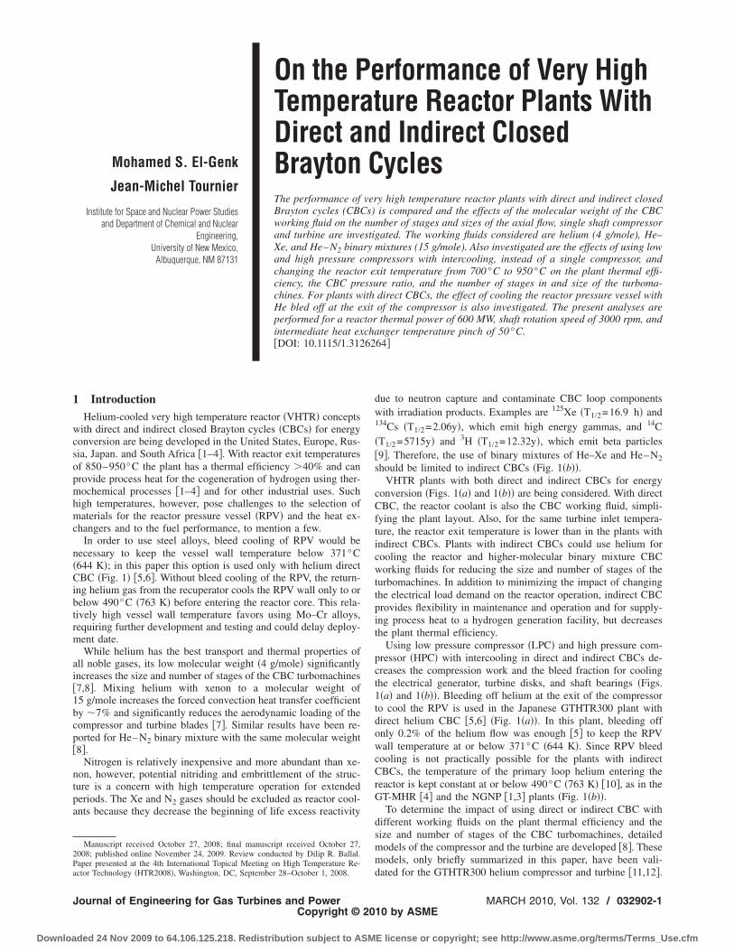
VHTR plants with both direct and indirect CBCs for energyconversion �Figs. 1�a� and 1�b�� are being considered. With directCBC, the reactor coolant is also the CBC working fluid, simpli-fying the plant layout. Also, for the same turbine inlet tempera-ture, the reactor exit temperature is lower than in the plants withindirect CBCs. Plants with indirect CBCs could use helium forcooling the reactor and higher-molecular binary mixture CBCworking fluids for reducing the size and number of stages of theturbomachines. In addition to minimizing the impact of changingthe electrical load demand on the reactor operation, indirect CBCprovides flexibility in maintenance and operation and for supply-ing process heat to a hydrogen generation facility, but decreasesthe plant thermal efficiency.
Using low pressure compressor �LPC� and high pressure com-pressor �HPC� with intercooling in direct and indirect CBCs de-creases the compression work and the bleed fraction for coolingthe electrical generator, turbine disks, and shaft bearings �Figs.1�a� and 1�b��. Bleeding off helium at the exit of the compressorto cool the RPV is used in the Japanese GTHTR300 plant withdirect helium CBC �5,6� �Fig. 1�a��. In this plant, bleeding offonly 0.2% of the helium flow was enough �5� to keep the RPVwall temperature at or below 371°C �644 K�. Since RPV bleedcooling is not practically possible for the plants with indirectCBCs, the temperature of the primary loop helium entering thereactor is kept constant at or below 490°C �763 K� �10�, as in theGT-MHR �4� and the NGNP �1,3� plants �Fig. 1�b��.
To determine the impact of using direct or indirect CBC withdifferent working fluids on the plant thermal efficiency and thesize and number of stages of the CBC turbomachines, detailedmodels of the compressor and the turbine are developed �8�. Thesemodels, only briefly summarized in this paper, have been vali-
dated for the GTHTR300 helium compressor and turbine �11,12�.MARCH 2010, Vol. 132 / 032902-110 by ASME
E license or copyright; see http://www.asme.org/terms/Terms_Use.cfm
Trt
wCa�fchpcsppd1
2
masse�V
lbtav
0
Downloa
he determined number of stages, polytropic efficiencies, pressureatios, and the hardware details were in excellent agreement withhe reported values �8�.
To investigate the effect of the molecular weight of the CBCorking fluid on the performance of the VHTR plant with indirectBC, the present analyses considered helium in direct CBC plantsnd helium and binary mixtures of He–Xe and He–N215 g/mole� in indirect CBC plants. Also investigated are the ef-ects of using LPC and HPC with intercooling instead of a singleompressor, using bleed cooling of the RPV in the plants withelium direct CBC �Fig. 1�a��, and changing the reactor exit tem-erature from 700°C to 950°C on the plant thermal efficiency,ycle pressure ratio, polytropic efficiency, and the number oftages in and size of the turbomachines. The present analyses areerformed for a shaft rotation speed of 3000 rpm, reactor thermalower of 600 MW, and a 50°C temperature pinch in the interme-iate heat exchanger �IHX� for the plants with indirect CBCs �Fig.�b��.
Model DescriptionThe present compressor and turbine design and performanceodels are based on a mean-line analysis of vortex free flow
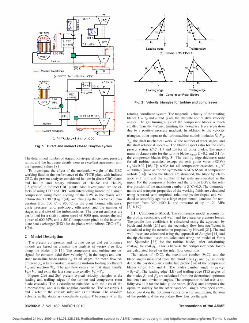
long the blades �13–17�. The compressor and turbine are de-igned for constant axial flow velocity Vx in the stages and con-tant mean-line blade radius rm. In all stages, the mean flow co-fficient �m is kept constant, assuming uniform loading coefficientm and reaction Rm. The gas flow enters the first stage axially,in=Vx, and exits the last stage also axially, Vex=Vx.Figures 2�a� and 2�b� present typical velocity triangles at the
eading and trailing edges of the turbine and compressor rotorlade cascades. The x-coordinate coincides with the axis of theurbomachine, and � is the angular coordinate. The subscripts 1nd 2 refer to the cascade inlet and exit stations. The absolute
Fig. 1 Direct and indirect closed Brayton cycles
elocity in the stationary coordinate system V becomes W in the
32902-2 / Vol. 132, MARCH 2010
ded 24 Nov 2009 to 64.106.125.218. Redistribution subject to ASM
rotating coordinate system. The tangential velocity of the rotatingblades U=U� and � and � are the absolute and relative velocityangles. The gas turning angle of the compressor blades is muchsmaller than the turbine, limiting the boundary layer separationdue to a positive pressure gradient. In addition to the velocity
triangles, other input to the turbomachine models includes N, Pin,
Tin, the shaft mechanical work W, the number of rotor stages, andthe shaft rotational speed �. The blades aspect ratio for the com-pressor stators H /C=1.7 and 1.4 for all other blades. The maxi-mum thickness ratio for the turbine blades tmax /C=0.2 and 0.1 forthe compressor blades �Fig. 3�. The trailing edge thickness ratiofor all turbine cascades, except the exit guide vanes �EGVs�tTE /S=0.02 �16,17�; while for all compressor cascades, tTE /C=0.00046 �same as for the symmetric NACA 65A010 compressorairfoils �14��. When the blades are shrouded, the blade tip clear-ance �=1 mm and the number of tip seals are specified in theinput. For the compressor blades and the turbine EGVs, the rela-tive position of the maximum camber is Z /C=0.5. The thermody-namic and transport properties of the working fluids are calculatedusing reported semi-empirical relationships developed and vali-dated successfully against a large experimental database for tem-perature from 300–1400 K and pressure of up to 20 MPa�7,18,19�.
2.1 Compressor Model. The compressor model accounts forthe profile, secondary, end wall, and tip clearance pressure losses.The profile loss coefficient is calculated using the approach byKoch and Smith �20� and the secondary flow loss coefficient iscalculated using the correlation proposed by Howell �21�. The endwall losses are calculated using the approach of Aungier �14� andthe tip clearance losses are calculated using the model of Yarasand Sjolander �22� for the turbine blades, after substitutingcos��2� for cos��1�. This is because the compressor blade lossesare calculated based on the inlet flow conditions.
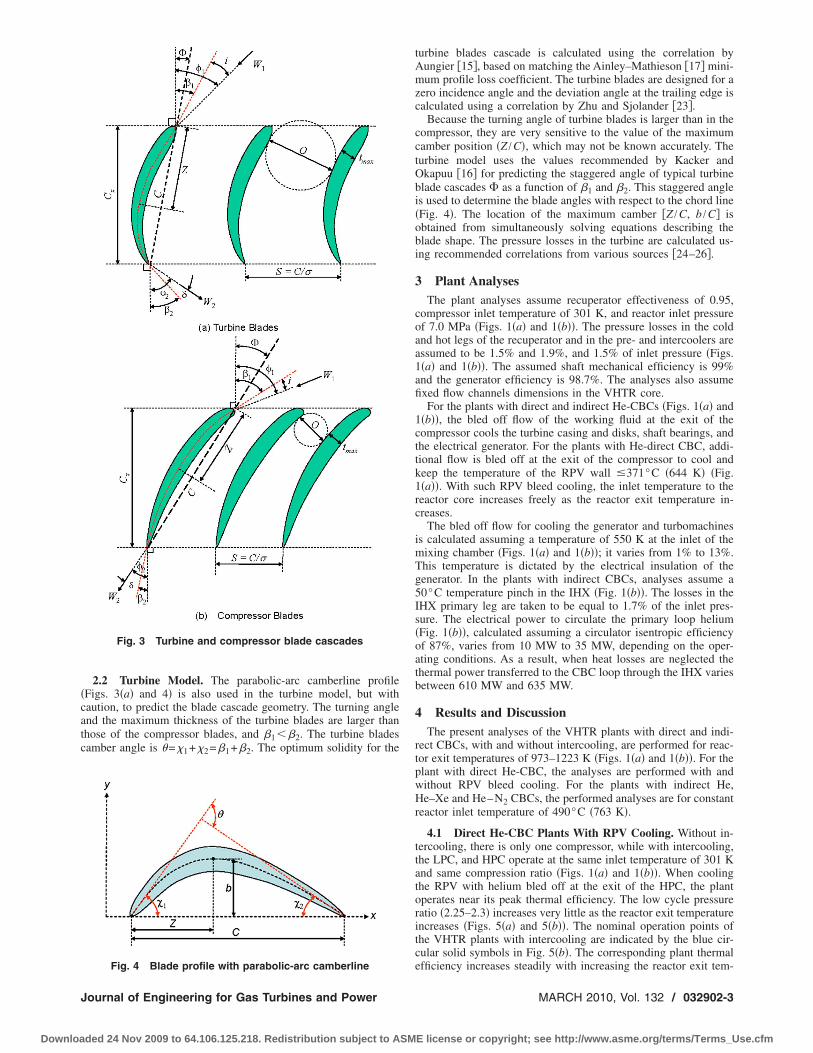
The values of �Z /C�, the maximum camber �b /C�, and theblade angles measured from the chord line �1 and 2� uniquelydefine the parabolic-arc camberline profile �14� of the compressorblades �Figs. 3�b� and 4�. The blades camber angle �=1+2=1−2. The leading edge �LE� and trailing edge �TE� angles ofthe blades 1 and 2 are calculated from the determined optimumincidence and deviation angles. The compressor model uses a so-lidity �=1.10 for the inlet guide vanes �IGVs� and computes theoptimum solidity for the other cascades using a developed corre-lation based on the optimum values of � for minimizing the sum
Fig. 2 Velocity triangles for turbine and compressor
of the profile and the secondary flow loss coefficients.
Transactions of the ASME
E license or copyright; see http://www.asme.org/terms/Terms_Use.cfm
�catc
J
Downloa
2.2 Turbine Model. The parabolic-arc camberline profileFigs. 3�a� and 4� is also used in the turbine model, but withaution, to predict the blade cascade geometry. The turning anglend the maximum thickness of the turbine blades are larger thanhose of the compressor blades, and 1�2. The turbine bladesamber angle is �=1+2=1+2. The optimum solidity for the
Fig. 3 Turbine and compressor blade cascades
Fig. 4 Blade profile with parabolic-arc camberline
ournal of Engineering for Gas Turbines and Power
ded 24 Nov 2009 to 64.106.125.218. Redistribution subject to ASM
turbine blades cascade is calculated using the correlation byAungier �15�, based on matching the Ainley–Mathieson �17� mini-mum profile loss coefficient. The turbine blades are designed for azero incidence angle and the deviation angle at the trailing edge iscalculated using a correlation by Zhu and Sjolander �23�.
Because the turning angle of turbine blades is larger than in thecompressor, they are very sensitive to the value of the maximumcamber position �Z /C�, which may not be known accurately. Theturbine model uses the values recommended by Kacker andOkapuu �16� for predicting the staggered angle of typical turbineblade cascades as a function of 1 and 2. This staggered angleis used to determine the blade angles with respect to the chord line�Fig. 4�. The location of the maximum camber �Z /C, b /C� isobtained from simultaneously solving equations describing theblade shape. The pressure losses in the turbine are calculated us-ing recommended correlations from various sources �24–26�.
3 Plant AnalysesThe plant analyses assume recuperator effectiveness of 0.95,
compressor inlet temperature of 301 K, and reactor inlet pressureof 7.0 MPa �Figs. 1�a� and 1�b��. The pressure losses in the coldand hot legs of the recuperator and in the pre- and intercoolers areassumed to be 1.5% and 1.9%, and 1.5% of inlet pressure �Figs.1�a� and 1�b��. The assumed shaft mechanical efficiency is 99%and the generator efficiency is 98.7%. The analyses also assumefixed flow channels dimensions in the VHTR core.
For the plants with direct and indirect He-CBCs �Figs. 1�a� and1�b��, the bled off flow of the working fluid at the exit of thecompressor cools the turbine casing and disks, shaft bearings, andthe electrical generator. For the plants with He-direct CBC, addi-tional flow is bled off at the exit of the compressor to cool andkeep the temperature of the RPV wall �371°C �644 K� �Fig.1�a��. With such RPV bleed cooling, the inlet temperature to thereactor core increases freely as the reactor exit temperature in-creases.
The bled off flow for cooling the generator and turbomachinesis calculated assuming a temperature of 550 K at the inlet of themixing chamber �Figs. 1�a� and 1�b��; it varies from 1% to 13%.This temperature is dictated by the electrical insulation of thegenerator. In the plants with indirect CBCs, analyses assume a50°C temperature pinch in the IHX �Fig. 1�b��. The losses in theIHX primary leg are taken to be equal to 1.7% of the inlet pres-sure. The electrical power to circulate the primary loop helium�Fig. 1�b��, calculated assuming a circulator isentropic efficiencyof 87%, varies from 10 MW to 35 MW, depending on the oper-ating conditions. As a result, when heat losses are neglected thethermal power transferred to the CBC loop through the IHX variesbetween 610 MW and 635 MW.
4 Results and DiscussionThe present analyses of the VHTR plants with direct and indi-
rect CBCs, with and without intercooling, are performed for reac-tor exit temperatures of 973–1223 K �Figs. 1�a� and 1�b��. For theplant with direct He-CBC, the analyses are performed with andwithout RPV bleed cooling. For the plants with indirect He,He–Xe and He–N2 CBCs, the performed analyses are for constantreactor inlet temperature of 490°C �763 K�.
4.1 Direct He-CBC Plants With RPV Cooling. Without in-tercooling, there is only one compressor, while with intercooling,the LPC, and HPC operate at the same inlet temperature of 301 Kand same compression ratio �Figs. 1�a� and 1�b��. When coolingthe RPV with helium bled off at the exit of the HPC, the plantoperates near its peak thermal efficiency. The low cycle pressureratio �2.25–2.3� increases very little as the reactor exit temperatureincreases �Figs. 5�a� and 5�b��. The nominal operation points ofthe VHTR plants with intercooling are indicated by the blue cir-cular solid symbols in Fig. 5�b�. The corresponding plant thermal
efficiency increases steadily with increasing the reactor exit tem-MARCH 2010, Vol. 132 / 032902-3
E license or copyright; see http://www.asme.org/terms/Terms_Use.cfm
pipptriii5t
ppaWccppatrl
ratrpRW
FV
0
Downloa
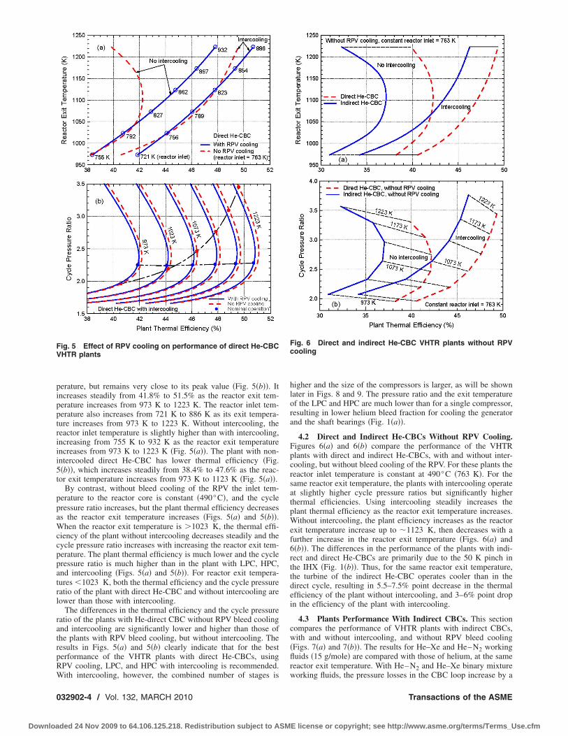
erature, but remains very close to its peak value �Fig. 5�b��. Itncreases steadily from 41.8% to 51.5% as the reactor exit tem-erature increases from 973 K to 1223 K. The reactor inlet tem-erature also increases from 721 K to 886 K as its exit tempera-ure increases from 973 K to 1223 K. Without intercooling, theeactor inlet temperature is slightly higher than with intercooling,ncreasing from 755 K to 932 K as the reactor exit temperaturencreases from 973 K to 1223 K �Fig. 5�a��. The plant with non-ntercooled direct He-CBC has lower thermal efficiency �Fig.�b��, which increases steadily from 38.4% to 47.6% as the reac-or exit temperature increases from 973 K to 1123 K �Fig. 5�a��.
By contrast, without bleed cooling of the RPV the inlet tem-erature to the reactor core is constant �490°C�, and the cycleressure ratio increases, but the plant thermal efficiency decreasess the reactor exit temperature increases �Figs. 5�a� and 5�b��.
hen the reactor exit temperature is �1023 K, the thermal effi-iency of the plant without intercooling decreases steadily and theycle pressure ratio increases with increasing the reactor exit tem-erature. The plant thermal efficiency is much lower and the cycleressure ratio is much higher than in the plant with LPC, HPC,nd intercooling �Figs. 5�a� and 5�b��. For reactor exit tempera-ures �1023 K, both the thermal efficiency and the cycle pressureatio of the plant with direct He-CBC and without intercooling areower than those with intercooling.
The differences in the thermal efficiency and the cycle pressureatio of the plants with He-direct CBC without RPV bleed coolingnd intercooling are significantly lower and higher than those ofhe plants with RPV bleed cooling, but without intercooling. Theesults in Figs. 5�a� and 5�b� clearly indicate that for the besterformance of the VHTR plants with direct He-CBCs, usingPV cooling, LPC, and HPC with intercooling is recommended.
ig. 5 Effect of RPV cooling on performance of direct He-CBCHTR plants
ith intercooling, however, the combined number of stages is
32902-4 / Vol. 132, MARCH 2010
ded 24 Nov 2009 to 64.106.125.218. Redistribution subject to ASM
higher and the size of the compressors is larger, as will be shownlater in Figs. 8 and 9. The pressure ratio and the exit temperatureof the LPC and HPC are much lower than for a single compressor,resulting in lower helium bleed fraction for cooling the generatorand the shaft bearings �Fig. 1�a��.
4.2 Direct and Indirect He-CBCs Without RPV Cooling.Figures 6�a� and 6�b� compare the performance of the VHTRplants with direct and indirect He-CBCs, with and without inter-cooling, but without bleed cooling of the RPV. For these plants thereactor inlet temperature is constant at 490°C �763 K�. For thesame reactor exit temperature, the plants with intercooling operateat slightly higher cycle pressure ratios but significantly higherthermal efficiencies. Using intercooling steadily increases theplant thermal efficiency as the reactor exit temperature increases.Without intercooling, the plant efficiency increases as the reactorexit temperature increase up to �1123 K, then decreases with afurther increase in the reactor exit temperature �Figs. 6�a� and6�b��. The differences in the performance of the plants with indi-rect and direct He-CBCs are primarily due to the 50 K pinch inthe IHX �Fig. 1�b��. Thus, for the same reactor exit temperature,the turbine of the indirect He-CBC operates cooler than in thedirect cycle, resulting in 5.5–7.5% point decrease in the thermalefficiency of the plant without intercooling, and 3–6% point dropin the efficiency of the plant with intercooling.
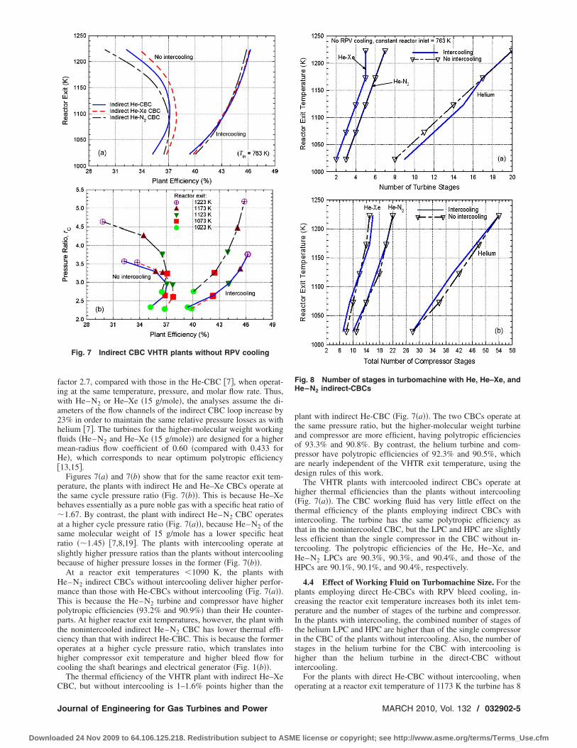
4.3 Plants Performance With Indirect CBCs. This sectioncompares the performance of VHTR plants with indirect CBCs,with and without intercooling, and without RPV bleed cooling�Figs. 7�a� and 7�b��. The results for He–Xe and He–N2 workingfluids �15 g/mole� are compared with those of helium, at the samereactor exit temperature. With He–N2 and He–Xe binary mixture
Fig. 6 Direct and indirect He-CBC VHTR plants without RPVcooling
working fluids, the pressure losses in the CBC loop increase by a
Transactions of the ASME
E license or copyright; see http://www.asme.org/terms/Terms_Use.cfm
fiwa2hflmH�
ptb�asrsb
HmTpptcohc
C
J
Downloa
actor 2.7, compared with those in the He-CBC �7�, when operat-ng at the same temperature, pressure, and molar flow rate. Thus,ith He–N2 or He–Xe �15 g/mole�, the analyses assume the di-
meters of the flow channels of the indirect CBC loop increase by3% in order to maintain the same relative pressure losses as withelium �7�. The turbines for the higher-molecular weight workinguids �He–N2 and He–Xe �15 g/mole�� are designed for a higherean-radius flow coefficient of 0.60 �compared with 0.433 fore�, which corresponds to near optimum polytropic efficiency
13,15�.Figures 7�a� and 7�b� show that for the same reactor exit tem-
erature, the plants with indirect He and He–Xe CBCs operate athe same cycle pressure ratio �Fig. 7�b��. This is because He–Xeehaves essentially as a pure noble gas with a specific heat ratio of1.67. By contrast, the plant with indirect He–N2 CBC operates
t a higher cycle pressure ratio �Fig. 7�a��, because He–N2 of theame molecular weight of 15 g/mole has a lower specific heatatio ��1.45� �7,8,19�. The plants with intercooling operate atlightly higher pressure ratios than the plants without intercoolingecause of higher pressure losses in the former �Fig. 7�b��.
At a reactor exit temperatures �1090 K, the plants withe–N2 indirect CBCs without intercooling deliver higher perfor-ance than those with He-CBCs without intercooling �Fig. 7�a��.his is because the He–N2 turbine and compressor have higherolytropic efficiencies �93.2% and 90.9%� than their He counter-arts. At higher reactor exit temperatures, however, the plant withhe nonintercooled indirect He–N2 CBC has lower thermal effi-iency than that with indirect He-CBC. This is because the formerperates at a higher cycle pressure ratio, which translates intoigher compressor exit temperature and higher bleed flow forooling the shaft bearings and electrical generator �Fig. 1�b��.
The thermal efficiency of the VHTR plant with indirect He–Xe
Fig. 7 Indirect CBC VHTR plants without RPV cooling
BC, but without intercooling is 1–1.6% points higher than the
ournal of Engineering for Gas Turbines and Power
ded 24 Nov 2009 to 64.106.125.218. Redistribution subject to ASM
plant with indirect He-CBC �Fig. 7�a��. The two CBCs operate atthe same pressure ratio, but the higher-molecular weight turbineand compressor are more efficient, having polytropic efficienciesof 93.3% and 90.8%. By contrast, the helium turbine and com-pressor have polytropic efficiencies of 92.3% and 90.5%, whichare nearly independent of the VHTR exit temperature, using thedesign rules of this work.
The VHTR plants with intercooled indirect CBCs operate athigher thermal efficiencies than the plants without intercooling�Fig. 7�a��. The CBC working fluid has very little effect on thethermal efficiency of the plants employing indirect CBCs withintercooling. The turbine has the same polytropic efficiency asthat in the nonintercooled CBC, but the LPC and HPC are slightlyless efficient than the single compressor in the CBC without in-tercooling. The polytropic efficiencies of the He, He–Xe, andHe–N2 LPCs are 90.3%, 90.3%, and 90.4%, and those of theHPCs are 90.1%, 90.1%, and 90.4%, respectively.
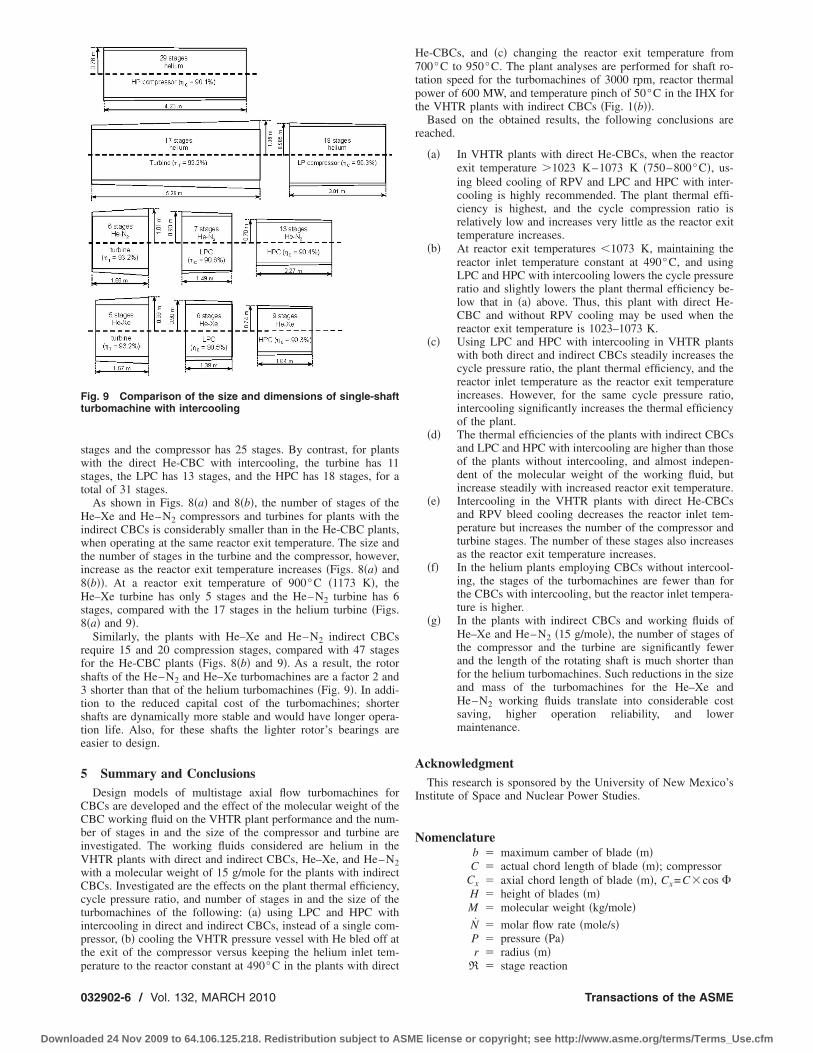
4.4 Effect of Working Fluid on Turbomachine Size. For theplants employing direct He-CBCs with RPV bleed cooling, in-creasing the reactor exit temperature increases both its inlet tem-perature and the number of stages of the turbine and compressor.In the plants with intercooling, the combined number of stages ofthe helium LPC and HPC are higher than of the single compressorin the CBC of the plants without intercooling. Also, the number ofstages in the helium turbine for the CBC with intercooling ishigher than the helium turbine in the direct-CBC withoutintercooling.
For the plants with direct He-CBC without intercooling, when
Fig. 8 Number of stages in turbomachine with He, He–Xe, andHe–N2 indirect-CBCs
operating at a reactor exit temperature of 1173 K the turbine has 8
MARCH 2010, Vol. 132 / 032902-5
E license or copyright; see http://www.asme.org/terms/Terms_Use.cfm
swst
Hiwti8Hs8
rfs3tste
5
CCbiVwCctiptp
Ft
0
Downloa
tages and the compressor has 25 stages. By contrast, for plantsith the direct He-CBC with intercooling, the turbine has 11
tages, the LPC has 13 stages, and the HPC has 18 stages, for aotal of 31 stages.
As shown in Figs. 8�a� and 8�b�, the number of stages of thee–Xe and He–N2 compressors and turbines for plants with the
ndirect CBCs is considerably smaller than in the He-CBC plants,hen operating at the same reactor exit temperature. The size and
he number of stages in the turbine and the compressor, however,ncrease as the reactor exit temperature increases �Figs. 8�a� and�b��. At a reactor exit temperature of 900°C �1173 K�, thee–Xe turbine has only 5 stages and the He–N2 turbine has 6
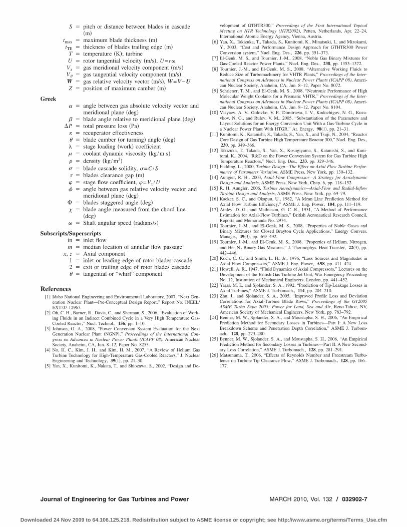
tages, compared with the 17 stages in the helium turbine �Figs.�a� and 9�.
Similarly, the plants with He–Xe and He–N2 indirect CBCsequire 15 and 20 compression stages, compared with 47 stagesor the He-CBC plants �Figs. 8�b� and 9�. As a result, the rotorhafts of the He–N2 and He–Xe turbomachines are a factor 2 andshorter than that of the helium turbomachines �Fig. 9�. In addi-
ion to the reduced capital cost of the turbomachines; shorterhafts are dynamically more stable and would have longer opera-ion life. Also, for these shafts the lighter rotor’s bearings areasier to design.
Summary and ConclusionsDesign models of multistage axial flow turbomachines for
BCs are developed and the effect of the molecular weight of theBC working fluid on the VHTR plant performance and the num-er of stages in and the size of the compressor and turbine arenvestigated. The working fluids considered are helium in theHTR plants with direct and indirect CBCs, He–Xe, and He–N2ith a molecular weight of 15 g/mole for the plants with indirectBCs. Investigated are the effects on the plant thermal efficiency,ycle pressure ratio, and number of stages in and the size of theurbomachines of the following: �a� using LPC and HPC withntercooling in direct and indirect CBCs, instead of a single com-ressor, �b� cooling the VHTR pressure vessel with He bled off athe exit of the compressor versus keeping the helium inlet tem-
ig. 9 Comparison of the size and dimensions of single-shafturbomachine with intercooling
erature to the reactor constant at 490°C in the plants with direct
32902-6 / Vol. 132, MARCH 2010
ded 24 Nov 2009 to 64.106.125.218. Redistribution subject to ASM
He-CBCs, and �c� changing the reactor exit temperature from700°C to 950°C. The plant analyses are performed for shaft ro-tation speed for the turbomachines of 3000 rpm, reactor thermalpower of 600 MW, and temperature pinch of 50°C in the IHX forthe VHTR plants with indirect CBCs �Fig. 1�b��.
Based on the obtained results, the following conclusions arereached.
�a� In VHTR plants with direct He-CBCs, when the reactorexit temperature �1023 K–1073 K �750–800°C�, us-ing bleed cooling of RPV and LPC and HPC with inter-cooling is highly recommended. The plant thermal effi-ciency is highest, and the cycle compression ratio isrelatively low and increases very little as the reactor exittemperature increases.
�b� At reactor exit temperatures �1073 K, maintaining thereactor inlet temperature constant at 490°C, and usingLPC and HPC with intercooling lowers the cycle pressureratio and slightly lowers the plant thermal efficiency be-low that in �a� above. Thus, this plant with direct He-CBC and without RPV cooling may be used when thereactor exit temperature is 1023–1073 K.
�c� Using LPC and HPC with intercooling in VHTR plantswith both direct and indirect CBCs steadily increases thecycle pressure ratio, the plant thermal efficiency, and thereactor inlet temperature as the reactor exit temperatureincreases. However, for the same cycle pressure ratio,intercooling significantly increases the thermal efficiencyof the plant.
�d� The thermal efficiencies of the plants with indirect CBCsand LPC and HPC with intercooling are higher than thoseof the plants without intercooling, and almost indepen-dent of the molecular weight of the working fluid, butincrease steadily with increased reactor exit temperature.
�e� Intercooling in the VHTR plants with direct He-CBCsand RPV bleed cooling decreases the reactor inlet tem-perature but increases the number of the compressor andturbine stages. The number of these stages also increasesas the reactor exit temperature increases.
�f� In the helium plants employing CBCs without intercool-ing, the stages of the turbomachines are fewer than forthe CBCs with intercooling, but the reactor inlet tempera-ture is higher.
�g� In the plants with indirect CBCs and working fluids ofHe–Xe and He–N2 �15 g/mole�, the number of stages ofthe compressor and the turbine are significantly fewerand the length of the rotating shaft is much shorter thanfor the helium turbomachines. Such reductions in the sizeand mass of the turbomachines for the He–Xe andHe–N2 working fluids translate into considerable costsaving, higher operation reliability, and lowermaintenance.
AcknowledgmentThis research is sponsored by the University of New Mexico’s
Institute of Space and Nuclear Power Studies.
Nomenclatureb � maximum camber of blade �m�C � actual chord length of blade �m�; compressor
Cx � axial chord length of blade �m�, Cx=C�cos H � height of blades �m�M � molecular weight �kg/mole�N � molar flow rate �mole/s�P � pressure �Pa�r � radius �m�
R � stage reaction
Transactions of the ASME
E license or copyright; see http://www.asme.org/terms/Terms_Use.cfm
G
S
R
J
Downloa
S � pitch or distance between blades in cascade�m�
tmax � maximum blade thickness �m�tTE � thickness of blades trailing edge �m�
T � temperature �K�; turbineU � rotor tangential velocity �m/s�, U=r�Vx � gas meridional velocity component �m/s�V� � gas tangential velocity component �m/s�W � gas relative velocity vector �m/s�, W=V−UZ � position of maximum camber �m�
reek� � angle between gas absolute velocity vector and
meridional plane �deg� � blade angle relative to meridional plane �deg�
�P � total pressure loss �Pa�� � recuperator effectiveness� � blade camber �or turning� angle �deg�� � stage loading �work� coefficient� � coolant dynamic viscosity �kg /m s�� � density �kg /m3�� � blade cascade solidity, �=C /S� � blades clearance gap �m�� � stage flow coefficient, �=Vx /U� � angle between gas relative velocity vector and
meridional plane �deg� � blades staggered angle �deg� � blade angle measured from the chord line
�deg�� � Shaft angular speed �radians/s�
ubscripts/Superscriptsin � inlet flowm � median location of annular flow passage
x, z � Axial component1 � inlet or leading edge of rotor blades cascade2 � exit or trailing edge of rotor blades cascade� � tangential or “whirl” component
eferences�1� Idaho National Engineering and Environmental Laboratory, 2007, “Next Gen-
eration Nuclear Plant—Pre-Conceptual Design Report,” Report No. INEEL/EXT-07-12967.
�2� Oh, C. H., Barner, R., Davis, C., and Sherman, S., 2006, “Evaluation of Work-ing Fluids in an Indirect Combined Cycle in a Very High Temperature Gas-Cooled Reactor,” Nucl. Technol., 156, pp. 1–10.
�3� Johnson, G. A., 2008, “Power Conversion System Evaluation for the NextGeneration Nuclear Plant �NGNP�,” Proceedings of the International Con-gress on Advances in Nuclear Power Plants (ICAPP 08), American NuclearSociety, Anaheim, CA, Jun. 8–12, Paper No. 8253.
�4� No, H. C., Kim, J. H., and Kim, H. M., 2007, “A Review of Helium GasTurbine Technology for High-Temperature Gas-Cooled Reactors,” J. NuclearEngineering and Technology, 39�1�, pp. 21–30.
�5� Yan, X., Kunitomi, K., Nakata, T., and Shiozawa, S., 2002, “Design and De-
ournal of Engineering for Gas Turbines and Power
ded 24 Nov 2009 to 64.106.125.218. Redistribution subject to ASM
velopment of GTHTR300,” Proceedings of the First International TopicalMeeting on HTR Technology (HTR2002), Petten, Netherlands, Apr. 22–24,International Atomic Energy Agency, Vienna, Austria.
�6� Yan, X., Takizuka, T., Takada, S., Kunitomi, K., Minatsuki, I., and Mizokami,Y., 2003, “Cost and Performance Design Approach for GTHTR300 PowerConversion system,” Nucl. Eng. Des., 226, pp. 351–373.
�7� El-Genk, M. S., and Tournier, J.-M., 2008, “Noble Gas Binary Mixtures forGas-Cooled Reactor Power Plants,” Nucl. Eng. Des., 238, pp. 1353–1372.
�8� Tournier, J.-M., and El-Genk, M. S., 2008, “Alternative Working Fluids toReduce Size of Turbomachinery for VHTR Plants,” Proceedings of the Inter-national Congress on Advances in Nuclear Power Plants (ICAPP 08), Ameri-can Nuclear Society, Anaheim, CA, Jun. 8–12, Paper No. 8072.
�9� Schriener, T. M., and El-Genk, M. S., 2008, “Neutronic Performance of HighMolecular Weight Coolants for a Prismatic VHTR,” Proceedings of the Inter-national Congress on Advances in Nuclear Power Plants (ICAPP 08), Ameri-can Nuclear Society, Anaheim, CA, Jun. 8–12, Paper No. 8104.
�10� Vasyaev, A. V., Golovko, V. F., Dimitrieva, I. V., Kodochigov, N. G., Kuza-vkov, N. G., and Rulev, V. M., 2005, “Substantiation of the Parameters andLayout Solutions for an Energy Conversion Unit With a Gas-Turbine Cycle ina Nuclear Power Plant With HTGR,” At. Energy, 98�1�, pp. 21–31.
�11� Kunitomi, K., Katanishi, S., Takada, S., Yan, X., and Tsuji, N., 2004, “ReactorCore Design of Gas Turbine High Temperature Reactor 300,” Nucl. Eng. Des.,230, pp. 349–366.
�12� Takizuka, T., Takada, S., Yan, X., Kosugiyama, S., Katanishi, S., and Kuni-tomi, K., 2004, “R&D on the Power Conversion System for Gas Turbine HighTemperature Reactors,” Nucl. Eng. Des., 233, pp. 329–346.
�13� Fielding, L., 2000, Turbine Design—The Effect on Axial Flow Turbine Perfor-mance of Parameter Variation, ASME Press, New York, pp. 130–132.
�14� Aungier, R. H., 2003, Axial-Flow Compressor—A Strategy for AerodynamicDesign and Analysis, ASME Press, New York, Chap. 6, pp. 118–152.
�15� R. H. Aungier, 2006, Turbine Aerodynamics—Axial-Flow and Radial-InflowTurbine Design and Analysis, ASME Press, New York, pp. 69–79.
�16� Kacker, S. C., and Okapuu, U., 1982, “A Mean Line Prediction Method forAxial Flow Turbine Efficiency,” ASME J. Eng. Power, 104, pp. 111–119.
�17� Ainley, D. G., and Mathieson, G. C. R., 1951, “A Method of PerformanceEstimation for Axial-Flow Turbines,” British Aeronautical Research Council,Reports and Memoranda No. 2974.
�18� Tournier, J.-M., and El-Genk, M. S., 2008, “Properties of Noble Gases andBinary Mixtures for Closed Brayton Cycle Applications,” Energy Convers.Manage., 49�3�, pp. 469–492.
�19� Tournier, J.-M., and El-Genk, M. S., 2008, “Properties of Helium, Nitrogen,and He–N2 Binary Gas Mixtures,” J. Thermophys. Heat Transfer, 22�3�, pp.442–446.
�20� Koch, C. C., and Smith, L. H., Jr., 1976, “Loss Sources and Magnitudes inAxial-Flow Compressors,” ASME J. Eng. Power, A98, pp. 411–424.
�21� Howell, A. R., 1947, “Fluid Dynamics of Axial Compressors,” Lectures on theDevelopment of the British Gas Turbine Jet Unit, War Emergency ProceedingNo. 12, Institution of Mechanical Engineers, London, pp. 441–452.
�22� Yaras, M. I., and Sjolander, S. A., 1992, “Prediction of Tip-Leakage Losses inAxial Turbines,” ASME J. Turbomach., 114, pp. 204–210.
�23� Zhu, J., and Sjolander, S. A., 2005, “Improved Profile Loss and DeviationCorrelations for Axial-Turbine Blade Rows,” Proceedings of the GT2005ASME Turbo Expo 2005: Power for Land, Sea and Air, Reno-Tahoe, NV,American Society of Mechanical Engineers, New York, pp. 783–792.
�24� Benner, M. W., Sjolander, S. A., and Moustapha, S. H., 2006, “An EmpiricalPrediction Method for Secondary Losses in Turbines—Part I: A New LossBreakdown Scheme and Penetration Depth Correlation,” ASME J. Turbom-ach., 128, pp. 273–280.
�25� Benner, M. W., Sjolander, S. A., and Moustapha, S. H., 2006, “An EmpiricalPrediction Method for Secondary Losses in Turbines—Part II: A New Second-ary Loss Correlation,” ASME J. Turbomach., 128, pp. 281–291.
�26� Matsunuma, T., 2006, “Effects of Reynolds Number and Freestream Turbu-lence on Turbine Tip Clearance Flow,” ASME J. Turbomach., 128, pp. 166–
177.MARCH 2010, Vol. 132 / 032902-7
E license or copyright; see http://www.asme.org/terms/Terms_Use.cfm