On the motion of non-spherical particles at high Reynolds number
13
Review On the motion of non-spherical particles at high Reynolds number Matthias Mandø ⁎, Lasse Rosendahl Aalborg University, Institute of Energy Technology, Pontoppidanstraede 101, 9220, Aalborg East, Denmark abstract article info Article history: Received 13 August 2009 Received in revised form 29 March 2010 Accepted 3 May 2010 Available online 7 May 2010 Keywords: Non-spherical particles Particle equation of motion Gas–solid interaction Dispersed multiphase flow This paper contains a critical review of available methodology for dealing with the motion of non-spherical particles at higher Reynolds numbers in the Eulerian–Lagrangian methodology for dispersed flow. First, an account of the various attempts to classify the various shapes and the efforts towards finding a universal shape parameter is given and the details regarding the significant secondary motion associated with non- spherical particles are outlined. Most investigations concerning large non-spherical particles to date have been focused on finding appropriate correlations of the drag coefficient for specific shapes either by parameter variation or by using shape parameters. Particular emphasis is here placed on showing the incapability of one-dimensional shape parameters to predict the multifaceted secondary motion associated with non-spherical particles. To properly predict secondary motion it is necessary to account for the non- coincidence between the center of pressure and center of gravity which is a direct consequence of the inertial pressure forces associated with particles at high Reynolds number flow. Extensions for non-spherical particles at higher Reynolds numbers are far in between and usually based on semi-heuristic approaches utilizing concepts from airfoil theory such as profile lift. Even for regular particles there seems to be a long way before a complete theory can be formulated. For irregular particles with small aspect ratio, where the secondary motion is insignificant compared to the effect of turbulence, the drag correlations based on one- dimensional shape parameters come to their right. The interactions between non-spherical particles and turbulence are not well understood and modeling attempts are limited to extending methods developed for spheres. © 2010 Elsevier B.V. All rights reserved. Contents 1. Introduction . . . . . . . . . . . . . . . . . . . . . . . . . . . . . . . . . . . . . . . . . . . . . . . . . . . . . . . . . . . . . . . 1 2. Classification of shape . . . . . . . . . . . . . . . . . . . . . . . . . . . . . . . . . . . . . . . . . . . . . . . . . . . . . . . . . . 2 3. Drag correlations for translational motion . . . . . . . . . . . . . . . . . . . . . . . . . . . . . . . . . . . . . . . . . . . . . . . . . 3 4. Classification of regimes of secondary motion . . . . . . . . . . . . . . . . . . . . . . . . . . . . . . . . . . . . . . . . . . . . . . . 4 5. Orientation dependent models . . . . . . . . . . . . . . . . . . . . . . . . . . . . . . . . . . . . . . . . . . . . . . . . . . . . . . 6 6. Interaction with turbulence . . . . . . . . . . . . . . . . . . . . . . . . . . . . . . . . . . . . . . . . . . . . . . . . . . . . . . . . 10 7. Summary/conclusions . . . . . . . . . . . . . . . . . . . . . . . . . . . . . . . . . . . . . . . . . . . . . . . . . . . . . . . . . . 11 Appendix A. Equations of motion for non-spherical particles . . . . . . . . . . . . . . . . . . . . . . . . . . . . . . . . . . . . . . . . . . . 11 References . . . . . . . . . . . . . . . . . . . . . . . . . . . . . . . . . . . . . . . . . . . . . . . . . . . . . . . . . . . . . . . . . . 12 1. Introduction Irregular non-spherical particles are found in most industrial particulate flows and similarly most engineering flows are turbulent. However, the vast majority of scientific investigations of particulate flows assume particles to be perfectly spherical particles. The exact governing equations for turbulent flow have been known for over a century but the utilization of these is significantly impeded by the need to resolve the smallest flow structures and time scales. Consequently, for most practical uses, turbulence is modeled using Reynolds or Favre averaging and the interaction with particles is handled by random walk models. Large non-spherical particles present their own set of particular problems in the context of Computational Fluids Dynamics (CFD): How to define and quantify the shape? How to deal with secondary motion? How well will the methodology developed for spheres work for highly non-spherical shapes? How to handle turbulence? This paper attempts to give an account of the present state of modeling the motion of large non- spherical particles. The relevance of this paper also becomes evident Powder Technology 202 (2010) 1–13 ⁎ Corresponding author. E-mail addresses: [email protected] (M. Mandø), [email protected] (L. Rosendahl). 0032-5910/$ – see front matter © 2010 Elsevier B.V. All rights reserved. doi:10.1016/j.powtec.2010.05.001 Contents lists available at ScienceDirect Powder Technology journal homepage: www.elsevier.com/locate/powtec
Transcript of On the motion of non-spherical particles at high Reynolds number

Powder Technology 202 (2010) 1–13
Contents lists available at ScienceDirect
Powder Technology
j ourna l homepage: www.e lsev ie r.com/ locate /powtec
Review
On the motion of non-spherical particles at high Reynolds number
Matthias Mandø ⁎, Lasse RosendahlAalborg University, Institute of Energy Technology, Pontoppidanstraede 101, 9220, Aalborg East, Denmark
⁎ Corresponding author.E-mail addresses: [email protected] (M. Mandø), lar@
0032-5910/$ – see front matter © 2010 Elsevier B.V. Aldoi:10.1016/j.powtec.2010.05.001
a b s t r a c t
a r t i c l e i n f oArticle history:Received 13 August 2009Received in revised form 29 March 2010Accepted 3 May 2010Available online 7 May 2010
Keywords:Non-spherical particlesParticle equation of motionGas–solid interactionDispersed multiphase flow
This paper contains a critical review of available methodology for dealing with the motion of non-sphericalparticles at higher Reynolds numbers in the Eulerian–Lagrangian methodology for dispersed flow. First, anaccount of the various attempts to classify the various shapes and the efforts towards finding a universalshape parameter is given and the details regarding the significant secondary motion associated with non-spherical particles are outlined. Most investigations concerning large non-spherical particles to date havebeen focused on finding appropriate correlations of the drag coefficient for specific shapes either byparameter variation or by using shape parameters. Particular emphasis is here placed on showing theincapability of one-dimensional shape parameters to predict the multifaceted secondary motion associatedwith non-spherical particles. To properly predict secondary motion it is necessary to account for the non-coincidence between the center of pressure and center of gravity which is a direct consequence of the inertialpressure forces associated with particles at high Reynolds number flow. Extensions for non-sphericalparticles at higher Reynolds numbers are far in between and usually based on semi-heuristic approachesutilizing concepts from airfoil theory such as profile lift. Even for regular particles there seems to be a longway before a complete theory can be formulated. For irregular particles with small aspect ratio, where thesecondary motion is insignificant compared to the effect of turbulence, the drag correlations based on one-dimensional shape parameters come to their right. The interactions between non-spherical particles andturbulence are not well understood and modeling attempts are limited to extending methods developed forspheres.
iet.aau.dk (L. Rosendahl).
l rights reserved.
© 2010 Elsevier B.V. All rights reserved.
Contents
1. Introduction . . . . . . . . . . . . . . . . . . . . . . . . . . . . . . . . . . . . . . . . . . . . . . . . . . . . . . . . . . . . . . . 12. Classification of shape . . . . . . . . . . . . . . . . . . . . . . . . . . . . . . . . . . . . . . . . . . . . . . . . . . . . . . . . . . 23. Drag correlations for translational motion . . . . . . . . . . . . . . . . . . . . . . . . . . . . . . . . . . . . . . . . . . . . . . . . . 34. Classification of regimes of secondary motion . . . . . . . . . . . . . . . . . . . . . . . . . . . . . . . . . . . . . . . . . . . . . . . 45. Orientation dependent models . . . . . . . . . . . . . . . . . . . . . . . . . . . . . . . . . . . . . . . . . . . . . . . . . . . . . . 66. Interaction with turbulence . . . . . . . . . . . . . . . . . . . . . . . . . . . . . . . . . . . . . . . . . . . . . . . . . . . . . . . . 107. Summary/conclusions . . . . . . . . . . . . . . . . . . . . . . . . . . . . . . . . . . . . . . . . . . . . . . . . . . . . . . . . . . 11Appendix A. Equations of motion for non-spherical particles . . . . . . . . . . . . . . . . . . . . . . . . . . . . . . . . . . . . . . . . . . . 11References . . . . . . . . . . . . . . . . . . . . . . . . . . . . . . . . . . . . . . . . . . . . . . . . . . . . . . . . . . . . . . . . . . 12
1. Introduction
Irregular non-spherical particles are found in most industrialparticulate flows and similarly most engineering flows are turbulent.However, the vast majority of scientific investigations of particulateflows assume particles to be perfectly spherical particles. The exactgoverning equations for turbulent flow have been known for over acentury but the utilization of these is significantly impeded by the
need to resolve the smallest flow structures and time scales.Consequently, for most practical uses, turbulence is modeled usingReynolds or Favre averaging and the interaction with particles ishandled by random walk models. Large non-spherical particlespresent their own set of particular problems in the context ofComputational Fluids Dynamics (CFD): How to define and quantifythe shape? How to deal with secondary motion? How well will themethodology developed for spheres work for highly non-sphericalshapes? How to handle turbulence? This paper attempts to give anaccount of the present state of modeling the motion of large non-spherical particles. The relevance of this paper also becomes evident

Table 1One possible categorization of shapes.
Spherical Non-spherical
Regular Polygons, spheroids with lowaspect ratio
Cubes, cylinders, disks, tetrahedron,spheroids with high aspect ratio
Irregular Pulverized coal, sand, manypowders, particulate matter
Pulverized biomass, flakes, splinters,agglomerates
Table 2Commonly used diameter definitions.
Aerodynamic/drag diameter Diameter of a sphere of unity density with thesame terminal velocity as the particle
Stokes diameter Diameter of a sphere of same density and thesame terminal velocity as the particle
Projected area diameter Diameter of a circle having the same area as theprojection of the particle
Ferets diameter The mean value of the distance between pairsof parallel tangents to the projected outline ofthe particle
Martins diameter The mean chord length of the projected outlineof the particle
Area equivalent diameter Diameter of a sphere having the same surfacearea as the particle
Volume equivalent diameter Diameter of a sphere having the same volumeas the particle
2 M. Mandø, L. Rosendahl / Powder Technology 202 (2010) 1–13
considering the increasing efforts towards the replacement ofpulverized coal with biomass in existing and new power plants.Whereas pulverized coal particles are small and the spherical ideal is afair approximation, pulverized biomass particles are characterized aslarge and with high aspect ratios due to their fibrous nature. Thisinvestigation has been limited to the Eulerian–Lagrangian methodol-ogy and to solid non-deforming particles in Newtonian fluids. Pleaserefer to Sommerfeld et al. [68] for an updated outline on existingknowledge concerning multiphase flow and Chhabra [13] for particlemotion in non-Newtonian fluids.
2. Classification of shape
Particles come in all sort of shapes and sizes, in fact, due to thearbitrary nature of naturally occurring particles there are an indefinitenumber of possible shapes. This necessitates the need for a set ofparameters to aid in the description of different particle shapes for theimplementation in the numerical models and the relay of relevantinformation to other scientists. This information is available in manybooks on the subject, e.g. Rhodes [61] or Clift et al. [18] contain muchuseful information, and here we limit ourselves to focus on the mostpertinent issues involved in the classification of shapes. One suchissue seems to be the terminology used. The word non-spherical mostoften, and somehow also in the title of this paper, refers to all shapeswhich are not perfect spheres. However, the truemeaning of the wordspherical is: “shape which is sphere-like” which thus implies asubjective distinction. In the context of CFD it is useful to use this toobjectively distinguish between shapes which with reasonableaccuracy can be approximated as spheres and shapes which requirea more intricate handling. Another often used terminology tocharacterize shapes which are not spheres1 is the word “irregular”whose true definition is counter to that of regular shapes. Table 1outlines the categorization using the above discussed terminology.
Table 1 serves as a reference for the following discussion ofdifferent simulation strategies in this work. Spherical particles haveno or only little secondary motion associated with their trajectories,assume no preferred orientation but rather tumbles and thus it wouldbe justified to base the simulation methodology on that used forspherical particles i.e. not considering orientation or shape inducedlift. Possible extensions to the simulation methodology thus revolvearound modifications to the drag coefficient considering the shape orby specifying an equivalent diameter and using drag correlationsbased on spheres. Non-spherical particles on the other hand areassociatedwith shape induced lift, orientation dependent lift and dragforces, significant secondary motion and may assume a preferredorientation depending on the regime of motion. Thus, it is necessaryto revise the usual strategy to properly capture these phenomena. Thisinvolves keeping track of the orientation and rotation of the particle aswell as the formulation of appropriate orientation dependent lift anddrag force on a per shape basis. For irregular non-spherical particlescommon strategies involve the approximation of the shape to aregular counterpart e.g. cylinder for a wood splinter, disk for a flake.The distinction between spherical and non-spherical particles isprincipally subjective and thus open for interpretation. Here, it issuggested that the distinction is made on the basis of the aspect ratio,β. This simple criterion can be easily measured via microscopytechniques and is a good representative for when secondary effectsbecome important. According to Christiansen and Barker [15] and Cliftet al. [18] a suitable value for this criterion is β=1.7 which alsoroughly corresponds to the aspect ratio for a cube (based on thediagonal to the side length). Thus, particles below this ratio areconsidered spherical and can be treated with reasonable accuracy
1 The appropriate term non-sphere is surprisingly hardly ever used.
using a single drag correlation of choice. Particles above this ratioshould be classified according to which generic shape they resemblethemost e.g. cylinder, disk, spheroid, super-ellipsoid of revolution andtreated accordingly.
For spherical particles it is only necessary to specify an equivalentdiameter and optionally a shape factor to account for the departure inshape from a sphere. Table 2 gives an outline of commonly useddiameter definitions after Allen [1]. Note that projected area, Feretsand Martins diameters are determined directly from image analysiswhile area and volume equivalent diameters often are based on imageanalysis by assuming a thickness. The other diameters listedcorrespond to a particular analysis method e.g. Stokes diameterwhich is found from sedimentation techniques.
The main difficulties are thus reduced to a matter of measurementand it seems appropriate to offer a few comments about availablemeasurement methods. The basis for all methods is that they providethe same result when applied to a perfect sphere while markeddifferences occur as the shape becomes non-spherical due to thedifferences in the diameter definitions. In some scientific or industrialfields specific methods are prevailing due to the individual strengthsof particular methods e.g. sieve analysis is often preferred whenever awide size distribution is encountered while it may be unsuitable forvery fine powders. Aerodynamic separation and sedimentationtechniques are used for fine powders and particulate matter whichtends to be spherical in nature and due to the diameter definitions thesize distributions can be used directly in Lagrangian trajectorycalculations using the drag coefficient of a sphere. Due to practicaland theoretical considerations these methods are not used forparticles larger than 50 μm and thus any discussion concerninglarge non-spherical particles becomes somewhat irrelevant. Imageanalysis is regarded as a benchmark compared to other techniques asthis involves direct determination of the diameter. However, as imageanalysis is based on a two-dimensional measurement this methodbecomes increasingly biased as the particles deviate from thespherical ideal. For example the volume equivalent diameter offlake-like particles will be systematically overestimated if theirthickness is assumed to be proportional to their 2D extent while
Sieve/mesh diameter The width of the minimum square aperturethrough which the particle will pass
Laser diffraction diameter Diameter is calculated according to the Mie orFraunhofer diffraction theory
3M. Mandø, L. Rosendahl / Powder Technology 202 (2010) 1–13
laying flat on a plate [59]. This bias can somewhat be rectified byanalyzing images of particles in free fall but the failure to resolve thethird dimension ultimately means that this method is associated withsignificant measurement uncertainty. Full 3D analysis which wouldinvolve the use of two or more cameras set at an angle to each otherhas the potential to provide accurate measurement of the shape andvolume. However, the complicity of such amethod has so far hinderedthe implementation into commercially available equipment. Popularmethods to determine the size distribution of particles are by sievesand laser diffraction. Although these methods are very different theyare associated with similar types of uncertainty. Sieve analysis allowsslender particles to pass through a fine mesh compared to the particlevolume equivalent diameter while flake-like particles will be stoppedby a coarse mesh relative to the particle volume equivalent diameter.Similarly, the laser diffraction technique relates the diameter to theorientation of the particle crossing the measurement volume [3]. Asthe particle is allowed to rotate freely, this means that a slenderparticle can be assessed on the basis of its smallest dimension whilethe flake-like particle might be assessed on the basis of its largestdimension. As such both methods are associated with similar, widersize distributions [55]. Furthermore, the cross-sectional area averagedover all orientations for a non-spherical particle is larger than for anequal volume sphere [23]. Depending on predominant shape in agiven sample sieve analysis might predict a larger or a smaller meanvalue compared to the true mean while laser diffraction tends tooverestimate the true size distribution [55,58]. As a final remark onthe use of single dimension definitions for non-spherical particles, itmay be said that they are often reported indiscriminately and usedwithout any regard to the requirement of the drag correlation [6].Significant biases are associated with the measurement of particlesizes for non-spherical particles for all measurement methods and theproblem severely deteriorates for increasing aspect ratios. By usingequivalent diameters all data about the shape of the particle isessentially lost and to be able to retain this information additionalshape factors have been suggested to quantify the geometry/irregularity of non-spherical particles. These can be seen as a parallelto the roughness factors which are commonly used for pipe flow. Notethat only image analysis is capable of supplying the additionalinformation regarding the shape of the particle and that thisinformation is often based on the assumption that 2D images ofparticles can be directly related to the 3D shape of the particle. Table 3gives an outline of the most commonly used shape factors.
These shape factors can be used for both regular and irregularparticles, but especially suited for the latter since the shape ofirregular particles cannot be expressed in any other way [44]. Manyalternative shape factors [18,21,48,72] have also been suggested, butnone has won greater acceptance or use despite clamed superiority.Fractal dimensions and harmonics have also been used to characterizethe shape/morphology of irregular particles [16,67,76]. However,these have not been used in conjunction with CFD simulations and arenot addressed further. Automated algorithms in image processingsoftware allow for quick determination of shape factors as well asdimensions but the accuracy is limited by the previously mentionedassumptions for 2D images of 3D particles. Presently, the most
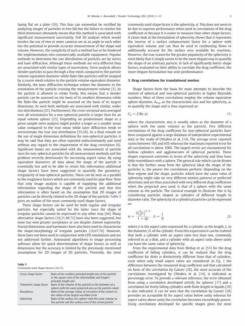
Table 3Commonly used shape factors [34,75].
Corey shape factor Ratio of the smallest principal length axis of the particleto the square root of the intermediate and longestprinciple length axis
Volumetric shape factor Ratio of the volume of the particle to the diameter of asphere with the same projected area as the particle cubed
Roundness Ratio of the average radius of curvature of the corners tothe radius of the largest inscribed circle
Sphericity Ratio of the surface of a sphere with the same volume asthe particle and the surface area of the actual particle
commonly used shape factor is the sphericity, ψ. This does not seem tobe due to superior performance when used in correlations of the dragcoefficient or because it is easier to measure than other shape factors.A closer look at the formulation of sphericity shows that it representsthe inverse of a surface enhancement factor for a sphere withequivalent volume and can thus be used in combusting flows toadditionally account for the surface area available for reactions.However, the true reason for the greater popularity of the sphericity ismost likely that it simply seems to be themost elegant way to quantifythe shape of an arbitrary particle. In lack of significantly better shapefactors, evaluated on their ability to correlate the drag coefficient, themore elegant formulation has won predominance.
3. Drag correlations for translational motion
Shape factors form the basis for most attempts to describe themotion of spherical and non-spherical particles at higher Reynoldsnumbers. Most of these correlations employ the volume equivalentsphere diameter, dVeq, as the characteristic size and the sphericity, ψ,to quantify the shape and is thus expressed as:
CD = f Re;ψð Þ ð1Þ
where the characteristic size is usually taken as the diameter of asphere with the same volume as the particle. Five differentcorrelations of the drag coefficient for non-spherical particles havebeen compared against a large database of independent experimentaldata in the study of Chhabra et al. [14]. The average error reportedvaries between 16% and 43%whereas themaximum reported error forall correlations is above 100%. The largest errors are encountered forhollow cylinders and agglomerates of spherical particles. Theseshapes represent extremes in terms of the sphericity and they havelittle resemblance with a sphere. The general rule which can be drawnis that the further away from the spherical ideal the shape of theparticles is, the poorer the correlations perform. Depending on theflow regime and the shape, particles which have the same value ofsphericity might take on very different motion patterns or preferreddirections and are thus associated with very different drag coefficientswhen the projected area used, is that of a sphere with the samevolume as the particle. The classical example to illustrate this is byconsidering particles shaped as cylinders of different length todiameter ratio. The sphericity of a cylindrical particle can be expressedas:
ψ =2 3
2β
� �2=31 + 2β
; β =LD
ð2Þ
where β is the aspect ratio expressed for a cylinder as the length, L, tothe diameter,D, of the cylinder. From this expression it can be realizedthat both a cylinder with an aspect ratio less than one, commonlyreferred to as a disk, and a cylinder with an aspect ratio above unitycan have the same value of sphericity.
From the experimental data from McKay et al. [53] for the dragcoefficient of falling cylinders, it can be realized that the dragcoefficient for disks is distinctively different from that of cylinders,even when only small aspect ratios are considered. In Fig. 1 thedifference between the measured drag coefficient and that calculatedon basis of the correlation by Ganser [28], the most accurate of thecorrelations investigated by Chhabra et al. [14], is indicated aspercentage error. To provide a relevant reference, the error obtainedfrom using a correlation developed strictly for spheres [17] and acorrelation for freely falling cylinders with finite length in liquids [39]is also indicated. It can be seen that the correlation by Ganser [28]provides an acceptable fit for aspect ratios below unity whereas foraspect ratios above unity the correlation becomes exceedingly poorer.Using correlations developed for specific shapes gives the most
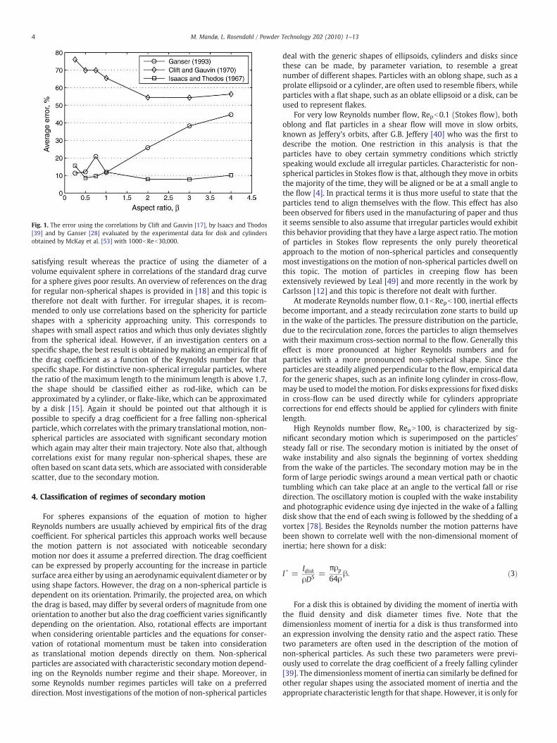
Fig. 1. The error using the correlations by Clift and Gauvin [17], by Isaacs and Thodos[39] and by Ganser [28] evaluated by the experimental data for disk and cylindersobtained by McKay et al. [53] with 1000bReb30,000.
4 M. Mandø, L. Rosendahl / Powder Technology 202 (2010) 1–13
satisfying result whereas the practice of using the diameter of avolume equivalent sphere in correlations of the standard drag curvefor a sphere gives poor results. An overview of references on the dragfor regular non-spherical shapes is provided in [18] and this topic istherefore not dealt with further. For irregular shapes, it is recom-mended to only use correlations based on the sphericity for particleshapes with a sphericity approaching unity. This corresponds toshapes with small aspect ratios and which thus only deviates slightlyfrom the spherical ideal. However, if an investigation centers on aspecific shape, the best result is obtained by making an empirical fit ofthe drag coefficient as a function of the Reynolds number for thatspecific shape. For distinctive non-spherical irregular particles, wherethe ratio of the maximum length to the minimum length is above 1.7,the shape should be classified either as rod-like, which can beapproximated by a cylinder, or flake-like, which can be approximatedby a disk [15]. Again it should be pointed out that although it ispossible to specify a drag coefficient for a free falling non-sphericalparticle, which correlates with the primary translational motion, non-spherical particles are associated with significant secondary motionwhich again may alter their main trajectory. Note also that, althoughcorrelations exist for many regular non-spherical shapes, these areoften based on scant data sets, which are associated with considerablescatter, due to the secondary motion.
4. Classification of regimes of secondary motion
For spheres expansions of the equation of motion to higherReynolds numbers are usually achieved by empirical fits of the dragcoefficient. For spherical particles this approach works well becausethe motion pattern is not associated with noticeable secondarymotion nor does it assume a preferred direction. The drag coefficientcan be expressed by properly accounting for the increase in particlesurface area either by using an aerodynamic equivalent diameter or byusing shape factors. However, the drag on a non-spherical particle isdependent on its orientation. Primarily, the projected area, on whichthe drag is based, may differ by several orders of magnitude from oneorientation to another but also the drag coefficient varies significantlydepending on the orientation. Also, rotational effects are importantwhen considering orientable particles and the equations for conser-vation of rotational momentum must be taken into considerationas translational motion depends directly on them. Non-sphericalparticles are associated with characteristic secondary motion depend-ing on the Reynolds number regime and their shape. Moreover, insome Reynolds number regimes particles will take on a preferreddirection. Most investigations of the motion of non-spherical particles
deal with the generic shapes of ellipsoids, cylinders and disks sincethese can be made, by parameter variation, to resemble a greatnumber of different shapes. Particles with an oblong shape, such as aprolate ellipsoid or a cylinder, are often used to resemble fibers, whileparticles with a flat shape, such as an oblate ellipsoid or a disk, can beused to represent flakes.
For very low Reynolds number flow, Repb0.1 (Stokes flow), bothoblong and flat particles in a shear flow will move in slow orbits,known as Jeffery's orbits, after G.B. Jeffery [40] who was the first todescribe the motion. One restriction in this analysis is that theparticles have to obey certain symmetry conditions which strictlyspeaking would exclude all irregular particles. Characteristic for non-spherical particles in Stokes flow is that, although they move in orbitsthe majority of the time, they will be aligned or be at a small angle tothe flow [4]. In practical terms it is thus more useful to state that theparticles tend to align themselves with the flow. This effect has alsobeen observed for fibers used in the manufacturing of paper and thusit seems sensible to also assume that irregular particles would exhibitthis behavior providing that they have a large aspect ratio. Themotionof particles in Stokes flow represents the only purely theoreticalapproach to the motion of non-spherical particles and consequentlymost investigations on the motion of non-spherical particles dwell onthis topic. The motion of particles in creeping flow has beenextensively reviewed by Leal [49] and more recently in the work byCarlsson [12] and this topic is therefore not dealt with further.
At moderate Reynolds number flow, 0.1bRepb100, inertial effectsbecome important, and a steady recirculation zone starts to build upin the wake of the particles. The pressure distribution on the particle,due to the recirculation zone, forces the particles to align themselveswith their maximum cross-section normal to the flow. Generally thiseffect is more pronounced at higher Reynolds numbers and forparticles with a more pronounced non-spherical shape. Since theparticles are steadily aligned perpendicular to the flow, empirical datafor the generic shapes, such as an infinite long cylinder in cross-flow,may be used tomodel themotion. For disks expressions for fixed disksin cross-flow can be used directly while for cylinders appropriatecorrections for end effects should be applied for cylinders with finitelength.
High Reynolds number flow, RepN100, is characterized by sig-nificant secondary motion which is superimposed on the particles'steady fall or rise. The secondary motion is initiated by the onset ofwake instability and also signals the beginning of vortex sheddingfrom the wake of the particles. The secondary motion may be in theform of large periodic swings around a mean vertical path or chaotictumbling which can take place at an angle to the vertical fall or risedirection. The oscillatory motion is coupled with the wake instabilityand photographic evidence using dye injected in the wake of a fallingdisk show that the end of each swing is followed by the shedding of avortex [78]. Besides the Reynolds number the motion patterns havebeen shown to correlate well with the non-dimensional moment ofinertia; here shown for a disk:
I � =IdiskρD5 =
πρp
64ρβ: ð3Þ
For a disk this is obtained by dividing the moment of inertia withthe fluid density and disk diameter times five. Note that thedimensionless moment of inertia for a disk is thus transformed intoan expression involving the density ratio and the aspect ratio. Thesetwo parameters are often used in the description of the motion ofnon-spherical particles. As such these two parameters were previ-ously used to correlate the drag coefficient of a freely falling cylinder[39]. The dimensionless moment of inertia can similarly be defined forother regular shapes using the associated moment of inertia and theappropriate characteristic length for that shape. However, it is only for
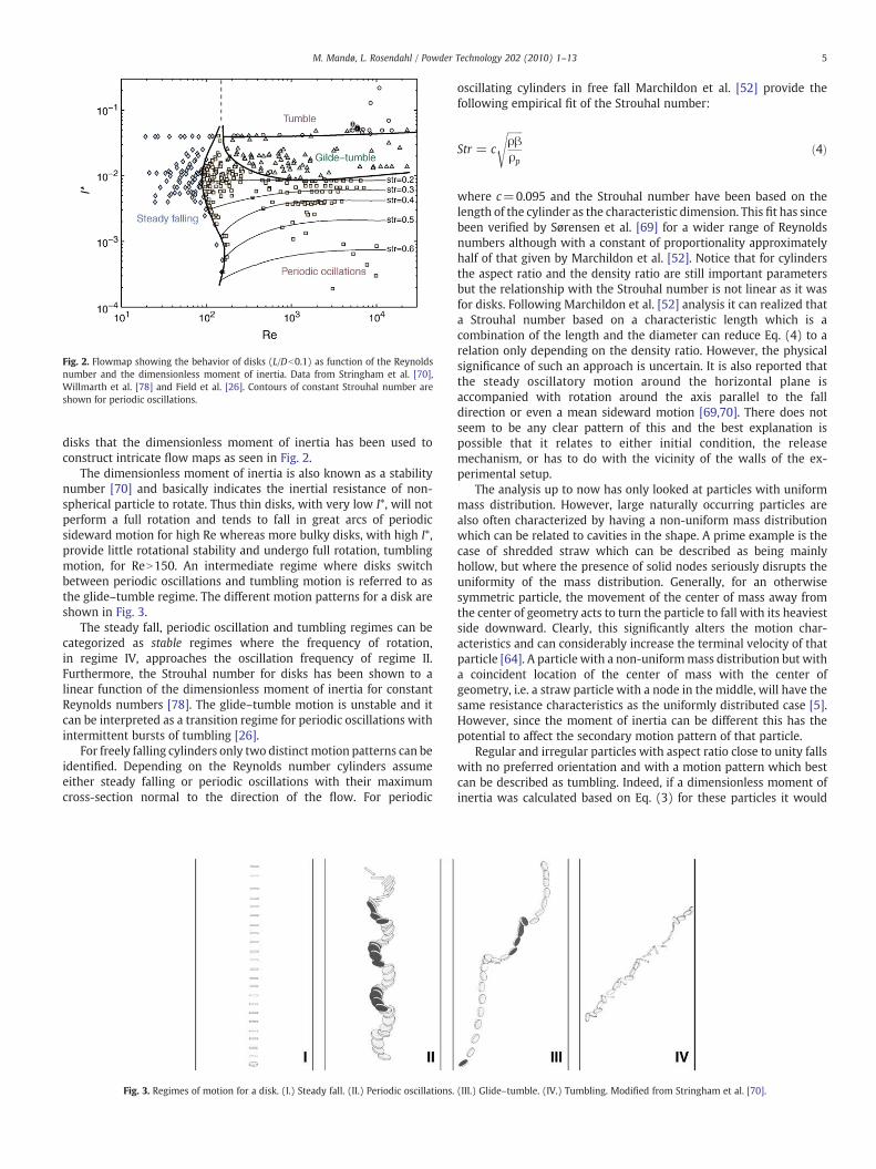
Fig. 2. Flowmap showing the behavior of disks (L/Db0.1) as function of the Reynoldsnumber and the dimensionless moment of inertia. Data from Stringham et al. [70],Willmarth et al. [78] and Field et al. [26]. Contours of constant Strouhal number areshown for periodic oscillations.
5M. Mandø, L. Rosendahl / Powder Technology 202 (2010) 1–13
disks that the dimensionless moment of inertia has been used toconstruct intricate flow maps as seen in Fig. 2.
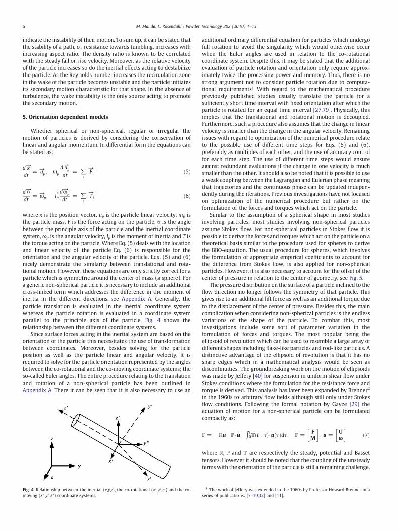
The dimensionless moment of inertia is also known as a stabilitynumber [70] and basically indicates the inertial resistance of non-spherical particle to rotate. Thus thin disks, with very low I*, will notperform a full rotation and tends to fall in great arcs of periodicsideward motion for high Re whereas more bulky disks, with high I*,provide little rotational stability and undergo full rotation, tumblingmotion, for ReN150. An intermediate regime where disks switchbetween periodic oscillations and tumbling motion is referred to asthe glide–tumble regime. The different motion patterns for a disk areshown in Fig. 3.
The steady fall, periodic oscillation and tumbling regimes can becategorized as stable regimes where the frequency of rotation,in regime IV, approaches the oscillation frequency of regime II.Furthermore, the Strouhal number for disks has been shown to alinear function of the dimensionless moment of inertia for constantReynolds numbers [78]. The glide–tumble motion is unstable and itcan be interpreted as a transition regime for periodic oscillations withintermittent bursts of tumbling [26].
For freely falling cylinders only two distinctmotion patterns can beidentified. Depending on the Reynolds number cylinders assumeeither steady falling or periodic oscillations with their maximumcross-section normal to the direction of the flow. For periodic
Fig. 3. Regimes of motion for a disk. (I.) Steady fall. (II.) Periodic oscillations.
oscillating cylinders in free fall Marchildon et al. [52] provide thefollowing empirical fit of the Strouhal number:
Str = c
ffiffiffiffiffiffiρβρp
sð4Þ
where c=0.095 and the Strouhal number have been based on thelength of the cylinder as the characteristic dimension. This fit has sincebeen verified by Sørensen et al. [69] for a wider range of Reynoldsnumbers although with a constant of proportionality approximatelyhalf of that given by Marchildon et al. [52]. Notice that for cylindersthe aspect ratio and the density ratio are still important parametersbut the relationship with the Strouhal number is not linear as it wasfor disks. Following Marchildon et al. [52] analysis it can realized thata Strouhal number based on a characteristic length which is acombination of the length and the diameter can reduce Eq. (4) to arelation only depending on the density ratio. However, the physicalsignificance of such an approach is uncertain. It is also reported thatthe steady oscillatory motion around the horizontal plane isaccompanied with rotation around the axis parallel to the falldirection or even a mean sideward motion [69,70]. There does notseem to be any clear pattern of this and the best explanation ispossible that it relates to either initial condition, the releasemechanism, or has to do with the vicinity of the walls of the ex-perimental setup.
The analysis up to now has only looked at particles with uniformmass distribution. However, large naturally occurring particles arealso often characterized by having a non-uniform mass distributionwhich can be related to cavities in the shape. A prime example is thecase of shredded straw which can be described as being mainlyhollow, but where the presence of solid nodes seriously disrupts theuniformity of the mass distribution. Generally, for an otherwisesymmetric particle, the movement of the center of mass away fromthe center of geometry acts to turn the particle to fall with its heaviestside downward. Clearly, this significantly alters the motion char-acteristics and can considerably increase the terminal velocity of thatparticle [64]. A particle with a non-uniformmass distribution but witha coincident location of the center of mass with the center ofgeometry, i.e. a straw particle with a node in the middle, will have thesame resistance characteristics as the uniformly distributed case [5].However, since the moment of inertia can be different this has thepotential to affect the secondary motion pattern of that particle.
Regular and irregular particles with aspect ratio close to unity fallswith no preferred orientation and with a motion pattern which bestcan be described as tumbling. Indeed, if a dimensionless moment ofinertia was calculated based on Eq. (3) for these particles it would
(III.) Glide–tumble. (IV.) Tumbling. Modified from Stringham et al. [70].
6 M. Mandø, L. Rosendahl / Powder Technology 202 (2010) 1–13
indicate the instability of their motion. To sum up, it can be stated thatthe stability of a path, or resistance towards tumbling, increases withincreasing aspect ratio. The density ratio is known to be correlatedwith the steady fall or rise velocity. Moreover, as the relative velocityof the particle increases so do the inertial effects acting to destabilizethe particle. As the Reynolds number increases the recirculation zonein the wake of the particle becomes unstable and the particle initiatesits secondary motion characteristic for that shape. In the absence ofturbulence, the wake instability is the only source acting to promotethe secondary motion.
5. Orientation dependent models
Whether spherical or non-spherical, regular or irregular themotion of particles is derived by considering the conservation oflinear and angular momentum. In differential form the equations canbe stated as:
d→xdt
= →up; mpd→up
dt= ∑
i
→Fi ð5Þ
d→θdt
= →ωp;→Ip
d→ωp
dt= ∑
i
→Ti ð6Þ
where x is the position vector, up is the particle linear velocity, mp isthe particle mass, F is the force acting on the particle, θ is the anglebetween the principle axis of the particle and the inertial coordinatesystem, ωp is the angular velocity, Ip is the moment of inertia and T isthe torque acting on the particle.Where Eq. (5) deals with the locationand linear velocity of the particle Eq. (6) is responsible for theorientation and the angular velocity of the particle. Eqs. (5) and (6)nicely demonstrate the similarity between translational and rota-tional motion. However, these equations are only strictly correct for aparticle which is symmetric around the center of mass (a sphere). Fora generic non-spherical particle it is necessary to include an additionalcross-linked term which addresses the difference in the moment ofinertia in the different directions, see Appendix A. Generally, theparticle translation is evaluated in the inertial coordinate systemwhereas the particle rotation is evaluated in a coordinate systemparallel to the principle axis of the particle. Fig. 4 shows therelationship between the different coordinate systems.
Since surface forces acting in the inertial system are based on theorientation of the particle this necessitates the use of transformationbetween coordinates. Moreover, besides solving for the particleposition as well as the particle linear and angular velocity, it isrequired to solve for the particle orientation represented by the anglesbetween the co-rotational and the co-moving coordinate systems; theso-called Euler angles. The entire procedure relating to the translationand rotation of a non-spherical particle has been outlined inAppendix A. There it can be seen that it is also necessary to use an
Fig. 4. Relationship between the inertial (x,y,z), the co-rotational (x′,y′,z′) and the co-moving (x″,y″,z″) coordinate systems.
additional ordinary differential equation for particles which undergofull rotation to avoid the singularity which would otherwise occurwhen the Euler angles are used in relation to the co-rotationalcoordinate system. Despite this, it may be stated that the additionalevaluation of particle rotation and orientation only require approx-imately twice the processing power and memory. Thus, there is nostrong argument not to consider particle rotation due to computa-tional requirements! With regard to the mathematical procedurepreviously published studies usually translate the particle for asufficiently short time interval with fixed orientation after which theparticle is rotated for an equal time interval [27,79]. Physically, thisimplies that the translational and rotational motion is decoupled.Furthermore, such a procedure also assumes that the change in linearvelocity is smaller than the change in the angular velocity. Remainingissues with regard to optimization of the numerical procedure relateto the possible use of different time steps for Eqs. (5) and (6),preferably as multiples of each other, and the use of accuracy controlfor each time step. The use of different time steps would ensureagainst redundant evaluations if the change in one velocity is muchsmaller than the other. It should also be noted that it is possible to usea weak coupling between the Lagrangian and Eulerian phase meaningthat trajectories and the continuous phase can be updated indepen-dently during the iterations. Previous investigations have not focusedon optimization of the numerical procedure but rather on theformulation of the forces and torques which act on the particle.
Similar to the assumption of a spherical shape in most studiesinvolving particles, most studies involving non-spherical particlesassume Stokes flow. For non-spherical particles in Stokes flow it ispossible to derive the forces and torques which act on the particle on atheoretical basis similar to the procedure used for spheres to derivethe BBO-equation. The usual procedure for spheres, which involvesthe formulation of appropriate empirical coefficients to account forthe difference from Stokes flow, is also applied for non-sphericalparticles. However, it is also necessary to account for the offset of thecenter of pressure in relation to the center of geometry, see Fig. 5.
The pressure distribution on the surface of a particle inclined to theflow direction no longer follows the symmetry of that particle. Thisgives rise to an additional lift force as well as an additional torque dueto the displacement of the center of pressure. Besides this, the maincomplication when considering non-spherical particles is the endlessvariations of the shape of the particle. To combat this, mostinvestigations include some sort of parameter variation in theformulation of forces and torques. The most popular being theellipsoid of revolution which can be used to resemble a large array ofdifferent shapes including flake-like particles and rod-like particles. Adistinctive advantage of the ellipsoid of revolution is that it has nosharp edges which in a mathematical analysis would be seen asdiscontinuities. The groundbreaking work on the motion of ellipsoidswas made by Jeffery [40] for suspension in uniform shear flow underStokes conditions where the formulation for the resistance force andtorque is derived. This analysis has later been expanded by Brenner2
in the 1960s to arbitrary flow fields although still only under Stokesflow conditions. Following the formal notation by Gavze [29] theequation of motion for a non-spherical particle can be formulatedcompactly as:
F = −ℝu−ℙ⋅u̇−∫t0T t−τð Þ⋅u̇ τð Þdτ; F = F
M
� �; u = U
ω
� �ð7Þ
where R, P and T are respectively the steady, potential and Bassettensors. However it should be noted that the coupling of the unsteadytermswith the orientation of the particle is still a remaining challenge.
2 The work of Jeffery was extended in the 1960s by Professor Howard Brenner in aseries of publications: [7–10,32] and [11].
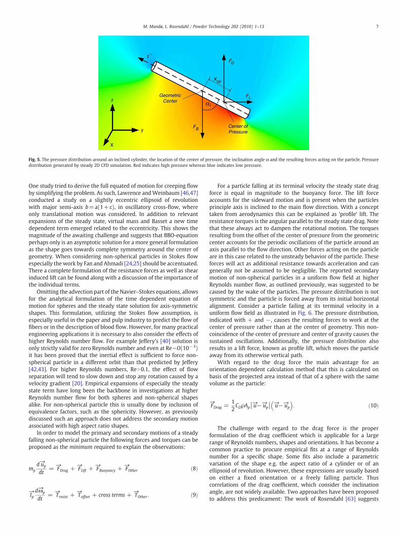
Fig. 5. The pressure distribution around an inclined cylinder, the location of the center of pressure, the inclination angle α and the resulting forces acting on the particle. Pressuredistribution generated by steady 2D CFD simulation. Red indicates high pressure whereas blue indicates low pressure.
7M. Mandø, L. Rosendahl / Powder Technology 202 (2010) 1–13
One study tried to derive the full equated of motion for creeping flowby simplifying the problem. As such, Lawrence andWeinbaum [46,47]conducted a study on a slightly eccentric ellipsoid of revolutionwith major semi-axis b=a(1+ε), in oscillatory cross-flow, whereonly translational motion was considered. In addition to relevantexpansions of the steady state, virtual mass and Basset a new timedependent term emerged related to the eccentricity. This shows themagnitude of the awaiting challenge and suggests that BBO-equationperhaps only is an asymptotic solution for a more general formulationas the shape goes towards complete symmetry around the center ofgeometry. When considering non-spherical particles in Stokes flowespecially the work by Fan and Ahmadi [24,25] should be accentuated.There a complete formulation of the resistance forces as well as shearinduced lift can be found along with a discussion of the importance ofthe individual terms.
Omitting the advection part of the Navier–Stokes equations, allowsfor the analytical formulation of the time dependent equation ofmotion for spheres and the steady state solution for axis-symmetricshapes. This formulation, utilizing the Stokes flow assumption, isespecially useful in the paper and pulp industry to predict the flow offibers or in the description of blood flow. However, for many practicalengineering applications it is necessary to also consider the effects ofhigher Reynolds number flow. For example Jeffery's [40] solution isonly strictly valid for zero Reynolds number and even at Re∼O(10−3)it has been proved that the inertial effect is sufficient to force non-spherical particle in a different orbit than that predicted by Jeffery[42,43]. For higher Reynolds numbers, ReN0.1, the effect of flowseparation will tend to slow down and stop any rotation caused by avelocity gradient [20]. Empirical expansions of especially the steadystate term have long been the backbone in investigations at higherReynolds number flow for both spheres and non-spherical shapesalike. For non-spherical particle this is usually done by inclusion ofequivalence factors, such as the sphericity. However, as previouslydiscussed such an approach does not address the secondary motionassociated with high aspect ratio shapes.
In order to model the primary and secondary motions of a steadyfalling non-spherical particle the following forces and torques can beproposed as the minimum required to explain the observations:
mpd→up
dt=
→FDrag +
→FLift +
→FBuoyancy +
→FOther ð8Þ
→Ipd→ωp
dt=
→Tresist +
→Toffset + cross terms +
→TOther: ð9Þ
For a particle falling at its terminal velocity the steady state dragforce is equal in magnitude to the buoyancy force. The lift forceaccounts for the sideward motion and is present when the particlesprinciple axis is inclined to the main flow direction. With a concepttaken from aerodynamics this can be explained as ‘profile’ lift. Theresistance torques is the angular parallel to the steady state drag. Notethat these always act to dampen the rotational motion. The torquesresulting from the offset of the center of pressure from the geometriccenter accounts for the periodic oscillations of the particle around anaxis parallel to the flow direction. Other forces acting on the particleare in this case related to the unsteady behavior of the particle. Theseforces will act as additional resistance towards acceleration and cangenerally not be assumed to be negligible. The reported secondarymotion of non-spherical particles in a uniform flow field at higherReynolds number flow, as outlined previously, was suggested to becaused by the wake of the particles. The pressure distribution is notsymmetric and the particle is forced away from its initial horizontalalignment. Consider a particle failing at its terminal velocity in auniform flow field as illustrated in Fig. 6. The pressure distribution,indicated with + and −, causes the resulting forces to work at thecenter of pressure rather than at the center of geometry. This non-coincidence of the center of pressure and center of gravity causes thesustained oscillations. Additionally, the pressure distribution alsoresults in a lift force, known as profile lift, which moves the particleaway from its otherwise vertical path.
With regard to the drag force the main advantage for anorientation dependent calculation method that this is calculated onbasis of the projected area instead of that of a sphere with the samevolume as the particle:
→FDrag =
12CDρApj→u−→upj →u−→up
� �: ð10Þ
The challenge with regard to the drag force is the properformulation of the drag coefficient which is applicable for a largerange of Reynolds numbers, shapes and orientations. It has become acommon practice to procure empirical fits at a range of Reynoldsnumber for a specific shape. Some fits also include a parametricvariation of the shape e.g. the aspect ratio of a cylinder or of anellipsoid of revolution. However, these expressions are usually basedon either a fixed orientation or a freely falling particle. Thuscorrelations of the drag coefficient, which consider the inclinationangle, are not widely available. Two approaches have been proposedto address this predicament: The work of Rosendahl [63] suggests

Fig. 6. Illustration of resultant forces and the pressure distribution of a particle at higherReynolds numbers (ReN100) in uniform flow. CP is the Center of Pressure and CG is theCenter of Gravity/Geometry. FB is the buoyancy force, FL is the lift force and FD is thedrag force.
Fig. 7. Evaluation of the different approaches to correlate the drag coefficient with theincidence angle.
8 M. Mandø, L. Rosendahl / Powder Technology 202 (2010) 1–13
using a ‘blending’ function between the drag coefficient for flownormal and parallel to the major axis of the particle:
CD αð Þ = CD;α=0 + CD;α=90−CD;α=0
� �sin3 α ð11Þ
where α is the angle between the major axis of the particle and theflow direction. Here the projected area at the evaluated orientation isused in the calculation of the drag force. Secondly, the work by Yinet al. [79] suggests using available drag correlations expressed by thesphericity and thus solely accounting for the dependence oforientation by using the projected area in the calculation of the dragforce. Recently, a third option has presented itself. Based on a plethoraof empirical data for fixed and freely falling particles Hölzer andSommerfeld [37] came upwith an expressionwhich uses a cross-wise,ψ⊥, and lengthwise sphericity, ψ||, to account for the drag coefficient ofdifferent shapes at different orientations:
CD =8Re
1ffiffiffiffiffiψ∥
p +16Re
1ffiffiffiffiψ
p +3Re
1ffiffiffiffiffiffiffiffiffiffiffiψ3=4
q + 0:42100:4 − logψð Þ0:2 1ψ⊥
ð12Þ
Here the cross-wise sphericity is the ratio between the cross-sectional area of the volume equivalent sphere and the projected areaof the actual particle. The lengthwise sphericity is the ratio betweenthe cross-sectional area of the volume equivalent sphere and thedifference between half of the surface area and the mean projected
area. The cross-wise sphericity should thus aid in the correlation ofthe form drag while the lengthwise sphericity is expressive of thefriction drag. Note that here the Reynolds number and the dragcoefficient are based on the volume equivalent sphere.
Fig. 7 shows the drag force for a cylinder at different orientations,normalized with the drag force at zero incidence angle, calculatedusing the three suggested methods and compared to the benchmark(lattice-Boltzmann simulations) by Hölzer and Sommerfeld [36].Overall, it may be noted that the drag force increases with increasingincidence angles due to the increase in projected area. However, thisalone is not sufficient to properly account for the observed results. Themethod by Rosendahl [63] provides a pragmatic way to calculate thedrag force at different incidence angles but also relies upon theavailability of experimental data. For regular shapes these cantypically be found for particles at 90° incidence angle whereasempirical fits for particle at zero incidence angle are not widelyavailable. In this regard it might be useful to refer to the studies byMilitzer et al. [54] which provide a parametric fit for spheroids as afunction of the Reynolds number and the aspect ratio as well as Isaacsand Thodos [39] which provides the same for disks and cylinders at90° incidence angle. For the present benchmark data it may be notedthat a ‘blending’ function using sin(α) instead of sin3(α) provides asuperior fit. Hölzer and Sommerfeld [37] constitute a good fit of thepresent benchmark data and attractively address all possible shapes atall Reynolds numbers in a single expression. However, this alsoindicates that for some specific shapes such a correlation, similar tothe one by Yin et al. [79], might be associated with a relatively largeerror compared to correlations developed for that specific shape.
The theoretical and empirical basis of predicting the profile liftrelies on much more scant information compared to that available fordrag. For symmetric particles the lift is zero at both α=0° and α=90°and it assumes a maximum somewhere in between dependent on theshape and Reynolds number. The usual assumption has been toassume that the lift is proportional to the drag and that thedependence with the orientation is given by the so-called ‘cross-flow principle’ with reference to Hoerner [35]:
CL
CD= sin2 α⋅ cosα: ð13Þ
This relationship was developed for infinite cylinders at Reynoldsnumber in the Newton law regime. Fig. 8 shows data for a spheroidwith small aspect ratio together with the cross-flow principle fromEq. (13).
It can be seen that the cross-flow principle provides a fair fit to thepresent data at Reynolds numbers in the Newton law regime whereasthe maximum lift/drag ratio diminishes as the Reynolds number

Table 4The different expressions used to correlate the location of the center of pressure.
Rayleigh [60] xcp = L = 3 = 4ð Þ sinαið Þ= 4 + π cosαið ÞMarchildon et al. [52] xcp = L = 90−αið Þ= 480Rosendahl [63] xcp = L = 0:25 1− sin3αi
� �Yin et al. [79] xcp = L = 0:25 cos3 αi
Fig. 8. Lift/drag ratio at different Reynolds numbers. Data by Hölzer and Sommerfeld[36] and Rosendahl [62].
9M. Mandø, L. Rosendahl / Powder Technology 202 (2010) 1–13
decreases. This is related to the relative importance of the friction andpressure drag at these intermediate Reynolds numbers. Here weprovide the following fit to the present data set (30bReb1500) tocorrelate the influence of the Reynolds number for the cross-flowprinciple:
CL
CD=
sin2α⋅ cosα0:65 + 40Re0:72
ð14Þ
This expression gives the correct asymptotic values for large andsmall Reynolds numbers but is based on a narrow data set withfollowing low accuracy. It should also be noted that data shown inFig. 8 is for a spheroid with relatively low aspect ratio. It seems as ifthe better the shape approximates an infinitely long cylinder, theclearer the resemblance with the cross-flow principle becomes. Oncethe lift coefficient is specified the lift force can be found using anexpression equivalent to Eq. (10).
In order to correctly predict the incidence angle, to estimate theforces and torques, it is of prime importance to locate the center ofpressure. As previously stated, a non-spherical particle tends to fallwith its largest cross-sectional area normal to the flow direction i.e.α=90°. Here the center of pressure is coincidental with the geometriccenter and the lift force and torque is zero. Hence this can be describedas the state of stable equilibrium of the particle. A non-sphericalparticle inclined to the flow direction with α=0° will also experienceno lift or torque but this can instinctively be perceived as an unstableequilibrium. At this extreme the center of pressure must therefore benon-coincidental with the geometric center to match observedbehavior. Using concepts from airfoil theory the center of pressureat this extreme inclination is placed at the “quarter chord point”which in this case is equivalent to half the distance from the geometriccenter to the end of the particle which is oriented towards the flow[63,79]. Please refer to Fig. 5 for visual illustration. Marchildon et al.[52] provide a linear approximation to the derivation3 by Rayleigh[60] for the pressure distribution on an infinite flat plate to predict thecenter of pressure of a cylinder. This is reported by Marchildon et al.[52] to be valid for inclinations above α=15° due to the uniformity ofthe pressure distribution above this angle. Both Rosendahl [63] andYin et al. [79] present expressions which close the gap with regard to
3 Derived by the application of discontinuous potential flow theory.
the location of the center of pressure between the two extremes(Table 4).
Fig. 9 shows an illustration of the different expressions and it canbe seen that there is some discrepancy in the prediction of the centerof pressure. More unfortunately, there seem not to be any guidelinestowards which expression is most appropriate to use. A freely fallingnon-spherical particle will spendmost of the time close to α=90° andeffort should thus be directed towards finding the best fit close to thispoint. Assuming that Rayleigh's derivation is valid for general non-spherical particles at intermediate Reynolds numbers it seemsattractive to use the simple linear fit by Marchildon et al. [52]. Oncethe lift and drag forces are found as well as the location of their pointof attack, i.e. the center of pressure, it is a small matter of calculatingthe resulting torque which is due to the offset from the geometriccenter, Toffset.
→Toffset = xcp
→FLift +
→FDrag +
→FOther
� �: ð15Þ
The torque due to resistance can be directly derived by integrationof the friction, caused by rotation, over the length of the particle. Forspheroids subject to the Stokes conditions solutions have been knownsince Jeffery [40] and have since been expanded to other shapes [19].Relevant expansions for higher Reynolds number can be found byincorporating appropriate fits for the drag coefficient in the definitionof the drag force before the integration is performed.
→Tresist = 2∫L = 2
0→Fresistdl = ∫L=2
0 CD;cylρ ωf−ωp
� �2l2Apdl: ð16Þ
This integral can be evaluated with increasing degrees ofsophistication. Note that if the particle aspect ratio is sufficientlylarge the angular velocity will tend to be low and an assumption ofcreeping flow may suffice. For the completeness of this investigation
Fig. 9. Location of the center of pressure for a cylinder with length L.
10 M. Mandø, L. Rosendahl / Powder Technology 202 (2010) 1–13
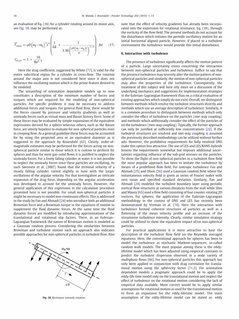
an evaluation of Eq. (16) for a cylinder rotating around its minor axis,see Fig. 10, may be performed as:
→Tresist = ρD ωf−ωp
� �2L4
164
+1
3:36ρD ωf−ωp
� �L
μ
!2=3
0BBBBB@
1CCCCCA for
CD;cyl = 1 +10
Re2=3:
ð17Þ
Here the drag coefficient, suggested by White [77], is valid for theentire subcritical region for a cylinder in cross-flow. The rotationaround the major axis is not considered here since it does notinfluence the oscillating motion which is the prime feature desired tobe modeled.
The unraveling of orientation dependent models up to nowconstitutes a description of the minimum number of forces andtorques which are required for the modeling of non-sphericalparticles. For specific problems it may be necessary to addressadditional forces and torques. For general fluid flow, these would bethe forces caused by pressure and velocity gradients as well asunsteady forces such as virtual mass and Basset history force. Some ofthese forces may be evaluated by simple expansions of the equivalentexpressions derived for a sphere whereas others, such as the Bassetforce, are utterly hopeless to evaluate for non-spherical particles evenin creeping flow. As a general guideline these forces may be accountedfor by using the projected area or an equivalent diameter as issuggested in the approach by Rosendahl [62]. Clearly, order-of-magnitude estimates may be performed for the forces acting on non-spherical particle similar to those which it is custom to perform forspheres and thus for most gas–solid flows it is justified to neglect theunsteady forces. For a freely falling cylinder in water it is not possibleto neglect the unsteady forces since these particles are oscillating. Assuch Sørensen et al. (2007) found that the terminal velocity of asteady falling cylinder varied slightly in tune with the largeroscillations of the angular velocity. For that investigation an intricateexpansion of the drag force, depending on the angular accelerationwas developed to account for the unsteady forces. However, thegeneral application of this expression in the calculation procedurepresented here is not possible. For small non-spherical particles itmight be necessary to model non-continuum effects. This is addressedin the study by Fan and Ahmadi [24] who introduce both an additionalBrownian force and a Brownian torque in the equations of motion tosupplement the fluid dynamic forces. At the same time the fluiddynamic forces are modified by introducing approximations of thetranslational and rotational slip factors. There, in an Eulerian–Lagrangian framework the nature of Brownian motion is modeled asa Gaussian random process. Considering the similarities betweenBrownian and turbulent motion such an approach also indicatespossible approaches for non-spherical particles in turbulent flow. Also
Fig. 10. Resistance towards rotation.
note that the effect of velocity gradients has already been incorpo-rated into the expression for rotational resistance, Eq. (16), throughthe vorticity of the flow field. The present methods do not account forthe disturbance which initiates the periodic oscillatory motion for aninitial horizontal aligned particle. However, if placed in a turbulentenvironment the turbulence would provide this initial disturbance.
6. Interaction with turbulence
The presence of turbulence significantly affects the motion patternof a particle. Large uncertainty exists concerning the interactionbetween non-spherical particles and turbulence. Suffice to say thatthe presence turbulencemay severely alter themotion pattern of non-spherical particles and similarly, the motion of non-spherical particlesmay alter the properties of the turbulence. Consequently, thetreatment of this subject will here rely more on a discussion of theunderlying mechanics and suggestions for implementation strategiesin the Eulerian–Lagrangian framework than on a critical evaluation ofexisting approacheswhich simply do not exist. Overall, we distinguishbetween methods which resolve the turbulent structures directly andmethods which use an average description of turbulence. Similarly, itis a common procedure to distinguish between methods which onlyconsider the effect of turbulence on the particles (one-way coupling)and methods which additionally consider the effect of the particles ofon the turbulence (two-way coupling). Typically, the former approachcan only be justified at sufficiently low concentrations [22]. If theturbulent structures are resolved and one-way coupling is assumedthe previously described methodology can be utilized without furtherado. However, the prohibitive requirements for fully resolved DNSmake this option less attractive. The use of LES and LES/RANS-hybridslessens the requirements somewhat but imposes additional uncer-tainties regarding influence of the sub-grid stresses on the particles.To show the flight of non-spherical particles in a turbulent flow fieldthe most popular approach has been to imitate the turbulence bymeans of a predefined flow field. For isotropic turbulence Fan andAhmadi [25] and Olson [56] used a Gaussian random field where theinstantaneous velocity field is given as series of Fourier nodes withzero mean and specified standard deviation. Similarly, Fan andAhmadi [24] modeled the turbulent boundary layer using periodicvortical flow structures at various distances from the wall while ShinandMaxey [65] used a flow field consisting of four counter rotating 2Dvortices. For spheres, the application of the Eulerian–Lagrangianmethodology in the context of DNS and LES has recently beendemonstrated by Vreman et al. [74]. Here the interaction withturbulence formed coherent structures of particles as well as aflattening of the mean velocity profile and an increase of thestreamwise turbulence intensity. Clearly, similar simulation strategycould be utilized to show the equivalent impact of/on non-sphericalparticles.
For practical applications it is more attractive to base thedescription of the turbulent flow field on the Reynolds averagedequations. Here, the conventional approach for spheres has been tomodel the turbulence as stochastic Markow-sequences; so-calledrandom walk models. The most popular among these is the eddy-lifetime model which has been adjusted using empirical constants topredict the turbulent dispersion observed in a wide variety ofmultiphase flows [66]. For non-spherical particles this approach hasonly been applied in conjunction with drag correlation for transla-tional motion using the sphericity factor [71,2]. For orientationdependent models a pragmatic approach could be to apply theeddy-life timemodel only on the translational motion and neglect theeffect of turbulence on the rotational motion considering the lack ofempirical data available. More correct would be to apply similarassumptions for rotational motion as used for the translational motionto form an expansion for the eddy-lifetime model. The mainassumption of the eddy-lifetime model can be stated as: eddy
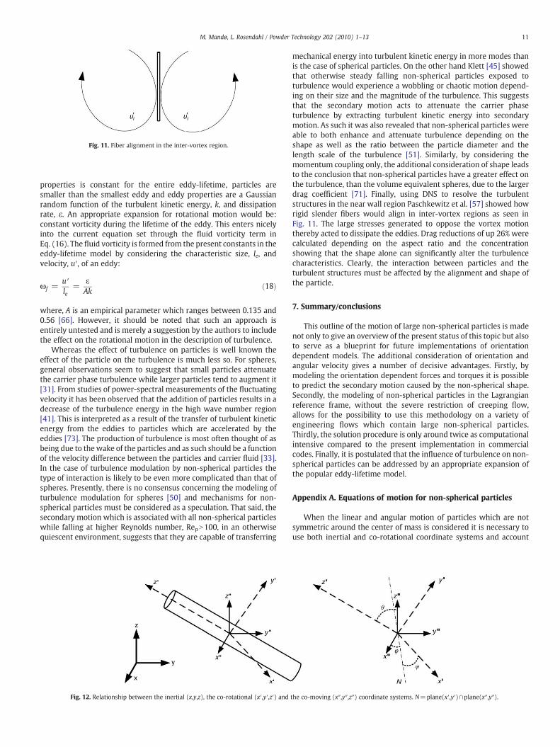
Fig. 11. Fiber alignment in the inter-vortex region.
11M. Mandø, L. Rosendahl / Powder Technology 202 (2010) 1–13
properties is constant for the entire eddy-lifetime, particles aresmaller than the smallest eddy and eddy properties are a Gaussianrandom function of the turbulent kinetic energy, k, and dissipationrate, ε. An appropriate expansion for rotational motion would be:constant vorticity during the lifetime of the eddy. This enters nicelyinto the current equation set through the fluid vorticity term inEq. (16). The fluid vorticity is formed from the present constants in theeddy-lifetime model by considering the characteristic size, le, andvelocity, u′, of an eddy:
ωf =u′le
=εAk
ð18Þ
where, A is an empirical parameter which ranges between 0.135 and0.56 [66]. However, it should be noted that such an approach isentirely untested and is merely a suggestion by the authors to includethe effect on the rotational motion in the description of turbulence.
Whereas the effect of turbulence on particles is well known theeffect of the particle on the turbulence is much less so. For spheres,general observations seem to suggest that small particles attenuatethe carrier phase turbulence while larger particles tend to augment it[31]. From studies of power-spectral measurements of the fluctuatingvelocity it has been observed that the addition of particles results in adecrease of the turbulence energy in the high wave number region[41]. This is interpreted as a result of the transfer of turbulent kineticenergy from the eddies to particles which are accelerated by theeddies [73]. The production of turbulence is most often thought of asbeing due to thewake of the particles and as such should be a functionof the velocity difference between the particles and carrier fluid [33].In the case of turbulence modulation by non-spherical particles thetype of interaction is likely to be even more complicated than that ofspheres. Presently, there is no consensus concerning the modeling ofturbulence modulation for spheres [50] and mechanisms for non-spherical particles must be considered as a speculation. That said, thesecondary motion which is associated with all non-spherical particleswhile falling at higher Reynolds number, RepN100, in an otherwisequiescent environment, suggests that they are capable of transferring
Fig. 12. Relationship between the inertial (x,y,z), the co-rotational (x′,y′,z′) and
mechanical energy into turbulent kinetic energy in more modes thanis the case of spherical particles. On the other hand Klett [45] showedthat otherwise steady falling non-spherical particles exposed toturbulence would experience a wobbling or chaotic motion depend-ing on their size and the magnitude of the turbulence. This suggeststhat the secondary motion acts to attenuate the carrier phaseturbulence by extracting turbulent kinetic energy into secondarymotion. As such it was also revealed that non-spherical particles wereable to both enhance and attenuate turbulence depending on theshape as well as the ratio between the particle diameter and thelength scale of the turbulence [51]. Similarly, by considering themomentum coupling only, the additional consideration of shape leadsto the conclusion that non-spherical particles have a greater effect onthe turbulence, than the volume equivalent spheres, due to the largerdrag coefficient [71]. Finally, using DNS to resolve the turbulentstructures in the near wall region Paschkewitz et al. [57] showed howrigid slender fibers would align in inter-vortex regions as seen inFig. 11. The large stresses generated to oppose the vortex motionthereby acted to dissipate the eddies. Drag reductions of up 26% werecalculated depending on the aspect ratio and the concentrationshowing that the shape alone can significantly alter the turbulencecharacteristics. Clearly, the interaction between particles and theturbulent structures must be affected by the alignment and shape ofthe particle.
7. Summary/conclusions
This outline of the motion of large non-spherical particles is madenot only to give an overview of the present status of this topic but alsoto serve as a blueprint for future implementations of orientationdependent models. The additional consideration of orientation andangular velocity gives a number of decisive advantages. Firstly, bymodeling the orientation dependent forces and torques it is possibleto predict the secondary motion caused by the non-spherical shape.Secondly, the modeling of non-spherical particles in the Lagrangianreference frame, without the severe restriction of creeping flow,allows for the possibility to use this methodology on a variety ofengineering flows which contain large non-spherical particles.Thirdly, the solution procedure is only around twice as computationalintensive compared to the present implementation in commercialcodes. Finally, it is postulated that the influence of turbulence on non-spherical particles can be addressed by an appropriate expansion ofthe popular eddy-lifetime model.
Appendix A. Equations of motion for non-spherical particles
When the linear and angular motion of particles which are notsymmetric around the center of mass is considered it is necessary touse both inertial and co-rotational coordinate systems and account
the co-moving (x″,y″,z″) coordinate systems. N=plane(x′,y′)∩plane(x″,y″).
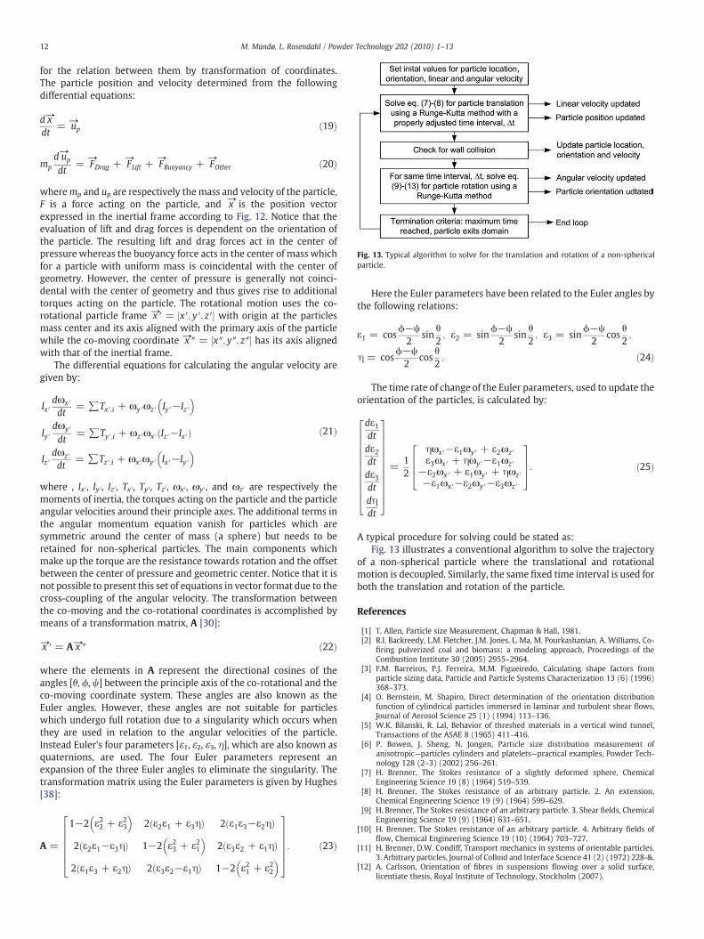
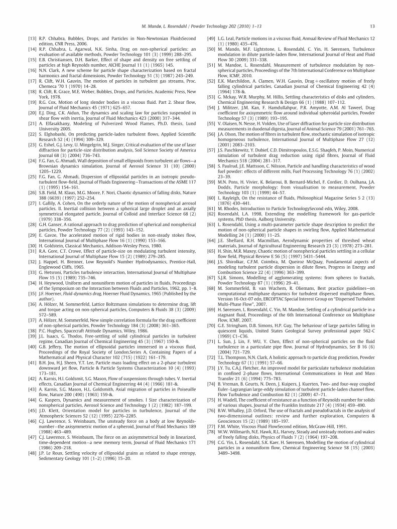
Fig. 13. Typical algorithm to solve for the translation and rotation of a non-sphericalparticle.
12 M. Mandø, L. Rosendahl / Powder Technology 202 (2010) 1–13
for the relation between them by transformation of coordinates.The particle position and velocity determined from the followingdifferential equations:
d→xdt
= →up ð19Þ
mpd→up
dt=
→FDrag +
→FLift +
→FBuoyancy +
→FOther ð20Þ
wheremp and up are respectively the mass and velocity of the particle,F is a force acting on the particle, and →x is the position vectorexpressed in the inertial frame according to Fig. 12. Notice that theevaluation of lift and drag forces is dependent on the orientation ofthe particle. The resulting lift and drag forces act in the center ofpressure whereas the buoyancy force acts in the center of mass whichfor a particle with uniform mass is coincidental with the center ofgeometry. However, the center of pressure is generally not coinci-dental with the center of geometry and thus gives rise to additionaltorques acting on the particle. The rotational motion uses the co-rotational particle frame →x ′ = x′; y′; z′½ � with origin at the particlesmass center and its axis aligned with the primary axis of the particlewhile the co-moving coordinate →x ″ = x″; y″; z″½ � has its axis alignedwith that of the inertial frame.
The differential equations for calculating the angular velocity aregiven by:
Ix′dωx′
dt= ∑Tx′;i + ωy′ωz ′ Iy′−Iz ′
� �
Iy′dωy′
dt= ∑Ty′;i + ωz ′ωx′ Iz ′−Ix′ð Þ
Iz ′dωz ′
dt= ∑Tz′;i + ωx′ωy′ Ix′−Iy′
� �ð21Þ
where , Ix′, Iy′, Iz′, Tx′, Ty′, Tz′, ωx′, ωy′, and ωz′ are respectively themoments of inertia, the torques acting on the particle and the particleangular velocities around their principle axes. The additional terms inthe angular momentum equation vanish for particles which aresymmetric around the center of mass (a sphere) but needs to beretained for non-spherical particles. The main components whichmake up the torque are the resistance towards rotation and the offsetbetween the center of pressure and geometric center. Notice that it isnot possible to present this set of equations in vector format due to thecross-coupling of the angular velocity. The transformation betweenthe co-moving and the co-rotational coordinates is accomplished bymeans of a transformation matrix, A [30]:
→x ′ = A→x ″ ð22Þ
where the elements in A represent the directional cosines of theangles [θ, ϕ, ψ] between the principle axis of the co-rotational and theco-moving coordinate system. These angles are also known as theEuler angles. However, these angles are not suitable for particleswhich undergo full rotation due to a singularity which occurs whenthey are used in relation to the angular velocities of the particle.Instead Euler's four parameters [ε1, ε2, ε3, η], which are also known asquaternions, are used. The four Euler parameters represent anexpansion of the three Euler angles to eliminate the singularity. Thetransformation matrix using the Euler parameters is given by Hughes[38]:
A =
1−2 ε22 + ε23� �
2 ε2ε1 + ε3ηð Þ 2 ε1ε3−ε2ηð Þ
2 ε2ε1−ε3ηð Þ 1−2 ε23 + ε21� �
2 ε3ε2 + ε1ηð Þ
2 ε1ε3 + ε2ηð Þ 2 ε3ε2−ε1ηð Þ 1−2 ε21 + ε22� �
2666664
3777775: ð23Þ
Here the Euler parameters have been related to the Euler angles bythe following relations:
ε1 = cosϕ−ψ2
sinθ2; ε2 = sin
ϕ−ψ2
sinθ2; ε3 = sin
ϕ−ψ2
cosθ2;
η = cosϕ−ψ2
cosθ2: ð24Þ
The time rate of change of the Euler parameters, used to update theorientation of the particles, is calculated by:
dε1dtdε2dtdε3dtdηdt
2666666666664
3777777777775=
12
ηωx′−ε1ωy′ + ε2ωz′ε3ωx′ + ηωy′−ε1ωz′
−ε2ωx′ + ε1ωy′ + ηωz ′−ε1ωx′−ε2ωy′−ε3ωz ′
2664
3775: ð25Þ
A typical procedure for solving could be stated as:Fig. 13 illustrates a conventional algorithm to solve the trajectory
of a non-spherical particle where the translational and rotationalmotion is decoupled. Similarly, the same fixed time interval is used forboth the translation and rotation of the particle.
References
[1] T. Allen, Particle size Measurement, Chapman & Hall, 1981.[2] R.I. Backreedy, L.M. Fletcher, J.M. Jones, L. Ma, M. Pourkashanian, A. Williams, Co-
firing pulverized coal and biomass: a modeling approach, Proceedings of theCombustion Institute 30 (2005) 2955–2964.
[3] F.M. Barreiros, P.J. Ferreira, M.M. Figueiredo, Calculating shape factors fromparticle sizing data, Particle and Particle Systems Characterization 13 (6) (1996)368–373.
[4] O. Bernstein, M. Shapiro, Direct determination of the orientation distributionfunction of cylindrical particles immersed in laminar and turbulent shear flows,Journal of Aerosol Science 25 (1) (1994) 113–136.
[5] W.K. Bilanski, R. Lal, Behavior of threshed materials in a vertical wind tunnel,Transactions of the ASAE 8 (1965) 411–416.
[6] P. Bowen, J. Sheng, N. Jongen, Particle size distribution measurement ofanisotropic—particles cylinders and platelets—practical examples, Powder Tech-nology 128 (2–3) (2002) 256–261.
[7] H. Brenner, The Stokes resistance of a slightly deformed sphere, ChemicalEngineering Science 19 (8) (1964) 519–539.
[8] H. Brenner, The Stokes resistance of an arbitrary particle. 2. An extension,Chemical Engineering Science 19 (9) (1964) 599–629.
[9] H. Brenner, The Stokes resistance of an arbitrary particle. 3. Shear fields, ChemicalEngineering Science 19 (9) (1964) 631–651.
[10] H. Brenner, The Stokes resistance of an arbitrary particle. 4. Arbitrary fields offlow, Chemical Engineering Science 19 (10) (1964) 703–727.
[11] H. Brenner, D.W. Condiff, Transport mechanics in systems of orientable particles.3. Arbitrary particles, Journal of Colloid and Interface Science 41 (2) (1972) 228-&.
[12] A. Carlsson, Orientation of fibres in suspensions flowing over a solid surface,licentiate thesis, Royal Institute of Technology, Stockholm (2007).
13M. Mandø, L. Rosendahl / Powder Technology 202 (2010) 1–13
[13] R.P. Chhabra, Bubbles, Drops, and Particles in Non-Newtonian FluidsSecondedition, CNR Press, 2006.
[14] R.P. Chhabra, L. Agarwal, N.K. Sinha, Drag on non-spherical particles: anevaluation of available methods, Powder Technology 101 (3) (1999) 288–295.
[15] E.B. Christiansen, D.H. Barker, Effect of shape and density on free settling ofparticles at high Reynolds number, AICHE Journal 11 (1) (1965) 145.
[16] N.N. Clark, A new scheme for particle shape characterization based on fractalharmonics and fractal dimensions, Powder Technology 51 (3) (1987) 243–249.
[17] R. Clift, W.H. Gauvin, The motion of particles in turbulent gas streams, Proc.Chemeca '70 1 (1970) 14–28.
[18] R. Clift, R. Grace, M.E. Weber, Bubbles, Drops, and Particles, Academic Press, NewYork, 1978.
[19] R.G. Cox, Motion of long slender bodies in a viscous fluid. Part 2. Shear flow,Journal of Fluid Mechanics 45 (1971) 625–657.
[20] E.J. Ding, C.K. Aidun, The dynamics and scaling law for particles suspended inshear flow with inertia, Journal of Fluid Mechanics 423 (2000) 317–344.
[21] A. Elfasakhany, Modeling of Pulverized Wood Flames, Ph.D. thesis, LundUniversity 2005.
[22] S. Elghobashi, On predicting particle-laden turbulent flows, Applied ScientificResearch 52 (4) (1994) 309–329.
[23] G. Eshel, G.J. Levy, U. Mingelgrin, M.J. Singer, Critical evaluation of the use of laserdiffraction for particle-size distribution analysis, Soil Science Society of AmericaJournal 68 (3) (2004) 736–743.
[24] F.G. Fan, G. Ahmadi, Wall deposition of small ellipsoids from turbulent air flows—aBrownian dynamics simulation, Journal of Aerosol Science 31 (10) (2000)1205–1229.
[25] F.G. Fan, G. Ahmadi, Dispersion of ellipsoidal particles in an isotropic pseudo-turbulent flow-field, Journal of Fluids Engineering—Transactions of the ASME 117(1) (1995) 154–161.
[26] S.B. Field, M. Klaus, M.G. Moore, F. Nori, Chaotic dynamics of falling disks, Nature388 (6639) (1997) 252–254.
[27] I. Gallily, A. Cohen, On the orderly nature of the motion of nonspherical aerosolparticles. II. Inertial collision between a spherical large droplet and an axiallysymmetrical elongated particle, Journal of Colloid and Interface Science 68 (2)(1979) 338–356.
[28] G.H. Ganser, A rational approach to drag prediction of spherical and nonsphericalparticles, Powder Technology 77 (2) (1993) 143–152.
[29] E. Gavze, The accelerated motion of rigid bodies in non-steady stokes flow,International Journal of Multiphase Flow 16 (1) (1990) 153–166.
[30] H. Goldstein, Classical Mechanics, Addison-Wesley Press, 1980.[31] R.A. Gore, C.T. Crowe, Effect of particle-size on modulating turbulent intensity,
International Journal of Multiphase Flow 15 (2) (1989) 279–285.[32] J. Happel, H. Brenner, Low Reynold's Number Hydrodynamics, Prentice-Hall,
Englewood Cliffs, 1965.[33] G. Hetsroni, Particles turbulence interaction, International Journal of Multiphase
Flow 15 (5) (1989) 735–746.[34] H. Heywood, Uniform and nonuniform motion of particles in fluids, Proceedings
of the Symposium on the Interaction between Fluids and Particles, 1962, pp. 1–8.[35] J.F. Hoerner, Fluid-dynamics drag,Hoerner Fluid Dynamics, 1965 (Published by the
author).[36] A. Hölzer, M. Sommerfeld, Lattice Boltzmann simulations to determine drag, lift
and torque acting on non-spherical particles, Computers & Fluids 38 (3) (2009)572–589.
[37] A. Hölzer, M. Sommerfeld, New simple correlation formula for the drag coefficientof non-spherical particles, Powder Technology 184 (3) (2008) 361–365.
[38] P.C. Hughes, Spacecraft Attitude Dynamics, Wiley, 1986.[39] J.L. Isaacs, G. Thodos, Free-settling of solid cylindrical particles in turbulent
regime, Canadian Journal of Chemical Engineering 45 (3) (1967) 150-&.[40] G.B. Jeffery, The motion of ellipsoidal particles immersed in a viscous fluid,
Proceedings of the Royal Society of London.Series A, Containing Papers of aMathematical and Physical Character 102 (715) (1922) 161–179.
[41] B.H. Jou, H.J. Sheen, Y.T. Lee, Particle mass loading effect on a 2-phase turbulentdownward jet flow, Particle & Particle Systems Characterization 10 (4) (1993)173–181.
[42] A. Karnis, H.l. Goldsmit, S.G. Mason, Flow of suspensions through tubes. V. Inertialeffects, Canadian Journal of Chemical Engineering 44 (4) (1966) 181-&.
[43] A. Karnis, S.G. Mason, H.L. Goldsmith, Axial migration of particles in Poiseuilleflow, Nature 200 (490) (1963) 159-&.
[44] G. Kaspers, Dynamics and measurement of smokes. I Size characterization ofnonspherical particles, Aerosol Science and Technology 1 (2) (1982) 187–199.
[45] J.D. Klett, Orientation model for particles in turbulence, Journal of theAtmospheric Sciences 52 (12) (1995) 2276–2285.
[46] C.J. Lawrence, S. Weinbaum, The unsteady force on a body at low Reynolds-number—the axisymmetric motion of a spheroid, Journal of Fluid Mechanics 189(1988) 463–489.
[47] C.J. Lawrence, S. Weinbaum, The force on an axisymmetrical body in linearized,time-dependent motion—a new memory term, Journal of Fluid Mechanics 171(1986) 209–218.
[48] J.P. Le Roux, Settling velocity of ellipsoidal grains as related to shape entropy,Sedimentary Geology 101 (1–2) (1996) 15–20.
[49] L.G. Leal, Particle motions in a viscous fluid, Annual Review of Fluid Mechanics 12(1) (1980) 435–476.
[50] M. Mando, M.F. Lightstone, L. Rosendahl, C. Yin, H. Sørensen, Turbulencemodulation in dilute particle-laden flow, International Journal of Heat and FluidFlow 30 (2009) 331–338.
[51] M. Mandoe, L. Rosendahl, Measurement of turbulence modulation by non-spherical particles, Proceedings of the 7th International Conference onMultiphaseFlow, ICMF, 2010.
[52] E.K. Marchildon, A. Clamen, W.H. Gauvin, Drag+oscillatory motion of freelyfalling cylindrical particles, Canadian Journal of Chemical Engineering 42 (4)(1964) 178-&.
[53] G. Mckay, W.R. Murphy, M. Hillis, Settling characteristics of disks and cylinders,Chemical Engineering Research & Design 66 (1) (1988) 107–112.
[54] J. Militzer, J.M. Kan, F. Hamdullahpur, P.R. Amyotte, A.M. Al Taweel, Dragcoefficient for axisymmetric flow around individual spheroidal particles, PowderTechnology 57 (3) (1989) 193–195.
[55] V. Olaisen, N. Nesse, H. Volden, Use of laser diffraction for particle size distributionmeasurements in duodenal digesta, Journal of Animal Science 79 (2001) 761–765.
[56] J.A. Olson, Themotion of fibres in turbulent flow, stochastic simulation of isotropichomogeneous turbulence, International Journal of Multiphase Flow 27 (12)(2001) 2083–2103.
[57] J.S. Paschkewitz, Y. Dubief, C.D. Dimitropoulos, E.S.G. Shaqfeh, P. Moin, Numericalsimulation of turbulent drag reduction using rigid fibres, Journal of FluidMechanics 518 (2004) 281–317.
[58] S. Paulrud, J.E. Mattsson, C. Nilsson, Particle and handling characteristics of woodfuel powder: effects of different mills, Fuel Processing Technology 76 (1) (2002)23–39.
[59] M.N. Pons, H. Vivier, K. Belaroui, B. Bernard-Michel, F. Cordier, D. Oulhana, J.A.Dodds, Particle morphology: from visualisation to measurement, PowderTechnology 103 (1) (1999) 44–57.
[60] L. Rayleigh, On the resistance of fluids, Philosophical Magazine Series 5 2 (13)(1876) 430–441.
[61] M. Rhodes, Introduction to Particle TechnologySecond edn, Wiley, 2008.[62] Rosendahl, L.A. 1998, Extending the modelling framework for gas-particle
systems, PhD thesis, Aalborg University.[63] L. Rosendahl, Using a multi-parameter particle shape description to predict the
motion of non-spherical particle shapes in swirling flow, Applied MathematicalModelling 24 (1) (2000) 11–25.
[64] J.E. Shellard, R.H. Macmillan, Aerodynamic properties of threshed wheatmaterials, Journal of Agricultural Engineering Research 23 (3) (1978) 273–281.
[65] H. Shin, M.R. Maxey, Chaotic motion of nonspherical particles settling in a cellularflow field, Physical Review E 56 (5) (1997) 5431–5444.
[66] J.S. Shirolkar, C.F.M. Coimbra, M. Queiroz McQuay, Fundamental aspects ofmodeling turbulent particle dispersion in dilute flows, Progress in Energy andCombustion Science 22 (4) (1996) 363–399.
[67] S.J.R. Simons, Modelling of agglomerating systems: from spheres to fractals,Powder Technology 87 (1) (1996) 29–41.
[68] M. Sommerfeld, B. van Wachem, R. Oliemans, Best practice guidelines—oncomputational multiphase dynamics for turbulent dispersed multiphase flows,Version 16-Oct-07 edn, ERCOFTAC Special Interest Group on “Dispersed TurbulentMulti-Phase Flow”, 2007.
[69] H. Sørensen, L. Rosendahl, C. Yin, M. Mandoe, Settling of a cylindrical particle in astagnant fluid, Proceedings of the 6th International Conference on MultiphaseFlow, ICMF, 2007.
[70] G.E. Stringham, D.B. Simons, H.P. Guy, The behaviour of large particles falling inquiescent liquids, United States Geological Survey professional paper 562-C(1969) C1–C36.
[71] L. Sun, J. Lin, F. WU, Y. Chen, Effect of non-spherical particles on the fluidturbulence in a particulate pipe flow, Journal of Hydrodynamics, Ser B 16 (6)(2004) 721–729.
[72] T.L. Thompson, N.N. Clark, A holistic approach to particle drag prediction, PowderTechnology 67 (1) (1991) 57–66.
[73] J.Y. Tu, C.A.J. Fletcher, An improved model for particulate turbulence modulationin confined 2-phase flows, International Communications in Heat and MassTransfer 21 (6) (1994) 775–783.
[74] B. Vreman, B. Geurts, N. Deen, J. Kuipers, J. Kuerten, Two- and four-way coupledEuler–Lagrangian large-eddy simulation of turbulent particle-laden channel flow,Flow Turbulence and Combustion 82 (1) (2009) 47–71.
[75] H.Wadell, The coefficient of resistance as a function of Reynolds number for solidsof various shapes, Journal of the Franklin Institute 217 (4) (1934) 459–490.
[76] B.W. Whalley, J.D. Orford, The use of fractals and pseudofractals in the analysis oftwo-dimensional outlines: review and further exploration, Computers &Geosciences 15 (2) (1989) 185–197.
[77] F.M. White, Viscous Fluid FlowSecond edition, McGraw-Hill, 1991.[78] W.W.Willmarth, N.E. Hawk, R.L. Harvey, Steady and unsteady motions and wakes
of freely falling disks, Physics of Fluids 7 (2) (1964) 197–208.[79] C.G. Yin, L. Rosendahl, S.K. Kaer, H. Sørensen, Modelling the motion of cylindrical
particles in a nonuniform flow, Chemical Engineering Science 58 (15) (2003)3489–3498.