OMNIA HYBRID C - FERROLI
116
OMNIA HYBRID C REVERSIBLE HYBRID AIR-WATER HEAT PUMPS FOR SPLIT INSTALLATION WITH INSTANTANEOUS DHW PRODUCTION INSTALLATION, MAINTENANCE AND USER MANUAL EN R E F R I G E R A N T G A S E C O - F R I E N D L Y Cod. 3541T090 - Rev. 03 - 05/2021 3541T090
-
Upload
khangminh22 -
Category
Documents
-
view
0 -
download
0
Transcript of OMNIA HYBRID C - FERROLI

OMNIA HYBRID CREVERSIBLE HYBRID AIR-WATER HEAT PUMPS FOR SPLIT INSTALLATIONWITH INSTANTANEOUS DHW PRODUCTION
INSTALLATION, MAINTENANCE AND USER MANUALEN
RE
FRIGERANT G
AS
E
CO-FRIEND
LYC
od. 3
541T
090
- R
ev. 0
3 - 0
5/20
21
3541T090
2 EN Cod. 3541T090 - Rev. 03 - 05/2021
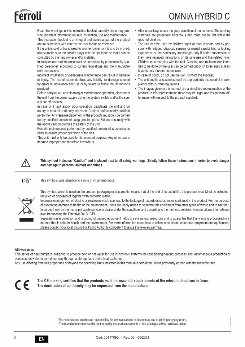
OMNIA HYBRID C• Read the warnings in this instruction booklet carefully since they pro-
vide important information on safe installation, use and maintenance.• This instruction booklet is an integral and essential part of the product
and must be kept with care by the user for future reference.• If the unit is sold or transferred to another owner or if it is to be moved,
always make sure the booklet stays with the appliance so that it can be consulted by the new owner and/or installer.
• Installation and maintenance must be carried out by professionally qua-lified personnel, according to current regulations and the manufactu-rer's instructions.
• Incorrect installation or inadequate maintenance can result in damage or injury. The manufacturer declines any liability for damage caused by errors in installation and use or by failure to follow the instructions provided.
• Before carrying out any cleaning or maintenance operation, disconnect the unit from the power supply using the system switch and/or the spe-cial cut-off devices.
• In case of a fault and/or poor operation, deactivate the unit and do not try to repair it or directly intervene. Contact professionally qualified personnel. Any repair/replacement of the products must only be carried out by qualified personnel using genuine parts. Failure to comply with the above cancompromise the safety of the unit.
• Periodic maintenance performed by qualified personnel is essential in order to ensure proper operation of the unit.
• This unit must only be used for its intended purpose. Any other use is deemed improper and therefore hazardous.
• After unpacking, check the good condition of the contents. The packing materials are potentially hazardous and must not be left within the reach of children.
• The unit can be used by children aged at least 8 years and by per-sons with reduced physical, sensory or mental capabilities, or lacking experience or the necessary knowledge, only if under supervision or they have received instructions on its safe use and the related risks. Children must not play with the unit. Cleaning and maintenance inten-ded to be done by the user can be carried out by children aged at least 8 years only if under supervision.
• In case of doubt, do not use the unit. Contact the supplier.• The unit and its accessories must be appropriately disposed of in com-
pliance with current regulations.• The images given in this manual are a simplified representation of the
product. In this representation there may be slight and insignificant dif-ferences with respect to the product supplied.
The CE marking certifies that the products meet the essential requirements of the relevant directives in force.The declaration of conformity may be requested from the manufacturer.
This symbol indicates "Caution" and is placed next to all safety warnings. Strictly follow these instructions in order to avoid danger and damage to persons, animals and things.
☞ This symbols calls attention to a note or important notice.
This symbol, which is used on the product, packaging or documents, means that at the end of its useful life, this product must Mnot be collected, recycled or disposed of together with domestic waste.Improper management of electric or electronic waste can lead to the leakage of hazardous substances contained in the product. For the purpose of preventing damage to health or the environment, users are kindly asked to separate this equipment from other types of waste and to ask for it to be dealt with by the municipal waste service or dealer under the conditions and according to the methods set down in national and international laws transposing the Directive 2012/19/EU.Separate waste collection and recycling of unused equipment helps to save natural resources and to guarantee that this waste is processed in a manner that is safe for health and the environment. For more information about how to collect electric and electronic equipment and appliances, please contact your local Council or Public Authority competent to issue the relevant permits.
Allowed usesThis series of heat pumps is designed to produce cold or hot water for use in hydronic systems for conditioning/heating purposes and instantaneous production of domestic hot water in an indirect way through a storage tank and a heat exchanger.Any use differing from this proper use or beyond the operating limits indicated in this manual is forbidden unless previously agreed with the manufacturer.
The manufacturer declines all responsibility for any inaccuracies in this manual due to printing or typing errors.The manufacturer reserves the right to modify the products contents in this catalogue without previous notice.
3ENCod. 3541T090 - Rev. 03 - 05/2021
OMNIA HYBRID C
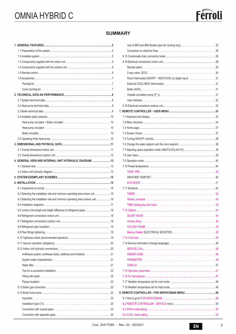
SUMMARY
1. GENERAL FEATURES ................................................................................................51.1 Presentation of the system ............................................................................................. 5
1.2 Available system ............................................................................................................. 5
1.3 Components supplied with the indoor unit ..................................................................... 6
1.4 Components supplied with the outdoor unit ................................................................... 6
1.5 Remote control ............................................................................................................... 6
1.6 Accessories .................................................................................................................... 7
Plumbig kit . . . . . . . . . . . . . . . . . . . . . . . . . . . . . . . . . . . . . . . . . . . . . . . . . . . . . . . . . . 7
Cover plumbig kit . . . . . . . . . . . . . . . . . . . . . . . . . . . . . . . . . . . . . . . . . . . . . . . . . . . . . 7
2. TECHNICAL DATA AN PERFORMANCE ...................................................................82.1 System technical data .................................................................................................... 8
2.2 Heat pump technical data ............................................................................................... 8
2.3 Boiler technical data ....................................................................................................... 9
2.4 Available static pressure ............................................................................................... 10
Heat pump circulator + Boiler circulator . . . . . . . . . . . . . . . . . . . . . . . . . . . . . . . . . . . 10
Heat pump circulator . . . . . . . . . . . . . . . . . . . . . . . . . . . . . . . . . . . . . . . . . . . . . . . . . 10
Boiler circulator. . . . . . . . . . . . . . . . . . . . . . . . . . . . . . . . . . . . . . . . . . . . . . . . . . . . . . 10
2.5 Operating limits heat pump .......................................................................................... 10
3. DIMENSIONAL AND PHYSICAL DATA ....................................................................113.1 Overall dimensions indoor unit ..................................................................................... 11
3.2 Overall dimensions outdoor unit ................................................................................... 12
4. GENERAL VIEW AND INTERNAL UNIT HYDRAULIC DIAGRAM ..........................134.1 General view ................................................................................................................ 13
4.2 Indoor unit hydraulic diagram ....................................................................................... 13
5. SYSTEM EXEMPLARY SCHEMES ...........................................................................146. INSTALLATION .........................................................................................................15
6.1 Inspections on arrival ................................................................................................... 15
6.2 Selecting the installation site and minimum operating area indoor unit ....................... 15
6.3 Selecting the installation site and minimum operating area outdoor unit ..................... 16
6.4 Installation diagrams .................................................................................................... 17
6.5 Limits to the length and heigth difference of refrigerant pipes ...................................... 18
6.6 Refrigerant connections indoor unit .............................................................................. 18
6.7 Refrigerant connections outdoor unit ........................................................................... 18
6.8 Refrigerant pipe insulation ............................................................................................ 19
6.9 Pipe fittings tightening .................................................................................................. 19
6.10 Tightness check (recommended operation) ............................................................... 19
6.11 Vacuum operation (obligatory) .................................................................................... 20
6.12 Indoor unit hydraulic connections ............................................................................... 20
Antifreeze system, antifreeze fluids, additives and inhibitors . . . . . . . . . . . . . . . . . . . 21
System water characteristics . . . . . . . . . . . . . . . . . . . . . . . . . . . . . . . . . . . . . . . . . . . 21
Water filter . . . . . . . . . . . . . . . . . . . . . . . . . . . . . . . . . . . . . . . . . . . . . . . . . . . . . . . . . 21
Tips for a successful installation . . . . . . . . . . . . . . . . . . . . . . . . . . . . . . . . . . . . . . . . . 22
Filling with water . . . . . . . . . . . . . . . . . . . . . . . . . . . . . . . . . . . . . . . . . . . . . . . . . . . . . 22
Piping insulation . . . . . . . . . . . . . . . . . . . . . . . . . . . . . . . . . . . . . . . . . . . . . . . . . . . . . 22
6.13 Boiler gas connection ................................................................................................. 22
6.14 Boiler fume ducts ........................................................................................................ 23
Important . . . . . . . . . . . . . . . . . . . . . . . . . . . . . . . . . . . . . . . . . . . . . . . . . . . . . . . . . . 23
Installation type C10 . . . . . . . . . . . . . . . . . . . . . . . . . . . . . . . . . . . . . . . . . . . . . . . . . . 23
Connection with coaxial pipes . . . . . . . . . . . . . . . . . . . . . . . . . . . . . . . . . . . . . . . . . . 23
Connection with separate pipes . . . . . . . . . . . . . . . . . . . . . . . . . . . . . . . . . . . . . . . . . 24
Use of Ø50 and Ø60 flexible pipe (for ducting only). . . . . . . . . . . . . . . . . . . . . . . . . . 25
Connection to collective flues . . . . . . . . . . . . . . . . . . . . . . . . . . . . . . . . . . . . . . . . . . . 26
6.15 Condensate drain connection boiler ........................................................................... 28
6.16 Electrical connections indoor unit ............................................................................... 28
Remote alarm . . . . . . . . . . . . . . . . . . . . . . . . . . . . . . . . . . . . . . . . . . . . . . . . . . . . . . . 30
2-way valve (SV2) . . . . . . . . . . . . . . . . . . . . . . . . . . . . . . . . . . . . . . . . . . . . . . . . . . . 30
Room thermostat (ON/OFF - HEAT/COOL by digital input) . . . . . . . . . . . . . . . . . . . 31
External COOL/HEAT (thermostat). . . . . . . . . . . . . . . . . . . . . . . . . . . . . . . . . . . . . . . 31
Boiler (AHS) . . . . . . . . . . . . . . . . . . . . . . . . . . . . . . . . . . . . . . . . . . . . . . . . . . . . . . . . 31
Outside circulation pump (P_o) . . . . . . . . . . . . . . . . . . . . . . . . . . . . . . . . . . . . . . . . . 31
User interface . . . . . . . . . . . . . . . . . . . . . . . . . . . . . . . . . . . . . . . . . . . . . . . . . . . . . . . 32
6.18 Electrical conections outdoor unit ............................................................................... 32
7. REMOTE CONTROLLER - USER MENU .................................................................337.1 Keyboard and display ................................................................................................... 33
7.2 Menu structure ............................................................................................................. 34
7.3 Home page ................................................................................................................... 37
7.4 Screen Unlock .............................................................................................................. 37
7.5 Turning ON/OFF controls ............................................................................................. 38
7.6 Change the water setpoint and the room setpoint ........................................................ 38
7.7 Adjusting space operation mode (HEAT/COOL/AUTO) ............................................... 39
7.8 User menu .................................................................................................................... 39
7.9 Operation mode ............................................................................................................ 40
7.10 Preset temperature ..................................................................................................... 40
TEMP. PRE. . . . . . . . . . . . . . . . . . . . . . . . . . . . . . . . . . . . . . . . . . . . . . . . . . . . . . . . . 40
WEATHER TEMP.SET . . . . . . . . . . . . . . . . . . . . . . . . . . . . . . . . . . . . . . . . . . . . . . . . 40
ECO MODE . . . . . . . . . . . . . . . . . . . . . . . . . . . . . . . . . . . . . . . . . . . . . . . . . . . . . . . . 41
7.11 Schedule ..................................................................................................................... 42
TIMER . . . . . . . . . . . . . . . . . . . . . . . . . . . . . . . . . . . . . . . . . . . . . . . . . . . . . . . . . . . . 42
Weekly schedule. . . . . . . . . . . . . . . . . . . . . . . . . . . . . . . . . . . . . . . . . . . . . . . . . . . . . 43
TIME (setting day and hour) . . . . . . . . . . . . . . . . . . . . . . . . . . . . . . . . . . . . . . . . . . . . 43
7.12 Options ....................................................................................................................... 44
SILENT MODE . . . . . . . . . . . . . . . . . . . . . . . . . . . . . . . . . . . . . . . . . . . . . . . . . . . . . . 44
Holiday Away . . . . . . . . . . . . . . . . . . . . . . . . . . . . . . . . . . . . . . . . . . . . . . . . . . . . . . . 45
HOLIDAY HOME . . . . . . . . . . . . . . . . . . . . . . . . . . . . . . . . . . . . . . . . . . . . . . . . . . . . 45
Backup Heater (ELECTRICAL BOOSTER) . . . . . . . . . . . . . . . . . . . . . . . . . . . . . . . . 45
7.13 Child lock .................................................................................................................... 46
7.14 Service information (change language) ...................................................................... 46
SERVCE CALL. . . . . . . . . . . . . . . . . . . . . . . . . . . . . . . . . . . . . . . . . . . . . . . . . . . . . . 46
ERROR CODE . . . . . . . . . . . . . . . . . . . . . . . . . . . . . . . . . . . . . . . . . . . . . . . . . . . . . . 46
PARAMETER . . . . . . . . . . . . . . . . . . . . . . . . . . . . . . . . . . . . . . . . . . . . . . . . . . . . . . . 46
DISPLAY . . . . . . . . . . . . . . . . . . . . . . . . . . . . . . . . . . . . . . . . . . . . . . . . . . . . . . . . . . 47
7.15 Operation parameter .................................................................................................. 47
7.16 For Serviceman .......................................................................................................... 47
7.17 Weather temperature set for cool mode ..................................................................... 48
7.18 Weather temperature set for heat mode .................................................................... 48
8. REMOTE CONTROLLER - FOR SERVICEMAN MENU ...........................................498.1 How to go to FOR SERVICEMAN ................................................................................ 49
8.2 REMOTE CONTROLLER - SERVICE menù................................................................ 50
8.3 DHW mode setting ....................................................................................................... 54
8.4 COOL mode setting ...................................................................................................... 54
4 EN Cod. 3541T090 - Rev. 03 - 05/2021
OMNIA HYBRID C8.5 HEAT mode setting ....................................................................................................... 55
8.6 AUTO mode setting ..................................................................................................... 55
8.7 Temp. Type setting (to activate the internal temperature probe of the controller as room thermostat) ......................................................................................................................... 56
8.8 Room thermostat (ON/OFF - HEAT/COOL by digital input) ......................................... 56
8.9 Other heating source .................................................................................................... 57
8.10 AHS (bolier) ................................................................................................................ 57
8.11 Holiday away setting ................................................................................................... 57
8.12 Service call ................................................................................................................. 57
8.13 Restore factory settings .............................................................................................. 58
8.14 Special function .......................................................................................................... 58
8.15 Auto restart ................................................................................................................. 59
8.16 Test run ....................................................................................................................... 60
Tabella parametri . . . . . . . . . . . . . . . . . . . . . . . . . . . . . . . . . . . . . . . . . . . . . . . . . . . . 62
8.18 Check parameter list .................................................................................................. 63
Basic factory settings . . . . . . . . . . . . . . . . . . . . . . . . . . . . . . . . . . . . . . . . . . . . . . . . . 63
Settings to be changed for OMNIA HYBRID C. . . . . . . . . . . . . . . . . . . . . . . . . . . . . . 64
9. BOILER CONTROLLER - USER MENU ...................................................................659.1 Control panel boiler ...................................................................................................... 65
Indication during operation . . . . . . . . . . . . . . . . . . . . . . . . . . . . . . . . . . . . . . . . . . . . . 65
9.2 Connection to the power supply, switching on and off.................................................. 66
Boiler not electrically powered . . . . . . . . . . . . . . . . . . . . . . . . . . . . . . . . . . . . . . . . . . 66
Boiler electrically powered . . . . . . . . . . . . . . . . . . . . . . . . . . . . . . . . . . . . . . . . . . . . . 66
Spegnimento e accensione caldaia . . . . . . . . . . . . . . . . . . . . . . . . . . . . . . . . . . . . . . 66
9.3 Adjustments .................................................................................................................. 67
Winter/summer switchover . . . . . . . . . . . . . . . . . . . . . . . . . . . . . . . . . . . . . . . . . . . . . 67
Heating temperature adjustment . . . . . . . . . . . . . . . . . . . . . . . . . . . . . . . . . . . . . . . . 67
DHW temperature adjustment . . . . . . . . . . . . . . . . . . . . . . . . . . . . . . . . . . . . . . . . . . 67
10. BOILER CONTROLLER - SERVICE MENU ...........................................................6810.1 Adjustments ................................................................................................................ 68
Gas conversion. . . . . . . . . . . . . . . . . . . . . . . . . . . . . . . . . . . . . . . . . . . . . . . . . . . . . . 68
Checking the combustion values . . . . . . . . . . . . . . . . . . . . . . . . . . . . . . . . . . . . . . . . 69
100% calibration . . . . . . . . . . . . . . . . . . . . . . . . . . . . . . . . . . . . . . . . . . . . . . . . . . . . . 69
Loading parameters with “BCC KEY” . . . . . . . . . . . . . . . . . . . . . . . . . . . . . . . . . . . . . 69
TEST mode activation . . . . . . . . . . . . . . . . . . . . . . . . . . . . . . . . . . . . . . . . . . . . . . . . 69
Heating power adjustment . . . . . . . . . . . . . . . . . . . . . . . . . . . . . . . . . . . . . . . . . . . . . 70
Service menu . . . . . . . . . . . . . . . . . . . . . . . . . . . . . . . . . . . . . . . . . . . . . . . . . . . . . . . 70
11. ALARMS ..................................................................................................................7411.1 Heat pump alarms ...................................................................................................... 74
11.2 Boiler faults ................................................................................................................. 78
12. COMMISSIONING ....................................................................................................8112.1 Heat pump commissioning ......................................................................................... 81
Preliminary heat pump checks . . . . . . . . . . . . . . . . . . . . . . . . . . . . . . . . . . . . . . . . . . 81
12.2 Setting to be done during the initial check of the product ........................................... 81
12.3 Boiler commissioning ................................................................................................. 81
Preliminary boiler checks . . . . . . . . . . . . . . . . . . . . . . . . . . . . . . . . . . . . . . . . . . . . . . 81
First boiler ignition . . . . . . . . . . . . . . . . . . . . . . . . . . . . . . . . . . . . . . . . . . . . . . . . . . . 82
12.4 Final check before turning on the unit ........................................................................ 82
12.5 Turn on the unit .......................................................................................................... 82
12.6 System water flow set point setting in heating mode ................................................. 82
12.7 Setting of system water delivery set point in cooling mode ........................................ 82
12.8 Domestic hot water production temperature setting ................................................... 82
13. MANAGEMENT PARAMETERS HEAT PUMP AND BOILER IN HEATING MODE 8313.1 Boiler in integration to the heat pump (setting to be done during the initial check of the product) .............................................................................................................................. 83
13.2 Boiler in substitution of the heat pump ....................................................................... 84
14. WORKING MODES OF THE SYSTEM ....................................................................8514.1 Plant operating modes ............................................................................................... 85
14.2 DHW production ......................................................................................................... 86
14.3 Plant operating modes + DHW production ................................................................. 86
15. MAINTENANCE .......................................................................................................8715.1 General notes ............................................................................................................. 87
15.2 Apertura del pannello frontale .................................................................................... 88
15.3 Access to internal components ................................................................................... 89
15.4 Heat pump circulator speed setting ........................................................................... 89
15.5 Water load and system water pressure adjustment ................................................... 90
15.6 System draining .......................................................................................................... 90
15.7 Heat pump routine maintenance ................................................................................ 90
15.8 Extraordinary maintenance and replacement of heat pump components .................. 92
Heat pump circulator . . . . . . . . . . . . . . . . . . . . . . . . . . . . . . . . . . . . . . . . . . . . . . . . . 92
15.9 Boiler periodical check ............................................................................................... 92
15.10 Boiler - Extraordinary maintenance and replacement of components ...................... 93
Boiler - Plate heat exchanger . . . . . . . . . . . . . . . . . . . . . . . . . . . . . . . . . . . . . . . . . . . 93
Boiler - Circulating pump . . . . . . . . . . . . . . . . . . . . . . . . . . . . . . . . . . . . . . . . . . . . . . 94
Boiler - Replacing the main exchanger. . . . . . . . . . . . . . . . . . . . . . . . . . . . . . . . . . . . 94
Boiler - Disassembling the burner and cleaning the exchanger . . . . . . . . . . . . . . . . . 95
Boiler - Exchanger insulation replacement . . . . . . . . . . . . . . . . . . . . . . . . . . . . . . . . . 96
Boiler - Fan . . . . . . . . . . . . . . . . . . . . . . . . . . . . . . . . . . . . . . . . . . . . . . . . . . . . . . . . . 96
Boiler - Replacing the circuit board. . . . . . . . . . . . . . . . . . . . . . . . . . . . . . . . . . . . . . . 97
Replacing the electrode and maintenance . . . . . . . . . . . . . . . . . . . . . . . . . . . . . . . . . 97
Removing the diverter valve . . . . . . . . . . . . . . . . . . . . . . . . . . . . . . . . . . . . . . . . . . . . 97
Replacing the water pressure switch . . . . . . . . . . . . . . . . . . . . . . . . . . . . . . . . . . . . . 97
Cleaning or replacing the flowmeter . . . . . . . . . . . . . . . . . . . . . . . . . . . . . . . . . . . . . . 98
Water inlet filter cleaning . . . . . . . . . . . . . . . . . . . . . . . . . . . . . . . . . . . . . . . . . . . . . . 99
15.11 Disconnection and disposal ...................................................................................... 99
16. ELECTRICAL DIAGRAM INDOOR UNIT ..............................................................10017. REFRIGERANT DIAGRAM ...................................................................................10418. OUTDOOR UNIT ELECTRONIC BOARDS ...........................................................10519. HEAT PUMP ELECTRONIC BOARD ....................................................................108
19.1 Electronic board’s DIP switch settings of the of the heat pump................................ 108
19.2 Parameters check in the electrical board ................................................................. 109
20. BOILER TERMINAL BLOCK .................................................................................11020.1 Accessing to the electrical terminal board and to the fuse of the boiler electrical box 110
20.2 Variable output relay LC32 card (factory installed) ................................................... 110
20.3 ON/OFF (A fig. 206) configuration .............................................................................111
21. GENERAL RECOMMENDATIONS ABOUT THE R410A REFRIGERANT USED 112
5ENCod. 3541T090 - Rev. 03 - 05/2021
OMNIA HYBRID C1. GENERAL FEATURES1.1 Presentation of the system> GENERAL CHARACTERISTICS:
• The family of OMNIA HYBRID C hybrid heat pumps integrates the technology of the heat pump and the condensing boiler with instantaneous dhw production in a single compact product.
• This represents the ideal solution for replacing old existing boilers, also on high temperature system with radiators.• The compact dimensions, similar to those of a wall-hung boiler, make it easier to replace without losing significant space or requiring significant restructuring work.• Internal electronics, by running the boiler or the heat pump as the climatic conditions vary, optimise the output of the system by always working in the most eco-
nomic consumption-related modes possible.• During heat pump operation in heating or conditioning mode, the boiler can produce dhw at the same time without interfering on heat pump operation, thereby
maximising the comfort of both services.• If the heat pump is partially or fully blocked, the boiler can operate separately in heating and dhw production.• it is composed of an external inverter unit available in 3 power sizes associated with an internal condensation unit with integrated hydronic module for cooling
circuit control.• A highly versatile system that can operate in particularly cold climatic conditions (outdoor air down to -20°C).• The split cooling circuit avoids the risk of freezing in particularly cold outdoor applications.• The user interface is composed of a digital remote controller equipped with a large display and simple setting controls.• Wall flue gas exhaust in cases pertaining to Lgs.D. 4 July 2014, No. 102.
> CHARACTERISTICS OF EXTERNAL UNIT:• Approved for outdoor operation in completely exposed site.• Breakaway starting current thanks to Inverter technology.• Compressor with twin rotary DC INVERTER motor on vibration damping supports and wrapped in double layer of soundproofing material to reduce vibrations and
noise to a minimum.• The compressor is also equipped with casing oil heating element.• Two-flow electronic expansion valve, cycle inversion valve.• Axial fans with brushless DC motor complete with protective grids.• Outdoor air temperature probe already installed on the unit.
> CHARACTERISTICS OF INTERNAL UNIT:• A particularly sturdy boiler, suitable for replacements even in particularly critical and resistant systems.• Combustion module with high modulation range (1:10) with high thickness stainless steel primary exchanger, with larger passes maintaining high efficiency even
on old systems with oxidation and soiling• M.G.R: Methane, LPG, Propane air Ready, with a simple configuration the internal unit can run on methane, lpg and propane-air without the use of any additional
conversion kits.• MC2: Multi Combustion Control, combustion system with gas-adaptive patented technology for better adaptability of use to the varying gas network conditions
(ex. pressure fluctuations or drops)• F.P.S: Flue gas Protection System. The standard flue gas check valve offers easy connection to pressurised collective flue systems• Particularly suitable for operation in flues requiring “heavy duty” pipes thanks to approval for operation with flue gas exhaust with a diameter of 50mm.• Can be combined with preheating systems for the domestic hot water.• Place of installation: also for outdoor use in a partially protected place that is up to -5°C, as standard • Free methane/LPG/Propane-air conversion at the time of product testing and warranty activation, by the Authorised Assistance Centre
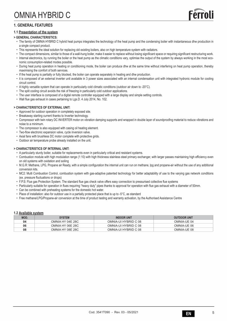
1.2 Available systemMOD. SYSTEM INDOOR UNIT OUTDOOR UNIT04 OMNIA HY 04E 28C OMNIA-UI HYBRID C 08 OMNIA-UE 0406 OMNIA HY 06E 28C OMNIA-UI HYBRID C 08 OMNIA-UE 0608 OMNIA HY 08E 28C OMNIA-UI HYBRID C 08 OMNIA-UE 08
6 EN Cod. 3541T090 - Rev. 03 - 05/2021
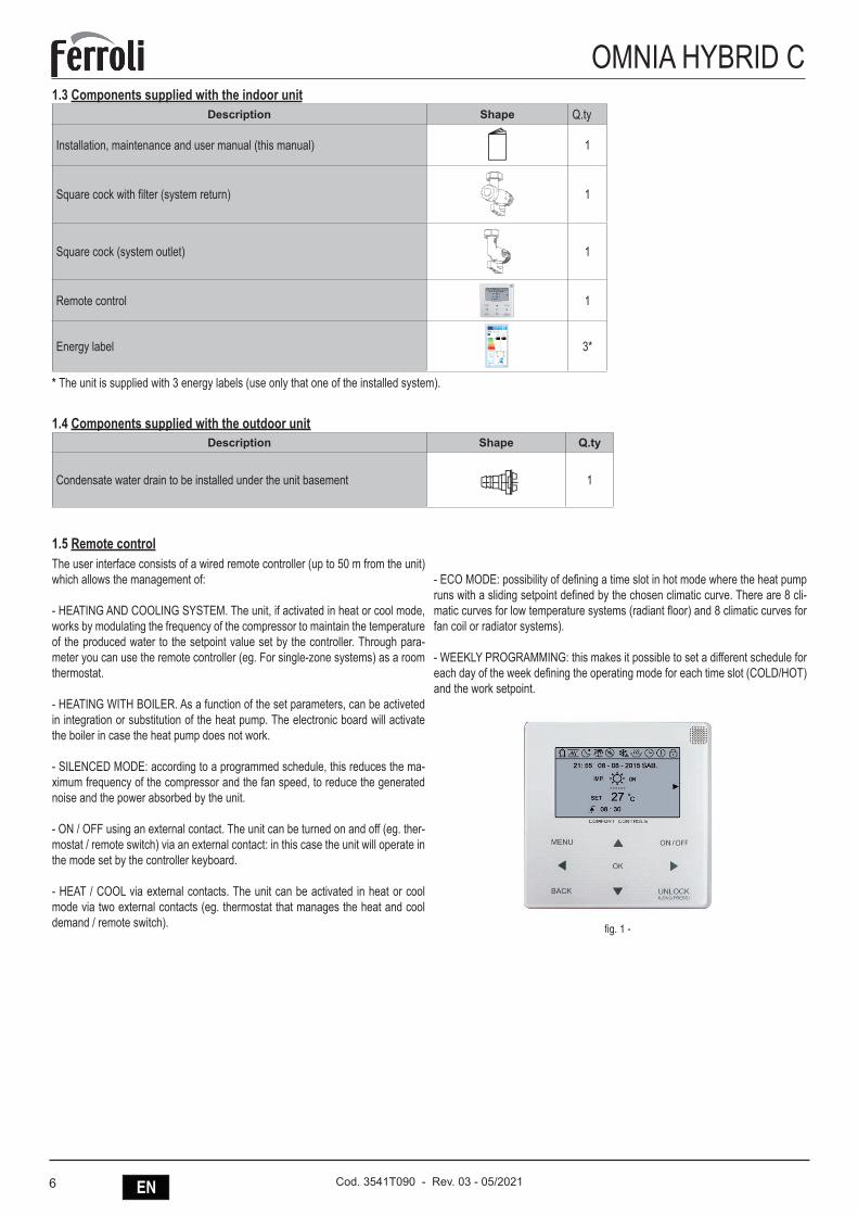
OMNIA HYBRID C1.3 Components supplied with the indoor unit
Description Shape Q.ty
Installation, maintenance and user manual (this manual) 1
Square cock with filter (system return) 1
Square cock (system outlet) 1
Remote control 1
Energy label
Y IJA
IE IA
RVL-I PLUS 5
A
63 dB
75kW
555kW
5
811/20132015
BCDEFG
A
35°C
AA
++
+
+
55°C
+A+ +
- dB
3*
* The unit is supplied with 3 energy labels (use only that one of the installed system).
1.4 Components supplied with the outdoor unitDescription Shape Q.ty
Condensate water drain to be installed under the unit basement 1
1.5 Remote controlThe user interface consists of a wired remote controller (up to 50 m from the unit) which allows the management of:
- HEATING AND COOLING SYSTEM. The unit, if activated in heat or cool mode, works by modulating the frequency of the compressor to maintain the temperature of the produced water to the setpoint value set by the controller. Through para-meter you can use the remote controller (eg. For single-zone systems) as a room thermostat.
- HEATING WITH BOILER. As a function of the set parameters, can be activeted in integration or substitution of the heat pump. The electronic board will activate the boiler in case the heat pump does not work.
- SILENCED MODE: according to a programmed schedule, this reduces the ma-ximum frequency of the compressor and the fan speed, to reduce the generated noise and the power absorbed by the unit.
- ON / OFF using an external contact. The unit can be turned on and off (eg. ther-mostat / remote switch) via an external contact: in this case the unit will operate in the mode set by the controller keyboard.
- HEAT / COOL via external contacts. The unit can be activated in heat or cool mode via two external contacts (eg. thermostat that manages the heat and cool demand / remote switch).
- ECO MODE: possibility of defining a time slot in hot mode where the heat pump runs with a sliding setpoint defined by the chosen climatic curve. There are 8 cli-matic curves for low temperature systems (radiant floor) and 8 climatic curves for fan coil or radiator systems).
- WEEKLY PROGRAMMING: this makes it possible to set a different schedule for each day of the week defining the operating mode for each time slot (COLD/HOT) and the work setpoint.
fig. 1 -
7ENCod. 3541T090 - Rev. 03 - 05/2021
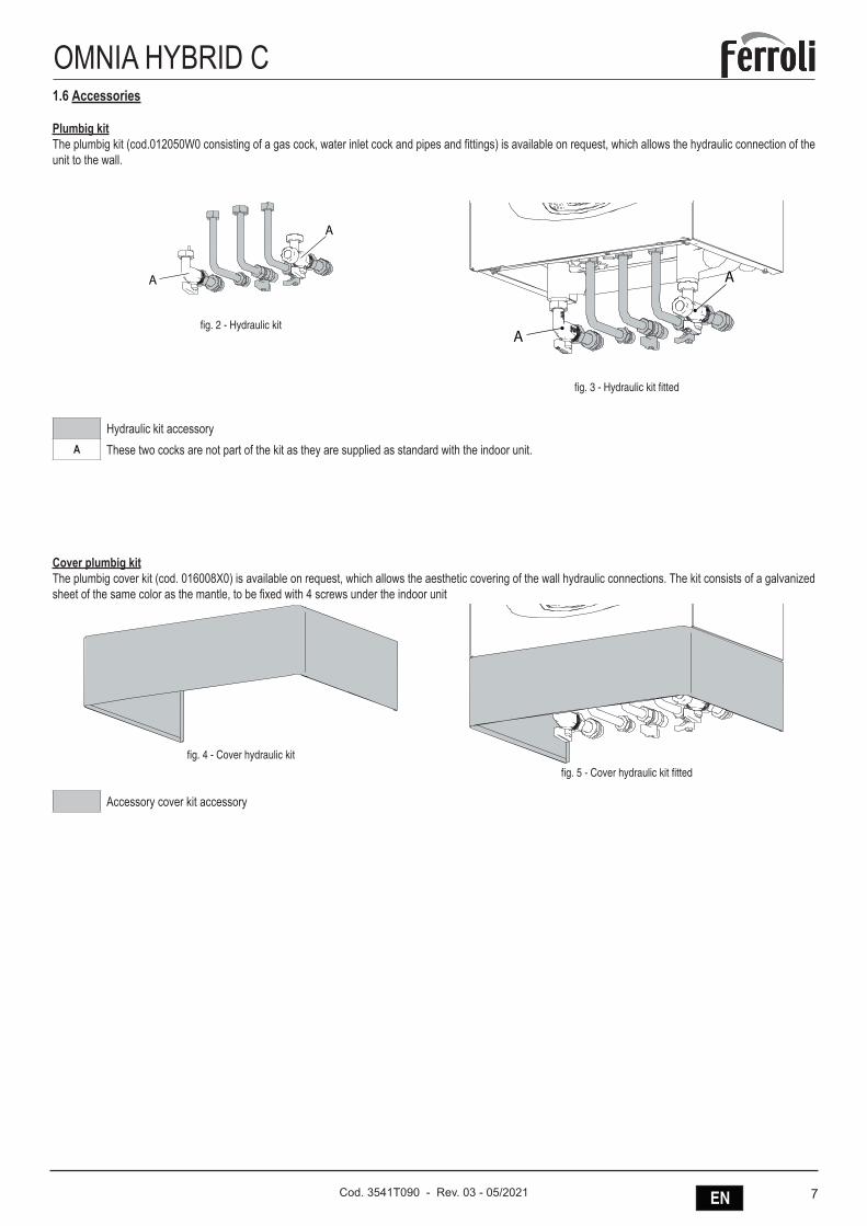
OMNIA HYBRID C1.6 Accessories
Plumbig kitThe plumbig kit (cod.012050W0 consisting of a gas cock, water inlet cock and pipes and fittings) is available on request, which allows the hydraulic connection of the unit to the wall.
A
A
fig. 2 - Hydraulic kitA
A
fig. 3 - Hydraulic kit fitted
Hydraulic kit accessoryA These two cocks are not part of the kit as they are supplied as standard with the indoor unit.
Cover plumbig kitThe plumbig cover kit (cod. 016008X0) is available on request, which allows the aesthetic covering of the wall hydraulic connections. The kit consists of a galvanized sheet of the same color as the mantle, to be fixed with 4 screws under the indoor unit
fig. 4 - Cover hydraulic kit
fig. 5 - Cover hydraulic kit fitted
Accessory cover kit accessory
8 EN Cod. 3541T090 - Rev. 03 - 05/2021
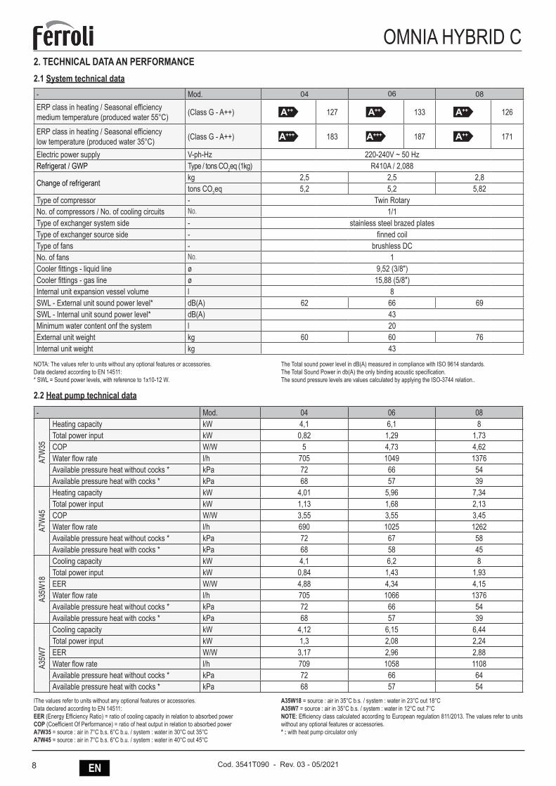
OMNIA HYBRID C2. TECHNICAL DATA AN PERFORMANCE2.1 System technical data- Mod. 04 06 08
ERP class in heating / Seasonal efficiencymedium temperature (produced water 55°C) (Class G - A++) A++ 127 A++ 133 A++ 126
ERP class in heating / Seasonal efficiencylow temperature (produced water 35°C) (Class G - A++) A+++ 183 A+++ 187 A++ 171
Electric power supply V-ph-Hz 220-240V ~ 50 HzRefrigerat / GWP Type / tons CO2eq (1kg) R410A / 2,088
Change of refrigerantkg 2,5 2,5 2,8tons CO2eq 5,2 5,2 5,82
Type of compressor - Twin RotaryNo. of compressors / No. of cooling circuits No. 1/1Type of exchanger system side - stainless steel brazed platesType of exchanger source side - finned coilType of fans - brushless DCNo. of fans No. 1Cooler fittings - liquid line ø 9,52 (3/8")Cooler fittings - gas line ø 15,88 (5/8")Internal unit expansion vessel volume l 8SWL - External unit sound power level* dB(A) 62 66 69SWL - Internal unit sound power level* dB(A) 43Minimum water content onf the system l 20External unit weight kg 60 60 76Internal unit weight kg 43
NOTA: The values refer to units without any optional features or accessories.Data declared according to EN 14511:* SWL = Sound power levels, with reference to 1x10-12 W.
The Total sound power level in dB(A) measured in compliance with ISO 9614 standards.The Total Sound Power in db(A) the only binding acoustic specification.The sound pressure levels are values calculated by applying the ISO-3744 relation..
2.2 Heat pump technical data
- Mod. 04 06 08
A7W
35
Heating capacity kW 4,1 6,1 8Total power input kW 0,82 1,29 1,73COP W/W 5 4,73 4,62Water flow rate l/h 705 1049 1376Available pressure heat without cocks * kPa 72 66 54Available pressure heat with cocks * kPa 68 57 39
A7W
45
Heating capacity kW 4,01 5,96 7,34Total power input kW 1,13 1,68 2,13COP W/W 3,55 3,55 3,45Water flow rate l/h 690 1025 1262Available pressure heat without cocks * kPa 72 67 58Available pressure heat with cocks * kPa 68 58 45
A35W
18
Cooling capacity kW 4,1 6,2 8Total power input kW 0,84 1,43 1,93EER W/W 4,88 4,34 4,15Water flow rate l/h 705 1066 1376Available pressure heat without cocks * kPa 72 66 54Available pressure heat with cocks * kPa 68 57 39
A35W
7
Cooling capacity kW 4,12 6,15 6,44Total power input kW 1,3 2,08 2,24EER W/W 3,17 2,96 2,88Water flow rate l/h 709 1058 1108Available pressure heat without cocks * kPa 72 66 64Available pressure heat with cocks * kPa 68 57 54
IThe values refer to units without any optional features or accessories.Data declared according to EN 14511:EER (Energy Efficiency Ratio) = ratio of cooling capacity in relation to absorbed powerCOP (Coefficient Of Performance) = ratio of heat output in relation to absorbed powerA7W35 = source : air in 7°C b.s. 6°C b.u. / system : water in 30°C out 35°CA7W45 = source : air in 7°C b.s. 6°C b.u. / system : water in 40°C out 45°C
A35W18 = source : air in 35°C b.s. / system : water in 23°C out 18°CA35W7 = source : air in 35°C b.s. / system : water in 12°C out 7°CNOTE: Efficiency class calculated according to European regulation 811/2013. The values refer to units without any optional features or accessories.* : with heat pump circulator only
9ENCod. 3541T090 - Rev. 03 - 05/2021
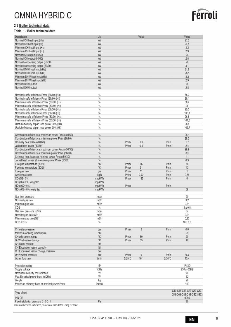
OMNIA HYBRID C2.3 Boiler technical dataTable. 1 - Boiler technical data
Description UM Value ValueNominal CH heat input (Hs) kW 27,2Nominal CH heat input (Hi) kW 24,5Minimum CH heat input (Hs) kW 3,2Minimum CH heat input (Hi) kW 2,9Nominal CH output (80/60) kW 24Nominal CH output (80/60) kW 2,8Nominal condensing output (50/30) kW 26Nominal condensing output (50/30) kW 3,1Nominal DHW heat input (Hs) kW 31,6Nominal DHW heat input (Hi) kW 28,5Minimum DHW heat input (Hs) kW 3,2Minimum DHW heat input (Hi) kW 2,9Nominal DHW output kW 28Nominal DHW output kW 2,8
Nominal useful efficiency Pmax (80/60) (Hs) % 88,3Nominal useful efficiency Pmax (80/60) (Hi) % 98,1Minimum useful efficiency Pmin. (80/60) (Hs) % 88,2Minimum useful efficiency Pmin. (80/60) (Hi) % 98Nominal useful efficiency Pmax (50/30) (Hs) % 95,5Nominal useful efficiency Pmax (50/30) (Hi) % 106,1Minimum useful efficiency Pmin. (50/30) (Hs) % 96,8Minimum useful efficiency Pmin. (50/30) (Hi) % 107,5Useful efficiency at part load power 30% (Hs) % 98,8Useful efficiency at part load power 30% (Hi) % 109,7
Combustion efficiency at maximum power Pmax (80/60) % 98,1Combustion efficiency at minimum power Pmin (80/60) % 98,3Chimney heat losses (80/60) % Pmax 1,9 Pmin 1,7Jacket heat losses (80/60) % Pmax 0,4 Pmin 2,4Combustion efficiency at maximum power Pmax (50/30) % 98,9Combustion efficiency at minimum power Pmin (50/30) % 99,3Chimney heat losses at nominal power Pmax (50/30) % 1,1Jacket heat losses at maximum power Pmax (50/30) % 0,3Flue gas temperature (80/60) °C Pmax 66 Pmin 58Flue gas temperature (50/30) °C Pmax 51 Pmin 43Flue gas rate g/s Pmax 11 Pmin 1Condensate rate kg/h Pmax 2,72 Pmin 0,66CO (O2= 0%) mg/kWh Pmax 185 Pmin 6CO (O2= 0%) weighted mg/kWhNOx (O2= 0%) mg/kWh Pmax PminNOx (O2= 0%) weighted mg/kWh 39
Gas inlet pressure mbar 20Nominal gas rate m3/h 3,2Minimum gas rate m3/h 0,31CO2 % 9 ± 0,8Gas inlet pressure (G31) mbar 37Nominal gas rate (G31) m3/h 2,21Minimum gas rate (G31) m3/h 0,23CO2 (G31) % 10 ± 0,8
CH water pressure bar Pmax 3 Pmin 0,8Maximun working temperature °C 95CH adjustment range °C Pmax 80 Pmin 20DHW adjustment range °C Pmax 55 Pmin 40CH Water content litriCH Expansion vessel capacity litriCH Expansion vessel charge pressure barDHW water pressure bar Pmax 9 Pmin 0,3Water flow rate l/min Δt25°C 16,1 Δt30°C 13,4
Protection rating IP IPX4DSupply voltage V/Hz 230V~50HZNominal electricity consumption W 70Max Electrical power input in DHW W 82Weight kg 28Maximum chimney head at nominal power Pmax Pascal 100
Type of unit C10-C11-C13-C23-C33-C43-C53-C63-C83-C93-CB23-B33
PIN CE 0085Flue installation pressure C10-C11 Pa 80
Unless otherwise indicated, values are calculated using G20 fuel
10 EN Cod. 3541T090 - Rev. 03 - 05/2021
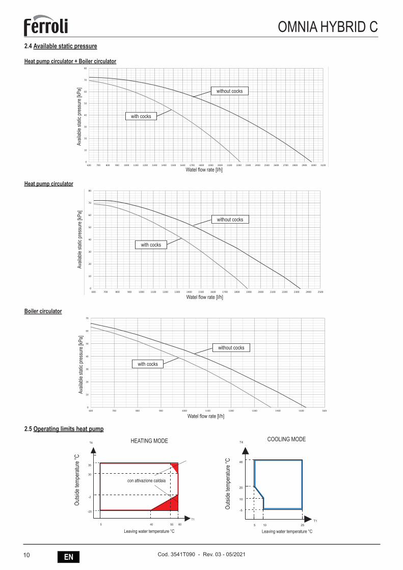
OMNIA HYBRID C2.4 Available static pressure
Heat pump circulator + Boiler circulator
40
50
60
70
80
UI OMNIA HYBRID C 08Prev_utile_senza rub._CIRC. PDC + CIRC. CALD. [kPa] Prev_utile_con rub._CIRC.PDC+CIRC_CALD. [kPa]
0
10
20
30
600 700 800 900 1000 1100 1200 1300 1400 1500 1600 1700 1800 1900 2000 2100 2200 2300 2400 2500 2600 2700 2800 2900 3000 3100
without cocks
with cocks
Watel flow rate [l/h]
Avail
able
static
pre
ssur
e [kP
a]
Heat pump circulator
40
50
60
70
80
UI OMNIA HYBRID C 08
Prev_utile_senza rub._CIRC. PDC [kPa] Prev_utile_con rub._CIRC_PDC [kPa]
0
10
20
30
600 700 800 900 1000 1100 1200 1300 1400 1500 1600 1700 1800 1900 2000 2100 2200 2300 2400 2500
without cocks
with cocks
Watel flow rate [l/h]
Avail
able
static
pre
ssur
e [kP
a]
Boiler circulator
30
40
50
60
70
UI OMNIA HYBRID C 08Prev_utile_senza rub._CIRC. CALD. [kPa] Prev_utile_con rub._CIRC_CALD. [kPa]
0
10
20
600 700 800 900 1000 1100 1200 1300 1400 1500 1600
without cocks
with cocks
Watel flow rate [l/h]
Avail
able
static
pre
ssur
e [kP
a]
2.5 Operating limits heat pumpHEATING MODE COOLING MODE
T4T4
T1 T1
20
46
35
-2
-20 -5
5 10 255 40 60
30
55
10
Leaving water temperature °C
con attivazione caldaia
Outsi
de te
mpe
ratu
re °C
HEATING MODE
HEATING MODE COOLING MODE
T4T4
T1 T1
20
46
35
-2
-20 -5
5 10 255 40 60
30
55
10
Leaving water temperature °C
Outsi
de te
mpe
ratu
re °C
COOLING MODE
11ENCod. 3541T090 - Rev. 03 - 05/2021
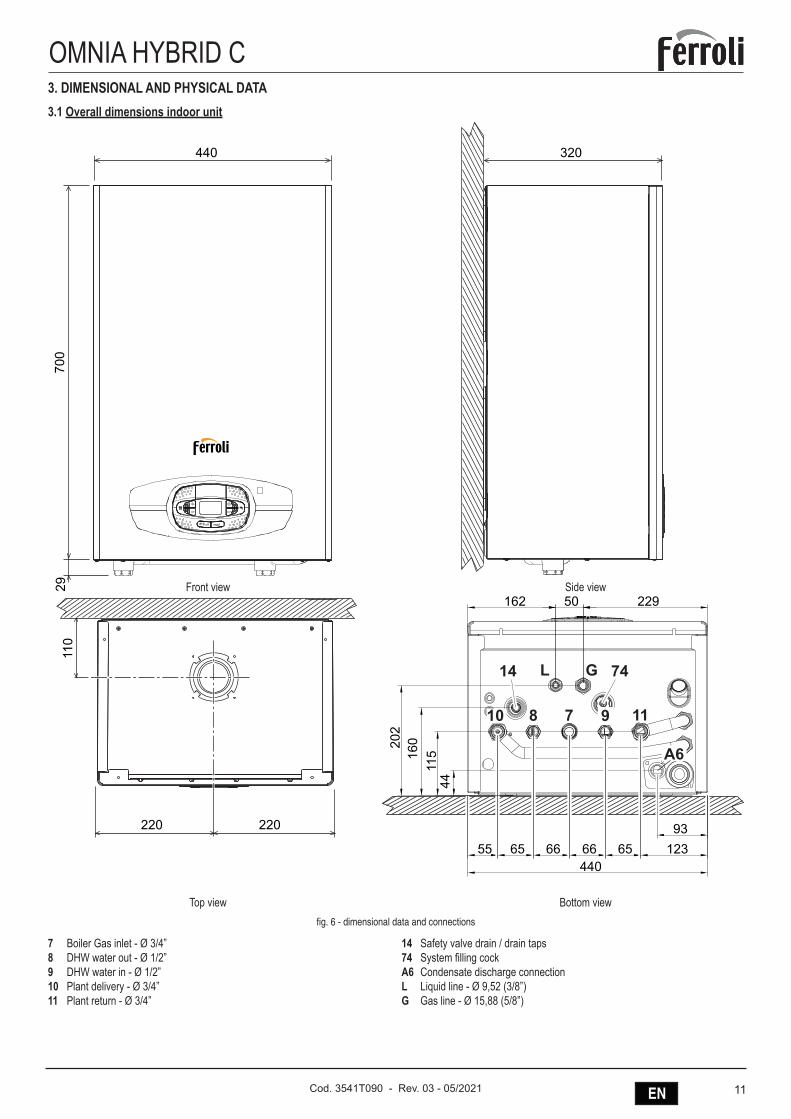
OMNIA HYBRID C3. DIMENSIONAL AND PHYSICAL DATA3.1 Overall dimensions indoor unit
440 320
700
29
220
110
220
440
115
22950162
44
55 65 66 66 65 12393
16020
2
11
GL14 74
A6
810 7 9
Top view
Front view
Bottom view
Side view
fig. 6 - dimensional data and connections
7 Boiler Gas inlet - Ø 3/4”8 DHW water out - Ø 1/2”9 DHW water in - Ø 1/2”10 Plant delivery - Ø 3/4”11 Plant return - Ø 3/4”
14 Safety valve drain / drain taps74 System filling cockA6 Condensate discharge connectionL Liquid line - Ø 9,52 (3/8”)G Gas line - Ø 15,88 (5/8”)
12 EN Cod. 3541T090 - Rev. 03 - 05/2021
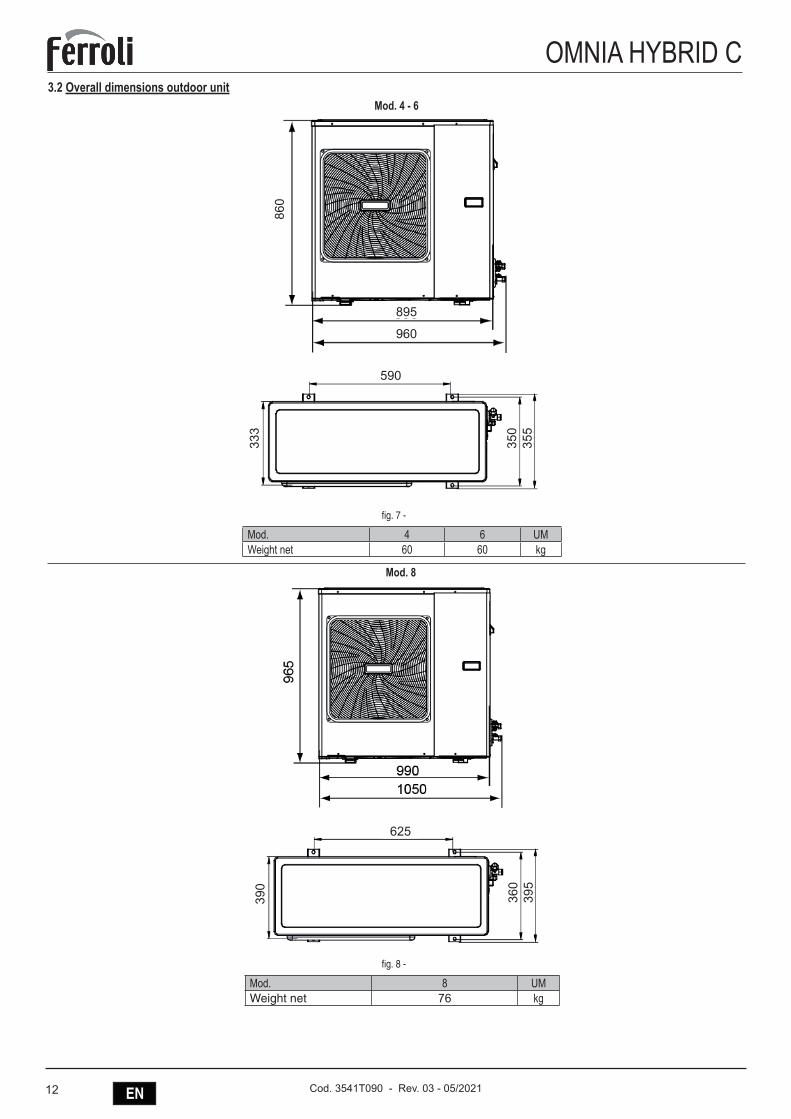
OMNIA HYBRID C3.2 Overall dimensions outdoor unit
Mod. 4 - 64/6kW
8kW
860
333
350
355
895
960
590
390
360
395
625
fig. 7 -
Mod. 4 6 UMWeight net 60 60 kg
Mod. 8
4/6kW
8kW
860
333
350
355
895
960
590
390
360
395
625
fig. 8 -
Mod. 8 UMWeight net 76 kg
13ENCod. 3541T090 - Rev. 03 - 05/2021
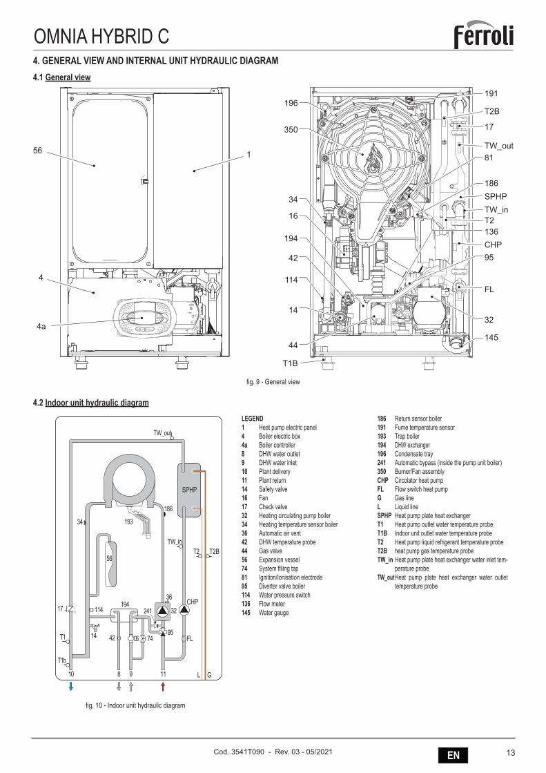
OMNIA HYBRID C4. GENERAL VIEW AND INTERNAL UNIT HYDRAULIC DIAGRAM4.1 General view
SPHP
FL
CHP
4
56
J5 J6 J3
1
196191
17
81
186
136
95
32
145
350
34
16
194
42
114
14
44
T1B
4a
TW_out
TW_inT2
T2B
fig. 9 - General view
4.2 Indoor unit hydraulic diagram
241194
14
G
OMNIA_HYBRID_C_
L
114
9574
56
193
186
34
10 118 9
42
36
32CHP
SPHP
FL136
17
fig. 10 - Indoor unit hydraulic diagram
LEGEND 1 Heat pump electric panel4 Boiler electric box4a Boiler controller8 DHW water outlet9 DHW water inlet10 Plant delivery11 Plant return14 Safety valve16 Fan17 Check valve32 Heating circulating pump boiler34 Heating temperature sensor boiler36 Automatic air vent42 DHW temperature probe44 Gas valve56 Expansion vessel74 System filling tap81 Ignition/Ionisation electrode95 Diverter valve boiler114 Water pressure switch136 Flow meter145 Water gauge
186 Return sensor boiler191 Fume temperature sensor193 Trap boiler194 DHW exchanger 196 Condensate tray241 Automatic bypass (inside the pump unit boiler)350 Burner/Fan assemblyCHP Circolator heat pumpFL Flow switch heat pumpG Gas lineL Liquid lineSPHP Heat pump plate heat exchangerT1 Heat pump outlet water temperature probeT1B Indoor unit outlet water temperature probeT2 Heat pump liquid refrigerant temperature probeT2B heat pump gas temperature probeTW_in Heat pump plate heat exchanger water inlet tem-
perature probeTW_out Heat pump plate heat exchanger water outlet
temperature probe
14 EN Cod. 3541T090 - Rev. 03 - 05/2021
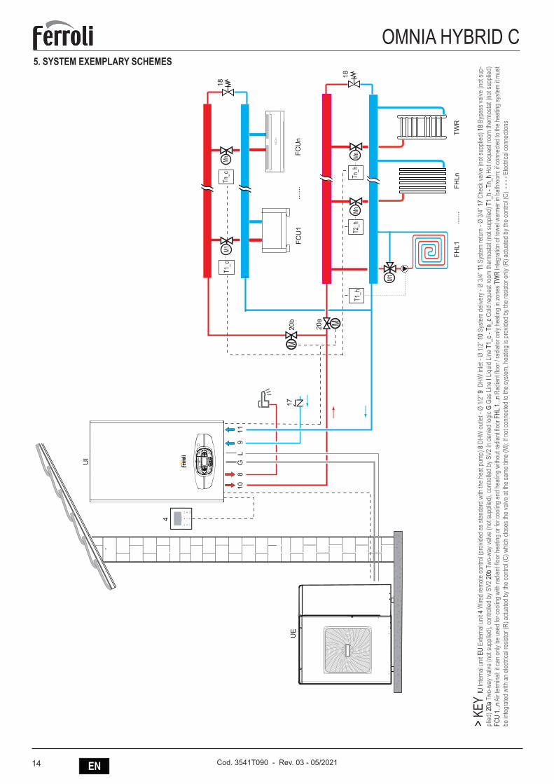
OMNIA HYBRID C5. SYSTEM EXEMPLARY SCHEMES
FCU
1
FHLn
Mn
......
.
......
.FC
Un
M18
18Mn Mn
20a
M20
b
TWR
M1T1
_c
T1_h
Tn_c
10G
L9
118
17
OM
NIA
HYB
RID
C_0
1
M1
T2_h
Tn_h
FHL1
4
UE
UI
> KE
Y IU
Inte
rnal
unit E
U Ex
tern
al un
it 4 W
ired
rem
ote
cont
rol (
prov
ided
as st
anda
rd w
ith th
e he
at p
ump)
8 D
HW o
utlet
- Ø
1/2”
9 D
HW in
let -
Ø 1/
2” 1
0 Sy
stem
deli
very
- Ø
3/4”
11 S
yste
m re
turn
- Ø
3/4”
17
Chec
k valv
e (n
ot su
pplie
d) 1
8 By
pass
valve
(not
sup-
plied
) 20a
Two-
way v
alve
(not
supp
lied)
, con
trolle
d by
SV2
20b
Two-
way v
alve
(not
supp
lied)
, con
trolle
d by
SV2
in d
enied
logic
G G
as L
ine l L
iquid
Line T
1_c -
Tn_
c Cold
requ
est r
oom
ther
mos
tat (
not s
uppli
ed) T
1_h
- Tn_
h Ho
t req
uest
room
ther
mos
tat (
not s
uppli
ed)
FCU
1...n
Air t
erm
inal: i
t can
only
be us
ed fo
r coo
ling w
ith ra
diant
floor
heat
ing or
for c
oolin
g and
heat
ing w
ithou
t rad
iant fl
oor F
HL 1.
..n R
adian
t floo
r / ra
diato
r only
heat
ing in
zone
s TW
R In
tegr
ation
of to
wel w
arm
er in
bath
room
: if co
nnec
ted t
o the
heat
ing sy
stem
it m
ust
be in
tegr
ated
with
an
electr
ical r
esist
or (R
) actu
ated
by t
he co
ntro
l (C)
whic
h clo
ses t
he va
lve a
t the
sam
e tim
e (M
); if n
ot co
nnec
ted
to th
e sy
stem
, hea
ting
is pr
ovide
d by
the
resis
tor o
nly (R
) actu
ated
by t
he co
ntro
l (C)
- -
- - E
lectri
cal c
onne
ction
s
15ENCod. 3541T090 - Rev. 03 - 05/2021
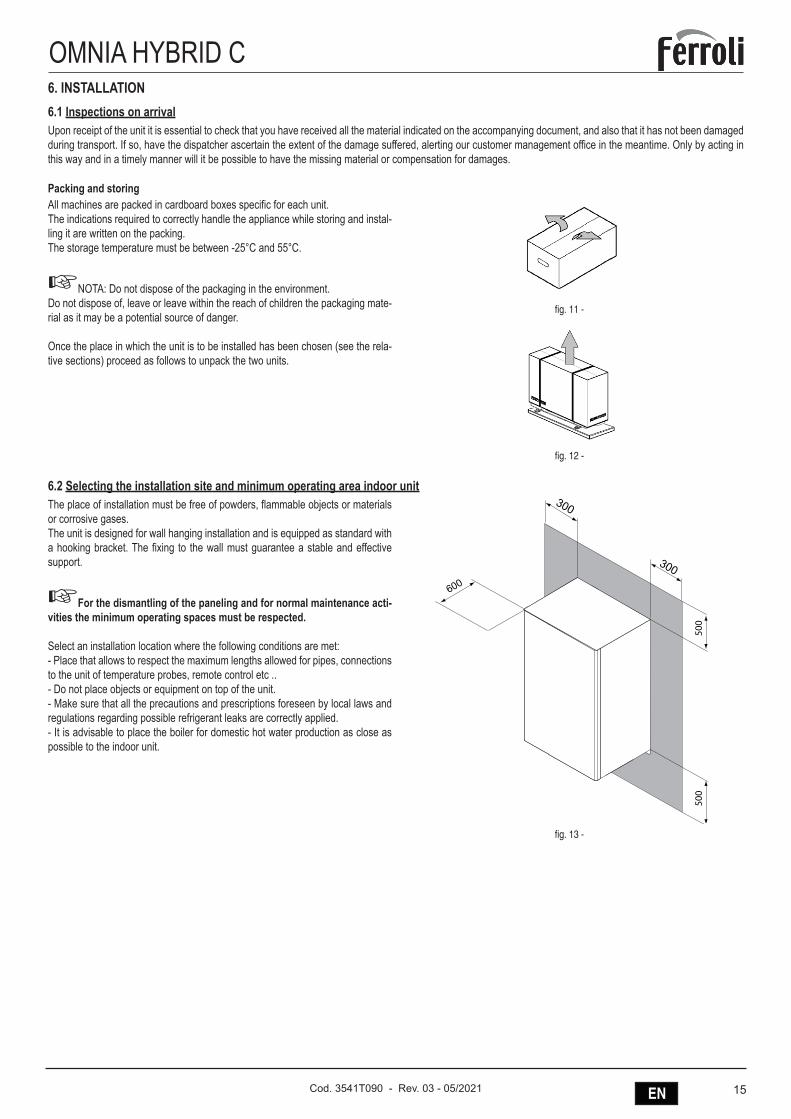
OMNIA HYBRID C6. INSTALLATION 6.1 Inspections on arrivalUpon receipt of the unit it is essential to check that you have received all the material indicated on the accompanying document, and also that it has not been damaged during transport. If so, have the dispatcher ascertain the extent of the damage suffered, alerting our customer management office in the meantime. Only by acting in this way and in a timely manner will it be possible to have the missing material or compensation for damages.
Packing and storingAll machines are packed in cardboard boxes specific for each unit.The indications required to correctly handle the appliance while storing and instal-ling it are written on the packing.The storage temperature must be between -25°C and 55°C.
☞NOTA: Do not dispose of the packaging in the environment.Do not dispose of, leave or leave within the reach of children the packaging mate-rial as it may be a potential source of danger.
Once the place in which the unit is to be installed has been chosen (see the rela-tive sections) proceed as follows to unpack the two units.
fig. 11 -
fig. 12 -
6.2 Selecting the installation site and minimum operating area indoor unitThe place of installation must be free of powders, flammable objects or materials or corrosive gases.The unit is designed for wall hanging installation and is equipped as standard with a hooking bracket. The fixing to the wall must guarantee a stable and effective support.
☞For the dismantling of the paneling and for normal maintenance acti-vities the minimum operating spaces must be respected.
Select an installation location where the following conditions are met:- Place that allows to respect the maximum lengths allowed for pipes, connections to the unit of temperature probes, remote control etc ..- Do not place objects or equipment on top of the unit.- Make sure that all the precautions and prescriptions foreseen by local laws and regulations regarding possible refrigerant leaks are correctly applied.- It is advisable to place the boiler for domestic hot water production as close as possible to the indoor unit.
300
300
600
500
500
fig. 13 -
16 EN Cod. 3541T090 - Rev. 03 - 05/2021
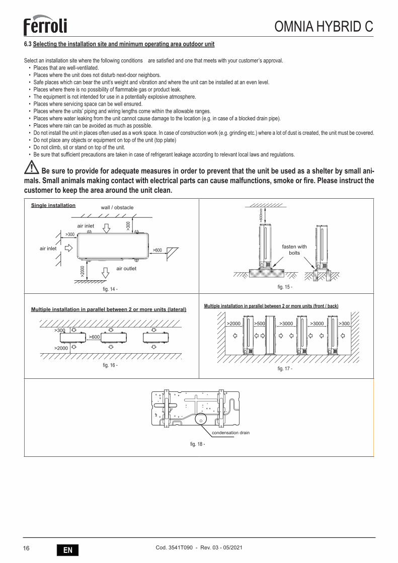
OMNIA HYBRID C6.3 Selecting the installation site and minimum operating area outdoor unit
Select an installation site where the following conditions are satisfied and one that meets with your customer’s approval.• Places that are well-ventilated.• Places where the unit does not disturb next-door neighbors.• Safe places which can bear the unit’s weight and vibration and where the unit can be installed at an even level.• Places where there is no possibility of flammable gas or product leak.• The equipment is not intended for use in a potentially explosive atmosphere.• Places where servicing space can be well ensured.• Places where the units’ piping and wiring lengths come within the allowable ranges.• Places where water leaking from the unit cannot cause damage to the location (e.g. in case of a blocked drain pipe).• Places where rain can be avoided as much as possible.• Do not install the unit in places often used as a work space. In case of construction work (e.g. grinding etc.) where a lot of dust is created, the unit must be covered.• Do not place any objects or equipment on top of the unit (top plate)• Do not climb, sit or stand on top of the unit.• Be sure that sufficient precautions are taken in case of refrigerant leakage according to relevant local laws and regulations.
Be sure to provide for adequate measures in order to prevent that the unit be used as a shelter by small ani-mals. Small animals making contact with electrical parts can cause malfunctions, smoke or fire. Please instruct the customer to keep the area around the unit clean.
>300
>300
>200
0
>600
(Wall or obstacle)
Maintain channel
Air outlet
Air inlet
Air inlet
air outlet
air inlet
wall / obstacleSingle installation
air inlet
fig. 14 -
Fix with bolt
>600
mm
fasten with bolts
fig. 15 -
Multiple installation in parallel between 2 or more units (lateral)
>2000 >500 >3000 >3000 >300
>600
>2000
>300
fig. 16 -
Multiple installation in parallel between 2 or more units (front / back)
>2000 >500 >3000 >3000 >300
>600
>2000
>300
fig. 17 -
Reserve water outlet
Reserve water outlet Water Outlet
Water Outlet
Outlet for power and connecting pipes
(Need to knock open)
(With rubber stopper)
condensation drain
fig. 18 -
17ENCod. 3541T090 - Rev. 03 - 05/2021
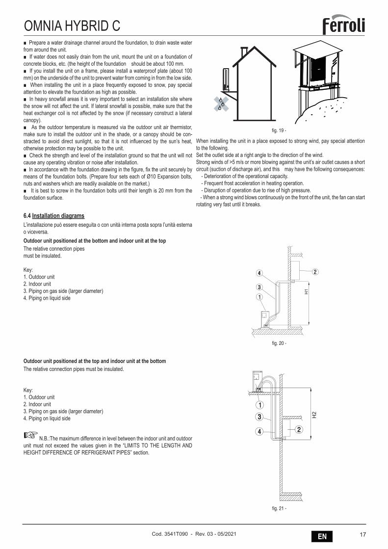
OMNIA HYBRID C■ Prepare a water drainage channel around the foundation, to drain waste water from around the unit.■ If water does not easily drain from the unit, mount the unit on a foundation of concrete blocks, etc. (the height of the foundation should be about 100 mm.■ If you install the unit on a frame, please install a waterproof plate (about 100 mm) on the underside of the unit to prevent water from coming in from the low side.■ When installing the unit in a place frequently exposed to snow, pay special attention to elevate the foundation as high as possible. ■ In heavy snowfall areas it is very important to select an installation site where the snow will not affect the unit. If lateral snowfall is possible, make sure that the heat exchanger coil is not affected by the snow (if necessary construct a lateral canopy).■ As the outdoor temperature is measured via the outdoor unit air thermistor, make sure to install the outdoor unit in the shade, or a canopy should be con-stracted to avoid direct sunlight, so that it is not influenced by the sun’s heat, otherwise protection may be possible to the unit.■ Check the strength and level of the installation ground so that the unit will not cause any operating vibration or noise after installation.■ In accordance with the foundation drawing in the figure, fix the unit securely by means of the foundation bolts. (Prepare four sets each of Ø10 Expansion bolts, nuts and washers which are readily available on the market.)■ It is best to screw in the foundation bolts until their length is 20 mm from the foundation surface.
fig. 19 -
When installing the unit in a place exposed to strong wind, pay special attention to the following.Set the outlet side at a right angle to the direction of the wind.Strong winds of >5 m/s or more blowing against the unit’s air outlet causes a short circuit (suction of discharge air), and this may have the following consequences: - Deterioration of the operational capacity. - Frequent frost acceleration in heating operation. - Disruption of operation due to rise of high pressure. - When a strong wind blows continuously on the front of the unit, the fan can start rotating very fast until it breaks.
6.4 Installation diagramsL’installazione può essere eseguita o con unità interna posta sopra l’unità esterna o viceversa.Outdoor unit positioned at the bottom and indoor unit at the topThe relative connection pipesmust be insulated.
Key:1. Outdoor unit2. Indoor unit3. Piping on gas side (larger diameter)4. Piping on liquid side
fig. 20 -
Outdoor unit positioned at the top and indoor unit at the bottomThe relative connection pipes must be insulated.
Key:1. Outdoor unit2. Indoor unit3. Piping on gas side (larger diameter)4. Piping on liquid side
☞ N.B.:The maximum difference in level between the indoor unit and outdoor unit must not exceed the values given in the “LIMITS TO THE LENGTH AND HEIGHT DIFFERENCE OF REFRIGERANT PIPES” section.
fig. 21 -
18 EN Cod. 3541T090 - Rev. 03 - 05/2021
OMNIA HYBRID C6.5 Limits to the length and heigth difference of refrigerant pipesThe length of the refrigerant pipes between the indoor and outdoor units must be as short as possible and is in any case limited by compliance with the maximum height difference values between the units.Diminution of the difference in height between the units (H1,H2) and of the pipe lengths (L) will limit the load losses, consequently increasing the overall efficiency of the machine.Comply with the limits given in the following tables.
MOD. 4-6 8Connections LIQUID line " 3/8Connections GAS line " 5/8Length with standard charge m 10Cooling line maximum length m 20 30Maximum diff.in height Outdoor unit low (H1) m 8 15Maximum diff.in height Outdoor unit high (H2) m 10 20Refrigerant charge Type R410AQuantity of additional refrigerant per meter g/m 54
Contact our technical department for the required modifications if the units must operate beyond the specifications given above.
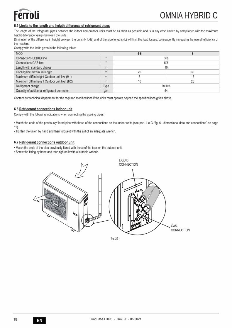
6.6 Refrigerant connections indoor unitComply with the following indications when connecting the cooling pipes:
• Match the ends of the previously flared pipe with those of the connections on the indoor units (see part. L e G “fig. 6 - dimensional data and connections” on page 11).• Tighten the union by hand and then torque it with the aid of an adequate wrench.
6.7 Refrigerant connections outdoor unit• Match the ends of the pipe previously flared with those of the taps on the outdoor unit.• Screw the fitting by hand and then tighten it with a suitable wrench.
1 2gasliqulid
LIQUIDCONNECTION
GASCONNECTION
fig. 22 -
19ENCod. 3541T090 - Rev. 03 - 05/2021
OMNIA HYBRID C6.8 Refrigerant pipe insulationTo ensure system efficiency and its correct operation it is necessary to use pre-insulated cooling connection lines easily available on the market. Pay also atten-tion to the connection points according to what described.
Use thermal insulating tape to tie the hoses, from the area connecting the outdoor unit cocks to the upper end of the hose in correspondence of the wall entry point. (side figure) .
fig. 23 -
6.9 Pipe fittings tighteningMake sure that the connecting zone is free from dust and dirt.• Make sure that the flare and connection are perfectly aligned.• Tighten the union first by hand and then with an adequate torque wrench.Leaks could occur if the parts are insufficiently tightened, while the flare could be damaged if it is tightened too strongly.The table below lists the torques recommended for the various pipe diameters.
Nominal Diameter (“) External Diameter (mm) Ø Tightening torqueNxm
3/8 9.52 30-405/8 15.88 60-65
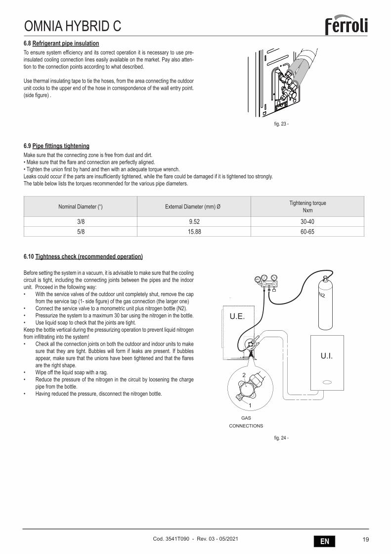
6.10 Tightness check (recommended operation)
Before setting the system in a vacuum, it is advisable to make sure that the cooling circuit is tight, including the connecting joints between the pipes and the indoor unit. Proceed in the following way:• With the service valves of the outdoor unit completely shut, remove the cap
from the service tap (1- side figure) of the gas connection (the larger one)• Connect the service valve to a monometric unit plus nitrogen bottle (N2).• Pressurize the system to a maximum 30 bar using the nitrogen in the bottle.• Use liquid soap to check that the joints are tight. Keep the bottle vertical during the pressurizing operation to prevent liquid nitrogen from infiltrating into the system!• Check all the connection joints on both the outdoor and indoor units to make
sure that they are tight. Bubbles will form if leaks are present. If bubbles appear, make sure that the unions have been tightened and that the flares are the right shape.
• Wipe off the liquid soap with a rag.• Reduce the pressure of the nitrogen in the circuit by loosening the charge
pipe from the bottle.• Having reduced the pressure, disconnect the nitrogen bottle.
GAS
CONNECTIONS
U.I.
U.E.
fig. 24 -
20 EN Cod. 3541T090 - Rev. 03 - 05/2021
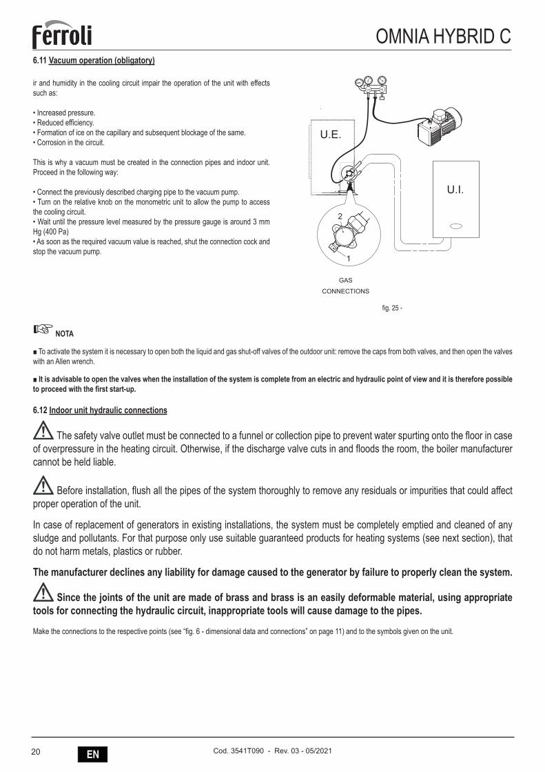
OMNIA HYBRID C6.11 Vacuum operation (obligatory)
ir and humidity in the cooling circuit impair the operation of the unit with effects such as:
• Increased pressure.• Reduced efficiency.• Formation of ice on the capillary and subsequent blockage of the same.• Corrosion in the circuit.
This is why a vacuum must be created in the connection pipes and indoor unit. Proceed in the following way:
• Connect the previously described charging pipe to the vacuum pump.• Turn on the relative knob on the monometric unit to allow the pump to access the cooling circuit.• Wait until the pressure level measured by the pressure gauge is around 3 mm Hg (400 Pa)• As soon as the required vacuum value is reached, shut the connection cock and stop the vacuum pump.
U.I.
U.E.
GAS
CONNECTIONS
fig. 25 -
☞ NOTA
■ To activate the system it is necessary to open both the liquid and gas shut-off valves of the outdoor unit: remove the caps from both valves, and then open the valves with an Allen wrench.
■ It is advisable to open the valves when the installation of the system is complete from an electric and hydraulic point of view and it is therefore possible to proceed with the first start-up.
6.12 Indoor unit hydraulic connections
The safety valve outlet must be connected to a funnel or collection pipe to prevent water spurting onto the floor in case of overpressure in the heating circuit. Otherwise, if the discharge valve cuts in and floods the room, the boiler manufacturer cannot be held liable.
Before installation, flush all the pipes of the system thoroughly to remove any residuals or impurities that could affect proper operation of the unit.
In case of replacement of generators in existing installations, the system must be completely emptied and cleaned of any sludge and pollutants. For that purpose only use suitable guaranteed products for heating systems (see next section), that do not harm metals, plastics or rubber.
The manufacturer declines any liability for damage caused to the generator by failure to properly clean the system.
Since the joints of the unit are made of brass and brass is an easily deformable material, using appropriate tools for connecting the hydraulic circuit, inappropriate tools will cause damage to the pipes.
Make the connections to the respective points (see “fig. 6 - dimensional data and connections” on page 11) and to the symbols given on the unit.
21ENCod. 3541T090 - Rev. 03 - 05/2021
OMNIA HYBRID CAntifreeze system, antifreeze fluids, additives and inhibitorsWhen necessary, antifreeze fluids, additives and inhibitors can be used only if the manufacturer of such fluids or additives guarantees that they are suitable and do not cause damage to the exchanger or other components and/or materials of the boiler/heat pump and system. Do not use generic antifreeze fluids, additives or inhibitors that are not specific for use in heating systems and compatible with the materials of the boiler/heat pump and system.
System water characteristics
The heat pumps are suitable for installation in heating systems with non-significant entry of oxygen (ref. systems “case I” EN14868). A physical separator (e.g. plate heat exchanger) must be provided in systems with continuous entry of oxygen (e.g. underfloor systems without antidiffusion pipes or open vessel), or intermittent (less than 20% of system water content).
The water within a heating system must have the characteristics required by UNI 8065, and comply with laws and regulations in force and the provisions of EN14868 (protection of metallic materials against corrosion).
The filling water (first filling and subsequent replenishment) must be clear, with hardness below 15°F and treated with suitable chemical conditioners against the initiation of corrosion, that are not aggressive on metals and plastics, do not develop gases and, in low-temperature systems, do not cause proliferation of bacterial or microbial masses.
The water in the system must be periodically checked (at least twice a year during the season when the systems are used, as required by UNI8065) and have: possibly a clear appearance, hardness below 15°F for new systems or 20°F for existing systems, pH above 7 and below 8.5, iron content (Fe) below 0.5 mg/l, copper content (Cu) below 0.1 mg/l, chloride content below 50mg/l, electrical conductivity below 200 µs/cm, and must contain chemical conditioners in a concentration sufficient to protect the system for at least one year. Bacterial or microbial loads must not be present in low temperature systems.
Only use conditioners, additives, inhibitors and antifreeze liquids declared by the producer suitable for use in heating systems and that do not cause damage to the heat exchanger or other components and/or materials of the boiler and system.
Chemical conditioners must ensure complete deoxygenation of the water, contain specific protection for yellow metals (cop-per and its alloys), anti-fouling agents for scale, neutral pH stabilizers and, in low-temperature systems, specific biocides for use in heating systems.
Recommended chemical conditioners:
SENTINEL X100 and SENTINEL X200
FERNOX F1 and FERNOX F3
The unit is equipped with a frost protection system that activates the heat pump in heating mode when the system delivery water temperature falls below 4°C. The device is not active if the power and/or gas supply to the unit is turned off. If neces-sary, for system protection use a suitable antifreeze liquid that meets the same requirements as set out above and provided for by Standard UNI 8065.
In the presence of adequate chemical/physical system and feed water treatments and related high cyclicity controls able to ensure the required parameters, for industrial process applications the product can be installed in open-vessel systems with vessel hydrostatic height able to ensure compliance with the minimum operating pressure indicated in the product technical specifications.
The presence of deposits on the indoor unit exchange surfaces due to non-compliance with the above requirements will involve non-recognition of the warranty.
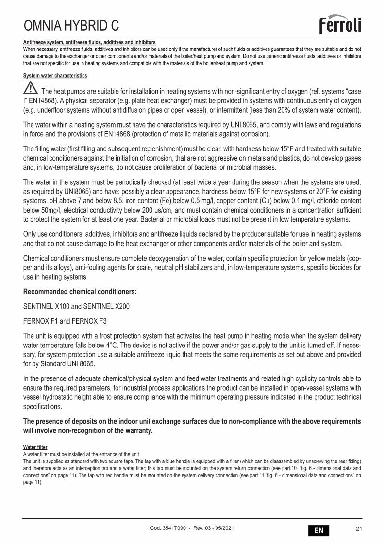
Water filterA water filter must be installed at the entrance of the unit.The unit is supplied as standard with two square taps. The tap with a blue handle is equipped with a filter (which can be disassembled by unscrewing the rear fitting) and therefore acts as an interception tap and a water filter; this tap must be mounted on the system return connection (see part.10 “fig. 6 - dimensional data and connections” on page 11). The tap with red handle must be mounted on the system delivery connection (see part 11 “fig. 6 - dimensional data and connections” on page 11).
22 EN Cod. 3541T090 - Rev. 03 - 05/2021
OMNIA HYBRID CTips for a successful installationFor a correct design and installation of the hydraulic plant comply the local laws governing safety matters and sound.The following information is suggestion for a correct installation of the unit.
• Before connecting the unit to the system wash adequately the pipes using clean water, filling and emptying and cleaning the filters.• Only after that proceed connecting the unit to the system; this operation is crucial to ensure proper start-up without the need to have repeated stops to clean the
filter, with the possible risk of damage to heat exchangers and other components.• Check by qualified personnel the quality of the water or of the mixture used; avoid the presence of inorganic salts, biological load (seaweeds, etc.) suspended
solids, dissolved oxygen and the pH. Water with inadequate characteristics can cause a pressure drop increase due to a rapid fouling of the filter, energy efficiency decrease and corrosive symptom increase that can damage the unit.
• The pipes must have the least possible number of bends to minimize load losses and must be adequately supported in order to prevent the connections of the unait from being excessively stressed.
• Install on-off valves near components that need to be serviced to isolate them when maintenance work needs to be done and to allow them to be replaced without having to discharge the system.
• Before isolating the pipes and charging the system, carry out preliminary inspections to make sure that there are no leaks.• Isolate all the chilled water pipes to prevent condensation from forming along the pipes themselves. Make sure that the material used is the steam barrier type,
failing this, cover the insulation with an appropriate protection. Also make sure that the air venting valves can be accessed through the insulation.• The circuit can be maintained under pressure using an expansion vessel (present in the unit) and a pressure reducer. A system filling device can be used that
automatically, under a pressure value, provides for the loading and maintenance of the desired pressure.• Check that all plant components are able to withstand the maximum static pressure (depending on the height of the building to be served).
☞ NOTE
• If there is no glycol in the system (antifreeze) or if the unit is not able to remain electrically powered for possible blackouts, in order to avoid possible icing problems, empty the water during winter.
• The unit is only to be used in a closed water system. Application in an open water circuit can lead to excessive corrosion of the water piping.• Water connections must be made in accordance with the outlook diagram delivered with the unit, with respect to the water intake and water outlet (refer to section
“DIMENSIONAL AND PHYSICAL DATA”). • If air, moisture or dust gets in the water circuit, problems may occur. Therefore, always take into account the following when connecting the water circuit:• Use clean pipes only.• Hold the pipe end downwards when removing burrs• Cover the pipe end when inserting it through a wall so that no dust and dirt enter.• Use a good thread sealant for sealing the connections. The sealing must be able to withstand the pressures and temperatures of the system.• When using non-brass metallic piping,make sure to insulate both materials from each other to prevent galvanic corrosion. Never use Zn-coated parts in the water
circuit. Excessive corrosion of these parts may occur as copper piping is used in the unit’s internal water circuit.
Filling with water1. Connect the water supply to the relevant connection (see part 9 “fig. 6 - dimensional data and connections” on page 11) and open the valve.2. Make sure the automatic air purge valve is open (at least 2 turns).3. Fill with water until the manometer indicates a pressure of approximately 2.0 bar. Remove air in the circuit as much as possible using the air purge valves. Air present in the water circuit might cause malfunctioning of the backup heater.
☞ NOTE
During filling, it might not be possible to remove all air in the system. Remaining air will be removed through the automatic air purge valves during the first operating hours of the system. Topping up the water afterwards might be required.
The water pressure indicated on the manometer will vary depending on the water temperature (higher pressure at higher water temperature). However, at all times water pressure should remain above 0.3 bar to avoid air entering the circuit.
Piping insulationThe complete hydraulic circuit that includes all the pipes must be insulated to avoid heat loss, condensation during operation, reduction of heating or cooling capacity, as well as to prevent freezing of water pipes during winter.
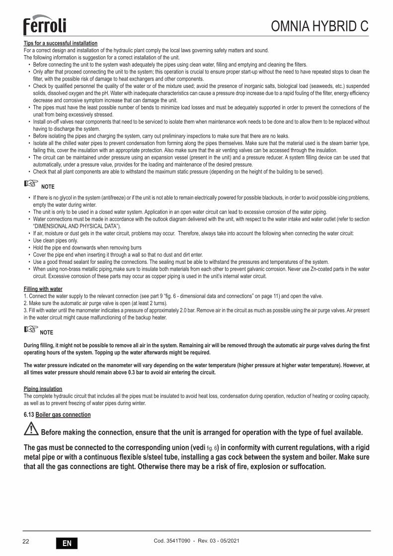
6.13 Boiler gas connection
Before making the connection, ensure that the unit is arranged for operation with the type of fuel available.
The gas must be connected to the corresponding union (vedi fig. 6) in conformity with current regulations, with a rigid metal pipe or with a continuous flexible s/steel tube, installing a gas cock between the system and boiler. Make sure that all the gas connections are tight. Otherwise there may be a risk of fire, explosion or suffocation.
23ENCod. 3541T090 - Rev. 03 - 05/2021
OMNIA HYBRID C6.14 Boiler fume ducts
THE BOILER MUST BE INSTALLED IN PLACES THAT MEET THE FUNDAMENTAL REQUIREMENTS FOR VEN-TILATION. OTHERWISE THERE IS A DANGER OF SUFFOCATION OR INTOXICATION.
READ THE INSTALLATION AND MAINTENANCE INSTRUCTIONS BEFORE INSTALLING THE UNIT.
ALSO FOLLOW THE DESIGN INSTRUCTIONS.
IN CASE OF PRESSURES ABOVE 200 Pa INSIDE THE FUME EXHAUST PIPES, CLASS “H1” FLUES MUST BE USED.
ImportantThe unit is “type C” with sealed chamber and forced draught; the air inlet and fume outlet must be connected to one of the following extraction/suction systems. Before installation, check and carefully observe the above prescriptions. Also, comply with the provisions concerning the positioning of wall and/or roof terminals and the minimum distances from windows, walls, vents, etc.
Installation type C10In case of flues under pressure in a collective flue, before installation and at subsequent maintenance operations, close the fume discharge duct coming from the flue. OTHERWISE THERE IS DANGER OF SUFFOCATION DUE TO PRODUCTS OF COMBUSTION ESCAPING INTO THE BOILER ROOM.Installation of the boiler according to type C10 must be carried out by specialist personnel doing the calculations required by current regulations in compliance with the maximum positive pressure of the flue and the boiler.
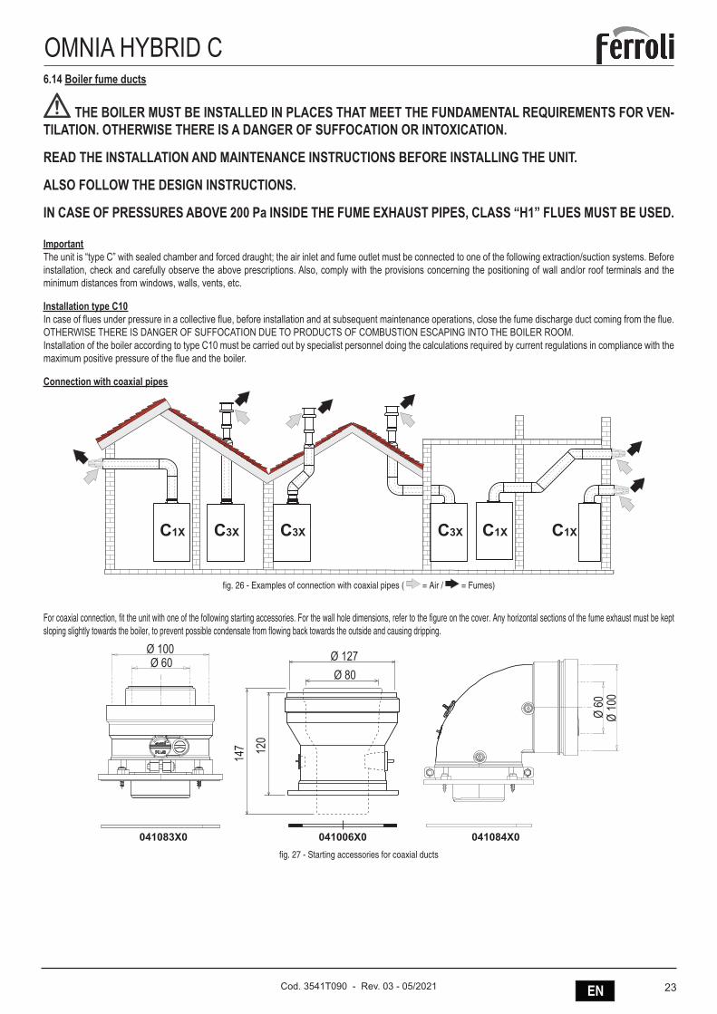
Connection with coaxial pipes
��� ������ ��� ������
fig. 26 - Examples of connection with coaxial pipes ( = Air / = Fumes)
For coaxial connection, fit the unit with one of the following starting accessories. For the wall hole dimensions, refer to the figure on the cover. Any horizontal sections of the fume exhaust must be kept sloping slightly towards the boiler, to prevent possible condensate from flowing back towards the outside and causing dripping.
�������� ����������������
���������
���
���
���������
���
����
��
fig. 27 - Starting accessories for coaxial ducts
24 EN Cod. 3541T090 - Rev. 03 - 05/2021
OMNIA HYBRID CTable. 2 - Max. length coaxial ducts
Coaxial 60/100 Coaxial 80/125Max. permissible length (horizontal) 7 m 20 mMax. permissible length (vertical) 8 mReduction factor 90° bend 1 m 0.5 mReduction factor 45° bend 0.5 m 0.25 m
Connection with separate pipes
��� ��� ��� ��� ���
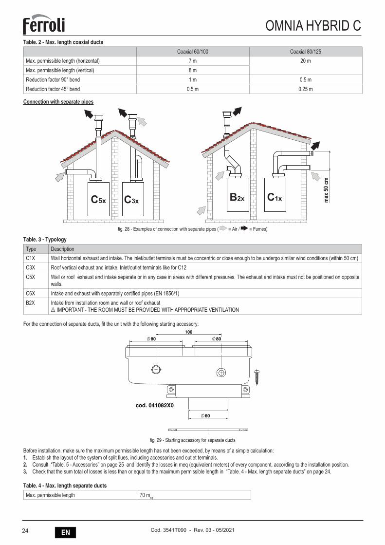
����
��
fig. 28 - Examples of connection with separate pipes ( = Air / = Fumes)
Table. 3 - Typology
Type DescriptionC1X Wall horizontal exhaust and intake. The inlet/outlet terminals must be concentric or close enough to be undergo similar wind conditions (within 50 cm)C3X Roof vertical exhaust and intake. Inlet/outlet terminals like for C12C5X Wall or roof exhaust and intake separate or in any case in areas with different pressures. The exhaust and intake must not be positioned on opposite
walls.C6X Intake and exhaust with separately certified pipes (EN 1856/1)B2X Intake from installation room and wall or roof exhaust
B IMPORTANT - THE ROOM MUST BE PROVIDED WITH APPROPRIATE VENTILATION
For the connection of separate ducts, fit the unit with the following starting accessory:
��
����
��
��
�������������
fig. 29 - Starting accessory for separate ducts
Before installation, make sure the maximum permissible length has not been exceeded, by means of a simple calculation:1. Establish the layout of the system of split flues, including accessories and outlet terminals.2. Consult “Table. 5 - Accessories” on page 25 and identify the losses in meq (equivalent meters) of every component, according to the installation position.3. Check that the sum total of losses is less than or equal to the maximum permissible length in “Table. 4 - Max. length separate ducts” on page 24.
Table. 4 - Max. length separate ducts
Max. permissible length 70 meq
25ENCod. 3541T090 - Rev. 03 - 05/2021
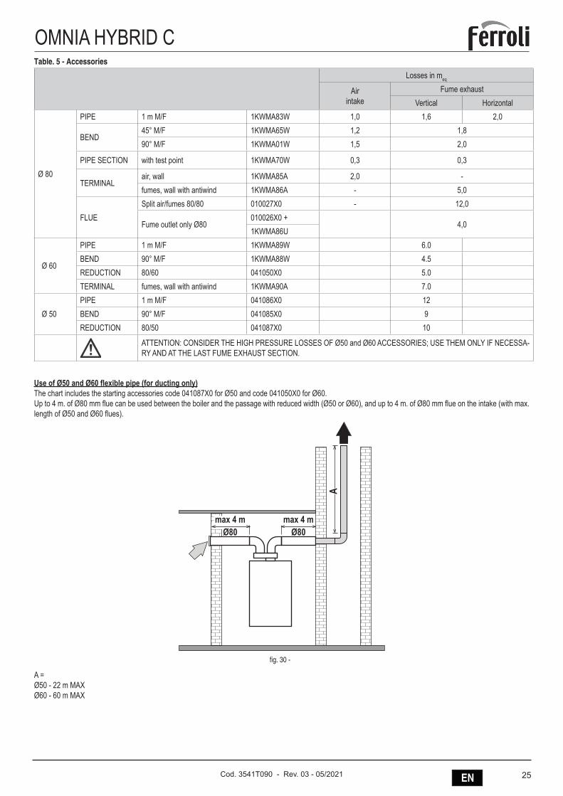
OMNIA HYBRID CTable. 5 - Accessories
Losses in meq
Airintake
Fume exhaustVertical Horizontal
Ø 80
PIPE 1 m M/F 1KWMA83W 1,0 1,6 2,0
BEND45° M/F 1KWMA65W 1,2 1,890° M/F 1KWMA01W 1,5 2,0
PIPE SECTION with test point 1KWMA70W 0,3 0,3
TERMINALair, wall 1KWMA85A 2,0 -fumes, wall with antiwind 1KWMA86A - 5,0
FLUESplit air/fumes 80/80 010027X0 - 12,0
Fume outlet only Ø80010026X0 +
4,01KWMA86U
Ø 60
PIPE 1 m M/F 1KWMA89W 6.0BEND 90° M/F 1KWMA88W 4.5REDUCTION 80/60 041050X0 5.0TERMINAL fumes, wall with antiwind 1KWMA90A 7.0
Ø 50PIPE 1 m M/F 041086X0 12BEND 90° M/F 041085X0 9REDUCTION 80/50 041087X0 10
ATTENTION: CONSIDER THE HIGH PRESSURE LOSSES OF Ø50 and Ø60 ACCESSORIES; USE THEM ONLY IF NECESSA-RY AND AT THE LAST FUME EXHAUST SECTION.
Use of Ø50 and Ø60 flexible pipe (for ducting only)The chart includes the starting accessories code 041087X0 for Ø50 and code 041050X0 for Ø60.Up to 4 m. of Ø80 mm flue can be used between the boiler and the passage with reduced width (Ø50 or Ø60), and up to 4 m. of Ø80 mm flue on the intake (with max. length of Ø50 and Ø60 flues).
����������
����������
�
fig. 30 -
A =Ø50 - 22 m MAXØ60 - 60 m MAX
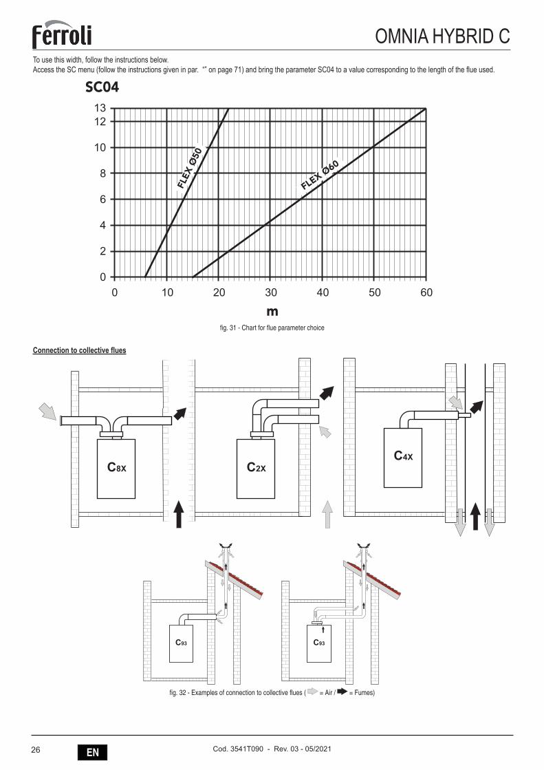
26 EN Cod. 3541T090 - Rev. 03 - 05/2021
OMNIA HYBRID CTo use this width, follow the instructions below.Access the SC menu (follow the instructions given in par. “” on page 71) and bring the parameter SC04 to a value corresponding to the length of the flue used.
�
����
� �� �� �� �� �� ��
��
��
�
�
�
�
�
��
����
����
����
����
fig. 31 - Chart for flue parameter choice
Connection to collective flues
��� ������
������
fig. 32 - Examples of connection to collective flues ( = Air / = Fumes)
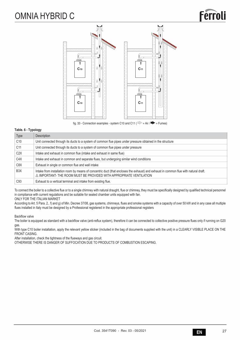
27ENCod. 3541T090 - Rev. 03 - 05/2021
OMNIA HYBRID C
���
���
���
���
fig. 33 - Connection examples - system C10 and C11 ( = Air / = Fumes)
Table. 6 - Typology
Type DescriptionC10 Unit connected through its ducts to a system of common flue pipes under pressure obtained in the structureC11 Unit connected through its ducts to a system of common flue pipes under pressureC2X Intake and exhaust in common flue (intake and exhaust in same flue)C4X Intake and exhaust in common and separate flues, but undergoing similar wind conditionsC8X Exhaust in single or common flue and wall intakeB3X Intake from installation room by means of concentric duct (that encloses the exhaust) and exhaust in common flue with natural draft.
B IMPORTANT- THE ROOM MUST BE PROVIDED WITH APPROPRIATE VENTILATIONC93 Exhaust to a vertical terminal and intake from existing flue.
To connect the boiler to a collective flue or to a single chimney with natural draught, flue or chimney, they must be specifically designed by qualified technical personnel in compliance with current regulations and be suitable for sealed chamber units equipped with fan.ONLY FOR THE ITALIAN MARKETAccording to Art. 5 Para. 2,. f) and g) of Min. Decree 37/08, gas systems, chimneys, flues and smoke systems with a capacity of over 50 kW and in any case all multiple flues installed in Italy must be designed by a Professional registered in the appropriate professional registers
Backflow valveThe boiler is equipped as standard with a backflow valve (anti-reflux system), therefore it can be connected to collective positive pressure flues only if running on G20 gas.With type C10 boiler installation, apply the relevant yellow sticker (included in the bag of documents supplied with the unit) in a CLEARLY VISIBLE PLACE ON THE FRONT CASING.After installation, check the tightness of the flueways and gas circuit.OTHERWISE THERE IS DANGER OF SUFFOCATION DUE TO PRODUCTS OF COMBUSTION ESCAPING.
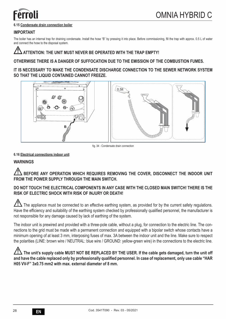
28 EN Cod. 3541T090 - Rev. 03 - 05/2021
OMNIA HYBRID C6.15 Condensate drain connection boiler
IMPORTANTThe boiler has an internal trap for draining condensate. Install the hose “B” by pressing it into place. Before commissioning, fill the trap with approx. 0.5 L of water and connect the hose to the disposal system.
ATTENTION: THE UNIT MUST NEVER BE OPERATED WITH THE TRAP EMPTY!
OTHERWISE THERE IS A DANGER OF SUFFOCATION DUE TO THE EMISSION OF THE COMBUSTION FUMES.
IT IS NECESSARY TO MAKE THE CONDENSATE DISCHARGE CONNECTION TO THE SEWER NETWORK SYSTEM SO THAT THE LIQUID CONTAINED CANNOT FREEZE.
fig. 34 - Condensate drain connection
6.16 Electrical connections indoor unit
WARNINGS
BEFORE ANY OPERATION WHICH REQUIRES REMOVING THE COVER, DISCONNECT THE INDOOR UNIT FROM THE POWER SUPPLY THROUGH THE MAIN SWITCH.
DO NOT TOUCH THE ELECTRICAL COMPONENTS IN ANY CASE WITH THE CLOSED MAIN SWITCH! THERE IS THE RISK OF ELECTRIC SHOCK WITH RISK OF INJURY OR DEATH!
The appliance must be connected to an effective earthing system, as provided for by the current safety regulations. Have the efficiency and suitability of the earthing system checked by professionally qualified personnel, the manufacturer is not responsible for any damage caused by lack of earthing of the system.
The indoor unit is prewired and provided with a three-pole cable, without a plug, for connection to the electric line. The con-nections to the grid must be made with a permanent connection and equipped with a bipolar switch whose contacts have a minimum opening of at least 3 mm, interposing fuses of max. 3A between the indoor unit and the line. Make sure to respect the polarities (LINE: brown wire / NEUTRAL: blue wire / GROUND: yellow-green wire) in the connections to the electric line.
The unit’s supply cable MUST NOT BE REPLACED BY THE USER. If the cable gets damaged, turn the unit off and have the cable replaced only by professionally qualified personnel. In case of replacement, only use cable “HAR H05 VV-F” 3x0.75 mm2 with max. external diameter of 8 mm.
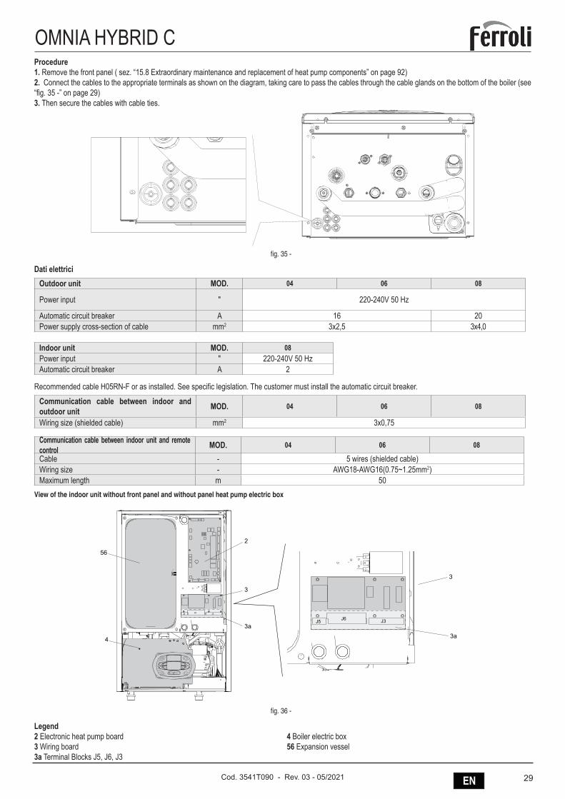
29ENCod. 3541T090 - Rev. 03 - 05/2021
OMNIA HYBRID CProcedure1. Remove the front panel ( sez. “15.8 Extraordinary maintenance and replacement of heat pump components” on page 92) 2. Connect the cables to the appropriate terminals as shown on the diagram, taking care to pass the cables through the cable glands on the bottom of the boiler (see “fig. 35 -” on page 29)3. Then secure the cables with cable ties.
fig. 35 -
Dati elettriciOutdoor unit MOD. 04 06 08
Power input " 220-240V 50 Hz
Automatic circuit breaker A 16 20Power supply cross-section of cable mm2 3x2,5 3x4,0
Indoor unit MOD. 08Power input " 220-240V 50 HzAutomatic circuit breaker A 2
Recommended cable H05RN-F or as installed. See specific legislation. The customer must install the automatic circuit breaker.
Communication cable between indoor and outdoor unit MOD. 04 06 08
Wiring size (shielded cable) mm2 3x0,75
Communication cable between indoor unit and remote control MOD. 04 06 08
Cable - 5 wires (shielded cable)Wiring size - AWG18-AWG16(0.75~1.25mm2)Maximum length m 50
View of the indoor unit without front panel and without panel heat pump electric box
4
56
2
3
3a
J5 J6 J3
J5 J6 J3
3
3a
fig. 36 -
Legend2 Electronic heat pump board3 Wiring board3a Terminal Blocks J5, J6, J3
4 Boiler electric box56 Expansion vessel
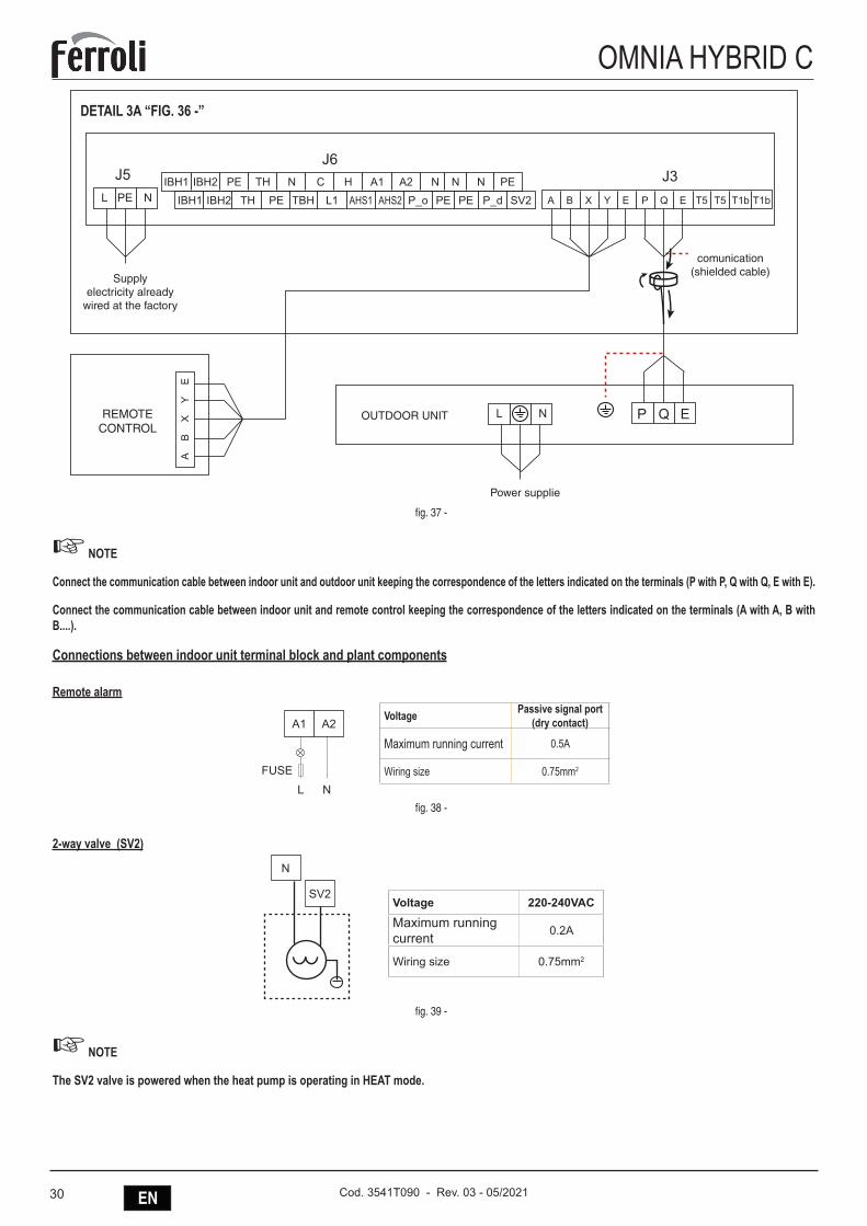
30 EN Cod. 3541T090 - Rev. 03 - 05/2021
OMNIA HYBRID C
Outdoor Unit
Power Supply 3-shield wire
COMANDO REMOTO
A B X Y E
AB
XY
E
P Q E T5 T5 T1b T1b
IBH1J5J6
J3IBH2 PE TH N C H A1 A2 N N N PEIBH1 IBH2L PE
PE
N TH PE TBH L1 AHS1 AHS2 P_o PEPE P_d SV2
Power Supply
L N EQPOUTDOOR UNITREMOTE CONTROL
Supplyelectricity already
wired at the factory
Power supplie
comunication (shielded cable)
DETAIL 3A “FIG. 36 -”
fig. 37 -
☞ NOTE
Connect the communication cable between indoor unit and outdoor unit keeping the correspondence of the letters indicated on the terminals (P with P, Q with Q, E with E).
Connect the communication cable between indoor unit and remote control keeping the correspondence of the letters indicated on the terminals (A with A, B with B....).
Connections between indoor unit terminal block and plant components
Remote alarm
Voltage Passive signal port(dry contact)
Maximum running current 0.5A
Wiring size 0.75mm2
A1 A2
LFUSE
Nfig. 38 -
2-way valve (SV2)
Voltage 220-240VAC
Maximum running current 0.2A
Wiring size 0.75mm2
SV2
N
fig. 39 -
☞ NOTE
The SV2 valve is powered when the heat pump is operating in HEAT mode.
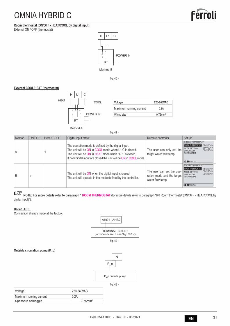
31ENCod. 3541T090 - Rev. 03 - 05/2021
OMNIA HYBRID CRoom thermostat (ON/OFF - HEAT/COOL by digital input) External ON / OFF (thermostat)
POWER IN
Method B
H
RT
L1 C
fig. 40 -
External COOL/HEAT (thermostat)
Voltage 220-240VAC
Maximum running current 0.2A
Wiring size 0.75mm2
HEATCOOL
POWER IN
Method A
H
RT
L1 C
fig. 41 -
Method ON/OFF Heat / COOL Digital input effect Remote controller Setup*
A √
The operation mode is defined by the digital input. The unit will be ON in COOL mode when L1-C is closed. The unit will be ON in HEAT mode when H-L1 is closed.If both digital input are closed the unit will be ON in COOL mode.
The user can only set the target water flow temp.
6 ROOM THERMOSTATROOM THERMOSTATMODE SETTINGDUAL ROOMTHERMOSTAT
SCROLL
YES NONYES NON
YES NON
6 ROOM THERMOSTATROOM THERMOSTATMODE SETTINGDUAL ROOMTHERMOSTAT
SCROLL
YES NONYES NON
YES NONB √ The unit will be ON when the digital input is closed. The unit will operate in the mode defined by the controller.
The user can set the ope-ration mode and the target water flow temp.
6 ROOM THERMOSTATROOM THERMOSTATMODE SETTINGDUAL ROOMTHERMOSTAT
SCROLL
YES NONYES NON
YES NON
6 ROOM THERMOSTATROOM THERMOSTATMODE SETTINGDUAL ROOMTHERMOSTAT
SCROLL
YES NONYES NON
YES NON
☞ NOTE: For more details refer to paragraph “ ROOM THERMOSTAT (for more details refer to paragraph “8.8 Room thermostat (ON/OFF - HEAT/COOL by digital input)”).
Boiler (AHS)Connection already made at the factory.
TERMINAL BOILER(terminals 5 and 6 see “fig. 207 -”)
AHS1 AHS2
fig. 42 -
Outside circulation pump (P_o)
P_o outside pump
P_o
N
fig. 43 -
Voltage 220-240VACMaximum running current 0.2ASpessore cablaggio 0.75mm2
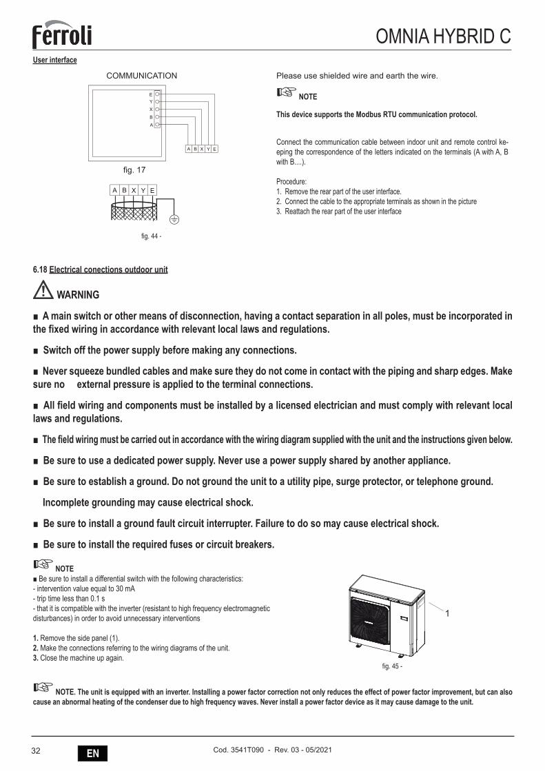
32 EN Cod. 3541T090 - Rev. 03 - 05/2021
OMNIA HYBRID CUser interface
A B X Y E
A
B
X
YE
A B X Y E
COMMUNICATION
fig. 17
fig. 44 -
Please use shielded wire and earth the wire.
☞ NOTE
This device supports the Modbus RTU communication protocol.
Connect the communication cable between indoor unit and remote control ke-eping the correspondence of the letters indicated on the terminals (A with A, B with B....).
Procedure:1. Remove the rear part of the user interface.2. Connect the cable to the appropriate terminals as shown in the picture 3. Reattach the rear part of the user interface
6.18 Electrical conections outdoor unit
WARNING
■ A main switch or other means of disconnection, having a contact separation in all poles, must be incorporated in the fixed wiring in accordance with relevant local laws and regulations.
■ Switch off the power supply before making any connections.
■ Never squeeze bundled cables and make sure they do not come in contact with the piping and sharp edges. Make sure no external pressure is applied to the terminal connections.
■ All field wiring and components must be installed by a licensed electrician and must comply with relevant local laws and regulations.
■ The field wiring must be carried out in accordance with the wiring diagram supplied with the unit and the instructions given below.
■ Be sure to use a dedicated power supply. Never use a power supply shared by another appliance.
■ Be sure to establish a ground. Do not ground the unit to a utility pipe, surge protector, or telephone ground.
Incomplete grounding may cause electrical shock.
■ Be sure to install a ground fault circuit interrupter. Failure to do so may cause electrical shock.
■ Be sure to install the required fuses or circuit breakers.
☞ NOTE ■ Be sure to install a differential switch with the following characteristics:- intervention value equal to 30 mA- trip time less than 0.1 s- that it is compatible with the inverter (resistant to high frequency electromagnetic disturbances) in order to avoid unnecessary interventions
1. Remove the side panel (1).2. Make the connections referring to the wiring diagrams of the unit.3. Close the machine up again.
1
fig. 45 -
☞ NOTE. The unit is equipped with an inverter. Installing a power factor correction not only reduces the effect of power factor improvement, but can also cause an abnormal heating of the condenser due to high frequency waves. Never install a power factor device as it may cause damage to the unit.
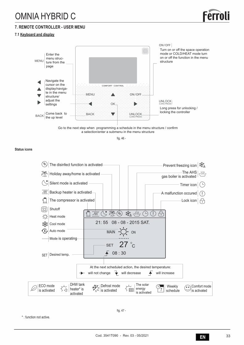
33ENCod. 3541T090 - Rev. 03 - 05/2021
OMNIA HYBRID C7. REMOTE CONTROLLER - USER MENU7.1 Keyboard and display
Enter the menu struc-ture from the page
Navigate the cursor on the display/naviga-te in the menu structure/ adjust the settings
Come back to the up level
Go to the next step when programming a schedule in the menu structure / confirm a selection/enter a submenu in the menu structure
Long press for unlocking /locking the controller
Turn on or off the space operation mode or COLD/HEAT mode turn on or off the function in the menu structure
fig. 46 -
Status icons
Lock icon
Timer icon
Prevent freezing icon
The AHSgas boiler is activated
A malfunction occured
Silent mode is activated
The disinfect function is activated
Holiday away/home is activated
Backup heater is activated
The compressor is activated
Desired temp.
will not change will decrease will increase
27SET
SET 08 : 30C
ONMAIN
21: 55 08 - 08 - 2015 SAT.Heat mode
Cool mode
Auto mode
Mode is operating
A
At the next scheduled action, the desired temperature:
Shutoff
ECO mode is activated
DHW tank heater* is activated
Defrost modeis activated
The solar energy is activated
Weekly schedule7
Comfort modeis activated
fig. 47 -
* : function not active.
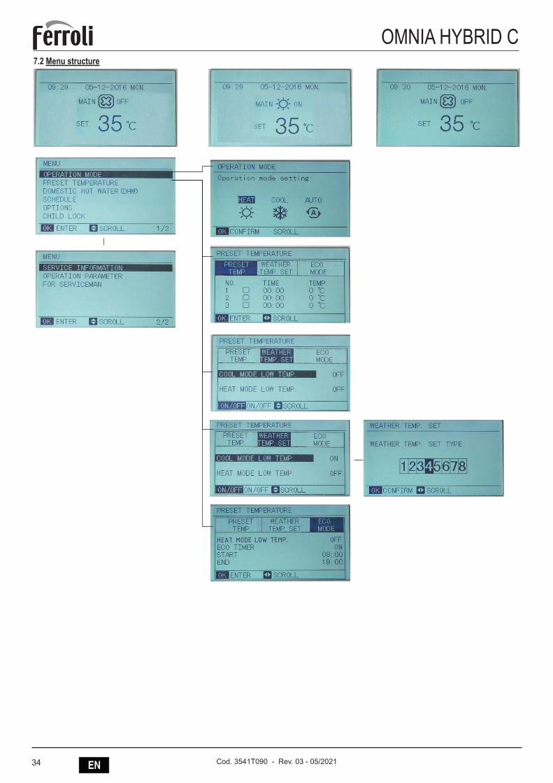
34 EN Cod. 3541T090 - Rev. 03 - 05/2021
OMNIA HYBRID C7.2 Menu structure
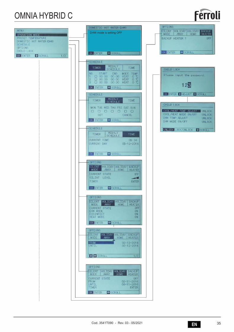
35ENCod. 3541T090 - Rev. 03 - 05/2021
OMNIA HYBRID C
DHW mode is setting OFF
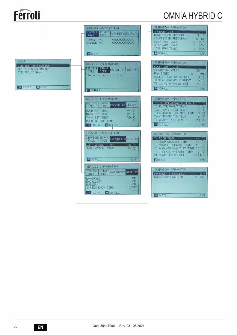
36 EN Cod. 3541T090 - Rev. 03 - 05/2021
OMNIA HYBRID C
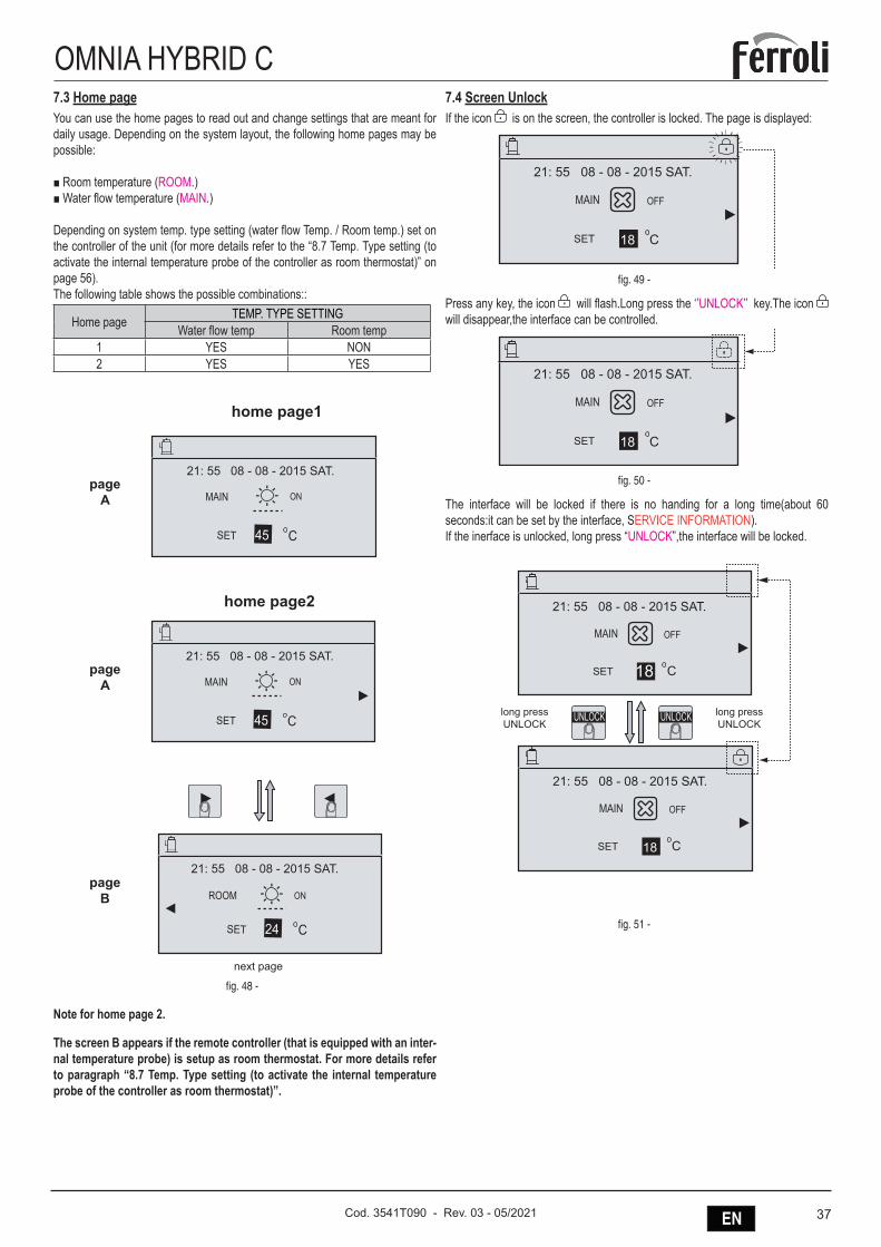
37ENCod. 3541T090 - Rev. 03 - 05/2021
OMNIA HYBRID C7.3 Home pageYou can use the home pages to read out and change settings that are meant for daily usage. Depending on the system layout, the following home pages may be possible:
■ Room temperature (ROOM.) ■ Water flow temperature (MAIN.)
Depending on system temp. type setting (water flow Temp. / Room temp.) set on the controller of the unit (for more details refer to the “8.7 Temp. Type setting (to activate the internal temperature probe of the controller as room thermostat)” on page 56).The following table shows the possible combinations::
Home page TEMP. TYPE SETTINGWater flow temp Room temp
1 YES NON2 YES YES
home page1
home page2
next page
FHL1FHL2...FHLn
FCU1FCU2...FCUn
next page
21: 55 08 - 08 - 2015 SAT.
ON
21: 55 08 - 08 - 2015 SAT.
ONMAIN
ROOM
the system layout 3
SET C45
SET C24
next page
FHL1FHL2...FHLn
FCU1FCU2...FCUn
next page
21: 55 08 - 08 - 2015 SAT.
ON
21: 55 08 - 08 - 2015 SAT.
ONMAIN
ROOM
the system layout 3
SET C45
SET C24
next page
FHL1FHL2...FHLn
FCU1FCU2...FCUn
next page
21: 55 08 - 08 - 2015 SAT.
ON
21: 55 08 - 08 - 2015 SAT.
ONMAIN
ROOM
the system layout 3
SET C45
SET C24
next page
FHL1FHL2...FHLn
FCU1FCU2...FCUn
next page
21: 55 08 - 08 - 2015 SAT.
ON
21: 55 08 - 08 - 2015 SAT.
ONMAIN
ROOM
the system layout 3
SET C45
SET C24
next page
FHL1FHL2...FHLn
FCU1FCU2...FCUn
next page
21: 55 08 - 08 - 2015 SAT.
ON
21: 55 08 - 08 - 2015 SAT.
ONMAIN
ROOM
the system layout 3
SET C45
SET C24
pageA
pageA
pageB
fig. 48 -
Note for home page 2.
The screen B appears if the remote controller (that is equipped with an inter-nal temperature probe) is setup as room thermostat. For more details refer to paragraph “8.7 Temp. Type setting (to activate the internal temperature probe of the controller as room thermostat)”.
7.4 Screen UnlockIf the icon is on the screen, the controller is locked. The page is displayed:
SET C
OFFMAIN
21: 55 08 - 08 - 2015 SAT.
18
SET C
OFFMAIN
21: 55 08 - 08 - 2015 SAT.
18
fig. 49 -
Press any key, the icon will flash.Long press the ‘’UNLOCK’’ key.The icon will disappear,the interface can be controlled.
SET C
OFFMAIN
21: 55 08 - 08 - 2015 SAT.
18
SET C
OFFMAIN
21: 55 08 - 08 - 2015 SAT.
18
fig. 50 -
The interface will be locked if there is no handing for a long time(about 60 seconds:it can be set by the interface, SERVICE INFORMATION).If the inerface is unlocked, long press “UNLOCK”,the interface will be locked.
SET C
OFFMAIN
21: 55 08 - 08 - 2015 SAT.
18
SET C
OFFMAIN
21: 55 08 - 08 - 2015 SAT.
18
UNLOCK UNLOCKlong pressUNLOCK
long pressUNLOCK
fig. 51 -
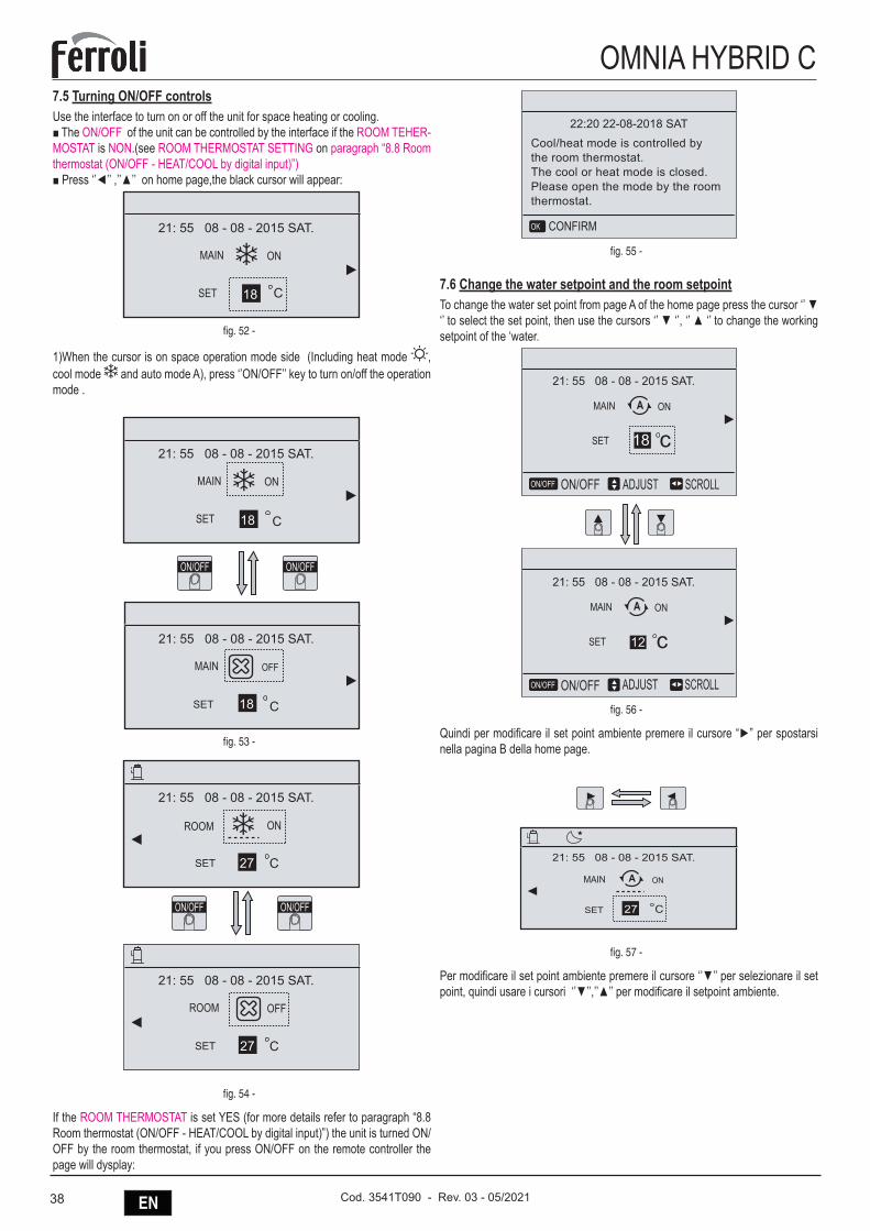
38 EN Cod. 3541T090 - Rev. 03 - 05/2021
OMNIA HYBRID C7.5 Turning ON/OFF controlsUse the interface to turn on or off the unit for space heating or cooling.■ The ON/OFF of the unit can be controlled by the interface if the ROOM TEHER-MOSTAT is NON.(see ROOM THERMOSTAT SETTING on paragraph “8.8 Room thermostat (ON/OFF - HEAT/COOL by digital input)”)■ Press ‘’◄’’ ,’’▲’’ on home page,the black cursor will appear:
SET C
ONMAIN
21: 55 08 - 08 - 2015 SAT.
18
fig. 52 -
1)When the cursor is on space operation mode side (Including heat mode , cool mode and auto mode A), press ‘’ON/OFF’’ key to turn on/off the operation mode .
SET C
ONMAIN
21: 55 08 - 08 - 2015 SAT.
18
SET C
OFFMAIN
21: 55 08 - 08 - 2015 SAT.
18
ON/OFF ON/OFF
fig. 53 -
SET C
21: 55 08 - 08 - 2015 SAT.
ONROOM
27
SET C
21: 55 08 - 08 - 2015 SAT.
OFFROOM
27
ON/OFF ON/OFF
fig. 54 -
If the ROOM THERMOSTAT is set YES (for more details refer to paragraph “8.8 Room thermostat (ON/OFF - HEAT/COOL by digital input)”) the unit is turned ON/OFF by the room thermostat, if you press ON/OFF on the remote controller the page will dysplay:
22:20 22-08-2018 SATCool/heat mode is controlled bythe room thermostat.The cool or heat mode is closed.Please open the mode by the roomthermostat.
CONFIRMOK
fig. 55 -
7.6 Change the water setpoint and the room setpointTo change the water set point from page A of the home page press the cursor ‘’ ▼ ‘’ to select the set point, then use the cursors ‘’ ▼ ‘’, ‘’ ▲ ‘’ to change the working setpoint of the ‘water.
SET cONMAIN
21: 55 08 - 08 - 2015 SAT.
A
ON/OFFON/OFF
SET cONMAIN
21: 55 08 - 08 - 2015 SAT.
A
ON/OFFON/OFF
12
18
SCROLLADJUST
SCROLLADJUST
fig. 56 -
Quindi per modificare il set point ambiente premere il cursore “►” per spostarsi nella pagina B della home page.
SET C27
21: 55 08 - 08 - 2015 SAT.
ONMAIN A
SET cONROOM
21: 55 08 - 08 - 2015 SAT.
A
ON/OFFON/OFF
SET cONROOM
21: 55 08 - 08 - 2015 SAT.
A
ON/OFFON/OFF
25
27
SCROLLADJUST
SCROLLADJUST
fig. 57 -
Per modificare il set point ambiente premere il cursore ‘’▼’’ per selezionare il set point, quindi usare i cursori ‘’▼’’,’’▲’’ per modificare il setpoint ambiente.
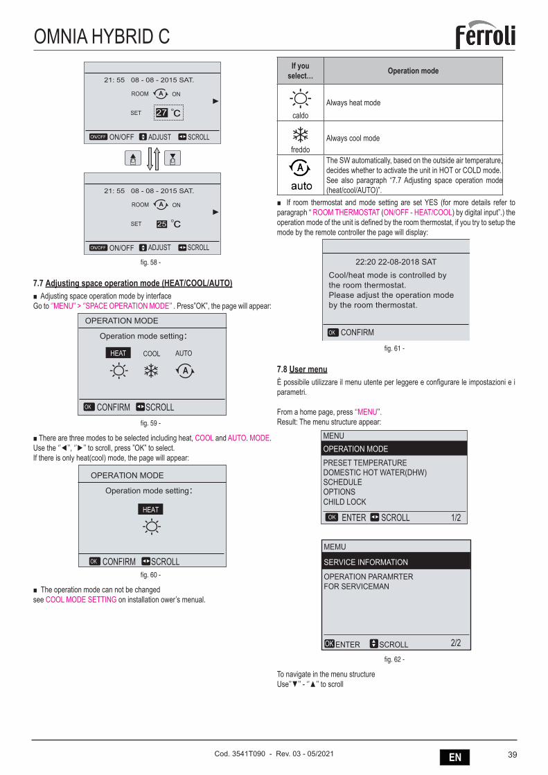
39ENCod. 3541T090 - Rev. 03 - 05/2021
OMNIA HYBRID CSET C27
21: 55 08 - 08 - 2015 SAT.
ONMAIN A
SET cONROOM
21: 55 08 - 08 - 2015 SAT.
A
ON/OFFON/OFF
SET cONROOM
21: 55 08 - 08 - 2015 SAT.
A
ON/OFFON/OFF
25
27
SCROLLADJUST
SCROLLADJUST
fig. 58 -
7.7 Adjusting space operation mode (HEAT/COOL/AUTO)■ Adjusting space operation mode by interfaceGo to ‘’MENU’’ > ‘’SPACE OPERATION MODE’’ . Press”OK”, the page will appear:
Operation mode setting:
OPERATION MODE
SCROLLCONFIRMOK
COOL AUTO
A
HEAT
fig. 59 -
■ There are three modes to be selected including heat, COOL and AUTO. MODE. Use the ‘’◄’’, ‘’►’’ to scroll, press ”OK” to select.If there is only heat(cool) mode, the page will appear:
Operation mode setting:
OPERATION MODE
SCROLLCONFIRMOK
HEAT
fig. 60 -
■ The operation mode can not be changedsee COOL MODE SETTING on installation ower’s menual.
If you select… Operation mode
caldoAlways heat mode
freddoAlways cool mode
The SW automatically, based on the outside air temperature, decides whether to activate the unit in HOT or COLD mode.See also paragraph “7.7 Adjusting space operation mode (heat/cool/AUTO)”.
■ If room thermostat and mode setting are set YES (for more details refer to paragraph “ ROOM THERMOSTAT (ON/OFF - HEAT/COOL) by digital input”.) the operation mode of the unit is defined by the room thermostat, if you try to setup the mode by the remote controller the page will display:
22:20 22-08-2018 SATCool/heat mode is controlled bythe room thermostat.Please adjust the operation modeby the room thermostat.
CONFIRMOK
fig. 61 -
7.8 User menuÈ possibile utilizzare il menu utente per leggere e configurare le impostazioni e i parametri.
From a home page, press ‘‘MENU’’. Result: The menu structure appear:
MEMU
SERVICE INFORMATION
OPERATION PARAMRTERFOR SERVICEMAN
SCROLLENTEROK
SCROLL 1/2
2/2
ENTEROK
MENUOPERATION MODE PRESET TEMPERATUREDOMESTIC HOT WATER(DHW)SCHEDULEOPTIONSCHILD LOCK
fig. 62 -
To navigate in the menu structureUse’’▼’’ - ‘’▲’’ to scroll
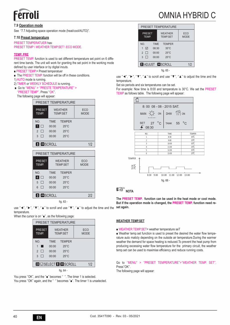
40 EN Cod. 3541T090 - Rev. 03 - 05/2021
OMNIA HYBRID C7.9 Operation modeSee “7.7 Adjusting space operation mode (heat/cool/AUTO)”.
7.10 Preset temperaturePRESET TEMPERATUER has:PRESET TEMP \ WEATHER TEMP.SET \ ECO MODE.
TEMP. PREPRESET TEMP. function is used to set different temperature set point on 6 diffe-rent time bands. The unit will work for granting the set point in the working mode defined by user interface or by digital inouts.■ PRESET TEMP.= Preset temperatuer■ The PRESET TEMP. function will be off in these conditions.1) AUTO mode is running.2) TIMER or WEEKLY SCHEDULE is running. ■ Go to ‘’MENU’’ > ‘’PRESTE TEMPERATURE’’ > ‘’PRESET TEMP’’. Press ‘‘OK’’. The following page will appear:
PRESET TEMPERATURE
SCROLL 1/2
WEATHERTEMP.SET
ECOMODE
PRESETTEMP.
NO. TIME TEMPER00:00 25°C00:00 25°C00:00 25°C
23
1
PRESET TEMPERATURE
SCROLL 2/2
WEATHERTEMP.SET
ECOMODE
PRESETTEMP.
NO. TIME TEMPER00:00 25°C00:00 25°C00:00 25°C
56
4
fig. 63 -
use ‘’◄’’, ‘’►’’, ‘’▼’’, ‘’▲’’ to scroll and use ‘’▼’’, ‘’▲’’ to adjust the time and the temperature.When the cursor is on ‘’■’’, as the following page:
PRESET TEMPERATURE
SELECT SCROLL 1/2
WEATHERTEMP.SET
ECOMODE
PRESETTEMP.
NO. TIME TEMPER00:00 25°C00:00 25°C00:00 25°C
23
1
OK
fig. 64 -
You press ‘’OK’’, and the ‘’■’’ becomes ‘’ ‘’. The timer 1 is selected.You press ‘’OK’’ again, and the ‘’ ‘’ becomes ‘’■’’. The timer 1 is unselected.
PRESET TEMPERATURE
SCROLLADJUST 1/2
WEATHERTEMP.SET
ECOMODE
PRESETTEMP.
NO. TIME TEMPER08:30 35°C00:00 25°C00:00 25°C
23
1
fig. 65 -
use ‘’◄’’, ‘’►’’, ‘’▼’’, ‘’▲’’ to scroll and use ‘’▼’’, ‘’▲’’ to adjust the time and the temperature.Set six periods and six temperatures can be set.For example: Now time is 8:00 and temperature is 30°C. We set the PRESET TEMP as follows table. The following page will appear:
TANK 55 C2708:30
SET C
ONON DHWMAIN
8: 00 08 - 08 - 2015 SAT.
NO. TIME TEMPER 1 8:30 35℃
2 9:00 25℃ 3 10:00 35℃
4 11:00 25℃ 5 12:00 35℃ 6 13:00 25℃
TEMPER
35℃ 25℃
8:30 9:00 10:00 11:00 12:00 13:00
fig. 66 -
☞ NOTA
The PRESET TEMP. function can be used in the heat mode or cool mode. But if the operation mode is changed, the PRESET TEMP. function need re-set again.
WEATHER TEMP.SET
■ WEATHER TEMP.SET= weather temperature seT■ Weather temp.set function is used to preset the desired the water flow tempe-rature auto maticly depending on the outside air temperature.During the warmer weather the demand for space heating is reduced.To prevent the heat pump from producing excessing water flow temperature for the primary circuit, the weather temp.set can be used to maximise efficiency and reduce running costs.
Go to ‘’MENU’’ > ‘’PRESET TEMPERATURE’’>’’WEATHER TEMP. SET’’. Press’’OK’’. The following page will appear:
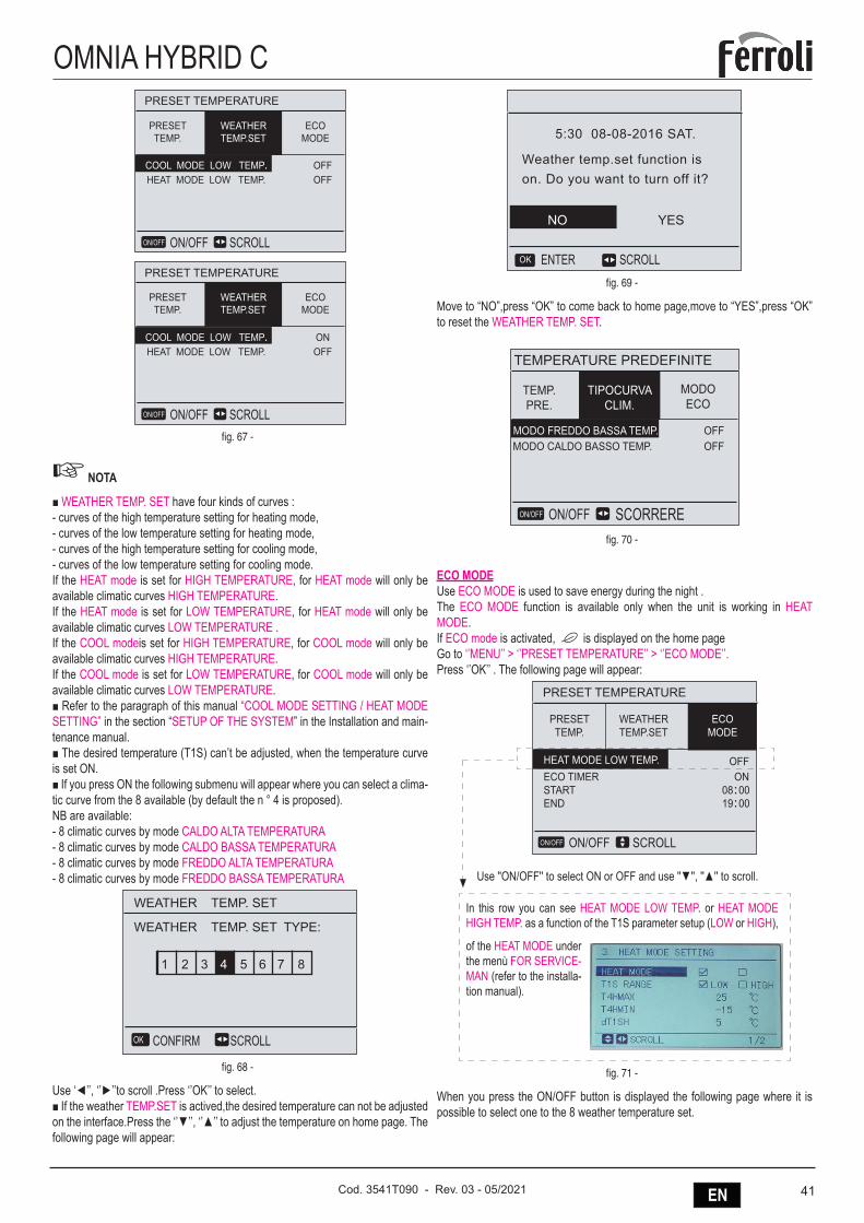
41ENCod. 3541T090 - Rev. 03 - 05/2021
OMNIA HYBRID CPRESET TEMPERATURE
SCROLLON/OFF
ECOMODE
PRESETTEMP.
COOL MODE LOW TEMP.HEAT MODE LOW TEMP.
OFFOFF
WEATHERTEMP.SET
ON/OFF
PRESET TEMPERATURE
SCROLLON/OFF
COOL MODE LOW TEMP.HEAT MODE LOW TEMP.
ONOFF
ON/OFF
ECOMODE
PRESETTEMP.
WEATHERTEMP.SET
fig. 67 -
☞ NOTA
■ WEATHER TEMP. SET have four kinds of curves :- curves of the high temperature setting for heating mode,- curves of the low temperature setting for heating mode, - curves of the high temperature setting for cooling mode,- curves of the low temperature setting for cooling mode.If the HEAT mode is set for HIGH TEMPERATURE, for HEAT mode will only be available climatic curves HIGH TEMPERATURE.If the HEAT mode is set for LOW TEMPERATURE, for HEAT mode will only be available climatic curves LOW TEMPERATURE .If the COOL modeis set for HIGH TEMPERATURE, for COOL mode will only be available climatic curves HIGH TEMPERATURE.If the COOL mode is set for LOW TEMPERATURE, for COOL mode will only be available climatic curves LOW TEMPERATURE.■ Refer to the paragraph of this manual “COOL MODE SETTING / HEAT MODE SETTING” in the section “SETUP OF THE SYSTEM” in the Installation and main-tenance manual.■ The desired temperature (T1S) can’t be adjusted, when the temperature curve is set ON.■ If you press ON the following submenu will appear where you can select a clima-tic curve from the 8 available (by default the n ° 4 is proposed).NB are available:- 8 climatic curves by mode CALDO ALTA TEMPERATURA - 8 climatic curves by mode CALDO BASSA TEMPERATURA - 8 climatic curves by mode FREDDO ALTA TEMPERATURA - 8 climatic curves by mode FREDDO BASSA TEMPERATURA
WEATHER TEMP. SET TYPE:
WEATHER TEMP. SET
SCROLLCONFIRMOK
1 2 3 5 6 7 84
fig. 68 -
Use ‘◄’’, ‘’►’’to scroll .Press ‘’OK’’ to select.■ If the weather TEMP.SET is actived,the desired temperature can not be adjusted on the interface.Press the ‘’▼’’, ‘’▲’’ to adjust the temperature on home page. The following page will appear:
5:30 08-08-2016 SAT.
Weather temp.set function ison. Do you want to turn off it?
SCROLLENTEROK
NO YES
fig. 69 -
Move to “NO”,press “OK” to come back to home page,move to “YES”,press “OK” to reset the WEATHER TEMP. SET.
ON/OFF
MODO FREDDO BASSA TEMP.MODO CALDO BASSO TEMP.
OFFOFF
ON/OFF
ON/OFF
ONOFF
ON/OFF
SCORRERE
SCORRERE
TEMPERATURE PREDEFINITE
TIPOCURVACLIM.
MODOECO
TEMP.PRE.
TEMPERATURE PREDEFINITE
MODO FREDDO BASSA TEMP.MODO CALDO BASSO TEMP.
TIPOCURVACLIM.
MODOECO
TEMP.PRE.
fig. 70 -
ECO MODEUse ECO MODE is used to save energy during the night .The ECO MODE function is available only when the unit is working in HEAT MODE. If ECO mode is activated, is displayed on the home pageGo to ‘’MENU’’ > ‘’PRESET TEMPERATURE’’ > ‘’ECO MODE’’.Press ‘’OK’’ . The following page will appear:
Use ''ON/OFF'' to select ON or OFF and use ''▼'', ''▲'' to scroll.
In this row you can see HEAT MODE LOW TEMP. or HEAT MODE HIGH TEMP. as a function of the T1S parameter setup (LOW or HIGH),
PRESET TEMPERATURE
PRESETTEMP.
ECO TIMERSTARTEND
OFF
WEATHERTEMP.SET
ECOMODE
HEAT MODE LOW TEMP.
SCROLLON/OFFON/OFF
of the HEAT MODE under the menù FOR SERVICE-MAN (refer to the installa-tion manual).
fig. 71 -
When you press the ON/OFF button is displayed the following page where it is possible to select one to the 8 weather temperature set.
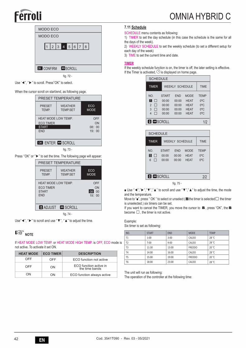
42 EN Cod. 3541T090 - Rev. 03 - 05/2021
OMNIA HYBRID C
SCROLLCONFIRMOK
1 2 3 5 6 7 84
MODO ECO
MODO ECO
fig. 72 -
Use ‘◄’’, ‘’►’’ to scroll. Press’’OK’’ to select.
When the cursor scroll on start/end, as following page.
PRESET TEMPERATURE
SCROLLENTER
OFF
OK
ECO TIMER
END
ON08:0019:00
START
PRESETTEMP.
HEAT MODE LOW TEMP.
WEATHERTEMP.SET
ECOMODE
fig. 73 -
Press ‘’OK’’ or ‘’►’’ to set the time. The following page will appear:
PRESET TEMPERATURE
OFFECO TIMERSTARTEND
SCROLLADJUST
ON08:0019:00
PRESETTEMP.
HEAT MODE LOW TEMP.
WEATHERTEMP.SET
ECOMODE
fig. 74 -
Use’’◄’’, ‘’►’’ to scroll and use ‘’▼’’, ‘’▲’’ to adjust the time.
☞ NOTE
If HEAT MODE LOW TEMP. or HEAT MODE HIGH TEMP. is OFF, ECO mode is not active. To activate it set ON.
HEAT MODE ECO TIMER DESCRIPTIONOFF OFF ECO function not active
OFF ON ECO function active in the time bands
ON ON ECO function always active
7.11 ScheduleSCHEDULE menu contents as following:1) TIMER to set the day schedule (in this case the schedule is the same for all the days of the week).2) WEEKLY SCHEDULE to set the weekly schedule (to set a different setup for each day of the week) 3) TIME to set the current time and date.
TIMERIf the weekly schedule function is on, the timer is off, the later setting is effective. If the Timer is activated, is displayed on home page.
SCHEDULE
1/2
NO. START
00:0000:00
23
00:004
1END MODE TEMP
HEATHEATHEATHEAT
0ºC0ºC0ºC0ºC
WEEKLY SCHEDULE TIME
00:0000:0000:0000:00
00:00
TIMER
SCROLL
SCHEDULE
2/2
NO. START
00:0065
END MODE TEMPHEATHEAT
0ºC0ºC
WEEKLY SCHEDULE TIME
00:0000:0000:00
TIMER
SCROLLfig. 75 -
■ Use ‘’◄’’,’’►’’,’’▼’’,’’▲’’ to scroll and use ‘’▼’’,’’▲’’ to adjust the time, the mode and the temperature.Move to “■”, press ‘’ OK ‘’ to select or unselect ( the timer is selected the timer is unselected.) six timers can be set.If you want to cancel the TIMER, you move the cursor to , press “OK”, the become , the timer is not active.
Example:Six timer is set as following:
NO. START END MODE TEMP
T1 1:00 3:00 CALDO 28 °C
28 °C
28 °C
T2 7:00 9:00 CALDO
T3 11:30 13:00 FREDDO 20 °C
T4 14:00 16:00 CALDO 28 °C
T5 15:00 19:00 FREDDO 20 °C
T6 18:00 23:00 CALDO
The unit will run as following:The operation of the controller at the following time:
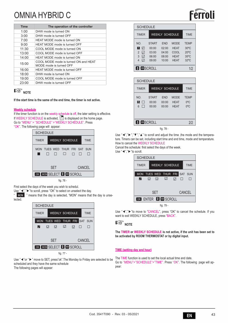
43ENCod. 3541T090 - Rev. 03 - 05/2021
OMNIA HYBRID CTime The operation of the controller1:00 DHW mode is turned ON3:00 DHW mode is turned OFF7:00 HEAT MODE mode is turned ON9:00 HEAT MODE mode is turned OFF11:30 COOL MODE mode is turned ON13:00 COOL MODE mode is turned OFF14:00 HEAT MODE mode is turned ON
15:00 COOL MODE mode is turned ON and HEAT MODE mode is turned OFF
16:00 HEAT MODE mode is turned OFF18:00 DHW mode is turned ON19:00 COOL MODE mode is turned OFF23:00 DHW mode is turned OFF
☞ NOTE
If the start time is the same of the end time, the timer is not active.
Weekly scheduleIf the timer function is on the weekly schedule is off, the later setting is effective. If WEEKLY SCHEDULE is activated, is displayed on the home page.Go to ‘‘MENU’’ > ‘’SCHEDULE’’ >’’WEEKLY SCHEDULE’’. Press‘‘OK’’. The following page will appear:
SCHEDULE
MON TUES WED THUR FRI SAT SUN
TIMETIMER
SCROLL
SET CANCEL
SELECT
WEEKLY SCHEDULE
OK MON
fig. 76 -
First select the days of the week you wish to schedul.Use ‘’◄’’,’’►’’to scroll, press ‘’OK’’ to select on unselect the day.“ ” means that the day is selected, “MON” means that the day is unse-lected.
SCHEDULE
TIMETIMER
SCROLL
SET CANCEL
SELECT
WEEKLY SCHEDULE
OK MON
MON TUES WED THUR FRI SAT SUN
fig. 77 -
Use ‘’◄’’or ‘’►’’ move to SET, press”ok”.The Monday to Friday are selected to be scheduled and they have the same scheduleThe following pages will appear:
TIMETIMER WEEKLY SCHEDULE
SCHEDULE
2/2
NO. START
00:0065
END MODE TEMPHEATHEAT
0ºC0ºC
00:0000:0000:00
SCROLL
TIMETIMER WEEKLY SCHEDULE
SCHEDULE
1/2
NO. START
03:0006:00
23
09:004
1END MODE TEMP
HEATCOOLHEATHEAT
30ºC20ºC35ºC32ºC
00:0004:0008:0010:00
02:00
SCROLL
fig. 78 -
Use ‘’◄’’,’’►’’,’’▼’’,’’▲’’ to scroll and adjust the time ,the mode and the tempera-ture. Timers can be set, including start time and end time, mode and temperature.How to cancel the WEEKLY SCHEDULECancel the schedule: first select the days of the week.Use ‘’◄’’,’’►’’to scroll.
SCHEDULE
TIMETIMER
SCROLL
SET
ENTER
WEEKLY SCHEDULE
OK
MON TUES WED THUR FRI SAT SUN
CANCEL
fig. 79 -
Use ‘’◄’’,’’►’’to move to ”CANCEL”, press “OK” to cancel the schedule. If you want to exit WEEKLY SCHEDULE, press “BACK”.
☞ NOTE
The TIMER or WEEKLY SCHEDULE is not active, if the unit has been set to be activated by ROOM THERMOSTAT or by digital input.
TIME (setting day and hour)
The TIME function is used to set the local actual time and date.Go to ‘’MENU’’>’’SCHEDULE’’>’’TIME’’. Press ‘‘OK’’. The following page will ap-pear:
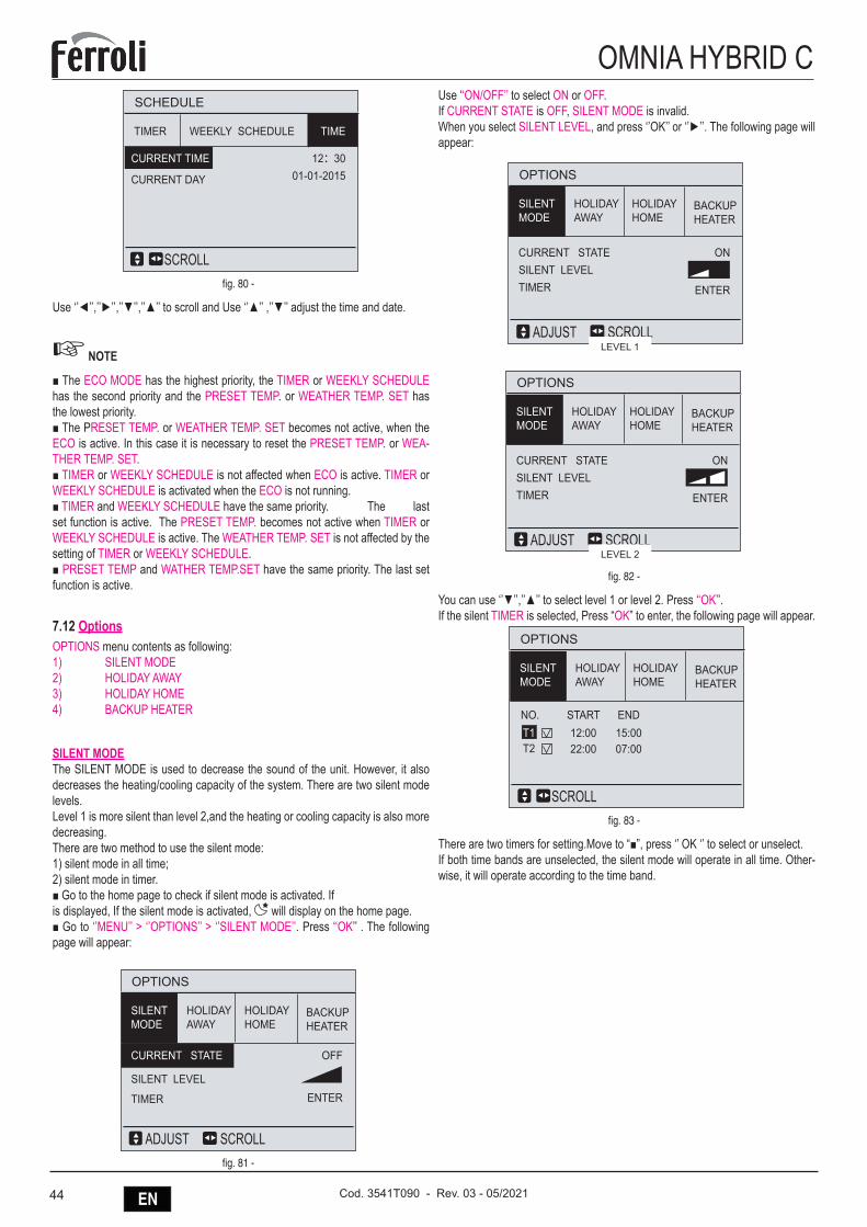
44 EN Cod. 3541T090 - Rev. 03 - 05/2021
OMNIA HYBRID C
TIMER WEEKLY SCHEDULE
SCHEDULE
12:3001-01-2015
SCROLL
TIME
CURRENT TIME
CURRENT DAY
fig. 80 -
Use ‘’◄’’,’’►’’,’’▼’’,’’▲’’ to scroll and Use ‘’▲’’ ,’’▼’’ adjust the time and date.
☞ NOTE
■ The ECO MODE has the highest priority, the TIMER or WEEKLY SCHEDULE has the second priority and the PRESET TEMP. or WEATHER TEMP. SET has the lowest priority.■ The PRESET TEMP. or WEATHER TEMP. SET becomes not active, when the ECO is active. In this case it is necessary to reset the PRESET TEMP. or WEA-THER TEMP. SET.■ TIMER or WEEKLY SCHEDULE is not affected when ECO is active. TIMER or WEEKLY SCHEDULE is activated when the ECO is not running.■ TIMER and WEEKLY SCHEDULE have the same priority. The last set function is active. The PRESET TEMP. becomes not active when TIMER or WEEKLY SCHEDULE is active. The WEATHER TEMP. SET is not affected by the setting of TIMER or WEEKLY SCHEDULE.■ PRESET TEMP and WATHER TEMP.SET have the same priority. The last set function is active.
7.12 OptionsOPTIONS menu contents as following:1) SILENT MODE2) HOLIDAY AWAY3) HOLIDAY HOME4) BACKUP HEATER
SILENT MODEThe SILENT MODE is used to decrease the sound of the unit. However, it also decreases the heating/cooling capacity of the system. There are two silent mode levels.Level 1 is more silent than level 2,and the heating or cooling capacity is also more decreasing.There are two method to use the silent mode:1) silent mode in all time;2) silent mode in timer.■ Go to the home page to check if silent mode is activated. Ifis displayed, If the silent mode is activated, will display on the home page.■ Go to ‘’MENU’’ > ‘’OPTIONS’’ > ‘’SILENT MODE’’. Press ‘‘OK’’ . The following page will appear:
HOLIDAYAWAY
HOLIDAYHOME
BACKUPHEATER
OPTIONS
OFF
ENTER
SILENTMODE
SCROLLADJUST
CURRENT STATE
SILENT LEVEL
TIMER
fig. 81 -
Use ‘‘ON/OFF’’ to select ON or OFF.If CURRENT STATE is OFF, SILENT MODE is invalid.When you select SILENT LEVEL, and press ‘’OK’’ or ‘’►’’. The following page will appear:
LEVEL 1
HOLIDAYAWAY
HOLIDAYHOME
BACKUPHEATER
OPTIONS
CURRENT STATESILENT LEVELTIMER
ON
ENTER
SILENTMODE
SCROLLADJUST
LEVEL 2
HOLIDAYAWAY
HOLIDAYHOME
BACKUPHEATER
OPTIONS
CURRENT STATESILENT LEVELTIMER
ON
ENTER
SILENTMODE
SCROLLADJUSTLEVEL 1
LEVEL 2
fig. 82 -
You can use ‘’▼’’,’’▲’’ to select level 1 or level 2. Press ‘‘OK’’.If the silent TIMER is selected, Press “OK” to enter, the following page will appear.
HOLIDAYAWAY
HOLIDAYHOME
BACKUPHEATER
OPTIONS
SILENTMODE
NO. START
22:00T1T2
END12:00
07:0015:00
SCROLLfig. 83 -
There are two timers for setting.Move to “■”, press ‘’ OK ‘’ to select or unselect.If both time bands are unselected, the silent mode will operate in all time. Other-wise, it will operate according to the time band.
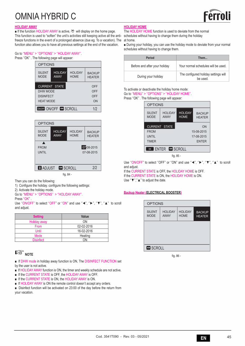
45ENCod. 3541T090 - Rev. 03 - 05/2021
OMNIA HYBRID CHOLIDAY AWAY■ If the function HOLIDAY AWAY is active, will display on the home page.This function is used to “soften” the unit’s activities still keeping active all the anti-freeze functions in the event of a prolonged absence (due eg. To a vacation). The function also allows you to have all previous settings at the end of the vacation.
Go to ‘‘MENU’’ > ‘’OPTIONS’’ > ‘’HOLIDAY AWAY’’. Press ‘’OK’’ . The following page will appear:
HOLIDAYAWAY
HOLIDAYHOME
BACKUPHEATER
OPTIONS
OFFOFFOFFON
SILENTMODE
SCROLL 1/2ON/OFFON/OFF
CURRENT STATEDHW MODEDISINFECTHEAT MODE
HOLIDAYAWAY
HOLIDAYHOME
BACKUPHEATER
OPTIONS
SILENTMODE
2/2
FROMUNTIL
SCROLLADJUST
07-08-201507-08-2015
fig. 84 -
Then you can do the following:1) Configure the holiday. configure the following settings:2) Activate the holiday mode.Go to ‘‘MENU’’ > ‘’OPTIONS’’ > ‘’HOLIDAY AWAY’’. Press ‘‘OK’’ .Use ‘’ON/OFF’’ to select ‘‘OFF’’ or ‘‘ON’’ and use ‘’◄’’, ‘’►’’, ‘’▼’’, ‘’▲’’ to scroll and adjust.
Setting ValueHoliday away ON
From 02-02-2016Until 16-02-2016Mode Heating
Disinfect ON
☞ NOTE
■ If DHW mode in holiday away function is ON, The DISINFECT FUNCTION set by the user is not active.■ If HOLIDAY AWAY function is ON, the timer and weekly schedule are not active. ■ If the CURRENT STATE is OFF, the HOLIDAY AWAY is OFF.■ If the CURRENT STATE is ON, the HOLIDAY AWAY is ON.■ If HOLIDAY AWAY is ON the remote control doesn’t accept any orders.■ Disinfect function will be activated on 23:00 of the day before the return from your vacation.
HOLIDAY HOMEThe HOLIDAY HOME function is used to deviate from the normal schedules without having to change them during the holiday at home.■ During your holiday, you can use the holiday mode to deviate from your normal schedules without having to change them.
Period Them...
Before and after your holiday Your normal schedules will be used.
During your holiday The configured holiday settings will be used.
To activate or deactivate the holiday home mode:Go to ‘’MENU’’ > ‘’OPTIONS’’ > ‘’HOLIDAY HOME’’. Press ‘’OK’’ . The following page will appear:
HOLIDAYAWAY
HOLIDAYHOME
BACKUPHEATER
OPTIONS
ON15-08-201517-08-2015
ENTER
SILENTMODE
SCROLLENTER OK
CURRENT STATEFROMUNTILTIMER
fig. 85 -
Use ‘’ON/OFF’’ to select ‘’OFF’’ or ‘’ON’’ and use ‘’◄’’, ‘’►’’, ‘’▼’’, ‘’▲’’ to scroll and adjust. If the CURRENT STATE is OFF, the HOLIDAY HOME is OFF.If the CURRENT STATE is ON, the HOLIDAY HOME is ON.Use ‘’▼’’,’’▲’’ to adjust the date.
Backup Heater (ELECTRICAL BOOSTER)
HOLIDAYAWAY
HOLIDAYHOME
BACKUPHEATER
OPTIONS
SILENTMODE
SCROLL
HOLIDAYAWAY
HOLIDAYHOME
BACKUPHEATER
OPTIONS
ONON
SILENTMODE
SCROLLENTEROK
BACKUP HEATER1BACKUP HEATER2
fig. 86 -
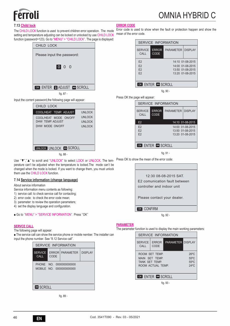
46 EN Cod. 3541T090 - Rev. 03 - 05/2021
OMNIA HYBRID C7.13 Child lockThe CHILD LOCK function is used to prevent children error operation. The mode setting and temperature adjusting can be locked or unlocked by use CHILD LOCK function (password=123). Go to “MENU’’ > ‘’CHILD LOCK’’. The page is displayed:
CHILD LOCK
Please input the password:
ADJUST SCROLLENTEROK
0 0 0
fig. 87 -
Input the corrent password,the following page will appear:
CHILD LOCK
SCROLLUNLOCKUNLOCK
UNLOCK
COOL/HEAT MODE ON/OFFDHW TEMP. ADJUSTDHW MODE ON/OFF
UNLOCKUNLOCKUNLOCK
COOL/HEAT TEMP. ADJUST
fig. 88 -
Use ‘’▼’’,’’▲’’ to scroll and ‘‘UNLOCK’’ to select LOCK or UNLOCK. The tem-perature can’t be adjusted when the temperature is locked.The mode can’t be changed when the mode is locked. If you want to change them, you must unlock them use the CHILD LOCK function.
7.14 Service information (change language)About service informationService information menu contents as following:1) service call: to check service call for contacting;2) error code: to check the error code mean;3) parameter: to review the operation parameters;4) set the display language and configuration.
■ Go to ‘’MENU’’ > ‘’SERVICE INFORMATION’’. Press ‘’OK’’
SERVCE CALLThe following page will appear:■ The service call can show the service phone or mobile nember. The installer can input the phone number. See “8.12 Service call”.
SERVICE INFORMATION
DISPLAY
PHONE NO. 0000000000000MOBILE NO. 0000000000000
ERRORCODE
SCROLL
PARAMETERSERVICECALL
SERVICE INFORMATION
DISPLAYSERVICECALL
E2E2E2E2
14:10 01-08-201514:00 01-08-201513:50 01-08-201513:20 01-08-2015
SCROLLENTEROK
PARAMETERERRORCODE
fig. 89 -
ERROR CODEError code is used to show when the fault or protection happen and show the mean of the error code.
SERVICE INFORMATION
DISPLAY
PHONE NO. 0000000000000MOBILE NO. 0000000000000
ERRORCODE
SCROLL
PARAMETERSERVICECALL
SERVICE INFORMATION
DISPLAYSERVICECALL
E2E2E2E2
14:10 01-08-201514:00 01-08-201513:50 01-08-201513:20 01-08-2015
SCROLLENTEROK
PARAMETERERRORCODE
fig. 90 -
Press OK the page will appear:
12:30 08-08-2015 SAT.E2 comunication fault betweencontroller and indoor unit
Please contact your dealer.
CONFIRMOK
SERVICE INFORMATION
DISPLAYSERVICECALL
E2E2E2
14:00 01-08-201513:50 01-08-201513:20 01-08-2015
SCROLLENTEROK
PARAMETERERRORCODE
E2 14:10 01-08-2015
fig. 91 -
Press OK to show the mean of the error code:
12:30 08-08-2015 SAT.E2 comunication fault betweencontroller and indoor unit
Please contact your dealer.
CONFIRMOK
SERVICE INFORMATION
DISPLAYSERVICECALL
E2E2E2
14:00 01-08-201513:50 01-08-201513:20 01-08-2015
SCROLLENTEROK
PARAMETERERRORCODE
E2 14:10 01-08-2015
fig. 92 -
PARAMETERThe parameter function is used to display the main working parameters:
SERVICE INFORMATION
DISPLAYSERVICECALL
ROOM SET TEMP.MAIN SET TEMP.TANK SET TEMP.ROOM ACTUAL TEMP.
26ºC55ºC55ºC24ºC
ERRORCODE
SCROLLENTEROK
PARAMETER
fig. 93 -
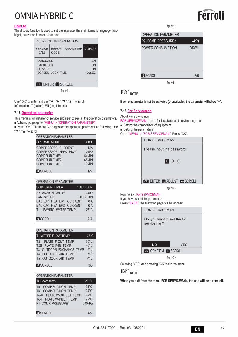
47ENCod. 3541T090 - Rev. 03 - 05/2021
OMNIA HYBRID CDISPLAY The display function is used to set the interface, the main items is language, bac-klight, buzzer and screen lock time:
SERVICE INFORMATION
SERVICECALL
LANGUAGEBACKLIGHTBUZZERSCREEN LOCK TIME
ENONON
120SEC
ERRORCODE
SCROLLENTEROK
PARAMETER DISPLAY
fig. 94 -
Use ‘’OK’’ to enter and use ‘’◄’’,’’►’’,’’▼’’,’’▲’’ to scroll.Information: IT (Italian), EN (english), ecc
7.15 Operation parameterThis menu is for installer or service engineer to see all the operation parameters.■ At home page, go to ‘’MENU’’ > ‘’OPERATION PARAMETER’’.■ Press ‘’OK’’. There are five pages for the operating parameter as following. Use ‘’▼’’, ‘’▲’’ to scroll.
OPERATION PARAMETERP2 COMP. PRESSURE2 --kPaPOWER CONSUMPTION OKWH
SCROLL 5/5
OPERATION PARAMETERT1 WATER FLOW TEMP. 25°C
30°CT2 PLATE F-OUT TEMP. 45°CT2B PLATE F-IN TEMP. -7°CT3 OUTDOOR EXCHANGE TEMP. -7°CT4 OUTDOOR AIR TEMP. -7°CT5 OUTDOOR AIR TEMP.
SCROLL 3/5
OPERATION PARAMETERCOMP.RUN TIME4 1000HOUREXPANSION VALUE 240P
600 R/MINFAN SPEED 0 ABACKUP HEATER1 CURRENT 0 ABACKUP HEATER2 CURRENT
T1 LEAVING WATER TEMP.1 25°C
SCROLL 2/5
OPERATION PARAMETERTa Room temp 25°C
P1 COMP. PRESSURE1 200kPa
SCROLL 4/5
25°CTw-0 PLATE W-OUTLET TEMP. 25°CTw-I PLATE W-INLET TEMP.
25°CTh COMP.SUCTION TEMP.25°CTh COMP.SUCTION TEMP.
OPERATION PARAMETEROPERATE MODE COOLCOMPRESSOR CURRENT 12A
24HzCOMPRESSOR FREQUNCY 54MINCOMP.RUN TIME1 65MINCOMP.RUN TIME2 10MINCOMP.RUN TIME3
SCROLL 1/5
fig. 95 -
OPERATION PARAMETERP2 COMP. PRESSURE2 --kPaPOWER CONSUMPTION OKWH
SCROLL 5/5
OPERATION PARAMETERT1 WATER FLOW TEMP. 25°C
30°CT2 PLATE F-OUT TEMP. 45°CT2B PLATE F-IN TEMP. -7°CT3 OUTDOOR EXCHANGE TEMP. -7°CT4 OUTDOOR AIR TEMP. -7°CT5 OUTDOOR AIR TEMP.
SCROLL 3/5
OPERATION PARAMETERCOMP.RUN TIME4 1000HOUREXPANSION VALUE 240P
600 R/MINFAN SPEED 0 ABACKUP HEATER1 CURRENT 0 ABACKUP HEATER2 CURRENT
T1 LEAVING WATER TEMP.1 25°C
SCROLL 2/5
OPERATION PARAMETERTa Room temp 25°C
P1 COMP. PRESSURE1 200kPa
SCROLL 4/5
25°CTw-0 PLATE W-OUTLET TEMP. 25°CTw-I PLATE W-INLET TEMP.
25°CTh COMP.SUCTION TEMP.25°CTh COMP.SUCTION TEMP.
OPERATION PARAMETEROPERATE MODE COOLCOMPRESSOR CURRENT 12A
24HzCOMPRESSOR FREQUNCY 54MINCOMP.RUN TIME1 65MINCOMP.RUN TIME2 10MINCOMP.RUN TIME3
SCROLL 1/5
fig. 96 -
☞ NOTE
if some parameter is not be activated (or available), the parameter will show “--”.
7.16 For ServicemanAbout For Serviceman FOR SERVICEMAN is used for installater and service engineer.■ Setting the composition of equipment.■ Setting the parameters.Go to ‘’MENU’’ > ‘’FOR SERVICEMAN’’. Press ‘’OK’’.
FOR SERVICEMAN
Please input the password:
ADJUST SCROLLENTEROK
0 0 0
fig. 97 -
How To Exit For SERVICEMAN If you have set all the parameter.Press ‘‘BACK’’, the following page will be appear:
FOR SERVICEMAN
Do you want to exit the for serviceman?
SCROLLCONFIRMOK
NO YES
fig. 98 -
Selecting ‘YES’ ‘and pressing’ ‘OK’ ‘exits the menu.
☞ NOTE
When you exit from the menu FOR SERVICEMAN, the unit will be turned off.
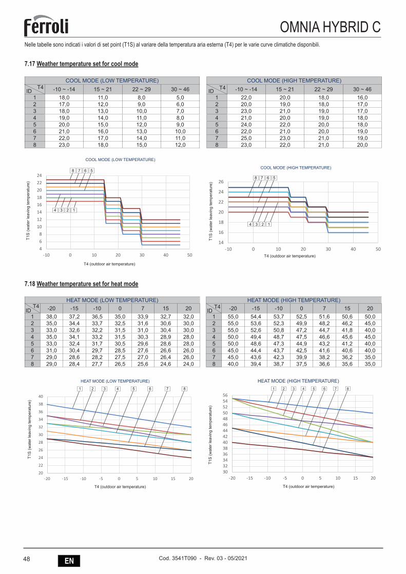
48 EN Cod. 3541T090 - Rev. 03 - 05/2021
OMNIA HYBRID CNelle tabelle sono indicati i valori di set point (T1S) al variare della temperatura aria esterna (T4) per le varie curve climatiche disponibili.
7.17 Weather temperature set for cool mode
COOL MODE (LOW TEMPERATURE)-10 ~ -14 15 ~ 21 22 ~ 29 30 ~ 46
1 18,0 11,0 8,0 5,02 17,0 12,0 9,0 6,03 18,0 13,0 10,0 7,04 19,0 14,0 11,0 8,05 20,0 15,0 12,0 9,06 21,0 16,0 13,0 10,07 22,0 17,0 14,0 11,08 23,0 18,0 15,0 12,0
COOL MODE (HIGH TEMPERATURE)-10 ~ -14 15 ~ 21 22 ~ 29 30 ~ 46
1 22,0 20,0 18,0 16,02 20,0 19,0 18,0 17,03 23,0 21,0 19,0 17,04 21,0 20,0 19,0 18,05 24,0 22,0 20,0 18,06 22,0 21,0 20,0 19,07 25,0 23,0 21,0 19,08 23,0 22,0 21,0 20,0
T4ID T4ID
COOL MODE (HIGH TEMPERATURE)
T4 (outdoor air temperature)
T1S
(wat
er le
avin
g te
mpe
ratu
re)
14
16
18
20
22
24
26
-10 0 10 20 30 40 50
WTS COOLING MODE MIDEA HIGH TEMP
Serie1
Serie2
Serie3
Serie4
Serie5
Serie6
Serie7
8 7 6 5
4 3 2 1
COOL MODE (LOW TEMPERATURE)
T4 (outdoor air temperature)
T1S
(wat
er le
avin
g te
mpe
ratu
re)
468
1012141618202224
-10 0 10 20 30 40 50
WTS COOLING MODE MIDEA LOW TEMP
Serie1
Serie2
Serie3
Serie4
Serie5
Serie6
Serie7
Serie8
8 7 6 5
4 3 2 1
7.18 Weather temperature set for heat mode
HEAT MODE (LOW TEMPERATURE)-20 -15 -10 0 7 15 20
1 38,0 37,2 36,5 35,0 33,9 32,7 32,02 35,0 34,4 33,7 32,5 31,6 30,6 30,03 33,0 32,6 32,2 31,5 31,0 30,4 30,04 35,0 34,1 33,2 31,5 30,3 28,9 28,05 33,0 32,4 31,7 30,5 29,6 28,6 28,06 31,0 30,4 29,7 28,5 27,6 26,6 26,07 29,0 28,6 28,2 27,5 27,0 26,4 26,08 29,0 28,4 27,7 26,5 25,6 24,6 24,0
HEAT MODE (HIGH TEMPERATURE)-20 -15 -10 0 7 15 20
1 55,0 54,4 53,7 52,5 51,6 50,6 50,02 55,0 53,6 52,3 49,9 48,2 46,2 45,03 55,0 52,6 50,8 47,2 44,7 41,8 40,04 50,0 49,4 48,7 47,5 46,6 45,6 45,05 50,0 48,6 47,3 44,9 43,2 41,2 40,06 45,0 44,4 43,7 42,5 41,6 40,6 40,07 45,0 43,6 42,3 39,9 38,2 36,2 35,08 40,0 39,4 38,7 37,5 36,6 35,6 35,0
T4ID
T4ID
20
22
24
26
28
30
32
34
36
38
40
-20 -15 -10 -5 0 5 10 15 20
WTS HEATING MODE FERROLI LOW TEMP
Serie1
Serie2
Serie3
Serie4
Serie5
Serie6
Serie7
Serie8
HEAT MODE (LOW TEMPERATURE)
T4 (outdoor air temperature)
T1S
(wat
er le
avin
g te
mpe
ratu
re)
1 2 3 4 5 6 7 8
3032343638404244464850525456
-20 -15 -10 -5 0 5 10 15 20
WTS HEATING MODE FERROLI HIGH TEMP
Serie1
Serie2
Serie3
Serie4
Serie5
Serie6
Serie7
Serie8
HEAT MODE (HIGH TEMPERATURE)
T4 (outdoor air temperature)
T1S
(wat
er le
avin
g te
mpe
ratu
re)
1 2 3 4 5 6 7 8
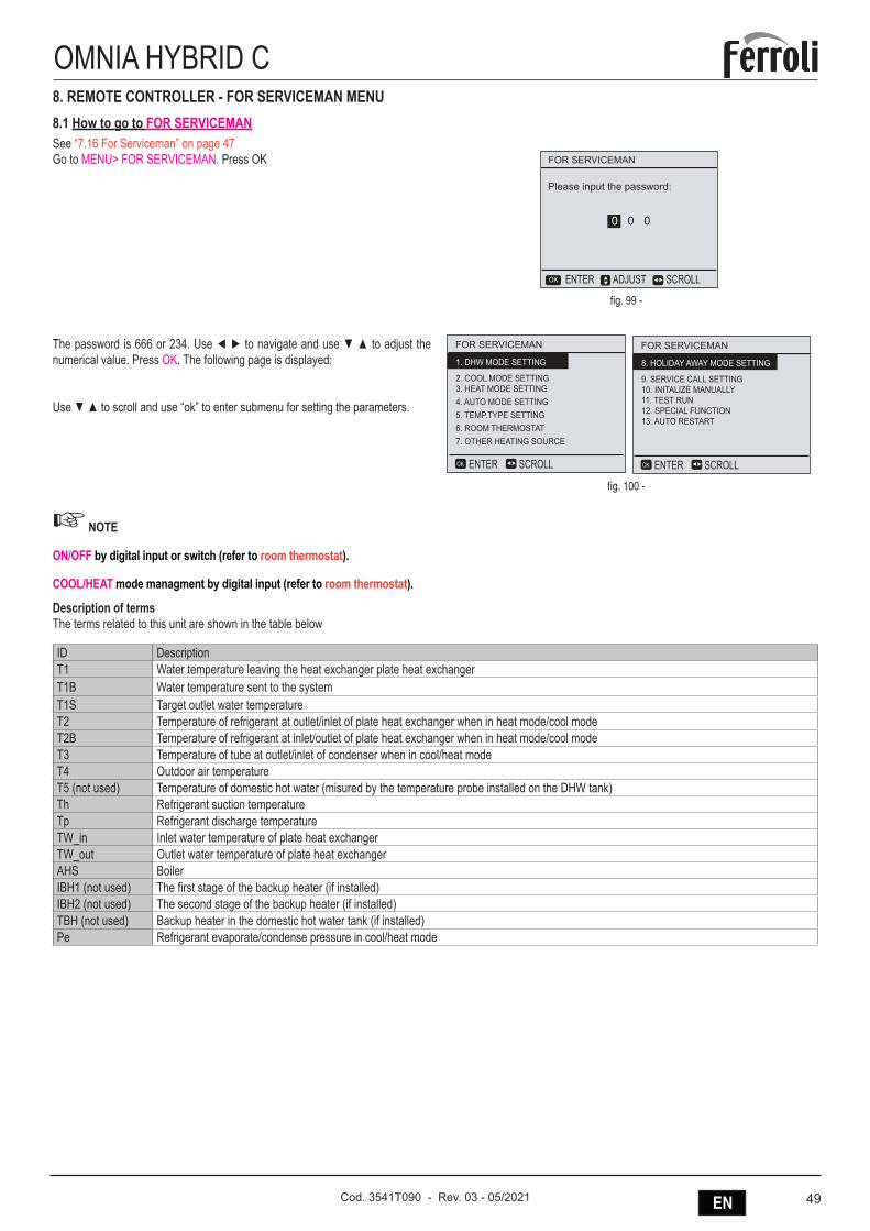
49ENCod. 3541T090 - Rev. 03 - 05/2021
OMNIA HYBRID C8. REMOTE CONTROLLER - FOR SERVICEMAN MENU8.1 How to go to FOR SERVICEMANSee “7.16 For Serviceman” on page 47Go to MENU> FOR SERVICEMAN. Press OK FOR SERVICEMAN
Please input the password:
ADJUST SCROLLENTEROK
0 0 0
fig. 99 -
The password is 666 or 234. Use ◄ ► to navigate and use ▼ ▲ to adjust the numerical value. Press OK. The following page is displayed:
Use ▼ ▲ to scroll and use “ok” to enter submenu for setting the parameters.
FOR SERVICEMAN
2. COOL MODE SETTING3. HEAT MODE SETTING4. AUTO MODE SETTING5. TEMP.TYPE SETTING6. ROOM THERMOSTAT7. OTHER HEATING SOURCE
1. DHW MODE SETTING
SCROLLENTEROK
FOR SERVICEMAN
9. SERVICE CALL SETTING10. INITALIZE MANUALLY11. TEST RUN12. SPECIAL FUNCTION13. AUTO RESTART
8. HOLIDAY AWAY MODE SETTING
SCROLLENTEROK
fig. 100 -
☞ NOTE
ON/OFF by digital input or switch (refer to room thermostat).
COOL/HEAT mode managment by digital input (refer to room thermostat).
Description of terms The terms related to this unit are shown in the table below
ID DescriptionT1 Water temperature leaving the heat exchanger plate heat exchangerT1B Water temperature sent to the systemT1S Target outlet water temperatureT2 Temperature of refrigerant at outlet/inlet of plate heat exchanger when in heat mode/cool modeT2B Temperature of refrigerant at inlet/outlet of plate heat exchanger when in heat mode/cool modeT3 Temperature of tube at outlet/inlet of condenser when in cool/heat modeT4 Outdoor air temperatureT5 (not used) Temperature of domestic hot water (misured by the temperature probe installed on the DHW tank)Th Refrigerant suction temperatureTp Refrigerant discharge temperatureTW_in Inlet water temperature of plate heat exchangerTW_out Outlet water temperature of plate heat exchangerAHS BoilerIBH1 (not used) The first stage of the backup heater (if installed)IBH2 (not used) The second stage of the backup heater (if installed)TBH (not used) Backup heater in the domestic hot water tank (if installed)Pe Refrigerant evaporate/condense pressure in cool/heat mode
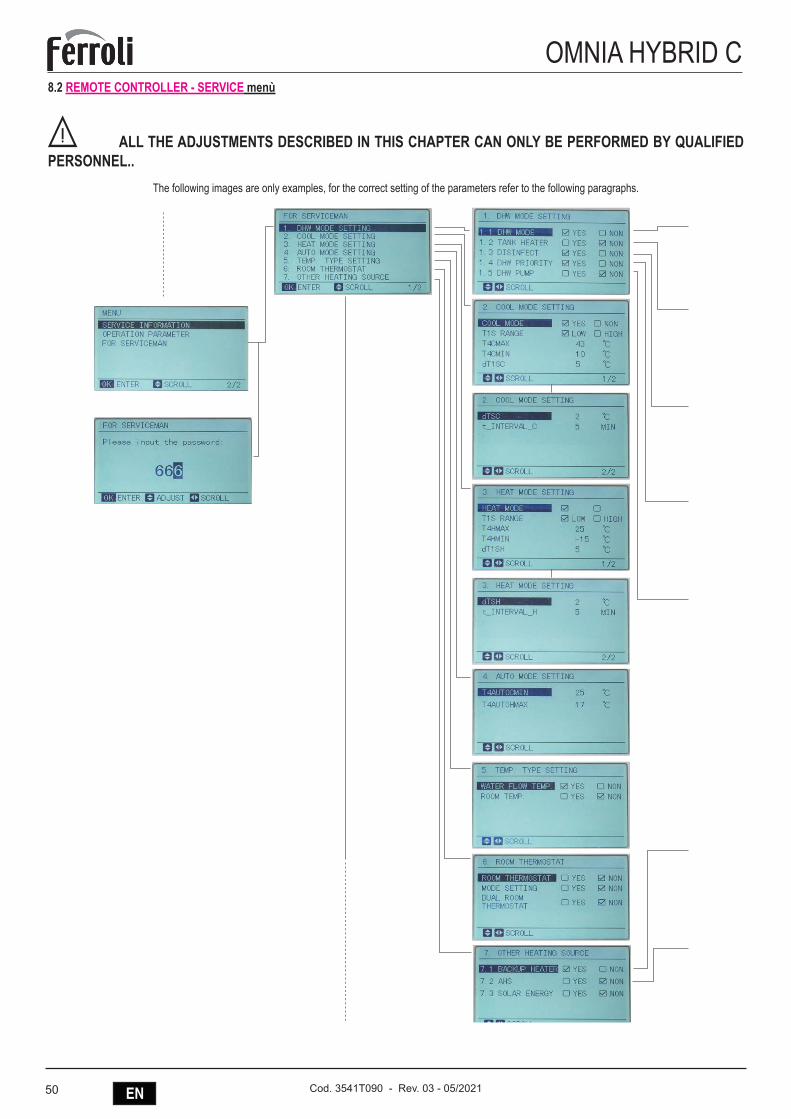
50 EN Cod. 3541T090 - Rev. 03 - 05/2021
OMNIA HYBRID C8.2 REMOTE CONTROLLER - SERVICE menù
B ALL THE ADJUSTMENTS DESCRIBED IN THIS CHAPTER CAN ONLY BE PERFORMED BY QUALIFIED PERSONNEL..
The following images are only examples, for the correct setting of the parameters refer to the following paragraphs.
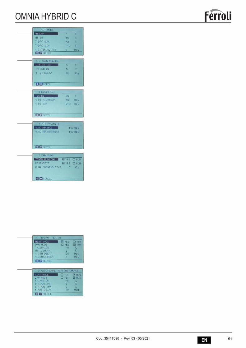
51ENCod. 3541T090 - Rev. 03 - 05/2021
OMNIA HYBRID C
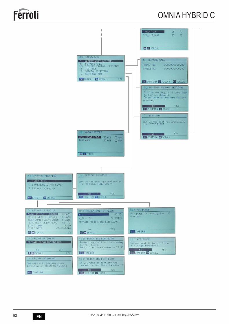
52 EN Cod. 3541T090 - Rev. 03 - 05/2021
OMNIA HYBRID C
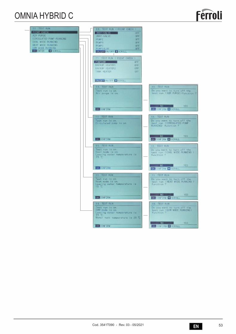
53ENCod. 3541T090 - Rev. 03 - 05/2021
OMNIA HYBRID C
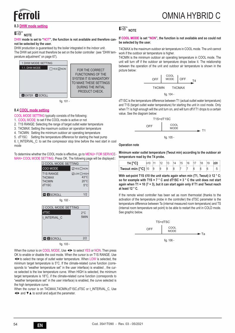
54 EN Cod. 3541T090 - Rev. 03 - 05/2021
OMNIA HYBRID C8.3 DHW mode setting
☞ NOTEDHW mode is set to “NOT”, the function is not available and therefore can-not be selected by the user.DHW production is guaranteed by the boiler integrated in the indoor unit.The DHW set point must therefore be set on the boiler controller (see “DHW tem-perature adjustment” on page 67).
FOR THE CORRECT FUNCTIONING OF THE
SYSTEM IT IS MANDATORY TO MAKE THESE SETTINGS
DURING THE INITIAL PRODUCT CHECK.
1 DHW MODE SETTING
1.1. DHW MODE
SCROLLENTEROK
YES NON
fig. 101 -
8.4 COOL mode settingCOOL MODE SETTING typically consists of the following:1. COOL MODE: to set if the COOL mode is active or not2. T1S RANGE: Selecting the range of target outlet water temperature3. T4CMAX: Setting the maximum outdoor air operation temperature4. T4CMIN: Setting the minimum outdoor air operating temperature5. dT1SC: Setting the temperature difference for starting the heat pump6. t_INTERVAL_C: to set the compressor stop time before the next start in cool mode
To determine whether the COOL mode is effective, go to MENU> FOR SERVICE-MAN> COOL MODE SETTING. Press OK. The following page will be displayed::
2 COOL MODE SETTINGCOO MODET1S RANGET4CMAXT4CMINdT1SC
SCROLL
LOW HIGH43°C20°C
5°C
YES NON
2 COOL MODE SETTINGdTSCt_INTERVAL_C
SCROLL 2/21/2
2°C5MIN
fig. 102 -
2 COOL MODE SETTINGCOO MODET1S RANGET4CMAXT4CMINdT1SC
SCROLL
LOW HIGH43°C20°C
5°C
YES NON
2 COOL MODE SETTINGdTSCt_INTERVAL_C
SCROLL 2/21/2
2°C5MIN
fig. 103 -
When the cursor is on COOL MODE, Use ◄► to select YES or NON. Then press OK to enable or disable the cool mode. When the cursor is on T1S RANGE. Use ◄►to select the range of outlet water temperature. When LOW is selected, the minimum target temperature is 5°C. If the climate-related curve function (corre-sponds to “weather temperature set” in the user interface) is enabled , the cur-ve selected is the low temperature curve. When HIGH is selected, the minimum target temperature is 18°C, if the climate-related curve function (corresponds to “weather temperature set” in the user interface) is enabled, the curve selected is the high temperature curve. When the cursor is on T4CMAX,T4CMIN,dT1SC,dTSC or t_INTERVAL_C, Use ◄► and ▼▲ to scroll and adjust the parameter.
☞ NOTE
If COOL MODE is set “NON”, the function is not available and so could not be selected by the user.
T4CMAX is the maximum outdoor air temperature in COOL mode. The unit cannot work if the outdoor air temperature is higher.T4CMIN is the minimum outdoor air operating temperature in COOL mode. The unit will turn off if the outdoor air temperature drops below it. The relationship between the operation of the unit and outdoor air temperature is shown in the picture below:
OFF COOL T4OFF
T4CMAXT4CMIN
COOL MODE
fig. 104 -
dT1SC is the temperature difference between T1 (actual outlet water temperature) and T1S (target outlet water temperature) for starting the unit in cool mode. Only when T1 is high enough will the unit turn on, and will turn off if T1 drops to a certain value. See the diagram below:
T1S+dT1SC
OFF COOLT1
COOL MODE
fig. 105 -
Operation note
Minimum water outlet temperature (Twout min) according to the outdoor air temperature read by the T4 probe.
T4 [°C] ≤10 11 12 13 14 15 16 17 18 19 ≥20
Twout min [°C] 10 9 9 8 8 7 7 6 6 6 5
With set-point T1S ≤10 the unit starts again when min (T1, Twout) ≥ 12 ° C; so for example with T1S = 7 ° C and dT1SC = 3 ° C the unit does not start again when T1 = 10 (7 + 3), but it can start again only if T1 and Twout reach at least 12 ° C.
If the remote wired controller has been set as room thermostat (thanks to the activation of the temperature probe in the controller) the dTSC parameter is the temperature difference between Ta (internal measured room temperature) and TS (internal room temperature set point) to be able to restart the unit in COLD mode. See graphic below.
TS+dTSC
OFF COOLTa
COOL MODE
fig. 106 -
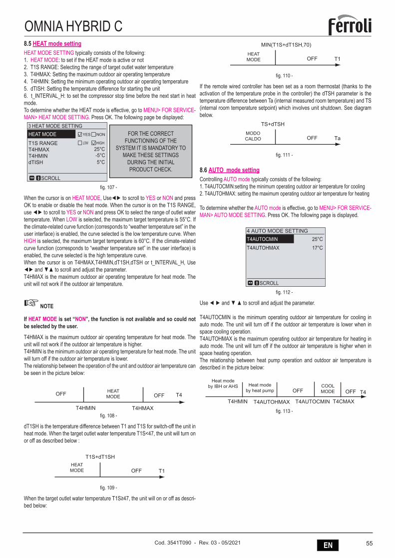
55ENCod. 3541T090 - Rev. 03 - 05/2021
OMNIA HYBRID C8.5 HEAT mode settingHEAT MODE SETTING typically consists of the following:1. HEAT MODE: to set if the HEAT mode is active or not2. T1S RANGE: Selecting the range of target outlet water temperature3. T4HMAX: Setting the maximum outdoor air operating temperature4. T4HMIN: Setting the minimum operating outdoor air operating temperature5. dTISH: Setting the temperature difference for starting the unit6. t_INTERVAL_H: to set the compressor stop time before the next start in heat mode.To determine whether the HEAT mode is effective, go to MENU> FOR SERVICE-MAN> HEAT MODE SETTING. Press OK. The following page be displayed:
FOR THE CORRECT FUNCTIONING OF THE
SYSTEM IT IS MANDATORY TO MAKE THESE SETTINGS
DURING THE INITIAL PRODUCT CHECK.
3 HEAT MODE SETTINGHEAT MODE
T1S RANGET4HMAXT4HMINdTISH
SCROLL
LOW HIGH25°C-5°C5°C
YES NON
fig. 107 -
When the cursor is on HEAT MODE, Use◄► to scroll to YES or NON and press OK to enable or disable the heat mode. When the cursor is on the T1S RANGE, use ◄► to scroll to YES or NON and press OK to select the range of outlet water temperature. When LOW is selected, the maximum target temperature is 55°C. If the climate-related curve function (corresponds to “weather temperature set” in the user interface) is enabled, the curve selected is the low temperature curve. When HIGH is selected, the maximum target temperature is 60°C. If the climate-related curve function (corresponds to “weather temperature set” in the user interface) is enabled, the curve selected is the high temperature curve.When the cursor is on T4HMAX,T4HMIN,dT1SH, dTSH or t_INTERVAL_H, Use ◄► and ▼▲ to scroll and adjust the parameter.T4HMAX is the maximum outdoor air operating temperature for heat mode. The unit will not work if the outdoor air temperature.
☞ NOTE
If HEAT MODE is set “NON”, the function is not available and so could not be selected by the user.
T4HMAX is the maximum outdoor air operating temperature for heat mode. The unit will not work if the outdoor air temperature is higher.T4HMIN is the minimum outdoor air operating temperature for heat mode. The unit will turn off if the outdoor air temperature is lower.The relationship between the operation of the unit and outdoor air temperature can be seen in the picture below:
HEATOFF OFF T4
T4HMIN T4HMAX
HEAT MODE
fig. 108 -
dT1SH is the temperature difference between T1 and T1S for switch-off the unit in heat mode. When the target outlet water temperature T1S<47, the unit will turn on or off as described below :
T1S+dT1SH
OFFHEAT T1HEAT MODE
fig. 109 -
When the target outlet water temperature T1S≥47, the unit will on or off as descri-bed below:
MIN(T1S+dT1SH,70)
OFFHEAT T1HEAT MODE
fig. 110 -
If the remote wired controller has been set as a room thermostat (thanks to the activation of the temperature probe in the controller) the dTSH parameter is the temperature difference between Ta (internal measured room temperature) and TS (internal room temperature setpoint) which involves unit shutdown. See diagram below.
TS+dTSH
OFFHEAT TaMODO CALDO
fig. 111 -
8.6 AUTO mode settingControlling AUTO mode typically consists of the following:1. T4AUTOCMIN:setting the minimum operating outdoor air temperature for cooling2. T4AUTOHMAX: setting the maximum operating outdoor air temperature for heating
To determine whether the AUTO mode is effective, go to MENU> FOR SERVICE-MAN> AUTO MODE SETTING. Press OK. The following page is displayed.
4 AUTO MODE SETTINGT4AUTOCMINT4AUTOHMAX
25°C17°C
SCROLL
fig. 112 -
Use ◄ ► and ▼ ▲ to scroll and adjust the parameter.
T4AUTOCMIN is the minimum operating outdoor air temperature for cooling in auto mode. The unit will turn off if the outdoor air temperature is lower when in space cooling operation.T4AUTOHMAX is the maximum operating outdoor air temperature for heating in auto mode. The unit will turn off if the outdoor air temperature is higher when in space heating operation.The relationship between heat pump operation and outdoor air temperature is described in the picture below:
COOL OFF T4
T4HMIN T4CMAXT4AUTOCMIN
OFF
T4AUTOHMAX
Heat modeby IBH or AHS
Heat modeby heat pump
Heat modeby IBH or AHS Heat mode
by heat pumpCOOL MODE
fig. 113 -
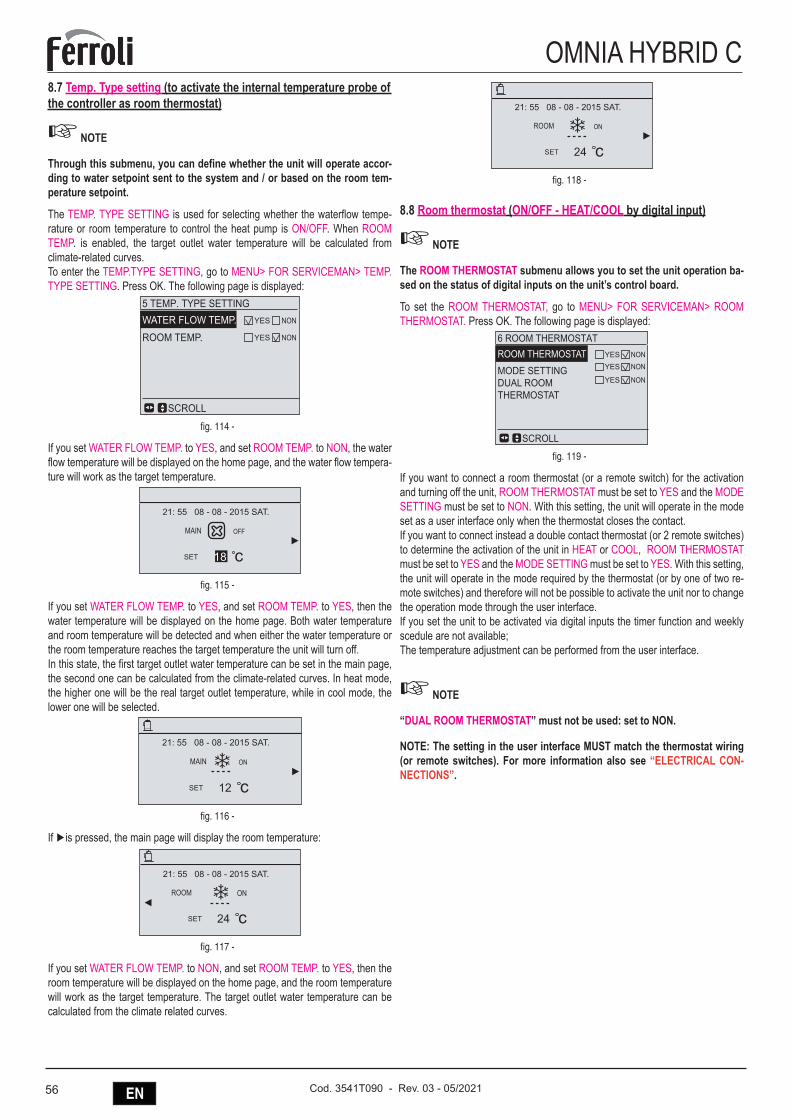
56 EN Cod. 3541T090 - Rev. 03 - 05/2021
OMNIA HYBRID C8.7 Temp. Type setting (to activate the internal temperature probe of the controller as room thermostat)
☞ NOTE
Through this submenu, you can define whether the unit will operate accor-ding to water setpoint sent to the system and / or based on the room tem-perature setpoint.
The TEMP. TYPE SETTING is used for selecting whether the water flow tempe-rature or room temperature to control the heat pump is ON/OFF. When ROOM TEMP. is enabled, the target outlet water temperature will be calculated from climate-related curves.To enter the TEMP.TYPE SETTING, go to MENU> FOR SERVICEMAN> TEMP. TYPE SETTING. Press OK. The following page is displayed:
5 TEMP. TYPE SETTINGWATER FLOW TEMP.ROOM TEMP.
SCROLL
YES NON
YES NON
fig. 114 -
If you set WATER FLOW TEMP. to YES, and set ROOM TEMP. to NON, the water flow temperature will be displayed on the home page, and the water flow tempera-ture will work as the target temperature.
SET cOFFMAIN
21: 55 08 - 08 - 2015 SAT.
18
fig. 115 -
If you set WATER FLOW TEMP. to YES, and set ROOM TEMP. to YES, then the water temperature will be displayed on the home page. Both water temperature and room temperature will be detected and when either the water temperature or the room temperature reaches the target temperature the unit will turn off. In this state, the first target outlet water temperature can be set in the main page, the second one can be calculated from the climate-related curves. In heat mode, the higher one will be the real target outlet temperature, while in cool mode, the lower one will be selected.
12SET cONMAIN
21: 55 08 - 08 - 2015 SAT.
fig. 116 -
If ►is pressed, the main page will display the room temperature:
24SET c
21: 55 08 - 08 - 2015 SAT.
ONROOM
fig. 117 -
If you set WATER FLOW TEMP. to NON, and set ROOM TEMP. to YES, then the room temperature will be displayed on the home page, and the room temperature will work as the target temperature. The target outlet water temperature can be calculated from the climate related curves.
24SET cONROOM
21: 55 08 - 08 - 2015 SAT.
fig. 118 -
8.8 Room thermostat (ON/OFF - HEAT/COOL by digital input)
☞ NOTE
The ROOM THERMOSTAT submenu allows you to set the unit operation ba-sed on the status of digital inputs on the unit’s control board.
To set the ROOM THERMOSTAT, go to MENU> FOR SERVICEMAN> ROOM THERMOSTAT. Press OK. The following page is displayed:
6 ROOM THERMOSTATROOM THERMOSTATMODE SETTINGDUAL ROOMTHERMOSTAT
SCROLL
YES NONYES NON
YES NON
fig. 119 -
If you want to connect a room thermostat (or a remote switch) for the activation and turning off the unit, ROOM THERMOSTAT must be set to YES and the MODE SETTING must be set to NON. With this setting, the unit will operate in the mode set as a user interface only when the thermostat closes the contact.If you want to connect instead a double contact thermostat (or 2 remote switches) to determine the activation of the unit in HEAT or COOL, ROOM THERMOSTAT must be set to YES and the MODE SETTING must be set to YES. With this setting, the unit will operate in the mode required by the thermostat (or by one of two re-mote switches) and therefore will not be possible to activate the unit nor to change the operation mode through the user interface.If you set the unit to be activated via digital inputs the timer function and weekly scedule are not available;The temperature adjustment can be performed from the user interface.
☞ NOTE
“DUAL ROOM THERMOSTAT” must not be used: set to NON.
NOTE: The setting in the user interface MUST match the thermostat wiring (or remote switches). For more information also see “ELECTRICAL CON-NECTIONS”.
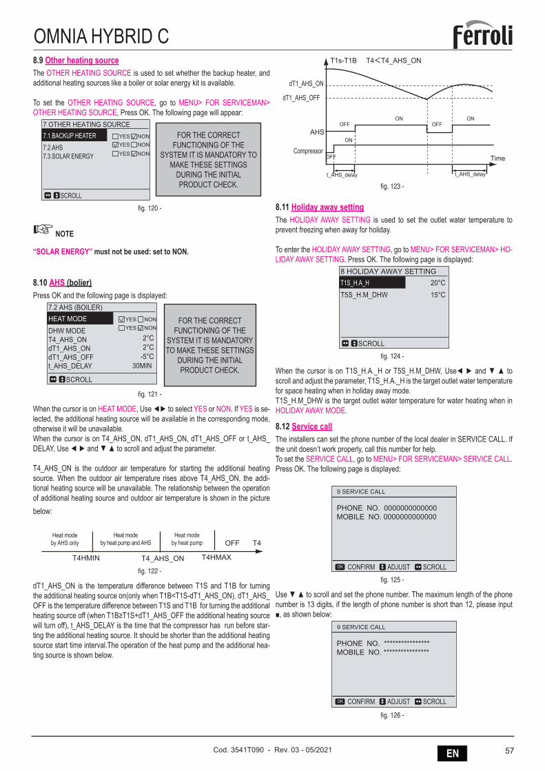
57ENCod. 3541T090 - Rev. 03 - 05/2021
OMNIA HYBRID C8.9 Other heating sourceThe OTHER HEATING SOURCE is used to set whether the backup heater, and additional heating sources like a boiler or solar energy kit is available.
To set the OTHER HEATING SOURCE, go to MENU> FOR SERVICEMAN> OTHER HEATING SOURCE, Press OK. The following page will appear:
FOR THE CORRECT FUNCTIONING OF THE
SYSTEM IT IS MANDATORY TO MAKE THESE SETTINGS
DURING THE INITIAL PRODUCT CHECK.
7 OTHER HEATING SOURCE7.1.BACKUP HEATER7.2.AHS7.3.SOLAR ENERGY
SCROLL
YESYES
NONNON
YES NON
fig. 120 -
☞ NOTE
“SOLAR ENERGY” must not be used: set to NON.
8.10 AHS (bolier)Press OK and the following page is displayed:
FOR THE CORRECT FUNCTIONING OF THE
SYSTEM IT IS MANDATORY TO MAKE THESE SETTINGS
DURING THE INITIAL PRODUCT CHECK.
7.2 AHS (BOILER)HEAT MODEDHW MODET4_AHS_ONdT1_AHS_ONdT1_AHS_OFFt_AHS_DELAY
2°C2°C
-5°C30MIN
SCROLL
YESYES
NONNON
fig. 121 -
When the cursor is on HEAT MODE, Use ◄► to select YES or NON. If YES is se-lected, the additional heating source will be available in the corresponding mode, otherwise it will be unavailable.When the cursor is on T4_AHS_ON, dT1_AHS_ON, dT1_AHS_ OFF or t_AHS_DELAY, Use ◄ ► and ▼ ▲ to scroll and adjust the parameter.
T4_AHS_ON is the outdoor air temperature for starting the additional heating source. When the outdoor air temperature rises above T4_AHS_ ON, the addi-tional heating source will be unavailable. The relationship between the operation of additional heating source and outdoor air temperature is shown in the picture below:
OFF T4
T4HMIN T4HMAX
Heat modeby heat pump
T4_AHS_ON
Heat modeby AHS only
Heat mode by heat pump and AHS
Heat modeby heat pump and AHS
Heat modeby AHS only
Heat modeby heat pump
fig. 122 -
dT1_AHS_ON is the temperature difference between T1S and T1B for turning the additional heating source on(only when T1B<T1S-dT1_AHS_ON), dT1_AHS_OFF is the temperature difference between T1S and T1B for turning the additional heating source off (when T1B≥T1S+dT1_AHS_OFF the additional heating source will turn off), t_AHS_DELAY is the time that the compressor has run before star-ting the additional heating source. It should be shorter than the additional heating source start time interval.The operation of the heat pump and the additional hea-ting source is shown below.
T1s-T1B T4<T4_AHS_ON
OFF OFF
OFF Time
ONON
ON
t_AHS_delay t_AHS_delay
dT1_AHS_ON
dT1_AHS_OFF
AHS
Compressor
fig. 123 -
8.11 Holiday away settingThe HOLIDAY AWAY SETTING is used to set the outlet water temperature to prevent freezing when away for holiday.
To enter the HOLIDAY AWAY SETTING, go to MENU> FOR S ERVICEMAN> HO-LIDAY AWAY SETTING. Press OK. The following page is displayed:
8 HOLIDAY AWAY SETTINGT1S_H.A_HT5S_H.M_DHW
20°C15°C
SCROLL
fig. 124 -
When the cursor is on T1S_H.A._H or T5S_H.M_DHW, Use◄ ► and ▼ ▲ to scroll and adjust the parameter, T1S_H.A._H is the target outlet water temperature for space heating when in holiday away mode.T1S_H.M_DHW is the target outlet water temperature for water heating when in HOLIDAY AWAY MODE.
8.12 Service callThe installers can set the phone number of the local dealer in SERVICE CALL. If the unit doesn’t work properly, call this number for help.To set the SERVICE CALL, go to MENU> FOR SERVICEMAN> SERVICE CALL. Press OK. The following page is displayed:
9 SERVICE CALL
PHONE NO. 0000000000000MOBILE NO. 0000000000000
ADJUST SCROLLCONFIRMOK
fig. 125 -
Use ▼ ▲ to scroll and set the phone number. The maximum length of the phone number is 13 digits, if the length of phone number is short than 12, please input ■, as shown below:
9 SERVICE CALL
PHONE NO. ****************MOBILE NO. ****************
ADJUST SCROLLCONFIRMOK
fig. 126 -
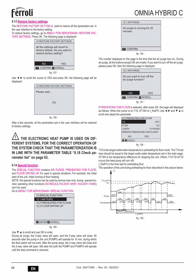
58 EN Cod. 3541T090 - Rev. 03 - 05/2021
OMNIA HYBRID C8.13 Restore factory settingsThe RESTORE FACTORY SETTING is used to restore all the parameters set in the user interface to the factory setting.To restore factory settings, go to MENU> FOR SERVICEMAN> RESTORE FAC-TORY SETTINGS. Press OK. The following page is displayed:
10 RESTORE FACTORY SETTINGS
All the settings will revert to factory default. Do you want to restore factory setting?
SCROLLCONFIRMOK
NO YES
fig. 127 -
Use ◄ ► to scroll the cursor to YES and press OK. the following page will be displayed:
10 RESTORE FACTORY SETTINGS
Please wait…
5%
fig. 128 -
After a few seconds, all the parameters set in the user interface will be restored to factory settings.
B THE ELECTRONIC HEAT PUMP IS USED ON DIF-FERENT SYSTEMS, FOR THE CORRECT OPERATION OF THE SYSTEM CHECK THAT THE PARAMETERIZATION IS IN LINE WITH THE PARAMETER TABLE “8.18 Check pa-rameter list” on page 63.
8.14 Special functionThe SPECIAL FUNCTION contains AIR PURGE, PREHEATING FOR FLOOR, and FLOOR DRYING UP. It’s used in special situations. For example: the initial start of the unit, initial running of floor heating.NOTE: the special functions can be used by service man only, during special fun-ction operating other functions (SCHEDULE,HOLIDAY AWAY, HOLIDAY HOME) can’t be used.Go to MENU> FOR SERVICEMAN> SPECIAL FUNCTION.
12 SPECIAL FUNCTION
12.2 PREHEATING FOR FLOOR12.3 FLOOR DRYING UP
12.1 AIR PURG
SCROLLENTEROK
fig. 129 -
Use ▼ ▲ to scroll and use OK to enter. During air purge, the 3-way valve will open, and the 2-way valve will close. 60 seconds later the pump in the unit (PUMPI) will operate for 10 min, during which the flow switch will not work. After the pump stops, the 3-way valve will close and the 2-way valve will open. 60s later the both the PUMPI and PUMPO will operate until the stop command is received.
12.1 AIR PURGE
Air purge is running for 25 minutes.
CONFIRMOK
fig. 130 -
The number displayed on the page is the time that the air purge has run. During air purge, all the buttons except OK are invalid. If you want to turn off the air purge, please press OK, then the following page is displayed.
12.1 AIR PURGE
Do you want to turn off the air purge function?
SCROLLCONFIRMOK
NO YES
fig. 131 -
If PREHEATING FOR FLOOR is selected, after press OK ,the page will displayed as follows. When the cursor is on T1S, dT1SH or t_fristFH, Use ◄ ► and ▼ ▲ to scroll and adjust the parameter.
12.2 PREHEATING FOR FLOORT1SdT1SHt_fristFHOPERATE PREHEATING FOR FLOOR?
30°C5°C
72 HOURS
SCROLL
NO YES
fig. 132 -
T1S is the target outlet water temperature in preheating for floor mode. The T1S set here should be equal to the target outlet water temperature set in the main page. dT1SH is the temperature difference for stopping the unit. (When T1≥T1S+dT1S occurs the heat pump will turn off)t_fristFH is the time last for preheating floor.The operation of the unit during preheating for floor described in the picture below:
T1s+dT1sT1s
Compressor
Pump
30min t_interval_H
OFFON
OFFON
OFF
T1
OFF OFF OFF OFF OFF OFFON ON ON ON ON
t_firstFHt
fig. 133 -
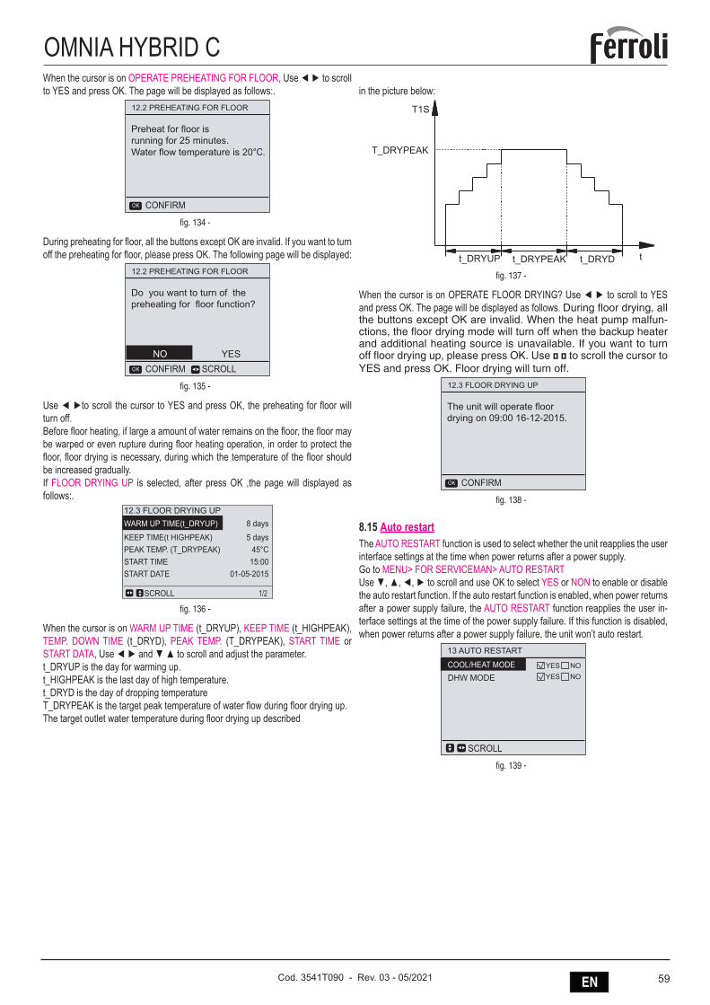
59ENCod. 3541T090 - Rev. 03 - 05/2021
OMNIA HYBRID CWhen the cursor is on OPERATE PREHEATING FOR FLOOR, Use ◄ ► to scroll to YES and press OK. The page will be displayed as follows:.
12.2 PREHEATING FOR FLOOR
Preheat for floor is running for 25 minutes.Water flow temperature is 20°C.
CONFIRMOK
fig. 134 -
During preheating for floor, all the buttons except OK are invalid. If you want to turn off the preheating for floor, please press OK. The following page will be displayed:
12.2 PREHEATING FOR FLOOR
Do you want to turn of the preheating for floor function?
SCROLLCONFIRMOK
NO YES
fig. 135 -
Use ◄ ►to scroll the cursor to YES and press OK, the preheating for floor will turn off.Before floor heating, if large a amount of water remains on the floor, the floor may be warped or even rupture during floor heating operation, in order to protect the floor, floor drying is necessary, during which the temperature of the floor should be increased gradually.If FLOOR DRYING UP is selected, after press OK ,the page will displayed as follows:.
12.3 FLOOR DRYING UPWARM UP TIME(t_DRYUP)KEEP TIME(t HIGHPEAK)PEAK TEMP. (T_DRYPEAK)START TIMESTART DATE
8 days5 days
45°C15:00
01-05-2015
SCROLL 1/2
fig. 136 -
When the cursor is on WARM UP TIME (t_DRYUP), KEEP TIME (t_HIGHPEAK), TEMP. DOWN TIME (t_DRYD), PEAK TEMP. (T_DRYPEAK), START TIME or START DATA, Use ◄ ► and ▼ ▲ to scroll and adjust the parameter.t_DRYUP is the day for warming up.t_HIGHPEAK is the last day of high temperature. t_DRYD is the day of dropping temperatureT_DRYPEAK is the target peak temperature of water flow during floor drying up.The target outlet water temperature during floor drying up described
in the picture below:
t_DRYUP t_DRYPEAK
T1S
tt_DRYD
T_DRYPEAK
fig. 137 -
When the cursor is on OPERATE FLOOR DRYING? Use ◄ ► to scroll to YES and press OK. The page will be displayed as follows. During floor drying, all the buttons except OK are invalid. When the heat pump malfun-ctions, the floor drying mode will turn off when the backup heater and additional heating source is unavailable. If you want to turn off floor drying up, please press OK. Use ◄ ◄ to scroll the cursor to YES and press OK. Floor drying will turn off.
12.3 FLOOR DRYING UP
The unit will operate floordrying on 09:00 16-12-2015.
CONFIRMOK
fig. 138 -
8.15 Auto restartThe AUTO RESTART function is used to select whether the unit reapplies the user interface settings at the time when power returns after a power supply.Go to MENU> FOR SERVICEMAN> AUTO RESTARTUse ▼, ▲, ◄, ► to scroll and use OK to select YES or NON to enable or disable the auto restart function. If the auto restart function is enabled, when power returns after a power supply failure, the AUTO RESTART function reapplies the user in-terface settings at the time of the power supply failure. If this function is disabled, when power returns after a power supply failure, the unit won’t auto restart.
13 AUTO RESTART
DHW MODECOOL/HEAT MODE
SCROLL
YESYES
NONO
fig. 139 -
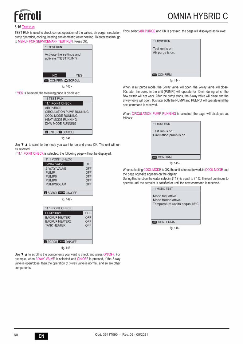
60 EN Cod. 3541T090 - Rev. 03 - 05/2021
OMNIA HYBRID C8.16 Test runTEST RUN is used to check correct operation of the valves, air purge, circulation pump operation, cooling, heating and domestic water heating. To enter test run, go to MENU> FOR SERVICEMAN> TEST RUN. Press OK.
11 TEST RUN
Activate the settings and activate “TEST RUN”?
SCROLLCONFIRMOK
NO YES
fig. 140 -
If YES is selected, the following page is displayed:11 TEST RUN
AIR PURGECIRCULATION PUMP RUNNINGCOOL MODE RUNNINGHEAT MODE RUNNINGDHW MODE RUNNING
11.1 POINT CHECK
SCROLLENTEROK
fig. 141 -
Use ▼ ▲ to scroll to the mode you want to run and press OK. The unit will run as selected.If 11.1 POINT CHECK is selected, the following page will not be displayed:
11.1 POINT CHECK
2-WAY VALVEPUMP1PUMP0PUMP0PUMPSOLAR
3-WAY VALVEOFFOFFOFFOFFOFF
OFF
SCROLL ON/OFFON/OFF
11.1 PIONT CHECK
BACKUP HEATER1BACKUP HEATER2TANK HEATER
PUMPDHWOFFOFFOFF
OFF
SCROLL ON/OFFON/OFF
fig. 142 -
11.1 POINT CHECK
2-WAY VALVEPUMP1PUMP0PUMP0PUMPSOLAR
3-WAY VALVEOFFOFFOFFOFFOFF
OFF
SCROLL ON/OFFON/OFF
11.1 PIONT CHECK
BACKUP HEATER1BACKUP HEATER2TANK HEATER
PUMPDHWOFFOFFOFF
OFF
SCROLL ON/OFFON/OFF
fig. 143 -
Use ▼ ▲ to scroll to the components you want to check and press ON/OFF. For example, when 3-WAY VALVE is selected and ON/OFF is pressed, if the 3-way valve is open/close, then the operation of 3-way valve is normal, and so are other components.
If you select AIR PURGE and OK is pressed, the page will displayed as follows:
11 TEST RUN
Test run is on.Air purge is on.
CONFIRMOK
fig. 144 -
When in air purge mode, the 3-way valve will open, the 2-way valve will close. 60s later the pump in the unit (PUMPI) will operate for 10min during which the flow switch will not work. After the pump stops, the 3-way valve will close and the 2-way valve will open. 60s later both the PUMPI and PUMPO will operate until the next command is received.
When CIRCULATION PUMP RUNNING is selected, the page will displayed as follows:
11 TEST RUN
Test run is on.Circulation pump is on.
CONFIRMOK
fig. 145 -
When selecting COOL MODE is OK, the unit is forced to work in COOL MODE and the page opposite appears on the display.During this function the water setpoint (T1S) is equal to 7 ° C. The unit continues to operate until the setpoint is satisfied or until the next command is received.
11 MODO TEST
Modo test attivo.Modo freddo attivo.Temperatura uscita acqua 15°C.
CONFERMAOK
fig. 146 -

61ENCod. 3541T090 - Rev. 03 - 05/2021
OMNIA HYBRID CWhen selecting HEAT MODE is OK, the unit is forced to operate in HEAT MODE and the page opposite appears on the display.During this function the water setpoint (T1S) is equal to 35 ° C. After 10 minutes of compressor operation the first stage of the electric booster (IBH1) is activated, after 60 seconds the second stage of the electric booster (IBH2) is activated, after 3 minutes IBH1 and IBH2 are turned off. The unit then continues to operate until the setpoint is satisfied or until the next command is received.
11 MODO TEST
Modo test attivo.Modo caldo attivo.Temperatura uscita acqua 15°C.
CONFERMAOK
fig. 147 -
When you select DHW MODE is OK, the unit is forced to operate in DHW mode and the page opposite appears on the display.During this function the water cas setpoint (T5S) is equal to 55 ° C. After 10 minu-tes of compressor operation the ACS electric support heater (TBH) is activated. After 3 minutes TBH is switched off and the unit continues to operate until the setpoint is satisfied or until the next command is received.
11 TEST RUN
Test run is on.DHW mode is on.Water flow temper. is 45°CWater tank temper. is 30°C
CONFIRMOK
fig. 148 -
During test run, all buttons except OK are invalid. If you want to turn off the test run, please press OK. For example ,when the unit is in air purge mode, after you press OK, the page will displayed as follows:
11 TEST RUN
Do you want to turn of the test run(air purge) function?
SCROLLCONFIRMOK
NO YES
fig. 149 -
Use ◄ ► to scroll the cursor to YES and press OK. The test run will turn off.
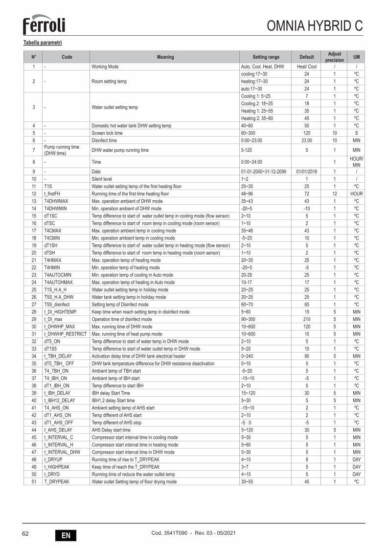
62 EN Cod. 3541T090 - Rev. 03 - 05/2021
OMNIA HYBRID CTabella parametri
N° Code Meaning Setting range Default Adjust precision UM
1 - Working Mode Auto, Cool, Heat, DHW Heat/ Cool / /
2 - Room setting tempcooling:17~30 24 1 ºCheating:17~30 24 1 ºCauto:17~30 24 1 ºC
3 - Water outlet setting temp
Cooling 1: 5~25 7 1 ºCCooling 2: 18~25 18 1 ºCHeating 1: 25~55 35 1 ºCHeating 2: 35~60 45 1 ºC
4 - Domestic hot water tank DHW setting temp 40~60 50 1 ºC5 - Screen lock time 60~300 120 10 S6 - Disinfect time 0:00~23:00 23.00 10 MIN
7 Pump running time (DHW time) DHW water pump running time 5-120 5 1 MIN
8 - Time 0:00~24:00 1 HOUR/MIN
9 - Date 01-01-2000~31-12-2099 01/01/2016 1 /10 - Silent level 1~2 1 1 /11 T1S Water outlet setting temp of the first heating floor 25~35 25 1 ºC12 t_firstFH Running time of the first time heating floor 48~96 72 12 HOUR13 T4DHWMAX Max. operation ambient of DHW mode 35~43 43 1 ºC14 T4DHWMIN Min. operation ambient of DHW mode -20~5 -10 1 ºC15 dT1SC Temp difference to start of water outlet temp in cooling mode (flow sensor) 2~10 5 1 ºC16 dTSC Temp difference to start of room temp in cooling mode (room sensor) 1~10 2 1 ºC17 T4CMAX Max. operation ambient temp in cooling mode 35~46 43 1 ºC18 T4CMIN Min. operation ambient temp in cooling mode -5~25 10 1 ºC19 dT1SH Temp difference to start of water outlet temp in heating mode (flow sensor) 2~10 5 1 ºC20 dTSH Temp difference to start of room temp in heating mode (room sensor) 1~10 2 1 ºC21 T4HMAX Max. operation temp of heating mode 20~35 25 1 ºC22 T4HMIN Min. operation temp of heating mode -20~5 -5 1 ºC23 T4AUTOCMIN Min. operation temp of cooling in Auto mode 20-29 25 1 ºC24 T4AUTOHMAX Max. operation temp of heating in Auto mode 10-17 17 1 ºC25 T1S_H.A_H Water outlet setting temp in holiday mode 20~25 25 1 ºC26 T5S_H.A_DHW Water tank setting temp in holiday mode 20~25 25 1 ºC27 T5S_disinfect Setting temp of Disinfect mode 60~70 65 1 ºC28 t_DI_HIGHTEMP. Keep time when reach setting temp in disinfect mode 5~60 15 5 MIN29 t_DI_max Operation time of disinfect mode 90~300 210 5 MIN30 t_DHWHP_MAX Max. running time of DHW mode 10~600 120 5 MIN31 t_DHWHP_RESTRICT Max. running time of heat pump mode 10~600 10 5 MIN32 dT5_ON Temp difference to start of water temp in DHW mode 2~10 5 1 ºC33 dT1S5 Temp difference to start of water outlet temp in DHW mode 5~20 10 1 ºC34 t_TBH_DELAY Activation delay time of DHW tank electrical heater 0~240 90 5 MIN35 dT5_TBH_ OFF DHW tank temperature difference for DHW resistance deactivation 0~10 5 1 ºC36 T4_TBH_ON Ambient temp of TBH start -5~20 5 1 ºC37 T4_IBH_ON Ambient temp of IBH start -15~10 -5 1 ºC38 dT1_IBH_ON Temp difference to start IBH 2~10 5 1 ºC39 t_IBH_DELAY IBH delay Start Time 15~120 30 5 MIN40 t_IBH12_DELAY IBH1,2 delay Start time 5~30 5 5 MIN41 T4_AHS_ON Ambient setting temp of AHS start -15~10 2 1 ºC42 dT1_AHS_ON Temp different of AHS start 2~10 2 1 ºC43 dT1_AHS_OFF Temp different of AHS stop -5~0 -5 1 ºC44 t_AHS_DELAY AHS Delay start time 5~120 30 5 MIN45 t_INTERVAL_C Compressor start interval time in cooling mode 5~30 5 1 MIN46 t_INTERVAL_H Compressor start interval time in heating mode 5~60 5 1 MIN47 t_INTERVAL_DHW Compressor start interval time in DHW mode 5~30 5 1 MIN48 t_DRYUP Running time of rise to T_DRYPEAK 4~15 8 1 DAY49 t_HIGHPEAK Keep time of reach the T_DRYPEAK 3~7 5 1 DAY50 t_DRYD Running time of reduce the water outlet temp 4~15 5 1 DAY51 T_DRYPEAK Water outlet Setting temp of floor drying mode 30~55 45 1 ºC
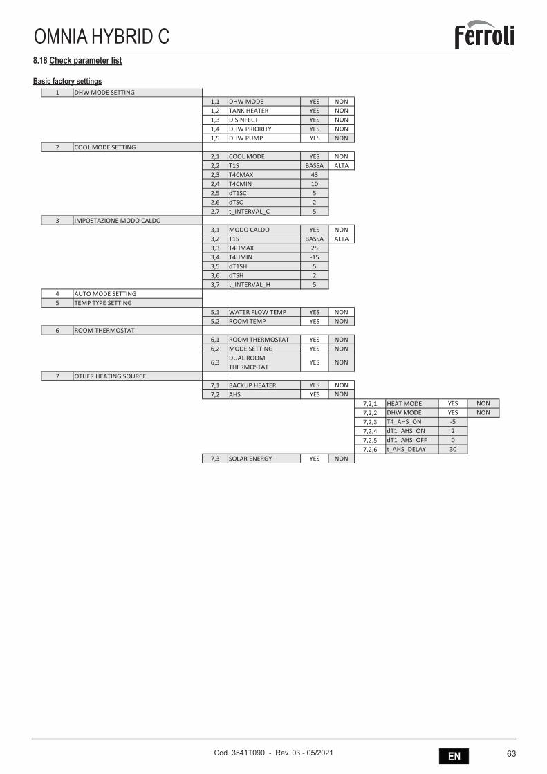
63ENCod. 3541T090 - Rev. 03 - 05/2021
OMNIA HYBRID C8.18 Check parameter list
Basic factory settings
Data di stampa: 17/06/2019
1 DHW MODE SETTING1,1 DHW MODE YES NON1,2 TANK HEATER YES NON1,3 DISINFECT YES NON1,4 DHW PRIORITY YES NON1,5 DHW PUMP YES NON
2 COOL MODE SETTING2,1 COOL MODE YES NON2,2 T1S BASSA ALTA2,3 T4CMAX 432,4 T4CMIN 102,5 dT1SC 52,6 dTSC 22,7 t_INTERVAL_C 5
3 IMPOSTAZIONE MODO CALDO3,1 MODO CALDO YES NON3,2 T1S BASSA ALTA3,3 T4HMAX 253,4 T4HMIN -153,5 dT1SH 53,6 dTSH 23,7 t_INTERVAL_H 5
4 AUTO MODE SETTING5 TEMP TYPE SETTING
5,1 WATER FLOW TEMP YES NON5,2 ROOM TEMP YES NON
6 ROOM THERMOSTAT6,1 ROOM THERMOSTAT YES NON6,2 MODE SETTING YES NON
6,3DUAL ROOM THERMOSTAT
YES NON
7 OTHER HEATING SOURCE7,1 BACKUP HEATER YES NON7,2 AHS YES NON
7,2,1 HEAT MODE YES NON7,2,2 DHW MODE YES NON7,2,3 T4_AHS_ON -57,2,4 dT1_AHS_ON 27,2,5 dT1_AHS_OFF 07,2,6 t_AHS_DELAY 30
7,3 SOLAR ENERGY YES NON
OMNIA HYBRID CDEFAULT MIDEA
Le celle con fondo verde scuro indicano il valore di default da impostare
Impostando 1,1 = NON le righe da 1,2 a 1,5 non saranno visibili
File: Menu RVL-I PLUS - OMNIA H - OMNIA HYBRID C- OMNIA HYBRID H_EN.xlsx Scheda: MIDEA (default2) Pagina 1 / 1
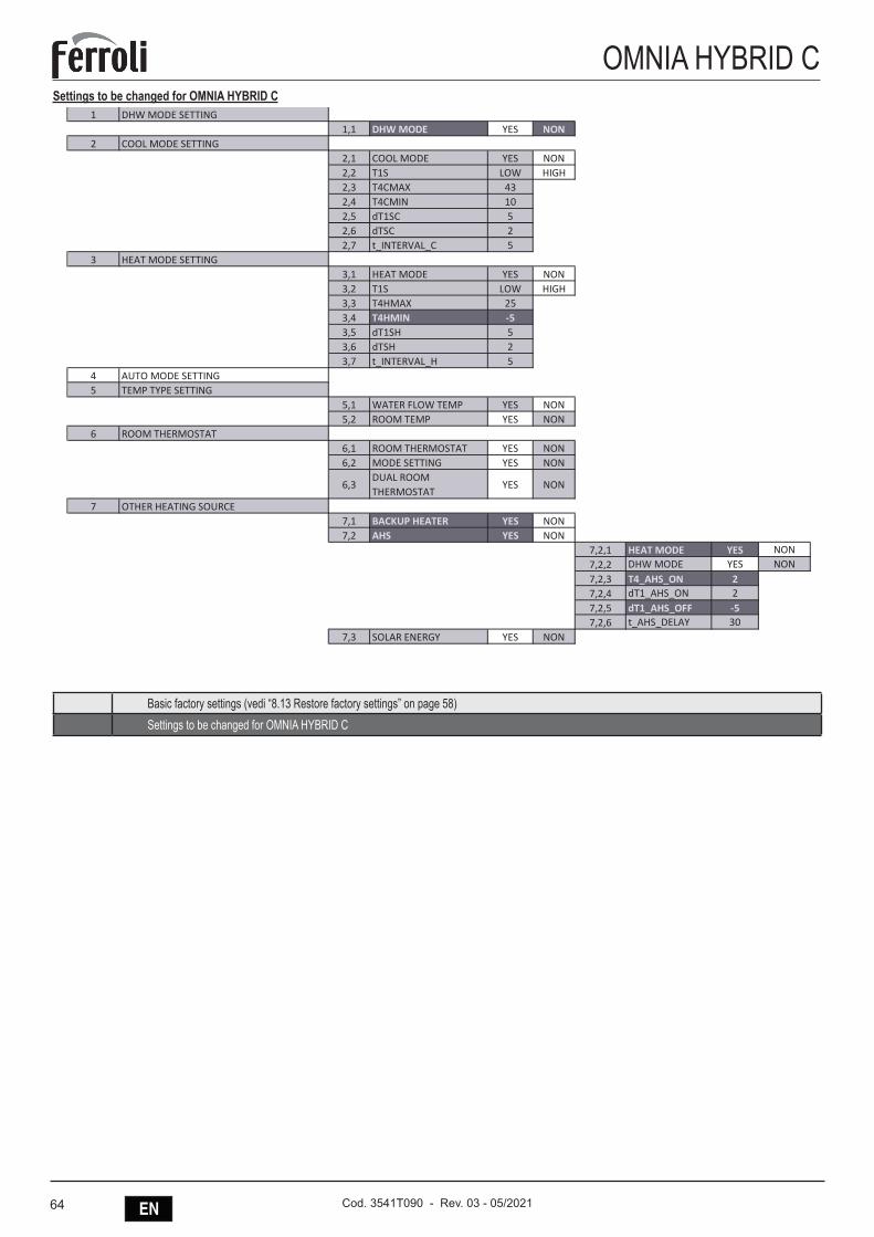
64 EN Cod. 3541T090 - Rev. 03 - 05/2021
OMNIA HYBRID CSettings to be changed for OMNIA HYBRID C
Data di stampa: 13/06/2019
File: Menu RVL-I PLUS - OMNIA H - OMNIA HYBRID C- OMNIA HYBRID H_EN Scheda: OMNIA HYBRID C Pagina 2 / 2
1 DHW MODE SETTING1,1 DHW MODE YES NON
2 COOL MODE SETTING2,1 COOL MODE YES NON2,2 T1S LOW HIGH2,3 T4CMAX 432,4 T4CMIN 102,5 dT1SC 52,6 dTSC 22,7 t_INTERVAL_C 5
3 HEAT MODE SETTING3,1 HEAT MODE YES NON3,2 T1S LOW HIGH3,3 T4HMAX 253,4 T4HMIN -53,5 dT1SH 53,6 dTSH 23,7 t_INTERVAL_H 5
4 AUTO MODE SETTING5 TEMP TYPE SETTING
5,1 WATER FLOW TEMP YES NON5,2 ROOM TEMP YES NON
6 ROOM THERMOSTAT6,1 ROOM THERMOSTAT YES NON6,2 MODE SETTING YES NON
6,3DUAL ROOM THERMOSTAT
YES NON
7 OTHER HEATING SOURCE7,1 BACKUP HEATER YES NON7,2 AHS YES NON
7,2,1 HEAT MODE YES NON7,2,2 DHW MODE YES NON7,2,3 T4_AHS_ON 27,2,4 dT1_AHS_ON 27,2,5 dT1_AHS_OFF -57,2,6 t_AHS_DELAY 30
7,3 SOLAR ENERGY YES NON
DEFAULT MIDEA
Impostando 1,1 = NON le righe da
OMNIA HYBRID C
Le celle con fondo verde scuro indicano il valore di default da impostare di fabbrica
Basic factory settings (vedi “8.13 Restore factory settings” on page 58)Settings to be changed for OMNIA HYBRID C
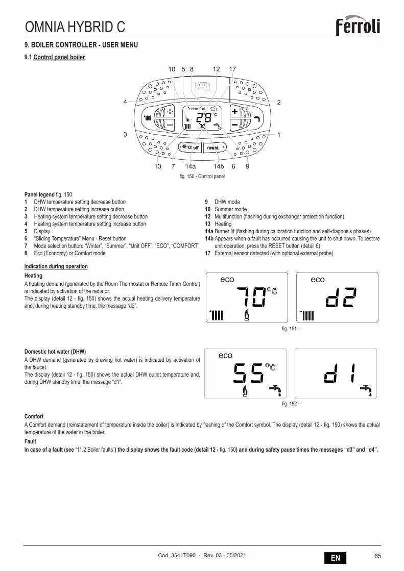
65ENCod. 3541T090 - Rev. 03 - 05/2021
OMNIA HYBRID C9. BOILER CONTROLLER - USER MENU9.1 Control panel boiler
�
�
��������
�
�
�
������ ����fig. 150 - Control panel
Panel legend fig. 1501 DHW temperature setting decrease button2 DHW temperature setting increase button3 Heating system temperature setting decrease button4 Heating system temperature setting increase button5 Display6 “Sliding Temperature” Menu - Reset button7 Mode selection button: “Winter”, “Summer”, “Unit OFF”, “ECO”, “COMFORT”8 Eco (Economy) or Comfort mode
9 DHW mode10 Summer mode12 Multifunction (flashing during exchanger protection function)13 Heating14a Burner lit (flashing during calibration function and self-diagnosis phases)14b Appears when a fault has occurred causing the unit to shut down. To restore
unit operation, press the RESET button (detail 6)17 External sensor detected (with optional external probe)
Indication during operationHeatingA heating demand (generated by the Room Thermostat or Remote Timer Control) is indicated by activation of the radiator.The display (detail 12 - fig. 150) shows the actual heating delivery temperature and, during heating standby time, the message “d2”.
fig. 151 -
Domestic hot water (DHW)A DHW demand (generated by drawing hot water) is indicated by activation of the faucet.The display (detail 12 - fig. 150) shows the actual DHW outlet temperature and, during DHW standby time, the message “d1“.
fig. 152 -
ComfortA Comfort demand (reinstatement of temperature inside the boiler) is indicated by flashing of the Comfort symbol. The display (detail 12 - fig. 150) shows the actual temperature of the water in the boiler.FaultIn case of a fault (see “11.2 Boiler faults”) the display shows the fault code (detail 12 - fig. 150) and during safety pause times the messages “d3” and “d4”.
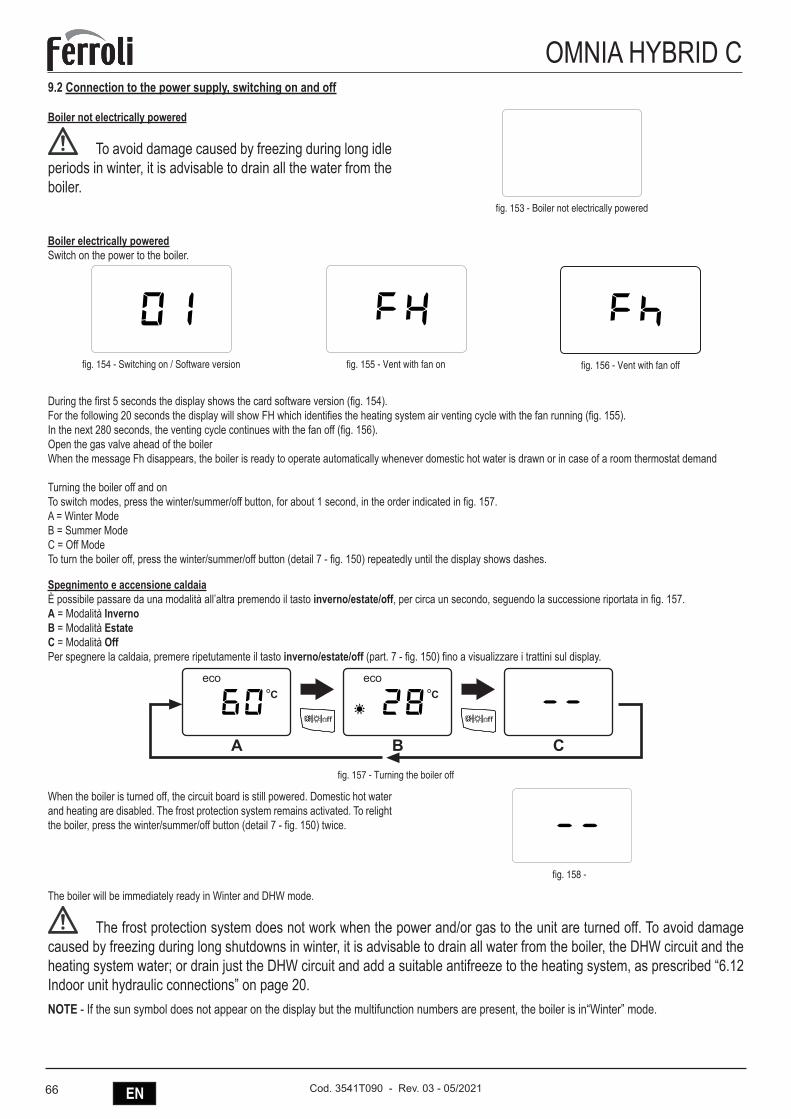
66 EN Cod. 3541T090 - Rev. 03 - 05/2021
OMNIA HYBRID C9.2 Connection to the power supply, switching on and off
Boiler not electrically powered
To avoid damage caused by freezing during long idle periods in winter, it is advisable to drain all the water from the boiler.
fig. 153 - Boiler not electrically powered
Boiler electrically poweredSwitch on the power to the boiler.
fig. 154 - Switching on / Software version fig. 155 - Vent with fan on fig. 156 - Vent with fan off
During the first 5 seconds the display shows the card software version (fig. 154).For the following 20 seconds the display will show FH which identifies the heating system air venting cycle with the fan running (fig. 155).In the next 280 seconds, the venting cycle continues with the fan off (fig. 156).Open the gas valve ahead of the boilerWhen the message Fh disappears, the boiler is ready to operate automatically whenever domestic hot water is drawn or in case of a room thermostat demand
Turning the boiler off and onTo switch modes, press the winter/summer/off button, for about 1 second, in the order indicated in fig. 157.A = Winter ModeB = Summer ModeC = Off ModeTo turn the boiler off, press the winter/summer/off button (detail 7 - fig. 150) repeatedly until the display shows dashes.
Spegnimento e accensione caldaiaÈ possibile passare da una modalità all’altra premendo il tasto inverno/estate/off, per circa un secondo, seguendo la successione riportata in fig. 157.A = Modalità InvernoB = Modalità EstateC = Modalità OffPer spegnere la caldaia, premere ripetutamente il tasto inverno/estate/off (part. 7 - fig. 150) fino a visualizzare i trattini sul display.
� � �
fig. 157 - Turning the boiler off
When the boiler is turned off, the circuit board is still powered. Domestic hot water and heating are disabled. The frost protection system remains activated. To relight the boiler, press the winter/summer/off button (detail 7 - fig. 150) twice.
fig. 158 -
The boiler will be immediately ready in Winter and DHW mode.
The frost protection system does not work when the power and/or gas to the unit are turned off. To avoid damage caused by freezing during long shutdowns in winter, it is advisable to drain all water from the boiler, the DHW circuit and the heating system water; or drain just the DHW circuit and add a suitable antifreeze to the heating system, as prescribed “6.12 Indoor unit hydraulic connections” on page 20.NOTE - If the sun symbol does not appear on the display but the multifunction numbers are present, the boiler is in“Winter” mode.
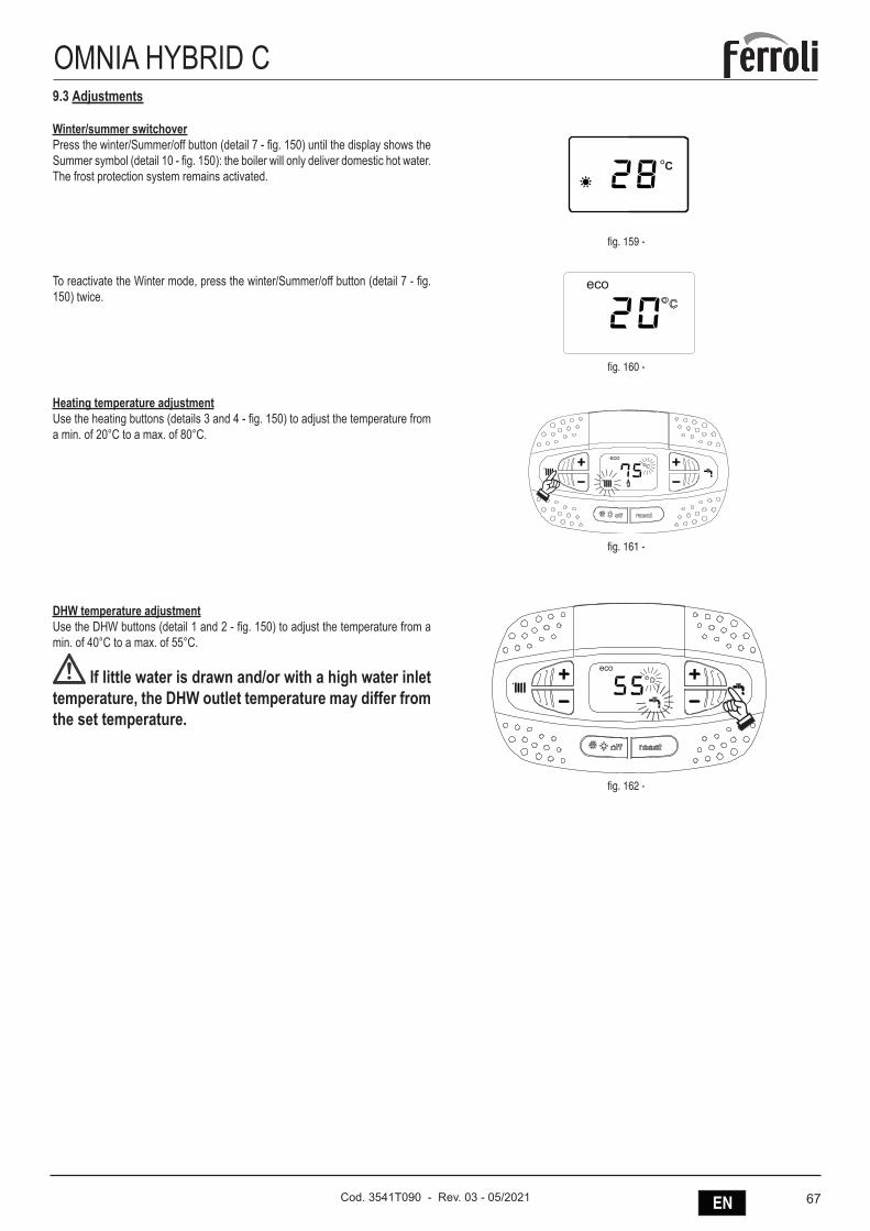
67ENCod. 3541T090 - Rev. 03 - 05/2021
OMNIA HYBRID C9.3 Adjustments
Winter/summer switchoverPress the winter/Summer/off button (detail 7 - fig. 150) until the display shows the Summer symbol (detail 10 - fig. 150): the boiler will only deliver domestic hot water. The frost protection system remains activated.
fig. 159 -
To reactivate the Winter mode, press the winter/Summer/off button (detail 7 - fig. 150) twice.
fig. 160 -
Heating temperature adjustmentUse the heating buttons (details 3 and 4 - fig. 150) to adjust the temperature from a min. of 20°C to a max. of 80°C.
fig. 161 -
DHW temperature adjustmentUse the DHW buttons (detail 1 and 2 - fig. 150) to adjust the temperature from a min. of 40°C to a max. of 55°C.
If little water is drawn and/or with a high water inlet temperature, the DHW outlet temperature may differ from the set temperature.
fig. 162 -
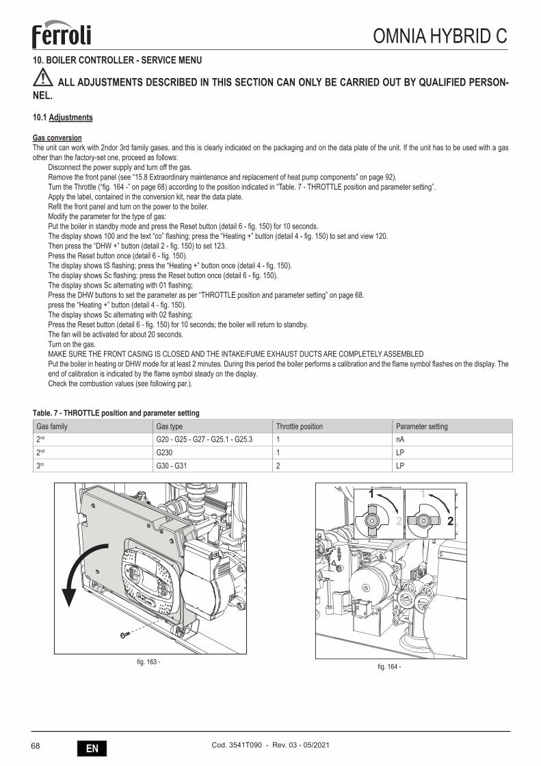
68 EN Cod. 3541T090 - Rev. 03 - 05/2021
OMNIA HYBRID C10. BOILER CONTROLLER - SERVICE MENU
ALL ADJUSTMENTS DESCRIBED IN THIS SECTION CAN ONLY BE CARRIED OUT BY QUALIFIED PERSON-NEL.
10.1 Adjustments
Gas conversionThe unit can work with 2ndor 3rd family gases, and this is clearly indicated on the packaging and on the data plate of the unit. If the unit has to be used with a gas other than the factory-set one, proceed as follows:
Disconnect the power supply and turn off the gas.Remove the front panel (see “15.8 Extraordinary maintenance and replacement of heat pump components” on page 92).Turn the Throttle (“fig. 164 -” on page 68) according to the position indicated in “Table. 7 - THROTTLE position and parameter setting”.Apply the label, contained in the conversion kit, near the data plate.Refit the front panel and turn on the power to the boiler.Modify the parameter for the type of gas:Put the boiler in standby mode and press the Reset button (detail 6 - fig. 150) for 10 seconds.The display shows 100 and the text “co” flashing; press the “Heating +” button (detail 4 - fig. 150) to set and view 120.Then press the “DHW +” button (detail 2 - fig. 150) to set 123.Press the Reset button once (detail 6 - fig. 150).The display shows tS flashing; press the “Heating +” button once (detail 4 - fig. 150).The display shows Sc flashing; press the Reset button once (detail 6 - fig. 150).The display shows Sc alternating with 01 flashing;Press the DHW buttons to set the parameter as per “THROTTLE position and parameter setting” on page 68.press the “Heating +” button (detail 4 - fig. 150).The display shows Sc alternating with 02 flashing;Press the Reset button (detail 6 - fig. 150) for 10 seconds; the boiler will return to standby.The fan will be activated for about 20 seconds.Turn on the gas. MAKE SURE THE FRONT CASING IS CLOSED AND THE INTAKE/FUME EXHAUST DUCTS ARE COMPLETELY ASSEMBLEDPut the boiler in heating or DHW mode for at least 2 minutes. During this period the boiler performs a calibration and the flame symbol flashes on the display. The end of calibration is indicated by the flame symbol steady on the display.Check the combustion values (see following par.).
Table. 7 - THROTTLE position and parameter setting
Gas family Gas type Throttle position Parameter setting2nd G20 - G25 - G27 - G25.1 - G25.3 1 nA2nd G230 1 LP3rd G30 - G31 2 LP
fig. 163 - fig. 164 -
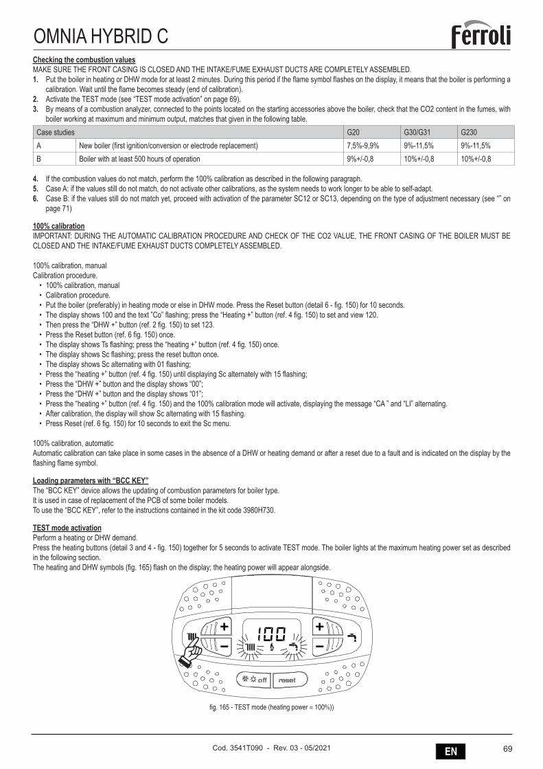
69ENCod. 3541T090 - Rev. 03 - 05/2021
OMNIA HYBRID CChecking the combustion valuesMAKE SURE THE FRONT CASING IS CLOSED AND THE INTAKE/FUME EXHAUST DUCTS ARE COMPLETELY ASSEMBLED.1. Put the boiler in heating or DHW mode for at least 2 minutes. During this period if the flame symbol flashes on the display, it means that the boiler is performing a
calibration. Wait until the flame becomes steady (end of calibration).2. Activate the TEST mode (see “TEST mode activation” on page 69).3. By means of a combustion analyzer, connected to the points located on the starting accessories above the boiler, check that the CO2 content in the fumes, with
boiler working at maximum and minimum output, matches that given in the following table.Case studies G20 G30/G31 G230A New boiler (first ignition/conversion or electrode replacement) 7,5%-9,9% 9%-11,5% 9%-11,5%B Boiler with at least 500 hours of operation 9%+/-0,8 10%+/-0,8 10%+/-0,8
4. If the combustion values do not match, perform the 100% calibration as described in the following paragraph.5. Case A: if the values still do not match, do not activate other calibrations, as the system needs to work longer to be able to self-adapt.6. Case B: if the values still do not match yet, proceed with activation of the parameter SC12 or SC13, depending on the type of adjustment necessary (see “” on
page 71)
100% calibrationIMPORTANT: DURING THE AUTOMATIC CALIBRATION PROCEDURE AND CHECK OF THE CO2 VALUE, THE FRONT CASING OF THE BOILER MUST BE CLOSED AND THE INTAKE/FUME EXHAUST DUCTS COMPLETELY ASSEMBLED.
100% calibration, manualCalibration procedure.
• 100% calibration, manual• Calibration procedure.• Put the boiler (preferably) in heating mode or else in DHW mode. Press the Reset button (detail 6 - fig. 150) for 10 seconds.• The display shows 100 and the text ”Co” flashing; press the “Heating +” button (ref. 4 fig. 150) to set and view 120.• Then press the “DHW +” button (ref. 2 fig. 150) to set 123.• Press the Reset button (ref. 6 fig. 150) once.• The display shows Ts flashing; press the “heating +” button (ref. 4 fig. 150) once.• The display shows Sc flashing; press the reset button once.• The display shows Sc alternating with 01 flashing;• Press the “heating +” button (ref. 4 fig. 150) until displaying Sc alternately with 15 flashing;• Press the “DHW +” button and the display shows “00”;• Press the “DHW +” button and the display shows “01”;• Press the “heating +” button (ref. 4 fig. 150) and the 100% calibration mode will activate, displaying the message “CA ” and “LI” alternating.• After calibration, the display will show Sc alternating with 15 flashing.• Press Reset (ref. 6 fig. 150) for 10 seconds to exit the Sc menu.
100% calibration, automaticAutomatic calibration can take place in some cases in the absence of a DHW or heating demand or after a reset due to a fault and is indicated on the display by the flashing flame symbol.
Loading parameters with “BCC KEY”The “BCC KEY” device allows the updating of combustion parameters for boiler type.It is used in case of replacement of the PCB of some boiler models.To use the “BCC KEY”, refer to the instructions contained in the kit code 3980H730.
TEST mode activationPerform a heating or DHW demand.Press the heating buttons (detail 3 and 4 - fig. 150) together for 5 seconds to activate TEST mode. The boiler lights at the maximum heating power set as described in the following section.The heating and DHW symbols (fig. 165) flash on the display; the heating power will appear alongside.
fig. 165 - TEST mode (heating power = 100%))
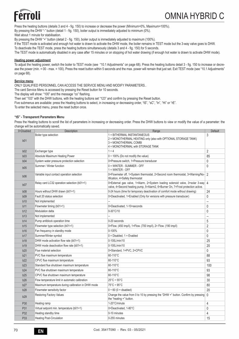
70 EN Cod. 3541T090 - Rev. 03 - 05/2021
OMNIA HYBRID CPress the heating buttons (details 3 and 4 - fig. 150) to increase or decrease the power (Minimum=0%, Maximum=100%).By pressing the DHW “-” button (detail 1 - fig. 150), boiler output is immediately adjusted to minimum (0%).Wait about 1 minute for stabilisation.By pressing the DHW “+” button (detail 2 - fig. 150), boiler output is immediately adjusted to maximum (100%).If the TEST mode is activated and enough hot water is drawn to activate the DHW mode, the boiler remains in TEST mode but the 3-way valve goes to DHW.To deactivate the TEST mode, press the heating buttons simultaneously (details 3 and 4 - fig. 150) for 5 seconds.The TEST mode is automatically disabled in any case after 15 minutes or on stopping of hot water drawing (if enough hot water is drawn to activate DHW mode).
Heating power adjustmentTo adjust the heating power, switch the boiler to TEST mode (see “10.1 Adjustments” on page 68). Press the heating buttons detail 3 - fig. 150 to increase or decre-ase the power (min. = 00 - max. = 100). Press the reset button within 5 seconds and the max. power will remain that just set. Exit TEST mode (see “10.1 Adjustments” on page 68).
Service menuONLY QUALIFIED PERSONNEL CAN ACCESS THE SERVICE MENU AND MODIFY PARAMETERS..The card Service Menu is accessed by pressing the Reset button for 10 seconds.The display will show: “100” and the message “co” flashing.Then set “103” with the DHW buttons, with the heating buttons set “123” and confirm by pressing the Reset button.Five submenus are available: press the Heating buttons to select, in increasing or decreasing order, “tS”, “sC”, “In”, “Hi” or “rE”.To enter the selected menu, press the reset button once.
“tS” - Transparent Parameters MenuPress the Heating buttons to scroll the list of parameters in increasing or decreasing order. Press the DHW buttons to view or modify the value of a parameter: the change will be automatically saved.
0=Disabled Description Range Default
b01
Boiler type selection 1 = BITHERMAL INSTANTANEOUS2 = MONOTHERMAL HEATING only (also with OPTIONAL STORAGE TANK)3 = MONOTHERMAL COMBI4 = MONOTHERMAL with STORAGE TANK
3
b02 Exchanger type 1 ÷ 4 2b03 Absolute Maximum Heating Power 0 ÷ 100% (Do not modify the value) 85b04 System water pressure protection selection 0=Pressure switch, 1=Pressure transducer 0
b05 Summer / Winter function 0 = WINTER - SUMMER - OFF1 = WINTER - OFF
0
b06 Variable input contact operation selection 0=Flowmeter off, 1=System thermostat, 2=Second room thermostat, 3=Warning/No-tification, 4=Safety thermostat
2
b07 Relay card LC32 operation selection (b01=1) 0=External gas valve, 1=Alarm, 2=System loading solenoid valve, 3=solar 3-way valve, 4=Second heating pump, 5=Alarm2, 6=Burner On, 7=Frost protection active.
4
b08 Hours without DHW drawn (b01=1) 0-24 hours (time for temporary deactivation of comfort mode without drawing) 24b09 Fault 20 status selection 0=Deactivated, 1=Enabled (Only for versions with pressure transducer) 0b10 Not implemented -- --b11 Flowmeter timing (b01=1) 0=Deactivated, 1-10=seconds 0b12 Modulation delta 0-30°C/10 0b13 Not implemented -- --b14 Pump antiblock operation time 0-20 seconds 5b15 Flowmeter type selection (b01=1) 0=Flow. (450 imp/l), 1=Flow. (700 imp/l), 2= Flow. (190 imp/l) 2b16 Fan frequency in standby mode 0-100% 0b17 Summer/Winter symbol 0 = Disabled, 1 = Enabled 0b18 DHW mode activation flow rate (b01=1) 0-100L/min/10 25b19 DHW mode deactivation flow rate (b01=1) 0-100L/min/10 20b20 Flue material selection 0=Standard, 1=PVC, 2=CPVC 0b21 PVC flue maximum temperature 60-110°C 88b22 CPVC flue maximum temperature 60-110°C 93b23 Standard flue shutdown maximum temperature 60-110°C 100b24 PVC flue shutdown maximum temperature 60-110°C 93b25 CPVC flue shutdown maximum temperature 60-110°C 98b26 Flow temperature limit in automatic calibration 25°C ÷ 55°C 30b27 Maximum temperature during calibration in DHW mode 75°C ÷ 95°C 80b28 Flowmeter sensitivity factor 0 ÷ 60 (0 = disabled) 20
b29 Restoring Factory Values Change the value from 0 to 10 by pressing the “DHW +” button. Confirm by pressing the “heating +” button.
0
P30 Heating ramp 1-20°C/minute 4P31 Virtual setpoint min. temperature (b01=1) 0=Deactivated, 1-80°C 0P32 Heating standby time 0-10 minutes 4P33 Heating Post-Circulation 0-255 minutes 15
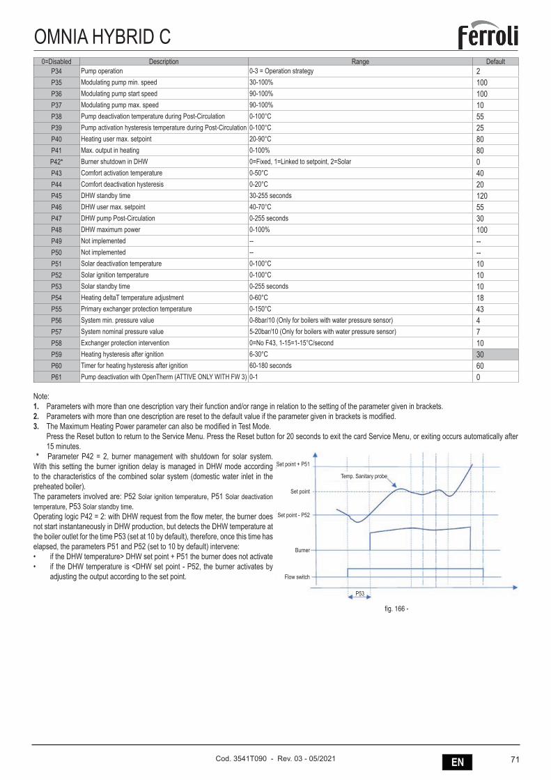
71ENCod. 3541T090 - Rev. 03 - 05/2021
OMNIA HYBRID C0=Disabled Description Range Default
P34 Pump operation 0-3 = Operation strategy 2P35 Modulating pump min. speed 30-100% 100P36 Modulating pump start speed 90-100% 100P37 Modulating pump max. speed 90-100% 10P38 Pump deactivation temperature during Post-Circulation 0-100°C 55P39 Pump activation hysteresis temperature during Post-Circulation 0-100°C 25P40 Heating user max. setpoint 20-90°C 80P41 Max. output in heating 0-100% 80P42* Burner shutdown in DHW 0=Fixed, 1=Linked to setpoint, 2=Solar 0P43 Comfort activation temperature 0-50°C 40P44 Comfort deactivation hysteresis 0-20°C 20P45 DHW standby time 30-255 seconds 120P46 DHW user max. setpoint 40-70°C 55P47 DHW pump Post-Circulation 0-255 seconds 30P48 DHW maximum power 0-100% 100P49 Not implemented -- --P50 Not implemented -- --P51 Solar deactivation temperature 0-100°C 10P52 Solar ignition temperature 0-100°C 10P53 Solar standby time 0-255 seconds 10P54 Heating deltaT temperature adjustment 0-60°C 18P55 Primary exchanger protection temperature 0-150°C 43P56 System min. pressure value 0-8bar/10 (Only for boilers with water pressure sensor) 4P57 System nominal pressure value 5-20bar/10 (Only for boilers with water pressure sensor) 7P58 Exchanger protection intervention 0=No F43, 1-15=1-15°C/second 10P59 Heating hysteresis after ignition 6-30°C 30P60 Timer for heating hysteresis after ignition 60-180 seconds 60P61 Pump deactivation with OpenTherm (ATTIVE ONLY WITH FW 3) 0-1 0
Note:1. Parameters with more than one description vary their function and/or range in relation to the setting of the parameter given in brackets.2. Parameters with more than one description are reset to the default value if the parameter given in brackets is modified.3. The Maximum Heating Power parameter can also be modified in Test Mode.
Press the Reset button to return to the Service Menu. Press the Reset button for 20 seconds to exit the card Service Menu, or exiting occurs automatically after 15 minutes.
* Parameter P42 = 2, burner management with shutdown for solar system. With this setting the burner ignition delay is managed in DHW mode according to the characteristics of the combined solar system (domestic water inlet in the preheated boiler).The parameters involved are: P52 Solar ignition temperature, P51 Solar deactivation temperature, P53 Solar standby time.Operating logic P42 = 2: with DHW request from the flow meter, the burner does not start instantaneously in DHW production, but detects the DHW temperature at the boiler outlet for the time P53 (set at 10 by default), therefore, once this time has elapsed, the parameters P51 and P52 (set to 10 by default) intervene:• if the DHW temperature> DHW set point + P51 the burner does not activate• if the DHW temperature is <DHW set point - P52, the burner activates by
adjusting the output according to the set point.
Temp. Sanitary probe
Set point + P51
Set point - P52
Burner
Flow switch
Set point
P53
fig. 166 -
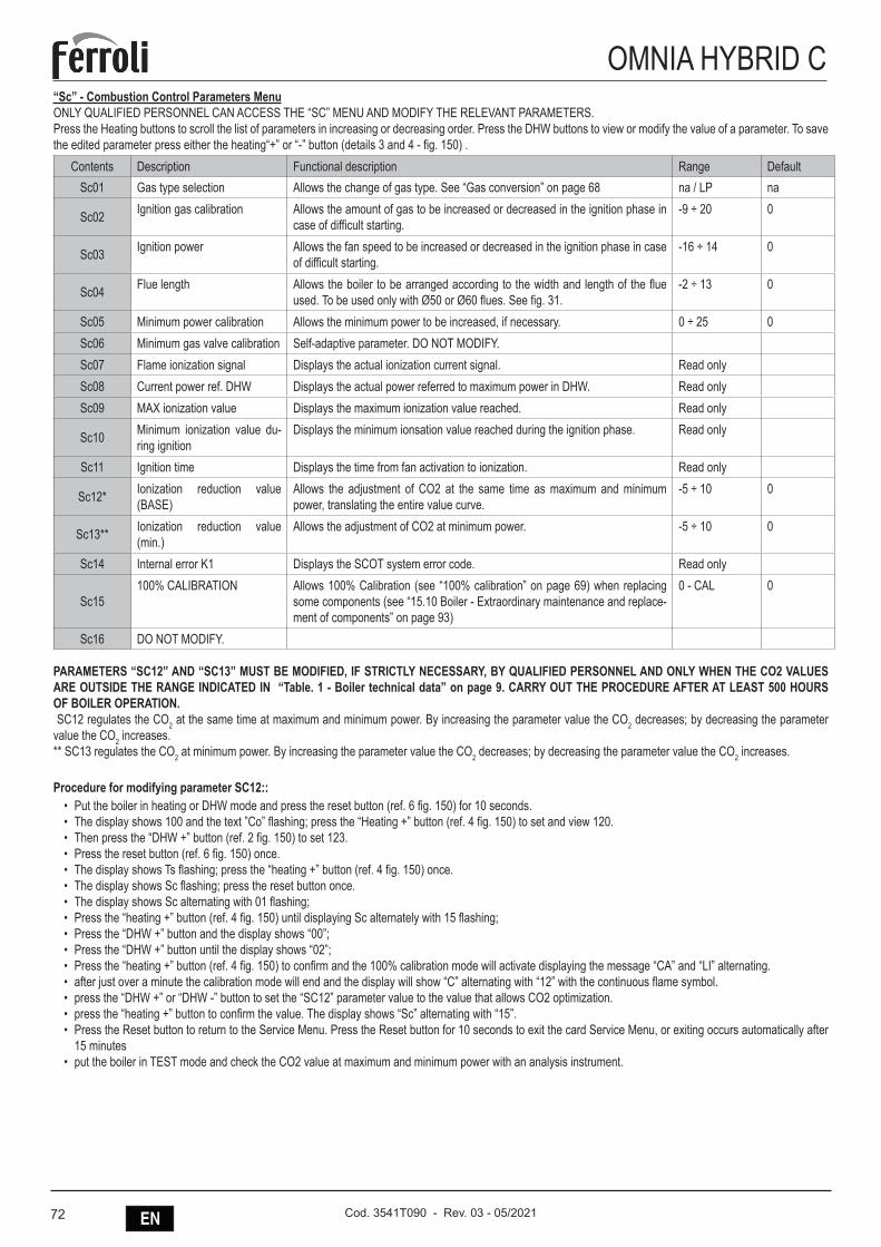
72 EN Cod. 3541T090 - Rev. 03 - 05/2021
OMNIA HYBRID C“Sc” - Combustion Control Parameters MenuONLY QUALIFIED PERSONNEL CAN ACCESS THE “SC” MENU AND MODIFY THE RELEVANT PARAMETERS.Press the Heating buttons to scroll the list of parameters in increasing or decreasing order. Press the DHW buttons to view or modify the value of a parameter. To save the edited parameter press either the heating“+” or “-” button (details 3 and 4 - fig. 150) .
Contents Description Functional description Range DefaultSc01 Gas type selection Allows the change of gas type. See “Gas conversion” on page 68 na / LP na
Sc02 Ignition gas calibration Allows the amount of gas to be increased or decreased in the ignition phase in case of difficult starting.
-9 ÷ 20 0
Sc03 Ignition power Allows the fan speed to be increased or decreased in the ignition phase in case of difficult starting.
-16 ÷ 14 0
Sc04 Flue length Allows the boiler to be arranged according to the width and length of the flue used. To be used only with Ø50 or Ø60 flues. See fig. 31.
-2 ÷ 13 0
Sc05 Minimum power calibration Allows the minimum power to be increased, if necessary. 0 ÷ 25 0Sc06 Minimum gas valve calibration Self-adaptive parameter. DO NOT MODIFY.Sc07 Flame ionization signal Displays the actual ionization current signal. Read onlySc08 Current power ref. DHW Displays the actual power referred to maximum power in DHW. Read onlySc09 MAX ionization value Displays the maximum ionization value reached. Read only
Sc10 Minimum ionization value du-ring ignition
Displays the minimum ionsation value reached during the ignition phase. Read only
Sc11 Ignition time Displays the time from fan activation to ionization. Read only
Sc12* Ionization reduction value (BASE)
Allows the adjustment of CO2 at the same time as maximum and minimum power, translating the entire value curve.
-5 ÷ 10 0
Sc13** Ionization reduction value (min.)
Allows the adjustment of CO2 at minimum power. -5 ÷ 10 0
Sc14 Internal error K1 Displays the SCOT system error code. Read only
Sc15100% CALIBRATION Allows 100% Calibration (see “100% calibration” on page 69) when replacing
some components (see “15.10 Boiler - Extraordinary maintenance and replace-ment of components” on page 93)
0 - CAL 0
Sc16 DO NOT MODIFY.
PARAMETERS “SC12” AND “SC13” MUST BE MODIFIED, IF STRICTLY NECESSARY, BY QUALIFIED PERSONNEL AND ONLY WHEN THE CO2 VALUES ARE OUTSIDE THE RANGE INDICATED IN “Table. 1 - Boiler technical data” on page 9. CARRY OUT THE PROCEDURE AFTER AT LEAST 500 HOURS OF BOILER OPERATION. SC12 regulates the CO2 at the same time at maximum and minimum power. By increasing the parameter value the CO2 decreases; by decreasing the parameter value the CO2 increases.** SC13 regulates the CO2 at minimum power. By increasing the parameter value the CO2 decreases; by decreasing the parameter value the CO2 increases.
Procedure for modifying parameter SC12::• Put the boiler in heating or DHW mode and press the reset button (ref. 6 fig. 150) for 10 seconds.• The display shows 100 and the text ”Co” flashing; press the “Heating +” button (ref. 4 fig. 150) to set and view 120.• Then press the “DHW +” button (ref. 2 fig. 150) to set 123.• Press the reset button (ref. 6 fig. 150) once.• The display shows Ts flashing; press the “heating +” button (ref. 4 fig. 150) once.• The display shows Sc flashing; press the reset button once.• The display shows Sc alternating with 01 flashing;• Press the “heating +” button (ref. 4 fig. 150) until displaying Sc alternately with 15 flashing;• Press the “DHW +” button and the display shows “00”;• Press the “DHW +” button until the display shows “02”;• Press the “heating +” button (ref. 4 fig. 150) to confirm and the 100% calibration mode will activate displaying the message “CA” and “LI” alternating.• after just over a minute the calibration mode will end and the display will show “C” alternating with “12” with the continuous flame symbol.• press the “DHW +” or “DHW -” button to set the “SC12” parameter value to the value that allows CO2 optimization.• press the “heating +” button to confirm the value. The display shows “Sc” alternating with “15”.• Press the Reset button to return to the Service Menu. Press the Reset button for 10 seconds to exit the card Service Menu, or exiting occurs automatically after
15 minutes• put the boiler in TEST mode and check the CO2 value at maximum and minimum power with an analysis instrument.
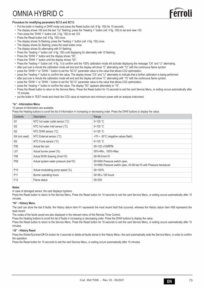
73ENCod. 3541T090 - Rev. 03 - 05/2021
OMNIA HYBRID CProcedure for modifying parameters SC12 and SC13:
• Put the boiler in heating or DHW mode and press the Reset button (ref. 6 fig. 150) for 10 seconds.• The display shows 100 and the text ”Co” flashing; press the “Heating +” button (ref. 4 fig. 150) to set and view 120.• Then press the “DHW +” button (ref. 2 fig. 150) to set 123.• Press the Reset button (ref. 6 fig. 150) once.• The display shows Ts flashing; press the “heating +” button (ref. 4 fig. 150) once.• The display shows Sc flashing; press the reset button once.• The display shows Sc alternating with 01 flashing;• Press the “heating +” button (ref. 4 fig. 150) until displaying Sc alternately with 15 flashing;• Press the “DHW +” button and the display shows “00”;• Press the “DHW +” button until the display shows “03”;• Press the “heating +” button (ref. 4 fig. 1) to confirm and the 100% calibration mode will activate displaying the message “CA” and “LI” alternating.• after just over a minute the calibration mode will end and the display will show “C” alternating with “12” with the continuous flame symbol.• press the “DHW +” or “DHW -” button to set the “SC12” parameter value to the value that allows CO2 optimisation.• press the “heating +” button to confirm the value. The display shows “CA” and “LI” alternately to indicate that a further calibration is being performed.• after just over a minute the calibration mode will end and the display will show “C” alternating with “15” with the continuous flame symbol.• press the “DHW +” or “DHW -” button to set the “SC13” parameter value to the value that allows CO2 optimization.• press the “heating +” button to confirm the value. The display “SC” appears alternately to “15”.• Press the Reset button to return to the Service Menu. Press the Reset button for 10 seconds to exit the card Service Menu, or exiting occurs automatically after
15 minutes• put the boiler in TEST mode and check the CO2 value at maximum and minimum power with an analysis instrument.
“In” - Information Menu12 pieces of information are available.Press the Heating buttons to scroll the list of information in increasing or decreasing order. Press the DHW buttons to display the value.
Contents Description Ranget01 NTC hot water outlet sensor (°C) 0÷125 °Ct02 NTC hot water inlet sensor (°C) 0÷125 °Ct03 NTC DHW sensor (°C) 0÷125 °Ct04 (not used) NTC External sensor (°C) +70 ÷ -30°C (negative values flash)t05 NTC Fume sensor (°C) 0÷125 °CF06 Actual fan rpm 00÷120 x100RPML07 Actual burner power (%) 00%=Min., 100%=Max.F08 Actual DHW drawing (l/min/10) 00÷99 l/min/10P09 Actual system water pressure (bar/10) 00=With Pressure switch open,
14=With Pressure switch open, 00-99 bar/10 with Pressure transducerP10 Actual modulating pump speed (%) 00÷100%P11 Burner operating hours 00÷99 x 100 hoursF12 Flame status 00÷255
Notes:In case of damaged sensor, the card displays hyphens.Press the Reset button to return to the Service Menu. Press the Reset button for 10 seconds to exit the card Service Menu, or exiting occurs automatically after 15 minutes.“Hi” - History MenuThe card can store the last 8 faults: the History datum item H1 represents the most recent fault that occurred, whereas the History datum item H08 represents the least recent.The codes of the faults saved are also displayed in the relevant menu of the Remote Timer Control.Press the Heating buttons to scroll the list of faults in increasing or decreasing order. Press the DHW buttons to display the value.Press the Reset button to return to the Service Menu. Press the Reset button for 10 seconds to exit the card Service Menu, or exiting occurs automatically after 15 minutes.“rE” - History ResetPress the Winter/Summer/Off-On button for 3 seconds to delete all faults stored in the History Menu: the card automatically exits the Service Menu, in order to confirm the operation.Press the Reset button for 10 seconds to exit the card Service Menu, or exiting occurs automatically after 15 minutes.
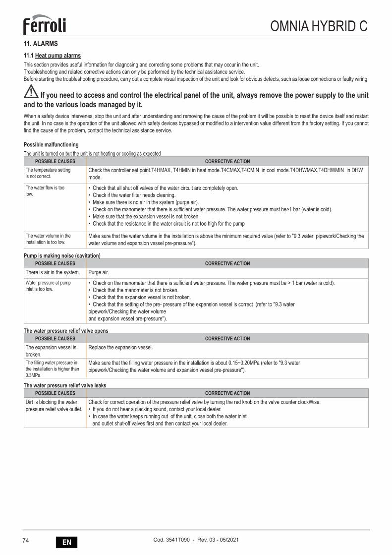
74 EN Cod. 3541T090 - Rev. 03 - 05/2021
OMNIA HYBRID C11. ALARMS11.1 Heat pump alarmsThis section provides useful information for diagnosing and correcting some problems that may occur in the unit.Troubleshooting and related corrective actions can only be performed by the technical assistance service.Before starting the troubleshooting procedure, carry out a complete visual inspection of the unit and look for obvious defects, such as loose connections or faulty wiring.
If you need to access and control the electrical panel of the unit, always remove the power supply to the unit and to the various loads managed by it.When a safety device intervenes, stop the unit and after understanding and removing the cause of the problem it will be possible to reset the device itself and restart the unit. In no case is the operation of the unit allowed with safety devices bypassed or modified to a intervention value different from the factory setting. If you cannot find the cause of the problem, contact the technical assistance service.
Possible malfunctioningThe unit is turned on but the unit is not heating or cooling as expected
POSSIBLE CAUSES CORRECTIVE ACTIONThe temperature setting is not correct.
Check the controller set point.T4HMAX, T4HMIN in heat mode.T4CMAX,T4CMIN in cool mode.T4DHWMAX,T4DHWMIN in DHW mode.
The water flow is too low.
• Check that all shut off valves of the water circuit are completely open.• Check if the water filter needs cleaning.• Make sure there is no air in the system (purge air).• Check on the manometer that there is sufficient water pressure. The water pressure must be>1 bar (water is cold).• Make sure that the expansion vessel is not broken.• Check that the resistance in the water circuit is not too high for the pump
The water volume in the installation is too low.
Make sure that the water volume in the installation is above the minimum required value (refer to "9.3 water pipework/Checking the water volume and expansion vessel pre-pressure").
Pump is making noise (cavitation)POSSIBLE CAUSES CORRECTIVE ACTION
There is air in the system. Purge air.
Water pressure at pump inlet is too low.
• Check on the manometer that there is sufficient water pressure. The water pressure must be > 1 bar (water is cold).• Check that the manometer is not broken.• Check that the expansion vessel is not broken.• Check that the setting of the pre- pressure of the expansion vessel is correct (refer to "9.3 water pipework/Checking the water volume and expansion vessel pre-pressure").
The water pressure relief valve opensPOSSIBLE CAUSES CORRECTIVE ACTION
The expansion vessel is broken.
Replace the expansion vessel.
The filling water pressure in the installation is higher than 0.3MPa.
Make sure that the filling water pressure in the installation is about 0.15~0.20MPa (refer to "9.3 water pipework/Checking the water volume and expansion vessel pre-pressure").
The water pressure relief valve leaksPOSSIBLE CAUSES CORRECTIVE ACTION
Dirt is blocking the water pressure relief valve outlet.
Check for correct operation of the pressure relief valve by turning the red knob on the valve counter clockWise:• If you do not hear a clacking sound, contact your local dealer.• In case the water keeps running out of the unit, close both the water inlet and outlet shut-off valves first and then contact your local dealer.
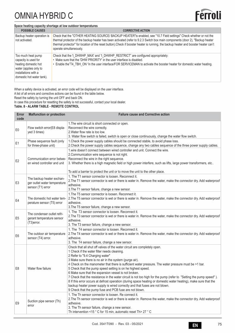
75ENCod. 3541T090 - Rev. 03 - 05/2021
OMNIA HYBRID CSpace heating capacity shortage at low outdoor temperatures
POSSIBLE CAUSES CORRECTIVE ACTIONBackup heater operation is not activated.
Check that the "OTHER HEATING SOURCE/ BACKUP HEATER"is enabled, see "10.7 Field settings" Check whether or not the thermal protector of the backup heater has been activated (refer to 9.2.3 Switch box main components (door 2), "Backup heater thermal protector" for location of the reset button).Check if booster heater is running, the backup heater and booster heater can’t operate simultaneously.
Too much heat pump capacity is used for heating domestic hot water (applies only to installations with a domestic hot water tank).
Check that the 't_DHWHP_MAX' and “t_ DHWHP_RESTRICT” are configured appropriately:• Make sure that the 'DHW PRIORITY' in the user interface is disabled.• Enable the”T4_TBH_ON “in the user interface/FOR SERVICEMAN to activate the booster heater for domestic water heating.
When a safety device is activated, an error code will be displayed on the user interface.A list of all errors and corrective actions can be found in the table below.Reset the safety by turning the unit OFF and back ON.In case this procedure for resetting the safety is not successful, contact your local dealer.Table. 8 - ALARM TABLE - REMOTE CONTROL
Error code
Malfunction or protection Failure cause and Corrective action
E0 Flow switch error(E8 displa-yed 3 times)
1.The wire circuit is short connected or open.Reconnect the wire correctly.2.Water flow rate is too low.3. Water flow switch is failed, switch is open or close continuously, change the water flow switch.
E1 Phase sequence fault (only for three-phase unit)
1.Check the power supply cables should be connected stable, to avoid phase loss.2.Check the power supply cables sequence, change any two cables sequence of the three power supply cables.
E2 Communication error betwe-en wired controller and unit
1.wire doesn’t connect between wired controller and unit. Connect the wire.2.Communication wire sequence is not right.Reconnect the wire in the right sequence.3. Whether there is a high magnetic field or high power interfere, such as lifts, large power transformers, etc..
To add a barrier to protect the unit or to move the unit to the other place.
E3The backup heater exchan-ger outlet water temperature sensor (T1) error
1. The T1 sensor connector is loosen. Reconnect it.2.The T1 sensor connector is wet or there is water in. Remove the water, make the connector dry. Add waterproof adhesive.3.The T1 sensor failure, change a new sensor.
E4 The domestic hot water tem-perature sensor (T5) error
1.The T5 sensor connector is loosen. Reconnect it.2.The T5 sensor connector is wet or there is water in. Remove the water, make the connector dry. Add waterproof adhesive.3.The T5 sensor failure, change a new sensor.
E5The condenser outlet refri-gerant temperature sensor (T3)error.
1. The T3 sensor connector is loosen. Reconnect it.2.The T3 sensor connector is wet or there is water in. Remove the water, make the connector dry. Add waterproof adhesive.3. The T3 sensor failure, change a new sensor.
E6 The outdoor air temperature sensor (T4) error.
1. The T4 sensor connector is loosen. Reconnect it.2.The T4 sensor connector is wet or there is water in. Remove the water, make the connector dry. Add waterproof adhesive.3. The T4 sensor failure, change a new sensor.
E8 Water flow failure
Check that all shut off valves of the water circuit are completely open.1 Check if the water filter needs cleaning.2 Refer to "9.4 Charging water" 3 Make sure there is no air in the system (purge air).4 Check on the manometer that there is sufficient water pressure. The water pressure must be >1 bar.5 Check that the pump speed setting is on he highest speed.6 Make sure that the expansion vessel is not broken.7 Check that the resistance in the water circuit is not too high for the pump (refer to "Setting the pump speed" ).8 If this error occurs at defrost operation (during space heating or domestic water heating), make sure that the backup heater power supply is wired correctly and that fuses are not blown.9 Check that the pump fuse and PCB fuse are not blown.
E9 Suction pipe sensor (Th) error
1. The Th sensor connector is loosen. Re connect it.2.The Th sensor connector is wet or there is water in. Remove the water, make the connector dry. Add waterproof adhesive.3. The Th sensor failure, change a new sensor.Th intervention <15 ° C for 15 min, automatic reset Th> 27 ° C
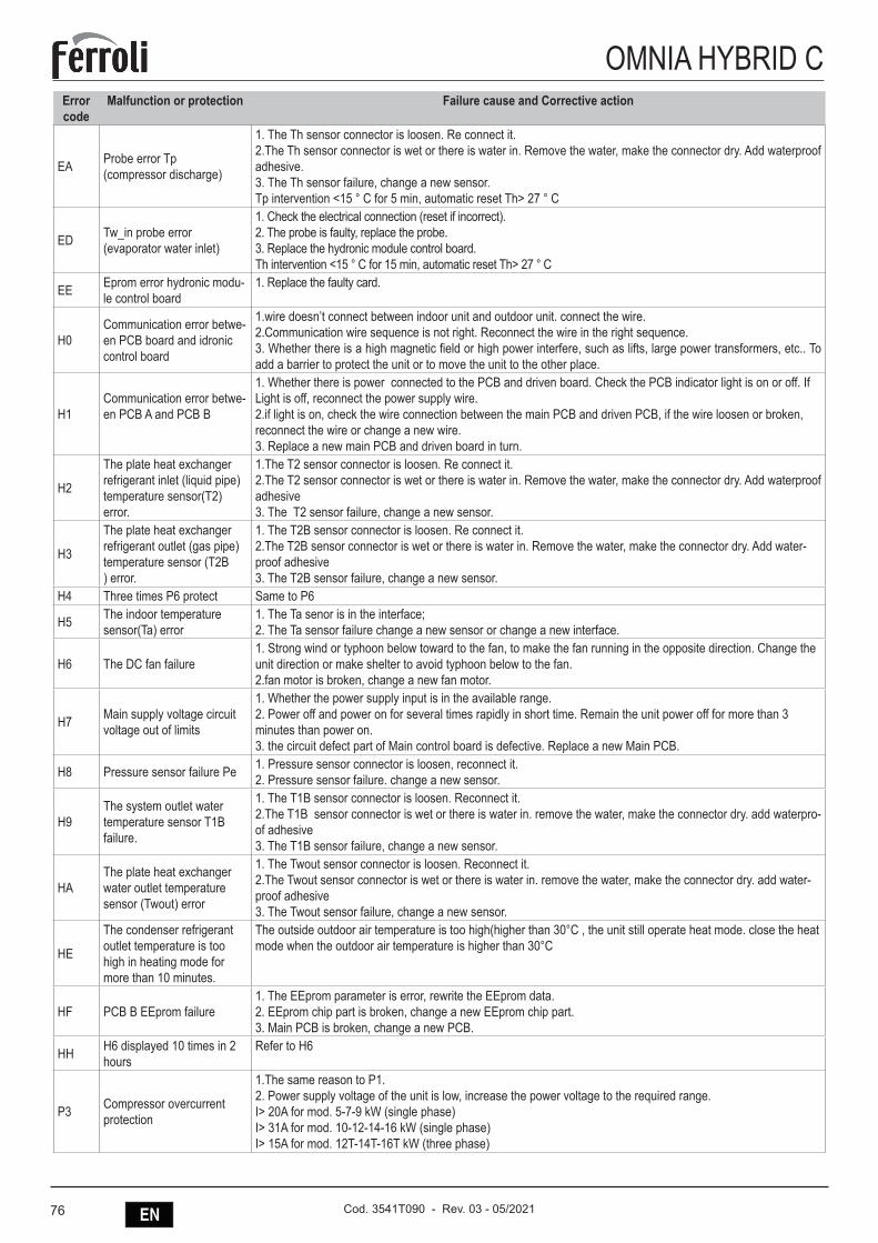
76 EN Cod. 3541T090 - Rev. 03 - 05/2021
OMNIA HYBRID CError code
Malfunction or protection Failure cause and Corrective action
EA Probe error Tp(compressor discharge)
1. The Th sensor connector is loosen. Re connect it.2.The Th sensor connector is wet or there is water in. Remove the water, make the connector dry. Add waterproof adhesive.3. The Th sensor failure, change a new sensor.Tp intervention <15 ° C for 5 min, automatic reset Th> 27 ° C
ED Tw_in probe error(evaporator water inlet)
1. Check the electrical connection (reset if incorrect).2. The probe is faulty, replace the probe.3. Replace the hydronic module control board.Th intervention <15 ° C for 15 min, automatic reset Th> 27 ° C
EE Eprom error hydronic modu-le control board
1. Replace the faulty card.
H0Communication error betwe-en PCB board and idronic control board
1.wire doesn’t connect between indoor unit and outdoor unit. connect the wire.2.Communication wire sequence is not right. Reconnect the wire in the right sequence.3. Whether there is a high magnetic field or high power interfere, such as lifts, large power transformers, etc.. To add a barrier to protect the unit or to move the unit to the other place.
H1Communication error betwe-en PCB A and PCB B
1. Whether there is power connected to the PCB and driven board. Check the PCB indicator light is on or off. If Light is off, reconnect the power supply wire.2.if light is on, check the wire connection between the main PCB and driven PCB, if the wire loosen or broken, reconnect the wire or change a new wire.3. Replace a new main PCB and driven board in turn.
H2
The plate heat exchanger refrigerant inlet (liquid pipe) temperature sensor(T2) error.
1.The T2 sensor connector is loosen. Re connect it.2.The T2 sensor connector is wet or there is water in. Remove the water, make the connector dry. Add waterproof adhesive 3. The T2 sensor failure, change a new sensor.
H3
The plate heat exchanger refrigerant outlet (gas pipe) temperature sensor (T2B ) error.
1. The T2B sensor connector is loosen. Re connect it.2.The T2B sensor connector is wet or there is water in. Remove the water, make the connector dry. Add water-proof adhesive 3. The T2B sensor failure, change a new sensor.
H4 Three times P6 protect Same to P6
H5 The indoor temperature sensor(Ta) error
1. The Ta senor is in the interface;2. The Ta sensor failure change a new sensor or change a new interface.
H6 The DC fan failure1. Strong wind or typhoon below toward to the fan, to make the fan running in the opposite direction. Change the unit direction or make shelter to avoid typhoon below to the fan.2.fan motor is broken, change a new fan motor.
H7 Main supply voltage circuit voltage out of limits
1. Whether the power supply input is in the available range.2. Power off and power on for several times rapidly in short time. Remain the unit power off for more than 3 minutes than power on.3. the circuit defect part of Main control board is defective. Replace a new Main PCB.
H8 Pressure sensor failure Pe 1. Pressure sensor connector is loosen, reconnect it.2. Pressure sensor failure. change a new sensor.
H9The system outlet water temperature sensor T1B failure.
1. The T1B sensor connector is loosen. Reconnect it.2.The T1B sensor connector is wet or there is water in. remove the water, make the connector dry. add waterpro-of adhesive3. The T1B sensor failure, change a new sensor.
HAThe plate heat exchanger water outlet temperature sensor (Twout) error
1. The Twout sensor connector is loosen. Reconnect it.2.The Twout sensor connector is wet or there is water in. remove the water, make the connector dry. add water-proof adhesive3. The Twout sensor failure, change a new sensor.
HE
The condenser refrigerant outlet temperature is too high in heating mode for more than 10 minutes.
The outside outdoor air temperature is too high(higher than 30°C , the unit still operate heat mode. close the heat mode when the outdoor air temperature is higher than 30°C
HF PCB B EEprom failure1. The EEprom parameter is error, rewrite the EEprom data.2. EEprom chip part is broken, change a new EEprom chip part.3. Main PCB is broken, change a new PCB.
HH H6 displayed 10 times in 2 hours
Refer to H6
P3 Compressor overcurrent protection
1.The same reason to P1. 2. Power supply voltage of the unit is low, increase the power voltage to the required range.I> 20A for mod. 5-7-9 kW (single phase)I> 31A for mod. 10-12-14-16 kW (single phase)I> 15A for mod. 12T-14T-16T kW (three phase)
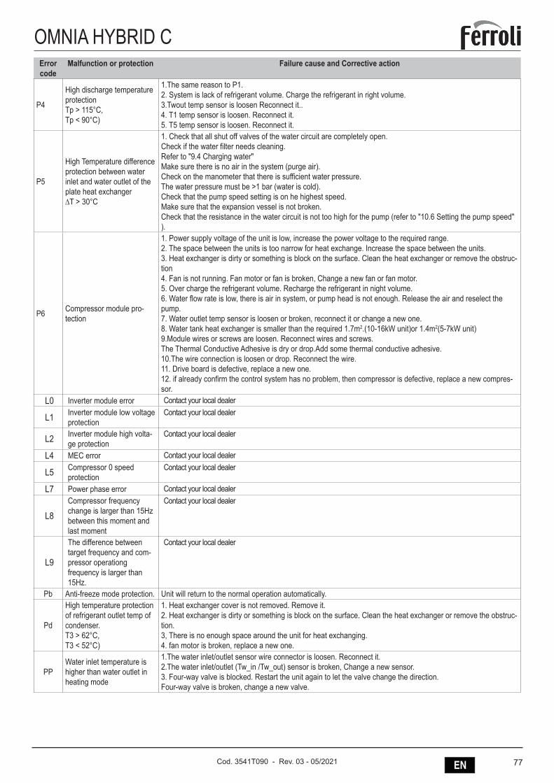
77ENCod. 3541T090 - Rev. 03 - 05/2021
OMNIA HYBRID CError code
Malfunction or protection Failure cause and Corrective action
P4
High discharge temperature protectionTp > 115°C, Tp < 90°C)
1.The same reason to P1.2. System is lack of refrigerant volume. Charge the refrigerant in right volume.3.Twout temp sensor is loosen Reconnect it..4. T1 temp sensor is loosen. Reconnect it.5. T5 temp sensor is loosen. Reconnect it.
P5
High Temperature difference protection between water inlet and water outlet of the plate heat exchanger∆T > 30°C
1. Check that all shut off valves of the water circuit are completely open.Check if the water filter needs cleaning.Refer to "9.4 Charging water"Make sure there is no air in the system (purge air).Check on the manometer that there is sufficient water pressure.The water pressure must be >1 bar (water is cold).Check that the pump speed setting is on he highest speed.Make sure that the expansion vessel is not broken.Check that the resistance in the water circuit is not too high for the pump (refer to "10.6 Setting the pump speed" ).
P6 Compressor module pro-tection
1. Power supply voltage of the unit is low, increase the power voltage to the required range.2. The space between the units is too narrow for heat exchange. Increase the space between the units. 3. Heat exchanger is dirty or something is block on the surface. Clean the heat exchanger or remove the obstruc-tion4. Fan is not running. Fan motor or fan is broken, Change a new fan or fan motor.5. Over charge the refrigerant volume. Recharge the refrigerant in night volume.6. Water flow rate is low, there is air in system, or pump head is not enough. Release the air and reselect the pump.7. Water outlet temp sensor is loosen or broken, reconnect it or change a new one.8. Water tank heat exchanger is smaller than the required 1.7m2.(10-16kW unit)or 1.4m2(5-7kW unit)9.Module wires or screws are loosen. Reconnect wires and screws.The Thermal Conductive Adhesive is dry or drop.Add some thermal conductive adhesive.10.The wire connection is loosen or drop. Reconnect the wire.11. Drive board is defective, replace a new one.12. if already confirm the control system has no problem, then compressor is defective, replace a new compres-sor.
L0 Inverter module error Contact your local dealer
L1 Inverter module low voltage protection
Contact your local dealer
L2 Inverter module high volta-ge protection
Contact your local dealer
L4 MEC error Contact your local dealer
L5 Compressor 0 speed protection
Contact your local dealer
L7 Power phase error Contact your local dealer
L8Compressor frequency change is larger than 15Hz between this moment and last moment
Contact your local dealer
L9
The difference between target frequency and com-pressor operationgfrequency is larger than 15Hz.
Contact your local dealer
Pb Anti-freeze mode protection. Unit will return to the normal operation automatically.
Pd
High temperature protection of refrigerant outlet temp of condenser.T3 > 62°C, T3 < 52°C)
1. Heat exchanger cover is not removed. Remove it.2. Heat exchanger is dirty or something is block on the surface. Clean the heat exchanger or remove the obstruc-tion.3, There is no enough space around the unit for heat exchanging.4. fan motor is broken, replace a new one.
PPWater inlet temperature is higher than water outlet in heating mode
1.The water inlet/outlet sensor wire connector is loosen. Reconnect it.2.The water inlet/outlet (Tw_in /Tw_out) sensor is broken, Change a new sensor.3. Four-way valve is blocked. Restart the unit again to let the valve change the direction.Four-way valve is broken, change a new valve.
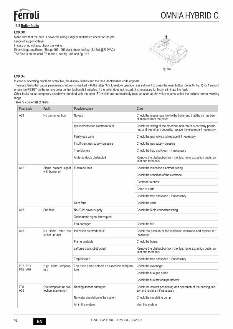
78 EN Cod. 3541T090 - Rev. 03 - 05/2021
OMNIA HYBRID C11.2 Boiler faultsLCD OffMake sure that the card is powered: using a digital multimeter, check for the pre-sence of supply voltage.In case of no voltage, check the wiring.If the voltage is sufficient ( Range 195 – 253 Vac ), check the fuse (3.15AL@230VAC). The fuse is on the card. To reach it, see fig. 206 and fig. 167.
fig. 167 -
LCD On In case of operating problems or trouble, the display flashes and the fault identification code appearsThere are faults that cause permanent shutdowns (marked with the letter “A”): to restore operation it is sufficient to press the reset button (detail 6 - fig. 1) for 1 second or use the RESET on the remote timer control (optional) if installed; if the boiler does not restart, it is necessary to, firstly, eliminate the fault.Other faults cause temporary shutdowns (marked with the letter “F”) which are automatically reset as soon as the value returns within the boiler’s normal working range. Table. 9 - Boiler list of faults
Fault code Fault Possible cause Cure
A01 No burner ignition No gas Check the regular gas flow to the boiler and that the air has been eliminated from the pipes
Ignition/detection electrode fault Check the wiring of the electrode and that it is correctly positio-ned and free of any deposits; replace the electrode if necessary.
Faulty gas valve Check the gas valve and replace it if necessary
Insufficient gas supply pressure Check the gas supply pressure
Trap blocked Check the trap and clean it if necessary
Air/fume ducts obstructed Remove the obstruction from the flue, fume extraction ducts, air inlet and terminals.
A02 Flame present signal with burner off
Electrode fault Check the ionization electrode wiring
Check the condition of the electrode
Electrode to earth
Cable to earth
Check the trap and clean it if necessary
Card fault Check the card
A05 Fan fault No 230V power supply Check the 5-pin connector wiring
Tachometric signal interrupted
Fan damaged Check the fan
A06 No flame after the ignition phase
Ionization electrode fault Check the position of the ionization electrode and replace it if necessary
Flame unstable Check the burner
air/fume ducts obstructed Remove the obstruction from the flue, fume extraction ducts, air inlet and terminals
Trap blocked Check the trap and clean it if necessary
F07 - F14F15 - A07
High fume tempera-ture
The fume probe detects an excessive tempera-ture
Check the exchanger
Check the flue gas probe
Check the flue material parameter
F08A08
Overtemperature pro-tection intervention
Heating sensor damaged Check the correct positioning and operation of the heating sen-sor and replace it if necessary
No water circulation in the system Check the circulating pump
Air in the system Vent the system
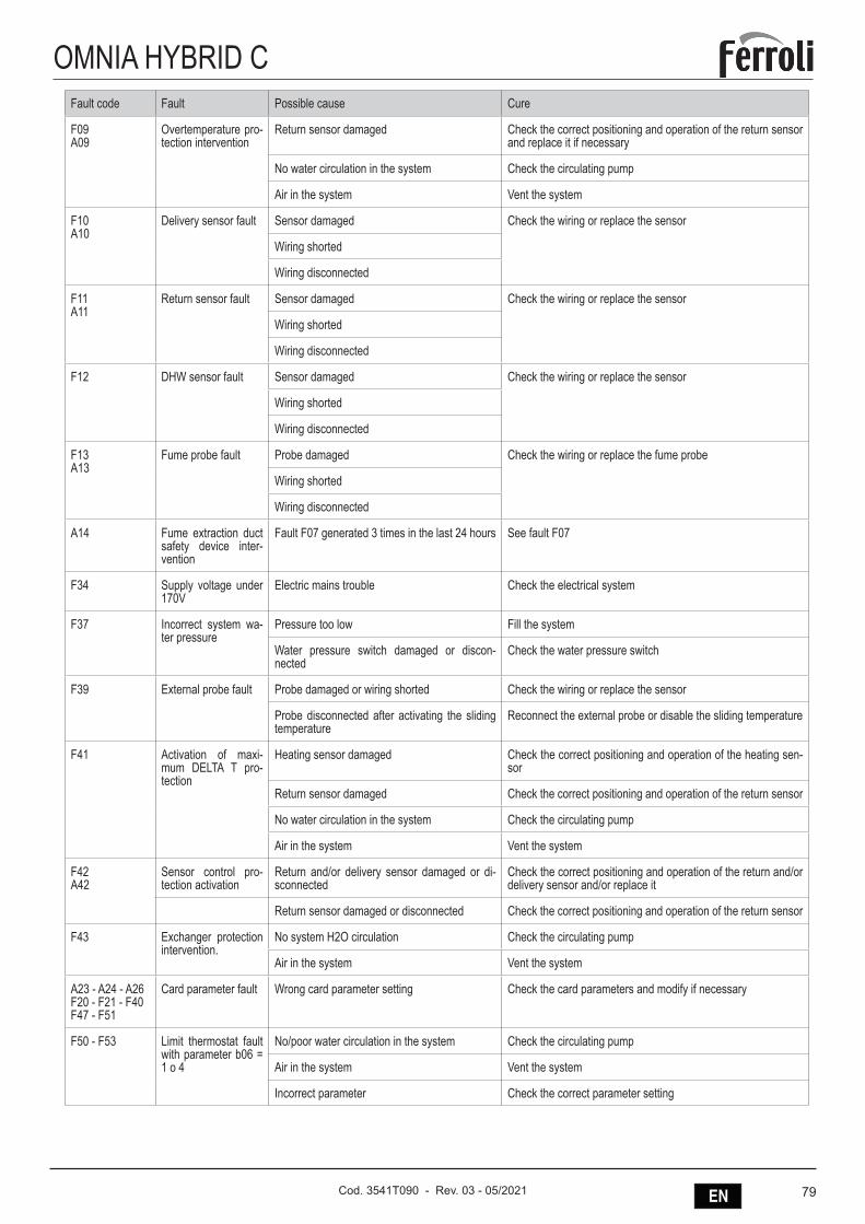
79ENCod. 3541T090 - Rev. 03 - 05/2021
OMNIA HYBRID CFault code Fault Possible cause Cure
F09A09
Overtemperature pro-tection intervention
Return sensor damaged Check the correct positioning and operation of the return sensor and replace it if necessary
No water circulation in the system Check the circulating pump
Air in the system Vent the system
F10A10
Delivery sensor fault Sensor damaged Check the wiring or replace the sensor
Wiring shorted
Wiring disconnected
F11A11
Return sensor fault Sensor damaged Check the wiring or replace the sensor
Wiring shorted
Wiring disconnected
F12 DHW sensor fault Sensor damaged Check the wiring or replace the sensor
Wiring shorted
Wiring disconnected
F13A13
Fume probe fault Probe damaged Check the wiring or replace the fume probe
Wiring shorted
Wiring disconnected
A14 Fume extraction duct safety device inter-vention
Fault F07 generated 3 times in the last 24 hours See fault F07
F34 Supply voltage under 170V
Electric mains trouble Check the electrical system
F37 Incorrect system wa-ter pressure
Pressure too low Fill the system
Water pressure switch damaged or discon-nected
Check the water pressure switch
F39 External probe fault Probe damaged or wiring shorted Check the wiring or replace the sensor
Probe disconnected after activating the sliding temperature
Reconnect the external probe or disable the sliding temperature
F41 Activation of maxi-mum DELTA T pro-tection
Heating sensor damaged Check the correct positioning and operation of the heating sen-sor
Return sensor damaged Check the correct positioning and operation of the return sensor
No water circulation in the system Check the circulating pump
Air in the system Vent the system
F42A42
Sensor control pro-tection activation
Return and/or delivery sensor damaged or di-sconnected
Check the correct positioning and operation of the return and/or delivery sensor and/or replace it
Return sensor damaged or disconnected Check the correct positioning and operation of the return sensor
F43 Exchanger protection intervention.
No system H2O circulation Check the circulating pump
Air in the system Vent the system
A23 - A24 - A26F20 - F21 - F40F47 - F51
Card parameter fault Wrong card parameter setting Check the card parameters and modify if necessary
F50 - F53 Limit thermostat fault with parameter b06 = 1 o 4
No/poor water circulation in the system Check the circulating pump
Air in the system Vent the system
Incorrect parameter Check the correct parameter setting
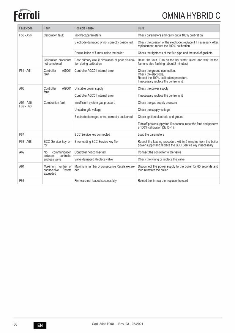
80 EN Cod. 3541T090 - Rev. 03 - 05/2021
OMNIA HYBRID CFault code Fault Possible cause Cure
F56 - A56 Calibration fault Incorrect parameters Check parameters and carry out a 100% calibration
Electrode damaged or not correctly positioned. Check the position of the electrode, replace it if necessary. After replacement, repeat the 100% calibration
Recirculation of fumes inside the boiler Check the tightness of the flue pipe and the seal of gaskets
Calibration procedure not completed
Poor primary circuit circulation or poor dissipa-tion during calibration
Reset the fault. Turn on the hot water faucet and wait for the flame to stop flashing (about 2 minutes)
F61 - A61 Controller AGC01 fault
Controller AGC01 internal error Check the ground connection.Check the electrode.Repeat the 100% calibration procedure.If necessary replace the control unit.
A63 Controller AGC01 fault
Unstable power supply Check the power supply
Controller AGC01 internal error If necessary replace the control unit
A54 - A55F62 - F63
Combustion fault Insufficient system gas pressure Check the gas supply pressure
Unstable grid voltage Check the supply voltage
Electrode damaged or not correctly positioned Check ignition electrode and ground
Turn off power supply for 10 seconds, reset the fault and perform a 100% calibration (Sc15=1).
F67 BCC Service key connected Load the parameters
F68 - A68 BCC Service key er-ror
Error loading BCC Service key file Repeat the loading procedure within 5 minutes from the boiler power supply and replace the BCC Service key if necessary
A62 No communication between controller and gas valve
Controller not connected Connect the controller to the valve
Valve damaged Replace valve Check the wiring or replace the valve
A64 Maximum number of consecutive Resets exceeded
Maximum number of consecutive Resets excee-ded
Disconnect the power supply to the boiler for 60 seconds and then reinstate the boiler
F66 Firmware not loaded successfully Reload the firmware or replace the card
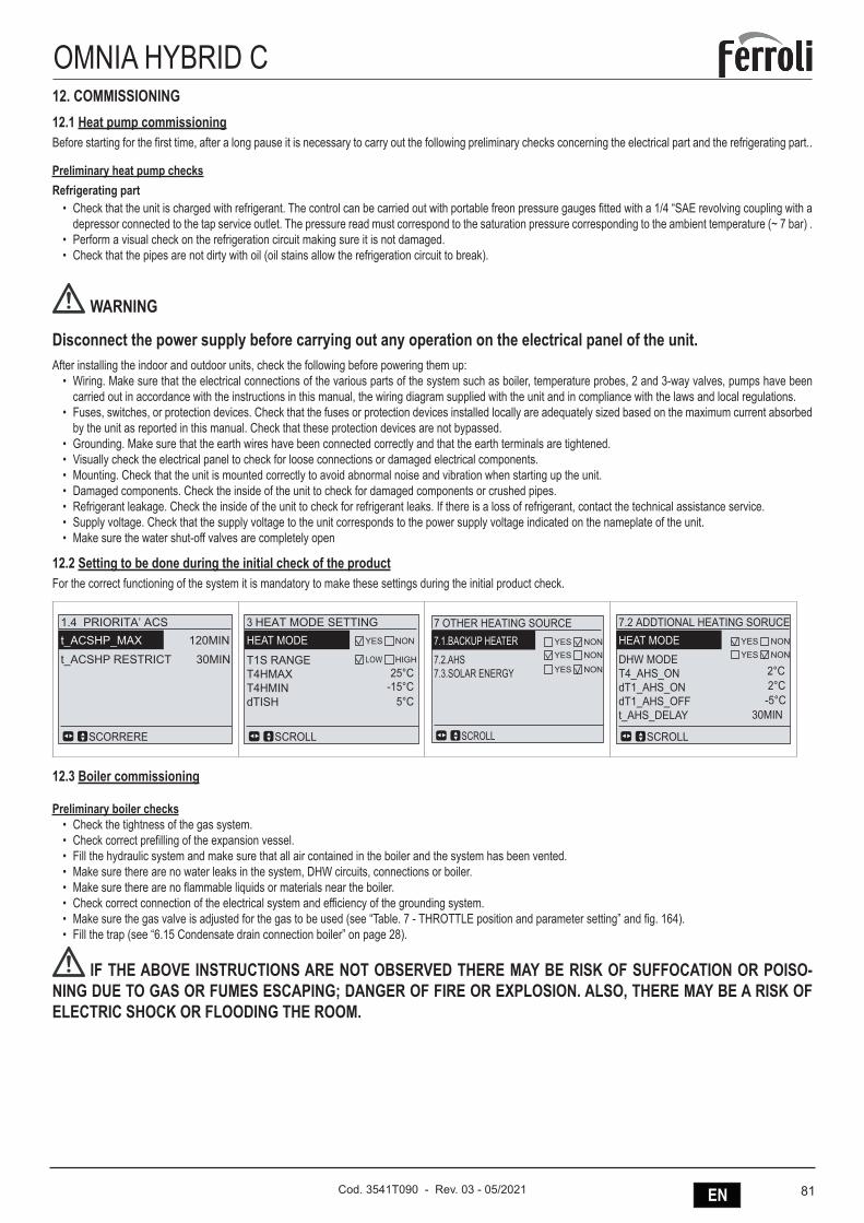
81ENCod. 3541T090 - Rev. 03 - 05/2021
OMNIA HYBRID C12. COMMISSIONING12.1 Heat pump commissioningBefore starting for the first time, after a long pause it is necessary to carry out the following preliminary checks concerning the electrical part and the refrigerating part..
Preliminary heat pump checksRefrigerating part
• Check that the unit is charged with refrigerant. The control can be carried out with portable freon pressure gauges fitted with a 1/4 “SAE revolving coupling with a depressor connected to the tap service outlet. The pressure read must correspond to the saturation pressure corresponding to the ambient temperature (~ 7 bar) .
• Perform a visual check on the refrigeration circuit making sure it is not damaged.• Check that the pipes are not dirty with oil (oil stains allow the refrigeration circuit to break).
WARNING
Disconnect the power supply before carrying out any operation on the electrical panel of the unit.After installing the indoor and outdoor units, check the following before powering them up:
• Wiring. Make sure that the electrical connections of the various parts of the system such as boiler, temperature probes, 2 and 3-way valves, pumps have been carried out in accordance with the instructions in this manual, the wiring diagram supplied with the unit and in compliance with the laws and local regulations.
• Fuses, switches, or protection devices. Check that the fuses or protection devices installed locally are adequately sized based on the maximum current absorbed by the unit as reported in this manual. Check that these protection devices are not bypassed.
• Grounding. Make sure that the earth wires have been connected correctly and that the earth terminals are tightened.• Visually check the electrical panel to check for loose connections or damaged electrical components.• Mounting. Check that the unit is mounted correctly to avoid abnormal noise and vibration when starting up the unit.• Damaged components. Check the inside of the unit to check for damaged components or crushed pipes.• Refrigerant leakage. Check the inside of the unit to check for refrigerant leaks. If there is a loss of refrigerant, contact the technical assistance service.• Supply voltage. Check that the supply voltage to the unit corresponds to the power supply voltage indicated on the nameplate of the unit.• Make sure the water shut-off valves are completely open
12.2 Setting to be done during the initial check of the productFor the correct functioning of the system it is mandatory to make these settings during the initial product check.
1.4 PRIORITA’ ACSt_ACSHP_MAXt_ACSHP RESTRICT
120MIN30MIN
SCORRERE
3 HEAT MODE SETTINGHEAT MODE
T1S RANGET4HMAXT4HMINdTISH
SCROLL
LOW HIGH25°C
-15°C5°C
YES NON
7 OTHER HEATING SOURCE7.1.BACKUP HEATER7.2.AHS7.3.SOLAR ENERGY
SCROLL
YESYES
NONNON
YES NON
7.2 ADDTIONAL HEATING SORUCEHEAT MODEDHW MODET4_AHS_ONdT1_AHS_ONdT1_AHS_OFFt_AHS_DELAY
2°C2°C
-5°C30MIN
SCROLL
YESYES
NONNON
12.3 Boiler commissioning
Preliminary boiler checks• Check the tightness of the gas system.• Check correct prefilling of the expansion vessel.• Fill the hydraulic system and make sure that all air contained in the boiler and the system has been vented.• Make sure there are no water leaks in the system, DHW circuits, connections or boiler.• Make sure there are no flammable liquids or materials near the boiler.• Check correct connection of the electrical system and efficiency of the grounding system.• Make sure the gas valve is adjusted for the gas to be used (see “Table. 7 - THROTTLE position and parameter setting” and fig. 164).• Fill the trap (see “6.15 Condensate drain connection boiler” on page 28).
IF THE ABOVE INSTRUCTIONS ARE NOT OBSERVED THERE MAY BE RISK OF SUFFOCATION OR POISO-NING DUE TO GAS OR FUMES ESCAPING; DANGER OF FIRE OR EXPLOSION. ALSO, THERE MAY BE A RISK OF ELECTRIC SHOCK OR FLOODING THE ROOM.
82 EN Cod. 3541T090 - Rev. 03 - 05/2021
OMNIA HYBRID CFirst boiler ignition
• Make sure there is no drawing of hot water and room thermostat requests.• Turn on the gas and check that the gas supply pressure ahead of the unit complies with the technical data table or in any case the tolerance provided for by the
regulations.• Electrically power the boiler; the display will show the software version number and then Fh and FH air venting cycle (see “9.2 Connection to the power supply,
switching on and off” on page 66).• At the end of the FH cycle, the winter mode screen (fig. 157) will appear on the display; make the temperature adjustments: heating delivery and DHW outlet (fig.
161 and fig. 162).• Check if the flue parameter value (“” on page 71) is suitable for the length of flue installed.• In case of gas change (G20 - G30 - G31), check if the relevant parameter is suitable for the type of gas present in the supply system (“” on page 71 and see
“11.1 Heat pump alarms” on page 74).• Set the boiler to DHW or heating mode (see “9.2 Connection to the power supply, switching on and off” on page 66).• In Heating mode, carry out a demand: the display shows the radiator symbol and the actual heating system temperature; when the flashing flame symbol appears,
the burner is lit and the system is performing the calibration. Wait for the end of calibration, indicated by the steady flame symbol.• DHW mode with hot water drawing: the display shows the faucet symbol and the actual DHW temperature; when the flashing flame symbol appears, the burner
is lit and the system is performing the calibration; wait for the end of the calibration, indicated by the steady flame symbol.• Carry out the fuel check as described in par. “Checking the combustion values” on page 69.
12.4 Final check before turning on the unitWhen the installation is complete and all the necessary settings have been made, reassemble and close all the panels of the unit.
12.5 Turn on the unitWhen power is supplied to the unit, the remote controller display shows “1% ~ 99%” (initialization phase). During this process (which lasts a few seconds) the user interface cannot be used.To activate the system, refer to the section “REMOTE CONTROLLER - USER MENU” on page 33.
12.6 System water flow set point setting in heating modeThe heating set point can be modified by the user within some limits defined by the T1S RANGE settings in the HOT MODE SETTING menu of the remote controller (see “fig. 171 - Heating with heat pump” on page 85)T1S RANGE set to LOW (factory setting) 25~55°CT1S RANGE set to HIGH 35~60°C
☞ NOTE:To optimize the energy efficiency of the boiler it is suggested to set the boiler heating setpoint to the same value as the heat pump setpoint.
12.7 Setting of system water delivery set point in cooling modeThe cooling set point can be modified by the user within some limits defined by the T1S RANGE settings in the COOL MODE SETTING menu of the remote controller (see “fig. 173 - Heating with heat pump and boiler” on page 85)T1S RANGE set to LOW (factory settin) 5~25°CT1S RANGE set to HIGH 18~25°C
12.8 Domestic hot water production temperature settingTo set the domestic hot water temperature (default 55 ° C) act on the boiler controller (see “DHW temperature adjustment” on page 67).
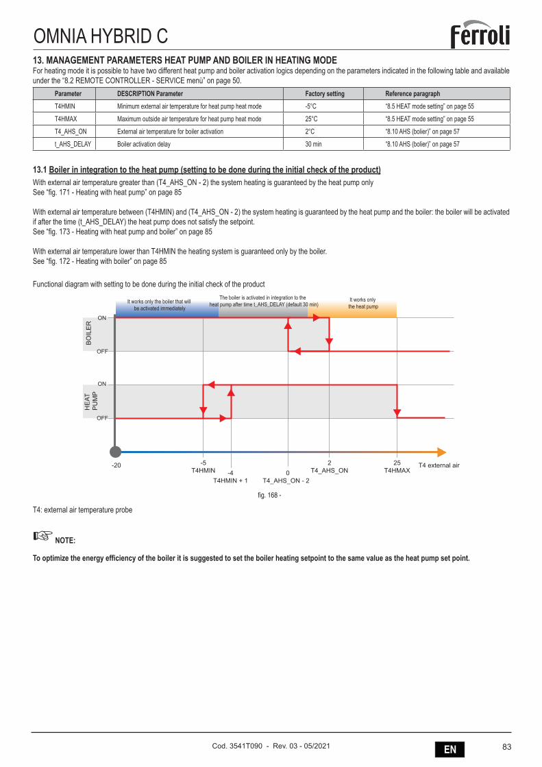
83ENCod. 3541T090 - Rev. 03 - 05/2021
OMNIA HYBRID C13. MANAGEMENT PARAMETERS HEAT PUMP AND BOILER IN HEATING MODEFor heating mode it is possible to have two different heat pump and boiler activation logics depending on the parameters indicated in the following table and available under the “8.2 REMOTE CONTROLLER - SERVICE menù” on page 50.
Parameter DESCRIPTION Parameter Factory setting Reference paragraphT4HMIN Minimum external air temperature for heat pump heat mode -5°C “8.5 HEAT mode setting” on page 55
T4HMAX Maximum outside air temperature for heat pump heat mode 25°C “8.5 HEAT mode setting” on page 55
T4_AHS_ON External air temperature for boiler activation 2°C “8.10 AHS (bolier)” on page 57
t_AHS_DELAY Boiler activation delay 30 min “8.10 AHS (bolier)” on page 57
13.1 Boiler in integration to the heat pump (setting to be done during the initial check of the product)With external air temperature greater than (T4_AHS_ON - 2) the system heating is guaranteed by the heat pump onlySee “fig. 171 - Heating with heat pump” on page 85
With external air temperature between (T4HMIN) and (T4_AHS_ON - 2) the system heating is guaranteed by the heat pump and the boiler: the boiler will be activated if after the time (t_AHS_DELAY) the heat pump does not satisfy the setpoint.See “fig. 173 - Heating with heat pump and boiler” on page 85
With external air temperature lower than T4HMIN the heating system is guaranteed only by the boiler.See “fig. 172 - Heating with boiler” on page 85
Functional diagram with setting to be done during the initial check of the product
-5T4HMIN -4
T4HMIN + 1
-20
OFF
ON
OFF
ON
RISCALDAMENTO IMPIANTOCALDAIA IN INTEGRAZIONE ALLA POMPA DI CALORE
Esempio con parametri T4HMIN= -5 e T4_AHS_ON= 2
0T4_AHS_ON - 2
2T4_AHS_ON
25T4HMAX
BO
ILE
R
It works only the boiler that will be activated immediately
The boiler is activated in integration to the heat pump after time t_AHS_DELAY (default 30 min)
It works only the heat pump
HE
AT
PU
MP
T4 external air
fig. 168 -
T4: external air temperature probe
☞ NOTE:
To optimize the energy efficiency of the boiler it is suggested to set the boiler heating setpoint to the same value as the heat pump set point.
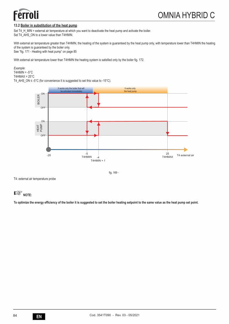
84 EN Cod. 3541T090 - Rev. 03 - 05/2021
OMNIA HYBRID C13.2 Boiler in substitution of the heat pumpSet T4_H_MIN = external air temperature at which you want to deactivate the heat pump and activate the boiler.Set T4_AHS_ON to a lower value than T4HMIN.
With external air temperature greater than T4HMIN, the heating of the system is guaranteed by the heat pump only, with temperature lower than T4HMIN the heating of the system is guaranteed by the boiler only.See “fig. 171 - Heating with heat pump” on page 85
With external air temperature lower than T4HMIN the heating system is satisfied only by the boiler fig. 172.
Example:T4HMIN = -5°CT4HMAX = 25°CT4_AHS_ON ≤ -5°C (for convenience it is suggested to set this value to -15°C).
OFF
ON
OFF
ON
-20
RISCALDAMENTO IMPIANTOCALDAIA IN SOSTITUZIONE ALLA POMPA DI CALOREEsempio con parametri T4HMIN= -5 e T4 AHS ON= -16
25T4HMAX
-5T4HMIN -4
T4HMIN + 1
It works only the boiler that will be activated immediately
It works only the heat pump
BO
ILE
RH
EAT
P
UM
P
T4 external air
fig. 169 -
T4: external air temperature probe
☞ NOTE:
To optimize the energy efficiency of the boiler it is suggested to set the boiler heating setpoint to the same value as the heat pump set point.
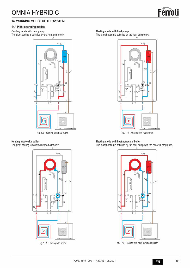
85ENCod. 3541T090 - Rev. 03 - 05/2021
OMNIA HYBRID C14. WORKING MODES OF THE SYSTEM14.1 Plant operating modesCooling mode with heat pumpThe plant cooling is satisfied by the heat pump only.
241
14
OMNIA_HYBRID_C_01_Schema COOL_impianto
114
9574
56
193
186
34
10 118 9
42
36
32CHP
FL
17
GL
SPHP
136
UE
UI
fig. 170 - Cooling with heat pump
Heating mode with heat pumpThe plant heating is satisfied by the heat pump only.
241
14
OMNIA_HYBRID_C_03_Schema HEAT PDC
114
9574
56
193
186
34
10 118 9
42
36
32CHP
FL
17
GL
SPHP
136
UE
UI
fig. 171 - Heating with heat pump
Heating mode with boilerThe plant heating is satisfied by the boiler only.
241
14
OMNIA_HYBRID_C_04_Schema HEAT CALDAIA
114
9574
56
193
186
34
10 118 9
42
36
32CHP
FL
17
GL
SPHP
136
UE
UI
fig. 172 - Heating with boiler
Heating mode with heat pump and boilerThe plant heating is satisfied by the heat pump with the boiler in integration.
241
14
OMNIA_HYBRID_C_05_Schema HEAT PDC + HEAT CALDAIA
114
9574
56
193
186
34
10 118 9
42
36
32CHP
FL
17
GL
SPHP
136
UE
UI
fig. 173 - Heating with heat pump and boiler
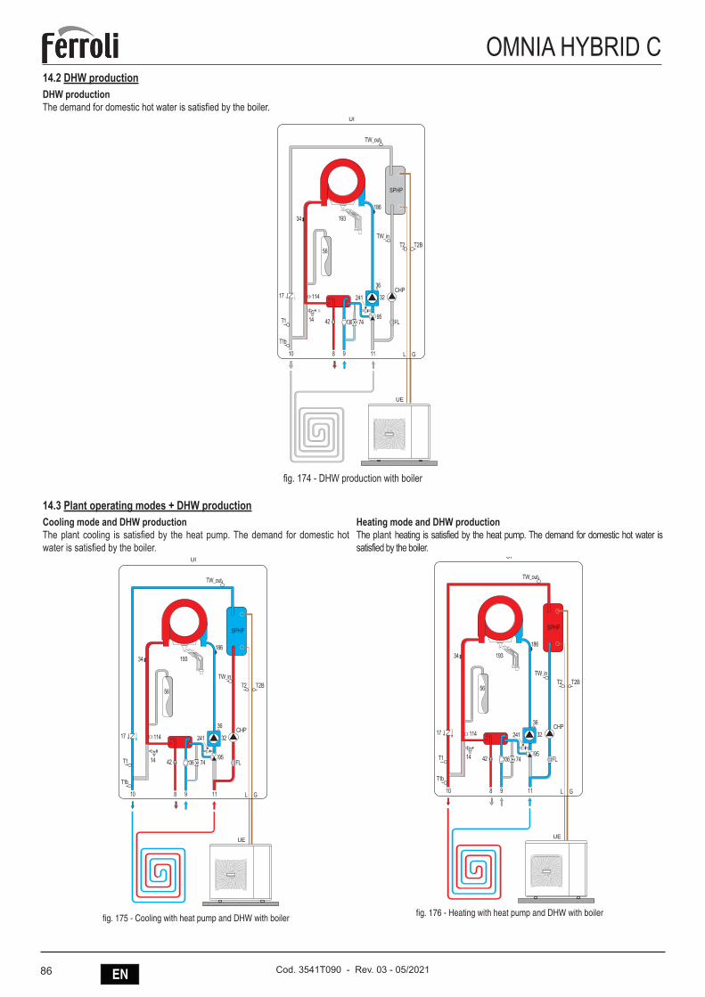
86 EN Cod. 3541T090 - Rev. 03 - 05/2021
OMNIA HYBRID C14.2 DHW productionDHW productionThe demand for domestic hot water is satisfied by the boiler.
241
14
OMNIA_HYBRID_C_08_Schema ACS CALDAIA
114
9574
56
193
186
34
10 118 9
42
36
32CHP
FL
17
GL
SPHP
136
UE
UI
fig. 174 - DHW production with boiler
14.3 Plant operating modes + DHW productionCooling mode and DHW productionThe plant cooling is satisfied by the heat pump. The demand for domestic hot water is satisfied by the boiler.
241
14
OMNIA_HYBRID_C_02_Schema COOL + ACS_impianto
114
9574
56
193
186
34
10 118 9
42
36
32CHP
FL
17
GL
SPHP
136
UE
UI
fig. 175 - Cooling with heat pump and DHW with boiler
Heating mode and DHW productionThe plant heating is satisfied by the heat pump. The demand for domestic hot water is satisfied by the boiler.
241
14
OMNIA_HYBRID_C_06_Schema HEAT PDC + ACS CALDAIA
114
9574
56
193
186
34
10 118 9
42
36
32CHP
FL
17
GL
SPHP
136
UE
UI
fig. 176 - Heating with heat pump and DHW with boiler
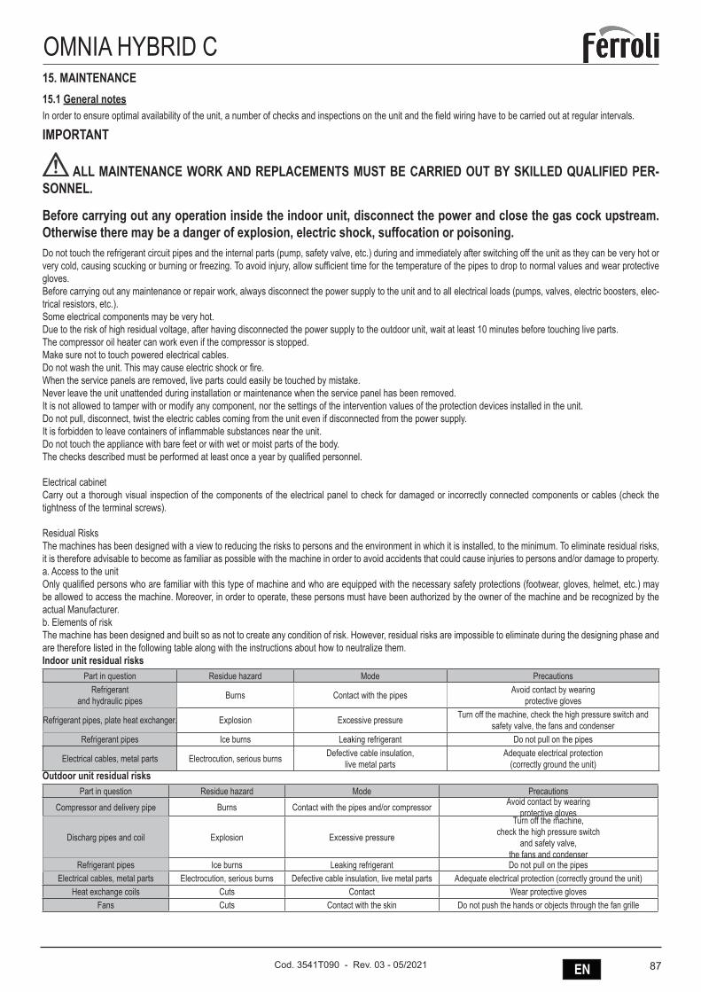
87ENCod. 3541T090 - Rev. 03 - 05/2021
OMNIA HYBRID C15. MAINTENANCE15.1 General notesIn order to ensure optimal availability of the unit, a number of checks and inspections on the unit and the field wiring have to be carried out at regular intervals.
IMPORTANT
ALL MAINTENANCE WORK AND REPLACEMENTS MUST BE CARRIED OUT BY SKILLED QUALIFIED PER-SONNEL.
Before carrying out any operation inside the indoor unit, disconnect the power and close the gas cock upstream. Otherwise there may be a danger of explosion, electric shock, suffocation or poisoning.Do not touch the refrigerant circuit pipes and the internal parts (pump, safety valve, etc.) during and immediately after switching off the unit as they can be very hot or very cold, causing scucking or burning or freezing. To avoid injury, allow sufficient time for the temperature of the pipes to drop to normal values and wear protective gloves.Before carrying out any maintenance or repair work, always disconnect the power supply to the unit and to all electrical loads (pumps, valves, electric boosters, elec-trical resistors, etc.).Some electrical components may be very hot.Due to the risk of high residual voltage, after having disconnected the power supply to the outdoor unit, wait at least 10 minutes before touching live parts.The compressor oil heater can work even if the compressor is stopped.Make sure not to touch powered electrical cables.Do not wash the unit. This may cause electric shock or fire.When the service panels are removed, live parts could easily be touched by mistake.Never leave the unit unattended during installation or maintenance when the service panel has been removed.It is not allowed to tamper with or modify any component, nor the settings of the intervention values of the protection devices installed in the unit.Do not pull, disconnect, twist the electric cables coming from the unit even if disconnected from the power supply.It is forbidden to leave containers of inflammable substances near the unit.Do not touch the appliance with bare feet or with wet or moist parts of the body.The checks described must be performed at least once a year by qualified personnel.
Electrical cabinetCarry out a thorough visual inspection of the components of the electrical panel to check for damaged or incorrectly connected components or cables (check the tightness of the terminal screws).
Residual RisksThe machines has been designed with a view to reducing the risks to persons and the environment in which it is installed, to the minimum. To eliminate residual risks, it is therefore advisable to become as familiar as possible with the machine in order to avoid accidents that could cause injuries to persons and/or damage to property.a. Access to the unitOnly qualified persons who are familiar with this type of machine and who are equipped with the necessary safety protections (footwear, gloves, helmet, etc.) may be allowed to access the machine. Moreover, in order to operate, these persons must have been authorized by the owner of the machine and be recognized by the actual Manufacturer.b. Elements of riskThe machine has been designed and built so as not to create any condition of risk. However, residual risks are impossible to eliminate during the designing phase and are therefore listed in the following table along with the instructions about how to neutralize them.Indoor unit residual risks
Part in question Residue hazard Mode PrecautionsRefrigerant
and hydraulic pipes Burns Contact with the pipes Avoid contact by wearing protective gloves
Refrigerant pipes, plate heat exchanger. Explosion Excessive pressure Turn off the machine, check the high pressure switch and safety valve, the fans and condenser
Refrigerant pipes Ice burns Leaking refrigerant Do not pull on the pipes
Electrical cables, metal parts Electrocution, serious burns Defective cable insulation, live metal parts
Adequate electrical protection (correctly ground the unit)
Outdoor unit residual risksPart in question Residue hazard Mode Precautions
Compressor and delivery pipe Burns Contact with the pipes and/or compressor Avoid contact by wearing protective gloves
Discharg pipes and coil Explosion Excessive pressure
Turn off the machine,check the high pressure switch
and safety valve,the fans and condenser
Refrigerant pipes Ice burns Leaking refrigerant Do not pull on the pipesElectrical cables, metal parts Electrocution, serious burns Defective cable insulation, live metal parts Adequate electrical protection (correctly ground the unit)
Heat exchange coils Cuts Contact Wear protective glovesFans Cuts Contact with the skin Do not push the hands or objects through the fan grille
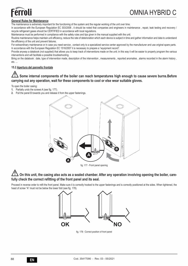
88 EN Cod. 3541T090 - Rev. 03 - 05/2021
OMNIA HYBRID CGeneral Rules for MaintananceThe maintenance is extremely important for the functioning of the system and the regular working of the unit over time.In accordance with the European Regulation EC 303/2008 , it should be noted that companies and engineers in maintenance , repair, leak testing and recovery / recycle refrigerant gases should be CERTIFIED in accordance with local regulations.Maintenance must be performed in compliance with the safety rules and tips given in the manual supplied with the unit.Routine maintenance helps maintain unit efficiency, reduce the rate of deterioration which each device is subject in time and gather information and data to understand the efficiency of the unit and prevent failures.For extraordinary maintenance or in case you need service , contact only to a specialized service center approved by the manufacturer and use original spare parts.In accordance with the European Regulation EC 1516/2007 it is necessary to prepare a “equipment record”.Provide anyway a databook (not supplied) that allows you to keep track of interventions made on the unit; in this way it will be easier to properly program the various interventions and will facilitate a possible troubleshooting.Bring on the databook : date, type of intervention made, description of the intervention , measurements , reported anomalies , alarms recorded in the alarm history , etc. ...
15.2 Apertura del pannello frontale
Some internal components of the boiler can reach temperatures high enough to cause severe burns.Before carrying out any operation, wait for these components to cool or else wear suitable gloves.To open the boiler casing:1. Partially undo the screws A (see fig. 177).2. Pull the panel B towards you and release it from the upper fastenings.
fig. 177 - Front panel opening
On this unit, the casing also acts as a sealed chamber. After any operation involving opening the boiler, care-fully check the correct refitting of the front panel and its seal.Proceed in reverse order to refit the front panel. Make sure it is correctly hooked to the upper fastenings and is correctly positioned at the sides. When tightened, the head of screw “A” must not be below the lower fold (see fig. 178).
�� ��fig. 178 - Correct position of front panel
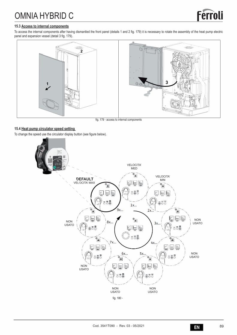
89ENCod. 3541T090 - Rev. 03 - 05/2021
OMNIA HYBRID C15.3 Access to internal componentsTo access the internal components after having dismantled the front panel (details 1 and 2 fig. 179) it is necessary to rotate the assembly of the heat pump electric panel and expansion vessel (detail 3 fig. 179).
2
1 3
fig. 179 - access to internal components
15.4 Heat pump circulator speed setting To change the speed use the circulator display button (see figure below).
DEFAULTVELOCITA’ MAX
VELOCITA’MED
VELOCITA’MIN
NONUSATO
NONUSATO
NONUSATO
NONUSATO
NONUSATO
NONUSATO
fig. 180 -
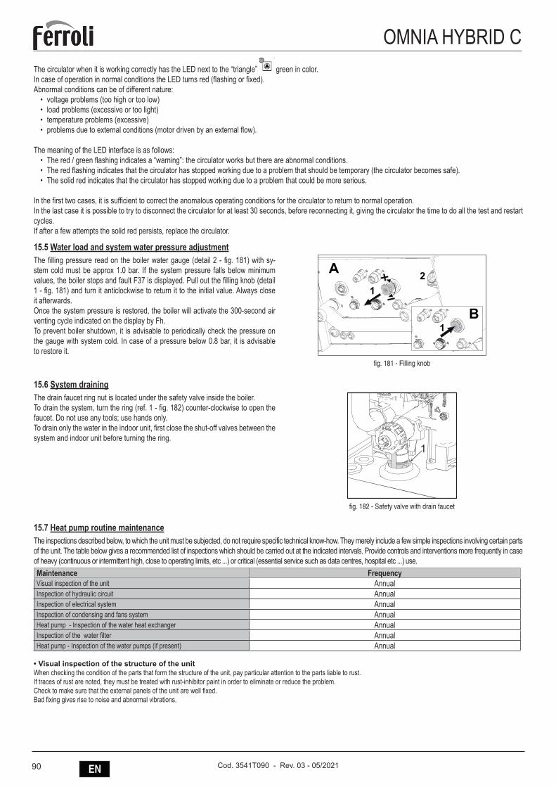
90 EN Cod. 3541T090 - Rev. 03 - 05/2021
OMNIA HYBRID CThe circulator when it is working correctly has the LED next to the “triangle”
DEFAULTVELOCITA’ MAX
VELOCITA’MED
VELOCITA’MIN
NONUSATO
NONUSATO
NONUSATO
NONUSATO
NONUSATO
NONUSATO
green in color.In case of operation in normal conditions the LED turns red (flashing or fixed).Abnormal conditions can be of different nature:
• voltage problems (too high or too low)• load problems (excessive or too light)• temperature problems (excessive)• problems due to external conditions (motor driven by an external flow).
The meaning of the LED interface is as follows:
• The red / green flashing indicates a “warning”: the circulator works but there are abnormal conditions.• The red flashing indicates that the circulator has stopped working due to a problem that should be temporary (the circulator becomes safe).• The solid red indicates that the circulator has stopped working due to a problem that could be more serious.
In the first two cases, it is sufficient to correct the anomalous operating conditions for the circulator to return to normal operation.In the last case it is possible to try to disconnect the circulator for at least 30 seconds, before reconnecting it, giving the circulator the time to do all the test and restart cycles.If after a few attempts the solid red persists, replace the circulator.
15.5 Water load and system water pressure adjustmentThe filling pressure read on the boiler water gauge (detail 2 - fig. 181) with sy-stem cold must be approx 1.0 bar. If the system pressure falls below minimum values, the boiler stops and fault F37 is displayed. Pull out the filling knob (detail 1 - fig. 181) and turn it anticlockwise to return it to the initial value. Always close it afterwards.Once the system pressure is restored, the boiler will activate the 300-second air venting cycle indicated on the display by Fh.To prevent boiler shutdown, it is advisable to periodically check the pressure on the gauge with system cold. In case of a pressure below 0.8 bar, it is advisable to restore it.
A1
2
B1
fig. 181 - Filling knob
15.6 System drainingThe drain faucet ring nut is located under the safety valve inside the boiler.To drain the system, turn the ring (ref. 1 - fig. 182) counter-clockwise to open the faucet. Do not use any tools; use hands only.To drain only the water in the indoor unit, first close the shut-off valves between the system and indoor unit before turning the ring.
�
fig. 182 - Safety valve with drain faucet
15.7 Heat pump routine maintenanceThe inspections described below, to which the unit must be subjected, do not require specific technical know-how. They merely include a few simple inspections involving certain parts of the unit. The table below gives a recommended list of inspections which should be carried out at the indicated intervals. Provide controls and interventions more frequently in case of heavy (continuous or intermittent high, close to operating limits, etc ...) or critical (essential service such as data centres, hospital etc ...) use.Maintenance FrequencyVisual inspection of the unit AnnualInspection of hydraulic circuit AnnualInspection of electrical system AnnualInspection of condensing and fans system AnnualHeat pump - Inspection of the water heat exchanger AnnualInspection of the water filter AnnualHeat pump - Inspection of the water pumps (if present) Annual
• Visual inspection of the structure of the unitWhen checking the condition of the parts that form the structure of the unit, pay particular attention to the parts liable to rust.If traces of rust are noted, they must be treated with rust-inhibitor paint in order to eliminate or reduce the problem.Check to make sure that the external panels of the unit are well fixed.Bad fixing gives rise to noise and abnormal vibrations.
91ENCod. 3541T090 - Rev. 03 - 05/2021
OMNIA HYBRID C • Inspection of hydraulic circuitCheck visually to make sure that there are no leaks in the hydraulic circuit. Check that water filters are clean.
• Inspection of electrical systemMake sure that power cables that supply the unit are not torn, cracked or damaged in a way that could impair its insulation.Perform a thorough visual inspection of the components of the electrical panel to check for the presence of damaged or not well connected components or cables (check the tightening of the terminal screws).
• Inspection of the ventilated condensing/evaporating sectionWARNING: The finned pack exchanger has fins made of aluminium or some other thin material, thus even accidental contact could cause cuts.
Condensing/Evaporating coilsIn view of the function of this component, it is very important for the surface of the exchanger to be as free as possible from clogging caused by items that could reduce the fan’s air flow rate and, thus, the performances of the unit itself.The following operations may be required:- Remove all impurities (such as paper scraps, leaves, etc.) that could be clogging the surface of the bank either by hand or using a brush (comply with the above mentioned safety prescriptions).- If the dirt has deposited on the fins and is difficult to remove by hand, use a flow of compressed air or pressurized water on the aluminium surface of the coils, re-membering to direct the flow in a vertical and opposite to the standard flow direction to prevent the fins from being damaged.- “Comb” the coils with the relative tool, using the appropriate comb spacing for the fins if some parts of them are bent or squashed.
Axial fansVisually inspect these parts to make sure that the fans are well fixed to the bearing grille and that this latter is fixed to the structure of the unit. Check the fan bearings, and close the terminal box and cable glands. Bearings damaged and bad fixing are the source of abnormal noise and vibrations,
• Heat pump - Inspection of the water heat exchangersThe exchangers must ensure the maximum heat transfer possible so keep them clean and free from dirt that may reduce efficiency; make sure that the temperature difference between water outlet temperature and evaporation/condensation does not increase over time, if the difference exceeds 8 -10 ° C it is necessary to proceed cleaning the water side of the exchanger, keeping in mind the following: water circulation must be in the opposite direction than normal, the fluid velocity does not exceed 1.5 times the nominal velocity and use just water or moderately acid products but only water for final washing.
• Inspection of the water filtersMake sure to clean the filter and remove any impurities that block the proper flow of water, contributing to increase pressure drop and therefore energy consumption of the pumps. Refer to the section “Hydraulic Connections” too.
• Heat pump - Inspection of the water pumpsCheck water leakages, the state of the bearings, the closing of the terminal box and integrity of the cable. Bearings damaged and bad fixing are the source of abnormal noise and vibrations,
BCAUTION
As a result of extraordinary maintenance on the cooling circuit with component replacement, before restarting the machine, perform the following steps:
- Pay attention to restore the refrigerant charge indicated on the name plate of the machine.
- Open all the ball valves in the refrigerant circuit.
- Correctly connect the power supply and grounding.
- Check the hydraulic connections.
- Check that the water pump is working properly.
- Clean water filters.
- Check that the finned coils are not dirty or clogged.
- Check the proper rotation of fans.
- Check correct operation of safety devices with particular attention to differential water pressure switch and / or water flow switch.
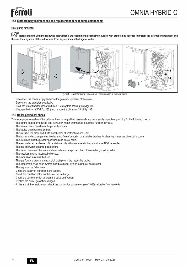
92 EN Cod. 3541T090 - Rev. 03 - 05/2021
OMNIA HYBRID C15.8 Extraordinary maintenance and replacement of heat pump components
Heat pump circulator
ABefore starting with the following instructions, we recommend organizing yourself with protections in order to protect the internal environment and the electrical system of the indoor unit from any accidental leakage of water.
2
1 3 4
4
5
fig. 183 - Circulator pump replacement / maintenance of the heat pump
• Disconnect the power supply and close the gas cock upstream of the valve.• Disconnect the circulator electrically.• Drain the water from the indoor unit (see “15.6 System draining” on page 90).• Unscrew the fillers (“4” di fig. 185.) and remove the circulator (“5” di fig. 185.)
15.9 Boiler periodical checkTo ensure proper operation of the unit over time, have qualified personnel carry out a yearly inspection, providing for the following checks:
• The control and safety devices (gas valve, flow meter, thermostats, etc.) must function correctly.• The fume exhaust circuit must be perfectly efficient.• The sealed chamber must be tight.• The air-fume end piece and ducts must be free of obstructions and leaks• The burner and exchanger must be clean and free of deposits. Use suitable brushes for cleaning. Never use chemical products.• The electrode must be properly positioned and free of scale.• The electrode can be cleaned of incrustations only with a non-metallic brush, and must NOT be sanded.• The gas and water systems must be tight.• The water pressure in the system when cold must be approx. 1 bar; otherwise bring it to that value.• The circulating pump must not be blocked.• The expansion tank must be filled.• The gas flow and pressure must match that given in the respective tables.• The condensate evacuation system must be efficient with no leakage or obstructions.• The trap must be full of water.• Check the quality of the water in the system.• Check the condition of the insulation of the exchanger.• Check the gas connection between the valve and Venturi.• Replace the burner gasket if damaged.• At the end of the check, always check the combustion parameters (see “100% calibration” on page 69).
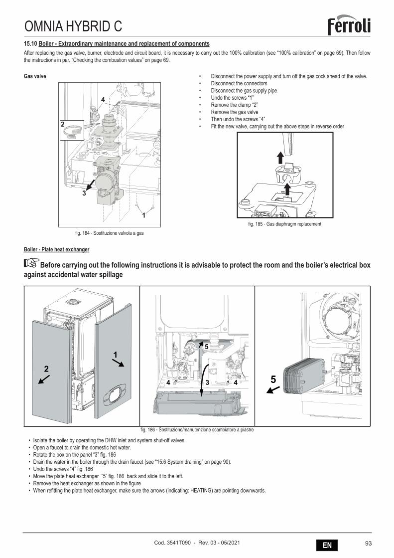
93ENCod. 3541T090 - Rev. 03 - 05/2021
OMNIA HYBRID C15.10 Boiler - Extraordinary maintenance and replacement of componentsAfter replacing the gas valve, burner, electrode and circuit board, it is necessary to carry out the 100% calibration (see “100% calibration” on page 69). Then follow the instructions in par. “Checking the combustion values” on page 69.
Gas valve
�
�
�
�
fig. 184 - Sostituzione valvola a gas
• Disconnect the power supply and turn off the gas cock ahead of the valve.• Disconnect the connectors• Disconnect the gas supply pipe• Undo the screws “1”• Remove the clamp “2”• Remove the gas valve• Then undo the screws “4”• Fit the new valve, carrying out the above steps in reverse order
fig. 185 - Gas diaphragm replacement
Boiler - Plate heat exchanger
ABefore carrying out the following instructions it is advisable to protect the room and the boiler’s electrical box against accidental water spillage
21
3
5
44 5
fig. 186 - Sostituzione/manutenzione scambiatore a piastre
• Isolate the boiler by operating the DHW inlet and system shut-off valves.• Open a faucet to drain the domestic hot water.• Rotate the box on the panel “3” fig. 186• Drain the water in the boiler through the drain faucet (see “15.6 System draining” on page 90).• Undo the screws “4” fig. 186• Move the plate heat exchanger “5” fig. 186 back and slide it to the left.• Remove the heat exchanger as shown in the figure• When refitting the plate heat exchanger, make sure the arrows (indicating: HEATING) are pointing downwards.
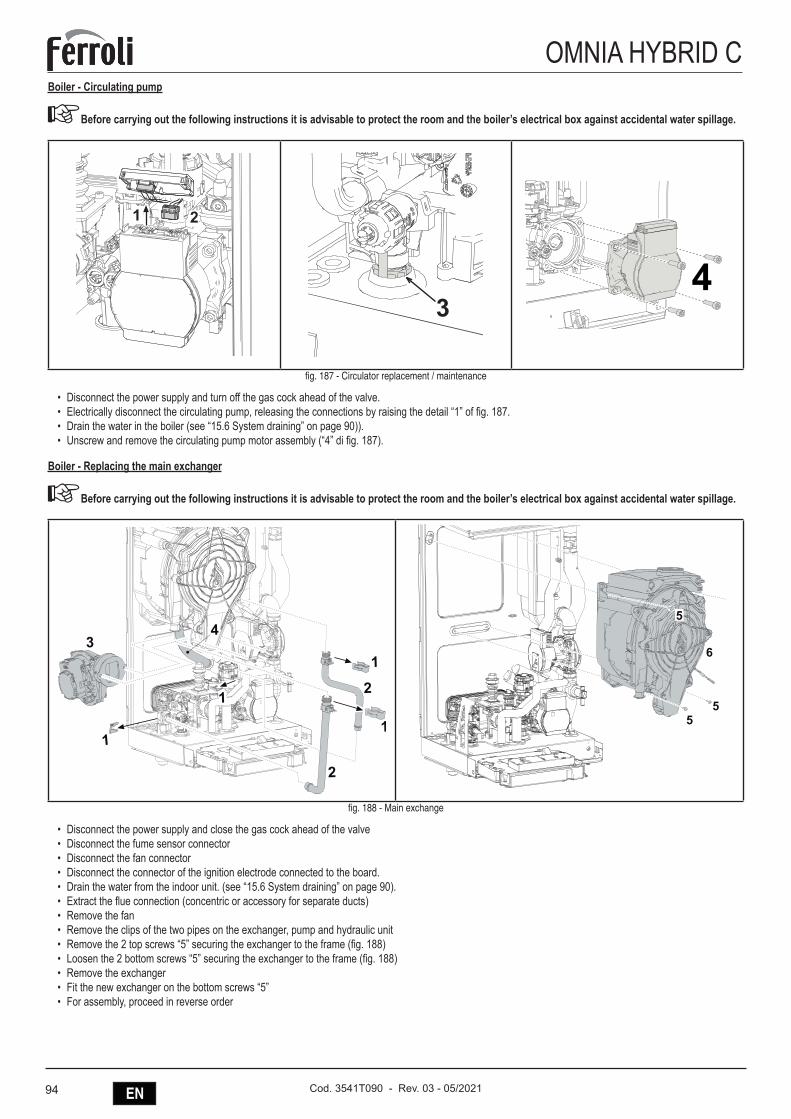
94 EN Cod. 3541T090 - Rev. 03 - 05/2021
OMNIA HYBRID CBoiler - Circulating pump
ABefore carrying out the following instructions it is advisable to protect the room and the boiler’s electrical box against accidental water spillage.
� �
�4
fig. 187 - Circulator replacement / maintenance
• Disconnect the power supply and turn off the gas cock ahead of the valve.• Electrically disconnect the circulating pump, releasing the connections by raising the detail “1” of fig. 187.• Drain the water in the boiler (see “15.6 System draining” on page 90)).• Unscrew and remove the circulating pump motor assembly (“4” di fig. 187).
Boiler - Replacing the main exchanger
ABefore carrying out the following instructions it is advisable to protect the room and the boiler’s electrical box against accidental water spillage.
fig. 188 - Main exchange
• Disconnect the power supply and close the gas cock ahead of the valve• Disconnect the fume sensor connector• Disconnect the fan connector• Disconnect the connector of the ignition electrode connected to the board.• Drain the water from the indoor unit. (see “15.6 System draining” on page 90).• Extract the flue connection (concentric or accessory for separate ducts)• Remove the fan• Remove the clips of the two pipes on the exchanger, pump and hydraulic unit• Remove the 2 top screws “5” securing the exchanger to the frame (fig. 188)• Loosen the 2 bottom screws “5” securing the exchanger to the frame (fig. 188)• Remove the exchanger• Fit the new exchanger on the bottom screws “5”• For assembly, proceed in reverse order
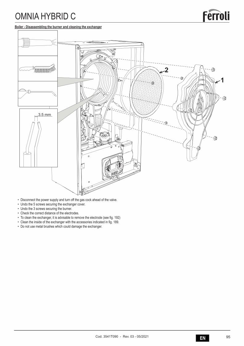
95ENCod. 3541T090 - Rev. 03 - 05/2021
OMNIA HYBRID CBoiler - Disassembling the burner and cleaning the exchanger
������
�
�
• Disconnect the power supply and turn off the gas cock ahead of the valve.• Undo the 5 screws securing the exchanger cover.• Undo the 3 screws securing the burner.• Check the correct distance of the electrodes.• To clean the exchanger, it is advisable to remove the electrode (see fig. 192)• Clean the inside of the exchanger with the accessories indicated in fig. 189.• Do not use metal brushes which could damage the exchanger.
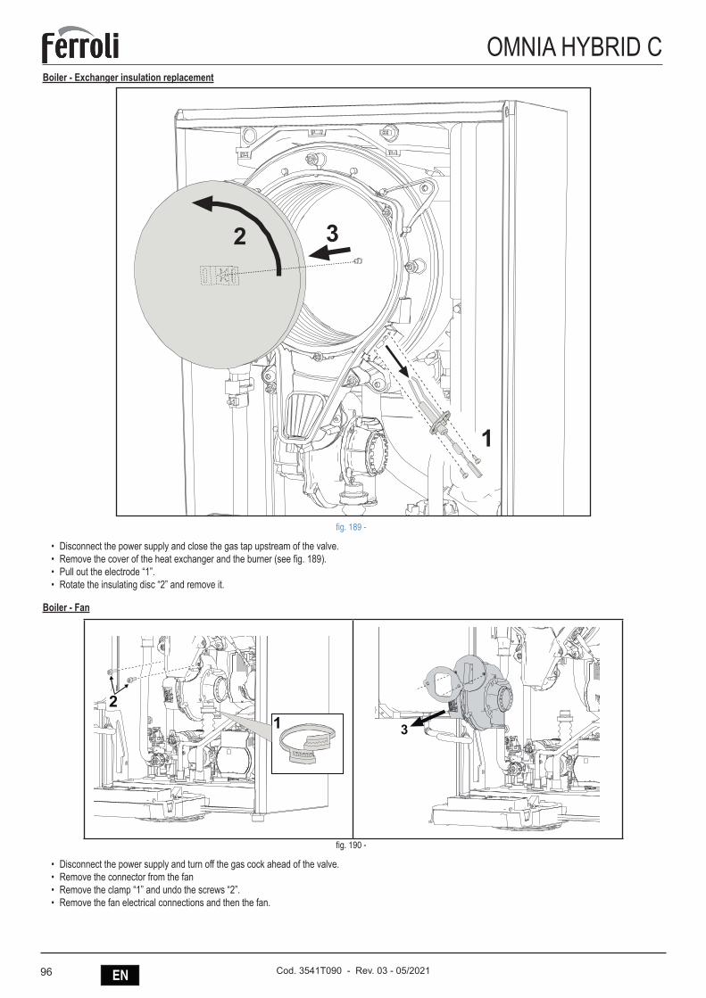
96 EN Cod. 3541T090 - Rev. 03 - 05/2021
OMNIA HYBRID CBoiler - Exchanger insulation replacement
�
� �
fig. 189 -
• Disconnect the power supply and close the gas tap upstream of the valve.• Remove the cover of the heat exchanger and the burner (see fig. 189).• Pull out the electrode “1”.• Rotate the insulating disc “2” and remove it.
Boiler - Fan
fig. 190 -
• Disconnect the power supply and turn off the gas cock ahead of the valve.• Remove the connector from the fan• Remove the clamp “1” and undo the screws “2”.• Remove the fan electrical connections and then the fan.
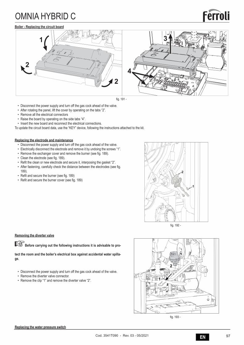
97ENCod. 3541T090 - Rev. 03 - 05/2021
OMNIA HYBRID CBoiler - Replacing the circuit board
fig. 191 -
• Disconnect the power supply and turn off the gas cock ahead of the valve.• After rotating the panel, lift the cover by operating on the tabs “2”.• Remove all the electrical connectors• Raise the board by operating on the side tabs “4”.• Insert the new board and reconnect the electrical connections.
To update the circuit board data, use the “KEY” device, following the instructions attached to the kit.
Replacing the electrode and maintenance• Disconnect the power supply and turn off the gas cock ahead of the valve.• Electrically disconnect the electrode and remove it by undoing the screws “1”.• Remove the exchanger cover and remove the burner (see fig. 189).• Clean the electrode (see fig. 189).• Refit the clean or new electrode and secure it, interposing the gasket “2”.• After fastening, carefully check the distance between the electrodes (see fig.
189).• Refit and secure the burner (see fig. 189)• Refit and secure the burner cover (see fig. 189)
�
�
fig. 192 -
Removing the diverter valve
ABefore carrying out the following instructions it is advisable to pro-
tect the room and the boiler’s electrical box against accidental water spilla-ge.
• Disconnect the power supply and turn off the gas cock ahead of the valve.• Remove the diverter valve connector.• Remove the clip “1” and remove the diverter valve “2”.
fig. 193 -
Replacing the water pressure switch
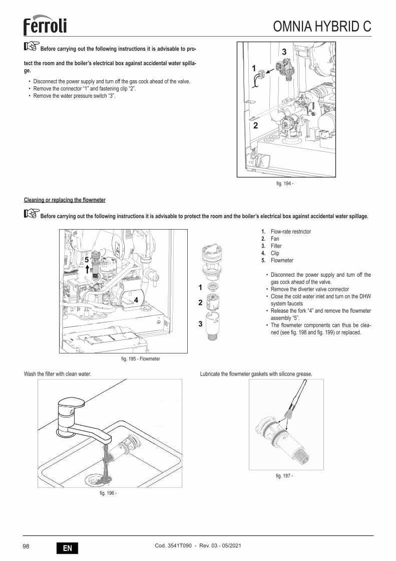
98 EN Cod. 3541T090 - Rev. 03 - 05/2021
OMNIA HYBRID CABefore carrying out the following instructions it is advisable to pro-
tect the room and the boiler’s electrical box against accidental water spilla-ge.
• Disconnect the power supply and turn off the gas cock ahead of the valve.• Remove the connector “1” and fastening clip “2”.• Remove the water pressure switch “3”.
�
�
�
fig. 194 -
Cleaning or replacing the flowmeter
ABefore carrying out the following instructions it is advisable to protect the room and the boiler’s electrical box against accidental water spillage.
fig. 195 - Flowmeter
1. Flow-rate restrictor2. Fan3. Filter4. Clip5. Flowmeter
• Disconnect the power supply and turn off the gas cock ahead of the valve.
• Remove the diverter valve connector• Close the cold water inlet and turn on the DHW
system faucets• Release the fork “4” and remove the flowmeter
assembly “5”.• The flowmeter components can thus be clea-
ned (see fig. 198 and fig. 199) or replaced.
Wash the filter with clean water.
fig. 196 -
Lubricate the flowmeter gaskets with silicone grease.
fig. 197 -
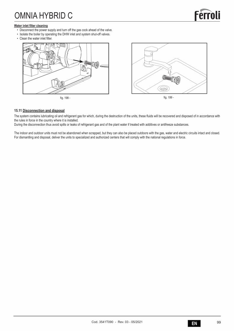
99ENCod. 3541T090 - Rev. 03 - 05/2021
OMNIA HYBRID CWater inlet filter cleaning
• Disconnect the power supply and turn off the gas cock ahead of the valve.• Isolate the boiler by operating the DHW inlet and system shut-off valves.• Clean the water inlet filter.
fig. 198 - fig. 199 -
15.11 Disconnection and disposalThe system contains lubricating oil and refrigerant gas for which, during the destruction of the units, these fluids will be recovered and disposed of in accordance with the rules in force in the country where it is installed. During the disconnection thus avoid spills or leaks of refrigerant gas and of the plant water if treated with additives or antifreeze substances.
The indoor and outdoor units must not be abandoned when scrapped, but they can also be placed outdoors with the gas, water and electric circuits intact and closed.For dismantling and disposal, deliver the units to specialized and authorized centers that will comply with the national regulations in force.
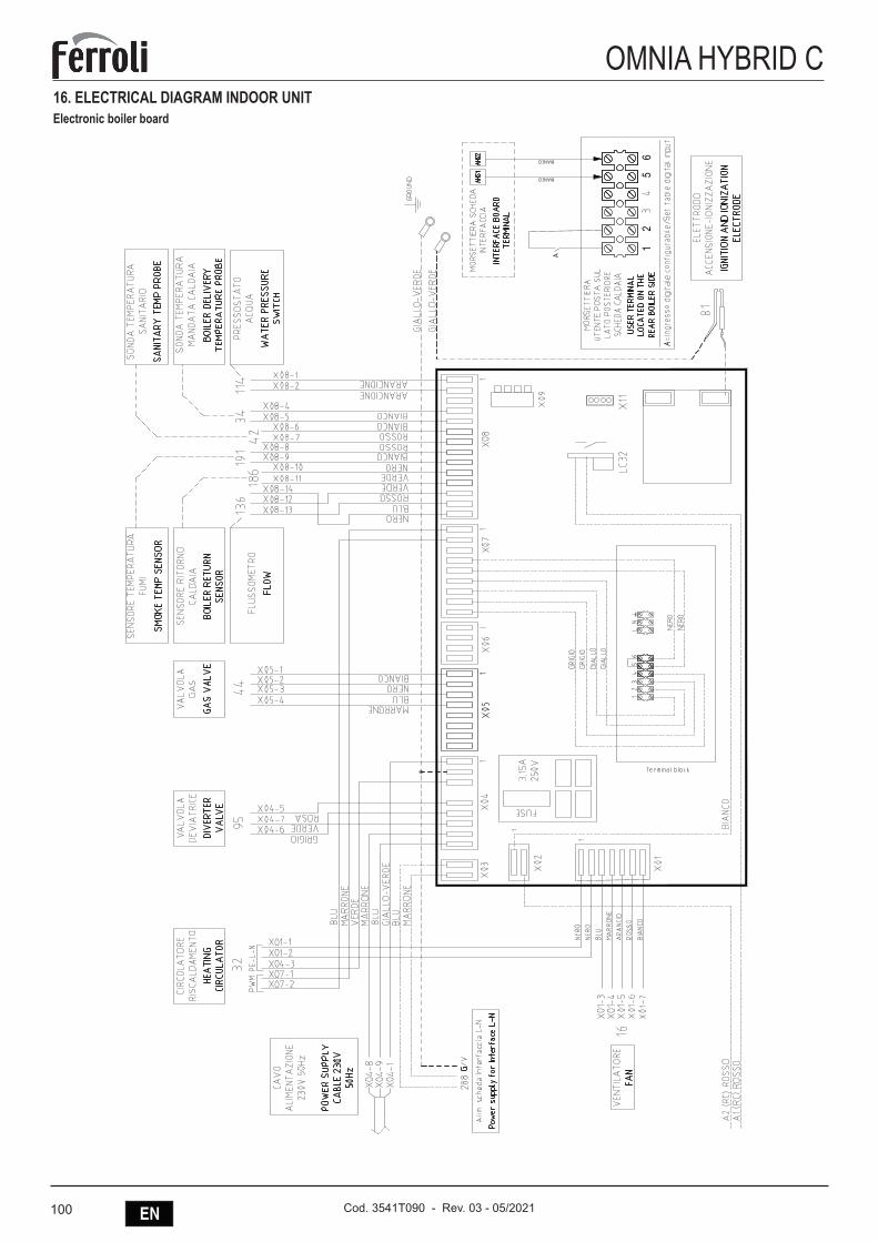
100 EN Cod. 3541T090 - Rev. 03 - 05/2021
OMNIA HYBRID C16. ELECTRICAL DIAGRAM INDOOR UNITElectronic boiler board
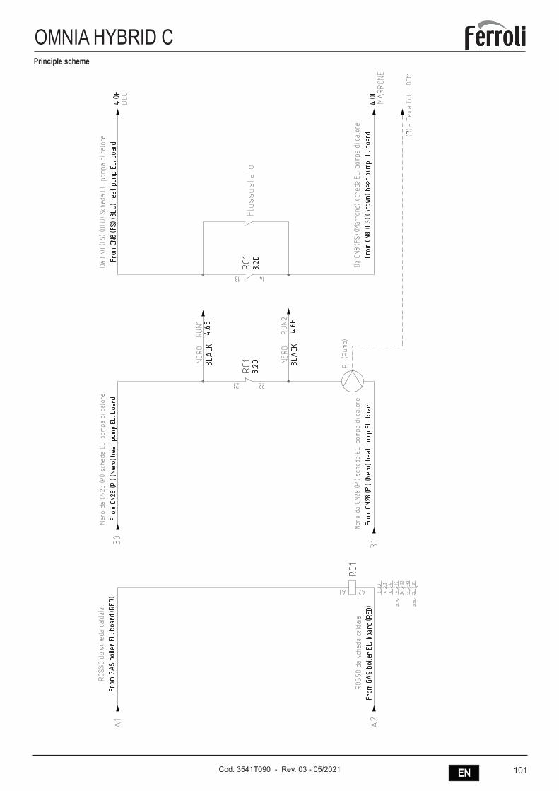
101ENCod. 3541T090 - Rev. 03 - 05/2021
OMNIA HYBRID CPrinciple scheme
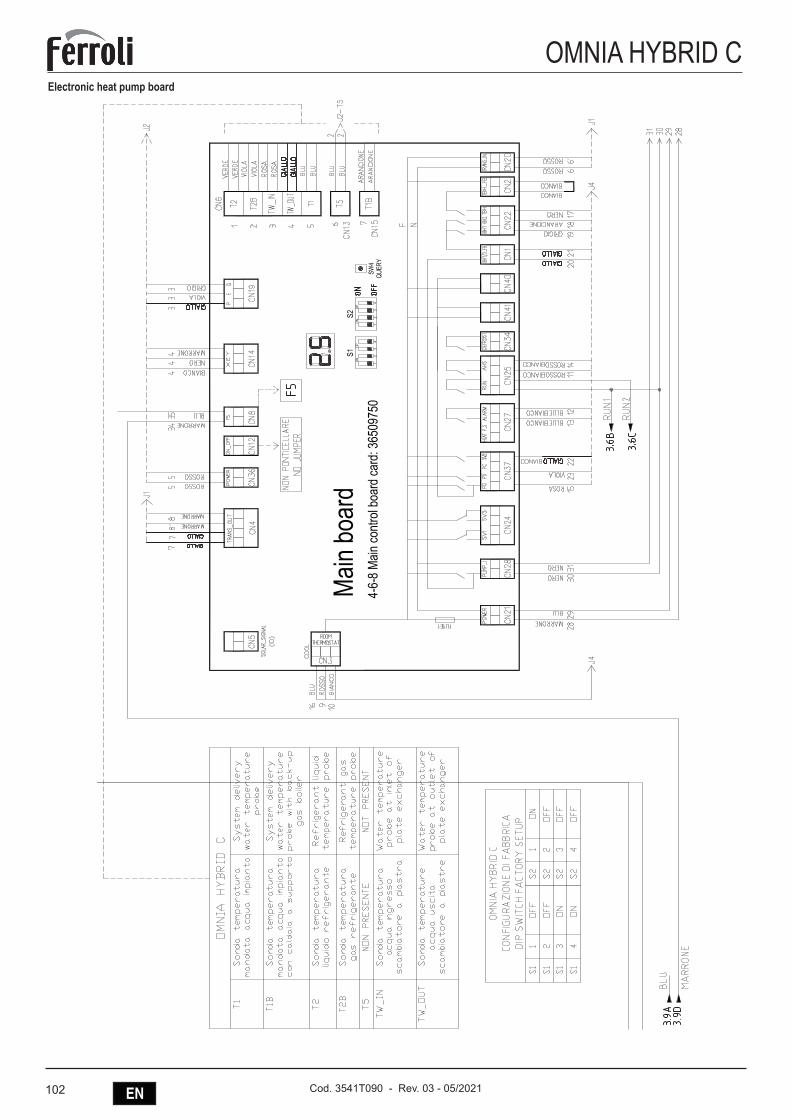
102 EN Cod. 3541T090 - Rev. 03 - 05/2021
OMNIA HYBRID CElectronic heat pump board
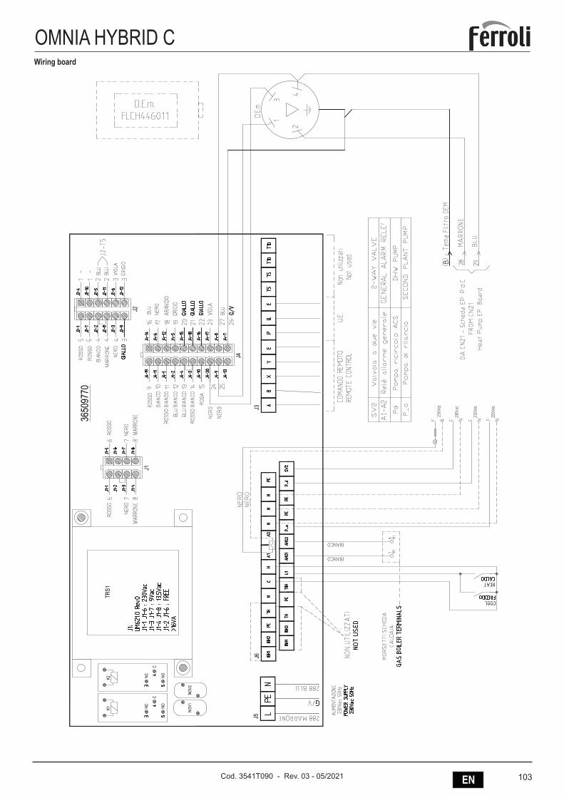
103ENCod. 3541T090 - Rev. 03 - 05/2021
OMNIA HYBRID CWiring board
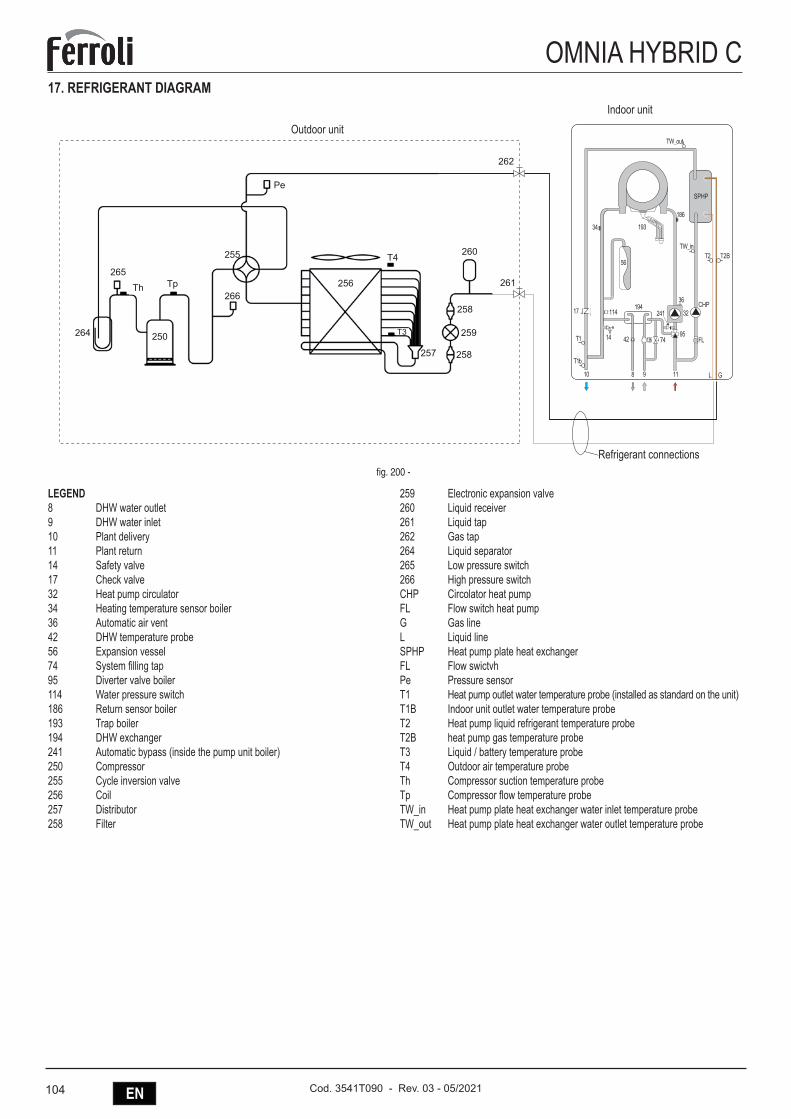
104 EN Cod. 3541T090 - Rev. 03 - 05/2021
OMNIA HYBRID C17. REFRIGERANT DIAGRAM
265
264
Th Tp
250
266
255
Pe
T4 260
262
261
258
259
258257
T3
256
241194
14
GL
114
9574
56
193
186
34
10 118 9
42
36
32
TW_in
TW_out
CHP
SPHP
FL136T1
T1b
17
T2BT2
Outdoor unitIndoor unit
Refrigerant connectionsfig. 200 -
LEGEND 8 DHW water outlet9 DHW water inlet10 Plant delivery11 Plant return14 Safety valve17 Check valve32 Heat pump circulator34 Heating temperature sensor boiler36 Automatic air vent42 DHW temperature probe56 Expansion vessel74 System filling tap95 Diverter valve boiler114 Water pressure switch186 Return sensor boiler193 Trap boiler194 DHW exchanger 241 Automatic bypass (inside the pump unit boiler)250 Compressor255 Cycle inversion valve256 Coil257 Distributor258 Filter
259 Electronic expansion valve260 Liquid receiver261 Liquid tap262 Gas tap264 Liquid separator265 Low pressure switch266 High pressure switchCHP Circolator heat pumpFL Flow switch heat pumpG Gas lineL Liquid lineSPHP Heat pump plate heat exchangerFL Flow swictvhPe Pressure sensorT1 Heat pump outlet water temperature probe (installed as standard on the unit)T1B Indoor unit outlet water temperature probeT2 Heat pump liquid refrigerant temperature probeT2B heat pump gas temperature probeT3 Liquid / battery temperature probeT4 Outdoor air temperature probeTh Compressor suction temperature probeTp Compressor flow temperature probeTW_in Heat pump plate heat exchanger water inlet temperature probeTW_out Heat pump plate heat exchanger water outlet temperature probe

105ENCod. 3541T090 - Rev. 03 - 05/2021
OMNIA HYBRID C18. OUTDOOR UNIT ELECTRONIC BOARDSPCB-3 - Inverter board for 1-phase Mod. 4-6-8 (outdoor unit)
24
PCB A, Inverter board for 1 phase 5,7kw unit. 1
4567
38
9
10
11
2
1-phase 5/7kW
1 To main board (CN101,CN105)2 Compressor connection port U V W (U,V,W)3 Input port N for IPM module(N)4 Input port P for IPM module(P)5 Input port for PFC inductance P1(P1)6 Input port for bridge Rectifiers(P5)7 Input port for Bridge Rectifiers(P6) 8 Output port P of PFC(P2)9 Input port for PFC inductance 3(P3)10 Output port N of PFC(P4)11 +18V(P9)
fig. 201 -
1 To main board (CN101,CN105)2 Compressor connection port U V W (U,V,W)3 Input port N for IPM module(N)4 Input port P for IPM module(P)5 Input port for PFC inductance P1(P1)6 Input port for bridge Rectifiers(P5)
7 Input port for Bridge Rectifiers(P6)8 Output port P of PFC(P2)9 Input port for PFC inductance 3(P3)10 Output port N of PFC(P4)11 +18V(P9)

106 EN Cod. 3541T090 - Rev. 03 - 05/2021
OMNIA HYBRID CPCB-2 - Main control board for 1-phase Mod. 4-6-8 (outdoor unit)
25
1 Rectifier bridge input port L
2 Hydraulic compartment input port2
3 Rectifier bridge input port N
4 Power supply N
5 Power supply L
6 Transformer output port
7 BLACK: T3 temperature sensor port
WHITE:T4 temperature sensor port
8 TP temperature sensor port
9 YELLOW: High pressure switch
RED: Low pressure switch
10 Th temperature sensor port
11 Pressure sensor port
12 Wire controller port
13 P/N/+18V port
14 To IPDU/PFC
15 DC fan port
16 Compression electromechanical
heating belt
17 4-way valve port
18 Transformer input port
1-phase 5/7kW
PCB B, Main control board for 1 phase 5,7kw unit.
PCB A
2
4
567891011
12
13
15
14
16
17
183
1
19
1 Rectifier bridge input port L2 Hydraulic compartment input port23 Rectifier bridge input port N4 Power supply N5 Power supply L6 Transformer output port7 BLACK: T3 temperature sensor portWHITE:T4 temperature sensor port8 TP temperature sensor port9 YELLOW: High pressure switchRED: Low pressure switch10 Th temperature sensor port11 Pressure sensor port12 Wire controller port13 P/N/+18V port14 To IPDU/PFC
15 DC fan port16 Compression electromechanicalheating belt17 4-way valve port18 Transformer input port
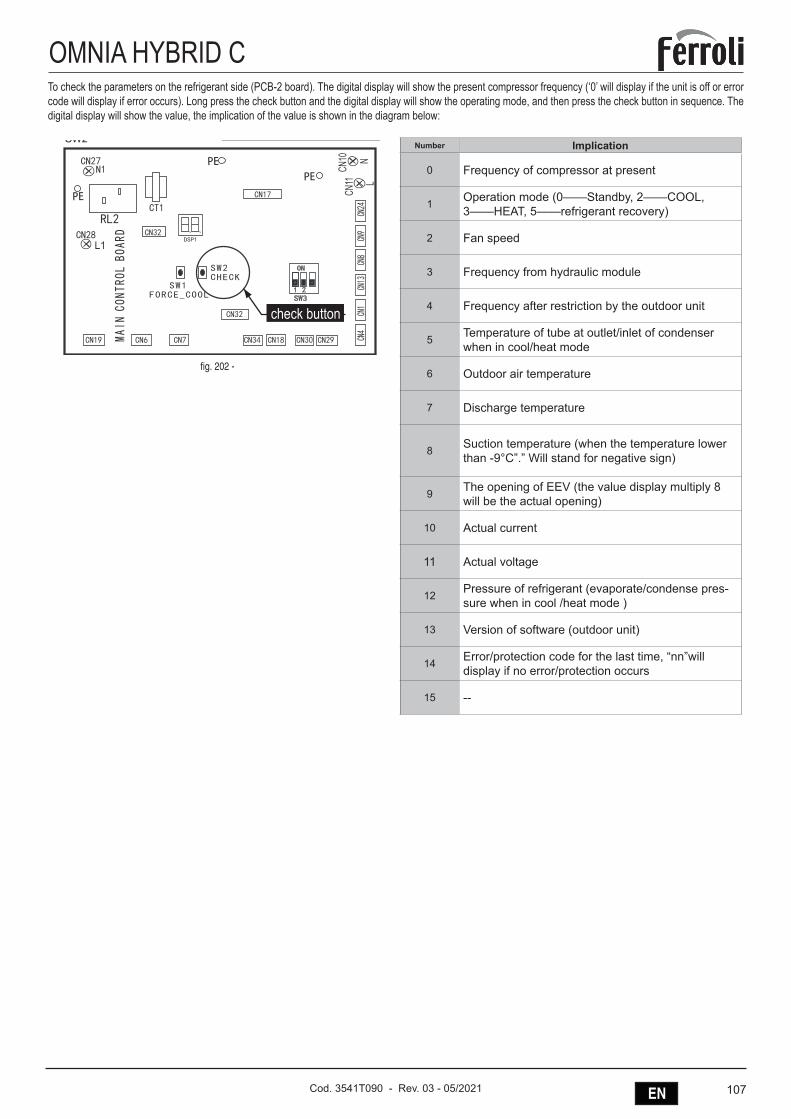
107ENCod. 3541T090 - Rev. 03 - 05/2021
OMNIA HYBRID CTo check the parameters on the refrigerant side (PCB-2 board). The digital display will show the present compressor frequency (‘0’ will display if the unit is off or error code will display if error occurs). Long press the check button and the digital display will show the operating mode, and then press the check button in sequence. The digital display will show the value, the implication of the value is shown in the diagram below:
1TC
4NC
3NC
1NC
2NC
8NC
03NC01NC
11NC
9NC
21NC
TUOSNART
62NC6NCNISNART 15NC
81NC
22NC
TUO_L
TUO_N
NI_L
NI_N
WS 4
O N
1 2 3WS 3
O N
1 2 3
ECROFLOOCKCEHC
WS 1WS 2 D IS 1
71NC91NC
DRAOBLORTNOCNIAM31NC
41NC42NC
82NC
61NC
SW2
SW2
check button
check button
check button
SW2
56NC
46NC
76NC
66NC
86NC
71NC
102CI
502NC
91NC
11NC
6NC
8NC
9NC
01NC
22NC
102NC
DRAOBLORTNOCNIAM
052NC
2WS1WS
1 2 3
O N
1 2
O N
7WS 8WS
36NC
4NC
63NC
etoNnoitceridgnidaerhT
)14NC(16NC
)16NC(14NC
11NC01NC
LN
PEPE
PE
L1
fig. 202 -
Number Implication
0 Frequency of compressor at present
1 Operation mode (0——Standby, 2——COOL, 3——HEAT, 5——refrigerant recovery)
2 Fan speed
3 Frequency from hydraulic module
4 Frequency after restriction by the outdoor unit
5 Temperature of tube at outlet/inlet of condenser when in cool/heat mode
6 Outdoor air temperature
7 Discharge temperature
8 Suction temperature (when the temperature lower than -9°C”.” Will stand for negative sign)
9 The opening of EEV (the value display multiply 8 will be the actual opening)
10 Actual current
11 Actual voltage
12 Pressure of refrigerant (evaporate/condense pres-sure when in cool /heat mode )
13 Version of software (outdoor unit)
14 Error/protection code for the last time, “nn”will display if no error/protection occurs
15 --

108 EN Cod. 3541T090 - Rev. 03 - 05/2021
OMNIA HYBRID C19. HEAT PUMP ELECTRONIC BOARD19.1 Electronic board’s DIP switch settings of the of the heat pumpThe DIP switch are located on the electronic board inside the unit’s electrical panel.
WARNING -Switch off the power supply before opening the switch box service panel and making any changes to the DIP switch settings..
DIP SWITCH Description ON OFFS1 (1) Set always OFF 50m 5mS1 (2) Set always OFF Installed InstalledS1 (3) Electrical booster (IBH1-first stage) (OFF if installed) Not installed InstalledS1 (4) Electrical booster (IBH2-second stage) (OFF if installed) Not installed InstalledS2 (1) Temperature probe (necessary if AHS-gas boiler is installed, in this case set ON) Installed Not installedS2 (2) Set always OFF / /
S2 (3) Set always OFF / /
S2 (4) Set always OFF / /
Table. 10 - Dip switch configuration (see part 13 “fig. 204 -”).
DIP SWITCH ID FACTORY DIP SWITCH SETTING*
OFF
ON
1 2 3 4 1 2 3 4
S1 S2
fig. 203 -
S1
1 OFF2 OFF3 ON4 ON
S2
1 ON2 OFF3 OFF4 OFF
*: Do not change the dip-switch settings.
PCB-1 - Hydraulic module control board heat pump
3 2
1 2 3 4 5 6 7
8
11
9
10
12
13
1423
24
25
26
27
151718 1619202122fig. 204 -
1 Input port for solar energy(CN5)2 Output port for transformer(CN4)3 Power supply port for user interface(CN36)4 Port for remote switch(CN12)5 Port for flow switch(CN8)6 Communicate port between door PCB B and door PCB(CN14)7 Communicate port between door PCB and user interface(CN19)8 Port for temperature sensors(TW_out, TW_in, T1, T2,T2B )(CN6)9 Port for temperature sensor(CN13)10 Port for temperature sensor(T1B, the final outlet temp.)(CN15)11 Digital displays(DIS1)12 Check button(SW4)13 DIP switch(S1,S2)14 output port for deforst(CN34)15 Port for anti-freeze eletric heating tape (internal)(CN40)16 Port for anti-freeze eletric heating tape (internal)(CN41)
17 Output port for external heating source / operation output port(CN25)18 Port for anti-freeze eletric heating tape(external) /port for solarenergy pump/output port for remote alarm(CN27)19 Port for external circulted pump/pipe pump/mix pump/2-wayvalve SV2(CN37)20 Port for SV1(3-way valve) and SV3(CN24)21 Port for internal pump(CN28)22 Input port for transformer(CN20)23 Feedback port for temperature switch(CN1)24 Port for power supply(CN21)25 Feedback port for external temp. switch(shorted in default)(CN2)26 Control port backup heater/booster heater(CN22)27 Control port for room thermostat(CN3)
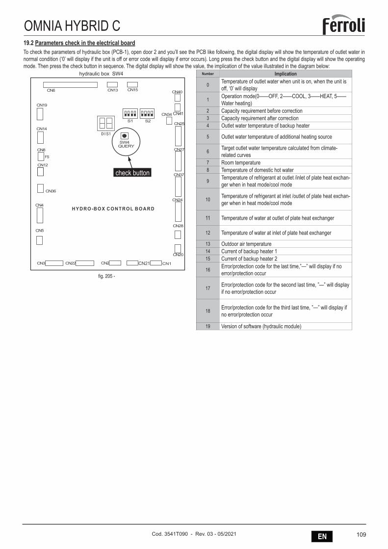
109ENCod. 3541T090 - Rev. 03 - 05/2021
OMNIA HYBRID C19.2 Parameters check in the electrical boardTo check the parameters of hydraulic box (PCB-1), open door 2 and you’ll see the PCB like following, the digital display will show the temperature of outlet water in normal condition (‘0’ will display if the unit is off or error code will display if error occurs). Long press the check button and the digital display will show the operating mode. Then press the check button in sequence. The digital display will show the value, the implication of the value illustrated in the diagram below:
hydraulic box SW4
check button
4NC
02NC
21NC
91NC
8NC
SF
41NC
63NC
CN21
72NC
42NC
43NC
31NC6NC
1S 2S
3NC
4WSYREUQ
82NC
73NC
52NC
04NC
14NC
5NC
51NC
CN122NC 2NC
DRAOBLORTNOCXOB-ORDYH
fig. 205 -
Number Implication
0 Temperature of outlet water when unit is on, when the unit is off, ‘0’ will display
1 Operation mode(0——OFF, 2——COOL, 3——HEAT, 5——Water heating)
2 Capacity requirement before correction3 Capacity requirement after correction4 Outlet water temperature of backup heater
5 Outlet water temperature of additional heating source
6 Target outlet water temperature calculated from climate-related curves
7 Room temperature8 Temperature of domestic hot water
9 Temperature of refrigerant at outlet /inlet of plate heat exchan-ger when in heat mode/cool mode
10 Temperature of refrigerant at inlet /outlet of plate heat exchan-ger when in heat mode/cool mode
11 Temperature of water at outlet of plate heat exchanger
12 Temperature of water at inlet of plate heat exchanger
13 Outdoor air temperature14 Current of backup heater 115 Current of backup heater 2
16 Error/protection code for the last time,”—” will display if no error/protection occur
17 Error/protection code for the second last time, ”—” will display if no error/protection occur
18 Error/protection code for the third last time, ”—” will display if no error/protection occur
19 Version of software (hydraulic module)
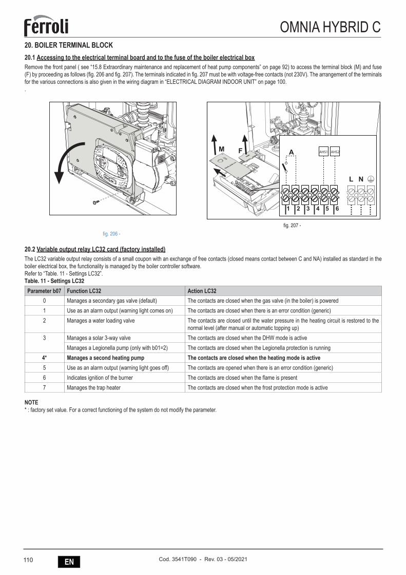
110 EN Cod. 3541T090 - Rev. 03 - 05/2021
OMNIA HYBRID C20. BOILER TERMINAL BLOCK20.1 Accessing to the electrical terminal board and to the fuse of the boiler electrical boxRemove the front panel ( see “15.8 Extraordinary maintenance and replacement of heat pump components” on page 92) to access the terminal block (M) and fuse (F) by proceeding as follows (fig. 206 and fig. 207). The terminals indicated in fig. 207 must be with voltage-free contacts (not 230V). The arrangement of the terminals for the various connections is also given in the wiring diagram in “ELECTRICAL DIAGRAM INDOOR UNIT” on page 100..
fig. 206 -
AHS1 AHS2
fig. 207 -
20.2 Variable output relay LC32 card (factory installed)The LC32 variable output relay consists of a small coupon with an exchange of free contacts (closed means contact between C and NA) installed as standard in the boiler electrical box, the functionality is managed by the boiler controller software.Refer to “Table. 11 - Settings LC32”.Table. 11 - Settings LC32
Parameter b07 Function LC32 Action LC320 Manages a secondary gas valve (default) The contacts are closed when the gas valve (in the boiler) is powered1 Use as an alarm output (warning light comes on) The contacts are closed when there is an error condition (generic)2 Manages a water loading valve The contacts are closed until the water pressure in the heating circuit is restored to the
normal level (after manual or automatic topping up)3 Manages a solar 3-way valve The contacts are closed when the DHW mode is active
Manages a Legionella pump (only with b01=2) The contacts are closed when the Legionella protection is running4* Manages a second heating pump The contacts are closed when the heating mode is active5 Use as an alarm output (warning light goes off) The contacts are opened when there is an error condition (generic)6 Indicates ignition of the burner The contacts are closed when the flame is present7 Manages the trap heater The contacts are closed when the frost protection mode is active
NOTE* : factory set value. For a correct functioning of the system do not modify the parameter.
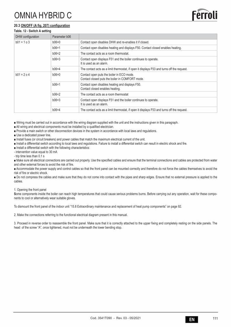
111ENCod. 3541T090 - Rev. 03 - 05/2021
OMNIA HYBRID C20.3 ON/OFF (A fig. 207) configurationTable. 12 - Switch A setting
DHW configuration Parameter b06b01 = 1 o 3 b06=0 Contact open disables DHW and re-enables it if closed.
b06=1 Contact open disables heating and displays F50. Contact closed enables heating.b06=2 The contact acts as a room thermostat.b06=3 Contact open displays F51 and the boiler continues to operate.
It is used as an alarm.b06=4 The contact acts as a limit thermostat, if open it displays F53 and turns off the request.
b01 = 2 o 4 b06=0 Contact open puts the boiler in ECO mode.Contact closed puts the boiler in COMFORT mode.
b06=1 Contact open disables heating and displays F50.Contact closed enables heating.
b06=2 The contact acts as a room thermostatb06=3 Contact open displays F51 and the boiler continues to operate.
It is used as an alarm.b06=4 The contact acts as a limit thermostat, if open it displays F53 and turns off the request.
■ Wiring must be carried out in accordance with the wiring diagram supplied with the unit and the instructions given in this paragraph.■ All wiring and electrical components must be installed by a qualified electrician.■ Provide a main switch or other disconnection devices in the system in accordance with local laws and regulations.■ Use a dedicated power line.■ Install fuses (or circuit breakers) and power cables that match the maximum electrical current of the unit.■ Install a differential switch according to local laws and regulations. Failure to install a differential switch can result in electric shock and fire.■ Install a differential switch with the following characteristics:- intervention value equal to 30 mA- trip time less than 0.1 s■ Make sure all electrical connections are carried out properly. Use the specified cables and ensure that the terminal connections and cables are protected from water and other external forces to avoid the risk of fire.■ Accommodate the power supply and control cables so that the front panel can be mounted correctly and therefore do not force the cables themselves to avoid the risk of fire or electric shock.■ Do not compress the cables and make sure that they do not come into contact with the pipes and sharp edges. Ensure that no external pressure is applied to the cables.
1. Opening the front panelSome components inside the boiler can reach high temperatures that could cause serious problems burns. Before carrying out any operation, wait for these compo-nents to cool or alternatively wear suitable gloves.
To dismount the front panel of the indoor unit “15.8 Extraordinary maintenance and replacement of heat pump components” on page 92.
2. Make the connections referring to the functional electrical diagram present in this manual.
3. Proceed in reverse order to reassemble the front panel. Make sure that it is correctly attached to the upper fixing and completely resting on the side panels. The head of the screw “A”, once tightened, must not be underneath the lower bending stop.
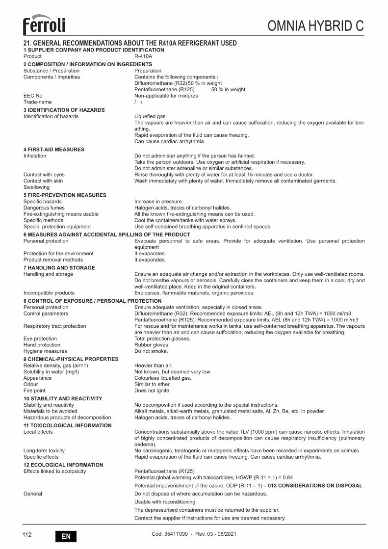
112 EN Cod. 3541T090 - Rev. 03 - 05/2021
OMNIA HYBRID C21. GENERAL RECOMMENDATIONS ABOUT THE R410A REFRIGERANT USED 1 SUPPLIER COMPANY AND PRODUCT IDENTIFICATIONProduct R-410A2 COMPOSITION / INFORMATION ON INGREDIENTSSubstance / Preparation PreparationComponents / Impurities Contains the following components : Difluoromethane (R32) 50 % in weight Pentafluoroethane (R125) 50 % in weightEEC No. Non-applicable for mixturesTrade-name / /3 IDENTIFICATION OF HAZARDSIdentification of hazards Liquefied gas. The vapours are heavier than air and can cause suffocation, reducing the oxygen available for bre-
athing. Rapid evaporation of the fluid can cause freezing. Can cause cardiac arrhythmia.4 FIRST-AID MEASURESInhalation Do not administer anything if the person has fainted. Take the person outdoors. Use oxygen or artificial respiration if necessary. Do not administer adrenaline or similar substances.Contact with eyes Rinse thoroughly with plenty of water for at least 15 minutes and see a doctor.Contact with skin Wash immediately with plenty of water. Immediately remove all contaminated garments.Swallowing5 FIRE-PREVENTION MEASURESSpecific hazards Increase in pressure.Dangerous fumes Halogen acids, traces of carbonyl halides.Fire-extinguishing means usable All the known fire-extinguishing means can be used.Specific methods Cool the containers/tanks with water sprays.Special protection equipment Use self-contained breathing apparatus in confined spaces.6 MEASURES AGAINST ACCIDENTAL SPILLING OF THE PRODUCTPersonal protection Evacuate personnel to safe areas. Provide for adequate ventilation. Use personal protection
equipmentProtection for the environment It evaporates.Product removal methods It evaporates.7 HANDLING AND STORAGEHandling and storage Ensure an adequate air change and/or extraction in the workplaces. Only use well-ventilated rooms.
Do not breathe vapours or aerosols. Carefully close the containers and keep them in a cool, dry and well-ventilated place. Keep in the original containers.
Incompatible products Explosives, flammable materials, organic peroxides.8 CONTROL OF EXPOSURE / PERSONAL PROTECTIONPersonal protection Ensure adequate ventilation, especially in closed areas.Control parameters Difluoromethane (R32): Recommended exposure limits: AEL (8h and 12h TWA) = 1000 ml/m3 Pentafluoroethane (R125): Recommended exposure limits: AEL (8h and 12h TWA) = 1000 ml/m3Respiratory tract protection For rescue and for maintenance works in tanks, use self-contained breathing apparatus. The vapours
are heavier than air and can cause suffocation, reducing the oxygen available for breathing.Eye protection Total protection glasses.Hand protection Rubber gloves.Hygiene measures Do not smoke.9 CHEMICAL-PHYSICAL PROPERTIESRelative density, gas (air=1) Heavier than air.Solubility in water (mg/l) Not known, but deemed very low.Appearance Colourless liquefied gas.Odour Similar to ether.Fire point Does not ignite.10 STABILITY AND REACTIVITYStability and reactivity No decomposition if used according to the special instructions.Materials to be avoided Alkali metals, alkali-earth metals, granulated metal salts, Al, Zn, Be, etc. in powder.Hazardous products of decomposition Halogen acids, traces of carbonyl halides.11 TOXICOLOGICAL INFORMATIONLocal effects Concentrations substantially above the value TLV (1000 ppm) can cause narcotic effects. Inhalation
of highly concentrated products of decomposition can cause respiratory insufficiency (pulmonary oedema).
Long-term toxicity No carcinogenic, teratogenic or mutagenic effects have been recorded in experiments on animals.Specific effects Rapid evaporation of the fluid can cause freezing. Can cause cardiac arrhythmia.12 ECOLOGICAL INFORMATIONEffects linked to ecotoxicity Pentafluoroethane (R125) Potential global warming with halocarbides; HGWP (R-11 = 1) = 0.84 Potential impoverishment of the ozone; ODP (R-11 = 1) = 013 CONSIDERATIONS ON DISPOSALGeneral Do not dispose of where accumulation can be hazardous. Usable with reconditioning. The depressurised containers must be returned to the supplier. Contact the supplier if instructions for use are deemed necessary.
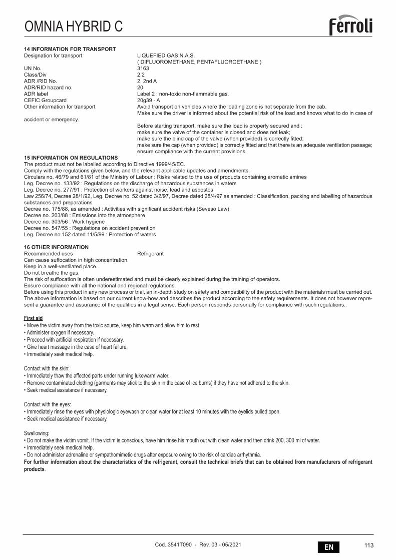
113ENCod. 3541T090 - Rev. 03 - 05/2021
OMNIA HYBRID C14 INFORMATION FOR TRANSPORTDesignation for transport LIQUEFIED GAS N.A.S. ( DIFLUOROMETHANE, PENTAFLUOROETHANE )UN No. 3163Class/Div 2.2ADR /RID No. 2, 2nd AADR/RID hazard no. 20ADR label Label 2 : non-toxic non-flammable gas.CEFIC Groupcard 20g39 - AOther information for transport Avoid transport on vehicles where the loading zone is not separate from the cab. Make sure the driver is informed about the potential risk of the load and knows what to do in case of accident or emergency. Before starting transport, make sure the load is properly secured and : make sure the valve of the container is closed and does not leak; make sure the blind cap of the valve (when provided) is correctly fitted; make sure the cap (when provided) is correctly fitted and that there is an adequate ventilation passage; ensure compliance with the current provisions.15 INFORMATION ON REGULATIONSThe product must not be labelled according to Directive 1999/45/EC.Comply with the regulations given below, and the relevant applicable updates and amendments.Circulars no. 46/79 and 61/81 of the Ministry of Labour : Risks related to the use of products containing aromatic aminesLeg. Decree no. 133/92 : Regulations on the discharge of hazardous substances in watersLeg. Decree no. 277/91 : Protection of workers against noise, lead and asbestosLaw 256/74, Decree 28/1/92, Leg. Decree no. 52 dated 3/2/97, Decree dated 28/4/97 as amended : Classification, packing and labelling of hazardous substances and preparationsDecree no. 175/88, as amended : Activities with significant accident risks (Seveso Law)Decree no. 203/88 : Emissions into the atmosphereDecree no. 303/56 : Work hygieneDecree no. 547/55 : Regulations on accident preventionLeg. Decree no.152 dated 11/5/99 : Protection of waters
16 OTHER INFORMATIONRecommended uses RefrigerantCan cause suffocation in high concentration.Keep in a well-ventilated place.Do not breathe the gas.The risk of suffocation is often underestimated and must be clearly explained during the training of operators.Ensure compliance with all the national and regional regulations.Before using this product in any new process or trial, an in-depth study on safety and compatibility of the product with the materials must be carried out.The above information is based on our current know-how and describes the product according to the safety requirements. It does not however repre-sent a guarantee and assurance of the qualities in a legal sense. Each person responds personally for compliance with such regulations..
First aid• Move the victim away from the toxic source, keep him warm and allow him to rest.• Administer oxygen if necessary.• Proceed with artificial respiration if necessary.• Give heart massage in the case of heart failure.• Immediately seek medical help. Contact with the skin:• Immediately thaw the affected parts under running lukewarm water.• Remove contaminated clothing (garments may stick to the skin in the case of ice burns) if they have not adhered to the skin.• Seek medical assistance if necessary. Contact with the eyes:• Immediately rinse the eyes with physiologic eyewash or clean water for at least 10 minutes with the eyelids pulled open.• Seek medical assistance if necessary. Swallowing:• Do not make the victim vomit. If the victim is conscious, have him rinse his mouth out with clean water and then drink 200, 300 ml of water.• Immediately seek medical help.• Do not administer adrenaline or sympathomimetic drugs after exposure owing to the risk of cardiac arrhythmia.For further information about the characteristics of the refrigerant, consult the technical briefs that can be obtained from manufacturers of refrigerant products.


FERROLI S.p.A.Via Ritonda 78/a
37047 San Bonifacio - Verona - ITALYwww.ferroli.com
Cod
. 354
1T09
0 -
Rev
. 03
- 05/
2021