Product catalogue - FERROLI
204
March 2018 Product catalogue CLIMA & COMFORT | PROFESSIONAL
-
Upload
khangminh22 -
Category
Documents
-
view
0 -
download
0
Transcript of Product catalogue - FERROLI

March 2018
Product catalogue
CLIMA&COMFORT | PROFESSIONAL

3
Ferroli production plantLaboratory R&D
ReferencesAIR CONDITIONING
HEAT PUMPS
4
6
8
11
105
SUMMARY
4
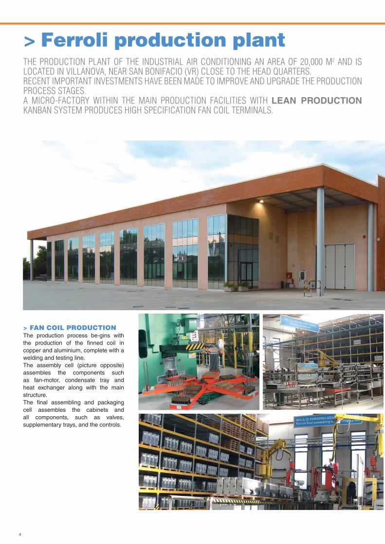
> Ferroli production plantTHE PRODUCTION PLANT OF THE INDUSTRIAL AIR CONDITIONING AN AREA OF 20,000 M2 AND IS LOCATED IN VILLANOVA, NEAR SAN BONIFACIO (VR) CLOSE TO THE HEAD QUARTERS.RECENT IMPORTANT INVESTMENTS HAVE BEEN MADE TO IMPROVE AND UPGRADE THE PRODUCTION PROCESS STAGES. A MICRO-FACTORY WITHIN THE MAIN PRODUCTION FACILITIES WITH LEAN PRODUCTION KANBAN SYSTEM PRODUCES HIGH SPECIFICATION FAN COIL TERMINALS.
> FAN COIL PRODUCTIONThe production process be-gins with the production of the finned coil in copper and aluminium, complete with a welding and testing line.The assembly cell (picture opposite) assembles the components such as fan-motor, condensate tray and heat exchanger along with the main structure.The final assembling and packaging cell assembles the cabinets and all components, such as valves, supplementary trays, and the controls.
5
fig. a fig. b
fig. c
fig. d
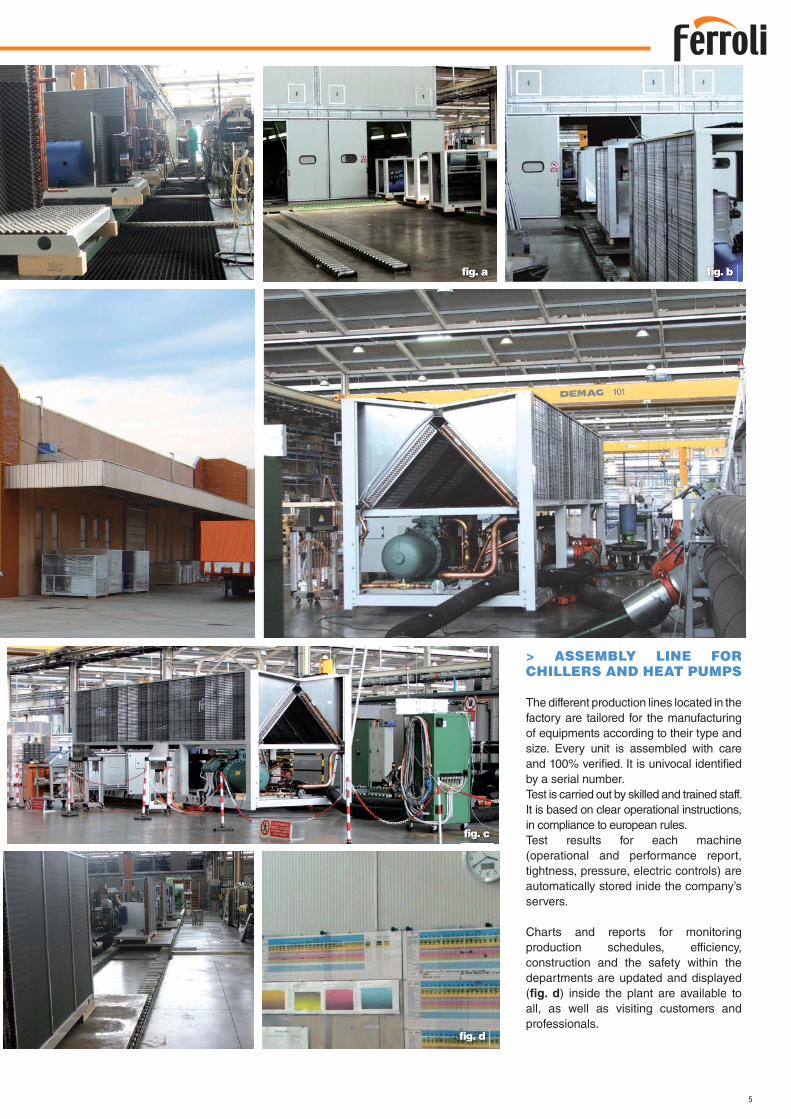
> ASSEMBLY LINE FORCHILLERS AND HEAT PUMPS
The different production lines located in the factory are tailored for the manufacturing of equipments according to their type and size. Every unit is assembled with care and 100% verified. It is univocal identified by a serial number.Test is carried out by skilled and trained staff. It is based on clear operational instructions, in compliance to european rules.Test results for each machine (operational and performance report, tightness, pressure, electric controls) are automatically stored inide the company’s servers.
Charts and reports for monitoring production schedules, efficiency, construction and the safety within the departments are updated and displayed (fig. d) inside the plant are available to all, as well as visiting customers and professionals.
6
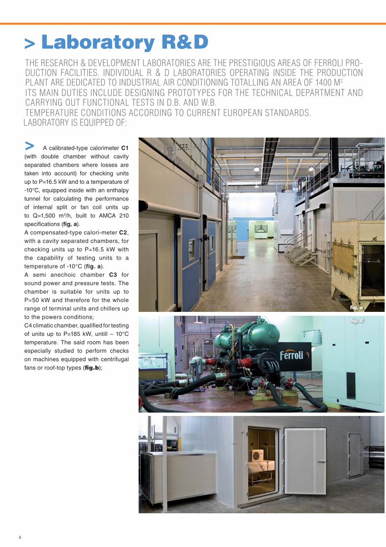
> Laboratory R&DTHE RESEARCH & DEVELOPMENT LABORATORIES ARE THE PRESTIGIOUS AREAS OF FERROLI PRO-DUCTION FACILITIES. INDIVIDUAL R & D LABORATORIES OPERATING INSIDE THE PRODUCTION PLANT ARE DEDICATED TO INDUSTRIAL AIR CONDITIONING TOTALLING AN AREA OF 1400 M2.
ITS MAIN DUTIES INCLUDE DESIGNING PROTOTYPES FOR THE TECHNICAL DEPARTMENT AND CARRYING OUT FUNCTIONAL TESTS IN D.B. AND W.B.
TEMPERATURE CONDITIONS ACCORDING TO CURRENT EUROPEAN STANDARDS.LABORATORY IS EQUIPPED OF:
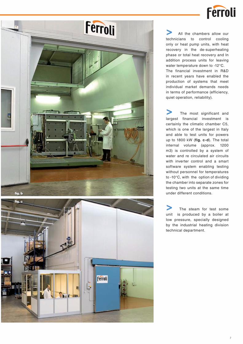
> A calibrated-type calorimeter C1 (with double chamber without cavity separated chambers where losses are taken into account) for checking units up to P=16.5 kW and to a temperature of -10°C, equipped inside with an enthalpytunnel for calculating the performanceof internal split or fan coil units upto Q=1,500 m3/h, built to AMCA 210specifications (fig. a).A compensated-type calori-meter C2,with a cavity separated chambers, forchecking units up to P=16.5 kW withthe capability of testing units to atemperature of -10°C (fig. a).A semi anechoic chamber C3 forsound power and pressure tests. Thechamber is suitable for units up toP=50 kW and therefore for the wholerange of terminal units and chillers upto the powers conditions;C4 climatic chamber, qualified for testing of units up to P=185 kW, untill – 10°Ctemperature. The said room has beenespecially studied to perform checkson machines equipped with centrifugalfans or roof-top types (fig.b);
fig. a
fig. d
7
> All the chambers allow our technicians to control cooling only or heat pump units, with heat recovery in the de-superheating phase or total heat recovery and In addition process units for leaving water temperature down to -12°C. The financial investment in R&D in recent years have enabled the production of systems that meet individual market demands needs in terms of performance (efficiency, quiet operation, reliability).
> The most significant and largest financial investment is certainly the climatic chamber C5, which is one of the largest in Italy and able to test units for powers up to 1800 kW (fig. c-d). The total internal volume (approx. 1200 m3) is controlled by a system of water and re circulated air circuits with inverter control and a smart software system enabling testing without personnel for temperatures to -10°C, with the option of dividing the chamber into separate zones for testing two units at the same time under different conditions.
> The steam for test some unit is produced by a boiler at low pressure, specially designed by the industrial heating division technical department.
fig. b
fig. c
8
REFERENCES / RÉFÉRENCES
HOSPITAL AUTHORITIES / HÔPITAUXMilazzo (ME)RHA + RGA + UTAPiemonte (ME)RLA + FAN COILS. Filippo Neri RomaRMA + FAN COILMilitare Celio (RM)UTA + FAN COILOpera Pia (VB)RMA + FAN COILCotugno (NA)RGA + UTA + FAN COILVecchio Palmanova (UD)FAN COILV. Emanuele Gela (RG)RHA + UTABorgosesia (VC)RHV + UTAMisericordia (GR)FAN COILSilvestrini (PG)FAN COILVilla San Pietro (RM)UTASan Bonifacio (VR)UTAC. Poma (MN)FAN COILMonaldi (NA)RLA + UTA
Sarcone (BA)RGAS. Anna (CO)UTABelcolle (VT)UTAMaggiore (BO)UTAS.Martino (GE)RGABarcellona (ME)UTAG. Rummo (BN)RGACà Foncello (TV)UTAS. Maria della Circe (SI)UTAVittorio Emanuele III (CL)UTAVincenzo dell’Erba (BA)RMA + UTASanthià (TO)RLA + FCFBorgomanero (NO)RHA + UTABambin Gesù RomaUTA + FANCOILSandro Pertini (RM)RGA + FAN COIL
Manduria (TA)RXA + RMA + FAN COIL +TERMOVENTILANTIMoscati (TA)RXA + TERMOVENTILANTIS. Vito al Tagliamento (UD)UTA + TERMOVENTILANTINiguarda (MI)TERMOVENTILANTIMaggiore della Carità (NO)UTA + RLA + RGAGubbio (PG)RGA + FAN COILPresidio Ospedaliero ASL n. 4 APICELLA (NA)RGAAzienda Ospedaliera Senese (SI)RXAPoliclinico di Monza (MI)RGAUSL 4 di Prato (PO)CENTRALI TRATTAMENTO ARIA + RGA +VENTILCONVETTORI
USL 13 (BA)CENTRALI TRATTAMENTO ARIAASL NAPOLI 2 (NA)CENTRALI TRATTAMENTO ARIA
ASL di Frosinone (FR)RLA + CENTRALI TRATTAMENTO ARIACasa di Cura Columbus (MI)CENTRALI TRATTAMENTO ARIAIstituto Zooprofilattico (SS)RLA + RHARegione Lazio (RM)CENTRALI TRATTAMENTO ARIAClinica Villa Sandra (RM)CENTRALI TRATTAMENTO ARIACasa di Cura S. Lorenzino (FC)RGALaboratorio TUV Scarmagno (TO)RGA + FCSI.P.A.B. Ist. Giovanni XXIII(BO)RHA + CENTRALI TRATTAMENTO ARIACentro Sterilizzazione“Steril Piemonte” (VC)RHV + RLA + CENTRALI TRATTAMEN-TO ARIAIngegneria BiomedicaS. Lucia (NO)RGA + VENTILCONVETTORI
SCHOOLS, UNIVERSITIES, LIBRARIES / HOTEL / CATERING - ECOLES, UNIVERSITÉ, BIBLIOTHÈQUES / HÔTELS / RESTAURATION
SCHOOLS, UNIVERSITIES, LIBRARIESECOLES, UNIVERSITÉ, BIBLIOTHÈQUESLiceo Classico S.M. Legnani (VA)RGA + UTABiblioteca di Palazzo Chigi (RM)FAN COILBiblioteca Com. Macomer (SS)ROOF TOPBiblioteca Com. Caserta (CE)RLAUniversità Magna Grecia (CZ)UTA
IPSIA di Gallarate (VA)UTAUniversità di Bari (BA)RGA + UTAUniversità di Salerno (SA)ROOF TOPPalazzo Reale (NA)RGCPolitecnico di BariUTACampus Universitario (PI)UTA + FAN COIL
HOTEL / HOTELHotel San Marco (VR)UTAHotel Mediterraneo (RG)RLA
Hotel Baco da Seta (AQ)RGAHotel Torricella (PG)RGAHotel Tilibas (SS)UTAHotel Tiberio Palace (NA)RHA + RHV + FCF + UTA + UT RECHotel Incanto (PI)RGAHotel Hilton (MT)UT REC + TCXResidence “La Giurlita” (LE)RMA + FCF + TCX
CATERING / RESTAURATIONRistorante “Mare Rosso” (MI)HSWCantine le Cionce (GR)RLACantina Zaccagnini (PE)ROOF TOPCastello di Radda (SI)UTARistorante Santo Spirito (SA)RLA + UTAVillaggio turistico Casalvelino (SA)RLA + FAN COILBest Western Soave Hotel (VR)RLA + FAN COIL + UT REC
BANKS / OFFICES / SALES OUTLETS - BANQUES / BUREAUX / COMMERCE
BANKS / BANQUESMonte dei Paschi di SienaUTA + TERMOVENTILANTICMP - Poste Italiane (PG)RLA + RGA + RMAPoste Italiane CMP (AN)UT RECPoste Italiane (RM)UTABanca FinconsumoRSA + RPC + FAN COILBanca d’Italia (BS)RXA
OFFICES / BUREAUXRegione Puglia (LE)RGATelecom S.P.A. (AQ)FAN COILTelecom S.p.A. (RM)FAN COILPirelli R.E. (TO)RVWOlivetti Multiservices SpA (TO)UTASede Municipale S. Teresadi Riva (ME)RGA
Direzione compartimentaleFerrovie Italiane (AN)FCF + FCS
Fiat Group - Ingest Facility (TO)RGA + RLA + UTAAutostrade ItalianeDirezione tronco 2 (MI)UTA
SALES OUTLETS / COMMERCELuisa Spagnoli S.P.A. (PG)POLARLIDL Cairo Montenotte (SV)RGA
Carrefour (NO)RLABrico Center (PV)ROOF TOPCarrefour (CE)CX + FAN COILConcessionaria AUDI (VC)RGAConcessionaria AUDI (NO)RLACalisese Centrum (CE)RLA + FTP + MERCURY ST + VEC
ITALY / ITALIE
9
REFERENCES / RÉFÉRENCESMILITARY SECTOR / SECTEUR MILITAIRE - LARGE AREAS / GRANDES SURFACES
MILITARY SECTOR / SECTEUR MILITAIRECaserma Guardia di Finanza“Cefalonia Corfù” (PG)FCFScuola di Polizia MinisteroInfrastrutture (RM)RFA + RMA + RGA + RLAEsercito Italiano (RM)CARRELLABILIComando Guardia di Finanza (TP)RLACaserma U. Polonio (GO)RGA + FAN COIL + UTACaserma Guardia di Finanza (RA)RGA + FCSArsenale di Taranto (TA)RHA + FAN COIL + UTAScuola Militare di Cavalleria (TO)
CENTRALI TRATTAMENTO ARIACaserma CarabinieriS. Bonifacio (VR)RGA + RMA
LARGE AREAS / GRANDES SURFACESCentro Congressi (AR)UTA + RLA + RGAMuseo delle Scienze Naturali (BN)RGA + FAN COILPiscina Intercomunale Fucec-chio (FI)UTAMuseo Etnografico Caravel (AO)RGA + UTAMuseo Comunale (RN)RLA + UTACentro Comm.le Ortuso (RC)UTA
Centro Comm.le Corolla (ME)UTADe Martini Shipping (GE)UTATeatro San Carlo (NA)UTATeatro Diana (SA)RLA
Mercato Tartini (BO)UTAMultisala Impero (VA)ROOF TOPSala Bingo di Gallipoli (LE)ROOF TOPPalazzo INAIL (VC)RGAEUROMA (RM)RHVAuditorium di Mantova (MN)
RGA + UTAConservatorio Musicale (SA)RMA + FCSCentro Natatorio (MN)RLA + UTACUS Campo Hockey (PI)UTAPalacilento (SA)RHA + UTA
INDUSTRIES / INDUSTRIE - AIRPORTS / AÉROPORTS
INDUSTRIES / INDUSTRIEStabilimento Versace S.P.A. (NO)RHAStab. Artema S.P.A. Zegna (BI)RGAStabilimento AIA (VR)RHAGruppo Fendi S.P.A. (MI)UTAStab. Doimo City Line (TV)RLA
Stabilimento LIOLà Spa (NO)RGA
Stab. TYCO VALVES (PC)RGARiseria Stroppiana (VC)RLAFinmeccanica (RM)RGAStabilimento Ferrero (CN)UTA + RLAConcerie Settebello (PI)RHA + RGA
Stabilimento Unoaerre (AR)RHV + UTA
Stabilimento Ericsson (NA)UTA + FAN COILStabilimento Ansaldo (TO)RGA + UTA + FAN COILCantiere S. Paolo (BA)RGA + FAN COIL + UT RECStab. Missano S.p.A. (SA)RLA + RGA + UTA
AIRPORTS / AÉROPORTSMilitare Base Nato (BR)RLAFiumicino L. da Vinci (RM)UTAMilitare “F. Baracca” (RM)RGAMilitare Pratica di Mare (RM)RLA + UTA + FAN COIL
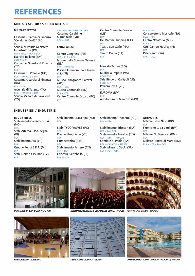
OSPEDALE DI SAN BONIFACIO (VR) TIBERIO PALACE, HOTEL & CONFERENCE CENTER - NAPOLI TEATRO SAN CARLO - NAPOLI
PALACILENTO - SALERNO SEDE FINMECCANICA - ROMA COMPLEJO HOTELERO TERRALTA - ALICANTE, SPAGNA
10
REFERENCES / RÉFÉRENCESSPAIN / ESPAGNE
Hospital de Alta Resolución de LojaHospital de Sagrado CorazónHospital Meixorio de VigoHospital de Enfermedades RarasHospital Benito MenniHospital XanitCentro Salud ManzanaresClinica Cefer
Rehabilitación oficinasMarcado MunicipalMuseo de CalahorraColegio CorazonistasEdificio Presidencia de laGeneralitatEdificio banco EspañaPolideportivo Parque Coim-braPolideportivo Siec
Faculdad de DerechoCentro Cultural BembriveEdificio Banco EspanaAyuntamientoComplejo Hotelero TerraltaHotel CarltonHotel Fuente Las PiedrasHotel San franciscoHotel El EspinarHotel Acosta
Hotel ParadorHotel Villa de BenaventeHotel MeridionalHotel BenidormHotel Balneario de OrioHotel AbandoJuzgados de Olot
ROMANIA / ROUMANIE
Rsi Electro Office BuildingOffice Building VitanOffice Building PiperaHotel FloreascaHotel RodnaHotel MaximNess Service - Dvd FactorySediu Galmopan
Sediu ArabesqueMoticica GrupMmm AutomotiveClimatherm CenterFrigoglass RomaniaTeo CenterAmma PrintRh Printing
ReamediaS.C.Delphi Romania S.R.L.Club OfficeCazinoAeroport SIBIUODS Business Service-DVDManoil MallBazin OLIMPIC
Sala SporturilorStabilusStella Building/ Jules VerneSempo SALoial
RUSSIA & REPUBLIC OF BELARUS / RUSSIE ET RÉPUBLIQUE DE BIÉLORUSSIE
RUSSIA / RUSSIECommercial Center “ARMA-DA”Moscow,RHV + VHF3“Kuba Commercial Center” Chelabinsk,RHV + FCSMedical Center of Tamo-grphicsChelabinsk,RGA + FCS + TOP FANCommercial center “Moscow prospect”,RGA + TOP FAN VB-M + VHF3, RHV“SBER-BANK Russia” Mo-scow office.Moscow,RGA + CMA + TOP FANBank “URASLIV” Moscow, RussiaRGA
Factory of Technical line pro-ductionFrazevo,RGAJEWELLER Department store Krasnodar,RGA + TOP FAN“Kvaevitskiy Museum” Kra-snodar,RGA + TOP FAN“Medical center branch” Mo-scow,RGA + FCPBusiness Hotel – Krassnodar,RGA + RLA“Historical – Archeological Museum-Felizina”FCS
REPUBLIC OF BELARUSRÉPUBLIQUE DE BIÉLORUSSIEThe Skating Ring “Ice Palace”Baranovichi,
Republican theoretical and practicalCenter “Mother and Child” Minsk,
9- th municipal clinical ho-spitalMinsk,
Research and Production Corporation “Integral” Minsk,
Business Center “BME BU-SINESSCENTER” Minsk,
Republican theoretical and practical
Center of oncology and me-dicalradiology Minsk,
BMW offices and service center Minsk,
Business Center “Europe” Minsk,
Unitary enterprise “Mucipal Bathhouses” Minsk,
BELMICROSYSTEMS RE-SEACH & DESIGN CENTER Minsk,
Organizations of the NASB Department of Chemical and Earth Sciences Minsk
TURKEY & REST OF THE WORLD / TURQUIE ET RESTE DU MONDE
TURKEY / TURQUIETurkmenistan ProjeleriBs PressCemdag PlastikPlasko PlastikIzmit Ticaret OdasiIzmit Skoda PlazaLady Diana HotelLidersanSamandira
Aksoy PlazaNizip Diyyaliliz MerkeziYasam HastanesiVan HastenesiCorlu Belediye BinasiGebze OteliKultur MerkeziUnsal Radyator Fabrikasi
REST OF THE WORLDRESTE DU MONDECentro Commerciale FC BIHDedinje 3.ObjekatNew Nork Shopping CenterSrbija Beograd, DedinjeCeek
11
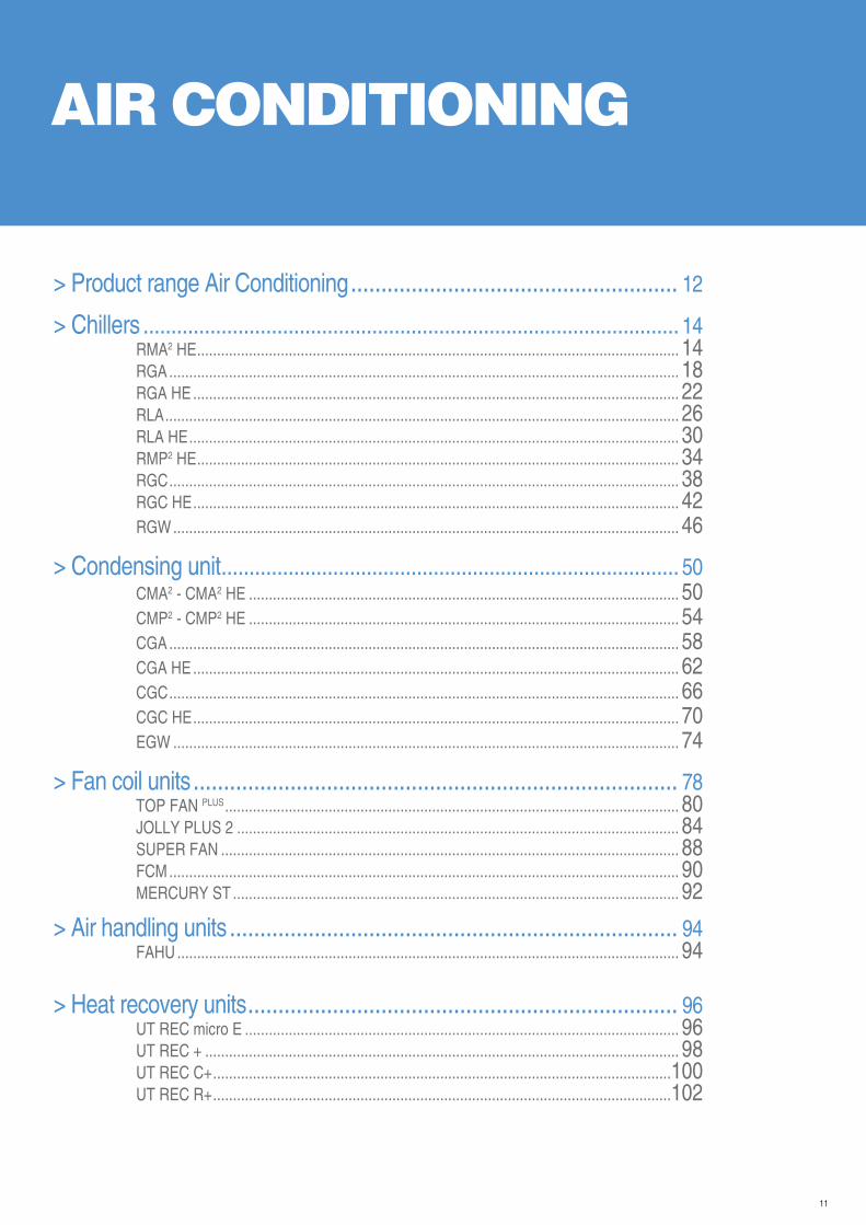
AIR CONDITIONING
> Product range Air Conditioning ...................................................... 12
> Chillers ................................................................................................ 14RMA2 HE ......................................................................................................................... 14RGA ................................................................................................................................ 18RGA HE .......................................................................................................................... 22RLA ................................................................................................................................. 26RLA HE ........................................................................................................................... 30RMP2 HE ......................................................................................................................... 34RGC ................................................................................................................................ 38RGC HE .......................................................................................................................... 42RGW ............................................................................................................................... 46
> Condensing unit .................................................................................. 50CMA2 - CMA2 HE ............................................................................................................ 50CMP2 - CMP2 HE ............................................................................................................ 54CGA ................................................................................................................................ 58CGA HE .......................................................................................................................... 62CGC ................................................................................................................................ 66CGC HE .......................................................................................................................... 70EGW ............................................................................................................................... 74
> Fan coil units ................................................................................ 78TOP FAN PLUS .................................................................................................................. 80JOLLY PLUS 2 ............................................................................................................... 84SUPER FAN ................................................................................................................... 88FCM ................................................................................................................................ 90MERCURY ST ................................................................................................................ 92
> Air handling units .......................................................................... 94FAHU .............................................................................................................................. 94
> Heat recovery units ....................................................................... 96UT REC micro E ............................................................................................................. 96UT REC + ....................................................................................................................... 98UT REC C+ ...................................................................................................................100UT REC R+ ...................................................................................................................102
12
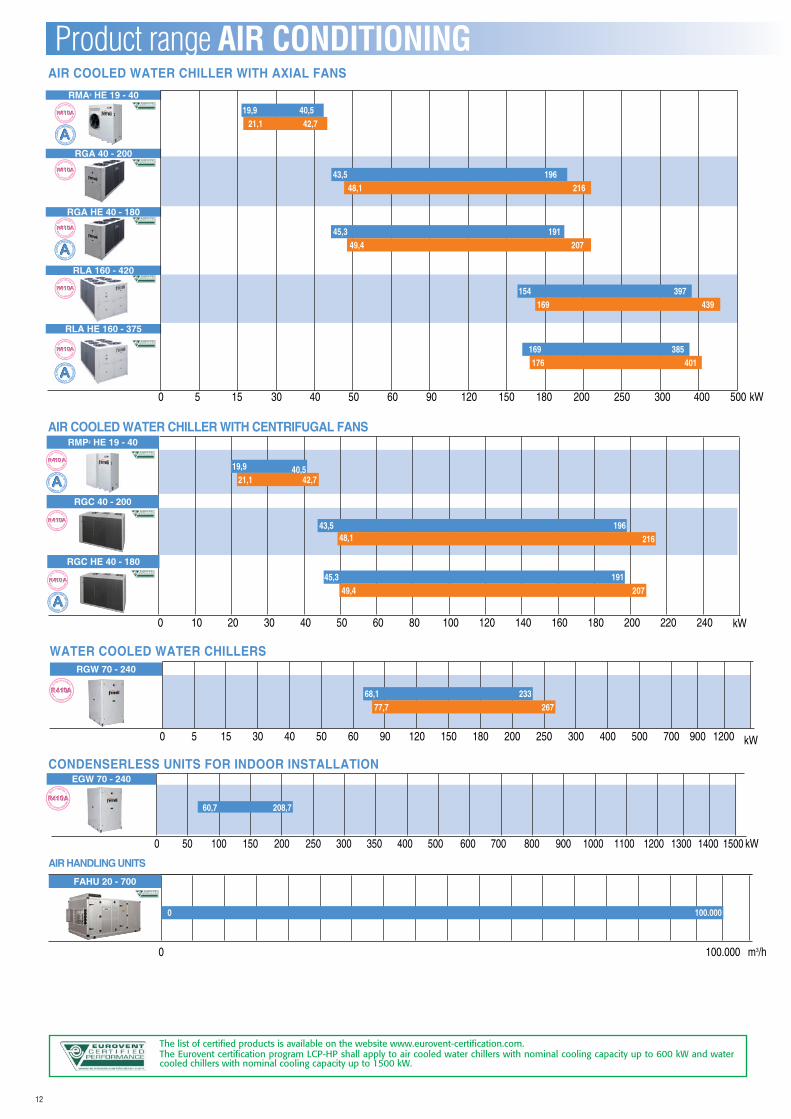
The list of certified products is available on the website www.eurovent-certification.com.The Eurovent certification program LCP-HP shall apply to air cooled water chillers with nominal cooling capacity up to 600 kW and water cooled chillers with nominal cooling capacity up to 1500 kW.
Product range AIR CONDITIONING
0 50 100 150 200 250 300 350 400 500 600 700 800 900 1000 1100 1200 1300 1400 1500 kW
EGW 70 - 240
60,7 208,7
CONDENSERLESS UNITS FOR INDOOR INSTALLATION
RGW 70 - 240
WATER COOLED WATER CHILLERS
0 5 15 30 40 50 60 90 120 150 180 200 250 300 400 500 700 900 1200 kW
68,1 23377,7 267
AIR COOLED WATER CHILLER WITH CENTRIFUGAL FANS
0 10 20 30 40 50 60 80 100 120 140 160 180 200 220 240
RMP2 HE 19 - 40
19,921,1 42,7
RGC 40 - 200
21643,5 196
48,1
RGC HE 40 - 180
45,3 19149,4 207
40,5
kW
RMA2 HE 19 - 40
RGA 40 - 200
RGA HE 40 - 180
RLA 160 - 420
RLA HE 160 - 375
AIR COOLED WATER CHILLER WITH AXIAL FANS
19,9 40,521,1 42,7
216196
48,143,5
45,3 19149,4 207
169154 397
439
176169 385
401
0 5 15 30 40 50 60 90 120 150 180 200 250 300 400 500 kW
FAHU 20 - 700
AIR HANDLING UNITS
0 100.000 m3/h
0 100.000
13
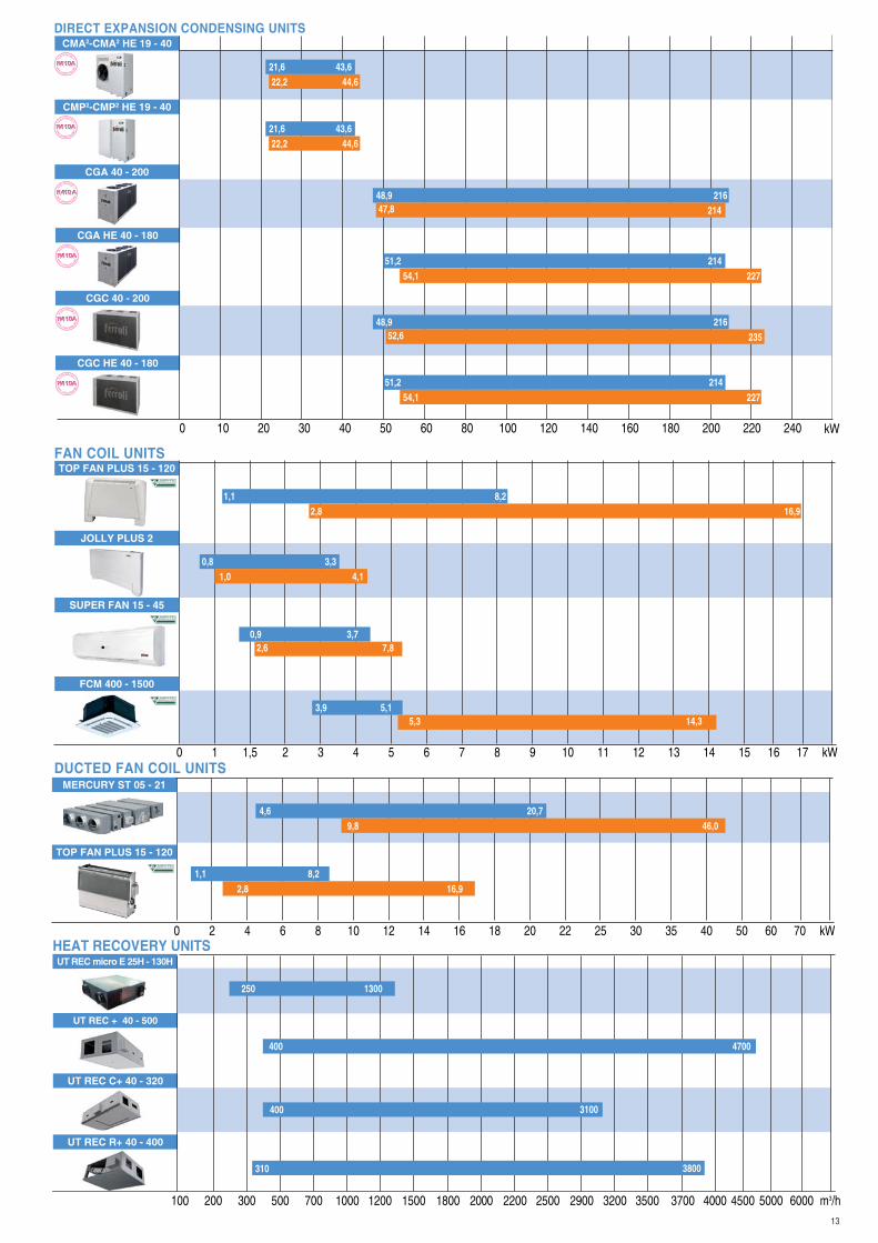
CMA2-CMA2 HE 19 - 40
CMP2-CMP2 HE 19 - 40
CGA 40 - 200
CGA HE 40 - 180
CGC 40 - 200
CGC HE 40 - 180
0 10 20 30 40 50 60 80 100 120 140 160 180 200 220 240 kW
51,2 21454,1 227
23548,9 216
52,6
51,2 21454,1 227
21448,9 21647,8
44,621,6 43,622,2
44,621,6 43,622,2
DIRECT EXPANSION CONDENSING UNITS
TOP FAN PLUS 15 - 120
JOLLY PLUS 2
FAN COIL UNITS
kW0 1 1,5 2 3 4 5 6 7 8 9 10 11 12 13 14 15 16 17
1,1 8,22,8 16,9
0,8 3,31,0 4,1
0,9 3,72,6 7,8
3,9 5,15,3 14,3
SUPER FAN 15 - 45
FCM 400 - 1500
MERCURY ST 05 - 21
TOP FAN PLUS 15 - 120
DUCTED FAN COIL UNITS
kW0 2 4 6 8 10 12 14 16 18 20 22 25 30 35 40 50 60 70
4,6 20,79,8 46,0
1,1 8,22,8 16,9
UT REC micro E 25H - 130HHEAT RECOVERY UNITS
UT REC + 40 - 500
UT REC C+ 40 - 320
UT REC R+ 40 - 400
m3/h100 200 300 500 700 1000 1200 1500 1800 2000 2200 2500 2900 3200 3500 3700 4000 4500 5000 6000
400
250
4700
1300
400
310
3100
3800
14
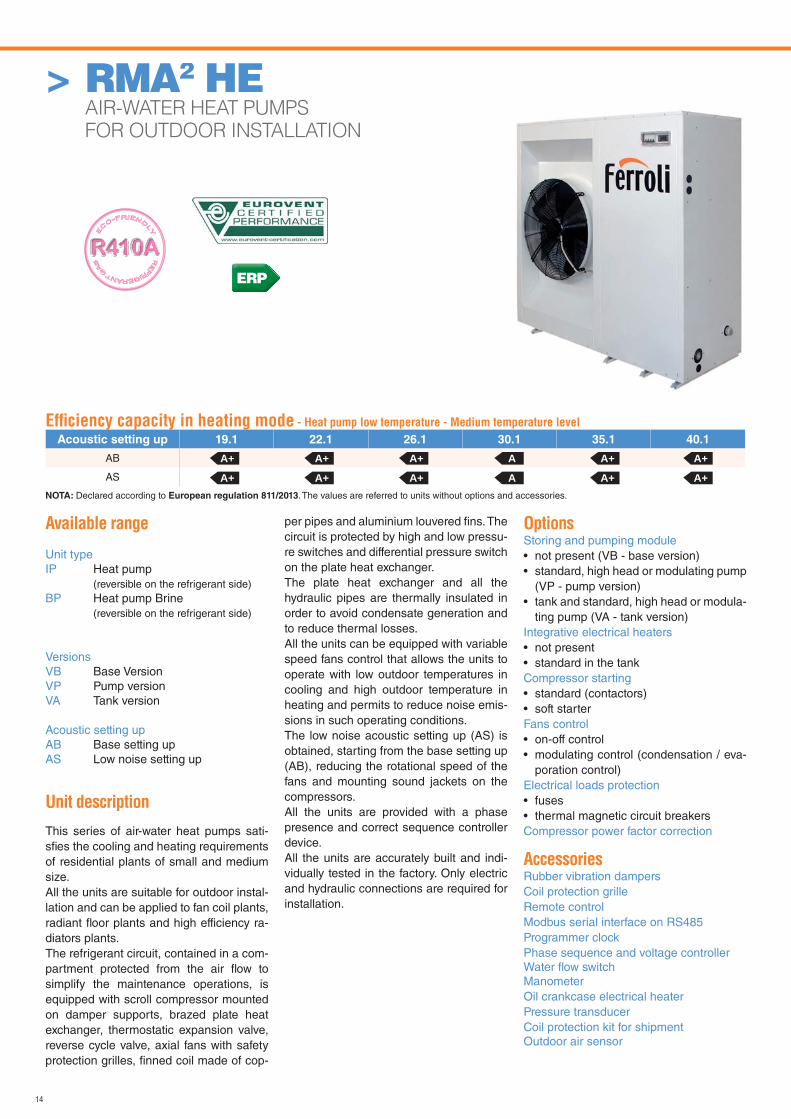
Available range
Unit typeIP Heat pump (reversible on the refrigerant side)BP Heat pump Brine (reversible on the refrigerant side)
VersionsVB Base VersionVP Pump versionVA Tank version
Acoustic setting upAB Base setting upAS Low noise setting up
Unit description
This series of air-water heat pumps sati-sfi es the cooling and heating requirements of residential plants of small and medium size.All the units are suitable for outdoor instal-lation and can be applied to fan coil plants, radiant fl oor plants and high efficiency ra-diators plants.The refrigerant circuit, contained in a com-partment protected from the air fl ow to simplify the maintenance operations, is equipped with scroll compressor mounted on damper supports, brazed plate heat exchanger, thermostatic expansion valve, reverse cycle valve, axial fans with safety protection grilles, fi nned coil made of cop-
per pipes and aluminium louvered fi ns. The circuit is protected by high and low pressu-re switches and differential pressure switch on the plate heat exchanger.The plate heat exchanger and all the hydraulic pipes are thermally insulated in order to avoid condensate generation and to reduce thermal losses.All the units can be equipped with variable speed fans control that allows the units to operate with low outdoor temperatures in cooling and high outdoor temperature in heating and permits to reduce noise emis-sions in such operating conditions.The low noise acoustic setting up (AS) is obtained, starting from the base setting up (AB), reducing the rotational speed of the fans and mounting sound jackets on the compressors.All the units are provided with a phase presence and correct sequence controller device.All the units are accurately built and indi-vidually tested in the factory. Only electric and hydraulic connections are required for installation.
OptionsStoring and pumping module • not present (VB - base version)• standard, high head or modulating pump
(VP - pump version)• tank and standard, high head or modula-
ting pump (VA - tank version)Integrative electrical heaters• not present• standard in the tankCompressor starting• standard (contactors)• soft starterFans control• on-off control• modulating control (condensation / eva-
poration control)Electrical loads protection• fuses• thermal magnetic circuit breakersCompressor power factor correction
AccessoriesRubber vibration dampersCoil protection grilleRemote controlModbus serial interface on RS485Programmer clockPhase sequence and voltage controllerWater fl ow switchManometerOil crankcase electrical heaterPressure transducerCoil protection kit for shipmentOutdoor air sensor
> RMA2 HE AIR-WATER HEAT PUMPS
FOR OUTDOOR INSTALLATION
Effi ciency capacity in heating mode - Heat pump low temperature - Medium temperature level
Acoustic setting up 19.1 22.1 26.1 30.1 35.1 40.1
AB
AS
A+ A+ A+ A A+ A+
A+ A+ A+ A A+ A+NOTA: Declared according to European regulation 811/2013. The values are referred to units without options and accessories.
ERP
15
> RMA2 HE AIR-WATER HEAT PUMPS FOR OUTDOOR INSTALLATION
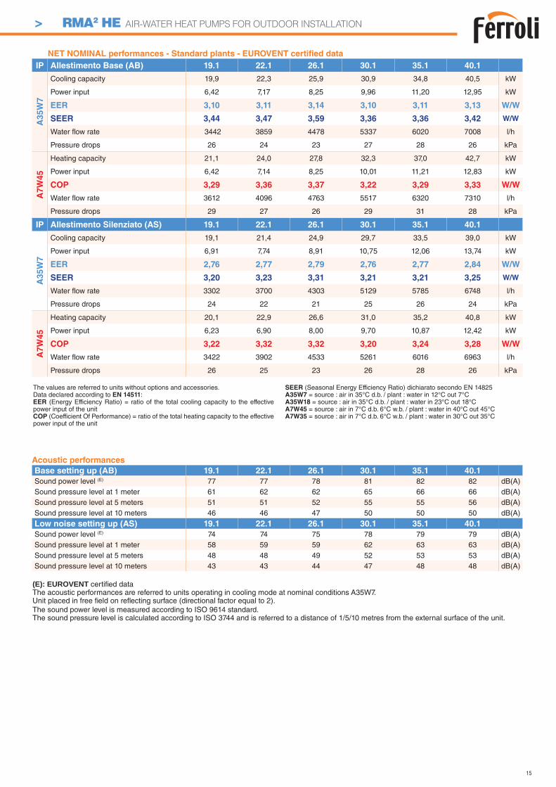
Acoustic performances
Base setting up (AB) 19.1 22.1 26.1 30.1 35.1 40.1
Sound power level (E) 77 77 78 81 82 82 dB(A)Sound pressure level at 1 meter 61 62 62 65 66 66 dB(A)Sound pressure level at 5 meters 51 51 52 55 55 56 dB(A)Sound pressure level at 10 meters 46 46 47 50 50 50 dB(A)
Low noise setting up (AS) 19.1 22.1 26.1 30.1 35.1 40.1
Sound power level (E) 74 74 75 78 79 79 dB(A)Sound pressure level at 1 meter 58 59 59 62 63 63 dB(A)Sound pressure level at 5 meters 48 48 49 52 53 53 dB(A)Sound pressure level at 10 meters 43 43 44 47 48 48 dB(A)
(E): EUROVENT certifi ed data The acoustic performances are referred to units operating in cooling mode at nominal conditions A35W7.Unit placed in free fi eld on refl ecting surface (directional factor equal to 2).The sound power level is measured according to ISO 9614 standard.The sound pressure level is calculated according to ISO 3744 and is referred to a distance of 1/5/10 metres from the external surface of the unit.
The values are referred to units without options and accessories. Data declared according to EN 14511:EER (Energy Efficiency Ratio) = ratio of the total cooling capacity to the effective power input of the unitCOP (Coefficient Of Performance) = ratio of the total heating capacity to the effective power input of the unit
SEER (Seasonal Energy Efficiency Ratio) dichiarato secondo EN 14825A35W7 = source : air in 35°C d.b. / plant : water in 12°C out 7°CA35W18 = source : air in 35°C d.b. / plant : water in 23°C out 18°CA7W45 = source : air in 7°C d.b. 6°C w.b. / plant : water in 40°C out 45°CA7W35 = source : air in 7°C d.b. 6°C w.b. / plant : water in 30°C out 35°C
NET NOMINAL performances - Standard plants - EUROVENT certifi ed data
IP Allestimento Base (AB) 19.1 22.1 26.1 30.1 35.1 40.1
A3
5W
7
Cooling capacity 19,9 22,3 25,9 30,9 34,8 40,5 kW
Power input 6,42 7,17 8,25 9,96 11,20 12,95 kW
EER 3,10 3,11 3,14 3,10 3,11 3,13 W/W
SEER 3,44 3,47 3,59 3,36 3,36 3,42 W/W
Water fl ow rate 3442 3859 4478 5337 6020 7008 l/h
Pressure drops 26 24 23 27 28 26 kPa
A7
W4
5
Heating capacity 21,1 24,0 27,8 32,3 37,0 42,7 kW
Power input 6,42 7,14 8,25 10,01 11,21 12,83 kW
COP 3,29 3,36 3,37 3,22 3,29 3,33 W/W
Water fl ow rate 3612 4096 4763 5517 6320 7310 l/h
Pressure drops 29 27 26 29 31 28 kPa
IP Allestimento Silenziato (AS) 19.1 22.1 26.1 30.1 35.1 40.1
A3
5W
7
Cooling capacity 19,1 21,4 24,9 29,7 33,5 39,0 kW
Power input 6,91 7,74 8,91 10,75 12,06 13,74 kW
EER 2,76 2,77 2,79 2,76 2,77 2,84 W/W
SEER 3,20 3,23 3,31 3,21 3,21 3,25 W/W
Water fl ow rate 3302 3700 4303 5129 5785 6748 l/h
Pressure drops 24 22 21 25 26 24 kPa
A7W
45
Heating capacity 20,1 22,9 26,6 31,0 35,2 40,8 kW
Power input 6,23 6,90 8,00 9,70 10,87 12,42 kW
COP 3,22 3,32 3,32 3,20 3,24 3,28 W/W
Water fl ow rate 3422 3902 4533 5261 6016 6963 l/h
Pressure drops 26 25 23 26 28 26 kPa
16
> RMA2 HE AIR-WATER HEAT PUMPS FOR OUTDOOR INSTALLATION
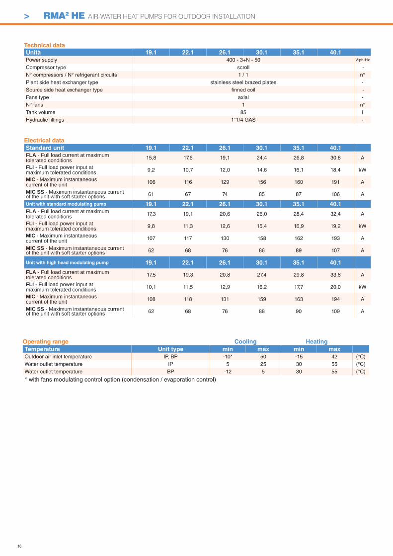
Technical data
Unità 19.1 22.1 26.1 30.1 35.1 40.1
Power supply 400 - 3+N - 50 V-ph-Hz
Compressor type scroll -N° compressors / N° refrigerant circuits 1 / 1 n°Plant side heat exchanger type stainless steel brazed plates -Source side heat exchanger type fi nned coil -Fans type axial -N° fans 1 n°Tank volume 85 lHydraulic fi ttings 1”1/4 GAS -
* with fans modulating control option (condensation / evaporation control)
Electrical data
Standard unit 19.1 22.1 26.1 30.1 35.1 40.1
FLA - Full load current at maximum tolerated conditions 15,8 17,6 19,1 24,4 26,8 30,8 A
FLI - Full load power input at maximum tolerated conditions 9,2 10,7 12,0 14,6 16,1 18,4 kW
MIC - Maximum instantaneous current of the unit 106 116 129 156 160 191 A
MIC SS - Maximum instantaneous current of the unit with soft starter options 61 67 74 85 87 106 A
Unit with standard modulating pump 19.1 22.1 26.1 30.1 35.1 40.1
FLA - Full load current at maximum tolerated conditions 17,3 19,1 20,6 26,0 28,4 32,4 A
FLI - Full load power input at maximum tolerated conditions 9,8 11,3 12,6 15,4 16,9 19,2 kW
MIC - Maximum instantaneous current of the unit 107 117 130 158 162 193 A
MIC SS - Maximum instantaneous current of the unit with soft starter options 62 68 76 86 89 107 A
Unit with high head modulating pump 19.1 22.1 26.1 30.1 35.1 40.1
FLA - Full load current at maximum tolerated conditions 17,5 19,3 20,8 27,4 29,8 33,8 A
FLI - Full load power input at maximum tolerated conditions 10,1 11,5 12,9 16,2 17,7 20,0 kW
MIC - Maximum instantaneous current of the unit 108 118 131 159 163 194 A
MIC SS - Maximum instantaneous current of the unit with soft starter options 62 68 76 88 90 109 A
Operating range Cooling Heating
Temperatura Unit type min max min max
Outdoor air inlet temperature IP, BP -10* 50 -15 42 (°C)Water outlet temperature IP 5 25 30 55 (°C)Water outlet temperature BP -12 5 30 55 (°C)
17
> RMA2 HE AIR-WATER HEAT PUMPS FOR OUTDOOR INSTALLATION
B
C
AW
L
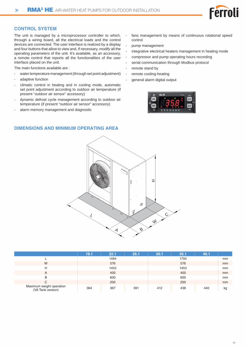
DIMENSIONS AND MINIMUM OPERATING AREA
19.1 22.1 26.1 30.1 35.1 40.1
L 1494 1704 mmW 576 576 mmH 1453 1453 mmA 400 400 mmB 600 600 mmC 200 200 mm
Maximum weight operation(VA Tank version) 364 367 391 412 438 440 kg
The unit is managed by a microprocessor controller to which, through a wiring board, all the electrical loads and the control devices are connected. The user interface is realized by a display and four buttons that allow to view and, if necessary, modify all the operating parameters of the unit. It’s available, as an accessory, a remote control that reports all the functionalities of the user interface placed on the unit.The main functions available are :- water temperature management (through set point adjustment)- adaptive function- climatic control in heating and in cooling mode, automatic
set point adjustment according to outdoor air temperature (if present “outdoor air sensor” accessory)
- dynamic defrost cycle management according to outdoor air temperature (if present “outdoor air sensor” accessory)
- alarm memory management and diagnostic
- fans management by means of continuous rotational speed control
- pump management- integrative electrical heaters management in heating mode - compressor and pump operating hours recording- serial communication through Modbus protocol- remote stand by- remote cooling-heating- general alarm digital output
CONTROL SYSTEM
18
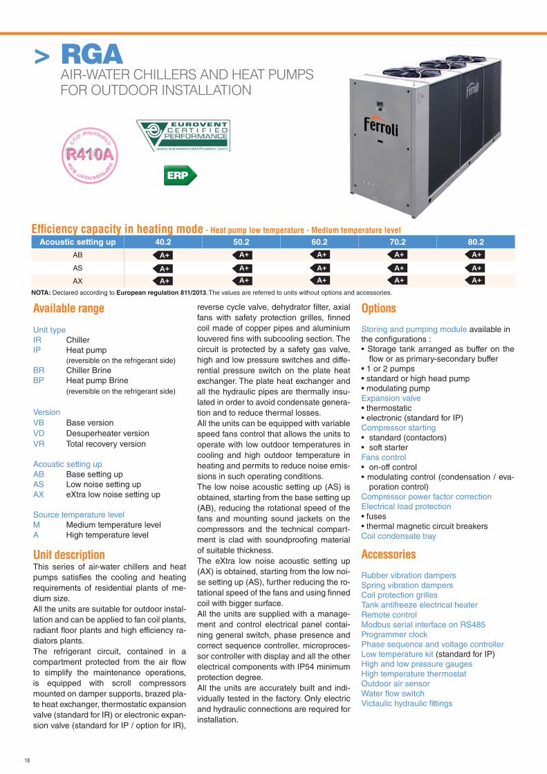
> RGA AIR-WATER CHILLERS AND HEAT PUMPS
FOR OUTDOOR INSTALLATION
Available range
Unit typeIR ChillerIP Heat pump
(reversible on the refrigerant side)BR Chiller BrineBP Heat pump Brine
(reversible on the refrigerant side)
VersionVB Base versionVD Desuperheater versionVR Total recovery version
Acoustic setting upAB Base setting upAS Low noise setting upAX eXtra low noise setting up
Source temperature levelM Medium temperature levelA High temperature level
Unit descriptionThis series of air-water chillers and heat pumps satisfi es the cooling and heating requirements of residential plants of me-dium size.All the units are suitable for outdoor instal-lation and can be applied to fan coil plants, radiant fl oor plants and high efficiency ra-diators plants.The refrigerant circuit, contained in a compartment protected from the air fl ow to simplify the maintenance operations, is equipped with scroll compressors mounted on damper supports, brazed pla-te heat exchanger, thermostatic expansion valve (standard for IR) or electronic expan-sion valve (standard for IP / option for IR),
reverse cycle valve, dehydrator fi lter, axial fans with safety protection grilles, fi nned coil made of copper pipes and aluminium louvered fi ns with subcooling section. The circuit is protected by a safety gas valve, high and low pressure switches and diffe-rential pressure switch on the plate heat exchanger. The plate heat exchanger and all the hydraulic pipes are thermally insu-lated in order to avoid condensate genera-tion and to reduce thermal losses.All the units can be equipped with variable speed fans control that allows the units to operate with low outdoor temperatures in cooling and high outdoor temperature in heating and permits to reduce noise emis-sions in such operating conditions.The low noise acoustic setting up (AS) is obtained, starting from the base setting up (AB), reducing the rotational speed of the fans and mounting sound jackets on the compressors and the technical compart-ment is clad with soundproofi ng material of suitable thickness.The eXtra low noise acoustic setting up (AX) is obtained, starting from the low noi-se setting up (AS), further reducing the ro-tational speed of the fans and using fi nned coil with bigger surface.All the units are supplied with a manage-ment and control electrical panel contai-ning general switch, phase presence and correct sequence controller, microproces-sor controller with display and all the other electrical components with IP54 minimum protection degree.All the units are accurately built and indi-vidually tested in the factory. Only electric and hydraulic connections are required for installation.
Options
Storing and pumping module available in the confi gurations :• Storage tank arranged as buffer on the
fl ow or as primary-secondary buffer• 1 or 2 pumps• standard or high head pump• modulating pumpExpansion valve • thermostatic• electronic (standard for IP)Compressor starting• standard (contactors)• soft starterFans control• on-off control• modulating control (condensation / eva-
poration control)Compressor power factor correction Electrical load protection• fuses• thermal magnetic circuit breakersCoil condensate tray
Accessories
Rubber vibration dampersSpring vibration dampersCoil protection grillesTank antifreeze electrical heaterRemote controlModbus serial interface on RS485Programmer clockPhase sequence and voltage controllerLow temperature kit (standard for IP)High and low pressure gaugesHigh temperature thermostatOutdoor air sensorWater fl ow switchVictaulic hydraulic fi ttings
Effi ciency capacity in heating mode - Heat pump low temperature - Medium temperature level
Acoustic setting up 40.2 50.2 60.2 70.2 80.2
AB
AS
AX
A+ A+ A+ A+ A+
A+A+
A+A+
A+A+
A+A+
A+A+
NOTA: Declared according to European regulation 811/2013. The values are referred to units without options and accessories.
ERP
19
> RGA AIR-WATER CHILLERS AND HEAT PUMPS FOR OUTDOOR INSTALLATION
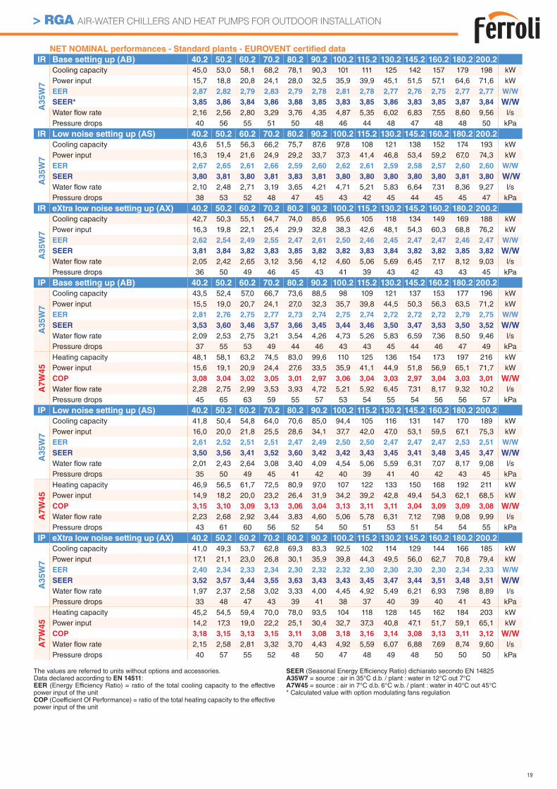
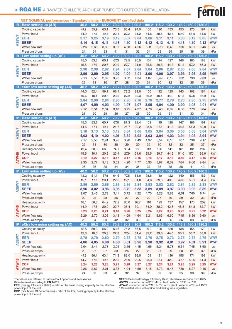
NET NOMINAL performances - Standard plants - EUROVENT certifi ed data
IR Base setting up (AB) 40.2 50.2 60.2 70.2 80.2 90.2 100.2 115.2 130.2 145.2 160.2 180.2 200.2
A3
5W
7
Cooling capacity 45,0 53,0 58,1 68,2 78,1 90,3 101 111 125 142 157 179 198 kWPower input 15,7 18,8 20,8 24,1 28,0 32,5 35,9 39,9 45,1 51,5 57,1 64,6 71,6 kWEER 2,87 2,82 2,79 2,83 2,79 2,78 2,81 2,78 2,77 2,76 2,75 2,77 2,77 W/W
SEER* 3,85 3,86 3,84 3,86 3,88 3,85 3,83 3,85 3,86 3,83 3,85 3,87 3,84 W/W
Water fl ow rate 2,16 2,56 2,80 3,29 3,76 4,35 4,87 5,35 6,02 6,83 7,55 8,60 9,56 l/sPressure drops 40 56 55 51 50 48 46 44 48 47 48 48 50 kPa
IR Low noise setting up (AS) 40.2 50.2 60.2 70.2 80.2 90.2 100.2 115.2 130.2 145.2 160.2 180.2 200.2
A3
5W
7
Cooling capacity 43,6 51,5 56,3 66,2 75,7 87,6 97,8 108 121 138 152 174 193 kWPower input 16,3 19,4 21,6 24,9 29,2 33,7 37,3 41,4 46,8 53,4 59,2 67,0 74,3 kWEER 2,67 2,65 2,61 2,66 2,59 2,60 2,62 2,61 2,59 2,58 2,57 2,60 2,60 W/W
SEER 3,80 3,81 3,80 3,81 3,83 3,81 3,80 3,80 3,80 3,80 3,80 3,81 3,80 W/W
Water fl ow rate 2,10 2,48 2,71 3,19 3,65 4,21 4,71 5,21 5,83 6,64 7,31 8,36 9,27 l/sPressure drops 38 53 52 48 47 45 43 42 45 44 45 45 47 kPa
IR eXtra low noise setting up (AX) 40.2 50.2 60.2 70.2 80.2 90.2 100.2 115.2 130.2 145.2 160.2 180.2 200.2
A3
5W
7
Cooling capacity 42,7 50,3 55,1 64,7 74,0 85,6 95,6 105 118 134 149 169 188 kWPower input 16,3 19,8 22,1 25,4 29,9 32,8 38,3 42,6 48,1 54,3 60,3 68,8 76,2 kWEER 2,62 2,54 2,49 2,55 2,47 2,61 2,50 2,46 2,45 2,47 2,47 2,46 2,47 W/W
SEER 3,81 3,84 3,82 3,83 3,85 3,82 3,82 3,83 3,84 3,82 3,82 3,85 3,82 W/W
Water fl ow rate 2,05 2,42 2,65 3,12 3,56 4,12 4,60 5,06 5,69 6,45 7,17 8,12 9,03 l/sPressure drops 36 50 49 46 45 43 41 39 43 42 43 43 45 kPa
IP Base setting up (AB) 40.2 50.2 60.2 70.2 80.2 90.2 100.2 115.2 130.2 145.2 160.2 180.2 200.2
A35W
7
Cooling capacity 43,5 52,4 57,0 66,7 73,6 88,5 98 109 121 137 153 177 196 kWPower input 15,5 19,0 20,7 24,1 27,0 32,3 35,7 39,8 44,5 50,3 56,3 63,5 71,2 kWEER 2,81 2,76 2,75 2,77 2,73 2,74 2,75 2,74 2,72 2,72 2,72 2,79 2,75 W/W
SEER 3,53 3,60 3,46 3,57 3,66 3,45 3,44 3,46 3,50 3,47 3,53 3,50 3,52 W/W
Water fl ow rate 2,09 2,53 2,75 3,21 3,54 4,26 4,73 5,26 5,83 6,59 7,36 8,50 9,46 l/sPressure drops 37 55 53 49 44 46 43 43 45 44 46 47 49 kPa
A7W
45
Heating capacity 48,1 58,1 63,2 74,5 83,0 99,6 110 125 136 154 173 197 216 kWPower input 15,6 19,1 20,9 24,4 27,6 33,5 35,9 41,1 44,9 51,8 56,9 65,1 71,7 kWCOP 3,08 3,04 3,02 3,05 3,01 2,97 3,06 3,04 3,03 2,97 3,04 3,03 3,01 W/W
Water fl ow rate 2,28 2,75 2,99 3,53 3,93 4,72 5,21 5,92 6,45 7,31 8,17 9,32 10,2 l/sPressure drops 45 65 63 59 55 57 53 54 55 54 56 56 57 kPa
IP Low noise setting up (AS) 40.2 50.2 60.2 70.2 80.2 90.2 100.2 115.2 130.2 145.2 160.2 180.2 200.2
A35W
7
Cooling capacity 41,8 50,4 54,8 64,0 70,6 85,0 94,4 105 116 131 147 170 189 kWPower input 16,0 20,0 21,8 25,5 28,6 34,1 37,7 42,0 47,0 53,1 59,5 67,1 75,3 kWEER 2,61 2,52 2,51 2,51 2,47 2,49 2,50 2,50 2,47 2,47 2,47 2,53 2,51 W/W
SEER 3,50 3,56 3,41 3,52 3,60 3,42 3,42 3,43 3,45 3,41 3,48 3,45 3,47 W/W
Water fl ow rate 2,01 2,43 2,64 3,08 3,40 4,09 4,54 5,06 5,59 6,31 7,07 8,17 9,08 l/sPressure drops 35 50 49 45 41 42 40 39 41 40 42 43 45 kPa
A7W
45
Heating capacity 46,9 56,5 61,7 72,5 80,9 97,0 107 122 133 150 168 192 211 kWPower input 14,9 18,2 20,0 23,2 26,4 31,9 34,2 39,2 42,8 49,4 54,3 62,1 68,5 kWCOP 3,15 3,10 3,09 3,13 3,06 3,04 3,13 3,11 3,11 3,04 3,09 3,09 3,08 W/W
Water fl ow rate 2,23 2,68 2,92 3,44 3,83 4,60 5,06 5,78 6,31 7,12 7,98 9,08 9,99 l/sPressure drops 43 61 60 56 52 54 50 51 53 51 54 54 55 kPa
IP eXtra low noise setting up (AX) 40.2 50.2 60.2 70.2 80.2 90.2 100.2 115.2 130.2 145.2 160.2 180.2 200.2
A35W
7
Cooling capacity 41,0 49,3 53,7 62,8 69,3 83,3 92,5 102 114 129 144 166 185 kWPower input 17,1 21,1 23,0 26,8 30,1 35,9 39,8 44,3 49,5 56,0 62,7 70,8 79,4 kWEER 2,40 2,34 2,33 2,34 2,30 2,32 2,32 2,30 2,30 2,30 2,30 2,34 2,33 W/W
SEER 3,52 3,57 3,44 3,55 3,63 3,43 3,43 3,45 3,47 3,44 3,51 3,48 3,51 W/W
Water fl ow rate 1,97 2,37 2,58 3,02 3,33 4,00 4,45 4,92 5,49 6,21 6,93 7,98 8,89 l/sPressure drops 33 48 47 43 39 41 38 37 40 39 40 41 43 kPa
A7W
45
Heating capacity 45,2 54,5 59,4 70,0 78,0 93,5 104 118 128 145 162 184 203 kWPower input 14,2 17,3 19,0 22,2 25,1 30,4 32,7 37,3 40,8 47,1 51,7 59,1 65,1 kWCOP 3,18 3,15 3,13 3,15 3,11 3,08 3,18 3,16 3,14 3,08 3,13 3,11 3,12 W/W
Water fl ow rate 2,15 2,58 2,81 3,32 3,70 4,43 4,92 5,59 6,07 6,88 7,69 8,74 9,60 l/sPressure drops 40 57 55 52 48 50 47 48 49 48 50 50 50 kPa
The values are referred to units without options and accessories. Data declared according to EN 14511:EER (Energy Efficiency Ratio) = ratio of the total cooling capacity to the effective power input of the unitCOP (Coefficient Of Performance) = ratio of the total heating capacity to the effective power input of the unit
SEER (Seasonal Energy Efficiency Ratio) dichiarato secondo EN 14825A35W7 = source : air in 35°C d.b. / plant : water in 12°C out 7°CA7W45 = source : air in 7°C d.b. 6°C w.b. / plant : water in 40°C out 45°C* Calculated value with option modulating fans regulation
20
> RGA AIR-WATER CHILLERS AND HEAT PUMPS FOR OUTDOOR INSTALLATION
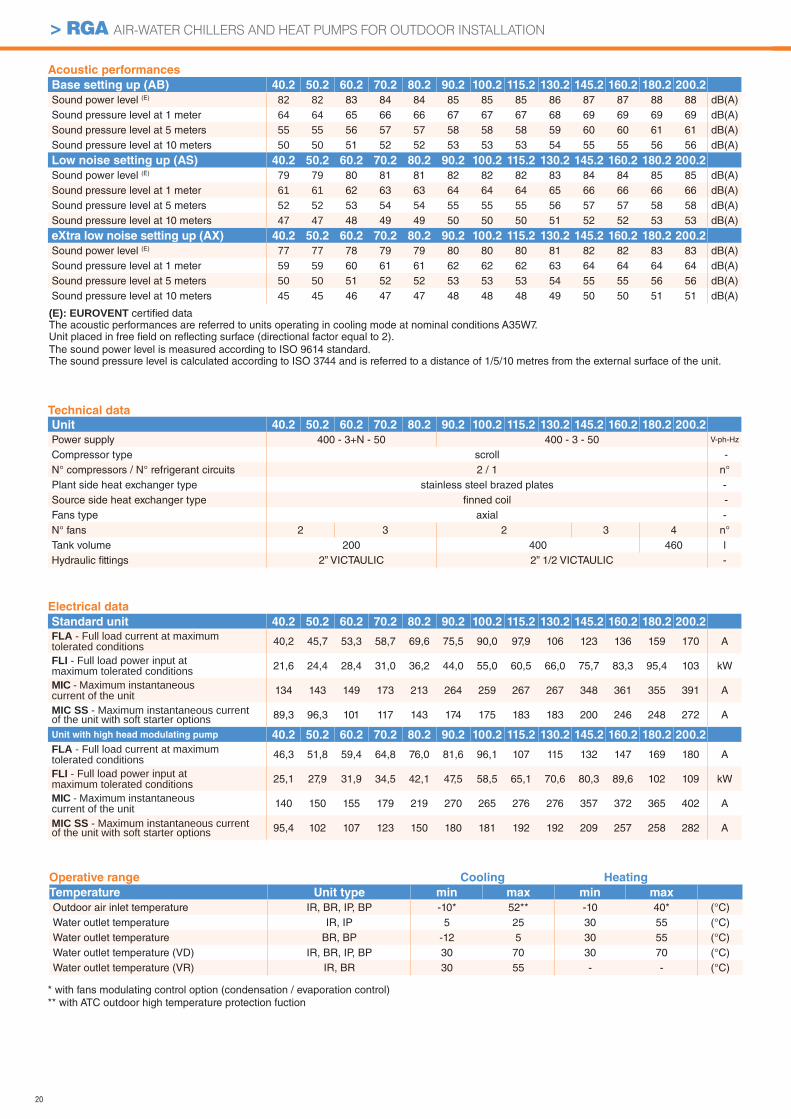
Acoustic performances
Base setting up (AB) 40.2 50.2 60.2 70.2 80.2 90.2 100.2 115.2 130.2 145.2 160.2 180.2 200.2
Sound power level (E) 82 82 83 84 84 85 85 85 86 87 87 88 88 dB(A)Sound pressure level at 1 meter 64 64 65 66 66 67 67 67 68 69 69 69 69 dB(A)Sound pressure level at 5 meters 55 55 56 57 57 58 58 58 59 60 60 61 61 dB(A)Sound pressure level at 10 meters 50 50 51 52 52 53 53 53 54 55 55 56 56 dB(A)
Low noise setting up (AS) 40.2 50.2 60.2 70.2 80.2 90.2 100.2 115.2 130.2 145.2 160.2 180.2 200.2
Sound power level (E) 79 79 80 81 81 82 82 82 83 84 84 85 85 dB(A)Sound pressure level at 1 meter 61 61 62 63 63 64 64 64 65 66 66 66 66 dB(A)Sound pressure level at 5 meters 52 52 53 54 54 55 55 55 56 57 57 58 58 dB(A)Sound pressure level at 10 meters 47 47 48 49 49 50 50 50 51 52 52 53 53 dB(A)
eXtra low noise setting up (AX) 40.2 50.2 60.2 70.2 80.2 90.2 100.2 115.2 130.2 145.2 160.2 180.2 200.2
Sound power level (E) 77 77 78 79 79 80 80 80 81 82 82 83 83 dB(A)Sound pressure level at 1 meter 59 59 60 61 61 62 62 62 63 64 64 64 64 dB(A)Sound pressure level at 5 meters 50 50 51 52 52 53 53 53 54 55 55 56 56 dB(A)Sound pressure level at 10 meters 45 45 46 47 47 48 48 48 49 50 50 51 51 dB(A)
Electrical data
Standard unit 40.2 50.2 60.2 70.2 80.2 90.2 100.2 115.2 130.2 145.2 160.2 180.2 200.2
FLA - Full load current at maximum tolerated conditions 40,2 45,7 53,3 58,7 69,6 75,5 90,0 97,9 106 123 136 159 170 A
FLI - Full load power input at maximum tolerated conditions 21,6 24,4 28,4 31,0 36,2 44,0 55,0 60,5 66,0 75,7 83,3 95,4 103 kW
MIC - Maximum instantaneous current of the unit 134 143 149 173 213 264 259 267 267 348 361 355 391 A
MIC SS - Maximum instantaneous current of the unit with soft starter options 89,3 96,3 101 117 143 174 175 183 183 200 246 248 272 A
Unit with high head modulating pump 40.2 50.2 60.2 70.2 80.2 90.2 100.2 115.2 130.2 145.2 160.2 180.2 200.2
FLA - Full load current at maximum tolerated conditions 46,3 51,8 59,4 64,8 76,0 81,6 96,1 107 115 132 147 169 180 A
FLI - Full load power input at maximum tolerated conditions 25,1 27,9 31,9 34,5 42,1 47,5 58,5 65,1 70,6 80,3 89,6 102 109 kW
MIC - Maximum instantaneous current of the unit 140 150 155 179 219 270 265 276 276 357 372 365 402 A
MIC SS - Maximum instantaneous current of the unit with soft starter options 95,4 102 107 123 150 180 181 192 192 209 257 258 282 A
(E): EUROVENT certifi ed data The acoustic performances are referred to units operating in cooling mode at nominal conditions A35W7.Unit placed in free fi eld on refl ecting surface (directional factor equal to 2).The sound power level is measured according to ISO 9614 standard.The sound pressure level is calculated according to ISO 3744 and is referred to a distance of 1/5/10 metres from the external surface of the unit.
Operative range Cooling Heating
Temperature Unit type min max min max
Outdoor air inlet temperature IR, BR, IP, BP -10* 52** -10 40* (°C)Water outlet temperature IR, IP 5 25 30 55 (°C)Water outlet temperature BR, BP -12 5 30 55 (°C)Water outlet temperature (VD) IR, BR, IP, BP 30 70 30 70 (°C)Water outlet temperature (VR) IR, BR 30 55 - - (°C)
Technical data
Unit 40.2 50.2 60.2 70.2 80.2 90.2 100.2 115.2 130.2 145.2 160.2 180.2 200.2
Power supply 400 - 3+N - 50 400 - 3 - 50 V-ph-Hz
Compressor type scroll -N° compressors / N° refrigerant circuits 2 / 1 n°Plant side heat exchanger type stainless steel brazed plates -Source side heat exchanger type fi nned coil -Fans type axial -N° fans 2 3 2 3 4 n°Tank volume 200 400 460 lHydraulic fi ttings 2” VICTAULIC 2” 1/2 VICTAULIC -
* with fans modulating control option (condensation / evaporation control)** with ATC outdoor high temperature protection fuction
21
> RGA AIR-WATER CHILLERS AND HEAT PUMPS FOR OUTDOOR INSTALLATION
1000
L
W
A
H
1000
1000
40.2 50.2 60.2 70.2 80.2 90.2 100.2 115.2 130.2 145.2 160.2 180.2 200.2
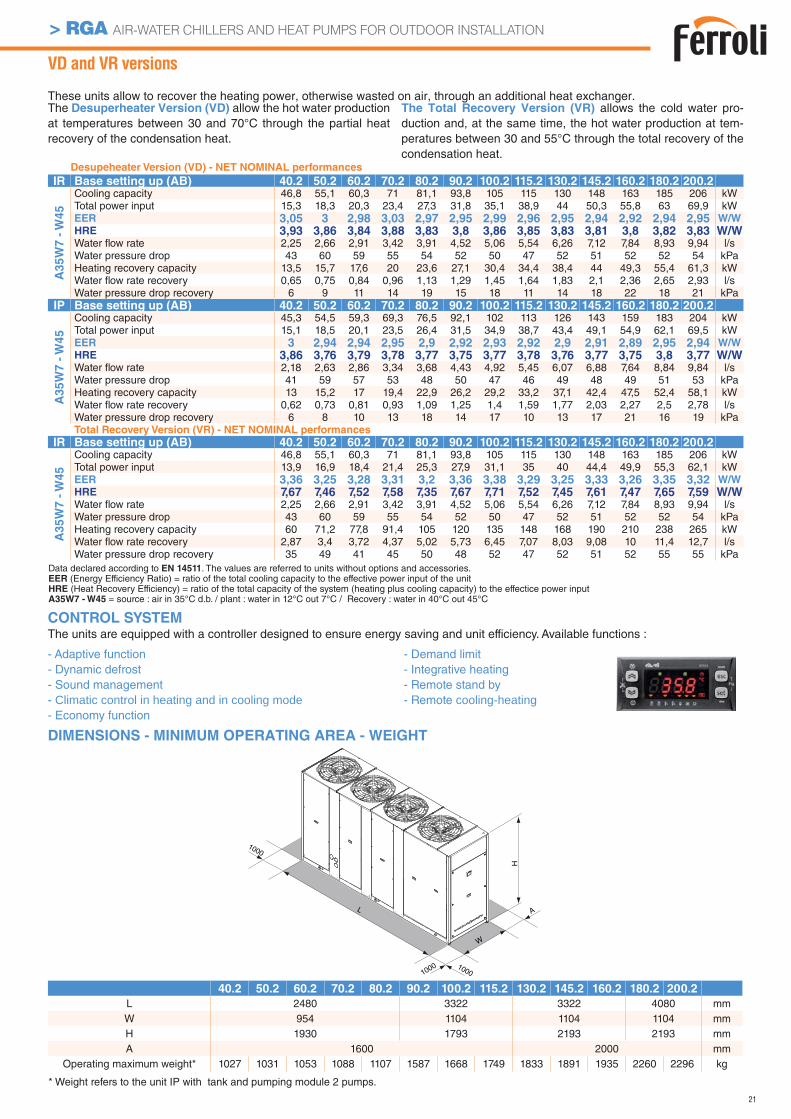
L 2480 3322 3322 4080 mmW 954 1104 1104 1104 mmH 1930 1793 2193 2193 mmA 1600 2000 mm
Operating maximum weight* 1027 1031 1053 1088 1107 1587 1668 1749 1833 1891 1935 2260 2296 kg
VD and VR versions
These units allow to recover the heating power, otherwise wasted on air, through an additional heat exchanger.The Desuperheater Version (VD) allow the hot water production at temperatures between 30 and 70°C through the partial heat recovery of the condensation heat.
The Total Recovery Version (VR) allows the cold water pro-duction and, at the same time, the hot water production at tem-peratures between 30 and 55°C through the total recovery of the condensation heat.
DIMENSIONS - MINIMUM OPERATING AREA - WEIGHT
Desupeheater Version (VD) - NET NOMINAL performances
IR Base setting up (AB) 40.2 50.2 60.2 70.2 80.2 90.2 100.2 115.2 130.2 145.2 160.2 180.2 200.2
A3
5W
7 -
W4
5
Cooling capacity 46,8 55,1 60,3 71 81,1 93,8 105 115 130 148 163 185 206 kWTotal power input 15,3 18,3 20,3 23,4 27,3 31,8 35,1 38,9 44 50,3 55,8 63 69,9 kWEER 3,05 3 2,98 3,03 2,97 2,95 2,99 2,96 2,95 2,94 2,92 2,94 2,95 W/W
HRE 3,93 3,86 3,84 3,88 3,83 3,8 3,86 3,85 3,83 3,81 3,8 3,82 3,83 W/WWater fl ow rate 2,25 2,66 2,91 3,42 3,91 4,52 5,06 5,54 6,26 7,12 7,84 8,93 9,94 l/sWater pressure drop 43 60 59 55 54 52 50 47 52 51 52 52 54 kPaHeating recovery capacity 13,5 15,7 17,6 20 23,6 27,1 30,4 34,4 38,4 44 49,3 55,4 61,3 kWWater fl ow rate recovery 0,65 0,75 0,84 0,96 1,13 1,29 1,45 1,64 1,83 2,1 2,36 2,65 2,93 l/sWater pressure drop recovery 6 9 11 14 19 15 18 11 14 18 22 18 21 kPa
IP Base setting up (AB) 40.2 50.2 60.2 70.2 80.2 90.2 100.2 115.2 130.2 145.2 160.2 180.2 200.2
A3
5W
7 -
W4
5
Cooling capacity 45,3 54,5 59,3 69,3 76,5 92,1 102 113 126 143 159 183 204 kWTotal power input 15,1 18,5 20,1 23,5 26,4 31,5 34,9 38,7 43,4 49,1 54,9 62,1 69,5 kWEER 3 2,94 2,94 2,95 2,9 2,92 2,93 2,92 2,9 2,91 2,89 2,95 2,94 W/W
HRE 3,86 3,76 3,79 3,78 3,77 3,75 3,77 3,78 3,76 3,77 3,75 3,8 3,77 W/WWater fl ow rate 2,18 2,63 2,86 3,34 3,68 4,43 4,92 5,45 6,07 6,88 7,64 8,84 9,84 l/sWater pressure drop 41 59 57 53 48 50 47 46 49 48 49 51 53 kPaHeating recovery capacity 13 15,2 17 19,4 22,9 26,2 29,2 33,2 37,1 42,4 47,5 52,4 58,1 kWWater fl ow rate recovery 0,62 0,73 0,81 0,93 1,09 1,25 1,4 1,59 1,77 2,03 2,27 2,5 2,78 l/sWater pressure drop recovery 6 8 10 13 18 14 17 10 13 17 21 16 19 kPaTotal Recovery Version (VR) - NET NOMINAL performances
IR Base setting up (AB) 40.2 50.2 60.2 70.2 80.2 90.2 100.2 115.2 130.2 145.2 160.2 180.2 200.2
A35W
7 -
W45
Cooling capacity 46,8 55,1 60,3 71 81,1 93,8 105 115 130 148 163 185 206 kWTotal power input 13,9 16,9 18,4 21,4 25,3 27,9 31,1 35 40 44,4 49,9 55,3 62,1 kWEER 3,36 3,25 3,28 3,31 3,2 3,36 3,38 3,29 3,25 3,33 3,26 3,35 3,32 W/W
HRE 7,67 7,46 7,52 7,58 7,35 7,67 7,71 7,52 7,45 7,61 7,47 7,65 7,59 W/WWater fl ow rate 2,25 2,66 2,91 3,42 3,91 4,52 5,06 5,54 6,26 7,12 7,84 8,93 9,94 l/sWater pressure drop 43 60 59 55 54 52 50 47 52 51 52 52 54 kPaHeating recovery capacity 60 71,2 77,8 91,4 105 120 135 148 168 190 210 238 265 kWWater fl ow rate recovery 2,87 3,4 3,72 4,37 5,02 5,73 6,45 7,07 8,03 9,08 10 11,4 12,7 l/sWater pressure drop recovery 35 49 41 45 50 48 52 47 52 51 52 55 55 kPa
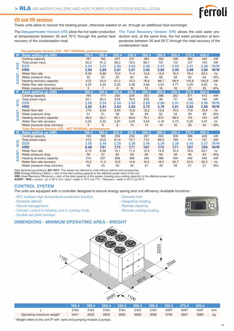
CONTROL SYSTEMThe units are equipped with a controller designed to ensure energy saving and unit efficiency. Available functions :
- Adaptive function- Dynamic defrost - Sound management - Climatic control in heating and in cooling mode- Economy function
- Demand limit- Integrative heating- Remote stand by- Remote cooling-heating
* Weight refers to the unit IP with tank and pumping module 2 pumps.
Data declared according to EN 14511. The values are referred to units without options and accessories.EER (Energy Efficiency Ratio) = ratio of the total cooling capacity to the effective power input of the unitHRE (Heat Recovery Efficiency) = ratio of the total capacity of the system (heating plus cooling capacity) to the effectice power inputA35W7 - W45 = source : air in 35°C d.b. / plant : water in 12°C out 7°C / Recovery : water in 40°C out 45°C
22
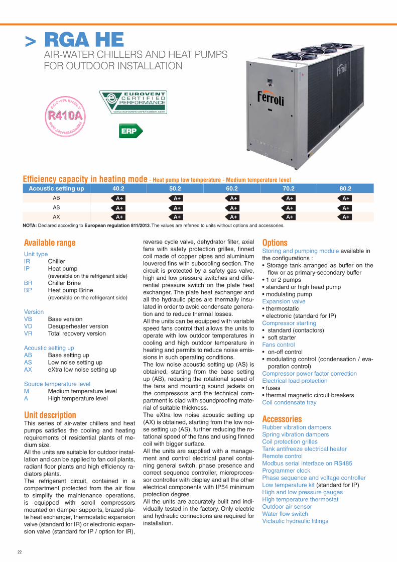
> RGA HE AIR-WATER CHILLERS AND HEAT PUMPS
FOR OUTDOOR INSTALLATION
Available range
Unit typeIR ChillerIP Heat pump
(reversible on the refrigerant side)BR Chiller BrineBP Heat pump Brine
(reversible on the refrigerant side)
VersionVB Base versionVD Desuperheater versionVR Total recovery version
Acoustic setting upAB Base setting upAS Low noise setting upAX eXtra low noise setting up
Source temperature levelM Medium temperature levelA High temperature level
Unit descriptionThis series of air-water chillers and heat pumps satisfi es the cooling and heating requirements of residential plants of me-dium size.All the units are suitable for outdoor instal-lation and can be applied to fan coil plants, radiant fl oor plants and high efficiency ra-diators plants.The refrigerant circuit, contained in a compartment protected from the air fl ow to simplify the maintenance operations, is equipped with scroll compressors mounted on damper supports, brazed pla-te heat exchanger, thermostatic expansion valve (standard for IR) or electronic expan-sion valve (standard for IP / option for IR),
reverse cycle valve, dehydrator fi lter, axial fans with safety protection grilles, fi nned coil made of copper pipes and aluminium louvered fi ns with subcooling section. The circuit is protected by a safety gas valve, high and low pressure switches and diffe-rential pressure switch on the plate heat exchanger. The plate heat exchanger and all the hydraulic pipes are thermally insu-lated in order to avoid condensate genera-tion and to reduce thermal losses.All the units can be equipped with variable speed fans control that allows the units to operate with low outdoor temperatures in cooling and high outdoor temperature in heating and permits to reduce noise emis-sions in such operating conditions.The low noise acoustic setting up (AS) is obtained, starting from the base setting up (AB), reducing the rotational speed of the fans and mounting sound jackets on the compressors and the technical com-partment is clad with soundproofi ng mate-rial of suitable thickness.The eXtra low noise acoustic setting up (AX) is obtained, starting from the low noi-se setting up (AS), further reducing the ro-tational speed of the fans and using fi nned coil with bigger surface.All the units are supplied with a manage-ment and control electrical panel contai-ning general switch, phase presence and correct sequence controller, microproces-sor controller with display and all the other electrical components with IP54 minimum protection degree.All the units are accurately built and indi-vidually tested in the factory. Only electric and hydraulic connections are required for installation.
OptionsStoring and pumping module available in the confi gurations :• Storage tank arranged as buffer on the
fl ow or as primary-secondary buffer• 1 or 2 pumps• standard or high head pump• modulating pumpExpansion valve • thermostatic• electronic (standard for IP)Compressor starting• standard (contactors)• soft starterFans control• on-off control• modulating control (condensation / eva-
poration control)Compressor power factor correction Electrical load protection• fuses• thermal magnetic circuit breakersCoil condensate tray
AccessoriesRubber vibration dampersSpring vibration dampersCoil protection grillesTank antifreeze electrical heaterRemote controlModbus serial interface on RS485Programmer clockPhase sequence and voltage controllerLow temperature kit (standard for IP)High and low pressure gaugesHigh temperature thermostatOutdoor air sensorWater fl ow switchVictaulic hydraulic fi ttings
Effi ciency capacity in heating mode - Heat pump low temperature - Medium temperature level
Acoustic setting up 40.2 50.2 60.2 70.2 80.2
AB
AS
AX
A+ A+ A+ A+ A+
A+A+
A+A+
A+A+
A+A+
A+A+
NOTA: Declared according to European regulation 811/2013. The values are referred to units without options and accessories.
ERP
23
> RGA HE AIR-WATER CHILLERS AND HEAT PUMPS FOR OUTDOOR INSTALLATION
NET NOMINAL performances - Standard plants - EUROVENT certifi ed data
IR Base setting up (AB) 40.2 50.2 60.2 70.2 80.2 90.2 100.2 115.2 130.2 145.2 160.2 180.2
A3
5W
7
Cooling capacity 47,2 55,9 63,1 70,5 83,4 94,9 106 120 133 153 173 197 kWPower input 14,9 17,2 19,8 22,1 27,2 31,2 34,6 38,6 42,7 50,0 55,5 64,6 kW
EER 3,17 3,25 3,19 3,19 3,07 3,04 3,06 3,11 3,11 3,06 3,12 3,05 W/W
SEER* 4,14 4,15 4,11 4,16 4,10 4,12 4,12 4,13 4,15 4,13 4,10 4,13 W/W
Water fl ow rate 2,26 2,69 3,03 3,39 4,00 4,56 5,11 5,78 6,40 7,36 8,31 9,46 l/sPressure drops 24 34 33 41 31 32 34 33 35 35 38 39 kPa
IR Low noise setting up (AS) 40.2 50.2 60.2 70.2 80.2 90.2 100.2 115.2 130.2 145.2 160.2 180.2
A3
5W
7
Cooling capacity 45,0 53,3 60,1 67,3 79,5 90,5 101 114 127 146 165 188 kWPower input 15,5 17,9 20,6 22,9 27,7 31,9 35,6 39,8 44,3 51,3 57,2 66,3 kW
EER 2,90 2,98 2,92 2,94 2,87 2,84 2,84 2,86 2,87 2,85 2,88 2,84 W/W
SEER 3,96 3,99 3,95 4,02 4,04 4,01 3,90 4,00 3,97 3,93 3,98 3,95 W/W
Water fl ow rate 2,16 2,56 2,89 3,23 3,82 4,34 4,87 5,49 6,12 7,02 7,93 9,03 l/sPressure drops 22 31 30 37 28 29 31 30 32 32 35 36 kPa
IR eXtra low noise setting up (AX) 40.2 50.2 60.2 70.2 80.2 90.2 100.2 115.2 130.2 145.2 160.2 180.2
A3
5W
7
Cooling capacity 44,3 52,4 59,1 66,1 78,2 89,0 100 112 125 143 162 184 kWPower input 15,6 18,1 20,8 23,2 27,9 32,3 36,0 40,4 44,9 51,8 57,8 66,9 kW
EER 2,84 2,90 2,84 2,85 2,80 2,76 2,76 2,77 2,78 2,76 2,80 2,75 W/W
SEER 4,07 4,09 4,03 4,09 4,07 4,07 3,95 4,04 4,00 3,99 4,03 4,01 W/W
Water fl ow rate 2,12 2,51 2,84 3,18 3,75 4,27 4,78 5,40 6,02 6,88 7,79 8,84 l/sPressure drops 21 30 29 36 27 28 30 29 31 31 33 34 kPa
IP Base setting up (AB) 40.2 50.2 60.2 70.2 80.2 90.2 100.2 115.2 130.2 145.2 160.2 180.2
A35W
7
Cooling capacity 45,3 53,6 60,7 67,8 81,3 92,4 103 115 128 147 166 191 kWPower input 14,6 17,1 19,4 21,7 26,7 30,2 33,8 37,8 41,8 48,5 54,3 62,8 kW
EER 3,10 3,13 3,13 3,12 3,04 3,06 3,05 3,04 3,06 3,03 3,06 3,04 W/W
SEER 4,03 4,10 4,02 4,01 3,84 3,92 3,93 3,94 4,03 3,94 4,03 3,94 W/W
Water fl ow rate 2,17 2,58 2,91 3,26 3,90 4,43 4,97 5,54 6,16 7,07 7,98 9,17 l/sPressure drops 22 31 30 38 29 30 32 30 32 32 35 37 kPa
A7W
45
Heating capacity 49,4 58,3 66,0 74,1 88,4 100 113 126 141 161 181 207 kWPower input 15,5 18,1 20,8 23,4 27,9 31,6 35,5 39,7 44,3 51,0 57,1 65,6 kWCOP 3,19 3,22 3,17 3,17 3,17 3,16 3,18 3,17 3,18 3,16 3,17 3,16 W/W
Water fl ow rate 2,35 2,77 3,13 3,52 4,20 4,77 5,35 5,97 6,69 7,64 8,60 9,84 l/sPressure drops 26 36 35 44 34 35 37 35 38 38 41 42 kPa
IP Low noise setting up (AS) 40.2 50.2 60.2 70.2 80.2 90.2 100.2 115.2 130.2 145.2 160.2 180.2
A35W
7
Cooling capacity 43,2 51,1 57,8 64,6 77,5 88,0 98,6 110 122 140 158 182 kWPower input 15,1 17,7 20,1 22,6 27,1 31,0 34,8 39,0 43,3 49,8 56,1 64,4 kW
EER 2,86 2,89 2,88 2,86 2,86 2,84 2,83 2,82 2,82 2,81 2,82 2,83 W/W
SEER 3,96 4,02 3,96 3,96 3,79 3,88 3,89 3,89 3,97 3,90 3,98 3,89 W/W
Water fl ow rate 2,07 2,45 2,78 3,11 3,72 4,22 4,73 5,26 5,88 6,74 7,60 8,74 l/sPressure drops 20 28 28 35 27 27 29 27 30 29 32 33 kPa
A7W
45
Heating capacity 48,1 56,8 64,2 72,2 86,0 97,7 110 123 137 157 176 202 kWPower input 14,9 17,5 20,0 22,7 26,4 30,1 34,0 38,2 42,8 48,8 54,8 62,7 kWCOP 3,23 3,25 3,21 3,18 3,26 3,25 3,24 3,22 3,20 3,22 3,21 3,22 W/W
Water fl ow rate 2,29 2,70 3,05 3,43 4,09 4,64 5,21 5,83 6,50 7,45 8,36 9,60 l/sPressure drops 25 34 33 42 32 33 35 34 36 36 38 40 kPa
IP eXtra low noise setting up (AX) 40.2 50.2 60.2 70.2 80.2 90.2 100.2 115.2 130.2 145.2 160.2 180.2
A35W
7
Cooling capacity 42,5 50,3 56,9 63,6 76,2 86,5 97,0 109 120 138 155 179 kWPower input 15,3 18,0 20,3 22,8 27,4 31,4 35,2 39,6 44,0 50,2 56,7 65,0 kW
EER 2,78 2,79 2,80 2,79 2,78 2,75 2,76 2,75 2,73 2,75 2,73 2,75 W/W
SEER 4,00 4,05 4,00 4,00 3,81 3,90 3,90 3,92 4,01 3,92 4,01 3,91 W/W
Water fl ow rate 2,04 2,41 2,73 3,05 3,66 4,15 4,65 5,21 5,78 6,64 7,45 8,60 l/sPressure drops 20 27 27 33 26 27 28 27 29 28 31 32 kPa
A7W
45
Heating capacity 47,6 56,1 63,4 71,3 85,0 96,5 109 121 136 155 174 199 kWPower input 14,7 17,2 19,6 22,2 25,9 29,5 33,3 37,4 42,0 47,7 53,6 61,3 kWCOP 3,24 3,26 3,23 3,21 3,28 3,27 3,27 3,24 3,24 3,25 3,25 3,25 W/W
Water fl ow rate 2,26 2,67 3,01 3,38 4,04 4,59 5,16 5,73 6,45 7,36 8,27 9,46 l/sPressure drops 24 33 33 41 32 32 35 32 36 35 38 39 kPa
The values are referred to units without options and accessories. Data declared according to EN 14511:EER (Energy Efficiency Ratio) = ratio of the total cooling capacity to the effective power input of the unitCOP (Coefficient Of Performance) = ratio of the total heating capacity to the effective power input of the unit
SEER (Seasonal Energy Efficiency Ratio) dichiarato secondo EN 14825A35W7 = source : air in 35°C d.b. / plant : water in 12°C out 7°CA7W45 = source : air in 7°C d.b. 6°C w.b. / plant : water in 40°C out 45°C* Calculated value with option modulating fans regulation
24
> RGA HE AIR-WATER CHILLERS AND HEAT PUMPS FOR OUTDOOR INSTALLATION
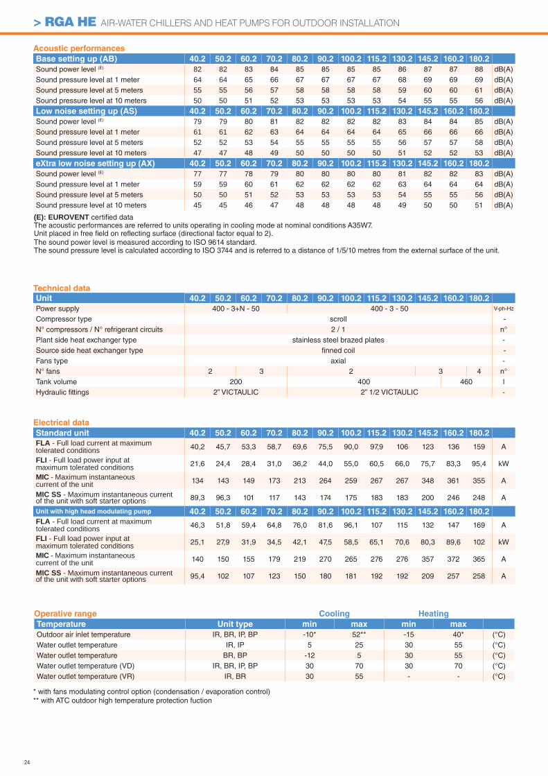
Acoustic performances
Base setting up (AB) 40.2 50.2 60.2 70.2 80.2 90.2 100.2 115.2 130.2 145.2 160.2 180.2
Sound power level (E) 82 82 83 84 85 85 85 85 86 87 87 88 dB(A)Sound pressure level at 1 meter 64 64 65 66 67 67 67 67 68 69 69 69 dB(A)Sound pressure level at 5 meters 55 55 56 57 58 58 58 58 59 60 60 61 dB(A)Sound pressure level at 10 meters 50 50 51 52 53 53 53 53 54 55 55 56 dB(A)
Low noise setting up (AS) 40.2 50.2 60.2 70.2 80.2 90.2 100.2 115.2 130.2 145.2 160.2 180.2
Sound power level (E) 79 79 80 81 82 82 82 82 83 84 84 85 dB(A)Sound pressure level at 1 meter 61 61 62 63 64 64 64 64 65 66 66 66 dB(A)Sound pressure level at 5 meters 52 52 53 54 55 55 55 55 56 57 57 58 dB(A)Sound pressure level at 10 meters 47 47 48 49 50 50 50 50 51 52 52 53 dB(A)
eXtra low noise setting up (AX) 40.2 50.2 60.2 70.2 80.2 90.2 100.2 115.2 130.2 145.2 160.2 180.2
Sound power level (E) 77 77 78 79 80 80 80 80 81 82 82 83 dB(A)Sound pressure level at 1 meter 59 59 60 61 62 62 62 62 63 64 64 64 dB(A)Sound pressure level at 5 meters 50 50 51 52 53 53 53 53 54 55 55 56 dB(A)Sound pressure level at 10 meters 45 45 46 47 48 48 48 48 49 50 50 51 dB(A)
Electrical data
Standard unit 40.2 50.2 60.2 70.2 80.2 90.2 100.2 115.2 130.2 145.2 160.2 180.2
FLA - Full load current at maximum tolerated conditions 40,2 45,7 53,3 58,7 69,6 75,5 90,0 97,9 106 123 136 159 A
FLI - Full load power input at maximum tolerated conditions 21,6 24,4 28,4 31,0 36,2 44,0 55,0 60,5 66,0 75,7 83,3 95,4 kW
MIC - Maximum instantaneous current of the unit 134 143 149 173 213 264 259 267 267 348 361 355 A
MIC SS - Maximum instantaneous current of the unit with soft starter options 89,3 96,3 101 117 143 174 175 183 183 200 246 248 A
Unit with high head modulating pump 40.2 50.2 60.2 70.2 80.2 90.2 100.2 115.2 130.2 145.2 160.2 180.2
FLA - Full load current at maximum tolerated conditions 46,3 51,8 59,4 64,8 76,0 81,6 96,1 107 115 132 147 169 A
FLI - Full load power input at maximum tolerated conditions 25,1 27,9 31,9 34,5 42,1 47,5 58,5 65,1 70,6 80,3 89,6 102 kW
MIC - Maximum instantaneous current of the unit 140 150 155 179 219 270 265 276 276 357 372 365 A
MIC SS - Maximum instantaneous current of the unit with soft starter options 95,4 102 107 123 150 180 181 192 192 209 257 258 A
(E): EUROVENT certifi ed data The acoustic performances are referred to units operating in cooling mode at nominal conditions A35W7.Unit placed in free fi eld on refl ecting surface (directional factor equal to 2).The sound power level is measured according to ISO 9614 standard.The sound pressure level is calculated according to ISO 3744 and is referred to a distance of 1/5/10 metres from the external surface of the unit.
Operative range Cooling Heating
Temperature Unit type min max min max
Outdoor air inlet temperature IR, BR, IP, BP -10* 52** -15 40* (°C)Water outlet temperature IR, IP 5 25 30 55 (°C)Water outlet temperature BR, BP -12 5 30 55 (°C)Water outlet temperature (VD) IR, BR, IP, BP 30 70 30 70 (°C)Water outlet temperature (VR) IR, BR 30 55 - - (°C)
Technical data
Unit 40.2 50.2 60.2 70.2 80.2 90.2 100.2 115.2 130.2 145.2 160.2 180.2
Power supply 400 - 3+N - 50 400 - 3 - 50 V-ph-Hz
Compressor type scroll -N° compressors / N° refrigerant circuits 2 / 1 n°Plant side heat exchanger type stainless steel brazed plates -Source side heat exchanger type fi nned coil -Fans type axial -N° fans 2 3 2 3 4 n°Tank volume 200 400 460 lHydraulic fi ttings 2” VICTAULIC 2” 1/2 VICTAULIC -
* with fans modulating control option (condensation / evaporation control)** with ATC outdoor high temperature protection fuction
25
> RGA HE AIR-WATER CHILLERS AND HEAT PUMPS FOR OUTDOOR INSTALLATION
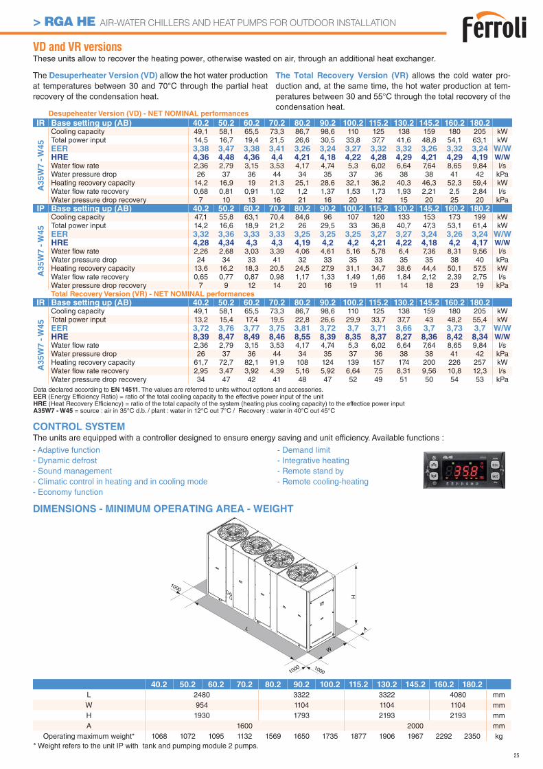
40.2 50.2 60.2 70.2 80.2 90.2 100.2 115.2 130.2 145.2 160.2 180.2
L 2480 3322 3322 4080 mmW 954 1104 1104 1104 mmH 1930 1793 2193 2193 mmA 1600 2000 mm
Operating maximum weight* 1068 1072 1095 1132 1569 1650 1735 1877 1906 1967 2292 2350 kg
1000
L
W
A
H
1000
1000
VD and VR versionsThese units allow to recover the heating power, otherwise wasted on air, through an additional heat exchanger.
The Desuperheater Version (VD) allow the hot water production at temperatures between 30 and 70°C through the partial heat recovery of the condensation heat.
The Total Recovery Version (VR) allows the cold water pro-duction and, at the same time, the hot water production at tem-peratures between 30 and 55°C through the total recovery of the condensation heat.
DIMENSIONS - MINIMUM OPERATING AREA - WEIGHT
Desupeheater Version (VD) - NET NOMINAL performances
IR Base setting up (AB) 40.2 50.2 60.2 70.2 80.2 90.2 100.2 115.2 130.2 145.2 160.2 180.2
A3
5W
7 -
W4
5
Cooling capacity 49,1 58,1 65,5 73,3 86,7 98,6 110 125 138 159 180 205 kWTotal power input 14,5 16,7 19,4 21,5 26,6 30,5 33,8 37,7 41,6 48,8 54,1 63,1 kWEER 3,38 3,47 3,38 3,41 3,26 3,24 3,27 3,32 3,32 3,26 3,32 3,24 W/WHRE 4,36 4,48 4,36 4,4 4,21 4,18 4,22 4,28 4,29 4,21 4,29 4,19 W/W
Water fl ow rate 2,36 2,79 3,15 3,53 4,17 4,74 5,3 6,02 6,64 7,64 8,65 9,84 l/sWater pressure drop 26 37 36 44 34 35 37 36 38 38 41 42 kPaHeating recovery capacity 14,2 16,9 19 21,3 25,1 28,6 32,1 36,2 40,3 46,3 52,3 59,4 kWWater fl ow rate recovery 0,68 0,81 0,91 1,02 1,2 1,37 1,53 1,73 1,93 2,21 2,5 2,84 l/sWater pressure drop recovery 7 10 13 16 21 16 20 12 15 20 25 20 kPa
IP Base setting up (AB) 40.2 50.2 60.2 70.2 80.2 90.2 100.2 115.2 130.2 145.2 160.2 180.2
A3
5W
7 -
W4
5
Cooling capacity 47,1 55,8 63,1 70,4 84,6 96 107 120 133 153 173 199 kWTotal power input 14,2 16,6 18,9 21,2 26 29,5 33 36,8 40,7 47,3 53,1 61,4 kWEER 3,32 3,36 3,33 3,33 3,25 3,25 3,25 3,27 3,27 3,24 3,26 3,24 W/WHRE 4,28 4,34 4,3 4,3 4,19 4,2 4,2 4,21 4,22 4,18 4,2 4,17 W/W
Water fl ow rate 2,26 2,68 3,03 3,39 4,06 4,61 5,16 5,78 6,4 7,36 8,31 9,56 l/sWater pressure drop 24 34 33 41 32 33 35 33 35 35 38 40 kPaHeating recovery capacity 13,6 16,2 18,3 20,5 24,5 27,9 31,1 34,7 38,6 44,4 50,1 57,5 kWWater fl ow rate recovery 0,65 0,77 0,87 0,98 1,17 1,33 1,49 1,66 1,84 2,12 2,39 2,75 l/sWater pressure drop recovery 7 9 12 14 20 16 19 11 14 18 23 19 kPaTotal Recovery Version (VR) - NET NOMINAL performances
IR Base setting up (AB) 40.2 50.2 60.2 70.2 80.2 90.2 100.2 115.2 130.2 145.2 160.2 180.2
A35W
7 -
W45
Cooling capacity 49,1 58,1 65,5 73,3 86,7 98,6 110 125 138 159 180 205 kWTotal power input 13,2 15,4 17,4 19,5 22,8 26,6 29,9 33,7 37,7 43 48,2 55,4 kWEER 3,72 3,76 3,77 3,75 3,81 3,72 3,7 3,71 3,66 3,7 3,73 3,7 W/WHRE 8,39 8,47 8,49 8,46 8,55 8,39 8,35 8,37 8,27 8,36 8,42 8,34 W/W
Water fl ow rate 2,36 2,79 3,15 3,53 4,17 4,74 5,3 6,02 6,64 7,64 8,65 9,84 l/sWater pressure drop 26 37 36 44 34 35 37 36 38 38 41 42 kPaHeating recovery capacity 61,7 72,7 82,1 91,9 108 124 139 157 174 200 226 257 kWWater fl ow rate recovery 2,95 3,47 3,92 4,39 5,16 5,92 6,64 7,5 8,31 9,56 10,8 12,3 l/sWater pressure drop recovery 34 47 42 41 48 47 52 49 51 50 54 53 kPa
* Weight refers to the unit IP with tank and pumping module 2 pumps.
CONTROL SYSTEMThe units are equipped with a controller designed to ensure energy saving and unit efficiency. Available functions :
- Adaptive function- Dynamic defrost - Sound management - Climatic control in heating and in cooling mode- Economy function
- Demand limit- Integrative heating- Remote stand by- Remote cooling-heating
Data declared according to EN 14511. The values are referred to units without options and accessories.EER (Energy Efficiency Ratio) = ratio of the total cooling capacity to the effective power input of the unitHRE (Heat Recovery Efficiency) = ratio of the total capacity of the system (heating plus cooling capacity) to the effectice power inputA35W7 - W45 = source : air in 35°C d.b. / plant : water in 12°C out 7°C / Recovery : water in 40°C out 45°C
26
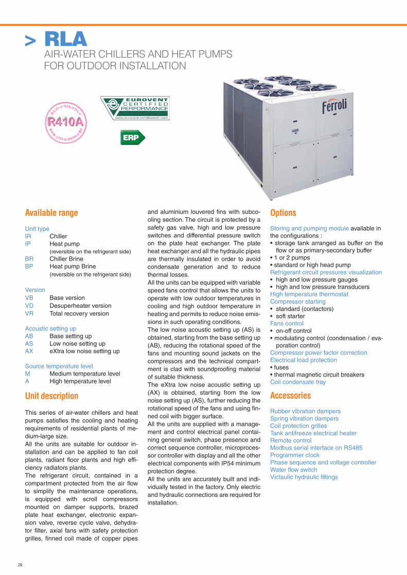
Available range
Unit typeIR ChillerIP Heat pump (reversible on the refrigerant side)BR Chiller BrineBP Heat pump Brine (reversible on the refrigerant side)
VersionVB Base versionVD Desuperheater versionVR Total recovery version
Acoustic setting upAB Base setting upAS Low noise setting upAX eXtra low noise setting up
Source temperature levelM Medium temperature levelA High temperature level
Unit description
This series of air-water chillers and heat pumps satisfi es the cooling and heating requirements of residential plants of me-dium-large size.All the units are suitable for outdoor in-stallation and can be applied to fan coil plants, radiant fl oor plants and high effi-ciency radiators plants.The refrigerant circuit, contained in a compartment protected from the air fl ow to simplify the maintenance operations, is equipped with scroll compressors mounted on damper supports, brazed plate heat exchanger, electronic expan-sion valve, reverse cycle valve, dehydra-tor fi lter, axial fans with safety protection grilles, fi nned coil made of copper pipes
and aluminium louvered fi ns with subco-oling section. The circuit is protected by a safety gas valve, high and low pressure switches and differential pressure switch on the plate heat exchanger. The plate heat exchanger and all the hydraulic pipes are thermally insulated in order to avoid condensate generation and to reduce thermal losses.All the units can be equipped with variable speed fans control that allows the units to operate with low outdoor temperatures in cooling and high outdoor temperature in heating and permits to reduce noise emis-sions in such operating conditions.The low noise acoustic setting up (AS) is obtained, starting from the base setting up (AB), reducing the rotational speed of the fans and mounting sound jackets on the compressors and the technical compart-ment is clad with soundproofi ng material of suitable thickness.The eXtra low noise acoustic setting up (AX) is obtained, starting from the low noise setting up (AS), further reducing the rotational speed of the fans and using fi n-ned coil with bigger surface.All the units are supplied with a manage-ment and control electrical panel contai-ning general switch, phase presence and correct sequence controller, microproces-sor controller with display and all the other electrical components with IP54 minimum protection degree.All the units are accurately built and indi-vidually tested in the factory. Only electric and hydraulic connections are required for installation.
Options
Storing and pumping module available in the confi gurations :• storage tank arranged as buffer on the
fl ow or as primary-secondary buffer• 1 or 2 pumps• standard or high head pumpRefrigerant circuit pressures visualization• high and low pressure gauges• high and low pressure transducersHigh temperature thermostatCompressor starting• standard (contactors)• soft starterFans control• on-off control• modulating control (condensation / eva-
poration control)Compressor power factor correction Electrical load protection• fuses• thermal magnetic circuit breakersCoil condensate tray
Accessories
Rubber vibration dampersSpring vibration dampersCoil protection grillesTank antifreeze electrical heaterRemote controlModbus serial interface on RS485Programmer clockPhase sequence and voltage controllerWater fl ow switchVictaulic hydraulic fi ttings
> RLA AIR-WATER CHILLERS AND HEAT PUMPS
FOR OUTDOOR INSTALLATION
ERP
27
> RLA AIR-WATER CHILLERS AND HEAT PUMPS FOR OUTDOOR INSTALLATION
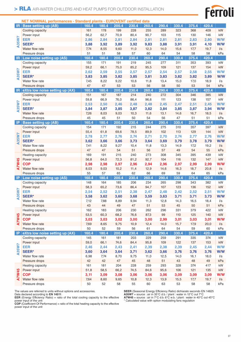
NET NOMINAL performances - Standard plants - EUROVENT certifi ed data
IR Base setting up (AB) 160.4 180.4 200.4 230.4 260.4 290.4 330.4 375.4 420.4
A3
5W
7
Cooling capacity 161 178 199 228 255 289 323 368 409 kWPower input 56,2 62,7 70,9 80,4 90,7 103 115 130 146 kW
EER 2,86 2,84 2,81 2,84 2,81 2,81 2,81 2,83 2,80 W/W
SEER* 3,88 3,92 3,89 3,92 9,83 3,88 3,91 3,91 4,10 W/W
Water fl ow rate 7,74 8,55 9,60 11,0 12,3 14,0 15,6 17,7 19,7 l/sPressure drops 51 51 58 57 60 64 54 58 58 kPa
IR Low noise setting up (AS) 160.4 180.4 200.4 230.4 260.4 290.4 330.4 375.4 420.4
A3
5W
7
Cooling capacity 155 171 191 219 245 277 311 353 393 kWPower input 59,2 66,1 75,0 85,2 95,5 109 121 137 154 kW
EER 2,62 2,59 2,55 2,57 2,57 2,54 2,57 2,58 2,55 W/W
SEER* 3,83 3,85 3,82 3,85 3,81 3,83 3,82 3,82 3,89 W/W
Water fl ow rate 7,45 8,22 9,22 10,6 11,8 13,4 15,0 17,0 18,9 l/sPressure drops 47 47 53 53 56 58 50 53 54 kPa
IR eXtra low noise setting up (AX) 160.4 180.4 200.4 230.4 260.4 290.4 330.4 375.4 420.4
A3
5W
7
Cooling capacity 151 167 187 214 240 272 304 346 385 kWPower input 59,8 66,9 76,0 86,4 96,6 111 123 138 157 kW
EER 2,53 2,50 2,46 2,48 2,48 2,45 2,47 2,51 2,45 W/W
SEER* 3,84 3,87 3,85 3,87 3,82 3,84 3,85 3,87 3,94 W/W
Water fl ow rate 7,26 8,03 9,03 10,3 11,6 13,1 14,6 16,7 18,5 l/sPressure drops 45 45 51 50 54 56 47 51 51 kPa
IP Base setting up (AB) 160.4 180.4 200.4 230.4 260.4 290.4 330.4 375.4 420.4
A35W
7
Cooling capacity 154 171 192 215 244 275 310 357 397 kWPower input 55,4 61,8 69,6 78,5 89,9 102 113 129 144 kW
EER 2,78 2,77 2,76 2,74 2,71 2,70 2,74 2,77 2,76 W/W
SEER* 3,62 3,66 3,66 3,73 3,64 3,69 3,79 3,78 3,79 W/W
Water fl ow rate 7,41 8,22 9,27 10,4 11,8 13,3 14,9 17,2 19,2 l/sPressure drops 47 47 54 51 56 57 49 54 55 kPa
A7W
45
Heating capacity 169 191 215 240 273 308 345 395 439 kWPower input 56,8 64,0 72,3 81,2 92,7 104 116 132 147 kW
COP 2,98 2,98 2,97 2,96 2,94 2,96 2,97 2,99 2,99 W/W
Water fl ow rate 8,03 9,03 10,2 11,4 12,9 14,6 16,3 18,7 20,8 l/sPressure drops 55 57 65 62 66 69 59 64 65 kPa
IP Low noise setting up (AS) 160.4 180.4 200.4 230.4 260.4 290.4 330.4 375.4 420.4
A35W
7
Cooling capacity 148 164 185 206 234 265 298 343 382 kWPower input 58,3 65,2 73,6 86,4 94,7 107 123 136 152 kW
EER 2,54 2,52 2,51 2,38 2,47 2,48 2,42 2,52 2,51 W/W
SEER* 3,58 3,62 3,60 3,68 3,59 3,63 3,71 3,71 3,73 W/W
Water fl ow rate 7,12 7,88 8,89 9,94 11,3 12,8 14,3 16,5 18,4 l/sPressure drops 43 44 49 47 51 53 45 50 51 kPa
A7W
45
Heating capacity 162 183 206 230 262 296 331 379 422 kWPower input 53,5 60,3 68,2 76,6 87,3 99 110 125 140 kW
COP 3,03 3,03 3,02 3,00 3,00 2,99 3,01 3,03 3,01 W/W
Water fl ow rate 7,69 8,65 9,75 10,9 12,4 14,0 15,7 17,9 20,0 l/sPressure drops 50 52 59 56 61 64 54 59 60 kPa
IP eXtra low noise setting up (AX) 160.4 180.4 200.4 230.4 260.4 290.4 330.4 375.4 420.4
A35W
7
Cooling capacity 145 161 181 203 229 259 291 335 374 kWPower input 59,0 66,1 74,6 84,4 95,8 109 122 137 153 kW
EER 2,46 2,44 2,43 2,41 2,39 2,38 2,39 2,45 2,44 W/W
SEER* 3,60 3,64 3,64 3,71 3,62 3,66 3,76 3,76 3,76 W/W
Water fl ow rate 6,98 7,74 8,70 9,75 11,0 12,5 14,0 16,1 18,0 l/sPressure drops 42 42 47 45 48 51 43 48 49 kPa
A7W
45
Heating capacity 161 181 204 228 259 293 328 374 417 kWPower input 51,8 58,5 66,2 74,5 84,6 95,6 106 121 135 kW
COP 3,11 3,09 3,08 3,06 3,06 3,06 3,09 3,09 3,09 W/W
Water fl ow rate 7,64 8,60 9,65 10,8 12,3 13,9 15,5 17,7 19,7 l/sPressure drops 50 52 58 55 60 63 53 58 58 kPa
The values are referred to units without options and accessories. Data declared according to EN 14511:EER (Energy Efficiency Ratio) = ratio of the total cooling capacity to the effective power input of the unitCOP (Coefficient Of Performance) = ratio of the total heating capacity to the effective power input of the unit
SEER (Seasonal Energy Efficiency Ratio) dichiarato secondo EN 14825A35W7 = source : air in 35°C d.b. / plant : water in 12°C out 7°CA7W45 = source : air in 7°C d.b. 6°C w.b. / plant : water in 40°C out 45°C* Calculated value with option modulating fans regulation
28
> RLA AIR-WATER CHILLERS AND HEAT PUMPS FOR OUTDOOR INSTALLATION
* with fans modulating control option (condensation / evaporation control)** with ATC outdoor high temperature protection fuction
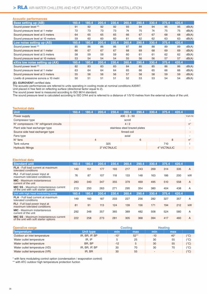
Acoustic performances
Base setting up (AB) 160.4 180.4 200.4 230.4 260.4 290.4 330.4 375.4 420.4
Sound power level (E) 91 92 92 92 93 94 94 95 95 dB(A)Sound pressure level at 1 meter 72 73 73 73 74 75 74 75 75 dB(A)Sound pressure level at 5 meters 64 65 65 65 66 67 67 68 68 dB(A)Sound pressure level at 10 meters 59 60 60 60 61 62 62 63 63 dB(A)
Low noise setting up (AS) 160.4 180.4 200.4 230.4 260.4 290.4 330.4 375.4 420.4
Sound power level (E) 85 86 86 86 87 88 88 89 89 dB(A)Sound pressure level at 1 meter 66 67 67 67 68 69 68 69 69 dB(A)Sound pressure level at 5 meters 58 59 59 59 60 61 61 62 62 dB(A)Sound pressure level at 10 meters 53 54 54 54 55 56 56 57 57 dB(A)
eXtra low noise setting up (AX) 160.4 180.4 200.4 230.4 260.4 290.4 330.4 375.4 420.4
Sound power level (E) 82 83 83 83 84 85 85 86 86 dB(A)Sound pressure level at 1 meter 63 64 64 64 65 66 65 66 66 dB(A)Sound pressure level at 5 meters 55 56 56 56 57 58 58 59 59 dB(A)Livello di pressione sonora a 10 metri 50 51 51 51 52 53 53 54 54 dB(A)
Electrical data
Standard unit 160.4 180.4 200.4 230.4 260.4 290.4 330.4 375.4 420.4
FLA - Full load current at maximum tolerated conditions 140 151 177 193 217 243 269 314 335 A
FLI - Full load power input at maximum tolerated conditions 76 87 107 118 133 148 163 186 200 kW
MIC - Maximum instantaneous current of the unit 283 340 347 355 379 469 495 510 558 A
MIC SS - Maximum instantaneous current of the unit with soft starter options 213 250 263 271 295 354 380 404 438 A
Unit with high head modulating pump 160.4 180.4 200.4 230.4 260.4 290.4 330.4 375.4 420.4
FLA - Full load current at maximum tolerated conditions 149 160 187 203 227 256 282 327 357 A
FLI - Full load power input at maximum tolerated conditions 81 91 113 124 139 156 171 194 212 kW
MIC - Maximum instantaneous current of the unit 292 348 357 365 389 482 508 524 580 A
MIC SS - Maximum instantaneous current of the unit with soft starter options 222 258 273 281 305 368 394 417 460 A
(E): EUROVENT certifi ed data The acoustic performances are referred to units operating in cooling mode at nominal conditions A35W7.Unit placed in free fi eld on refl ecting surface (directional factor equal to 2).The sound power level is measured according to ISO 9614 standard.The sound pressure level is calculated according to ISO 3744 and is referred to a distance of 1/5/10 metres from the external surface of the unit.
Operative range Cooling Heating
Temperature Unit type min max min max
Outdoor air inlet temperature IR, BR, IP, BP -10* 52** -10 40* (°C)Water outlet temperature IR, IP 5 25 30 55 (°C)Water outlet temperature BR, BP -12 5 30 55 (°C)Water outlet temperature (VD) IR, BR, IP, BP 30 70 30 70 (°C)Water outlet temperature (VR) IR, BR 30 55 - - (°C)
Technical data
Unit 160.4 180.4 200.4 230.4 260.4 290.4 330.4 375.4 420.4
Power supply 400 - 3 - 50 V-ph-Hz
Compressor type scroll -N° compressors / N° refrigerant circuits 4 / 2 n°Plant side heat exchanger type stainless steel brazed plates -Source side heat exchanger type fi nned coil -Fans type axial -N° fans 4 6 8 n°Tank volume 325 710 lHydraulic fi ttings 3” VICTAULIC 4” VICTAULIC -
29
> RLA AIR-WATER CHILLERS AND HEAT PUMPS FOR OUTDOOR INSTALLATION
160.4 180.4 200.4 230.4 260.4 290.4 330.4 375.4 420.4
L 3164 3164 3164 3164 3164 3164 4097 4097 4097 mmOperating maximum weight* 2441 2633 2829 3005 3069 3096 3790 3907 3980 kg
VD and VR versionsThese units allow to recover the heating power, otherwise wasted on air, through an additional heat exchanger.
The Desuperheater Version (VD) allow the hot water production at temperatures between 30 and 70°C through the partial heat recovery of the condensation heat.
The Total Recovery Version (VR) allows the cold water pro-duction and, at the same time, the hot water production at tem-peratures between 30 and 55°C through the total recovery of the condensation heat.
DIMENSIONS - MINIMUM OPERATING AREA - WEIGHT
Desupeheater Version (VD) - NET NOMINAL performances
IR Base setting up (AB) 160.4 180.4 200.4 230.4 260.4 290.4 330.4 375.4 420.4
A3
5W
7 -
W4
5
Cooling capacity 167 185 207 237 264 300 336 382 425 kWTotal power input 55,0 61,2 69,3 78,5 88,7 101 112 127 143 kWEER 3,04 3,01 2,99 3,02 2,98 2,97 3,00 3,01 2,98 W/WHRE 3,90 3,89 3,87 3,91 3,85 3,85 3,90 3,88 3,86 W/WWater fl ow rate 8,05 8,89 10,0 11,4 12,8 14,5 16,2 18,4 20,5 l/sWater pressure drop 55 55 63 62 65 68 58 62 63 kPaHeating recovery capacity 47,2 53,4 61,2 70,3 76,6 88,7 99,9 110,8 126,6 kWWater fl ow rate recovery 2,25 2,55 2,93 3,36 3,66 4,24 4,77 5,29 6,05 l/sWater pressure drop recovery 5 7 8 10 13 16 16 21 25 kPa
IP Base setting up (AB) 160.4 180.4 200.4 230.4 260.4 290.4 330.4 375.4 420.4
A3
5W
7 -
W4
5
Cooling capacity 160 177 200 224 253 286 322 371 413 kWTotal power input 54,1 60,4 67,9 76,6 87,8 99 111 126 140 kWEER 2,96 2,94 2,94 2,92 2,89 2,88 2,91 2,95 2,96 W/WHRE 3,82 3,81 3,83 3,82 3,75 3,76 3,81 3,83 3,85 W/WWater fl ow rate 7,70 8,55 9,64 10,8 12,2 13,8 15,5 17,9 19,9 l/sWater pressure drop 51 51 58 55 59 62 53 59 59 kPaHeating recovery capacity 46,5 52,7 60,1 68,8 76,1 87,5 98,9 110 124 kWWater fl ow rate recovery 2,22 2,52 2,87 3,29 3,64 4,18 4,73 5,25 5,91 l/sWater pressure drop recovery 5 6 8 10 13 16 16 20 24 kPaTotal Recovery Version (VR) - NET NOMINAL performances
IR Base setting up (AB) 160.4 180.4 200.4 230.4 260.4 290.4 330.4 375.4 420.4
A35W
7 -
W45
Cooling capacity 169 186 209 239 267 303 339 386 429 kWTotal power input 47,3 53,5 61,6 70,7 77,2 89,5 100 111 127 kWEER 3,56 3,48 3,39 3,38 3,46 3,39 3,38 3,46 3,37 W/WHRE 8,08 7,91 7,75 7,71 7,87 7,72 7,71 7,87 7,69 W/WWater fl ow rate 8,13 8,98 10,1 11,5 12,9 14,6 16,4 18,6 20,7 l/sWater pressure drop 56 57 64 63 66 69 59 64 64 kPaHeating recovery capacity 214 237 268 306 340 388 434 492 550 kWWater fl ow rate recovery 10,2 11,3 12,8 14,6 16,2 18,5 20,7 23,5 26,3 l/sWater pressure drop recovery 45 43 45 45 47 49 49 51 51 kPa
Data declared according to EN 14511. The values are referred to units without options and accessories.EER (Energy Efficiency Ratio) = ratio of the total cooling capacity to the effective power input of the unitHRE (Heat Recovery Efficiency) = ratio of the total capacity of the system (heating plus cooling capacity) to the effectice power inputA35W7 - W45 = source : air in 35°C d.b. / plant : water in 12°C out 7°C / Recovery : water in 40°C out 45°C
* Weight refers to the unit IP with tank and pumping module 2 pumps.
CONTROL SYSTEMThe units are equipped with a controller designed to ensure energy saving and unit efficiency. Available functions :
- ATC outdoor high temperature protection function - Dynamic defrost - Sound management - Climatic control in heating and in cooling mode- Double set point function
- Demand limit- Integrative heating- Remote stand by- Remote cooling-heating
1100
L
2210
2000
2223
2000
1100
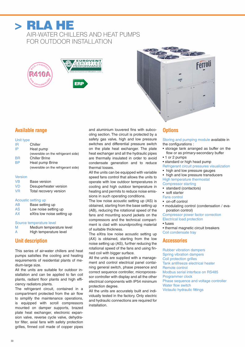
30
Available range
Unit typeIR ChillerIP Heat pump (reversible on the refrigerant side)BR Chiller BrineBP Heat pump Brine (reversible on the refrigerant side)
VersionVB Base versionVD Desuperheater versionVR Total recovery version
Acoustic setting upAB Base setting upAS Low noise setting upAX eXtra low noise setting up
Source temperature levelM Medium temperature levelA High temperature level
Unit description
This series of air-water chillers and heat pumps satisfi es the cooling and heating requirements of residential plants of me-dium-large size.All the units are suitable for outdoor in-stallation and can be applied to fan coil plants, radiant fl oor plants and high effi-ciency radiators plants.The refrigerant circuit, contained in a compartment protected from the air fl ow to simplify the maintenance operations, is equipped with scroll compressors mounted on damper supports, brazed plate heat exchanger, electronic expan-sion valve, reverse cycle valve, dehydra-tor fi lter, axial fans with safety protection grilles, fi nned coil made of copper pipes
and aluminium louvered fi ns with subco-oling section. The circuit is protected by a safety gas valve, high and low pressure switches and differential pressure switch on the plate heat exchanger. The plate heat exchanger and all the hydraulic pipes are thermally insulated in order to avoid condensate generation and to reduce thermal losses.All the units can be equipped with variable speed fans control that allows the units to operate with low outdoor temperatures in cooling and high outdoor temperature in heating and permits to reduce noise emis-sions in such operating conditions.The low noise acoustic setting up (AS) is obtained, starting from the base setting up (AB), reducing the rotational speed of the fans and mounting sound jackets on the compressors and the technical compart-ment is clad with soundproofi ng material of suitable thickness.The eXtra low noise acoustic setting up (AX) is obtained, starting from the low noise setting up (AS), further reducing the rotational speed of the fans and using fi n-ned coil with bigger surface.All the units are supplied with a manage-ment and control electrical panel contai-ning general switch, phase presence and correct sequence controller, microproces-sor controller with display and all the other electrical components with IP54 minimum protection degree.All the units are accurately built and indi-vidually tested in the factory. Only electric and hydraulic connections are required for installation.
Options
Storing and pumping module available in the confi gurations :• storage tank arranged as buffer on the
fl ow or as primary-secondary buffer• 1 or 2 pumps• standard or high head pumpRefrigerant circuit pressures visualization• high and low pressure gauges• high and low pressure transducersHigh temperature thermostatCompressor starting• standard (contactors)• soft starterFans control• on-off control• modulating control (condensation / eva-
poration control)Compressor power factor correction Electrical load protection• fuses• thermal magnetic circuit breakersCoil condensate tray
Accessories
Rubber vibration dampersSpring vibration dampersCoil protection grillesTank antifreeze electrical heaterRemote controlModbus serial interface on RS485Programmer clockPhase sequence and voltage controllerWater fl ow switchVictaulic hydraulic fi ttings
> RLA HE AIR-WATER CHILLERS AND HEAT PUMPS
FOR OUTDOOR INSTALLATION
ERP
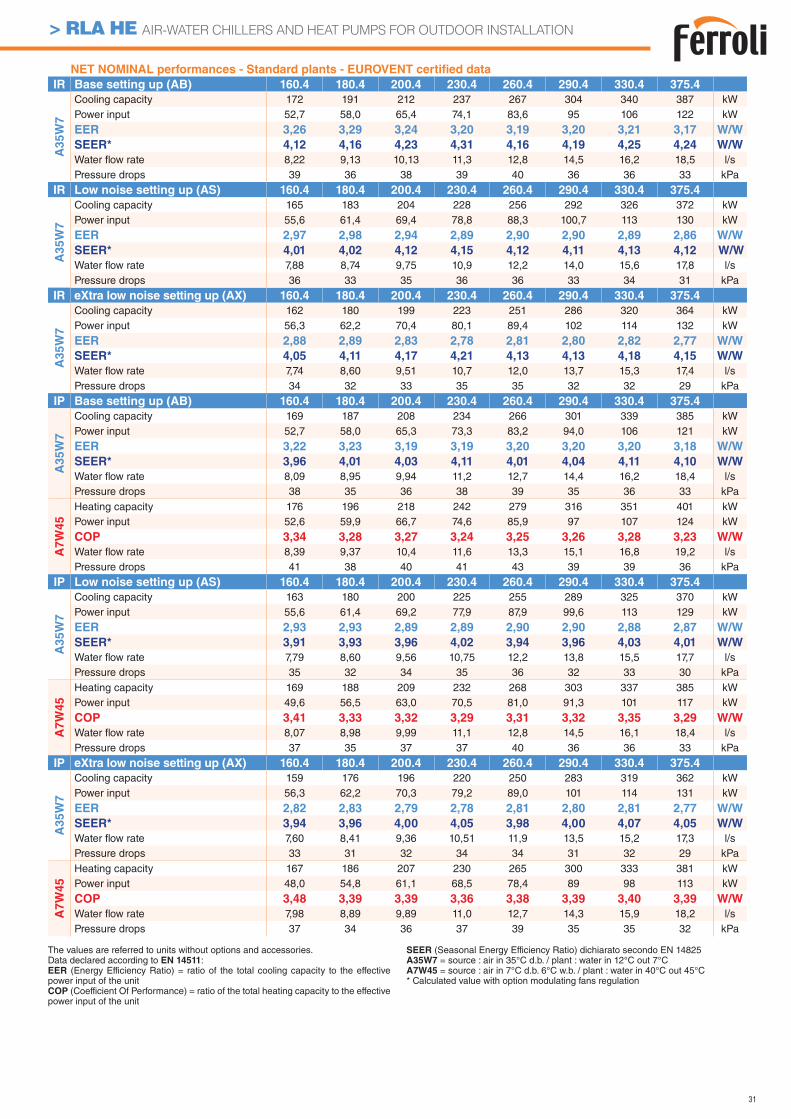
31
> RLA HE AIR-WATER CHILLERS AND HEAT PUMPS FOR OUTDOOR INSTALLATION
NET NOMINAL performances - Standard plants - EUROVENT certifi ed data
IR Base setting up (AB) 160.4 180.4 200.4 230.4 260.4 290.4 330.4 375.4
A3
5W
7
Cooling capacity 172 191 212 237 267 304 340 387 kWPower input 52,7 58,0 65,4 74,1 83,6 95 106 122 kW
EER 3,26 3,29 3,24 3,20 3,19 3,20 3,21 3,17 W/W
SEER* 4,12 4,16 4,23 4,31 4,16 4,19 4,25 4,24 W/W
Water fl ow rate 8,22 9,13 10,13 11,3 12,8 14,5 16,2 18,5 l/sPressure drops 39 36 38 39 40 36 36 33 kPa
IR Low noise setting up (AS) 160.4 180.4 200.4 230.4 260.4 290.4 330.4 375.4
A3
5W
7
Cooling capacity 165 183 204 228 256 292 326 372 kWPower input 55,6 61,4 69,4 78,8 88,3 100,7 113 130 kW
EER 2,97 2,98 2,94 2,89 2,90 2,90 2,89 2,86 W/W
SEER* 4,01 4,02 4,12 4,15 4,12 4,11 4,13 4,12 W/W
Water fl ow rate 7,88 8,74 9,75 10,9 12,2 14,0 15,6 17,8 l/sPressure drops 36 33 35 36 36 33 34 31 kPa
IR eXtra low noise setting up (AX) 160.4 180.4 200.4 230.4 260.4 290.4 330.4 375.4
A3
5W
7
Cooling capacity 162 180 199 223 251 286 320 364 kWPower input 56,3 62,2 70,4 80,1 89,4 102 114 132 kW
EER 2,88 2,89 2,83 2,78 2,81 2,80 2,82 2,77 W/W
SEER* 4,05 4,11 4,17 4,21 4,13 4,13 4,18 4,15 W/W
Water fl ow rate 7,74 8,60 9,51 10,7 12,0 13,7 15,3 17,4 l/sPressure drops 34 32 33 35 35 32 32 29 kPa
IP Base setting up (AB) 160.4 180.4 200.4 230.4 260.4 290.4 330.4 375.4
A35W
7
Cooling capacity 169 187 208 234 266 301 339 385 kWPower input 52,7 58,0 65,3 73,3 83,2 94,0 106 121 kW
EER 3,22 3,23 3,19 3,19 3,20 3,20 3,20 3,18 W/W
SEER* 3,96 4,01 4,03 4,11 4,01 4,04 4,11 4,10 W/W
Water fl ow rate 8,09 8,95 9,94 11,2 12,7 14,4 16,2 18,4 l/sPressure drops 38 35 36 38 39 35 36 33 kPa
A7W
45
Heating capacity 176 196 218 242 279 316 351 401 kWPower input 52,6 59,9 66,7 74,6 85,9 97 107 124 kW
COP 3,34 3,28 3,27 3,24 3,25 3,26 3,28 3,23 W/W
Water fl ow rate 8,39 9,37 10,4 11,6 13,3 15,1 16,8 19,2 l/sPressure drops 41 38 40 41 43 39 39 36 kPa
IP Low noise setting up (AS) 160.4 180.4 200.4 230.4 260.4 290.4 330.4 375.4
A35W
7
Cooling capacity 163 180 200 225 255 289 325 370 kWPower input 55,6 61,4 69,2 77,9 87,9 99,6 113 129 kW
EER 2,93 2,93 2,89 2,89 2,90 2,90 2,88 2,87 W/W
SEER* 3,91 3,93 3,96 4,02 3,94 3,96 4,03 4,01 W/W
Water fl ow rate 7,79 8,60 9,56 10,75 12,2 13,8 15,5 17,7 l/sPressure drops 35 32 34 35 36 32 33 30 kPa
A7W
45
Heating capacity 169 188 209 232 268 303 337 385 kWPower input 49,6 56,5 63,0 70,5 81,0 91,3 101 117 kW
COP 3,41 3,33 3,32 3,29 3,31 3,32 3,35 3,29 W/W
Water fl ow rate 8,07 8,98 9,99 11,1 12,8 14,5 16,1 18,4 l/sPressure drops 37 35 37 37 40 36 36 33 kPa
IP eXtra low noise setting up (AX) 160.4 180.4 200.4 230.4 260.4 290.4 330.4 375.4
A35W
7
Cooling capacity 159 176 196 220 250 283 319 362 kWPower input 56,3 62,2 70,3 79,2 89,0 101 114 131 kW
EER 2,82 2,83 2,79 2,78 2,81 2,80 2,81 2,77 W/W
SEER* 3,94 3,96 4,00 4,05 3,98 4,00 4,07 4,05 W/W
Water fl ow rate 7,60 8,41 9,36 10,51 11,9 13,5 15,2 17,3 l/sPressure drops 33 31 32 34 34 31 32 29 kPa
A7W
45
Heating capacity 167 186 207 230 265 300 333 381 kWPower input 48,0 54,8 61,1 68,5 78,4 89 98 113 kW
COP 3,48 3,39 3,39 3,36 3,38 3,39 3,40 3,39 W/W
Water fl ow rate 7,98 8,89 9,89 11,0 12,7 14,3 15,9 18,2 l/sPressure drops 37 34 36 37 39 35 35 32 kPa
The values are referred to units without options and accessories. Data declared according to EN 14511:EER (Energy Efficiency Ratio) = ratio of the total cooling capacity to the effective power input of the unitCOP (Coefficient Of Performance) = ratio of the total heating capacity to the effective power input of the unit
SEER (Seasonal Energy Efficiency Ratio) dichiarato secondo EN 14825A35W7 = source : air in 35°C d.b. / plant : water in 12°C out 7°CA7W45 = source : air in 7°C d.b. 6°C w.b. / plant : water in 40°C out 45°C* Calculated value with option modulating fans regulation
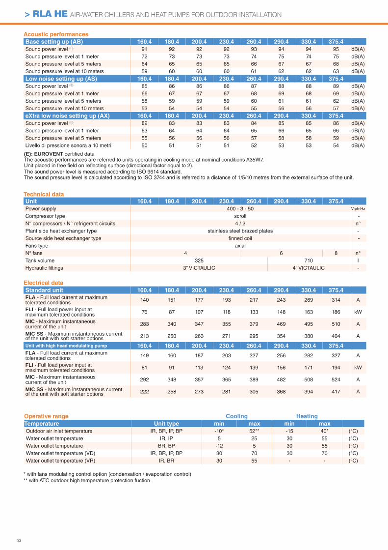
32
> RLA HE AIR-WATER CHILLERS AND HEAT PUMPS FOR OUTDOOR INSTALLATION
* with fans modulating control option (condensation / evaporation control)** with ATC outdoor high temperature protection fuction
Acoustic performances
Base setting up (AB) 160.4 180.4 200.4 230.4 260.4 290.4 330.4 375.4
Sound power level (E) 91 92 92 92 93 94 94 95 dB(A)Sound pressure level at 1 meter 72 73 73 73 74 75 74 75 dB(A)Sound pressure level at 5 meters 64 65 65 65 66 67 67 68 dB(A)Sound pressure level at 10 meters 59 60 60 60 61 62 62 63 dB(A)
Low noise setting up (AS) 160.4 180.4 200.4 230.4 260.4 290.4 330.4 375.4
Sound power level (E) 85 86 86 86 87 88 88 89 dB(A)Sound pressure level at 1 meter 66 67 67 67 68 69 68 69 dB(A)Sound pressure level at 5 meters 58 59 59 59 60 61 61 62 dB(A)Sound pressure level at 10 meters 53 54 54 54 55 56 56 57 dB(A)
eXtra low noise setting up (AX) 160.4 180.4 200.4 230.4 260.4 290.4 330.4 375.4
Sound power level (E) 82 83 83 83 84 85 85 86 dB(A)Sound pressure level at 1 meter 63 64 64 64 65 66 65 66 dB(A)Sound pressure level at 5 meters 55 56 56 56 57 58 58 59 dB(A)Livello di pressione sonora a 10 metri 50 51 51 51 52 53 53 54 dB(A)
Electrical data
Standard unit 160.4 180.4 200.4 230.4 260.4 290.4 330.4 375.4
FLA - Full load current at maximum tolerated conditions 140 151 177 193 217 243 269 314 A
FLI - Full load power input at maximum tolerated conditions 76 87 107 118 133 148 163 186 kW
MIC - Maximum instantaneous current of the unit 283 340 347 355 379 469 495 510 A
MIC SS - Maximum instantaneous current of the unit with soft starter options 213 250 263 271 295 354 380 404 A
Unit with high head modulating pump 160.4 180.4 200.4 230.4 260.4 290.4 330.4 375.4
FLA - Full load current at maximum tolerated conditions 149 160 187 203 227 256 282 327 A
FLI - Full load power input at maximum tolerated conditions 81 91 113 124 139 156 171 194 kW
MIC - Maximum instantaneous current of the unit 292 348 357 365 389 482 508 524 A
MIC SS - Maximum instantaneous current of the unit with soft starter options 222 258 273 281 305 368 394 417 A
(E): EUROVENT certifi ed data The acoustic performances are referred to units operating in cooling mode at nominal conditions A35W7.Unit placed in free fi eld on refl ecting surface (directional factor equal to 2).The sound power level is measured according to ISO 9614 standard.The sound pressure level is calculated according to ISO 3744 and is referred to a distance of 1/5/10 metres from the external surface of the unit.
Operative range Cooling Heating
Temperature Unit type min max min max
Outdoor air inlet temperature IR, BR, IP, BP -10* 52** -15 40* (°C)Water outlet temperature IR, IP 5 25 30 55 (°C)Water outlet temperature BR, BP -12 5 30 55 (°C)Water outlet temperature (VD) IR, BR, IP, BP 30 70 30 70 (°C)Water outlet temperature (VR) IR, BR 30 55 - - (°C)
Technical data
Unit 160.4 180.4 200.4 230.4 260.4 290.4 330.4 375.4
Power supply 400 - 3 - 50 V-ph-Hz
Compressor type scroll -N° compressors / N° refrigerant circuits 4 / 2 n°Plant side heat exchanger type stainless steel brazed plates -Source side heat exchanger type fi nned coil -Fans type axial -N° fans 4 6 8 n°Tank volume 325 710 lHydraulic fi ttings 3” VICTAULIC 4” VICTAULIC -
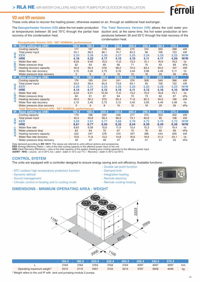
33
> RLA HE AIR-WATER CHILLERS AND HEAT PUMPS FOR OUTDOOR INSTALLATION
160.4 180.4 200.4 230.4 260.4 290.4 330.4 375.4
L 3164 3164 3164 3164 3164 4097 4097 4097 mmOperating maximum weight* 2512 2712 2957 3122 3214 3787 3948 4046 kg
DIMENSIONS - MINIMUM OPERATING AREA - WEIGHT
CONTROL SYSTEMThe units are equipped with a controller designed to ensure energy saving and unit efficiency. Available functions :
- ATC outdoor high temperature protection function - Dynamic defrost - Sound management - Climatic control in heating and in cooling mode
- Double set point function- Demand limit- Integrative heating- Remote stand by- Remote cooling-heating
Desupeheater Version (VD) - NET NOMINAL performances
IR Base setting up (AB) 160.4 180.4 200.4 230.4 260.4 290.4 330.4 375.4
A3
5W
7 -
W4
5
Cooling capacity 177 197 218 244 275 312 350 398 kWTotal power input 53,1 58,5 66,1 74,7 84,5 96 106 123 kWEER 3,33 3,36 3,30 3,27 3,25 3,24 3,29 3,22 W/WHRE 4,18 4,22 4,17 4,15 4,10 4,11 4,17 4,09 W/WWater fl ow rate 8,55 9,49 10,5 11,8 13,3 15,1 16,9 19,2 l/sWater pressure drop 62 63 69 66 71 74 63 68 kPaHeating recovery capacity 45,0 50,3 57,6 66,2 72,0 83,4 94,0 107 kWWater fl ow rate recovery 2,15 2,40 2,75 3,16 3,44 3,98 4,49 5,11 l/sWater pressure drop recovery 5 6 8 10 12 16 20 26 kPa
IP Base setting up (AB) 160.4 180.4 200.4 230.4 260.4 290.4 330.4 375.4
A3
5W
7 -
W4
5
Cooling capacity 174 193 214 241 274 309 349 396 kWTotal power input 53,0 58,4 65,9 73,8 84,1 95 106 122 kWEER 3,29 3,31 3,25 3,26 3,25 3,25 3,28 3,23 W/WHRE 4,14 4,17 4,12 4,15 4,11 4,12 4,16 4,10 W/WWater fl ow rate 8,42 9,31 10,34 11,6 13,2 15,0 16,8 19,1 l/sWater pressure drop 60 61 67 64 70 73 62 67 kPaHeating recovery capacity 45,0 50,3 57,5 65,4 71,6 82,3 94,0 106 kWWater fl ow rate recovery 2,15 2,40 2,75 3,12 3,42 3,93 4,49 5,06 l/sWater pressure drop recovery 5 6 8 10 12 16 20 26 kPaTotal Recovery Version (VR) - NET NOMINAL performances
IR Base setting up (AB) 160.4 180.4 200.4 230.4 260.4 290.4 330.4 375.4
A35W
7 -
W45
Cooling capacity 179 198 220 246 277 315 353 402 kWTotal power input 45,5 50,8 58,4 66,9 73,1 84,8 95 108 kWEER 3,93 3,91 3,77 3,68 3,79 3,72 3,72 3,72 W/WHRE 8,81 8,77 8,50 8,32 8,54 8,39 8,40 8,38 W/WWater fl ow rate 8,63 9,58 10,6 11,9 13,4 15,3 17,1 19,4 l/sWater pressure drop 64 64 70 67 72 76 65 69 kPaHeating recovery capacity 222 247 276 310 347 396 444 505 kWWater fl ow rate recovery 10,6 11,8 13,2 14,8 16,6 18,9 21,2 24,1 l/sWater pressure drop recovery 49 47 48 47 49 51 51 53 kPa
Data declared according to EN 14511. The values are referred to units without options and accessories.EER (Energy Efficiency Ratio) = ratio of the total cooling capacity to the effective power input of the unitHRE (Heat Recovery Efficiency) = ratio of the total capacity of the system (heating plus cooling capacity) to the effectice power inputA35W7 - W45 = source : air in 35°C d.b. / plant : water in 12°C out 7°C / Recovery : water in 40°C out 45°C
* Weight refers to the unit IP with tank and pumping module 2 pumps.
VD and VR versionsThese units allow to recover the heating power, otherwise wasted on air, through an additional heat exchanger.
The Desuperheater Version (VD) allow the hot water production at temperatures between 30 and 70°C through the partial heat recovery of the condensation heat.
The Total Recovery Version (VR) allows the cold water pro-duction and, at the same time, the hot water production at tem-peratures between 30 and 55°C through the total recovery of the condensation heat.
1100
L
2210
2000
2223
2000
1100
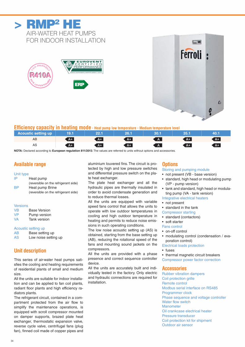
34
Available range
Unit typeIP Heat pump (reversible on the refrigerant side)BP Heat pump Brine (reversible on the refrigerant side)
VersionsVB Base VersionVP Pump versionVA Tank version
Acoustic setting upAB Base setting upAS Low noise setting up
Unit description
This series of air-water heat pumps sati-sfi es the cooling and heating requirements of residential plants of small and medium size.All the units are suitable for indoor installa-tion and can be applied to fan coil plants, radiant fl oor plants and high efficiency ra-diators plants.The refrigerant circuit, contained in a com-partment protected from the air fl ow to simplify the maintenance operations, is equipped with scroll compressor mounted on damper supports, brazed plate heat exchanger, thermostatic expansion valve, reverse cycle valve, centrifugal fans (plug fan), fi nned coil made of copper pipes and
aluminium louvered fi ns. The circuit is pro-tected by high and low pressure switches and differential pressure switch on the pla-te heat exchanger.The plate heat exchanger and all the hydraulic pipes are thermally insulated in order to avoid condensate generation and to reduce thermal losses.All the units are equipped with variable speed fans control that allows the units to operate with low outdoor temperatures in cooling and high outdoor temperature in heating and permits to reduce noise emis-sions in such operating conditions.The low noise acoustic setting up (AS) is obtained, starting from the base setting up (AB), reducing the rotational speed of the fans and mounting sound jackets on the compressors.All the units are provided with a phase presence and correct sequence controller device.All the units are accurately built and indi-vidually tested in the factory. Only electric and hydraulic connections are required for installation.
OptionsStoring and pumping module • not present (VB - base version)• standard, high head or modulating pump
(VP - pump version)• tank and standard, high head or modula-
ting pump (VA - tank version)Integrative electrical heaters• not present• standard in the tankCompressor starting• standard (contactors)• soft starterFans control• on-off control• modulating control (condensation / eva-
poration control)Electrical loads protection• fuses• thermal magnetic circuit breakersCompressor power factor correction
AccessoriesRubber vibration dampersCoil protection grilleRemote controlModbus serial interface on RS485Programmer clockPhase sequence and voltage controllerWater fl ow switchManometerOil crankcase electrical heaterPressure transducerCoil protection kit for shipmentOutdoor air sensor
> RMP2 HE AIR-WATER HEAT PUMPS
FOR INDOOR INSTALLATION
Effi ciency capacity in heating mode - Heat pump low temperature - Medium temperature level
Acoustic setting up 19.1 22.1 26.1 30.1 35.1 40.1
AB
AS
A+ A+ A+ A A+ A+
A+ A+ A+ A A+ A+NOTA: Declared according to European regulation 811/2013. The values are referred to units without options and accessories.
ERP
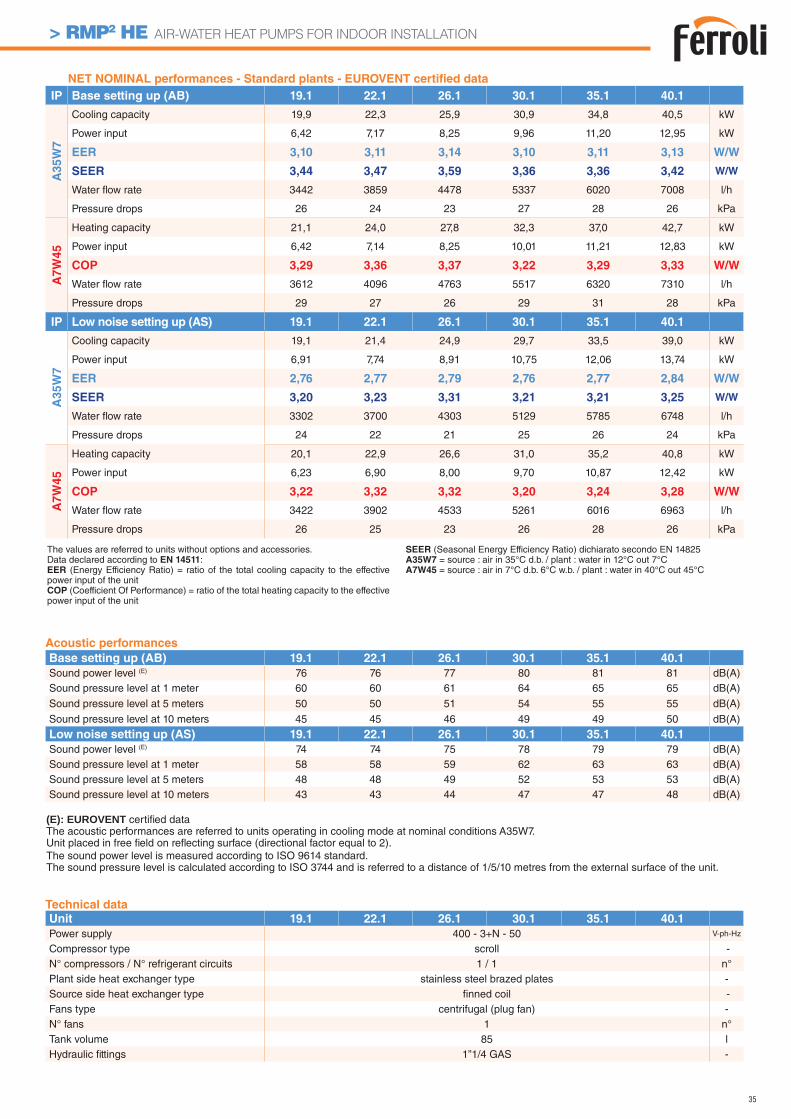
35
> RMP2 HE AIR-WATER HEAT PUMPS FOR INDOOR INSTALLATION
Acoustic performances
Base setting up (AB) 19.1 22.1 26.1 30.1 35.1 40.1
Sound power level (E) 76 76 77 80 81 81 dB(A)Sound pressure level at 1 meter 60 60 61 64 65 65 dB(A)
Sound pressure level at 5 meters 50 50 51 54 55 55 dB(A)
Sound pressure level at 10 meters 45 45 46 49 49 50 dB(A)
Low noise setting up (AS) 19.1 22.1 26.1 30.1 35.1 40.1
Sound power level (E) 74 74 75 78 79 79 dB(A)Sound pressure level at 1 meter 58 58 59 62 63 63 dB(A)Sound pressure level at 5 meters 48 48 49 52 53 53 dB(A)Sound pressure level at 10 meters 43 43 44 47 47 48 dB(A)
(E): EUROVENT certifi ed data The acoustic performances are referred to units operating in cooling mode at nominal conditions A35W7.Unit placed in free fi eld on refl ecting surface (directional factor equal to 2).The sound power level is measured according to ISO 9614 standard.The sound pressure level is calculated according to ISO 3744 and is referred to a distance of 1/5/10 metres from the external surface of the unit.
Technical data
Unit 19.1 22.1 26.1 30.1 35.1 40.1
Power supply 400 - 3+N - 50 V-ph-Hz
Compressor type scroll -N° compressors / N° refrigerant circuits 1 / 1 n°Plant side heat exchanger type stainless steel brazed plates -Source side heat exchanger type fi nned coil -Fans type centrifugal (plug fan) -N° fans 1 n°Tank volume 85 lHydraulic fi ttings 1”1/4 GAS -
The values are referred to units without options and accessories. Data declared according to EN 14511:EER (Energy Efficiency Ratio) = ratio of the total cooling capacity to the effective power input of the unitCOP (Coefficient Of Performance) = ratio of the total heating capacity to the effective power input of the unit
SEER (Seasonal Energy Efficiency Ratio) dichiarato secondo EN 14825A35W7 = source : air in 35°C d.b. / plant : water in 12°C out 7°CA7W45 = source : air in 7°C d.b. 6°C w.b. / plant : water in 40°C out 45°C
NET NOMINAL performances - Standard plants - EUROVENT certifi ed data
IP Base setting up (AB) 19.1 22.1 26.1 30.1 35.1 40.1
A3
5W
7
Cooling capacity 19,9 22,3 25,9 30,9 34,8 40,5 kW
Power input 6,42 7,17 8,25 9,96 11,20 12,95 kW
EER 3,10 3,11 3,14 3,10 3,11 3,13 W/W
SEER 3,44 3,47 3,59 3,36 3,36 3,42 W/W
Water fl ow rate 3442 3859 4478 5337 6020 7008 l/h
Pressure drops 26 24 23 27 28 26 kPa
A7
W4
5
Heating capacity 21,1 24,0 27,8 32,3 37,0 42,7 kW
Power input 6,42 7,14 8,25 10,01 11,21 12,83 kW
COP 3,29 3,36 3,37 3,22 3,29 3,33 W/W
Water fl ow rate 3612 4096 4763 5517 6320 7310 l/h
Pressure drops 29 27 26 29 31 28 kPa
IP Low noise setting up (AS) 19.1 22.1 26.1 30.1 35.1 40.1
A3
5W
7
Cooling capacity 19,1 21,4 24,9 29,7 33,5 39,0 kW
Power input 6,91 7,74 8,91 10,75 12,06 13,74 kW
EER 2,76 2,77 2,79 2,76 2,77 2,84 W/W
SEER 3,20 3,23 3,31 3,21 3,21 3,25 W/W
Water fl ow rate 3302 3700 4303 5129 5785 6748 l/h
Pressure drops 24 22 21 25 26 24 kPa
A7W
45
Heating capacity 20,1 22,9 26,6 31,0 35,2 40,8 kW
Power input 6,23 6,90 8,00 9,70 10,87 12,42 kW
COP 3,22 3,32 3,32 3,20 3,24 3,28 W/W
Water fl ow rate 3422 3902 4533 5261 6016 6963 l/h
Pressure drops 26 25 23 26 28 26 kPa
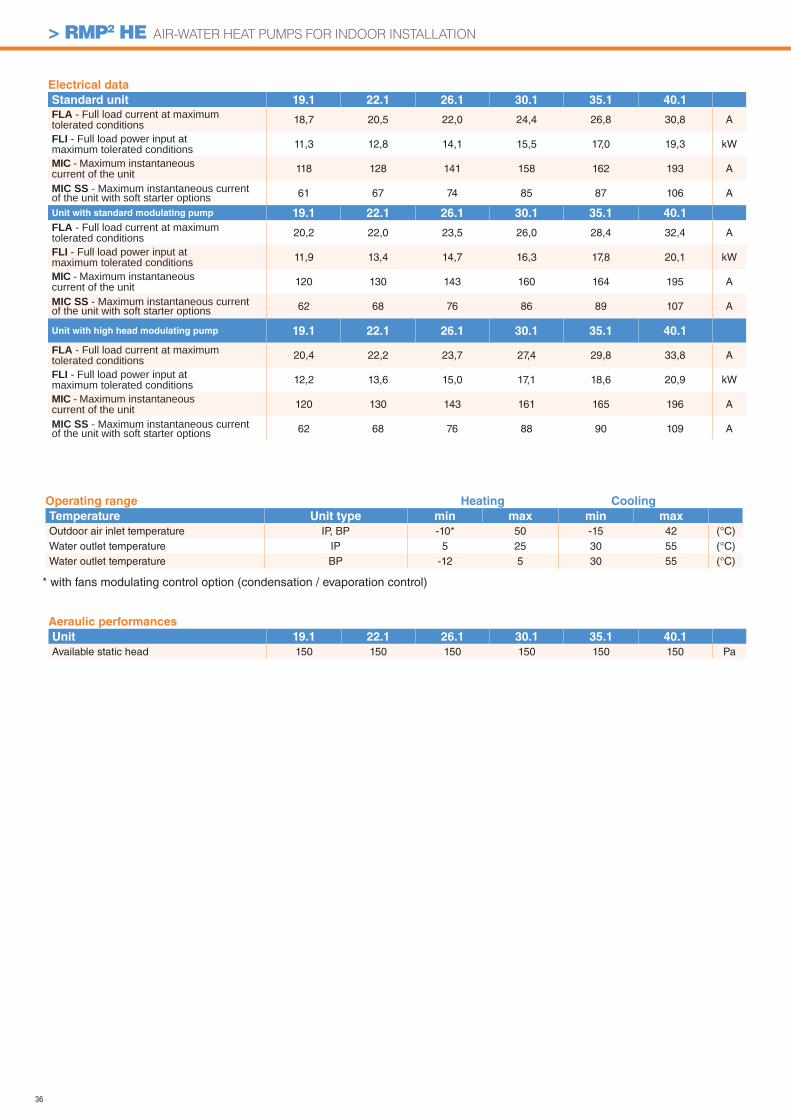
36
> RMP2 HE AIR-WATER HEAT PUMPS FOR INDOOR INSTALLATION
Aeraulic performances
Unit 19.1 22.1 26.1 30.1 35.1 40.1
Available static head 150 150 150 150 150 150 Pa
Electrical data
Standard unit 19.1 22.1 26.1 30.1 35.1 40.1
FLA - Full load current at maximum tolerated conditions 18,7 20,5 22,0 24,4 26,8 30,8 A
FLI - Full load power input at maximum tolerated conditions 11,3 12,8 14,1 15,5 17,0 19,3 kW
MIC - Maximum instantaneous current of the unit 118 128 141 158 162 193 A
MIC SS - Maximum instantaneous current of the unit with soft starter options 61 67 74 85 87 106 A
Unit with standard modulating pump 19.1 22.1 26.1 30.1 35.1 40.1
FLA - Full load current at maximum tolerated conditions 20,2 22,0 23,5 26,0 28,4 32,4 A
FLI - Full load power input at maximum tolerated conditions 11,9 13,4 14,7 16,3 17,8 20,1 kW
MIC - Maximum instantaneous current of the unit 120 130 143 160 164 195 A
MIC SS - Maximum instantaneous current of the unit with soft starter options 62 68 76 86 89 107 A
Unit with high head modulating pump 19.1 22.1 26.1 30.1 35.1 40.1
FLA - Full load current at maximum tolerated conditions 20,4 22,2 23,7 27,4 29,8 33,8 A
FLI - Full load power input at maximum tolerated conditions 12,2 13,6 15,0 17,1 18,6 20,9 kW
MIC - Maximum instantaneous current of the unit 120 130 143 161 165 196 A
MIC SS - Maximum instantaneous current of the unit with soft starter options 62 68 76 88 90 109 A
Operating range Heating Cooling
Temperature Unit type min max min max
Outdoor air inlet temperature IP, BP -10* 50 -15 42 (°C)Water outlet temperature IP 5 25 30 55 (°C)Water outlet temperature BP -12 5 30 55 (°C)
* with fans modulating control option (condensation / evaporation control)
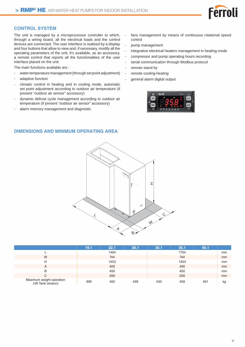
37
> RMP2 HE AIR-WATER HEAT PUMPS FOR INDOOR INSTALLATION
DIMENSIONS AND MINIMUM OPERATING AREA
B
C
AW
L
19.1 22.1 26.1 30.1 35.1 40.1
L 1494 1704 mmW 744 744 mmH 1453 1453 mmA 400 400 mmB 450 450 mmC 200 200 mm
Maximum weight operation(VA Tank version) 399 402 426 433 459 461 kg
The unit is managed by a microprocessor controller to which, through a wiring board, all the electrical loads and the control devices are connected. The user interface is realized by a display and four buttons that allow to view and, if necessary, modify all the operating parameters of the unit. It’s available, as an accessory, a remote control that reports all the functionalities of the user interface placed on the unit.The main functions available are :- water temperature management (through set point adjustment)- adaptive function- climatic control in heating and in cooling mode, automatic
set point adjustment according to outdoor air temperature (if present “outdoor air sensor” accessory)
- dynamic defrost cycle management according to outdoor air temperature (if present “outdoor air sensor” accessory)
- alarm memory management and diagnostic
- fans management by means of continuous rotational speed control
- pump management- integrative electrical heaters management in heating mode - compressor and pump operating hours recording- serial communication through Modbus protocol- remote stand by- remote cooling-heating- general alarm digital output
CONTROL SYSTEM
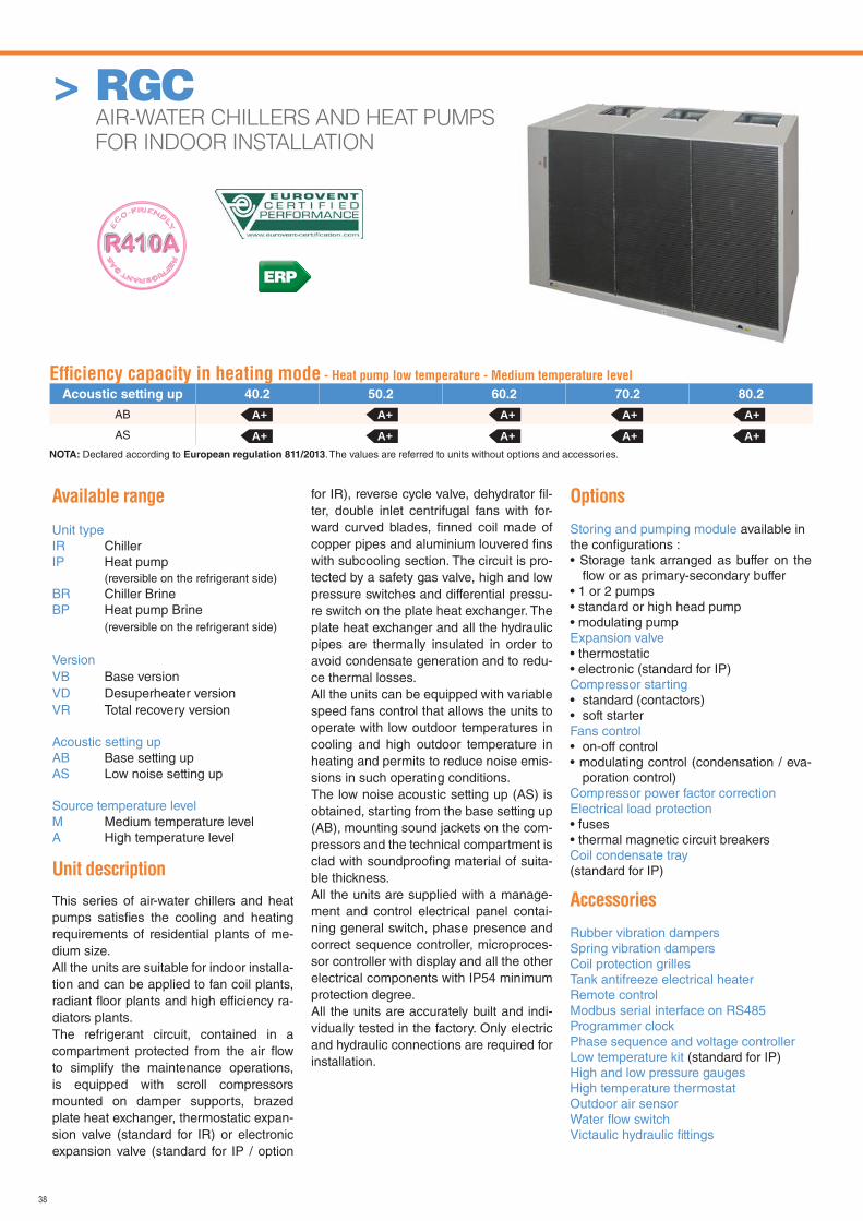
38
> RGC AIR-WATER CHILLERS AND HEAT PUMPS
FOR INDOOR INSTALLATION
Available range
Unit typeIR ChillerIP Heat pump (reversible on the refrigerant side)BR Chiller BrineBP Heat pump Brine (reversible on the refrigerant side)
VersionVB Base versionVD Desuperheater versionVR Total recovery version
Acoustic setting upAB Base setting upAS Low noise setting up
Source temperature levelM Medium temperature levelA High temperature level
Unit description
This series of air-water chillers and heat pumps satisfi es the cooling and heating requirements of residential plants of me-dium size.All the units are suitable for indoor installa-tion and can be applied to fan coil plants, radiant fl oor plants and high efficiency ra-diators plants.The refrigerant circuit, contained in a compartment protected from the air fl ow to simplify the maintenance operations, is equipped with scroll compressors mounted on damper supports, brazed plate heat exchanger, thermostatic expan-sion valve (standard for IR) or electronic expansion valve (standard for IP / option
for IR), reverse cycle valve, dehydrator fi l-ter, double inlet centrifugal fans with for-ward curved blades, fi nned coil made of copper pipes and aluminium louvered fi ns with subcooling section. The circuit is pro-tected by a safety gas valve, high and low pressure switches and differential pressu-re switch on the plate heat exchanger. The plate heat exchanger and all the hydraulic pipes are thermally insulated in order to avoid condensate generation and to redu-ce thermal losses.All the units can be equipped with variable speed fans control that allows the units to operate with low outdoor temperatures in cooling and high outdoor temperature in heating and permits to reduce noise emis-sions in such operating conditions.The low noise acoustic setting up (AS) is obtained, starting from the base setting up (AB), mounting sound jackets on the com-pressors and the technical compartment is clad with soundproofi ng material of suita-ble thickness.All the units are supplied with a manage-ment and control electrical panel contai-ning general switch, phase presence and correct sequence controller, microproces-sor controller with display and all the other electrical components with IP54 minimum protection degree.All the units are accurately built and indi-vidually tested in the factory. Only electric and hydraulic connections are required for installation.
Options
Storing and pumping module available in the confi gurations :• Storage tank arranged as buffer on the
fl ow or as primary-secondary buffer• 1 or 2 pumps• standard or high head pump• modulating pumpExpansion valve • thermostatic• electronic (standard for IP)Compressor starting• standard (contactors)• soft starterFans control• on-off control• modulating control (condensation / eva-
poration control)Compressor power factor correction Electrical load protection• fuses• thermal magnetic circuit breakersCoil condensate tray(standard for IP)
Accessories
Rubber vibration dampersSpring vibration dampersCoil protection grillesTank antifreeze electrical heaterRemote controlModbus serial interface on RS485Programmer clockPhase sequence and voltage controllerLow temperature kit (standard for IP)High and low pressure gaugesHigh temperature thermostatOutdoor air sensorWater fl ow switchVictaulic hydraulic fi ttings
Effi ciency capacity in heating mode - Heat pump low temperature - Medium temperature level
Acoustic setting up 40.2 50.2 60.2 70.2 80.2
AB
AS
A+ A+ A+ A+ A+
A+ A+ A+ A+ A+NOTA: Declared according to European regulation 811/2013. The values are referred to units without options and accessories.
ERP
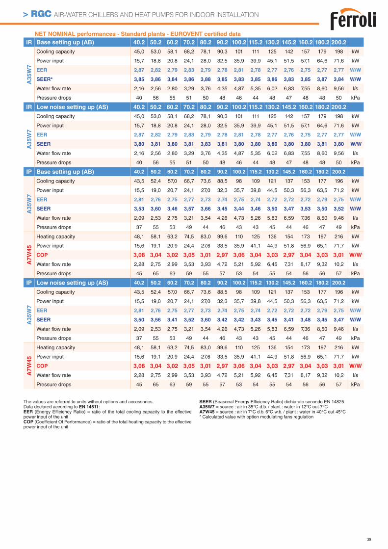
39
> RGC AIR-WATER CHILLERS AND HEAT PUMPS FOR INDOOR INSTALLATION
NET NOMINAL performances - Standard plants - EUROVENT certifi ed data
IR Base setting up (AB) 40.2 50.2 60.2 70.2 80.2 90.2 100.2 115.2 130.2 145.2 160.2 180.2 200.2
A3
5W
7
Cooling capacity 45,0 53,0 58,1 68,2 78,1 90,3 101 111 125 142 157 179 198 kW
Power input 15,7 18,8 20,8 24,1 28,0 32,5 35,9 39,9 45,1 51,5 57,1 64,6 71,6 kW
EER 2,87 2,82 2,79 2,83 2,79 2,78 2,81 2,78 2,77 2,76 2,75 2,77 2,77 W/W
SEER* 3,85 3,86 3,84 3,86 3,88 3,85 3,83 3,85 3,86 3,83 3,85 3,87 3,84 W/W
Water fl ow rate 2,16 2,56 2,80 3,29 3,76 4,35 4,87 5,35 6,02 6,83 7,55 8,60 9,56 l/s
Pressure drops 40 56 55 51 50 48 46 44 48 47 48 48 50 kPa
IR Low noise setting up (AS) 40.2 50.2 60.2 70.2 80.2 90.2 100.2 115.2 130.2 145.2 160.2 180.2 200.2
A3
5W
7
Cooling capacity 45,0 53,0 58,1 68,2 78,1 90,3 101 111 125 142 157 179 198 kW
Power input 15,7 18,8 20,8 24,1 28,0 32,5 35,9 39,9 45,1 51,5 57,1 64,6 71,6 kW
EER 2,87 2,82 2,79 2,83 2,79 2,78 2,81 2,78 2,77 2,76 2,75 2,77 2,77 W/W
SEER 3,80 3,81 3,80 3,81 3,83 3,81 3,80 3,80 3,80 3,80 3,80 3,81 3,80 W/W
Water fl ow rate 2,16 2,56 2,80 3,29 3,76 4,35 4,87 5,35 6,02 6,83 7,55 8,60 9,56 l/s
Pressure drops 40 56 55 51 50 48 46 44 48 47 48 48 50 kPa
IP Base setting up (AB) 40.2 50.2 60.2 70.2 80.2 90.2 100.2 115.2 130.2 145.2 160.2 180.2 200.2
A3
5W
7
Cooling capacity 43,5 52,4 57,0 66,7 73,6 88,5 98 109 121 137 153 177 196 kW
Power input 15,5 19,0 20,7 24,1 27,0 32,3 35,7 39,8 44,5 50,3 56,3 63,5 71,2 kW
EER 2,81 2,76 2,75 2,77 2,73 2,74 2,75 2,74 2,72 2,72 2,72 2,79 2,75 W/W
SEER 3,53 3,60 3,46 3,57 3,66 3,45 3,44 3,46 3,50 3,47 3,53 3,50 3,52 W/W
Water fl ow rate 2,09 2,53 2,75 3,21 3,54 4,26 4,73 5,26 5,83 6,59 7,36 8,50 9,46 l/s
Pressure drops 37 55 53 49 44 46 43 43 45 44 46 47 49 kPa
A7W
45
Heating capacity 48,1 58,1 63,2 74,5 83,0 99,6 110 125 136 154 173 197 216 kW
Power input 15,6 19,1 20,9 24,4 27,6 33,5 35,9 41,1 44,9 51,8 56,9 65,1 71,7 kW
COP 3,08 3,04 3,02 3,05 3,01 2,97 3,06 3,04 3,03 2,97 3,04 3,03 3,01 W/W
Water fl ow rate 2,28 2,75 2,99 3,53 3,93 4,72 5,21 5,92 6,45 7,31 8,17 9,32 10,2 l/s
Pressure drops 45 65 63 59 55 57 53 54 55 54 56 56 57 kPa
IP Low noise setting up (AS) 40.2 50.2 60.2 70.2 80.2 90.2 100.2 115.2 130.2 145.2 160.2 180.2 200.2
A35W
7
Cooling capacity 43,5 52,4 57,0 66,7 73,6 88,5 98 109 121 137 153 177 196 kW
Power input 15,5 19,0 20,7 24,1 27,0 32,3 35,7 39,8 44,5 50,3 56,3 63,5 71,2 kW
EER 2,81 2,76 2,75 2,77 2,73 2,74 2,75 2,74 2,72 2,72 2,72 2,79 2,75 W/W
SEER 3,50 3,56 3,41 3,52 3,60 3,42 3,42 3,43 3,45 3,41 3,48 3,45 3,47 W/W
Water fl ow rate 2,09 2,53 2,75 3,21 3,54 4,26 4,73 5,26 5,83 6,59 7,36 8,50 9,46 l/s
Pressure drops 37 55 53 49 44 46 43 43 45 44 46 47 49 kPa
A7W
45
Heating capacity 48,1 58,1 63,2 74,5 83,0 99,6 110 125 136 154 173 197 216 kW
Power input 15,6 19,1 20,9 24,4 27,6 33,5 35,9 41,1 44,9 51,8 56,9 65,1 71,7 kW
COP 3,08 3,04 3,02 3,05 3,01 2,97 3,06 3,04 3,03 2,97 3,04 3,03 3,01 W/W
Water fl ow rate 2,28 2,75 2,99 3,53 3,93 4,72 5,21 5,92 6,45 7,31 8,17 9,32 10,2 l/s
Pressure drops 45 65 63 59 55 57 53 54 55 54 56 56 57 kPa
The values are referred to units without options and accessories. Data declared according to EN 14511:EER (Energy Efficiency Ratio) = ratio of the total cooling capacity to the effective power input of the unitCOP (Coefficient Of Performance) = ratio of the total heating capacity to the effective power input of the unit
SEER (Seasonal Energy Efficiency Ratio) dichiarato secondo EN 14825A35W7 = source : air in 35°C d.b. / plant : water in 12°C out 7°CA7W45 = source : air in 7°C d.b. 6°C w.b. / plant : water in 40°C out 45°C* Calculated value with option modulating fans regulation
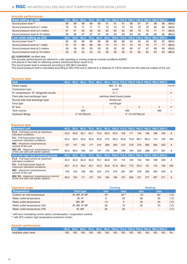
40
> RGC AIR-WATER CHILLERS AND HEAT PUMPS FOR INDOOR INSTALLATION
Aeraulic performance
Unit 40.2 50.2 60.2 70.2 80.2 90.2 100.2 115.2 130.2 145.2 160.2 180.2 200.2
Available static head 150 150 150 150 150 150 150 150 150 150 150 150 150 Pa
Acoustic performances
Base setting up (AB) 40.2 50.2 60.2 70.2 80.2 90.2 100.2 115.2 130.2 145.2 160.2 180.2 200.2
Sound power level (E) 88 88 89 89 89 91 91 91 96 97 97 98 98 dB(A)Sound pressure level at 1 meter 70 70 71 71 71 73 73 73 78 79 79 80 80 dB(A)Sound pressure level at 5 meters 61 61 62 62 62 65 65 65 69 70 70 71 71 dB(A)Sound pressure level at 10 meters 56 56 57 57 57 59 59 59 64 65 65 66 66 dB(A)
Low noise setting up (AS) 40.2 50.2 60.2 70.2 80.2 90.2 100.2 115.2 130.2 145.2 160.2 180.2 200.2
Sound power level (E) 85 85 86 86 86 88 88 88 93 94 94 95 95 dB(A)Sound pressure level at 1 meter 67 67 68 68 68 70 70 70 75 76 76 77 77 dB(A)Sound pressure level at 5 meters 58 58 59 59 59 62 62 62 66 67 67 68 68 dB(A)Sound pressure level at 10 meters 53 53 54 54 54 56 56 56 61 62 62 63 63 dB(A)
Electrical data
Standard unit 40.2 50.2 60.2 70.2 80.2 90.2 100.2 115.2 130.2 145.2 160.2 180.2 200.2
FLA - Full load current at maximum tolerated conditions 43,2 48,8 56,7 62,1 73,0 80,5 95,0 103 117 145 158 188 199 A
FLI - Full load power input at maximum tolerated conditions 25,2 28,0 33,0 35,6 40,8 47,3 58,3 63,8 72,8 88,7 96,3 113 120 kW
MIC - Maximum instantaneous current of the unit 137 147 152 177 216 269 264 272 278 370 383 384 420 A
MIC SS - Maximum instantaneous current of the unit with soft starter options 92,4 99,4 105 121 147 179 180 188 194 222 268 277 301 A
Unit with high head modulating pump 40.2 50.2 60.2 70.2 80.2 90.2 100.2 115.2 130.2 145.2 160.2 180.2 200.2
FLA - Full load current at maximum tolerated conditions 49,3 54,9 62,8 68,2 79,1 86,6 101 112 126 153 166 198 209 A
FLI - Full load power input at maximum tolerated conditions 28,7 31,5 36,5 39,1 44,3 50,8 61,8 68,4 77,3 93,2 101 119 126 kW
MIC - Maximum instantaneous current of the unit 143 153 158 183 222 275 270 281 287 378 392 394 430 A
MIC SS - Maximum instantaneous current of the unit with soft starter options 98,5 105 111 127 153 185 186 197 203 231 277 287 311 A
(E): EUROVENT certifi ed data The acoustic performances are referred to units operating in cooling mode at nominal conditions A35W7.Unit placed in free fi eld on refl ecting surface (directional factor equal to 2).The sound power level is measured according to ISO 9614 standard.The sound pressure level is calculated according to ISO 3744 and is referred to a distance of 1/5/10 metres from the external surface of the unit.
Operative range Cooling Heating
Temperature Unit type min max min max
Outdoor air inlet temperature IR, BR, IP, BP -10* 52** -10 40* (°C)Water outlet temperature IR, IP 5 25 30 55 (°C)Water outlet temperature BR, BP -12 5 30 55 (°C)Water outlet temperature (VD) IR, BR, IP, BP 30 70 30 70 (°C)Water outlet temperature (VR) IR, BR 30 55 - - (°C)
Technical data
Unit 40.2 50.2 60.2 70.2 80.2 90.2 100.2 115.2 130.2 145.2 160.2 180.2 200.2
Power supply 400 - 3 - 50 V-ph-Hz
Compressor type scroll -N° compressors / N° refrigerant circuits 2 / 1 n°Plant side heat exchanger type stainless steel brazed plates -Source side heat exchanger type fi nned coil -Fans type centrifugal -N° fans 1 2 3 4 n°Tank volume 200 400 460 lHydraulic fi ttings 2” VICTAULIC 2” 1/2 VICTAULIC -
* with fans modulating control option (condensation / evaporation control)** with ATC outdoor high temperature protection fuction
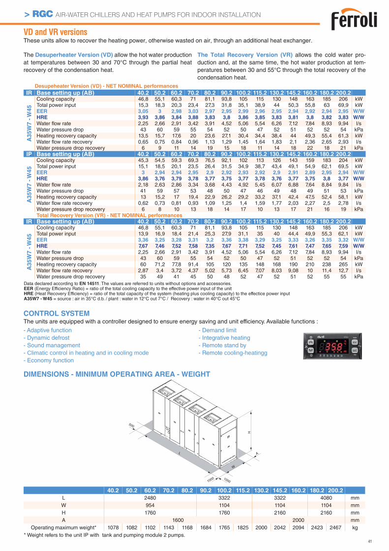
41
> RGC AIR-WATER CHILLERS AND HEAT PUMPS FOR INDOOR INSTALLATION
VD and VR versionsThese units allow to recover the heating power, otherwise wasted on air, through an additional heat exchanger.
The Desuperheater Version (VD) allow the hot water production at temperatures between 30 and 70°C through the partial heat recovery of the condensation heat.
The Total Recovery Version (VR) allows the cold water pro-duction and, at the same time, the hot water production at tem-peratures between 30 and 55°C through the total recovery of the condensation heat.
DIMENSIONS - MINIMUM OPERATING AREA - WEIGHT
1000
L
W
A
H
1000
500
40.2 50.2 60.2 70.2 80.2 90.2 100.2 115.2 130.2 145.2 160.2 180.2 200.2
L 2480 3322 3322 4080 mmW 954 1104 1104 1104 mmH 1760 1760 2160 2160 mmA 1600 2000 mm
Operating maximum weight* 1078 1082 1102 1143 1168 1684 1765 1825 2000 2042 2094 2423 2467 kg
CONTROL SYSTEMThe units are equipped with a controller designed to ensure energy saving and unit efficiency. Available functions :
- Adaptive function- Dynamic defrost - Sound management - Climatic control in heating and in cooling mode- Economy function
- Demand limit- Integrative heating- Remote stand by- Remote cooling-heatingg
Desupeheater Version (VD) - NET NOMINAL performances
IR Base setting up (AB) 40.2 50.2 60.2 70.2 80.2 90.2 100.2 115.2 130.2 145.2 160.2 180.2 200.2
A3
5W
7 -
W4
5
Cooling capacity 46,8 55,1 60,3 71 81,1 93,8 105 115 130 148 163 185 206 kWTotal power input 15,3 18,3 20,3 23,4 27,3 31,8 35,1 38,9 44 50,3 55,8 63 69,9 kWEER 3,05 3 2,98 3,03 2,97 2,95 2,99 2,96 2,95 2,94 2,92 2,94 2,95 W/W
HRE 3,93 3,86 3,84 3,88 3,83 3,8 3,86 3,85 3,83 3,81 3,8 3,82 3,83 W/W
Water fl ow rate 2,25 2,66 2,91 3,42 3,91 4,52 5,06 5,54 6,26 7,12 7,84 8,93 9,94 l/sWater pressure drop 43 60 59 55 54 52 50 47 52 51 52 52 54 kPaHeating recovery capacity 13,5 15,7 17,6 20 23,6 27,1 30,4 34,4 38,4 44 49,3 55,4 61,3 kWWater fl ow rate recovery 0,65 0,75 0,84 0,96 1,13 1,29 1,45 1,64 1,83 2,1 2,36 2,65 2,93 l/sWater pressure drop recovery 6 9 11 14 19 15 18 11 14 18 22 18 21 kPa
IP Base setting up (AB) 40.2 50.2 60.2 70.2 80.2 90.2 100.2 115.2 130.2 145.2 160.2 180.2 200.2
A3
5W
7 -
W4
5
Cooling capacity 45,3 54,5 59,3 69,3 76,5 92,1 102 113 126 143 159 183 204 kWTotal power input 15,1 18,5 20,1 23,5 26,4 31,5 34,9 38,7 43,4 49,1 54,9 62,1 69,5 kWEER 3 2,94 2,94 2,95 2,9 2,92 2,93 2,92 2,9 2,91 2,89 2,95 2,94 W/W
HRE 3,86 3,76 3,79 3,78 3,77 3,75 3,77 3,78 3,76 3,77 3,75 3,8 3,77 W/W
Water fl ow rate 2,18 2,63 2,86 3,34 3,68 4,43 4,92 5,45 6,07 6,88 7,64 8,84 9,84 l/sWater pressure drop 41 59 57 53 48 50 47 46 49 48 49 51 53 kPaHeating recovery capacity 13 15,2 17 19,4 22,9 26,2 29,2 33,2 37,1 42,4 47,5 52,4 58,1 kWWater fl ow rate recovery 0,62 0,73 0,81 0,93 1,09 1,25 1,4 1,59 1,77 2,03 2,27 2,5 2,78 l/sWater pressure drop recovery 6 8 10 13 18 14 17 10 13 17 21 16 19 kPaTotal Recovery Version (VR) - NET NOMINAL performances
IR Base setting up (AB) 40.2 50.2 60.2 70.2 80.2 90.2 100.2 115.2 130.2 145.2 160.2 180.2 200.2
A35W
7 -
W45
Cooling capacity 46,8 55,1 60,3 71 81,1 93,8 105 115 130 148 163 185 206 kWTotal power input 13,9 16,9 18,4 21,4 25,3 27,9 31,1 35 40 44,4 49,9 55,3 62,1 kWEER 3,36 3,25 3,28 3,31 3,2 3,36 3,38 3,29 3,25 3,33 3,26 3,35 3,32 W/W
HRE 7,67 7,46 7,52 7,58 7,35 7,67 7,71 7,52 7,45 7,61 7,47 7,65 7,59 W/W
Water fl ow rate 2,25 2,66 2,91 3,42 3,91 4,52 5,06 5,54 6,26 7,12 7,84 8,93 9,94 l/sWater pressure drop 43 60 59 55 54 52 50 47 52 51 52 52 54 kPaHeating recovery capacity 60 71,2 77,8 91,4 105 120 135 148 168 190 210 238 265 kWWater fl ow rate recovery 2,87 3,4 3,72 4,37 5,02 5,73 6,45 7,07 8,03 9,08 10 11,4 12,7 l/sWater pressure drop recovery 35 49 41 45 50 48 52 47 52 51 52 55 55 kPa
* Weight refers to the unit IP with tank and pumping module 2 pumps.
Data declared according to EN 14511. The values are referred to units without options and accessories.EER (Energy Efficiency Ratio) = ratio of the total cooling capacity to the effective power input of the unitHRE (Heat Recovery Efficiency) = ratio of the total capacity of the system (heating plus cooling capacity) to the effectice power inputA35W7 - W45 = source : air in 35°C d.b. / plant : water in 12°C out 7°C / Recovery : water in 40°C out 45°C
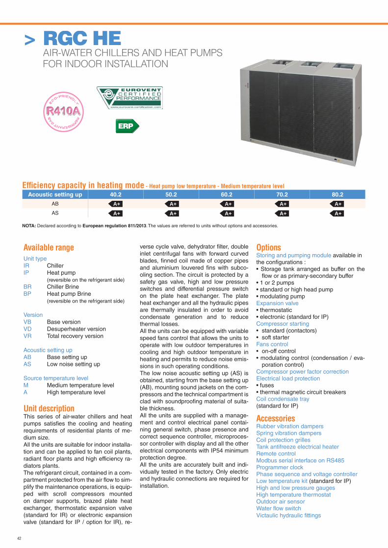
42
> RGC HE AIR-WATER CHILLERS AND HEAT PUMPS
FOR INDOOR INSTALLATION
Available range
Unit typeIR ChillerIP Heat pump (reversible on the refrigerant side)BR Chiller BrineBP Heat pump Brine (reversible on the refrigerant side)
VersionVB Base versionVD Desuperheater versionVR Total recovery version
Acoustic setting upAB Base setting upAS Low noise setting up
Source temperature levelM Medium temperature levelA High temperature level
Unit descriptionThis series of air-water chillers and heat pumps satisfi es the cooling and heating requirements of residential plants of me-dium size.All the units are suitable for indoor installa-tion and can be applied to fan coil plants, radiant fl oor plants and high efficiency ra-diators plants.The refrigerant circuit, contained in a com-partment protected from the air fl ow to sim-plify the maintenance operations, is equip-ped with scroll compressors mounted on damper supports, brazed plate heat exchanger, thermostatic expansion valve (standard for IR) or electronic expansion valve (standard for IP / option for IR), re-
verse cycle valve, dehydrator fi lter, double inlet centrifugal fans with forward curved blades, fi nned coil made of copper pipes and aluminium louvered fi ns with subco-oling section. The circuit is protected by a safety gas valve, high and low pressure switches and differential pressure switch on the plate heat exchanger. The plate heat exchanger and all the hydraulic pipes are thermally insulated in order to avoid condensate generation and to reduce thermal losses.All the units can be equipped with variable speed fans control that allows the units to operate with low outdoor temperatures in cooling and high outdoor temperature in heating and permits to reduce noise emis-sions in such operating conditions.The low noise acoustic setting up (AS) is obtained, starting from the base setting up (AB), mounting sound jackets on the com-pressors and the technical compartment is clad with soundproofi ng material of suita-ble thickness.All the units are supplied with a manage-ment and control electrical panel contai-ning general switch, phase presence and correct sequence controller, microproces-sor controller with display and all the other electrical components with IP54 minimum protection degree.All the units are accurately built and indi-vidually tested in the factory. Only electric and hydraulic connections are required for installation.
OptionsStoring and pumping module available in the confi gurations :• Storage tank arranged as buffer on the
fl ow or as primary-secondary buffer• 1 or 2 pumps• standard or high head pump• modulating pumpExpansion valve • thermostatic• electronic (standard for IP)Compressor starting• standard (contactors)• soft starterFans control• on-off control• modulating control (condensation / eva-
poration control)Compressor power factor correction Electrical load protection• fuses• thermal magnetic circuit breakersCoil condensate tray(standard for IP)
AccessoriesRubber vibration dampersSpring vibration dampersCoil protection grillesTank antifreeze electrical heaterRemote controlModbus serial interface on RS485Programmer clockPhase sequence and voltage controllerLow temperature kit (standard for IP)High and low pressure gaugesHigh temperature thermostatOutdoor air sensorWater fl ow switchVictaulic hydraulic fi ttings
Effi ciency capacity in heating mode - Heat pump low temperature - Medium temperature level
Acoustic setting up 40.2 50.2 60.2 70.2 80.2
AB
AS
A+ A+ A+ A+ A+
A+ A+ A+ A+ A+
NOTA: Declared according to European regulation 811/2013. The values are referred to units without options and accessories.
ERP
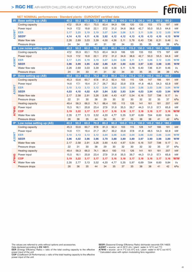
43
> RGC HE AIR-WATER CHILLERS AND HEAT PUMPS FOR INDOOR INSTALLATION
NET NOMINAL performances - Standard plants - EUROVENT certifi ed data
IR Base setting up (AB) 40.2 50.2 60.2 70.2 80.2 90.2 100.2 115.2 130.2 145.2 160.2 180.2
A3
5W
7
Cooling capacity 47,2 55,9 63,1 70,5 83,4 94,9 106 120 133 153 173 197 kW
Power input 14,9 17,2 19,8 22,1 27,2 31,2 34,6 38,6 42,7 50,0 55,5 64,6 kW
EER 3,17 3,25 3,19 3,19 3,07 3,04 3,06 3,11 3,11 3,06 3,12 3,05 W/W
SEER* 4,14 4,15 4,11 4,16 3,92 4,12 4,12 4,13 4,15 4,13 4,10 4,13 W/W
Water fl ow rate 2,26 2,69 3,03 3,39 4,00 4,56 5,11 5,78 6,40 7,36 8,31 9,46 l/s
Pressure drops 24 34 33 41 31 32 34 33 35 35 38 39 kPa
IR Low noise setting up (AS) 40.2 50.2 60.2 70.2 80.2 90.2 100.2 115.2 130.2 145.2 160.2 180.2
A3
5W
7
Cooling capacity 47,2 55,9 63,1 70,5 83,4 94,9 106 120 133 153 173 197 kW
Power input 14,9 17,2 19,8 22,1 27,2 31,2 34,6 38,6 42,7 50,0 55,5 64,6 kW
EER 3,17 3,25 3,19 3,19 3,07 3,04 3,06 3,11 3,11 3,06 3,12 3,05 W/W
SEER 3,96 3,99 3,95 4,02 3,86 4,01 3,90 4,00 3,97 3,93 3,98 3,95 W/W
Water fl ow rate 2,26 2,69 3,03 3,39 4,00 4,56 5,11 5,78 6,40 7,36 8,31 9,46 l/s
Pressure drops 24 34 33 41 31 32 34 33 35 35 38 39 kPa
IP Base setting up (AB) 40.2 50.2 60.2 70.2 80.2 90.2 100.2 115.2 130.2 145.2 160.2 180.2
A3
5W
7
Cooling capacity 45,3 53,6 60,7 67,8 81,3 92,4 103 115 128 147 166 191 kW
Power input 14,6 17,1 19,4 21,7 26,7 30,2 33,8 37,8 41,8 48,5 54,3 62,8 kW
EER 3,10 3,13 3,13 3,12 3,04 3,06 3,05 3,04 3,06 3,03 3,06 3,04 W/W
SEER 4,03 4,10 4,02 4,01 3,84 3,92 3,93 3,94 4,03 3,94 4,03 3,94 W/W
Water fl ow rate 2,17 2,58 2,91 3,26 3,90 4,43 4,97 5,54 6,16 7,07 7,98 9,17 l/s
Pressure drops 22 31 30 38 29 30 32 30 32 32 35 37 kPa
A7W
45
Heating capacity 49,4 58,3 66,0 74,1 88,4 100 113 126 141 161 181 207 kW
Power input 15,5 18,1 20,8 23,4 27,9 31,6 35,5 39,7 44,3 51,0 57,1 65,6 kW
COP 3,19 3,22 3,17 3,17 3,17 3,16 3,18 3,17 3,18 3,16 3,17 3,16 W/W
Water fl ow rate 2,35 2,77 3,13 3,52 4,20 4,77 5,35 5,97 6,69 7,64 8,60 9,84 l/s
Pressure drops 26 36 35 44 34 35 37 35 38 38 41 42 kPa
IP Low noise setting up (AS) 40.2 50.2 60.2 70.2 80.2 90.2 100.2 115.2 130.2 145.2 160.2 180.2
A35W
7
Cooling capacity 45,3 53,6 60,7 67,8 81,3 92,4 103 115 128 147 166 191 kW
Power input 14,6 17,1 19,4 21,7 26,7 30,2 33,8 37,8 41,8 48,5 54,3 62,8 kW
EER 3,10 3,13 3,13 3,12 3,04 3,06 3,05 3,04 3,06 3,03 3,06 3,04 W/W
SEER 3,96 4,02 3,96 3,96 3,79 3,88 3,89 3,89 3,97 3,90 3,98 3,89 W/W
Water fl ow rate 2,17 2,58 2,91 3,26 3,90 4,43 4,97 5,54 6,16 7,07 7,98 9,17 l/s
Pressure drops 22 31 30 38 29 30 32 30 32 32 35 37 kPa
A7W
45
Heating capacity 49,4 58,3 66,0 74,1 88,4 100 113 126 141 161 181 207 kW
Power input 15,5 18,1 20,8 23,4 27,9 31,6 35,5 39,7 44,3 51,0 57,1 65,6 kW
COP 3,19 3,22 3,17 3,17 3,17 3,16 3,18 3,17 3,18 3,16 3,17 3,16 W/W
Water fl ow rate 2,35 2,77 3,13 3,52 4,20 4,77 5,35 5,97 6,69 7,64 8,60 9,84 l/s
Pressure drops 26 36 35 44 34 35 37 35 38 38 41 42 kPa
The values are referred to units without options and accessories. Data declared according to EN 14511:EER (Energy Efficiency Ratio) = ratio of the total cooling capacity to the effective power input of the unitCOP (Coefficient Of Performance) = ratio of the total heating capacity to the effective power input of the unit
SEER (Seasonal Energy Efficiency Ratio) dichiarato secondo EN 14825A35W7 = source : air in 35°C d.b. / plant : water in 12°C out 7°CA7W45 = source : air in 7°C d.b. 6°C w.b. / plant : water in 40°C out 45°C* Calculated value with option modulating fans regulation
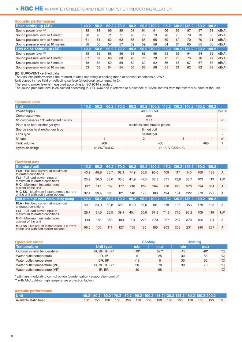
44
> RGC HE AIR-WATER CHILLERS AND HEAT PUMPS FOR INDOOR INSTALLATION
Aeraulic performance
Unit 40.2 50.2 60.2 70.2 80.2 90.2 100.2 115.2 130.2 145.2 160.2 180.2 200.2
Available static head 150 150 150 150 150 150 150 150 150 150 150 150 150 Pa
Acoustic performances
Base setting up (AB) 40.2 50.2 60.2 70.2 80.2 90.2 100.2 115.2 130.2 145.2 160.2 180.2
Sound power level (E) 88 88 89 89 91 91 91 96 96 97 97 98 dB(A)Sound pressure level at 1 meter 70 70 71 71 73 73 73 78 78 79 79 80 dB(A)Sound pressure level at 5 meters 61 61 62 62 65 65 65 69 69 70 70 71 dB(A)Sound pressure level at 10 meters 56 56 57 57 59 59 59 64 64 65 65 66 dB(A)
Low noise setting up (AS) 40.2 50.2 60.2 70.2 80.2 90.2 100.2 115.2 130.2 145.2 160.2 180.2
Sound power level (E) 85 85 86 86 88 88 88 93 93 94 94 95 dB(A)Sound pressure level at 1 meter 67 67 68 68 70 70 70 75 75 76 76 77 dB(A)Sound pressure level at 5 meters 58 58 59 59 62 62 62 66 66 67 67 68 dB(A)Sound pressure level at 10 meters 53 53 54 54 56 56 56 61 61 62 62 63 dB(A)
Electrical data
Standard unit 40.2 50.2 60.2 70.2 80.2 90.2 100.2 115.2 130.2 145.2 160.2 180.2FLA - Full load current at maximum tolerated conditions 43,2 48,8 56,7 62,1 74,9 80,5 95,0 109 117 145 169 188 A
FLI - Full load power input at maximum tolerated conditions 25,2 28,0 33,0 35,6 41,9 47,3 58,3 67,3 72,8 88,7 103 113 kW
MIC - Maximum instantaneous current of the unit 137 147 152 177 218 269 264 278 278 370 394 384 A
MIC SS - Maximum instantaneous current of the unit with soft starter options 92,4 99,4 105 121 148 179 180 194 194 222 279 277 A
Unit with high head modulating pump 40.2 50.2 60.2 70.2 80.2 90.2 100.2 115.2 130.2 145.2 160.2 180.2
FLA - Full load current at maximum tolerated conditions 49,3 54,9 62,8 68,2 81,0 86,6 101 118 126 153 179 198 A
FLI - Full load power input at maximum tolerated conditions 28,7 31,5 36,5 39,1 45,4 50,8 61,8 71,8 77,3 93,2 109 119 kW
MIC - Maximum instantaneous current of the unit 143 153 158 183 224 275 270 287 287 378 405 394 A
MIC SS - Maximum instantaneous current of the unit with soft starter options 98,5 105 111 127 155 185 186 203 203 231 290 287 A
(E): EUROVENT certifi ed data The acoustic performances are referred to units operating in cooling mode at nominal conditions A35W7.Unit placed in free fi eld on refl ecting surface (directional factor equal to 2).The sound power level is measured according to ISO 9614 standard.The sound pressure level is calculated according to ISO 3744 and is referred to a distance of 1/5/10 metres from the external surface of the unit.
Operative range Cooling Heating
Temperature Unit type min max min max
Outdoor air inlet temperature IR, BR, IP, BP -10* 52** -15 40* (°C)Water outlet temperature IR, IP 5 25 30 55 (°C)Water outlet temperature BR, BP -12 5 30 55 (°C)Water outlet temperature (VD) IR, BR, IP, BP 30 70 30 70 (°C)Water outlet temperature (VR) IR, BR 30 55 - - (°C)
Technical data
Unit 40.2 50.2 60.2 70.2 80.2 90.2 100.2 115.2 130.2 145.2 160.2 180.2
Power supply 400 - 3 - 50 V-ph-Hz
Compressor type scroll -N° compressors / N° refrigerant circuits 2 / 1 n°Plant side heat exchanger type stainless steel brazed plates -Source side heat exchanger type fi nned coil -Fans type centrifugal -N° fans 1 2 3 4 n°Tank volume 200 400 460 lHydraulic fi ttings 2” VICTAULIC 2” 1/2 VICTAULIC -
* with fans modulating control option (condensation / evaporation control)** with ATC outdoor high temperature protection fuction
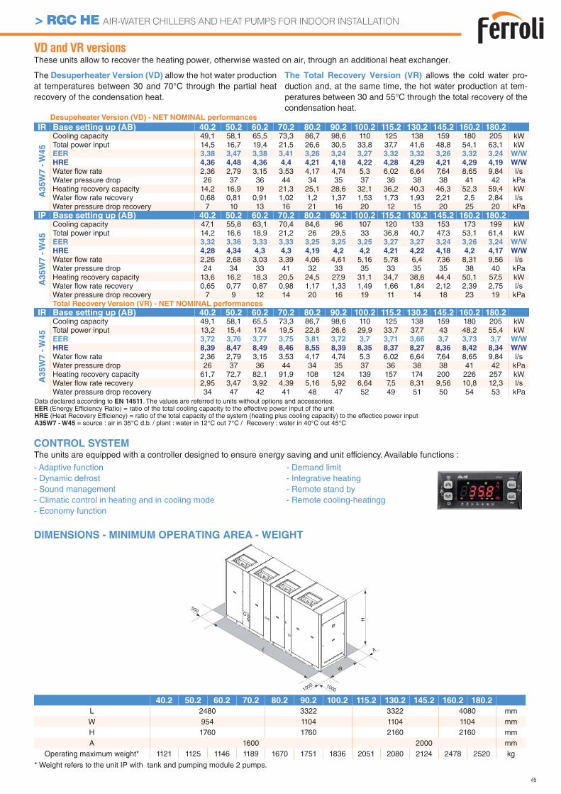
45
> RGC HE AIR-WATER CHILLERS AND HEAT PUMPS FOR INDOOR INSTALLATION
VD and VR versionsThese units allow to recover the heating power, otherwise wasted on air, through an additional heat exchanger.
The Desuperheater Version (VD) allow the hot water production at temperatures between 30 and 70°C through the partial heat recovery of the condensation heat.
The Total Recovery Version (VR) allows the cold water pro-duction and, at the same time, the hot water production at tem-peratures between 30 and 55°C through the total recovery of the condensation heat.
DIMENSIONS - MINIMUM OPERATING AREA - WEIGHT
1000
L
W
A
H
1000
500
40.2 50.2 60.2 70.2 80.2 90.2 100.2 115.2 130.2 145.2 160.2 180.2
L 2480 3322 3322 4080 mmW 954 1104 1104 1104 mmH 1760 1760 2160 2160 mmA 1600 2000 mm
Operating maximum weight* 1121 1125 1146 1189 1670 1751 1836 2051 2080 2124 2478 2520 kg
CONTROL SYSTEMThe units are equipped with a controller designed to ensure energy saving and unit efficiency. Available functions :
- Adaptive function- Dynamic defrost - Sound management - Climatic control in heating and in cooling mode- Economy function
- Demand limit- Integrative heating- Remote stand by- Remote cooling-heatingg
Desupeheater Version (VD) - NET NOMINAL performances
IR Base setting up (AB) 40.2 50.2 60.2 70.2 80.2 90.2 100.2 115.2 130.2 145.2 160.2 180.2
A3
5W
7 -
W4
5
Cooling capacity 49,1 58,1 65,5 73,3 86,7 98,6 110 125 138 159 180 205 kWTotal power input 14,5 16,7 19,4 21,5 26,6 30,5 33,8 37,7 41,6 48,8 54,1 63,1 kWEER 3,38 3,47 3,38 3,41 3,26 3,24 3,27 3,32 3,32 3,26 3,32 3,24 W/W
HRE 4,36 4,48 4,36 4,4 4,21 4,18 4,22 4,28 4,29 4,21 4,29 4,19 W/W
Water fl ow rate 2,36 2,79 3,15 3,53 4,17 4,74 5,3 6,02 6,64 7,64 8,65 9,84 l/sWater pressure drop 26 37 36 44 34 35 37 36 38 38 41 42 kPaHeating recovery capacity 14,2 16,9 19 21,3 25,1 28,6 32,1 36,2 40,3 46,3 52,3 59,4 kWWater fl ow rate recovery 0,68 0,81 0,91 1,02 1,2 1,37 1,53 1,73 1,93 2,21 2,5 2,84 l/sWater pressure drop recovery 7 10 13 16 21 16 20 12 15 20 25 20 kPa
IP Base setting up (AB) 40.2 50.2 60.2 70.2 80.2 90.2 100.2 115.2 130.2 145.2 160.2 180.2
A3
5W
7 -
W4
5
Cooling capacity 47,1 55,8 63,1 70,4 84,6 96 107 120 133 153 173 199 kWTotal power input 14,2 16,6 18,9 21,2 26 29,5 33 36,8 40,7 47,3 53,1 61,4 kWEER 3,32 3,36 3,33 3,33 3,25 3,25 3,25 3,27 3,27 3,24 3,26 3,24 W/W
HRE 4,28 4,34 4,3 4,3 4,19 4,2 4,2 4,21 4,22 4,18 4,2 4,17 W/W
Water fl ow rate 2,26 2,68 3,03 3,39 4,06 4,61 5,16 5,78 6,4 7,36 8,31 9,56 l/sWater pressure drop 24 34 33 41 32 33 35 33 35 35 38 40 kPaHeating recovery capacity 13,6 16,2 18,3 20,5 24,5 27,9 31,1 34,7 38,6 44,4 50,1 57,5 kWWater fl ow rate recovery 0,65 0,77 0,87 0,98 1,17 1,33 1,49 1,66 1,84 2,12 2,39 2,75 l/sWater pressure drop recovery 7 9 12 14 20 16 19 11 14 18 23 19 kPaTotal Recovery Version (VR) - NET NOMINAL performances
IR Base setting up (AB) 40.2 50.2 60.2 70.2 80.2 90.2 100.2 115.2 130.2 145.2 160.2 180.2
A35W
7 -
W45
Cooling capacity 49,1 58,1 65,5 73,3 86,7 98,6 110 125 138 159 180 205 kWTotal power input 13,2 15,4 17,4 19,5 22,8 26,6 29,9 33,7 37,7 43 48,2 55,4 kWEER 3,72 3,76 3,77 3,75 3,81 3,72 3,7 3,71 3,66 3,7 3,73 3,7 W/W
HRE 8,39 8,47 8,49 8,46 8,55 8,39 8,35 8,37 8,27 8,36 8,42 8,34 W/W
Water fl ow rate 2,36 2,79 3,15 3,53 4,17 4,74 5,3 6,02 6,64 7,64 8,65 9,84 l/sWater pressure drop 26 37 36 44 34 35 37 36 38 38 41 42 kPaHeating recovery capacity 61,7 72,7 82,1 91,9 108 124 139 157 174 200 226 257 kWWater fl ow rate recovery 2,95 3,47 3,92 4,39 5,16 5,92 6,64 7,5 8,31 9,56 10,8 12,3 l/sWater pressure drop recovery 34 47 42 41 48 47 52 49 51 50 54 53 kPa
* Weight refers to the unit IP with tank and pumping module 2 pumps.
Data declared according to EN 14511. The values are referred to units without options and accessories.EER (Energy Efficiency Ratio) = ratio of the total cooling capacity to the effective power input of the unitHRE (Heat Recovery Efficiency) = ratio of the total capacity of the system (heating plus cooling capacity) to the effectice power inputA35W7 - W45 = source : air in 35°C d.b. / plant : water in 12°C out 7°C / Recovery : water in 40°C out 45°C
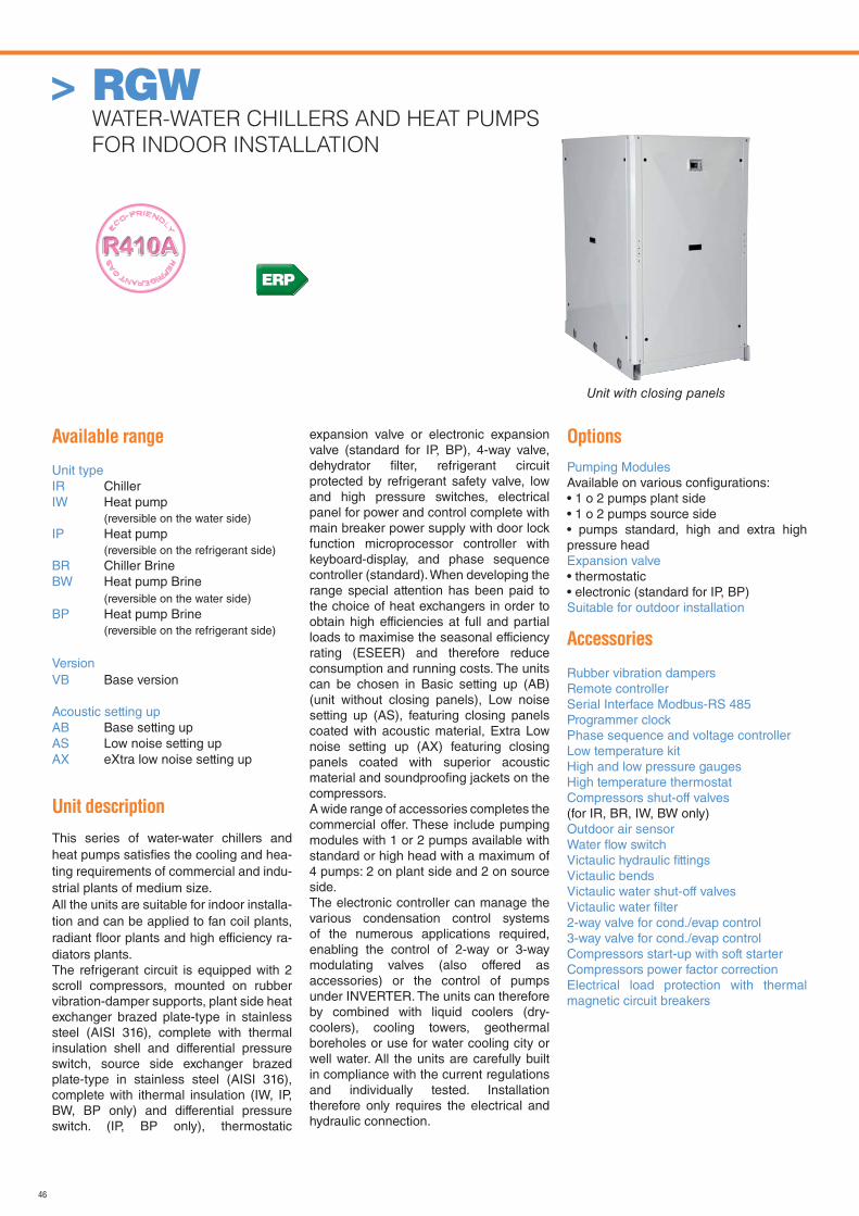
46
> RGWWATER-WATER CHILLERS AND HEAT PUMPS
FOR INDOOR INSTALLATION
ERP
Unit with closing panels
Available range
Unit typeIR ChillerIW Heat pump
(reversible on the water side)IP Heat pump
(reversible on the refrigerant side)BR Chiller BrineBW Heat pump Brine
(reversible on the water side)BP Heat pump Brine
(reversible on the refrigerant side)
VersionVB Base version
Acoustic setting upAB Base setting upAS Low noise setting upAX eXtra low noise setting up
Unit description
This series of water-water chillers and heat pumps satisfi es the cooling and hea-ting requirements of commercial and indu-strial plants of medium size.All the units are suitable for indoor installa-tion and can be applied to fan coil plants, radiant fl oor plants and high efficiency ra-diators plants.The refrigerant circuit is equipped with 2 scroll compressors, mounted on rubber vibration-damper supports, plant side heat exchanger brazed plate-type in stainless steel (AISI 316), complete with thermal insulation shell and differential pressure switch, source side exchanger brazed plate-type in stainless steel (AISI 316), complete with ithermal insulation (IW, IP, BW, BP only) and differential pressure switch. (IP, BP only), thermostatic
expansion valve or electronic expansion valve (standard for IP, BP), 4-way valve, dehydrator fi lter, refrigerant circuit protected by refrigerant safety valve, low and high pressure switches, electrical panel for power and control complete with main breaker power supply with door lock function microprocessor controller with keyboard-display, and phase sequence controller (standard). When developing the range special attention has been paid to the choice of heat exchangers in order to obtain high efficiencies at full and partial loads to maximise the seasonal efficiency rating (ESEER) and therefore reduce consumption and running costs. The units can be chosen in Basic setting up (AB) (unit without closing panels), Low noise setting up (AS), featuring closing panels coated with acoustic material, Extra Low noise setting up (AX) featuring closing panels coated with superior acoustic material and soundproofi ng jackets on the compressors.A wide range of accessories completes the commercial offer. These include pumping modules with 1 or 2 pumps available with standard or high head with a maximum of 4 pumps: 2 on plant side and 2 on source side.The electronic controller can manage the various condensation control systems of the numerous applications required, enabling the control of 2-way or 3-way modulating valves (also offered as accessories) or the control of pumps under INVERTER. The units can therefore by combined with liquid coolers (dry-coolers), cooling towers, geothermal boreholes or use for water cooling city or well water. All the units are carefully built in compliance with the current regulations and individually tested. Installation therefore only requires the electrical and hydraulic connection.
Options
Pumping ModulesAvailable on various confi gurations:• 1 o 2 pumps plant side• 1 o 2 pumps source side• pumps standard, high and extra highpressure headExpansion valve• thermostatic• electronic (standard for IP, BP)Suitable for outdoor installation
Accessories
Rubber vibration dampersRemote controllerSerial Interface Modbus-RS 485Programmer clockPhase sequence and voltage controllerLow temperature kit High and low pressure gaugesHigh temperature thermostatCompressors shut-off valves (for IR, BR, IW, BW only)Outdoor air sensorWater fl ow switchVictaulic hydraulic fi ttingsVictaulic bendsVictaulic water shut-off valvesVictaulic water fi lter2-way valve for cond./evap control3-way valve for cond./evap controlCompressors start-up with soft starterCompressors power factor correctionElectrical load protection with thermalmagnetic circuit breakers
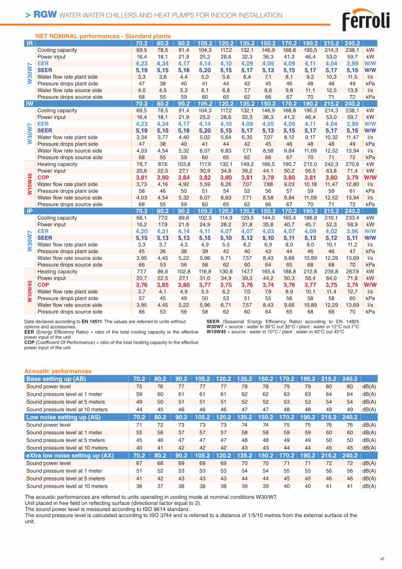
47
> RGW WATER-WATER CHILLERS AND HEAT PUMPS FOR INDOOR INSTALLATION
NET NOMINAL performances - Standard plants
IR 70.2 80.2 90.2 105.2 120.2 135.2 150.2 170.2 190.2 215.2 240.2
W3
0W
7
Cooling capacity 69,5 78,5 91,4 104,3 117,2 132,1 146,9 168,8 190,5 214,3 238,1 kWPower input 16,4 18,1 21,9 25,2 28,6 32,3 36,3 41,3 46,4 53,0 59,7 kWEER 4,23 4,34 4,17 4,14 4,10 4,09 4,05 4,09 4,11 4,04 3,99 W/W
SEER 5,19 5,15 5,16 5,20 5,15 5,17 5,13 5,15 5,17 5,17 5,15 W/W
Water fl ow rate plant side 3,3 3,8 4,4 5,0 5,6 6,4 7,1 8,1 9,2 10,3 11,5 l/sPressure drops plant side 47 38 40 41 44 42 45 46 48 48 49 kPaWater fl ow rate source side 4,0 4,5 5,3 6,1 6,8 7,7 8,6 9,8 11,1 12,5 13,9 l/sPressure drops source side 68 55 59 60 65 62 66 67 70 71 72 kPa
IW 70.2 80.2 90.2 105.2 120.2 135.2 150.2 170.2 190.2 215.2 240.2
W3
0W
7
Cooling capacity 69,5 78,5 91,4 104,3 117,2 132,1 146,9 168,8 190,5 214,3 238,1 kWPower input 16,4 18,1 21,9 25,2 28,6 32,3 36,3 41,3 46,4 53,0 59,7 kWEER 4,23 4,34 4,17 4,14 4,10 4,09 4,05 4,09 4,11 4,04 3,99 W/W
SEER 5,19 5,15 5,16 5,20 5,15 5,17 5,13 5,15 5,17 5,17 5,15 W/W
Water fl ow rate plant side 3,34 3,77 4,40 5,02 5,64 6,35 7,07 8,12 9,17 10,32 11,47 l/sPressure drops plant side 47 38 40 41 44 42 45 46 48 48 49 kPaWater fl ow rate source side 4,03 4,54 5,32 6,07 6,83 7,71 8,58 9,84 11,09 12,52 13,94 l/sPressure drops source side 68 55 59 60 65 62 66 67 70 71 72 kPa
W10W
45
Heating capacity 78,7 87,6 103,8 117,9 132,1 149,2 166,5 190,7 215,0 242,3 270,6 kWPower input 20,6 22,5 27,1 30,9 34,8 39,2 44,1 50,2 56,5 63,8 71,4 kWCOP 3,81 3,90 3,84 3,82 3,80 3,81 3,78 3,80 3,81 3,80 3,79 W/WWater fl ow rate plant side 3,73 4,16 4,92 5,59 6,26 7,07 7,88 9,03 10,18 11,47 12,80 l/sPressure drops plant side 58 46 50 51 54 52 56 57 59 59 61 kPaWater fl ow rate source side 4,03 4,54 5,32 6,07 6,83 7,71 8,58 9,84 11,09 12,52 13,94 l/sPressure drops source side 68 55 59 60 65 62 66 67 70 71 72 kPa
IP 70.2 80.2 90.2 105.2 120.2 135.2 150.2 170.2 190.2 215.2 240.2
W30W
7
Cooling capacity 68,1 77,0 89,6 102,3 114,9 129,5 144,0 165,4 186,8 210,1 233,4 kWPower input 16,2 17,9 21,6 24,9 28,2 31,8 35,8 40,7 45,7 52,3 58,9 kWEER 4,20 4,31 4,14 4,11 4,07 4,07 4,03 4,07 4,09 4,02 3,96 W/W
SEER 5,15 5,13 5,13 5,15 5,10 5,12 5,10 5,11 5,13 5,12 5,11 W/W
Water fl ow rate plant side 3,3 3,7 4,3 4,9 5,5 6,2 6,9 8,0 9,0 10,1 11,2 l/sPressure drops plant side 45 36 38 39 42 40 43 44 46 46 47 kPaWater fl ow rate source side 3,95 4,45 5,22 5,96 6,71 7,57 8,43 9,66 10,89 12,29 13,69 l/sPressure drops source side 66 53 56 58 62 60 64 65 68 68 70 kPa
W10W
45
Heating capacity 77,7 86,6 102,8 116,8 130,8 147,7 165,4 188,8 212,8 239,8 267,9 kWPower input 20,7 22,5 27,1 31,0 34,9 39,3 44,2 50,3 56,4 64,0 71,6 kWCOP 3,76 3,85 3,80 3,77 3,75 3,76 3,74 3,76 3,77 3,75 3,74 W/WWater fl ow rate plant side 3,7 4,1 4,9 5,5 6,2 7,0 7,8 8,9 10,1 11,4 12,7 l/sPressure drops plant side 57 45 49 50 53 51 55 56 58 58 60 kPaWater fl ow rate source side 3,95 4,45 5,22 5,96 6,71 7,57 8,43 9,66 10,89 12,29 13,69 l/sPressure drops source side 66 53 56 58 62 60 64 65 68 68 70 kPa
Acoustic performances
Base setting up (AB) 70.2 80.2 90.2 105.2 120.2 135.2 150.2 170.2 190.2 215.2 240.2Sound power level 75 76 77 77 77 78 78 79 79 80 80 dB(A)Sound pressure level at 1 meter 59 60 61 61 61 62 62 63 63 64 64 dB(A)Sound pressure level at 5 meters 49 50 51 51 51 52 52 53 53 54 54 dB(A)Sound pressure level at 10 meters 44 45 46 46 46 47 47 48 48 49 49 dB(A)
Low noise setting up (AS) 70.2 80.2 90.2 105.2 120.2 135.2 150.2 170.2 190.2 215.2 240.2Sound power level 71 72 73 73 73 74 74 75 75 76 76 dB(A)Sound pressure level at 1 meter 55 56 57 57 57 58 58 59 59 60 60 dB(A)Sound pressure level at 5 meters 45 46 47 47 47 48 48 49 49 50 50 dB(A)Sound pressure level at 10 meters 40 41 42 42 42 43 43 44 44 45 45 dB(A)
eXtra low noise setting up (AX) 70.2 80.2 90.2 105.2 120.2 135.2 150.2 170.2 190.2 215.2 240.2Sound power level 67 68 69 69 69 70 70 71 71 72 72 dB(A)Sound pressure level at 1 meter 51 52 53 53 53 54 54 55 55 56 56 dB(A)Sound pressure level at 5 meters 41 42 43 43 43 44 44 45 45 46 46 dB(A)Sound pressure level at 10 meters 36 37 38 38 38 39 39 40 40 41 41 dB(A)
The acoustic performances are referred to units operating in cooling mode at nominal conditions W30/W7.Unit placed in free fi eld on refl ecting surface (directional factor equal to 2).The sound power level is measured according to ISO 9614 standard.The sound pressure level is calculated according to ISO 3744 and is referred to a distance of 1/5/10 metres from the external surface of the unit.
Data declared according to EN 14511. The values are referred to units without options and accessories.EER (Energy Efficiency Ratio) = ratio of the total cooling capacity to the effective power input of the unitCOP (Coefficient Of Performance) = ratio of the total heating capacity to the effective power input of the unit
SEER (Seasonal Energy Efficiency Ratio) according to EN 14825 W30W7 = source : water in 30°C out 35°C / plant : water in 12°C out 7°C W10W45 = source : water in 10°C / plant : water in 40°C out 45°C
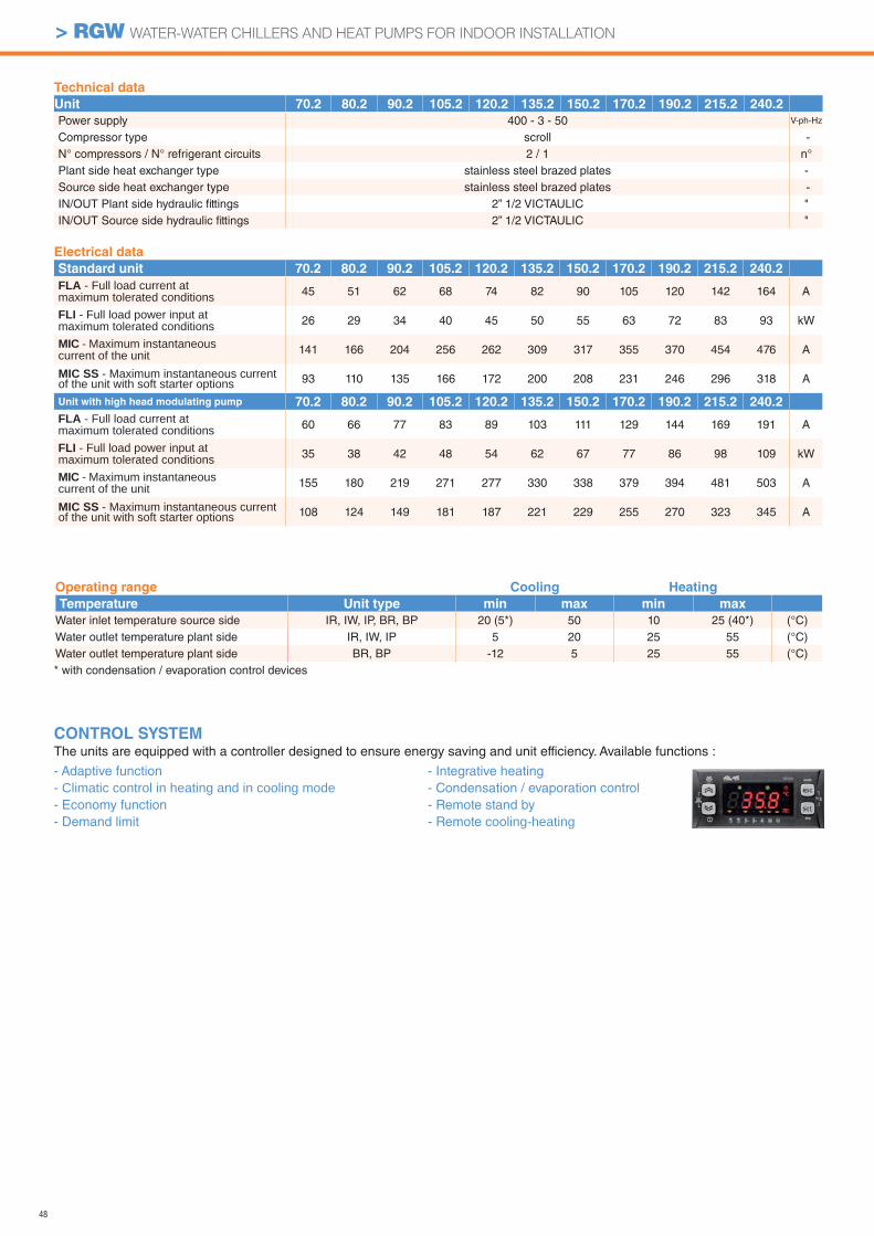
48
> RGW WATER-WATER CHILLERS AND HEAT PUMPS FOR INDOOR INSTALLATION
CONTROL SYSTEMThe units are equipped with a controller designed to ensure energy saving and unit efficiency. Available functions :
- Adaptive function- Climatic control in heating and in cooling mode- Economy function- Demand limit
- Integrative heating- Condensation / evaporation control- Remote stand by- Remote cooling-heating
Technical data
Unit 70.2 80.2 90.2 105.2 120.2 135.2 150.2 170.2 190.2 215.2 240.2Power supply 400 - 3 - 50 V-ph-Hz
Compressor type scroll -N° compressors / N° refrigerant circuits 2 / 1 n°Plant side heat exchanger type stainless steel brazed plates -Source side heat exchanger type stainless steel brazed plates -IN/OUT Plant side hydraulic fi ttings 2” 1/2 VICTAULIC "IN/OUT Source side hydraulic fi ttings 2” 1/2 VICTAULIC "
Electrical data
Standard unit 70.2 80.2 90.2 105.2 120.2 135.2 150.2 170.2 190.2 215.2 240.2FLA - Full load current at maximum tolerated conditions 45 51 62 68 74 82 90 105 120 142 164 A
FLI - Full load power input at maximum tolerated conditions 26 29 34 40 45 50 55 63 72 83 93 kW
MIC - Maximum instantaneous current of the unit 141 166 204 256 262 309 317 355 370 454 476 A
MIC SS - Maximum instantaneous current of the unit with soft starter options 93 110 135 166 172 200 208 231 246 296 318 A
Unit with high head modulating pump 70.2 80.2 90.2 105.2 120.2 135.2 150.2 170.2 190.2 215.2 240.2FLA - Full load current at maximum tolerated conditions 60 66 77 83 89 103 111 129 144 169 191 A
FLI - Full load power input at maximum tolerated conditions 35 38 42 48 54 62 67 77 86 98 109 kW
MIC - Maximum instantaneous current of the unit 155 180 219 271 277 330 338 379 394 481 503 A
MIC SS - Maximum instantaneous current of the unit with soft starter options 108 124 149 181 187 221 229 255 270 323 345 A
Operating range Cooling Heating
Temperature Unit type min max min max
Water inlet temperature source side IR, IW, IP, BR, BP 20 (5*) 50 10 25 (40*) (°C)Water outlet temperature plant side IR, IW, IP 5 20 25 55 (°C)Water outlet temperature plant side BR, BP -12 5 25 55 (°C)* with condensation / evaporation control devices
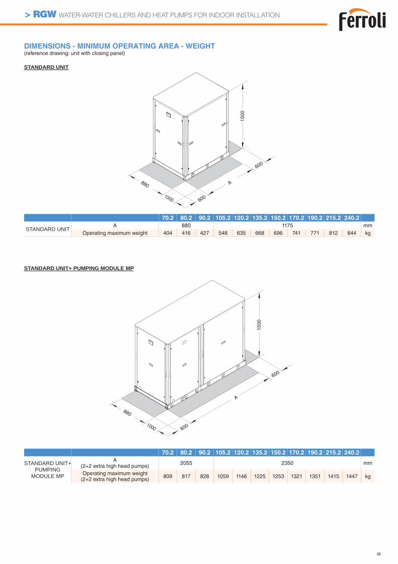
49
> RGW WATER-WATER CHILLERS AND HEAT PUMPS FOR INDOOR INSTALLATION
DIMENSIONS - MINIMUM OPERATING AREA - WEIGHT(reference drawing: unit with closing panel)
70.2 80.2 90.2 105.2 120.2 135.2 150.2 170.2 190.2 215.2 240.2
STANDARD UNIT+PUMPING
MODULE MP
A (2+2 extra high head pumps) 2055 2350 mm
Operating maximum weight (2+2 extra high head pumps) 809 817 828 1059 1146 1225 1253 1321 1351 1415 1447 kg
70.2 80.2 90.2 105.2 120.2 135.2 150.2 170.2 190.2 215.2 240.2
STANDARD UNITA 880 1175 mm
Operating maximum weight 404 416 427 548 635 668 696 741 771 812 844 kg
880
600
600
A
1000
1500
880
600
600
A
1000
1500
STANDARD UNIT
STANDARD UNIT+ PUMPING MODULE MP
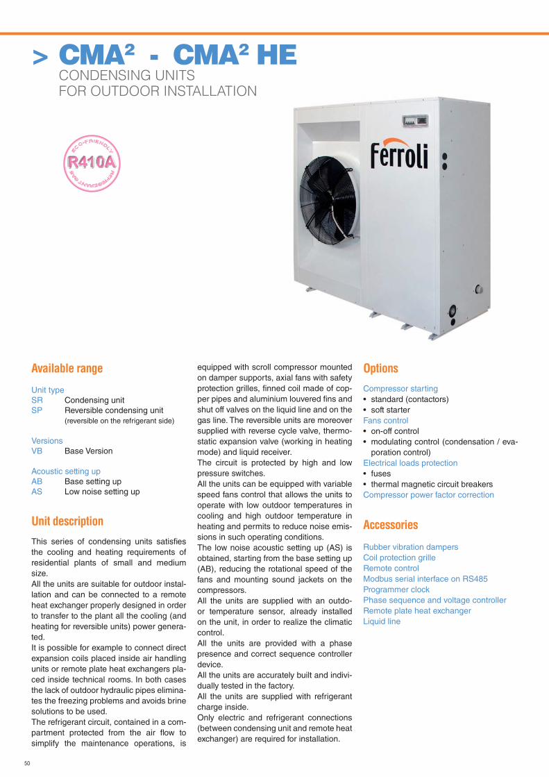
50
Available range
Unit typeSR Condensing unitSP Reversible condensing unit (reversible on the refrigerant side)
VersionsVB Base Version
Acoustic setting upAB Base setting upAS Low noise setting up
Unit description
This series of condensing units satisfi es the cooling and heating requirements of residential plants of small and medium size.All the units are suitable for outdoor instal-lation and can be connected to a remote heat exchanger properly designed in order to transfer to the plant all the cooling (and heating for reversible units) power genera-ted.It is possible for example to connect direct expansion coils placed inside air handling units or remote plate heat exchangers pla-ced inside technical rooms. In both cases the lack of outdoor hydraulic pipes elimina-tes the freezing problems and avoids brine solutions to be used. The refrigerant circuit, contained in a com-partment protected from the air fl ow to simplify the maintenance operations, is
equipped with scroll compressor mounted on damper supports, axial fans with safety protection grilles, fi nned coil made of cop-per pipes and aluminium louvered fi ns and shut off valves on the liquid line and on the gas line. The reversible units are moreover supplied with reverse cycle valve, thermo-static expansion valve (working in heating mode) and liquid receiver.The circuit is protected by high and low pressure switches.All the units can be equipped with variable speed fans control that allows the units to operate with low outdoor temperatures in cooling and high outdoor temperature in heating and permits to reduce noise emis-sions in such operating conditions.The low noise acoustic setting up (AS) is obtained, starting from the base setting up (AB), reducing the rotational speed of the fans and mounting sound jackets on the compressors.All the units are supplied with an outdo-or temperature sensor, already installed on the unit, in order to realize the climatic control.All the units are provided with a phase presence and correct sequence controller device.All the units are accurately built and indivi-dually tested in the factory.All the units are supplied with refrigerant charge inside.Only electric and refrigerant connections (between condensing unit and remote heat exchanger) are required for installation.
Options
Compressor starting• standard (contactors)• soft starterFans control• on-off control• modulating control (condensation / eva-
poration control)Electrical loads protection• fuses• thermal magnetic circuit breakersCompressor power factor correction
Accessories
Rubber vibration dampersCoil protection grilleRemote controlModbus serial interface on RS485Programmer clockPhase sequence and voltage controller Remote plate heat exchangerLiquid line
> CMA2 - CMA2 HE CONDENSING UNITS
FOR OUTDOOR INSTALLATION

51
CMA2 - CMA2 HE CONDENSING UNITS FOR OUTDOOR INSTALLATION
NET NOMINAL performances - CMA2
SR Base setting up (AB) 19.1 22.1 26.1 30.1 35.1 40.1
A3
5E
5 Cooling capacity 21,4 24,2 28,0 32,9 37,7 43,8 kWPower input 6,75 7,53 8,67 10,66 11,99 13,85 kW
EER 3,17 3,21 3,23 3,08 3,14 3,17 W/W
SR Low noise setting up (AS) 19.1 22.1 26.1 30.1 35.1 40.1
A3
5E
5 Cooling capacity 20,5 23,2 26,9 31,6 36,2 42,1 kWPower input 7,26 8,14 9,34 11,45 12,97 14,92 kW
EER 2,83 2,85 2,88 2,76 2,79 2,82 W/W
SP Base setting up (AB) 19.1 22.1 26.1 30.1 35.1 40.1
A3
5E
5 Cooling capacity 20,9 23,5 27,2 32,0 36,7 42,8 kWPower input 6,82 7,65 8,76 10,78 12,12 14,00 kW
EER 3,06 3,07 3,11 2,97 3,02 3,06 W/W
A7
C5
0 Heating capacity 20,0 22,5 26,1 30,9 35,5 40,1 kWPower input 6,87 7,71 8,95 11,07 12,42 13,97 kW
COP 2,91 2,92 2,92 2,79 2,86 2,87 W/W
A7
C4
5 Heating capacity 22,0 24,8 28,8 34,1 39,1 44,2 kWPower input 6,05 6,79 7,88 9,76 10,88 12,25 kW
COP 3,64 3,66 3,66 3,50 3,60 3,61 W/W
SP Low noise setting up (AS) 19.1 22.1 26.1 30.1 35.1 40.1
A3
5E
5 Cooling capacity 20,0 22,6 26,2 30,7 35,2 41,0 kWPower input 7,32 8,23 9,41 11,54 13,09 15,05 kW
EER 2,73 2,74 2,79 2,66 2,69 2,72 W/W
A7C
50 Heating capacity 18,9 21,4 24,9 29,6 33,8 38,2 kW
Power input 6,63 7,41 8,61 10,66 12,02 13,40 kW
COP 2,85 2,89 2,89 2,77 2,81 2,85 W/W
A7C
45 Heating capacity 20,9 23,6 27,5 32,6 37,3 42,2 kW
Power input 5,84 6,52 7,59 9,39 10,58 11,88 kW
COP 3,58 3,62 3,62 3,47 3,52 3,55 W/W
EER (Energy Efficiency Ratio) = ratio of the total cooling capacity to the effective power input of the unitCOP (Coefficient Of Performance) = ratio of the total heating capacity to the effective power input of the unitA35E5 = source : air in 35°C d.b. / plant : evaporation temperature (dew point) 5°C - superheating 5°CA7C50 = source : air in 7°C d.b. 6°C w.b. / plant : condensation temperature (dew point) 50°C - subcooling 5°CA7C45 = source : air in 7°C d.b. 6°C w.b. / plant : condensation temperature (dew point) 45°C - subcooling 5°C
The values are referred to units without options and accessories.
NET NOMINAL performances - CMA2 HE
SR Base setting up (AB) 19.1 22.1 26.1 30.1 35.1 40.1
A35E
5 Cooling capacity 22,3 24,9 29,0 34,9 39,6 46,2 kWPower input 6,12 6,83 7,83 9,52 10,84 12,46 kW
EER 3,63 3,65 3,70 3,66 3,65 3,71 W/W
SR Low noise setting up (AS) 19.1 22.1 26.1 30.1 35.1 40.1
A35E
5 Cooling capacity 21,4 23,9 27,9 33,6 38,1 44,6 kWPower input 6,62 7,38 8,47 10,29 11,61 13,21 kW
EER 3,24 3,23 3,29 3,26 3,29 3,38 W/W
SP Base setting up (AB) 19.1 22.1 26.1 30.1 35.1 40.1
A35E
5 Cooling capacity 21,8 23,8 27,8 33,6 39 44,1 kWPower input 6,07 7,03 8,16 10,1 11,7 13,2 kW
EER 3,60 3,39 3,4 3,34 3,33 3,33 W/W
A7C
50 Heating capacity 20,5 23,2 27,0 31,8 36,5 42,4 kW
Power input 6,46 7,13 8,21 10,01 11,40 12,91 kW
COP 3,18 3,26 3,29 3,17 3,20 3,29 W/W
A7C
45 Heating capacity 22,7 25,6 29,8 35,1 40,2 46,8 kW
Power input 5,69 6,28 7,23 8,78 10,04 11,44 kW
COP 3,98 4,08 4,12 3,99 4,01 4,09 W/W
SP Low noise setting up (AS) 19.1 22.1 26.1 30.1 35.1 40.1
A35E
5 Cooling capacity 20,9 23,8 27,8 33,6 39 44,1 kWPower input 6,55 7,03 8,16 10,1 11,7 13,2 kW
EER 3,20 3,39 3,4 3,34 3,33 3,33 W/W
A7C
50 Heating capacity 19,5 22,1 25,9 30,4 34,6 40,4 kW
Power input 6,24 6,91 7,95 9,64 10,98 12,51 kW
COP 3,12 3,19 3,25 3,15 3,16 3,23 W/W
A7C
45 Heating capacity 21,5 24,3 28,5 33,6 38,3 44,6 kW
Power input 5,50 6,09 7,00 8,50 9,71 11,03 kW
COP 3,91 3,99 4,08 3,96 3,95 4,05 W/W
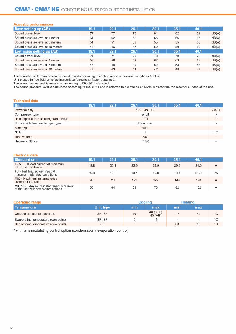
52
CMA2 - CMA2 HE CONDENSING UNITS FOR OUTDOOR INSTALLATION
Acoustic performances
Base setting up (AB) 19.1 22.1 26.1 30.1 35.1 40.1
Sound power level 77 77 78 81 82 82 dB(A)Sound pressure level at 1 meter 61 62 62 65 66 66 dB(A)Sound pressure level at 5 meters 51 51 52 55 55 56 dB(A)Sound pressure level at 10 meters 46 46 47 50 50 50 dB(A)
Low noise setting up (AS) 19.1 22.1 26.1 30.1 35.1 40.1
Sound power level 74 74 75 78 79 79 dB(A)Sound pressure level at 1 meter 58 59 59 62 63 63 dB(A)Sound pressure level at 5 meters 48 48 49 52 53 53 dB(A)Sound pressure level at 10 meters 43 43 44 47 48 48 dB(A)
The acoustic performan ces are referred to units operating in cooling mode at nominal conditions A35E5.Unit placed in free fi eld on refl ecting surface (directional factor equal to 2).The sound power level is measured according to ISO 9614 standard.The sound pressure level is calculated according to ISO 3744 and is referred to a distance of 1/5/10 metres from the external surface of the unit.
Technical data
Unit 19.1 22.1 26.1 30.1 35.1 40.1
Power supply 400 - 3N - 50 V-ph-Hz
Compressor type scroll -N° compressors / N° refrigerant circuits 1 / 1 n°Source side heat exchanger type fi nned coil -Fans type axial -N° fans 1 n°Tank volume 5/8” -Hydraulic fi ttings 1” 1/8 -
Electrical data
Standard unit 19.1 22.1 26.1 30.1 35.1 40.1
FLA - Full load current at maximum tolerated conditions 18,8 20,8 22,9 25,9 29,9 34,0 A
FLI - Full load power input at maximum tolerated conditions 10,8 12,1 13,4 15,8 18,4 21,0 kW
MIC - Maximum instantaneous current of the unit 98 114 121 129 144 178 A
MIC SS - Maximum instantaneous current of the unit with soft starter options 55 64 68 73 82 102 A
Operating range Cooling Heating
Temperature Unit type min max min max
Outdoor air inlet temperature SR, SP -10* 48 (STD)50 (HE) -15 42 °C
Evaporating temperature (dew point) SR, SP 0 15 - - °CCondensing temperature (dew point) SP - - 30 60 °C
* with fans modulating control option (condensation / evaporation control)
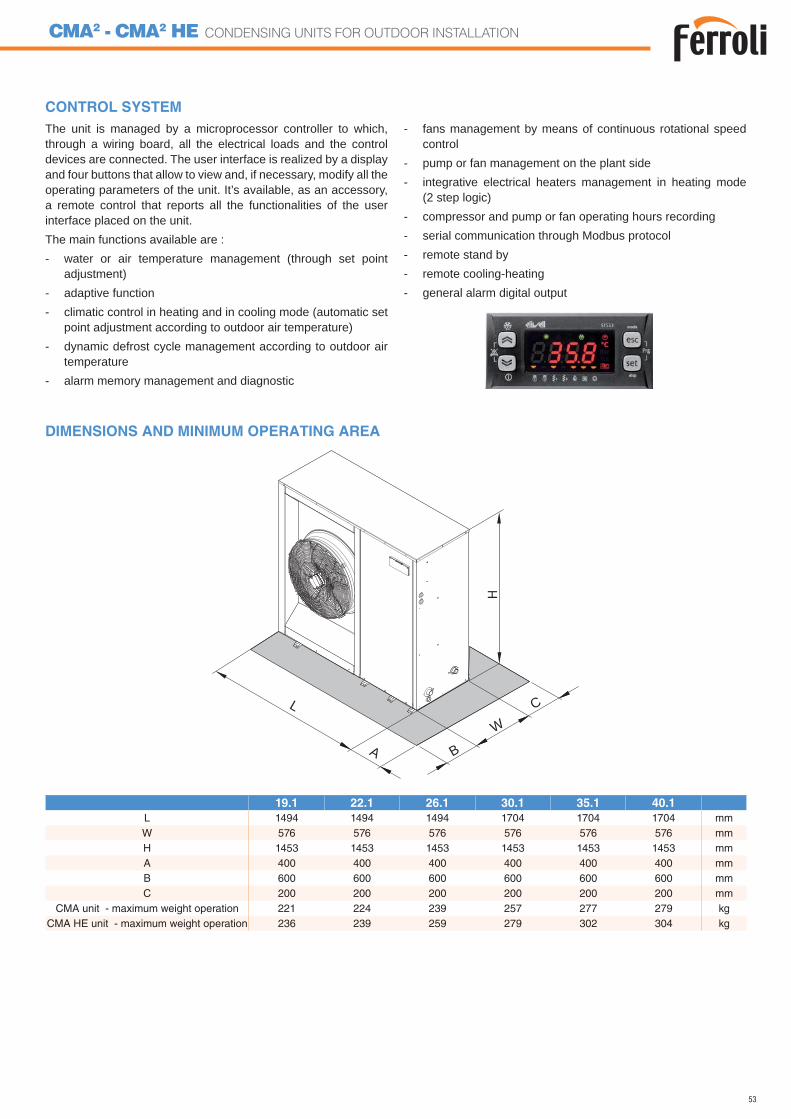
53
CMA2 - CMA2 HE CONDENSING UNITS FOR OUTDOOR INSTALLATION
B
C
AW
L
DIMENSIONS AND MINIMUM OPERATING AREA
CONTROL SYSTEMThe unit is managed by a microprocessor controller to which, through a wiring board, all the electrical loads and the control devices are connected. The user interface is realized by a display and four buttons that allow to view and, if necessary, modify all the operating parameters of the unit. It’s available, as an accessory, a remote control that reports all the functionalities of the user interface placed on the unit.The main functions available are :- water or air temperature management (through set point
adjustment)- adaptive function- climatic control in heating and in cooling mode (automatic set
point adjustment according to outdoor air temperature)- dynamic defrost cycle management according to outdoor air
temperature- alarm memory management and diagnostic
- fans management by means of continuous rotational speed control
- pump or fan management on the plant side- integrative electrical heaters management in heating mode
(2 step logic)- compressor and pump or fan operating hours recording- serial communication through Modbus protocol- remote stand by- remote cooling-heating- general alarm digital output
19.1 22.1 26.1 30.1 35.1 40.1
L 1494 1494 1494 1704 1704 1704 mmW 576 576 576 576 576 576 mmH 1453 1453 1453 1453 1453 1453 mmA 400 400 400 400 400 400 mmB 600 600 600 600 600 600 mmC 200 200 200 200 200 200 mm
CMA unit - maximum weight operation 221 224 239 257 277 279 kgCMA HE unit - maximum weight operation 236 239 259 279 302 304 kg
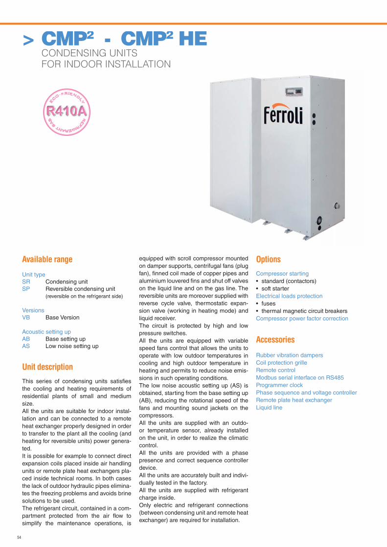
54
Available range
Unit typeSR Condensing unitSP Reversible condensing unit (reversible on the refrigerant side)
VersionsVB Base Version
Acoustic setting upAB Base setting upAS Low noise setting up
Unit description
This series of condensing units satisfi es the cooling and heating requirements of residential plants of small and medium size.All the units are suitable for indoor instal-lation and can be connected to a remote heat exchanger properly designed in order to transfer to the plant all the cooling (and heating for reversible units) power genera-ted.It is possible for example to connect direct expansion coils placed inside air handling units or remote plate heat exchangers pla-ced inside technical rooms. In both cases the lack of outdoor hydraulic pipes elimina-tes the freezing problems and avoids brine solutions to be used. The refrigerant circuit, contained in a com-partment protected from the air fl ow to simplify the maintenance operations, is
equipped with scroll compressor mounted on damper supports, centrifugal fans (plug fan), fi nned coil made of copper pipes and aluminium louvered fi ns and shut off valves on the liquid line and on the gas line. The reversible units are moreover supplied with reverse cycle valve, thermostatic expan-sion valve (working in heating mode) and liquid receiver.The circuit is protected by high and low pressure switches.All the units are equipped with variable speed fans control that allows the units to operate with low outdoor temperatures in cooling and high outdoor temperature in heating and permits to reduce noise emis-sions in such operating conditions.The low noise acoustic setting up (AS) is obtained, starting from the base setting up (AB), reducing the rotational speed of the fans and mounting sound jackets on the compressors.All the units are supplied with an outdo-or temperature sensor, already installed on the unit, in order to realize the climatic control.All the units are provided with a phase presence and correct sequence controller device.All the units are accurately built and indivi-dually tested in the factory.All the units are supplied with refrigerant charge inside.Only electric and refrigerant connections (between condensing unit and remote heat exchanger) are required for installation.
Options
Compressor starting• standard (contactors)• soft starterElectrical loads protection• fuses• thermal magnetic circuit breakersCompressor power factor correction
Accessories
Rubber vibration dampersCoil protection grilleRemote controlModbus serial interface on RS485Programmer clockPhase sequence and voltage controller Remote plate heat exchangerLiquid line
> CMP2 - CMP2 HE CONDENSING UNITS
FOR INDOOR INSTALLATION
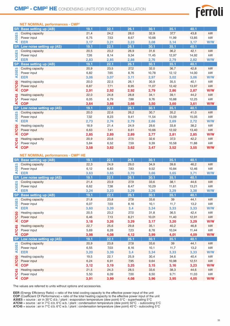
55
CMP2 - CMP2 HE CONDENSING UNITS FOR INDOOR INSTALLATION
NET NOMINAL performances - CMP2
SR Base setting up (AB) 19.1 22.1 26.1 30.1 35.1 40.1
A3
5E
5 Cooling capacity 21,4 24,2 28,0 32,9 37,7 43,8 kWPower input 6,75 7,53 8,67 10,66 11,99 13,85 kW
EER 3,17 3,21 3,23 3,08 3,14 3,17 W/W
SR Low noise setting up (AS) 19.1 22.1 26.1 30.1 35.1 40.1
A3
5E
5 Cooling capacity 20,5 23,2 26,9 31,6 36,2 42,1 kWPower input 7,26 8,14 9,34 11,45 12,97 14,92 kW
EER 2,83 2,85 2,88 2,76 2,79 2,82 W/W
SP Base setting up (AB) 19.1 22.1 26.1 30.1 35.1 40.1
A3
5E
5 Cooling capacity 20,9 23,5 27,2 32,0 36,7 42,8 kWPower input 6,82 7,65 8,76 10,78 12,12 14,00 kW
EER 3,06 3,07 3,11 2,97 3,02 3,06 W/W
A7
C5
0 Heating capacity 20,0 22,5 26,1 30,9 35,5 40,1 kWPower input 6,87 7,71 8,95 11,07 12,42 13,97 kW
COP 2,91 2,92 2,92 2,79 2,86 2,87 W/W
A7
C4
5 Heating capacity 22,0 24,8 28,8 34,1 39,1 44,2 kWPower input 6,05 6,79 7,88 9,76 10,88 12,25 kW
COP 3,64 3,66 3,66 3,50 3,60 3,61 W/W
SP Low noise setting up (AS) 19.1 22.1 26.1 30.1 35.1 40.1
A3
5E
5 Cooling capacity 20,0 22,6 26,2 30,7 35,2 41,0 kWPower input 7,32 8,23 9,41 11,54 13,09 15,05 kW
EER 2,73 2,74 2,79 2,66 2,69 2,72 W/W
A7C
50 Heating capacity 18,9 21,4 24,9 29,6 33,8 38,2 kW
Power input 6,63 7,41 8,61 10,66 12,02 13,40 kW
COP 2,85 2,89 2,89 2,77 2,81 2,85 W/W
A7C
45 Heating capacity 20,9 23,6 27,5 32,6 37,3 42,2 kW
Power input 5,84 6,52 7,59 9,39 10,58 11,88 kW
COP 3,58 3,62 3,62 3,47 3,52 3,55 W/W
NET NOMINAL performances - CMP2 HE
SR Base setting up (AB) 19.1 22.1 26.1 30.1 35.1 40.1
A35E
5 Cooling capacity 22,3 24,9 29,0 34,9 39,6 46,2 kWPower input 6,12 6,83 7,83 9,52 10,84 12,46 kW
EER 3,63 3,65 3,70 3,66 3,65 3,71 W/W
SR Low noise setting up (AS) 19.1 22.1 26.1 30.1 35.1 40.1
A35E
5 Cooling capacity 21,4 23,9 27,9 33,6 38,1 44,6 kWPower input 6,62 7,38 8,47 10,29 11,61 13,21 kW
EER 3,24 3,23 3,29 3,26 3,29 3,38 W/W
SP Base setting up (AB) 19.1 22.1 26.1 30.1 35.1 40.1
A35E
5 Cooling capacity 21,8 23,8 27,8 33,6 39 44,1 kWPower input 6,07 7,03 8,16 10,1 11,7 13,2 kW
EER 3,60 3,39 3,4 3,34 3,33 3,33 W/W
A7C
50 Heating capacity 20,5 23,2 27,0 31,8 36,5 42,4 kW
Power input 6,46 7,13 8,21 10,01 11,40 12,91 kW
COP 3,18 3,26 3,29 3,17 3,20 3,29 W/W
A7C
45 Heating capacity 22,7 25,6 29,8 35,1 40,2 46,8 kW
Power input 5,69 6,28 7,23 8,78 10,04 11,44 kW
COP 3,98 4,08 4,12 3,99 4,01 4,09 W/W
SP Low noise setting up (AS) 19.1 22.1 26.1 30.1 35.1 40.1
A35E
5 Cooling capacity 20,9 23,8 27,8 33,6 39 44,1 kWPower input 6,55 7,03 8,16 10,1 11,7 13,2 kW
EER 3,20 3,39 3,4 3,34 3,33 3,33 W/W
A7C
50 Heating capacity 19,5 22,1 25,9 30,4 34,6 40,4 kW
Power input 6,24 6,91 7,95 9,64 10,98 12,51 kW
COP 3,12 3,19 3,25 3,15 3,16 3,23 W/W
A7C
45 Heating capacity 21,5 24,3 28,5 33,6 38,3 44,6 kW
Power input 5,50 6,09 7,00 8,50 9,71 11,03 kW
COP 3,91 3,99 4,08 3,96 3,95 4,05 W/W
EER (Energy Efficiency Ratio) = ratio of the total cooling capacity to the effective power input of the unitCOP (Coefficient Of Performance) = ratio of the total heating capacity to the effective power input of the unitA35E5 = source : air in 35°C d.b. / plant : evaporation temperature (dew point) 5°C - superheating 5°CA7C50 = source : air in 7°C d.b. 6°C w.b. / plant : condensation temperature (dew point) 50°C - subcooling 5°CA7C45 = source : air in 7°C d.b. 6°C w.b. / plant : condensation temperature (dew point) 45°C - subcooling 5°C
The values are referred to units without options and accessories.
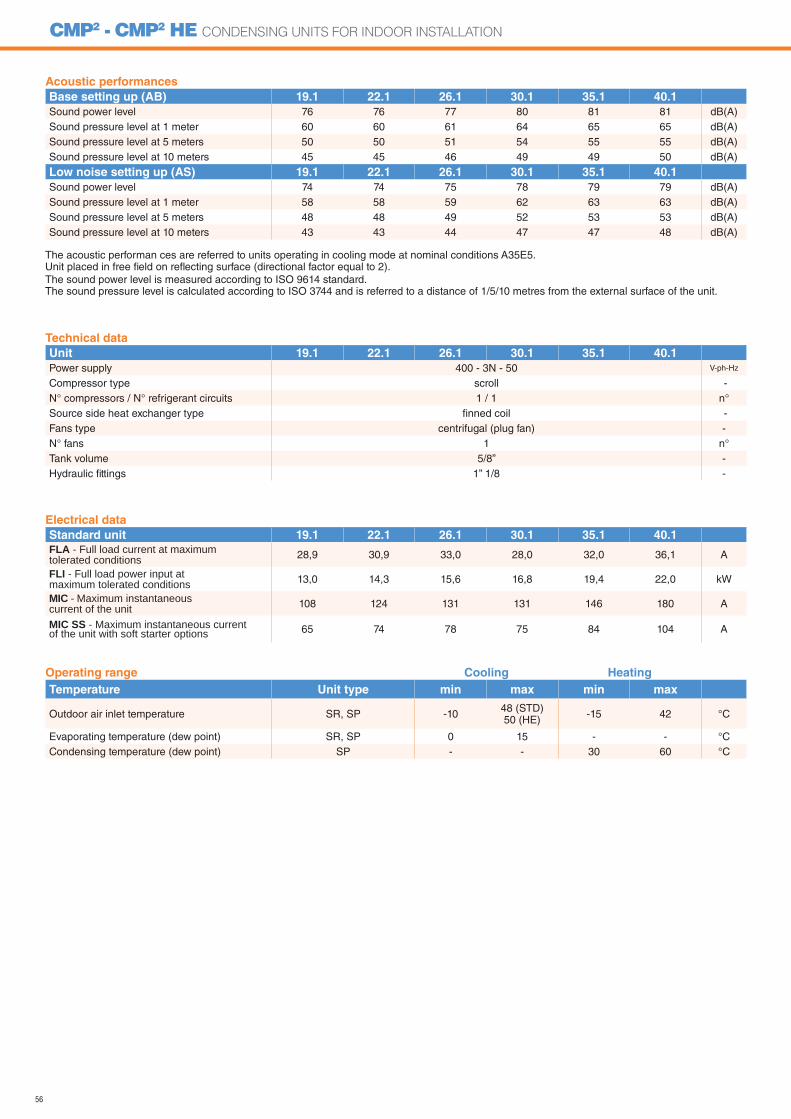
56
CMP2 - CMP2 HE CONDENSING UNITS FOR INDOOR INSTALLATION
Acoustic performances
Base setting up (AB) 19.1 22.1 26.1 30.1 35.1 40.1
Sound power level 76 76 77 80 81 81 dB(A)Sound pressure level at 1 meter 60 60 61 64 65 65 dB(A)Sound pressure level at 5 meters 50 50 51 54 55 55 dB(A)Sound pressure level at 10 meters 45 45 46 49 49 50 dB(A)
Low noise setting up (AS) 19.1 22.1 26.1 30.1 35.1 40.1
Sound power level 74 74 75 78 79 79 dB(A)Sound pressure level at 1 meter 58 58 59 62 63 63 dB(A)Sound pressure level at 5 meters 48 48 49 52 53 53 dB(A)Sound pressure level at 10 meters 43 43 44 47 47 48 dB(A)
The acoustic performan ces are referred to units operating in cooling mode at nominal conditions A35E5.Unit placed in free fi eld on refl ecting surface (directional factor equal to 2).The sound power level is measured according to ISO 9614 standard.The sound pressure level is calculated according to ISO 3744 and is referred to a distance of 1/5/10 metres from the external surface of the unit.
Operating range Cooling Heating
Temperature Unit type min max min max
Outdoor air inlet temperature SR, SP -10 48 (STD)50 (HE) -15 42 °C
Evaporating temperature (dew point) SR, SP 0 15 - - °CCondensing temperature (dew point) SP - - 30 60 °C
Technical data
Unit 19.1 22.1 26.1 30.1 35.1 40.1
Power supply 400 - 3N - 50 V-ph-Hz
Compressor type scroll -N° compressors / N° refrigerant circuits 1 / 1 n°Source side heat exchanger type fi nned coil -Fans type centrifugal (plug fan) -N° fans 1 n°Tank volume 5/8” -Hydraulic fi ttings 1” 1/8 -
Electrical data
Standard unit 19.1 22.1 26.1 30.1 35.1 40.1
FLA - Full load current at maximum tolerated conditions 28,9 30,9 33,0 28,0 32,0 36,1 A
FLI - Full load power input at maximum tolerated conditions 13,0 14,3 15,6 16,8 19,4 22,0 kW
MIC - Maximum instantaneous current of the unit 108 124 131 131 146 180 A
MIC SS - Maximum instantaneous current of the unit with soft starter options 65 74 78 75 84 104 A
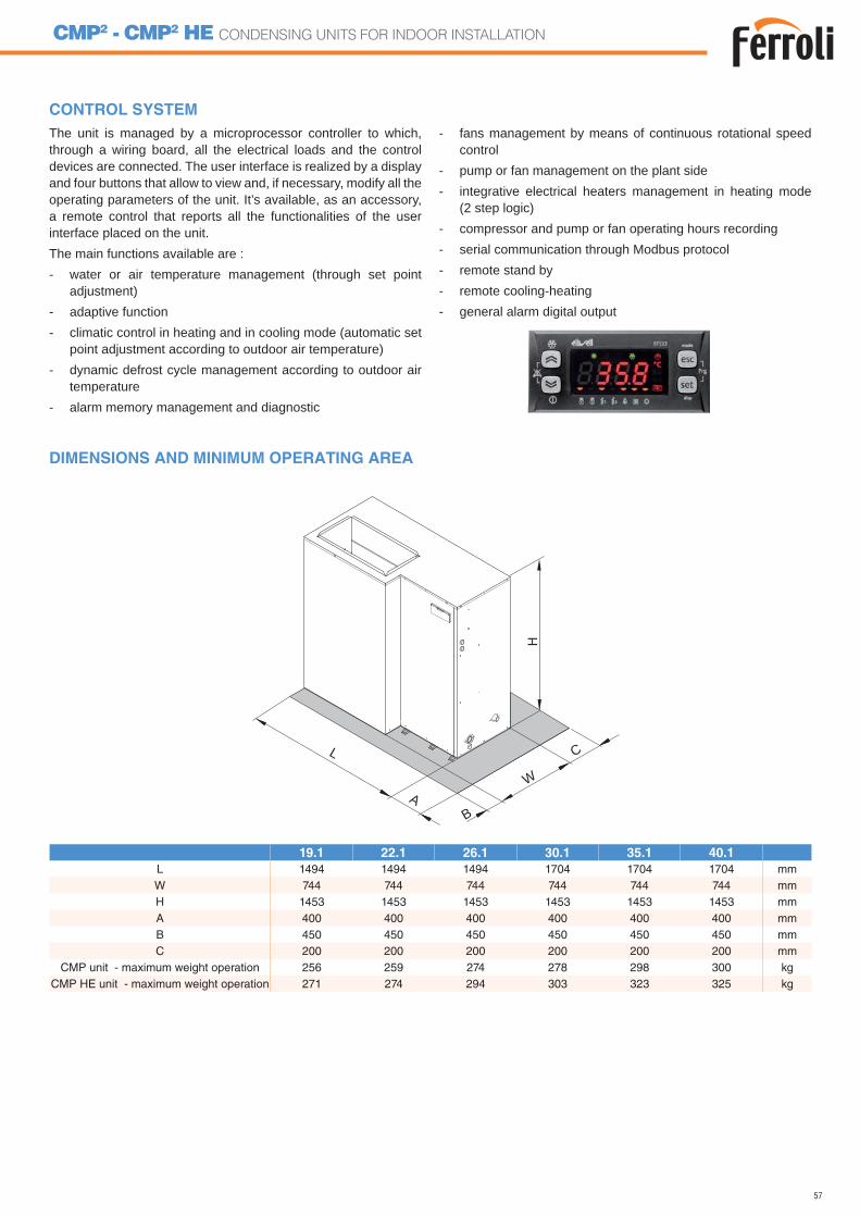
57
CMP2 - CMP2 HE CONDENSING UNITS FOR INDOOR INSTALLATION
DIMENSIONS AND MINIMUM OPERATING AREA
CONTROL SYSTEMThe unit is managed by a microprocessor controller to which, through a wiring board, all the electrical loads and the control devices are connected. The user interface is realized by a display and four buttons that allow to view and, if necessary, modify all the operating parameters of the unit. It’s available, as an accessory, a remote control that reports all the functionalities of the user interface placed on the unit.The main functions available are :- water or air temperature management (through set point
adjustment)- adaptive function- climatic control in heating and in cooling mode (automatic set
point adjustment according to outdoor air temperature)- dynamic defrost cycle management according to outdoor air
temperature- alarm memory management and diagnostic
- fans management by means of continuous rotational speed control
- pump or fan management on the plant side- integrative electrical heaters management in heating mode
(2 step logic)- compressor and pump or fan operating hours recording- serial communication through Modbus protocol- remote stand by- remote cooling-heating- general alarm digital output
B
C
AW
L
19.1 22.1 26.1 30.1 35.1 40.1
L 1494 1494 1494 1704 1704 1704 mmW 744 744 744 744 744 744 mmH 1453 1453 1453 1453 1453 1453 mmA 400 400 400 400 400 400 mmB 450 450 450 450 450 450 mmC 200 200 200 200 200 200 mm
CMP unit - maximum weight operation 256 259 274 278 298 300 kgCMP HE unit - maximum weight operation 271 274 294 303 323 325 kg
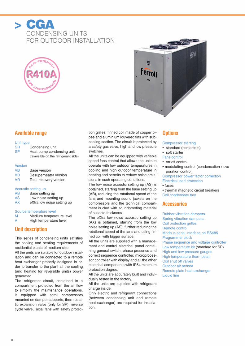
58
Available range
Unit typeSR Condensing unitSP Heat pump condensing unit
(reversible on the refrigerant side)
VersionVB Base versionVD Desuperheater versionVR Total recovery version
Acoustic setting upAB Base setting upAS Low noise setting upAX eXtra low noise setting up
Source temperature levelM Medium temperature levelA High temperature level
Unit description
This series of condensing units satisfi es the cooling and heating requirements of residential plants of medium size.All the units are suitable for outdoor instal-lation and can be connected to a remote heat exchanger properly designed in or-der to transfer to the plant all the cooling (and heating for reversible units) power generated.The refrigerant circuit, contained in a compartment protected from the air fl ow to simplify the maintenance operations, is equipped with scroll compressors mounted on damper supports, thermosta-tic expansion valve (only for SP), reverse cycle valve, axial fans with safety protec-
tion grilles, fi nned coil made of copper pi-pes and aluminium louvered fi ns with sub-cooling section. The circuit is protected by a safety gas valve, high and low pressure switches. All the units can be equipped with variable speed fans control that allows the units to operate with low outdoor temperatures in cooling and high outdoor temperature in heating and permits to reduce noise emis-sions in such operating conditions.The low noise acoustic setting up (AS) is obtained, starting from the base setting up (AB), reducing the rotational speed of the fans and mounting sound jackets on the compressors and the technical compart-ment is clad with soundproofi ng material of suitable thickness.The eXtra low noise acoustic setting up (AX) is obtained, starting from the low noise setting up (AS), further reducing the rotational speed of the fans and using fi n-ned coil with bigger surface.All the units are supplied with a manage-ment and control electrical panel contai-ning general switch, phase presence and correct sequence controller, microproces-sor controller with display and all the other electrical components with IP54 minimum protection degree.All the units are accurately built and indivi-dually tested in the factory. All the units are supplied with refrigerant charge inside.Only electric and refrigerant connections (between condensing unit and remote heat exchanger) are required for installa-tion.
Options
Compressor starting• standard (contactors)• soft starterFans control• on-off control• modulating control (condensation / eva-
poration control)Compressor power factor correction Electrical load protection• fuses• thermal magnetic circuit breakersCoil condensate tray
Accessories
Rubber vibration dampersSpring vibration dampersCoil protection grillesRemote controlModbus serial interface on RS485Programmer clockPhase sequence and voltage controllerLow temperature kit (standard for SP)High and low pressure gaugesHigh temperature thermostatCoil shut off valvesOutdoor air sensorRemote plate heat exchangerLiquid line
> CGA CONDENSING UNITS
FOR OUTDOOR INSTALLATION
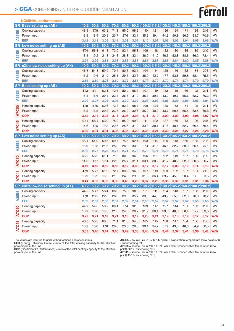
59
> CGA CONDENSING UNITS FOR OUTDOOR INSTALLATION
NOMINAL performances
SR Base setting up (AB) 40.2 50.2 60.2 70.2 80.2 90.2 100.2 115.2 130.2 145.2 160.2 180.2 200.2
A3
5E
5 Cooling capacity 48,9 57,8 63,3 74,3 85,0 98,3 110 121 136 154 171 194 216 kW
Power input 15,5 18,4 20,5 23,7 27,6 32,1 35,5 39,4 44,5 50,8 56,3 63,7 70,6 kW
EER 3,15 3,14 3,09 3,14 3,08 3,06 3,10 3,07 3,06 3,03 3,04 3,05 3,06 W/W
SR Low noise setting up (AS) 40.2 50.2 60.2 70.2 80.2 90.2 100.2 115.2 130.2 145.2 160.2 180.2 200.2
A3
5E
5 Cooling capacity 47,4 56,1 61,3 72,0 82,4 95,3 106 118 132 150 165 189 210 kW
Power input 16,1 19,2 21,3 24,6 28,8 33,4 36,9 41,0 46,3 52,8 58,6 66,2 73,4 kW
EER 2,94 2,92 2,88 2,93 2,86 2,85 2,87 2,88 2,85 2,84 2,82 2,85 2,86 W/W
SR eXtra low noise setting up (AX) 40.2 50.2 60.2 70.2 80.2 90.2 100.2 115.2 130.2 145.2 160.2 180.2 200.2
A3
5E
5 Cooling capacity 46,3 54,8 59,9 70,4 80,5 93,1 104 114 129 146 162 184 204 kW
Power input 16,2 19,6 21,9 25,1 29,6 32,5 38,0 42,2 47,7 53,8 59,8 68,1 75,5 kW
EER 2,86 2,80 2,74 2,80 2,72 2,86 2,74 2,70 2,70 2,71 2,71 2,70 2,70 W/W
SP Base setting up (AB) 40.2 50.2 60.2 70.2 80.2 90.2 100.2 115.2 130.2 145.2 160.2 180.2 200.2
A3
5E
5 Cooling capacity 47,3 57,1 62,1 72,6 80,0 96,3 107 119 132 149 166 192 214 kW
Power input 15,3 18,6 20,4 23,8 26,7 31,9 35,3 39,3 43,9 49,7 55,6 62,7 70,3 kW
EER 3,09 3,07 3,04 3,05 3,00 3,02 3,03 3,03 3,01 3,00 2,99 3,06 3,04 W/W
A7
C5
0 Heating capacity 47,8 57,5 62,6 73,8 82,3 98,7 109 124 135 153 171 195 214 kW
Power input 15,3 18,5 20,3 23,7 26,9 32,6 35,0 40,0 43,7 50,5 55,4 63,4 69,8 kW
COP 3,12 3,11 3,08 3,11 3,06 3,03 3,11 3,10 3,09 3,03 3,09 3,08 3,07 W/W
A7
C4
5 Heating capacity 49,4 58,4 63,9 75,0 85,9 99,3 111 122 137 156 173 196 218 kW
Power input 14,6 17,6 19,3 22,6 25,6 31,0 33,3 38,1 41,6 48,1 52,7 60,4 66,4 kW
COP 3,39 3,31 3,31 3,33 3,35 3,20 3,33 3,21 3,30 3,24 3,27 3,25 3,28 W/W
SP Low noise setting up (AS) 40.2 50.2 60.2 70.2 80.2 90.2 100.2 115.2 130.2 145.2 160.2 180.2 200.2
A35E
5 Cooling capacity 45,4 54,9 59,6 69,7 76,8 92,4 103 114 126 143 160 185 205 kW
Power input 15,9 19,8 21,6 25,2 28,3 33,8 37,4 41,6 46,6 52,7 59,0 66,4 74,5 kW
EER 2,86 2,77 2,76 2,77 2,71 2,73 2,75 2,74 2,70 2,71 2,71 2,79 2,75 W/W
A7C
50 Heating capacity 46,6 56,0 61,1 71,9 80,2 96,2 106 121 132 149 167 190 209 kW
Power input 14,6 17,7 19,4 22,6 25,7 31,1 33,4 38,2 41,7 48,2 52,9 60,5 66,7 kW
COP 3,19 3,16 3,15 3,18 3,12 3,09 3,17 3,17 3,17 3,09 3,16 3,14 3,13 W/W
A7C
45 Heating capacity 47,9 56,7 61,9 72,7 83,2 96,3 107 119 133 152 167 191 212 kW
Power input 13,9 16,9 18,5 21,5 24,5 29,6 31,8 36,4 39,7 45,9 50,4 57,6 63,5 kW
COP 3,44 3,36 3,35 3,38 3,40 3,25 3,37 3,28 3,36 3,30 3,31 3,31 3,34 W/W
SP eXtra low noise setting up (AX) 40.2 50.2 60.2 70.2 80.2 90.2 100.2 115.2 130.2 145.2 160.2 180.2 200.2
A35E
5 Cooling capacity 44,5 53,7 58,4 68,3 75,3 90,5 101 111 124 140 157 180 201 kW
Power input 17,0 20,9 22,8 26,6 29,9 35,7 39,5 44,0 49,2 55,6 62,3 70,3 78,7 kW
EER 2,62 2,57 2,56 2,57 2,52 2,54 2,56 2,52 2,52 2,52 2,52 2,56 2,55 W/W
A7C
50 Heating capacity 44,9 54,0 58,9 69,4 77,4 92,8 103 117 127 144 161 183 201 kW
Power input 13,9 16,8 18,5 21,6 24,5 29,7 31,9 36,4 39,8 46,0 50,4 57,7 63,5 kW
COP 3,23 3,21 3,18 3,21 3,16 3,12 3,23 3,21 3,19 3,13 3,19 3,17 3,17 W/W
A7C
45 Heating capacity 46,8 55,3 60,5 71,1 81,3 94,0 105 115 130 147 164 186 206 kW
Power input 13,2 16,0 17,6 20,6 23,3 28,3 30,4 34,7 37,9 43,8 48,0 54,9 60,5 kW
COP 3,53 3,46 3,44 3,46 3,49 3,33 3,46 3,32 3,44 3,37 3,41 3,38 3,41 W/W
The values are referred to units without options and accessories.EER (Energy Efficiency Ratio) = ratio of the total cooling capacity to the effective power input of the unitCOP (Coefficient Of Performance) = ratio of the total heating capacity to the effective power input of the unit
A35E5 = source : air in 35°C d.b. / plant : evaporation temperature (dew point) 5°C - superheating 5°CA7C50 = source : air in 7°C d.b. 6°C w.b. / plant : condensation temperature (dew point) 50°C - subcooling 5°CA7C45 = source : air in 7°C d.b. 6°C w.b. / plant : condensation temperature (dew point) 45°C - subcooling 5°C
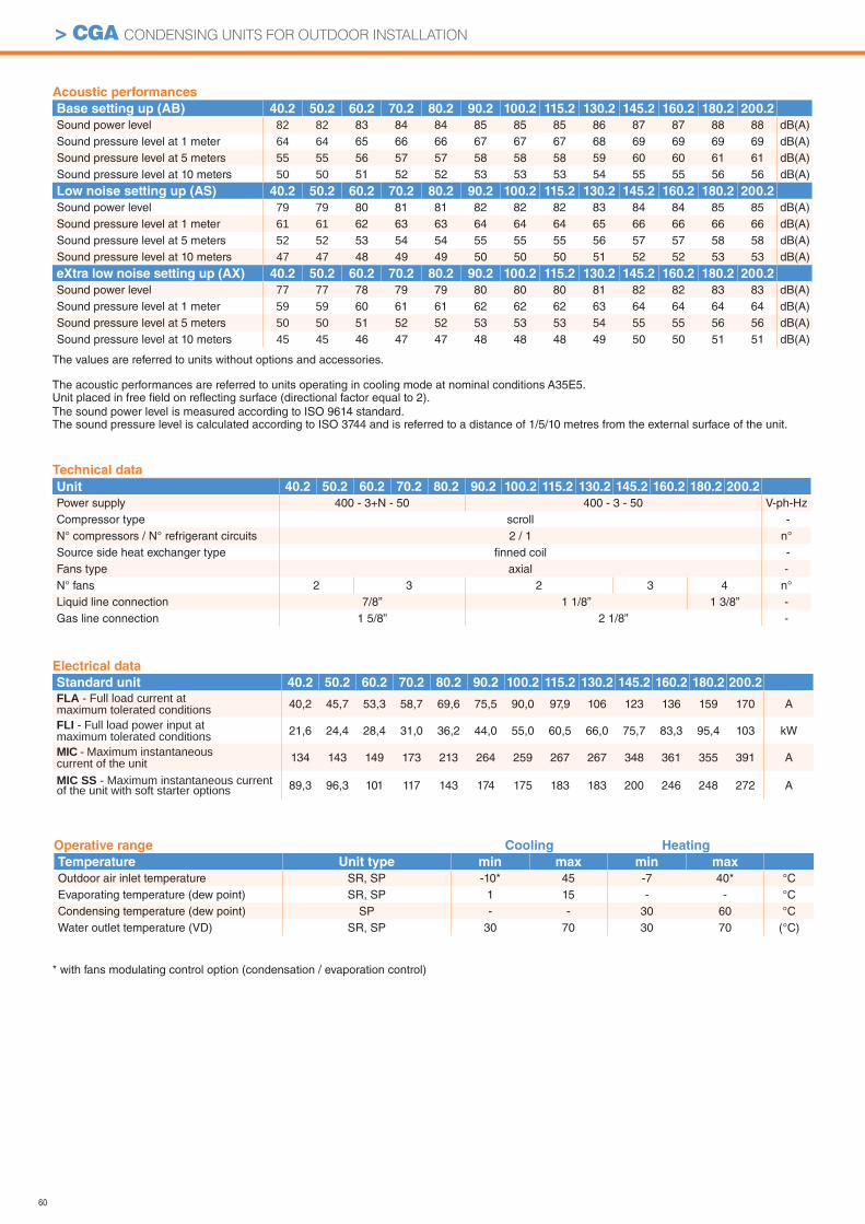
60
> CGA CONDENSING UNITS FOR OUTDOOR INSTALLATION
Operative range Cooling Heating
Temperature Unit type min max min max
Outdoor air inlet temperature SR, SP -10* 45 -7 40* °CEvaporating temperature (dew point) SR, SP 1 15 - - °CCondensing temperature (dew point) SP - - 30 60 °CWater outlet temperature (VD) SR, SP 30 70 30 70 (°C)
Technical data
Unit 40.2 50.2 60.2 70.2 80.2 90.2 100.2 115.2 130.2 145.2 160.2 180.2 200.2
Power supply 400 - 3+N - 50 400 - 3 - 50 V-ph-HzCompressor type scroll -N° compressors / N° refrigerant circuits 2 / 1 n°Source side heat exchanger type fi nned coil -Fans type axial -N° fans 2 3 2 3 4 n°Liquid line connection 7/8” 1 1/8” 1 3/8” -Gas line connection 1 5/8” 2 1/8” -
* with fans modulating control option (condensation / evaporation control)
Acoustic performances
Base setting up (AB) 40.2 50.2 60.2 70.2 80.2 90.2 100.2 115.2 130.2 145.2 160.2 180.2 200.2
Sound power level 82 82 83 84 84 85 85 85 86 87 87 88 88 dB(A)Sound pressure level at 1 meter 64 64 65 66 66 67 67 67 68 69 69 69 69 dB(A)Sound pressure level at 5 meters 55 55 56 57 57 58 58 58 59 60 60 61 61 dB(A)Sound pressure level at 10 meters 50 50 51 52 52 53 53 53 54 55 55 56 56 dB(A)
Low noise setting up (AS) 40.2 50.2 60.2 70.2 80.2 90.2 100.2 115.2 130.2 145.2 160.2 180.2 200.2
Sound power level 79 79 80 81 81 82 82 82 83 84 84 85 85 dB(A)Sound pressure level at 1 meter 61 61 62 63 63 64 64 64 65 66 66 66 66 dB(A)Sound pressure level at 5 meters 52 52 53 54 54 55 55 55 56 57 57 58 58 dB(A)Sound pressure level at 10 meters 47 47 48 49 49 50 50 50 51 52 52 53 53 dB(A)
eXtra low noise setting up (AX) 40.2 50.2 60.2 70.2 80.2 90.2 100.2 115.2 130.2 145.2 160.2 180.2 200.2
Sound power level 77 77 78 79 79 80 80 80 81 82 82 83 83 dB(A)Sound pressure level at 1 meter 59 59 60 61 61 62 62 62 63 64 64 64 64 dB(A)Sound pressure level at 5 meters 50 50 51 52 52 53 53 53 54 55 55 56 56 dB(A)Sound pressure level at 10 meters 45 45 46 47 47 48 48 48 49 50 50 51 51 dB(A)
Electrical data
Standard unit 40.2 50.2 60.2 70.2 80.2 90.2 100.2 115.2 130.2 145.2 160.2 180.2 200.2
FLA - Full load current at maximum tolerated conditions 40,2 45,7 53,3 58,7 69,6 75,5 90,0 97,9 106 123 136 159 170 A
FLI - Full load power input at maximum tolerated conditions 21,6 24,4 28,4 31,0 36,2 44,0 55,0 60,5 66,0 75,7 83,3 95,4 103 kW
MIC - Maximum instantaneous current of the unit 134 143 149 173 213 264 259 267 267 348 361 355 391 A
MIC SS - Maximum instantaneous current of the unit with soft starter options 89,3 96,3 101 117 143 174 175 183 183 200 246 248 272 A
The values are referred to units without options and accessories.
The acoustic performances are referred to units operating in cooling mode at nominal conditions A35E5.Unit placed in free fi eld on refl ecting surface (directional factor equal to 2).The sound power level is measured according to ISO 9614 standard.The sound pressure level is calculated according to ISO 3744 and is referred to a distance of 1/5/10 metres from the external surface of the unit.
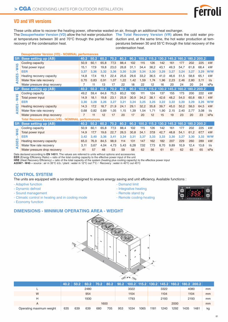
61
> CGA CONDENSING UNITS FOR OUTDOOR INSTALLATION
1000
L
W
A
H
1000
1000
40.2 50.2 60.2 70.2 80.2 90.2 100.2 115.2 130.2 145.2 160.2 180.2 200.2
L 2480 3322 3322 4080 mm
W 954 1104 1104 1104 mm
H 1930 1793 2193 2193 mm
A 1600 2000 mm
Operating maximum weight 635 639 639 680 705 953 1034 1065 1181 1240 1292 1435 1481 kg
VD and VR versions
These units allow to recover the heating power, otherwise wasted on air, through an additional heat exchanger.The Desuperheater Version (VD) allow the hot water production at temperatures between 30 and 70°C through the partial heat recovery of the condensation heat.
The Total Recovery Version (VR) allows the cold water pro-duction and, at the same time, the hot water production at tem-peratures between 30 and 55°C through the total recovery of the condensation heat.
DIMENSIONS - MINIMUM OPERATING AREA - WEIGHT
Desupeheater Version (VD) - NOMINAL performances
SR Base setting up (AB) 40.2 50.2 60.2 70.2 80.2 90.2 100.2 115.2 130.2 145.2 160.2 180.2 200.2
A3
5E
5 -
W4
5 Cooling capacity 50,9 60,1 65,8 77,3 88,4 102 115 126 142 161 177 202 225 kWTotal power input 15,1 17,9 19,8 23,0 26,8 31,1 34,4 38,2 43,1 49,3 54,7 61,8 68,4 kWEER 3,37 3,36 3,32 3,36 3,30 3,28 3,34 3,30 3,29 3,27 3,24 3,27 3,29 W/W
Heating recovery capacity 14,8 17,4 19,1 22,4 25,6 29,6 33,2 36,5 41,0 46,6 51,5 58,6 65,1 kWWater fl ow rate recovery 0,70 0,83 0,91 1,07 1,22 1,42 1,59 1,74 1,96 2,23 2,46 2,80 3,11 l/sWater pressure drop recovery 7 11 13 17 22 18 22 12 16 20 24 20 24 kPa
SP Base setting up (AB) 40.2 50.2 60.2 70.2 80.2 90.2 100.2 115.2 130.2 145.2 160.2 180.2 200.2
A3
5E
5 -
W4
5 Cooling capacity 49,2 59,4 64,6 75,5 83,2 100 111 124 137 155 173 200 222 kWTotal power input 14,9 18,1 19,8 23,1 25,9 30,9 34,2 38,1 42,6 48,2 54,0 60,8 68,1 kWEER 3,30 3,28 3,26 3,27 3,21 3,24 3,25 3,25 3,22 3,22 3,20 3,29 3,26 W/W
Heating recovery capacity 14,3 17,2 18,7 21,9 24,1 29,1 32,2 35,8 39,7 45,0 50,2 58,0 64,5 kWWater fl ow rate recovery 0,68 0,82 0,89 1,05 1,15 1,39 1,54 1,71 1,90 2,15 2,40 2,77 3,08 l/sWater pressure drop recovery 7 11 12 17 20 17 20 12 15 19 23 20 23 kPaTotal Recovery Version (VR) - NOMINAL performances
SR Base setting up (AB) 40.2 50.2 60.2 70.2 80.2 90.2 100.2 115.2 130.2 145.2 160.2 180.2 200.2
A35E
5 -
W45 Cooling capacity 50,9 60,1 65,8 77,3 88,4 102 115 126 142 161 177 202 225 kW
Total power input 14,9 17,7 19,6 22,7 26,5 30,8 34,1 37,8 42,7 48,8 54,1 61,2 67,7 kWEER 3,42 3,40 3,36 3,41 3,34 3,31 3,37 3,33 3,33 3,30 3,27 3,30 3,32 W/W
Heating recovery capacity 65,0 76,9 84,5 98,9 114 131 147 162 182 207 229 260 289 kWWater fl ow rate recovery 3,11 3,67 4,04 4,73 5,43 6,28 7,02 7,73 8,70 9,89 10,9 12,4 13,8 l/sWater pressure drop recovery 41 57 48 53 59 58 62 56 61 61 62 65 65 kPa
CONTROL SYSTEMThe units are equipped with a controller designed to ensure energy saving and unit efficiency. Available functions :
- Adaptive function- Dynamic defrost - Sound management - Climatic control in heating and in cooling mode- Economy function
- Demand limit- Integrative heating- Remote stand by- Remote cooling-heating
Data declared according to EN 14511. The values are referred to units without options and accessories.EER (Energy Efficiency Ratio) = ratio of the total cooling capacity to the effective power input of the unitHRE (Heat Recovery Efficiency) = ratio of the total capacity of the system (heating plus cooling capacity) to the effectice power inputA35W7 - W45 = source : air in 35°C d.b. / plant : water in 12°C out 7°C / Recovery : water in 40°C out 45°C
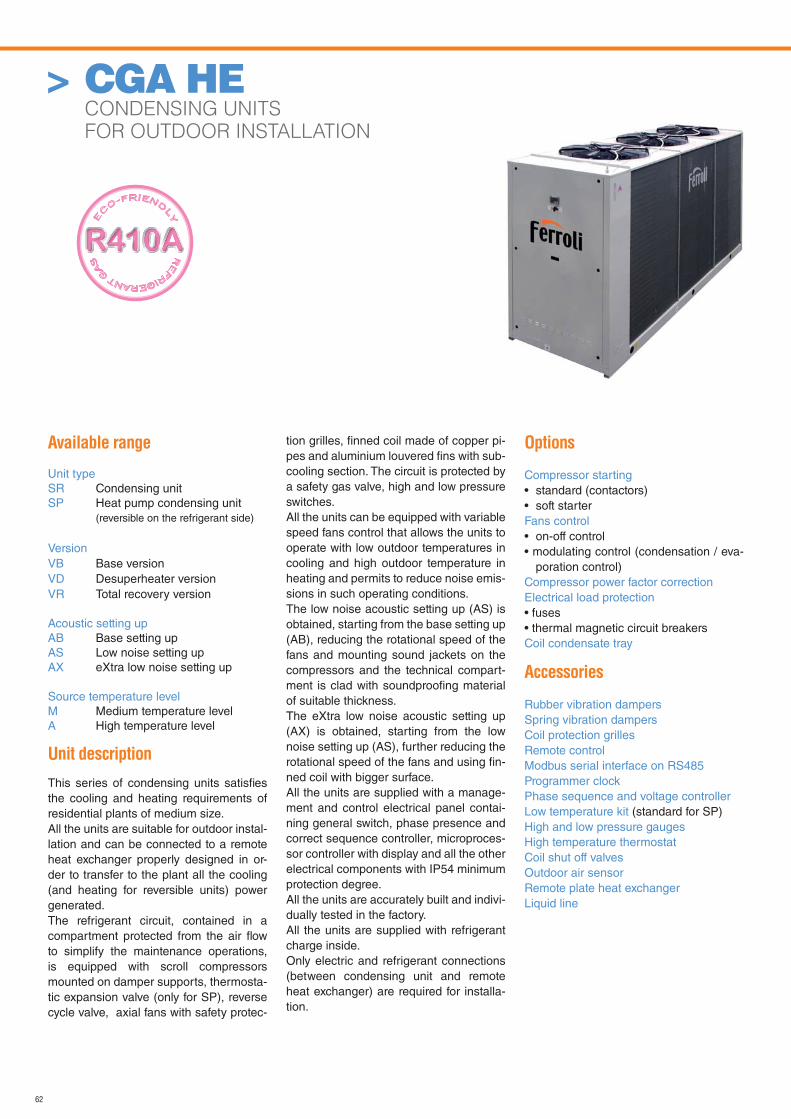
62
Available range
Unit typeSR Condensing unitSP Heat pump condensing unit
(reversible on the refrigerant side)
VersionVB Base versionVD Desuperheater versionVR Total recovery version
Acoustic setting upAB Base setting upAS Low noise setting upAX eXtra low noise setting up
Source temperature levelM Medium temperature levelA High temperature level
Unit description
This series of condensing units satisfi es the cooling and heating requirements of residential plants of medium size.All the units are suitable for outdoor instal-lation and can be connected to a remote heat exchanger properly designed in or-der to transfer to the plant all the cooling (and heating for reversible units) power generated.The refrigerant circuit, contained in a compartment protected from the air fl ow to simplify the maintenance operations, is equipped with scroll compressors mounted on damper supports, thermosta-tic expansion valve (only for SP), reverse cycle valve, axial fans with safety protec-
tion grilles, fi nned coil made of copper pi-pes and aluminium louvered fi ns with sub-cooling section. The circuit is protected by a safety gas valve, high and low pressure switches. All the units can be equipped with variable speed fans control that allows the units to operate with low outdoor temperatures in cooling and high outdoor temperature in heating and permits to reduce noise emis-sions in such operating conditions.The low noise acoustic setting up (AS) is obtained, starting from the base setting up (AB), reducing the rotational speed of the fans and mounting sound jackets on the compressors and the technical compart-ment is clad with soundproofi ng material of suitable thickness.The eXtra low noise acoustic setting up (AX) is obtained, starting from the low noise setting up (AS), further reducing the rotational speed of the fans and using fi n-ned coil with bigger surface.All the units are supplied with a manage-ment and control electrical panel contai-ning general switch, phase presence and correct sequence controller, microproces-sor controller with display and all the other electrical components with IP54 minimum protection degree.All the units are accurately built and indivi-dually tested in the factory. All the units are supplied with refrigerant charge inside.Only electric and refrigerant connections (between condensing unit and remote heat exchanger) are required for installa-tion.
Options
Compressor starting• standard (contactors)• soft starterFans control• on-off control• modulating control (condensation / eva-
poration control)Compressor power factor correction Electrical load protection• fuses• thermal magnetic circuit breakersCoil condensate tray
Accessories
Rubber vibration dampersSpring vibration dampersCoil protection grillesRemote controlModbus serial interface on RS485Programmer clockPhase sequence and voltage controllerLow temperature kit (standard for SP)High and low pressure gaugesHigh temperature thermostatCoil shut off valvesOutdoor air sensorRemote plate heat exchangerLiquid line
> CGA HE CONDENSING UNITS
FOR OUTDOOR INSTALLATION
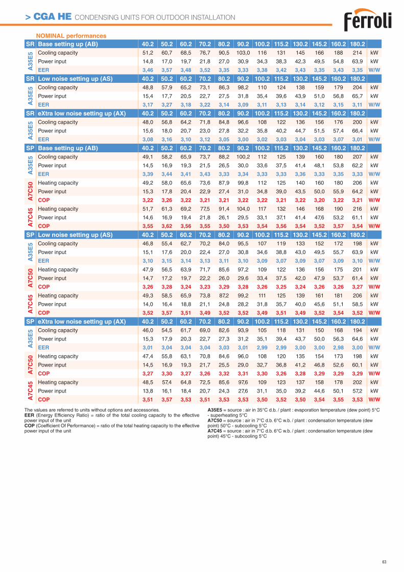
63
> CGA HE CONDENSING UNITS FOR OUTDOOR INSTALLATION
NOMINAL performances
SR Base setting up (AB) 40.2 50.2 60.2 70.2 80.2 90.2 100.2 115.2 130.2 145.2 160.2 180.2
A3
5E
5 Cooling capacity 51,2 60,7 68,5 76,7 90,5 103,0 116 131 145 166 188 214 kW
Power input 14,8 17,0 19,7 21,8 27,0 30,9 34,3 38,3 42,3 49,5 54,8 63,9 kW
EER 3,46 3,57 3,48 3,52 3,35 3,33 3,38 3,42 3,43 3,35 3,43 3,35 W/W
SR Low noise setting up (AS) 40.2 50.2 60.2 70.2 80.2 90.2 100.2 115.2 130.2 145.2 160.2 180.2
A3
5E
5 Cooling capacity 48,8 57,9 65,2 73,1 86,3 98,2 110 124 138 159 179 204 kW
Power input 15,4 17,7 20,5 22,7 27,5 31,8 35,4 39,6 43,9 51,0 56,8 65,7 kW
EER 3,17 3,27 3,18 3,22 3,14 3,09 3,11 3,13 3,14 3,12 3,15 3,11 W/W
SR eXtra low noise setting up (AX) 40.2 50.2 60.2 70.2 80.2 90.2 100.2 115.2 130.2 145.2 160.2 180.2
A3
5E
5 Cooling capacity 48,0 56,8 64,2 71,8 84,8 96,6 108 122 136 156 176 200 kW
Power input 15,6 18,0 20,7 23,0 27,8 32,2 35,8 40,2 44,7 51,5 57,4 66,4 kW
EER 3,08 3,16 3,10 3,12 3,05 3,00 3,02 3,03 3,04 3,03 3,07 3,01 W/W
SP Base setting up (AB) 40.2 50.2 60.2 70.2 80.2 90.2 100.2 115.2 130.2 145.2 160.2 180.2
A3
5E
5 Cooling capacity 49,1 58,2 65,9 73,7 88,2 100,2 112 125 139 160 180 207 kW
Power input 14,5 16,9 19,3 21,5 26,5 30,0 33,6 37,5 41,4 48,1 53,8 62,2 kW
EER 3,39 3,44 3,41 3,43 3,33 3,34 3,33 3,33 3,36 3,33 3,35 3,33 W/W
A7
C5
0 Heating capacity 49,2 58,0 65,6 73,6 87,9 99,8 112 125 140 160 180 206 kW
Power input 15,3 17,8 20,4 22,9 27,4 31,0 34,8 39,0 43,5 50,0 55,9 64,2 kW
COP 3,22 3,26 3,22 3,21 3,21 3,22 3,22 3,21 3,22 3,20 3,22 3,21 W/W
A7
C4
5 Heating capacity 51,7 61,3 69,2 77,5 91,4 104,0 117 132 146 168 190 216 kW
Power input 14,6 16,9 19,4 21,8 26,1 29,5 33,1 37,1 41,4 47,6 53,2 61,1 kW
COP 3,55 3,62 3,56 3,55 3,50 3,53 3,54 3,56 3,54 3,52 3,57 3,54 W/W
SP Low noise setting up (AS) 40.2 50.2 60.2 70.2 80.2 90.2 100.2 115.2 130.2 145.2 160.2 180.2
A35E
5 Cooling capacity 46,8 55,4 62,7 70,2 84,0 95,5 107 119 133 152 172 198 kW
Power input 15,1 17,6 20,0 22,4 27,0 30,8 34,6 38,8 43,0 49,5 55,7 63,9 kW
EER 3,10 3,15 3,14 3,13 3,11 3,10 3,09 3,07 3,09 3,07 3,09 3,10 W/W
A7C
50 Heating capacity 47,9 56,5 63,9 71,7 85,6 97,2 109 122 136 156 175 201 kW
Power input 14,7 17,2 19,7 22,2 26,0 29,6 33,4 37,5 42,0 47,9 53,7 61,4 kW
COP 3,26 3,28 3,24 3,23 3,29 3,28 3,26 3,25 3,24 3,26 3,26 3,27 W/W
A7C
45 Heating capacity 49,3 58,5 65,9 73,8 87,2 99,2 111 125 139 161 181 206 kW
Power input 14,0 16,4 18,8 21,1 24,8 28,2 31,8 35,7 40,0 45,6 51,1 58,5 kW
COP 3,52 3,57 3,51 3,49 3,52 3,52 3,49 3,51 3,49 3,52 3,54 3,52 W/W
SP eXtra low noise setting up (AX) 40.2 50.2 60.2 70.2 80.2 90.2 100.2 115.2 130.2 145.2 160.2 180.2
A35E
5 Cooling capacity 46,0 54,5 61,7 69,0 82,6 93,9 105 118 131 150 168 194 kW
Power input 15,3 17,9 20,3 22,7 27,3 31,2 35,1 39,4 43,7 50,0 56,3 64,6 kW
EER 3,01 3,04 3,04 3,04 3,03 3,01 2,99 2,99 3,00 3,00 2,98 3,00 W/W
A7C
50 Heating capacity 47,4 55,8 63,1 70,8 84,6 96,0 108 120 135 154 173 198 kW
Power input 14,5 16,9 19,3 21,7 25,5 29,0 32,7 36,8 41,2 46,8 52,6 60,1 kW
COP 3,27 3,30 3,27 3,26 3,32 3,31 3,30 3,26 3,28 3,29 3,29 3,29 W/W
A7C
45 Heating capacity 48,5 57,4 64,8 72,5 85,6 97,6 109 123 137 158 178 202 kW
Power input 13,8 16,1 18,4 20,7 24,3 27,6 31,1 35,0 39,2 44,6 50,1 57,2 kW
COP 3,51 3,57 3,53 3,51 3,53 3,53 3,50 3,52 3,50 3,54 3,55 3,53 W/W
The values are referred to units without options and accessories.EER (Energy Efficiency Ratio) = ratio of the total cooling capacity to the effective power input of the unitCOP (Coefficient Of Performance) = ratio of the total heating capacity to the effective power input of the unit
A35E5 = source : air in 35°C d.b. / plant : evaporation temperature (dew point) 5°C - superheating 5°CA7C50 = source : air in 7°C d.b. 6°C w.b. / plant : condensation temperature (dew point) 50°C - subcooling 5°CA7C45 = source : air in 7°C d.b. 6°C w.b. / plant : condensation temperature (dew point) 45°C - subcooling 5°C
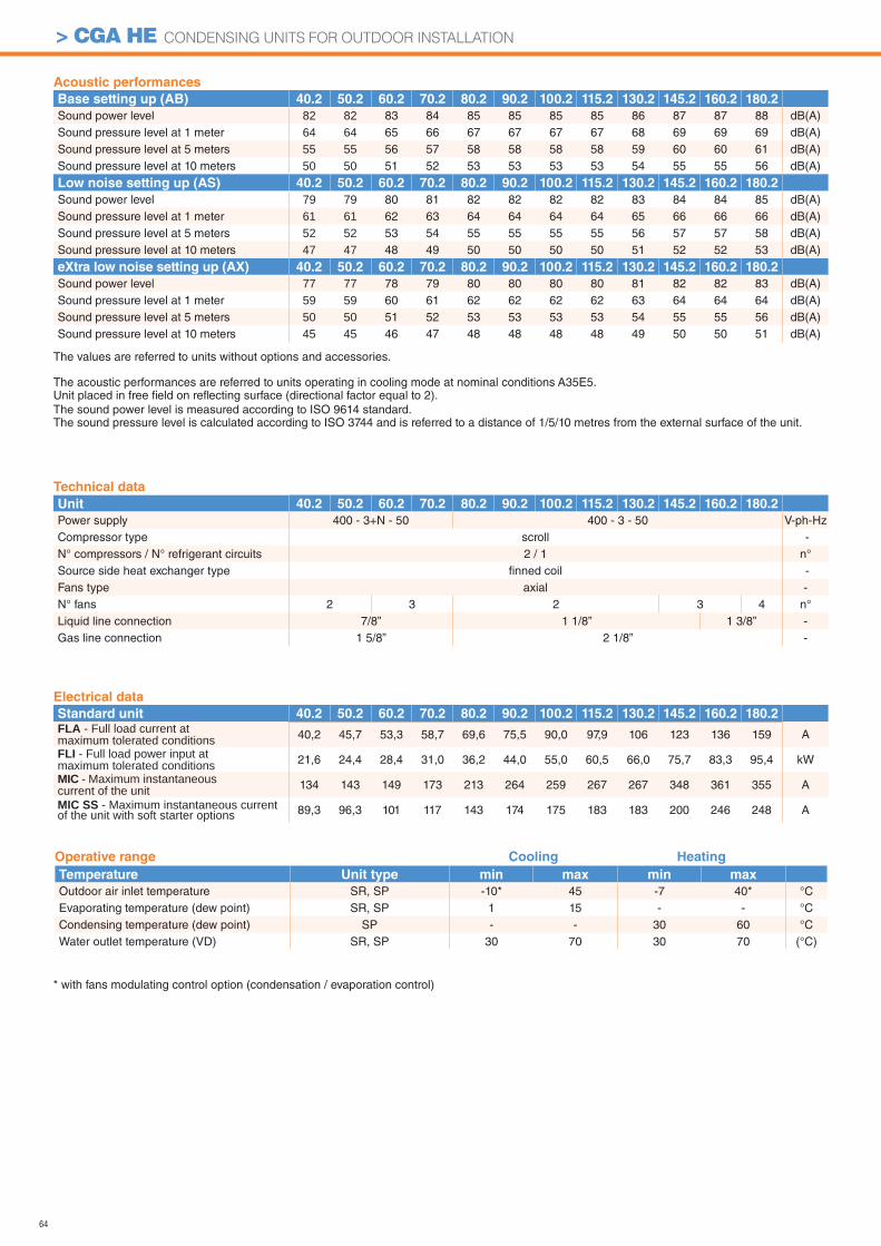
64
> CGA HE CONDENSING UNITS FOR OUTDOOR INSTALLATION
Acoustic performances
Base setting up (AB) 40.2 50.2 60.2 70.2 80.2 90.2 100.2 115.2 130.2 145.2 160.2 180.2
Sound power level 82 82 83 84 85 85 85 85 86 87 87 88 dB(A)Sound pressure level at 1 meter 64 64 65 66 67 67 67 67 68 69 69 69 dB(A)Sound pressure level at 5 meters 55 55 56 57 58 58 58 58 59 60 60 61 dB(A)Sound pressure level at 10 meters 50 50 51 52 53 53 53 53 54 55 55 56 dB(A)
Low noise setting up (AS) 40.2 50.2 60.2 70.2 80.2 90.2 100.2 115.2 130.2 145.2 160.2 180.2
Sound power level 79 79 80 81 82 82 82 82 83 84 84 85 dB(A)Sound pressure level at 1 meter 61 61 62 63 64 64 64 64 65 66 66 66 dB(A)Sound pressure level at 5 meters 52 52 53 54 55 55 55 55 56 57 57 58 dB(A)Sound pressure level at 10 meters 47 47 48 49 50 50 50 50 51 52 52 53 dB(A)
eXtra low noise setting up (AX) 40.2 50.2 60.2 70.2 80.2 90.2 100.2 115.2 130.2 145.2 160.2 180.2
Sound power level 77 77 78 79 80 80 80 80 81 82 82 83 dB(A)Sound pressure level at 1 meter 59 59 60 61 62 62 62 62 63 64 64 64 dB(A)Sound pressure level at 5 meters 50 50 51 52 53 53 53 53 54 55 55 56 dB(A)Sound pressure level at 10 meters 45 45 46 47 48 48 48 48 49 50 50 51 dB(A)
Operative range Cooling Heating
Temperature Unit type min max min max
Outdoor air inlet temperature SR, SP -10* 45 -7 40* °CEvaporating temperature (dew point) SR, SP 1 15 - - °CCondensing temperature (dew point) SP - - 30 60 °CWater outlet temperature (VD) SR, SP 30 70 30 70 (°C)
Technical data
Unit 40.2 50.2 60.2 70.2 80.2 90.2 100.2 115.2 130.2 145.2 160.2 180.2
Power supply 400 - 3+N - 50 400 - 3 - 50 V-ph-HzCompressor type scroll -N° compressors / N° refrigerant circuits 2 / 1 n°Source side heat exchanger type fi nned coil -Fans type axial -N° fans 2 3 2 3 4 n°Liquid line connection 7/8” 1 1/8” 1 3/8” -Gas line connection 1 5/8” 2 1/8” -
* with fans modulating control option (condensation / evaporation control)
The values are referred to units without options and accessories.
The acoustic performances are referred to units operating in cooling mode at nominal conditions A35E5.Unit placed in free fi eld on refl ecting surface (directional factor equal to 2).The sound power level is measured according to ISO 9614 standard.The sound pressure level is calculated according to ISO 3744 and is referred to a distance of 1/5/10 metres from the external surface of the unit.
Electrical data
Standard unit 40.2 50.2 60.2 70.2 80.2 90.2 100.2 115.2 130.2 145.2 160.2 180.2FLA - Full load current at maximum tolerated conditions 40,2 45,7 53,3 58,7 69,6 75,5 90,0 97,9 106 123 136 159 A
FLI - Full load power input at maximum tolerated conditions 21,6 24,4 28,4 31,0 36,2 44,0 55,0 60,5 66,0 75,7 83,3 95,4 kW
MIC - Maximum instantaneous current of the unit 134 143 149 173 213 264 259 267 267 348 361 355 A
MIC SS - Maximum instantaneous current of the unit with soft starter options 89,3 96,3 101 117 143 174 175 183 183 200 246 248 A
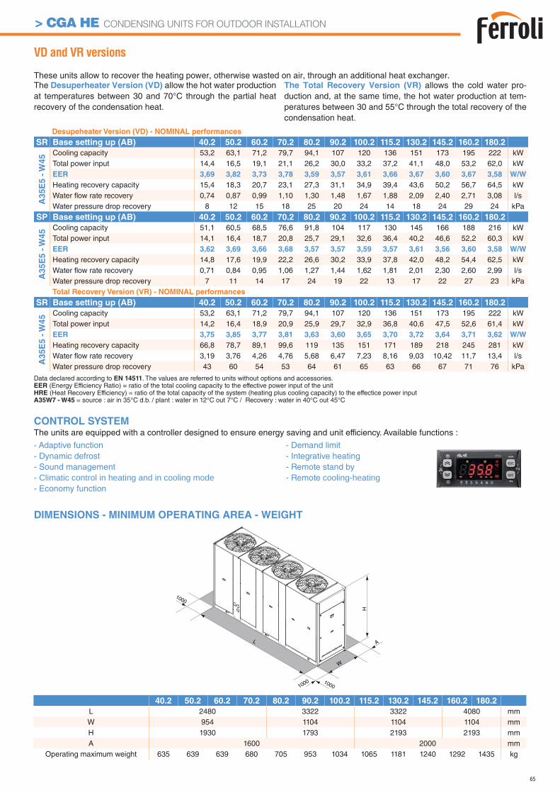
65
> CGA HE CONDENSING UNITS FOR OUTDOOR INSTALLATION
1000
L
W
A
H
1000
1000
VD and VR versions
These units allow to recover the heating power, otherwise wasted on air, through an additional heat exchanger.The Desuperheater Version (VD) allow the hot water production at temperatures between 30 and 70°C through the partial heat recovery of the condensation heat.
The Total Recovery Version (VR) allows the cold water pro-duction and, at the same time, the hot water production at tem-peratures between 30 and 55°C through the total recovery of the condensation heat.
DIMENSIONS - MINIMUM OPERATING AREA - WEIGHT
Desupeheater Version (VD) - NOMINAL performances
SR Base setting up (AB) 40.2 50.2 60.2 70.2 80.2 90.2 100.2 115.2 130.2 145.2 160.2 180.2
A3
5E
5 -
W4
5 Cooling capacity 53,2 63,1 71,2 79,7 94,1 107 120 136 151 173 195 222 kWTotal power input 14,4 16,5 19,1 21,1 26,2 30,0 33,2 37,2 41,1 48,0 53,2 62,0 kWEER 3,69 3,82 3,73 3,78 3,59 3,57 3,61 3,66 3,67 3,60 3,67 3,58 W/W
Heating recovery capacity 15,4 18,3 20,7 23,1 27,3 31,1 34,9 39,4 43,6 50,2 56,7 64,5 kWWater fl ow rate recovery 0,74 0,87 0,99 1,10 1,30 1,48 1,67 1,88 2,09 2,40 2,71 3,08 l/sWater pressure drop recovery 8 12 15 18 25 20 24 14 18 24 29 24 kPa
SP Base setting up (AB) 40.2 50.2 60.2 70.2 80.2 90.2 100.2 115.2 130.2 145.2 160.2 180.2
A3
5E
5 -
W4
5 Cooling capacity 51,1 60,5 68,5 76,6 91,8 104 117 130 145 166 188 216 kWTotal power input 14,1 16,4 18,7 20,8 25,7 29,1 32,6 36,4 40,2 46,6 52,2 60,3 kWEER 3,62 3,69 3,66 3,68 3,57 3,57 3,59 3,57 3,61 3,56 3,60 3,58 W/W
Heating recovery capacity 14,8 17,6 19,9 22,2 26,6 30,2 33,9 37,8 42,0 48,2 54,4 62,5 kWWater fl ow rate recovery 0,71 0,84 0,95 1,06 1,27 1,44 1,62 1,81 2,01 2,30 2,60 2,99 l/sWater pressure drop recovery 7 11 14 17 24 19 22 13 17 22 27 23 kPaTotal Recovery Version (VR) - NOMINAL performances
SR Base setting up (AB) 40.2 50.2 60.2 70.2 80.2 90.2 100.2 115.2 130.2 145.2 160.2 180.2
A35E
5 -
W45 Cooling capacity 53,2 63,1 71,2 79,7 94,1 107 120 136 151 173 195 222 kW
Total power input 14,2 16,4 18,9 20,9 25,9 29,7 32,9 36,8 40,6 47,5 52,6 61,4 kWEER 3,75 3,85 3,77 3,81 3,63 3,60 3,65 3,70 3,72 3,64 3,71 3,62 W/W
Heating recovery capacity 66,8 78,7 89,1 99,6 119 135 151 171 189 218 245 281 kWWater fl ow rate recovery 3,19 3,76 4,26 4,76 5,68 6,47 7,23 8,16 9,03 10,42 11,7 13,4 l/sWater pressure drop recovery 43 60 54 53 64 61 65 63 66 67 71 76 kPa
40.2 50.2 60.2 70.2 80.2 90.2 100.2 115.2 130.2 145.2 160.2 180.2
L 2480 3322 3322 4080 mmW 954 1104 1104 1104 mmH 1930 1793 2193 2193 mmA 1600 2000 mm
Operating maximum weight 635 639 639 680 705 953 1034 1065 1181 1240 1292 1435 kg
CONTROL SYSTEMThe units are equipped with a controller designed to ensure energy saving and unit efficiency. Available functions :
- Adaptive function- Dynamic defrost - Sound management - Climatic control in heating and in cooling mode- Economy function
- Demand limit- Integrative heating- Remote stand by- Remote cooling-heating
Data declared according to EN 14511. The values are referred to units without options and accessories.EER (Energy Efficiency Ratio) = ratio of the total cooling capacity to the effective power input of the unitHRE (Heat Recovery Efficiency) = ratio of the total capacity of the system (heating plus cooling capacity) to the effectice power inputA35W7 - W45 = source : air in 35°C d.b. / plant : water in 12°C out 7°C / Recovery : water in 40°C out 45°C
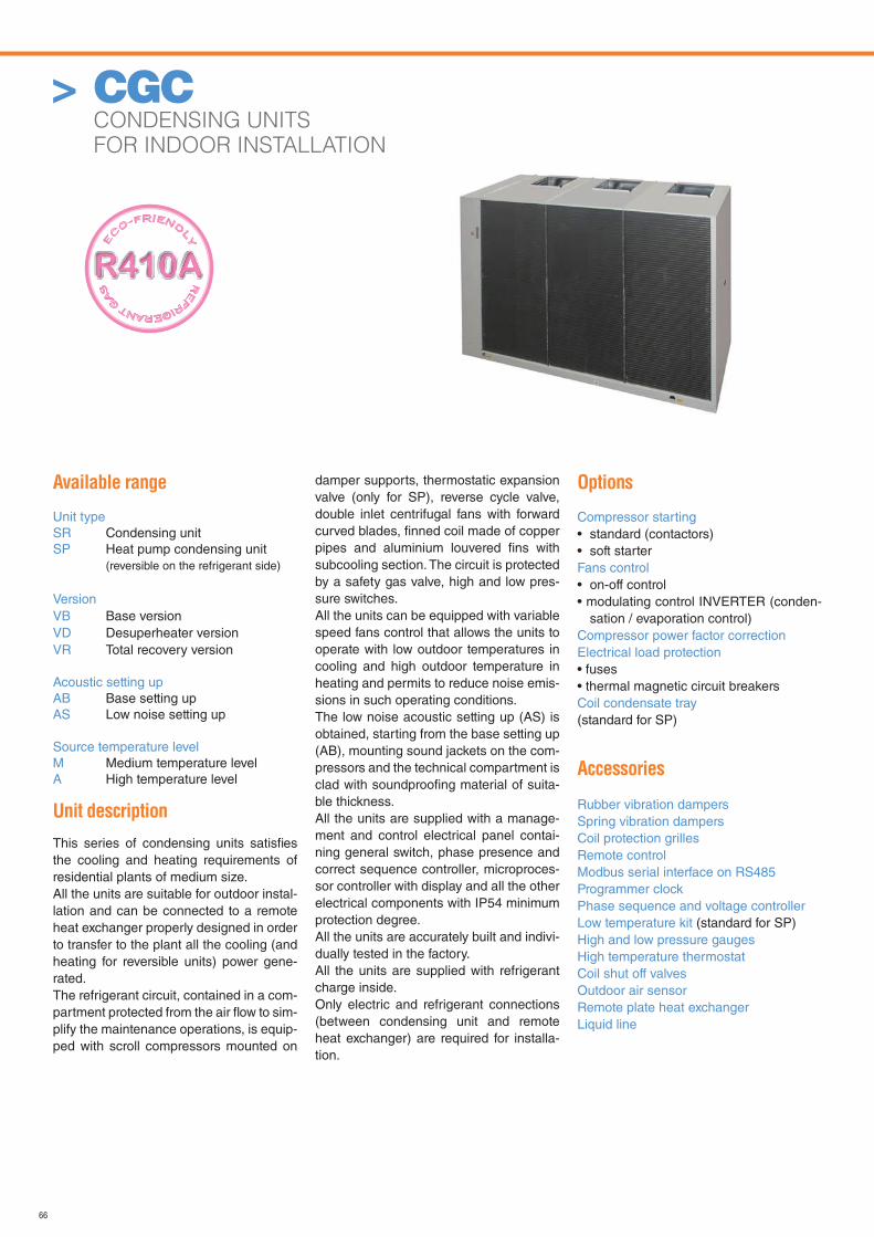
66
> CGC CONDENSING UNITS
FOR INDOOR INSTALLATION
Available range
Unit typeSR Condensing unitSP Heat pump condensing unit (reversible on the refrigerant side)
VersionVB Base versionVD Desuperheater versionVR Total recovery version
Acoustic setting upAB Base setting upAS Low noise setting up
Source temperature levelM Medium temperature levelA High temperature level
Unit description
This series of condensing units satisfi es the cooling and heating requirements of residential plants of medium size.All the units are suitable for outdoor instal-lation and can be connected to a remote heat exchanger properly designed in order to transfer to the plant all the cooling (and heating for reversible units) power gene-rated.The refrigerant circuit, contained in a com-partment protected from the air fl ow to sim-plify the maintenance operations, is equip-ped with scroll compressors mounted on
damper supports, thermostatic expansion valve (only for SP), reverse cycle valve, double inlet centrifugal fans with forward curved blades, fi nned coil made of copper pipes and aluminium louvered fi ns with subcooling section. The circuit is protected by a safety gas valve, high and low pres-sure switches. All the units can be equipped with variable speed fans control that allows the units to operate with low outdoor temperatures in cooling and high outdoor temperature in heating and permits to reduce noise emis-sions in such operating conditions.The low noise acoustic setting up (AS) is obtained, starting from the base setting up (AB), mounting sound jackets on the com-pressors and the technical compartment is clad with soundproofi ng material of suita-ble thickness.All the units are supplied with a manage-ment and control electrical panel contai-ning general switch, phase presence and correct sequence controller, microproces-sor controller with display and all the other electrical components with IP54 minimum protection degree.All the units are accurately built and indivi-dually tested in the factory. All the units are supplied with refrigerant charge inside.Only electric and refrigerant connections (between condensing unit and remote heat exchanger) are required for installa-tion.
Options
Compressor starting• standard (contactors)• soft starterFans control• on-off control• modulating control INVERTER (conden-
sation / evaporation control)Compressor power factor correction Electrical load protection• fuses• thermal magnetic circuit breakersCoil condensate tray(standard for SP)
Accessories
Rubber vibration dampersSpring vibration dampersCoil protection grillesRemote controlModbus serial interface on RS485Programmer clockPhase sequence and voltage controllerLow temperature kit (standard for SP)High and low pressure gaugesHigh temperature thermostatCoil shut off valvesOutdoor air sensorRemote plate heat exchangerLiquid line
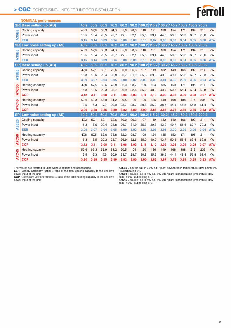
67
> CGC CONDENSING UNITS FOR INDOOR INSTALLATION
NOMINAL performances
SR Base setting up (AB) 40.2 50.2 60.2 70.2 80.2 90.2 100.2 115.2 130.2 145.2 160.2 180.2 200.2
A3
5E
5 Cooling capacity 48,9 57,8 63,3 74,3 85,0 98,3 110 121 136 154 171 194 216 kW
Power input 15,5 18,4 20,5 23,7 27,6 32,1 35,5 39,4 44,5 50,8 56,3 63,7 70,6 kW
EER 3,15 3,14 3,09 3,14 3,08 3,06 3,10 3,07 3,06 3,03 3,04 3,05 3,06 W/W
SR Low noise setting up (AS) 40.2 50.2 60.2 70.2 80.2 90.2 100.2 115.2 130.2 145.2 160.2 180.2 200.2
A3
5E
5 Cooling capacity 48,9 57,8 63,3 74,3 85,0 98,3 110 121 136 154 171 194 216 kW
Power input 15,5 18,4 20,5 23,7 27,6 32,1 35,5 39,4 44,5 50,8 56,3 63,7 70,6 kW
EER 3,15 3,14 3,09 3,14 3,08 3,06 3,10 3,07 3,06 3,03 3,04 3,05 3,06 W/W
SP Base setting up (AB) 40.2 50.2 60.2 70.2 80.2 90.2 100.2 115.2 130.2 145.2 160.2 180.2 200.2
A3
5E
5 Cooling capacity 47,3 57,1 62,1 72,6 80,0 96,3 107 119 132 149 166 192 214 kW
Power input 15,3 18,6 20,4 23,8 26,7 31,9 35,3 39,3 43,9 49,7 55,6 62,7 70,3 kW
EER 3,09 3,07 3,04 3,05 3,00 3,02 3,03 3,03 3,01 3,00 2,99 3,06 3,04 W/W
A7
C5
0 Heating capacity 47,8 57,5 62,6 73,8 82,3 98,7 109 124 135 153 171 195 214 kW
Power input 15,3 18,5 20,3 23,7 26,9 32,6 35,0 40,0 43,7 50,5 55,4 63,4 69,8 kW
COP 3,12 3,11 3,08 3,11 3,06 3,03 3,11 3,10 3,09 3,03 3,09 3,08 3,07 W/W
A7
C4
5 Heating capacity 52,6 63,3 68,9 81,2 90,5 109 120 136 149 168 188 215 235 kW
Power input 13,5 16,3 17,9 20,9 23,7 28,7 30,8 35,2 38,5 44,4 48,8 55,8 61,4 kW
COP 3,90 3,88 3,85 3,89 3,82 3,80 3,90 3,86 3,87 3,78 3,85 3,85 3,83 W/W
SP Low noise setting up (AS) 40.2 50.2 60.2 70.2 80.2 90.2 100.2 115.2 130.2 145.2 160.2 180.2 200.2
A3
5E
5 Cooling capacity 47,3 57,1 62,1 72,6 80,0 96,3 107 119 132 149 166 192 214 kW
Power input 15,3 18,6 20,4 23,8 26,7 31,9 35,3 39,3 43,9 49,7 55,6 62,7 70,3 kW
EER 3,09 3,07 3,04 3,05 3,00 3,02 3,03 3,03 3,01 3,00 2,99 3,06 3,04 W/W
A7C
50 Heating capacity 47,8 57,5 62,6 73,8 82,3 98,7 109 124 135 153 171 195 214 kW
Power input 15,3 18,5 20,3 23,7 26,9 32,6 35,0 40,0 43,7 50,5 55,4 63,4 69,8 kW
COP 3,12 3,11 3,08 3,11 3,06 3,03 3,11 3,10 3,09 3,03 3,09 3,08 3,07 W/W
A7C
45 Heating capacity 52,6 63,3 68,9 81,2 90,5 109 120 136 149 168 188 215 235 kW
Power input 13,5 16,3 17,9 20,9 23,7 28,7 30,8 35,2 38,5 44,4 48,8 55,8 61,4 kW
COP 3,90 3,88 3,85 3,89 3,82 3,80 3,90 3,86 3,87 3,78 3,85 3,85 3,83 W/W
The values are referred to units without options and accessories.EER (Energy Efficiency Ratio) = ratio of the total cooling capacity to the effective power input of the unitCOP (Coefficient Of Performance) = ratio of the total heating capacity to the effective power input of the unit
A35E5 = source : air in 35°C d.b. / plant : evaporation temperature (dew point) 5°C - superheating 5°CA7C50 = source : air in 7°C d.b. 6°C w.b. / plant : condensation temperature (dew point) 50°C - subcooling 5°CA7C45 = source : air in 7°C d.b. 6°C w.b. / plant : condensation temperature (dew point) 45°C - subcooling 5°C
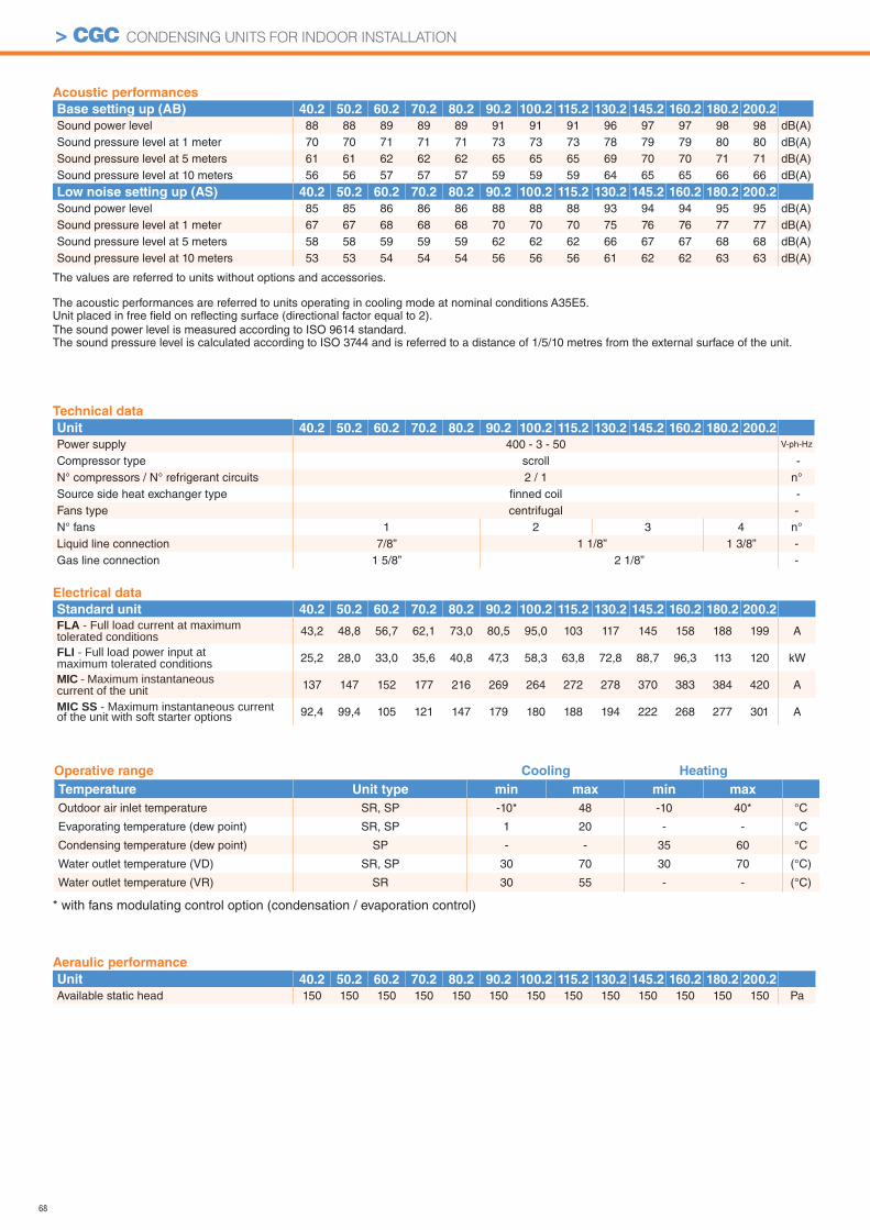
68
> CGC CONDENSING UNITS FOR INDOOR INSTALLATION
Operative range Cooling Heating
Temperature Unit type min max min max
Outdoor air inlet temperature SR, SP -10* 48 -10 40* °C
Evaporating temperature (dew point) SR, SP 1 20 - - °C
Condensing temperature (dew point) SP - - 35 60 °C
Water outlet temperature (VD) SR, SP 30 70 30 70 (°C)
Water outlet temperature (VR) SR 30 55 - - (°C)
* with fans modulating control option (condensation / evaporation control)
Acoustic performances
Base setting up (AB) 40.2 50.2 60.2 70.2 80.2 90.2 100.2 115.2 130.2 145.2 160.2 180.2 200.2
Sound power level 88 88 89 89 89 91 91 91 96 97 97 98 98 dB(A)Sound pressure level at 1 meter 70 70 71 71 71 73 73 73 78 79 79 80 80 dB(A)Sound pressure level at 5 meters 61 61 62 62 62 65 65 65 69 70 70 71 71 dB(A)Sound pressure level at 10 meters 56 56 57 57 57 59 59 59 64 65 65 66 66 dB(A)
Low noise setting up (AS) 40.2 50.2 60.2 70.2 80.2 90.2 100.2 115.2 130.2 145.2 160.2 180.2 200.2
Sound power level 85 85 86 86 86 88 88 88 93 94 94 95 95 dB(A)Sound pressure level at 1 meter 67 67 68 68 68 70 70 70 75 76 76 77 77 dB(A)Sound pressure level at 5 meters 58 58 59 59 59 62 62 62 66 67 67 68 68 dB(A)Sound pressure level at 10 meters 53 53 54 54 54 56 56 56 61 62 62 63 63 dB(A)
Technical data
Unit 40.2 50.2 60.2 70.2 80.2 90.2 100.2 115.2 130.2 145.2 160.2 180.2 200.2
Power supply 400 - 3 - 50 V-ph-Hz
Compressor type scroll -N° compressors / N° refrigerant circuits 2 / 1 n°Source side heat exchanger type fi nned coil -Fans type centrifugal -N° fans 1 2 3 4 n°Liquid line connection 7/8” 1 1/8” 1 3/8” -Gas line connection 1 5/8” 2 1/8” -
Aeraulic performance
Unit 40.2 50.2 60.2 70.2 80.2 90.2 100.2 115.2 130.2 145.2 160.2 180.2 200.2
Available static head 150 150 150 150 150 150 150 150 150 150 150 150 150 Pa
Electrical data
Standard unit 40.2 50.2 60.2 70.2 80.2 90.2 100.2 115.2 130.2 145.2 160.2 180.2 200.2
FLA - Full load current at maximum tolerated conditions 43,2 48,8 56,7 62,1 73,0 80,5 95,0 103 117 145 158 188 199 A
FLI - Full load power input at maximum tolerated conditions 25,2 28,0 33,0 35,6 40,8 47,3 58,3 63,8 72,8 88,7 96,3 113 120 kW
MIC - Maximum instantaneous current of the unit 137 147 152 177 216 269 264 272 278 370 383 384 420 A
MIC SS - Maximum instantaneous current of the unit with soft starter options 92,4 99,4 105 121 147 179 180 188 194 222 268 277 301 A
The values are referred to units without options and accessories.
The acoustic performances are referred to units operating in cooling mode at nominal conditions A35E5.Unit placed in free fi eld on refl ecting surface (directional factor equal to 2).The sound power level is measured according to ISO 9614 standard.The sound pressure level is calculated according to ISO 3744 and is referred to a distance of 1/5/10 metres from the external surface of the unit.
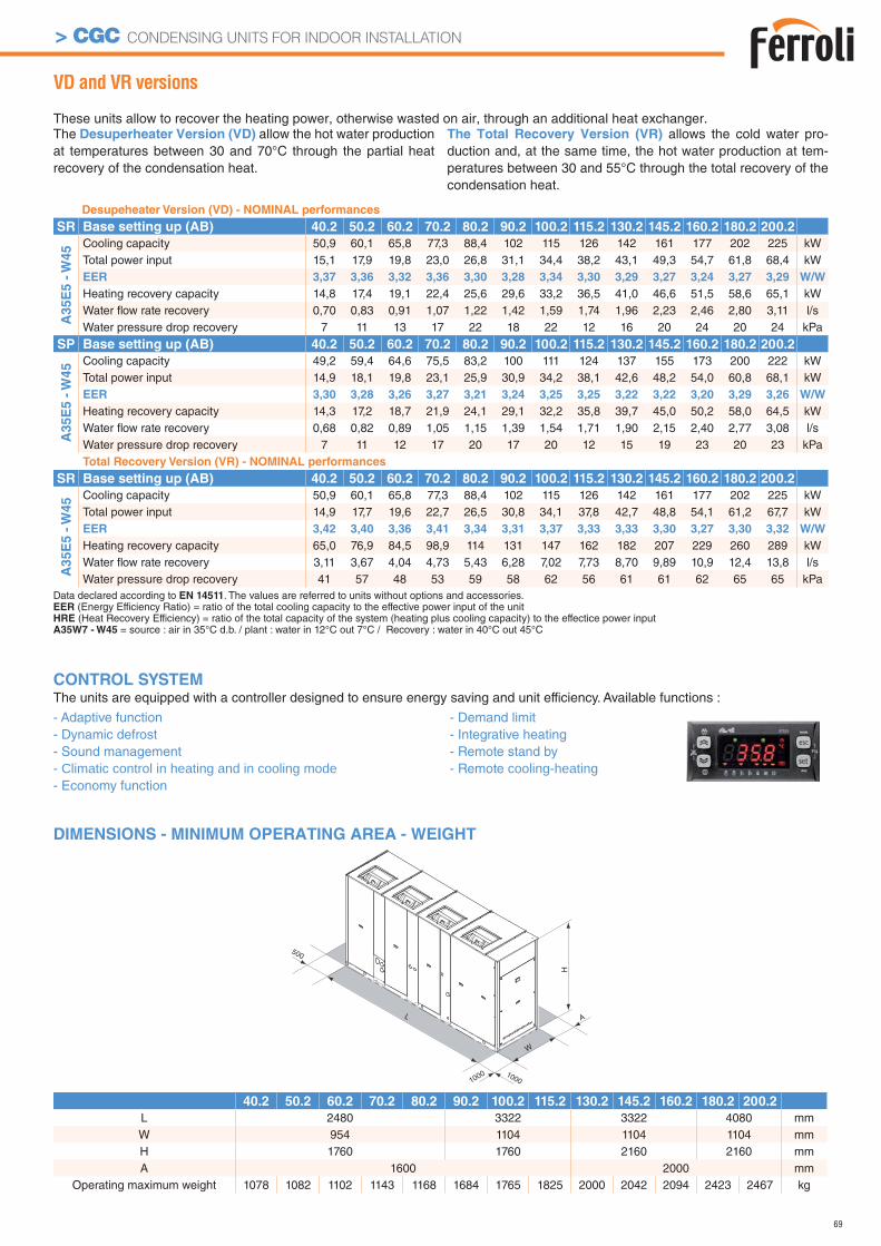
69
> CGC CONDENSING UNITS FOR INDOOR INSTALLATION
VD and VR versions
These units allow to recover the heating power, otherwise wasted on air, through an additional heat exchanger.The Desuperheater Version (VD) allow the hot water production at temperatures between 30 and 70°C through the partial heat recovery of the condensation heat.
The Total Recovery Version (VR) allows the cold water pro-duction and, at the same time, the hot water production at tem-peratures between 30 and 55°C through the total recovery of the condensation heat.
DIMENSIONS - MINIMUM OPERATING AREA - WEIGHT
Desupeheater Version (VD) - NOMINAL performances
SR Base setting up (AB) 40.2 50.2 60.2 70.2 80.2 90.2 100.2 115.2 130.2 145.2 160.2 180.2 200.2
A3
5E
5 -
W4
5 Cooling capacity 50,9 60,1 65,8 77,3 88,4 102 115 126 142 161 177 202 225 kWTotal power input 15,1 17,9 19,8 23,0 26,8 31,1 34,4 38,2 43,1 49,3 54,7 61,8 68,4 kWEER 3,37 3,36 3,32 3,36 3,30 3,28 3,34 3,30 3,29 3,27 3,24 3,27 3,29 W/W
Heating recovery capacity 14,8 17,4 19,1 22,4 25,6 29,6 33,2 36,5 41,0 46,6 51,5 58,6 65,1 kWWater fl ow rate recovery 0,70 0,83 0,91 1,07 1,22 1,42 1,59 1,74 1,96 2,23 2,46 2,80 3,11 l/sWater pressure drop recovery 7 11 13 17 22 18 22 12 16 20 24 20 24 kPa
SP Base setting up (AB) 40.2 50.2 60.2 70.2 80.2 90.2 100.2 115.2 130.2 145.2 160.2 180.2 200.2
A3
5E
5 -
W4
5 Cooling capacity 49,2 59,4 64,6 75,5 83,2 100 111 124 137 155 173 200 222 kWTotal power input 14,9 18,1 19,8 23,1 25,9 30,9 34,2 38,1 42,6 48,2 54,0 60,8 68,1 kWEER 3,30 3,28 3,26 3,27 3,21 3,24 3,25 3,25 3,22 3,22 3,20 3,29 3,26 W/W
Heating recovery capacity 14,3 17,2 18,7 21,9 24,1 29,1 32,2 35,8 39,7 45,0 50,2 58,0 64,5 kWWater fl ow rate recovery 0,68 0,82 0,89 1,05 1,15 1,39 1,54 1,71 1,90 2,15 2,40 2,77 3,08 l/sWater pressure drop recovery 7 11 12 17 20 17 20 12 15 19 23 20 23 kPaTotal Recovery Version (VR) - NOMINAL performances
SR Base setting up (AB) 40.2 50.2 60.2 70.2 80.2 90.2 100.2 115.2 130.2 145.2 160.2 180.2 200.2
A35E
5 -
W45 Cooling capacity 50,9 60,1 65,8 77,3 88,4 102 115 126 142 161 177 202 225 kW
Total power input 14,9 17,7 19,6 22,7 26,5 30,8 34,1 37,8 42,7 48,8 54,1 61,2 67,7 kWEER 3,42 3,40 3,36 3,41 3,34 3,31 3,37 3,33 3,33 3,30 3,27 3,30 3,32 W/W
Heating recovery capacity 65,0 76,9 84,5 98,9 114 131 147 162 182 207 229 260 289 kWWater fl ow rate recovery 3,11 3,67 4,04 4,73 5,43 6,28 7,02 7,73 8,70 9,89 10,9 12,4 13,8 l/sWater pressure drop recovery 41 57 48 53 59 58 62 56 61 61 62 65 65 kPa
1000
L
W
A
H
1000
500
40.2 50.2 60.2 70.2 80.2 90.2 100.2 115.2 130.2 145.2 160.2 180.2 200.2
L 2480 3322 3322 4080 mmW 954 1104 1104 1104 mmH 1760 1760 2160 2160 mmA 1600 2000 mm
Operating maximum weight 1078 1082 1102 1143 1168 1684 1765 1825 2000 2042 2094 2423 2467 kg
Data declared according to EN 14511. The values are referred to units without options and accessories.EER (Energy Efficiency Ratio) = ratio of the total cooling capacity to the effective power input of the unitHRE (Heat Recovery Efficiency) = ratio of the total capacity of the system (heating plus cooling capacity) to the effectice power inputA35W7 - W45 = source : air in 35°C d.b. / plant : water in 12°C out 7°C / Recovery : water in 40°C out 45°C
CONTROL SYSTEMThe units are equipped with a controller designed to ensure energy saving and unit efficiency. Available functions :
- Adaptive function- Dynamic defrost - Sound management - Climatic control in heating and in cooling mode- Economy function
- Demand limit- Integrative heating- Remote stand by- Remote cooling-heating
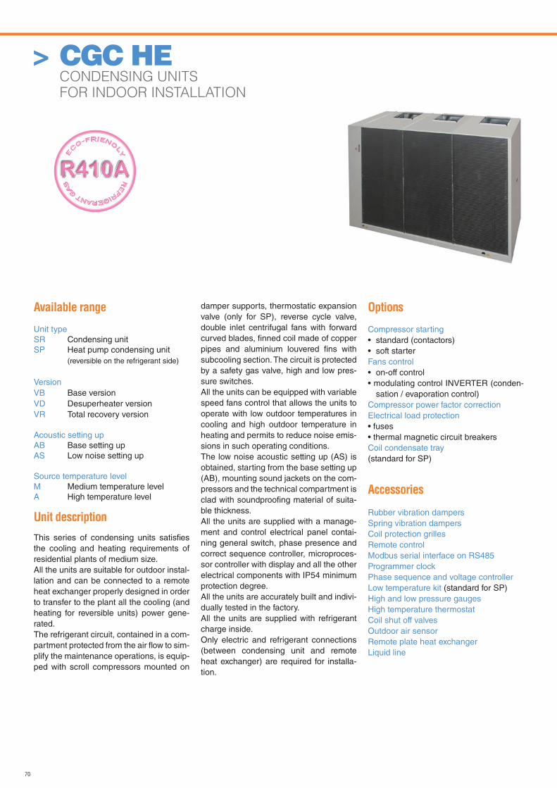
70
> CGC HE CONDENSING UNITS
FOR INDOOR INSTALLATION
Available range
Unit typeSR Condensing unitSP Heat pump condensing unit (reversible on the refrigerant side)
VersionVB Base versionVD Desuperheater versionVR Total recovery version
Acoustic setting upAB Base setting upAS Low noise setting up
Source temperature levelM Medium temperature levelA High temperature level
Unit description
This series of condensing units satisfi es the cooling and heating requirements of residential plants of medium size.All the units are suitable for outdoor instal-lation and can be connected to a remote heat exchanger properly designed in order to transfer to the plant all the cooling (and heating for reversible units) power gene-rated.The refrigerant circuit, contained in a com-partment protected from the air fl ow to sim-plify the maintenance operations, is equip-ped with scroll compressors mounted on
damper supports, thermostatic expansion valve (only for SP), reverse cycle valve, double inlet centrifugal fans with forward curved blades, fi nned coil made of copper pipes and aluminium louvered fi ns with subcooling section. The circuit is protected by a safety gas valve, high and low pres-sure switches. All the units can be equipped with variable speed fans control that allows the units to operate with low outdoor temperatures in cooling and high outdoor temperature in heating and permits to reduce noise emis-sions in such operating conditions.The low noise acoustic setting up (AS) is obtained, starting from the base setting up (AB), mounting sound jackets on the com-pressors and the technical compartment is clad with soundproofi ng material of suita-ble thickness.All the units are supplied with a manage-ment and control electrical panel contai-ning general switch, phase presence and correct sequence controller, microproces-sor controller with display and all the other electrical components with IP54 minimum protection degree.All the units are accurately built and indivi-dually tested in the factory. All the units are supplied with refrigerant charge inside.Only electric and refrigerant connections (between condensing unit and remote heat exchanger) are required for installa-tion.
Options
Compressor starting• standard (contactors)• soft starterFans control• on-off control• modulating control INVERTER (conden-
sation / evaporation control)Compressor power factor correction Electrical load protection• fuses• thermal magnetic circuit breakersCoil condensate tray(standard for SP)
Accessories
Rubber vibration dampersSpring vibration dampersCoil protection grillesRemote controlModbus serial interface on RS485Programmer clockPhase sequence and voltage controllerLow temperature kit (standard for SP)High and low pressure gaugesHigh temperature thermostatCoil shut off valvesOutdoor air sensorRemote plate heat exchangerLiquid line
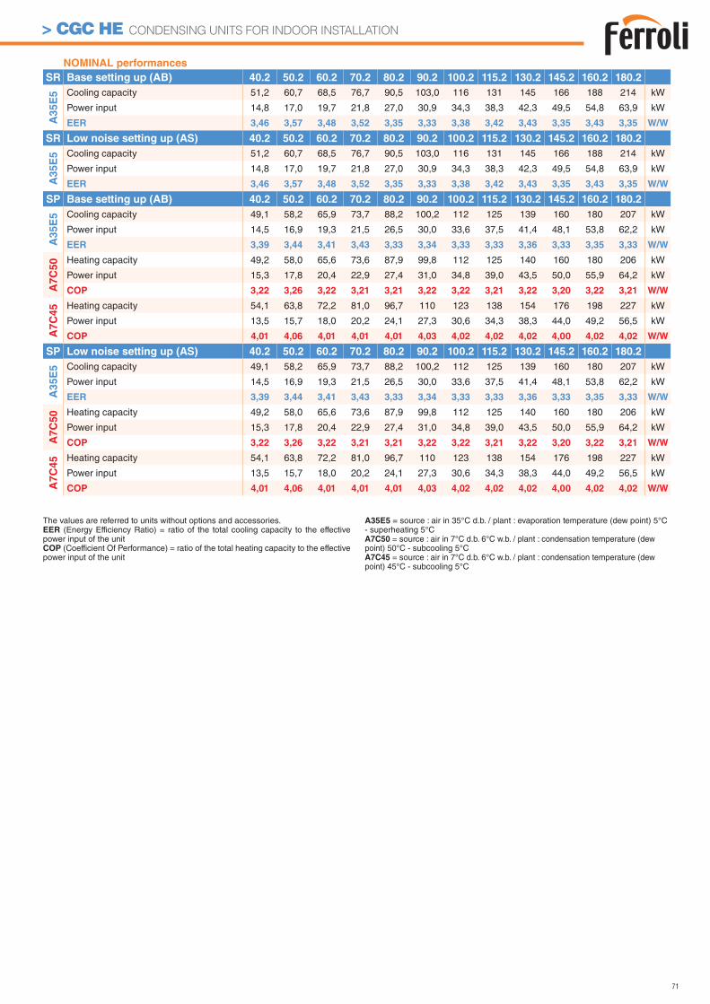
71
> CGC HE CONDENSING UNITS FOR INDOOR INSTALLATION
NOMINAL performances
SR Base setting up (AB) 40.2 50.2 60.2 70.2 80.2 90.2 100.2 115.2 130.2 145.2 160.2 180.2
A3
5E
5 Cooling capacity 51,2 60,7 68,5 76,7 90,5 103,0 116 131 145 166 188 214 kW
Power input 14,8 17,0 19,7 21,8 27,0 30,9 34,3 38,3 42,3 49,5 54,8 63,9 kW
EER 3,46 3,57 3,48 3,52 3,35 3,33 3,38 3,42 3,43 3,35 3,43 3,35 W/W
SR Low noise setting up (AS) 40.2 50.2 60.2 70.2 80.2 90.2 100.2 115.2 130.2 145.2 160.2 180.2
A3
5E
5 Cooling capacity 51,2 60,7 68,5 76,7 90,5 103,0 116 131 145 166 188 214 kW
Power input 14,8 17,0 19,7 21,8 27,0 30,9 34,3 38,3 42,3 49,5 54,8 63,9 kW
EER 3,46 3,57 3,48 3,52 3,35 3,33 3,38 3,42 3,43 3,35 3,43 3,35 W/W
SP Base setting up (AB) 40.2 50.2 60.2 70.2 80.2 90.2 100.2 115.2 130.2 145.2 160.2 180.2
A3
5E
5 Cooling capacity 49,1 58,2 65,9 73,7 88,2 100,2 112 125 139 160 180 207 kW
Power input 14,5 16,9 19,3 21,5 26,5 30,0 33,6 37,5 41,4 48,1 53,8 62,2 kW
EER 3,39 3,44 3,41 3,43 3,33 3,34 3,33 3,33 3,36 3,33 3,35 3,33 W/W
A7
C5
0 Heating capacity 49,2 58,0 65,6 73,6 87,9 99,8 112 125 140 160 180 206 kW
Power input 15,3 17,8 20,4 22,9 27,4 31,0 34,8 39,0 43,5 50,0 55,9 64,2 kW
COP 3,22 3,26 3,22 3,21 3,21 3,22 3,22 3,21 3,22 3,20 3,22 3,21 W/W
A7
C4
5 Heating capacity 54,1 63,8 72,2 81,0 96,7 110 123 138 154 176 198 227 kW
Power input 13,5 15,7 18,0 20,2 24,1 27,3 30,6 34,3 38,3 44,0 49,2 56,5 kW
COP 4,01 4,06 4,01 4,01 4,01 4,03 4,02 4,02 4,02 4,00 4,02 4,02 W/W
SP Low noise setting up (AS) 40.2 50.2 60.2 70.2 80.2 90.2 100.2 115.2 130.2 145.2 160.2 180.2
A3
5E
5 Cooling capacity 49,1 58,2 65,9 73,7 88,2 100,2 112 125 139 160 180 207 kW
Power input 14,5 16,9 19,3 21,5 26,5 30,0 33,6 37,5 41,4 48,1 53,8 62,2 kW
EER 3,39 3,44 3,41 3,43 3,33 3,34 3,33 3,33 3,36 3,33 3,35 3,33 W/W
A7C
50 Heating capacity 49,2 58,0 65,6 73,6 87,9 99,8 112 125 140 160 180 206 kW
Power input 15,3 17,8 20,4 22,9 27,4 31,0 34,8 39,0 43,5 50,0 55,9 64,2 kW
COP 3,22 3,26 3,22 3,21 3,21 3,22 3,22 3,21 3,22 3,20 3,22 3,21 W/W
A7C
45 Heating capacity 54,1 63,8 72,2 81,0 96,7 110 123 138 154 176 198 227 kW
Power input 13,5 15,7 18,0 20,2 24,1 27,3 30,6 34,3 38,3 44,0 49,2 56,5 kW
COP 4,01 4,06 4,01 4,01 4,01 4,03 4,02 4,02 4,02 4,00 4,02 4,02 W/W
The values are referred to units without options and accessories.EER (Energy Efficiency Ratio) = ratio of the total cooling capacity to the effective power input of the unitCOP (Coefficient Of Performance) = ratio of the total heating capacity to the effective power input of the unit
A35E5 = source : air in 35°C d.b. / plant : evaporation temperature (dew point) 5°C - superheating 5°CA7C50 = source : air in 7°C d.b. 6°C w.b. / plant : condensation temperature (dew point) 50°C - subcooling 5°CA7C45 = source : air in 7°C d.b. 6°C w.b. / plant : condensation temperature (dew point) 45°C - subcooling 5°C
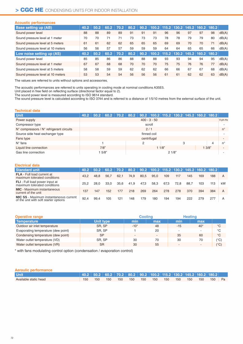
72
> CGC HE CONDENSING UNITS FOR INDOOR INSTALLATION
Acoustic performances
Base setting up (AB) 40.2 50.2 60.2 70.2 80.2 90.2 100.2 115.2 130.2 145.2 160.2 180.2
Sound power level 88 88 89 89 91 91 91 96 96 97 97 98 dB(A)
Sound pressure level at 1 meter 70 70 71 71 73 73 73 78 78 79 79 80 dB(A)
Sound pressure level at 5 meters 61 61 62 62 65 65 65 69 69 70 70 71 dB(A)
Sound pressure level at 10 meters 56 56 57 57 59 59 59 64 64 65 65 66 dB(A)
Low noise setting up (AS) 40.2 50.2 60.2 70.2 80.2 90.2 100.2 115.2 130.2 145.2 160.2 180.2
Sound power level 85 85 86 86 88 88 88 93 93 94 94 95 dB(A)
Sound pressure level at 1 meter 67 67 68 68 70 70 70 75 75 76 76 77 dB(A)
Sound pressure level at 5 meters 58 58 59 59 62 62 62 66 66 67 67 68 dB(A)
Sound pressure level at 10 meters 53 53 54 54 56 56 56 61 61 62 62 63 dB(A)
Operative range Cooling Heating
Temperature Unit type min max min max
Outdoor air inlet temperature SR, SP -10* 48 -15 40* °CEvaporating temperature (dew point) SR, SP 1 20 - - °CCondensing temperature (dew point) SP - - 35 60 °CWater outlet temperature (VD) SR, SP 30 70 30 70 (°C)Water outlet temperature (VR) SR 30 55 - - (°C)
* with fans modulating control option (condensation / evaporation control)
Technical data
Unit 40.2 50.2 60.2 70.2 80.2 90.2 100.2 115.2 130.2 145.2 160.2 180.2
Power supply 400 - 3 - 50 V-ph-Hz
Compressor type scroll -N° compressors / N° refrigerant circuits 2 / 1 n°Source side heat exchanger type fi nned coil -Fans type centrifugal -N° fans 1 2 3 4 n°Liquid line connection 7/8” 1 1/8” 1 3/8” -Gas line connection 1 5/8” 2 1/8” -
Aeraulic performance
Unit 40.2 50.2 60.2 70.2 80.2 90.2 100.2 115.2 130.2 145.2 160.2 180.2
Available static head 150 150 150 150 150 150 150 150 150 150 150 150 Pa
Electrical data
Standard unit 40.2 50.2 60.2 70.2 80.2 90.2 100.2 115.2 130.2 145.2 160.2 180.2
FLA - Full load current at maximum tolerated conditions 43,2 48,8 56,7 62,1 74,9 80,5 95,0 109 117 145 169 188 A
FLI - Full load power input at maximum tolerated conditions 25,2 28,0 33,0 35,6 41,9 47,3 58,3 67,3 72,8 88,7 103 113 kW
MIC - Maximum instantaneous current of the unit 137 147 152 177 218 269 264 278 278 370 394 384 A
MIC SS - Maximum instantaneous current of the unit with soft starter options 92,4 99,4 105 121 148 179 180 194 194 222 279 277 A
The values are referred to units without options and accessories.
The acoustic performances are referred to units operating in cooling mode at nominal conditions A35E5.Unit placed in free fi eld on refl ecting surface (directional factor equal to 2).The sound power level is measured according to ISO 9614 standard.The sound pressure level is calculated according to ISO 3744 and is referred to a distance of 1/5/10 metres from the external surface of the unit.
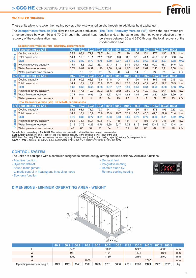
73
> CGC HE CONDENSING UNITS FOR INDOOR INSTALLATION
VD and VR versions
These units allow to recover the heating power, otherwise wasted on air, through an additional heat exchanger.
The Desuperheater Version (VD) allow the hot water production at temperatures between 30 and 70°C through the partial heat recovery of the condensation heat.
The Total Recovery Version (VR) allows the cold water pro-duction and, at the same time, the hot water production at tem-peratures between 30 and 55°C through the total recovery of the condensation heat.
Desupeheater Version (VD) - NOMINAL performances
SR Base setting up (AB) 40.2 50.2 60.2 70.2 80.2 90.2 100.2 115.2 130.2 145.2 160.2 180.2
A3
5E
5 -
W4
5 Cooling capacity 53,2 63,1 71,2 79,7 94,1 107 120 136 151 173 195 222 kWTotal power input 14,4 16,5 19,1 21,1 26,2 30,0 33,2 37,2 41,1 48,0 53,2 62,0 kWEER 3,69 3,82 3,73 3,78 3,59 3,57 3,61 3,66 3,67 3,60 3,67 3,58 W/W
Heating recovery capacity 15,4 18,3 20,7 23,1 27,3 31,1 34,9 39,4 43,6 50,2 56,7 64,5 kWWater fl ow rate recovery 0,74 0,87 0,99 1,10 1,30 1,48 1,67 1,88 2,09 2,40 2,71 3,08 l/sWater pressure drop recovery 8 12 15 18 25 20 24 14 18 24 29 24 kPa
SP Base setting up (AB) 40.2 50.2 60.2 70.2 80.2 90.2 100.2 115.2 130.2 145.2 160.2 180.2
A3
5E
5 -
W4
5 Cooling capacity 51,1 60,5 68,5 76,6 91,8 104 117 130 145 166 188 216 kWTotal power input 14,1 16,4 18,7 20,8 25,7 29,1 32,6 36,4 40,2 46,6 52,2 60,3 kWEER 3,62 3,69 3,66 3,68 3,57 3,57 3,59 3,57 3,61 3,56 3,60 3,58 W/W
Heating recovery capacity 14,8 17,6 19,9 22,2 26,6 30,2 33,9 37,8 42,0 48,2 54,4 62,5 kWWater fl ow rate recovery 0,71 0,84 0,95 1,06 1,27 1,44 1,62 1,81 2,01 2,30 2,60 2,99 l/sWater pressure drop recovery 7 11 14 17 24 19 22 13 17 22 27 23 kPaTotal Recovery Version (VR) - NOMINAL performances
SR Base setting up (AB) 40.2 50.2 60.2 70.2 80.2 90.2 100.2 115.2 130.2 145.2 160.2 180.2
A35E
5 -
W45 Cooling capacity 53,2 63,1 71,2 79,7 94,1 107 120 136 151 173 195 222 kW
Total power input 14,2 16,4 18,9 20,9 25,9 29,7 32,9 36,8 40,6 47,5 52,6 61,4 kWEER 3,75 3,85 3,77 3,81 3,63 3,60 3,65 3,70 3,72 3,64 3,71 3,62 W/W
Heating recovery capacity 66,8 78,7 89,1 99,6 119 135 151 171 189 218 245 281 kWWater fl ow rate recovery 3,19 3,76 4,26 4,76 5,68 6,47 7,23 8,16 9,03 10,42 11,7 13,4 l/sWater pressure drop recovery 43 60 54 53 64 61 65 63 66 67 71 76 kPa
DIMENSIONS - MINIMUM OPERATING AREA - WEIGHT
1000
L
W
A
H
1000
500
40.2 50.2 60.2 70.2 80.2 90.2 100.2 115.2 130.2 145.2 160.2 180.2
L 2480 3322 3322 4080 mmW 954 1104 1104 1104 mmH 1760 1760 2160 2160 mmA 1600 2000 mm
Operating maximum weight 1121 1125 1146 1189 1670 1751 1836 2051 2080 2124 2478 2520 kg
Data declared according to EN 14511. The values are referred to units without options and accessories.EER (Energy Efficiency Ratio) = ratio of the total cooling capacity to the effective power input of the unitHRE (Heat Recovery Efficiency) = ratio of the total capacity of the system (heating plus cooling capacity) to the effectice power inputA35W7 - W45 = source : air in 35°C d.b. / plant : water in 12°C out 7°C / Recovery : water in 40°C out 45°C
CONTROL SYSTEMThe units are equipped with a controller designed to ensure energy saving and unit efficiency. Available functions :
- Adaptive function- Dynamic defrost - Sound management - Climatic control in heating and in cooling mode- Economy function
- Demand limit- Integrative heating- Remote stand by- Remote cooling-heating
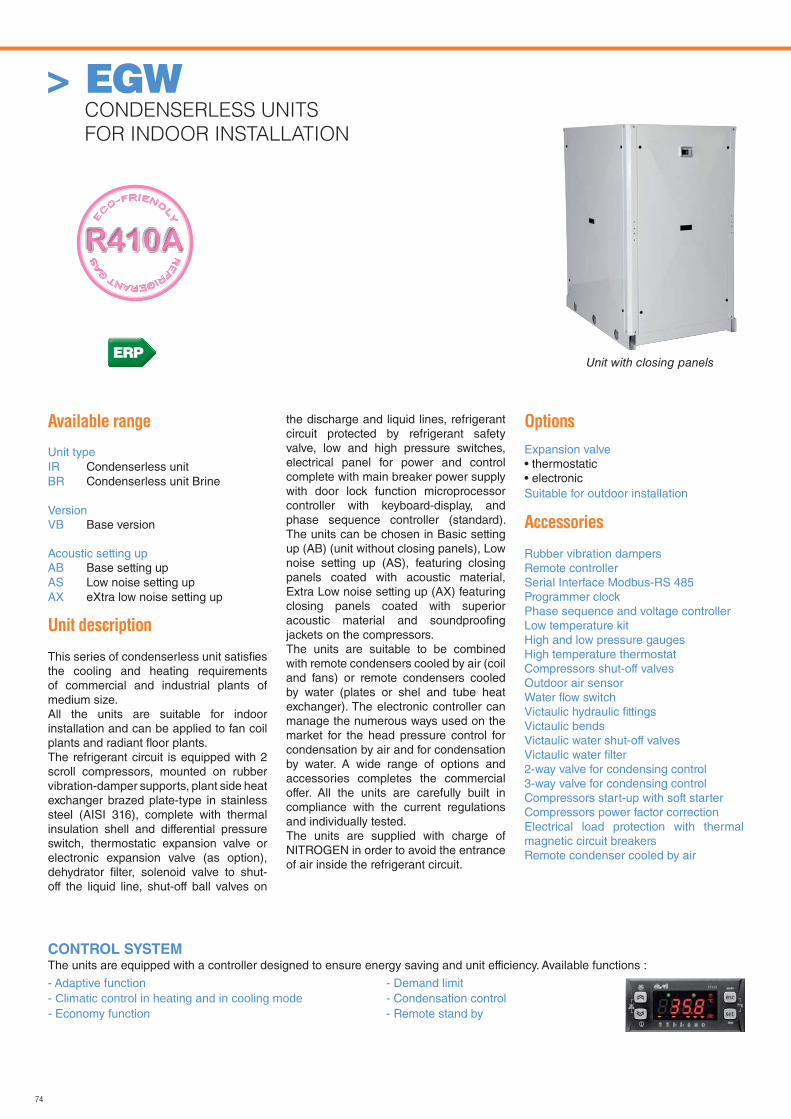
74
> EGW CONDENSERLESS UNITS
FOR INDOOR INSTALLATION
CONTROL SYSTEMThe units are equipped with a controller designed to ensure energy saving and unit efficiency. Available functions :
- Adaptive function- Climatic control in heating and in cooling mode- Economy function
- Demand limit- Condensation control- Remote stand by
Unit with closing panels
Available range
Unit typeIR Condenserless unitBR Condenserless unit Brine
VersionVB Base version
Acoustic setting upAB Base setting upAS Low noise setting upAX eXtra low noise setting up
Unit description
This series of condenserless unit satisfi es the cooling and heating requirements of commercial and industrial plants of medium size.All the units are suitable for indoor installation and can be applied to fan coil plants and radiant fl oor plants.The refrigerant circuit is equipped with 2 scroll compressors, mounted on rubber vibration-damper supports, plant side heat exchanger brazed plate-type in stainless steel (AISI 316), complete with thermal insulation shell and differential pressure switch, thermostatic expansion valve or electronic expansion valve (as option), dehydrator fi lter, solenoid valve to shut-off the liquid line, shut-off ball valves on
the discharge and liquid lines, refrigerant circuit protected by refrigerant safety valve, low and high pressure switches, electrical panel for power and control complete with main breaker power supply with door lock function microprocessor controller with keyboard-display, and phase sequence controller (standard). The units can be chosen in Basic setting up (AB) (unit without closing panels), Low noise setting up (AS), featuring closing panels coated with acoustic material, Extra Low noise setting up (AX) featuring closing panels coated with superior acoustic material and soundproofi ng jackets on the compressors.The units are suitable to be combined with remote condensers cooled by air (coil and fans) or remote condensers cooled by water (plates or shel and tube heat exchanger). The electronic controller can manage the numerous ways used on the market for the head pressure control for condensation by air and for condensation by water. A wide range of options and accessories completes the commercial offer. All the units are carefully built in compliance with the current regulations and individually tested. The units are supplied with charge of NITROGEN in order to avoid the entrance of air inside the refrigerant circuit.
Options
Expansion valve• thermostatic• electronicSuitable for outdoor installation
Accessories
Rubber vibration dampersRemote controllerSerial Interface Modbus-RS 485Programmer clockPhase sequence and voltage controllerLow temperature kit High and low pressure gaugesHigh temperature thermostatCompressors shut-off valves Outdoor air sensorWater fl ow switchVictaulic hydraulic fi ttingsVictaulic bendsVictaulic water shut-off valvesVictaulic water fi lter2-way valve for condensing control3-way valve for condensing control Compressors start-up with soft starterCompressors power factor correctionElectrical load protection with thermal magnetic circuit breakersRemote condenser cooled by air
ERP
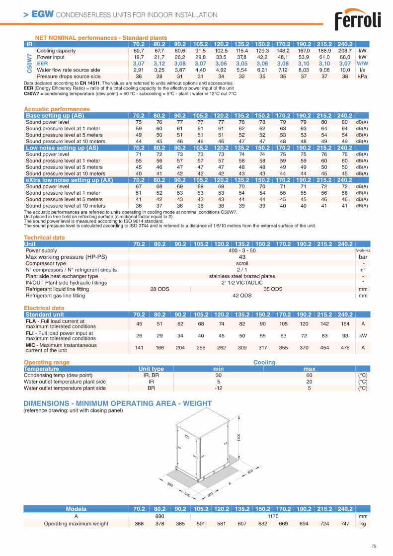
75
> EGW CONDENSERLESS UNITS FOR INDOOR INSTALLATION
Data declared according to EN 14511. The values are referred to units without options and accessories.EER (Energy Efficiency Ratio) = ratio of the total cooling capacity to the effective power input of the unitC50W7 = condensing temperature (dew point) = 50 °C - subcooling = 5°C - plant : water in 12°C out 7°C
Technical dataUnit 70.2 80.2 90.2 105.2 120.2 135.2 150.2 170.2 190.2 215.2 240.2Power supply 400 - 3 - 50 V-ph-Hz
Max working pressure (HP-PS) 43 barCompressor type scroll -N° compressors / N° refrigerant circuits 2 / 1 n°Plant side heat exchanger type stainless steel brazed plates -IN/OUT Plant side hydraulic fi ttings 2” 1/2 VICTAULIC "Refrigerant liquid line fi tting 28 ODS 35 ODS mmRefrigerant gas line fi tting 42 ODS mm
Electrical dataStandard unit 70.2 80.2 90.2 105.2 120.2 135.2 150.2 170.2 190.2 215.2 240.2FLA - Full load current at maximum tolerated conditions 45 51 62 68 74 82 90 105 120 142 164 A
FLI - Full load power input at maximum tolerated conditions 26 29 34 40 45 50 55 63 72 83 93 kW
MIC - Maximum instantaneous current of the unit 141 166 204 256 262 309 317 355 370 454 476 A
NET NOMINAL performances - Standard plantsIR 70.2 80.2 90.2 105.2 120.2 135.2 150.2 170.2 190.2 215.2 240.2
C5
0W
7
Cooling capacity 60,7 67,7 80,6 91,5 102,5 115,4 129,3 148,2 167,0 188,9 208,7 kWPower input 19,7 21,7 26,2 29,8 33,5 37,8 42,2 48,1 53,9 61,0 68,0 kWEER 3,07 3,12 3,08 3,07 3,06 3,05 3,06 3,08 3,10 3,10 3,07 W/W
Water fl ow rate source side 2,91 3,25 3,87 4,40 4,92 5,54 6,21 7,12 8,03 9,08 10,0 l/sPressure drops source side 36 28 31 31 34 32 35 35 37 37 38 kPa
Acoustic performancesBase setting up (AB) 70.2 80.2 90.2 105.2 120.2 135.2 150.2 170.2 190.2 215.2 240.2Sound power level 75 76 77 77 77 78 78 79 79 80 80 dB(A)
Sound pressure level at 1 meter 59 60 61 61 61 62 62 63 63 64 64 dB(A)
Sound pressure level at 5 meters 49 50 51 51 51 52 52 53 53 54 54 dB(A)
Sound pressure level at 10 meters 44 45 46 46 46 47 47 48 48 49 49 dB(A)
Low noise setting up (AS) 70.2 80.2 90.2 105.2 120.2 135.2 150.2 170.2 190.2 215.2 240.2Sound power level 71 72 73 73 73 74 74 75 75 76 76 dB(A)
Sound pressure level at 1 meter 55 56 57 57 57 58 58 59 59 60 60 dB(A)
Sound pressure level at 5 meters 45 46 47 47 47 48 48 49 49 50 50 dB(A)
Sound pressure level at 10 meters 40 41 42 42 42 43 43 44 44 45 45 dB(A)
eXtra low noise setting up (AX) 70.2 80.2 90.2 105.2 120.2 135.2 150.2 170.2 190.2 215.2 240.2Sound power level 67 68 69 69 69 70 70 71 71 72 72 dB(A)
Sound pressure level at 1 meter 51 52 53 53 53 54 54 55 55 56 56 dB(A)
Sound pressure level at 5 meters 41 42 43 43 43 44 44 45 45 46 46 dB(A)
Sound pressure level at 10 meters 36 37 38 38 38 39 39 40 40 41 41 dB(A)
Operating range CoolingTemperature Unit type min maxCondensing temp (dew point) IR, BR 30 60 (°C)Water outlet temperature plant side IR 5 20 (°C)Water outlet temperature plant side BR -12 5 (°C)
880
600
600
A
1000
1500
Models 70.2 80.2 90.2 105.2 120.2 135.2 150.2 170.2 190.2 215.2 240.2A 880 1175 mm
Operating maximum weight 368 378 385 501 581 607 632 669 694 724 747 kg
DIMENSIONS - MINIMUM OPERATING AREA - WEIGHT(reference drawing: unit with closing panel)
The acoustic performances are referred to units operating in cooling mode at nominal conditions C50W7.Unit placed in free fi eld on refl ecting surface (directional factor equal to 2).The sound power level is measured according to ISO 9614 standard.The sound pressure level is calculated according to ISO 3744 and is referred to a distance of 1/5/10 metres from the external surface of the unit.
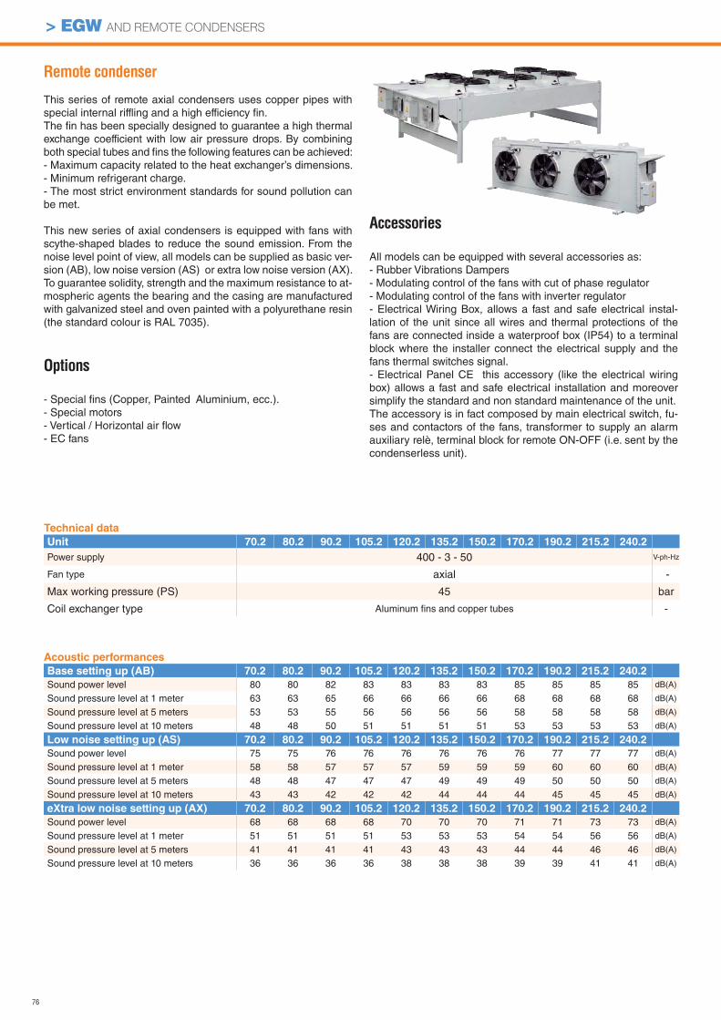
76
> EGW AND REMOTE CONDENSERS
Technical data
Unit 70.2 80.2 90.2 105.2 120.2 135.2 150.2 170.2 190.2 215.2 240.2Power supply 400 - 3 - 50 V-ph-Hz
Fan type axial -
Max working pressure (PS) 45 bar
Coil exchanger type Aluminum fi ns and copper tubes -
Acoustic performances
Base setting up (AB) 70.2 80.2 90.2 105.2 120.2 135.2 150.2 170.2 190.2 215.2 240.2Sound power level 80 80 82 83 83 83 83 85 85 85 85 dB(A)
Sound pressure level at 1 meter 63 63 65 66 66 66 66 68 68 68 68 dB(A)
Sound pressure level at 5 meters 53 53 55 56 56 56 56 58 58 58 58 dB(A)
Sound pressure level at 10 meters 48 48 50 51 51 51 51 53 53 53 53 dB(A)
Low noise setting up (AS) 70.2 80.2 90.2 105.2 120.2 135.2 150.2 170.2 190.2 215.2 240.2Sound power level 75 75 76 76 76 76 76 76 77 77 77 dB(A)
Sound pressure level at 1 meter 58 58 57 57 57 59 59 59 60 60 60 dB(A)
Sound pressure level at 5 meters 48 48 47 47 47 49 49 49 50 50 50 dB(A)
Sound pressure level at 10 meters 43 43 42 42 42 44 44 44 45 45 45 dB(A)
eXtra low noise setting up (AX) 70.2 80.2 90.2 105.2 120.2 135.2 150.2 170.2 190.2 215.2 240.2Sound power level 68 68 68 68 70 70 70 71 71 73 73 dB(A)
Sound pressure level at 1 meter 51 51 51 51 53 53 53 54 54 56 56 dB(A)
Sound pressure level at 5 meters 41 41 41 41 43 43 43 44 44 46 46 dB(A)
Sound pressure level at 10 meters 36 36 36 36 38 38 38 39 39 41 41 dB(A)
Remote condenser
This series of remote axial condensers uses copper pipes with special internal riffling and a high efficiency fi n. The fi n has been specially designed to guarantee a high thermal exchange coefficient with low air pressure drops. By combining both special tubes and fi ns the following features can be achieved:- Maximum capacity related to the heat exchanger’s dimensions.- Minimum refrigerant charge.- The most strict environment standards for sound pollution can be met.
This new series of axial condensers is equipped with fans with scythe-shaped blades to reduce the sound emission. From the noise level point of view, all models can be supplied as basic ver-sion (AB), low noise version (AS) or extra low noise version (AX).To guarantee solidity, strength and the maximum resistance to at-mospheric agents the bearing and the casing are manufactured with galvanized steel and oven painted with a polyurethane resin (the standard colour is RAL 7035).
Options
- Special fi ns (Copper, Painted Aluminium, ecc.).- Special motors- Vertical / Horizontal air fl ow- EC fans
Accessories
All models can be equipped with several accessories as:- Rubber Vibrations Dampers- Modulating control of the fans with cut of phase regulator- Modulating control of the fans with inverter regulator- Electrical Wiring Box, allows a fast and safe electrical instal-lation of the unit since all wires and thermal protections of the fans are connected inside a waterproof box (IP54) to a terminal block where the installer connect the electrical supply and the fans thermal switches signal.- Electrical Panel CE this accessory (like the electrical wiring box) allows a fast and safe electrical installation and moreover simplify the standard and non standard maintenance of the unit.The accessory is in fact composed by main electrical switch, fu-ses and contactors of the fans, transformer to supply an alarm auxiliary relè, terminal block for remote ON-OFF (i.e. sent by the condenserless unit).
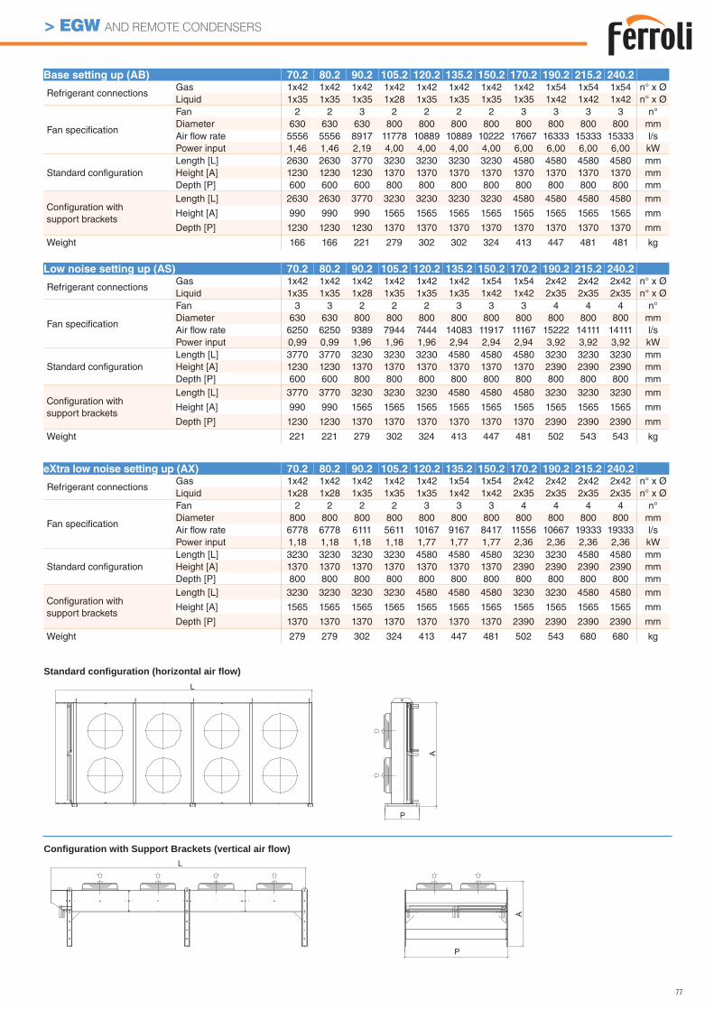
77
> EGW AND REMOTE CONDENSERS
Base setting up (AB) 70.2 80.2 90.2 105.2 120.2 135.2 150.2 170.2 190.2 215.2 240.2
Refrigerant connectionsGas 1x42 1x42 1x42 1x42 1x42 1x42 1x42 1x42 1x54 1x54 1x54 n° x ØLiquid 1x35 1x35 1x35 1x28 1x35 1x35 1x35 1x35 1x42 1x42 1x42 n° x Ø
Fan specifi cation
Fan 2 2 3 2 2 2 2 3 3 3 3 n°Diameter 630 630 630 800 800 800 800 800 800 800 800 mmAir fl ow rate 5556 5556 8917 11778 10889 10889 10222 17667 16333 15333 15333 l/sPower input 1,46 1,46 2,19 4,00 4,00 4,00 4,00 6,00 6,00 6,00 6,00 kW
Standard confi gurationLength [L] 2630 2630 3770 3230 3230 3230 3230 4580 4580 4580 4580 mmHeight [A] 1230 1230 1230 1370 1370 1370 1370 1370 1370 1370 1370 mmDepth [P] 600 600 600 800 800 800 800 800 800 800 800 mm
Confi guration with support brackets
Length [L] 2630 2630 3770 3230 3230 3230 3230 4580 4580 4580 4580 mm
Height [A] 990 990 990 1565 1565 1565 1565 1565 1565 1565 1565 mm
Depth [P] 1230 1230 1230 1370 1370 1370 1370 1370 1370 1370 1370 mm
Weight 166 166 221 279 302 302 324 413 447 481 481 kg
Low noise setting up (AS) 70.2 80.2 90.2 105.2 120.2 135.2 150.2 170.2 190.2 215.2 240.2
Refrigerant connectionsGas 1x42 1x42 1x42 1x42 1x42 1x42 1x54 1x54 2x42 2x42 2x42 n° x ØLiquid 1x35 1x35 1x28 1x35 1x35 1x35 1x42 1x42 2x35 2x35 2x35 n° x Ø
Fan specifi cation
Fan 3 3 2 2 2 3 3 3 4 4 4 n°Diameter 630 630 800 800 800 800 800 800 800 800 800 mmAir fl ow rate 6250 6250 9389 7944 7444 14083 11917 11167 15222 14111 14111 l/sPower input 0,99 0,99 1,96 1,96 1,96 2,94 2,94 2,94 3,92 3,92 3,92 kW
Standard confi gurationLength [L] 3770 3770 3230 3230 3230 4580 4580 4580 3230 3230 3230 mmHeight [A] 1230 1230 1370 1370 1370 1370 1370 1370 2390 2390 2390 mmDepth [P] 600 600 800 800 800 800 800 800 800 800 800 mm
Confi guration with support brackets
Length [L] 3770 3770 3230 3230 3230 4580 4580 4580 3230 3230 3230 mm
Height [A] 990 990 1565 1565 1565 1565 1565 1565 1565 1565 1565 mm
Depth [P] 1230 1230 1370 1370 1370 1370 1370 1370 2390 2390 2390 mm
Weight 221 221 279 302 324 413 447 481 502 543 543 kg
eXtra low noise setting up (AX) 70.2 80.2 90.2 105.2 120.2 135.2 150.2 170.2 190.2 215.2 240.2
Refrigerant connectionsGas 1x42 1x42 1x42 1x42 1x42 1x54 1x54 2x42 2x42 2x42 2x42 n° x ØLiquid 1x28 1x28 1x35 1x35 1x35 1x42 1x42 2x35 2x35 2x35 2x35 n° x Ø
Fan specifi cation
Fan 2 2 2 2 3 3 3 4 4 4 4 n°Diameter 800 800 800 800 800 800 800 800 800 800 800 mmAir fl ow rate 6778 6778 6111 5611 10167 9167 8417 11556 10667 19333 19333 l/sPower input 1,18 1,18 1,18 1,18 1,77 1,77 1,77 2,36 2,36 2,36 2,36 kW
Standard confi gurationLength [L] 3230 3230 3230 3230 4580 4580 4580 3230 3230 4580 4580 mmHeight [A] 1370 1370 1370 1370 1370 1370 1370 2390 2390 2390 2390 mmDepth [P] 800 800 800 800 800 800 800 800 800 800 800 mm
Confi guration with support brackets
Length [L] 3230 3230 3230 3230 4580 4580 4580 3230 3230 4580 4580 mm
Height [A] 1565 1565 1565 1565 1565 1565 1565 1565 1565 1565 1565 mm
Depth [P] 1370 1370 1370 1370 1370 1370 1370 2390 2390 2390 2390 mm
Weight 279 279 302 324 413 447 481 502 543 680 680 kg
Standard configuration (horizontal air flow)
Configuration with Support Brackets (vertical air flow)
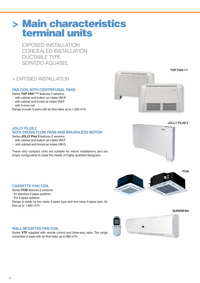
78
TOP FAN PLUS
JOLLY PLUS 2
> EXPOSED INSTALLATION
FAN COIL WITH CENTRIFUGAL FANSSeries TOP FAN PLUS features 2 versions:- with cabinet and bottom air intake VM-B- with cabinet and frontal air intake VM-F- with 3-rows coilRange include 9 sizes with air flow-rates up to 1,350 m3/h.
JOLLY PLUS 2 WITH CROSS FLOW FANS AND BRUSHLESS MOTORSeries JOLLY Plus 2 features 2 versions:- with cabinet and bottom air intake VM-F- with cabinet and frontal air intake VM-G
These very compact units are suitable for indoor installations and are amply configurable to meet the needs of highly qualified designers.
CASSETTE FAN COILSeries FCM features 2 versions:- for standard 2 pipes systems- For 4 pipes systemsRange is made by four sizes 2-pipes type and two sizes 4-pipes type. Air flow up to 1.850 m3/h.
WALL-MOUNTED FAN COILSeries VTP supplied with remote control and three-way valve. The range comprises 4 sizes with air flow-rates up to 880 m3/h.
> Main characteristics terminal unitsEXPOSED INSTALLATION
CONCEALED INSTALLATION
DUCTABLE TYPE
SERVIZIO AQUASEL
FCM
SUPERFAN
JOLLY
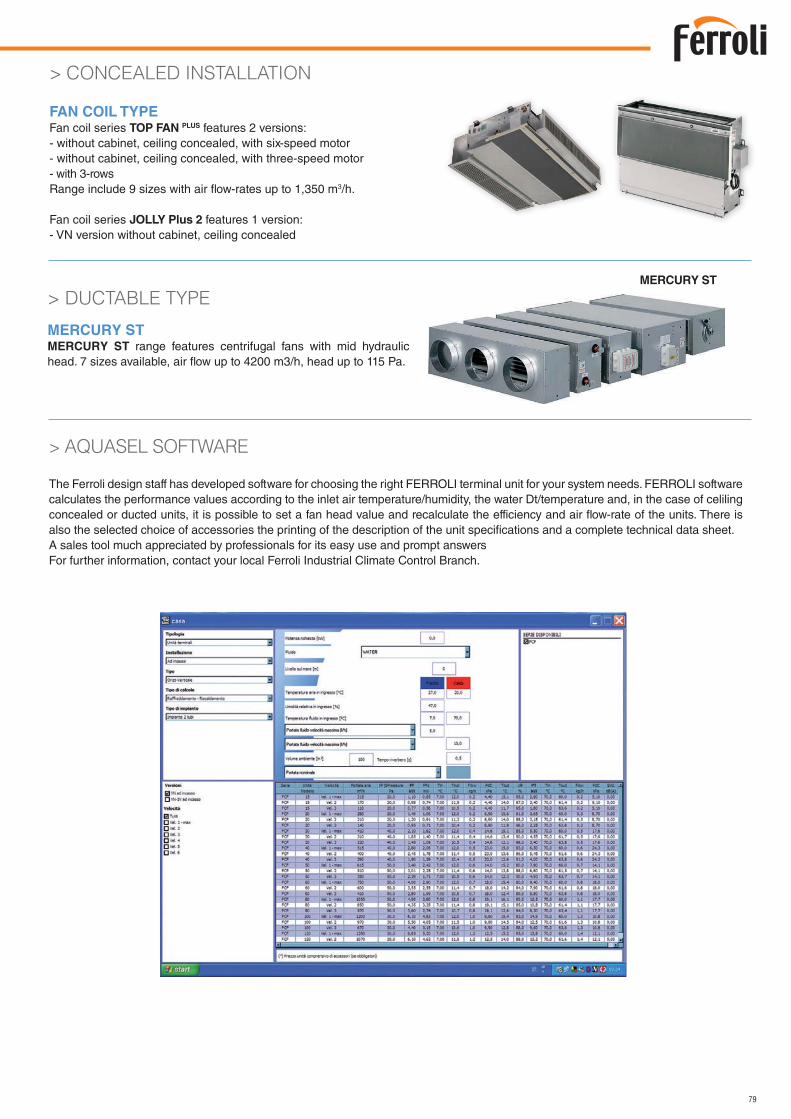
79
MERCURY ST
> AQUASEL SOFTWARE
The Ferroli design staff has developed software for choosing the right FERROLI terminal unit for your system needs. FERROLI software calculates the performance values according to the inlet air temperature/humidity, the water Dt/temperature and, in the case of celiling concealed or ducted units, it is possible to set a fan head value and recalculate the efficiency and air flow-rate of the units. There is also the selected choice of accessories the printing of the description of the unit specifications and a complete technical data sheet.A sales tool much appreciated by professionals for its easy use and prompt answersFor further information, contact your local Ferroli Industrial Climate Control Branch.
> CONCEALED INSTALLATION
FAN COIL TYPEFan coil series TOP FAN PLUS features 2 versions:- without cabinet, ceiling concealed, with six-speed motor- without cabinet, ceiling concealed, with three-speed motor- with 3-rowsRange include 9 sizes with air flow-rates up to 1,350 m3/h.
Fan coil series JOLLY Plus 2 features 1 version:- VN version without cabinet, ceiling concealed
> DUCTABLE TYPE
MERCURY STMERCURY ST range features centrifugal fans with mid hydraulic head. 7 sizes available, air flow up to 4200 m3/h, head up to 115 Pa.
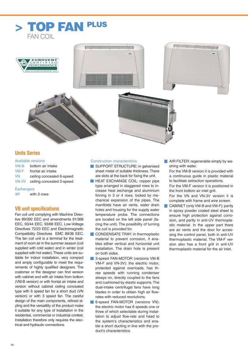
80
> TOP FAN PLUS
FAN COIL
Units Series
Available versionsVM-B bottom air intake VM-F frontal air intakeVN ceiling concealed 6-speedVN-3V ceiling concealed 3-speed
Exchangers3R with 3 rows
VB unit specificationsFan coil unit complying with Machine Direc-tive 89/392 EEC and amendments 91/368 EEC, 93/44 EEC, 93/68 EEC, Low-Voltage Directives 72/23 EEC and Electromagnetic Compatibility Directives EMC 89/36 EEC. The fan coil unit is a terminal for the treat-ment of room air in the summer season (coil supplied with cold water) and in winter (coil supplied with hot water). These units are su-itable for indoor installation, very compact and amply configurable to meet the requi-rements of highly qualified designers. The costomer or the designer can find version with cabinet and with air intake from bottom (VM-B version) or with frontal air intake and version without cabinet ceiling concealed type with 6 speed fan for a short duct (VN version) or with 3 speed fan. The careful design of the main components, refined st-yling and the versatility of the product make it suitable for any type of installation in the residential, commercial or industrial context. Installation therefore only requires the elec-trical and hydraulic connections.
Construction characteristicsSUPPORT STRUCTURE: in galvanised sheet metal of suitable thickness. There are slots at the back for fixing the unit.HEAT EXCHANGE COIL: copper pipe type arranged in staggered rows to in-crease heat exchange and aluminium finning in 3 or 4 rows, locked by me-chanical expansion of the pipes. The manifolds have air vents, water drain holes and housing for the supply water temperature probe. The connections are located on the left side panel (fa-cing the unit). The possibility of turning the coil is provided for.CONDENSATE TRAY: in thermoplastic material to prevent corrosion, it ena-bles either vertical and horizontal unit installation. The drain hole is present on both sides.3-speed FAN-MOTOR (versions VM-B VM-F and VN-3V): the electric motor, protected against overloads, has th-ree speeds with running condenser always on, directly coupled to the fans and cushioned by elastic supports. The dual-intake centrifugal fans have long blades in order to obtain high air flow-rates with reduced revolutions. 6-speed FAN-MOTOR (versions VN): the electric motor has 6 speeds one or three of which selectable during instal-lation to adjust flow-rate and head to the system's characteristics and ena-ble a short ducting in line with the pro-duct's characteristics.
AIR FILTER: regenerable simply by wa-shing with water.
For the VM-B version it is provided with a continuous guide in plastic material to facilitate extraction operations.
For the VM-F version it is positioned in the front bottom air inlet grill.
For the VN and VN-3V version it is complete with frame and wire screen.CABINET (only VM-B and VM-F): partly in epoxy powder coated steel sheet to ensure high protection against corro-sion, and partly in anti-UV thermopla-stic material. In the upper part there are air vents and the door for acces-sing the control panel, both in anti-UV thermoplastic material. The VM-F ver-sion also has a front grill in anti-UV thermoplastic material for the air inlet.
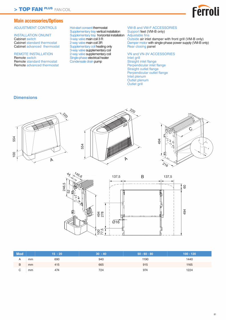
81
Dimensions
> TOP FAN PLUS FAN COIL
ADJUSTMENT CONTROLS
INSTALLATION ONUNITCabinet switchCabinet standard thermostatCabinet advanced thermostat
REMOTE INSTALLATIONRemote switchRemote standard thermostatRemote advanced thermostat
Main accessories/OptionsVM-B and VM-F ACCESSORIESSupport feet (VM-B only)Adjustable fins Outside air inlet damper with front grill (VM-B only)Damper motor with single-phase power supply (VM-B only)Rear closing panel
VN and VN-3V ACCESSORIESInlet grill Straight inlet flange Perpendicular inlet flangeStraight outlet flange Perpendicular outlet flange Inlet plenum Outlet plenumOutlet grill
Hot-start consent thermostatSupplementary tray vertical installationSupplementary tray horizontal installation3-way valve main coil 3 R2-way valve main coil 3RSupplementary coil heating only3-way valve supplementary coil2-way valve supplementary coilSingle-phase electrical heaterCondensate drain pump
494
100
5224
6,5
145,644
137,5 137,5B
494
60
Ø16
278
77,5
220
A
554
220A
554
100
216
C
494
Mod 15 - 20 30 - 40 50 - 60 - 80 100 - 120
A mm 690 940 1190 1440
B mm 415 665 915 1165
C mm 474 724 974 1224
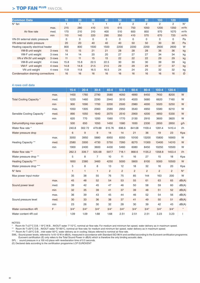
82
> TOP FAN PLUS FAN COIL
NOTES:* Room Air T=27°C D.B. / 19°C W.B. , IN/OUT water 7°/12°C, nominal air flow-rate; For medium and minimum fan speed, water delivery as in maximum speed.** Room Air T=20°C D.B. , IN/OUT water 70°/60°C, nominal air flow-rate; for medium and minimum fan speed, water delivery as in maximum speed.*** Room Air T=20°C D.B. , inlet water 50°C, water delivery as in cooling; Values referred to nominal air flow-rate.SWL : Sound power levels, referred to 1x10-12 W in dB(A), measured in accordance with Standard ISO 9614 and certified according to the Eurovent certification programme.
Eurovent certification (E) only refers to the Total Sound Power in dB(A) which is therefore the only binding acoustic data.SPL : sound pressure in a 100 m3 place with reverberation time of 0.5 seconds.(E) Declared data according to the certification programme LCP EUROVENT
Common Data 15 20 30 40 50 60 80 100 120
N° fan 1 1 1 1 2 2 2 2 2 N°
Air flow ratemax. 215 280 410 515 615 750 1050 1200 1350 m3/hmed. 170 210 310 400 510 600 850 970 1070 m3/hmin 110 140 220 290 350 410 570 670 720 m3/h
VN-3V external static pressure 0 0 0 0 0 0 0 0 0 PaVN external static pressure 20 20 40 40 40 50 50 30 30 PaHeating capacity electrical heater 800 800 1500 1500 2200 2200 2200 2600 2600 W
VM-B unit weight 3 rows 15 15 21 21 28 28 28 36 36 kgVM-F unit weight 3 rows 14 14 20 20 27 27 27 34 34 kg
VN e VN-3V unit weight 3 rows 11 11 15 15 22 22 22 29 29 kgVM-B unit weight 4 rows 15.8 15.8 22.5 22.5 30 30 30 39 39 kgVM-F unit weight 4 rows 14.8 14.8 21.5 21.5 29 29 29 37 37 kg
VN unit weight 4 rows 11.8 11.8 16.5 16.5 24 24 25 32 32 kgCondensation draining connections 16 16 16 16 16 16 16 16 16 Ø
4 rows coil data
15-4 20-4 30-4 40-4 50-4 60-4 80-4 100-4 120-4
Total Cooling Capacity *
max. 1400 1760 2790 3580 4050 4890 6450 7450 8200 W
med. 1220 1460 2290 2940 3510 4020 5680 6620 7160 W
min 900 1090 1700 2200 2500 2980 4000 5020 5250 W
Sensible Cooling Capacity *
max. 1050 1305 2060 2580 2950 3540 4950 5580 6210 W
med. 890 1050 1640 2070 2510 2900 4200 4850 5330 W
min 620 770 1200 1560 1770 2130 2910 3600 3820 W
Dehumidifying max speed 500 650 1050 1450 1580 1930 2330 2650 2850 g/h
Water flow rate * 240.8 302.72 479.88 615.76 696.6 841.08 1109.4 1281.4 1410.4 l/h
Water pressure drop 6 9 9 14 14 21 36 19 23 Kpa
Heating Capacity **
max. 3050 3950 5880 6950 8350 10100 13200 15800 16900 W
med. 2580 3300 4730 5750 7260 8270 11300 13400 14310 W
min 1900 2400 3600 4430 5460 6080 8450 10250 10500 W
Water flow rate ** 262.3 339.7 505.68 597.7 718.1 868.6 1135.2 1358.8 1453.4 l/h
Water pressure drop ** 5 8 7 10 11 16 27 15 18 Kpa
Heating Capacity *** 1850 2380 3460 4250 5000 5800 8100 9300 10500 W
Water pressure drop *** 5 8 8 13 12 18 32 16 20 Kpa
N° fans 1 1 1 2 2 2 2 2 2 N°
Max power input motor 35 38 55 76 75 85 144 163 200 W
Sound power level
max. 45 48 52 54 53 55 61 63 65 dB(A)
med. 39 42 45 47 46 50 58 59 60 dB(A)
min 32 35 39 41 37 39 48 51 52 dB(A)
Sound pressure level
max. 36 39 43 45 44 46 52 54 56 dB(A)
med. 30 33 36 38 37 41 49 50 51 dB(A)
min 23 26 30 32 28 30 39 42 43 dB(A)
Water connecttion 4R F 3/4" 3/4" 3/4" 3/4" 3/4" 3/4" 3/4" 3/4" 3/4" "
Water content 4R coil 1.09 1.09 1.68 1.68 2.51 2.51 2.51 3.23 3.23 l
83
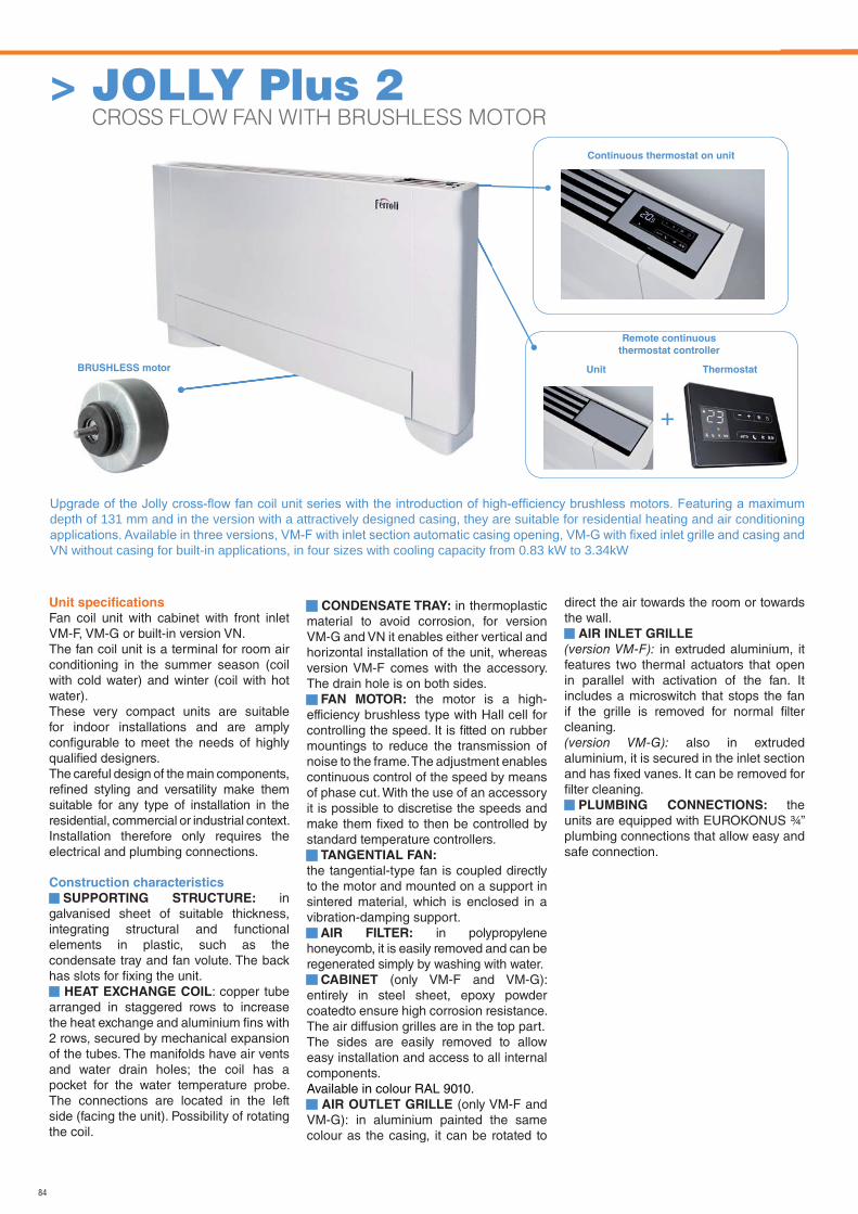
84
BRUSHLESS motor
Unit specifi cations
Fan coil unit with cabinet with front inlet VM-F, VM-G or built-in version VN.The fan coil unit is a terminal for room air conditioning in the summer season (coil with cold water) and winter (coil with hot water). These very compact units are suitable for indoor installations and are amply confi gurable to meet the needs of highly qualifi ed designers. The careful design of the main components, refi ned styling and versatility make them suitable for any type of installation in the residential, commercial or industrial context.Installation therefore only requires the electrical and plumbing connections.
Construction characteristics
SUPPORTING STRUCTURE: in galvanised sheet of suitable thickness, integrating structural and functional elements in plastic, such as the condensate tray and fan volute. The back has slots for fi xing the unit.
HEAT EXCHANGE COIL: copper tube arranged in staggered rows to increase the heat exchange and aluminium fi ns with 2 rows, secured by mechanical expansion of the tubes. The manifolds have air vents and water drain holes; the coil has a pocket for the water temperature probe. The connections are located in the left side (facing the unit). Possibility of rotating the coil.
CONDENSATE TRAY: in thermoplastic material to avoid corrosion, for version VM-G and VN it enables either vertical and horizontal installation of the unit, whereas version VM-F comes with the accessory. The drain hole is on both sides.
FAN MOTOR: the motor is a high-efficiency brushless type with Hall cell for controlling the speed. It is fi tted on rubber mountings to reduce the transmission of noise to the frame. The adjustment enables continuous control of the speed by means of phase cut. With the use of an accessory it is possible to discretise the speeds and make them fi xed to then be controlled by standard temperature controllers.
TANGENTIAL FAN:
the tangential-type fan is coupled directly to the motor and mounted on a support in sintered material, which is enclosed in a vibration-damping support.
AIR FILTER: in polypropylene honeycomb, it is easily removed and can be regenerated simply by washing with water.
CABINET (only VM-F and VM-G): entirely in steel sheet, epoxy powder coatedto ensure high corrosion resistance. The air diffusion grilles are in the top part.The sides are easily removed to allow easy installation and access to all internal components.Available in colour RAL 9010.
AIR OUTLET GRILLE (only VM-F and VM-G): in aluminium painted the same colour as the casing, it can be rotated to
direct the air towards the room or towards the wall.
AIR INLET GRILLE (version VM-F): in extruded aluminium, it features two thermal actuators that open in parallel with activation of the fan. It includes a microswitch that stops the fan if the grille is removed for normal fi lter cleaning.(version VM-G): also in extruded aluminium, it is secured in the inlet section and has fi xed vanes. It can be removed for fi lter cleaning.
PLUMBING CONNECTIONS: the units are equipped with EUROKONUS ¾” plumbing connections that allow easy and safe connection.
depth of 131 mm and in the version with a attractively designed casing, they are suitable for residential heating and air conditioning
VN without casing for built-in applications, in four sizes with cooling capacity from 0.83 kW to 3.34kW
Continuous thermostat on unit
+
ThermostatUnit
Remote continuous
thermostat controller
> JOLLY Plus 2 CROSS FLOW FAN WITH BRUSHLESS MOTOR
motor
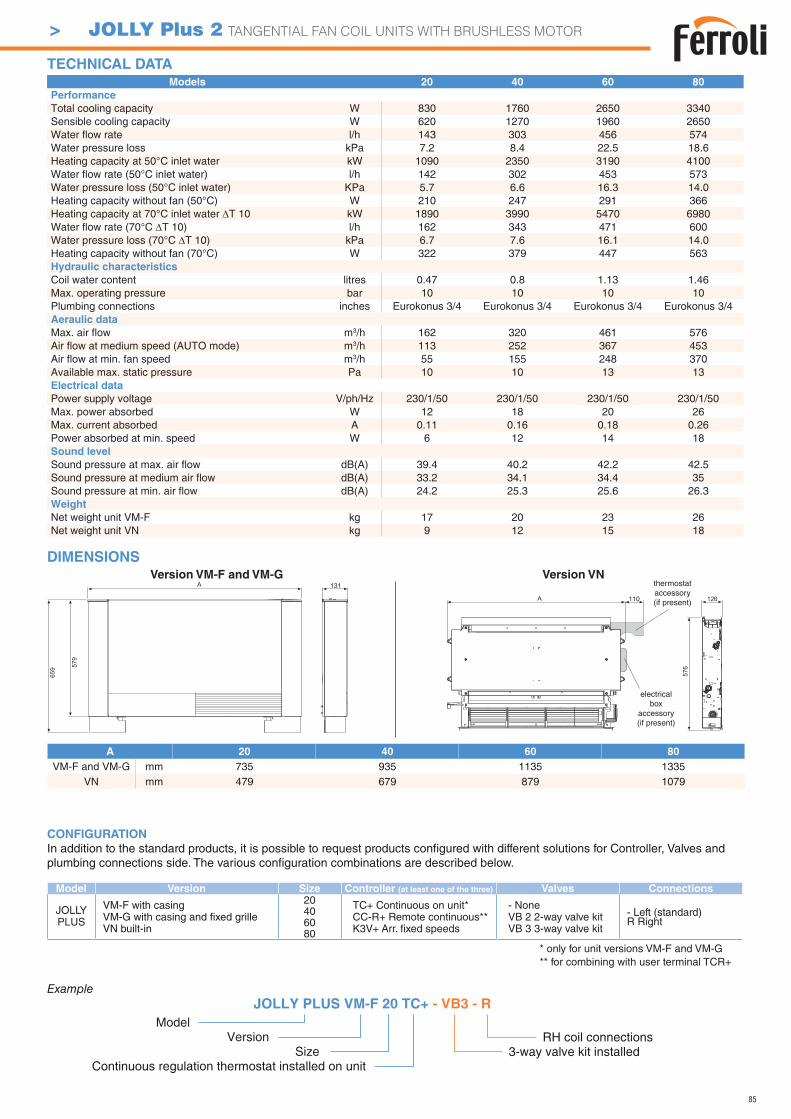
85
DIMENSIONS
A 20 40 60 80VM-F and VM-G mm 735 935 1135 1335
VN mm 479 679 879 1079
110
131Version VM-F and VM-G Version VN
Models 20 40 60 80PerformanceTotal cooling capacity W 830 1760 2650 3340Sensible cooling capacity W 620 1270 1960 2650Water flow rate l/h 143 303 456 574Water pressure loss kPa 7.2 8.4 22.5 18.6Heating capacity at 50°C inlet water kW 1090 2350 3190 4100Water flow rate (50°C inlet water) l/h 142 302 453 573Water pressure loss (50°C inlet water) KPa 5.7 6.6 16.3 14.0Heating capacity without fan (50°C) W 210 247 291 366Heating capacity at 70°C inlet water T 10 kW 1890 3990 5470 6980Water flow rate (70°C T 10) l/h 162 343 471 600Water pressure loss (70°C T 10) kPa 6.7 7.6 16.1 14.0Heating capacity without fan (70°C) W 322 379 447 563Hydraulic characteristicsCoil water content litres 0.47 0.8 1.13 1.46Max. operating pressure bar 10 10 10 10Plumbing connections inches Eurokonus 3/4 Eurokonus 3/4 Eurokonus 3/4 Eurokonus 3/4 Aeraulic dataMax. air flow m3/h 162 320 461 576Air flow at medium speed (AUTO mode) m3/h 113 252 367 453Air flow at min. fan speed m3/h 55 155 248 370Available max. static pressure Pa 10 10 13 13Electrical dataPower supply voltage V/ph/Hz 230/1/50 230/1/50 230/1/50 230/1/50 Max. power absorbed W 12 18 20 26Max. current absorbed A 0.11 0.16 0.18 0.26Power absorbed at min. speed W 6 12 14 18Sound levelSound pressure at max. air flow dB(A) 39.4 40.2 42.2 42.5Sound pressure at medium air flow dB(A) 33.2 34.1 34.4 35Sound pressure at min. air flow dB(A) 24.2 25.3 25.6 26.3WeightNet weight unit VM-F kg 17 20 23 26Net weight unit VN kg 9 12 15 18
TECHNICAL DATA
CONFIGURATION
In addition to the standard products, it is possible to request products confi gured with different solutions for Controller, Valves and plumbing connections side. The various confi guration combinations are described below.
Model Version Size Controller (at least one of the three) Valves Connections
VM-F with casingVM-G with casing and fi xed grilleVN built-in
20 TC+ Continuous on unit*CC-R+ Remote continuous**K3V+ Arr. fi xed speeds
- NoneVB 2 2-way valve kitVB 3 3-way valve kit
- Left (standard)R Right
406080
Example
ModelVersion
SizeContinuous regulation thermostat installed on unit
3-way valve kit installedRH coil connections
* only for unit versions VM-F and VM-G** for combining with user terminal TCR+
electricalbox
accessory(if present)
thermostat accessory(if present)
JOLLY PLUS VM-F 20 TC+ - VB3 - R
JOLLYPLUS
> JOLLY Plus 2 TANGENTIAL FAN COIL UNITS WITH BRUSHLESS MOTOR
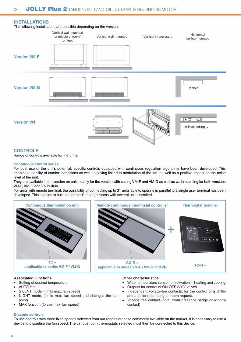
86
CONTROLSRange of controls available for the units:
Continuous control series
For best use of the unit’s potential, specifi c controls equipped with continuous regulation algorithms have been developed. This enables a stability of comfort conditions as well as saving linked to modulation of the fan, as well as a positive impact on the noise level of the unit.They are available in the version on unit, mainly for the version with casing VM-F and VM-G as well as wall-mounting for both versions VM-F, VM-G and VN built-in.For units with remote terminal, the possibility of connecting up to 31 units able to operate in parallel to a single user terminal has been developed. This solution is suitable for medium large rooms with several units installed.
INSTALLATIONSThe following installations are possible depending on the version:
Continuous thermostat on unit Remote continuous thermostat controller Thermostat terminal
+
TC +
applicable to series VM-F / VM-GCC-R +
applicable to series VM-F / VM-G and VNTC-R +
Discrete controls
To use controls with three fi xed speeds selected from our ranges or those commonly available on the market, it is necessary to use a device to discretise the fan speed. The various room thermostats selected must then be connected to this device.
Associated Functions
Setting of desired temperatureAUTO fan. SILENT mode. (limits max. fan speed)NIGHT mode. (limits max. fan speed and changes the set point) MAX function (forces max. fan speed)
Other characteristics
Water temperature sensor for activation in heating and cooling.Outputs for control of ON-OFF 230V valves. Independent voltage-fee contacts, for the control of a chiller and a boiler depending on room request. Voltage-free contact (hotel room presence badge or window contact)
Version VN
Version VM-G
Version VM-F
Vertical wall-mounted or middle of room*
on feetVertical wall-mounted Vertical in enclosure
Horizontal ceiling-mounted
in false ceiling
visible
> JOLLY Plus 2 TANGENTIAL FAN COIL UNITS WITH BRUSHLESS MOTOR
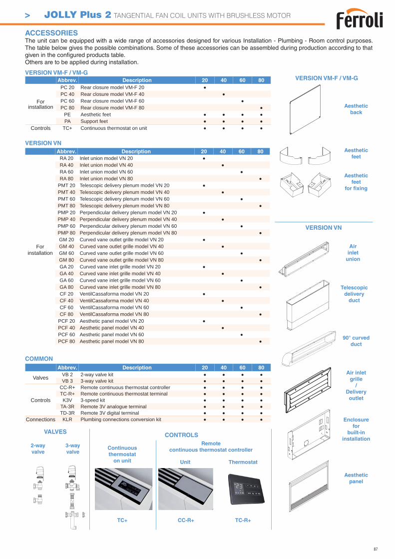
87
Abbrev. Description 20 40 60 80
For installation
PC 20 Rear closure model VM-F 20PC 40 Rear closure model VM-F 40PC 60 Rear closure model VM-F 60PC 80 Rear closure model VM-F 80
PE Aesthetic feetPA Support feet
Controls TC+ Continuous thermostat on unit
Abbrev. Description 20 40 60 80
For installation
RA 20 Inlet union model VN 20RA 40 Inlet union model VN 40RA 60 Inlet union model VN 60RA 80 Inlet union model VN 80
PMT 20 Telescopic delivery plenum model VN 20PMT 40 Telescopic delivery plenum model VN 40PMT 60 Telescopic delivery plenum model VN 60PMT 80 Telescopic delivery plenum model VN 80PMP 20 Perpendicular delivery plenum model VN 20PMP 40 Perpendicular delivery plenum model VN 40PMP 60 Perpendicular delivery plenum model VN 60PMP 80 Perpendicular delivery plenum model VN 80GM 20 Curved vane outlet grille model VN 20GM 40 Curved vane outlet grille model VN 40GM 60 Curved vane outlet grille model VN 60GM 80 Curved vane outlet grille model VN 80GA 20 Curved vane inlet grille model VN 20GA 40 Curved vane inlet grille model VN 40GA 60 Curved vane inlet grille model VN 60GA 80 Curved vane inlet grille model VN 80CF 20 VentilCassaforma model VN 20CF 40 VentilCassaforma model VN 40CF 60 VentilCassaforma model VN 60CF 80 VentilCassaforma model VN 80
PCF 20 Aesthetic panel model VN 20PCF 40 Aesthetic panel model VN 40PCF 60 Aesthetic panel model VN 60PCF 80 Aesthetic panel model VN 80
ACCESSORIES The unit can be equipped with a wide range of accessories designed for various Installation - Plumbing - Room control purposes. The table below gives the possible combinations. Some of these accessories can be assembled during production according to that given in the confi gured products table.Others are to be applied during installation.
Abbrev. Description 20 40 60 80
Valves VB 2 2-way valve kitVB 3 3-way valve kit
Controls
CC-R+ Remote continuous thermostat controllerTC-R+ Remote continuous thermostat terminalK3V 3-speed kit
TA-3R Remote 3V analogue terminalTD-3R Remote 3V digital terminal
Connections KLR Plumbing connections conversion kit
VERSION VM-F / VM-G
VERSION VN
COMMON
Aesthetic
back
Aesthetic
feet
Aesthetic
feet
for fi xing
Air
inlet
union
Telescopic
delivery
duct
90° curved
duct
Air inlet
grille
/
Delivery
outlet
Enclosure
for
built-in
installation
Aesthetic
panel
2-way
valve
3-way
valve
VERSION VM-F / VM-G
VERSION VN
CONTROLSVALVES
Continuous
thermostat
on unit
TC+
Remote
continuous thermostat controller
CC-R+
Thermostat Unit
TC-R+
> JOLLY Plus 2 TANGENTIAL FAN COIL UNITS WITH BRUSHLESS MOTOR
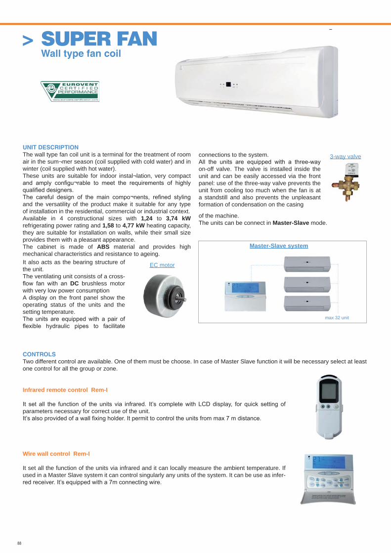
88
UNIT DESCRIPTION
The wall type fan coil unit is a terminal for the treatment of room air in the sum¬mer season (coil supplied with cold water) and in winter (coil supplied with hot water). These units are suitable for indoor instal¬lation, very compact
and the versatility of the product make it suitable for any type of installation in the residential, commercial or industrial context.Available in 4 constructional sizes with 1,24 to 3,74 kW refrigerating power rating and 1,58 to 4,77 kW heating capacity, they are suitable for installation on walls, while their small size provides them with a pleasant appearance.The cabinet is made of ABS material and provides high mechanical characteristics and resistance to ageing.
CONTROLS
Two different control are available. One of them must be choose. In case of Master Slave function it will be necessary select at least one control for all the group or zone.
Infrared remote control Rem-I
parameters necessary for correct use of the unit.
Wire wall control Rem-I
It set all the function of the units via infrared and it can locally measure the ambient temperature. If used in a Master Slave system it can control singularly any units of the system. It can be use as infer-
Master-Slave system
max 32 unit
EC motor
3-way valve
It also acts as the bearing structure of the unit.The ventilating unit consists of a cross-
DC brushless motor with very low power consumption A display on the front panel show the operating status of the units and the setting temperature.
connections to the system.
on-off valve. The valve is installed inside the unit and can be easily accessed via the front panel: use of the three-way valve prevents the unit from cooling too much when the fan is at a standstill and also prevents the unpleasant formation of condensation on the casing
of the machine.The units can be connect in Master-Slave mode.
> SUPER FAN Wall type fan coil
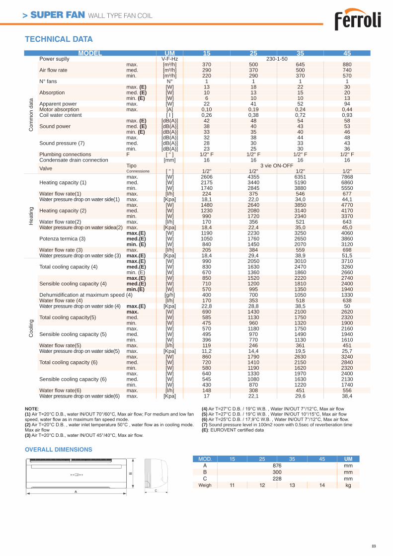
89
> SUPER FAN WALL TYPE FAN COIL
TECHNICAL DATA
OVERALL DIMENSIONS
MOD. 15 25 35 45 UM
A 876 mmB 300 mmC 228 mm
Weigh 11 12 13 14 kgC
MODEL UM 15 25 35 45
Com
mon
dat
a
Power suplly V-F-Hz 230-1-50
Air flow ratemax. [m³/h] 370 500 645 880med. [m³/h] 290 370 500 740min. [m³/h] 220 290 370 570
N° fans N° 1 1 1 1
Absorptionmax. (E) [W] 13 18 22 30med. (E) [W] 10 13 15 20min. (E) [W] 6 10 10 13
Apparent power max. [W] 22 41 52 94Motor absorption max. [A] 0,10 0,19 0,24 0,44Coil water content [ l ] 0,26 0,38 0,72 0,93
Sound powermax. (E) [dB(A)] 42 48 54 58med. (E) [dB(A)] 38 40 43 53min. (E) [dB(A)] 33 35 40 46
Sound pressure (7)max. [dB(A)] 32 38 44 48med. [dB(A)] 28 30 33 43min. [dB(A)] 23 25 30 36
Plumbing connections F [ " ] 1/2" F 1/2" F 1/2" F 1/2" FCondensate drain connection [mm] 16 16 16 16Valve Tipo 3 vie ON-OFF
Connessione [ " ] 1/2" 1/2" 1/2" 1/2"
Hea
ting
Heating capacity (1)max. [W] 2606 4355 6351 7868med. [W] 2175 3440 5190 6860min. [W] 1740 2845 3880 5550
Water flow rate(1) max. [l/h] 224 375 546 677Water pressure drop on water side(1) max. [Kpa] 18,1 22,0 34,0 44,1
Heating capacity (2)max. [W] 1480 2640 3850 4770med. [W] 1230 2080 3140 4170min. [W] 990 1720 2340 3370
Water flow rate(2) max. [l/h] 170 356 521 643Water pressure drop on water sidea(2) max. [Kpa] 18,4 22,4 35,0 45,0
Potenza termica (3)max.(E) [W] 1190 2230 3250 4060med.(E) [W] 1050 1760 2650 3860min. (E) [W] 840 1450 2070 3120
Water flow rate (3) max. [l/h] 205 384 559 698Water pressure drop on water side (3) max.(E) [Kpa] 18,4 29,4 38,9 51,5
Coo
ling
Total cooling capacity (4)max.(E) [W] 990 2050 3010 3710med.(E) [W] 830 1630 2470 3260min. (E) [W] 670 1360 1860 2660
Sensible cooling capacity (4)max.(E) [W] 850 1520 2220 2740med.(E) [W] 710 1200 1810 2400min.(E) [W] 570 995 1350 1940
Dehumidification at maximum speed (4) [g/h] 400 700 1050 1330Water flow rate (4) [l/h] 170 353 518 638Water pressure drop on water side (4) max.(E) [Kpa] 22,8 28,8 38,5 50
Total cooling capacity(5)max. [W] 690 1430 2100 2620med. [W] 585 1130 1750 2320min. [W] 475 960 1320 1900
Sensible cooling capacity (5)max. [W] 570 1180 1750 2160med. [W] 495 970 1490 1940min. [W] 396 770 1130 1610
Water flow rate(5) max. [l/h] 119 246 361 451Water pressure drop on water side(5) max. [Kpa] 11,2 14,4 19,5 25,7
Total cooling capacity (6)max. [W] 860 1790 2630 3240med. [W] 720 1410 2150 2840min. [W] 580 1190 1620 2320
Sensible cooling capacity (6)max. [W] 640 1330 1970 2400med. [W] 545 1080 1630 2130min. [W] 430 870 1220 1740
Water flow rate(6) max. [l/h] 148 308 451 556Water pressure drop on water side(6) max. [Kpa] 17 22,1 29,6 38,4
NOTE:(1)
(2)
(3)
(4)(5)(6)(7) Sound pressure level in 100m2 room with 0.5sec of reverberation time(E)
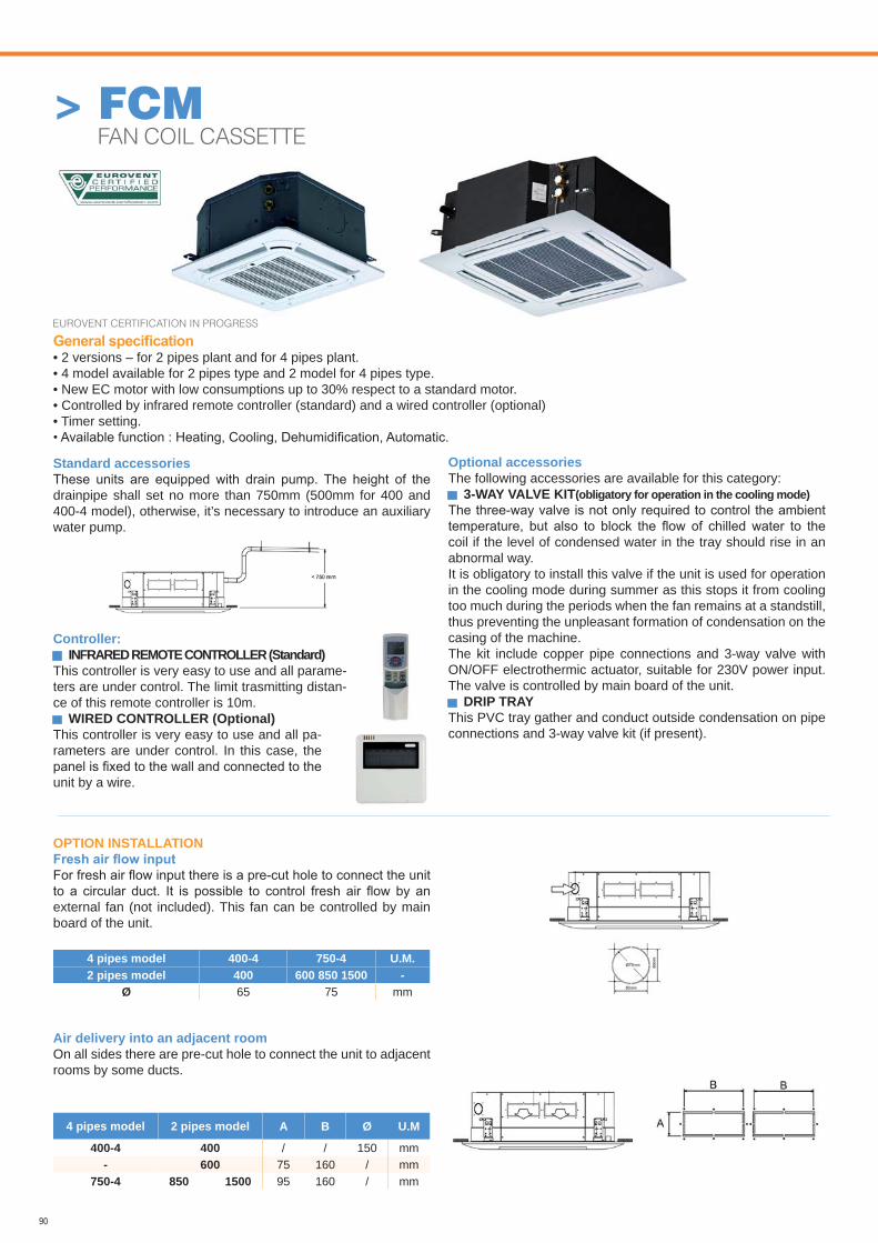
90
Standard accessories
drainpipe shall set no more than 750mm (500mm for 400 and 400-4 model), otherwise, it’s necessary to introduce an auxiliary water pump.
Controller: INFRARED REMOTE CONTROLLER (Standard)
This controller is very easy to use and all parame-ters are under control. The limit trasmitting distan-ce of this remote controller is 10m.
WIRED CONTROLLER (Optional) This controller is very easy to use and all pa-rameters are under control. In this case, the
unit by a wire.
Optional accessoriesThe following accessories are available for this category:
3-WAY VALVE KIT(obligatory for operation in the cooling mode)
coil if the level of condensed water in the tray should rise in an abnormal way.It is obligatory to install this valve if the unit is used for operation in the cooling mode during summer as this stops it from cooling too much during the periods when the fan remains at a standstill, thus preventing the unpleasant formation of condensation on the casing of the machine.The kit include copper pipe connections and 3-way valve with ON/OFF electrothermic actuator, suitable for 230V power input. The valve is controlled by main board of the unit.
DRIP TRAYThis PVC tray gather and conduct outside condensation on pipe connections and 3-way valve kit (if present).
> FCM FAN COIL CASSETTE
• 2 versions – for 2 pipes plant and for 4 pipes plant.• 4 model available for 2 pipes type and 2 model for 4 pipes type.• New EC motor with low consumptions up to 30% respect to a standard motor.• Controlled by infrared remote controller (standard) and a wired controller (optional)• Timer setting.
OPTION INSTALLATION
external fan (not included). This fan can be controlled by main board of the unit.
Air delivery into an adjacent roomOn all sides there are pre-cut hole to connect the unit to adjacent rooms by some ducts.
4 pipes model 400-4 750-4 U.M.2 pipes model 400 600 850 1500 -
Ø 65 75 mm
4 pipes model 2 pipes model A B Ø U.M
400-4 400 / / 150 mm- 600 75 160 / mm
750-4 850 1500 95 160 / mm
EUROVENT CERTIFICATION IN PROGRESS
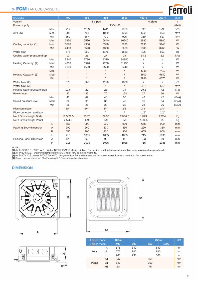
91
> FCM FAN COIL CASSETTE
DIMENSION
NOTE:(1) (2)(3)(4) Sound pressure level in 100m2 room with 0.5sec of reverberation time
MODELS 400 600 850 1500 400-4 750-4 U.MVersion 2 pipes 4 pipes \Power supply 230-1-50 V-f-Hz
Air Flow Max 717 1133 1441 1850 717 1233 m³/hMed 502 793 1009 1295 502 863 m³/hMin 359 567 721 925 359 617 m³/h
Cooling capacity (1)Max 3930 5580 6840 10640 2880 5180 WMed 3070 4350 5330 8090 2190 3940 W Min 2480 3520 4300 6600 1800 3260 W
676 960 1176 1830 495 891 l/hCooling water pressure drop 12 21 27 34 14,5 12 kPa
Heating Capacity (2)Max 5340 7720 9370 14380 \ \ WMed 4000 5920 7250 11290 \ \ WMin 3150 4500 5500 8440 \ \ W
Heating Capacity (3)Max \ \ \ \ 4730 7410 WMed \ \ \ \ 3600 5640 WMin \ \ \ \ 2980 4670 W
676 960 1176 1830 \ \ m³/h\ \ \ \ 407 637 m³/h
Heating water pressure drop 10,6 22 23 34 29,1 42 kPaPower input 27 42 70 124 27 50 W
Sound pressure level Max 40 42 46 50 40 42 dB(A)Med 36 33 36 40 36 34 dB(A)Min 28 26 28 33 28 26 dB(A)
Pipe connection 3/4” 3/4” 3/4” 3/4” 3/4” 3/4” “Pipe connection auxiliary \ \ \ \ 1/2" 1/2" “Net \ Gross weight Body 16.5/21.5 23/28 27/33 29/34.5 17/23 28/34 KgNet \ Gross weight Panel 2.5/4.5 6/9 6/9 6/9 2.5/4.5 6/9 Kg
Packing Body dimension L 655 900 900 900 655 900 mmA 290 260 330 330 290 330 mmP 655 900 900 900 655 900 mm
Packing Panel dimensionL 715 1035 1035 1035 715 1035 mmA 123 90 90 90 123 90 mmP 715 1035 1035 1035 715 1035 mm
4 pipes model 400-4 - 750-4 UM2 pipes model 400 600 850 1500 -
BodyA 575 840 840 mmB 575 840 840 mmH 260 230 300 mm
PanelA1 647 950 mmB1 647 950 mmH1 50 45 mm
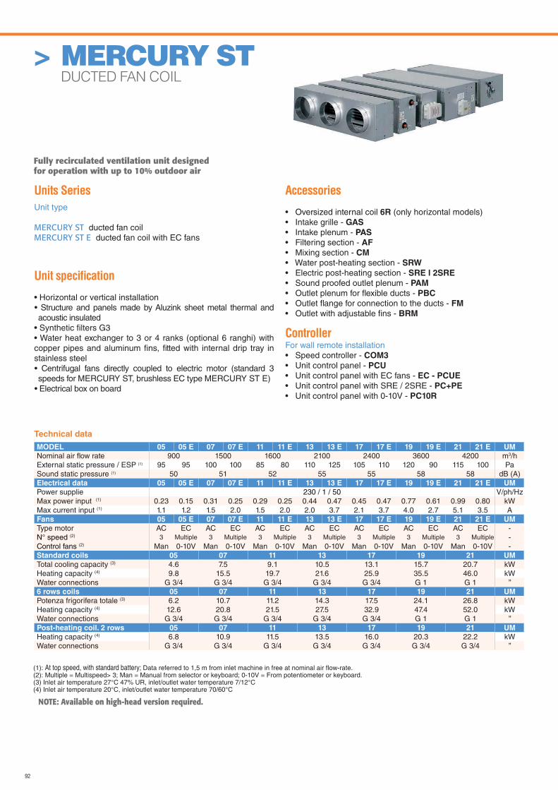
92
> MERCURY ST DUCTED FAN COIL
Units Series
Unit type
MERCURY ST ducted fan coilMERCURY ST E ducted fan coil with EC fans
Unit specifi cation
• Horizontal or vertical installation• Structure and panels made by Aluzink sheet metal thermal and acoustic insulated
• Synthetic fi lters G3• Water heat exchanger to 3 or 4 ranks (optional 6 ranghi) with copper pipes and aluminum fi ns, fi tted with internal drip tray in stainless steel• Centrifugal fans directly coupled to electric motor (standard 3 speeds for MERCURY ST, brushless EC type MERCURY ST E)
• Electrical box on board
Accessories
• Oversized internal coil 6R (only horizontal models)• Intake grille - GAS
• Intake plenum - PAS
• Filtering section - AF
• Mixing section - CM
• Water post-heating section - SRW
• Electric post-heating section - SRE l 2SRE
• Sound proofed outlet plenum - PAM
• Outlet plenum for fl exible ducts - PBC
• Outlet fl ange for connection to the ducts - FM
• Outlet with adjustable fi ns - BRM
ControllerFor wall remote installation• Speed controller - COM3
• Unit control panel - PCU
• Unit control panel with EC fans - EC - PCUE
• Unit control panel with SRE / 2SRE - PC+PE
• Unit control panel with 0-10V - PC10R
NOTE: Available on high-head version required.
MODEL 05 05 E 07 07 E 11 11 E 13 13 E 17 17 E 19 19 E 21 21 E UM
Nominal air fl ow rate 900 1500 1600 2100 2400 3600 4200 m3/hExternal static pressure / ESP (1) 95 95 100 100 85 80 110 125 105 110 120 90 115 100 PaSound static pressure (1) 50 51 52 55 55 58 58 dB (A)Electrical data 05 05 E 07 07 E 11 11 E 13 13 E 17 17 E 19 19 E 21 21 E UM
Power supplie 230 / 1 / 50 V/ph/HzMax power input (1) 0.23 0.15 0.31 0.25 0.29 0.25 0.44 0.47 0.45 0.47 0.77 0.61 0.99 0.80 kWMax current input (1) 1.1 1.2 1.5 2.0 1.5 2.0 2.0 3.7 2.1 3.7 4.0 2.7 5.1 3.5 AFans 05 05 E 07 07 E 11 11 E 13 13 E 17 17 E 19 19 E 21 21 E UM
Type motor AC EC AC EC AC EC AC EC AC EC AC EC AC EC -N° speed (2) 3 Multiple 3 Multiple 3 Multiple 3 Multiple 3 Multiple 3 Multiple 3 Multiple -Control fans (2) Man 0-10V Man 0-10V Man 0-10V Man 0-10V Man 0-10V Man 0-10V Man 0-10V -Standard coils 05 07 11 13 17 19 21 UM
Total cooling capacity (3) 4.6 7.5 9.1 10.5 13.1 15.7 20.7 kWHeating capacity (4) 9.8 15.5 19.7 21.6 25.9 35.5 46.0 kWWater connections G 3/4 G 3/4 G 3/4 G 3/4 G 3/4 G 1 G 1 ”6 rows coils 05 07 11 13 17 19 21 UM
Potenza frigorifera totale (3) 6.2 10.7 11.2 14.3 17.5 24.1 26.8 kWHeating capacity (4) 12.6 20.8 21.5 27.5 32.9 47.4 52.0 kWWater connections G 3/4 G 3/4 G 3/4 G 3/4 G 3/4 G 1 G 1 ”Post-heating coil. 2 rows 05 07 11 13 17 19 21 UM
Heating capacity (4) 6.8 10.9 11.5 13.5 16.0 20.3 22.2 kWWater connections G 3/4 G 3/4 G 3/4 G 3/4 G 3/4 G 3/4 G 3/4 ”
(1): At top speed, with standard battery; Data referred to 1,5 m from inlet machine in free at nominal air flow-rate.(2): Multiple = Multispeed> 3; Man = Manual from selector or keyboard; 0-10V = From potentiometer or keyboard.(3) Inlet air temperature 27°C 47% UR, inlet/outlet water temperature 7/12°C(4) Inlet air temperature 20°C, inlet/outlet water temperature 70/60°C
Technical data
Fully recirculated ventilation unit designed for operation with up to 10% outdoor air
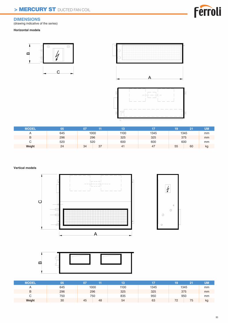
93
> MERCURY ST DUCTED FAN COIL
DIMENSIONS (drawing indicative of the series)
Horizontal models
Vertical models
MODEL 05 07 11 13 17 19 21 UM
A 645 1000 1100 1345 1345 mmB 296 296 325 325 375 mmC 520 520 600 600 600 mm
Weight 24 34 37 41 47 55 60 kg
MODEL 05 07 11 13 17 19 21 UM
A 645 1000 1100 1345 1345 mmB 296 296 325 325 375 mmC 750 750 835 950 950 mm
Weight 30 45 48 54 63 72 75 kg
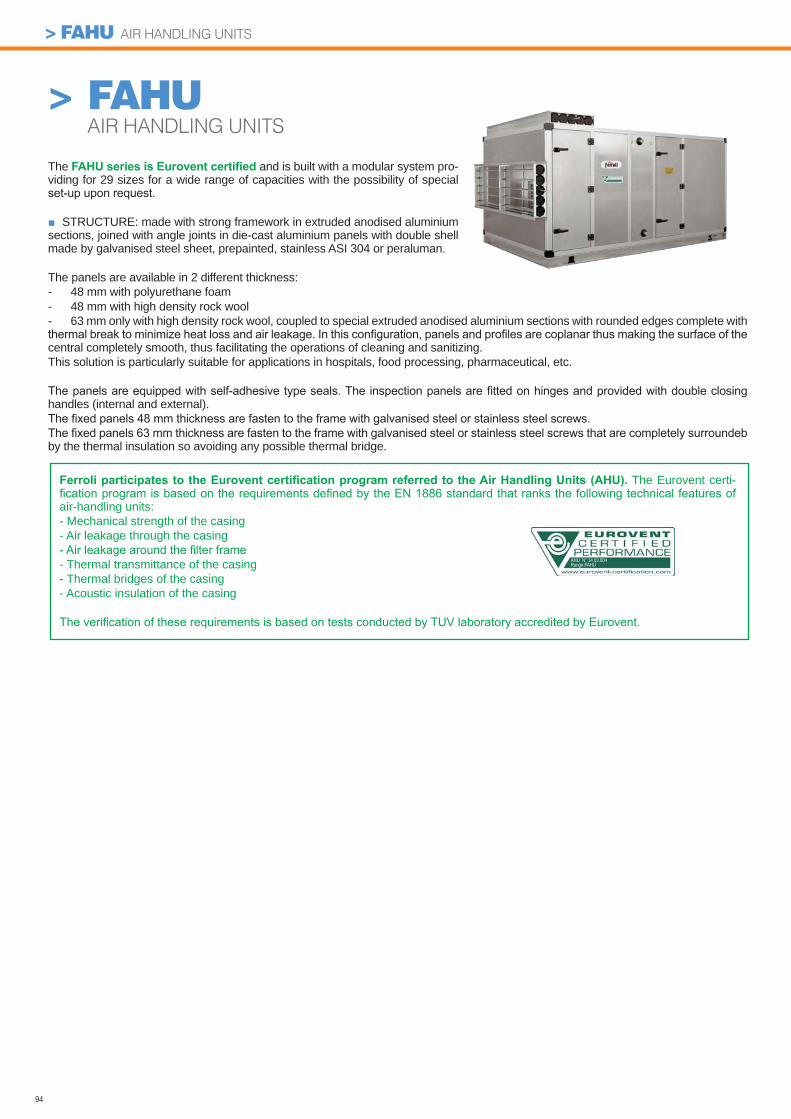
94
> FAHUAIR HANDLING UNITS
The Eurovent certi-
air-handling units: - Mechanical strength of the casing- Air leakage through the casing
- Thermal transmittance of the casing- Thermal bridges of the casing- Acoustic insulation of the casing
The and is built with a modular system pro-viding for 29 sizes for a wide range of capacities with the possibility of special
STRUCTURE: made with strong framework in extruded anodised aluminium sections, joined with angle joints in die-cast aluminium panels with double shell made by galvanised steel sheet, prepainted, stainless ASI 304 or peraluman.
The panels are available in 2 different thickness:- 48 mm with polyurethane foam- 48 mm with high density rock wool- 63 mm only with high density rock wool, coupled to special extruded anodised aluminium sections with rounded edges complete with
central completely smooth, thus facilitating the operations of cleaning and sanitizing.This solution is particularly suitable for applications in hospitals, food processing, pharmaceutical, etc.
handles (internal and external).
by the thermal insulation so avoiding any possible thermal bridge.
AHU N° 14.03.004Range FAHU
> FAHU AIR HANDLING UNITS
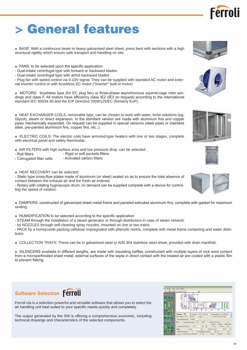
95
Software Selection
Ferroli cta is a selection powerful and versatile software that allows you to select the
The output generated by the SW is offering a comprehensive economic, including technical drawings and characteristics of the selected components.
BASE: With a continuous beam in heavy galvanised steel sheet, press bent with sections with a high structural rigidity which ensure safe transport and handling on site.
- Dual-intake centrifugal type with forward or backward blades- Dual-intake centrifugal type with airfoil backward blades- Plug fan with speed control via 0-10V signal. They can be supplied with standard AC motor and exter-nal inverter control or with brushless EC motor ("inverter" built-in motor)
-
standard IEC 60034-30 and the ErP Directive 2009/125/EC (formerly EuP).
HEAT EXCHANGER COILS, removable type, can be chosen to work with water, brine solutions (eg.
ELECTRIC COILS: The electric coils have armored-type heaters with one or two stages, complete with electrical panel and safety thermostat.
AIR FILTERS with high surface area and low pressure drop, can be selected:
HEAT RECOVERY can be selected:
contact between the exhaust air and the fresh air entered. -
ling the speed of rotation.
> General features
sealing.
- STEAM through the installation of a steam generator or through distributors in case of steam network.- by NOZZLES through self-cleaning spray nozzles, mounted on one or two trains.- PACK by a honeycomb packing cellulose impregnated with phenolic resins, complete with metal frame containing and water distri-butor.
COLLECTION TRAYS: These can be in galvanised steel or AISI 304 stainless steel sheet, provided with drain manifold.
c t a
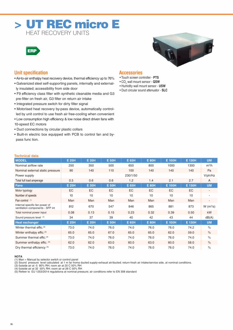
96
Unit specifi cation • Air-to-air enthalpy heat recovery device, thermal efficiency up to 76%• Galvanized steel self-supporting panels, internally and external-ly insulated; accessibility from side door
• F9 efficiency class fi lter with synthetic cleanable media and G3 pre-fi lter on fresh air, G3 fi lter on return air intake
• Integrated pressure switch for dirty fi lter signal• Motorised heat recovery by-pass device, automatically control-led by unit control to use fresh air free-cooling when convenient
• Low consumption high efficiency & low noise direct driven fans with10-speed EC motors• Duct connections by circular plastic collars• Built-in electric box equipped with PCB to control fan and by-pass func tion.
Accessories• Touch screen controller - PTS
• CO2 wall mount sensor - QSW
• Humidity wall mount sensor - USW
• Duct circular sound attenuator - SLC
> UT REC micro E HEAT RECOVERY UNITS
Technical data
MODEL E 25H E 35H E 50H E 65H E 80H E 100H E 130H UM
Nominal airfl ow rate 250 350 500 650 800 1000 1300 m3/h
Nominal external static pressure 90 140 110 100 140 140 140 Pa
Power supply 230/1/50 V/ph/Hz
Total full load amperage 0.5 0.6 0.6 1.2 1.4 2.1 2.7 A
Fans E 25H E 35H E 50H E 65H E 80H E 100H E 130H UM
Motor typology EC EC EC EC EC EC EC -
Number of speeds 10 10 10 10 10 10 10 -
Fan control (1) Man Man Man Man Man Man Man -Internal specifi c fan power of ventilation components - SFP int 812 670 547 846 865 881 873 W (m3/s)
Total nominal power input 0.08 0.13 0.15 0.23 0.32 0.39 0.50 kW
Sound pressure level (2) 34 37 39 40 42 43 44 dB(A)
Heat exchanger E 25H E 35H E 50H E 65H E 80H E 100H E 130H UM
Winter thermal effic.(3) 73.0 74.0 76.0 74.0 76.0 76.0 74.2 %
Winter enthalpy effic.(3) 65.0 65.0 67.0 65.0 65.0 62.0 59.0 %
Summer thermal effic.(4) 73.0 74.0 76.0 74.0 76.0 76.0 74.0 %
Summer enthalpy effic. (4) 62.0 62.0 63.0 60.0 63.0 60.0 58.0 %
Dry thermal efficiency (5) 73.0 74.0 76.0 74.0 76.0 76.0 74.0 %
NOTA (1) Man = Manual by selector switch or control panel(2) Sound pressure level calculated at 1 m far froma ducted supply-exhaust air/ducted; return-fresh air intake/service side, at nominal conditions. (3) 0utside air at -5 80% RH; room air at 20 C 50% RH (4) 0utside air at 32 50% RH; room air at 26 C 50% RH(5) Refeer to EU 1253/2014 regulationa at nominal pressure; air conditions refer to EN 308 standard
ERP
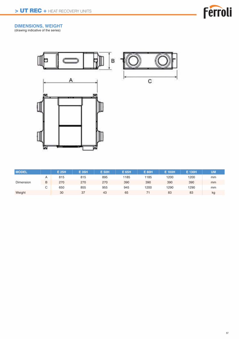
97
DIMENSIONS, WEIGHT (drawing indicative of the series)
MODEL E 25H E 35H E 50H E 65H E 80H E 100H E 130H UM
Dimension
A 815 815 895 1185 1185 1200 1200 mm
B 270 270 270 390 390 390 390 mm
C 650 855 955 945 1200 1290 1290 mm
Weight 30 37 43 65 71 83 83 kg
> UT REC + HEAT RECOVERY UNITS
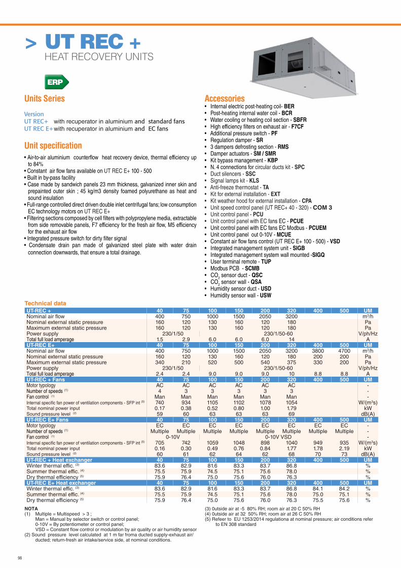
98
Units Series
VersionUT REC+ with recuperator in aluminium and standard fans UT REC E+ with recuperator in aluminium and EC fans
Unit specifi cation
• Air-to-air aluminium counterfl ow heat recovery device, thermal efficiency up to 84%
• Constant air fl ow fans available on UT REC E+ 100 - 500• Built in by-pass facility• Case made by sandwich panels 23 mm thickness, galvanized inner skin and
prepainted outer skin ; 45 kg/m3 density foamed polyurethane as heat and sound insulation
• Full-range controlled direct driven double inlet centrifugal fans; low consumption EC technology motors on UT REC E+
• Filtering sections composed by cell fi lters with polypropylene media, extractable from side removable panels, F7 efficiency for the fresh air fl ow, M5 efficiency for the exhaust air fl ow
• Integrated pressure switch for dirty fi lter signal• Condensate drain pan made of galvanized steel plate with water drain
connection downwards, that ensure a total drainage.
Accessories• Internal electric post-heating coil- BER• Post-heating internal water coil - BCR• Water cooling or heating coil section - SBFR• High efficiency fi lters on exhaust air - F7CF• Additional pressure switch - PF• Regulation damper - SR• 3 dampers defrosting section - RMS• Damper actuators - SM / SMR• Kit bypass management - KBP• N. 4 connections for circular ducts kit - SPC• Duct silencers - SSC• Signal lamps kit - KLS• Anti-freeze thermostat - TA• Kit for external installation - EXT• Kit weather hood for external installation - CPA• Unit speed control panel (UT REC+ 40 - 320) - COM 3• Unit control panel - PCU • Unit control panel with EC fans EC - PCUE• Unit control panel with EC fans EC Modbus - PCUEM• Unit control panel out 0-10V - MCUE• Constant air fl ow fans control (UT REC E+ 100 - 500) - VSD• Integrated management system unit - SIGB• Integrated management system wall mounted -SIGQ• User terminal remote - TUP• Modbus PCB - SCMB• CO2 sensor duct - QSC• CO2 sensor wall - QSA• Humidity sensor duct - USD• Humidity sensor wall - USW
> UT REC + HEAT RECOVERY UNITS
Technical data
UT-REC + 40 75 100 150 200 320 400 500 UMNominal air fl ow 400 750 1000 1500 2050 3200 m3/hNominal external static pressure 160 120 130 160 120 180 PaMaximum external static pressure 160 120 130 160 120 180 PaPower supply 230/1/50 230/1/50-60 V/ph/HzTotal full load amperage 1.5 2.9 6.0 6.0 6.0 14 AUT-REC E+ 40 75 100 150 200 320 400 500 UMNominal air fl ow 400 750 1000 1500 2050 3200 3800 4700 m3/hNominal external static pressure 160 120 130 160 120 180 200 200 PaMaximum external static pressure 340 210 520 500 540 375 330 200 PaPower supply 230/1/50 230/1/50-60 V/ph/HzTotal full load amperage 2.4 2.4 9.0 9.0 9.0 10 8.8 8.8 AUT-REC + Fans 40 75 100 150 200 320 400 500 UMMotor typology AC AC AC AC AC AC -Number of speeds (1) 4 3 3 3 3 3 -Fan control (1) Man Man Man Man Man Man -Internal specifi c fan power of ventilation components - SFP int (5) 740 934 1105 1102 1078 1054 W/(m3s)Total nominal power input 0.17 0.38 0.52 0.80 1.00 1.79 kWSound pressure level (2) 59 60 63 63 63 69 dB(A)UT-REC E+ Fans 40 75 100 150 200 320 400 500 UMMotor typology EC EC EC EC EC EC EC EC -Number of speeds (1) Multiple Multiple Multiple Multiple Multiple Multiple Multiple Multiple -Fan control (1) 0-10V 0-10V VSD -Internal specifi c fan power of ventilation components - SFP int (5) 705 742 1059 1048 898 1040 949 935 W/(m3s)Total nominal power input 0.16 0.30 0.49 0.76 0.84 1.77 1.78 2.19 kWSound pressure level (2) 60 61 62 64 62 68 70 73 dB(A)UT-REC + Heat exchanger 40 75 100 150 200 320 400 500 UMWinter thermal effic. (3) 83.6 82.9 81.6 83.3 83.7 86.8 %Summer thermal effic. (4) 75.5 75.9 74.5 75.1 75.6 78.0 %Dry thermal efficiency (5) 75.9 76.4 75.0 75.6 76.0 76.3 %UT-REC E+ Heat exchanger 40 75 100 150 200 320 400 500 UMWinter thermal effic. (3) 83.6 82.9 81.6 83.3 83.7 86.8 84.1 84.2 %Summer thermal effic. (4) 75.5 75.9 74.5 75.1 75.6 78.0 75.0 75.1 %Dry thermal efficiency (5) 75.9 76.4 75.0 75.6 76.0 76.3 75.5 75.6 %
NOTA (1) Multiple = Multispeed > 3 ; Man = Manual by selector switch or control panel; 0-10V = By potentiometer or control panel; VSD = Constant flow control or modulation by air quality or air humidity sensor(2) Sound pressure level calculated at 1 m far froma ducted supply-exhaust air/
ducted; return-fresh air intake/service side, at nominal conditions.
(3) 0utside air at -5 80% RH; room air at 20 C 50% RH (4) 0utside air at 32 50% RH; room air at 26 C 50% RH(5) Refeer to EU 1253/2014 regulationa at nominal pressure; air conditions refer
to EN 308 standard
ERP
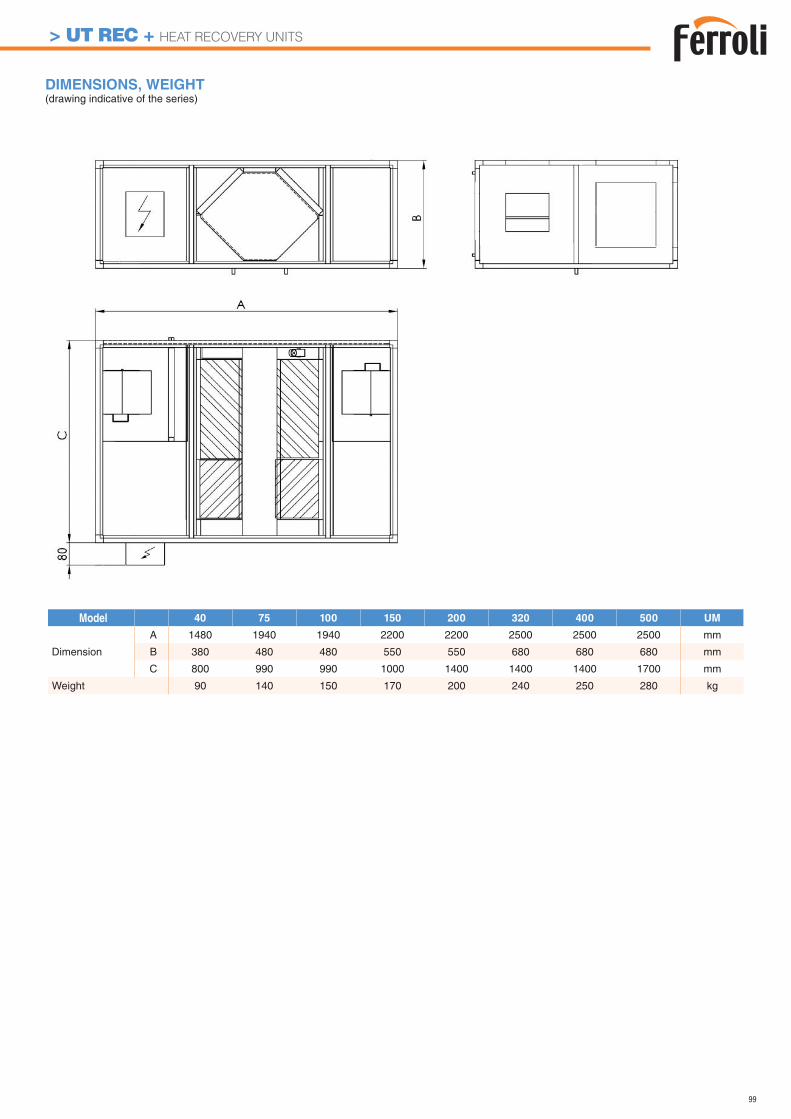
99
DIMENSIONS, WEIGHT (drawing indicative of the series)
Model 40 75 100 150 200 320 400 500 UM
Dimension
A 1480 1940 1940 2200 2200 2500 2500 2500 mm
B 380 480 480 550 550 680 680 680 mm
C 800 990 990 1000 1400 1400 1400 1700 mm
Weight 90 140 150 170 200 240 250 280 kg
> UT REC + HEAT RECOVERY UNITS
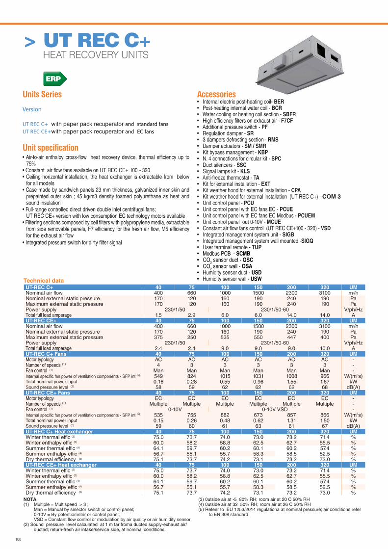
100
Units Series
Version
UT REC C+ with paper pack recuperator and standard fans UT REC CE+ with paper pack recuperator and EC fans
Unit specifi cation • Air-to-air enthalpy cross-fl ow heat recovery device, thermal efficiency up to
75%• Constant air fl ow fans available on UT REC CE+ 100 - 320• Ceiling horizontal installation, the heat exchanger is extractable from below
for all models• Case made by sandwich panels 23 mm thickness, galvanized inner skin and
prepainted outer skin ; 45 kg/m3 density foamed polyurethane as heat and sound insulation
• Full-range controlled direct driven double inlet centrifugal fans; UT REC CE+ version with low consumption EC technology motors available• Filtering sections composed by cell fi lters with polypropylene media, extractable
from side removable panels, F7 efficiency for the fresh air fl ow, M5 efficiency for the exhaust air fl ow
• Integrated pressure switch for dirty fi lter signal
Accessories• Internal electric post-heating coil- BER• Post-heating internal water coil - BCR• Water cooling or heating coil section - SBFR• High efficiency fi lters on exhaust air - F7CF• Additional pressure switch - PF• Regulation damper - SR• 3 dampers defrosting section - RMS• Damper actuators - SM / SMR• Kit bypass management - KBP• N. 4 connections for circular kit - SPC• Duct silencers - SSC• Signal lamps kit - KLS• Anti-freeze thermostat - TA• Kit for external installation - EXT• Kit weather hood for external installation - CPA• Kit weather hood for external installation (UT REC C+) - COM 3• Unit control panel - PCU • Unit control panel with EC fans EC - PCUE• Unit control panel with EC fans EC Modbus - PCUEM• Unit control panel out 0-10V - MCUE• Constant air fl ow fans control (UT REC CE+100 - 320) - VSD• Integrated management system unit - SIGB• Integrated management system wall mounted -SIGQ• User terminal remote - TUP• Modbus PCB - SCMB• CO2 sensor duct - QSC• CO2 sensor wall - QSA• Humidity sensor duct - USD• Humidity sensor wall - USW
> UT REC C+ HEAT RECOVERY UNITS
UT-REC C+ 40 75 100 150 200 320 UMNominal air fl ow 400 660 1000 1500 2300 3100 m3/hNominal external static pressure 170 120 160 190 240 190 PaMaximum external static pressure 170 120 160 190 240 190 PaPower supply 230/1/50 230/1/50-60 V/ph/HzTotal full load amperage 1.5 2.9 6.0 6.0 14.0 14.0 AUT-REC CE+ 40 75 100 150 200 320 UMNominal air fl ow 400 660 1000 1500 2300 3100 m3/hNominal external static pressure 170 120 160 190 240 190 PaMaximum external static pressure 375 250 535 550 447 400 PaPower supply 230/1/50 230/1/50-60 V/ph/HzTotal full load amperage 2.4 2.4 9.0 9.0 9.0 10.0 AUT-REC C+ Fans 40 75 100 150 200 320 UMMotor typology AC AC AC AC AC AC -Number of speeds (1) 4 3 3 3 3 3 -Fan control (1) Man Man Man Man Man Man -Internal specifi c fan power of ventilation components - SFP int (5) 549 824 1015 1031 1008 966 W/(m3s)Total nominal power input 0.16 0.28 0.55 0.96 1.55 1.67 kWSound pressure level (2) 58 59 62 62 62 68 dB(A)UT-REC CE+ Fans 40 75 100 150 200 320 UMMotor typology EC EC EC EC EC EC -Number of speeds (1) Multiple Multiple Multiple Multiple Multiple Multiple -Fan control (1) 0-10V 0-10V VSD -Internal specifi c fan power of ventilation components - SFP int (5) 535 755 882 673 857 866 W/(m3s)Total nominal power input 0.15 0.26 0.48 0.62 1.31 1.50 kWSound pressure level (2) 59 60 61 63 61 67 dB(A)UT-REC C+ Heat exchanger 40 75 100 150 200 320 UMWinter thermal effic (3) 75.0 73.7 74.0 73.0 73.2 71.4 %Winter enthalpy effic (3) 60.0 58.2 58.8 62.5 62.7 55.5 %Summer thermal effic (4) 64.1 59.7 60.2 60.1 60.2 57.4 %Summer enthalpy effic (4) 56.7 55.1 55.7 58.3 58.5 52.5 %Dry thermal efficiency (5) 75.1 73.7 74.2 73.1 73.2 73.0 %UT-REC CE+ Heat exchanger 40 75 100 150 200 320 UMWinter thermal effic (3) 75.0 73.7 74.0 73.0 73.2 71.4 %Winter enthalpy effic (3) 60.0 58.2 58.8 62.5 62.7 55.5 %Summer thermal effic (4) 64.1 59.7 60.2 60.1 60.2 57.4 %Summer enthalpy effic (4) 56.7 55.1 55.7 58.3 58.5 52.5 %Dry thermal efficiency (5) 75.1 73.7 74.2 73.1 73.2 73.0 %
NOTA (1) Multiple = Multispeed > 3 ; Man = Manual by selector switch or control panel; 0-10V = By potentiometer or control panel; VSD = Constant flow control or modulation by air quality or air humidity sensor(2) Sound pressure level calculated at 1 m far froma ducted supply-exhaust air/
ducted; return-fresh air intake/service side, at nominal conditions.
(3) 0utside air at -5 80% RH; room air at 20 C 50% RH (4) 0utside air at 32 50% RH; room air at 26 C 50% RH(5) Refeer to EU 1253/2014 regulationa at nominal pressure; air conditions refer
to EN 308 standard
Technical data
ERP
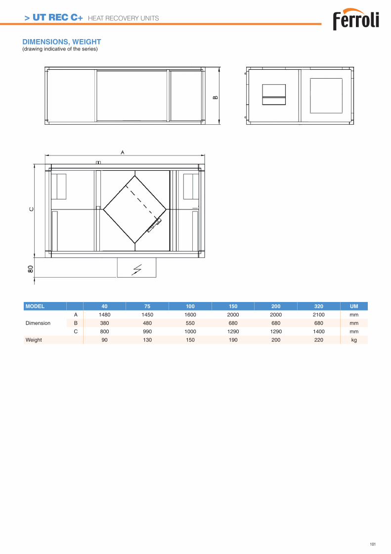
101
DIMENSIONS, WEIGHT (drawing indicative of the series)
MODEL 40 75 100 150 200 320 UM
Dimension
A 1480 1450 1600 2000 2000 2100 mm
B 380 480 550 680 680 680 mm
C 800 990 1000 1290 1290 1400 mm
Weight 90 130 150 190 200 220 kg
> UT REC C+ HEAT RECOVERY UNITS
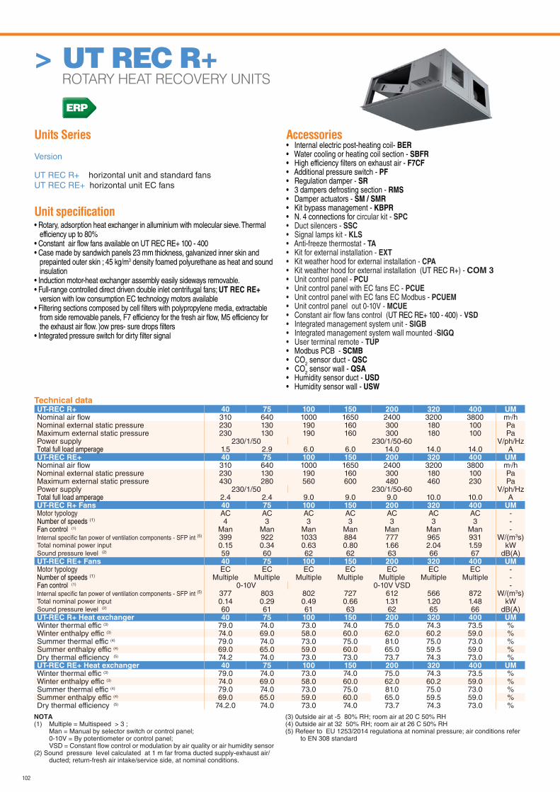
102
Units Series
Version
UT REC R+ horizontal unit and standard fansUT REC RE+ horizontal unit EC fans
Unit specifi cation • Rotary, adsorption heat exchanger in alluminium with molecular sieve. Thermal
efficiency up to 80%• Constant air fl ow fans available on UT REC RE+ 100 - 400• Case made by sandwich panels 23 mm thickness, galvanized inner skin and
prepainted outer skin ; 45 kg/m3 density foamed polyurethane as heat and sound insulation
• Induction motor-heat exchanger assembly easily sideways removable.• Full-range controlled direct driven double inlet centrifugal fans; UT REC RE+
version with low consumption EC technology motors available• Filtering sections composed by cell fi lters with polypropylene media, extractable
from side removable panels, F7 efficiency for the fresh air fl ow, M5 efficiency for the exhaust air fl ow. )ow pres- sure drops fi lters
• Integrated pressure switch for dirty fi lter signal
Accessories• Internal electric post-heating coil- BER• Water cooling or heating coil section - SBFR• High efficiency fi lters on exhaust air - F7CF• Additional pressure switch - PF• Regulation damper - SR• 3 dampers defrosting section - RMS• Damper actuators - SM / SMR• Kit bypass management - KBPR• N. 4 connections for circular kit - SPC• Duct silencers - SSC• Signal lamps kit - KLS• Anti-freeze thermostat - TA• Kit for external installation - EXT• Kit weather hood for external installation - CPA• Kit weather hood for external installation (UT REC R+) - COM 3• Unit control panel - PCU • Unit control panel with EC fans EC - PCUE• Unit control panel with EC fans EC Modbus - PCUEM• Unit control panel out 0-10V - MCUE• Constant air fl ow fans control (UT REC RE+ 100 - 400) - VSD• Integrated management system unit - SIGB• Integrated management system wall mounted -SIGQ• User terminal remote - TUP• Modbus PCB - SCMB• CO2 sensor duct - QSC• CO2 sensor wall - QSA• Humidity sensor duct - USD• Humidity sensor wall - USW
> UT REC R+ ROTARY HEAT RECOVERY UNITS
Technical dataUT-REC R+ 40 75 100 150 200 320 400 UMNominal air fl ow 310 640 1000 1650 2400 3200 3800 m3/hNominal external static pressure 230 130 190 160 300 180 100 PaMaximum external static pressure 230 130 190 160 300 180 100 PaPower supply 230/1/50 230/1/50-60 V/ph/HzTotal full load amperage 1.5 2.9 6.0 6.0 14.0 14.0 14.0 AUT-REC RE+ 40 75 100 150 200 320 400 UMNominal air fl ow 310 640 1000 1650 2400 3200 3800 m3/hNominal external static pressure 230 130 190 160 300 180 100 PaMaximum external static pressure 430 280 560 600 480 460 230 PaPower supply 230/1/50 230/1/50-60 V/ph/HzTotal full load amperage 2.4 2.4 9.0 9.0 9.0 10.0 10.0 AUT-REC R+ Fans 40 75 100 150 200 320 400 UMMotor typology AC AC AC AC AC AC AC -Number of speeds (1) 4 3 3 3 3 3 3 -Fan control (1) Man Man Man Man Man Man Man -Internal specifi c fan power of ventilation components - SFP int (5) 399 922 1033 884 777 965 931 W/(m3s)Total nominal power input 0.15 0.34 0.63 0.80 1.66 2.04 1.59 kWSound pressure level (2) 59 60 62 62 63 66 67 dB(A)UT-REC RE+ Fans 40 75 100 150 200 320 400 UMMotor typology EC EC EC EC EC EC EC -Number of speeds (1) Multiple Multiple Multiple Multiple Multiple Multiple Multiple -Fan control (1) 0-10V 0-10V VSD -Internal specifi c fan power of ventilation components - SFP int (5) 377 803 802 727 612 566 872 W/(m3s)Total nominal power input 0.14 0.29 0.49 0.66 1.31 1.20 1.48 kWSound pressure level (2) 60 61 61 63 62 65 66 dB(A)UT-REC R+ Heat exchanger 40 75 100 150 200 320 400 UMWinter thermal effic (3) 79.0 74.0 73.0 74.0 75.0 74.3 73.5 %Winter enthalpy effic (3) 74.0 69.0 58.0 60.0 62.0 60.2 59.0 %Summer thermal effic (4) 79.0 74.0 73.0 75.0 81.0 75.0 73.0 %Summer enthalpy effic (4) 69.0 65.0 59.0 60.0 65.0 59.5 59.0 %Dry thermal efficiency (5) 74.2 74.0 73.0 73.0 73.7 74.3 73.0 %UT-REC RE+ Heat exchanger 40 75 100 150 200 320 400 UMWinter thermal effic (3) 79.0 74.0 73.0 74.0 75.0 74.3 73.5 %Winter enthalpy effic (3) 74.0 69.0 58.0 60.0 62.0 60.2 59.0 %Summer thermal effic (4) 79.0 74.0 73.0 75.0 81.0 75.0 73.0 %Summer enthalpy effic (4) 69.0 65.0 59.0 60.0 65.0 59.5 59.0 %Dry thermal efficiency (5) 74.2.0 74.0 73.0 74.0 73.7 74.3 73.0 %
NOTA (1) Multiple = Multispeed > 3 ; Man = Manual by selector switch or control panel; 0-10V = By potentiometer or control panel; VSD = Constant flow control or modulation by air quality or air humidity sensor(2) Sound pressure level calculated at 1 m far froma ducted supply-exhaust air/
ducted; return-fresh air intake/service side, at nominal conditions.
(3) 0utside air at -5 80% RH; room air at 20 C 50% RH (4) 0utside air at 32 50% RH; room air at 26 C 50% RH(5) Refeer to EU 1253/2014 regulationa at nominal pressure; air conditions refer
to EN 308 standard
ERP
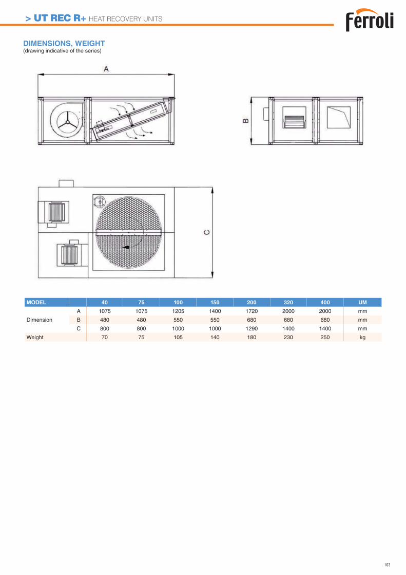
103
DIMENSIONS, WEIGHT (drawing indicative of the series)
MODEL 40 75 100 150 200 320 400 UM
Dimension
A 1075 1075 1205 1400 1720 2000 2000 mm
B 480 480 550 550 680 680 680 mm
C 800 800 1000 1000 1290 1400 1400 mm
Weight 70 75 105 140 180 230 250 kg
> UT REC R+ HEAT RECOVERY UNITS

104
105
HEAT PUMPS
> Technical datasheets ............................................................. 121
> Product range Heat pumps.................................................... 132> AIR-WATER Heat pumps
RVL-I PLUS ................................................................................................................134HXP HT .......................................................................................................................146HMP HT ......................................................................................................................150HGA ............................................................................................................................154HGA HT ......................................................................................................................158HGP ............................................................................................................................162
HGP HT ......................................................................................................................166> WATER-WATER and BRINE-WATER Heat pumps
HSW LT ......................................................................................................................170HXW LT ......................................................................................................................176HMW LT ......................................................................................................................182HMW HT .....................................................................................................................188HGW HT .....................................................................................................................194
> Control accessories overview .......................................................200

106
renewablesource
The air, the water and the ground, the three most common elements on Earth, represent a virtually inhexaustible source of energy and heat, that the
modern technology applied to heat pumps allow to be used in an optimized way in order to satisfy the heating and cooling needs of all the dwellings with
efficient and ecological solutions.
Satisfy the room comfort needs using the heat available in the environment as renewable and inhexaustible energy source
energyefficiencyHeat pumps allow to get much higher efficiency levels compared to the traditional heating systems because they draw the main part of the required energy directly from the environment. The continuos improvement of the technologies applied to all the components and the constant optimization of the thermodynamic cycle, upon which the heat pump operating mode is based, allow to achieve always better performances.
HEAT PUMP SYSTEM
BENEFITS
> A new strategyfor heating and
comfort
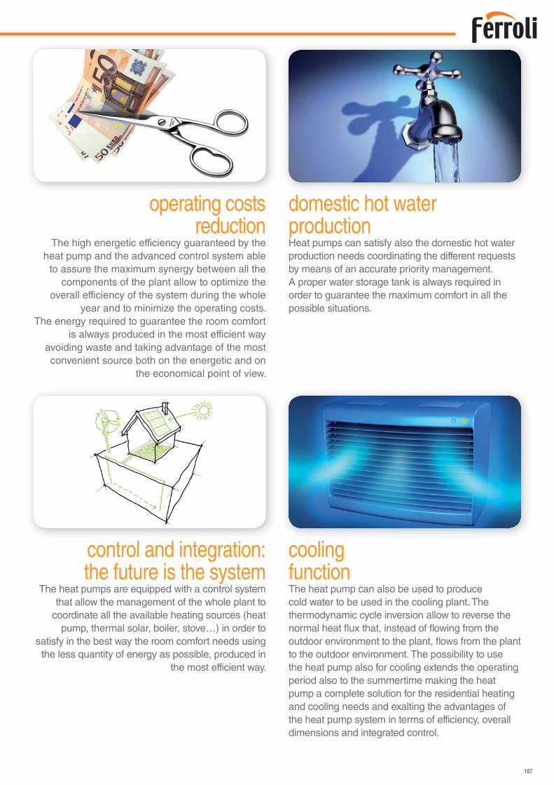
107
domestic hot waterproductionHeat pumps can satisfy also the domestic hot water production needs coordinating the different requests by means of an accurate priority management.A proper water storage tank is always required in order to guarantee the maximum comfort in all the possible situations.
operating costsreduction
The high energetic efficiency guaranteed by the heat pump and the advanced control system able
to assure the maximum synergy between all the components of the plant allow to optimize the
overall efficiency of the system during the whole year and to minimize the operating costs.
The energy required to guarantee the room comfort is always produced in the most efficient way
avoiding waste and taking advantage of the most convenient source both on the energetic and on
the economical point of view.
coolingfunctionThe heat pump can also be used to produce cold water to be used in the cooling plant. The thermodynamic cycle inversion allow to reverse the normal heat flux that, instead of flowing from the outdoor environment to the plant, flows from the plant to the outdoor environment. The possibility to use the heat pump also for cooling extends the operating period also to the summertime making the heat pump a complete solution for the residential heating and cooling needs and exalting the advantages of the heat pump system in terms of efficiency, overall dimensions and integrated control.
control and integration:the future is the system
The heat pumps are equipped with a control system that allow the management of the whole plant to
coordinate all the available heating sources (heat pump, thermal solar, boiler, stove…) in order to
satisfy in the best way the room comfort needs using the less quantity of energy as possible, produced in
the most efficient way.
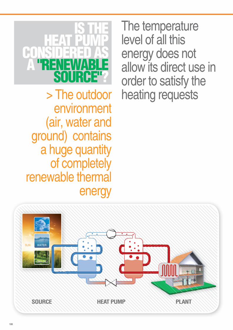
108
> The outdoor environment
(air, water and ground) contains
a huge quantity of completely
renewable thermal energy
IS THEHEAT PUMP
CONSIDERED AS A "RENEWABLE
SOURCE"?
The temperature level of all this energy does not allow its direct use in order to satisfy the heating requests
SUN
AIR
WATER
HEAT PUMPSOURCE PLANT
GROUND
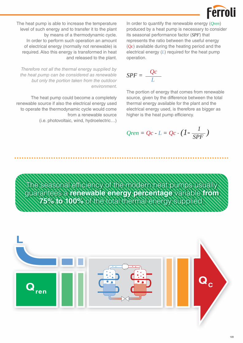
109
The heat pump is able to increase the temperature level of such energy and to transfer it to the plant
by means of a thermodynamic cycle.In order to perform such operation an amount
of electrical energy (normally not renewable) is required. Also this energy is transformed in heat
and released to the plant.
Therefore not all the thermal energy supplied by the heat pump can be considered as renewable
but only the portion taken from the outdoor environment.
The heat pump could become a completely renewable source if also the electrical energy used
to operate the thermodynamic cycle would come from a renewable source
(i.e. photovoltaic, wind, hydroelectric…)
In order to quantify the renewable energy (Qren) produced by a heat pump is necessary to consider its seasonal performance factor (SPF) that represents the ratio between the useful energy (Qc) available during the heating period and the electrical energy (L) required for the heat pump operation.
SPF = Qc L
The portion of energy that comes from renewable source, given by the difference between the total thermal energy available for the plant and the electrical energy used, is therefore as bigger as higher is the heat pump efficiency.
Qren = Qc - L = Qc . (1- )1SPF
Qren
QC
L
The seasonal efficiency of the modern heat pumps usually guarantees a renewable energy percentage variable from
75% to 100% of the total thermal energy supplied.
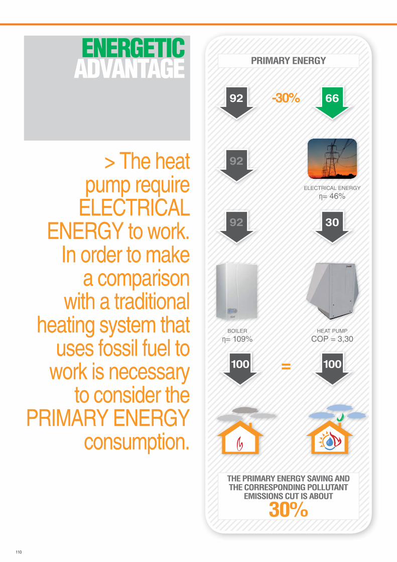
110
> The heat pump require
ELECTRICAL ENERGY to work.
In order to make a comparison
with a traditional heating system that
uses fossil fuel to work is necessary
to consider the PRIMARY ENERGY
consumption.
ENERGETICADVANTAGE
3092
ELECTRICAL ENERGY
= 46%
92
-30%92 66
HEAT PUMP
COP = 3,30BOILER
= 109%
100100 =
PRIMARY ENERGY
THE PRIMARY ENERGY SAVING AND THE CORRESPONDING POLLUTANT
EMISSIONS CUT IS ABOUT
30%
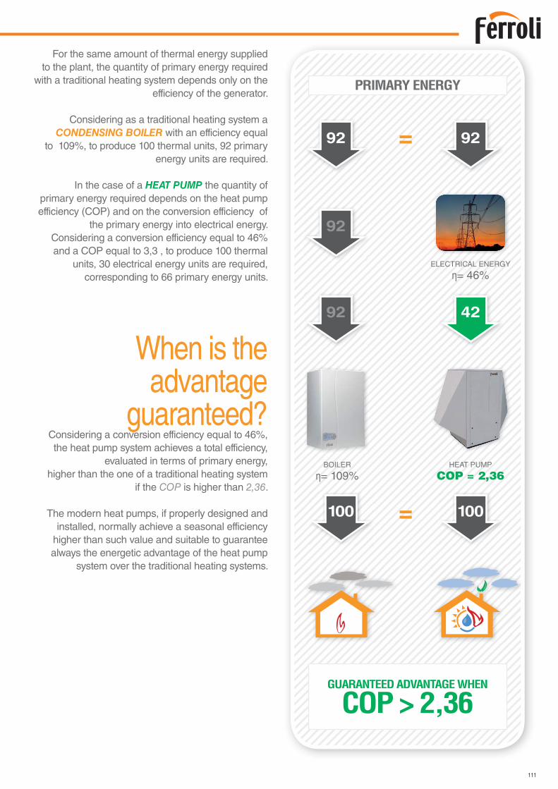
111
For the same amount of thermal energy supplied to the plant, the quantity of primary energy required
with a traditional heating system depends only on the efficiency of the generator.
Considering as a traditional heating system a CONDENSING BOILER with an efficiency equal
to 109%, to produce 100 thermal units, 92 primary energy units are required.
In the case of a HEAT PUMP the quantity of primary energy required depends on the heat pump efficiency (COP) and on the conversion efficiency of
the primary energy into electrical energy.Considering a conversion efficiency equal to 46% and a COP equal to 3,3 , to produce 100 thermal
units, 30 electrical energy units are required, corresponding to 66 primary energy units.
When is the advantage
guaranteed?Considering a conversion efficiency equal to 46%, the heat pump system achieves a total efficiency,
evaluated in terms of primary energy,higher than the one of a traditional heating system
if the COP is higher than 2,36.
The modern heat pumps, if properly designed and installed, normally achieve a seasonal efficiency
higher than such value and suitable to guarantee always the energetic advantage of the heat pump
system over the traditional heating systems.
4292
ELECTRICAL ENERGY
= 46%
92
=92 92
HEAT PUMP
COP = 2,36BOILER
= 109%
100100 =
PRIMARY ENERGY
GUARANTEED ADVANTAGE WHEN
COP > 2,36
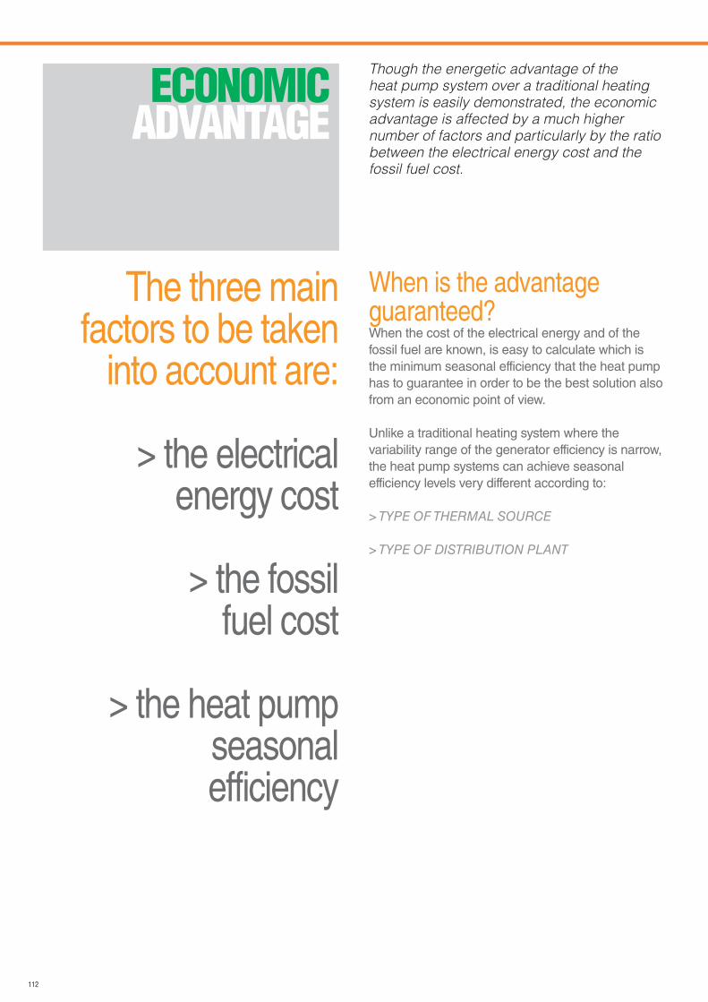
112
The three main factors to be taken
into account are:
> the electrical energy cost
> the fossilfuel cost
> the heat pump seasonalefficiency
ECONOMICADVANTAGE
Though the energetic advantage of the
heat pump system over a traditional heating
system is easily demonstrated, the economic
advantage is affected by a much higher
number of factors and particularly by the ratio
between the electrical energy cost and the
fossil fuel cost.
When is the advantage guaranteed?When the cost of the electrical energy and of the fossil fuel are known, is easy to calculate which is the minimum seasonal efficiency that the heat pump has to guarantee in order to be the best solution also from an economic point of view.
Unlike a traditional heating system where the variability range of the generator efficiency is narrow, the heat pump systems can achieve seasonal efficiency levels very different according to:
> TYPE OF THERMAL SOURCE
> TYPE OF DISTRIBUTION PLANT
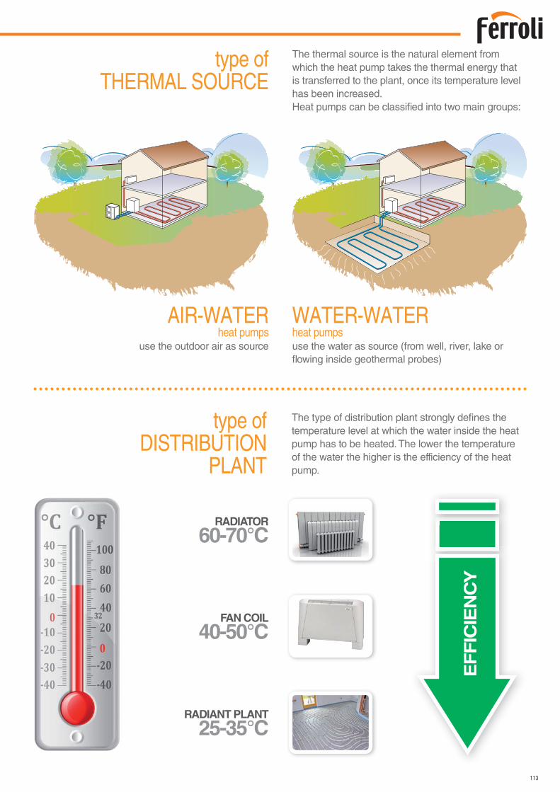
113
The type of distribution plant strongly defines the temperature level at which the water inside the heat pump has to be heated. The lower the temperature of the water the higher is the efficiency of the heat pump.
The thermal source is the natural element from which the heat pump takes the thermal energy that is transferred to the plant, once its temperature level has been increased.Heat pumps can be classified into two main groups:
AIR-WATERheat pumps
use the outdoor air as source
WATER-WATERheat pumpsuse the water as source (from well, river, lake or flowing inside geothermal probes)
EF
FIC
IEN
CY
RADIANT PLANT
25-35°C
FAN COIL
40-50°C
RADIATOR
60-70°C
type of THERMAL SOURCE
type of DISTRIBUTION
PLANT
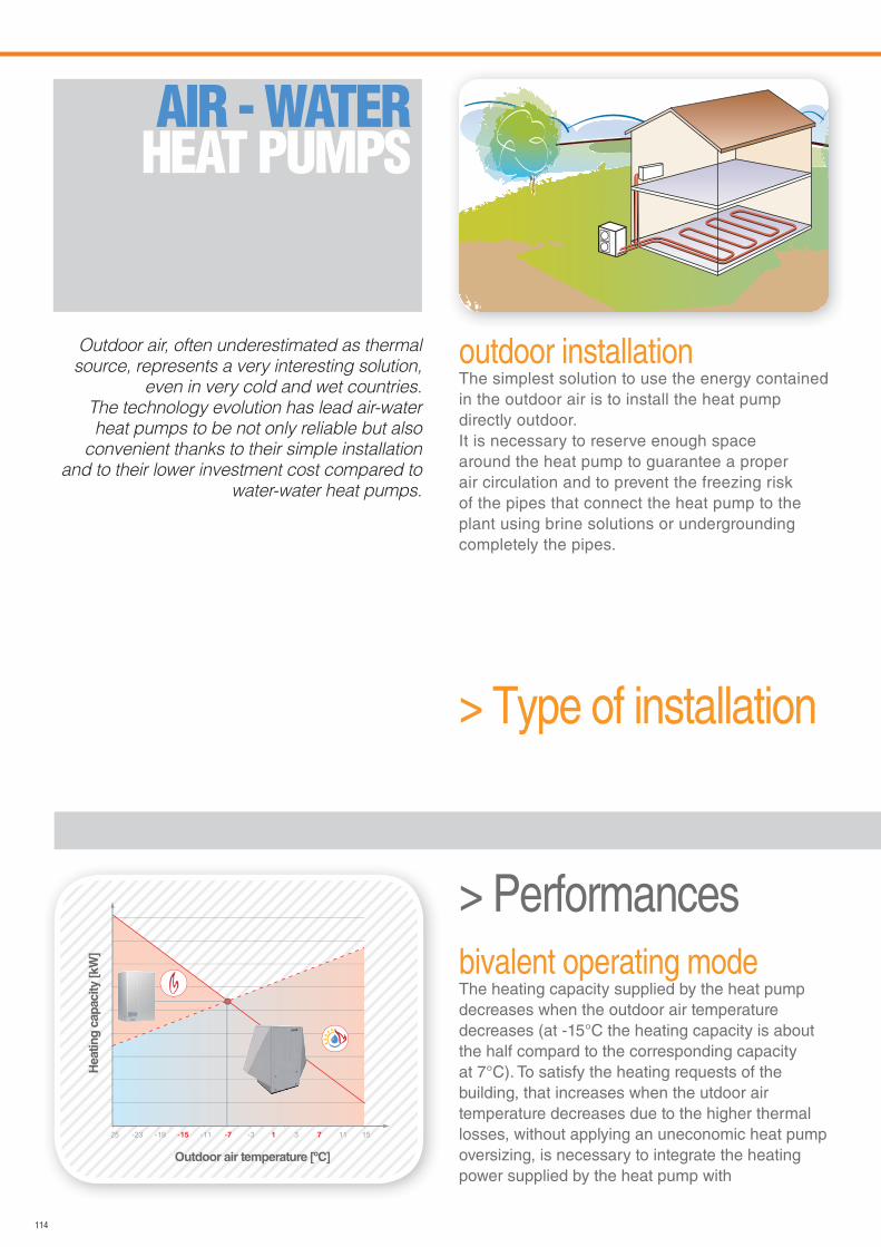
114
-19 -15 -11 -7 -3 31 7 11 15-2325
Outdoor air temperature [ºC]
Heatin
g c
ap
acity [kW
]
Outdoor air, often underestimated as thermal
source, represents a very interesting solution,
even in very cold and wet countries.
The technology evolution has lead air-water
heat pumps to be not only reliable but also
convenient thanks to their simple installation
and to their lower investment cost compared to
water-water heat pumps.
> Type of installation
AIR - WATER HEAT PUMPS
outdoor installationThe simplest solution to use the energy contained in the outdoor air is to install the heat pump directly outdoor.It is necessary to reserve enough space around the heat pump to guarantee a proper air circulation and to prevent the freezing risk of the pipes that connect the heat pump to the plant using brine solutions or undergrounding completely the pipes.
> Performancesbivalent operating modeThe heating capacity supplied by the heat pump decreases when the outdoor air temperature decreases (at -15°C the heating capacity is about the half compard to the corresponding capacity at 7°C). To satisfy the heating requests of the building, that increases when the utdoor air temperature decreases due to the higher thermal losses, without applying an uneconomic heat pump oversizing, is necessary to integrate the heating power supplied by the heat pump with
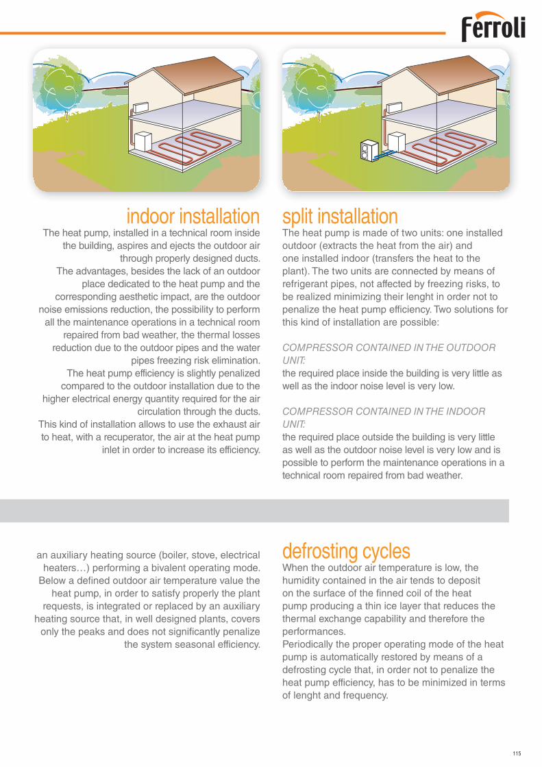
115
split installationThe heat pump is made of two units: one installed outdoor (extracts the heat from the air) and one installed indoor (transfers the heat to the plant). The two units are connected by means of refrigerant pipes, not affected by freezing risks, to be realized minimizing their lenght in order not to penalize the heat pump efficiency. Two solutions for this kind of installation are possible:
COMPRESSOR CONTAINED IN THE OUTDOOR UNIT: the required place inside the building is very little as well as the indoor noise level is very low.
COMPRESSOR CONTAINED IN THE INDOOR UNIT: the required place outside the building is very little as well as the outdoor noise level is very low and is possible to perform the maintenance operations in a technical room repaired from bad weather.
an auxiliary heating source (boiler, stove, electrical heaters…) performing a bivalent operating mode.
Below a defined outdoor air temperature value the heat pump, in order to satisfy properly the plant
requests, is integrated or replaced by an auxiliary heating source that, in well designed plants, covers
only the peaks and does not significantly penalize the system seasonal efficiency.
indoor installationThe heat pump, installed in a technical room inside
the building, aspires and ejects the outdoor air through properly designed ducts.
The advantages, besides the lack of an outdoor place dedicated to the heat pump and the
corresponding aesthetic impact, are the outdoor noise emissions reduction, the possibility to perform
all the maintenance operations in a technical room repaired from bad weather, the thermal losses
reduction due to the outdoor pipes and the water pipes freezing risk elimination.
The heat pump efficiency is slightly penalized compared to the outdoor installation due to the
higher electrical energy quantity required for the air circulation through the ducts.
This kind of installation allows to use the exhaust air to heat, with a recuperator, the air at the heat pump
inlet in order to increase its efficiency.
defrosting cyclesWhen the outdoor air temperature is low, the humidity contained in the air tends to deposit on the surface of the finned coil of the heat pump producing a thin ice layer that reduces the thermal exchange capability and therefore the performances.Periodically the proper operating mode of the heat pump is automatically restored by means of a defrosting cycle that, in order not to penalize the heat pump efficiency, has to be minimized in terms of lenght and frequency.
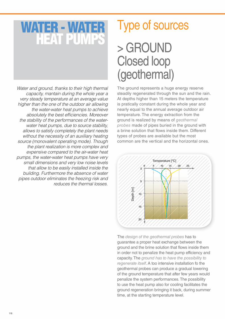
116
WATER - WATER HEAT PUMPS
Water and ground, thanks to their high thermal
capacity, mantain during the whole year a
very steady temperature at an average value
higher than the one of the outdoor air allowing
the water-water heat pumps to achieve
absolutely the best efficiencies. Moreover
the stability of the performances of the water-
water heat pumps, due to source stability,
allows to satisfy completely the plant needs
without the necessity of an auxiliary heating
source (monovalent operating mode). Though
the plant realization is more complex and
expensive compared to the air-water heat
pumps, the water-water heat pumps have very
small dimensions and very low noise levels
that allow to be easily installed inside the
building. Furthermore the absence of water
pipes outdoor eliminates the freezing risk and
reduces the thermal losses.
The ground represents a huge energy reserve steadily regenerated through the sun and the rain. At depths higher than 15 meters the temperature is pratically constant during the whole year and nearly equal to the annual average outdoor air temperature. The energy extraction from the ground is realized by means of geothermal probes made of pipes buried in the ground with a brine solution that flows inside them. Different types of probes are available but the most common are the vertical and the horizontal ones.
The design of the geothermal probes has to guarantee a proper heat exchange between the ground and the brine solution that flows inside them in order not to penalize the heat pump efficiency and capacity. The ground has to have the possibility to regenerate itself. A too intensive installation fo the geothermal probes can produce a gradual lowering of the ground temperature that after few years would penalize the system performances. The possibility to use the heat pump also for cooling facilitates the ground regeneration bringing it back, during summer time, at the starting temperature level.
Type of sources
> GROUNDClosed loop (geothermal)
Temperature [ºC]
Dep
th [m
]
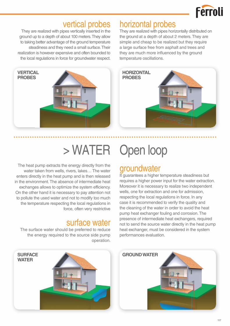
117
VERTICALPROBES
HORIZONTALPROBES
SURFACEWATER
GROUND WATER
horizontal probesThey are realized with pipes horizontally distributed on the ground at a depth of about 2 meters. They are simple and cheap to be realized but they require a large surface free from asphalt and trees and they are much more influenced by the ground temperature oscillations.
vertical probesThey are realized with pipes vertically inserted in the
ground up to a depth of about 100 meters. They allow to taking better advantage of the ground temperature
steadiness and they need a small surface. Their realization is however expensive and often bounded to
the local regulations in force for groundwater respect.
The heat pump extracts the energy directly from the water taken from wells, rivers, lakes… The water
enters directly in the heat pump and is then released in the environment. The absence of intermediate heat
exchanges allows to optimize the system efficiency. On the other hand it is necessary to pay attention not to pollute the used water and not to modify too much
the temperature respecting the local regulations in force, often very restrictive
groundwaterIt guarantees a higher temperature steadiness but requires a higher power input for the water extraction. Moreover it is necessary to realize two independent wells, one for extraction and one for admission, respecting the local regulations in force. In any case it is recommended to verify the quality and the cleaning of the water in order to avoid the heat pump heat exchanger fouling and corrosion. The presence of intermediate heat exchangers, required not to send the source water directly in the heat pump heat exchanger, must be considered in the system performances evaluation.
surface waterThe surface water should be preferred to reduce
the energy required to the source side pump operation.
> WATER Open loop
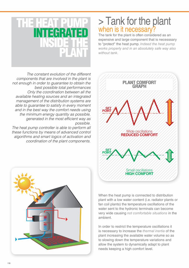
118
THE HEAT PUMPINTEGRATED
INSIDE THE PLANT
The constant evolution of the different
components that are involved in the plant is
not enough in order to guarantee to obtain the
best possible total performances
Only the coordination between all the
available heating sources and an integrated
management of the distribution systems are
able to guarantee to satisfy in every moment
and in the best way the comfort needs using
the minimum energy quantity as possible,
generated in the most efficient way as
possible.
The heat pump controller is able to perform all
these functions by means of advanced control
algorithms and smart logics of activation and
coordination of the plant components.
PLANT COMFORTGRAPH
Small oscillationsHIGH COMFORT
SETPOINT
Wide oscillationsREDUCED COMFORT
> Tank for the plantwhen is it necessary?The tank for the plant is often considered as an expensive and large component that is necesssary to "protect" the heat pump. Indeed the heat pump works properly and in an absolutely safe way also without tank.
When the heat pump is connected to distribution plant with a low water content (i.e. radiator plants or fan coil plants) the temperature oscillations of the water sent to the hydronic terminals can become very wide causing not comfortable situations in the ambient.
In order to restrict the temperature oscillations it is necessary to increase the thermal inertia of the plant increasing the available water volume so as to slowing down the temperature variations and allow the system to dynamically adapt to plant needs keeping a high comfort level.
SETPOINT
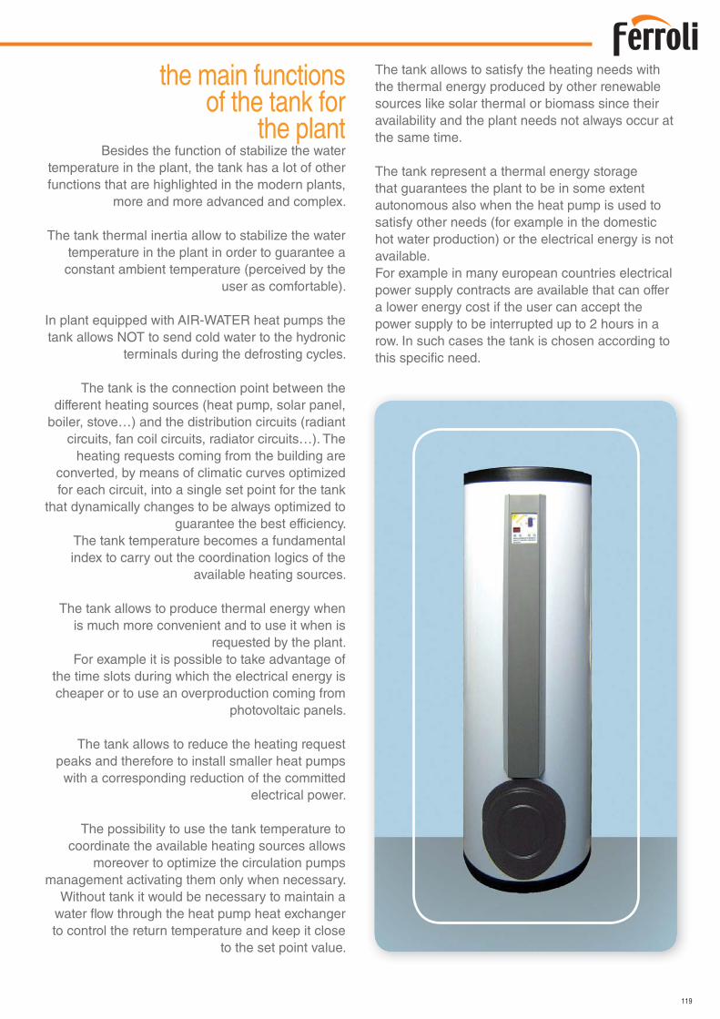
119
the main functionsof the tank for
the plantBesides the function of stabilize the water
temperature in the plant, the tank has a lot of other functions that are highlighted in the modern plants,
more and more advanced and complex.
The tank thermal inertia allow to stabilize the water temperature in the plant in order to guarantee a constant ambient temperature (perceived by the
user as comfortable).
In plant equipped with AIR-WATER heat pumps the tank allows NOT to send cold water to the hydronic
terminals during the defrosting cycles.
The tank is the connection point between the different heating sources (heat pump, solar panel,
boiler, stove…) and the distribution circuits (radiant circuits, fan coil circuits, radiator circuits…). The
heating requests coming from the building are converted, by means of climatic curves optimized for each circuit, into a single set point for the tank
that dynamically changes to be always optimized to guarantee the best efficiency.
The tank temperature becomes a fundamental index to carry out the coordination logics of the
available heating sources.
The tank allows to produce thermal energy when is much more convenient and to use it when is
requested by the plant.For example it is possible to take advantage of
the time slots during which the electrical energy is cheaper or to use an overproduction coming from
photovoltaic panels.
The tank allows to reduce the heating request peaks and therefore to install smaller heat pumps
with a corresponding reduction of the committed electrical power.
The possibility to use the tank temperature to coordinate the available heating sources allows
moreover to optimize the circulation pumps management activating them only when necessary.
Without tank it would be necessary to maintain a water flow through the heat pump heat exchanger to control the return temperature and keep it close
to the set point value.
The tank allows to satisfy the heating needs with the thermal energy produced by other renewable sources like solar thermal or biomass since their availability and the plant needs not always occur at the same time.
The tank represent a thermal energy storage that guarantees the plant to be in some extent autonomous also when the heat pump is used to satisfy other needs (for example in the domestic hot water production) or the electrical energy is not available.For example in many european countries electrical power supply contracts are available that can offer a lower energy cost if the user can accept the power supply to be interrupted up to 2 hours in a row. In such cases the tank is chosen according to this specific need.
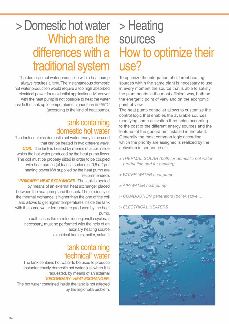
120
> HeatingsourcesHow to optimize their use?To optimize the integration of different heating sources within the same plant is necessary to use in every moment the source that is able to satisfy the plant needs in the most efficient way, both on the energetic point of view and on the economic point of view.The heat pump controller allows to customize the control logic that enables the available sources modifying some activation thresholds according to the cost of the different energy sources and the features of the generators installed in the plant.Generally the most common logic according which the priority are assigned is realized by the activation in sequence of :
> THERMAL SOLAR (both for domestic hot water production and for heating)
> WATER-WATER heat pump
> AIR-WATER heat pump
> COMBUSTION generators (boiler, stove...)
> ELECTRICAL HEATERS
> Domestic hot waterWhich are the
differences with a traditional system
The domestic hot water production with a heat pump always requires a tank. The instantaneous domestic
hot water production would require a too high absorbed electrical power for residential applications. Moreover with the heat pump is not possible to heat the water
inside the tank up to temperatures higher than 50-55°C (according to the kind of heat pump).
tank containingdomestic hot water
The tank contains domestic hot water ready to be used that can be heated in two different ways.
COIL The tank is heated by means of a coil inside which the hot water produced by the heat pump flows.The coil must be properly sized in order to be coupled
with heat pumps (at least a surface of 0,5 m2 per heating power kW supplied by the heat pump are
recommended)."PRIMARY" HEAT EXCHANGER The tank is heated
by means of an external heat exchanger placed between the heat pump and the tank. The efficiency of the thermal exchange is higher than the one of the coil
and allows to get higher temperatures inside the tank with the same water temperature produced by the heat
pump.In both cases the disinfection legionella cycles, if
necessary, must ne performed with the help of an auxiliary heating source
(electrical heaters, boiler, solar...)
tank containing"technical" water
The tank contains hot water to be used to produce instantaneously domestic hot water, just when it is
requested, by means of an external "SECONDARY" HEAT EXCHANGER.
The hot water contained inside the tank is not affected by the legionella problem.

121
>TECHNICALdatasheets
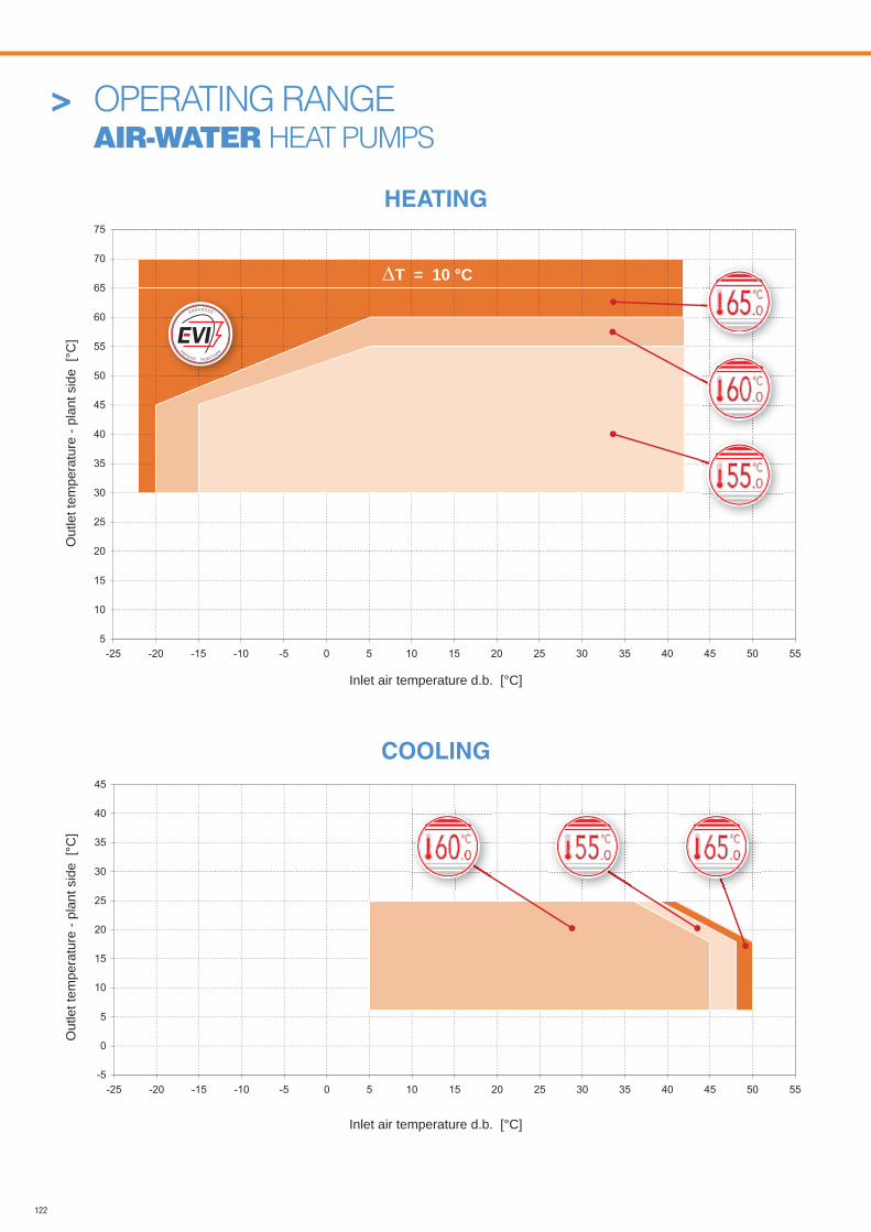
122
HEATING
> OPERATING RANGE AIR-WATER HEAT PUMPS
-5
0
5
10
15
20
25
30
35
40
45
-25 -20 -15 -10 -5 0 5 10 15 20 25 30 35 40 45 50 55
Inlet air temperature d.b. [°C]
Out
let t
empe
ratu
re -
plan
t sid
e [°
C]
Inlet air temperature d.b. [°C]
Out
let t
empe
ratu
re -
plan
t sid
e [°
C]
COOLING
5
10
15
20
25
30
35
40
45
50
55
60
65
70
75
-25 -20 -15 -10 -5 0 5 10 15 20 25 30 35 40 45 50 55
.055
.065
.055 .065
T = 10 °C
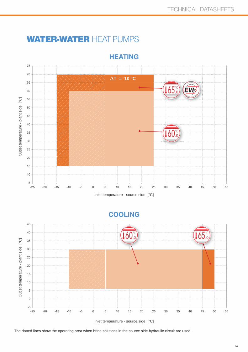
123
TECHNICAL DATASHEETS
-5
0
5
10
15
20
25
30
35
40
45
-25 -20 -15 -10 -5 0 5 10 15 20 25 30 35 40 45 50 55
Inlet temperature - source side [°C]
Out
let t
empe
ratu
re -
plan
t sid
e [°
C]
Inlet temperature - source side [°C]
Out
let t
empe
ratu
re -
plan
t sid
e [°
C]
WATER-WATER HEAT PUMPS
The dotted lines show the operating area when brine solutions in the source side hydraulic circuit are used.
HEATING
COOLING
5
10
15
20
25
30
35
40
45
50
55
60
65
70
75
-25 -20 -15 -10 -5 0 5 10 15 20 25 30 35 40 45 50 55
.065
.065
T = 10 °C
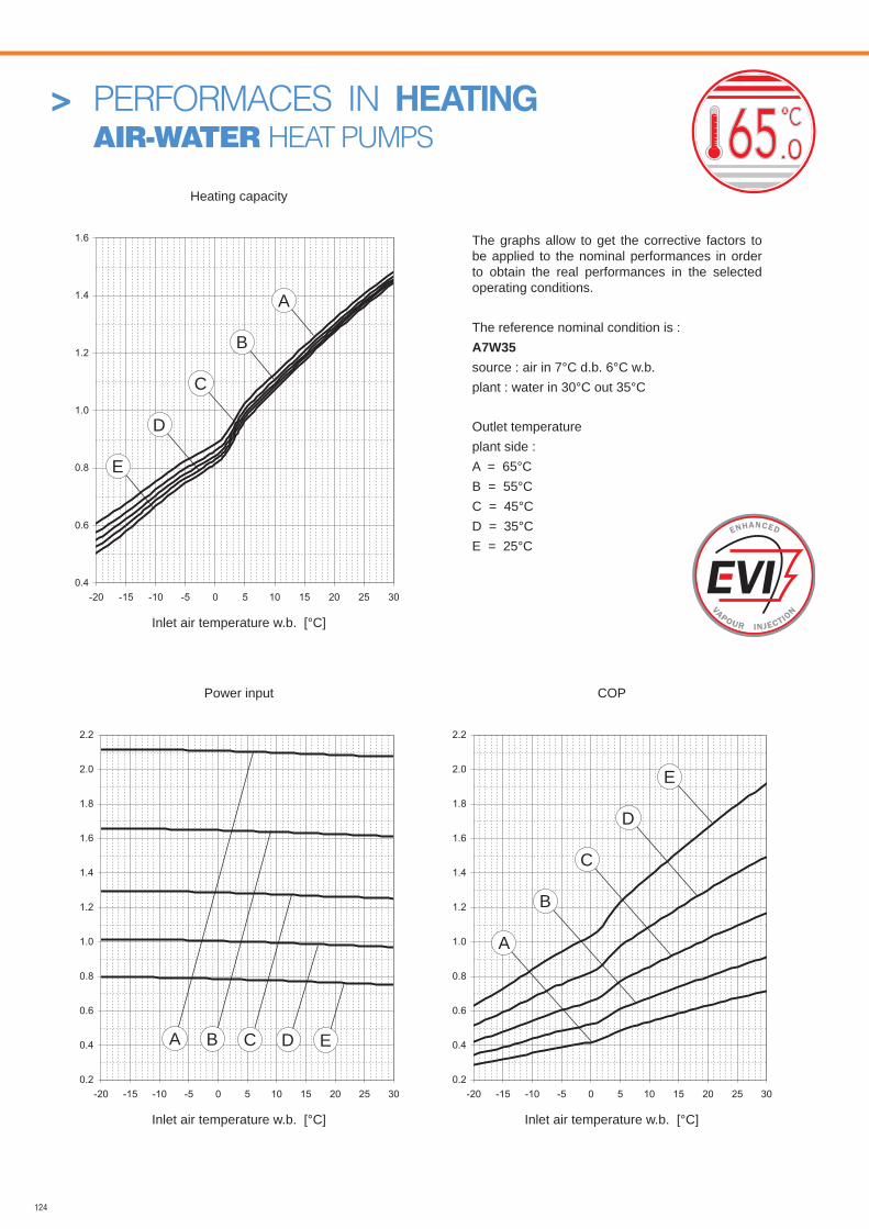
124
> PERFORMACES IN HEATING AIR-WATER HEAT PUMPS .065
The graphs allow to get the corrective factors to be applied to the nominal performances in order to obtain the real performances in the selected operating conditions.
The reference nominal condition is :A7W35source : air in 7°C d.b. 6°C w.b.plant : water in 30°C out 35°C
Outlet temperatureplant side :A = 65°CB = 55°CC = 45°CD = 35°CE = 25°C
Heating capacity
Inlet air temperature w.b. [°C]
Inlet air temperature w.b. [°C] Inlet air temperature w.b. [°C]
Power input COP
0.2
0.4
0.6
0.8
1.0
1.2
1.4
1.6
1.8
2.0
2.2
-20 -15 -10 -5 0 5 10 15 20 25 300.2
0.4
0.6
0.8
1.0
1.2
1.4
1.6
1.8
2.0
2.2
-20 -15 -10 -5 0 5 10 15 20 25 30
B
C
D
E
B C D E
0.4
0.6
0.8
1.0
1.2
1.4
1.6
-20 -15 -10 -5 0 5 10 15 20 25 30
E
D
C
B
A
A
A
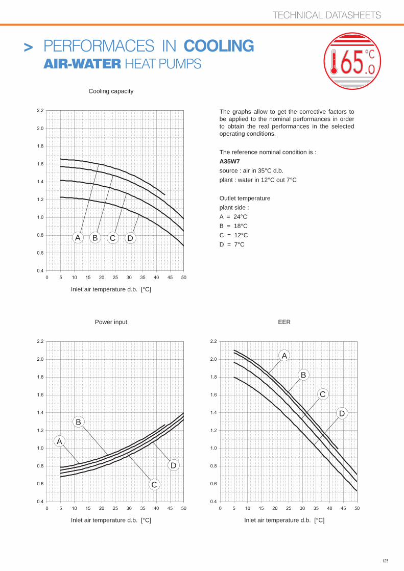
125
TECHNICAL DATASHEETS
> PERFORMACES IN COOLING AIR-WATER HEAT PUMPS .065
The graphs allow to get the corrective factors to be applied to the nominal performances in order to obtain the real performances in the selected operating conditions.
The reference nominal condition is :A35W7source : air in 35°C d.b.plant : water in 12°C out 7°C
Outlet temperatureplant side :A = 24°CB = 18°CC = 12°CD = 7°C
Cooling capacity
Inlet air temperature d.b. [°C]
Inlet air temperature d.b. [°C] Inlet air temperature d.b. [°C]
Power input EER
0.4
0.6
0.8
1.0
1.2
1.4
1.6
1.8
2.0
2.2
0 5 10 15 20 25 30 35 40 45 500.4
0.6
0.8
1.0
1.2
1.4
1.6
1.8
2.0
2.2
0 5 10 15 20 25 30 35 40 45 50
0.4
0.6
0.8
1.0
1.2
1.4
1.6
1.8
2.0
2.2
0 5 10 15 20 25 30 35 40 45 50
A B C D
A
B
C
D
A
B
C
D
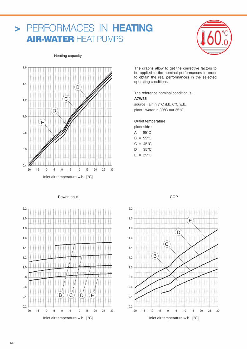
126
> PERFORMACES IN HEATING AIR-WATER HEAT PUMPS
The graphs allow to get the corrective factors to be applied to the nominal performances in order to obtain the real performances in the selected operating conditions.
The reference nominal condition is :A7W35source : air in 7°C d.b. 6°C w.b.plant : water in 30°C out 35°C
Outlet temperatureplant side :A = 65°CB = 55°CC = 45°CD = 35°CE = 25°C
Heating capacity
Inlet air temperature w.b. [°C]
Inlet air temperature w.b. [°C] Inlet air temperature w.b. [°C]
Power input COP
0.2
0.4
0.6
0.8
1.0
1.2
1.4
1.6
1.8
2.0
2.2
-20 -15 -10 -5 0 5 10 15 20 25 300.2
0.4
0.6
0.8
1.0
1.2
1.4
1.6
1.8
2.0
2.2
-20 -15 -10 -5 0 5 10 15 20 25 30
B
C
D
E
B C D E
0.4
0.6
0.8
1.0
1.2
1.4
1.6
-20 -15 -10 -5 0 5 10 15 20 25 30
E
D
C
B
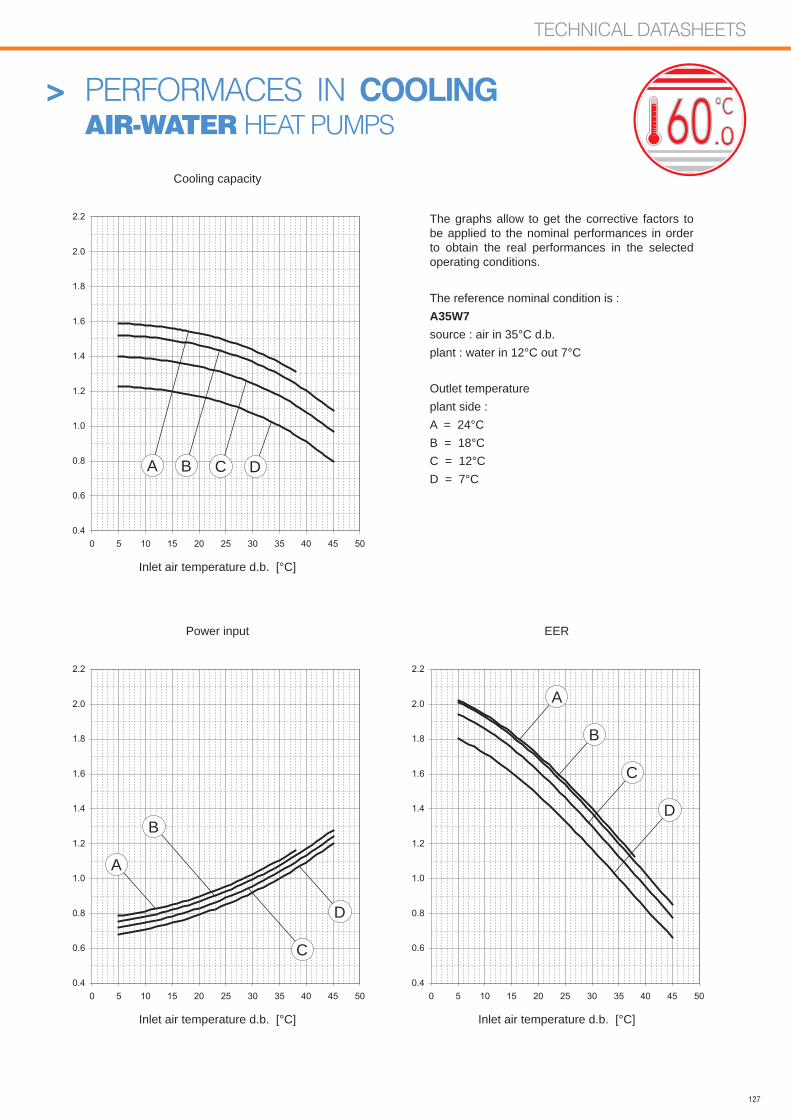
127
TECHNICAL DATASHEETS
> PERFORMACES IN COOLING AIR-WATER HEAT PUMPS
The graphs allow to get the corrective factors to be applied to the nominal performances in order to obtain the real performances in the selected operating conditions.
The reference nominal condition is :A35W7source : air in 35°C d.b.plant : water in 12°C out 7°C
Outlet temperatureplant side :A = 24°CB = 18°CC = 12°CD = 7°C
Cooling capacity
Inlet air temperature d.b. [°C]
Inlet air temperature d.b. [°C] Inlet air temperature d.b. [°C]
Power input EER
A B C D
A
B
C
D
A
B
C
D
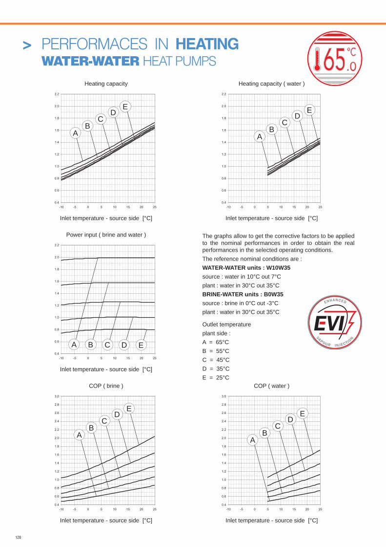
128
> PERFORMACES IN HEATING WATER-WATER HEAT PUMPS
Inlet temperature - source side [°C] Inlet temperature - source side [°C]
COP ( brine )
Inlet temperature - source side [°C] Inlet temperature - source side [°C]
COP ( water )
Power input ( brine and water )
Inlet temperature - source side [°C]
Heating capacity Heating capacity ( water )
The graphs allow to get the corrective factors to be applied to the nominal performances in order to obtain the real performances in the selected operating conditions.The reference nominal conditions are :WATER-WATER units : W10W35source : water in 10°C out 7°Cplant : water in 30°C out 35°CBRINE-WATER units : B0W35source : brine in 0°C out -3°Cplant : water in 30°C out 35°C
Outlet temperatureplant side :A = 65°CB = 55°CC = 45°CD = 35°CE = 25°C
.065
0.4
0.6
0.8
1.0
1.2
1.4
1.6
1.8
2.0
2.2
-10 -5 0 5 10 15 20 250.4
0.6
0.8
1.0
1.2
1.4
1.6
1.8
2.0
2.2
-10 -5 0 5 10 15 20 25
0.4
0.6
0.8
1.0
1.2
1.4
1.6
1.8
2.0
2.2
-10 -5 0 5 10 15 20 25
0.4
0.6
0.8
1.0
1.2
1.4
1.6
1.8
2.0
2.2
2.4
2.6
2.8
3.0
-10 -5 0 5 10 15 20 250.4
0.6
0.8
1.0
1.2
1.4
1.6
1.8
2.0
2.2
2.4
2.6
2.8
3.0
-10 -5 0 5 10 15 20 25
B C D EA
BC
DE
AB
CD
E
A
BC
DE
AB
CD
E
A
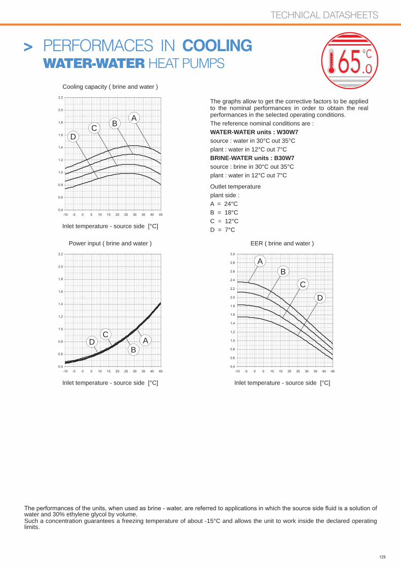
129
TECHNICAL DATASHEETS
> PERFORMACES IN COOLING WATER-WATER HEAT PUMPS
Cooling capacity ( brine and water )
Inlet temperature - source side [°C]
Inlet temperature - source side [°C] Inlet temperature - source side [°C]
Power input ( brine and water ) EER ( brine and water )
water and 30% ethylene glycol by volume.Such a concentration guarantees a freezing temperature of about -15°C and allows the unit to work inside the declared operating limits.
The graphs allow to get the corrective factors to be applied to the nominal performances in order to obtain the real performances in the selected operating conditions.The reference nominal conditions are :WATER-WATER units : W30W7source : water in 30°C out 35°Cplant : water in 12°C out 7°CBRINE-WATER units : B30W7source : brine in 30°C out 35°Cplant : water in 12°C out 7°C
Outlet temperatureplant side :A = 24°CB = 18°CC = 12°CD = 7°C
.065
A
A
B
B
C
C
D
D
ABC
D
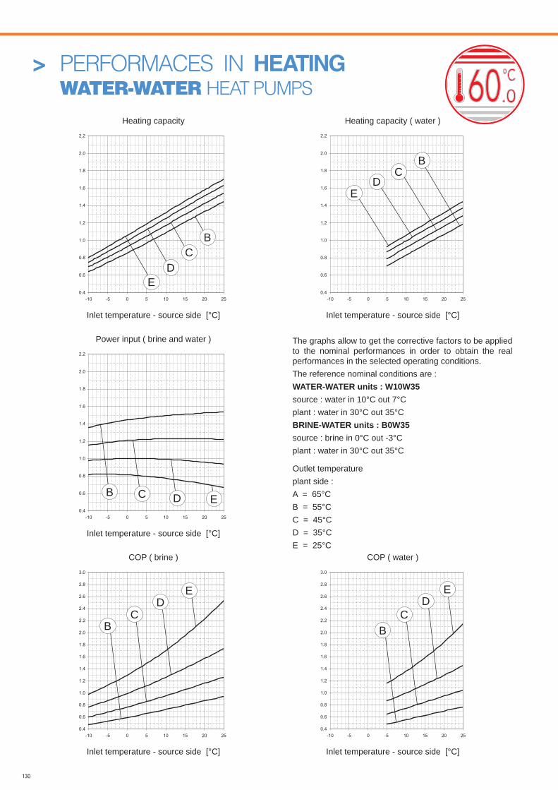
130
> PERFORMACES IN HEATING WATER-WATER HEAT PUMPS
Inlet temperature - source side [°C] Inlet temperature - source side [°C]
COP ( brine )
Inlet temperature - source side [°C] Inlet temperature - source side [°C]
COP ( water )
Power input ( brine and water )
Inlet temperature - source side [°C]
Heating capacity Heating capacity ( water )
The graphs allow to get the corrective factors to be applied to the nominal performances in order to obtain the real performances in the selected operating conditions.The reference nominal conditions are :WATER-WATER units : W10W35source : water in 10°C out 7°Cplant : water in 30°C out 35°CBRINE-WATER units : B0W35source : brine in 0°C out -3°Cplant : water in 30°C out 35°C
Outlet temperatureplant side :A = 65°CB = 55°CC = 45°CD = 35°CE = 25°C
B
B
B B
B
C
C
C C
C
D
D
D D
D
E
E
E E
E

131
TECHNICAL DATASHEETS
> PERFORMACES IN COOLING WATER-WATER HEAT PUMPS
Cooling capacity ( brine and water )
Inlet temperature - source side [°C]
Inlet temperature - source side [°C] Inlet temperature - source side [°C]
Power input ( brine and water ) EER ( brine and water )
water and 30% ethylene glycol by volume.Such a concentration guarantees a freezing temperature of about -15°C and allows the unit to work inside the declared operating limits.
The graphs allow to get the corrective factors to be applied to the nominal performances in order to obtain the real performances in the selected operating conditions.The reference nominal conditions are :WATER-WATER units : W30W7source : water in 30°C out 35°Cplant : water in 12°C out 7°CBRINE-WATER units : B30W7source : brine in 30°C out 35°Cplant : water in 12°C out 7°C
Outlet temperatureplant side :A = 24°CB = 18°CC = 12°CD = 7°C
A
A
A
B
B
B
C
C
C
D
D
D
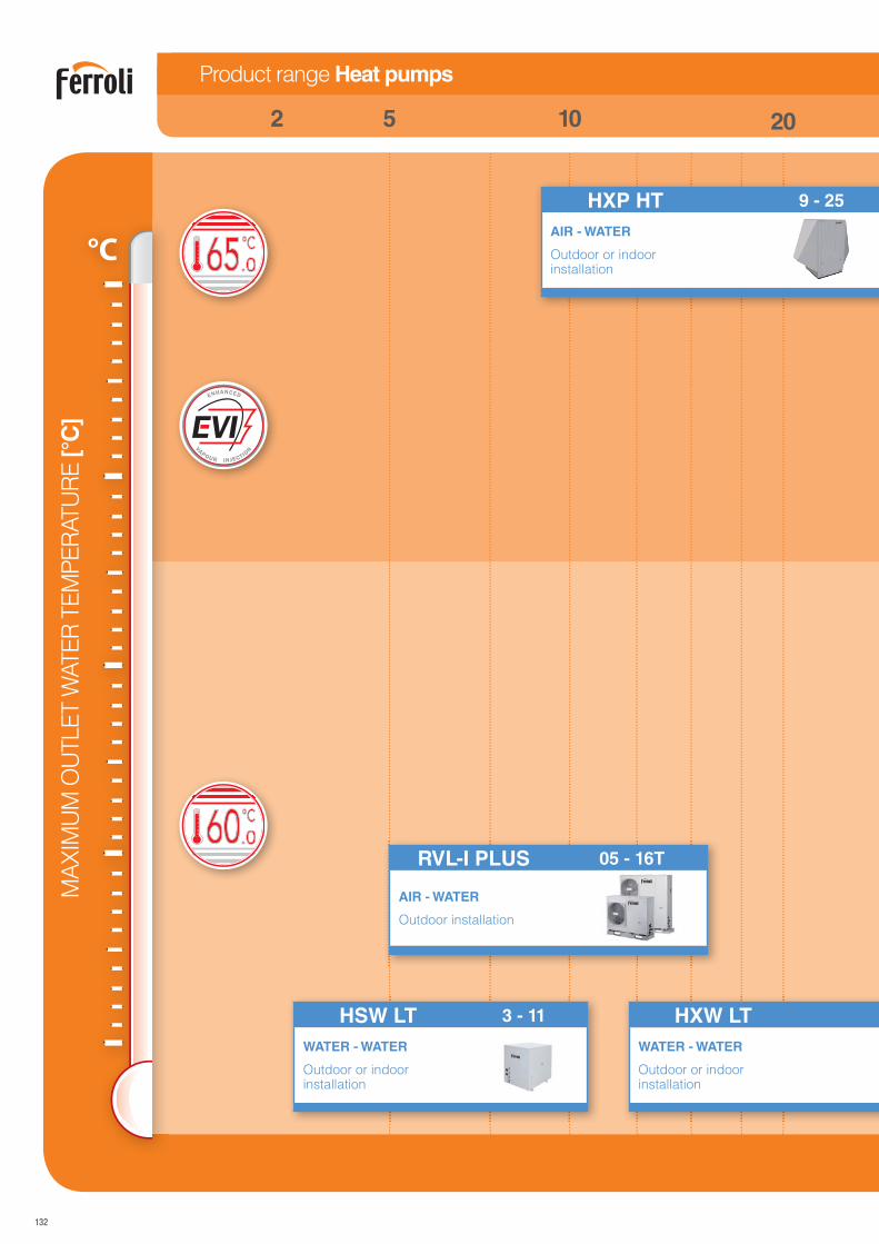
132
°C .065
HSW LT 3 - 11
WATER - WATER
Outdoor or indoor installation
HXW LT
WATER - WATER
Outdoor or indoor installation
HXP HT 9 - 25
AIR - WATER
Outdoor or indoor installation
MA
XIM
UM
OU
TLE
T W
ATE
R T
EM
PE
RATU
RE
[°C
]
201052
Product range Heat pumps
RVL-I PLUS 05 - 16T
AIR - WATER
Outdoor installation
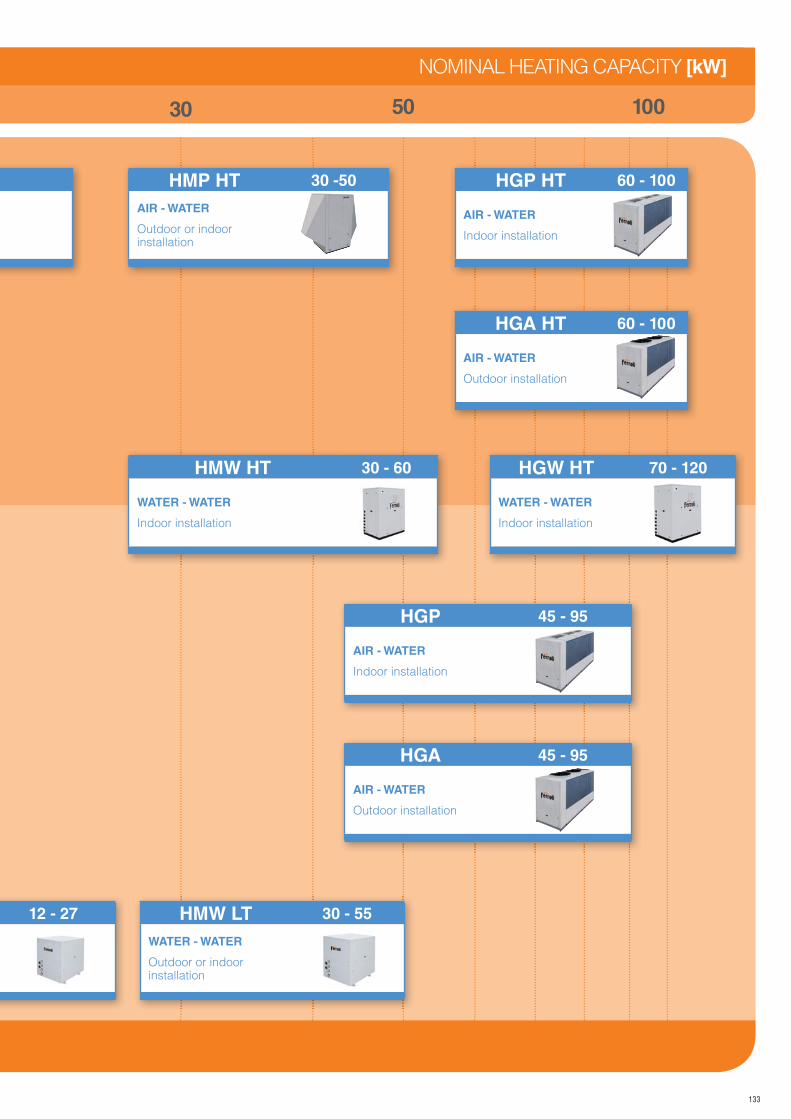
133
HGP 45 - 95
AIR - WATER
Indoor installation
HMP HT 30 -50
AIR - WATER
Outdoor or indoor installation
HGP HT 60 - 100
AIR - WATER
Indoor installation
HGA HT 60 - 100
AIR - WATER
Outdoor installation
HMW LT 30 - 55
WATER - WATER
Outdoor or indoor installation
12 - 27
HGA 45 - 95
AIR - WATER
Outdoor installation
1005030
NOMINAL HEATING CAPACITY [kW]
HGW HT 70 - 120
WATER - WATER
Indoor installation
HMW HT 30 - 60
WATER - WATER
Indoor installation
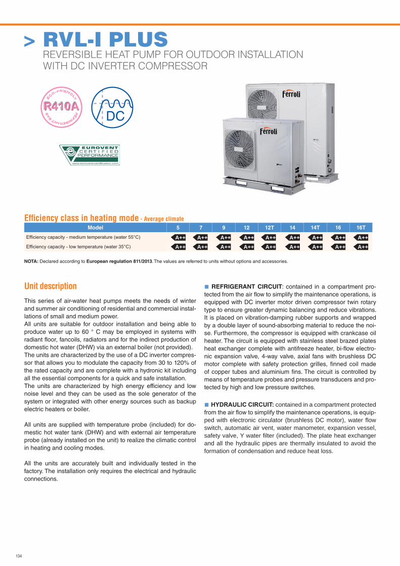
134
Unit description
This series of air-water heat pumps meets the needs of winter and summer air conditioning of residential and commercial instal-lations of small and medium power.All units are suitable for outdoor installation and being able to produce water up to 60 ° C may be employed in systems with radiant floor, fancoils, radiators and for the indirect production of domestic hot water (DHW) via an external boiler (not provided).The units are characterized by the use of a DC inverter compres-sor that allows you to modulate the capacity from 30 to 120% of the rated capacity and are complete with a hydronic kit including all the essential components for a quick and safe installation.The units are characterized by high energy efficiency and low noise level and they can be used as the sole generator of the system or integrated with other energy sources such as backup electric heaters or boiler.
All units are supplied with temperature probe (included) for do-mestic hot water tank (DHW) and with external air temperature probe (already installed on the unit) to realize the climatic control in heating and cooling modes.
All the units are accurately built and individually tested in the factory. The installation only requires the electrical and hydraulic connections.
REFRIGERANT CIRCUIT: contained in a compartment pro-tected from the air fl ow to simplify the maintenance operations, is equipped with DC inverter motor driven compressor twin rotary type to ensure greater dynamic balancing and reduce vibrations. It is placed on vibration-damping rubber supports and wrapped by a double layer of sound-absorbing material to reduce the noi-se. Furthermore, the compressor is equipped with crankcase oil heater. The circuit is equipped with stainless steel brazed plates heat exchanger complete with antifreeze heater, bi-fl ow electro-nic expansion valve, 4-way valve, axial fans with brushless DC motor complete with safety protection grilles, fi nned coil made of copper tubes and aluminium fi ns. The circuit is controlled by means of temperature probes and pressure transducers and pro-tected by high and low pressure switches.
contained in a compartment protected
ped with electronic circulator (brushless DC motor), water flow switch, automatic air vent, water manometer, expansion vessel, safety valve, Y water filter (included). The plate heat exchanger and all the hydraulic pipes are thermally insulated to avoid the formation of condensation and reduce heat loss.
Effi ciency class in heating mode - Average climate
Model 5 7 9 12 12T 14 14T 16 16T
NOTA: Declared according to European regulation 811/2013. The values are referred to units without options and accessories.
A++ A++ A++ A++ A++ A++ A++ A++ A++A++ A++ A++ A++ A++ A++ A++ A++ A++
> RVL-I PLUS REVERSIBLE HEAT PUMP FOR OUTDOOR INSTALLATION
WITH DC INVERTER COMPRESSOR
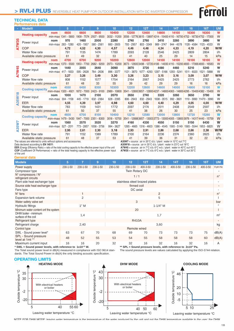
135
35
-2
-20
5 40 60
30
55
TECHNICAL DATA
3043
-2
-20
5 5040 60
OPERATING LIMITS
Leaving water temperature °CLeaving water temperature °C
With electrical heaters or bolier
With electrical heaters or bolier
Out
side
tem
pera
ture
°C
Out
side
tem
pera
ture
°C
DHW MODEHEATING MODE
Leaving water temperature °C
Out
side
tem
pera
ture
°C
20
46
-5
5 10 25
10
COOLING MODE
NOTE FOR DHW MODE: leaving water temperature is the temperature of the water produced by the unit and not the DHW temperature available to the user; the DHW
* SWL = Sound power levels, with reference to 1x10-12 W.The Total sound power level in dB(A) measured in compliance with ISO 9614 stan-dards. The Total Sound Power in db(A) the only binding acoustic specification.
** SPL = Sound pressure levels, with reference to 2x10⁻⁵ Pa.The sound pressure levels are values calculated by applying the ISO-3744 relation.
The values are referred to units without options and accessories. Data declared according to EN 14511:EER (Energy Efficiency Ratio) = ratio of the total cooling capacity to the effective power input of the unitCOP (Coefficient Of Performance) = ratio of the total heating capacity to the effective power input of the unit
A35W7 = source : air in 35°C d.b. / plant : water in 12°C out 7°CA35W18 = source : air in 35°C d.b. / plant : water in 23°C out 18°CA7W45 = source : air in 7°C d.b. 6°C w.b. / plant : water in 40°C out 45°CA7W35 = source : air in 7°C d.b. 6°C w.b. / plant : water in 30°C out 35°C
Performances data
- Modelli 5 7 9 10 12 12T 14 14T 16 16T UM
A7
W3
5
Heating capacitynom 4600 6600 8600 10400 12200 12400 14800 14100 16300 16300 W
min-max 1341 - 5800 1909 - 7574 2507 - 9500 3032 - 11200 3556 - 12776 3615 - 13697 4314 - 15400 4110 - 16700 4752 - 167304752 - 17000 W
Power inputnom 970 1460 2000 2280 2740 2760 3410 3260 3890 3880 W
min-max 283 - 1280 420 - 1957 580 - 2561 660 - 2605 793 - 2957 803 - 3349 989 - 3747 944 - 4578 1128 - 4584 1125 - 4533 WCOP 4,72 4,52 4,30 4,57 4,46 4,48 4,34 4,33 4,19 4,20 W/W
Water fl ow rate 791 1135 1474 1789 2093 2128 2546 2425 2809 2804 l/hAvailable static pressure 61 49 32 53 41 40 25 29 14 15 kPa
A7
W4
5
Heating capacitynom 4700 6700 9200 10200 12600 12000 14100 14100 16100 16100 W
min-max 1370 - 5500 1953 - 7700 2682 - 9200 2973 - 10200 3673 - 126003498 - 12720 4106 - 14930 4110 - 15200 4693 - 170664693 - 16583 W
Power inputnom 1440 2055 2640 3090 3870 3720 4480 4460 5210 5240 W
min-max 417 - 1833 595 - 2628 764 - 2636 896 - 3377 1121 - 3870 1077 - 4293 1297 - 5166 1293 - 5241 1511 - 6020 1521 - 5888 WCOP 3,27 3,26 3,49 3,30 3,26 3,23 3,15 3,16 3,09 3,07 W/W
Water fl ow rate 808 1152 1577 1754 2164 2067 2425 2425 2773 2762 l/hAvailable static pressure 61 48 33 55 39 42 29 29 16 16 kPa
A3
5W
18
Cooling capacitynom 4550 6450 8350 10300 12200 12600 14600 14000 14800 15100 W
min-max 1320 - 4921 1872 - 7000 2423 - 9100 2989 - 10800 3541 - 128003657 - 128004237 - 148004063 - 148004295 - 154004382 - 15400 W
Power inputnom 1000 1470 2100 2070 2650 2740 3320 3260 3650 3780 W
min-max 304 - 1158 445 - 1719 632 - 2364 628 - 2395 806 - 2943 832 - 2943 1008 - 3515 992 - 3601 1110 - 3990 11470 - 3990 WEER 4,55 4,39 3,97 4,98 4,60 4,60 4,40 4,29 4,05 4,00 W/W
Water fl ow rate 783 1109 1431 1772 2097 2174 2511 2408 2549 2597 l/hAvailable static pressure 61 50 37 55 41 38 26 30 25 23 kPa
A35
W7
Cooling capacitynom 4600 6700 8100 10400 12210 12580 13000 13800 13720 15260 W
min-max 1479 - 5430 1947 - 7000 2351 - 8300 3018 - 10700 3541 - 126883657 - 130033773 - 130004005 - 13800 3976 - 14317 4440 - 15759 W
Power inputnom 1560 2570 3520 3270 4160 4330 4550 5150 5150 6430 W
min-max 527 - 2011 773 - 2857 1058 - 3756 994 - 3627 1265 - 4665 1316 - 4603 1386 - 4545 1565 - 5149 1565 - 5544 1953 - 6820 WEER 2,95 2,61 2,30 3,18 2,93 2,91 2,86 2,68 2,66 2,38 W/WWater fl ow rate 791 1152 1389 1789 2100 2164 2236 2374 2360 2625 l/hAvailable static pressure 61 48 37 53 41 39 36 31 32 22 kPa
General data
Models 5 7 9 10 12 12T 14 14T 16 16T UM
Power supply 230-1-50 230-1-50 230-1-50 230-1-50 230-1-50 400-3-50 230-1-50 400-3-50 230-1-50 400-3-50 V-ph-Hz
Compressor type Twin Rotary DC -N° compressors / N° refrigerant circuits 1 / 1 n°
Plant side heat exchanger type stainless steel brazed plates -Source side heat exchanger type fi nned coil -Fans type DC axial -N° fans 1 2 n°Expansion tank volume 2 5 lWater safety valve set 3 barHydraulic fi ttings 1" M 1-1/4" M “Minimum water content onf the system 20 lDHW boiler - minimum surface of the coil 1,4 1,7 m2
Refrigerant type R410A -Refrigerant charge 2,40 3,60 kgControl type Remote wired -SWL - Sound power level* 63 67 70 68 69 70 73 73 73 75 dB(A)SPL - Sound pressure level at 1mt ** 48 52 55 53 54 55 58 58 58 60 dB(A)
Maximum current input 16 16 20 32 32 16 32 16 32 16 A
> RVL-I PLUS REVERSIBLE HEAT PUMP FOR OUTDOOR INSTALLATION WITH DC INVERTER COMPRESSOR
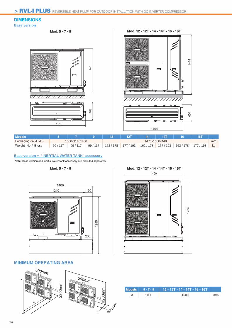
136
402
1210
945
1404
1414
404
DIMENSIONS
Base version
Base version + “INERTIAL WATER TANK” accessory
MINIMUM OPERATING AREA
Mod. 12 - 12T - 14 - 14T - 16 - 16T
Mod. 12 - 12T - 14 - 14T - 16 - 16T
Mod. 5 - 7 - 9
Mod. 5 - 7 - 9
500mm
≥200
mm
500mm
≥200
mm
≥300
mm
Models 5 - 7 - 9 12 - 12T - 14 - 14T - 16 - 16T
A 1000 1500 mm
Models 5 7 9 12 12T 14 14T 16 16T
Packaging (W×H×D) 1500x1140x450 1475x1580x440 mmWeight Net \ Gross 99 / 117 99 / 117 99 / 117 162 / 178 177 / 193 162 / 178 177 / 193 162 / 178 177 / 193 kg
Note: Base version and inertial water tank accessory are provided separately.
1400
1724
1255
1210 190
1400
238
> RVL-I PLUS REVERSIBLE HEAT PUMP FOR OUTDOOR INSTALLATION WITH DC INVERTER COMPRESSOR
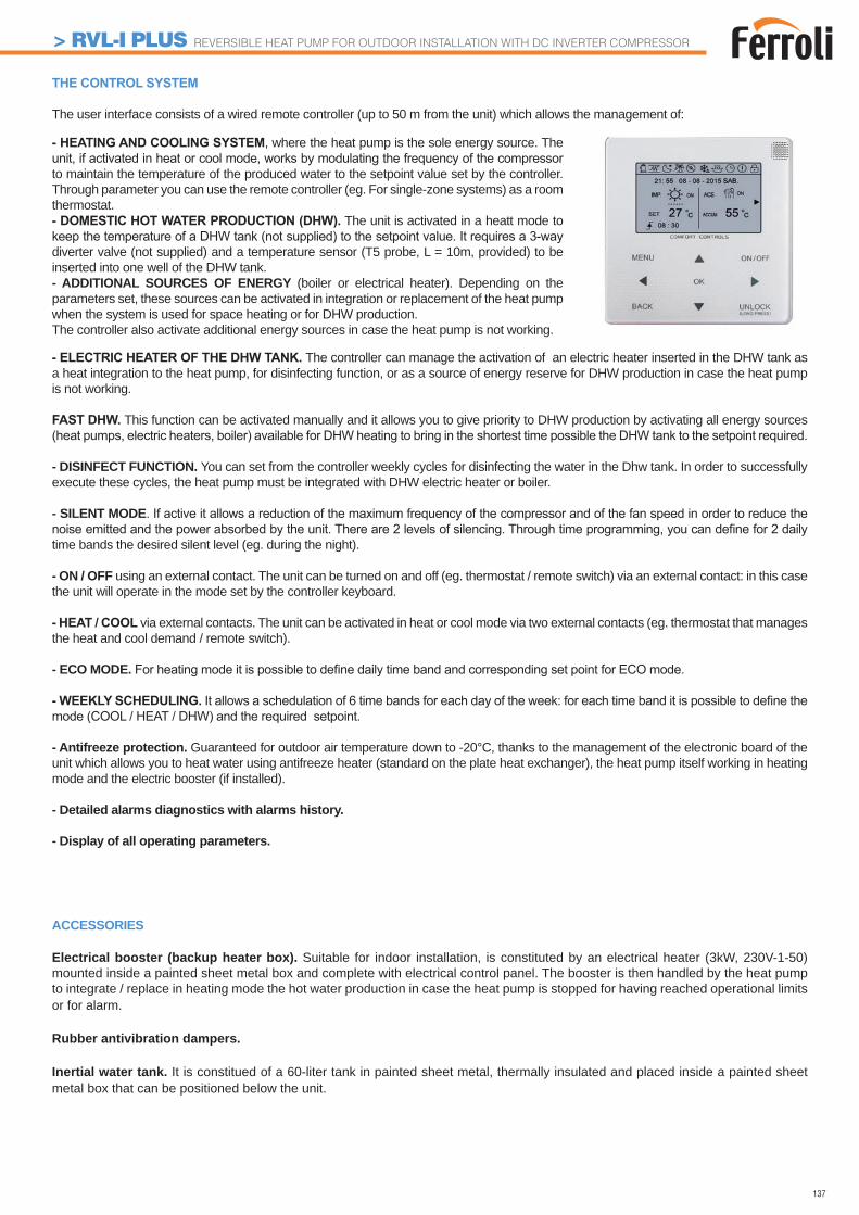
137
The user interface consists of a wired remote controller (up to 50 m from the unit) which allows the management of:
, where the heat pump is the sole energy source. The
to maintain the temperature of the produced water to the setpoint value set by the controller. Through parameter you can use the remote controller (eg. For single-zone systems) as a room thermostat.
The unit is activated in a heatt mode to
diverter valve (not supplied) and a temperature sensor (T5 probe, L = 10m, provided) to be inserted into one well of the DHW tank.- ADDITIONAL SOURCES OF ENERGY (boiler or electrical heater). Depending on the parameters set, these sources can be activated in integration or replacement of the heat pump when the system is used for space heating or for DHW production.The controller also activate additional energy sources in case the heat pump is not working.
The controller can manage the activation of an electric heater inserted in the DHW tank as a heat integration to the heat pump, for disinfecting function, or as a source of energy reserve for DHW production in case the heat pump is not working.
This function can be activated manually and it allows you to give priority to DHW production by activating all energy sources
- DISINFECT FUNCTION. You can set from the controller weekly cycles for disinfecting the water in the Dhw tank. In order to successfully execute these cycles, the heat pump must be integrated with DHW electric heater or boiler.
- SILENT MODE
time bands the desired silent level (eg. during the night).
- ON / OFF using an external contact. The unit can be turned on and off (eg. thermostat / remote switch) via an external contact: in this case the unit will operate in the mode set by the controller keyboard.
via external contacts. The unit can be activated in heat or cool mode via two external contacts (eg. thermostat that manages the heat and cool demand / remote switch).
- ECO MODE.
- Antifreeze protection. Guaranteed for outdoor air temperature down to -20°C, thanks to the management of the electronic board of the unit which allows you to heat water using antifreeze heater (standard on the plate heat exchanger), the heat pump itself working in heating mode and the electric booster (if installed).
- Detailed alarms diagnostics with alarms history.
- Display of all operating parameters.
ACCESSORIES
Electrical booster (backup heater box). Suitable for indoor installation, is constituted by an electrical heater (3kW, 230V-1-50) mounted inside a painted sheet metal box and complete with electrical control panel. The booster is then handled by the heat pump to integrate / replace in heating mode the hot water production in case the heat pump is stopped for having reached operational limits or for alarm.
Rubber antivibration dampers.
Inertial water tank. It is constitued of a 60-liter tank in painted sheet metal, thermally insulated and placed inside a painted sheet metal box that can be positioned below the unit.
> RVL-I PLUS REVERSIBLE HEAT PUMP FOR OUTDOOR INSTALLATION WITH DC INVERTER COMPRESSOR
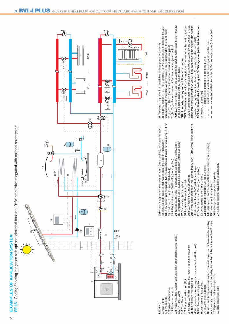
138
25
FCU
1
FHL1
FHLn
MnM1
......
.
......
.FC
Un
1
1.41.5
67
255
1.1
33
1.31.6 1.
2
4
MM
13
1818
C
Mn
1.7
8
1021
23
20a
M20
b
19
M
R
TWR
M1T1
_c
T1_h
Tn_c
Tn_h
2927
13.1
1424
26
2217
11
LEG
END
1 H
eat p
ump
1.1
Man
omet
er1.
2 W
ater
saf
ety
valv
e1.
3 E
xpan
sion
Ves
sel
1.4
Pla
te H
eat E
xcha
nger
(com
plet
e w
ith a
ntifr
eeze
ele
ctric
hea
ter)
1.5
Air
Pur
ge V
alve
1.6
Flow
Sw
itch
1.7
Pum
p in
side
the
unit
(P_i
)2 3
Shu
t-off
valv
e (n
ot s
uppl
ied)
4 W
ired
rem
ote
cont
rol (
supp
lied
as s
tand
ard
with
the
unit)
5 Fl
exib
le jo
int (
not s
uppl
ied)
6 D
rain
Val
ve (n
ot s
uppl
ied)
7 Fi
ll Va
lve
(not
sup
plie
d)8 or
if th
e sy
stem
wat
er c
onte
nt (e
xclu
ding
the
cont
ent o
f the
uni
t) is
less
than
20
liters
10 E
xpan
sion
tank
(not
sup
plie
d)11
Sol
ar e
xpan
sion
tank
12 H
ydra
ulic
sep
arat
or a
nd b
oost
er p
ump
(not
sup
plie
d), e
valu
ate
the
need
fo
r ins
talla
tion
in c
ase
of h
igh
wat
er p
ress
ure
drop
in th
e sy
stem
.13
DH
W b
oile
r (no
t sup
plie
d), M
inim
um s
urfa
ce o
f the
coi
l for
hea
t pum
p (1
,4 m
2 fo
r mod
. 5-7
, 1,7
m2 f
or m
od. 1
0-14
-14T
)13
.1 E
lect
rical
Hea
ter D
HW
boi
ler (
not s
uppl
ied)
14 T
empe
ratu
re p
robe
T5
(sup
plie
d, m
ount
ing
by th
e in
stal
ler)
15 T
empe
ratu
re p
robe
(ava
ilabl
e as
acc
esso
ry o
f the
gas
boi
ler)
17 C
heck
-val
ve (n
ot s
uppl
ied)
18 B
ypas
s va
lve
(not
sup
plie
d)19
3-w
ay v
alve
SV
1 (n
ot s
uppl
ied)
20a
2-w
ay v
alve
(not
sup
plie
d), c
ontro
lled
by S
V2
- 20b
2-w
ay v
alve
(not
sup
-pl
ied)
, con
trolle
d by
SV
2 w
ith d
enie
d lo
gic
21 D
HW
Exp
ansi
on V
esse
l (no
t sup
plie
d)22
DH
W s
afet
y va
lve
(not
sup
plie
d)
23 T
herm
osta
tic m
ixin
g va
lve(
not s
uppl
ied)
24 S
olar
sys
tem
con
trol b
ox w
ith it
s ow
n pr
obes
(not
sup
plie
d)25
Sol
ar p
anel
(not
sup
plie
d)26
Sol
ar s
yste
m p
ump
(not
sup
plie
d)27
Ele
ctric
al B
oost
er (a
vaila
ble
as a
cces
sory
)
28 T
empe
ratu
re p
robe
T1B
(ava
ilabl
e as
hea
t pum
p ac
cess
ory)
29 E
xter
nal p
ump
(P_o
), (n
ot s
uppl
ied)
, to
eval
uate
pos
sibl
e ne
ed fo
r ins
talla
-tio
n ac
cord
ing
to th
e pl
ant w
ater
pre
ssur
e dr
op, m
anag
ed b
y th
e he
at p
ump.
T1_c
- Tn
_c R
oom
ther
mos
tat f
or c
ool d
eman
d (n
ot s
uppl
ied)
T1_h
- Tn
_h R
oom
ther
mos
tat f
or h
eat d
eman
d (n
ot s
uppl
ied)
FCU
1...
n
TWR
Tow
el w
ater
radi
ator
for b
ath
inte
grat
ion:
if c
onne
cted
to th
e he
atin
g sy
stem
it
MU
ST b
e iIn
tegr
ated
with
ele
ctric
al h
eate
r (R
) act
ivat
ed b
y th
e co
ntro
l (C
) tha
t
is g
rant
ed o
nly
by th
e el
ectri
cal h
eate
r (R
) act
ivat
ed v
ia th
e co
ntro
l (C
)
for h
eatin
g on
ly ve
rsio
ns)
e
lect
rical
con
nect
ions
to th
e he
at p
ump
e
lect
rical
con
nect
ions
to th
e so
lar s
yste
m c
ontro
l box
c
onne
ctio
n to
the
boile
r of t
he D
HW
boi
ler w
ater
pro
be (n
ot s
uppl
ied)
EX
AM
PL
ES
OF
AP
PL
ICA
TIO
N S
YS
TE
MF
E 1
S -
Coo
ling
/ hea
ting
inte
grat
ed w
ith o
ptio
nal e
lect
rical
boo
ster
/ D
HW
pro
duct
ion
inte
grat
ed w
ith o
ptio
nal s
olar
sys
tem
> RVL-I PLUS REVERSIBLE HEAT PUMP FOR OUTDOOR INSTALLATION WITH DC INVERTER COMPRESSOR
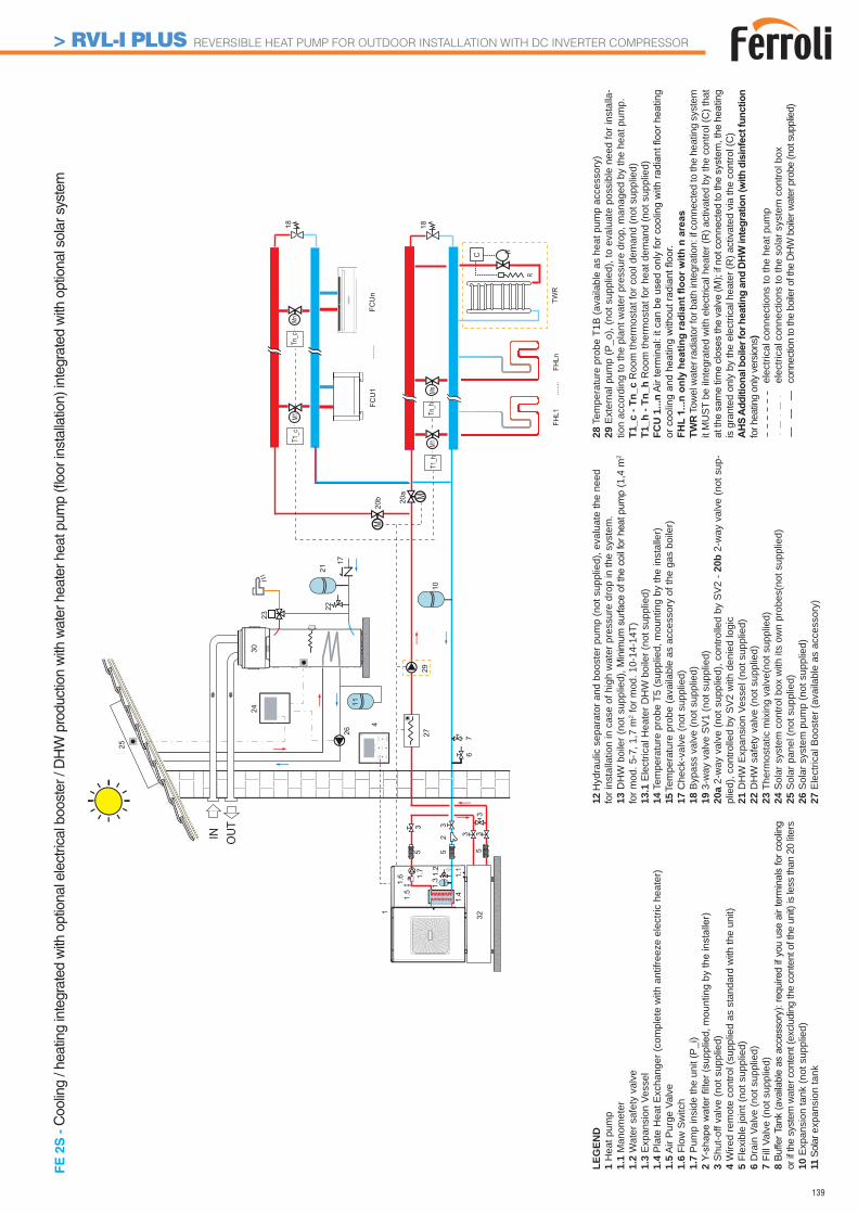
139
25
FCU
1
FHL1
FHLn
MnM1
......
.
......
.FC
Un
1
1.41.5
67
25 55
1.1
3
3 33
3
1.31.6 1.
2
4
M1818
C
Mn
1.7
10
23
20a
M20
b
M
R
TWR
M1T1
_c
T1_h
Tn_c
Tn_h
29
IN OUT
2430
26 27
17
2122
32
11
FE
2S
- C
oolin
g / h
eatin
g in
tegr
ated
with
opt
iona
l ele
ctric
al b
oost
er /
DH
W p
rodu
ctio
n w
ith w
ater
hea
ter h
eat p
ump
(fl oo
r ins
talla
tion)
inte
grat
ed w
ith o
ptio
nal s
olar
sys
tem
LEG
END
1 H
eat p
ump
1.1
Man
omet
er1.
2 W
ater
saf
ety
valv
e1.
3 E
xpan
sion
Ves
sel
1.4
Pla
te H
eat E
xcha
nger
(com
plet
e w
ith a
ntifr
eeze
ele
ctric
hea
ter)
1.5
Air
Pur
ge V
alve
1.6
Flow
Sw
itch
1.7
Pum
p in
side
the
unit
(P_i
)2 3
Shu
t-off
valv
e (n
ot s
uppl
ied)
4 W
ired
rem
ote
cont
rol (
supp
lied
as s
tand
ard
with
the
unit)
5 Fl
exib
le jo
int (
not s
uppl
ied)
6 D
rain
Val
ve (n
ot s
uppl
ied)
7 Fi
ll Va
lve
(not
sup
plie
d)8 or
if th
e sy
stem
wat
er c
onte
nt (e
xclu
ding
the
cont
ent o
f the
uni
t) is
less
than
20
liters
10 E
xpan
sion
tank
(not
sup
plie
d)11
Sol
ar e
xpan
sion
tank
12 H
ydra
ulic
sep
arat
or a
nd b
oost
er p
ump
(not
sup
plie
d), e
valu
ate
the
need
fo
r ins
talla
tion
in c
ase
of h
igh
wat
er p
ress
ure
drop
in th
e sy
stem
.13
DH
W b
oile
r (no
t sup
plie
d), M
inim
um s
urfa
ce o
f the
coi
l for
hea
t pum
p (1
,4 m
2 fo
r mod
. 5-7
, 1,7
m2 f
or m
od. 1
0-14
-14T
)13
.1 E
lect
rical
Hea
ter D
HW
boi
ler (
not s
uppl
ied)
14 T
empe
ratu
re p
robe
T5
(sup
plie
d, m
ount
ing
by th
e in
stal
ler)
15 T
empe
ratu
re p
robe
(ava
ilabl
e as
acc
esso
ry o
f the
gas
boi
ler)
17 C
heck
-val
ve (n
ot s
uppl
ied)
18 B
ypas
s va
lve
(not
sup
plie
d)19
3-w
ay v
alve
SV
1 (n
ot s
uppl
ied)
20a
2-w
ay v
alve
(not
sup
plie
d), c
ontro
lled
by S
V2
- 20b
2-w
ay v
alve
(not
sup
-pl
ied)
, con
trolle
d by
SV
2 w
ith d
enie
d lo
gic
21 D
HW
Exp
ansi
on V
esse
l (no
t sup
plie
d)22
DH
W s
afet
y va
lve
(not
sup
plie
d)
23 T
herm
osta
tic m
ixin
g va
lve(
not s
uppl
ied)
24 S
olar
sys
tem
con
trol b
ox w
ith it
s ow
n pr
obes
(not
sup
plie
d)25
Sol
ar p
anel
(not
sup
plie
d)26
Sol
ar s
yste
m p
ump
(not
sup
plie
d)27
Ele
ctric
al B
oost
er (a
vaila
ble
as a
cces
sory
)
28 T
empe
ratu
re p
robe
T1B
(ava
ilabl
e as
hea
t pum
p ac
cess
ory)
29 E
xter
nal p
ump
(P_o
), (n
ot s
uppl
ied)
, to
eval
uate
pos
sibl
e ne
ed fo
r ins
talla
-tio
n ac
cord
ing
to th
e pl
ant w
ater
pre
ssur
e dr
op, m
anag
ed b
y th
e he
at p
ump.
T1_c
- Tn
_c R
oom
ther
mos
tat f
or c
ool d
eman
d (n
ot s
uppl
ied)
T1_h
- Tn
_h R
oom
ther
mos
tat f
or h
eat d
eman
d (n
ot s
uppl
ied)
FCU
1...
n
TWR
Tow
el w
ater
radi
ator
for b
ath
inte
grat
ion:
if c
onne
cted
to th
e he
atin
g sy
stem
it
MU
ST b
e iIn
tegr
ated
with
ele
ctric
al h
eate
r (R
) act
ivat
ed b
y th
e co
ntro
l (C
) tha
t
is g
rant
ed o
nly
by th
e el
ectri
cal h
eate
r (R
) act
ivat
ed v
ia th
e co
ntro
l (C
)
for h
eatin
g on
ly ve
rsio
ns)
e
lect
rical
con
nect
ions
to th
e he
at p
ump
e
lect
rical
con
nect
ions
to th
e so
lar s
yste
m c
ontro
l box
c
onne
ctio
n to
the
boile
r of t
he D
HW
boi
ler w
ater
pro
be (n
ot s
uppl
ied)
> RVL-I PLUS REVERSIBLE HEAT PUMP FOR OUTDOOR INSTALLATION WITH DC INVERTER COMPRESSOR
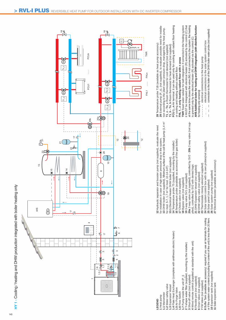
140
FCU
1
FHL1
FHLn
MnM1
......
.
......
.FC
Un
1
1.41.5
67
255
1.1
33
1.31.6 1.
2
4
MM
13
1818
C
Mn
1.7
10
12
29
12
22
23
20a
M20
b
19
M
R
TWR
M1T1
_c
T1_h
Tn_c
Tn_h
AHS
1728
1415
21
8
1717
HY
1 -
Coo
ling
/ hea
ting
and
DH
W p
rodu
ctio
n in
tegr
ated
with
boi
ler h
eatin
g on
ly
LEG
END
1 H
eat p
ump
1.1
Man
omet
er1.
2 W
ater
saf
ety
valv
e1.
3 E
xpan
sion
Ves
sel
1.4
Pla
te H
eat E
xcha
nger
(com
plet
e w
ith a
ntifr
eeze
ele
ctric
hea
ter)
1.5
Air
Pur
ge V
alve
1.6
Flow
Sw
itch
1.7
Pum
p in
side
the
unit
(P_i
)2 3
Shu
t-off
valv
e (n
ot s
uppl
ied)
4 W
ired
rem
ote
cont
rol (
supp
lied
as s
tand
ard
with
the
unit)
5 Fl
exib
le jo
int (
not s
uppl
ied)
6 D
rain
Val
ve (n
ot s
uppl
ied)
7 Fi
ll Va
lve
(not
sup
plie
d)8 or
if th
e sy
stem
wat
er c
onte
nt (e
xclu
ding
the
cont
ent o
f the
uni
t) is
less
than
20
liters
10 E
xpan
sion
tank
(not
sup
plie
d)11
Sol
ar e
xpan
sion
tank
12 H
ydra
ulic
sep
arat
or a
nd b
oost
er p
ump
(not
sup
plie
d), e
valu
ate
the
need
fo
r ins
talla
tion
in c
ase
of h
igh
wat
er p
ress
ure
drop
in th
e sy
stem
.13
DH
W b
oile
r (no
t sup
plie
d), M
inim
um s
urfa
ce o
f the
coi
l for
hea
t pum
p (1
,4 m
2 fo
r mod
. 5-7
, 1,7
m2 f
or m
od. 1
0-14
-14T
)13
.1 E
lect
rical
Hea
ter D
HW
boi
ler (
not s
uppl
ied)
14 T
empe
ratu
re p
robe
T5
(sup
plie
d, m
ount
ing
by th
e in
stal
ler)
15 T
empe
ratu
re p
robe
(ava
ilabl
e as
acc
esso
ry o
f the
gas
boi
ler)
17 C
heck
-val
ve (n
ot s
uppl
ied)
18 B
ypas
s va
lve
(not
sup
plie
d)19
3-w
ay v
alve
SV
1 (n
ot s
uppl
ied)
20a
2-w
ay v
alve
(not
sup
plie
d), c
ontro
lled
by S
V2
- 20b
2-w
ay v
alve
(not
sup
-pl
ied)
, con
trolle
d by
SV
2 w
ith d
enie
d lo
gic
21 D
HW
Exp
ansi
on V
esse
l (no
t sup
plie
d)22
DH
W s
afet
y va
lve
(not
sup
plie
d)
23 T
herm
osta
tic m
ixin
g va
lve(
not s
uppl
ied)
24 S
olar
sys
tem
con
trol b
ox w
ith it
s ow
n pr
obes
(not
sup
plie
d)25
Sol
ar p
anel
(not
sup
plie
d)26
Sol
ar s
yste
m p
ump
(not
sup
plie
d)27
Ele
ctric
al B
oost
er (a
vaila
ble
as a
cces
sory
)
28 T
empe
ratu
re p
robe
T1B
(ava
ilabl
e as
hea
t pum
p ac
cess
ory)
29 E
xter
nal p
ump
(P_o
), (n
ot s
uppl
ied)
, to
eval
uate
pos
sibl
e ne
ed fo
r ins
talla
-tio
n ac
cord
ing
to th
e pl
ant w
ater
pre
ssur
e dr
op, m
anag
ed b
y th
e he
at p
ump.
T1_c
- Tn
_c R
oom
ther
mos
tat f
or c
ool d
eman
d (n
ot s
uppl
ied)
T1_h
- Tn
_h R
oom
ther
mos
tat f
or h
eat d
eman
d (n
ot s
uppl
ied)
FCU
1...
n
TWR
Tow
el w
ater
radi
ator
for b
ath
inte
grat
ion:
if c
onne
cted
to th
e he
atin
g sy
stem
it
MU
ST b
e iIn
tegr
ated
with
ele
ctric
al h
eate
r (R
) act
ivat
ed b
y th
e co
ntro
l (C
) tha
t
is g
rant
ed o
nly
by th
e el
ectri
cal h
eate
r (R
) act
ivat
ed v
ia th
e co
ntro
l (C
)
for h
eatin
g on
ly ve
rsio
ns)
e
lect
rical
con
nect
ions
to th
e he
at p
ump
e
lect
rical
con
nect
ions
to th
e so
lar s
yste
m c
ontro
l box
c
onne
ctio
n to
the
boile
r of t
he D
HW
boi
ler w
ater
pro
be (n
ot s
uppl
ied)
> RVL-I PLUS REVERSIBLE HEAT PUMP FOR OUTDOOR INSTALLATION WITH DC INVERTER COMPRESSOR
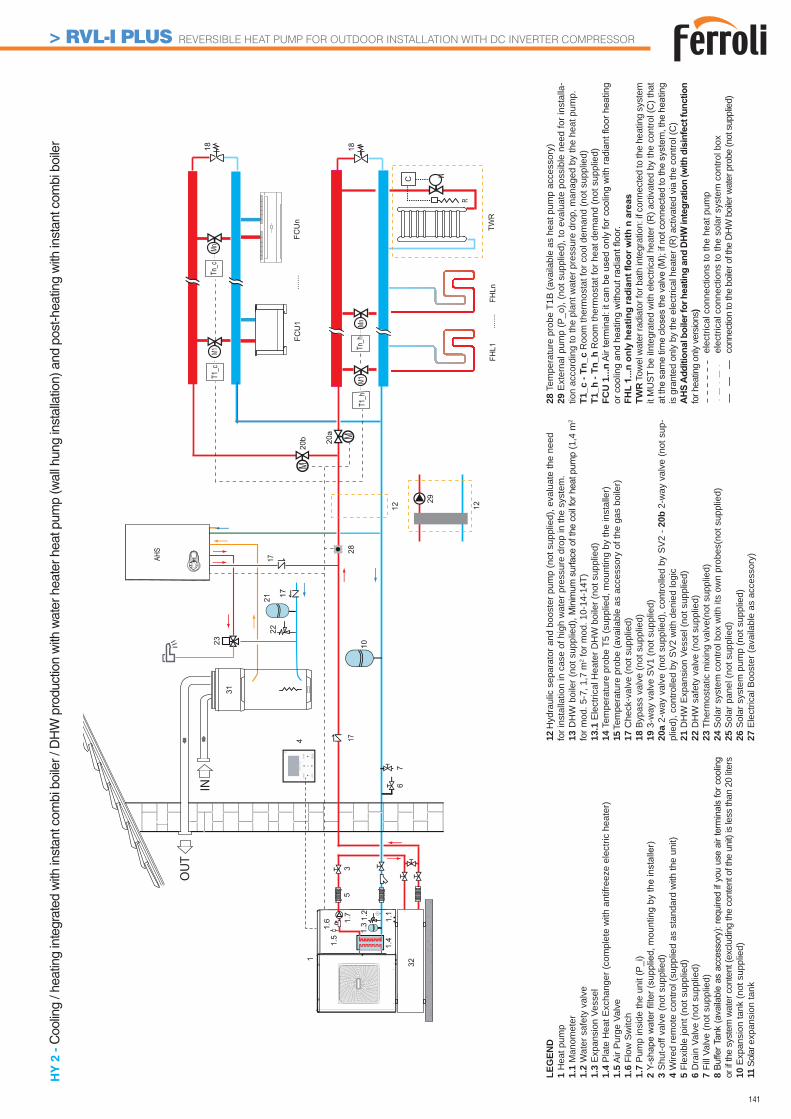
141
FCU
1
FHL1
FHLn
MnM1
......
.
......
.FC
Un
1
1.41.5
67
5
1.1
3
1.31.6 1.
2
4
M1818
C
Mn
1.7
10
20a
M20
b
M
R
TWR
M1T1
_c
T1_h
Tn_c
Tn_h
17AHS
1728
2331
2122
17
IN
OUT
12
29
12
32
HY
2 -
Coo
ling
/ hea
ting
inte
grat
ed w
ith in
stan
t com
bi b
oile
r / D
HW
pro
duct
ion
with
wat
er h
eate
r hea
t pum
p (w
all h
ung
inst
alla
tion)
and
pos
t-hea
ting
with
inst
ant c
ombi
boi
ler
LEG
END
1 H
eat p
ump
1.1
Man
omet
er1.
2 W
ater
saf
ety
valv
e1.
3 E
xpan
sion
Ves
sel
1.4
Pla
te H
eat E
xcha
nger
(com
plet
e w
ith a
ntifr
eeze
ele
ctric
hea
ter)
1.5
Air
Pur
ge V
alve
1.6
Flow
Sw
itch
1.7
Pum
p in
side
the
unit
(P_i
)2 3
Shu
t-off
valv
e (n
ot s
uppl
ied)
4 W
ired
rem
ote
cont
rol (
supp
lied
as s
tand
ard
with
the
unit)
5 Fl
exib
le jo
int (
not s
uppl
ied)
6 D
rain
Val
ve (n
ot s
uppl
ied)
7 Fi
ll Va
lve
(not
sup
plie
d)8 or
if th
e sy
stem
wat
er c
onte
nt (e
xclu
ding
the
cont
ent o
f the
uni
t) is
less
than
20
liters
10 E
xpan
sion
tank
(not
sup
plie
d)11
Sol
ar e
xpan
sion
tank
12 H
ydra
ulic
sep
arat
or a
nd b
oost
er p
ump
(not
sup
plie
d), e
valu
ate
the
need
fo
r ins
talla
tion
in c
ase
of h
igh
wat
er p
ress
ure
drop
in th
e sy
stem
.13
DH
W b
oile
r (no
t sup
plie
d), M
inim
um s
urfa
ce o
f the
coi
l for
hea
t pum
p (1
,4 m
2 fo
r mod
. 5-7
, 1,7
m2 f
or m
od. 1
0-14
-14T
)13
.1 E
lect
rical
Hea
ter D
HW
boi
ler (
not s
uppl
ied)
14 T
empe
ratu
re p
robe
T5
(sup
plie
d, m
ount
ing
by th
e in
stal
ler)
15 T
empe
ratu
re p
robe
(ava
ilabl
e as
acc
esso
ry o
f the
gas
boi
ler)
17 C
heck
-val
ve (n
ot s
uppl
ied)
18 B
ypas
s va
lve
(not
sup
plie
d)19
3-w
ay v
alve
SV
1 (n
ot s
uppl
ied)
20a
2-w
ay v
alve
(not
sup
plie
d), c
ontro
lled
by S
V2
- 20b
2-w
ay v
alve
(not
sup
-pl
ied)
, con
trolle
d by
SV
2 w
ith d
enie
d lo
gic
21 D
HW
Exp
ansi
on V
esse
l (no
t sup
plie
d)22
DH
W s
afet
y va
lve
(not
sup
plie
d)
23 T
herm
osta
tic m
ixin
g va
lve(
not s
uppl
ied)
24 S
olar
sys
tem
con
trol b
ox w
ith it
s ow
n pr
obes
(not
sup
plie
d)25
Sol
ar p
anel
(not
sup
plie
d)26
Sol
ar s
yste
m p
ump
(not
sup
plie
d)27
Ele
ctric
al B
oost
er (a
vaila
ble
as a
cces
sory
)
28 T
empe
ratu
re p
robe
T1B
(ava
ilabl
e as
hea
t pum
p ac
cess
ory)
29 E
xter
nal p
ump
(P_o
), (n
ot s
uppl
ied)
, to
eval
uate
pos
sibl
e ne
ed fo
r ins
talla
-tio
n ac
cord
ing
to th
e pl
ant w
ater
pre
ssur
e dr
op, m
anag
ed b
y th
e he
at p
ump.
T1_c
- Tn
_c R
oom
ther
mos
tat f
or c
ool d
eman
d (n
ot s
uppl
ied)
T1_h
- Tn
_h R
oom
ther
mos
tat f
or h
eat d
eman
d (n
ot s
uppl
ied)
FCU
1...
n
TWR
Tow
el w
ater
radi
ator
for b
ath
inte
grat
ion:
if c
onne
cted
to th
e he
atin
g sy
stem
it
MU
ST b
e iIn
tegr
ated
with
ele
ctric
al h
eate
r (R
) act
ivat
ed b
y th
e co
ntro
l (C
) tha
t
is g
rant
ed o
nly
by th
e el
ectri
cal h
eate
r (R
) act
ivat
ed v
ia th
e co
ntro
l (C
)
for h
eatin
g on
ly ve
rsio
ns)
e
lect
rical
con
nect
ions
to th
e he
at p
ump
e
lect
rical
con
nect
ions
to th
e so
lar s
yste
m c
ontro
l box
c
onne
ctio
n to
the
boile
r of t
he D
HW
boi
ler w
ater
pro
be (n
ot s
uppl
ied)
> RVL-I PLUS REVERSIBLE HEAT PUMP FOR OUTDOOR INSTALLATION WITH DC INVERTER COMPRESSOR
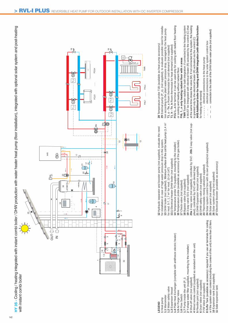
142
FCU
1
FHL1
FHLn
MnM1
......
.
......
.FC
Un
1
1.41.5
67
255
1.1
33
1.31.6 1.
2
M1818
C
Mn
1.7
20a
M20
b
M
R
TWR
M1T1
_c
T1_h
Tn_c
Tn_h
17AHS
1728
23
2122
17
INOUT
2430
25
26
4
10
12
29
12
32
11
HY
3S
- C
oolin
g / h
eatin
g in
tegr
ated
with
inst
ant c
ombi
boi
ler /
DH
W p
rodu
ctio
n w
ith w
ater
hea
ter h
eat p
ump
(fl oo
r ins
talla
tion)
, int
egra
ted
with
opt
iona
l sol
ar s
yste
m a
nd p
ost-h
eatin
g w
ith in
stan
t com
bi b
oile
r
LEG
END
1 H
eat p
ump
1.1
Man
omet
er1.
2 W
ater
saf
ety
valv
e1.
3 E
xpan
sion
Ves
sel
1.4
Pla
te H
eat E
xcha
nger
(com
plet
e w
ith a
ntifr
eeze
ele
ctric
hea
ter)
1.5
Air
Pur
ge V
alve
1.6
Flow
Sw
itch
1.7
Pum
p in
side
the
unit
(P_i
)2 3
Shu
t-off
valv
e (n
ot s
uppl
ied)
4 W
ired
rem
ote
cont
rol (
supp
lied
as s
tand
ard
with
the
unit)
5 Fl
exib
le jo
int (
not s
uppl
ied)
6 D
rain
Val
ve (n
ot s
uppl
ied)
7 Fi
ll Va
lve
(not
sup
plie
d)8 or
if th
e sy
stem
wat
er c
onte
nt (e
xclu
ding
the
cont
ent o
f the
uni
t) is
less
than
20
liters
10 E
xpan
sion
tank
(not
sup
plie
d)11
Sol
ar e
xpan
sion
tank
12 H
ydra
ulic
sep
arat
or a
nd b
oost
er p
ump
(not
sup
plie
d), e
valu
ate
the
need
fo
r ins
talla
tion
in c
ase
of h
igh
wat
er p
ress
ure
drop
in th
e sy
stem
.13
DH
W b
oile
r (no
t sup
plie
d), M
inim
um s
urfa
ce o
f the
coi
l for
hea
t pum
p (1
,4 m
2 fo
r mod
. 5-7
, 1,7
m2 f
or m
od. 1
0-14
-14T
)13
.1 E
lect
rical
Hea
ter D
HW
boi
ler (
not s
uppl
ied)
14 T
empe
ratu
re p
robe
T5
(sup
plie
d, m
ount
ing
by th
e in
stal
ler)
15 T
empe
ratu
re p
robe
(ava
ilabl
e as
acc
esso
ry o
f the
gas
boi
ler)
17 C
heck
-val
ve (n
ot s
uppl
ied)
18 B
ypas
s va
lve
(not
sup
plie
d)19
3-w
ay v
alve
SV
1 (n
ot s
uppl
ied)
20a
2-w
ay v
alve
(not
sup
plie
d), c
ontro
lled
by S
V2
- 20b
2-w
ay v
alve
(not
sup
-pl
ied)
, con
trolle
d by
SV
2 w
ith d
enie
d lo
gic
21 D
HW
Exp
ansi
on V
esse
l (no
t sup
plie
d)22
DH
W s
afet
y va
lve
(not
sup
plie
d)
23 T
herm
osta
tic m
ixin
g va
lve(
not s
uppl
ied)
24 S
olar
sys
tem
con
trol b
ox w
ith it
s ow
n pr
obes
(not
sup
plie
d)25
Sol
ar p
anel
(not
sup
plie
d)26
Sol
ar s
yste
m p
ump
(not
sup
plie
d)27
Ele
ctric
al B
oost
er (a
vaila
ble
as a
cces
sory
)
28 T
empe
ratu
re p
robe
T1B
(ava
ilabl
e as
hea
t pum
p ac
cess
ory)
29 E
xter
nal p
ump
(P_o
), (n
ot s
uppl
ied)
, to
eval
uate
pos
sibl
e ne
ed fo
r ins
talla
-tio
n ac
cord
ing
to th
e pl
ant w
ater
pre
ssur
e dr
op, m
anag
ed b
y th
e he
at p
ump.
T1_c
- Tn
_c R
oom
ther
mos
tat f
or c
ool d
eman
d (n
ot s
uppl
ied)
T1_h
- Tn
_h R
oom
ther
mos
tat f
or h
eat d
eman
d (n
ot s
uppl
ied)
FCU
1...
n
TWR
Tow
el w
ater
radi
ator
for b
ath
inte
grat
ion:
if c
onne
cted
to th
e he
atin
g sy
stem
it
MU
ST b
e iIn
tegr
ated
with
ele
ctric
al h
eate
r (R
) act
ivat
ed b
y th
e co
ntro
l (C
) tha
t
is g
rant
ed o
nly
by th
e el
ectri
cal h
eate
r (R
) act
ivat
ed v
ia th
e co
ntro
l (C
)
for h
eatin
g on
ly ve
rsio
ns)
e
lect
rical
con
nect
ions
to th
e he
at p
ump
e
lect
rical
con
nect
ions
to th
e so
lar s
yste
m c
ontro
l box
c
onne
ctio
n to
the
boile
r of t
he D
HW
boi
ler w
ater
pro
be (n
ot s
uppl
ied)
> RVL-I PLUS REVERSIBLE HEAT PUMP FOR OUTDOOR INSTALLATION WITH DC INVERTER COMPRESSOR
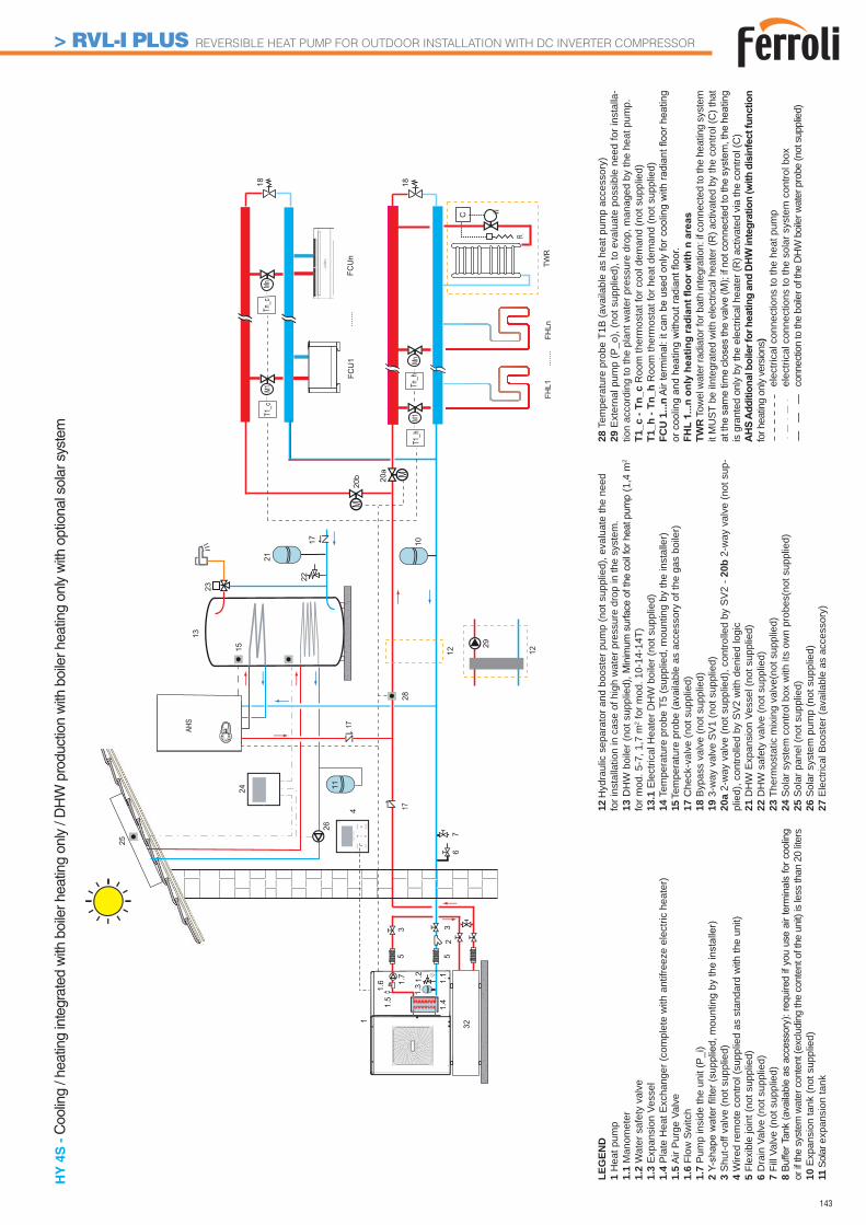
143
1
1.41.5
67
255
1.1
33
1.31.6 1.
2
4
1.7
17
25
26
24
FCU
1
FHL1
FHLn
MnM1
......
.
......
.FC
Un
M
13
15
1818
C
Mn
10
22
20a
M20
b
M
R
TWR
M1T1
_c
T1_h
Tn_c
Tn_h
17AHS
28
21
23
17
32
12
29
12
11
HY
4S
- C
oolin
g / h
eatin
g in
tegr
ated
with
boi
ler h
eatin
g on
ly /
DH
W p
rodu
ctio
n w
ith b
oile
r hea
ting
only
with
opt
iona
l sol
ar s
yste
m
LEG
END
1 H
eat p
ump
1.1
Man
omet
er1.
2 W
ater
saf
ety
valv
e1.
3 E
xpan
sion
Ves
sel
1.4
Pla
te H
eat E
xcha
nger
(com
plet
e w
ith a
ntifr
eeze
ele
ctric
hea
ter)
1.5
Air
Pur
ge V
alve
1.6
Flow
Sw
itch
1.7
Pum
p in
side
the
unit
(P_i
)2 3
Shu
t-off
valv
e (n
ot s
uppl
ied)
4 W
ired
rem
ote
cont
rol (
supp
lied
as s
tand
ard
with
the
unit)
5 Fl
exib
le jo
int (
not s
uppl
ied)
6 D
rain
Val
ve (n
ot s
uppl
ied)
7 Fi
ll Va
lve
(not
sup
plie
d)8 or
if th
e sy
stem
wat
er c
onte
nt (e
xclu
ding
the
cont
ent o
f the
uni
t) is
less
than
20
liters
10 E
xpan
sion
tank
(not
sup
plie
d)11
Sol
ar e
xpan
sion
tank
12 H
ydra
ulic
sep
arat
or a
nd b
oost
er p
ump
(not
sup
plie
d), e
valu
ate
the
need
fo
r ins
talla
tion
in c
ase
of h
igh
wat
er p
ress
ure
drop
in th
e sy
stem
.13
DH
W b
oile
r (no
t sup
plie
d), M
inim
um s
urfa
ce o
f the
coi
l for
hea
t pum
p (1
,4 m
2 fo
r mod
. 5-7
, 1,7
m2 f
or m
od. 1
0-14
-14T
)13
.1 E
lect
rical
Hea
ter D
HW
boi
ler (
not s
uppl
ied)
14 T
empe
ratu
re p
robe
T5
(sup
plie
d, m
ount
ing
by th
e in
stal
ler)
15 T
empe
ratu
re p
robe
(ava
ilabl
e as
acc
esso
ry o
f the
gas
boi
ler)
17 C
heck
-val
ve (n
ot s
uppl
ied)
18 B
ypas
s va
lve
(not
sup
plie
d)19
3-w
ay v
alve
SV
1 (n
ot s
uppl
ied)
20a
2-w
ay v
alve
(not
sup
plie
d), c
ontro
lled
by S
V2
- 20b
2-w
ay v
alve
(not
sup
-pl
ied)
, con
trolle
d by
SV
2 w
ith d
enie
d lo
gic
21 D
HW
Exp
ansi
on V
esse
l (no
t sup
plie
d)22
DH
W s
afet
y va
lve
(not
sup
plie
d)
23 T
herm
osta
tic m
ixin
g va
lve(
not s
uppl
ied)
24 S
olar
sys
tem
con
trol b
ox w
ith it
s ow
n pr
obes
(not
sup
plie
d)25
Sol
ar p
anel
(not
sup
plie
d)26
Sol
ar s
yste
m p
ump
(not
sup
plie
d)27
Ele
ctric
al B
oost
er (a
vaila
ble
as a
cces
sory
)
28 T
empe
ratu
re p
robe
T1B
(ava
ilabl
e as
hea
t pum
p ac
cess
ory)
29 E
xter
nal p
ump
(P_o
), (n
ot s
uppl
ied)
, to
eval
uate
pos
sibl
e ne
ed fo
r ins
talla
-tio
n ac
cord
ing
to th
e pl
ant w
ater
pre
ssur
e dr
op, m
anag
ed b
y th
e he
at p
ump.
T1_c
- Tn
_c R
oom
ther
mos
tat f
or c
ool d
eman
d (n
ot s
uppl
ied)
T1_h
- Tn
_h R
oom
ther
mos
tat f
or h
eat d
eman
d (n
ot s
uppl
ied)
FCU
1...
n
TWR
Tow
el w
ater
radi
ator
for b
ath
inte
grat
ion:
if c
onne
cted
to th
e he
atin
g sy
stem
it
MU
ST b
e iIn
tegr
ated
with
ele
ctric
al h
eate
r (R
) act
ivat
ed b
y th
e co
ntro
l (C
) tha
t
is g
rant
ed o
nly
by th
e el
ectri
cal h
eate
r (R
) act
ivat
ed v
ia th
e co
ntro
l (C
)
for h
eatin
g on
ly ve
rsio
ns)
e
lect
rical
con
nect
ions
to th
e he
at p
ump
e
lect
rical
con
nect
ions
to th
e so
lar s
yste
m c
ontro
l box
c
onne
ctio
n to
the
boile
r of t
he D
HW
boi
ler w
ater
pro
be (n
ot s
uppl
ied)
> RVL-I PLUS REVERSIBLE HEAT PUMP FOR OUTDOOR INSTALLATION WITH DC INVERTER COMPRESSOR
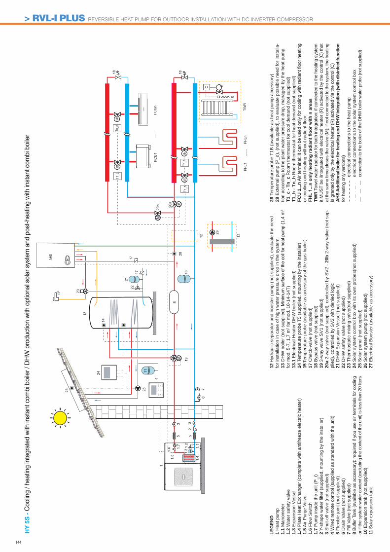
144
25
FCU
1
FHL1
FHLn
MnM1
......
.
......
.FC
Un
1
1.41.5
67
255
1.1
33
1.31.6 1.
2
4
MM
13
1818
C
Mn
1.7
8
10
20a
M20
b
19
M
R
TWR
M1T1
_c
T1_h
Tn_c
Tn_h
1424
26
17AHS 28
23
2122
17
12
29
12
11
HY
5S
- C
oolin
g / h
eatin
g in
tegr
ated
with
inst
ant c
ombi
boi
ler /
DH
W p
rodu
ctio
n w
ith o
ptio
nal s
olar
sys
tem
and
pos
t-hea
ting
with
inst
ant c
ombi
boi
ler
LEG
END
1 H
eat p
ump
1.1
Man
omet
er1.
2 W
ater
saf
ety
valv
e1.
3 E
xpan
sion
Ves
sel
1.4
Pla
te H
eat E
xcha
nger
(com
plet
e w
ith a
ntifr
eeze
ele
ctric
hea
ter)
1.5
Air
Pur
ge V
alve
1.6
Flow
Sw
itch
1.7
Pum
p in
side
the
unit
(P_i
)2 3
Shu
t-off
valv
e (n
ot s
uppl
ied)
4 W
ired
rem
ote
cont
rol (
supp
lied
as s
tand
ard
with
the
unit)
5 Fl
exib
le jo
int (
not s
uppl
ied)
6 D
rain
Val
ve (n
ot s
uppl
ied)
7 Fi
ll Va
lve
(not
sup
plie
d)8 or
if th
e sy
stem
wat
er c
onte
nt (e
xclu
ding
the
cont
ent o
f the
uni
t) is
less
than
20
liters
10 E
xpan
sion
tank
(not
sup
plie
d)11
Sol
ar e
xpan
sion
tank
12 H
ydra
ulic
sep
arat
or a
nd b
oost
er p
ump
(not
sup
plie
d), e
valu
ate
the
need
fo
r ins
talla
tion
in c
ase
of h
igh
wat
er p
ress
ure
drop
in th
e sy
stem
.13
DH
W b
oile
r (no
t sup
plie
d), M
inim
um s
urfa
ce o
f the
coi
l for
hea
t pum
p (1
,4 m
2 fo
r mod
. 5-7
, 1,7
m2 f
or m
od. 1
0-14
-14T
)13
.1 E
lect
rical
Hea
ter D
HW
boi
ler (
not s
uppl
ied)
14 T
empe
ratu
re p
robe
T5
(sup
plie
d, m
ount
ing
by th
e in
stal
ler)
15 T
empe
ratu
re p
robe
(ava
ilabl
e as
acc
esso
ry o
f the
gas
boi
ler)
17 C
heck
-val
ve (n
ot s
uppl
ied)
18 B
ypas
s va
lve
(not
sup
plie
d)19
3-w
ay v
alve
SV
1 (n
ot s
uppl
ied)
20a
2-w
ay v
alve
(not
sup
plie
d), c
ontro
lled
by S
V2
- 20b
2-w
ay v
alve
(not
sup
-pl
ied)
, con
trolle
d by
SV
2 w
ith d
enie
d lo
gic
21 D
HW
Exp
ansi
on V
esse
l (no
t sup
plie
d)22
DH
W s
afet
y va
lve
(not
sup
plie
d)
23 T
herm
osta
tic m
ixin
g va
lve(
not s
uppl
ied)
24 S
olar
sys
tem
con
trol b
ox w
ith it
s ow
n pr
obes
(not
sup
plie
d)25
Sol
ar p
anel
(not
sup
plie
d)26
Sol
ar s
yste
m p
ump
(not
sup
plie
d)27
Ele
ctric
al B
oost
er (a
vaila
ble
as a
cces
sory
)
28 T
empe
ratu
re p
robe
T1B
(ava
ilabl
e as
hea
t pum
p ac
cess
ory)
29 E
xter
nal p
ump
(P_o
), (n
ot s
uppl
ied)
, to
eval
uate
pos
sibl
e ne
ed fo
r ins
talla
-tio
n ac
cord
ing
to th
e pl
ant w
ater
pre
ssur
e dr
op, m
anag
ed b
y th
e he
at p
ump.
T1_c
- Tn
_c R
oom
ther
mos
tat f
or c
ool d
eman
d (n
ot s
uppl
ied)
T1_h
- Tn
_h R
oom
ther
mos
tat f
or h
eat d
eman
d (n
ot s
uppl
ied)
FCU
1...
n
TWR
Tow
el w
ater
radi
ator
for b
ath
inte
grat
ion:
if c
onne
cted
to th
e he
atin
g sy
stem
it
MU
ST b
e iIn
tegr
ated
with
ele
ctric
al h
eate
r (R
) act
ivat
ed b
y th
e co
ntro
l (C
) tha
t
is g
rant
ed o
nly
by th
e el
ectri
cal h
eate
r (R
) act
ivat
ed v
ia th
e co
ntro
l (C
)
for h
eatin
g on
ly ve
rsio
ns)
e
lect
rical
con
nect
ions
to th
e he
at p
ump
e
lect
rical
con
nect
ions
to th
e so
lar s
yste
m c
ontro
l box
c
onne
ctio
n to
the
boile
r of t
he D
HW
boi
ler w
ater
pro
be (n
ot s
uppl
ied)
> RVL-I PLUS REVERSIBLE HEAT PUMP FOR OUTDOOR INSTALLATION WITH DC INVERTER COMPRESSOR
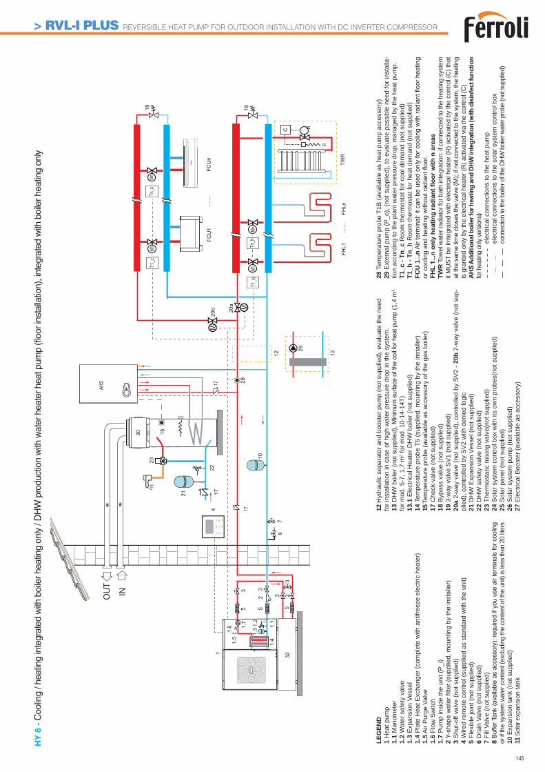
145
FCU
1
FHL1
FHLn
MnM1
......
.
......
.FC
Un
1
1.41.5
67
255
1.1
33
1.31.6 1.
2
M1818
C
Mn
1.7
20a
M20
b
M
R
TWR
M1T1
_c
T1_h
Tn_c
Tn_h
AHS
1728
INOUT
30
4
10
1722
23
1721
32
12
29
12
5
3 33
15
HY
6 -
Coo
ling
/ hea
ting
inte
grat
ed w
ith b
oile
r hea
ting
only
/ D
HW
pro
duct
ion
with
wat
er h
eate
r hea
t pum
p (fl
oor i
nsta
llatio
n), i
nteg
rate
d w
ith b
oile
r hea
ting
only
LEG
END
1 H
eat p
ump
1.1
Man
omet
er1.
2 W
ater
saf
ety
valv
e1.
3 E
xpan
sion
Ves
sel
1.4
Pla
te H
eat E
xcha
nger
(com
plet
e w
ith a
ntifr
eeze
ele
ctric
hea
ter)
1.5
Air
Pur
ge V
alve
1.6
Flow
Sw
itch
1.7
Pum
p in
side
the
unit
(P_i
)2 3
Shu
t-off
valv
e (n
ot s
uppl
ied)
4 W
ired
rem
ote
cont
rol (
supp
lied
as s
tand
ard
with
the
unit)
5 Fl
exib
le jo
int (
not s
uppl
ied)
6 D
rain
Val
ve (n
ot s
uppl
ied)
7 Fi
ll Va
lve
(not
sup
plie
d)8 or
if th
e sy
stem
wat
er c
onte
nt (e
xclu
ding
the
cont
ent o
f the
uni
t) is
less
than
20
liters
10 E
xpan
sion
tank
(not
sup
plie
d)11
Sol
ar e
xpan
sion
tank
12 H
ydra
ulic
sep
arat
or a
nd b
oost
er p
ump
(not
sup
plie
d), e
valu
ate
the
need
fo
r ins
talla
tion
in c
ase
of h
igh
wat
er p
ress
ure
drop
in th
e sy
stem
.13
DH
W b
oile
r (no
t sup
plie
d), M
inim
um s
urfa
ce o
f the
coi
l for
hea
t pum
p (1
,4 m
2 fo
r mod
. 5-7
, 1,7
m2 f
or m
od. 1
0-14
-14T
)13
.1 E
lect
rical
Hea
ter D
HW
boi
ler (
not s
uppl
ied)
14 T
empe
ratu
re p
robe
T5
(sup
plie
d, m
ount
ing
by th
e in
stal
ler)
15 T
empe
ratu
re p
robe
(ava
ilabl
e as
acc
esso
ry o
f the
gas
boi
ler)
17 C
heck
-val
ve (n
ot s
uppl
ied)
18 B
ypas
s va
lve
(not
sup
plie
d)19
3-w
ay v
alve
SV
1 (n
ot s
uppl
ied)
20a
2-w
ay v
alve
(not
sup
plie
d), c
ontro
lled
by S
V2
- 20b
2-w
ay v
alve
(not
sup
-pl
ied)
, con
trolle
d by
SV
2 w
ith d
enie
d lo
gic
21 D
HW
Exp
ansi
on V
esse
l (no
t sup
plie
d)22
DH
W s
afet
y va
lve
(not
sup
plie
d)
23 T
herm
osta
tic m
ixin
g va
lve(
not s
uppl
ied)
24 S
olar
sys
tem
con
trol b
ox w
ith it
s ow
n pr
obes
(not
sup
plie
d)25
Sol
ar p
anel
(not
sup
plie
d)26
Sol
ar s
yste
m p
ump
(not
sup
plie
d)27
Ele
ctric
al B
oost
er (a
vaila
ble
as a
cces
sory
)
28 T
empe
ratu
re p
robe
T1B
(ava
ilabl
e as
hea
t pum
p ac
cess
ory)
29 E
xter
nal p
ump
(P_o
), (n
ot s
uppl
ied)
, to
eval
uate
pos
sibl
e ne
ed fo
r ins
talla
-tio
n ac
cord
ing
to th
e pl
ant w
ater
pre
ssur
e dr
op, m
anag
ed b
y th
e he
at p
ump.
T1_c
- Tn
_c R
oom
ther
mos
tat f
or c
ool d
eman
d (n
ot s
uppl
ied)
T1_h
- Tn
_h R
oom
ther
mos
tat f
or h
eat d
eman
d (n
ot s
uppl
ied)
FCU
1...
n
TWR
Tow
el w
ater
radi
ator
for b
ath
inte
grat
ion:
if c
onne
cted
to th
e he
atin
g sy
stem
it
MU
ST b
e iIn
tegr
ated
with
ele
ctric
al h
eate
r (R
) act
ivat
ed b
y th
e co
ntro
l (C
) tha
t
is g
rant
ed o
nly
by th
e el
ectri
cal h
eate
r (R
) act
ivat
ed v
ia th
e co
ntro
l (C
)
for h
eatin
g on
ly ve
rsio
ns)
e
lect
rical
con
nect
ions
to th
e he
at p
ump
e
lect
rical
con
nect
ions
to th
e so
lar s
yste
m c
ontro
l box
c
onne
ctio
n to
the
boile
r of t
he D
HW
boi
ler w
ater
pro
be (n
ot s
uppl
ied)
> RVL-I PLUS REVERSIBLE HEAT PUMP FOR OUTDOOR INSTALLATION WITH DC INVERTER COMPRESSOR
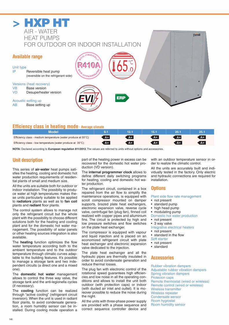
146
Available range
Unit typeIP Reversible heat pump (reversible on the refrigerant side)
Versions (heat recovery)VB Base versionVD Desuperheater version
Acoustic setting upAB Base setting up
RE
FRIGERANT G
AS
E
CO-FRIEND
LY
.065
ERP
Unit description
This series of air-water heat pumps sati-sfi es the heating, cooling and domestic hot water production requirements of residen-tial plants of small and medium size.All the units are suitable both for outdoor or indoor installation. The possibiliy to produ-ce water at high temperatures makes the-se units particularly suitable to be applied to radiators plants as well as to fan coil plants and radiant fl oor plants.The control system allows to manage not only the refrigerant circuit but the whole plant with the possibility to choose different solutions both for the heating and cooling plant and for the domestic hot water ma-nagement. The possibility of solar panels or other heating sources integration is also available.The heating function optimizes the fl ow water temperature according both to the ambient temperature and to the outdoor temperature through climatic curves adap-table to the building features. It’s possible to manage a storage tank and two inde-pendent circuits (a direct one and a mixed one).The domestic hot water management allows to control the three way valve, the storage tank and the anti-legionella cycles (if necessary).The cooling function can be realized through “active cooling” (refrigerant circuit inversion). When the unit is used in radiant fl oor plants, to avoid condensate genera-tion, a room humidity sensor can be in-stalled. During cooling mode operation a
part of the heating power in excess can be recovered for the domestic hot water pro-duction (VD version).The internal programmer clock allows to defi ne different daily switching programs for heating, cooling and domestic hot wa-ter production.The refrigerant circuit, contained in a box repaired from the air fl ow to simplify the maintenance operations, is equipped with scroll compressor mounted on damper supports, brazed plate heat exchangers, electronic expansion valve, reverse cycle valve, centrifugal fan (plug fan), fi nned coil realized with copper pipes and alluminium fi ns. The circuit is protected by high and low pressure switches and fl ow switches on the plate heat exchanger.The compressor is equipped with vapour and liquid injection and is placed on an economized refrigerant circuit with plate heat exchanger and electronic expansion valve dedicated to the injection. The plate heat exchanger and all the hydraulic pipes are thermally insulated in order to avoid condensate generation and reduce thermal losses.The plug fan with electronic control of the rotational speed guarantees high efficien-cies and low noise in all the operating con-ditions and allows to install the unit both outdoor (with protection caps) or indoor (with ducted air inlet and outlet). It is mo-reover possible to reduce the noise during the night.All the units with three-phase power supply are provided with a phase sequence and correct sequence controller device and
with an outdoor temperature sensor in or-der to realize the climatic control.All the units are accurately built and indi-vidually tested in the factory. Only electric and hydraulic connections are required for installation.
Options
Plant side fl ow rate management • not present• standard pump• high head pump• modulating pumpDomestic hot water production • not present• 3 way valveIntegrative electrical heaters• not present• standard in the fl owSoft starter• not present• standard
Accessories
Rubber vibration dampersAdjustable rubber vibration dampersSpring vibration dampersProtecion capsRemote thermostat (wired or wireless)Remote control (wired or wireless)Wireless transmitterWireless repeaterCondensate sensorRoom hygrostatRoom humidity sensor
Effi ciency class in heating mode - Average climate
Model 9.1 12.1 15.1 20.1 25.1
NOTA: Declared according to European regulation 811/2013. The values are referred to units without options and accessories.
A+A+
A+A+
A+A+
A+A+
A+A+
> HXP HT AIR - WATER
HEAT PUMPS
FOR OUTDOOR OR INDOOR INSTALLATION
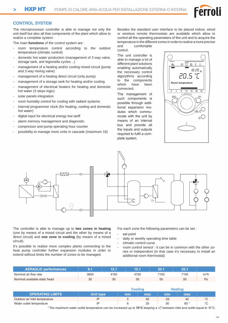
147
The microprocessor controller is able to manage not only the unit itself but also all that components of the plant which allow to realize a complete system.The main functions of the control system are :- room temperature control according to the outdoor
temperature (climatic control)- domestic hot water production (management of 3 way valve,
storage tank, anti legionella cycles…)- management of a heating and/or cooling mixed circuit (pump
and 3 way mixing valve)- management of a heating direct circuit (only pump)- management of a storage tank for heating and/or cooling- management of electrical heaters for heating and domestic
hot water (3 steps logic)- solar panels integration- room humidity control for cooling with radiant systems- internal programmer clock (for heating, cooling and domestic
hot water)- digital input for electrical energy low tariff- alarm memory management and diagnostic- compressor and pump operating hour counter- possibility to manage more units in cascade (maximum 16)
Besides the standard user interface to be placed indoor, wired or wireless remote thermostats are available which allow to
temperature in the different zones in order to realize a more precise and comfortable control.The unit controller is able to manage a lot of different plant solutions enabling automatically the necessary control algorythms according to the components which have been connected.The management of such components is possible through addi-tional expansion mo-dules which commu-nicate with the unit by means of an internal bus and provide all the inputs and outputs required to fulfi l a com-plete system.
CONTROL SYSTEM
The controller is able to manage up to two zones in heating (one by means of a mixed circuit and the other by means of a direct circuit) and one zone in cooling (by means of a mixed circuit).It’s possible to realize more complex plants connecting to the heat pump controller further expansion modules in order to extend without limits the number of zones to be managed.
For each zone the following parameters can be set :- set point- daily or weekly operating time table- climatic control curve- room control sensor : it can be in common with the other zo-
nes or independent (in that case it’s necessary to install an additional room thermostat)
AERAULIC performances 9.1 12.1 15.1 20.1 25.1
Nominal air fl ow rate 3650 4150 4150 7150 7150 m3/h
Nominal available static head 30 30 30 50 50 Pa
FS
Room temperature
20.5 C18:28
Cooling Heating
OPERATING LIMITS Unit type min max min max
Outdoor air inlet temperature IP 5 50 -22 42 °CWater outlet temperature IP 6 25 30 65 * °C
* The maximum water outlet temperature can be increased up to 70°C keeping a T between inlet and outlet equal to 10°C.
> HXP HT POMPE DI CALORE ARIA-ACQUA PER INSTALLAZIONE ESTERNA O INTERNA
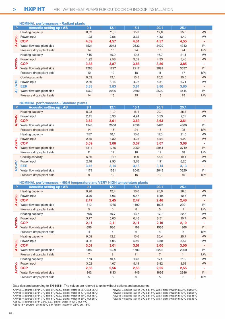
148
NOMINAL performances - Radiant plants
IP Acoustic setting up : AB 9.1 12.1 15.1 20.1 25.1
A7
W3
5
Heating capacity 8,82 11,8 15,3 19,8 25,0 kW
Power input 1,92 2,58 3,32 4,33 5,49 kW
COP 4,59 4,57 4,61 4,57 4,55 -
Water fl ow rate plant side 1524 2043 2632 3429 4312 l/h
Pressure drops plant side 14 16 24 16 24 kPa
A2
W3
5
Heating capacity 7,45 10,0 12,8 16,7 21,1 kW
Power input 1,92 2,58 3,32 4,33 5,48 kW
COP 3,88 3,87 3,86 3,86 3,85 -
Water fl ow rate plant side 1288 1727 2217 2892 3637 l/h
Pressure drops plant side 10 12 18 11 17 kPa
A3
5W
18
Cooling capacity 9,03 12,1 15,5 20,2 25,5 kW
Power input 2,36 3,16 4,07 5,31 6,71 kW
EER 3,83 3,83 3,81 3,80 3,80 -
Water fl ow rate plant side 1560 2086 2690 3500 4414 l/h
Pressure drops plant side 14 16 25 16 25 kPa
NOMINAL performances - Standard plants
IP Acoustic setting up : AB 9.1 12.1 15.1 20.1 25.1
A7
W4
5
Heating capacity 8,93 11,9 15,4 20,1 25,3 kW
Power input 2,45 3,30 4,24 5,53 7,01 kW
COP 3,64 3,61 3,63 3,63 3,61 -
Water fl ow rate plant side 1548 2068 2659 3476 4380 l/h
Pressure drops plant side 14 16 24 16 25 kPa
A2W
45
Heating capacity 7,57 10,1 13,0 17,0 21,5 kW
Power input 2,45 3,30 4,23 5,54 6,99 kW
COP 3,09 3,06 3,07 3,07 3,08 -
Water fl ow rate plant side 1314 1755 2259 2954 3719 l/h
Pressure drops plant side 11 12 18 12 18 kPa
A35W
7
Cooling capacity 6,86 9,19 11,9 15,4 19,4 kW
Power input 2,18 2,93 3,76 4,91 6,20 kW
EER 3,15 3,14 3,16 3,14 3,13 -
Water fl ow rate plant side 1179 1581 2042 2643 3329 l/h
Pressure drops plant side 9 10 16 10 15 kPa
NOMINAL performances - HIGH temperature and VERY HIGH temperature plants
IP Acoustic setting up : AB 9.1 12.1 15.1 20.1 25.1
A7W
65
Heating capacity 9,28 12,4 16,0 20,9 26,3 kW
Power input 3,76 5,06 6,47 8,49 10,7 kW
COP 2,47 2,45 2,47 2,46 2,46 -
Water fl ow rate plant side 812 1085 1400 1828 2301 l/h
Pressure drops plant side 5 5 8 5 7 kPa
A2W
65
Heating capacity 7,96 10,7 13,7 17,9 22,5 kW
Power input 3,77 5,06 6,48 8,51 10,7 kW
COP 2,11 2,11 2,11 2,10 2,10 -
Water fl ow rate plant side 696 936 1199 1566 1968 l/h
Pressure drops plant side 4 4 6 4 5 kPa
A7W
55
Heating capacity 9,08 12,2 15,6 20,4 25,7 kW
Power input 3,02 4,05 5,19 6,80 8,57 kW
COP 3,01 3,01 3,01 3,00 3,00 -
Water fl ow rate plant side 988 1329 1700 2223 2800 l/h
Pressure drops plant side 7 8 11 7 11 kPa
A2
W55
Heating capacity 7,73 10,4 13,3 17,4 21,9 kW
Power input 3,02 4,07 5,19 6,82 8,59 kW
COP 2,56 2,56 2,56 2,55 2,55 -
Water fl ow rate plant side 842 1133 1449 1896 2386 l/h
Pressure drops plant side 5 6 9 5 8 kPa
A7W65 = source : air in 7°C d.b. 6°C w.b. / plant : water in 55°C out 65°CA7W55 = source : air in 7°C d.b. 6°C w.b. / plant : water in 47°C out 55°CA7W45 = source : air in 7°C d.b. 6°C w.b. / plant : water in 40°C out 45°CA7W35 = source : air in 7°C d.b. 6°C w.b. / plant : water in 30°C out 35°C
Data declared according to EN 14511. The values are referred to units without options and accessories.
A35W7 = source : air in 35°C d.b. / plant : water in 12°C out 7°CA35W18 = source : air in 35°C d.b. / plant : water in 23°C out 18°C
A2W65 = source : air in 2°C d.b. 1°C w.b. / plant : water in 55°C out 65°CA2W55 = source : air in 2°C d.b. 1°C w.b. / plant : water in 47°C out 55°CA2W45 = source : air in 2°C d.b. 1°C w.b. / plant : water in 40°C out 45°CA2W35 = source : air in 2°C d.b. 1°C w.b. / plant : water in 30°C out 35°C
> HXP HT AIR - WATER HEAT PUMPS FOR OUTDOOR OR INDOOR INSTALLATION
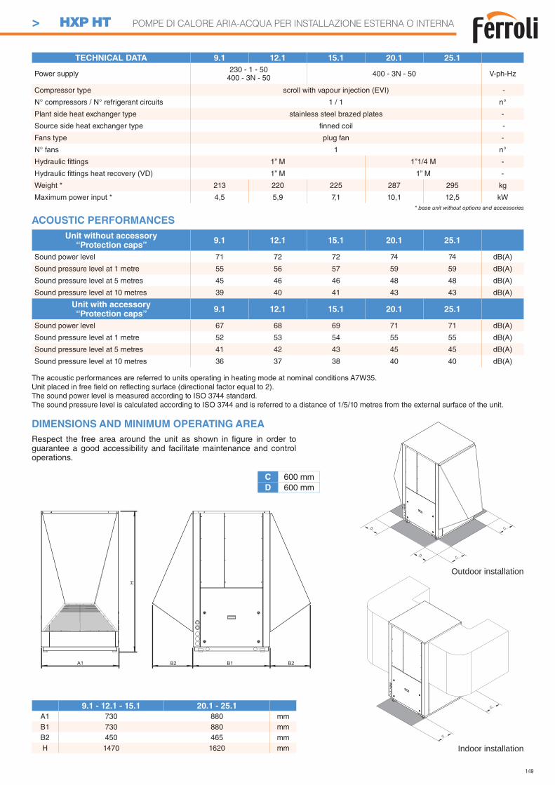
149
TECHNICAL DATA 9.1 12.1 15.1 20.1 25.1
Power supply 230 - 1 - 50400 - 3N - 50 400 - 3N - 50 V-ph-Hz
Compressor type scroll with vapour injection (EVI) -
N° compressors / N° refrigerant circuits 1 / 1 n°
Plant side heat exchanger type stainless steel brazed plates -
Source side heat exchanger type fi nned coil -
Fans type plug fan -
N° fans 1 n°
Hydraulic fi ttings 1” M 1”1/4 M -
Hydraulic fi ttings heat recovery (VD) 1” M 1” M -
Weight * 213 220 225 287 295 kg
Maximum power input * 4,5 5,9 7,1 10,1 12,5 kW* base unit without options and accessories
DIMENSIONS AND MINIMUM OPERATING AREA
C 600 mmD 600 mm
Respect the free area around the unit as shown in fi gure in order to guarantee a good accessibility and facilitate maintenance and control operations.
9.1 - 12.1 - 15.1 20.1 - 25.1
A1 730 880 mmB1 730 880 mmB2 450 465 mmH 1470 1620 mm
Outdoor installation
Indoor installation
The acoustic performances are referred to units operating in heating mode at nominal conditions A7W35.Unit placed in free fi eld on refl ecting surface (directional factor equal to 2).The sound power level is measured according to ISO 3744 standard.The sound pressure level is calculated according to ISO 3744 and is referred to a distance of 1/5/10 metres from the external surface of the unit.
Unit without accessory“Protection caps”
9.1 12.1 15.1 20.1 25.1
Sound power level 71 72 72 74 74 dB(A)
Sound pressure level at 1 metre 55 56 57 59 59 dB(A)
Sound pressure level at 5 metres 45 46 46 48 48 dB(A)
Sound pressure level at 10 metres 39 40 41 43 43 dB(A)
Unit with accessory“Protection caps”
9.1 12.1 15.1 20.1 25.1
Sound power level 67 68 69 71 71 dB(A)
Sound pressure level at 1 metre 52 53 54 55 55 dB(A)
Sound pressure level at 5 metres 41 42 43 45 45 dB(A)
Sound pressure level at 10 metres 36 37 38 40 40 dB(A)
ACOUSTIC PERFORMANCES
> HXP HT POMPE DI CALORE ARIA-ACQUA PER INSTALLAZIONE ESTERNA O INTERNA
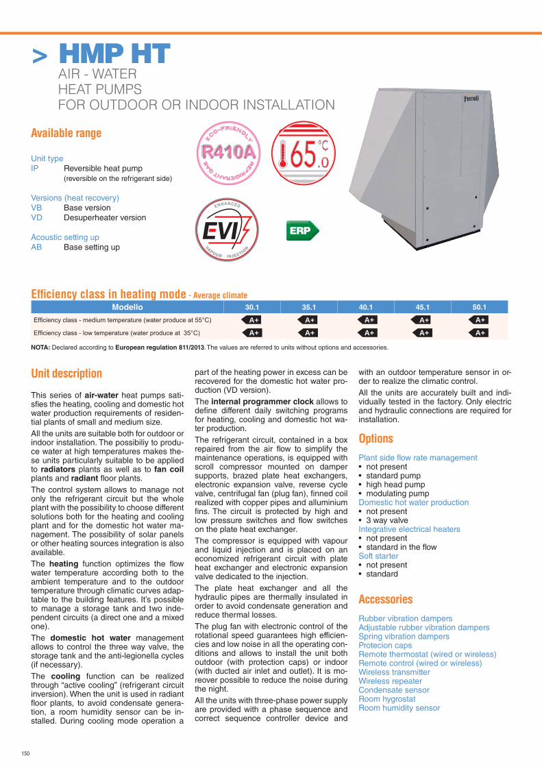
150
Available range
Unit typeIP Reversible heat pump (reversible on the refrigerant side)
Versions (heat recovery)VB Base versionVD Desuperheater version
Acoustic setting upAB Base setting up
Unit description
This series of air-water heat pumps sati-sfi es the heating, cooling and domestic hot water production requirements of residen-tial plants of small and medium size.All the units are suitable both for outdoor or indoor installation. The possibiliy to produ-ce water at high temperatures makes the-se units particularly suitable to be applied to radiators plants as well as to fan coil plants and radiant fl oor plants.The control system allows to manage not only the refrigerant circuit but the whole plant with the possibility to choose different solutions both for the heating and cooling plant and for the domestic hot water ma-nagement. The possibility of solar panels or other heating sources integration is also available.The heating function optimizes the fl ow water temperature according both to the ambient temperature and to the outdoor temperature through climatic curves adap-table to the building features. It’s possible to manage a storage tank and two inde-pendent circuits (a direct one and a mixed one).The domestic hot water management allows to control the three way valve, the storage tank and the anti-legionella cycles (if necessary).The cooling function can be realized through “active cooling” (refrigerant circuit inversion). When the unit is used in radiant fl oor plants, to avoid condensate genera-tion, a room humidity sensor can be in-stalled. During cooling mode operation a
part of the heating power in excess can be recovered for the domestic hot water pro-duction (VD version).The internal programmer clock allows to defi ne different daily switching programs for heating, cooling and domestic hot wa-ter production.The refrigerant circuit, contained in a box repaired from the air fl ow to simplify the maintenance operations, is equipped with scroll compressor mounted on damper supports, brazed plate heat exchangers, electronic expansion valve, reverse cycle valve, centrifugal fan (plug fan), fi nned coil realized with copper pipes and alluminium fi ns. The circuit is protected by high and low pressure switches and fl ow switches on the plate heat exchanger.The compressor is equipped with vapour and liquid injection and is placed on an economized refrigerant circuit with plate heat exchanger and electronic expansion valve dedicated to the injection. The plate heat exchanger and all the hydraulic pipes are thermally insulated in order to avoid condensate generation and reduce thermal losses.The plug fan with electronic control of the rotational speed guarantees high efficien-cies and low noise in all the operating con-ditions and allows to install the unit both outdoor (with protection caps) or indoor (with ducted air inlet and outlet). It is mo-reover possible to reduce the noise during the night.All the units with three-phase power supply are provided with a phase sequence and correct sequence controller device and
with an outdoor temperature sensor in or-der to realize the climatic control.All the units are accurately built and indi-vidually tested in the factory. Only electric and hydraulic connections are required for installation.
Options
Plant side fl ow rate management • not present• standard pump• high head pump• modulating pumpDomestic hot water production • not present• 3 way valveIntegrative electrical heaters• not present• standard in the fl owSoft starter• not present• standard
Accessories
Rubber vibration dampersAdjustable rubber vibration dampersSpring vibration dampersProtecion capsRemote thermostat (wired or wireless)Remote control (wired or wireless)Wireless transmitterWireless repeaterCondensate sensorRoom hygrostatRoom humidity sensor
RE
FRIGERANT G
AS
E
CO-FRIEND
LY
.065
Effi ciency class in heating mode - Average climate
Modello 30.1 35.1 40.1 45.1 50.1
NOTA: Declared according to European regulation 811/2013. The values are referred to units without options and accessories.
A+A+
A+A+
A+A+
A+A+
A+A+
ERP
> HMP HT AIR - WATER
HEAT PUMPS
FOR OUTDOOR OR INDOOR INSTALLATION
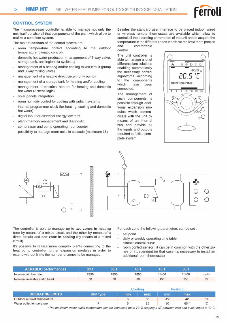
151
AERAULIC performances 30.1 35.1 40.1 45.1 50.1
Nominal air fl ow rate 7850 7850 7850 11400 11400 m3/h
Nominal available static head 50 50 50 150 150 Pa
The microprocessor controller is able to manage not only the unit itself but also all that components of the plant which allow to realize a complete system.The main functions of the control system are :- room temperature control according to the outdoor
temperature (climatic control)- domestic hot water production (management of 3 way valve,
storage tank, anti legionella cycles…)- management of a heating and/or cooling mixed circuit (pump
and 3 way mixing valve)- management of a heating direct circuit (only pump)- management of a storage tank for heating and/or cooling- management of electrical heaters for heating and domestic
hot water (3 steps logic)- solar panels integration- room humidity control for cooling with radiant systems- internal programmer clock (for heating, cooling and domestic
hot water)- digital input for electrical energy low tariff- alarm memory management and diagnostic- compressor and pump operating hour counter- possibility to manage more units in cascade (maximum 16)
Besides the standard user interface to be placed indoor, wired or wireless remote thermostats are available which allow to
temperature in the different zones in order to realize a more precise and comfortable control.The unit controller is able to manage a lot of different plant solutions enabling automatically the necessary control algorythms according to the components which have been connected.The management of such components is possible through addi-tional expansion mo-dules which commu-nicate with the unit by means of an internal bus and provide all the inputs and outputs required to fulfi l a com-plete system.
CONTROL SYSTEM
The controller is able to manage up to two zones in heating (one by means of a mixed circuit and the other by means of a direct circuit) and one zone in cooling (by means of a mixed circuit).It’s possible to realize more complex plants connecting to the heat pump controller further expansion modules in order to extend without limits the number of zones to be managed.
For each zone the following parameters can be set :- set point- daily or weekly operating time table- climatic control curve- room control sensor : it can be in common with the other zo-
nes or independent (in that case it’s necessary to install an additional room thermostat)
FS
Room temperature
20.5 C18:28
Cooling Heating
OPERATING LIMITS Unit type min max min max
Outdoor air inlet temperature IP 5 50 -22 42 °CWater outlet temperature IP 6 25 30 65 * °C
* The maximum water outlet temperature can be increased up to 70°C keeping a T between inlet and outlet equal to 10°C.
> HMP HT AIR - WATER HEAT PUMPS FOR OUTDOOR OR INDOOR INSTALLATION
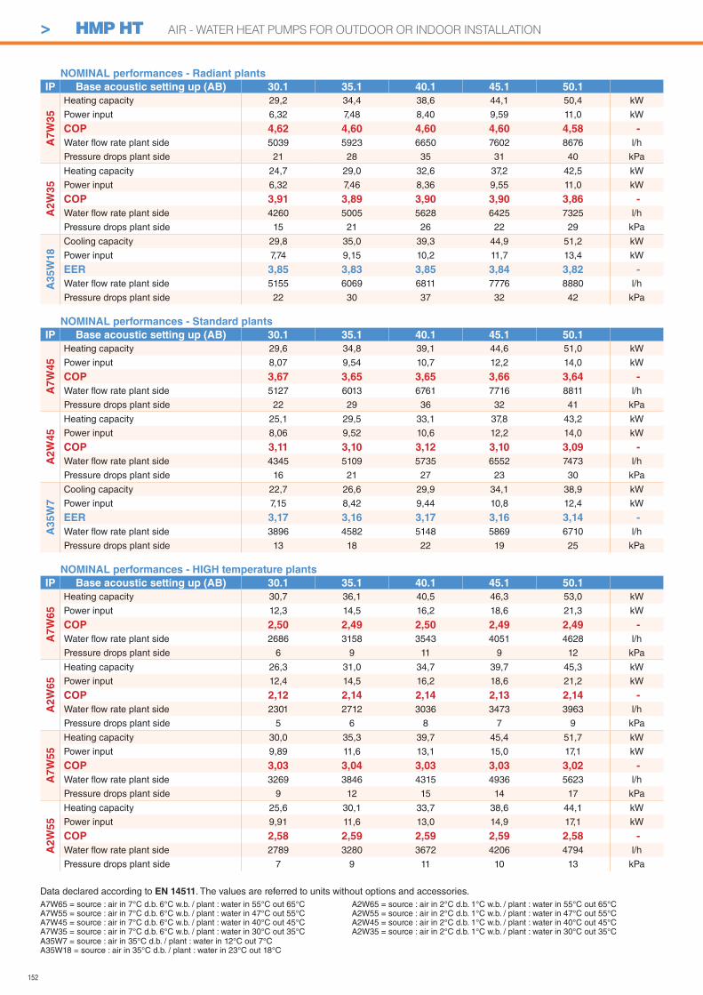
152
NOMINAL performances - Radiant plants
IP Base acoustic setting up (AB) 30.1 35.1 40.1 45.1 50.1
A7
W3
5
Heating capacity 29,2 34,4 38,6 44,1 50,4 kW
Power input 6,32 7,48 8,40 9,59 11,0 kW
COP 4,62 4,60 4,60 4,60 4,58 -
Water fl ow rate plant side 5039 5923 6650 7602 8676 l/h
Pressure drops plant side 21 28 35 31 40 kPa
A2
W3
5
Heating capacity 24,7 29,0 32,6 37,2 42,5 kW
Power input 6,32 7,46 8,36 9,55 11,0 kW
COP 3,91 3,89 3,90 3,90 3,86 -
Water fl ow rate plant side 4260 5005 5628 6425 7325 l/h
Pressure drops plant side 15 21 26 22 29 kPa
A3
5W
18
Cooling capacity 29,8 35,0 39,3 44,9 51,2 kW
Power input 7,74 9,15 10,2 11,7 13,4 kW
EER 3,85 3,83 3,85 3,84 3,82 -
Water fl ow rate plant side 5155 6069 6811 7776 8880 l/h
Pressure drops plant side 22 30 37 32 42 kPa
NOMINAL performances - Standard plants
IP Base acoustic setting up (AB) 30.1 35.1 40.1 45.1 50.1
A7
W4
5
Heating capacity 29,6 34,8 39,1 44,6 51,0 kW
Power input 8,07 9,54 10,7 12,2 14,0 kW
COP 3,67 3,65 3,65 3,66 3,64 -
Water fl ow rate plant side 5127 6013 6761 7716 8811 l/h
Pressure drops plant side 22 29 36 32 41 kPa
A2W
45
Heating capacity 25,1 29,5 33,1 37,8 43,2 kW
Power input 8,06 9,52 10,6 12,2 14,0 kW
COP 3,11 3,10 3,12 3,10 3,09 -
Water fl ow rate plant side 4345 5109 5735 6552 7473 l/h
Pressure drops plant side 16 21 27 23 30 kPa
A35W
7
Cooling capacity 22,7 26,6 29,9 34,1 38,9 kW
Power input 7,15 8,42 9,44 10,8 12,4 kW
EER 3,17 3,16 3,17 3,16 3,14 -
Water fl ow rate plant side 3896 4582 5148 5869 6710 l/h
Pressure drops plant side 13 18 22 19 25 kPa
NOMINAL performances - HIGH temperature plants
IP Base acoustic setting up (AB) 30.1 35.1 40.1 45.1 50.1
A7W
65
Heating capacity 30,7 36,1 40,5 46,3 53,0 kW
Power input 12,3 14,5 16,2 18,6 21,3 kW
COP 2,50 2,49 2,50 2,49 2,49 -
Water fl ow rate plant side 2686 3158 3543 4051 4628 l/h
Pressure drops plant side 6 9 11 9 12 kPa
A2W
65
Heating capacity 26,3 31,0 34,7 39,7 45,3 kW
Power input 12,4 14,5 16,2 18,6 21,2 kW
COP 2,12 2,14 2,14 2,13 2,14 -
Water fl ow rate plant side 2301 2712 3036 3473 3963 l/h
Pressure drops plant side 5 6 8 7 9 kPa
A7W
55
Heating capacity 30,0 35,3 39,7 45,4 51,7 kW
Power input 9,89 11,6 13,1 15,0 17,1 kW
COP 3,03 3,04 3,03 3,03 3,02 -
Water fl ow rate plant side 3269 3846 4315 4936 5623 l/h
Pressure drops plant side 9 12 15 14 17 kPa
A2
W55
Heating capacity 25,6 30,1 33,7 38,6 44,1 kW
Power input 9,91 11,6 13,0 14,9 17,1 kW
COP 2,58 2,59 2,59 2,59 2,58 -
Water fl ow rate plant side 2789 3280 3672 4206 4794 l/h
Pressure drops plant side 7 9 11 10 13 kPa
A7W65 = source : air in 7°C d.b. 6°C w.b. / plant : water in 55°C out 65°CA7W55 = source : air in 7°C d.b. 6°C w.b. / plant : water in 47°C out 55°CA7W45 = source : air in 7°C d.b. 6°C w.b. / plant : water in 40°C out 45°CA7W35 = source : air in 7°C d.b. 6°C w.b. / plant : water in 30°C out 35°C
Data declared according to EN 14511. The values are referred to units without options and accessories.
A35W7 = source : air in 35°C d.b. / plant : water in 12°C out 7°CA35W18 = source : air in 35°C d.b. / plant : water in 23°C out 18°C
A2W65 = source : air in 2°C d.b. 1°C w.b. / plant : water in 55°C out 65°CA2W55 = source : air in 2°C d.b. 1°C w.b. / plant : water in 47°C out 55°CA2W45 = source : air in 2°C d.b. 1°C w.b. / plant : water in 40°C out 45°CA2W35 = source : air in 2°C d.b. 1°C w.b. / plant : water in 30°C out 35°C
> HMP HT AIR - WATER HEAT PUMPS FOR OUTDOOR OR INDOOR INSTALLATION
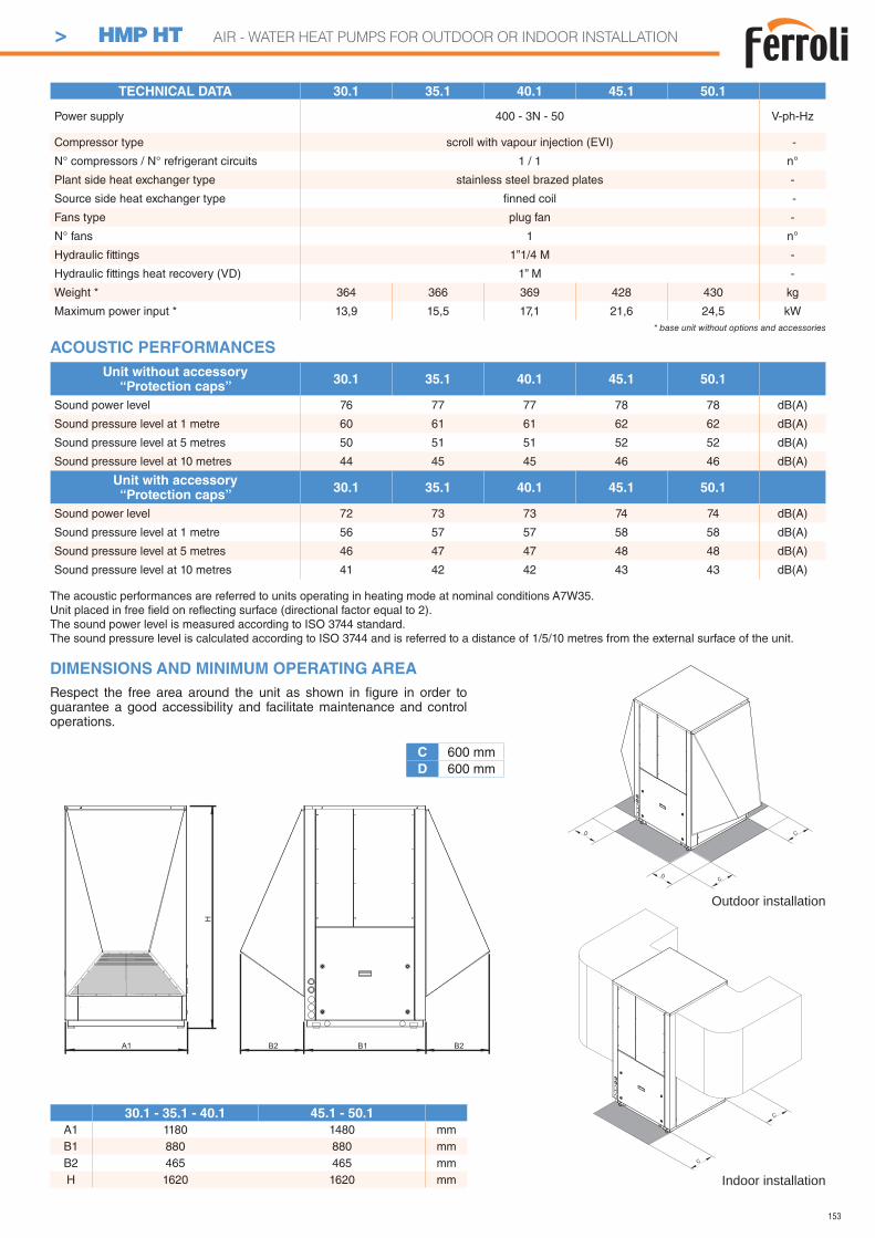
153
TECHNICAL DATA 30.1 35.1 40.1 45.1 50.1
Power supply 400 - 3N - 50 V-ph-Hz
Compressor type scroll with vapour injection (EVI) -
N° compressors / N° refrigerant circuits 1 / 1 n°
Plant side heat exchanger type stainless steel brazed plates -
Source side heat exchanger type fi nned coil -
Fans type plug fan -
N° fans 1 n°
Hydraulic fi ttings 1”1/4 M -
Hydraulic fi ttings heat recovery (VD) 1” M -
Weight * 364 366 369 428 430 kg
Maximum power input * 13,9 15,5 17,1 21,6 24,5 kW* base unit without options and accessories
30.1 - 35.1 - 40.1 45.1 - 50.1
A1 1180 1480 mmB1 880 880 mmB2 465 465 mmH 1620 1620 mm
Unit without accessory“Protection caps”
30.1 35.1 40.1 45.1 50.1
Sound power level 76 77 77 78 78 dB(A)
Sound pressure level at 1 metre 60 61 61 62 62 dB(A)
Sound pressure level at 5 metres 50 51 51 52 52 dB(A)
Sound pressure level at 10 metres 44 45 45 46 46 dB(A)
Unit with accessory“Protection caps”
30.1 35.1 40.1 45.1 50.1
Sound power level 72 73 73 74 74 dB(A)
Sound pressure level at 1 metre 56 57 57 58 58 dB(A)
Sound pressure level at 5 metres 46 47 47 48 48 dB(A)
Sound pressure level at 10 metres 41 42 42 43 43 dB(A)
DIMENSIONS AND MINIMUM OPERATING AREA
C 600 mmD 600 mm
Respect the free area around the unit as shown in fi gure in order to guarantee a good accessibility and facilitate maintenance and control operations.
Outdoor installation
Indoor installation
The acoustic performances are referred to units operating in heating mode at nominal conditions A7W35.Unit placed in free fi eld on refl ecting surface (directional factor equal to 2).The sound power level is measured according to ISO 3744 standard.The sound pressure level is calculated according to ISO 3744 and is referred to a distance of 1/5/10 metres from the external surface of the unit.
ACOUSTIC PERFORMANCES
> HMP HT AIR - WATER HEAT PUMPS FOR OUTDOOR OR INDOOR INSTALLATION
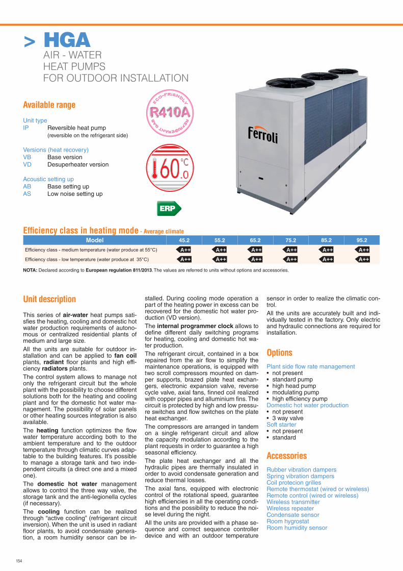
154
Available range
Unit typeIP Reversible heat pump (reversible on the refrigerant side)
Versions (heat recovery)VB Base versionVD Desuperheater version
Acoustic setting upAB Base setting upAS Low noise setting up
Unit description
This series of air-water heat pumps sati-sfi es the heating, cooling and domestic hot water production requirements of autono-mous or centralized residential plants of medium and large size.All the units are suitable for outdoor in-stallation and can be applied to fan coil plants, radiant fl oor plants and high effi-ciency radiators plants.The control system allows to manage not only the refrigerant circuit but the whole plant with the possibility to choose different solutions both for the heating and cooling plant and for the domestic hot water ma-nagement. The possibility of solar panels or other heating sources integration is also available.The heating function optimizes the fl ow water temperature according both to the ambient temperature and to the outdoor temperature through climatic curves adap-table to the building features. It’s possible to manage a storage tank and two inde-pendent circuits (a direct one and a mixed one).The domestic hot water management allows to control the three way valve, the storage tank and the anti-legionella cycles (if necessary).The cooling function can be realized through “active cooling” (refrigerant circuit inversion). When the unit is used in radiant fl oor plants, to avoid condensate genera-tion, a room humidity sensor can be in-
stalled. During cooling mode operation a part of the heating power in excess can be recovered for the domestic hot water pro-duction (VD version).The internal programmer clock allows to defi ne different daily switching programs for heating, cooling and domestic hot wa-ter production.The refrigerant circuit, contained in a box repaired from the air fl ow to simplify the maintenance operations, is equipped with two scroll compressors mounted on dam-per supports, brazed plate heat exchan-gers, electronic expansion valve, reverse cycle valve, axial fans, fi nned coil realized with copper pipes and alluminium fi ns. The circuit is protected by high and low pressu-re switches and fl ow switches on the plate heat exchanger.The compressors are arranged in tandem on a single refrigerant circuit and allow the capacity modulation according to the plant requests in order to guarantee a high seasonal efficiency.The plate heat exchanger and all the hydraulic pipes are thermally insulated in order to avoid condensate generation and reduce thermal losses. The axial fans, equipped with electronic control of the rotational speed, guarantee high efficiencies in all the operating condi-tions and the possibility to reduce the noi-se level during the night.All the units are provided with a phase se-quence and correct sequence controller device and with an outdoor temperature
sensor in order to realize the climatic con-trol.All the units are accurately built and indi-vidually tested in the factory. Only electric and hydraulic connections are required for installation.
Options
Plant side fl ow rate management • not present• standard pump• high head pump• modulating pump• high efficiency pumpDomestic hot water production • not present• 3 way valveSoft starter• not present• standard
Accessories
Rubber vibration dampersSpring vibration dampersCoil protecion grillesRemote thermostat (wired or wireless)Remote control (wired or wireless)Wireless transmitterWireless repeaterCondensate sensorRoom hygrostatRoom humidity sensor
RE
FRIGERANT G
AS
E
CO-FRIEND
LY
Effi ciency class in heating mode - Average climate
Model 45.2 55.2 65.2 75.2 85.2 95.2
NOTA: Declared according to European regulation 811/2013. The values are referred to units without options and accessories.
ERP
A++ A++ A++ A++ A++A++ A++ A++ A++ A++
A++A++
> HGA AIR - WATER
HEAT PUMPS
FOR OUTDOOR INSTALLATION
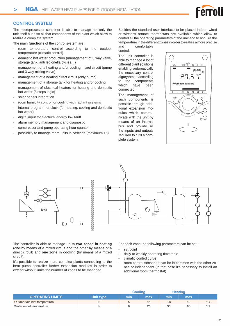
155
The controller is able to manage up to two zones in heating (one by means of a mixed circuit and the other by means of a direct circuit) and one zone in cooling (by means of a mixed circuit).It’s possible to realize more complex plants connecting to the heat pump controller further expansion modules in order to extend without limits the number of zones to be managed.
For each zone the following parameters can be set :- set point- daily or weekly operating time table- climatic control curve- room control sensor : it can be in common with the other zo-
nes or independent (in that case it’s necessary to install an additional room thermostat)
FS
The microprocessor controller is able to manage not only the unit itself but also all that components of the plant which allow to realize a complete system.The main functions of the control system are :- room temperature control according to the outdoor
temperature (climatic control)- domestic hot water production (management of 3 way valve,
storage tank, anti legionella cycles…)- management of a heating and/or cooling mixed circuit (pump
and 3 way mixing valve)- management of a heating direct circuit (only pump)- management of a storage tank for heating and/or cooling- management of electrical heaters for heating and domestic
hot water (3 steps logic)- solar panels integration- room humidity control for cooling with radiant systems- internal programmer clock (for heating, cooling and domestic
hot water)- digital input for electrical energy low tariff- alarm memory management and diagnostic- compressor and pump operating hour counter- possibility to manage more units in cascade (maximum 16)
Besides the standard user interface to be placed indoor, wired or wireless remote thermostats are available which allow to
temperature in the different zones in order to realize a more precise and comfortable control.The unit controller is able to manage a lot of different plant solutions enabling automatically the necessary control algorythms according to the components which have been connected.The management of such components is possible through addi-tional expansion mo-dules which commu-nicate with the unit by means of an internal bus and provide all the inputs and outputs required to fulfi l a com-plete system.
CONTROL SYSTEM
Room temperature
20.5 C18:28
Cooling Heating
OPERATING LIMITS Unit type min max min max
Outdoor air inlet temperature IP 5 45 -20 42 °CWater outlet temperature IP 6 25 30 60 °C
> HGA AIR - WATER HEAT PUMPS FOR OUTDOOR INSTALLATION
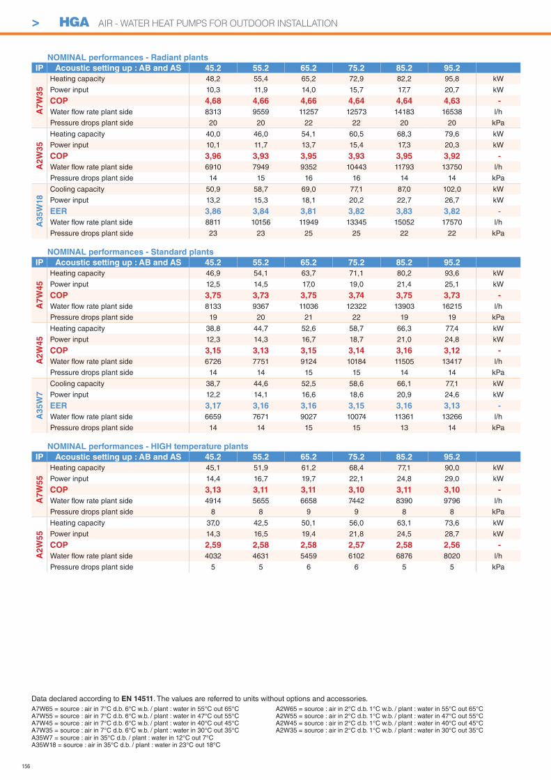
156
> HGA AIR - WATER HEAT PUMPS FOR OUTDOOR INSTALLATION
A7W65 = source : air in 7°C d.b. 6°C w.b. / plant : water in 55°C out 65°CA7W55 = source : air in 7°C d.b. 6°C w.b. / plant : water in 47°C out 55°CA7W45 = source : air in 7°C d.b. 6°C w.b. / plant : water in 40°C out 45°CA7W35 = source : air in 7°C d.b. 6°C w.b. / plant : water in 30°C out 35°C
Data declared according to EN 14511. The values are referred to units without options and accessories.
A35W7 = source : air in 35°C d.b. / plant : water in 12°C out 7°CA35W18 = source : air in 35°C d.b. / plant : water in 23°C out 18°C
A2W65 = source : air in 2°C d.b. 1°C w.b. / plant : water in 55°C out 65°CA2W55 = source : air in 2°C d.b. 1°C w.b. / plant : water in 47°C out 55°CA2W45 = source : air in 2°C d.b. 1°C w.b. / plant : water in 40°C out 45°CA2W35 = source : air in 2°C d.b. 1°C w.b. / plant : water in 30°C out 35°C
NOMINAL performances - Radiant plants
IP Acoustic setting up : AB and AS 45.2 55.2 65.2 75.2 85.2 95.2
A7
W3
5
Heating capacity 48,2 55,4 65,2 72,9 82,2 95,8 kW
Power input 10,3 11,9 14,0 15,7 17,7 20,7 kW
COP 4,68 4,66 4,66 4,64 4,64 4,63 -
Water fl ow rate plant side 8313 9559 11257 12573 14183 16538 l/h
Pressure drops plant side 20 20 22 22 20 20 kPa
A2
W3
5
Heating capacity 40,0 46,0 54,1 60,5 68,3 79,6 kW
Power input 10,1 11,7 13,7 15,4 17,3 20,3 kW
COP 3,96 3,93 3,95 3,93 3,95 3,92 -
Water fl ow rate plant side 6910 7949 9352 10443 11793 13750 l/h
Pressure drops plant side 14 15 16 16 14 14 kPa
A3
5W
18
Cooling capacity 50,9 58,7 69,0 77,1 87,0 102,0 kW
Power input 13,2 15,3 18,1 20,2 22,7 26,7 kW
EER 3,86 3,84 3,81 3,82 3,83 3,82 -
Water fl ow rate plant side 8811 10156 11949 13345 15052 17570 l/h
Pressure drops plant side 23 23 25 25 22 22 kPa
NOMINAL performances - Standard plants
IP Acoustic setting up : AB and AS 45.2 55.2 65.2 75.2 85.2 95.2
A7
W4
5
Heating capacity 46,9 54,1 63,7 71,1 80,2 93,6 kW
Power input 12,5 14,5 17,0 19,0 21,4 25,1 kW
COP 3,75 3,73 3,75 3,74 3,75 3,73 -
Water fl ow rate plant side 8133 9367 11036 12322 13903 16215 l/h
Pressure drops plant side 19 20 21 22 19 19 kPa
A2W
45
Heating capacity 38,8 44,7 52,6 58,7 66,3 77,4 kW
Power input 12,3 14,3 16,7 18,7 21,0 24,8 kW
COP 3,15 3,13 3,15 3,14 3,16 3,12 -
Water fl ow rate plant side 6726 7751 9124 10184 11505 13417 l/h
Pressure drops plant side 14 14 15 15 14 14 kPa
A35W
7
Cooling capacity 38,7 44,6 52,5 58,6 66,1 77,1 kW
Power input 12,2 14,1 16,6 18,6 20,9 24,6 kW
EER 3,17 3,16 3,16 3,15 3,16 3,13 -
Water fl ow rate plant side 6659 7671 9027 10074 11361 13266 l/h
Pressure drops plant side 14 14 15 15 13 14 kPa
NOMINAL performances - HIGH temperature plants
IP Acoustic setting up : AB and AS 45.2 55.2 65.2 75.2 85.2 95.2
A7W
55
Heating capacity 45,1 51,9 61,2 68,4 77,1 90,0 kW
Power input 14,4 16,7 19,7 22,1 24,8 29,0 kW
COP 3,13 3,11 3,11 3,10 3,11 3,10 -
Water fl ow rate plant side 4914 5655 6658 7442 8390 9796 l/h
Pressure drops plant side 8 8 9 9 8 8 kPa
A2W
55
Heating capacity 37,0 42,5 50,1 56,0 63,1 73,6 kW
Power input 14,3 16,5 19,4 21,8 24,5 28,7 kW
COP 2,59 2,58 2,58 2,57 2,58 2,56 -
Water fl ow rate plant side 4032 4631 5459 6102 6876 8020 l/h
Pressure drops plant side 5 5 6 6 5 5 kPa
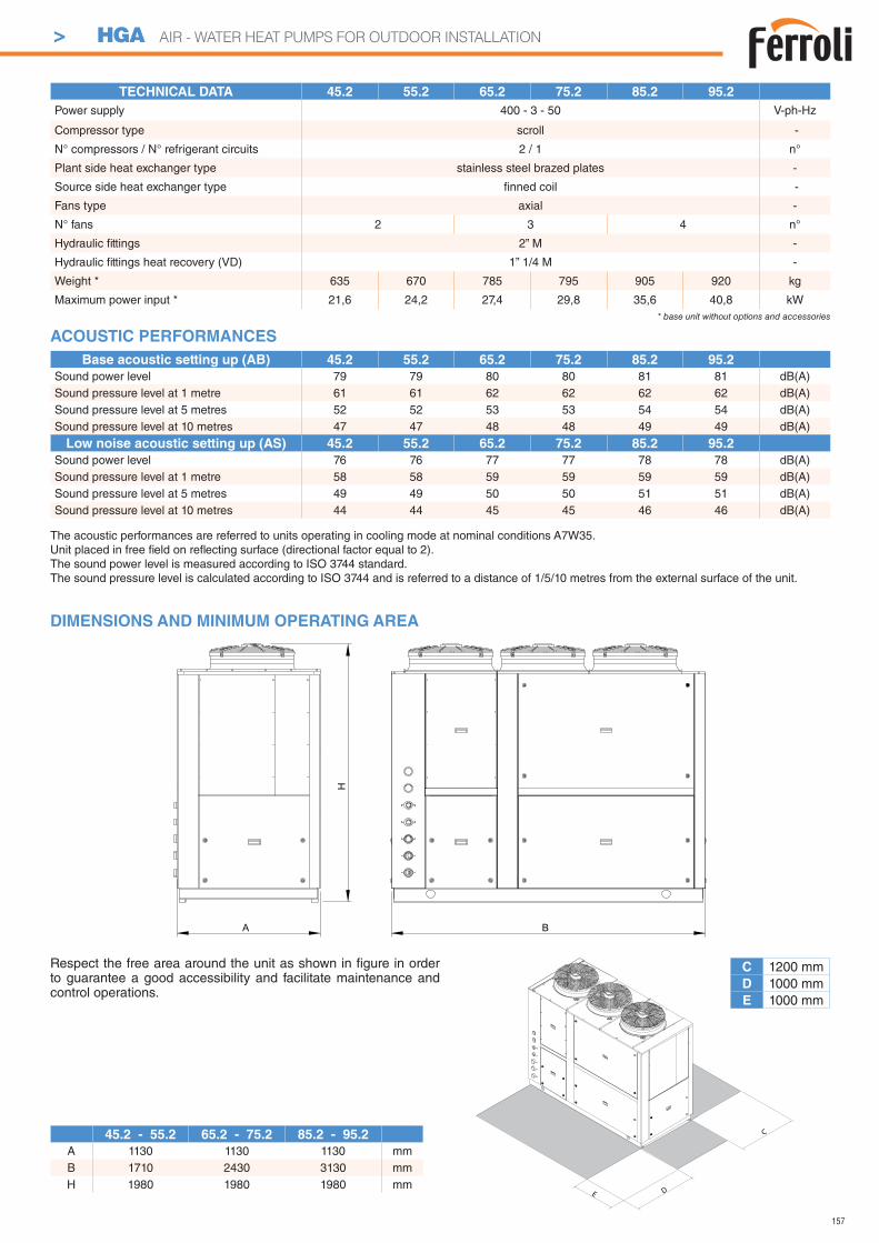
157
> HGA AIR - WATER HEAT PUMPS FOR OUTDOOR INSTALLATION
H
A B
DIMENSIONS AND MINIMUM OPERATING AREA
C 1200 mmD 1000 mmE 1000 mm
Respect the free area around the unit as shown in fi gure in order to guarantee a good accessibility and facilitate maintenance and control operations.
D
C
E
The acoustic performances are referred to units operating in cooling mode at nominal conditions A7W35.Unit placed in free fi eld on refl ecting surface (directional factor equal to 2).The sound power level is measured according to ISO 3744 standard.The sound pressure level is calculated according to ISO 3744 and is referred to a distance of 1/5/10 metres from the external surface of the unit.
ACOUSTIC PERFORMANCES
45.2 - 55.2 65.2 - 75.2 85.2 - 95.2
A 1130 1130 1130 mmB 1710 2430 3130 mmH 1980 1980 1980 mm
Base acoustic setting up (AB) 45.2 55.2 65.2 75.2 85.2 95.2
Sound power level 79 79 80 80 81 81 dB(A)Sound pressure level at 1 metre 61 61 62 62 62 62 dB(A)Sound pressure level at 5 metres 52 52 53 53 54 54 dB(A)Sound pressure level at 10 metres 47 47 48 48 49 49 dB(A)
Low noise acoustic setting up (AS) 45.2 55.2 65.2 75.2 85.2 95.2
Sound power level 76 76 77 77 78 78 dB(A)Sound pressure level at 1 metre 58 58 59 59 59 59 dB(A)Sound pressure level at 5 metres 49 49 50 50 51 51 dB(A)Sound pressure level at 10 metres 44 44 45 45 46 46 dB(A)
TECHNICAL DATA 45.2 55.2 65.2 75.2 85.2 95.2
Power supply 400 - 3 - 50 V-ph-Hz
Compressor type scroll -
N° compressors / N° refrigerant circuits 2 / 1 n°
Plant side heat exchanger type stainless steel brazed plates -
Source side heat exchanger type fi nned coil -
Fans type axial -
N° fans 2 3 4 n°
Hydraulic fi ttings 2” M -
Hydraulic fi ttings heat recovery (VD) 1” 1/4 M -
Weight * 635 670 785 795 905 920 kg
Maximum power input * 21,6 24,2 27,4 29,8 35,6 40,8 kW* base unit without options and accessories
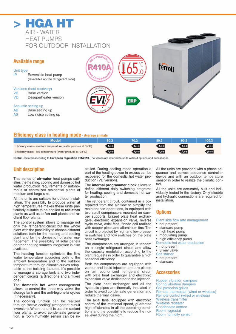
158
Available range
Unit typeIP Reversible heat pump (reversible on the refrigerant side)
Versions (heat recovery)VB Base versionVD Desuperheater version
Acoustic setting upAB Base setting upAS Low noise setting up
Unit description
This series of air-water heat pumps sati-sfi es the heating, cooling and domestic hot water production requirements of autono-mous or centralized residential plants of medium and large size.All the units are suitable for outdoor instal-lation. The possibiliy to produce water at high temperatures makes these units par-ticularly suitable to be applied to radiators plants as well as to fan coil plants and ra-diant fl oor plants.The control system allows to manage not only the refrigerant circuit but the whole plant with the possibility to choose different solutions both for the heating and cooling plant and for the domestic hot water ma-nagement. The possibility of solar panels or other heating sources integration is also available.The heating function optimizes the fl ow water temperature according both to the ambient temperature and to the outdoor temperature through climatic curves adap-table to the building features. It’s possible to manage a storage tank and two inde-pendent circuits (a direct one and a mixed one).The domestic hot water management allows to control the three way valve, the storage tank and the anti-legionella cycles (if necessary).The cooling function can be realized through “active cooling” (refrigerant circuit inversion). When the unit is used in radiant fl oor plants, to avoid condensate genera-tion, a room humidity sensor can be in-
stalled. During cooling mode operation a part of the heating power in excess can be recovered for the domestic hot water pro-duction (VD version).The internal programmer clock allows to defi ne different daily switching programs for heating, cooling and domestic hot wa-ter production.The refrigerant circuit, contained in a box repaired from the air fl ow to simplify the maintenance operations, is equipped with two scroll compressors mounted on dam-per supports, brazed plate heat exchan-gers, electronic expansion valve, reverse cycle valve, axial fans, fi nned coil realized with copper pipes and alluminium fi ns. The circuit is protected by high and low pressu-re switches and fl ow switches on the plate heat exchanger.The compressors are arranged in tandem on a single refrigerant circuit and allow the capacity modulation according to the plant requests in order to guarantee a high seasonal efficiency.Both the compressors are equipped with vapour and liquid injection and are placed on an economized refrigerant circuit with plate heat exchanger and electronic expansion valve dedicated to the injection.The plate heat exchanger and all the hydraulic pipes are thermally insulated in order to avoid condensate generation and reduce thermal losses. The axial fans, equipped with electronic control of the rotational speed, guarantee high efficiencies in all the operating condi-tions and the possibility to reduce the noi-se level during the night.
All the units are provided with a phase se-quence and correct sequence controller device and with an outdoor temperature sensor in order to realize the climatic con-trol.All the units are accurately built and indi-vidually tested in the factory. Only electric and hydraulic connections are required for installation.
Options
Plant side fl ow rate management • not present• standard pump• high head pump• modulating pump• high efficiency pumpDomestic hot water production • not present• 3 way valveSoft starter• not present• standard
Accessories
Rubber vibration dampersSpring vibration dampersCoil protecion grillesRemote thermostat (wired or wireless)Remote control (wired or wireless)Wireless transmitterWireless repeaterCondensate sensorRoom hygrostatRoom humidity sensor
RE
FRIGERANT G
AS
E
CO-FRIEND
LY
.065
ERP
Effi ciency class in heating mode - Average climate
Model 60.2 70.2 80.2 90.2 100.2
NOTA: Declared according to European regulation 811/2013. The values are referred to units without options and accessories.
A++ A++ A++ A++ A++A++ A++ A++ A++ A++
> HGA HT AIR - WATER
HEAT PUMPS
FOR OUTDOOR INSTALLATION
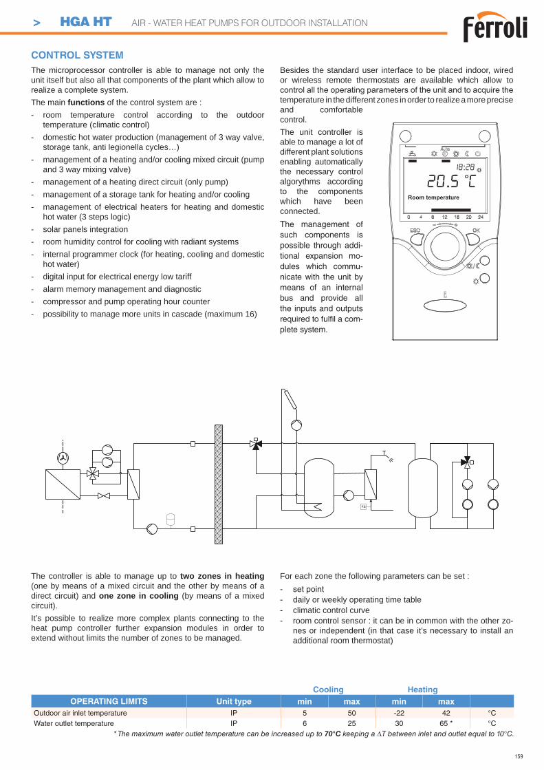
159
The controller is able to manage up to two zones in heating (one by means of a mixed circuit and the other by means of a direct circuit) and one zone in cooling (by means of a mixed circuit).It’s possible to realize more complex plants connecting to the heat pump controller further expansion modules in order to extend without limits the number of zones to be managed.
For each zone the following parameters can be set :- set point- daily or weekly operating time table- climatic control curve- room control sensor : it can be in common with the other zo-
nes or independent (in that case it’s necessary to install an additional room thermostat)
FS
The microprocessor controller is able to manage not only the unit itself but also all that components of the plant which allow to realize a complete system.The main functions of the control system are :- room temperature control according to the outdoor
temperature (climatic control)- domestic hot water production (management of 3 way valve,
storage tank, anti legionella cycles…)- management of a heating and/or cooling mixed circuit (pump
and 3 way mixing valve)- management of a heating direct circuit (only pump)- management of a storage tank for heating and/or cooling- management of electrical heaters for heating and domestic
hot water (3 steps logic)- solar panels integration- room humidity control for cooling with radiant systems- internal programmer clock (for heating, cooling and domestic
hot water)- digital input for electrical energy low tariff- alarm memory management and diagnostic- compressor and pump operating hour counter- possibility to manage more units in cascade (maximum 16)
Besides the standard user interface to be placed indoor, wired or wireless remote thermostats are available which allow to
temperature in the different zones in order to realize a more precise and comfortable control.The unit controller is able to manage a lot of different plant solutions enabling automatically the necessary control algorythms according to the components which have been connected.The management of such components is possible through addi-tional expansion mo-dules which commu-nicate with the unit by means of an internal bus and provide all the inputs and outputs required to fulfi l a com-plete system.
CONTROL SYSTEM
Room temperature
20.5 C18:28
Cooling Heating
OPERATING LIMITS Unit type min max min max
Outdoor air inlet temperature IP 5 50 -22 42 °CWater outlet temperature IP 6 25 30 65 * °C
* The maximum water outlet temperature can be increased up to 70°C keeping a T between inlet and outlet equal to 10°C.
> HGA HT AIR - WATER HEAT PUMPS FOR OUTDOOR INSTALLATION
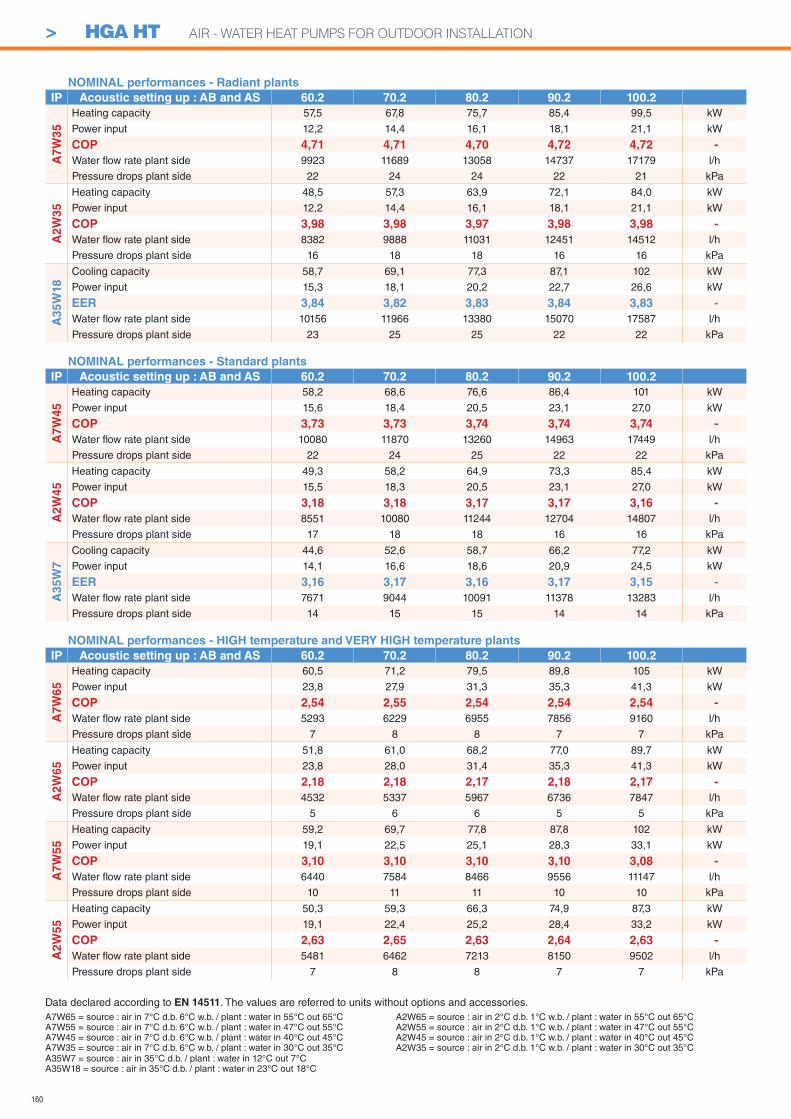
160
A7W65 = source : air in 7°C d.b. 6°C w.b. / plant : water in 55°C out 65°CA7W55 = source : air in 7°C d.b. 6°C w.b. / plant : water in 47°C out 55°CA7W45 = source : air in 7°C d.b. 6°C w.b. / plant : water in 40°C out 45°CA7W35 = source : air in 7°C d.b. 6°C w.b. / plant : water in 30°C out 35°C
Data declared according to EN 14511. The values are referred to units without options and accessories.
A35W7 = source : air in 35°C d.b. / plant : water in 12°C out 7°CA35W18 = source : air in 35°C d.b. / plant : water in 23°C out 18°C
A2W65 = source : air in 2°C d.b. 1°C w.b. / plant : water in 55°C out 65°CA2W55 = source : air in 2°C d.b. 1°C w.b. / plant : water in 47°C out 55°CA2W45 = source : air in 2°C d.b. 1°C w.b. / plant : water in 40°C out 45°CA2W35 = source : air in 2°C d.b. 1°C w.b. / plant : water in 30°C out 35°C
NOMINAL performances - Radiant plants
IP Acoustic setting up : AB and AS 60.2 70.2 80.2 90.2 100.2
A7
W3
5
Heating capacity 57,5 67,8 75,7 85,4 99,5 kW
Power input 12,2 14,4 16,1 18,1 21,1 kW
COP 4,71 4,71 4,70 4,72 4,72 -
Water fl ow rate plant side 9923 11689 13058 14737 17179 l/h
Pressure drops plant side 22 24 24 22 21 kPa
A2
W3
5
Heating capacity 48,5 57,3 63,9 72,1 84,0 kW
Power input 12,2 14,4 16,1 18,1 21,1 kW
COP 3,98 3,98 3,97 3,98 3,98 -
Water fl ow rate plant side 8382 9888 11031 12451 14512 l/h
Pressure drops plant side 16 18 18 16 16 kPa
A3
5W
18
Cooling capacity 58,7 69,1 77,3 87,1 102 kW
Power input 15,3 18,1 20,2 22,7 26,6 kW
EER 3,84 3,82 3,83 3,84 3,83 -
Water fl ow rate plant side 10156 11966 13380 15070 17587 l/h
Pressure drops plant side 23 25 25 22 22 kPa
NOMINAL performances - Standard plants
IP Acoustic setting up : AB and AS 60.2 70.2 80.2 90.2 100.2
A7
W4
5
Heating capacity 58,2 68,6 76,6 86,4 101 kW
Power input 15,6 18,4 20,5 23,1 27,0 kW
COP 3,73 3,73 3,74 3,74 3,74 -
Water fl ow rate plant side 10080 11870 13260 14963 17449 l/h
Pressure drops plant side 22 24 25 22 22 kPa
A2W
45
Heating capacity 49,3 58,2 64,9 73,3 85,4 kW
Power input 15,5 18,3 20,5 23,1 27,0 kW
COP 3,18 3,18 3,17 3,17 3,16 -
Water fl ow rate plant side 8551 10080 11244 12704 14807 l/h
Pressure drops plant side 17 18 18 16 16 kPa
A35W
7
Cooling capacity 44,6 52,6 58,7 66,2 77,2 kW
Power input 14,1 16,6 18,6 20,9 24,5 kW
EER 3,16 3,17 3,16 3,17 3,15 -
Water fl ow rate plant side 7671 9044 10091 11378 13283 l/h
Pressure drops plant side 14 15 15 14 14 kPa
NOMINAL performances - HIGH temperature and VERY HIGH temperature plants
IP Acoustic setting up : AB and AS 60.2 70.2 80.2 90.2 100.2
A7W
65
Heating capacity 60,5 71,2 79,5 89,8 105 kW
Power input 23,8 27,9 31,3 35,3 41,3 kW
COP 2,54 2,55 2,54 2,54 2,54 -
Water fl ow rate plant side 5293 6229 6955 7856 9160 l/h
Pressure drops plant side 7 8 8 7 7 kPa
A2W
65
Heating capacity 51,8 61,0 68,2 77,0 89,7 kW
Power input 23,8 28,0 31,4 35,3 41,3 kW
COP 2,18 2,18 2,17 2,18 2,17 -
Water fl ow rate plant side 4532 5337 5967 6736 7847 l/h
Pressure drops plant side 5 6 6 5 5 kPa
A7W
55
Heating capacity 59,2 69,7 77,8 87,8 102 kW
Power input 19,1 22,5 25,1 28,3 33,1 kW
COP 3,10 3,10 3,10 3,10 3,08 -
Water fl ow rate plant side 6440 7584 8466 9556 11147 l/h
Pressure drops plant side 10 11 11 10 10 kPa
A2
W55
Heating capacity 50,3 59,3 66,3 74,9 87,3 kW
Power input 19,1 22,4 25,2 28,4 33,2 kW
COP 2,63 2,65 2,63 2,64 2,63 -
Water fl ow rate plant side 5481 6462 7213 8150 9502 l/h
Pressure drops plant side 7 8 8 7 7 kPa
> HGA HT AIR - WATER HEAT PUMPS FOR OUTDOOR INSTALLATION
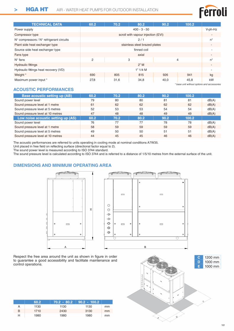
161
TECHNICAL DATA 60.2 70.2 80.2 90.2 100.2
Power supply 400 - 3 - 50 V-ph-Hz
Compressor type scroll with vapour injection (EVI) -
N° compressors / N° refrigerant circuits 2 / 1 n°
Plant side heat exchanger type stainless steel brazed plates -
Source side heat exchanger type fi nned coil -
Fans type axial -
N° fans 2 3 4 n°
Hydraulic fi ttings 2” M -
Hydraulic fi ttings heat recovery (VD) 1” 1/4 M -
Weight * 690 805 815 926 941 kg
Maximum power input * 27,8 31,6 34,8 40,0 45,8 kW* base unit without options and accessories
H
A B
DIMENSIONS AND MINIMUM OPERATING AREA
C 1200 mmD 1000 mmE 1000 mm
Respect the free area around the unit as shown in fi gure in order to guarantee a good accessibility and facilitate maintenance and control operations.
D
C
E
60.2 70.2 - 80.2 90.2 - 100.2
A 1130 1130 1130 mmB 1710 2430 3130 mmH 1980 1980 1980 mm
The acoustic performances are referred to units operating in cooling mode at nominal conditions A7W35.Unit placed in free fi eld on refl ecting surface (directional factor equal to 2).The sound power level is measured according to ISO 3744 standard.The sound pressure level is calculated according to ISO 3744 and is referred to a distance of 1/5/10 metres from the external surface of the unit.
ACOUSTIC PERFORMANCES
Base acoustic setting up (AB) 60.2 70.2 80.2 90.2 100.2
Sound power level 79 80 80 81 81 dB(A)Sound pressure level at 1 metre 61 62 62 62 62 dB(A)Sound pressure level at 5 metres 52 53 53 54 54 dB(A)Sound pressure level at 10 metres 47 48 48 49 49 dB(A)
Low noise acoustic setting up (AS) 60.2 70.2 80.2 90.2 100.2
Sound power level 76 77 77 78 78 dB(A)Sound pressure level at 1 metre 58 59 59 59 59 dB(A)Sound pressure level at 5 metres 49 50 50 51 51 dB(A)Sound pressure level at 10 metres 44 45 45 46 46 dB(A)
> HGA HT AIR - WATER HEAT PUMPS FOR OUTDOOR INSTALLATION
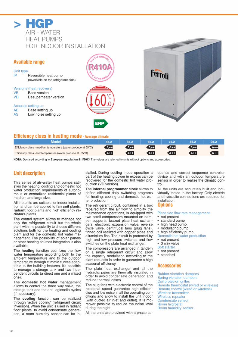
162
Available range
Unit typeIP Reversible heat pump (reversible on the refrigerant side)
Versions (heat recovery)VB Base versionVD Desuperheater version
Acoustic setting upAB Base setting upAS Low noise setting up
Unit description
This series of air-water heat pumps sati-sfi es the heating, cooling and domestic hot water production requirements of autono-mous or centralized residential plants of medium and large size.All the units are suitable for indoor installa-tion and can be applied to fan coil plants, radiant fl oor plants and high efficiency ra-diators plants.The control system allows to manage not only the refrigerant circuit but the whole plant with the possibility to choose different solutions both for the heating and cooling plant and for the domestic hot water ma-nagement. The possibility of solar panels or other heating sources integration is also available.The heating function optimizes the fl ow water temperature according both to the ambient temperature and to the outdoor temperature through climatic curves adap-table to the building features. It’s possible to manage a storage tank and two inde-pendent circuits (a direct one and a mixed one).The domestic hot water management allows to control the three way valve, the storage tank and the anti-legionella cycles (if necessary).The cooling function can be realized through “active cooling” (refrigerant circuit inversion). When the unit is used in radiant fl oor plants, to avoid condensate genera-tion, a room humidity sensor can be in-
stalled. During cooling mode operation a part of the heating power in excess can be recovered for the domestic hot water pro-duction (VD version).The internal programmer clock allows to defi ne different daily switching programs for heating, cooling and domestic hot wa-ter production.The refrigerant circuit, contained in a box repaired from the air fl ow to simplify the maintenance operations, is equipped with two scroll compressors mounted on dam-per supports, brazed plate heat exchan-gers, electronic expansion valve, reverse cycle valve, centrifugal fans (plug fans), fi nned coil realized with copper pipes and alluminium fi ns. The circuit is protected by high and low pressure switches and fl ow switches on the plate heat exchanger.The compressors are arranged in tandem on a single refrigerant circuit and allow the capacity modulation according to the plant requests in order to guarantee a high seasonal efficiency.The plate heat exchanger and all the hydraulic pipes are thermally insulated in order to avoid condensate generation and reduce thermal losses.The plug fans with electronic control of the rotational speed guarantee high efficien-cies and low noise in all the operating con-ditions and allow to install the unit indoor (with ducted air inlet and outlet). It is mo-reover possible to reduce the noise level during the night.All the units are provided with a phase se-
quence and correct sequence controller device and with an outdoor temperature sensor in order to realize the climatic con-trol.All the units are accurately built and indi-vidually tested in the factory. Only electric and hydraulic connections are required for installation.Options
Plant side fl ow rate management • not present• standard pump• high head pump• modulating pump• high efficiency pumpDomestic hot water production • not present• 3 way valveSoft starter• not present• standard
Accessories
Rubber vibration dampersSpring vibration dampersCoil protecion grillesRemote thermostat (wired or wireless)Remote control (wired or wireless)Wireless transmitterWireless repeaterCondensate sensorRoom hygrostatRoom humidity sensor
RE
FRIGERANT G
AS
E
CO-FRIEND
LY
Effi ciency class in heating mode - Average climate
Model 45.2 55.2 65.2 75.2 85.2 95.2
NOTA: Declared according to European regulation 811/2013. The values are referred to units without options and accessories.
A++ A++ A++ A++ A++A++ A++ A++ A++ A++
A++A++
ERP
> HGP AIR - WATER
HEAT PUMPS
FOR INDOOR INSTALLATION
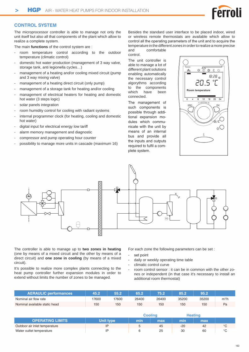
163
The controller is able to manage up to two zones in heating (one by means of a mixed circuit and the other by means of a direct circuit) and one zone in cooling (by means of a mixed circuit).It’s possible to realize more complex plants connecting to the heat pump controller further expansion modules in order to extend without limits the number of zones to be managed.
For each zone the following parameters can be set :- set point- daily or weekly operating time table- climatic control curve- room control sensor : it can be in common with the other zo-
nes or independent (in that case it’s necessary to install an additional room thermostat)
FS
The microprocessor controller is able to manage not only the unit itself but also all that components of the plant which allow to realize a complete system.The main functions of the control system are :- room temperature control according to the outdoor
temperature (climatic control)- domestic hot water production (management of 3 way valve,
storage tank, anti legionella cycles…)- management of a heating and/or cooling mixed circuit (pump
and 3 way mixing valve)- management of a heating direct circuit (only pump)- management of a storage tank for heating and/or cooling- management of electrical heaters for heating and domestic
hot water (3 steps logic)- solar panels integration- room humidity control for cooling with radiant systems- internal programmer clock (for heating, cooling and domestic
hot water)- digital input for electrical energy low tariff- alarm memory management and diagnostic- compressor and pump operating hour counter- possibility to manage more units in cascade (maximum 16)
Besides the standard user interface to be placed indoor, wired or wireless remote thermostats are available which allow to
temperature in the different zones in order to realize a more precise and comfortable control.The unit controller is able to manage a lot of different plant solutions enabling automatically the necessary control algorythms according to the components which have been connected.The management of such components is possible through addi-tional expansion mo-dules which commu-nicate with the unit by means of an internal bus and provide all the inputs and outputs required to fulfi l a com-plete system.
CONTROL SYSTEM
Room temperature
20.5 C18:28
Cooling Heating
OPERATING LIMITS Unit type min max min max
Outdoor air inlet temperature IP 5 45 -20 42 °CWater outlet temperature IP 6 25 30 60 °C
AERAULIC performances 45.2 55.2 65.2 75.2 85.2 95.2
Nominal air fl ow rate 17600 17600 26400 26400 35200 35200 m3/h
Nominal available static head 150 150 150 150 150 150 Pa
> HGP AIR - WATER HEAT PUMPS FOR INDOOR INSTALLATION
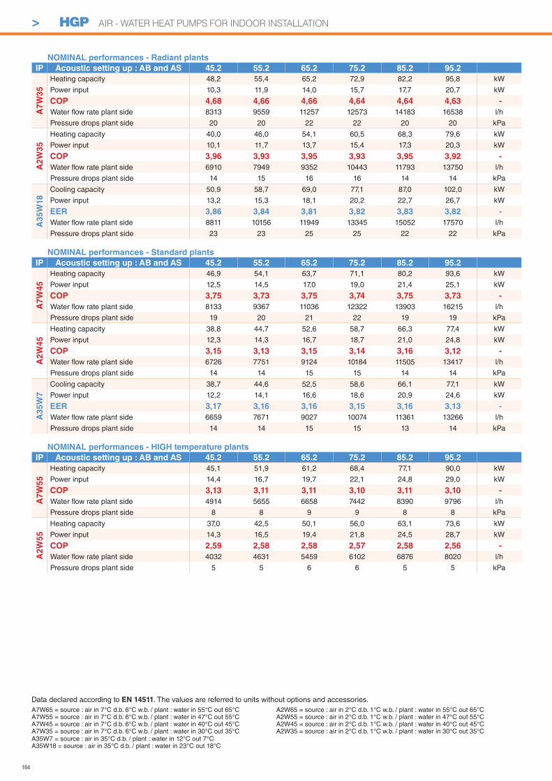
164
> HGP AIR - WATER HEAT PUMPS FOR INDOOR INSTALLATION
A7W65 = source : air in 7°C d.b. 6°C w.b. / plant : water in 55°C out 65°CA7W55 = source : air in 7°C d.b. 6°C w.b. / plant : water in 47°C out 55°CA7W45 = source : air in 7°C d.b. 6°C w.b. / plant : water in 40°C out 45°CA7W35 = source : air in 7°C d.b. 6°C w.b. / plant : water in 30°C out 35°C
Data declared according to EN 14511. The values are referred to units without options and accessories.
A35W7 = source : air in 35°C d.b. / plant : water in 12°C out 7°CA35W18 = source : air in 35°C d.b. / plant : water in 23°C out 18°C
A2W65 = source : air in 2°C d.b. 1°C w.b. / plant : water in 55°C out 65°CA2W55 = source : air in 2°C d.b. 1°C w.b. / plant : water in 47°C out 55°CA2W45 = source : air in 2°C d.b. 1°C w.b. / plant : water in 40°C out 45°CA2W35 = source : air in 2°C d.b. 1°C w.b. / plant : water in 30°C out 35°C
NOMINAL performances - Radiant plants
IP Acoustic setting up : AB and AS 45.2 55.2 65.2 75.2 85.2 95.2
A7
W3
5
Heating capacity 48,2 55,4 65,2 72,9 82,2 95,8 kW
Power input 10,3 11,9 14,0 15,7 17,7 20,7 kW
COP 4,68 4,66 4,66 4,64 4,64 4,63 -
Water fl ow rate plant side 8313 9559 11257 12573 14183 16538 l/h
Pressure drops plant side 20 20 22 22 20 20 kPa
A2
W3
5
Heating capacity 40,0 46,0 54,1 60,5 68,3 79,6 kW
Power input 10,1 11,7 13,7 15,4 17,3 20,3 kW
COP 3,96 3,93 3,95 3,93 3,95 3,92 -
Water fl ow rate plant side 6910 7949 9352 10443 11793 13750 l/h
Pressure drops plant side 14 15 16 16 14 14 kPa
A3
5W
18
Cooling capacity 50,9 58,7 69,0 77,1 87,0 102,0 kW
Power input 13,2 15,3 18,1 20,2 22,7 26,7 kW
EER 3,86 3,84 3,81 3,82 3,83 3,82 -
Water fl ow rate plant side 8811 10156 11949 13345 15052 17570 l/h
Pressure drops plant side 23 23 25 25 22 22 kPa
NOMINAL performances - Standard plants
IP Acoustic setting up : AB and AS 45.2 55.2 65.2 75.2 85.2 95.2
A7
W4
5
Heating capacity 46,9 54,1 63,7 71,1 80,2 93,6 kW
Power input 12,5 14,5 17,0 19,0 21,4 25,1 kW
COP 3,75 3,73 3,75 3,74 3,75 3,73 -
Water fl ow rate plant side 8133 9367 11036 12322 13903 16215 l/h
Pressure drops plant side 19 20 21 22 19 19 kPa
A2W
45
Heating capacity 38,8 44,7 52,6 58,7 66,3 77,4 kW
Power input 12,3 14,3 16,7 18,7 21,0 24,8 kW
COP 3,15 3,13 3,15 3,14 3,16 3,12 -
Water fl ow rate plant side 6726 7751 9124 10184 11505 13417 l/h
Pressure drops plant side 14 14 15 15 14 14 kPa
A35W
7
Cooling capacity 38,7 44,6 52,5 58,6 66,1 77,1 kW
Power input 12,2 14,1 16,6 18,6 20,9 24,6 kW
EER 3,17 3,16 3,16 3,15 3,16 3,13 -
Water fl ow rate plant side 6659 7671 9027 10074 11361 13266 l/h
Pressure drops plant side 14 14 15 15 13 14 kPa
NOMINAL performances - HIGH temperature plants
IP Acoustic setting up : AB and AS 45.2 55.2 65.2 75.2 85.2 95.2
A7W
55
Heating capacity 45,1 51,9 61,2 68,4 77,1 90,0 kW
Power input 14,4 16,7 19,7 22,1 24,8 29,0 kW
COP 3,13 3,11 3,11 3,10 3,11 3,10 -
Water fl ow rate plant side 4914 5655 6658 7442 8390 9796 l/h
Pressure drops plant side 8 8 9 9 8 8 kPa
A2W
55
Heating capacity 37,0 42,5 50,1 56,0 63,1 73,6 kW
Power input 14,3 16,5 19,4 21,8 24,5 28,7 kW
COP 2,59 2,58 2,58 2,57 2,58 2,56 -
Water fl ow rate plant side 4032 4631 5459 6102 6876 8020 l/h
Pressure drops plant side 5 5 6 6 5 5 kPa
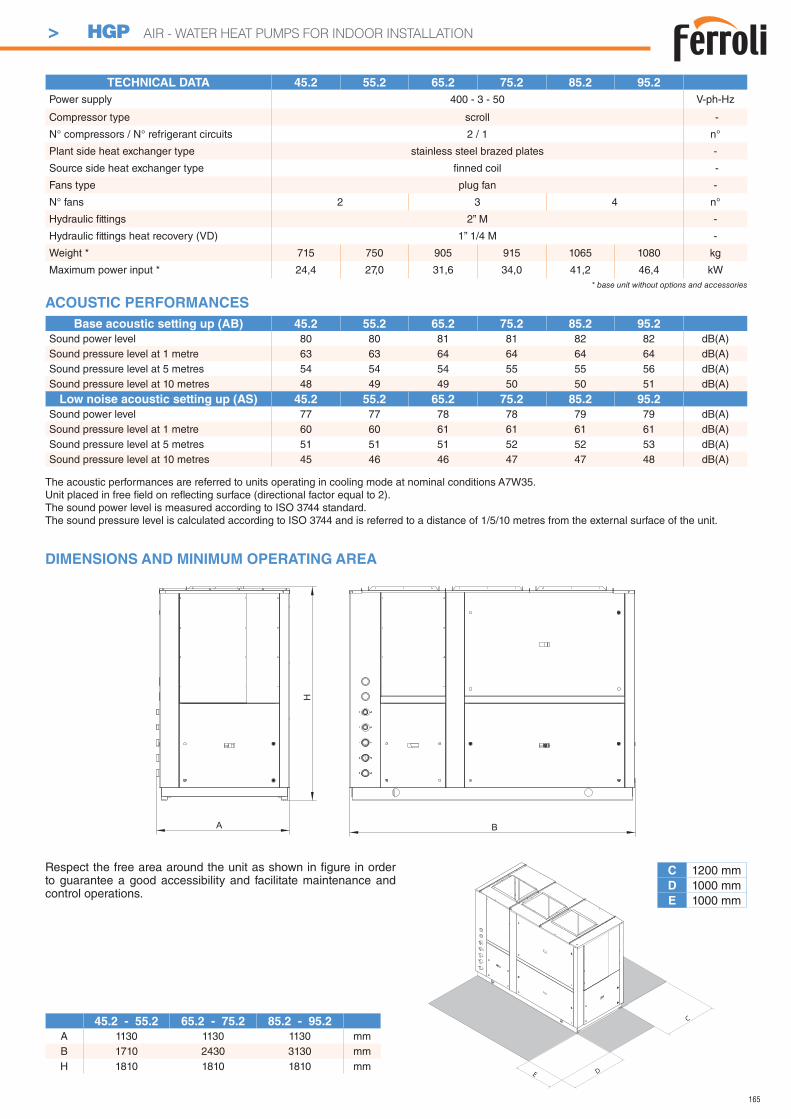
165
> HGP AIR - WATER HEAT PUMPS FOR INDOOR INSTALLATION
A
H
B
DIMENSIONS AND MINIMUM OPERATING AREA
C 1200 mmD 1000 mmE 1000 mm
Respect the free area around the unit as shown in fi gure in order to guarantee a good accessibility and facilitate maintenance and control operations.
D
C
E
45.2 - 55.2 65.2 - 75.2 85.2 - 95.2
A 1130 1130 1130 mmB 1710 2430 3130 mmH 1810 1810 1810 mm
The acoustic performances are referred to units operating in cooling mode at nominal conditions A7W35.Unit placed in free fi eld on refl ecting surface (directional factor equal to 2).The sound power level is measured according to ISO 3744 standard.The sound pressure level is calculated according to ISO 3744 and is referred to a distance of 1/5/10 metres from the external surface of the unit.
ACOUSTIC PERFORMANCES
Base acoustic setting up (AB) 45.2 55.2 65.2 75.2 85.2 95.2
Sound power level 80 80 81 81 82 82 dB(A)Sound pressure level at 1 metre 63 63 64 64 64 64 dB(A)Sound pressure level at 5 metres 54 54 54 55 55 56 dB(A)Sound pressure level at 10 metres 48 49 49 50 50 51 dB(A)
Low noise acoustic setting up (AS) 45.2 55.2 65.2 75.2 85.2 95.2
Sound power level 77 77 78 78 79 79 dB(A)Sound pressure level at 1 metre 60 60 61 61 61 61 dB(A)Sound pressure level at 5 metres 51 51 51 52 52 53 dB(A)Sound pressure level at 10 metres 45 46 46 47 47 48 dB(A)
TECHNICAL DATA 45.2 55.2 65.2 75.2 85.2 95.2
Power supply 400 - 3 - 50 V-ph-Hz
Compressor type scroll -
N° compressors / N° refrigerant circuits 2 / 1 n°
Plant side heat exchanger type stainless steel brazed plates -
Source side heat exchanger type fi nned coil -
Fans type plug fan -
N° fans 2 3 4 n°
Hydraulic fi ttings 2” M -
Hydraulic fi ttings heat recovery (VD) 1” 1/4 M -
Weight * 715 750 905 915 1065 1080 kg
Maximum power input * 24,4 27,0 31,6 34,0 41,2 46,4 kW* base unit without options and accessories
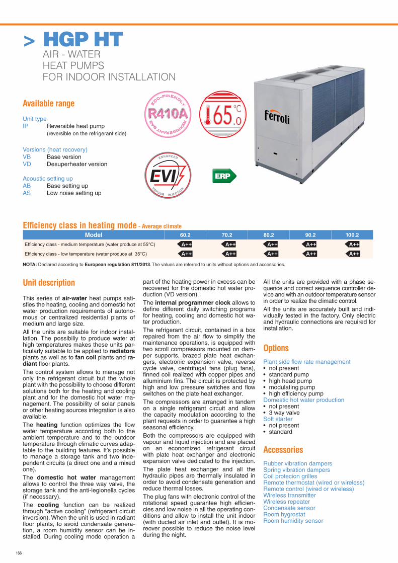
166
Available range
Unit typeIP Reversible heat pump (reversible on the refrigerant side)
Versions (heat recovery)VB Base versionVD Desuperheater version
Acoustic setting upAB Base setting upAS Low noise setting up
Unit description
This series of air-water heat pumps sati-sfi es the heating, cooling and domestic hot water production requirements of autono-mous or centralized residential plants of medium and large size.All the units are suitable for indoor instal-lation. The possibiliy to produce water at high temperatures makes these units par-ticularly suitable to be applied to radiators plants as well as to fan coil plants and ra-diant fl oor plants.The control system allows to manage not only the refrigerant circuit but the whole plant with the possibility to choose different solutions both for the heating and cooling plant and for the domestic hot water ma-nagement. The possibility of solar panels or other heating sources integration is also available.The heating function optimizes the fl ow water temperature according both to the ambient temperature and to the outdoor temperature through climatic curves adap-table to the building features. It’s possible to manage a storage tank and two inde-pendent circuits (a direct one and a mixed one).The domestic hot water management allows to control the three way valve, the storage tank and the anti-legionella cycles (if necessary).The cooling function can be realized through “active cooling” (refrigerant circuit inversion). When the unit is used in radiant fl oor plants, to avoid condensate genera-tion, a room humidity sensor can be in-stalled. During cooling mode operation a
part of the heating power in excess can be recovered for the domestic hot water pro-duction (VD version).The internal programmer clock allows to defi ne different daily switching programs for heating, cooling and domestic hot wa-ter production.The refrigerant circuit, contained in a box repaired from the air fl ow to simplify the maintenance operations, is equipped with two scroll compressors mounted on dam-per supports, brazed plate heat exchan-gers, electronic expansion valve, reverse cycle valve, centrifugal fans (plug fans), fi nned coil realized with copper pipes and alluminium fi ns. The circuit is protected by high and low pressure switches and fl ow switches on the plate heat exchanger.The compressors are arranged in tandem on a single refrigerant circuit and allow the capacity modulation according to the plant requests in order to guarantee a high seasonal efficiency.Both the compressors are equipped with vapour and liquid injection and are placed on an economized refrigerant circuit with plate heat exchanger and electronic expansion valve dedicated to the injection.The plate heat exchanger and all the hydraulic pipes are thermally insulated in order to avoid condensate generation and reduce thermal losses.The plug fans with electronic control of the rotational speed guarantee high efficien-cies and low noise in all the operating con-ditions and allow to install the unit indoor (with ducted air inlet and outlet). It is mo-reover possible to reduce the noise level during the night.
All the units are provided with a phase se-quence and correct sequence controller de-vice and with an outdoor temperature sensor in order to realize the climatic control.All the units are accurately built and indi-vidually tested in the factory. Only electric and hydraulic connections are required for installation.
Options
Plant side fl ow rate management • not present• standard pump• high head pump• modulating pump• high efficiency pumpDomestic hot water production • not present• 3 way valveSoft starter• not present• standard
Accessories
Rubber vibration dampersSpring vibration dampersCoil protecion grillesRemote thermostat (wired or wireless)Remote control (wired or wireless)Wireless transmitterWireless repeaterCondensate sensorRoom hygrostatRoom humidity sensor
RE
FRIGERANT G
AS
E
CO-FRIEND
LY
.065
Effi ciency class in heating mode - Average climate
Model 60.2 70.2 80.2 90.2 100.2
NOTA: Declared according to European regulation 811/2013. The values are referred to units without options and accessories.
ERP
A++ A++ A++ A++ A++A++ A++ A++ A++ A++
> HGP HT AIR - WATER
HEAT PUMPS
FOR INDOOR INSTALLATION

167
The controller is able to manage up to two zones in heating (one by means of a mixed circuit and the other by means of a direct circuit) and one zone in cooling (by means of a mixed circuit).It’s possible to realize more complex plants connecting to the heat pump controller further expansion modules in order to extend without limits the number of zones to be managed.
For each zone the following parameters can be set :- set point- daily or weekly operating time table- climatic control curve- room control sensor : it can be in common with the other zo-
nes or independent (in that case it’s necessary to install an additional room thermostat)
Cooling Heating
OPERATING LIMITS Unit type min max min max
Outdoor air inlet temperature IP 5 50 -22 42 °CWater outlet temperature IP 6 25 30 65 * °C
FS
* The maximum water outlet temperature can be increased up to 70°C keeping a T between inlet and outlet equal to 10°C.
The microprocessor controller is able to manage not only the unit itself but also all that components of the plant which allow to realize a complete system.The main functions of the control system are :- room temperature control according to the outdoor
temperature (climatic control)- domestic hot water production (management of 3 way valve,
storage tank, anti legionella cycles…)- management of a heating and/or cooling mixed circuit (pump
and 3 way mixing valve)- management of a heating direct circuit (only pump)- management of a storage tank for heating and/or cooling- management of electrical heaters for heating and domestic
hot water (3 steps logic)- solar panels integration- room humidity control for cooling with radiant systems- internal programmer clock (for heating, cooling and domestic
hot water)- digital input for electrical energy low tariff- alarm memory management and diagnostic- compressor and pump operating hour counter- possibility to manage more units in cascade (maximum 16)
Besides the standard user interface to be placed indoor, wired or wireless remote thermostats are available which allow to
temperature in the different zones in order to realize a more precise and comfortable control.The unit controller is able to manage a lot of different plant solutions enabling automatically the necessary control algorythms according to the components which have been connected.The management of such components is possible through addi-tional expansion mo-dules which commu-nicate with the unit by means of an internal bus and provide all the inputs and outputs required to fulfi l a com-plete system.
CONTROL SYSTEM
Room temperature
20.5 C18:28
AERAULIC performances 60.2 70.2 80.2 90.2 100.2
Nominal air fl ow rate 17600 26400 26400 35200 35200 m3/h
Nominal available static head 150 150 150 150 150 Pa
> HGP HT AIR - WATER HEAT PUMPS FOR INDOOR INSTALLATION
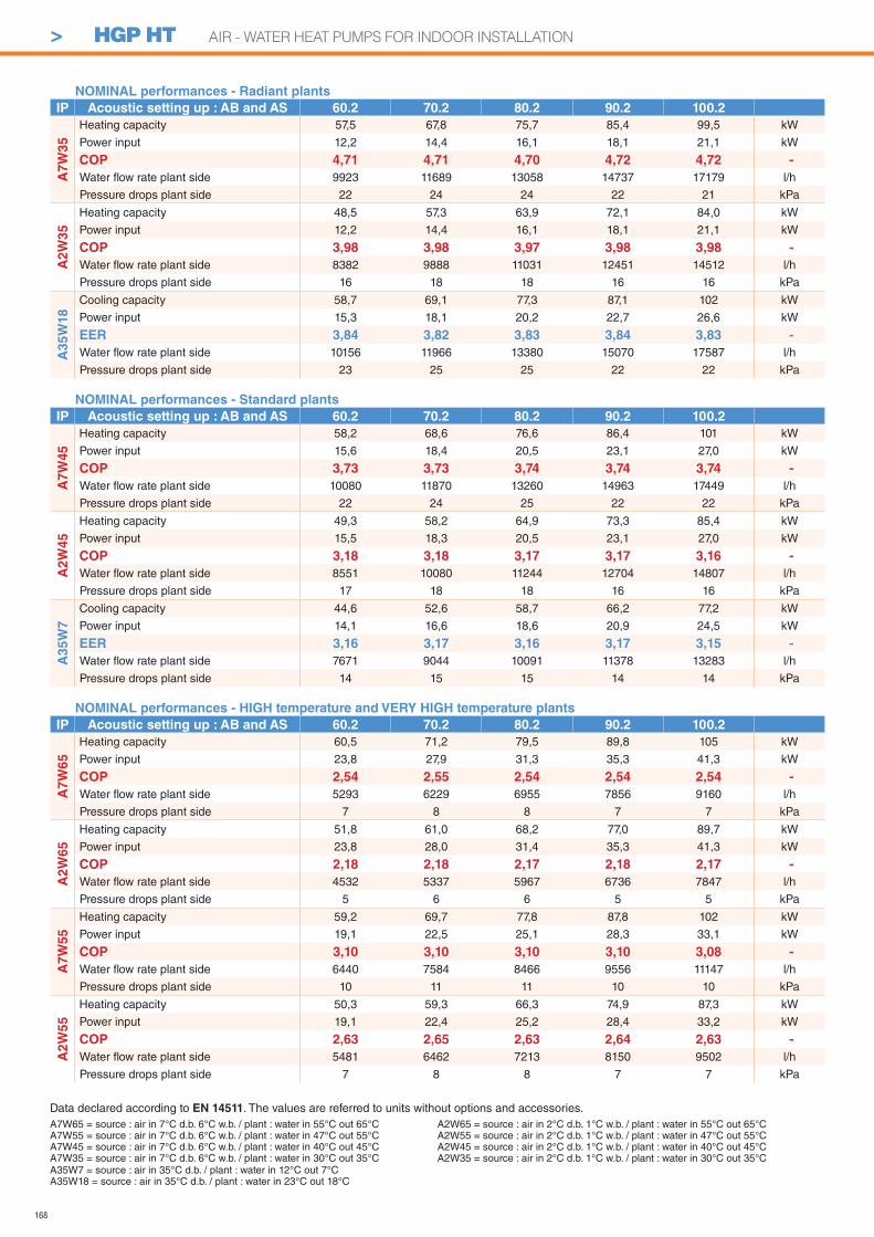
168
A7W65 = source : air in 7°C d.b. 6°C w.b. / plant : water in 55°C out 65°CA7W55 = source : air in 7°C d.b. 6°C w.b. / plant : water in 47°C out 55°CA7W45 = source : air in 7°C d.b. 6°C w.b. / plant : water in 40°C out 45°CA7W35 = source : air in 7°C d.b. 6°C w.b. / plant : water in 30°C out 35°C
Data declared according to EN 14511. The values are referred to units without options and accessories.
A35W7 = source : air in 35°C d.b. / plant : water in 12°C out 7°CA35W18 = source : air in 35°C d.b. / plant : water in 23°C out 18°C
A2W65 = source : air in 2°C d.b. 1°C w.b. / plant : water in 55°C out 65°CA2W55 = source : air in 2°C d.b. 1°C w.b. / plant : water in 47°C out 55°CA2W45 = source : air in 2°C d.b. 1°C w.b. / plant : water in 40°C out 45°CA2W35 = source : air in 2°C d.b. 1°C w.b. / plant : water in 30°C out 35°C
NOMINAL performances - Radiant plants
IP Acoustic setting up : AB and AS 60.2 70.2 80.2 90.2 100.2
A7
W3
5
Heating capacity 57,5 67,8 75,7 85,4 99,5 kW
Power input 12,2 14,4 16,1 18,1 21,1 kW
COP 4,71 4,71 4,70 4,72 4,72 -
Water fl ow rate plant side 9923 11689 13058 14737 17179 l/h
Pressure drops plant side 22 24 24 22 21 kPa
A2
W3
5
Heating capacity 48,5 57,3 63,9 72,1 84,0 kW
Power input 12,2 14,4 16,1 18,1 21,1 kW
COP 3,98 3,98 3,97 3,98 3,98 -
Water fl ow rate plant side 8382 9888 11031 12451 14512 l/h
Pressure drops plant side 16 18 18 16 16 kPa
A3
5W
18
Cooling capacity 58,7 69,1 77,3 87,1 102 kW
Power input 15,3 18,1 20,2 22,7 26,6 kW
EER 3,84 3,82 3,83 3,84 3,83 -
Water fl ow rate plant side 10156 11966 13380 15070 17587 l/h
Pressure drops plant side 23 25 25 22 22 kPa
NOMINAL performances - Standard plants
IP Acoustic setting up : AB and AS 60.2 70.2 80.2 90.2 100.2
A7
W4
5
Heating capacity 58,2 68,6 76,6 86,4 101 kW
Power input 15,6 18,4 20,5 23,1 27,0 kW
COP 3,73 3,73 3,74 3,74 3,74 -
Water fl ow rate plant side 10080 11870 13260 14963 17449 l/h
Pressure drops plant side 22 24 25 22 22 kPa
A2W
45
Heating capacity 49,3 58,2 64,9 73,3 85,4 kW
Power input 15,5 18,3 20,5 23,1 27,0 kW
COP 3,18 3,18 3,17 3,17 3,16 -
Water fl ow rate plant side 8551 10080 11244 12704 14807 l/h
Pressure drops plant side 17 18 18 16 16 kPa
A35W
7
Cooling capacity 44,6 52,6 58,7 66,2 77,2 kW
Power input 14,1 16,6 18,6 20,9 24,5 kW
EER 3,16 3,17 3,16 3,17 3,15 -
Water fl ow rate plant side 7671 9044 10091 11378 13283 l/h
Pressure drops plant side 14 15 15 14 14 kPa
NOMINAL performances - HIGH temperature and VERY HIGH temperature plants
IP Acoustic setting up : AB and AS 60.2 70.2 80.2 90.2 100.2
A7W
65
Heating capacity 60,5 71,2 79,5 89,8 105 kW
Power input 23,8 27,9 31,3 35,3 41,3 kW
COP 2,54 2,55 2,54 2,54 2,54 -
Water fl ow rate plant side 5293 6229 6955 7856 9160 l/h
Pressure drops plant side 7 8 8 7 7 kPa
A2W
65
Heating capacity 51,8 61,0 68,2 77,0 89,7 kW
Power input 23,8 28,0 31,4 35,3 41,3 kW
COP 2,18 2,18 2,17 2,18 2,17 -
Water fl ow rate plant side 4532 5337 5967 6736 7847 l/h
Pressure drops plant side 5 6 6 5 5 kPa
A7W
55
Heating capacity 59,2 69,7 77,8 87,8 102 kW
Power input 19,1 22,5 25,1 28,3 33,1 kW
COP 3,10 3,10 3,10 3,10 3,08 -
Water fl ow rate plant side 6440 7584 8466 9556 11147 l/h
Pressure drops plant side 10 11 11 10 10 kPa
A2
W55
Heating capacity 50,3 59,3 66,3 74,9 87,3 kW
Power input 19,1 22,4 25,2 28,4 33,2 kW
COP 2,63 2,65 2,63 2,64 2,63 -
Water fl ow rate plant side 5481 6462 7213 8150 9502 l/h
Pressure drops plant side 7 8 8 7 7 kPa
> HGP HT AIR - WATER HEAT PUMPS FOR INDOOR INSTALLATION
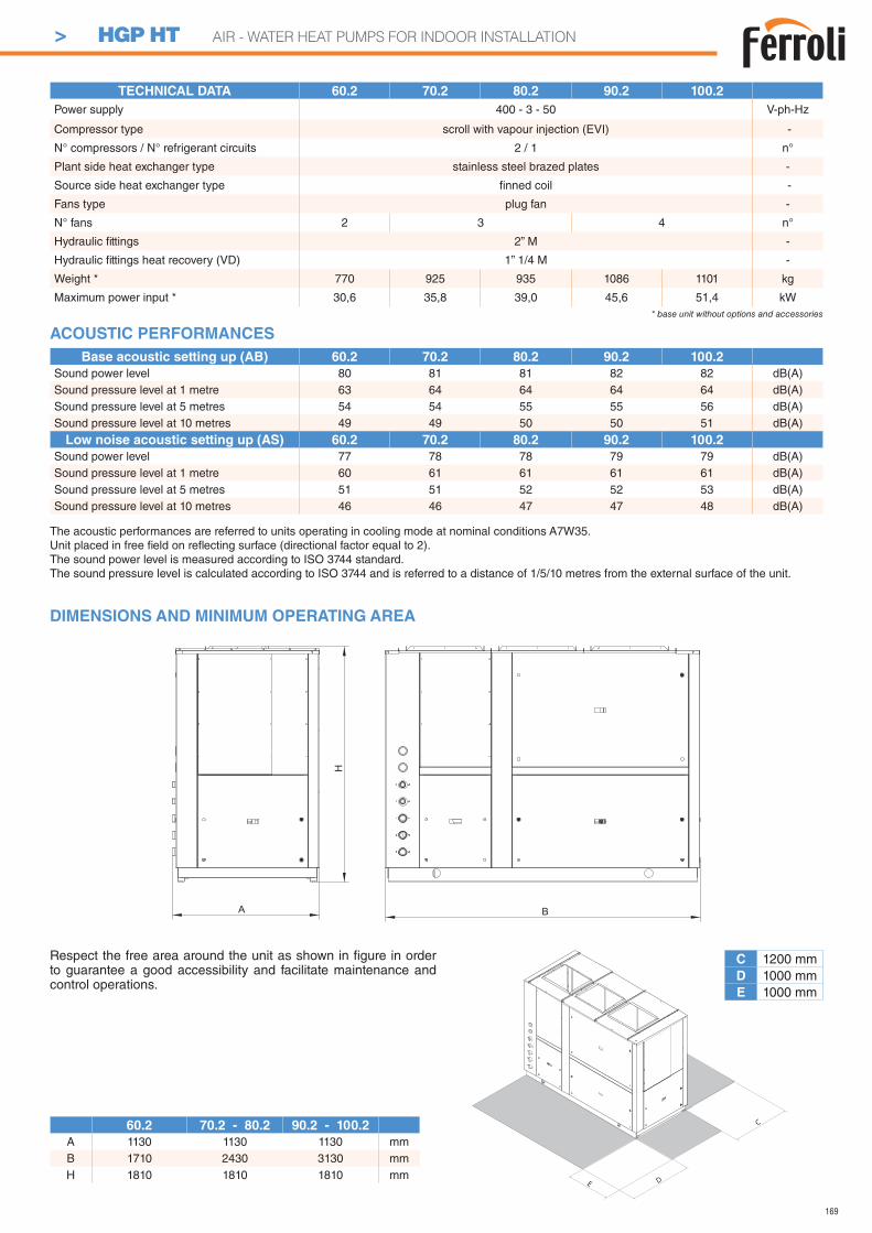
169
TECHNICAL DATA 60.2 70.2 80.2 90.2 100.2
Power supply 400 - 3 - 50 V-ph-Hz
Compressor type scroll with vapour injection (EVI) -
N° compressors / N° refrigerant circuits 2 / 1 n°
Plant side heat exchanger type stainless steel brazed plates -
Source side heat exchanger type fi nned coil -
Fans type plug fan -
N° fans 2 3 4 n°
Hydraulic fi ttings 2” M -
Hydraulic fi ttings heat recovery (VD) 1” 1/4 M -
Weight * 770 925 935 1086 1101 kg
Maximum power input * 30,6 35,8 39,0 45,6 51,4 kW* base unit without options and accessories
A
H
B
DIMENSIONS AND MINIMUM OPERATING AREA
C 1200 mmD 1000 mmE 1000 mm
Respect the free area around the unit as shown in fi gure in order to guarantee a good accessibility and facilitate maintenance and control operations.
D
C
E
60.2 70.2 - 80.2 90.2 - 100.2
A 1130 1130 1130 mmB 1710 2430 3130 mmH 1810 1810 1810 mm
The acoustic performances are referred to units operating in cooling mode at nominal conditions A7W35.Unit placed in free fi eld on refl ecting surface (directional factor equal to 2).The sound power level is measured according to ISO 3744 standard.The sound pressure level is calculated according to ISO 3744 and is referred to a distance of 1/5/10 metres from the external surface of the unit.
ACOUSTIC PERFORMANCES
Base acoustic setting up (AB) 60.2 70.2 80.2 90.2 100.2
Sound power level 80 81 81 82 82 dB(A)Sound pressure level at 1 metre 63 64 64 64 64 dB(A)Sound pressure level at 5 metres 54 54 55 55 56 dB(A)Sound pressure level at 10 metres 49 49 50 50 51 dB(A)
Low noise acoustic setting up (AS) 60.2 70.2 80.2 90.2 100.2
Sound power level 77 78 78 79 79 dB(A)Sound pressure level at 1 metre 60 61 61 61 61 dB(A)Sound pressure level at 5 metres 51 51 52 52 53 dB(A)Sound pressure level at 10 metres 46 46 47 47 48 dB(A)
> HGP HT AIR - WATER HEAT PUMPS FOR INDOOR INSTALLATION
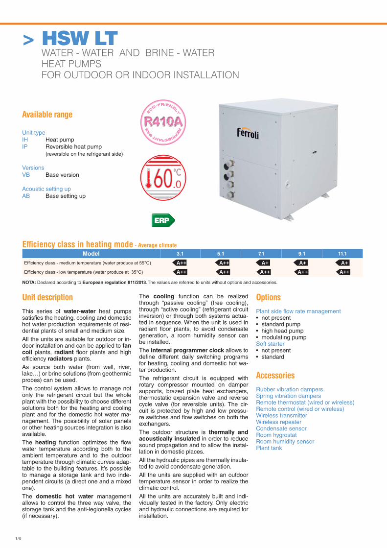
170
> HSW LT WATER - WATER AND BRINE - WATER
HEAT PUMPS
FOR OUTDOOR OR INDOOR INSTALLATION
Available range
Unit typeIH Heat pumpIP Reversible heat pump (reversible on the refrigerant side)
VersionsVB Base version
Acoustic setting upAB Base setting up
Unit description
This series of water-water heat pumps satisfi es the heating, cooling and domestic hot water production requirements of resi-dential plants of small and medium size.All the units are suitable for outdoor or in-door installation and can be applied to fan coil plants, radiant fl oor plants and high efficiency radiators plants.As source both water (from well, river, lake…) or brine solutions (from geothermic probes) can be used.The control system allows to manage not only the refrigerant circuit but the whole plant with the possibility to choose different solutions both for the heating and cooling plant and for the domestic hot water ma-nagement. The possibility of solar panels or other heating sources integration is also available.The heating function optimizes the fl ow water temperature according both to the ambient temperature and to the outdoor temperature through climatic curves adap-table to the building features. It’s possible to manage a storage tank and two inde-pendent circuits (a direct one and a mixed one).The domestic hot water management allows to control the three way valve, the storage tank and the anti-legionella cycles (if necessary).
The cooling function can be realized through “passive cooling” (free cooling), through “active cooling” (refrigerant circuit inversion) or through both systems actua-ted in sequence. When the unit is used in radiant fl oor plants, to avoid condensate generation, a room humidity sensor can be installed.The internal programmer clock allows to defi ne different daily switching programs for heating, cooling and domestic hot wa-ter production.The refrigerant circuit is equipped with rotary compressor mounted on damper supports, brazed plate heat exchangers, thermostatic expansion valve and reverse cycle valve (for reversible units). The cir-cuit is protected by high and low pressu-re switches and fl ow switches on both the exchangers.The outdoor structure is thermally and acoustically insulated in order to reduce sound propagation and to allow the instal-lation in domestic places.All the hydraulic pipes are thermally insula-ted to avoid condensate generation.All the units are supplied with an outdoor temperature sensor in order to realize the climatic control.All the units are accurately built and indi-vidually tested in the factory. Only electric and hydraulic connections are required for installation.
Options
Plant side fl ow rate management • not present• standard pump• high head pump• modulating pumpSoft starter• not present• standard
Accessories
Rubber vibration dampersSpring vibration dampersRemote thermostat (wired or wireless)Remote control (wired or wireless)Wireless transmitterWireless repeaterCondensate sensorRoom hygrostatRoom humidity sensorPlant tank
RE
FRIGERANT G
AS
E
CO-FRIEND
LY
Effi ciency class in heating mode - Average climate
Model 3.1 5.1 7.1 9.1 11.1
NOTA: Declared according to European regulation 811/2013. The values are referred to units without options and accessories.
A++ A++ A++ A++ A++A++ A++ A+ A+ A+
ERP
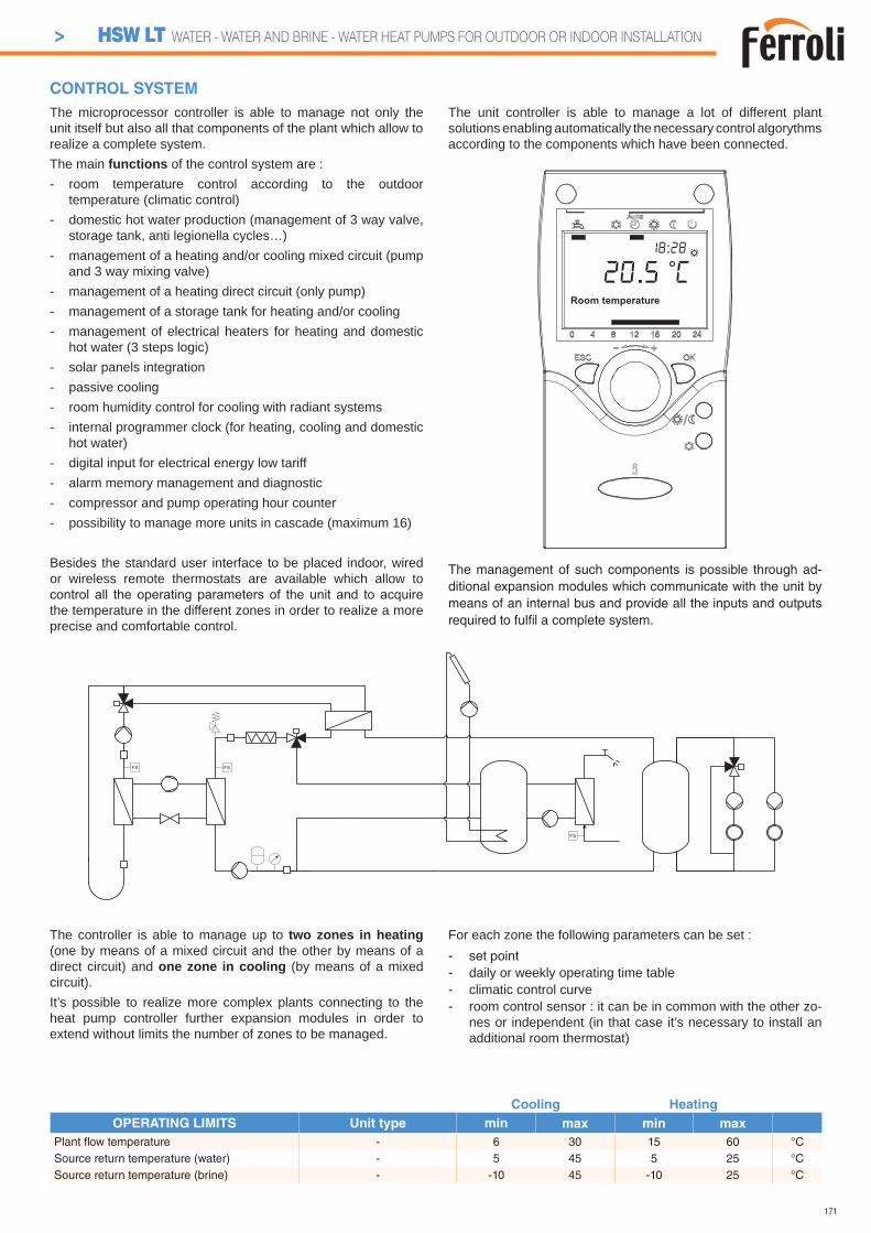
171
Cooling Heating
OPERATING LIMITS Unit type min max min max
Plant fl ow temperature - 6 30 15 60 °CSource return temperature (water) - 5 45 5 25 °CSource return temperature (brine) - -10 45 -10 25 °C
CONTROL SYSTEM
The controller is able to manage up to two zones in heating (one by means of a mixed circuit and the other by means of a direct circuit) and one zone in cooling (by means of a mixed circuit).It’s possible to realize more complex plants connecting to the heat pump controller further expansion modules in order to extend without limits the number of zones to be managed.
For each zone the following parameters can be set :- set point- daily or weekly operating time table- climatic control curve- room control sensor : it can be in common with the other zo-
nes or independent (in that case it’s necessary to install an additional room thermostat)
The microprocessor controller is able to manage not only the unit itself but also all that components of the plant which allow to realize a complete system.The main functions of the control system are :- room temperature control according to the outdoor
temperature (climatic control)- domestic hot water production (management of 3 way valve,
storage tank, anti legionella cycles…)- management of a heating and/or cooling mixed circuit (pump
and 3 way mixing valve)- management of a heating direct circuit (only pump)- management of a storage tank for heating and/or cooling- management of electrical heaters for heating and domestic
hot water (3 steps logic)- solar panels integration- passive cooling- room humidity control for cooling with radiant systems- internal programmer clock (for heating, cooling and domestic
hot water)- digital input for electrical energy low tariff- alarm memory management and diagnostic- compressor and pump operating hour counter- possibility to manage more units in cascade (maximum 16)
Besides the standard user interface to be placed indoor, wired or wireless remote thermostats are available which allow to
the temperature in the different zones in order to realize a more precise and comfortable control.
The unit controller is able to manage a lot of different plant solutions enabling automatically the necessary control algorythms according to the components which have been connected.
The management of such components is possible through ad-ditional expansion modules which communicate with the unit by means of an internal bus and provide all the inputs and outputs required to fulfi l a complete system.
Room temperature
20.5 C18:28
> HSW LT WATER - WATER AND BRINE - WATER HEAT PUMPS FOR OUTDOOR OR INDOOR INSTALLATION
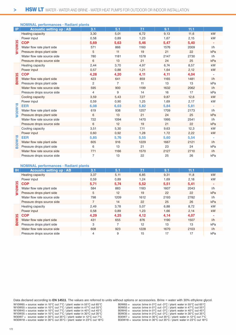
172
> HSW LT WATER - WATER AND BRINE - WATER HEAT PUMPS FOR OUTDOOR OR INDOOR INSTALLATION
NOMINAL performances - Radiant plants
IP Acoustic setting up : AB 3.1 5.1 7.1 9.1 11.1
W10
W3
5
Heating capacity 3,30 5,01 6,72 9,13 11,6 kWPower input 0,58 0,89 1,23 1,67 2,15 kW
COP 5,69 5,63 5,46 5,47 5,40 -
Water fl ow rate plant side 571 866 1160 1576 2009 l/hPressure drops plant side 5 11 19 21 22 kPaWater fl ow rate source side 780 1181 1578 2147 2730 l/hPressure drops source side 6 13 21 24 25 kPa
B0
W3
5
Heating capacity 2,44 3,70 4,97 6,74 8,57 kWPower input 0,57 0,88 1,21 1,64 2,12 kW
COP 4,28 4,20 4,11 4,11 4,04 -
Water fl ow rate plant side 423 641 859 1165 1481 l/hPressure drops plant side 2 7 11 13 13 kPaWater fl ow rate source side 595 900 1199 1632 2062 l/hPressure drops source side 4 9 14 16 17 kPa
W3
0W
18
Cooling capacity 3,59 5,43 7,27 9,87 12,6 kWPower input 0,59 0,90 1,25 1,69 2,17 kW
EER 6,08 6,03 5,82 5,84 5,81 -
Water fl ow rate plant side 619 938 1257 1709 2173 l/hPressure drops plant side 6 13 21 24 25 kPaWater fl ow rate source side 722 1094 1470 1995 2541 l/hPressure drops source side 6 12 19 21 22 kPa
B30W
18
Cooling capacity 3,51 5,30 7,11 9,63 12,3 kWPower input 0,60 0,92 1,28 1,72 2,22 kW
EER 5,85 5,76 5,55 5,60 5,54 -
Water fl ow rate plant side 605 916 1229 1667 2121 l/hPressure drops plant side 6 13 21 23 24 kPaWater fl ow rate source side 771 1166 1570 2127 2710 l/hPressure drops source side 7 13 22 25 26 kPa
NOMINAL performances - Radiant plants
IH Acoustic setting up : AB 3.1 5.1 7.1 9.1 11.1
W10W
35
Heating capacity 3,37 5,11 6,85 9,31 11,8 kWPower input 0,59 0,89 1,24 1,69 2,18 kW
COP 5,71 5,74 5,52 5,51 5,41 -
Water fl ow rate plant side 584 883 1183 1607 2043 l/hPressure drops plant side 5 12 19 22 22 kPaWater fl ow rate source side 798 1209 1612 2193 2782 l/hPressure drops source side 7 14 22 25 26 kPa
B0W
35
Heating capacity 2,49 3,78 5,07 6,88 8,72 kWPower input 0,58 0,89 1,23 1,66 2,14 kW
COP 4,29 4,25 4,12 4,14 4,07 -
Water fl ow rate plant side 431 655 876 1190 1507 l/hPressure drops plant side 3 7 12 13 13 kPaWater fl ow rate source side 608 923 1228 1670 2103 l/hPressure drops source side 4 9 15 17 17 kPa
W10W65 = source: water in 10°C out 7°C / plant: water in 55°C out 65°CW10W55 = source: water in 10°C out 7°C / plant: water in 47°C out 55°CW10W45 = source: water in 10°C out 7°C / plant: water in 40°C out 45°CW10W35 = source: water in 10°C out 7°C / plant: water in 30°C out 35°C
Data declared according to EN 14511. The values are referred to units without options or accessories. Brine = water with 30% ethylene glycol.
W30W7 = source: water in 30°C out 35°C / plant: water in 12°C out 7°CW30W18 = source: water in 30°C out 35°C / plant: water in 23°C out 18°C
B0W65 = source: brine in 0°C out -3°C / plant: water in 55°C out 65°CB0W55 = source: brine in 0°C out -3°C / plant: water in 47°C out 55°CB0W45 = source: brine in 0°C out -3°C / plant: water in 40°C out 45°CB0W35 = source: brine in 0°C out -3°C / plant: water in 30°C out 35°CB30W7 = source: brine in 30°C out 35°C / plant: water in 12°C out 7°CB30W18 = source: brine in 30°C out 35°C / plant: water in 23°C out 18°C
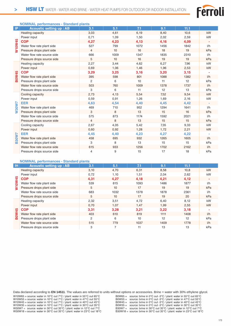
173
> HSW LT WATER - WATER AND BRINE - WATER HEAT PUMPS FOR OUTDOOR OR INDOOR INSTALLATION
NOMINAL performances - Standard plants
IP Acoustic setting up : AB 3.1 5.1 7.1 9.1 11.1
W10
W4
5
Heating capacity 3,03 4,61 6,19 8,40 10,6 kWPower input 0,71 1,09 1,50 2,02 2,59 kW
COP 4,27 4,23 4,13 4,16 4,09 -
Water fl ow rate plant side 527 799 1072 1456 1842 l/hPressure drops plant side 4 10 16 18 19 kPaWater fl ow rate source side 666 1009 1347 1835 2310 l/hPressure drops source side 5 10 16 19 19 kPa
B0
W4
5
Heating capacity 2,27 3,44 4,62 6,27 7,96 kWPower input 0,69 1,06 1,46 1,96 2,53 kW
COP 3,29 3,25 3,16 3,20 3,15 -
Water fl ow rate plant side 395 598 801 1088 1382 l/hPressure drops plant side 2 6 10 11 12 kPaWater fl ow rate source side 503 760 1009 1378 1737 l/hPressure drops source side 3 6 11 12 13 kPa
W3
0W
7
Cooling capacity 2,73 4,13 5,54 7,52 9,54 kWPower input 0,59 0,91 1,26 1,69 2,16 kW
EER 4,63 4,54 4,40 4,45 4,42 -
Water fl ow rate plant side 469 710 952 1294 1641 l/hPressure drops plant side 3 8 13 15 16 kPaWater fl ow rate source side 575 873 1174 1592 2021 l/hPressure drops source side 4 8 13 15 15 kPa
B30W
7
Cooling capacity 2,67 4,05 5,42 7,35 9,33 kWPower input 0,60 0,92 1,28 1,72 2,21 kW
EER 4,45 4,40 4,23 4,27 4,22 -
Water fl ow rate plant side 458 695 932 1265 1605 l/hPressure drops plant side 3 8 13 15 15 kPaWater fl ow rate source side 615 933 1256 1702 2162 l/hPressure drops source side 4 9 15 17 18 kPa
NOMINAL performances - Standard plants
IH Acoustic setting up : AB 3.1 5.1 7.1 9.1 11.1
W10W
45
Heating capacity 3,10 4,70 6,31 8,58 10,8 kWPower input 0,72 1,10 1,51 2,04 2,62 kW
COP 4,31 4,27 4,18 4,21 4,12 -
Water fl ow rate plant side 539 815 1093 1486 1877 l/hPressure drops plant side 5 10 17 19 19 kPaWater fl ow rate source side 683 1032 1378 1878 2361 l/hPressure drops source side 5 10 17 19 20 kPa
B0W
45
Heating capacity 2,32 3,51 4,72 6,40 8,12 kWPower input 0,70 1,07 1,47 1,99 2,55 kW
COP 3,31 3,28 3,21 3,22 3,18 -
Water fl ow rate plant side 403 610 819 1111 1408 l/hPressure drops plant side 2 6 10 12 12 kPaWater fl ow rate source side 515 779 1037 1409 1778 l/hPressure drops source side 3 7 11 13 13 kPa
W10W65 = source: water in 10°C out 7°C / plant: water in 55°C out 65°CW10W55 = source: water in 10°C out 7°C / plant: water in 47°C out 55°CW10W45 = source: water in 10°C out 7°C / plant: water in 40°C out 45°CW10W35 = source: water in 10°C out 7°C / plant: water in 30°C out 35°C
Data declared according to EN 14511. The values are referred to units without options or accessories. Brine = water with 30% ethylene glycol.B0W65 = source: brine in 0°C out -3°C / plant: water in 55°C out 65°CB0W55 = source: brine in 0°C out -3°C / plant: water in 47°C out 55°CB0W45 = source: brine in 0°C out -3°C / plant: water in 40°C out 45°CB0W35 = source: brine in 0°C out -3°C / plant: water in 30°C out 35°C
W30W7 = source: water in 30°C out 35°C / plant: water in 12°C out 7°CW30W18 = source: water in 30°C out 35°C / plant: water in 23°C out 18°C
B30W7 = source: brine in 30°C out 35°C / plant: water in 12°C out 7°CB30W18 = source: brine in 30°C out 35°C / plant: water in 23°C out 18°C
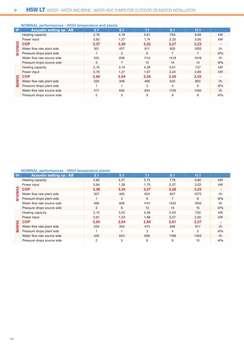
174
NOMINAL performances - HIGH temperature plants
IH Acoustic setting up : AB 3.1 5.1 7.1 9.1 11.1
W10W
55
Heating capacity 2,82 4,27 5,72 7,78 9,85 kWPower input 0,84 1,28 1,75 2,37 3,03 kW
COP 3,36 3,34 3,27 3,28 3,25 -
Water fl ow rate plant side 307 465 623 847 1072 l/hPressure drops plant side 1 3 6 7 8 kPaWater fl ow rate source side 566 858 1141 1552 1955 l/hPressure drops source side 3 8 12 14 15 kPa
B0W
55
Heating capacity 2,15 3,25 4,36 5,93 7,50 kWPower input 0,81 1,23 1,68 2,27 2,92 kW
COP 2,65 2,64 2,60 2,61 2,57 -
Water fl ow rate plant side 234 354 475 646 817 l/hPressure drops plant side 1 1 3 4 5 kPaWater fl ow rate source side 426 643 856 1168 1463 l/hPressure drops source side 2 5 8 9 10 kPa
NOMINAL performances - HIGH temperature and plants
IP Acoustic setting up : AB 3.1 5.1 7.1 9.1 11.1
W10
W5
5
Heating capacity 2,76 4,19 5,61 7,63 9,69 kWPower input 0,82 1,27 1,74 2,33 3,00 kW
COP 3,37 3,30 3,22 3,27 3,23 -
Water fl ow rate plant side 301 457 611 830 1055 l/hPressure drops plant side 1 3 6 7 7 kPaWater fl ow rate source side 555 838 1112 1518 1918 l/hPressure drops source side 3 7 12 14 14 kPa
B0
W5
5
Heating capacity 2,10 3,19 4,28 5,81 7,37 kWPower input 0,79 1,21 1,67 2,24 2,89 kW
COP 2,66 2,64 2,56 2,59 2,55 -
Water fl ow rate plant side 229 348 466 633 803 l/hPressure drops plant side 1 1 3 4 5 kPaWater fl ow rate source side 417 630 834 1139 1432 l/hPressure drops source side 2 5 8 9 9 kPa
> HSW LT WATER - WATER AND BRINE - WATER HEAT PUMPS FOR OUTDOOR OR INDOOR INSTALLATION
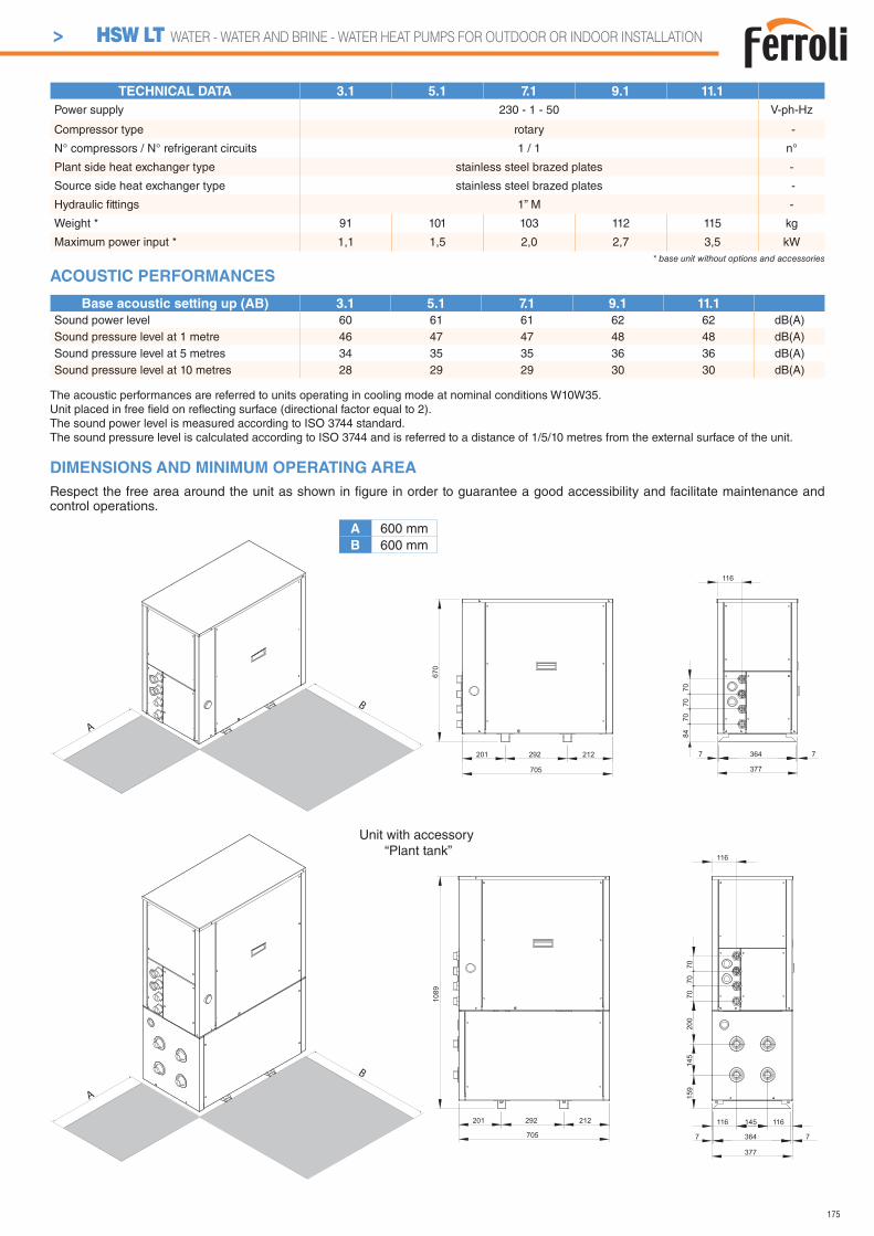
175
DIMENSIONS AND MINIMUM OPERATING AREA
Respect the free area around the unit as shown in fi gure in order to guarantee a good accessibility and facilitate maintenance and control operations.
TECHNICAL DATA 3.1 5.1 7.1 9.1 11.1
Power supply 230 - 1 - 50 V-ph-Hz
Compressor type rotary -
N° compressors / N° refrigerant circuits 1 / 1 n°
Plant side heat exchanger type stainless steel brazed plates -
Source side heat exchanger type stainless steel brazed plates -
Hydraulic fi ttings 1” M -
Weight * 91 101 103 112 115 kg
Maximum power input * 1,1 1,5 2,0 2,7 3,5 kW* base unit without options and accessories
A
B
A
B
A 600 mmB 600 mm
705
292201 212 7 364 7
377
8470
7070
116
670
7 364 7
377
201 292 212
705
159
7070
1089
145
200
70
116
116 145 116
Unit with accessory “Plant tank”
The acoustic performances are referred to units operating in cooling mode at nominal conditions W10W35.Unit placed in free fi eld on refl ecting surface (directional factor equal to 2).The sound power level is measured according to ISO 3744 standard.The sound pressure level is calculated according to ISO 3744 and is referred to a distance of 1/5/10 metres from the external surface of the unit.
Base acoustic setting up (AB) 3.1 5.1 7.1 9.1 11.1
Sound power level 60 61 61 62 62 dB(A)Sound pressure level at 1 metre 46 47 47 48 48 dB(A)Sound pressure level at 5 metres 34 35 35 36 36 dB(A)Sound pressure level at 10 metres 28 29 29 30 30 dB(A)
ACOUSTIC PERFORMANCES
> HSW LT WATER - WATER AND BRINE - WATER HEAT PUMPS FOR OUTDOOR OR INDOOR INSTALLATION
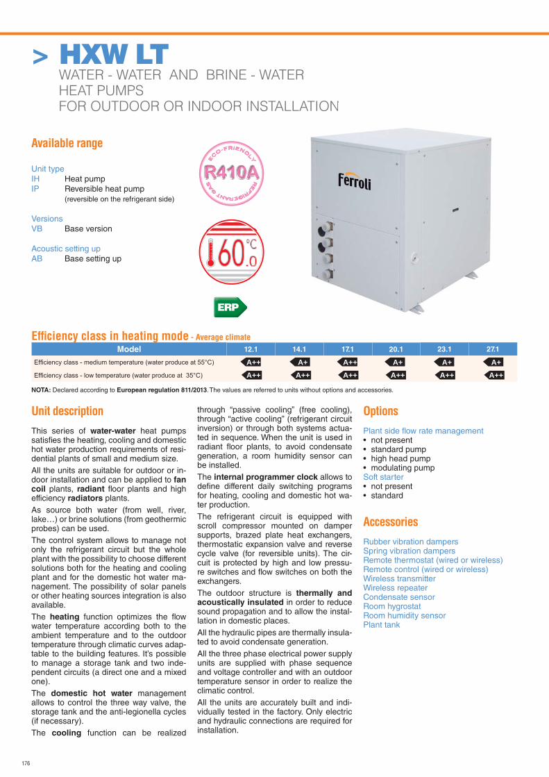
176
> HXW LT WATER - WATER AND BRINE - WATER
HEAT PUMPS
FOR OUTDOOR OR INDOOR INSTALLATION
Available range
Unit typeIH Heat pumpIP Reversible heat pump (reversible on the refrigerant side)
VersionsVB Base version
Acoustic setting upAB Base setting up
Unit description
This series of water-water heat pumps satisfi es the heating, cooling and domestic hot water production requirements of resi-dential plants of small and medium size.All the units are suitable for outdoor or in-door installation and can be applied to fan coil plants, radiant fl oor plants and high efficiency radiators plants.As source both water (from well, river, lake…) or brine solutions (from geothermic probes) can be used.The control system allows to manage not only the refrigerant circuit but the whole plant with the possibility to choose different solutions both for the heating and cooling plant and for the domestic hot water ma-nagement. The possibility of solar panels or other heating sources integration is also available.The heating function optimizes the fl ow water temperature according both to the ambient temperature and to the outdoor temperature through climatic curves adap-table to the building features. It’s possible to manage a storage tank and two inde-pendent circuits (a direct one and a mixed one).The domestic hot water management allows to control the three way valve, the storage tank and the anti-legionella cycles (if necessary).The cooling function can be realized
through “passive cooling” (free cooling), through “active cooling” (refrigerant circuit inversion) or through both systems actua-ted in sequence. When the unit is used in radiant fl oor plants, to avoid condensate generation, a room humidity sensor can be installed.The internal programmer clock allows to defi ne different daily switching programs for heating, cooling and domestic hot wa-ter production.The refrigerant circuit is equipped with scroll compressor mounted on damper supports, brazed plate heat exchangers, thermostatic expansion valve and reverse cycle valve (for reversible units). The cir-cuit is protected by high and low pressu-re switches and fl ow switches on both the exchangers.The outdoor structure is thermally and acoustically insulated in order to reduce sound propagation and to allow the instal-lation in domestic places.All the hydraulic pipes are thermally insula-ted to avoid condensate generation.All the three phase electrical power supply units are supplied with phase sequence and voltage controller and with an outdoor temperature sensor in order to realize the climatic control.All the units are accurately built and indi-vidually tested in the factory. Only electric and hydraulic connections are required for installation.
Options
Plant side fl ow rate management • not present• standard pump• high head pump• modulating pumpSoft starter• not present• standard
Accessories
Rubber vibration dampersSpring vibration dampersRemote thermostat (wired or wireless)Remote control (wired or wireless)Wireless transmitterWireless repeaterCondensate sensorRoom hygrostatRoom humidity sensorPlant tank
LATION
RE
FRIGERANT G
AS
E
CO-FRIEND
LY
Effi ciency class in heating mode - Average climate
Model 12.1 14.1 17.1 20.1 23.1 27.1
NOTA: Declared according to European regulation 811/2013. The values are referred to units without options and accessories.
A++ A++ A++ A++ A++ A++A++ A+ A++ A+ A+ A+
ERP
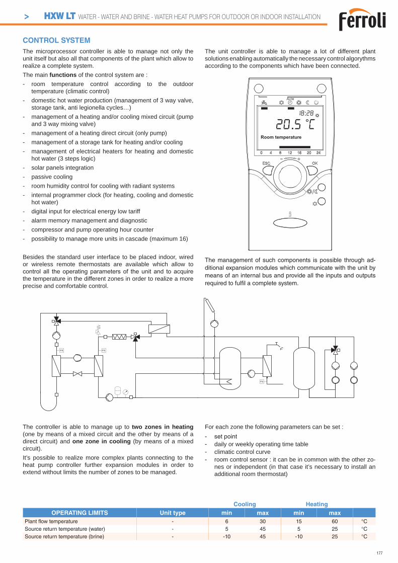
177
Cooling Heating
OPERATING LIMITS Unit type min max min max
Plant fl ow temperature - 6 30 15 60 °CSource return temperature (water) - 5 45 5 25 °CSource return temperature (brine) - -10 45 -10 25 °C
CONTROL SYSTEM
The controller is able to manage up to two zones in heating (one by means of a mixed circuit and the other by means of a direct circuit) and one zone in cooling (by means of a mixed circuit).It’s possible to realize more complex plants connecting to the heat pump controller further expansion modules in order to extend without limits the number of zones to be managed.
For each zone the following parameters can be set :- set point- daily or weekly operating time table- climatic control curve- room control sensor : it can be in common with the other zo-
nes or independent (in that case it’s necessary to install an additional room thermostat)
The microprocessor controller is able to manage not only the unit itself but also all that components of the plant which allow to realize a complete system.The main functions of the control system are :- room temperature control according to the outdoor
temperature (climatic control)- domestic hot water production (management of 3 way valve,
storage tank, anti legionella cycles…)- management of a heating and/or cooling mixed circuit (pump
and 3 way mixing valve)- management of a heating direct circuit (only pump)- management of a storage tank for heating and/or cooling- management of electrical heaters for heating and domestic
hot water (3 steps logic)- solar panels integration- passive cooling- room humidity control for cooling with radiant systems- internal programmer clock (for heating, cooling and domestic
hot water)- digital input for electrical energy low tariff- alarm memory management and diagnostic- compressor and pump operating hour counter- possibility to manage more units in cascade (maximum 16)
Besides the standard user interface to be placed indoor, wired or wireless remote thermostats are available which allow to
the temperature in the different zones in order to realize a more precise and comfortable control.
The unit controller is able to manage a lot of different plant solutions enabling automatically the necessary control algorythms according to the components which have been connected.
The management of such components is possible through ad-ditional expansion modules which communicate with the unit by means of an internal bus and provide all the inputs and outputs required to fulfi l a complete system.
Room temperature
20.5 C18:28
> HXW LT WATER - WATER AND BRINE - WATER HEAT PUMPS FOR OUTDOOR OR INDOOR INSTALLATION
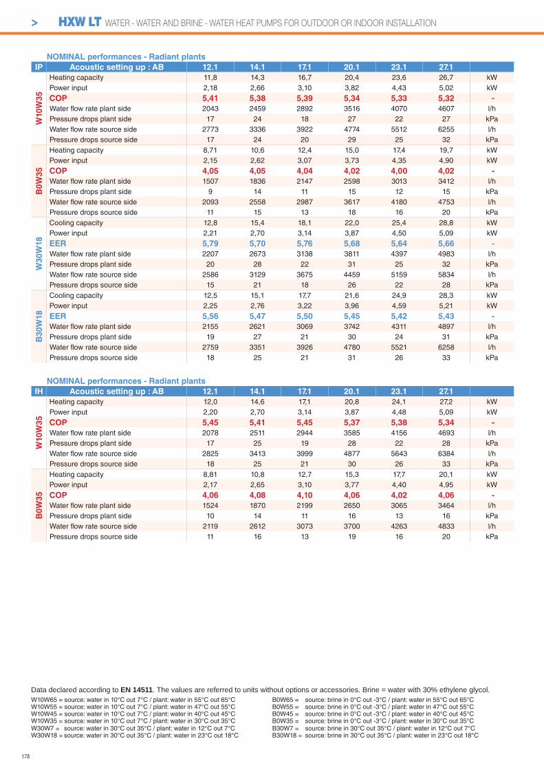
178
> HXW LT WATER - WATER AND BRINE - WATER HEAT PUMPS FOR OUTDOOR OR INDOOR INSTALLATION
NOMINAL performances - Radiant plants
IP Acoustic setting up : AB 12.1 14.1 17.1 20.1 23.1 27.1
W10
W3
5
Heating capacity 11,8 14,3 16,7 20,4 23,6 26,7 kWPower input 2,18 2,66 3,10 3,82 4,43 5,02 kW
COP 5,41 5,38 5,39 5,34 5,33 5,32 -
Water fl ow rate plant side 2043 2459 2892 3516 4070 4607 l/hPressure drops plant side 17 24 18 27 22 27 kPaWater fl ow rate source side 2773 3336 3922 4774 5512 6255 l/hPressure drops source side 17 24 20 29 25 32 kPa
B0
W3
5
Heating capacity 8,71 10,6 12,4 15,0 17,4 19,7 kWPower input 2,15 2,62 3,07 3,73 4,35 4,90 kW
COP 4,05 4,05 4,04 4,02 4,00 4,02 -
Water fl ow rate plant side 1507 1836 2147 2598 3013 3412 l/hPressure drops plant side 9 14 11 15 12 15 kPaWater fl ow rate source side 2093 2558 2987 3617 4180 4753 l/hPressure drops source side 11 15 13 18 16 20 kPa
W3
0W
18
Cooling capacity 12,8 15,4 18,1 22,0 25,4 28,8 kWPower input 2,21 2,70 3,14 3,87 4,50 5,09 kW
EER 5,79 5,70 5,76 5,68 5,64 5,66 -
Water fl ow rate plant side 2207 2673 3138 3811 4397 4983 l/hPressure drops plant side 20 28 22 31 25 32 kPaWater fl ow rate source side 2586 3129 3675 4459 5159 5834 l/hPressure drops source side 15 21 18 26 22 28 kPa
B30W
18
Cooling capacity 12,5 15,1 17,7 21,6 24,9 28,3 kWPower input 2,25 2,76 3,22 3,96 4,59 5,21 kW
EER 5,56 5,47 5,50 5,45 5,42 5,43 -
Water fl ow rate plant side 2155 2621 3069 3742 4311 4897 l/hPressure drops plant side 19 27 21 30 24 31 kPaWater fl ow rate source side 2759 3351 3926 4780 5521 6258 l/hPressure drops source side 18 25 21 31 26 33 kPa
NOMINAL performances - Radiant plants
IH Acoustic setting up : AB 12.1 14.1 17.1 20.1 23.1 27.1
W10W
35
Heating capacity 12,0 14,6 17,1 20,8 24,1 27,2 kWPower input 2,20 2,70 3,14 3,87 4,48 5,09 kW
COP 5,45 5,41 5,45 5,37 5,38 5,34 -
Water fl ow rate plant side 2078 2511 2944 3585 4156 4693 l/hPressure drops plant side 17 25 19 28 22 28 kPaWater fl ow rate source side 2825 3413 3999 4877 5643 6384 l/hPressure drops source side 18 25 21 30 26 33 kPa
B0W
35
Heating capacity 8,81 10,8 12,7 15,3 17,7 20,1 kWPower input 2,17 2,65 3,10 3,77 4,40 4,95 kW
COP 4,06 4,08 4,10 4,06 4,02 4,06 -
Water fl ow rate plant side 1524 1870 2199 2650 3065 3464 l/hPressure drops plant side 10 14 11 16 13 16 kPaWater fl ow rate source side 2119 2612 3073 3700 4263 4833 l/hPressure drops source side 11 16 13 19 16 20 kPa
W10W65 = source: water in 10°C out 7°C / plant: water in 55°C out 65°CW10W55 = source: water in 10°C out 7°C / plant: water in 47°C out 55°CW10W45 = source: water in 10°C out 7°C / plant: water in 40°C out 45°CW10W35 = source: water in 10°C out 7°C / plant: water in 30°C out 35°C
Data declared according to EN 14511. The values are referred to units without options or accessories. Brine = water with 30% ethylene glycol.
W30W7 = source: water in 30°C out 35°C / plant: water in 12°C out 7°CW30W18 = source: water in 30°C out 35°C / plant: water in 23°C out 18°C
B0W65 = source: brine in 0°C out -3°C / plant: water in 55°C out 65°CB0W55 = source: brine in 0°C out -3°C / plant: water in 47°C out 55°CB0W45 = source: brine in 0°C out -3°C / plant: water in 40°C out 45°CB0W35 = source: brine in 0°C out -3°C / plant: water in 30°C out 35°CB30W7 = source: brine in 30°C out 35°C / plant: water in 12°C out 7°CB30W18 = source: brine in 30°C out 35°C / plant: water in 23°C out 18°C

179
> HXW LT WATER - WATER AND BRINE - WATER HEAT PUMPS FOR OUTDOOR OR INDOOR INSTALLATION
NOMINAL performances - Standard plants
IP Acoustic setting up : AB 12.1 14.1 17.1 20.1 23.1 27.1
W10
W4
5
Heating capacity 10,8 13,1 15,4 18,8 21,7 24,6 kWPower input 2,63 3,21 3,76 4,58 5,34 6,02 kW
COP 4,11 4,08 4,10 4,10 4,06 4,09 -
Water fl ow rate plant side 1877 2277 2676 3250 3754 4258 l/hPressure drops plant side 14 21 16 23 18 23 kPaWater fl ow rate source side 2350 2853 3353 4080 4688 5343 l/hPressure drops source side 13 18 15 22 18 23 kPa
B0
W4
5
Heating capacity 8,10 9,84 11,5 14,0 16,2 18,3 kWPower input 2,57 3,12 3,67 4,45 5,20 5,83 kW
COP 3,15 3,15 3,13 3,15 3,12 3,14 -
Water fl ow rate plant side 1406 1707 1999 2433 2815 3180 l/hPressure drops plant side 8 12 9 13 11 13 kPaWater fl ow rate source side 1763 2144 2504 3061 3519 3996 l/hPressure drops source side 8 11 9 13 11 14 kPa
W3
0W
7
Cooling capacity 9,71 11,8 13,8 16,8 19,4 21,9 kWPower input 2,21 2,68 3,14 3,82 4,47 5,02 kW
EER 4,39 4,40 4,39 4,40 4,34 4,36 -
Water fl ow rate plant side 1670 2025 2368 2883 3329 3775 l/hPressure drops plant side 12 17 13 18 15 19 kPaWater fl ow rate source side 2061 2497 2923 3554 4116 4655 l/hPressure drops source side 10 14 12 17 14 18 kPa
B30W
7
Cooling capacity 9,50 11,6 13,6 16,5 19,1 21,5 kWPower input 2,25 2,74 3,21 3,91 4,56 5,14 kW
EER 4,22 4,23 4,24 4,22 4,19 4,18 -
Water fl ow rate plant side 1634 1991 2334 2832 3278 3707 l/hPressure drops plant side 11 16 12 18 14 18 kPaWater fl ow rate source side 2206 2683 3148 3815 4428 4998 l/hPressure drops source side 12 17 14 20 17 22 kPa
NOMINAL performances - Standard plants
IH Acoustic setting up : AB 12.1 14.1 17.1 20.1 23.1 27.1
W10W
45
Heating capacity 11,0 13,4 15,7 19,2 22,2 25,0 kWPower input 2,67 3,26 3,80 4,64 5,40 6,09 kW
COP 4,12 4,11 4,13 4,14 4,11 4,11 -
Water fl ow rate plant side 1912 2329 2729 3319 3841 4327 l/hPressure drops plant side 15 22 16 24 19 24 kPaWater fl ow rate source side 2399 2927 3428 4180 4817 5440 l/hPressure drops source side 13 19 16 23 19 24 kPa
B0W
45
Heating capacity 8,21 10,0 11,8 14,3 16,5 18,6 kWPower input 2,59 3,16 3,70 4,49 5,26 5,90 kW
COP 3,17 3,16 3,19 3,18 3,14 3,15 -
Water fl ow rate plant side 1425 1738 2051 2485 2868 3233 l/hPressure drops plant side 8 12 10 14 11 14 kPaWater fl ow rate source side 1791 2189 2590 3143 3598 4072 l/hPressure drops source side 8 12 10 14 12 15 kPa
W10W65 = source: water in 10°C out 7°C / plant: water in 55°C out 65°CW10W55 = source: water in 10°C out 7°C / plant: water in 47°C out 55°CW10W45 = source: water in 10°C out 7°C / plant: water in 40°C out 45°CW10W35 = source: water in 10°C out 7°C / plant: water in 30°C out 35°C
Data declared according to EN 14511. The values are referred to units without options or accessories. Brine = water with 30% ethylene glycol.B0W65 = source: brine in 0°C out -3°C / plant: water in 55°C out 65°CB0W55 = source: brine in 0°C out -3°C / plant: water in 47°C out 55°CB0W45 = source: brine in 0°C out -3°C / plant: water in 40°C out 45°CB0W35 = source: brine in 0°C out -3°C / plant: water in 30°C out 35°C
W30W7 = source: water in 30°C out 35°C / plant: water in 12°C out 7°CW30W18 = source: water in 30°C out 35°C / plant: water in 23°C out 18°C
B30W7 = source: brine in 30°C out 35°C / plant: water in 12°C out 7°CB30W18 = source: brine in 30°C out 35°C / plant: water in 23°C out 18°C
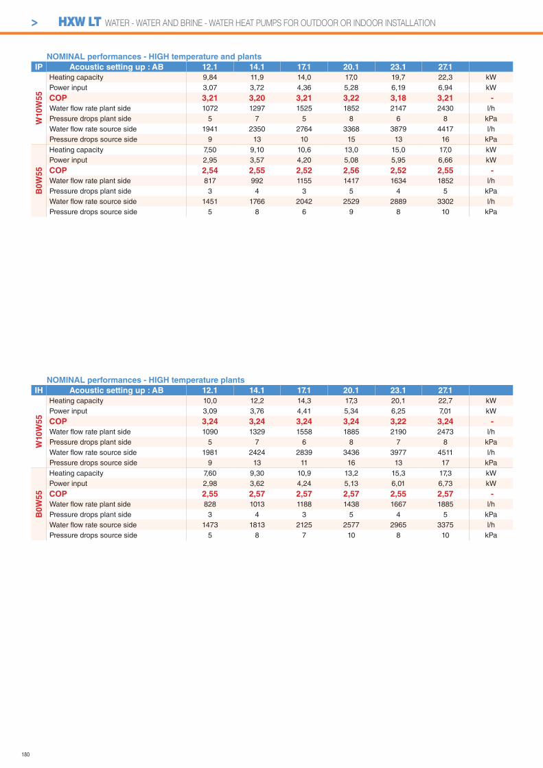
180
> HXW LT WATER - WATER AND BRINE - WATER HEAT PUMPS FOR OUTDOOR OR INDOOR INSTALLATION
NOMINAL performances - HIGH temperature plants
IH Acoustic setting up : AB 12.1 14.1 17.1 20.1 23.1 27.1
W10W
55
Heating capacity 10,0 12,2 14,3 17,3 20,1 22,7 kWPower input 3,09 3,76 4,41 5,34 6,25 7,01 kW
COP 3,24 3,24 3,24 3,24 3,22 3,24 -
Water fl ow rate plant side 1090 1329 1558 1885 2190 2473 l/hPressure drops plant side 5 7 6 8 7 8 kPaWater fl ow rate source side 1981 2424 2839 3436 3977 4511 l/hPressure drops source side 9 13 11 16 13 17 kPa
B0W
55
Heating capacity 7,60 9,30 10,9 13,2 15,3 17,3 kWPower input 2,98 3,62 4,24 5,13 6,01 6,73 kW
COP 2,55 2,57 2,57 2,57 2,55 2,57 -
Water fl ow rate plant side 828 1013 1188 1438 1667 1885 l/hPressure drops plant side 3 4 3 5 4 5 kPaWater fl ow rate source side 1473 1813 2125 2577 2965 3375 l/hPressure drops source side 5 8 7 10 8 10 kPa
NOMINAL performances - HIGH temperature and plants
IP Acoustic setting up : AB 12.1 14.1 17.1 20.1 23.1 27.1
W10
W5
5
Heating capacity 9,84 11,9 14,0 17,0 19,7 22,3 kWPower input 3,07 3,72 4,36 5,28 6,19 6,94 kW
COP 3,21 3,20 3,21 3,22 3,18 3,21 -
Water fl ow rate plant side 1072 1297 1525 1852 2147 2430 l/hPressure drops plant side 5 7 5 8 6 8 kPaWater fl ow rate source side 1941 2350 2764 3368 3879 4417 l/hPressure drops source side 9 13 10 15 13 16 kPa
B0
W5
5
Heating capacity 7,50 9,10 10,6 13,0 15,0 17,0 kWPower input 2,95 3,57 4,20 5,08 5,95 6,66 kW
COP 2,54 2,55 2,52 2,56 2,52 2,55 -
Water fl ow rate plant side 817 992 1155 1417 1634 1852 l/hPressure drops plant side 3 4 3 5 4 5 kPaWater fl ow rate source side 1451 1766 2042 2529 2889 3302 l/hPressure drops source side 5 8 6 9 8 10 kPa

181
> HXW LT WATER - WATER AND BRINE - WATER HEAT PUMPS FOR OUTDOOR OR INDOOR INSTALLATION
TECHNICAL DATA 12.1 14.1 17.1 20.1 23.1 27.1
Power supply 230-1-50400-3N-50 400-3N-50 V-ph-Hz
Compressor type scroll -
N° compressors / N° refrigerant circuits 1 / 1 n°
Plant side heat exchanger type stainless steel brazed plates -
Source side heat exchanger type stainless steel brazed plates -
Hydraulic fi ttings 1” M -
Weight * 138 141 160 162 165 168 kg
Maximum power input * 3,5 4,5 5,1 5,8 6,8 7,6 kW* base unit without options and accessories
AB
AB
A 600 mmB 600 mm
DIMENSIONS AND MINIMUM OPERATING AREA
Respect the free area around the unit as shown in fi gure in order to guarantee a good accessibility and facilitate maintenance and control operations.
Unit with accessory “Plant tank”
7 509 7
522
201 292 212
705
116
670
8470
7070
156
7070
1239
201 292 212
705 7 509 7
522
7030
019
8
116
189 145 188
The acoustic performances are referred to units operating in cooling mode at nominal conditions W10W35.Unit placed in free fi eld on refl ecting surface (directional factor equal to 2).The sound power level is measured according to ISO 3744 standard.The sound pressure level is calculated according to ISO 3744 and is referred to a distance of 1/5/10 metres from the external surface of the unit.
Base acoustic setting up (AB) 12.1 14.1 17.1 20.1 23.1 27.1
Sound power level 63 63 64 64 65 65 dB(A)Sound pressure level at 1 metre 50 50 51 51 52 52 dB(A)Sound pressure level at 5 metres 38 38 39 39 40 40 dB(A)Sound pressure level at 10 metres 32 32 33 33 34 34 dB(A)
ACOUSTIC PERFORMANCES
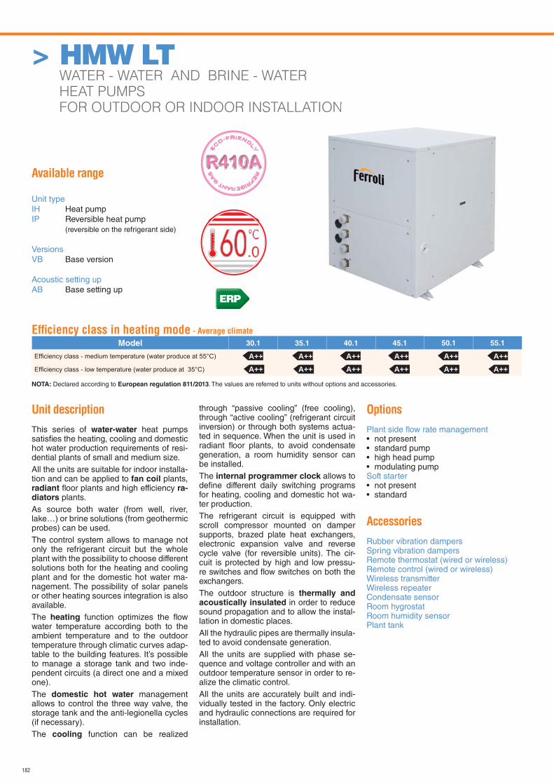
182
> HMW LT WATER - WATER AND BRINE - WATER
HEAT PUMPS
FOR OUTDOOR OR INDOOR INSTALLATION
Available range
Unit typeIH Heat pumpIP Reversible heat pump (reversible on the refrigerant side)
VersionsVB Base version
Acoustic setting upAB Base setting up
Unit description
This series of water-water heat pumps satisfi es the heating, cooling and domestic hot water production requirements of resi-dential plants of small and medium size.All the units are suitable for indoor installa-tion and can be applied to fan coil plants, radiant fl oor plants and high efficiency ra-diators plants.As source both water (from well, river, lake…) or brine solutions (from geothermic probes) can be used.The control system allows to manage not only the refrigerant circuit but the whole plant with the possibility to choose different solutions both for the heating and cooling plant and for the domestic hot water ma-nagement. The possibility of solar panels or other heating sources integration is also available.The heating function optimizes the fl ow water temperature according both to the ambient temperature and to the outdoor temperature through climatic curves adap-table to the building features. It’s possible to manage a storage tank and two inde-pendent circuits (a direct one and a mixed one).The domestic hot water management allows to control the three way valve, the storage tank and the anti-legionella cycles (if necessary).The cooling function can be realized
through “passive cooling” (free cooling), through “active cooling” (refrigerant circuit inversion) or through both systems actua-ted in sequence. When the unit is used in radiant fl oor plants, to avoid condensate generation, a room humidity sensor can be installed.The internal programmer clock allows to defi ne different daily switching programs for heating, cooling and domestic hot wa-ter production.The refrigerant circuit is equipped with scroll compressor mounted on damper supports, brazed plate heat exchangers, electronic expansion valve and reverse cycle valve (for reversible units). The cir-cuit is protected by high and low pressu-re switches and fl ow switches on both the exchangers.The outdoor structure is thermally and acoustically insulated in order to reduce sound propagation and to allow the instal-lation in domestic places.All the hydraulic pipes are thermally insula-ted to avoid condensate generation.All the units are supplied with phase se-quence and voltage controller and with an outdoor temperature sensor in order to re-alize the climatic control.All the units are accurately built and indi-vidually tested in the factory. Only electric and hydraulic connections are required for installation.
Options
Plant side fl ow rate management • not present• standard pump• high head pump• modulating pumpSoft starter• not present• standard
Accessories
Rubber vibration dampersSpring vibration dampersRemote thermostat (wired or wireless)Remote control (wired or wireless)Wireless transmitterWireless repeaterCondensate sensorRoom hygrostatRoom humidity sensorPlant tank
TION
RE
FRIGERANT G
AS
E
CO-FRIEND
LY
Effi ciency class in heating mode - Average climate
Model 30.1 35.1 40.1 45.1 50.1 55.1
NOTA: Declared according to European regulation 811/2013. The values are referred to units without options and accessories.
A++ A++ A++ A++ A++ A++A++ A++ A++ A++ A++ A++
ERP

183
Cooling Heating
OPERATING LIMITS Unit type min max min max
Plant fl ow temperature - 6 30 15 60 °CSource return temperature (water) - 5 45 5 25 °CSource return temperature (brine) - -10 45 -10 25 °C
CONTROL SYSTEM
The controller is able to manage up to two zones in heating (one by means of a mixed circuit and the other by means of a direct circuit) and one zone in cooling (by means of a mixed circuit).It’s possible to realize more complex plants connecting to the heat pump controller further expansion modules in order to extend without limits the number of zones to be managed.
For each zone the following parameters can be set :- set point- daily or weekly operating time table- climatic control curve- room control sensor : it can be in common with the other zo-
nes or independent (in that case it’s necessary to install an additional room thermostat)
The microprocessor controller is able to manage not only the unit itself but also all that components of the plant which allow to realize a complete system.The main functions of the control system are :- room temperature control according to the outdoor
temperature (climatic control)- domestic hot water production (management of 3 way valve,
storage tank, anti legionella cycles…)- management of a heating and/or cooling mixed circuit (pump
and 3 way mixing valve)- management of a heating direct circuit (only pump)- management of a storage tank for heating and/or cooling- management of electrical heaters for heating and domestic
hot water (3 steps logic)- solar panels integration- passive cooling- room humidity control for cooling with radiant systems- internal programmer clock (for heating, cooling and domestic
hot water)- digital input for electrical energy low tariff- alarm memory management and diagnostic- compressor and pump operating hour counter- possibility to manage more units in cascade (maximum 16)
Besides the standard user interface to be placed indoor, wired or wireless remote thermostats are available which allow to
the temperature in the different zones in order to realize a more precise and comfortable control.
The unit controller is able to manage a lot of different plant solutions enabling automatically the necessary control algorythms according to the components which have been connected.
The management of such components is possible through ad-ditional expansion modules which communicate with the unit by means of an internal bus and provide all the inputs and outputs required to fulfi l a complete system.
Room temperature
20.5 C18:28
> HMW LT WATER - WATER AND BRINE - WATER HEAT PUMPS FOR OUTDOOR OR INDOOR INSTALLATION
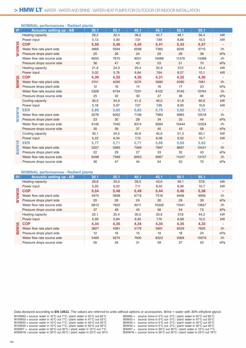
184
NOMINAL performances - Radiant plants
IP Acoustic setting up : AB 30.1 35.1 40.1 45.1 50.1 55.1
W10
W3
5
Heating capacity 28,2 32,4 38,2 42,7 48,1 56,4 kWPower input 5,13 5,93 7,01 7,90 8,86 10,5 kW
COP 5,50 5,46 5,45 5,41 5,43 5,37 -
Water fl ow rate plant side 4866 5594 6598 7360 8295 9715 l/hPressure drops plant side 20 26 24 29 28 38 kPaWater fl ow rate source side 6655 7670 9031 10089 11378 13368 l/hPressure drops source side 36 47 43 53 51 70 kPa
B0
W3
5
Heating capacity 21,6 24,9 29,4 32,9 37,0 43,4 kWPower input 5,02 5,76 6,84 7,64 8,57 10,1 kW
COP 4,30 4,32 4,30 4,31 4,32 4,30 -
Water fl ow rate plant side 3741 4295 5074 5680 6390 7481 l/hPressure drops plant side 12 16 14 18 17 23 kPaWater fl ow rate source side 5326 6134 7231 8122 9140 10744 l/hPressure drops source side 25 32 30 37 36 48 kPa
W3
0W
18
Cooling capacity 30,5 34,9 41,2 46,0 51,8 60,6 kWPower input 5,18 5,97 7,07 7,95 8,90 10,6 kW
EER 5,89 5,85 5,83 5,79 5,82 5,72 -
Water fl ow rate plant side 5276 6052 7138 7983 8983 10518 l/hPressure drops plant side 23 30 28 34 33 44 kPaWater fl ow rate source side 6146 7040 8314 9284 10444 12204 l/hPressure drops source side 30 39 37 45 43 58 kPa
B30W
18
Cooling capacity 30,1 34,5 40,8 45,6 51,3 60,1 kWPower input 5,22 6,04 7,15 8,06 9,02 10,7 kW
EER 5,77 5,71 5,71 5,66 5,69 5,62 -
Water fl ow rate plant side 5207 5983 7069 7897 8897 10431 l/hPressure drops plant side 22 29 27 33 32 43 kPaWater fl ow rate source side 6598 7569 8953 9987 11247 13157 l/hPressure drops source side 36 47 44 54 52 70 kPa
NOMINAL performances - Radiant plants
IH Acoustic setting up : AB 30.1 35.1 40.1 45.1 50.1 55.1
W10W
35
Heating capacity 28,8 33,0 39,0 43,6 49,1 57,6 kWPower input 5,20 6,02 7,11 8,02 8,99 10,7 kW
COP 5,54 5,48 5,49 5,44 5,46 5,38 -
Water fl ow rate plant side 4970 5698 6719 7516 8468 9906 l/hPressure drops plant side 20 26 24 30 29 39 kPaWater fl ow rate source side 6813 7825 9211 10326 11641 13657 l/hPressure drops source side 37 48 45 56 54 73 kPa
B0W
35
Heating capacity 22,1 25,4 30,0 33,6 37,8 44,2 kWPower input 5,09 5,84 6,92 7,74 8,68 10,2 kW
COP 4,34 4,35 4,34 4,34 4,35 4,33 -
Water fl ow rate plant side 3827 4381 5178 5801 6529 7620 l/hPressure drops plant side 12 16 15 19 18 24 kPaWater fl ow rate source side 5469 6274 7400 8323 9369 10970 l/hPressure drops source side 26 34 31 39 37 50 kPa
W10W65 = source: water in 10°C out 7°C / plant: water in 55°C out 65°CW10W55 = source: water in 10°C out 7°C / plant: water in 47°C out 55°CW10W45 = source: water in 10°C out 7°C / plant: water in 40°C out 45°CW10W35 = source: water in 10°C out 7°C / plant: water in 30°C out 35°C
Data declared according to EN 14511. The values are referred to units without options or accessories. Brine = water with 30% ethylene glycol.
W30W7 = source: water in 30°C out 35°C / plant: water in 12°C out 7°CW30W18 = source: water in 30°C out 35°C / plant: water in 23°C out 18°C
B0W65 = source: brine in 0°C out -3°C / plant: water in 55°C out 65°CB0W55 = source: brine in 0°C out -3°C / plant: water in 47°C out 55°CB0W45 = source: brine in 0°C out -3°C / plant: water in 40°C out 45°CB0W35 = source: brine in 0°C out -3°C / plant: water in 30°C out 35°CB30W7 = source: brine in 30°C out 35°C / plant: water in 12°C out 7°CB30W18 = source: brine in 30°C out 35°C / plant: water in 23°C out 18°C
> HMW LT WATER - WATER AND BRINE - WATER HEAT PUMPS FOR OUTDOOR OR INDOOR INSTALLATION
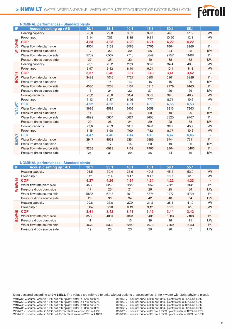
185
NOMINAL performances - Standard plants
IP Acoustic setting up : AB 30.1 35.1 40.1 45.1 50.1 55.1
W10
W4
5
Heating capacity 26,0 29,8 35,1 39,3 44,3 51,9 kWPower input 6,14 7,05 8,35 9,34 10,50 12,3 kW
COP 4,23 4,23 4,20 4,21 4,22 4,22 -
Water fl ow rate plant side 4501 5162 6083 6795 7664 8968 l/hPressure drops plant side 17 22 20 25 24 32 kPaWater fl ow rate source side 5709 6567 7716 8642 9757 11464 l/hPressure drops source side 27 35 32 40 38 52 kPa
B0
W4
5
Heating capacity 20,1 23,2 27,3 30,6 34,4 40,3 kWPower input 5,97 6,82 8,10 9,01 10,1 11,8 kW
COP 3,37 3,40 3,37 3,40 3,41 3,42 -
Water fl ow rate plant side 3493 4015 4727 5301 5961 6986 l/hPressure drops plant side 10 14 13 16 15 20 kPaWater fl ow rate source side 4530 5233 6134 6916 7779 9163 l/hPressure drops source side 18 24 22 27 26 36 kPa
W3
0W
7
Cooling capacity 23,2 26,6 31,4 35,2 39,6 46,2 kWPower input 5,13 5,87 6,96 7,77 8,71 10,2 kW
EER 4,52 4,53 4,51 4,53 4,55 4,53 -
Water fl ow rate plant side 3999 4582 5406 6058 6813 7963 l/hPressure drops plant side 14 18 16 20 19 26 kPaWater fl ow rate source side 4899 5604 6621 7403 8325 9707 l/hPressure drops source side 20 26 24 29 28 38 kPa
B30W
7
Cooling capacity 23,0 26,3 31,1 34,8 39,2 45,9 kWPower input 5,15 5,90 7,00 7,82 8,77 10,3 kW
EER 4,47 4,46 4,44 4,45 4,47 4,46 -
Water fl ow rate plant side 3947 4531 5354 5989 6744 7911 l/hPressure drops plant side 13 17 16 20 19 26 kPaWater fl ow rate source side 5263 6029 7132 7963 8964 10483 l/hPressure drops source side 24 31 29 35 34 46 kPa
NOMINAL performances - Standard plants
IH Acoustic setting up : AB 30.1 35.1 40.1 45.1 50.1 55.1
W10W
45
Heating capacity 26,5 30,4 35,9 40,2 45,2 52,9 kWPower input 6,21 7,14 8,47 9,47 10,7 12,5 kW
COP 4,27 4,26 4,24 4,24 4,22 4,23 -
Water fl ow rate plant side 4588 5266 6222 6952 7821 9141 l/hPressure drops plant side 17 23 21 26 25 34 kPaWater fl ow rate source side 5835 6718 7919 8874 9977 11721 l/hPressure drops source side 28 36 34 42 40 54 kPa
B0W
45
Heating capacity 20,6 23,6 27,9 31,2 35,1 41,0 kWPower input 6,04 6,90 8,19 9,12 10,2 12,0 kW
COP 3,41 3,42 3,41 3,42 3,44 3,42 -
Water fl ow rate plant side 3580 4084 4831 5405 6083 7108 l/hPressure drops plant side 11 14 13 16 16 21 kPaWater fl ow rate source side 4670 5338 6299 7079 7969 9353 l/hPressure drops source side 19 25 23 29 28 37 kPa
W10W65 = source: water in 10°C out 7°C / plant: water in 55°C out 65°CW10W55 = source: water in 10°C out 7°C / plant: water in 47°C out 55°CW10W45 = source: water in 10°C out 7°C / plant: water in 40°C out 45°CW10W35 = source: water in 10°C out 7°C / plant: water in 30°C out 35°C
Data declared according to EN 14511. The values are referred to units without options or accessories. Brine = water with 30% ethylene glycol.B0W65 = source: brine in 0°C out -3°C / plant: water in 55°C out 65°CB0W55 = source: brine in 0°C out -3°C / plant: water in 47°C out 55°CB0W45 = source: brine in 0°C out -3°C / plant: water in 40°C out 45°CB0W35 = source: brine in 0°C out -3°C / plant: water in 30°C out 35°C
W30W7 = source: water in 30°C out 35°C / plant: water in 12°C out 7°CW30W18 = source: water in 30°C out 35°C / plant: water in 23°C out 18°C
B30W7 = source: brine in 30°C out 35°C / plant: water in 12°C out 7°CB30W18 = source: brine in 30°C out 35°C / plant: water in 23°C out 18°C
> HMW LT WATER - WATER AND BRINE - WATER HEAT PUMPS FOR OUTDOOR OR INDOOR INSTALLATION
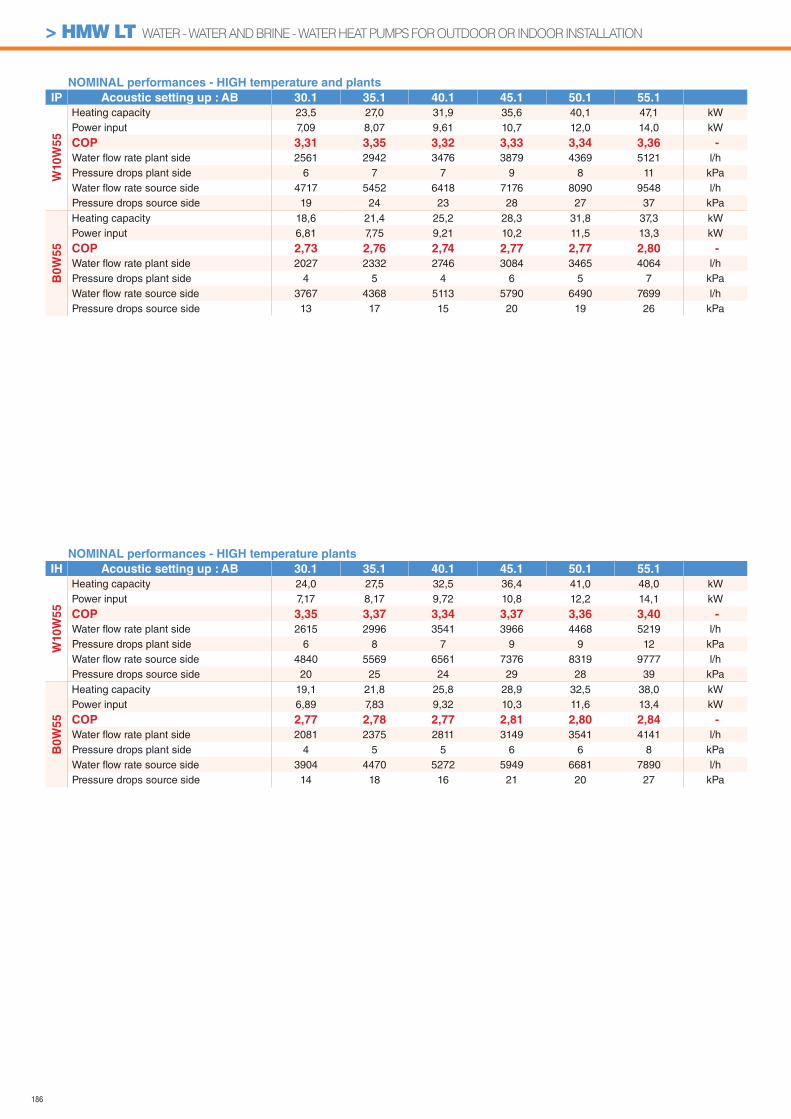
186
NOMINAL performances - HIGH temperature plants
IH Acoustic setting up : AB 30.1 35.1 40.1 45.1 50.1 55.1
W10W
55
Heating capacity 24,0 27,5 32,5 36,4 41,0 48,0 kWPower input 7,17 8,17 9,72 10,8 12,2 14,1 kW
COP 3,35 3,37 3,34 3,37 3,36 3,40 -
Water fl ow rate plant side 2615 2996 3541 3966 4468 5219 l/hPressure drops plant side 6 8 7 9 9 12 kPaWater fl ow rate source side 4840 5569 6561 7376 8319 9777 l/hPressure drops source side 20 25 24 29 28 39 kPa
B0W
55
Heating capacity 19,1 21,8 25,8 28,9 32,5 38,0 kWPower input 6,89 7,83 9,32 10,3 11,6 13,4 kW
COP 2,77 2,78 2,77 2,81 2,80 2,84 -
Water fl ow rate plant side 2081 2375 2811 3149 3541 4141 l/hPressure drops plant side 4 5 5 6 6 8 kPaWater fl ow rate source side 3904 4470 5272 5949 6681 7890 l/hPressure drops source side 14 18 16 21 20 27 kPa
NOMINAL performances - HIGH temperature and plants
IP Acoustic setting up : AB 30.1 35.1 40.1 45.1 50.1 55.1
W10
W5
5
Heating capacity 23,5 27,0 31,9 35,6 40,1 47,1 kWPower input 7,09 8,07 9,61 10,7 12,0 14,0 kW
COP 3,31 3,35 3,32 3,33 3,34 3,36 -
Water fl ow rate plant side 2561 2942 3476 3879 4369 5121 l/hPressure drops plant side 6 7 7 9 8 11 kPaWater fl ow rate source side 4717 5452 6418 7176 8090 9548 l/hPressure drops source side 19 24 23 28 27 37 kPa
B0
W5
5
Heating capacity 18,6 21,4 25,2 28,3 31,8 37,3 kWPower input 6,81 7,75 9,21 10,2 11,5 13,3 kW
COP 2,73 2,76 2,74 2,77 2,77 2,80 -
Water fl ow rate plant side 2027 2332 2746 3084 3465 4064 l/hPressure drops plant side 4 5 4 6 5 7 kPaWater fl ow rate source side 3767 4368 5113 5790 6490 7699 l/hPressure drops source side 13 17 15 20 19 26 kPa
> HMW LT WATER - WATER AND BRINE - WATER HEAT PUMPS FOR OUTDOOR OR INDOOR INSTALLATION
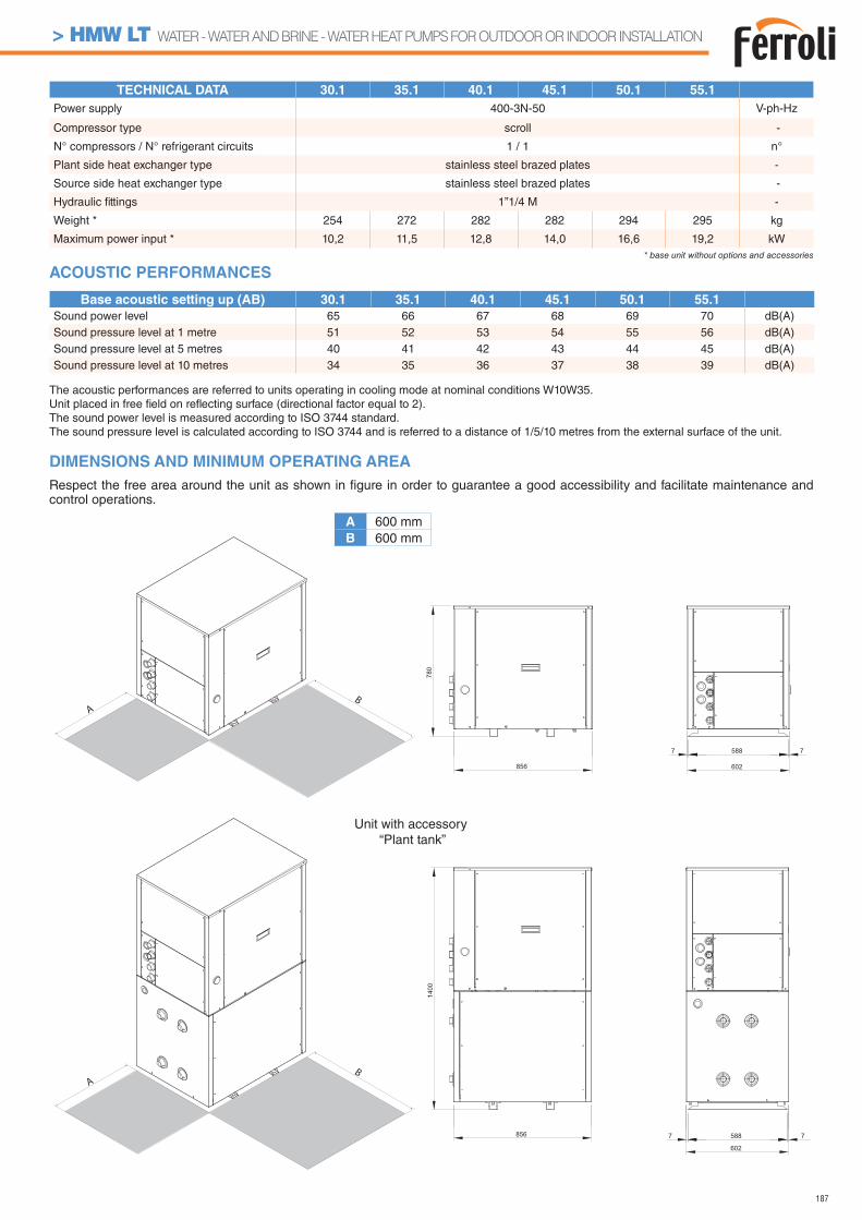
187
TECHNICAL DATA 30.1 35.1 40.1 45.1 50.1 55.1
Power supply 400-3N-50 V-ph-Hz
Compressor type scroll -
N° compressors / N° refrigerant circuits 1 / 1 n°
Plant side heat exchanger type stainless steel brazed plates -
Source side heat exchanger type stainless steel brazed plates -
Hydraulic fi ttings 1”1/4 M -
Weight * 254 272 282 282 294 295 kg
Maximum power input * 10,2 11,5 12,8 14,0 16,6 19,2 kW* base unit without options and accessories
AB
AB
A 600 mmB 600 mm
DIMENSIONS AND MINIMUM OPERATING AREA
Respect the free area around the unit as shown in fi gure in order to guarantee a good accessibility and facilitate maintenance and control operations.
Unit with accessory “Plant tank”
7 588 7
602856
780
1400
856 7 588 7
602
The acoustic performances are referred to units operating in cooling mode at nominal conditions W10W35.Unit placed in free fi eld on refl ecting surface (directional factor equal to 2).The sound power level is measured according to ISO 3744 standard.The sound pressure level is calculated according to ISO 3744 and is referred to a distance of 1/5/10 metres from the external surface of the unit.
Base acoustic setting up (AB) 30.1 35.1 40.1 45.1 50.1 55.1
Sound power level 65 66 67 68 69 70 dB(A)Sound pressure level at 1 metre 51 52 53 54 55 56 dB(A)Sound pressure level at 5 metres 40 41 42 43 44 45 dB(A)Sound pressure level at 10 metres 34 35 36 37 38 39 dB(A)
ACOUSTIC PERFORMANCES
> HMW LT WATER - WATER AND BRINE - WATER HEAT PUMPS FOR OUTDOOR OR INDOOR INSTALLATION
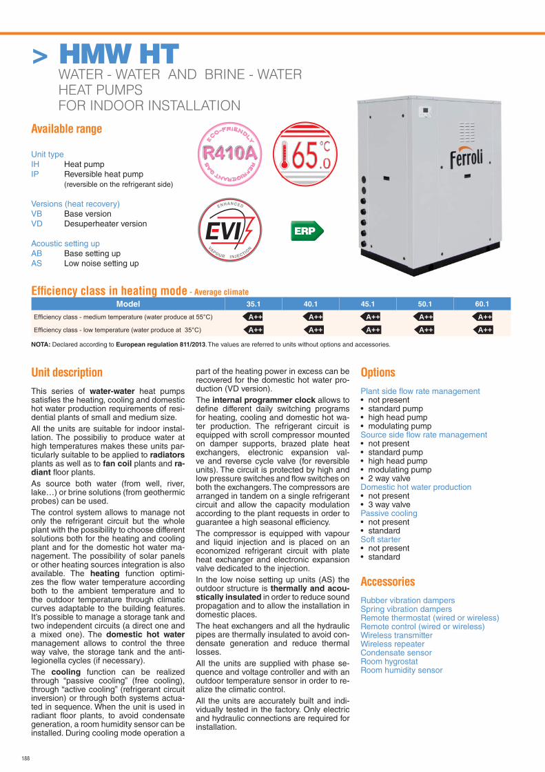
188
> HMW HT WATER - WATER AND BRINE - WATER
HEAT PUMPS
FOR INDOOR INSTALLATION
Available range
Unit typeIH Heat pumpIP Reversible heat pump (reversible on the refrigerant side)
Versions (heat recovery)VB Base versionVD Desuperheater version
Acoustic setting upAB Base setting upAS Low noise setting up
Unit description
This series of water-water heat pumps satisfi es the heating, cooling and domestic hot water production requirements of resi-dential plants of small and medium size.All the units are suitable for indoor instal-lation. The possibiliy to produce water at high temperatures makes these units par-ticularly suitable to be applied to radiators plants as well as to fan coil plants and ra-diant fl oor plants.As source both water (from well, river, lake…) or brine solutions (from geothermic probes) can be used.The control system allows to manage not only the refrigerant circuit but the whole plant with the possibility to choose different solutions both for the heating and cooling plant and for the domestic hot water ma-nagement. The possibility of solar panels or other heating sources integration is also available. The heating function optimi-zes the fl ow water temperature according both to the ambient temperature and to the outdoor temperature through climatic curves adaptable to the building features. It’s possible to manage a storage tank and two independent circuits (a direct one and a mixed one). The domestic hot water management allows to control the three way valve, the storage tank and the anti-legionella cycles (if necessary).The cooling function can be realized through “passive cooling” (free cooling), through “active cooling” (refrigerant circuit inversion) or through both systems actua-ted in sequence. When the unit is used in radiant fl oor plants, to avoid condensate generation, a room humidity sensor can be installed. During cooling mode operation a
part of the heating power in excess can be recovered for the domestic hot water pro-duction (VD version).The internal programmer clock allows to defi ne different daily switching programs for heating, cooling and domestic hot wa-ter production. The refrigerant circuit is equipped with scroll compressor mounted on damper supports, brazed plate heat exchangers, electronic expansion val-ve and reverse cycle valve (for reversible units). The circuit is protected by high and low pressure switches and fl ow switches on both the exchangers. The compressors are arranged in tandem on a single refrigerant circuit and allow the capacity modulation according to the plant requests in order to guarantee a high seasonal efficiency.The compressor is equipped with vapour and liquid injection and is placed on an economized refrigerant circuit with plate heat exchanger and electronic expansion valve dedicated to the injection.In the low noise setting up units (AS) the outdoor structure is thermally and acou-stically insulated in order to reduce sound propagation and to allow the installation in domestic places.The heat exchangers and all the hydraulic pipes are thermally insulated to avoid con-densate generation and reduce thermal losses.All the units are supplied with phase se-quence and voltage controller and with an outdoor temperature sensor in order to re-alize the climatic control.All the units are accurately built and indi-vidually tested in the factory. Only electric and hydraulic connections are required for installation.
Options
Plant side fl ow rate management • not present• standard pump• high head pump• modulating pumpSource side fl ow rate management • not present• standard pump• high head pump• modulating pump• 2 way valveDomestic hot water production • not present• 3 way valvePassive cooling• not present• standardSoft starter• not present• standard
Accessories
Rubber vibration dampersSpring vibration dampersRemote thermostat (wired or wireless)Remote control (wired or wireless)Wireless transmitterWireless repeaterCondensate sensorRoom hygrostatRoom humidity sensor
RE
FRIGERANT G
AS
E
CO-FRIEND
LY
.065
Effi ciency class in heating mode - Average climate
Model 35.1 40.1 45.1 50.1 60.1
NOTA: Declared according to European regulation 811/2013. The values are referred to units without options and accessories.
A++ A++ A++ A++ A++A++ A++ A++ A++ A++
ERP
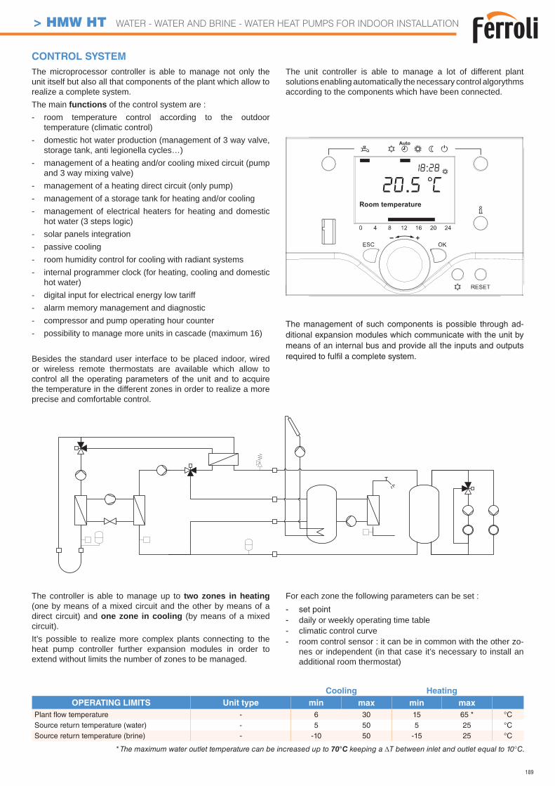
189
Cooling Heating
OPERATING LIMITS Unit type min max min max
Plant fl ow temperature - 6 30 15 65 * °CSource return temperature (water) - 5 50 5 25 °CSource return temperature (brine) - -10 50 -15 25 °C
CONTROL SYSTEM
The controller is able to manage up to two zones in heating (one by means of a mixed circuit and the other by means of a direct circuit) and one zone in cooling (by means of a mixed circuit).It’s possible to realize more complex plants connecting to the heat pump controller further expansion modules in order to extend without limits the number of zones to be managed.
For each zone the following parameters can be set :- set point- daily or weekly operating time table- climatic control curve- room control sensor : it can be in common with the other zo-
nes or independent (in that case it’s necessary to install an additional room thermostat)
The microprocessor controller is able to manage not only the unit itself but also all that components of the plant which allow to realize a complete system.The main functions of the control system are :- room temperature control according to the outdoor
temperature (climatic control)- domestic hot water production (management of 3 way valve,
storage tank, anti legionella cycles…)- management of a heating and/or cooling mixed circuit (pump
and 3 way mixing valve)- management of a heating direct circuit (only pump)- management of a storage tank for heating and/or cooling- management of electrical heaters for heating and domestic
hot water (3 steps logic)- solar panels integration- passive cooling- room humidity control for cooling with radiant systems- internal programmer clock (for heating, cooling and domestic
hot water)- digital input for electrical energy low tariff- alarm memory management and diagnostic- compressor and pump operating hour counter- possibility to manage more units in cascade (maximum 16)
Besides the standard user interface to be placed indoor, wired or wireless remote thermostats are available which allow to
the temperature in the different zones in order to realize a more precise and comfortable control.
The unit controller is able to manage a lot of different plant solutions enabling automatically the necessary control algorythms according to the components which have been connected.
The management of such components is possible through ad-ditional expansion modules which communicate with the unit by means of an internal bus and provide all the inputs and outputs required to fulfi l a complete system.
* The maximum water outlet temperature can be increased up to 70°C keeping a T between inlet and outlet equal to 10°C.
> HMW HT WATER - WATER AND BRINE - WATER HEAT PUMPS FOR INDOOR INSTALLATION
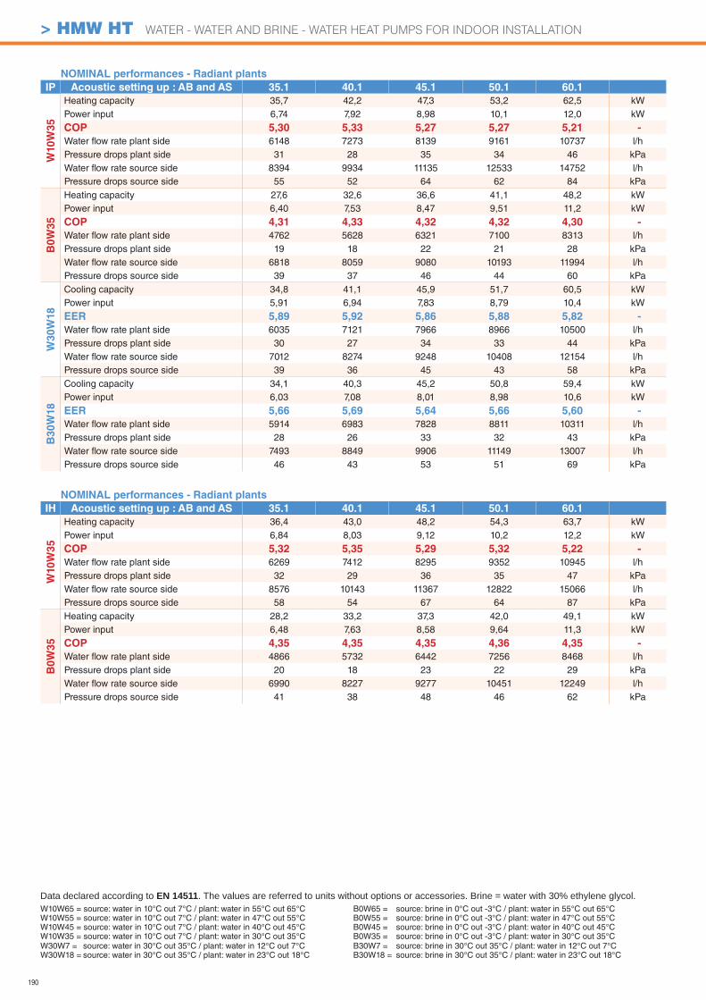
190
> HMW HT WATER - WATER AND BRINE - WATER HEAT PUMPS FOR INDOOR INSTALLATION
NOMINAL performances - Radiant plants
IP Acoustic setting up : AB and AS 35.1 40.1 45.1 50.1 60.1
W10
W3
5
Heating capacity 35,7 42,2 47,3 53,2 62,5 kWPower input 6,74 7,92 8,98 10,1 12,0 kW
COP 5,30 5,33 5,27 5,27 5,21 -
Water fl ow rate plant side 6148 7273 8139 9161 10737 l/hPressure drops plant side 31 28 35 34 46 kPaWater fl ow rate source side 8394 9934 11135 12533 14752 l/hPressure drops source side 55 52 64 62 84 kPa
B0
W3
5
Heating capacity 27,6 32,6 36,6 41,1 48,2 kWPower input 6,40 7,53 8,47 9,51 11,2 kW
COP 4,31 4,33 4,32 4,32 4,30 -
Water fl ow rate plant side 4762 5628 6321 7100 8313 l/hPressure drops plant side 19 18 22 21 28 kPaWater fl ow rate source side 6818 8059 9080 10193 11994 l/hPressure drops source side 39 37 46 44 60 kPa
W3
0W
18
Cooling capacity 34,8 41,1 45,9 51,7 60,5 kWPower input 5,91 6,94 7,83 8,79 10,4 kW
EER 5,89 5,92 5,86 5,88 5,82 -
Water fl ow rate plant side 6035 7121 7966 8966 10500 l/hPressure drops plant side 30 27 34 33 44 kPaWater fl ow rate source side 7012 8274 9248 10408 12154 l/hPressure drops source side 39 36 45 43 58 kPa
B30W
18
Cooling capacity 34,1 40,3 45,2 50,8 59,4 kWPower input 6,03 7,08 8,01 8,98 10,6 kW
EER 5,66 5,69 5,64 5,66 5,60 -
Water fl ow rate plant side 5914 6983 7828 8811 10311 l/hPressure drops plant side 28 26 33 32 43 kPaWater fl ow rate source side 7493 8849 9906 11149 13007 l/hPressure drops source side 46 43 53 51 69 kPa
NOMINAL performances - Radiant plants
IH Acoustic setting up : AB and AS 35.1 40.1 45.1 50.1 60.1
W10W
35
Heating capacity 36,4 43,0 48,2 54,3 63,7 kWPower input 6,84 8,03 9,12 10,2 12,2 kW
COP 5,32 5,35 5,29 5,32 5,22 -
Water fl ow rate plant side 6269 7412 8295 9352 10945 l/hPressure drops plant side 32 29 36 35 47 kPaWater fl ow rate source side 8576 10143 11367 12822 15066 l/hPressure drops source side 58 54 67 64 87 kPa
B0W
35
Heating capacity 28,2 33,2 37,3 42,0 49,1 kWPower input 6,48 7,63 8,58 9,64 11,3 kW
COP 4,35 4,35 4,35 4,36 4,35 -
Water fl ow rate plant side 4866 5732 6442 7256 8468 l/hPressure drops plant side 20 18 23 22 29 kPaWater fl ow rate source side 6990 8227 9277 10451 12249 l/hPressure drops source side 41 38 48 46 62 kPa
W10W65 = source: water in 10°C out 7°C / plant: water in 55°C out 65°CW10W55 = source: water in 10°C out 7°C / plant: water in 47°C out 55°CW10W45 = source: water in 10°C out 7°C / plant: water in 40°C out 45°CW10W35 = source: water in 10°C out 7°C / plant: water in 30°C out 35°C
Data declared according to EN 14511. The values are referred to units without options or accessories. Brine = water with 30% ethylene glycol.
W30W7 = source: water in 30°C out 35°C / plant: water in 12°C out 7°CW30W18 = source: water in 30°C out 35°C / plant: water in 23°C out 18°C
B0W65 = source: brine in 0°C out -3°C / plant: water in 55°C out 65°CB0W55 = source: brine in 0°C out -3°C / plant: water in 47°C out 55°CB0W45 = source: brine in 0°C out -3°C / plant: water in 40°C out 45°CB0W35 = source: brine in 0°C out -3°C / plant: water in 30°C out 35°CB30W7 = source: brine in 30°C out 35°C / plant: water in 12°C out 7°CB30W18 = source: brine in 30°C out 35°C / plant: water in 23°C out 18°C
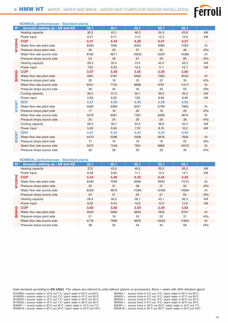
191
> HMW HT WATER - WATER AND BRINE - WATER HEAT PUMPS FOR INDOOR INSTALLATION
NOMINAL performances - Standard plants
IP Acoustic setting up : AB and AS 35.1 40.1 45.1 50.1 60.1
W10
W4
5
Heating capacity 36,5 43,1 48,3 54,3 63,8 kWPower input 8,27 9,71 11,0 12,3 14,6 kW
COP 4,41 4,44 4,39 4,41 4,37 -
Water fl ow rate plant side 6309 7456 8342 9385 11001 l/hPressure drops plant side 32 30 37 35 48 kPaWater fl ow rate source side 8182 9671 10835 12207 14380 l/hPressure drops source side 53 49 61 59 80 kPa
B0
W4
5
Heating capacity 28,3 33,4 37,4 42,0 49,3 kWPower input 7,93 9,33 10,5 11,7 13,7 kW
COP 3,57 3,58 3,56 3,59 3,60 -
Water fl ow rate plant side 4901 5787 6482 7282 8533 l/hPressure drops plant side 20 18 23 22 30 kPaWater fl ow rate source side 6547 7734 8688 9767 11517 l/hPressure drops source side 36 34 42 40 55 kPa
W3
0W
7
Cooling capacity 26,5 31,3 35,1 39,5 46,2 kWPower input 5,80 6,82 7,65 8,60 9,99 kW
EER 4,57 4,59 4,59 4,59 4,62 -
Water fl ow rate plant side 4565 5389 6041 6796 7963 l/hPressure drops plant side 17 16 20 19 26 kPaWater fl ow rate source side 5576 6581 7367 8288 9674 l/hPressure drops source side 25 24 29 28 38 kPa
B30W
7
Cooling capacity 26,0 30,7 34,5 38,8 45,4 kWPower input 5,90 6,94 7,78 8,74 10,2 kW
EER 4,41 4,42 4,43 4,44 4,45 -
Water fl ow rate plant side 4479 5286 5938 6676 7826 l/hPressure drops plant side 17 16 19 19 25 kPaWater fl ow rate source side 5972 7048 7901 8885 10370 l/hPressure drops source side 30 28 35 33 45 kPa
NOMINAL performances - Standard plants
IH Acoustic setting up : AB and AS 35.1 40.1 45.1 50.1 60.1
W10W
45
Heating capacity 37,2 43,9 49,2 55,5 65,0 kWPower input 8,38 9,84 11,1 12,5 14,7 kW
COP 4,44 4,46 4,43 4,44 4,42 -
Water fl ow rate plant side 6430 7595 8498 9593 11210 l/hPressure drops plant side 33 31 38 37 50 kPaWater fl ow rate source side 8359 9874 11064 12493 14694 l/hPressure drops source side 55 51 63 61 83 kPa
B0W
45
Heating capacity 28,9 34,0 38,1 43,1 50,3 kWPower input 8,02 9,44 10,6 12,0 13,9 kW
COP 3,60 3,60 3,59 3,59 3,62 -
Water fl ow rate plant side 5005 5892 6604 7456 8707 l/hPressure drops plant side 21 19 24 23 31 kPaWater fl ow rate source side 6716 7896 8876 10022 11803 l/hPressure drops source side 38 35 44 42 58 kPa
W10W65 = source: water in 10°C out 7°C / plant: water in 55°C out 65°CW10W55 = source: water in 10°C out 7°C / plant: water in 47°C out 55°CW10W45 = source: water in 10°C out 7°C / plant: water in 40°C out 45°CW10W35 = source: water in 10°C out 7°C / plant: water in 30°C out 35°C
Data declared according to EN 14511. The values are referred to units without options or accessories. Brine = water with 30% ethylene glycol.
W30W7 = source: water in 30°C out 35°C / plant: water in 12°C out 7°CW30W18 = source: water in 30°C out 35°C / plant: water in 23°C out 18°C
B0W65 = source: brine in 0°C out -3°C / plant: water in 55°C out 65°CB0W55 = source: brine in 0°C out -3°C / plant: water in 47°C out 55°CB0W45 = source: brine in 0°C out -3°C / plant: water in 40°C out 45°CB0W35 = source: brine in 0°C out -3°C / plant: water in 30°C out 35°CB30W7 = source: brine in 30°C out 35°C / plant: water in 12°C out 7°CB30W18 = source: brine in 30°C out 35°C / plant: water in 23°C out 18°C
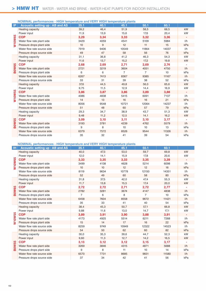
192
NOMINAL performances - HIGH temperature and VERY HIGH temperature plants
IH Acoustic setting up : AB and AS 35.1 40.1 45.1 50.1 60.1
W10W
65
Heating capacity 40,0 47,3 53,0 59,7 69,8 kWPower input 12,0 14,1 15,9 17,8 20,6 kW
COP 3,33 3,35 3,33 3,35 3,39 -
Water fl ow rate plant side 3499 4138 4628 5214 6098 l/hPressure drops plant side 10 10 12 12 16 kPaWater fl ow rate source side 8119 9634 10778 12150 14351 l/hPressure drops source side 52 49 60 58 80 kPa
B0W
65
Heating capacity 31,8 37,5 42,0 47,4 55,3 kWPower input 11,7 13,8 15,5 17,4 20,0 kW
COP 2,72 2,72 2,71 2,72 2,77 -
Water fl ow rate plant side 2782 3281 3674 4147 4838 l/hPressure drops plant side 7 6 8 7 10 kPaWater fl ow rate source side 6458 7604 8558 9672 11421 l/hPressure drops source side 35 33 41 40 54 kPa
W10W
55
Heating capacity 38,4 45,3 50,7 57,1 66,8 kWPower input 9,88 11,6 13,0 14,7 17,1 kW
COP 3,89 3,91 3,90 3,88 3,91 -
Water fl ow rate plant side 4173 4925 5514 6211 7268 l/hPressure drops plant side 15 14 17 16 22 kPaWater fl ow rate source side 8259 9749 10949 12322 14523 l/hPressure drops source side 54 50 62 60 82 kPa
B0W
55
Heating capacity 30,0 35,3 39,6 44,7 52,3 kWPower input 9,60 11,3 12,7 14,2 16,5 kW
COP 3,13 3,12 3,12 3,15 3,17 -
Water fl ow rate plant side 3269 3846 4315 4871 5688 l/hPressure drops plant side 9 8 11 10 14 kPaWater fl ow rate source side 6570 7731 8685 9831 11580 l/hPressure drops source side 37 34 42 41 56 kPa
NOMINAL performances - HIGH temperature and VERY HIGH temperature plants
IP Acoustic setting up : AB and AS 35.1 40.1 45.1 50.1 60.1
W10
W6
5
Heating capacity 39,2 46,4 51,9 58,5 68,5 kWPower input 11,9 13,9 15,6 17,6 20,4 kW
COP 3,29 3,34 3,33 3,32 3,36 -
Water fl ow rate plant side 3429 4059 4541 5109 5984 l/hPressure drops plant side 10 9 12 11 15 kPaWater fl ow rate source side 7919 9406 10549 11864 14037 l/hPressure drops source side 49 47 58 56 76 kPa
B0
W6
5
Heating capacity 31,1 36,8 41,2 46,3 54,3 kWPower input 11,6 13,7 15,2 17,2 19,8 kW
COP 2,68 2,69 2,71 2,69 2,74 -
Water fl ow rate plant side 2721 3219 3604 4051 4750 l/hPressure drops plant side 6 6 7 7 10 kPaWater fl ow rate source side 6267 7413 8367 9385 11167 l/hPressure drops source side 33 31 39 38 52 kPa
W10
W5
5
Heating capacity 37,6 44,5 49,8 56,0 65,6 kWPower input 9,75 11,5 12,9 14,4 16,9 kW
COP 3,86 3,87 3,86 3,89 3,88 -
Water fl ow rate plant side 4086 4838 5415 6091 7137 l/hPressure drops plant side 14 13 16 16 21 kPaWater fl ow rate source side 8056 9548 10721 12064 14237 l/hPressure drops source side 51 48 60 57 79 kPa
B0W
55
Heating capacity 29,3 34,7 38,9 43,7 51,3 kWPower input 9,48 11,2 12,5 14,1 16,2 kW
COP 3,09 3,10 3,11 3,10 3,17 -
Water fl ow rate plant side 3193 3781 4239 4762 5579 l/hPressure drops plant side 9 8 10 10 13 kPaWater fl ow rate source side 6379 7572 8526 9544 11326 l/hPressure drops source side 35 32 41 39 54 kPa
> HMW HT WATER - WATER AND BRINE - WATER HEAT PUMPS FOR INDOOR INSTALLATION
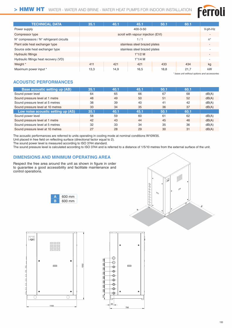
193
Low noise acoustic setting up (AS) 35.1 40.1 45.1 50.1 60.1
Sound power level 58 59 60 61 62 dB(A)Sound pressure level at 1 metre 42 43 44 45 46 dB(A)Sound pressure level at 5 metres 32 33 34 35 36 dB(A)Sound pressure level at 10 metres 27 28 29 30 31 dB(A)
TECHNICAL DATA 35.1 40.1 45.1 50.1 60.1
Power supply 400-3-50 V-ph-Hz
Compressor type scroll with vapour injection (EVI) -
N° compressors / N° refrigerant circuits 1 / 1 n°
Plant side heat exchanger type stainless steel brazed plates -
Source side heat exchanger type stainless steel brazed plates -
Hydraulic fi ttings 1”1/2 M -
Hydraulic fi ttings heat recovery (VD) 1”1/4 M -
Weight * 411 421 421 433 434 kg
Maximum power input * 13,3 14,9 16,5 18,8 21,7 kW* base unit without options and accessories
The acoustic performances are referred to units operating in cooling mode at nominal conditions W10W35.Unit placed in free fi eld on refl ecting surface (directional factor equal to 2).The sound power level is measured according to ISO 3744 standard.The sound pressure level is calculated according to ISO 3744 and is referred to a distance of 1/5/10 metres from the external surface of the unit.
DIMENSIONS AND MINIMUM OPERATING AREA
Respect the free area around the unit as shown in fi gure in order to guarantee a good accessibility and facilitate maintenance and control operations.
Base acoustic setting up (AB) 35.1 40.1 45.1 50.1 60.1
Sound power level 64 65 66 67 68 dB(A)Sound pressure level at 1 metre 48 49 50 51 52 dB(A)Sound pressure level at 5 metres 38 39 40 41 42 dB(A)Sound pressure level at 10 metres 33 34 35 36 37 dB(A)
ACOUSTIC PERFORMANCES
A 600 mmB 600 mm
A
B
1150790
100
100
100
1552
100
100
100
100
100
153
93
> HMW HT WATER - WATER AND BRINE - WATER HEAT PUMPS FOR INDOOR INSTALLATION
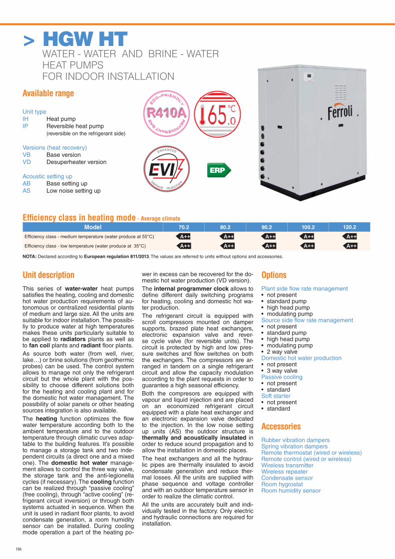
194
> HGW HT WATER - WATER AND BRINE - WATER
HEAT PUMPS
FOR INDOOR INSTALLATION
Available range
Unit typeIH Heat pumpIP Reversible heat pump (reversible on the refrigerant side)
Versions (heat recovery)VB Base versionVD Desuperheater version
Acoustic setting upAB Base setting upAS Low noise setting up
Unit description
This series of water-water heat pumps satisfi es the heating, cooling and domestic hot water production requirements of au-tonomous or centralized residential plants of medium and large size. All the units are suitable for indoor installation. The possibi-liy to produce water at high temperatures makes these units particularly suitable to be applied to radiators plants as well as to fan coil plants and radiant fl oor plants.As source both water (from well, river, lake…) or brine solutions (from geothermic probes) can be used. The control system allows to manage not only the refrigerant circuit but the whole plant with the pos-sibility to choose different solutions both for the heating and cooling plant and for the domestic hot water management. The possibility of solar panels or other heating sources integration is also available.The heating function optimizes the fl ow water temperature according both to the ambient temperature and to the outdoor temperature through climatic curves adap-table to the building features. It’s possible to manage a storage tank and two inde-pendent circuits (a direct one and a mixed one). The domestic hot water manage-ment allows to control the three way valve, the storage tank and the anti-legionella cycles (if necessary). The cooling function can be realized through “passive cooling” (free cooling), through “active cooling” (re-frigerant circuit inversion) or through both systems actuated in sequence. When the unit is used in radiant fl oor plants, to avoid condensate generation, a room humidity sensor can be installed. During cooling mode operation a part of the heating po-
wer in excess can be recovered for the do-mestic hot water production (VD version).The internal programmer clock allows to defi ne different daily switching programs for heating, cooling and domestic hot wa-ter production.The refrigerant circuit is equipped with scroll compressors mounted on damper supports, brazed plate heat exchangers, electronic expansion valve and rever-se cycle valve (for reversible units). The circuit is protected by high and low pres-sure switches and fl ow switches on both the exchangers. The compressors are ar-ranged in tandem on a single refrigerant circuit and allow the capacity modulation according to the plant requests in order to guarantee a high seasonal efficiency.Both the compresors are equipped with vapour and liquid injection and are placed on an economized refrigerant circuit equipped with a plate heat exchanger and an electronic expansion valve dedicated to the injection. In the low noise setting up units (AS) the outdoor structure is thermally and acoustically insulated in order to reduce sound propagation and to allow the installation in domestic places.The heat exchangers and all the hydrau-lic pipes are thermally insulated to avoid condensate generation and reduce ther-mal losses. All the units are supplied with phase sequence and voltage controller and with an outdoor temperature sensor in order to realize the climatic control.All the units are accurately built and indi-vidually tested in the factory. Only electric and hydraulic connections are required for installation.
Options
Plant side fl ow rate management • not present• standard pump• high head pump• modulating pumpSource side fl ow rate management • not present• standard pump• high head pump• modulating pump• 2 way valveDomestic hot water production • not present• 3 way valvePassive cooling• not present• standardSoft starter• not present• standard
Accessories
Rubber vibration dampersSpring vibration dampersRemote thermostat (wired or wireless)Remote control (wired or wireless)Wireless transmitterWireless repeaterCondensate sensorRoom hygrostatRoom humidity sensor
RE
FRIGERANT G
AS
E
CO-FRIEND
LY
.065
Effi ciency class in heating mode - Average climate
Model 70.2 80.2 90.2 100.2 120.2
NOTA: Declared according to European regulation 811/2013. The values are referred to units without options and accessories.
A++ A++ A++ A++ A++A++ A++ A++ A++ A++
ERP
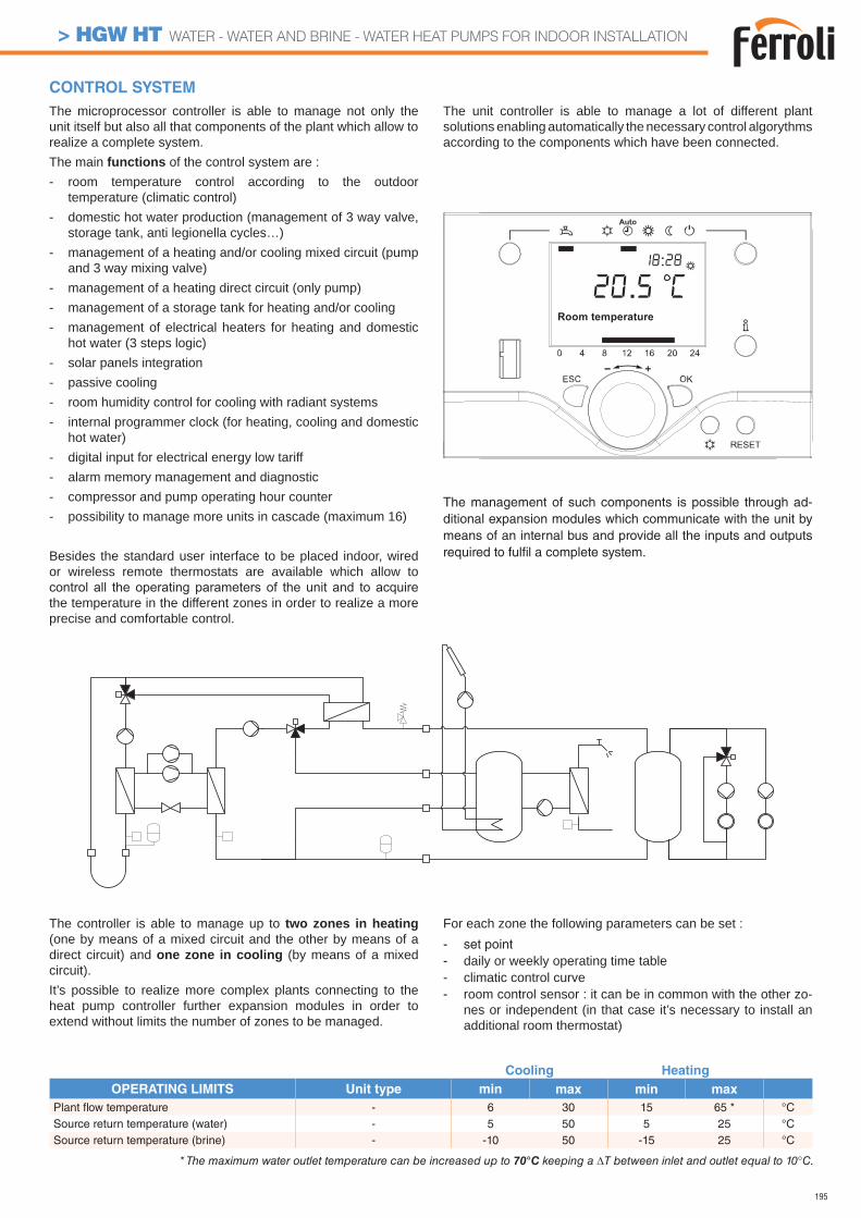
195
Cooling Heating
OPERATING LIMITS Unit type min max min max
Plant fl ow temperature - 6 30 15 65 * °CSource return temperature (water) - 5 50 5 25 °CSource return temperature (brine) - -10 50 -15 25 °C
CONTROL SYSTEM
The controller is able to manage up to two zones in heating (one by means of a mixed circuit and the other by means of a direct circuit) and one zone in cooling (by means of a mixed circuit).It’s possible to realize more complex plants connecting to the heat pump controller further expansion modules in order to extend without limits the number of zones to be managed.
For each zone the following parameters can be set :- set point- daily or weekly operating time table- climatic control curve- room control sensor : it can be in common with the other zo-
nes or independent (in that case it’s necessary to install an additional room thermostat)
The microprocessor controller is able to manage not only the unit itself but also all that components of the plant which allow to realize a complete system.The main functions of the control system are :- room temperature control according to the outdoor
temperature (climatic control)- domestic hot water production (management of 3 way valve,
storage tank, anti legionella cycles…)- management of a heating and/or cooling mixed circuit (pump
and 3 way mixing valve)- management of a heating direct circuit (only pump)- management of a storage tank for heating and/or cooling- management of electrical heaters for heating and domestic
hot water (3 steps logic)- solar panels integration- passive cooling- room humidity control for cooling with radiant systems- internal programmer clock (for heating, cooling and domestic
hot water)- digital input for electrical energy low tariff- alarm memory management and diagnostic- compressor and pump operating hour counter- possibility to manage more units in cascade (maximum 16)
Besides the standard user interface to be placed indoor, wired or wireless remote thermostats are available which allow to
the temperature in the different zones in order to realize a more precise and comfortable control.
The unit controller is able to manage a lot of different plant solutions enabling automatically the necessary control algorythms according to the components which have been connected.
The management of such components is possible through ad-ditional expansion modules which communicate with the unit by means of an internal bus and provide all the inputs and outputs required to fulfi l a complete system.
* The maximum water outlet temperature can be increased up to 70°C keeping a T between inlet and outlet equal to 10°C.
> HGW HT WATER - WATER AND BRINE - WATER HEAT PUMPS FOR INDOOR INSTALLATION
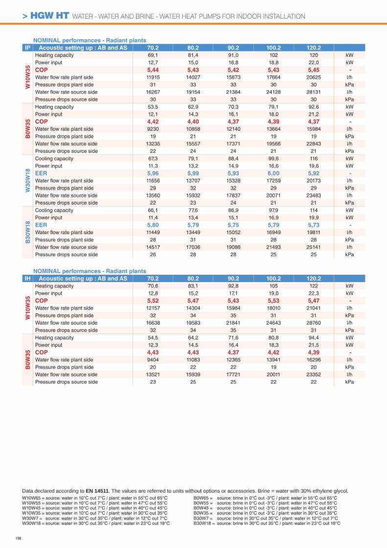
196
NOMINAL performances - Radiant plants
IP Acoustic setting up : AB and AS 70.2 80.2 90.2 100.2 120.2
W10
W3
5
Heating capacity 69,1 81,4 91,0 102 120 kWPower input 12,7 15,0 16,8 18,8 22,0 kW
COP 5,44 5,43 5,42 5,43 5,45 -
Water fl ow rate plant side 11915 14027 15673 17664 20625 l/hPressure drops plant side 31 33 33 30 30 kPaWater fl ow rate source side 16267 19154 21384 24128 28131 l/hPressure drops source side 30 33 33 30 30 kPa
B0
W3
5
Heating capacity 53,5 62,9 70,3 79,1 92,6 kWPower input 12,1 14,3 16,1 18,0 21,2 kW
COP 4,42 4,40 4,37 4,39 4,37 -
Water fl ow rate plant side 9230 10858 12140 13664 15984 l/hPressure drops plant side 19 21 21 19 19 kPaWater fl ow rate source side 13235 15557 17371 19566 22843 l/hPressure drops source side 22 24 24 21 21 kPa
W3
0W
18
Cooling capacity 67,3 79,1 88,4 99,6 116 kWPower input 11,3 13,2 14,9 16,6 19,6 kW
EER 5,96 5,99 5,93 6,00 5,92 -
Water fl ow rate plant side 11656 13707 15328 17259 20173 l/hPressure drops plant side 29 32 32 29 29 kPaWater fl ow rate source side 13560 15932 17837 20071 23483 l/hPressure drops source side 22 23 24 21 21 kPa
B30W
18
Cooling capacity 66,1 77,6 86,9 97,9 114 kWPower input 11,4 13,4 15,1 16,9 19,9 kW
EER 5,80 5,79 5,75 5,79 5,73 -
Water fl ow rate plant side 11449 13449 15052 16949 19811 l/hPressure drops plant side 28 31 31 28 28 kPaWater fl ow rate source side 14517 17036 19086 21493 25141 l/hPressure drops source side 26 28 28 25 25 kPa
NOMINAL performances - Radiant plants
IH Acoustic setting up : AB and AS 70.2 80.2 90.2 100.2 120.2
W10W
35
Heating capacity 70,6 83,1 92,8 105 122 kWPower input 12,8 15,2 17,1 19,0 22,3 kW
COP 5,52 5,47 5,43 5,53 5,47 -
Water fl ow rate plant side 12157 14304 15984 18010 21041 l/hPressure drops plant side 32 34 35 31 31 kPaWater fl ow rate source side 16638 19583 21841 24643 28760 l/hPressure drops source side 32 34 35 31 31 kPa
B0W
35
Heating capacity 54,5 64,2 71,6 80,8 94,4 kWPower input 12,3 14,5 16,4 18,3 21,5 kW
COP 4,43 4,43 4,37 4,42 4,39 -
Water fl ow rate plant side 9404 11083 12365 13941 16296 l/hPressure drops plant side 20 22 22 19 20 kPaWater fl ow rate source side 13521 15939 17721 20011 23352 l/hPressure drops source side 23 25 25 22 22 kPa
W10W65 = source: water in 10°C out 7°C / plant: water in 55°C out 65°CW10W55 = source: water in 10°C out 7°C / plant: water in 47°C out 55°CW10W45 = source: water in 10°C out 7°C / plant: water in 40°C out 45°CW10W35 = source: water in 10°C out 7°C / plant: water in 30°C out 35°C
Data declared according to EN 14511. The values are referred to units without options or accessories. Brine = water with 30% ethylene glycol.
W30W7 = source: water in 30°C out 35°C / plant: water in 12°C out 7°CW30W18 = source: water in 30°C out 35°C / plant: water in 23°C out 18°C
B0W65 = source: brine in 0°C out -3°C / plant: water in 55°C out 65°CB0W55 = source: brine in 0°C out -3°C / plant: water in 47°C out 55°CB0W45 = source: brine in 0°C out -3°C / plant: water in 40°C out 45°CB0W35 = source: brine in 0°C out -3°C / plant: water in 30°C out 35°CB30W7 = source: brine in 30°C out 35°C / plant: water in 12°C out 7°CB30W18 = source: brine in 30°C out 35°C / plant: water in 23°C out 18°C
> HGW HT WATER - WATER AND BRINE - WATER HEAT PUMPS FOR INDOOR INSTALLATION
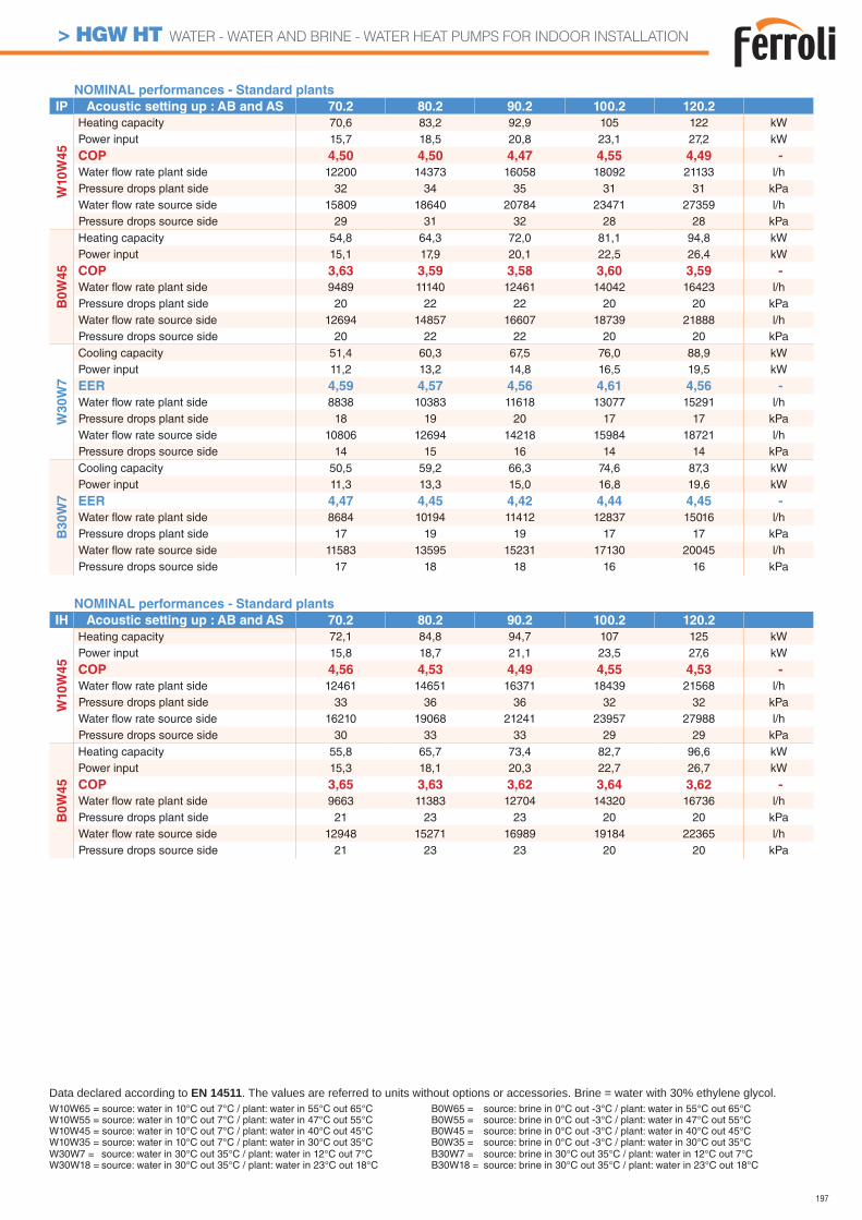
197
NOMINAL performances - Standard plants
IP Acoustic setting up : AB and AS 70.2 80.2 90.2 100.2 120.2
W10
W4
5
Heating capacity 70,6 83,2 92,9 105 122 kWPower input 15,7 18,5 20,8 23,1 27,2 kW
COP 4,50 4,50 4,47 4,55 4,49 -
Water fl ow rate plant side 12200 14373 16058 18092 21133 l/hPressure drops plant side 32 34 35 31 31 kPaWater fl ow rate source side 15809 18640 20784 23471 27359 l/hPressure drops source side 29 31 32 28 28 kPa
B0
W4
5
Heating capacity 54,8 64,3 72,0 81,1 94,8 kWPower input 15,1 17,9 20,1 22,5 26,4 kW
COP 3,63 3,59 3,58 3,60 3,59 -
Water fl ow rate plant side 9489 11140 12461 14042 16423 l/hPressure drops plant side 20 22 22 20 20 kPaWater fl ow rate source side 12694 14857 16607 18739 21888 l/hPressure drops source side 20 22 22 20 20 kPa
W3
0W
7
Cooling capacity 51,4 60,3 67,5 76,0 88,9 kWPower input 11,2 13,2 14,8 16,5 19,5 kW
EER 4,59 4,57 4,56 4,61 4,56 -
Water fl ow rate plant side 8838 10383 11618 13077 15291 l/hPressure drops plant side 18 19 20 17 17 kPaWater fl ow rate source side 10806 12694 14218 15984 18721 l/hPressure drops source side 14 15 16 14 14 kPa
B30W
7
Cooling capacity 50,5 59,2 66,3 74,6 87,3 kWPower input 11,3 13,3 15,0 16,8 19,6 kW
EER 4,47 4,45 4,42 4,44 4,45 -
Water fl ow rate plant side 8684 10194 11412 12837 15016 l/hPressure drops plant side 17 19 19 17 17 kPaWater fl ow rate source side 11583 13595 15231 17130 20045 l/hPressure drops source side 17 18 18 16 16 kPa
NOMINAL performances - Standard plants
IH Acoustic setting up : AB and AS 70.2 80.2 90.2 100.2 120.2
W10W
45
Heating capacity 72,1 84,8 94,7 107 125 kWPower input 15,8 18,7 21,1 23,5 27,6 kW
COP 4,56 4,53 4,49 4,55 4,53 -
Water fl ow rate plant side 12461 14651 16371 18439 21568 l/hPressure drops plant side 33 36 36 32 32 kPaWater fl ow rate source side 16210 19068 21241 23957 27988 l/hPressure drops source side 30 33 33 29 29 kPa
B0W
45
Heating capacity 55,8 65,7 73,4 82,7 96,6 kWPower input 15,3 18,1 20,3 22,7 26,7 kW
COP 3,65 3,63 3,62 3,64 3,62 -
Water fl ow rate plant side 9663 11383 12704 14320 16736 l/hPressure drops plant side 21 23 23 20 20 kPaWater fl ow rate source side 12948 15271 16989 19184 22365 l/hPressure drops source side 21 23 23 20 20 kPa
W10W65 = source: water in 10°C out 7°C / plant: water in 55°C out 65°CW10W55 = source: water in 10°C out 7°C / plant: water in 47°C out 55°CW10W45 = source: water in 10°C out 7°C / plant: water in 40°C out 45°CW10W35 = source: water in 10°C out 7°C / plant: water in 30°C out 35°C
Data declared according to EN 14511. The values are referred to units without options or accessories. Brine = water with 30% ethylene glycol.
W30W7 = source: water in 30°C out 35°C / plant: water in 12°C out 7°CW30W18 = source: water in 30°C out 35°C / plant: water in 23°C out 18°C
B0W65 = source: brine in 0°C out -3°C / plant: water in 55°C out 65°CB0W55 = source: brine in 0°C out -3°C / plant: water in 47°C out 55°CB0W45 = source: brine in 0°C out -3°C / plant: water in 40°C out 45°CB0W35 = source: brine in 0°C out -3°C / plant: water in 30°C out 35°CB30W7 = source: brine in 30°C out 35°C / plant: water in 12°C out 7°CB30W18 = source: brine in 30°C out 35°C / plant: water in 23°C out 18°C
> HGW HT WATER - WATER AND BRINE - WATER HEAT PUMPS FOR INDOOR INSTALLATION
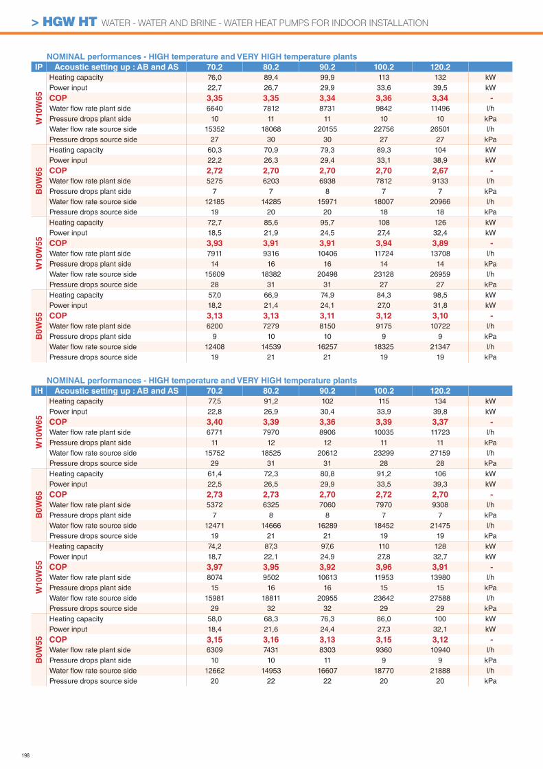
198
NOMINAL performances - HIGH temperature and VERY HIGH temperature plants
IH Acoustic setting up : AB and AS 70.2 80.2 90.2 100.2 120.2
W10W
65
Heating capacity 77,5 91,2 102 115 134 kWPower input 22,8 26,9 30,4 33,9 39,8 kW
COP 3,40 3,39 3,36 3,39 3,37 -
Water fl ow rate plant side 6771 7970 8906 10035 11723 l/hPressure drops plant side 11 12 12 11 11 kPaWater fl ow rate source side 15752 18525 20612 23299 27159 l/hPressure drops source side 29 31 31 28 28 kPa
B0W
65
Heating capacity 61,4 72,3 80,8 91,2 106 kWPower input 22,5 26,5 29,9 33,5 39,3 kW
COP 2,73 2,73 2,70 2,72 2,70 -
Water fl ow rate plant side 5372 6325 7060 7970 9308 l/hPressure drops plant side 7 8 8 7 7 kPaWater fl ow rate source side 12471 14666 16289 18452 21475 l/hPressure drops source side 19 21 21 19 19 kPa
W10W
55
Heating capacity 74,2 87,3 97,6 110 128 kWPower input 18,7 22,1 24,9 27,8 32,7 kW
COP 3,97 3,95 3,92 3,96 3,91 -
Water fl ow rate plant side 8074 9502 10613 11953 13980 l/hPressure drops plant side 15 16 16 15 15 kPaWater fl ow rate source side 15981 18811 20955 23642 27588 l/hPressure drops source side 29 32 32 29 29 kPa
B0W
55
Heating capacity 58,0 68,3 76,3 86,0 100 kWPower input 18,4 21,6 24,4 27,3 32,1 kW
COP 3,15 3,16 3,13 3,15 3,12 -
Water fl ow rate plant side 6309 7431 8303 9360 10940 l/hPressure drops plant side 10 10 11 9 9 kPaWater fl ow rate source side 12662 14953 16607 18770 21888 l/hPressure drops source side 20 22 22 20 20 kPa
NOMINAL performances - HIGH temperature and VERY HIGH temperature plants
IP Acoustic setting up : AB and AS 70.2 80.2 90.2 100.2 120.2
W10
W6
5
Heating capacity 76,0 89,4 99,9 113 132 kWPower input 22,7 26,7 29,9 33,6 39,5 kW
COP 3,35 3,35 3,34 3,36 3,34 -
Water fl ow rate plant side 6640 7812 8731 9842 11496 l/hPressure drops plant side 10 11 11 10 10 kPaWater fl ow rate source side 15352 18068 20155 22756 26501 l/hPressure drops source side 27 30 30 27 27 kPa
B0
W6
5
Heating capacity 60,3 70,9 79,3 89,3 104 kWPower input 22,2 26,3 29,4 33,1 38,9 kW
COP 2,72 2,70 2,70 2,70 2,67 -
Water fl ow rate plant side 5275 6203 6938 7812 9133 l/hPressure drops plant side 7 7 8 7 7 kPaWater fl ow rate source side 12185 14285 15971 18007 20966 l/hPressure drops source side 19 20 20 18 18 kPa
W10
W5
5
Heating capacity 72,7 85,6 95,7 108 126 kWPower input 18,5 21,9 24,5 27,4 32,4 kW
COP 3,93 3,91 3,91 3,94 3,89 -
Water fl ow rate plant side 7911 9316 10406 11724 13708 l/hPressure drops plant side 14 16 16 14 14 kPaWater fl ow rate source side 15609 18382 20498 23128 26959 l/hPressure drops source side 28 31 31 27 27 kPa
B0W
55
Heating capacity 57,0 66,9 74,9 84,3 98,5 kWPower input 18,2 21,4 24,1 27,0 31,8 kW
COP 3,13 3,13 3,11 3,12 3,10 -
Water fl ow rate plant side 6200 7279 8150 9175 10722 l/hPressure drops plant side 9 10 10 9 9 kPaWater fl ow rate source side 12408 14539 16257 18325 21347 l/hPressure drops source side 19 21 21 19 19 kPa
> HGW HT WATER - WATER AND BRINE - WATER HEAT PUMPS FOR INDOOR INSTALLATION
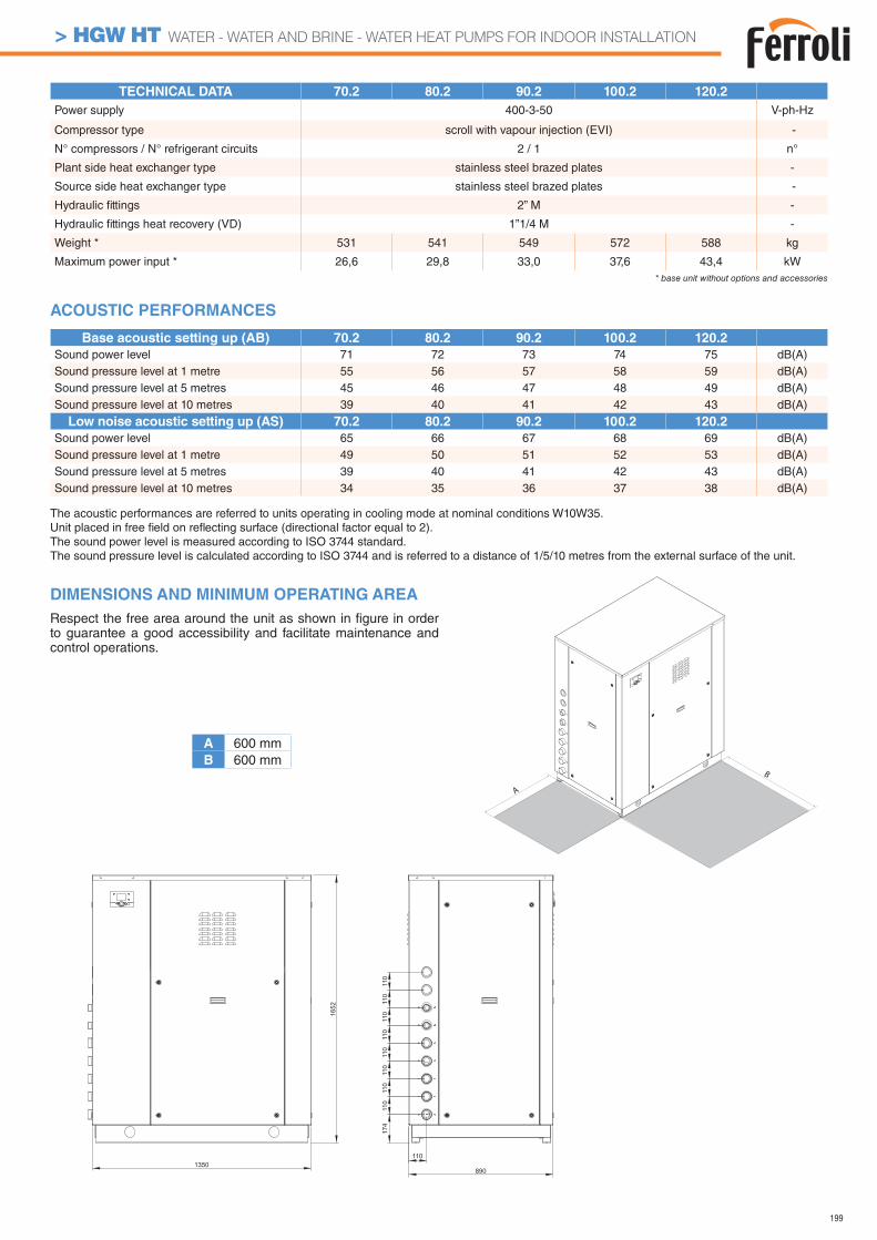
199
Low noise acoustic setting up (AS) 70.2 80.2 90.2 100.2 120.2
Sound power level 65 66 67 68 69 dB(A)Sound pressure level at 1 metre 49 50 51 52 53 dB(A)Sound pressure level at 5 metres 39 40 41 42 43 dB(A)Sound pressure level at 10 metres 34 35 36 37 38 dB(A)
TECHNICAL DATA 70.2 80.2 90.2 100.2 120.2
Power supply 400-3-50 V-ph-Hz
Compressor type scroll with vapour injection (EVI) -
N° compressors / N° refrigerant circuits 2 / 1 n°
Plant side heat exchanger type stainless steel brazed plates -
Source side heat exchanger type stainless steel brazed plates -
Hydraulic fi ttings 2” M -
Hydraulic fi ttings heat recovery (VD) 1”1/4 M -
Weight * 531 541 549 572 588 kg
Maximum power input * 26,6 29,8 33,0 37,6 43,4 kW* base unit without options and accessories
The acoustic performances are referred to units operating in cooling mode at nominal conditions W10W35.Unit placed in free fi eld on refl ecting surface (directional factor equal to 2).The sound power level is measured according to ISO 3744 standard.The sound pressure level is calculated according to ISO 3744 and is referred to a distance of 1/5/10 metres from the external surface of the unit.
DIMENSIONS AND MINIMUM OPERATING AREA
Respect the free area around the unit as shown in fi gure in order to guarantee a good accessibility and facilitate maintenance and control operations.
Base acoustic setting up (AB) 70.2 80.2 90.2 100.2 120.2
Sound power level 71 72 73 74 75 dB(A)Sound pressure level at 1 metre 55 56 57 58 59 dB(A)Sound pressure level at 5 metres 45 46 47 48 49 dB(A)Sound pressure level at 10 metres 39 40 41 42 43 dB(A)
ACOUSTIC PERFORMANCES
A
B
1350110
890
174
110
110
110
110
1652
110
110
110
110
A 600 mmB 600 mm
> HGW HT WATER - WATER AND BRINE - WATER HEAT PUMPS FOR INDOOR INSTALLATION
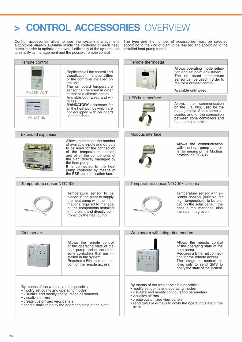
200
> CONTROL ACCESSORIES OVERVIEW
Remote control
Replicates all the control and visualization functionalities of the controller installed on the unit.The on board temperature sensor can be used in order to realize a climatic control.Available both wired and wi-reless.MANDATORY accessory for all the heat pumps which are not equipped with on board user interface.
Remote thermostat
Control accessories allow to use the system management algorythms already available inside the controller of each heat pump in order to optimize the overall efficiency of the system and to simplify its management and the possible remote control.
The type and the number of accessories must be selected according to the kind of plant to be realized and according to the installed heat pump model.
Extended expansion
Temperature sensor NTC 10k
Temperature sensor to be placed in the plant to supply the heat pump with the infor-mations required to manage all the components installed in the plant and directly con-trolled by the heat pump.
Temperature sensor NTC 10k siliconic
Temperature sensor with si-liconic coating (suitable for high temperature) to be pla-ced on the solar panel if the heat pump manages also the solar integration.
LPB bus interface
Modbus interface
Allows the communication with the heat pump control-ler by means of the Modbus protocol on RS 485.
Web server
Allows the remote control of the operating state of the heat pump and of the other zone controllers that are in-stalled in the system.Requires a Ethernet connec-tion for the remote access.
By means of the web server it is possible : • modify set points and operating modes• visualize and modify configuration parameters• visualize alarms• create customized view panels• send e-mails to notify the operating state of the plant
Web server with integrated modem
Allows the remote control of the operating state of the heat pump.Requires a Ethernet connec-tion for the remote access.The integrated modem al-lows only to send SMS to notify the state of the system.
By means of the web server it is possible : • modify set points and operating modes• visualize and modify configuration parameters• visualize alarms• create customized view panels• send SMS or e-mails to notify the operating state of the
plant
PHASE-IN
PHASE-OUT
Allows operating mode selec-tion and set point adjustment.The on board temperature sensor can be used in order to realize a climatic control.
Available only wired.
Allows to increase the number of available inputs and outputs to be used for the connection of the temperature sensors and of all the components of the plant directly managed by the heat pump. It is connected to the heat pump controller by means of the BSB communication bus.
Allows the communication on the LPB bus, used for the management of heat pump ca-scades and for the connection between zone controllers and heat pump controller.
201
HOW TO CONTACT US
FERROLI FRANCEParc TechnoLand - Z.I. du Champ Dollin3, allée des Abruzzes - Bât. K69800 Saint PriestFranceTel. +33 (0)4 72 76 76 76
REPRESENTATIVE OFFICE IN UKRAINE FERROLI S.P.A. 10/17, Preobrazhenska str. 03037, KievUkraine Tel. +38 044 537 02 39
FLJSC "FERROLIBEL" 222750, Minsk Region, Dzerzhinsk Province, Fanipol, 45, Zavodskaya str Republic of Belarus Tel.+37 517 16 9 79 49
MOSCOW REPRESENTATIVE OFFICE FERROLI S.P.A. 115054, , Moscow, Piatnitskaya st. 73 RussiaTel. +7 495 788-80-35
FERROLI LIMITED Branston Ind Estate Lichfield Road Burton upon Trent DE14 3HD United Kingdom Tel. (+44) 1283 715250
FERROLI POLAND SP. Z O.O. UL. NARUTOWICZA 53 41-200 SOSNOWIEC Tel. +48 604 516 300
FERROLI NEDERLAND B.V. Takkebijsters 62 4817 BL Breda Netherlands Tel. +31 76 5725 725
FERROLI ROMANIA B-dul Timisoara, nr. 104E, sector 6, Bucuresti 061334 RomaniaTel. +40 21 444 36 50
FEROLI ESPAÑA Avda. Italia, 2. Edif. Ferroli 28820 Coslada - Madrid ESPAÑATel. +34 91.661.23.04
FERROLI HEATING EQUIPMENT (CHINA) CO., LTD Address: No. 9, Jianshedong Road, Taoyuan Economic Development Zone, Heshan City, Guangdong Province Tel: +86 750 8779888 Service hot line: 400-1000-188
QINGDAO FERROLI HVAC TECHNOLOGIES MANUFACTORY CO. LTD. QINGDAO FERROLI BOILER & HEATING EQUIPMENTS CO. LTD. Address: Jinling Industrial Zone, Chenyang District, Qingdao City, Shandong Province Tel: +86 532 66727100 Service hot line: 400-1000-188
www.ferroli.com

202
NOTE

203
NOTE

Cod
. 89L
G00
03/0
0 -
ediz
ione
03.
2018
Ferroli spa37047 San Bonifacio (VR) ItalyVia Ritonda 78/Atel. +39.045.6139411fax +39.045.6103595www.ferroli.com
Ferroli è attenta all’ambiente. Questo listino è stampato su carta ecologica senza uso di cloro.