PRODUCT CATALOGUE - Эридан
49
Õ PRODUCT CATALOGUE DESIGN AND PRODUCTION OF EXPLOSION-PROOF EQUIPMENT 2020
-
Upload
khangminh22 -
Category
Documents
-
view
6 -
download
0
Transcript of PRODUCT CATALOGUE - Эридан

Õ
PRODUCT CATALOGUEDESIGN AND PRODUCTION OF EXPLOSION-PROOF EQUIPMENT
2020

OUR CLIENTS:
TABLE OF CONTENTS4About us
Pictogram legend
Detectors:
IP103 and IP101 series heat detectors
IP535 series call points
Gelios series flame detectors
Annunciators:
EKRAN series light and light and acoustic panels
EKRAN-INFO series multifunctional light and light and acoustic panels
VS-Z series acoustic annunciators and acoustic annunciators with indication
GRV series horn loudspeakers
Switching boxes
Video surveillance:
TVK series thermohousings
Media converters
Pan/tilt system
TOR Glass cleaning system
Duplex IR spotlights
Devices and appliances:
Ex-TEST
Remote start-up device
EKRAN-INFO series annunciator controller
Interface converters
Test lanterns for Gelios series flame detectors
Dialog Ex analog-addressable system
Dialog-PRO design-composable hardware and software suite
Scope of supply
Cable glands
Accessories
6
8
20
38
44
62
72
84
90

4 eridan.ru
ABOUT THE COMPANY
Eridan is the leading manufacturer of
explosion-proof equipment.
Eridan Company began its operations in
1999 by creating the IP103-2/1 fire detector. The
new product was successful, and since then, we
have been supplying high quality products to the
market for the sole purpose of ensuring the safety
of people at industrial facilities, however complex,
including those located in the extreme conditions
of the Arctic.
Eridan produces equipment developed by the company's design department; the advantages of
this equipment include enhanced reliability, ease of installation and compatibility with products of third
party manufacturers. These features find daily practical proof, since Eridan branded products are used by
over 2,000 companies in Russia, in the CIS countries as well as in Europe and in the Middle East.
Our company has its own production facilities and has established cooperation channels with R&D
institutes and other agencies within the structures of GAZPROM PJSC, OC Lukoil PJSC, Transneft PJSC, TNK
PJSC, Public Corporation Rosatom, the Emercom of the RF, Russian Railways OJSC and other federal level
companies.
We have established our dealership network in the biggest cities of Russia and the CIS:
• Almaty
• Almetievsk
• Atyrau
• Voronezh
• Ekaterinburg
• Kazan
• Karaganda
• Krasnodar
• Minsk
• Moscow
• Naberezhnye Chelny
• Nizhnekamsk;
• Novosibirsk
• Nur-Sultan
• Omsk
• Perm
• Rostov-on-Don
• Samara
• Saint Petersburg
• Saratov
• Tashkent
• Tomsk
• Khabarovsk
• Ufa, etc.
We promote our products in the market following the principles of customer orientation, open pricing policy and prompt performance of orders (provided quality of our work is not compromised by its speed).
Thanks to a comprehensive analysis of the current market of explosion-proof equipment as well as to our experience, we are able to specifically look for certain new technical solutions, and, moreover, to find, implement and put them into practice of the industry. Currently, our portfolio includes 12 product types with thirty modifications, but development of new products and systems never stops. For example, the Dialog-Ex analog-addressable system based on the Dozor-1A FACIE and designed jointly with NITA Company has found successful application at a number of explosive facilities (OC KazMunaiGaz JSC, Gazprom PJSC, etc.).
One of our priority activities is a series of TVK-07 explosion-proof casings. They are specifically designed for video surveillance systems, and aluminum as well as low carbon and stainless steel are used as structural materials for the models TVK-07-А/V/S/N, in order to ensure high strength and reliability during operation within the temperature range from -60 to 200°С. Modification TVK-07-S/N-IK30/120 and the infrared spotlight IK-07е designed specifically for limited visibility applications as well as the TOR and Modbus software offer additional opportunities.
Applied materials, structural elements and parameters of the manufactured products meet the strict requirements of the Marine and River Registers of Shipping and are widely used at offshore drilling platforms, oil tankers and shore infrastructure of sea and river ports.
Each product we make is subjected to several levels of quality control at all production stages, from procurement of components through final climatic tests that enable us to offer the warranty period of 5 years. Meanwhile, the actual service life of the products is minimum 10 years.
Our technology meets the rigid requirements of the quality management system GOST R ISO 9001-2015. Besides, Eridan has been entered into the Register of Reliable Partners of the Chamber of Commerce and Industry of the Russian Federation, which means that our brand name is highly appreciated. In 2019, the Ministry of Industry and Trade of Russia declared our company's production as Russian. This gives us the right to use the entire range of Eridan products in the import substitution programs at particularly hazardous facilities.
In the same year, our company obtained Intergazcert VCS Certificates for our products, quality management system and goodwill assessment. This high rating gives us the opportunity to include our products into the Gazprom Register of Vendors of Materials and Equipment and supply equipment to its facilities.
However, for us, the principal driver is the personal motivation of each employee, which, in combination with high responsibility, brings great results!
We will be happy to answer any question you may have. Contact us: telephone +7 (343) 351-05-07 (multichannel); e-mail: [email protected]
5Eridan

PICTOGRAM LEGEND
6 eridan.ru
-60°+60°Ñ
1ExdIICÒ6 Õ
IP67
Explosion proofness marking
Ingress protection rating
Operating temperature range, °С
130
105170
mm
Max. overall dimensions, mm
IR lighting
30°, 50° 70°, 120°Glow color
850 nm
Level of acoustic pressure
Continuous operation time
Max. weight, kg
Visor
Viewing angle
Enclosure material
Supported protocol
Radiation spectrum3 IR
IR/UV
9 kg
3 hours
Aluminum/Steel
Emission wavelength, nm
100 dB
Light indication
Light + sound
Modbus RTU/Dozor
5 J
10 modes
Flare pulse energy
Number of operation modes
Light-signal contrast
50 000 lx
78õ220mm
Effective internal volume
Supply voltage, V
8-28 V
20 mÀMaximum current consumption, A
Power
50W
Lifetime, min., years
Warranty period, years
10 years
5 years
7
PICTOGRAM LEGEND
Protection from overheating
Cold start mode
IP camera
USB port
Furnishing with a videocamera
Explosion proofness certification
ATEX certification
Fire safery certification
Certificate of compliance with the Technical Regulations of the Customs Union
The management system of the company meets the requirements of GOST ISO 9001-2015
Stock item identification guide MTR Gazprom PJSC
Certificate of type approval of the Russian Maritime Register of Shipping
Voluntary certification certificate «INTERGAZCERT»
MTR OC Rosneft PJSC suppliers data base
Certificate of compliance with the requirements TR 2009/013/BY of the Republic of Belarus
Permir for use in the Reoublic of Kazakhstan
360°
Turning angle, degree
0,6 ÌPa
Operating air pressure
30 ìElevation difference of installation between the valve unit and the washer tank, max., m
Dirt knocking off with high pressure liquid jet
Step 1
Drying with high pressure air
Step 2
Equipment and material list of Transneft, PJSC
Certificate of type approval of the Russian Inland Register of Shipping
Eridan

DETECTORS
8 eridan.ru 9Eridan
Detectors are the most important elements of the fire alarm and automation systems. Fire
detectors are technical devices installed directly at the protected facility and designed to transmit
fire alarm notification to the fire detection control panel. The detector detects fire by controlling
changes in the physical environmental parameters caused by the fire. The fire detectors are not
measuring instruments.
They may be installed in open spaces and enclosed areas of different buildings and structures, as
well as on river and sea-going vessels and production facilities, where explosive mixtures of air and
combustible gases or vapors may be present.
The detectors may be used at chemical, oil and gas production, oil and gas processing and other
plants with explosion hazardous areas.

DETECTORS
10
IP103-2/1 and IP101-07
Explosion-proof heat fire detectors
Explosion-proof heat fire detectors are applied in fire alarm systems and designed for detection of any inflagration followed by
temperature rising within the monitored area and for transferring to a a top level instrument or device of the temperature value, as well as
for detection of fire signs in case the ambient temperature exceeds the preset threshold and/or the temperature growth rate.
They are used at chemical, oil and gas production, oil and gas processing industry enterprises and in explosion hazardous areas of other
production facilities.
eridan.ru
1Ex db [ia Ga] IIC
T6...T4 Gb X
0Ex ia IIC T6...T2 Ga X
-60°+250°Ñ
20 mÀ
5 years8-28 V
Aluminum
IP66/IP67
VERSIONS OF THE SENSING ELEMENT:
DIMENSIONS
VersionsVersion 1 (I1) Version 2 (I2, upon request)
I2
Sensing element length
0.2 meter long tubeFlexible external sensitive element,
1.5-30 m (upon request)
10 years
I1
11
DETECTORS
MODIFICATIONS:
IP103-2/1-TR Explosion-proof heat fire detector
The detector unit is designed for sending an alarm signal to the fire alarm loop in case the preset actuation temperature in the controlled environment is exceeded. This detector is passive and therefore non-current consuming. It can be used in class 0 explosive areas if connected to spark-safe circuits.
IP101-07eExplosion-Proof Heat Fire Detector
The detector unit is designed for sending an alarm signal to the fire alarm loop in case the preset actuation temperature in the controlled environment is exceeded.
IP101-07aExplosion-Proof Addressable Programmable Heat Fire Detector
It is designed for detection of any inflagration followed by temperature rising within the monitored area and for transferring to a receiving and controlling instrument of the current temperature value, as well as for detection of fire signs in case the ambient temperature exceeds the preset threshold and/or the temperature growth rate. It is designed for operation only as part of addressable loop of devices with support of Dozor-07a protocol.
IP101-07em Adjustable Explosion-Proof Heat Fire Detector
The detector unit is designed for sending an alarm signal to the fire alarm loop in case the preset actuation temperature in the controlled environment is exceeded.This detector is provided with the option of readjustment of the actuation temperature at its operation site without altering the loop parameters.
IP101-07md Maximum Differential Explosion-Proof Heat Fire Detector
The detector unit is designed for sending an alarm signal to the fire alarm loop in case the preset actuation temperature in the controlled environment is exceeded. Availability of variation channel allows detecting combustion at early stages.
IP101-07vt High-Temperature Explosion-Proof Heat Fire Detector
The detector unit is designed for sending an alarm signal to the fire alarm loop in case the preset actuation temperature in the controlled environment is exceeded. Thanks to spatial separation of the detector's body with electronic components from the sensing element, it is possible to monitor the controlled environment up to +250°С.
IP101-07a-RS Addressable Programmable Explosion-Proof Heat Fire Detector (Modbus RTU protocol)
The detector is applied in fire alarm systems or in supervisory control and data acquisition systems. The detector is designed for detection of any inflagration followed by temperature rising within the monitored area and for transferring to a top level instrument or device of the temperature value, as well as for detection of fire signs in case the ambient temperature exceeds the preset threshold and/or the temperature growth rate. It is designed for transferring digital data signal via standard communication channel RS-485 with Modbus RTU protocol.
Eridan

DETECTORS
12 eridan.ru
TECHNICAL DATA:
Number of cable glandsin the enclosure
Max. cable entry diameter, mm
Detector installation mode
Check of detector's functionality
Lifetime, min., years
Available packages
Max. weight, kg
Enclosure material
Sensing element material
Enclosure explosion proofness marking
Ingress protection rating
Actuation temperature, °С;
Temperature class of setting
Operating conditions: Operating temperature, °С Monitored area temperature, °С
Explosion proofness marking of the terminal/external sensing element
Supported protocol
Maximum current consumption, mA
Supply voltage, V
Max. overall dimensions (without cable glands), mm
Readjustment of detector's temperature at the installation site
Possibility of connection to addressable loop
Max. sensing element tube length, mm
Light indication
2
6...12 (into equipment body) up to 22 (along the external insulation)
Bracket for mounting of the detector body (optional)
Bracket, input devices
1,0
5
Aluminum alloy АК 12 ПЧ
Stainless steel
IР66/ IP67
+64...100
А3, В, С
Т5: -60...100Т6: -60...80
-35...80
0
6...28 (without OE)
200±2
No
Yes
0Ex ia IIC Т6...Т5 Ga X1Ex db IIC Т6...Т5 Gb X
Ex tb lIIC T85°C...T100°C Db X
0Ex ia IIC Т6...Т5 Ga X1Ex db ia IIC Т6...Т5 Gb X
Ex tb lIIC T85°C...T100°C Db X
128*104*81
IP103-2/1-TR (-OE) Explosion-Proof Heat
Fire Detector
IP101-07e Explosion-Proof Heat
Fire Detector
IP101-07a (I1, I2) Explosion-Proof Addressable
Programmable Heat Fire Detector
1Ex db [ia Ga] IIC T6...T4 Gb XEx tb [ia Da] IIIC
T85°C...T135°C Db X
1Ex db [ia Ga] IIC T6...T4 Gb XEx tb [ia Da] IIIC
T85°C...T135°C Db X
IР66/ IP67
+54...130
А1, А2, А3, В, С, D, Е
0Ex ia IIC T6...T4 Ga XEx ia IIIC T85°C...T135°C Da X
IР66/ IP67
+54...130
А1, А2, А3, В, С, D, Е
-60...115
-60...130
5 5
Bracket for mounting of the detector body (optional); for I2, bracket for mounting of the external sensing element
(optional)
2 2
No Yes
Stainless steel Stainless steel
200±2
128*281*104
8...28
In standby mode - 0.03 In activation mode - 0.05 OE - 0.05 1,0
Dozor-07a
No
Modification
Warranty period, years
-60...130
-60...130
Yes, with 2°С increment (by means of the console menu)
Yes (via the Dozor-07a protocol) Maximum number of addressable
devices to be connected: 255
Yes(by means of setting the address marks)
15...39
128*104*81
I1: 200±2I2: 1.5 to 30 m (upon request)
Is possible without disassembly at the installation
site by means of the Ex-TEST instrument
FACP polling each 3-5 sec. Is possible without disassembly at
the installation site by means of magnetic key
(included in the supply package) and/or the Ex-TEST instrument
External sensing element, brackets, input devices
1,1 1,1
10 10 10
0Ex ia IIC T6...T4 Ga XEx ia IIIC T85°C...T135°C Da X
Yes(by means of setting the address marks)
Aluminum alloy АК 12 ПЧ Aluminum alloy АК 12 ПЧ
6...12 (into equipment body) up to 22 (along the external insulation)
6...12 (into equipment body) up to 22 (along the external insulation)
Bracket for mounting of the detector body (optional)
Is possible without disassembly at the installation
site by means of the Ex-TEST instrument
Bracket, input devices
13
DETECTORS
TECHNICAL DATA:
2
1,1
5
Aluminum alloy АК 12 ПЧ
IР66/ IP67
А1R, А2R, А3R, ВR, СR, DR, ЕR
I1: 200±2I2: 1.5 to 30 m (upon request)
No, possible values of the differential channel
5, 10, 20, 30°C/min
Yes
1Ex db [ia Ga] IIC T6...T4 Gb XEx tb [ia Da] IIIC T85°C...T135°C Db X
0Ex ia IIC T6...T4 Ga XEx ia IIIC T85°C...T135°C Da X
128*104*81
IP101-07md (I1, I2) Maximum Differential
Explosion-Proof Heat Fire Detector
IP101-07vt High-Temperature
Explosion-Proof Heat Fire Detector
IP101-07a-RS (I1, I2) Addressable Programmable
Explosion-Proof Heat Fire Detector (Modbus RTU protocol)
1Ex db [ia Ga] IIC T6...T4 Gb XEx tb [ia Da] IIIC T85°C...T135°C Db X
1Ex db [ia Ga] IIC T6...T4 Gb XEx tb [ia Da] IIIC T85°C...T135°C Db X
0Ex ia IIC T6...T2 Ga XEx ia IIIC T85°C...T250°C Da X
IР66/ IP67
+54...250
А1, А2, А3, В, С, D, E, F, G, H1, H2
0Ex ia IIC T6...T4 Ga XEx ia IIIC T85°C...T135°C Da X
IР66/ IP67
+54...130
А1, А2, А3, В, С, D, Е
-60...115
-60...250
5 5
Brackets, input devices
2 2
Yes
Aluminum alloy АК 12 ПЧ Aluminum alloy АК 12 ПЧ
1.5 to 30 m (upon request)
8...28
In standby mode - 5In activation mode - 10 During polling - 20
Modbus RTU
No
-60...130
-60...130
Yes, with increments of 1-2°С (via PC) Possible values
of the differential channel 5, 10, 20, 30°C/min
Yes (in case of transferring of signal via communication channel RS-485
with Modbus RTU protocol). Maximum number of addressable
devices to be connected: 32
128*104*81
I1: 200±2I2: 1.5 to 30 m (upon request)
Is possible without disassembly at the installation site
by means of the Ex-TEST instrument
Is possible without disassembly at the installation
site by means of the Ex-TEST instrument (up to 150°C)
External sensing element, brackets, input devices
1,1 1,1
10 10 10
IP101-07em (I1, I2)Adjustable Explosion-Proof
Heat Fire Detector
1Ex db [ia Ga] IIC T6...T4 Gb XEx tb [ia Da] IIIC T85°C...T135°C Db X
0Ex ia IIC T6...T4 Ga XEx ia IIIC T85°C...T135°C Da X
IР66/ IP67
+54...130
А1, А2, А3, В, С, D, Е
5
2
Yes
Stainless steel
8...28
0,2
Yes(by means of setting the address marks)
-60...130
-60...130
Yes, with increments of 3-5°С (by means of installation
of the resistor in the terminals)
128*104*81
I1: 200±2I2: 1.5 to 30 m (upon request)
Aluminum alloy АК 12 ПЧ
6...12 (into equipment casing) up to 22 (along the external insulation)
Bracket for mounting of the detector body (optional);
for I2, bracket for mounting of the external sensing element
(optional)
Is possible without disassembly at the installation site
by means of magnetic key (included in the supply package)
and/or the Ex-TEST instrument
1,1
10
+54...130
-60...130
-60...130
0,2 0,2
8...28 8...28
128*104*81
Yes
Is possible without disassembly at the installation
site by means of the Ex-TEST instrument
External sensing element, brackets, input devices
Eridan
Yes(by means of setting the address marks)
Yes(by means of setting the address marks)
Stainless steel Stainless steel Stainless steel
6...12 (into equipment casing) up to 22 (along the external insulation)
6...12 (into equipment casing) up to 22 (along the external insulation)
6...12 (into equipment casing) up to 22 (along the external insulation)
Bracket for mounting of the detector body (optional);
for I2, bracket for mounting of the external sensing element
(optional)
Bracket for mounting of the detector body (optional);
for I2, bracket for mounting of the external sensing element
(optional)
Bracket for mounting of the detector body (optional);
for I2, bracket for mounting of the external sensing element
(optional)
External sensing element, brackets, input devices

DETECTORS
14
IP535-07e
Explosion-Proof Fire Call Points
The explosion-proof fire call point IP535-07e is used in fire alarm and fire extinguishing systems and designed for manual activation of
fire alarm signal in explosive areas or general industrial purpose areas.
It is used at chemical, oil and gas production, oil and gas processing industry enterprises and in explosive areas of other production
facilities.
eridan.ru
1Ex db IIC T6 Gb
0,1 sec
5 years
Aluminum
CALL POINT CLASSES:
DIMENSIONS
10 years
IP535-07e-A: explosion-proof fire call point with one-step activation IP535-07e-B: explosion-proof fire call point with several-step activation
IP535-07e-A IP535-07e-B
IP66/IP67
-60°+85°Ñ
70 μA
Response time
Vandal-proof
ВА
PATENTED
15
DETECTORS
TECHNICAL DATA:
Max. cable entry diameter, mm
Detector installation mode
Enclosure explosion proofness marking
Ingress protection rating
Operating temperature range, °С
Supply voltage, V
Max. overall dimensions (without cable glands and bracket), mm
Enclosure material
Light indication
Driving element
Possibility of connection to addressable loop
6...12 (into equipment casing) up to 22 (along the external insulation)
To the surface by means of the mounting hole with
the cable glands facing down
5
IР66/ IP67
-60...85
70
Magnetically-controlled, vibration-resistant, shock-proof
1Ex db IIC T6 Gb
IP535-07e (A, B) Explosion-Proof Fire Call Point
IP535-07ea (A, B) Explosion-Proof Addressable
Fire Call Point
IP535-07ea-RS (A, B) Explosion-Proof Addressable
Fire Call Point
1Ex db IIC T6 Gb 1Ex db IIC T6 Gb
IР66/ IP67
1,0
IР66/ IP67
5 5
Modifications
Warranty period, years
Standby mode - 5 In activation mode - 10
During polling - 20
Yes (in case of transferring of signal via communication
channel RS-485 with Modbus RTU protocol)
Maximum number of addressable devices to be connected: 32
Yes(via the Dozor-07a protocol)
Maximum number of addressable devices to be connected: 255
Yes(by means of setting the address marks)
Input devices, visor (optional)
-60...85 -60...85
Maximum current consumption, max., µA
8...28 15...39 8...28
Magnetically-controlled, vibration-resistant, shock-proof
Magnetically-controlled,vibration-resistant, shock-proof
120*135*110 120*135*110 120*135*110
Aluminum alloy АК 12 ПЧ Vandal-proof design
Yes Yes Yes
Number of cable glandsin the enclosure
22 2
Available packages
Max. weight, kg 1,0 1,0 1,0
Supported protocol Dozor-07a Modbus RTU
Lifetime, min., years 10 10 10
Eridan
Aluminum alloy АК 12 ПЧ Vandal-proof design
Aluminum alloy АК 12 ПЧ Vandal-proof design
6...12 (into equipment casing) up to 22 (along the external insulation)
6...12 (into equipment casing) up to 22 (along the external insulation)
To the surface by means of the mounting hole with
the cable glands facing down
Input devices, visor (optional)
To the surface by means of the mounting hole with
the cable glands facing down
Input devices, visor (optional)

DETECTORS
16
IPP-07e Gelios
Explosion-Proof Flame Fire Detectors
The detector is designed for detection of flame outbreaks followed by electromagnetic radiation of the flame source, smoldering or
initial phase of explosive process formation in outdoor areas, covered premises of various buildings and structures as well as river and
maritime ships and industrial facilities that may contain explosive mixtures of flammable gas and vapors with air. The detector is equipped
with sensing elements, i.e. infrared (IR) and ultraviolet (UV) receivers. It is used at chemical, oil and gas production, oil and gas processing
industry enterprises and in explosive areas of other production facilities.
eridan.ru
1Ex d IIC T6 Gb
SIZES AND MODIFICATIONS:
IP66/IP67
-60°+55°Ñ
2 IR 3 IR IR/UV
Modbus RTU
5 years
Aluminum90°
IPP-07e-330-1/2 Explosion-Proof Flame Fire Detector Gelios - 2 IK
It is designed for detection of flame outbreaks followed by electromagnetic radiation of the flame source, smoldering or initial phase of explosive process formation in outdoor areas, covered premises of various buildings and structures as well as river and maritime ships and industrial facilities that may contain explosive mixtures of flammable gas and vapors with air.
Versions:
1. I1: IPP-07e-I1-330-1/2 - standard version of the detector
2. I2: IPP-07e-I2-330-1/2 - the detector remains operational under the conditions of direct sun striking of up to 70,000 lx
3. I3: IPP-07e-I3-330-1/2 - the detector remains operational when there are hot objects with surface temperature of up to 250°C within its viewing field
17
DETECTORS
MODIFICATIONS:
IPP-07ea-RS-330-1 Explosion-Proof Flame Fire Detector Gelios - 3 IK RS
Multirange flame detector for detection of ignition of various substances based on electromagnetic radiation of flame in IR band (three infrared sensors are available). The detector can be used in fire alarm systems for generation and sending of alarm signals to fire alarm control panels (FACP) or in automatic process control systemsfor transferring of digital data signal via the standard communication channel RS-485 with Modbus RTU protocol
IPP-07ea-329/330-1 Explosion-proof addressable flame fire detector Gelios - IK/UF
IPP-07ea-RS-329/330-1 Explosion-proof flamefire detector Gelios - IK/UF RS
Multirange flame detector for detection of ignition of various substances based on electromagnetic radiation of flame in UV and IR bands (ultraviolet and infrared sensors are available). The detector can be used in fire alarm systems for generationand sending of alarm signals to fire alarm control panels (FACP) or in automatic process control systems for transferring of digital data signal via the standard communication channel RS-485 with Modbus RTU protocol
Multirange flame detector for detection of ignition of various substances based on electromagnetic radiation of flame in UV and IR bands (ultraviolet and infrared sensors are available). The detector is designed for application only as part of addressable loop of instruments supporting the Dozor-07а protocol
IPP-07ea-330-1Explosion-Proof Addressable Flame Fire Detector Gelios - 3 IK
Multirange flame detector for detection of ignition of various substances based on electromagnetic radiation of flame in IR band (three infrared sensors are available). The detector is designed for application only as part of addressable loop of instruments supporting the Dozor-07а protocol
Eridan

DETECTORS
18 eridan.ru
TECHNICAL DATA:
Number of cable glands in the enclosure
Cable entry diameter, mm
Detector installation mode
Lifetime, min., years
Max. weight, kg
Max. overall dimensions (without cable glands and bracket), mm
Enclosure material
Enclosure explosion proofness marking
Ingress protection rating
Max. response time, sec.
Maximum current consumption, mA
Supply voltage, V
Functionality without false alerts with max. background illumination, lx
Activation range in case the source is deflected from the optical axis
Sensitivity, min., m
Supported protocol
Light indication
2
6...12 (into equipment casing) up to 22 (along the external insulation)
Bracket (included in the supply package), long bracket (optional)
1,0
5
87*81*144
IР66/ IP67
3
Standby mode - 0.11 In activation mode - 0.25
From fluorescent light sources - 2,500 From incandescent lamps - 250Direct sun illumination - I1, I3 - 2,500; I2 - 70,000
Yes
1Ex d IIC T6 Gb
IPP-07e-330-1/2 (I1, I2, I3)Explosion-Proof 2 IR Flame Fire Detector
IPP-07ea-330-1 Explosion-Proof Addressable 3 IR
Flame Fire Detector
1Ex d IIC T6 Gb
IР66/ IP67
5/10
From addressable loop - 2.0 From external power supply source - 20
From external power supply source with the heating on - 200
5
2
Aluminum alloy АК 12 ПЧ
146*105*110
Dozor-07a
From fluorescent light sources - 6,500 From incandescent lamps - 2,500 Visible light spectrum - 80,000
Modification
Warranty period, years
TP-5 (H-heptane), TP-6 (ethyl alcohol) - 25TP-5 (H-heptane), TP-6 (ethyl alcohol) - 25
1,6
10 10
Operating temperature range, °С -60...55 -60...55
8...2815...39
(remains operational at 8...28)
Viewing angle, min., ° 70 90
Deflection angle, deg.Stable activation
distance, %
0 100
±15 96
±30 86
±45 71
Control of the inspection window glass contamination
Yes Yes
Possibility of connection to addressable loop
Yes (by means of setting the address marks)Yes (via the Dozor-07a protocol)
Maximum number of addressable devices to be connected: 255
Yes
Available packages Input devices, long bracker (optional), test lantern (optional)
Aluminum alloy АК 12 ПЧ
6...12 (into equipment casing) up to 22 (along the external insulation)
Bracket (included in the supply package), long bracket (optional)
Input devices, long bracker (optional), test lantern (optional)
DETECTORS
19
TECHNICAL DATA:
2
5
IР66/ IP67
IR channel - 10 UV channel - 4
From addressable loop - 2.0 From external power supply source - 20
From external power supply source with the heating on - 200
Yes
1Ex d IIC T6 Gb
IPP-07ea-329/330-1 Explosion-Proof Addressable IR/UV
Flame Fire Detector
IPP-07ea-RS-329/330-1 Explosion-Proof IR/UV
Flame Fire Detector
1Ex d IIC T6 Gb
IР66/ IP67
5/10
Standby mode - 20 In activation mode - 30
During polling - 50 When heating is on - 200
5
2
146*105*110
From fluorescent light sources - 2,500 From incandescent lamps - 250 Visible light spectrum - 80,000
IPP-07ea-RS-330-1 Explosion-Proof 3 IR Flame Fire Detector
1,6
10 10
-60...55 -60...55
8...28
90
Deflection angle, deg.Stable activation
distance, %
0 100
±15 96
±30 86
±45 71
Yes Yes
Yes (in case of transferring of signal via communication channel RS-485 with Modbus RTU protocol) Maximum number of addressable devices
to be connected: 32
Yes (via the Dozor-07a protocol) Maximum number of addressable
devices to be connected: 255
Yes (in case of transferring of signal via communication channel RS-485 with Modbus RTU protocol) Maximum number of addressable devices
to be connected: 32
Aluminum alloy АК 12 ПЧ
Yes
5
10
1,61,6
Input devices, long bracket (optional),test lantern (optional)
Bracket (included in the supply package), long bracket (optional)
6...12 (into equipment casing) up to 22 (along the external insulation)
2
Yes
146*105*110146*105*110
Dozor-07aModbus RTU Modbus RTU
From fluorescent light sources - 2,500 From incandescent lamps - 250 Visible light spectrum - 80,000
From fluorescent light sources - 6,500 From incandescent lamps - 2,500 Visible light spectrum - 80,000
Yes
TP-5 (H-heptane), TP-6 (ethyl alcohol) - 25
Deflection angle, deg.Stable activation
distance, %
0 100
±15 96
±30 86
±45 71
Deflection angle, deg.Stable activation
distance, %
0 100
±15 96
±30 86
±45 71
9090
8...2815...39
(remains operational at 8...28)
Standby mode - 20 In activation mode - 30
During polling - 50 When heating is on - 200
IR channel - 10 UV channel - 4
-60...55
IР66/ IP67
1Ex d IIC T6 Gb
Eridan
TP-5 (H-heptane), TP-6 (ethyl alcohol) - 25 TP-5 (H-heptane), TP-6 (ethyl alcohol) - 25
Aluminum alloy АК 12 ПЧAluminum alloy АК 12 ПЧ
6...12 (into equipment casing) up to 22 (along the external insulation)
6...12 (into equipment casing) up to 22 (along the external insulation)
Bracket (included in the supply package), long bracket (optional)
Bracket (included in the supply package), long bracket (optional)
Input devices, long bracket (optional),test lantern (optional)
Input devices, long bracket (optional),test lantern (optional)

ANNUNCIATORS
20 eridan.ru 21Eridan
Fire warning and evacuation management system is a mandatory fire-safety element of any facility.
It is designed to inform people of an emergency situation and organization of safe exit to a safe place.
Fire annunciaroes, as its elements, are technical means intended to inform people about fire by
emitting a light, acoustic or voice signal or their combination in order to draw people's attention to the
information being delivered. They exercise several functions at the same time: send various fire
signals, activate lighting on evacuation signs and set up communication with the dispatch center.
They may be installed in open spaces and enclosed areas of different buildings and structures, as
well as on river and sea-going vessels and production facilities, where explosive mixtures of air and
combustible gases or vapors may be present.
The annnunciators may be used at chemical, oil and gas production, oil and gas processing and
other plants with explosion hazardous areas.

ANNUNCIATORS
22
EKRAN (panel)
Fire annunciators
The explosion-proof annunciator and indicator (panel) EKRAN is designed to be used as a light and light and acoustic means of
notification and information indicator; it provides light and/or acoustic signal in explosive areas. It is used at chemical, oil and gas
production, oil and gas processing industry enterprises and in explosive areas of other production facilities.
eridan.ru
1Ex d mb [ib] IIC Ò4 Gb X
-60°+75°Ñ
IP6612-24, 230 V 15 mÀ 100 dB
3 hours
DIMENSIONS
MODIFICATIONS:
EKRAN-S/SU
EKRAN-SZ
EKRAN-S/SZ/SU-K1/K2/K3/K4
EKRAN-KKV
EKRAN-a (KKV)
23
ANNUNCIATORS
EKRAN-O (a, KKV)
CURRENT CONSUMPTION, MA Consumption of the main section *
EKRAN-S/SU
Yellow and red glow
White glow
Supply voltage, V
Glow mode
12VDC
24VDC
230VАC
Bright
Bright
Bright
Reduced consumption
Reduced consumption
Reduced consumption
180
110
110
20
75
15
150
95
100
20
70
15
EKRAN-SZ
190
120
110
20
80
15
170
110
100
20
75
15
* Indicated current includes current consumption of the control circuit equal to 7.5 mA at 12 VDC (15 mA at 24 VDC)
Consumption of additional section *
Additional section K3 (acoustic)
Additional section K4 (light and acoustic)
Supply voltage, V
Additional section K2 (light)
12VDC
24VDC
230VАC
40
45
5
45
50
5
55
55
5
Explosion-proof light fire annunciator/ light indicator with permanent cable in metal hose
Explosion-proof light and acoustic fire annunciator with permanent cable in metal hose
Explosion-proof fire annunciator with additional section with permanent cable in metal hose Version of the additional section of the annunciator:K1 - annunciator without additional section K2 - annunciator with an additional light section K3 - annunciator with an additional acoustic section (excepting EKRAN-SZ)K4 - annunciator with an additional light and acoustic section (excepting EKRAN-SZ)
Explosion-proof fire annunciator with permanent external explosion-proof terminal box
Explosion-proof addressable fire annunciator
General-purpose industrial fire annunciator
Eridan
Yellow and red glow
White glow

TECHNICAL DATA:
Number of cable glands in the annunciator body
Cable entry diameter, mm
Installation of the annunciator at site
Available packages
Supported protocol
Max. overall dimensions, mm- body (without visor and cable)- information field- cable/metal hose length
Enclosure explosion proofness marking
Operating temperature range, °С
Supply voltage, V
Availability of power supply circuit control (for 24 VDC)
Maximum current consumption, mA
Light source
Light channel flashing frequency, Hz
Available glow modes
Available glow colors:- display text colors
- background color
Level of acoustic pressure, min., dB
Frequency range of generated acoustic signals, kHz
Maximum duration of continuous operation of the annunciator in acoustic signal generation mode, hours
Enclosure material
24 VDC / 230 VAC
Yes(not installed upon request)
'Bright' mode:12 VDC - 150...180 24 VDC - 100...110
230 VAC - 20 'Reduced consumption' mode:
12 VDC - 95...110 24 VDC - 70...75
230 VAC - 15
1Ex mb [ib] IIC Т4 Gb X
EKRAN-S/SU Explosion-proof light
fire annunciator/ light indicator
EKRAN-SZ Explosion-proof light
and acoustic fire annunciator
EKRAN-K2/K3/K4 Explosion-proof fire
annunciator with additional section
24 VDC / 230 VAC 24 VDC / 230 VAC
The permanent cable in 1.5 m long metal hose with a G1/2" coupling at the end comes
out of the annunciator
Impact-resistant polycarbonate
390*170*60250*1001,5 м
Modification
1,0...4,5
ANNUNCIATORS
24 eridan.ru
1Ex mb [ib] IIC Т4 Gb X 1Ex mb [ib] IIC Т4 Gb X
Ingress protection rating IР66 IР66 IР66
-60...75 -60...75 -60...75
'Bright' mode:12 VDC - 170...190 24 VDC - 100...110
230 VAC - 20 'Reduced consumption' mode:
12 VDC - 110...120 24 VDC - 75...80
230 VAC - 15
'Bright' mode:12 VDC - 190...245 24 VDC - 145...165
230 VAC - 25 'Reduced consumption' mode:
12 VDC - 135...175 24 VDC - 115...135
230 VAC - 20
100 100(for SZ, K3, K4 versions)
Acoustic signal type Siren Siren (for SZ, K3, K4 versions)
Available acoustic modes Tone 1 / Tone 2 (self-initiated switching is possible)
Tone1 / Tone 2 (for SZ, K3, K4 versions)
LEDs
3,0 3,0
Impact-resistant polycarbonate Impact-resistant polycarbonate
Visor, cable length (optional)
Lifetime, min., years
Max. weight, kg 2,5
55 5Warranty period, years
2,5 2,5
10 10 10
Possibility of connection to addressable loop
Yes (by means of connecting the address marks via the switch box)
1,0...4,5 (for SZ, K3, K4 versions)
LEDs LEDs
0,5...2,0 0,5...2,0 0,5...2,0
Flashing light / Constant glow (self-initiated switching is available)
- Red, yellow, blue, white (or upon request)
- Black, red, green, white
390*170*60250*1001,5 м
390*170*60250*1001,5 м
Yes(not installed upon request)
Yes(not installed upon request)
Flashing light / Constant glow (self-initiated switching is available)
Flashing light / Constant glow (self-initiated switching is available)
- Red, yellow, blue, white (or upon request)
- Black, red, green, white
- Red, yellow, blue, white (or upon request)
- Black, red, green, white
Yes (by means of connecting the address marks via the switch box)
Yes (by means of connecting the address marks via the switch box)
The permanent cable in 1.5 m long metal hose with a G1/2" coupling at the end comes
out of the annunciator
The permanent cable in 1.5 m long metal hose with a G1/2" coupling at the end comes
out of the annunciator
By means of mounting holes to the surface
By means of mounting holes to the surface
By means of mounting holes to the surface
Visor, cable length (optional) Visor, cable length (optional)
By means of mounting holes to the surface
24 VDC / 230 VAC
Yes(not installed upon request)
'Bright' mode:12 VDC - 150...245 24 VDC - 100..165
230 VAC - 25 'Reduced consumption' mode:
12 VDC - 95...175 24 VDC - 70...135
230 VAC - 20
EKRAN-KKVExplosion-proof fire annunciator
with permanent external explosion-proof terminal box
EKRAN-a Explosion-proof
addressable fire annunciator
EKRAN-O General-purpose
industrial fire annunciator
From addressable loop - 15...39 (remains operational at 8...28)
From external power supply source - 24 VDC24 VDC / 230 VAC
3
530*200*70250*100-
EKRAN - 1Ex mb [ib] IIC Т4 Gb XEKRAN-ККV - 1Ex d mb [ib] IIC Т4 Gb X
IР66 IР66 IР66
-60...75 -60...75 -60...75
From addressable loop - 2.0 From external power supply source:
'Bright' mode:12 VDC 150...225 24 VDC 100...145
'Reduced consumption': 12 VDC - 95...155 24 VDC - 70...105
'Bright' mode:12 VDC - 150...245 24 VDC - 100...165 230 VAC - 20...25
'Reduced consumption' mode: 12 VDC - 95...175 24 VDC - 70...135 230 VAC - 15...20
Tone 1 / Tone 2 (for SZ, K3, K4 versions)
LEDs
3,0 3,0
Input devices, visor
2,5
55 5
2,5 2,5
10 10 10
Yes (by means of setting the address marks)
Yes(not installed upon request)
1,0...4,5 (for SZ, K3, K4 versions)
LEDs LEDs
0,5...2,0 0,5...2,0 0,5...2,0
Flashing light / Constant glow (self-initiated switching is possible)
- Red, yellow, blue, white (or upon request)
- Black, red, green, white
Yes (via the Dozor-07a protocol) Maximum number of addressable
devices to be connected: 120
Yes (by means of connecting the address marks via the switch box)
For EKRAN-a-O version - Yes (via the Dozor-07a protocol)
390*170*60 (KKV version: 530*200*70) 250*1001,5 м (not available for the KKV version)
390*170*60 (KKV version: 530*200*70)250*1001,5 м (not available for the KKV version)
The permanent cable in 1.5 m long metal hose with a G1/2"
coupling at the end comes out of the annunciatorFor the KKV version - 3
25
ANNUNCIATORS
TECHNICAL DATA:
100 (for SZ, K3, K4 versions)
Siren (for SZ, K3, K4 versions)
Tone 1 / Tone 2 (for SZ, K3, K4 versions) changing modes from the FACP is possible
Tone 1 / Tone 2 (for SZ, K3, K4 versions)
1,0...4,5 (for SZ, K3, K4 versions)
changing modes from the FACP is possible
1,0...4,5 (for SZ, K3, K4 versions)
Dozor-07a
EKRAN - Impact-resistant polycarbonate KKV - aluminum alloy АК 12 ПЧ
6...12 (into the equipment enclosure) Up to 22 (along the external insulation)
1Ex d mb [ib] IIC Т4 Gb X
3,0
Input devices (for EKRAN-KKV), visor, cable length (optional)
Eridan
100 (for SZ, K3, K4 versions)
100 (for SZ, K3, K4 versions)
Siren (for SZ, K3, K4 versions) Siren (for SZ, K3, K4 versions)
Flashing light / Constant glow (self-initiated switching is possible)
Flashing light / Constant glow (self-initiated switching is possible)
- Red, yellow, blue, white (or upon request)
- Black, red, green, white
- Red, yellow, blue, white (or upon request)
- Black, red, green, white
EKRAN - Impact-resistant polycarbonate KKV - aluminum alloy АК 12 ПЧ
EKRAN - Impact-resistant polycarbonate KKV - aluminum alloy АК 12 ПЧ
The permanent cable in 1.5 m long metal hose with a G1/2"
coupling at the end comes out of the annunciatorFor the KKV version - 3
For the KKV version - 6...12 (into the equipment enclosure) Up to 22 (along the external insulation)
By means of mounting holes to the surface By means of mounting holes to the surface
Input devices (for EKRAN-KKV), visor, cable length (optional)

DIMENSIONS
IP66 -60°+75°Ñ
26 eridan.ru
EKRAN-INFO/ EKRAN-INFO RGB Fire
AnnunciatorThe fire annunciator EKRAN-INFO is designed to be used as a light, acoustic or combined means of notification, information indicator and panel in general address systems, fire alarm and control systems in joint operation with alarm control equipment.The annunciator EKRAN-INFO-RGB can be used as an illuminated information panel with capability of remote control via RS485 (protocol MODBUS-RTU) communication line. It is used at chemical, oil and gas production, oil and gas processing and shipbuilding industry enterprises and in explosion hazardous areas of other production facilities.
100 dB
1Ex d mb [ib] IIC
Ò4 Gb X 12-24 V 230 V
up to 512 scenarios
ANNUNCIATORS
MODIFICATIONS:
EKRAN-INFO Single-color explosion-proof fire annunciator
EKRAN-INFO-O Single-color general industrial version fire annunciator
EKRAN-INFO-RGB Multi-color explosion-proof fire annunciator
EKRAN-INFO-RGB-a Multi-color explosion-proof addressable fire annunciator
EKRAN-INFO-RGB-O Multi-color general industrial version fire annunciator
27
ANNUNCIATORS
EKRAN-INFO-RGB-TECHNO Multi-color explosion-proof fire annunciator for displaying technical data in PCS
Eridan
The annunciator is designed to be used in explosive environments as a light, acoustic or combined means of notification, information indicator and panel; it provides signals in fire and security alarm systems operating in combination with any receiving and control devices.
The annunciator can be used for indication of equipment operation modes and for alerting the personnel in case of emergencies or other situations. One of the following glow colors can be selected: red, yellow or green
The general industrial version annunciator is designed to be used as a light, acoustic or combined means of notification, information indicator and panel; it provides signals in fire and security alarm systems operating in combination with any receiving and control devices.
The annunciator can be used for indication of equipment operation modes and for alerting the personnel in case of emergencies or other situations. One of the following glow colors can be selected: red, yellow or green
The annunciator is designed to be used in explosive environments as a light, acoustic or combined means of notification, information indicator and panel; it provides signals in fire and security alarm systems operating in combination with any receiving and control devices.
The annunciator can be used for indication of equipment operation modes and for alerting the personnel in case of emergencies or other situations. It can be used as an all-purpose illuminated information panel with capability of remote control. The annunciator provides multi-colored imaging (7 colors) - red, pink, yellow, green, sky-blue, blue, white
The annunciator is designed to be used in explosive environments as a light, acoustic or combined means of notification, information indicator and panel; it provides signals in fire and security alarm systems operating in combination with FACP Dozor-1A via the Dozor-07a protocol.
The annunciator can be used for indication of equipment operation modes and for alerting the personnel in case of emergencies or other situations. It can be used as an all-purpose illuminated information panel with capability of remote control. The annunciator provides multi-colored imaging (7 colors) - red, pink, yellow, green, sky-blue, blue, white
The general industrial version annunciator is designed to be used in explosive environments as a light, acoustic or combined means of notification, information indicator and panel; it provides signals in fire and security alarm systems operating in combination with any receiving and control devices. The annunciator can be used for indication of equipment operation modes and for alerting the personnel in case of emergencies or other situations. It can be used as an all-purpose illuminated information panel with capability of remote control. The annunciator provides multi-colored imaging (7 colors) - red, pink, yellow, green, sky-blue, blue, white
It is designed for displaying technical data in PCS. It can both request data from an external device acting as the master in the Modbus line and be a slave device receiving data from the PCS.
It can be used as an all-purpose illuminated information panel with capability of remote control. The annunciator provides multi-colored imaging (7 colors) - red, pink, yellow, green, sky-blue, blue, white

TECHNICAL DATA:
ANNUNCIATORS
28 eridan.ru
Number of cable glands in the annunciator body
Cable entry diameter, mm
Installation of the annunciator at site
Available packages
Supported protocol
Max. overall dimensions, mm- body (with visor and cable gland)
- information field
Enclosure explosion proofness marking
Operating temperature range, °С
Supply voltage, V
Maximum current consumption, mA
Light source
Light channel flashing frequency, Hz
Available glow modes
Available glow colors
Level of acoustic pressure, min., dB
Enclosure material
Bracket (included in the supply package)
24 VDC / 230 VAC
Depends on the size of the image being displayed
(% of the whole field) 0%/50%/100%: 12 VDC - 170/400/690 24 VDC - 120/260/360 230 VAC - 30/70/100
1Ex d mb [ib] IIC Т4 Gb X
EKRAN-INFO Single-color explosion-proof
fire annunciator
EKRAN-INFO-O Single-color general industrial
version fire annunciator
EKRAN-INFO-RGB Multi-color explosion-proof
fire annunciator
24 VDC / 230 VAC 24 VDC / 230 VAC
1
453*226*155
422*122
Modification
Ingress protection rating IР66 IР66 IР66
-60...75 -60...75 -60...75
Depends on the size of the image being displayed and the colors used
(% of the whole field) from-to: 12 VDC - 20-75 24 VDC - 12-4
230 VAC - 0.35-0.85
100
Acoustic signal type Siren
Available acoustic modes
LEDs
Lifetime, min., years
Max. weight, kg 8,9
55 5Warranty period, years
8,9 8,9
10 10 10
Message programming method
0,5...5,0 0,5...5,0 0,5...5,0
1Ex d mb [ib] IIC Т4 Gb X
Depends on the size of the image being displayed
(% of the whole field) 0%/50%/100%: 12 VDC - 170/400/690 24 VDC - 120/260/360 230 VAC - 30/70/100
100100
Siren Siren
Constant or intermittent Constant or intermittent Constant or intermittent
Frequency range of generated acoustic signals, kHz
1,0...4,51,0...4,5 1,0...4,5
Single color: Single color: Multi-color:
56*16Display field of the annunciator, pixels 56*16 56*16
Text input features Text, icons or images
Allowed number of messages (scenarios) Up to 4 scenarios Up to 4 scenarios
Up to 512 scenarios (storage in nonvolatile memory
of the annunciator)
By the user via the USB port
Possibility of remote control of the annunciator
Maximum duration of continuous operation of the annunciator in acoustic signal generation mode, hours
3,0 3,0 3,0
Possibility of connection to addressable loop
Yes (by means of setting the address marks)
Yes (in case of transferring of signal via communication
channel RS-485 with Modbus RTU protocol)
Maximum number of addressable devices to be connected: 32
Modbus RTU
453*226*155
422*122
453*226*155
422*122
Powder-coated steel / Bright annealed stainless steel 12Х18Н10Т
1 1
6...12 (into equipment enclosure), up to 22 (along the external insulation)
Input devices, USB�RS-485 (PI1, PI2) converter, UUO annunciator controller
Yes, by means of the UUO - annunciator control device - via RS-485 communication channel
Static text/ Flashing/ Scrolling text/ Slide-show
LEDs LEDs
Text, icons or images Text, icons or images
By the user via the USB port
By the user via the USB port
Yes (by means of setting the address marks)
Bracket (included in the supply package)
Bracket (included in the supply package)
29
ANNUNCIATORS
TECHNICAL DATA:
Bracket (included in the supply package)
From addressable loop - 15...39 (remains operational at 8...28) From external power supply source - 24 VDC
From addressable loop - 2.0.From external power supply source:
depends on the size of the image being displayed and the colors used (% of the whole field) from-to:
12 VDC - 20-75 24 VDC - 12-4
1Ex d mb [ib] IIC Т4 Gb X
EKRAN-INFO-RGB-a Multi-color explosion-proof addressable fire annunciator
EKRAN-INFO-RGB-O Multi-color general industrial
version fire annunciator
24 VDC / 230 VAC 24 VDC / 230 VAC
1
453*226*155
422*122
IР66 IР66 IР66
-60...75 -60...75 -60...75
Depends on the size of the image being displayed and the colors used
(% of the whole field) from-to: 12 VDC - 20-75 24 VDC - 12-4
230 VAC - 0.35-0.85
100
Siren
LEDs
8,9
55 5
8,9 8,9
10 10 10
0,5...5,0 0,5...5,0 0,5...5,0
1Ex d mb [ib] IIC Т4 Gb X
Depends on the size of the image being displayed
(% of the whole field)12 VDC - 20-75 24 VDC - 12-4
230 VAC - 0.35-0.85
100100
Siren Siren
Constant or intermittent Constant or intermittent Constant or intermittent
1,0...4,51,0...4,5 1,0...4,5
Multi-color:
56*16 56*16 56*16
Text, icons or images
Up to 10 scenariosUp to 512 scenarios
(storage in nonvolatile memory of the annunciator)
Up to 2 values, in each value up to 7 zones. Each zone can be assigned its own test,
color and acoustic settings
By the user via the USB port
Configuration via the USB port with displaying the current values in text,
numeric and/or graphical form with possibility to change the color from the attached sensor
3,0 3,0 3,0
Yes (via the Dozor-07a protocol) Maximum number of addressable
devices to be connected: 120
Modbus RTU
453*226*155
422*122
453*226*155
422*122
1 1
Yes, by means of the UUO - annunciator control device - via RS-485 communication channel
Static text/ Flashing/ Scrolling text/ Slide-show
EKRAN-INFO-RGB-TECHNO Multi-color explosion-proof
fire annunciator for displaying technical data in PCS
Multi-color:Multi-color:
Yes (in case of transferring of signal via communication
channel RS-485 with Modbus RTU protocol) Maximum number of addressable devices
to be connected: 32
Modbus RTUDozor-07a
Input devices, USB↔RS-485 (PI1, PI2) converter, UUO annunciator controller
6...12 (into equipment enclosure), up to 22 (along the external insulation)
Powder-coated steel / Bright annealed stainless steel 12Х18Н10Т
NEW
NEW
Eridan
LEDs LEDs
Text, icons or images Text, icons or images
By the user via the USB port
Yes (in case of transferring of signal via communication
channel RS-485 with Modbus RTU protocol) Maximum number of addressable devices
to be connected: 32
Bracket (included in the supply package) Bracket (included in the supply package)

ANNUNCIATORS
30
VS-07e-Ex-S
Light Fire Annunciators
The light fire annunciator VS-07e-Ex-S is designed for generation of alarm light signals in fire and security alarm systems, in joint
operation with any fire alarm control units. The annunciator can be used for indication of equipment operation modes and for alerting
the personnel in case of emergencies or other situations. It is used at chemical, oil and gas production, oil and gas processing industry
enterprises and in explosive areas of other production facilities.
eridan.ru
1Ex db IIC Ò6...Ò5 Gb X
-60°+70°Ñ
DIMENSIONS
IP67/IP68 12-24 V 230 V
5 years
10 000 lx
5 J 10 modes
31
ANNUNCIATORS
TECHNICAL DATA:
Number of cable glands in the annunciator body
Max. cable entry diameter, mm
Installation of the annunciator at site
Available packages
Max. overall dimensions (without cable glands and bracket), mm
Enclosure explosion proofness marking
Operating temperaturerange, °С
Supply voltage, V
Maximum current consumption, mA
Power consumption,max., Wat: 24 VDC / 230 VAC
The light signal is clearly distinguishable at the 360-deg visibility, at a distance of 15 meters and at the minimum external illuminance level, lx
Available glow colors:
Maximum duration of continuous operation of the annunciator in light signal generation mode, hours
Light source
Enclosure material
2
24 VDC / 230 VAC
12 VDC - 32024 VDC - 220230 VAC - 40
24 VDC – 5,1230 VAC – 9,2
3,0
LED lamp
1Ex db IIC Т6...Т5 Gb XEx tb IIIC Т80°C...Т100°C Gb X
86
VS-07e-Ех-SD Light explosion-proof
fire annunciator with LED lamp
VS-07e-Ех-SL Light explosion-proof fire annunciator with
flash photoilluminating lamp (strobe light)
VS-07e-O-SL Light general industrial purpose
fire annunciator with flash photoilluminating
lamp (strobe light)
24 VDC / 230 VAC
2 2
Aluminum alloy АК 12 ПЧ
113*165*175
Modification
Ingress protection rating IP67/ IP68
-60...70 -60...70 -60...70
Pulse photoilluminating lamp (strobe light)
Available glow modes
10 operation modes (fitted with DIP-switch):
Constant glow/ Flashing/ Flare
Strobe light (flare pulse energy: 5 J)
10 000
Input devices, long bracket (optional)
Lifetime, min., years
Max. weight, kg 1,5
55 5Warranty period, years
1,5 1,5
10 10 10
Possibility of connection to addressable loop
Yes (by means of setting the address marks)
12 VDC - 65024 VDC - 320230 VAC - 70
VS-07e-O-SD Light general industrial
purpose fire annunciator with LED lamp
1Ex db IIC Т6...Т5 Gb XEx tb IIIC Т80°C...Т100°C Gb X
IP67/ IP68 IP67/ IP68 IP67/ IP68
-60...70
24 VDC / 230 VAC 24 VDC / 230 VAC
12 VDC - 32024 VDC - 220230 VAC - 40
12 VDC - 65024 VDC - 320230 VAC - 70
24 VDC - 10,0230 VAC - 15,5
24 VDC – 5,1230 VAC – 9,2
24 VDC - 10,0230 VAC - 15,5
10 000 10 000 10 000
Brightness of the alarm light signal, min., cd 153 86 153
3,0 3,0 3,0
113*165*175 113*165*175 113*165*175
2
1,5
10
5
Eridan
LED lampPulse photoilluminating lamp
(strobe light)
10 operation modes (fitted with DIP-switch):
Constant glow/ Flashing/ Flare
Strobe light (flare pulse energy: 5 J)
Yes (by means of setting the address marks)
Yes (by means of setting the address marks)
Yes (by means of setting the address marks)
Aluminum alloy АК 12 ПЧ Aluminum alloy АК 12 ПЧ Aluminum alloy АК 12 ПЧ
6...12 (into the equipment enclosure) up to 22 (along the external insulation)
Bracket (included in the supply package) long bracket (optional)
Input devices, long bracket (optional)
Input devices, long bracket (optional)
Input devices, long bracket (optional)

ANNUNCIATORS
32
VS-07e-Ex-Z (ZI)
Acoustic Fire Annunciators
Acoustic fire annunciator VS-07e-Ex-Z (ZI) is designed for generation of acoustic and light signals in fire and security alarm systems, in
joint operation with any fire alarm control units. The annunciator can be used for indication of equipment operation modes and for
alerting the personnel in case of emergencies or other situations. It is used at chemical, oil and gas production, oil and gas processing
industry enterprises and in explosive areas of other production facilities.
eridan.ru
1Ex db IIC Ò6 Gb X
-60°+70°Ñ
DIMENSIONS
IP6612-24 V 230 V 100 dB
5 years
3 hours
33
MODIFICATIONS:
VS-07e-Ex-ZExplosion-proof acoustic fire annunciator (siren)
VS-07e-Ex-ZI Explosion-proof acoustic fire annunciator with indication
VS-07e-O-ZFire annunciator in general-purposeindustrial version (siren)
VS-07e-O-ZI Fire annunciator in general-purpose industrial version (siren)
VS-07e-a-O-Z Addressable fire annunciator in general-purpose industrial version (siren)
VS-07e-a-O-ZI Addressable fire annunciator in general-purpose industrial version with indication
VS-07e-a-Ex-Z Explosion-proof acoustic addressable fire annunciator (siren)
VS-07e-a-Ex-ZI Explosion-proof acoustic addressable fire annunciator with indication
ANNUNCIATORS
Eridan
The annunciator is designed for generation in explosive areas of alarm acoustic signals in fire and security alarm systems, in joint operation with any fire alarm control units. It can be used for indication of equipment operation modes and for alerting the personnel in case of emergencies or other situations.
The annunciator is designed for generation in explosive areas of alarm acoustic, light or combined signals in fire and security alarm systems, in joint operation with any fire alarm control units.
It can be used for indication of equipment operation modes and for alerting the personnel in case of emergencies or other situations.
The annunciator is designed for generation in explosive areas of alarm acoustic signals in fire and security alarm systems, for application only as part of addressable loop of instruments supporting the Dozor-07а protocol. It can be used for indication of equipment operation modes and for alerting the personnel in case of emergencies or other situations.
The annunciator is designed for generation in explosive areas of alarm acoustic, light or combined signals in fire and security alarm systems, for application only as part of addressable loop of instruments supporting the Dozor-07а protocol. It can be used for indication of equipment operation modes and for alerting the personnel in case of emergencies or other situations.
The annunciator in general-purpose industrial version is designed for generation of alarm acoustic signals in fire and security alarm systems, in joint operation with any fire alarm control units. It can be used for indication of equipment operation modes and for alerting the personnel in case of emergencies or other situations.
The annunciator in general-purpose industrial version is designed for generation of alarm acoustic, light or combined signals in fire and security alarm systems, in joint operation with any fire alarm control units. It can be used for indication of equipment operation modes and for alerting the personnel in case of emergencies or other situations.
The annunciator in general-purpose industrial version is designed for generation of alarm acoustic signals in fire and security alarm systems, for application only as part of addressable loop of instruments supporting the Dozor-07а protocol.
It can be used for indication of equipment operation modes and for alerting the personnel in case of emergencies or other situations.
The annunciator in general-purpose industrial version is designed for generation of alarm acoustic, light or combined signals in fire and security alarm systems, for application only as part of addressable loop of instruments supporting the Dozor-07а protocol. It can be used for indication of equipment operation modes and for alerting the personnel in case of emergencies or other situations.

TECHNICAL DATA:
Number of cable glands in the annunciator body
Max. cable entry diameter, mm
Annunciator installation mode
Available packages
Supported protocol
Max. overall dimensions (without cable glands and bracket), mm
Enclosure explosion proofness marking
Operating temperature range, °С
Supply voltage, V
Maximum current consumption, mA
Level of acoustic pressure, min., dB
Light function flashingfrequency, Hz
Available glow modes
Available glow colors: Standby mode / Emergency mode
The light signal is clearly distinguishable at the 360-deg visibility, at a distance of 15 meters and at the minimum external illuminance level, lx
Acoustic signal type
Light source
Maximum duration of continuous operation of the annunciator in acoustic signal generation mode, hours
Enclosure material
2
95*85*135
24 VDC / 230 VAC
12 VDC – 3524 VDC – 70230 VAC – 10
100
3,0
Siren
1Ex db IIC Т6 Gb XEx tb IIIC Т80°C Db X
10 000
VS-07e-Ex-Z Explosion-proof acoustic fire annunciator (siren)
VS-07e-Ex-ZI Explosion-proof acoustic
fire annunciator with indication
VS-07e-a-Ex-Z Explosion-proof acoustic
addressable fire annunciator (siren)
24 VDC / 230 VAC
From addressable loop - 15...39 (remains operational at 8...28)
From external power supply source - 24
12 VDC – 3524 VDC – 70
2 2
Aluminum alloy АК 12 ПЧ
85*85*140
Dozor-07a
Flashing
Modification
LED lamp
ANNUNCIATORS
34 eridan.ru
Ingress protection rating IР66 IР66 IР66
-60...70 -60...70 -60...70
100 100
Siren Siren
Available acoustic modes Tone 1 / Tone 2 Tone 1 / Tone 2 Tone 1 / Tone 2
Frequency range of generated acoustic signals, kHz 1,0...4,5 1,0...4,5 1,0...4,5
0,5...2,0
3,0 3,0
85*85*140
Input devices, long bracket (optional)
Lifetime, min., years
Max. weight, kg 1,5
55 5Warranty period, years
1,5 1,5
10 10 10
Possibility of connection to addressable loop
Yes (by means of setting the address marks)
Yes (via the Dozor-07a protocol) Maximum number of addressable
devices to be connected: 255
12 VDC – 9024 VDC – 120230 VAC – 15
/
1Ex db IIC Т6 Gb XEx tb IIIC Т80°C Db X
1Ex db IIC Т6 Gb XEx tb IIIC Т80°C Db X
Yes (by means of setting the address marks)
Aluminum alloy АК 12 ПЧ Aluminum alloy АК 12 ПЧ
6...12 (into the equipment enclosure) up to 22 (along the external insulation)
Bracket (included in the supply package), long bracket (optional)
Input devices, long bracket (optional)
Input devices, long bracket (optional)
35
ANNUNCIATORS
TECHNICAL DATA:
2
95*85*135
24 VDC / 230 VAC
12 VDC – 3524 VDC – 70230 VAC – 10
100
Siren
10 000
VS-07e-a-Ex-ZI Explosion-proof acoustic
addressable fire annunciator with indication
VS-07e-O-Z Fire annunciator in general-purpose
industrial version (siren)
VS-07e-O-ZI Fire annunciator in general-purpose
industrial version with indication
24 VDC / 230 VACFrom addressable loop - 15...39(remains operational at 8...28)
From external power supply source - 24 VDC
12 VDC – 9024 VDC – 120
2 2
Flashing
LED lamp
IР66 IР66 IР66
-60...70 -60...70 -60...70
12 VDC – 9024 VDC – 120230 VAC – 15
100 100
Siren Siren
Tone 1 / Tone 2 Tone 1 / Tone 2 Tone 1 / Tone 2
1,0...4,5 1,0...4,5 1,0...4,5
0,5...2,0
85*85*140
1,5
55 5
1,5 1,5
10 10 10
95*85*135
10 000
Flashing
0,5...2,0
LED lamp
/ /
1Ex db IIC Т6 Gb XEx tb IIIC Т80°C Db X
Eridan
Yes (via the Dozor-07a protocol) Maximum number of addressable
devices to be connected: 255
Yes (by means of setting the address marks)
Yes (by means of setting the address marks)
Aluminum alloy АК 12 ПЧ Aluminum alloy АК 12 ПЧ Aluminum alloy АК 12 ПЧ
Input devices, long bracket (optional)
6...12 (into the equipment enclosure) up to 22 (along the external insulation)
Bracket (included in the supply package), long bracket (optional)
Input devices, long bracket (optional)
Input devices, long bracket (optional)
Dozor-07a
3,0 3,0 3,0

ANNUNCIATORS
36
GRV-07e
Explosion-Proof Horn Loudspeakers
Explosion-proof horn loudspeakers GRV-07e are designed for use as a sound source in fire and security alarm systems, industrial and
technological loud-speaking communication and other kinds of annunciation and acoustic warning operating jointly with alarm control
units and amplifiers. In fire alarm systems, loudspeakers are used as explosion-proof voice alarm devices providing broadcasting of fire
alert and evacuations instructions. They are used at chemical, oil and gas production, oil and gas processing industry enterprises and in
explosion hazardous areas of other production facilities.
eridan.ru
1Ex d IIC Ò6 X
-60°+55°Ñ
IP6620W
5 years
DIMENSIONS (GRV-07E-20)
äî 126 dB
Aluminum
30W 30/25/12,5/6/4/2/1W 50W
37
ANNUNCIATORS
TECHNICAL DATA:
Number of cable glands in the annunciator body
Max. cable entry diameter, mm
Installation of the annunciator at site
Available packages
Enclosure explosion proofness marking
Operating temperaturerange, °С
Rated capacity PMAX, W
Rated voltage, V
Switch mode connection:- impedance, Ohm- power, W
Maximum sound pressure level (P max, 1 m) min., dB
Maximum duration of continuous operation in acoustic (voice) signal generation mode, hours
Enclosure material
Low resistant connection:- impedance, Ohm- power, W
2
20
100
0,5/120/10
820
1Ex d IIC Т6 X
Ø250*330
GRV-07е-20 Explosion-proof horn loudspeaker 20 W
GRV-07е-30 Explosion-proof horn loudspeaker 30 W
GRV-07e-50 Explosion-proof horn
loudspeaker 50 W
30
2 2
Modification
Ingress protection rating IP66
-60...55 -60...55 -60...55
830
Effective operating frequency band, Hz
380-6500
119
Input devices, fastening adapter for post/angular mounting
(optional)
Lifetime, min., years
Max. weight, kg 4,5
55 5Warranty period, years
4,9 5,3
10 10 10
100
GRV-07e-30-PM Explosion-proof horn
loudspeaker 30 W with power selection
1Ex d IIC Т6 X
IP66 IP66 IP66
-60...55
100 100
0,33/0,6630/15
0,33/0,4/0,8/1,67/2,5/5/1030/25/12,5/6/4/2/1
0,2/0,450/25
850
122 122 126
Max. overall dimensions (without bracket), mm
2
4,9
10
5
1Ex d IIC Т6 X 1Ex d IIC Т6 X
30 50
380-6500 380-6500 380-6500
1,0 1,0 1,0 1,0
Ø280*380 Ø280*380 Ø320*400
Aluminum alloy АК 12 ПЧ
Eridan
Aluminum alloy АК 12 ПЧ Aluminum alloy АК 12 ПЧ Aluminum alloy АК 12 ПЧ
6...12 (into the equipment enclosure) up to 22 (along the external insulation)
Bracket (included in the supply package) fastening adapter for post/angular mounting (optional)
Input devices, fastening adapter for post/angular mounting
(optional)
Input devices, fastening adapter for post/angular mounting
(optional)
Input devices, fastening adapter for post/angular mounting
(optional)

SWITCH BOXES
38 eridan.ru
Switch boxes are electric devices used for allocation of cables and their connections, tails, routing,
etc. in- and outdoors when setting-up electrical networks.
They may be installed in open spaces and enclosed areas of different buildings and structures, as
well as on river and sea-going vessels and production facilities, where explosive mixtures of air and
combustible gases or vapors may be present.
The switch boxes may be used at chemical, oil and gas production, oil and gas processing and
other plants with explosion hazardous areas.
39Eridan

SWITCH BOXES
40
KKV-07e
Switch boxes
The KKV-07e switch boxes are designed for connection and branching of general and special purpose electrical circuits (control and
power cables of automatic and telemechanics systems, control, security and alarm circuits, etc.) in explosive areas.
They are used at chemical, oil and gas production, oil and gas processing industry enterprises and in explosive areas of other
production facilities.
eridan.ru
1Ex db IIC Ò6...T4 Gb X
-60°+100°Ñ
IP66/IP67 12-24, 230 V
3268 sm ...3...6952 sm
Aluminum
Steel
Stainless steel
2…12 cable glands
in the box body
Sight glass
MODIFICATIONS:KKV-07e-Ex-A-R1-U/P/T/KExplosion-proof aluminum switch box, frame size R1P - pass-throughU - angularT - three-wayK - cross-shaped
KKV-07e-O(-A)-U/P/T/KGeneral industrial version aluminum switch box, frame size R1 - 268 m³
MODIFICATIONS:
KKV-07e-Ex-A-R2Explosion-proof aluminum switch box, frame size R2 - 1475 m³
KKV-07e-Ex-S/N-R3Explosion-proof switch box in a steel/ stainless steel body with a window/ without window with heating option, frame size R3 - 5275 m³
KKV-07e-Ex-S/N(-SO)-R4Explosion-proof switch box in a steel/ stainless steel body with a window/ without window with heating option, frame size R4 - 6952 m³
41
SWITCH BOXES
Eridan

SWITCH BOXES
42 eridan.ru
TECHNICAL DATA:
Cable entry diameter, mm
Lifetime, min., years
Max. weight, kg
Available packages
Enclosure material
Enclosure explosion proofness marking
Ingress protection rating
Supply voltage, V
Max. switching current, A
Number of cable glands in the box body
Max. overall dimensions, mm:
- body (without cable gland)
- internal size
3- effective internal volume, cm3
Number of terminals:- t erminals, max.
- number of wires in a terminal
6...12 (into equipment casing)up to 22 (along the external insulation)
1,0
5
Input devices
IР66/ IP67
400
32
2-4
Ex tb IIIC T80°C...T100°C Db X1Ex db IIC Т6...T4 Gb X
KKV-07e-Ex-A-R1-U/P/T/KExplosion-proof aluminum switch box, frame size R1
КKKV-07e-O(-A)-U/P/T/KGeneral industrial version aluminum switch box,
frame size R1
IР66/ IP67
5
Aluminum alloy АК 12 ПЧ
Modification
Warranty period, years
5
P/U – 2, Т – 3, К - 5
6...12 (into equipment casing)up to 22 (along the external insulation)
2,0
10 10
Operating temperature range, °С -60...100 -60...100
Possibility of connection to addressable loop
Yes (by means of connecting the address marks)
Box installation mode By means of mounting holes to the surface
Аluminum alloy АК 12 ПЧ
400
32
Availability of sight glass in the cover
Interior space heating system
Yes (by means of connecting the address marks)
P – 150*120*70U – 130*130*70Т – 150*130*70К - 150*150*70
78*60
268
P - 150*120*70U - 130*130*70Т - 150*130*70К - 150*150*70
78*60
268
5
P/U – 2, Т – 3, К - 5
2-4
By means of mounting holes to the surface
Input devices
TECHNICAL DATA:
14,9
5
IР66/ IP67
600
32
8
Ex tb IIIC T80°C...T100°C Db XPB Ex db I Mb X
1Ex db IIC Т6...T4 Gb X1Ex db e IIC Т6...T4 Gb X
ККВ-07е-Ех-S/N-R3Explosion-proof switch box
in a steel/ stainless steel body with a window/ without
window with heating option, frame size R3
KKV-07e-Ex-S/N(-SO)-R4Explosion-proof switch box
in a steel/ stainless steel body with a window/ without
window with heating option, frame size R4
IР66/ IP67
5
12
4
19,0
10 10
-60...100 -60...100
Yes (by means of setting the address marks)
By means of mounting holes to the surface
Powder-coated plated steel / Stainless steel 12Х18Н10Т
600
32
285*285*140
230*130 (*110 with the window)
5275
285*285*190
230*170 (*150 with the window)
6952
18
4
12
By means of mounting holes to the surface
Input devices, sight window in the cover, heating system, visor, post mounting adapter
6...12 (into equipment casing)up to 22 (along the external insulation)
2,1
Input devices
IР66/ IP67
600
32
6
Ex tb IIIC T80°C...T100°C Db X1Ex db IIC Т6...T4 Gb X
KKV-07e-Ex-A-R2Explosion-proof aluminum switch box,
frame size R2
5
Aluminum alloy АК 12 ПЧ
8
4
10
-60...100
Yes (by means of setting the address marks)
By means of mounting holes to the surface
190*190*125
130*105 (*88 with the window)
1475
Input devices, sight window in the cover, heating system, visor, post mounting adapter
Powder-coated plated steel/ Stainless steel 12Х18Н10Т
Yes (by means of setting the address marks)
Yes (optional)Heating system parameters:24 VDC / 230 VАC40 / 60 W
Yes (optional)Heating system parameters:24 VDC / 230 VАC40 / 60 W
Yes (optional) Yes (optional)Yes (optional)
Ex tb IIIC T80°C...T100°C Db XPB Ex db I Mb X
1Ex db IIC Т6...T4 Gb X1Ex db e IIC Т6...T4 Gb X
SWITCH BOXES
43
NEW
NEWNEWNEW
Eridan
6...12 (into equipment casing)up to 22 (along the external insulation)
6...12 (into equipment casing)up to 22 (along the external insulation)

44 eridan.ru
VIDEO SURVEILLANCE
45Eridan
In case of production facilities, video surveillance means, in the first place, ensuring protection,
security and control of automated processes. Eridan JSC develops and manufactures components for
video surveillance systems, which among other things prevent ignition or detonation of the
environment surrounding the video camera which may result from a failure in the electric networks of
the camera.
They may be installed in open spaces and enclosed areas of different buildings and structures, as
well as on river and sea-going vessels and production facilities, where explosive mixtures of
combustible gases or vapors may be present.
They may be used at chemical, oil and gas production, oil and gas processing and other plants with
explosion hazardous areas.

VIDEO SURVEILLANCE
46
TVK-07
Thermohousings
The TVK-07 thermohousings are designed for operation as part of video surveillance security, safety and technological process control
systems with simultaneous prevention of ignition or detonation of the media surrounding the camera due to faults in the camera's
electric circuits.
They can be used in underground (mining) development and extraction of coal, mineral salts and other mineral deposits.
They are used at chemical, oil and gas production, oil and gas processing industry enterprises and in explosive areas of other
production facilities.
eridan.ru
1Ex db IIC T6 Gb X
PB Ex db I Mb X
IP66/IP67
-70°+50°Ñ
Aluminum SteelStainless
steel
MODIFICATIONS:
TVK-07-AExplosion-proof thermohousingin an aluminum alloy body
VIDEO SURVEILLANCE
MODIFICATIONS:
TVK-07-VExplosion-proof thermohousing with cooling capacity in a stainless steel body
TVK-S/N with IR lightingExplosion-proof thermohousing in a stainless steel/ low carbon steel body with IR lighting
TVK-07-N/S Explosion-proof thermohousing in a stainless steel/ low carbon steel body
47Eridan

MODIFICATIONS:TVK-07-N/S-ARKTIKAExplosion-proof thermohousing in a stainless steel/ low carbon steel body for extremely low temperatures
TVK-07-S/N-PoE-ARKTIKAExplosion-proof thermohousing in a stainless steel/ low carbon steel body with a thermoregulator, power supply 4РРоЕ IEEE 802.3bt, and integrated lightning protector for extremely low temperatures
TVK-07-N/S/OPTIC-IS Explosion-proof thermohousing in a stainless steel/ low carbon steel body with integrated equipment for data transfer via optic cable of up to 20 km
TVK-07-N/S-VIZORExplosion-proof thermohousing in a stainless steel/ low carbon steel body for installation of thermal imaging cameras
VIDEO SURVEILLANCE
48 eridan.ru 49
VIDEO SURVEILLANCE
TVK-07-OGeneral purpose industrial version thermohousing in the following modifications:- TVK-07-O-V- TVK-07-O-N/S- TVK-07-O-S/N with IR lighting- TVK-07-O-N/S-ARKTIKA- TVK-07-O-N/S-OPTIC-IS- TVK-07-O-N/S-VIZOR
TVK-07-N/S-I2Explosion-proof thermohousing in a stainless steel/ low carbon steel body without sight glass for installation of video equipment
TVK-07-A/N-MiniCompact explosion-proof thermohousing in an aluminum alloy/ stainless steel body
MODIFICATIONS:
Eridan

50 eridan.ru
VIDEO SURVEILLANCE
Enclosure explosion proofness marking
Supply voltage, V
Maximum current consumption, max., A (including video camera current consumption)- NF1
- NF4
Warming up
Power consumption of video equipment inside the housing, max., W
Cooling
- 24 VDC – 2,2, 230 VAC – 0,3
- 24 VDC – 0,5, 230 VAC – 0,05
5
1Ex db е IIC Т6 Gb X1Ex db IIC Т6 Gb X
TVK-07-AExplosion-proof thermohousing
in an aluminum alloy body
TVK-07-VExplosion-proof thermohousing
with cooling capacity in a stainless steel body
Modification
Cold start mode Yes (NF1)
- TVK-07-V:Ex tb IIIC T130/ T200°C Db X,
1 Ex db IIC T2/T4 Gb XPB Ex db I Mb X
- TVK-07-V OPTIC-IS:Ex tb [op is] IIIC T130/ T200°C Db X
1Ex db [op is] IIC T2/T4 Gb XPB Ex db [op is] I Mb X
Ingress protection rating IP66/IP67
Operating temperature range, °С
24 VDC – 1,0, 24 VAC – 0,4, 230 VAC – 0,1
Protection from overheating Yes
Yes, by means of feeding and removal of water
IP66/IP67
Nf1: -60...50NF4: 1...50
I1: 1...130I2: 1...200
Furnishing with a video camera Yes, installation at the manufacturing factory
Upon request
6
Yes, independent warming of the glass and the inner space
Yes
IR lighting
Overall dimensions(without bracket), max., mm- body
- effective internal volume diameter*length)
- 370*210*150
- Ø78*220
- 460*195*215
- Ø123*240
Enclosure material Aluminum alloy АК 12 ПЧ Stainless steel
Number of cable glands in the box body
2; 2 unions for feeding and removal of cooling water2
Cable entry diameter, mm 6...12 (into equipment casing)Up to 22 (along the external insulation)
5...12 (into equipment casing)Up to 22 (along the external insulation)
Installation modeBracket (included in the supply package),
fastening adapters for post/angular mounting (optional)
Bracket (included in the supply package), fastening adapters for post/angular mounting (optional)
Lifetime, min., years
Max. weight, kg 6,0
5Warranty period, years
10
Available packagesVideo equipment (optional), visor (optional), input devices, fastening adapters for post/
angular mounting (optional)
Video equipment (optional), protective pneumatic lens hood (optional),
wires (optional), input devices, fastening adapters for post/
angular mounting (optional), media converter (optional)
17,0
5
10
TECHNICAL DATA:
TVK-07-N/SExplosion-proof thermohousing
in a stainless steel/ low carbon steel body
Ex tb IIIC T80°C Db X1Ex db IIC T6 Gb X
PB Ex db I Mb X
IP66/IP67
Nf1: -60...50NF4: 1...50
- 24 VDC - 3,3, 24 VAC - 3,3, 230 VAC- 0,4
- 24 VDC - 1,0, 24 VAC - 0,4, 230 VAC - 0,1
Upon request
6
Yes (NF1)
Yes
- 525*170*160
- Ø113*240Upon request, the body length can
be of the following frame sizes:R1 - 400; R2 - 300; R3 - 200
Stainless steel/ Powder-coated low-carbon steel
10
2
5...12 (into equipment casing)Up to 22 (along the external insulation)
Bracket (included in the supply package), fastening adapters for post/angular mounting (optional), safety appliance (optional)
Video equipment (optional), wires (optional), visor (optional),
protective pneumatic lens hood (optional), input devices, fastening adapters for post/
angular mounting (optional), safety appliance (optional)
5
12,5
24 VDC / 230 VACThere is a voltage converter that provides 12V power feed for video-equipment
Sight glass cleaning system
Media converter (possibility to transfer signal via optic fiber) Yes (optional, OPTIC-IS)
Protective pneumatic lens hood (optional)
- Protective pneumatic lens hood (optional)- Duplex-07e - glass cleaning system (optional)
Yes, independent warming of the glass and the inner space
Yes, independent warming of the glass and the inner space
51
VIDEO SURVEILLANCE
TVK-07-S/N with IR lightingExplosion-proof thermohousing in a stainless steel/
low carbon steel body with IR lighting
Ex tb IIIC T80°C Db X1Ex db IIC T6 Gb X
PB Ex db I Mb X
- 24 VDC - 3.3, 24 VAC - 3.3, 230 VAC - 0.4
- 24 VDC - 1.0, 24 VAC - 0.4, 230 VAC - 0.1Including IR lighting current consumption - 0.25
- 24 VDC - 3.3, 24 VAC - 3.3, 230 VAC - 0.4
- 24 VDC - 1.0, 24 VAC - 0.4, 230 VAC - 0.1
TVK-07-N/S-ARKTIKAExplosion-proof thermohousing in a stainless steel/
low carbon steel body for extremely low temperatures
1Ex db е IIC T6 Gb X
IP66/IP67 IP66/IP67
Nf1: -60...50 NF4: 1...50 Nf1: -70...50
Upon request Upon request
6 6
Yes (NF1) Yes (NF1)
Да, раздельный подогрев стекла и внутреннего пространства
Да, раздельный подогрев стекла и внутреннего пространства
Yes Yes
Yes:-A utomatic ON/OFF under illumination of 18±5 lx-C urrent consumption 0.25 A-E mission wavelength 850 um-B eam angle 15/30/90/120°Lighting distance 100/80/40/25 m
Yes (optional)
- 525*170*230
- Ø113*240Upon request, the body length
can be of the following frame sizes:R1 - 400; R2 - 300; R3 - 200
- 525*170*230/160 (with IR/without IR)
- Ø113*240Upon request, the body length
can be of the following frame sizes:R1 - 400; R2 - 300; R3 - 200
5 5
10 10
12,5 12,5
2 2
5...12 (into equipment casing)Up to 22 (along the external insulation)
Bracket (included in the supply package), fastening adapters for post/angular mounting (optional), safety appliance (optional)
24 VDC / 24 VAC / 230 VACThere is a voltage converter that provides 12V
power feed for video-equipment
24 VDC / 24 VAC / 230 VACThere is a voltage converter that provides 12V
power feed for video-equipment
Stainless steel/ Powder-coated low-carbon steel
Stainless steel/ Powder-coated low-carbon steel
Video equipment (optional), wires (optional), visor (optional),
protective pneumatic lens hood (optional), input devices, fastening adapters for post/
angular mounting (optional), safety appliance (optional)
Yes (optional)
Upon request
5
10
12,5
2
Stainless steel/ Powder-coated low-carbon steel
TVK-07-S/N-RoE-ARKTIKAExplosion-proof thermohousing in a stainless steel/
low carbon steel body with athermoregulator, power supply 4РРоЕ IEEE 802.3bt, and integrated lightning protector
for extremely low temperatures
Ex tb IIIC T80°C Db X 1Ex db IIC T6 Gb X
PB Ex db I Mb X
IP66/IP67
Nf1: -70...50
IEEE 802.3bt, Type 4; 52...57VDC
1,92
Yes (NF1)
Yes
- 525*170*230/160 (with IR/without IR)
- Ø113*195
NEW
NEW
- Protective pneumatic lens hood (optional)- Duplex-07e - glass cleaning system (optional)
Eridan
Yes, independent warming of the glass and the inner space
Yes, independent warming of the glass and the inner space
Yes, independent warming of the glass and the inner space
- Protective pneumatic lens hood (optional)- Duplex-07e - glass cleaning system (optional)
- Protective pneumatic lens hood (optional)- Duplex-07e - glass cleaning system (optional)
5...12 (into equipment casing)Up to 22 (along the external insulation)
5...12 (into equipment casing)Up to 22 (along the external insulation)
Bracket (included in the supply package), fastening adapters for post/angular mounting (optional), safety appliance (optional)
Bracket (included in the supply package), fastening adapters for post/angular mounting (optional), safety appliance (optional)
Video equipment (optional), wires (optional), visor (optional),
protective pneumatic lens hood (optional), input devices, fastening adapters for post/
angular mounting (optional), safety appliance (optional)
Video equipment (optional), wires (optional), visor (optional),
protective pneumatic lens hood (optional), input devices, fastening adapters for post/
angular mounting (optional), safety appliance (optional)
TECHNICAL DATA:

52 eridan.ru
VIDEO SURVEILLANCE
Sight glass cleaning system
Enclosure explosion proofness marking
Supply voltage, V
Maximum current consumption, max., A (including video camera current consumption)- NF1- NF4
Warming up
Power consumption of video equipment inside the housing, max., W
Cooling
6
Modification
Cold start mode Yes (NF1)
Ingress protection rating IP66/IP67
Operating temperature range, °С
Protection from overheating Yes
IP66/IP67
Furnishing with a video camera Upon request
6
Yes, independent warming of the glass and the inner space
Yes
IR lighting
Media converter (possibility to transfer signal via optic fiber)
Overall dimensions(without bracket), max., mm- body- effective internal volume (diameter*length)
Enclosure material
Number of cable glandsin the box body 2
Cable entry diameter, mm 5...12 (into equipment casing)Up to 22 (along the external insulation)
5...12 (into equipment casing)Up to 22 (along the external insulation)
Installation mode
Lifetime, min., years
Max. weight, kg 12,5
5Warranty period, years
10
Available packages
12,5
5
10
TVK-07-N/S-VIZORExplosion-proof thermohousing
in a stainless steel/ low carbon steel body for installation of thermal imaging cameras
TVK-07-N/S-OPTIC-ISExplosion-proof thermohousing
in a stainless steel/ low carbon steel body with integrated equipment
for data transfer via optic cable of up to 20 km
Ex tb [op is] IIIC T80°C Db X1Ex db [op is] IIC T6 Gb X
1Ex db е [op is] IIC T6 Gb XPB Ex db [op is] I Mb X
Ex tb IIIC T80°C Db X1Ex db IIC T6 Gb X
PB Ex db I Mb X
Nf1: -60 (-70)...50NF4: 1...50
Nf1: -60 (-70)...50NF4: 1...50
24 VDC / 24 VAC / 230 VACThere is a voltage converter that provides 12V
power feed for video-equipment
24 VDC / 24 VAC / 230 VACThere is a voltage converter that provides 12V
power feed for video-equipment
- 24 VDC – 3,3, 24 VAC – 3,3, 230 VAC – 0,4- 24 VDC – 1,0, 24 VAC – 0,4, 230 VAC – 0,1
- 24 VDC – 3,3, 24 VAC – 3,3, 230 VAC – 0,4- 24 VDC – 1,0, 24 VAC – 0,4, 230 VAC – 0,1
Upon request
Yes (NF1)
Yes,independent warming of the glass and the inner space
Video equipment (optional), wires (optional), visor (optional), protective pneumatic lens hood (optional), input devices, fastening adapters for post/
angular mounting (optional), safety appliance (optional)
Video equipment (optional), wires (optional), visor (optional), protective pneumatic lens hood (optional), input devices, fastening adapters for post/angular mounting (optional),
safety appliance (optional)
Bracket (included in the supply package), fastening adapters for post/angular mounting (optional),
safety appliance (optional)
Bracket (included in the supply package), fastening adapters for post/angular mounting (optional),
safety appliance (optional)
Stainless steel / Powder-coated low-carbon steel Stainless steel / Powder-coated low-carbon steelSight glass: material Ge (GMO 5-40 Ohm x cm)
2
- 525*170*230/160 (with IR/without IR)- Ø113*240
Upon request, the body length can be of the following frame sizes:
R1 – 400R2 – 300R3 – 200
- Protective pneumatic lens hood (optional)- Duplex-07e - glass cleaning system (optional)
Yes (optional)Yes (optional)
TECHNICAL DATA:
- Yes: signal transmission range up to 20 km,10.8-13.2 VDC, 0.12А,
laser emission power Ро-15 mW,operating wavelength 1310/1550 nm,data transfer rate 10/100 Mbit/sec,
optic cable type - monofilament single mode 9/125 �m
- 525*170*230/160 (with IR/without IR)- Ø113*240
Upon request, the body length can be of the following frame sizes:
R1 – 400R2 – 300R3 – 200
- Protective pneumatic lens hood (optional)- Duplex-07e - glass cleaning system (optional)
NEW
NEW
3
IP66/IP67 IP66/IP67
Upon request
6
Yes, independent warming of the glass and the inner space
1
5...12 (into equipment casing)Up to 22 (along the external insulation)
5...12 (into equipment casing)Up to 22 (along the external insulation)
5
10
12,5
5
10
Upon request
8
- Protective pneumatic lens hood (optional)- Duplex-07e - glass cleaning system (optional)
53
TECHNICAL DATA:
VIDEO SURVEILLANCE
TVK-07-OGeneral purpose industrial version thermohousing:
- TVK-07-O-V- TVK-07-O-N/S
- TVK-07-O-S/N with IR lighting-T VK-07-O-N/S-ARKTIKA- TVK-07-O-N/S-OPTIC-IS- TVK-07-O-N/S-VIZOR
TVK-07-N/S-I2Explosion-proof thermohousing
in a stainless steel/ low carbon steel body without sight glass for installation of video equipment
TVK-07-A/N-MiniCompact explosion-proof thermohousing in an aluminum alloy/ stainless steel body
Ex tb IIIC T80°C Db X1Ex db IIC T6 Gb X
PB Ex db I Mb X
1Ex db op pr IIC T6 Gb X1Ex db е op pr IIC T6 Gb X
Nf1: -60 (-70)...50NF4: 1...50
Nf1: -60...50NF4: 1...50
Nf1: -60 (-70)...50NF4: 1...50
24 VDC / 24 VAC / 230 VACThere is a voltage converter that provides 12V
power feed for video-equipment
24 VDC / 24 VAC / 230 VACThere is a voltage converter that provides 12V
power feed for video-equipment
24 VDC / 24 VAC / 230 VAC / PоEThere is a voltage converter that provides 12V
power feed for video-equipment
IP66/IP67
- 24 VDC – 3,3, 24 VAC – 3,3, 230 VAC – 0,4- 24 VDC – 1,0, 24 VAC – 0,4, 230 VAC – 0,1
- 24 VDC – 3,3, 24 VAC – 3,3, 230 VAC – 0,4- 24 VDC – 1,0, 24 VAC – 0,4, 230 VAC – 0,1
Yes, installation at the manufacturing factory
6
Yes (NF1)
In TVK-07-O-V modification, by means of feeding and removal of water
Yes (optional)Yes (optional)
Yes (optional, OPTIC-IS)
Yes: signal transmission range up to 20 km, 12-24 VDC, 0.2 A,operating wavelength Тх1310/Rх1550 nm, data transfer rate 10/100 Mbit/sec, optic cable type - monofilament single mode 9/125 �m
- 525*170*160/230 (with IR/without IR)- Ø113*240
Upon request, the body length can be of the following frame sizes:
R1 – 400R2 – 300R3 – 200
- 499*161*160- Ø113*240
Upon request, the body length can be of the following frame sizes:
R1 – 400R2 – 300R3 – 200
Stainless steel/ Powder-coated low-carbon steel
Stainless steel/ Powder-coated low-carbon steel
Aluminum alloy АК 12 ПЧ/ Stainless steel
5...12 (into equipment casing)Up to 22 (along the external insulation)
Bracket (included in the supply package), fastening adapters for post/angular mounting (optional),
safety appliance (optional)
Video equipment (optional), wires (optional), visor (optional), input devices,
protective pneumatic lens hood (optional), fastening adapters for post/angular
mounting (optional), safety appliance (optional)
Video equipment (optional), visor (optional), input devices, fastening adapters for post/
angular mounting (optional)
Video equipment (optional), wires (optional), visor (optional), input devices, fastening adapters for post/angular mounting (optional)
5
10
12,5...17,0
Bracket (included in the supply package), fastening adapters for post/angular mounting (optional)
Bracket (included in the supply package), fastening adapters for post/angular mounting
(optional)
2
NEW
NEW
276*92*117(with mounting bracket and visor)
2,0...3,0
Eridan
Yes (NF1) Yes (NF1)
Yes, independent warming of the glass and the inner space
Yes, independent warming of the glass and the inner space
Yes Yes Yes

VIDEO SURVEILLANCE
54
МК-07е
Explosion-Proof Media Converters
The MK-07e media converters are intended for providing safe information interaction between the wired interface of the general
induatrial data transfer network Ethernet-10/100Base-T/TX and explosion-proof optical interface of the explosion-proof Ethernet-
100Base-LX WDM data network.
It is used at chemical, oil and gas production, oil and gas processing industry enterprises and in explosive areas of other production
facilities.
eridan.ru
TECHNICAL DATA:
MK-07e-11EXXExplosion-proof media converter for installation in explosion-proof body type TVK-07-S/N OPTIC-IS
MK-07e-13EXXMedia converter for installation in explosion-proof body type
TVK-07-S/N-I2-OPTIC
MK 07e-23EXXBoxed media converter
for installation on a DIN rail with power supply from an external power source
(power supply unit)
Modification
MK-07e-22EXXFrameless media converter
for placing in a chassis for installation
in a hardware rack
Ingress protection rating IP00 IP00
Operating temperature range,°С
Body type
FramelessIt is an Ex-component meant
for application as part of another explosion-proof product,
for example, TVK-07-S/N-OPTIC-IS
ME 22.5 type enclosure for installation on a 35 mm
DIN railIt is an Ex-component meant for application as part
of another explosion-proof product, for example, TVK-07-S/N-I2-OPTIC
Frameless design for installation in the MK-07e-Sh190AS chassis
for installation in a 19” hardware rack
It is intended for use outside the explosive area
to connect to explosion-proof equipment installed
in the hazardous area via the optical information interface
with intrinsically safe optical radiation 'op is'
ME 22.5 type enclosure for installation on a 35 mm DIN rail
It is intended for use outside the explosive area
to connect to explosion-proof equipment installed
in the hazardous area via the optical information interface
with intrinsically safe optical radiation 'op is'
Enclosure explosion proofness marking
Ex op is IIIC Da U / Ex op is I Мa U /
Ex op is IIC Т6 Ga U
Ex op is IIIC Da U/ Ex op is I Мa U/
Ex op is IIC Т6 Ga U
[Ex op is Da] IIIC/ [Ex op is Мa] I/
[Ex op is Т6 Ga] IIC
[Ex op is Da] IIIC/ [Ex op is Мa] I/
[Ex op is Т6 Ga] IIC
IP20 IP20
-40...50 -40...50 -40...50 -40...50
-40°+50°Ñ
10 years
Fiber optic cableIP20
12-24
20 kmsignal
transmission range
NEW
NEW NEW NEW NEW
55
TECHNICAL DATA:
VIDEO SURVEILLANCE
Operating wavelength of the transmitter / receiver, nm
Optical transmitter power, min. / max., dBm (mW)
Relative noise intensity of optical transmitter dB/Hz
Rated voltage, V
Data transfer method
Voltage, V:- interface galvanic isolation- input voltage on the receiver line- output voltage on the transmitter line- direct current
- effective voltage of alternating current
Optical interface type
Laser type
-14 (0,04) / -8 (0,16)
-117
Duplex, half duplex
- 1500
- 5,0
- 3,6- 350
- 247
MK-07e-11EXXExplosion-proof media converter for installation
in explosion-proof body type TVK-07-S/N-OPTIC-IS
MK-07е-13ЕХХMedia converter for installation
in explosion-proof body type TVK-07-S/N-I2-OPTIC
MK-07е-23ЕХХBoxed media converter
for installation on a DIN rail with power supply from an external power source
(power supply unit)
1310 / 1550
Fabry–Pеrot (FP) laser
Modification
Wired interface transmitting distance, m 100
Lifetime, min., years
Optical signal transmittinglength, km 20
10 10 10
MK-07е-22ЕХХFrameless media converter
for placing in a chassis for installation
in a hardware rack
10
12 24 12 24
Maximum data transfer rate via optical interface, Mbit/sec
155
Wired network interface typeEthernet-10/100Base-T/TХ Ethernet-10/100Base-T/TХ Ethernet-10/100Base-T/TХ Ethernet-10/100Base-T/TХ
Maximum data transfer rate via wired networkinterface, Mbit/sec
100 100 100 100
- 1500
- 5,0
- 3,6- 350
- 247
- 1500
- 5,0
- 3,6- 350
- 247
- 1500
- 5,0
- 3,6- 350
- 247
100 100 100
Ethernet-100Base-LX WDM Ethernet-100Base-LX WDM Ethernet-100Base-LX WDM Ethernet-100Base-LX WDM
155 155 155
1310 / 1550 1310 / 15501550 / 1310
1310 / 15501550 / 1310
-14 (0,04) / -8 (0,16) -14 (0,04) / -8 (0,16) -14 (0,04) / -8 (0,16)
-117 -117 -117
Optical receiver sensitivity, dBm -34 -34 -34 -34
Maximum input optical power of the receiver, dBm
-5,0 -5,0 -5,0 -5,0
Optical receiver sensitivity, dBm
Monofilament single mode 9/125 um
20 20 20
Light indication Yes Yes Yes Yes
Mounting methodDepends on the selected
Ex-bodyInstallation on a 35 mm
DIN rail
Installation in the MK-07e-Sh190AS chassis for installation
in a 19” hardware rackChassis TRC-190-AC MOXA,
220 V, 1,5 A, 440*300*90 mm, 5.2 kg, 0...60°C
Available packages Power supply unit (optional)
Max. overall dimensions, mm
MK-07е-Sh190AS chassis for installing up to 19 modules
of MK-07e-22EXX media converters (optional)
114*99*22,575*83*32 114*99*22,5 123*87*21
Max. weight, kg 0,1 0,13 0,115 0,13
33 3Warranty period, years 3
Eridan
Duplex, half duplex Duplex, half duplex Duplex, half duplex
Fabry–Pеrot (FP) laser Fabry–Pеrot (FP) laser Fabry–Pеrot (FP) laser
Monofilament single mode 9/125 um
Monofilament single mode 9/125 um
Monofilament single mode 9/125 um
Installation on a 35 mm DIN rail
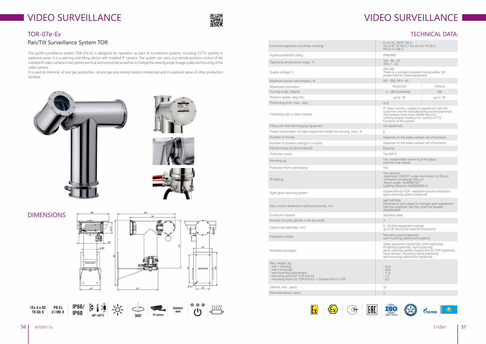
VIDEO SURVEILLANCE
56
TOR-07e-Ex
Pan/Tilt Surveillance System TOR
The pa/tilt surveillance system TOR-07е-Ех is designed for operation as part of surveillance systems, including CCTV systems in
explosive areas. It is a panning and tilting device with installed IP camera. The system can carry out remote position control of the
installed IP video camera in two planes (vertical and horizontal) as well as to change the viewing angle (image scale) and focusing of the
video camera.
It is used at chemical, oil and gas production, oil and gas processing industry enterprises and in explosive areas of other production
facilities.
eridan.ru
IP66/IP68
DIMENSIONS
1Ex d å IIC T6 Gb Õ
Stainless steel
360°
IP camera -60°+50°Ñ
PB Ex d I Mb X
57
TECHNICAL DATA:
VIDEO SURVEILLANCE
Ethernet
Nf1: -60...50 NF4: 1...50
Nf1 - 200, NF4 - 40
230 VACThere is a voltage converter that provides 12V power feed for video-equipment
IP66/IP68
IP video camera, subject to agreement with the customer and the manufacturing factory (optional)The camera must have RS485 Pelco-D communication interface for control of PTZ functions of the system
Horizontal Vertical
±900...360 (unlimited)
up to 24
6
Depends on the video camera set of functions
up to 24
Duplex-07e-Ex-TOR - explosion-proof contactless glass cleaning system (optional)
540*330*600Dimensions are subject to change upon agreement with the customer, but they shall not exceed 200х200х400
Yes
3
Stainless steel
Yes (option):-A utomatic ON/OFF under illumination of 25±5 lx-E mission wavelength 850 um-B eam angle 15/30/90/120°Lighting distance 100/80/40/25 m
Yes (NF1)
Yes, independent warming of the glass and the inner space
5...12 (into equipment casing) up to 22 (along the external insulation)
Video equipment (optional), wires (optional), IR lighting (optional), visor (optional), glass cleaning system Duplex-07е-Ех-TOR (optional), input devices, mounting stand (optional), wall mounting attachment (optional)
- 40,0- 50,0 - 11,0- 7,0- 8,0
10
3
Mounting stand (optional), wall mounting attachment (option)
Interface type (control protocol)
Enclosure explosion proofness marking
Positioning error, max., deg.
Operating temperature range, °С
Ingress protection rating
Furnishing with a video camera
Movement orientation
Turning angle, degree
Rotation speed, deg./sec
Power consumption of video equipment inside the housing, max., W
Number of position settings in a round
Number of rounds
Sight glass cleaning system
Max. overall dimensions (without bracket), mm
Protection from overheating
Number of cable glands in the box body
Enclosure material
IR lighting
Cold start mode
Warming up
Cable entry diameter, mm
Max. weight, kg:- with 1 housing- with 2 housings- wall mounting attachment- mounting stand for TOR-07e-Ex- mounting stand for TOR-07e-Ex + Duplex-07e-Ex-TOR
Lifetime, min., years
Warranty period, years
Installation mode
Available packages
Ex tb IIIC T80°C Db X1Ex d IIC T6 Gb X / 1Ex d е IIC T6 Gb XPB Ex d I Mb X
Supply voltage, V
Maximum power consumption, W
±0,5
Fitting with thermal-imaging equipment Yes (optional)
Depends on the video camera set of functions
Eridan

VIDEO SURVEILLANCE
58
Duplex-07e
Glass Cleaning System
The class cleaning system Duplex-07e-Ex is designed for touch-free removing of any dirt from thermohousing sight glasses.
Cleaning is an important element of efficient CCTV monitoring since it guarantees clear picture irrespective of ambient conditions
and decreases the maintenance requirement. The system is designed for TVK and TOR series devices manufactured by Eridan JSC.
It is used at chemical, oil and gas production, oil and gas processing industry enterprises and in explosive areas of other production
facilities.
eridan.ru
0,6 ÌPà
30 mStep 1 Step 2
-30°+50°Ñ
10 years
3 years
IP66
ADVANTAGES OF THE CLEANING SYSTEM- Touch-free washing and drying of the sight glass- Operation in Ex zones and in corrosive environments- Sight glass zero wear- Operation at low temperatures
- Removal of all types of contamination- Capability to install at a height- Remote location of the liquid storage tank is possible
PATENTED
filling with washing liquid
washing liquid under pressure
compressed air
washing liquid nozzle
washing liquid nozzle
stand
receiver
valve unit
59
TECHNICAL DATA:
VIDEO SURVEILLANCE
Washing liquid tank capacity, min., l
Consumption for one cycle of cleaning, max.:- water, l- air, m3
Possibility of remote control of the cleaning process
Maximum power consumption, W
Number of solenoid operated valves
Operating air pressure, min., MPa
System portability (portable system)
5
Control module (optional), mounting stand (common for TOR-07e and Duplex-07e)
- 0,05- 0,1
30
Yes, taking into account the available video camera functions
Nf1 - 200, NF4 - 40
2
0,6-1,0
Allowable change in pressure from minimum to maximum, max., MPa
0,9
Available packages
Max. weight, kg 4,5
System composition
Operation principle description
1. Receiver2. Solenoid operated valves assembly3. Nozzle assembly (washing and air)4. Set of hoses5. Control module (optional)
Duplex-07e-Ex-TORExplosion-proof glass cleaning
system for pan/tilt system TOR-07e-Ex
Portable Duplex-07e-Ех-TVKExplosion-proof glass cleaning
system for the TVK-07-S/N series thermohousings
Extended capacity portable Duplex-07e-Ех-TVK
Explosion-proof glass cleaning system for the TVK-07-S/N
series thermohousings
Modification
Enclosure explosion proofness marking
Ingress protection rating
Operating temperature range, °С
IP66
Supply voltage, V 24 VDC / 230 VAC
Lifetime, min., years
33 3Warranty period, years
10 10 10
1. Compressed air tank2. Pressure regulator3. Washing liquid tank4. Set of hoses5. Control panel6. Flange with nozzles
1. Compressed air tank2. Pressure regulator3. Washing liquid tank4. Set of hoses5. Control panel6. Flange with nozzles7. Backpack for transportation
IP66 IP66
2 2
0,6-1,0 0,6-1,0
0,5-1,0 2-4
(30) leading to washing capacity decrease
- 0,125 - 0,05
No, at site
Replacement washing liquid tanks Double washing liquid tank capacity
3,5 10
Yes Yes
During patrolling, the operating staff shall connect the control panel of the cleaning system to the brought-out pulse tubes. Launches dirt knocking off cycle with high pressure water jet (or any other solvent). Then, the sight glass is air-dried thus removing all residual dirt. Water and air supply can be varied as well as the number of cycles and their duration.
Upon command from the operator or a contamination monitoring sensor of the sight glass, a cleaning cycle consisting in knocking off of dirt with high pressure water (or other liquid) will commence. Then, the sight glass is air-dried thus removing all residual dirt. Configuration mode for water and air supply sequence, number of cycles and their duration is available.
I MB / II GB C T6 / III DB C T80°C
-30...50, The minimum temperature allowing operation of the system will depend on the temperature-dependent properties of the liquid filled in the washer tank
- Receiver: I Mb/ II Gb c T6/ III Db c T80°C - Valve unit: РВ Ex mb I Mb X/ 1Ex mb IIC T6 Gb X/ Ex mb IIIC T80°C Db X - Nozzle assembly (washing and air): I Mb/ II Gb c T6/ III Db c T80°C - Control unit: 1 Ex d IIC T6 Gb X/ Ex tb IIIC T80°C Db X
Tank capacity, l 0,8 3
Tank pressure, MPa 30 30
- 0,125 - 0,05
No, at site
NEW
NEW NEW
Types of contamination that can be cleaned
1. Organic: petroleum-oil, oil, street dirt/mud, paints, grease2. Non-organic: combustion deposits, smoke-black, carbon, furnace black, cement3. Biological: dust, spider web
Possible washing liquids1. Neutral: water 2. Acid: сіtric acid
3. Alkaline: soda ash, caustic ash, soda crystals, trisodium phoshate, sodium metasilicate4. Organic: alcohols, solvents, SAS
Elevation difference of installation between the valve unit and the washer tank, max., m
Eridan
(30) leading to washing capacity decrease

VIDEO SURVEILLANCE
60
IK-07e
Explosion-Proof Infrared Spotlamp
Explosion-proof infrared spotlamp IK-07e is designed for continuous operation as part of CCTV system when natural illumination is not
sufficient for normal operation of the video camera.
The spotlamp provides efficient illumination of the monitored sector in explosive areas at chemical, oil and gas production, oil and gas
processing industry enterprises and in explosive areas of other production facilities.
eridan.ru
-60°+60°Ñ
10 years
5 years
Aluminum
DIMENSIONS
30°, 50° 70°, 120°
850 nm1ExdIIC
Ò6 Õ IP67130
105170
mm
61
TECHNICAL DATA:
VIDEO SURVEILLANCE
9,2
18±5
-60...60
12-24 VDC, 24 VАC
1ExdIICТ6 Х
Bracket (included in the supply package)
105*130*170
30
Radiation angle, °
80
Lighting distance, m
50
70
120
65
50
30
Aluminum alloy
2,2
10
5
IP67
850
20±5
Full/half power
Input devices
2
6...12 (into equipment casing)up to 22 (along the external insulation)
Enclosure explosion proofness marking
Maximum power consumption, max., W
Automatic enabling/disabling of spotlight with hysteresis,illumination level, lux
Operating temperature range, °С
Supply voltage, V
Spotlamp installation mode
Max. overall dimensions (with bracket and cable glands), mm
Beam parameters*
*data are shown for CCD-matrix with sensitivity of 0.03 lux
Enclosure material
Max. weight, kg
Lifetime, min., years
Warranty period, years
Emission wavelength, nm
Photosensor off-delay, sec.
Radiation power selection jumper
Available packages
Number of cable glands in the box body
Cable entry diameter, mm
Ingress protection rating
Eridan

INSTRUMENTS AND DEVICES
62 eridan.ru 63
This section comprises instruments and devices, which facilitate use of other equipment designed
and manufactured by Eridan JSC.
Instruments and devices may be installed in open spaces and enclosed areas of different buildings
and structures, as well as on river and sea-going vessels and production facilities, where explosive
mixtures of air and combustible gases or vapors may be present.
They may be used at chemical, oil and gas production, oil and gas processing and other plants with
explosion hazardous areas.
Eridan

INSTRUMENTS AND DEVICES
64
Ex-TEST
Explosion-Proof Instrument for Functional Testing of Heat Fire Detectors
eridan.ru
-20°+60°Ñ
10 years
3 years9 kg
3 hoursIP541Exs [ib]
IIÑÒ3 X
120
300300
mm
Explosion-proof instrument for functional testing of heat fire detectors Ex-TEST allows checking IP103-2/1-TR, IP101-07е, IP101-
07em detectors and their analogs (in terms of sensing element design) without disassembly, right on the installation site as well as
the loop and the FACP.
Ex-TEST is used at chemical, oil and gas production, oil and gas processing industry enterprises and in explosion hazardous areas of
other production facilities.
65
TECHNICAL DATA:
INSTRUMENTS AND DEVICES
Enclosure explosion proofness marking
Operating temperature range, °С -20...60
Heating temperature range of the MHH, °С 50...162±2
Emergency shutdown temperature, °C 167±3
Supply voltage, V in offline mode with the battery in charge
10,1...14,5100...240 (battery charge control)
1Exs[ib]IIСТ3 X
Ingress protection rating IP54
Maximum current consumption of MHH, max., A 4,8
Continuous operation time with battery fully charged, min., h 3, battery charge control
MHH cable overall dimensions:MHH cable length, m Max. MHH inside diameter, mm Max. insert inside diameter, mm Max. MHH depth, mm
3...5 (upon request)16,56,0160,0
Lifetime, min, years 10
Warranty period, years 3
Enclosure material Aluminum alloy
Max. weight, kg 9,0
Protection- MHH cable protection against opening and short-circuiting- Protection from overheating
Instrument max. overall dimensions, mm 300*300*120
Eridan

INSTRUMENTS AND DEVICES
66
IP535-07e-START
Explosion-Proof Remote Start-Up Devices
The explosion-proof remote start-up device IP535-07e-START is designed for manual activation of fire fighting systems in explosive
areas or areal of general industrial purpose.
It is used at chemical, oil and gas production, oil and gas processing industry enterprises and in explosive areas of other production
facilities.
IP535-07e-START-I1 is designed for manual activation of fire-safety systems; when activated, it provides circuit closingIP535-07e-START-I2 is designed for manual activation of fire-safety systems when operating in fire alarm loops;it is activated by fire-alarm circuit opening (series connection) or closing (parallel connection)
eridan.ru
1Ex db IIC T6 Gb
-60°+85°Ñ
70 μA 10 years
5 years
AluminumIP66/IP67
DIMENSIONS
DEVICE CLASSES
DESIGNATIONLAUNCH OF
FIRE FIGHTING
launch of automatic gaseous
fire fighting equipment (color - yellow)
LAUNCH OF SMOKE REMOVAL
START
launch of smoke removal systems (color - orange)
EMERGENCY EXIT
generation of emergency signals or signals
of emergency exit unlocking (color - green)
application of the UDP is defined by the user
(color - grey)
EMERGENCY STOP
shutdown of automatic gaseous
fire fighting equipment (color - blue)
PATENTED
Max. cable entry diameter, mm
Detector installation mode
Max. overall dimensions (without cable glands and bracket), mm
Enclosure material
Light indication
6...12 (into equipment casing) up to 22 (along the external insulation)
To the surface by means of the mounting
hole with the cable glands facing down
Input devices, visor (optional), removable element (optional)
120*135*110 120*135*110 120*135*110
Aluminum alloy АК 12 ПЧ Vandal-proof design
Yes Yes Yes
Number of cable glands in the body 22 2
Available packages
Max. weight, kg 1,0 1,0 1,0
Maximum current consumption, max., mA (for I2)
0,07
67
INSTRUMENTS AND DEVICES
Enclosure explosion proofness marking
Operating temperature range, °С
Maximum switching power, max., W (for I1) 10
1Ex db IIC T6 GbEx tb IIIC 85°C Db
IP535-07e-START (I1, I2) Explosion-proof remote
start-up device
IP535-07ea-START Addressable explosion-proof
remote start-up device
IP535-07ea-RS-START Addressable explosion-proof
remote start-up device
Modification
Ingress protection rating IP66/IP67 IP66/IP67 IP66/IP67
-60...85 -60...85 -60...85
1Ex db IIC T6 GbEx tb IIIC 85°C Db
1Ex db IIC T6 GbEx tb IIIC 85°C Db
Supply voltage, V (for I2)
Driving element
Possibility of connection to addressable loop
Magnetically-controlled, vibration-resistant, shock-proof
Yes (in case of transferring of signal via communication channel RS-485
with Modbus RTU protocol) Maximum number of addressable
devices to be connected: 32
Yes(via the Dozor-07a protocol)
Maximum number of addressable devices to be connected: 255
Yes(by means of setting the address marks)
8...28 15...39 8...28
Magnetically-controlled, vibration-resistant, shock-proof
Magnetically-controlled, vibration-resistant, shock-proof
Maximum switching voltage, V (for I1)
60
Maximum switching current, A (for I1)
0,5
1,0Standby mode - 5
In activation mode - 10 During polling - 20
Supported protocol Dozor-07a Modbus RTU
Lifetime, min, years
55 5Warranty period, years
10 10 10
Eridan
TECHNICAL DATA:
Aluminum alloy АК 12 ПЧ Vandal-proof design
Aluminum alloy АК 12 ПЧ Vandal-proof design
6...12 (into equipment casing) up to 22 (along the external insulation)
6...12 (into equipment casing) up to 22 (along the external insulation)
To the surface by means of the mounting
hole with the cable glands facing down
To the surface by means of the mounting
hole with the cable glands facing down
Input devices, visor (optional), removable element (optional)
Input devices, visor (optional), removable element (optional)

INSTRUMENTS AND DEVICES
68
UUO
eridan.ru
-10°+50°Ñ
10 years
5 years
IP54
DIMENSIONS
Annunciator Controller
The external annunciator controller UUO (UUO-RGB) provides possibility to connect the annunciator to the discrete outputs (for
example, relays) of fire alarm panels or controllers. Use of the annunciator EKRAN-INFO or EKRAN-INFO-RGB together with the UUO
(UUO-RGB) allows replacing of up to four separate annunciators. Communication with the annunciator is carried out via the RS-485
interface with galvanic separation unit and the communication line controller. The maximum length of the communication line is 1 km.
The UUO (UUO-RGB) is located outside the explosive area.
0,2 kg
55
21080
mm12-24 V
0,15 À
69
INSTRUMENTS AND DEVICES
Number of cable glandsin the body
Max. cable entry diameter, mm
Installation of the annunciator at site
Controlled annunciator type
Supply voltage, V
Maximum power consumption, A
Number of configured discrete outputs (control loops)
Supported protocol
Interface for communication with the annunciator
Enclosure material
6...12 (into equipment casing)
By means of the mounting hole to the surface
12-24 VDC
0,15
4
RS-485 with galvanic separation unit
EKRAN-INFO
UUO EKRAN-INFO
annunciator controller in a G258C sealed casing
UUOEKRAN-INFO
annunciator controller in an open DIN casing
UUO-RGBEKRAN-INFO-RGB
annunciator controller in an open DIN casing
2
Plastic
Modification
Connection of wires, 2
cross-section 0.08-1.5 mm
Number of annunciators to be connected 1
Baudrate, baud 9600 9600
Modbus RTU
On a 32/35 DIN-rail
Lifetime, min, years
Max. weight, kg 0,2
55 5Warranty period, years
10 10 10
UUO-RGBEKRAN-INFO-RGB
annunciator controller in a G258C sealed casing
EKRAN-INFO
1 1 1
Yes (in case of transferring of signal via communication
channel RS-485 with Modbus RTU protocol)
2
10
5
EKRAN-INFO-RGB EKRAN-INFO-RGB
Ingress protection rating IP54 IP54
Operating temperature range, °С
-10...50 -10...50 -10...50 -10...50
12-24 VDC 12-24 VDC 12-24 VDC
0,15 0,15 0,15
4 4 4
RS-485 with galvanic separation unit
Modbus RTU
Max. overall dimensions, mm 70,5*96*60210*80*55210*80*55 70,5*96*60
Plastic Plastic Plastic
0,2 0,2 0,2
Eridan
TECHNICAL DATA:
Yes (in case of transferring of signal via communication
channel RS-485 with Modbus RTU protocol)
6...12 (into equipment casing)Connection of wires,
2cross-section 0.08-1.5 mm
By means of the mounting hole to the surface On a 32/35 DIN-rail
9600, 19200, 38400, 57600, 115200 (selection by means of switches)

INSTRUMENTS AND DEVICES
PI-1, PI-2
PI-1 and PI-2 USB ↔ RS-485 Interface Converters
USB ↔ RS-485 interface converters are designed for configuring the annunciator EKRAN-INFO and communication with the FACP Dozor-1A with the PC for setting it up and for transfer (reading and recording) of data when working with different applications. The following functions are available for the user:- Recording of the created configuration into the annunciator EKRAN-INFO or the FACP Dozor-1A- Reading the existing configurations in the device or the annunciator- For the FACP Dozor-1A, reading of the event log, monitoring of the system status, firmware upgrading.PI1: Connection of one or a group of Dozor-1A devices to PC in order to work with the software. The PI1 unit is connected directly to the device's terminals. The communication line between the PI1 and the PC may be several meters long (1-2 m).The PI2 differs from the PI1 by its galvanic separation, owing to which communication is much more jam-resistant, and which allows laying the lines (RS-485) from the FACP-1A to the PI2 up to several kilometers long.
70 eridan.ru
10 years
5 years
80 mÀ 0,2 kg
TECHNICAL DATA:
Power supply From USB port
Communication line length from the FACP to the device, max., m 2,0
Weight, kg 0,2
Max. overall dimensions, mm 70*20*15
Modifications PI-1
Maximum current consumption, mA 80
Levels and output capacity of the RS-485 line USB standard
PI-2
90*60*22
Up to several km
0,2
Lifetime, min, years 10
Warranty period, years 5
TEST LANTERNS
Explosion-proof test lanterns for checking of IPP-07e Gelios series flame detectors
INSTRUMENTS AND DEVICES
71
Max. overall dimensions, mm
Enclosure material
Supply package
Lifetime, min., years 10
Warranty period, years 2
Enclosure explosion proofness marking
Ingress protection rating IP65
Min. continuous operation time at an ambient temperature of 0°С, h
Operating temperature, °С
Weight without batteries, max., kg
The test lantern allows checking the IPP-07e Gelios series flame detectors and their analogs without disassembly, at the installation
site as well as the loop and the FACP. It is used at chemical, oil and gas production, oil and gas processing industry enterprises and in
explosion hazardous areas of other production facilities.
For detector checkingIPP-07e-330-1/2 Gelios 2 IR:- I1 - Explosion-proof test set No. 1- I2, I3 - Explosion-proof test set No. 2
- IPP-07ea-RS-330-1 Gelios 3 IR- IPP-07ea-RS-329/330-1 Gelios IR/UV
1Ex d IIB T4 Gb X
IP65
0...55
Operating range of coverage, m 3 4
The product is designed for functional checking of the flame detector in explosive and non-explosive areas. The product mimics the electromagnetic emission of flame.
Supply package:- Test lantern- Hollow head screw hex wrench 3 mm and 0.89 mm- AC/DC power adapter, 12 V, 0.3 A
10
2
0,5
89*165*96
Aluminum
6
Designation Explosion-proof test set No. 1 and No. 2 Test lantern Tulpan TF-2Ex
1,2
Certificates available - Certificate of compliance No. С-RU. ПБ34. В.01828 (No. 0001265)- Certificate of compliance No. ТС RU C-RU.AA87.B.00217 series RU No. 0406128
Eridan
- Certificate of compliance No. С-RU. ПБ34. В.01828 (No. 0001265)- Certificate of compliance No. ТС RU C-RU.AA87.B.00217 series RU No. 0406128
The product is designed for functional checking of the flame detector in explosive and non-explosive areas. The product mimics the electromagnetic emission of flame.
Supply package:- Test lantern- Hollow head screw hex wrench 3 mm and 0.89 mm- AC/DC power adapter, 12 V, 0.3 A- Optical attachment- Replacement lamp
89*165*96
0,5
0...55
1Ex d IIB T4 Gb X
1,2
Aluminum
TECHNICAL DATA:

72 eridan.ru
DIALOG-EX
73Eridan
Analog-addressable system is a modern automated system based on continuous measurement
of the controlled parameters with sensors. All data from the detectors of this system type are
transmitted to the control panel, where the change of situation at the facility is analyzed using special
algorithms. The system is considered to be one of the most advanced and effective ones.
DIALOG-EX FEATURES:
• Fire outbreak place detection accuracy and local application fire suppression;
• Operability self-check of the whole system and identification of the cause of failures in case there is
any;
• Survival in case of loop opening and short-circuit;
• Integrated circular loop for notification, annunciation and fire-extinguishing systems;
• Control of all functions via the fire alarm control panel;
• No need for operational check;
• Possibility to connect zero-address devices to the loop;
• Cost cut thanks to the use of modern technologies.

DIALOG-ЕХ ANALOG-ADDRESSABLE SYSTEM
74
ADDRESSABLE DOES NOT MEAN ANALOG-ADDRESSABLE!
eridan.ru
In non-addressable and addressable systems 'fire decision' is made by the detector itself and then it is transmitted to the fire alarm
control panel. In analog-addressable systems values of the parameter (temperature, smoke content within the premises) monitored by
the detector are transmitted to the FACP. The FACP constantly monitors ambient conditions in all the premises and on the basis of these
data makes decision not only on generation of 'Fire' signal, but also on generation of 'Warning', 'Fault' and other signals. The 'decision'
is made by the fire alarm control panel and not the detector.
The AAS constantly monitors ambient conditions in the premises promptly detecting start of temperature (or smoke content) change
and sends a warning signal to the console. Therefore, the AAS provides early detection of fire. This means that fire can be easily
extinguished thus minimizing possible losses for the facility. In analog-addressable devices offer a possibility to individually set not only
'Fire' and 'Warning' signal generation levels for each detector but also to define algorithms of their combined operation. This means
that the AAS can create an optimal fire alarm system at a facility because it allows creating early fire detection system in the most
appropriate way for each facility taking into consideration its individual features.
DIALOG-EX - ANALOG-ADDRESSABLE SYSTEM FOR EXPLOSIVE AREAS.
DETERMINATION OF EXACT LOCATION OF FAILURE AREA OR FIRE OUTBREAK. During polling, the fire alarm control panel reads
in unique sequential numbers of all devices in the loop, thanks to which the operator always knows the exact place of the event in the
periphery (loop opening, short-circuiting, failure of any of the devices or fire outbreak).
Number of devices in the loop: up to 225 (systems may as well be extended by installing additional fire alarm control panels DOZOR-
1A). This allows considerable cost reduction during installation of the system and use of detectors powered by the loop reduces costs
for laying new lines of alarm system by half as a minimum. In accordance with the safety requirements, where installation of two
detectors is necessary in case of non-addressable loop, in addressable loop one analog-addressable detector is enough. Besides, use
of different address marks provides possibility to use a wide range of non-addressable devices and to control and monitor operation of
the facility's automatic fire fighting and engineering systems of any complexity level by simply updating and building up the existing
explosive area safety system to up to 128 addressable loops and more.
DETECTOR PERFORMANCE MONITORING (SYSTEM NO. 1 SURVIVABILITY). In Dialog-Ex AAS there cannot by any faulty detector
not detected by the FACP. By way of data exchange with each device in sequence, the device conducts polling via Dozor-07a protocol
every 3 seconds. As a result of each device polling, new information on the status of each location of addressable detectors and
external devices and their condition is generated, thus providing continuous monitoring of the facility and system elements.
CIRCULAR LOOP (SYSTEM NO. 2 SURVIVABILITY). Use of circular alarm loop architecture allows normal operation of Dialog-Ex in
case of short-circuit or loop opening with precise detection of exact failure place and address. At the same time, the system is divided
into two radial loops without loosing their functionality.
75
CIRCULAR LOOP
SYSTEM EFFICIENCY. Dialog-Ex allows not only detecting the place of possible fire outbreak but also it provides for timely
activation of the alert system plotting routes of evacuation of people during early stages of fire outbreak, launch of automatic
fire suppression system at the fire outbreak site.
SYSTEM PROGRAMMING. Possibility to change sensitivity of the sensors depending on the ambient or operating conditions.
ZERO MAINTENANCE COSTS. Continuous self-checking makes system maintenance and (which is important) system
functionality routine tests unnecessary.
INTEGRATION OF ZERO-ADDRESS DEVICES IN DIALOG-EX SYSTEM. Zero-address devices can be easily integrated into the
system. It is done by means of installation of corresponding address marks. However, this does not grant these devices the
analog function.
INTERGRATION OF DIALOG-EX INTO GLOBAL SECURITY SYSTEMS OF AN ENTERPRISE. Dialog-Ex AAS on the basis of
Dozor 1A device provides possibility of integration into 'top-level' security systems such as 'Intellect' and 'Eselta'.
TWO RADIAL LOOPS
POLLING
POLLING
CIUCIU
DIALOG-ЕХ ANALOG-ADDRESSABLE SYSTEM
Eridan
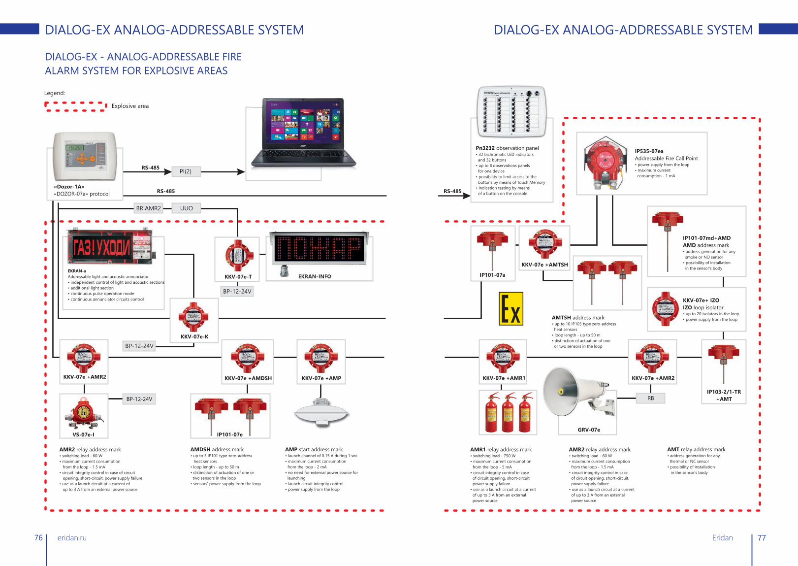
76 eridan.ru
DIALOG-EX - ANALOG-ADDRESSABLE FIRE
ALARM SYSTEM FOR EXPLOSIVE AREAS
Legend:
Explosive area
RS-485PI(2)
«Dozor-1A»
«DOZOR-07a» protocol RS-485
EKRAN-a
Addressable light and acoustic annunciator
• independent control of light and acoustic sections
• additional light section
• continuous pulse operation mode
• continuous annunciator circuits control
BR AMR2 UUО
EKRAN-INFO
ККV-07е-К
BP-12-24V
KKV-07e +AMR2
BP-12-24V
VS-07e-I
AMR2 relay address mark• switching load - 60 W
• maximum current consumption
from the loop - 1.5 mA
• circuit integrity control in case of circuit
opening, short-circuit, power supply failure
• use as a launch circuit at a current of
up to 3 A from an external power source
AMDSH address mark• up to 3 IP101 type zero-address
heat sensors
• loop length - up to 50 m
• distinction of actuation of one or
two sensors in the loop
• sensors' power supply from the loop
AMP start address mark• launch channel of 0.15 A during 1 sec.
• maximum current consumption
from the loop - 2 mA
• no need for external power source for
launching
• launch circuit integrity control
• power supply from the loop
BP-12-24V
KKV-07e +AMDSH KKV-07e +AMP
ККV-07е-T
IP101-07е
DIALOG-ЕХ ANALOG-ADDRESSABLE SYSTEM
77
Õ
RS-485
IP535-07ea
Addressable Fire Call Point• power supply from the loop
• maximum current
consumption - 1 mA
Pn3232 observation panel• 32 bichromatic LED indicators
and 32 buttons
• up to 8 observations panels
for one device
• possibility to limit access to the
buttons by means of Touch Memory
• indication testing by means
of a button on the console
IP101-07а
AMTSH address mark• up to 10 IP103 type zero-address
heat sensors
• loop length - up to 50 m
• distinction of actuation of one
or two sensors in the loop
KKV-07e+ IZO
IZO loop isolator• up to 20 isolators in the loop
• power supply from the loop
IP103-2/1-TR
+AMTRB
AMR1 relay address mark• switching load - 750 W
• maximum current consumption
from the loop - 5 mA
• circuit integrity control in case
of circuit opening, short-circuit,
power supply failure
• use as a launch circuit at a current
of up to 3 A from an external
power source
AMT relay address mark• address generation for any
thermal or NC sensor
• possibility of installation
in the sensor's body
AMR2 relay address mark• switching load - 60 W
• maximum current consumption
from the loop - 1.5 mA
• circuit integrity control in case
of circuit opening, short-circuit,
power supply failure
• use as a launch circuit at a current
of up to 3 A from an external
power source
KKV-07e +AMTSH
KKV-07e +AMR1
GRV-07e
KKV-07e +AMR2
IP101-07md+AMD
AMD address mark • address generation for any
smoke or NO sensor
• possibility of installation
in the sensor's body
Eridan
DIALOG-ЕХ ANALOG-ADDRESSABLE SYSTEM

78 eridan.ru
Pn3232
Observation panel
The PN3232 observation panel is a microprocessor
device designed for displaying information on
bichromatic LED indicators and controlling the system
by means of the buttons.
TECHNICAL DATA:
Ingress protection rating
Operating temperature range, °С
IP30
-10...50
External power supply source voltage, V
Body material
Number of bichromatic LED indicators, pcs.
Number of Touch Memory keys providing access to control from the keyboard, pcs.
Communication channel with the central FACP-1A unit
Number of PN3232 consoles that can be connected to one FACP-1A, pcs.
Lifetime, min., years
Maximum current consumption from power supply source, A
Max. overall dimensions, mm
Light indication
Indicator colores
Number of controls (buttons), pcs.
Detector installation mode
Max. weight, kg
Warranty period, years
10,5...14
PLASTIC
32
4
RS-485
8
10
0,15
300*220*15
Yes
Green, red
32
By means of the mounting hole to the surface
0,3
3
Dozor-1A
Addressable Security, Fire Alarm and Control Panel with Dozor-07a Protocol
DOZOR-1A addressable security, fire alarm and control panel is
designed for creating an effective security and fire alarm system as well
as for full-service control of smoke extraction, ventilation, fire alarm,
processing equipment and fire extinguishing of all types (gas, powder,
aerosol, water and foam) at small facilities of different assignment both
in off line mode and in combination with central surveillance panels and
fire alarm control panels.
261
11278
mm
10 years
3 years10,5-14 V
130
20230
mm
DIALOG-ЕХ ANALOG-ADDRESSABLE SYSTEM
TECHNICAL DATA:
Ingress protection rating
Adjustment of addressable devices at the installation sitePossibility to change sensitivity of the sensors depending of the operating conditions
Supported protocol Doror-07a
IP30
280Maximum current consumption of addressable devices from addressable loop, max., mA
Supply voltage, V 10,5...14
Body material Plastic with LED indicator and control buttons
Max. overall dimensions, mm 202*130*30
Light indication Yes
Number of recorded events 4000
Detector installation mode By means of the mounting hole to the surface
Operating temperature range, °С -10...50
Maximum current consumption from power supply source - without external devices: 230.0 mA- at the maximum load: 2.0 A
Addressable loop voltage (at FACP-1A output), V 28...38
Addressable loop resistance (at maximum load), max., Ohm 33
Number of circular addressable loops 1
Maximum number of addressable devices in addressable loop, pcs. 255
Number of Dozor series devices integrated into one network 128
Addressable devices operability check
- Continuous cyclic polling of addressable devices in the system- Full status monitoring for each addressable device- Continuous control of circuit opening and short-circuiting- Out-of-sequence detection of devices that switched into the activation mode
Available packages
FACP-1A-1 (Dozor-07a protocol) - Central unit with an indicator and a keyboard on the device body.FACP-1A-2 (Doror-07a protocol) - Central unit WITHOUT indicator and keyboard on the device body.PI1: connection of one or a group of Dozor-1A devices to PC in order to work with the software.PI2: Connection between the PC and a group of DOZOR series devices for creation of integrated systems as well as for working with software
Warranty period, years 3
Max. weight, kg 1,0
Lifetime, min., years 10
79Eridan
DIALOG-ЕХ ANALOG-ADDRESSABLE SYSTEM

80 eridan.ru
ADDRESS MARKS
AMT address mark (NC contacts)
AMD address mark (NO contacts)
AMTSH loop address mark (NC contacts)
AMTSHloop address mark (NO contacts)
-60°
-60°
The address mark is a microprocessor device intended for generation of address of one thermal or any contact sensor with
normally-closed or normally-opened contacts. Application of address marks allows efficient transformation of a
conventional threshold detector into an addressable one.
The AMT address mark is intended for generation of address of one thermal or any contact sensor with normally-closed contacts The address mark is connected to the addressable loop formed by the FACP-1A through which data transfer and power supply is effected. Application of the AMT allows efficient transformation of a conventional threshold detector into an addressable one. The detector acquires then its own unique address in the system. This provides precise determination of its location when it is actuated. The AMT is a small-size mark and it can be easily installed inside the body of many detectors and explosion-proof switch-boxes KKV-07e. Thanks to that, it can be mounted easily and will become unnoticeable after its installation is complete providing convenience and nice appearance. In addition, cost saving during installation due to reduction of the number of connecting wires and use of cheap sensors may result quite significant as well.
The AMD address mark is intended for generation of address of smoke or any contact sensor with normally-open contacts. The address mark is connected to the addressable loop formed by the FACP-1A through which data transfer and power supply is effected. Application of the AMD allows efficient transformation of conventional, threshold detectors, for example, smoke and flame detectors and call points as well as any other sensors with NO dry contacts into addressable ones. In this case the detector acquired its own unique address in the system.
This provides precise determination of its location when it is actuated. The AMD is a small-size mark and it can be installed inside the body of many detectors, for example, smoke detectors or call points and explosion-proof switch-boxes KKV-07e.
The AMTSH address mark is intended for generation of threshold-oriented alarm loop (AL) for thermal or any other contact sensors with normally-closed contacts. The address mark is connected to the addressable loop formed by the FACP-1A through which data transfer and power supply is effected. Application of the AMTSH allows formation of threshold-oriented alarm loops for conventional, cheap detectors, for example, thermal detectors, call points, and SMK as well as any other sensors with NC dry contacts. In this case the alarm loop acquires its own unique address in the system and is controlled by the address mark. This provides precise determination of the loop's location in case of actuation or failure. As a matter of practice, the AMTSH is often installed before the premise into which the threshold-oriented loop is brought in. Other options of the address mark application are possible as well.
The AMDSH address mark is intended for formation of threshold-oriented alarm loop for smoke or any other contact sensors with normally-open contacts. The address mark is connected to the addressable loop formed by the FACP-1A through which data transfer and power supply is effected. The address mark provides power supply of power consuming sensors. Application of the AMDSH allows formation of threshold-oriented alarm loops for conventional, cheap detectors, for example, smoke, flame detectors and call points (as well as arbitrarily NO dry contacts). In this case, the loop acquires its own unique address in the system and is controlled by the address mark. This provides precise determination of its location when it is actuated. Actuation of formed threshold-oriented alarm loop is possible both by one and two sensors. As a matter of practice, the AMDSH is often installed before the premise into which the threshold-oriented loop is brought in. Other options of the address mark application are possible as well.
DIALOG-ЕХ ANALOG-ADDRESSABLE SYSTEM
81
The relay address mark is a microprocessor device with controlled circuit integrity control as per current requirements of the 'Technical Regulations on Fire Safety Requirements' (TRoFSR). The mark is connected to the addressable loop formed by the FACP-1A through which data transfer and power supply is effected. On the one hand, the address mark constantly transfers to the FACP-1A information on its status and on the other hand receives commands to connect and disconnect load from the FACP-1A.
The address mark AMR1 is designed for controlling by means of the external load via the relay bridging contacts fire and smoke dampers, production equipment and launching fire-extinguishing modules.
The address mark AMR2 is designed to control the external load via the relay bridging contacts with controlled circuit integrity control as per current requirements of the 'Technical Regulations on Fire Safety Requirements' (TRoFSR). The address mark is connected to the addressable loop formed by the FACP-1A through which data transfer and power supply is effected. On the one hand, the address mark constantly transfers to the FACP-1A information on its status and on the other hand receives commands to connect and disconnect load from the FACP-1A. When receiving an activation command, the AMR2 mark not only is able to connect the load but also to work in flashing mode at 1 Hz frequency. The flashing mode in activated mode is often used when various light and acoustic annunciators are connected to the mark.
As a matter of practice, the AMR2 is usually used for controlling various annunciators, valves and dumpers (fire, smoke dumpers, etc.), production equipment and for launching (gas, powder, aerosol) fire-extinguishing modules.
The AMP start address mark is designed for generation of current pulse in order to activate fire-extinguishing modules or other equipment. It is provided with start circuit integrity control as per current requirements of the 'Technical Regulations on Fire Safety Requirements' (TRoFSR). The address mark is connected to the addressable loop formed by the FACP-1A through which data transfer and power supply is effected.
As a matter of practice, the AMP is used for launching of various fire-extinguishing modules, activated by destruction of a pyrotechnic squib. Usually, these are powder fire-extinguishing modules.
The addressable loop isolator IZO is designed for isolating of a portion of the loop in case of short-circuiting. The isolator in connected to the addressable loop formed by a FACP-1A, and it is an independent device that is only fed from the loop. It is activated by the loop disruption.
On a practical level, presence of various IZO's in one addressable loop allows a more precise localization of the damaged portion maintaining operability of the rest of the addressable devices.
AMR2 Low Consumption Relay Address Mark
AMP Start Address Mark
IZO Addressable Loop Isolator
-60°
-60°
AMR1 Heavy-Current Relay Address Mark
-60°
Eridan
DIALOG-ЕХ ANALOG-ADDRESSABLE SYSTEM

82 eridan.ru
ADDRESSABLE EQUIPMENT:
IP101-07aExplosion-Proof Addressable Programmable Heat Fire DetectorIt is designed for detection of any inflagration followed by temperature rising within the monitored area and for transferring to a receiving and controlling instrument of the current temperature value, as well as for detection of fire signs in case the ambient temperature exceeds the preset threshold and/or the temperature growth rate. It is designed for operation only as part of addressable loop of devices with support of Dozor-07a protocol.
IP535-07ea (A, B) Explosion-Proof Addressable Fire Call PointIt is used for manual generation of fire alarm signal in explosive areas; it is designed for sending an alarm message to the fire alarm loop when the driving element is pulled out.
It is designed for application only as part of addressable loop of instruments supporting the Dozor-07а protocol
IP535-07ea-STARTAddressable explosion-proof remote start-up deviceIt is designed for launching the executive mechanisms of fire-fighting, smoke removal systems, etc., for application only as part of addressable loop of instruments supporting the Dozor-07а protocol
IPP-07ea-330-1Explosion-Proof Addressable Flame Fire Detector Gelios - 3 IKMultirange flame detector for detection of ignition of various substances based on electromagnetic radiation of flame in IR band (three infrared sensors are available). The detector is designed for application only as part of addressable loop of instruments supporting the Dozor-07а protocol
IPP-07ea-329/330-1Explosion-proof addressable flame fire detector Gelios - IK/UFMultirange flame detector for detection of ignition of various substances based on electromagnetic radiation of flame in UV and IR bands (ultraviolet and infrared sensors are available). The detector is designed for application only as part of addressable loop of instruments supporting the Dozor-07а protocol
DIALOG-ЕХ ANALOG-ADDRESSABLE SYSTEM
83
АО «Эридан»
EKRAN-a (KKV)Explosion-proof addressable fire annunciatorIt is designed to be used as a light or light and acoustic means of notification and information indicator; it provides light or acoustic signal in explosive areas. It is designed for operation only as part of addressable loop of devices with support of Dozor-07a protocol
VS-07e-а-Ех-ZExplosion-proof acoustic addressable fire annunciator (siren)The annunciator is designed for generation of acoustic signals in fire and security alarm systems, in joint operation with any fire alarm control units.
The annunciator is designed for operation only as part of addressable loop of devices with support of the Dozor-07a protocol.
VS-07e-a-Ex-ZIExplosion-proof acoustic addressable fire annunciator with indicationIt is designed for generation of acoustic signals with indication (light and acoustic) in fire and security alarm systems, in joint operation with any fire alarm control units. The annunciator is designed for operation only as part of addressable loop of devices with support of the Dozor-07a protocol.
KKV-07e-Ex-A-R1-U/P/T/KR1 frame size explosion-proof aluminum switch-box with a transition board for installation of address marks.The explosion-proof boxes KKV-07e-A with transition board is designed for installation of address marks as well as for connection and branching of general and special purpose electrical circuits (control and power cables of automatic and telemechanics systems, control and alarm circuits, etc.) in explosive areas.
ADDRESSABLE EQUIPMENT:
EKRAN-INFO-RGB-aMulti-Color Explosion-Proof Addressable Fire Annunciator
The annunciator is designed to be used in explosive environments as a light, acoustic or combined means of notification, information indicator and panel; it provides signals in fire and security alarm systems operating in combination with FACP Dozor-1A via the Dozor-07a protocol.
The annunciator can be used for indication of equipment operation modes and for alerting the personnel in case of emergencies or other situations. It can be used as an all-purpose illuminated information panel with capability of remote control. The annunciator provides multi-colored imaging (7 colors) - red, pink, yellow, green, sky-blue, blue, white
Eridan
DIALOG-ЕХ ANALOG-ADDRESSABLE SYSTEM

84 eridan.ru
DIALOG-PRO
DIALOG PRO is a hardware-software complex with a combinable design based on analog-addressable
explosion-proof detectors and programmable controllers.
The hardware and software suite for automatic fire suppression Dialog Pro is designed for fire alarm
system control and gas hazard monitoring, control of pumping modules and check valves of water-based,
foam and subsurface fire-extinguishing systems, solenoid operated valves of gaseous fire suppression
systems, aerosol and dry chemical fire suppression pyrotechnic squibs, control of alarm and warning
means at technological facilities for oil and gas extraction, processing and transportation in all climatic
zones of the Customs Union.
HSS AFS Dialog Pro is a design-composable distributed system with variable composition of
functional devices: attendant workstations with SCADA system, elements, programmable industrial
controllers, network equipment, fire detectors and control and measurement instrumentation.
85Eridan

86 eridan.ru
HSS AFS Dialog Pro
SCOPE OF APPLICATION:
FIRE EXTINGUISHMENT TECHNIQUES:
• Oil extraction and processing• Oil transportation• Oil storage and handling• Gas extraction and processing
• Gas transportation• Gas distribution• Petrochemistry
SYSTEM PLATFORMS:
• Schneider Electric (Modicon, SCADAPack)• Siemens (S7-1200, S7-1500, S7-400)• Rockwell (Control Logix, Compact Logix)• Yokogawa (Stardom)• Beckhoff (P205, Bc9100)• Dolomant (Fastwel I/O)
STANDARD ASSETS TO BE PROTECTED:
• Water-based• Foam (including subsurface suppression)• Dry chemical
• Gaseous• Aerosol
• Well clusters• Booster compression station, preliminary water discharge, oil treatment plant, central processing facility and packaged well pad pump station units• Tank farms• Oil and gas metering units
• Gas distribution plants• Transformer substations• Administrative and amenity buildings• Motor fuel production plants
MAJOR CUSTOMERS:
• Prosoft (REGUL R200, R400, R500)• Emikon (DCS 2000)• Tersi-KB (BCE-5-3)• Promavtomatika (TK-166M2)• NITA (PKP-1А-1, PKP-1А-5)
87
FUNCTIONS:• Fire detector signal processing• Gas sensor signal processing• Alarm with indication of alarm generation source• Automated equipment control• Automated ventilation system control• Loop and equipment visualization• Control of visual and acoustic notification means• Information registration and backup• Data exchange with interfacing systems.
PARAMETERS AND FEATURES:
COMPOSITION: • Top level - Operator WS (principal, auxiliary) - I/O server (principal, auxiliary)
DESIGN-INHERENT SOLUTIONS:• Design configuration based on order sheet agreed with the customer• Free choice of PLC and SCADA system• Explosion-proof detectors, annunciators and gas sensors within addressable-analog loop• Distributed structure on the basis of ring fiber-optic communication line• High level of reliability thanks to SCADA systems, PLC, ring fiber-optic communication lines, fire loops and UPS redundancy• High integrated information security• Integratability with PCS and CCTV systems• Possibility to carry out remote diagnostics via WEB access• Full compliance with the requirements of GOST 53325-2012 Section 7
SOFTWARE:
Software tools:• IEC 61131-3 programming languages• Predefined standard algorithm libraries• SCADA systems In Touch, WinCC, Master SCADA• Web access for diagnostics and maintenance
Application software:• Intuitive interface• Impediment to incorrect input• User-friendly event visualization• Maintenance of several message archives• Breakdown of personnel into groups• Remote diagnostics
• Middle level - PLC cabinet with operator panel•L ow level - Detectors, annunciators and control and measurement instrumentation
HSS AFS Dialog Pro
Eridan
Name of parameter (feature)
Maximum number of monitored fire loop, min.
Maximum number of areas to be protected, min.
Length of ring fibre-optic communication line, min.
Uptime after powering up, max.
Rated service life
Value of parameter (feature)1002010 km60 s20 years
100
20
10 km
60 s
20 years

88 eridan.ru
HSS AFS Dialog Pro
Foam generation stationBlock box
IP54 cabinet
AAB
Ethernet
FO
Control room
to PCS
Operator's workstation
6 / 0.4 kV switchgear Block box
Technology
Zone 2
OGS-PGPIP535-07ea
Manifolding bankBlock box
Tank farm
OGS-PGPIP535-07ea
IP54 cabinet
. . .
. . .
RS485 MB RTU. . .
Pumps
Level
FO FO
FO FO
FO
IPR
IP IP. . .
IPR
IP IP. . .
IP54 cabinet
PN
Pressure
Flow
Dampers
Õ Õ
IPP330-07eaGelios
IPP330-07eaGelios
IP535-07eaSTART
. . .
IP535-07eaSTART
. . .
. . .
. . .
. . .
. . .
IP101-07a
. . .
IP101-07a
. . .
Dozor-07A Dozor-07A
Oil pump station
. . .
Dozor-07A
Ventilation
Exd unit
OGS-PGP
Oil and gas metering units
Ekran-Info-RGB-a
IPP330-07eaGelios
IP535-07eaSTART
IP101-07a
Doors
IP535-07ea
. . .
. . .
. . .
. . .
. . .
Zone 2 Õ
Открывать отключив от сети
ERR
A
ERR
B
FO
SIGNAL
PHOENIX
CONTACT
VCC
TD
RD
SIGNAL
SIGNAL
SIGNAL
SIGNAL
Открывать отключив от сети
CP
RS485 MB RTU
* Composition of a particular HSS AFS Dialog Pro is defined on the basis of a configuration data sheet approved by the customer and design
documentation specifications.
FUNCTIONAL CHART
FOCL Ethernet Modbus TCP/IP
Zone 2
89
HSS AFS Dialog Pro
DISTINGUISHING FEATURES AND ADVANTAGES:• High reliability• Optimal cost of the equipment• Import-substituting solutions• Selection from 11 modern platforms• Full compliance with the requirements of GOST 53325• Minimum delivery timeframes• Minimum project design work timeframes and manpower input thanks to the use of a set of standard design solution documentation• Minimum application software development timeframes and manpower input thanks to the use of predefined standard algorithm libraries• Minimum erection work timeframes and manpower input thanks to the use of distributed structure on the basis of ring fiber-optic communication line, addressable-analogue loops of fire detectors and installation kits• Minimum operating expenses thanks to advanced diagnostics and maintenance means including those provided via Internet access.
AVAILABLE ADDITIONAL SERVICES:
• Pre-project inspection of the facility and determination ( jointly with the Customer) of the equipment range• Coordination of HSS AFS Dialog Pro configuration data sheets with the Customer• Budget estimate of HSS AFS Dialog Pro cost and determination of work completion stages• Development of project documents for the facility general design contractor on subcontract basis• HSS AFS Dialog Pro package supply• HSS AFS Dialog Pro erection supervision and pre-commissioning activities• Re-engineering of HSS AFS Dialog Pro based on the test results• Customer's attending personnel training• HSS AFS Dialog Pro maintenance and development
Eridan

91Eridan
This section comprises components designed for a more user-friendly, effective and safe
operation of devices developed and manufactured by Eridan JSC. These are switching equipment,
fittings, protective devices against weather conditions, etc.
They may be used at chemical, oil and gas production, oil and gas processing and other plants
with explosion hazardous areas.
SUPPLY PACKAGE
90 eridan.ru

SUPPLY PACKAGE
92 eridan.ru
KVO10
KVO14
ShT1/2
ShT3/4
ShT1
ShT20
ShT25
Cable gland for surface laying of cable with outer diameter of up to 10 mm
Cable gland for surface laying of cable with outer diameter of up to 14 mm
Pipe union for pipe arrangement with the thread G ¾”
Pipe union for pipe arrangement with the thread G1”
Pipe union for pipe arrangement with the thread М20х1,5
Pipe union for pipe arrangement with the thread М25х1,5
Pipe union for pipe arrangement with the thread G ½”
Cable glands of various modifications are designed for electric cable (including armored cables) entry (transit) into explosion-
proof enclosure of devices manufactured by Eridan JSC. These cable glands are not independent explosion-proof devices and
they are certified as in combination with other products.
Installed cable glands with sealing rings provide device explosion-proofness type 'Ex d', explosion-proofness level 1 and
minimum ingress protection rating IP66.
Depending on the material of sealing rings, cable glands may be designed for operation at ambient temperatures of -70/-
60...130°С, -60...200°С. Materials for cable glands are galvanized structural steel and stainless corrosion-resistant steel.
All input devices have zinc lamellar coating that provides following properties:
- excellent cathodic anticorrosion protection
- prevention of hydrogen embrittlement
- high resistance to chemicals, etc.
Cable glands
SUPPLY PACKAGE
93
KVМ15
KVМ20
KVBU14
KVBU18
KVBU22
OE
ZG
KVP12
Cable gland for cable installation in the metal hose, internal diameter D=20 mm
Cable gland for armored cable with outer diameter 10-14 mm with double seal along the cable external insulation and cable wrapping
Cable gland for armored cable with outer diameter 14-18 mm with double seal along the cable external insulation and cable wrapping
Cable gland for armored cable with outer diameter 18-22 mm with double seal along the cable external insulation and cable wrapping
Terminal plug М20х1,5 mm
General purpose industrial version plastic cable gland for surface cable laying, D=6-12 mm (IP67, -60…100°С)
Cable gland for cable installation in the metal hose, internal diameter D=15 mm
KVB17Cable gland for armored cable with max. armor diameter 17 mm with single seal along the cable wrapping
KVB12
Cable gland for armored cable with max. armor diameter 12 mm with single seal along the cable wrapping
Terminal element (ОЭ) is not a separate device; it is part of one of the option packs for explosion-proof fire detectors IP103-2/1-TR, IP101-07e and series IP101-07 and it is designed for continuous control of fire alarm loop integrity (it is installed in the last detector of the loop)
Eridan
PATENTED

94 eridan.ru
Bracket for IP103 and IP101-07 series heat detector body mounting
Accessories
KIPT
KCHE
SZKIP535
Removable element
Attachment bracket for I2 external sensing element of IP101-07 series heat detector
Sunshade visor for IP535 series call points
For fixation of the protective element of IP535
Long bracket (L=0.2 m) for installation of Gelios series flame detectors and VS series annunciators
Sunshade visor for Ekran annunciators
Adapter for mounting on a post for GRV annunciators and TVK series thermohousings
Adapter for angle mounting for GRV annunciators and TVK series thermohousings
KU
SZK EKRAN
AK-S
AK-U
Sunshade visor for TVK-A thermohousingSZK TVK-A
SUPPLY PACKAGE SUPPLY PACKAGE
95
SZK TVKSunshade visor for TVK series thermohousings
BZPProtective pneumatic lens hood for TVK series thermohousings
PS TVKSafety appliance for TVK series thermohousings
SZK TOR Sunshade visor for Pan/tilt TOR system
PKP-TOR-100 Mounting stand for Pan/tilt TOR system
UKN-TOR-100Wall mounting attachment for Pan/tilt TOR system
PKP-TOR-200Mounting stand for Pan/tilt TOR system in case of fitting with Duplex cleaning system
Chassis
MK-07е-SH190AS
For installation in 19 modules of MK-07e-22EXX media converters
MK-07e-BP Power supply unit for MK-07е-23ЕХХ
Eridan

www.eridan.ru
12 Lenina Str., Beryozovsky, Sverdlovsk oblast, Russia, 623700Sales department: +7 (343) 351-05-07 e-mail: [email protected]
International sales department:+7 (343) 351-05-07 (ext. 112, 113) e-mail: [email protected]