Oil India Limited (A Govt. of India Enterprise) PO Duliajan
102
Page 1 of 102 Oil India Limited (A Govt. of India Enterprise) P.O. Duliajan – 786602, Assam Telephone No. (91-374) 2808705 Fax No: (91-374) 2800533 Email: [email protected]; [email protected] Tender No. & Date : SDG2470P20/07 dated: 12.09.2019 Bid Security Amount : INR 13,76,600.00 OR USD 19,654.00 Bidding Type : SINGLE STAGE TWO BID SYSTEM Bid Closing on : 06.11.2019 (at 11.00 Hrs. IST) Technical Bid Opening on : 06.11.2019 (at14.00 Hrs. IST) Bid Validity : Bid Should be valid for 120 days from bid closing date. Bid Bond Validity : Bid Bond Should be valid up to 06.06.2020 Performance Guarantee : Applicable @ 10% of Order value Integrity Pact : Applicable OIL INDIA LIMITED invites Global Tenders for items detailed below: Item No./Mat. Code Material Description Quantity UOM 10 0C000117 Design, Manufacturing & Supply of PLC based DC- PCR for Drilling Rig application 1 NO 20 Installation Commissioning of Item No. 10 1 AU List of Annexures : Annexure-I:Technical Specifications, General& Special Applicable notes to bidders Annexure- II: Bid Rejection & Evaluation Criteria Annexure- IIIA: Commercial Check List Annexure- IIIB: Bidder’s Response Sheet Annexure- IV: Certificate of Annual Turnover & Net Worth FORMAT A- Format of undertaking by Bidders towards submission of authentic Information /document
-
Upload
khangminh22 -
Category
Documents
-
view
1 -
download
0
Transcript of Oil India Limited (A Govt. of India Enterprise) PO Duliajan
Page 1 of 102
Oil India Limited (A Govt. of India Enterprise) P.O. Duliajan – 786602, Assam
Telephone No. (91-374) 2808705
Fax No: (91-374) 2800533 Email: [email protected]; [email protected]
Tender No. & Date : SDG2470P20/07 dated: 12.09.2019 Bid Security Amount : INR 13,76,600.00 OR USD 19,654.00 Bidding Type : SINGLE STAGE TWO BID SYSTEM Bid Closing on : 06.11.2019 (at 11.00 Hrs. IST) Technical Bid Opening on : 06.11.2019 (at14.00 Hrs. IST) Bid Validity : Bid Should be valid for 120 days from bid closing
date. Bid Bond Validity : Bid Bond Should be valid up to 06.06.2020 Performance Guarantee : Applicable @ 10% of Order value Integrity Pact : Applicable OIL INDIA LIMITED invites Global Tenders for items detailed below: Item No./Mat. Code
Material Description Quantity UOM
10 0C000117
Design, Manufacturing & Supply of PLC based DC- PCR for Drilling Rig application
1 NO
20 Installation Commissioning of Item No. 10 1 AU List of Annexures : Annexure-I:Technical Specifications, General& Special Applicable notes to bidders
Annexure- II: Bid Rejection & Evaluation Criteria Annexure- IIIA: Commercial Check List Annexure- IIIB: Bidder’s Response Sheet Annexure- IV: Certificate of Annual Turnover & Net
Worth
FORMAT A- Format of undertaking by Bidders towards submission of authentic Information
/document
Page 2 of 102
Annexure-I
AA:: TECHNICAL SPECIFICATION FOR PLC BASED DC PCR FOR DRILLING RIG APPLICATION
1.0 SCOPE:
This specification covers the requirement for design, manufacturing, supply & commissioning of PLC based DC PCR (Quantity required : 1 No.) with Ross Hill AC-SCR system for drilling oil rig application along with commissioning spares, tools, tackles and two years O E M (Original Equipment Manufacturer) spares.
The PLC based DC PCR system should be capable of operating one 3000HP draw works (with 3 DC motors), Two mud pumps (2 DC motors to each pump) and One Independent Rotary Drive (IRD) (1 DC motor).
The system shall also have provision for three 600 VAC feeder circuit breaker to provide power to one Mud Pump (Third Mud Pump), one Top Drive and one Power Factor improvement device respectively, and two feeder circuit breakers to provide power to Main Transformers (Located in the AC-PCR).
The air conditioners of the PCR shall be provided on a separate oil field skid with proper bottom lifting arrangement.
The general requirements of the system shall be as per this specification however for any other details, if required, supplier can ask for specific information from OIL INDIA. A layout diagram, showing the relative placement of the DC-PCR is provided in Annexure 3.
2.0 DIMENSIONAL DETAILS & CONSTRUCTIONAL FEATURES :
2.1 Dimensional details & operating environment:
PLC based DC power control room mainly consists of the following and shall have limiting dimensions as given below:
1. DC PCR house : 12.2 Meter (L) x 3.15 Meter (W) x 3.15 Meter (H); Weight – 28 Tons + 10%
(Note: The skid should be four runner type & the spacing between the middle runners to be kept more for better stability. See “Skid” in Para 2.2.b below)
2. The air conditioners Skid: 3.5m (L) x 3.15m (W) x 3.15 m(H) and approx weight shall be 10 TON(+/-10%).
3. Drillers Console : 1.2 M(L) x 0.42 M (W) x 0.80 M (H)
4. Mud Pump Console : 0.75 M(L) x 0.42 M(W) x 0.40 M(H)
The SCR System shall be capable of delivering rated output continuously in the following environmental condition.
i) Max. ambient temperature : 45 degree centigrade
ii) Min. ambient temperature : Zero degree centigrade
iii) Altitude : 1000m above sea level.
iv) Relative humidity : 98%
v) Atmosphere : Dusty

Page 3 of 102
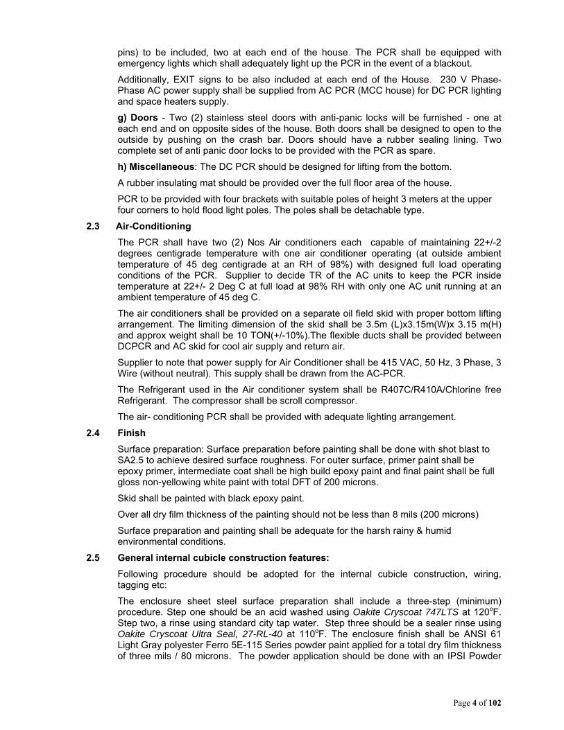
2.2 General construction features of DC-PCR:
a) Body / House - The DC power control room should be an outdoor type, weather proof, transportable steel housing with self-supporting skid suitable for onshore oil field application and should not be weighing more than the limiting Dimensions above.
DC PCR house columns and ceiling frame to be constructed from structural steel seam welded. The outside shall be fabricated from twelve-gauge sheet steel. All corners are to be formed by bending, leaving no sheet edge exposed. Roof of the PCR should have proper slopes so that no water logging takes place during rainy season. The entire body of the PCR should be contained within the skid (without any extension out of the base skid).
The roof of the PCR house shall be plain, without any protrusion. This is necessary for transportation of the PCR.
b) Skid –
The Skid design shall incorporate at least 4(four) longitudinal channels with two mid channels kept sufficiently apart so that the unit can be placed evenly on narrow trailers (general width of trailers 2.4 to 2.6 meters only) with proper load distribution & balancing. Each longitudinal channel of a skid shall be of single length and shall have smooth finish underneath and curve finish at both the end, so that the skid can roll over smoothly on surfaces/truck body without any obstruction.
The skid so designed should be sufficiently strong and properly welded at joints and should be able to withstand shocks while being handled and transported over rough and slushy roads/locations. Height of the joint used for the longitudinal members should be minimum 20 cm. Sufficient provision should be available at both ends for lifting the entire PCR (bottom lift arrangement).
The skid shall be properly prepared, and painted with black coal tar epoxy paint with a final thickness of about 200 microns.
c) Thermal Insulation - Three of the PCR walls should be thermally insulated with three-inch thick polystyrene block insulation. Insulation of any other technology may also be acceptable, provided the insulating properties are same as polystyrene. The inside surface of the walls will be finished with a sandwich style insulating board three eight’s of an inch thick with white pebble coating on the interior side and aluminum foil on the exterior side.
d) Panel line up shall be provided in center. All components of the panels should be accessible from the front of the panels and bus bars should be accessible from back side of the panels, if required for maintenance.
e) Plug Panel - Plug panel for the Generator and DC motor cables to be provided on the front end plug panel (facing the DW). In case it is difficult to provide generator plug panel on front end then standard arrangement of supplier i.e. generator plug panel recessed type on the side facing power packs can be provided but height of such plug panel should be around 1.5 mtrs from bottom of the PCR. The Plug Panel(s) should feature shutter or doors which can be closed/opened smoothly with all the cables plugged in, during normal running condition to avoid ingress of water inside the plug panels due to rain. Suitable fluorescent lighting fixtures should be provided for plug panel(s) lighting.
The PCR should have a recessed panel on the rear end to feed electrical equipments mounted on the AC/PCR such as the primary side of the transformers and other electrical equipments as required. Plug Panel for 4 x 20 core cable interconnection with AC PCR to be provided on the front end (DW end).
f) Indoor Lighting – Fluorescent /CFL/LED lighting fixtures to be provided for aisle lighting. Four- 230 volt Phase – Phase duplex receptacles (suitable for Indian style plug
Page 4 of 102
pins) to be included, two at each end of the house. The PCR shall be equipped with emergency lights which shall adequately light up the PCR in the event of a blackout.
Additionally, EXIT signs to be also included at each end of the House. 230 V Phase-Phase AC power supply shall be supplied from AC PCR (MCC house) for DC PCR lighting and space heaters supply.
g) Doors - Two (2) stainless steel doors with anti-panic locks will be furnished - one at each end and on opposite sides of the house. Both doors shall be designed to open to the outside by pushing on the crash bar. Doors should have a rubber sealing lining. Two complete set of anti panic door locks to be provided with the PCR as spare.
h) Miscellaneous: The DC PCR should be designed for lifting from the bottom.
A rubber insulating mat should be provided over the full floor area of the house.
PCR to be provided with four brackets with suitable poles of height 3 meters at the upper four corners to hold flood light poles. The poles shall be detachable type.
2.3 Air-Conditioning
The PCR shall have two (2) Nos Air conditioners each capable of maintaining 22+/-2 degrees centigrade temperature with one air conditioner operating (at outside ambient temperature of 45 deg centigrade at an RH of 98%) with designed full load operating conditions of the PCR. Supplier to decide TR of the AC units to keep the PCR inside temperature at 22+/- 2 Deg C at full load at 98% RH with only one AC unit running at an ambient temperature of 45 deg C.
The air conditioners shall be provided on a separate oil field skid with proper bottom lifting arrangement. The limiting dimension of the skid shall be 3.5m (L)x3.15m(W)x 3.15 m(H) and approx weight shall be 10 TON(+/-10%).The flexible ducts shall be provided between DCPCR and AC skid for cool air supply and return air.
Supplier to note that power supply for Air Conditioner shall be 415 VAC, 50 Hz, 3 Phase, 3 Wire (without neutral). This supply shall be drawn from the AC-PCR.
The Refrigerant used in the Air conditioner system shall be R407C/R410A/Chlorine free Refrigerant. The compressor shall be scroll compressor.
The air- conditioning PCR shall be provided with adequate lighting arrangement.
2.4 Finish
Surface preparation: Surface preparation before painting shall be done with shot blast to SA2.5 to achieve desired surface roughness. For outer surface, primer paint shall be epoxy primer, intermediate coat shall be high build epoxy paint and final paint shall be full gloss non-yellowing white paint with total DFT of 200 microns.
Skid shall be painted with black epoxy paint.
Over all dry film thickness of the painting should not be less than 8 mils (200 microns)
Surface preparation and painting shall be adequate for the harsh rainy & humid environmental conditions.
2.5 General internal cubicle construction features:
Following procedure should be adopted for the internal cubicle construction, wiring, tagging etc:
The enclosure sheet steel surface preparation shall include a three-step (minimum) procedure. Step one should be an acid washed using Oakite Cryscoat 747LTS at 120oF. Step two, a rinse using standard city tap water. Step three should be a sealer rinse using Oakite Cryscoat Ultra Seal, 27-RL-40 at 110oF. The enclosure finish shall be ANSI 61 Light Gray polyester Ferro 5E-115 Series powder paint applied for a total dry film thickness of three mils / 80 microns. The powder application should be done with an IPSI Powder

Page 5 of 102
Coating Booth and Electrostatic “Nordson” Powder Spray Guns. The paint shall be oven cured at 400oF for 20 minutes.
External equipment identification nameplates, control and instrument identification plates and operating and warning instruction plates should be anodized aluminum with markings using a photographic etching process and to be attached with corrosion resistant self-tapping screws or rivets. Component tag characters to be minimum 5 mm high.
Wiring is to be done with ITT Surprenant Exane. (Exane insulation being an irradiation cross-linked polyolefin compound, thermosetting in nature; and rated for 120oC). Conductors are tinned copper, grouped in tied and secured bundles. The colour of insulation of all control wiring should be white or light grey. Wire within the cubicle is 1.5mm2 / 14 AWG minimum. Wire within guarded electronic enclosures may be sized to suit the lower current levels and higher wiring density often present in such devices. Wiring identification markers should appear at both ends of each wire which cannot be visually traced end to end. The wire numbers should correspond to numbers appearing on schematic drawings. All wiring to be routed to avoid sharp edges wherever possible and protected by bushings and/or auxiliary wrapping where it passes over sharp edges, through barriers and at service loops. All terminations should have margin to allow a minimum of one re-lugging operation.
Ring lugs to be used at all critical connections such as CT connections and main bus taps. Components, including modules and printed wiring boards to be connected using split lugs allowing removal of the device without removal of screws. No more than two wires or lugs to be attached under any one screw.
All terminal strips to have minimum 2 Nos spare terminals to accommodate any modification required during commissioning / operation.
Bus bars shall be of tinned copper. Hardware for all bus connections should be zinc plated and passivated hardware as per property class 8.8 and shall be provided with plain and spring washers with hex nuts as per standard design. All the bus bars should be marked with R, Y and B for ease in identification.
All items mounted in the cubicles should be accessible from the front and easy maintenance access should be available in the panels for removal and fitment of the items in the panels.
All the indication lamps should be high visibility LED type with LVGP (low voltage glow protection).
3.0 TECHNICAL DETAILS & SPECIFICATION:
The technical details & specifications covered under this part are broad technical details of the equipments required.
3.1 ENGINE / GENERATOR CONTROL PANEL (5 NOS).
3.1.1 Salient features of Engine / Generator controls :
The engine & generator control system should be suitable for 5 Nos. KATO/BHEL make 1430 KVA, 600V, 3-Phase, 50 Hz, 1000 RPM, 0.7 pf lag alternators, driven by Caterpillar D399 / 3512 engines / equivalent engines. Main bus bar to be designed for a minimum of 65 KA Fault current and it shall be able to take rated current continuously with simultaneous operation of all the drives and feeders.
Control panel should be suitable for engine provided with electrical actuator with 40 mA at no-load and 160 mA at full load extended up to 200 mA.
Control panel should be suitable for generator provided with electrical exciter field with excitation characteristics of 6 amps maximum current @ 125 VDC or 12 amps maximum current @ 63 VDC suitable for KATO/BHEL Alternators.
Power supply to exciter PCB (preferably identical to HGC part # P359T) shall be from a 600:0-120-240 VAC (at least 1.8 kVA) transformer.
Page 6 of 102
Control panel to have tinned plated insulated, copper bus bar of adequate design suitable for 600V AC application as per international standard. Connection leads from generator panel to the socket board should be of adequate size to carry 1500A continuous current.
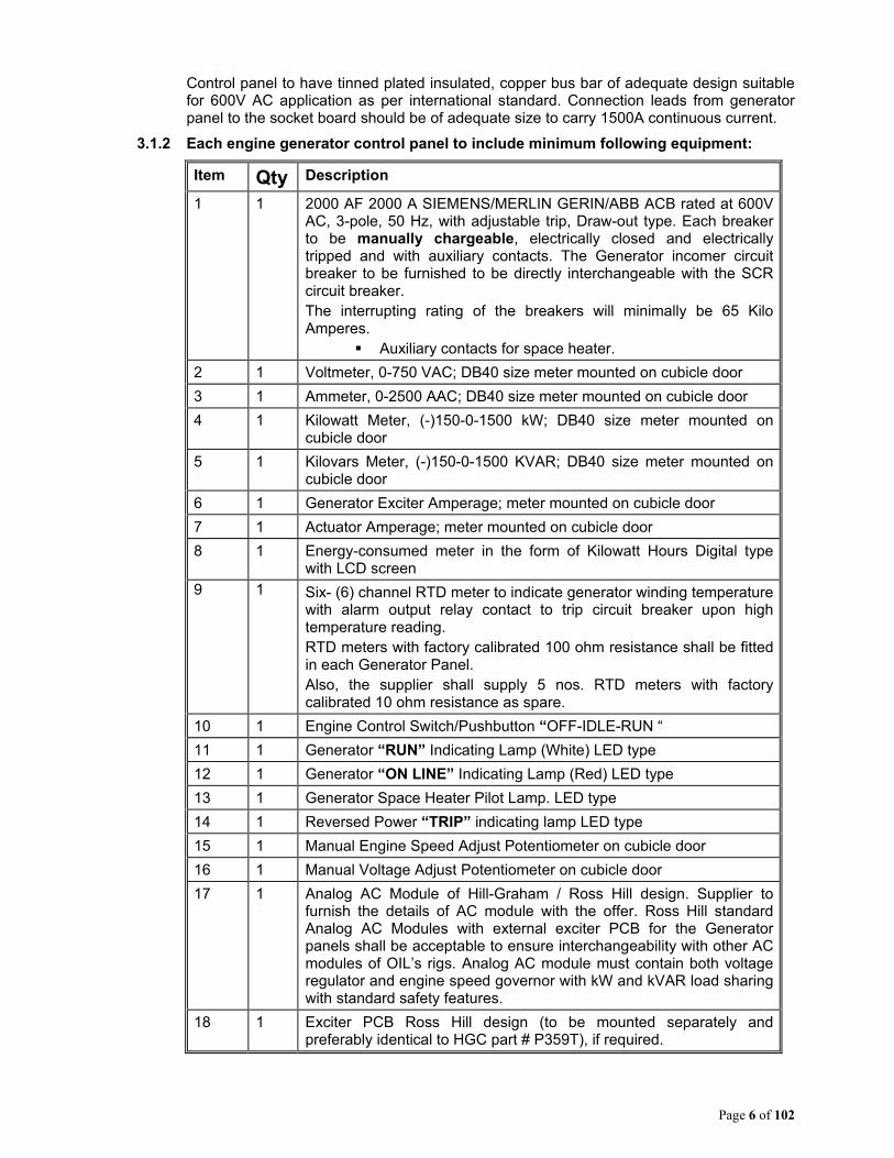
3.1.2 Each engine generator control panel to include minimum following equipment:
Item Qty Description
1 1 2000 AF 2000 A SIEMENS/MERLIN GERIN/ABB ACB rated at 600V AC, 3-pole, 50 Hz, with adjustable trip, Draw-out type. Each breaker to be manually chargeable, electrically closed and electrically tripped and with auxiliary contacts. The Generator incomer circuit breaker to be furnished to be directly interchangeable with the SCR circuit breaker. The interrupting rating of the breakers will minimally be 65 Kilo Amperes.
Auxiliary contacts for space heater.
2 1 Voltmeter, 0-750 VAC; DB40 size meter mounted on cubicle door
3 1 Ammeter, 0-2500 AAC; DB40 size meter mounted on cubicle door
4 1 Kilowatt Meter, (-)150-0-1500 kW; DB40 size meter mounted on cubicle door
5 1 Kilovars Meter, (-)150-0-1500 KVAR; DB40 size meter mounted on cubicle door
6 1 Generator Exciter Amperage; meter mounted on cubicle door
7 1 Actuator Amperage; meter mounted on cubicle door
8 1 Energy-consumed meter in the form of Kilowatt Hours Digital type with LCD screen
9 1 Six- (6) channel RTD meter to indicate generator winding temperature with alarm output relay contact to trip circuit breaker upon high temperature reading. RTD meters with factory calibrated 100 ohm resistance shall be fitted in each Generator Panel. Also, the supplier shall supply 5 nos. RTD meters with factory calibrated 10 ohm resistance as spare.
10 1 Engine Control Switch/Pushbutton “OFF-IDLE-RUN “
11 1 Generator “RUN” Indicating Lamp (White) LED type
12 1 Generator “ON LINE” Indicating Lamp (Red) LED type
13 1 Generator Space Heater Pilot Lamp. LED type
14 1 Reversed Power “TRIP” indicating lamp LED type
15 1 Manual Engine Speed Adjust Potentiometer on cubicle door
16 1 Manual Voltage Adjust Potentiometer on cubicle door
17 1 Analog AC Module of Hill-Graham / Ross Hill design. Supplier to furnish the details of AC module with the offer. Ross Hill standard Analog AC Modules with external exciter PCB for the Generator panels shall be acceptable to ensure interchangeability with other AC modules of OIL’s rigs. Analog AC module must contain both voltage regulator and engine speed governor with kW and kVAR load sharing with standard safety features.
18 1 Exciter PCB Ross Hill design (to be mounted separately and preferably identical to HGC part # P359T), if required.
Page 7 of 102
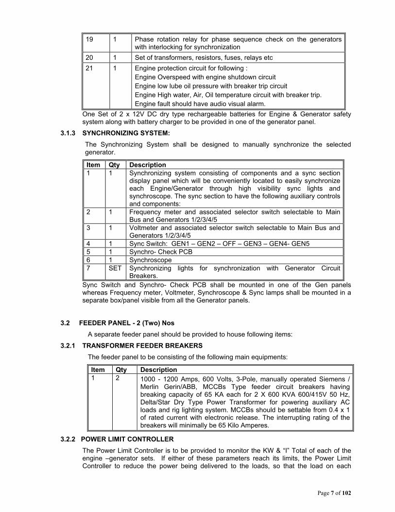
19 1 Phase rotation relay for phase sequence check on the generators with interlocking for synchronization
20 1 Set of transformers, resistors, fuses, relays etc
21 1 Engine protection circuit for following : Engine Overspeed with engine shutdown circuit Engine low lube oil pressure with breaker trip circuit Engine High water, Air, Oil temperature circuit with breaker trip. Engine fault should have audio visual alarm.
One Set of 2 x 12V DC dry type rechargeable batteries for Engine & Generator safety system along with battery charger to be provided in one of the generator panel.
3.1.3 SYNCHRONIZING SYSTEM:
The Synchronizing System shall be designed to manually synchronize the selected generator.
Item Qty Description 1 1 Synchronizing system consisting of components and a sync section
display panel which will be conveniently located to easily synchronize each Engine/Generator through high visibility sync lights and synchroscope. The sync section to have the following auxiliary controls and components:
2 1 Frequency meter and associated selector switch selectable to Main Bus and Generators 1/2/3/4/5
3 1 Voltmeter and associated selector switch selectable to Main Bus and Generators 1/2/3/4/5
4 1 Sync Switch: GEN1 – GEN2 – OFF – GEN3 – GEN4- GEN5 5 1 Synchro- Check PCB 6 1 Synchroscope 7 SET Synchronizing lights for synchronization with Generator Circuit
Breakers. Sync Switch and Synchro- Check PCB shall be mounted in one of the Gen panels whereas Frequency meter, Voltmeter, Synchroscope & Sync lamps shall be mounted in a separate box/panel visible from all the Generator panels.
3.2 FEEDER PANEL - 2 (Two) Nos
A separate feeder panel should be provided to house following items:
3.2.1 TRANSFORMER FEEDER BREAKERS
The feeder panel to be consisting of the following main equipments:
Item Qty Description 1 2 1000 - 1200 Amps, 600 Volts, 3-Pole, manually operated Siemens /
Merlin Gerin/ABB, MCCBs Type feeder circuit breakers having breaking capacity of 65 KA each for 2 X 600 KVA 600/415V 50 Hz, Delta/Star Dry Type Power Transformer for powering auxiliary AC loads and rig lighting system. MCCBs should be settable from 0.4 x 1 of rated current with electronic release. The interrupting rating of the breakers will minimally be 65 Kilo Amperes.
3.2.2 POWER LIMIT CONTROLLER
The Power Limit Controller is to be provided to monitor the KW & “I” Total of each of the engine –generator sets. If either of these parameters reach its limits, the Power Limit Controller to reduce the power being delivered to the loads, so that the load on each

Page 8 of 102
generator is held at its limit until the loads on the SCR drives are reduced (by other action) to a level below the generator limit. The Controller will allow for adjustment of each parameter independent of the other.
The range of adjustment will allow the Power Limit to be lowered to 80% or raised to 110%. The Controller will have built-in under-frequency circuitry, which shall keep the engines operating when sudden engine problems, such as bad fuel, may cause the engine to shutdown. A meter on the Drillers Console is to be provided to indicate percentage Power Limit. A warning lamp is illuminated on the Drillers Console at a load level just below the power limit.
3.2.3 HANDS-OFF CIRCUIT (HOC)
The HOC shall be designed to supply power for the engine actuator starting circuit, suitable for supplying CAT D399 / 3512 engines with an actuator current of 40-200 mA and the pulse pick-up circuit respectively in each of the AC generator control modules. The items to be included shall be as follows:
Item Qty Description 1 1 CPT fused on the primary and secondary. 2 1 Single-phase diode bridge. 3 1 Capacitive DC filter 4 1 Voltage clamping circuit. 5 2 12V Batteries dry rechargeable type 6 2 Circuit breakers—DC feeders.
3.2.4 GROUND FAULT DETECTOR CIRCUIT (in the 600 VAC Circuit):
Ground Fault detector circuit shall mainly consist of the following:
Item Qty Description
1 1 AC & DC Ground Fault detector PCB
2 3 AC ground detection lamps – One lamp per phase
3 1 600 VAC ground test button
4 1 AC/DC ground fault relay
5 1 Percent DC ground detection meter
6 1 Percent AC ground detection meter
Audio Alarm in PCR in addition to indication at Driller’s Console shall be provided for ground fault system.
Ground fault circuit should be of standard design of OEM connected to each phase and to the ground through individual phase lamp (filament type). In case of AC ground fault the phase which is grounded will have lower illumination in the lamp connected to that phase and in DC ground fault all the 3 lamps will glow brighter.
Any other better arrangement shall be acceptable if furnished with full details.
3.3 FEEDER BREAKER - 3 (Three) Nos:
Three nos. of AC Feeder breaker for supplying 600 VAC power to external drives from main bus shall be provided at a convenient location in the PCR for future provision of Third Mud Pump, Top drive and Power Factor improvement device respectively. The feeder breaker shall be as per following details.
Item Qty Description
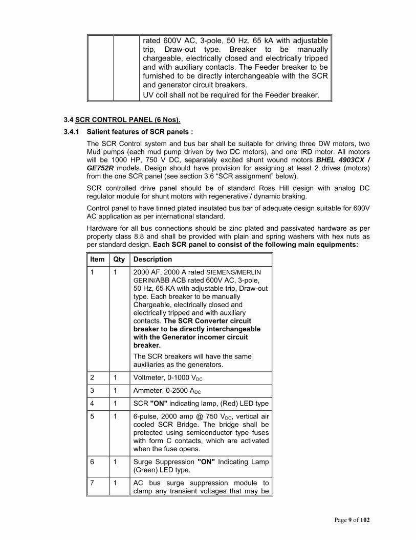
1 3 2000 AF 2000A SIEMENS/MERLIN GERIN/ABB ACB
Page 9 of 102
rated 600V AC, 3-pole, 50 Hz, 65 kA with adjustable trip, Draw-out type. Breaker to be manually chargeable, electrically closed and electrically tripped and with auxiliary contacts. The Feeder breaker to be furnished to be directly interchangeable with the SCR and generator circuit breakers. UV coil shall not be required for the Feeder breaker.
3.4 SCR CONTROL PANEL (6 Nos).
3.4.1 Salient features of SCR panels :
The SCR Control system and bus bar shall be suitable for driving three DW motors, two Mud pumps (each mud pump driven by two DC motors), and one IRD motor. All motors will be 1000 HP, 750 V DC, separately excited shunt wound motors BHEL 4903CX / GE752R models. Design should have provision for assigning at least 2 drives (motors) from the one SCR panel (see section 3.6 “SCR assignment” below).
SCR controlled drive panel should be of standard Ross Hill design with analog DC regulator module for shunt motors with regenerative / dynamic braking.
Control panel to have tinned plated insulated bus bar of adequate design suitable for 600V AC application as per international standard.
Hardware for all bus connections should be zinc plated and passivated hardware as per property class 8.8 and shall be provided with plain and spring washers with hex nuts as per standard design. Each SCR panel to consist of the following main equipments:
Item Qty Description
1 1 2000 AF, 2000 A rated SIEMENS/MERLIN GERIN/ABB ACB rated 600V AC, 3-pole, 50 Hz, 65 KA with adjustable trip, Draw-out type. Each breaker to be manually Chargeable, electrically closed and electrically tripped and with auxiliary contacts. The SCR Converter circuit breaker to be directly interchangeable with the Generator incomer circuit breaker.
The SCR breakers will have the same auxiliaries as the generators.
2 1 Voltmeter, 0-1000 VDC
3 1 Ammeter, 0-2500 ADC
4 1 SCR "ON" indicating lamp, (Red) LED type
5 1 6-pulse, 2000 amp @ 750 VDC, vertical air cooled SCR Bridge. The bridge shall be protected using semiconductor type fuses with form C contacts, which are activated when the fuse opens.
6 1 Surge Suppression "ON" Indicating Lamp (Green) LED type.
7 1 AC bus surge suppression module to clamp any transient voltages that may be

Page 10 of 102
damaging to the SCR devices. The surge suppressor to consist of a fused enclosure of metal oxide varistors (MOVs). Each SCR panel should have individual surge suppression MOVs connected in Delta mode.
8 1 Set of DC assignment contactors. DC assignment contactors should be suitable to break full load current at rated power. GE Series IC2800 or Siemens Type 700 contactors shall be provided. Supplier to furnish full details of the proposed contactors.
9 1 Cubicle Space Heater. (To be “ON” when SCR is not in operation.)
10 1 Analog DC Module of Ross Hill design for shunt motors and regenerative braking for firing control of the SCR drive. Full details of analog DC modules to be furnished along with the offer.
11 1 3 phase 600 V AC twin blower for cooling of the SCR bridges. The motor is to be started with a manually operated switch and SCR should be assignable only if the blower is running. In case blower failure takes place during SCR working, SCR breaker to trip.
The rating of the blower must be adequate for proper cooling of the SCR bridge. Bidder to mention the rating of the blower motor with the offer.
12 1 One logic indicator PCB with LED to show the flow of -14V signal in the assignment circuit of the SCR drive
Armature reversing feature should be available in the system for the DWA, DWB, DWC & IRD motors.
Cutler Hammer/NOV/Siemens or equivalent make reversing contactor to be used in the SCR panels for DWA, DWB, DWC & IRD motors reversing.
Field interlocks such as field loss contacts etc to be included in the system design so that assignment cannot be completed in case field loss relay does not pick-up.
Drive / assignment fault alarm should be available in the DC PCR with external electrical HOOTER.
3.4.2 Draw works Braking
a) Regenerative Braking - The system shall be designed to provide regenerative braking facility on DWA & DWB motors to slow the Draw works motors from full speed to a preset cathead speed within 10 to 15 seconds after the foot throttle is released. The power generated by the freewheeling DC motors is to be fed back into the 600 volt bus and absorbed by the engine-generator sets that are on line. During normal operation of the Draw works the regenerative brake should be non-operative. If, at any time, the
Page 11 of 102
motor speed is higher than the DW throttle setting and the foot throttle is not in use and no DW clutch is engaged (to be achieved through high & low clutch pressure switches in Driller’s Console), the brake circuit to engage and reduce the motor speed to the hand throttle setting.
There should be maximum current limit feature in the DC Module to prevent over speeding of the engine-generator set during re-generative mode. Controls shall ensure that change over of Forward-Reverse Contactors from Forward to reverse and vice-versa & assignment contactors On-OFF-On take place at Zero current.
b) Dynamic Braking - Alternatively, system may be designed with dynamic braking (Resistor bank based), in which case, bidder to quote for the Resistor Bank (forced Cooled), as well as Brake control panel (If required), and all accessories.
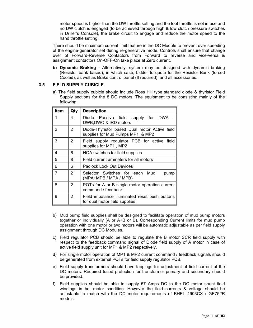
3.5 FIELD SUPPLY CUBICLE
a) The field supply cubicle should include Ross Hill type standard diode & thyristor Field Supply sections for the 8 DC motors. The equipment to be consisting mainly of the following:
Item Qty Description
1 4 Diode Passive field supply for DWA , DWB,DWC & IRD motors
2 2 Diode-Thyristor based Dual motor Active field supplies for Mud Pumps MP1 & MP2
3 2 Field supply regulator PCB for active field supplies for MP1 , MP2
4 6 HOA switches for field supplies
5 8 Field current ammeters for all motors
6 6 Padlock Lock Out Devices
7 2 Selector Switches for each Mud pump (MPA+MPB / MPA / MPB)
8 2 POTs for A or B single motor operation current command / feedback
9 2 Field imbalance illuminated reset push buttons for dual motor field supplies
b) Mud pump field supplies shall be designed to facilitate operation of mud pump motors together or individually (A or A+B or B). Corresponding Current limits for mud pump operation with one motor or two motors will be automatic adjustable as per field supply assignment through DC Modules.
c) Field regulator PCB should be able to regulate the B motor SCR field supply with respect to the feedback command signal of Diode field supply of A motor in case of active field supply unit for MP1 & MP2 respectively.
d) For single motor operation of MP1 & MP2 current command / feedback signals should be generated from external POTs for field supply regulator PCB.
e) Field supply transformers should have tappings for adjustment of field current of the DC motors. Required fused protection for transformer primary and secondary should be provided.
f) Field supplies should be able to supply 57 Amps DC to the DC motor shunt field windings in hot motor condition. However the field currents & voltage should be adjustable to match with the DC motor requirements of BHEL 4903CX / GE752R models.
Page 12 of 102
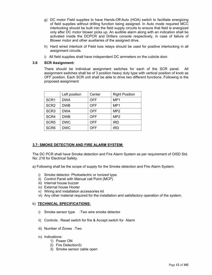
g) DC motor Field supplies to have Hands-Off-Auto (HOA) switch to facilitate energizing of field supplies without drilling function being assigned. In Auto mode required MCC interlocking should be built into the field supply circuits to ensure that field is energized only after DC motor blower picks up. An audible alarm along with an indication shall be activated inside the DCPCR and Drillers console respectively, in case of failure of Blower motor and other auxiliaries of the assigned drive.
h) Hard wired interlock of Field loss relays should be used for positive interlocking in all assignment circuits.
i) All field supplies shall have independent DC ammeters on the cubicle door.
3.6 SCR Assignment:
There should be individual assignment switches for each of the SCR panel. All assignment switches shall be of 3 position heavy duty type with vertical position of knob as OFF position. Each SCR unit shall be able to drive two different functions. Following is the proposed assignment:
Left position Center Right Position
SCR1 DWA OFF MP1
SCR2 DWB OFF MP1
SCR3 DWA OFF MP2
SCR4 DWB OFF MP2
SCR5 DWC OFF IRD
SCR6 DWC OFF IRD
3.7: SMOKE DETECTION AND FIRE ALARM SYSTEM:
The DC PCR shall have Smoke detection and Fire Alarm System as per requirement of OISD Std. No: 216 for Electrical Safety. a) Following shall be the scope of supply for the Smoke detection and Fire Alarm System:
i) Smoke detector: Photoelectric or Ionized type. ii) Control Panel with Manual call Point (MCP) iii) Internal house buzzer iv) External house Hooter v) Wiring and installation accessories kit vi) Any other material required for the installation and satisfactory operation of the system.
b) TECHNICAL SPECIFICATIONS:
i) Smoke sensor type :Two wire smoke detector
ii) Controls : Reset switch for fire & Accept switch for Alarm
iii) Number of Zones :Two
iv) Indications: 1) Power ON 2) Fire Detection3) 3) Smoke sensor cable open
Page 13 of 102
4) Smoke sensor cable short
v) Operating supply: 230VAC, 50Hz supply
vi) Internal House buzzer: Size 96x96mm, 80 dB at 1 m
vii) External Hooter : Min 100 dB at 1 m
c) Location of Smoke detectors shall be 2 on front side of the panels and 2 on the rear side of the panels at accessible locations. Smoke detectors shall preferably be mounted on the ceiling of the PCRs or at any other location inside the house. d) Control panel along with internal house buzzer & manual call point control shall be installed near entry/exit door. External house hooter shall be installed at the outside of the house facing derrick side. All wiring inside the house should be properly dressed and routed through conduits / cable trays.
3.8 EXTERNAL CONNECTIONS:
The rig external connections from the DC PCR to different loads and drives should be through easily removable type plug & receptacles and following should be taken care of in the design:
3.8.1 External power connections to Alternators, Top drive feeder, Power Factor Improvement Device, Mud pump feeder and Transformers in AC PCR and DC motor power connection to be done through single pole Pyle National make power plug & sockets of suitable rating. Plugs & sockets (crimped type) should be suitable to accommodate 300 sq mm flexible copper cable with built-up conductor dia of 26 mm & OD of 35 mm (+/-1 mm). The alternator socket board should be provided with adequate nos. of sockets per phase to carry 1500 A continuous current per phase.
3.8.2 Each of the actuator & MPU signals shall be through two separate 1.5 sq mm x 4 core cables. The exciter field supply, RTD and engine protection circuits shall be connected through a 2.5 sq mm x 20 core cable. Space heater connection for Alternators shall be through MCBs in the distribution panel. The pin configuration for 20 core cable Alternator control connections is enclosed as Annexure-1. Pyle National make star line plugs & sockets (crimped type) should be used for Generator control connections for 3 core & 20 core cables.
3.8.3 Exclusive 20 Pin plugs & sockets to be provided for shunt fields of DC motors & control connections. The DC motor field supplies to run through 2 x 6 cores of 2.5 sq mm x 20 core cable. Space heater connections, air flow switch & lock out switch connections to the DC motors shall also be through this 20 core cable. The pin configuration for 20 core cable for DC motor control connections is enclosed as Annexure – 2. Space heater connection for DC motors shall be through MCBs in the distribution panel. Pyle National - Star Line make plugs & sockets (crimped type) should be used for Motor control connections for 20 conductor cables.
3.8.4 All control interconnections for AC PCR shall be through 2.5 sq mm x 20 core cables. Pyle National - Star Line make plugs & sockets (crimped type) should be used for interconnections for 20 core cables.
3.8.5 The Plug Panel(s) should feature shutter or doors which can be closed/opened smoothly with all the cables plugged in, during normal running condition to avoid ingress of water inside the plug panels due to rain.
3.8.6 Suitable lighting fixtures should be provided for plug panel(s) lighting.

Page 14 of 102
3.8.7 To avoid damage due to sharp bend and injury to the cable due to its self weight, sockets should be mounted on socket board of slant stair case design.
3.8.8 Earthing cable from earth bus bar should be brought out up to the socket board for termination at the earth pit.
3.8.9 Sufficient redundancy should be provided in sockets consisting of each ratings by quantity proportion and at least one for each rating. PCR socket board to have extra socket holes of each rating with blank covers for use to meet exigency.
3.8.10 Air-conditioner incomer supply from AC PCR shall be through a 4-pin 100 Amps Appleton plug & socket. DC PCR lighting & space heater supply from AC PCR shall be through a 4 pin 60 Amps Appleton Plug & socket.
3.8.11 10% extra plug and sockets of each type & rating shall be supplied as loose spare items by the supplier with minimum 1 No. of each type. Supplier to furnish list of plugs & sockets used and spare qty supplied. This should be finally included in the 2 years spares list by supplier.
3.8.12 Oil India shall supply all external cables except the PLC communication cables for Driller Console & MP Console. PLC communication cable of 120 meter length for Driller’s Console and 30 meter length for Mud Pump Console shall be in supplier scope and to be supplied with the DC PCR. One PLC cable each of the above lengths should be supplied as spare for both Drillers console and mud pump console. Suitable repeaters for the PLC cable shall be incorporated in the design for effective transmission of signal over a long distance. The termination of all external cables to the loose plugs & sockets supplied by the supplier shall be the responsibility of Oil India. The outside diameters of cables for Plug grommet sizing is furnished by Oil India in respective Annexure.
3.9 SPACE HEATERS
The space heater supplies to be suitable for 500 W, 230 VAC rating of the space heaters. Space heaters shall be powered through 230 V AC Phase-Phase 3 wire supply from AC PCR (MCC house).
Space heater connections shall be required for all Eight DC motors & five alternators and to be provided through the 2 Pole MCBs in the distribution panel. DC motor space heaters will remain energized, if DC motor blower is not operational. Alternator space heaters to remain energized, if Alternator is not operational.
All cubicles shall have their independent space heaters.
Any other method proposed by supplier for supply of Space heaters meeting the functional requirement can be accepted, if full details are provided by supplier.
3.10 PLC CONTROL PANEL:
3.10.1 The programmable logic control panel has to perform the following functions for over all SCR control, inter lock with accessories and monitoring.
The System Host PLC shall be a high speed, versatile modular PLC. The PLC to be used shall be suitable for serial communication with remote consoles and other rig components and devices.
3.10.2 The PLC shall incorporate the SCR bridge assignment logic.
The PLC system shall have provision for twisted pair cable for communication with the remote Racks in Driller & MP Console. A signal repeater shall also be provided in the design. The controls including PLC shall be suitable for a cable length of up to 120 meters form DC/PCR to Driller Console to meet cluster drilling requirement.
The PLC shall have provisions for interfacing with the LAN. Interface with controls and indicators of the driller’s console shall be via the field I/O units. PLC shall provide status, alarm and diagnostic tools via local annunciation functions. PLC will provide automatic
Page 15 of 102
starting of Mud Pump and Draw works auxiliaries with indicating lights on console. The supercharger pumps shall be started & stopped manually from Driller’s Console.
There is no remote PLC in the AC/PCR for MCC interlocking for the DC motor control logics. All PLC relay inputs/outputs for auto starting of DC motor auxiliaries and alarm functions through MCC in AC PCR should have interface relays in PLC cubicle with adequate contact ratings.
Fault storage facility should be available through the PLC in the system with built-in self diagnostic features.
3.10.3 Touch Screen Display - PLC shall have touch screen for all miscellaneous indications for all generators & all SCR panels, indications for various drives, ground faults, power limits, Driller assignment, Hour meter, current & voltage metering, trending of historic data & faults etc. See Clause 3.9.6 (below) for full details.
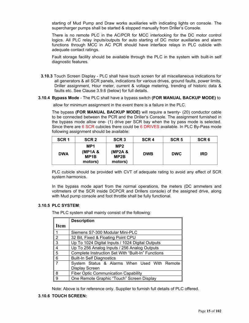
3.10.4 Bypass Mode - The PLC shall have a bypass switch (FOR MANUAL BACKUP MODE) to
allow for minimum assignment in the event there is a failure in the PLC.
The bypass (FOR MANUAL BACKUP MODE) will require a twenty- (20) conductor cable to be connected between the PCR and the Driller’s Console. The assignment furnished in the bypass mode allow one- (1) drive per SCR bay when the by pass mode is selected. Since there are 6 SCR cubicles there could be 6 DRIVES available. In PLC By-Pass mode following assignment should be available:
SCR 1 SCR 2 SCR 3 SCR 4 SCR 5 SCR 6
DWA
MP1 (MP1A &
MP1B motors)
MP2 (MP2A &
MP2B motors)
DWB DWC IRD
PLC cubicle should be provided with CVT of adequate rating to avoid any effect of SCR system harmonics.
In the bypass mode apart from the normal operations, the meters (DC ammeters and voltmeters of the SCR inside DCPCR and Drillers console) of the assigned drive, along with Mud pump console and foot throttle shall be fully functional.
3.10.5 PLC SYSTEM:
The PLC system shall mainly consist of the following:
Item Description
1 Siemens S7-300 Modular Mini-PLC 2 32 Bit, Fixed & Floating Point CPU 3 Up To 1024 Digital Inputs / 1024 Digital Outputs 4 Up To 256 Analog Inputs / 256 Analog Outputs 5 Complete Instruction Set With “Built-In” Functions 6 Built-In Self Diagnostics 7 System Status & Alarms When Used With Remote
Display Screen 8 Fiber Optic Communication Capability 9 One Remote Graphic “Touch” Screen Display
Note: Above is for reference only. Supplier to furnish full details of PLC offered.
3.10.6 TOUCH SCREEN:

Page 16 of 102
A touch screen / soft button display screen shall be provided in the PLC cubicle / Field supply cubicle. The following represents data to be displayed preferably on multiple screens.
MISCELLANEOUS INDICATORS
PLC System Communication OK Generator ON (For each Generator) Ground Fault Power Limit Driller Console Assignment.
SCR INDICATORS (To be repeated for each SCR panel) SCR ON Bridge Temp Switch B A Blown Fuse Bridge Current Gauge B Blown Fuse Bridge Volts Gauge C Blown Fuse Speed Reference Contactor Assignments % Power Limit MUD PUMP INDICATORS (To be repeated for each Pump-2 Nos.) MP 1 Field ON MP 1 Lube pump ON MP 1 (both A & B motors) Blower ON MP 1 Liner Wash ON Charging Pump 1 ON MP1 A Armature Current MP1 B Armature Current MP1 A Field current MP1 B Field current
DRAWWORKS INDICATORS (Repeated for Each Motor-3 Nos.)
DW Field ON DW Field current
DW Blower ON DW Lube pump ON DW Armature current
IRD INDICATORS
IRD Field ON IRD Field current
IRD Blower ON IRD Lube pump ON IRD Armature current
GENERATOR CUBICLE INDICATORS (Repeated for each Generator Cubicle)
Running Hours for Power pack 3.11. DRILLER CONSOLE:
3.11.1 Driller Console construction :

Page 17 of 102
The Driller’s Console to be a pressurized stainless steel enclosure, constructed suitably for installation in Class 1, Division 2 (IEC Zone 2) locations as per International standard.
The console should be constructed of 12 gauge No. 304 stainless steel and the hand throttle wheels of solid stainless steel. Each hand wheel will drive two (2) independent potentiometers to provide 100% backup of the throttle function. The console should be water tight and include a gasketed door.
a) Continuous Purging - The console should be equipped with approved purging for application in a Class I Division 2, Group D Hazardous area. A rig air supply fitting (1/4" BSP male threads) will be provided for connection to an external 85 to 150 PSI rig air supply. As rig air supply is normally contaminated (with moisture and oil) an air drier and filter assembly shall be supplied along with the driller console separately. An internal pressure regulator in the console is to be provided to maintain the internal pressure of the Console.
b) The console to have the following standard equipment and features:
Item Qty Description
1 6 Assignment Switches SCR 1-6
2 1 Rotary Table Current Limit POT
3 2 Draw works Speed Control (Hand throttle)/IRD Speed control (Hand throttle)
4 4 Draw works Switch "FWD-OFF-REV"/ IRD Switch "FWD-OFF-REV"
5 2 Mud Pump Speed Controls (Hand throttle)
6 2 MUD PUMP “On-Off” selector switch
7 2 Super charger “Start-Stop” selector/ pushbutton switch
8 1 Mud Pump Console / Driller’s Console selector switch
9 1 “E” Stop Push button # 1 – Shuts off all drives. Should be fitted with a cover / flap to prevent accidental activation.
10 1 “E” Stop Push Button # 2 – Shuts off all Generators. Should be fitted with a cover / flap to prevent accidental activation.
11 1 Alarm Silence spring return switch
12 1 Lamp test spring return switch
13 1 PLC “BYPASS” Switch
14 1 RT Override Push Button
15 1 Power Limit Meter 0-100%
16 5 Generator “ON” Lamps (Red)
17 6 SCR “ON” Lamps (Green)
18 4 Draw works DWA , DWB &DWC Blower “ON” Lamp (Red) */IRD Blower ON
19 1 Draw works lube pump “ON” Lamp (Red)
20 1 IRD “ON” Lamp - Red
21 2 Mud Pump Auxiliaries “ON” Lamps (Red) *

Page 18 of 102
22 2 Super Charger “On” Lamp (Red)
23 1 Power Limit Lamp (Amber)
24 1 Console Purge Loss Lamp (Amber) *
25 1 Ground fault lamp (Yellow)
26 1 Audible alarm activated for items marked (*)
27 Lot Plugs & receptacles for console connection
28 6 DC Current Meters for amperage of Drilling motors (MP1, MP2,DWA, DWB, DWC & IRD) 0-2000 A
29 1 RT Torque meter
30 1 Set of relays, fuses, sockets etc
31 1 PLC remote rack
32 1 DW / RT Clutch pressure switch
33 2 DW Hi / Low clutch pressure switches.
34 1 set IRD controls including hand throttle
Note: Any other item required for Driller Console as per system design to be included by supplier.
c) Control circuit shall be designed so that Super Chargers can be made operational irrespective of mud pumps assignment. Mud pumps can be made operational without working of super chargers.
d) Emergency Stop Push-Buttons - The “E” STOP PB# 1 will trip all SCR breakers and will cut off the power to the console. All DC motor blowers and IRD/Draw-works/MP auxiliaries also should stop. The “E” STOP PB# 2 will trip all Generator Breakers, and cut off total Electrical Power supply to the Rig. Both the “E” STOP push buttons shall be hard wired and fully operational in the PLC BYPASS mode.
e) PLC “Bypass” mode - When PLC Bypass mode is selected one dedicated SCR for one DC motor shall be available. The assignment to be provided is one (1) motor per SCR bay. Since there will be 6 SCR cubicles there could be 6 drives available for emergency operation in manual mode. In the bypass mode apart from normal operation the meters (DC ammeters and voltmeters of the SCR inside DCPCR and Drillers console) of the assigned drive, along with Mud pump console and foot throttle should be fully functional.
f) Provision for Running RT from DW – The RT may be run from DW, in case of failure of RT drive or any other reason. The DW / RT selection should be through a Pressure switch in the Driller Console. Pressure switch to pick-up when driller operates Rotary Clutch as per standard Ross Hill design. There should be separate pressure switches for Hi & Lo clutch engagement sensing and regenerative brake should operate only when no clutch is engaged.
3.11.2 Driller's Foot throttle
The foot-throttle to be manufactured of 12 gauge No. 304 stainless steel throughout, built to withstand the environment normally encountered on the rig floor. It should contain dual stainless steel return springs to provide a fail-safe return to the off position in the event of the single spring failure. Provisions for a dry air connection to the electrical compartment are to be included. The foot throttle connects directly to the Driller’s console through a three-conductor cable. A spare plug is to be provided with the foot throttle. The foot throttle shall be fully functional in the PLC BYPASS mode

Page 19 of 102
3.12 MUD PUMP CONSOLE:
3.12.1 The mud pump console should be manufactured of 12 gauge No.304 stainless steel and the hand throttle wheels of solid stainless steel. Each hand throttle will drive two (2) independent potentiometers to provide 100% backup of the throttle function. The console will be watertight and include a gasketed door. Purging is not required as MP console will be placed in a safe area.
The console shall include the following main controls and indicators:
Qty Description 2 Mud Pump Speed Controls Hand Throttle 2 Mud Pump "ON-OFF" Switches 2 Mud Pump "ON" Indicating Lamps (Green)
2 Mud Pump DC Current meter 0-2000A
1 PLC remote rack
Lot Plugs & receptacles for console connection
Note: Any other item required for MP Console as per system design to be included by supplier.
It should be possible to run mud pumps up to full speed through MP Console. Operation through MP Console should be possible only if MPC / Driller’s Console switch at Driller Console is in MPC mode.
4.0 SPARES, TOOLS & TACKLES:
Following tools, tackles & spares to be supplied by Bidder; other than specified against any specific clause earlier in this document.
4.1 TOOLS & TACKLES :
Qty Description
SURVIVAL KIT CONSISTING OF THE FOLLOWING -
2 Pyle-National Plug and Receptacle Crimping Tools
1 Hydraulic Crimping Tool for Generator and DC Motor 300 sq mm cables
1 Tool Box with Hand Tools applicable to a rig up
1 Laptop with Windows 10 or later with software for programming the PLC
1 PLC-SIE, Software for PLC with license
2 PLC-SIE, Cable/Adptr, USB, PMB
1 Fluke Multi-meter model 175
1 Secondary injection test kit for Gen/SCR/Top Drive/Transformer feeder breakers
1 Jigsaw
1 25 Piece Jigsaw Blade Kit
1 300 sq mm Cable Cutter
1 Set of Pyle-National Pin Extraction/Insertion Tool Kit
2 Taparia Box wrench set
Page 20 of 102
1 Hand drill machine,800 Watt,Bosch
2 Anti panic door locks
1 Megger MIT 300 IR tester
1 Force 4941 94PC 1/2" & 1/4" SOCKET SET & SCREWDRIVER BIT TORX RATCHET DRIVER CASE TOOL KIT
NOTE: The laptop will have the PLC program software installed along with the PLC system logics program. Appropriate storage (CD / Flash Media) with the required software (s) also to be supplied loose. All software’s supplied shall be original and licensed to OIL India without expiration date. No trial version/evaluation /shareware copy of the software will be accepted.
4.2 COMMISSIONING AND OTHER RELATED SPARES
The following list of spares to be supplied with the PCR
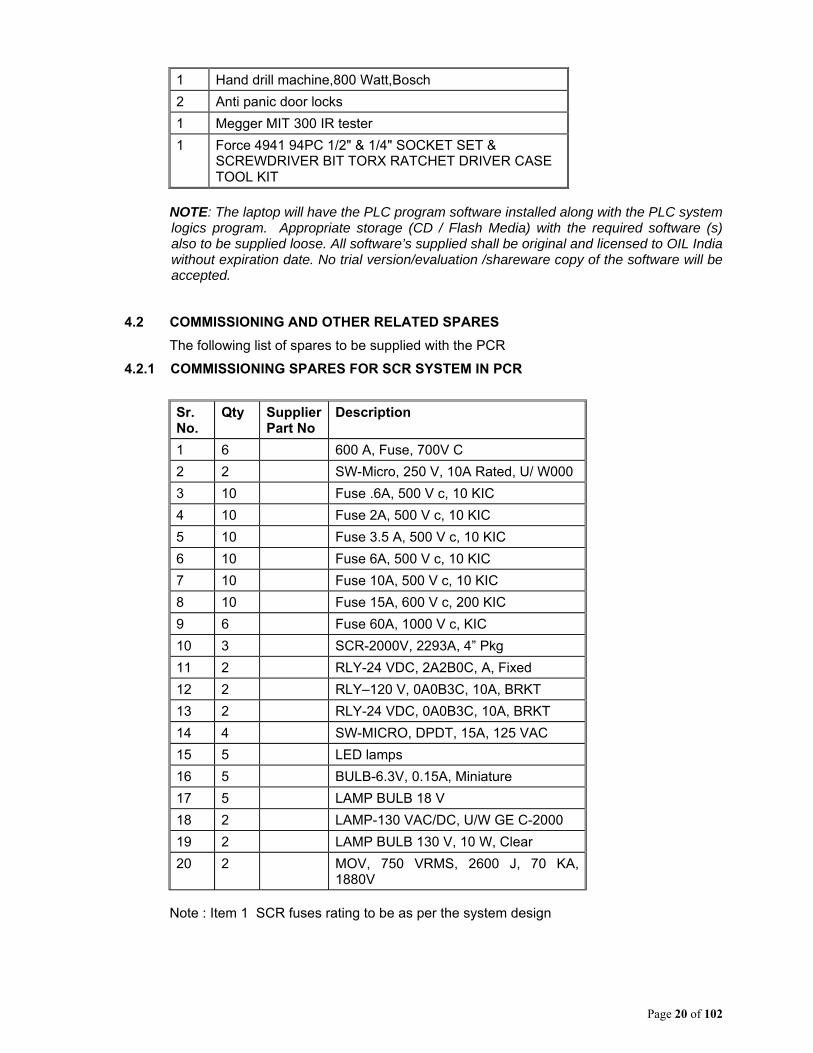
4.2.1 COMMISSIONING SPARES FOR SCR SYSTEM IN PCR
Sr. No.
Qty Supplier Part No
Description
1 6 600 A, Fuse, 700V C
2 2 SW-Micro, 250 V, 10A Rated, U/ W000
3 10 Fuse .6A, 500 V c, 10 KIC
4 10 Fuse 2A, 500 V c, 10 KIC
5 10 Fuse 3.5 A, 500 V c, 10 KIC
6 10 Fuse 6A, 500 V c, 10 KIC
7 10 Fuse 10A, 500 V c, 10 KIC
8 10 Fuse 15A, 600 V c, 200 KIC
9 6 Fuse 60A, 1000 V c, KIC
10 3 SCR-2000V, 2293A, 4” Pkg
11 2 RLY-24 VDC, 2A2B0C, A, Fixed
12 2 RLY–120 V, 0A0B3C, 10A, BRKT
13 2 RLY-24 VDC, 0A0B3C, 10A, BRKT
14 4 SW-MICRO, DPDT, 15A, 125 VAC
15 5 LED lamps
16 5 BULB-6.3V, 0.15A, Miniature
17 5 LAMP BULB 18 V
18 2 LAMP-130 VAC/DC, U/W GE C-2000
19 2 LAMP BULB 130 V, 10 W, Clear
20 2 MOV, 750 VRMS, 2600 J, 70 KA, 1880V
Note : Item 1 SCR fuses rating to be as per the system design

Page 21 of 102
4.2.2 SPARES FOR SCR SYSTEM IN PCR (Please insert supplier part #)
Sr. No. Qty Supplier Part No
Description
1 2 Module-AC, For generator panel
2 2 Module-DC, for SCR panel
3 2 Diode for passive field supply
4 2 Thyristor for active field supply
5 1 Exciter field supply transformer
6 1 sets Control transformers (1 each) all type
7 2 DC Contactors for SCR
8 1 sets Relays ( 1 each type)
9 2 Switch 3 position for Generator control
10 1 sets Indicating meters DB40 (1 each type)
11 1 Phase rotation relay for generator panel
12 2 Syncronising Switch
13 6 600 A, Fuse, 700V
14 3 SW-Micro, 250 V, 10A Rated, U/ W000
15 20 Fuse .6A, 500 V c, 10 KIC
16 20 Fuse 2A, 500 V c, 10 KIC
17 20 Fuse 3.5 A, 500 V c, 10 KIC
18 20 Fuse 6A, 500 V c, 10 KIC
19 20 Fuse 10A, 500 V c, 10 KIC
20 20 Fuse 15A, 600 V c, 200 KIC
21 10 Fuse 60A, 1000 V c, KIC
22 4 SCR-2000V, 2293A, 4” Pkg
23 2 RLY-120VAC, 4A0B0C, 10A, IEC D
24 2 RLY-120VAC, 0A0B4C, 1A, Bifur
25 2 RLY-24VDC, 2A2B0C, 10A, IEC
26 4 SW-MICRO, DPDT, 15A, 125 VAC
27 1 BLWR-G/3B, 600V, 3PH, 2. HP, 50 HZ
28 10 LED lamps
29 10 BULB-6.3V, 0.15A, Miniature
30 5 LAMP BULB 18 V
31 5 LAMP-130VAC/DC, U/W GE C-2000
32 5 LAMP BULB 130 V, 10 W, Clear
33 2 MOV, 750 VRMS, 2600 J, 70 KA, 1880V
34 1 PCA PWR LIM CTRL
35 1 PC-DC SLIDE FOR SCR panel
36 1 ASSY-GND Leakage Detector
37 2 PC Auctioneering CKT BD

Page 22 of 102
38 2 PC Generator Exciter BD
39 2 PC Voltage feedback
40 2 PC solid state relay ckt board
41 2 PC Field supply regulator for MP1-2
42 3 CABLE-ASSY, Profibus, 120 mtr.
43 1 1000 Amps, 600 Volts, 3-Pole, manually operated MCCBs used in transformer feeder panel
44 2 CB-1600AF/AT 690VAC, 65KIC, one for Gen & one for SCR panels.
45 1 CB-1000-1200AF/AT 690VAC, 65KIC
46 1 CB-UVR (YU), 24VDC
47 1 CB-Shunt Closing Release
48 1 CB-Charging Motor, 120VDC
49 2 set PLC Power supply ( 1 each type)
50 2 PLC Processor card
51 2 PLC interface card
52 2 sets PLC I/O Cards
53 1 set 10% spare plug and receptacles
54 4 Spare RTD temp scanner for PT-100 4.2.3.: Spares for SMOKE DETECTION AND FIRE ALARM SYSTEM:
Sr. No. Qty Supplier Part No
Description
1 2 nos Smoke detector ( Photoelectric or Ionized type)
2 1 no Internal house buzzer
3 1 no External house Hooter
4 1 set Any other Spares/ Accessories of Control Panel
4.2.4 SPARES FOR DRILLER CONSOLE
Item DESCRIPTION Supplier Pt No
QTY.
1 Hand Throttle, Potentiometers, RTI limit Pot
1 set
2 SW- Assignment 3 position with contact blocks
2
3 SW – MP on/off 2 position with contact blocks
2
4 SW DW For/Rev 3 position with 2
Page 23 of 102
contact blocks
5 PCB – auctioneering circuit board 1
6 Relays (1 each type) 1 set
7 Pushbuttons 1 each
8. Indication lamps 1 set
9. Ammeters 1
10. PLC power supply 2
11 PLC Interface /Communications Module
2
12 PLC cable 120 m
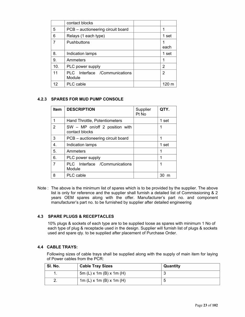
4.2.3 SPARES FOR MUD PUMP CONSOLE
Item DESCRIPTION Supplier Pt No
QTY.
1 Hand Throttle, Potentiometers 1 set
2 SW – MP on/off 2 position with contact blocks
1
3 PCB – auctioneering circuit board 1
4. Indication lamps 1 set
5. Ammeters 1
6. PLC power supply 1
7 PLC Interface /Communications Module
1
8 PLC cable 30 m
Note : The above is the minimum list of spares which is to be provided by the supplier. The above list is only for reference and the supplier shall furnish a detailed list of Commissioning & 2 years OEM spares along with the offer. Manufacturer’s part no. and component manufacturer’s part no. to be furnished by supplier after detailed engineering
4.3 SPARE PLUGS & RECEPTACLES
10% plugs & sockets of each type are to be supplied loose as spares with minimum 1 No of each type of plug & receptacle used in the design. Supplier will furnish list of plugs & sockets used and spare qty. to be supplied after placement of Purchase Order.
4.4 CABLE TRAYS:
Following sizes of cable trays shall be supplied along with the supply of main item for laying of Power cables from the PCR:
Sl. No. Cable Tray Sizes Quantity
1. 5m (L) x 1m (B) x 1m (H) 3
2. 1m (L) x 1m (B) x 1m (H) 5
Page 24 of 102
5.0 GENERAL POINTS:
i) Though a broad outline on the requirement has been made, yet the scope should include anything not mentioned but required for completeness of the system to meet the requirement of oil well deep drilling rig (drilling capacity 6100 meters depth) and make the same suitable for dismantling, transportation and installation very often in rough and tough conditions.
ii) The system offered shall have proven performance record. All relevant safety systems are to be incorporated and safety codes, relevant international codes to be strictly followed. Systems to be designed & manufactured to the latest NEC, IEC, IEEE-45, API 500, and NEMA standards, & should meet all present accepted international standards for the product/application
iii) Supplier shall use components/ sub-assemblies only of reputed and proven make and of latest design.
iv) The system shall be free from any defect arising from faulty material, workmanship or design. Any such defects, including replacement of faulty components, shall be carried out by the manufacturer free of cost during warranty period. The SUPPLIER shall have the total and final responsibility for the design and performance of all equipment.
v) All components, modules, subsystems shall be of current generation with latest technology which must be in production and must not face obsolescence in near future. The supplier and the manufacturer in turn shall guarantee that spare parts shall be available for at least fifteen years.
vi) The controls i.e. all electronics including modules and different electronic components, PLC etc. shall have high levels of noise immunity. They shall have high level of EMC and shall be immune from noise generated by future AC Variable Frequency Drive for Top Drive inclusion that will be powered from the 600 VAC Top Drive Feeder in the PCR.
vii) The system including all sub-assemblies and components should be designed to facilitate backward integration of future modules, cards etc without any modification.
viii) Bidder shall manufacture the DC-PCR at their works.
Bidder shall have adequate facilities for supply of DC-PCR spare parts for at least fifteen years. A certificate to this effect shall be attached with the bid.
ix) Bidder shall have well equipped testing and repair set-up in India, suitable for complete testing and repair of PCRs, including repairs to the skid and housing. Facilities available shall include Welding and painting. The set-up should include both on-site repair, as well as factory repair capability.
x) The DC-PCR shall be brand new, unused, manufactured especially for Oil India, and free from any manufacturing defect. This shall be categorically stated by the bidders in their quotations.
xi) Offers shall be complete in all respects and all the items/equipment as specified in the tender must be included in the package. Offers deemed to be incomplete shall be rejected (Bidders may quote additional items / equipment or accessories, other than Handling Equipment, not covered in this enquiry, if felt necessary for the completeness and efficient. operation of the DC-PCR)
xii) The bidder shall fill up the bidder’s response sheet with comments at the time of submission of bid.
Page 25 of 102
6.0 PRE ENGINEERING INFORMATION: After placement of order, supplier can ask for pre-engineering information, if required, to start the system engineering. Oil India shall provide all necessary data required.
7.0 COMMISSIONING a. GENERAL Commissioning is an essential part of this Tender, and bids that do not quote for commissioning shall be treated as incomplete bids. Bidder has to successfully commission the DC-PCR at location in Assam, India, to the complete satisfaction of Oil India. Commissioning charges to be quoted separately on lumpsum basis which shall be considered for evaluation of the offers. These charges should include amongst others to and fro fares, boarding/lodging, local transport at Duliajan and other expenses of supplier’s commissioning personnel during their stay at Duliajan, Assam(India). All income, GST, Corporate Taxes etc. towards the services provided under installation / commissioning /training shall be borne by the supplier and will be deducted at source at the time of releasing the payment. Bidder should also confirm about providing all these services in the Technical Bid. Commissioning of the DC-PCR may require more than one visit, depending on availability of drilling rig and other factors. Charges for commissioning shall be paid as one lump-sum, and not per visit. The time available to commission the PCR shall be two weeks. However, Bidder shall note that the PCR cannot be commissioned at one single visit. Bidder should plan for a minimum of two visits to complete the commissioning of the PCR. Successful bidder shall submit a tentative plan for commissioning the DC-PCR, for approval of Oil India. The completed DC-PCR shall be connected to existing equipment (AC-PCR, Electrical motors, devices, cables etc.) in a drilling rig, checked for integrity of connections and acceptable levels of electrical insulation resistance, and powered up (phased up). All devices and interlocks shall be individually tested, and should work exactly as intended. The completed DC PCR shall be integrated with Third Mud Pump System as a whole on later date. The entire drilling rig, with the DC-PCR fully integrated shall be tested, and should work exactly as intended. Any problems, design inadequacies, material failure, device malfunction etc. shall be addressed / replaced by the successful bidder. Adequate spares for commissioning activity should be arranged for by the successful bidder. All personnel, statutory permissions (if required), equipment, tools, tackles and instruments required to commission the DC-PCR at site shall be arranged by the successful bidder. Oil India shall provide 415 VAC, 3 phase power, and transportation to and from Duliajan to drill-site only. b. RECEIPT OF MATERIALS DESPATCHED FROM MANUFACTURER'S WORKS The supplier should physically verify upon receipt, all equipment and materials (including commissioning spares etc.) after delivery at OIL's premises. The supplier should carry out inspection of all the supplied items to ascertain and certify that there all dispatched items have reached site, there is no transit damage and items are complete in all respects and ready for installation. In case of any discrepancy, supplier shall take necessary action for immediate replacement/ replenishment of the same before installation.
Page 26 of 102
c. A GUIDE FOR INSTALLATION AND COMMISSIONING ACTIVITIES EXPECTED: i. Installation, wiring and laying out of equipment: On arrival of equipment and materials (commissioning spares etc.) at OIL's premises the supplier should carry out inspection of the supplied items to ascertain and certify that there is no transit damage and items are complete in all respect and ready for installation. In case of any discrepancy, supplier shall take necessary action for immediate replacement/ replenishment of the same before installation. After receipt, the equipment shall be installed at site. This will include wiring/ cabling, fitting of plugs and sockets and any other activity required to make the equipment ready for commissioning. Any third party devices (if applicable) shall be installed inside the PCR at this stage. ii. Initial commissioning after start up connection: This activity will cover electrical insulation checks, wiring checks, phasing up (powering up) of individual equipment and the system as a whole. After start up connection and powering up, the complete system shall be tested at no load and minimum/ low load at OIL's well site. All equipment as well as the whole system shall work exactly as intended. Any modification/ re-wiring/ repair shall be carried out at this stage. iii. 2nd Stage commissioning: The PCR shall be integrated with the other equipment of the Drilling Rig, and operated in conjunction with these pieces of equipment, as a complete system. Any problems, abnormalities, anomalies and defects noticed/ logged during this stage (operation at full/rated load) shall be rectified by the supplier. This will cover setting/ adjustment/ calibration of limits in the control system, drives etc. All equipment as well as the whole system shall work exactly as intended. iii. Final Commissioning: Final commissioning of the PCR shall be done after 3 months but not later than six months from the date of 2nd Stage commissioning. This will cover setting/ adjustment/ calibration of limits in the control system, drives etc and the system as a whole. Any problems, abnormalities, anomalies and defects noticed/ logged after 2nd Stage commissioning and up to this stage (operation at full/rated load) shall be rectified by the supplier. All equipment as well as the whole system shall work exactly as intended. d. PRECAUTIONS TO BE OBSERVED: Oil India's drilling sites have an elaborate system of hazardous areas / zones, where restrictions on electrical equipment operation are enforced. All personnel coming for any activity inside the drilling site is advised to familiarize themselves with such demarcations before commencing any work.
8.0 LIST OF ANNEXURE (S)
a. Annexure – 1: 20 pin receptacle pin connections for Alternators. b. Annexure – 2: 20 pin receptacle pin connections for DC Motors. c. Annexure – 3: Layout showing Placement of DC-PCR (Information to bidder)
9.0 OTHER ISSUES
a. EARTHING OF THE PCR SHELL Six studs/bolts of M8 size shall be provided on each side of the DC-PCR for grounding.
Page 27 of 102
b. STAGE & PRE-DESPATCH INSPECTION Oil India's Engineers shall inspect the DC-PCR at various stages of manufacture to ensure job quality and adherence to specifications. The inspection of DCPCR by OIL India’s Engineers shall be in two stages which is as follows:
I. Stage Inspection: During panel wiring and testing of different electrical components of the
DCPCR. II. Pre- Dispatch inspection.
All the above inspection(s) shall be conducted by OIL or its representative at manufacturer's works. The DC-PCR shall be dispatched from works only after the Pre- Dispatch Inspection. Supplier shall give call for above mentioned inspection(s) at least 45 days in advance, to enable Oil India to prepare for inspection. Bidders are also advised to include the above mentioned inspection costs (if any) in the bid. All to and fro travel expenses, boarding, lodging expenses of OIL representative shall be borne by OIL. c. DETAILED ENGINEERING STAGE This is the period between award of Purchase order, and the start of manufacture is referred to as the "Detailed Engineering Stage". Successful bidder shall provide OIL with all required drawings, and get them approved before manufacture. All engineering details not covered in these specifications, or specifications requiring modifications, shall be worked out mutually during this "pre-manufacturing" stage. d. TESTING AT MANUFACTURER'S WORKS Successful Bidder shall have to test the PCR at Manufacturer's works, and provide the following certificates to Oil India before despatch: Factory Acceptance Test Certificate Manufacturer's Quality Assurance Plan and Certificate of adherence to this plan Welding NDT Report for all welds at important points of the DC-PCR body Bidder to take note that the despatch clearance would not be given if the above certificates are not produced duly signed and authenticated. e. DESPATCH OF DC-PCR TO OIL INDIA DESIGNATED SITE AT ASSAM After completion of manufacture and testing at Manufacturer's works, supplier shall have to arrange for despatch of the DC-PCR to site at Duliajan. The exact site will be communicated by Oil India at the time of despatch. The entire PCR shall be adequately packed and sealed to avoid ingress of dust and water during travel, as well as to afford mechanical protection to the PCR. All arrangements in this regard will have to be borne by supplier. Bidders shall confirm categorically that Installation & Commissioning of the Rig Package with all accessories would be carried out by their competent personnel at OIL's designated drill site, in Duliajan, ASSAM, INDIA. However, the basic facilities required for installation & commissioning such as to & fro transportation to site from Duliajan, Crane service, electric power (3 phase, 415 VAC), water supply, pressurized air etc. shall be provided by OIL. All other facilities are to be arranged by the supplier. Bidders, quoting for any bought out / third party item(s) should undertake & comply with Guarantee / Warranty clause indicated elsewhere in this tender.

Page 28 of 102
f. MARKINGS ON THE BODY OF THE DC-PCR The following shall be done after external painting of the PCR is complete. The Two ends of the PCR shall be labeled "Draw works End" and "Compressor End", as appropriate. The sides will be painted with Oil India's logo (to be provided), and the Words "Oil India Limited", "A Government of India Undertaking", "DC-PCR", "Rig #S8 ", the Purchase Order Number, Dimensions and weight of the DC-PCR, Manufacturer's Name and any Lifting Instructions. g. SAFETY CONSIDERATIONS INSIDE THE PCR Appropriate warning labels and safety provisions shall be made in the PCR to caution the operating and maintenance personnel against potential hazards and to prevent direct human contact to any live part or rotating part during operation.
10.0 WARRANTEE / GUARANTEE Bidder should confirm in their bid that they will provide warranty / guarantee for a period of 1 year (12 months) from date of successful commissioning of the DC-PCR at site. This guarantee shall cover all items of the PCR package, including (but not limited to) the skid, housing, all the internal components and any spares supplied. Any repairs / replacements required during this Warrantee period shall be carried out by the successful bidder, on site, at no cost to Oil India. The typical response time shall be 48 hours (at site) after a repair call is given by Oil India. Repairs / replacements shall normally be carried out at site by the supplier. However, for serious problems the DC-PCRs may need to be returned to factory for major repairs. If the DC-PCR needs to be returned to the factory for repairs due to manufacturing or design problems, all transportation and repair charges shall be to supplier's account.
11.0 DRAWINGS AND APPROVALS
a. GENERAL All information, operating and warning labels and O&M Manuals should be in English only. The bidder should provide at least one set of parts list, operations manual & maintenance manual covering all the items & its accessories including any special / alignment tools for the same along with the technical offer. Technical details of the electrical system with dimensional drawing (including Layout, arrangement and circuit diagrams) must also be forwarded along with the technical offer. Successful Bidder shall provide engineering drawings and BOM for approval of Oil India before manufacturing. All engineering details not covered in these specifications shall be worked out before manufacture. Any corrections / additions / modifications to drawings and BOM requested by Oil India shall be carried out by successful bidder without any cost to Oil India. Manufacture shall start only after written approval from Oil India on all issues. See sub-section "d" below for details about drawing submission schedule. b. PARTS CATALOGUE, OPERATION / INSTRUCTION MANUAL & DRAWING, TECHNICAL INFORMATION & BULLETIN: After successful commissioning of the DC-PCR, the successful bidder shall provide Oil India with five sets of O&M manuals, BOM, and "as-built" drawings, of the DC-PCR. Five of these sets shall be in printed form, and two in electronic form (flash memory format). Operation & Maintenance manual should cover the following:
Layout drawing of all components on the unit with details of load distribution Literature of all third party devices installed on the DC-PCR Safety related Information
Page 29 of 102
c. CONFIDENTIALITY Any third party details required and obtained by the successful bidder through Oil India, to complete the DC-PCR design shall be kept confidential. All such material shall be returned to Oil India after completion of related job. Any materials or information about Oil India, obtained by the successful bidder during execution of this job shall be kept confidential, returned to Oil India, or properly disposed of. d. SCHEDULE OF SUBMISSION OF DRAWINGS/ DOCUMENTS Successful Bidder shall submit the following Drawings/ documents at the stages indicated therein: A. The following Drawings shall be submitted with the Bid:
i) Indicative single line power flow diagram of the DC-PCR, showing all voltage levels, current ratings & short circuit making/ breaking capacities of breakers/ isolators, bus ampere rating (taking into account all generators / SCRs fully loaded) etc.
ii) Details of the Short circuit calculation of the complete electrical system iii) Indicative Layout diagram (Plan), showing all electrical panels of the PCR,
Socket boards, etc. iv) Indicative PCR dimensional drawings, including details of rain protection for
cable & plug sockets etc. v) Spare parts/ Spare equipment / Consumables list and quotations of spares
B. The following Drawings shall be submitted after successful commissioning of the PCR:
i) Equipment literature/ Third party (quality control) inspection report ii) "As-built" drawings, iii) Operation and workshop manuals, iv) Bill of Materials (BOM) and any other relevant documents
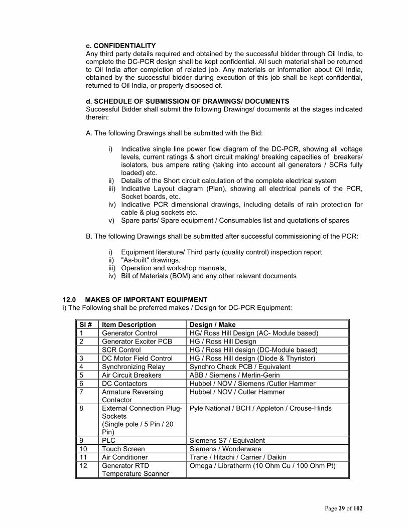
12.0 MAKES OF IMPORTANT EQUIPMENT i) The Following shall be preferred makes / Design for DC-PCR Equipment:
Sl # Item Description Design / Make 1 Generator Control HG/ Ross Hill Design (AC- Module based) 2 Generator Exciter PCB HG / Ross Hill Design SCR Control HG / Ross Hill design (DC-Module based) 3 DC Motor Field Control HG / Ross Hill design (Diode & Thyristor) 4 Synchronizing Relay Synchro Check PCB / Equivalent 5 Air Circuit Breakers ABB / Siemens / Merlin-Gerin 6 DC Contactors Hubbel / NOV / Siemens /Cutler Hammer 7 Armature Reversing
Contactor Hubbel / NOV / Cutler Hammer
8 External Connection Plug-Sockets (Single pole / 5 Pin / 20 Pin)
Pyle National / BCH / Appleton / Crouse-Hinds
9 PLC Siemens S7 / Equivalent 10 Touch Screen Siemens / Wonderware 11 Air Conditioner Trane / Hitachi / Carrier / Daikin 12 Generator RTD
Temperature Scanner Omega / Libratherm (10 Ohm Cu / 100 Ohm Pt)

Page 30 of 102
ii) Existing Equipment at Drilling Rigs of Oil India (Provided as Information to Bidder) Sl # Item Description Make / Model 1 Generator KATO / BHEL 1215/1430
kVA, 600 VAC, 1000 RPM, 50 Hz
2 DC Motor BHEL 750 VDC, 1000 HP, separately excited, shunt wound, with 55-60ADC field winding current,
3 Power Transformers 2 x 600 kVA, 600/415 VAC, 3 Phase, 50 Hz. Neutral on secondary (415 VAC side) grounded through NGR, hence neutral will not be available.
4 Isolation Transformers
2 x 30 kVA/1 X100 kVA, 415 VAC/415 VAC, Mainly for Rig accommodation bunk-houses’ facilities; and areas lighting.
Page 31 of 102
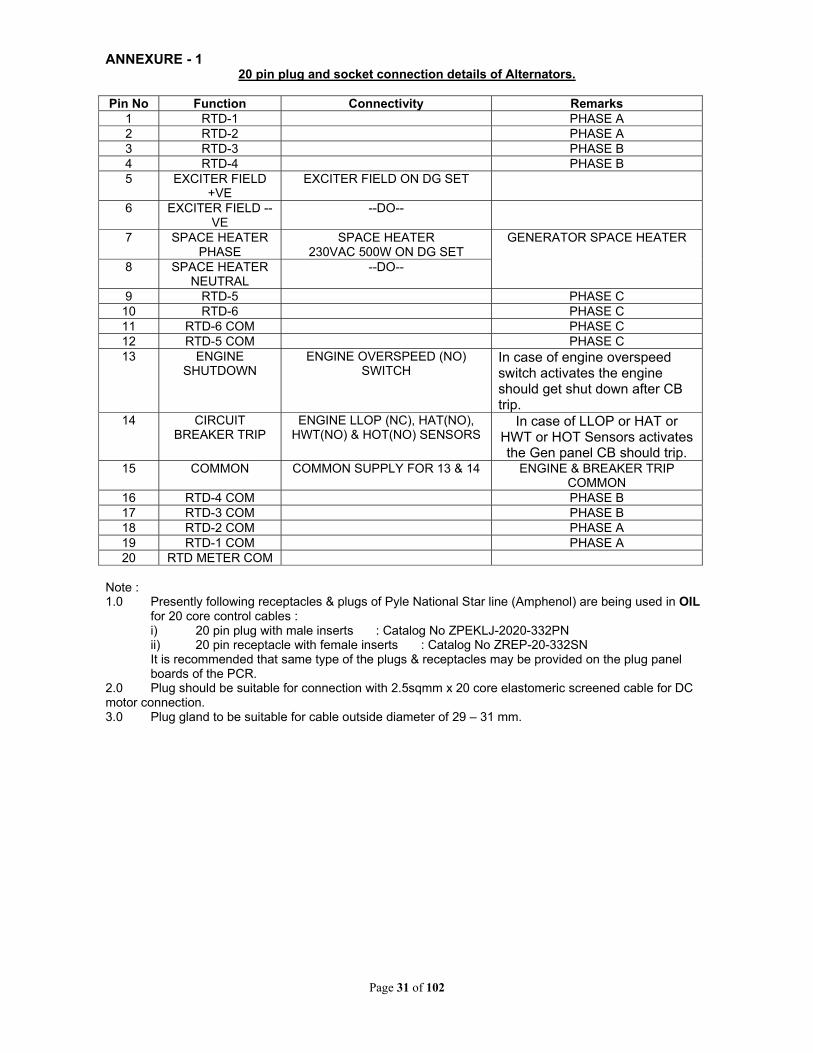
ANNEXURE - 1
20 pin plug and socket connection details of Alternators.
Pin No Function Connectivity Remarks 1 RTD-1 PHASE A 2 RTD-2 PHASE A 3 RTD-3 PHASE B 4 RTD-4 PHASE B 5 EXCITER FIELD
+VE EXCITER FIELD ON DG SET
6 EXCITER FIELD --VE
--DO--
7 SPACE HEATER PHASE
SPACE HEATER 230VAC 500W ON DG SET
GENERATOR SPACE HEATER
8 SPACE HEATER NEUTRAL
--DO--
9 RTD-5 PHASE C 10 RTD-6 PHASE C 11 RTD-6 COM PHASE C 12 RTD-5 COM PHASE C 13
ENGINE SHUTDOWN
ENGINE OVERSPEED (NO) SWITCH
In case of engine overspeed switch activates the engine should get shut down after CB trip.
14 CIRCUIT BREAKER TRIP
ENGINE LLOP (NC), HAT(NO), HWT(NO) & HOT(NO) SENSORS
In case of LLOP or HAT or HWT or HOT Sensors activates the Gen panel CB should trip.
15 COMMON COMMON SUPPLY FOR 13 & 14 ENGINE & BREAKER TRIP COMMON
16 RTD-4 COM PHASE B 17 RTD-3 COM PHASE B 18 RTD-2 COM PHASE A 19 RTD-1 COM PHASE A 20 RTD METER COM
Note : 1.0 Presently following receptacles & plugs of Pyle National Star line (Amphenol) are being used in OIL
for 20 core control cables : i) 20 pin plug with male inserts : Catalog No ZPEKLJ-2020-332PN ii) 20 pin receptacle with female inserts : Catalog No ZREP-20-332SN It is recommended that same type of the plugs & receptacles may be provided on the plug panel boards of the PCR.
2.0 Plug should be suitable for connection with 2.5sqmm x 20 core elastomeric screened cable for DC motor connection. 3.0 Plug gland to be suitable for cable outside diameter of 29 – 31 mm.

Page 32 of 102
ANNEXURE - 2 20 pin plug and socket connection details of DC motors.
Pin No Function Connectivity Remarks
1 SPARE SPARE 2 BLOWER AIR-FLOW
SWITCH,N/C AIR LOSS SWITCH
9 BLOWER AIR-FLOW SWITCH,COM
3 MOTOR CUT OUT SWITCH,N/C
MOTOR CUT OUT SWICH
4 MOTOR CUTOUT SWITCH,COM
5 + VE FIELD +VE FIELD OF DC MOTOR FOR + SIDE OF FIELD 6 + VE FIELD +VE FIELD OF DC MOTOR
7 + VE FIELD +VE FIELD OF DC MOTOR 8 + VE FIELD +VE FIELD OF DC MOTOR 17 + VE FIELD +VE FIELD OF DC MOTOR 18 + VE FIELD +VE FIELD OF DC MOTOR 10 - VE FIELD -VE FIELD OF DC MOTOR FOR -- SIDE OF FIELD.
11 - VE FIELD -VE FIELD OF DC MOTOR 12 - VE FIELD -VE FIELD OF DC MOTOR 13 - VE FIELD -VE FIELD OF DC MOTOR 19 - VE FIELD -VE FIELD OF DC MOTOR 20 - VE FIELD -VE FIELD OF DC MOTOR 14 SPACE HEATER PHASE SPACE HEATER
230VAC 500W SPACE HEATER ON DC
MOTOR 15 SPACE HEATER
NEUTRAL SPACE HEATER 230VAC 500W
16 GROUND GROUND Note : 2.0 Presently following receptacles & plugs of Pyle National Star line (Amphenol) are being used in OIL
for 20 core control cables : iii) 20 pin plug with male inserts : Catalog No ZPEKLJ-2020-332PN iv) 20 pin receptacle with female inserts : Catalog No ZREP-20-332SN It is recommended that same type of the plugs & receptacles may be provided on the plug panel boards of the PCR.
2.0 Plug should be suitable for connection with 2.5sqmm x 20 core elastomeric screened cable for DC motor connection. 3.0 Plug gland to be suitable for cable outside diameter of 29 – 31 mm.

Page 33 of 102
ANNEXURE – 3 Rig Layout showing placement of DC-PCR
Page 34 of 102
BB:: GENERAL NOTES TO BIDDERS: Sl. No.
Clause description
1.0 Tender fee is not applicable against this tender. Bidders to take note of the following:
1. Bidders without having E-tender Login ID and Password should complete their online registration at least seven (7) days prior to the scheduled bid closing date and time of the tender. For online registration, Bidder may visit the OIL’s E-tender site https://etender.srm.oilindia.in/irj/portal
2. Necessary Login ID& Password will be issued by OIL only after submitting the complete online registration by the Bidder. In the event of late registration/incomplete registration by Bidder, OIL INDIA LIMITED shall not be responsible for late allotment of User ID & Password and request for bid closing date extension on that plea shall not be entertained by Company.
3. MSEs Units (manufacturers/Service Providers only and not their
dealers/distributors) who are already registered with District Industry Centers or Khadi& Village Industries Commission or Khadi& Village Industries Board or Coir Board or National Small Industries Corporation or Directorate of Handicrafts & Handloom or any other body specified by Ministry of MSME are exempted from payment of Bid Security (EMD) irrespective of monetary limit, product category and capacity mentioned in their registration, subject to submission of valid MSE registration certificate issued by appropriate authority.
4. For availing benefits under Public Procurement Policy (Purchase
preference & EMD exemption), the interested MSE Bidders must ensure that they are the manufacturer/ service provider of tendered item(s) and registered with the appropriate authority for the said item(s). Bids without EMD shall be rejected, if the technical offer does not include a valid copy of relevant MSE Certificate issued by appropriate authority specifying the item as per tender. Therefore, it is in the interest of such MSE Vendors to furnish a copy of complete certificate to the concerned tender handling officer of OIL at least seven (7) days prior to the scheduled Bid Closing Date of the tender; seeking clarification/confirmation as to whether their registered item is eligible for EMD exemption or not. Late communications in this regard and request for bid closing date extension on that plea shall not be entertained by Company.
2.0 Bid Security/EMD/Performance Bank Guarantee – Must be paid either through online mode or Submission of Bank Guarantee/LC only. No DD/Cheques/Cashier Cheque or any other mode will be acceptable. The Bank Guarantee issued by bank must be routed through SFMS platform as per following details:
Page 35 of 102
a. (i) “MT760/ MT760 COV for issuance of bank guarantee (ii) MT767/ MT767 COV for amendment of bank guarantee The above message / intimation shall be sent through SFMS by the BG issuing Bank branch to HDFC Bank, Duliajan Branch, IFS Code – HDFC0002118; SWIFT Code - HDFCINBBCAL. Branch Address: HDFC Bank Limited, Duliajan Branch, Utopia Complex, BOC Gate, Jayanagar, Duliajan, Dibrugarh, PIN – 786602.” b. The vendor shall submit to OIL the copy of the SFMS message as sent by the issuing bank branch along with the original bank guarantee.
3.0 The tender will be governed by “General Terms & Conditions” for e-Procurement as per Booklet No. MM/GLOBAL/E-01/2005 for E-procurement (ICB Tenders) including Amendments & Addendum to “General Terms & Conditions” for e-Procurement.
4.0 Bid must be submitted online through OIL’s e-procurement portal. Bid submitted in any other form will be rejected.
5.0 Please note that all tender forms and supporting documents are to be submitted through OIL’s e-Procurement site only except following documents which are to be submitted manually in sealed envelope super scribing tender no. and due date to The GM Materials, Materials Department, Oil India Limited, Duliajan- 786602, Assam on or before 13:00 hrs (IST) on the Bid Closing Date mentioned in the Tender. a) Original Bid Security along with two duplicate copies of Bid Security. b) Any other documents which have been particularly asked for in this tender for submission.
6.0 Bidders must ensure that their bid is uploaded in the system before the tender closing date and time. Also, they must ensure that above documents which are to be submitted in a sealed envelope are also submitted at the above mentioned address before the bid closing date and time, failing which the offer shall be rejected.
7.0 The tender is invited under SINGLE STAGE-TWO BID SYSTEM. The bidder has to submit both the “TECHNO-COMMERCIAL UNPRICED BID” and “PRICED BID” through electronic form in the OIL’s e-Tender portal within the Bid Closing Date and Time stipulated in the e-Tender. The “Techno-commercial Unpriced Bid” shall contain all technical and commercial details except the prices which shall be kept blank. Details of prices as per Bid format / Commercial bid to be uploaded as attachment in the Attachment Tab “Notes and Attachments”. Any offer not complying with above submission procedure will be rejected as per Bid Rejection Criteria mentioned in the tender.
Only Price Details Should Be Uploaded
Notes and Attachments
Technical attachments
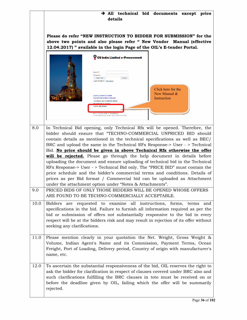
Page 36 of 102
All technical bid documents except price details
Please do refer “NEW INSTRUCTION TO BIDDER FOR SUBMISSION” for the above two points and also please refer “ New Vendor Manual (effective 12.04.2017) ” available in the login Page of the OIL’s E-tender Portal.
8.0 In Technical Bid opening, only Technical Rfx will be opened. Therefore, the bidder should ensure that “TECHNO-COMMERCIAL UNPRICED BID should contain details as mentioned in the technical specifications as well as BEC/ BRC and upload the same in the Technical RFx Response-> User - > Technical Bid. No price should be given in above Technical Rfx otherwise the offer will be rejected. Please go through the help document in details before uploading the document and ensure uploading of technical bid in the Technical RFx Response-> User - > Technical Bid only. The “PRICE BID” must contain the price schedule and the bidder’s commercial terms and conditions. Details of prices as per Bid format / Commercial bid can be uploaded as Attachment under the attachment option under “Notes & Attachments”.
9.0 PRICED BIDS OF ONLY THOSE BIDDERS WILL BE OPENED WHOSE OFFERS ARE FOUND TO BE TECHNO-COMMERCIALLY ACCEPTABLE.
10.0 Bidders are requested to examine all instructions, forms, terms and specifications in the bid. Failure to furnish all information required as per the bid or submission of offers not substantially responsive to the bid in every respect will be at the bidders risk and may result in rejection of its offer without seeking any clarifications.
11.0 Please mention clearly in your quotation the Net. Weight, Gross Weight & Volume, Indian Agent's Name and its Commission, Payment Terms, Ocean Freight, Port of Loading, Delivery period, Country of origin with manufacturer's name, etc.
12.0 To ascertain the substantial responsiveness of the bid, OIL reserves the right to ask the bidder for clarification in respect of clauses covered under BRC also and such clarifications fulfilling the BRC clauses in toto must be received on or before the deadline given by OIL, failing which the offer will be summarily rejected.
Click here for the New Manual & Instruction
Page 37 of 102
13.0 Other terms and conditions of the tender shall be as per “General Terms & Conditions” for e- Procurement as per Booklet No. MM/GLOBAL/E-01/2005 for E-procurement (ICB Tenders). However, if any of the Clauses of the Bid Rejection Criteria (BRC) / Bid Evaluation Criteria (BEC) mentioned here contradict the Clauses in the “General Terms & Conditions” for e-Procurement as per Booklet No. MM/GLOBAL/E-01/2005 for E-procurement (ICB Tenders) of the tender and/or elsewhere, those mentioned in this BEC / BRC shall prevail.
14.0 All the Bids must be Digitally Signed using “Class 3” [Organization] digital certificate (e-commerce application) only as per Indian IT Act obtained from the licensed Certifying Authorities operating under the Root Certifying Authority of India (RCAI), Controller of Certifying Authorities (CCA) of India. The bid signed using other than “Class 3” [Organization] digital certificate, will be liable for rejection.
15.0 Please do refer the User Manual provided on the portal on the procedure How to create Response for submitting offer. "In order to bid for OIL e-tenders all the vendors are required to obtain a 1egally valid Digital Certificate Class III [Organization] along with Encryption Certificate as per Indian IT Act from the licensed Certifying Authorities (CA) operating under the Root Certifying Authority of India (RCAI), Controller of Certifying Authorities (CCA) of India. Digital Signature Certificate comes in a pair of Signing/verification and Encryption/decryption certificate. Bidder should have both the Signing/verification and Encryption/Decryption certificate for Signing and encryption, decryption purpose respectively. The driver needs to be installed once, without which the DSC will not be recognized. While participating on e-Tendering the DSC token should be connected to your system. Encryption certificate is mandatorily required for submission of bid. In case bidder created response with one certificate (using encryption key) and bidder change his Digital Signature Certificate then old certificate (used for encryption) is required in order to decrypt his encrypted response for getting the edit mode of the response. Once decryption is done, bidder may use new DSC certificate for uploading and submission of their offer. It is the sole responsibility of the bidder to keep their DSC certificate properly. In case of loss of the certificate, OIL INDIA LTD is not responsible."
16.0 Bidders to note that Govt. of India under Micro, Small and Medium Enterprises Development (MSMED) Act 2006, has proclaimed the Public Procurement Policy, 2012 with effect from 1st April, 2012 in respect of procurement of goods and services, produced and provided by micro and small enterprises, by its Ministries, Departments and Public Sector Undertakings for promotion and development of Micro and Small Enterprises. A new Clause on applicability of Public Procurement Policy for procurement of goods from Micro and Small Enterprises (MSE) in the tender is furnished vide Amendment to General Terms and Conditions for Global Tender (MM/GLOBAL/E-01/2005). Bidders are requested to take note of the same and to submit their offers accordingly.
17.0 The items shall be brand new, unused & of prime quality. The manufacturer shall warrant (in the event of an order) that the product supplied will be free from all defects & fault in material, workmanship & manufacture and shall be in full conformity with ordered specifications. This clause shall be valid for a period

Page 38 of 102
of 1 year (12 months) from date of successful commissioning of the DC-PCR at site. The defective materials, if any, rejected by OIL shall be replaced by the supplier at their own expense. Bidders must confirm the same in their quotations.
18.0 Quantity of Individual item may be increased or decrease at the time of final placement of order. The minimum FOB charges in case of partial order for reduced quantity/enhanced quantity shall have to be indicated by the bidder. In case, this is not indicated specifically, the charges quoted would be pro-rata calculated and the same will be binding on the bidder.
19.0 Any deviation(s) from the tender specification should be clearly highlighted specifying justification in support of deviation.
20.0 The Integrity Pact is applicable against this tender .OIL shall be entering into an Integrity Pact with the bidders as per format enclosed vide Annexure- IX of the tender document. This Integrity Pact proforma has been duly signed digitally by OIL’s competent signatory. The proforma has to be returned by the bidder (along with the technical bid) duly signed (digitally) by the same signatory who signed the bid, i.e., who is duly authorized to sign the bid. Uploading the Integrity Pact with digital signature will be construed that all pages of the Integrity Pact has been signed by the bidder’s authorized signatory who sign the Bid. If any bidder refuses to sign Integrity Pact or declines to submit Integrity Pact with the offer, their bid shall be rejected straightway. OIL’s Independent External Monitors at present are as under: SHRI RAJIV MATHUR, IPS (Retd.), Former Director (IB) Govt. of India e-Mail ID : [email protected] SHRI RUDHRAGANGADHARAN, IAS (Retd.) Ex-Secretary, Ministry of Agriculture E-mail Id :[email protected] SHRI JAGMOHAN GARG, Ex-Vigilance Commissioner, CVC e-Mail id : [email protected]
21.0 Original Bid Closing Date shall be considered by OIL for evaluation of BRC Criteria in case of any extension of the original bid closing date.
22.0 Performance Security clause (Clause No. 10.0 of Section-A) of "General Terms & Conditions for Global Tenders (MM/GLOBAL/01/2005)" has been amended and the new clause is detailed in the Amendment dated 25.04.2016 issued to MM/GLOBAL/01/2005. Successful bidder will be required to furnish a Performance Bank Guarantee @10% of the order value which should remain valid for the period execution, including extension, if any and the entire warranty period in line with tender requirement. The successful bidder shall submit Performance Security within 30 days of award, failing which OIL reserves the right to cancel the order and forfeit their Bid Security. Bidders should undertake in their bids to submit Performance Security as stated above. Bidders to note the same and to confirm its acceptance in their offers.
Page 39 of 102
The Bank Guarantee issued by bank must be routed through SFMS platform as per following details: a. (i) “MT760/ MT760 COV for issuance of bank guarantee (ii) MT767/ MT767 COV for amendment of bank guarantee The above message / intimation shall be sent through SFMS by the BG issuing Bank branch to HDFC Bank, Duliajan Branch, IFS Code – HDFC0002118; SWIFT Code - HDFCINBBCAL. Branch Address: HDFC Bank Limited, Duliajan Branch, Utopia Complex, BOC Gate, Jayanagar, Duliajan, Dibrugarh, PIN – 786602.” b. The vendor shall submit to OIL the copy of the SFMS message as sent by the issuing bank branch along with the original bank guarantee.
23.0 Bidder to sign and submit completely filled up Technical & Commercial check list.
24.0 Payment terms: Payment shall be released as follows- (i) 80% value shall be released on supply against proof of dispatch/shipment of the DC-PCR (ii) Remaining 20% along with the installation & commissioning charges shall be paid after successful commissioning and acceptance by OIL at site.
25.0 Liquidated Damage: Refer to “General Terms & Conditions” for e- Procurement as per Booklet No. MM/GLOBAL/E-01/2005 for E-procurement (ICB Tenders). In case of deduction of LD, LD amount will be deducted along with applicable rate of GST.
26.0 The items covered by this enquiry shall be used by Oil India Limited in the PEL/ML areas which are issued/renewed after 01/04/99 and hence Nil Customs Duty against CIF valuing INR 1.00 Lakh and above (Or value as per prevailing Govt. policy) & concessional IGST during import will be applicable. In the event of an order on indigenous bidder, OIL will issue Project Authority Certificate (PAC) under Deemed Export benefit, where import content is declared by the bidder for availing Advance Licence for intermediate Supply. However, Indian bidders will not be issued Recommendatory Letter. Details of Deemed Export benefit are furnished vide Addendum to “General Terms & Conditions” Booklet No. MM/GLOBAL/E-01/2005. The bidders are requested to check the latest position on the subject on their own and OIL shall not accept any liability, whatsoever, on this account. Indigenous Supplier shall furnish the invoice to OIL before the dispatch for obtaining Essentiality Certificate from DGH towards concessional rate of GST against invoice valuing INR 1.00 Lakh and above (Or value as per prevailing Govt. policy). Supplier shall arrange to provide all necessary documents to apply for the essentiality certificate on receipt of request from OIL, if any. Further, supplier shall affect dispatch only on receipt of relevant certificates from OIL, failing which all related liabilities shall be to Supplier’s account.
Page 40 of 102
27.0 Bidders to note that Ministry of Petroleum & Natural Gas, Government of India implemented PPLC Policy to provide Purchase Preference (linked with local content) by notification no. Ref. O-27011/44/2016-ONG-II/FP dtd.25.04.2017. A new Clause on applicability of Purchase Preference (linked with local content) policy in the tender is furnished as Annexure-VIII of the tender document. Bidders are requested to take note of the same and to submit their offers accordingly wherever applicable.
28.0 Clauses related to GST: 1. For the purposes of levy and imposition of GST, the expressions shall have
the following meanings: (a) GST - means any tax imposed on the supply of goods and/or services
under GST Law. (b) Cess – means any applicable cess, existing or future on the supply of
Goods and Services as per Goods and Services Tax (Compensation to States) Act, 2017.
(c) GST Law - means IGST Act 2017, CGST Act 2017, UTGST Act, 2017 and SGST Act, 2017and all related ancillary Rules and Notifications issued in this regard from time to time.
2. The rates quoted by the bidders shall be inclusive of all taxes, duties and levies. However, bidders are required to provide separately the rate and amount of all types of taxes, duties and levies. In case, the quoted information related to various taxes, duties & levies subsequently proves wrong, incorrect or misleading, OIL will have no liability to reimburse the difference in the duty/ tax, if the finally assessed amount is on the higher side and OIL will have to right to recover the difference in case the rate of duty/ taxes finally assessed is on the lower side. Further, bidders have to clearly show the amount of GST separately in the Tax Invoices. Further, it is the responsibility of the bidders to make all possible efforts to make their accounting / IT system GST compliant in order to ensure availability of Input Tax Credit (ITC) to Oil India Ltd.
3. Offers without giving any of the details of the taxes (Including rates and amounts) as specified above will be considered as inclusive of all taxes including GST. When a bidder mentions taxes as extra without specifying the rates & amount, the offer will be loaded with maximum value towards taxes received against the tender for comparison purposes. If the bidder emerges as lowest bidder after such loading, in the event of order on that bidder, taxes mentioned by OIL on the Purchase Order/ Contracts will be binding on the bidder.
4. Bidders are required to pass on the benefit arising out of introduction of GST, including seamless flow of Input Tax Credit, reduction in Tax Rate on inputs as well as final goods by way of reduction of price as contemplated in the provision relating to Anti-Profiteering Measure vide Section 171 of the CGST Act, 2017. Accordingly, for supplies made under GST, the bidders should confirm that benefit of lower costs has been passed on to OIL by way of lower prices/taxes and also provide details of the same as applicable. OIL reserves the right to examine such details about costs of inputs/input services of the bidders to ensure that the intended benefits of GST have been passed on to OIL.
Page 41 of 102
5. Oil India Ltd. shall declare the value of free issue of materials and services, if any, involved in the execution of the contract. The Contractor should consider the same while working out the GST liability, if any. Further in cases where GST is leviable on any facilities provided by OIL and used by bidders and the consideration for which is recovered by OIL in the form of reduction in the invoice raised by bidders then OIL will raise GST invoices on such transactions and the same will be reimbursed by bidders.
6. When Input tax credit is available for Set Off Evaluation of L-1 prices shall be done based on Quoted price after deduction of Input Tax Credit (ITC) of GST, if available to OIL.OIL shall evaluate the offers on the basis of the quoted rates only and any claim subsequently by the bidders for additional payment/liability shall not be admitted and has to be borne by the bidders When Input tax credit is NOT available for Set Off Evaluation of L-1 prices shall be done based on Quoted price only. OIL shall evaluate the offers on the basis of the quoted rates only and any claim subsequently by the bidders for additional payment/liability shall not be admitted and has to be borne by the bidders
7. Bidders agree to do all things not limited to providing GST compliant Tax Invoices or other documentation as per GST law relating to the supply of goods and/or services covered in the instant contract like raising of and /or acceptance or rejection of credit notes / debit notes as the case may be, payment of taxes, timely filing of valid statutory Returns for the tax period on the Goods and Service Tax Network (GSTN), submission of general information as and when called for by OIL in the customized format shared by OIL in order to enable OIL to update its database etc. that may be necessary to match the invoices on GSTN common portal and enable OIL to claim input tax credit in relation to any GST payable under this Contract or in respect of any supply under this Contract.
8. In case Input Tax Credit of GST is denied or demand is recovered from OIL by the Central / State Authorities on account of any non-compliance by bidders, including non-payment of GST charged and recovered, the Vendor/Supplier/Contractor shall indemnify OIL in respect of all claims of tax, penalty and/or interest, loss, damages, costs, expenses and liability that may arise due to such non-compliance. OIL, at its discretion, may also withhold/recover such disputed amount from the pending payments of the bidders.
29.0 Along with the technical bid, bidders must submit duly filled undertaking as per format enclosed vide Format-A as undertaking towards submission of authentic information/documents.
30.0 For convenience of the qualified Bidders and to improve transparency, the rates/costs quoted by bidders against OIL's e-tenders shall be available for online viewing by such Bidders whose price bids are opened by Company. A Bidder can view item-wise rates/ costs of all other such peer bidders against the tender immediately after price bid opening, if the e-tender is floated by Company with PRICE CONDITION. In case the Price-Bid is invited by Company through attachment form under "Notes & Attachment" (i.e., NO PRICE Condition), Bidders must upload their detailed Price-Bid as per the prescribed format under "Notes & Attachment", in addition to filling up the "Total Bid Value" Tab taking into account the cost of all individual line items and other applicable charges like freight, tax, duties, levies etc. Under NO PRICE Condition (i.e., Price Bid in attachment form), the "Total Bid Value" as calculated & quoted by the Bidder

Page 42 of 102
shall only be shared amongst the eligible bidders and Company will not assume any responsibility whatsoever towards calculation errors/ omissions therein, if any. Notwithstanding to sharing the "Total Bid Value" or the same is whether filled up by the Bidder or not, Company will evaluate the cost details to ascertain the inter-se-ranking of bidders strictly as per the uploaded attachment and Bid Evaluation Criteria only. Online view of prices as above shall be available to the Bidders only upto seven days from the date of Price-Bid opening of the e-tender.
Page 43 of 102
Annexure-II
BID REJECTION CRITERIA (BRC) / BID EVALUATION CRITERIA (BEC)
(I) BID REJECTION CRITERIA (BRC) : The bids must conform to the specifications and terms and conditions given in the enquiry. Bids shall be rejected in case the item(s) offered do not conform to the minimum/maximum parameters stipulated in the technical specifications and to the respective international / national standards wherever stipulated. Notwithstanding the general conformity of the bids to the stipulated specifications and terms and conditions, the following requirements shall have to be particularly met by the bidders, without which the offer will be considered as non-responsive and rejected.
(A) TECHNICAL:
1.0 Bidder shall be a manufacturer of PCRs (AC-PCR / DC-PCR / VFD PCR etc.) used in Drilling Rigs of minimum capacity 1400HP and above, and supplied during last 05 (Five) years to be reckoned from the date of Bid Closing Date to PSU / Central Govt. / State Govt./Public Limited Companies operating in India. Necessary evidence in the form of Purchase Orders/Invoices/Bill of Lading/acceptance / performance certificates shall be submitted along with the offer. Bids from parties other than manufacturers shall not be entertained.
2.0 Bidder shall have adequate manufacturing facility for manufacturing and
assembly of PCRs (AC-PCR / DC-PCR / VFD PCR) of his own. The bidder shall supply proof of this facility in his bid. This is however exempt for bidders that have previously supplied PCRs (AC-PCR / DC-PCR / VFD PCR) to Oil India. Such exempted bidders shall provide a list of Purchase Orders from Oil India Limited, executed successfully. Acceptable proof in this regard shall be Quality certifications for the facility issued by independent agencies/ Invoices for PCRs shipped from this facility ,Valid Certificate of Incorporation of the manufacturing facility / Valid Uddyog Aadhar number certificate/ Government approval for this facility.
3.0 Bidder should have manufactured and supplied at least 1 PCR during last 05
(Five) years to be reckoned from the date of Bid Closing Date in the manufacturing facility stated in 2.0 above, and these PCRs should have been supplied for 50 Hz systems (as in use in Oil India’s Drilling Rigs) as on Bid Closing Date.
Copies of Purchase Orders and any of the following documents should be
enclosed with the bid, as proof of supply of PCR: Performance Certificates/Invoice/Bill of Lading.
This is however exempt for bidders that have previously supplied PCRs (AC-
PCRs, DC-PCRs or VFD PCR’s used in Drilling Rigs) to Oil India Limited. Such exempted bidders shall provide a list of Purchase Orders from Oil India Limited, executed successfully.
4.0 Delivery required against this tender is maximum 14 (Fourteen) months from
the date of opening of LC in case order is placed on the foreign supplier OR within 14 (Fourteen) months from the date of receipt of order in case order is
Page 44 of 102
placed on indigenous supplier. Date of clean Bill of Lading (B/L in case of foreign supplier) or Consignment Note date (C/Note date in case of indigenous supplier) shall be considered as delivery date. Bidder must comply the above schedule and confirm in their Techno-Commercial bid. Bids not meeting time schedule as mentioned above shall be summarily rejected.
(B). FINANCIAL:
1.0 Annual Turnover: The bidder shall have an annual financial turnover of minimum US$ 5,36,158 OR INR 376 Lacs during any of the preceding 03 (three) financial years reckoned from the original bid closing date.
2.0 "Net Worth" of the bidder should be positive for the financial/accounting year
just preceding to the original bid closing date of the tender (i.e. FY 2018-19). 3.0 Considering the time required for preparation of Financial Statements, if the
last date of preceding financial / accounting year falls within the preceding six months reckoned from the original bid closing date and the Financial Statements of the preceding financial / accounting year are not available with the bidder, then the financial turnover of the previous three financial / accounting years excluding the preceding financial / accounting year will be considered. In such cases, the Net worth of the previous financial / accounting year excluding the preceding financial / accounting year will be considered. However, the bidder has to submit an affidavit/undertaking certifying that ‘the balance sheet/Financial Statements for the financial year 2018-19 has actually not been audited so far’.
Note: a) For proof of Annual Turnover & Net worth any one of the following document
must be submitted along with the bid:- i) Audited Balance Sheet alongwith Profit & Loss account. In case of Foreign
bidders, self-attested/digitally signed printed published accounts are also acceptable.
OR ii) A certificate issued by a practicing Chartered/Cost Accountant (with Membership
Number and Firm Registration Number), certifying the Annual turnover & Net worth as per format prescribed in Annexure-IV.
b) In case the bidder is a Central Govt. Organization/PSU/State Govt.
Organization/Semi-State Govt. Organization or any other Central/State Govt. Undertaking, where the auditor is appointed only after the approval of Comptroller and Auditor General of India and the Central Government, their certificates may be accepted even though FRN is not available. However, bidder to provide documentary evidence for the same.
4.0 In case the Audited Balance Sheet and Profit & Loss Account submitted along
with the bid are in currencies other than INR or US$, the bidder shall have to convert the figures in equivalent INR or US$ considering the prevailing conversion rate on the date of Balance Sheet and Profit & Loss Account. A CA certificate is to be submitted by the bidder regarding converted figures in equivalent INR or US$.
Page 45 of 102
(C). COMMERCIAL: Commercial Bid Rejection Criteria will be as per Section D of General Terms & Conditions of Global Tender (MM/GLOBAL/E-01/2005) with following Special Bid Rejection Criteria.
1.0 Bids are invited under Single Stage Two Bid System. Bidders shall quote accordingly under Single Stage Two Bid System. Please note that no price details should be furnished in the Technical (i.e. Unpriced) bid. The “Unpriced Bid” shall contain all techno-commercial details except the prices, which shall be kept blank. The “Price Bid” must contain the price schedule and the bidder’s commercial terms and conditions. Bidder not complying with above submission procedure will be rejected.
2.0 Bid security of INR 13,76,600.00 or US$ 19,654.00; shall be furnished
as a part of the TECHNICAL BID. Any bid not accompanied by a proper bid security in ORIGINAL will be rejected without any further consideration. A bid shall be rejected straightway if Original Bid Security is not received within the stipulated date & time mentioned in the Tender and/or if the Bid Security validity is shorter than the validity indicated in Tender and/or if the Bid Security amount is lesser than the amount indicated in the Tender.
2.1 For exemption for submission of Bid Security please refer Clause No. 9.8
(Section A) of “General Terms & Conditions” for e-Procurement as per Booklet No. MM/GLOBAL/E-01/2005 for E-procurement (ICB Tenders).
2.2 Bank Guarantee towards Bid Security shall remain valid up to 06.06.2020.
3.0 Validity of the bid shall be minimum 120 days from the date of Bid Closing Date. Bids with lesser validity will be straightway rejected.
4.0 Bidders must confirm that Goods, materials or plant(s) to be supplied shall
be new of recent make and of the best quality and workmanship and shall be guaranteed for a period of 01 (one) year from the date of successful completion of installation and commissioning of the entire equipment at site against any defects arising from faulty materials, workmanship or design. Defective goods/materials or parts rejected by OIL shall be replaced immediately by the supplier at the supplier’s expenses at no extra cost to OIL.
5.0 Successful bidder will be required to furnish a Performance Bank
Guarantee @10% of the order value. The Performance Bank Guarantee must be valid for a period of 01 (one) year from the date of successful completion of installation and commissioning of the entire equipment at site and also throughout the period execution, including extension, if any. Bidder must confirm the same in their Technical Bid. The successful bidder shall submit Performance Security within 30 days of award, failing which OIL reserves the right to cancel the order and forfeit their Bid Security. Offers not complying with this clause will be rejected.

Page 46 of 102
6.0 Offers should be submitted with Integrity Pact duly signed by the authorized signatory of the bidder. If any bidder refuses to sign Integrity Pact or declined to submit Integrity Pact with the offer, their bid shall be rejected straightway.
7.0 Bidders are required to submit the summary of the prices in their price bids as per bid format (Summary), given below:
(i) Price Bid Format (SUMMARY) for Foreign Bidders:
(Prices to be quoted as per Tender Specification vide Annexure-I)
(A) Total Cost of DC PCR Unit: (B) Total Cost of Spare Parts, Tools, Tackles etc.: (C) Pre-Despatch/shipment Inspection Charges: (D) Packaging, Covering, Documentation & FOB Charges for above supply: (E) Total FOB Port of Shipment value, (A+B+C+D) above : (F) Ocean Freight Charges upto Kolkata, India for above supply: (G) Banking &Insurance Charges @1.5% of E : (H) Total CIF Kolkata value (E+F+G) : (I) IGST @ 5% on (H) above: (J) Compensatory Cess on (I), If any: (K) Total CIF + IGST Value (H+I+J): (L) Installation and Commissioning Charges: (M) GST & Applicable Compensatory Cess If any; on Installation and
Commissioning Charges vide (L) above: (N) Grand Total Value (K+L+M) : (O) Grand Total Value in words : (P) Gross Weight, Volume, Port of Shipment, Country of Origin:
(ii) Price Bid Format (SUMMARY) for Indigenous Bidders: (Prices to be quoted as per Tender Specification vide Annexure-I)
(A) Total Cost of DC PCR Unit: (B) Total Cost of Spare Parts, Tools, Tackles etc.: (C) Pre-Despatch/shipment Inspection Charges: (D) Packaging, Covering, Documentation & Forwarding Charges for above
supply: (E) Total Ex-Works Value (A+B+C+D): (F) GST @ 5% on (E) above : (G) Compensatory Cess, If any on (F): (H) Total FOR Dispatching Station Value, (E+F+G) above : (I) Inland Transportation charges to Duliajan, Assam for above supply
including GST: (J) Insurance Charges @0.5% on (H) including GST: (K) Total FOR Duliajan value, (H+I+J) above:
(L) Installation and Commissioning Charges: (M) GST & Applicable Compensatory Cess If any; on Installation and
Commissioning Charges vide (L) above: (N) Grand Total value, (K+L+M) above : (O) Grand Total Duliajan Value in words : (P) Gross Weight& Volume: (Q) Import Content, if any for the above supply:

Page 47 of 102
Note: i) Please indicate HSN /SAC Code of the quoted material & services. Cost of the individual items should be shown separately. In line with requirements as per Annexure-I, items are to be identified by the bidder and detailed price break up of these items separately and summary thereof as called for in the Price Bid Format is to be submitted in “Price Bid”. ii) Domestic Bidders must quote inland freight charges upto Duliajan. In case bidder fails to quote inland freight charges, highest freight quoted by domestic bidder (considering pro-rata distance) against this tender or OIL’s estimated freight, whichever is higher, shall be loaded to their offer for comparison purpose. iii) The items covered under this enquiry shall be used by OIL in the PEL/ML areas and hence, applicable customs duty for import of goods shall be nil as per prevailing govt. policy. However, IGST @5% shall be applicable during import. IGST /Concessional GST @5% shall be applicable for Indigenous bidders also. Indigenous bidders must quote Deemed Export prices. OIL will issue Project Authority Certificate (PAC) under Deemed Export benefit, where import content is declared by the bidder for availing Advance Licence for intermediate Supply. However, Indian bidders will not be issued Recommendatory Letter towards import, but EC will be provided by OIL for concessional GST @5% on the finished product. .
8.0 The prices offered will have to be firm through delivery and not subject to variation on any account. A bid submitted with an adjustable price will be treated as non-responsive and rejected.
9.0 Bids received in physical form against online invitation through e-portal shall
be rejected (except the documents specifically called for in hard copies, if any).
Also, modifications to bids received after the bid closing date & time shall not be considered.
10.0 Bids containing incorrect statement will be rejected. 11.0 Bidders shall quote directly and not through Agents in India. Offers made by
Indian Agents on behalf of their foreign principals will be rejected. Similarly offers from unsolicited bidders will be rejected.
12.0 Bidder shall accept and comply with the following clauses as given in the Bid Document, failing which bid shall be liable for rejection:
i) Liquidated Damages ii) Warranty/Guarantee of material iii) Arbitration / Resolution of Dispute iv) Force Majeure v) Applicable Laws
(II) BID EVALUATION CRITERIA
The bids conforming to the specifications, terms and conditions stipulated in the tender and considered to be responsive after subjecting to the Bid Rejection Criteria shall be considered for further evaluation as per General Terms and Conditions for Global Tender and the Bid Evaluation Criteria given below:

Page 48 of 102
1.0 The evaluation of bids shall be done as per the Price Bid Format (SUMMARY) provided under I, C, Commercial Para 7.0 detailed below.
2.0 If there is any discrepancy between the unit price and the total price, the unit
price will prevail and the total price shall be corrected. Similarly, if there is any discrepancy between words and figure, the amounts in words shall prevail and will be adopted for evaluation.
3.0 For conversion of foreign currency into Indian currency, B.C. selling (Market) rate declared by State Bank of India, one day prior to the date of price bid opening shall be considered. However, if the time lag between the opening of the bids and final decision exceed 3(three) months, then B.C. Selling(Market) rate of exchange declared by SBI on the date prior to the date of final decision shall be adopted for conversion and evaluation.
4.0 To ascertain the inter-se-ranking, bid prices shall be converted into Indian Rupees and the comparison of responsive bids shall be made as under, subject to corrections / adjustments, if any.
4.1 When only foreign bidders are involved:
Comparison of bids will be done on the basis of “GRAND TOTAL VALUE” as mentioned in para I, C. Commercial, 7), (i) (N) above.
NOTE: *Banking charge in the country of the foreign bidder shall be borne by the bidder. Banking charge 1% for payment through Letter of Credit. If confirmed L/C at buyer’s account is required, 1.5 % will be loaded.
4.2 When only domestic bidders are involved:
Comparison of bids will be done on the basis of “GRAND TOTAL VALUE" as mentioned in para I, C. Commercial, 7), (ii) (N) above.
4.3 When both foreign and domestic bidders are involved:
The Grand Total Value of domestic bidder as worked out as per para I, C. Commercial, 7), (ii) (N) excluding (I+J) i.e Grand Total Value of domestic bidder excluding inland transportation charges with GST and Insurance charges with GST worked out as above; vis-à-vis Grand Total Value of the foreign bidder worked out as per Para I, C. Commercial, 7), (i) (N) above will be compared. Note: When more than one domestic bidders fall within price preference range, inter-se-ranking will be done on Grand Total Value basis. If the Government of India revises these evaluation criteria the same as applicable on the bid closing date will be adopted for evaluation of the offers.
5.0 Other terms and conditions of the enquiry shall be as per General Terms and Conditions for Global Tender. However, if any of the Clauses of the Bid Evaluation Criteria (BEC) mentioned here contradict the Clauses in the General Terms & Conditions of Global Tender of the tender and/or elsewhere, those mentioned in this BEC shall prevail.
******

Page 49 of 102
Annexure– IIIA
COMMERCIAL CHECK LIST
THE CHECK LIST MUST BE COMPLETED AND RETURNED WITH YOUR OFFER. PLEASE ENSURE THAT ALL THESE POINTS ARE COVERED IN YOUR OFFER. THESE WILL ENSURE THAT YOUR OFFER IS PROPERLY EVALUATED. PLEASE SELECT "Yes" OR "No" TO THE FOLLOWING QUESTIONS, IN THE RIGHT HAND COLUMN.
Sl# REQUIREMENT COMPLIANCE
1.0 Whether bid submitted under Single Stage Two Bid System? Yes / No
2.0 Whether quoted as manufacturer? Yes / No
3.0 Whether ORIGINAL Bid Bond (not copy of Bid Bond) as per Revised Format(Annexure VII Revised) Sent separately? If YES, provide details
Yes / No
(a) Amount :
(b) Name of issuing Bank :
(c) Validity of Bid Bond :
4.0 Whether offered firm prices ? Yes / No
4.1 Whether quoted offer validity of 120 days from the bid closing date of tender?
Yes / No
4.2 Whether quoted a firm delivery period? Yes / No
4.3 Whether agreed to the NIT Warranty clause? Yes / No
4.4 Whether confirmed acceptance of tender Payment Terms ? Yes / No
5.0 Whether confirmed to submit PBG as asked for in NIT? Yes / No
5.1 Whether agreed to submit PBG within 30 days of placement of order?
Yes / No
6.0 Whether Price submitted as per Price Schedule (refer Para 7.0 of BRC Commercial vide Annexure – II)?
Yes / No
7.0 Whether quoted as per NIT (without any deviations)? Yes / No
7.0 Whether quoted any deviation? Yes / No
7.1 Whether deviation separately highlighted? Yes / No
8.0 Whether indicated the country of origin for the items quoted? Yes / No
8.1 Whether technical literature / catalogue enclosed? Yes / No
8.2 Whether weight & volume of items offered indicated? Yes / No
9.0 For Foreign Bidders - Whether offered FOB / FCA port of despatch including sea / air worthy packing & forwarding?
Yes / No
9.1 For Foreign Bidders – Whether port of shipment indicated. To specify:
Yes / No
9.2 For Foreign Bidders only - Whether indicated ocean freight up to Kolkata port (Excluding marine insurance ) ?
Yes / No
9.3 Whether Indian Agent applicable ? Yes / No
If YES, whether following details of Indian Agent provided?
(a) Name & address of the agent in India – To indicate
(b) Amount of agency commission – To indicate
(c) Whether agency commission included in quoted material value?
10.0 For Indian Bidders – Whether indicated the place from where the goods will be dispatched. To specify :
Yes / No
10.1 For Indian Bidders – Whether road transportation charges up Yes / No

Page 50 of 102
to Duliajan quoted?
10.2 For Indian Bidders only - Whether offered Ex-works price including packing/forwarding charges?
Yes / No
10.3 For Indian Bidders only - Whether indicated import content in the offer?
Yes / No
10.4 For Indian Bidders only - Whether offered Deemed Export prices?
Yes / No
10.5 For Indian Bidders only – Whether all applicable Taxes & Duties have been quoted?
Yes / No
11.0 Whether all BRC/BEC clauses accepted ? Yes / No
12.0 Whether Integrity Pact with digital signature uploaded? Yes / No
12.1 Whether all the clauses in the Integrity Pact have been accepted?
Yes / No
13 Whether all Financial documents as per BRC Financial vide Annexure – II have been uploaded?
Yes / No
Signature _______________________ Name _______________________
Designation ______________________
Page 51 of 102
Bidder’s response sheet:
Sl No
Clause No of Tender, Technical specification/Scope of work, Special Note.
Description Bidders remarks Complied/Not Complied/ Deviation
Bidder to indicate relevant page no of their bid to support the remarks/compliance
1 Scope This specification covers the requirement for design, manufacturing, supply &
commissioning of PLC based DC PCR (Quantity required : 1 No.) with Ross Hill AC-SCR system for drilling oil rig application along with commissioning spares, tools, tackles and two years O E M (Original Equipment Manufacturer) spares.
The PLC based DC PCR system should be capable of operating one 3000HP draw works (with 3 DC motors), Two mud pumps (2 DC motors to each pump) and One Independent Rotary Drive (IRD) (1 DC motor).
The system shall also have provision for three 600 VAC feeder circuit breaker to provide power to one Mud Pump (Third Mud Pump), one Top Drive and one Power Factor improvement device respectively, and two feeder circuit breakers to provide power to Main Transformers (Located in the AC-PCR).
The air conditioners of the PCR shall be provided on a separate oil field skid with proper bottom lifting arrangement.
The general requirements of the system shall be as per this specification however for any other details, if required, supplier can ask for specific information from OIL INDIA. A layout diagram, showing the relative placement of the DC-PCR is provided in Annexure 3.
ANNEXURE – IIIB

Page 52 of 102
2 2.0 DIMENSIONAL DETAILS & CONSTRUCTIONAL FEATURES 2.1 Dimensional details & operating environment :
PLC based DC power control room mainly consists of the following and shall have limiting dimensions as given below:
1. DC PCR house : 12.2 Meter (L) x 3.15 Meter (W) x 3.15 Meter (H); Weight – 28 Tons + 10%
(Note: The skid should be four runner type & the spacing between the middle runners to be kept more for better stability. See “Skid” in Para 2.2.b below)
2. The air conditioners Skid: 3.5m (L) x 3.15m (W) x 3.15 m(H) and approx weight shall be 10 TON(+/-10%).
3. Drillers Console : 1.2 M(L) x 0.42 M (W) x 0.80 M (H)
4. Mud Pump Console : 0.75 M(L) x 0.42 M(W) x 0.40 M(H)
The SCR System shall be capable of delivering rated output continuously in the following environmental condition.
i) Max. ambient temperature : 45 degree centigrade
ii) Min. ambient temperature : Zero degree centigrade
iii) Altitude : 1000m above sea level.
iv) Relative humidity : 98%
v) Atmosphere : Dusty
3 2.2 General construction features of DC-PCR:
a) Body / House - The DC power control room should be an outdoor type, weather proof, transportable steel housing with self-supporting skid suitable for onshore oil field application and should not be weighing more than the limiting Dimensions above.
DC PCR house columns and ceiling frame to be constructed from structural steel seam welded. The outside shall be fabricated from twelve-gauge sheet steel. All corners are to be formed by bending, leaving no sheet edge exposed. Roof of the PCR should have proper slopes so that no water logging takes place during rainy season. The entire body of the PCR should be contained

Page 53 of 102
within the skid (without any extension out of the base skid).
The roof of the PCR house shall be plain, without any protrusion. This is necessary for transportation of the PCR.
b) Skid –
The Skid design shall incorporate at least 4(four) longitudinal channels with two mid channels kept sufficiently apart so that the unit can be placed evenly on narrow trailers (general width of trailers 2.4 to 2.6 meters only) with proper load distribution & balancing. Each longitudinal channel of a skid shall be of single length and shall have smooth finish underneath and curve finish at both the end, so that the skid can roll over smoothly on surfaces/truck body without any obstruction.
The skid so designed should be sufficiently strong and properly welded at joints and should be able to withstand shocks while being handled and transported over rough and slushy roads/locations. Height of the joint used for the longitudinal members should be minimum 20 cm. Sufficient provision should be available at both ends for lifting the entire PCR (bottom lift arrangement).
The skid shall be properly prepared, and painted with black coal tar epoxy paint with a final thickness of about 200 microns.
c) Thermal Insulation - Three of the PCR walls should be thermally insulated with three-inch thick polystyrene block insulation. Insulation of any other technology may also be acceptable, provided the insulating properties are same as polystyrene. The inside surface of the walls will be finished with a sandwich style insulating board three eight’s of an inch thick with white pebble coating on the interior side and aluminum foil on the exterior side.
d) Panel line up shall be provided in center. All components of the panels should be accessible from the front of the panels and bus bars should be accessible from back side of the panels, if required for maintenance.
e) Plug Panel - Plug panel for the Generator and DC motor cables to be provided on the front end plug panel (facing the DW). In case it is difficult to provide generator plug panel on front end then standard arrangement of supplier i.e. generator plug panel recessed type on the side facing power packs can be provided but height of such plug panel should be around 1.5 mtrs from

Page 54 of 102
bottom of the PCR. The Plug Panel(s) should feature shutter or doors which can be closed/opened smoothly with all the cables plugged in, during normal running condition to avoid ingress of water inside the plug panels due to rain. Suitable fluorescent lighting fixtures should be provided for plug panel(s) lighting.
The PCR should have a recessed panel on the rear end to feed electrical equipments mounted on the AC/PCR such as the primary side of the transformers and other electrical equipments as required. Plug Panel for 4 x 20 core cable interconnection with AC PCR to be provided on the front end (DW end).
f) Indoor Lighting – Fluorescent /CFL/LED lighting fixtures to be provided for aisle lighting. Four- 230 volt Phase – Phase duplex receptacles (suitable for Indian style plug pins) to be included, two at each end of the house. The PCR shall be equipped with emergency lights which shall adequately light up the PCR in the event of a blackout.
Additionally, EXIT signs to be also included at each end of the House. 230 V Phase-Phase AC power supply shall be supplied from AC PCR (MCC house) for DC PCR lighting and space heaters supply.
g) Doors - Two (2) stainless steel doors with anti-panic locks will be furnished - one at each end and on opposite sides of the house. Both doors shall be designed to open to the outside by pushing on the crash bar. Doors should have a rubber sealing lining. Two complete set of anti panic door locks to be provided with the PCR as spare.
h) Miscellaneous: The DC PCR should be designed for lifting from the bottom.
A rubber insulating mat should be provided over the full floor area of the house.
PCR to be provided with four brackets with suitable poles of height 3 meters at the upper four corners to hold flood light poles. The poles shall be detachable type.
Page 55 of 102
4 2.3 Air-Conditioning
The PCR shall have two (2) Nos Air conditioners each capable of maintaining 22+/-2 degrees centigrade temperature with one air conditioner operating (at outside ambient temperature of 45 deg centigrade at an RH of 98%) with designed full load operating conditions of the PCR. Supplier to decide TR of the AC units to keep the PCR inside temperature at 22+/- 2 Deg C at full load at 98% RH with only one AC unit running at an ambient temperature of 45 deg C.
The air conditioners shall be provided on a separate oil field skid with proper bottom lifting arrangement. The limiting dimension of the skid shall be 3.5m (L)x3.15m(W)x 3.15 m(H) and approx weight shall be 10 TON(+/-10%).The flexible ducts shall be provided between DCPCR and AC skid for cool air supply and return air.
Supplier to note that power supply for Air Conditioner shall be 415 VAC, 50 Hz, 3 Phase, 3 Wire (without neutral). This supply shall be drawn from the AC-PCR.
The Refrigerant used in the Air conditioner system shall be R407C/R410A/Chlorine free Refrigerant. The compressor shall be scroll compressor.
The air- conditioning PCR shall be provided with adequate lighting arrangement.
5 2.4 Finish Surface preparation: Surface preparation before painting shall be done with shot blast to SA2.5 to achieve desired surface roughness. For outer surface, primer paint shall be epoxy primer, intermediate coat shall be high build epoxy paint and final paint shall be full gloss non-yellowing white paint with total DFT of 200 microns.
Skid shall be painted with black epoxy paint.
Over all dry film thickness of the painting should not be less than 8 mils (200 microns)
Surface preparation and painting shall be adequate for the harsh rainy & humid environmental conditions.
Page 56 of 102
6 2.5 General internal cubicle construction features:
Following procedure should be adopted for the internal cubicle construction, wiring, tagging etc:
The enclosure sheet steel surface preparation shall include a three-step (minimum) procedure. Step one should be an acid washed using Oakite Cryscoat 747LTS at 120oF. Step two, a rinse using standard city tap water. Step three should be a sealer rinse using Oakite Cryscoat Ultra Seal, 27-RL-40 at 110oF. The enclosure finish shall be ANSI 61 Light Gray polyester Ferro 5E-115 Series powder paint applied for a total dry film thickness of three mils / 80 microns. The powder application should be done with an IPSI Powder Coating Booth and Electrostatic “Nordson” Powder Spray Guns. The paint shall be oven cured at 400oF for 20 minutes.
External equipment identification nameplates, control and instrument identification plates and operating and warning instruction plates should be anodized aluminum with markings using a photographic etching process and to be attached with corrosion resistant self-tapping screws or rivets. Component tag characters to be minimum 5 mm high.
Wiring is to be done with ITT Surprenant Exane. (Exane insulation being an irradiation cross-linked polyolefin compound, thermosetting in nature; and rated for 120oC). Conductors are tinned copper, grouped in tied and secured bundles. The colour of insulation of all control wiring should be white or light grey. Wire within the cubicle is 1.5mm2 / 14 AWG minimum. Wire within guarded electronic enclosures may be sized to suit the lower current levels and higher wiring density often present in such devices. Wiring identification markers should appear at both ends of each wire which cannot be visually traced end to end. The wire numbers should correspond to numbers appearing on schematic drawings. All wiring to be routed to avoid sharp edges wherever possible and protected by bushings and/or auxiliary wrapping where it passes over sharp edges, through barriers and at service loops. All terminations should have margin to allow a minimum of one re-lugging operation.
Ring lugs to be used at all critical connections such as CT connections and main bus taps. Components, including modules and printed wiring boards to be connected using split lugs allowing removal of the device without removal of screws. No more than two wires or lugs to be attached under any one screw.
All terminal strips to have minimum 2 Nos spare terminals to accommodate any
Page 57 of 102
modification required during commissioning / operation.
Bus bars shall be of tinned copper. Hardware for all bus connections should be zinc plated and passivated hardware as per property class 8.8 and shall be provided with plain and spring washers with hex nuts as per standard design. All the bus bars should be marked with R, Y and B for ease in identification.
All items mounted in the cubicles should be accessible from the front and easy maintenance access should be available in the panels for removal and fitment of the items in the panels.
All the indication lamps should be high visibility LED type with LVGP (low voltage glow protection).
7 3.0 TECHNICAL DETAILS & SPECIFICATION:
The technical details & specifications covered under this part are broad technical details of the equipments required.
8 3.1 ENGINE /
GENERATOR CONTROL PANEL
(5 NOS).
3.1.1 Salient features of Engine / Generator controls :
The engine & generator control system should be suitable for 5 Nos. KATO/BHEL make 1430 KVA, 600V, 3-Phase, 50 Hz, 1000 RPM, 0.7 pf lag alternators, driven by Caterpillar D399 / 3512 engines / equivalent engines. Main bus bar to be designed for a minimum of 65 KA Fault current and it shall be able to take rated current continuously with simultaneous operation of all the drives and feeders.
Control panel should be suitable for engine provided with electrical actuator with 40 mA at no-load and 160 mA at full load extended up to 200 mA.
Control panel should be suitable for generator provided with electrical exciter field with excitation characteristics of 6 amps maximum current @ 125 VDC or 12 amps maximum current @ 63 VDC suitable for KATO/BHEL Alternators.
Power supply to exciter PCB (preferably identical to HGC part # P359T) shall be from a 600:0-120-240 VAC (at least 1.8 kVA) transformer.
Control panel to have tinned plated insulated, copper bus bar of adequate design suitable for 600V AC application as per international standard. Connection leads from generator panel to the socket board should be of adequate size to carry 1500A continuous current.
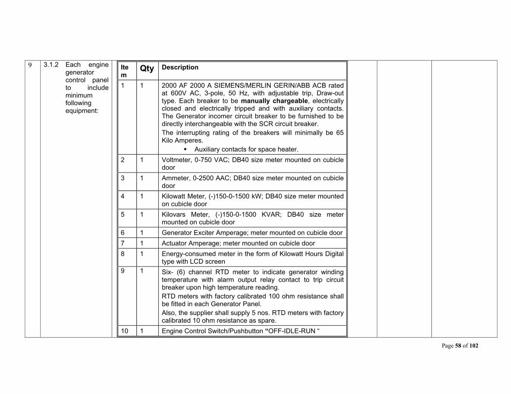
Page 58 of 102
9 3.1.2 Each engine generator control panel to include minimum following equipment:
Item
Qty Description
1 1 2000 AF 2000 A SIEMENS/MERLIN GERIN/ABB ACB rated at 600V AC, 3-pole, 50 Hz, with adjustable trip, Draw-out type. Each breaker to be manually chargeable, electrically closed and electrically tripped and with auxiliary contacts. The Generator incomer circuit breaker to be furnished to be directly interchangeable with the SCR circuit breaker. The interrupting rating of the breakers will minimally be 65 Kilo Amperes.
Auxiliary contacts for space heater.
2 1 Voltmeter, 0-750 VAC; DB40 size meter mounted on cubicle door
3 1 Ammeter, 0-2500 AAC; DB40 size meter mounted on cubicle door
4 1 Kilowatt Meter, (-)150-0-1500 kW; DB40 size meter mounted on cubicle door
5 1 Kilovars Meter, (-)150-0-1500 KVAR; DB40 size meter mounted on cubicle door
6 1 Generator Exciter Amperage; meter mounted on cubicle door
7 1 Actuator Amperage; meter mounted on cubicle door
8 1 Energy-consumed meter in the form of Kilowatt Hours Digital type with LCD screen
9 1 Six- (6) channel RTD meter to indicate generator winding temperature with alarm output relay contact to trip circuit breaker upon high temperature reading. RTD meters with factory calibrated 100 ohm resistance shall be fitted in each Generator Panel. Also, the supplier shall supply 5 nos. RTD meters with factory calibrated 10 ohm resistance as spare.
10 1 Engine Control Switch/Pushbutton “OFF-IDLE-RUN “
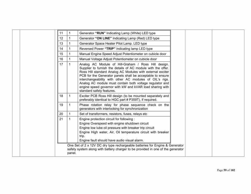
Page 59 of 102
11 1 Generator “RUN” Indicating Lamp (White) LED type
12 1 Generator “ON LINE” Indicating Lamp (Red) LED type
13 1 Generator Space Heater Pilot Lamp. LED type
14 1 Reversed Power “TRIP” indicating lamp LED type
15 1 Manual Engine Speed Adjust Potentiometer on cubicle door
16 1 Manual Voltage Adjust Potentiometer on cubicle door
17 1 Analog AC Module of Hill-Graham / Ross Hill design. Supplier to furnish the details of AC module with the offer. Ross Hill standard Analog AC Modules with external exciter PCB for the Generator panels shall be acceptable to ensure interchangeability with other AC modules of OIL’s rigs. Analog AC module must contain both voltage regulator and engine speed governor with kW and kVAR load sharing with standard safety features.
18 1 Exciter PCB Ross Hill design (to be mounted separately and preferably identical to HGC part # P359T), if required.
19 1 Phase rotation relay for phase sequence check on the generators with interlocking for synchronization
20 1 Set of transformers, resistors, fuses, relays etc
21 1 Engine protection circuit for following : Engine Overspeed with engine shutdown circuit Engine low lube oil pressure with breaker trip circuit Engine High water, Air, Oil temperature circuit with breaker trip. Engine fault should have audio visual alarm.
One Set of 2 x 12V DC dry type rechargeable batteries for Engine & Generator safety system along with battery charger to be provided in one of the generator panel.

Page 60 of 102
10 3.1.3
SYNCHRONIZING SYSTEM:
The Synchronizing System shall be designed to manually synchronize the selected generator.
Item Qty Description 1 1 Synchronizing system consisting of components and a
sync section display panel which will be conveniently located to easily synchronize each Engine/Generator through high visibility sync lights and synchroscope. The sync section to have the following auxiliary controls and components:
2 1 Frequency meter and associated selector switch selectable to Main Bus and Generators 1/2/3/4/5
3 1 Voltmeter and associated selector switch selectable to Main Bus and Generators 1/2/3/4/5
4 1 Sync Switch: GEN1 – GEN2 – OFF – GEN3 – GEN4- GEN5
5 1 Synchro- Check PCB 6 1 Synchroscope 7 SET Synchronizing lights for synchronization with Generator
Circuit Breakers. Sync Switch and Synchro- Check PCB shall be mounted in one of the Gen panels whereas Frequency meter, Voltmeter, Synchroscope & Sync lamps shall be mounted in a separate box/panel visible from all the Generator panels.
11 3.2 FEEDER PANEL - 2 (Two) Nos
A separate feeder panel should be provided to house following items:
12 3.2.1 TRANSFORMER FEEDER BREAKERS
The feeder panel to be consisting of the following main equipments:
Item Qty Description 1 2 1000 - 1200 Amps, 600 Volts, 3-Pole, manually operated
Siemens / Merlin Gerin/ABB, MCCBs Type feeder circuit breakers having breaking capacity of 65 KA each for 2 X 600 KVA 600/415V 50 Hz, Delta/Star Dry Type Power Transformer for powering auxiliary AC loads and rig lighting system. MCCBs should be settable from 0.4 x 1 of rated current with electronic release. The interrupting rating of the
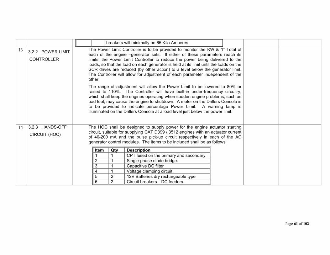
Page 61 of 102
breakers will minimally be 65 Kilo Amperes.
13 3.2.2 POWER LIMIT
CONTROLLER
The Power Limit Controller is to be provided to monitor the KW & “I” Total of each of the engine –generator sets. If either of these parameters reach its limits, the Power Limit Controller to reduce the power being delivered to the loads, so that the load on each generator is held at its limit until the loads on the SCR drives are reduced (by other action) to a level below the generator limit. The Controller will allow for adjustment of each parameter independent of the other.
The range of adjustment will allow the Power Limit to be lowered to 80% or raised to 110%. The Controller will have built-in under-frequency circuitry, which shall keep the engines operating when sudden engine problems, such as bad fuel, may cause the engine to shutdown. A meter on the Drillers Console is to be provided to indicate percentage Power Limit. A warning lamp is illuminated on the Drillers Console at a load level just below the power limit.
14 3.2.3 HANDS-OFF
CIRCUIT (HOC)
The HOC shall be designed to supply power for the engine actuator starting circuit, suitable for supplying CAT D399 / 3512 engines with an actuator current of 40-200 mA and the pulse pick-up circuit respectively in each of the AC generator control modules. The items to be included shall be as follows:
Item Qty Description 1 1 CPT fused on the primary and secondary. 2 1 Single-phase diode bridge. 3 1 Capacitive DC filter 4 1 Voltage clamping circuit. 5 2 12V Batteries dry rechargeable type 6 2 Circuit breakers—DC feeders.
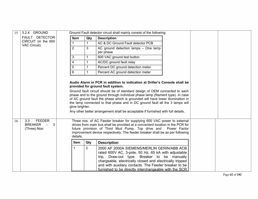
Page 62 of 102
15 3.2.4 GROUND
FAULT DETECTOR CIRCUIT (in the 600 VAC Circuit):
Ground Fault detector circuit shall mainly consist of the following:
Item Qty Description
1 1 AC & DC Ground Fault detector PCB
2 3 AC ground detection lamps – One lamp per phase
3 1 600 VAC ground test button
4 1 AC/DC ground fault relay
5 1 Percent DC ground detection meter
6 1 Percent AC ground detection meter
Audio Alarm in PCR in addition to indication at Driller’s Console shall be provided for ground fault system.
Ground fault circuit should be of standard design of OEM connected to each phase and to the ground through individual phase lamp (filament type). In case of AC ground fault the phase which is grounded will have lower illumination in the lamp connected to that phase and in DC ground fault all the 3 lamps will glow brighter.
Any other better arrangement shall be acceptable if furnished with full details.
16 3.3 FEEDER BREAKER - 3 (Three) Nos:
Three nos. of AC Feeder breaker for supplying 600 VAC power to external drives from main bus shall be provided at a convenient location in the PCR for future provision of Third Mud Pump, Top drive and Power Factor improvement device respectively. The feeder breaker shall be as per following details.
Item Qty Description
1 3 2000 AF 2000A SIEMENS/MERLIN GERIN/ABB ACB rated 600V AC, 3-pole, 50 Hz, 65 kA with adjustable trip, Draw-out type. Breaker to be manually chargeable, electrically closed and electrically tripped and with auxiliary contacts. The Feeder breaker to be furnished to be directly interchangeable with the SCR
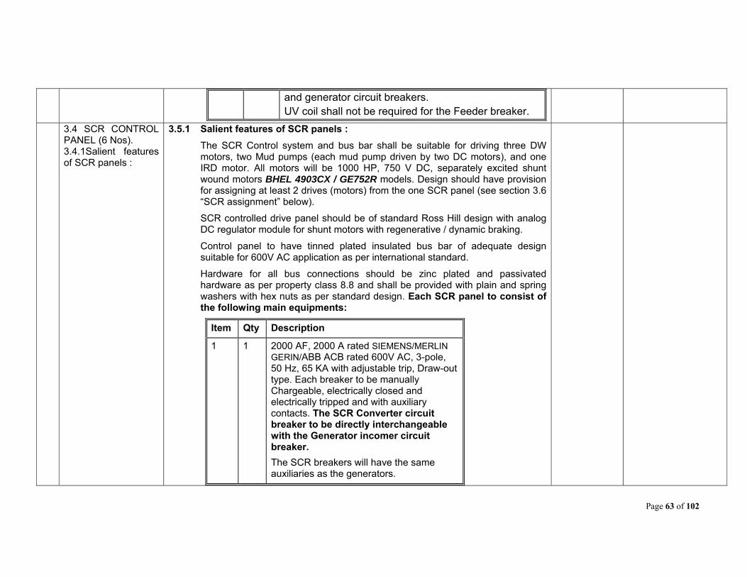
Page 63 of 102
and generator circuit breakers. UV coil shall not be required for the Feeder breaker.
3.4 SCR CONTROL PANEL (6 Nos). 3.4.1Salient features of SCR panels :
3.5.1 Salient features of SCR panels :
The SCR Control system and bus bar shall be suitable for driving three DW motors, two Mud pumps (each mud pump driven by two DC motors), and one IRD motor. All motors will be 1000 HP, 750 V DC, separately excited shunt wound motors BHEL 4903CX / GE752R models. Design should have provision for assigning at least 2 drives (motors) from the one SCR panel (see section 3.6 “SCR assignment” below).
SCR controlled drive panel should be of standard Ross Hill design with analog DC regulator module for shunt motors with regenerative / dynamic braking.
Control panel to have tinned plated insulated bus bar of adequate design suitable for 600V AC application as per international standard.
Hardware for all bus connections should be zinc plated and passivated hardware as per property class 8.8 and shall be provided with plain and spring washers with hex nuts as per standard design. Each SCR panel to consist of the following main equipments:
Item Qty Description
1 1 2000 AF, 2000 A rated SIEMENS/MERLIN GERIN/ABB ACB rated 600V AC, 3-pole, 50 Hz, 65 KA with adjustable trip, Draw-out type. Each breaker to be manually Chargeable, electrically closed and electrically tripped and with auxiliary contacts. The SCR Converter circuit breaker to be directly interchangeable with the Generator incomer circuit breaker.
The SCR breakers will have the same auxiliaries as the generators.
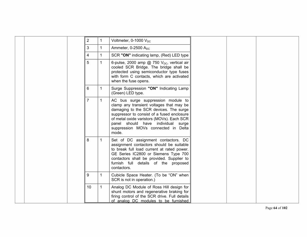
Page 64 of 102
2 1 Voltmeter, 0-1000 VDC
3 1 Ammeter, 0-2500 ADC
4 1 SCR "ON" indicating lamp, (Red) LED type
5 1 6-pulse, 2000 amp @ 750 VDC, vertical air cooled SCR Bridge. The bridge shall be protected using semiconductor type fuses with form C contacts, which are activated when the fuse opens.
6 1 Surge Suppression "ON" Indicating Lamp (Green) LED type.
7 1 AC bus surge suppression module to clamp any transient voltages that may be damaging to the SCR devices. The surge suppressor to consist of a fused enclosure of metal oxide varistors (MOVs). Each SCR panel should have individual surge suppression MOVs connected in Delta mode.
8 1 Set of DC assignment contactors. DC assignment contactors should be suitable to break full load current at rated power. GE Series IC2800 or Siemens Type 700 contactors shall be provided. Supplier to furnish full details of the proposed contactors.
9 1 Cubicle Space Heater. (To be “ON” when SCR is not in operation.)
10 1 Analog DC Module of Ross Hill design for shunt motors and regenerative braking for firing control of the SCR drive. Full details of analog DC modules to be furnished
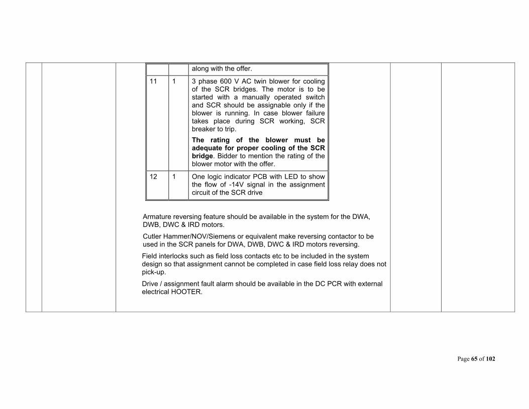
Page 65 of 102
along with the offer.
11 1 3 phase 600 V AC twin blower for cooling of the SCR bridges. The motor is to be started with a manually operated switch and SCR should be assignable only if the blower is running. In case blower failure takes place during SCR working, SCR breaker to trip.
The rating of the blower must be adequate for proper cooling of the SCR bridge. Bidder to mention the rating of the blower motor with the offer.
12 1 One logic indicator PCB with LED to show the flow of -14V signal in the assignment circuit of the SCR drive
Armature reversing feature should be available in the system for the DWA, DWB, DWC & IRD motors.
Cutler Hammer/NOV/Siemens or equivalent make reversing contactor to be used in the SCR panels for DWA, DWB, DWC & IRD motors reversing.
Field interlocks such as field loss contacts etc to be included in the system design so that assignment cannot be completed in case field loss relay does not pick-up.
Drive / assignment fault alarm should be available in the DC PCR with external electrical HOOTER.
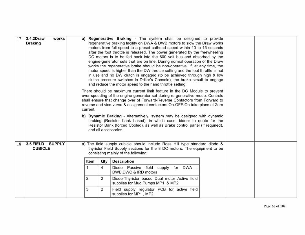
Page 66 of 102
17 3.4.2Draw works Braking
a) Regenerative Braking - The system shall be designed to provide regenerative braking facility on DWA & DWB motors to slow the Draw works motors from full speed to a preset cathead speed within 10 to 15 seconds after the foot throttle is released. The power generated by the freewheeling DC motors is to be fed back into the 600 volt bus and absorbed by the engine-generator sets that are on line. During normal operation of the Draw works the regenerative brake should be non-operative. If, at any time, the motor speed is higher than the DW throttle setting and the foot throttle is not in use and no DW clutch is engaged (to be achieved through high & low clutch pressure switches in Driller’s Console), the brake circuit to engage and reduce the motor speed to the hand throttle setting.
There should be maximum current limit feature in the DC Module to prevent over speeding of the engine-generator set during re-generative mode. Controls shall ensure that change over of Forward-Reverse Contactors from Forward to reverse and vice-versa & assignment contactors On-OFF-On take place at Zero current.
b) Dynamic Braking - Alternatively, system may be designed with dynamic braking (Resistor bank based), in which case, bidder to quote for the Resistor Bank (forced Cooled), as well as Brake control panel (If required), and all accessories.
18 3.5 FIELD SUPPLY CUBICLE
a) The field supply cubicle should include Ross Hill type standard diode & thyristor Field Supply sections for the 8 DC motors. The equipment to be consisting mainly of the following:
Item Qty Description
1 4 Diode Passive field supply for DWA , DWB,DWC & IRD motors
2 2 Diode-Thyristor based Dual motor Active field supplies for Mud Pumps MP1 & MP2
3 2 Field supply regulator PCB for active field supplies for MP1 , MP2

Page 67 of 102
4 6 HOA switches for field supplies
5 8 Field current ammeters for all motors
6 6 Padlock Lock Out Devices
7 2 Selector Switches for each Mud pump (MPA+MPB / MPA / MPB)
8 2 POTs for A or B single motor operation current command / feedback
9 2 Field imbalance illuminated reset push buttons for dual motor field supplies
b) Mud pump field supplies shall be designed to facilitate operation of mud pump motors together or individually (A or A+B or B). Corresponding Current limits for mud pump operation with one motor or two motors will be automatic adjustable as per field supply assignment through DC Modules.
c) Field regulator PCB should be able to regulate the B motor SCR field supply with respect to the feedback command signal of Diode field supply of A motor in case of active field supply unit for MP1 & MP2 respectively.
d) For single motor operation of MP1 & MP2 current command / feedback signals should be generated from external POTs for field supply regulator PCB.
e) Field supply transformers should have tappings for adjustment of field current of the DC motors. Required fused protection for transformer primary and secondary should be provided.
f) Field supplies should be able to supply 57 Amps DC to the DC motor shunt field windings in hot motor condition. However the field currents & voltage should be adjustable to match with the DC motor requirements of BHEL 4903CX / GE752R models.
g) DC motor Field supplies to have Hands-Off-Auto (HOA) switch to facilitate energizing of field supplies without drilling function being assigned. In Auto mode required MCC interlocking should be built into the field supply circuits to ensure that field is energized only after DC motor blower picks up. An
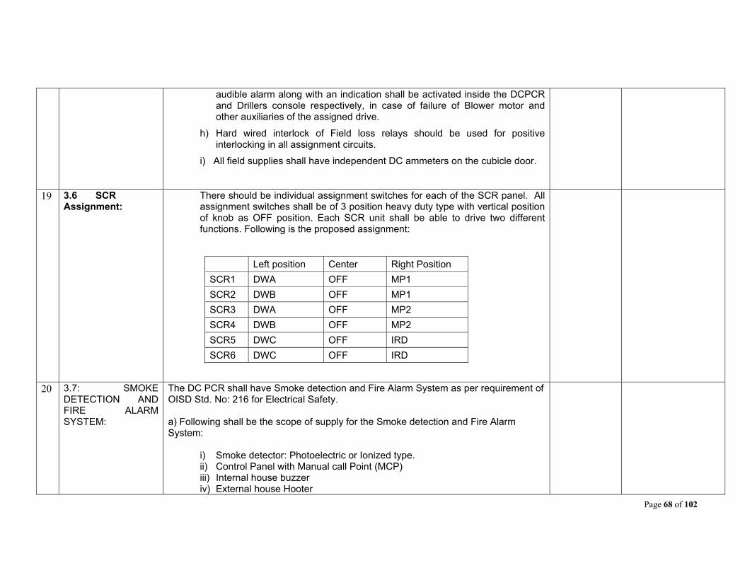
Page 68 of 102
audible alarm along with an indication shall be activated inside the DCPCR and Drillers console respectively, in case of failure of Blower motor and other auxiliaries of the assigned drive.
h) Hard wired interlock of Field loss relays should be used for positive interlocking in all assignment circuits.
i) All field supplies shall have independent DC ammeters on the cubicle door.
19 3.6 SCR Assignment:
There should be individual assignment switches for each of the SCR panel. All assignment switches shall be of 3 position heavy duty type with vertical position of knob as OFF position. Each SCR unit shall be able to drive two different functions. Following is the proposed assignment:
Left position Center Right Position
SCR1 DWA OFF MP1
SCR2 DWB OFF MP1
SCR3 DWA OFF MP2
SCR4 DWB OFF MP2
SCR5 DWC OFF IRD
SCR6 DWC OFF IRD
20 3.7: SMOKE DETECTION AND FIRE ALARM SYSTEM:
The DC PCR shall have Smoke detection and Fire Alarm System as per requirement of OISD Std. No: 216 for Electrical Safety. a) Following shall be the scope of supply for the Smoke detection and Fire Alarm System:
i) Smoke detector: Photoelectric or Ionized type. ii) Control Panel with Manual call Point (MCP) iii) Internal house buzzer iv) External house Hooter
Page 69 of 102
v) Wiring and installation accessories kit vi) Any other material required for the installation and satisfactory operation of
the system. b) TECHNICAL SPECIFICATIONS:
i) Smoke sensor type :Two wire smoke detector
ii) Controls : Reset switch for fire & Accept switch for Alarm
iii) Number of Zones :Two
iv) Indications: a. Power ON b. Fire Detection3) c. Smoke sensor cable open d. Smoke sensor cable short
v) Operating supply: 230VAC, 50Hz supply
vi) Internal House buzzer: Size 96x96mm, 80 dB at 1 m
vii) External Hooter : Min 100 dB at 1 m
c) Location of Smoke detectors shall be 2 on front side of the panels and 2 on the rear side of the panels at accessible locations. Smoke detectors shall preferably be mounted on the ceiling of the PCRs or at any other location inside the house. d) Control panel along with internal house buzzer & manual call point control shall be installed near entry/exit door. External house hooter shall be installed at the outside of the house facing derrick side. All wiring inside the house should be properly dressed and routed through conduits / cable trays.
Page 70 of 102
21 3.8 EXTERNAL CONNECTIONS:
The rig external connections from the DC PCR to different loads and drives should be through easily removable type plug & receptacles and following should be taken care of in the design:
3.8.1 External power connections to Alternators, Top drive feeder, Power Factor Improvement Device, Mud pump feeder and Transformers in AC PCR and DC motor power connection to be done through single pole Pyle National make power plug & sockets of suitable rating. Plugs & sockets (crimped type) should be suitable to accommodate 300 sq mm flexible copper cable with built-up conductor dia of 26 mm & OD of 35 mm (+/-1 mm). The alternator socket board should be provided with adequate nos. of sockets per phase to carry 1500 A continuous current per phase.
3.8.2 Each of the actuator & MPU signals shall be through two separate 1.5 sq mm x 4 core cables. The exciter field supply, RTD and engine protection circuits shall be connected through a 2.5 sq mm x 20 core cable. Space heater connection for Alternators shall be through MCBs in the distribution panel. The pin configuration for 20 core cable Alternator control connections is enclosed as Annexure-1. Pyle National make star line plugs & sockets (crimped type) should be used for Generator control connections for 3 core & 20 core cables.
3.8.3 Exclusive 20 Pin plugs & sockets to be provided for shunt fields of DC motors & control connections. The DC motor field supplies to run through 2 x 6 cores of 2.5 sq mm x 20 core cable. Space heater connections, air flow switch & lock out switch connections to the DC motors shall also be through this 20 core cable. The pin configuration for 20 core cable for DC motor control connections is enclosed as Annexure – 2. Space heater connection for DC motors shall be through MCBs in the distribution panel. Pyle National - Star Line make plugs & sockets (crimped type) should be used for Motor control connections for 20 conductor cables.
3.8.4 All control interconnections for AC PCR shall be through 2.5 sq mm x 20 core cables. Pyle National - Star Line make plugs & sockets (crimped type) should be used for interconnections for 20 core cables.
3.8.5 The Plug Panel(s) should feature shutter or doors which can be closed/opened smoothly with all the cables plugged in, during normal running condition to avoid ingress of water inside the plug panels due to rain.
Page 71 of 102
3.8.6 Suitable lighting fixtures should be provided for plug panel(s) lighting.
3.8.7 To avoid damage due to sharp bend and injury to the cable due to its self weight, sockets should be mounted on socket board of slant stair case design.
3.8.8 Earthing cable from earth bus bar should be brought out up to the socket board for termination at the earth pit.
3.8.9 Sufficient redundancy should be provided in sockets consisting of each ratings by quantity proportion and at least one for each rating. PCR socket board to have extra socket holes of each rating with blank covers for use to meet exigency.
3.8.10 Air-conditioner incomer supply from AC PCR shall be through a 4-pin 100 Amps Appleton plug & socket. DC PCR lighting & space heater supply from AC PCR shall be through a 4 pin 60 Amps Appleton Plug & socket.
3.8.11 10% extra plug and sockets of each type & rating shall be supplied as loose spare items by the supplier with minimum 1 No. of each type. Supplier to furnish list of plugs & sockets used and spare qty supplied. This should be finally included in the 2 years spares list by supplier.
3.8.12 Oil India shall supply all external cables except the PLC communication cables for Driller Console & MP Console. PLC communication cable of 120 meter length for Driller’s Console and 30 meter length for Mud Pump Console shall be in supplier scope and to be supplied with the DC PCR. One PLC cable each of the above lengths should be supplied as spare for both Drillers console and mud pump console. Suitable repeaters for the PLC cable shall be incorporated in the design for effective transmission of signal over a long distance. The termination of all external cables to the loose plugs & sockets supplied by the supplier shall be the responsibility of Oil India. The outside diameters of cables for Plug grommet sizing is furnished by Oil India in respective Annexure.

Page 72 of 102
22 3.9 SPACE HEATERS
The space heater supplies to be suitable for 500 W, 230 VAC rating of the space heaters. Space heaters shall be powered through 230 V AC Phase-Phase 3 wire supply from AC PCR (MCC house).
Space heater connections shall be required for all Eight DC motors & five alternators and to be provided through the 2 Pole MCBs in the distribution panel. DC motor space heaters will remain energized, if DC motor blower is not operational. Alternator space heaters to remain energized, if Alternator is not operational.
All cubicles shall have their independent space heaters.
Any other method proposed by supplier for supply of Space heaters meeting the functional requirement can be accepted, if full details are provided by supplier.
23 3.10 PLC CONTROL PANEL:
3.10.1 The programmable logic control panel has to perform the following functions for over all SCR control, inter lock with accessories and monitoring.
The System Host PLC shall be a high speed, versatile modular PLC. The PLC to be used shall be suitable for serial communication with remote consoles and other rig components and devices.
3.10.2 The PLC shall incorporate the SCR bridge assignment logic.
The PLC system shall have provision for twisted pair cable for communication with the remote Racks in Driller & MP Console. A signal repeater shall also be provided in the design. The controls including PLC shall be suitable for a cable length of up to 120 meters form DC/PCR to Driller Console to meet cluster drilling requirement.
The PLC shall have provisions for interfacing with the LAN. Interface with controls and indicators of the driller’s console shall be via the field I/O units. PLC shall provide status, alarm and diagnostic tools via local annunciation functions. PLC will provide automatic starting of Mud Pump and Draw works auxiliaries with indicating lights on console. The supercharger pumps shall be started & stopped manually from Driller’s Console.
There is no remote PLC in the AC/PCR for MCC interlocking for the DC motor control logics. All PLC relay inputs/outputs for auto starting of DC motor auxiliaries and alarm functions through MCC in AC PCR should have interface

Page 73 of 102
relays in PLC cubicle with adequate contact ratings.
Fault storage facility should be available through the PLC in the system with built-in self diagnostic features.
3.10.3 Touch Screen Display - PLC shall have touch screen for all miscellaneous indications for all generators & all SCR panels, indications for various drives, ground faults, power limits, Driller assignment, Hour meter, current & voltage metering, trending of historic data & faults etc. See Clause 3.9.6 (below) for full details.
24 3.10.4 Bypass Mode The PLC shall have a bypass switch (FOR MANUAL BACKUP MODE) to
allow for minimum assignment in the event there is a failure in the PLC.
The bypass (FOR MANUAL BACKUP MODE) will require a twenty- (20) conductor cable to be connected between the PCR and the Driller’s Console. The assignment furnished in the bypass mode allow one- (1) drive per SCR bay when the by pass mode is selected. Since there are 6 SCR cubicles there could be 6 DRIVES available. In PLC By-Pass mode following assignment should be available:
SCR 1 SCR 2 SCR 3 SCR 4 SCR 5 SCR 6
DWA
MP1 (MP1A &
MP1B motors)
MP2 (MP2A &
MP2B motors)
DWB DWC IRD
PLC cubicle should be provided with CVT of adequate rating to avoid any effect of SCR system harmonics.
In the bypass mode apart from the normal operations, the meters (DC ammeters and voltmeters of the SCR inside DCPCR and Drillers console) of the assigned drive, along with Mud pump console and foot throttle shall be fully functional.
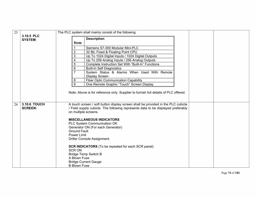
Page 74 of 102
25 3.10.5 PLC SYSTEM:
The PLC system shall mainly consist of the following:
Item Description
1 Siemens S7-300 Modular Mini-PLC 2 32 Bit, Fixed & Floating Point CPU 3 Up To 1024 Digital Inputs / 1024 Digital Outputs 4 Up To 256 Analog Inputs / 256 Analog Outputs 5 Complete Instruction Set With “Built-In” Functions 6 Built-In Self Diagnostics 7 System Status & Alarms When Used With Remote
Display Screen 8 Fiber Optic Communication Capability 9 One Remote Graphic “Touch” Screen Display
Note: Above is for reference only. Supplier to furnish full details of PLC offered.
26 3.10.6 TOUCH SCREEN:
A touch screen / soft button display screen shall be provided in the PLC cubicle / Field supply cubicle. The following represents data to be displayed preferably on multiple screens.
MISCELLANEOUS INDICATORS
PLC System Communication OK Generator ON (For each Generator) Ground Fault Power Limit Driller Console Assignment.
SCR INDICATORS (To be repeated for each SCR panel) SCR ON Bridge Temp Switch B A Blown Fuse Bridge Current Gauge B Blown Fuse
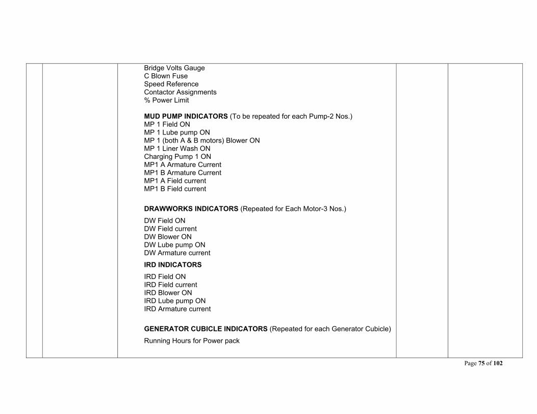
Page 75 of 102
Bridge Volts Gauge C Blown Fuse Speed Reference Contactor Assignments % Power Limit MUD PUMP INDICATORS (To be repeated for each Pump-2 Nos.) MP 1 Field ON MP 1 Lube pump ON MP 1 (both A & B motors) Blower ON MP 1 Liner Wash ON Charging Pump 1 ON MP1 A Armature Current MP1 B Armature Current MP1 A Field current MP1 B Field current
DRAWWORKS INDICATORS (Repeated for Each Motor-3 Nos.)
DW Field ON DW Field current
DW Blower ON DW Lube pump ON DW Armature current
IRD INDICATORS
IRD Field ON IRD Field current
IRD Blower ON IRD Lube pump ON IRD Armature current
GENERATOR CUBICLE INDICATORS (Repeated for each Generator Cubicle)
Running Hours for Power pack
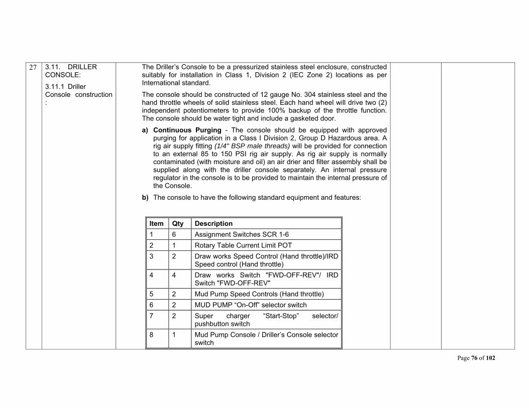
Page 76 of 102
27 3.11. DRILLER CONSOLE:
3.11.1 Driller Console construction :
The Driller’s Console to be a pressurized stainless steel enclosure, constructed suitably for installation in Class 1, Division 2 (IEC Zone 2) locations as per International standard.
The console should be constructed of 12 gauge No. 304 stainless steel and the hand throttle wheels of solid stainless steel. Each hand wheel will drive two (2) independent potentiometers to provide 100% backup of the throttle function. The console should be water tight and include a gasketed door.
a) Continuous Purging - The console should be equipped with approved purging for application in a Class I Division 2, Group D Hazardous area. A rig air supply fitting (1/4" BSP male threads) will be provided for connection to an external 85 to 150 PSI rig air supply. As rig air supply is normally contaminated (with moisture and oil) an air drier and filter assembly shall be supplied along with the driller console separately. An internal pressure regulator in the console is to be provided to maintain the internal pressure of the Console.
b) The console to have the following standard equipment and features:
Item Qty Description
1 6 Assignment Switches SCR 1-6
2 1 Rotary Table Current Limit POT
3 2 Draw works Speed Control (Hand throttle)/IRD Speed control (Hand throttle)
4 4 Draw works Switch "FWD-OFF-REV"/ IRD Switch "FWD-OFF-REV"
5 2 Mud Pump Speed Controls (Hand throttle)
6 2 MUD PUMP “On-Off” selector switch
7 2 Super charger “Start-Stop” selector/ pushbutton switch
8 1 Mud Pump Console / Driller’s Console selector switch
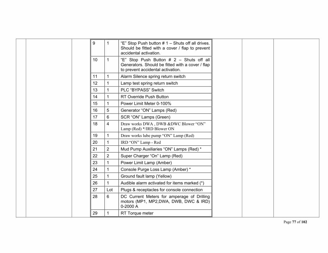
Page 77 of 102
9 1 “E” Stop Push button # 1 – Shuts off all drives. Should be fitted with a cover / flap to prevent accidental activation.
10 1 “E” Stop Push Button # 2 – Shuts off all Generators. Should be fitted with a cover / flap to prevent accidental activation.
11 1 Alarm Silence spring return switch
12 1 Lamp test spring return switch
13 1 PLC “BYPASS” Switch
14 1 RT Override Push Button
15 1 Power Limit Meter 0-100%
16 5 Generator “ON” Lamps (Red)
17 6 SCR “ON” Lamps (Green)
18 4 Draw works DWA , DWB &DWC Blower “ON” Lamp (Red) */IRD Blower ON
19 1 Draw works lube pump “ON” Lamp (Red)
20 1 IRD “ON” Lamp - Red
21 2 Mud Pump Auxiliaries “ON” Lamps (Red) *
22 2 Super Charger “On” Lamp (Red)
23 1 Power Limit Lamp (Amber)
24 1 Console Purge Loss Lamp (Amber) *
25 1 Ground fault lamp (Yellow)
26 1 Audible alarm activated for items marked (*)
27 Lot Plugs & receptacles for console connection
28 6 DC Current Meters for amperage of Drilling motors (MP1, MP2,DWA, DWB, DWC & IRD) 0-2000 A
29 1 RT Torque meter

Page 78 of 102
30 1 Set of relays, fuses, sockets etc
31 1 PLC remote rack
32 1 DW / RT Clutch pressure switch
33 2 DW Hi / Low clutch pressure switches.
34 1 set IRD controls including hand throttle
Note: Any other item required for Driller Console as per system design to be included by supplier.
c) Control circuit shall be designed so that Super Chargers can be made operational irrespective of mud pumps assignment. Mud pumps can be made operational without working of super chargers.
d) Emergency Stop Push-Buttons - The “E” STOP PB# 1 will trip all SCR breakers and will cut off the power to the console. All DC motor blowers and IRD/Draw-works/MP auxiliaries also should stop. The “E” STOP PB# 2 will trip all Generator Breakers, and cut off total Electrical Power supply to the Rig. Both the “E” STOP push buttons shall be hard wired and fully operational in the PLC BYPASS mode.
e) PLC “Bypass” mode - When PLC Bypass mode is selected one dedicated SCR for one DC motor shall be available. The assignment to be provided is one (1) motor per SCR bay. Since there will be 6 SCR cubicles there could be 6 drives available for emergency operation in manual mode. In the bypass mode apart from normal operation the meters (DC ammeters and voltmeters of the SCR inside DCPCR and Drillers console) of the assigned drive, along with Mud pump console and foot throttle should be fully functional.
f) Provision for Running RT from DW – The RT may be run from DW, in case of failure of RT drive or any other reason. The DW / RT selection should be through a Pressure switch in the Driller Console. Pressure switch to pick-up when driller operates Rotary Clutch as per standard Ross Hill design. There should be separate pressure switches for Hi & Lo clutch engagement sensing and regenerative brake should operate only when no clutch is engaged.
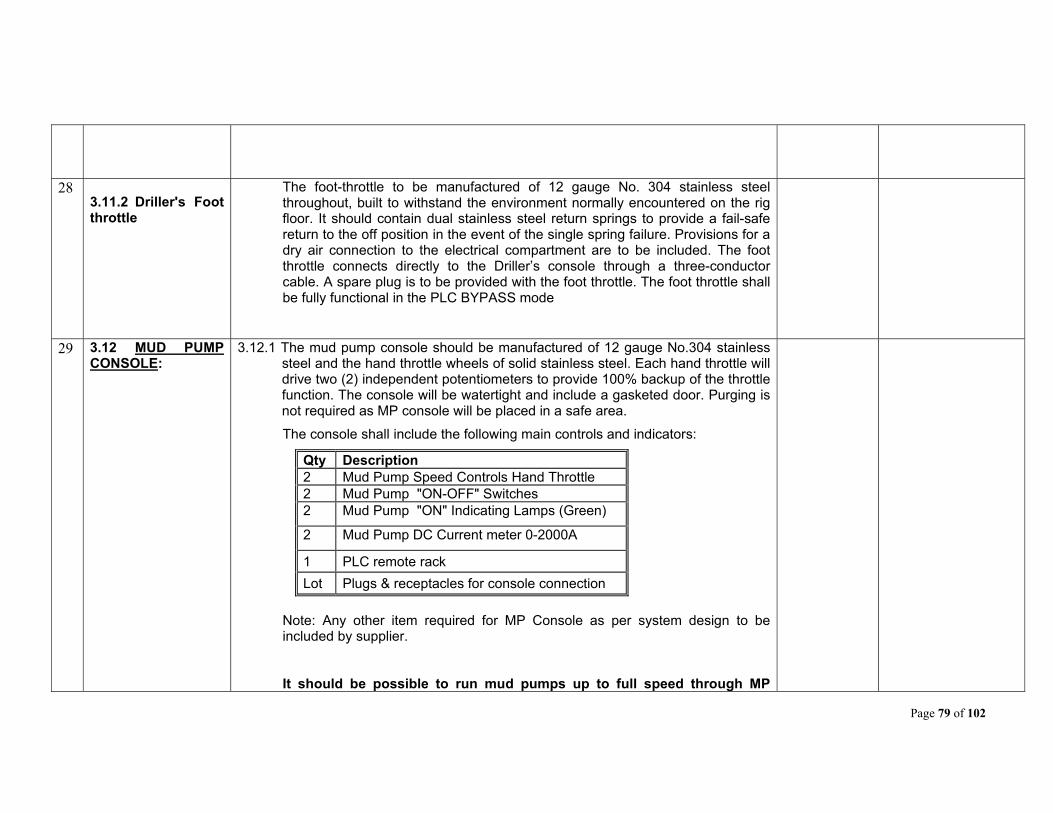
Page 79 of 102
28 3.11.2 Driller's Foot throttle
The foot-throttle to be manufactured of 12 gauge No. 304 stainless steel throughout, built to withstand the environment normally encountered on the rig floor. It should contain dual stainless steel return springs to provide a fail-safe return to the off position in the event of the single spring failure. Provisions for a dry air connection to the electrical compartment are to be included. The foot throttle connects directly to the Driller’s console through a three-conductor cable. A spare plug is to be provided with the foot throttle. The foot throttle shall be fully functional in the PLC BYPASS mode
29 3.12 MUD PUMP CONSOLE:
3.12.1 The mud pump console should be manufactured of 12 gauge No.304 stainless steel and the hand throttle wheels of solid stainless steel. Each hand throttle will drive two (2) independent potentiometers to provide 100% backup of the throttle function. The console will be watertight and include a gasketed door. Purging is not required as MP console will be placed in a safe area.
The console shall include the following main controls and indicators:
Qty Description 2 Mud Pump Speed Controls Hand Throttle 2 Mud Pump "ON-OFF" Switches 2 Mud Pump "ON" Indicating Lamps (Green)
2 Mud Pump DC Current meter 0-2000A
1 PLC remote rack
Lot Plugs & receptacles for console connection
Note: Any other item required for MP Console as per system design to be included by supplier.
It should be possible to run mud pumps up to full speed through MP

Page 80 of 102
Console. Operation through MP Console should be possible only if MPC / Driller’s Console switch at Driller Console is in MPC mode.
30 4.0 SPARES, TOOLS & TACKLES:
Following tools, tackles & spares to be supplied by Bidder; other than specified against any specific clause earlier in this document.
4.1 TOOLS & TACKLES :
Qty Description
SURVIVAL KIT CONSISTING OF THE FOLLOWING -
2 Pyle-National Plug and Receptacle Crimping Tools
1 Hydraulic Crimping Tool for Generator and DC Motor 300 sq mm cables
1 Tool Box with Hand Tools applicable to a rig up
1 Laptop with Windows 10 or later with software for programming the PLC
1 PLC-SIE, Software for PLC with license
2 PLC-SIE, Cable/Adptr, USB, PMB
1 Fluke Multi-meter model 175
1 Secondary injection test kit for Gen/SCR/Top Drive/Transformer feeder breakers
1 Jigsaw
1 25 Piece Jigsaw Blade Kit
1 300 sq mm Cable Cutter
1 Set of Pyle-National Pin Extraction/Insertion Tool Kit
2 Taparia Box wrench set
1 Hand drill machine,800 Watt,Bosch
2 Anti panic door locks
1 Megger MIT 300 IR tester

Page 81 of 102
1 Force 4941 94PC 1/2" & 1/4" SOCKET SET & SCREWDRIVER BIT TORX RATCHET DRIVER CASE TOOL KIT
NOTE: The laptop will have the PLC program software installed along with the PLC system logics program. Appropriate storage (CD / Flash Media) with the required software (s) also to be supplied loose. All software’s supplied shall be original and licensed to OIL India without expiration date. No trial version/evaluation /shareware copy of the software will be accepted.
31 4.2
COMMISSIONING AND OTHER RELATED SPARES
The following list of spares to be supplied with the PCR
4.2.1 COMMISSIONING SPARES FOR SCR SYSTEM IN PCR
Sr. No.
Qty Supplier Part No
Description
1 6 600 A, Fuse, 700V C
2 2 SW-Micro, 250 V, 10A Rated, U/ W000
3 10 Fuse .6A, 500 V c, 10 KIC
4 10 Fuse 2A, 500 V c, 10 KIC
5 10 Fuse 3.5 A, 500 V c, 10 KIC
6 10 Fuse 6A, 500 V c, 10 KIC
7 10 Fuse 10A, 500 V c, 10 KIC
8 10 Fuse 15A, 600 V c, 200 KIC
9 6 Fuse 60A, 1000 V c, KIC
10 3 SCR-2000V, 2293A, 4” Pkg
11 2 RLY-24 VDC, 2A2B0C, A, Fixed
12 2 RLY–120 V, 0A0B3C, 10A, BRKT
13 2 RLY-24 VDC, 0A0B3C, 10A, BRKT
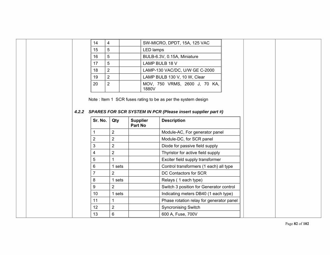
Page 82 of 102
14 4 SW-MICRO, DPDT, 15A, 125 VAC
15 5 LED lamps
16 5 BULB-6.3V, 0.15A, Miniature
17 5 LAMP BULB 18 V
18 2 LAMP-130 VAC/DC, U/W GE C-2000
19 2 LAMP BULB 130 V, 10 W, Clear
20 2 MOV, 750 VRMS, 2600 J, 70 KA, 1880V
Note : Item 1 SCR fuses rating to be as per the system design
4.2.2 SPARES FOR SCR SYSTEM IN PCR (Please insert supplier part #)
Sr. No. Qty Supplier Part No
Description
1 2 Module-AC, For generator panel
2 2 Module-DC, for SCR panel
3 2 Diode for passive field supply
4 2 Thyristor for active field supply
5 1 Exciter field supply transformer
6 1 sets Control transformers (1 each) all type
7 2 DC Contactors for SCR
8 1 sets Relays ( 1 each type)
9 2 Switch 3 position for Generator control
10 1 sets Indicating meters DB40 (1 each type)
11 1 Phase rotation relay for generator panel
12 2 Syncronising Switch
13 6 600 A, Fuse, 700V

Page 83 of 102
14 3 SW-Micro, 250 V, 10A Rated, U/ W000
15 20 Fuse .6A, 500 V c, 10 KIC
16 20 Fuse 2A, 500 V c, 10 KIC
17 20 Fuse 3.5 A, 500 V c, 10 KIC
18 20 Fuse 6A, 500 V c, 10 KIC
19 20 Fuse 10A, 500 V c, 10 KIC
20 20 Fuse 15A, 600 V c, 200 KIC
21 10 Fuse 60A, 1000 V c, KIC
22 4 SCR-2000V, 2293A, 4” Pkg
23 2 RLY-120VAC, 4A0B0C, 10A, IEC D
24 2 RLY-120VAC, 0A0B4C, 1A, Bifur
25 2 RLY-24VDC, 2A2B0C, 10A, IEC
26 4 SW-MICRO, DPDT, 15A, 125 VAC
27 1 BLWR-G/3B, 600V, 3PH, 2. HP, 50 HZ
28 10 LED lamps
29 10 BULB-6.3V, 0.15A, Miniature
30 5 LAMP BULB 18 V
31 5 LAMP-130VAC/DC, U/W GE C-2000
32 5 LAMP BULB 130 V, 10 W, Clear
33 2 MOV, 750 VRMS, 2600 J, 70 KA, 1880V
34 1 PCA PWR LIM CTRL
35 1 PC-DC SLIDE FOR SCR panel
36 1 ASSY-GND Leakage Detector
37 2 PC Auctioneering CKT BD
38 2 PC Generator Exciter BD
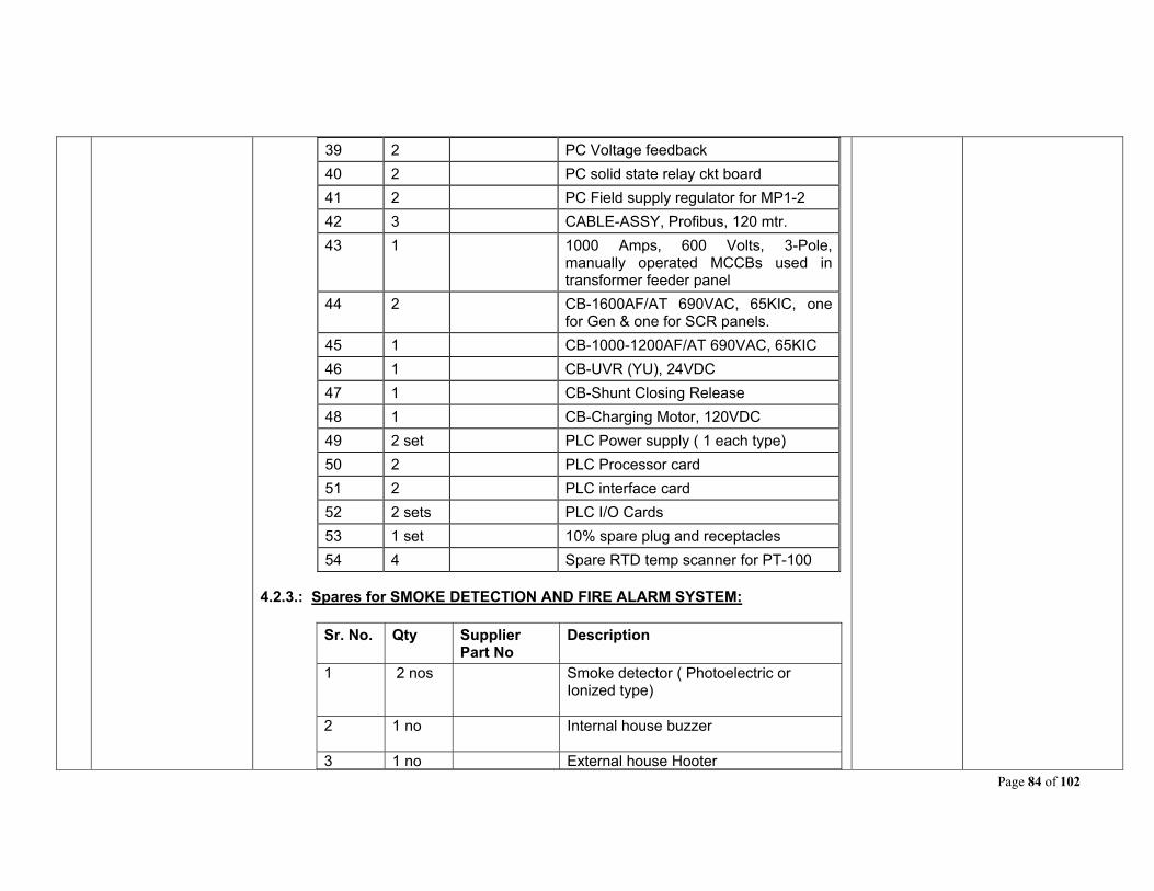
Page 84 of 102
39 2 PC Voltage feedback
40 2 PC solid state relay ckt board
41 2 PC Field supply regulator for MP1-2
42 3 CABLE-ASSY, Profibus, 120 mtr.
43 1 1000 Amps, 600 Volts, 3-Pole, manually operated MCCBs used in transformer feeder panel
44 2 CB-1600AF/AT 690VAC, 65KIC, one for Gen & one for SCR panels.
45 1 CB-1000-1200AF/AT 690VAC, 65KIC
46 1 CB-UVR (YU), 24VDC
47 1 CB-Shunt Closing Release
48 1 CB-Charging Motor, 120VDC
49 2 set PLC Power supply ( 1 each type)
50 2 PLC Processor card
51 2 PLC interface card
52 2 sets PLC I/O Cards
53 1 set 10% spare plug and receptacles
54 4 Spare RTD temp scanner for PT-100 4.2.3.: Spares for SMOKE DETECTION AND FIRE ALARM SYSTEM:
Sr. No. Qty Supplier Part No
Description
1 2 nos Smoke detector ( Photoelectric or Ionized type)
2 1 no Internal house buzzer
3 1 no External house Hooter

Page 85 of 102
4 1 set Any other Spares/ Accessories of
Control Panel
4.2.4 SPARES FOR DRILLER CONSOLE
Item DESCRIPTION Supplier Pt No
QTY.
1 Hand Throttle, Potentiometers, RTI limit Pot
1 set
2 SW- Assignment 3 position with contact blocks
2
3 SW – MP on/off 2 position with contact blocks
2
4 SW DW For/Rev 3 position with contact blocks
2
5 PCB – auctioneering circuit board 1
6 Relays (1 each type) 1 set
7 Pushbuttons 1 each
8. Indication lamps 1 set
9. Ammeters 1
10. PLC power supply 2
11 PLC Interface /Communications Module
2
12 PLC cable 120
4.2.3 SPARES FOR MUD PUMP CONSOLE
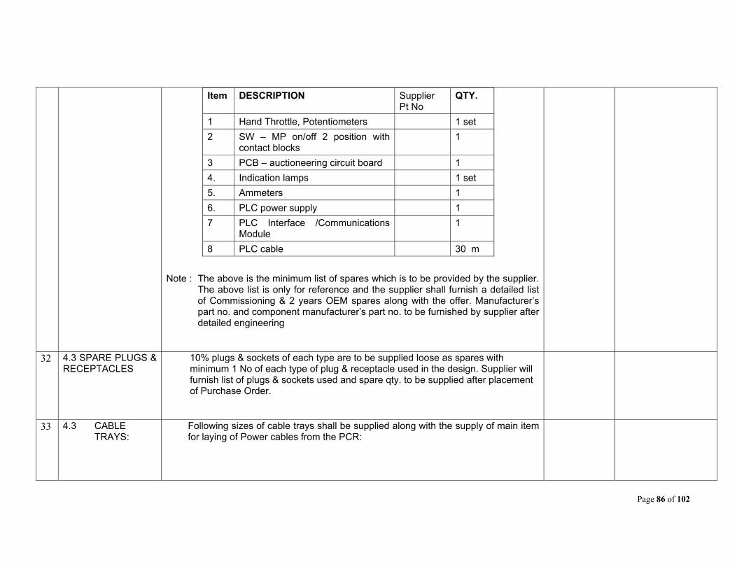
Page 86 of 102
Item DESCRIPTION Supplier Pt No
QTY.
1 Hand Throttle, Potentiometers 1 set
2 SW – MP on/off 2 position with contact blocks
1
3 PCB – auctioneering circuit board 1
4. Indication lamps 1 set
5. Ammeters 1
6. PLC power supply 1
7 PLC Interface /Communications Module
1
8 PLC cable 30 m
Note : The above is the minimum list of spares which is to be provided by the supplier. The above list is only for reference and the supplier shall furnish a detailed list of Commissioning & 2 years OEM spares along with the offer. Manufacturer’s part no. and component manufacturer’s part no. to be furnished by supplier after detailed engineering
32 4.3 SPARE PLUGS & RECEPTACLES
10% plugs & sockets of each type are to be supplied loose as spares with minimum 1 No of each type of plug & receptacle used in the design. Supplier will furnish list of plugs & sockets used and spare qty. to be supplied after placement of Purchase Order.
33 4.3 CABLE TRAYS:
Following sizes of cable trays shall be supplied along with the supply of main item for laying of Power cables from the PCR:

Page 87 of 102
Sl. No. Cable Tray Sizes Quantity
1. 5m (L) x 1m (B) x 1m (H)
3
2. 1m (L) x 1m (B) x 1m (H)
5
34 5.0 GENERAL POINTS:
i) Though a broad outline on the requirement has been made, yet the scope should include anything not mentioned but required for completeness of the system to meet the requirement of oil well deep drilling rig (drilling capacity 6100 meters depth) and make the same suitable for dismantling, transportation and installation very often in rough and tough conditions.
ii) The system offered shall have proven performance record. All relevant safety systems are to be incorporated and safety codes, relevant international codes to be strictly followed. Systems to be designed & manufactured to the latest NEC, IEC, IEEE-45, API 500, and NEMA standards, & should meet all present accepted international standards for the product/application
iii) Supplier shall use components/ sub-assemblies only of reputed and proven make and of latest design.
iv) The system shall be free from any defect arising from faulty material, workmanship or design. Any such defects, including replacement of faulty components, shall be carried out by the manufacturer free of cost during warranty period. The SUPPLIER shall have the total and final responsibility for the design and performance of all equipment.
v) All components, modules, subsystems shall be of current generation with latest technology which must be in production and must not face obsolescence in near future. The supplier and the manufacturer in turn shall guarantee that spare parts shall be available for at least fifteen years.
vi) The controls i.e. all electronics including modules and different electronic components, PLC etc. shall have high levels of noise immunity. They shall
Page 88 of 102
have high level of EMC and shall be immune from noise generated by future AC Variable Frequency Drive for Top Drive inclusion that will be powered from the 600 VAC Top Drive Feeder in the PCR.
vii) The system including all sub-assemblies and components should be designed to facilitate backward integration of future modules, cards etc without any modification.
viii) Bidder shall manufacture the DC-PCR at their works.
Bidder shall have adequate facilities for supply of DC-PCR spare parts for at least fifteen years. A certificate to this effect shall be attached with the bid.
ix) Bidder shall have well equipped testing and repair set-up in India, suitable for complete testing and repair of PCRs, including repairs to the skid and housing. Facilities available shall include Welding and painting. The set-up should include both on-site repair, as well as factory repair capability.
x) The DC-PCR shall be brand new, unused, manufactured especially for Oil India, and free from any manufacturing defect. This shall be categorically stated by the bidders in their quotations.
xi) Offers shall be complete in all respects and all the items/equipment as specified in the tender must be included in the package. Offers deemed to be incomplete shall be rejected (Bidders may quote additional items / equipment or accessories, other than Handling Equipment, not covered in this enquiry, if felt necessary for the completeness and efficient. operation of the DC-PCR)
xii) The bidder shall fill up the bidder’s response sheet with comments at the time of submission of bid.
35 6.0 PRE ENGINEERING
INFORMATION:
After placement of order, supplier can ask for pre-engineering information, if required, to start the system engineering. Oil India shall provide all necessary data required.
Page 89 of 102
36 7.0 COMMISSIONING
a. GENERAL Commissioning is an essential part of this Tender, and bids that do not quote for commissioning shall be treated as incomplete bids. Bidder has to successfully commission the DC-PCR at location in Assam, India, to the complete satisfaction of Oil India. Commissioning charges to be quoted separately on lumpsum basis which shall be considered for evaluation of the offers. These charges should include amongst others to and fro fares, boarding/lodging, local transport at Duliajan and other expenses of supplier’s commissioning personnel during their stay at Duliajan, Assam(India). All income, GST, Corporate Taxes etc. towards the services provided under installation / commissioning /training shall be borne by the supplier and will be deducted at source at the time of releasing the payment. Bidder should also confirm about providing all these services in the Technical Bid. Commissioning of the DC-PCR may require more than one visit, depending on availability of drilling rig and other factors. Charges for commissioning shall be paid as one lump-sum, and not per visit. The time available to commission the PCR shall be two weeks. However, Bidder shall note that the PCR cannot be commissioned at one single visit. Bidder should plan for a minimum of two visits to complete the commissioning of the PCR. Successful bidder shall submit a tentative plan for commissioning the DC-PCR, for approval of Oil India. The completed DC-PCR shall be connected to existing equipment (AC-PCR, Electrical motors, devices, cables etc.) in a drilling rig, checked for integrity of connections and acceptable levels of electrical insulation resistance, and powered up (phased up). All devices and interlocks shall be individually tested, and should work exactly as intended. The completed DC PCR shall be integrated with Third Mud Pump System as a whole on later date. The entire drilling rig, with the DC-PCR fully integrated shall be tested, and should work exactly as intended. Any problems, design inadequacies, material failure, device malfunction etc. shall be addressed / replaced by the successful bidder. Adequate spares for commissioning activity should be arranged for by
Page 90 of 102
the successful bidder. All personnel, statutory permissions (if required), equipment, tools, tackles and instruments required to commission the DC-PCR at site shall be arranged by the successful bidder. Oil India shall provide 415 VAC, 3 phase power, and transportation to and from Duliajan to drill-site only. b. RECEIPT OF MATERIALS DESPATCHED FROM MANUFACTURER'S WORKS The supplier should physically verify upon receipt, all equipment and materials (including commissioning spares etc.) after delivery at OIL's premises. The supplier should carry out inspection of all the supplied items to ascertain and certify that there all dispatched items have reached site, there is no transit damage and items are complete in all respects and ready for installation. In case of any discrepancy, supplier shall take necessary action for immediate replacement/ replenishment of the same before installation. c. A GUIDE FOR INSTALLATION AND COMMISSIONING ACTIVITIES EXPECTED: i. Installation, wiring and laying out of equipment: On arrival of equipment and materials (commissioning spares etc.) at OIL's premises the supplier should carry out inspection of the supplied items to ascertain and certify that there is no transit damage and items are complete in all respect and ready for installation. In case of any discrepancy, supplier shall take necessary action for immediate replacement/ replenishment of the same before installation. After receipt, the equipment shall be installed at site. This will include wiring/ cabling, fitting of plugs and sockets and any other activity required to make the equipment ready for commissioning. Any third party devices (if applicable) shall be installed inside the PCR at this stage. ii. Initial commissioning after start up connection: This activity will cover electrical insulation checks, wiring checks, phasing up

Page 91 of 102
(powering up) of individual equipment and the system as a whole. After start up connection and powering up, the complete system shall be tested at no load and minimum/ low load at OIL's well site. All equipment as well as the whole system shall work exactly as intended. Any modification/ re-wiring/ repair shall be carried out at this stage. iii. 2nd Stage commissioning: The PCR shall be integrated with the other equipment of the Drilling Rig, and operated in conjunction with these pieces of equipment, as a complete system. Any problems, abnormalities, anomalies and defects noticed/ logged during this stage (operation at full/rated load) shall be rectified by the supplier. This will cover setting/ adjustment/ calibration of limits in the control system, drives etc. All equipment as well as the whole system shall work exactly as intended. iii. Final Commissioning: Final commissioning of the PCR shall be done after 3 months but not later than six months from the date of 2nd Stage commissioning. This will cover setting/ adjustment/ calibration of limits in the control system, drives etc and the system as a whole. Any problems, abnormalities, anomalies and defects noticed/ logged after 2nd Stage commissioning and up to this stage (operation at full/rated load) shall be rectified by the supplier. All equipment as well as the whole system shall work exactly as intended. d. PRECAUTIONS TO BE OBSERVED: Oil India's drilling sites have an elaborate system of hazardous areas / zones, where restrictions on electrical equipment operation are enforced. All personnel coming for any activity inside the drilling site is advised to familiarize themselves with such demarcations before commencing any work.
Page 92 of 102
37 8.0 LIST OF ANNEXURE (S)
a. Annexure – 1: 20 pin receptacle pin connections for Alternators.
b. Annexure – 2: 20 pin receptacle pin connections for DC Motors.
Annexure – 3: Layout showing Placement of DC-PCR (Information to bidder)
38 9.0 OTHER ISSUES
a. EARTHING OF THE PCR SHELL Six studs/bolts of M8 size shall be provided on each side of the DC-PCR for grounding. b. STAGE & PRE-DESPATCH INSPECTION Oil India's Engineers shall inspect the DC-PCR at various stages of manufacture to ensure job quality and adherence to specifications. The inspection of DCPCR by OIL India’s Engineers shall be in two stages which is as follows:
I. Stage Inspection: During panel wiring and testing of different electrical
components of the DCPCR. II. Pre- Dispatch inspection.
All the above inspection(s) shall be conducted by OIL or its representative at manufacturer's works. The DC-PCR shall be dispatched from works only after the Pre- Dispatch Inspection. Supplier shall give call for above mentioned inspection(s) at least 45 days in advance, to enable Oil India to prepare for inspection. Bidders are also advised to include the above mentioned inspection costs (if any) in the bid. All to and fro travel expenses, boarding, lodging expenses of OIL representative shall be borne by OIL. c. DETAILED ENGINEERING STAGE This is the period between award of Purchase order, and the start of manufacture is referred to as the "Detailed Engineering Stage". Successful
Page 93 of 102
bidder shall provide OIL with all required drawings, and get them approved before manufacture. All engineering details not covered in these specifications, or specifications requiring modifications, shall be worked out mutually during this "pre-manufacturing" stage. d. TESTING AT MANUFACTURER'S WORKS Successful Bidder shall have to test the PCR at Manufacturer's works, and provide the following certificates to Oil India before despatch: Factory Acceptance Test Certificate Manufacturer's Quality Assurance Plan and Certificate of adherence to this plan Welding NDT Report for all welds at important points of the DC-PCR body Bidder to take note that the despatch clearance would not be given if the above certificates are not produced duly signed and authenticated. e. DESPATCH OF DC-PCR TO OIL INDIA DESIGNATED SITE AT ASSAM After completion of manufacture and testing at Manufacturer's works, supplier shall have to arrange for despatch of the DC-PCR to site at Duliajan. The exact site will be communicated by Oil India at the time of despatch. The entire PCR shall be adequately packed and sealed to avoid ingress of dust and water during travel, as well as to afford mechanical protection to the PCR. All arrangements in this regard will have to be borne by supplier. Bidders shall confirm categorically that Installation & Commissioning of the Rig Package with all accessories would be carried out by their competent personnel at OIL's designated drill site, in Duliajan, ASSAM, INDIA. However, the basic facilities required for installation & commissioning such as to & fro transportation to site from Duliajan, Crane service, electric power (3 phase, 415 VAC), water supply, pressurized air etc. shall be provided by OIL. All other facilities are to be arranged by the supplier. Bidders, quoting for any bought out / third party item(s) should undertake & comply with Guarantee / Warranty clause indicated elsewhere in this tender.

Page 94 of 102
f. MARKINGS ON THE BODY OF THE DC-PCR The following shall be done after external painting of the PCR is complete. The Two ends of the PCR shall be labeled "Draw works End" and "Compressor End", as appropriate. The sides will be painted with Oil India's logo (to be provided), and the Words "Oil India Limited", "A Government of India Undertaking", "DC-PCR", "Rig #S8 ", the Purchase Order Number, Dimensions and weight of the DC-PCR, Manufacturer's Name and any Lifting Instructions. g. SAFETY CONSIDERATIONS INSIDE THE PCR Appropriate warning labels and safety provisions shall be made in the PCR to caution the operating and maintenance personnel against potential hazards and to prevent direct human contact to any live part or rotating part during operation.
39 10.0
WARRANTEE / GUARANTEE
Bidder should confirm in their bid that they will provide warranty / guarantee for a period of 1 year (12 months) from date of successful commissioning of the DC-PCR at site. This guarantee shall cover all items of the PCR package, including (but not limited to) the skid, housing, all the internal components and any spares supplied. Any repairs / replacements required during this Warrantee period shall be carried out by the successful bidder, on site, at no cost to Oil India. The typical response time shall be 48 hours (at site) after a repair call is given by Oil India. Repairs / replacements shall normally be carried out at site by the supplier. However, for serious problems the DC-PCRs may need to be returned to factory for major repairs. If the DC-PCR needs to be returned to the factory for repairs due to manufacturing or design problems, all transportation and repair charges shall be to supplier's account.
40 11.0 DRAWINGS AND APPROVALS
a. GENERAL All information, operating and warning labels and O&M Manuals should be in English only. The bidder should provide at least one set of parts list, operations manual &
Page 95 of 102
maintenance manual covering all the items & its accessories including any special / alignment tools for the same along with the technical offer. Technical details of the electrical system with dimensional drawing (including Layout, arrangement and circuit diagrams) must also be forwarded along with the technical offer. Successful Bidder shall provide engineering drawings and BOM for approval of Oil India before manufacturing. All engineering details not covered in these specifications shall be worked out before manufacture. Any corrections / additions / modifications to drawings and BOM requested by Oil India shall be carried out by successful bidder without any cost to Oil India. Manufacture shall start only after written approval from Oil India on all issues. See sub-section "d" below for details about drawing submission schedule. b. PARTS CATALOGUE, OPERATION / INSTRUCTION MANUAL & DRAWING, TECHNICAL INFORMATION & BULLETIN: After successful commissioning of the DC-PCR, the successful bidder shall provide Oil India with five sets of O&M manuals, BOM, and "as-built" drawings, of the DC-PCR. Five of these sets shall be in printed form, and two in electronic form (flash memory format). Operation & Maintenance manual should cover the following:
Layout drawing of all components on the unit with details of load distribution
Literature of all third party devices installed on the DC-PCR Safety related Information
c. CONFIDENTIALITY Any third party details required and obtained by the successful bidder through Oil India, to complete the DC-PCR design shall be kept confidential. All such material shall be returned to Oil India after completion of related job. Any materials or information about Oil India, obtained by the successful bidder during execution of this job shall be kept confidential, returned to Oil India, or properly disposed of. d. SCHEDULE OF SUBMISSION OF DRAWINGS/ DOCUMENTS
Page 96 of 102
Successful Bidder shall submit the following Drawings/ documents at the stages indicated therein: A. The following Drawings shall be submitted with the Bid:
i) Indicative single line power flow diagram of the DC-PCR, showing all voltage levels, current ratings & short circuit making/ breaking capacities of breakers/ isolators, bus ampere rating (taking into account all generators / SCRs fully loaded) etc.
ii) Details of the Short circuit calculation of the complete electrical system
iii) Indicative Layout diagram (Plan), showing all electrical panels of the PCR, Socket boards, etc.
iv) Indicative PCR dimensional drawings, including details of rain protection for cable & plug sockets etc.
v) Spare parts/ Spare equipment / Consumables list and quotations of spares
B. The following Drawings shall be submitted after successful commissioning of the PCR:
i) Equipment literature/ Third party (quality control) inspection report
ii) "As-built" drawings, iii) Operation and workshop manuals, iv) Bill of Materials (BOM) and any other relevant documents

Page 97 of 102
41 12.0 MAKES OF IMPORTANT EQUIPMENT i) The Following shall be preferred makes / Design for DC-PCR Equipment:
Sl # Item Description Design / Make 1 Generator Control HG/ Ross Hill Design
(AC- Module based) 2 Generator Exciter PCB HG / Ross Hill Design SCR Control HG / Ross Hill design
(DC-Module based) 3 DC Motor Field Control HG / Ross Hill design
(Diode & Thyristor) 4 Synchronizing Relay Synchro Check PCB /
Equivalent 5 Air Circuit Breakers ABB / Siemens / Merlin-
Gerin 6 DC Contactors Hubbel / NOV / Siemens
/Cutler Hammer 7 Armature Reversing
Contactor Hubbel / NOV / Cutler Hammer
8 External Connection Plug-Sockets (Single pole / 5 Pin / 20 Pin)
Pyle National / BCH / Appleton / Crouse-Hinds
9 PLC Siemens S7 / Equivalent 10 Touch Screen Siemens / Wonderware 11 Air Conditioner Trane / Hitachi / Carrier /
Daikin 12 Generator RTD
Temperature Scanner Omega / Libratherm (10 Ohm Cu / 100 Ohm Pt)
12.0 ii) Existing Equipment at Drilling Rigs of Oil India (Provided as Information to Bidder)
Sl # Item Description Make / Model 1 Generator KATO / BHEL 1215/1430
kVA, 600 VAC, 1000 RPM, 50 Hz
2 DC Motor BHEL 750 VDC, 1000 HP, separately excited, shunt wound, with 55-60ADC field winding current,
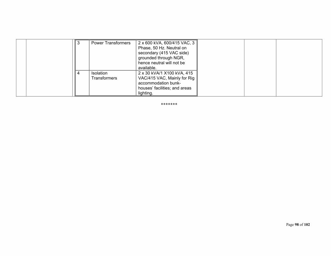
Page 98 of 102
3 Power Transformers 2 x 600 kVA, 600/415 VAC, 3 Phase, 50 Hz. Neutral on secondary (415 VAC side) grounded through NGR, hence neutral will not be available.
4 Isolation Transformers
2 x 30 kVA/1 X100 kVA, 415 VAC/415 VAC, Mainly for Rig accommodation bunk-houses’ facilities; and areas lighting.
*******
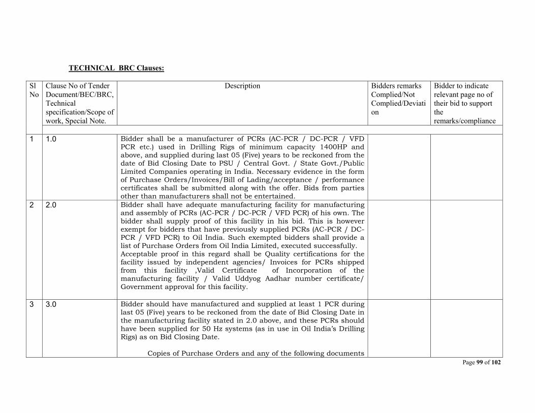
Page 99 of 102
TECHNICAL BRC Clauses:
Sl No
Clause No of Tender Document/BEC/BRC, Technical specification/Scope of work, Special Note.
Description Bidders remarks Complied/Not Complied/Deviation
Bidder to indicate relevant page no of their bid to support the remarks/compliance
1 1.0 Bidder shall be a manufacturer of PCRs (AC-PCR / DC-PCR / VFD
PCR etc.) used in Drilling Rigs of minimum capacity 1400HP and above, and supplied during last 05 (Five) years to be reckoned from the date of Bid Closing Date to PSU / Central Govt. / State Govt./Public Limited Companies operating in India. Necessary evidence in the form of Purchase Orders/Invoices/Bill of Lading/acceptance / performance certificates shall be submitted along with the offer. Bids from parties other than manufacturers shall not be entertained.
2 2.0 Bidder shall have adequate manufacturing facility for manufacturing and assembly of PCRs (AC-PCR / DC-PCR / VFD PCR) of his own. The bidder shall supply proof of this facility in his bid. This is however exempt for bidders that have previously supplied PCRs (AC-PCR / DC-PCR / VFD PCR) to Oil India. Such exempted bidders shall provide a list of Purchase Orders from Oil India Limited, executed successfully. Acceptable proof in this regard shall be Quality certifications for the facility issued by independent agencies/ Invoices for PCRs shipped from this facility ,Valid Certificate of Incorporation of the manufacturing facility / Valid Uddyog Aadhar number certificate/ Government approval for this facility.
3 3.0 Bidder should have manufactured and supplied at least 1 PCR during last 05 (Five) years to be reckoned from the date of Bid Closing Date in the manufacturing facility stated in 2.0 above, and these PCRs should have been supplied for 50 Hz systems (as in use in Oil India’s Drilling Rigs) as on Bid Closing Date. Copies of Purchase Orders and any of the following documents

Page 100 of 102
should be enclosed with the bid, as proof of supply of PCR: Performance Certificates/Invoice/Bill of Lading. This is however exempt for bidders that have previously supplied PCRs (AC-PCRs, DC-PCRs or VFD PCR’s used in Drilling Rigs) to Oil India Limited. Such exempted bidders shall provide a list of Purchase Orders from Oil India Limited, executed successfully.
4 4.0 Delivery required against this tender is maximum 14 (Fourteen) months from the date of opening of LC in case order is placed on the foreign supplier OR within 14 (Fourteen) months from the date of receipt of order in case order is placed on indigenous supplier. Date of clean Bill of Lading (B/L in case of foreign supplier) or Consignment Note date (C/Note date in case of indigenous supplier) shall be considered as delivery date. Bidder must comply the above schedule and confirm in their Techno-Commercial bid. Bids not meeting time schedule as mentioned above shall be summarily rejected.
*********
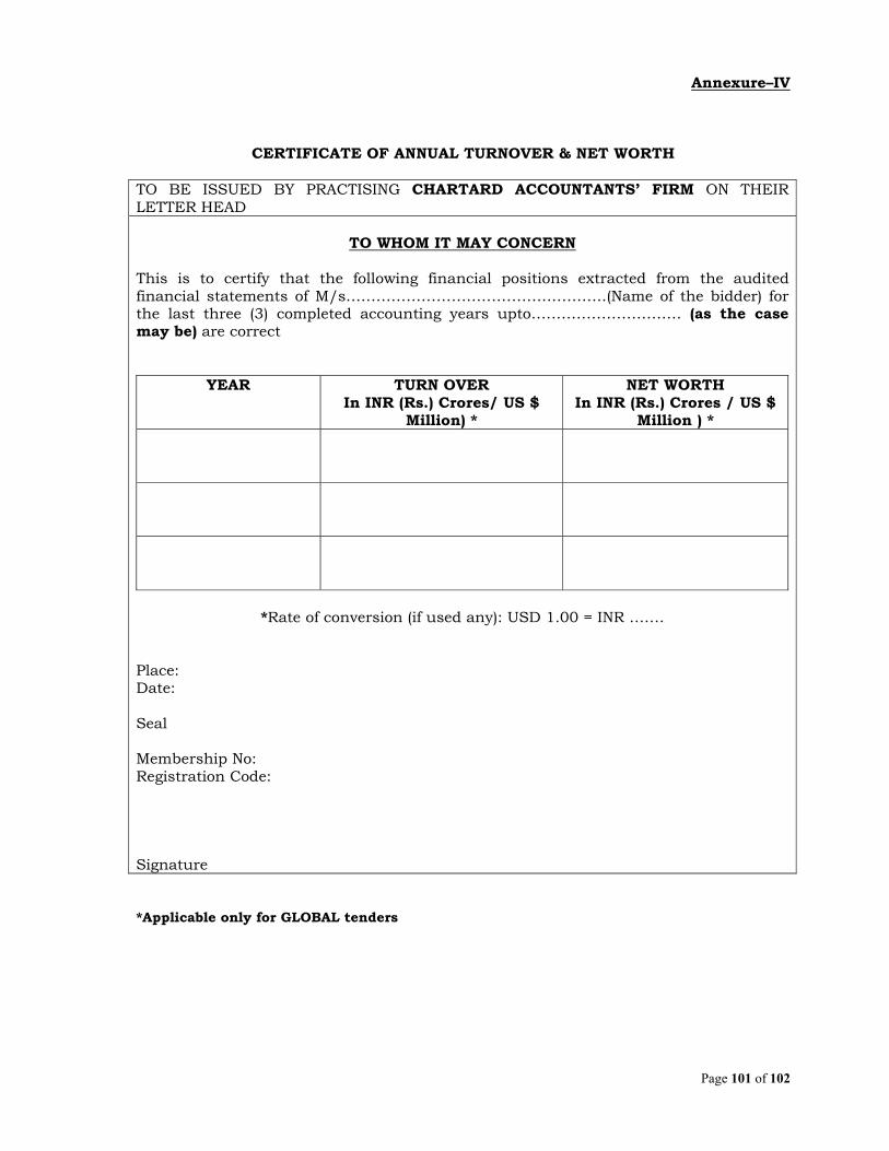
Page 101 of 102
Annexure–IV
CERTIFICATE OF ANNUAL TURNOVER & NET WORTH
TO BE ISSUED BY PRACTISING CHARTARD ACCOUNTANTS’ FIRM ON THEIR LETTER HEAD
TO WHOM IT MAY CONCERN
This is to certify that the following financial positions extracted from the audited financial statements of M/s…………………………………………….(Name of the bidder) for the last three (3) completed accounting years upto………………………… (as the case may be) are correct
YEAR TURN OVER In INR (Rs.) Crores/ US $
Million) *
NET WORTH In INR (Rs.) Crores / US $
Million ) *
*Rate of conversion (if used any): USD 1.00 = INR …….
Place: Date: Seal Membership No: Registration Code:
Signature
*Applicable only for GLOBAL tenders
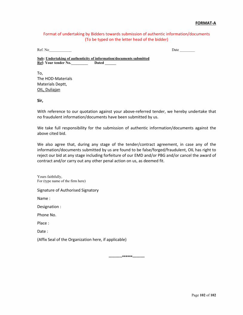
Page 102 of 102
FORMAT‐A
Format of undertaking by Bidders towards submission of authentic information/documents (To be typed on the letter head of the bidder)
Ref. No____________ Date ________ Sub: Undertaking of authenticity of information/documents submitted Ref: Your tender No._________ Dated ______ To, The HOD‐Materials Materials Deptt, OIL, Duliajan Sir, With reference to our quotation against your above‐referred tender, we hereby undertake that no fraudulent information/documents have been submitted by us. We take full responsibility for the submission of authentic information/documents against the above cited bid. We also agree that, during any stage of the tender/contract agreement, in case any of the information/documents submitted by us are found to be false/forged/fraudulent, OIL has right to reject our bid at any stage including forfeiture of our EMD and/or PBG and/or cancel the award of contract and/or carry out any other penal action on us, as deemed fit. Yours faithfully, For (type name of the firm here)
Signature of Authorised Signatory
Name :
Designation :
Phone No.
Place :
Date :
(Affix Seal of the Organization here, if applicable)
----------******---------