OIL AND NATURAL GAS CORPORATION LIMITED - Pollution ...
340
OIL AND NATURAL GAS CORPORATION LIMITED Environmental Impact Assessment (EIA) Report for Development Drilling of Wells in Onshore ML Areas of Jorhat and Golaghat Districts, Assam State JANUARY 2016 Asian Consulting Engineers Private Limited, New Delhi
-
Upload
khangminh22 -
Category
Documents
-
view
0 -
download
0
Transcript of OIL AND NATURAL GAS CORPORATION LIMITED - Pollution ...
OIL AND NATURAL GAS CORPORATION LIMITED
Environmental Impact Assessment (EIA) Report for Development
Drilling of Wells in Onshore ML Areas of Jorhat and Golaghat Districts,
Assam State
JANUARY 2016
Asian Consulting Engineers Private Limited, New Delhi
Environmental Impact Assessment (EIA) Report for Development Drilling of Wells in Onshore ML areas of Jorhat and Golaghat Districts, Assam
Asian Consulting Engineers Pvt. Ltd. i
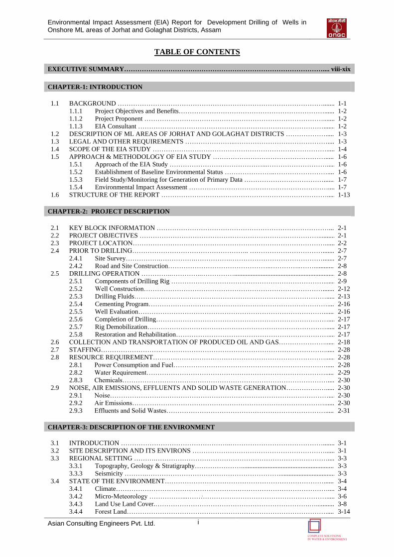
TABLE OF CONTENTS
EXECUTIVE SUMMARY……………………………………………………………………………….... viii-xix
CHAPTER-1: INTRODUCTION
1.1 BACKGROUND …………………………………………………………………………………......... 1-1
1.1.1 Project Objectives and Benefits…………………………………………………………........ 1-2
1.1.2 Project Proponent ………………………………………………………………………......... 1-2
1.1.3 EIA Consultant …………………………………………………………………………......... 1-2
1.2 DESCRIPTION OF ML AREAS OF JORHAT AND GOLAGHAT DISTRICTS ………………....... 1-3
1.3 LEGAL AND OTHER REQUIREMENTS …………………..……………………………………...... 1-3
1.4 SCOPE OF THE EIA STUDY ……………………………………………………….……………....... 1-4
1.5 APPROACH & METHODOLOGY OF EIA STUDY ……………………………………………........ 1-6
1.5.1 Approach of the EIA Study ……………………………………...………………………....... 1-6
1.5.2 Establishment of Baseline Environmental Status …………………..……………………...... 1-6
1.5.3 Field Study/Monitoring for Generation of Primary Data ………………………………......... 1-7
1.5.4 Environmental Impact Assessment ………………………………………………………...... 1-7
1.6 STRUCTURE OF THE REPORT …………………………………………………………………....... 1-13
CHAPTER-2: PROJECT DESCRIPTION
2.1 KEY BLOCK INFORMATION ……………………………………………………………………..... 2-1
2.2 PROJECT OBJECTIVES ………………………………………………………………………............ 2-1
2.3 PROJECT LOCATION……………………………………………………………………………........ 2-2
2.4 PRIOR TO DRILLING…………………………………………….. ……………………………......... 2-7
2.4.1 Site Survey…………….…………….…………….……………………………………......... 2-7
2.4.2 Road and Site Construction………………………………………..…………..……............... 2-8
2.5 DRILLING OPERATION …………..…………..……………............................................................... 2-8
2.5.1 Components of Drilling Rig ……………………………………………………………......... 2-9
2.5.2 Well Construction………………………………………………………………………......... 2-12
2.5.3 Drilling Fluids……………………………………………………………………………....... 2-13
2.5.4 Cementing Program………………………………………………………………………...... 2-16
2.5.5 Well Evaluation…………………………………………………………………………......... 2-16
2.5.6 Completion of Drilling……………………………………………………………………...... 2-17
2.5.7 Rig Demobilization………………………………………………………………………....... 2-17
2.5.8 Restoration and Rehabilitation……………………………………………………………...... 2-17
2.6 COLLECTION AND TRANSPORTATION OF PRODUCED OIL AND GAS…………………........ 2-18
2.7 STAFFING…………………………………………………………………………………………....... 2-28
2.8 RESOURCE REQUIREMENT……………………………………………………………………........ 2-28
2.8.1 Power Consumption and Fuel……………………………………………………………....... 2-28
2.8.2 Water Requirement………………………………………………………………………........ 2-29
2.8.3 Chemicals…………………………………………………………………………………...... 2-30
2.9 NOISE, AIR EMISSIONS, EFFLUENTS AND SOLID WASTE GENERATION………………....... 2-30
2.9.1 Noise………………………………………………………………………………………...... 2-30
2.9.2 Air Emissions……………………………………………………………………………........ 2-30
2.9.3 Effluents and Solid Wastes………………………………………………………………........ 2-31
CHAPTER-3: DESCRIPTION OF THE ENVIRONMENT
3.1 INTRODUCTION …………………………………………..……………………………………......... 3-1
3.2 SITE DESCRIPTION AND ITS ENVIRONS ……………………………………………………........ 3-1
3.3 REGIONAL SETTING ……….……………………………………………………………………...... 3-3
3.3.1 Topography, Geology & Stratigraphy…………………........................................................... 3-3
3.3.3 Seismicity ……….…………………………………………………….................................... 3-3
3.4 STATE OF THE ENVIRONMENT………………………………………………………………......... 3-4
3.4.1 Climate……………………………………………………………………………………...... 3-4
3.4.2 Micro-Meteorology ……………...………………………………………………………....... 3-6
3.4.3 Land Use Land Cover.…………………………………………………………….…............ 3-8
3.4.4 Forest Land………………………………………………………………………………........ 3-14
Environmental Impact Assessment (EIA) Report for Development Drilling of Wells in Onshore ML areas of Jorhat and Golaghat Districts, Assam
Asian Consulting Engineers Pvt. Ltd. ii
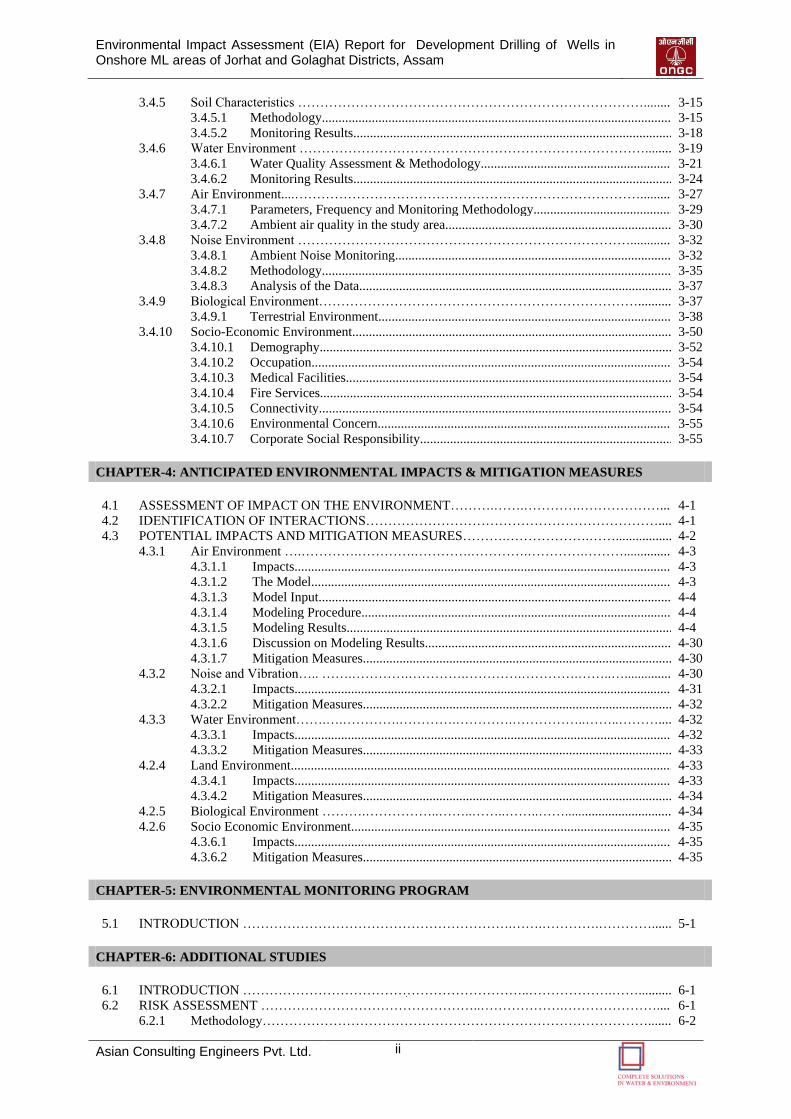
3.4.5 Soil Characteristics ……………………………………………………………………........... 3-15
3.4.5.1 Methodology........................................................................................................... 3-15
3.4.5.2 Monitoring Results.................................................................................................. 3-18
3.4.6 Water Environment …………………………………………………………………….......... 3-19
3.4.6.1 Water Quality Assessment & Methodology........................................................... 3-21
3.4.6.2 Monitoring Results.................................................................................................. 3-24
3.4.7 Air Environment....……………………………………………………………………............ 3-27
3.4.7.1 Parameters, Frequency and Monitoring Methodology............................................ 3-29
3.4.7.2 Ambient air quality in the study area...................................................................... 3-30
3.4.8 Noise Environment …………………………………………………………………............... 3-32
3.4.8.1 Ambient Noise Monitoring..................................................................................... 3-32
3.4.8.2 Methodology........................................................................................................... 3-35
3.4.8.3 Analysis of the Data................................................................................................ 3-37
3.4.9 Biological Environment………………………………………………………………............ 3-37
3.4.9.1 Terrestrial Environment.......................................................................................... 3-38
3.4.10 Socio-Economic Environment.................................................................................................. 3-50
3.4.10.1 Demography............................................................................................................ 3-52
3.4.10.2 Occupation.............................................................................................................. 3-54
3.4.10.3 Medical Facilities.................................................................................................... 3-54
3.4.10.4 Fire Services............................................................................................................ 3-54
3.4.10.5 Connectivity............................................................................................................ 3-54
3.4.10.6 Environmental Concern.......................................................................................... 3-55
3.4.10.7 Corporate Social Responsibility.............................................................................. 3-55
CHAPTER-4: ANTICIPATED ENVIRONMENTAL IMPACTS & MITIGATION MEASURES
4.1 ASSESSMENT OF IMPACT ON THE ENVIRONMENT……….…….………….………………...... 4-1
4.2 IDENTIFICATION OF INTERACTIONS…………………………………………………………...... 4-1
4.3 POTENTIAL IMPACTS AND MITIGATION MEASURES……….……………….……................... 4-2
4.3.1 Air Environment ….………….………….………….………….………….………................. 4-3
4.3.1.1 Impacts................................................................................................................... 4-3
4.3.1.2 The Model.............................................................................................................. 4-3
4.3.1.3 Model Input............................................................................................................ 4-4
4.3.1.4 Modeling Procedure............................................................................................... 4-4
4.3.1.5 Modeling Results.................................................................................................... 4-4
4.3.1.6 Discussion on Modeling Results............................................................................ 4-30
4.3.1.7 Mitigation Measures............................................................................................... 4-30
4.3.2 Noise and Vibration….. …….………….………….………….………….……..…................ 4-30
4.3.2.1 Impacts................................................................................................................... 4-31
4.3.2.2 Mitigation Measures............................................................................................... 4-32
4.3.3 Water Environment…….….………….………….………….……………..……..………...... 4-32
4.3.3.1 Impacts................................................................................................................... 4-32
4.3.3.2 Mitigation Measures............................................................................................... 4-33
4.2.4 Land Environment..................................................................................................................... 4-33
4.3.4.1 Impacts................................................................................................................... 4-33
4.3.4.2 Mitigation Measures............................................................................................... 4-34
4.2.5 Biological Environment ……….……………..……..……..……..…….................................. 4-34
4.2.6 Socio Economic Environment................................................................................................... 4-35
4.3.6.1 Impacts................................................................................................................... 4-35
4.3.6.2 Mitigation Measures............................................................................................... 4-35
CHAPTER-5: ENVIRONMENTAL MONITORING PROGRAM
5.1 INTRODUCTION …………………………………………………….…….………….…………........ 5-1
CHAPTER-6: ADDITIONAL STUDIES
6.1 INTRODUCTION ………………………………………………………..……………….……............ 6-1
6.2 RISK ASSESSMENT …………………………………………..……………….…………………....... 6-1
6.2.1 Methodology……………………………………………………………………………......... 6-2
Environmental Impact Assessment (EIA) Report for Development Drilling of Wells in Onshore ML areas of Jorhat and Golaghat Districts, Assam
Asian Consulting Engineers Pvt. Ltd. iii
6.2.2 Identification of Hazards in Drilling and Production Testing Operations………………........ 6-3
6.2.2.1 Minor Oil Spill....................................................................................................... 6-3
6.2.2.2 Major Oil Spill....................................................................................................... 6-4
6.2.2.3 Blowout.................................................................................................................. 6-4
6.2.2.4 Hydrogen Sulphide (H2S)...................................................................................... 6-4
6.2.2.5 Natural Disaster and Hazards................................................................................. 6-5
6.2.3 Development Drilling in ML areas of Jorhat and Golaghat Districts……………................... 6-6
6.2.4 QRA Approach……….………….…………………………………….................................... 6-7
6.2.4.1 Damage due to Explosion...................................................................................... 6-8
6.2.4.2 Thermal Incidents/ Fire in Storage Area................................................................ 6-8
6.2.5 Mitigation Measures ……………….….…………………………………………………....... 6-9
6.2.5.1 Control Measures for Major Hazards..................................................................... 6-9
6.2.5.2 Control Measures for H2S Leakage/Emission during Drilling.............................. 6-10
6.2.5.3 Natural Disaster and Hazards................................................................................ 6-11
6.2.5.4 Fire Fighting Facility............................................................................................. 6-11
6.2.6 Occupational Health………………………………………………………………………...... 6-12
6.2.7 Frequency of Occurrence of Accident Scenario....................................................................... 6-13
6.2.8 Conclusion………………………………………………………………………………........ 6-14
6.3 DISASTER MANAGEMENT PLAN ……………………………………………………………........ 6-14
6.3.1 Statuary Requirements……………………………………………………………………...... 6-15
6.3.2 Nature of Emergencies……………………………………………………………………...... 6-15
6.3.3 Onsite Emergency Operations……………………………………………………………....... 6-16
6.3.3.1 Functions & Responsibilities of Various Coordinators......................................... 6-17
6.3.3.2 Emergency Control Room (ECR) at Base office................................................... 6-18
6.3.3.3 Responding to an Emergency................................................................................ 6-19
6.3.4 Offsite Emergency Plan…………………………………………………………………. 6-23
6.3.4.1 Assessment of Hazard leading to Off-Site Emergency.......................................... 6-23
6.3.4.2 Disaster due to Man-made causes (Terrorist attack).............................................. 6-24
6.3.4.3 Action Plan - Reporting of an Off-Site Emergency............................................... 6-27
6.3.4.4 Mock Drill for Onsite and Off-Site Emergency Management............................... 6-29
6.3.4.5 Review of the Plan................................................................................................. 6-30
6.3.4.6 Blow Out Contingency Plan.................................................................................. 6-30
CHAPTER-7: PROJECT BENEFITS
7.1 PROJECT BENEFITS ……………………………………………………………................................. 7-1
CHAPTER-8: ENVIRONMENTAL MANAGEMENT PLAN
8.1 INTRODUCTION…………………………………………………………………………………........ 8-1
8.2 PURPOSE AND OBJECTIVES OF THE ENVIRONMENTAL MANAGEMENT PLAN.………...... 8-1
8.2.1 HSE Policy of Block Operator…………………………………………………………......... 8-1
8.2.2 Organizational Structure and Responsibilities……………………………………………...... 8-2
8.3 MITIGATION PLAN………………………………………………………………………………....... 8-3
8.4 ENVIRONMENTAL TRAINING ……………………………………………….................................. 8-12
8.5 WASTE MANAGEMENT PLAN …………………………………….…………………………......... 8-12
8.6 RESTORATION AND REHABILITATION………………………………………………………...... 8-17
8.7 OCCUPATIONAL HEALTH AND SAFETY MANAGEMENT PLAN…………………………....... 8-21
8.8 CAPITAL AND RECURRING COST FOR POLLUTION CONTROL MEASURES.……................. 8-22
CHAPTER-9: SUMMARY AND CONCLUSION
9.1 SUMMARY AND CONCLUSION ………………………………………………………………........ 9-1
CHAPTER 10: DISCLOSURE OF CONSULTANTS ENGAGED
10.1 INTRODUCTION …………………………………………………………………………………....... 10-1
10.2 QUALITY OF SERVICES …………………………………….…………………………………........ 10-1
10.3 AREA OF SPECIALIZATION …………………………………………………………….………...... 10-1
10.4 RESOURCES …………………………………………………………………………….………......... 10-2
Environmental Impact Assessment (EIA) Report for Development Drilling of Wells in Onshore ML areas of Jorhat and Golaghat Districts, Assam
Asian Consulting Engineers Pvt. Ltd. iv
LIST OF ANNEXURES
ANNEXURE - I Copy of Approved ToR, Form - 1 and PFR
ANNEXURE - II Copy of Existing EC, CTO and Compliance Report
ANNEXURE - III Environmental and Safety related Policies
ANNEXURE - IV Corporate Environmental Policy
ANNEXURE - V CSR’s details (for the period of 2013-14 to 2014-15)
LIST OF TABLES
Table No. Title Page
No.
Table 1.1 Applicable Acts and Guidelines ……………………………………………………….......... 1-3
Table 1.2 TOR Compliance Status for Development Drilling in Golaghat and Jorhat Districts,
Assam……………............................................................................................................... 1-8
Table 2.1 Co-ordinates of the ML Blocks…………………………………………………………...... 2-2
Table 2.2 Co-ordinates of the Drilling Locations…………………………………………………......... 2-3
Table 2.3 Ingredients of Water Based Drilling Fluid ………………………………………………...... 2-13
Table 2.4 Ingredients of Water Based Drilling Mud………………………………………………........ 2-14
Table 2.5 Special Additives and their Function in Water Based Drilling Fluids……………………..... 2-14
Table 2.6 Collection and Transportation of Produced Oil and Gas…………………………………..... 2-18
Table 2.7 Water Utilization Per Well………………………………………………………………....... 2-29
Table 3.1 Climate Data for the Study Area…………………………………………………………...... 3-6
Table 3.2 Landuse Distribution of the Study Area……………………………………………………... 3-11
Table 3.3 Important Features within 1 Km Radius of Drilling Locations…………………………........ 3-13
Table 3.4 Soil Sampling Locations…………………………………………………………………...... 3-16
Table 3.5 Results of Soil Analysis…………………………………………………………………...... 3-18
Table 3.6 ML Blocks and their Categorization as per Central Ground Water Authority (CGWA)…..... 3-21
Table 3.7 Water Sampling Locations………………………………………………………………....... 3-21
Table 3.8 Ground Water Quality Analytical Results………………………………………………….... 3-24
Table 3.9 Surface Water Quality Analytical Results………………………………………………….... 3-25
Table 3.10 Location Details for Ambient Air Quality Monitoring…………………………………….... 3-26
Table 3.11 Method of Analysis for Different Air Quality Parameters………………………………....... 3-28
Table 3.12 Summary of PM10 Levels Monitored in the Study Area…………………………………...... 3-30
Table 3.13 Summary of SO2 Levels Monitored in the Study Area…………………………………........ 3-30
Table 3.14 Summary of NOX Levels Monitored in the Study Area…………………………………....... 3-31
Table 3.15 Summary of VOC Levels in the Study Area……………………………………………........ 3-31
Table 3.16 Summary of HC Levels in the Study Area………………………………………………....... 3-32
Table 3.17 Location of Noise Monitoring Stations…………………………………………………........ 3-32
Table 3.18 Summary of Ambient Noise levels monitored in the study area…………………………...... 3-36
Table 3.19 List of Important Flora in the Golaghat Study Area……………………………………….... 3-38
Table 3.20 List of Important Flora in the Jorhat Study Area…………………………………………..... 3-40
Table 3.21 List of Important Medicinal Plant in the Jorhat Study Area……………………………….... 3-43
Table 3.22 List of Important Fauna in the Golaghat Study Area………………………………………... 3-45
Table 3.23 List of Important Fauna in the Jorhat Study Area………………………………………….... 3-47
Table 3.24 Administrative Divisions of the Districts…………………………………………………..... 3-50
Table 3.25 Demographic Details of the Jorhat Study Area…………………………………………….... 3-52
Table 3.26 Demographic Details of the Golaghat Study Area…………………………………………... 3-52
Table 3.27 Available Medical Facilities in and around Study Area…………………………………....... 3-54
Table 4.1 Interactions between Project Activities and Environmental Parameters ………………......... 4-2
Table 4.2 Stack & Emission Characteristics……………………………………………………............ 4-4
Table 4.3 Predicted 24-hourly Maximum GLCs for air pollutants ……………………......................... 4-5
Table 4.4 Occupational and Human Exposure Levels ……………………………………………........ 4-31
Table 5.1 Recommended Environmental Monitoring Protocol – Pre Drilling Phase………………...... 5-2
Table 5.2 Recommended Environmental Monitoring Protocol – During Drilling Phase…………..... 5-2
Table 5.3 Recommended Environmental Monitoring Protocol – Post Drilling……………………....... 5-4
Table 6.1 Symptoms of H2S as per Concentrations………………………………………………......... 6-5
Table 6.2 Co-ordinates of the ML Areas………………………………………………………….......... 6-6
Table 6.3 Bulk Hazardous Chemical Storage facility at Drilling Site (tentative)…………………........ 6-7
Environmental Impact Assessment (EIA) Report for Development Drilling of Wells in Onshore ML areas of Jorhat and Golaghat Districts, Assam
Asian Consulting Engineers Pvt. Ltd. v
LIST OF TABLES
Table No. Title Page
No.
Table 6.4 Risk Classification………………………………………………………………………........ 6-7
Table 6.5 Damage due to Overpressure……………………………………………………………....... 6-8
Table 6.6 Possible Major Scenarios………………………………………………………………......... 6-9
Table 6.7 Fire Extinguishers Distribution…………………………………………………………........ 6-12
Table 6.8 Occupational Health hazards and mitigating measures…………………………………........ 6-13
Table 6.9 Frequency occurrence for various accidents scenarios…………………………………........ 6-14
Table 6.10 Existing GGS stations within the ML Areas……………………………………………........ 6-15
Table 6.11 Shut in Procedure while Drilling…………………………………………………………...... 6-22
Table 6.12 Shut in Procedure while Tripping………………………………………………………........ 6-23
Table 8.1 EMP - Mitigation Management Matrix (Prior to Drilling Phase) ………………………....... 8-4
Table 8.2 EMP - Mitigation Management Matrix (During Drilling Phase) ………………………........ 8-5
Table 8.3 Waste Management Plan ……………………………………………………………............. 8-13
Table 8.4 Capital and Recurring Cost for Pollution Control Measures................................................... 8-22
LIST OF FIGURES
Figure No. Title Page
No.
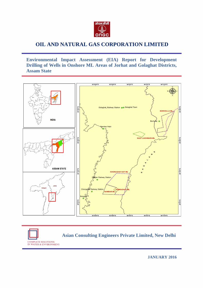
Figure 1.1 Project Location Map……………………………………...……....................................... 1-1
Figure 2.1 Project Location of Nambar, Khoraghat and Khoraghat ML areas..................................... 2-4
Figure 2.2 Project Location of East Lakhibari and Borholla ML areas................................................ 2-5
Figure 2.3 Field Geography of Hydrocarbon Reserve Areas……………………………………….... 2-6
Figure 2.4 Field Geography of Jorhat………………………………………………………………... 2-6
Figure 2.5 Approximate Road Distance Map………………………………………………………... 2-7
Figure 2.6 Layout of Drilling Site with Facilities…………………………………………………..... 2-9
Figure 2.7 The Anatomy of Drilling Rig…………………………………………………………...... 2-10
Figure 2.8 Typical On-Shore Drilling Rig………………………………………………………….... 2-12
Figure 2.9 Typical Drill Fluid Circulation System…………………………………………………... 2-15
Figure 2.10 Layout Map of Borholla GGS…………………………………………………………..... 2-20
Figure 2.11 (a) Process Flow Diagram of Borholla GGS………………………………………………..... 2-21
Figure 2.11 (b) Schematic Diagram of Borholla GGS Process Flow…………………………………....... 2-22
Figure 2.12 (a) Layout Map of Khoraghat GGS-1……………………………………………………....... 2-23
Figure 2.12 (b) Schematic Diagram of Khoraghat GGS-1 Facility Layout……………………………...... 2-24
Figure 2.13 Process Flow Diagram of Khoraghat GGS-1…………………………………………...... 2-25
Figure 2.14 Layout Map of Nambar GGS-1…………………………………………………………... 2-26
Figure 2.15 Process Flow Diagram of Nambar GGS-1……………………………………………...... 2-27
Figure 2.16 Well Flow Line Route of Borholla GGS………………………………………………..... 2-28
Figure 2.17 Water Balance Diagram………………………………………………………………....... 2-30
Figure 2.18 Flow Chart of Effluent Treatment Plant (ETP)…………………………………………... 2-33
Figure 3.1 Location of ML areas…………………………………………………………………….. 3-2
Figure 3.2 Map showing Seismic Zones of India…………………………………………………..... 3-4
Figure 3.3 Monthly rainfall variations for Golaghat district (10 years data)……………………….... 3-5
Figure 3.4 Monthly rainfall variations for Jorhat district (10 years data)…………………………..... 3-5
Figure 3.5 Historical rainfall data for Golaghat and Jorhat Districts……………………………….... 3-6
Figure 3.6 Wind rose diagram for Golaghat district (Oct to Dec 2015)……………………………... 3-7
Figure 3.7 Wind rose diagram for Jorhat district (Oct to Dec 2015)……………………………….... 3-8
Figure 3.8 LULC study of Borholla ML area………………………………………………………... 3-9
Figure 3.9 LULC study of Nambar, Khoraghat and Khoraghat Extension ML area……………….... 3-10
Figure 3.10 LULC study of East Lakhibari ML area………………………………………………...... 3-11
Figure 3.11 Distance of Wildlife Sanctuaries and National Parks from the project area……………... 3-15
Figure 3.12 Triangular classification of soil…………………………………………………………... 3-16
Figure 3.13 Soil Sampling Location Map…………………………………………………………....... 3-17
Figure 3.14 Drainage Map of Study Area…………………………………………………………….. 3-19
Figure 3.15 Surface Water Sampling Location Map………………………………………………..... 3-21
Figure 3.16 Ground Water Sampling Location Map………………………………………………...... 3-22
Figure 3.17 Ambient Air Quality Monitoring Location Map………………………………………..... 3-27
Figure 3.18 Ambient Noise Quality Monitoring Location Map……………………………………..... 3-34
Figure 3.19 Ambient Noise Levels Monitored in the Study Area (Day time) ………………………... 3-37
Environmental Impact Assessment (EIA) Report for Development Drilling of Wells in Onshore ML areas of Jorhat and Golaghat Districts, Assam
Asian Consulting Engineers Pvt. Ltd. vi
LIST OF FIGURES
Figure No. Title Page
No.
Figure 3.20 Ambient Noise Levels Monitored in the Study Area (Night time) …………………….... 3-37
Figure 3.21 Villages found within the Study Area…………………………………………………..... 3-51
Figure 4.1 Methodology for Environmental Impact Assessment…………………………………..... 4-1
Figure 4.2 Isopleths plot of concentration for PM10 (μg/m3) at Different ML Blocks Location…...... 4-6
Figure 4.3 Isopleths plot of concentration for SO2 (μg/m3) at Different ML Blocks Location…….... 4-12
Figure 4.4 Isopleths plot of concentration for NOX (μg/m3) at Different ML Blocks Location…....... 4-18
Figure 4.5 Isopleths Plot of Concentration for HC (μg/m3) at Different ML Blocks Location…….... 4-24
Figure 6.1 Onsite-Emergency Organization………………………………………………………..... 6-17
Figure 6.2 Flow chart for Offsite Emergency Management………………………………………..... 6-28
Figure 6.3 Blowout Contingency Plan……………………………………………………………...... 6-31
LIST OF PHOTOPLATE
Photo plate No. Title Page
No.
Photo plate 3.1 Project Area......................................................................................................................... 3-14
Photo plate 3.2 Collection of Soil Samples.................................................................................................. 3-18
Photo plate 3.3 Collection of Surface Water Samples................................................................................. 3-22
Photo plate 3.4 Collection of Ground Water Samples………………………………………..................... 3-23
Photo plate 3.5 Ambient air quality monitoring………………………………......................................... 3-29
Photo plate 3.6 Noise level Monitoring at Different Locations in Study Area………………………….... 3-35
Photo plate 3.7 Local Vegetations and Surroundings of the Study Area ……………………………........ 3-45
Photo plate 3.8 Public consultations conducted at different locations in Study Area ……………............. 3-55
LIST OF ACRONYMS AND ABBREVIATIONS
ACE Asian Consulting Engineers
API American Petroleum Institute
BOD Biochemical Oxygen Demand
BOP Blow out Preventers
CEC Chief Executive Coordinator
COD Chemical Oxygen Demand
CGWA Central Ground Water Authority
CPCB Central Pollution Control Board
CSR Corporate Social Responsibility
CWC Central Water Commission
DG Diesel Generators
DGMS Directorate General of Mines Safety
DMP Disaster Management Plan
DSA Drill Site Accommodation
ECR Emergency Control Room
EIA Environmental Impact Assessment
EMP Environmental Management Plan
EP Lube Extreme Pressure Lube
ERP Emergency Response Plan
FICCI Federation of Indian Chambers of Commerce and Industry
GDP Gross Domestic Product
GGS Group Gathering Stations
GSI Geological Survey of India
GSM Grams per Square Meter
GWRE Groundwater Resource Estimation
HC Hydrocarbon
HSD High Speed Diesel
HSE Health, Safety and Environment
IS Indian Standard
kl Kilo Litre
Environmental Impact Assessment (EIA) Report for Development Drilling of Wells in Onshore ML areas of Jorhat and Golaghat Districts, Assam
Asian Consulting Engineers Pvt. Ltd. vii
kld Kilo Litre Per Day
LNG Liquefied Natural Gas
ML Mining Lease
MMTOE Million Metric Tonne
MoEF Ministry of Environment and Forest
MTOE Million Tonnes of Oil Equivalent
NAAQS National Ambient Air Quality Standards
NIDM National Institute of Disaster Management
NRSC National Remote Sensing Centre
OISD Oil Industry Safety Directorate
OMR Oil Mines Regulation
ONGC Oil and Natural Gas Corporation Limited
OSC On-Scene Commander/Coordinate
OSHA Occupational Safety and Health Act
PM Particulate Matter
PPM Parts Per Million
QRA Quantitative Risk Assessment
SOP Standard (Safe) Operating Procedures
SPCB State Pollution Control Board
STEL Short Term Exposure Limit
TDS Total Dissolved Solids
TSS Total Suspended Solids
TWA Time Weighted Average
VOC Volatile Organic Compound
WBM Water Based Mud

EEXXEECCUUTTIIVVEE
SSUUMMMMAARRYY
Environmental Impact Assessment (EIA) Report for Development Drilling of Wells in Onshore ML areas of Jorhat and Golaghat Districts, Assam
Asian Consulting Engineers Pvt. Ltd. viii
EXECUTIVE SUMMARY
1. INTRODUCTION
Project Highlights
Oil & Natural Gas Corporation Limited (ONGC), a premier Govt. of India Undertaking and
the major National Oil Company with Maharatna Status, is a vertically integrated company
producing crude oil, natural gas and value added products like LPG, NGL, Petrol, HSD etc.
Operations of ONGC extend over both onshore as well as offshore within India and outside
India.
ONGC has proposed Eight (08) Development Drilling Locations in Nambar, East Lakhibari,
Khoraghat and Khoraghat Extension Mining lease areas in the Golaghat district and Four (04)
Development Drilling Locations in Borholla Mining lease area in the Jorhat district of Assam
State. The total ML area of Jorhat district and Golaghat district is 32.116 sq. km. and 120.5
sq. km. respectively. The Total Project Cost is INR 240.00 Crores.
Objective and Scope of EIA study
The Objective of EIA study is to meet the regulatory environmental clearance criteria as well
as to ascertain a sustainable development through the assessment of likely impacts due to
project related activities on the surrounding environment. The study envisages likely
assessment of negative impacts and alleviation of these negative impacts, to such extent that it
avoids/mitigates any harm/ permanent changes in the naturally existing environment.
The scope of the EIA study includes detailed characterization of the existing status of the
terrestrial and socio-economic environment within the study area, identification of the
potential environmental impacts of the project, and formulation of an effective Environmental
Management Plan (EMP) to prevent, control & mitigate the adverse environmental impacts,
and ensuring the environmental compliance. Apart from suggesting mitigation measures to
the negative impacts, the report suggests implementation of various positive and enhancement
measures as a part of project benefit program to people of the nearby areas. This report is
based on the TOR approved by Ministry of Environment and Forests, Government of India
vide letter- J-11011/49/2014-IA II (I) dated 18th December, 2014.
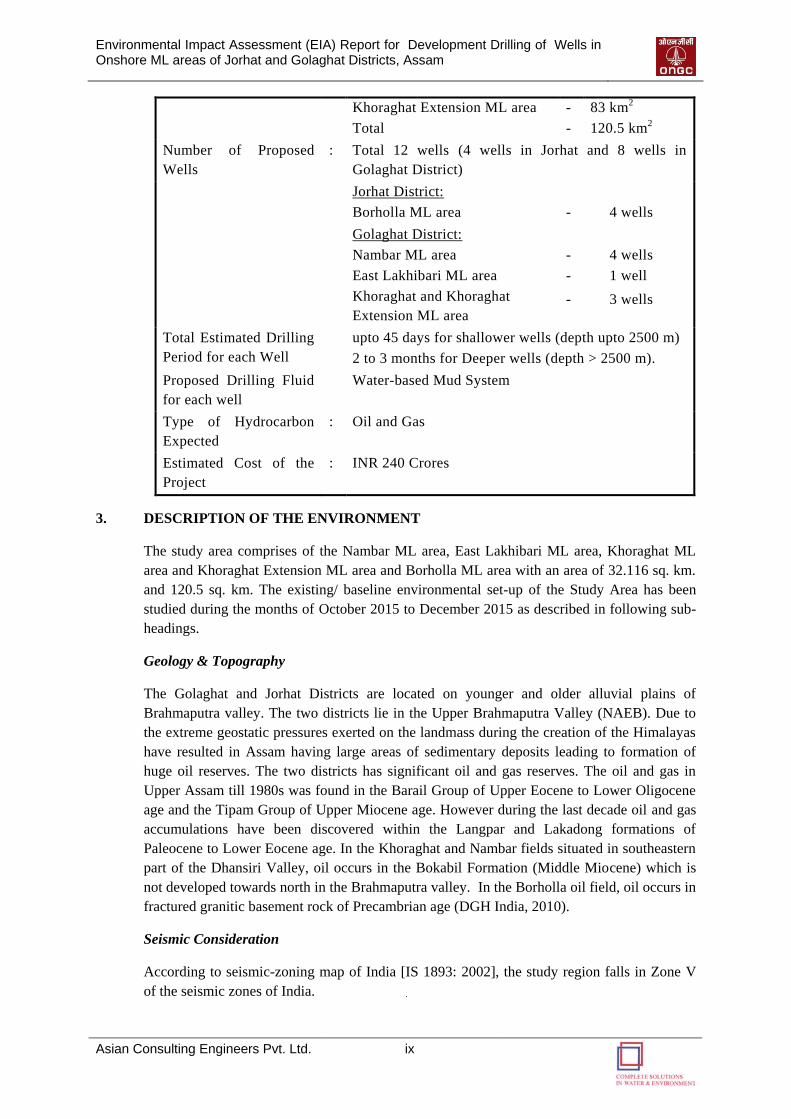
2. PROJECT DESCRIPTION
ONGC intends to drill about 12 Developmental Wells in Five ML areas of Golaghat District
and Jorhat District of Assam State. The salient features of the project have been summarized
in the following table:
Name of the Project : Development Drilling in Jorhat and Golaghat districts
Location : Jorhat and Golaghat districts, Assam
Total Area of the
Project
Jorhat District:
Borholla ML area
-
32.116 km2
Golaghat District:
Nambar ML area
East Lakhibari ML area
Khoraghat ML area
-
-
-
26 km2
8.5 km2
3 km2
Environmental Impact Assessment (EIA) Report for Development Drilling of Wells in Onshore ML areas of Jorhat and Golaghat Districts, Assam
Asian Consulting Engineers Pvt. Ltd. ix
Khoraghat Extension ML area
Total
-
-
83 km2
120.5 km2
Number of Proposed
Wells
: Total 12 wells (4 wells in Jorhat and 8 wells in
Golaghat District)
Jorhat District:
Borholla ML area
-
4 wells
Golaghat District:
Nambar ML area
East Lakhibari ML area
Khoraghat and Khoraghat
Extension ML area
-
-
-
4 wells
1 well
3 wells
Total Estimated Drilling
Period for each Well
upto 45 days for shallower wells (depth upto 2500 m)
2 to 3 months for Deeper wells (depth > 2500 m).
Proposed Drilling Fluid
for each well
Water-based Mud System
Type of Hydrocarbon
Expected
: Oil and Gas
Estimated Cost of the
Project
: INR 240 Crores
3. DESCRIPTION OF THE ENVIRONMENT
The study area comprises of the Nambar ML area, East Lakhibari ML area, Khoraghat ML
area and Khoraghat Extension ML area and Borholla ML area with an area of 32.116 sq. km.
and 120.5 sq. km. The existing/ baseline environmental set-up of the Study Area has been
studied during the months of October 2015 to December 2015 as described in following sub-
headings.
Geology & Topography
The Golaghat and Jorhat Districts are located on younger and older alluvial plains of
Brahmaputra valley. The two districts lie in the Upper Brahmaputra Valley (NAEB). Due to
the extreme geostatic pressures exerted on the landmass during the creation of the Himalayas
have resulted in Assam having large areas of sedimentary deposits leading to formation of
huge oil reserves. The two districts has significant oil and gas reserves. The oil and gas in
Upper Assam till 1980s was found in the Barail Group of Upper Eocene to Lower Oligocene
age and the Tipam Group of Upper Miocene age. However during the last decade oil and gas
accumulations have been discovered within the Langpar and Lakadong formations of
Paleocene to Lower Eocene age. In the Khoraghat and Nambar fields situated in southeastern
part of the Dhansiri Valley, oil occurs in the Bokabil Formation (Middle Miocene) which is
not developed towards north in the Brahmaputra valley. In the Borholla oil field, oil occurs in
fractured granitic basement rock of Precambrian age (DGH India, 2010).
Seismic Consideration
According to seismic-zoning map of India [IS 1893: 2002], the study region falls in Zone V
of the seismic zones of India.
Environmental Impact Assessment (EIA) Report for Development Drilling of Wells in Onshore ML areas of Jorhat and Golaghat Districts, Assam
Asian Consulting Engineers Pvt. Ltd. x
Climate and Meteorology
The Golaghat and Jorhat District lies in the Hot sub-humid (moist) to humid (inclusion of per-
humid) eco-regions (NRSC & CWC, 2014). The climate is dominated by the subtropical
monsoon which is normally active from April to October with occasional winter showers. At
times approach of monsoon is also marked by cyclones in April and May. The plains get
flooded. Autumn and winter are dry seasons.
The yearly rainfall for Golaghat district varied from minimum 1232 mm to maximum 1871
mm with an average rainfall of 1450 mm. The yearly rainfall for Jorhat district varied from
minimum 1380 mm to maximum 2112 mm with an average rainfall of 1755 mm.
The temperature varies from 03oC to 37oC and 04oC to 37oC (October to December) in
Golaghat and Jorhat Districts respectively.
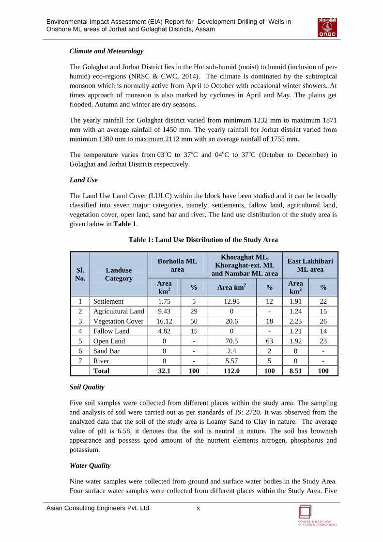
Land Use
The Land Use Land Cover (LULC) within the block have been studied and it can be broadly
classified into seven major categories, namely, settlements, fallow land, agricultural land,
vegetation cover, open land, sand bar and river. The land use distribution of the study area is
given below in Table 1.
Table 1: Land Use Distribution of the Study Area
Sl.
No.
Landuse
Category
Borholla ML
area
Khoraghat ML,
Khoraghat-ext. ML
and Nambar ML area
East Lakhibari
ML area
Area
km2
% Area km2 %
Area
km2
%
1 Settlement 1.75 5 12.95 12 1.91 22
2 Agricultural Land 9.43 29 0 - 1.24 15
3 Vegetation Cover 16.12 50 20.6 18 2.23 26
4 Fallow Land 4.82 15 0 - 1.21 14
5 Open Land 0 - 70.5 63 1.92 23
6 Sand Bar 0 - 2.4 2 0 -
7 River 0 - 5.57 5 0 -
Total 32.1 100 112.0 100 8.51 100
Soil Quality
Five soil samples were collected from different places within the study area. The sampling
and analysis of soil were carried out as per standards of IS: 2720. It was observed from the
analyzed data that the soil of the study area is Loamy Sand to Clay in nature. The average
value of pH is 6.58, it denotes that the soil is neutral in nature. The soil has brownish
appearance and possess good amount of the nutrient elements nitrogen, phosphorus and
potassium.
Water Quality
Nine water samples were collected from ground and surface water bodies in the Study Area.
Four surface water samples were collected from different places within the Study Area. Five
Environmental Impact Assessment (EIA) Report for Development Drilling of Wells in Onshore ML areas of Jorhat and Golaghat Districts, Assam
Asian Consulting Engineers Pvt. Ltd. xi
ground water samples were collected from representative places within the study area. The
sampling and analysis of water were carried out as per Standard Methods of Water and
Wastewater Analysis (APHA). The result of water samples is compared with IS: 10500-2012
drinking water standard to assess their suitability for drinking purpose.
Ground Water: It is observed from the analyzed data that the content of Iron in ground water
samples is higher (varied between 1.5 to 2.2 mg/l) than the desirable limits of IS: 10500:2012,
because of naturally high level, which is also reported by the CGWB. The pH of the samples
was in the range of 6.9 to 8.2, which is within the prescribed drinking water (DW) limit.
Electrical conductivity values varied in a wide range of 296μs/cm to 418μs/cm indicating the
presence of considerable amount of ionic matter in ground water. The phenolic compounds,
Oil & Grease, Mercury and Biochemical Oxygen Demand (BOD) content are found below
detection limit in all ground water samples. The other parameters have been found to be
within the limits as per standards.
Surface Water: The pH of the surface water samples was found little alkaline in nature, it
ranges between 7.9 to 8.5. Total hardness and Alkalinity were found in the range of 106 to
132 mg/l and 115 to 1164 mg/l, respectively, which were also within the DW limit. Phenolic
compounds, Oil & Grease and Mercury content of all samples are below detection limit.
Dissolved Oxygen (DO), Biochemical Oxygen Demand (BOD) and Chemical Oxygen
Demand (COD) were in the range of 5.2 to 7.6 mg/l, 13 and 23 mg/l and 3.0 to 5.0 mg/l,
respectively. The other parameters have been found to be within the limits as per standards.
Analytical results indicate the absence of pollution in these water sources both industrial and
domestic pollution. This is also evident from the surrounding land use land cover, which is
deviated from anthropogenic activities in the surrounding areas.
Air Quality
Air quality was monitored at Eight different locations within the study area. The 24-hourly
average of PM10 levels varied station wise between 39.7 µg/m3 to 64.4 µg/m3. The 24-hourly
average values of SO2 varied between 3.92 µg/m3 to 6.78 µg/m3. The 24-hourly average NO2
level measured in the study area ranged between 9.24 µg/m3 and 16.53 µg/m3. The analytical
result of value reveals that the concentrations of PM10, SO2 and NOx were found within the
prescribed standard limits at all the monitoring locations. VOC and HC (methane and non-
methane) was also monitored. VOC was found below dateable limit. The average values of
Methane and Non-Methane varied between 0.79 µg/m3 to 2.1 µg/m3 and 0.23 µg/m3 to 1.0
µg/m3 respectively.
Noise Quality
Ambient noise intensity at Eight locations within the study area has been collected. Noise
monitoring was carried out on a 24-hour basis to assess the baseline noise-levels and to
evaluate the impact. The values of noise level, which were recorded, was in the range of 41.5
- 67.8 dB (A) during daytime and 30.0 – 59.8 dB (A) during nighttime
Biological Characteristics
There are no eco-sensitive areas or forest or wild life sanctuaries within the 10 km of the
study area. The nearest Wildlife Sanctuary is the Nambor Wildlife Sanctuary from the
Environmental Impact Assessment (EIA) Report for Development Drilling of Wells in Onshore ML areas of Jorhat and Golaghat Districts, Assam
Asian Consulting Engineers Pvt. Ltd. xii
boundary of East Lakhibari ML areas at a distance of 10.5 km. Other sensitive areas are at a
distance greater than 25 km.
The floristic composition of the Golaghat and Jorhat district is very rich; most of the plants
are tropical evergreen and semi-evergreen variety. Secondary data obtained from the Forest
department was evaluated to assess the floristic structure of the study area. Major tree species
found in the area are Sida, Dimaru, aam, segun, Nahar, bel etc. Common wild fauna are
Swamp Deer, Butterflies, Honeybee, Great Indian Hornbill, Bengal Florican, White
wing Wood Duck, etc.
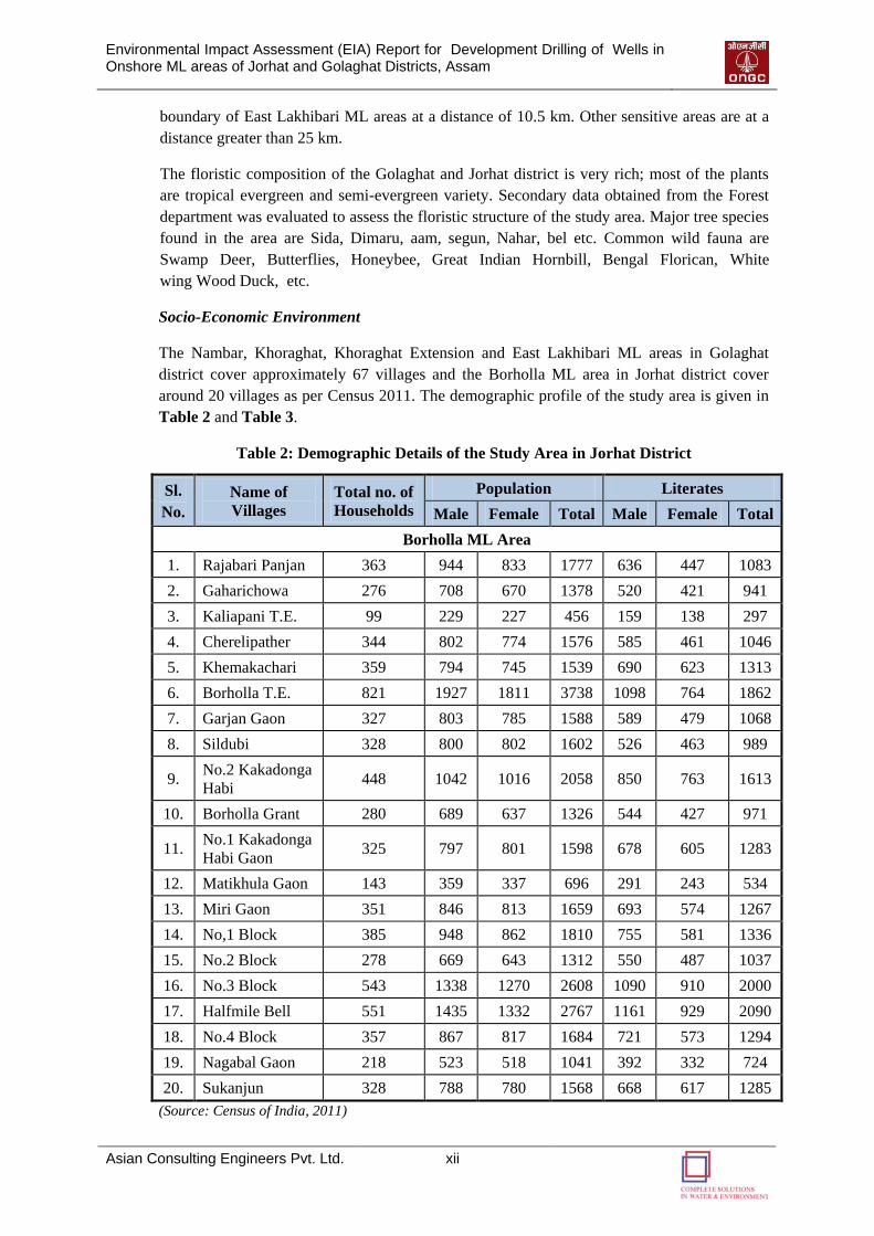
Socio-Economic Environment
The Nambar, Khoraghat, Khoraghat Extension and East Lakhibari ML areas in Golaghat
district cover approximately 67 villages and the Borholla ML area in Jorhat district cover
around 20 villages as per Census 2011. The demographic profile of the study area is given in
Table 2 and Table 3.
Table 2: Demographic Details of the Study Area in Jorhat District
Sl.
No.
Name of
Villages
Total no. of
Households
Population Literates
Male Female Total Male Female Total
Borholla ML Area
1. Rajabari Panjan 363 944 833 1777 636 447 1083
2. Gaharichowa 276 708 670 1378 520 421 941
3. Kaliapani T.E. 99 229 227 456 159 138 297
4. Cherelipather 344 802 774 1576 585 461 1046
5. Khemakachari 359 794 745 1539 690 623 1313
6. Borholla T.E. 821 1927 1811 3738 1098 764 1862
7. Garjan Gaon 327 803 785 1588 589 479 1068
8. Sildubi 328 800 802 1602 526 463 989
9. No.2 Kakadonga
Habi 448 1042 1016 2058 850 763 1613
10. Borholla Grant 280 689 637 1326 544 427 971
11. No.1 Kakadonga
Habi Gaon 325 797 801 1598 678 605 1283
12. Matikhula Gaon 143 359 337 696 291 243 534
13. Miri Gaon 351 846 813 1659 693 574 1267
14. No,1 Block 385 948 862 1810 755 581 1336
15. No.2 Block 278 669 643 1312 550 487 1037
16. No.3 Block 543 1338 1270 2608 1090 910 2000
17. Halfmile Bell 551 1435 1332 2767 1161 929 2090
18. No.4 Block 357 867 817 1684 721 573 1294
19. Nagabal Gaon 218 523 518 1041 392 332 724
20. Sukanjun 328 788 780 1568 668 617 1285
(Source: Census of India, 2011)

Environmental Impact Assessment (EIA) Report for Development Drilling of Wells in Onshore ML areas of Jorhat and Golaghat Districts, Assam
Asian Consulting Engineers Pvt. Ltd. xiii
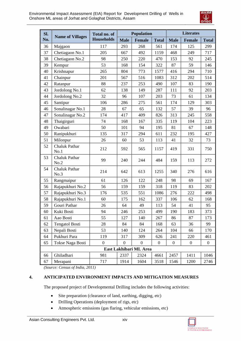
Table 3: Demographic Details of the Study Area in Golaghat District
Sl.
No. Name of Villages
Total no. of
Households
Population Literates
Male Female Total Male Female Total
Khoraghat & Nambar ML Area
1. Ajharguri No.2 51 137 117 254 83 60 143
2. Kathonipur 26 56 55 111 44 31 75
3. Madhupur No.1 58 186 151 337 134 95 229
4. Madhupur No.2 364 1066 1021 2087 408 333 741
5. Kamalpur 33 75 75 150 61 52 113
6. Ranipukhuri 98 263 209 472 127 69 196
7. Rajapukhuri 95 226 218 444 157 139 296
8. Chetonapur 77 185 188 373 102 82 184
9. Lakhinagar No.1 136 299 349 648 239 188 427
10. Lakhinagar No.2 79 163 189 352 133 108 241
11. Bidyapur 363 1145 1052 2197 650 484 1134
12. Janakpur 39 96 96 192 77 64 141
13 Hatidubi 176 439 434 873 257 222 479
14 Navajyoti
Majgaon 75 185 168 353 144 120 264
15 Misamari 13 20 28 48 12 14 26
16 Bordondi No.1 28 71 58 129 53 36 89
17 Bordondi No.2 85 221 216 437 158 116 274
18 Goroibil 47 108 124 232 72 60 132
19 Dhonpur No.2 0 0 0 0 0 0 0
20 Tamulpur 37 92 100 192 75 70 145
21 Lotapur 43 106 97 203 70 51 121
22 Haldhibari 183 490 387 877 314 185 499
23 Jordolong No.1 41 97 105 202 69 56 125
24 Dimorujan 85 189 179 368 143 97 240
25 Jurpukhuri 33 74 89 163 54 48 102
26 Benganabari 51 138 126 264 92 69 161
27 Da-Kawalipathar
No.1 75 165 158 323 122 88 210
28 Da-Kawalipathar
No.2 30 63 53 116 43 29 72
29 Jordolong No.2 52 132 111 243 106 74 180
30 Jahajibosti 45 132 129 261 65 53 118
31 Gholapani 114 235 216 451 144 121 265
32 Lachit Gaon No.2 190 533 518 1051 380 301 681
33 Lachit Gaon No.1 80 220 194 414 162 104 266
34 Bilgaon 151 346 353 699 253 230 483
35 Santipur No.2 46 108 109 217 82 63 145
Environmental Impact Assessment (EIA) Report for Development Drilling of Wells in Onshore ML areas of Jorhat and Golaghat Districts, Assam
Asian Consulting Engineers Pvt. Ltd. xiv
Sl.
No. Name of Villages
Total no. of
Households
Population Literates
Male Female Total Male Female Total
36 Majgaon 117 293 268 561 174 125 299
37 Chetiagaon No.1 205 667 492 1159 468 249 717
38 Chetiagaon No.2 98 250 220 470 153 92 245
39 Kempur 53 168 154 322 87 59 146
40 Krishnapur 265 804 773 1577 416 294 710
41 Chainpur 201 567 516 1083 312 202 514
42 Ratanpur 88 237 253 490 107 83 190
43 Jordolong No.1 62 138 149 287 111 92 203
44 Jordolong No.2 32 96 107 203 73 61 134
45 Santipur 106 286 275 561 174 129 303
46 Sonalinagar No.1 28 67 65 132 57 39 96
47 Sonalinagar No.2 174 417 409 826 313 245 558
48 Thaigirguri 74 168 167 335 119 104 223
49 Owabari 50 101 94 195 81 67 148
50 Ranipukhuri 135 317 294 611 232 195 427
51 Milonpur 26 60 53 113 41 32 73
52 Chaluk Pathar
No.1 212 592 565 1157 419 331 750
53 Chaluk Pathar
No.2 99 240 244 484 159 113 272
54 Chaluk Pathar
No.3 214 642 613 1255 340 276 616
55 Rangmaipur 61 126 122 248 98 69 167
56 Rajapukhuri No.2 56 159 159 318 119 83 202
57 Rajapukhuri No.3 176 535 551 1086 276 222 498
58 Rajapukhuri No.1 60 175 162 337 106 62 168
59 Gouri Pathar 26 64 49 113 54 41 95
60 Kuki Bosti 94 246 253 499 190 183 373
61 Aao Bosti 55 127 140 267 86 87 173
62 Tengatol Bosti 28 84 84 168 63 36 99
63 Nepali Bosti 53 140 124 264 104 66 170
64 Pukhuri Para 119 317 309 626 241 220 461
65 Tokse Naga Bosti 0 0 0 0 0 0 0
East Lakhibari ML Area
66 Ghiladhari 981 2337 2324 4661 2457 1411 1046
67 Merapani 717 1914 1604 3518 1546 1200 2746
(Source: Census of India, 2011)
4. ANTICIPATED ENVIRONMENT IMPACTS AND MITIGATION MEASURES
The proposed project of Developmental Drilling includes the following activities:
Site preparation (clearance of land, earthing, digging, etc)
Drilling Operations (deployment of rigs, etc)
Atmospheric emissions (gas flaring, vehicular emissions, etc)
Environmental Impact Assessment (EIA) Report for Development Drilling of Wells in Onshore ML areas of Jorhat and Golaghat Districts, Assam
Asian Consulting Engineers Pvt. Ltd. xv
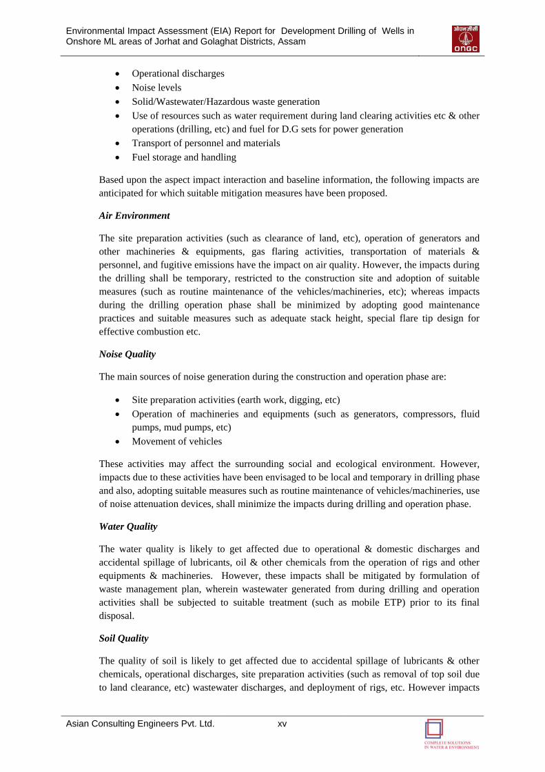
Operational discharges
Noise levels
Solid/Wastewater/Hazardous waste generation
Use of resources such as water requirement during land clearing activities etc & other
operations (drilling, etc) and fuel for D.G sets for power generation
Transport of personnel and materials
Fuel storage and handling
Based upon the aspect impact interaction and baseline information, the following impacts are
anticipated for which suitable mitigation measures have been proposed.
Air Environment
The site preparation activities (such as clearance of land, etc), operation of generators and
other machineries & equipments, gas flaring activities, transportation of materials &
personnel, and fugitive emissions have the impact on air quality. However, the impacts during
the drilling shall be temporary, restricted to the construction site and adoption of suitable
measures (such as routine maintenance of the vehicles/machineries, etc); whereas impacts
during the drilling operation phase shall be minimized by adopting good maintenance
practices and suitable measures such as adequate stack height, special flare tip design for
effective combustion etc.
Noise Quality
The main sources of noise generation during the construction and operation phase are:
Site preparation activities (earth work, digging, etc)
Operation of machineries and equipments (such as generators, compressors, fluid
pumps, mud pumps, etc)
Movement of vehicles
These activities may affect the surrounding social and ecological environment. However,
impacts due to these activities have been envisaged to be local and temporary in drilling phase
and also, adopting suitable measures such as routine maintenance of vehicles/machineries, use
of noise attenuation devices, shall minimize the impacts during drilling and operation phase.
Water Quality
The water quality is likely to get affected due to operational & domestic discharges and
accidental spillage of lubricants, oil & other chemicals from the operation of rigs and other
equipments & machineries. However, these impacts shall be mitigated by formulation of
waste management plan, wherein wastewater generated from during drilling and operation
activities shall be subjected to suitable treatment (such as mobile ETP) prior to its final
disposal.
Soil Quality
The quality of soil is likely to get affected due to accidental spillage of lubricants & other
chemicals, operational discharges, site preparation activities (such as removal of top soil due
to land clearance, etc) wastewater discharges, and deployment of rigs, etc. However impacts
Environmental Impact Assessment (EIA) Report for Development Drilling of Wells in Onshore ML areas of Jorhat and Golaghat Districts, Assam
Asian Consulting Engineers Pvt. Ltd. xvi
shall be mitigated by adoption of suitable measures and implementation of waste management
plan.
Biological Environment
The impacts on flora and fauna may occur due to site preparation activities (land clearance,
etc), gas flaring activities, movement of vehicles, noise generation from machineries &
equipments, operational discharges and accidental spillage of oil, lubricants and other
chemicals during drilling and operation phase. However, these impacts shall be local and
minimized by adopting suitable measures (such as adequate flare tip design, use of noise
attenuation devices, waste management plan etc).
Socio-Economic Environment
The near by human settlement is likely to get affected due to proposed activities (such as
movement of vehicles, operation of generators, compressors and other machineries &
equipments, gas flaring activities, etc) during drilling and operation phase. However, these
adoptions of suitable mitigation measures such as use of PPEs, implementation of waste
management plan etc shall minimize the occupational health hazards and impacts on local
community, thereby contributing to the net positive impacts on socio-economic environment.
The proposed activities will generate indirect employment opportunities in the region. The
proposed project will also result in the implementation of social welfare project as per
Company’s CSR policy and improvement in existing infrastructure facilities (such as roads,
etc).
5. ENVIRONMENT MONITORING PROGRAM
An Environmental Monitoring Program is suggested to monitor environmental parameters
during the proposed activities. The Monitoring program is given in the following sections.
Pre Drilling Phase
Air Quality: Once prior to drilling, monitor the NOX, SO2, PM10 VOCs and HC parameters at
drilling site.
Surface Water Quality: The analysis of pH, Total Suspended Solids, Total Dissolved Solids,
BOD, COD, O&G, and heavy metals (Zinc, lead, iron, nickel, cadmium and chromium) are to
be monitored where water up to 1 Km radius from drilling site, once prior to drilling.
Noise Quality: Monitor the background noise levels at the drilling site, once prior to drilling.
Clearing of tress (if existing): Inventory of tress will be carried out prior to drilling operation.
During Drilling Phase
Natural Resources: Daily monitor the quantity of each type of material (including water
consumption) and fuel used at drilling site during drilling operation phase.
Air Quality: Monitor the NOX, SO2, PM10 VOCs and HC parameters at drilling site, once in a
six month.
Environmental Impact Assessment (EIA) Report for Development Drilling of Wells in Onshore ML areas of Jorhat and Golaghat Districts, Assam
Asian Consulting Engineers Pvt. Ltd. xvii
Surface Water Quality: The analysis of pH, Total Suspended Solids, Total Dissolved Solids,
BOD, COD, O&G, and heavy metals (Zinc, lead, iron, nickel, cadmium and chromium) are to
be monitored where water up to 1 Km radius from drilling site, once in season.
Noise Quality: Monitor the noise level and maintenance of machineries at the project site,
once during the drilling at drilling site.
Drilling Waste: During the drilling operation phase, monitor and record the generation of
waste quantity on daily basis at drilling site; whereas quantification, characterization of drill
cuttings and its safe disposal as per G.S.R. 546 (E), dated 30/08/05.
Post Drilling Phase
Drilling Waste: At the end of the drilling operation, the quantification, characterization of
drill cuttings and its safe disposal as per G.S.R. 546 (E), dated 30/08/05.
Surface Water Quality: The analysis of pH, Total Suspended Solids, Total Dissolved Solids,
BOD, COD, O&G, and heavy metals (Zinc, lead, iron, nickel, cadmium and chromium) at the
same location where pre and during drilling phase monitoring was done. Once after the
closing of drilled well.
Compensatory tree plantation: If tree cutting is involved during drilling phase, Survival rate
of tree saplings was carried out once in every three years at tree plantation locations.
6. ADDITIONAL STUDIES
Risk Assessment
ONGC is committed to maintain high standards for health and safety at all times. However,
on rare occasions, an unplanned event can have the potential to jeopardize the safety of the
crew and cause environmental damage. Potential non-routine events that may occur during
the proposed activities drilling activities:
Blowout
Oil Spills
H2S Emissions
Gas leakage
Fire (if gas comes in contact with source of ignition)
Occupational Hazards
Specific procedures and training will be carried out to ensure that the correct action would be
taken in the event of unplanned occurring. The drill site will be equipped with suitable safety
measures such as fire fighting facility (fire suit, fire extinguisher, gas sensors etc), medical
facilities, etc. The operating personnel will be provided PPEs and trained for such an
eventuality and the key responsible people will be required to hold relevant well control
certifications.
Disaster Management Plan and Emergency Response Plan
The Disaster Management Plan (DMP) and Emergency Response Plan (ERP) also includes in
this chapter. The objectives of DMP and ERP are to:
Environmental Impact Assessment (EIA) Report for Development Drilling of Wells in Onshore ML areas of Jorhat and Golaghat Districts, Assam
Asian Consulting Engineers Pvt. Ltd. xviii
Obtain an early warning of emergency conditions so as to prevent a negative impact on
personnel, the environment and assets.
Immediate response to emergency with effective communication and organized
procedures.
Safeguard personnel to prevent injuries or loss of life by either protecting personnel from
the hazard or evacuating them from the facilities.
Minimize the impact of such an event on the environment and the facilities by mitigating
the potential for escalation and, where possible, containing the release.
The following key elements of DMP and ERP are:
Contingency plan
Accident prevention procedures/measures
Accident/emergency response planning procedures
Onsite and offsite crisis management, communication, contact information etc.
7. PROJECT BENEFITS
The project will enhance reliable hydrocarbon supplies, which will bring economic benefits
and provide indirect employment opportunities to the local people and also benefit the area by
way of improvement in existing infrastructure.
8. ENVIRONMENT MANAGEMENT PLAN
Site-specific Environment Management Plans (EMP) has been developed to prevent and
mitigate significant adverse impacts and to accentuate beneficial impacts which shall be
implemented by ONGC for the proposed project. The relevant mitigation measures are
proposed for the following environment issues.
Rig Mobilization
Wastewater and Effluent Management
Fuels, Lubricants and Chemicals
Non-routine events and accidental releases (Well kicks, blow out)
Air emissions
Noise and Vibration
Solid wastes (hazardous and non-hazardous waste)
Soil quality
Ecological Impacts
Socio-economic impacts
To facilitate field level implementation, a waste management plan is framed which will be
subjected to fine tuning depending on site conditions. Appropriate measures and engineering
practices will be taken as per established standards and requirements such as adequate stack
height, effluent discharge as per CPCB standards, installation of generators set as per notified
norms by MoEF, installation of HSD Tanks, fire protection system and occupational health
safety program as per OISD Standards etc. Socio-economic welfare plan shall also be
implemented as per company’s CSR policy.
Environmental training is also an essential part, which will help to ensure that the
requirements of the EMP are clearly understood and followed by all project personnel
throughout the project period for operations.
Environmental Impact Assessment (EIA) Report for Development Drilling of Wells in Onshore ML areas of Jorhat and Golaghat Districts, Assam
Asian Consulting Engineers Pvt. Ltd. xix
9. SUMMARY AND CONCLUSION
ONGC had proposed Developmental Drilling of 12 wells in Five ML areas of Golaghat
(Nambar, East Lakhibari, Khoraghat and Khoraghat Extension ML areas) and Jorhat
(Borholla ML area) Districts of Assam State.
This EIA study has been conducted for identification of impacts based on the analyzed data
(collection from primary and secondary sources) and mitigation measures for minimizing any
environmental impact due to the project operations has been suggested. Impacts due to
operation of machineries and equipments, operational discharges, accidental spillage of
lubricants, oil and other chemicals, movement of vehicles, gas flaring activities, etc during
drilling and operational phase may affect the surrounding environment. However, all these
impacts shall be minimized by adopting suitable measures, suggested in Environment
Management Plan (EMP). As a result of the control measures and management processes in
place, there should be no significant impact resulting from the proposed operations.
In general, this project will bring economic benefits, increase energy security of the country
and generate employment opportunities.
10. DISCLOSURE OF CONSULTANTS ENGAGED
Asian Consulting Engineers Pvt. Ltd. (ACE) is QCI-NABET accredited EIA consulting
organization (Certificate No.: NABET/EIA/1013/012) for varied sectors including Onshore
And Offshore Oil and Gas Exploration and Development and Transportation of Oil and Gas
through Pipelines (Category A). ACE has been awarded ISO 9001: 2008 certified (Certificate
no: 22340/10/S) by RINA, to provide consultancy services for water supply, waste water
treatment, municipal solid waste management, environment and social impact assessment,
environment impact and audit, remote sensing and geographical information systems. ACE
has provided its consulting services and has successfully completed projects in India and
other countries including Mongolia, U.A.E., Vietnam, etc. ACE has carried out EIA and EMP
studies for Oil & Gas, infrastructure and industrial developmental sectors; HSE compliance
audits; and has also been involved in design of water supply, wastewater management,
industrial waste treatment, solid wastes and hazardous wastes management systems.

11
IINNTTRROODDUUCCTTIIOONN
Environmental Impact Assessment (EIA) Report for Development Drilling of Wells in Onshore ML areas of Jorhat and Golaghat Districts, Assam
Asian Consulting Engineers Pvt. Ltd. 1-1
INTRODUCTION
1.1 BACKGROUND
Assam is one of the most vibrant states in the North Eastern region of India and is rich in
important natural resources that appeal many investors to set up their production and
manufacturing units in the state. It is blessed with huge quantities of river water, abundant
limestone, dolomite and coal resources and has enormous potential of hydrocarbon
production. The Assam & Assam Arakan Basin with major tectonic elements has rich
deposits of these hydro carbons including both Crude oil and gas. The basin has been
explored for more than 60 years now and ONGC has been instrumental in exploring these oil
reserves.
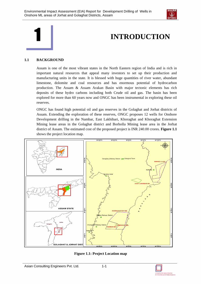
ONGC has found high potential oil and gas reserves in the Golaghat and Jorhat districts of
Assam. Extending the exploration of these reserves, ONGC proposes 12 wells for Onshore
Development drilling in the Nambar, East Lakhibari, Khoraghat and Khoraghat Extension
Mining lease areas in the Golaghat district and Borholla Mining lease area in the Jorhat
district of Assam. The estimated cost of the proposed project is INR 240.00 crores. Figure 1.1
shows the project location map.
Figure 1.1: Project Location map
1
Environmental Impact Assessment (EIA) Report for Development Drilling of Wells in Onshore ML areas of Jorhat and Golaghat Districts, Assam
Asian Consulting Engineers Pvt. Ltd. 1-2
1.1.1 Project Objectives and Benefits
As per a report published by FICCI, India is the fifth largest energy consumer in the world.
While the world consumes 12000 million tonnes of oil equivalent (mtoe) of energy resources,
India consumes 4.4% of the world total (524.2 mtoe). Of the total primary energy
consumption basket, oil and gas constitute 45% share in the total energy basket mix. About 78
per cent of India„s petroleum consumption is met from imports (mostly of crude oil), while
about 25% of natural gas (including LNG) consumption comes from imports. It is estimated
that in the coming years, the import dependency for crude oil alone would reach above 90%
level.
Thus, Development of existing oil reserves has become a necessity to bridge the rising
demand-supply gap, reduce import dependency and make ourselves resilient to the external
factors of economic and political disruptions in the sourcing nations. Considering this
scenario, ONGC proposes development of oil and gas reserves by development drilling of 12
wells in Golagahat and Jorhat districts of Assam. The development of these projects will
reduce the dependency of India on import of oil by adding to the availability of energy
sources in the country. It will also have a socio-economic benefit at the local level by
development of infrastructure like Roads, Drainage etc. and by providing employment
opportunities.
1.1.2 Project Proponent
Oil and Natural Gas Corporation Limited (ONGC) is a Public Sector Undertaking (PSU) of
the Government of India, under the administrative control of the Ministry of Petroleum and
Natural Gas. It is India's largest oil and gas exploration and Production Maharatna Status
Company with crude oil, natural gas, LPG, NGL, Petrol, HSD etc. as the key products. It
produces around 70% of India's crude oil (equivalent to around 25% of the country's total
demand) and around 60% of its natural gas (ONGC). Along with hydrocarbons, ONGC has
expanded its horizon to emerging domains of renewable and other alternative sources of
energy. With a market capitalization of over INR 2 trillion, it is one of India's most valuable
publicly-traded companies.
1.1.3 EIA Consultant
Development of any oil and gas exploration project requires Environmental Impact
Assessment (EIA) study as per the regulatory requirements and best practices. ONGC has
proposed to conduct an EIA study for „Development Drilling of 4 wells in Borholla ML
block, Jorhat District and drilling of 8 wells in Nambar ML area, East Lakhibari ML area,
Khoraghat ML area and Khoraghat Extension ML area in Golaghat district, Assam” and has
engaged M/s Asian Consulting Engineers Private Limited for the EIA studies and
preparation of an Environment Management plan.
This report pertains to the EIA study for “Development Drilling of 4 wells in Borholla ML
block, Jorhat District and drilling of 8 wells in Nambar ML area, East Lakhibari ML area,
Khoraghat ML area and Khoraghat Extension ML area in Golaghat district, Assam” and to
obtain Environmental Clearance (EC) form the MoEF, Government of India.
Asian Consulting Engineers Pvt. Ltd. (ACE) is QCI-NABET accredited EIA Consulting
Organization (Certificate No.: NABET/EIA/1013/012) for varied sectors including Offshore
and Onshore Oil and Gas Exploration, Development, Production & Oil and Gas transportation
Environmental Impact Assessment (EIA) Report for Development Drilling of Wells in Onshore ML areas of Jorhat and Golaghat Districts, Assam
Asian Consulting Engineers Pvt. Ltd. 1-3
through pipelines. The Quality Management System of ACE is ISO 9001:2008 Certified.
ACE has provided its consulting services and has successfully completed projects in India and
other countries including Mongolia, U.A.E., Vietnam, etc. ACE has carried out EIA and EMP
studies for Oil & Gas, Infrastructure and Industrial Developmental Sectors; HSE Compliance
Audits; and has also been involved in Design of Water Supply, Wastewater Management,
Industrial Waste Treatment, Solid Wastes and Hazardous Wastes Management Systems.
1.2 DESCRIPTION OF ML AREAS OF JORHAT AND GOLAGHAT DISTRICTS
The blocks awarded to ONGC fall in the Jorhat and Golaghat districts of Assam. In total 12
wells are proposed to be drilled at Borholla ML area (4 wells) in Jorhat District as well as
Nambar ML area (4 wells), East Lakhibari ML area (1 well), Khoraghat ML area and
Khoraghat Extension ML area (3 wells) in Golaghat districts of Assam. The total ML area of
Jorhat district and Golaghat district is 32.116 sq. km. and 120.5 sq. km. respectively.
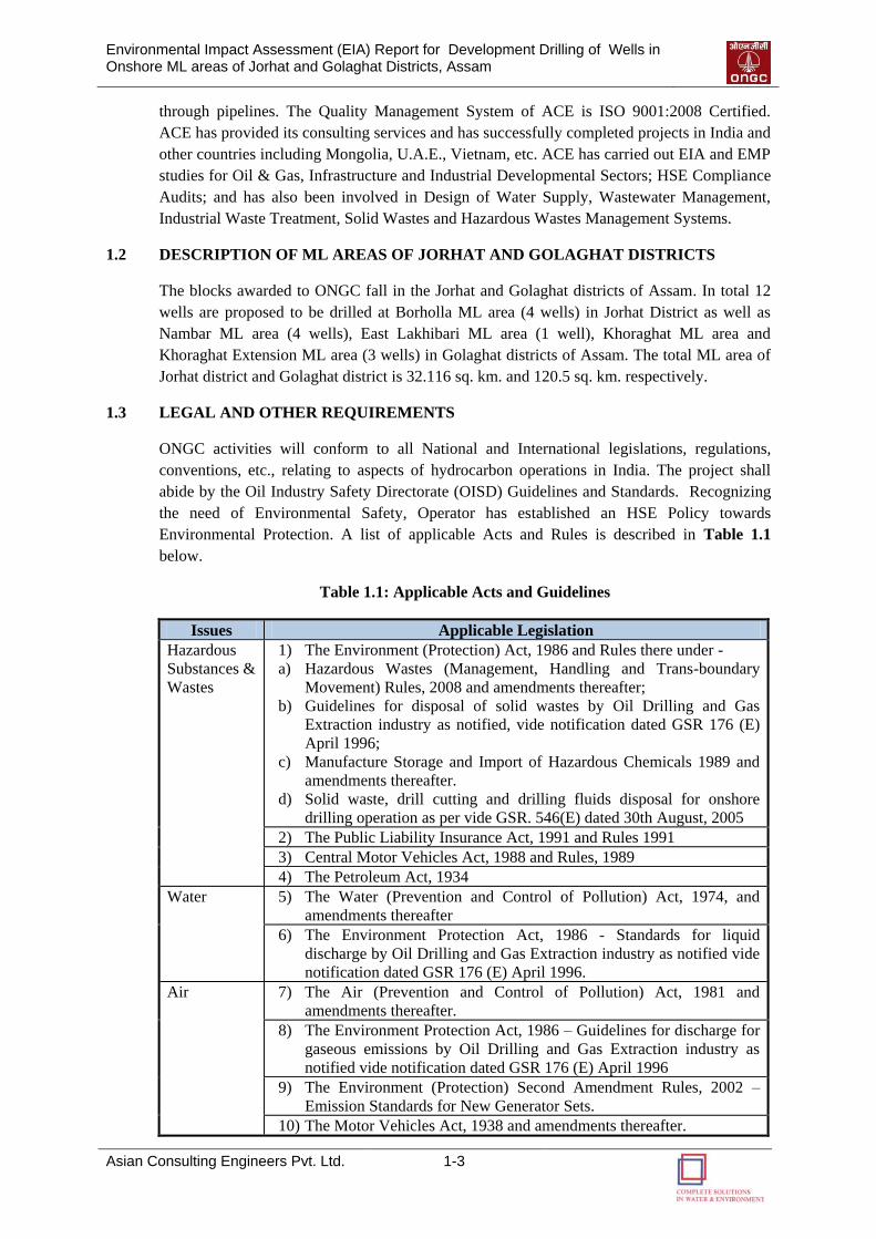
1.3 LEGAL AND OTHER REQUIREMENTS
ONGC activities will conform to all National and International legislations, regulations,
conventions, etc., relating to aspects of hydrocarbon operations in India. The project shall
abide by the Oil Industry Safety Directorate (OISD) Guidelines and Standards. Recognizing
the need of Environmental Safety, Operator has established an HSE Policy towards
Environmental Protection. A list of applicable Acts and Rules is described in Table 1.1
below.
Table 1.1: Applicable Acts and Guidelines
Issues Applicable Legislation
Hazardous
Substances &
Wastes
1) The Environment (Protection) Act, 1986 and Rules there under -
a) Hazardous Wastes (Management, Handling and Trans-boundary
Movement) Rules, 2008 and amendments thereafter;
b) Guidelines for disposal of solid wastes by Oil Drilling and Gas
Extraction industry as notified, vide notification dated GSR 176 (E)
April 1996;
c) Manufacture Storage and Import of Hazardous Chemicals 1989 and
amendments thereafter.
d) Solid waste, drill cutting and drilling fluids disposal for onshore
drilling operation as per vide GSR. 546(E) dated 30th August, 2005
2) The Public Liability Insurance Act, 1991 and Rules 1991
3) Central Motor Vehicles Act, 1988 and Rules, 1989
4) The Petroleum Act, 1934
Water 5) The Water (Prevention and Control of Pollution) Act, 1974, and
amendments thereafter
6) The Environment Protection Act, 1986 - Standards for liquid
discharge by Oil Drilling and Gas Extraction industry as notified vide
notification dated GSR 176 (E) April 1996.
Air 7) The Air (Prevention and Control of Pollution) Act, 1981 and
amendments thereafter.
8) The Environment Protection Act, 1986 – Guidelines for discharge for
gaseous emissions by Oil Drilling and Gas Extraction industry as
notified vide notification dated GSR 176 (E) April 1996
9) The Environment (Protection) Second Amendment Rules, 2002 –
Emission Standards for New Generator Sets.
10) The Motor Vehicles Act, 1938 and amendments thereafter.
Environmental Impact Assessment (EIA) Report for Development Drilling of Wells in Onshore ML areas of Jorhat and Golaghat Districts, Assam
Asian Consulting Engineers Pvt. Ltd. 1-4
Issues Applicable Legislation
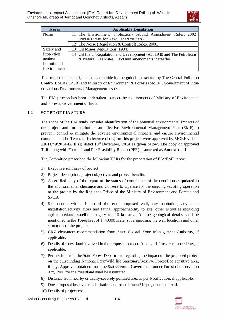
Noise 11) The Environment (Protection) Second Amendment Rules, 2002
(Noise Limits for New Generator Sets).
12) The Noise (Regulation & Control) Rules, 2000.
Safety and
Protection
against
Pollution of
Environment
13) Oil Mines Regulations, 1984.
14) Oil Field (Regulation and Development) Act 1948 and The Petroleum
& Natural Gas Rules, 1959 and amendments thereafter.
The project is also designed so as to abide by the guidelines set out by The Central Pollution
Control Board (CPCB) and Ministry of Environment & Forests (MoEF), Government of India
on various Environmental Management issues.
The EIA process has been undertaken to meet the requirements of Ministry of Environment
and Forests, Government of India.
1.4 SCOPE OF EIA STUDY
The scope of the EIA study includes identification of the potential environmental impacts of
the project and formulation of an effective Environmental Management Plan (EMP) to
prevent, control & mitigate the adverse environmental impacts, and ensure environmental
compliance. The Terms of Reference (ToR) for this project were approved by MOEF vide J-
11011/49/2014-IA II (I) dated 18th December, 2014 as given below. The copy of approved
ToR along with Form - 1 and Pre-Feasibility Report (PFR) is annexed as Annexure - I.
The Committee prescribed the following TORs for the preparation of EIA/EMP report:
1) Executive summary of project
2) Project description, project objectives and project benefits
3) A certified copy of the report of the status of compliance of the conditions stipulated in
the environmental clearance and Consent to Operate for the ongoing /existing operation
of the project by the Regional Office of the Ministry of Environment and Forests and
SPCB.
4) Site details within 1 km of the each proposed well, any habitation, any other
installation/activity, flora and fauna, approachability to site, other activities including
agriculture/land, satellite imagery for 10 km area. All the geological details shall be
mentioned in the Toposheet of 1 :40000 scale, superimposing the well locations and other
structures of the projects
5) CRZ clearance/ recommendation from State Coastal Zone Management Authority, if
applicable.
6) Details of forest land involved in the proposed project. A copy of forest clearance letter, if
applicable.
7) Permission from the State Forest Department regarding the impact of the proposed project
on the surrounding National Park/Wild life Sanctuary/Reserve Forest/Eco sensitive area,
if any. Approval obtained from the State/Central Government under Forest (Conservation
Act, 1980 for the forestland shall be submitted.
8) Distance from nearby critically/severely polluted area as per Notification, if applicable.
9) Does proposal involves rehabilitation and resettlement? If yes, details thereof.
10) Details of project cost.
Environmental Impact Assessment (EIA) Report for Development Drilling of Wells in Onshore ML areas of Jorhat and Golaghat Districts, Assam
Asian Consulting Engineers Pvt. Ltd. 1-5
11) Environmental considerations in the selection of the drilling locations for which
environmental clearance is being sought. Present any analysis suggested for minimizing
the footprint giving details of drilling and development options considered
12) Baseline data collection for air, water and soil for one season leaving the monsoon season
in an area of 10 km radius with centre of Oil Field as its centre covering the area of all
proposed drilling wells.
a. Topography of the project site.
b. Ambient Air Quality monitoring at 8 locations for PM10, S02, NOx, VOCs,
Methane and non-methane HC.
c. Soil sample analysis (physical and chemical properties) at the areas located at 5
locations
d. Ground and surface water quality in the vicinity of the proposed wells site.
e. Climatology and Meteorology including wind speed, wind direction, temperature
rainfall relative humidity etc.
f. Measurement of Noise levels within 1 km radius of the proposed wells.
g. Vegetation and land use; Animal resources
13) Incremental GLC as a result of DG set operation.
14) Potential environmental impact envisages during various stages of project activities such
as site activation, development, operation/ maintenance and decommissioning.
15) Actual source of water and 'Permission' for the drawl of water from the Competent
Authority. Detailed water balance, wastewater generation and discharge.
16) Noise abatement measures and measures to minimize disturbance due to light and visual
intrusions in case coastally located.
17) Treatment and disposal of waste water.
18) Treatment and disposal of solid waste generation.
19) Disposal of spent oil and lube.
20) Storage-of chemicals and diesel at site.
21) Commitment for the use of WBM only
22) Mud make-up and mud and cutting disposal - all options considered shall be listed with
selective option.
23) Hazardous material usage, storage accounting and disposal.
24) Disposal of packaging waste from site
25) Oil spill emergency plans in respect of recovery/ reclamation.
26) H2S emissions control.
27) Produced oil handling and storage
28) Details of scheme for oil collection system along with process flow diagram and its
capacity.
29) Details of control of air, water and noise pollution in oil collection system.
30) Disposal of produced/formation water.
31) Whether any burn pits being utilized for well test operations
32) Restoration and decommissioning plans which shall include mud pits and wastage
restoration also and documentation and monitoring of site recovery.
33) Measures to protect ground water and shallow aquifers from contamination.
Environmental Impact Assessment (EIA) Report for Development Drilling of Wells in Onshore ML areas of Jorhat and Golaghat Districts, Assam
Asian Consulting Engineers Pvt. Ltd. 1-6
34) Risk assessment and disaster management plan for independent reviews of well designed
construction etc. for prevention of blowout.
35) Environmental management plan.
36) Documentary proof of membership of common disposal facilities, if any
37) Details of environmental and safety related documentation within the company including
documentation and proposed occupational health and safety Surveillance Safety
Programme for all personnel at site. This shall also include monitoring programme for the
environmental.
38) Total capital and recurring cost for environmental control measures.
39) A copy of Corporate Environment Policy of the company as per the Ministry's O.M. No.
J-11 013/41 /2006-IAII(I) dated 26th April, 2011 available on the Ministry's website.
40) Public hearing to be conducted and issues raised and commitments made by the project
proponent on the same should be included in EIAIEMP Report in the form of tabular
chart with financial budget for complying with the commitments made.
41) Any litigation pending against the project and or any direction/order passed by any court
of law against the project. If so details thereof.
42) A tabular chart with index for point-wise compliance of above TORs.
The following general points should be noted:
(i) All documents should be properly indexed, page numbered.
(ii) Period/date of data collection should be clearly indicated.
(iii) Authenticated English translation of all material provided in Regional languages.
(iv) The letter/application for EC should quote the MOEF file No. and also attach a copy of
the letter.
(v) A copy of the letter received from the Ministry should be also attached as an annexure
to the final EIA-EMP Report.
(vi) The final EIA-EMP report submitted to the Ministry must incorporate the issues in this
letter. The index of the final EIA-EMP report must indicate the specific chapter and
page no. of the EIA-EMP Report where the above issues have been incorporated.
(vii) „Certificate of Accreditation‟ issued by the QCI to the environmental consultant
should be included.
1.5 APPROACH & METHODOLOGY OF THE EIA STUDY
1.5.1 Approach of the EIA Study
The EIA study basically includes establishment of the present environmental scenario within
the study area. EIA report consists of study of the specific activities related to the project and
evaluation of the probable environmental impacts, thus, leading to the recommendations of
necessary environmental pollution control measures. The entire EIA study has been carried
out on the basis of the applicable Environmental Legislation, Regulations and Guidelines of
MoEF, Government of India.
1.5.2 Establishment of Baseline Environmental Status
A comprehensive database on the baseline environmental status/conditions of the study area
has been established through review, compilation & analysis of:
Existing published secondary data/ literature/ information collected, and
Environmental Impact Assessment (EIA) Report for Development Drilling of Wells in Onshore ML areas of Jorhat and Golaghat Districts, Assam
Asian Consulting Engineers Pvt. Ltd. 1-7
Primary data generated/ collected through field study, survey and monitoring.
1.5.3 Field study/ Monitoring for generation of Primary Data
The collected secondary data has been appropriately supplemented by conducting the
necessary primary data generation/ collection through field study/monitoring. The field
monitoring has been carried out as per the guidelines of CPCB & BIS and requirement of the
MoEF.
1) Soil Monitoring: To study the soil characteristics in the study area, soil samples from
representative locations in the study area have been collected and analysed for important
relevant physical & chemical parameters.
2) Water Quality Monitoring: For drawing up the baseline data on water quality, water
quality monitoring has been conducted at representative locations in the study area.
Ground and Surface water samples have been collected and analyzed for important
relevant physical and chemical parameters.
3) Ambient Air Quality Monitoring: For drawing up the baseline status of ambient air
quality in the study area, ambient air quality monitoring in respect of PM10, SO2, NO2, HC
and VOC has been conducted at representative locations in the study area.
4) Noise Monitoring: To establish the ambient noise scenario in the study area, monitoring
of ambient noise level has been carried out at the representative locations in the study area
using a suitable portable sound level meter over a period of twenty-four hours.
1.5.4 Environmental Impact Assessment
This includes collection of primary data through field investigations, environmental
monitoring and secondary data from sources like Maps, Reports and Scientific Literatures etc.
The collected data is then analyzed for identification of impacts and cost effective mitigation
measures are suggested. The Environmental Impact Assessment has been conducted in
accordance with the norms and guidelines of the MoEF/CPCB Government of India.
A point-wise compliance of approved ToR for proposed project is given in Table 1.2.
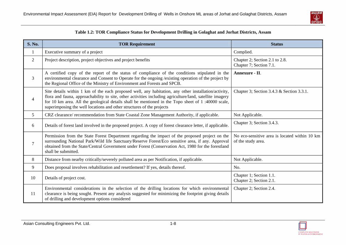
Environmental Impact Assessment (EIA) Report for Development Drilling of Wells in Onshore ML areas of Jorhat and Golaghat Districts, Assam
Asian Consulting Engineers Pvt. Ltd. 1-8
Table 1.2: TOR Compliance Status for Development Drilling in Golaghat and Jorhat Districts, Assam
S. No. TOR Requirement Status
1 Executive summary of a project Complied.
2 Project description, project objectives and project benefits Chapter 2; Section 2.1 to 2.8.
Chapter 7; Section 7.1.
3
A certified copy of the report of the status of compliance of the conditions stipulated in the
environmental clearance and Consent to Operate for the ongoing /existing operation of the project by
the Regional Office of the Ministry of Environment and Forests and SPCB.
Annexure - II.
4
Site details within 1 km of the each proposed well, any habitation, any other installation/activity,
flora and fauna, approachability to site, other activities including agriculture/land, satellite imagery
for 10 km area. All the geological details shall be mentioned in the Topo sheet of 1 :40000 scale,
superimposing the well locations and other structures of the projects
Chapter 3; Section 3.4.3 & Section 3.3.1.
5 CRZ clearance/ recommendation from State Coastal Zone Management Authority, if applicable. Not Applicable.
6 Details of forest land involved in the proposed project. A copy of forest clearance letter, if applicable. Chapter 3; Section 3.4.3.
7
Permission from the State Forest Department regarding the impact of the proposed project on the
surrounding National Park/Wild life Sanctuary/Reserve Forest/Eco sensitive area, if any. Approval
obtained from the State/Central Government under Forest (Conservation Act, 1980 for the forestland
shall be submitted.
No eco-sensitive area is located within 10 km
of the study area.
8 Distance from nearby critically/severely polluted area as per Notification, if applicable. Not Applicable.
9 Does proposal involves rehabilitation and resettlement? If yes, details thereof. No.
10 Details of project cost. Chapter 1; Section 1.1.
Chapter 2; Section 2.1.
11
Environmental considerations in the selection of the drilling locations for which environmental
clearance is being sought. Present any analysis suggested for minimizing the footprint giving details
of drilling and development options considered
Chapter 2; Section 2.4.
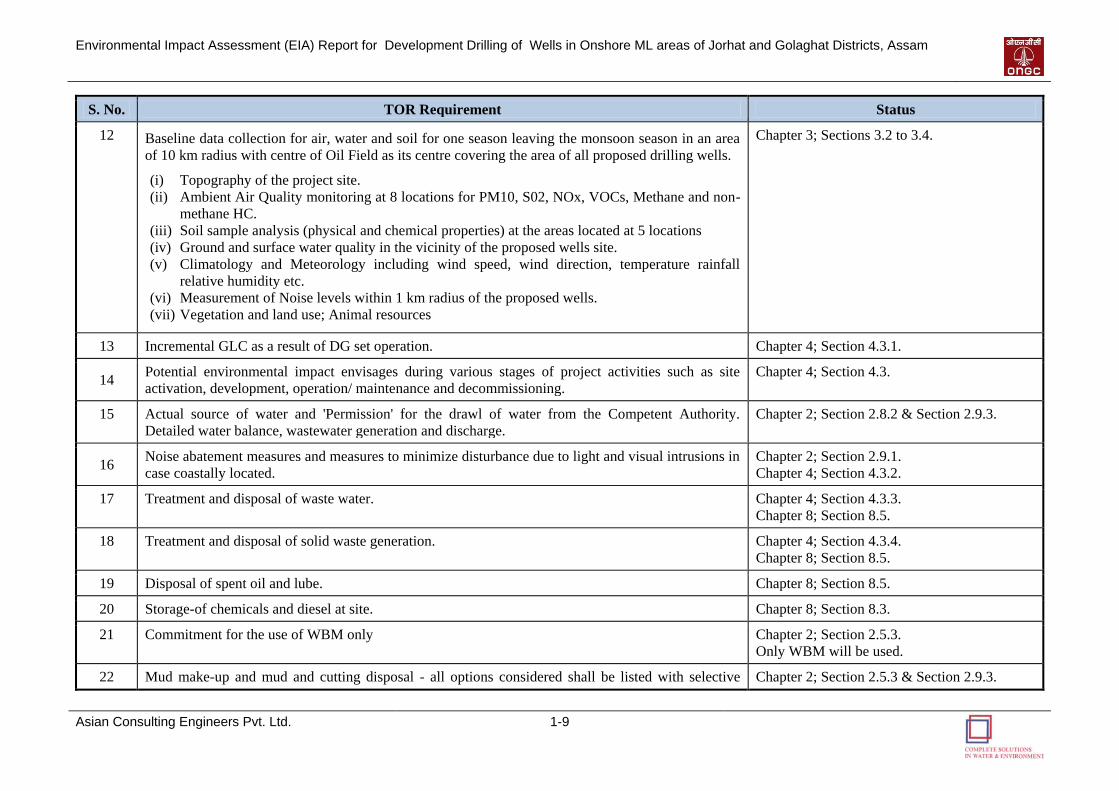
Environmental Impact Assessment (EIA) Report for Development Drilling of Wells in Onshore ML areas of Jorhat and Golaghat Districts, Assam
Asian Consulting Engineers Pvt. Ltd. 1-9
S. No. TOR Requirement Status
12 Baseline data collection for air, water and soil for one season leaving the monsoon season in an area
of 10 km radius with centre of Oil Field as its centre covering the area of all proposed drilling wells.
(i) Topography of the project site.
(ii) Ambient Air Quality monitoring at 8 locations for PM10, S02, NOx, VOCs, Methane and non-
methane HC.
(iii) Soil sample analysis (physical and chemical properties) at the areas located at 5 locations
(iv) Ground and surface water quality in the vicinity of the proposed wells site.
(v) Climatology and Meteorology including wind speed, wind direction, temperature rainfall
relative humidity etc.
(vi) Measurement of Noise levels within 1 km radius of the proposed wells.
(vii) Vegetation and land use; Animal resources
Chapter 3; Sections 3.2 to 3.4.
13 Incremental GLC as a result of DG set operation. Chapter 4; Section 4.3.1.
14 Potential environmental impact envisages during various stages of project activities such as site
activation, development, operation/ maintenance and decommissioning.
Chapter 4; Section 4.3.
15 Actual source of water and 'Permission' for the drawl of water from the Competent Authority.
Detailed water balance, wastewater generation and discharge.
Chapter 2; Section 2.8.2 & Section 2.9.3.
16 Noise abatement measures and measures to minimize disturbance due to light and visual intrusions in
case coastally located.
Chapter 2; Section 2.9.1.
Chapter 4; Section 4.3.2.
17 Treatment and disposal of waste water. Chapter 4; Section 4.3.3.
Chapter 8; Section 8.5.
18 Treatment and disposal of solid waste generation. Chapter 4; Section 4.3.4.
Chapter 8; Section 8.5.
19 Disposal of spent oil and lube. Chapter 8; Section 8.5.
20 Storage-of chemicals and diesel at site. Chapter 8; Section 8.3.
21 Commitment for the use of WBM only Chapter 2; Section 2.5.3.
Only WBM will be used.
22 Mud make-up and mud and cutting disposal - all options considered shall be listed with selective Chapter 2; Section 2.5.3 & Section 2.9.3.
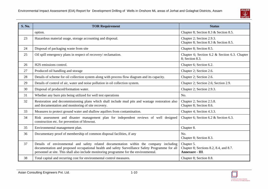
Environmental Impact Assessment (EIA) Report for Development Drilling of Wells in Onshore ML areas of Jorhat and Golaghat Districts, Assam
Asian Consulting Engineers Pvt. Ltd. 1-10
S. No. TOR Requirement Status
option. Chapter 8; Section 8.3 & Section 8.5.
23 Hazardous material usage, storage accounting and disposal. Chapter 2; Section 2.9.3.
Chapter 8; Section 8.3 & Section 8.5.
24 Disposal of packaging waste from site Chapter 8; Section 8.5.
25 Oil spill emergency plans in respect of recovery/ reclamation. Chapter 6; Section 6.2 & Section 6.3. Chapter
8; Section 8.3.
26 H2S emissions control. Chapter 6; Section 6.2.
27 Produced oil handling and storage Chapter 2; Section 2.6.
28 Details of scheme for oil collection system along with process flow diagram and its capacity. Chapter 2; Section 2.6.
29 Details of control of air, water and noise pollution in oil collection system. Chapter 2; Section 2.6; Section 2.9.
30 Disposal of produced/formation water. Chapter 2; Section 2.9.3.
31 Whether any burn pits being utilized for well test operations No.
32 Restoration and decommissioning plans which shall include mud pits and wastage restoration also
and documentation and monitoring of site recovery.
Chapter 2; Section 2.5.8.
Chapter 8; Section 8.6.
33 Measures to protect ground water and shallow aquifers from contamination. Chapter 4; Section 4.3.3.
34 Risk assessment and disaster management plan for independent reviews of well designed
construction etc. for prevention of blowout.
Chapter 6; Section 6.2 & Section 6.3.
35 Environmental management plan. Chapter 8.
36 Documentary proof of membership of common disposal facilities, if any No.
Chapter 8; Section 8.3.
37 Details of environmental and safety related documentation within the company including
documentation and proposed occupational health and safety Surveillance Safety Programme for all
personnel at site. This shall also include monitoring programme for the environmental.
Chapter 5.
Chapter 8; Sections 8.2, 8.4, and 8.7.
Annexure - III.
38 Total capital and recurring cost for environmental control measures. Chapter 8; Section 8.8.
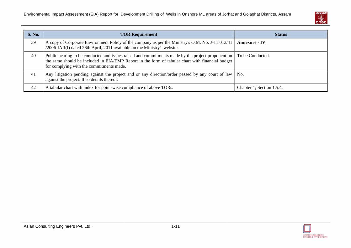
Environmental Impact Assessment (EIA) Report for Development Drilling of Wells in Onshore ML areas of Jorhat and Golaghat Districts, Assam
Asian Consulting Engineers Pvt. Ltd. 1-11
S. No. TOR Requirement Status
39 A copy of Corporate Environment Policy of the company as per the Ministry's O.M. No. J-11 013/41
/2006-IAII(I) dated 26th April, 2011 available on the Ministry's website.
Annexure - IV.
40 Public hearing to be conducted and issues raised and commitments made by the project proponent on
the same should be included in EIA/EMP Report in the form of tabular chart with financial budget
for complying with the commitments made.
To be Conducted.
41 Any litigation pending against the project and or any direction/order passed by any court of law
against the project. If so details thereof.
No.
42 A tabular chart with index for point-wise compliance of above TORs. Chapter 1; Section 1.5.4.
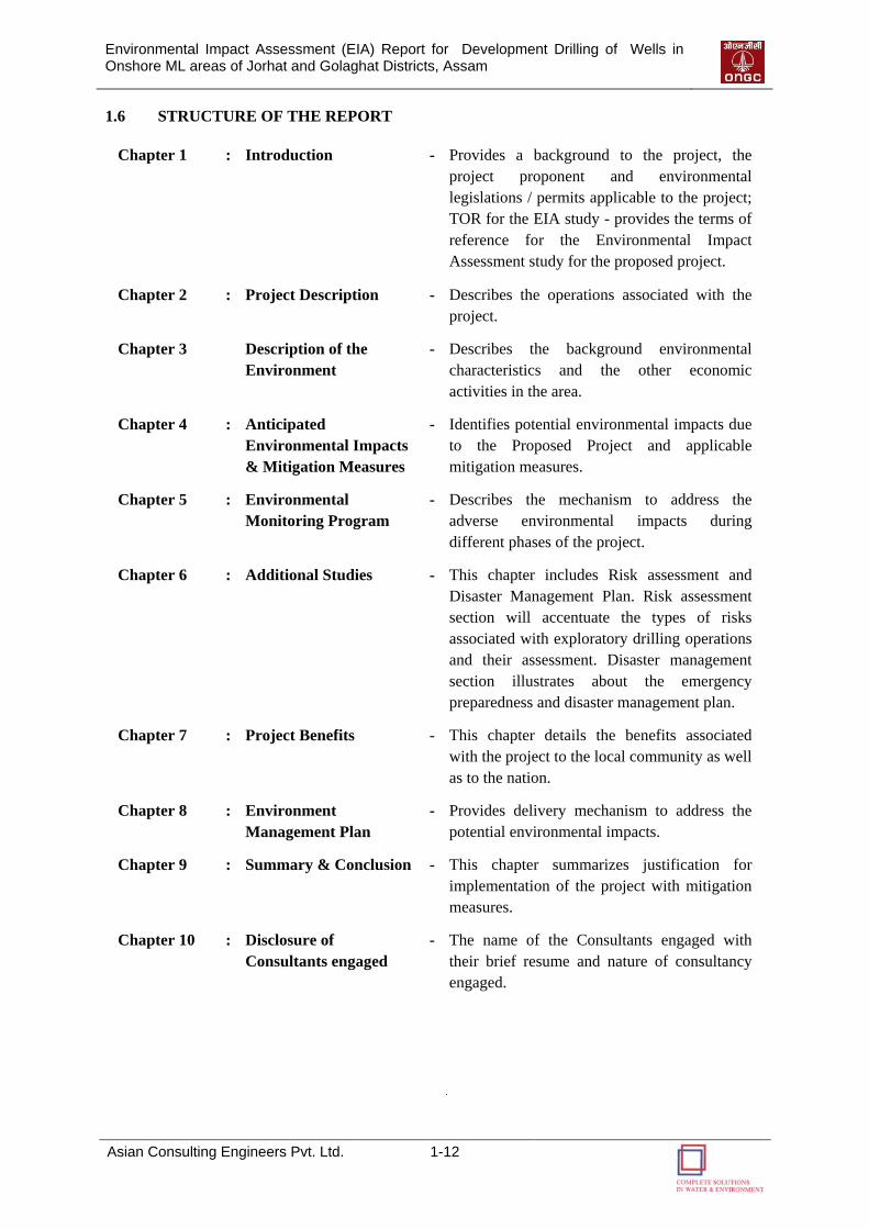
Environmental Impact Assessment (EIA) Report for Development Drilling of Wells in Onshore ML areas of Jorhat and Golaghat Districts, Assam
Asian Consulting Engineers Pvt. Ltd. 1-12
1.6 STRUCTURE OF THE REPORT
Chapter 1 : Introduction - Provides a background to the project, the
project proponent and environmental
legislations / permits applicable to the project;
TOR for the EIA study - provides the terms of
reference for the Environmental Impact
Assessment study for the proposed project.
Chapter 2 : Project Description - Describes the operations associated with the
project.
Chapter 3 Description of the
Environment
- Describes the background environmental
characteristics and the other economic
activities in the area.
Chapter 4 : Anticipated
Environmental Impacts
& Mitigation Measures
- Identifies potential environmental impacts due
to the Proposed Project and applicable
mitigation measures.
Chapter 5 : Environmental
Monitoring Program
- Describes the mechanism to address the
adverse environmental impacts during
different phases of the project.
Chapter 6 : Additional Studies - This chapter includes Risk assessment and
Disaster Management Plan. Risk assessment
section will accentuate the types of risks
associated with exploratory drilling operations
and their assessment. Disaster management
section illustrates about the emergency
preparedness and disaster management plan.
Chapter 7 : Project Benefits - This chapter details the benefits associated
with the project to the local community as well
as to the nation.
Chapter 8 : Environment
Management Plan
- Provides delivery mechanism to address the
potential environmental impacts.
Chapter 9 : Summary & Conclusion - This chapter summarizes justification for
implementation of the project with mitigation
measures.
Chapter 10 : Disclosure of
Consultants engaged
- The name of the Consultants engaged with
their brief resume and nature of consultancy
engaged.

22
PPRROOJJEECCTT
DDEESSCCRRIIPPTTIIOONN
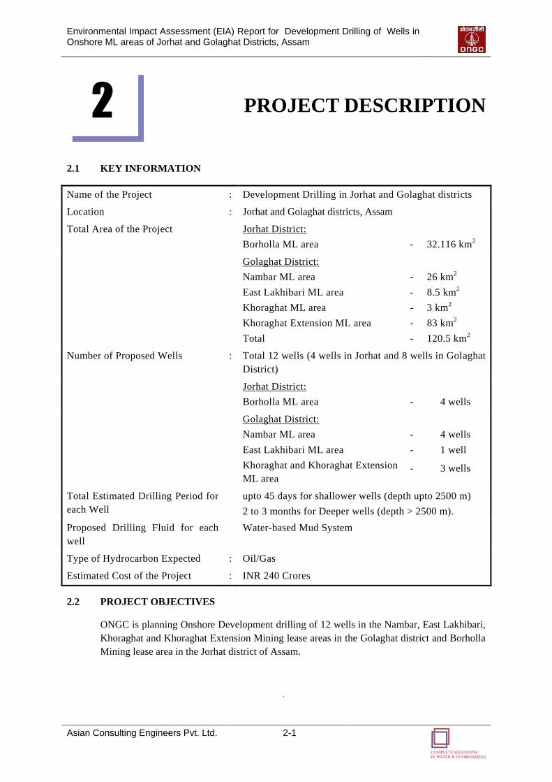
Environmental Impact Assessment (EIA) Report for Development Drilling of Wells in Onshore ML areas of Jorhat and Golaghat Districts, Assam
Asian Consulting Engineers Pvt. Ltd. 2-1
PROJECT DESCRIPTION
2.1 KEY INFORMATION
Name of the Project : Development Drilling in Jorhat and Golaghat districts
Location : Jorhat and Golaghat districts, Assam
Total Area of the Project Jorhat District:
Borholla ML area
-
32.116 km2
Golaghat District:
Nambar ML area
East Lakhibari ML area
Khoraghat ML area
Khoraghat Extension ML area
Total
-
-
-
-
-
26 km2
8.5 km2
3 km2
83 km2
120.5 km2
Number of Proposed Wells : Total 12 wells (4 wells in Jorhat and 8 wells in Golaghat
District)
Jorhat District:
Borholla ML area
-
4 wells
Golaghat District:
Nambar ML area
East Lakhibari ML area
Khoraghat and Khoraghat Extension
ML area
-
-
-
4 wells
1 well
3 wells
Total Estimated Drilling Period for
each Well
upto 45 days for shallower wells (depth upto 2500 m)
2 to 3 months for Deeper wells (depth > 2500 m).
Proposed Drilling Fluid for each
well
Water-based Mud System
Type of Hydrocarbon Expected : Oil/Gas
Estimated Cost of the Project : INR 240 Crores
2.2 PROJECT OBJECTIVES
ONGC is planning Onshore Development drilling of 12 wells in the Nambar, East Lakhibari,
Khoraghat and Khoraghat Extension Mining lease areas in the Golaghat district and Borholla
Mining lease area in the Jorhat district of Assam.
2
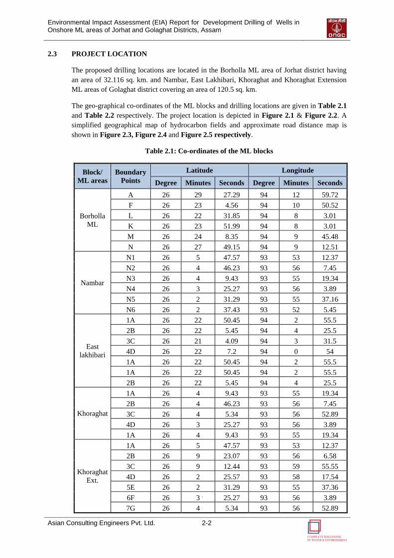
Environmental Impact Assessment (EIA) Report for Development Drilling of Wells in Onshore ML areas of Jorhat and Golaghat Districts, Assam
Asian Consulting Engineers Pvt. Ltd. 2-2
2.3 PROJECT LOCATION
The proposed drilling locations are located in the Borholla ML area of Jorhat district having
an area of 32.116 sq. km. and Nambar, East Lakhibari, Khoraghat and Khoraghat Extension
ML areas of Golaghat district covering an area of 120.5 sq. km.
The geo-graphical co-ordinates of the ML blocks and drilling locations are given in Table 2.1
and Table 2.2 respectively. The project location is depicted in Figure 2.1 & Figure 2.2. A
simplified geographical map of hydrocarbon fields and approximate road distance map is
shown in Figure 2.3, Figure 2.4 and Figure 2.5 respectively.
Table 2.1: Co-ordinates of the ML blocks
Block/
ML areas
Boundary
Points
Latitude Longitude
Degree Minutes Seconds Degree Minutes Seconds
Borholla
ML
A 26 29 27.29 94 12 59.72
F 26 23 4.56 94 10 50.52
L 26 22 31.85 94 8 3.01
K 26 23 51.99 94 8 3.01
M 26 24 8.35 94 9 45.48
N 26 27 49.15 94 9 12.51
Nambar
N1 26 5 47.57 93 53 12.37
N2 26 4 46.23 93 56 7.45
N3 26 4 9.43 93 55 19.34
N4 26 3 25.27 93 56 3.89
N5 26 2 31.29 93 55 37.16
N6 26 2 37.43 93 52 5.45
East
lakhibari
1A 26 22 50.45 94 2 55.5
2B 26 22 5.45 94 4 25.5
3C 26 21 4.09 94 3 31.5
4D 26 22 7.2 94 0 54
1A 26 22 50.45 94 2 55.5
1A 26 22 50.45 94 2 55.5
2B 26 22 5.45 94 4 25.5
Khoraghat
1A 26 4 9.43 93 55 19.34
2B 26 4 46.23 93 56 7.45
3C 26 4 5.34 93 56 52.89
4D 26 3 25.27 93 56 3.89
1A 26 4 9.43 93 55 19.34
Khoraghat
Ext.
1A 26 5 47.57 93 53 12.37
2B 26 9 23.07 93 56 6.58
3C 26 9 12.44 93 59 55.55
4D 26 2 25.57 93 58 17.54
5E 26 2 31.29 93 55 37.36
6F 26 3 25.27 93 56 3.89
7G 26 4 5.34 93 56 52.89
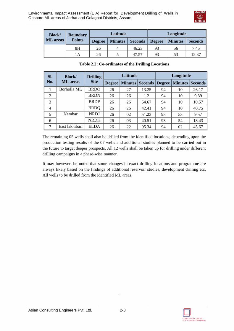
Environmental Impact Assessment (EIA) Report for Development Drilling of Wells in Onshore ML areas of Jorhat and Golaghat Districts, Assam
Asian Consulting Engineers Pvt. Ltd. 2-3
Block/
ML areas
Boundary
Points
Latitude Longitude
Degree Minutes Seconds Degree Minutes Seconds
8H 26 4 46.23 93 56 7.45
1A 26 5 47.57 93 53 12.37
Table 2.2: Co-ordinates of the Drilling Locations
Sl.
No.
Block/
ML areas
Drilling
Site
Latitude Longitude
Degree Minutes Seconds Degree Minutes Seconds
1 Borholla ML BRDO 26 27 13.25 94 10 26.17
2 BRDN 26 26 1.2 94 10 9.39
3 BRDP 26 26 54.67 94 10 10.57
4 BRDQ 26 26 42.41 94 10 40.75
5 Nambar NRDJ 26 02 51.23 93 53 9.57
6 NRDK 26 03 40.51 93 54 18.43
7 East lakhibari ELDA 26 22 05.34 94 02 45.67
The remaining 05 wells shall also be drilled from the identified locations, depending upon the
production testing results of the 07 wells and additional studies planned to be carried out in
the future to target deeper prospects. All 12 wells shall be taken up for drilling under different
drilling campaigns in a phase-wise manner.
It may however, be noted that some changes in exact drilling locations and programme are
always likely based on the findings of additional reservoir studies, development drilling etc.
All wells to be drilled from the identified ML areas.
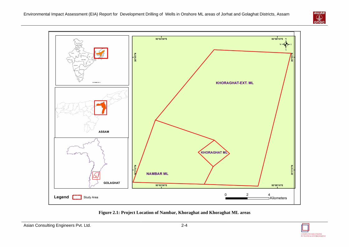
Environmental Impact Assessment (EIA) Report for Development Drilling of Wells in Onshore ML areas of Jorhat and Golaghat Districts, Assam
Asian Consulting Engineers Pvt. Ltd. 2-4
Figure 2.1: Project Location of Nambar, Khoraghat and Khoraghat ML areas

Environmental Impact Assessment (EIA) Report for Development Drilling of Wells in Onshore ML areas of Jorhat and Golaghat Districts, Assam
Asian Consulting Engineers Pvt. Ltd. 2-5
Figure 2.2: Project Location of East Lakhibari and Borholla ML areas
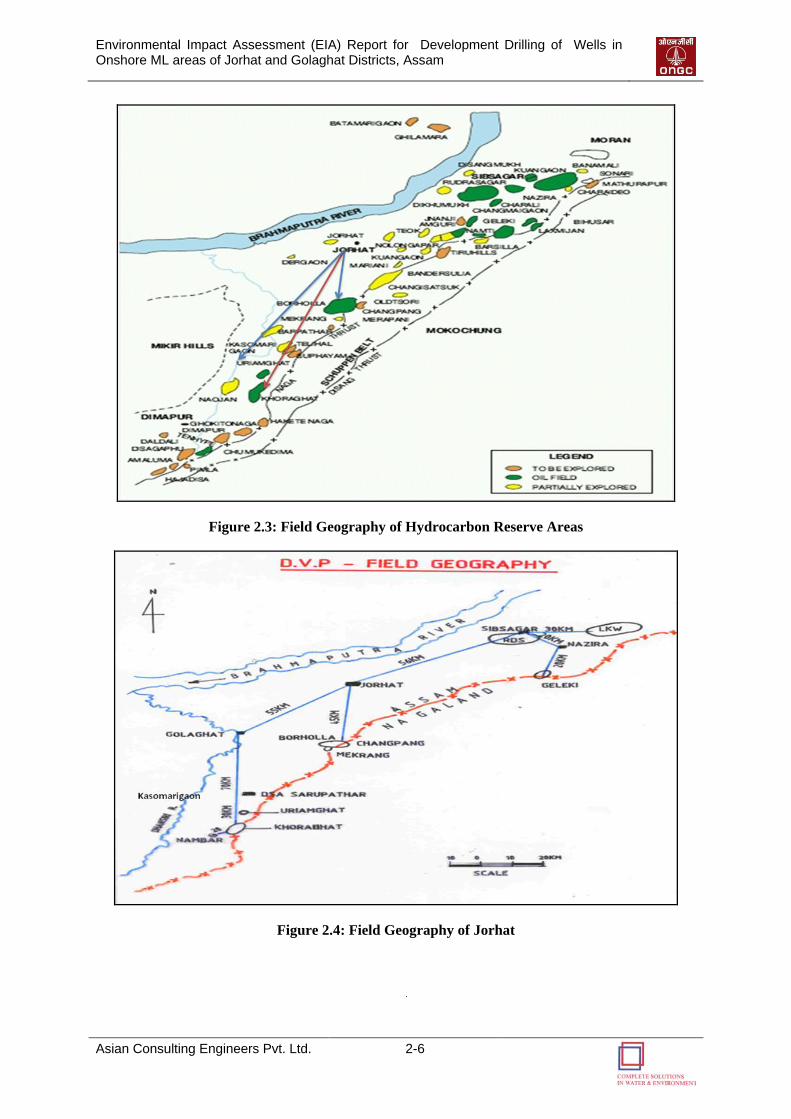
Environmental Impact Assessment (EIA) Report for Development Drilling of Wells in Onshore ML areas of Jorhat and Golaghat Districts, Assam
Asian Consulting Engineers Pvt. Ltd. 2-6
Figure 2.3: Field Geography of Hydrocarbon Reserve Areas
Figure 2.4: Field Geography of Jorhat
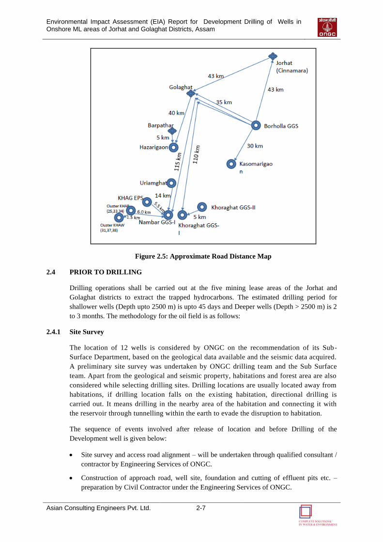
Environmental Impact Assessment (EIA) Report for Development Drilling of Wells in Onshore ML areas of Jorhat and Golaghat Districts, Assam
Asian Consulting Engineers Pvt. Ltd. 2-7
Figure 2.5: Approximate Road Distance Map
2.4 PRIOR TO DRILLING
Drilling operations shall be carried out at the five mining lease areas of the Jorhat and
Golaghat districts to extract the trapped hydrocarbons. The estimated drilling period for
shallower wells (Depth upto 2500 m) is upto 45 days and Deeper wells (Depth > 2500 m) is 2
to 3 months. The methodology for the oil field is as follows:
2.4.1 Site Survey
The location of 12 wells is considered by ONGC on the recommendation of its Sub-
Surface Department, based on the geological data available and the seismic data acquired.
A preliminary site survey was undertaken by ONGC drilling team and the Sub Surface
team. Apart from the geological and seismic property, habitations and forest area are also
considered while selecting drilling sites. Drilling locations are usually located away from
habitations, if drilling location falls on the existing habitation, directional drilling is
carried out. It means drilling in the nearby area of the habitation and connecting it with
the reservoir through tunnelling within the earth to evade the disruption to habitation.
The sequence of events involved after release of location and before Drilling of the
Development well is given below:
Site survey and access road alignment – will be undertaken through qualified consultant /
contractor by Engineering Services of ONGC.
Construction of approach road, well site, foundation and cutting of effluent pits etc. –
preparation by Civil Contractor under the Engineering Services of ONGC.
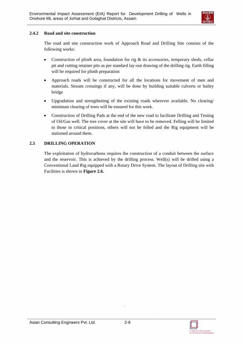
Environmental Impact Assessment (EIA) Report for Development Drilling of Wells in Onshore ML areas of Jorhat and Golaghat Districts, Assam
Asian Consulting Engineers Pvt. Ltd. 2-8
2.4.2 Road and site construction
The road and site construction work of Approach Road and Drilling Site consists of the
following works:
Construction of plinth area, foundation for rig & its accessories, temporary sheds, cellar
pit and cutting retainer pits as per standard lay-out drawing of the drilling rig. Earth filling
will be required for plinth preparation
Approach roads will be constructed for all the locations for movement of men and
materials. Stream crossings if any, will be done by building suitable culverts or bailey
bridge
Upgradation and strengthening of the existing roads wherever available. No clearing/
minimum clearing of trees will be ensured for this work.
Construction of Drilling Pads at the end of the new road to facilitate Drilling and Testing
of Oil/Gas well. The tree cover at the site will have to be removed. Felling will be limited
to those in critical positions, others will not be felled and the Rig equipment will be
stationed around them.
2.5 DRILLING OPERATION
The exploitation of hydrocarbons requires the construction of a conduit between the surface
and the reservoir. This is achieved by the drilling process. Well(s) will be drilled using a
Conventional Land Rig equipped with a Rotary Drive System. The layout of Drilling site with
Facilities is shown in Figure 2.6.
Environmental Impact Assessment (EIA) Report for Development Drilling of Wells in Onshore ML areas of Jorhat and Golaghat Districts, Assam
Asian Consulting Engineers Pvt. Ltd. 2-9
Figure 2.6: Layout of Drilling Site with Facilities
2.5.1 Components of Drilling Rig
A typical drilling rig is shown in Figure 2.7 and its main components are discussed below:
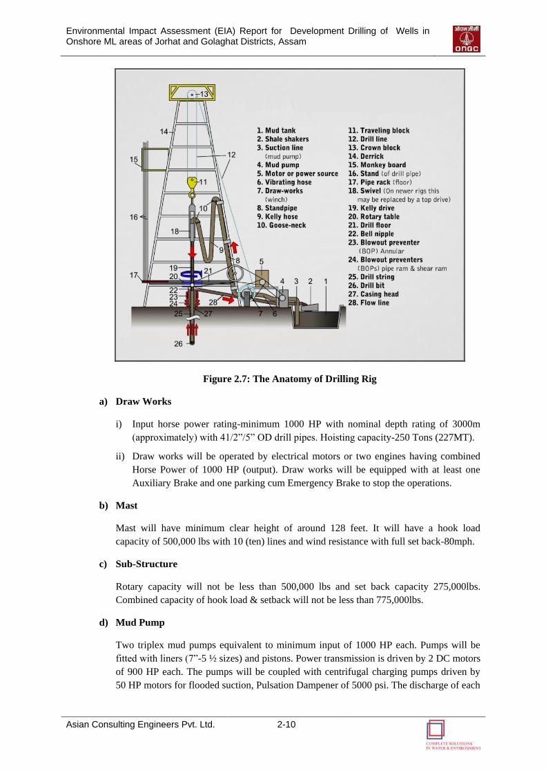
Environmental Impact Assessment (EIA) Report for Development Drilling of Wells in Onshore ML areas of Jorhat and Golaghat Districts, Assam
Asian Consulting Engineers Pvt. Ltd. 2-10
Figure 2.7: The Anatomy of Drilling Rig
a) Draw Works
i) Input horse power rating-minimum 1000 HP with nominal depth rating of 3000m
(approximately) with 41/2”/5” OD drill pipes. Hoisting capacity-250 Tons (227MT).
ii) Draw works will be operated by electrical motors or two engines having combined
Horse Power of 1000 HP (output). Draw works will be equipped with at least one
Auxiliary Brake and one parking cum Emergency Brake to stop the operations.
b) Mast
Mast will have minimum clear height of around 128 feet. It will have a hook load
capacity of 500,000 lbs with 10 (ten) lines and wind resistance with full set back-80mph.
c) Sub-Structure
Rotary capacity will not be less than 500,000 lbs and set back capacity 275,000lbs.
Combined capacity of hook load & setback will not be less than 775,000lbs.
d) Mud Pump
Two triplex mud pumps equivalent to minimum input of 1000 HP each. Pumps will be
fitted with liners (7”-5 ½ sizes) and pistons. Power transmission is driven by 2 DC motors
of 900 HP each. The pumps will be coupled with centrifugal charging pumps driven by
50 HP motors for flooded suction, Pulsation Dampener of 5000 psi. The discharge of each
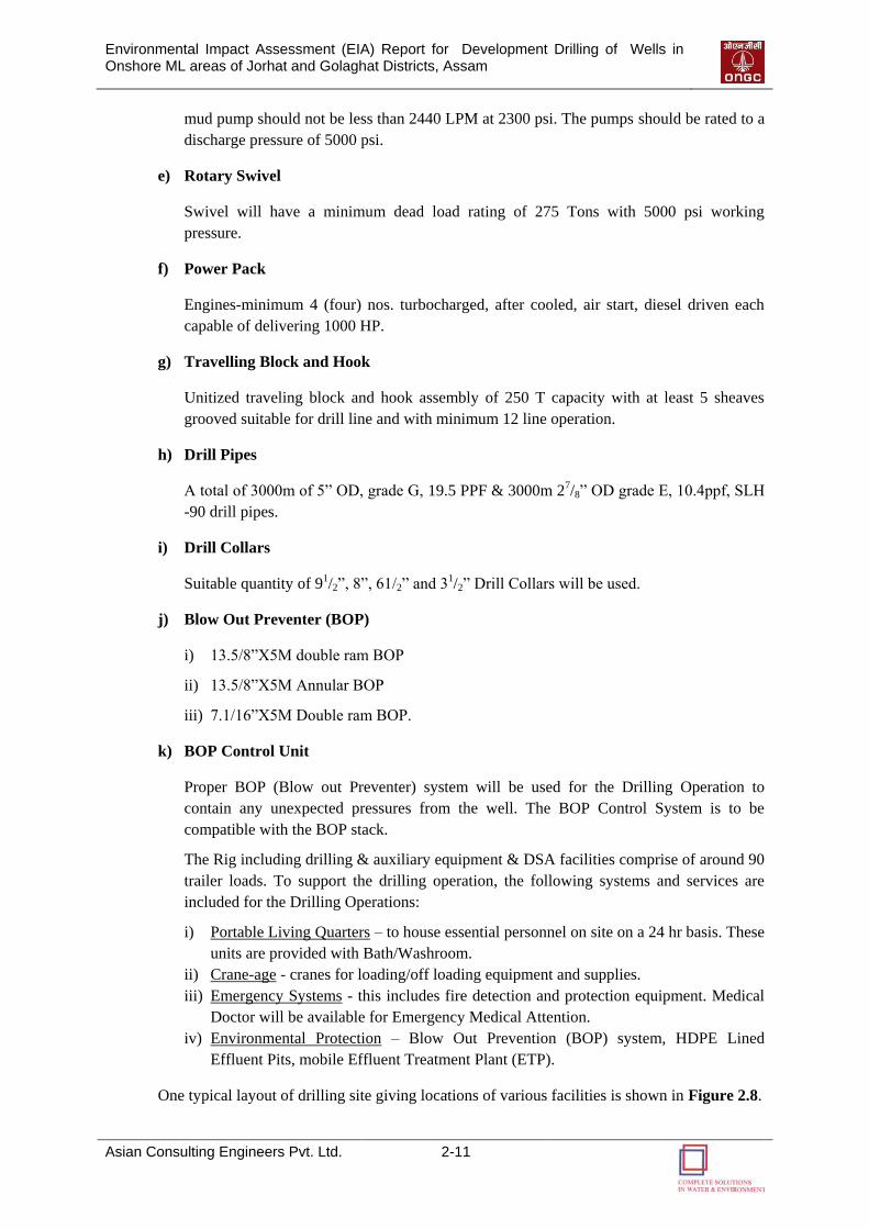
Environmental Impact Assessment (EIA) Report for Development Drilling of Wells in Onshore ML areas of Jorhat and Golaghat Districts, Assam
Asian Consulting Engineers Pvt. Ltd. 2-11
mud pump should not be less than 2440 LPM at 2300 psi. The pumps should be rated to a
discharge pressure of 5000 psi.
e) Rotary Swivel
Swivel will have a minimum dead load rating of 275 Tons with 5000 psi working
pressure.
f) Power Pack
Engines-minimum 4 (four) nos. turbocharged, after cooled, air start, diesel driven each
capable of delivering 1000 HP.
g) Travelling Block and Hook
Unitized traveling block and hook assembly of 250 T capacity with at least 5 sheaves
grooved suitable for drill line and with minimum 12 line operation.
h) Drill Pipes
A total of 3000m of 5” OD, grade G, 19.5 PPF & 3000m 27/8” OD grade E, 10.4ppf, SLH
-90 drill pipes.
i) Drill Collars
Suitable quantity of 91/2”, 8”, 61/2” and 31/2” Drill Collars will be used.
j) Blow Out Preventer (BOP)
i) 13.5/8”X5M double ram BOP
ii) 13.5/8”X5M Annular BOP
iii) 7.1/16”X5M Double ram BOP.
k) BOP Control Unit
Proper BOP (Blow out Preventer) system will be used for the Drilling Operation to
contain any unexpected pressures from the well. The BOP Control System is to be
compatible with the BOP stack.
The Rig including drilling & auxiliary equipment & DSA facilities comprise of around 90
trailer loads. To support the drilling operation, the following systems and services are
included for the Drilling Operations:
i) Portable Living Quarters – to house essential personnel on site on a 24 hr basis. These
units are provided with Bath/Washroom.
ii) Crane-age - cranes for loading/off loading equipment and supplies.
iii) Emergency Systems - this includes fire detection and protection equipment. Medical
Doctor will be available for Emergency Medical Attention.
iv) Environmental Protection – Blow Out Prevention (BOP) system, HDPE Lined
Effluent Pits, mobile Effluent Treatment Plant (ETP).
One typical layout of drilling site giving locations of various facilities is shown in Figure 2.8.
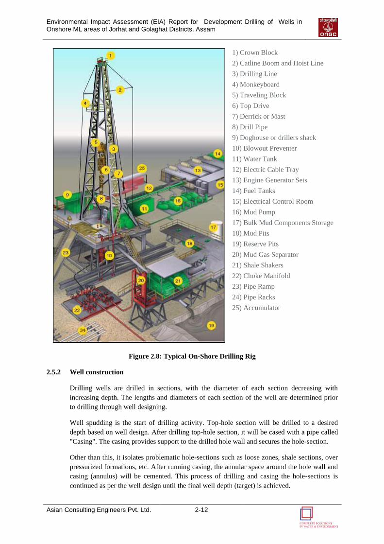
Environmental Impact Assessment (EIA) Report for Development Drilling of Wells in Onshore ML areas of Jorhat and Golaghat Districts, Assam
Asian Consulting Engineers Pvt. Ltd. 2-12
1) Crown Block
2) Catline Boom and Hoist Line
3) Drilling Line
4) Monkeyboard
5) Traveling Block
6) Top Drive
7) Derrick or Mast
8) Drill Pipe
9) Doghouse or drillers shack
10) Blowout Preventer
11) Water Tank
12) Electric Cable Tray
13) Engine Generator Sets
14) Fuel Tanks
15) Electrical Control Room
16) Mud Pump
17) Bulk Mud Components Storage
18) Mud Pits
19) Reserve Pits
20) Mud Gas Separator
21) Shale Shakers
22) Choke Manifold
23) Pipe Ramp
24) Pipe Racks
25) Accumulator
Figure 2.8: Typical On-Shore Drilling Rig
2.5.2 Well construction
Drilling wells are drilled in sections, with the diameter of each section decreasing with
increasing depth. The lengths and diameters of each section of the well are determined prior
to drilling through well designing.
Well spudding is the start of drilling activity. Top-hole section will be drilled to a desired
depth based on well design. After drilling top-hole section, it will be cased with a pipe called
"Casing". The casing provides support to the drilled hole wall and secures the hole-section.
Other than this, it isolates problematic hole-sections such as loose zones, shale sections, over
pressurized formations, etc. After running casing, the annular space around the hole wall and
casing (annulus) will be cemented. This process of drilling and casing the hole-sections is
continued as per the well design until the final well depth (target) is achieved.

Environmental Impact Assessment (EIA) Report for Development Drilling of Wells in Onshore ML areas of Jorhat and Golaghat Districts, Assam
Asian Consulting Engineers Pvt. Ltd. 2-13
2.5.3 Drilling fluids
During Drilling Operations, a fluid known as Drilling Fluid (more commonly Mud) is
pumped through the drill string down to the drilling bit and returns between the drill pipe and
hole / casing annulus up to surface back into the circulation system after separation of drill
cuttings / solids through solids control equipment. Drilling fluid is essential to the drilling
operation and performs the following functions:
Cleans the bottom of the hole by removing the cuttings and carrying them to surface;
Cools and lubricates drill bit and string;
Continuously builds a wall around the inside of the hole which prevents the hole from
caving in;
Counters natural formation pressures, preventing the uncontrolled flow of oil, gas, or
water into the borehole;
Holds cuttings and weighing material in suspension, when circulation is stopped;
Supports part of the weight of drill pipes, casing, tubing, etc.;
Transmits hydraulic horse power to the bit;
Acts as medium for electrical well logging;
Ensures maximum information about the formations penetrated;
Prevents corrosion of tubular.
The composition of Water based drilling fluid is given in Table 2.3.
Table 2.3: Ingredients of Water Based Drilling Fluid
Sl. No. Component Quantity
1 KCI-PHPA-Polyol Mud Composition-KCI ~3 %
2 PHPA 0.2-0.3 %
3 PAC 0.5-0.75 %
5 E P Lube 0.2-0.3 %
6 Bentonite 2-3 %
8 Caustic Soda for pH 8-5-9.0
9 XC Polymer 0.3-0.5 %
10 S. Asphalt 2-3 %
Type of Drilling Fluid (Mud)
An environment-friendly Water-Based Mud (WBM) system will be used for drilling of the
proposed wells. It may be noted that a typical WBM may contain nearly 80% water and 20%
Clay as well as Chemicals by weight. The ingredients of WBM and Special Additives and
their Function in Water Based Drilling Fluids are given in Table 2.4 and Table 2.5
respectively.
Environmental Impact Assessment (EIA) Report for Development Drilling of Wells in Onshore ML areas of Jorhat and Golaghat Districts, Assam
Asian Consulting Engineers Pvt. Ltd. 2-14
Table 2.4: Ingredients of Water Based Drilling Mud
Sl.
No.
Raw
Material Quantity
1 Barite 150 MT/Well
2 Bentonite 90 MT/Well
3 Carboxyl Methyl Cellulose 2.2-3 MT/Well
5 Resinated Lignite 2 MT/Well
6 Non-Weighted Spotting Fluid ASOS
8 Extreme Pressure (EP) Lube 1000 Lts/Well
9 Drilling Detergent 1800 Lts/Well
10 Caustic Soda 4.4 MT/Well
11 Potassium Chloride 35 MT/Well
12 Soda Ash 1.3 MT/Well
Table 2.5: Special Additives and their Function in Water Based Drilling Fluids
Sl. No. Discharge Category Function of Additives
1. Sodium bicarbonate Eliminate excess calcium ions due to cement
contamination
2. Sodium Chloride Minimize borehole washout in salt zone
3. Groundnut shells, mica of
cellophane Minimize loss of drilling mud to formation
4. Cellulose polymers or starch Counter thick, sticky filter cake, decrease filter
loss to formation
5. Aluminium stearate Minimize foaming
6. Vegetable Oil
lubricant Reduce torque and drag on drill string.
7. Pill of oil-based mud spotting
fluid
Counter differential pressure sticking of drilling
string. Pill is placed down hole opposite contact
zone to free pipe
Mud Circulation & Solid Control System
The drilling fluid circulation system consists of several items of equipment as given in Figure
2.9. The mud pumps take drilling fluid from tanks and pump the same to the bit through drill
pipes. The mud travels through annulus and finally falls over the shale shaker. The mud used
during the operation will flush out formation cuttings from the well bore which will be
separated from the fluid using solids control system. This will include shale shakers, de-
sanders, de-silters etc. The process of reusing the drilling fluid during drilling operation is
commonly known as “closed loop system”. The system is ideal for drilling operations in
sensitive environments as it cuts down immensely on the total water consumption for the
formulation of drilling mud and also saves on the consumption of the chemicals.
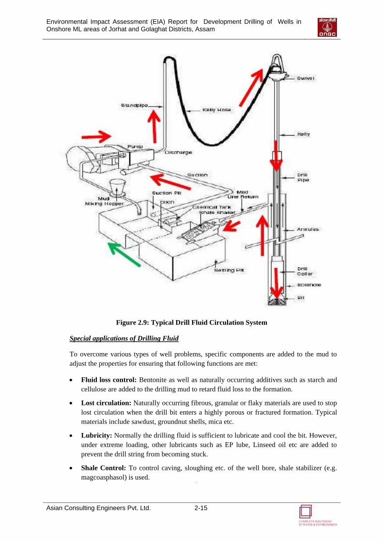
Environmental Impact Assessment (EIA) Report for Development Drilling of Wells in Onshore ML areas of Jorhat and Golaghat Districts, Assam
Asian Consulting Engineers Pvt. Ltd. 2-15
Figure 2.9: Typical Drill Fluid Circulation System
Special applications of Drilling Fluid
To overcome various types of well problems, specific components are added to the mud to
adjust the properties for ensuring that following functions are met:
Fluid loss control: Bentonite as well as naturally occurring additives such as starch and
cellulose are added to the drilling mud to retard fluid loss to the formation.
Lost circulation: Naturally occurring fibrous, granular or flaky materials are used to stop
lost circulation when the drill bit enters a highly porous or fractured formation. Typical
materials include sawdust, groundnut shells, mica etc.
Lubricity: Normally the drilling fluid is sufficient to lubricate and cool the bit. However,
under extreme loading, other lubricants such as EP lube, Linseed oil etc are added to
prevent the drill string from becoming stuck.
Shale Control: To control caving, sloughing etc. of the well bore, shale stabilizer (e.g.
magcoasphasol) is used.
Environmental Impact Assessment (EIA) Report for Development Drilling of Wells in Onshore ML areas of Jorhat and Golaghat Districts, Assam
Asian Consulting Engineers Pvt. Ltd. 2-16
pH control: Caustic Soda is used to control the alkalinity of the drilling fluid in the range
of pH of 9 to 10. This ensures the optimum performance of the polymers in the fluid and
controls bacterial activity.
Pressure control: Barite is generally used as a weighting material to control down-hole
formation pressure and to prevent the ingress of formation fluid into well bore.
The essential ingredients of the WBM are all low toxicity materials, rated either as Grade ‟E‟
products (according to the new OCNS grading system), or Grade „O‟ (according to the former
OCNS system). These are the two lowest toxicity categories. A variety of other products will
be available for various contingencies. Thinners such as chrome free ligno-sulphonates
(CFLS) and lignin compounds may be used to control Rheology.
2.5.4 Cementing Program
Oil well cementing is the process of preparing slurry of API Class G cement with water and
various additives in required quantities as accelerators/ retarders, density adjusters,
dispersants, fluid loss additives, anti gas migration additives, etc. This slurry is pumped down
through steel casing to cover the critical points in the annulus around the casing in the open
hole.
Functions of the cementing process
Bond and support the casing strings;
Isolate oil, gas and water bearing zones;
Protect fresh water bearing zone from contamination;
Prevent Blowouts by quickly forming a seal;
Seal off zones of lost –circulation or thief zones;
Protect casing from corrosion; and
Protect casing from shock loads.
2.5.5 Well evaluation
Well Logging
Wire line logging operations are undertaken with specialized equipment mounted on custom
built trucks to provide information on the potential type and quantities of hydrocarbons
present in the prospective formations.
There are different well logging techniques including electric, electronic, sonic, radioactive
logging etc. Logging instruments (sensors) are attached to the bottom of a wire line and
lowered to the bottom of the well. They are then slowly brought back, the devices reading
different geo-scientific parameters pass each information and record the corresponding data
on graphs, which can be interpreted by the drilling team. There are no emissions to the
environment associated with wire line logging operations. The radioactive sources required
for well logging operations will be kept in specially designed containers, if used.
Environmental Impact Assessment (EIA) Report for Development Drilling of Wells in Onshore ML areas of Jorhat and Golaghat Districts, Assam
Asian Consulting Engineers Pvt. Ltd. 2-17
Well Testing
If prospects of hydrocarbons appear in conventional core or in wire line logs, a detailed
production testing is carried out. For production testing equipments like separator, ground X-
mas tree, and compressors are required.
Conventional Coring
Conventional cores of sub-surface formations are taken on selective basis to carry out Petro-
physical and Geo-scientific studies.
2.5.6 Completion of drilling
On completion of activities, the well will be either plugged or suspended (if the well
evaluations indicate commercial quantities of hydrocarbons) or will be permanently
abandoned. In the event of a decision to suspend the well, it will be filled with a brine
solution containing very small quantities of inhibitors to protect the well. The well will be
sealed with cement plugs and some of the wellhead equipment (Blind Flange) will be left on
the surface (Cellar).
If the well is abandoned it will be sealed with a series of cement plugs, all the wellhead
equipment will be removed leaving the surface clear of any debris and the site will be
restored.
2.5.7 Rig Demobilization
Demobilization will involve the dismantling of the rig and Drill Site Accommodation (DSA),
and transporting it out of the project area. It is expected that demobilization will take
approximately 30 days and will require around 80 to 85 trailer and 50 to 55 truck loads.
2.5.8 Restoration and Rehabilitation
On completion of drilling activities, well site restoration plan will be prepared for the
following two scenarios:
1) Commercially viable Hydrocarbons are discovered
In the event that economic quantities of hydrocarbons are found, the well will be shut in with
a wellhead / X-mas tree in place, but all other equipment and materials will be removed from
present location to the next drilling site. At the end of well testing at each drilling site, the
HDPE Lined Secured Pits for Drill Cuttings and Drilling Mud will be covered with a top
HDPE lining. The pit will then be backfilled with minimum 300 mm layer of soil.
2) Economic Quantities of Hydrocarbons are not found
In the event that economic quantities of hydrocarbons are not found an abandonment plan will
be implemented for the drilling site in accordance with the applicable Indian regulations,
OISD, Oil Mines Regulation (OMR) etc. Plugging requirement of abandoned wells as per Oil
Mines Regulation, 1984 are as follows:
When it is intended to abandon a well:
All permeable formations shall be isolated with cement;
Cased hole may be abandoned by placing a bridge-plug on top of perforations;
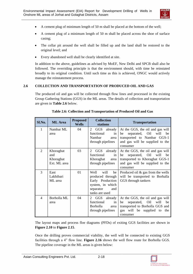
Environmental Impact Assessment (EIA) Report for Development Drilling of Wells in Onshore ML areas of Jorhat and Golaghat Districts, Assam
Asian Consulting Engineers Pvt. Ltd. 2-18
A cement plug of minimum length of 50 m shall be placed at the bottom of the well;
A cement plug of a minimum length of 50 m shall be placed across the shoe of surface
casing;
The cellar pit around the well shall be filled up and the land shall be restored to the
original level; and
Every abandoned well shall be clearly identified at site.
In addition to the above, guidelines as advised by MoEF, New Delhi and SPCB shall also be
followed. The overriding principle is that the environment should, with time be reinstated
broadly to its original condition. Until such time as this is achieved, ONGC would actively
manage the reinstatement process.
2.6 COLLECTION AND TRANSPORTATION OF PRODUCED OIL AND GAS
The produced oil and gas will be collected through flow lines and processed in the existing
Group Gathering Stations (GGS) in the ML areas. The details of collection and transportation
are given in Table 2.6 below.
Table 2.6: Collection and Transportation of Produced Oil and Gas
Sl.No. ML Area Proposed
Wells
Collection
stations Transportation
1 Nambar ML
area
04 2 GGS already
functional in
Nambar area
through pipelines
At the GGS, the oil and gas will
be separated, Oil will be
transported to Nambar GGS-1
and gas will be supplied to the
consumer
2 Khoraghat
and
Khoraghat
Ext. ML area
03 2 GGS already
functional in
Khoraghat area
through pipelines
At the GGS, the oil and gas will
be separated, Oil will be
transported to Khoraghat GGS-1
and gas will be supplied to the
consumer
3 East
Lakhibari
ML area
01 Well will be
produced through
Early Production
system, in which
separator and
tanks are used
Produced oil & gas from the wells
will be transported to Borhalla
GGS through tankers
4 Borholla ML
area
04 2 GGS already
functional in
Borholla area
through pipelines
At the GGS, the oil and gas will
be separated, Oil will be
transported to Borholla GGS and
gas will be supplied to the
consumer
The layout maps and process floe diagrams (PFDs) of exiting GGS facilities are shown in
Figure 2.10 to Figure 2.15.
Once the drilling proves commercial viability, the well will be connected to existing GGS
facilities through a 4” flow line. Figure 2.16 shows the well flow route for Borholla GGS.
The pipeline coverage in the ML areas is given below:

Environmental Impact Assessment (EIA) Report for Development Drilling of Wells in Onshore ML areas of Jorhat and Golaghat Districts, Assam
Asian Consulting Engineers Pvt. Ltd. 2-19
12” oil trunk pipeline (43 Km) from BRH GGS to CTF Jorhat
8” oil trunk pipeline system (65 Km) from KHG GGS-I to BRH GGS
8” well fluid pipeline (4.5 Km) from NR GGS to KHG GGS-I
3 1/2”gas pipeline ( 4.5 Km) from NR GGS via well KH-09 & NR-02 to KHR GGS-I
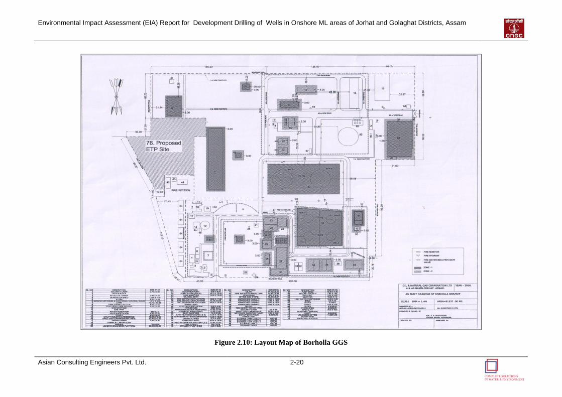
Environmental Impact Assessment (EIA) Report for Development Drilling of Wells in Onshore ML areas of Jorhat and Golaghat Districts, Assam
Asian Consulting Engineers Pvt. Ltd. 2-20
Figure 2.10: Layout Map of Borholla GGS
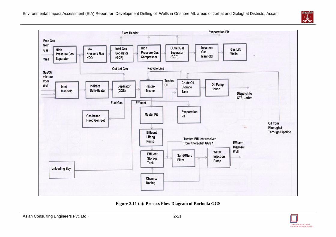
Environmental Impact Assessment (EIA) Report for Development Drilling of Wells in Onshore ML areas of Jorhat and Golaghat Districts, Assam
Asian Consulting Engineers Pvt. Ltd. 2-21
Figure 2.11 (a): Process Flow Diagram of Borholla GGS

Environmental Impact Assessment (EIA) Report for Development Drilling of Wells in Onshore ML areas of Jorhat and Golaghat Districts, Assam
Asian Consulting Engineers Pvt. Ltd. 2-22
Figure 2.11 (b): Schematic Diagram of Borholla GGS Process Flow
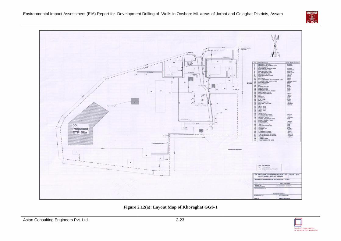
Environmental Impact Assessment (EIA) Report for Development Drilling of Wells in Onshore ML areas of Jorhat and Golaghat Districts, Assam
Asian Consulting Engineers Pvt. Ltd. 2-23
Figure 2.12(a): Layout Map of Khoraghat GGS-1

Environmental Impact Assessment (EIA) Report for Development Drilling of Wells in Onshore ML areas of Jorhat and Golaghat Districts, Assam
Asian Consulting Engineers Pvt. Ltd. 2-24
Figure 2.12 (b): Schematic Diagram of Khoraghat GGS-1 Facility Layout
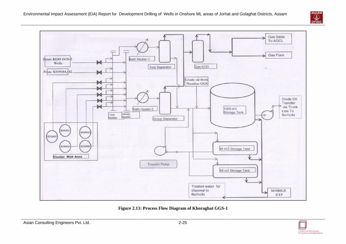
Environmental Impact Assessment (EIA) Report for Development Drilling of Wells in Onshore ML areas of Jorhat and Golaghat Districts, Assam
Asian Consulting Engineers Pvt. Ltd. 2-25
Figure 2.13: Process Flow Diagram of Khoraghat GGS-1
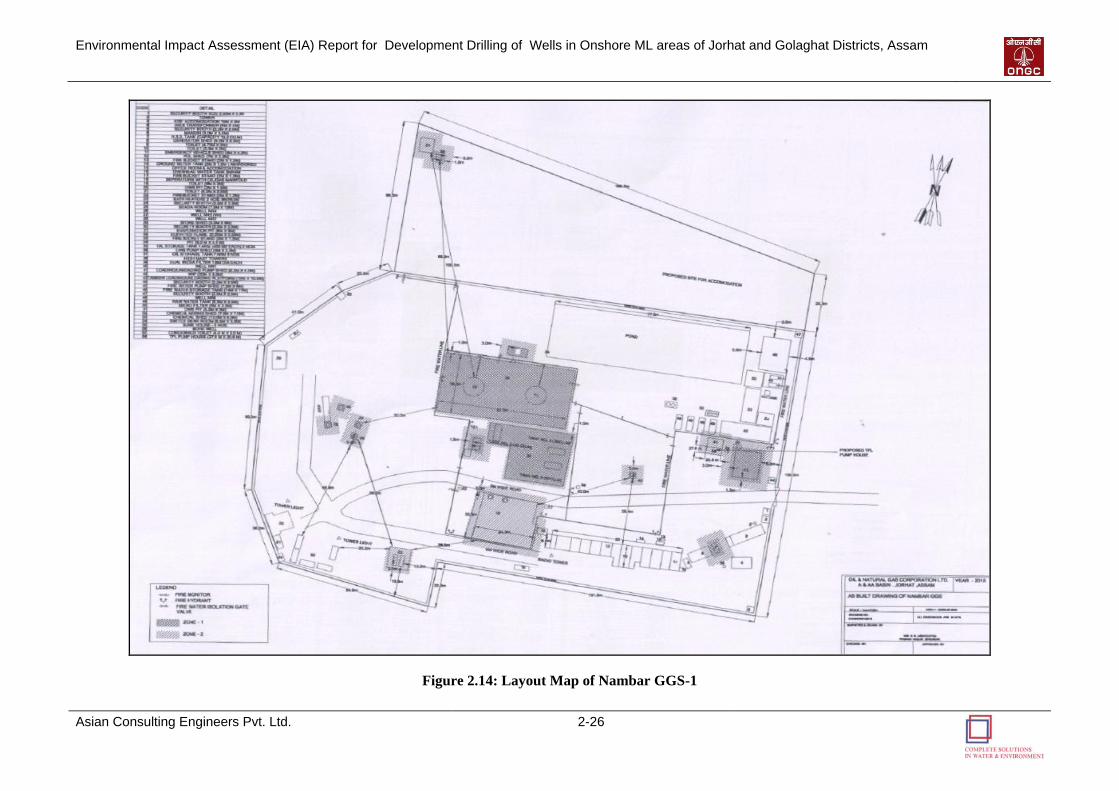
Environmental Impact Assessment (EIA) Report for Development Drilling of Wells in Onshore ML areas of Jorhat and Golaghat Districts, Assam
Asian Consulting Engineers Pvt. Ltd. 2-26
Figure 2.14: Layout Map of Nambar GGS-1
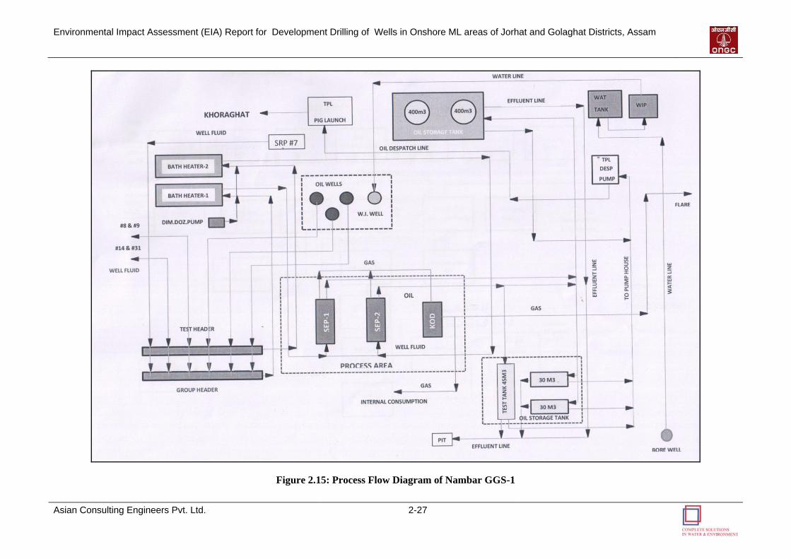
Environmental Impact Assessment (EIA) Report for Development Drilling of Wells in Onshore ML areas of Jorhat and Golaghat Districts, Assam
Asian Consulting Engineers Pvt. Ltd. 2-27
Figure 2.15: Process Flow Diagram of Nambar GGS-1
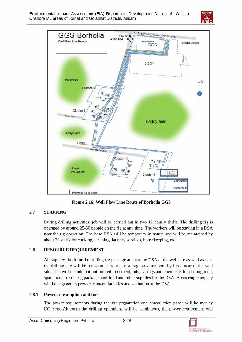
Environmental Impact Assessment (EIA) Report for Development Drilling of Wells in Onshore ML areas of Jorhat and Golaghat Districts, Assam
Asian Consulting Engineers Pvt. Ltd. 2-28
Figure 2.16: Well Flow Line Route of Borholla GGS
2.7 STAFFING
During drilling activities, job will be carried out in two 12 hourly shifts. The drilling rig is
operated by around 25-30 people on the rig at any time. The workers will be staying in a DSA
near the rig operation. The base DSA will be temporary in nature and will be maintained by
about 20 staffs for cooking, cleaning, laundry services, housekeeping, etc.
2.8 RESOURCE REQUIREMENT
All supplies, both for the drilling rig package and for the DSA at the well site as well as near
the drilling site will be transported from any storage area temporarily hired near to the well
site. This will include but not limited to cement, bits, casings and chemicals for drilling mud,
spare parts for the rig package, and food and other supplies for the DSA. A catering company
will be engaged to provide canteen facilities and sanitation at the DSA.
2.8.1 Power consumption and fuel
The power requirements during the site preparation and construction phase will be met by
DG Sets. Although the drilling operations will be continuous, the power requirement will
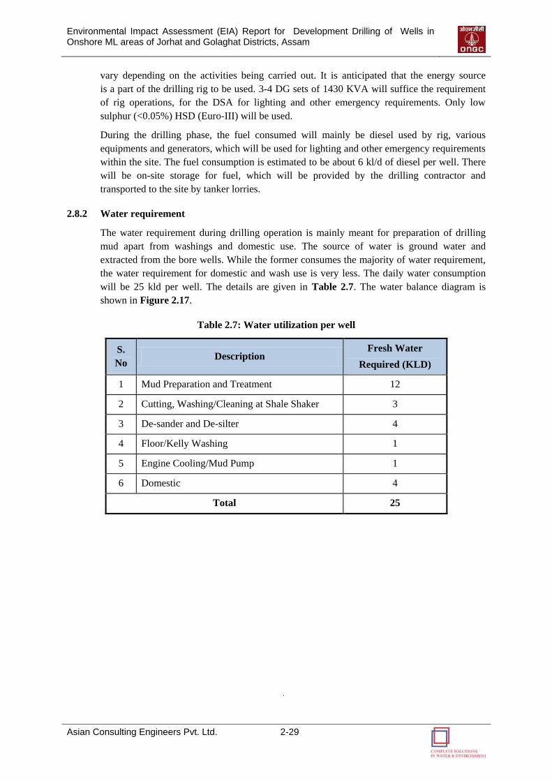
Environmental Impact Assessment (EIA) Report for Development Drilling of Wells in Onshore ML areas of Jorhat and Golaghat Districts, Assam
Asian Consulting Engineers Pvt. Ltd. 2-29
vary depending on the activities being carried out. It is anticipated that the energy source
is a part of the drilling rig to be used. 3-4 DG sets of 1430 KVA will suffice the requirement
of rig operations, for the DSA for lighting and other emergency requirements. Only low
sulphur (<0.05%) HSD (Euro-III) will be used.
During the drilling phase, the fuel consumed will mainly be diesel used by rig, various
equipments and generators, which will be used for lighting and other emergency requirements
within the site. The fuel consumption is estimated to be about 6 kl/d of diesel per well. There
will be on-site storage for fuel, which will be provided by the drilling contractor and
transported to the site by tanker lorries.
2.8.2 Water requirement
The water requirement during drilling operation is mainly meant for preparation of drilling
mud apart from washings and domestic use. The source of water is ground water and
extracted from the bore wells. While the former consumes the majority of water requirement,
the water requirement for domestic and wash use is very less. The daily water consumption
will be 25 kld per well. The details are given in Table 2.7. The water balance diagram is
shown in Figure 2.17.
Table 2.7: Water utilization per well
S.
No Description
Fresh Water
Required (KLD)
1 Mud Preparation and Treatment 12
2 Cutting, Washing/Cleaning at Shale Shaker 3
3 De-sander and De-silter 4
4 Floor/Kelly Washing 1
5 Engine Cooling/Mud Pump 1
6 Domestic 4
Total 25
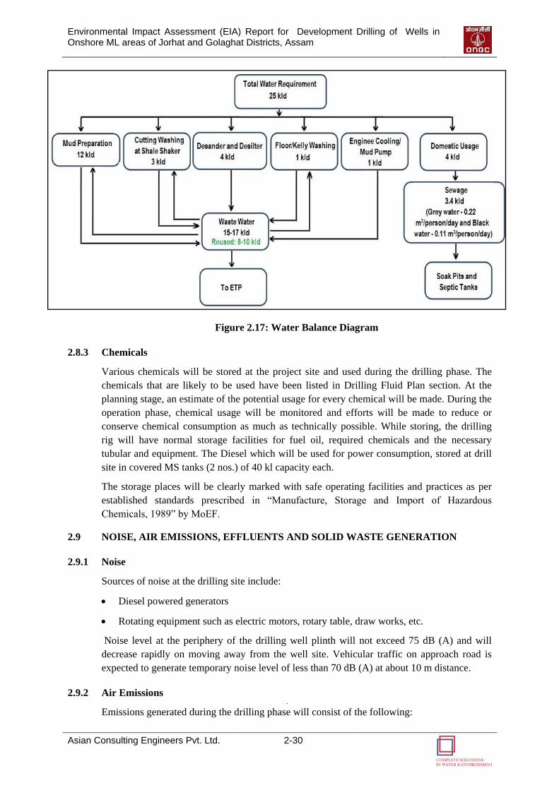
Environmental Impact Assessment (EIA) Report for Development Drilling of Wells in Onshore ML areas of Jorhat and Golaghat Districts, Assam
Asian Consulting Engineers Pvt. Ltd. 2-30
Figure 2.17: Water Balance Diagram
2.8.3 Chemicals
Various chemicals will be stored at the project site and used during the drilling phase. The
chemicals that are likely to be used have been listed in Drilling Fluid Plan section. At the
planning stage, an estimate of the potential usage for every chemical will be made. During the
operation phase, chemical usage will be monitored and efforts will be made to reduce or
conserve chemical consumption as much as technically possible. While storing, the drilling
rig will have normal storage facilities for fuel oil, required chemicals and the necessary
tubular and equipment. The Diesel which will be used for power consumption, stored at drill
site in covered MS tanks (2 nos.) of 40 kl capacity each.
The storage places will be clearly marked with safe operating facilities and practices as per
established standards prescribed in “Manufacture, Storage and Import of Hazardous
Chemicals, 1989” by MoEF.
2.9 NOISE, AIR EMISSIONS, EFFLUENTS AND SOLID WASTE GENERATION
2.9.1 Noise
Sources of noise at the drilling site include:
Diesel powered generators
Rotating equipment such as electric motors, rotary table, draw works, etc.
Noise level at the periphery of the drilling well plinth will not exceed 75 dB (A) and will
decrease rapidly on moving away from the well site. Vehicular traffic on approach road is
expected to generate temporary noise level of less than 70 dB (A) at about 10 m distance.
2.9.2 Air Emissions
Emissions generated during the drilling phase will consist of the following:
Environmental Impact Assessment (EIA) Report for Development Drilling of Wells in Onshore ML areas of Jorhat and Golaghat Districts, Assam
Asian Consulting Engineers Pvt. Ltd. 2-31
Exhaust emissions from generators operating at site;
Dust emissions from vehicular traffic movement on roads;
Emissions from flares during testing.
The proposed drilling site will have 3-4 diesel generators (each of 1430 KVA capacity).
No treatment of air emissions is required as these involve burning of diesel with low Sulphur
content (< 0.05%). The disposal of the air emissions will be through adequate stack height as
per norms.
Movement of about 3 to 4 passenger and heavy vehicles in a day is not likely to have any
adverse impact on the environment.
Air emissions may result from gas flaring activities during the well testing and is a temporary
activity of two-three days only. The test flare boom will be located at a distance from the
drilling rig.
Heat Generation
The drilling work will generate heat which will be dissipated to the WBM (about 500C at
surface) and then to the atmosphere. Hence, it is unlikely to have any noticeable effect in the
area surrounding the drilling rig.
Potential Accidental Events
Due to observation of necessary safety requirements as per OMR, OISD and other regulations
vis-à-vis Safe Operating Practices (SOP), chances of accident occurring are negligible.
However, in all aspects of hydrocarbon exploration, there is always a risk of non-routine or
accidental events such as
Occurrence of blow out
Occurrence of sour gas (H2S)
Blow out followed by ignition can be extremely hazardous. Blow out Preventers (BOP) are
always used to combat abrupt appearance of sub surface high pressure. Sour gas (H2S) may
also be released from the well along with gaseous hydrocarbons. However, it is known that
crude oil/gas in this region is sweet in nature; i.e. there is no presence of H2S in produced
oil/gas.
Spillage of diesel fuel is near negligible from storage facilities at the drilling site.
2.9.3 Effluents and Solid Waste
The following types of wastes are likely to be generated during the drilling activities:
Drill Cuttings: comprises of drilled formation cuttings, mainly shale, sands and clay
Under flow from solid removal equipment: Generated from solids control/removal
equipment
Drill cuttings wash water: This is generated while washing the mud laden cuttings/
cavings separated through shale shaker/vibrating screen
Drainage discharges: Drainage discharges will occur from a variety of sources. These
include:
Environmental Impact Assessment (EIA) Report for Development Drilling of Wells in Onshore ML areas of Jorhat and Golaghat Districts, Assam
Asian Consulting Engineers Pvt. Ltd. 2-32
o Cleaning at derrick floor area
o Machine area floor drains
o Cleaning of shale shaker screens
Sewage: Waste water generated from office toilets and labour/staff accommodation
Chemical Sludge: Waste water treatment would result in generation of chemical sludge
Hydrocarbon Wastes: Used oils during replacement of oil in machineries
Non-hazardous solid waste: Non hazardous wastes like paper, cloth rags, jute, wood,
plastics, containers, etc.
Medical Wastes: Small quantities of medical wastes like used bandages, syringes, empty
medicinal bottles etc.
Bio-degradable waste: The DSA would generate food waste or fallen leaves constituting
biodegradable wastes
Drill Cuttings
During drilling operations, approx 225 m3 per well of wet drill cuttings are expected to be
generated from each well depending on the type of formation and depth of drilling. The mud
used during the operation will transport formation cuttings from the well bore to the surface.
These cuttings will be separated from the drilling mud using a solids-control system. This will
comprise a system of processes consisting of linear motion shale shaker/ vibrating screens,
hydro-cyclones (including de-sanders and de-silters), and centrifuges to mechanically separate
cuttings from the mud fluid. These cuttings will be stored on site in HDPE lined pits and
disposed into the waste pit as per the direction of regulatory authority.
The drilling mud is reused in the system. This “closed loop system” is ideal for drilling
operations as it cuts down immensely on the total water consumption for the formulation of
drilling mud and also saves on the consumption of chemicals. If it is not used so, it will be
tested to ascertain hazardous or non-hazardous nature and disposed off as per directions from
regulatory authority.
Wastewater and Sludge
In addition to the cuttings 15-17 m3/day of wastewater is likely to be generated during well
drilling. Once the cuttings have been separated, the drilling fluid will be reused or processed
after further treatment. Drilling wastewater would be collected in HDPE lined pits and will be
treated by Mobile Effluent Treatment Plant (ETP). In case of excess water, permanent ETP
attached at existing GGS facilities will be used. An average of 50 m3 /day waste water is
treated by the ETP. The capacity of ETP is 125 m3/day and part of treated waste water
(approx. 4000 m3/well) will be reused in mud preparation, shale shaker cleaning and other
operation related applications. Two ETPs are also proposed, which will be installed one each
in Borholla GGS and Khoraghat GGS-1 facility. The flow chart of the ETP is shown in
Figure 2.18.

Environmental Impact Assessment (EIA) Report for Development Drilling of Wells in Onshore ML areas of Jorhat and Golaghat Districts, Assam
Asian Consulting Engineers Pvt. Ltd. 2-33
Figure 2.18: Flow Chat of Effluent Treatment Plant (ETP)
The oil sludge is collected in a concrete sludge storage facility at a centralized location and
disposed by bio-remediation.
Produced/Formation Water
Produced/formation water separated during gas processing will sent to the produced water
storage tank after the chemical treatment for intermediate storage before disposal. Then,
produced water transfers from storage tank through produced water pumps to existing
produced water disposal header and from disposal header produced water is sent for injection
into disposal wells below 1000 m depth as per CPCB guidelines.
Sewage
As part of the site preparation stage, a drainage and sewerage system will be constructed. The
sewerage system will consist of septic tanks followed by soak pits for the collection and
treatment of wastewater generated from the DSA kitchen, laundry, and showers. Overflow
from the soak pits, if any will be sprayed over the ground allowing it to soak away or
evaporate. The semi-solid residue from septic tanks will be periodically cleaned and
transported to nearest available municipal solid waste disposal site.
Solid Waste
Solid waste including domestic waste (from kitchen, offices etc), combustible and recyclable
waste generated shall be collected, segregated and stored in specified containers and shall be
transferred to authorized contractors for its disposal.
Environmental Impact Assessment (EIA) Report for Development Drilling of Wells in Onshore ML areas of Jorhat and Golaghat Districts, Assam
Asian Consulting Engineers Pvt. Ltd. 2-34
Hazardous Waste
Hazardous waste such as waste lube/system oil approximately 0.15 kL/well from machinery,
used oil from D.G set (in case in operation), lead acid cells and oil filters are likely to be
generated. The waste shall be handled as per Hazardous Wastes (Management, Handling and
Trans-boundary Movement) Rules, 2008. The waste will be carefully stored in drums, and
given to MoEF approved recyclers for its final disposal. All precautions will be taken to avoid
spillage from the storage.
Recyclable material will periodically be transported out of the project area and given to the
recyclers/contractors. Disposal of specified hazardous wastes including discarded containers
will be sent back to the chemical supplier and ensured that all surplus or residual chemical
additives are also given back to them on restocking basis.
Medical waste
Small amounts of medical waste like used syringes, bandages, empty medicinal bottles etc.,
will be generated. Usually this may not be more than few kilograms. After proper segregation,
this waste will be disposed properly as per norms.
Drill Accommodation Site (DSA)
All biodegradable waste (left over food, kitchen waste etc.) will be disposed off into small
humus pits in DSA area away from use by rig crew members. The pits will be covered to
avoid any odour nuisance and contact with flies or insects. The sewerage system will consist
of soak pits for collection of waste water from the DSA kitchen, laundry and showers.
Sewage from toilets will go into septic tanks.

33
DDEESSCCRRIIPPTTIIOONN OOFF
TTHHEE EENNVVIIRROONNMMEENNTT
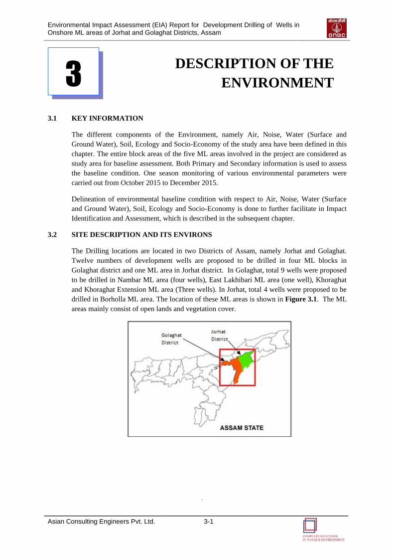
Environmental Impact Assessment (EIA) Report for Development Drilling of Wells in Onshore ML areas of Jorhat and Golaghat Districts, Assam
Asian Consulting Engineers Pvt. Ltd. 3-1
DESCRIPTION OF THE
ENVIRONMENT
3.1 KEY INFORMATION
The different components of the Environment, namely Air, Noise, Water (Surface and
Ground Water), Soil, Ecology and Socio-Economy of the study area have been defined in this
chapter. The entire block areas of the five ML areas involved in the project are considered as
study area for baseline assessment. Both Primary and Secondary information is used to assess
the baseline condition. One season monitoring of various environmental parameters were
carried out from October 2015 to December 2015.
Delineation of environmental baseline condition with respect to Air, Noise, Water (Surface
and Ground Water), Soil, Ecology and Socio-Economy is done to further facilitate in Impact
Identification and Assessment, which is described in the subsequent chapter.
3.2 SITE DESCRIPTION AND ITS ENVIRONS
The Drilling locations are located in two Districts of Assam, namely Jorhat and Golaghat.
Twelve numbers of development wells are proposed to be drilled in four ML blocks in
Golaghat district and one ML area in Jorhat district. In Golaghat, total 9 wells were proposed
to be drilled in Nambar ML area (four wells), East Lakhibari ML area (one well), Khoraghat
and Khoraghat Extension ML area (Three wells). In Jorhat, total 4 wells were proposed to be
drilled in Borholla ML area. The location of these ML areas is shown in Figure 3.1. The ML
areas mainly consist of open lands and vegetation cover.
3
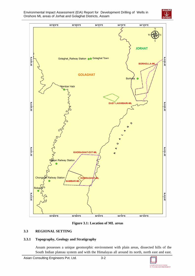
Environmental Impact Assessment (EIA) Report for Development Drilling of Wells in Onshore ML areas of Jorhat and Golaghat Districts, Assam
Asian Consulting Engineers Pvt. Ltd. 3-2
Figure 3.1: Location of ML areas
3.3 REGIONAL SETTING
3.3.1 Topography, Geology and Stratigraphy
Assam possesses a unique geomorphic environment with plain areas, dissected hills of the
South Indian plateau system and with the Himalayas all around its north, north east and east.
GOLAGHAT
JORHAT
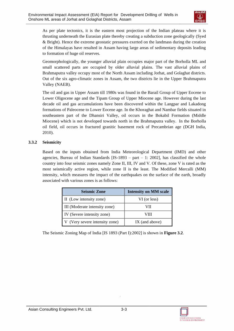
Environmental Impact Assessment (EIA) Report for Development Drilling of Wells in Onshore ML areas of Jorhat and Golaghat Districts, Assam
Asian Consulting Engineers Pvt. Ltd. 3-3
As per plate tectonics, it is the eastern most projection of the Indian plateau where it is
thrusting underneath the Eurasian plate thereby creating a subduction zone geologically (Syed
& Bright). Hence the extreme geostatic pressures exerted on the landmass during the creation
of the Himalayas have resulted in Assam having large areas of sedimentary deposits leading
to formation of huge oil reserves.
Geomorphologically, the younger alluvial plain occupies major part of the Borholla ML and
small scattered parts are occupied by older alluvial plains. The vast alluvial plains of
Brahmaputra valley occupy most of the North Assam including Jorhat, and Golaghat districts.
Out of the six agro-climatic zones in Assam, the two districts lie in the Upper Brahmaputra
Valley (NAEB).
The oil and gas in Upper Assam till 1980s was found in the Barail Group of Upper Eocene to
Lower Oligocene age and the Tipam Group of Upper Miocene age. However during the last
decade oil and gas accumulations have been discovered within the Langpar and Lakadong
formations of Paleocene to Lower Eocene age. In the Khoraghat and Nambar fields situated in
southeastern part of the Dhansiri Valley, oil occurs in the Bokabil Formation (Middle
Miocene) which is not developed towards north in the Brahmaputra valley. In the Borholla
oil field, oil occurs in fractured granitic basement rock of Precambrian age (DGH India,
2010).
3.3.2 Seismicity
Based on the inputs obtained from India Meteorological Department (IMD) and other
agencies, Bureau of Indian Standards [IS-1893 – part – 1: 2002], has classified the whole
country into four seismic zones namely Zone II, III, IV and V. Of these, zone V is rated as the
most seismically active region, while zone II is the least. The Modified Mercalli (MM)
intensity, which measures the impact of the earthquakes on the surface of the earth, broadly
associated with various zones is as follows:
Seismic Zone Intensity on MM scale
II (Low intensity zone) VI (or less)
III (Moderate intensity zone) VII
IV (Severe intensity zone) VIII
V (Very severe intensity zone) IX (and above)
The Seismic Zoning Map of India [IS 1893 (Part I):2002] is shown in Figure 3.2.
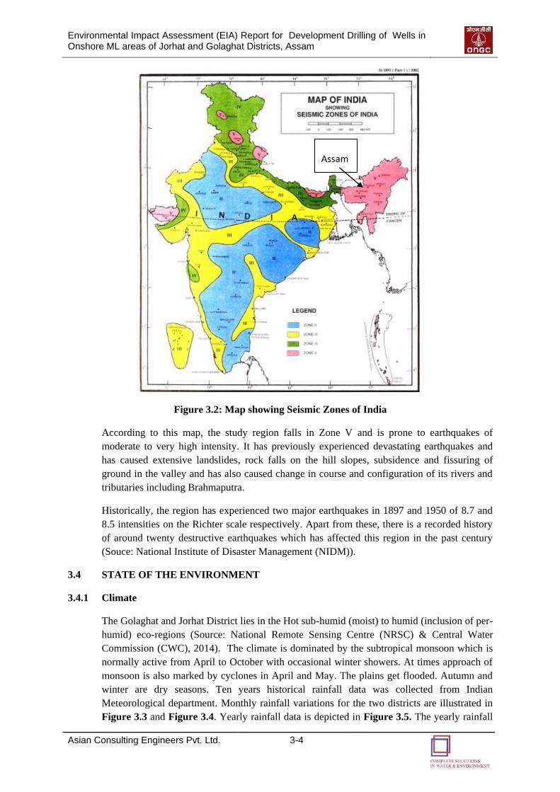
Environmental Impact Assessment (EIA) Report for Development Drilling of Wells in Onshore ML areas of Jorhat and Golaghat Districts, Assam
Asian Consulting Engineers Pvt. Ltd. 3-4
Figure 3.2: Map showing Seismic Zones of India
According to this map, the study region falls in Zone V and is prone to earthquakes of
moderate to very high intensity. It has previously experienced devastating earthquakes and
has caused extensive landslides, rock falls on the hill slopes, subsidence and fissuring of
ground in the valley and has also caused change in course and configuration of its rivers and
tributaries including Brahmaputra.
Historically, the region has experienced two major earthquakes in 1897 and 1950 of 8.7 and
8.5 intensities on the Richter scale respectively. Apart from these, there is a recorded history
of around twenty destructive earthquakes which has affected this region in the past century
(Souce: National Institute of Disaster Management (NIDM)).
3.4 STATE OF THE ENVIRONMENT
3.4.1 Climate
The Golaghat and Jorhat District lies in the Hot sub-humid (moist) to humid (inclusion of per-
humid) eco-regions (Source: National Remote Sensing Centre (NRSC) & Central Water
Commission (CWC), 2014). The climate is dominated by the subtropical monsoon which is
normally active from April to October with occasional winter showers. At times approach of
monsoon is also marked by cyclones in April and May. The plains get flooded. Autumn and
winter are dry seasons. Ten years historical rainfall data was collected from Indian
Meteorological department. Monthly rainfall variations for the two districts are illustrated in
Figure 3.3 and Figure 3.4. Yearly rainfall data is depicted in Figure 3.5. The yearly rainfall
Assam
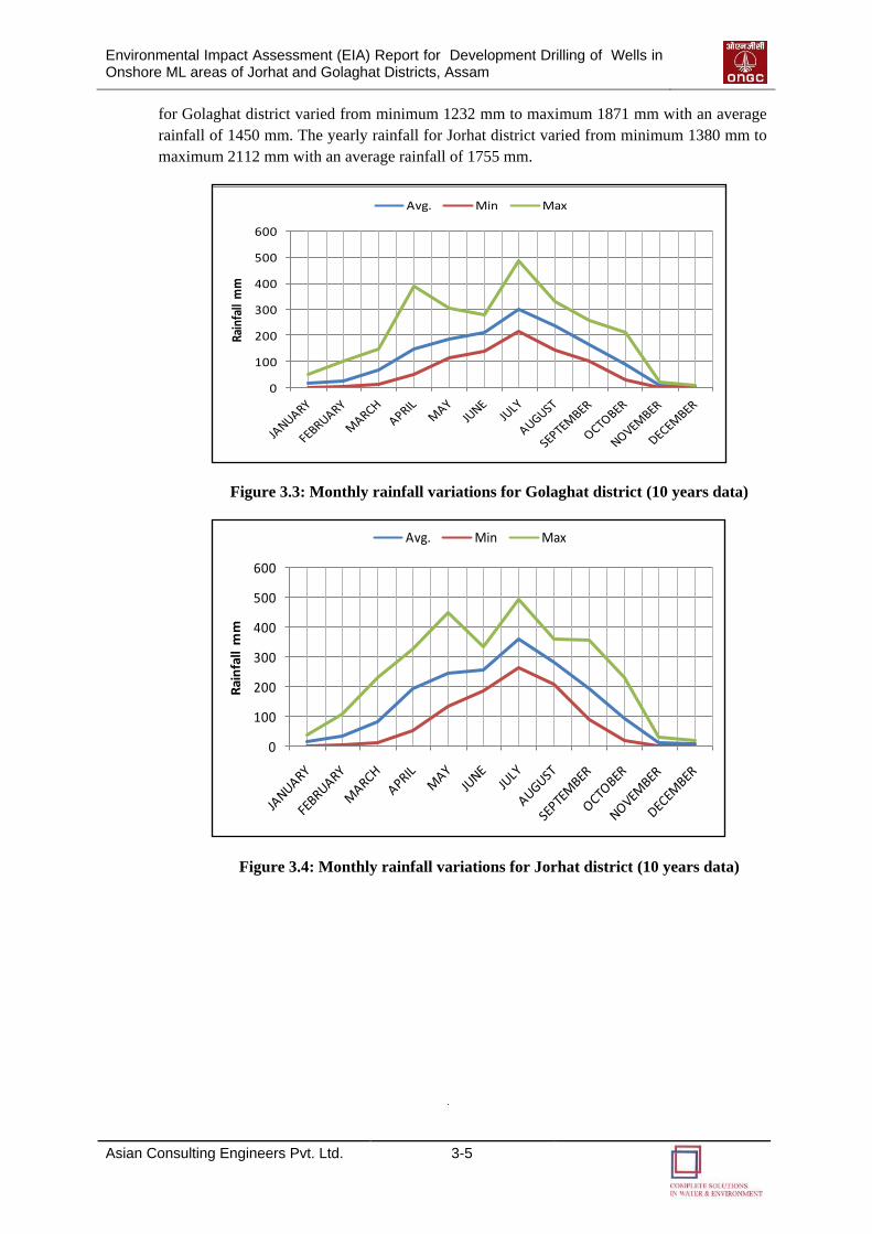
Environmental Impact Assessment (EIA) Report for Development Drilling of Wells in Onshore ML areas of Jorhat and Golaghat Districts, Assam
Asian Consulting Engineers Pvt. Ltd. 3-5
for Golaghat district varied from minimum 1232 mm to maximum 1871 mm with an average
rainfall of 1450 mm. The yearly rainfall for Jorhat district varied from minimum 1380 mm to
maximum 2112 mm with an average rainfall of 1755 mm.
Figure 3.3: Monthly rainfall variations for Golaghat district (10 years data)
Figure 3.4: Monthly rainfall variations for Jorhat district (10 years data)
0
100
200
300
400
500
600Ra
infa
ll m
m
Avg. Min Max
0
100
200
300
400
500
600
Rai
nfa
ll m
m
Avg. Min Max
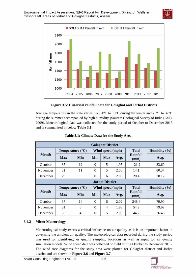
Environmental Impact Assessment (EIA) Report for Development Drilling of Wells in Onshore ML areas of Jorhat and Golaghat Districts, Assam
Asian Consulting Engineers Pvt. Ltd. 3-6
Figure 3.5: Historical rainfall data for Golaghat and Jorhat Districts
Average temperature in the state varies from 4°C to 19°C during the winter and 26°C to 37°C
during the summer accompanied by high humidity (Source: Geological Survey of India (GSI),
2009). Meteorological data was collected for the study period of October to December 2015
and is summarized in below Table 3.1.
Table 3.1: Climate Data for the Study Area
Golaghat District
Month Temperature (°C) Wind speed (mph) Total
Rainfall
(mm)
Humidity (%)
Max Min Min Max Avg. Avg.
October 37 12 0 5 1.95 121.2 83.60
November 31 11 0 5 2.08 14.1 80.37
December 29 3 0 6 2.08 20.4 78.12
Jorhat District
Month Temperature (°C) Wind speed (mph) Total
Rainfall
(mm)
Humidity (%)
Max Min Min Max Avg. Avg.
October 37 14 0 6 2.02 248.4 79.90
November 31 6 0 4 1.93 54.9 79.99
December 30 4 0 5 2.09 44.2 76.46
3.4.2 Micro-Meteorology
Meteorological study exerts a critical influence on air quality as it is an important factor in
governing the ambient air quality. The meteorological data recorded during the study period
was used for identifying air quality sampling locations as well as input for air quality
simulation models. Wind speed data was collected on field during October to December 2015.
The wind rose diagrams for the study area were plotted for Golaghat district and Jorhat
district and are shown in Figure 3.6 and Figure 3.7.
1000
1200
1400
1600
1800
2000
2200
2004 2005 2006 2007 2008 2009 2010 2011 2012 2013
Rai
nfa
ll m
m
GOLAGHAT Rainfall in mm JORHAT Rainfall in mm
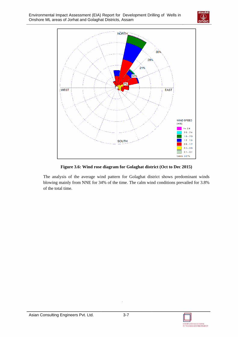
Environmental Impact Assessment (EIA) Report for Development Drilling of Wells in Onshore ML areas of Jorhat and Golaghat Districts, Assam
Asian Consulting Engineers Pvt. Ltd. 3-7
Figure 3.6: Wind rose diagram for Golaghat district (Oct to Dec 2015)
The analysis of the average wind pattern for Golaghat district shows predominant winds
blowing mainly from NNE for 34% of the time. The calm wind conditions prevailed for 3.8%
of the total time.
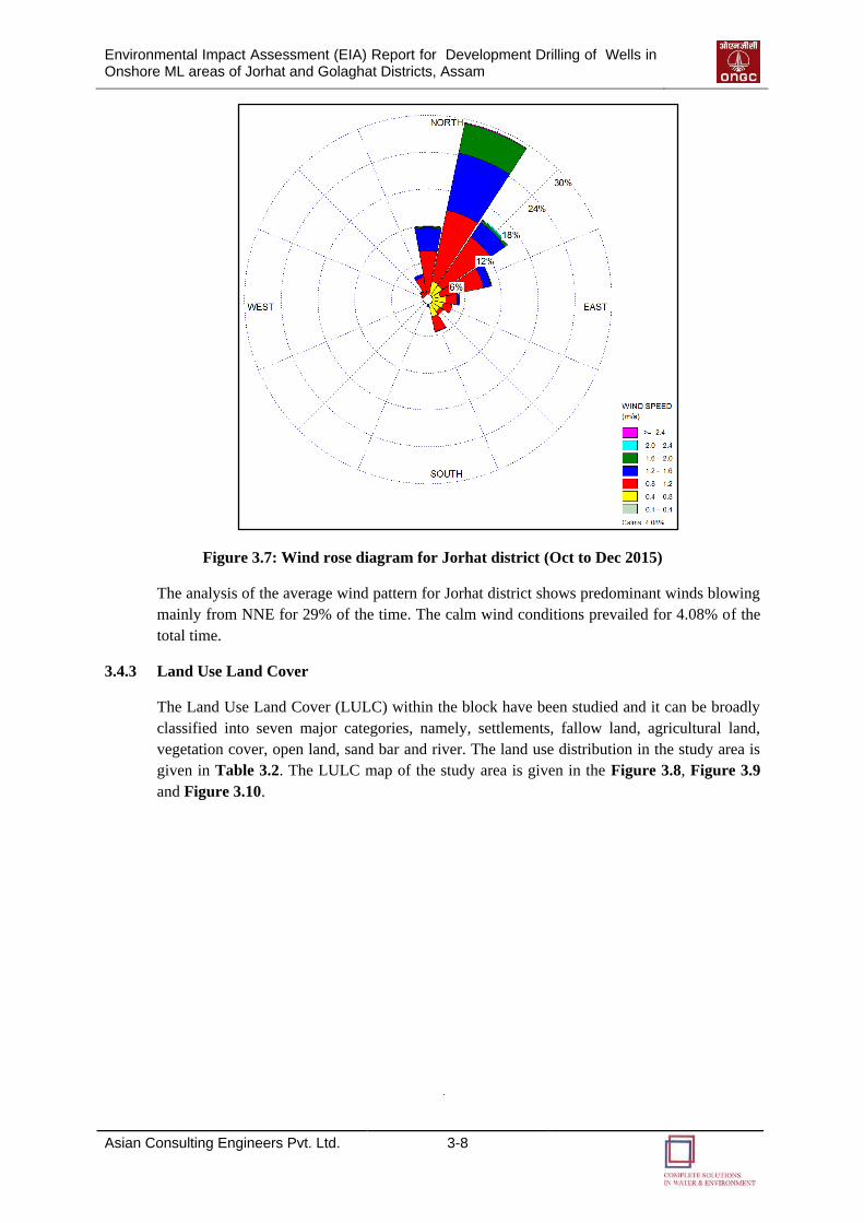
Environmental Impact Assessment (EIA) Report for Development Drilling of Wells in Onshore ML areas of Jorhat and Golaghat Districts, Assam
Asian Consulting Engineers Pvt. Ltd. 3-8
Figure 3.7: Wind rose diagram for Jorhat district (Oct to Dec 2015)
The analysis of the average wind pattern for Jorhat district shows predominant winds blowing
mainly from NNE for 29% of the time. The calm wind conditions prevailed for 4.08% of the
total time.
3.4.3 Land Use Land Cover
The Land Use Land Cover (LULC) within the block have been studied and it can be broadly
classified into seven major categories, namely, settlements, fallow land, agricultural land,
vegetation cover, open land, sand bar and river. The land use distribution in the study area is
given in Table 3.2. The LULC map of the study area is given in the Figure 3.8, Figure 3.9
and Figure 3.10.
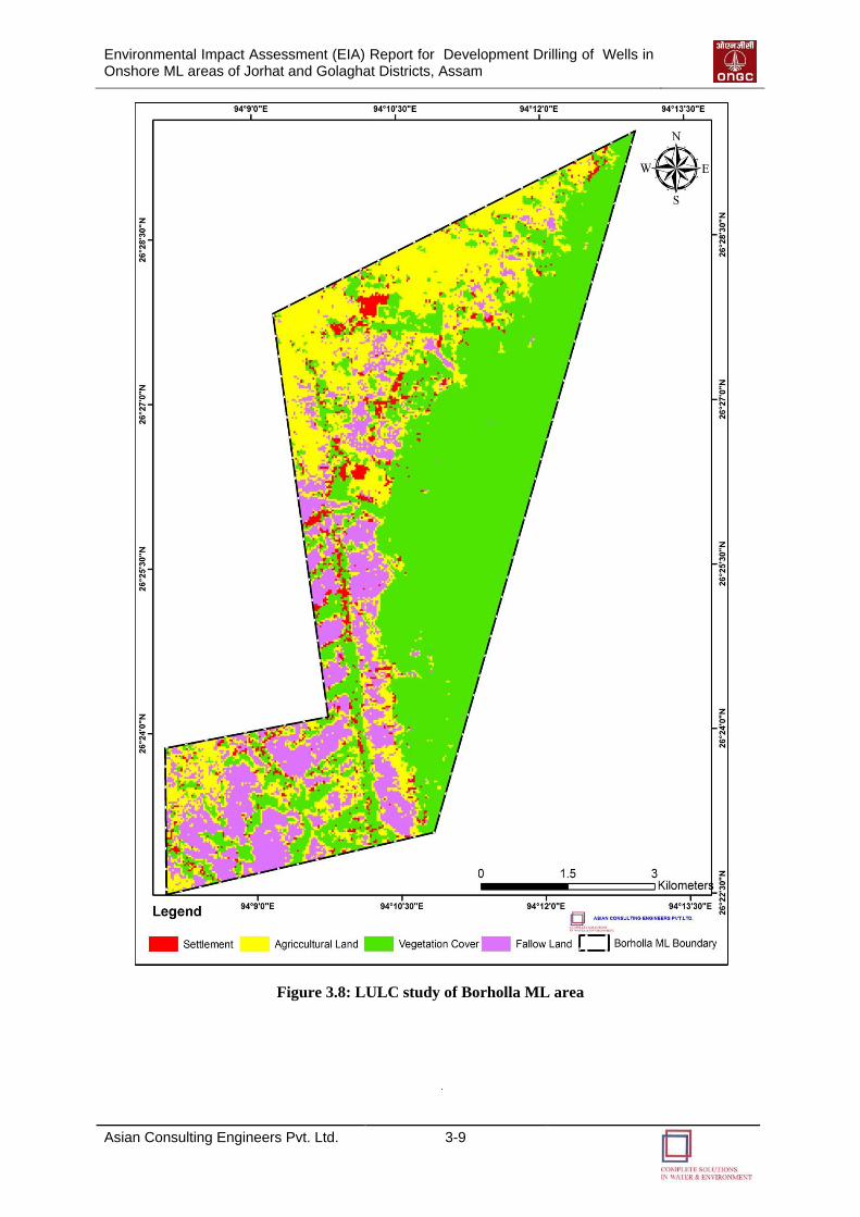
Environmental Impact Assessment (EIA) Report for Development Drilling of Wells in Onshore ML areas of Jorhat and Golaghat Districts, Assam
Asian Consulting Engineers Pvt. Ltd. 3-9
Figure 3.8: LULC study of Borholla ML area
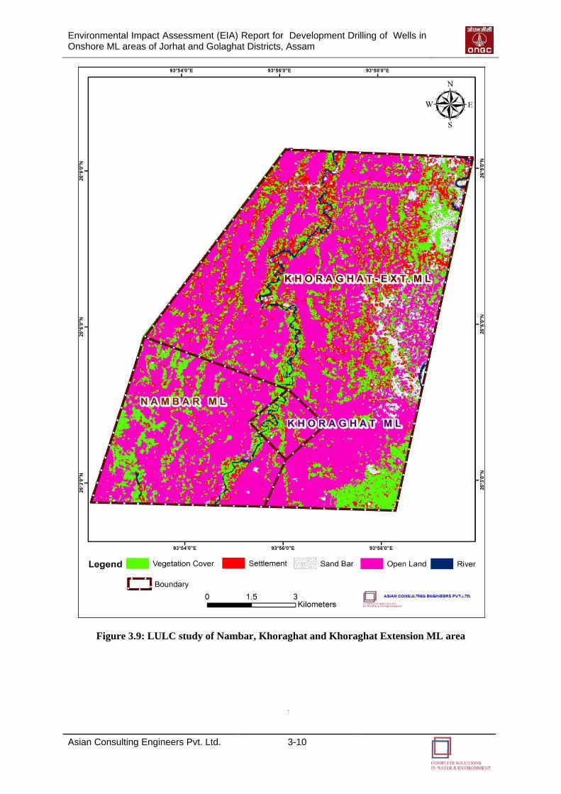
Environmental Impact Assessment (EIA) Report for Development Drilling of Wells in Onshore ML areas of Jorhat and Golaghat Districts, Assam
Asian Consulting Engineers Pvt. Ltd. 3-10
Figure 3.9: LULC study of Nambar, Khoraghat and Khoraghat Extension ML area
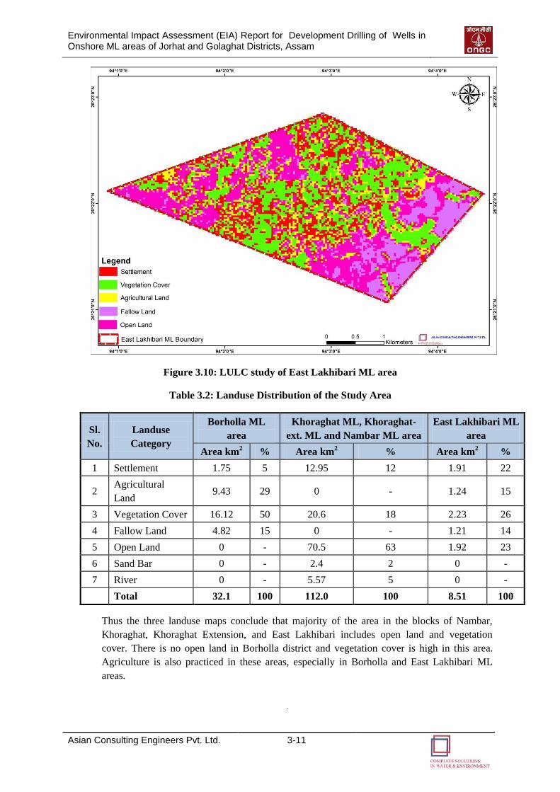
Environmental Impact Assessment (EIA) Report for Development Drilling of Wells in Onshore ML areas of Jorhat and Golaghat Districts, Assam
Asian Consulting Engineers Pvt. Ltd. 3-11
Figure 3.10: LULC study of East Lakhibari ML area
Table 3.2: Landuse Distribution of the Study Area
Sl.
No.
Landuse
Category
Borholla ML
area
Khoraghat ML, Khoraghat-
ext. ML and Nambar ML area
East Lakhibari ML
area
Area km2 % Area km
2 % Area km
2 %
1 Settlement 1.75 5 12.95 12 1.91 22
2 Agricultural
Land 9.43 29 0 - 1.24 15
3 Vegetation Cover 16.12 50 20.6 18 2.23 26
4 Fallow Land 4.82 15 0 - 1.21 14
5 Open Land 0 - 70.5 63 1.92 23
6 Sand Bar 0 - 2.4 2 0 -
7 River 0 - 5.57 5 0 -
Total 32.1 100 112.0 100 8.51 100
Thus the three landuse maps conclude that majority of the area in the blocks of Nambar,
Khoraghat, Khoraghat Extension, and East Lakhibari includes open land and vegetation
cover. There is no open land in Borholla district and vegetation cover is high in this area.
Agriculture is also practiced in these areas, especially in Borholla and East Lakhibari ML
areas.
Environmental Impact Assessment (EIA) Report for Development Drilling of Wells in Onshore ML areas of Jorhat and Golaghat Districts, Assam
Asian Consulting Engineers Pvt. Ltd. 3-12
3.4.3.1 Site Details of Drilling Site
Twelve drilling locations have been proposed in this project. The surrounding features for the
same within 1 km radial distance have been tabulated in Table 3.3. From the table, it is
evident that all the coordinates are located on agricultural land area. Photo Plate 3.1 shows
the photographs of the study area.
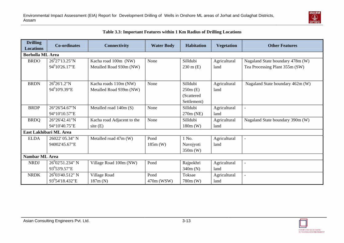
Environmental Impact Assessment (EIA) Report for Development Drilling of Wells in Onshore ML areas of Jorhat and Golaghat Districts, Assam
Asian Consulting Engineers Pvt. Ltd. 3-13
Table 3.3: Important Features within 1 Km Radius of Drilling Locations
Drilling
Locations Co-ordinates Connectivity Water Body Habitation Vegetation Other Features
Borholla ML Area
BRDO 26027'13.25"N
94010'26.17"E
Kacha road 100m (NW)
Metalled Road 930m (NW)
None
Silldubi
230 m (E)
Agricultural
land
Nagaland State boundary 478m (W)
Tea Processing Plant 355m (SW)
BRDN 26026'1.2"N
94010'9.39"E
Kacha roads 110m (NW)
Metalled Road 939m (NW)
None Silldubi
250m (E)
(Scattered
Settlement)
Agricultural
land
Nagaland State boundary 462m (W)
BRDP 26°26'54.67"N
94°10'10.57"E
Metalled road 140m (S) None Silldubi
270m (NE)
Agricultural
land
-
BRDQ 26°26'42.41"N
94°10'40.75"E
Kacha road Adjacent to the
site (E)
None Silldubi
180m (W)
Agricultural
land
Nagaland State boundary 390m (W)
East Lakhibari ML Area
ELDA 26022' 05.34" N
94002'45.67"E
Metalled road 47m (W) Pond
185m (W)
1 No.
Navojyoti
350m (W)
Agricultural
land
-
Nambar ML Area
NRDJ 26002'51.234" N
93053'9.57"E
Village Road 100m (NW) Pond Rajpokhri
340m (N)
Agricultural
land
-
NRDK 26003'40.512" N
93054'18.432"E
Village Road
187m (N)
Pond
470m (WSW)
Toksae
780m (W)
Agricultural
land
-
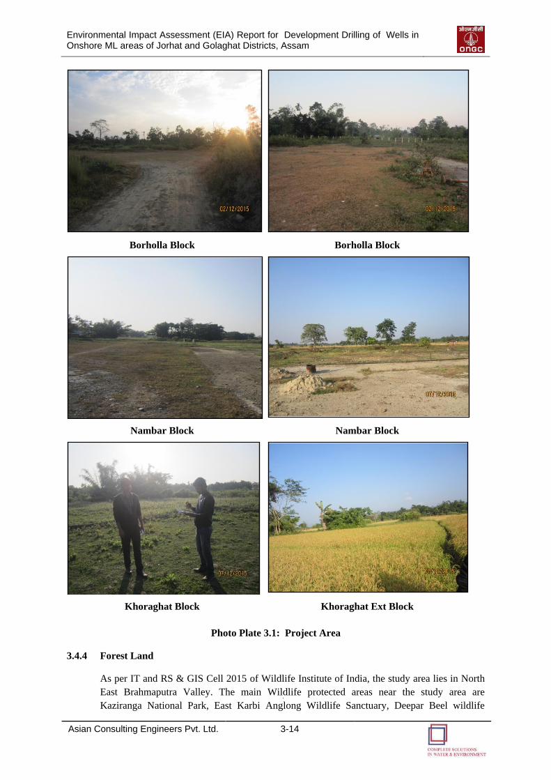
Environmental Impact Assessment (EIA) Report for Development Drilling of Wells in Onshore ML areas of Jorhat and Golaghat Districts, Assam
Asian Consulting Engineers Pvt. Ltd. 3-14
Borholla Block Borholla Block
Nambar Block Nambar Block
Khoraghat Block Khoraghat Ext Block
Photo Plate 3.1: Project Area
3.4.4 Forest Land
As per IT and RS & GIS Cell 2015 of Wildlife Institute of India, the study area lies in North
East Brahmaputra Valley. The main Wildlife protected areas near the study area are
Kaziranga National Park, East Karbi Anglong Wildlife Sanctuary, Deepar Beel wildlife
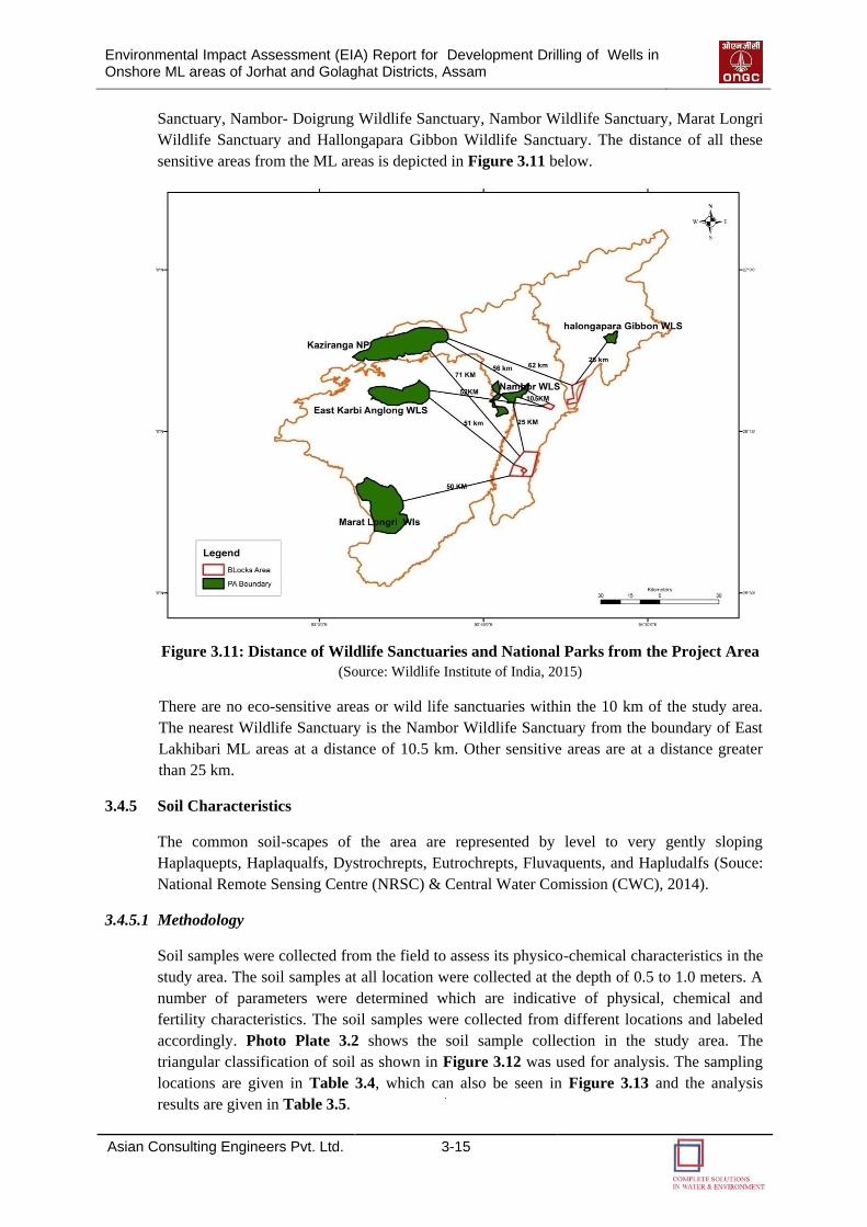
Environmental Impact Assessment (EIA) Report for Development Drilling of Wells in Onshore ML areas of Jorhat and Golaghat Districts, Assam
Asian Consulting Engineers Pvt. Ltd. 3-15
Sanctuary, Nambor- Doigrung Wildlife Sanctuary, Nambor Wildlife Sanctuary, Marat Longri
Wildlife Sanctuary and Hallongapara Gibbon Wildlife Sanctuary. The distance of all these
sensitive areas from the ML areas is depicted in Figure 3.11 below.
Figure 3.11: Distance of Wildlife Sanctuaries and National Parks from the Project Area
(Source: Wildlife Institute of India, 2015)
There are no eco-sensitive areas or wild life sanctuaries within the 10 km of the study area.
The nearest Wildlife Sanctuary is the Nambor Wildlife Sanctuary from the boundary of East
Lakhibari ML areas at a distance of 10.5 km. Other sensitive areas are at a distance greater
than 25 km.
3.4.5 Soil Characteristics
The common soil-scapes of the area are represented by level to very gently sloping
Haplaquepts, Haplaqualfs, Dystrochrepts, Eutrochrepts, Fluvaquents, and Hapludalfs (Souce:
National Remote Sensing Centre (NRSC) & Central Water Comission (CWC), 2014).
3.4.5.1 Methodology
Soil samples were collected from the field to assess its physico-chemical characteristics in the
study area. The soil samples at all location were collected at the depth of 0.5 to 1.0 meters. A
number of parameters were determined which are indicative of physical, chemical and
fertility characteristics. The soil samples were collected from different locations and labeled
accordingly. Photo Plate 3.2 shows the soil sample collection in the study area. The
triangular classification of soil as shown in Figure 3.12 was used for analysis. The sampling
locations are given in Table 3.4, which can also be seen in Figure 3.13 and the analysis
results are given in Table 3.5.
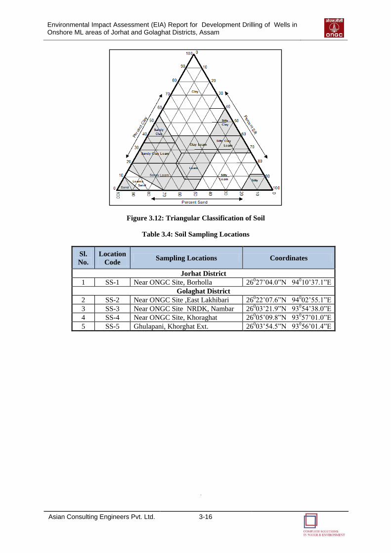
Environmental Impact Assessment (EIA) Report for Development Drilling of Wells in Onshore ML areas of Jorhat and Golaghat Districts, Assam
Asian Consulting Engineers Pvt. Ltd. 3-16
Figure 3.12: Triangular Classification of Soil
Table 3.4: Soil Sampling Locations
Sl.
No.
Location
Code Sampling Locations Coordinates
Jorhat District
1 SS-1 Near ONGC Site, Borholla 26027’04.0”N 94010’37.1”E
Golaghat District
2 SS-2 Near ONGC Site ,East Lakhibari 26022’07.6”N 94002’55.1”E
3 SS-3 Near ONGC Site NRDK, Nambar 26003’21.9”N 93054’38.0”E
4 SS-4 Near ONGC Site, Khoraghat 26005’09.8”N 93057’01.0”E
5 SS-5 Ghulapani, Khorghat Ext. 26003’54.5”N 93056’01.4”E
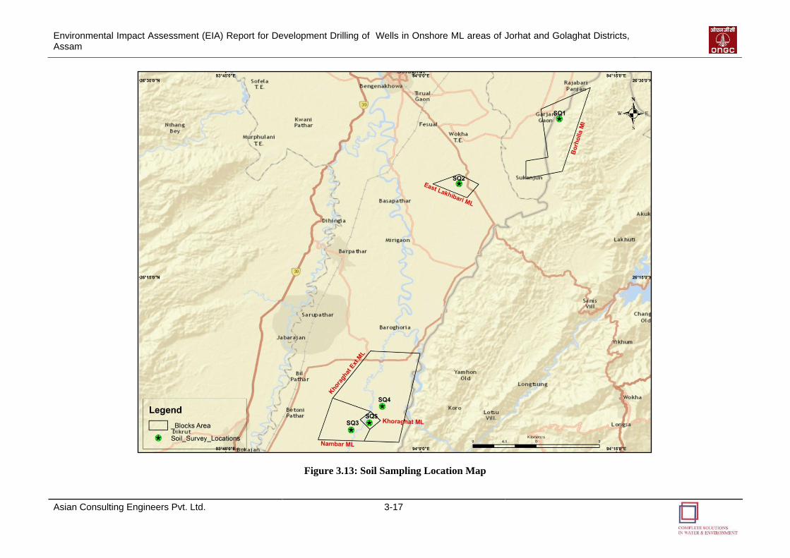
Environmental Impact Assessment (EIA) Report for Development Drilling of Wells in Onshore ML areas of Jorhat and Golaghat Districts, Assam
Asian Consulting Engineers Pvt. Ltd. 3-17
Figure 3.13: Soil Sampling Location Map
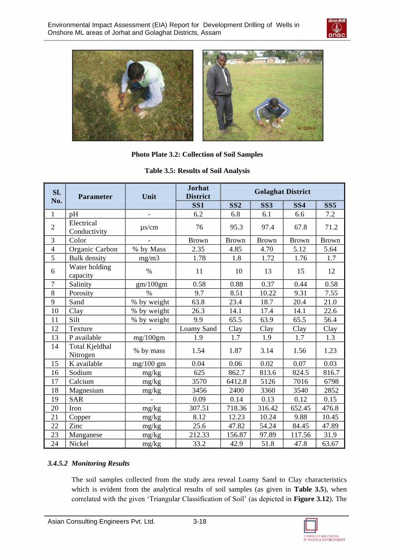
Environmental Impact Assessment (EIA) Report for Development Drilling of Wells in Onshore ML areas of Jorhat and Golaghat Districts, Assam
Asian Consulting Engineers Pvt. Ltd. 3-18
Photo Plate 3.2: Collection of Soil Samples
Table 3.5: Results of Soil Analysis
Sl.
No. Parameter Unit
Jorhat
District Golaghat District
SS1 SS2 SS3 SS4 SS5
1 pH - 6.2 6.8 6.1 6.6 7.2
2 Electrical
Conductivity µs/cm 76 95.3 97.4 67.8 71.2
3 Color - Brown Brown Brown Brown Brown
4 Organic Carbon % by Mass 2.35 4.85 4.70 5.12 5.64
5 Bulk density mg/m3 1.78 1.8 1.72 1.76 1.7
6 Water holding
capacity % 11 10 13 15 12
7 Salinity gm/100gm 0.58 0.88 0.37 0.44 0.58
8 Porosity % 9.7 8.51 10.22 9.31 7.55
9 Sand % by weight 63.8 23.4 18.7 20.4 21.0
10 Clay % by weight 26.3 14.1 17.4 14.1 22.6
11 Silt % by weight 9.9 65.5 63.9 65.5 56.4
12 Texture - Loamy Sand Clay Clay Clay Clay
13 P available mg/100gm 1.9 1.7 1.9 1.7 1.3
14 Total Kjeldhal
Nitrogen % by mass 1.54 1.87 3.14 1.56 1.23
15 K available mg/100 gm 0.04 0.06 0.02 0.07 0.03
16 Sodium mg/kg 625 862.7 813.6 824.5 816.7
17 Calcium mg/kg 3570 6412.8 5126 7016 6798
18 Magnesium mg/kg 3456 2400 3360 3540 2852
19 SAR - 0.09 0.14 0.13 0.12 0.15
20 Iron mg/kg 307.51 718.36 316.42 652.45 476.8
21 Copper mg/kg 8.12 12.23 10.24 9.88 10.45
22 Zinc mg/kg 25.6 47.82 54.24 84.45 47.89
23 Manganese mg/kg 212.33 156.87 97.89 117.56 31.9
24 Nickel mg/kg 33.2 42.9 51.8 47.8 63.67
3.4.5.2 Monitoring Results
The soil samples collected from the study area reveal Loamy Sand to Clay characteristics
which is evident from the analytical results of soil samples (as given in Table 3.5), when
correlated with the given ‘Triangular Classification of Soil’ (as depicted in Figure 3.12). The
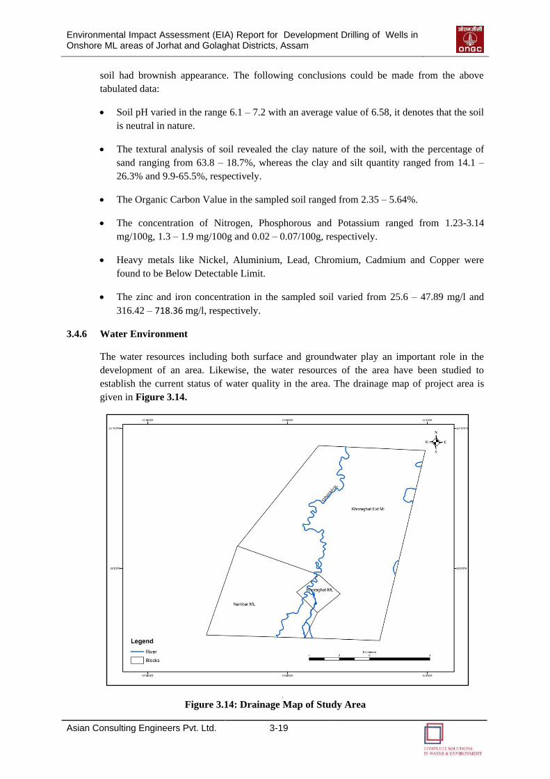
Environmental Impact Assessment (EIA) Report for Development Drilling of Wells in Onshore ML areas of Jorhat and Golaghat Districts, Assam
Asian Consulting Engineers Pvt. Ltd. 3-19
soil had brownish appearance. The following conclusions could be made from the above
tabulated data:
Soil pH varied in the range 6.1 – 7.2 with an average value of 6.58, it denotes that the soil
is neutral in nature.
The textural analysis of soil revealed the clay nature of the soil, with the percentage of
sand ranging from 63.8 – 18.7%, whereas the clay and silt quantity ranged from 14.1 –
26.3% and 9.9-65.5%, respectively.
The Organic Carbon Value in the sampled soil ranged from 2.35 – 5.64%.
The concentration of Nitrogen, Phosphorous and Potassium ranged from 1.23-3.14
mg/100g, 1.3 – 1.9 mg/100g and 0.02 – 0.07/100g, respectively.
Heavy metals like Nickel, Aluminium, Lead, Chromium, Cadmium and Copper were
found to be Below Detectable Limit.
The zinc and iron concentration in the sampled soil varied from 25.6 – 47.89 mg/l and
316.42 – 718.36 mg/l, respectively.
3.4.6 Water Environment
The water resources including both surface and groundwater play an important role in the
development of an area. Likewise, the water resources of the area have been studied to
establish the current status of water quality in the area. The drainage map of project area is
given in Figure 3.14.
Figure 3.14: Drainage Map of Study Area
Environmental Impact Assessment (EIA) Report for Development Drilling of Wells in Onshore ML areas of Jorhat and Golaghat Districts, Assam
Asian Consulting Engineers Pvt. Ltd. 3-20
No rivers are passing through the Borholla ML and East Lakhibari ML area. However, the
Dhansiri River passes through the Nambar ML area, Khoraghat ML area and Khoraghat
Extension ML area. The Dhansiri River rises in the south west corner of Nagaland below the
Laishiang peak. From its source upto Dimapur, the Dhansiri forms the boundary between the
districts of Cachar, Nagaon and Nagaland. Beyond Dimapur, the river enters and flows
through the Karbi Anglong and Golaghat districts of Assam.
Surface Water
Four surface water samples were collected from different places within the study area.
Groundwater
Groundwater is an important source in the study area and is used for drinking, irrigation and
fish breeding. Negative fluctuation with a fall in range of 2 - 4 m bgl and 4 m bgl is noticed
in Jorhat, Karbi Anglong, Golaghat, Sibasagar, Nagaon, Kamrup districts of Assam and
Jaintia Hills and Ribhoi districts of Meghalaya due to overexploitation of ground water for
different purposes and other natural cycle disruption like less rainfall etc. (Souce: National
Remote Sensing Centre (NRSC) & Central Water Comission (CWC), 2014). According to the
Ministry of Water Resources, River Development and Ganga Rejuvenation as well as The
Ministry of Agriculture (Department of Agricultural Research and Education) (DARE), both
Jorhat and Golaghat districts have presence of high arsenic content in groundwater (Ministry
of Water Resources, River Development and Ganga Rejuvenation, 2014). Another study also
confirmed presence of high iron and arsenic levels in Golaghat district of Assam (Chetia,
Sarma, Banerjee, Singh, & Dutta, 2010), (Central Ground Water Authority (CGWB), 2013).
The ground water categorization of blocks in Golaghat and Jorhat district is given in Table
3.6. Five groundwater samples were collected from different places within the study area.
Table 3.6: ML Blocks and their Categorization as per Central Ground Water Authority
(CGWA)
Sl.
No. Name of ML Blocks District
Category
GWRE Area Type
1
East Lakhibari, Nambar,
Khoraghat, Khoraghat
extension ML areas
Golaghat Safe Not-notified
2 Borholla ML Jorhat Safe Not-notified
Source: Central Ground Water Authority (CGWA), 2011
3.4.6.1 Water Quality Assessment & Methodology
The sampling and analysis of water were carried out as per Standard Methods of Water and
Wastewater Analysis (APHA). Nine water samples were collected from ground and surface
water bodies within the block. A total of four samples from surface except Borholla and five
samples from ground water bodies were taken from different locations and were analysed for
physico-chemical parameters. The results of Ground Water Analysis have been compared
with IS: 10500-2012 drinking water standard to assess their suitability for drinking purpose.
Sampling locations for surface and ground water samples are listed in Table 3.7, which are
also shown in Figure 3.15 and Figure 3.16. Photo Plate 3.3 and Photo Plate 3.4 shows the
water sample collection in the study area.
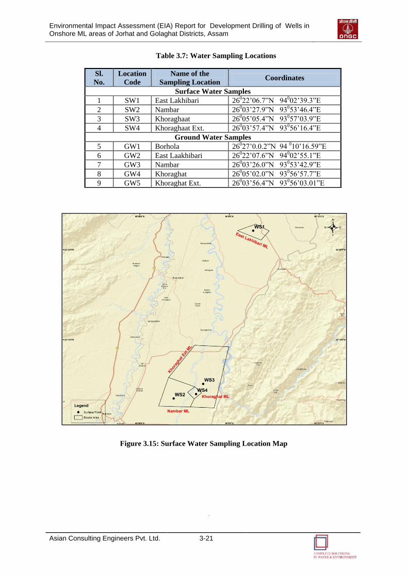
Environmental Impact Assessment (EIA) Report for Development Drilling of Wells in Onshore ML areas of Jorhat and Golaghat Districts, Assam
Asian Consulting Engineers Pvt. Ltd. 3-21
Table 3.7: Water Sampling Locations
Figure 3.15: Surface Water Sampling Location Map
Sl.
No.
Location
Code
Name of the
Sampling Location Coordinates
Surface Water Samples
1 SW1 East Lakhibari 26022’06.7”N 94002’39.3”E
2 SW2 Nambar 26003’27.9”N 93
053’46.4”E
3 SW3 Khoraghaat 26005’05.4”N 93057’03.9”E
4 SW4 Khoraghaat Ext. 26003’57.4”N 93056’16.4”E
Ground Water Samples
5 GW1 Borhola 26027’0.0.2”N 94 010’16.59”E
6 GW2 East Laakhibari 26022’07.6”N 94002’55.1”E
7 GW3 Nambar 26003’26.0”N 93053’42.9”E
8 GW4 Khoraghat 26005’02.0”N 93056’57.7”E
9 GW5 Khoraghat Ext. 26003’56.4”N 93056’03.01”E
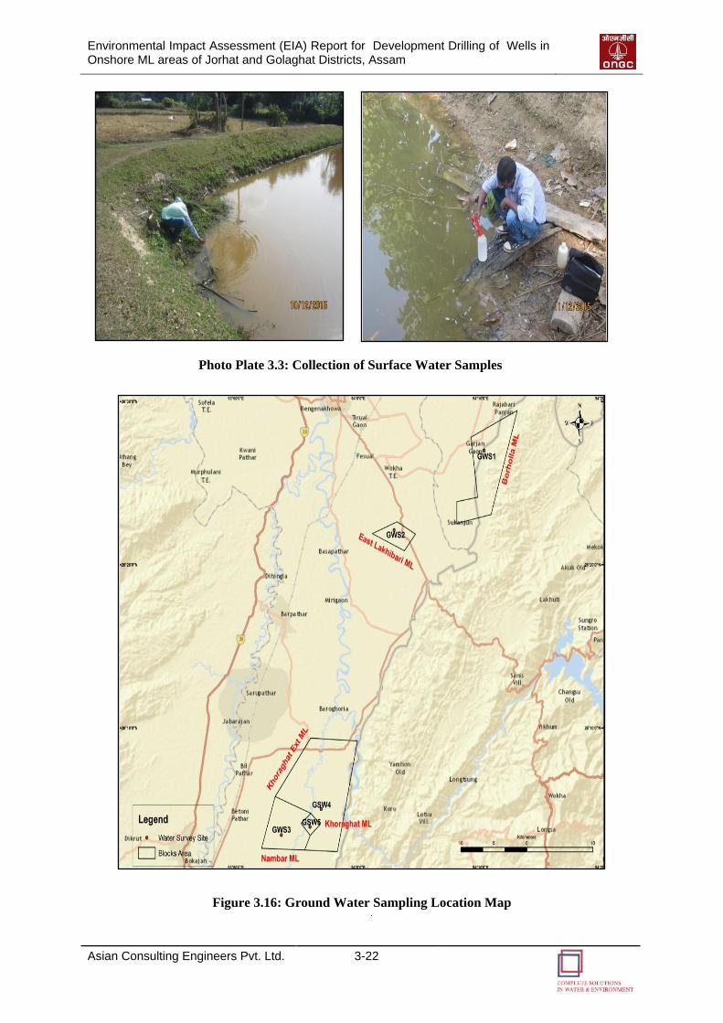
Environmental Impact Assessment (EIA) Report for Development Drilling of Wells in Onshore ML areas of Jorhat and Golaghat Districts, Assam
Asian Consulting Engineers Pvt. Ltd. 3-22
Photo Plate 3.3: Collection of Surface Water Samples
Figure 3.16: Ground Water Sampling Location Map
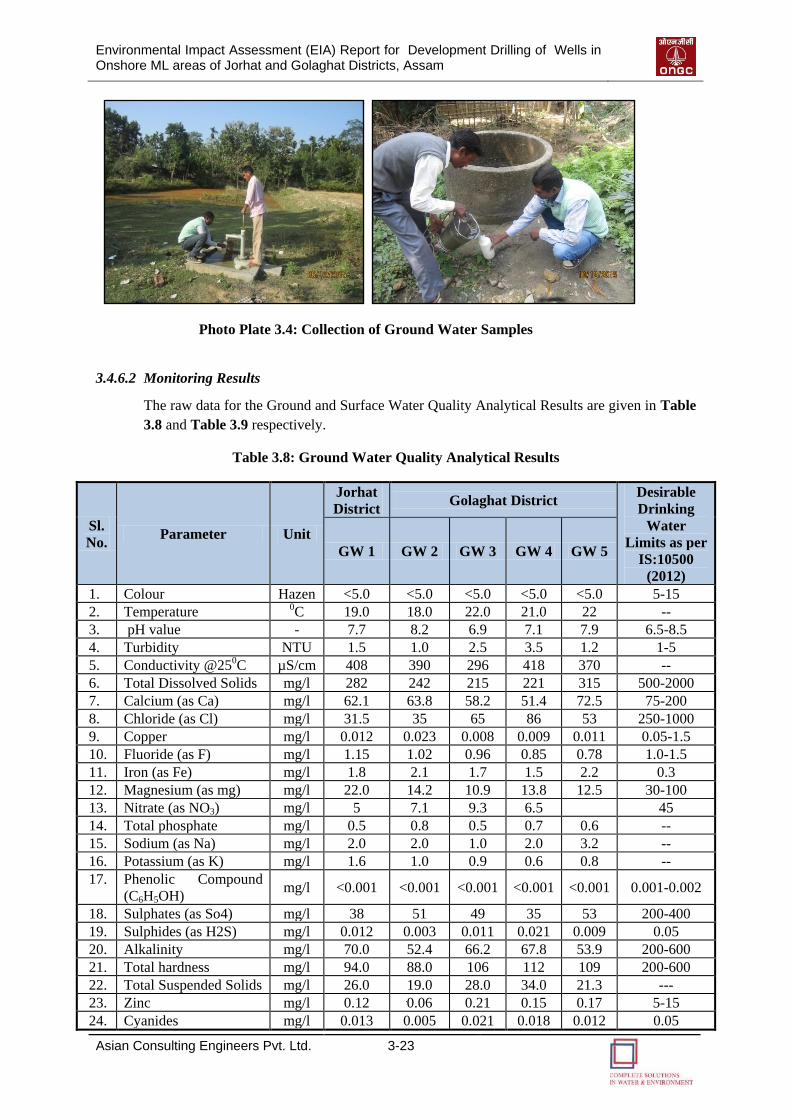
Environmental Impact Assessment (EIA) Report for Development Drilling of Wells in Onshore ML areas of Jorhat and Golaghat Districts, Assam
Asian Consulting Engineers Pvt. Ltd. 3-23
Photo Plate 3.4: Collection of Ground Water Samples
3.4.6.2 Monitoring Results
The raw data for the Ground and Surface Water Quality Analytical Results are given in Table
3.8 and Table 3.9 respectively.
Table 3.8: Ground Water Quality Analytical Results
Sl.
No. Parameter Unit
Jorhat
District Golaghat District
Desirable
Drinking
Water
Limits as per
IS:10500
(2012)
GW 1 GW 2 GW 3 GW 4 GW 5
1. Colour Hazen <5.0 <5.0 <5.0 <5.0 <5.0 5-15
2. Temperature 0C 19.0 18.0 22.0 21.0 22 --
3. pH value - 7.7 8.2 6.9 7.1 7.9 6.5-8.5
4. Turbidity NTU 1.5 1.0 2.5 3.5 1.2 1-5
5. Conductivity @250C µS/cm 408 390 296 418 370 --
6. Total Dissolved Solids mg/l 282 242 215 221 315 500-2000
7. Calcium (as Ca) mg/l 62.1 63.8 58.2 51.4 72.5 75-200
8. Chloride (as Cl) mg/l 31.5 35 65 86 53 250-1000
9. Copper mg/l 0.012 0.023 0.008 0.009 0.011 0.05-1.5
10. Fluoride (as F) mg/l 1.15 1.02 0.96 0.85 0.78 1.0-1.5
11. Iron (as Fe) mg/l 1.8 2.1 1.7 1.5 2.2 0.3
12. Magnesium (as mg) mg/l 22.0 14.2 10.9 13.8 12.5 30-100
13. Nitrate (as NO3) mg/l 5 7.1 9.3 6.5 45
14. Total phosphate mg/l 0.5 0.8 0.5 0.7 0.6 --
15. Sodium (as Na) mg/l 2.0 2.0 1.0 2.0 3.2 --
16. Potassium (as K) mg/l 1.6 1.0 0.9 0.6 0.8 --
17. Phenolic Compound
(C6H5OH) mg/l <0.001 <0.001 <0.001 <0.001 <0.001 0.001-0.002
18. Sulphates (as So4) mg/l 38 51 49 35 53 200-400
19. Sulphides (as H2S) mg/l 0.012 0.003 0.011 0.021 0.009 0.05
20. Alkalinity mg/l 70.0 52.4 66.2 67.8 53.9 200-600
21. Total hardness mg/l 94.0 88.0 106 112 109 200-600
22. Total Suspended Solids mg/l 26.0 19.0 28.0 34.0 21.3 ---
23. Zinc mg/l 0.12 0.06 0.21 0.15 0.17 5-15
24. Cyanides mg/l 0.013 0.005 0.021 0.018 0.012 0.05
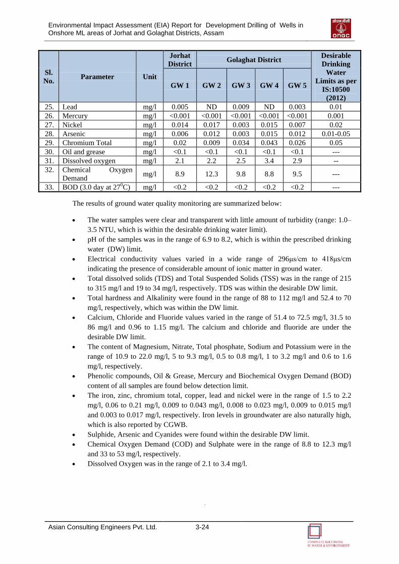
Environmental Impact Assessment (EIA) Report for Development Drilling of Wells in Onshore ML areas of Jorhat and Golaghat Districts, Assam
Asian Consulting Engineers Pvt. Ltd. 3-24
Sl.
No. Parameter Unit
Jorhat
District Golaghat District
Desirable
Drinking
Water
Limits as per
IS:10500
(2012)
GW 1 GW 2 GW 3 GW 4 GW 5
25. Lead mg/l 0.005 ND 0.009 ND 0.003 0.01
26. Mercury mg/l <0.001 <0.001 <0.001 <0.001 <0.001 0.001
27. Nickel mg/l 0.014 0.017 0.003 0.015 0.007 0.02
28. Arsenic mg/l 0.006 0.012 0.003 0.015 0.012 0.01-0.05
29. Chromium Total mg/l 0.02 0.009 0.034 0.043 0.026 0.05
30. Oil and grease mg/l <0.1 <0.1 <0.1 <0.1 <0.1 ---
31. Dissolved oxygen mg/l 2.1 2.2 2.5 3.4 2.9 --
32. Chemical Oxygen
Demand mg/l 8.9 12.3 9.8 8.8 9.5 ---
33. BOD (3.0 day at 270C) mg/l <0.2 <0.2 <0.2 <0.2 <0.2 ---
The results of ground water quality monitoring are summarized below:
The water samples were clear and transparent with little amount of turbidity (range: 1.0–
3.5 NTU, which is within the desirable drinking water limit).
pH of the samples was in the range of 6.9 to 8.2, which is within the prescribed drinking
water (DW) limit.
Electrical conductivity values varied in a wide range of 296μs/cm to 418μs/cm
indicating the presence of considerable amount of ionic matter in ground water.
Total dissolved solids (TDS) and Total Suspended Solids (TSS) was in the range of 215
to 315 mg/l and 19 to 34 mg/l, respectively. TDS was within the desirable DW limit.
Total hardness and Alkalinity were found in the range of 88 to 112 mg/l and 52.4 to 70
mg/l, respectively, which was within the DW limit.
Calcium, Chloride and Fluoride values varied in the range of 51.4 to 72.5 mg/l, 31.5 to
86 mg/l and 0.96 to 1.15 mg/l. The calcium and chloride and fluoride are under the
desirable DW limit.
The content of Magnesium, Nitrate, Total phosphate, Sodium and Potassium were in the
range of 10.9 to 22.0 mg/l, 5 to 9.3 mg/l, 0.5 to 0.8 mg/l, 1 to 3.2 mg/l and 0.6 to 1.6
mg/l, respectively.
Phenolic compounds, Oil & Grease, Mercury and Biochemical Oxygen Demand (BOD)
content of all samples are found below detection limit.
The iron, zinc, chromium total, copper, lead and nickel were in the range of 1.5 to 2.2
mg/l, 0.06 to 0.21 mg/l, 0.009 to 0.043 mg/l, 0.008 to 0.023 mg/l, 0.009 to 0.015 mg/l
and 0.003 to 0.017 mg/l, respectively. Iron levels in groundwater are also naturally high,
which is also reported by CGWB.
Sulphide, Arsenic and Cyanides were found within the desirable DW limit.
Chemical Oxygen Demand (COD) and Sulphate were in the range of 8.8 to 12.3 mg/l
and 33 to 53 mg/l, respectively.
Dissolved Oxygen was in the range of 2.1 to 3.4 mg/l.
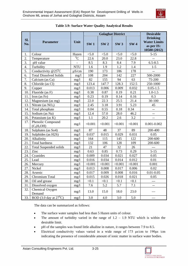
Environmental Impact Assessment (EIA) Report for Development Drilling of Wells in Onshore ML areas of Jorhat and Golaghat Districts, Assam
Asian Consulting Engineers Pvt. Ltd. 3-25
Table 3.9: Surface Water Quality Analytical Results
Sl.
No. Parameter Unit
Golaghat District Desirable
Drinking
Water Limits
as per IS:
10500 (2012)
SW 1 SW 2 SW 3 SW 4
1. Colour Hazen <5.0 <5.0 <5.0 <5.0 5-15
2. Temperature 0C 22.6 20.0 23.0 22.8 --
3. pH value - 8.5 8.3 8.4 7.9 6.5-8.5
4. Turbidity NTU 1.6 1.9 1.2 1.4 1-5
5. Conductivity @250C µS/cm 190 173 186 178 --
6. Total Dissolved Solids mg/l 108 204 142 227 500-2000
7. Calcium (as Ca) mg/l 82 155 94 63 75-200
8. Chloride (as Cl) mg/l 123.4 147.7 128.3 152.5 250-1000
9. Copper mg/l 0.013 0.006 0.009 0.032 0.05-1.5
10. Fluoride (as F) mg/l 0.38 0.87 0.19 0.21 1.0-1.5
11. Iron (as Fe) mg/l 0.23 0.19 0.14 0.16 0.3
12. Magnesium (as mg) mg/l 22.0 22.3 25.5 21.4 30-100
13. Nitrate (as NO3) mg/l 2.45 3.18 3.91 5.23 45
14. Total phosphate mg/l 0.04 0.55 0.18 0.34 --
15. Sodium (as Na) mg/l 12.4 57.0 28.0 46.2 --
16. Potassium (as K) mg/l 1.1 20.2 2.6 3.2 --
17. Phenolic Compound
(C6H5OH) mg/l <0.001 <0.001 <0.001 <0.001 0.001-0.002
18. Sulphates (as So4) mg/l 87 48 37 89 200-400
19. Sulphides (as H2S) mg/l 0.037 0.015 0.029 0.031 0.05
20. Alkalinity mg/l 164 115 145 122 200-600
21. Total hardness mg/l 132 106 128 109 200-600
22. Total Suspended solids mg/l 21 47 32 26 ---
23. Zinc mg/l 0.63 0.85 0.73 0.29 5-15
24. Cyanides mg/l 0.009 0.034 0.021 0.027 0.05
25. Lead mg/l 0.016 0.034 0.014 0.012 0.01
26. Mercury mg/l <0.001 <0.001 <0.001 <0.001 0.001
27. Nickel mg/l 0.013 0.008 0.017 0.006 0.02
28. Arsenic mg/l 0.017 0.009 0.008 0.016 0.01-0.05
29. Chromium Total mg/l 0.015 0.026 0.018 0.021 0.05
30. Oil and grease mg/l <0.1 <0.1 <0.1 <0.1 ---
31. Dissolved oxygen mg/l 7.6 5.2 5.7 7.1 --
32. Chemical Oxygen
Demand mg/l 13.0 15.0 18.0 23.0 ---
33. BOD (3.0 day at 270C) mg/l 3.0 4.0 3.0 5.0 ---
The data can be summarized as follows:
The surface water samples had less than 5 Hazen units of colour.
The amount of turbidity varied in the range of 1.2 – 1.9 NTU which is within the
desirable limit.
pH of the samples was found little alkaline in nature, it ranges between 7.9 to 8.5.
Electrical conductivity values varied in a wide range of 173 μs/cm to 190μs /cm
indicating the presence of considerable amount of ionic matter in surface water bodies.
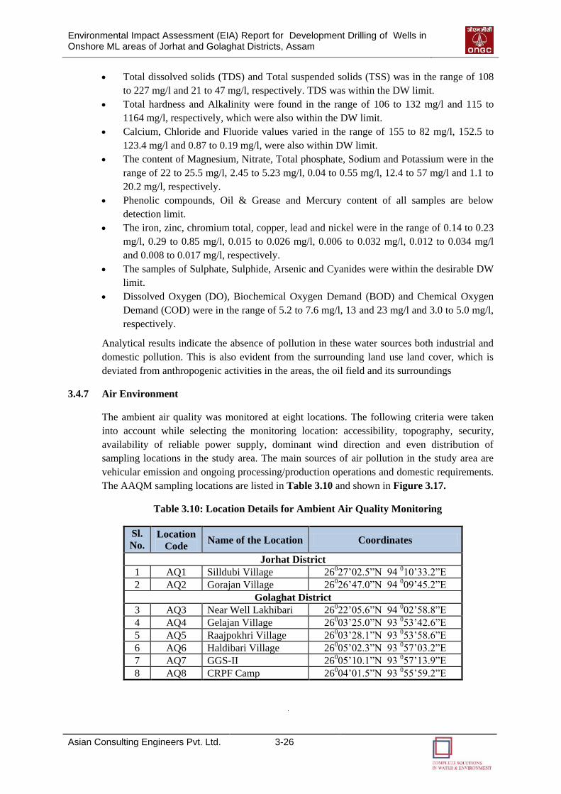
Environmental Impact Assessment (EIA) Report for Development Drilling of Wells in Onshore ML areas of Jorhat and Golaghat Districts, Assam
Asian Consulting Engineers Pvt. Ltd. 3-26
Total dissolved solids (TDS) and Total suspended solids (TSS) was in the range of 108
to 227 mg/l and 21 to 47 mg/l, respectively. TDS was within the DW limit.
Total hardness and Alkalinity were found in the range of 106 to 132 mg/l and 115 to
1164 mg/l, respectively, which were also within the DW limit.
Calcium, Chloride and Fluoride values varied in the range of 155 to 82 mg/l, 152.5 to
123.4 mg/l and 0.87 to 0.19 mg/l, were also within DW limit.
The content of Magnesium, Nitrate, Total phosphate, Sodium and Potassium were in the
range of 22 to 25.5 mg/l, 2.45 to 5.23 mg/l, 0.04 to 0.55 mg/l, 12.4 to 57 mg/l and 1.1 to
20.2 mg/l, respectively.
Phenolic compounds, Oil & Grease and Mercury content of all samples are below
detection limit.
The iron, zinc, chromium total, copper, lead and nickel were in the range of 0.14 to 0.23
mg/l, 0.29 to 0.85 mg/l, 0.015 to 0.026 mg/l, 0.006 to 0.032 mg/l, 0.012 to 0.034 mg/l
and 0.008 to 0.017 mg/l, respectively.
The samples of Sulphate, Sulphide, Arsenic and Cyanides were within the desirable DW
limit.
Dissolved Oxygen (DO), Biochemical Oxygen Demand (BOD) and Chemical Oxygen
Demand (COD) were in the range of 5.2 to 7.6 mg/l, 13 and 23 mg/l and 3.0 to 5.0 mg/l,
respectively.
Analytical results indicate the absence of pollution in these water sources both industrial and
domestic pollution. This is also evident from the surrounding land use land cover, which is
deviated from anthropogenic activities in the areas, the oil field and its surroundings
3.4.7 Air Environment
The ambient air quality was monitored at eight locations. The following criteria were taken
into account while selecting the monitoring location: accessibility, topography, security,
availability of reliable power supply, dominant wind direction and even distribution of
sampling locations in the study area. The main sources of air pollution in the study area are
vehicular emission and ongoing processing/production operations and domestic requirements.
The AAQM sampling locations are listed in Table 3.10 and shown in Figure 3.17.
Table 3.10: Location Details for Ambient Air Quality Monitoring
Sl.
No. Location
Code Name of the Location Coordinates
Jorhat District
1 AQ1 Silldubi Village 26027’02.5”N 94 010’33.2”E
2 AQ2 Gorajan Village 26026’47.0”N 94 009’45.2”E
Golaghat District
3 AQ3 Near Well Lakhibari 26022’05.6”N 94 002’58.8”E
4 AQ4 Gelajan Village 26003’25.0”N 93 053’42.6”E
5 AQ5 Raajpokhri Village 26003’28.1”N 93 053’58.6”E
6 AQ6 Haldibari Village 26005’02.3”N 93 057’03.2”E
7 AQ7 GGS-II 26005’10.1”N 93 057’13.9”E
8 AQ8 CRPF Camp 26004’01.5”N 93 055’59.2”E
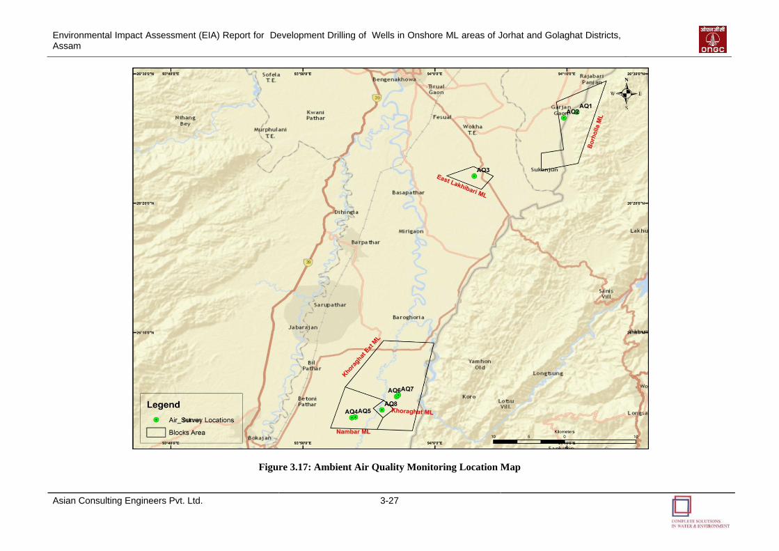
Environmental Impact Assessment (EIA) Report for Development Drilling of Wells in Onshore ML areas of Jorhat and Golaghat Districts, Assam
Asian Consulting Engineers Pvt. Ltd. 3-27
Figure 3.17: Ambient Air Quality Monitoring Location Map
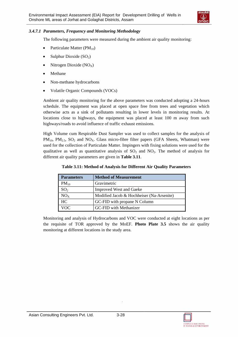
Environmental Impact Assessment (EIA) Report for Development Drilling of Wells in Onshore ML areas of Jorhat and Golaghat Districts, Assam
Asian Consulting Engineers Pvt. Ltd. 3-28
3.4.7.1 Parameters, Frequency and Monitoring Methodology
The following parameters were measured during the ambient air quality monitoring:
Particulate Matter (PM10)
Sulphur Dioxide (SO2)
Nitrogen Dioxide (NOX)
Methane
Non-methane hydrocarbons
Volatile Organic Compounds (VOCs)
Ambient air quality monitoring for the above parameters was conducted adopting a 24-hours
schedule. The equipment was placed at open space free from trees and vegetation which
otherwise acts as a sink of pollutants resulting in lower levels in monitoring results. At
locations close to highways, the equipment was placed at least 100 m away from such
highways/roads to avoid influence of traffic exhaust emissions.
High Volume cum Respirable Dust Sampler was used to collect samples for the analysis of
PM10, PM2.5, SO2 and NOX. Glass micro-fibre filter papers (GFA Sheets, Whatman) were
used for the collection of Particulate Matter. Impingers with fixing solutions were used for the
qualitative as well as quantitative analysis of SO2 and NO2. The method of analysis for
different air quality parameters are given in Table 3.11.
Table 3.11: Method of Analysis for Different Air Quality Parameters
Parameters Method of Measurement
PM10 Gravimetric
SO2 Improved West and Gaeke
NOX Modified Jacob & Hochheiser (Na-Arsenite)
HC GC-FID with propane N Column
VOC GC-FID with Methanizer
Monitoring and analysis of Hydrocarbons and VOC were conducted at eight locations as per
the requisite of TOR approved by the MoEF. Photo Plate 3.5 shows the air quality
monitoring at different locations in the study area.
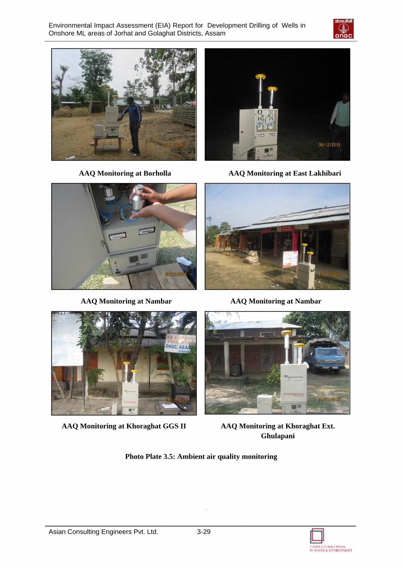
Environmental Impact Assessment (EIA) Report for Development Drilling of Wells in Onshore ML areas of Jorhat and Golaghat Districts, Assam
Asian Consulting Engineers Pvt. Ltd. 3-29
AAQ Monitoring at Borholla AAQ Monitoring at East Lakhibari
AAQ Monitoring at Nambar AAQ Monitoring at Nambar
AAQ Monitoring at Khoraghat GGS II AAQ Monitoring at Khoraghat Ext.
Ghulapani
Photo Plate 3.5: Ambient air quality monitoring
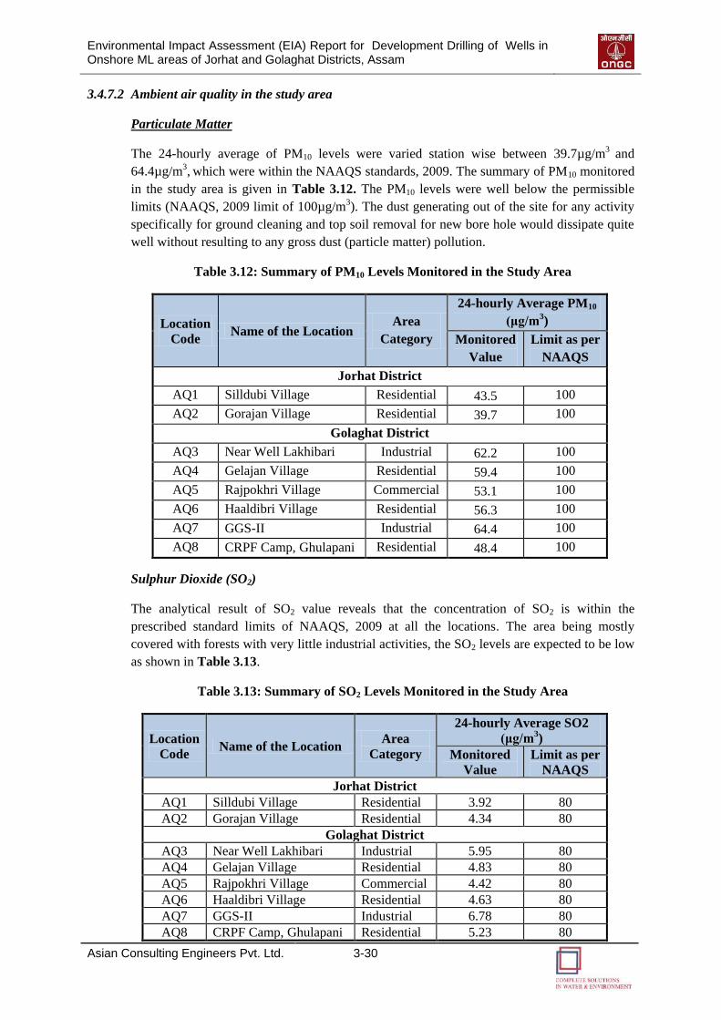
Environmental Impact Assessment (EIA) Report for Development Drilling of Wells in Onshore ML areas of Jorhat and Golaghat Districts, Assam
Asian Consulting Engineers Pvt. Ltd. 3-30
3.4.7.2 Ambient air quality in the study area
Particulate Matter
The 24-hourly average of PM10 levels were varied station wise between 39.7µg/m3 and
64.4µg/m3, which were within the NAAQS standards, 2009. The summary of PM10 monitored
in the study area is given in Table 3.12. The PM10 levels were well below the permissible
limits (NAAQS, 2009 limit of 100µg/m3). The dust generating out of the site for any activity
specifically for ground cleaning and top soil removal for new bore hole would dissipate quite
well without resulting to any gross dust (particle matter) pollution.
Table 3.12: Summary of PM10 Levels Monitored in the Study Area
Location
Code Name of the Location
Area
Category
24-hourly Average PM10
(μg/m3)
Monitored
Value
Limit as per
NAAQS
Jorhat District
AQ1 Silldubi Village Residential 43.5 100
AQ2 Gorajan Village Residential 39.7 100
Golaghat District
AQ3 Near Well Lakhibari Industrial 62.2 100
AQ4 Gelajan Village Residential 59.4 100
AQ5 Rajpokhri Village Commercial 53.1 100
AQ6 Haaldibri Village Residential 56.3 100
AQ7 GGS-II Industrial 64.4 100
AQ8 CRPF Camp, Ghulapani Residential 48.4 100
Sulphur Dioxide (SO2)
The analytical result of SO2 value reveals that the concentration of SO2 is within the
prescribed standard limits of NAAQS, 2009 at all the locations. The area being mostly
covered with forests with very little industrial activities, the SO2 levels are expected to be low
as shown in Table 3.13.
Table 3.13: Summary of SO2 Levels Monitored in the Study Area
Location
Code Name of the Location
Area
Category
24-hourly Average SO2
(μg/m3)
Monitored
Value
Limit as per
NAAQS
Jorhat District
AQ1 Silldubi Village Residential 3.92 80
AQ2 Gorajan Village Residential 4.34 80
Golaghat District
AQ3 Near Well Lakhibari Industrial 5.95 80
AQ4 Gelajan Village Residential 4.83 80
AQ5 Rajpokhri Village Commercial 4.42 80
AQ6 Haaldibri Village Residential 4.63 80
AQ7 GGS-II Industrial 6.78 80
AQ8 CRPF Camp, Ghulapani Residential 5.23 80
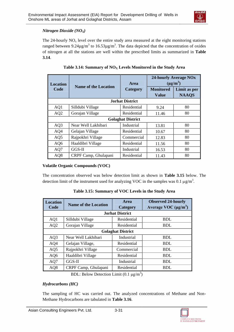
Environmental Impact Assessment (EIA) Report for Development Drilling of Wells in Onshore ML areas of Jorhat and Golaghat Districts, Assam
Asian Consulting Engineers Pvt. Ltd. 3-31
Nitrogen Dioxide (NOX)
The 24-hourly NOx level over the entire study area measured at the eight monitoring stations
ranged between 9.24µg/m3 to 16.53µg/m3. The data depicted that the concentration of oxides
of nitrogen at all the stations are well within the prescribed limits as summarized in Table
3.14.
Table 3.14: Summary of NOX Levels Monitored in the Study Area
Location
Code Name of the Location
Area
Category
24-hourly Average NOx
(μg/m3)
Monitored
Value
Limit as per
NAAQS
Jorhat District
AQ1 Silldubi Village Residential 9.24 80
AQ2 Gorajan Village Residential 11.46 80
Golaghat District
AQ3 Near Well Lakhibari Industrial 13.81 80
AQ4 Gelajan Village Residential 10.67 80
AQ5 Rajpokhri Village Commercial 12.83 80
AQ6 Haaldibri Village Residential 11.56 80
AQ7 GGS-II Industrial 16.53 80
AQ8 CRPF Camp, Ghulapani Residential 11.43 80
Volatile Organic Compounds (VOC)
The concentration observed was below detection limit as shown in Table 3.15 below. The
detection limit of the instrument used for analyzing VOC in the samples was 0.1 g/m3.
Table 3.15: Summary of VOC Levels in the Study Area
Location
Code Name of the Location
Area
Category
Observed 24-hourly
Average VOC (μg/m3)
Jorhat District
AQ1 Silldubi Village Residential BDL
AQ2 Gorajan Village Residential BDL
Golaghat District
AQ3 Near Well Lakhibari Industrial BDL
AQ4 Gelajan Village, Residential BDL
AQ5 Rajpokhri Village Commercial BDL
AQ6 Haaldibri Village Residential BDL
AQ7 GGS-II Industrial BDL
AQ8 CRPF Camp, Ghulapani Residential BDL
BDL: Below Detection Limit (0.1 μg/m3)
Hydrocarbons (HC)
The sampling of HC was carried out. The analyzed concentrations of Methane and Non-
Methane Hydrocarbons are tabulated in Table 3.16.
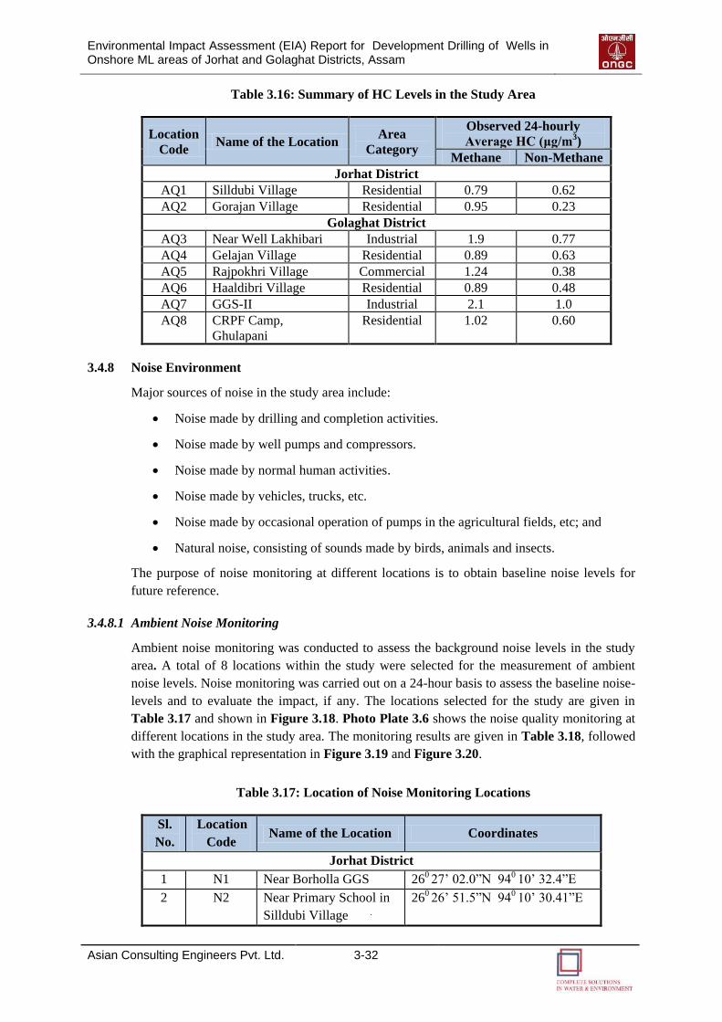
Environmental Impact Assessment (EIA) Report for Development Drilling of Wells in Onshore ML areas of Jorhat and Golaghat Districts, Assam
Asian Consulting Engineers Pvt. Ltd. 3-32
Table 3.16: Summary of HC Levels in the Study Area
Location
Code Name of the Location
Area
Category
Observed 24-hourly
Average HC (μg/m3)
Methane Non-Methane
Jorhat District
AQ1 Silldubi Village Residential 0.79 0.62
AQ2 Gorajan Village Residential 0.95 0.23
Golaghat District
AQ3 Near Well Lakhibari Industrial 1.9 0.77
AQ4 Gelajan Village Residential 0.89 0.63
AQ5 Rajpokhri Village Commercial 1.24 0.38
AQ6 Haaldibri Village Residential 0.89 0.48
AQ7 GGS-II Industrial 2.1 1.0
AQ8 CRPF Camp,
Ghulapani
Residential 1.02 0.60
3.4.8 Noise Environment
Major sources of noise in the study area include:
Noise made by drilling and completion activities.
Noise made by well pumps and compressors.
Noise made by normal human activities.
Noise made by vehicles, trucks, etc.
Noise made by occasional operation of pumps in the agricultural fields, etc; and
Natural noise, consisting of sounds made by birds, animals and insects.
The purpose of noise monitoring at different locations is to obtain baseline noise levels for
future reference.
3.4.8.1 Ambient Noise Monitoring
Ambient noise monitoring was conducted to assess the background noise levels in the study
area. A total of 8 locations within the study were selected for the measurement of ambient
noise levels. Noise monitoring was carried out on a 24-hour basis to assess the baseline noise-
levels and to evaluate the impact, if any. The locations selected for the study are given in
Table 3.17 and shown in Figure 3.18. Photo Plate 3.6 shows the noise quality monitoring at
different locations in the study area. The monitoring results are given in Table 3.18, followed
with the graphical representation in Figure 3.19 and Figure 3.20.
Table 3.17: Location of Noise Monitoring Locations
Sl.
No.
Location
Code Name of the Location Coordinates
Jorhat District
1 N1 Near Borholla GGS 260 27’ 02.0”N 940 10’ 32.4”E
2 N2 Near Primary School in
Silldubi Village
260 26’ 51.5”N 940 10’ 30.41”E

Environmental Impact Assessment (EIA) Report for Development Drilling of Wells in Onshore ML areas of Jorhat and Golaghat Districts, Assam
Asian Consulting Engineers Pvt. Ltd. 3-33
Sl.
No.
Location
Code Name of the Location Coordinates
Golaghat District
3 N3 Near Well Lakhibari 260 22’ 07.2”N 940 02’ 58.1”E
4 N4 Gelajan Village 260 03’ 24.2”N 930 53’ 42.8”E
5 N5 Raajpokhri Village 260 03’ 28.9”N 930 53’ 58.6”E
6 N6 Haldibari Village 260 05’ 01.1”N 930 57’ 03.2”E
7 N7 GGS-II 260 04’ 47.2”N 930 56’ 56.2”E
8 N8 Ghulapni 260 04’ 01.5”N 930 56’ 03.0”E
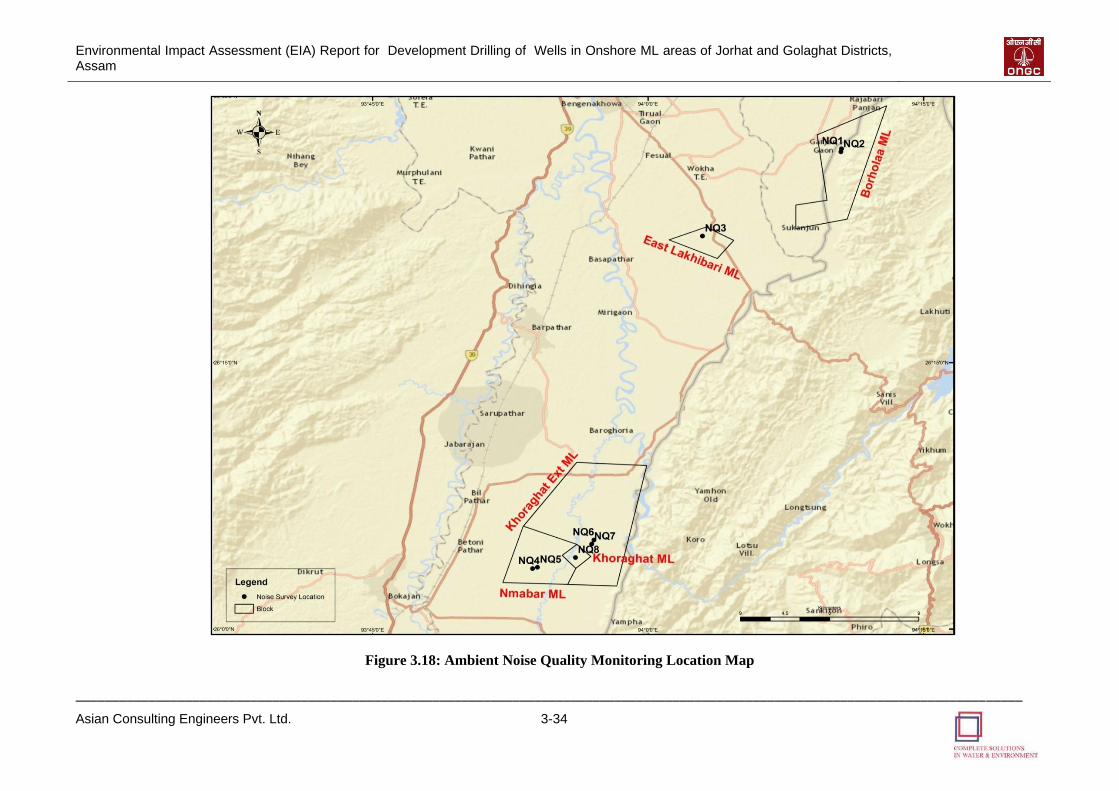
Environmental Impact Assessment (EIA) Report for Development Drilling of Wells in Onshore ML areas of Jorhat and Golaghat Districts, Assam
__________________________________________________________________________________________________________________________________
Asian Consulting Engineers Pvt. Ltd. 3-34
Figure 3.18: Ambient Noise Quality Monitoring Location Map
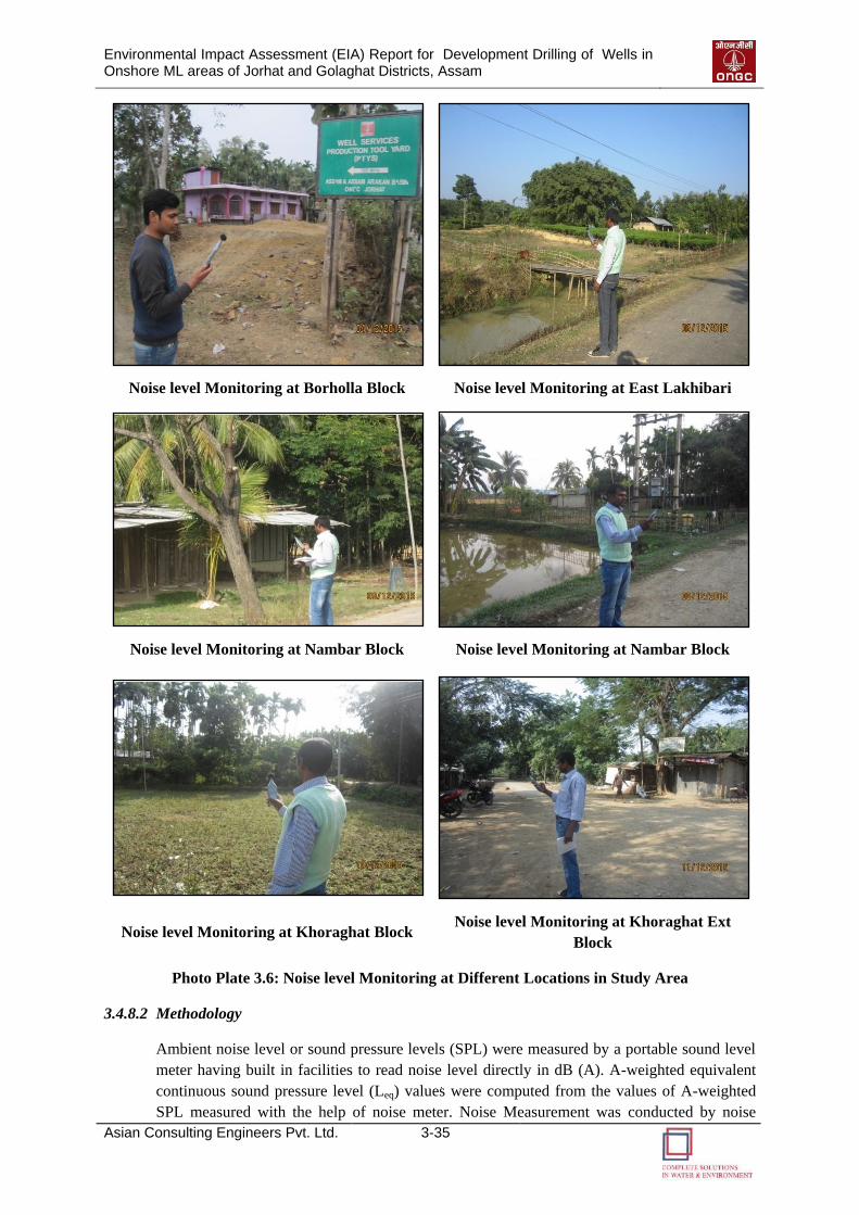
Environmental Impact Assessment (EIA) Report for Development Drilling of Wells in Onshore ML areas of Jorhat and Golaghat Districts, Assam
Asian Consulting Engineers Pvt. Ltd. 3-35
Noise level Monitoring at Borholla Block
Noise level Monitoring at East Lakhibari
Block
Noise level Monitoring at Nambar Block Noise level Monitoring at Nambar Block
Noise level Monitoring at Khoraghat Block Noise level Monitoring at Khoraghat Ext
Block
Photo Plate 3.6: Noise level Monitoring at Different Locations in Study Area
3.4.8.2 Methodology
Ambient noise level or sound pressure levels (SPL) were measured by a portable sound level
meter having built in facilities to read noise level directly in dB (A). A-weighted equivalent
continuous sound pressure level (Leq) values were computed from the values of A-weighted
SPL measured with the help of noise meter. Noise Measurement was conducted by noise
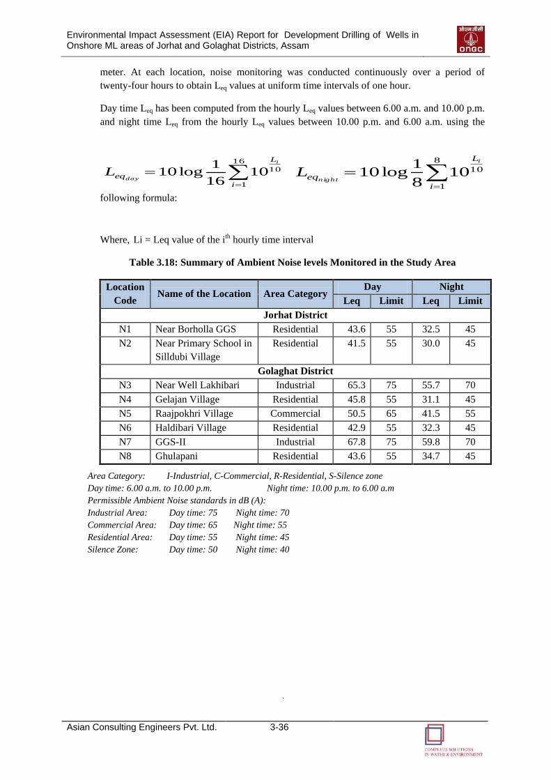
Environmental Impact Assessment (EIA) Report for Development Drilling of Wells in Onshore ML areas of Jorhat and Golaghat Districts, Assam
Asian Consulting Engineers Pvt. Ltd. 3-36
meter. At each location, noise monitoring was conducted continuously over a period of
twenty-four hours to obtain Leq values at uniform time intervals of one hour.
Day time Leq has been computed from the hourly Leq values between 6.00 a.m. and 10.00 p.m.
and night time Leq from the hourly Leq values between 10.00 p.m. and 6.00 a.m. using the
following formula:
Where, Li = Leq value of the ith hourly time interval
Table 3.18: Summary of Ambient Noise levels Monitored in the Study Area
Location
Code Name of the Location Area Category
Day Night
Leq Limit Leq Limit
Jorhat District
N1 Near Borholla GGS Residential 43.6 55 32.5 45
N2 Near Primary School in
Silldubi Village
Residential 41.5 55 30.0 45
Golaghat District
N3 Near Well Lakhibari Industrial 65.3 75 55.7 70
N4 Gelajan Village Residential 45.8 55 31.1 45
N5 Raajpokhri Village Commercial 50.5 65 41.5 55
N6 Haldibari Village Residential 42.9 55 32.3 45
N7 GGS-II Industrial 67.8 75 59.8 70
N8 Ghulapani Residential 43.6 55 34.7 45
Area Category: I-Industrial, C-Commercial, R-Residential, S-Silence zone
Day time: 6.00 a.m. to 10.00 p.m. Night time: 10.00 p.m. to 6.00 a.m
Permissible Ambient Noise standards in dB (A):
Industrial Area: Day time: 75 Night time: 70
Commercial Area: Day time: 65 Night time: 55
Residential Area: Day time: 55 Night time: 45
Silence Zone: Day time: 50 Night time: 40
16
1
101016
1log10
i
L
eq
i
dayL
8
1
10108
1log10
i
L
eq
i
nightL
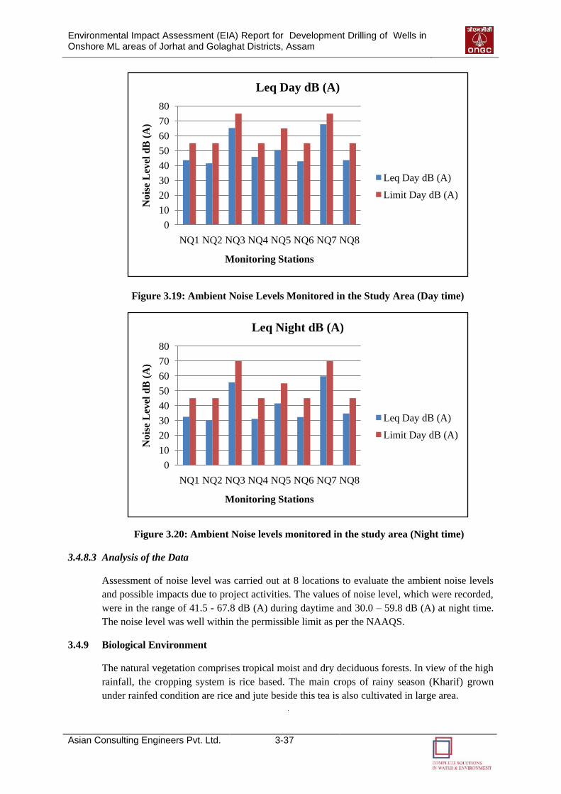
Environmental Impact Assessment (EIA) Report for Development Drilling of Wells in Onshore ML areas of Jorhat and Golaghat Districts, Assam
Asian Consulting Engineers Pvt. Ltd. 3-37
Figure 3.19: Ambient Noise Levels Monitored in the Study Area (Day time)
Figure 3.20: Ambient Noise levels monitored in the study area (Night time)
3.4.8.3 Analysis of the Data
Assessment of noise level was carried out at 8 locations to evaluate the ambient noise levels
and possible impacts due to project activities. The values of noise level, which were recorded,
were in the range of 41.5 - 67.8 dB (A) during daytime and 30.0 – 59.8 dB (A) at night time.
The noise level was well within the permissible limit as per the NAAQS.
3.4.9 Biological Environment
The natural vegetation comprises tropical moist and dry deciduous forests. In view of the high
rainfall, the cropping system is rice based. The main crops of rainy season (Kharif) grown
under rainfed condition are rice and jute beside this tea is also cultivated in large area.
0
10
20
30
40
50
60
70
80
NQ1 NQ2 NQ3 NQ4 NQ5 NQ6 NQ7 NQ8
Nois
e L
evel
dB
(A
)
Monitoring Stations
Leq Day dB (A)
Leq Day dB (A)
Limit Day dB (A)
0
10
20
30
40
50
60
70
80
NQ1 NQ2 NQ3 NQ4 NQ5 NQ6 NQ7 NQ8
Nois
e L
evel
dB
(A
)
Monitoring Stations
Leq Night dB (A)
Leq Day dB (A)
Limit Day dB (A)
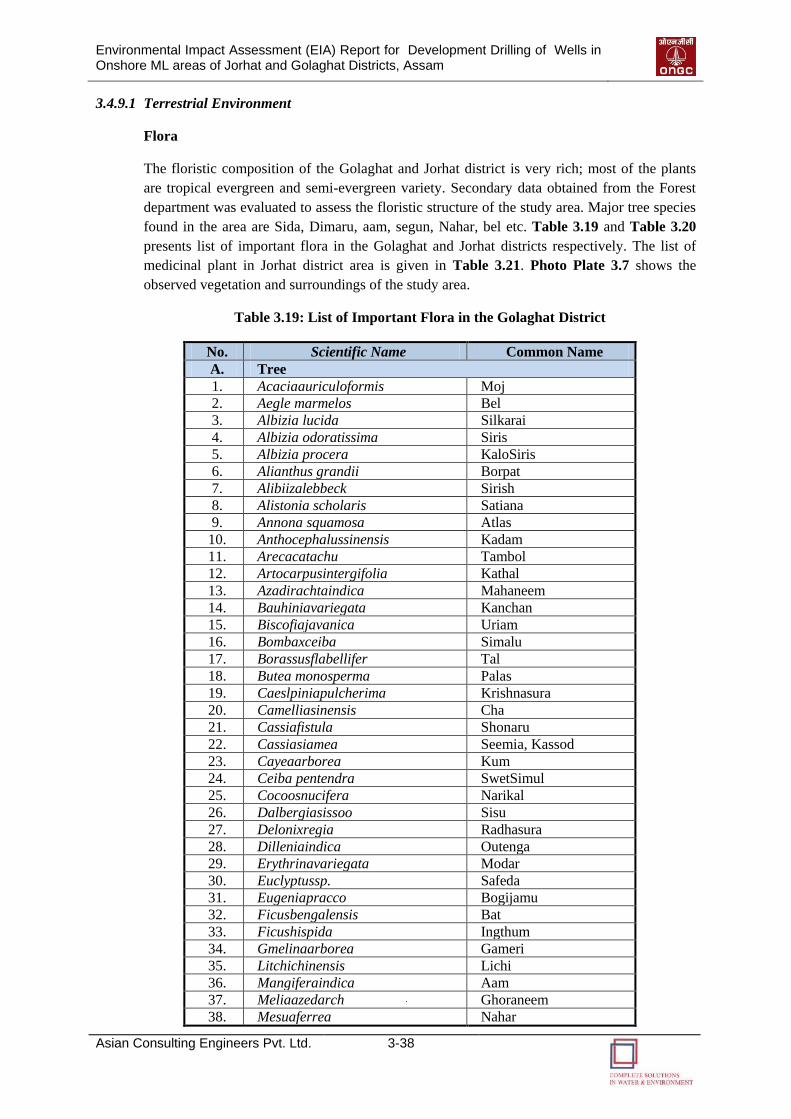
Environmental Impact Assessment (EIA) Report for Development Drilling of Wells in Onshore ML areas of Jorhat and Golaghat Districts, Assam
Asian Consulting Engineers Pvt. Ltd. 3-38
3.4.9.1 Terrestrial Environment
Flora
The floristic composition of the Golaghat and Jorhat district is very rich; most of the plants
are tropical evergreen and semi-evergreen variety. Secondary data obtained from the Forest
department was evaluated to assess the floristic structure of the study area. Major tree species
found in the area are Sida, Dimaru, aam, segun, Nahar, bel etc. Table 3.19 and Table 3.20
presents list of important flora in the Golaghat and Jorhat districts respectively. The list of
medicinal plant in Jorhat district area is given in Table 3.21. Photo Plate 3.7 shows the
observed vegetation and surroundings of the study area.
Table 3.19: List of Important Flora in the Golaghat District
No. Scientific Name Common Name
A. Tree
1. Acaciaauriculoformis Moj
2. Aegle marmelos Bel
3. Albizia lucida Silkarai
4. Albizia odoratissima Siris
5. Albizia procera KaloSiris
6. Alianthus grandii Borpat
7. Alibiizalebbeck Sirish
8. Alistonia scholaris Satiana
9. Annona squamosa Atlas
10. Anthocephalussinensis Kadam
11. Arecacatachu Tambol
12. Artocarpusintergifolia Kathal
13. Azadirachtaindica Mahaneem
14. Bauhiniavariegata Kanchan
15. Biscofiajavanica Uriam
16. Bombaxceiba Simalu
17. Borassusflabellifer Tal
18. Butea monosperma Palas
19. Caeslpiniapulcherima Krishnasura
20. Camelliasinensis Cha
21. Cassiafistula Shonaru
22. Cassiasiamea Seemia, Kassod
23. Cayeaarborea Kum
24. Ceiba pentendra SwetSimul
25. Cocoosnucifera Narikal
26. Dalbergiasissoo Sisu
27. Delonixregia Radhasura
28. Dilleniaindica Outenga
29. Erythrinavariegata Modar
30. Euclyptussp. Safeda
31. Eugeniapracco Bogijamu
32. Ficusbengalensis Bat
33. Ficushispida Ingthum
34. Gmelinaarborea Gameri
35. Litchichinensis Lichi
36. Mangiferaindica Aam
37. Meliaazedarch Ghoraneem
38. Mesuaferrea Nahar
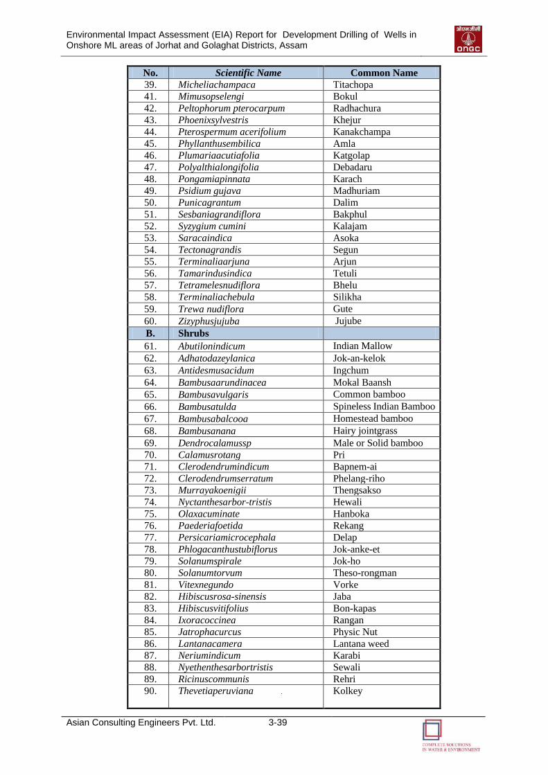
Environmental Impact Assessment (EIA) Report for Development Drilling of Wells in Onshore ML areas of Jorhat and Golaghat Districts, Assam
Asian Consulting Engineers Pvt. Ltd. 3-39
No. Scientific Name Common Name
39. Micheliachampaca Titachopa
41. Mimusopselengi Bokul
42. Peltophorum pterocarpum Radhachura
43. Phoenixsylvestris Khejur
44. Pterospermum acerifolium Kanakchampa
45. Phyllanthusembilica Amla
46. Plumariaacutiafolia Katgolap
47. Polyalthialongifolia Debadaru
48. Pongamiapinnata Karach
49. Psidium gujava Madhuriam
50. Punicagrantum Dalim
51. Sesbaniagrandiflora Bakphul
52. Syzygium cumini Kalajam
53. Saracaindica Asoka
54. Tectonagrandis Segun
55. Terminaliaarjuna Arjun
56. Tamarindusindica Tetuli
57. Tetramelesnudiflora Bhelu
58. Terminaliachebula Silikha
59. Trewa nudiflora Gute
60. Zizyphusjujuba Jujube
B. Shrubs 61. Abutilonindicum Indian Mallow
62. Adhatodazeylanica Jok-an-kelok
63. Antidesmusacidum Ingchum
64. Bambusaarundinacea Mokal Baansh
65. Bambusavulgaris Common bamboo
66. Bambusatulda Spineless Indian Bamboo
67. Bambusabalcooa Homestead bamboo
68. Bambusanana Hairy jointgrass
69. Dendrocalamussp Male or Solid bamboo
70. Calamusrotang Pri
71. Clerodendrumindicum Bapnem-ai
72. Clerodendrumserratum Phelang-riho
73. Murrayakoenigii Thengsakso
74. Nyctanthesarbor-tristis Hewali
75. Olaxacuminate Hanboka
76. Paederiafoetida Rekang
77. Persicariamicrocephala Delap
78. Phlogacanthustubiflorus Jok-anke-et
79. Solanumspirale Jok-ho
80. Solanumtorvum Theso-rongman
81. Vitexnegundo Vorke
82. Hibiscusrosa-sinensis Jaba
83. Hibiscusvitifolius Bon-kapas
84. Ixoracoccinea Rangan
85. Jatrophacurcus Physic Nut
86. Lantanacamera Lantana weed
87. Neriumindicum Karabi
88. Nyethenthesarbortristis Sewali
89. Ricinuscommunis Rehri
90. Thevetiaperuviana Kolkey
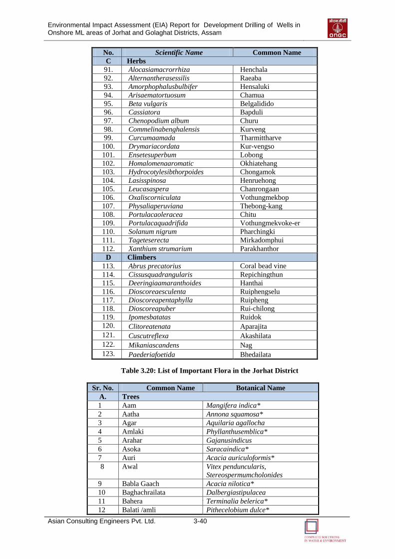
Environmental Impact Assessment (EIA) Report for Development Drilling of Wells in Onshore ML areas of Jorhat and Golaghat Districts, Assam
Asian Consulting Engineers Pvt. Ltd. 3-40
No. Scientific Name Common Name
C Herbs
91. Alocasiamacrorrhiza Henchala
92. Alternantherasessilis Raeaba
93. Amorphophalusbulbifer Hensaluki
94. Arisaematortuosum Chamua
95. Beta vulgaris Belgalidido
96. Cassiatora Bapduli
97. Chenopodium album Churu
98. Commelinabenghalensis Kurveng
99. Curcumaamada Tharmittharve
100. Drymariacordata Kur-vengso
101. Ensetesuperbum Lobong
102. Homalomenaaromatic Okhiatehang
103. Hydrocotylesibthorpoides Chongamok
104. Lasisspinosa Henruehong
105. Leucasaspera Chanrongaan
106. Oxaliscorniculata Vothungmekbop
107. Physaliaperuviana Thebong-kang
108. Portulacaoleracea Chitu
109. Portulacaquadrifida Vothungmekvoke-er
110. Solanum nigrum Pharchingki
111. Tageteserecta Mirkadomphui
112. Xanthium strumarium Parakhanthor
D Climbers
113. Abrus precatorius Coral bead vine
114. Cissusquadrangularis Repichingthun
115. Deeringiaamaranthoides Hanthai
116. Dioscoreaesculenta Ruiphengselu
117. Dioscoreapentaphylla Ruipheng
118. Dioscoreapuber Rui-chilong
119. Ipomesbatatas Ruidok
120. Clitoreatenata Aparajita
121. Cuscutreflexa Akashilata
122. Mikaniascandens Nag
123. Paederiafoetida Bhedailata
Table 3.20: List of Important Flora in the Jorhat District
Sr. No. Common Name Botanical Name
A. Trees
1 Aam Mangifera indica*
2 Aatha Annona squamosa*
3 Agar Aquilaria agallocha
4 Amlaki Phyllanthusemblica*
5 Arahar Gajanusindicus
6 Asoka Saracaindica*
7 Auri Acacia auriculoformis*
8 Awal Vitex penduncularis,
Stereospermumcholonides
9 Babla Gaach Acacia nilotica*
10 Baghachrailata Dalbergiastipulacea
11 Bahera Terminalia belerica*
12 Balati /amli Pithecelobium dulce*
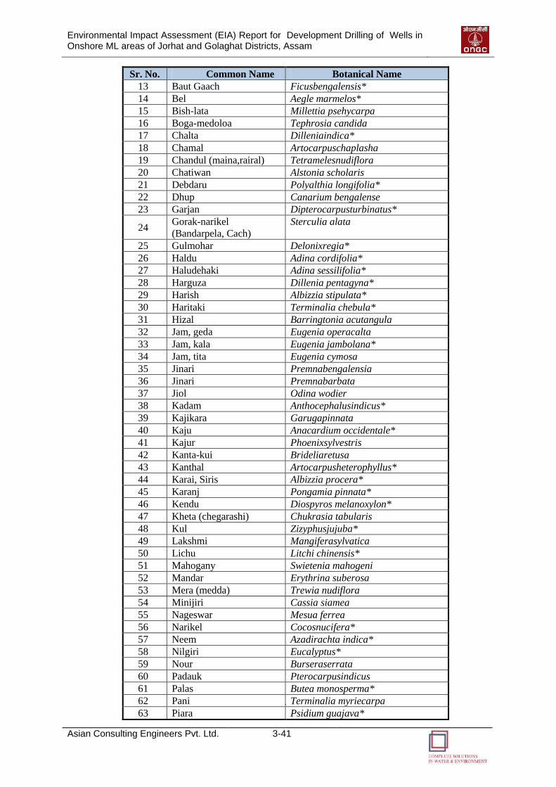
Environmental Impact Assessment (EIA) Report for Development Drilling of Wells in Onshore ML areas of Jorhat and Golaghat Districts, Assam
Asian Consulting Engineers Pvt. Ltd. 3-41
Sr. No. Common Name Botanical Name
13 Baut Gaach Ficusbengalensis*
14 Bel Aegle marmelos*
15 Bish-lata Millettia psehycarpa
16 Boga-medoloa Tephrosia candida
17 Chalta Dilleniaindica*
18 Chamal Artocarpuschaplasha
19 Chandul (maina,rairal) Tetramelesnudiflora
20 Chatiwan Alstonia scholaris
21 Debdaru Polyalthia longifolia*
22 Dhup Canarium bengalense
23 Garjan Dipterocarpusturbinatus*
24 Gorak-narikel
(Bandarpela, Cach)
Sterculia alata
25 Gulmohar Delonixregia*
26 Haldu Adina cordifolia*
27 Haludehaki Adina sessilifolia*
28 Harguza Dillenia pentagyna*
29 Harish Albizzia stipulata*
30 Haritaki Terminalia chebula*
31 Hizal Barringtonia acutangula
32 Jam, geda Eugenia operacalta
33 Jam, kala Eugenia jambolana*
34 Jam, tita Eugenia cymosa
35 Jinari Premnabengalensia
36 Jinari Premnabarbata
37 Jiol Odina wodier
38 Kadam Anthocephalusindicus*
39 Kajikara Garugapinnata
40 Kaju Anacardium occidentale*
41 Kajur Phoenixsylvestris
42 Kanta-kui Brideliaretusa
43 Kanthal Artocarpusheterophyllus*
44 Karai, Siris Albizzia procera*
45 Karanj Pongamia pinnata*
46 Kendu Diospyros melanoxylon*
47 Kheta (chegarashi) Chukrasia tabularis
48 Kul Zizyphusjujuba*
49 Lakshmi Mangiferasylvatica
50 Lichu Litchi chinensis*
51 Mahogany Swietenia mahogeni
52 Mandar Erythrina suberosa
53 Mera (medda) Trewia nudiflora
54 Minijiri Cassia siamea
55 Nageswar Mesua ferrea
56 Narikel Cocosnucifera*
57 Neem Azadirachta indica*
58 Nilgiri Eucalyptus*
59 Nour Burseraserrata
60 Padauk Pterocarpusindicus
61 Palas Butea monosperma*
62 Pani Terminalia myriecarpa
63 Piara Psidium guajava*
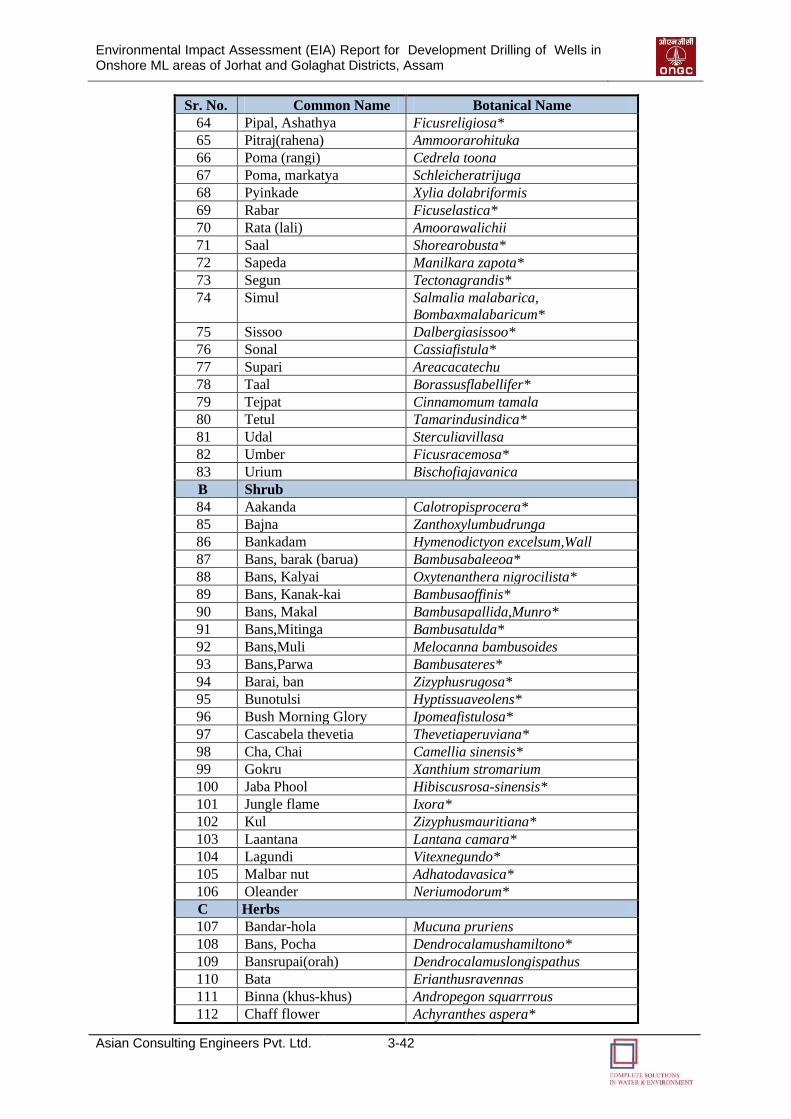
Environmental Impact Assessment (EIA) Report for Development Drilling of Wells in Onshore ML areas of Jorhat and Golaghat Districts, Assam
Asian Consulting Engineers Pvt. Ltd. 3-42
Sr. No. Common Name Botanical Name
64 Pipal, Ashathya Ficusreligiosa*
65 Pitraj(rahena) Ammoorarohituka
66 Poma (rangi) Cedrela toona
67 Poma, markatya Schleicheratrijuga
68 Pyinkade Xylia dolabriformis
69 Rabar Ficuselastica*
70 Rata (lali) Amoorawalichii
71 Saal Shorearobusta*
72 Sapeda Manilkara zapota*
73 Segun Tectonagrandis*
74 Simul Salmalia malabarica,
Bombaxmalabaricum*
75 Sissoo Dalbergiasissoo*
76 Sonal Cassiafistula*
77 Supari Areacacatechu
78 Taal Borassusflabellifer*
79 Tejpat Cinnamomum tamala
80 Tetul Tamarindusindica*
81 Udal Sterculiavillasa
82 Umber Ficusracemosa*
83 Urium Bischofiajavanica
B Shrub
84 Aakanda Calotropisprocera*
85 Bajna Zanthoxylumbudrunga
86 Bankadam Hymenodictyon excelsum,Wall
87 Bans, barak (barua) Bambusabaleeoa*
88 Bans, Kalyai Oxytenanthera nigrocilista*
89 Bans, Kanak-kai Bambusaoffinis*
90 Bans, Makal Bambusapallida,Munro*
91 Bans,Mitinga Bambusatulda*
92 Bans,Muli Melocanna bambusoides
93 Bans,Parwa Bambusateres*
94 Barai, ban Zizyphusrugosa*
95 Bunotulsi Hyptissuaveolens*
96 Bush Morning Glory Ipomeafistulosa*
97 Cascabela thevetia Thevetiaperuviana*
98 Cha, Chai Camellia sinensis*
99 Gokru Xanthium stromarium
100 Jaba Phool Hibiscusrosa-sinensis*
101 Jungle flame Ixora*
102 Kul Zizyphusmauritiana*
103 Laantana Lantana camara*
104 Lagundi Vitexnegundo*
105 Malbar nut Adhatodavasica*
106 Oleander Neriumodorum*
C Herbs
107 Bandar-hola Mucuna pruriens
108 Bans, Pocha Dendrocalamushamiltono*
109 Bansrupai(orah) Dendrocalamuslongispathus
110 Bata Erianthusravennas
111 Binna (khus-khus) Andropegon squarrrous
112 Chaff flower Achyranthes aspera*
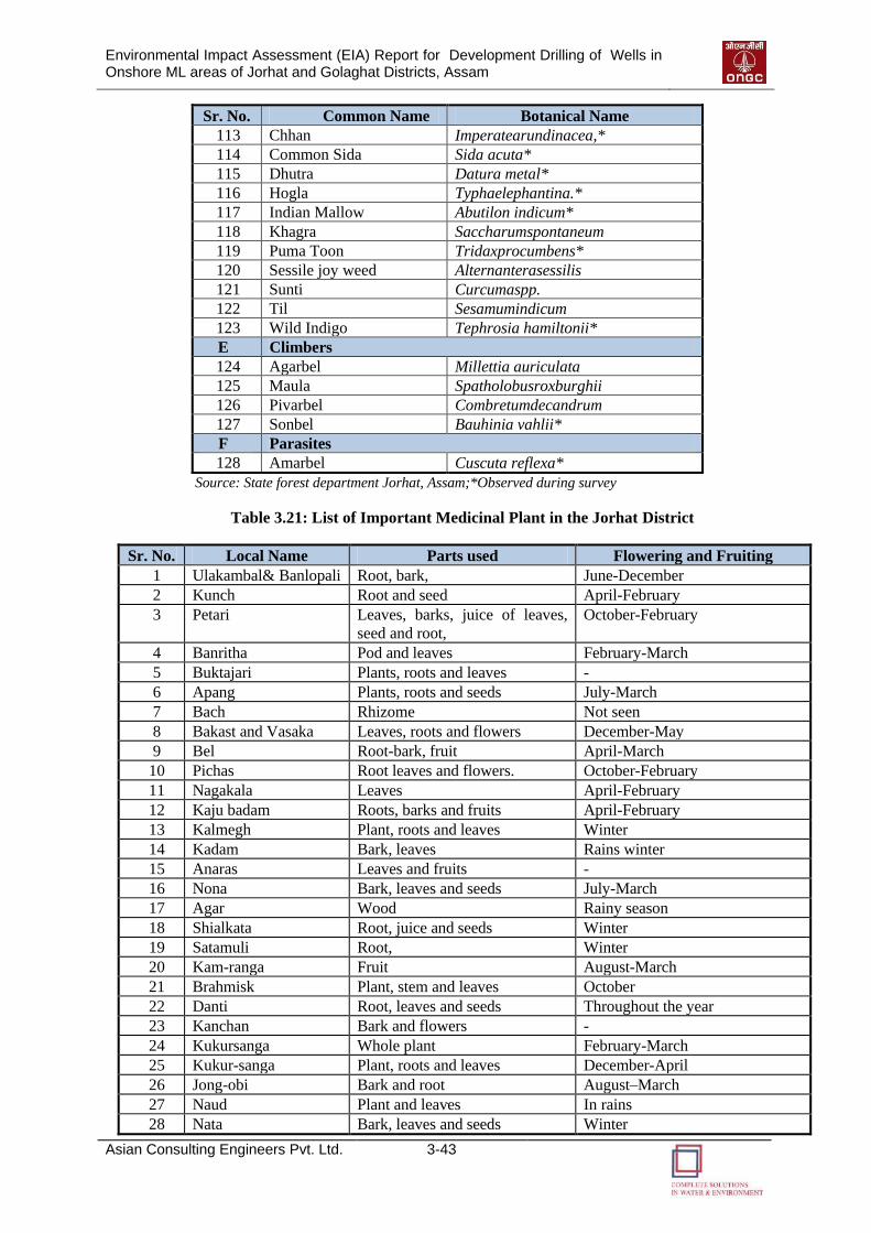
Environmental Impact Assessment (EIA) Report for Development Drilling of Wells in Onshore ML areas of Jorhat and Golaghat Districts, Assam
Asian Consulting Engineers Pvt. Ltd. 3-43
Sr. No. Common Name Botanical Name
113 Chhan Imperatearundinacea,*
114 Common Sida Sida acuta*
115 Dhutra Datura metal*
116 Hogla Typhaelephantina.*
117 Indian Mallow Abutilon indicum*
118 Khagra Saccharumspontaneum
119 Puma Toon Tridaxprocumbens*
120 Sessile joy weed Alternanterasessilis
121 Sunti Curcumaspp.
122 Til Sesamumindicum
123 Wild Indigo Tephrosia hamiltonii*
E Climbers
124 Agarbel Millettia auriculata
125 Maula Spatholobusroxburghii
126 Pivarbel Combretumdecandrum
127 Sonbel Bauhinia vahlii*
F Parasites
128 Amarbel Cuscuta reflexa*
Source: State forest department Jorhat, Assam;*Observed during survey
Table 3.21: List of Important Medicinal Plant in the Jorhat District
Sr. No. Local Name Parts used Flowering and Fruiting
1 Ulakambal& Banlopali Root, bark, June-December
2 Kunch Root and seed April-February
3 Petari Leaves, barks, juice of leaves,
seed and root,
October-February
4 Banritha Pod and leaves February-March
5 Buktajari Plants, roots and leaves -
6 Apang Plants, roots and seeds July-March
7 Bach Rhizome Not seen
8 Bakast and Vasaka Leaves, roots and flowers December-May
9 Bel Root-bark, fruit April-March
10 Pichas Root leaves and flowers. October-February
11 Nagakala Leaves April-February
12 Kaju badam Roots, barks and fruits April-February
13 Kalmegh Plant, roots and leaves Winter
14 Kadam Bark, leaves Rains winter
15 Anaras Leaves and fruits -
16 Nona Bark, leaves and seeds July-March
17 Agar Wood Rainy season
18 Shialkata Root, juice and seeds Winter
19 Satamuli Root, Winter
20 Kam-ranga Fruit August-March
21 Brahmisk Plant, stem and leaves October
22 Danti Root, leaves and seeds Throughout the year
23 Kanchan Bark and flowers -
24 Kukursanga Whole plant February-March
25 Kukur-sanga Plant, roots and leaves December-April
26 Jong-obi Bark and root August–March
27 Naud Plant and leaves In rains
28 Nata Bark, leaves and seeds Winter
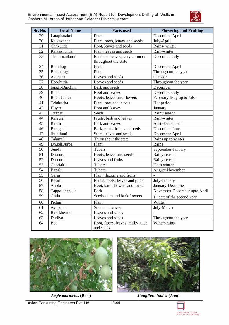
Environmental Impact Assessment (EIA) Report for Development Drilling of Wells in Onshore ML areas of Jorhat and Golaghat Districts, Assam
Asian Consulting Engineers Pvt. Ltd. 3-44
Sr. No. Local Name Parts used Flowering and Fruiting
29 Lataphatakri Plant December-April
30 Kalkasunda Plant, roots, leaves and seeds July-April
31 Chakunda Root, leaves and seeds Rains- winter
32 Kalkashunda Plant, leaves and seeds Rain-winter
33 Thunimankuni Plant and leaves; very common
throughout the state
December-July
34 Bethshag Plant December-April
35 Bethushag Plant Throughout the year
36 Akanadi Leaves and seeds October
37 Hoorhuria Leaves and seeds Throughout the year
38 Jangli-Darchini Bark and seeds December
39 Bhai Root and leaves December-July
40 Bhait Juthur Roots, leaves and flowers February-May up to July
41 Telakucha Plant, root and leaves Hot period
42 Huyer Root and leaves January
43 Titapati Seeds Rainy season
44 Kalauja Fruits, bark and leaves Rain-winter
45 Barun Bark and leaves April-December
46 Baragach Bark, roots, fruits and seeds December-June
47 Jhunjhuni Stem, leaves and seeds December-April
48 Talamuli Throughout the state Rains up to winter
49 DhubhDurba Plant, Rains
50 Sunda Tubers September-January
51 Dhutura Roots, leaves and seeds Rainy season
52 Dhutura Leaves and fruits Rainy season
53 Chprialu Tubers Upto winter
54 Banalu Tubers August-November
55 Garur Plant, rhizome and fruits -
56 Kesuti Plants, roots, leaves and juice July-January
57 Anola Root, bark, flowers and fruits January-December
58 Tappa-changue Bark November-December upto April
59 Ghila Seeds stem and bark flowers 1st part of the second year
60 Pichas Plant Winter
61 Ayapana Stem and leaves July-March
62 Barokhernie Leaves and seeds -
63 Dudiya Leaves and seeds Throughout the year
64 Bot Root, fibers, leaves, milky juice
and seeds
Winter-rains
Aegle marmelos (Bael) Mangifera indica (Aam)
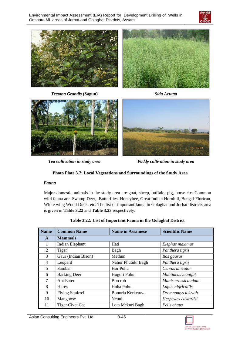
Environmental Impact Assessment (EIA) Report for Development Drilling of Wells in Onshore ML areas of Jorhat and Golaghat Districts, Assam
Asian Consulting Engineers Pvt. Ltd. 3-45
Tectona Grandis (Sagun) Sida Acutaa
Tea cultivation in study area Paddy cultivation in study area
Photo Plate 3.7: Local Vegetations and Surroundings of the Study Area
Fauna
Major domestic animals in the study area are goat, sheep, buffalo, pig, horse etc. Common
wild fauna are Swamp Deer, Butterflies, Honeybee, Great Indian Hornbill, Bengal Florican,
White wing Wood Duck, etc. The list of important fauna in Golaghat and Jorhat districts area
is given in Table 3.22 and Table 3.23 respectively.
Table 3.22: List of Important Fauna in the Golaghat District
Name Common Name Name in Assamese Scientific Name
A Mammals
1 Indian Elephant Hati Elephas maximus
2 Tiger Bagh Panthera tigris
3 Gaur (Indian Bison) Methun Bos gaurus
4 Leopard Nahor Phutuki Bagh Panthera tigris
5 Sambar Hor Pohu Cervus unicolor
6 Barking Deer Hugori Pohu Muntiacus muntjak
7 Ant Eater Bon roh Manis crassicaudata
8 Hares Hoha Pohu Lupus nigricallis
9 Flying Squirrel Bonoria Kerketuva Dremnomys lokriah
10 Mangoose Neoul Herpestes edwardsi
11 Tiger Civet Cat Lota Mekuri Bagh Felis chaus

Environmental Impact Assessment (EIA) Report for Development Drilling of Wells in Onshore ML areas of Jorhat and Golaghat Districts, Assam
Asian Consulting Engineers Pvt. Ltd. 3-46
Name Common Name Name in Assamese Scientific Name
12 Slow Loris Lajuki Bandor Nycticebus ceucang
13 Hog Deer Khotia Pohu Axis porcinus
14 Wild Pig Bonoria Gahori Sus scrofa
15 Civet Cat Johamal Viverra zibetha
16 Monkey (Langoor) Honuman Bandor Presbytis entellus
17 Monkey (Rhesus ) Moluva Bandor Macaca mulatta
18 Porcupine Ketala Pohu Hystrix indica
19 Jackal Hiyal Canis aureas
20 Otter Ud Lutra lutra
21 Sloth Bear Matir bhaluk Melursus ursinus
22 Himalayan Black Bear Himalayan Kola Bhaluk Selenarctos thebetanus
23 Honey Bear Gos Bhaluk -
24 Swamp Deer Dol Horin Cervus duvauceli
25 Wild Dog Rang kukur -
26 Hoolock Monkey Holoh Bandor Hylobates hoolock
27 Bat Baduli Various spp.
B Reptiles
28 King Cobra Sokori Pheti Hap Dphiophagus hannah
29 Cobra Pheti Hap -
30 Python Ajogor -
31 Monitor Lizard Guie Veranus bengalensis
32 Golden Lizard Hoon Guie -
C Birds
33 Imperial Pigeon Parghuma Sorai Docula aenea
34 Green Pigeon Haisa Sorai Treron bicincta
35 Jungle Fowl Bonoria Kukura Gallus gallus
36 Pheasant Dorik Lophura leucomelana
37 Qual Bota Sorai Apus apus
38 Whistling Teal Horali Hah Debdrocynga javanica
39 Cotton Teal Pani Hah Nettapus
40 Plover Bali Mahi Coromandelianus
41 Great Hornbill Raj Dhoneh Vanellus vanellus
42 Hawk Hen Sorai Falco peregrinus
43 Crow Kauri Corvus macrorhynchos
44 Magpies Dohikotora Copsyehus saularis
45 Hill Myna Maina Gracula religiosa
46 Parrot Bhatoh Psittacula krameri
47 Horn Bill Dhoneh Anthracocerusmalabaricus
48 Racket Tailed Dronge Bhim Raj Diccrurus paradiseus
49 Rock Dove Hil Kopoh Columbar livia
50 King Crow Phesu Dicrurus Adsimilis
(Source: Primary Survey & ENVIS Centre Assam, MoEF, GoI)
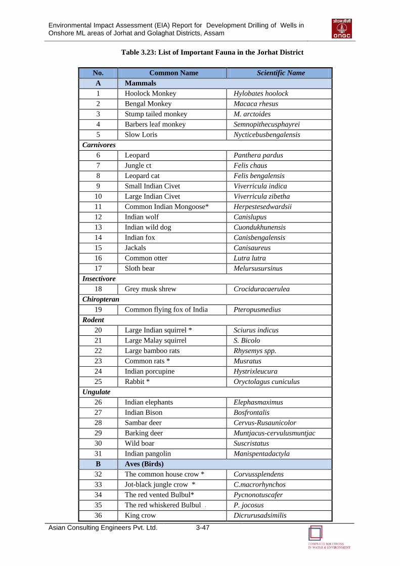
Environmental Impact Assessment (EIA) Report for Development Drilling of Wells in Onshore ML areas of Jorhat and Golaghat Districts, Assam
Asian Consulting Engineers Pvt. Ltd. 3-47
Table 3.23: List of Important Fauna in the Jorhat District
No. Common Name Scientific Name
A Mammals
1 Hoolock Monkey Hylobates hoolock
2 Bengal Monkey Macaca rhesus
3 Stump tailed monkey M. arctoides
4 Barbers leaf monkey Semnopithecusphayrei
5 Slow Loris Nycticebusbengalensis
Carnivores
6 Leopard Panthera pardus
7 Jungle ct Felis chaus
8 Leopard cat Felis bengalensis
9 Small Indian Civet Viverricula indica
10 Large Indian Civet Viverricula zibetha
11 Common Indian Mongoose* Herpestesedwardsii
12 Indian wolf Canislupus
13 Indian wild dog Cuondukhunensis
14 Indian fox Canisbengalensis
15 Jackals Canisaureus
16 Common otter Lutra lutra
17 Sloth bear Melursusursinus
Insectivore
18 Grey musk shrew Crociduracaerulea
Chiropteran
19 Common flying fox of India Pteropusmedius
Rodent
20 Large Indian squirrel * Sciurus indicus
21 Large Malay squirrel S. Bicolo
22 Large bamboo rats Rhysemys spp.
23 Common rats * Musratus
24 Indian porcupine Hystrixleucura
25 Rabbit * Oryctolagus cuniculus
Ungulate
26 Indian elephants Elephasmaximus
27 Indian Bison Bosfrontalis
28 Sambar deer Cervus-Rusaunicolor
29 Barking deer Muntjacus-cervulusmuntjac
30 Wild boar Suscristatus
31 Indian pangolin Manispentadactyla
B Aves (Birds)
32 The common house crow * Corvussplendens
33 Jot-black jungle crow * C.macrorhynchos
34 The red vented Bulbul* Pycnonotuscafer
35 The red whiskered Bulbul P. jocosus
36 King crow Dicrurusadsimilis
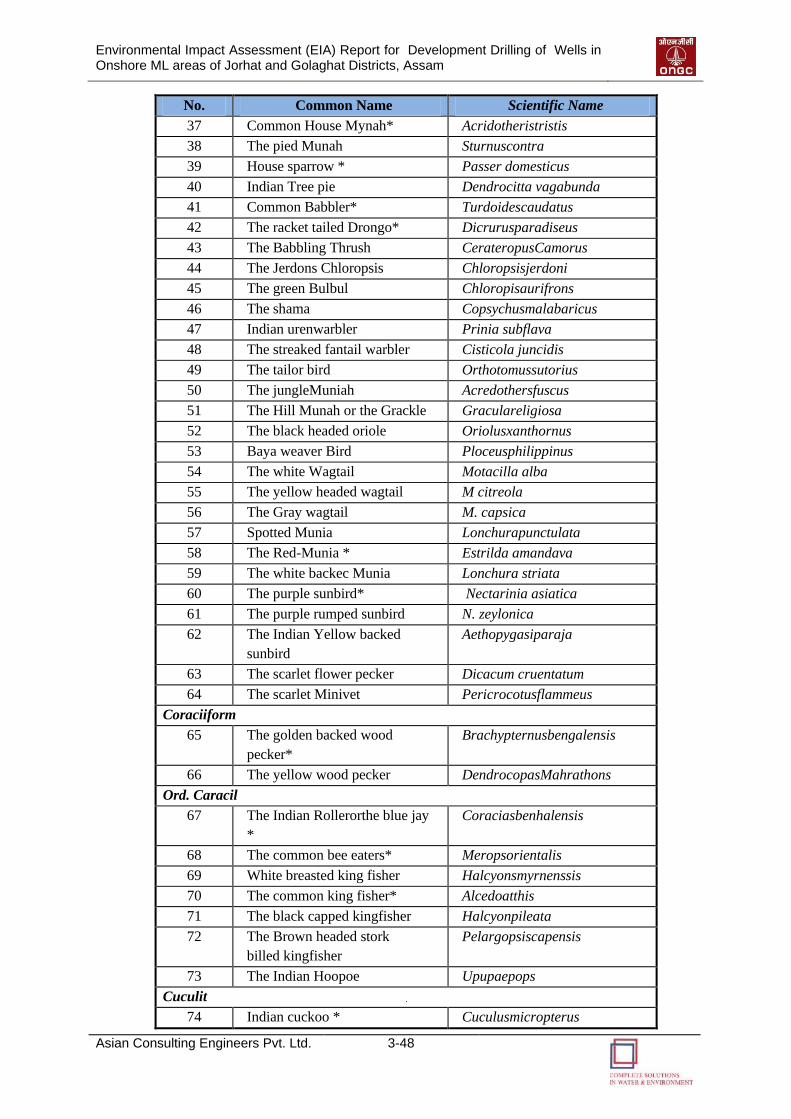
Environmental Impact Assessment (EIA) Report for Development Drilling of Wells in Onshore ML areas of Jorhat and Golaghat Districts, Assam
Asian Consulting Engineers Pvt. Ltd. 3-48
No. Common Name Scientific Name
37 Common House Mynah* Acridotheristristis
38 The pied Munah Sturnuscontra
39 House sparrow * Passer domesticus
40 Indian Tree pie Dendrocitta vagabunda
41 Common Babbler* Turdoidescaudatus
42 The racket tailed Drongo* Dicrurusparadiseus
43 The Babbling Thrush CerateropusCamorus
44 The Jerdons Chloropsis Chloropsisjerdoni
45 The green Bulbul Chloropisaurifrons
46 The shama Copsychusmalabaricus
47 Indian urenwarbler Prinia subflava
48 The streaked fantail warbler Cisticola juncidis
49 The tailor bird Orthotomussutorius
50 The jungleMuniah Acredothersfuscus
51 The Hill Munah or the Grackle Graculareligiosa
52 The black headed oriole Oriolusxanthornus
53 Baya weaver Bird Ploceusphilippinus
54 The white Wagtail Motacilla alba
55 The yellow headed wagtail M citreola
56 The Gray wagtail M. capsica
57 Spotted Munia Lonchurapunctulata
58 The Red-Munia * Estrilda amandava
59 The white backec Munia Lonchura striata
60 The purple sunbird* Nectarinia asiatica
61 The purple rumped sunbird N. zeylonica
62 The Indian Yellow backed
sunbird
Aethopygasiparaja
63 The scarlet flower pecker Dicacum cruentatum
64 The scarlet Minivet Pericrocotusflammeus
Coraciiform
65 The golden backed wood
pecker*
Brachypternusbengalensis
66 The yellow wood pecker DendrocopasMahrathons
Ord. Caracil
67 The Indian Rollerorthe blue jay
*
Coraciasbenhalensis
68 The common bee eaters* Meropsorientalis
69 White breasted king fisher Halcyonsmyrnenssis
70 The common king fisher* Alcedoatthis
71 The black capped kingfisher Halcyonpileata
72 The Brown headed stork
billed kingfisher
Pelargopsiscapensis
73 The Indian Hoopoe Upupaepops
Cuculit
74 Indian cuckoo * Cuculusmicropterus
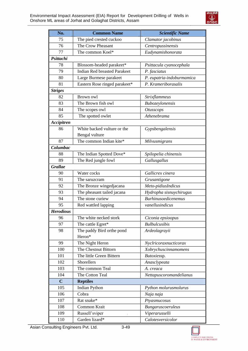
Environmental Impact Assessment (EIA) Report for Development Drilling of Wells in Onshore ML areas of Jorhat and Golaghat Districts, Assam
Asian Consulting Engineers Pvt. Ltd. 3-49
No. Common Name Scientific Name
75 The pied crested cuckoo Clamator jacobinus
76 The Crow Pheasant Centropussinensis
77 The common Koel* Eudynamishonorata
Psittachi
78 Blossom-headed parakeet* Psittacula cyanocephala
79 Indian Red breasted Parakeet P. fasciatus
80 Large Burmese parakeet P. eupatria-indoburmamica
81 Eastern Rose ringed parakeet* P. Krameriborasalis
Striges
82 Brown owl Strixflammeus
83 The Brown fish owl Bubozeylonensis
84 The scopes owl Otusscops
85 The spotted owlet Athenebrama
Accipitren
86 White backed vulture or the
Bengal vulture
Gypsbengalensis
87 The common Indian kite* Milvusmigrans
Columbac
88 The Indian Spotted Dove* Spilopelia chinensis
89 The Red jungle fowl Gallusgallus
Grallae
90 Water cocks Gallicrex cinera
91 The saruzcram Grusantigone
92 The Bronze wingedjacana Meto-pidiusIndicus
93 The pheasant tailed jacana Hydropha sisnuychirugus
94 The stone curiew Burhinusoedicenemus
95 Red wattled lapping vanellusindicus
Herodious
96 The white necked stork Ciconia epsioopus
97 The cattle Egret* Bulbulcusibis
98 The paddy Bird orthe pond
Heron*
Ardeolagrayii
99 The Night Heron Nyclricoraxnucticorax
100 The Chestnut Bittorn Xobrychuscinnamomens
101 The little Green Bittern Butoxiessp.
102 Shorellers Anasclypeata
103 The common Teal A. creaca
104 The Cotton Teal Nettapuscoromandelianus
C Reptiles
105 Indian Python Python molurusmolurus
106 Cobra Naja naja
107 Rat snake* Ptyasmucosus
108 Common Krait Bungaruscoeruleus
109 Russell’sviper Viperarusselli
110 Garden lizard* Calotesversicolor
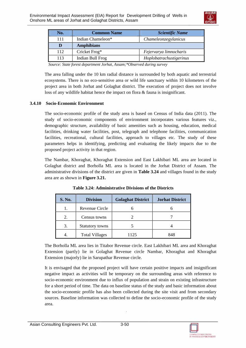
Environmental Impact Assessment (EIA) Report for Development Drilling of Wells in Onshore ML areas of Jorhat and Golaghat Districts, Assam
Asian Consulting Engineers Pvt. Ltd. 3-50
No. Common Name Scientific Name
111 Indian Chameleon* Chameleonzegylanicus
D Amphibians
112 Cricket Frog* Fejervarya limnocharis
113 Indian Bull Frog Hoplobatrachustigerinus
Source: State forest department Jorhat, Assam;*Observed during survey
The area falling under the 10 km radial distance is surrounded by both aquatic and terrestrial
ecosystems. There is no eco-sensitive area or wild life sanctuary within 10 kilometers of the
project area in both Jorhat and Golaghat district. The execution of project does not involve
loss of any wildlife habitat hence the impact on flora & fauna is insignificant.
3.4.10 Socio-Economic Environment
The socio-economic profile of the study area is based on Census of India data (2011). The
study of socio-economic components of environment incorporates various features viz.,
demographic structure, availability of basic amenities such as housing, education, medical
facilities, drinking water facilities, post, telegraph and telephone facilities, communication
facilities, recreational, cultural facilities, approach to villages etc. The study of these
parameters helps in identifying, predicting and evaluating the likely impacts due to the
proposed project activity in that region.
The Nambar, Khoraghat, Khoraghat Extension and East Lakhibari ML area are located in
Golaghat district and Borholla ML area is located in the Jorhat District of Assam. The
administrative divisions of the district are given in Table 3.24 and villages found in the study
area are as shown in Figure 3.21.
Table 3.24: Administrative Divisions of the Districts
S. No. Division Golaghat District Jorhat District
1. Revenue Circle 6 6
2. Census towns 2 7
3. Statutory towns 5 4
4. Total Villages 1125 848
The Borholla ML area lies in Titabor Revenue circle. East Lakhibari ML area and Khoraghat
Extension (partly) lie in Golaghat Revenue circle Nambar, Khoraghat and Khoraghat
Extension (majorly) lie in Sarupathar Revenue circle.
It is envisaged that the proposed project will have certain positive impacts and insignificant
negative impact as activities will be temporary on the surrounding areas with reference to
socio-economic environment due to influx of population and strain on existing infrastructure
for a short period of time. The data on baseline status of the study and basic information about
the socio-economic profile has also been collected during the site visit and from secondary
sources. Baseline information was collected to define the socio-economic profile of the study
area.

Environmental Impact Assessment (EIA) Report for Development Drilling of Wells in Onshore ML areas of Jorhat and Golaghat Districts, Assam
Asian Consulting Engineers Pvt. Ltd. 3-51
Golaghat District
Jorhat District
Figure 3.21: Villages found within the Study Area
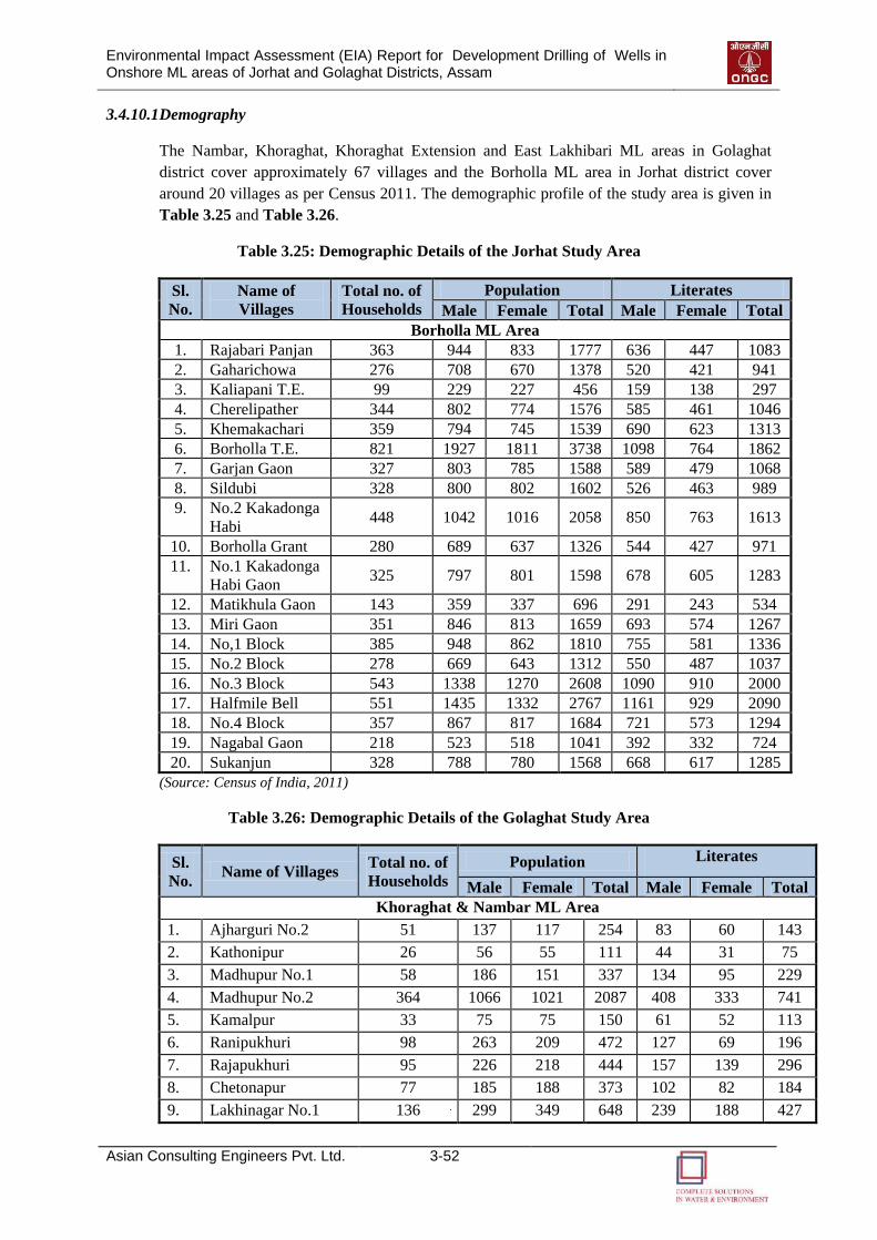
Environmental Impact Assessment (EIA) Report for Development Drilling of Wells in Onshore ML areas of Jorhat and Golaghat Districts, Assam
Asian Consulting Engineers Pvt. Ltd. 3-52
3.4.10.1 Demography
The Nambar, Khoraghat, Khoraghat Extension and East Lakhibari ML areas in Golaghat
district cover approximately 67 villages and the Borholla ML area in Jorhat district cover
around 20 villages as per Census 2011. The demographic profile of the study area is given in
Table 3.25 and Table 3.26.
Table 3.25: Demographic Details of the Jorhat Study Area
Sl.
No.
Name of
Villages
Total no. of
Households
Population Literates
Male Female Total Male Female Total
Borholla ML Area
1. Rajabari Panjan 363 944 833 1777 636 447 1083
2. Gaharichowa 276 708 670 1378 520 421 941
3. Kaliapani T.E. 99 229 227 456 159 138 297
4. Cherelipather 344 802 774 1576 585 461 1046
5. Khemakachari 359 794 745 1539 690 623 1313
6. Borholla T.E. 821 1927 1811 3738 1098 764 1862
7. Garjan Gaon 327 803 785 1588 589 479 1068
8. Sildubi 328 800 802 1602 526 463 989
9. No.2 Kakadonga
Habi 448 1042 1016 2058 850 763 1613
10. Borholla Grant 280 689 637 1326 544 427 971
11. No.1 Kakadonga
Habi Gaon 325 797 801 1598 678 605 1283
12. Matikhula Gaon 143 359 337 696 291 243 534
13. Miri Gaon 351 846 813 1659 693 574 1267
14. No,1 Block 385 948 862 1810 755 581 1336
15. No.2 Block 278 669 643 1312 550 487 1037
16. No.3 Block 543 1338 1270 2608 1090 910 2000
17. Halfmile Bell 551 1435 1332 2767 1161 929 2090
18. No.4 Block 357 867 817 1684 721 573 1294
19. Nagabal Gaon 218 523 518 1041 392 332 724
20. Sukanjun 328 788 780 1568 668 617 1285
(Source: Census of India, 2011)
Table 3.26: Demographic Details of the Golaghat Study Area
Sl.
No. Name of Villages
Total no. of
Households
Population Literates
Male Female Total Male Female Total
Khoraghat & Nambar ML Area
1. Ajharguri No.2 51 137 117 254 83 60 143
2. Kathonipur 26 56 55 111 44 31 75
3. Madhupur No.1 58 186 151 337 134 95 229
4. Madhupur No.2 364 1066 1021 2087 408 333 741
5. Kamalpur 33 75 75 150 61 52 113
6. Ranipukhuri 98 263 209 472 127 69 196
7. Rajapukhuri 95 226 218 444 157 139 296
8. Chetonapur 77 185 188 373 102 82 184
9. Lakhinagar No.1 136 299 349 648 239 188 427
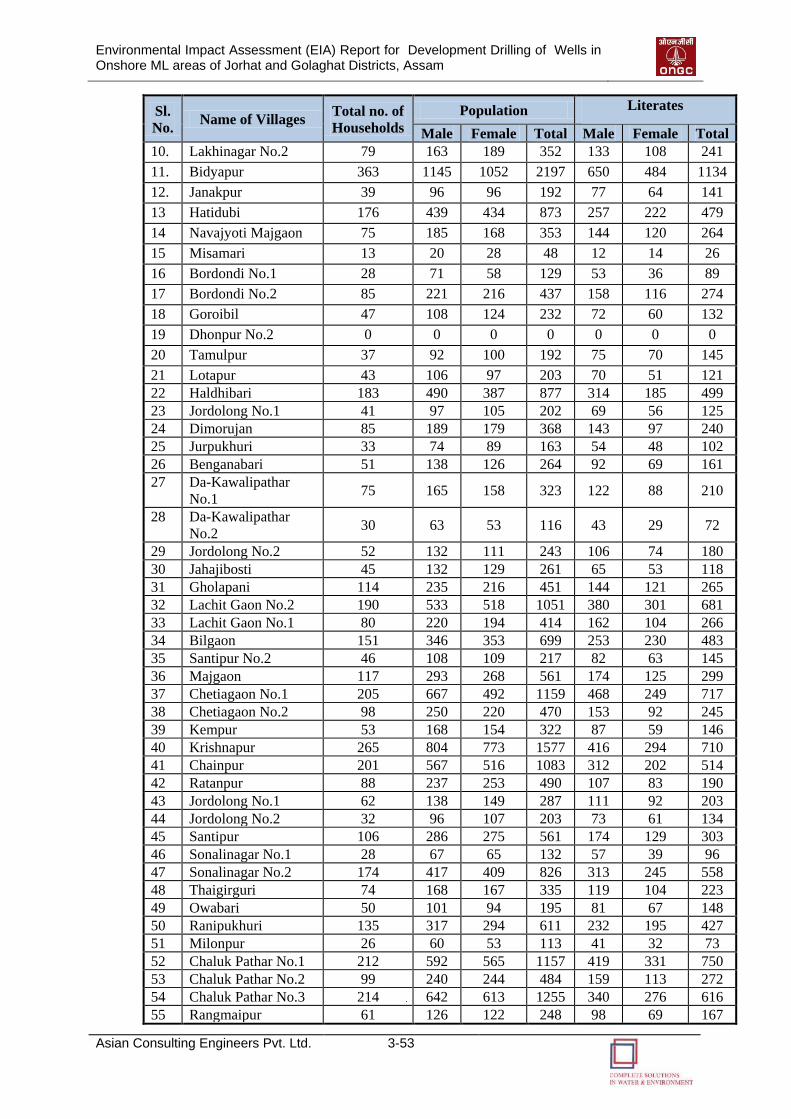
Environmental Impact Assessment (EIA) Report for Development Drilling of Wells in Onshore ML areas of Jorhat and Golaghat Districts, Assam
Asian Consulting Engineers Pvt. Ltd. 3-53
Sl.
No. Name of Villages
Total no. of
Households
Population Literates
Male Female Total Male Female Total
10. Lakhinagar No.2 79 163 189 352 133 108 241
11. Bidyapur 363 1145 1052 2197 650 484 1134
12. Janakpur 39 96 96 192 77 64 141
13 Hatidubi 176 439 434 873 257 222 479
14 Navajyoti Majgaon 75 185 168 353 144 120 264
15 Misamari 13 20 28 48 12 14 26
16 Bordondi No.1 28 71 58 129 53 36 89
17 Bordondi No.2 85 221 216 437 158 116 274
18 Goroibil 47 108 124 232 72 60 132
19 Dhonpur No.2 0 0 0 0 0 0 0
20 Tamulpur 37 92 100 192 75 70 145
21 Lotapur 43 106 97 203 70 51 121
22 Haldhibari 183 490 387 877 314 185 499
23 Jordolong No.1 41 97 105 202 69 56 125
24 Dimorujan 85 189 179 368 143 97 240
25 Jurpukhuri 33 74 89 163 54 48 102
26 Benganabari 51 138 126 264 92 69 161
27 Da-Kawalipathar
No.1 75 165 158 323 122 88 210
28 Da-Kawalipathar
No.2 30 63 53 116 43 29 72
29 Jordolong No.2 52 132 111 243 106 74 180
30 Jahajibosti 45 132 129 261 65 53 118
31 Gholapani 114 235 216 451 144 121 265
32 Lachit Gaon No.2 190 533 518 1051 380 301 681
33 Lachit Gaon No.1 80 220 194 414 162 104 266
34 Bilgaon 151 346 353 699 253 230 483
35 Santipur No.2 46 108 109 217 82 63 145
36 Majgaon 117 293 268 561 174 125 299
37 Chetiagaon No.1 205 667 492 1159 468 249 717
38 Chetiagaon No.2 98 250 220 470 153 92 245
39 Kempur 53 168 154 322 87 59 146
40 Krishnapur 265 804 773 1577 416 294 710
41 Chainpur 201 567 516 1083 312 202 514
42 Ratanpur 88 237 253 490 107 83 190
43 Jordolong No.1 62 138 149 287 111 92 203
44 Jordolong No.2 32 96 107 203 73 61 134
45 Santipur 106 286 275 561 174 129 303
46 Sonalinagar No.1 28 67 65 132 57 39 96
47 Sonalinagar No.2 174 417 409 826 313 245 558
48 Thaigirguri 74 168 167 335 119 104 223
49 Owabari 50 101 94 195 81 67 148
50 Ranipukhuri 135 317 294 611 232 195 427
51 Milonpur 26 60 53 113 41 32 73
52 Chaluk Pathar No.1 212 592 565 1157 419 331 750
53 Chaluk Pathar No.2 99 240 244 484 159 113 272
54 Chaluk Pathar No.3 214 642 613 1255 340 276 616
55 Rangmaipur 61 126 122 248 98 69 167
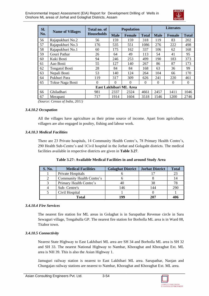
Environmental Impact Assessment (EIA) Report for Development Drilling of Wells in Onshore ML areas of Jorhat and Golaghat Districts, Assam
Asian Consulting Engineers Pvt. Ltd. 3-54
Sl.
No. Name of Villages
Total no. of
Households
Population Literates
Male Female Total Male Female Total
56 Rajapukhuri No.2 56 159 159 318 119 83 202
57 Rajapukhuri No.3 176 535 551 1086 276 222 498
58 Rajapukhuri No.1 60 175 162 337 106 62 168
59 Gouri Pathar 26 64 49 113 54 41 95
60 Kuki Bosti 94 246 253 499 190 183 373
61 Aao Bosti 55 127 140 267 86 87 173
62 Tengatol Bosti 28 84 84 168 63 36 99
63 Nepali Bosti 53 140 124 264 104 66 170
64 Pukhuri Para 119 317 309 626 241 220 461
65 Tokse Naga Bosti 0 0 0 0 0 0 0
East Lakhibari ML Area
66 Ghiladhari 981 2337 2324 4661 2457 1411 1046
67 Merapani 717 1914 1604 3518 1546 1200 2746
(Source: Census of India, 2011)
3.4.10.2 Occupation
All the villages have agriculture as their prime source of income. Apart from agriculture,
villagers are also engaged in poultry, fishing and labour work.
3.4.10.3 Medical Facilities
There are 23 Private hospitals, 14 Community Health Centre’s, 78 Primary Health Centre’s,
290 Health Sub-Centre’s and 1Civil hospital in the Jorhat and Golagaht districts. The medical
facilities available in respective districts are given in Table 3.27.
Table 3.27: Available Medical Facilities in and around Study Area
S. No. Medical Facilities Golaghat District Jorhat District Total
1 Private Hospitals 6 17 23
2 Community Health Centre’s 6 8 14
3 Primary Health Centre’s 40 38 78
4 Sub- Centre's 146 144 290
5 Civil Hospital 1 0 1
Total 199 207 406
3.4.10.4 Fire Services
The nearest fire station for ML areas in Golaghat is in Sarupathar Revenue circle in Saru
Sewaguri village, Tengahulla GP. The nearest fire station for Borholla ML area is in Ward 08,
Titabor town.
3.4.10.5 Connectivity
Nearest State Highway to East Lakhibari ML area are SH 34 and Borholla ML area is SH 32
and SH 33. The nearest National Highway to Nambar, Khoraghat and Khoraghat Ext. ML
area is NH 39. This is also the Asian Highway 1.
Jamuguri railway station is nearest to East Lakhibari ML area. Sarupathar, Naojan and
Chungajan railway stations are nearest to Nambar, Khoraghat and Khoraghat Ext. ML area.
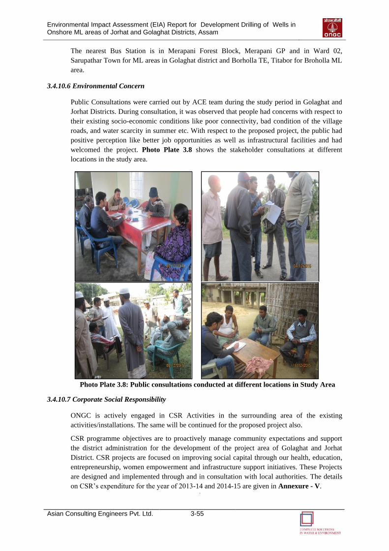
Environmental Impact Assessment (EIA) Report for Development Drilling of Wells in Onshore ML areas of Jorhat and Golaghat Districts, Assam
Asian Consulting Engineers Pvt. Ltd. 3-55
The nearest Bus Station is in Merapani Forest Block, Merapani GP and in Ward 02,
Sarupathar Town for ML areas in Golaghat district and Borholla TE, Titabor for Broholla ML
area.
3.4.10.6 Environmental Concern
Public Consultations were carried out by ACE team during the study period in Golaghat and
Jorhat Districts. During consultation, it was observed that people had concerns with respect to
their existing socio-economic conditions like poor connectivity, bad condition of the village
roads, and water scarcity in summer etc. With respect to the proposed project, the public had
positive perception like better job opportunities as well as infrastructural facilities and had
welcomed the project. Photo Plate 3.8 shows the stakeholder consultations at different
locations in the study area.
Photo Plate 3.8: Public consultations conducted at different locations in Study Area
3.4.10.7 Corporate Social Responsibility
ONGC is actively engaged in CSR Activities in the surrounding area of the existing
activities/installations. The same will be continued for the proposed project also.
CSR programme objectives are to proactively manage community expectations and support
the district administration for the development of the project area of Golaghat and Jorhat
District. CSR projects are focused on improving social capital through our health, education,
entrepreneurship, women empowerment and infrastructure support initiatives. These Projects
are designed and implemented through and in consultation with local authorities. The details
on CSR’s expenditure for the year of 2013-14 and 2014-15 are given in Annexure - V.
44
AANNTTIICCIIPPAATTEEDD
EENNVVIIRROONNMMEENNTTAALL
IIMMPPAACCTTSS AANNDD
MMIITTIIGGAATTIIOONN
MMEEAASSUURREESS
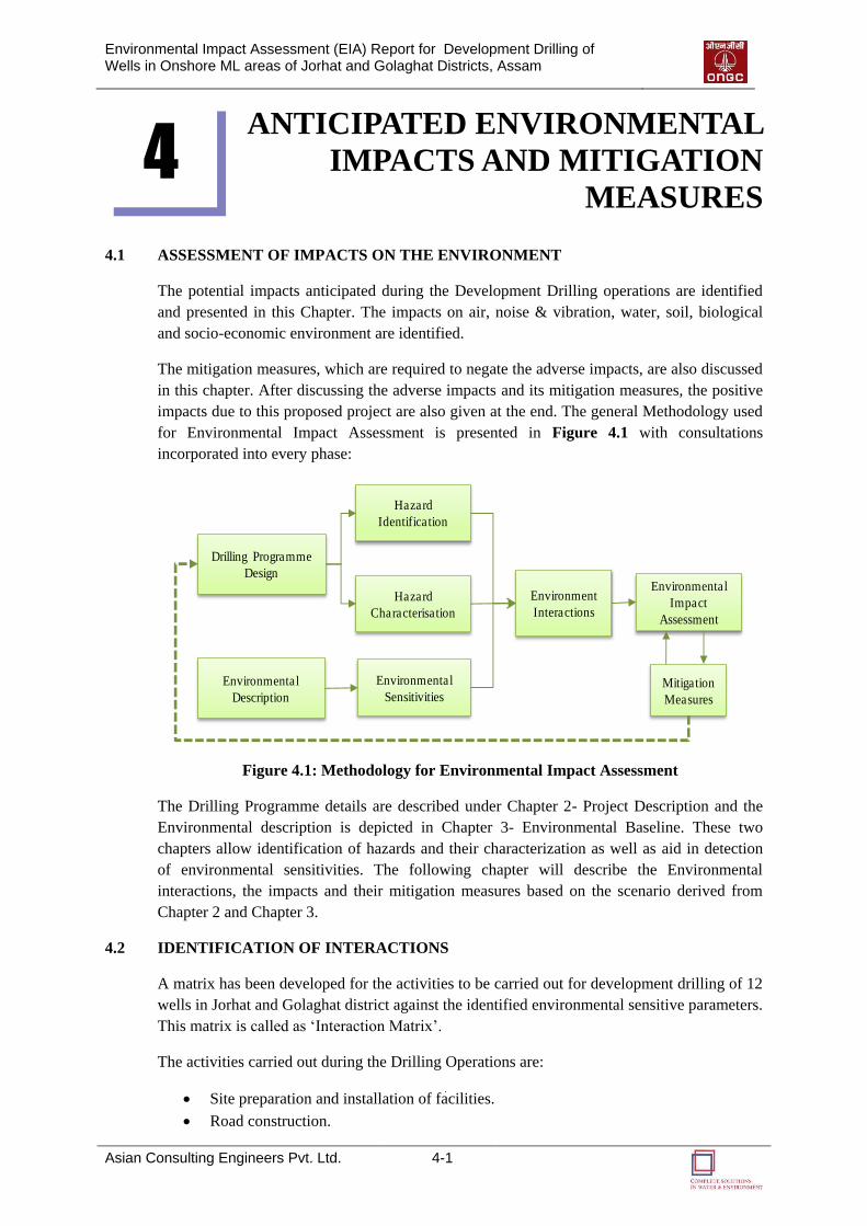
Environmental Impact Assessment (EIA) Report for Development Drilling of Wells in Onshore ML areas of Jorhat and Golaghat Districts, Assam
Asian Consulting Engineers Pvt. Ltd. 4-1
ANTICIPATED ENVIRONMENTAL
IMPACTS AND MITIGATION
MEASURES
4.1 ASSESSMENT OF IMPACTS ON THE ENVIRONMENT
The potential impacts anticipated during the Development Drilling operations are identified
and presented in this Chapter. The impacts on air, noise & vibration, water, soil, biological
and socio-economic environment are identified.
The mitigation measures, which are required to negate the adverse impacts, are also discussed
in this chapter. After discussing the adverse impacts and its mitigation measures, the positive
impacts due to this proposed project are also given at the end. The general Methodology used
for Environmental Impact Assessment is presented in Figure 4.1 with consultations
incorporated into every phase:
Environmental
Description
Drilling Programme
Design
Hazard
Identification
Hazard
Characterisation
Environmental
Sensitivities
Environment
Interactions
Environmental
Impact
Assessment
Mitigation
Measures
Figure 4.1: Methodology for Environmental Impact Assessment
The Drilling Programme details are described under Chapter 2- Project Description and the
Environmental description is depicted in Chapter 3- Environmental Baseline. These two
chapters allow identification of hazards and their characterization as well as aid in detection
of environmental sensitivities. The following chapter will describe the Environmental
interactions, the impacts and their mitigation measures based on the scenario derived from
Chapter 2 and Chapter 3.
4.2 IDENTIFICATION OF INTERACTIONS
A matrix has been developed for the activities to be carried out for development drilling of 12
wells in Jorhat and Golaghat district against the identified environmental sensitive parameters.
This matrix is called as ‘Interaction Matrix’.
The activities carried out during the Drilling Operations are:
Site preparation and installation of facilities.
Road construction.
4
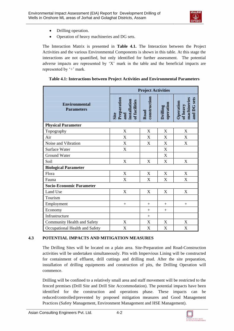
Environmental Impact Assessment (EIA) Report for Development Drilling of Wells in Onshore ML areas of Jorhat and Golaghat Districts, Assam
Asian Consulting Engineers Pvt. Ltd. 4-2
Drilling operation.
Operation of heavy machineries and DG sets.
The Interaction Matrix is presented in Table 4.1. The Interaction between the Project
Activities and the various Environmental Components is shown in this table. At this stage the
interactions are not quantified, but only identified for further assessment. The potential
adverse impacts are represented by ‘X’ mark in the table and the beneficial impacts are
represented by ‘+’ mark.
Table 4.1: Interactions between Project Activities and Environmental Parameters
Environmental
Parameters
Project Activities
Sit
e
Pre
para
tio
n
an
d
inst
all
ati
on
of
faci
liti
es
Roa
d
con
stru
ctio
n
Dri
llin
g
op
erati
on
Op
erati
on
of
hea
vy
mach
iner
ies
an
d D
G s
ets
Physical Parameter
Topography X X X X
Air X X X X
Noise and Vibration X X X X
Surface Water X X
Ground Water X
Soil X X X X
Biological Parameter
Flora X X X X
Fauna X X X X
Socio-Economic Parameter
Land Use X X X X
Tourism
Employment + + + +
Economy + +
Infrastructure +
Community Health and Safety X X X X
Occupational Health and Safety X X X X
4.3 POTENTIAL IMPACTS AND MITIGATION MEASURES
The Drilling Sites will be located on a plain area. Site-Preparation and Road-Construction
activities will be undertaken simultaneously. Pits with Impervious Lining will be constructed
for containment of effluent, drill cuttings and drilling mud. After the site preparation,
installation of drilling equipments and construction of pits, the Drilling Operation will
commence.
Drilling will be confined to a relatively small area and staff movement will be restricted to the
fenced premises (Drill Site and Drill Site Accommodation). The potential impacts have been
identified for the construction and operations phase. These impacts can be
reduced/controlled/prevented by proposed mitigation measures and Good Management
Practices (Safety Management, Environment Management and HSE Management).
Environmental Impact Assessment (EIA) Report for Development Drilling of Wells in Onshore ML areas of Jorhat and Golaghat Districts, Assam
Asian Consulting Engineers Pvt. Ltd. 4-3
4.3.1 Air Environment
The drilling and other operations during development drilling may generate emissions
impacting the air environment. Main emission sources include:
Site clearance and transportation
Emissions from DG sets and use of pumps
Flaring and venting of hydrocarbons
Fugitive emissions
4.3.1.1 Impacts
Temporary and marginal impact to air quality may occur during the construction activities
such as clearing of land, road construction and installation of drilling equipments. However,
these shall be limited to the site and its immediate environ due to dilution of finer particles
and settlement of large particulate matter.
Air quality may also be affected during transportation of materials and other resources during
construction and operational phase. However, adoption of suitable measures, good roads and
routine maintenance of the vehicles shall minimize the impact of transportation.
Exhaust emissions from operation of construction machinery is likely to contribute to air
pollutant load (primarily PM, NOX, SO2 etc.) in the ambient air near well site facilities.
However the impact will be of low significance due to localized nature as well as considering
the temporary duration of construction and drilling activities and the necessary mitigation
measures that will be adopted by the proponent.
Other, major source of emission may be attributed to the DG Sets used during drilling phase,
which is minimal but essential for any well development facility to operate in a safe and
reliable manner. However, DG sets will be installed with adequate stack height to ensure
wider dispersion and adoption of appropriate fuel such as low sulfur diesel oil for effective
combustion. Also, adoption of good engineering and maintenance practice shall minimize the
impacts of emission.
Fugitive emissions (mainly consisting of methane and VOC) may also result due to leaks in
tubing, valves, connections, flanges, packing’s, pump and compressor seals, gas, conveyance
systems, pressure relief valves, tanks or open pits/containments, and loading and unloading
operations of hydrocarbons. The drilling operation may leak minimal amounts of gas into the
atmosphere, which may affect the air quality. Adoption of good maintenance practices shall
minimize the risk of these emissions.
Detailed air quality modeling has been carried out for predicting the concentration of different
pollutants contributed during the proposed drilling operation.
4.3.1.2 The Model
Air dispersion modeling for prediction of maximum increment in Ground Level
Concentration (GLC) of different air pollutants in the surrounding area due to the emission
from DG sets present in proposed drilling during operation stage has been carried out by using
the AERMOD View model developed by the US EPA. This model is used extensively to
assess pollution concentration and deposition from a wide variety of sources and is also
recommended by CPCB. The model is based on Gaussian Plume Air Dispersion. It is a steady
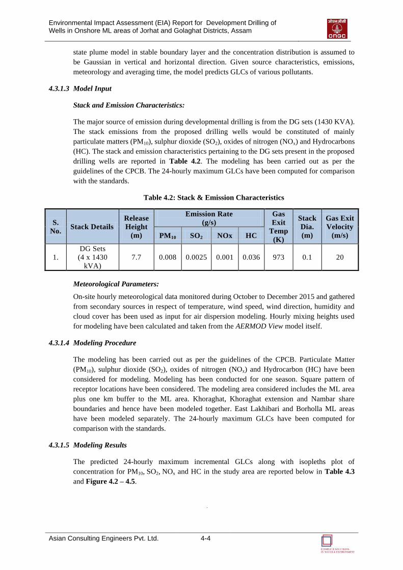
Environmental Impact Assessment (EIA) Report for Development Drilling of Wells in Onshore ML areas of Jorhat and Golaghat Districts, Assam
Asian Consulting Engineers Pvt. Ltd. 4-4
state plume model in stable boundary layer and the concentration distribution is assumed to
be Gaussian in vertical and horizontal direction. Given source characteristics, emissions,
meteorology and averaging time, the model predicts GLCs of various pollutants.
4.3.1.3 Model Input
Stack and Emission Characteristics:
The major source of emission during developmental drilling is from the DG sets (1430 KVA).
The stack emissions from the proposed drilling wells would be constituted of mainly
particulate matters (PM10), sulphur dioxide (SO2), oxides of nitrogen (NOx) and Hydrocarbons
(HC). The stack and emission characteristics pertaining to the DG sets present in the proposed
drilling wells are reported in Table 4.2. The modeling has been carried out as per the
guidelines of the CPCB. The 24-hourly maximum GLCs have been computed for comparison
with the standards.
Table 4.2: Stack & Emission Characteristics
S.
No. Stack Details
Release
Height
(m)
Emission Rate
(g/s)
Gas
Exit
Temp
(K)
Stack
Dia.
(m)
Gas Exit
Velocity
(m/s) PM10 SO2 NOx HC
1.
DG Sets
(4 x 1430
kVA)
7.7 0.008 0.0025 0.001 0.036 973 0.1 20
Meteorological Parameters:
On-site hourly meteorological data monitored during October to December 2015 and gathered
from secondary sources in respect of temperature, wind speed, wind direction, humidity and
cloud cover has been used as input for air dispersion modeling. Hourly mixing heights used
for modeling have been calculated and taken from the AERMOD View model itself.
4.3.1.4 Modeling Procedure
The modeling has been carried out as per the guidelines of the CPCB. Particulate Matter
(PM10), sulphur dioxide (SO2), oxides of nitrogen (NOx) and Hydrocarbon (HC) have been
considered for modeling. Modeling has been conducted for one season. Square pattern of
receptor locations have been considered. The modeling area considered includes the ML area
plus one km buffer to the ML area. Khoraghat, Khoraghat extension and Nambar share
boundaries and hence have been modeled together. East Lakhibari and Borholla ML areas
have been modeled separately. The 24-hourly maximum GLCs have been computed for
comparison with the standards.
4.3.1.5 Modeling Results
The predicted 24-hourly maximum incremental GLCs along with isopleths plot of
concentration for PM10, SO2, NOx and HC in the study area are reported below in Table 4.3
and Figure 4.2 – 4.5.
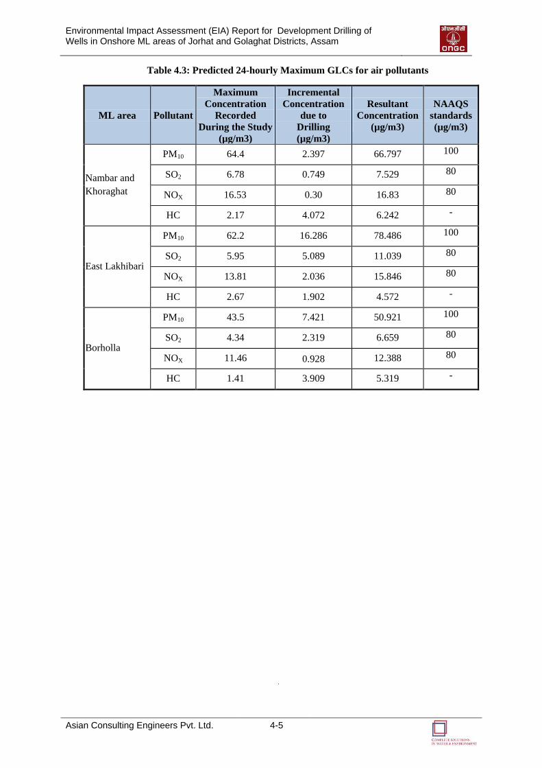
Environmental Impact Assessment (EIA) Report for Development Drilling of Wells in Onshore ML areas of Jorhat and Golaghat Districts, Assam
Asian Consulting Engineers Pvt. Ltd. 4-5
Table 4.3: Predicted 24-hourly Maximum GLCs for air pollutants
ML area Pollutant
Maximum
Concentration
Recorded
During the Study
(µg/m3)
Incremental
Concentration
due to
Drilling
(µg/m3)
Resultant
Concentration
(µg/m3)
NAAQS
standards
(µg/m3)
Nambar and
Khoraghat
PM10 64.4 2.397 66.797 100
SO2 6.78 0.749 7.529 80
NOX 16.53 0.30 16.83 80
HC 2.17 4.072 6.242 -
East Lakhibari
PM10 62.2 16.286 78.486 100
SO2 5.95 5.089 11.039 80
NOX 13.81 2.036 15.846 80
HC 2.67 1.902 4.572 -
Borholla
PM10 43.5 7.421 50.921 100
SO2 4.34 2.319 6.659 80
NOX 11.46 0.928 12.388 80
HC 1.41 3.909 5.319 -
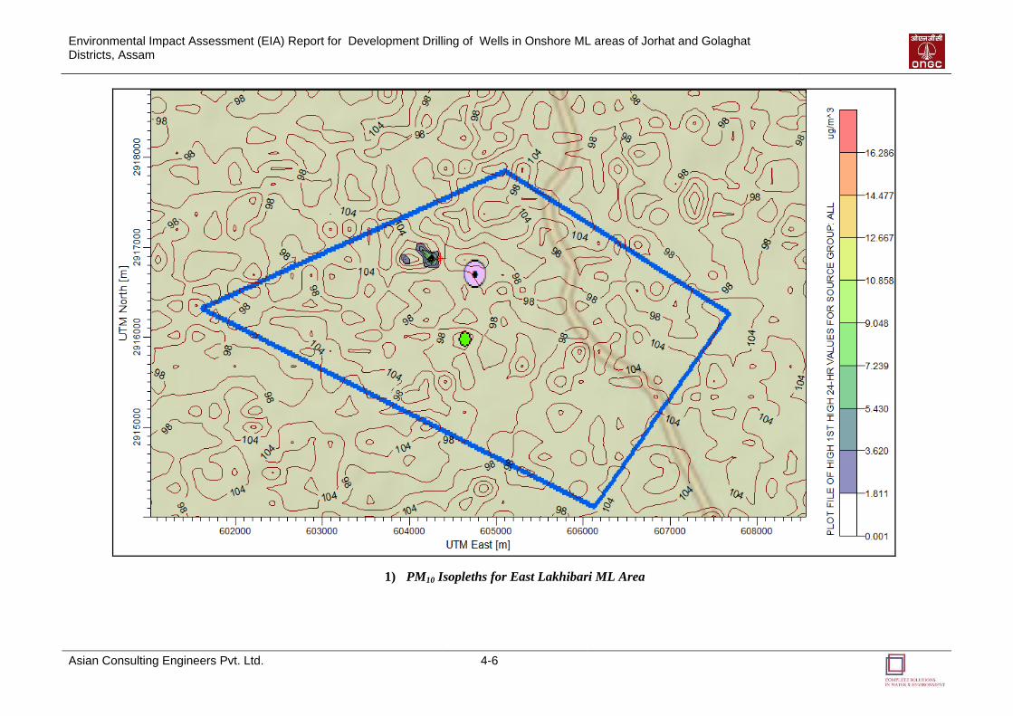
Environmental Impact Assessment (EIA) Report for Development Drilling of Wells in Onshore ML areas of Jorhat and Golaghat Districts, Assam
Asian Consulting Engineers Pvt. Ltd. 4-6
1) PM10 Isopleths for East Lakhibari ML Area
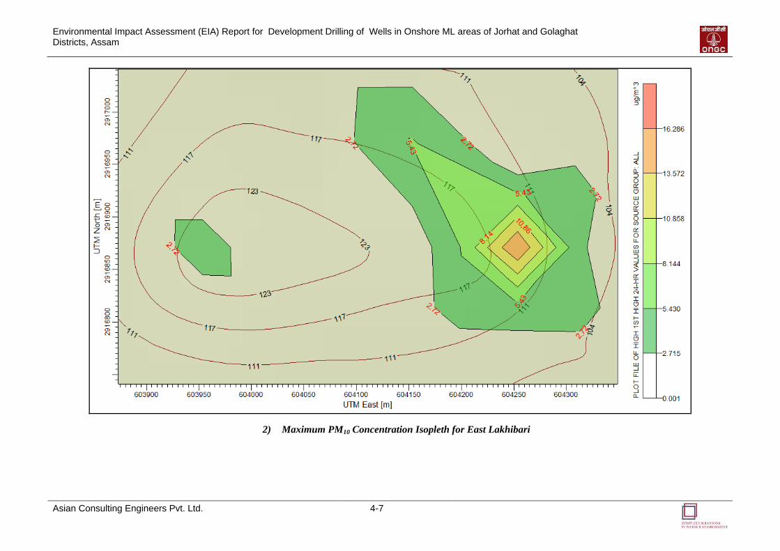
Environmental Impact Assessment (EIA) Report for Development Drilling of Wells in Onshore ML areas of Jorhat and Golaghat Districts, Assam
Asian Consulting Engineers Pvt. Ltd. 4-7
2) Maximum PM10 Concentration Isopleth for East Lakhibari
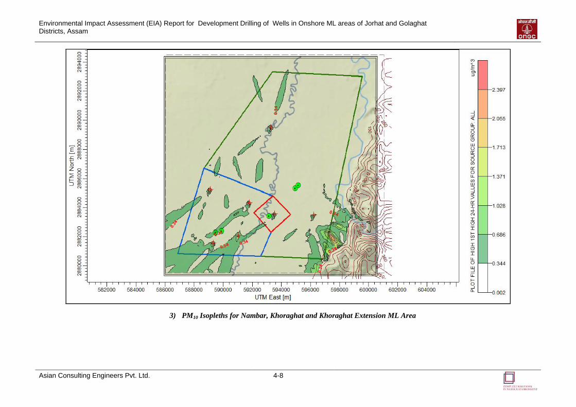
Environmental Impact Assessment (EIA) Report for Development Drilling of Wells in Onshore ML areas of Jorhat and Golaghat Districts, Assam
Asian Consulting Engineers Pvt. Ltd. 4-8
3) PM10 Isopleths for Nambar, Khoraghat and Khoraghat Extension ML Area
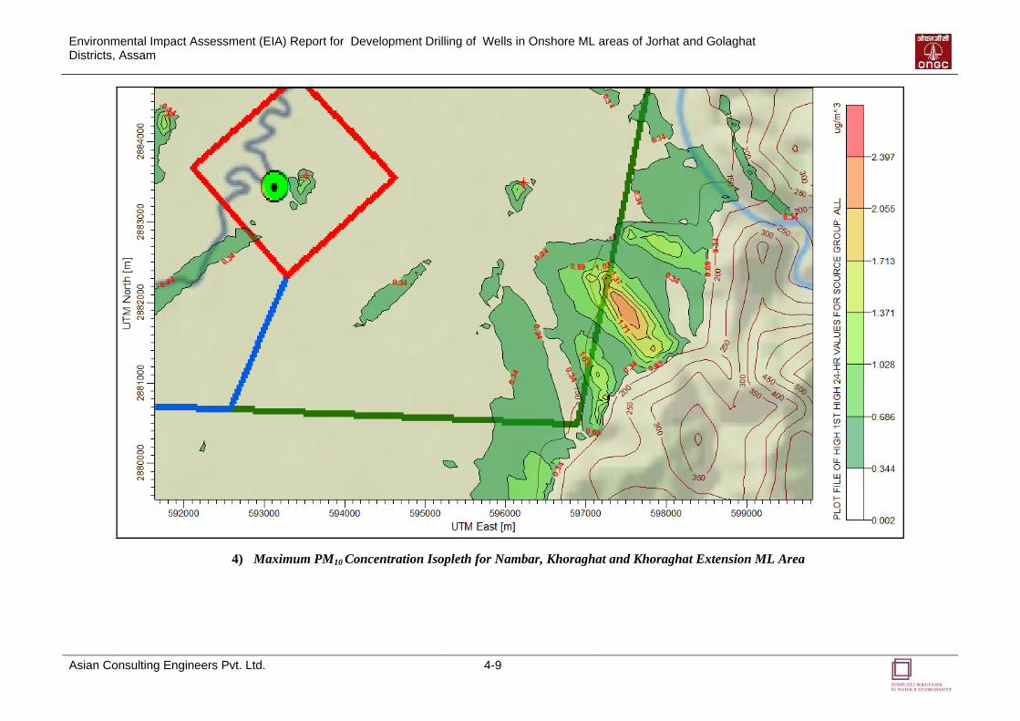
Environmental Impact Assessment (EIA) Report for Development Drilling of Wells in Onshore ML areas of Jorhat and Golaghat Districts, Assam
Asian Consulting Engineers Pvt. Ltd. 4-9
4) Maximum PM10 Concentration Isopleth for Nambar, Khoraghat and Khoraghat Extension ML Area
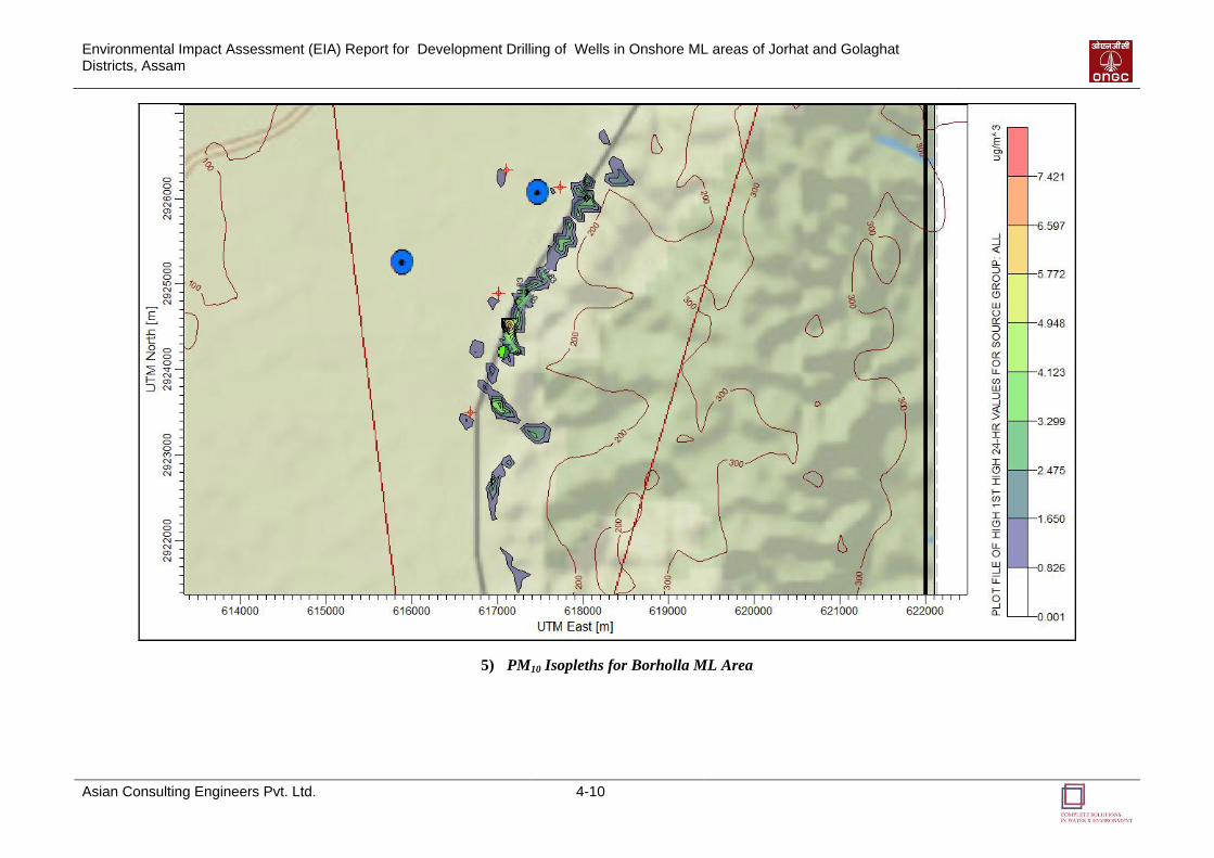
Environmental Impact Assessment (EIA) Report for Development Drilling of Wells in Onshore ML areas of Jorhat and Golaghat Districts, Assam
Asian Consulting Engineers Pvt. Ltd. 4-10
5) PM10 Isopleths for Borholla ML Area
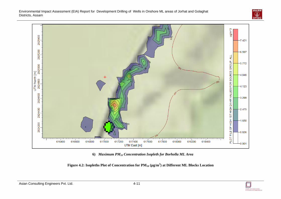
Environmental Impact Assessment (EIA) Report for Development Drilling of Wells in Onshore ML areas of Jorhat and Golaghat Districts, Assam
Asian Consulting Engineers Pvt. Ltd. 4-11
6) Maximum PM10 Concentration Isopleth for Borholla ML Area
Figure 4.2: Isopleths Plot of Concentration for PM10 (µg/m3) at Different ML Blocks Location
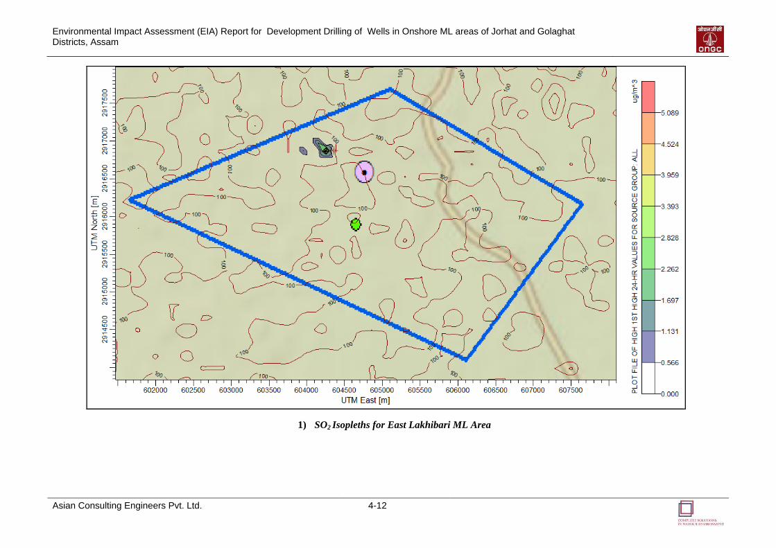
Environmental Impact Assessment (EIA) Report for Development Drilling of Wells in Onshore ML areas of Jorhat and Golaghat Districts, Assam
Asian Consulting Engineers Pvt. Ltd. 4-12
1) SO2 Isopleths for East Lakhibari ML Area
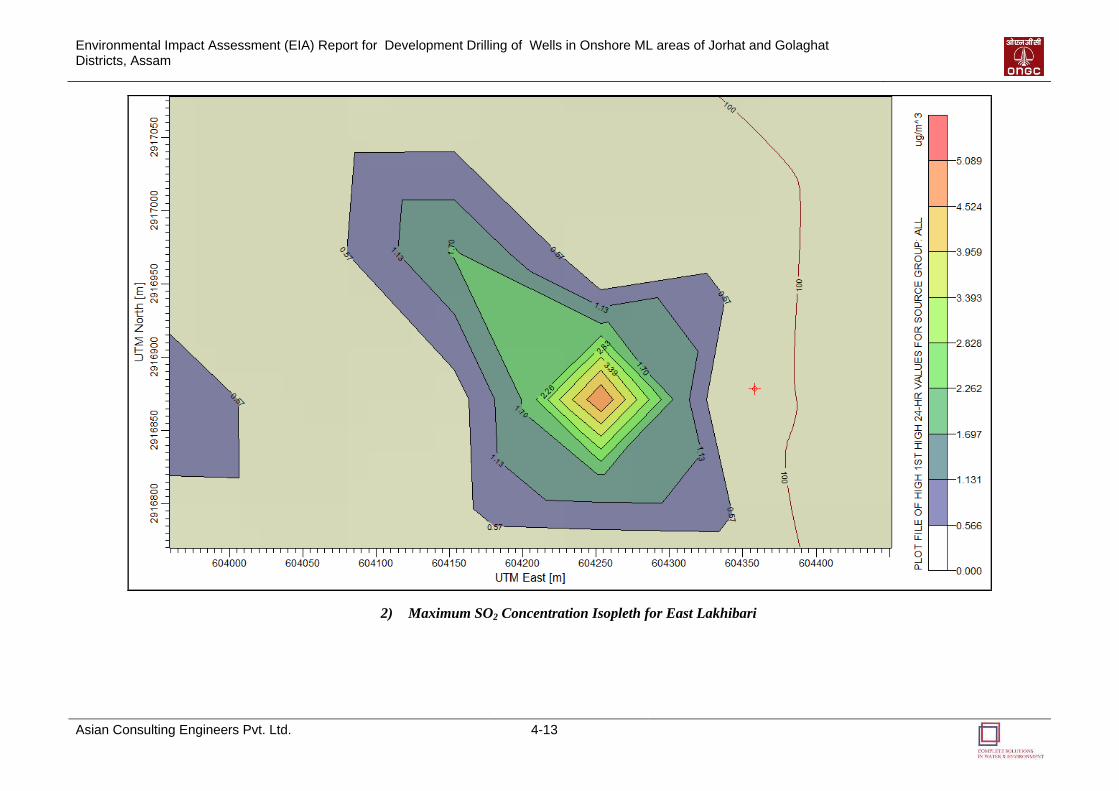
Environmental Impact Assessment (EIA) Report for Development Drilling of Wells in Onshore ML areas of Jorhat and Golaghat Districts, Assam
Asian Consulting Engineers Pvt. Ltd. 4-13
2) Maximum SO2 Concentration Isopleth for East Lakhibari
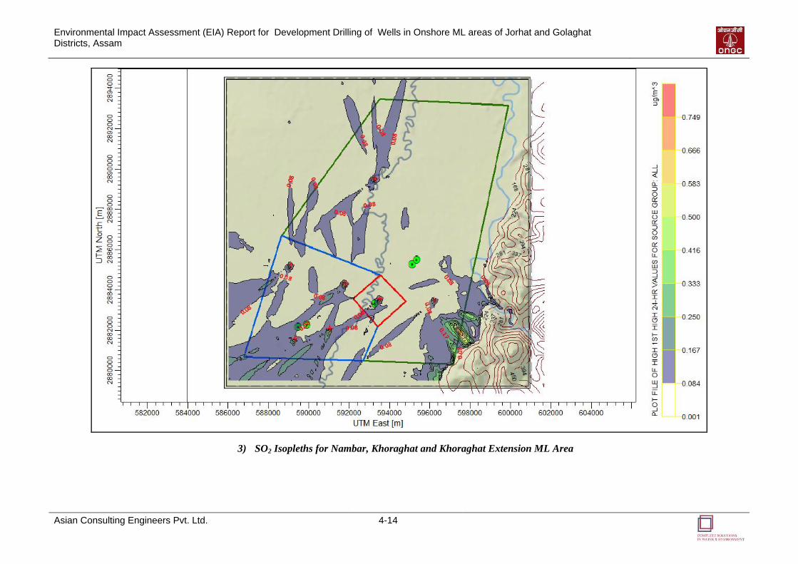
Environmental Impact Assessment (EIA) Report for Development Drilling of Wells in Onshore ML areas of Jorhat and Golaghat Districts, Assam
Asian Consulting Engineers Pvt. Ltd. 4-14
3) SO2 Isopleths for Nambar, Khoraghat and Khoraghat Extension ML Area
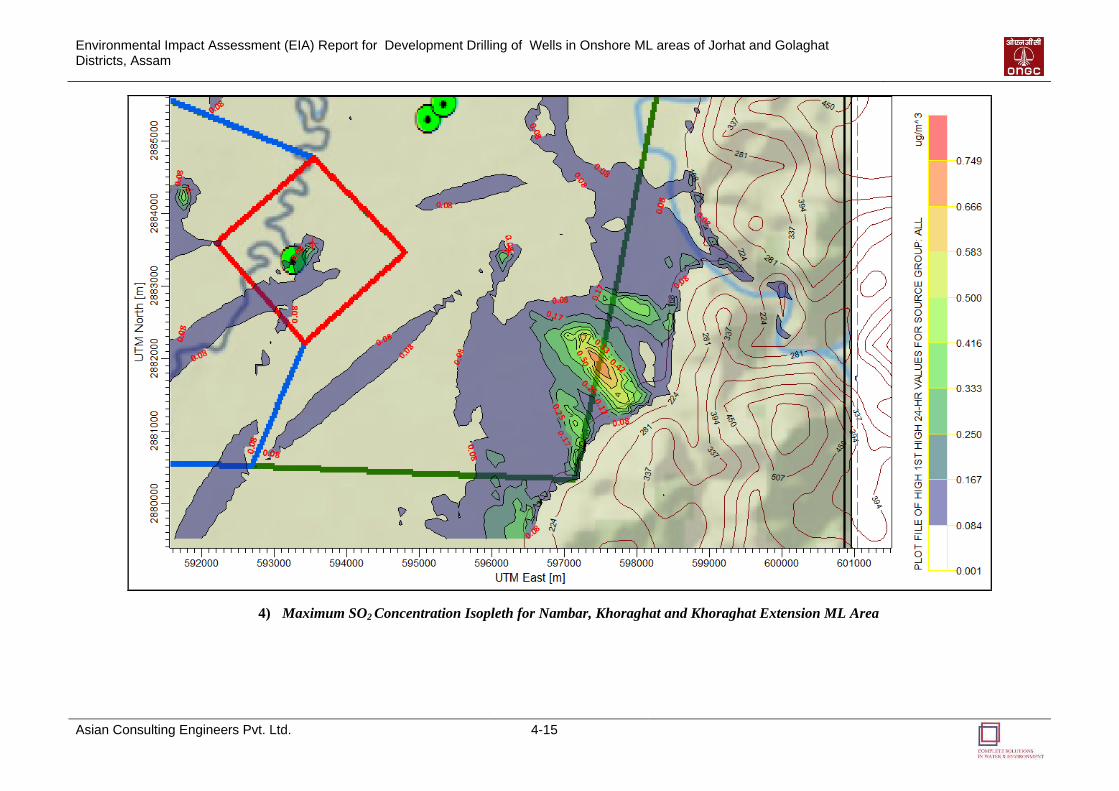
Environmental Impact Assessment (EIA) Report for Development Drilling of Wells in Onshore ML areas of Jorhat and Golaghat Districts, Assam
Asian Consulting Engineers Pvt. Ltd. 4-15
4) Maximum SO2 Concentration Isopleth for Nambar, Khoraghat and Khoraghat Extension ML Area
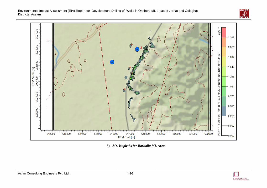
Environmental Impact Assessment (EIA) Report for Development Drilling of Wells in Onshore ML areas of Jorhat and Golaghat Districts, Assam
Asian Consulting Engineers Pvt. Ltd. 4-16
5) SO2 Isopleths for Borholla ML Area
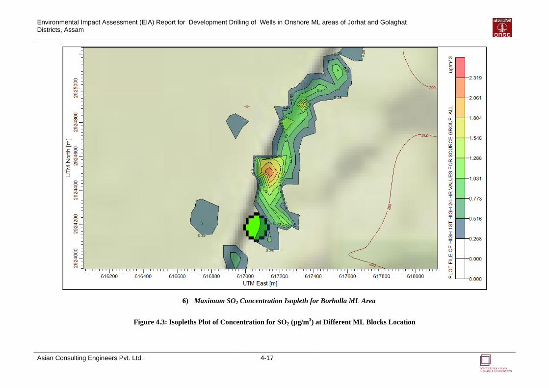
Environmental Impact Assessment (EIA) Report for Development Drilling of Wells in Onshore ML areas of Jorhat and Golaghat Districts, Assam
Asian Consulting Engineers Pvt. Ltd. 4-17
6) Maximum SO2 Concentration Isopleth for Borholla ML Area
Figure 4.3: Isopleths Plot of Concentration for SO2 (µg/m3) at Different ML Blocks Location
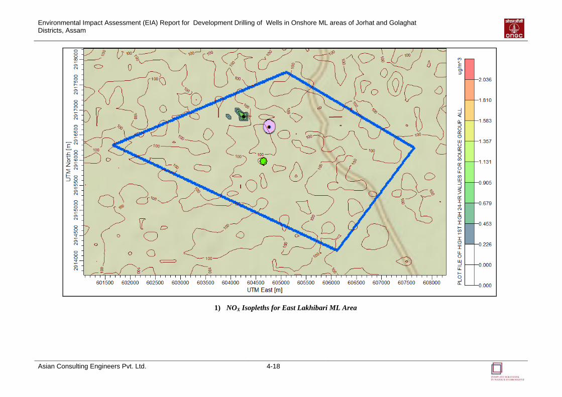
Environmental Impact Assessment (EIA) Report for Development Drilling of Wells in Onshore ML areas of Jorhat and Golaghat Districts, Assam
Asian Consulting Engineers Pvt. Ltd. 4-18
1) NOX Isopleths for East Lakhibari ML Area
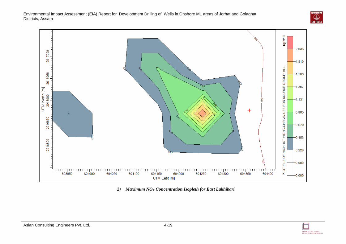
Environmental Impact Assessment (EIA) Report for Development Drilling of Wells in Onshore ML areas of Jorhat and Golaghat Districts, Assam
Asian Consulting Engineers Pvt. Ltd. 4-19
2) Maximum NOX Concentration Isopleth for East Lakhibari
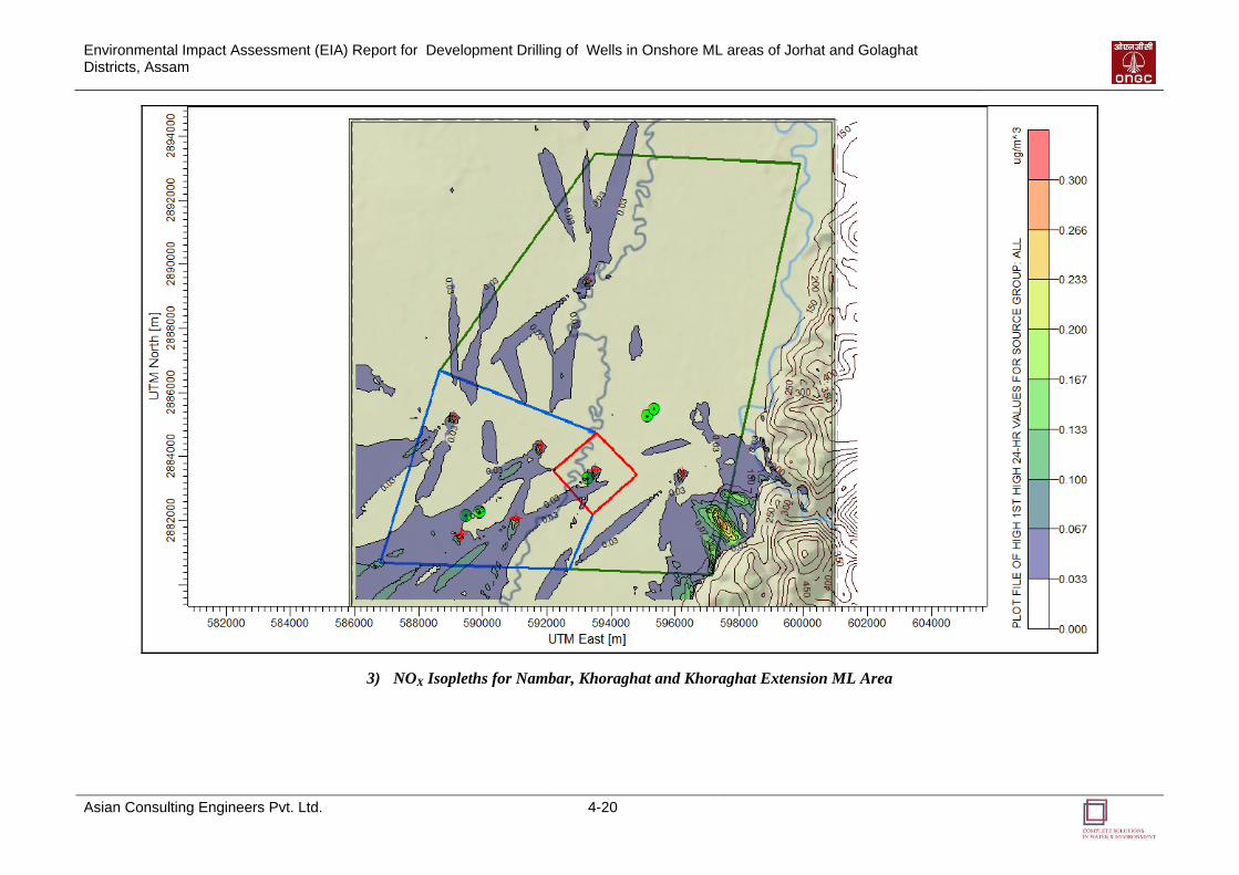
Environmental Impact Assessment (EIA) Report for Development Drilling of Wells in Onshore ML areas of Jorhat and Golaghat Districts, Assam
Asian Consulting Engineers Pvt. Ltd. 4-20
3) NOX Isopleths for Nambar, Khoraghat and Khoraghat Extension ML Area
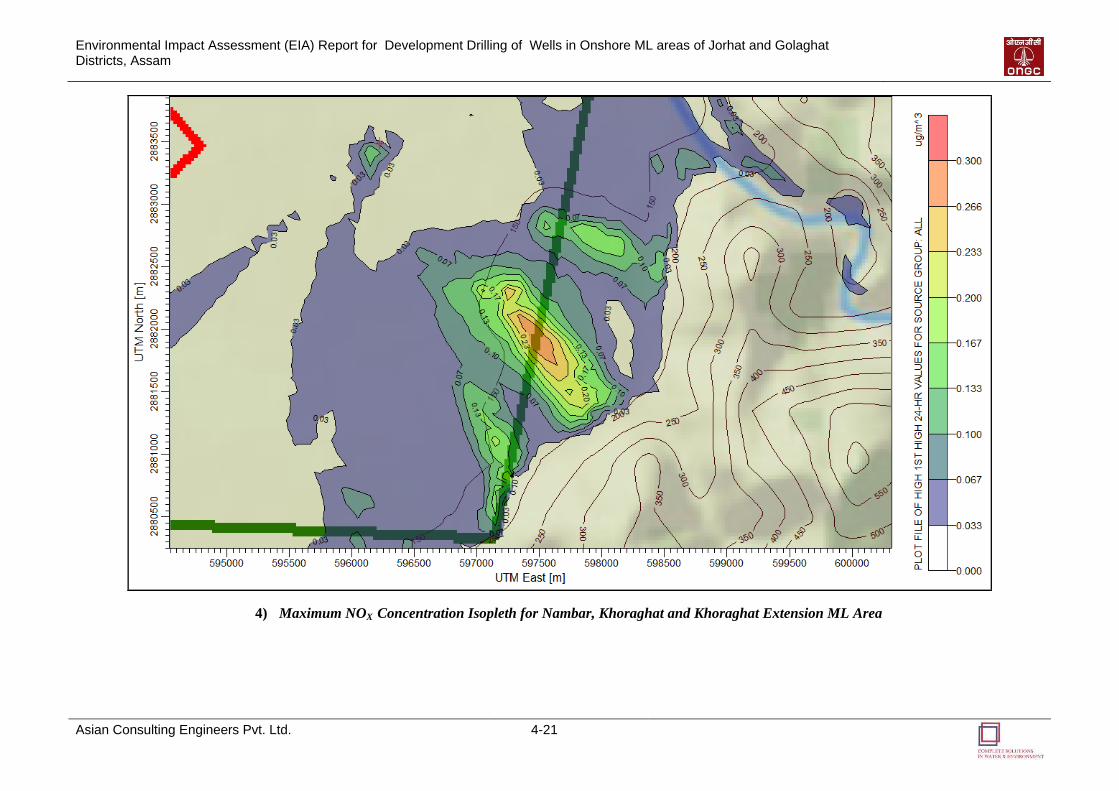
Environmental Impact Assessment (EIA) Report for Development Drilling of Wells in Onshore ML areas of Jorhat and Golaghat Districts, Assam
Asian Consulting Engineers Pvt. Ltd. 4-21
4) Maximum NOX Concentration Isopleth for Nambar, Khoraghat and Khoraghat Extension ML Area
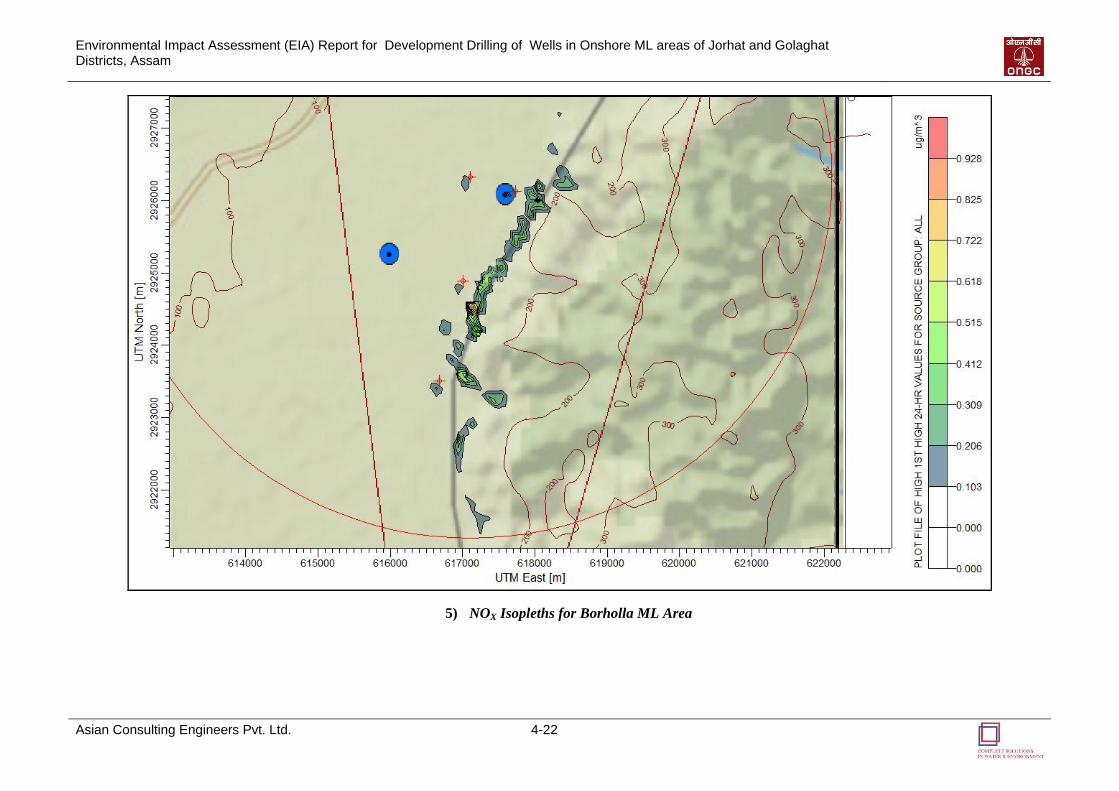
Environmental Impact Assessment (EIA) Report for Development Drilling of Wells in Onshore ML areas of Jorhat and Golaghat Districts, Assam
Asian Consulting Engineers Pvt. Ltd. 4-22
5) NOX Isopleths for Borholla ML Area

Environmental Impact Assessment (EIA) Report for Development Drilling of Wells in Onshore ML areas of Jorhat and Golaghat Districts, Assam
Asian Consulting Engineers Pvt. Ltd. 4-23
6) Maximum NOX Concentration Isopleth for Borholla ML Area
Figure 4.4: Isopleths Plot of Concentration for NOX (µg/m3) at Different ML Blocks Location
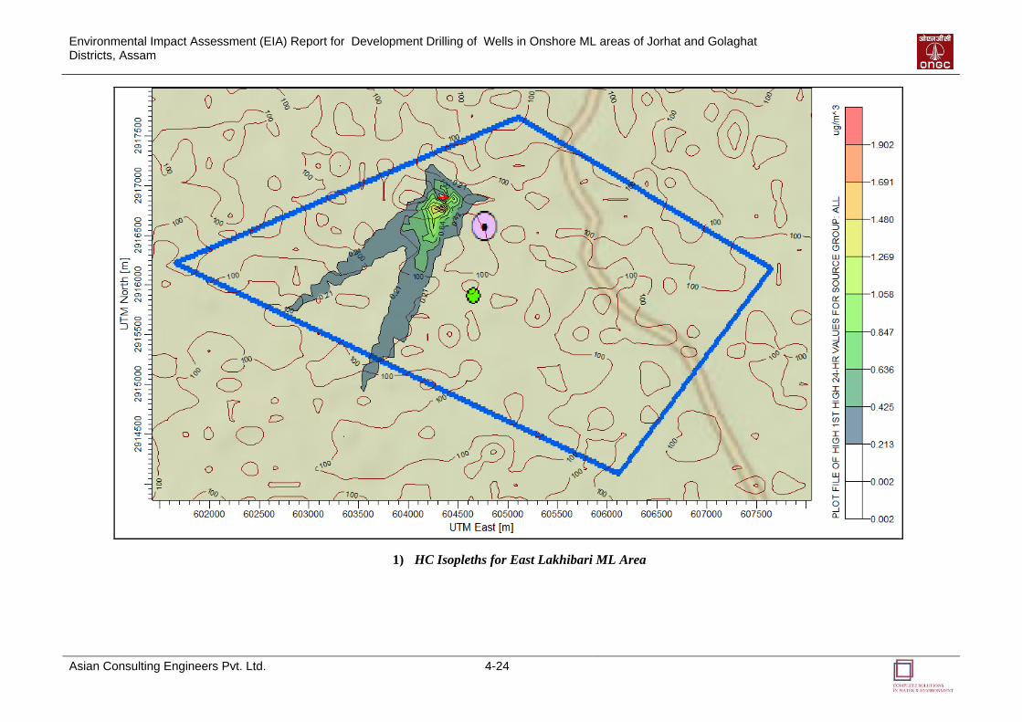
Environmental Impact Assessment (EIA) Report for Development Drilling of Wells in Onshore ML areas of Jorhat and Golaghat Districts, Assam
Asian Consulting Engineers Pvt. Ltd. 4-24
1) HC Isopleths for East Lakhibari ML Area
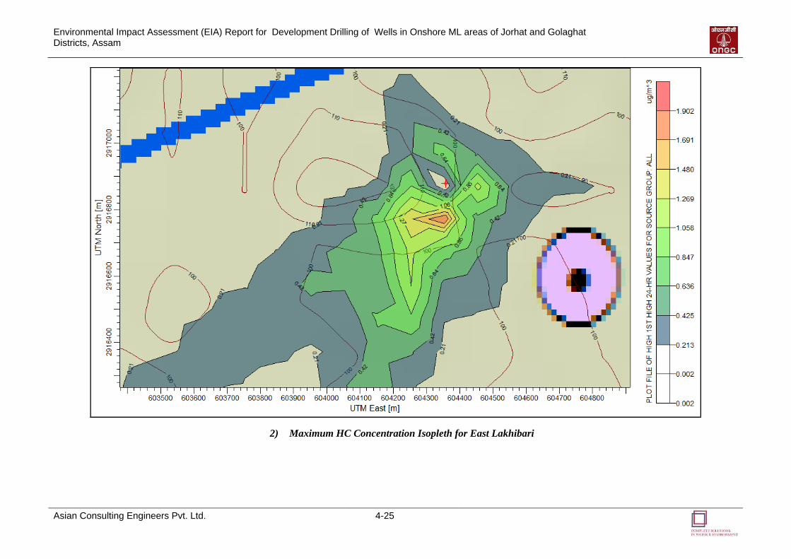
Environmental Impact Assessment (EIA) Report for Development Drilling of Wells in Onshore ML areas of Jorhat and Golaghat Districts, Assam
Asian Consulting Engineers Pvt. Ltd. 4-25
2) Maximum HC Concentration Isopleth for East Lakhibari
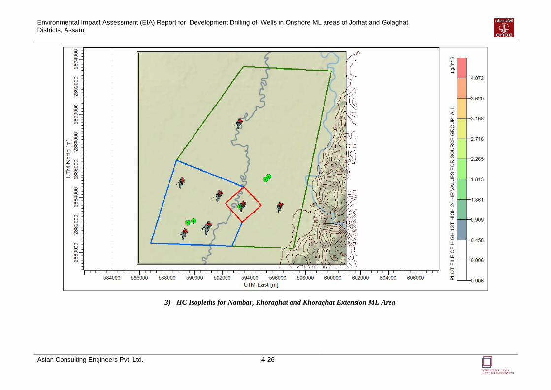
Environmental Impact Assessment (EIA) Report for Development Drilling of Wells in Onshore ML areas of Jorhat and Golaghat Districts, Assam
Asian Consulting Engineers Pvt. Ltd. 4-26
3) HC Isopleths for Nambar, Khoraghat and Khoraghat Extension ML Area
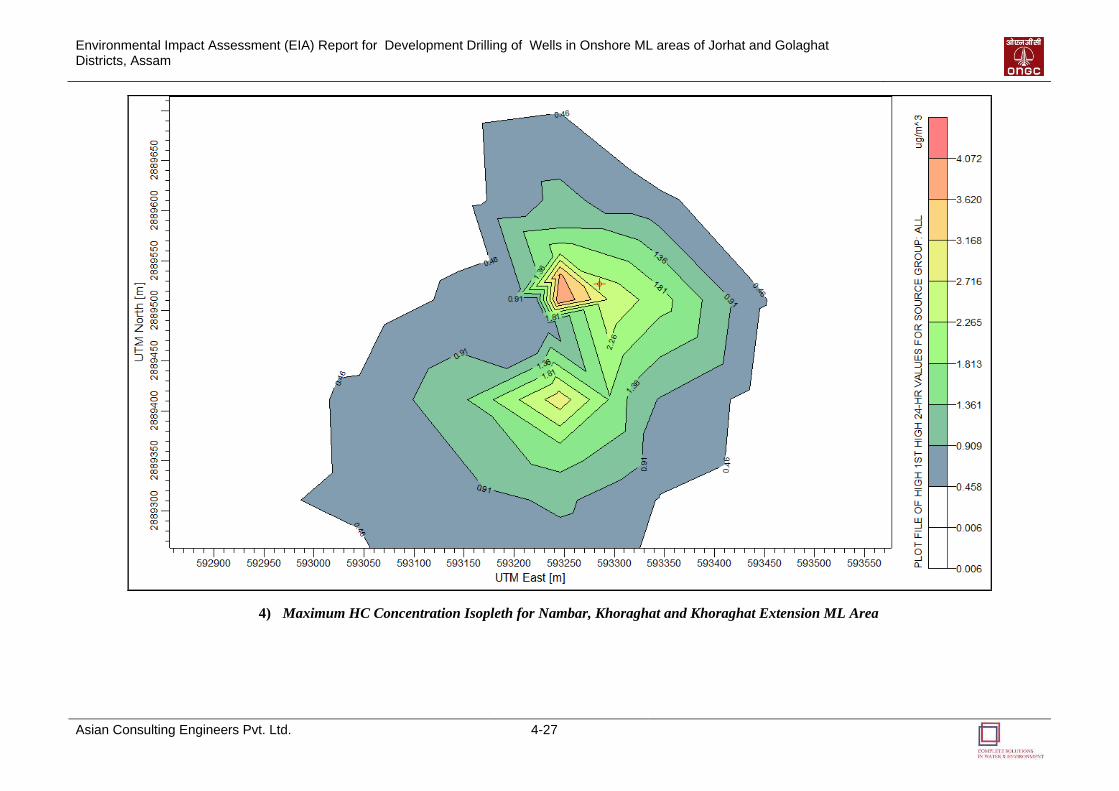
Environmental Impact Assessment (EIA) Report for Development Drilling of Wells in Onshore ML areas of Jorhat and Golaghat Districts, Assam
Asian Consulting Engineers Pvt. Ltd. 4-27
4) Maximum HC Concentration Isopleth for Nambar, Khoraghat and Khoraghat Extension ML Area

Environmental Impact Assessment (EIA) Report for Development Drilling of Wells in Onshore ML areas of Jorhat and Golaghat Districts, Assam
Asian Consulting Engineers Pvt. Ltd. 4-28
5) HC Isopleths for Borholla ML Area
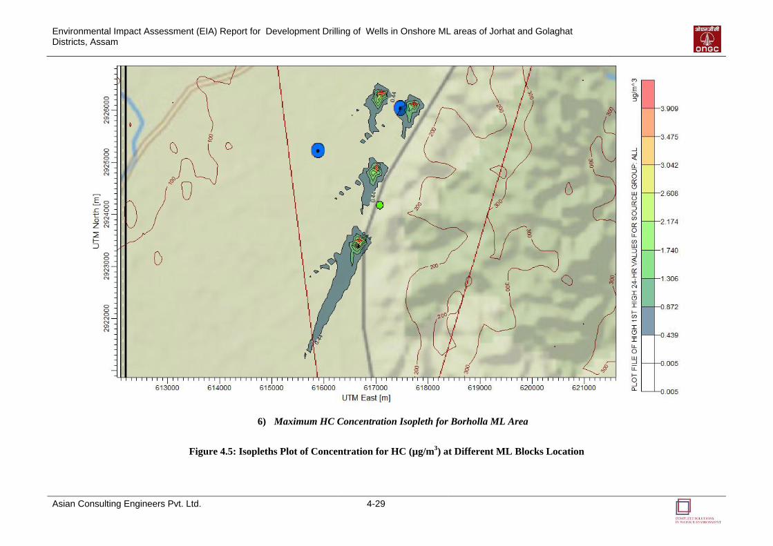
Environmental Impact Assessment (EIA) Report for Development Drilling of Wells in Onshore ML areas of Jorhat and Golaghat Districts, Assam
Asian Consulting Engineers Pvt. Ltd. 4-29
6) Maximum HC Concentration Isopleth for Borholla ML Area
Figure 4.5: Isopleths Plot of Concentration for HC (µg/m3) at Different ML Blocks Location
Environmental Impact Assessment (EIA) Report for Development Drilling of Wells in Onshore ML areas of Jorhat and Golaghat Districts, Assam
Asian Consulting Engineers Pvt. Ltd. 4-30
4.3.1.6 Discussion on Modeling Results
The predicted 24-hourly maximum incremental GLC for PM10 is found to be highest (about
78.486 g/m3) in East Lakhibari ML area. The GLC for SO2 is also found to be highest in this
area (about 11.039 g/m3). This may be due to the difference in elevation in the surrounding
areas, not allowing the pollutants to disperse spatially.
The GLC for NOx and HC are higher in the Nambar, Khoraghat and Khoraghat Extension ML
area. This may be due to concentration of the pollutants at the base of the sudden elevated
area, where the maximum concentrations are found. The elevations may restrict the flow of
pollutants further. Also the maximum concentrations are found in area with no settlements.
Referring to the background (monitored) ambient air quality, the mean baseline level when
added to the corresponding maximum predicted incremental GLC, the resultant levels of
PM10, SO2, NOx and HC at different receptor locations are found to be well within their
permissible standard limits pertaining to industrial, residential and rural areas.
4.3.1.7 Mitigation measures
The mitigation measures to control the impacts of air pollution are given below:
Water spraying will be done on the access roads to control re-entrained dust during dry
season.
Regular maintenance and servicing of heavy machineries and DG sets to avoid generation
of air pollutants due to un-optimal working condition of the machineries and DG sets will
be carried out. The stack height of the DG will be maintained as per the CPCB standards.
Mandate only PUC certified vehicles. Ensure vehicles used for transportation of loose
construction materials are covered and not overloaded over the free board limit
Plan in advance to ensure efficient operations.
Conduct regular monitoring of fuel consumption.
Use diesel with low Sulphur content.
Mandate wearing of dust masks for all workers working in and around dust generating
area
Only minimum volume of hydrocarbons required for the test should be flowed and well
test durations should be reduced to the extent practical. An efficient test flare burner head
equipped with an appropriate combustion enhancement system should be selected to
minimize incomplete combustion, black smoke, and hydrocarbon fallout. Volumes of
hydrocarbons flared should be recorded.
4.3.2 Noise and Vibrations
Noise will be generated during the construction and operational phase due to drilling, rotating
equipments, pumping, diesel generator sets, flaring, transportation etc.
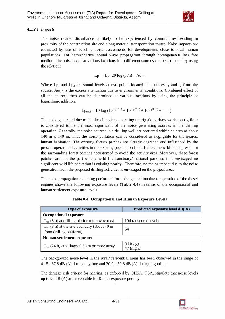
Environmental Impact Assessment (EIA) Report for Development Drilling of Wells in Onshore ML areas of Jorhat and Golaghat Districts, Assam
Asian Consulting Engineers Pvt. Ltd. 4-31
4.3.2.1 Impacts
The noise related disturbance is likely to be experienced by communities residing in
proximity of the construction site and along material transportation routes. Noise impacts are
estimated by use of baseline noise assessments for developments close to local human
populations. For hemispherical sound wave propagation through homogeneous loss free
medium, the noise levels at various locations from different sources can be estimated by using
the relation:
Lp2 = Lp1 20 log (r2/rl) – Ae1,2
Where Lp1 and Lp2 are sound levels at two points located at distances r1 and r2 from the
source. Ae1, 2 is the excess attenuation due to environmental conditions. Combined effect of
all the sources then can be determined at various locations by using the principle of
logarithmic addition:
Lptotal = 10 log (10(Lp1/10) + 10(Lp2/10) + 10(Lp3/10) + ………)
The noise generated due to the diesel engines operating the rig along draw works on rig floor
is considered to be the most significant of the noise generating sources in the drilling
operation. Generally, the noise sources in a drilling well are scattered within an area of about
140 m x 140 m. Thus the noise pollution can be considered as negligible for the nearest
human habitation. The existing forests patches are already degraded and influenced by the
present operational activities in the existing production field. Hence, the wild fauna present in
the surrounding forest patches accustomed to avoid the activity area. Moreover, these forest
patches are not the part of any wild life sanctuary/ national park, so it is envisaged no
significant wild life habitation is existing nearby. Therefore, no major impact due to the noise
generation from the proposed drilling activities is envisaged on the project area.
The noise propagation modeling performed for noise generation due to operation of the diesel
engines shows the following exposure levels (Table 4.4) in terms of the occupational and
human settlement exposure levels.
Table 0.4: Occupational and Human Exposure Levels
Type of exposure Predicted exposure level dB( A)
Occupational exposure
Leq (8 h) at drilling platform (draw works) 104 (at source level)
Leq (8 h) at the site boundary (about 40 m
from drilling platform) 64
Human settlement exposure
Leq (24 h) at villages 0.5 km or more away 54 (day)
47 (night)
The background noise level in the rural/ residential areas has been observed in the range of
41.5 - 67.8 dB (A) during daytime and 30.0 – 59.8 dB (A) during nighttime.
The damage risk criteria for hearing, as enforced by OHSA, USA, stipulate that noise levels
up to 90 dB (A) are acceptable for 8-hour exposure per day.
Environmental Impact Assessment (EIA) Report for Development Drilling of Wells in Onshore ML areas of Jorhat and Golaghat Districts, Assam
Asian Consulting Engineers Pvt. Ltd. 4-32
4.3.2.2 Mitigation measures
The mitigation measures for the aforementioned potential impacts are listed below:
The DG sets should be kept in acoustic enclosures.
The machineries and DG sets have to be serviced and maintained regularly to avoid
generation of unwanted noise and vibration.
The workers working in noisy environment will compulsorily wear ear muffs to protect
themselves from the impacts of high noise level.
The workers handling vibrating equipments will compulsorily wear viscoelastic anti-
vibration gloves.
Field-related vehicle traffic should be reduced as far as possible and access through local
communities should be avoided when not necessary.
4.3.3 Water Environment
Water is required for the construction, operation and maintenance of the development well.
All these activities generate wastewater including drilling waste water, gray and black water
from showers, toilets and kitchen facilities etc.
4.3.3.1 Impacts
About 25 kLD of water will be consumed during the drilling period per well. Wastewater
generate from the drilling activity is about 15-17 m3/day per well.
Around 3.4 kLD (80% of domestic water requirement, i.e. 04 kLD) is anticipated quantity of
sewage generation from each well. Runoff water from the drilling area might consist of
dissolved inorganic or organic compounds. Approximately 0.22 m3 per person/day and 0.11
m3 per person/day of grey water and black water respectively will be generated during the
project activity. Hazardous waste such as waste lube/system oil approximately 0.15 kL/well
from machinery, used oil from generator sets are likely to be generated. Approximately 225
m3 Drill Cuttings will be generated during drilling phase of wells.
An environment-friendly Water-Based Mud (WBM) system will be used for drilling of the
proposed wells. It may be noted that a typical WBM may contain nearly 80% water and 20%
Clay as well as Chemicals by weight. Thus this will have minimum impact on the water
environment.
The casing used in the development drilling prevents natural gas, oil, associated water from
leaking out into the surrounding freshwater aquifer. Thus a properly designed casing will
prevent impact on the surrounding water bodies.
Discharge of untreated sewage or effluent from drilling operation or run off, onto the land or
surface water body might contaminate the ground and surface water. This can in turn have
secondary impact on the flora, fauna and biodiversity of that area.
Surface runoff over drilling waste, chemical and fuel storage areas during rainfall may get
contaminated and impact the water quality.
Environmental Impact Assessment (EIA) Report for Development Drilling of Wells in Onshore ML areas of Jorhat and Golaghat Districts, Assam
Asian Consulting Engineers Pvt. Ltd. 4-33
4.3.3.2 Mitigation measures
Suitable and viable mitigation measures for the anticipated potential impacts on water
environment are presented below:
Install cuttings and fluid cleaning/treatment equipment to ensure optimal cleaning of
cuttings in order to reduce the amount of fluid that will be discharged with the cuttings.
Oily sludge will be collected and disposed by bio-remediation.
Hazardous wastes such as waste lube/system oil will be collected and sold to authorized
recycler.
Put in place management procedures to ensure optimal performance of the cuttings
cleaning equipment and proper housekeeping of shale shaker screen.
Well Casing will be done to protect ground water and shallow aquifers from
contamination.
Maintain a continuous drill fluid mass balance throughout the drilling program.
Optimize drilling well size to minimize the amount of rock to be drilled.
Drilling site constructed with garland system with Oil & Gas separator pit at one corner of
the site (having location above high flood level).
Proper treatment of the all wastewater produced will be carried out through Mobile
Effluent Treatment Plant to ensure compliance with criteria set by regulatory bodies.
4.3.4 Land Environment
Land is required for drilling pads, temporary storage facilities, drilling site accommodation,
construction of waste pits, access roads, equipment staging area, storage of construction
materials, transmission facilities etc. During all these construction and operation phases land
environment gets continuously impacted. Nearly 140x140 m of land will be required for each
drilling location.
4.3.4.1 Impacts
The following impacts are anticipated on the land environment due to the proposed drilling
operation:
Site clearance/preparation will result in removal/change of top soil.
Change in Land Use pattern will occur due to the construction activities.
Indiscriminate discharge of sewage/solid waste from the drilling activity will contaminate
the land
Accidental spillage from Storage of chemicals and fuels on unlined areas/unprotected
areas can cause land contamination.
Usage of heavy machineries and construction activities will lead to soil compaction
Environmental Impact Assessment (EIA) Report for Development Drilling of Wells in Onshore ML areas of Jorhat and Golaghat Districts, Assam
Asian Consulting Engineers Pvt. Ltd. 4-34
Improper decommissioning/ abandonment will lead to loss of aesthetics, deterioration in
soil quality and accidental hazards.
4.3.4.2 Mitigation measures
The following mitigation measures will aid in reduction of impacts on land:
The top soil removed during site clearance will be stored and preserved in a manner to
maintain its fertility and later used for restoration purpose.
Proper sanitation facilities and bins will be provided at the drilling location for collection
of sewage/solid waste.
The Sewage/Solid Wastes will be treated and disposed or sold to Authorized Recyclers as
per the Notification of MoEF (G.S.R.546 (E) dated 30th August 2005).
Ensuring proper storage of drill cutting and chemicals to prevent any potential
contamination from spillage.
Ensure well-designed storage facility with regular inventory checking for fuels, lubricants
and chemicals to prevent any potential contamination from spillage.
Restrict the Movement of Vehicles and Heavy Machinery to the paved area only.
Efforts to restore the drilling area back to its original condition should be made to the
extent possible during the decommissioning period.
4.3.5 Biological Environment
The three landuse maps conclude that majority of the area in the blocks of Nambar,
Khoraghat, Khoraghat Extension, and East Lakhibari includes open land and vegetation
cover. There is no open land in Borholla district and vegetation cover is high in this area.
Agriculture is also practiced in these areas, especially in Borholla and East Lakhibari ML
areas. No eco-sensitive or wild life sanctuary within the blocks area. No endangered species
were found within the study area. Common flora and wild fauna were observed in the study
area.
Impact on local flora and fauna may occur due to changes in habitat or habitat destruction due
to land clearance and preparation activities for proposed drilling site. However, this activity
shall be restricted to the limited land area and therefore the impact shall be local and minimal.
Emission of particulate matter during drilling activities is also likely to have impact on flora
and fauna. However, these impacts have been envisaged to be low as the drilling phase is a
temporary phase. To further reduce the impact of suspended particulate matter, the land shall
be sprayed with water during drilling activities. Impact on biological environment due to
emissions from movement of vehicles (transportation of construction materials), operation of
generators and other process have been envisaged to be negligible as suitable mitigation
measures (such as routine maintenance etc) shall be adopted to minimize the impacts from
these sources.
Noise generated from operation of equipments, machinery, generators and vehicles during
drilling have been envisaged to be negligible as the activity is for short duration of time and
suitable measures shall be adopted (such as use of noise attenuation devices) during drilling
and operation phase. Significant impacts on flora and fauna may occur due to dumping of
Environmental Impact Assessment (EIA) Report for Development Drilling of Wells in Onshore ML areas of Jorhat and Golaghat Districts, Assam
Asian Consulting Engineers Pvt. Ltd. 4-35
solid waste and wastewater discharges from drilling activities. However, these impacts shall
be minimized by adoption of waste management plan, wherein solid waste and wastewater
generated shall be subjected to appropriate treatment prior to their final disposal (such as
mobile effluent treatment plant).
4.3.6 Socio-Economic Environment
4.3.6.1 Impacts
The drilling activities are likely to have many beneficial outcomes and few impacts on the
existing socio-economic profile of the area:
The proposed activities will generate temporary employment opportunities to the local
people for road construction, site preparation, supply and transport of raw materials and
equipment, auxiliary and ancillary works, etc.
Construction of new roads and upgradation of existing roads to facilitate the movement of
the heavy equipments and vehicles would lead to improvement in transport facilities in
the area.
There will not be major influx of people, as only 25 – 30 people will be employed per
well per shift with two shifts in a day. Hence, the impact due to influx of people will be
insignificant.
The activities would also result in enhancement of local skill levels through exposure to
drilling activities and technology and will help in capacity building for future
employment opportunities.
There can be occupational hazards such as personal injuries, accidents during installation
and operation of drilling rigs. However, block operator will follow stringent health, safety
and environment practices as per Mines Act, 1952 and OISD guideline for all its
operations, which are to be followed by all employees, consultants and contractors
working for this development project.
Community health and safety may get impacted due to various pollution generating
activities of the proposed project. However, the proponent will ensure compliance to all
the applicable laws, rules, regulations, acts and standards to have minimum pollution
footprint. Also, development drilling being a temporary activity, this impact will be of
temporary nature and of low significance.
4.3.6.2 Mitigation measures
The following mitigation measures are proposed for augmenting the socio-economic benefits:
ONGC will implement Waste Management Plan and undertake water quality monitoring
before, during and after the operations.
ONGC is already undertaking Corporate Social Responsibility (CSR) activities in the
form of monetary help for education, infrastructural development, sports, culture and
orphanages, preferably to girl children, destitute women and senior citizens in the vicinity
of operational area. The same will be followed for the proposed project as well.
55
EENNVVIIRROONNMMEENNTTAALL
MMOONNIITTOORRIINNGG
PPRROOGGRRAAMM
Environmental Impact Assessment (EIA) Report for Development Drilling of Wells in Onshore ML areas of Jorhat and Golaghat Districts, Assam
Asian Consulting Engineers Pvt. Ltd. 5-1
ENVIRONMENTAL
MONITORING PROGRAM
5.1 INTRODUCTION
An environmental monitoring plan provides a delivery mechanism to address the adverse
environmental impacts of a project during its execution, to enhance project benefits, and to
introduce standards of good practice to be adopted for all project works. An environmental
monitoring program is important as it provides useful information and helps to:
Assist in detecting the development of any unwanted environmental situation, and thus,
provides opportunities for adopting appropriate control measures;
Define the responsibilities of the project proponents, contractors and environmental
monitors and provides means of effectively communicating environmental issues among
them;
Define monitoring mechanism and identify monitoring parameters;
Evaluate the performance and effectiveness of mitigation measures proposed in the
Environment Management Plan (EMP) and suggest improvements in management plan, if
required;
Identify training requirement at various levels.
An environmental monitoring program is suggested to monitor environmental parameters
during survey, drilling and Post Drilling Phase of the project. The monitoring plan is given in
Table 5.1, Table 5.2 and Table 5.3 below. This environment monitoring plan is designed for
ten years.
5
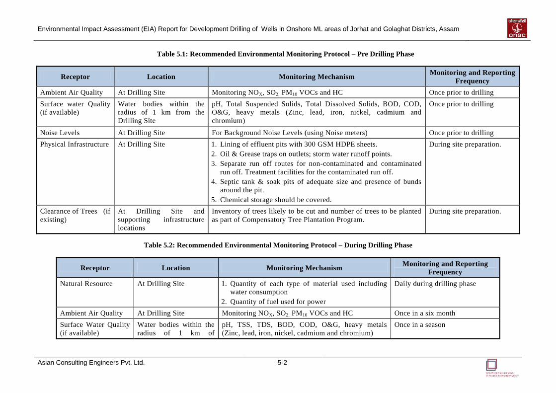
Environmental Impact Assessment (EIA) Report for Development Drilling of Wells in Onshore ML areas of Jorhat and Golaghat Districts, Assam
Asian Consulting Engineers Pvt. Ltd. 5-2
Table 5.1: Recommended Environmental Monitoring Protocol – Pre Drilling Phase
Receptor Location Monitoring Mechanism Monitoring and Reporting
Frequency
Ambient Air Quality At Drilling Site Monitoring NOX, SO2, PM10 VOCs and HC Once prior to drilling
Surface water Quality
(if available)
Water bodies within the
radius of 1 km from the
Drilling Site
pH, Total Suspended Solids, Total Dissolved Solids, BOD, COD,
O&G, heavy metals (Zinc, lead, iron, nickel, cadmium and
chromium)
Once prior to drilling
Noise Levels At Drilling Site For Background Noise Levels (using Noise meters) Once prior to drilling
Physical Infrastructure
At Drilling Site 1. Lining of effluent pits with 300 GSM HDPE sheets.
2. Oil & Grease traps on outlets; storm water runoff points.
3. Separate run off routes for non-contaminated and contaminated
run off. Treatment facilities for the contaminated run off.
4. Septic tank & soak pits of adequate size and presence of bunds
around the pit.
5. Chemical storage should be covered.
During site preparation.
Clearance of Trees (if
existing)
At Drilling Site and
supporting infrastructure
locations
Inventory of trees likely to be cut and number of trees to be planted
as part of Compensatory Tree Plantation Program.
During site preparation.
Table 5.2: Recommended Environmental Monitoring Protocol – During Drilling Phase
Receptor Location Monitoring Mechanism Monitoring and Reporting
Frequency
Natural Resource At Drilling Site 1. Quantity of each type of material used including
water consumption
2. Quantity of fuel used for power
Daily during drilling phase
Ambient Air Quality At Drilling Site Monitoring NOX, SO2, PM10 VOCs and HC Once in a six month
Surface Water Quality
(if available)
Water bodies within the
radius of 1 km of
pH, TSS, TDS, BOD, COD, O&G, heavy metals
(Zinc, lead, iron, nickel, cadmium and chromium)
Once in a season

Environmental Impact Assessment (EIA) Report for Development Drilling of Wells in Onshore ML areas of Jorhat and Golaghat Districts, Assam
Asian Consulting Engineers Pvt. Ltd. 5-3
Receptor Location Monitoring Mechanism Monitoring and Reporting
Frequency
Drilling Site that will be
utilized for consumption
and disposal.
Noise & Vibration
At Drilling Site, near DG
sets and drilling pumps.
1. Noise level monitoring
2. Maintenance of machineries
3. No unnecessary operation of machinery when not
required
4. Use of ear plug by workforce
5. Presence of sound barriers or acoustic enclosure
around DG sets.
Once in a month
Drilling wastes At Drilling Site 1. Drill cuttings wash water: its quantification,
characteristics (TSS, TDS, organic compounds,
heavy metals, oil & grease), its treatment and safe
disposal.
2. Spent drilling fluid: its treatment and reuse.
3. Maintenance of effluent pits, drill cutting storage
pit and waste mud pit.
Quantity of wastes to be
recorded on daily basis.
Characterization of the waste to
be done every month.
Wastewater
Generation
At Drilling Site Waste water generation rate. Quantity to be recorded every
day.
Oil wastes At Drilling Site Spent oil from engines.
A logbook should be maintained
daily during drilling phase. If no
spent oil is produced, the same
should be noted in the logbook.
Oil Spills At Drilling Site Facilities oil spill contingency plan should be in
place.
During drilling phase
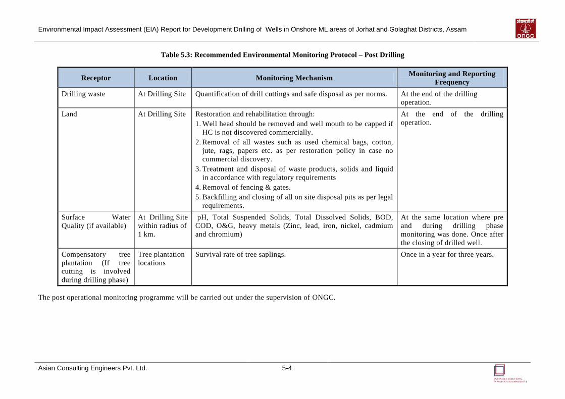
Environmental Impact Assessment (EIA) Report for Development Drilling of Wells in Onshore ML areas of Jorhat and Golaghat Districts, Assam
Asian Consulting Engineers Pvt. Ltd. 5-4
Table 5.3: Recommended Environmental Monitoring Protocol – Post Drilling
Receptor Location Monitoring Mechanism Monitoring and Reporting
Frequency
Drilling waste At Drilling Site Quantification of drill cuttings and safe disposal as per norms. At the end of the drilling
operation.
Land At Drilling Site Restoration and rehabilitation through:
1. Well head should be removed and well mouth to be capped if
HC is not discovered commercially.
2. Removal of all wastes such as used chemical bags, cotton,
jute, rags, papers etc. as per restoration policy in case no
commercial discovery.
3. Treatment and disposal of waste products, solids and liquid
in accordance with regulatory requirements
4. Removal of fencing & gates.
5. Backfilling and closing of all on site disposal pits as per legal
requirements.
At the end of the drilling
operation.
Surface Water
Quality (if available)
At Drilling Site
within radius of
1 km.
pH, Total Suspended Solids, Total Dissolved Solids, BOD,
COD, O&G, heavy metals (Zinc, lead, iron, nickel, cadmium
and chromium)
At the same location where pre
and during drilling phase
monitoring was done. Once after
the closing of drilled well.
Compensatory tree
plantation (If tree
cutting is involved
during drilling phase)
Tree plantation
locations
Survival rate of tree saplings. Once in a year for three years.
The post operational monitoring programme will be carried out under the supervision of ONGC.

66
AADDDDIITTIIOONNAALL
SSTTUUDDIIEESS
Environmental Impact Assessment (EIA) Report for Development Drilling of Wells in Onshore ML areas of Jorhat and Golaghat Districts, Assam
Asian Consulting Engineers Pvt. Ltd. 6-1
6 ADDITIONAL STUDIES
6.1 INTRODUCTION
As discussed in earlier chapters, ONGC proposes to conduct Development Drilling in
Nambar, Khoraghat, Khoraghat Extension and East Lakhibari ML areas in Golaghat district
and Borholla ML area in Jorhat district of Assam State. This chapter elucidates the Risk
Assessment (RA), Disaster Management Plan (DMP) and Emergency Response Plan (ERP)
for the proposed development wells.
6.2 RISK ASSESSMENT
„Risk Assessment (RA)‟ also known as „Hazard Analysis‟ and „Vulnerability Assessment‟ is
a procedure for identifying hazards and determining their possible effects on a community
and environment. Risk or hazard by itself is not an event - it is the potential for an event.
Drilling rig floor is the centre stage of all the drilling operations and it is most susceptible to
accidents. Safety precaution with utmost care is required to be taken during drilling as per the
prevailing regulations and practices so that accidents can be avoided. Due to advancement in
technology, number of equipments has been developed over a period to cater the need of
smooth operation on a rig floor. Various standards are required to be referred to cover the
variety of equipments used for safe operation in drilling and it is desirable to use a properly
prepared manual for occupational safety while working or drilling over a rig. It may,
however, be noted that well testing and production testing of hydrocarbons also require proper
analysis of hazards involved in production testing operations and preparation of an
appropriate Emergency Control Plan.
Hydrocarbon Operations are generally hazardous in nature by virtue of intrinsic chemical
properties of hydrocarbons or their temperature or pressure of operation or a combination of
them. Fire, Explosion, Hazardous Release or a combination of these are the hazard associated
with Hydrocarbon Operations.
Risk Screening
Some of the hazards associated with the drilling are:
Fires and Explosions:
o Non-Process Hydrocarbon Leak (Diesel, Fuel, Oil etc.);
o Non-Process Fire;
o Control system failure including electrical failure in control room.
Impact and Collisions:
o Accidental Falling of Object from Crown Block.
Loss of Station Keeping / Loss of Stability:
o Structural Failure;
o Equipment Failure.
6
Environmental Impact Assessment (EIA) Report for Development Drilling of Wells in Onshore ML areas of Jorhat and Golaghat Districts, Assam
Asian Consulting Engineers Pvt. Ltd. 6-2
External Hazards:
o Failure due to Earthquake, Extreme Weather, Strong Winds, Floods and Sabotage etc.
The primary emphasis in Safety Engineering is to reduce Risk to Human Life and
Environment. Some of the more important methods used to achieve this are:
Risk Analysis: Provides a relative measure of the likelihood and severity of various
possible hazardous events by critically examining the proposed drilling and associated
activities.
Work Safety Analysis: The technique discerns whether the project site and operating
procedures in practice have any inherent infirmities.
Safety Audit: Takes a careful look at operating conditions, work practices and work
environments to detect unsafe conditions
Together, these three broad tools attempt to minimize the chances of accidents occurring. Yet,
there always exists, no matter how remote, that Small Probability of a Major Accident
occurring. If the accident involves hydrocarbon in sufficient large quantities, the
consequences may be serious to the project, to surrounding area and the population therein.
These have resulted in the development of more comprehensive, systematic and sophisticated
methods of Safety Engineering such as Identification and Analysis of Hazards and Risk
Assessment to improve upon the Integrity, Reliability and Safety of Hydrocarbon Operations.
6.2.1 Methodology
The RA studies are based on Quantitative Risk Assessment Analysis (QRA). QRA aims to
provide a systematic analysis of the major risks that may arise as a result of onshore drilling
activities. Normally a three „levels‟ risk assessment approach is adopted for the industrial
activities. The brief outline of the three tier approach is given below:
A) Level 1 – Risk Screening
This is Top-Down Review of Worst- Case Potential Hazards/Risks, aimed primarily at
identifying drilling sites or areas within Blocks, which pose the Highest Risk. Various
screening factors considered, include:
Inventory of Hazardous Materials;
Hazardous Material Properties;
Storage Conditions (e.g. Temperature and pressure);
Location Sensitivity (Distance to Residential Areas / Populace).
The Data/Information is obtained from Site. The results provide a relative indication of the
extent of hazards and Potential for Risk Exposure.
B) Level 2 – Major Risk Survey (Semi - Quantitative)
The survey approach combines the Site Inspection with established Risk Assessment
Techniques applied both Qualitative as well Quantitative Mode. The primary objective is to
identify and select Major Risks at a specific location in the drilling site considering possible
soft spots / weak links during construction/operation/maintenance. Aspects covered in the risk
usually include:
Environmental Impact Assessment (EIA) Report for Development Drilling of Wells in Onshore ML areas of Jorhat and Golaghat Districts, Assam
Asian Consulting Engineers Pvt. Ltd. 6-3
Process Hazards;
Process Safety Management Systems;
Fire Protection and Emergency Response Equipments and Programs;
Security Vulnerability;
Impact of Hazards Consequences (Equipment Damage, Business Interruption, Injury,
Fatalities);
Qualitative Risk Identification of Scenarios Involving Hazardous Materials.
Risk Reduction Measures
Selection of critical scenarios and their potential of damage provide means of prioritizing
mitigation measures and allocation of resources to the areas with Highest Risks.
C) Level 3 – Quantitative Risk Assessment (Deterministic)
This is the stage of assessment of risks, associated with all Credible Hazards (scenarios) with
potential to cause an undesirable outcome such as Human Injury, Fatality or Destruction of
Property. The four basic elements include:
Hazards Identification utilizing formal approach (Level 2, HAZOP etc.);
Frequency Analysis: Based on past Safety Data (incidents / accidents), identifying likely
pathway of failures and quantifying the toxic / inflammable material release;
Hazards Analysis to quantify the consequences of various hazards scenarios (Fire,
Explosion [due to release of NG], Toxic Vapour Release [due to release of H2S] etc.).
Establish minimum value for damage (e.g. IDLH, Over Pressure, Radiation Flux) to
assess the Impact on Environment.
Risk Quantification: Quantitative techniques are used considering effect / impact due to
weather data, population data, and frequency of occurrences and likelihood of Ignition /
Toxic release. Data are analyzed considering likely Damage (in terms of Injury / Fatality,
Property Damage) each scenario is likely to cause.
QRA provides a means to determine the relative significance of each undesired event,
allowing analyst and the team to focus on their Risk Reduction Efforts, which will be most
beneficial.
6.2.2 Identification of Hazards in Drilling and Production Testing Operations
Various hazards associated with onshore hydrocarbon drilling and testing operations are
briefly described in following sub-sections.
6.2.2.1 Minor Oil Spill
There exists a possibility of Hydrocarbon (gases / oil) getting released due to some
unavoidable incidents during the Drill Stem Testing. Spillage may occur from lines, valves
and separator or due to tank failure. Once the flow of Oil / Gas from well is stopped, then on-
site access for clean-up is possible.
Environmental Impact Assessment (EIA) Report for Development Drilling of Wells in Onshore ML areas of Jorhat and Golaghat Districts, Assam
Asian Consulting Engineers Pvt. Ltd. 6-4
6.2.2.2 Major Oil Spill
A major spill can arise as a result of an uncontrolled flow from a well i.e. Blowout. Provided
that ignition does not take place and the well head is not obstructed the well can be shut in at
the wellhead.
6.2.2.3 Blowout
Blowout means uncontrolled violent escape of hydrocarbon fluids from a well. Blowout
followed by ignition prevents access to the wellhead and is categorized as a major hazard.
Contributors to blowout are:
Primary
Failure to keep the hole full;
Mud weight too low;
Swabbing during trips;
Lost circulation; and
Failure of differential fill-up equipment.
Secondary
Failure to detect and control a kick as quickly as possible;
Mechanical failure of BOP;
Failure to test BOP equipment properly;
Damage to or failure of wellhead equipment;
Failure of casing; and
Failure of formation or bond of cementing around casing.
If the hydrostatic head exerted by the column of drilling fluid is allowed to drop below the
formation pressure, then formation fluids will enter the wellbore (this is known as a kick) and
can lead to a potential blowout situation. Fast and efficient action by operating personnel in
recognizing the above situations and taking precautionary measure can avert a blowout.
6.2.2.4 Hydrogen Sulphide (H2S)
Hydrogen sulphide gas (H2S) is extremely toxic, even very low concentrations can be lethal,
depending upon the duration of exposure. Without any warning, H2S may render victims
unconscious and death can follow shortly afterwards.
The Occupational Safety and Health Act (OSHA Regulations) set a 20 ppm ceiling limit and a
Peak exposure of 50 ppm for 10 minutes exposure. It has also set a TWA limit of 10 ppm for
an eight hourly continuous exposure and 15 ppm STEL limit for 15 minutes (OSHA, 1989).
Important characteristics of H2S gas are given as below:
H2S is a colourless gas heavier than air and may accumulate in low lying areas
It is toxic even in low concentrations
It has an odour of rotten eggs and may cause loss of sense to smell.
It occurs together with natural gas in all oil provinces of the world. In characteristic H2S
gas areas concentration above 42% in natural gas have been reported.
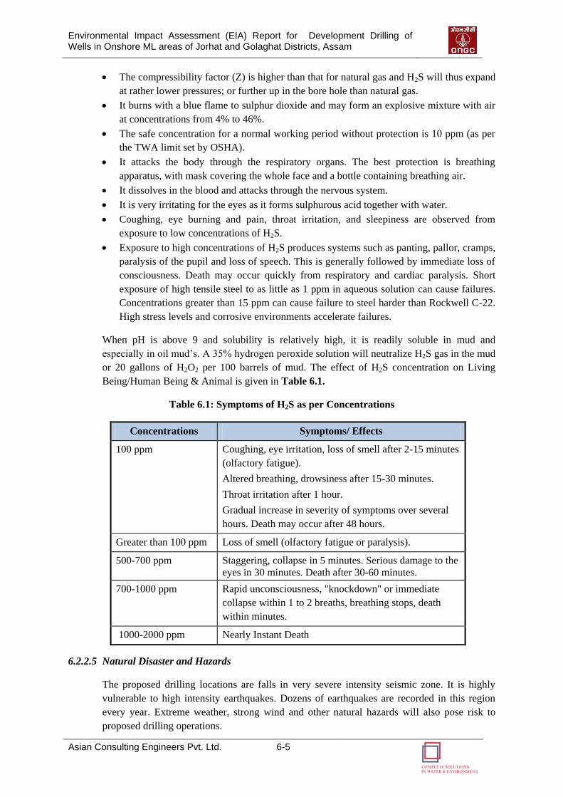
Environmental Impact Assessment (EIA) Report for Development Drilling of Wells in Onshore ML areas of Jorhat and Golaghat Districts, Assam
Asian Consulting Engineers Pvt. Ltd. 6-5
The compressibility factor (Z) is higher than that for natural gas and H2S will thus expand
at rather lower pressures; or further up in the bore hole than natural gas.
It burns with a blue flame to sulphur dioxide and may form an explosive mixture with air
at concentrations from 4% to 46%.
The safe concentration for a normal working period without protection is 10 ppm (as per
the TWA limit set by OSHA).
It attacks the body through the respiratory organs. The best protection is breathing
apparatus, with mask covering the whole face and a bottle containing breathing air.
It dissolves in the blood and attacks through the nervous system.
It is very irritating for the eyes as it forms sulphurous acid together with water.
Coughing, eye burning and pain, throat irritation, and sleepiness are observed from
exposure to low concentrations of H2S.
Exposure to high concentrations of H2S produces systems such as panting, pallor, cramps,
paralysis of the pupil and loss of speech. This is generally followed by immediate loss of
consciousness. Death may occur quickly from respiratory and cardiac paralysis. Short
exposure of high tensile steel to as little as 1 ppm in aqueous solution can cause failures.
Concentrations greater than 15 ppm can cause failure to steel harder than Rockwell C-22.
High stress levels and corrosive environments accelerate failures.
When pH is above 9 and solubility is relatively high, it is readily soluble in mud and
especially in oil mud‟s. A 35% hydrogen peroxide solution will neutralize H2S gas in the mud
or 20 gallons of H2O2 per 100 barrels of mud. The effect of H2S concentration on Living
Being/Human Being & Animal is given in Table 6.1.
Table 6.1: Symptoms of H2S as per Concentrations
Concentrations Symptoms/ Effects
100 ppm Coughing, eye irritation, loss of smell after 2-15 minutes
(olfactory fatigue).
Altered breathing, drowsiness after 15-30 minutes.
Throat irritation after 1 hour.
Gradual increase in severity of symptoms over several
hours. Death may occur after 48 hours.
Greater than 100 ppm Loss of smell (olfactory fatigue or paralysis).
500-700 ppm Staggering, collapse in 5 minutes. Serious damage to the
eyes in 30 minutes. Death after 30-60 minutes.
700-1000 ppm Rapid unconsciousness, "knockdown" or immediate
collapse within 1 to 2 breaths, breathing stops, death
within minutes.
1000-2000 ppm Nearly Instant Death
6.2.2.5 Natural Disaster and Hazards
The proposed drilling locations are falls in very severe intensity seismic zone. It is highly
vulnerable to high intensity earthquakes. Dozens of earthquakes are recorded in this region
every year. Extreme weather, strong wind and other natural hazards will also pose risk to
proposed drilling operations.
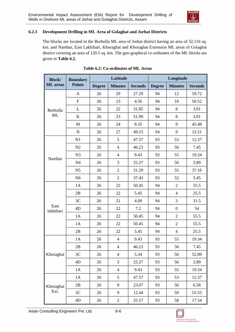
Environmental Impact Assessment (EIA) Report for Development Drilling of Wells in Onshore ML areas of Jorhat and Golaghat Districts, Assam
Asian Consulting Engineers Pvt. Ltd. 6-6
6.2.3 Development Drilling in ML Area of Golaghat and Jorhat Districts
The blocks are located in the Borholla ML area of Jorhat district having an area of 32.116 sq.
km. and Nambar, East Lakhibari, Khoraghat and Khoraghat Extension ML areas of Golaghat
district covering an area of 120.5 sq. km. The geo-graphical co-ordinates of the ML blocks are
given in Table 6.2.
Table 6.2: Co-ordinates of ML Areas
Block/
ML areas
Boundary
Points
Latitude Longitude
Degree Minutes Seconds Degree Minutes Seconds
Borholla
ML
A 26 29 27.29 94 12 59.72
F 26 23 4.56 94 10 50.52
L 26 22 31.85 94 8 3.01
K 26 23 51.99 94 8 3.01
M 26 24 8.35 94 9 45.48
N 26 27 49.15 94 9 12.51
Nambar
N1 26 5 47.57 93 53 12.37
N2 26 4 46.23 93 56 7.45
N3 26 4 9.43 93 55 19.34
N4 26 3 25.27 93 56 3.89
N5 26 2 31.29 93 55 37.16
N6 26 2 37.43 93 52 5.45
East
lakhibari
1A 26 22 50.45 94 2 55.5
2B 26 22 5.45 94 4 25.5
3C 26 21 4.09 94 3 31.5
4D 26 22 7.2 94 0 54
1A 26 22 50.45 94 2 55.5
1A 26 22 50.45 94 2 55.5
2B 26 22 5.45 94 4 25.5
Khoraghat
1A 26 4 9.43 93 55 19.34
2B 26 4 46.23 93 56 7.45
3C 26 4 5.34 93 56 52.89
4D 26 3 25.27 93 56 3.89
1A 26 4 9.43 93 55 19.34
Khoraghat
Ext.
1A 26 5 47.57 93 53 12.37
2B 26 9 23.07 93 56 6.58
3C 26 9 12.44 93 59 55.55
4D 26 2 25.57 93 58 17.54
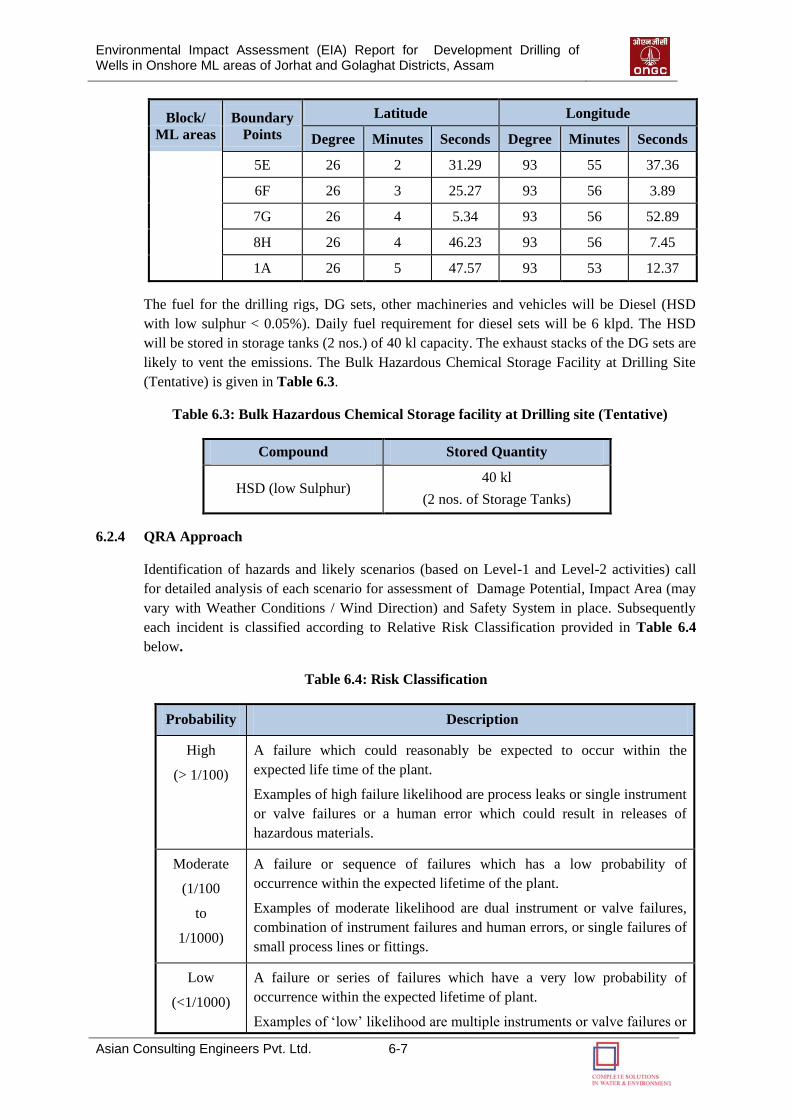
Environmental Impact Assessment (EIA) Report for Development Drilling of Wells in Onshore ML areas of Jorhat and Golaghat Districts, Assam
Asian Consulting Engineers Pvt. Ltd. 6-7
Block/
ML areas
Boundary
Points
Latitude Longitude
Degree Minutes Seconds Degree Minutes Seconds
5E 26 2 31.29 93 55 37.36
6F 26 3 25.27 93 56 3.89
7G 26 4 5.34 93 56 52.89
8H 26 4 46.23 93 56 7.45
1A 26 5 47.57 93 53 12.37
The fuel for the drilling rigs, DG sets, other machineries and vehicles will be Diesel (HSD
with low sulphur < 0.05%). Daily fuel requirement for diesel sets will be 6 klpd. The HSD
will be stored in storage tanks (2 nos.) of 40 kl capacity. The exhaust stacks of the DG sets are
likely to vent the emissions. The Bulk Hazardous Chemical Storage Facility at Drilling Site
(Tentative) is given in Table 6.3.
Table 6.3: Bulk Hazardous Chemical Storage facility at Drilling site (Tentative)
Compound Stored Quantity
HSD (low Sulphur) 40 kl
(2 nos. of Storage Tanks)
6.2.4 QRA Approach
Identification of hazards and likely scenarios (based on Level-1 and Level-2 activities) call
for detailed analysis of each scenario for assessment of Damage Potential, Impact Area (may
vary with Weather Conditions / Wind Direction) and Safety System in place. Subsequently
each incident is classified according to Relative Risk Classification provided in Table 6.4
below.
Table 6.4: Risk Classification
Probability Description
High
(> 1/100)
A failure which could reasonably be expected to occur within the
expected life time of the plant.
Examples of high failure likelihood are process leaks or single instrument
or valve failures or a human error which could result in releases of
hazardous materials.
Moderate
(1/100
to
1/1000)
A failure or sequence of failures which has a low probability of
occurrence within the expected lifetime of the plant.
Examples of moderate likelihood are dual instrument or valve failures,
combination of instrument failures and human errors, or single failures of
small process lines or fittings.
Low
(<1/1000)
A failure or series of failures which have a very low probability of
occurrence within the expected lifetime of plant.
Examples of „low‟ likelihood are multiple instruments or valve failures or
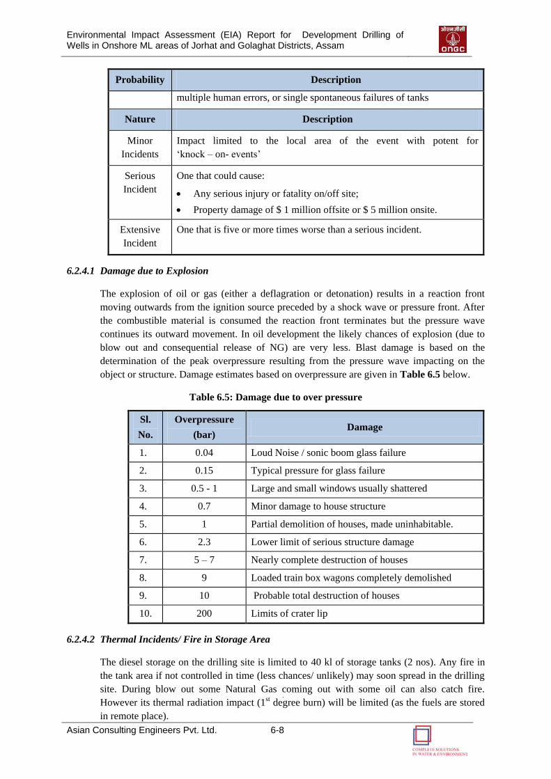
Environmental Impact Assessment (EIA) Report for Development Drilling of Wells in Onshore ML areas of Jorhat and Golaghat Districts, Assam
Asian Consulting Engineers Pvt. Ltd. 6-8
Probability Description
multiple human errors, or single spontaneous failures of tanks
Nature Description
Minor
Incidents
Impact limited to the local area of the event with potent for
„knock – on- events‟
Serious
Incident
One that could cause:
Any serious injury or fatality on/off site;
Property damage of $ 1 million offsite or $ 5 million onsite.
Extensive
Incident
One that is five or more times worse than a serious incident.
6.2.4.1 Damage due to Explosion
The explosion of oil or gas (either a deflagration or detonation) results in a reaction front
moving outwards from the ignition source preceded by a shock wave or pressure front. After
the combustible material is consumed the reaction front terminates but the pressure wave
continues its outward movement. In oil development the likely chances of explosion (due to
blow out and consequential release of NG) are very less. Blast damage is based on the
determination of the peak overpressure resulting from the pressure wave impacting on the
object or structure. Damage estimates based on overpressure are given in Table 6.5 below.
Table 6.5: Damage due to over pressure
Sl.
No.
Overpressure
(bar) Damage
1. 0.04 Loud Noise / sonic boom glass failure
2. 0.15 Typical pressure for glass failure
3. 0.5 - 1 Large and small windows usually shattered
4. 0.7 Minor damage to house structure
5. 1 Partial demolition of houses, made uninhabitable.
6. 2.3 Lower limit of serious structure damage
7. 5 – 7 Nearly complete destruction of houses
8. 9 Loaded train box wagons completely demolished
9. 10 Probable total destruction of houses
10. 200 Limits of crater lip
6.2.4.2 Thermal Incidents/ Fire in Storage Area
The diesel storage on the drilling site is limited to 40 kl of storage tanks (2 nos). Any fire in
the tank area if not controlled in time (less chances/ unlikely) may soon spread in the drilling
site. During blow out some Natural Gas coming out with some oil can also catch fire.
However its thermal radiation impact (1st degree burn) will be limited (as the fuels are stored
in remote place).
Environmental Impact Assessment (EIA) Report for Development Drilling of Wells in Onshore ML areas of Jorhat and Golaghat Districts, Assam
Asian Consulting Engineers Pvt. Ltd. 6-9
Minor spill can occur as various scenarios and may also catch fire. If fire is not controlled
these can lead to domino effect as major scenarios. During the drilling crude oil, some well
water may come out which can be treated and disposed off or pushed back in the non-
producing well. The likely impact due to major scenario considered as given below in Table
6.6.
Table 6.6: Possible Major Scenarios
S. No. Scenario Impact Zone Remarks
1. HSD Tank failure, spillage & Fire
(~ 5 m Pool fire)
~ 8.5 From edge of
pool
The impact due to the above scenarios will be within the rig area. It may have some impact on
the nearby vegetation but will not have any impact on local population.
6.2.5 Mitigation Measures
6.2.5.1 Control Measures for Major Hazards
Out of different hazards described in sections 6.2, occurrence of (a) Blowout and (b) Emission
of Sour Gas (H2S) are the two major hazards and (c) HSD spillage/ fire. The first two possible
incidents can have built in alarm and preventive measures (as more likely to occur if system
fails). The third incident has remote chances and more likely due to some domino effect
caused by other incident. Occurrence of H2S along with oil and gas, if detected in any new
well, is the major hazard during production testing of each well. Control measures for
occurrence of blowout and Emission or Leakage of H2S gas are discussed in following sub-
sections.
Blowout
The precautionary and control measures used for blowout prevention are discussed below:
A. Precaution against Blowout
(i) The following control equipments for Drilling Mud System shall be installed and kept in use
during Drilling Operations to prevent the Blowout:
A Tank Level Indicator registering increase or reduction in the Drilling Mud Volume and
shall include a visual and audio –warning device near the Driller Stand.
A device to accurately measure the volume of Mud required to keep the well filled at all
times.
A Gas Detector or Explosimeter at the Primary Shale Shaker and connected to audible or
visual alarm near the Driller Stand.
A device to ensure filling of well with Mud when the string is being pulled out.
A control device near driller stand to close the Mud Pump when well kicks.
(ii) BOP Drill shall be carried out as per OMR & OISD.
(iii) BOP Control Unit shall be kept available near the well which can be used in case of
Emergency to control the Well.
(iv) When Running In or Pulling Out tubing, Full Opening Safety Valve (FOSV) shall be kept
Environmental Impact Assessment (EIA) Report for Development Drilling of Wells in Onshore ML areas of Jorhat and Golaghat Districts, Assam
Asian Consulting Engineers Pvt. Ltd. 6-10
readily available at rig floor.
B. Precaution after Blowout
On appearance of any sign indicating the Blowout of well, all persons, other than those whose
presence is deemed necessary for Controlling Blowout, shall be withdrawn from the Well.
During the whole time while any work of Controlling a Blowout is in progress, the following
precautions shall be taken:
(i) A competent person shall be present on the spot throughout.
(ii) An area within the 500 meters of the well on the down wind direction shall be demarcated as
Danger Zone.
All Electrical Installations shall be de-energized.
Approved Safety Lamps or torches shall only be used within the Danger Zone.
No Naked Light or Vehicular Traffic shall be permitted within the Danger Zone.
(iii) A competent person shall ascertain the condition of ventilation and presence of gases with an
approved instrument as far as Safety of persons is concerned.
(iv) There shall be available at or near the place, two approved type of self containing Breathing
Apparatus or any other Breathing Apparatus of approved type for use in emergency.
(v) Adequate Firefighting Equipment shall be kept readily available for immediate use.
6.2.5.2 Control Measures for H2S Leakage/Emission during Drilling
The following control measures for H2S will become necessary if presence of H2S is detected
at any new well.
A. H2S Detection System Presence
A four channels H2S gas detection system should be provided. Sensors should be positioned
at optimum points for detection, actual locations being decided on site but likely to be:
Just above Riser/Flow Nipple
Shale shaker
The detection system should be connected to an Audio Visual (Siren and Lights) Alarm
system. This system should be set to be activated at a concentration of 15 ppm H2S.
The Mud Logging will have a completely independent Detection System which is connected
to an alarm in the cabin. This system will be adjusted to sound an Alarm at a concentration
level of 10 ppm H2S as suggested in the Drilling and Production Safety Code for Onshore
Operations issued by The Institute of Petroleum.
A stock of H2S scavenger will be kept at drilling site for emergency use.
Environmental Impact Assessment (EIA) Report for Development Drilling of Wells in Onshore ML areas of Jorhat and Golaghat Districts, Assam
Asian Consulting Engineers Pvt. Ltd. 6-11
B. Small Levels of H2S
Small levels of H2S (less than 10 ppm) will not activate the well site alarms. Such levels do
not create an immediate safety hazard but could be a first indication of high levels of H2S to
follow.
H2S will cause a sudden drop of mud pH. The Mud Engineer/Mud Services will therefore
organize and supervise continuous pH checks while drilling. Checks should be as frequent as
possible and always made following a formation change.
Following control measures will be taken in case of small level of detection:
Add H2S scavenger to mud.
Check H2S levels at regular intervals for possible increase.
Inform all personnel of the rig about the presence of H2S and current wind direction.
Commence operations in pairs.
Render sub base and cellar out-of-bounds without further checking levels in this area.
C. High Levels of H2S
Higher levels of H2S (greater than 10 ppm) do not necessarily cause an immediate safety
hazard. However some risk does exist and, therefore, any levels greater than 10 ppm should
be treated in the same manner. Occurrence of 10 ppm or more H2S concentration will sound
an alarm in the mud logging unit.
If higher levels of H2S (greater than 10 ppm) are found, following steps will be taken:
Driller to Shut Down Rotary, pick up Kelly, close BOP and Shut Down Pump.
One pre-assigned roughneck will go to doghouse and put on breathing apparatus. All
other Rig Personnel will evacuate the rig and move in Up-Wind direction to Designated
Muster Point.
Driller and roughneck will return to the rig floor and commence circulating H2S
scavenger slowly and reciprocating pipe.
The level of H2S will be checked in all work areas. H2S Scavenger will be added to the
Mud and circulated. If H2S levels drop, drilling will be continued with scavenger in the
mud. Approximately 30 % of hydrogen peroxide (H2O2) solution will neutralize H2S gas
in the mud at 20 gallon of H2O2 per 100 barrels of mud.
6.2.5.3 Natural Disaster and Hazards
Following measures will be adopted to minimize the risks of Natural Hazards:
Enactment of building codes and construction standards.
Adaption of earthquake resistant designing in the establishment of structures and
installation.
Adoption of Emergency Shut Down (ESD) mechanism.
Implementation of offsite and onsite DMP and ERP.
6.2.5.4 Fire Fighting Facility
Fixed Fire Fighting System as per Oil Industry Safety Directorate (OISD) Standard 189
should be in place.
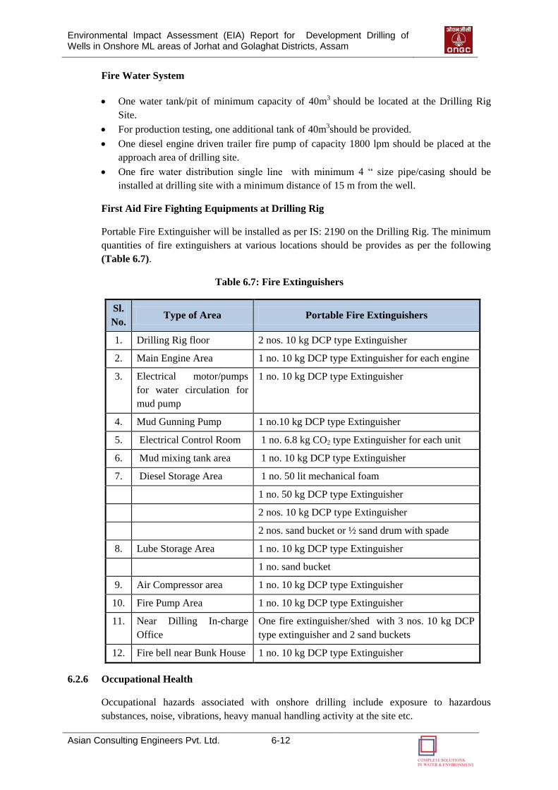
Environmental Impact Assessment (EIA) Report for Development Drilling of Wells in Onshore ML areas of Jorhat and Golaghat Districts, Assam
Asian Consulting Engineers Pvt. Ltd. 6-12
Fire Water System
One water tank/pit of minimum capacity of 40m3 should be located at the Drilling Rig
Site.
For production testing, one additional tank of 40m3should be provided.
One diesel engine driven trailer fire pump of capacity 1800 lpm should be placed at the
approach area of drilling site.
One fire water distribution single line with minimum 4 “ size pipe/casing should be
installed at drilling site with a minimum distance of 15 m from the well.
First Aid Fire Fighting Equipments at Drilling Rig
Portable Fire Extinguisher will be installed as per IS: 2190 on the Drilling Rig. The minimum
quantities of fire extinguishers at various locations should be provides as per the following
(Table 6.7).
Table 6.7: Fire Extinguishers
Sl.
No. Type of Area Portable Fire Extinguishers
1. Drilling Rig floor 2 nos. 10 kg DCP type Extinguisher
2. Main Engine Area 1 no. 10 kg DCP type Extinguisher for each engine
3. Electrical motor/pumps
for water circulation for
mud pump
1 no. 10 kg DCP type Extinguisher
4. Mud Gunning Pump 1 no.10 kg DCP type Extinguisher
5. Electrical Control Room 1 no. 6.8 kg CO2 type Extinguisher for each unit
6. Mud mixing tank area 1 no. 10 kg DCP type Extinguisher
7. Diesel Storage Area 1 no. 50 lit mechanical foam
1 no. 50 kg DCP type Extinguisher
2 nos. 10 kg DCP type Extinguisher
2 nos. sand bucket or ½ sand drum with spade
8. Lube Storage Area 1 no. 10 kg DCP type Extinguisher
1 no. sand bucket
9. Air Compressor area 1 no. 10 kg DCP type Extinguisher
10. Fire Pump Area 1 no. 10 kg DCP type Extinguisher
11. Near Dilling In-charge
Office
One fire extinguisher/shed with 3 nos. 10 kg DCP
type extinguisher and 2 sand buckets
12. Fire bell near Bunk House 1 no. 10 kg DCP type Extinguisher
6.2.6 Occupational Health
Occupational hazards associated with onshore drilling include exposure to hazardous
substances, noise, vibrations, heavy manual handling activity at the site etc.
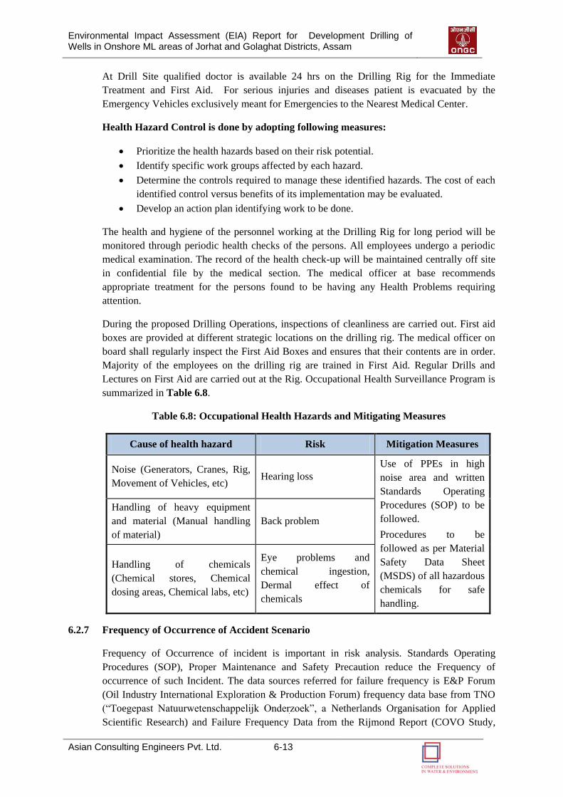
Environmental Impact Assessment (EIA) Report for Development Drilling of Wells in Onshore ML areas of Jorhat and Golaghat Districts, Assam
Asian Consulting Engineers Pvt. Ltd. 6-13
At Drill Site qualified doctor is available 24 hrs on the Drilling Rig for the Immediate
Treatment and First Aid. For serious injuries and diseases patient is evacuated by the
Emergency Vehicles exclusively meant for Emergencies to the Nearest Medical Center.
Health Hazard Control is done by adopting following measures:
Prioritize the health hazards based on their risk potential.
Identify specific work groups affected by each hazard.
Determine the controls required to manage these identified hazards. The cost of each
identified control versus benefits of its implementation may be evaluated.
Develop an action plan identifying work to be done.
The health and hygiene of the personnel working at the Drilling Rig for long period will be
monitored through periodic health checks of the persons. All employees undergo a periodic
medical examination. The record of the health check-up will be maintained centrally off site
in confidential file by the medical section. The medical officer at base recommends
appropriate treatment for the persons found to be having any Health Problems requiring
attention.
During the proposed Drilling Operations, inspections of cleanliness are carried out. First aid
boxes are provided at different strategic locations on the drilling rig. The medical officer on
board shall regularly inspect the First Aid Boxes and ensures that their contents are in order.
Majority of the employees on the drilling rig are trained in First Aid. Regular Drills and
Lectures on First Aid are carried out at the Rig. Occupational Health Surveillance Program is
summarized in Table 6.8.
Table 6.8: Occupational Health Hazards and Mitigating Measures
Cause of health hazard Risk Mitigation Measures
Noise (Generators, Cranes, Rig,
Movement of Vehicles, etc) Hearing loss
Use of PPEs in high
noise area and written
Standards Operating
Procedures (SOP) to be
followed.
Procedures to be
followed as per Material
Safety Data Sheet
(MSDS) of all hazardous
chemicals for safe
handling.
Handling of heavy equipment
and material (Manual handling
of material)
Back problem
Handling of chemicals
(Chemical stores, Chemical
dosing areas, Chemical labs, etc)
Eye problems and
chemical ingestion,
Dermal effect of
chemicals
6.2.7 Frequency of Occurrence of Accident Scenario
Frequency of Occurrence of incident is important in risk analysis. Standards Operating
Procedures (SOP), Proper Maintenance and Safety Precaution reduce the Frequency of
occurrence of such Incident. The data sources referred for failure frequency is E&P Forum
(Oil Industry International Exploration & Production Forum) frequency data base from TNO
(“Toegepast Natuurwetenschappelijk Onderzoek”, a Netherlands Organisation for Applied
Scientific Research) and Failure Frequency Data from the Rijmond Report (COVO Study,
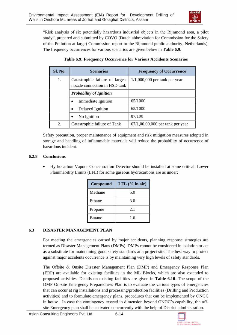
Environmental Impact Assessment (EIA) Report for Development Drilling of Wells in Onshore ML areas of Jorhat and Golaghat Districts, Assam
Asian Consulting Engineers Pvt. Ltd. 6-14
“Risk analysis of six potentially hazardous industrial objects in the Rijnmond area, a pilot
study”, prepared and submitted by COVO (Dutch abbreviation for Commission for the Safety
of the Pollution at large) Commission report to the Rijnmond public authority, Netherlands).
The frequency occurrences for various scenarios are given below in Table 6.9.
Table 6.9: Frequency Occurrence for Various Accidents Scenarios
Sl. No. Scenarios Frequency of Occurrence
1. Catastrophic failure of largest
nozzle connection in HSD tank
1/1,000,000 per tank per year
Probability of Ignition
Immediate Ignition 65/1000
Delayed Ignition 65/1000
No Ignition 87/100
2. Catastrophic failure of Tank 67/1,00,00,000 per tank per year
Safety precaution, proper maintenance of equipment and risk mitigation measures adopted in
storage and handling of inflammable materials will reduce the probability of occurrence of
hazardous incident.
6.2.8 Conclusions
Hydrocarbon Vapour Concentration Detector should be installed at some critical. Lower
Flammability Limits (LFL) for some gaseous hydrocarbons are as under:
Compound LFL (% in air)
Methane 5.0
Ethane 3.0
Propane 2.1
Butane 1.6
6.3 DISASTER MANAGEMENT PLAN
For meeting the emergencies caused by major accidents, planning response strategies are
termed as Disaster Management Plans (DMPs). DMPs cannot be considered in isolation or act
as a substitute for maintaining good safety standards at a project site. The best way to protect
against major accidents occurrence is by maintaining very high levels of safety standards.
The Offsite & Onsite Disaster Management Plan (DMP) and Emergency Response Plan
(ERP) are available for existing facilities in the ML Blocks, which are also extended to
proposed activities. Details on existing facilities are given in Table 6.10. The scope of the
DMP On-site Emergency Preparedness Plan is to evaluate the various types of emergencies
that can occur at rig installations and processing/production facilities (Drilling and Production
activities) and to formulate emergency plans, procedures that can be implemented by ONGC
in house. In case the contingency exceed in dimension beyond ONGC‟s capability, the off-
site Emergency plan shall be activated concurrently with the help of District administration.
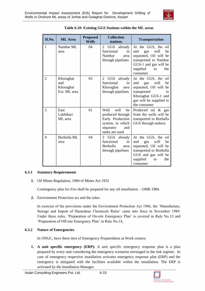
Environmental Impact Assessment (EIA) Report for Development Drilling of Wells in Onshore ML areas of Jorhat and Golaghat Districts, Assam
Asian Consulting Engineers Pvt. Ltd. 6-15
Table 6.10: Existing GGS Stations within the ML areas
Sl.No. ML Area Proposed
Wells
Collection
stations Transportation
1 Nambar ML
area
04 2 GGS already
functional in
Nambar area
through pipelines
At the GGS, the oil
and gas will be
separated, Oil will be
transported to Nambar
GGS-1 and gas will be
supplied to the
consumer
2 Khoraghat
and
Khoraghat
Ext. ML area
03 2 GGS already
functional in
Khoraghat area
through pipelines
At the GGS, the oil
and gas will be
separated, Oil will be
transported to
Khoraghat GGS-1 and
gas will be supplied to
the consumer
3 East
Lakhibari
ML area
01 Well will be
produced through
Early Production
system, in which
separator and
tanks are used
Produced oil & gas
from the wells will be
transported to Borhalla
GGS through tankers
4 Borholla ML
area
04 2 GGS already
functional in
Borholla area
through pipelines
At the GGS, the oil
and gas will be
separated, Oil will be
transported to Borholla
GGS and gas will be
supplied to the
consumer
6.3.1 Statutory Requirements
1. Oil Mines Regulation, 1984 of Mines Act 1952
Contingency plan for Fire shall be prepared for any oil installation – OMR 1984.
2. Environment Protection act and the rules:
In exercise of the provisions under the Environment Protection Act 1986, the „Manufacture,
Storage and Import of Hazardous Chemicals Rules‟ came into force in November 1989.
Under these rules, „Preparation of On-site Emergency Plan‟ is covered in Rule No.13 and
„Preparation of Off-site Emergency Plan‟ in Rule No.14,
6.3.2 Nature of Emergencies
In ONGC, have three tiers of Emergency Preparedness at Work centers:
1. A unit specific emergency (ERP): A unit specific emergency response plan is a plan
prepared by every unit considering the emergency scenarios envisaged in the risk register. In
case of emergency respective installation activates emergency response plan (ERP) and the
emergency is mitigated with the facilities available within the installation. The ERP is
activated by the Installation Manager.
Environmental Impact Assessment (EIA) Report for Development Drilling of Wells in Onshore ML areas of Jorhat and Golaghat Districts, Assam
Asian Consulting Engineers Pvt. Ltd. 6-16
2. On-site emergency (On-site DMP): The On-site Disaster Management plan is activated in
case the emergency requires mobilization of resources from the other units / Asset. This plan
is activated by the Chief Emergency Coordinator (CEC), Asset Manager and will exercise
control through the Asset Emergency Control Room (ECR).
3. Off-site emergency (off-site DMP): The off-site disaster management plan will be put into
action in the following situations:
i) In case of an Onsite emergency spreads beyond the boundary of installation and
causes damage to the life or property outside the boundary.
ii) In case an emergency originated from outside the premises of the installation/Drilling
Rig/Work over Rig which is likely to effect the operations of installation.
The off-site emergency requires mobilization of resources beyond ONGC capabilities such as
state emergency services.
6.3.3 Onsite Emergency Organization
The Asset Manager is head of the On-site emergency organization and is designated as the
Chief Emergency Coordinator (CEC) at Asset level. He will exercise control through the
Asset Emergency Control Room (ECR). The CEC is assisted by an expert team drawn from
various disciplines.
The Chief Emergency Coordinator (CEC) will assume control through the Assistant
Emergency Coordinator (AEC). The emergency coordinator (CEC) may appoint Surface
Manager / Head Drilling Services / Head Well Services as Assistant Emergency Coordinator
(AEC). The flow chart of onsite emergency organisation is shown in Figure 6.1.
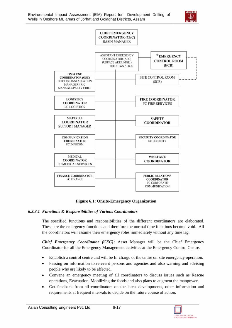
Environmental Impact Assessment (EIA) Report for Development Drilling of Wells in Onshore ML areas of Jorhat and Golaghat Districts, Assam
Asian Consulting Engineers Pvt. Ltd. 6-17
Figure 6.1: Onsite-Emergency Organization
6.3.3.1 Functions & Responsibilities of Various Coordinators
The specified functions and responsibilities of the different coordinators are elaborated.
These are the emergency functions and therefore the normal time functions become void. All
the coordinators will assume their emergency roles immediately without any time lag.
Chief Emergency Coordinator (CEC): Asset Manager will be the Chief Emergency
Coordinator for all the Emergency Management activities at the Emergency Control Centre.
Establish a control centre and will be In-charge of the entire on-site emergency operation.
Passing on information to relevant persons and agencies and also warning and advising
people who are likely to be affected.
Convene an emergency meeting of all coordinators to discuss issues such as Rescue
operations, Evacuation, Mobilizing the foods and also plans to augment the manpower.
Get feedback from all coordinators on the latest developments, other information and
requirements at frequent intervals to decide on the future course of action.
Environmental Impact Assessment (EIA) Report for Development Drilling of Wells in Onshore ML areas of Jorhat and Golaghat Districts, Assam
Asian Consulting Engineers Pvt. Ltd. 6-18
Arrange to operate Mutual Aid Scheme through Head HSE. In case of Major Fire /
Explosion he has to get mobilized force and appliance from State / Municipal Fire
Service.
In case On-site emergency is escalating and speeding to an off-site emergency, the matter
to be informed to the District Collector to enable them trigger off-site emergency plan
activities to combat emergency.
Assistant Emergency Coordinator (AEC): In case of an emergency in production operations,
the Surface Manager will assume the responsibilities of AEC. He will work under the orders
of CEC. The responsibilities are:
Assessment of the gravity of the situation and to declare the state of emergency
Establishment of Site Control Room (SCR)
Mobilization of resources
Control of logistic support
Control of rescue operations
Supervision of Medical attention to injured
Oversees all situation reports
Organizes all Post emergency operations
On-Scene Coordinator (OSC): The senior most person or the Installation Manager will
assume the role of OSC, unless otherwise directed. In case of abandoning the installation in
distress, the In-charge of the nearest Installation will take over the role of OSC. CEC may
also appoint a person from base to take over the task of OSC at Site Control Room.
On-scene coordinator is the key person in emergency situation. After receiving the message,
shall reach the spot immediately.
He will take control of Fire Fighting operation / damage control measures till the arrival of
Incharge Fire.
In coordination with Incharge Fire, arrange to take all steps to control emergency situation.
Closely monitor the emergency situation and change action plan as per need.
In case of Major / Serious Emergency arrange to blow all clear siren when the emergency
situation is under control.
Key Personnel: Key personnel for respective services, depending upon the nature of the
emergency shall arrive at the site to take charge of their respective positions such as Logistics
Coordinator, Safety (HSE) Coordinator, Fire Coordinator, Finance Coordinator, Medical
Coordinator, Communication Coordinator etc.
6.3.3.2 Emergency Control Room (ECR) at Base office
An emergency control room (ECR) will be set up at base office in radio room under the
control of Chief Emergency coordinator (CEC). Management decisions and plans will be
conveyed from ECR to emergency site by AEC. From Site Control Room (SCR) all
developments at emergency site will be communicated to ECR at base.
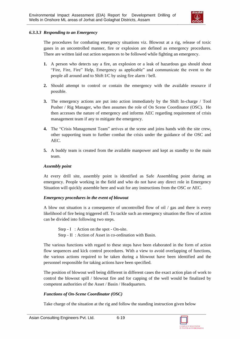
Environmental Impact Assessment (EIA) Report for Development Drilling of Wells in Onshore ML areas of Jorhat and Golaghat Districts, Assam
Asian Consulting Engineers Pvt. Ltd. 6-19
6.3.3.3 Responding to an Emergency
The procedures for combating emergency situations viz. Blowout at a rig, release of toxic
gases in an uncontrolled manner, fire or explosion are defined as emergency procedures.
There are written laid out action sequences to be followed while fighting an emergency.
1. A person who detects say a fire, an explosion or a leak of hazardous gas should shout
“Fire, Fire, Fire” Help, Emergency as applicable” and communicate the event to the
people all around and to Shift I/C by using fire alarm / bell.
2. Should attempt to control or contain the emergency with the available resource if
possible.
3. The emergency actions are put into action immediately by the Shift In-charge / Tool
Pusher / Rig Manager, who then assumes the role of On Scene Coordinator (OSC). He
then accesses the nature of emergency and informs AEC regarding requirement of crisis
management team if any to mitigate the emergency.
4. The “Crisis Management Team” arrives at the scene and joins hands with the site crew,
other supporting team to further combat the crisis under the guidance of the OSC and
AEC.
5. A buddy team is created from the available manpower and kept as standby to the main
team.
Assembly point
At every drill site, assembly point is identified as Safe Assembling point during an
emergency. People working in the field and who do not have any direct role in Emergency
Situation will quickly assemble here and wait for any instructions from the OSC or AEC.
Emergency procedures in the event of blowout
A blow out situation is a consequence of uncontrolled flow of oil / gas and there is every
likelihood of fire being triggered off. To tackle such an emergency situation the flow of action
can be divided into following two steps.
Step - I : Action on the spot - On-site.
Step - II : Action of Asset in co-ordination with Basin.
The various functions with regard to these steps have been elaborated in the form of action
flow sequences and kick control procedures. With a view to avoid overlapping of functions,
the various actions required to be taken during a blowout have been identified and the
personnel responsible for taking actions have been specified.
The position of blowout well being different in different cases the exact action plan of work to
control the blowout spill / blowout fire and for capping of the well would be finalized by
competent authorities of the Asset / Basin / Headquarters.
Functions of On-Scene Coordinator (OSC)
Take charge of the situation at the rig and follow the standing instruction given below
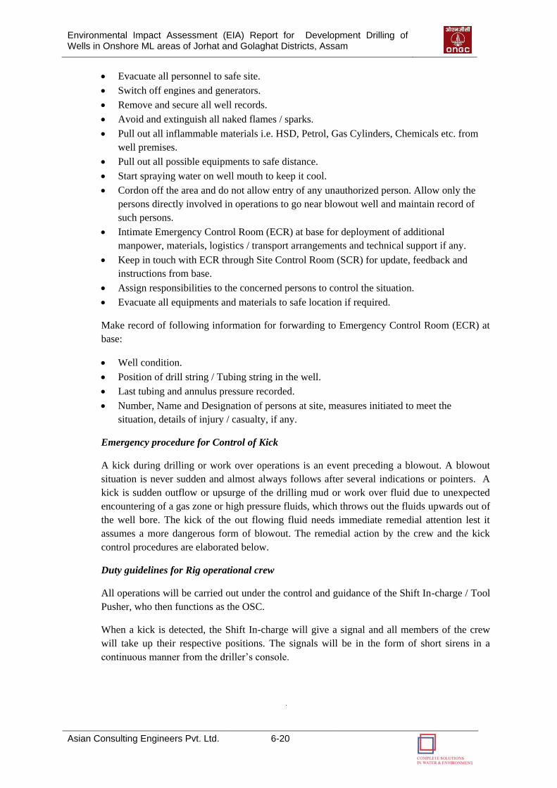
Environmental Impact Assessment (EIA) Report for Development Drilling of Wells in Onshore ML areas of Jorhat and Golaghat Districts, Assam
Asian Consulting Engineers Pvt. Ltd. 6-20
Evacuate all personnel to safe site.
Switch off engines and generators.
Remove and secure all well records.
Avoid and extinguish all naked flames / sparks.
Pull out all inflammable materials i.e. HSD, Petrol, Gas Cylinders, Chemicals etc. from
well premises.
Pull out all possible equipments to safe distance.
Start spraying water on well mouth to keep it cool.
Cordon off the area and do not allow entry of any unauthorized person. Allow only the
persons directly involved in operations to go near blowout well and maintain record of
such persons.
Intimate Emergency Control Room (ECR) at base for deployment of additional
manpower, materials, logistics / transport arrangements and technical support if any.
Keep in touch with ECR through Site Control Room (SCR) for update, feedback and
instructions from base.
Assign responsibilities to the concerned persons to control the situation.
Evacuate all equipments and materials to safe location if required.
Make record of following information for forwarding to Emergency Control Room (ECR) at
base:
Well condition.
Position of drill string / Tubing string in the well.
Last tubing and annulus pressure recorded.
Number, Name and Designation of persons at site, measures initiated to meet the
situation, details of injury / casualty, if any.
Emergency procedure for Control of Kick
A kick during drilling or work over operations is an event preceding a blowout. A blowout
situation is never sudden and almost always follows after several indications or pointers. A
kick is sudden outflow or upsurge of the drilling mud or work over fluid due to unexpected
encountering of a gas zone or high pressure fluids, which throws out the fluids upwards out of
the well bore. The kick of the out flowing fluid needs immediate remedial attention lest it
assumes a more dangerous form of blowout. The remedial action by the crew and the kick
control procedures are elaborated below.
Duty guidelines for Rig operational crew
All operations will be carried out under the control and guidance of the Shift In-charge / Tool
Pusher, who then functions as the OSC.
When a kick is detected, the Shift In-charge will give a signal and all members of the crew
will take up their respective positions. The signals will be in the form of short sirens in a
continuous manner from the driller‟s console.
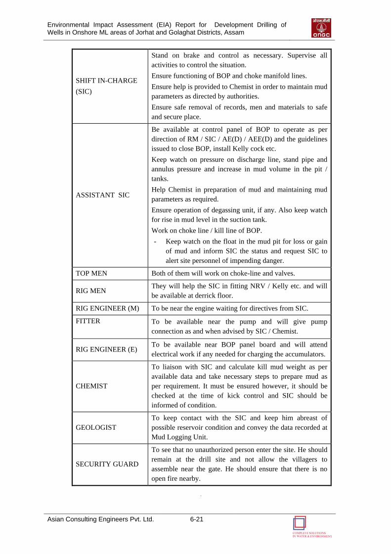
Environmental Impact Assessment (EIA) Report for Development Drilling of Wells in Onshore ML areas of Jorhat and Golaghat Districts, Assam
Asian Consulting Engineers Pvt. Ltd. 6-21
SHIFT IN-CHARGE
(SIC)
Stand on brake and control as necessary. Supervise all
activities to control the situation.
Ensure functioning of BOP and choke manifold lines.
Ensure help is provided to Chemist in order to maintain mud
parameters as directed by authorities.
Ensure safe removal of records, men and materials to safe
and secure place.
ASSISTANT SIC
Be available at control panel of BOP to operate as per
direction of RM / SIC / AE(D) / AEE(D) and the guidelines
issued to close BOP, install Kelly cock etc.
Keep watch on pressure on discharge line, stand pipe and
annulus pressure and increase in mud volume in the pit /
tanks.
Help Chemist in preparation of mud and maintaining mud
parameters as required.
Ensure operation of degassing unit, if any. Also keep watch
for rise in mud level in the suction tank.
Work on choke line / kill line of BOP.
- Keep watch on the float in the mud pit for loss or gain
of mud and inform SIC the status and request SIC to
alert site personnel of impending danger.
TOP MEN Both of them will work on choke-line and valves.
RIG MEN They will help the SIC in fitting NRV / Kelly etc. and will
be available at derrick floor.
RIG ENGINEER (M) To be near the engine waiting for directives from SIC.
FITTER
To be available near the pump and will give pump
connection as and when advised by SIC / Chemist.
RIG ENGINEER (E) To be available near BOP panel board and will attend
electrical work if any needed for charging the accumulators.
CHEMIST
To liaison with SIC and calculate kill mud weight as per
available data and take necessary steps to prepare mud as
per requirement. It must be ensured however, it should be
checked at the time of kick control and SIC should be
informed of condition.
GEOLOGIST
To keep contact with the SIC and keep him abreast of
possible reservoir condition and convey the data recorded at
Mud Logging Unit.
SECURITY GUARD
To see that no unauthorized person enter the site. He should
remain at the drill site and not allow the villagers to
assemble near the gate. He should ensure that there is no
open fire nearby.
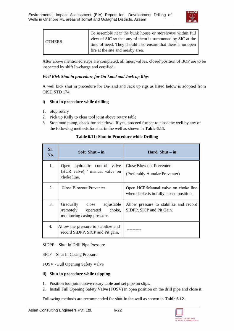
Environmental Impact Assessment (EIA) Report for Development Drilling of Wells in Onshore ML areas of Jorhat and Golaghat Districts, Assam
Asian Consulting Engineers Pvt. Ltd. 6-22
OTHERS
To assemble near the bunk house or storehouse within full
view of SIC so that any of them is summoned by SIC at the
time of need. They should also ensure that there is no open
fire at the site and nearby area.
After above mentioned steps are completed, all lines, valves, closed position of BOP are to be
inspected by shift In-charge and certified.
Well Kick Shut in procedure for On Land and Jack up Rigs
A well kick shut in procedure for On-land and Jack up rigs as listed below is adopted from
OISD STD 174.
i) Shut in procedure while drilling
1. Stop rotary
2. Pick up Kelly to clear tool joint above rotary table.
3. Stop mud pump, check for self-flow. If yes, proceed further to close the well by any of
the following methods for shut in the well as shown in Table 6.11.
Table 6.11: Shut in Procedure while Drilling
Sl.
No. Soft Shut – in Hard Shut – in
1. Open hydraulic control valve
(HCR valve) / manual valve on
choke line.
Close Blow out Preventer.
(Preferably Annular Preventer)
2. Close Blowout Preventer. Open HCR/Manual valve on choke line
when choke is in fully closed position.
3. Gradually close adjustable
/remotely operated choke,
monitoring casing pressure.
Allow pressure to stabilize and record
SIDPP, SICP and Pit Gain.
4. Allow the pressure to stabilize and
record SIDPP, SICP and Pit gain. ----------
SIDPP – Shut In Drill Pipe Pressure
SICP – Shut In Casing Pressure
FOSV - Full Opening Safety Valve
ii) Shut in procedure while tripping
1. Position tool joint above rotary table and set pipe on slips.
2. Install Full Opening Safety Valve (FOSV) in open position on the drill pipe and close it.
Following methods are recommended for shut-in the well as shown in Table 6.12.
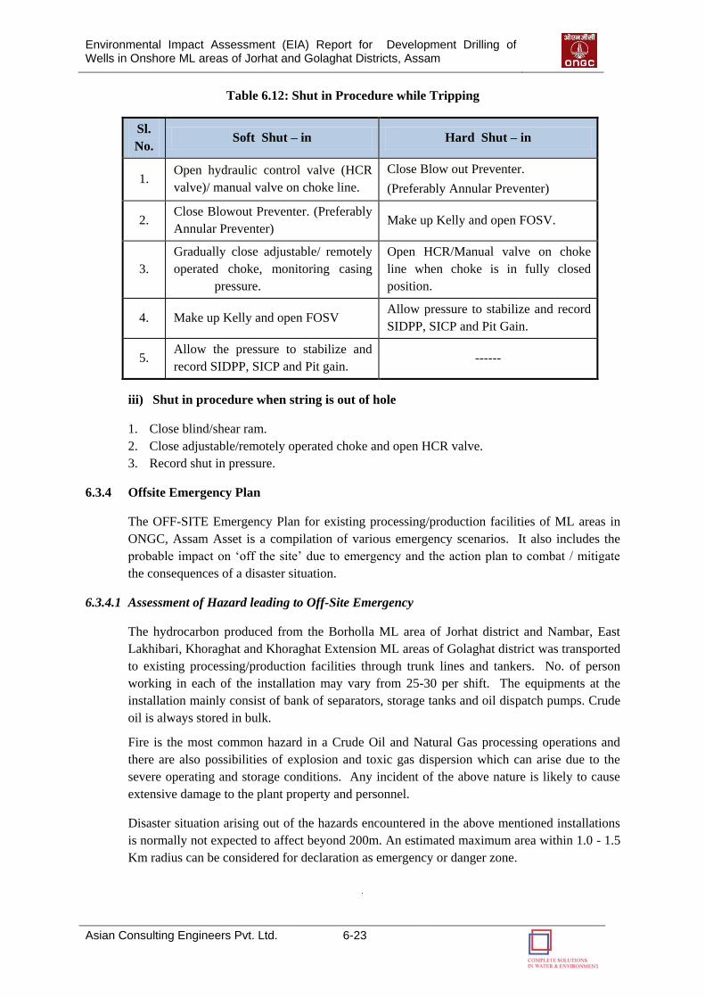
Environmental Impact Assessment (EIA) Report for Development Drilling of Wells in Onshore ML areas of Jorhat and Golaghat Districts, Assam
Asian Consulting Engineers Pvt. Ltd. 6-23
Table 6.12: Shut in Procedure while Tripping
Sl.
No. Soft Shut – in Hard Shut – in
1. Open hydraulic control valve (HCR
valve)/ manual valve on choke line.
Close Blow out Preventer.
(Preferably Annular Preventer)
2. Close Blowout Preventer. (Preferably
Annular Preventer) Make up Kelly and open FOSV.
3.
Gradually close adjustable/ remotely
operated choke, monitoring casing
pressure.
Open HCR/Manual valve on choke
line when choke is in fully closed
position.
4. Make up Kelly and open FOSV Allow pressure to stabilize and record
SIDPP, SICP and Pit Gain.
5. Allow the pressure to stabilize and
record SIDPP, SICP and Pit gain. ------
iii) Shut in procedure when string is out of hole
1. Close blind/shear ram.
2. Close adjustable/remotely operated choke and open HCR valve.
3. Record shut in pressure.
6.3.4 Offsite Emergency Plan
The OFF-SITE Emergency Plan for existing processing/production facilities of ML areas in
ONGC, Assam Asset is a compilation of various emergency scenarios. It also includes the
probable impact on „off the site‟ due to emergency and the action plan to combat / mitigate
the consequences of a disaster situation.
6.3.4.1 Assessment of Hazard leading to Off-Site Emergency
The hydrocarbon produced from the Borholla ML area of Jorhat district and Nambar, East
Lakhibari, Khoraghat and Khoraghat Extension ML areas of Golaghat district was transported
to existing processing/production facilities through trunk lines and tankers. No. of person
working in each of the installation may vary from 25-30 per shift. The equipments at the
installation mainly consist of bank of separators, storage tanks and oil dispatch pumps. Crude
oil is always stored in bulk.
Fire is the most common hazard in a Crude Oil and Natural Gas processing operations and
there are also possibilities of explosion and toxic gas dispersion which can arise due to the
severe operating and storage conditions. Any incident of the above nature is likely to cause
extensive damage to the plant property and personnel.
Disaster situation arising out of the hazards encountered in the above mentioned installations
is normally not expected to affect beyond 200m. An estimated maximum area within 1.0 - 1.5
Km radius can be considered for declaration as emergency or danger zone.
Environmental Impact Assessment (EIA) Report for Development Drilling of Wells in Onshore ML areas of Jorhat and Golaghat Districts, Assam
Asian Consulting Engineers Pvt. Ltd. 6-24
Outside the premises of the these installations, environmental hazards are likely to occur due
to the leakage / bursting of either trunk pipeline or flow lines from wells and flaring of natural
gas.
Hazard in Flow Lines: A pipeline connecting one installation to another installation is termed
as a trunk line while a pipeline connecting hydrocarbon well to the installation is called as a
flow line.
The trunk pipeline and almost all the well flow lines pass through the agricultural fields. The
trunk and flow lines are sub-surface pipelines and are laid 1.2 m below the ground level. Due
care has been taken during laying of trunk and flow lines. As far as possible laying of
pipeline is avoided in populated area. The main risk in transportation of oil / gas through
pipeline is leakage of oil / gas which may result in fire if source of ignition is present. Once,
detected, the emergency procedure will be activated and remedial action will be taken to
control the leak, spread of fire etc. Moreover, no major evacuation is required as pipelines are
passing through non populated areas.
Hazard in Transportation of Condensate by Tankers: The crude oil is transported through
road tankers from various isolated installations within the Asset to processing/production
installation. There is a chance of oil spill due to overturning or collision of tankers. In this
case, a small quantity of crude oil is likely to be spilled. When an emergency arises the
nearby police station may be contacted to cordon off the affected area and all sources of
ignition are removed to safe distance to avoid fire. Nearby public is instructed not to light any
source of ignition. Efforts should be made to stop the flow of oil into nearby water bodies to
avoid water contamination. For this purpose, improvised booms made of bamboo‟s plants
etc. can be rigged up to contain the oil and prevent its spreading.
6.3.4.2 Disaster due to Man-made causes (Terrorist attack)
Other than above technical and operational hazards ONGC units also poses disasters due to
man-made causes such as Terrorist attack, Bomb threats. The action plan for these scenarios
is as below:
i) IED Attack
Primary rule
If a suspected device is encountered, it should not be handled and the area should be secured.
Improvised explosive devices are very unstable. They are extremely sensitive to shock,
friction, impact, and heat, and may detonate without warning. Even the smallest devices can
cause serious injury or death.
Secondary rule
Always assume that there is more than one device present, whether any other bomb or a
device has been located.
Package-type IEDs: Institute security procedures in receipt and dispatch section and
instruct employees on how to recognize suspicious packages.
Environmental Impact Assessment (EIA) Report for Development Drilling of Wells in Onshore ML areas of Jorhat and Golaghat Districts, Assam
Asian Consulting Engineers Pvt. Ltd. 6-25
Luggage-type IEDs: Train security personnel and employees regarding
unattended packages of any type. Never pick up or open any suspicious package or
piece of luggage. If an IED is discovered, call the police and do not touch the device.
Vehicle-borne IEDs: Perform a vulnerability/threat assessment for the facility with
special attention to this type of explosive delivery mechanism. Consider the use of
enhanced security away from your key buildings (such as a vehicle checkpoint) or the use
of bullards or barriers to block vehicular access to building entrances.
ii) Chemical Attacks
A chemical emergency occurs when a hazardous chemical has been released and has the
possibility of harming people‟s health. Potentially lethal, chemical agents are difficult to
deliver in deadly amounts. If released outdoors, the agents often dissipate rapidly. As such,
the most lethal area for a chemical release is inside a confined space, such as a building,
public place, or subway system.
Industrial chemicals, while not as lethal, can be just as effective if released in sufficient
quantities. Chlorine, ammonia, benzene, and other toxic chemicals are routinely transported
through densely populated areas in rail tankers or truck tankers and could be the target of a
terrorist attack.
Chemical terrorist attacks will most likely be overt because the effects of most chemical
agents are immediate and obvious. Your response will have to be thought out and practiced in
advance to be effective.
Evacuation
Some types of chemical emergencies will require evacuation from the immediate area. If you
are up-wind and in the open, evacuate up-wind and away from the incident. Cover your
mouth and nose with a damp cloth. If you have been exposed, you will have to be
decontaminated by first responders.
Shelter in Place
If you are already in down-wind and/or in a multistory building, you may be instructed to
shelter in place or to make that decision on your own. Most likely you will only need to
shelter for a few hours. The procedure includes:
Go inside as quickly as possible shut and lock all windows and doors; turn off all
HVAC equipment and any fans.
If you have multiple floors, go as high as practical, three to five floors. (Most chemical
agents are heavier than air.)
If you have duct tape, tape over door and window
cracks, vents, electrical outlets, and any opening to the outside.
Wait for instructions from first responders before leaving.
iii) Biological Attacks
A bio-terrorist attack could happen in any workplace, yet most company personnel know little
about potential bio-toxins or bio-pathogens or how to recognize these agents and respond in
the event of an attack.
Environmental Impact Assessment (EIA) Report for Development Drilling of Wells in Onshore ML areas of Jorhat and Golaghat Districts, Assam
Asian Consulting Engineers Pvt. Ltd. 6-26
There are several ways a bio-terrorist event may manifest itself. The biological event may
result from a covert attack. A covert attack may be unleashed by the receipt of an object, such
as a package or piece of mail, accompanied by a warning or threat. For example, release of a
biological agent could occur through delivery of a package contaminated with anthrax spores
or another pathogen. Biological agent release also could occur via the ventilation system
(HVAC) in a building, where dispersal could take place within a matter of minutes. Because
the covert release is not witnessed, the effects of such an event can be widespread and
difficult to isolate or recognize.
While terror is intended to produce casualties, disruption, and fear, the use of biological
agents is particularly injurious. Biological attacks are delayed events. The sudden appearance
of generalized symptoms in victims who present themselves to medical providers may
initially disguise the true source of exposure. Only when a trickle of patients turns into a flood
or mysterious pathogens quickly make their presence felt does the magnitude of the event
reveal itself.
The goal of the medical care community (i.e., hospitals, physicians, and other health care
providers) is to recognize and diagnose the disease (which frequently may be unfamiliar to
most clinicians) and to provide treatment. The goal of public health authorities is to detect and
control the outbreak of the illness. Public health officials will focus on identifying and
treating exposed persons and preventing the spread of disease.
In response to a covert release, it is important for ONGC health officials to recognize the
signs and symptoms of an emerging disease among employees. If an overt release is
recognized, take immediate action to isolate the exposed employees and/or area of agent
dispersion and to remove others from the area of release. Notify local public health authorities
immediately and follow their directions. Decontamination may also be warranted in response
to an overt release.
iv) Radiological Attacks
A radiological weapon or “dirty bomb” is a crude device that combines a conventional
explosive with highly radioactive material. When detonated, the blast vaporizes the
radioactive material and propels it across a wide area.
The main danger from a dirty bomb is the initial blast, which could cause serious injury or
property damage. The radioactive materials will likely not be concentrated enough to cause
immediate serious illness, except to those very close to the blast site or those who inhale
smoke and dust. Dirty bombs are designed to cause tremendous psychological damage by
exploiting the public‟s fear of radiation. These are not weapons of mass destruction, but
weapons of mass disruption aimed at wreaking economic havoc by making target areas
uninhabitable for extended periods.
There are three basic ways to reduce your exposure:
1. Reduce the time near the source of radiation,
2. Increase the distance from the source of radiation,
3. Increase the shielding between person and the source of radiation. Shielding is anything
that puts distance and mass between person and the radiation source.

Environmental Impact Assessment (EIA) Report for Development Drilling of Wells in Onshore ML areas of Jorhat and Golaghat Districts, Assam
Asian Consulting Engineers Pvt. Ltd. 6-27
Evacuation
If a person is outside, evacuate up-wind from the blast site cover the nose and mouth with a
wet cloth to reduce the risk of inhaling radioactive smoke or dust. Once out of the immediate
area, seek shelter and wait for instructions from first responders. If individual has been
exposed to dust or smoke, follow the decontamination procedure.
Shelter in Place
If a person is close to the blast and inside a building, stay inside if the building is intact. Move
to the basement and turn off all HVAC equipment and fans bringing in outside air it is not
necessary to seal doors and windows, but it may be helpful. Wait for instructions from
first responders.
6.3.4.3 Action Plan - Reporting of an Off-Site Emergency
The off-site disaster management plan will be put into action in the following situations:
a) In case of an Onsite emergency spreads beyond the boundary of installation and causes
damage to the life or property outside the boundary.
b) In case an emergency originated from outside the premises of the installation/Drilling
Rig/Work over Rig which is likely to effect the operations of installation.
The off-site emergency requires mobilization of resources beyond ONGC capabilities
such as state emergency services.
In case of an off-site emergency, the On-site Chief emergency coordinator (Asset Manager)
will report the matter to the District Collector, who is Chairman of District emergency
committee. Further, the Chairman will mobilize other members of District Emergency
committee as per the organization Chart for an Off-site emergency management (Figure 6.2).
Communication to Corporate Disaster Management Group (CDMG)
The Chief Emergency coordinator shall immediately inform CMD, Director (HR),-CCEC,
Director-concerned and Director-I/C HSE on the situation and his assessment for intervention
of Corporate Disaster Management Group (CDMG).
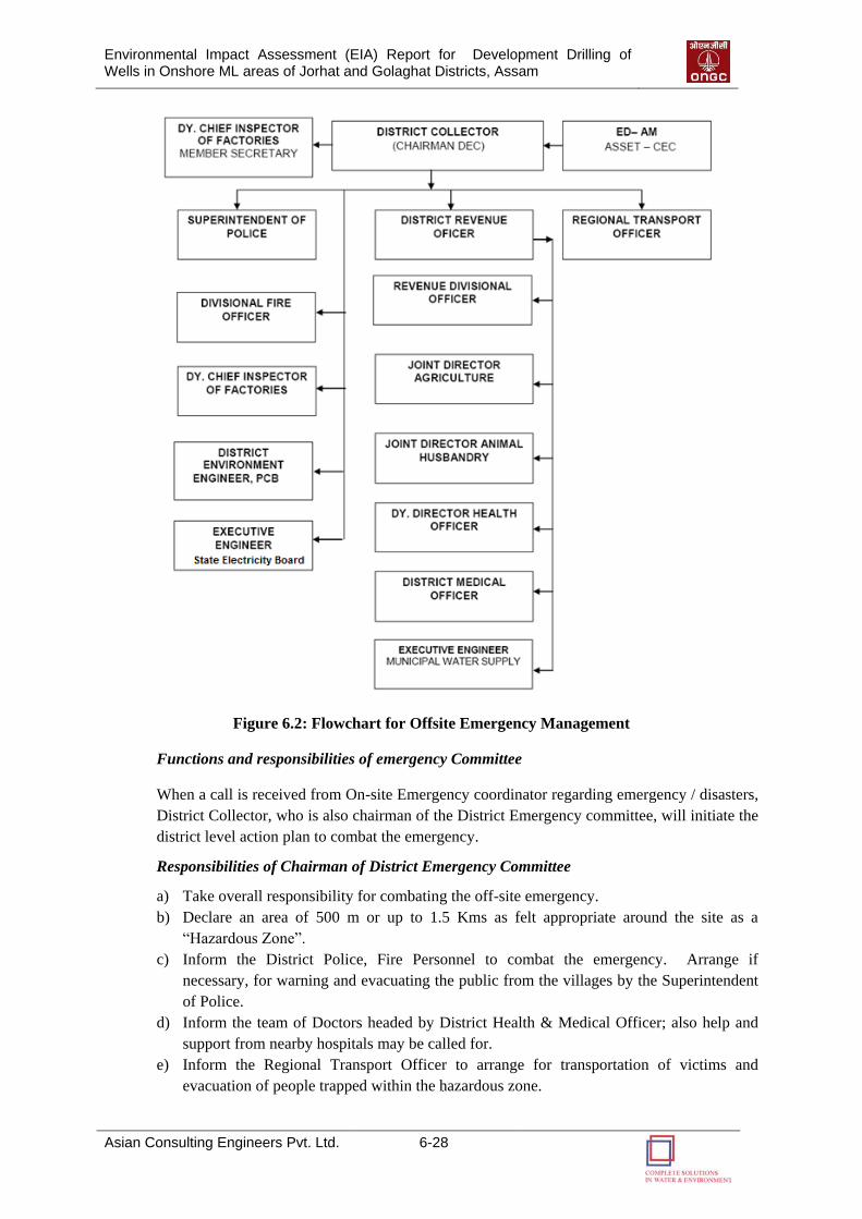
Environmental Impact Assessment (EIA) Report for Development Drilling of Wells in Onshore ML areas of Jorhat and Golaghat Districts, Assam
Asian Consulting Engineers Pvt. Ltd. 6-28
Figure 6.2: Flowchart for Offsite Emergency Management
Functions and responsibilities of emergency Committee
When a call is received from On-site Emergency coordinator regarding emergency / disasters,
District Collector, who is also chairman of the District Emergency committee, will initiate the
district level action plan to combat the emergency.
Responsibilities of Chairman of District Emergency Committee
a) Take overall responsibility for combating the off-site emergency.
b) Declare an area of 500 m or up to 1.5 Kms as felt appropriate around the site as a
“Hazardous Zone”.
c) Inform the District Police, Fire Personnel to combat the emergency. Arrange if
necessary, for warning and evacuating the public from the villages by the Superintendent
of Police.
d) Inform the team of Doctors headed by District Health & Medical Officer; also help and
support from nearby hospitals may be called for.
e) Inform the Regional Transport Officer to arrange for transportation of victims and
evacuation of people trapped within the hazardous zone.
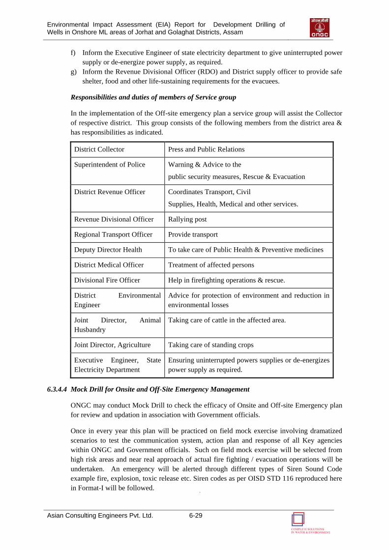
Environmental Impact Assessment (EIA) Report for Development Drilling of Wells in Onshore ML areas of Jorhat and Golaghat Districts, Assam
Asian Consulting Engineers Pvt. Ltd. 6-29
f) Inform the Executive Engineer of state electricity department to give uninterrupted power
supply or de-energize power supply, as required.
g) Inform the Revenue Divisional Officer (RDO) and District supply officer to provide safe
shelter, food and other life-sustaining requirements for the evacuees.
Responsibilities and duties of members of Service group
In the implementation of the Off-site emergency plan a service group will assist the Collector
of respective district. This group consists of the following members from the district area &
has responsibilities as indicated.
District Collector Press and Public Relations
Superintendent of Police Warning & Advice to the
public security measures, Rescue & Evacuation
District Revenue Officer Coordinates Transport, Civil
Supplies, Health, Medical and other services.
Revenue Divisional Officer Rallying post
Regional Transport Officer Provide transport
Deputy Director Health To take care of Public Health & Preventive medicines
District Medical Officer Treatment of affected persons
Divisional Fire Officer Help in firefighting operations & rescue.
District Environmental
Engineer
Advice for protection of environment and reduction in
environmental losses
Joint Director, Animal
Husbandry
Taking care of cattle in the affected area.
Joint Director, Agriculture Taking care of standing crops
Executive Engineer, State
Electricity Department
Ensuring uninterrupted powers supplies or de-energizes
power supply as required.
6.3.4.4 Mock Drill for Onsite and Off-Site Emergency Management
ONGC may conduct Mock Drill to check the efficacy of Onsite and Off-site Emergency plan
for review and updation in association with Government officials.
Once in every year this plan will be practiced on field mock exercise involving dramatized
scenarios to test the communication system, action plan and response of all Key agencies
within ONGC and Government officials. Such on field mock exercise will be selected from
high risk areas and near real approach of actual fire fighting / evacuation operations will be
undertaken. An emergency will be alerted through different types of Siren Sound Code
example fire, explosion, toxic release etc. Siren codes as per OISD STD 116 reproduced here
in Format-I will be followed.
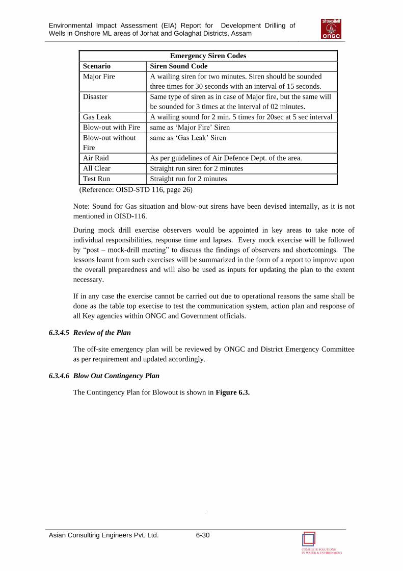
Environmental Impact Assessment (EIA) Report for Development Drilling of Wells in Onshore ML areas of Jorhat and Golaghat Districts, Assam
Asian Consulting Engineers Pvt. Ltd. 6-30
Emergency Siren Codes
Scenario Siren Sound Code
Major Fire A wailing siren for two minutes. Siren should be sounded
three times for 30 seconds with an interval of 15 seconds.
Disaster Same type of siren as in case of Major fire, but the same will
be sounded for 3 times at the interval of 02 minutes.
Gas Leak A wailing sound for 2 min. 5 times for 20sec at 5 sec interval
Blow-out with Fire same as „Major Fire‟ Siren
Blow-out without
Fire
same as „Gas Leak‟ Siren
Air Raid As per guidelines of Air Defence Dept. of the area.
All Clear Straight run siren for 2 minutes
Test Run Straight run for 2 minutes
(Reference: OISD-STD 116, page 26)
Note: Sound for Gas situation and blow-out sirens have been devised internally, as it is not
mentioned in OISD-116.
During mock drill exercise observers would be appointed in key areas to take note of
individual responsibilities, response time and lapses. Every mock exercise will be followed
by “post – mock-drill meeting” to discuss the findings of observers and shortcomings. The
lessons learnt from such exercises will be summarized in the form of a report to improve upon
the overall preparedness and will also be used as inputs for updating the plan to the extent
necessary.
If in any case the exercise cannot be carried out due to operational reasons the same shall be
done as the table top exercise to test the communication system, action plan and response of
all Key agencies within ONGC and Government officials.
6.3.4.5 Review of the Plan
The off-site emergency plan will be reviewed by ONGC and District Emergency Committee
as per requirement and updated accordingly.
6.3.4.6 Blow Out Contingency Plan
The Contingency Plan for Blowout is shown in Figure 6.3.

Environmental Impact Assessment (EIA) Report for Development Drilling of Wells in Onshore ML areas of Jorhat and Golaghat Districts, Assam
Asian Consulting Engineers Pvt. Ltd. 6-31
Figure 6.3: Blowout Contingency Plan
F IRST AID
WELL IS OUT OF CONTROL- BLOW OUT DECLARED
RESTRICT THE ENTRY OF OUTSIDERS
ORGANISE HEAD COUNT
EVACUATE THE SITE
BLOW OUT
ORGANISE SEARCH AND
RESCUE
FOR MINOR INJURIES
MOBILISE THE PATIENT TO NEAREST HOSPITAL
BLOWOUT WITH FIRE BLOWOUT WITHOUT FIRE
EVACUATE SITE
WAIT FOR INSTRUCTIONS
GAS OIL
SPRAY WATER
WAIT FOR FURTHER
INSTRUCTIONS
TAKE POLLUTION CONTROL MEASURES
WAIT FOR INSTRUCTIONS
EVACUATE SURROUNDINGS IF H2S PRESENTS
TALLIED?
YesNo
PRIMARY RESPONSE INCIDENT REPORTING
BASE RADIO ROOM
ASSET MANAGER / BASIN MANAGER
HEAD DRILLING SERVICES
SURFACE MANAGER & HEAD WELL SERVICES
NEAREST POLICE STATION
M.R.O. OFFICE
STATE FIRE DEPT.
R.C.M.T.
S.E.M.
SECURITY
ASSESSMENT OF SITUATION ON SITE
ON SITE MEETING
NOMINATE PROJECT CO-ORDINATOR
CIVIL , ADMN., POLICE, STATE FIRE, MEDICAL
TASK FORCE
ENGINEERING
RELIEF WELL TEAM
SUPPORT SERVICES
FIELD INTERVENTION TEAMWORK OUT THE CONTROL STRATEGY
MOBILIZE THE RESOURCES
BLOW OUT CONTROL & FIRE FIGHTING EQUIPMENT
POLLUTION CONTROL EQUIPMENT
O.N.G.C.
OUT SIDE
EXPERTS
ESTABLISH INFRASTRUCTURE-- COMMUNICATION
-- FIRST AID-- ON SITE CAMP
-- OFF SITE OFFICEEXECUTE CONTROL PLAN
LOGISTICS, COMMUNICATION, WORK SHOP, S.E.M., FIRE, MEDICAL, P&A,
F&A, M.M, P.R., LEGAL
SECONDARY RESPONSE
O.N.G.C.
OUT SIDE
O.N.G.C.
OUT SIDE

77
PPRROOJJEECCTT BBEENNEEFFIITTSS
Environmental Impact Assessment (EIA) Report for Development Drilling of Wells in Onshore ML areas of Jorhat and Golaghat Districts, Assam
Asian Consulting Engineers Pvt. Ltd. 7-1
PROJECT BENEFITS
7.1 PROJECT BENEFITS
The proposed development drilling of twelve (12) onshore wells drilling in the Nambar, East
Lakhibari, Khoraghat and Khoraghat Extension Mining lease areas in the Golaghat district
and Borholla Mining lease area in the Jorhat district of Assam will lead to following benefits:
The Project will enhance hydrocarbon production, the hydrocarbon gain is expected to be
30m3/day (NRDJ & NRDK wells), 30m3/day (ELDA well) and 90m3/day (KHDD,
KHDE & KHDF wells) in Golaghat District and 60 m3/day (BRDO & BRDN wells) in
Jorhat District, which will in-turn contribute to country’s economy by enhancing energy
security and reducing foreign exchange outgo.
The proposed project will result in the direct and indirect employment opportunities to the
unskilled/skilled local/regional people as well as increase in business opportunities.
The proposed project will benefit the region by way of creation and improvement of
infrastructure facilities like roads, drainage, bridges etc.
Assistance from ONGC as part of Corporate Social Responsibility (CSR) schemes in the
fields of education, health, infrastructure etc. for the benefit of local people and region.
7

88
EENNVVIIRROONNMMEENNTTAALL
MMAANNAAGGEEMMEENNTT
PPLLAANN
Environmental Impact Assessment (EIA) Report for Development Drilling of Wells in Onshore ML areas of Jorhat and Golaghat Districts, Assam
Asian Consulting Engineers Pvt. Ltd. 8-1
8 ENVIRONMENTAL
MANAGEMENT PLAN
8.1 INTRODUCTION
This Environmental Management Plan and Monitoring Framework is a site specific document
for the development drilling of hydrocarbons that has been developed to ensure that ONGC
can implement the project in an environmentally conscious manner and where all contractors,
understand the potential environmental risks arising out of the proposed project and take
appropriate actions to properly manage such risk.
This EMP will be an overview document that will guide environmental management of all
aspects of ONGC’s activities i.e. construction and operation of exploration/development
wells, GGS and Pipelines within the Block. This EMP will be backed up by more specific
Environmental Action Plans, Procedures and Bridging Documents with the progress of the
well site preparation, development drilling, well testing and site decommissioning activities.
8.2 PURPOSE AND OBJECTIVES OF THE ENVIRONMENTAL MANAGEMENT
PLAN (EMP)
An Environmental Management Plan (EMP) provides a delivery mechanism to address the
adverse environmental impact of a project during its execution, to enhance project benefits,
and to introduce standards of good practice to be adopted for all project works.
The primary objectives of the EMP are to:
Facilitate the implementation of mitigation measures for identified Adverse Impacts;
Define the responsibilities of the Project Proponents and Contractors in order to
effectively implement the Environmental Management Plan;
Define a Monitoring Mechanism and identify Monitoring Parameters in order to:
o Ensure the complete implementation of all Mitigation Measures;
o Ensure the effectiveness of the Mitigation Measure;
o Provide a mechanism for taking timely action in the face of Unanticipated
Environmental Situations;
Identify training requirements at various levels.
8.2.1 HSE Policy of Block Operator
The use of fossil fuel will depend not only on Technical, Economic and Political decisions but
increasingly on environmental considerations and its impact.
Block Operator will continue to conduct its activities in a professional and responsible
manner. The company, not only will comply with the laid down legislation requirements
8
Environmental Impact Assessment (EIA) Report for Development Drilling of Wells in Onshore ML areas of Jorhat and Golaghat Districts, Assam
Asian Consulting Engineers Pvt. Ltd. 8-2
but when found inadequate will promote creative measures and internal standards for the
protection of Health, Safety & Environment of the highest order for all who may directly
or indirectly be affected by any of the activities.
Personal Safety and Employee Health is our greatest responsibility, followed by the
protection of the Environment and Company Property. The company will continue to take
a proactive approach towards creating safe work environment for all employees and will
be concerned for promoting continued safety education and training for all employees,
assigning responsibility for all aspects of the program, continuously reviewing the
program to identify potential areas of improvement, and ensuring a thorough evaluation
of all incidents.
The company will continue to address the Environmental and Health impact of the
operations by reducing Waste, Emissions, discharges and by using energy efficiently.
The company will maintain awareness of HSE matters, so as to be proactive in providing
a value-added service to the Clients. This awareness is achieved through Education,
Communication and definition of the goals and standards appropriate to operation and
those undertaken on the Client’s behalf.
8.2.2 Organizational Structure and Responsibilities
This section provides an organizational structure for Environmental Management during
the proposed drilling project and defines the roles and responsibilities of the various role
players for the duration of the project.
A) Management Approach
The organizational roles and responsibilities are summarized below:
Block Operator: The overall responsibility for compliance with the Environmental
Management Plan rests with the Project Proponent.
Contractors: The Contractors (Civil, Drilling and Others) will carry out field activities as
part of the Development Drilling project. The contractors will be subject to certain
liabilities under the environmental laws of the country, and under their contract with
Block Operator.
A certain degree of redundancy is inevitable across all management levels, but this is in
order to ensure that compliance with the environmental management plan is
crosschecked.
Other essential features of the EMP are:
Block Operator will appoint a Mine Manager to oversee HSE compliance throughout
the duration of the Drilling Program. HSE Officer/ Safety Officer as per DGMS will
assist him in implementation and monitoring;
Block Operator will ensure that all contracts comply with the requirements given in
the Environmental Management Plan;
Environmental Impact Assessment (EIA) Report for Development Drilling of Wells in Onshore ML areas of Jorhat and Golaghat Districts, Assam
Asian Consulting Engineers Pvt. Ltd. 8-3
Block Operator will cooperate with regulatory agencies (such as the State Pollution
Control Board, CPCB, DGMS, OISD, MoEF) who may want to send their own teams
to monitor the activities during the Drilling Program.
B) Organizational Responsibilities
The salient features of the organisational responsibilities are described below:
(i) Primary Responsibilities:
The primary responsibilities for the environmental performance of the Project
Proponent & the Contractors will be assumed by their senior level officers during the
project period.
Block Operator’s Mine Manager will be responsible for the company’s compliance
with the EMP throughout the project.
The contractor will assume the main responsibility for all environmental matters
pertaining to their work.
Block Operator will coordinate with relevant Government Departments.
(ii) Field Management and Quality Control:
Conducting Drilling Activities in an environmentally sound manner will be the
responsibility of the Drilling Contractor/Company.
Block Operator’s Safety Officer (Drilling) will be responsible for the overall
environmental soundness of all field operations.
(iii) On-the-job Supervision and Monitoring:
Block Operator has a Safety Officer, who is responsible for ensuring compliance with
the EMP during the drilling operation. He is also responsible for communicating with
and training the Drilling Crews in all aspects of the EMP.
Block Operator has an HSE Coordinator who will be responsible for all
environmental issues and for the implementation of the environmental management
plan in the field.
If any Monitoring Team from Government Departments or from NGOs visit the field
during the Drilling Operation, Block Operator’s HSE Coordinator will be responsible
for coordinating their visits.
8.3 MITIGATION PLAN
The Mitigation Plan is the key component of any EMP. It lists all the potential impacts of the
project and their associated mitigation measures identified in the EIA. For each
Impact/Hazard, the following information is presented in the plan:
A comprehensive listing of Mitigation Measures
Actions Required
The mitigation plan for proposed development drillings is presented Table 8.1 (prior to
drilling phase) and Table 8.2 (during drilling phase).
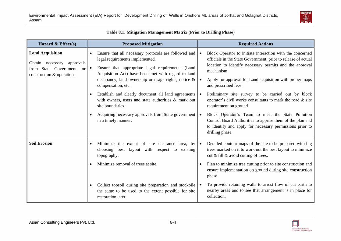
Environmental Impact Assessment (EIA) Report for Development Drilling of Wells in Onshore ML areas of Jorhat and Golaghat Districts, Assam
Asian Consulting Engineers Pvt. Ltd. 8-4
Table 8.1: Mitigation Management Matrix (Prior to Drilling Phase)
Hazard & Effect(s) Proposed Mitigation Required Actions
Land Acquisition
Obtain necessary approvals
from State Government for
construction & operations.
Ensure that all necessary protocols are followed and
legal requirements implemented.
Ensure that appropriate legal requirements (Land
Acquisition Act) have been met with regard to land
occupancy, land ownership or usage rights, notice &
compensation, etc.
Establish and clearly document all land agreements
with owners, users and state authorities & mark out
site boundaries.
Acquiring necessary approvals from State government
in a timely manner.
Block Operator to initiate interaction with the concerned
officials in the State Government, prior to release of actual
location to identify necessary permits and the approval
mechanism.
Apply for approval for Land acquisition with proper maps
and prescribed fees.
Preliminary site survey to be carried out by block
operator’s civil works consultants to mark the road & site
requirement on ground.
Block Operator’s Team to meet the State Pollution
Control Board Authorities to apprise them of the plan and
to identify and apply for necessary permissions prior to
drilling phase.
Soil Erosion Minimize the extent of site clearance area, by
choosing best layout with respect to existing
topography.
Minimize removal of trees at site.
Collect topsoil during site preparation and stockpile
the same to be used to the extent possible for site
restoration later.
Detailed contour maps of the site to be prepared with big
trees marked on it to work out the best layout to minimize
cut & fill & avoid cutting of trees.
Plan to minimize tree cutting prior to site construction and
ensure implementation on ground during site construction
phase.
To provide retaining walls to arrest flow of cut earth to
nearby areas and to see that arrangement is in place for
collection.
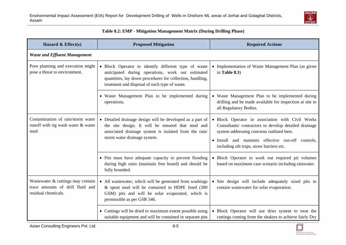
Environmental Impact Assessment (EIA) Report for Development Drilling of Wells in Onshore ML areas of Jorhat and Golaghat Districts, Assam
Asian Consulting Engineers Pvt. Ltd. 8-5
Table 8.2: EMP - Mitigation Management Matrix (During Drilling Phase)
Hazard & Effect(s) Proposed Mitigation Required Actions
Waste and Effluent Management
Poor planning and execution might
pose a threat to environment.
Block Operator to identify different type of waste
anticipated during operations, work out estimated
quantities, lay down procedures for collection, handling,
treatment and disposal of each type of waste.
Implementation of Waste Management Plan (as given
in Table 8.3)
Waste Management Plan to be implemented during
operations.
Waste Management Plan to be implemented during
drilling and be made available for inspection at site to
all Regulatory Bodies.
Contamination of rain/storm water
runoff with rig wash water & waste
mud
Detailed drainage design will be developed as a part of
the site design. It will be ensured that mud and
associated drainage system is isolated from the rain/
storm water drainage system.
Block Operator in association with Civil Works
Consultants/ contractors to develop detailed drainage
system addressing concerns outlined here.
Install and maintain effective run-off controls,
including silt traps, straw barriers etc.
Pits must have adequate capacity to prevent flooding
during high rains (maintain free board) and should be
fully bounded.
Block Operator to work out required pit volumes
based on maximum case scenario including rainwater.
Wastewater & cuttings may contain
trace amounts of drill fluid and
residual chemicals.
All wastewater, which will be generated from washings
& spent mud will be contained in HDPE lined (300
GSM) pits and will be solar evaporated, which is
permissible as per GSR 546.
Site design will include adequately sized pits to
contain wastewater for solar evaporation.
Cuttings will be dried to maximum extent possible using
suitable equipment and will be contained in separate pits
Block Operator will use drier system to treat the
cuttings coming from the shakers to achieve fairly Dry
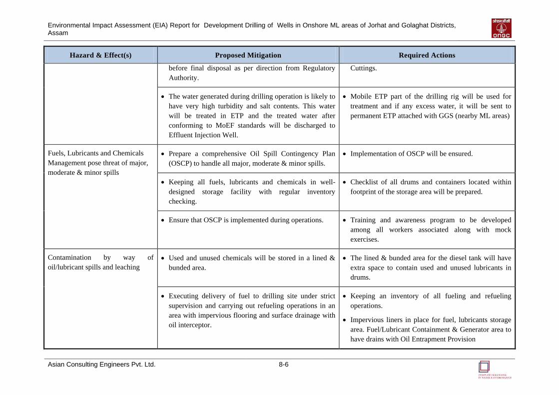
Environmental Impact Assessment (EIA) Report for Development Drilling of Wells in Onshore ML areas of Jorhat and Golaghat Districts, Assam
Asian Consulting Engineers Pvt. Ltd. 8-6
Hazard & Effect(s) Proposed Mitigation Required Actions
before final disposal as per direction from Regulatory
Authority.
Cuttings.
The water generated during drilling operation is likely to
have very high turbidity and salt contents. This water
will be treated in ETP and the treated water after
conforming to MoEF standards will be discharged to
Effluent Injection Well.
Mobile ETP part of the drilling rig will be used for
treatment and if any excess water, it will be sent to
permanent ETP attached with GGS (nearby ML areas)
Fuels, Lubricants and Chemicals
Management pose threat of major,
moderate & minor spills
Prepare a comprehensive Oil Spill Contingency Plan
(OSCP) to handle all major, moderate & minor spills.
Implementation of OSCP will be ensured.
Keeping all fuels, lubricants and chemicals in well-
designed storage facility with regular inventory
checking.
Checklist of all drums and containers located within
footprint of the storage area will be prepared.
Ensure that OSCP is implemented during operations. Training and awareness program to be developed
among all workers associated along with mock
exercises.
Contamination by way of
oil/lubricant spills and leaching
Used and unused chemicals will be stored in a lined &
bunded area.
The lined & bunded area for the diesel tank will have
extra space to contain used and unused lubricants in
drums.
Executing delivery of fuel to drilling site under strict
supervision and carrying out refueling operations in an
area with impervious flooring and surface drainage with
oil interceptor.
Keeping an inventory of all fueling and refueling
operations.
Impervious liners in place for fuel, lubricants storage
area. Fuel/Lubricant Containment & Generator area to
have drains with Oil Entrapment Provision
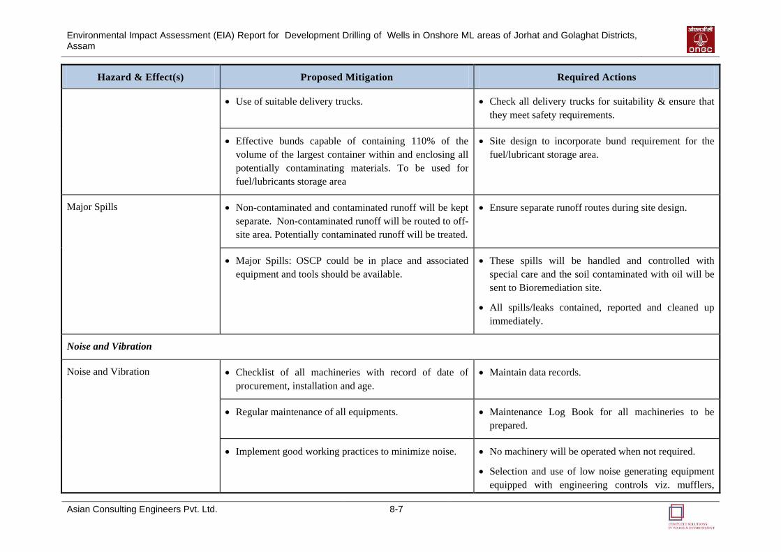
Environmental Impact Assessment (EIA) Report for Development Drilling of Wells in Onshore ML areas of Jorhat and Golaghat Districts, Assam
Asian Consulting Engineers Pvt. Ltd. 8-7
Hazard & Effect(s) Proposed Mitigation Required Actions
Use of suitable delivery trucks. Check all delivery trucks for suitability & ensure that
they meet safety requirements.
Effective bunds capable of containing 110% of the
volume of the largest container within and enclosing all
potentially contaminating materials. To be used for
fuel/lubricants storage area
Site design to incorporate bund requirement for the
fuel/lubricant storage area.
Major Spills
Non-contaminated and contaminated runoff will be kept
separate. Non-contaminated runoff will be routed to off-
site area. Potentially contaminated runoff will be treated.
Ensure separate runoff routes during site design.
Major Spills: OSCP could be in place and associated
equipment and tools should be available.
These spills will be handled and controlled with
special care and the soil contaminated with oil will be
sent to Bioremediation site.
All spills/leaks contained, reported and cleaned up
immediately.
Noise and Vibration
Noise and Vibration Checklist of all machineries with record of date of
procurement, installation and age.
Maintain data records.
Regular maintenance of all equipments. Maintenance Log Book for all machineries to be
prepared.
Implement good working practices to minimize noise. No machinery will be operated when not required.
Selection and use of low noise generating equipment
equipped with engineering controls viz. mufflers,
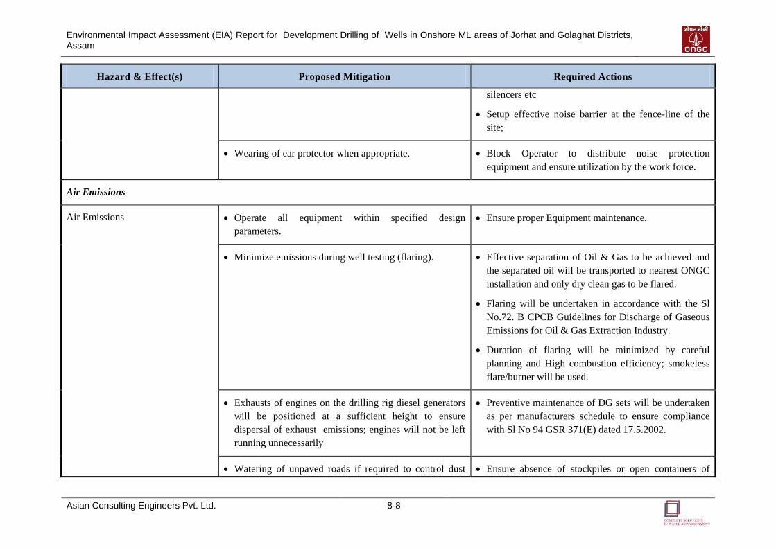
Environmental Impact Assessment (EIA) Report for Development Drilling of Wells in Onshore ML areas of Jorhat and Golaghat Districts, Assam
Asian Consulting Engineers Pvt. Ltd. 8-8
Hazard & Effect(s) Proposed Mitigation Required Actions
silencers etc
Setup effective noise barrier at the fence-line of the
site;
Wearing of ear protector when appropriate. Block Operator to distribute noise protection
equipment and ensure utilization by the work force.
Air Emissions
Air Emissions Operate all equipment within specified design
parameters.
Ensure proper Equipment maintenance.
Minimize emissions during well testing (flaring). Effective separation of Oil & Gas to be achieved and
the separated oil will be transported to nearest ONGC
installation and only dry clean gas to be flared.
Flaring will be undertaken in accordance with the Sl
No.72. B CPCB Guidelines for Discharge of Gaseous
Emissions for Oil & Gas Extraction Industry.
Duration of flaring will be minimized by careful
planning and High combustion efficiency; smokeless
flare/burner will be used.
Exhausts of engines on the drilling rig diesel generators
will be positioned at a sufficient height to ensure
dispersal of exhaust emissions; engines will not be left
running unnecessarily
Preventive maintenance of DG sets will be undertaken
as per manufacturers schedule to ensure compliance
with Sl No 94 GSR 371(E) dated 17.5.2002.
Watering of unpaved roads if required to control dust Ensure absence of stockpiles or open containers of
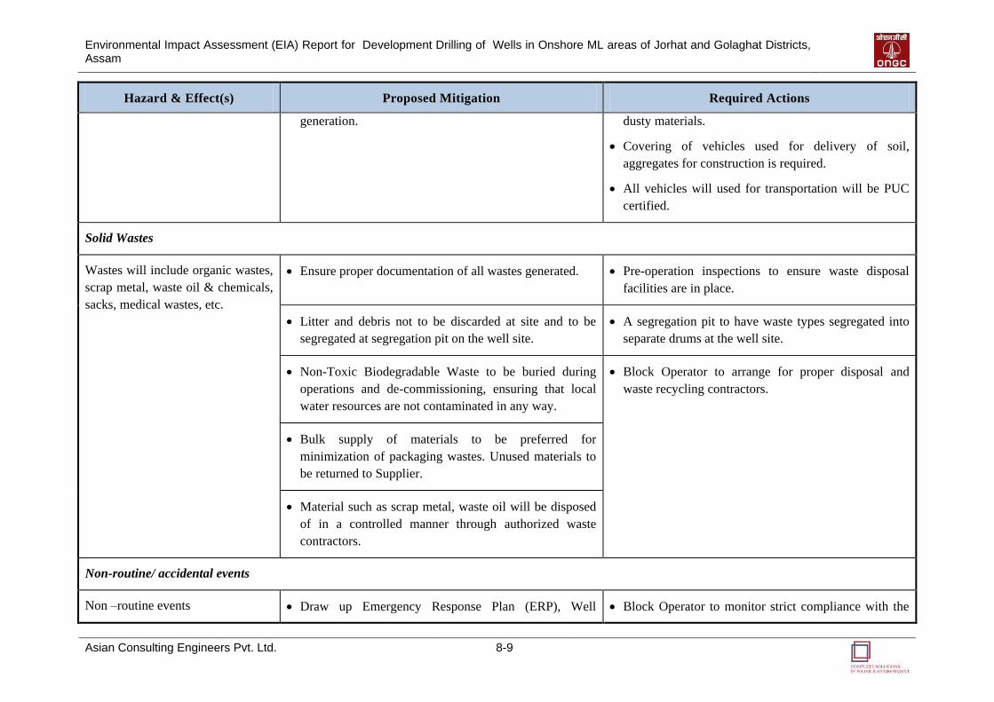
Environmental Impact Assessment (EIA) Report for Development Drilling of Wells in Onshore ML areas of Jorhat and Golaghat Districts, Assam
Asian Consulting Engineers Pvt. Ltd. 8-9
Hazard & Effect(s) Proposed Mitigation Required Actions
generation. dusty materials.
Covering of vehicles used for delivery of soil,
aggregates for construction is required.
All vehicles will used for transportation will be PUC
certified.
Solid Wastes
Wastes will include organic wastes,
scrap metal, waste oil & chemicals,
sacks, medical wastes, etc.
Ensure proper documentation of all wastes generated. Pre-operation inspections to ensure waste disposal
facilities are in place.
Litter and debris not to be discarded at site and to be
segregated at segregation pit on the well site.
A segregation pit to have waste types segregated into
separate drums at the well site.
Non-Toxic Biodegradable Waste to be buried during
operations and de-commissioning, ensuring that local
water resources are not contaminated in any way.
Block Operator to arrange for proper disposal and
waste recycling contractors.
Bulk supply of materials to be preferred for
minimization of packaging wastes. Unused materials to
be returned to Supplier.
Material such as scrap metal, waste oil will be disposed
of in a controlled manner through authorized waste
contractors.
Non-routine/ accidental events
Non –routine events Draw up Emergency Response Plan (ERP), Well Block Operator to monitor strict compliance with the
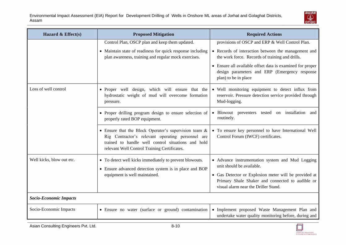
Environmental Impact Assessment (EIA) Report for Development Drilling of Wells in Onshore ML areas of Jorhat and Golaghat Districts, Assam
Asian Consulting Engineers Pvt. Ltd. 8-10
Hazard & Effect(s) Proposed Mitigation Required Actions
Control Plan, OSCP plan and keep them updated.
Maintain state of readiness for quick response including
plan awareness, training and regular mock exercises.
provisions of OSCP and ERP & Well Control Plan.
Records of interaction between the management and
the work force. Records of training and drills.
Ensure all available offset data is examined for proper
design parameters and ERP (Emergency response
plan) to be in place
Loss of well control Proper well design, which will ensure that the
hydrostatic weight of mud will overcome formation
pressure.
Well monitoring equipment to detect influx from
reservoir. Pressure detection service provided through
Mud-logging.
Proper drilling program design to ensure selection of
properly rated BOP equipment.
Blowout preventers tested on installation and
routinely.
Ensure that the Block Operator’s supervision team &
Rig Contractor’s relevant operating personnel are
trained to handle well control situations and hold
relevant Well Control Training Certificates.
To ensure key personnel to have International Well
Control Forum (IWCF) certificates.
Well kicks, blow out etc.
To detect well kicks immediately to prevent blowouts.
Ensure advanced detection system is in place and BOP
equipment is well maintained.
Advance instrumentation system and Mud Logging
unit should be available.
Gas Detector or Explosion meter will be provided at
Primary Shale Shaker and connected to audible or
visual alarm near the Driller Stand.
Socio-Economic Impacts
Socio-Economic Impacts Ensure no water (surface or ground) contamination Implement proposed Waste Management Plan and
undertake water quality monitoring before, during and
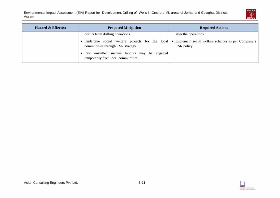
Environmental Impact Assessment (EIA) Report for Development Drilling of Wells in Onshore ML areas of Jorhat and Golaghat Districts, Assam
Asian Consulting Engineers Pvt. Ltd. 8-11
Hazard & Effect(s) Proposed Mitigation Required Actions
occurs from drilling operations.
Undertake social welfare projects for the local
communities through CSR strategy.
Few unskilled manual labours may be engaged
temporarily from local communities.
after the operations.
Implement social welfare schemes as per Company’s
CSR policy.
Environmental Impact Assessment (EIA) Report for Development Drilling of Wells in Onshore ML areas of Jorhat and Golaghat Districts, Assam
Asian Consulting Engineers Pvt. Ltd. 8-12
8.4 ENVIRONMENTAL TRAINING
HSE training will help to ensure that the requirements of the EIA and EMP are clearly
understood and followed by all project personnel throughout the project period. The primary
responsibility for providing training to all project personnel will be that of ONGC.
ONGC will train the site staff, the drilling contractor, and other staff engaged by Block
Operator for the project. Training will cover all staff levels, ranging from the management
and supervisory to the skilled and unskilled categories. The scope of the training will cover
the requirements of the EIA and the EMP, with special emphasis on sensitizing the project
staff to environmental, social, ethnic, and tribal context of the area.
The Drilling In-charge will conduct Pit Level Meeting, Job Safety Analysis and Tool Box
Meeting for the Block Operator Staff and the Contractor Staff to better appreciate
environmental risks and their mitigation measures. This will be undertaken after conducting
audits on the operations. SOP and provisions of the Mines Act and relevant OISD standards
should be discussed with Rig Operator.
8.5 WASTE MANAGEMENT PLAN
For the proposed drilling, it is expected that the drill cuttings will be free from oil and may
not be rendered as hazardous, provided it is out of the purview of concentration criteria laid
down under the Rules.
The sludge from the proposed drilling operations may be rendered as free from oil by
providing suitable pre-treatment measures. However, as per the Rules, any chemical sludge
generated from wastewater treatment is considered as hazardous. Therefore, the chemical
sludge from the wastewater treatment at the proposed Developmental Drilling can be rendered
as hazardous.
The Drilling Mud and Other Drilling Wastes also considered as hazardous. However, based
on sampling and analysis carried out through a recognized laboratory after the end of the
drilling phase, if it is proved that the drilling mud and other drilling wastes do not contain any
of the constituents mentioned in HWM Rules to the extent of concentration limits specified
therein, the wastes may not be treated as hazardous.
Block Operator would require prior authorization from the State Pollution Control Board for
treatment, storage, transportation and disposal of any hazardous waste generated at site during
drilling operations. Management of drill cuttings, waste drilling mud, waste oil and domestic
waste will be made in accordance with S No. 72 C.1.a Schedule I Standards for Emission or
Discharge of Environmental Pollutants from Oil Drilling and Gas Extraction Industry of
CPCB as modified in 2005.
To facilitate field level implementation, a Waste Management Plan is proposed, which will be
subject to fine tuning before the start of the operations. This Waste Management plan is
presented below in Table 8.3.
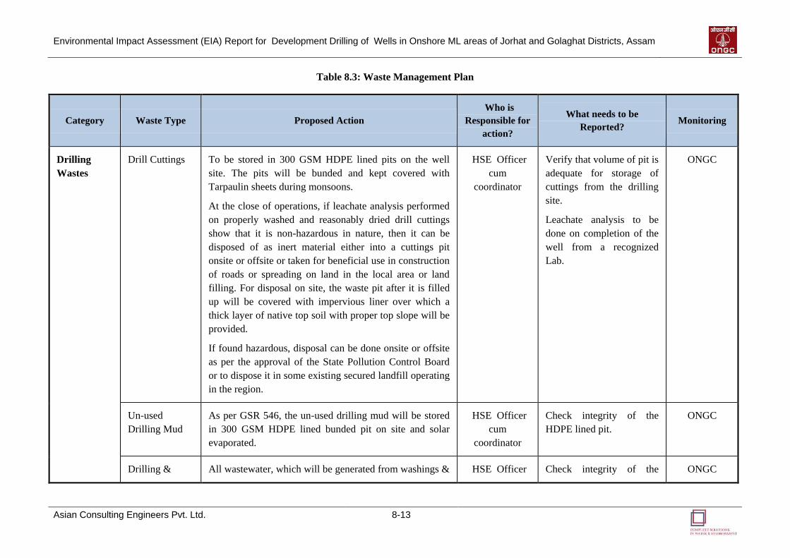
Environmental Impact Assessment (EIA) Report for Development Drilling of Wells in Onshore ML areas of Jorhat and Golaghat Districts, Assam
Asian Consulting Engineers Pvt. Ltd. 8-13
Table 8.3: Waste Management Plan
Category Waste Type Proposed Action
Who is
Responsible for
action?
What needs to be
Reported? Monitoring
Drilling
Wastes
Drill Cuttings To be stored in 300 GSM HDPE lined pits on the well
site. The pits will be bunded and kept covered with
Tarpaulin sheets during monsoons.
At the close of operations, if leachate analysis performed
on properly washed and reasonably dried drill cuttings
show that it is non-hazardous in nature, then it can be
disposed of as inert material either into a cuttings pit
onsite or offsite or taken for beneficial use in construction
of roads or spreading on land in the local area or land
filling. For disposal on site, the waste pit after it is filled
up will be covered with impervious liner over which a
thick layer of native top soil with proper top slope will be
provided.
If found hazardous, disposal can be done onsite or offsite
as per the approval of the State Pollution Control Board
or to dispose it in some existing secured landfill operating
in the region.
HSE Officer
cum
coordinator
Verify that volume of pit is
adequate for storage of
cuttings from the drilling
site.
Leachate analysis to be
done on completion of the
well from a recognized
Lab.
ONGC
Un-used
Drilling Mud
As per GSR 546, the un-used drilling mud will be stored
in 300 GSM HDPE lined bunded pit on site and solar
evaporated.
HSE Officer
cum
coordinator
Check integrity of the
HDPE lined pit.
ONGC
Drilling & All wastewater, which will be generated from washings & HSE Officer Check integrity of the ONGC
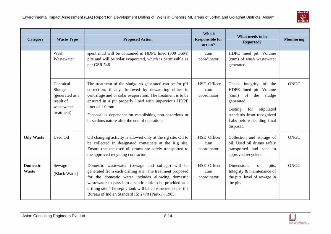
Environmental Impact Assessment (EIA) Report for Development Drilling of Wells in Onshore ML areas of Jorhat and Golaghat Districts, Assam
Asian Consulting Engineers Pvt. Ltd. 8-14
Category Waste Type Proposed Action
Who is
Responsible for
action?
What needs to be
Reported? Monitoring
Wash
Wastewater
spent mud will be contained in HDPE lined (300 GSM)
pits and will be solar evaporated, which is permissible as
per GSR 546.
cum
coordinator
HDPE lined pit. Volume
(cum) of wash wastewater
generated.
Chemical
Sludge
(generated as a
result of
wastewater
treatment)
The treatment of the sludge so generated can be for pH
correction, if any, followed by dewatering either in
centrifuge and or solar evaporation. The treatment is to be
ensured in a pit properly lined with impervious HDPE
liner of 1.0 mm.
Disposal is dependent on establishing non-hazardous or
hazardous nature after the end of operations.
HSE Officer
cum
coordinator
Check integrity of the
HDPE lined pit. Volume
(cum) of the sludge
generated.
Testing for stipulated
standards from recognized
Labs before deciding final
disposal.
ONGC
Oily Waste Used Oil Oil changing activity is allowed only at the rig site. Oil to
be collected in designated containers at the Rig site.
Ensure that the used oil drums are safely transported to
the approved recycling contractor.
HSE Officer
cum
coordinator
Collection and storage of
oil. Used oil drums safely
transported and sent to
approved recyclers.
ONGC
Domestic
Waste
Sewage
(Black Water)
Domestic wastewater (sewage and sullage) will be
generated from each drilling site. The treatment proposed
for the domestic water includes allowing domestic
wastewater to pass into a septic tank to be provided at a
drilling site. The septic tank will be constructed as per the
Bureau of Indian Standard IS: 2470 (Part-1): 1985.
HSE Officer
cum
coordinator
Dimensions of pits,
Integrity & maintenance of
the pits, level of sewage in
the pits.
ONGC
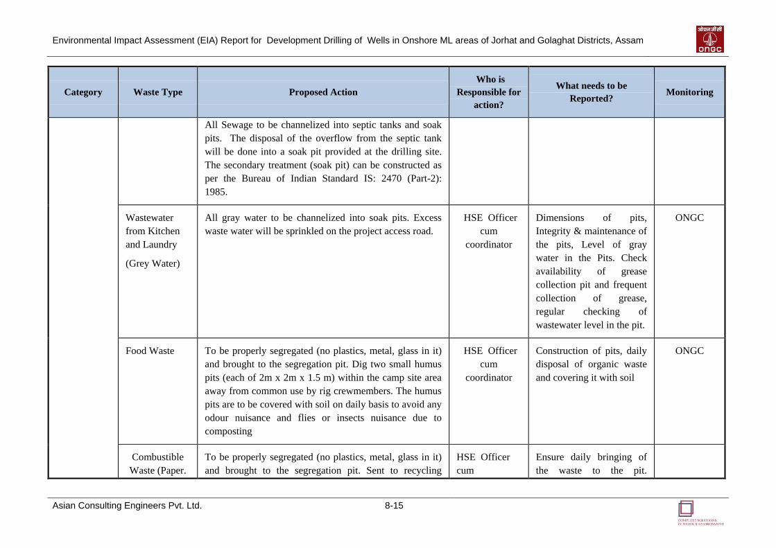
Environmental Impact Assessment (EIA) Report for Development Drilling of Wells in Onshore ML areas of Jorhat and Golaghat Districts, Assam
Asian Consulting Engineers Pvt. Ltd. 8-15
Category Waste Type Proposed Action
Who is
Responsible for
action?
What needs to be
Reported? Monitoring
All Sewage to be channelized into septic tanks and soak
pits. The disposal of the overflow from the septic tank
will be done into a soak pit provided at the drilling site.
The secondary treatment (soak pit) can be constructed as
per the Bureau of Indian Standard IS: 2470 (Part-2):
1985.
Wastewater
from Kitchen
and Laundry
(Grey Water)
All gray water to be channelized into soak pits. Excess
waste water will be sprinkled on the project access road.
HSE Officer
cum
coordinator
Dimensions of pits,
Integrity & maintenance of
the pits, Level of gray
water in the Pits. Check
availability of grease
collection pit and frequent
collection of grease,
regular checking of
wastewater level in the pit.
ONGC
Food Waste To be properly segregated (no plastics, metal, glass in it)
and brought to the segregation pit. Dig two small humus
pits (each of 2m x 2m x 1.5 m) within the camp site area
away from common use by rig crewmembers. The humus
pits are to be covered with soil on daily basis to avoid any
odour nuisance and flies or insects nuisance due to
composting
HSE Officer
cum
coordinator
Construction of pits, daily
disposal of organic waste
and covering it with soil
ONGC
Combustible
Waste (Paper.
To be properly segregated (no plastics, metal, glass in it)
and brought to the segregation pit. Sent to recycling
HSE Officer
cum
Ensure daily bringing of
the waste to the pit.
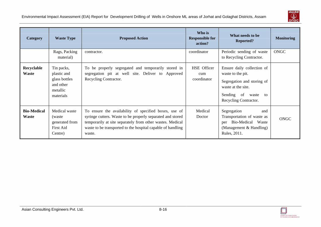
Environmental Impact Assessment (EIA) Report for Development Drilling of Wells in Onshore ML areas of Jorhat and Golaghat Districts, Assam
Asian Consulting Engineers Pvt. Ltd. 8-16
Category Waste Type Proposed Action
Who is
Responsible for
action?
What needs to be
Reported? Monitoring
Rags, Packing
material)
contractor. coordinator Periodic sending of waste
to Recycling Contractor.
ONGC
Recyclable
Waste
Tin packs,
plastic and
glass bottles
and other
metallic
materials
To be properly segregated and temporarily stored in
segregation pit at well site. Deliver to Approved
Recycling Contractor.
HSE Officer
cum
coordinator
Ensure daily collection of
waste to the pit.
Segregation and storing of
waste at the site.
Sending of waste to
Recycling Contractor.
Bio-Medical
Waste
Medical waste
(waste
generated from
First Aid
Centre)
To ensure the availability of specified boxes, use of
syringe cutters. Waste to be properly separated and stored
temporarily at site separately from other wastes. Medical
waste to be transported to the hospital capable of handling
waste.
Medical
Doctor
Segregation and
Transportation of waste as
per Bio-Medical Waste
(Management & Handling)
Rules, 2011.
ONGC
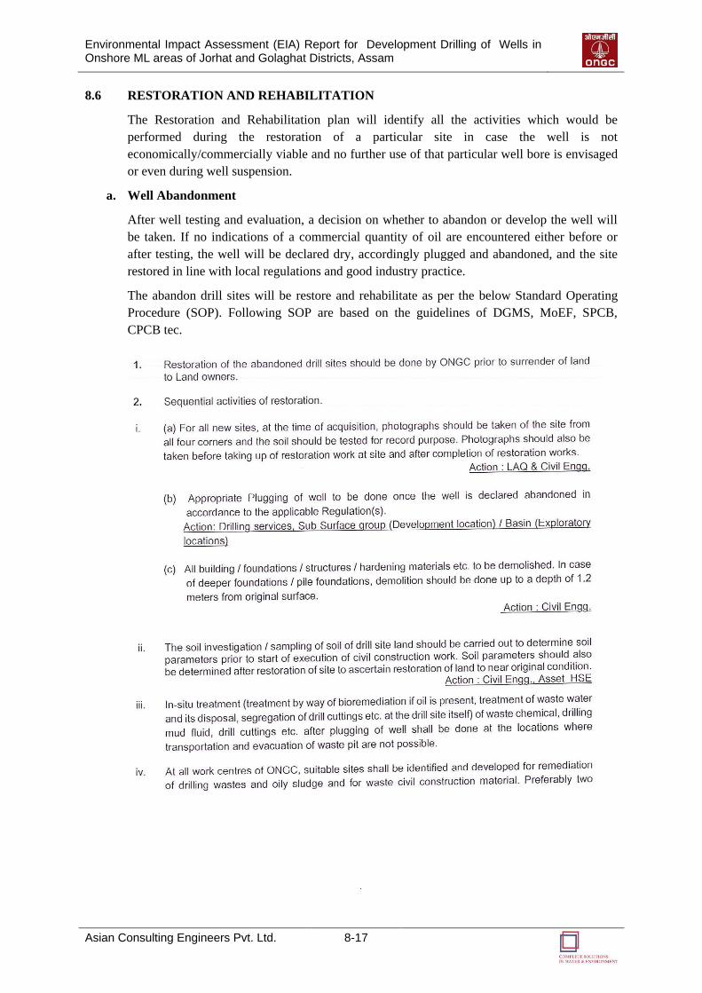
Environmental Impact Assessment (EIA) Report for Development Drilling of Wells in Onshore ML areas of Jorhat and Golaghat Districts, Assam
Asian Consulting Engineers Pvt. Ltd. 8-17
8.6 RESTORATION AND REHABILITATION
The Restoration and Rehabilitation plan will identify all the activities which would be
performed during the restoration of a particular site in case the well is not
economically/commercially viable and no further use of that particular well bore is envisaged
or even during well suspension.
a. Well Abandonment
After well testing and evaluation, a decision on whether to abandon or develop the well will
be taken. If no indications of a commercial quantity of oil are encountered either before or
after testing, the well will be declared dry, accordingly plugged and abandoned, and the site
restored in line with local regulations and good industry practice.
The abandon drill sites will be restore and rehabilitate as per the below Standard Operating
Procedure (SOP). Following SOP are based on the guidelines of DGMS, MoEF, SPCB,
CPCB tec.
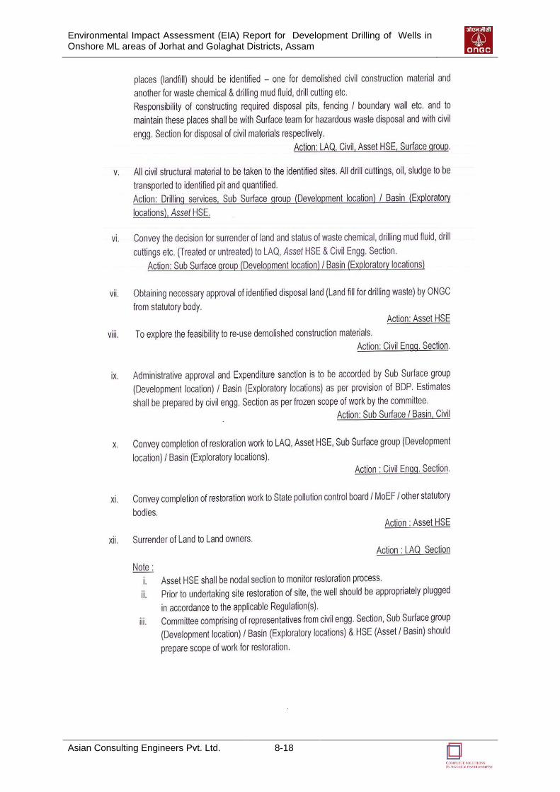
Environmental Impact Assessment (EIA) Report for Development Drilling of Wells in Onshore ML areas of Jorhat and Golaghat Districts, Assam
Asian Consulting Engineers Pvt. Ltd. 8-18
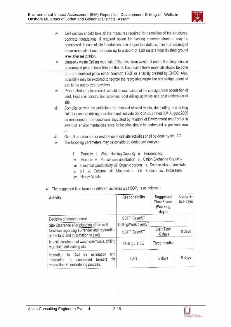
Environmental Impact Assessment (EIA) Report for Development Drilling of Wells in Onshore ML areas of Jorhat and Golaghat Districts, Assam
Asian Consulting Engineers Pvt. Ltd. 8-19

Environmental Impact Assessment (EIA) Report for Development Drilling of Wells in Onshore ML areas of Jorhat and Golaghat Districts, Assam
Asian Consulting Engineers Pvt. Ltd. 8-20
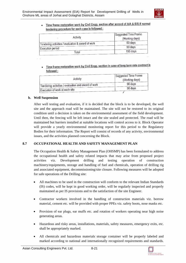
Environmental Impact Assessment (EIA) Report for Development Drilling of Wells in Onshore ML areas of Jorhat and Golaghat Districts, Assam
Asian Consulting Engineers Pvt. Ltd. 8-21
b. Well Suspension
After well testing and evaluation, if it is decided that the block is to be developed, the well
site and the approach road will be maintained. The site will not be restored to its original
condition until a decision is taken on the environmental assessment of the field development.
Until then, the fencing will be left intact and the site sealed and protected. The road will be
maintained but barriers installed at suitable locations will control access to it. Block Operator
will provide a yearly environmental monitoring report for this period to the Regulatory
Bodies for their information. The Report will consist of records of any activity, environmental
issues, and the activities planned concerning the Block.
8.7 OCCUPATIONAL HEALTH AND SAFETY MANAGEMENT PLAN
The Occupation Health & Safety Management Plan (OHSMP) has been formulated to address
the occupational health and safety related impacts that may arise from proposed project
activities viz. Development drilling and testing operation of construction
machinery/equipments, storage and handling of fuel and chemicals, operation of drilling rig
and associated equipment, decommissioning/site closure. Following measures will be adopted
for safe operations of the Drilling site:
All machines to be used in the construction will conform to the relevant Indian Standards
(IS) codes, will be kept in good working order, will be regularly inspected and properly
maintained as per IS provisions and to the satisfaction of the site Engineer.
Contractor workers involved in the handling of construction materials viz. borrow
material, cement etc. will be provided with proper PPEs viz. safety boots, nose masks etc.
Provision of ear plugs, ear muffs etc. and rotation of workers operating near high noise
generating areas.
Hazardous and risky areas, installations, materials, safety measures, emergency exits, etc.
shall be appropriately marked.
All chemicals and hazardous materials storage container will be properly labeled and
marked according to national and internationally recognized requirements and standards.
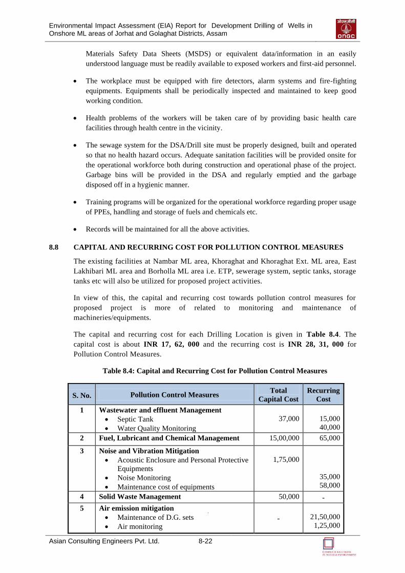
Environmental Impact Assessment (EIA) Report for Development Drilling of Wells in Onshore ML areas of Jorhat and Golaghat Districts, Assam
Asian Consulting Engineers Pvt. Ltd. 8-22
Materials Safety Data Sheets (MSDS) or equivalent data/information in an easily
understood language must be readily available to exposed workers and first-aid personnel.
The workplace must be equipped with fire detectors, alarm systems and fire-fighting
equipments. Equipments shall be periodically inspected and maintained to keep good
working condition.
Health problems of the workers will be taken care of by providing basic health care
facilities through health centre in the vicinity.
The sewage system for the DSA/Drill site must be properly designed, built and operated
so that no health hazard occurs. Adequate sanitation facilities will be provided onsite for
the operational workforce both during construction and operational phase of the project.
Garbage bins will be provided in the DSA and regularly emptied and the garbage
disposed off in a hygienic manner.
Training programs will be organized for the operational workforce regarding proper usage
of PPEs, handling and storage of fuels and chemicals etc.
Records will be maintained for all the above activities.
8.8 CAPITAL AND RECURRING COST FOR POLLUTION CONTROL MEASURES
The existing facilities at Nambar ML area, Khoraghat and Khoraghat Ext. ML area, East
Lakhibari ML area and Borholla ML area i.e. ETP, sewerage system, septic tanks, storage
tanks etc will also be utilized for proposed project activities.
In view of this, the capital and recurring cost towards pollution control measures for
proposed project is more of related to monitoring and maintenance of
machineries/equipments.
The capital and recurring cost for each Drilling Location is given in Table 8.4. The
capital cost is about INR 17, 62, 000 and the recurring cost is INR 28, 31, 000 for
Pollution Control Measures.
Table 8.4: Capital and Recurring Cost for Pollution Control Measures
S. No. Pollution Control Measures Total
Capital Cost
Recurring
Cost
1 Wastewater and effluent Management
Septic Tank
Water Quality Monitoring
37,000
15,000
40,000
2 Fuel, Lubricant and Chemical Management 15,00,000 65,000
3 Noise and Vibration Mitigation
Acoustic Enclosure and Personal Protective
Equipments
Noise Monitoring
Maintenance cost of equipments
1,75,000
35,000
58,000
4 Solid Waste Management 50,000 -
5 Air emission mitigation
Maintenance of D.G. sets
Air monitoring -
21,50,000
1,25,000
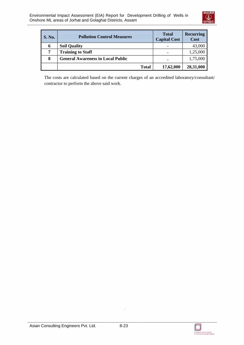
Environmental Impact Assessment (EIA) Report for Development Drilling of Wells in Onshore ML areas of Jorhat and Golaghat Districts, Assam
Asian Consulting Engineers Pvt. Ltd. 8-23
S. No. Pollution Control Measures Total
Capital Cost
Recurring
Cost
6 Soil Quality - 43,000
7 Training to Staff - 1,25,000
8 General Awareness in Local Public - 1,75,000
Total 17,62,000 28,31,000
The costs are calculated based on the current charges of an accredited laboratory/consultant/
contractor to perform the above said work.
99
SSUUMMMMAARRYY AANNDD
CCOONNCCLLUUSSIIOONN
Environmental Impact Assessment (EIA) Report for Development Drilling of Wells in Onshore ML areas of Jorhat and Golaghat Districts, Assam
Asian Consulting Engineers Pvt. Ltd. 9-1
SUMMARY AND
CONCLUSION
9.1 SUMMARY AND CONCLUSION
ONGC had proposed On-shore Developmental Drilling of Eight (08) wells in Nambar, East
Lakhibari, Khoraghat and Khoraghat Extension Mining lease areas in the Golaghat district
and Four (04) wells in Borholla Mining lease area in the Jorhat district of Assam State.
The environment status of the drill site and the Borholla ML area of 32.116 sq. km. and
Nambar, East Lakhibari, Khoraghat and Khoraghat Extension ML areas of 120.5 sq. km., is
delineated with respect to air, noise, soil, water, biological and socio-economic environment.
The different project activities are identified and evaluated on the basis of primary and
secondary data collection through field investigations, environment monitoring and from
secondary sources viz. maps, reports, scientific literatures etc. A summary of the identified
impacts are given in the following paragraphs.
In the pre drilling phase, different construction activities (land clearance, earth work, site
grading etc.), movement of vehicles (for transportation of raw materials), operation of
generators and other associated project activities will have impact on air, water, soil, flora,
fauna and surrounding communities. On the other hand, during operation phase, operation of
generators, gas compressors etc; flaring, discharge of wastewater and movement of vehicles
will affect the air, noise, soil, ecology and social environment.
With respect to occupational health, impacts are anticipated on the health of the employees
during operation phase. Personnel working near the noise generating machines, DG sets, flare
and hazardous waste storage area are more susceptible to health hazards.
However, all these impacts can be overcome with the proposed mitigation measures proposed
in Chapter 4 and Chapter 8. Overall; this project will bring economic benefits, increase energy
security of the country and generate employment opportunities.
9

1100
DDIISSCCLLOOSSUURREE OOFF
CCOONNSSUULLTTAANNTTSS
EENNGGAAGGEEDD
Environmental Impact Assessment (EIA) Report for Development Drilling of Wells in Onshore ML areas of Jorhat and Golaghat Districts, Assam
Asian Consulting Engineers Pvt. Ltd. 10-1
DISCLOSURE OF
CONSULTANTS ENGAGED
10.1 INTRODUCTION
Asian Consulting Engineers Pvt. Ltd. (ACE) is an independent consulting company in the
field of Water and Environment Engineering with its headquarters located in New Delhi,
India. ACE provides Consulting Services and Sustainable Solutions for Infrastructure Projects
(Roads, Railways, Ports, Hydropower, Water Resources and Other Urban Infrastructural Plan
Outs), Industrial Projects (Refineries, Petrochemicals, Gas Pipelines, Offshore and Onshore
Oil & Gas Exploration, Fertilizers, Steel Plants, Power Plants, Textiles, Hotels, Distilleries
and Tanneries) And Social Development Projects.
ACE is committed to provide consultancy services of International Quality at local costs to
suit its client’s requirements. ACE believes that the key to success is the ability to work
effectively with clients to understand, define, and resolve their environmental concerns. ACE
offers technical talent, specialized expertise, physical resources, and requisite facilities that
are important in responding to water and environmental issues, the world faces today. The
quality of work and timely completion of project are of paramount importance in each
assignment that ACE undertakes.
We, at ACE, know what makes for a successful project. Clients turn to ACE because
We understand the issue at hand
Have the required experience and expertise to develop unique solutions
Complete work on time and within budget
Work towards client satisfaction
ACE offers this combination of quality and performance through its professionals, managers
and Support Personnel. Our People are equipped with state-of-the-art technologies and they
are motivated to implement the project to the satisfaction of the Client.
10.2 QUALITY OF SERVICES
ACE is committed to providing a high quality consultancy service. As a recognition of same,
ACE has been awarded ISO 9001: 2008 certified (Certificate no: 22340/10/S) by RINA, to
provide consultancy services for Water Supply, Waste Water Treatment, Municipal Solid
Waste Management, Environment And Social Impact Assessment, Environment Impact And
Audit, Remote Sensing And Geographical Information Systems. In addition to this, ACE is
also accredited with Quality Council of India (QCI) (Certificate No.: NABET/EIA/1013/012)
for preparation of EIA of Onshore and Offshore Oil and Gas Exploration and Development
and Transportation of Oil and Gas through Pipelines (Category A).
10.3 AREA OF SPECIALIZATION
Water Resources Engineering
Water Supply
Wastewater Management
10
Environmental Impact Assessment (EIA) Report for Development Drilling of Wells in Onshore ML areas of Jorhat and Golaghat Districts, Assam
Asian Consulting Engineers Pvt. Ltd. 10-2
Urban Environment Improvement
Environmental Management
Social Development
GIS and Remote Sensing
10.4 RESOURCES
Panel of Experts
ACE has Experts in the following specialized areas:
Water supply engineering
Water resources engineering
Wastewater engineering
Solid waste management
Public Health and Sanitation
Environmental Management
Forestry and Wildlife
Environmental modeling
Fisheries
Aquaculture
Social development
Infrastructural Resources
Following facilities are available with ACE:
Air quality models
Noise quality models
Water quality models
Water distribution analysis software
Sewer network analysis software
Software Availability
AERMOD
CALINE4
Erdas Imagine
Arc GIS
AutoCAD
Map Info

AANNNNEEXXUURREE -- II
CCOOPPYY OOFF AAPPPPRROOVVEEDD TTOORR,, FFOORRMM--11 AANNDD PPFFRR
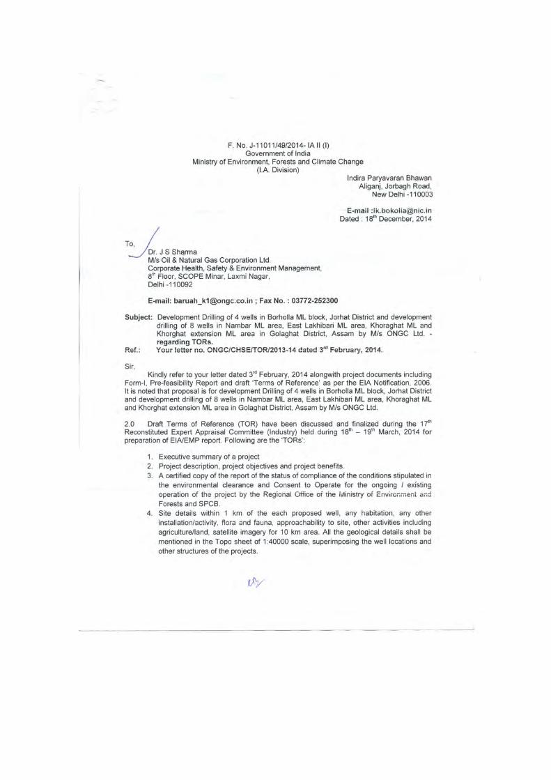
121
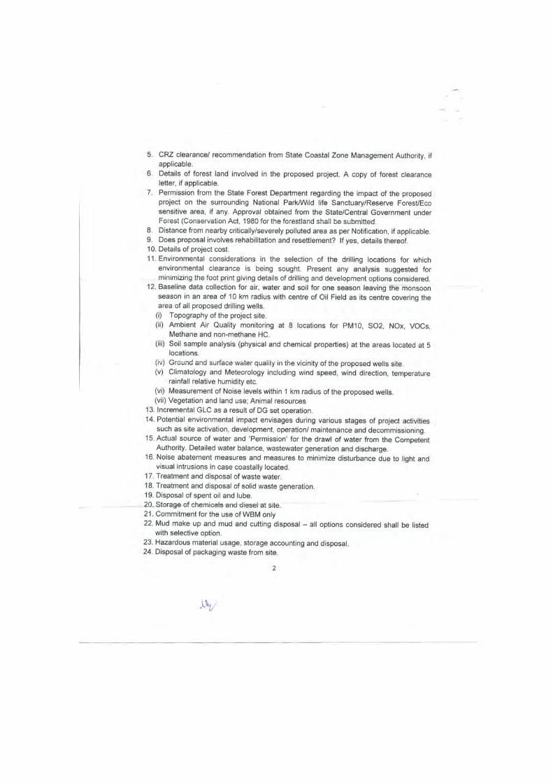
122
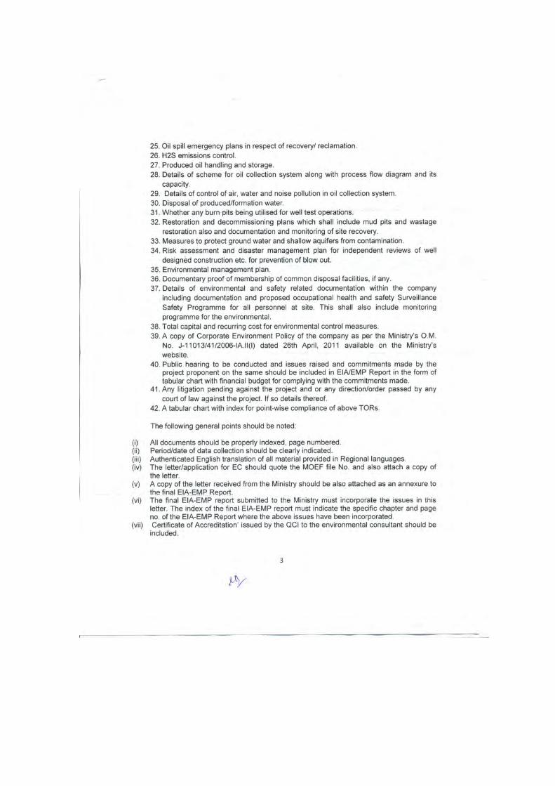
123
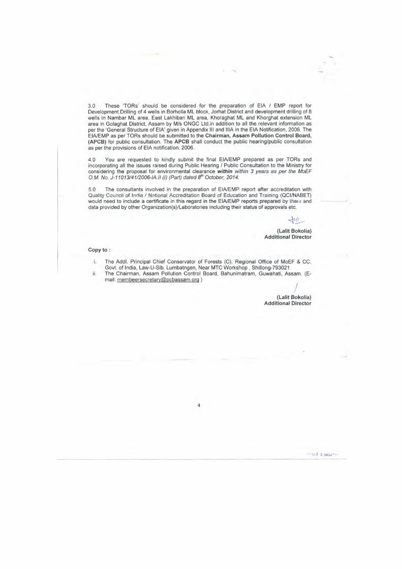
124
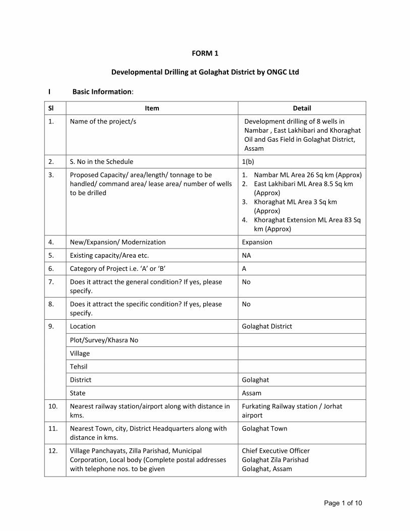
Page 1 of 10
FORM 1
Developmental Drilling at Golaghat District by ONGC Ltd
I Basic Information:
Sl Item Detail
1. Name of the project/s Development drilling of 8 wells in
Nambar , East Lakhibari and Khoraghat
Oil and Gas Field in Golaghat District,
Assam
2. S. No in the Schedule 1(b)
3. Proposed Capacity/ area/length/ tonnage to be
handled/ command area/ lease area/ number of wells
to be drilled
1. Nambar ML Area 26 Sq km (Approx)
2. East Lakhibari ML Area 8.5 Sq km
(Approx)
3. Khoraghat ML Area 3 Sq km
(Approx)
4. Khoraghat Extension ML Area 83 Sq
km (Approx)
4. New/Expansion/ Modernization Expansion
5. Existing capacity/Area etc. NA
6. Category of Project i.e. ‘A’ or ‘B’ A
7. Does it attract the general condition? If yes, please
specify.
No
8. Does it attract the specific condition? If yes, please
specify.
No
9. Location Golaghat District
Plot/Survey/Khasra No
Village
Tehsil
District Golaghat
State Assam
10. Nearest railway station/airport along with distance in
kms.
Furkating Railway station / Jorhat
airport
11. Nearest Town, city, District Headquarters along with
distance in kms.
Golaghat Town
12. Village Panchayats, Zilla Parishad, Municipal
Corporation, Local body (Complete postal addresses
with telephone nos. to be given
Chief Executive Officer
Golaghat Zila Parishad
Golaghat, Assam
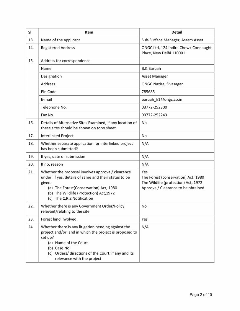
Page 2 of 10
Sl Item Detail
13. Name of the applicant Sub-Surface Manager, Assam Asset
14. Registered Address ONGC Ltd, 124 Indira Chowk Connaught
Place, New Delhi 110001
15. Address for correspondence
Name B.K.Baruah
Designation Asset Manager
Address ONGC Nazira, Sivasagar
Pin Code 785685
E-mail [email protected]
Telephone No. 03772-252300
Fax No 03772-252243
16. Details of Alternative Sites Examined, if any location of
these sites should be shown on topo sheet.
No
17. Interlinked Project No
18. Whether separate application for interlinked project
has been submitted?
N/A
19. If yes, date of submission N/A
20. If no, reason N/A
21. Whether the proposal involves approval/ clearance
under: if yes, details of same and their status to be
given.
(a) The Forest(Conservation) Act, 1980
(b) The Wildlife (Protection) Act,1972
(c) The C.R.Z Notification
Yes
The Forest (conservation) Act. 1980
The Wildlife (protection) Act, 1972
Approval/ Clearance to be obtained
22. Whether there is any Government Order/Policy
relevant/relating to the site
No
23. Forest land involved Yes
24. Whether there is any litigation pending against the
project and/or land in which the project is proposed to
set up?
(a) Name of the Court
(b) Case No
(c) Orders/ directions of the Court, if any and its
relevance with the project
N/A

Page 3 of 10
II Activity
1. Construction, operation or decommissioning of the Project involving actions, which
will cause physical changes in the locality (topography, land use, changes in water
bodies, etc.)
S.
No.
Information/Checklist confirmation Yes/No Details thereof (with approximate
quantities / rates, wherever possible)
with source of information data
1.1 Permanent or temporary change in land use, land
cover or topography including increase in
intensity of land use (with respect to local land
use plan)
Yes There will be a permanent change in
land use. However land will be restored
after drilling.
1.2 Clearance of existing land, vegetation and
buildings?
Yes Approximately 2 Ha land will have to be
cleared for each drilling locations and its
associated activities.
1.3 Creation of new land uses? Yes Same as Sl. No. 1.1 above
1.4 Pre-construction investigations e.g. bore houses,
soil testing?
No Hard field area. Normally soil testing
not essential for shallow / temporary
foundation for deployment of rig.
1.5 Construction works? Yes Construction of plinth area, foundation
for rig & its accessories, temporary
sheds, cellar pit and cutting retainer pits
as per standard lay-out drawing of the
drilling rig.
1.6 Demolition works? No
1.7 Temporary sites used for construction works or
housing of construction workers?
Yes Construction workers will stay in
temporary camps.
1.8 Above ground buildings, structures or earthworks
including linear structures, cut and fill or
excavations
Yes Earth filling is required to prepare
plinth.
1.9 Underground works including mining or
tunneling?
Yes The well bore hole will be drilled up to a
maximum depth of 3500m each.
1.10 Reclamation works? No
1.11 Dredging? No
1.12 Offshore structures? No
1.13 Production and manufacturing processes? Yes Oil Gas produced will be processed in
existing GGS Production testing of each
well will require at least about15 days
1.14 Facilities for storage of goods or materials? Yes Mechanical and drilling spares and
drilling chemicals in temporary sheds.
1.15 Facilities for treatment or disposal of solid waste Yes Solid waste / drilled rock cuttings will be
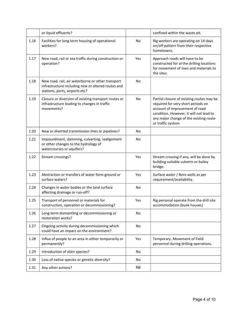
Page 4 of 10
or liquid effluents? confined within the waste pit.
1.16 Facilities for long term housing of operational
workers?
No Rig workers are operating on 14 days
on/off pattern from their respective
hometowns.
1.17 New road, rail or sea traffic during construction or
operation?
Yes Approach roads will have to be
constructed for al the drilling locations
for movement of men and materials to
the sites.
1.18 New road, rail, air waterborne or other transport
infrastructure including new or altered routes and
stations, ports, airports etc?
No
1.19 Closure or diversion of existing transport routes or
infrastructure leading to changes in traffic
movements?
No Partial closure of existing routes may be
required for very short periods on
account of improvement of road
condition. However, it will not lead to
any major change of the existing route
or traffic system.
1.20 New or diverted transmission lines or pipelines? No
1.21 Impoundment, damming, culverting, realignment
or other changes to the hydrology of
watercourses or aquifers?
No
1.22 Stream crossings? Yes Stream crossing if any, will be done by
building suitable culverts or bailey
bridge.
1.23 Abstraction or transfers of water form ground or
surface waters?
Yes Surface water / Bore wells as per
requirement/availability.
1.24 Changes in water bodies or the land surface
affecting drainage or run-off?
No
1.25 Transport of personnel or materials for
construction, operation or decommissioning?
Yes Rig personal operate from the drill site
accommodation (bunk houses)
1.26 Long-term dismantling or decommissioning or
restoration works?
No
1.27 Ongoing activity during decommissioning which
could have an impact on the environment?
No
1.28 Influx of people to an area in either temporarily or
permanently?
Yes Temporary. Movement of Field
personnel during drilling operations.
1.29 Introduction of alien species? No
1.30 Loss of native species or genetic diversity? No
1.31 Any other actions? Nil
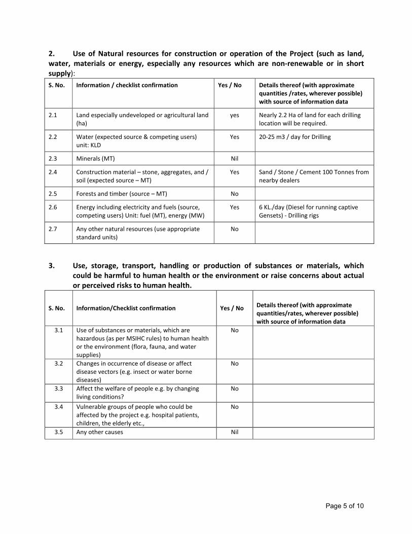
Page 5 of 10
2. Use of Natural resources for construction or operation of the Project (such as land,
water, materials or energy, especially any resources which are non-renewable or in short
supply):
S. No. Information / checklist confirmation Yes / No Details thereof (with approximate
quantities /rates, wherever possible)
with source of information data
2.1 Land especially undeveloped or agricultural land
(ha)
yes Nearly 2.2 Ha of land for each drilling
location will be required.
2.2 Water (expected source & competing users)
unit: KLD
Yes 20-25 m3 / day for Drilling
2.3 Minerals (MT) Nil
2.4 Construction material – stone, aggregates, and /
soil (expected source – MT)
Yes Sand / Stone / Cement 100 Tonnes from
nearby dealers
2.5 Forests and timber (source – MT) No
2.6 Energy including electricity and fuels (source,
competing users) Unit: fuel (MT), energy (MW)
Yes 6 KL./day (Diesel for running captive
Gensets) - Drilling rigs
2.7 Any other natural resources (use appropriate
standard units)
No
3. Use, storage, transport, handling or production of substances or materials, which
could be harmful to human health or the environment or raise concerns about actual
or perceived risks to human health.
S. No. Information/Checklist confirmation Yes / No Details thereof (with approximate
quantities/rates, wherever possible)
with source of information data
3.1 Use of substances or materials, which are
hazardous (as per MSIHC rules) to human health
or the environment (flora, fauna, and water
supplies)
No
3.2 Changes in occurrence of disease or affect
disease vectors (e.g. insect or water borne
diseases)
No
3.3 Affect the welfare of people e.g. by changing
living conditions?
No
3.4 Vulnerable groups of people who could be
affected by the project e.g. hospital patients,
children, the elderly etc.,
No
3.5 Any other causes Nil

Page 6 of 10
4. Production of solid wastes during construction or operation or decommissioning
(MT/month)
S. No. Information/Checklist confirmation Yes/
No
Details thereof (with approximate
quantities/rates, wherever possible) with source
of information data
4.1 Spoil, overburden or mine wastes Yes Drilled cuttings generated will be about 212 m3
during the drilling over a period of 40-45 days
4.2 Municipal waste (domestic and or
commercial wastes)
No Septic tank will be provided for toilets in the drill
site (Sewage about 10 m3/day
4.3 Hazardous wastes (as per Hazardous Waste
Management Rules)
Yes 1. Spent oil
2. Waste Drilling mud
4.4 Other industrial process wastes Nil
4.5 Surplus product Nil
4.6 Sewage sludge or other sludge from effluent
treatment
Yes Oily sludge will be collected and disposed by
bioremediation
4.7 Construction or demolition wastes Will be disposed of for in surface hardening within
drill site area.
4.8 Redundant machinery or equipment Nil
4.9 Contaminated soils or other materials Nil Will be confined in impermeable waste pit within
the drill site area.
4.10 Agricultural wastes Nil
4.11 Other solid wastes Nil
5. Release of pollutants or any hazardous, toxic or noxious substances to air (Kg/hr)
S. No. Information/Checklist confirmation Yes/
No
Details thereof (with approximate
quantities/rates, wherever possible) with source
of information data
5.1 Emissions from combustion of fossil fuels
from stationary or mobile sources
Yes Emissions from Captive Gensets (Rating: 6 x 750
KW) Only 3 units will be normally operated for
drilling rig.
5.2 Emissions from production processes
Yes If the well is hydrocarbon bearing during
production testing flaring of well fluids for a short
period of time.
5.3 Emissions from materials handling including
storage or transport
No
5.4 Emissions from construction activities
including plant and equipment
Nil
5.5 Dust or odors from handling of materials
including construction materials, sewage and
waste
Nil
5.6 Emissions from incineration of waste Nil
5.7 Emissions from burning of waste in open air
(e.g. slash materials, construction debris)
Nil
5.8 Emissions from any other sources Nil

Page 7 of 10
6. Generation of Noise and Vibration, and Emissions of Light and Heat:
S. No. Information/Checklist confirmation
Yes/No
Details thereof (with approximate
quantities/rates, wherever possible)
with source of information data with
source of information data
6.1 From operation of equipment e.g. engines,
ventilation plant, crushers
Yes Within 75 dB
Noise levels within permissible limits
(Personal Protective Equipment will be
provided if required)
6.2 From industrial or similar processes Yes Within 75 dB
6.3 From construction or demolition Nil
6.4 From blasting or piling Nil
6.5 From construction or operational traffic Nil
6.6 From lighting or cooling systems Nil
6.7 From any other sources Nil
7. Risks of contamination of land or water from releases of pollutants into the ground or
into sewers, surface waters, groundwater, coastal waters or the sea:
S. No. Information/Checklist confirmation Yes/No Details thereof (with approximate
quantities/rates, wherever possible)
with source of information data
7.1 From handling, storage, use or spillage of
hazardous materials
No All effluents will be confined within
impermeable waste pits
7.2 From discharge of sewage or other effluents to
water or the land (expected mode and place of
discharge)
No -do-
7.3 By deposition of pollutants emitted to air into the
land or into water
No
7.4 From any other sources No
7.5 Is there a risk of long term build up of pollutants
in the environment from these sources?
No Development drilling is a temporary
activity lasting 2 to 3 months.

Page 8 of 10
8. Risk of accidents during construction or operation of the Project, which could affect
human health or the environment
S. No. Information/Checklist confirmation Yes/No
Details thereof (with approximate
quantities/rates, wherever possible)
with source of information data
8.1 From explosions, spillages, fires etc from storage,
handling, use or production of hazardous
substances
Nil
8.2 From any other causes Yes Development drilling has the potential
risk of blow outs which will be handled as
per existing contingency plan.
8.3 Could the project be affected by natural disasters
causing environmental damage (e.g. floods,
earthquakes, landslides, cloudburst etc)?
Yes
9. Factors which should be considered (such as consequential development) which could
lead to environmental effects or the potential for cumulative impacts with other existing or
planned activities in the locality
S. No. Information/Checklist confirmation Yes/No
Details thereof (with approximate
quantities/rates, wherever possible)
with source of information data
9.1 Lead to development of supporting facilities,
ancillary development or development stimulated
by the project which could have impact on the
environment e.g.:
• Supporting infrastructure (roads, power supply,
waste or waste water treatment, etc.)
• housing development
• extractive industries
• supply industries
• other
Yes
If the Development drilling is successful
supporting infrastructure road, power
supply will be developed.
9.2 Lead to after-use of the site, which could have an
impact on the environment
No
9.3 Set a precedent for later developments Nil
9.4 Have cumulative effects due to proximity to other
existing or planned projects with similar effects
Nil No industries is nearby
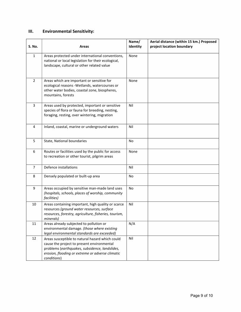
Page 9 of 10
III. Environmental Sensitivity:
S. No.
Areas
Name/
Identity
Aerial distance (within 15 km.) Proposed
project location boundary
1 Areas protected under international conventions,
national or local legislation for their ecological,
landscape, cultural or other related value
None
2 Areas which are important or sensitive for
ecological reasons -Wetlands, watercourses or
other water bodies, coastal zone, biospheres,
mountains, forests
None
3 Areas used by protected, important or sensitive
species of flora or fauna for breeding, nesting,
foraging, resting, over wintering, migration
Nil
4 Inland, coastal, marine or underground waters Nil
5 State, National boundaries No
6 Routes or facilities used by the public for access
to recreation or other tourist, pilgrim areas
None
7 Defence installations Nil
8 Densely populated or built-up area No
9 Areas occupied by sensitive man-made land uses
(hospitals, schools, places of worship, community
facilities)
No
10 Areas containing important, high quality or scarce
resources (ground water resources, surface
resources, forestry, agriculture, fisheries, tourism,
minerals)
Nil
11 Areas already subjected to pollution or
environmental damage. (those where existing
legal environmental standards are exceeded)
N/A
12 Areas susceptible to natural hazard which could
cause the project to present environmental
problems (earthquakes, subsidence, landslides,
erosion, flooding or extreme or adverse climatic
conditions)
Nil
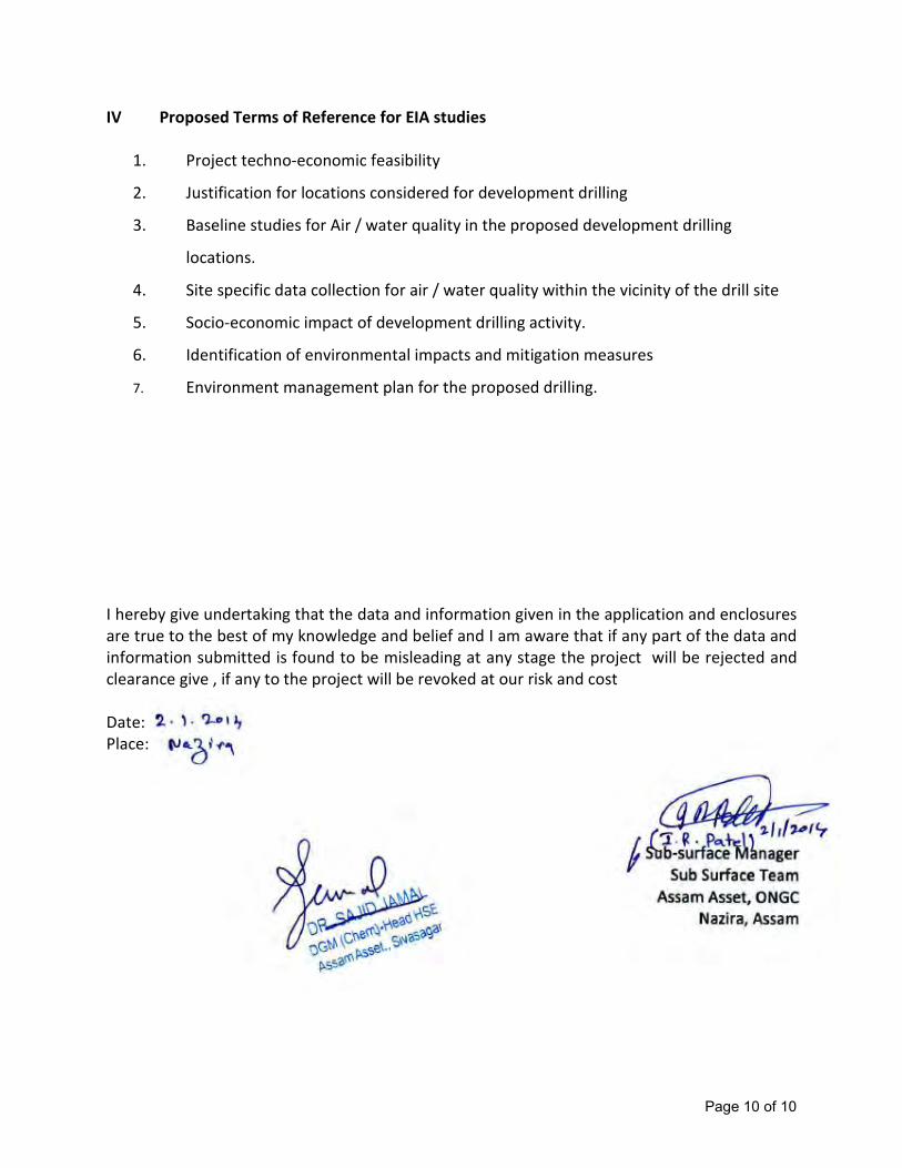
Page 10 of 10
IV Proposed Terms of Reference for EIA studies
1. Project techno-economic feasibility
2. Justification for locations considered for development drilling
3. Baseline studies for Air / water quality in the proposed development drilling
locations.
4. Site specific data collection for air / water quality within the vicinity of the drill site
5. Socio-economic impact of development drilling activity.
6. Identification of environmental impacts and mitigation measures
7. Environment management plan for the proposed drilling.
I hereby give undertaking that the data and information given in the application and enclosures
are true to the best of my knowledge and belief and I am aware that if any part of the data and
information submitted is found to be misleading at any stage the project will be rejected and
clearance give , if any to the project will be revoked at our risk and cost
Date:
Place:
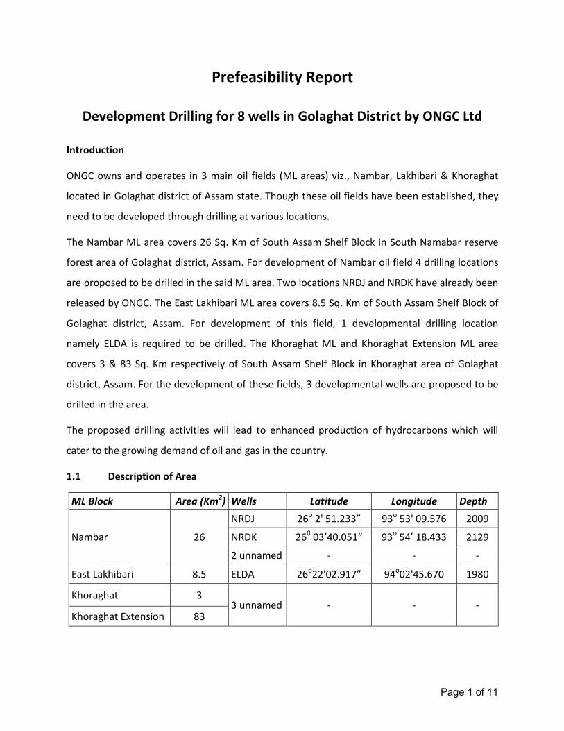
Page 1 of 11
Prefeasibility Report
Development Drilling for 8 wells in Golaghat District by ONGC Ltd
Introduction
ONGC owns and operates in 3 main oil fields (ML areas) viz., Nambar, Lakhibari & Khoraghat
located in Golaghat district of Assam state. Though these oil fields have been established, they
need to be developed through drilling at various locations.
The Nambar ML area covers 26 Sq. Km of South Assam Shelf Block in South Namabar reserve
forest area of Golaghat district, Assam. For development of Nambar oil field 4 drilling locations
are proposed to be drilled in the said ML area. Two locations NRDJ and NRDK have already been
released by ONGC. The East Lakhibari ML area covers 8.5 Sq. Km of South Assam Shelf Block of
Golaghat district, Assam. For development of this field, 1 developmental drilling location
namely ELDA is required to be drilled. The Khoraghat ML and Khoraghat Extension ML area
covers 3 & 83 Sq. Km respectively of South Assam Shelf Block in Khoraghat area of Golaghat
district, Assam. For the development of these fields, 3 developmental wells are proposed to be
drilled in the area.
The proposed drilling activities will lead to enhanced production of hydrocarbons which will
cater to the growing demand of oil and gas in the country.
1.1 Description of Area
ML Block Area (Km2) Wells Latitude Longitude Depth
Nambar 26
NRDJ 26o 2' 51.233” 93
o 53' 09.576 2009
NRDK 260 03’40.051” 93
o 54’ 18.433 2129
2 unnamed - - -
East Lakhibari 8.5 ELDA 26o22'02.917” 94
o02'45.670 1980
Khoraghat 3 3 unnamed - - -
Khoraghat Extension 83
Page 2 of 11
1.2 Proposed Project
Nambar field, discovered in 1999, is a multi-reservoir field situated south-west of Khoraghat in
South Assam Shelf. The field has five pay sands (named from top: N-10, N-20, N-30, N-40 and N-
50) which belong to Lower Bokabil Formation of Miocene age. Nambar, an important
hydrocarbon-producing field of South Assam shelf was discovered in the year 1999 and came
into commercial production since March, 1999. Oil was struck at the first well Khoraghat#11
(later renamed as Nambar#1(NR-01) drilled on the structure. Free gas was tested only in 1 well
(NR-02). Nambar Field is characterized by the presence of multi-layered hydrocarbon reservoirs
belonging to Lower Bokabil Formation. For development of the field 2 Development locations
are currently available which namely NRDJ & NRDK. In addition to that 2 more locations are
also proposed to be drilled.
The East Lakhibari ML area covers 8.5 Sq. Km of South Assam Shelf Block of Golaghat district,
Assam. For development of the field, it is proposed to drill 1 well namely ELDA. The proposed
location is for augmentation of production of oil and gas from established East Lakhibari field in
Golaghat district of Assam. The expected oil is 30 m3/d.
The Khoraghat field lie in the southern fringe of Upper Assam in Dhansiri Valley. Khoraghat field
was discovered in 1989 through exploratory well KH#1(KGP#1). Proved Oil in Place (OIIP)
reserves has been estimated as 9.6 MT and ultimate recoverable reserves has been estimated
to be as 1.96 MMT with a recovery factor of 20%. For development of this field, it is proposed
to drill 3 wells in the area to augment production of oil and gas from established Khoraghat
field in Golaghat district of Assam.
1.3 Project Justification
It is expected that the proposed drilling activities lead to further development of Khoraghat
field which will augment the production of hydrocarbons, in the present scenario of growing
demand of oil and gas in the country.
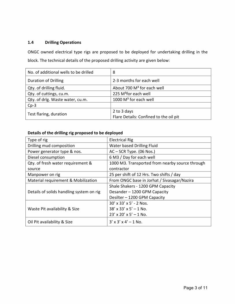
Page 3 of 11
1.4 Drilling Operations
ONGC owned electrical type rigs are proposed to be deployed for undertaking drilling in the
block. The technical details of the proposed drilling activity are given below:
No. of additional wells to be drilled 8
Duration of Drilling 2-3 months for each well
Qty. of drilling fluid. About 700 M³ for each well
Qty. of cuttings, cu.m. 225 M³for each well
Qty. of drlg. Waste water, cu.m. 1000 M³ for each well
Cp-3
Test flaring, duration 2 to 3 days
Flare Details: Confined to the oil pit
Details of the drilling rig proposed to be deployed
Type of rig Electrical Rig
Drilling mud composition Water based Drilling Fluid
Power generator type & nos. AC – SCR Type. (06 Nos.)
Diesel consumption 6 M3 / Day for each well
Qty. of fresh water requirement &
source
1000 M3. Transported from nearby source through
contractor
Manpower on rig 25 per shift of 12 Hrs. Two shifts / day
Material requirement & Mobilization From ONGC base in Jorhat / Sivasagar/Nazira
Details of solids handling system on rig
Shale Shakers - 1200 GPM Capacity
Desander – 1200 GPM Capacity
Desilter – 1200 GPM Capacity
Waste Pit availability & Size
30’ x 33’ x 5’ - 2 Nos.
38’ x 33’ x 5’ – 1 No.
23’ x 20’ x 5’ – 1 No.
Oil Pit availability & Size 3’ x 3’ x 4’ – 1 No.
Page 4 of 11
Only water based drilling mud will be used. The quantity of drill cuttings generated will be
around 212 m3
. The quantity of wastewater produced will be about 15 m3/day. The rig will be
provided with solids handling system comprising Shale shakers (1200 GPM), Desander (1200
GPM) and Desilter (1200 GPM) and Degasser with vacuum pump.
Drilling operations will be carried out using an electrical type. Drilling unit for drilling of oil and
gas wells consists of a derrick at the top of which is mounted a crown block and a hoisting block
with a hook. From the swivel is suspended a Kelly stem passes through a square or hexagonal
Kelly bush which fits into the rotary table. The rotary table receives the power to drive it from
an electric motor. The electric motor rotates the rotary table which passes through the Kelly
bush and the rotations are transmitted to the bit as the drilling progresses, the drill pipe in
singles are added to continue the drilling process. At the end of the bit life, the drill pipes are
pulled out in stands and stacked on the derrick platform. A stand normally has 3 single drill
pipes. After changing the bit, the drill string is run back into the hole and further drilling is
continued. This process continues till the target depth is reached.
During the course of drilling, cuttings are generated due to crushing action of the bit. These
cuttings are removed by flushing the well with duplex/triplex mud pumps. The mud from the
pump discharge through the rotary hose connected to stationary part of the swivel, the drill
string and bit nozzles. The mud coming out of the bit nozzles pushes the cuttings up hole and
transports them to the surface through the annular space between the drill string and the hole.
The mud not only carries away crushed rock from the bottom of the hole but it also cools the
bit as it gets heated due to friction with formation while rotating. The mud also helps in
balancing subsurface formation pressures and by forming a cake on the walls of the well
diminishes the possibility of crumbling or caving of the well bore.
At the surface, the mud coming out from well along with the cuttings falls in a trough, passes
through the solids control equipments i.e. shale shaker, de-sander and de-silter. These
equipments remove the solids of different sizes which get mixed with the mud during the
course of drilling. The cleaned mud flows back to the suction tanks to be again pumped into the
well. The drilling mud/fluid circulation is thus a continuous cyclic operation. The most suitable
clay for mud preparation is bentonite which is capable of forming highly dispersed colloidal

Page 5 of 11
solutions. Various other chemicals are also used in mud preparation as per requirements
dictated by the temperature/pressure conditions of the wells. The mud is continuously tested
for its density, viscosity, yield point, water loss, pH value etc. to ensure that the drilling
operations can be sustained without any down hole complications.
1.5 Drilling Facilities
Drilling is a temporary activity which will continue for about 45 days for each well in the block.
The rigs are self-contained for all routine jobs. Once the drilling operations are completed, and
if sufficient indications of hydrocarbons are noticed while drilling, the well is tested by
perforation in the production casing. This normally takes 2-3 days. If the well is found to be a
successful hydrocarbon bearing structure, it is sealed off for future development, if any.
1.6 General Requirements of Drilling
Exploratory drilling programme requires the following common facilities:
a. Drilling muds
Drilling of wells requires specially formulated muds which basically comprise inert earth
materials like bentonite, barite in water with several additives to give mud weight, fluidity
and filter cake characteristics while drilling. The drilling muds have several functions like
lubrication and cooling of the drill bit, balancing subsurface formation, bringing out the
drill cuttings from the well bore, thixotropic property to hold cuttings during non-
operations, formation of thin cake to prevent liquid loss along well bore etc. Several
additives are mixed into the mud system to give the required properties. Water based mud
will be used to the possible extent in exploratory drilling but use of synthetic based mud
may require due to complexities associated with the geological formations and associated
hole stability problems. The constituents of water based mud (WBM) are given in Table
1.2. The special additives and their functions in WBM are shown in Table 1.3.
Page 6 of 11
b. Power Generation
The drilling process requires movement of drill bit through the draw works which require
power. The power requirement of the drilling rig will be met by using the six Diesel
Generator sets with a diesel consumption of about 06 Kl/day. The exhaust stacks of the DG
sets are likely to vent the emissions.
c. Water requirements
The water requirement in a drilling rig is mainly meant for preparation of drilling mud apart
from washings and domestic use. While the former consumes the majority of water
requirement, the water requirement for domestic and wash use is very less. The daily
water consumption will be 25 m3/d of which 15 m
3/d will be used for mud preparation and
10 m3/d will be used for domestic purposes including drinking.
d. Domestic wastewater
The operating personnel in the drilling rigs will operate from drill site accommodation
(DSA) in the vicinity of the location. Suitable soak pits will be available at the DSA.
e. Solids removal
The rock cuttings and fragments of shale, sand and silt associated with the return drilling
fluid during well drilling will be separated using shale shakers and other solids removal
equipment like desanders and desilters. The recovered mud will be reused while the
rejected solids will be collected and discharged into the waste pit.
f. Drill cuttings and waste residual muds
During drilling operations, approx 212 m3 per well of wet drill cuttings are expected to be
generated from each well depending on the type of formation and depth of drilling. In
addition to the cuttings 15-20 m3/day of wastewater is likely to be generated during well
drilling. The waste residual muds and drill cuttings which contain clay, sand etc. will be
disposed into the waste pit.
Page 7 of 11
g. Testing
Testing facilities will be available at drilling rig for separation of liquid phase and burning of
all hydrocarbons during testing. The test flare boom will be located at a distance from the
drilling rig.
h. Chemical storage
The drilling rig will have normal storage facilities for fuel oil, required chemicals and the
necessary tubulars and equipment. The storage places will be clearly marked with safe
operating facilities and practices.
i. Manpower
The drilling rig will be operated by approx. 30 persons on the rig at anytime. The
manpower will operate in two shifts with continuous operations on the rig.
j. Logistics
Crew transfers to and from the drilling rig, materials, diesel and chemicals will be through
light vehicles, trucks and trailers.
1.7 Production
After successful drilling of the wells, the produced oil & gas will be transported to Nambar GGS,
Khoraghat GGS through flowlines for further treatment and dispatch.
In Lakhibari Field, the produced oil & gas from the wells will be transported to Borhalla GGS
through tankers.
1.8 Project Investment
The total cost of drilling of 8 wells including daily drilling rates, consumables, well accessories
etc. will approximately be about Rs. 160 Crores.
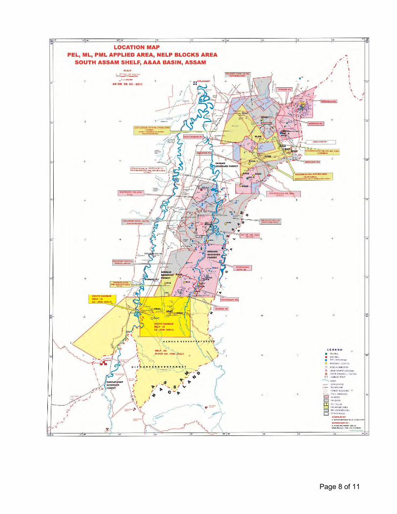
Page 8 of 11
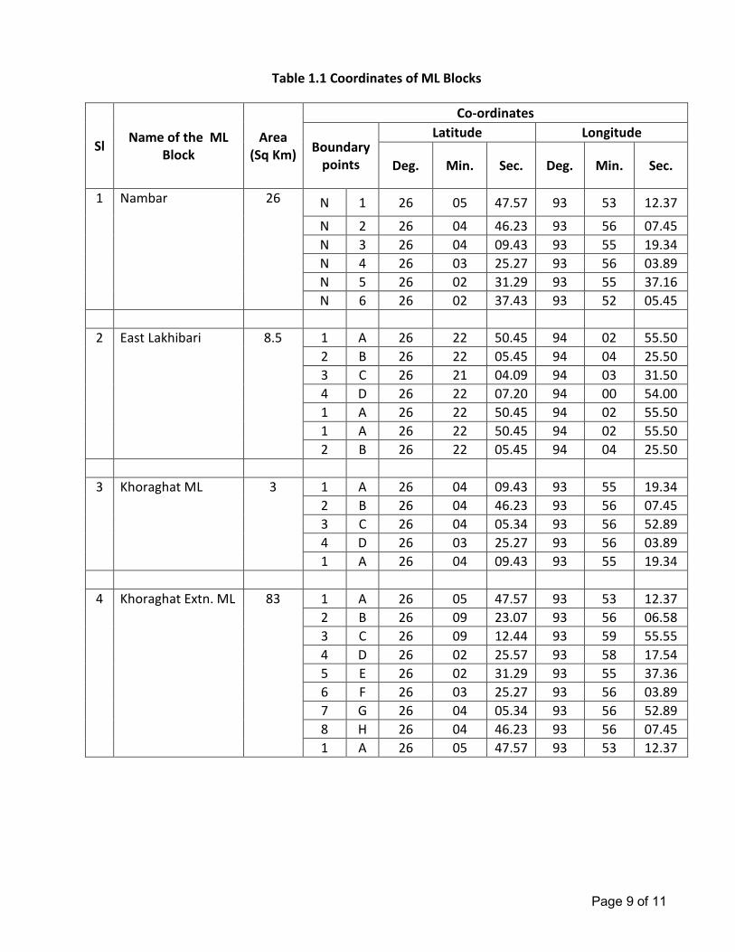
Page 9 of 11
Table 1.1 Coordinates of ML Blocks
Sl Name of the ML
Block
Area
(Sq Km)
Co-ordinates
Boundary
points
Latitude Longitude
Deg. Min. Sec. Deg. Min. Sec.
1 Nambar 26 N 1 26 05 47.57 93 53 12.37
N 2 26 04 46.23 93 56 07.45
N 3 26 04 09.43 93 55 19.34
N 4 26 03 25.27 93 56 03.89
N 5 26 02 31.29 93 55 37.16
N 6 26 02 37.43 93 52 05.45
2 East Lakhibari 8.5 1 A 26 22 50.45 94 02 55.50
2 B 26 22 05.45 94 04 25.50
3 C 26 21 04.09 94 03 31.50
4 D 26 22 07.20 94 00 54.00
1 A 26 22 50.45 94 02 55.50
1 A 26 22 50.45 94 02 55.50
2 B 26 22 05.45 94 04 25.50
3 Khoraghat ML 3 1 A 26 04 09.43 93 55 19.34
2 B 26 04 46.23 93 56 07.45
3 C 26 04 05.34 93 56 52.89
4 D 26 03 25.27 93 56 03.89
1 A 26 04 09.43 93 55 19.34
4 Khoraghat Extn. ML 83 1 A 26 05 47.57 93 53 12.37
2 B 26 09 23.07 93 56 06.58
3 C 26 09 12.44 93 59 55.55
4 D 26 02 25.57 93 58 17.54
5 E 26 02 31.29 93 55 37.36
6 F 26 03 25.27 93 56 03.89
7 G 26 04 05.34 93 56 52.89
8 H 26 04 46.23 93 56 07.45
1 A 26 05 47.57 93 53 12.37
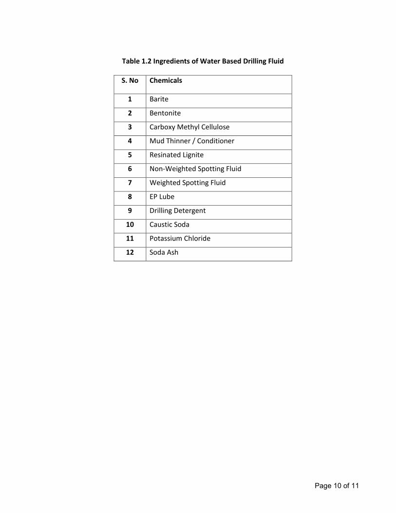
Page 10 of 11
Table 1.2 Ingredients of Water Based Drilling Fluid
S. No Chemicals
1 Barite
2 Bentonite
3 Carboxy Methyl Cellulose
4 Mud Thinner / Conditioner
5 Resinated Lignite
6 Non-Weighted Spotting Fluid
7 Weighted Spotting Fluid
8 EP Lube
9 Drilling Detergent
10 Caustic Soda
11 Potassium Chloride
12 Soda Ash
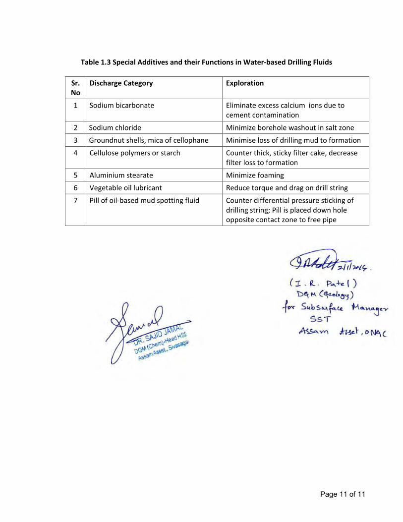
Page 11 of 11
Table 1.3 Special Additives and their Functions in Water-based Drilling Fluids
Sr.
No
Discharge Category Exploration
1 Sodium bicarbonate Eliminate excess calcium ions due to
cement contamination
2 Sodium chloride Minimize borehole washout in salt zone
3 Groundnut shells, mica of cellophane Minimise loss of drilling mud to formation
4 Cellulose polymers or starch Counter thick, sticky filter cake, decrease
filter loss to formation
5 Aluminium stearate Minimize foaming
6 Vegetable oil lubricant Reduce torque and drag on drill string
7 Pill of oil-based mud spotting fluid Counter differential pressure sticking of
drilling string; Pill is placed down hole
opposite contact zone to free pipe
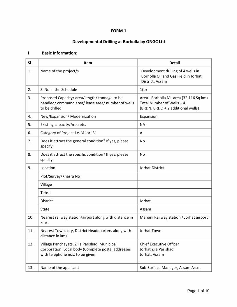
Page 1 of 10
FORM 1
Developmental Drilling at Borholla by ONGC Ltd
I Basic Information:
Sl Item Detail
1. Name of the project/s Development drilling of 4 wells in
Borholla Oil and Gas Field in Jorhat
District, Assam
2. S. No in the Schedule 1(b)
3. Proposed Capacity/ area/length/ tonnage to be
handled/ command area/ lease area/ number of wells
to be drilled
Area - Borholla ML area (32.116 Sq km)
Total Number of Wells – 4
(BRDN, BRDO + 2 additional wells)
4. New/Expansion/ Modernization Expansion
5. Existing capacity/Area etc. NA
6. Category of Project i.e. ‘A’ or ‘B’ A
7. Does it attract the general condition? If yes, please
specify.
No
8. Does it attract the specific condition? If yes, please
specify.
No
9. Location Jorhat District
Plot/Survey/Khasra No
Village
Tehsil
District Jorhat
State Assam
10. Nearest railway station/airport along with distance in
kms.
Mariani Railway station / Jorhat airport
11. Nearest Town, city, District Headquarters along with
distance in kms.
Jorhat Town
12. Village Panchayats, Zilla Parishad, Municipal
Corporation, Local body (Complete postal addresses
with telephone nos. to be given
Chief Executive Officer
Jorhat Zila Parishad
Jorhat, Assam
13. Name of the applicant Sub-Surface Manager, Assam Asset
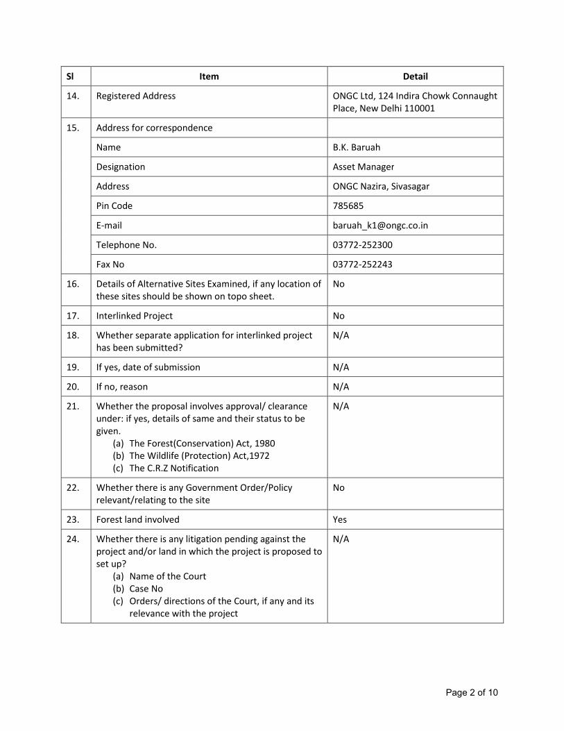
Page 2 of 10
Sl Item Detail
14. Registered Address ONGC Ltd, 124 Indira Chowk Connaught
Place, New Delhi 110001
15. Address for correspondence
Name B.K. Baruah
Designation Asset Manager
Address ONGC Nazira, Sivasagar
Pin Code 785685
E-mail [email protected]
Telephone No. 03772-252300
Fax No 03772-252243
16. Details of Alternative Sites Examined, if any location of
these sites should be shown on topo sheet.
No
17. Interlinked Project No
18. Whether separate application for interlinked project
has been submitted?
N/A
19. If yes, date of submission N/A
20. If no, reason N/A
21. Whether the proposal involves approval/ clearance
under: if yes, details of same and their status to be
given.
(a) The Forest(Conservation) Act, 1980
(b) The Wildlife (Protection) Act,1972
(c) The C.R.Z Notification
N/A
22. Whether there is any Government Order/Policy
relevant/relating to the site
No
23. Forest land involved Yes
24. Whether there is any litigation pending against the
project and/or land in which the project is proposed to
set up?
(a) Name of the Court
(b) Case No
(c) Orders/ directions of the Court, if any and its
relevance with the project
N/A
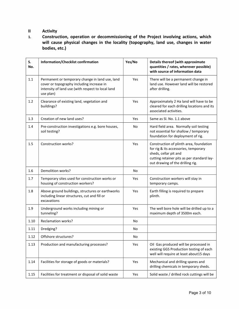
Page 3 of 10
II Activity
1. Construction, operation or decommissioning of the Project involving actions, which
will cause physical changes in the locality (topography, land use, changes in water
bodies, etc.)
S.
No.
Information/Checklist confirmation Yes/No Details thereof (with approximate
quantities / rates, wherever possible)
with source of information data
1.1 Permanent or temporary change in land use, land
cover or topography including increase in
intensity of land use (with respect to local land
use plan)
Yes There will be a permanent change in
land use. However land will be restored
after drilling.
1.2 Clearance of existing land, vegetation and
buildings?
Yes Approximately 2 Ha land will have to be
cleared for each drilling locations and its
associated activities.
1.3 Creation of new land uses? Yes Same as Sl. No. 1.1 above
1.4 Pre-construction investigations e.g. bore houses,
soil testing?
No Hard field area. Normally soil testing
not essential for shallow / temporary
foundation for deployment of rig.
1.5 Construction works? Yes Construction of plinth area, foundation
for rig & its accessories, temporary
sheds, cellar pit and
cutting retainer pits as per standard lay-
out drawing of the drilling rig.
1.6 Demolition works? No
1.7 Temporary sites used for construction works or
housing of construction workers?
Yes Construction workers will stay in
temporary camps.
1.8 Above ground buildings, structures or earthworks
including linear structures, cut and fill or
excavations
Yes Earth filling is required to prepare
plinth.
1.9 Underground works including mining or
tunneling?
Yes The well bore hole will be drilled up to a
maximum depth of 3500m each.
1.10 Reclamation works? No
1.11 Dredging? No
1.12 Offshore structures? No
1.13 Production and manufacturing processes? Yes Oil Gas produced will be processed in
existing GGS Production testing of each
well will require at least about15 days
1.14 Facilities for storage of goods or materials? Yes Mechanical and drilling spares and
drilling chemicals in temporary sheds.
1.15 Facilities for treatment or disposal of solid waste Yes Solid waste / drilled rock cuttings will be
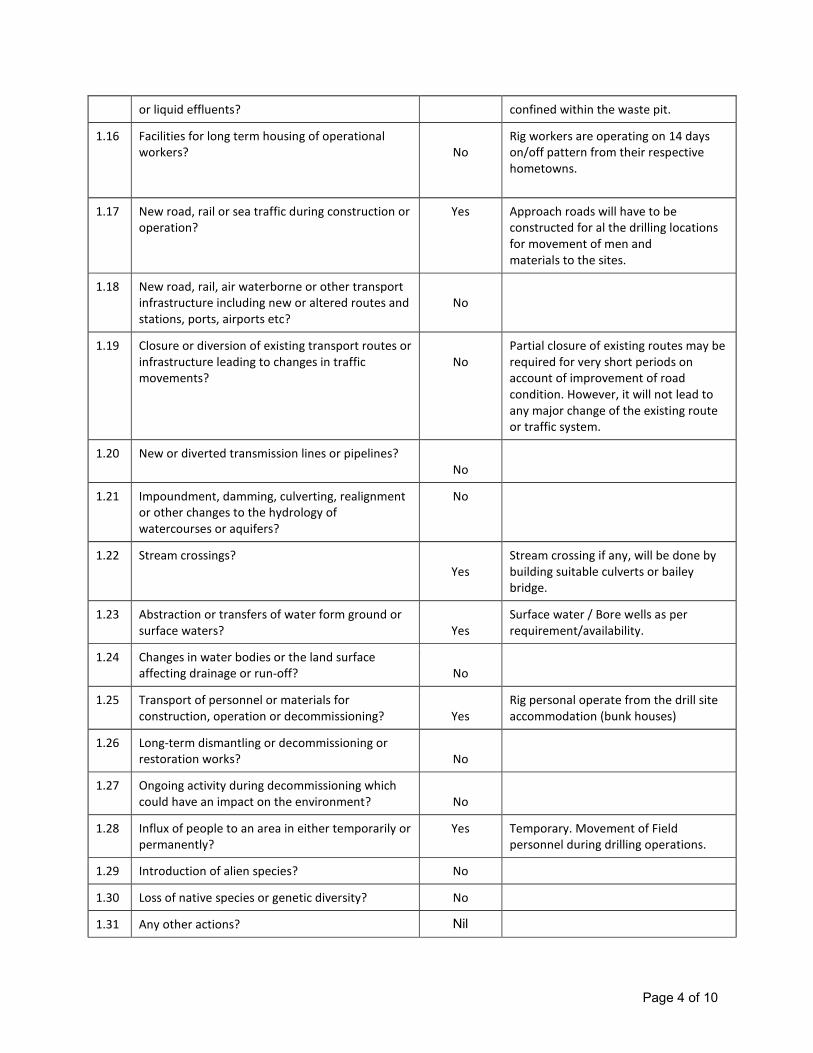
Page 4 of 10
or liquid effluents? confined within the waste pit.
1.16 Facilities for long term housing of operational
workers?
No
Rig workers are operating on 14 days
on/off pattern from their respective
hometowns.
1.17 New road, rail or sea traffic during construction or
operation?
Yes Approach roads will have to be
constructed for al the drilling locations
for movement of men and
materials to the sites.
1.18 New road, rail, air waterborne or other transport
infrastructure including new or altered routes and
stations, ports, airports etc?
No
1.19 Closure or diversion of existing transport routes or
infrastructure leading to changes in traffic
movements?
No
Partial closure of existing routes may be
required for very short periods on
account of improvement of road
condition. However, it will not lead to
any major change of the existing route
or traffic system.
1.20 New or diverted transmission lines or pipelines?
No
1.21 Impoundment, damming, culverting, realignment
or other changes to the hydrology of
watercourses or aquifers?
No
1.22 Stream crossings?
Yes
Stream crossing if any, will be done by
building suitable culverts or bailey
bridge.
1.23 Abstraction or transfers of water form ground or
surface waters?
Yes
Surface water / Bore wells as per
requirement/availability.
1.24 Changes in water bodies or the land surface
affecting drainage or run-off?
No
1.25 Transport of personnel or materials for
construction, operation or decommissioning?
Yes
Rig personal operate from the drill site
accommodation (bunk houses)
1.26 Long-term dismantling or decommissioning or
restoration works?
No
1.27 Ongoing activity during decommissioning which
could have an impact on the environment?
No
1.28 Influx of people to an area in either temporarily or
permanently?
Yes Temporary. Movement of Field
personnel during drilling operations.
1.29 Introduction of alien species? No
1.30 Loss of native species or genetic diversity? No
1.31 Any other actions? Nil

Page 5 of 10
2. Use of Natural resources for construction or operation of the Project (such as land,
water, materials or energy, especially any resources which are non-renewable or in short
supply):
S. No. Information / checklist confirmation Yes / No Details thereof (with approximate
quantities /rates, wherever possible)
with source of information data
2.1 Land especially undeveloped or agricultural land
(ha)
yes Nearly 2.2 Ha of land for each drilling
location will be required.
2.2 Water (expected source & competing users)
unit: KLD
Yes 20-25 m3 / day for Drilling
2.3 Minerals (MT) Nil
2.4 Construction material – stone, aggregates, and /
soil (expected source – MT)
Yes Sand / Stone / Cement 100 Tonnes from
nearby dealers
2.5 Forests and timber (source – MT) No
2.6 Energy including electricity and fuels (source,
competing users) Unit: fuel (MT), energy (MW)
Yes 6 KL./day (Diesel for running captive
Gensets) - Drilling rigs
2.7 Any other natural resources (use appropriate
standard units)
No
3. Use, storage, transport, handling or production of substances or materials, which
could be harmful to human health or the environment or raise concerns about actual
or perceived risks to human health.
S. No. Information/Checklist confirmation Yes / No Details thereof (with approximate
quantities/rates, wherever possible)
with source of information data
3.1 Use of substances or materials, which are
hazardous (as per MSIHC rules) to human health
or the environment (flora, fauna, and water
supplies)
No
3.2 Changes in occurrence of disease or affect
disease vectors (e.g. insect or water borne
diseases)
No
3.3 Affect the welfare of people e.g. by changing
living conditions?
No
3.4 Vulnerable groups of people who could be
affected by the project e.g. hospital patients,
children, the elderly etc.,
No
3.5 Any other causes Nil
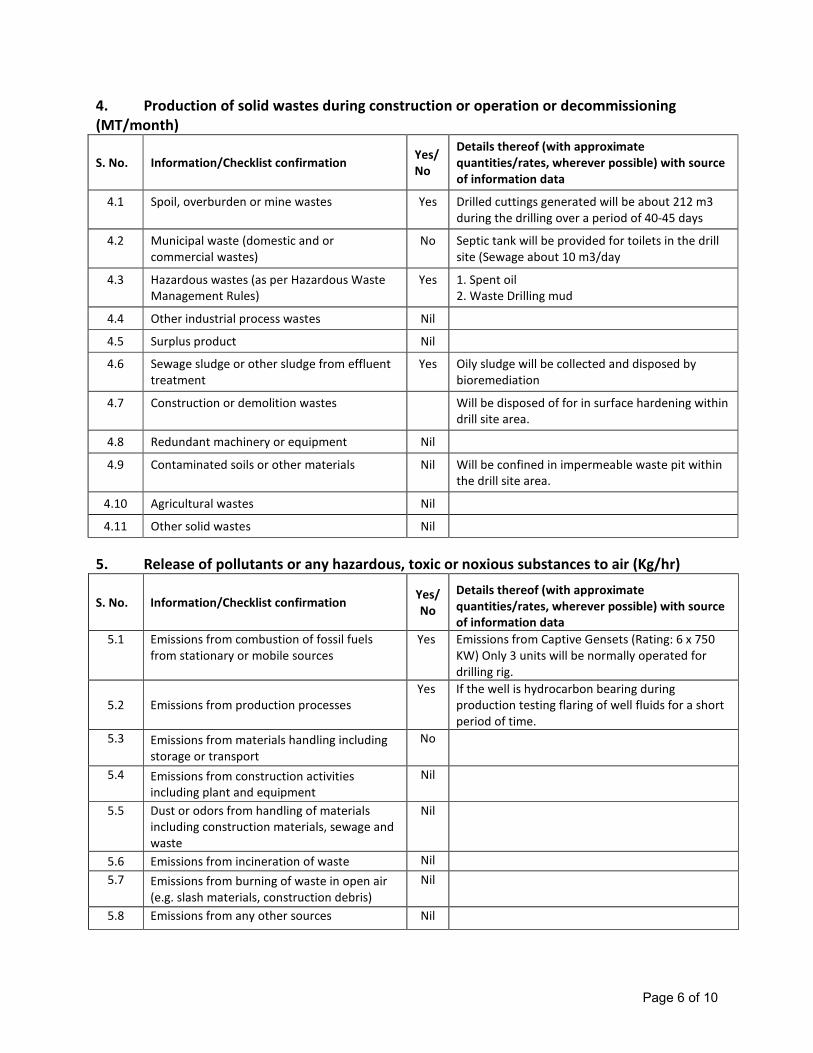
Page 6 of 10
4. Production of solid wastes during construction or operation or decommissioning
(MT/month)
S. No. Information/Checklist confirmation Yes/
No
Details thereof (with approximate
quantities/rates, wherever possible) with source
of information data
4.1 Spoil, overburden or mine wastes Yes Drilled cuttings generated will be about 212 m3
during the drilling over a period of 40-45 days
4.2 Municipal waste (domestic and or
commercial wastes)
No Septic tank will be provided for toilets in the drill
site (Sewage about 10 m3/day
4.3 Hazardous wastes (as per Hazardous Waste
Management Rules)
Yes 1. Spent oil
2. Waste Drilling mud
4.4 Other industrial process wastes Nil
4.5 Surplus product Nil
4.6 Sewage sludge or other sludge from effluent
treatment
Yes Oily sludge will be collected and disposed by
bioremediation
4.7 Construction or demolition wastes Will be disposed of for in surface hardening within
drill site area.
4.8 Redundant machinery or equipment Nil
4.9 Contaminated soils or other materials Nil Will be confined in impermeable waste pit within
the drill site area.
4.10 Agricultural wastes Nil
4.11 Other solid wastes Nil
5. Release of pollutants or any hazardous, toxic or noxious substances to air (Kg/hr)
S. No. Information/Checklist confirmation Yes/
No
Details thereof (with approximate
quantities/rates, wherever possible) with source
of information data
5.1 Emissions from combustion of fossil fuels
from stationary or mobile sources
Yes Emissions from Captive Gensets (Rating: 6 x 750
KW) Only 3 units will be normally operated for
drilling rig.
5.2 Emissions from production processes
Yes If the well is hydrocarbon bearing during
production testing flaring of well fluids for a short
period of time.
5.3 Emissions from materials handling including
storage or transport
No
5.4 Emissions from construction activities
including plant and equipment
Nil
5.5 Dust or odors from handling of materials
including construction materials, sewage and
waste
Nil
5.6 Emissions from incineration of waste Nil
5.7 Emissions from burning of waste in open air
(e.g. slash materials, construction debris)
Nil
5.8 Emissions from any other sources Nil
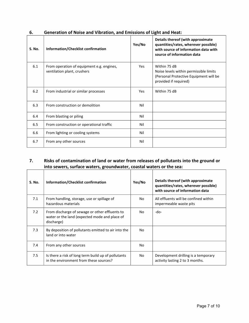
Page 7 of 10
6. Generation of Noise and Vibration, and Emissions of Light and Heat:
S. No. Information/Checklist confirmation
Yes/No
Details thereof (with approximate
quantities/rates, wherever possible)
with source of information data with
source of information data
6.1 From operation of equipment e.g. engines,
ventilation plant, crushers
Yes Within 75 dB
Noise levels within permissible limits
(Personal Protective Equipment will be
provided if required)
6.2 From industrial or similar processes Yes Within 75 dB
6.3 From construction or demolition Nil
6.4 From blasting or piling Nil
6.5 From construction or operational traffic Nil
6.6 From lighting or cooling systems Nil
6.7 From any other sources Nil
7. Risks of contamination of land or water from releases of pollutants into the ground or
into sewers, surface waters, groundwater, coastal waters or the sea:
S. No. Information/Checklist confirmation Yes/No Details thereof (with approximate
quantities/rates, wherever possible)
with source of information data
7.1 From handling, storage, use or spillage of
hazardous materials
No All effluents will be confined within
impermeable waste pits
7.2 From discharge of sewage or other effluents to
water or the land (expected mode and place of
discharge)
No -do-
7.3 By deposition of pollutants emitted to air into the
land or into water
No
7.4 From any other sources No
7.5 Is there a risk of long term build up of pollutants
in the environment from these sources?
No Development drilling is a temporary
activity lasting 2 to 3 months.
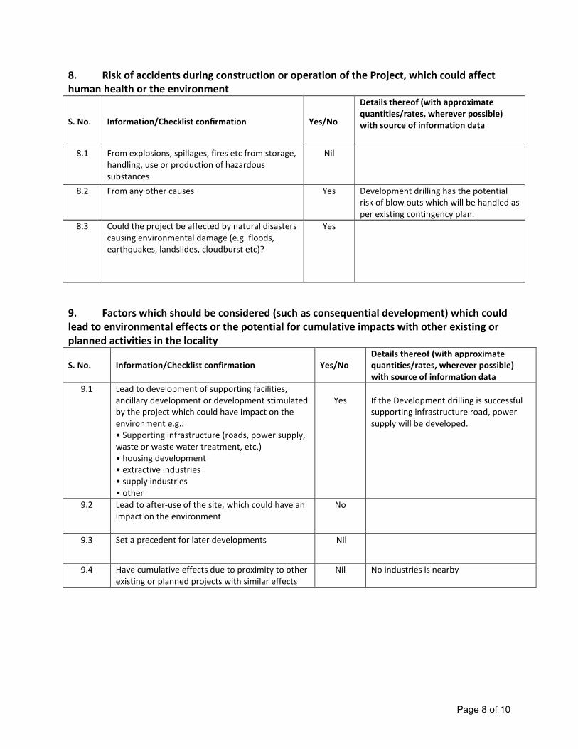
Page 8 of 10
8. Risk of accidents during construction or operation of the Project, which could affect
human health or the environment
S. No. Information/Checklist confirmation Yes/No
Details thereof (with approximate
quantities/rates, wherever possible)
with source of information data
8.1 From explosions, spillages, fires etc from storage,
handling, use or production of hazardous
substances
Nil
8.2 From any other causes Yes Development drilling has the potential
risk of blow outs which will be handled as
per existing contingency plan.
8.3 Could the project be affected by natural disasters
causing environmental damage (e.g. floods,
earthquakes, landslides, cloudburst etc)?
Yes
9. Factors which should be considered (such as consequential development) which could
lead to environmental effects or the potential for cumulative impacts with other existing or
planned activities in the locality
S. No. Information/Checklist confirmation Yes/No
Details thereof (with approximate
quantities/rates, wherever possible)
with source of information data
9.1 Lead to development of supporting facilities,
ancillary development or development stimulated
by the project which could have impact on the
environment e.g.:
• Supporting infrastructure (roads, power supply,
waste or waste water treatment, etc.)
• housing development
• extractive industries
• supply industries
• other
Yes
If the Development drilling is successful
supporting infrastructure road, power
supply will be developed.
9.2 Lead to after-use of the site, which could have an
impact on the environment
No
9.3 Set a precedent for later developments Nil
9.4 Have cumulative effects due to proximity to other
existing or planned projects with similar effects
Nil No industries is nearby

Page 9 of 10
III. Environmental Sensitivity:
S. No.
Areas
Name/
Identity
Aerial distance (within 15 km.) Proposed
project location boundary
1 Areas protected under international conventions,
national or local legislation for their ecological,
landscape, cultural or other related value
None
2 Areas which are important or sensitive for
ecological reasons -Wetlands, watercourses or
other water bodies, coastal zone, biospheres,
mountains, forests
None
3 Areas used by protected, important or sensitive
species of flora or fauna for breeding, nesting,
foraging, resting, over wintering, migration
Nil
4 Inland, coastal, marine or underground waters Nil
5 State, National boundaries No
6 Routes or facilities used by the public for access
to recreation or other tourist, pilgrim areas
None
7 Defence installations Nil
8 Densely populated or built-up area No
9 Areas occupied by sensitive man-made land uses
(hospitals, schools, places of worship, community
facilities)
No
10 Areas containing important, high quality or scarce
resources (ground water resources, surface
resources, forestry, agriculture, fisheries, tourism,
minerals)
Nil
11 Areas already subjected to pollution or
environmental damage. (those where existing
legal environmental standards are exceeded)
N/A
12 Areas susceptible to natural hazard which could
cause the project to present environmental
problems (earthquakes, subsidence, landslides,
erosion, flooding or extreme or adverse climatic
conditions)
Nil
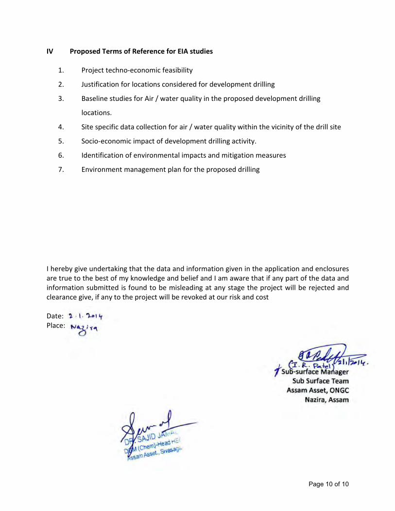
Page 10 of 10
IV Proposed Terms of Reference for EIA studies
1. Project techno-economic feasibility
2. Justification for locations considered for development drilling
3. Baseline studies for Air / water quality in the proposed development drilling
locations.
4. Site specific data collection for air / water quality within the vicinity of the drill site
5. Socio-economic impact of development drilling activity.
6. Identification of environmental impacts and mitigation measures
7. Environment management plan for the proposed drilling
I hereby give undertaking that the data and information given in the application and enclosures
are true to the best of my knowledge and belief and I am aware that if any part of the data and
information submitted is found to be misleading at any stage the project will be rejected and
clearance give, if any to the project will be revoked at our risk and cost
Date:
Place:

Page 1 of 9
Pre-feasibility Report
Development Drilling for 4 wells in Borholla ML area by ONGC Ltd
Introduction
The Borholla ML. area covers 32.116 Sq. Km of South Assam Shelf Block in Golaghat district,
Assam. During the year 2013-15, 4 development locations are planned to be taken up for drilling
which falls in the ML area. It is expected that the proposed drilling activities will lead to augment
the production of hydrocarbons in the present scenario of growing demand of oil and gas in the
country.
1.1 Description of Contract Area
ML Block Area, km2 Wells Latitude Longitude Depth, m
Borholla 32.116 BRDO 26o
27' 13.25” 94o
10' 26.17” 2722
BRDN 26o
26' 01.20” 94o 10' 9.39” 2700
2 unnamed - - -
1.2 Proposed Project
Based on the Studies carried out by Institute of Reservoir Studies, two development locations
BRDN & BRDO are proposed to be drilled alongwith 2 more locations whose locations are yet to
be finalised.
1.2.1 Geological setting of the area falling in Borholla ML Block.
The Borholla filed is located about 35kms SSE of Jorhat, along the Naga hills. There are four oil
bearing formations i.e. Basement, Basal Sandstone, Sylhet, Kopili, and two gas bearing formations
i.e. Tipam and Girujan (from Bottom to top). Structurally, Borholla is a faulted anticline located on
an E-W trending ridge, bounded to the North and South by deep grabens. Faults divide Borholla
filed in to many faults blocks. The oil was discovered in basal sandstone in year 1970 through
BR#04 and commercially production started in year 1981
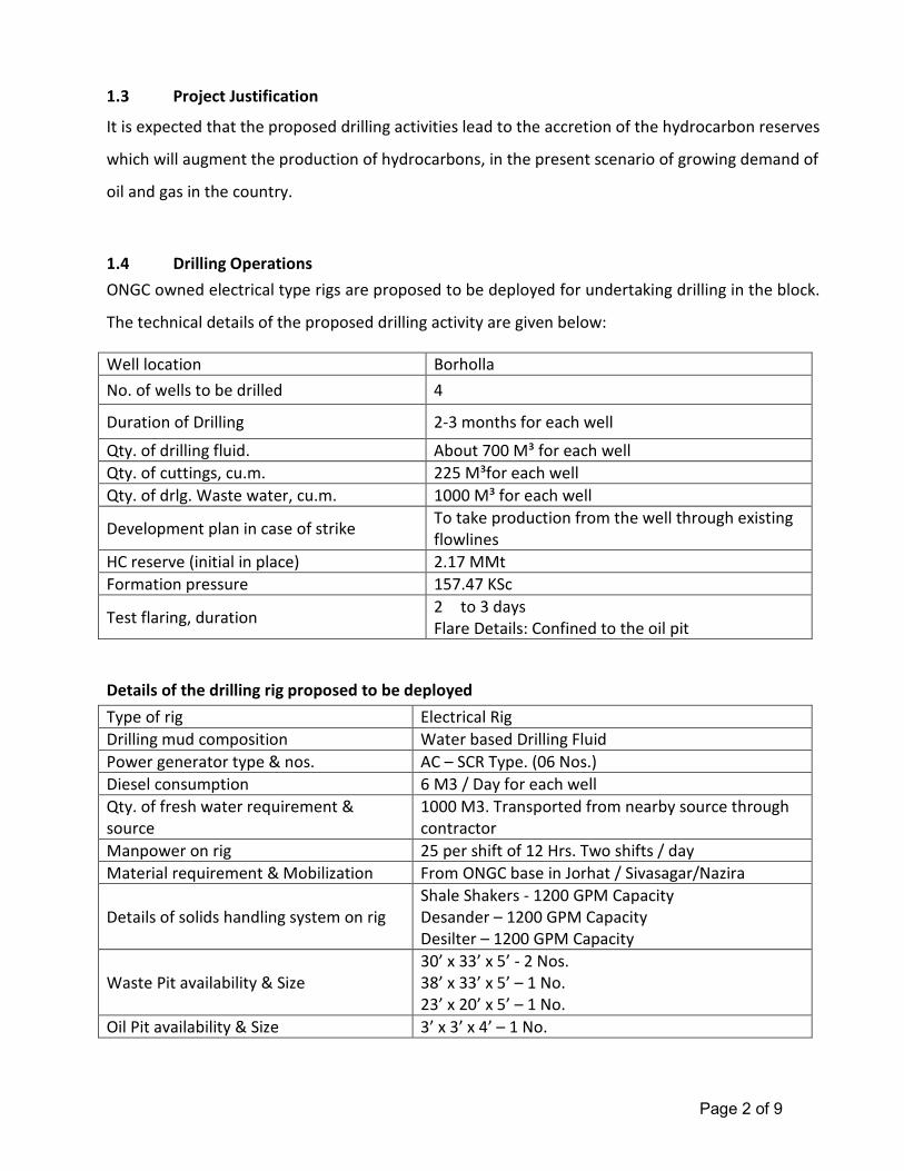
Page 2 of 9
1.3 Project Justification
It is expected that the proposed drilling activities lead to the accretion of the hydrocarbon reserves
which will augment the production of hydrocarbons, in the present scenario of growing demand of
oil and gas in the country.
1.4 Drilling Operations
ONGC owned electrical type rigs are proposed to be deployed for undertaking drilling in the block.
The technical details of the proposed drilling activity are given below:
Well location Borholla
No. of wells to be drilled 4
Duration of Drilling 2-3 months for each well
Qty. of drilling fluid. About 700 M³ for each well
Qty. of cuttings, cu.m. 225 M³for each well
Qty. of drlg. Waste water, cu.m. 1000 M³ for each well
Development plan in case of strike To take production from the well through existing
flowlines
HC reserve (initial in place) 2.17 MMt
Formation pressure 157.47 KSc
Test flaring, duration 2 to 3 days
Flare Details: Confined to the oil pit
Details of the drilling rig proposed to be deployed
Type of rig Electrical Rig
Drilling mud composition Water based Drilling Fluid
Power generator type & nos. AC – SCR Type. (06 Nos.)
Diesel consumption 6 M3 / Day for each well
Qty. of fresh water requirement &
source
1000 M3. Transported from nearby source through
contractor
Manpower on rig 25 per shift of 12 Hrs. Two shifts / day
Material requirement & Mobilization From ONGC base in Jorhat / Sivasagar/Nazira
Details of solids handling system on rig
Shale Shakers - 1200 GPM Capacity
Desander – 1200 GPM Capacity
Desilter – 1200 GPM Capacity
Waste Pit availability & Size
30’ x 33’ x 5’ - 2 Nos.
38’ x 33’ x 5’ – 1 No.
23’ x 20’ x 5’ – 1 No.
Oil Pit availability & Size 3’ x 3’ x 4’ – 1 No.
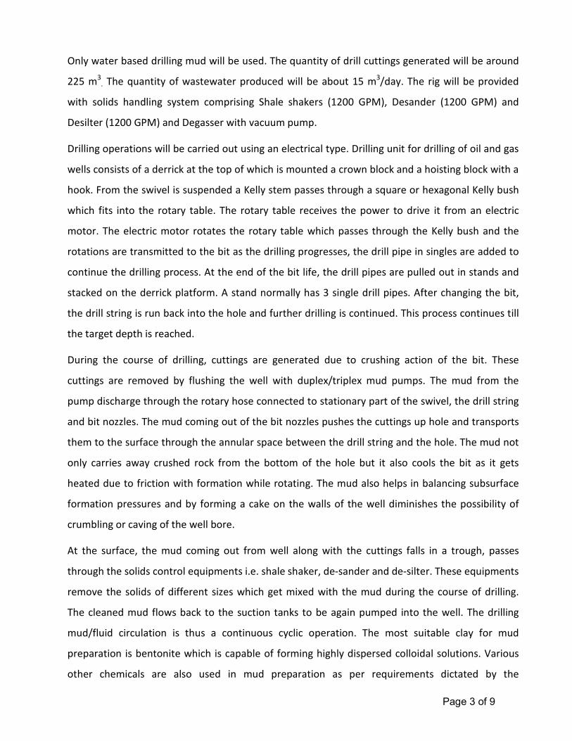
Page 3 of 9
Only water based drilling mud will be used. The quantity of drill cuttings generated will be around
225 m3
. The quantity of wastewater produced will be about 15 m3/day. The rig will be provided
with solids handling system comprising Shale shakers (1200 GPM), Desander (1200 GPM) and
Desilter (1200 GPM) and Degasser with vacuum pump.
Drilling operations will be carried out using an electrical type. Drilling unit for drilling of oil and gas
wells consists of a derrick at the top of which is mounted a crown block and a hoisting block with a
hook. From the swivel is suspended a Kelly stem passes through a square or hexagonal Kelly bush
which fits into the rotary table. The rotary table receives the power to drive it from an electric
motor. The electric motor rotates the rotary table which passes through the Kelly bush and the
rotations are transmitted to the bit as the drilling progresses, the drill pipe in singles are added to
continue the drilling process. At the end of the bit life, the drill pipes are pulled out in stands and
stacked on the derrick platform. A stand normally has 3 single drill pipes. After changing the bit,
the drill string is run back into the hole and further drilling is continued. This process continues till
the target depth is reached.
During the course of drilling, cuttings are generated due to crushing action of the bit. These
cuttings are removed by flushing the well with duplex/triplex mud pumps. The mud from the
pump discharge through the rotary hose connected to stationary part of the swivel, the drill string
and bit nozzles. The mud coming out of the bit nozzles pushes the cuttings up hole and transports
them to the surface through the annular space between the drill string and the hole. The mud not
only carries away crushed rock from the bottom of the hole but it also cools the bit as it gets
heated due to friction with formation while rotating. The mud also helps in balancing subsurface
formation pressures and by forming a cake on the walls of the well diminishes the possibility of
crumbling or caving of the well bore.
At the surface, the mud coming out from well along with the cuttings falls in a trough, passes
through the solids control equipments i.e. shale shaker, de-sander and de-silter. These equipments
remove the solids of different sizes which get mixed with the mud during the course of drilling.
The cleaned mud flows back to the suction tanks to be again pumped into the well. The drilling
mud/fluid circulation is thus a continuous cyclic operation. The most suitable clay for mud
preparation is bentonite which is capable of forming highly dispersed colloidal solutions. Various
other chemicals are also used in mud preparation as per requirements dictated by the
Page 4 of 9
temperature/pressure conditions of the wells. The mud is continuously tested for its density,
viscosity, yield point, water loss, pH value etc. to ensure that the drilling operations can be
sustained without any down hole complications.
1.5 Drilling Facilities
Drilling is a temporary activity which will continue for about 2-3 months for each well in the block.
The rigs are self-contained for all routine jobs. Once the drilling operations are completed, and if
sufficient indications of hydrocarbons are noticed while drilling, the well is tested by perforation in
the production casing. This normally takes 2-3 days. If the well is found to be a successful
hydrocarbon bearing structure, it is sealed off for future development, if any.
1.6 General Requirements of Drilling
Exploratory drilling programme requires the following common facilities:
a. Drilling muds
Drilling of wells requires specially formulated muds which basically comprise inert earth
materials like bentonite, barite in water with several additives to give mud weight, fluidity and
filter cake characteristics while drilling. The drilling muds have several functions like
lubrication and cooling of the drill bit, balancing subsurface formation, bringing out the drill
cuttings from the well bore, thixotropic property to hold cuttings during non-operations,
formation of thin cake to prevent liquid loss along well bore etc. Several additives are mixed
into the mud system to give the required properties. Water based mud will be used to the
possible extent in exploratory drilling but use of synthetic based mud may require due to
complexities associated with the geological formations and associated hole stability problems.
The constituents of water based mud (WBM) are given in Table 1.2. The special additives and
their functions in WBM are shown in Table 1.3.
b. Power Generation
The drilling process requires movement of drill bit through the draw works which require
power. The power requirement of the drilling rig will be met by using the six Diesel Generator
Page 5 of 9
sets with a diesel consumption of about 06 Kl/day. The exhaust stacks of the DG sets are likely
to vent the emissions.
c. Water requirements
The water requirement in a drilling rig is mainly meant for preparation of drilling mud apart
from washings and domestic use. While the former consumes the majority of water
requirement, the water requirement for domestic and wash use is very less. The daily water
consumption will be 25 m3/d of which 15 m
3/d will be used for mud preparation and 10 m
3/d
will be used for domestic purposes including drinking.
d. Domestic wastewater
The operating personnel in the drilling rigs will operate from drill site accommodation (DSA) in
the vicinity of the location. Suitable soak pits will be available at the DSA.
e. Solids removal
The rock cuttings and fragments of shale, sand and silt associated with the return drilling fluid
during well drilling will be separated using shale shakers and other solids removal equipment
like desanders and desilters. The recovered mud will be reused while the rejected solids will
be collected and discharged into the waste pit.
f. Drill cuttings and waste residual muds
During drilling operations, approx. 225 m3 per well of wet drill cuttings are expected to be
generated from each well depending on the type of formation and depth of drilling. In
addition to the cuttings 15-20 m3/day of wastewater is likely to be generated during well
drilling. The waste residual muds and drill cuttings which contain clay, sand etc. will be
disposed into the waste pit.
g. Testing
Testing facilities will be available at drilling rig for separation of liquid phase and burning of all
hydrocarbons during testing. The test flare boom will be located at a distance from the drilling
rig.
h. Chemical storage
Page 6 of 9
The drilling rig will have normal storage facilities for fuel oil, required chemicals and the
necessary tubulars and equipment. The storage places will be clearly marked with safe
operating facilities and practices.
i. Manpower
The drilling rig will be operated by approx. 30 persons on the rig at anytime. The manpower
will operate in two shifts with continuous operations on the rig.
j. Logistics
Crew transfers to and from the drilling rig, materials, diesel and chemicals will be through
light vehicles, trucks and trailers.
1.7 Production
After successful drilling of the wells, the produced oil & gas will be transported to Borholla GGS
through flowlines for further treatment and dispatch.
1.8 Project Investment
The total cost of drilling of 4 wells including daily drilling rates, consumables, well accessories etc.
will approximately be about Rs. 80 Crores.
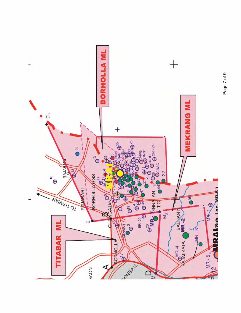
Page 7 of 9
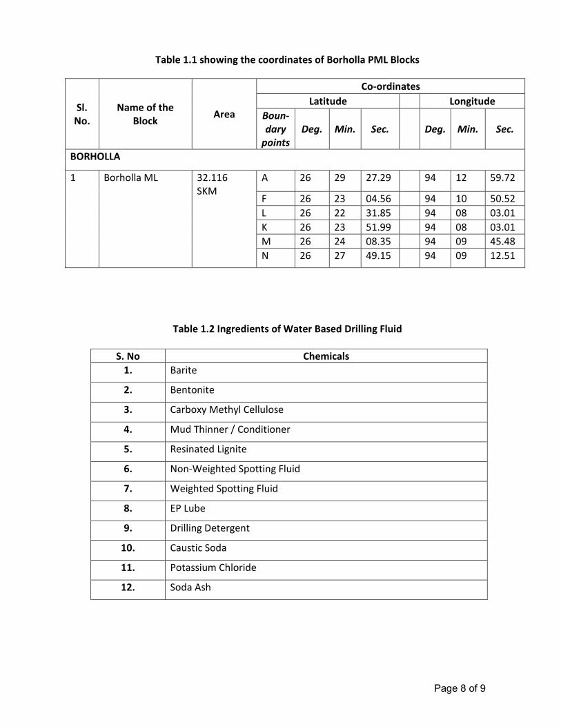
Page 8 of 9
Table 1.1 showing the coordinates of Borholla PML Blocks
Sl.
No.
Name of the
Block Area
Co-ordinates
Latitude Longitude
Boun-
dary
points
Deg. Min. Sec. Deg. Min. Sec.
BORHOLLA
1
Borholla ML
32.116
SKM
A 26 29 27.29 94 12 59.72
F 26 23 04.56 94 10 50.52
L 26 22 31.85 94 08 03.01
K 26 23 51.99 94 08 03.01
M 26 24 08.35 94 09 45.48
N 26 27 49.15 94 09 12.51
Table 1.2 Ingredients of Water Based Drilling Fluid
S. No Chemicals
1. Barite
2. Bentonite
3. Carboxy Methyl Cellulose
4. Mud Thinner / Conditioner
5. Resinated Lignite
6. Non-Weighted Spotting Fluid
7. Weighted Spotting Fluid
8. EP Lube
9. Drilling Detergent
10. Caustic Soda
11. Potassium Chloride
12. Soda Ash
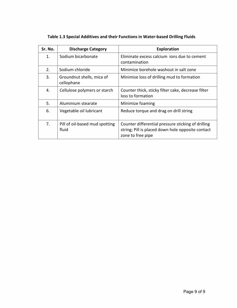
Page 9 of 9
Table 1.3 Special Additives and their Functions in Water-based Drilling Fluids
Sr. No. Discharge Category Exploration
1. Sodium bicarbonate Eliminate excess calcium ions due to cement
contamination
2. Sodium chloride Minimize borehole washout in salt zone
3. Groundnut shells, mica of
cellophane
Minimise loss of drilling mud to formation
4. Cellulose polymers or starch Counter thick, sticky filter cake, decrease filter
loss to formation
5. Aluminium stearate Minimize foaming
6. Vegetable oil lubricant Reduce torque and drag on drill string
7. Pill of oil-based mud spotting
fluid
Counter differential pressure sticking of drilling
string; Pill is placed down hole opposite contact
zone to free pipe
AANNNNEEXXUURREE –– IIII
CCOOPPYY OOFF EEXXIISSTTIINNGG EECC,, CCTTOO AANNDD CCOOMMPPLLIIAANNCCEE
RREEPPOORRTT
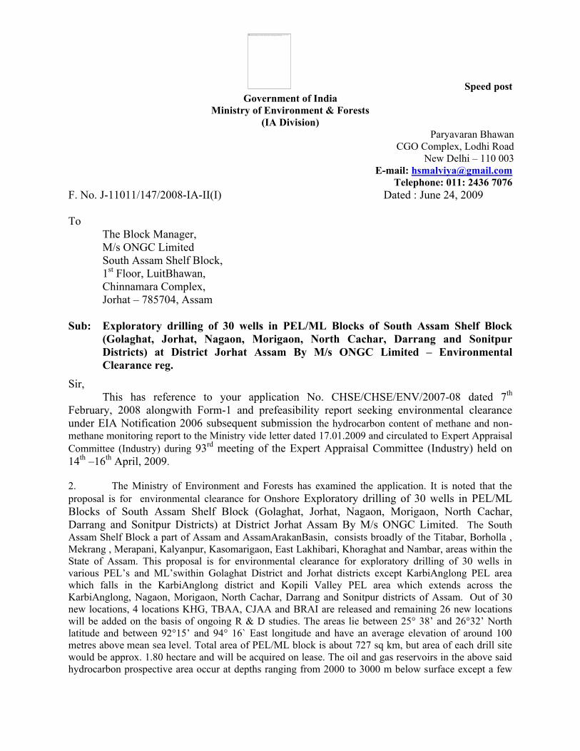
Speed post
Government of India Ministry of Environment & Forests
(IA Division) Paryavaran Bhawan
CGO Complex, Lodhi Road New Delhi – 110 003
E-mail: [email protected] Telephone: 011: 2436 7076
F. No. J-11011/147/2008-IA-II(I) Dated : June 24, 2009 To
The Block Manager, M/s ONGC Limited South Assam Shelf Block, 1st Floor, LuitBhawan, Chinnamara Complex, Jorhat – 785704, Assam
Sub: Exploratory drilling of 30 wells in PEL/ML Blocks of South Assam Shelf Block (Golaghat, Jorhat, Nagaon, Morigaon, North Cachar, Darrang and Sonitpur Districts) at District Jorhat Assam By M/s ONGC Limited – Environmental Clearance reg.
Sir, This has reference to your application No. CHSE/CHSE/ENV/2007-08 dated 7th
February, 2008 alongwith Form-1 and prefeasibility report seeking environmental clearance under EIA Notification 2006 subsequent submission the hydrocarbon content of methane and non-methane monitoring report to the Ministry vide letter dated 17.01.2009 and circulated to Expert Appraisal Committee (Industry) during 93rd meeting of the Expert Appraisal Committee (Industry) held on 14th –16th April, 2009. 2. The Ministry of Environment and Forests has examined the application. It is noted that the proposal is for environmental clearance for Onshore Exploratory drilling of 30 wells in PEL/ML Blocks of South Assam Shelf Block (Golaghat, Jorhat, Nagaon, Morigaon, North Cachar, Darrang and Sonitpur Districts) at District Jorhat Assam By M/s ONGC Limited. The South Assam Shelf Block a part of Assam and AssamArakanBasin, consists broadly of the Titabar, Borholla , Mekrang , Merapani, Kalyanpur, Kasomarigaon, East Lakhibari, Khoraghat and Nambar, areas within the State of Assam. This proposal is for environmental clearance for exploratory drilling of 30 wells in various PEL’s and ML’swithin Golaghat District and Jorhat districts except KarbiAnglong PEL area which falls in the KarbiAnglong district and Kopili Valley PEL area which extends across the KarbiAnglong, Nagaon, Morigaon, North Cachar, Darrang and Sonitpur districts of Assam. Out of 30 new locations, 4 locations KHG, TBAA, CJAA and BRAI are released and remaining 26 new locations will be added on the basis of ongoing R & D studies. The areas lie between 25° 38’ and 26°32’ North latitude and between 92°15’ and 94° 16` East longitude and have an average elevation of around 100 metres above mean sea level. Total area of PEL/ML block is about 727 sq km, but area of each drill site would be approx. 1.80 hectare and will be acquired on lease. The oil and gas reservoirs in the above said hydrocarbon prospective area occur at depths ranging from 2000 to 3000 m below surface except a few
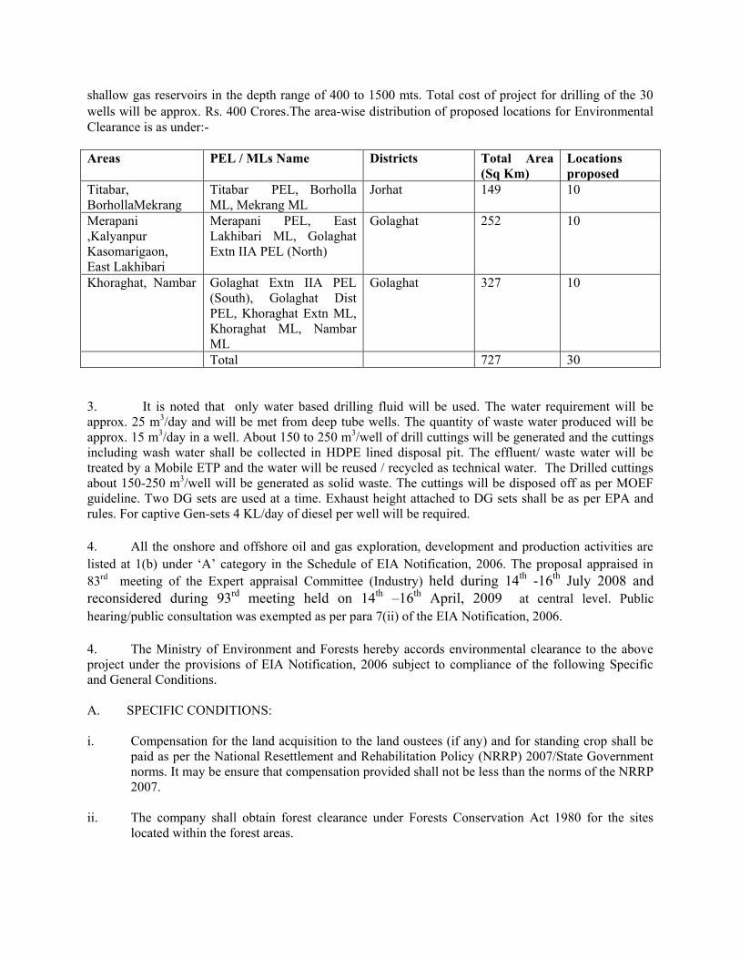
shallow gas reservoirs in the depth range of 400 to 1500 mts. Total cost of project for drilling of the 30 wells will be approx. Rs. 400 Crores.The area-wise distribution of proposed locations for Environmental Clearance is as under:- Areas PEL / MLs Name Districts Total Area
(Sq Km) Locations proposed
Titabar, BorhollaMekrang
Titabar PEL, Borholla ML, Mekrang ML
Jorhat 149 10
Merapani ,Kalyanpur Kasomarigaon, East Lakhibari
Merapani PEL, East Lakhibari ML, Golaghat Extn IIA PEL (North)
Golaghat 252 10
Khoraghat, Nambar Golaghat Extn IIA PEL (South), Golaghat Dist PEL, Khoraghat Extn ML, Khoraghat ML, Nambar ML
Golaghat 327 10
Total 727 30 3. It is noted that only water based drilling fluid will be used. The water requirement will be approx. 25 m3/day and will be met from deep tube wells. The quantity of waste water produced will be approx. 15 m3/day in a well. About 150 to 250 m3/well of drill cuttings will be generated and the cuttings including wash water shall be collected in HDPE lined disposal pit. The effluent/ waste water will be treated by a Mobile ETP and the water will be reused / recycled as technical water. The Drilled cuttings about 150-250 m3/well will be generated as solid waste. The cuttings will be disposed off as per MOEF guideline. Two DG sets are used at a time. Exhaust height attached to DG sets shall be as per EPA and rules. For captive Gen-sets 4 KL/day of diesel per well will be required.
4. All the onshore and offshore oil and gas exploration, development and production activities are listed at 1(b) under ‘A’ category in the Schedule of EIA Notification, 2006. The proposal appraised in 83rd meeting of the Expert appraisal Committee (Industry) held during 14th -16th July 2008 and reconsidered during 93rd meeting held on 14th –16th April, 2009 at central level. Public hearing/public consultation was exempted as per para 7(ii) of the EIA Notification, 2006. 4. The Ministry of Environment and Forests hereby accords environmental clearance to the above project under the provisions of EIA Notification, 2006 subject to compliance of the following Specific and General Conditions. A. SPECIFIC CONDITIONS: i. Compensation for the land acquisition to the land oustees (if any) and for standing crop shall be
paid as per the National Resettlement and Rehabilitation Policy (NRRP) 2007/State Government norms. It may be ensure that compensation provided shall not be less than the norms of the NRRP 2007.
ii. The company shall obtain forest clearance under Forests Conservation Act 1980 for the sites
located within the forest areas.
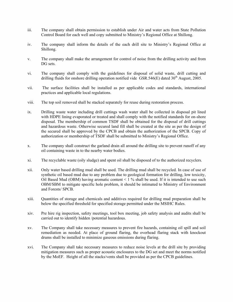
iii. The company shall obtain permission to establish under Air and water acts from State Pollution Control Board for each well and copy submitted to Ministry’s Regional Office at Shillong.
iv. The company shall inform the details of the each drill site to Ministry’s Regional Office at
Shillong. v. The company shall make the arrangement for control of noise from the drilling activity and from
DG sets. vi. The company shall comply with the guidelines for disposal of solid waste, drill cutting and
drilling fluids for onshore drilling operation notified vide GSR.546(E) dated 30th August, 2005. vii. The surface facilities shall be installed as per applicable codes and standards, international
practices and applicable local regulations. viii. The top soil removed shall be stacked separately for reuse during restoration process. ix. Drilling waste water including drill cuttings wash water shall be collected in disposal pit lined
with HDPE lining evaporated or treated and shall comply with the notified standards for on-shore disposal. The membership of common TSDF shall be obtained for the disposal of drill cuttings and hazardous waste. Otherwise secured land fill shall be created at the site as per the design of the secured shall be approved by the CPCB and obtain the authorization of the SPCB. Copy of authorization or membership of TSDF shall be submitted to Ministry’s Regional Office.
x. The company shall construct the garland drain all around the drilling site to prevent runoff of any
oil containing waste in to the nearby water bodies. xi. The recyclable waste (oily sludge) and spent oil shall be disposed of to the authorized recyclers. xii. Only water based drilling mud shall be used. The drilling mud shall be recycled. In case of use of
synthetic oil based mud due to any problem due to geological formation for drilling, low toxicity, Oil Based Mud (OBM) having aromatic content < 1 % shall be used. If it is intended to use such OBM/SBM to mitigate specific hole problem, it should be intimated to Ministry of Environment and Forests/ SPCB.
xiii. Quantities of storage and chemicals and additives required for drilling mud preparation shall be
below the specified threshold for specified storage permitted under the MSIHC Rules. xiv. Pre hire rig inspection, safety meetings, tool box meeting, job safety analysis and audits shall be
carried out to identify hidden /potential hazardous. xv. The Company shall take necessary measures to prevent fire hazards, containing oil spill and soil
remediation as needed. At place of ground flaring, the overhead flaring stack with knockout drums shall be installed to minimize gaseous emissions during flaring.
xvi. The Company shall take necessary measures to reduce noise levels at the drill site by providing
mitigation measures such as proper acoustic enclosures to the DG set and meet the norms notified by the MoEF. Height of all the stacks/vents shall be provided as per the CPCB guidelines.
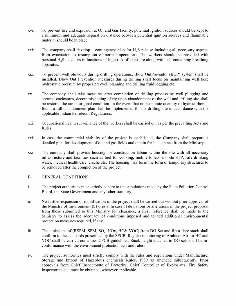
xvii. To prevent fire and explosion at Oil and Gas facility, potential ignition sources should be kept to a minimum and adequate separation distance between potential ignition sources and flammable material should be in place.
xviii. The company shall develop a contingency plan for H2S release including all necessary aspects
from evacuation to resumption of normal operations. The workers should be provided with personal H2S detectors in locations of high risk of exposure along with self containing breathing apparatus.
xix. To prevent well blowouts during drilling operations, Blow OutPreventor (BOP) system shall be
installed. Blow Out Prevention measures during drilling shall focus on maintaining well bore hydrostatic pressure by proper pre-well planning and drilling fluid logging etc.
xx. The company shall take measures after completion of drilling process by well plugging and
secured enclosures, decommissioning of rig upon abandonment of the well and drilling site shall be restored the are in original condition. In the event that no economic quantity of hydrocarbon is found a full abandonment plan shall be implemented for the drilling site in accordance with the applicable Indian Petroleum Regulations.
xxi. Occupational health surveillance of the workers shall be carried out as per the prevailing Acts and
Rules.
xxii. In case the commercial viability of the project is established, the Company shall prepare a detailed plan for development of oil and gas fields and obtain fresh clearance from the Ministry.
xxiii. The company shall provide housing for construction labour within the site with all necessary infrastructure and facilities such as fuel for cooking, mobile toilets, mobile STP, safe drinking water, medical health care, crèche etc. The housing may be in the form of temporary structures to be removed after the completion of the project.
B. GENERAL CONDITIONS: i. The project authorities must strictly adhere to the stipulations made by the State Pollution Control
Board, the State Government and any other statutory. ii. No further expansion or modification in the project shall be carried out without prior approval of
the Ministry of Environment & Forests. In case of deviations or alterations in the project proposal from those submitted to this Ministry for clearance, a fresh reference shall be made to the Ministry to assess the adequacy of conditions imposed and to add additional environmental protection measures required, if any.
iii. The emissions of (RSPM, SPM, SO2, NOx, HC& VOC) from DG Set and from flare stack shall
conform to the standards prescribed by the SPCB. Regular monitoring of Ambient Air for HC and VOC shall be carried out as per CPCB guidelines. Stack height attached to DG sets shall be in-conformance with the environment protection acts and rules.
iv. The project authorities must strictly comply with the rules and regulations under Manufacture,
Storage and Import of Hazardous chemicals Rules, 1989 as amended subsequently. Prior approvals from Chief Inspectorate of Factories, Chief Controller of Explosives, Fire Safety Inspectorate etc. must be obtained, wherever applicable.
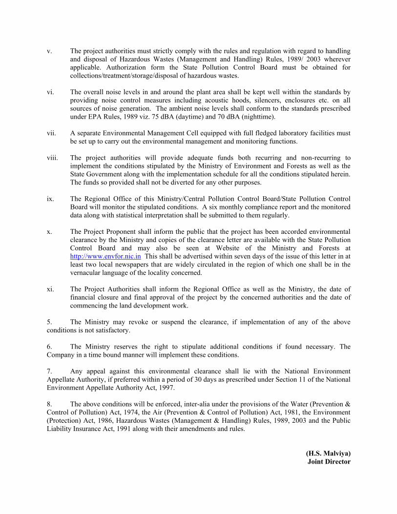
v. The project authorities must strictly comply with the rules and regulation with regard to handling and disposal of Hazardous Wastes (Management and Handling) Rules, 1989/ 2003 wherever applicable. Authorization form the State Pollution Control Board must be obtained for collections/treatment/storage/disposal of hazardous wastes.
vi. The overall noise levels in and around the plant area shall be kept well within the standards by
providing noise control measures including acoustic hoods, silencers, enclosures etc. on all sources of noise generation. The ambient noise levels shall conform to the standards prescribed under EPA Rules, 1989 viz. 75 dBA (daytime) and 70 dBA (nighttime).
vii. A separate Environmental Management Cell equipped with full fledged laboratory facilities must
be set up to carry out the environmental management and monitoring functions. viii. The project authorities will provide adequate funds both recurring and non-recurring to
implement the conditions stipulated by the Ministry of Environment and Forests as well as the State Government along with the implementation schedule for all the conditions stipulated herein. The funds so provided shall not be diverted for any other purposes.
ix. The Regional Office of this Ministry/Central Pollution Control Board/State Pollution Control
Board will monitor the stipulated conditions. A six monthly compliance report and the monitored data along with statistical interpretation shall be submitted to them regularly.
x. The Project Proponent shall inform the public that the project has been accorded environmental
clearance by the Ministry and copies of the clearance letter are available with the State Pollution Control Board and may also be seen at Website of the Ministry and Forests at http://www.envfor.nic.in This shall be advertised within seven days of the issue of this letter in at least two local newspapers that are widely circulated in the region of which one shall be in the vernacular language of the locality concerned.
xi. The Project Authorities shall inform the Regional Office as well as the Ministry, the date of
financial closure and final approval of the project by the concerned authorities and the date of commencing the land development work.
5. The Ministry may revoke or suspend the clearance, if implementation of any of the above conditions is not satisfactory. 6. The Ministry reserves the right to stipulate additional conditions if found necessary. The Company in a time bound manner will implement these conditions. 7. Any appeal against this environmental clearance shall lie with the National Environment Appellate Authority, if preferred within a period of 30 days as prescribed under Section 11 of the National Environment Appellate Authority Act, 1997. 8. The above conditions will be enforced, inter-alia under the provisions of the Water (Prevention & Control of Pollution) Act, 1974, the Air (Prevention & Control of Pollution) Act, 1981, the Environment (Protection) Act, 1986, Hazardous Wastes (Management & Handling) Rules, 1989, 2003 and the Public Liability Insurance Act, 1991 along with their amendments and rules.
(H.S. Malviya) Joint Director
Copy to : 1. The Secretary, Department of Environment, Science & Technology, Assam Secretariat, Government of
Assam, Guwahati- 781 006. 2. Chief Conservator of Forests, Ministry of Environment & Forests, Regional Office (NEZ),Upland
Road, Laitumkhrah, Shillong : 793 003, Meghalaya. 3. The Chairman, Central Pollution Control Board PariveshBhavan, CBD-cum-Office Complex, East
Arjun Nagar, New Delhi - 110 032. 4. The Chairman, Assam State Pollution Control Board, Bamunimaidan, Guwahati- 781 021, Assam. 5. Monitoring Cell, Ministry of Environment and Forests, ParyavaranBhavan, CGO Complex, New Delhi. 6. Guard File. 7. Monitoring File. 8. Record File.
(H.S. Malviya) Joint Director
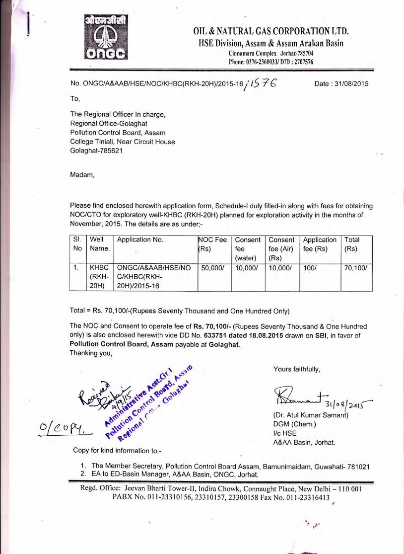
OIL & NATURAL GAS CORPORATION LTD.
HSE Division, Assam & Assam Arakan BasinCinnamara Complex Jorhat-785704
Phone: 0376-2360033/ DID : 2707 57 6
No. ONGC/A&AAB/HSE/NoC/KHBc(RKH-20H)/201s-16 / l5 7 €To,
The Regional Officer ln charge,Regional Office-GolaghatPollution Control Board, AssamCollege Tiniali, Near Circuit HouseGolaghat-785621
Madam,
Date: 3110812015
Please find enclosed herewith application form, Schedule-l duly filled-in along with fees for obtainingNOC/CTO for exploratory well-KHBC (RKH-2OH) planned for exploration activity in the months ofNovember, 2015. The details are as under'-
Total = Rs. 70,1OO/-(Rupees Seventy Thousand and One Hundred Only)
The NOC and Consent to operate fee of Rs. 70,100/- (Rupees Seventy Thousand & One Hundredonly) is also enclosed herewith vide DD No.633751 dated 18.08.2015 drawn on SBl, in favorofPotlution Contro! Board, Assam payable at Golaghat.Thanking you,
Yours faithfully,
K_J; \.e!>af(Dr. Atul Kumar Samant)DGM (Chem.)
l/c HSE
A&AA Basin, Jorhat.Copy for kind information to:-
1. The Member Secretary, Pollution Control Board Assam, Bamunimaidam, Guwahati- 7810212. EA tO ED-Basin Manager, A&M Basin, ONGC, Jorhat.
Regd. Office: Jeevan Bharti Tower-II, Indira Chowk, Connaught Place, New Delhi- 110 001PABX No. 0l l-23310156,23310157, 23300158 Fax No.0l l-23316413
! ,J'
t_
-L &
st.No
WellName.
Application No. {OC FeeRs)
Consentfee(water)
Consentfee (Air)(Rs)
Applicationfee (Rs)
Total(Rs)
1. KHBC(RKH-
20H)
ONGC/A&AAB/HSE/NOc/KHBC(RKH-2OH)t2015-16
50,000/ 10,000/ 10,000/ 100/ 70,100t
Annexure-2B 1
SCHEDULE-I
Common Application for Consent under Water (Prevention and Control of Pollution) Act, 1974,
Air (Prevention and Control of Pollution) Act, 1981) and authorization under Hazardous Wastes (Management and Handling) Rules, 1989, as amended
No. ONGC/AAAB/HSE/NOC/ KHBC (RWK#20H)/2015-16 Date 28.08.2015 Accompanying form in triplicate to be submitted by the applicant. One copy may be retained by the applicant.
Explanatory note for filling in application form for
Consent / Authorization
(1) Any applicant knowingly giving incorrect information or suppressing any information pertaining to any of the items of the application shall be liable for punishment as per provisions under the relevant Act.
(2) The application form shall be submitted at the head-quarter office of the Board at the address given on the first page of the application form or to the respective Zonal or Regional or Sub-Regional office or District Office of the Board / Pollution Control Committee under whose jurisdiction the applicants’ activity falls.
(3) The application shall be accompanied by the consent fee in the form of Demand Draft No633751 dated 18.08.2015 in favor of Pollution Control Board, Assam State Pollution Control Board / Pollution Control Committee. Fee paid is not refundable.
(4) For the items marked * strike out which is not relevant.
(5) If any of the items is not relevant to the activity of the applicant, please state 'Not Applicable'.
(6) If the space for reply provided for any item is inadequate, use additional sheets, duly referenced.
(7) Item 1: Give the name of the person who is authorized by the applicant to transact their business.
(8) Item 2: Also state the concerned institutions under whose administrative area the unit falls.
(9) The form shall be accompanied by the relevant documents specified on the last page of the application form.
(10) Capital Investment - Consent fee is to be paid based on gross fixed capital investment of the unit without depreciation till the date of application. The gross capital investment shall include cost of "land, building, plant and machinery without depreciation.
Annexure-2B 2
Application form for Consent / Authorisation
No. ONGC/AAAB/HSE/NOC/ KHBC (RWK#20H)/2015-16 Date: 28.08.2015
From
Head HSE Nambar – I Building
ONGC, A & AA Basin, Cinnamara, Jorhat-785704 (Assam)
To
The Member Secretary State Pollution Control Board GUWAHATI, ASSAM Sir,
I / We hereby apply for * (No Objection Certificate)
(i) Consent to Establish/Operate / Renewal of consent under section 25 and 26 of the Water (Prevention and Control of Pollution) Act, 1974, as amended.
(ii) Consent to Establish/Operate / renewal of consent under Section 21 of the
Air (Prevention and Control of Pollution) Act, 1981, as amended.
(iii) Authorization / renewal of authorization under rule 5 of the Hazardous Wastes (Management and Handling) Rules, 1989, as amended in connection with my / our existing / proposed / altered / additional manufacturing processing activity from the premises as per the details given below.
Part A: General
1. Name, designation, office address with telephone, fax numbers, e-mail of the
Applicant/occupier/industry/instituti
on / Local Body
: Dr. Atul Kr. Samant, Dy. General Manager (Chem.) Nambar – I Building ONGC, A & AA Basin, Cinnamara, Jorhat-785704 (Assam) - 0376-2360033,Fax – 0376 –2360014 Mobile-+919435718283
2. (a) Name and location of the industrial Unit / premises for which the application is made. (Give revenue Survey Number/ plot number, name of
: An exploratory well KHBC Khoraghat Extn. ML, Khoraghat. Distt. Golaghat (location map enclosed)
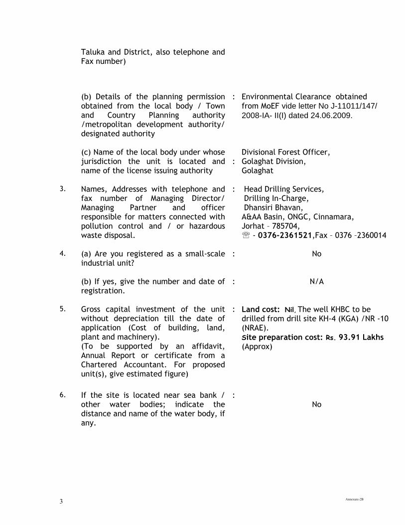
Annexure-2B 3
Taluka and District, also telephone and Fax number)
(b) Details of the planning permission obtained from the local body / Town and Country Planning authority /metropolitan development authority/ designated authority
: Environmental Clearance obtained from MoEF vide letter No J-11011/147/
2008-IA- II(I) dated 24.06.2009.
(c) Name of the local body under whose jurisdiction the unit is located and name of the license issuing authority
:
Divisional Forest Officer, Golaghat Division, Golaghat
3. Names, Addresses with telephone and fax number of Managing Director/ Managing Partner and officer responsible for matters connected with pollution control and / or hazardous waste disposal.
: Head Drilling Services, Drilling In-Charge, Dhansiri Bhavan, A&AA Basin, ONGC, Cinnamara, Jorhat – 785704, - 0376-2361521,Fax – 0376 –2360014
4. (a) Are you registered as a small-scale industrial unit?
: No
(b) If yes, give the number and date of registration.
: N/A
5. Gross capital investment of the unit without depreciation till the date of application (Cost of building, land, plant and machinery). (To be supported by an affidavit, Annual Report or certificate from a Chartered Accountant. For proposed unit(s), give estimated figure)
: Land cost: Nil, The well KHBC to be drilled from drill site KH-4 (KGA) /NR -10 (NRAE).
Site preparation cost: Rs. 93.91 Lakhs (Approx)
6. If the site is located near sea bank / other water bodies; indicate the distance and name of the water body, if any.
: No
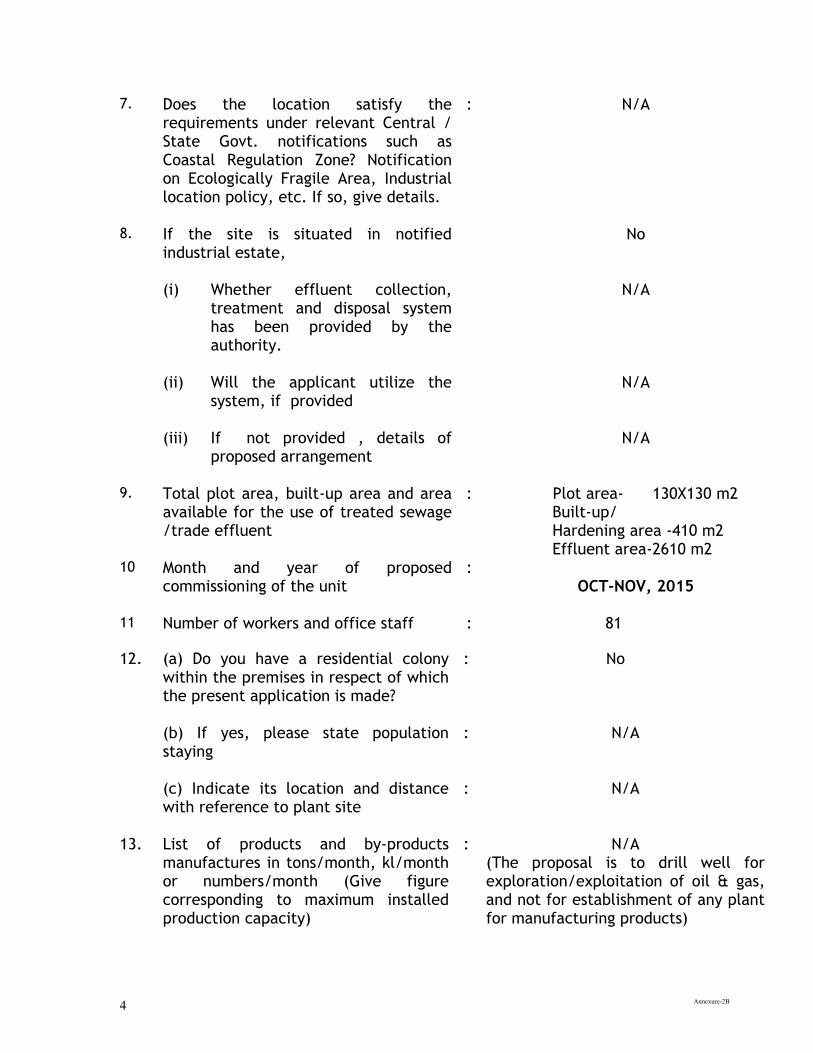
Annexure-2B 4
7. Does the location satisfy the requirements under relevant Central / State Govt. notifications such as Coastal Regulation Zone? Notification on Ecologically Fragile Area, Industrial location policy, etc. If so, give details.
: N/A
8. If the site is situated in notified industrial estate,
No
(i) Whether effluent collection, treatment and disposal system has been provided by the authority.
N/A
(ii) Will the applicant utilize the system, if provided
N/A
(iii) If not provided , details of proposed arrangement
N/A
9. Total plot area, built-up area and area available for the use of treated sewage /trade effluent
: Plot area- 130X130 m2 Built-up/ Hardening area -410 m2 Effluent area-2610 m2
10 Month and year of proposed commissioning of the unit
: OCT-NOV, 2015
11 Number of workers and office staff : 81
12. (a) Do you have a residential colony within the premises in respect of which the present application is made?
: No
(b) If yes, please state population staying
: N/A
(c) Indicate its location and distance with reference to plant site
: N/A
13. List of products and by-products manufactures in tons/month, kl/month or numbers/month (Give figure corresponding to maximum installed production capacity)
: N/A (The proposal is to drill well for exploration/exploitation of oil & gas, and not for establishment of any plant for manufacturing products)
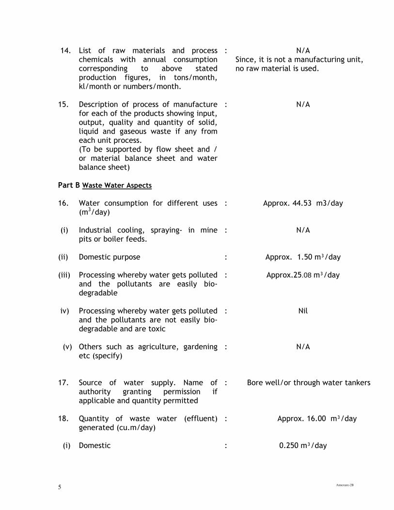
Annexure-2B 5
14. List of raw materials and process chemicals with annual consumption corresponding to above stated production figures, in tons/month, kl/month or numbers/month.
: N/A Since, it is not a manufacturing unit, no raw material is used.
15. Description of process of manufacture for each of the products showing input, output, quality and quantity of solid, liquid and gaseous waste if any from each unit process. (To be supported by flow sheet and / or material balance sheet and water balance sheet)
: N/A
Part B Waste Water Aspects 16. Water consumption for different uses
(m3/day)
: Approx. 44.53 m3/day
(i) Industrial cooling, spraying- in mine pits or boiler feeds.
: N/A
(ii) Domestic purpose
: Approx. 1.50 m³/day
(iii) Processing whereby water gets polluted and the pollutants are easily bio-degradable
:
Approx.25.08 m³/day
iv) Processing whereby water gets polluted and the pollutants are not easily bio-degradable and are toxic
: Nil
(v) Others such as agriculture, gardening etc (specify)
: N/A
17. Source of water supply. Name of
authority granting permission if applicable and quantity permitted
: Bore well/or through water tankers
18. Quantity of waste water (effluent) generated (cu.m/day)
: Approx. 16.00 m³/day
(i) Domestic
: 0.250 m³/day
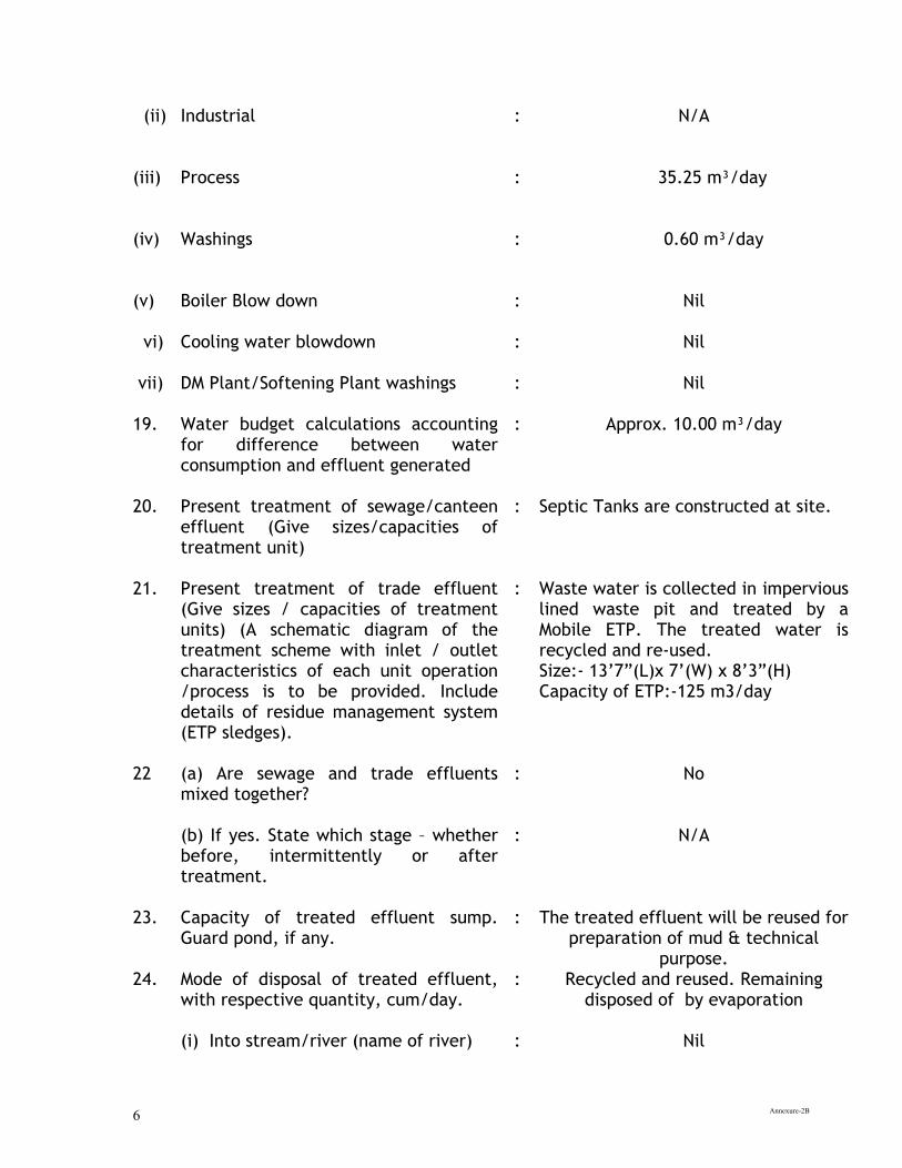
Annexure-2B 6
(ii) Industrial :
N/A
(iii)
Process
:
35.25 m³/day
(iv)
Washings
:
0.60 m³/day
(v)
Boiler Blow down
:
Nil
vi) Cooling water blowdown
: Nil
vii) DM Plant/Softening Plant washings : Nil 19. Water budget calculations accounting
for difference between water consumption and effluent generated
: Approx. 10.00 m³/day
20. Present treatment of sewage/canteen effluent (Give sizes/capacities of treatment unit)
: Septic Tanks are constructed at site.
21. Present treatment of trade effluent (Give sizes / capacities of treatment units) (A schematic diagram of the treatment scheme with inlet / outlet characteristics of each unit operation /process is to be provided. Include details of residue management system (ETP sledges).
: Waste water is collected in impervious lined waste pit and treated by a Mobile ETP. The treated water is recycled and re-used. Size:- 13’7”(L)x 7’(W) x 8’3”(H) Capacity of ETP:-125 m3/day
22 (a) Are sewage and trade effluents
mixed together?
: No
(b) If yes. State which stage – whether before, intermittently or after treatment.
: N/A
23. Capacity of treated effluent sump. Guard pond, if any.
: The treated effluent will be reused for preparation of mud & technical
purpose. 24. Mode of disposal of treated effluent,
with respective quantity, cum/day.
: Recycled and reused. Remaining disposed of by evaporation
(i) Into stream/river (name of river) : Nil
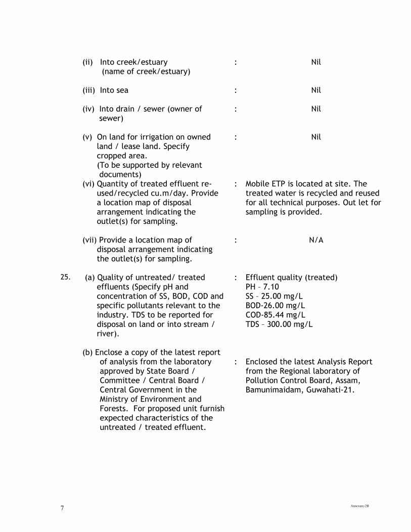
Annexure-2B 7
(ii) Into creek/estuary
(name of creek/estuary)
: Nil
(iii) Into sea
: Nil
(iv) Into drain / sewer (owner of sewer)
: Nil
(v) On land for irrigation on owned land / lease land. Specify cropped area. (To be supported by relevant documents)
: Nil
(vi) Quantity of treated effluent re- used/recycled cu.m/day. Provide a location map of disposal arrangement indicating the outlet(s) for sampling.
: Mobile ETP is located at site. The treated water is recycled and reused for all technical purposes. Out let for sampling is provided.
(vii) Provide a location map of disposal arrangement indicating the outlet(s) for sampling.
: N/A
25. (a) Quality of untreated/ treated effluents (Specify pH and concentration of SS, BOD, COD and specific pollutants relevant to the industry. TDS to be reported for disposal on land or into stream / river).
: Effluent quality (treated) PH – 7.10 SS – 25.00 mg/L BOD-26.00 mg/L COD-85.44 mg/L TDS – 300.00 mg/L
(b) Enclose a copy of the latest report of analysis from the laboratory approved by State Board / Committee / Central Board / Central Government in the Ministry of Environment and Forests. For proposed unit furnish expected characteristics of the untreated / treated effluent.
:
Enclosed the latest Analysis Report from the Regional laboratory of Pollution Control Board, Assam, Bamunimaidam, Guwahati-21.
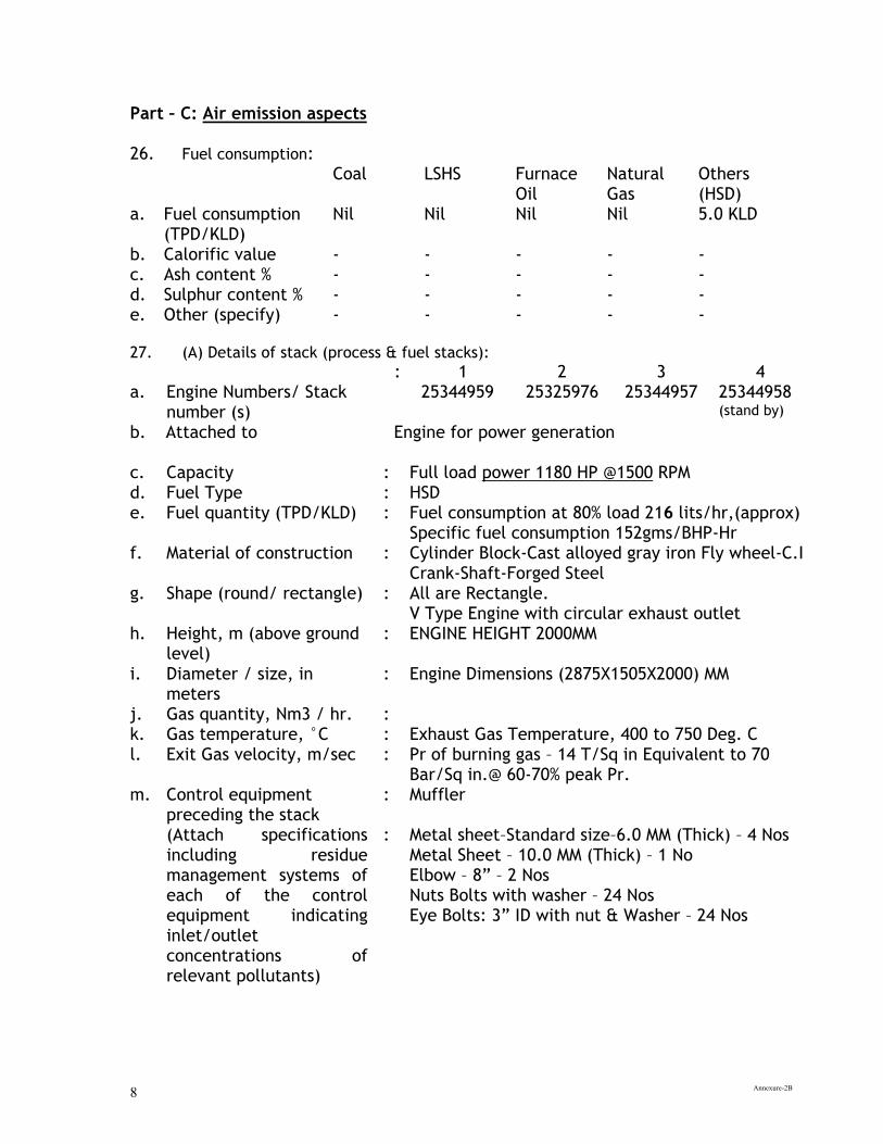
Annexure-2B 8
Part – C: Air emission aspects 26. Fuel consumption: Coal LSHS Furnace
Oil Natural Gas
Others (HSD)
a. Fuel consumption (TPD/KLD)
Nil Nil Nil Nil 5.0 KLD
b. Calorific value - - - - - c. Ash content % - - - - - d. Sulphur content % - - - - - e. Other (specify) - - - - - 27. (A) Details of stack (process & fuel stacks):
: 1 2 3 4 a. Engine Numbers/ Stack
number (s) 25344959
25325976 25344957 25344958
(stand by)
b. Attached to Engine for power generation
c. Capacity : Full load power 1180 HP @1500 RPM d. Fuel Type : HSD e. Fuel quantity (TPD/KLD) : Fuel consumption at 80% load 216 lits/hr,(approx)
Specific fuel consumption 152gms/BHP-Hr f. Material of construction : Cylinder Block-Cast alloyed gray iron Fly wheel-C.I
Crank-Shaft-Forged Steel g. Shape (round/ rectangle) : All are Rectangle.
V Type Engine with circular exhaust outlet h. Height, m (above ground
level) : ENGINE HEIGHT 2000MM
i. Diameter / size, in meters
: Engine Dimensions (2875X1505X2000) MM
j. Gas quantity, Nm3 / hr. : k. Gas temperature, °C : Exhaust Gas Temperature, 400 to 750 Deg. C l. Exit Gas velocity, m/sec : Pr of burning gas – 14 T/Sq in Equivalent to 70
Bar/Sq in.@ 60-70% peak Pr. m. Control equipment
preceding the stack : Muffler
(Attach specifications including residue management systems of each of the control equipment indicating inlet/outlet concentrations of relevant pollutants)
: Metal sheet–Standard size–6.0 MM (Thick) – 4 Nos Metal Sheet – 10.0 MM (Thick) – 1 No Elbow – 8” – 2 Nos Nuts Bolts with washer – 24 Nos Eye Bolts: 3” ID with nut & Washer – 24 Nos
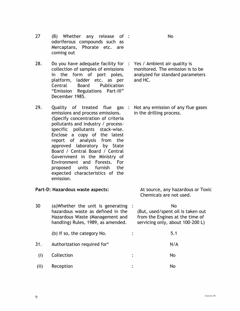
Annexure-2B 9
27
(B) Whether any release of odoriferous compounds such as Mercaptans, Phorate etc. are coming out
:
No
28. Do you have adequate facility for collection of samples of emissions in the form of port poles, platform, ladder etc. as per Central Board Publication “Emission Regulations Part-III” December 1985.
: Yes / Ambient air quality is monitored. The emission is to be analyzed for standard parameters and HC.
29. Quality of treated flue gas emissions and process emissions. (Specify concentration of criteria pollutants and industry / process- specific pollutants stack-wise. Enclose a copy of the latest report of analysis from the approved laboratory by State Board / Central Board / Central Government in the Ministry of Environment and Forests. For proposed units furnish the expected characteristics of the emission.
: Not any emission of any flue gases in the drilling process.
Part-D: Hazardous waste aspects: At source, any hazardous or Toxic Chemicals are not used. 30 (a)Whether the unit is generating
hazardous waste as defined in the Hazardous Waste (Management and handling) Rules, 1989, as amended.
: No (But, used/spent oil is taken out from the Engines at the time of servicing only, about 100-200 L)
(b) If so, the category No.
: 5.1
31. Authorization required for*
N/A
(i) Collection
: No
(ii)
Reception : No
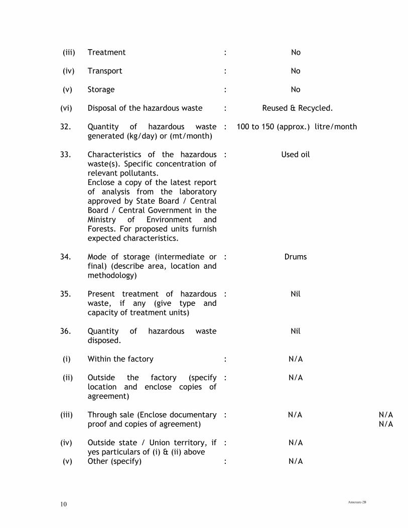
Annexure-2B 10
(iii) Treatment
: No
(iv) Transport
: No
(v) Storage
: No
(vi) Disposal of the hazardous waste : Reused & Recycled. 32. Quantity of hazardous waste
generated (kg/day) or (mt/month) : 100 to 150 (approx.) litre/month
33. Characteristics of the hazardous
waste(s). Specific concentration of relevant pollutants. Enclose a copy of the latest report of analysis from the laboratory approved by State Board / Central Board / Central Government in the Ministry of Environment and Forests. For proposed units furnish expected characteristics.
: Used oil
34. Mode of storage (intermediate or final) (describe area, location and methodology)
: Drums
35. Present treatment of hazardous waste, if any (give type and capacity of treatment units)
: Nil
36. Quantity of hazardous waste disposed.
Nil
(i) Within the factory
: N/A
(ii) Outside the factory (specify location and enclose copies of agreement)
: N/A
(iii) Through sale (Enclose documentary proof and copies of agreement)
: N/A N/A N/A
(iv) Outside state / Union territory, if yes particulars of (i) & (ii) above
: N/A
(v) Other (specify) : N/A
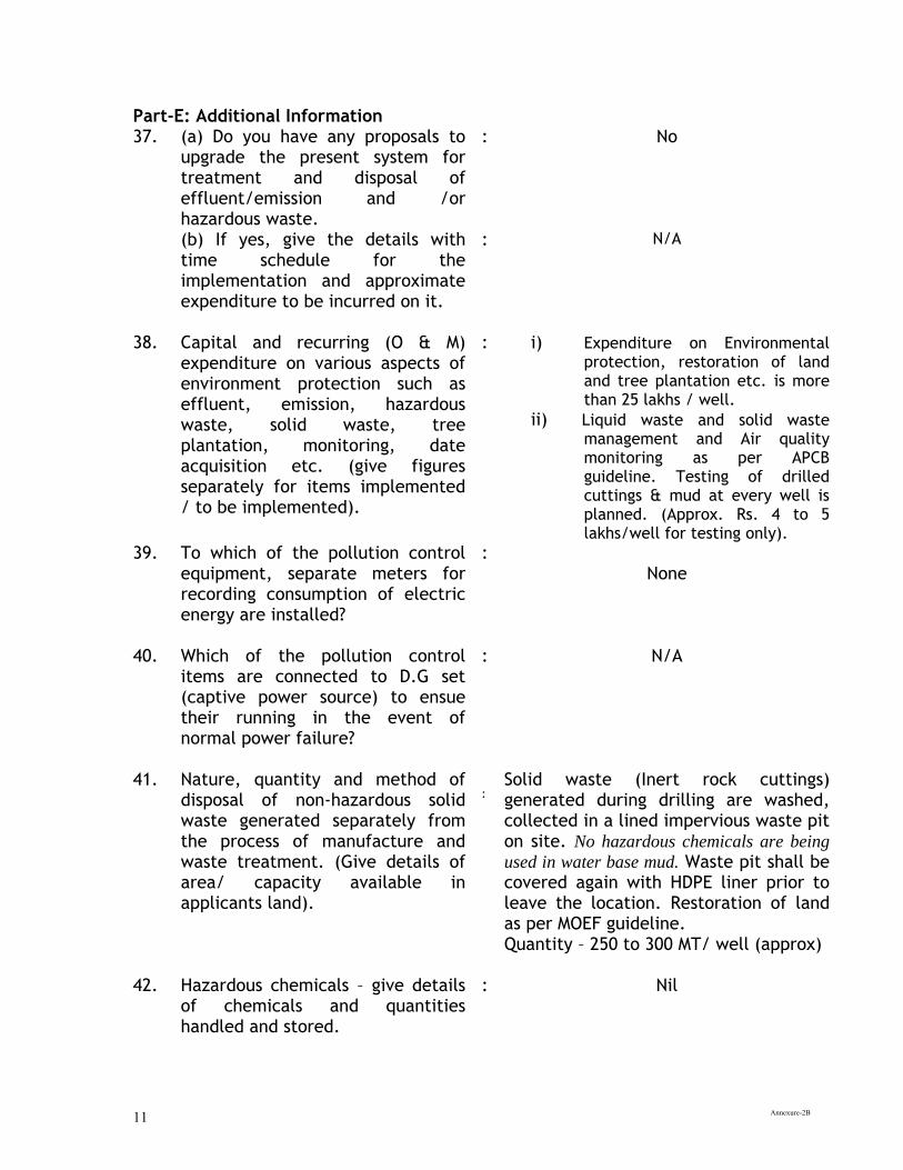
Annexure-2B 11
Part-E: Additional Information 37. (a) Do you have any proposals to
upgrade the present system for treatment and disposal of effluent/emission and /or hazardous waste.
: No
(b) If yes, give the details with time schedule for the implementation and approximate expenditure to be incurred on it.
: N/A
38. Capital and recurring (O & M) expenditure on various aspects of environment protection such as effluent, emission, hazardous waste, solid waste, tree plantation, monitoring, date acquisition etc. (give figures separately for items implemented / to be implemented).
: i) Expenditure on Environmental protection, restoration of land and tree plantation etc. is more than 25 lakhs / well.
ii) Liquid waste and solid waste management and Air quality monitoring as per APCB guideline. Testing of drilled cuttings & mud at every well is planned. (Approx. Rs. 4 to 5 lakhs/well for testing only).
39. To which of the pollution control equipment, separate meters for recording consumption of electric energy are installed?
: None
40. Which of the pollution control items are connected to D.G set (captive power source) to ensue their running in the event of normal power failure?
: N/A
41. Nature, quantity and method of disposal of non-hazardous solid waste generated separately from the process of manufacture and waste treatment. (Give details of area/ capacity available in applicants land).
: Solid waste (Inert rock cuttings) generated during drilling are washed, collected in a lined impervious waste pit on site. No hazardous chemicals are being
used in water base mud. Waste pit shall be covered again with HDPE liner prior to leave the location. Restoration of land as per MOEF guideline. Quantity – 250 to 300 MT/ well (approx)
42. Hazardous chemicals – give details of chemicals and quantities handled and stored.
: Nil
Annexure-2B 12
i. Is the unit a major accident hazard unit as per MSIHC rules?
: N/A
ii. Is the unit an isolated storage as defined under the MSIHC rules?
: N/A
iii. Indicate status of compliance of rules 5, 7, 10, 11, 12, 13 and 18 of the MSIHC rules.
: N/A
iv. Has approval of site has been obtained from the concerned authority?
: N/A
v. Has the unit prepared an offsite emergency plan? Is it updated?
: N/A
vi.
Has information on imports of chemicals been provided to the concerned authority?
:
N/A
vii. Does the unit posses a policy under the PLI act?
: yes
43. Brief details of tree plantation/green belt development within applicant’s premises (in hectares).
: Trees are planted in available open space and around site.
44 Information of schemes for waste minimization, resource recovery and recycling-implemented and to be implemented, separately.
: Mobile ETP will be used to treat drilling waste water for reuse/recycle as technical water.
45 (a) The applicant shall indicate whether industry comes under Public Hearing, if so, the relevant documents such as EIA, EMP, Risk Analysis etc. shall be enclosed shall be indicated accordingly.
(b)Any other additional information that the applicant desires to give.
: As per EIA Notification 2006, environmental clearance is obtained from MoEF vide letter No J-11011/147/
2008-IA- II(I) dated 24.06.2009.
Nil
Annexure-2B 13
46. I/We further declare that the information furnished above is correct to the best of my/our knowledge. 47. I / We hereby submit that in case of any change from what is stated in this application in respect of raw materials, products, process of manufacture and treatment and /or disposal of effluent, emissions, hazardous wastes etc. in quality and quantity; a fresh application for Consent / Authorization shall be made and until the grant to fresh Consent/ Authorization no change shall be made 48. I / We undertake to furnish any other information within one month of its being called by the Board/committee. 49. I / We agree to submit to the Board an application for renewal of consent /authorization in two months in advance before the date of expiry of the consent / authorization validity period. 50. I / We enclose herewith a Demand draft of Rs.70,100/- (Rupees Seventy thousand one hundred only) bearing No.633751 dated 18.08.2015 drawn on SBI, Golaghat main Branch & payable in favour of Pollution Control Board, Assam , as the fee for consents & authorization for a period up to completion of said oil well.
Yours faithfully,
(Dr.Atul Kumar Samant)
DGM (Chem.)-Head HSE Nambar-1 Building
ONGC, A & AA Basin Cinnamara, Jorhat-785704 Documents enclosed:-
1. Environmental clearance obtained from MOEF vide letter No J-11011/147/ 2008-IA II (I) dated 24.06.2009.
2. Location Map 3. Demand Draft No.633751 dated 18.08.2015, drawn on SBI, Main Br., Golaghat in favor of Pollution Control Board, Assam, & payable at Golaghat. 4. Effluent Analysis Report by regional laboratory of PCB: Assam, Bamunimaidam, Guwahati-21.

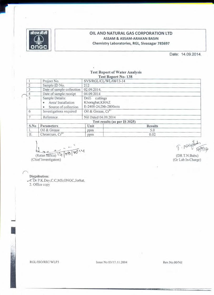
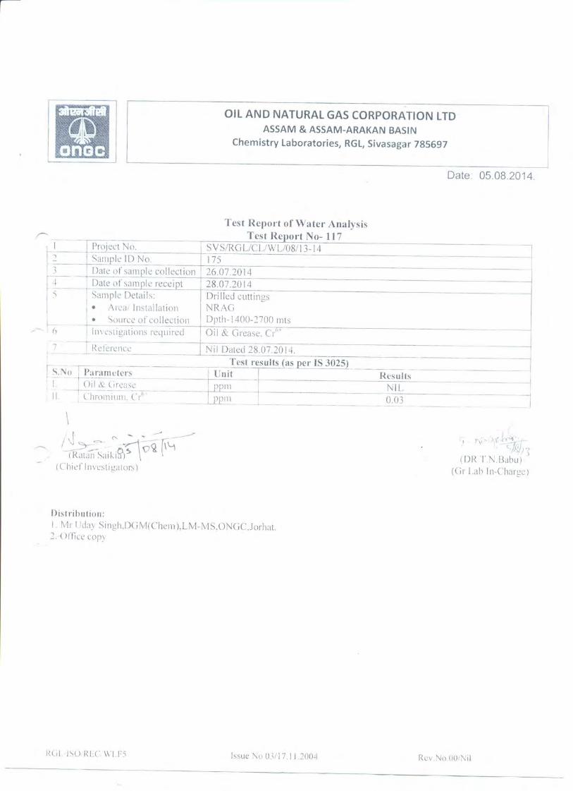
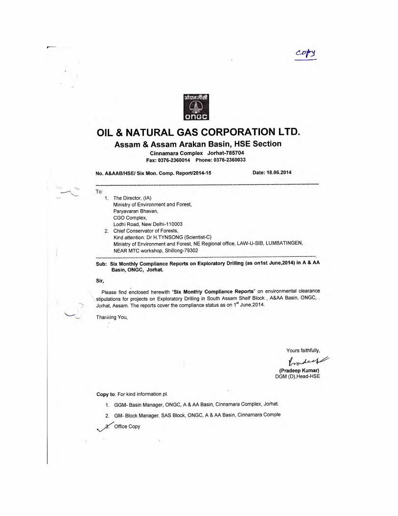

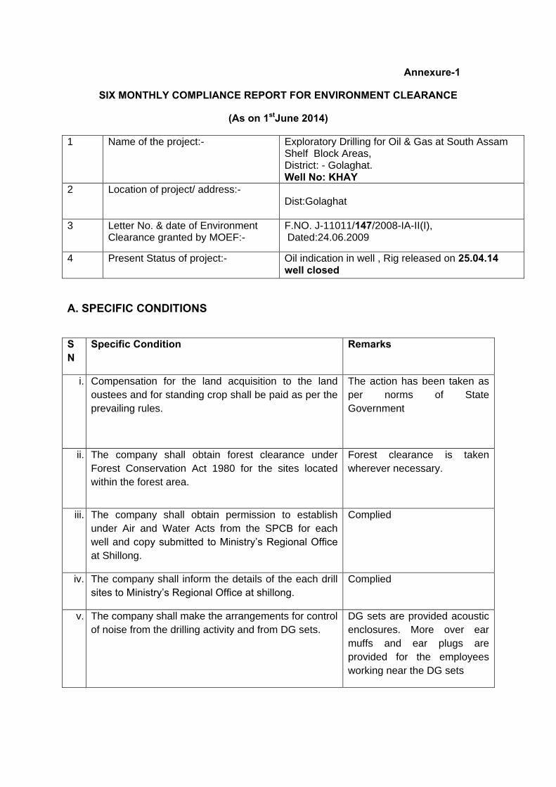
Annexure-1
SIX MONTHLY COMPLIANCE REPORT FOR ENVIRONMENT CLEARANCE
(As on 1stJune 2014)
1 Name of the project:-
Exploratory Drilling for Oil & Gas at South Assam Shelf Block Areas, District: - Golaghat. Well No: KHAY
2 Location of project/ address:-
Dist:Golaghat
3 Letter No. & date of Environment Clearance granted by MOEF:-
F.NO. J-11011/147/2008-IA-II(I), Dated:24.06.2009
4 Present Status of project:-
Oil indication in well , Rig released on 25.04.14 well closed
A. SPECIFIC CONDITIONS
SN
Specific Condition Remarks
i. Compensation for the land acquisition to the land
oustees and for standing crop shall be paid as per the
prevailing rules.
The action has been taken as
per norms of State
Government
ii. The company shall obtain forest clearance under
Forest Conservation Act 1980 for the sites located
within the forest area.
Forest clearance is taken
wherever necessary.
iii. The company shall obtain permission to establish
under Air and Water Acts from the SPCB for each
well and copy submitted to Ministry’s Regional Office
at Shillong.
Complied
iv. The company shall inform the details of the each drill
sites to Ministry’s Regional Office at shillong.
Complied
v. The company shall make the arrangements for control
of noise from the drilling activity and from DG sets.
DG sets are provided acoustic
enclosures. More over ear
muffs and ear plugs are
provided for the employees
working near the DG sets
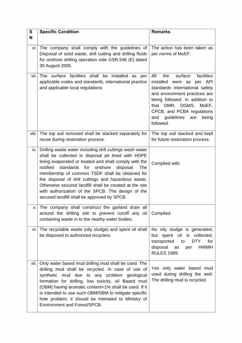
SN
Specific Condition Remarks
vi. The company shall comply with the guidelines of
Disposal of solid waste, drill cutting and drilling fluids
for onshore drilling operation vide GSR.546 (E) dated
30 August 2005.
The action has been taken as
per norms of MoEF.
vii. The surface facilities shall be installed as per
applicable codes and standards, international practice
and applicable local regulations
All the surface facilities
installed were as per API
standards international safety
and environment practices are
being followed. In addition to
that OMR, DGMS, MoEF,
CPCB, and PCBA regulations
and guidelines are being
followed.
viii. The top soil removed shall be stacked separately for
reuse during restoration process.
The top soil stacked and kept
for future restoration process.
ix. Drilling waste water including drill cuttings wash water
shall be collected in disposal pit lined with HDPE
lining evaporated or treated and shall comply with the
notified standards for onshore disposal. The
membership of common TSDF shall be obtained for
the disposal of drill cuttings and hazardous waste.
Otherwise secured landfill shall be created at the site
with authorization of the SPCB. The design of the
secured landfill shall be approved by SPCB.
Complied with.
x. The company shall construct the garland drain all
around the drilling site to prevent runoff any oil
containing waste in to the nearby water bodies.
Complied.
xi. The recyclable waste (oily sludge) and spent oil shall
be disposed to authorized recyclers.
No oily sludge is generated,
but spent oil is collected,
transported to DTY for
disposal as per HWMH
RULES 1989.
xii. Only water based mud drilling mud shall be used. The
drilling mud shall be recycled. In case of use of
synthetic mud due to any problem geological
formation for drilling, low toxicity, oil Based mud
(OBM) having aromatic content<1% shall be used. If it
is intended to use such OBM/SBM to mitigate specific
hole problem, it should be intimated to Ministry of
Environment and Forest/SPCB.
Yes only water based mud
used during drilling the well.
The drilling mud is recycled.
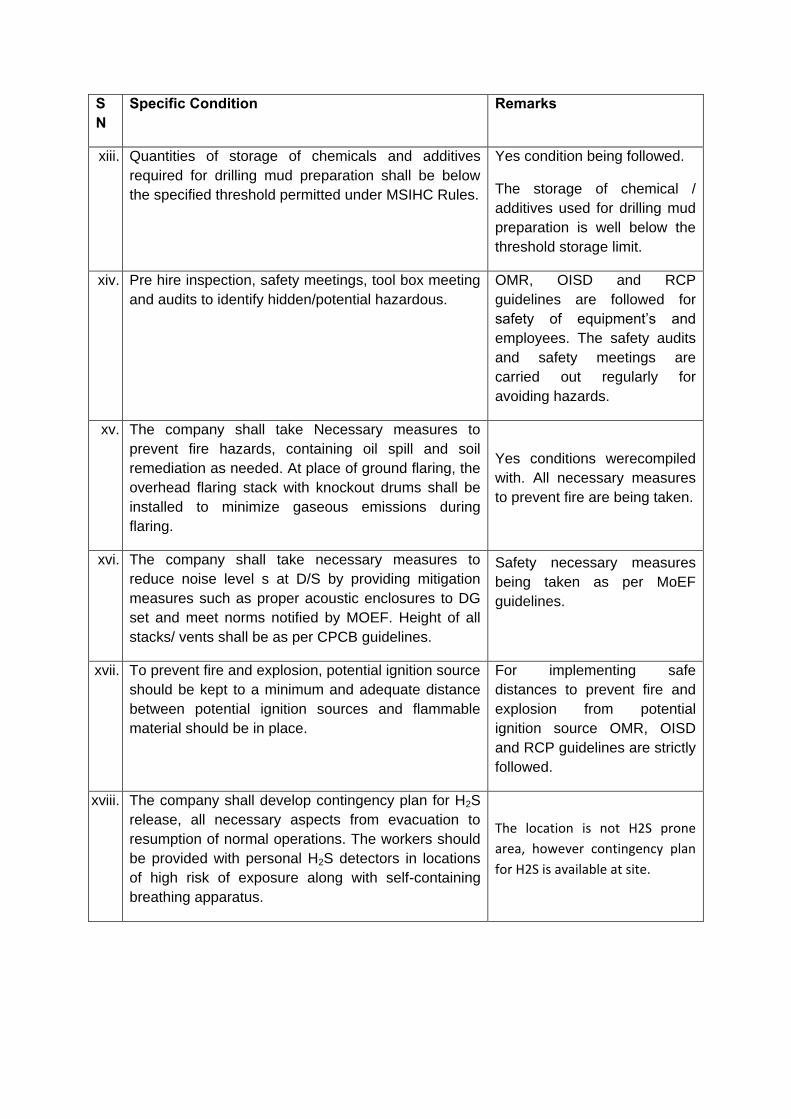
SN
Specific Condition Remarks
xiii. Quantities of storage of chemicals and additives
required for drilling mud preparation shall be below
the specified threshold permitted under MSIHC Rules.
Yes condition being followed.
The storage of chemical /
additives used for drilling mud
preparation is well below the
threshold storage limit.
xiv. Pre hire inspection, safety meetings, tool box meeting
and audits to identify hidden/potential hazardous.
OMR, OISD and RCP
guidelines are followed for
safety of equipment’s and
employees. The safety audits
and safety meetings are
carried out regularly for
avoiding hazards.
xv. The company shall take Necessary measures to
prevent fire hazards, containing oil spill and soil
remediation as needed. At place of ground flaring, the
overhead flaring stack with knockout drums shall be
installed to minimize gaseous emissions during
flaring.
Yes conditions werecompiled
with. All necessary measures
to prevent fire are being taken.
xvi. The company shall take necessary measures to
reduce noise level s at D/S by providing mitigation
measures such as proper acoustic enclosures to DG
set and meet norms notified by MOEF. Height of all
stacks/ vents shall be as per CPCB guidelines.
Safety necessary measures
being taken as per MoEF
guidelines.
xvii. To prevent fire and explosion, potential ignition source
should be kept to a minimum and adequate distance
between potential ignition sources and flammable
material should be in place.
For implementing safe
distances to prevent fire and
explosion from potential
ignition source OMR, OISD
and RCP guidelines are strictly
followed.
xviii. The company shall develop contingency plan for H2S
release, all necessary aspects from evacuation to
resumption of normal operations. The workers should
be provided with personal H2S detectors in locations
of high risk of exposure along with self-containing
breathing apparatus.
The location is not H2S prone
area, however contingency plan
for H2S is available at site.
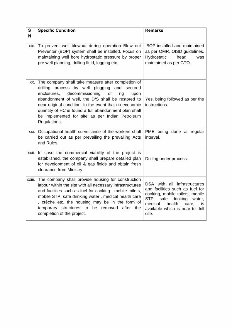
SN
Specific Condition Remarks
xix. To prevent well blowout during operation Blow out
Preventer (BOP) system shall be installed. Focus on
maintaining well bore hydrostatic pressure by proper
pre well planning, drilling fluid, logging etc.
BOP installed and maintained
as per OMR, OISD guidelines.
Hydrostatic head was
maintained as per GTO.
xx. The company shall take measure after completion of
drilling process by well plugging and secured
enclosures, decommissioning of rig upon
abandonment of well, the D/S shall be restored to
near original condition. In the event that no economic
quantity of HC is found a full abandonment plan shall
be implemented for site as per Indian Petroleum
Regulations.
Yes, being followed as per the
instructions.
xxi. Occupational health surveillance of the workers shall
be carried out as per prevailing the prevailing Acts
and Rules.
PME being done at regular
interval.
xxii. In case the commercial viability of the project is
established, the company shall prepare detailed plan
for development of oil & gas fields and obtain fresh
clearance from Ministry.
Drilling under process.
xxiii. The company shall provide housing for construction
labour within the site with all necessary infrastructures
and facilities such as fuel for cooking , mobile toilets,
mobile STP, safe drinking water , medical health care
, crèche etc. the housing may be in the form of
temporary structures to be removed after the
completion of the project.
DSA with all infrastructures and facilities such as fuel for cooking, mobile toilets, mobile STP, safe drinking water, medical health care, is available which is near to drill site.

B. GENERAL CONDITIONS
S. No.
General Conditions Remarks
i The project authorities must strictly
adhere to stipulations made by State
Pollution Control Board and the State
Government.
Followed as per the Guidelines provided
by State Pollution Control Board and the
State Government.
ii No further expansion or modification of
project shall be carried without prior
approval of MOEF. In case of deviation
or alteration in the project proposal from
those submitted to this ministry for
clearance, a fresh reference shall be
made to Ministry to access the
adequacy of conditions imposed and to
add additional environmental protection
measures required if any.
Shall be complied if any
iii The emissions of (RSPM, SPM, SO2,
NOx, HC& HOC) from DG set and flare
stack shall conform the standards of
SPCB. Regular monitoring of ambient
air for HC and VOC as per CPCB
guidelines. Stack height attached to DG
sets shall be as per EPA and rules.
Is strictly followed as per EPA and rules.
iv The project authorities must strictly
Comply with rules and regulations
under Manufacture, Storage and Import
of Hazardous Chemicals Rules
1989.Prior approval from Chief
Inspectorate of Factories, Chief
Controller of Explosive, Fire Safety
Inspectorate etc must be obtained,
wherever applicable.
Is strictly followed
No hazardous chemicals (as listed) are
being used however APCB will be
approached with list for authorisation as
per MoEF guidelines.

S. No.
General Conditions Remarks
v The project authorities must strictly
Comply with rules and regulations with
regard to handling and disposal of
Hazardous Wastes (Management and
handling) rules 1989/2003 wherever
applicable. Authorisation from SPCB
must be obtained for collections/
treatment/storage/ disposal of
hazardous wastes.
Complied.
Authorisation from SPCB obtained.
vi The overall noise levels in and around
the plant shall be kept within the
standards by providing noise control
measure including acoustic hoods,
silencers, enclosures etc. on all sources
of noise generation. The ambient noise
levels shall conform to EPA rules, 1989
viz 75 dBA (daytime) and 70 dBA (night
time).
Is strictly followed and conform to EPA
rules, 1989.
vii. A separate Environmental Management
Cell equipped with full fledge laboratory
facilities to carry out environment
management and monitoring functions.
A separate HSE section exists that
monitor the environmental performance
of the project. Our regional laboratory is
well equipped with most of such facilities.
viii The project authorities shall provide
adequate funds both recurring and non-
recurring to implement the conditions
stipulated by MOEF and State Govt.
along with implementation schedule for
all the conditions stipulated herein. The
funds so provided shall not be diverted
for any other purpose.
Adequate Budgetary Provision exists.
The allocated budget shall not be
diverted for any other purpose.
ix The Regional Office of this
Ministry/Central Pollution Control Board
will monitor the stipulated condition.
A six monthly compliance and the
monitored data along with statistical
interpretation to be submitted to them
regularly.
Complied.

S. No.
General Conditions Remarks
x The project proponent shall inform the
public that the project has accorded
environmental clearances and copies of
clearances letters are available with the
State Pollution Control Board and also
be seen at Web site of the Ministry of
Forests at http://www.envfor.nic.in.This
shall be advertise within seven days of
the issue of this letter in at least two
local newspapers that are widely
circulated in the region of which one
shall be in the vernacular language of
the locality concerned..
Complied.
xi. The project authority shall inform the
RO as well as the Ministry, the date of
financial closure and final approval of
project by the concerned authorities
and date of commencing of land
development work.
Shall be informed.
xii The above conditions will be enforced,
inter-alia under provision of Water
(Prevention & Control of Pollution) Act
1974, Air(Prevention & Control of
Pollution) Act 1981, Environment
(Protection) Act 1986, Hazardous
Waste Rules 1989, 2003 and Public
Liability Insurance Act 1991 along with
their amendments and rules.
Being followed.
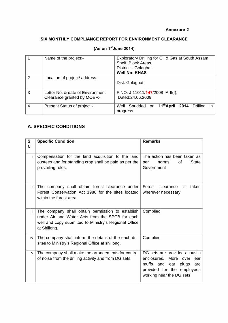
Annexure-2
SIX MONTHLY COMPLIANCE REPORT FOR ENVIRONMENT CLEARANCE
(As on 1stJune 2014)
1 Name of the project:-
Exploratory Drilling for Oil & Gas at South Assam Shelf Block Areas, District: - Golaghat. Well No: KHAS
2 Location of project/ address:-
Dist: Golaghat
3 Letter No. & date of Environment Clearance granted by MOEF:-
F.NO. J-11011/147/2008-IA-II(I), Dated:24.06.2009
4 Present Status of project:-
Well Spudded on 11thApril 2014 Drilling in progress
A. SPECIFIC CONDITIONS
SN
Specific Condition Remarks
i. Compensation for the land acquisition to the land
oustees and for standing crop shall be paid as per the
prevailing rules.
The action has been taken as
per norms of State
Government
ii. The company shall obtain forest clearance under
Forest Conservation Act 1980 for the sites located
within the forest area.
Forest clearance is taken
wherever necessary.
iii. The company shall obtain permission to establish
under Air and Water Acts from the SPCB for each
well and copy submitted to Ministry’s Regional Office
at Shillong.
Complied
iv. The company shall inform the details of the each drill
sites to Ministry’s Regional Office at shillong.
Complied
v. The company shall make the arrangements for control
of noise from the drilling activity and from DG sets.
DG sets are provided acoustic
enclosures. More over ear
muffs and ear plugs are
provided for the employees
working near the DG sets

SN
Specific Condition Remarks
vi. The company shall comply with the guidelines of
Disposal of solid waste, drill cutting and drilling fluids
for onshore drilling operation vide GSR.546 (E) dated
30 August 2005.
The action has been taken as
per norms of MoEF.
vii. The surface facilities shall be installed as per
applicable codes and standards, international practice
and applicable local regulations
All the surface facilities
installed were as per API
standards international safety
and environment practices are
being followed. In addition to
that OMR, DGMS, MoEF,
CPCB, and PCBA regulations
and guidelines are being
followed.
viii. The top soil removed shall be stacked separately for
reuse during restoration process.
The top soil stacked and kept
for future restoration process.
ix. Drilling waste water including drill cuttings wash water
shall be collected in disposal pit lined with HDPE
lining evaporated or treated and shall comply with the
notified standards for onshore disposal. The
membership of common TSDF shall be obtained for
the disposal of drill cuttings and hazardous waste.
Otherwise secured landfill shall be created at the site
with authorization of the SPCB. The design of the
secured landfill shall be approved by SPCB.
Complied with.
x. The company shall construct the garland drain all
around the drilling site to prevent runoff any oil
containing waste in to the nearby water bodies.
Complied.
xi. The recyclable waste (oily sludge) and spent oil shall
be disposed to authorized recyclers.
No oily sludge is generated,
but spent oil is collected,
transported to DTY for
disposal as per HWMH
RULES 1989.
xii. Only water based mud drilling mud shall be used. The
drilling mud shall be recycled. In case of use of
synthetic mud due to any problem geological
formation for drilling, low toxicity, oil Based mud
(OBM) having aromatic content<1% shall be used. If it
is intended to use such OBM/SBM to mitigate specific
hole problem, it should be intimated to Ministry of
Environment and Forest/SPCB.
Yes only water based mud
used during drilling the well.
The drilling mud is recycled.
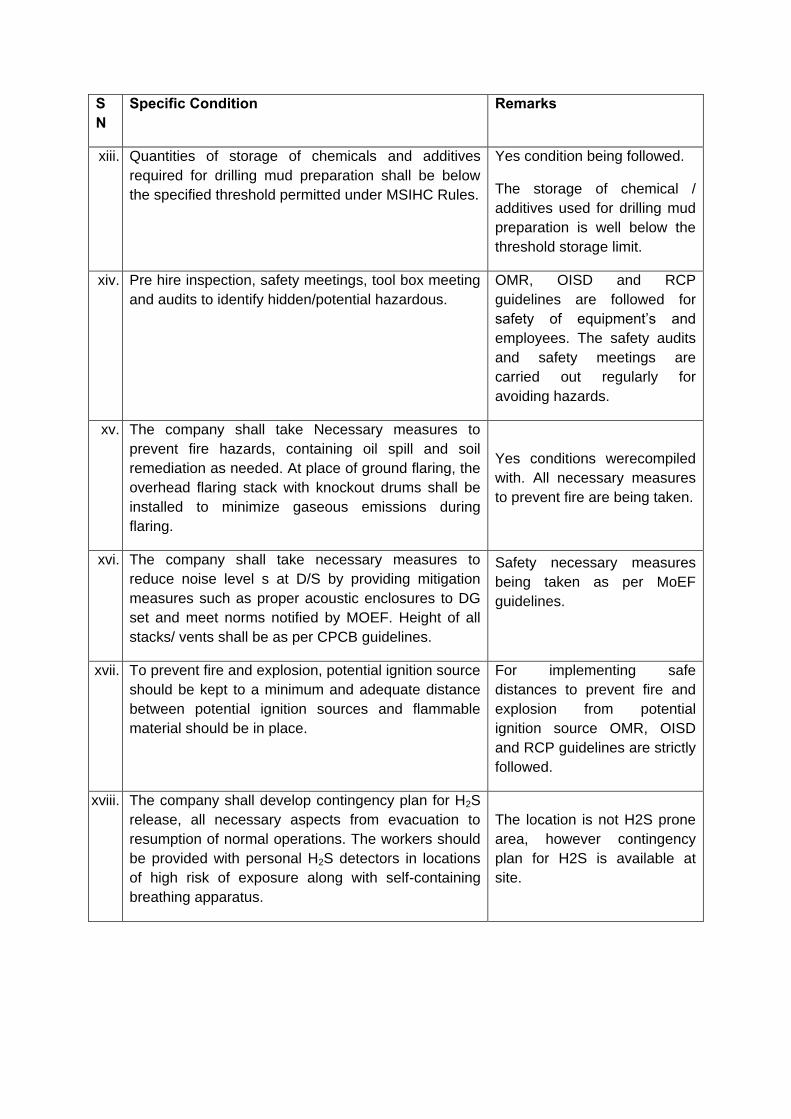
SN
Specific Condition Remarks
xiii. Quantities of storage of chemicals and additives
required for drilling mud preparation shall be below
the specified threshold permitted under MSIHC Rules.
Yes condition being followed.
The storage of chemical /
additives used for drilling mud
preparation is well below the
threshold storage limit.
xiv. Pre hire inspection, safety meetings, tool box meeting
and audits to identify hidden/potential hazardous.
OMR, OISD and RCP
guidelines are followed for
safety of equipment’s and
employees. The safety audits
and safety meetings are
carried out regularly for
avoiding hazards.
xv. The company shall take Necessary measures to
prevent fire hazards, containing oil spill and soil
remediation as needed. At place of ground flaring, the
overhead flaring stack with knockout drums shall be
installed to minimize gaseous emissions during
flaring.
Yes conditions werecompiled
with. All necessary measures
to prevent fire are being taken.
xvi. The company shall take necessary measures to
reduce noise level s at D/S by providing mitigation
measures such as proper acoustic enclosures to DG
set and meet norms notified by MOEF. Height of all
stacks/ vents shall be as per CPCB guidelines.
Safety necessary measures
being taken as per MoEF
guidelines.
xvii. To prevent fire and explosion, potential ignition source
should be kept to a minimum and adequate distance
between potential ignition sources and flammable
material should be in place.
For implementing safe
distances to prevent fire and
explosion from potential
ignition source OMR, OISD
and RCP guidelines are strictly
followed.
xviii. The company shall develop contingency plan for H2S
release, all necessary aspects from evacuation to
resumption of normal operations. The workers should
be provided with personal H2S detectors in locations
of high risk of exposure along with self-containing
breathing apparatus.
The location is not H2S prone
area, however contingency
plan for H2S is available at
site.
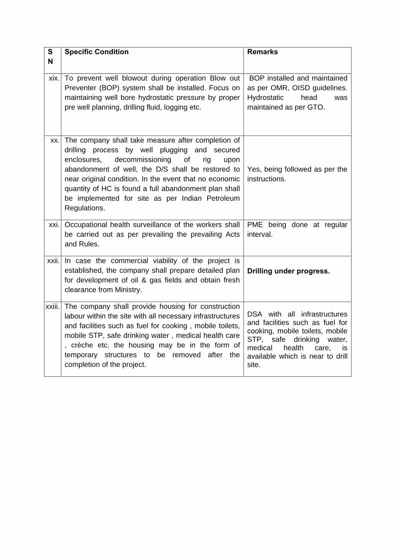
SN
Specific Condition Remarks
xix. To prevent well blowout during operation Blow out
Preventer (BOP) system shall be installed. Focus on
maintaining well bore hydrostatic pressure by proper
pre well planning, drilling fluid, logging etc.
BOP installed and maintained
as per OMR, OISD guidelines.
Hydrostatic head was
maintained as per GTO.
xx. The company shall take measure after completion of
drilling process by well plugging and secured
enclosures, decommissioning of rig upon
abandonment of well, the D/S shall be restored to
near original condition. In the event that no economic
quantity of HC is found a full abandonment plan shall
be implemented for site as per Indian Petroleum
Regulations.
Yes, being followed as per the
instructions.
xxi. Occupational health surveillance of the workers shall
be carried out as per prevailing the prevailing Acts
and Rules.
PME being done at regular
interval.
xxii. In case the commercial viability of the project is
established, the company shall prepare detailed plan
for development of oil & gas fields and obtain fresh
clearance from Ministry.
Drilling under progress.
xxiii. The company shall provide housing for construction
labour within the site with all necessary infrastructures
and facilities such as fuel for cooking , mobile toilets,
mobile STP, safe drinking water , medical health care
, crèche etc. the housing may be in the form of
temporary structures to be removed after the
completion of the project.
DSA with all infrastructures and facilities such as fuel for cooking, mobile toilets, mobile STP, safe drinking water, medical health care, is available which is near to drill site.
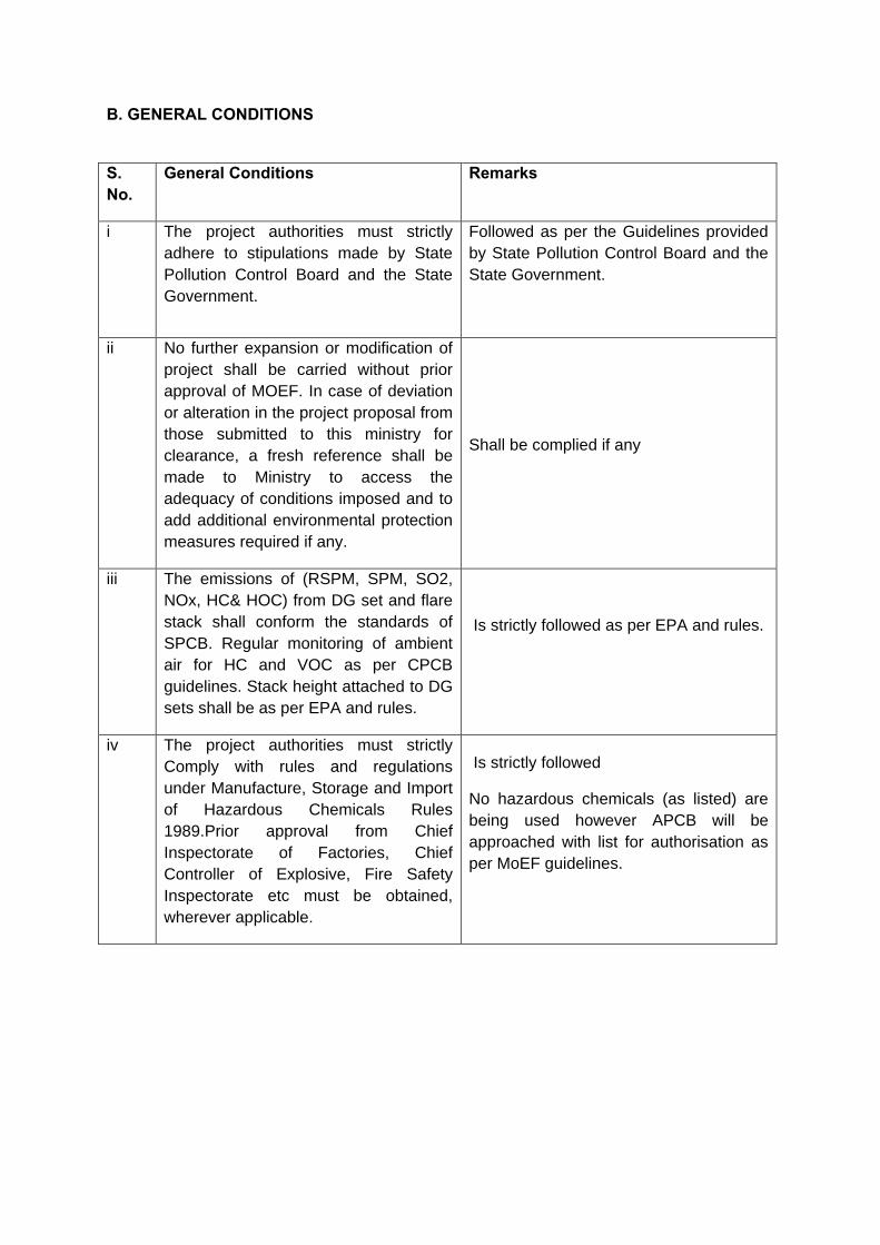
B. GENERAL CONDITIONS
S. No.
General Conditions Remarks
i The project authorities must strictly
adhere to stipulations made by State
Pollution Control Board and the State
Government.
Followed as per the Guidelines provided
by State Pollution Control Board and the
State Government.
ii No further expansion or modification of
project shall be carried without prior
approval of MOEF. In case of deviation
or alteration in the project proposal from
those submitted to this ministry for
clearance, a fresh reference shall be
made to Ministry to access the
adequacy of conditions imposed and to
add additional environmental protection
measures required if any.
Shall be complied if any
iii The emissions of (RSPM, SPM, SO2,
NOx, HC& HOC) from DG set and flare
stack shall conform the standards of
SPCB. Regular monitoring of ambient
air for HC and VOC as per CPCB
guidelines. Stack height attached to DG
sets shall be as per EPA and rules.
Is strictly followed as per EPA and rules.
iv The project authorities must strictly
Comply with rules and regulations
under Manufacture, Storage and Import
of Hazardous Chemicals Rules
1989.Prior approval from Chief
Inspectorate of Factories, Chief
Controller of Explosive, Fire Safety
Inspectorate etc must be obtained,
wherever applicable.
Is strictly followed
No hazardous chemicals (as listed) are
being used however APCB will be
approached with list for authorisation as
per MoEF guidelines.
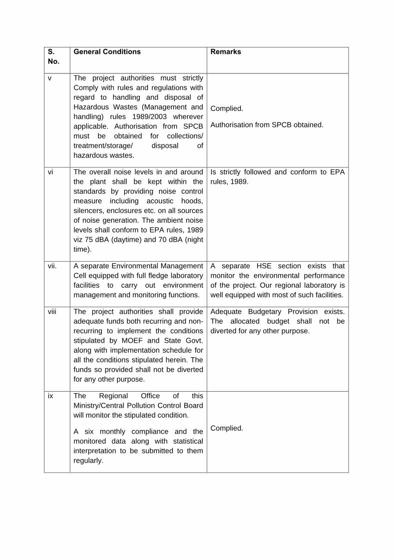
S. No.
General Conditions Remarks
v The project authorities must strictly
Comply with rules and regulations with
regard to handling and disposal of
Hazardous Wastes (Management and
handling) rules 1989/2003 wherever
applicable. Authorisation from SPCB
must be obtained for collections/
treatment/storage/ disposal of
hazardous wastes.
Complied.
Authorisation from SPCB obtained.
vi The overall noise levels in and around
the plant shall be kept within the
standards by providing noise control
measure including acoustic hoods,
silencers, enclosures etc. on all sources
of noise generation. The ambient noise
levels shall conform to EPA rules, 1989
viz 75 dBA (daytime) and 70 dBA (night
time).
Is strictly followed and conform to EPA
rules, 1989.
vii. A separate Environmental Management
Cell equipped with full fledge laboratory
facilities to carry out environment
management and monitoring functions.
A separate HSE section exists that
monitor the environmental performance
of the project. Our regional laboratory is
well equipped with most of such facilities.
viii The project authorities shall provide
adequate funds both recurring and non-
recurring to implement the conditions
stipulated by MOEF and State Govt.
along with implementation schedule for
all the conditions stipulated herein. The
funds so provided shall not be diverted
for any other purpose.
Adequate Budgetary Provision exists.
The allocated budget shall not be
diverted for any other purpose.
ix The Regional Office of this
Ministry/Central Pollution Control Board
will monitor the stipulated condition.
A six monthly compliance and the
monitored data along with statistical
interpretation to be submitted to them
regularly.
Complied.
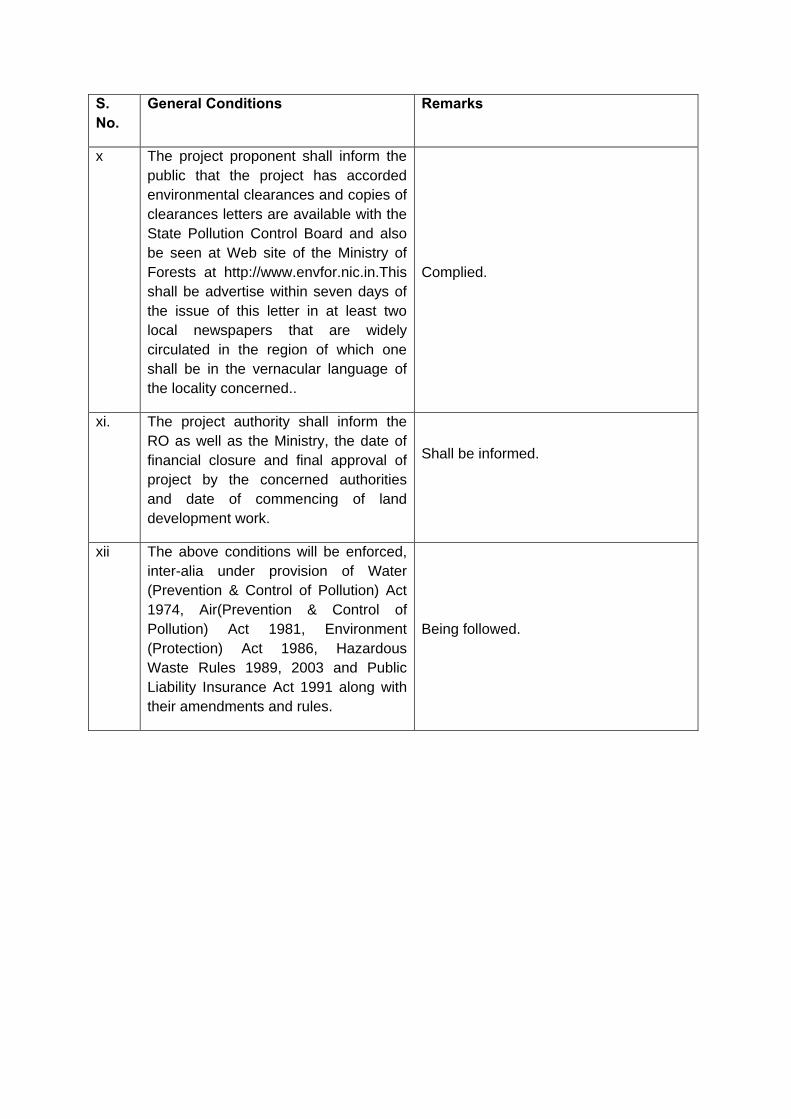
S. No.
General Conditions Remarks
x The project proponent shall inform the
public that the project has accorded
environmental clearances and copies of
clearances letters are available with the
State Pollution Control Board and also
be seen at Web site of the Ministry of
Forests at http://www.envfor.nic.in.This
shall be advertise within seven days of
the issue of this letter in at least two
local newspapers that are widely
circulated in the region of which one
shall be in the vernacular language of
the locality concerned..
Complied.
xi. The project authority shall inform the
RO as well as the Ministry, the date of
financial closure and final approval of
project by the concerned authorities
and date of commencing of land
development work.
Shall be informed.
xii The above conditions will be enforced,
inter-alia under provision of Water
(Prevention & Control of Pollution) Act
1974, Air(Prevention & Control of
Pollution) Act 1981, Environment
(Protection) Act 1986, Hazardous
Waste Rules 1989, 2003 and Public
Liability Insurance Act 1991 along with
their amendments and rules.
Being followed.
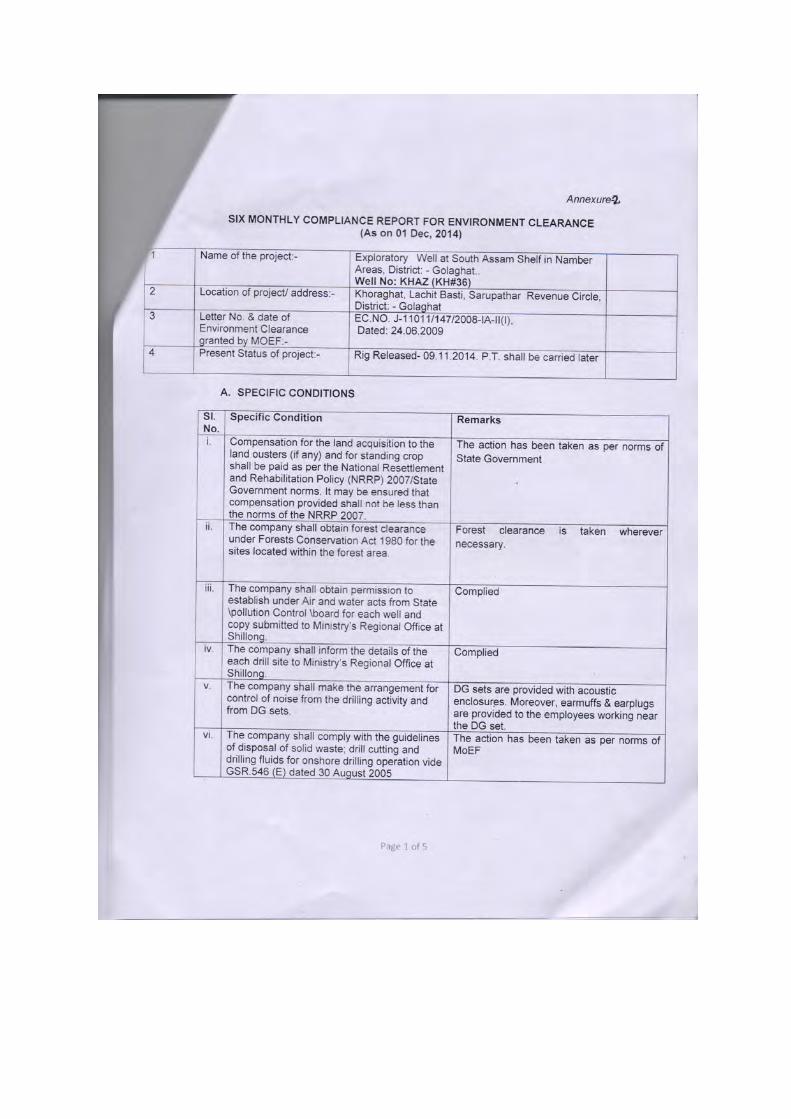
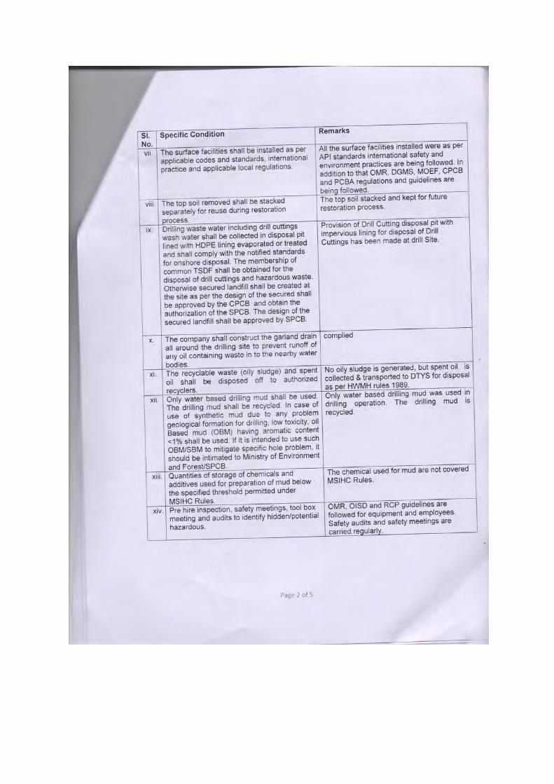
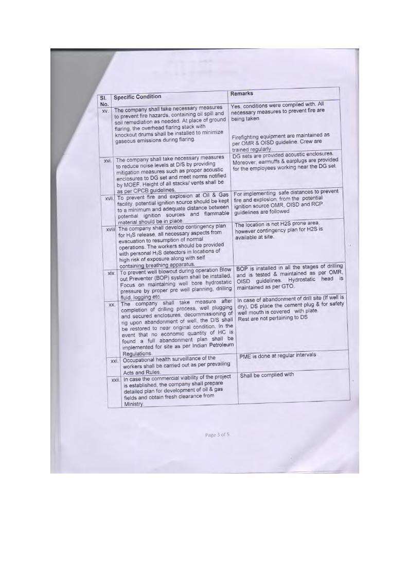
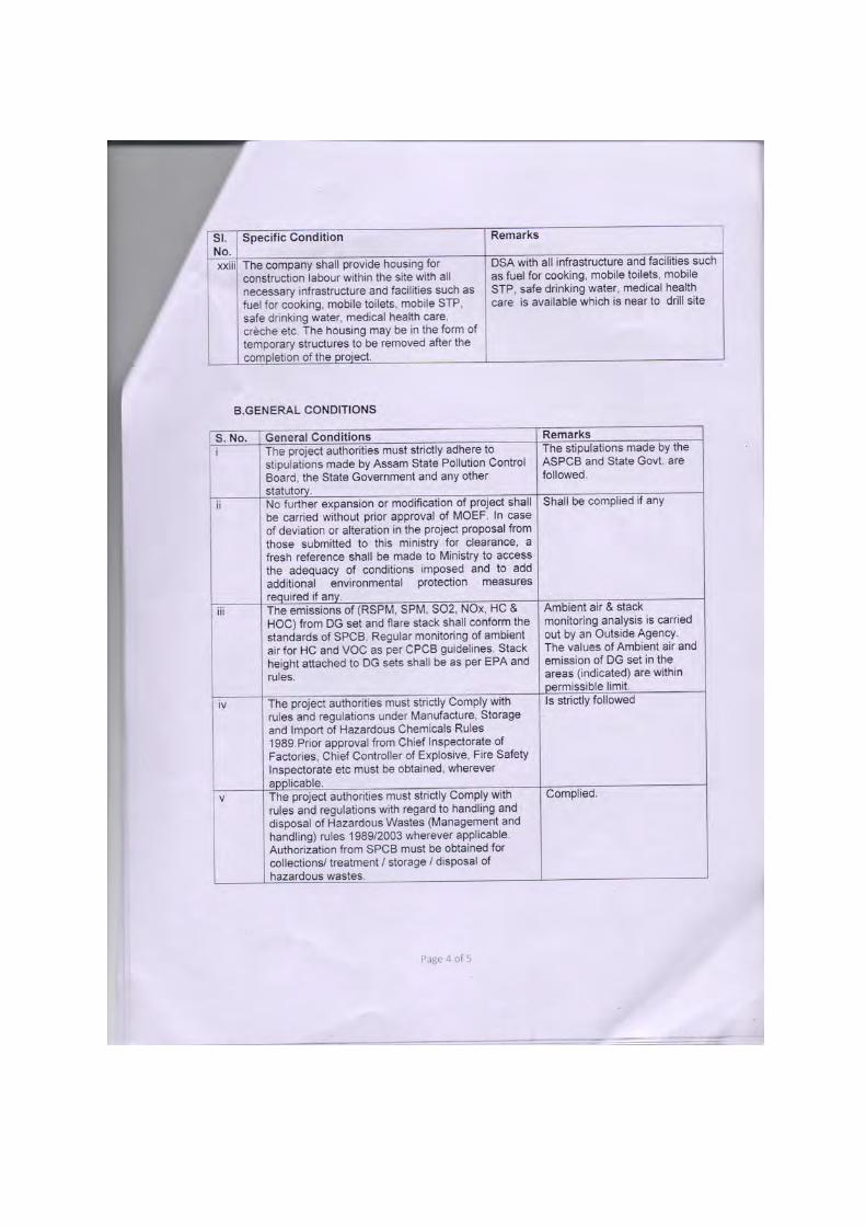
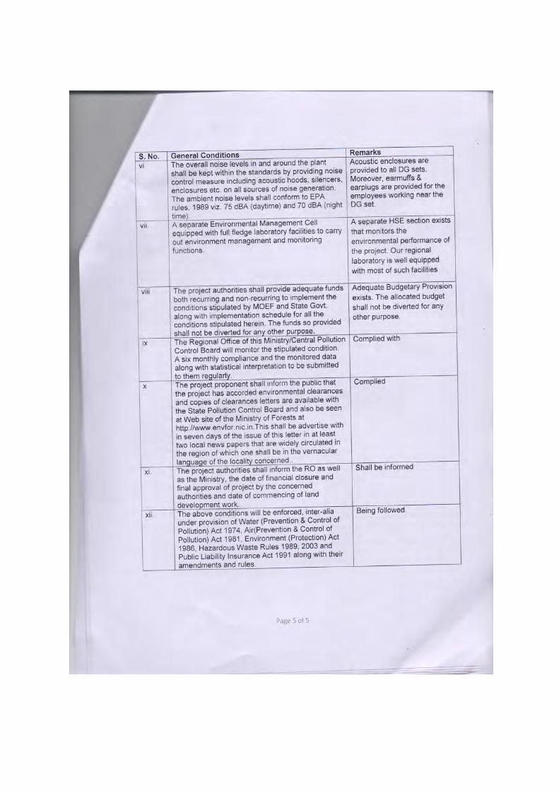
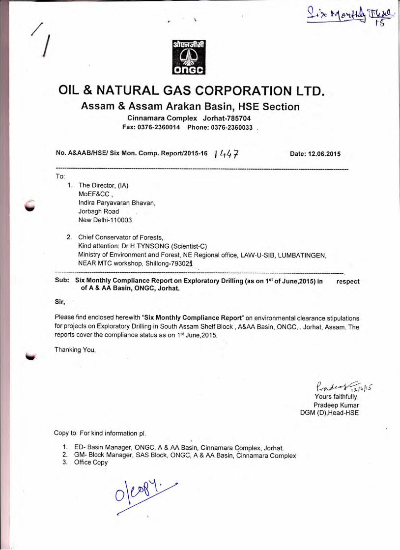
,!
OIL & NATURAL GAS CORPORATION LTD.Assam & Assam Arakan Basin, HSE Section
Cinnamara Complex Jorhat-785704Fax:0376-2360014 Phone: 0376-2360033 .
No. A&AAB/HSE/ Six Mon. Comp. ReporU2015-16 I q4V Date:12.06.2015
To:
1. The Director, (lA)MoEF&CC,lndira Paryavaran Bhavan,Jorbagh RoadNew Delhi-110003
2. Chief Conservator of Forests,Kind attention: Dr H.TYNSONG (Scientist-C)Ministry of Environment and Forest, NE Regional office, LAW-U-SIB, LUMBATINGEN,NEAR MTC workshop, Shillong -7 9302t
Sub: Six Monthly Compliance Reporton Exploratory Drilling (as on 1"t of June,2015) in respectof A & AA Basin, ONGC, Jorhat.
Sir,
Please find enclosd herepith "Six Monthly Compliance Report" on environmental clearance stipulationsfor projects on Exploratory Drilling in South Assam Shelf Block, A&AA Basin, ONGC, . Jorhat, Assam. Thereports cover the compliance status as on 1"t June,20'15.
- Thanking You,U
(*^l*+6rt,;Yours faithfully,Pradeep Kumar
DGM (D),Head-HSE
Copy to: For kind information pl.
1. ED- Basin Manager, ONGC, A & AA Basin, Cinnamara Qomplex, Jorhat.2. GM- Block Manager, SAS Block, ONGC, A & AA Basin, Cinnambra Complex3. Office Copy
o\ry
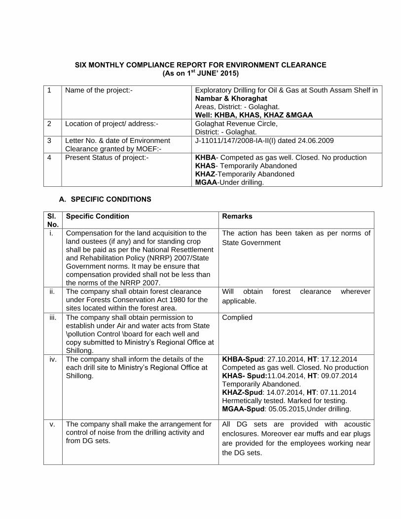
SIX MONTHLY COMPLIANCE REPORT FOR ENVIRONMENT CLEARANCE (As on 1st JUNE’ 2015)
1
Name of the project:-
Exploratory Drilling for Oil & Gas at South Assam Shelf in Nambar & Khoraghat Areas, District: - Golaghat. Well: KHBA, KHAS, KHAZ &MGAA
2 Location of project/ address:-
Golaghat Revenue Circle, District: - Golaghat.
3 Letter No. & date of Environment Clearance granted by MOEF:-
J-11011/147/2008-IA-II(I) dated 24.06.2009
4 Present Status of project:-
KHBA- Competed as gas well. Closed. No production KHAS- Temporarily Abandoned KHAZ-Temporarily Abandoned MGAA-Under drilling.
A. SPECIFIC CONDITIONS
Sl. No.
Specific Condition Remarks
i. Compensation for the land acquisition to the land oustees (if any) and for standing crop shall be paid as per the National Resettlement and Rehabilitation Policy (NRRP) 2007/State Government norms. It may be ensure that compensation provided shall not be less than the norms of the NRRP 2007.
The action has been taken as per norms of
State Government
ii. The company shall obtain forest clearance under Forests Conservation Act 1980 for the sites located within the forest area.
Will obtain forest clearance wherever
applicable.
iii. The company shall obtain permission to establish under Air and water acts from State \pollution Control \board for each well and copy submitted to Ministry’s Regional Office at Shillong.
Complied
iv. The company shall inform the details of the each drill site to Ministry’s Regional Office at Shillong.
KHBA-Spud: 27.10.2014, HT: 17.12.2014 Competed as gas well. Closed. No production KHAS- Spud:11.04.2014, HT: 09.07.2014 Temporarily Abandoned. KHAZ-Spud: 14.07.2014, HT: 07.11.2014 Hermetically tested. Marked for testing. MGAA-Spud: 05.05.2015,Under drilling.
v. The company shall make the arrangement for control of noise from the drilling activity and from DG sets.
All DG sets are provided with acoustic
enclosures. Moreover ear muffs and ear plugs
are provided for the employees working near
the DG sets.
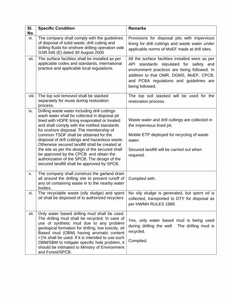
Sl. No.
Specific Condition Remarks
vi. The company shall comply with the guidelines of disposal of solid waste; drill cutting and drilling fluids for onshore drilling operation vide GSR.546 (E) dated 30 August 2005
Provisions for disposal pits with impervious
lining for drill cuttings and waste water under
applicable norms of MoEF made at drill sites.
vii. The surface facilities shall be installed as per applicable codes and standards, international practice and applicable local regulations.
All the surface facilities installed were as per
API standards stipulated for safety and
environment practices are being followed. In
addition to that OMR, DGMS, MoEF, CPCB,
and PCBA regulations and guidelines are
being followed.
viii. The top soil removed shall be stacked separately for reuse during restoration process.
The top soil stacked will be used for the
restoration process.
ix. Drilling waste water including drill cuttings wash water shall be collected in disposal pit lined with HDPE lining evaporated or treated and shall comply with the notified standards for onshore disposal. The membership of common TSDF shall be obtained for the disposal of drill cuttings and hazardous waste. Otherwise secured landfill shall be created at the site as per the design of the secured shall be approved by the CPCB and obtain the authorization of the SPCB. The design of the secured landfill shall be approved by SPCB.
Waste water and drill cuttings are collected in
the impervious lined pit.
Mobile ETP deployed for recycling of waste
water.
Secured landfill will be carried out when
required.
x. The company shall construct the garland drain all around the drilling site to prevent runoff of any oil containing waste in to the nearby water bodies.
Complied with.
xi. The recyclable waste (oily sludge) and spent oil shall be disposed of to authorized recyclers
No oily sludge is generated, but spent oil is
collected, transported to DTY for disposal as
per HWMH RULES 1989.
xii. Only water based drilling mud shall be used. The drilling mud shall be recycled. In case of use of synthetic mud due to any problem geological formation for drilling, low toxicity, oil Based mud (OBM) having aromatic content <1% shall be used. If it is intended to use such OBM/SBM to mitigate specific hole problem, it should be intimated to Ministry of Environment and Forest/SPCB.
Yes, only water based mud is being used
during drilling the well. The drilling mud is
recycled.
Complied.
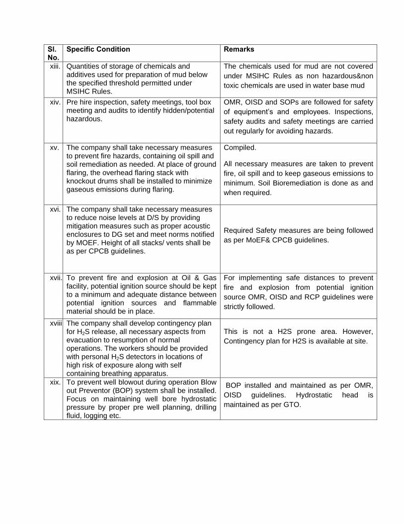
Sl. No.
Specific Condition Remarks
xiii. Quantities of storage of chemicals and additives used for preparation of mud below the specified threshold permitted under MSIHC Rules.
The chemicals used for mud are not covered
under MSIHC Rules as non hazardous&non
toxic chemicals are used in water base mud
xiv. Pre hire inspection, safety meetings, tool box meeting and audits to identify hidden/potential hazardous.
OMR, OISD and SOPs are followed for safety
of equipment’s and employees. Inspections,
safety audits and safety meetings are carried
out regularly for avoiding hazards.
xv. The company shall take necessary measures to prevent fire hazards, containing oil spill and soil remediation as needed. At place of ground flaring, the overhead flaring stack with knockout drums shall be installed to minimize gaseous emissions during flaring.
Compiled.
All necessary measures are taken to prevent
fire, oil spill and to keep gaseous emissions to
minimum. Soil Bioremediation is done as and
when required.
xvi. The company shall take necessary measures to reduce noise levels at D/S by providing mitigation measures such as proper acoustic enclosures to DG set and meet norms notified by MOEF. Height of all stacks/ vents shall be as per CPCB guidelines.
Required Safety measures are being followed
as per MoEF& CPCB guidelines.
xvii. To prevent fire and explosion at Oil & Gas facility, potential ignition source should be kept to a minimum and adequate distance between potential ignition sources and flammable material should be in place.
For implementing safe distances to prevent
fire and explosion from potential ignition
source OMR, OISD and RCP guidelines were
strictly followed.
xviii. The company shall develop contingency plan for H2S release, all necessary aspects from evacuation to resumption of normal operations. The workers should be provided with personal H2S detectors in locations of high risk of exposure along with self containing breathing apparatus.
This is not a H2S prone area. However,
Contingency plan for H2S is available at site.
xix. To prevent well blowout during operation Blow out Preventor (BOP) system shall be installed. Focus on maintaining well bore hydrostatic pressure by proper pre well planning, drilling fluid, logging etc.
BOP installed and maintained as per OMR,
OISD guidelines. Hydrostatic head is
maintained as per GTO.
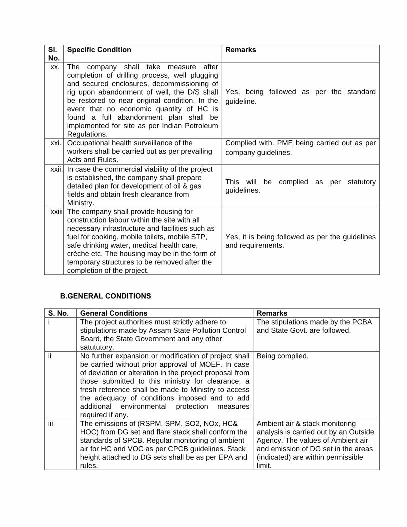
Sl. No.
Specific Condition Remarks
xx. The company shall take measure after completion of drilling process, well plugging and secured enclosures, decommissioning of rig upon abandonment of well, the D/S shall be restored to near original condition. In the event that no economic quantity of HC is found a full abandonment plan shall be implemented for site as per Indian Petroleum Regulations.
Yes, being followed as per the standard
guideline.
xxi. Occupational health surveillance of the workers shall be carried out as per prevailing Acts and Rules.
Complied with. PME being carried out as per
company guidelines.
xxii. In case the commercial viability of the project is established, the company shall prepare detailed plan for development of oil & gas fields and obtain fresh clearance from Ministry.
This will be complied as per statutory guidelines.
xxiii. The company shall provide housing for construction labour within the site with all necessary infrastructure and facilities such as fuel for cooking, mobile toilets, mobile STP, safe drinking water, medical health care, crèche etc. The housing may be in the form of temporary structures to be removed after the completion of the project.
Yes, it is being followed as per the guidelines and requirements.
B.GENERAL CONDITIONS
S. No. General Conditions Remarks i The project authorities must strictly adhere to
stipulations made by Assam State Pollution Control Board, the State Government and any other satututory.
The stipulations made by the PCBA and State Govt. are followed.
ii No further expansion or modification of project shall be carried without prior approval of MOEF. In case of deviation or alteration in the project proposal from those submitted to this ministry for clearance, a fresh reference shall be made to Ministry to access the adequacy of conditions imposed and to add additional environmental protection measures required if any.
Being complied.
iii The emissions of (RSPM, SPM, SO2, NOx, HC& HOC) from DG set and flare stack shall conform the standards of SPCB. Regular monitoring of ambient air for HC and VOC as per CPCB guidelines. Stack height attached to DG sets shall be as per EPA and rules.
Ambient air & stack monitoring analysis is carried out by an Outside Agency. The values of Ambient air and emission of DG set in the areas (indicated) are within permissible limit.
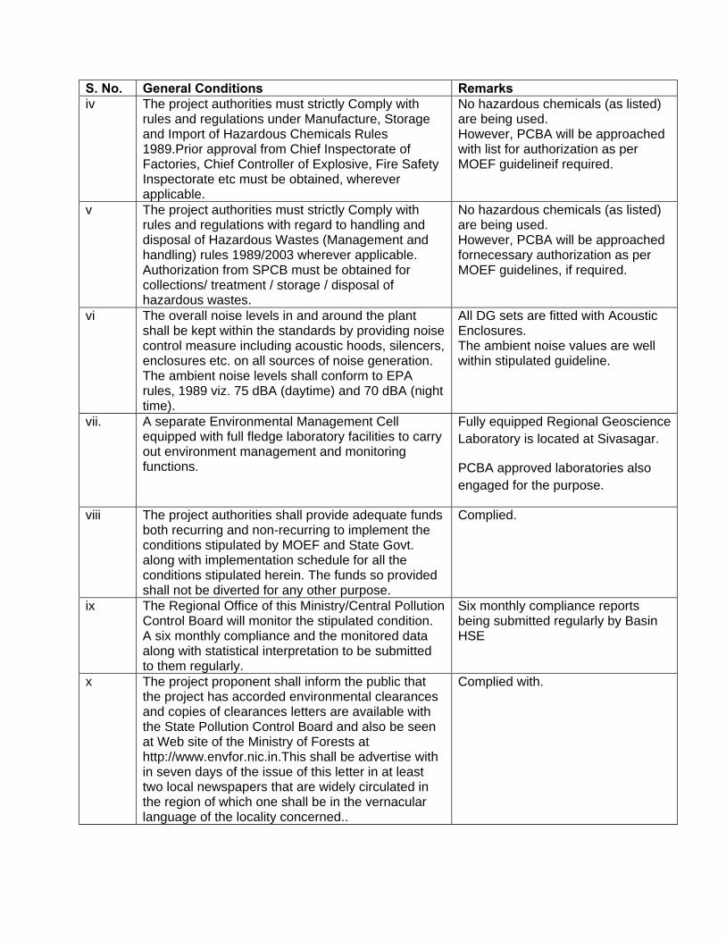
S. No. General Conditions Remarks iv The project authorities must strictly Comply with
rules and regulations under Manufacture, Storage and Import of Hazardous Chemicals Rules 1989.Prior approval from Chief Inspectorate of Factories, Chief Controller of Explosive, Fire Safety Inspectorate etc must be obtained, wherever applicable.
No hazardous chemicals (as listed) are being used. However, PCBA will be approached with list for authorization as per MOEF guidelineif required.
v The project authorities must strictly Comply with rules and regulations with regard to handling and disposal of Hazardous Wastes (Management and handling) rules 1989/2003 wherever applicable. Authorization from SPCB must be obtained for collections/ treatment / storage / disposal of hazardous wastes.
No hazardous chemicals (as listed) are being used. However, PCBA will be approached fornecessary authorization as per MOEF guidelines, if required.
vi The overall noise levels in and around the plant shall be kept within the standards by providing noise control measure including acoustic hoods, silencers, enclosures etc. on all sources of noise generation. The ambient noise levels shall conform to EPA rules, 1989 viz. 75 dBA (daytime) and 70 dBA (night time).
All DG sets are fitted with Acoustic Enclosures. The ambient noise values are well within stipulated guideline.
vii. A separate Environmental Management Cell equipped with full fledge laboratory facilities to carry out environment management and monitoring functions.
Fully equipped Regional Geoscience
Laboratory is located at Sivasagar.
PCBA approved laboratories also
engaged for the purpose.
viii The project authorities shall provide adequate funds both recurring and non-recurring to implement the conditions stipulated by MOEF and State Govt. along with implementation schedule for all the conditions stipulated herein. The funds so provided shall not be diverted for any other purpose.
Complied.
ix The Regional Office of this Ministry/Central Pollution Control Board will monitor the stipulated condition. A six monthly compliance and the monitored data along with statistical interpretation to be submitted to them regularly.
Six monthly compliance reports being submitted regularly by Basin HSE
x The project proponent shall inform the public that the project has accorded environmental clearances and copies of clearances letters are available with the State Pollution Control Board and also be seen at Web site of the Ministry of Forests at http://www.envfor.nic.in.This shall be advertise with in seven days of the issue of this letter in at least two local newspapers that are widely circulated in the region of which one shall be in the vernacular language of the locality concerned..
Complied with.
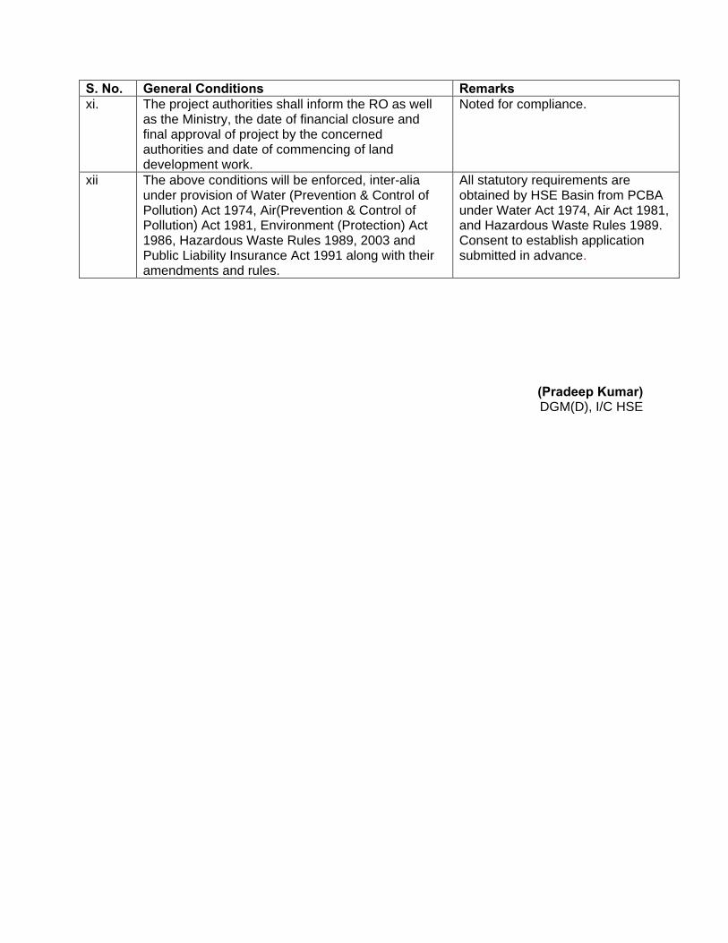
S. No. General Conditions Remarks xi. The project authorities shall inform the RO as well
as the Ministry, the date of financial closure and final approval of project by the concerned authorities and date of commencing of land development work.
Noted for compliance.
xii The above conditions will be enforced, inter-alia under provision of Water (Prevention & Control of Pollution) Act 1974, Air(Prevention & Control of Pollution) Act 1981, Environment (Protection) Act 1986, Hazardous Waste Rules 1989, 2003 and Public Liability Insurance Act 1991 along with their amendments and rules.
All statutory requirements are obtained by HSE Basin from PCBA under Water Act 1974, Air Act 1981, and Hazardous Waste Rules 1989. Consent to establish application submitted in advance.
(Pradeep Kumar) DGM(D), I/C HSE
AANNNNEEXXUURREE -- IIIIII EENNVVIIRROONNMMEENNTT
AANNDD SSAAFFEETTYY RREELLAATTEEDD PPOOLLIICCIIEESS
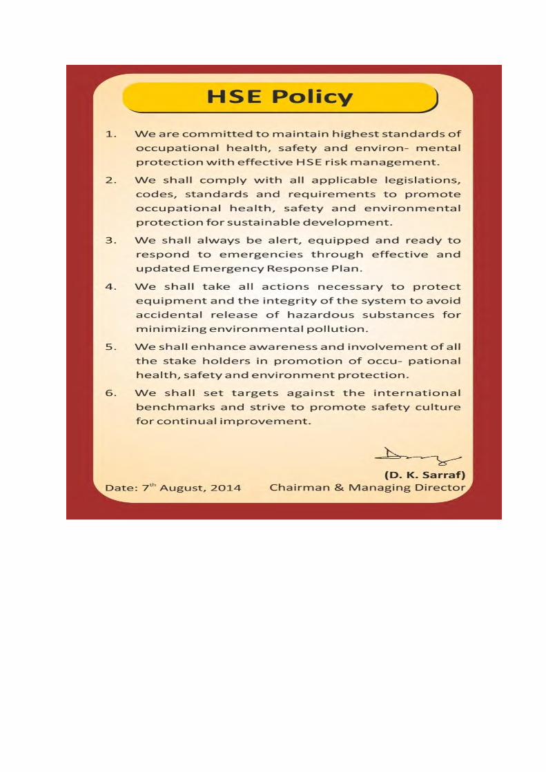
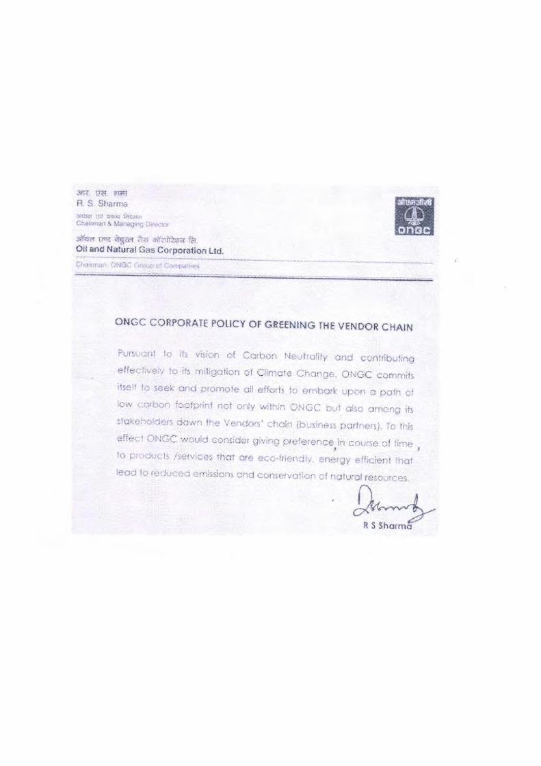


AANNNNEEXXUURREE -- IIVV
CCOORRPPOORRAATTEE EENNVVIIRROONNMMEENNTTAALL
PPOOLLIICCYY
AANNNNEEXXUURREE -- VV CCSSRR’’SS DDEETTAAIILLSS
((22001133--1144 AANNDD 22001144--1155))
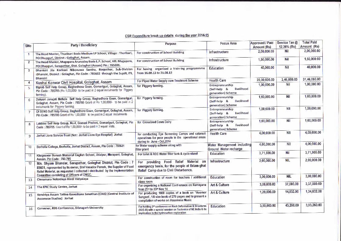
P&
.lLgag=O
YLF
o<?
oeodo-sl
oqoood,fr-
ooooo^o$
oqo€o-@*_o
o<?
oo_o_oo-
oqoeo-oa^
oqooo^(3o-
oqeood9_
oqeoo-ood
oooood0\f
oooo€-Fm
oqoo_e^ee-N
oqoeodo..i
oqo€o-tso-o
eoaooo{o^
oqo(I)rt(qq)-o
e)^E
g'osct@
ET
a
<z,
oqe€q@a<9
2z,
z,z
Jz.Jz.
oq(3@o-Ir60
ttDdF
oooal)nl-l
!tF6
Leo=3dLEa<
oqooodo-N
oqeoodh^
eoc;oe<i
-l
oqooe-oo-€6t
oqeoe^oo-
oeooodo^
oqoo9-oo^
oeooodo^
oooooeod
oqooo^oed
eeoooq\
oqoeode-N
oqooooo^c/t
oeeoeoo_
eeoeeorl
oqoooorl)-ao
.gd,at(Jol!
E(,a(tc
6'()anc,
o6oE'
ut
(uG'
(J= 6q,-
oo€o=c)F
.s63t!oiO
Fc^Xy=
E
9+
6
EdS
Eooso=q)
.=o
caEoa,H
Oc
5 -o.gL
o=
$, ,.i" d
E5e
T'ooEa,
=o
q.sbE
E:€9O
-C
^:e -;'EY
e O
Edg
ttoo=o=o
F^=
o9o3oc5 s.9:9E9j .:.
6
,85.9
€)C'
o= .Eq,E
=Eqt
CE
D6
E8
OL
sr.9!Y
ctF
==
E(D5
5.:
c.9(E(J
llJ
o)q)eatG
o(!o5ttLu
6'
=o€ts
E==oolt
coC'
oEul
q,ooct=CL
ottco5oIqoo9troIog
u!,co6oEI6oooIoI
b!i6F|1.!
Pd;ge6N!!oo6
doo qitrcl't
qi9d-gsi
ooEoatoEGEFEataov)o6=Eo1.9lo-t-l3
0=6boo.9ILo
o6boooCLo
ED
6od)E)
o-e
e'Fo= oc)Eoltoooo
EH
EE
6-eEE
€o6oboeEo
8go-.E
.=5-eoo<.B
gFE
bFul o-9)'
9
9 o-E
.E s
8E
Eo'i
lil or
==oGooo6.>oLCg6G
O
=-
-a
€Go-!9oocdIGo!=oG=c)od€gool!
5E?.E
E'-(Eo'EE
=
ct
=tEoF
-o CL=
O(,i,D
Ee66r-
E=
>
o -?'i8€;oo3.P
€=
l| o
E 3.q
o g,;_ E
.se b&
EcoEt,6aooGoooIoc.9o3leloloLlotr
6ltrtdldtE
IG
Itt=
looocooIol.)6E
:6>z.oczoH,gN.N
o6tE
Fo-oo
bstssE
E!gcOo€
oxZ
tIE
;=roo-
ao'-60F
O
Eoo
F
sIs8!
Eotgo!t
=.9 g
oo+l-E
oolo=
c
l=-
ol€bEla g''+lL
E
Eto
G o
I[ (/) o
DIJ
j€9.9:!;E!290!B
-F
Ee
uii sf
.o 0
0cxoooE
ceE
OO
o'6togE:frtE
E.ii
s'H .=
Eae
b=-E
BE
gE
:E6=
E
EO
EE
O
oE
E.E
b(tc)6)Eodtts.Eo-
E.
€E>to.€E6-u'-GS
E:,.-C
ir
gi5E
.-.>
5oX!O-96l-O
6cFob0gooIcJ
6lolcLtG
Iul:l5"il.ol
=ol
!- 6l
-61-.
hlo ,.to
-lE
E]
rr^LEro
€€3;>t
outt696=
(,<
;6i=o\*EqD
tJG>
sde6.-5=€Ha=4AE
ciF
C
E-'
I
oF
I
::€ |
6CL
I
3; i
d2cT!
tdd=6PtoNoq'sE
R6 "
ttl 0)E
g8fcE'd-
9Pl.:
_EloDt,-
olG
O
li9l9 r{Ll.l!
6l=
al--.--1.2 9'Alc::
olo H
o
EI
C,t
ahlo1
ri(tct)(!6(9(ll.1jC
LooI=(56= telol:<1_lcl-cIttl=l)<
i- I
6XI
6=.
I
{il=-b
I
6C
I
E9
I
(r-E
l6
'=ao:6=tsx
E.i
i.so-9O
G(9oseO
aE
FE
_'
-grE
l'_a-ls:looalcg-l-oR10hlT
€l-ts
lE€^
looPlo c).=Ioe
Fli6 E
"E
iNl
=c
I
D--
|
66 I
Eo
I
oo I
90 II
eF
I
GOJ
e8GO
o!!E
-o-^=
-&6$coojc5iYgo(9hoets=
6g6+
N=
..;E
€ =ot
-g o.E-8.=
aocL oE
-E'E
=
o.=
6G6^
E<
:'E
-
I oE
l:srsooao o.g
EG06Q;96CL6B
Eo-J6LO5Q
)o^,
Ec
oFoiiiod-o,go,g-oQE
OOO
o'-s#ou9F(9(9
-oQo=+
io
=€o
Ots
ct, ..o*2.6U
ar@
--6E
gE,:O-sd.sO
-
=6
tqcLoqgbS(9-gtOdo^Z
-CLE
oo(,E
-af;@
v-risO6t>U
'U
'=o
*€JCJ
!6o6o6o?= 6aooIogJ6,9JGo-jjoz.oFo.9eoat.9J6o-
0oDitol)[Gaoo'tr,r2o6oagoococt(t)-googoo(D
.2g)
ul6'Fo
:/oElt
E3F
IE;
ItrEto
old]olc
.=l=
Lto
:lg' Flo6lE
6lY
<
Gg)-go(966o=aoEjoooU
'
\EC
I
oo I
" oE
I
oLSl
I
E=
E
I
o:9 I
-J oE
i:o
^= E
IogE
ei:->.9 gEO
llo_go
c:v5
PA
E6 E
:8cZ
EZ
ftr =?iv
€;68::
f o(D
=!P
o6=
k-
o6
'EtF
3EfiE
€ B+
;E
E;E
o b:EE
E.E
8aE
e9t o
>o=
o# :=
.E.oaD
=@
@'=
E=
ooa=
6EC
J
6-gottEc!oGT'oltoz6oEotru
6togcruI!tnI4Uo-cF
ooFEGcoIrasIcG-c(tGtaGcG!E6ze-E
lE !
lO^
l'_ o
th?lo
E
l{?IG O
l>o
IE;
lci;lo
6l-<
'6o.E:)s(!o!flti5outrEocoIocoEoLtrlol9
o=U'
rtf)
\oF
.oo
O)
Nfn
$lnF
l(o
rf)l
+l
5tNI,t6lolxol
-cldJcl'=
l=l
El,lclot
Elol5t
vl.El
ol-olol=
l-!jlE
lelolglxtr!le.lutlC
JI
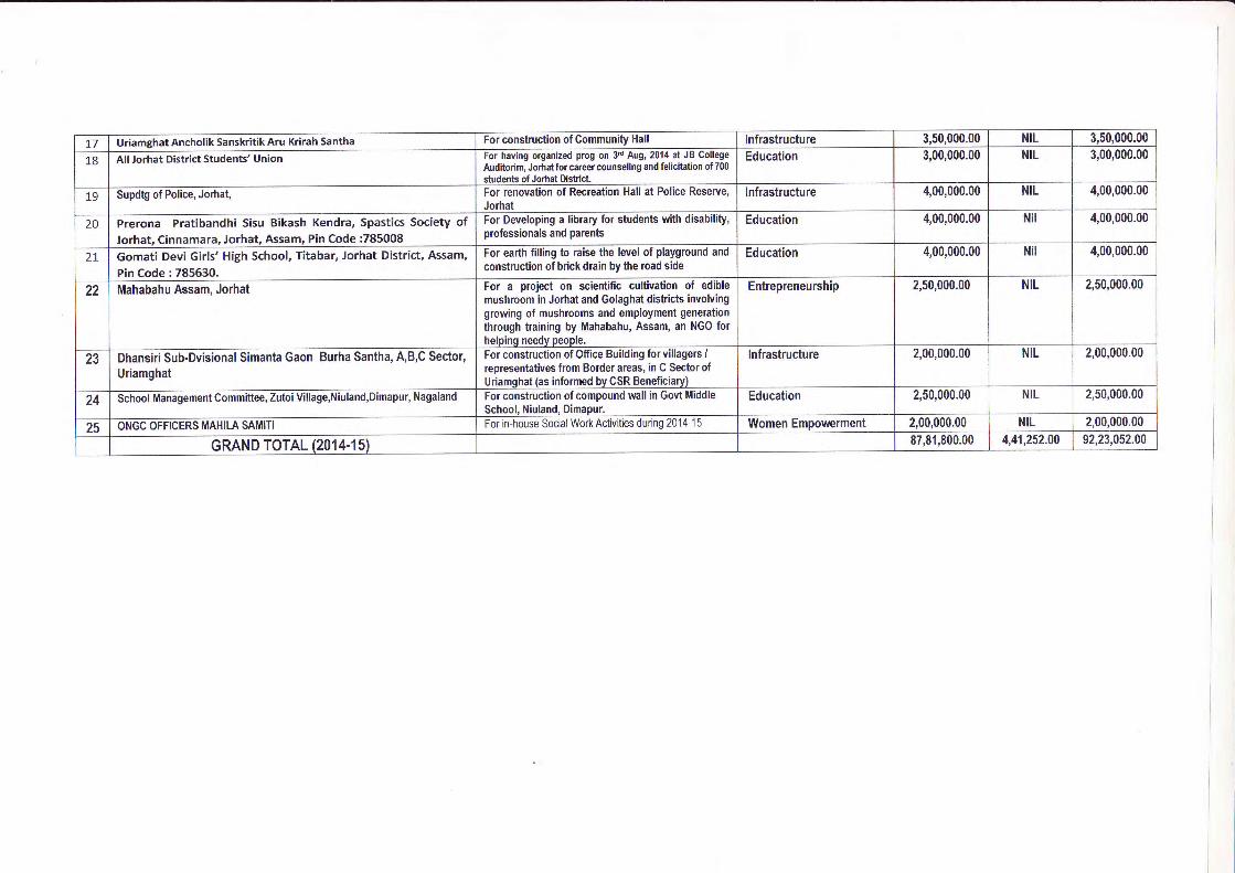
oqooociro6,t
ooooodo-60
oqooe^o(=+
oqooo-oe{
oqeoooo+
eqooo_ert)^
eqooo_oo-N
oqooo^onci
oqooo-oo^
oq6tu)oF'
No
Jz,Jz,
Jz.z,
J=Jz
Jz.Jz,
eqrf?rld
ooooo-or()-o
oc?ooooo-ca
oqooodod
oqooodo+
eqeoe-oo{
oqoeo^olf)-N
oqooo<t
o^(\t
oqooo^e,l?-6t
oqooqoo^
eec;ooqoql\€
d,qtan6
oa!oE'
ul
6'oogq
oa!()r!
oG'
o=t
ut
o.0(uoCL
o)cL!
oL(,Lo(!
oc'oUJ
d,Eo= ouloEo=
6EooooooEooor
oo60otso9O
Eog-tR
E-€9o<
.E
b8oh9 EE
g bE
P€E
o 0=---:>
't!E
€-EL!
!
€€t
dtEooodo,96LFG!o6oood.o.9oo9i;-coo
L-
=5G.9,
'=ooE'oo>=
FO
:6
=6_
i;B)6
.Eo
qEl?coo>
,6yogooYre
15GEoEg
>,Y
goCLE
-6o9E
o)a5ocl#.=oE.9E!g!-oo'=O
sE
Or-.9tgE
;LEooLO
o oc:
=.=
.9.EE
€Ee
E.E
5Z6
ocF
.E ;
'^E
i: !P
Ec-!!
t 6
=E
E.p
6L 5
€€:EE
(9 ET
.E=
,i€3 E
E=
o;
-ii 3 >
E:5 E
"c'E
o !
E_=
E
3F3:
go E
.E sE
- I - o_e
o=Y
=o
r E
6=t
-b=o
FE
C=
(t -g
svEoE
oE
.- E
siff=
od
= F
fiT
€:.!2 6=5? g+
=L
o90-E
=5 q'=E
:g=
i!e;E
FE
o--
oo=aE
=r
g=
o=o(,6=o.=o
o6oEoo
i3o
ooooooLL U
)
@aNoC'c=Eo=oxo=Eoo<Do3o-.coL
GcoEo5!.IJEGJ5otItr6to!E6=
olo!,rooo
Go-oooCLobrlia(n
oooothnco,:
ct
E3
vr- hr"'€E
8Oc
sh=
qco&
.adtnE'=
oT
':L66L€9(!EoEqqO
r!oJto-;
EoU'tr,9ot!Lo(!ltfE.:Foo.c0vl.9p4'i,
c;E
(nnE.-
00
dtoo'.: P69c(Jb.s(9o.
.Eo-Efr'o0.E.clG
'
(s
=
!joc,6'U
'(l-o<d.EU
)(g
oo.g(,Gc(!
cn6.9o'to-ct
U'?6
o='
CE
G,(!
o=
EGGo6=j6E.
EG=oItrG'5=Nqto'=Eoo(,oCD
6GE6ooa
ts=U'
5=a.l,d.EI
s24goo(,=o
|r,
so(\tJFoFoz,E('
1..d
@O
)c)N
r-{c{
(\I<
\t(Y
)(\I
$(\lrr)(\l
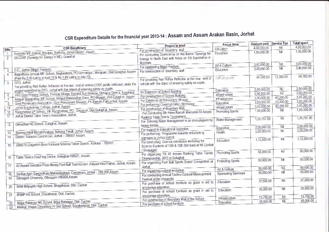
eo)CL
o6oF
OOOqOq
OqOoO.
Oro^
aOOdi
Oso
qc{@o_*o)
3?33qN
)?)f,)-D.
N
ci<0c.{
Oq
OqO(oC\
q
OqO(oc..lcnd
OqOO-
OO-
OOF-
ro\Oc{
3?=qq
3loalqcloO
IOo-
l.r)-o
lc{O
ll'-
Nl-
3?c3=>
-cro
OO.{6
oqoqOLr) qOOO-
Orr)
OqOro-f.--o
qOoO-
ro
oqOrr)\c\N
oeOoo_Lr)=
f
x(gFq,.9Eoat z
z.z
z"e(\@O
zz
OqOC\
$
OqO(oc\O
qO(ocl zz
z.z.
zz.
z.z
zz
z.z
z-
15.Ecto
OaOOO.
Oq
aOOtr)_
-iCq
OOoO-
o)$_
OqOOO-
s@
OqOO-
OLr).N
OqOOq
OaOOeOa
OqOOO.
Oo-c.) dOO-
Oqo
OdOO.
O__i
qF.*
\ol'.--Oc\
OqOOqON
OaOOOO.
N
OqOn_c{f-*-
qOOO.
Olr)
OOoO.
O!a)
OqOdlr)
OqO.
O()
OOOOLr)_
FT
o
qOOO^
rr)cf)
?=)
r)\NN
OO-
rosl-
(ltEan()ol!co'F(oOf,Eul
== (!O=ELLI
c)==odE
coFGOaELll
fi;n
COcsO=LU
0)=O=(gc
(DaO=(gc
CoFoOoul
0)=O=Nc
aEo-U
)o)gOEoo-
C0)E(.)o)(!-6o)G=
=.9(oo=ELU
c= (g0)-
C.F(!O=LU
aa€Eoo-
nor)CE=I
c)==-C)
od
a(!.=E(Du)o)'coa=<
n
=o(o(-)
=LU
Cots= -oLrl
(D=ota(E
c.9=Eul
9t=:ISll'it(Jl+u_l i
=S
ii t!
^O-
o LLI
OU
cPg
q)O
=gC()ooo_d=
yaCG
O
LLIO
_o)Eco=
rF>
UP
gOocLL U
I
t(l
ldiILL
l=lftl=ItE
lfN
l-66l(N
t!
=l'i
(g=-(sE==o-ooCOIOl=l6t6IOt-IoIrL
olc-la@
I
ol-6
I
60os I
o6 I
-olok
I
'9o' I
u = l:
&2
l=O
I:
6=
lcox
l>o. d
l-;E
€ Id
x$ l't
o€ l,
'; =
l!
9 d)
lio
c) l.'
O
O
I;LL
>
Ii
z,l
2litrl5):))5:))=DoL
inOx-rJ
oL
?=I5a
E(oa@6'-oE(Dsc=E
(gCcoE(D
C.=
Fl-qIrclw
clo)Fl.E
c
lO
(l=
a
IEL
Ic'lo
<
l() .!
t-:lo
!
l't a
-o-oq):o)(oE
-(gc)(u=o.=q)Ec)o,6col>t-]Ot(Ul=tolc.l -
lot-loIrL
c(==c-a(Etlt:talLr
lili
oC= oE.FcCq
a(g= oo)
lF t
t-.:lsrlo=lo
\lo_ :tilo)(lF
<
t-.-lo
c1=
(1o
<
lo(l(l^
IILL
(I
(gEo3
ouJ*oZ€ii6-too-o=
E6a*cE
N
L3tlE
=lc\_lO
=l-
ela9lofil=
alP
o16
ol"
c))o
oILAI
ta I
l- I
lc I
l0) I
lFl
ttl0) I
lcl16
I
lFl
lo I
lclcl6It*IN1-E
lo:l6
ol<
cD
t_-l<
:I=
Ol'-- Itoxl--=
lN;
!l c
cf.l 6
0]Jlb'=3tb E>
l G
bl 5..c--IU
- U
6tI
clOI
0)teloIO
IctOI
>l
LLi I
aliloloa(!cooLLoqINt-l6lolo
(otcl()
oILL
-I
lo lo
I
zlblplplE
1(g
|(E
I
8, l.= I.=
l<.t
l- l-
l:e
l- lc
l?s
ls lg
luz
lo) lo)
lS
=
l(g |(u
l:
= le Ie l;
V
lJ lJ
l-O
l'=
l'=
l-
c l=
l=
l:
c lf
l=
l!ol+
llo
t- t-
l(F
-zla la
l!_.=
tu lu
t:
= qlE
Els E
I:lE
5l= E
l= E
IIl9
ol o dlo €l'j
lE f lF
3lF 3ll
l€ olE R
lp 81,th gta=
ta=t
l. dl
L ()ls
Ol
lo c)l
o cl
o cl-
lLL tLILL
olu- 0)lr
II
;lrl;I)lrl-tIiljla.t:3l'F
llz<lc
Jl<>
l;- l'rjt!=
1 .3113l
:Jl(_t,3l(Llu
IEI((lal<
>6lc
Eli
ol-cl:q|h(D
l€e,l catt
I
(Jl o
lclrlcldl<l!L
l(
I 13
llr|:il!I
il-it6:16ll=,l=rl(9ilni;tz)lct-il
9)ll
O)
.lc,ILUll,-l o?t>:l s,dls2la>
l-=
lur2lz5lo=
11\! lur<
lu)
l<l6latal<I(glcloIGlololali5t-l'-l(olol6IOl>Il!l)-lo)dlc6
-Its=
lO.
l8:l6
dlo-lcolE
<l9-loolcOlm
.lac
:l 6=
(Elif
i.zla
L
'?l=
:
=l
(g:N
l 6 !
3F.
*l- (
(glG
,cl
L\=
toalc.-lE
'il q)'/ \l
O'
Yt6,
olco I
I
il-lalCDYcL
a, I
ol-E
Icl)ll,
ol(J l.
ol.
e€lcol=
-loE
lo"lO
>U
OI
_olool
>61
odl9xl6;lLc)l6'-961oqlc!l'ii !;-a)ca)€'6ot-
'-xO()F5ot>E
-X
a)
trgE_Q
=o
, Y?:
^- o ;ir
Ol,L
c
tl6lal1I(gtgtolOO
)0)6OoC.Eo)O-lqlutlitl<lo
(!t6lol<l;
IEo
lo.9{
l<I __-:
6lE616F
lco
ol\916.b
l--3I€oI(Jcl-o
lc)6
t-z
16o,
loQ
lo
a l=
- tu
@
l(qE
IEo
l.^
la l.o)
lF
l-la
l0)lz-
l-ot:
tL
!J=ECo
CbJ9!6o-L0)Coc)No-C.F(gr_CE(gaa illil
=111il
fl i I llB
l I I ll*l I I lllE
l I I l*;l
Jt t-
I tst
al lF
I
IRI
EI
t€ I lot
il- l()
I lt;l
Elt
li I
l^l5tfi l3 tH
l;tS
S ls lE
lEl
laE lE
lr lsl
l6lE l9 l€ Iq
lfil? l€_ lf in
lH18 l=
', IE l=
ldl.= l€
l€ le
\gEIg\E
Ig
cE=O(gJa(lcc(\a(cc"-tOI
olclolu)lol(!)l
?l-l-Jrl=l
E]=oEC)o)=oI=lclol>
ol I
zl-lscD
l I
<f
o(o
r@
o)O
INols
(oro
F-
c!P
IP
IRNG
oc{
G'
o?'6G'
oc(Ev(EE(sooEG
'
E(Eao*-la
ct)o(\I(E(l)
G'6(sEooI'6oo(l))=ttg(l,CL
xlllt.at,o
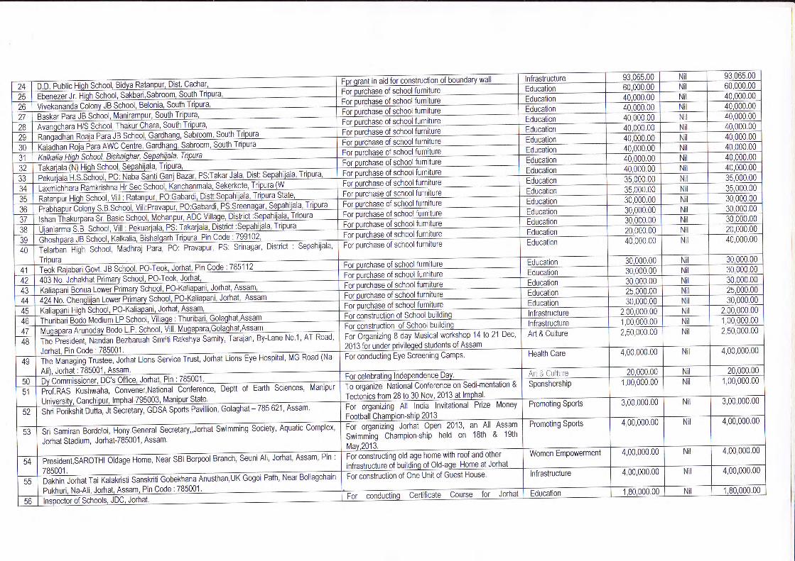
OIO
alarolo(oloO
IOoloolo
oqoqO{
<)
aoo$
OaoOqO
OqOqO*f
oeOOo-Os
oqOoq$
oqoOqO*
O<?OOO-
O
aaOoqo
>lo
lloild)lo)loolof)ln
:OqO
OqOOOct
OqOOO.
ON
OqOOO.
O+
eOoqO
AOqOO
c?cccc
eOu-)(\ aoOqO
OOON
oqOOO.
OO-
OqOOO^
Oro_c\I
OqOOo-<:
OOOO-
Oc! aOoo-OO-
OqOoo-OO-
oeooO.
OO-
$
OeooO-
oos
OqqOaq
zz
zz.z
z.z.
z.z.
z.z.z
z.z.z
z.z.
zz.
z.zz
zz.z
z.z.z
z.z
zz_
z
qrr)
c')O
)
O<2
oqO(o
OqOaqos
O-iOqO$
OqOOO$
O= O- qOOqO
=Ic3_-
OqOOO-
Os
qOOO
OqOOq@
OqOOqro
OOOO.
Oo
oqOOOO
OqOOO.
Ocf) qOOaOc!
OqOOO.
O
OOO.
O
OqOOO.
Oco
OqOOeOo
OqOOq6c!
=?-i
OqOOOO-
N
qOOqOq
oqOOO.
Oo-c{
qOOO.
OO-
s
OqOOqOc!
OqOOo_OO.
aOOOO^
c.)
OqOO.
o$
odoO.
Od
aooO.
OO.
s
OdOO-
O@.
c)30(EC
Coa=LIJ
o= (golELU
co(l(_)
I
oF(oOfELrj
=oCo
o5Etll
oF(!=ELU
c.9(u=ELU
coa=€Lll
coCg
= -ouJ
CoO=€LLl
oF(sO=Etll
Co$O-LU
oF(!O=EL1l
Co(oo= :oLU
coF(oO=ELll
=oNo=ELU
coE(oOf,-LU
=oCo
(-)
=L-t-l
== (gO=Lll
coa=ELU
=o(go=ELU
(DfoJCO
c
c)=O=(uc
o=!=C)od?
c)
OE= (gc)-
{t))3().li
.gE@EaCooa
aoo-U
)o)CoEoo_
@oo-U
)o)coEEo_
cc)E(l)= oo-Elllcc.)Eo=
I=o=(uc
ccELL
=-(E€C=o-ooCoFOf@Cooo'6.g6oloIL
OfzC=o=o@oq)a(!go=o.oTL
O==C=ooEoo.)aEO=oLL
(D=--cl6oEooq)(gc=oLL
= c:ccIcC
c)
.EE=€Eoao)@(Uco= ooLL
=c:?(s(a(((I(:i(L
=t=
flf*l*ol ooto-lcOI
O
ol oO
I O
ala616E
l-ol
o-15olo.lol o
LIL
()==Cf6EO@q)a(UEI=ooLL
c)=.=c=6o=oaoc)@(ggofaoLL
Of.!cf-oogOaoq)aEI=oLL
c)f.=C=6goaoo(Uso=ou_
O-=C=-oogoao0)a(6EOoLL
0)=c=ooCO@oc)a(EEO=ooLL
q)l
C=ooEOooc)a(gE7ooLL
a'=fEocaoE(oEo= ooL
.;:?(!(0(t<t(IIl(l(t.t(lrl
6)== g=-6coooq)a(oEtlfooLL
c.E=itcICUcc(
oiCE=-ooo=Oao=.o=@cOoIL
O()oc\,1
$E-(*v_E<
=!
q-6!aa=
->
t>:
co ':D
ic<
tolo;
lo;locll"L c
i+=s)Eo0)O/)o)IJo)CO=oCoC)
oI
(uoacc)E=0)o.c.)-oC(tC(E
-o(D6(JoLL
06=Fdcq)c:-!-o=<
J2 E
5rsgdnozO
c_dLE
c1.9 al'id olz.
F
t", iIti*tb .!lY
'(loilo
<IF
F
OI
clol>l
ON=I6cF(g=-cf)(gO6NE
O=<
C?EN(g
FO
O):
=N vc,ooo
TL LL
CE
$o)a{oo
{s_@(g
cf)o
Rco)
ggeoFq(E
cco-E
(!(t) c.g(JNh9
lP'=
to =
Itlb'=lLa
(I
DE
=-
3G5ef,f=^
=q
EC
o*o((t) c
(u:to=oiO
$c(6I=
-gi
6!Cr
oio;b.i[-!
3cL
IttllcIl-lcl"lct:lcILl,liItItIrl.l,il1t;IL
lsllrlloJ
slF)lsol=)ld:lu)D
l -
5lEjto1r€61<
;55l'-r'|6;l€>
.1 6rlanl
--tE3l€6laD
l--lEoiFE
l-.!2l--lb=
t N
rto.lc-lc-tcr
ILL
ol-loJEl
5l=t
olnltol7ogoEco3-6O(gE6=oE IlItll.l
I I rI
!|
1.3<I lF
liI l5l.I
tol :
I lcD
l,)I -lE
l.lslR
ltil "l xl
s
tlFlsli
:l€19,=
l Ol cll
)tlcD
l€llllE
lSll
rlsl ^l\
l()lEl
,
;l=t_E
t.i
!lslqll:lcl ol:!tot
=t<
=l-lLl
llAl-'l'
) l:E ldl.
ol ol -1.F
IEI F
I'
EIE
lBol
Gl cl.
ot >
t ot!l<
lEl:
sl=l
alF
]tl ";el,gll(Bol Q
-,_lED
l u=
l (E
Dt b
/l c
rlE?lo-!l
orlPLl-t-slu)IIE=
1trcsl (EolGol:6l
G<
tY
gll=
lloll'-llF
ll6ll6llcl(!to1qlololclotalclot=t^t=lol6l6l6IF
I
_lJl)l].1-l-tuloll-:l<ol<D
ti)1,.lirlc!ltul+rl
:!176l,i-t(
Dll
it (
5l(!tl5l
(
Dll
6lJl(-lrE
llD
l:N
I,31.7l:-l5lII
t-ol.ol-cl()I4lralilol.sl''=
1OI
o-l
l(ilar'1 c1l!il q: l,'-lral f,:ldild,l
cil
a)lq9tc-l-t--olt)l
(:l(9lc-l(
olitrl!lr=
l'hl-,=
lE
l(Y
Iolol--lclolE
Ixt.slJll l-llll
i=l
I I
I
lol I
I I
lElsl I
I
l'l=l
I I
16l e] I
I
-l6lIlol I
rl'=l
-l -l
l
rl-6lsl qlII dG
I LI
,l(l)l:='iF
lil@
-lEl.l
11F]41u1*
ilEl.;ljB
lpilY
.llslrl ;.
ilSi€lE
lEil€l=
l:J EtlololE
l gslol<
lXl =
:lo-l -l;l'=;l# alrl-r-l;l:l6l
o:l rslilalEll{l-lF
]€;l=
l8l:16il;tE
I8 t+:lP
l.el=li
;l,Bl3l>
l*:l .r;lo
I 'zil :2l(/)l(;l;lq:l z.l -1.?lt''lol6l
.1"',=
l=lolcO
lar
il:l*lrl*=
loJ.clbl >
cl G
lFM
>
EI€IF
IEIF
vlelu l5la
la I
lN
It>
I
IN
I
lo- I
t..tIOlo-I{oILt6lo-t.-l$lclEl(qt>I
'l ololcIOl216lT:l*tl Q o
ils d)lF
F
(gEg(uoc)
?O'=.aojoCo
c'EU)
ao_I
lllIltilIt=ll,;l
-l l@
l
3l l€l!l
l^l..1 l6l
sl iEl
cl lcl
!lGl
Ol
dlEl*l
=l-l\zl
!l=alB
lO
lFlil
ElolS
Ri:1fi
:l Q
l >.
EIE
IE
slElt
ilElE
ul€ls'=
t=1-
ol:Ylo
.ol=l.n
czlglSY
l4l6
EI€IE
5t I
Dll
ntttl6l
I
cl I
ol I
tl I
el I
6l I
ol -l
6l E
l
ilslilrlE
l€lcl-lol
-lnl'-l-l 3lcl
6l!t
6tnlY-la-)gl-Y
I O
-toclcol
o=
-<n
oi-(D
I .Y'
rlTvl -
-il 6;to-l(g$ls
flt{l<nl9ilt-l(5lc-l c
Et!
=l\
;tol(ol
;loocaf,_JE=Ec)
Eco'=(g-o'-cF
lEl
lo I
lo I
ItIlr- I
l<l
ttl-lIo I
lz. I
l. I
lc I
16 I
lrl:lco
IJt
- I
ll c I
?l s I
:l 6 I
1|ts I
rlF
I
ll ;rl.=Jtt:l 6!lcoll -il >T
I;:IY:16.lt'l.E31.itE'16rlN^loilco 5alF
3.lE
Pfll!
")tz
a=
l --o
=l=
O
<l_q "
EIE
a6lr
G9lo€=
Itr:
t=
I
lFl
lo I
to I
IE
I
IOlalaIClot:t-I(El--lo
6l-6I
-alg<l@
=t=
ElF
ro
l-@il E
't--l'o;
:lS
6lcE
ilS €
:1 "'.lY
-;lF
<I Gz-o(go&(9j(o'-oo-q)
ul=o'=(U
l€lol-
l=
|
lo I
l- I
16 l
l>Ilu;l4)IOlcIOlolal_IEt(oI rlrIloIloIOloIla)IO
.lc o
>llg (n
olo =
-lC)
6'l
c
ilE g
!lE 3
=tz
c31.-Cllo
o
8lq +E
lc r
\t o
cil,
-e.)l
^i-rl*
=F
IE t
6l@
hglE
ctlu)
aE
i<
p
.qlq !>
JY
cO
IL =
e(!@a--iC
.I(.otr)@F
-I
(!Eo)$(9ie-=6o-l-IEloIU
J
<L)=)o!!f;Og!)o)C-E;J)CU
Eo--(EoOo);a=
(gt@E
@o<O
-qq>
ix!@#\'6€6_AE
,o.jdE
fc:E
EE
<n
o=(/)Pa=
;1.o-
l.E
lG
I:oleI,JI(E
1.€t,ol
'?. I
rl(Dl
al_tE
lolcl6ldl
I
ololglolm
lI
lco I
l?l16
I
I(I) I
lzlt-tlo
I
lE
I
lo I
IIIl. I
loI(oIElot=IFIOItt<lal-lO
-lpalgi HliR
cl(!l-tolO
I6lnt-tolO
Izl-t=
l 6tII_tololol9lrlfIG
IE
IalE
Io5lcol(E
rr)lc6Y
No --
*o;d€E
.s2o-6i@
F'F
A@a
E<(5Jo:Y
\lt(g-
i6<g6ozlc'5lcclo
=lo
o-I
6soOo-oEE(JaooOoaqC
<t\
La)N
c{F
--c!
Noc\
Or)n
cf)$
Lr)C
Oca
:oI)olool$
=l
c{<f
ct$+
rr)$
(oF
rl@o)$
ol- lc{
616 lrr)
co6sro
K)
@(olr)
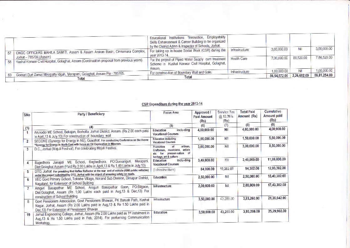
or=>
(EE
--6=
=
dE
5-=
c(J&
Cl
oqooo^oe{
eqooo-oro'rt
oqoooellt_@
oooeo-g)o)
oqcoc.r_oC
D
oq(\t@(q^at-f-ra)
oq(\I€o-C
At_t\
oecriaq@aa-
N
oqcleCD
.ar,(\I6
aE
EG-
CL:
o==
oF
E
oo
oqooodod
oq(3oo^ero-
oooeo-oo-o
oqee_o-6)c.t
oq€(o-f,g)
eoc;ee-olt?-it
ooooode^
oqo(ortc.tgr-(q
oo(t(ocaCD
F$0c2a
"9NE
E:.*
6J (d)a"
z.z
sN6sctz
<3O(l)c\j
c.t
o<lo(\t
(f)
\t
E=oO>E
GY
<E
<8
a€
oqeoode+
ooooo_olr)^
oqooo^c,e-o
oqooe^oc.t
oodood€
oqoooo6
oqooodo-
oqooqortt-
oqeoe-orft-G
'
FoooL
6
ED
o.Eooao(t
E6
oc'E
OS
'EO
G=
oE
OgJ>
Oo
co€p:3coE
6os59€E=
o€ou>
i9bt6eG
O.EF
?EE
:g ff€=
o0E
E-o
ei E
.99bdiE
E*
EE
€ 2
9Scb
qobE
CD
66=q
o2o(JE
F.9E6Eo6=
oE
OuJ>
gt"}:}t'}$g
o6o!tul
o0@6
E=o-gc
o6()EuJ
IEl6lol-IOlolo)loIOlNl@Itlel5lql<| -=
l-Fli6 T
d9il(o tlo
!ts
.!lo
e
l6:lc
(lc
(l'o- tlo
!
lq,ilO
.IrlO
lla:
I lE.
I l-_
cI
lorI
lE:
I lo
I
I lc
I
I l=
.I
I<.1
..goq,6)otctr
oEoooooco(JroiE
.iE
Io_oloiIi(grE
]Gl
=\
(9..{.U
-lz.c.o.o)clLU
.
o)o)CU)
ulz.oO[la
(gac)I=6'=o)=F(!-o(D
6oLL-l6a0)LL=(uEo-ci
_l=
t:oltr--lba>=t-l
-.-l-@
l=
slq)*l(gJlE
oloS
l
itlodl
s -_l
B<
fo.=
l(o@
lm
cl(oIjJlo^lo=
tE
-1oc{(D
atl'IlP
=gE
C$hCA(E<-.-(go*ol!cc,C
/n
o:zH
'Ecoo
oo=Ieoo.9,o0.oooe,IE€e,=o0r(sco?oFo
OI
'-l.alot-t=
lol(E
IE
I-lclol>
li5
I
-ol=
l<
./) I
ct6olciolocl6-I=
'=loml.o tsl€€l|- at-*'16 0lO
c
lc^t3Fl>
o)l6
xlcU
ld€-l >
Elo
cl(9(oIoEIILLI (sil>
z
=o
I
CLL
IF
Icr^
|
=6
|
R--
I
l8 I
!o II
iod I
ol(5Cr)
I
o I
=l
b<
IC
IalC
5E
I
E'F
I
ns II
E1
.-o=(g
6; 0)cke
(5
6'Jo^+
To
d6-p)aE
trloa=zcoe-6)Y
C)
=
@-
g< i6
3;*bcu=
cC
O -o-O
-39a9EE
.C:
<o
6
Ae
,(trco;atuYL(gJ= (oo
=q?
(5-n@<
tr- odgo=
'j6Y
'i<A
=O
_e.:loQE
pio- =
._(!>
J
'?ovocc!-9. ai60alO
F
e. v,a4()J
5E'a-\
O- e-
PC
U>
oo6(D
z.
D5uL3()c)l
-^sl I
3.U
I
5llrE
l=
E
I
:Ol
:-() I
6- I
o'=
I
ot I
oo I
2b I
=o-
I6lrb
I
DLL
I
i.- I
oSY
b*c{E
.(u-Oo0){LL(q€po(o?o-oioocO
YO
JO
^Pts
'Er
6)P&
'P"a q
ul 9
*P9
S
o:E
E;
oz,U)
6tc/)
rtra)
I@F
@g)
-flY
I<
ql5l,t6lol>
tol-clP
latcl5lE
lolLIflElclololxl
r.rJlelalol
OOdo-c)
OOc!La)_
CO
@^
F-
OaOoqO<2
oo+roNoo€6
z.
OeoC\
lr)_(o6
z.
oq(\loocal'6!
OqOoO.
Oo_co
qOOO.
OO-
F.-
oqOOOO-
oFhrn(€€
0)=O=(gc
0)oc60)-
c)=fo6c
>o
=c)
qFE
o 9r=-o-5€E
o 1
uJ.ol4P
8ioto c;(trll=>
'=
a36 rC
L,
-d)>-
pEs3i€.4"i.=
hEE
baoto(E
!cc
so
=7
E?!
l=:+
l-oJ >
ltrl u) I
q, I
EIrl
EI
I
tt<D
l!)to=6'6oU
)o)afoELl++
loolc-lV
ol(gc.llL
olo
0)ILL
>
(l)P
I
to6(oO
O.:(9F
-=(g
o.E>
3AT
a*u) .>5c)o6<
=e
-ooO
Vo-O
-o*c
A-=tj:<(l)'p.co-qP
;=
0)6gg
@oo@lL../)<
Io)l(ot(D
tEc(U
G=z.(oE==ocoC.e.iOf
lcloIOt-loIL
(EoF
_t<
Ip
l.al3lJI-lol6lclcl)I-lcl@
l(u1nt-l6lslE
I(glal6l
c5 I
EI
olalal
FI
=t
aI:^=F o
</) <
.LU
<!l
F-
t3-l(J-
6g
D31)n=tEo-Eo$ooo-C9CU
=c=o:_)
E$aoJcucct)(E
(9jC
U
=o-(Jo= go:<EEa=:<
)l)l;lll:I=l
!lslnlD\
1l!l=t
f,l5lllel=l
slfJ5lOI
-lcl(!D5Go-==(UE(g!c= ,oc(oEoC9
F-n
@lr)o)(o