Oil and Gas Industry Wireline Large Diameter Split Drum ...
11
International Journal of Engineering and Information Systems (IJEAIS) IS S N: 2643-640X Vol. 5 Issue 3, March - 2021, Pages: 116-126 www.ijeais.org/ijeais 116 Oil and Gas Industry Wireline Large Diameter Split Drum Winch Structure Design and Finite Element Analysis Study (Gerry), Man Li Department of Engineering, Rig Pro Painting and Fabrication Inc. Calgary, Alberta, Canada [email protected] Abstract —in oil and gas upstream industry, hoisting drum winch are essential piece of equipment for both onshore and offshore drilling and service rigs. Large diameter hoisting split drum winch has a wide applications for wireline equipment but with very limited structure design study and very high failure rate due to amount force exerting on its barrel core and flanges. To better resolve this issue, a large diameter split drum winch new structure design study is exploited and a finite element analysis-FEA study is also conducted to guide welding, machining, and manufacturing. Experimental and actual oilfield operational results show that the new structure design for the split drum winch is quite robust and provides good results in terms of reliability and customer satisfaction. Keywords — oil and gas, upstream, wireline, hoisting, split drum winch, structure, design, finite element analysis, study , large diameter, hoop stress, drum barrel, split flange, wire cable 1. I NTRO DUC TIO N A hoisting winch is a mechanical device that is used to pull in (wind up) or let out (wind out) or otherwise adjust the “tension” of a rope or wire rope (also called “cable” or “wire cable). In its simple form, it consists of a spool/winch drum with attached power driving and brake systems to sit on its drawwork. Some of larger drum winches are used in marine applications, and some of them are used in in oil and gas upstream and pipelines applications. These types of applications can require huge tractive forces and the larger drum winches must be of sufficient strength and quality in order to provide reliable service. An oil and gas upstream industry wide survey revealed that some of large split drum winches have failed during earlier services due to poor structure design and lack of related study to provide any guidance. These failures have exposing the owners to millions of dollars in repair or replacement costs plus the asset downtime and project delay. For the large diameter split drum winches, the two (2) major structure failures can be classified as drum winch barrel elastic deformation failure or buckling and drum flange splitting with brittle fracture or plastic collapse or excessive deflection of bending due to over load. There are mainly hoop stress acting on drum winch barrel and forces acting on the drum flanges due to larger quantities of layers of wire cables. Therefore, the strength of large diameter split drum winch material, proper engineering structure design, weld strength, fatigue of welded joint, and high quality of manufacturing are important factors to improve the reliability and high performance of a large diameter split drum winch. This study project looks at the requirements for the design of hoist drum winch from various design codes based on different industrial applications and carries out a literature review on the subject. Based upon the literature review and drum winch design failure models, a case study where most of large split drum winches has failed with early operational stage due to poor split drum winch structure design is presented and evaluated. To prevent both drum winch barrel and flange failures and based upon the winch drum stress and deformation behaviors, an optimizing structure design of the large split drum winches with less steel footprint and better manufacturing ability is developed and the finite element analysis is also conducted. Both the experimental and the actual field operations for total twenty five (25) such new structure designed large split drum winches haven't failed any one of them so far after five (5) years in actual operational services in oilfield.
-
Upload
khangminh22 -
Category
Documents
-
view
1 -
download
0
Transcript of Oil and Gas Industry Wireline Large Diameter Split Drum ...
International Journal of Engineering and Information Systems (IJEAIS)
ISSN: 2643-640X
Vol. 5 Issue 3, March - 2021, Pages: 116-126
www.ijeais.org/ijeais
116
Oil and Gas Industry Wireline Large Diameter Split Drum Winch Structure Design and Finite Element Analysis Study
(Gerry), Man Li
Department of Engineering, Rig Pro Painting and Fabrication Inc.
Calgary, Alberta, Canada
Abstract—in oil and gas upstream industry, hoisting drum winch are essential piece of equipment for both onshore and offshore
drilling and service rigs. Large diameter hoisting split drum winch has a wide applications for wireline equipment but with very
limited structure design study and very high failure rate due to amount force exerting on its barrel core and flanges. To better
resolve this issue, a large diameter split drum winch new structure design study is exploited and a finite element analysis-FEA
study is also conducted to guide welding, machining, and manufacturing. Experimental and actual oilfield operational results
show that the new structure design for the split drum winch is quite robust and provides good results in terms of reliability and
customer satisfaction.
Keywords— oil and gas, upstream, wireline, hoisting, split drum winch, structure, design, finite element analysis, study , large
diameter, hoop stress, drum barrel, split flange, wire cable
1. INTRO DUCTIO N
A hoisting winch is a mechanical device that is used to pull in (wind up) or let out (wind out) or otherwise adjust the “tension” of
a rope or wire rope (also called “cable” or “wire cable). In its simple form, it consists of a spool/winch drum with attached power
driving and brake systems to sit on its drawwork.
Some of larger drum winches are used in marine applications, and some of them are used in in oil and gas upstream and
pipelines applications. These types of applications can require huge tractive forces and the larger drum winches must be of sufficient
strength and quality in order to provide reliable service.
An oil and gas upstream industry wide survey revealed that some of large split drum winches have failed during earlier services
due to poor structure design and lack of related study to provide any guidance. These failures have exposing the owners to millions
of dollars in repair or replacement costs plus the asset downtime and project delay.
For the large diameter split drum winches, the two (2) major structure failures can be classified as drum winch barrel elastic
deformation failure or buckling and drum flange splitting with brittle fracture or plastic collapse or excessive deflection of bending
due to over load.
There are mainly hoop stress acting on drum winch barrel and forces acting on the drum flanges due to larger quantities of la yers
of wire cables. Therefore, the strength of large diameter split drum winch material, proper engineering structure design, weld
strength, fatigue of welded joint, and high quality of manufacturing are important factors to improve the reliability and hig h
performance of a large diameter split drum winch.
This study project looks at the requirements for the design of hoist drum winch from various design codes based on different
industrial applications and carries out a literature review on the subject. Based upon the literature review and drum winch design
failure models, a case study where most of large split drum winches has failed with early operational stage due to poor split drum
winch structure design is presented and evaluated.
To prevent both drum winch barrel and flange failures and based upon the winch drum s tress and deformation behaviors, an
optimizing structure design of the large split drum winches with less steel footprint and better manufacturing ability is developed
and the finite element analysis is also conducted.
Both the experimental and the actual field operations for total twenty five (25) such new structure designed large split drum
winches haven't failed any one of them so far after five (5) years in actual operational services in oilfield.

International Journal of Engineering and Information Systems (IJEAIS)
ISSN: 2643-640X
Vol. 5 Issue 3, March - 2021, Pages: 116-126
www.ijeais.org/ijeais
117
2. REVIEW OF SPLIT DRUM WINCH STRUCTURE DESIGN
2.1 Applications of Split Drum Winch in Marine, Construction and Oil and Gas Industry
The chain or rope large diameter split drum winches are used in anchoring or mooring in marine industry. The following figure 1
illustrates the main structure of the drum winch application. The anchoring or mooring application defines the wrapping chain or
rope around the drum barrel with relative light weight, low stress level and minimum deformation.
The figure 2 below shows the small diameter split drum winch used in construction hoisting application . This small split drum
winch application has the character of light weight, low stress level, and less deformation.
The figure 3 below represents the middle diameter split drum winch used in upstream oil and gas industry wireline application.
Because there is in need a large hoisting power, it was designed and constructed with heavy barrel core, thicker end flanges and
heavier split flange.
The following figure 4 and figure 5 below depict the middle diameter split drum winches used in upstream oil and gas industry
wireline application. Because there are in needs for large winch pulling powers with wire cable, they are designed and constructed
with strong barrel core, end flanges and split flange.
Fig. 1 Anchor Split Chain/Rope Drum Winch: Courtesy of DMT Marine Equipment SA
Fig. 2 Split Drum Winch for Construction Hoisting: Courtesy of Kolstrand
Fig. 3 Wireline Heavy Split Drum Winch: Courtesy of Arabian Crane Service L.L.C.
International Journal of Engineering and Information Systems (IJEAIS)
ISSN: 2643-640X
Vol. 5 Issue 3, March - 2021, Pages: 116-126
www.ijeais.org/ijeais
118
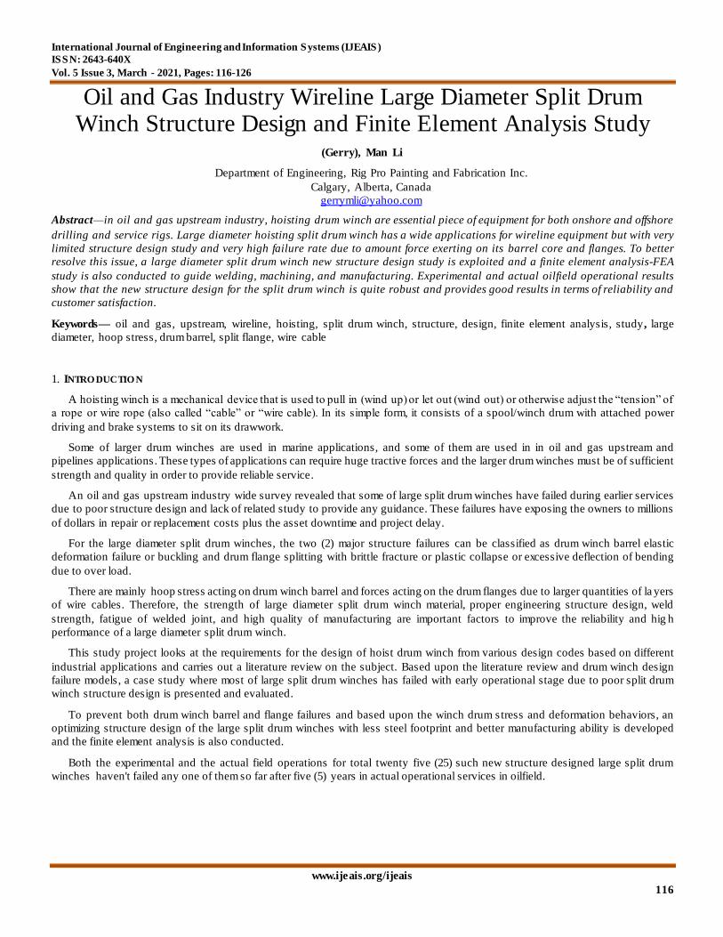
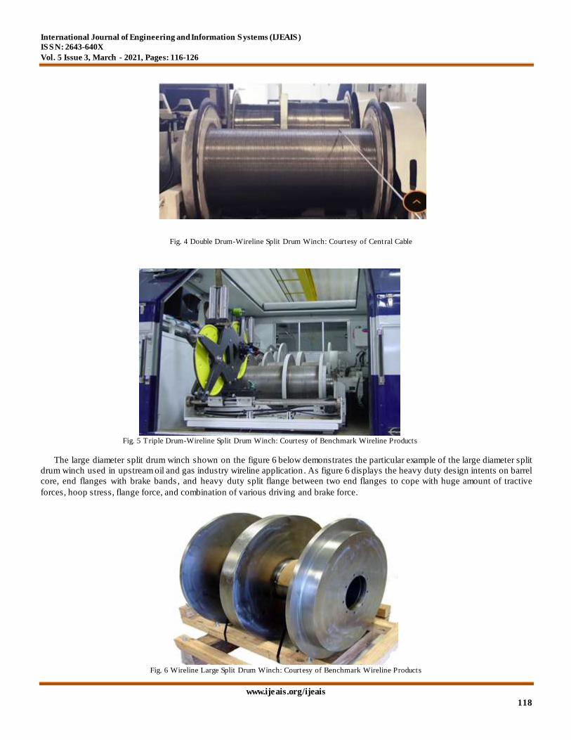
The large diameter split drum winch shown on the figure 6 below demonstrates the particular example of the large diameter split
drum winch used in upstream oil and gas industry wireline application . As figure 6 displays the heavy duty design intents on barrel
core, end flanges with brake bands , and heavy duty split flange between two end flanges to cope with huge amount of tractive
forces, hoop stress, flange force, and combination of various driving and brake force.
Fig. 4 Double Drum-Wireline Split Drum Winch: Courtesy of Central Cable
Fig. 5 Triple Drum-Wireline Split Drum Winch: Courtesy of Benchmark Wireline Products
Fig. 6 Wireline Large Split Drum Winch: Courtesy of Benchmark Wireline Products
International Journal of Engineering and Information Systems (IJEAIS)
ISSN: 2643-640X
Vol. 5 Issue 3, March - 2021, Pages: 116-126
www.ijeais.org/ijeais
119
2.2 General Review of the Current Drum Winch Structure Design Standards and Codes
The currently design standard literature review looks at published materials relating to the hoisting drum winch. The most
common hoisting drum winch design standards are listed below:
API SPECIFICATION 8A & 8C, Drilling and Production Hoisting Equipment
API SPECIFICATION 7K, Drilling and Well Servicing Equipment
ABS Guide for the Certification of Drilling Equipment
FEM Federation Europeenne de la Manutention (commonly referred to as FEM)
BS2573-Rules for the Design of Cranes. Specification for Classification, Stress Calculation and Design Criteria
API SPECIFICATION 2C, Offshore Pedestal-Mounted Cranes
AS1418, Cranes, Hoists and Winches
Lloyd's Register Code of Lifting Appliances in a Marine Environment
DNV Rules for Certification of Lifting Appliances
The literature reviews are focused on the subject of hoist drum barrel and flange forces. The requirements to design a hoist drum
barrel and flange from various design codes available are outlined above and are selected from the most comprehensive design
codes. The hoist drum strength is normally assessed based on the selected materials, code, and factor of safety to calculate the
probability of failure of the drum as an indicator of the hoist drum winch reliability .
The split drum is made up of a barrel, two flanges at both end, and a split flange between end flanges to fit two different wire
cables. All flanges are connected to the drum through various manufacturing means. Ideally the barrel and flanges of a split drum
can cast as a single unit with desired strength and physical properties . Other methods include welding the flanges to the barrel or
bolting it or a combination of the above. The most cost effective ways to manufacturing a split drum winch is to weld the flanges to
a barrel. A large split drum winch has been widely used in upstream wireline oil & gas industry because it has the larger capacity
drum and it can carry two different wire cables for totally different tasks and applications.
By comparisons of split drum winch shown on above from figure 1 to figure 6, the failure of a large diameter split drum winch
are more likely to happen due to poor structure design and combination of various huge forces. When a large diameter split drum
winch failure does occur, it has the potential to result in significant damage to the safety, company, economy, and environment and
it may also result in harm to personnel in the vicinity. Hence, the a large split diameter drum winch design study has posed to an
unique challenge to the upstream oil & gas wireline industry, especially it has not been the subject of oil and gas industry studies in
the past with rare and very limited research about it.
Most large diameter split drum winches in upstream wireline oil & gas industry consist of a drum to wind the wire cable and
where a number of wire cable layers are required and the end plates (flanges) and split plates (flanges) are fitted. Whilst the effects
of wire cables pressure on the drum itself are well researched and understood, the effect of flange forces in large diameter split drum
is constantly underestimated resulting in the catastrophic failure of the drum winch. In addition, flanges are also sometimes
subjected to forces from driving motor, sprockets, band brakes, brake calibers, clutches or the combinations. These additional forces
further complicate large diameter split drum design, and clear guidance on how the large diameter split drum barrel and flanges are
to be designed, is not readily available in public domain. The difficulty lies in determining the magnitude and pattern of loading of
the large diameter split drum barrel and flanges. Therefore, once the drum barrel and flange force have been determined, the stresses
can be evaluated. Then, the challenges would be the design a proper manufacturing process to meet the design intents.
There are some in depth studies about the hoop stresses acting on the drum barrel core. However, the forces acting on the drum
flanges are poorly understood even though there are numerous studies have been undertaken to determine the flange forces . Material
fatigue is also critical in the reliability of hoist drums as the structure is subjected to cyclic application of stress. Fatigue will result in
initiation and gradual growth of cracks until the remaining section of material cannot support the applied service load.
In general, the attachment of flanges to drum barrel is considered as rigid. This would indicate that the drum and flange are cast
as a single unit or all attachments need to be full penetration weld.
2.3 The Large Diameter Split Drum Winch Failure Model
According to P. Dietz [Dietz 1971], The loads on a drum are principally the wrapping pressure p(x) on the drum jacket caused by
the rope packet and the line loads Fi (r) and Fj (r) caused by the rope layers on the side discs/flanges [1] as shown on Figure 7
below.

International Journal of Engineering and Information Systems (IJEAIS)
ISSN: 2643-640X
Vol. 5 Issue 3, March - 2021, Pages: 116-126
www.ijeais.org/ijeais
120
Based upon P. Dietz [Dietz 1971], The design of drum winch must take into account completely different failure causes
explained in Figure 8 below. There are numbers of problem areas: A-drum jacket; B-bearing area (as a result of redial distortion and
misalignment; C-mounting restriction in axial direction; D- notch effects in the area of the side disc/flange joints; E-side disc/flange
deformation with multiple windings [1].
Based upon many studies about the strength of drum winch in the past, it is accepted that a drum winch generally fails in two
ways (Song, et al., 1979):
High wire/rope tensions causing the internal compressive hoop stress in the drum barrel to exceed the ultimate limit
strength of the drum material.
The pressure on the wound wire/rope on the drum flanges causes a high stress concentration at the root or fillet of the
flanges. This causes the flange to part from the drum barrel [2].
From the large diameter split drum winch structure design research undertaken during this project, it was found that the
magnitude of the drum barrel and flange force varies significantly depending on various split flange characteristics such as wire
cable type, drum dimensions, wire cable tension, number of layers of the wire cable and the fleet angle. It was also found that
despite significant research and experiments undertaken on the subject, these study findings have not yet incorporated into most
design standards. Even though large diameter split drum winch design is a complex subject, it is considered trivial by most design
codes and standards because most design codes and standards do not even specify any requirements, such as design safety of fa ctor,
for large diameter split drum winch barrel and flange, instead of leaving the design engineer to decide the best way to proceed based
on their knowledge and experience. Therefore, there are in need to have more research done and incorporate research and test
findings into design codes and standard to guide engineering design and guard public safety.
Fig. 8 Winch drum stress and deformation behaviors: Courtesy of P. Dietz [Dietz 1971], [1]
Fig. 7 Rotationally symmetrical pressure and line load distribution: Courtesy of P.
Dietz [Dietz 1971], [1]

International Journal of Engineering and Information Systems (IJEAIS)
ISSN: 2643-640X
Vol. 5 Issue 3, March - 2021, Pages: 116-126
www.ijeais.org/ijeais
121
2.4 The Design Improvement Challenges for the Large Diameter Split Drum Winch
The large diameter split drum winch structure design has its unique design intents due to split flange need to fit into between two
end flanges. As the results, there are different hoop stresses on each side of split flange barrel core and different line lo ad on each
side of split flanges due to different wire cable. Therefore, the large diameter split drum winch structure design improvement poses
unique challenges. It needs to improve its operational safety, strength, manufacturing ability, and long service life span while
reducing its carbon footprint and overall cost.
3. NEW STRUCTURE DESGIN STUDY AND APPROACHES
3.1 ABBREVIATIONS AND ACRONYMS
The abbreviations and acronyms are defined as the followings:
DNV: Det Norske Veritas
FEM: Federation Europeenne de la Manutention
ABS: American Bureau of Shipping
API: American Petroleum Institute
AS: Australian Standard
BS: British Standard
FEA: Finite Element Analysis
Glossaries of Terms are explained as the followings:
Fleet Angle: Angle at which the rope approaches the drum to the drum centre line
LeBus: Winding system on the drum-a designer and manufacturer of drums of all size
Lloyd's Register: A technical and business services organization and a maritime classification society
3.2 Large Diameter Split Drum Winch Barrel Stiffening
For heavier loads, in order to stiffen the barrel core for the large diameter split drum winch, one or two disc ring(s) may be used,
spaced a given distance apart as shown below at Fig. 9, (A), (B), and (C). Usually with shaft end, the inner disc along with shaft stub
are welded together first as a subassembly unit as shown at Fig. 9, (A). This unit is then welded into the barrel core as shown at Fig.
9, (B), and finally, the outer disc is then slipped over and welded in place as shown at Fig. 9, (C) [3].
A FEA conducted by LeBus as shown at Fig. 10 below delineates the low stress level after stiffening the drum winch barrel core
with a disc ring near the left-side end. On the opposite of near the right-side end, it displays relatively high stress level. The LeBus
FEA as shown at Fig. 10 below converges with analysis as shown at Fig. 9 above. That is the same approach used in this large
diameter split drum winch barrel core new structure design project.
Fig. 9 Drum Winch Barrel Core and Shaft Stiffening [3]
International Journal of Engineering and Information Systems (IJEAIS)
ISSN: 2643-640X
Vol. 5 Issue 3, March - 2021, Pages: 116-126
www.ijeais.org/ijeais
122
3.3 Large Diameter Split Drum Winch End Flange Stiffening
There are two scenarios to strengthen the end flanges. One is to utilize the band brake as shown at Fig.6. Another method is to
add gusseting plates to reinforce the two end flanges as shown at Fig.11 below [3].
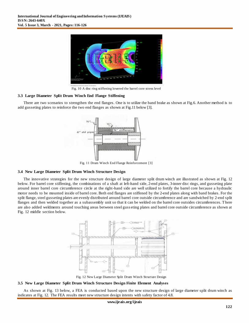
3.4 New Large Diameter Split Drum Winch Structure Design
The innovative strategies for the new structure design of large diameter split drum winch are illustrated as shown at Fig. 12
below. For barrel core stiffening, the combinations of a shaft at left-hand side, 2-end plates, 3-inner disc rings, and gusseting plate
around inner barrel core circumference circle at the right-hand side are well utilized to fortify the barrel core because a hydraulic
motor needs to be mounted inside of barrel core. Both end flanges are stiffened by the 2-end plates along with band brakes. For the
split flange, steel gusseting plates are evenly distributed around barrel core outside circumference and are sandwiched by 2-end split
flanges and then welded together as a subassembly unit so that it can be welded on the barrel core outsides circumferences. T here
are also added weldments around touching areas between steel guss eting plates and barrel core outside circumference as shown at
Fig. 12 middle section below.
3.5 New Large Diameter Split Drum Winch Structure Design Finite Element Analyses
As shown at Fig. 13 below, a FEA is conducted based upon the new structure design of large diameter split drum winch as
indicates at Fig. 12. The FEA results meet new structure design intents with safety factor of 4.8.
Fig. 11 Drum Winch End Flange Reinforcement [3]
Fig. 12 New Large Diameter Split Drum Winch Structure Design
Fig. 10 A disc ring stiffening lowered the barrel core stress level

International Journal of Engineering and Information Systems (IJEAIS)
ISSN: 2643-640X
Vol. 5 Issue 3, March - 2021, Pages: 116-126
www.ijeais.org/ijeais
123
As shown at Fig. 14 below, a case of through drive shaft of the new structure design of large diameter split drum winch FEA is
conducted. The FEA results indicate improvement with safety factor of 4.5 as expected.
As shown at Fig. 15 below, a FEA for smaller band brake at both end flanges of the new structure design of large diameter split
drum winch is conducted. The FEA results show with safety factor of 4.4 as expected.
3.6 Manufacturing Considerations for the New Design
Full penetration welding, proper welding procedure specifications and welding procedure data sheet, and all welding
consumables should be used and make sure to comply with American Welding Society or Canadian Welding Bureau or equivalent.
Fig. 13 New Large Diameter Split Drum Winch Structure Design FEA Shown at Hydraulic
Motor Drive End
Fig.14 New Large Diameter Split Drum Winch Structure Design FEA with Shaft Drive
Fig. 15 New Large Split Drum Winch Structure Design with Smaller Band Brake

International Journal of Engineering and Information Systems (IJEAIS)
ISSN: 2643-640X
Vol. 5 Issue 3, March - 2021, Pages: 116-126
www.ijeais.org/ijeais
124
All welders who perform the welding must be a qualified welder as per international standards. To weld the inside of large diameter
split flanges subassembly unit to the barrel core, a special long welding special nozzle is needed.
There are many machining processes before and after welding involved to properly prepare and get this large diameter split drum
winch manufactured to meet the engineering design specifications. Each subassembly step along with manufacturing sequence and
quality control are also critical to ensure high quality products.
3.7 Experimental and Actual Operational Results
After the completion of the new structure design of large diameter split drum winch, we have built and tracked total twenty (25)
such new large diameter split drum winch units since. The following Table 1 exhibits the overall experimental and actual field
operational results.
Table 1: New Structure Design of Large Diameter Split Drum Winch Operational Results
Numbers of
New Drum
Winch
Manufactured
New Structure Design Split Drum Winch 5 to 7 Years’ Operational Results
Average Design Factor of
Safety
Year of
Manufactured
Total Years’
in Operation
Customs’
Rating (1 to 10)
Number of
Unit Failed
7 units 4.26 Year of 2014 7 10 0
8 units 4.51 Year of 2015 6 10 0
10 units 4.68 Year of 2016 5 10 0
3.8 Discussions
Comparison the traditional large diameter split drum winch design shown at Fig. 6 with the new design shown from Fig. 12 to
Fig.15, the new design adds more weld strength around touching area between inside split flange and barrel outside circumference.
Moreover the new design uses less steel on both end flanges and split flange so it saves material cost and manufacturing time.
4. CONCLUSIONS
This large diameter split drum winch new structure reveals some positive improvements and precautions on the following areas:
The new design has resulted in enhanced structure and welding strength with high level of reliability and zero failure
case so far.
The new design factor of safety can reach a relatively high level depending on the application and cost. Optimum
design factor of safety around 4 to 5 rang would be most cost effective in practical point of view.
A properly modeled FEA can provide great insights to investigate any weak spot and create innovative solution to
eliminate the weakest link in order to meet engineering design intents and specifications.
All necessary well-developed and tested welding procedure specifications and welding procedure data sheets are
needed to guide proper welding processes from start to finish.
To weld the inside of large diameter split flanges subassembly unit to the barrel core with full penetration weld, a
special long welding nozzle is needed.
Material fatigue is considered the most common cause of structural failure for in-service structural component,
subassembly, frame, and/or equipment. Therefore, properly calculation of drum winch hoop stress, flange force, and
welding strength to specify suitable material strength and thickness are important.
High quality of workmanship for welding, machining, manufacturing, assembling, testing, and proper quality control
procedures and processes are crucial to ensure high quality and reliable large diameter split drum winch products .
5. REFERENCES
[1] P. Dietz. (2004). Design Criteria for Multilayer Wound Winch Drum Following Lightweight Design Principles, On,
International Design Conference-Design2004, Dubrovnik, May 18-21. 2004.

International Journal of Engineering and Information Systems (IJEAIS)
ISSN: 2643-640X
Vol. 5 Issue 3, March - 2021, Pages: 116-126
www.ijeais.org/ijeais
125
[2] Leslie L Moyo. (2009). Structure Reliability Assessment of a Hoist Drum for an Offshore Crane, School of the Built
Environment, Heriot-Watt University 2009, pp.12-13.
[3] Omer W. Blodgeet. (1963). Design of Weldments, The James F. Lincoln Arc Welding Fundation, Cleveland Ohio, pp. 5.3-3 to
5.3-10.

International Journal of Engineering and Information Systems (IJEAIS)
ISSN: 2643-640X
Vol. 5 Issue 3, March - 2021, Pages: 116-126
www.ijeais.org/ijeais
126
Authors
(Gerry), Man Li
Director of Engineering, P.Eng, PMP, MBA
Rig Pro Painting & Fabrication Inc.
Calgary, Alberta, Canada