
OEM MICODE USB/RS232 TURBO User Manual - Eccel ...
92
1 OEM MICODE USB/RS232 TURBO User Manual Manual version: v1.0 1 27/07/2021 Table of Contents 1. Introduction ..................................................................................................................................................7 1.1 Device Overview ................................................................................................................................................ 7 2. Electrical specification ...................................................................................................................................8 2.1 Absolute maximum ratings ................................................................................................................................ 8 2.2 Operating conditions ......................................................................................................................................... 8 2.3 DC characteristics (VDD = 5 V, TS = 25 °C) ........................................................................................................... 8 2.4 Current consumption (5V input)........................................................................................................................ 8 3. Getting started ..............................................................................................................................................9 3.1 Board description .............................................................................................................................................. 9 3.1.1 IO header description (J2) ................................................................................................................... 10 3.1.2 J1 header description (RS232 version) ................................................................................................ 11 3.2 Typical connection ........................................................................................................................................... 11 4. OEM Micode compatibility mode ................................................................................................................. 12 4.1 Auxiliary Data Output ...................................................................................................................................... 12 4.2 MIFARE Transponders ..................................................................................................................................... 12 4.3 ICODE SLI Transponders .................................................................................................................................. 13 4.4 ISO14443B Transponders ................................................................................................................................ 13 4.5 MicroRWD MF-IC modes of operation ............................................................................................................ 13 4.6 Supported transponder types.......................................................................................................................... 14 4.6.1 MIFARE Mode ...................................................................................................................................... 14 4.6.2 ICODE SLI Mode ................................................................................................................................... 14 4.6.3 ISO14443B Mode................................................................................................................................. 15 4.7 Serial Interface ................................................................................................................................................. 15 1 The newest User Manual can be found on our website: https://eccel.co.uk/wp-content/downloads/OEM_user_manual.pdf
-
Upload
khangminh22 -
Category
Documents
-
view
0 -
download
0
Transcript of OEM MICODE USB/RS232 TURBO User Manual - Eccel ...

1
OEM MICODE USB/RS232 TURBO User Manual
Manual version: v1.01
27/07/2021
Table of Contents
1. Introduction ..................................................................................................................................................7
1.1 Device Overview ................................................................................................................................................ 7
2. Electrical specification ...................................................................................................................................8
2.1 Absolute maximum ratings ................................................................................................................................ 8
2.2 Operating conditions ......................................................................................................................................... 8
2.3 DC characteristics (VDD = 5 V, TS = 25 °C) ........................................................................................................... 8
2.4 Current consumption (5V input)........................................................................................................................ 8
3. Getting started ..............................................................................................................................................9
3.1 Board description .............................................................................................................................................. 9
3.1.1 IO header description (J2) ................................................................................................................... 10
3.1.2 J1 header description (RS232 version) ................................................................................................ 11
3.2 Typical connection ........................................................................................................................................... 11
4. OEM Micode compatibility mode ................................................................................................................. 12
4.1 Auxiliary Data Output ...................................................................................................................................... 12
4.2 MIFARE Transponders ..................................................................................................................................... 12
4.3 ICODE SLI Transponders .................................................................................................................................. 13
4.4 ISO14443B Transponders ................................................................................................................................ 13
4.5 MicroRWD MF-IC modes of operation ............................................................................................................ 13
4.6 Supported transponder types.......................................................................................................................... 14
4.6.1 MIFARE Mode ...................................................................................................................................... 14
4.6.2 ICODE SLI Mode ................................................................................................................................... 14
4.6.3 ISO14443B Mode ................................................................................................................................. 15
4.7 Serial Interface ................................................................................................................................................. 15
1 The newest User Manual can be found on our website: https://eccel.co.uk/wp-content/downloads/OEM_user_manual.pdf

2
4.7.1 NO card present and NO host commands received. ........................................................................... 16
4.7.2 MIFARE/ICODE card in field, NO host commands received. ............................................................... 16
4.7.3 Host commands received and processed............................................................................................ 16
4.7.4 Auxiliary output and BEEP delay timing (if options are enabled) ........................................................ 18
4.8 Summary of Polling rates and command timing ............................................................................................. 18
4.9 Host Driver software ........................................................................................................................................ 19
4.10 Switch to C1 mode ........................................................................................................................................... 20
4.11 Commands for MIFARE, ICODE and ISO14443B modes .................................................................................. 20
4.11.1 Card / Label STATUS ........................................................................................................................... 20
4.11.2 MESSAGE Report ................................................................................................................................. 20
4.11.3 Program EEPROM ................................................................................................................................ 21
4.11.4 Internal EEPROM memory map .......................................................................................................... 21
4.11.5 Factory Reset ....................................................................................................................................... 23
4.11.6 Command Protocol (MIFARE Mode) ................................................................................................... 24
4.11.7 Store Keys ............................................................................................................................................ 24
4.11.8 Internal Key Storage memory map (default settings) ......................................................................... 25
4.11.9 Write Card Block .................................................................................................................................. 25
4.11.10 Read Card Block ................................................................................................................................... 26
4.11.11 Inc Value (only operates on Value Data Structure) ............................................................................. 27
4.11.12 Dec Value (only operates on Value Data Structure) ........................................................................... 28
4.11.13 Transfer Value (only operates on Value Data Structure) .................................................................... 29
4.11.14 Card UID ............................................................................................................................................. 29
4.11.15 Type Identification............................................................................................................................... 30
4.11.16 Command Protocol (ICODE SLI Mode) ................................................................................................ 31
4.11.17 Write Label Block ................................................................................................................................. 32
4.11.18 Read Label Block .................................................................................................................................. 32
4.11.19 Label UID ............................................................................................................................................ 33
4.11.20 Command Protocol (ISO14443B Mode) .............................................................................................. 34
4.11.21 Card UID ............................................................................................................................................. 34
4.11.22 Notes for Commands (MIFARE, ICODE, ISO14443B) ........................................................................... 35
4.12 Method of Operation....................................................................................................................................... 35
4.13 Basic RWD Communication ............................................................................................................................. 36

3
4.14 Auxiliary Asynchronous Serial output .............................................................................................................. 38
5. C1 protocol compatibility mode ................................................................................................................... 39
5.1 Overview .......................................................................................................................................................... 39
5.2 Frame structure ............................................................................................................................................... 39
5.3 CRC calculation ................................................................................................................................................ 40
6. C1 command list .......................................................................................................................................... 42
6.1 Generic commands .......................................................................................................................................... 42
6.1.1 Acknowledge frame (0x00) ................................................................................................................. 42
6.1.2 Error response (0xFF) .......................................................................................................................... 42
6.1.3 Dummy command (0x01) .................................................................................................................... 44
6.1.4 Get tag count (0x02) ............................................................................................................................ 44
6.1.5 Get tag UID (0x03) ............................................................................................................................... 45
6.1.6 Activate TAG (0x04) ............................................................................................................................. 46
6.1.7 Halt (0x05) ........................................................................................................................................... 47
6.1.8 Set key (0x07) ...................................................................................................................................... 47
6.1.9 Save keys (0x08) .................................................................................................................................. 48
6.1.10 Reboot (0x0A) ...................................................................................................................................... 48
6.1.11 Get version (0x0B) ............................................................................................................................... 48
6.1.12 Factory reset command (0x11) ........................................................................................................... 49
6.2 MIFARE Classics commands ............................................................................................................................. 50
6.2.1 Read block (0x20) ................................................................................................................................ 50
6.2.2 Write block (0x21) ............................................................................................................................... 50
6.2.3 Read value (0x22) ................................................................................................................................ 51
6.2.4 Write value (0x23) ............................................................................................................................... 52
6.2.5 Increment/decrement value (0x24) .................................................................................................... 52
6.2.6 Transfer value (0x25) ........................................................................................................................... 53
6.2.7 Restore value (0x26) ............................................................................................................................ 54
6.2.8 Transfer-Restore value (0x27) ............................................................................................................. 54
6.3 MIFARE Ultralight commands .......................................................................................................................... 55
6.3.1 Read page (0x40) ................................................................................................................................. 55
6.3.2 Write page (0x41) ................................................................................................................................ 56
6.3.3 Get version (0x42) ............................................................................................................................... 56

4
6.3.4 Read signature (0x43).......................................................................................................................... 57
6.3.5 Write signature (0x44) ........................................................................................................................ 57
6.3.6 Lock signature (0x45) .......................................................................................................................... 58
6.3.7 Read counter (0x46) ............................................................................................................................ 58
6.3.8 Increment counter (0x47) ................................................................................................................... 59
6.3.9 Password auth (0x48) .......................................................................................................................... 59
6.3.10 Ultralight-C authenticate (0x49) .......................................................................................................... 60
6.3.11 Check Tearing Event (0x4A) ................................................................................................................. 60
6.4 MIFARE Desfire commands ............................................................................................................................. 61
6.4.1 Get version (0x60) ............................................................................................................................... 61
6.4.2 Select application (0x61) ..................................................................................................................... 61
6.4.3 List application IDs (0x62) ................................................................................................................... 62
6.4.4 List files IDs (0x63) ............................................................................................................................... 62
6.4.5 Authenticate (0x64) ............................................................................................................................. 63
6.4.6 Authenticate ISO (0x65) ...................................................................................................................... 63
6.4.7 Authenticate AES (0x66) ...................................................................................................................... 64
6.4.8 Create application (0x67) .................................................................................................................... 64
6.4.9 Delete application (0x68) .................................................................................................................... 65
6.4.10 Change key (0x69) ............................................................................................................................... 65
6.4.11 Get key settings (0x6A) ........................................................................................................................ 65
6.4.12 Change key settings (0x6B) ................................................................................................................. 66
6.4.13 Create standard or backup data file (0x6C)......................................................................................... 66
6.4.14 Write data (0x6D) ................................................................................................................................ 67
6.4.15 Read data (0x6E) ................................................................................................................................. 67
6.4.16 Create value file (0x6F) ........................................................................................................................ 68
6.4.17 Get value (0x70) .................................................................................................................................. 69
6.4.18 Credit file (0x71) .................................................................................................................................. 69
6.4.19 Limited credit file (0x72) ..................................................................................................................... 69
6.4.20 Debit file (0x73) ................................................................................................................................... 70
6.4.21 Create record file (0x74)...................................................................................................................... 70
6.4.22 Write record (0x75) ............................................................................................................................. 71
6.4.23 Read record (0x76) .............................................................................................................................. 72

5
6.4.24 Clear records (0x77) ............................................................................................................................ 72
6.4.25 Delete file (0x78) ................................................................................................................................. 72
6.4.26 Get free memory (0x79) ...................................................................................................................... 73
6.4.27 Format memory (0x7A) ....................................................................................................................... 73
6.4.28 Commit transaction (0x7B) ................................................................................................................. 74
6.4.29 Abort transaction (0x7C) ..................................................................................................................... 74
6.5 ICODE (ISO15693) commands ......................................................................................................................... 75
6.5.1 Inventory start (0x90) .......................................................................................................................... 75
6.5.2 Inventory next (0x91) .......................................................................................................................... 75
6.5.3 Stay quiet (0x92).................................................................................................................................. 76
6.5.4 Read block (0x93) ................................................................................................................................ 76
6.5.5 Write block (0x94) ............................................................................................................................... 77
6.5.6 Lock block (0x95) ................................................................................................................................. 78
6.5.7 Write AFI (0x96)................................................................................................................................... 78
6.5.8 Lock AFI (0x97) .................................................................................................................................... 78
6.5.9 Write DSFID (0x98) .............................................................................................................................. 79
6.5.10 Lock DSFID (0x99) ................................................................................................................................ 79
6.5.11 Get System Information (0x9A) ........................................................................................................... 80
6.5.12 Get multiple BSS (0x9B) ....................................................................................................................... 80
6.5.13 Password protect AFI (0x9C) ............................................................................................................... 81
6.5.14 Read EPC (0x9D) .................................................................................................................................. 81
6.5.15 Get NXP System Information (0x9E).................................................................................................... 81
6.5.16 Get random number (0x9F) ................................................................................................................. 82
6.5.17 Set password (0xA0) ............................................................................................................................ 82
6.5.18 Write password (0xA1) ........................................................................................................................ 83
6.5.19 Lock password (0xA2) .......................................................................................................................... 84
6.5.20 Protect page (0xA3) ............................................................................................................................. 84
6.5.21 Lock page protection (0xA4) ............................................................................................................... 85
6.5.22 Get multiple block protection status (0xA5) ....................................................................................... 85
6.5.23 Destroy (0xA6) ..................................................................................................................................... 86
6.5.24 Enable privacy (0xA7) .......................................................................................................................... 86
6.5.25 Enable 64-bit password (0xA8) ............................................................................................................ 87

6
6.5.26 Read signature (0xA9) ......................................................................................................................... 87
6.5.27 Read config (0xAA) .............................................................................................................................. 88
6.5.28 Write config (0xAB) ............................................................................................................................. 88
6.5.29 Pick random ID (0xAC) ......................................................................................................................... 89
6.6 OTA upgrade .................................................................................................................................................... 89
6.6.1 OTA begin (0xF0) ................................................................................................................................. 89
6.6.2 OTA firmware frame (0xF1) ................................................................................................................. 89
6.6.3 OTA finish (0xF2) ................................................................................................................................. 90
7. Mechanical dimension ................................................................................................................................. 91

7
1. Introduction
1.1 Device Overview
Features
• Low cost RFID Reader with MIFARE®
Classic® in 1K, 4K memory, ICODE,
MIFARE Ultralight®, MIFARE DESFire®
EV1/EV2, MIFARE Plus® support
• Pin to pin compatible with OEM-
MICODE Reader v1
• Simple command interface via UART
• User selectable Eccel Pepper C1
protocol and RFID functionality
• Stand-alone mode (polling)
• High transponder read and write
speed
• -25°C to 85°C operating range
• Multiple internal reference voltages
• lifetime updates
• RoHS compliant
• Programmable “BEEP” output for
external control
• Wiegand protocol is not available on
this hardware
Applications
• Access control
• Monitoring goods
• Approval and monitoring
consumables
• Pre-payment systems
• Managing resources
• Contact-less data storage systems
• Evaluation and development of
RFID systems
Description
The OEM MICODE TURBO reader is a new generation OEM
MICODE product. Most of the features of the old OEM MICODE
products are supported, but also included are most of the RFID
features of the Pepper C1 range, which gives much better RFID
performance.
So, this is an ideal design choice for replacing old products, with a
migration option to our new Pepper C1 interface. With the C1
binary interface you can read/write most of the tags available on
the market not only read their UID like on the old MICODE
products.
The new devices support firmware updates, so all new features
requested by users or bug fixes can be uploaded to the module
later.
By default, the new reader works the same as old OEM MICODE
readers, with built in polling mode, UID output over serial
connection, programmable “BEEP” output for external control.
What is more, new products have the option to change baud rate
from 9600 to 115200 in RWD MICODE compatibility mode.
8
2. Electrical specification
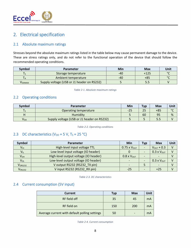
2.1 Absolute maximum ratings
Stresses beyond the absolute maximum ratings listed in the table below may cause permanent damage to the device.
These are stress ratings only, and do not refer to the functional operation of the device that should follow the
recommended operating conditions.
Symbol Parameter Min Max Unit
TS Storage temperature -40 +125 °C
TA Ambient temperature -40 +85 °C
VDDMAX Supply voltage (USB or J1 header on RS232) 5 5.5 V
Table 2-1. Absolute maximum ratings
2.2 Operating conditions
Symbol Parameter Min Typ Max Unit
TS Operating temperature -25 25 +85 °C
H Humidity 5 60 95 %
VDD Supply voltage (USB or J1 header on RS232) 5 5 5.5 V
Table 2-2. Operating conditions
2.3 DC characteristics (VDD = 5 V, TS = 25 °C)
Symbol Parameter Min Typ Max Unit
VIH High-level input voltage TTL 0.75 x VOUT - VOUT + 0.3 V
VIL Low-level input voltage (IO header) 0 - 0.3 x VOUT V
VOH High-level output voltage (IO header) 0.8 x VOUT - - V
VOL Low-level output voltage (IO header) - - 0.3 x VOUT V
VORS232 V output RS232 (RS232_TX pin) - 5 - V
VIRS232 V input RS232 (RS232_RX pin) -25 - +25 V
Table 2-3. DC characteristics
2.4 Current consumption (5V input)
Current Typ Max Unit
RF field off 35 45 mA
RF field on 150 200 mA
Average current with default polling settings 50 - mA
Table 2-4. Current consumption

9
RFID antenna
3. Getting started
3.1 Board description
Figure 1. OEM MICODE USB TURBO version
Figure 2. OEM MICODE RS232 TURBO version
USB B
LEDs
IO header
J1 RS232 header
10
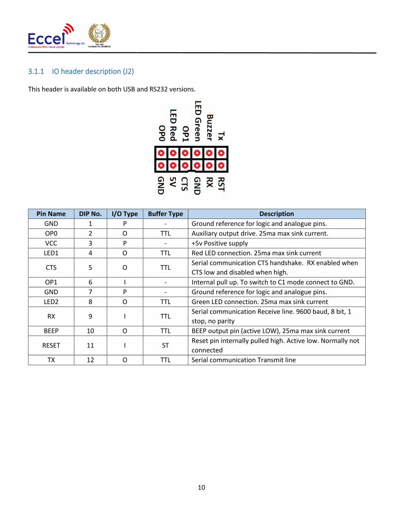
3.1.1 IO header description (J2)
This header is available on both USB and RS232 versions.
Pin Name DIP No. I/O Type Buffer Type Description
GND 1 P - Ground reference for logic and analogue pins.
OP0 2 O TTL Auxiliary output drive. 25ma max sink current.
VCC 3 P - +5v Positive supply
LED1 4 O TTL Red LED connection. 25ma max sink current
CTS 5 O TTL Serial communication CTS handshake. RX enabled when
CTS low and disabled when high.
OP1 6 I - Internal pull up. To switch to C1 mode connect to GND.
GND 7 P - Ground reference for logic and analogue pins.
LED2 8 O TTL Green LED connection. 25ma max sink current
RX 9 I TTL Serial communication Receive line. 9600 baud, 8 bit, 1
stop, no parity
BEEP 10 O TTL BEEP output pin (active LOW), 25ma max sink current
RESET 11 I ST Reset pin internally pulled high. Active low. Normally not
connected
TX 12 O TTL Serial communication Transmit line

11
3.1.2 J1 header description (RS232 version)
Pin Name DIP No. I/O Type Voltage range Description
GND 1 P - Ground reference for logic and analogue pins.
VCC 2 P 5V +5v Positive supply
CTS 3 O -5V – +5V Serial communication CTS handshake. RX enabled
when CTS low and disabled when high.
RX 4 I -13V – +13V Serial communication Receive line.
TX 5 O -5V – +5V Serial communication Transmit line
3.2 Typical connection
The OEM-Micode USB device can be connected to a host computer using a standard USB B cable. In the same way it
can be powered to operate as a standalone device by using power sources such as a USB charger or power bank.
The RS232 version should be powered using an external power supply with 5V output with minimum 200mA, but
recommended is 500mA.
The computer operating system should recognize this device as a USB to TTL bridge or a USB to Serial port converter
and it should appear in Windows device manager as a COM port. By default this COM port can be used for
communication using the binary protocol described below. The default configuration: baud: 9600, Data: 8 bit, Parity:
none, Stop bits: 1 bit, Flow Control: none. In C1 mode the reader uses always 115200 baud.

12
4. OEM Micode compatibility mode By default the reader works in the same way as version 1.0 modules and readers. So, communication, AUX output and
BUZZER output work exactly the same as in our old Micode products except the Wiegand protocol – it is removed on
this hardware. Also OP1 pin is now an input (pulled up internally). Pull down by the user forces the reader to works
in C1 mode.
4.1 Auxiliary Data Output The reader uses the 4-byte UID (serial number) or the least significant (first) 4bytes of data from
MIFARE/ICODE/ISO14443B (Calypso) card memory block to create a 32bit data frame. The data frame can then be
output as asynchronous 9600 baud serial data on OP0 pin.
An RWD EEPROM parameter can redirect the serial auxiliary output on OP0 (pin 20) to the main TX output (pin 23).
This allows both bi-directional command/data communication and the automatic auxiliary serial data output with
the same 3-wire RS232 interface.
Note that when the auxiliary serial output has been redirected to TX pin, there will be NO acknowledgement or data
response to commands (to avoid confusion of data).
For normal command and data response, the serial auxiliary output MUST be directed to the OP0 pin or turned OFF.
The “BEEP” output signal delay, data source, byte order and Hex/ASCII format for the auxiliary output and the various
options are all controlled by programmable RWD EEPROM parameters.
The MicroRWD can be used in standalone mode and automatically output blocks of data (such as the UID) WITHOUT
any commands being sent to the module. In addition, the “Green” LED output or the BEEP output can be used as a
control signal to “interrupt” the host computer or microcontroller just before the automatic data is transmitted.
NOTE that the “BEEP” output (RWD pin 4) idles in a high state and “sinks” current. External loads can be connected
between 5-volt supply and pin 4 with a series resistor to ensure “sink” current does not exceed 25mA.
Note that setting Polling rate parameter to minimum value (0x00) means the polling rate is always as fast as possible
and does not change.
4.2 MIFARE Transponders
The MIFARE transponders are available with 64 bytes (MIFARE Ultralight), 1024 bytes (MIFARE 1K) and 4096 bytes
(MIFARE 4K) of memory and the 13.56 MHz carrier frequency provides fast transaction times of 106 kbaud.
For the 1k and 4k cards the memory is organised as 16 and 40 Sectors respectively, each Sector has 4 x 16-byte Blocks
of memory (3 of which are available for general Read/Write use). Each Sector can be separately locked/unlocked for
access using security keys.
Initial communication with the cards can only proceed after mutual authentication between the RWD and the card has
succeeded (as defined by ISO 14443A standard). Combined with the “Security Key” access control for the memory

13
sectors and encrypted data streams, the MIFARE cards are ideally suited to Electronic-Purse applications such as
ticketing and vending applications where each sector can hold entirely separate data for different applications.
Note: Some ISO14443A compliant cards have a SINGLE (4-byte) UID and others have a DOUBLE (7-byte) UID. These
serial numbers are acquired as part of the initial anticollision / select procedure when a card is brought into the RF
field. This UID information can be reported using the CARD UID command (or automatically output via auxiliary OP
pins). The correct security keycodes will be required for subsequent card read/write operations.
This means that the MIFARE UID/serial number is always readable even if correct keycodes are not known. For many
applications, UID/serial number information is all that is required.
4.3 ICODE SLI Transponders
The ICODE SLI (and Tag-it HF-I) transponders support the ISO15693 standard and have 128 bytes of memory organised
as 4-byte blocks (UID/serial number is 8-bytes long). Fast communication times of up to 52kbaud and the low cost of
these transponders has allowed their use for asset tracking applications.
4.4 ISO14443B Transponders
The ISO14443B transponders (such as Calypso Rev2 types) are supported for serial number acquisition only.
Communication with the card is according to ISO14443B specification at 106kbaud rate. The REQB/ATQB response
contains the UID information that is stored and can be accessed using the CARD UID command or the automatic serial
number output feature.
4.5 MicroRWD MF-IC modes of operation
The Micro RWD has two basic modes of operation:-
Remote mode (connected to a host computer or microcontroller) and Standalone mode.
1) Remote mode involves connecting to a host serial interface. This is where the stored list of authorised identity
codes (serial numbers) can be empty, effectively authorising any MIFARE/ICODE/ISO14443B card for subsequent
read/write operations (depending on correct Security Key in MIFARE case). The simple command protocol allows a
Antenna Antenna
RWD reader
RWD reader
HOST
Standalone mode with Internal EEPROM holding authorised serial numbers for acceptance

14
host system to communicate with the Micro RWD in order to program new authorised identity codes, change
parameters, load Security Keys and perform Read/Write operations to the card itself.
2) Standalone mode is where the MIFARE/ICODE/ISO14443B card identity codes (serial numbers) are checked against
a stored list of authorised codes. If an identity code is matched, the Green LED and auxiliary outputs are enabled.
Effectively standalone mode occurs when there is no host system communicating with the Micro RWD. Up to 60
serial numbers can be stored in the authorisation list so this mode of operation can be used to create a “mini access
control” system.
4.6 Supported transponder types
4.6.1 MIFARE Mode
Selected by RWD EEPROM parameter byte 3 set to 0x00 (factory default setting)
Note that MIFARE cards and transponder devices are made by several companies under licence from Philips/NXP
Semiconductors. They are fully MIFARE compliant and only differ in having different manufacturers information in
memory Block 0 :
1) MIFARE standard 1k card (MF1 IC S50 transponder) and equivalent.
2) MIFARE standard 4k card (MF1 IC S70 transponder) and equivalent.
3) MIFARE Ultralight card (MF0 IC U1 transponder).
4) MIFARE ProX, Smart MX (JCOP) dual-interface card types are supported to allow single or double UID to be acquired and “MIFARE” operations performed across the contactless interface. DESFire, MIFARE PLUS supported for serial number acquisition.
5) Any ISO 14443A compliant contactless card can be accessed for Serial Number acquisition. Full Read/Write access
will only be possible if card fully supports Philips/NXP Semiconductors CRYPTO1 algorithm and encrypted data
protocols.
The operation of the MicroRWD MF-IC and the MIFARE transponders is described in more detail at the end of this
document.
The “ident codes” described in this text are regarded as the four byte (SINGLE) MIFARE UID (Unique Identifier/serial
number) or the least significant four bytes of the seven byte (DOUBLE) Ultralight UID.
4.6.2 ICODE SLI Mode
Selected by RWD EEPROM parameter byte 3 set to 0x01.

15
Note that ICODE SLI labels are designed to comply with the ISO15693 standard. Other ISO15693 smart labels may have
proprietary features such as different memory sizes and subsets of the ISO15693 command protocol. MicroRWD MF-
IC has been designed to work with the most common “mandatory” ISO15693 commands as supported on ICODE.
1) ICODE SLI (ISO15693) smart labels (Philips/NXP Semiconductors SL2 ICS20)
2) Any ISO15693 smart label that supports the core ISO15693 command set and has the same memory structure and configuration bytes as the ICODE SLI type (including Texas Instruments Tag-it HF-I)
The ICODE identity code is defined as the least significant four bytes of the 8-byte UID, (effectively UID0 - UID3). Note
that The UID used for the "Ident list" check is the first tag UID acquired when there are multiple tags in the field (first
tag in INVENTORY list).
4.6.3 ISO14443B Mode
Selected by RWD EEPROM parameter byte 3 set to 0x02.
ISO14443B card types are supported for serial number acquisition only.
1) Calypso Rev 2 card types.
2) Any ISO14443B card type supporting REQB/ATQB command/response protocol at 106kbaud
communication rate.
IMPORTANT NOTE: DUE TO DIFFERENCES IN THE RF CHARACTERISTICS OF MIFARE, ICODE AND ISO14443B CARDS,
THE ANTENNA TUNING MAY NEED ADJUSTING TO THE BEST COMPROMISE FOR OPERATION WITH ALL TYPES.
4.7 Serial Interface
This is a basic implementation of RS232. The Micro RWD does not support buffered interrupt driven input so it must
control a BUSY (CTS) line to inhibit communications from the host when it is fully occupied with card communication.
It is assumed that the host (such as a PC) can buffer received data. This CTS signal must be connected to the host
computer communication port to allow “hardware handshaking” or the host driver software must check the CTS signal
and only send commands/data when it is in a LOW state. The CTS signal is pulsed LOW for a 6ms period each polling
cycle. The host computer must wait for this LOW signal and then send the command and data.
The CTS line remains in a LOW state while the command and data bytes are being received. After the last byte of data,
the CTS signal “times out” for 6ms and returns HIGH.
This 6ms “window” every polling cycle allows the host computer to send a single command and associated data to the
RWD. Please note that only one command and it’s corresponding parameter bytes can be sent during a CTS LOW
period, the command and data bytes must be sent with no gaps between, if there is a pause of more than 6ms between
bytes then “time out” occurs, the CTS line returns high and the command fails (flagged as RS232 error). The CTS signal
idles in this HIGH state (to inhibit host communication) until the next polling cycle begins.

16
The default communication baud rate is 9600 baud, 8 bits, 1 stop, no parity.
The Micro RWD MF-IC (low-power) version has been specifically designed to operate with very low average power
consumption but still remain responsive to cards entering and leaving the field and be able to read large amounts
of data as quickly as possible.
4.7.1 NO card present and NO host commands received.
Polling cycle rate (time between subsequent CTS low periods) is determined by the “polling rate” parameter stored in the RWD EEPROM memory. This is typically set to a long period (4ms to 8 seconds, default setting 260mS) and is the primary means to reduce average power consumption. This is because most of the polling cycle period is spent in a power-down/sleep mode.
4.7.2 MIFARE/ICODE card in field, NO host commands received.
When a card is detected in the field the polling rate changes to approximately 100ms (between CTS low periods). This is to ensure that the RWD can respond quickly to the card leaving the field and a new card being presented.
4.7.3 Host commands received and processed.
When the RWD receives commands from the host computer, the polling rate increases to allow a quick response to the command. This means that commands such as READ or WRITE BLOCK can be repeated quickly and the large amounts of data read from, or written to the card as fast as possible.
The polling cycle delay in this case is effectively the minimum, so the RWD responds to the host command
immediately after the RF communication is complete.

17
Example a) NO card present, single CARD UID (0x55) command received.
Note: at 9600 baud serial communication rate, a single byte is received or transmitted in approximately 1mS (104uS per bit). If no commands follow then the polling rate reverts back to the stored parameter value as in (1).
Example b) MIFARE card in field, single CARD UID (0x55) command received

18
Example c) MIFARE card in field, valid READ BLOCK command received (Read cmd (0x52) + Keycode number +
Block number)
4.7.4 Auxiliary output and BEEP delay timing (if options are enabled)
Card in field for first time, Auxiliary output enabled and BEEP delay set. Green LED signal can be used as an
interrupt signal to the host to indicate that auxiliary data will follow.
4.8 Summary of Polling rates and command timing
Three polling rates:
1) NO card and NO commands: Polling rate determined by Polling rate parameter in RWD EEPROM (4mS to 8
seconds, default setting 260mS)
2) Card present but NO commands: 100ms polling delay between CTS pulses.
3) Command (and parameters) received: 10ms polling delay to next CTS pulse.

19
For lowest power consumption, the Polling rate parameter in EEPROM is typically set to a long period (> 1 second). Auxiliary output (if enabled) occurs after Green LED signal and before CTS.
4.9 Host Driver software
Communication with the MicroRWD module is via the TTL level RS232 interface (9600 baud, 8 bit, 1 stop bit, no parity)
and uses the CTS line for hardware handshaking. The Windows applications (supplied with the Evaluation kit) can be
used to communicate with the module or the user can write their own application on a PC or a microcontroller. Please
note that the host software must be able to handle the three distinct polling rates (different periods between CTS
pulses). The following basic communication algorithm can be used:
Typical host computer “pseudo” driver code
if (Green LED ON (pin 2 == 0)) // Optional check for valid tag in field
{
if (CTS == 0) // Wait for CTS = 0 (RWD ready to receive command / data)
{
// CTS times out after 6ms so command and all parameters must // be sent with no gaps otherwise CTS times out and goes HIGH. // For example, send READ BLOCK 1 using KEY 0 as KEYA (0x52 0x01 0x00) SEND_BYTE( 0x52); // Send command SEND_BYTE( 0x01); // Send argument 1 SEND_BYTE( 0x00); // Send argument 2
// RWD sets CTS = 1 after last parameter received. // RWD module processes command, turns on RF for // short period, waits then sends reply.
GET_REPLY( ); // Get Acknowledge byte + data
// Response to READ command is 0x80 (no tag) // or 0x86 + sixteen bytes of DATA.
}
}
20
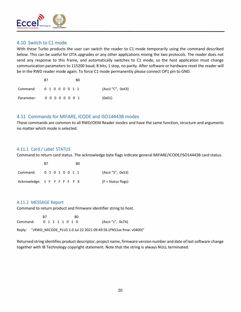
4.10 Switch to C1 mode With these Turbo products the user can switch the reader to C1 mode temporarily using the command described
below. This can be useful for OTA upgrades or any other applications mixing the two protocols. The reader does not
send any response to this frame, and automatically switches to C1 mode, so the host application must change
communication parameters to 115200 baud, 8 bits, 1 stop, no parity. After software or hardware reset the reader will
be in the RWD reader mode again. To force C1 mode permanently please connect OP1 pin to GND.
B7 B0
Command: 0 1 0 0 0 0 1 1 (Ascii “C”, 0x43)
Parameter: 0 0 0 0 0 0 0 1 (0x01)
4.11 Commands for MIFARE, ICODE and ISO14443B modes These commands are common to all RWD/OEM Reader modes and have the same function, structure and arguments
no matter which mode is selected.
4.11.1 Card / Label STATUS Command to return card status. The acknowledge byte flags indicate general MIFARE/ICODE/ISO14443B card status.
B7 B0
Command: 0 1 0 1 0 0 1 1 (Ascii “S”, 0x53)
Acknowledge: 1 F F F F F F X (F = Status flags)
4.11.2 MESSAGE Report Command to return product and firmware identifier string to host.
B7 B0
Command: 0 1 1 1 1 0 1 0 (Ascii “z”, 0x7A)
Reply: “zRWD_MICODE_PLUS 1.0 Jul 22 2021 09:49:56 (PN51xx fmw: v0400)”
Returned string identifies product descriptor, project name, firmware version number and date of last software change
together with IB Technology copyright statement. Note that the string is always NULL terminated.

21
4.11.3 Program EEPROM
The Micro RWD has internal EEPROM for storing system parameters such as polling rate and authorised identity codes
(serial numbers). This command sequence allows individual bytes of the EEPROM to be programmed with new data.
The data is internally read back after programming to verify successful operation.
B7 B0
Command: 0 1 0 1 0 0 0 0 (Ascii “P”, 0x50) Argument1: N N N N N N N N (N = EEPROM memory location 0 - 255) Argument2: D D D D D D D D
(D = data to write to EEPROM)
Acknowledge: 1 X X X F X X F (F = Status flags)
4.11.4 Internal EEPROM memory map
Polling delay parameter values (EEPROM location 0):
Polling delay can be set from 0 to 8 seconds to give complete control over current consumption and battery life. Note
that setting Polling delay = 0x00 skips the SLEEP and power-down operation so polling is as fast as possible (and
current consumption is highest).
Byte 0: Polling Delay (SLEEP / Power down) period (default = 0x60 = approx 260 milliseconds)
Parameter 0 value Polling Delay
SLEEP Period
0x00 0 mS
0x10 8 mS
0x20 16 mS
0x30 32 mS
0x40 65 mS
0x50 132 mS
0x60 262 mS
0x70 524 mS
0x80 1 second
0x90 2 seconds
0xA0 4 seconds
0xB0 8 seconds
22
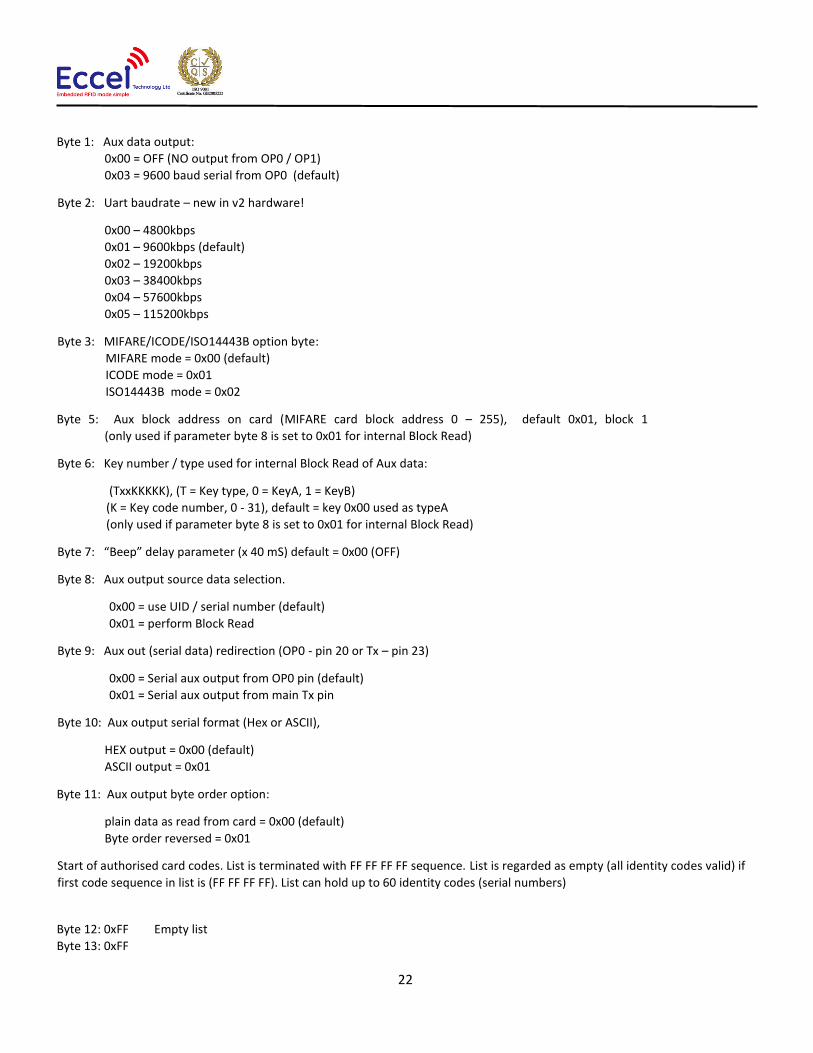
Byte 1: Aux data output:
0x00 = OFF (NO output from OP0 / OP1)
0x03 = 9600 baud serial from OP0 (default)
Byte 2: Uart baudrate – new in v2 hardware!
0x00 – 4800kbps
0x01 – 9600kbps (default)
0x02 – 19200kbps
0x03 – 38400kbps
0x04 – 57600kbps
0x05 – 115200kbps
Byte 3: MIFARE/ICODE/ISO14443B option byte:
MIFARE mode = 0x00 (default)
ICODE mode = 0x01
ISO14443B mode = 0x02
Byte 5: Aux block address on card (MIFARE card block address 0 – 255), default 0x01, block 1
(only used if parameter byte 8 is set to 0x01 for internal Block Read)
Byte 6: Key number / type used for internal Block Read of Aux data:
(TxxKKKKK), (T = Key type, 0 = KeyA, 1 = KeyB)
(K = Key code number, 0 - 31), default = key 0x00 used as typeA
(only used if parameter byte 8 is set to 0x01 for internal Block Read)
Byte 7: “Beep” delay parameter (x 40 mS) default = 0x00 (OFF)
Byte 8: Aux output source data selection.
0x00 = use UID / serial number (default)
0x01 = perform Block Read
Byte 9: Aux out (serial data) redirection (OP0 - pin 20 or Tx – pin 23)
0x00 = Serial aux output from OP0 pin (default) 0x01 = Serial aux output from main Tx pin
Byte 10: Aux output serial format (Hex or ASCII),
HEX output = 0x00 (default)
ASCII output = 0x01
Byte 11: Aux output byte order option:
plain data as read from card = 0x00 (default)
Byte order reversed = 0x01
Start of authorised card codes. List is terminated with FF FF FF FF sequence. List is regarded as empty (all identity codes valid) if
first code sequence in list is (FF FF FF FF). List can hold up to 60 identity codes (serial numbers)
Byte 12: 0xFF Empty list
Byte 13: 0xFF

23
Byte 14: 0xFF
Byte 15: 0xFF
Byte 16: (MSB) Tag identity code
Byte 17:
Byte 18:
Byte 19: (LSB)
…
Byte 255: Last Internal EEPROM location
Note that the polling delay parameter must be a valid value (as shown in the table above), other values will
give undefined results.
Factory Default RWD EEPROM parameter settings:
Byte 0: 0x60, 260mS Polling delay / SLEEP period Byte 1: 0x03, Aux data output as 9600 baud serial on OP0 Byte 2: 0x01, Protocol baud, default 9600kbps Byte 3: 0x00 MIFARE mode Byte 4: 0x00 Byte 5: 0x01 Aux block address on card (only used if Byte 8 = 0x01) Byte 6: 0x00 Key number / type used for internal Block Read of Aux data (Use Key Code 0 as Key Type A, only used if Byte 8 = 0x01) Byte 7: 0x00 “Beep” output delay OFF Byte 8: 0x00 Aux output source data is UID (serial number). Byte 9: 0x00 Aux output (serial data) directed to OP0 pin. Byte 10: 0x00 Aux output serial format, HEX byte format Byte 11: 0x00 Aux data byte order, plain as read from card
4.11.5 Factory Reset
Command to restore Factory default EEPROM values and Stored Keys and perform hardware Reset operation. The 0x55 0xAA parameters protect against accidental operation. After Reset, the Red LED will flash 5 times indicating the successful loading of the Factory default values.
B7 B0
Command: 0 1 0 0 0 1 1 0 (Ascii “F”, 0x46) Argument1: 0 1 0 1 0 1 0 1 0x55 Argument1: 1 0 1 0 1 0 1 0 0xAA
Reset occurs after the command is processed so there is no Acknowledge byte reply.

24
4.11.6 Command Protocol (MIFARE Mode)
The following commands are supported in MIFARE mode. The corresponding acknowledge code should be read back
by the host and decoded to confirm that the command was received and handled correctly. The serial bit protocol is
9600 baud, 8 bits, 1 stop, no parity (lsb transmitted first).
The status flags returned in the Acknowledge byte are as follows:
b7 b6 b5 b4 b3 b2 b1 b0
1 1 1 1 1 1 1 1
| | | | | | EEPROM error (Internal EEPROM write error)
| | | | | Card OK (Card serial number matched to identity code list)
| | | | Rx OK (Card communication and acknowledgement OK)
| | | RS232 error (Host serial communication error)
| | MF type (0 = MF 1k byte card, 1 = MF 4k byte card)
| UL type (0 = MF standard 1k/4k card, SINGLE UID), 1 = MF Ultralight card, DOUBLE UID)
MFRC error (Internal or antenna fault)
Note that bit 7 is fixed so that using a MIFARE 1k card, the RWD acknowledge response to a valid host command
would generally be 86 (Hex), indicating that a matched (or authorised) MF 1k card is present. The MF Ultralight card
has a different memory structure to the standard 1k/4k MF cards so bits 4 and 5 have to be checked to determine
which card type is present. Note also that only the relevant flags are set after each command as indicated in the
following specification.
4.11.7 Store Keys
The Micro RWD has additional internal storage for 32 Security KEYs. Six byte Key codes are required to access individual
card sectors for any Read or Write operations. This command sequence allows 6 byte Key codes to be stored at any
one of the 32 key code locations. Factory defaults are Infineon/Philips specified transport key pairs (Hex FF FF FF FF FF
FF / Hex FF FF FF FF FF FF) and (Hex A0 A1 A2 A3 A4 A5 / Hex B0 B1 B2 B3 B4 B5) and these are stored in the RWD non-
volatile memory during manufacture. Note that due to the fundamental nature of these Key codes, incorrect values
may render the system inoperable. Only one or two Security key codes are required to unlock a card sector so the
provision of 32 storage locations allows for many possible applications and card uses.
IT IS STRONGLY ADVISED THAT THE KEY CODES IN THE RWD AND STORED ON THE MIFARE CARD ARE NOT CHANGED
UNTIL THE OPERATION OF THE MIFARE CARD SECURITY IS FULLY UNDERSTOOD.
B7 B0
Command: 0 1 0 0 1 0 1 1 (Ascii “K”, 0x4B) Argument1: x x x K K K K K (K = Key code number, 0 - 31)
Argument2: D D D D D D D D Argument3: D D D D D D D D Argument4: D D D D D D D D Argument5: D D D D D D D D
(D = data to write to EEPROM, LS byte)

25
Argument6: D D D D D D D D
Argument7: D D D D D D D D (D = data to write to EEPROM, MS byte)
Acknowledge: 1 X X X F X X F (F = Status flags)
4.11.8 Internal Key Storage memory map (default settings)
Location 0 (0x00): Key code 0 (Default 0xFF FF FF FF FF FF) Location 1 (0x01):
Key code 1 (Default 0xFF FF FF FF FF FF)
Location 2 (0x02): Key code 2 (Default 0xA0 A1 A2 A3 A4 A5) Location 3 (0x03): - - -
Key code 3 (Default 0xB0 B1 B2 B3 B4 B5)
Location 28 (0x1C): Key code 28 (Default 0xFF FF FF FF FF FF) Location 29 (0x1D):
Key code 29 (Default 0xFF FF FF FF FF FF)
Location 30 (0x1E): Key code 30 (Default 0xA0 A1 A2 A3 A4 A5) Location 31 (0x1F): Key code 31 (Default 0xB0 B1 B2 B3 B4 B5)
Note that MIFARE cards manufactured by Infineon and other companies under licence can have default transport key
codes of (0xFF FF FF FF FF FF) and Philips/NXP cards have (0xA0 A1 A2 A3 A4 A5 / 0xB0 B1 B2 B3 B4 B5) default
transport keys. The MicroRWD MF has both pairs stored as factory settings to allow ease of use when the system is
first used. (More information on the MIFARE card memory maps and KeyA, KeyB Security Keys can be found at the
end of this document).
4.11.9 Write Card Block
Command to write 16 bytes of data to specified MIFARE block. A Block is made up of 16 bytes and there are four
blocks in each card sector (sixteen blocks per sector in upper half of MIFARE 4k card). Note that blocks 3, 7, 11, 15 etc
are sector trailer blocks that contain Security Key data and Access bits. Writing incorrect information to these blocks
can permanently disable the sector concerned. The first argument is the block number to write data to, the second
argument specifies which key code (0 - 31 from the internal storage area) to use for sector authentication/unlocking
and if the Security Key is to be used as a KeyA or KeyB type code. If the write was unsuccessful (invalid card,
authentication failed or card out of field) then Status flags in acknowledge byte indicate error.
B7 B0
Command: 0 1 0 1 0 1 1 1 (Ascii “W”, 0x57)
Argument1: N N N N N N N N (N = MF Card Block Address 0 – 255)

26
Argument2: T x x K K K K K (T = Key Type, 0 = KeyA, 1= KeyB)
(K = Key code number, 0 – 31)
Argument3: D D D D D D D D (D = LS Byte of data to write to card)
Argument4: D D D D D D D D
Argument5: D D D D D D D D
Argument6: D D D D D D D D
16 Bytes of data
Argument15: D D D D D D D D
Argument16: D D D D D D D D
Argument17: D D D D D D D D
Argument18: D D D D D D D D (D = MS Byte of data to write to card)
Acknowledge: 1 F F F F F F X (F = Status flags)
Note that MIFARE Ultralight cards DO NOT USE Security Keys or CRYPTO Authentication and the memory is organised
differently as groups of 4 bytes (Pages). Only one Page of 4 bytes can be written at a time so to maintain compatibility
and a simple RWD host command set, the same command as above is used to write data to Ultralight cards. The
command and arguments have the same structure but different meanings. The “Block” address is treated as a “Page
Address” and the KeyType/Key number parameter is a dummy 0x00 byte. In addition the 4 bytes of data are padded
out to 16 bytes with dummy 0x00 bytes.
B7 B0
Command: 0 1 0 1 0 1 1 1 (Ascii “W”, 0x57)
Argument1: x x x x N N N N (N = UL Card Page Address 0 – 15)
Argument2: 0 0 0 0 0 0 0 0 (Dummy byte, 0x00)
Argument3: D D D D D D D D (D = LS Byte of data to write to UL card)
Argument4: D D D D D D D D
Argument5: D D D D D D D D
Argument6: D D D D D D D D (D = MS Byte of data to write to UL card)
Argument7 – Argument18
0 0 0 0 0 0 0 0 12 Dummy padding bytes, 0x00
Acknowledge: 1 F F F F F F X (F = Status flags)
4.11.10 Read Card Block
Command to read 16 bytes of data from specified MIFARE block. The first argument is the block number to read data
from, the second argument specifies which key code (0 - 31 from the internal storage area) to use for sector
authentication/unlocking and if the Security Key is to be used as a KeyA or KeyB type code. If the read was successful,
indicated by acknowledge status flags then sixteen bytes of block data follow.
B7 B0
Command: 0 1 0 1 0 0 1 0 (Ascii “R”, 0x52)
Argument1: N N N N N N N N (N = MF Card Block Address 0 – 255)
Argument2: T x x K K K K K (T = Key Type, 0 = KeyA, 1= KeyB)

27
(K = Key code number, 0 – 31)
Acknowledge: 1 F F F F F F X (F = Status flags)
Data only follows if Read was successful
Reply1: D D D D D D D D (D = LS Byte of data Read from card)
Reply2: D D D D D D D D
Reply3: D D D D D D D D
Reply4: D D D D D D D D
16 Bytes of data
Reply13: D D D D D D D D
Reply14: D D D D D D D D
Reply15: D D D D D D D D
Reply16: D D D D D D D D (D = MS Byte of data Read from card)
Note that as mentioned for the WRITE command, MIFARE Ultralight cards DO NOT USE Security Keys or Authentication
and the memory is organised differently as groups of 4 bytes (Pages).
However, unlike the Write command, 16 bytes (4 pages) can be read in a single operation The same Read command
as above is used except the “Block” address is treated as a “Page Address” and the KeyType/Key number parameter is
a dummy 0x00 byte. For page numbers greater than 12, the card data wraps around to page 0 etc.
B7 B0
Command: 0 1 0 1 0 0 1 0 (Ascii “R”, 0x52)
Argument1: x x x x N N N N (N = UL Card Page Address 0 – 15)
Argument2: 0 0 0 0 0 0 0 0 (Dummy byte, 0x00)
Acknowledge: 1 F F F F F F X (F = Status flags)
Data only follows if Read was successful
Reply1: D D D D D D D D (D = LS Byte of data Read from UL card)
Reply2: D D D D D D D D
Reply3: D D D D D D D D
Reply4: D D D D D D D D
16 Bytes of data
Reply13: D D D D D D D D
Reply14: D D D D D D D D
Reply15: D D D D D D D D
Reply16: D D D D D D D D (D = MS Byte of data Read from UL card)
4.11.11 Inc Value (only operates on Value Data Structure)
Command to increment integer within a Value Data Structure. The command loads the value from the specified block
address, adds the integer parameter and stores the result at the same or another block address. Note that the source
block must have been formatted as a Value Block beforehand according to the data structure below, using the WRITE

28
command. The INC Value command only operates on a "Value Block Structure" and will fail if the block configuration
or the specified key type is incorrect.
Value Block Structure
Example format for value = 100 decimal (0x64), at block address 0.
(Value data stored LS byte first, ADR = block address, ADR = inverted block address)
0x64 00 00 00 9B FF FF FF 64 00 00 00 00 FF 00 FF Byte: 0 1 2 3 4 5 6 7 8 9 10 11 12 13 14 15
The first argument is the source block address to load data from, the second argument specifies which key code
and type to use for sector authentication (0-31 and if it is KeyA or KeyB type). The third argument specifies the
destination block address where the incremented data is stored. Note that source and destination blocks must
be within same authenticated sector. The four byte positive integer to add follows (least significant byte first).
B7 B0
Command: 0 1 0 0 1 0 0 1 (Ascii “I”, 0x49)
Argument1: N N N N N N N N (N = MF source block address 0 – 255)
Argument2: T x x K K K K K (T = Key Type, 0 = KeyA, 1= KeyB)
(K = Key code number, 0 – 31)
Argument3: N N N N N N N N (N = MF destination block address 0 – 255)
Argument4: D D D D D D D D (D = LS byte of integer to add)
Argument5: D D D D D D D D
Argument6: D D D D D D D D
Argument7: D D D D D D D D (D = MS byte of integer to add)
Acknowledge: 1 F F F F F F X (F = Status flags)
4.11.12 Dec Value (only operates on Value Data Structure)
Command to decrement integer within a Value Data Structure. The DEC Value command operates as the INC command
except the integer parameter is subtracted from the loaded value. The first argument is the source block address to
load data from, the second argument specifies which key code and type to use for sector authentication (0-31 and if
it is KeyA or KeyB type). The third argument specifies the destination block address where the decremented data is
stored. Note that source and destination blocks must be within same authenticated sector. The four byte positive
integer to subtract follows (least significant byte first).
Value Inverted Value Value ADR ADR
ADR ADR
4 byte integer

29
B7 B0
Command: 0 1 0 0 0 1 0 0 (Ascii “D”, 0x44)
Argument1: N N N N N N N N (N = MF source block address 0 – 255)
Argument2: T x x K K K K K (T = Key Type, 0 = KeyA, 1= KeyB)
(K = Key code number, 0 – 31)
Argument3: N N N N N N N N (N = MF destination block address 0 – 255)
Argument4: D D D D D D D D (D = LS byte of integer to subtract)
Argument5: D D D D D D D D
Argument6: D D D D D D D D
Argument7: D D D D D D D D (D = MS byte of integer to subtract)
Acknowledge: 1 F F F F F F X (F = Status flags)
4.11.13 Transfer Value (only operates on Value Data Structure)
Command to transfer (copy) Value Data Structure. The command loads the value from the specified block address and
then stores the result at the same or another block address. As with INC and DEC commands the source block must
have been formatted as a Value Block beforehand and the block addresses must be within same authenticated sector.
The first argument is the source block address to load data from, the second argument specifies which key code to use
for sector authentication (0-31) and if it is a KeyA or KeyB code. The third argument specifies where the data is stored.
B7 B0
Command: 0 1 0 1 0 1 0 0 (Ascii “T”, 0x54)
Argument1: N N N N N N N N (N = MF source block address 0 – 255)
Argument2: T x x K K K K K (T = Key Type, 0 = KeyA, 1= KeyB)
(K = Key code number, 0 – 31)
Argument3: N N N N N N N N (N = MF destination block address 0 – 255)
Acknowledge: 1 F F F F F F X (F = Status flags)
If the Inc, Dec or Transfer function was unsuccessful (invalid card, card out of field, authentication failed or data
structures are incorrect) then Status flags in acknowledge byte indicate error. Note that the value manipulation
commands operate internally on the MIFARE card and no data is transferred back to the MicroRWD. Note also that
Ultralight cards do not support Value Data Structures or the Inc, Dec, Transfer commands.
4.11.14 Card UID
Command to return card status and UID (Unique Identifier or Serial number).
The acknowledge byte flags indicate general MIFARE card status.
4 byte integer
30
B7 B0
Command: 0 1 0 1 0 1 0 1 (Ascii “U”, 0x55)
Acknowledge: 1 F F F F F F X (F = Status flags)
Data only follows if card was selected OK with no errors detected.
Reply1: D D D D D D D D (D = LS Byte of UID/Serial number from card)
Reply2: D D D D D D D D
Reply3: D D D D D D D D
Reply4: D D D D D D D D
Reply5: D D D D D D D D
Reply6: D D D D D D D D Dummy bytes (0x00) for MIFARE 1k/4k card types
Reply7: D D D D D D D D
Note that MIFARE 1k and 4k cards have a four-byte serial number but MIFARE Ultralight cards have a seven
byte serial number. To accommodate all card types, the Card UID command returns a seven-byte field with
the last three bytes padded out with 0x00 dummy bytes in the case of MIFARE 1k/4k cards.
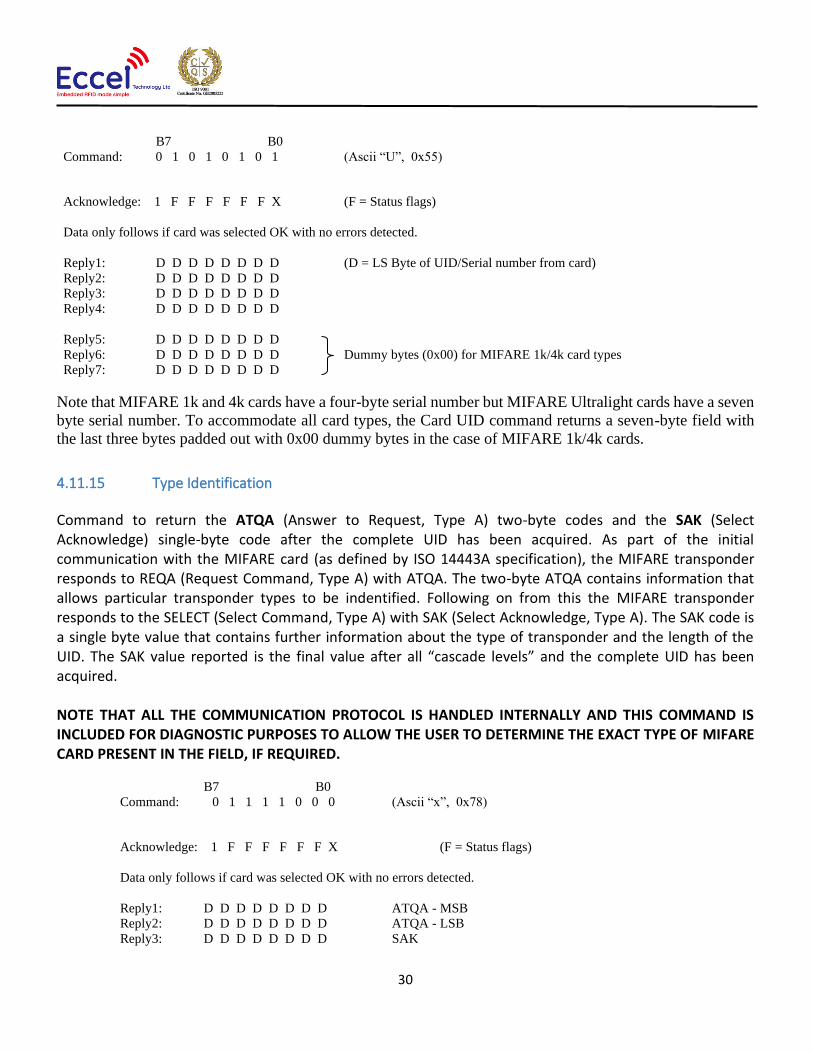
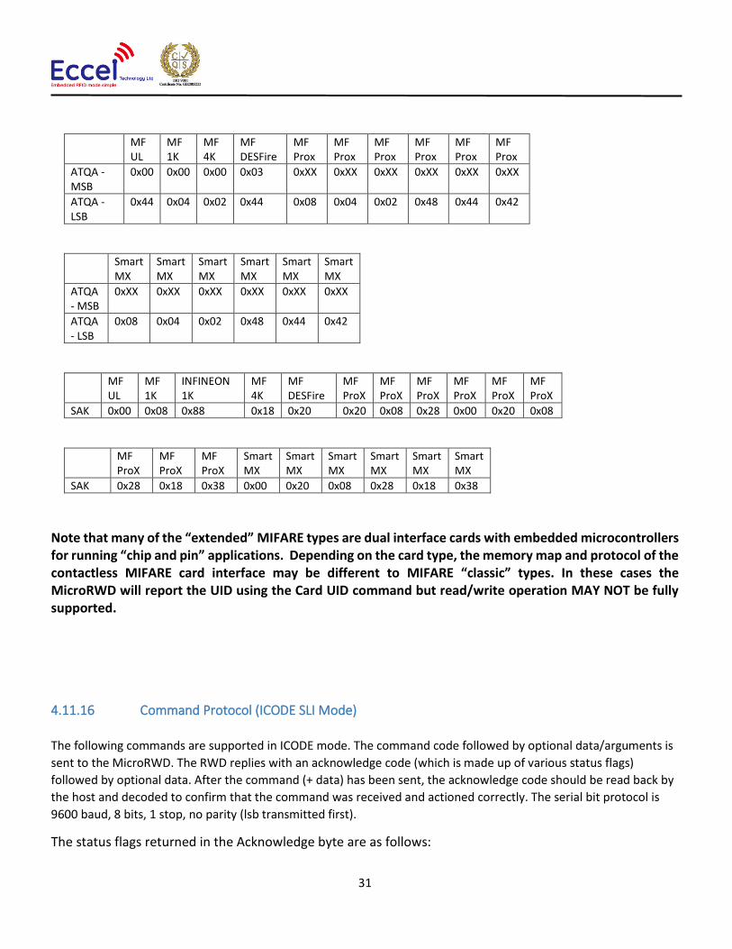
4.11.15 Type Identification
Command to return the ATQA (Answer to Request, Type A) two-byte codes and the SAK (Select Acknowledge) single-byte code after the complete UID has been acquired. As part of the initial communication with the MIFARE card (as defined by ISO 14443A specification), the MIFARE transponder responds to REQA (Request Command, Type A) with ATQA. The two-byte ATQA contains information that allows particular transponder types to be indentified. Following on from this the MIFARE transponder responds to the SELECT (Select Command, Type A) with SAK (Select Acknowledge, Type A). The SAK code is a single byte value that contains further information about the type of transponder and the length of the UID. The SAK value reported is the final value after all “cascade levels” and the complete UID has been acquired. NOTE THAT ALL THE COMMUNICATION PROTOCOL IS HANDLED INTERNALLY AND THIS COMMAND IS INCLUDED FOR DIAGNOSTIC PURPOSES TO ALLOW THE USER TO DETERMINE THE EXACT TYPE OF MIFARE CARD PRESENT IN THE FIELD, IF REQUIRED.
B7 B0
Command: 0 1 1 1 1 0 0 0 (Ascii “x”, 0x78)
Acknowledge: 1 F F F F F F X (F = Status flags)
Data only follows if card was selected OK with no errors detected.
Reply1: D D D D D D D D ATQA - MSB
Reply2: D D D D D D D D ATQA - LSB
Reply3: D D D D D D D D SAK
31
MF UL
MF 1K
MF 4K
MF DESFire
MF Prox
MF Prox
MF Prox
MF Prox
MF Prox
MF Prox
ATQA - MSB
0x00 0x00 0x00 0x03 0xXX 0xXX 0xXX 0xXX 0xXX 0xXX
ATQA - LSB
0x44 0x04 0x02 0x44 0x08 0x04 0x02 0x48 0x44 0x42
Smart MX
Smart MX
Smart MX
Smart MX
Smart MX
Smart MX
ATQA - MSB
0xXX 0xXX 0xXX 0xXX 0xXX 0xXX
ATQA - LSB
0x08 0x04 0x02 0x48 0x44 0x42
MF UL
MF 1K
INFINEON 1K
MF 4K
MF DESFire
MF ProX
MF ProX
MF ProX
MF ProX
MF ProX
MF ProX
SAK 0x00 0x08 0x88 0x18 0x20 0x20 0x08 0x28 0x00 0x20 0x08
MF ProX
MF ProX
MF ProX
Smart MX
Smart MX
Smart MX
Smart MX
Smart MX
Smart MX
SAK 0x28 0x18 0x38 0x00 0x20 0x08 0x28 0x18 0x38
Note that many of the “extended” MIFARE types are dual interface cards with embedded microcontrollers for running “chip and pin” applications. Depending on the card type, the memory map and protocol of the contactless MIFARE card interface may be different to MIFARE “classic” types. In these cases the MicroRWD will report the UID using the Card UID command but read/write operation MAY NOT be fully supported.
4.11.16 Command Protocol (ICODE SLI Mode)
The following commands are supported in ICODE mode. The command code followed by optional data/arguments is
sent to the MicroRWD. The RWD replies with an acknowledge code (which is made up of various status flags)
followed by optional data. After the command (+ data) has been sent, the acknowledge code should be read back by
the host and decoded to confirm that the command was received and actioned correctly. The serial bit protocol is
9600 baud, 8 bits, 1 stop, no parity (lsb transmitted first).
The status flags returned in the Acknowledge byte are as follows:

32
b7 b6 b5 b4 b3 b2 b1 b0
1 1 0 0 1 1 1 1
| | | | EEPROM error (Internal EEPROM write error)
| | | Card OK (Label serial number matched to identity code list)
| | Rx OK (Label communication and acknowledgement OK)
| RS232 error (Host serial communication error)
MFRC error (Internal or antenna fault)
Note that bit 7 is fixed so that the RWD acknowledge response to a valid host command would generally be 86 (Hex),
indicating that a matched (or authorised) ICODE tag is present.
4.11.17 Write Label Block
Command to write 4 bytes of data to specified ICODE transponder block. The first argument is the block number to
write data to (0 - 27), the next eight arguments specify the UID (Unique Identifier or serial number) of the tag to select
(sent least significant byte first). If the write was unsuccessful (invalid card, authentication failed or tag out of field)
then Status flags in acknowledge byte indicate error.
B7 B0
Command: 0 1 0 1 0 1 1 1 (Ascii “W”, 0x57)
Argument1: x x x N N N N N (N = ICODE block address, 0 – 27)
Argument2: U U U U U U U U (LSB, UID0)
Argument3: U U U U U U U U (UID1)
Argument4: U U U U U U U U (UID2)
Argument5: U U U U U U U U (UID3)
Argument6: U U U U U U U U (UID4)
Argument7: U U U U U U U U (UID5)
Argument8: U U U U U U U U (UID6)
Argument9: U U U U U U U U (MSB, UID7)
Argument10: D D D D D D D D (D = LS Byte of data to write to tag)
Argument11: D D D D D D D D
Argument12: D D D D D D D D
Argument13: D D D D D D D D (D = MS Byte of data to write to tag)
Acknowledge: 1 F F F F F F X (F = Status flags)
4.11.18 Read Label Block
Command to read 4 bytes of data from specified ICODE transponder block. The first argument is the block number to
read data from (0 - 27), the next eight arguments specify the UID (Unique Identifier or serial number) of the tag to
select (sent least significant byte first). If the write was unsuccessful (invalid card, authentication failed or tag out of
field) then Status flags in acknowledge byte indicate error.

33
B7 B0
Command: 0 1 0 1 0 0 1 0 (Ascii “R”, 0x52)
Argument1: x x x N N N N N (N = ICODE block address, 0 – 27)
Argument2: U U U U U U U U (LSB, UID0)
Argument3: U U U U U U U U (UID1)
Argument4: U U U U U U U U (UID2)
Argument5: U U U U U U U U (UID3)
Argument6: U U U U U U U U (UID4)
Argument7: U U U U U U U U (UID5)
Argument8: U U U U U U U U (UID6)
Argument9: U U U U U U U U (MSB, UID7)
Acknowledge: 1 F F F F F F X (F = Status flags)
Data only follows if Read was successful
Reply1: D D D D D D D D (D = LS Byte of data Read from ICODE tag)
Reply2: D D D D D D D D
Reply3: D D D D D D D D
Reply4: D D D D D D D D (D = MS Byte of data Read from ICODE tag)
4.11.19 Label UID
Command to return label status and UID (Unique Identifier or "serial number") of single (dominant) label. The
acknowledge byte flags indicate general Tag status. NOTE that if multiple labels are expected in the RF field then
LABEL INVENTORY command must be used to acquire full UID list.
B7 B0
Command: 0 1 0 1 0 1 0 1 (Ascii “U”, 0x55)
Acknowledge: 1 F F F F F F X (F = Status flags)
Data only follows if label responded OK and UID is available.
Reply1: U U U U U U U U (LSB, UID0)
Reply2: U U U U U U U U (UID1)
Reply3: U U U U U U U U (UID2)
Reply4: U U U U U U U U (UID3)
Reply5: U U U U U U U U (UID4)
Reply6: U U U U U U U U (UID5)
Reply7: U U U U U U U U (UID6)
Reply8: U U U U U U U U (MSB, UID7)

34
4.11.20 Command Protocol (ISO14443B Mode)
The following commands are supported in ISO14443B mode. The command code followed by optional
data/arguments is sent to the MicroRWD. The RWD replies with an acknowledge code (which is made up of various
status flags) followed by optional data. After the command (+ data) has been sent, the acknowledge code should be
read back by the host and decoded to confirm that the command was received and actioned correctly. The serial bit
protocol is 9600 baud 8 bits, 1 stop, no parity (lsb transmitted first).
The status flags returned in the Acknowledge byte are as follows:
b7 b6 b5 b4 b3 b2 b1 b0
1 1 0 0 1 1 1 1
| | | | EEPROM error (Internal EEPROM write error)
| | | Card OK (Card serial number matched to identity code list)
| | Rx OK (Card communication and acknowledgement OK)
| RS232 error (Host serial communication error)
MFRC error (Internal or antenna fault)
Note that bit 7 is fixed so that the RWD acknowledge response to a valid host command would generally be 86 (Hex),
indicating that a matched (or authorised) ISO14443B card is present.
4.11.21 Card UID
Command to return Card status and UID (Unique Identifier or "serial number") of the single (dominant) card. The
acknowledge byte flags indicate general Tag status. Multiple ISO14443B cards in the field will cause a data collision
and the RWD will return 0x80 status/acknowledge byte indicating NO card present.
B7 B0
Command: 0 1 0 1 0 1 0 1 (Ascii “U”, 0x55)
Acknowledge: 1 F F F F F F X (F = Status flags)
Data only follows if card responded OK and UID is available.
Reply1: U U U U U U U U (LSB, UID0)
Reply2: U U U U U U U U (UID1)
Reply3: U U U U U U U U (UID2)
Reply4: U U U U U U U U (MSB, UID3)

35
4.11.22 Notes for Commands (MIFARE, ICODE, ISO14443B)
NOTE also that for the “Read Card Block” or “Card UID” command, if an error flag has been set in the Acknowledge
code then there will be NO following data.
NOTE that the serial communication uses hardware handshaking to inhibit the host from sending the Micro RWD
commands while Card interrogation is in progress. The serial communication system and protocol allows for a 10ms
‘window’ every Card polling cycle indicated by the BUSY(CTS) line being low. During this ‘window’ the host must assert
the first start bit and start transmitting data. The BUSY goes high again 10ms after the last stop bit is received. The
host must therefore send the command and all the arguments with no gaps otherwise timeout will occur and BUSY
goes high. NOTE that only one command sequence is handled at a time.
4.12 Method of Operation The system works on a polling principle whereby the RF field is turned on for a short period to check if a card is present.
Authentication and Read/Write operations can then be performed before the RF field is turned off again and the
process repeats. A programmable polling delay period occurs after the RF is turned off and the microcontroller and RF
circuitry is put into sleep and power-down modes during this time to achieve low average power consumption.
When a card is detected in the field a multi-pass handshaking procedure takes place where card information and serial
number data is exchanged and checked for integrity. Once this procedure has completed successfully an individual
card can be selected and is available for other operations.
The RWD itself has the additional feature of then checking the four byte MIFARE/ISO14443B UID/serial number (or
least significant four bytes of Ultralight/ICODE UID) against an internal authorisation list. The RWD internal EEPROM
contains a list of four byte Identity codes (up to 60 of them) located from byte 12 onwards. If the list has FF FF FF FF
(hex) stored at the first location (EEPROM bytes 12 - 15) then the list is treated as empty so the Identity code check is
skipped.
Otherwise the card serial number is checked against all the entries in the list (until the FF FF FF FF termination code is
reached) and if matched then the RWD allows the card to be accessed for other operations. If not the Red LED remains
on and the card is blocked for further access. This is an additional level of security that can be used as a “mini access
control” system for simple applications that only involve the serial number or where the Security Keys are not known.
For MIFARE cards, once the RWD has selected the card and has matched the serial number against it’s internal list (or
the list is empty) then the Read/Write (or Inc/Dec/Transfer) operations can be performed. These require an internal
high-security Authentication Crypto algorithm to take place that use the supplied Security Keys to gain access to a
particular sector. If the Key selected does not match the Key stored in the MIFARE card sector then the operation fails
and the Red LED is turned on again
So in summary, a card can be successfully selected but can be blocked by the RWD authorisation list and fail Read/Write operations because the Keys are incorrect. Even if the Security Key is incorrect the Serial number can still be read using the “Card UID” command. For ICODE operation, when a label is in the RF field a handshaking procedure occurs and the RWD acquires the labels UID (Unique Identifier/serial number). The least significant four bytes of the UID (UID0 - UID3) are used to check against the internal authorisation list. For subsequent read/write operations, the labels are individually selected by including

36
their UID in the command sequence. The principle of the RF field being ON only for label communication means that the label is effectively turned off and reselected each polling cycle. The assumption is therefore made that after the label UID has been acquired (using Label UID command), the label is still present for the next polling cycle.
4.13 Basic RWD Communication For basic operation of the MicroRWD connected to a host computer, the RWD can either be polled or communication
can be triggered by an interrupt signal (Green LED output). In either case for MIFARE operation, the host would
generally send the “STORE KEYS” command to load a custom security key into the RWD memory or simply use the pre-
loaded default key values.
For a polling technique, the host computer would then keep sending the “STATUS” or “CARD UID” command and would
monitor the acknowledgement code until a valid card was detected.
For the interrupt technique, the Green LED output can be used as an interrupt signal connected to the host computer.
The Green LED output is normally high and goes low only when a valid card has been detected. This falling-edge signal
can trigger a host interrupt to then send the “STATUS” or “CARD UID” command to determine the card type and serial
number.
In both cases once a valid card has been detected a “READ BLOCK” or “WRITE BLOCK” command can be sent and the
acknowledge code monitored to establish that the operation was successful.

37
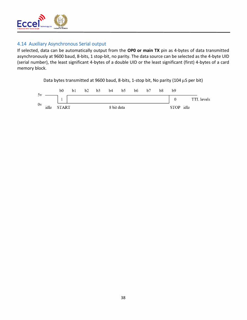
38
4.14 Auxiliary Asynchronous Serial output If selected, data can be automatically output from the OP0 or main TX pin as 4-bytes of data transmitted asynchronously at 9600 baud, 8-bits, 1 stop-bit, no parity. The data source can be selected as the 4-byte UID (serial number), the least significant 4-bytes of a double UID or the least significant (first) 4-bytes of a card memory block.
Data bytes transmitted at 9600 baud, 8-bits, 1-stop bit, No parity (104 S per bit)

39
5. C1 protocol compatibility mode
With these Turbo products the user can switch the reader to C1 mode which means the reader supports all of the RFID
commands supported by our C1 products using the same binary interface. To enable this mode. the user has two
options:
• Send frame using with two bytes [0x43 0x01]
• Connect OP1 pin to GND before power is connected to the power supply
To confirm this mode, the device keeps the green LED always on but red LED is off (opposite to RWD/OEM mode). In
C1 mode, the reader supports all of the tags supported by C1 devices like MIFARE® Classic® in 1K, 4K memory, ICODE,
MIFARE Ultralight®, MIFARE DESFire® EV1/EV2, MIFARE Plus® support. In this mode the device doesn’t have any built-
in polling like in the C1 devices. Instead, stand-alone polling mode is available in RWD/OEM mode.
The second biggest advantage of using this mode is OTA upgrade using the C1 client free application. The binary file
should be downloaded from our website manually.
5.1 Overview
This binary protocol was designed to be as simple as possible to implement on the host side whilst still providing robust
communication. Can be user over USB in USB version or RS232 connection. The communication parameters are always:
• Baud rate: 115200bps
• Data: 8 bit
• Parity: None
• Stop bits: 1 bit
• Flow Control: none
5.2 Frame structure
Communication with the module is symmetric so frames sent to and received from the module are coded in the same
way. All frames contain fields as described in the table below.
Frame STX Command body length + 2bytes
CRC
Command length XOR
Command body CRC16
1 byte 2-bytes 2-bytes 1-byte n-bytes 2-bytes
0xF5
Command body length, LSB,
maximum value 1024
XOR with 0xffff of command length bytes
Command Command
parameters Command body
CRC, LSB
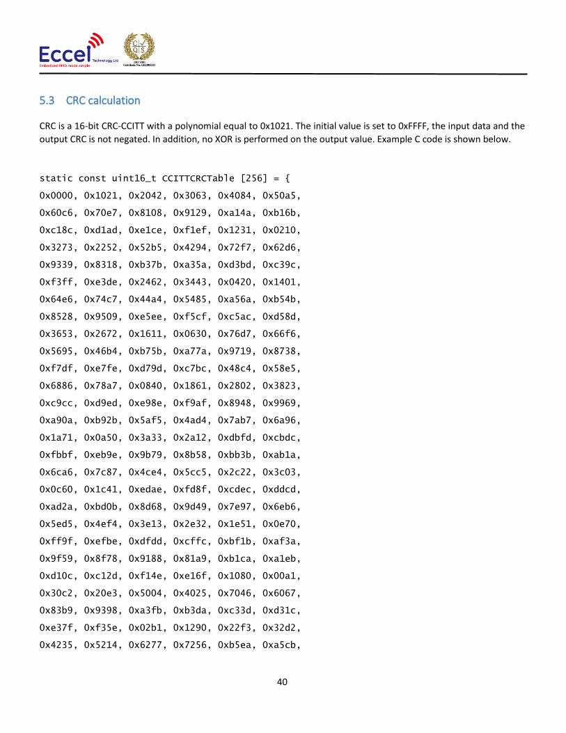
40
5.3 CRC calculation
CRC is a 16-bit CRC-CCITT with a polynomial equal to 0x1021. The initial value is set to 0xFFFF, the input data and the
output CRC is not negated. In addition, no XOR is performed on the output value. Example C code is shown below.
static const uint16_t CCITTCRCTable [256] = {
0x0000, 0x1021, 0x2042, 0x3063, 0x4084, 0x50a5,
0x60c6, 0x70e7, 0x8108, 0x9129, 0xa14a, 0xb16b,
0xc18c, 0xd1ad, 0xe1ce, 0xf1ef, 0x1231, 0x0210,
0x3273, 0x2252, 0x52b5, 0x4294, 0x72f7, 0x62d6,
0x9339, 0x8318, 0xb37b, 0xa35a, 0xd3bd, 0xc39c,
0xf3ff, 0xe3de, 0x2462, 0x3443, 0x0420, 0x1401,
0x64e6, 0x74c7, 0x44a4, 0x5485, 0xa56a, 0xb54b,
0x8528, 0x9509, 0xe5ee, 0xf5cf, 0xc5ac, 0xd58d,
0x3653, 0x2672, 0x1611, 0x0630, 0x76d7, 0x66f6,
0x5695, 0x46b4, 0xb75b, 0xa77a, 0x9719, 0x8738,
0xf7df, 0xe7fe, 0xd79d, 0xc7bc, 0x48c4, 0x58e5,
0x6886, 0x78a7, 0x0840, 0x1861, 0x2802, 0x3823,
0xc9cc, 0xd9ed, 0xe98e, 0xf9af, 0x8948, 0x9969,
0xa90a, 0xb92b, 0x5af5, 0x4ad4, 0x7ab7, 0x6a96,
0x1a71, 0x0a50, 0x3a33, 0x2a12, 0xdbfd, 0xcbdc,
0xfbbf, 0xeb9e, 0x9b79, 0x8b58, 0xbb3b, 0xab1a,
0x6ca6, 0x7c87, 0x4ce4, 0x5cc5, 0x2c22, 0x3c03,
0x0c60, 0x1c41, 0xedae, 0xfd8f, 0xcdec, 0xddcd,
0xad2a, 0xbd0b, 0x8d68, 0x9d49, 0x7e97, 0x6eb6,
0x5ed5, 0x4ef4, 0x3e13, 0x2e32, 0x1e51, 0x0e70,
0xff9f, 0xefbe, 0xdfdd, 0xcffc, 0xbf1b, 0xaf3a,
0x9f59, 0x8f78, 0x9188, 0x81a9, 0xb1ca, 0xa1eb,
0xd10c, 0xc12d, 0xf14e, 0xe16f, 0x1080, 0x00a1,
0x30c2, 0x20e3, 0x5004, 0x4025, 0x7046, 0x6067,
0x83b9, 0x9398, 0xa3fb, 0xb3da, 0xc33d, 0xd31c,
0xe37f, 0xf35e, 0x02b1, 0x1290, 0x22f3, 0x32d2,
0x4235, 0x5214, 0x6277, 0x7256, 0xb5ea, 0xa5cb,

41
0x95a8, 0x8589, 0xf56e, 0xe54f, 0xd52c, 0xc50d,
0x34e2, 0x24c3, 0x14a0, 0x0481, 0x7466, 0x6447,
0x5424, 0x4405, 0xa7db, 0xb7fa, 0x8799, 0x97b8,
0xe75f, 0xf77e, 0xc71d, 0xd73c, 0x26d3, 0x36f2,
0x0691, 0x16b0, 0x6657, 0x7676, 0x4615, 0x5634,
0xd94c, 0xc96d, 0xf90e, 0xe92f, 0x99c8, 0x89e9,
0xb98a, 0xa9ab, 0x5844, 0x4865, 0x7806, 0x6827,
0x18c0, 0x08e1, 0x3882, 0x28a3, 0xcb7d, 0xdb5c,
0xeb3f, 0xfb1e, 0x8bf9, 0x9bd8, 0xabbb, 0xbb9a,
0x4a75, 0x5a54, 0x6a37, 0x7a16, 0x0af1, 0x1ad0,
0x2ab3, 0x3a92, 0xfd2e, 0xed0f, 0xdd6c, 0xcd4d,
0xbdaa, 0xad8b, 0x9de8, 0x8dc9, 0x7c26, 0x6c07,
0x5c64, 0x4c45, 0x3ca2, 0x2c83, 0x1ce0, 0x0cc1,
0xef1f, 0xff3e, 0xcf5d, 0xdf7c, 0xaf9b, 0xbfba,
0x8fd9, 0x9ff8, 0x6e17, 0x7e36, 0x4e55, 0x5e74,
0x2e93, 0x3eb2, 0x0ed1, 0x1ef0 };
static uint16_t GetCCITTCRC(const uint8_t* Data, uint32_t Size) {
uint16_t CRC;
uint16_t Temp;
uint32_t Index;
if (Size == 0) {
return 0;
}
CRC = 0xFFFF;
for (Index = 0; Index < Size; Index++){
Temp = (uint16_t)( (CRC >> 8) ^ Data[Index] ) & 0x00FF;
CRC = CCITTCRCTable[Temp] ^ (CRC << 8);
}
return CRC;
}
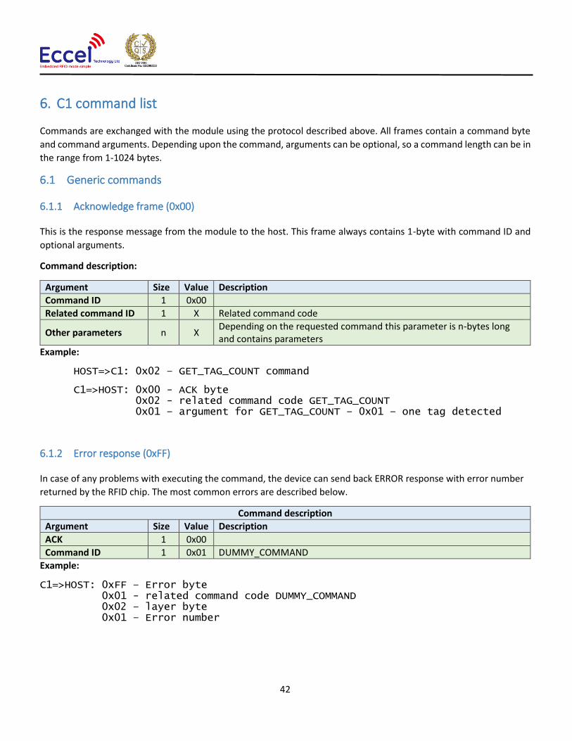
42
6. C1 command list
Commands are exchanged with the module using the protocol described above. All frames contain a command byte
and command arguments. Depending upon the command, arguments can be optional, so a command length can be in
the range from 1-1024 bytes.
6.1 Generic commands
6.1.1 Acknowledge frame (0x00)
This is the response message from the module to the host. This frame always contains 1-byte with command ID and
optional arguments.
Command description:
Argument Size Value Description
Command ID 1 0x00
Related command ID 1 X Related command code
Other parameters n X Depending on the requested command this parameter is n-bytes long and contains parameters
Example:
HOST=>C1: 0x02 – GET_TAG_COUNT command
C1=>HOST: 0x00 - ACK byte 0x02 - related command code GET_TAG_COUNT 0x01 – argument for GET_TAG_COUNT – 0x01 – one tag detected
6.1.2 Error response (0xFF)
In case of any problems with executing the command, the device can send back ERROR response with error number
returned by the RFID chip. The most common errors are described below.
Command description
Argument Size Value Description
ACK 1 0x00
Command ID 1 0x01 DUMMY_COMMAND
Example:
C1=>HOST: 0xFF – Error byte 0x01 - related command code DUMMY_COMMAND 0x02 – layer byte 0x01 – Error number

43
Here is a list with the most common errors:
MIFARE Desfire errors – layer byte 0x19
Error byte: 0x80 - MF DF Response - No changes done to backup files 0x81 - MF DF Response - Insufficient NV-Memory 0x82 - MF DF Invalid key number specified 0x83 - MF DF Current configuration/status does not allow the requested command 0x84 - MF DF Requested AID not found on PICC 0x85 - MF DF Attempt to read/write data from/to beyond the files/record's limits 0x86 - MF DF Previous cmd not fully completed. Not all frames were requested or provided by the PCD 0x87 - MF DF Num. of applns limited to 28. No additional applications possible 0x88 - MF DF File/Application with same number already exists 0x89 - MF DF Specified file number does not exist 0x8A - MF DF Crypto error returned by PICC 0x8B - MF DF Parameter value error returned by PICC 0x8C - MF DF DesFire Generic error. Check additional Info 0x8D - MF DF ISO 7816 Generic error. Check Additional Info
ICODE specific errors – layer byte 0x15 Error byte: 0x01 - The command is not supported, i.e. the request code is not recognized 0x02 - The command is not recognized, for example: a format error occurred 0x03 - The command option is not supported 0x0F - Error with no information given or a specific error code is not supported 0x10 - The specified block is not available (doesn't exist) 0x11 - The specified block is already locked and thus cannot be locked again 0x12 - The specified block is locked and its content cannot be changed 0x13 - The specified block was not successfully programmed 0x14 - The specified block was not successfully locked 0x15 - The specified block is protected 0x40 - Generic cryptographic error 0x81 - The command is not supported, i.e. the request code is not recognized 0x82 - The command is not recognized, for example: a format error occurred 0x83 - The command option is not supported 0x84 - Error with no information given or a specific error code is not supported 0x85 - The specified block is not available (doesn't exist) 0x86 - The specified block is already locked and thus cannot be locked again 0x87 - The specified block is locked and its content cannot be changed 0x88 - The specified block was not successfully programmed 0x89 - The specified block was not successfully locked 0x8A - The specified block is protected 0x8B - Generic cryptographic error

44
Other layers errors:
0x01 - No reply received, e.g. PICC removal 0x02 - Wrong CRC or parity detected 0x03 - A collision occurred 0x04 - Attempt to write beyond buffer size 0x05 - Invalid frame format 0x06 - Received response violates protocol 0x07 - Authentication error 0x08 - A Read or Write error occurred in RAM/ROM or Flash 0x09 - The RC sensors signal over heating 0x0A - Error due to RF. 0x0B - An error occurred in RC communication 0x0C - A length error occurred 0x0D - An resource error 0x0E - TX Rejected sanely by the counterpart 0x0F - RX request Rejected sanely by the counterpart 0x10 - Error due to External RF 0x11 - EMVCo EMD Noise Error 0x12 - Used when HAL ShutDown is called 0x7F - An internal error occurred 0xF0 – Protocol authorization error. This command is not allowed without protocol authorization (Command 0x12)
6.1.3 Dummy command (0x01)
This command takes no arguments. It is used to check that the module alive. The module replies to this command with
an ACK response and no optional parameters.
Command description
Argument Size Value Description
Command ID 1 0x01 DUMMY_COMMAND
Response description
ACK 1 0x00
Command ID 1 0x01 DUMMY_COMMAND
Example:
HOST=>C1: 0x01 –DUMMY_COMMAND
C1=>HOST: 0x00 - ACK byte 0x01 - related command code DUMMY_COMMAND
6.1.4 Get tag count (0x02)
The command send to the module to read how many TAGS are in range of the antenna no matter which technology
of tag, so it returns the total amount present of all supported tag types. The maximum number for this standard

45
discovery loop is 5. If you want to perform a full inventory command for ICODE tag types please refer to
ICODE_INVENTORY_xxx commands.
After this command, the module holds all UID’s and basic information about TAGs present in volatile memory and the
user can read it using the GET_TAG_UID command.
Command description
Argument Size Value Description
Command ID 1 0x02 GET_TAG_COUNT
Response description
ACK 1 0x00
Command ID 1 0x02 GET_TAG_COUNT
TAG count 1 X Maximum discovered tags is 5
Example:
HOST=>C1: 0x02 – GET_TAG_COUNT
C1=>HOST: 0x00 - ACK byte 0x02 - related command code GET_TAG_COUNT 0x01 – number of tags in range
6.1.5 Get tag UID (0x03)
This command should be executed after GET_TAG_COUNT frame to read information about the tag.
Command description
Argument Size Value Description
Command ID 1 0x03 GET_TAG_UID
TAG idx 1 X TAG index in module memory, must me less than number of tags reported by GET_TAG_COUNT command
Response description
ACK 1 0x00
Command ID 1 0x03 GET_TAG_UID
TAG type 1 X
0x01 - MIFARE Ultralight 0x02 - MIFARE Ultralight-C 0x03 - MIFARE Classic 0x04 - MIFARE Classic 1k 0x05 - MIFARE Classic 4k 0x06 - MIFARE Plus 0x07 - MIFARE Plus 2k 0x08 - MIFARE Plus 4k 0x09 - MIFARE Plus 2k sl2 0x0S - MIFARE Plus 4k sl2 0x0B - MIFARE Plus 2k sl3 0x0C - MIFARE Plus 4k sl3 0x0D - MIFARE Desfire 0x0F - JCOP
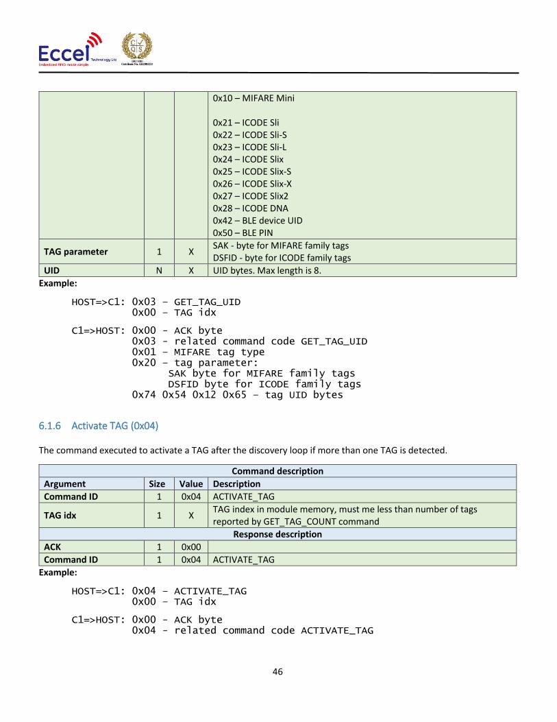
46
0x10 – MIFARE Mini 0x21 – ICODE Sli 0x22 – ICODE Sli-S 0x23 – ICODE Sli-L 0x24 – ICODE Slix 0x25 – ICODE Slix-S 0x26 – ICODE Slix-X 0x27 – ICODE Slix2 0x28 – ICODE DNA 0x42 – BLE device UID 0x50 – BLE PIN
TAG parameter 1 X SAK - byte for MIFARE family tags DSFID - byte for ICODE family tags
UID N X UID bytes. Max length is 8.
Example:
HOST=>C1: 0x03 – GET_TAG_UID 0x00 – TAG idx
C1=>HOST: 0x00 - ACK byte 0x03 - related command code GET_TAG_UID 0x01 – MIFARE tag type 0x20 – tag parameter: SAK byte for MIFARE family tags DSFID byte for ICODE family tags 0x74 0x54 0x12 0x65 – tag UID bytes
6.1.6 Activate TAG (0x04)
The command executed to activate a TAG after the discovery loop if more than one TAG is detected.
Command description
Argument Size Value Description
Command ID 1 0x04 ACTIVATE_TAG
TAG idx 1 X TAG index in module memory, must me less than number of tags reported by GET_TAG_COUNT command
Response description
ACK 1 0x00
Command ID 1 0x04 ACTIVATE_TAG
Example:
HOST=>C1: 0x04 – ACTIVATE_TAG 0x00 – TAG idx
C1=>HOST: 0x00 - ACK byte 0x04 - related command code ACTIVATE_TAG

47
6.1.7 Halt (0x05)
The Halt command takes no arguments. It halts the tag and turns off the RF field. It must be executed at the end of
each operation on a tag to disable the antenna and reduce the power consumption.
Command description
Argument Size Value Description
Command ID 1 0x05 HALT
Response description
ACK 1 0x00
Command ID 1 0x05 HALT
Example:
HOST=>C1: 0x05 – HALT
C1=>HOST: 0x00 - ACK byte 0x05 - related command code HALT
6.1.8 Set key (0x07)
This command sets a KEY in Key Storage Memory on a selected slot. Set key can be used for all RFID functions needing
authorization like e.g. READ/WRITE memory on the TAG etc. This command changes a key in volatile memory, so if the
user wants to save it permanently and load automatically after boot-up, then the user should use the CMD_SAVE_KEYS
command.
Command description
Argument Size Value Description
Command ID 1 0x07 SET_KEY
Key number 1 0-4 Key number in Key Storage Memory.
Key type 1 0 - 6
0x00 - AES 128 Key. (length = 16 bytes) 0x01 - AES 192 Key. (length = 24 bytes) 0x02 - AES 256 Key. (length = 32 bytes) 0x03 - DES Single Key. (length = 16 bytes) 0x04 - 2 Key Triple Des. (length = 16 bytes) 0x05 - 3 Key Triple Des. (length = 24 bytes) 0x06 - MIFARE (R) Key. (length = 12 bytes, key A+B)
Key 12-32 X Key bytes. Length must match to the type.
Response description
ACK 1 0x00
Command ID 1 0x07 SET_KEY
Example:
HOST=>C1: 0x07 – SET_KEY 0x00 – Key number 0x06 – MIFARE key type 0x00 0x00 0x00 0x00 0x00 0x00 0xFF 0xFF 0xFF 0xFF 0xFF 0xFF – Key bytes

48
C1=>HOST: 0x00 - ACK byte 0x07 - related command code SET_KEY
6.1.9 Save keys (0x08)
This command should be called if the user wants to save keys changed using the SET_KEY command in the module
non-volatile memory. Saved keys will be automatically loaded after power up or reboot.
Command description
Argument Size Value Description
Command ID 1 0x08 SAVE_KEYS
Response description
ACK 1 0x00
Command ID 1 0x08 SAVE_KEYS
Example:
HOST=>C1: 0x08 – SAVE_KEYS
C1=>HOST: 0x00 - ACK byte 0x08 - related command code SAVE_KEYS
6.1.10 Reboot (0x0A)
This command requests a software reboot for the reader. After this command the device will not accept any protocol
commands for 1 second.
Command description
Argument Size Value Description
Command ID 1 0x0A REBOOT
Response description
ACK 1 0x00
Command ID 1 0x0A REBOOT
Example:
HOST=>C1: 0x0A – REBOOT
C1=>HOST: 0x00 – ACK byte 0x0A – related command code REBOOT
6.1.11 Get version (0x0B)
This command requests a version string from the device.
Command description
Argument Size Value Description
Command ID 1 0x0B GET_VERSION

49
Response description
ACK 1 0x00
Command ID 1 0x0B GET_VERSION
Version string X X Version string, contains major and minor version and build data and time e.g.: 1.1 Jan 18 2019 15:35:03
Example:
HOST=>C1: 0x0B – GET_VERSION
C1=>HOST: 0x00 – ACK byte 0x0B – related command code GET_VERSION
0x31 0x2e 0x31 0x20 0x4a 0x61 0x6e 0x20 0x31 0x38 0x20 0x32 0x30 0x31 0x39 0x20 0x31 0x35 0x3a 0x33 0x35 0x3a 0x30 0x33 – version string bytes
6.1.12 Factory reset command (0x11)
This command should be user to perform a factory reset. To prevent resetting to factory default by accident, this
commands requires four extra bytes as extra parameters described in the table below.
Command description
Argument Size Value Description
Command ID 1 0x11 FACTORY_RESET
Extra bytes 4 0x01 0x02 0x03 0x04 Four digits pin number (optional)
Response description
ACK 1 0x00
Command ID 1 0x11 FACTORY_RESET _PIN
Example – setup new PIN:
HOST=>C1: 0x11 – FACTORY_RESET 0x01 0x02 0x03 0x04 – Extra parameters
C1=>HOST: 0x00 – ACK byte 0x11 – related command code FACTORY_RESET

50
6.2 MIFARE Classics commands
This set of commands should be performed on MIFARE Classics tags.
6.2.1 Read block (0x20)
The read block command should be used to read data from the tag. It takes as arguments the block number of the first
block to read, the number of blocks to read, the key A or B parameter, and the key number in key storage. The returned
ACK answer contains data read from the specified tag memory. The number of bytes of this data is MIFARE Classic
block size (16) multiplied by the number of blocks to be read.
Command description
Argument Size Value Description
Command ID 1 0x20 MF_READ_BLOCK
Block number 1 X
Number of blocks 1 Y
Key A/B parameter 1 X 0x0A – Key A should be selected from key storage
0x0B – Key B should be selected from key storage
Key number 1 0-4 Key number in key storage
Response description
ACK 1 0x00
Command ID 1 0x20 MF_READ_BLOCK
Read data Y*16 XXX Bytes read from the tag. Number of bytes is number of requested blocks multiplied by 16.
Example:
HOST=>C1: 0x20 – MF_READ_BLOCK 0x02 – block number 2 0x02 – two blocks to read 0x0A – key A should be selected from key storage 0x00 – first key should be selected from key storage
C1=>HOST: 0x00 – ACK byte 0x20 – related command code MF_READ_BLOCK
0x01 0x2e 0x41 0x22 0x43 0x11 0x8e 0x20 0x31 0x38 0x20 0x32 0x30 0x31 0x39 0x41 0x81 0x23 0x42 0x28 0x33 0x01 0x8e 0x72 0x31 0x35 0x3a 0x33 0x35 0x3a 0x30 0x33 – 32 bytes result
6.2.2 Write block (0x21)
The write block command should be used to write data to the tag. It takes as arguments the block number of the first
block to write, the number of blocks to write, the key A or B parameter, the key number in key storage, and the bytes
to be written. The number of bytes to be written must be exactly the number of blocks to write multiplied by 16.

51
Command description
Argument Size Value Description
Command ID 1 0x21 MF_WRITE_BLOCK
Block number 1 X
Number of blocks 1 Y
Key A/B parameter 1 X 0x0A – Key A should be selected from key storage
0x0B – Key B should be selected from key storage
Key number 1 0-4 Key number in key storage
Bytes to write Y*16 XXX Bytes to write. Number of this bytes must be number of requested
blocks multiplied by 16.
Response description
ACK 1 0x00
Command ID 1 0x21 MF_WRITE_BLOCK
Example:
HOST=>C1: 0x21 – MF_WRITE_BLOCK 0x02 – block number 2 0x02 – two blocks to write 0x0A – key A should be selected from key storage 0x00 – first key should be selected from key storage
0x01 0x2e 0x41 0x22 0x43 0x11 0x8e 0x20 0x31 0x38 0x20 0x32 0x30 0x31 0x39 0x41 0x81 0x23 0x42 0x28 0x33 0x01 0x8e 0x72 0x31 0x35 0x3a 0x33 0x35 0x3a 0x30 0x33 – 32 bytes to write
C1=>HOST: 0x00 – ACK byte 0x21 – related command code MF_WRITE_BLOCK
6.2.3 Read value (0x22)
This command should be used to read a value from the tag. It takes as arguments the block number where the value
is stored, the key A or B parameter, and the key number in key storage. The returned ACK response contains a value
as a signed 32-bit value (LSB first) and an address byte as an unsigned 8bit value.
Command description
Argument Size Value Description
Command ID 1 0x22 MF_READ_VALUE
Block number 1 X
Key A/B parameter 1 X 0x0A – Key A should be selected from key storage
0x0B – Key B should be selected from key storage
Key number 1 0-4 Key number in key storage
Response description
ACK 1 0x00
Command ID 1 0x22 MF_READ_VALUE
Value 4 X Signed 32-bit value (LSB first)
Address 1 X Address byte

52
Example:
HOST=>C1: 0x22 – MF_READ_VALUE 0x02 – block number 2 0x0A – key A should be selected from key storage 0x00 – first key should be selected from key storage
C1=>HOST: 0x00 – ACK byte 0x22 – related command code MF_READ_BLOCK 0x00 0x00 0x00 0x01 – value 0x01 – address byte
6.2.4 Write value (0x23)
This command should be used to write a value to the tag. It takes as arguments the block number where the value
should be stored, the key A or B parameter, the key number in key storage, a value (signed 32-bit LSB first) as 4 bytes,
and an address byte (unsigned 8-bit value).
Command description
Argument Size Value Description
Command ID 1 0x23 MF_WRITE_VALUE
Block number 1 X
Key A/B parameter 1 X 0x0A – Key A should be selected from key storage
0x0B – Key B should be selected from key storage
Key number 1 0-4 Key number in key storage
Value 4 X Signed 32-bit value (LSB first)
Address 1 X Address byte
Response description
ACK 1 0x00
Command ID 1 0x23 MF_WRITE_VALUE
Example:
HOST=>C1: 0x23 – MF_WRITE_VALUE 0x02 – block number 2 0x0A – key A should be selected from key storage 0x00 – first key should be selected from key storage 0x00 0x00 0x00 0x01 – value 0x01 – address byte
C1=>HOST: 0x00 – ACK byte 0x23 – related command code MF_WRITE_BLOCK
6.2.5 Increment/decrement value (0x24)
This command should be used to increment or decrement a value stored in the tag memory. It takes as arguments the
block number where the value is stored, the key A or B parameter, the key number in key storage, value (signed 32-
bit LSB first) as 4 bytes to increment or decrement, and the increment/decrement flag.

53
Command description
Argument Size Value Description
Command ID 1 0x24 MF_INCREMENT_VALUE
Block number 1 X
Key A/B parameter 1 X 0x0A – Key A should be selected from key storage 0x0B – Key B should be selected from key storage
Key number 1 0-4 Key number in key storage
Delta value 4 X Signed 32-bit value (LSB first)
Increment/Decrement 1 X 0x00 – Decrement by delta value 0x01 – Increment by delta value
Response description
ACK 1 0x00
Command ID 1 0x24 MF_INCREMENT_VALUE
Example:
HOST=>C1: 0x24 – MF_INCREMENT_VALUE 0x02 – block number 2 0x0A – key A should be selected from key storage 0x00 – first key should be selected from key storage 0x00 0x00 0x00 0x01 – delta value 0x01 – increment flag
C1=>HOST: 0x00 – ACK byte 0x24 – related command code MF_INCREMENT_BLOCK
6.2.6 Transfer value (0x25)
This command should be used to transfer a value from a volatile register on the tag to the block being addressed. It
takes as arguments the block number where the value should be stored, the key A or B parameter, the key number in
key storage.
Command description
Argument Size Value Description
Command ID 1 0x25 MF_TRANSFER_VALUE
Block number 1 X
Key A/B parameter 1 X 0x0A – Key A should be selected from key storage 0x0B – Key B should be selected from key storage
Key number 1 0-4 Key number in key storage
Response description
ACK 1 0x00
Command ID 1 0x25 MF_TRANSFER_VALUE
Example:
HOST=>C1: 0x25 – MF_TRANSFER_VALUE 0x02 – block number 2 0x0A – key A should be selected from key storage 0x00 – first key should be selected from key storage

54
C1=>HOST: 0x00 – ACK byte 0x25 – related command code MF_TRANSFER_BLOCK
6.2.7 Restore value (0x26)
This command should be used to restore a value to a volatile register on the tag from the block being addressed. It
takes as arguments the block number where the value is stored, the key A or B parameter, key number in key storage.
Command description
Argument Size Value Description
Command ID 1 0x26 MF_RESTORE_VALUE
Block number 1 X
Key A/B parameter 1 X 0x0A – Key A should be selected from key storage 0x0B – Key B should be selected from key storage
Key number 1 0-4 Key number in key storage
Response description
ACK 1 0x00
Command ID 1 0x26 MF_ RESTORE _VALUE
Example:
HOST=>C1: 0x26 – MF_RESTORE_VALUE 0x02 – block number 2 0x0A – key A should be selected from key storage 0x00 – first key should be selected from key storage
C1=>HOST: 0x00 – ACK byte 0x26 – related command code MF_RESTORE_BLOCK
6.2.8 Transfer-Restore value (0x27)
This command performs a Restore-Transfer command sequence on the tag. It takes as arguments the block number
to be decremented, the block number to be transferred to, the key A or B parameter, the key number in key storage.
This command has the same functionality as the read value command, except that it can be used on a block which is
corrupted – it tries to recover data from a corrupted block. The format of a value-type block allows for some bits to be
corrupted and it still be possible to read and recover the proper value
Command description
Argument Size Value Description
Command ID 1 0x27 MF_TRANSFER_RESTORE_VALUE
Source block number 1 X Block number to be decremented
Destination block number
1 X Block number to be transferred to
Key A/B parameter 1 X 0x0A – Key A should be selected from key storage 0x0B – Key B should be selected from key storage
Key number 1 0-4 Key number in key storage
Response description
ACK 1 0x00

55
Command ID 1 0x27 MF_ TRANSFER_RESTORE _VALUE
Example:
HOST=>C1: 0x27 – MF_TRANSFER_RESTORE_VALUE 0x02 – source block number 2 0x03 – destination block number 3 0x0A – key A should be selected from key storage 0x00 – first key should be selected from key storage
C1=>HOST: 0x00 – ACK byte 0x27 – related command code MF_TRANSFER_RESTORE_BLOCK
6.3 MIFARE Ultralight commands
This set of commands should be performed on MIFARE Ultralight tags.
6.3.1 Read page (0x40)
The read page command should be used to read data stored in tag pages. It takes as arguments the page number of
the first page to be read, and the number of pages to be read. The returned ACK answer contains data read from the
specified tag memory. The number of bytes of this data is MIFARE Ultralight page size (4) multiplied by the number of
pages to be read.
Command description
Argument Size Value Description
Command ID 1 0x40 MFU_READ_PAGE
Page number 1 X
Number of pages 1 Y
Response description
ACK 1 0x00
Command ID 1 0x40 MFU_READ_PAGE
Read data Y*4 XXX Bytes read from the tag. Number of bytes is number of requested pages multiplied by 4.
Example:
HOST=>C1: 0x40 – MFU_READ_PAGE 0x02 – page number 2 0x02 – two pages to read C1=>HOST: 0x00 – ACK byte 0x40 – related command code MFU_READ_PAGE 0x31 0x35 0x3a 0x33 0x35 0x3a 0x30 0x33 – 8 bytes result

56
6.3.2 Write page (0x41)
The write page command should be used to write data to the tag. It takes as arguments the page number of the first
page to write, the number of pages to write, and the bytes to be written. The number of bytes to be written must be
exactly the number of pages to write multiplied by 4.
Command description
Argument Size Value Description
Command ID 1 0x41 MFU_WRITE_PAGE
Page number 1 X
Number of pages 1 Y
Bytes to write Y*4 XXX Bytes to write. Number of this bytes must be number of requested pages
multiplied by 4.
Response description
ACK 1 0x00
Command ID 1 0x41 MFU_WRITE_PAGE
Example:
HOST=>C1: 0x41 – MFU_WRITE_PAGE 0x02 – page number 2 0x02 – two pages to write 0x31 0x35 0x3a 0x33 0x35 0x3a 0x30 0x33 – 32 bytes to write
C1=>HOST: 0x00 – ACK byte 0x41 – related command code MFU_WRITE_PAGE
6.3.3 Get version (0x42)
This command requests a version string from the TAG. The returned ACK answer consists of 8-bytes containing the
version information defined by the NXP standard. Please refer to the NXP documentation for more information.
Command description
Argument Size Value Description
Command ID 1 0x42 MFU_GET_VERSION
Response description
ACK 1 0x00
Command ID 1 0x42 MFU_GET_VERSION
Version bytes 8 X Version bytes from the TAG
Example:
HOST=>C1: 0x42 – MFU_GET_VERSION
C1=>HOST: 0x00 – ACK byte 0x42 – related command code MFU_GET_VERSION 0x31 0x35 0x3a 0x33 0x35 0x3a 0x30 0x33 – version bytes

57
6.3.4 Read signature (0x43)
This command requests a version string from the device. The returned ACK answer contains 32-bytes with ECC
signature defined by the NXP standard. Please refer to the NXP documentation for more information.
Command description
Argument Size Value Description
Command ID 1 0x43 MFU_READ_SIGNATURE
Response description
ACK 1 0x00
Command ID 1 0x43 MFU_READ_SIGNATURE
Version bytes 32 X Signature bytes from the TAG
Example:
HOST=>C1: 0x43 – MFU_READ_SIGNATURE
C1=>HOST: 0x00 – ACK byte 0x43 – related command code MFU_READ_SIGNATURE 0x01 0x2e 0x41 0x22 0x43 0x11 0x8e 0x20 0x31 0x38 0x20 0x32 0x30 0x31 0x39 0x41 0x81 0x23 0x42 0x28 0x33 0x01 0x8e 0x72 0x31 0x35 0x3a 0x33 0x35 0x3a 0x30 0x33 – signature bytes
6.3.5 Write signature (0x44)
This command writes the signature information to the MIFARE Ultralight Nano TAG. It takes as arguments relative page
location of the signature part to be written and four bytes of signature value to be written.
Command description
Argument Size Value Description
Command ID 1 0x44 MFU_WRITE_SIGNATURE
Relative page address 1 X Relative page location of the signature part to be written
Bytes to write 4 XXX Bytes of signature value to be written to the specified relative page address
Response description
ACK 1 0x00
Command ID 1 0x44 MFU_WRITE_ SIGNATURE
Example:
HOST=>C1: 0x44 – MFU_WRITE_SIGNATURE 0x00 – relative page number 0 0x35 0x3a 0x30 0x33 – 4 bytes to write
C1=>HOST: 0x00 – ACK byte 0x44 – related command code MFU_WRITE_SIGNATURE

58
6.3.6 Lock signature (0x45)
This command locks the signature temporarily or permanently based on the information provided in the API. The
locking and unlocking of the signature can be performed using this command if the signature is not locked or temporary
locked. If the signature is permanently locked, then unlocking can’t be done.
Command description
Argument Size Value Description
Command ID 1 0x45 MFU_LOCK_SIGNATURE
Lock mode 1 X 0x00 – Unlock 0x01 – Lock 0x02 – Permanent lock
Response description
ACK 1 0x00
Command ID 1 0x45 MFU_LOCK_SIGNATURE
Example:
HOST=>C1: 0x45 – MFU_LOCK_SIGNATURE 0x02 – permanent lock C1=>HOST: 0x00 – ACK byte 0x45 – related command code MFU_LOCK_SIGNATURE
6.3.7 Read counter (0x46)
This command should be used to read a counter from the TAG. It takes as arguments the counter number. The returned
ACK response contains a value as a signed 24-bit value (LSB first).
Command description
Argument Size Value Description
Command ID 1 0x46 MFU_READ_COUNTER
Counter number 1 0-2 Counter number
Response description
ACK 1 0x00
Command ID 1 0x46 MFU_READ_COUNTER
Counter value 3 X Unsigned 24-bit value, LSB first
Example:
HOST=>C1: 0x46 – MFU_READ_COUNTER 0x01 – counter number C1=>HOST: 0x00 – ACK byte 0x46 – related command code MFU_READ_COUNTER 0x00 0x00 0x01 – value

59
6.3.8 Increment counter (0x47)
This command should be used to increment a counter stored in the tag memory. It takes as arguments the counter
number and increment value (24-bit value LSB first) as 3 bytes.
Command description
Argument Size Value Description
Command ID 1 0x47 MFU_INCREMENT_COUNTER
Counter number 1 0-2 Counter number
Increment value 3 X Unsigned 24-bit value (LSB first)
Response description
ACK 1 0x00
Command ID 1 0x47 MFU_INCREMENT_COUNTER
Example:
HOST=>C1: 0x47 – MFU_INCREMENT_COUNTER 0x02 – block number 2 0x00 0x00 0x01 – increment value
C1=>HOST: 0x00 – ACK byte 0x47 – related command code MFU_INCREMENT_COUNTER
6.3.9 Password auth (0x48)
This command tries to authenticate the tag using the chosen password. It takes as an argument a password as four
bytes. The returned ACK response contains two bytes of password acknowledge (PACK).
Command description
Argument Size Value Description
Command ID 1 0x48 MFU_PASSWORD_AUTH
Counter number 4 X 4-bytes password
Response description
ACK 1 0x00
Command ID 1 0x48 MFU_PASSWORD_AUTH
PACK 2 X Password acknowledge bytes
Example:
HOST=>C1: 0x48 – MFU_PASSWORD_AUTH 0x00 0x00 0x00 0x00 – password
C1=>HOST: 0x00 – ACK byte 0x48 – related command code MFU_PASSWORD_AUTH 0x00 0x00 – password acknowledge bytes

60
6.3.10 Ultralight-C authenticate (0x49)
This command tries to authenticate the MIFARE Ultralight-C tag using the password stored in the key storage. It takes
as an argument one byte with the key number in the key storage.
Command description
Argument Size Value Description
Command ID 1 0x49 MFUC_AUTHENTICATE
Key number 1 0-4 Key number in key storage
Response description
ACK 1 0x00
Command ID 1 0x49 MFUC_AUTHENTICATE
Example:
HOST=>C1: 0x49 – MFUC_AUTHENTICATE 0x00 – key number C1=>HOST: 0x00 – ACK byte 0x49 – related command code MFUC_AUTHENTICATE
6.3.11 Check Tearing Event (0x4A)
The Check Tearing Event command takes as arguments one byte with the counter number. This command checks
whether there was a tearing event in the counter. The returned ACK response contains result byte. The value ‘0x00’ is
returned if there has been no tearing event, and ‘0x01’ is returned if a tearing event occurred. Please refer to the NXP
documentation for more information.
Command description
Argument Size Value Description
Command ID 1 0x49 MFU_CHECKEVENT
Counter number 1 0-2 Counter number
Response description
ACK 1 0x00
Command ID 1 0x49 MFU_CHECKEVENT
Example:
HOST=>C1: 0x49 – MFU_CHECKEVENT 0x00 – counter number C1=>HOST: 0x00 – ACK byte 0x49 – related command code MFU_CHECKEVENT 0x01 – tearing event occurred
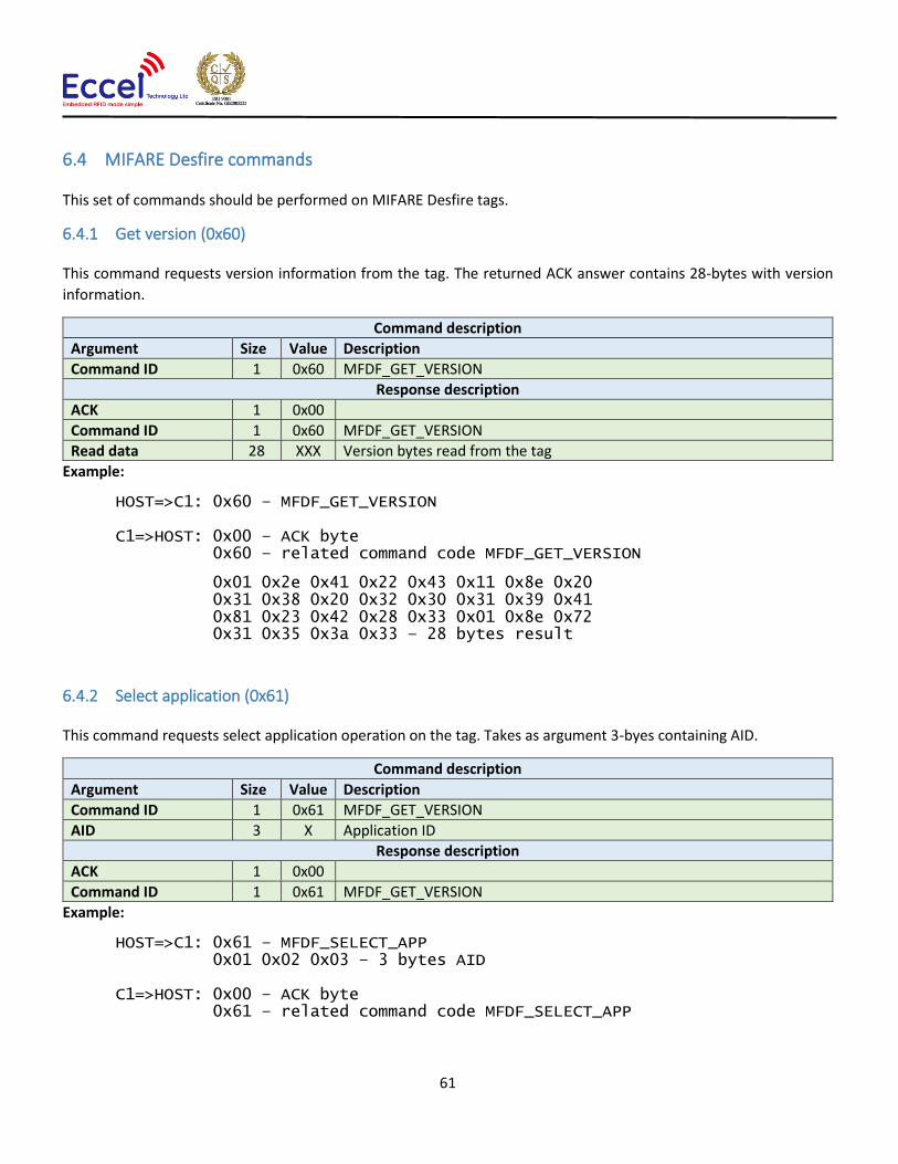
61
6.4 MIFARE Desfire commands
This set of commands should be performed on MIFARE Desfire tags.
6.4.1 Get version (0x60)
This command requests version information from the tag. The returned ACK answer contains 28-bytes with version
information.
Command description
Argument Size Value Description
Command ID 1 0x60 MFDF_GET_VERSION
Response description
ACK 1 0x00
Command ID 1 0x60 MFDF_GET_VERSION
Read data 28 XXX Version bytes read from the tag
Example:
HOST=>C1: 0x60 – MFDF_GET_VERSION C1=>HOST: 0x00 – ACK byte 0x60 – related command code MFDF_GET_VERSION
0x01 0x2e 0x41 0x22 0x43 0x11 0x8e 0x20 0x31 0x38 0x20 0x32 0x30 0x31 0x39 0x41 0x81 0x23 0x42 0x28 0x33 0x01 0x8e 0x72 0x31 0x35 0x3a 0x33 – 28 bytes result
6.4.2 Select application (0x61)
This command requests select application operation on the tag. Takes as argument 3-byes containing AID.
Command description
Argument Size Value Description
Command ID 1 0x61 MFDF_GET_VERSION
AID 3 X Application ID
Response description
ACK 1 0x00
Command ID 1 0x61 MFDF_GET_VERSION
Example:
HOST=>C1: 0x61 – MFDF_SELECT_APP 0x01 0x02 0x03 – 3 bytes AID C1=>HOST: 0x00 – ACK byte 0x61 – related command code MFDF_SELECT_APP

62
6.4.3 List application IDs (0x62)
This command requests lists application IDs from the TAG. The returned ACK answer contains the bytes with
application IDs. Every ID is 3-bytes long.
Command description
Argument Size Value Description
Command ID 1 0x62 MFDF_LIST_APP_IDS
Response description
ACK 1 0x00
Command ID 1 0x62 MFDF_LIST_APP_IDS
Application IDs X*3 X Bytes with applications IDs
Example:
HOST=>C1: 0x62 – MFDF_LIST_APP_IDS C1=>HOST: 0x00 – ACK byte 0x62 – related command code MFDF_LIST_APP_IDS 0x00 0x00 0x01 – first AID 0xAA 0xBB 0xCC – second AID 0x55 0x55 0x55 – third AID ...
6.4.4 List files IDs (0x63)
This command returns the file IDs of all active files within the currently selected application. The returned ACK answer
contains the bytes with file IDs. Every file ID is 3-bytes long.
Command description
Argument Size Value Description
Command ID 1 0x63 MFDF_LIST_FILE_IDS
Response description
ACK 1 0x00
Command ID 1 0x63 MFDF_LIST_FILE_IDS
Application IDs X*3 X Bytes with files IDs
Example:
HOST=>C1: 0x63 – MFDF_LIST_FILE_IDS C1=>HOST: 0x00 – ACK byte 0x63 – related command code MFDF_LIST_FILE_IDS 0x00 0x00 0x01 – first file ID 0xAA 0xBB 0xCC – second file ID 0x55 0x55 0x55 – third file ID ...

63
6.4.5 Authenticate (0x64)
This command tries to authenticate the MIFARE Desfire using the password stored in the key storage. It takes as an
argument one byte with the key number in the key storage, and one byte with the key number on the card. This
command can be used with DES and 2K3DES keys.
Command description
Argument Size Value Description
Command ID 1 0x64 MFDF_AUTHENTICATE
Key number in storage 1 0-4 Key number in key storage
Key number on card 1 x Key number on card
Response description
ACK 1 0x00
Command ID 1 0x64 MFDF_AUTHENTICATE
Example:
HOST=>C1: 0x64 – MFDF_AUTHENTICATE 0x01 – key number in key storage 0x00 – key number on the card C1=>HOST: 0x00 – ACK byte 0x64 – related command code MFDF_AUTHENTICATE
6.4.6 Authenticate ISO (0x65)
This command tries to authenticate the MIFARE Desfire tag in ISO CBS send mode using the key stored in the key
storage. It takes as an argument one byte with the key number in the key storage, and one byte with the key number
on the card. This command can be used with DES, 3DES and 3K3DES keys.
Command description
Argument Size Value Description
Command ID 1 0x65 MFDF_AUTHENTICATE_ISO
Key number 1 0-4 Key number in key storage
Key number on card 1 x Key number on card
Response description
ACK 1 0x00
Command ID 1 0x65 MFDF_AUTHENTICATE_ISO
Example:
HOST=>C1: 0x65 – MFDF_AUTHENTICATE_ISO 0x01 – key number in key storage 0x00 – key number on the card C1=>HOST: 0x00 – ACK byte 0x65 – related command code MFDF_AUTHENTICATE_ISO

64
6.4.7 Authenticate AES (0x66)
This command tries to authenticate the MIFARE Desfire using the key stored in the key storage, and one byte with the
key number on the card. It takes as an argument one byte with the key number in the key storage. This command can
be used with AES128 keys.
Command description
Argument Size Value Description
Command ID 1 0x66 MFDF_AUTHENTICATE_ISO
Key number 1 0-4 Key number in key storage
Key number on card 1 x Key number on card
Response description
ACK 1 0x00
Command ID 1 0x66 MFDF_AUTHENTICATE_ISO
Example:
HOST=>C1: 0x66 – MFDF_AUTHENTICATE_AES 0x01 – key number in key storage 0x00 – key number on the card C1=>HOST: 0x00 – ACK byte 0x66 – related command code MFDF_AUTHENTICATE_AES
6.4.8 Create application (0x67)
This command tries to create application on the tag. It takes three arguments: 3-bytes of application ID, the
keySettings1 byte and the keySettings2 byte. Please refer to the NXP documentation for more information about key
settings bytes.
Command description
Argument Size Value Description
Command ID 1 0x67 MFDF_CREATE_APP
Application ID 3 X Application ID bytes
Key settings 1 1 X Please refer to the NXP documentation for more information
Key settings 2 1 X Please refer to the NXP documentation for more information
Response description
ACK 1 0x00
Command ID 1 0x67 MFDF_CREATE_APP
Example:
HOST=>C1: 0x67 – MFDF_CREATE_APP 0x00 – key number 0x01 0x02 0x03 – application ID 0xED 0x84 – key settings bytes C1=>HOST: 0x00 – ACK byte 0x67 – related command code MFDF_CREATE_APP

65
6.4.9 Delete application (0x68)
This command tries to delete an application from the tag. It takes one argument with the application ID.
Command description
Argument Size Value Description
Command ID 1 0x68 MFDF_DELETE_APP
Application ID 3 X Application ID bytes
Response description
ACK 1 0x00
Command ID 1 0x68 MFDF_DELETE_APP
Example:
HOST=>C1: 0x68 – MFDF_DELETE_APP 0x01 0x02 0x03 – application ID C1=>HOST: 0x00 – ACK byte 0x68 – related command code MFDF_DELETE_APP
6.4.10 Change key (0x69)
This command tries to change the key for the selected application. It takes three arguments: the old key number from
key storage, the new key number in the key storage and the key number on the card. The key type of the application
keys cannot be changed.
Command description
Argument Size Value Description
Command ID 1 0x69 MFDF_CHANGE_KEY
Old key number 1 0-4 Key number in key storage
New key number 1 0-4 Key number in key storage
Key number on card 1 X Key number on the card
Response description
ACK 1 0x00
Command ID 1 0x69 MFDF_CHANGE_KEY
Example:
HOST=>C1: 0x69 – MFDF_CHANGE_APP 0x00 – old key number 0x01 – new key number 0x00 – key number C1=>HOST: 0x00 – ACK byte 0x69 – related command code MFDF_CHANGE_APP
6.4.11 Get key settings (0x6A)
This command gets the key settings bytes from the tag. This command does not require any arguments but an
application must be selected and authorized.
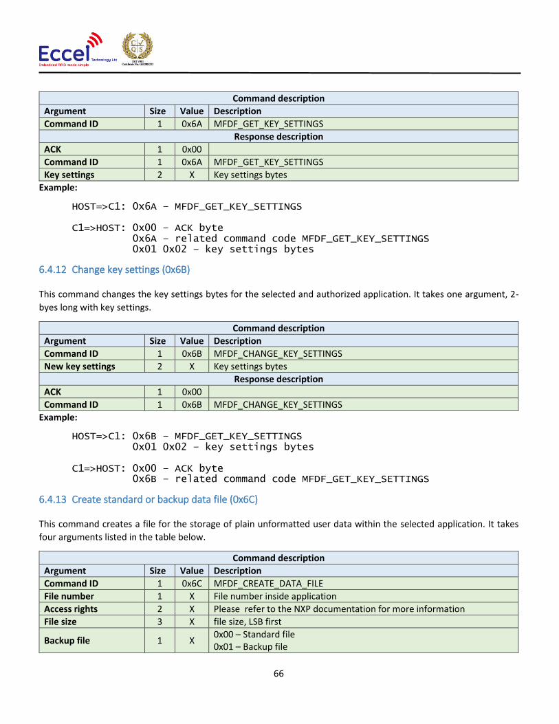
66
Command description
Argument Size Value Description
Command ID 1 0x6A MFDF_GET_KEY_SETTINGS
Response description
ACK 1 0x00
Command ID 1 0x6A MFDF_GET_KEY_SETTINGS
Key settings 2 X Key settings bytes
Example:
HOST=>C1: 0x6A – MFDF_GET_KEY_SETTINGS C1=>HOST: 0x00 – ACK byte 0x6A – related command code MFDF_GET_KEY_SETTINGS 0x01 0x02 – key settings bytes
6.4.12 Change key settings (0x6B)
This command changes the key settings bytes for the selected and authorized application. It takes one argument, 2-
byes long with key settings.
Command description
Argument Size Value Description
Command ID 1 0x6B MFDF_CHANGE_KEY_SETTINGS
New key settings 2 X Key settings bytes
Response description
ACK 1 0x00
Command ID 1 0x6B MFDF_CHANGE_KEY_SETTINGS
Example:
HOST=>C1: 0x6B – MFDF_GET_KEY_SETTINGS 0x01 0x02 – key settings bytes C1=>HOST: 0x00 – ACK byte 0x6B – related command code MFDF_GET_KEY_SETTINGS
6.4.13 Create standard or backup data file (0x6C)
This command creates a file for the storage of plain unformatted user data within the selected application. It takes
four arguments listed in the table below.
Command description
Argument Size Value Description
Command ID 1 0x6C MFDF_CREATE_DATA_FILE
File number 1 X File number inside application
Access rights 2 X Please refer to the NXP documentation for more information
File size 3 X file size, LSB first
Backup file 1 X 0x00 – Standard file 0x01 – Backup file
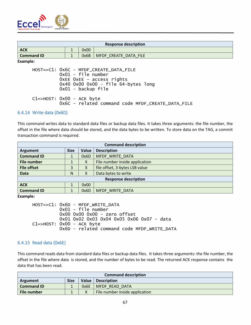
67
Response description
ACK 1 0x00
Command ID 1 0x6B MFDF_CREATE_DATA_FILE
Example:
HOST=>C1: 0x6C – MFDF_CREATE_DATA_FILE 0x01 – file number 0xEE 0xEE – access rights 0x40 0x00 0x00 – file 64-bytes long 0x01 – backup file C1=>HOST: 0x00 – ACK byte 0x6C – related command code MFDF_CREATE_DATA_FILE
6.4.14 Write data (0x6D)
This command writes data to standard data files or backup data files. It takes three arguments: the file number, the
offset in the file where data should be stored, and the data bytes to be written. To store data on the TAG, a commit
transaction command is required.
Command description
Argument Size Value Description
Command ID 1 0x6D MFDF_WRITE_DATA
File number 1 X File number inside application
File offset 3 X file offset, 3-bytes LSB value
Data N X Data bytes to write
Response description
ACK 1 0x00
Command ID 1 0x6D MFDF_WRITE_DATA
Example:
HOST=>C1: 0x6D – MFDF_WRITE_DATA 0x01 – file number 0x00 0x00 0x00 – zero offset 0x01 0x02 0x03 0x04 0x05 0x06 0x07 - data C1=>HOST: 0x00 – ACK byte 0x6D – related command code MFDF_WRITE_DATA
6.4.15 Read data (0x6E)
This command reads data from standard data files or backup data files. It takes three arguments: the file number, the
offset in the file where data is stored, and the number of bytes to be read. The returned ACK response contains the
data that has been read.
Command description
Argument Size Value Description
Command ID 1 0x6E MFDF_READ_DATA
File number 1 X File number inside application

68
File offset 3 X file offset, 3-bytes LSB value
Data length 3 X Read data length, 3-bytes LSB value
Response description
ACK 1 0x00
Command ID 1 0x6E MFDF_READ_DATA
Example:
HOST=>C1: 0x6E – MFDF_READ_DATA 0x01 – file number 0x00 0x00 0x00 – zero offset 0x07 0x00 0x00 – seven bytes to read C1=>HOST: 0x00 – ACK byte 0x6E – related command code MFDF_READ_DATA 0x01 0x02 0x03 0x04 0x05 0x06 0x07 - data
6.4.16 Create value file (0x6F)
This command creates files for the storage and manipulation of 32bit signed integer values within an existing
application on the TAG. It takes seven arguments listed in the table below.
Command description
Argument Size Value Description
Command ID 1 0x6F MFDF_CREATE_VALUE_FILE
File number 1 X File number inside application
Access rights 2 X Please refer to the NXP documentation for more information
Low limit 4 X Low limit as 4-bytes signed value, LSB first
Up limit 4 X Up limit as 4-bytes signed value, LSB first
Initial value 4 X Initial value as 4-bytes signed value, LSB first
Get free enabled 1 X Please refer to the NXP documentation for more information
Limit credited 1 X Please refer to the NXP documentation for more information
Response description
ACK 1 0x00
Command ID 1 0x6F MFDF_CREATE_VALUE_FILE
Example:
HOST=>C1: 0x6F – MFDF_CREATE_VALUE_FILE 0x02 – file number 0xEE 0xEE – access rights 0x00 0x00 0x00 0x00 – low limit 0x80 0x00 0x00 0x00 – up limit 0x00 0x00 0x00 0x00 – initial value 0x01 – get free enabled 0x01 – limited credit C1=>HOST: 0x00 – ACK byte 0x6F – related command code MFDF_CREATE_VALUE_FILE

69
6.4.17 Get value (0x70)
This command returns the value stored in a value file on the TAG. The returned ACK response contains 4 bytes of
signed value, LSB-first.
Command description
Argument Size Value Description
Command ID 1 0x70 MFDF_GET_VALUE
File number 1 X File number inside application
Response description
ACK 1 0x00
Command ID 1 0x70 MFDF_GET_VALUE
Value 4 X 4 bytes signed value, LSB first
Example:
HOST=>C1: 0x70 – MFDF_GET_VALUE 0x02 – file number C1=>HOST: 0x00 – ACK byte 0x70 – related command code MFDF_GET_VALUE 0x05 0x00 0x00 0x00 – 4 bytes signed value, LSB first
6.4.18 Credit file (0x71)
This command increases a value stored in a value file on the TAG.
Command description
Argument Size Value Description
Command ID 1 0x71 MFDF_CREDIT
File number 1 X File number inside application
Credit value 4 X 4 bytes signed value, LSB first
Response description
ACK 1 0x00
Command ID 1 0x71 MFDF_CREDIT
Example:
HOST=>C1: 0x71 – MFDF_CREDIT 0x02 – file number 0x05 0x00 0x00 0x00 – 4 bytes signed value, LSB first C1=>HOST: 0x00 – ACK byte 0x71 – related command code MFDF_CREDIT
6.4.19 Limited credit file (0x72)
This command allows a limited increase of a value stored in a value file without having full credit permissions to the
file. Please refer to the NXP documentation for more information.
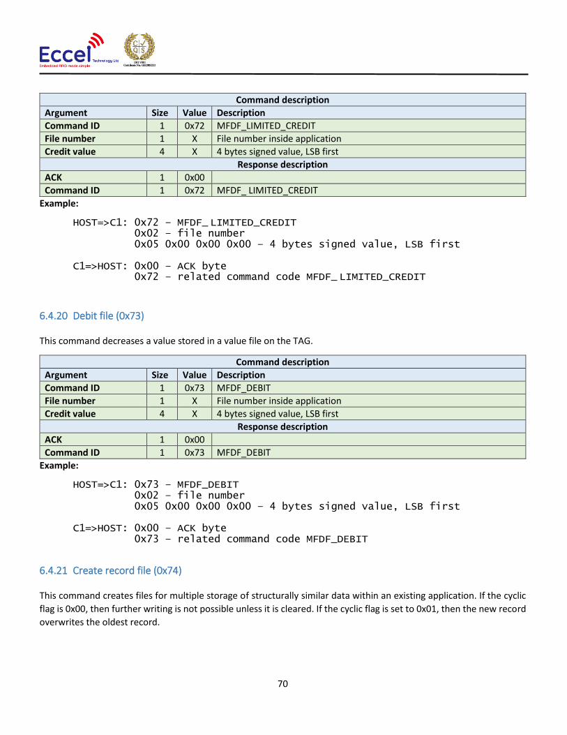
70
Command description
Argument Size Value Description
Command ID 1 0x72 MFDF_LIMITED_CREDIT
File number 1 X File number inside application
Credit value 4 X 4 bytes signed value, LSB first
Response description
ACK 1 0x00
Command ID 1 0x72 MFDF_ LIMITED_CREDIT
Example:
HOST=>C1: 0x72 – MFDF_ LIMITED_CREDIT 0x02 – file number 0x05 0x00 0x00 0x00 – 4 bytes signed value, LSB first C1=>HOST: 0x00 – ACK byte 0x72 – related command code MFDF_ LIMITED_CREDIT
6.4.20 Debit file (0x73)
This command decreases a value stored in a value file on the TAG.
Command description
Argument Size Value Description
Command ID 1 0x73 MFDF_DEBIT
File number 1 X File number inside application
Credit value 4 X 4 bytes signed value, LSB first
Response description
ACK 1 0x00
Command ID 1 0x73 MFDF_DEBIT
Example:
HOST=>C1: 0x73 – MFDF_DEBIT 0x02 – file number 0x05 0x00 0x00 0x00 – 4 bytes signed value, LSB first C1=>HOST: 0x00 – ACK byte 0x73 – related command code MFDF_DEBIT
6.4.21 Create record file (0x74)
This command creates files for multiple storage of structurally similar data within an existing application. If the cyclic
flag is 0x00, then further writing is not possible unless it is cleared. If the cyclic flag is set to 0x01, then the new record
overwrites the oldest record.

71
Command description
Argument Size Value Description
Command ID 1 0x74 MFDF_CREATE_RECORD_FILE
File number 1 X File number inside application
Access rights 2 X Please refer to the NXP documentation for more information
Record size 2 X Record size, 16-bits LSB value
Number of records 2 X Number of records, 16-bits LSB value
Cyclic flag 1 X If cyclic file is full:
0x00 - further writing is not possible unless it is cleared 0x01 - the new record overwrites oldest record
Response description
ACK 1 0x00
Command ID 1 0x74 MFDF_CREATE_RECORD_FILE
Example:
HOST=>C1: 0x74 – MFDF_CREATE_RECORD_FILE 0x03 – file number 0xEE 0xEE – access rights 0x08 0x00 – 8-bytes for every record 0x40 0x00 – 64 records 0x01 – cyclic flag C1=>HOST: 0x00 – ACK byte 0x74 – related command code MFDF_CREATE_VALUE_FILE
6.4.22 Write record (0x75)
This command writes data to a record file. It takes two arguments: the file number and the data bytes to be written.
To store data on the TAG, a commit transaction command is required.
Command description
Argument Size Value Description
Command ID 1 0x75 MFDF_WRITE_RECORD_DATA
File number 1 X File number inside application
Data N X Data bytes to write
Response description
ACK 1 0x00
Command ID 1 0x75 MFDF_WRITE_DATA
Example:
HOST=>C1: 0x75 – MFDF_WRITE_DATA 0x01 – file number 0x01 0x02 0x03 0x04 0x05 0x06 0x07 - data C1=>HOST: 0x00 – ACK byte 0x75 – related command code MFDF_WRITE_RECORD_DATA

72
6.4.23 Read record (0x76)
This command reads data from a record file. It takes three arguments: the file number, the record number, and the
number of bytes to be read. The returned ACK response contains the data that has been read.
Command description
Argument Size Value Description
Command ID 1 0x76 MFDF_READ_RECORD
File number 1 X File number inside application
Record number 2 X Record number, 2-bytes LSB value
Data length 2 X Read data length, 2-bytes LSB value
Response description
ACK 1 0x00
Command ID 1 0x76 MFDF_READ_RECORD
Example:
HOST=>C1: 0x76 – MFDF_READ_RECORD 0x01 – file number 0x00 0x01 – record number 0x08 0x00 – eighth bytes to read C1=>HOST: 0x00 – ACK byte 0x76 – related command code MFDF_READ_RECORD 0x00 0x01 0x02 0x03 0x04 0x05 0x06 0x07 - data
6.4.24 Clear records (0x77)
This command resets cyclic or lineal record files. It takes as an argument the file number.
Command description
Argument Size Value Description
Command ID 1 0x77 MFDF_CLEAR_RECORDS
File number 1 X File number inside application
Response description
ACK 1 0x00
Command ID 1 0x77 MFDF_CLEAR_RECORDS
Example:
HOST=>C1: 0x77 – MFDF_CLEAR_RECORDS 0x01 – file number C1=>HOST: 0x00 – ACK byte 0x77 – related command code MFDF_CLEAR_RECORDS
6.4.25 Delete file (0x78)
This command permanently deactivates a file within the file directory of the currently selected application. It takes as
an argument the file number.

73
Command description
Argument Size Value Description
Command ID 1 0x78 MFDF_DELETE_FILE
File number 1 X File number inside application
Response description
ACK 1 0x00
Command ID 1 0x78 MFDF_DELETE_FILE
Example:
HOST=>C1: 0x78 – MFDF_DELETE_FILE 0x01 – file number C1=>HOST: 0x00 – ACK byte 0x78 – related command code MFDF_DELETE_FILE
6.4.26 Get free memory (0x79)
This command returns a value corresponding to the amount of free memory available on the TAG. No arguments are
required. The available memory is returned as a 4 byte unsigned LSB value.
Command description
Argument Size Value Description
Command ID 1 0x79 MFDF_GET_FREE_MEM
Response description
ACK 1 0x00
Command ID 1 0x79 MFDF_GET_FREE_MEM
Free memory 4 X Free memory, 4-bytes, LSB first
Example:
HOST=>C1: 0x79 – MFDF_GET_FREE_MEM C1=>HOST: 0x00 – ACK byte 0x79 – related command code MFDF_GET_FREE_MEM 0x00 0x08 0x00 0x00 – free memory
6.4.27 Format memory (0x7A)
This command releases user memory in the TAG. No arguments are required.
Command description
Argument Size Value Description
Command ID 1 0x7A MFDF_FORMAT
Response description
ACK 1 0x00
Command ID 1 0x7A MFDF_FORMAT

74
Example:
HOST=>C1: 0x7A – MFDF_FORMAT C1=>HOST: 0x00 – ACK byte 0x7A – related command code MFDF_FORMAT
6.4.28 Commit transaction (0x7B)
This command validates all previous write access on backup data files, value files and record files within one
application. No arguments are required.
Command description
Argument Size Value Description
Command ID 1 0x7B MFDF_COMMIT_TRANSACTION
Response description
ACK 1 0x00
Command ID 1 0x7B MFDF_COMMIT_TRANSACTION
Example:
HOST=>C1: 0x7B – MFDF_COMMIT_TRANSACTION C1=>HOST: 0x00 – ACK byte 0x7B – related command code MFDF_COMMIT_TRANSACTION
6.4.29 Abort transaction (0x7C)
This command invalidates all previous write access on backup data files, value files and record files within one
application. No arguments are required.
Command description
Argument Size Value Description
Command ID 1 0x7C MFDF_ABORT_TRANSACTION
Response description
ACK 1 0x00
Command ID 1 0x7C MFDF_ABORT_TRANSACTION
Example:
HOST=>C1: 0x7C – MFDF_ABORT_TRANSACTION C1=>HOST: 0x00 – ACK byte 0x7C – related command code MFDF_ABORT_TRANSACTION

75
6.5 ICODE (ISO15693) commands
This set of commands should be performed on ICODE (ISO15693) TAGs.
6.5.1 Inventory start (0x90)
This command starts the inventory procedure on ISO 15693 TAGs. It activates the first TAG detected during collision
resolution. If no TAGs are detected, then an error with a timeout flag is returned. This command takes one argument
AFI - Application Family Identifier. Please refer to the NXP documentation for more information.
If any TAG(s) is/are detected, then the command returns an ACK message containing the UID (8-bytes), a DSFID byte,
and 1-byte which contains information about any other tags detected in the field that are available to be read.
Because GET_TAG_COUNT command is limited to 5 tags only, ICODE_INVENTORY_START/ICODE_INVENTORY_NEXT
commands should be used to detect all ICODE tags within range of the antenna.
Command description
Argument Size Value Description
Command ID 1 0x90 ICODE_INVENTORY_START
AFI 1 X Application Family Identifier
Response description
ACK 1 0x00
Command ID 1 0x90 ICODE_INVENTORY_START
UID 8 XXX Unique identifier, inverted order
DSFID 1 X Data Storage Format Identifier
More cards flag 1 X 0x00 – no more cards in range of antenna 0x01 – more cards in range of antenna
Example:
HOST=>C1: 0x90 – ICODE_INVENTORY_START 0x00 – Application Family Identifier
C1=>HOST: 0x00 – ACK byte 0x90 – related command code ICODE_INVENTORY_START 0x04 0x8F 0x7F 0x0A 0x01 0x24 0x16 0xE0 – UID 0x00 – DSFID 0x01 – more cards in range of antenna
6.5.2 Inventory next (0x91)
This command should be used to continue the inventory procedure on ISO 15693 TAGs. It activates the next TAG that
was detected during the collision resolution. It takes one argument, AFI - Application Family Identifier. Please refer to
the NXP documentation for more information. If a TAG or multiple tags is/are detected, then this command returns
an ACK message containing the UID (8-bytes), a DSFID byte, and 1-byte which contains information about any other
tags detected in the field that are available to be read.

76
Command description
Argument Size Value Description
Command ID 1 0x91 ICODE_INVENTORY_NEXT
AFI 1 X Application Family Identifier
Response description
ACK 1 0x00
Command ID 1 0x91 ICODE_INVENTORY_NEXT
UID 8 XXX Unique identifier
DSFID 1 X Data Storage Format Identifier
More cards flag 1 X 0x00 – no more cards in range of antenna 0x01 – more cards in range of antenna
Example:
HOST=>C1: 0x91 – ICODE_INVENTORY_NEXT 0x00 – Application Family Identifier
C1=>HOST: 0x00 – ACK byte 0x91 – related command code ICODE_INVENTORY_NEXT 0x04 0x8F 0x7F 0x0A 0x01 0x24 0x16 0xE0 – UID 0x00 – DSFID 0x00 – no more cards available for reading
6.5.3 Stay quiet (0x92)
This command performs an ISO15693 Stay Quiet command to the selected TAG. When the tag receives the Stay quiet
command, it enters the quiet state and will not send back a response. The TAG exits the quiet state upon the execution
of a reset (power off) or the command ICODE_INVENTORY_START. Please refer to the NXP documentation for more
information.
Command description
Argument Size Value Description
Command ID 1 0x92 ICODE_STAY_QUIET
Response description
ACK 1 0x00
Command ID 1 0x92 ICODE_STAY_QUIET
Example:
HOST=>C1: 0x92 – ICODE_STAY_QUIET
C1=>HOST: 0x00 – ACK byte 0x92 – related command code ICODE_STAY_QUIET
6.5.4 Read block (0x93)
The read block command should be used to read data stored in TAG blocks. It takes as arguments the block number of
the first block to be read, and the number of blocks to be read. The returned ACK answer contains data read from the

77
specified tag memory. The number of bytes of this data is ICODE block size (4) multiplied by the number of blocks to
be read.
Command description
Argument Size Value Description
Command ID 1 0x93 ICODE_READ_BLOCK
Block number 1 X
Block count 1 N Number of block to read
Response description
ACK 1 0x00
Command ID 1 0x93 ICODE_READ_BLOCK
Read data 4*N XXX Bytes read from the tag.
Example:
HOST=>C1: 0x93 – ICODE_READ_BLOCK 0x02 – block number 2 0x01 – 1 block to read C1=>HOST: 0x00 – ACK byte 0x93 – related command code ICODE_READ_BLOCK 0x35 0x3a 0x30 0x33 – 4 bytes block data
6.5.5 Write block (0x94)
The write block command should be used to write data to the tag. It takes as arguments the block number of the first
block to write, the number of blocks to write, and the bytes to be written. The number of bytes to be written must be
exactly the number of blocks to write multiplied by 4.
Command description
Argument Size Value Description
Command ID 1 0x94 ICODE_WRITE_BLOCK
Block number 1 X
Block count 1 N
Data to write 4*N X 4-bytes data to write
Response description
ACK 1 0x00
Command ID 1 0x94 ICODE_WRITE_BLOCK
Example:
HOST=>C1: 0x94 – ICODE_WRITE_BLOCK 0x02 – block number 2 0x01 – block count 1 0x35 0x3a 0x30 0x33 – 4 bytes to write
C1=>HOST: 0x00 – ACK byte 0x94 – related command code ICODE_WRITE_BLOCK

78
6.5.6 Lock block (0x95)
This command performs a lock block command. Once it receives the lock block command, the TAG permanently locks
the requested block. The command takes a one-byte argument representing the block number to be locked.
Command description
Argument Size Value Description
Command ID 1 0x95 ICODE_LOCK_BLOCK
Block number 1 X
Response description
ACK 1 0x00
Command ID 1 0x95 ICODE_LOCK_BLOCK
Example:
HOST=>C1: 0x95 – ICODE_LOCK_BLOCK 0x02 – block number 2 C1=>HOST: 0x00 – ACK byte 0x95 – related command code ICODE_LOCK_BLOCK
6.5.7 Write AFI (0x96)
This command performs a write to Application Family Identifier value inside the TAG memory. The command takes a
one-byte argument representing the AFI value.
Command description
Argument Size Value Description
Command ID 1 0x96 ICODE_WRITE_AFI
AFI value 1 X
Response description
ACK 1 0x00
Command ID 1 0x96 ICODE_WRITE_AFI
Example:
HOST=>C1: 0x96 – ICODE_WRITE_AFI 0xAA – new Application Family Identifier value C1=>HOST: 0x00 – ACK byte 0x96 – related command code ICODE_WRITE_AFI
6.5.8 Lock AFI (0x97)
This command performs a Lock AFI command on the TAG. When it receives the lock AFI request, the TAG locks the
AFI value permanently into its memory.
Command description
Argument Size Value Description
Command ID 1 0x97 ICODE_LOCK_AFI
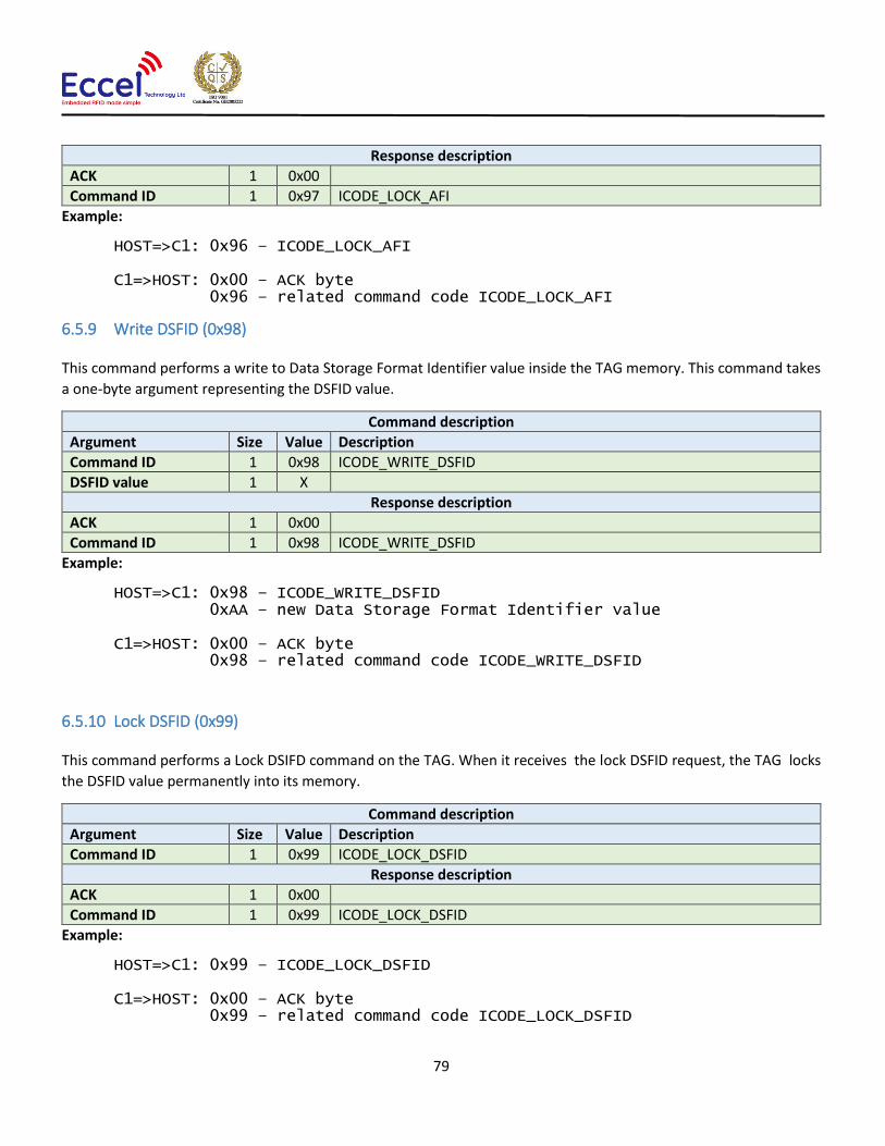
79
Response description
ACK 1 0x00
Command ID 1 0x97 ICODE_LOCK_AFI
Example:
HOST=>C1: 0x96 – ICODE_LOCK_AFI C1=>HOST: 0x00 – ACK byte 0x96 – related command code ICODE_LOCK_AFI
6.5.9 Write DSFID (0x98)
This command performs a write to Data Storage Format Identifier value inside the TAG memory. This command takes
a one-byte argument representing the DSFID value.
Command description
Argument Size Value Description
Command ID 1 0x98 ICODE_WRITE_DSFID
DSFID value 1 X
Response description
ACK 1 0x00
Command ID 1 0x98 ICODE_WRITE_DSFID
Example:
HOST=>C1: 0x98 – ICODE_WRITE_DSFID 0xAA – new Data Storage Format Identifier value C1=>HOST: 0x00 – ACK byte 0x98 – related command code ICODE_WRITE_DSFID
6.5.10 Lock DSFID (0x99)
This command performs a Lock DSIFD command on the TAG. When it receives the lock DSFID request, the TAG locks
the DSFID value permanently into its memory.
Command description
Argument Size Value Description
Command ID 1 0x99 ICODE_LOCK_DSFID
Response description
ACK 1 0x00
Command ID 1 0x99 ICODE_LOCK_DSFID
Example:
HOST=>C1: 0x99 – ICODE_LOCK_DSFID C1=>HOST: 0x00 – ACK byte 0x99 – related command code ICODE_LOCK_DSFID

80
6.5.11 Get System Information (0x9A)
This command performs get system information command on the TAG. No arguments are required. The ACK response
contains bytes with system information. Please refer to the NXP documentation for more information.
Command description
Argument Size Value Description
Command ID 1 0x9A ICODE_GET_SYSTEM_INFORMATION
Response description
ACK 1 0x00
Command ID 1 0x9A ICODE_GET_SYSTEM_INFORMATION
System information X XXX System information bytes
Example:
HOST=>C1: 0x9A – ICODE_GET_SYSTEM_INFORMATION C1=>HOST: 0x00 – ACK byte 0x9A – related command code ICODE_GET_SYSTEM_INFORMATION 0x0F 0x04 0x8F 0x7F 0x0A 0x01 0x24 0x16 0xE0 0x00 0x00 0x33 0x03 0x02 – result bytes
6.5.12 Get multiple BSS (0x9B)
This command performs get multiple block security status command on the TAG. It takes as arguments the block
number for which the status should be returned and the number of blocks to be used for returning the status. The ACK
response contains bytes with block security status information. Please refer to the NXP documentation for more
information.
Command description
Argument Size Value Description
Command ID 1 0x9B ICODE_GET_MULTIPLE_BSS
First block number 1 X
Number of blocks 1 N
Response description
ACK 1 0x00
Command ID 1 0x9B ICODE_GET_MULTIPLE_BSS
BSS information N X Blocks security status information
Example:
HOST=>C1: 0x9B – ICODE_GET_MULTIPLE_BSS 0x00 – starting block number 0x08 – number of BSS to read C1=>HOST: 0x00 – ACK byte 0x9B – related command code ICODE_GET_MULTIPLE_BSS 0x00 0x00 0x00 0x00 0x00 0x00 0x00 0x00 – result bytes

81
6.5.13 Password protect AFI (0x9C)
This command enables the password protection for AFI. The AFI password has to be transmitted before with
ICODE_SET_PASSWORD command.
Command description
Argument Size Value Description
Command ID 1 0x9C ICODE_PASSWORD_PROTECT_AFI
Response description
ACK 1 0x00
Command ID 1 0x9C ICODE_PASSWORD_PROTECT_AFI
Example:
HOST=>C1: 0x9C – ICODE_PASSWORD_PROTECT_AFI C1=>HOST: 0x00 – ACK byte 0x9C – related command code ICODE_PASSWORD_PROTECT_AFI
6.5.14 Read EPC (0x9D)
This command reads EPC data from the TAG. The ACK response contains 12-bytes of EPC data. Please refer to the NXP
documentation for more information.
Command description
Argument Size Value Description
Command ID 1 0x9D ICODE_READ_EPC
Response description
ACK 1 0x00
Command ID 1 0x9D ICODE_READ_EPC
EPC information 12 X Please refer to the NXP documentation for more information.
Example:
HOST=>C1: 0x9D – ICODE_READ_EPC C1=>HOST: 0x00 – ACK byte 0x9D – related command code ICODE_READ_EPC 0x00 0x00 0x00 0x00 0x00 0x00 0x00 0x00 – result bytes
6.5.15 Get NXP System Information (0x9E)
This command retrieves the NXP system information value from the TAG. No arguments are required. The ACK
response contains bytes with the NXP system information. Please refer to the NXP documentation for more
information.

82
Command description
Argument Size Value Description
Command ID 1 0x9E ICODE_GET_NXP_SYSTEM_INFORMATION
Response description
ACK 1 0x00
Command ID 1 0x9E ICODE_GET_NXP_SYSTEM_INFORMATION
System information X XXX System information bytes
Example:
HOST=>C1: 0x9E – ICODE_GET_NXP_SYSTEM_INFORMATION C1=>HOST: 0x00 – ACK byte 0x9E – related command code ICODE_GET_NXP_SYSTEM_INFORMATION 0x0F 0x04 0x8F 0x7F 0x0A 0x01 0x24 0x16 0xE0 0x00 0x00 0x33 0x03 0x02 – result bytes
6.5.16 Get random number (0x9F)
This command requests a random number from the ICODE TAG. No arguments are required. The ACK response
contains a 16-bit random number. This value should be used with ICODE_SET_PASSWORD command.
Command description
Argument Size Value Description
Command ID 1 0x9F ICODE_GET_RANDOM_NUMBER
Response description
ACK 1 0x00
Command ID 1 0x9F ICODE_GET_RANDOM_NUMBER
Random number 2 XXX 16-bits random number
Example:
HOST=>C1: 0x9F – ICODE_GET_RANDOM_NUMBER C1=>HOST: 0x00 – ACK byte 0x9F – related command code ICODE_GET_RANDOM_NUMBER 0x7F 0x14 – result bytes
6.5.17 Set password (0xA0)
This command sets the password for the selected identifier. This command has to be executed just once for the related
passwords if the TAG is powered. The password is calculated as XOR with the random number returned by the
previously executed command ICODE_GET_RANDOM_NUMBER.
Here is an example how to calculate XOR password:
xorPassword[0] = password[0] ^ rnd[0]; xorPassword[1] = password[1] ^ rnd[1]; xorPassword[2] = password[2] ^ rnd[0]; xorPassword[3] = password[3] ^ rnd[1];

83
Command description
Argument Size Value Description
Command ID 1 0xA0 ICODE_SET_PASSWORD
Password Identifier 1 X
0x01 – Read password 0x02 – Write password 0x04 – Privacy password 0x08 – Destroy password
XOR Password 4 X
Response description
ACK 1 0x00
Command ID 1 0xA0 ICODE_SET_PASSWORD
Example:
HOST=>C1: 0xA0 – ICODE_SET_PASSWORD 0x02 – write password 0x34 0x76 0x39 0x64 – calculated XOR password C1=>HOST: 0x00 – ACK byte 0xA0 – related command code ICODE_SET_PASSWORD
6.5.18 Write password (0xA1) This command writes a new password to a selected identifier. With this command, a new password is written into the
related memory. Note that the old password has to be transmitted before with ICODE_SET_PASSWORD. The new
password takes effect immediately which means that the new password has to be transmitted with
ICODE_SET_PASSWORD to get access to the protected blocks/pages. It takes as arguments the password identifier
byte and the plain password 4-bytes long.
Command description
Argument Size Value Description
Command ID 1 0xA1 ICODE_WRITE_PASSWORD
Password Identifier 1 X
0x01 – Read password 0x02 – Write password 0x04 – Privacy password 0x08 – Destroy password
Password 4 X Plain password
Response description
ACK 1 0x00
Command ID 1 0xA1 ICODE_WRITE_PASSWORD
Example:
HOST=>C1: 0xA1 – ICODE_WRITE_PASSWORD 0x02 – write password 0x34 0x76 0x39 0x64 – Plain password C1=>HOST: 0x00 – ACK byte 0xA1 – related command code ICODE_WRITE_PASSWORD
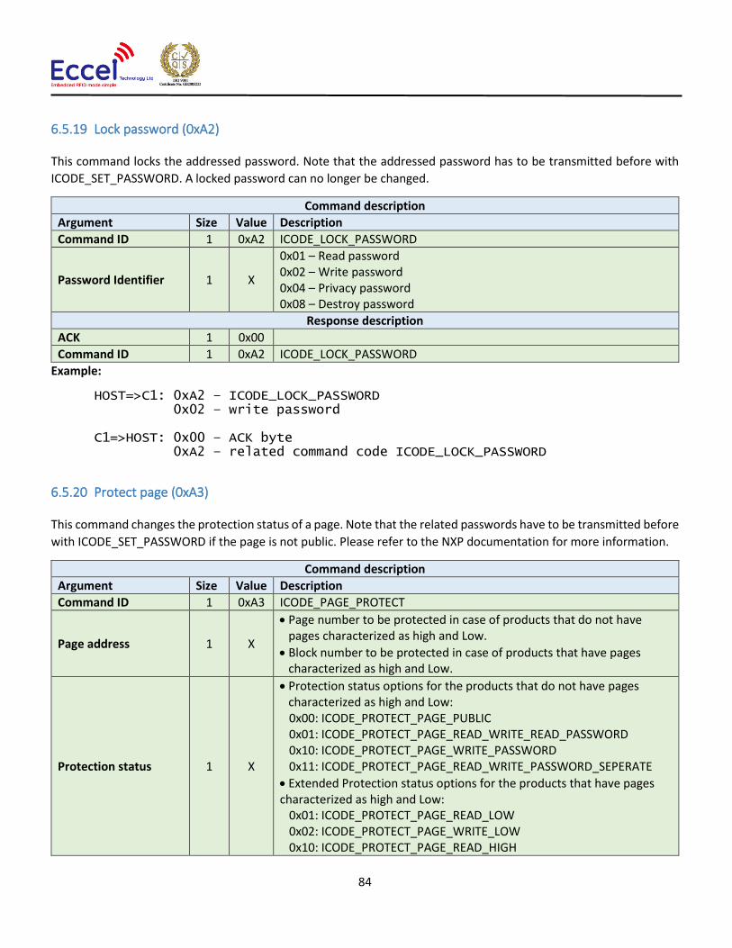
84
6.5.19 Lock password (0xA2)
This command locks the addressed password. Note that the addressed password has to be transmitted before with
ICODE_SET_PASSWORD. A locked password can no longer be changed.
Command description
Argument Size Value Description
Command ID 1 0xA2 ICODE_LOCK_PASSWORD
Password Identifier 1 X
0x01 – Read password 0x02 – Write password 0x04 – Privacy password 0x08 – Destroy password
Response description
ACK 1 0x00
Command ID 1 0xA2 ICODE_LOCK_PASSWORD
Example:
HOST=>C1: 0xA2 – ICODE_LOCK_PASSWORD 0x02 – write password C1=>HOST: 0x00 – ACK byte 0xA2 – related command code ICODE_LOCK_PASSWORD
6.5.20 Protect page (0xA3)
This command changes the protection status of a page. Note that the related passwords have to be transmitted before
with ICODE_SET_PASSWORD if the page is not public. Please refer to the NXP documentation for more information.
Command description
Argument Size Value Description
Command ID 1 0xA3 ICODE_PAGE_PROTECT
Page address 1 X
• Page number to be protected in case of products that do not have pages characterized as high and Low.
• Block number to be protected in case of products that have pages characterized as high and Low.
Protection status 1 X
• Protection status options for the products that do not have pages characterized as high and Low: 0x00: ICODE_PROTECT_PAGE_PUBLIC 0x01: ICODE_PROTECT_PAGE_READ_WRITE_READ_PASSWORD 0x10: ICODE_PROTECT_PAGE_WRITE_PASSWORD 0x11: ICODE_PROTECT_PAGE_READ_WRITE_PASSWORD_SEPERATE
• Extended Protection status options for the products that have pages characterized as high and Low:
0x01: ICODE_PROTECT_PAGE_READ_LOW 0x02: ICODE_PROTECT_PAGE_WRITE_LOW 0x10: ICODE_PROTECT_PAGE_READ_HIGH

85
0x20: ICODE_PROTECT_PAGE_WRITE_HIGH Response description
ACK 1 0x00
Command ID 1 0xA2 ICODE_PAGE_PROTECT
Example:
HOST=>C1: 0xA3 – ICODE_PAGE_PROTECT 0x02 – second block selected 0x01 - ICODE_PROTECT_PAGE_READ_LOW flag selected C1=>HOST: 0x00 – ACK byte 0xA3 – related command code ICODE_PAGE_PROTECT
6.5.21 Lock page protection (0xA4)
This command permanently locks the protection status of a page. Note that the related passwords have to be
transmitted before with ref ICODE_SET_PASSWORD if the page is not public.
Command description
Argument Size Value Description
Command ID 1 0xA4 ICODE_LOCK_PAGE_PROTECTION
Page number 1 X
Response description
ACK 1 0x00
Command ID 1 0xA4 ICODE_LOCK_PAGE_PROTECTION
Example:
HOST=>C1: 0xA4 – ICODE_LOCK_PAGE_PROTECTION 0x02 – page number C1=>HOST: 0x00 – ACK byte 0xA4 – related command code ICODE_LOCK_PAGE_PROTECTION
6.5.22 Get multiple block protection status (0xA5)
This instructs the label to return the block protection status of the requested blocks. It takes as arguments the first
block number to get the block protection status and the number of blocks.
Command description
Argument Size Value Description
Command ID 1 0xA5 ICODE_GET_MULTIPLE_BPS
First block number 1 X
Number of blocks 1 N
Response description
ACK 1 0x00
Command ID 1 0xA5 ICODE_GET_MULTIPLE_BPS
BSS information N X Blocks protection status information

86
Example:
HOST=>C1: 0xA5 – ICODE_GET_MULTIPLE_BPS 0x00 – starting block number 0x08 – number of BSS to read C1=>HOST: 0x00 – ACK byte 0xA5 – related command code ICODE_GET_MULTIPLE_BPS 0x00 0x00 0x00 0x00 0x00 0x00 0x00 0x00 – result bytes
6.5.23 Destroy (0xA6)
This command permanently destroys the label (tag). The destroy password has to be transmitted before with
ICODE_SET_PASSWORD. This command is irreversible and the label will never respond to any command again. This
command can take the XOR password argument for the ICODE products that requires this argument. The XOR
password calculation method is described in the ICODE_SET_PASSWORD description.
Command description
Argument Size Value Description
Command ID 1 0xA6 ICODE_DESTROY
XOR password 4 X Optional XOR password
Response description
ACK 1 0x00
Command ID 1 0xA6 ICODE_DESTROY
Example:
HOST=>C1: 0xA6 – ICODE_DESTROY C1=>HOST: 0x00 – ACK byte 0xA6 – related command code ICODE_DESTROY
6.5.24 Enable privacy (0xA7)
This command instructs the label to enter privacy mode. In privacy mode, the label will only respond to
ICODE_GET_RANDOM_NUMBER and ICODE_SET_PASSWORD commands. To get out of the privacy mode, the Privacy
password has to be transmitted before with ICODE_SET_PASSWORD.
Command description
Argument Size Value Description
Command ID 1 0xA7 ICODE_ENABLE_PRIVACY
XOR password 4 X Optional XOR password
Response description
ACK 1 0x00
Command ID 1 0xA7 ICODE_ENABLE_PRIVACY
Example:

87
HOST=>C1: 0xA7 – ICODE_ENABLE_PRIVACY C1=>HOST: 0x00 – ACK byte 0xA7 – related command code ICODE_ENABLE_PRIVACY
6.5.25 Enable 64-bit password (0xA8)
This instructs the label that both Read and Write passwords are required for protected access. Note that both the
Read and Write passwords have to be transmitted before with ICODE_SET_PASSWORD.
Command description
Argument Size Value Description
Command ID 1 0xA8 ICODE_ENABLE_64BIT_PASSWORD
Response description
ACK 1 0x00
Command ID 1 0xA8 ICODE_ENABLE_64BIT_PASSWORD
Example:
HOST=>C1: 0xA8 – ICODE_ENABLE_64BIT_PASSWORD C1=>HOST: 0x00 – ACK byte 0xA8 – related command code ICODE_ENABLE_64BIT_PASSWORD
6.5.26 Read signature (0xA9)
This command reads the signature bytes from the TAG. No arguments are required. The ACK response contains bytes
containing the signature bytes. Please refer to the NXP documentation for more information.
Command description
Argument Size Value Description
Command ID 1 0xA9 ICODE_READ_SIGNATURE
Response description
ACK 1 0x00
Command ID 1 0xA9 ICODE_READ_SIGNATURE
Signature bytes X XXX Signature bytes
Example:
HOST=>C1: 0xA9 – ICODE_READ_SIGNATURE C1=>HOST: 0x00 – ACK byte 0xA9 – related command code ICODE_READ_SIGNATURE 0x0F 0x04 0x8F 0x7F 0x0A 0x01 0x24 0x16 0xE0 0x00 0x00 0x33 0x03 0x02 – result bytes

88
6.5.27 Read config (0xAA)
This command reads multiple 4-byte data chunks from the selected configuration block address. It takes two
arguments, the first block number and the number of blocks to read the configuration data.
Command description
Argument Size Value Description
Command ID 1 0xAA ICODE_READ_CONFIG
First block number 1 X
Number of blocks 1 N
Response description
ACK 1 0x00
Command ID 1 0xAA ICODE_READ_CONFIG
Configuration bytes N*4 X
Example:
HOST=>C1: 0xAA – ICODE_READ_CONFIG 0x00 – starting block number 0x02 – number of blocks to read C1=>HOST: 0x00 – ACK byte 0xAA – related command code ICODE_READ_CONFIG 0x00 0x00 0x00 0x00 0x00 0x00 0x00 0x00 – result bytes
6.5.28 Write config (0xAB)
This command writes configuration bytes to addressed block data from the selected configuration block address. It
takes three arguments: the option byte, the block number and the configuration bytes. Please refer to the NXP
documentation for more information.
Command description
Argument Size Value Description
Command ID 1 0xAB ICODE_WRITE_CONFIG
Option byte 1 X 0x01 – Enable option 0x00 – Disable option
Block number 1 X
Configuration bytes 4 X
Response description
ACK 1 0x00
Command ID 1 0xAB ICODE_WRITE_CONFIG
Example:
HOST=>C1: 0xAB – ICODE_WRITE_CONFIG 0x01 – option byte 0x00 – block number 0x00 0x00 0x00 0x00 – config bytes

89
C1=>HOST: 0x00 – ACK byte 0xAB – related command code ICODE_WRITE_CONFIG
6.5.29 Pick random ID (0xAC)
This command enables the random ID generation in the tag. This interface is used to instruct the tag to generate a
random number in privacy mode. Please refer to the NXP documentation for more information.
Command description
Argument Size Value Description
Command ID 1 0xAC ICODE_PICK_RANDOM_ID
Response description
ACK 1 0x00
Command ID 1 0xAC ICODE_PICK_RANDOM_ID
Example:
HOST=>C1: 0xAB – ICODE_PICK_RANDOM_ID C1=>HOST: 0x00 – ACK byte 0xAB – related command code ICODE_PICK_RANDOM_ID
6.6 OTA upgrade
The commands listed below can be used to perform an OTA upgrade.
6.6.1 OTA begin (0xF0)
This command must be executed to start the OTA upgrade process. The device responds with an ACK and then host
should wait about 4seconds to send first OTA frame while the device is erasing internal flash.
Command description
Argument Size Value Description
Command ID 1 0x0F0 OTA begin
Response description
ACK 1 0x00
Command ID 1 0xF0 OTA begin
Example:
HOST=>C1: 0xF0 – OTA begin
C1=>HOST: 0x00 – ACK byte 0xF0 – related command code OTA begin
6.6.2 OTA firmware frame (0xF1)
When the OTA begin frame has already been executed, the host application can upload binary firmware file in chunks
that are 128 bytes long (the last frame can be smaller).

90
Command description
Argument Size Value Description
Command ID 1 0x0F1 OTA frame
Firmware bytes Max. 128
Firmware bytes in chunks 128bytes long.
Response description
ACK 1 0x00
Command ID 1 0xF1 OTA frame
Example:
HOST=>C1: 0xF1 – OTA frame 0x34 0x67 … 0x45 – firmware bytes
C1=>HOST: 0x00 – ACK byte 0xF1 – related command code OTA frame
6.6.3 OTA finish (0xF2)
The command must be executed after all firmware frames are written to the device. The bootloader application checks
the integrity of the application. After this step the host can send the REBOOT command to reboot the device and run
the new firmware. If there is a problem with communication after a device upgrade, please perform a factory reset.
Command description
Argument Size Value Description
Command ID 1 0x0F2 OTA finish
Response description
ACK 1 0x00
Command ID 1 0xF2 OTA finish
Example:
HOST=>C1: 0xF4 – OTA finish
C1=>HOST: 0x00 – ACK byte 0xF4 – related command code OTA finish

91
7. Mechanical dimension
All dimensions are in mm.
Figure 7-1

92
MIFARE, MIFARE Ultralight, MIFARE Plus, MIFARE Classic, and MIFARE DESFire are trademarks of NXP B.V.
No responsibility is taken for the method of integration or final use of the OEM readers
More information about the OEM readers and other products can be found at the Internet site:
http://www.eccel.co.uk
or alternatively contact ECCEL Technology (IB Technology) by e-mail at: