ODISHA POWER TRANSMISSION CORPORATION LIMITED
51
(1) (2) (3) (1) x (3) 1 245 KV,1200-600-300A,40KA,5CORE SINGLE PHASE CURRENT TRANSFORMER(4 PS Cl & 1 0.2s Cl) NOS 18 3 3 24 2 245 KV,2000A,40KA,ISOLATORS 2.1 S/I WITH OUT EARTH SWITCH NOS 18 3 3 24 2.2 S/I WITH SINGLE EARTH SWITCH NOS 4 1 1 6 2.3 BEAM MOUNTED S/I WITHOUT EARTH SWITCH NOS 4 1 1 6 3 245 KV,4400pF,3CORE,SINGLE PHASE CAPACITOR VOLTAGE TRANSFORMER NOS 6 3 3 12 4 245KV,3150A,50KA,SF6,CIRCUIT BREAKER WITH SUPPORTING STRUCTURE NOS 5 1 1 7 5 216 KV, METAL OXIDE SURGE ARRESTOR,10 KA, class III NOS 12 3 3 18 6 245 KV ,2 CORE,SINGLE PHASE,IVT NOS 6 0 0 6 7 220 KV Bus Post Insulators NOS 54 12 12 78 8 36 KV,800-400-200,25KA,4CORE SINGLE PHASE CURRENT TRANSFORMER(3 PS Cl & 1 0.2s Cl) NOS 6 0 0 6 ODISHA POWER TRANSMISSION CORPORATION LIMITED NAME OF THE WORK:- Design, Supply and Installation of Sub-Stations & Transmission Lines for Procurement of 2X20 MVA, 220/33 KV Sub-station at GOBINDPALLI & associated 220KV LILO line on 220KV BALIMELA - MALKANGIRI Second CKT Line (Approx. Line length- 37.600 Kms.) and stringing of 220 KV Second CKT line on existing DC Tower from BALIMELA to MALKANGIRI and associated 220KV bay extension at Balimela & Malkangiri S/S in Odisha State of India under PACKAGE-5A Under Japan International Cooperation Agency (JICA)’s ODA Loan. Loan Agreement No: [ID-P245] - FB No: [CPC/JICA/ICB/05A/16-17/]- Reference Identification No: [OPTCL/JICA/PKG- 5A] NAME OF THE BIDDER Unit Price 2 SUPPLY OF FOLLOWING EQUIPMENTS (As per Technical Specification) Schedule No. 1. Plant and Mandatory Spare Parts Supplied from Abroad (Sub-station & Bay extension) SL NO In Foreign Currency Total Price 2 Quantity for: Construction of 2x20 MVA, 220/33 KV Sub-Station at Gobindapalli 220 KV BAY 05 NOS (FDR:02,TFR:02 & B/C:01) & 33 KV BAY 07 NOS (FDR:04,TFR:02 & B/C:01) Quantity for: 01 No. Feeder Bay Extension at 220/33 kV Grid S/s Malkangiri Code 1 Units Quantity for: 01 No. Feeder Bay Extension at 220/33 kV Grid S/s Balimela CIP Total Quantity
-
Upload
khangminh22 -
Category
Documents
-
view
0 -
download
0
Transcript of ODISHA POWER TRANSMISSION CORPORATION LIMITED
(1) (2) (3) (1) x (3)
1245 KV,1200-600-300A,40KA,5CORE SINGLE PHASE CURRENT
TRANSFORMER(4 PS Cl & 1 0.2s Cl)NOS 18 3 3 24
2 245 KV,2000A,40KA,ISOLATORS
2.1 S/I WITH OUT EARTH SWITCH NOS 18 3 3 24
2.2 S/I WITH SINGLE EARTH SWITCH NOS 4 1 1 6
2.3 BEAM MOUNTED S/I WITHOUT EARTH SWITCH NOS 4 1 1 6
3245 KV,4400pF,3CORE,SINGLE PHASE CAPACITOR VOLTAGE
TRANSFORMERNOS 6 3 3 12
4245KV,3150A,50KA,SF6,CIRCUIT BREAKER WITH SUPPORTING
STRUCTURENOS 5 1 1 7
5 216 KV, METAL OXIDE SURGE ARRESTOR,10 KA, class III NOS 12 3 3 18
6 245 KV ,2 CORE,SINGLE PHASE,IVT NOS 6 0 0 6
7 220 KV Bus Post Insulators NOS 54 12 12 78
836 KV,800-400-200,25KA,4CORE SINGLE PHASE CURRENT
TRANSFORMER(3 PS Cl & 1 0.2s Cl)NOS 6 0 0 6
ODISHA POWER TRANSMISSION CORPORATION LIMITEDNAME OF THE WORK:- Design, Supply and Installation of Sub-Stations & Transmission Lines for Procurement of 2X20 MVA, 220/33 KV
Sub-station at GOBINDPALLI & associated 220KV LILO line on 220KV BALIMELA - MALKANGIRI Second CKT Line (Approx. Line length-
37.600 Kms.) and stringing of 220 KV Second CKT line on existing DC Tower from BALIMELA to MALKANGIRI and associated 220KV bay
extension at Balimela & Malkangiri S/S in Odisha State of India under PACKAGE-5A Under Japan International Cooperation Agency (JICA)’s
ODA Loan.Loan Agreement No: [ID-P245] - FB No: [CPC/JICA/ICB/05A/16-17/]- Reference Identification No: [OPTCL/JICA/PKG-
5A]
NAME OF THE BIDDER
Unit Price2
SUPPLY OF FOLLOWING EQUIPMENTS
(As per Technical Specification)
Schedule No. 1. Plant and Mandatory Spare Parts Supplied from Abroad (Sub-station & Bay extension)
SL NOIn Foreign
Currency
Total Price2
Qu
an
tity
fo
r: C
on
str
ucti
on
of
2x20 M
VA
,
220/3
3 K
V S
ub
-Sta
tio
n a
t G
ob
ind
ap
alli 220
KV
BA
Y 0
5 N
OS
(F
DR
:02,T
FR
:02 &
B/C
:01)
& 3
3 K
V B
AY
07 N
OS
(F
DR
:04,T
FR
:02 &
B/C
:01)
Qu
an
tity
fo
r: 0
1 N
o. F
eed
er
Bay E
xte
nsio
n a
t
220/3
3 k
V G
rid
S/s
Malk
an
gir
i
Code1 Units
Qu
an
tity
fo
r: 0
1 N
o. F
eed
er
Bay E
xte
nsio
n a
t
220/3
3 k
V G
rid
S/s
Balim
ela
CIP
To
tal Q
uan
tity

936 KV,800-400-200,25KA,3CORE SINGLE PHASE CURRENT
TRANSFORMER (2 PS Cl & 1 0.2s Cl)NOS 15 0 0 15
10 36 KV,1250A,25KA,ISOLATORS
10.1 S/I WITH OUT EARTH SWITCH NOS 8 0 0 8
10.2 D/I WITH SINGLE EARTH SWITCH NOS 4 0 0 4
10.3 D/I WITHOUT EARTH SWITCH NOS 2 0 0 2
10.4 S/I WITH BEAM MOUNTED NOS 2 0 0 2
1130 KV, METAL OXIDE SURGE ARRESTOR, 10KA, class II(Beam
Mounted)NOS 24 0 0 24
12 36 KV ,2 CORE,SINGLE PHASE,IVT NOS 3 0 0 3
1336KV,1250A,25KA,VACUUM CIRCUIT BREAKER WITH SUPPORTING
STRUCTURENOS 7 0 0 7
14 33 KV Bus Post Insulators NOS 20 0 0 20
15 BUS BAR & CIRCUIT MATERIALS
15.1 ANTI FOG TYPE INSULATOR
15.1.1 220 KV LONG ROD 160 KN PORCILAIN INSULATOR(220KV Side) NOS 96 30 30 156
15.1.2 220 KV LONG ROD 120 KN PORCILAIN INSULATOR(220KV Side) NOS 12 9 9 30
15.1.2 120 KNLong Rod Porcelain INSULATOR(33KV Side) NOS 66 0 0 66
15.1.3 90 KNLong Rod Porcelain INSULATOR(33KV Side) NOS 33 0 0 33
15.2 ACSR MOOSE CONDUCTOR KMS 5.00 0.50 0.50 6
15.3IPS 4" ALUMINIUM TUBES(114.2 mm OD, & 8.51mm Thickness) for
equipment to equipment connection in 220 KV side.MTRS 370 80 80 530
15.4 HARDWARES & FITTINGS/SPACERS/CLAMP & CONNECTORS
15.4.1 220 KV Double Tension H/W fitting for twin moose ACSR (Single Anchoring
Point)NOS 24 12 12 48
15.4.2 220 KV Single Tension H/W fitting for single moose ACSR NOS 24 12 12 48
15.4.3 220 KV Single Suspension H/W fitting for single mose ACSR NOS 6 6 6 18
15.4.4220 KV Double Suspension H/W fitting for twin mose ACSR (Single
Anchoring Point)NOS 18 6 6 30
15.4.5 33 KV Single Tension H/W fitting for single moose ACSR NOS 30 0 0 30
15.4.633 KV Double Tension H/W fitting for twin moose ACSR (Single Anchoring
Point)NOS 24 0 0 24
15.4.7 33 KV Single Suspension H/W fitting for single mose ACSR NOS 12 0 0 12
15.4.8 220kv T- clamp for ACSR ZEBRA run to ACSR MOOSE drop NOS 18 9 9 36
15.4.9 T-Clamp for single Moose -Single Moose ACSR NOS 42 3 3 48
15.4.10 T-Clamp for twin Moose run -Single Moose drop ACSR NOS 36 3 3 42
15.4.11 220 KV PI clamp NOS 54 12 12 78
15.4.12 33KV PI Clamp NOS 20 0 0 20
15.4.13 Spacer for Moose ACSR NOS 120 18 18 156
15.4.14 220 KV Isolator pad clamp NOS 132 30 30 192
15.4.15 220 KV LA Clamp NOS 12 3 3 18
15.4.16 220 KV CVT Clamp NOS 6 3 3 12
15.4.17 220 KV CT Clamp NOS 36 6 6 48
15.4.18 220 KV IVT Clamp NOS 6 0 0 6
15.4.19 220 KV CB Clamp NOS 30 6 6 42
15.4.20 33 KV Isolator pad clamp NOS 114 0 0 114

15.4.21 33 KV LA Clamp NOS 24 0 0 24
15.4.22 33 KV CT Clamp NOS 42 0 0 42
15.4.23 33 KV IVT Clamp NOS 3 0 0 3
15.4.24 33 KV CB Clamp NOS 42 0 0 42
15.4.25 PG Clamp for ACSR Moose NOS 48 18 18 84
15.5 EARTH WIRES & IT'S HARDWARES & FITTING
15.5.1 Earthing Spikes and Its Fittings in all respect.
15.5.1.1Earthing Spikes of 9 mtr long each and Its Fittings in all respect. (220 kv
side)NOS 37 3 3 43
15.5.1.2Earthing Spikes of 5 mtr long each and Its Fittings in all respect. (33 KV
side)NOS 25 0 0 25
16 SUBSTATION EARTHING SYSTEMS
16.1EARTHING CONDUCTOR FOR BURRIAL : 75X10 mm GI Flat for laying
(spacing maximum 5m both way ) MT 31 4 4 39
16.2EARTHING CONDUCTOR: 50X6 mm GI Flat for Raiser from the burial
earth mat to equipment,structure etc)MT 10.41 1.25 1.25 12.91
16.3EARTHING DEVICE & ASSOCIATED ACCESSORIES (50 mm heavy duty
GI PERFORATED PIPE 3 mtrs long for treated earth pit)Nos. 180 25 25 230
16.4EARTHING DEVICE & ASSOCIATED ACCESSORIES 40mm MS rod 3
mtrs long for non treated earth pit)Nos. 120 15 15 150
16.5 Pipe-in-Pipe earthing electrode Nos. 4 0 0 4
17
G.I Cable Trays including support GI angle suitable for different sections i.e.
Section:1-1,2-2,3-3 & 4-4 along with its accessories as per TS.
17.1 G.I Cable Trays(size: 450x75x2500mm) MTRS 1200 125 125 1450
17.2 G.I Cable Trays(size: 300x75x2500mm) MTRS 2000 100 100 2200
17.3 G.I Cable Trays(size: 150x75x2500mm) MTRS 1500 50 50 1600
17.4 Support G. I angle 50x50x6 mm for cable tray MT 2.5 0.25 0.25 3
18SUB STATION SWITCYARD BMK,AC CONSOLE & OTHER
MARSHALLING BOXES
18.1BAY MARSHALLING KIOSK (03 nos on 220 kV bay & 04Nos 33 KV bay )
NOS 7 1 1 9
18.2SWITCH YARD AC CONSOLE FOR LIGHTING (01 nos on 220 kV bay &
01 No in 33KV bay )NOS 2 0 0 2
18.3SWITCH YARD RECEPTACLE BOARD FOR TFR OIL FILTERATION (01
no. near 220/33 KV power Transformer)NOS 1 0 0 1
18.4SWITCH YARD RECEPTACLE BOARD FOR WELDING & OTHER
EMERGENCY (01 nos on 220 & 33 kV bay ) NOS 2 0 0 2
19
SWITCH YARD STRUCTURES (LATTICE TYPE FOR TOWER COLUMN
& BEAMS & PIPE TYPE FOR ALL EQUIPMENT COLUMN) FOR
220/132/33 KV CLASS INCLUDING FOUNDATION BOLTS & NUTS.
19.1 DIFFERENT TYPES OF COLUMNS WITH DETAILS
19.1.1 RP1S-220 KV (NOMINAL UNIT WT- 4.5 MT) (24 NOS.+4NOS.+4NOS.) MT 108 18 18 144
19.1.2 RP2S-220 KV (NOMINAL UNIT WT- 1.5 MT) (6NOS.) MT 9 0 0 9

19.1.3 T1S - 132 KV(NOMINAL UNIT WT- 1.2 MT) (4 NOS.) MT 0 0 0 0
19.1.4 T8S - 33KV(NOMINAL UNIT WT- 0.8 MT) (11 NOS.) MT 0 0 0 0
19.1.5 T9S - 33KV(NOMINAL UNIT WT- 0.6 MT) (14 NOS.) MT 8.4 0 0 8.4
19.2 DIFFERENT TYPE OF BEAMS WITH DETAILS
19.2.1 RQ1-220KV (NOMINAL UNIT WT- 1.5 MT) (22NOS.+4NOS.+4NOS.)) MT 33 6 6 45
19.2.2 RQ2-220KV (NOMINAL UNIT WT-2.5 MT) (8 NOS.+2NOS.+2NOS.) MT 20 5 5 30
19.2.3 Q4-220KV (NOMINAL UNIT WT- 0.9 MT) (4 NOS.) MT 0 0 0 0
19.2.4 G1 - 132KV (NOMINAL UNIT WT- 0.62 MT) (4 NOS.) MT 0 0 0 0
19.2.5 G6 - 33KV (NOMINAL UNIT WT- 0.53 MT) (4 NOS.) MT 2.12 0 0 2.12
19.2.6 G4 - 33KV(NOMINAL UNIT WT- 0.4 MT) (12 NOS.) MT 4.8 0 0 4.8
19.2.7 G4X - 33KV (NOMINAL UNIT WT- 0.4 MT) (2 NOS.) MT 0.8 0 0 0.8
19.3 TOTAL WEIGHT OF COLUMN & BEAM MT 186.12 29 29 244.12
19.4
EQUIPMENT SUPPORT STRUCTURES (PIPE TYPE) FOR ALL 220KV,
132 KV & 33KV EQUIPMENTS INCLUDING FOUNDATION BOLTS &
NUTS
19.4.1 ISOLATORS-220KV ( SI with E/S-4 No.+01 No.+01No.) MT 5.084 1.271 1.271 7.626
19.4.2 ISOLATORS-220KV (SI without E/S:18Nos.+03 nos.+03 nos.) MT 22.878 3.813 3.813 30.504
19.4.3 BEAM ISOLATORS-220KV ( SI with E/S: 4Nos.+01 No.+01No.) MT 5.084 1.271 1.271 7.626
19.4.4 ISOLATORS-33 KV ( SI-8 Nos.) MT 2.0664 0 0 2.0664
19.4.5 ISOLATORS-33 KV ( DI with E/S -4 Nos.) MT 2.5776 0 0 2.5776
19.4.6 ISOLATORS-33 KV ( DI without E/S-2 Nos.) MT 1.234 0 0 1.234
19.4.7 CTS-220 KV (15 nos.+03 nos.+03 nos.) MT 3.375 0.675 0.675 4.725
19.4.8 CTS-33 KV (15 nos.) MT 1.74 0 0 1.74
19.4.9 CVTS-220 KV (6 nos.+03 nos.+03 nos.) MT 1.326 0.663 0.663 2.652
19.4.10 IVTS-220 KV (3 nos.) MT 1.7232 0 0 1.7232
19.4.11 IVTS-33 KV (3 nos.) MT 0.3546 0 0 0.3546
19.4.12 Surge Arrester-220 Kv( 12 nos.+03 nos.+03 nos.) MT 3.5052 0.8763 0.8763 5.2578
19.4.13 BPI-220 KV (38nos.+12 Nos.+12Nos.) MT 15.8112 3.5136 3.5136 22.8384
19.4.14 BPI-33 KV (20 nos.) MT 4.126 0 0 4.126
19.4.15 NCTs(4 nos) MT 0.464 0 0 0.464
19.5 TOTAL WEIGHT OF EQUIPMENT STRUCTURE MT 71.3492 12.0829 12.0829 95.515
19.6TOTAL WEIGHT OF EQUIPMENT & Column GI Foundation Bolts &
NutsMT 12 2.412 2.412 16.824
19.7Total weight of GI Nuts and bolts for Columns, Beams & Equipment
StructuresMT 12 2.5 2.5 17
20 GENERAL EQUIPMENT & SUBSTATION ACCESSORIES
20.1POWER CABLES,1.1KV,XLPE & PVC ARMOURED, ALUMINIUM
CONDUCTOR (As per Specification)
20.1.1 XLPE 3.5 CX300 mm2 MTR 500 0 0 500
20.1.2 XLPE 3.5 CX185 mm2 MTR 300 0 0 300
20.1.3 XLPE 3.5 CX120 mm2 MTR 200 0 0 200
20.1.4 PVC 3.5 CX70 mm2 MTR 600 0 0 600
20.1.5 PVC 3.5 CX35 mm2 MTR 1500 500 500 2500
20.1.6 PVC 4 CX 16 mm2 MTR 1000 0 0 1000
20.1.7 PVC 4CX 6 sqmm MTR 3500 0 0 3500
20.1.9 PVC 2CX 6 sqmm MTR 2000 0 0 2000
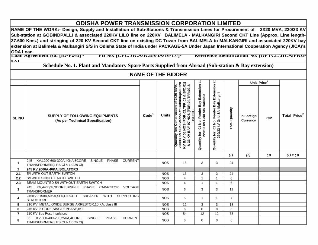
20.2 CONTROL CABLES,1.1 KV, PVC,STRANDED COPPER(As per
specification)20.2.1 2 CX 2.5 mm2 MTR 5000 2500 2500 10000
20.2.3 4 CX 2.5 mm2 MTR 12000 5000 5000 22000
20.2.4 5 CX 2.5 mm2 MTR 4000 0 0 4000
20.2.5 7CX 2.5 mm2 MTR 5000 0 0 5000
20.2.6 10 CX 2.5 mm2 MTR 2000 0 0 2000
20.2.7 12 CX 2.5 mm2 MTR 2000 1500 1500 5000
20.2.8 16 CX 2.5 mm2 MTR 1000 0 0 1000
20.2.9 19 CX 2.5 mm2 MTR 2000 0 0 2000
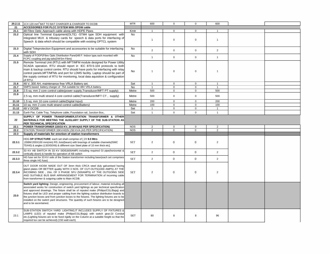
20.2.11 1CX 120 mm2
BAT TO BAT CHARGER & CHARGER TO DCDB MTR 600 0 0 600
21 ACCESSORIES FOR PLCC SYSTEM With OPGW cable
21.1 48 Fibre Optic Approach cable along with HDPE Pipes Kmtr 1.00 0.00 0.00 1
21.2 Optical line Terminal Equipment(OLTE) -STM4 type SDH equipment
with integrated MUX & tributary cards for speech & data ports for
interfacing of Speech & data which should be compatible with
existing OPTCL system
No 1 0 0
1
21.3 Digital Teleprotection Equipment and accessories to be suitable for
interfacing with SDH
No 2 0 02
21.4 Supply of FODP(Fibre Optic Distribution Panel)48 F: Indoor type,rack
mounted with FCPC coupling and pig tails(DWSm Fibre)No 1 0 0
1
21.5 Remote Terminal Unit (RTU) with MFT/MFM module designed for
Power Utility SCADA operation. RTU should report in IEC 870-5-
104 protocols to both main & backup control centre. RTU should
have ports for interfacing with relay control panels,MFT/MFMs and
port for LDMS facility. Laptop should be part of the supply contract
of RTU for monitoring, local data aquisition & configuration of RTU.
No 1
0 0
1
21.6 48 V, 300 AH, maintenance free VRLA Battery set. Set1
0 0 1
21.7 SMPS based battery charger of 75A suitable for 48V VRLA battery. No1
0 0 1
21.8 2.5 sq. mm 2 core control cable(power supply,Transducer/MFT PT
supply)Metre 500
0 0500
21.9 2.5 sq. mm multi strand 4 core control cable(Transducer/MFT CT ,
supply)Metre 500
0 0500
21.10 1.5 sq. mm 10 core control cable(Digital Input) Metre 200 0 0 200
21.11 10 sq. mm 2 core multi strand control cable(Battery) Metre 100 0 0 100
21.12 48 V DCDB Set 1 0 0 1
21.13 Earth Flat, Cable Tray, Telephone cable, Foundation rail, Junction Box,. Set 10 0
1
22
SUPPLY OF POWER TRANSFORMER,STATION TRANSFORMER &
OTHER MATERIALS FOR MEETING THE AUXILIARY SUPPLY OF THE
SUB-STATION AS PER TECHNICAL SPECIFICATION
22.1 POWER TRANSFORMER 220/33 KV, 20 MVA(AS PER SPECIFICATION) NOS 2 0 0 2

22.2STATION TRANSFORMER 33KV/433V,250 KVA (AS PER
SPECIFICATION)NOS 2 0 0 2
22.3 Supply of materials for erection of station transformers
22.3.1
HDG DP STRUCTURE: each set shall comprise of [ 2X 9.0 Mtrs
(ISBM:200X100 mm(min) RS Joist(beam) with bracings of suitable
channels(ISMC 75X40) & angles (L50X50X6) & different size Steel plate of
10 mm thick etc].
SET 2 0 0 2
22.3.233 KV AB SWITCH IN 33 KV SIDE(600AMP) including required GI
pipe(horizontal & vertically down) & handle for operation of AB switchSET 2 0 0 2
22.3.3HG fuse set for 33 KV side of the Station transformer including base(each
set comprises three single HG fuse) SET 2 0 0 2
22.3.4
OUT DOOR KIOSK MADE OUT OF 3mm thick CRCA steel duly galvanised
having gland plates OR BETTER quality WITH 3 NOS. OF CUT-
OUTS(1000 AMPS) AT THE INCOMING SIDE , 1No. OF 3 PHASE SFU
(500AMPS) AT THE OUTGOING SIDE AND SUITABLE BUS BAR
ARRANGEMENT FOR TERMINATION of incoming cable from transformer
& outgoing cable to Main ACDB.
SET 2 0 0 2
23.0
Switch yard lighting: Design, engineering, procurement of labour, material
including all associated works for construction of switch yard lightings as per
technical specification and approved drawings. The fixture shall be of
reputed make (Philips/CGL/Bajaj) and fixtures shall be LED and proper
cabling from the lighting outdoor distribution boards to the junction boxes
and from junction boxes to the fixtures. The lighting fixtures are to be
installed on the switch yard structures. The quantity of such fixtures are to be
designed and to be ascertained.
23.1
SUB-STATION SWITCH YARD LIGHTING,IT INCLUDES SUPPLY OF
FIXTURES & LAMPS (LED) of reputed make (Philips/CGL/Bajaj) with switch
gear,GI Conduit etc.(Lighting fixtures are to be fixed rigidly on the Column at
a suitable height so that the required lux can be achieved).(150 watt each)
SET 80 8 8 96
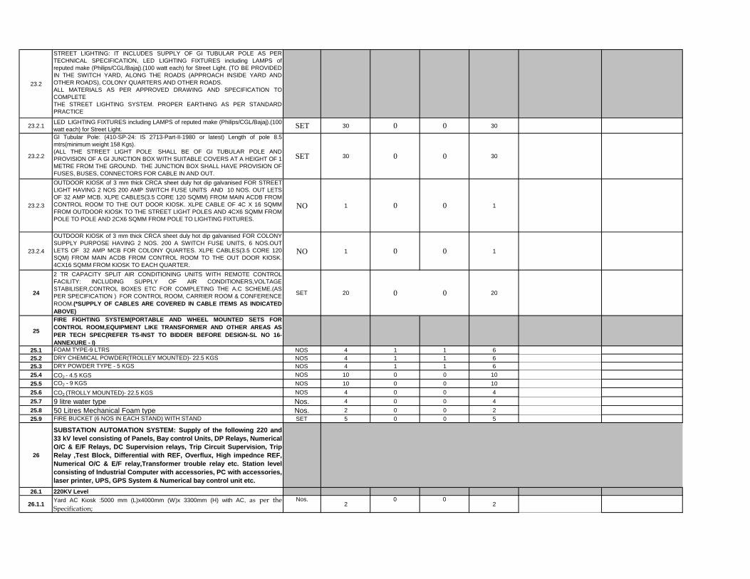
23.2
STREET LIGHTING: IT INCLUDES SUPPLY OF GI TUBULAR POLE AS
PER TECHNICAL SPECIFICATION, LED LIGHTING FIXTURES including
LAMPS of reputed make (Philips/CGL/Bajaj).(100 watt each) for Street Light.
(TO BE PROVIDED IN THE SWITCH YARD, ALONG THE ROADS
(APPROACH INSIDE YARD AND OTHER ROADS), COLONY
QUARTERS AND OTHER ROADS.
ALL MATERIALS AS PER APPROVED DRAWING AND SPECIFICATION
TO COMPLETE
THE STREET LIGHTING SYSTEM. PROPER EARTHING AS PER
STANDARD PRACTICE
23.2.1
LED LIGHTING FIXTURES including LAMPS of reputed make
(Philips/CGL/Bajaj).(100 watt each) for Street Light. SET 30 0 0 30

23.2.2
GI Tubular Pole: (410-SP-24: IS 2713-Part-II-1980 or latest) Length of pole
8.5 mtrs(minimum weight 158 Kgs).
(ALL THE STREET LIGHT POLE SHALL BE OF GI TUBULAR POLE AND
PROVISION OF A GI JUNCTION BOX WITH SUITABLE COVERS AT A
HEIGHT OF 1 METRE FROM THE GROUND. THE JUNCTION BOX
SHALL HAVE PROVISION OF FUSES, BUSES, CONNECTORS FOR
CABLE IN AND OUT.
SET 30 0 0 30
23.2.3
OUTDOOR KIOSK of 3 mm thick CRCA sheet duly hot dip galvanised FOR
STREET LIGHT HAVING 2 NOS 200 AMP SWITCH FUSE UNITS AND 10
NOS. OUT LETS OF 32 AMP MCB. XLPE CABLES(3.5 CORE 120 SQMM)
FROM MAIN ACDB FROM CONTROL ROOM TO THE OUT DOOR
KIOSK. XLPE CABLE OF 4C X 16 SQMM FROM OUTDOOR KIOSK TO
THE STREET LIGHT POLES AND 4CX6 SQMM FROM POLE TO POLE
AND 2CX6 SQMM FROM POLE TO LIGHTING FIXTURES.
NO 1 0 0 1
23.2.4
OUTDOOR KIOSK of 3 mm thick CRCA sheet duly hot dip galvanised FOR
COLONY SUPPLY PURPOSE HAVING 2 NOS. 200 A SWITCH FUSE
UNITS, 6 NOS.OUT LETS OF 32 AMP MCB FOR COLONY QUARTES.
XLPE CABLES(3.5 CORE 120 SQM) FROM MAIN ACDB FROM
CONTROL ROOM TO THE OUT DOOR KIOSK. 4CX16 SQMM FROM
KIOSK TO EACH QUARTER.
NO 1 0 0 1
24
2 TR CAPACITY SPLIT AIR CONDITIONING UNITS WITH REMOTE
CONTROL FACILITY: INCLUDING SUPPLY OF AIR
CONDITIONERS,VOLTAGE STABILISER,CONTROL BOXES ETC FOR
COMPLETING THE A.C SCHEME.(AS PER SPECIFICATION ) FOR
CONTROL ROOM, CARRIER ROOM & CONFERENCE ROOM.(*SUPPLY
OF CABLES ARE COVERED IN CABLE ITEMS AS INDICATED ABOVE)
SET 20 0 0 20
25
FIRE FIGHTING SYSTEM(PORTABLE AND WHEEL MOUNTED SETS
FOR CONTROL ROOM,EQUIPMENT LIKE TRANSFORMER AND
OTHER AREAS AS PER TECH SPEC(REFER TS-INST TO BIDDER
BEFORE DESIGN-SL NO 16-ANNEXURE - I)25.1 FOAM TYPE-9 LTRS NOS 4 1 1 6
25.2 DRY CHEMICAL POWDER(TROLLEY MOUNTED)- 22.5 KGS NOS 4 1 1 6
25.3 DRY POWDER TYPE - 5 KGS NOS 4 1 1 6
25.4 CO2 - 4.5 KGS NOS 10 0 0 10
25.5 CO2 - 9 KGS NOS 10 0 0 10
25.6 CO2 (TROLLY MOUNTED)- 22.5 KGS NOS 4 0 0 4
25.7 9 litre water type Nos. 4 0 0 4
25.8 50 Litres Mechanical Foam type Nos. 2 0 0 2
25.9 FIRE BUCKET (6 NOS IN EACH STAND) WITH STAND SET 5 0 0 5

26
SUBSTATION AUTOMATION SYSTEM: Supply of the following
220 and 33 kV level consisting of Panels, Bay control Units, DP
Relays, Numerical O/C & E/F Relays, DC Supervision relays,
Trip Circuit Supervision, Trip Relay ,Test Block, Differential
with REF, Overflux, High impednce REF, Numerical O/C & E/F
relay,Transformer trouble relay etc. Station level consisting of
Industrial Computer with accessories, PC with accessories,
laser printer, UPS, GPS System & Numerical bay control unit
etc.
26.1 220KV Level
26.1.1Yard AC Kiosk :5000 mm (L)x4000mm (W)x 3300mm (H) with AC, as per
the Specification;
Nos. 2 0 02
26.1.2
Numerical Bay control unit :32 Digital input & 24Nos digital out put with CT /
PT Input cards.IEC 61850 protocol. (The BCU for transformer panels should
have provision to accommodate required Analogue Inputs).
Nos. 5 0 0
5
26.1.3 Numerical distance protection with the following functions: IEC 61850
protocol.
Nos. 4 0 0 4
26.1.4Numerical Transformer Differential/REF protection with the following
functions: Over flux ,Over volt etc. IEC 61850 protocol
Nos. 2 0 02
26.1.5 Numerical over current , earth fault relays: IEC 61850 protocol Nos. 5 0 0 5
26.1.6 High Impedance REF Relay Nos. 2 0 0 2
26.1.7 Numerical Centralised Bus bar protection. Nos. 1 0 0 1
26.1.8 AUXILIARY RELAY FOR DC SUPERVISION Nos. 10 0 0 10
26.1.9 AUXILIARY RELAY FOR TRANSFORMER TROUBLES 4 Nos. 4 0 0 4
26.1.10 MPG - TEST BLOCK 2 Nos. 22 0 0 22
26.1.11 HIGH SPEED TRIP RELAY(HAND RESET) Nos. 9 0 0 9
26.1.12 TRIP CIRCUIT SUPERVISION RELAY 4 Nos. 10 0 0 10
26.1.13 Line interface unit; sets. 3 0 0 3
26.1.14 Ethernet switch IEC 61850-3,IEEE1588v2 set 4 0 0 4
26.1.15Multimode glass fibre Optical cord Double jacket armoured ,rodent resilient.. Mtr. 1000 0 0
1000
26.1.16
Simplex Cubicle type for process bus equipment , Swing frame front access
(VSG), Dimension 2300mm (H) X 900mm (D) X 1000mm (W), earth bar
25x6 Sq. mm. Copper
Set 5 0 0
5
26.1.17 DCDB panel; With Bus bar Switches,600(L)X 400(W)X 500(H) NOS 2 0 0 2
26.1.18 TIME SYNCH EQUIPMENT NOS 1 0 0 1
26.2 33KV Level
26.2.1Yard AC Kiosk :4500 mm (L)x3500mm (W)x 3300mm (H) with Air
conditioning as per the Specification;Nos. 1
0 01
26.2.2Integrated Numerical Bay control unit with protection function :24 Digital
input & 20Nos digital out put with CT / PT Input cards Nos. 8
0 08
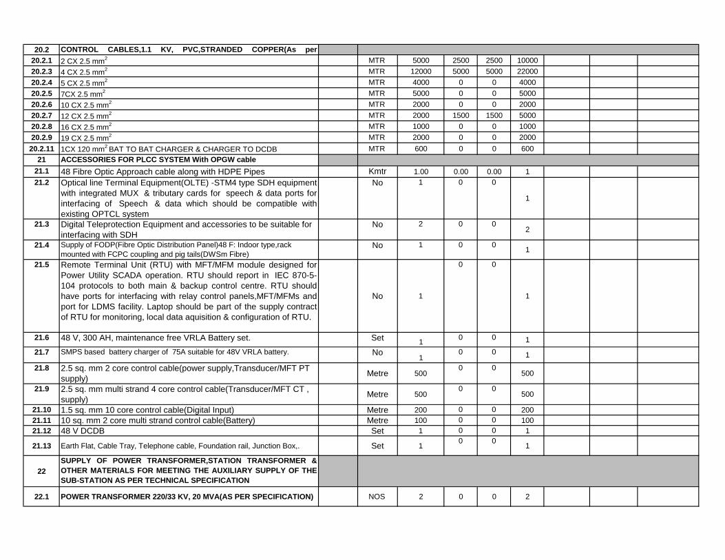
26.2.3 DC Supervision Relay Nos. 16 0 0 16
26.2.4 TRIP Relay Nos. 8 0 0 8
26.2.5 Test Block Nos. 16 0 0 16
26.2.6 Line interface unit; sets. 2 0 0 2
26.2.7 Ethernet switch IEC 61850-3,IEEE1588v2 set 3 0 0 3
26.2.8Multimode glass fibre Optical cord Double jacket armoured ,rodent resilient..
Mtr. 5000 0
500
26.2.9
Simplex Cubicle type for process bus equipment , Swing frame front access
(VSG), Dimension 2300mm (H) X 900mm (D) X 900mm (W), earth bar 25x6
Sq. mm. Copper with the following components
Set 4
0 0
4
26.2.10 DCDB panel; With Bus bar Switches,600(L)X 400(W)X 500(H) No. 1 0 0 1
26.3 STATION LEVEL
26.3.1
Windows based Industrial computer with standard accessories – Keyboard,
mouse, monitor with operating software window 10 or 8, IED configuration,
substation automation, . Main & Back up. With automation softwares.
Main
set 2 0 0
2
26.3.2
Windows based PC with standard accessories – Keyboard, mouse, monitor
with operating software window 10 or 8, IED configuration, substation
automation, Disturbance recorder software. DR & work Station PC.Client
set 1 0 0
1
26.3.3 Color Laser jet Printer No. 1 0 0 1
26.3.4 UPS , 3KVA No. 2 0 0 2
26.3.5 GPS System with PTP set 1 0 0 1
26.3.6 Gateway for SCADA set 1 0 0 1
26.4 220 KV CR Panel
26.4.1 220 KV Feeder Control & Relay Panel (duplex type) No. 0 1 0 1
26.4.2220 KV Protection Panel with BCU (The panel should integrate with existing
SAS system at Malkangiri S/S- SIEMENS MAKE)
No. 0 0 1 1
27 AC & DC SYSTEM
27.1 AC SYSTEM
27.1.1
MAIN AC DB,(HAVING 800 A,50KA,DRAWOUT TYPE ACB WITH 3
O/C,E/F,U/V RELAYING FACILITY INDOOR TYPE AS PER
SPECIFICATION.(MAIN DB-1,MAIN DB-2 WITH B/C)
SET 1 0 0 1
27.1.2ACDB (HAVING 400A MCCB) AS PER SPECIFICATION (AC DB-1,AC DB-
2 WITH B/C)SET 1 0 0 1
27.1.3MAIN LIGHTING DISTRIBUTION BOARD (HAVING 250A MCCB AS
INCOMER)AS PER SPECIFICATION (WITH DB-1,DB-2 & B/C)SET 1 0 0 1
27.1.4INDOOR LIGHTING DISTRIBUTION BOARD AS PER SPECIFICATION.
(WITH DB-1,DB-2 & B/C)SET 1 0 0 1
27.1.5 EMERGENCY LIGHTING DISTRIBUTION BOARD SET 1 0 0 1
27.1.6 INDOOR RECEPTACLE BOARD SET 1 0 0 1
27.2 DC SYSTEM
27.2.1
220 V DC BOARD (HAVING 100A DC MCCB AS INCOMER, E/F (EARTH
LEAKAGE), UNDER & OVER VOLTAGE AS PER SPECIFICATION (DC
DB-1,DC DB-2 & B/C)
SET 1 0 0 1
27.2.2 220 V DC EMERGENCY DISTRIBUTION BOARD SET 1 0 0 1
28 BATTERY (350 AH PLANTE TYPE) FOR 220 V DC SET 2 0 0 2
29BATTERY CHARGER FOR 220 V, 350 AH BATTERY (FLOAT AND FLOAT
CUM BOOST)SET 1 0 0 1
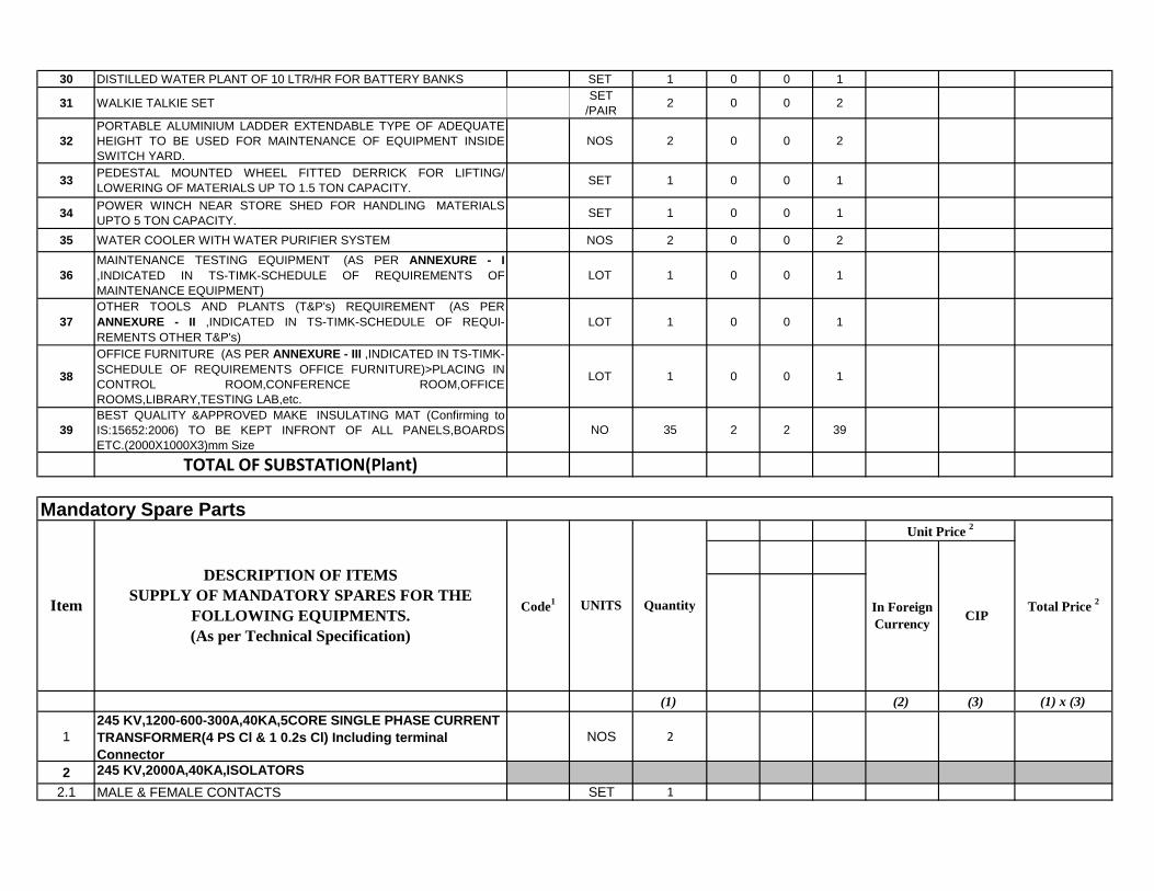
30 DISTILLED WATER PLANT OF 10 LTR/HR FOR BATTERY BANKS SET 1 0 0 1
31 WALKIE TALKIE SETSET
/PAIR 2 0 0 2
32
PORTABLE ALUMINIUM LADDER EXTENDABLE TYPE OF ADEQUATE
HEIGHT TO BE USED FOR MAINTENANCE OF EQUIPMENT INSIDE
SWITCH YARD.
NOS 2 0 0 2
33PEDESTAL MOUNTED WHEEL FITTED DERRICK FOR LIFTING/
LOWERING OF MATERIALS UP TO 1.5 TON CAPACITY.SET 1 0 0 1
34POWER WINCH NEAR STORE SHED FOR HANDLING MATERIALS
UPTO 5 TON CAPACITY.SET 1 0 0 1
35 WATER COOLER WITH WATER PURIFIER SYSTEM NOS 2 0 0 2
36
MAINTENANCE TESTING EQUIPMENT (AS PER ANNEXURE - I
,INDICATED IN TS-TIMK-SCHEDULE OF REQUIREMENTS OF
MAINTENANCE EQUIPMENT)
LOT 1 0 0 1
37
OTHER TOOLS AND PLANTS (T&P's) REQUIREMENT (AS PER
ANNEXURE - II ,INDICATED IN TS-TIMK-SCHEDULE OF REQUI-
REMENTS OTHER T&P's)
LOT 1 0 0 1
38
OFFICE FURNITURE (AS PER ANNEXURE - III ,INDICATED IN TS-TIMK-
SCHEDULE OF REQUIREMENTS OFFICE FURNITURE)>PLACING IN
CONTROL ROOM,CONFERENCE ROOM,OFFICE
ROOMS,LIBRARY,TESTING LAB,etc.
LOT 1 0 0 1
39
BEST QUALITY &APPROVED MAKE INSULATING MAT (Confirming to
IS:15652:2006) TO BE KEPT INFRONT OF ALL PANELS,BOARDS
ETC.(2000X1000X3)mm Size
NO 35 2 2 39
TOTAL OF SUBSTATION(Plant)
(1) (2) (3) (1) x (3)
1
245 KV,1200-600-300A,40KA,5CORE SINGLE PHASE CURRENT
TRANSFORMER(4 PS Cl & 1 0.2s Cl) Including terminal
Connector
NOS 2
2 245 KV,2000A,40KA,ISOLATORS
2.1 MALE & FEMALE CONTACTS SET 1
DESCRIPTION OF ITEMS
SUPPLY OF MANDATORY SPARES FOR THE
FOLLOWING EQUIPMENTS.
(As per Technical Specification)
UNITS Quantity
Unit Price 2
Mandatory Spare Parts
ItemCIP
Total Price 2
Code1
In Foreign
Currency

2.1,1
POWER CONTACTOR,RELAYS,MCBs,
SWITCHES,FUSES,PUSH BUTTONS,RESISTORS ETC AS PER
APPROVED SCHEMATIC.
SET 1
2.1,2 LIMIT SWITCH SET 2
2.1.3MOTOR WITH GEAR ASSEMBLY & BEVEL
GEAR ASSEMBLY COMPLETE.SET 1
2..1.4 AUXILIARY SWITCH CONTACTS ASSEMBLY SET 1
2.1.5 EARTHING ROD & BLADE CONTACT SIDE SET 1
2.1.6 HINGE PINS,TERMINAL CONNECTOR,TERMINAL PAD SET 1
3 245KV,3150A,40KA,SF6,CIRCUIT BREAKER
3.1 COMPLETE ONE POLE ASSEMBLY OF BREAKER NOS 1
3.2 SPRING CHARGING MOTOR NOS 1
3.3 BREAKER AUXILIARY CONTACTS SET 1
3.4
POWER CONTACTORS,RELAYS,MCBs,
SWITCHES,FUSES,PUSH BUTTONS,RESISTORS,PRESSURE
SWITCHES,LIMIT SWITCHES, ETC AS PER APPROVED
SCHEMATIC.
SET 1
3.5 DENSITY MONITORING SYSTEM SET 1
3.6 CLOSING COIL NOS 4
3.7 TRIPPING COIL NOS 4
3.8 SF6 GAS FILLING DEVICE NOS 1
3.9SET OF GASKETS ,"O" RINGS,SEALS PER CIRCUIT BREAKER
SET 1
436 KV,(800-400-200 A),25KA,3CORE SINGLE
PHASE CURRENT TRANSFORMERNOS 1
536 KV,(800-400-200 A),25KA,4 CORE SINGLE
PHASE CURRENT TRANSFORMERNOS 1
6 36 KV,1250A,25KA,ISOLATORS
6.1 MALE & FEMALE CONTACTS SET 1
6.2
POWER CONTACTOR,RELAYS,MCBs,
SWITCHES,FUSES,PUSH BUTTONS,RESISTORS ETC AS PER
APPROVED SCHEMATIC.
SET 1
6.3 LIMIT SWITCH SET 2
6.4MOTOR WITH GEAR ASSEMBLY & BEVEL
GEAR ASSEMBLY COMPLETE.SET 1
6.5 AUXILIARY SWITCH CONTACTS ASSEMBLY SET 1
6.6 EARTHING ROD & BLADE CONTACT SIDE SET 1
6.7 HINGE PINS,TERMINAL CONNECTOR,TERMINAL PAD SET 1
7 POST INSULATOR SET 1
10
30 KV,METAL OXIDE, 10 KA, CLASS II SURGE
ARRESTOR COMPLETE WITH INSULATOR BASE AND SURGE
MONITOR
NOS 3
11 245 KV ,2 CORE,SINGLE PHASE,IVT NOS 1
1236 KV ,2 CORE,SINGLE PHASE,IVT
INCLUDING TERMINAL CONNECTORNOS 1
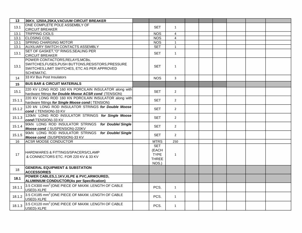
13 36KV, 1250A,25KA,VACUUM CIRCUIT BREAKER
13.1ONE COMPLETE POLE ASSEMBLY OF
CIRCUIT BREAKERSET 1
13.1 TRIPPING CIOLS NOS 4
13.1 CLOSING COIL NOS 4
13.1 SPRING CHARGING MOTOR NOS 1
13.1 AUXILIARY SWITCH CONTACTS ASSEMBLY SET 1
13.1SET OF GASKET,"O" RINGS,SEALING PER
CIRCUIT BREAKERSET 1
13.1
POWER CONTACTORS,RELAYS,MCBs,
SWITCHES,FUSES,PUSH BUTTONS,RESISTORS,PRESSURE
SWITCHES,LIMIT SWITCHES, ETC AS PER APPROVED
SCHEMATIC.
SET 1
14 33 KV Bus Post Insulators NOS 3
15 BUS BAR & CIRCUIT MATERIALS
15.1220 KV LONG ROD 160 KN PORCILAIN INSULATOR along with
hardware fittings for Double Moose ACSR cond (TENSION)SET 2
15.1.1220 KV LONG ROD 160 KN PORCILAIN INSULATOR along with
hardware fittings for Single Moose cond ( TENSION)SET 2
15.1.2120 kN LONG ROD INSULATOR STRINGS for Double Moose
cond ( TENSION)-33 KVSET 2
15.1.3120kN LONG ROD INSULATOR STRINGS for Single Moose
cond (TENSION)-33 KVSET 2
15.1.490kN LONG ROD INSULATOR STRINGS for Double/ Single
Moose cond ( SUSPENSION)-220KVSET 2
15.1.590kN LONG ROD INSULATOR STRINGS for Double/ Single
Moose cond (SUSPENSION)-33 KVSET 2
16 ACSR MOOSE CONDUCTOR MTRS 250
17HARDWARES & FITTINGS/SPACERS/CLAMP
& CONNECTORS ETC. FOR 220 KV & 33 KV
SET
(EACH
TYPE
THREE
NOS.)
1
18GENERAL EQUIPMENT & SUBSTATION
ACCESSORIES
18.1POWER CABLES,1.1KV,XLPE & PVC,ARMOURED,
ALUMINIUM CONDUCTOR(As per Specification)
18.1.13.5 CX300 mm
2 (ONE PIECE OF MAXM. LENGTH OF CABLE
USED)-XLPEPCS. 1
18.1.23.5 CX185 mm
2 (ONE PIECE OF MAXM. LENGTH OF CABLE
USED)-XLPEPCS. 1
18.1.33.5 CX120 mm
2 (ONE PIECE OF MAXM. LENGTH OF CABLE
USED)-XLPEPCS. 1

18.1.43.5 CX70 mm
2 (ONE PIECE OF MAXM. LENGTH OF CABLE
USED)-PVCPCS. 1
18.1.53.5 CX35 mm
2 (ONE PIECE OF MAXM. LENGTH OF CABLE
USED)-PVCPCS. 1
18.1.6 4 CX 16 mm2-
-PVC MTRS 250
18.1.7 4 CX 6 mm2 -PVC MTRS 250
18.1.8 2CX 6 mm2 -PVC MTRS 250
18.2CONTROL CABLES,1.1 KV, PVC,STRANDED COPPER(As per
specification)
18.2.1 4 CX 2.5 mm2 (ONE DRUM HAVING LENGTH OF 500 MTRS) Mtrs 500
18.2.2 5 CX 2.5 mm2 (ONE DRUM HAVING LENGTH OF 500 MTRS) Mtrs 500
18.2.3 7 CX 2.5 mm2 (ONE DRUM HAVING LENGTH OF 500 MTRS) Mtrs 500
18.2.4 10 CX 2.5 mm2 (ONE DRUM HAVING LENGTH OF 500 MTRS) Mtrs 500
18.2.5 12 CX 2.5 mm2 (ONE DRUM HAVING LENGTH OF 250 MTRS) Mtrs 250
18.2.6 16 CX 2.5 mm2 (ONE DRUM HAVING LENGTH OF 250 MTRS) Mtrs 250
18.2.7 19 CX 2.5 mm2 (ONE DRUM HAVING LENGTH OF 250 MTRS) Mtrs 250
18.2.81CX 120 mm
2
BAT TO BAT CHARGER & CHARGER TO DCDBMTRS 50
19 TELECOMMINICATION & OTHER MATERIALS
19.1ONE COMPLETE CELL ASSEMBLY OF BATTERY(FOR 48 V
VRLA TYPE BATTERY 300 AH) NOS 1
19.2ONE COMPLETE CELL ASSEMBLY OF BATTERY(FOR 220 V
PLANTE TYPE BATTERY 350 AH,) NOS 1
19.3BATTERY CHARGER FOR 300 AH (48V) ONE COMPLETE SET
OF ELECTRONIC CARDSSET 1
19.4BATTERY CHARGER FOR 350 AH (220V) ONE COMPLETE SET
OF ELECTRONIC CARDSSET 1
TOTAL OF MANDATORY SPARE PARTS
Country of Origin Declaration Form
TOTAL OF SUBSTATION-SCHEDULE-1 -Plant and Mandatory Spare Parts(to Schedule No. 6 Grand Summary)
Name of Bidder:_______________________________
Signature of Bidder:_____________________________
1 Bidders shall enter a code representing the country of origin of all imported plant and equipment.
2 Specify currency in accordance with specifications in Bid Data Sheet under ITB 19.1 in Single-Stage Bid, or ITB 34.1 in Two-Stage Bid. Create and use as

Item Description Code Country

(1) (2) (3) (1) x (3)
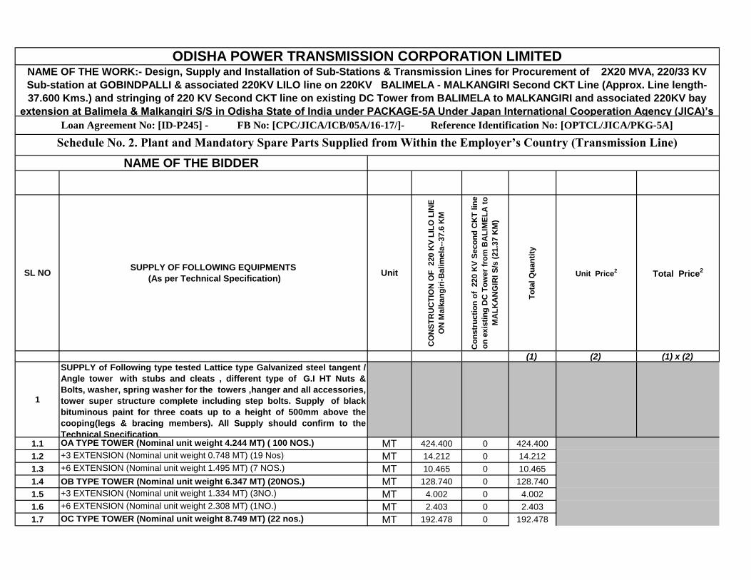
1
SUPPLY of Following type tested Lattice type Galvanized
steel tangent / Angle tower with stubs and cleats , different
type of G.I HT Nuts & Bolts, washer, spring washer for the
towers ,hanger and all accessories, tower super structure
complete including step bolts. Supply of black bituminous
paint for three coats up to a height of 500mm above the
cooping(legs & bracing members). All Supply should
confirm to the Technical Specification.
1.1OA TYPE TOWER (Nominal unit weight 4.244 MT) ( 100
NOS.)MT 424.400 0 424.400
1.2 +3 EXTENSION (Nominal unit weight 0.748 MT) (19 Nos) MT 14.212 0 14.212
1.3 +6 EXTENSION (Nominal unit weight 1.495 MT) (7 NOS.) MT 10.465 0 10.465
1.4 OB TYPE TOWER (Nominal unit weight 6.347 MT) (20NOS.) MT 128.740 0 128.740
1.5 +3 EXTENSION (Nominal unit weight 1.334 MT) (3NO.) MT 4.002 0 4.002
1.6 +6 EXTENSION (Nominal unit weight 2.308 MT) (1NO.) MT 2.403 0 2.403
1.7OC TYPE TOWER (Nominal unit weight 8.749 MT) (22 nos.)
MT 192.478 0 192.478
1.8 +3 EXTENSION (Nominal unit weight 1.436 MT) (4NOS.) MT 5.74 0 5.744
UNITS
CO
NS
TR
UC
TIO
N O
F 220 K
V L
ILO
LIN
E O
N M
alk
an
gir
i-B
alim
ela
--37.6
KM In Foreign
Currency
Co
nstr
ucti
on
of
220 K
V S
eco
nd
CK
T
lin
e o
n e
xis
tin
g D
C T
ow
er
fro
m
BA
LIM
EL
A t
o M
AL
KA
NG
IRI S
/s (
21.3
7
KM
) Total
Quantity
Unit Price2
ODISHA POWER TRANSMISSION CORPORATION LIMITED
Loan Agreement No: [ID-P245] - FB No: [CPC/JICA/ICB/05A/16-17/]- Reference Identification No: [OPTCL/JICA/PKG-5A]
Schedule No. 1. Plant and Mandatory Spare Parts Supplied from Abroad (Transmission Line)
SUPPLY OF FOLLOWING EQUIPMENT,STRUCTURES &
MATERIALS
(As per Technical Specification)
NAME OF THE BIDDER
Total Price2
Code1
NAME OF THE WORK:- Design, Supply and Installation of Sub-Stations & Transmission Lines for Procurement of 2X20 MVA, 220/33 KV Sub-station at GOBINDPALLI &
associated 220KV LILO line on 220KV BALIMELA - MALKANGIRI Second CKT Line (Approx. Line length-37.600 Kms.) and stringing of 220 KV Second CKT line on existing
DC Tower from BALIMELA to MALKANGIRI and associated 220KV bay extension at Balimela & Malkangiri S/S in Odisha State of India under PACKAGE-5A Under Japan
International Cooperation Agency (JICA)’s ODA Loan.
CIP

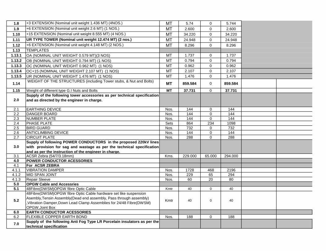
1.9 +6 EXTENSION (Nominal unit weight 2.6 MT) (1 NOS.) MT 2.600 0 2.600
1.10 +15 EXTENSION (Nominal unit weight 8.555 MT) (4 NOS.) MT 34.220 0 34.220
1.11UR TYPE TOWER (Nominal unit weight 12.474 MT) (2 nos.)
MT 24.948 0 24.948
1.12 +6 EXTENSION (Nominal unit weight 4.148 MT) (2 NOS.) MT 8.296 0 8.296
1.13 TEMPLATES
1.13.1 OA (NOMINAL UNIT WEIGHT 0.579 MT)(3 NOS) MT 1.737 0 1.737
1.13.2 OB (NOMINAL UNIT WEIGHT 0.794 MT) (1 NOS) MT 0.794 0 0.794
1.13.3 OC (NOMINAL UNIT WEIGHT 0.962 MT) (1 NOS) MT 0.962 0 0.962
1.13.4 OC+15 (NOMINAL UNIT WEIGHT 2.107 MT) (1 NOS) MT 2.107 0 2.107
1.13.5 UR (NOMINAL UNIT WEIGHT 1.476 MT) (1 NOS) MT 1.476 0 1.476
1.14WEIGHT OF THE STRUCTURES (including Tower stubs, &
Nut and Bolts)MT 859.584 0 859.584
1.15 Weight of different type G.I Nuts and Bolts MT 37.731 0 37.731
2.0
Supply of the following tower accessories as per technical
specification and as directed by the engineer in charge.
2.1 EARTHING DEVICE Nos. 144 0 144
2.2 DANGER BOARD Nos. 144 0 144
2.3 NUMBER PLATE Nos. 144 0 144
2.4 PHASE PLATE Sets 864 234 1098
2.5 BIRD GUARD Nos. 732 0 732
2.6 ANTICLIMBING DEVICE Nos. 144 0 144
2.7 CIRCUIT PLATE Nos. 288 0 288
3.0
Supply of following POWER CONDUCTORS in the
proposed 220kV lines with provision for sag and wastage
as per the technical specification and as per the instruction
of the engineer in charge.3.1 ACSR Zebra (54/7/3.18mm) Kms. 229.000 65.000 294.000
4.0 POWER CONDUCTOR ACESSORIES
4.1 For ACSR ZEBRA
4.1.1 VIBRATION DAMPER Nos. 1728 468 2196
4.1.2 MID SPAN JOINT Nos. 229 65 294
4.1.3 Repair Sleeve Nos. 60 20 80
5.0 OPGW Cable and Accessries
5.1 48Fibre(DWSM)OPGW fibre Optic Cable Kmtr 40 0 40
5.2
48Fibre(DWSM)OPGW fibre Optic Cable hardware set like
suspension Asembly,Tensin Assembly(Dead end assembly,
Pass through assembly) ,Vibration Damper,Down Lead Clamp
Assemblies for 24/48 Fibre(DWSM) OPGW,Joint Box
Kmtr 40 0 40
6.0 EARTH CONDUCTOR ACESSORIES
6.2 FLEXIBLE COPPER EARTH BOND Nos. 188 0 188
7.0Supply of the following Anti Fog Type LR Porcelain
insulators as per the technical specification
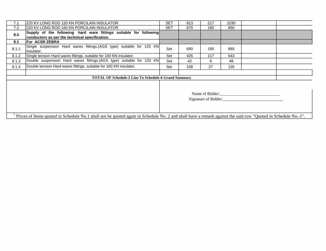
7.1 220 KV LONG ROD 120 KN PORCILAIN INSULATOR SET 813 217 1030
7.2 220 KV LONG ROD 160 KN PORCILAIN INSULATOR SET 670 180 850

8.0Supply of the following hard ware fittings suitable for
following conductors as per the technical specification.
8.1 For ACSR ZEBRA
8.1.1Single suspension Hard wares fittings.(AGS type) suitable for
120 KN insulator.Set 690 195 885
8.1.2Single tension Hard wares fittings, suitable for 160 KN insulator.
Set 426 117 543
8.1.3Double suspension Hard wares fittings.(AGS type) suitable for
120 KN insulator.Set 42 6 48
8.1.4Double tension Hard wares fittings, suitable for 160 KN
insulator.Set 108 27 135
TOTAL OF Schedule-1 Line To Schedule-6 Grand Summary
Item Description Code
Country of Origin Declaration Form
Name of Bidder:_____________________________
Signature of Bidder:_____________________________
1 Bidders shall enter a code representing the country of origin of all imported plant and equipment.
2 Specify currency in accordance with specifications in Bid Data Sheet under ITB 19.1 in Single-Stage Bid, or ITB 34.1 in Two-Stage Bid. Create and use as many columns for
Unit Price and Total Price as there are currencies.
Country

(1) (2) (1) x (2)
1245 KV,1200-600-300A,40KA,5CORE SINGLE PHASE CURRENT TRANSFORMER(4
PS Cl & 1 0.2s Cl)NOS 18 3 3 24
2 245 KV,2000A,40KA,ISOLATORS
2.1 S/I WITH OUT EARTH SWITCH NOS 18 3 3 24
2.2 S/I WITH SINGLE EARTH SWITCH NOS 4 1 1 6
2.3 BEAM MOUNTED S/I WITHOUT EARTH SWITCH NOS 4 1 1 6
3 245 KV,4400pF,3CORE,SINGLE PHASE CAPACITOR VOLTAGE TRANSFORMER NOS 6 3 3 12
4 245KV,3150A,50KA,SF6,CIRCUIT BREAKER WITH SUPPORTING STRUCTURE NOS 5 1 1 7
5 216 KV, METAL OXIDE SURGE ARRESTOR,10 KA, class III NOS 12 3 3 18
6 245 KV ,2 CORE,SINGLE PHASE,IVT NOS 6 0 0 6
7 220 KV Bus Post Insulators NOS 54 12 12 78
836 KV,800-400-200,25KA,4CORE SINGLE PHASE CURRENT TRANSFORMER(3 PS
Cl & 1 0.2s Cl)NOS 6 0 0 6
936 KV,800-400-200,25KA,3CORE SINGLE PHASE CURRENT TRANSFORMER (2
PS Cl & 1 0.2s Cl)NOS 15 0 0 15
10 36 KV,1250A,25KA,ISOLATORS
10.1 S/I WITH OUT EARTH SWITCH NOS 8 0 0 8
10.2 D/I WITH SINGLE EARTH SWITCH NOS 4 0 0 4
10.3 D/I WITHOUT EARTH SWITCH NOS 2 0 0 2
10.4 S/I WITH BEAM MOUNTED NOS 2 0 0 2
11 30 KV, METAL OXIDE SURGE ARRESTOR, 10KA, class II(Beam Mounted) NOS 24 0 0 24
12 36 KV ,2 CORE,SINGLE PHASE,IVT NOS 3 0 0 3
1336KV,1250A,25KA,VACUUM CIRCUIT BREAKER WITH SUPPORTING STRUCTURE
NOS 7 0 0 7
14 33 KV Bus Post Insulators NOS 20 0 0 20
15 BUS BAR & CIRCUIT MATERIALS
15.1 ANTI FOG TYPE INSULATOR
15.1.1 220 KV LONG ROD 160 KN PORCILAIN INSULATOR(220KV Side) NOS 96 30 30 156
15.1.2 220 KV LONG ROD 120 KN PORCILAIN INSULATOR(220KV Side) NOS 12 9 9 30
15.1.2 120 KNLong Rod Porcelain INSULATOR(33KV Side) NOS 66 0 0 66
15.1.3 90 KNLong Rod Porcelain INSULATOR(33KV Side) NOS 33 0 0 33
15.2 ACSR MOOSE CONDUCTOR KMS 5 0.50 0.50 6
Unit SUPPLY OF FOLLOWING EQUIPMENTS
(As per Technical Specification)
Qu
an
tity
fo
r: 0
1 N
o. F
ee
de
r B
ay
Ex
ten
sio
n a
t 2
20
/33
kV
Gri
d S
/s
Ma
lka
ng
iri
ODISHA POWER TRANSMISSION CORPORATION LIMITEDNAME OF THE WORK:- Design, Supply and Installation of Sub-Stations & Transmission Lines for Procurement of 2X20 MVA, 220/33 KV Sub-station at GOBINDPALLI &
associated 220KV LILO line on 220KV BALIMELA - MALKANGIRI Second CKT Line (Approx. Line length-37.600 Kms.) and stringing of 220 KV Second CKT line on existing DC
Tower from BALIMELA to MALKANGIRI and associated 220KV bay extension at Balimela & Malkangiri S/S in Odisha State of India under PACKAGE-5A Under Japan International
Cooperation Agency (JICA)’s ODA Loan.Loan Agreement No: [ID-P245] - FB No: [CPC/JICA/ICB/05A/16-17/]- Reference Identification No: [OPTCL/JICA/PKG-5A]
Schedule No. 2. Plant and Mandatory Spare Parts Supplied from Within the Employer’s Country (Sub-station & Bay extension)
NAME OF THE BIDDER
Qu
an
tity
fo
r: 0
1 N
o. F
ee
de
r B
ay
Ex
ten
sio
n a
t 2
20
/33
kV
Gri
d S
/s B
alim
ela
Unit Price2SL NO
Qu
an
tity
fo
r: C
on
str
uc
tio
n o
f 2
x2
0 M
VA
,
22
0/3
3 K
V S
ub
-Sta
tio
n a
t G
ob
ind
ap
alli
22
0 K
V B
AY
05
NO
S (
FD
R:0
2,T
FR
:02
&
B/C
:01
) &
33
KV
BA
Y 0
7 N
OS
(FD
R:0
4,T
FR
:02
& B
/C:0
1)
To
tal Q
ua
nti
ty
Total Price2

15.3IPS 4" ALUMINIUM TUBES(114.2 mm OD, & 8.51mm Thickness) for equipment to
equipment connection in 220 KV side.MTRS 370 80 80 530
15.4 HARDWARES & FITTINGS/SPACERS/CLAMP & CONNECTORS
15.4.1220 KV Double Tension H/W fitting for twin moose ACSR (Single Anchoring Point)
NOS 24 12 12 48
15.4.2 220 KV Single Tension H/W fitting for single moose ACSR NOS 24 12 12 48
15.4.3 220 KV Single Suspension H/W fitting for single mose ACSR NOS 6 6 6 18
15.4.4220 KV Double Suspension H/W fitting for twin mose ACSR (Single Anchoring Point)
NOS 18 6 6 30
15.4.5 33 KV Single Tension H/W fitting for single moose ACSR NOS 30 0 0 30
15.4.633 KV Double Tension H/W fitting for twin moose ACSR (Single Anchoring Point)
NOS 24 0 0 24
15.4.7 33 KV Single Suspension H/W fitting for single mose ACSR NOS 12 0 0 12
15.4.8 220kv T- clamp for ACSR ZEBRA run to ACSR MOOSE drop NOS 18 9 9 36
15.4.9 T-Clamp for single Moose -Single Moose ACSR NOS 42 3 3 48
15.4.10 T-Clamp for twin Moose run -Single Moose drop ACSR NOS 36 3 3 42
15.4.11 220 KV PI clamp NOS 54 12 12 78
15.4.12 33KV PI Clamp NOS 20 0 0 20
15.4.13 Spacer for Moose ACSR NOS 120 18 18 156
15.4.14 220 KV Isolator pad clamp NOS 132 30 30 192
15.4.15 220 KV LA Clamp NOS 12 3 3 18
15.4.16 220 KV CVT Clamp NOS 6 3 3 12
15.4.17 220 KV CT Clamp NOS 36 6 6 48
15.4.18 220 KV IVT Clamp NOS 6 0 0 6
15.4.19 220 KV CB Clamp NOS 30 6 6 42
15.4.20 33 KV Isolator pad clamp NOS 114 0 0 114
15.4.21 33 KV LA Clamp NOS 24 0 0 24
15.4.22 33 KV CT Clamp NOS 42 0 0 42
15.4.23 33 KV IVT Clamp NOS 3 0 0 3
15.4.24 33 KV CB Clamp NOS 42 0 0 42
15.4.25 PG Clamp for ACSR Moose NOS 48 18 18 84
15.5 EARTH WIRES & IT'S HARDWARES & FITTING
15.5.1 Earthing Spikes and Its Fittings in all respect.
15.5.1.1 Earthing Spikes of 9 mtr long each and Its Fittings in all respect. (220 kv side) NOS 37 3 3 43
15.5.1.2 Earthing Spikes of 5 mtr long each and Its Fittings in all respect. (33 KV side) NOS 25 0 0 25
16 SUBSTATION EARTHING SYSTEMS
16.1EARTHING CONDUCTOR FOR BURRIAL : 75X10 mm GI Flat for laying (spacing
maximum 5m both way ) MT 31 4 4 39
16.2EARTHING CONDUCTOR: 50X6 mm GI Flat for Raiser from the burial earth mat to
equipment,structure etc)MT 10.41 1.25 1.25 12.91
16.3EARTHING DEVICE & ASSOCIATED ACCESSORIES (50 mm heavy duty GI
PERFORATED PIPE 3 mtrs long for treated earth pit)Nos. 180 25 25 230
16.4EARTHING DEVICE & ASSOCIATED ACCESSORIES 40mm MS rod 3 mtrs long for
non treated earth pit)Nos. 120 15 15 150
16.5 Pipe-in-Pipe earthing electrode Nos. 4 0 0 4
17G.I Cable Trays including support GI angle suitable for different sections i.e. Section:1-
1,2-2,3-3 & 4-4 along with its accessories as per TS.
17.1 G.I Cable Trays(size: 450x75x2500mm) MTRS 1200 125 125 1450
17.2 G.I Cable Trays(size: 300x75x2500mm) MTRS 2000 100 100 2200
17.3 G.I Cable Trays(size: 150x75x2500mm) MTRS 1500 50 50 1600
17.4 Support G. I angle 50x50x6 mm for cable tray MT 2.5 0.25 0.25 3
18SUB STATION SWITCYARD BMK,AC CONSOLE & OTHER MARSHALLING BOXES
18.1 BAY MARSHALLING KIOSK (03 nos on 220 kV bay & 04Nos 33 KV bay ) NOS 7 1 1 9
18.2SWITCH YARD AC CONSOLE FOR LIGHTING (01 nos on 220 kV bay & 01 No in
33KV bay )NOS 2 0 0 2
18.3SWITCH YARD RECEPTACLE BOARD FOR TFR OIL FILTERATION (01 no. near
220/33 KV power Transformer)NOS 1 0 0 1
18.4SWITCH YARD RECEPTACLE BOARD FOR WELDING & OTHER EMERGENCY
(01 nos on 220 & 33 kV bay )NOS 2 0 0 2

19
SWITCH YARD STRUCTURES (LATTICE TYPE FOR TOWER COLUMN & BEAMS
& PIPE TYPE FOR ALL EQUIPMENT COLUMN) FOR 220/132/33 KV CLASS
INCLUDING FOUNDATION BOLTS & NUTS.
19.1 DIFFERENT TYPES OF COLUMNS WITH DETAILS
19.1.1 P1S-220 KV (NOMINAL UNIT WT- 4.5 MT) (21 NOS.+4NOS.+4NOS.) MT 108 18 18 144
19.1.2 P2A-220 KV (NOMINAL UNIT WT- 1..5 MT) (8NOS.) MT 9 0 0 9
19.1.3 T1S - 132 KV(NOMINAL UNIT WT- 1.2 MT) (4 NOS.) MT 0 0 0 0
19.1.4 T8S - 33KV(NOMINAL UNIT WT- 0.8 MT) (11 NOS.) MT 0 0 0 0
19.1.5 T9S - 33KV(NOMINAL UNIT WT- 0.6 MT) (14 NOS.) MT 8.4 0 0 8.4
19.2 DIFFERENT TYPE OF BEAMS WITH DETAILS
19.2.1 Q1-220KV (NOMINAL UNIT WT- 1.5 MT) (15NOS.+4NOS.+4NOS.)) MT 33 6 6 45
19.2.2 Q3-220KV (NOMINAL UNIT WT-2.5 MT) (4 NOS.+2NOS.+2NOS.) MT 20 5 5 30
19.2.3 Q4-220KV (NOMINAL UNIT WT- 0.9 MT) (4 NOS.) MT 0 0 0 0
19.2.4 G1 - 132KV (NOMINAL UNIT WT- 0.62 MT) (4 NOS.) MT 0 0 0 0
19.2.5 G6 - 33KV (NOMINAL UNIT WT- 0.53 MT) (4 NOS.) MT 2.12 0 0 2.12
19.2.6 G4 - 33KV(NOMINAL UNIT WT- 0.4 MT) (12 NOS.) MT 4.8 0 0 4.8
19.2.7 G4X - 33KV (NOMINAL UNIT WT- 0.4 MT) (2 NOS.) MT 0.8 0 0 0.8
19.3 TOTAL WEIGHT OF COLUMN & BEAM MT 186.12 29 29 244.12
19.4EQUIPMENT SUPPORT STRUCTURES (PIPE TYPE) FOR ALL 220KV, 132 KV &
33KV EQUIPMENTS INCLUDING FOUNDATION BOLTS & NUTS
19.4.1 ISOLATORS-220KV ( SI with E/S-4 No.+01 No.+01No.) MT 5.084 1.271 1.271 7.626
19.4.2 ISOLATORS-220KV (SI without E/S:14Nos.+03 nos.+03 nos.) MT 22.878 3.813 3.813 30.504
19.4.3 BEAM ISOLATORS-220KV ( SI with E/S: 6Nos.+01 No.+01No.) MT 5.084 1.271 1.271 7.626
19.4.4 ISOLATORS-33 KV ( SI-8 Nos.) MT 2.0664 0 0 2.0664
19.4.5 ISOLATORS-33 KV ( DI with E/S -4 Nos.) MT 2.5776 0 0 2.5776
19.4.6 ISOLATORS-33 KV ( DI without E/S-2 Nos.) MT 1.234 0 0 1.234
19.4.7 CTS-220 KV (15 nos.+03 nos.+03 nos.) MT 3.375 0.675 0.675 4.725
19.4.8 CTS-33 KV (15 nos.) MT 1.74 0 0 1.74
19.4.9 CVTS-220 KV (6 nos.+03 nos.+03 nos.) MT 1.326 0.663 0.663 2.652
19.4.10 IVTS-220 KV (3 nos.) MT 1.7232 0 0 1.7232
19.4.11 IVTS-33 KV (3 nos.) MT 0.3546 0 0 0.3546
19.4.12 Surge Arrester-220 Kv( 12 nos.+03 nos.+03 nos.) MT 3.5052 0.8763 0.8763 5.2578
19.4.13 BPI-220 KV (38nos.+12 Nos.+12Nos.) MT 15.8112 3.5136 3.5136 22.8384
19.4.14 BPI-33 KV (20 nos.) MT 4.126 0 0 4.126
19.4.15 NCTs(4 nos) MT 0.464 0 0 0.464
19.5 TOTAL WEIGHT OF EQUIPMENT STRUCTURE MT 71.3492 12.0829 12.0829 95.515
19.6 TOTAL WEIGHT OF EQUIPMENT & Column GI Foundation Bolts & Nuts MT 12 2.412 2.412 16.824
19.7Total weight of GI Nuts and bolts for Columns, Beams & Equipment Structures
MT 12 2.5 2.5 17
20 GENERAL EQUIPMENT & SUBSTATION ACCESSORIES
20.1POWER CABLES,1.1KV,XLPE & PVC ARMOURED, ALUMINIUM CONDUCTOR (As
per Specification)
20.1.1 XLPE 3.5 CX300 mm2 MTR 500 0 0 500
20.1.2 XLPE 3.5 CX185 mm2 MTR 300 0 0 300
20.1.3 XLPE 3.5 CX120 mm2 MTR 200 0 0 200
20.1.4 PVC 3.5 CX70 mm2 MTR 600 0 0 600
20.1.5 PVC 3.5 CX35 mm2 MTR 1500 500 500 2500
20.1.6 PVC 4 CX 16 mm2 MTR 1000 0 0 1000
20.1.7 PVC 4CX 6 sqmm MTR 3500 0 0 3500
20.1.9 PVC 2CX 6 sqmm MTR 2000 0 0 2000
20.2 CONTROL CABLES,1.1 KV, PVC,STRANDED COPPER(As per specification)
20.2.1 2 CX 2.5 mm2 MTR 5000 2500 2500 10000
20.2.3 4 CX 2.5 mm2 MTR 12000 5000 5000 22000
20.2.4 5 CX 2.5 mm2 MTR 4000 0 0 4000
20.2.5 7CX 2.5 mm2 MTR 5000 0 0 5000
20.2.6 10 CX 2.5 mm2 MTR 2000 0 0 2000
20.2.7 12 CX 2.5 mm2 MTR 2000 1500 1500 5000
20.2.8 16 CX 2.5 mm2 MTR 1000 0 0 1000
20.2.9 19 CX 2.5 mm2 MTR 2000 0 0 2000
20.2.11 1CX 120 mm2
BAT TO BAT CHARGER & CHARGER TO DCDB MTR 600 0 0 600
21 ACCESSORIES FOR PLCC SYSTEM With OPGW cable
21.1 48 Fibre Optic Approach cable along with HDPE Pipes Kmtr 1 0 0 1
21.2 Optical line Terminal Equipment(OLTE) -STM4 type SDH equipment with
integrated MUX & tributary cards for speech & data ports for interfacing of
Speech & data which should be compatible with existing OPTCL system
No
1 0 0 1
21.3 Digital Teleprotection Equipment and accessories to be suitable for interfacing
with SDH
No2 0 0 2
21.4 Supply of FODP(Fibre Optic Distribution Panel)48 F: Indoor type,rack mounted with
FCPC coupling and pig tails(DWSm Fibre)No
1 0 0 1
21.5 Remote Terminal Unit (RTU) with MFT/MFM module designed for Power Utility
SCADA operation. RTU should report in IEC 870-5-104 protocols to both
main & backup control centre. RTU should have ports for interfacing with relay
control panels,MFT/MFMs and port for LDMS facility. Laptop should be part of
the supply contract of RTU for monitoring, local data aquisition & configuration
of RTU.
No 1 0 0 1
21.6 48 V, 300 AH, maintenance free VRLA Battery set. Set 1 0 0 1
21.7 SMPS based battery charger of 75A suitable for 48V VRLA battery. No 1 0 0 1
21.8 2.5 sq. mm 2 core control cable(power supply,Transducer/MFT PT supply) Metre 500 0 0 500
21.92.5 sq. mm multi strand 4 core control cable(Transducer/MFT CT , supply) Metre 500 0 0 500
21.10 1.5 sq. mm 10 core control cable(Digital Input) Metre 200 0 0 200
21.11 10 sq. mm 2 core multi strand control cable(Battery) Metre 100 0 0 100
21.12 48 V DCDB Set 1 0 0 1
21.13 Earth Flat, Cable Tray, Telephone cable, Foundation rail, Junction Box,. Set 1 0 0 1
22
SUPPLY OF POWER TRANSFORMER,STATION TRANSFORMER & OTHER
MATERIALS FOR MEETING THE AUXILIARY SUPPLY OF THE SUB-STATION AS
PER TECHNICAL SPECIFICATION
22.1 POWER TRANSFORMER 220/33 KV, 20 MVA(AS PER SPECIFICATION) NOS 2 0 0 2
22.2 STATION TRANSFORMER 33KV/433V,250 KVA (AS PER SPECIFICATION) NOS 2 0 0 2
22.3 Supply of materials for erection of station transformers
22.3.1
HDG DP STRUCTURE: each set shall comprise of [ 2X 9.0 Mtrs
(ISBM:200X100 mm(min) RS Joist(beam) with bracings of suitable channels(ISMC
75X40) & angles (L50X50X6) & different size Steel plate of 10 mm thick etc].
SET 2 0 0 2
22.3.233 KV AB SWITCH IN 33 KV SIDE(600AMP) including required GI pipe(horizontal &
vertically down) & handle for operation of AB switchSET 2 0 0 2
22.3.3HG fuse set for 33 KV side of the Station transformer including base(each set comprises
three single HG fuse) SET 2 0 0 2
22.3.4
OUT DOOR KIOSK MADE OUT OF 3mm thick CRCA steel duly galvanised having
gland plates OR BETTER quality WITH 3 NOS. OF CUT-OUTS(1000 AMPS) AT THE
INCOMING SIDE , 1No. OF 3 PHASE SFU (500AMPS) AT THE OUTGOING SIDE
AND SUITABLE BUS BAR ARRANGEMENT FOR TERMINATION of incoming cable
from transformer & outgoing cable to Main ACDB.
SET 2 0 0 2
23.0
Switch yard lighting: Design, engineering, procurement of labour, material including all
associated works for construction of switch yard lightings as per technical specification
and approved drawings. The fixture shall be of reputed make (Philips/CGL/Bajaj) and
fixtures shall be LED and proper cabling from the lighting outdoor distribution boards to
the junction boxes and from junction boxes to the fixtures. The lighting fixtures are to be
installed on the switch yard structures. The quantity of such fixtures are to be designed
and to be ascertained.
23.1
SUB-STATION SWITCH YARD LIGHTING,IT INCLUDES SUPPLY OF FIXTURES &
LAMPS (LED) of reputed make (Philips/CGL/Bajaj) with switch gear,GI Conduit
etc.(Lighting fixtures are to be fixed rigidly on the Column at a suitable height so that the
required lux can be achieved).(150 watt each)
SET 80 8 8 96
23.2
STREET LIGHTING: IT INCLUDES SUPPLY OF GI TUBULAR POLE AS PER
TECHNICAL SPECIFICATION, LED LIGHTING FIXTURES including LAMPS of
reputed make (Philips/CGL/Bajaj).(100 watt each) for Street Light. (TO BE PROVIDED
IN THE SWITCH YARD, ALONG THE ROADS (APPROACH INSIDE YARD AND
OTHER ROADS), COLONY QUARTERS AND OTHER ROADS.
ALL MATERIALS AS PER APPROVED DRAWING AND SPECIFICATION TO
COMPLETE
THE STREET LIGHTING SYSTEM. PROPER EARTHING AS PER STANDARD
PRACTICE
23.2.1LED LIGHTING FIXTURES including LAMPS of reputed make (Philips/CGL/Bajaj).(100
watt each) for Street Light.SET 30 0 0 30
23.2.2
GI Tubular Pole: (410-SP-24: IS 2713-Part-II-1980 or latest) Length of pole 8.5
mtrs(minimum weight 158 Kgs).
(ALL THE STREET LIGHT POLE SHALL BE OF GI TUBULAR POLE AND
PROVISION OF A GI JUNCTION BOX WITH SUITABLE COVERS AT A HEIGHT OF 1
METRE FROM THE GROUND. THE JUNCTION BOX SHALL HAVE PROVISION OF
FUSES, BUSES, CONNECTORS FOR CABLE IN AND OUT.
SET 30 0 0 30
23.2.3
OUTDOOR KIOSK of 3 mm thick CRCA sheet duly hot dip galvanised FOR STREET
LIGHT HAVING 2 NOS 200 AMP SWITCH FUSE UNITS AND 10 NOS. OUT LETS
OF 32 AMP MCB. XLPE CABLES(3.5 CORE 120 SQMM) FROM MAIN ACDB FROM
CONTROL ROOM TO THE OUT DOOR KIOSK. XLPE CABLE OF 4C X 16 SQMM
FROM OUTDOOR KIOSK TO THE STREET LIGHT POLES AND 4CX6 SQMM FROM
POLE TO POLE AND 2CX6 SQMM FROM POLE TO LIGHTING FIXTURES.
NO 1 0 0 1
23.2.4
OUTDOOR KIOSK of 3 mm thick CRCA sheet duly hot dip galvanised FOR COLONY
SUPPLY PURPOSE HAVING 2 NOS. 200 A SWITCH FUSE UNITS, 6 NOS.OUT
LETS OF 32 AMP MCB FOR COLONY QUARTES. XLPE CABLES(3.5 CORE 120
SQM) FROM MAIN ACDB FROM CONTROL ROOM TO THE OUT DOOR KIOSK.
4CX16 SQMM FROM KIOSK TO EACH QUARTER.
NO 1 0 0 1
24
2 TR CAPACITY SPLIT AIR CONDITIONING UNITS WITH REMOTE CONTROL
FACILITY: INCLUDING SUPPLY OF AIR CONDITIONERS,VOLTAGE
STABILISER,CONTROL BOXES ETC FOR COMPLETING THE A.C SCHEME.(AS
PER SPECIFICATION ) FOR CONTROL ROOM, CARRIER ROOM & CONFERENCE
ROOM.(*SUPPLY OF CABLES ARE COVERED IN CABLE ITEMS AS INDICATED
ABOVE)
SET 20 0 0 20
25
FIRE FIGHTING SYSTEM(PORTABLE AND WHEEL MOUNTED SETS FOR
CONTROL ROOM,EQUIPMENT LIKE TRANSFORMER AND OTHER AREAS AS
PER TECH SPEC(REFER TS-INST TO BIDDER BEFORE DESIGN-SL NO 16-
ANNEXURE - I)
25.1 FOAM TYPE-9 LTRS NOS 4 1 1 6
25.2 DRY CHEMICAL POWDER(TROLLEY MOUNTED)- 22.5 KGS NOS 4 1 1 6
25.3 DRY POWDER TYPE - 5 KGS NOS 4 1 1 6
25.4 CO2 - 4.5 KGS NOS 10 0 0 10
25.5 CO2 - 9 KGS NOS 10 0 0 10
25.6 CO2 (TROLLY MOUNTED)- 22.5 KGS NOS 4 0 0 4
25.7 9 litre water type Nos. 4 0 0 4
25.8 50 Litres Mechanical Foam type Nos. 2 0 0 2
25.9 FIRE BUCKET (6 NOS IN EACH STAND) WITH STAND SET 5 0 0 5
26
SUBSTATION AUTOMATION SYSTEM: Supply of the following 220 and
33 kV level consisting of Panels, Bay control Units, DP Relays, Numerical
O/C & E/F Relays, DC Supervision relays, Trip Circuit Supervision, Trip
Relay ,Test Block, Differential with REF, Overflux, High impednce REF,
Numerical O/C & E/F relay,Transformer trouble relay etc. Station level
consisting of Industrial Computer with accessories, PC with accessories,
laser printer, UPS, GPS System & Numerical bay control unit etc.
26.1 220KV Level
26.1.1Yard AC Kiosk :5000 mm (L)x4000mm (W)x 3300mm (H) with AC, as per the
Specification;
Nos.2
0 02

26.1.2
Numerical Bay control unit :32 Digital input & 24Nos digital out put with CT / PT Input
cards.IEC 61850 protocol. (The BCU for transformer panels should have provision to
accommodate required Analogue Inputs).
Nos.
5
0 0
5
26.1.3Numerical distance protection with the following functions: IEC 61850 protocol. Nos.
40 0
4
26.1.4Numerical Transformer Differential/REF protection with the following functions: Over flux
,Over volt etc. IEC 61850 protocol
Nos.2
0 02
26.1.5 Numerical over current , earth fault relays: IEC 61850 protocol Nos. 5 0 0 5
26.1.6 High Impedance REF Relay Nos. 2 0 0 2
26.1.7 Numerical Centralised Bus bar protection. Nos. 1 0 0 1
26.1.8 AUXILIARY RELAY FOR DC SUPERVISION Nos. 10 0 0 10
26.1.9 AUXILIARY RELAY FOR TRANSFORMER TROUBLES 4 Nos. 4 0 0 4
26.1.10 MPG - TEST BLOCK 2 Nos. 22 0 0 22
26.1.11 HIGH SPEED TRIP RELAY(HAND RESET) Nos. 9 0 0 9
26.1.12 TRIP CIRCUIT SUPERVISION RELAY 4 Nos. 10 0 0 10
26.1.13 Line interface unit; sets. 3 0 0 3
26.1.14 Ethernet switch IEC 61850-3,IEEE1588v2 set 4 0 0 4
26.1.15 Multimode glass fibre Optical cord Double jacket armoured ,rodent resilient.. Mtr. 1000 0 0 1000
26.1.16
Simplex Cubicle type for process bus equipment , Swing frame front access (VSG),
Dimension 2300mm (H) X 900mm (D) X 1000mm (W), earth bar 25x6 Sq. mm. Copper
Set
5
0 0
5
26.1.17 DCDB panel; With Bus bar Switches,600(L)X 400(W)X 500(H) NOS 2 0 0 2
26.1.18 TIME SYNCH EQUIPMENT NOS 1 0 0 1
26.2 33KV Level
26.2.1Yard AC Kiosk :4500 mm (L)x3500mm (W)x 3300mm (H) with Air conditioning as per
the Specification;Nos. 1
0 01
26.2.2Integrated Numerical Bay control unit with protection function :24 Digital input & 20Nos
digital out put with CT / PT Input cards Nos. 8
0 08
26.2.3 DC Supervision Relay Nos. 16 0 0 16
26.2.4 TRIP Relay Nos. 8 0 0 8
26.2.5 Test Block Nos. 16 0 0 16
26.2.6 Line interface unit; sets. 2 0 0 2
26.2.7 Ethernet switch IEC 61850-3,IEEE1588v2 set 3 0 0 3
26.2.8 Multimode glass fibre Optical cord Double jacket armoured ,rodent resilient.. Mtr. 500 0 0 500
26.2.9
Simplex Cubicle type for process bus equipment , Swing frame front access (VSG),
Dimension 2300mm (H) X 900mm (D) X 900mm (W), earth bar 25x6 Sq. mm. Copper
with the following componentsSet 4
0 0
4
26.2.10 DCDB panel; With Bus bar Switches,600(L)X 400(W)X 500(H) No. 1 0 0 1
26.3 STATION LEVEL
26.3.1
Windows based Industrial computer with standard accessories – Keyboard, mouse,
monitor with operating software window 10 or 8, IED configuration, substation
automation, . Main & Back up. With automation softwares. Main
set
2
0 0
2
26.3.2
Windows based PC with standard accessories – Keyboard, mouse, monitor with
operating software window 10 or 8, IED configuration, substation automation,
Disturbance recorder software. DR & work Station PC.Client
set
1
0 0
1
26.3.3 Color Laser jet Printer No. 1 0 0 1
26.3.4 UPS , 3KVA No. 2 0 0 2
26.3.5 GPS System with PTP set 1 0 0 1
26.3.6 Gateway for SCADA set 1 0 0 1
26.4 220 KV CR Panel
26.4.1 220 KV Feeder Control & Relay Panel (duplex type) No. 0 1 0 1
26.4.2220 KV Protection Panel with BCU (The panel should integrate with existing SAS
system at Malkangiri S/S- SIEMENS MAKE)
No. 0
0 11
27 AC & DC SYSTEM
27.1 AC SYSTEM
27.1.1
MAIN AC DB,(HAVING 800 A,50KA,DRAWOUT TYPE ACB WITH 3 O/C,E/F,U/V
RELAYING FACILITY INDOOR TYPE AS PER SPECIFICATION.(MAIN DB-1,MAIN
DB-2 WITH B/C)SET 1 0 0 1
27.1.2ACDB (HAVING 400A MCCB) AS PER SPECIFICATION (AC DB-1,AC DB-2 WITH
B/C)SET 1 0 0 1

27.1.3MAIN LIGHTING DISTRIBUTION BOARD (HAVING 250A MCCB AS INCOMER)AS
PER SPECIFICATION (WITH DB-1,DB-2 & B/C)SET 1 0 0 1
27.1.4INDOOR LIGHTING DISTRIBUTION BOARD AS PER SPECIFICATION. (WITH DB-
1,DB-2 & B/C)SET 1 0 0 1
27.1.5 EMERGENCY LIGHTING DISTRIBUTION BOARD SET 1 0 0 1
27.1.6 INDOOR RECEPTACLE BOARD SET 1 0 0 1
27.2 DC SYSTEM
27.2.1220 V DC BOARD (HAVING 100A DC MCCB AS INCOMER, E/F (EARTH LEAKAGE),
UNDER & OVER VOLTAGE AS PER SPECIFICATION (DC DB-1,DC DB-2 & B/C)SET 1 0 0 1
27.2.2 220 V DC EMERGENCY DISTRIBUTION BOARD SET 1 0 0 1
28 BATTERY (350 AH PLANTE TYPE) FOR 220 V DC SET 2 0 0 2
29BATTERY CHARGER FOR 220 V, 350 AH BATTERY (FLOAT AND FLOAT CUM
BOOST)SET 1 0 0 1
30 DISTILLED WATER PLANT OF 10 LTR/HR FOR BATTERY BANKS SET 1 0 0 1
31 WALKIE TALKIE SETSET
/PAIR 2 0 0 2
32PORTABLE ALUMINIUM LADDER EXTENDABLE TYPE OF ADEQUATE HEIGHT TO
BE USED FOR MAINTENANCE OF EQUIPMENT INSIDE SWITCH YARD.NOS 2 0 0 2
33PEDESTAL MOUNTED WHEEL FITTED DERRICK FOR LIFTING/ LOWERING OF
MATERIALS UP TO 1.5 TON CAPACITY.SET 1 0 0 1
34POWER WINCH NEAR STORE SHED FOR HANDLING MATERIALS UPTO 5 TON
CAPACITY.SET 1 0 0 1
35 WATER COOLER WITH WATER PURIFIER SYSTEM NOS 2 0 0 2
36MAINTENANCE TESTING EQUIPMENT (AS PER ANNEXURE - I ,INDICATED IN TS-
TIMK-SCHEDULE OF REQUIREMENTS OF MAINTENANCE EQUIPMENT)LOT 1 0 0 1
37OTHER TOOLS AND PLANTS (T&P's) REQUIREMENT (AS PER ANNEXURE - II
,INDICATED IN TS-TIMK-SCHEDULE OF REQUI-REMENTS OTHER T&P's)LOT 1 0 0 1
38
OFFICE FURNITURE (AS PER ANNEXURE - III ,INDICATED IN TS-TIMK-
SCHEDULE OF REQUIREMENTS OFFICE FURNITURE)>PLACING IN CONTROL
ROOM,CONFERENCE ROOM,OFFICE ROOMS,LIBRARY,TESTING LAB,etc.
LOT 1 0 0 1
39
BEST QUALITY &APPROVED MAKE INSULATING MAT (Confirming to
IS:15652:2006) TO BE KEPT INFRONT OF ALL PANELS,BOARDS
ETC.(2000X1000X3)mm SizeNO 35 2 2 39
TOTAL OF SUBSTATION(Plant)
(1) 2 3
1245 KV,1200-600-300A,40KA,5CORE SINGLE PHASE CURRENT
TRANSFORMER(4 PS Cl & 1 0.2s Cl) Including terminal ConnectorNOS 2
2 245 KV,2000A,40KA,ISOLATORS2.1 MALE & FEMALE CONTACTS SET 1
2.1,1
POWER CONTACTOR,RELAYS,MCBs,
SWITCHES,FUSES,PUSH BUTTONS,RESISTORS ETC AS PER
APPROVED SCHEMATIC.
SET 1
2.1,2 LIMIT SWITCH SET 2
In Foreign
Currency
Unit Price 2
CIP
Mandatory Spare Parts
Item
DESCRIPTION OF ITEMS
SUPPLY OF MANDATORY SPARES FOR THE FOLLOWING
EQUIPMENTS.
(As per Technical Specification)
UNITS Quantity

2.1.3MOTOR WITH GEAR ASSEMBLY & BEVEL
GEAR ASSEMBLY COMPLETE.SET 1
2..1.4 AUXILIARY SWITCH CONTACTS ASSEMBLY SET 12.1.5 EARTHING ROD & BLADE CONTACT SIDE SET 12.1.6 HINGE PINS,TERMINAL CONNECTOR,TERMINAL PAD SET 1
3 245KV,3150A,40KA,SF6,CIRCUIT BREAKER3.1 COMPLETE ONE POLE ASSEMBLY OF BREAKER NOS 13.2 SPRING CHARGING MOTOR NOS 13.3 BREAKER AUXILIARY CONTACTS SET 1
3.4
POWER CONTACTORS,RELAYS,MCBs,
SWITCHES,FUSES,PUSH BUTTONS,RESISTORS,PRESSURE
SWITCHES,LIMIT SWITCHES, ETC AS PER APPROVED SCHEMATIC.
SET 1
3.5 DENSITY MONITORING SYSTEM SET 13.6 CLOSING COIL NOS 43.7 TRIPPING COIL NOS 43.8 SF6 GAS FILLING DEVICE NOS 13.9 SET OF GASKETS ,"O" RINGS,SEALS PER CIRCUIT BREAKER SET 1
436 KV,(800-400-200 A),25KA,3CORE SINGLE
PHASE CURRENT TRANSFORMERNOS 1
536 KV,(800-400-200 A),25KA,4 CORE SINGLE
PHASE CURRENT TRANSFORMERNOS 1
6 36 KV,1250A,25KA,ISOLATORS6.1 MALE & FEMALE CONTACTS SET 1
6.2
POWER CONTACTOR,RELAYS,MCBs,
SWITCHES,FUSES,PUSH BUTTONS,RESISTORS ETC AS PER
APPROVED SCHEMATIC.
SET 1
6.3 LIMIT SWITCH SET 2
6.4MOTOR WITH GEAR ASSEMBLY & BEVEL
GEAR ASSEMBLY COMPLETE.SET 1
6.5 AUXILIARY SWITCH CONTACTS ASSEMBLY SET 16.6 EARTHING ROD & BLADE CONTACT SIDE SET 16.7 HINGE PINS,TERMINAL CONNECTOR,TERMINAL PAD SET 17 POST INSULATOR SET 1
10
30 KV,METAL OXIDE, 10 KA, CLASS II SURGE
ARRESTOR COMPLETE WITH INSULATOR BASE AND SURGE MONITOR NOS 3
11 245 KV ,2 CORE,SINGLE PHASE,IVT NOS 1
1236 KV ,2 CORE,SINGLE PHASE,IVT
INCLUDING TERMINAL CONNECTORNOS 1
13 36KV, 1250A,25KA,VACUUM CIRCUIT BREAKER
13.1ONE COMPLETE POLE ASSEMBLY OF
CIRCUIT BREAKERSET 1
13.1 TRIPPING CIOLS NOS 413.1 CLOSING COIL NOS 413.1 SPRING CHARGING MOTOR NOS 113.1 AUXILIARY SWITCH CONTACTS ASSEMBLY SET 1
13.1SET OF GASKET,"O" RINGS,SEALING PER
CIRCUIT BREAKERSET 1
13.1
POWER CONTACTORS,RELAYS,MCBs,
SWITCHES,FUSES,PUSH BUTTONS,RESISTORS,PRESSURE
SWITCHES,LIMIT SWITCHES, ETC AS PER APPROVED SCHEMATIC.
SET 1
14 33 KV Bus Post Insulators NOS 315 BUS BAR & CIRCUIT MATERIALS
15.1220 KV LONG ROD 160 KN PORCILAIN INSULATOR along with hardware
fittings for Double Moose ACSR cond (TENSION)SET 2
15.1.1 220 KV LONG ROD 160 KN PORCILAIN INSULATOR along with hardware
fittings for Single Moose cond ( TENSION)SET 2
15.1.2 120 kN LONG ROD INSULATOR STRINGS for Double Moose cond (
TENSION)-33 KV
SET 2
15.1.3120kN LONG ROD INSULATOR STRINGS for Single Moose
cond (TENSION)-33 KVSET 2

15.1.490kN LONG ROD INSULATOR STRINGS for Double/ Single Moose cond
( SUSPENSION)-220KVSET 2
15.1.590kN LONG ROD INSULATOR STRINGS for Double/ Single Moose cond
(SUSPENSION)-33 KVSET 2
16 ACSR MOOSE CONDUCTOR MTRS 250
17HARDWARES & FITTINGS/SPACERS/CLAMP
& CONNECTORS ETC. FOR 220 KV & 33 KV
SET
(EACH
TYPE
THREE
NOS.)
1
18GENERAL EQUIPMENT & SUBSTATION
ACCESSORIES
18.1POWER CABLES,1.1KV,XLPE & PVC,ARMOURED,
ALUMINIUM CONDUCTOR(As per Specification)
18.1.1 3.5 CX300 mm2
(ONE PIECE OF MAXM. LENGTH OF CABLE USED)-XLPE PCS. 1
18.1.2 3.5 CX185 mm2
(ONE PIECE OF MAXM. LENGTH OF CABLE USED)-XLPE PCS. 1
18.1.3 3.5 CX120 mm2
(ONE PIECE OF MAXM. LENGTH OF CABLE USED)-XLPE PCS. 1
18.1.4 3.5 CX70 mm2
(ONE PIECE OF MAXM. LENGTH OF CABLE USED)-PVC PCS. 1
18.1.5 3.5 CX35 mm2
(ONE PIECE OF MAXM. LENGTH OF CABLE USED)-PVC PCS. 1
18.1.6 4 CX 16 mm2-
-PVC MTRS 250
18.1.7 4 CX 6 mm2 -PVC MTRS 250
18.1.8 2CX 6 mm2 -PVC MTRS 250
18.2CONTROL CABLES,1.1 KV, PVC,STRANDED COPPER(As per
specification)
18.2.1 4 CX 2.5 mm2
(ONE DRUM HAVING LENGTH OF 500 MTRS) Mtrs 500
18.2.2 5 CX 2.5 mm2
(ONE DRUM HAVING LENGTH OF 500 MTRS) Mtrs 500
18.2.3 7 CX 2.5 mm2
(ONE DRUM HAVING LENGTH OF 500 MTRS) Mtrs 500
18.2.4 10 CX 2.5 mm2
(ONE DRUM HAVING LENGTH OF 500 MTRS) Mtrs 500
18.2.5 12 CX 2.5 mm2
(ONE DRUM HAVING LENGTH OF 250 MTRS) Mtrs 250
18.2.6 16 CX 2.5 mm2
(ONE DRUM HAVING LENGTH OF 250 MTRS) Mtrs 250
18.2.7 19 CX 2.5 mm2
(ONE DRUM HAVING LENGTH OF 250 MTRS) Mtrs 250
18.2.81CX 120 mm
2
BAT TO BAT CHARGER & CHARGER TO DCDBMTRS 50
19 TELECOMMINICATION & OTHER MATERIALS
19.1ONE COMPLETE CELL ASSEMBLY OF BATTERY(FOR 48 V VRLA TYPE
BATTERY 300 AH)NOS 1
19.2ONE COMPLETE CELL ASSEMBLY OF BATTERY(FOR 220 V PLANTE
TYPE BATTERY 350 AH,)NOS 1
19.3BATTERY CHARGER FOR 300 AH (48V) ONE COMPLETE SET OF
ELECTRONIC CARDSSET 1
19.4BATTERY CHARGER FOR 350 AH (220V) ONE COMPLETE SET OF
ELECTRONIC CARDSSET 1
TOTAL OF MANDATORY SPARE PARTS
Name of Bidder:_____________________________
Signature of Bidder:_____________________________
TOTAL OF SUBSTATION-SCHEDULE-2 -Plant and Mandatory Spare Parts(To Schedule 6 Grand Summary)
1 Prices of Items quoted in Schedule No.1 shall not be quoted again in Schedule No. 2 and shall have a remark against the said row "Quoted in Schedule No.-1".
SL NOSUPPLY OF FOLLOWING EQUIPMENTS
(As per Technical Specification)Unit
CO
NS
TR
UC
TIO
N O
F 220 K
V L
ILO
LIN
E
ON
Malk
an
gir
i-B
alim
ela
--37.6
KM
Co
nstr
ucti
on
of
220 K
V S
eco
nd
CK
T lin
e
on
exis
tin
g D
C T
ow
er
fro
m B
AL
IME
LA
to
MA
LK
AN
GIR
I S
/s (
21.3
7 K
M)
To
tal Q
uan
tity
Unit Price2
Total Price2
(1) (2) (1) x (2)
1
SUPPLY of Following type tested Lattice type Galvanized steel tangent /
Angle tower with stubs and cleats , different type of G.I HT Nuts &
Bolts, washer, spring washer for the towers ,hanger and all accessories,
tower super structure complete including step bolts. Supply of black
bituminous paint for three coats up to a height of 500mm above the
cooping(legs & bracing members). All Supply should confirm to the
Technical Specification.1.1 OA TYPE TOWER (Nominal unit weight 4.244 MT) ( 100 NOS.) MT 424.400 0 424.400
1.2 +3 EXTENSION (Nominal unit weight 0.748 MT) (19 Nos) MT 14.212 0 14.212
1.3 +6 EXTENSION (Nominal unit weight 1.495 MT) (7 NOS.) MT 10.465 0 10.465
1.4 OB TYPE TOWER (Nominal unit weight 6.347 MT) (20NOS.) MT 128.740 0 128.740
1.5 +3 EXTENSION (Nominal unit weight 1.334 MT) (3NO.) MT 4.002 0 4.002
1.6 +6 EXTENSION (Nominal unit weight 2.308 MT) (1NO.) MT 2.403 0 2.403
1.7 OC TYPE TOWER (Nominal unit weight 8.749 MT) (22 nos.) MT 192.478 0 192.478
ODISHA POWER TRANSMISSION CORPORATION LIMITEDNAME OF THE WORK:- Design, Supply and Installation of Sub-Stations & Transmission Lines for Procurement of 2X20 MVA, 220/33 KV
Sub-station at GOBINDPALLI & associated 220KV LILO line on 220KV BALIMELA - MALKANGIRI Second CKT Line (Approx. Line length-
37.600 Kms.) and stringing of 220 KV Second CKT line on existing DC Tower from BALIMELA to MALKANGIRI and associated 220KV bay
extension at Balimela & Malkangiri S/S in Odisha State of India under PACKAGE-5A Under Japan International Cooperation Agency (JICA)’s
Loan Agreement No: [ID-P245] - FB No: [CPC/JICA/ICB/05A/16-17/]- Reference Identification No: [OPTCL/JICA/PKG-5A]
Schedule No. 2. Plant and Mandatory Spare Parts Supplied from Within the Employer’s Country (Transmission Line)
NAME OF THE BIDDER
1.8 +3 EXTENSION (Nominal unit weight 1.436 MT) (4NOS.) MT 5.74 0 5.744
1.9 +6 EXTENSION (Nominal unit weight 2.6 MT) (1 NOS.) MT 2.600 0 2.600
1.10 +15 EXTENSION (Nominal unit weight 8.555 MT) (4 NOS.) MT 34.220 0 34.220
1.11 UR TYPE TOWER (Nominal unit weight 12.474 MT) (2 nos.) MT 24.948 0 24.948
1.12 +6 EXTENSION (Nominal unit weight 4.148 MT) (2 NOS.) MT 8.296 0 8.296
1.13 TEMPLATES
1.13.1 OA (NOMINAL UNIT WEIGHT 0.579 MT)(3 NOS) MT 1.737 0 1.737
1.13.2 OB (NOMINAL UNIT WEIGHT 0.794 MT) (1 NOS) MT 0.794 0 0.794
1.13.3 OC (NOMINAL UNIT WEIGHT 0.962 MT) (1 NOS) MT 0.962 0 0.962
1.13.4 OC+15 (NOMINAL UNIT WEIGHT 2.107 MT) (1 NOS) MT 2.107 0 2.107
1.13.5 UR (NOMINAL UNIT WEIGHT 1.476 MT) (1 NOS) MT 1.476 0 1.476
1.14 WEIGHT OF THE STRUCTURES (including Tower stubs, & Nut and Bolts)
MT 859.584 0 859.584
1.15 Weight of different type G.I Nuts and Bolts MT 37.731 0 37.731
2.0
Supply of the following tower accessories as per technical specification
and as directed by the engineer in charge.
2.1 EARTHING DEVICE Nos. 144 0 144
2.2 DANGER BOARD Nos. 144 0 144
2.3 NUMBER PLATE Nos. 144 0 144
2.4 PHASE PLATE Sets 864 234 1098
2.5 BIRD GUARD Nos. 732 0 732
2.6 ANTICLIMBING DEVICE Nos. 144 0 144
2.7 CIRCUIT PLATE Nos. 288 0 288
3.0
Supply of following POWER CONDUCTORS in the proposed 220kV lines
with provision for sag and wastage as per the technical specification
and as per the instruction of the engineer in charge.3.1 ACSR Zebra (54/7/3.18mm) Kms. 229.000 65.000 294.000
4.0 POWER CONDUCTOR ACESSORIES
4.1 For ACSR ZEBRA
4.1.1 VIBRATION DAMPER Nos. 1728 468 2196
4.1.2 MID SPAN JOINT Nos. 229 65 294
4.1.3 Repair Sleeve Nos. 60 20 80
5.0 OPGW Cable and Accessries
5.1 48Fibre(DWSM)OPGW fibre Optic Cable Kmtr 40 0 40
5.2
48Fibre(DWSM)OPGW fibre Optic Cable hardware set like suspension
Asembly,Tensin Assembly(Dead end assembly, Pass through assembly)
,Vibration Damper,Down Lead Clamp Assemblies for 24/48 Fibre(DWSM)
OPGW,Joint Box
Kmtr 40 0 40
6.0 EARTH CONDUCTOR ACESSORIES
6.2 FLEXIBLE COPPER EARTH BOND Nos. 188 0 188
7.0Supply of the following Anti Fog Type LR Porcelain insulators as per the
technical specification
7.1 220 KV LONG ROD 120 KN PORCILAIN INSULATOR SET 813 217 1030
7.2 220 KV LONG ROD 160 KN PORCILAIN INSULATOR SET 670 180 850
8.0Supply of the following hard ware fittings suitable for following
conductors as per the technical specification. 8.1 For ACSR ZEBRA
8.1.1Single suspension Hard wares fittings.(AGS type) suitable for 120 KN
insulator.Set 690 195 885
8.1.2 Single tension Hard wares fittings, suitable for 160 KN insulator. Set 426 117 543
8.1.3 Double suspension Hard wares fittings.(AGS type) suitable for 120 KN
insulator.Set 42 6 48
8.1.4 Double tension Hard wares fittings, suitable for 160 KN insulator. Set 108 27 135
Name of Bidder:_____________________________
Signature of Bidder:_____________________________
TOTAL OF Schedule-2 Line To Schedule-6 Grand Summary
1 Prices of Items quoted in Schedule No.1 shall not be quoted again in Schedule No. 2 and shall have a remark against the said row "Quoted in Schedule No.-1".

Foreign
Currency
Portion
Local Currency
Portion
Foreign
Currency
Portion
Local
Currency
Portion
(1) (2) (3) (1) x (2) (1) x (3)PART A CIVIL WORKS
1 CONTOUR SURVEY,AND LEVELING, BACK FILLING
1.1 Contour survey and furnishing contour map including supply of all materials, Labour and T&P SQ.MTRS. 60000 1500 1500 63000
1.2
Soil investigation : Supply of labour,T&Pand other necessary arrangements for Soil
investigation/testing of the Switchyard,control Room, Quarters area etc.as per the site
requirement,Technical specification & instruction of Engineer-in-Charge.PER POINT 5 1 1 7
2 Cutting, Filling and Leveling of Sub-station area including supply of labour and T&P
2.1
LEVELLING OF S/S AREA:Providing, neatly dressing up and levelling of substation area including
switchyard area to a required level as decided by the Engineer in Charge, the work includes removal,
clearing of the entire area from vegetation, trees, bushes, uprooting of plants and disposal of surplus
earth and unusable material from the site by means of any mechanical transport, if required as per
direction of the Project In charge, with all labours, tools, tackles and plants complete as per approved
drawing and specification. This also includes excavation in all type of soils or rocks, back filling and
disposal of excess earth or rocks to make the area to a level for construction as per scope and as
per approved drawing and specification.
2.1.1 CUTTING & Filling of substation area
2.1.1.1 [ii]Dense/ Compact soilCUM 10000 550 550 11100
2.1.2 FILLING of substation area with borrowed earth with supply of all labour,T & P.
2.1.2.1 Beyond 30 mtr leadCUM 25000 100 200 25300
3 Anti-Weed Treatment
3.1Supply of labour,T&P,Chemicals and other necessary arrangements for anti-weed treatment of the
switch-yard areas,controlroom etc. as per the instruction of Engineer-in-Charge.Sq.Mtrs 6000 1700 1700 9400
4
Boundary wall : Soil investigation,Design, engineering, procurement of material, labour including
all associated works for construction of boundary-wall along the property line of the sub-station as per
technical specification and instruction of the Engineer in Charge.(the size of the Fly ash Bricks shall
be 250mm using fly ash Fly ash Brick & having compressive strength with 75kg/cm2). This also
includes excavation in all types of soil or rocks,backfilling,and disposal of excess earth as per the
direction of Engineer In charge.(**APPROXIMATE LENGHTH OF THE BOUNDARY WALL) and
approved drawing. Appox.
4.1Appox length of the boundary walls(Brick works rested on RCC Beam and RCC Column & footings
as per TS ) in mtrs Mtrs. 1050 0 0 1050
SL NO
Total Price 1
ERECTION,TESTING & COMMISSIONING OF FOLLOWING EQUIPMENTS ALONG WITH CIVIL
WORKS (As per Technical Specification)
Qu
an
tity
fo
r: C
on
str
ucti
on
of
2x2
0 M
VA
, 2
20
/33 K
V
Su
b-S
tati
on
at
Go
vin
dp
all
i 22
0 K
V B
AY
05 N
OS
(FD
R:0
2,T
FR
:02
& B
/C:0
1)
& 3
3 K
V B
AY
08 N
OS
(FD
R:0
5,T
FR
:02
& B
/C:0
1)
ODISHA POWER TRANSMISSION CORPORATION LIMITED
NAME OF THE BIDDER
Unit Price 1
Qu
an
tity
fo
r: 0
1 N
o.
Feed
er
Bay E
xte
nsio
n a
t
220/3
3 k
V G
rid
S/s
Bali
mela
Qu
an
tity
fo
r: 0
1 N
o.
Feed
er
Bay E
xte
nsio
n a
t
220/3
3 k
V G
rid
S/s
Malk
an
gir
i
To
tal
Qu
an
tity
UNITS
NAME OF THE WORK:- Design, Supply and Installation of Sub-Stations & Transmission Lines for Procurement of 2X20 MVA, 220/33 KV Sub-station at GOBINDPALLI & associated 220KV LILO
line on 220KV BALIMELA - MALKANGIRI Second CKT Line (Approx. Line length-37.600 Kms.) and stringing of 220 KV Second CKT line on existing DC Tower from BALIMELA to MALKANGIRI
and associated 220KV bay extension at Balimela & Malkangiri S/S in Odisha State of India under PACKAGE-5A Under Japan International Cooperation Agency (JICA)’s ODA Loan.
Loan Agreement No: [ID-P245] - FB No: [CPC/JICA/ICB/05A/16-17/]- Reference Identification No: [OPTCL/JICA/PKG-5A]
Schedule No. 4. Installation and Other Services (Sub-station & Bay extension)

4.2
RCC Retaining (2 mtr, 3 mtr, 4 mtr height) cum boundary wall : Design, engineering,
supply of all labour, material (Supply of Cement, MS Rod Cutting, Bending, Binding
(including supply of binding wire), coarse and fine aggregates and construction of PCC
(1:3:6) & RCC RATIO 1:1.5:3 as per requirement including excavation, concreting,
shuttering, grouting, underpinning and back filling of open cast grade beam concreting etc
complete for the boundary walls, as per the technical specification and approved drawings.
This also includes excavation in all types of soil or rocks, back filling and disposal of excess
earth as per the direction of Engineer In charge.
4.2.1 Excavation
4.2.1.1 Normal soil Cum 668.81 0 0 668.81
4.2.1.2 Hard soil Cum 891.75 0 0 891.75
4.2.1.3 Dis-intigrated rock (not required blasting) Cum 445.87 0 0 445.87
4.2.1.4 Hard rock (required blasting) Cum 222.94 0 0 222.94
4.2.2 RCC - M20 (1:1.5:3) with cost of cemet, shuttering & without steel. Cum 1064.35 0 0 1064.35
4.2.3 PCC - M10 (1:3:6) with cost of cemet, shuttering & without steel. Cum 120.53 0 0 120.53
4.2.4 PCC - M15 (1:2:4) with cost of cemet, shuttering & without steel. Cum 52.25 0 0 52.25
4.2.5Cutting, Bending, Binding Placing in position of steel rod for foundation including cost of
binding wire with supply all size of rod (TATA/ RAIL/ Sail Make)MT 61.093 0 0
61.0929
4.2.6Fabrication (Cutting and different sizes angles/ flats, driling of holes) including cost of GI
angle, consumable, labour, T&P and other anccillary item.MT 1.89 0 0
1.89
4.2.7 Cost of good quality Grill Gate LS 1 0 0 1
4.2.8 Cost of Barbed wire with 5% wastage Kg 942 0 0 942
4.2.9 Making charges of Barbed wire fencing per mtr 5358 0 0 5358
4.2.10Brick masonary in ratio 1:5 with supply of first class Bricks, good quality river sand, labour
and T&P.Cum 416.38 0 0
416.38
4.2.11Cement Plastering with morter of 1:6 ratio with supply of all aggregates (good quality river
sand) all labour and T&P.Sq. mtr 3277.1 0 0
3277.1
4.2.12Panting of Wall - applying three coats of paint, materils, consumables, labour and T&P.
Sq. mtr 3572 0 03572
5Excavation for OPEN CAST foundation and back filling of columns,Equipments
foundations,including supply of all labours,T&P,and materials and as per the direction of the
Engineer-in-Charge.
5.1.1 Soft Soil/Loose Soil. CUM 2000 300 400 2700
5.1.2 Hard Soil. CUM 3000 500 350 3850
5.1.3 Soft/Disintegrated Rock( not Requiring Blasting) CUM 1500 150 100 1750
5.1.4 Hard Rock (Requiring Blasting/Using Rock Breaker Machinery) CUM 2012 0 50 2062
6 OPEN CAST/SHALLOW FOUNDATION CONCRETE WORKS
6.1
Foundations : Design, engineering, supply of all labour, material and construction(open cast
foundation) of PCC, RCC footings of any depth, pedestal including the cost of soil investigation,
concreting, cement, reinforcement steel, shuttering, grouting, underpinning and back filling of
foundations etc complete for the switchyard gantry/ portal /column structures and equipment support
as per the technical specification and approved drawings & disposal of excess earth as per the
direction of Engineer In charge.
6.1.1 PCC(1:3:6) CUM 160 24 24 208
6.1.2 (RCC) MIX 1:1.5:3 (of grade M20) CUM 1450 225 225 19007 FOUNDATIONS FOR TRANSFORMERS:
7.1
Design, engineering, supply of labour, material, equipments and construction of Auto-
transformer/Transformer foundation including piling if any, all associated works, rail tracks,
jacking pads,anchor block RCC and PCC, miscellaneous structural steel including oil
collection pits, MS grating(if required), gravel filling, and other items etc. not mentioned
herein, but specifically required for the completion of the work as per technical
specification and approved drawing and this foundation should be connected with Main
concrete road of the switch-yard . (Rate shall be inclusive of cement, reinforcement steel,
angles,RS joists,Channels ,Rails ,flats and form work etc.)(all cement concrete shall have
RCC ratio 1:1.5:3).This also includes excavation in all types of soil or rocks,backfilling,and
disposal of excess earth as per the direction of Engineer In charge.
7.1.1
Suitable for 40 MVA, 220/ 33kV transformers- Overall dimension of transformer(appox) Length:7200
mmX Width 6000 mmX Height 6200 mm) Total weight with oil and tank: 97.5 MT (appox) Nos 2 0 0 2

8
OIL SUMP PIT:Oil collection (from transformers)sump pit with provision of pump(5 HP, with auto
level control , including cabling, fixing of control gear )as per CIGRE. As per spec and approved
drawing.
Oil capacity of each Transformer in ltrs appox.
a) 40 MVA,220/33 KV : 36000 ltrs.
Nos 1 0 0 1
9
Fire wall: Design, engineering, procurement of labour, material including all associated works for
construction of fire-walls as per technical specification and approved drawings(column shall be RCC
ratio1:1.5:3 and the walls are of fire resistant bricks).This also includes excavation in all types of soil
or rocks,backfilling,and disposal of excess earth as per the direction of Engineer In charge. As per
approved drawing and specification. Painting of the walls as per direction of the Site In chargeNos 1 0 0 1
10
NCT FOUNDATION: Design, engineering, procurement of labour, material including all associated
works for construction of foundation NCT(also refer clause 1,1.1,&1.2) near Transformers and as per
approved drawing and requirement and also as per the instruction of Engineer in charge. This also
includes excavation in all types of soil or rocks,backfilling,and disposal of excess earth as per the
direction of Engineer In charge.
Nos 4 0 0 4
11
STATION TRANSFORMER:Design, engineering, procurement of labour,material including all
associated works for construction of foundation and DP structure for station transformers 33/0.415
KV,250 KVA STN TRANSFORMER as per approved drawing and specification.33 KV AB
Switch(600A),HG Fuse, DP Structure & Angles (duly painted),Chanels, Plinth for erection of the
transformer, including fixing and laying of (insulators,surge arresters,XLPE armoured power
cables3.5 core 300 sq mm,LT out door kiosk near transformers and other accessories for complete
installation of transformer as per standard) and instruction of Engineer In charge. As per the
specification and approved drawing.
Nos 2 0 0 2
12
Cable Trenches: Design, engineering, and construction of RCC cable trenches and all associated
works for cable trench and cable trench crossings as per technical specifications and approved
drawings and as per direction of the Engineer in Charge including supply of all labour, T&P,
materials.
(1) This also includes excavation in all types of soil or rocks,back filling,and disposal of excess earth
as per the direction of Engineer In charge.
(2) Design, Engineering, Providing and laying of plain cement concrete (PCC 1:3:6) of grade M10
with approved quality coarse aggregates (Nominal size 12mm to 20mm) , fine aggregates, cement in
column and equipment foundation as blind layer inclusive of labour charges for concrete mixing &
curing. This includes supply of all labourers, T&P and dewatering wherever required as per Technical
specification and instruction of Engineer In charge.
(3) Open cast foundation for the cable trench with RCC: 1:1.5:3 (Grade M-20 Nominal
mixing),including supply of Labour all materials like MS Rod(FE 500),Cement, coarse and fine
aggregates,shuttering,cutting,bending,binding of M.S.Rod including supply of binding wire proper
curing of the foundations/concrete and T&P in line with the Specification and as per direction of
Engineer in Charge.
(4) Fly ash brickwork with Fly ash brick ,plastering (1:6 Ratio) & curing, wherever required including
the supply of labour,material, cement, etc.
(5)Erection,fabrication & Fixing of MS Angle(G.I) for cable tray support (as per specification). The
cable tray support frame shall be pre fabricated GI angle as per requirement and to be welded with
the plate fixed on the trench wall for better rigidity. The plate (6mm) fixed on the wall are also to be
welded with the MS rods provided for the trench wall before concreting.
(6) Precast of RCC covers (1:1.5:3) and its fixing on the cable trench as per spec and instruction of
Engg. In Charge.
(7) CABLE TRENCHES INSIDE THE CONTROL ROOM SHALL BE COVERED WITH M.S
CHEQUERED PLATE(Duly painted as per instruction of Engg in charge) INCLUDING STANDARD
SUPPORT STAND {HD Galvanised (M.S JOIST ,CHANNEL,ANGLE)}.
12.1 Cable trench with covers
12.1.1 Section 1-1 Mtrs 600 0 0 60012.1.2 Section 2- 2 Mtrs 400 35 35 470
12.1.3 Section 3-3 Mtrs 200 30 30 260
12.1.4 Section 4-4 Mtrs 200 20 20 240
12.2
Cable trench crossing:Design,engineering,construction including supply of labour, materials,
cement, reinforcement steel, form box etc,and all associated works for construction of trench
crossing as per technical specification and approved drawing.
12.2.1 Road crossing for
12.2.2 Section 1-1 Nos 1 0 0 1
12.2.3 Section 2- 2 Nos 1 0 0 1
12.2.4 Section 3-3 Nos 1 0 0 1

13
PCC before site surfacing :Providing and supplying all labour, material, equipments etc. required for
proper levelling of earth after erection of structures and equipments and proper compaction by using
roller of adequate capacity(minimum 3 Ton capacity) with water sprinkling of switch yard area .After
proper levelling of the switch yard area (after anti-weed treatment), spreading of plain cement concert
with mixing ratio 1:3:6 (M10) and maintaining proper sloping for easy discharge of storm water having
concrete thickness of 75 mm. including rolling , dressing, compacting,the area . As per technical
specification and approved drawing, and as per the instruction of the Engg-in-Charge.This also
includes excavation in all types of soil or rocks,backfilling,and disposal of excess earth as per the
direction of Engineer In charge and approved drawing.
CUM 580 130 130 840
14 METAL SPREADING IN THE SWITCH-YARD
14.1
Providing supplying and laying two layers of machine crushed metals (gravel) fill, the first layer after
compaction shall make minimum 50 mm thickness coarse/ layer of 20 mm nominal size consolidated/
compacted and (by using roller as specified in the specification).A final layer of 50 mm thickness of
machine crushed 20 mm nominal size of metals(gravel) above the first layer of 50 mm thickness and
as per the technical specification and instruction of Engineer in charge above the PCC(1:4:8).The
total compacted thickness of the metals(20 mm Nominal) 100mm above the PCC.
CUM 774 170 170 1114
15 Roads and Bridges:
15.1
Roads: Design, construction of roads and walkways/ shoulders within sub-station as per
specification, layout and approved drawings complete. This also includes excavation in all types of
soil or rocks,backfilling,and disposal of excess earth as per the direction of Engineer In charge.
Provision of drains on both the side of the roads for easy discharge of rain water.
15.1.1
3.75 mtrs Concrete road with shoulder at both the side & shall have drain on both side of the road as
per technical specification indicated in the civil section( Periphery roads outside switch yard fencing
and colony roads)MTRS 400 0 0 400
15.1.2
7 mtrs concrete road with shoulder at both the side as per technical specification indicated in the
civil section(from the switch yard main gate to all internal roads of the switch yard).Shall have drain
on both side of the road.MTRS 400 100 100 600
15.1.37 mtrs wide Concrete roads with shoulder as per specification indicated in the civil section.( for main
and approach roads).Shall have drain on both side of the road. MTRS 900 0 0 900
15.1.4 1 no Culvart for approch road Lot 1 0 0 1
16
Drainage system:Collection of rainfall data, Design, construction of storm water drainage
scheme, road-culverts, and drains crossing cable trenches etc. as per specification and approved
drawing. This also includes excavation in all types of soil or rocks,backfilling,and disposal of excess
earth as per the direction of Engineer In charge. All the switcyard bays , roads water drainage shall
be connected to the main surface drain. As per approved drawing and specification.
16.1 Storm water drain
16.1.1 Outer peripheral drain(RCC)(1500x1500) MTRS 700 100 100 900
16.1.2 Inner Peripheral & Switchyard inside(RCC)(1000x600) MTRS 450 50 50 550
16.1.3 Switchyard inside(1000x300) MTRS 300 25 25 350
16.2 Road-culverts, drain crossings Lots 1 0 0 1
16.3 Cable trench crossing Lots 1 0 0 1
17
Rain water harvesting system as per Technical specification and approval of drawing and as per
the direction of the Engineer in charge. Nos 4 0 0 4
18
Switchyard fencing: Providing and fixing of G.I chain link(2.5mm dia) fencing( the posts and links
shall be of HD Galvanised ) in switch yard and other areas of the substation with a total fence height
complete as per specification and approved drawings, and as required under the safety regulation of
local, state and central government bodies and as per instruction of the Engineer-in-Charge.(The
PCC work for grouting the post shall be 1:2:4 and a continuous RR masonary work with ratio 1:5 and
cement pointing of the joints, for the fencing upto a height of 350mm from the finished ground level)
.This also includes excavation in all types of soil or rocks,backfilling,and disposal of excess earth as
per the direction of Engineer In charge. The earthing of the fencing as per specification.
MTRS 450 80 80 610
19
MAIN & SWITCH YARD GATES:Design, engineering, procurement of labour, material including all
associated works for construction and fixing of of a main gate and one no. switch yard gates with
men gates as per specification and approved drawing.This also includes excavation in all types of soil
or rocks,backfilling,and disposal of excess earth as per the direction of Engineer In charge.
Provision of gate lights (Post top lantern type) on each pillar of the gate. It includes supply & fixing of
light fixtures including LED lamp, LV XLPE cables, switchgear etc required to complete works as per
specification and approved drawings
19.1 MAIN GATE NOS 1 0 0 1
19.2 WICKET GATE NEAR MAIN GATE NOS 1 0 0 1

19.3 SWITCH YARD GATE(ON BOTH SIDES OF 7MTRS. CONCRETE ROAD OF SWITCHYARD) NOS 2 0 0 2
19.4 WICKET GATE NEAR SWITCHYARD NOS 1 0 1
20
SECURITY SHED & CUM VISITOR ROOM: Design, engineering, procurement of labour,
material including all associated works for construction of Security shed near main
gate,watch tower shed at the corners of switch yard as per the approved drawing and
instruction of Engineer in charge. This also includes excavation in all types of soil or
rocks,back filling,and disposal of excess earth as per the direction of Engineer In charge.
Internal electrification including supply of lighting fixtures,fan with regulators and provision
of incoming AC supply from the main ACDB/outdoor kiosks installed for street light or colony
quarters. Also includes painting of the building (in side and out side) as per recommended
for colony building in the specification. (* REMARKS : FOR SUPPLY OF ALL THE CABLES
AS INDICATED ARE COVERED IN THE supply)}
20.1
SECURITY SHED:The size of the security shed shall be 3.5 mtrsX5mtrs and height of 3.5mtrs RCC
roof,Fly ash Brick masonary works,plastering and painting and fixing of MS doors and windows.
Internal concealed wiring (including supply of flexible copper FRP 1.1 KV PVC wire,conduits & its
accessories,modular type switches & switch board,Junction boxes with required MCB & Earth
leakage detector switcghear etc),fixing of lighting fixtures with lamps(LED Type) & switchgear ,ceiling
fans of 1400 sweep and regulators( including supply) and provision of incoming AC supply from the
main ACDB/outdoor kiosks installed for street light or colony quarters. Also includes painting of the
building (in side and out side) as per recommended for colony building in the specification. (*
REMARKS : FOR SUPPLY OF ALL THE CABLES AS INDICATED ARE COVERED IN THE
supply)}
Nos 1 0 0 1
21
BORE WELL & PUMP HOUSE:Design, engineering, procurement of labour, material including all
associated works for construction of two nos. bore wells for control room building including switch
yard and colony quarters as per specification and approved drawing and instruction of Engineer in
charge. This includes supply and fixing and commissioning of two nos 5 HP submersible water pump
with starter and other protection. Construction of two nos pump house at ideal location for fixing of
the electrical starter units. The pump house be of RCC roof and having walls of Fly ash Brick
masonry and plastering and painting with MS door having locking arrangement & Internal concealed
wiring and lighting (including supply of flexible copper FRP 1.1 KV PVC wire,conduits & its
accessories,modular type switches & switch board, fixing of lighting fixtures with lamps(LED Type) ).
The size of the room shall be 2.5mtrsX2.5 mtrs having height of 3 mtrs. as per approved drawing and
specification. There shall be approach road to the pump house. This includes supply of
materials,labours and T&P & excavation of all type of soils including rock and disposal of excess
materials as per instruction of Engineer In charge Supply & laying of LV XLPE 3.5CX 35 sq mm cable
from ACDB to pump house, control gear & earthing of the system etc to complete the scheme as per
approved drawing & instruction of Engineer-in charge.
NOS 2 0 0 2
22
PLATFORM FOR STORING EQUIMENTS:Design, engineering, procurement of labour, material
including all associated works for construction of a platform for storing of bushings,Instrument
transformers etc, as per specification and approved drawing.This also includes excavation in all types
of soil or rocks,backfilling,and disposal of excess earth as per the specification,approved drawing and
direction of Engineer In charge. One no platform outside the store shed RR masonry (compacted)
with PCC at the top for storing the transformer bushings, Instrument transformers, transformer oil
drums etc. The floor size of the platform shall be 15mtrX10 mtr with Galvanised Corrugated Sheet
(Tata Make) top cover and associated MS supporting structure duly painted.
NOS 1 0 0 1
23
PROVISION OF RAMP:Design, engineering, procurement of labour, material including all associated
works for construction and fixing of Ramp as per specification and approved drawing.This also
includes excavation in all types of soil or rocks,backfilling,and disposal of excess earth as per the
direction of Engineer In charge. Provision of a ramp of adequate size and capable of for loading and
unloading of the materials of 5 Ton capacity from the lorry or to the lorry near the store shed.
Adequate size of MS frames and RCC (1:1.5:3) based ramps to be used for the said purpose.
NOS 1 0 0 1
24
PROVISION OF PLANTATIONS:Provision of plantation of 100 nos fruit bearing plants and 100 nos
decorative plants at different locations, a garden in front of the control room including supply of
plants,soil treatment and its plantation including materials,labour and T&P. As per the instruction of
Engineer in Charge and specification.
LOT 1 0 0 1
25
Any other civil work to be included in the schedule by the Bidder if required essential for successful
completion of project, including supply of labour, material, cement reinforcement steel, form work etc.
Bidder shall also quote the unit rate for the following items of works.(Rate shall be inclusive of supply
of labour, material, cement, reinforcement steel, form work etc. )
25.1 PCC 1: 4 : 8 CUM 1 0 0 1
25.2 RCC M 15 CUM 1 0 0 1
25.3Brick masonry work in cement sand mortar 1: 6 with bricks of class designation 150KG/SQ.MTR.
CUM1 0 0 1
25.4 12 mm thick plaster in cement sand mortar ( 1: 6 ). SQ. MTRS. 1 0 0 1

25.5 Cutting,bending and fixing of reinforcement. MT 1 0 0 1
26
STONE PITCHING & TOE WALL:Stone pitching including making of toe walls both at top and
bottom, including surface drain both at top and bottom and partition wall in every 10 mtrs by
using boulders and RR masonry walls respectively. This also includes excavation in all types
of soil or rocks,back filling,and disposal of excess earth and supply of materials and labour &
T&P as per the direction of Engineer In charge and as per approved drawing and
specification.26.1 Excavation in Soft & Loose Soil Cum 375 0 0 375
26.2 P.C.C (1:3:6): Lean Concrete Grade M-10 Cum 90 0 0 90
26.3 RR Masonry (1:5) Cum 585 0 0 585
26.4 P.C.C (1:2:4): Lean Concrete Grade M-15 Cum 20 0 0 20
27
STORE SHED:Design, engineering, procurement of labour, material including all associated works
for construction of store shed as per specification and approved drawing. This also includes
excavation in all types of soil or rocks,back filling,and disposal of excess earth as per the
specification,approved drawing and direction of Engineer In charge. One no store shed of floor size
10X10 mtr having Fly ash Brick walls and plastering with RCC roof. The flooring shall be of 75 mm
thickness PCC (mix ratio1:2:4) over RR masonry works (as per standard practice of flooring).
Provision of adequate nos of MS racks (proper paintings also to be done as per the direction of site
in charge) for keeping the spare materials. The height of the shed shall be 4mtrs above the plinth.
Internal concealed wiring (including supply of flexible copper FRP 1.1 KV PVC wire,conduits & its
accessories,modular type switches & switch board,Junction boxes with required MCB & Earth
leakage detector switcghear etc),fixing of lighting fixtures & switchgear ,ceiling fans of 1400 sweep
and regulators( including supply) and provision of incoming AC supply from the main ACDB/outdoor
kiosks installed for street light or colony quarters. Also includes painting of the building (in side and
out side) as per recommended for colony building in the specification. (* REMARKS : FOR SUPPLY
OF ALL THE CABLES AS INDICATED ARE COVERED IN THE supply)}
Lot 1 0 0 1
28
RETAINING WALL: Design, engineering, supply of labour, material, equipments and construction of
retaining wall of height upto 3.5 meter. This includes all RCC, PCC, brick masonry work,
miscellaneous structural steel and other items etc. not mentioned herein, but specifically required for
the completion of the work as per technical specification and approved drawing. (all cement
concrete shall have RCC ratio 1:1.5:3).This also includes excavation in all types of soil or
rocks,backfilling,and disposal of excess earth as per the direction of Engineer In charge.
28.1 EXCAVATION: Dense and Compact Soil Cum 370 0 0 370
28.2 PCC (1:3:6) : (With cost of Cement,other consumable materials & Without Steel) Cum 20 0 0 20
28.3 RCC: (1:1.5:3): (With Cost of Cement,other consumable materials & Without Steel ) Cum 200 0 0 200
28.4 Brick masonry (1: 6)(With Supply of Cement &other Consumable Materials) Cum 35 0 0 35
28.5 Cement Plastering (1:6) Sqm 340 0 0 340
28.6Supply of MS TOR including cutting binding, Placing in position of steel rods for fondation concreting
including cost of binding wire.
MT4 0 0 4
29
CONTROL ROOM BUILDING: Design, engineering and construction of switch yard buildings
including the piling where required, the cost of material, supply of all labour, T&P, cement,
reinforcement- steel, form work and excavation as per the approved drawing and technical
specification ( The RCC structure frame should be in the ratio 1:1.5:3).This also includes excavation
in all types of soil or rocks,back filling,and disposal of excess earth as per the direction of Engineer In
charge. As per approved drawings and specification. CONTROL ROOM BUILDING:(one building): A)
Area of the Ground floor with portico at front side, stair case to first floor and top of the building. The
details of rooms to be provided are as per the Tech spec. B) Area of the first floor. The details of
rooms to be provided are as per the Tech spec. Size of Ground floor. Nos./ area of ground floor/area
of first floor . 01 No/ Area of Ground Floor : 42 mtrsX13 mtrs (546 sq mtrs) & Area of first floor
21 mtrsX13mtrs (273 sq mtrs), Only Fly ash brick is to used for brick work. One no. room shall be
used for ladies rest room & should have attached toilet facilty meant for ladies staff is to be included
in ground floor of the Control room building.
29.1RCC volume including MS rods(including column ,Beams and roofs etc) as per technical spec &
approved drawings. Lot 1 0 0 1
29.2Fly ash brick masonry work in cement sand mortar 1: 6 with Fly ash bricks of class designation 75 as
per technical spec & approved drawings. Lot 1 0 0 1
29.3
Flooring with double charged vitrified tiles with dado in all the rooms,Bath and toilets shall be
provided with anti skid ceramic tiles(wall of the same also to be provided with ceramic tiles),Acid
proof industrial tiles to be provided on the floor and wall of the battery room as per technical spec &
approved drawings.
Lot 1 0 0 1
29.4
External and internal wall (External (18mm thk ) and internal (12 mm thk) wall and ceiling plastering
as per technical spec mentioned in the civil section) and Building internal & external & ceiling
paintings as per technical spec mentioned in the civil section. The left over portion of walls and ceiling
of Battery room shall be acid proof paints as per specification & approved drawings.Lot 1 0 0 1

29.5Provision of ceiling in the control room area as per specification mentioned in the civil section &
approved drawings.Lot 1 0 0 1
29.6
Doors and windows shall be of sliding type with locking facility and shall be of aluminium with glaze of
6mm & windows shall have aluminium grills. As per technical spec & approved drawing. Lot 1 0 0 1
29.7
Provision of PHD and other fittings(in Toilets,wash room,overhead water tank of adequate capacity
etc) of reputed make,provision of rain water discharge pipes at different locations and etc as per
requirement and approved drawing. There shall be septic tank and soak pit of required capacity
including complete sewage system as per approved drawing & technical specification & as per
instruction of Engg- in-Charge. It includes supply of all types of materials of reputed make, labour etc
to complete the work. Toilets for Gents & Ladies to be provided including all good quality reputed
fittings as per technoical specification. The toilets & wash room shall have antiskid floor tiles & wall
tiles of seramic upto height of 8 feet.
Lot 1 0 0 1
29.8
Internal concealed wiring (including supply of flexible copper FRP 1.1 KV PVC wire,conduits & its
accessories,modular type switches & switch board,Junction boxes with required MCB & Earth
leakage detector switcghear etc),supply & fixing of lighting fixtures & switchgear ,ceiling fans of 1400
sweep and regulators( including supply) ,exhaust fan (including supply), Erection of all Lighting
FIXTURES & LAMPS (LED), D.C emergency lighting (including supply), as per technical
specification and approved drawing and direction of Engineer In charge.
Lot 1 0 0 1
29.9
Supply, fitting and fixing of stainless steel pf 304 grade in hand railing using 50mm dia of 2mm thick
circular pipe with balustrade of size 32mmx32mmx32mm @0.90mtr C/C and stainless square pipe
bracing of size 32mmx32mmx32mm in three rows in staircase as per approved design and
specification, buffing,polishing etc with cost, conveyance, taxes of all materials, labour, T&P etc
required for the complete in all respect
Lot 1 0 0 1
29.10 Provision of smoke and fire detection system of the building. Lot 1 0 0 130 Construction of township/colony (residential quarters) for staff and employees of the employer.
Layout, design, survey, levelling, site dressing and clearing of the area, soil investigation, excavation,
PCC, RCC, Fly ash Brick work, plastering ,flooring(flooring shall be with vitrified tiles of reputed make
with a dado of minimum6 inches),fixing of doors windows and window grills, including all labour, T&P,
material like cement ,sand aggregate, Fly ash Bricks, reinforcements etc with all bought items
required for completion of the quarters as per approved construction drawings with all facilities for
supply of drinking water. The outer paint shall be applied with weather coat synthetic enamel paint as
per the standard practice of application and the inner paint shall be applied with distemper of
approved quality as per the instruction and approval of the same by OPTCL. This also includes
excavation in all types of soil or rocks,back filling,and disposal of excess earth as per the direction of
Engineer In charge. Internal electrical wiring with fixing of light fixtures and fans with electronic
regulators and exhaust fans as per technical specification and approved drawing. Construction of
over head RCC tank(1000 ltrs capacity one for each quarters), sewerage disposal and connection
with main sewerage/ septic tank and soak pit, storm water and surface drainage, culverts, roads, with
suitable radius on the curves and its connection with main road the substation, street lighting,
internal lighting, internal plumbing and sanitation including internal/external finishing of quarters etc.
required for completion of the town ship. (RCC column structure frame and the Fly ash Bricks to be
used shall be fly ash Fly ash Brick, all the door and window frame & panels shall be aluminium with
adequate size as indicated in the TS and also as per the National Building Code adopted.
30.1 "D" type Quarter As per technical specification(01 Nos Quarter, each of size 120 SQ Mtrs)(D1 )
30.1.1 "D" type Quarter As per technical specification: 1 no quarter on ground floor & the size of
quarter plinth area shall be 120 Sq Mtrs(appox) SQ.MTRS 120 0 0 120
30.2 "E" type Quarter As per technical specification (one no. two storied flat. Each flat shall be
with 2 nos quarters on ground floor & 2 Nos quarters on 1st floor).(There shall be 4 Nos
quarters to be accommodated in one flat as E1,E2,E3 & E4)
30.2.1 "E" type Quarter As per technical specification: 2 nos quarters on ground floor (Each quarter
size plinth area shall be 73 Sq Mtrs(appox)SQ.MTRS 146 0 0 146
30.2.2 "E" type Quarter As per technical specification: 2 nos quarters on first floor(Each quarter
size plinth area shall be 73 Sq Mtrs(appox)SQ.MTRS 146 0 0 146
TOTAL OF ERECTION SUBSTATION (Civil Work)
PART B ELECTRICAL WORKS30.0 ERECTION OF SUPERSTRUCTURE :
30.1 Supply of labour,T&P and other necessary arrangements for erection of Columns,Beams,Equipments
supporting structures & Nuts and BoltsMT 269.4692 43.5829 43.5829 356.635
31 ERECTION OF EQUIPMENTS
31.1 Supply of all labour ,T&P and Transportation from the site store,erections as per specification
and testing commissioning etc as per the instruction of the Engineer-in-charge.
31.1.1 245 KV,1200-600-300A,40KA,5CORE SINGLE PHASE CURRENT TRANSFORMER(4 PS Cl & 1
0.2s Cl)NOS 18 3 3 24

31.2 245 KV,2000A,40KA,ISOLATORS
31.2.1 S/I WITH OUT EARTH SWITCH NOS 18 3 3 24
31.2.2 S/I WITH SINGLE EARTH SWITCH NOS 4 1 1 6
31.2.3 BEAM MOUNTED S/I WITHOUT EARTH SWITCH NOS 4 1 1 6
31.3 245 KV,4400pF,3CORE,SINGLE PHASE CAPACITOR VOLTAGE TRANSFORMER NOS 6 3 3 12
31.4 245KV,3150A,50KA,SF6,CIRCUIT BREAKER WITH SUPPORTING STRUCTURE NOS 5 1 1 7
31.5 216 KV, METAL OXIDE SURGE ARRESTOR,10 KA, class III NOS 12 3 3 18
31.6 245 KV ,2 CORE,SINGLE PHASE,IVT NOS 6 0 0 6
31.7 220 KV Bus Post Insulators NOS 54 12 12 78
31.8 36 KV,800-400-200,25KA,4CORE SINGLE PHASE CURRENT TRANSFORMER(3 PS Cl & 1 0.2s
Cl)NOS 6 0 0 6
31.8.1 36 KV,800-400-200,25KA,3 CORE SINGLE PHASE CURRENT TRANSFORMER(2 NOS PS
CLASS & 1 NO. 0.2s CLASS)NOS 15 0 0 15
31.9 36 KV CLASS NCT FOR POWER TRANSFORMER REF PROTECTION (RATIO 800-400-200 A) &
HAVING TWO CORE (PS CLASS) (IN EACH POWER TRANSFORMER 220 KV SIDE: 1 NO, & 33
KV SIDE:1 NO)NOS 4 0 0 4
31.10 36 KV,800A,25KA,ISOLATORS
31.10.1 S/I WITH OUT EARTH SWITCH NOS 8 0 0 8
31.10.2 D/I WITH SINGLE EARTH SWITCH NOS 4 0 0 4
31.10.3 D/I WITHOUT EARTH SWITCH NOS 2 0 0 2
31.10.4 S/I WITH BEAM MOUNTED NOS 2 0 0 2
31.11 30 KV METAL OXIDE SURGE ARRESTOR, 10 KA, Class II NOS 24 0 0 24
31.12 36 KV ,2 CORE,SINGLE PHASE,IVT NOS 3 0 0 3
31.13 36KV,1250A,25KA,VACUUM CIRCUIT BREAKER WITH SUPPORTING STRUCTURE. NOS 7 0 0 7
31.14 33 KV Bus Post Insulators NOS 20 0 0 20
32 BUS-BAR STRINGING
32.1 Supply of labour,T&P and other necessary arrangements for stringing of bus bar
conductors,hoisting of single or double insulator strings,Single or Double Hard-wares
Fittings, Clamp & connectors, as per requirements, Jumpers, connections to
Equipments,testing,commissioning etc. as per the instruction of Engineer-in charge.
33.1.1 Single conductor/Phase/Mtr. KM 3 0.3 0.2 3.5
33.1.2 Twin Conductor /Phase/Mtr. KM 2 0.3 0.2 2.5
33.1.3 IPS 4" ALUMINIUM TUBES(114.2 mm OD, & 8.51mm Thickness) for equipment to equipment
connection in 220 KV side.MTRS 370 80 80 530
33.2 EARTHING SPIKES & IT'S HARDWARES & FITTING( 220 KV SIDE @ 9 MTRS LENGTH EACH &
33KV SIDE: @ 5 MTRS EACH)
33.2.1 Earthing Spikes of 9 mtr long each and Its Fittings in all respect. (220 kv side) NOS 37 3 3 43
33.2.2 Earthing Spikes of 5 mtr long each and Its Fittings in all respect. (33 KV side) NOS 25 0 0 25
34 SUB-STATION EARTH-MAT
34.1
Substation earth-mat Design, engineering, supply inclusive of corrosion protection measures if
any,laying of earth-mat conductors of Hot dip galvanized flats of size 75X10mm to the approval of
Project Manager, excavation, welding/jointing ,application of two coats of bituminous Paint,wrapping
of HT Tape etc of ground conductors along with risers (of size 50X6 mm GI flats) etc back filling and
good compaction,grounding driven rods(40 mm MS solid rod),perforated GI pipes for treated earth
pits(with details of treatment as per IS). The spacing between the earth conductor not more than 5
mtrs(both way) and to be buried at depth of 700mm from the finished ground level. For provision of
treated earth-pit and untreated earth pit, refer the specification for designing. Provision of water taps
inside the switch yard areas and peripheral treated and un-treated earth pit are required to be
provided for watering the treated earth pits. The no. of treated and un treated earth pits are to be
done as per the practice and as indicated in the drawing for different equipments. This is as per
approved drawing and specification.
34.1.1 (i)75x10 MM GI FLAT MTRS 5167 800 800 6767
34.1.2 (ii)50x6 MM GI FLAT MTRS 4165 525 525 5215
34.1.3 (iii)40 MM MS ROD FOR NON-TREATED EARTH PIT ELECTORDE NOS 120 15 15 150
34.1.4 50MM GI PIPE FOR TREATED EARTH PIT ELECTRORDE WITH CHAMBER AND COVER NOS 180 25 25 230
34.1.5
Providing and supplying all labour, material, equipments etc. required for making of Special Bore well
type earthing by using Pipe-in-Pipe earthing electrode in order to minimize the earth resistance OF
THE SWITCH-YARD below 0.5 OHM.
NOS 4 0 0 4
34.2G.I Cable Trays including support GI angle suitable for different sections i.e. Section:1-1,2-2,3-
3 & 4-4 along with its accessories as per TS.
34.2.1 G.I Cable Trays(size: 450x75x2500mm) MTRS 1200 125 125 1450
34.2.2 G.I Cable Trays(size: 300x75x2500mm) MTRS 2000 100 100 2200
34.2.3 G.I Cable Trays(size: 150x75x2500mm) MTRS 1500 50 50 1600
34.2.4 Support G. I angle 50x50x6 mm for cable tray MT 2.5 0.25 0.25 3

34.3 SUB STATION SWITCYARD BMK,AC CONSOLE & OTHER MARSHALLING BOXES
34.5 BAY MARSHALLING KIOSK (03 nos on 220 kV bay & 04Nos 33 KV bay ) NOS 7 1 1 9
34.6SWITCH YARD AC CONSOLE FOR LIGHTING (01 nos on 220 kV bay & 01 No in 33KV bay )
NOS 2 0 0 2
34.7SWITCH YARD RECEPTACLE BOARD FOR TFR OIL FILTERATION (01 no. near 220/33 KV
power Transformer)NOS 1 0 0 1
34.8SWITCH YARD RECEPTACLE BOARD FOR WELDING & OTHER EMERGENCY (01 nos on 220
& 33 kV bay )NOS 2 0 0 2
35 Laying of Power and Control Cable including fixing of cable with terminal connections both at
equipments and control panels with supply of and fixing of
lugs,Ferrules,clamps,connectors,glands,fixing of cable trays, including supply of N&B,Link
plates,Cable Markers,PVC pipes Bends,Plaster of Paris, M-Seal compounds etc for sealing purpose
and all necessary arrangements,laying of Earthing Flats,earthing ,laying of Cable trench slabs and
chequered plate etc for the cable trench,Cable scheduled and cable diagram to be prepared by the
contractor
35.1 POWER CABLES,1.1KV,XLPE & PVC ARMOURED, ALUMINIUM CONDUCTOR (As per
Specification)
35.1.1 XLPE 3.5 CX300 mm2 MTR 500 0 0 500
35.1.2 XLPE 3.5 CX185 mm2 MTR 300 0 0 300
35.1.3 XLPE 3.5 CX120 mm2 MTR 200 0 0 200
35.1.4 PVC 3.5 CX70 mm2 MTR 600 0 0 600
35.1.5 PVC 3.5 CX35 mm2 MTR 1500 500 500 2500
35.1.6 PVC 4 CX 16 mm2 MTR 1000 0 0 1000
35.1.7 PVC 4CX 6 sqmm MTR 3500 0 0 3500
35.1.8 PVC 2CX 6 sqmm MTR 2000 0 0 2000
35.2 CONTROL CABLES,1.1 KV, PVC,STRANDED COPPER(As per specification)
35.2.1 2 CX 2.5 mm2 MTR 5000 2500 2500 10000
35.2.2 4 CX 2.5 mm2 MTR 12000 5000 5000 22000
35.2.3 5 CX 2.5 mm2 MTR 4000 0 0 4000
35.2.4 7CX 2.5 mm2 MTR 5000 0 0 5000
35.2.5 10 CX 2.5 mm2 MTR 2000 0 0 2000
35.2.6 12 CX 2.5 mm2 MTR 2000 1500 1500 5000
35.2.7 16 CX 2.5 mm2 MTR 1000 0 0 1000
35.2.8 19 CX 2.5 mm2 MTR 2000 0 0 2000
35.2.9 1CX 120 mm2 BAT TO BAT CHARGER & CHARGER TO DCDB MTR 600 0 0 600
36.0 ERECTION FOR OPGW System
36.1 Erection of 48 Fibre Optic Approach cable along with Hardware fittings KMTR 1
36.2 Erection/comissioning of SDH/MUX along with termination with FODP No 1 0 0 1
36.3 Erection/commissioning of RTU along with fixing,cabling of MFMs No 1 0 0 1
36.4 Erection/commissioning of FODP No 1 0 0 1
36.5 48 V, 300 AH, maintenance free VRLA Battery set. Set 1 0 0 1
36.6 SMPS based battery charger of 75A suitable for 48V VRLA battery. No 1 0 0 1
36.7 48 V DCDB Set 1 0 0 1
37.0ERECTION,FILTERATION,TESTING & COMMISSIONING OF POWER TRANSFORMER & ITS
OTHER RELATED ACCESSORIES
37.1
ERECTION OF TRANSFORMER & ACCESSORIES OF THE TRANSFORMERS, EART-
HING AS PER STANDARD(INCLUDING SUPPLY OF MATERIALS),VACUUM
TREATMENT OF THE TANK AND WINDING,OIL FILTRATION(INCLUDING SUPPLY OF
VACUUM CUM OIL FILTER MACHINE),SUPPLY & LAYING OF ALL TYPES OF
CONTROL & POWER CABLES PERTAINING TO TRANSFORMERS ,TESTING AND
COMMISSIONING INCLUDING ALL TESTS OF THE OILS AS PER STIPULATION IN
THE STANDARD APPROVED TESTING LABORATORY AND AS PER THE
INSTRUCTION OF THE ENGINEER IN CHARGE.THIS INCLUDE ALL RELATED WORKS
FOR ERECTION,TESTING AND COMMISSIONING OF THE POWER
TRANSFORMERS.(CONTRACTOR TO ARRANGE POWER SUPPLY FOR FILTRATION
AND VACUUM TREATMENT WORKS).IT ALSO INCLUDES SUPPLY OF ALL
MATERIALS FOR ERECTTION INCLUDING T&P's.
2x20MVA, 220/33KV Transformer
Nos 2 0 0 2
38
ERECTION,TESTING & COMMISSIONING OF STATION TRANSFORMER & OTHER MATERIALS
FOR MEETING THE AUXILIARY SUPPLY OF THE SUB-STATION
38.1 STATION TRANSFORMER 33KV/433V,250 KVA (AS PER SPECIFICATION) NOS 2 0 0 2
38.2 Erection of other materials for commissioning of station transformers

38.2.1
HDG DP STRUCTURE: each set shall comprise of [ 2X 9.0 Mtrs
(ISBM:200X100 mm(min) RS Joist(beam) with bracings of suitable channels(ISMC 75X40) & angles
(L50X50X6) & different size Steel plate of 10 mm thick etc].
SET 2 0 0 2
38.2.233 KV AB SWITCH IN 33 KV SIDE(600AMP) including required GI pipe(horizontal & vertically down)
& handle for operation of AB switchSET 2 0 0 2
38.2.3HG fuse set for 33 KV side of the Station transformer including base(each set comprises three single
HG fuse) SET 2 0 0 2
39.0
Switch yard lighting: Design, engineering, procurement of labour, material including all associated
works for construction of switch yard lightings as per technical specification and approved drawings.
The fixture shall be of reputed make (Philips/CGL/Bajaj) and fixtures shall be LED and proper cabling
from the lighting outdoor distribution boards to the junction boxes and from junction boxes to the
fixtures. The lighting fixtures are to be installed on the switch yard structures. The quantity of such
fixtures are to be designed and to be ascertained.
39.1
SUB-STATION SWITCH YARD LIGHTING,IT INCLUDES SUPPLY OF FIXTURES & LAMPS (LED)
of reputed make (Philips/CGL/Bajaj) with switch gear,GI Conduit etc.(Lighting fixtures are to be fixed
rigidly on the Column at a suitable height so that the required lux can be achieved).(150 watt each)SET 80 8 8 96
39.2
STREET LIGHTING: IT INCLUDES SUPPLY OF GI TUBULAR POLE AS PER TECHNICAL
SPECIFICATION, LED LIGHTING FIXTURES including LAMPS of reputed make
(Philips/CGL/Bajaj).(100 watt each) for Street Light. (TO BE PROVIDED IN THE SWITCH YARD,
ALONG THE ROADS (APPROACH INSIDE YARD AND OTHER ROADS), COLONY QUARTERS
AND OTHER ROADS.
ALL MATERIALS AS PER APPROVED DRAWING AND SPECIFICATION TO COMPLETE
THE STREET LIGHTING SYSTEM. PROPER EARTHING AS PER STANDARD PRACTICE
39.2.1LED LIGHTING FIXTURES including LAMPS of reputed make (Philips/CGL/Bajaj).(100 watt each)
for Street Light.SET 30 0 0 30
39.2.2
GI Tubular Pole: (410-SP-24: IS 2713-Part-II-1980 or latest) Length of pole 8.5 mtrs(minimum weight
158 Kgs).
(ALL THE STREET LIGHT POLE SHALL BE OF GI TUBULAR POLE AND PROVISION OF A GI
JUNCTION BOX WITH SUITABLE COVERS AT A HEIGHT OF 1 METRE FROM THE GROUND.
THE JUNCTION BOX SHALL HAVE PROVISION OF FUSES, BUSES, CONNECTORS FOR
CABLE IN AND OUT.
SET 30 0 0 30
39.2.3
OUTDOOR KIOSK of 3 mm thick CRCA sheet duly hot dip galvanised FOR STREET LIGHT
HAVING 2 NOS 200 AMP SWITCH FUSE UNITS AND 10 NOS. OUT LETS OF 32 AMP MCB.
XLPE CABLES(3.5 CORE 120 SQMM) FROM MAIN ACDB FROM CONTROL ROOM TO THE OUT
DOOR KIOSK. XLPE CABLE OF 4C X 16 SQMM FROM OUTDOOR KIOSK TO THE STREET
LIGHT POLES AND 4CX6 SQMM FROM POLE TO POLE AND 2CX6 SQMM FROM POLE TO
LIGHTING FIXTURES.
NO 1 0 0 1
39.2.4
OUTDOOR KIOSK of 3 mm thick CRCA sheet duly hot dip galvanised FOR COLONY SUPPLY
PURPOSE HAVING 2 NOS. 200 A SWITCH FUSE UNITS, 6 NOS.OUT LETS OF 32 AMP MCB
FOR COLONY QUARTES. XLPE CABLES(3.5 CORE 120 SQM) FROM MAIN ACDB FROM
CONTROL ROOM TO THE OUT DOOR KIOSK. 4CX16 SQMM FROM KIOSK TO EACH
QUARTER.
NO 1 0 0 1
39.3
2 TR CAPACITY SPLIT AIR CONDITIONING UNITS WITH REMOTE CONTROL FACILITY:
INCLUDING SUPPLY OF 5 star rated AIR CONDITIONERS, Automatic Voltage
Stabiliser,CONTROL BOXES ETC FOR COMPLETING THE A.C SCHEME.(AS PER
SPECIFICATION ) FOR CONTROL ROOM, CARRIER ROOM & CONFERENCE ROOM.,OFFICE
ROOM etc (*SUPPLY OF CABLES ARE COVERED IN CABLE ITEMS AS INDICATED ABOVE)
SET 20 0 0 20
40.0
FIRE FIGHTING SYSTEM(PORTABLE AND WHEEL MOUNTED SETS FOR CONTROL
ROOM,EQUIPMENT LIKE TRANSFORMER AND OTHER AREAS AS PER TECH SPEC(REFER
TS-INST TO BIDDER BEFORE DESIGN-SL NO 16-ANNEXURE - I)
40.1 FOAM TYPE-9 LTRS NOS 4 1 1 6
40.2 DRY CHEMICAL POWDER(TROLLEY MOUNTED)- 22.5 KGS NOS 4 1 1 6
40.3 DRY POWDER TYPE - 5 KGS NOS 4 1 1 6
40.4 CO2 - 4.5 KGS NOS 10 0 0 10
40.5 CO2 - 9 KGS NOS 10 0 0 10
40.6 CO2 (TROLLY MOUNTED)- 22.5 KGS NOS 4 0 0 4
40.7 9 litre water type Nos. 4 0 0 4
40.8 50 Litres Mechanical Foam type Nos. 2 0 0 2
40.9 FIRE BUCKET (6 NOS IN EACH STAND) WITH STAND SET 5 0 0 5
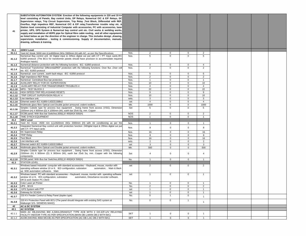
41
SUBSTATION AUTOMATION SYSTEM: Erection of the following equipemnts in 220 and 33 kV
level consisting of Panels, Bay control Units, DP Relays, Numerical O/C & E/F Relays, DC
Supervision relays, Trip Circuit Supervision, Trip Relay ,Test Block, Differential with REF,
Overflux, High impednce REF, Numerical O/C & E/F relay,Transformer trouble relay etc. &
Station level consisting of Industrial Computer with accessories, PC with accessories, laser
printer, UPS, GPS System & Numerical bay control unit etc. Civil works & weilding works,
supply and installation of HDPE pipe for Optical fibre cable routing, and all other equipments
as listed below as per the direction of the engineer in charge. This includes design ,drawing,
supervision, installation , testing & commissioning. Supply of documentation, manuals,
drawing, software & training.
41.1 220KV Level
41.1.1 Yard AC Kiosk :5000 mm (L)x4000mm (W)x 3300mm (H) with AC, as per the Specification; Nos. 2 0 0 2
41.1.2
Numerical Bay control unit :32 Digital input & 24Nos digital out put with CT / PT Input cards.IEC
61850 protocol. (The BCU for transformer panels should have provision to accommodate required
Analogue Inputs).
Nos. 5 0 0 5
41.1.3 Numerical distance protection with the following functions: IEC 61850 protocol. Nos. 4 0 0 4
41.1.4Numerical Transformer Differential/REF protection with the following functions: Over flux ,Over volt
etc. IEC 61850 protocol
Nos. 2 0 0 2
41.1.5 Numerical over current , earth fault relays: IEC 61850 protocol Nos. 5 0 0 5
41.1.6 High Impedance REF Relay Nos. 2 0 0 2
41.1.7 Numerical Centralised Bus bar protection. Nos. 1 0 0 1
41.1.8 AUXILIARY RELAY FOR DC SUPERVISION Nos. 10 0 0 10
41.1.9 AUXILIARY RELAY FOR TRANSFORMER TROUBLES 4 Nos. 4 0 0 4
41.1.10 MPG - TEST BLOCK 2 Nos. 22 0 0 22
41.1.11 HIGH SPEED TRIP RELAY(HAND RESET) Nos. 9 0 0 9
41.1.12 TRIP CIRCUIT SUPERVISION RELAY 4 Nos. 10 0 0 10
41.1.13 Line interface unit; sets. 3 0 0 3
41.1.14 Ethernet switch IEC 61850-3,IEEE1588v2 set 4 0 0 4
41.1.15 Multimode glass fibre Optical cord Double jacket armoured ,rodent resilient.. Mtr. 1000 0 0 1000
41.1.16Simplex Cubicle type for process bus equipment , Swing frame front access (VSG), Dimension
2300mm (H) X 900mm (D) X 1000mm (W), earth bar 25x6 Sq. mm. Copper
Set 5 0 0 5
41.1.17 DCDB panel; With Bus bar Switches,600(L)X 400(W)X 500(H) NOS 2 0 0 2
41.1.18 TIME SYNCH EQUIPMENT NOS 1 0 0 1
41.2 33KV Level
41.2.1 Yard AC Kiosk :4500 mm (L)x3500mm (W)x 3300mm (H) with Air conditioning as per the
Specification;Nos. 1 0 0 1
41.2.2Integrated Numerical Bay control unit with protection function :24Digital input & 20Nos digital out put
with CT / PT Input cards Nos. 8 0 0 8
41.2.3 DC Supervision Relay Nos. 16 0 0 16
41.2.4 TRIP Relay Nos. 8 0 0 8
41.2.5 Test Block Nos. 16 0 0 16
41.2.6 Line interface unit; sets. 2 0 0 2
41.2.7 Ethernet switch IEC 61850-3,IEEE1588v2 set 3 0 0 3
41.2.8 Multimode glass fibre Optical cord Double jacket armoured ,rodent resilient.. Mtr. 500 0 0 500
41.2.9
Simplex Cubicle type for process bus equipment , Swing frame front access (VSG), Dimension
2300mm (H) X 900mm (D) X 900mm (W), earth bar 25x6 Sq. mm. Copper with the following
componentsSet 4 0 0 4
41.2.10 DCDB panel; With Bus bar Switches,600(L)X 400(W)X 500(H) No. 1 0 0 1
41.3 STATION LEVEL
41.3.1
Windows based Industrial computer with standard accessories – Keyboard, mouse, monitor with
operating software window 10 or 8, IED configuration, substation automation, . Main & Back
up. With automation softwares. Main
set 2 0 0 2
41.3.2
Windows based PC with standard accessories – Keyboard, mouse, monitor with operating software
window 10 or 8, IED configuration, substation automation, Disturbance recorder software.
DR & work Station PC.Client
set 1 0 0 1
41.3.3 Color Laser jet Printer No. 1 0 0 1
41.3.4 UPS , 3KVA No. 2 0 0 2
41.3.5 GPS System with PTP set 1 0 0 1
41.3.6 Gateway for SCADA set 1 0 0 1
41.3.7220 KV Feeder Control & Relay Panel (duplex type) No. 0 1 0
1
41.3.8220 KV Protection Panel with BCU (The panel should integrate with existing SAS system at
Malkangiri S/S- SIEMENS MAKE)
No. 0 0 11
42 AC & DC SYSTEM
42.1 AC SYSTEM
42.1.1MAIN AC DB,(HAVING 800 A,50KA,DRAWOUT TYPE ACB WITH 3 O/C,E/F,U/V RELAYING
FACILITY INDOOR TYPE AS PER SPECIFICATION.(MAIN DB-1,MAIN DB-2 WITH B/C)SET 1 0 0 1
42.1.2 ACDB (HAVING 400A MCCB) AS PER SPECIFICATION (AC DB-1,AC DB-2 WITH B/C) SET 1 0 0 1

42.1.3MAIN LIGHTING DISTRIBUTION BOARD (HAVING 250A MCCB AS INCOMER)AS PER
SPECIFICATION (WITH DB-1,DB-2 & B/C)SET 1 0 0 1
42.1.4INDOOR LIGHTING DISTRIBUTION BOARD AS PER SPECIFICATION. (WITH DB-1,DB-2 & B/C)
SET 1 0 0 1
42.1.5 EMERGENCY LIGHTING DISTRIBUTION BOARD SET 1 0 0 1
42.1.6 INDOOR RECEPTACLE BOARD SET 1 0 0 1
43 DC SYSTEM
43.1220 V DC BOARD (HAVING 100A DC MCCB AS INCOMER, E/F (EARTH LEAKAGE), UNDER &
OVER VOLTAGE AS PER SPECIFICATION (DC DB-1,DC DB-2 & B/C)SET 1 0 0 1
43.2 220 V DC EMERGENCY DISTRIBUTION BOARD SET 1 0 0 1
43.3 BATTERY (350 AH PLANTE TYPE) for 220 V DC SET 2 0 0 2
43.4 BATTERY CHARGER FOR 220 V, 350 AH (Float and Float cum Boost) SET 1 0 0 1
43.5 DISTILLED WATER PLANT of 10 L/Hr FOR BATTERY BANKS NOS 1 0 0 1
44
COLOUR CODING, BAY MARKING Etc:Design, engineering, procurement of labour, material
including all associated works for the followings. This should be as per direction of site In charge.
a)Color coding (red,Yellow & Blue) for equipments,Bus gantry &column of entire switch yard. Good
quality weather proof sticker may be used for identification. b)Each bay should be identified with the
help of bay marker sign board, suitably grouted. MS sign board with stand to be installed. Proper
painting and lettering to be done of the entire switch yard area.
LOT 1 0.2 0.2 1.4
45PEDESTAL MOUNTED WHEEL FITTED DERRICK FOR LIFTING/ LOWERING OF MATERIALS
UP TO 1.5 TON CAPACITY.NOS 1 0 0 1
46 AC & DC SYSTEM NOS 1 0 0 1
47WATER COOLER WITH WATER PURIFIER SYSTEM
NOS 2 0 0 2
48
MAINTENANCE TESTING EQUIPMENT (AS PER ANNEXURE - I ,INDICATED IN TS-TIMK-
SCHEDULE OF REQUIREMENTS OF MAINTENANCE EQUIPMENT) SET 1 0 0 1
49
OTHER TOOLS AND PLANTS (T&P's) REQUIREMENT (AS PER ANNEXURE - II ,INDICATED IN
TS-TIMK-SCHEDULE OF REQUI-REMENTS OTHER T&P's) SET 1 0 0 1
50
OFFICE FURNITURE (AS PER ANNEXURE - III ,INDICATED IN TS-TIMK-SCHEDULE OF
REQUIREMENTS OFFICE FURNITURE)>PLACING IN CONTROL ROOM,CONFERENCE
ROOM,OFFICE ROOMS,LIBRARY,TESTING LAB,etc.SET 1 0 0 1
51BEST QUALITY &APPROVED MAKE INSULATING MAT (Confirming to IS:15652:2006) TO BE
KEPT INFRONT OF ALL PANELS,BOARDS ETC.(2000X1000X3)mm SizeNOS 35 2 2 39
52 WALKIE TALKIE SET SET/PAIR 2 0 0 2
53PORTABLE ALUMINIUM LADDER EXTENDABLE TYPE OF ADEQUATE HEIGHT TO BE USED
FOR MAINTENANCE OF EQUIPMENT INSIDE SWITCH YARD.NOS 2 0 0 2
54 TOTAL OF ERECTION SUBSTATION (PART-B-Electrical Work)
TOTAL OF ERECTION OF SUBSTATION (Electrical Work) & (Civil Work) -Schedule-
4-ss (to Schedule No. 6 Grand Summary)
1 Specify currency in accordance with specifications in Bid Data Sheet under ITB 19.1 in Single-Stage Bid, or ITB 34.1 in Two-Stage Bid.
Name of Bidder:_______________________________
Signature of Bidder:_______________________________

Foreign
Currency
Portion
Local
Currency
Portion
Foreign
Currency
Portion
Local
Currency
Portion
(1) (2) (3) (1) x (2) (1) x (3)
PART A CIVIL WORKS
1
SURVEY OF LINE & PREPARATION LAND SCHEDULE:
Supply of required T&P’s, Technical personnel’s, labours
for conducting
1.1
Preliminary survey, Detail survey and resurvey (required for
avoiding ROW problem) including but not limited to taking of
levels, profile plotting, tower spotting ,marking of towers
locations at site including showing P&T line, power line, Railway
line, river crossing, roads and submission of route map and
survey report etc. The P&T lines and railway lines for a
minimum distance of 8 kms on either side of alignment shall be
clearly indicated.(This item is applicable for revised portion of
the line only if the survey work was done by OPTCL previously)
KM. 37.6 0 37.60
NAME OF THE BIDDER
SL NO
Co
ns
tru
cti
on
of
22
0 K
V
Se
co
nd
CK
T l
ine
on
ex
isti
ng
DC
To
wer
fro
m B
AL
IME
LA
to
MA
LK
AN
GIR
I S
/s (
21
.37
KM
)
To
tal
Qu
an
tity
Total Price 1
ERECTION,TESTING & COMMISSIONING OF FOLLOWING
EQUIPMENTS ALONG WITH CIVIL WORKS (As per Technical
Specification)
UNITS
CO
NS
TR
UC
TIO
N O
F
220 K
V
LIL
O L
INE
O
N M
alk
an
gir
i-
Bali
mela
--37.6
KM
ORISSA POWER TRANSMISSION CORPORATION LIMITED
NAME OF THE WORK:- Design, Supply and Installation of Sub-Stations & Transmission Lines for Procurement of 2X20 MVA,
220/33 KV Sub-station at GOBINDPALLI & associated 220KV LILO line on 220KV BALIMELA - MALKANGIRI Second CKT Line
(Approx. Line length-37.600 Kms.) and stringing of 220 KV Second CKT line on existing DC Tower from BALIMELA to
MALKANGIRI and associated 220KV bay extension at Balimela & Malkangiri S/S in Odisha State of India under PACKAGE-5A
Under Japan International Cooperation Agency (JICA)’s ODA Loan.
Loan Agreement No: [ID-P245] - FB No: [CPC/JICA/ICB/05A/16-17/]- Reference Identification No: [OPTCL/JICA/PKG-5A]
Schedule No. 4. Installation and Other Services (Transmission Line)
Unit Price 1

1.2
Preparation of land schedule on revenue (if required) maps
indicating alignment therein duly authenticated by Revenue
Inspector & Tahasildar, enumeration of trees with the help of
Forest officer and other prominent features required for
alignment of the proposed 132 KV line. Final route to be plotted
on 1:50000 topo sheet for approval.(This item is applicable for
revised portion of the line only if the survey work was done by
OPTCL previously).Detail GIS (Geographical Information
System) of towers to be included.
KM. 37.6 0 37.60
1.3
Check survey including supply of all labour, T&P as per
instruction of Engineer in Charge and as per the approved
profile.
KM. 37.6 0 37.60
1.4Soil Testing in complete shape along with submission of report
etc. Per Loc. 10 0 10
2EXCAVATION WORKS FOR OPEN CAST/SHALLOW TYPE
FOUNDATIONS
2.1
Excavation in all type soil and rocks and back filling (back
filling shall be done in layers of 500mm sprinkling of water
and compaction thereafter and disposed of excess
quantity of excavated soil at suitable place after back
filling), & if required for filling the foundation, borrowed
earth/morrum/sand shall be brought for filling and
compaction, including supply of sand, all T&P, labour as
required.2.1.1 Soft/Loose soil CUM 2706 0 2,706
2.1.2 Dense/Compact soil CUM 1083 0 1,083
2.1.3 Wet soil CUM 7213 0 7,213
2.1.4 Partial Submerged soil CUM 1695 0 1,695
2.1.5 Fully submerged soil CUM 889 0 889
2.1.6 Soft/Disintegrated rock(Not requiring Blasting) CUM 956 0 956
2.1.7 Hard Rock(Requiring Blasting/Using breaker machinery) CUM 855 0 855
3.0 Fixing of Templates for setting of stubs
3.1 A Type (0.579 MT X 100 Nos) MT 57.900 0 57.90
3.2 B Type (0.794 MT X 20Nos) MT 15.880 0 15.88
3.3 C Type ( .962 MT X 22 Nos) MT 21.164 0 21.16
3.4 C +15 Type (2.107 MT X 4 Nos) MT 8.428 0 8.43
3.5 UR Type (1.476 MT X 2 Nos) MT 2.952 0 2.95

4.0
FOUNDATION MATERIALS: Supply of all materials like
cement, steel, all coarse aggregates, fine aggregates and
making foundations of the required above mentioned type
towers as per the direction laid down in the technical
specification and the direction of the site- in charge
4.1 PCC(Lean Concrete) in the ratio 1:3:6(Grade M-10) CUM 270.5 0 270.50
4.1.1
(i) FOR OPENCAST FOUNDATION:Providing & laying of RCC
work of ratio 1:1.5:3 (Grade M-20) with approved quality stone
chips of nominal size 12mm to 20mm in tower foundation and
cooping inclusive of cost of mixing, supply of form boxes
Chimney & fixing, curing, testing of sample cement concrete
cubes & cost of all materials including cement excluding steel
as per IS.456
(ii) The cooping height shall be 350mm above the ground level.
The surrounding area shall be clear from materials and
damage of land if any shall be repaired before measurement
and as per requirement, including labours and T&P as per
specification in the concrete ratio 1:1.5:3 (Grade M-20.)
CUM 2668.57 0 2,668.57
4.1.2
Steel of different size (as per design ) with cutting,bending
,binding in position of M.S.Rod for reinfocement of foundation
concret of towers (open cast ) including supply of binding wire
(With supply of steel rod (TATA/RINL/SAIL make )
MT 224.16 0 224.16
4.6 DE-WATERING(FOR OPEN CAST LOCATION)
4.6.1With Supply of all T&P, Fuel, Lubricant & electricity on HP Hour
basis.HP Hour 1500 0 1500
4.7Supply of borrowed earth/morrum for back filling for
foundation/revertment works4.7.1 beyond 100 mtr lead CUM 1800 0 1800
4.8
SHORING & SHUTTERING-Required in wet/submerged or
special locations of open cast/shallow type foundations
with supply of all materials,T&P and Labour.SQ.MTR. 12000 0 12000
4.9
Head-Loading of all types of foundation-
materials,towers,structures, conductors,Insulators,Hard-wares
& Emergency Restoration System towers required for special
inaccessible Locations beyond 400 mtrs from the nearest
approach road as per the recommendation of site Engineer-In-
Charge and approval of GM of Concerned circle.
Per
MT/Per
Mtr
1000 200 1200
5REVETMENT / STONE PITCHING FOR PROTECTION OF
TOWER BASE.

5.1 Excavation in all type of soil including rock
& back filling including supply of sand with back filling.CUM 2977 0 2977
5.2Lean Concrete in the ratio1:3:6(Grade M-10) including supply of
sand chips etc.CUM 127 0 127
5.3 PCC in the ratio 1:2:4(Grade M-15) as above. CUM 48 0 48
5.4 RR Massonary work in the ratio 1:5. CUM 4795 0 4795
5.5 Plastering and punning etc. SQ.MTR. 300 0 300
5.6 Stone Pitching CUM 300 0 300
6Benching in all type of soil including all required accessaries,
labour & T&P etc.
6.1 Hard soil CUM 3208 0 3208
6.2 Soft Rock (not required blasting) CUM 1611 0 1611
6.3 Hard Rock (requiring blasting) CUM 681 0 681
TOTAL of CIVIL WORKS Part-A
PART B ELECTRICAL WORKS
6.0
ERECTION,TESTING & COMMISSIONING of tested Lattice
type Galvanized steel tangent / Angle tower super structures
without stubs and cleats , different type of G.I HT Nuts & Bolts,
washer, spring washer for the above type towers ,hanger and
all accessories, tower super structure complete with tightening,
punching of bolts including step bolts. All other left out portion
of the bolts above bottom cross arm shall be riveted by using
suitable hammer. Painting of black bituminous paints three
coats shall be provided up to a height of 500mm above the
cooping(legs & bracing members. All Erection should confirm to
the Technical Specification laid there in the Tender
Specification.
MT 897.32 0 897.315
6.1
Hoisting and fixing of insulators with required accessories,
paying out of conductor ,jointing, stringing, sagging &
Jumpering etc. of power conductor in the proposed lines
and without earth wire with all required accessories
including scaffolding for 33 KV,11 KV, LT , P&T lines,
roads and using own required T&P and compression
jointing machines etc.with 1.5% provision for Sag &
Wastage and as per the direction of Engineer in charge.
6.1.1DOUBLE CIRCUIT(ACSR/AAAC, SIX POWER CONDCTOR )
RKM 37.6 0.00 37.60
6.1.2SINGLE CIRCUIT(ACSR/AAAC, THREE POWER
CONDCTOR ) (Hot Line)RKM 0 21.37 21.37
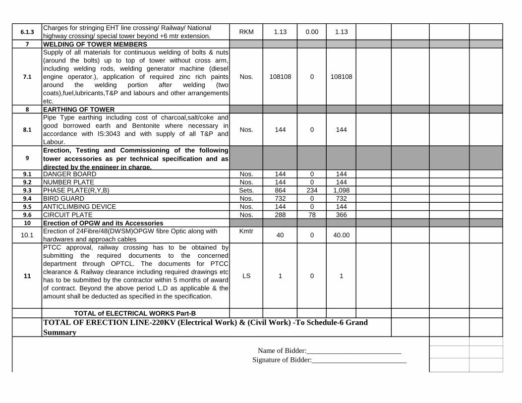
6.1.3Charges for stringing EHT line crossing/ Railway/ National
highway crossing/ special tower beyond +6 mtr extension.RKM 1.13 0.00 1.13
7 WELDING OF TOWER MEMBERS
7.1
Supply of all materials for continuous welding of bolts & nuts
(around the bolts) up to top of tower without cross arm,
including welding rods, welding generator machine (diesel
engine operator.), application of required zinc rich paints
around the welding portion after welding (two
coats),fuel,lubricants,T&P and labours and other arrangements
etc.
Nos. 108108 0 108108
8 EARTHING OF TOWER
8.1
Pipe Type earthing including cost of charcoal,salt/coke and
good borrowed earth and Bentonite where necessary in
accordance with IS:3043 and with supply of all T&P and
Labour.
Nos. 144 0 144
9Erection, Testing and Commissioning of the following
tower accessories as per technical specification and as
directed by the engineer in charge.9.1 DANGER BOARD Nos. 144 0 144
9.2 NUMBER PLATE Nos. 144 0 144
9.3 PHASE PLATE(R,Y,B) Sets. 864 234 1,098
9.4 BIRD GUARD Nos. 732 0 732
9.5 ANTICLIMBING DEVICE Nos. 144 0 144
9.6 CIRCUIT PLATE Nos. 288 78 366
10 Erection of OPGW and its Accessories
10.1Erection of 24Fibre/48(DWSM)OPGW fibre Optic along with
hardwares and approach cables
Kmtr40 0 40.00
11
PTCC approval, railway crossing has to be obtained by
submitting the required documents to the concerned
department through OPTCL. The documents for PTCC
clearance & Railway clearance including required drawings etc
has to be submitted by the contractor within 5 months of award
of contract. Beyond the above period L.D as applicable & the
amount shall be deducted as specified in the specification.
LS 1 0 1
TOTAL of ELECTRICAL WORKS Part-B
Name of Bidder:__________________________
Signature of Bidder:__________________________
TOTAL OF ERECTION LINE-220KV (Electrical Work) & (Civil Work) -To Schedule-6 Grand
Summary
Name of Bidder:__________________________
Signature of Bidder:__________________________
1 Specify currency in accordance with specifications in Bid Data Sheet under ITB 19.1 in Single-Stage Bid, or ITB 34.1 in Two-
Stage Bid.
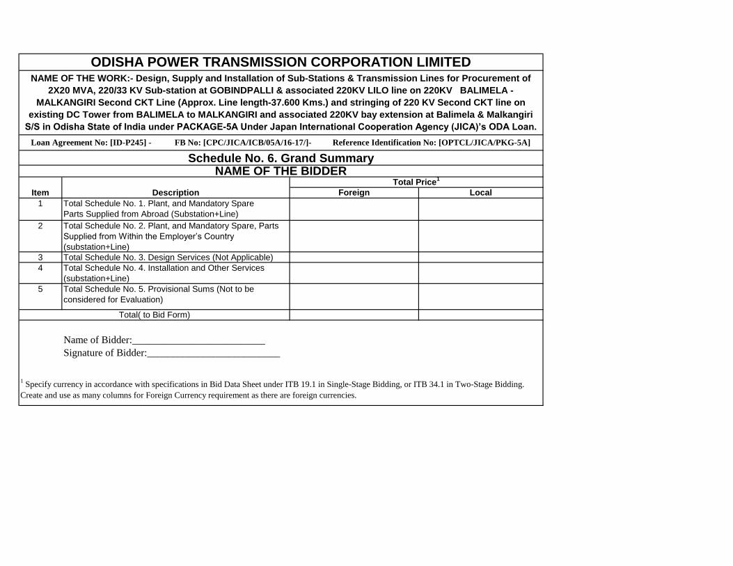
Foreign Local
1 Total Schedule No. 1. Plant, and Mandatory Spare
Parts Supplied from Abroad (Substation+Line)
2 Total Schedule No. 2. Plant, and Mandatory Spare, Parts
Supplied from Within the Employer’s Country
(substation+Line)
3 Total Schedule No. 3. Design Services (Not Applicable)
4 Total Schedule No. 4. Installation and Other Services
(substation+Line)
5 Total Schedule No. 5. Provisional Sums (Not to be
considered for Evaluation)
Total( to Bid Form)
Name of Bidder:__________________________
Signature of Bidder:__________________________
1 Specify currency in accordance with specifications in Bid Data Sheet under ITB 19.1 in Single-Stage Bidding, or ITB 34.1 in Two-Stage Bidding.
Create and use as many columns for Foreign Currency requirement as there are foreign currencies.
Loan Agreement No: [ID-P245] - FB No: [CPC/JICA/ICB/05A/16-17/]- Reference Identification No: [OPTCL/JICA/PKG-5A]
NAME OF THE BIDDER
ODISHA POWER TRANSMISSION CORPORATION LIMITEDNAME OF THE WORK:- Design, Supply and Installation of Sub-Stations & Transmission Lines for Procurement of
2X20 MVA, 220/33 KV Sub-station at GOBINDPALLI & associated 220KV LILO line on 220KV BALIMELA -
MALKANGIRI Second CKT Line (Approx. Line length-37.600 Kms.) and stringing of 220 KV Second CKT line on
existing DC Tower from BALIMELA to MALKANGIRI and associated 220KV bay extension at Balimela & Malkangiri
S/S in Odisha State of India under PACKAGE-5A Under Japan International Cooperation Agency (JICA)’s ODA Loan.
Schedule No. 6. Grand Summary
Item Description
Total Price1

CIP
(foreign parts)
Ex-Works Price
Local Parts
(1) (2) (3) (1) x (2) or (3)
TOTAL
Total Price in
INR
Note: Recommended Spares shall not be taken in to consideration for evaluation purpose.
Name of Bidder:________________________________
Signature of Bidder:_____________________________
NAME OF THE WORK:- Design, Supply and Installation of Sub-Stations & Transmission Lines for Procurement of
2X20 MVA, 220/33 KV Sub-station at GOBINDPALLI & associated 220KV LILO line on 220KV BALIMELA -
MALKANGIRI Second CKT Line (Approx. Line length-37.600 Kms.) and stringing of 220 KV Second CKT line on
existing DC Tower from BALIMELA to MALKANGIRI and associated 220KV bay extension at Balimela & Malkangiri
S/S in Odisha State of India under PACKAGE-5A Under Japan International Cooperation Agency (JICA)’s ODA Loan.
ODISHA POWER TRANSMISSION CORPORATION LIMITED
Schedule No. 7. Recommended Spare Parts
Sl. No. DESCRIPTION OF ITEMS
SUPPLY OF SPARES FOR THE FOLLOWING
EQUIPMENTS.
(As per Technical Specification)
Loan Agreement No: [ID-P245] - FB No: [CPC/JICA/ICB/05A/16-17/]- Reference Identification No: [OPTCL/JICA/PKG-5A]
NAME OF THE BIDDER
Unit Unit Price

NAME OF THE BIDDER
Sl No Description of Applicable Tax/LevyItem /Component Sl. No. of
Bid price on which ApplicableTax @ __%
Total Amount of Taxes
/Duty/ Levies
1
Details of Taxes and levies on the direct transactions between Bidder and
ODISHA POWER TRANSMISSION CORPORATION LTD included in the Bid
Price above but as may be payable by ODISHA POWER TRANSMISSION
CORPORATION LTD
(i) Excise Duty [as per Schedule-2]
(ii) CST [as per Schedule-2]
(III) VAT/Sales Tax [as per Schedule-2]
(iv) Entry Tax [as per Schedule-2]
(v) Any other Levies: [as per Schedule-2] (please specify): Central :-
(a)
(b)
TOTAL OF TAXES AND DUTIES [Sum (i) to (v) 0
2
Details of Taxes and levies on the Bought out transactions between
Bidder and ODISHA POWER TRANSMISSION CORPORATION LTD included
in the Bid Price above but as may be payable by ODISHA POWER
TRANSMISSION CORPORATION LTD
(i) Excise Duty [as per Schedule-2]
(ii) CST [as per Schedule-2]
(III) VAT/Sales Tax [as per Schedule-2]
(iv) Entry Tax [as per Schedule-2]
(v) Any other Levies: [as per Schedule-2] (please specify): Central :-
ODISHA POWER TRANSMISSION CORPORATION LIMITEDNAME OF THE WORK:- Design, Supply and Installation of Sub-Stations & Transmission Lines for Procurement of 2X20
MVA, 220/33 KV Sub-station at GOBINDPALLI & associated 220KV LILO line on 220KV BALIMELA - MALKANGIRI
Second CKT Line (Approx. Line length-37.600 Kms.) and stringing of 220 KV Second CKT line on existing DC Tower from
BALIMELA to MALKANGIRI and associated 220KV bay extension at Balimela & Malkangiri S/S in Odisha State of India
under PACKAGE-5A Under Japan International Cooperation Agency (JICA)’s ODA Loan.
Loan Agreement No: [ID-P245] - FB No: [CPC/JICA/ICB/05A/16-17/]- Reference Identification No:
[OPTCL/JICA/PKG-5A]
Schedule No. 8. Details of Taxes & Duties

(a)
(b)
TOTAL OF TAXES AND DUTIES [Sum (i) to (v)
3 Service Tax [as per Schedule-4]
4F. Total Bid Price: (including Taxes & Duties and other levies, if the
contract is awarded to us)
NOTE:- Lumpsum prices quoted by the Bidder shall include cost of total scope of work and any other supplies/work(s) not specifically mentioned in the
Bidding Document but necessary for the efficient, trouble free operation of the system and to make this package work complete in all respects.
i) Excise Duty/VAT/Sales Tax/Service Tax/ Entry Tax/ any other taxes shall be inclusive in the bid price and shall not be paid/reimbursed separately.
Name of Bidder:________________________________
Signature of Bidder:_____________________________


![ELECTRICAL SYLLABUS [NEW] - SCTEVT Odisha](https://static.fdokumen.com/doc/165x107/6317192cf68b807f88038180/electrical-syllabus-new-sctevt-odisha.jpg)


