October 19, 2015 Ms. Melanie Bartlett North Carolina ...
342
AECOM 919.854.6200 tel 701 Corporate Center Drive, Suite 475 919.854.6259 fax Raleigh, NC 27615 October 19, 2015 Ms. Melanie Bartlett North Carolina Department of Environment and Natural Resources Division of Waste Management – Superfund Section 217 West Jones Street Raleigh, North Carolina 27603 Subject: Soil Excavation Design Report and Implementation Work Plan Former Salem Uniform Services Facility (Cintas Corporation) Project Site 4015 North Cherry Street, Winston-Salem, NC Groundwater Incident #86643, NCDENR-DWM #NONCD0002438 Dear Ms. Bartlett, AECOM Technical Services of North Carolina, Inc. (AECOM), on behalf of Cintas Corporation (Cintas), herein submits the above-referenced design report and implementation plan for the Former Salem Uniform Services project site (the Site). The work plan summarizes the design specifications and forthcoming excavation plan being conducted at the Site. Should you have any questions, please contact us at (919) 854-6200 or Mr. Jim Buckman (Cintas) at (513) 701-2821. Sincerely, Matt Allen, P.G. Tom Marr, P.G., RSM Project Manager Senior Program Manager cc: Mr. Jim Buckman (Cintas)
-
Upload
khangminh22 -
Category
Documents
-
view
0 -
download
0
Transcript of October 19, 2015 Ms. Melanie Bartlett North Carolina ...
AECOM 919.854.6200 tel 701 Corporate Center Drive, Suite 475 919.854.6259 fax Raleigh, NC 27615
October 19, 2015
Ms. Melanie Bartlett North Carolina Department of Environment and Natural Resources Division of Waste Management – Superfund Section 217 West Jones Street Raleigh, North Carolina 27603
Subject: Soil Excavation Design Report and Implementation Work Plan Former Salem Uniform Services Facility (Cintas Corporation) Project Site 4015 North Cherry Street, Winston-Salem, NC Groundwater Incident #86643, NCDENR-DWM #NONCD0002438
Dear Ms. Bartlett,
AECOM Technical Services of North Carolina, Inc. (AECOM), on behalf of Cintas Corporation (Cintas), herein submits the above-referenced design report and implementation plan for the Former Salem Uniform Services project site (the Site). The work plan summarizes the design specifications and forthcoming excavation plan being conducted at the Site.
Should you have any questions, please contact us at (919) 854-6200 or Mr. Jim Buckman (Cintas) at (513) 701-2821.
Sincerely, Matt Allen, P.G. Tom Marr, P.G., RSM Project Manager Senior Program Manager
cc: Mr. Jim Buckman (Cintas)
Environment Submitted to Cintas Corporation Milford, OH
Submitted by URS Corporation – North Carolina, Inc. (a wholly owned AECOM Technical Services, Inc. subsidiary) Morrisville, NC 60333229.300 October 2015
Soil Excavation Design Report and Implementation Work Plan
Cintas Corporation Former Salem Uniform Services Facility 4015 North Cherry Street Winston-Salem, Forsyth County, NC NCDEQ Site #NONCD0002438
Environment Submitted to Cintas Corporation Milford, OH
Submitted by URS Corporation – North Carolina, Inc. (a wholly owned AECOM Technical Services, Inc. subsidiary) Morrisville, NC 60333229.300 October 2015
Soil Excavation Design Report and Implementation Work Plan ____________________________________________ Prepared By Chris Brownfield, P.E., Project Engineer ____________________________________________ Reviewed By Matt Allen, P.G., Project Manager ____________________________________________ Reviewed By Tom Marr, P.G., Cintas Account Manager
Cintas Corporation Former Salem Uniform Services Facility 4015 North Cherry Street Winston-Salem, Forsyth County, NC NCDEQ Site #NONCD0002438
AECOM Environment i
Footer October 2015
Table of Contents ........................................................................................................................................................................ i 1 Introduction and Background ............................................................................................................................................ 1-1
1.1 Project Goals ................................................................................................................................................................ 1-1 1.2 Background and Site History ........................................................................................................................................ 1-1
1.2.1 Site History and Use ............................................................................................................................................ 1-1 1.2.2 Previous Investigations and Regulatory Status ................................................................................................... 1-2 1.2.3 Brownfields Program Status ................................................................................................................................ 1-2
2 Summary of Final Design ................................................................................................................................................... 2-1
2.1 Overview ...................................................................................................................................................................... 2-1 2.2 Contracting Approach ................................................................................................................................................... 2-1
2.2.1 Contracting Structure and Lines of Authority ....................................................................................................... 2-1 2.2.2 Contractor’s Responsibilities ............................................................................................................................... 2-2 2.2.3 AECOM’s Responsibilities ................................................................................................................................... 2-2
2.3 Construction Sequence ................................................................................................................................................ 2-2 2.4 Detailed Design Elements ............................................................................................................................................ 2-2
2.4.1 Site Preparation and Controls ............................................................................................................................. 2-2 2.4.2 Utilities Demolition and Removal ......................................................................................................................... 2-3 2.4.3 Excavation and Waste Profiling ........................................................................................................................... 2-3 2.4.4 On-Site Soil Treatment ........................................................................................................................................ 2-3 2.4.5 Backfill ................................................................................................................................................................. 2-3 2.4.6 Surface Structure Demolition and Disposal ......................................................................................................... 2-3 2.4.7 Final Grading ....................................................................................................................................................... 2-4 2.4.8 Waste Disposal ................................................................................................................................................... 2-4
2.5 Other Applicable or Relevant and Appropriate Regulations ......................................................................................... 2-4 2.6 Third Party Commitments ............................................................................................................................................. 2-4 2.7 Additional Remediation................................................................................................................................................. 2-4
3 Air Monitoring Plan ............................................................................................................................................................. 3-1
3.1 Monitoring Activities ..................................................................................................................................................... 3-1
3.1.1 Perimeter Air Monitoring ...................................................................................................................................... 3-1 3.1.2 Work Zone Monitoring ......................................................................................................................................... 3-2 3.1.3 Personnel Monitoring .......................................................................................................................................... 3-2
3.2 Quality Assurance ........................................................................................................................................................ 3-2 3.3 Reporting ...................................................................................................................................................................... 3-2
4 Construction Quality Assurance ....................................................................................................................................... 4-1
4.1 Soil Confirmation Sampling .......................................................................................................................................... 4-1 4.2 Backfill Testing ............................................................................................................................................................. 4-1
5 Community and Public Relations ...................................................................................................................................... 5-1
5.1 Planned Communication with the Public ...................................................................................................................... 5-1 5.2 Unplanned Communication with the Public/Media ....................................................................................................... 5-1
6 References ........................................................................................................................................................................... 6-1
Table of Contents

AECOM Environment ii
Footer October 2015
List of Appendices
Appendix A. Design Drawings and Technical Specifications Appendix B. Typical Air Monitoring Instrument Information
List of Figures
Figure 1-1. Site Location Map Figure 2-1. Pre-Excavation Sampling Results Figure 2-2 Contract Overview Figure 3-1. Proposed Perimeter Air Monitoring Stations Figure 4-1. Proposed Phase I Soil Confirmation Samples Figure 4-2. Proposed Phase II Soil Confirmation Samples
AECOM Environment iii
Footer October 2015
List of Acronyms
AECOM AECOM Technical Services of North Carolina, Inc. Cintas Cintas Corporation CSA Comprehensive Site Assessment DWM Division of Waste Management DWQ Division of Water Quality EPA United Stated Environmental Protection Agency EPA guidance Management of Remediation Waste Under RCRA IHSB Inactive Hazardous Site Branch mg/kg milligrams per kilogram NCDEQ North Carolina Department of Environmental Quality PCE tetrachloroethene PoG protection-of-groundwater ppm parts per million PSRG preliminary site remedial goal REC Registered Environmental Consultant Site Former Salem Uniform Site in Winston-Salem, North Carolina UST underground storage tank VOC volatile organic compound Weaver Winston Weaver, Inc. µg/m3 microgram per cubic meter
AECOM Environment 1-1
Footer October 2015
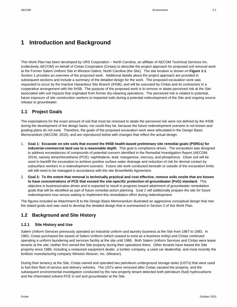
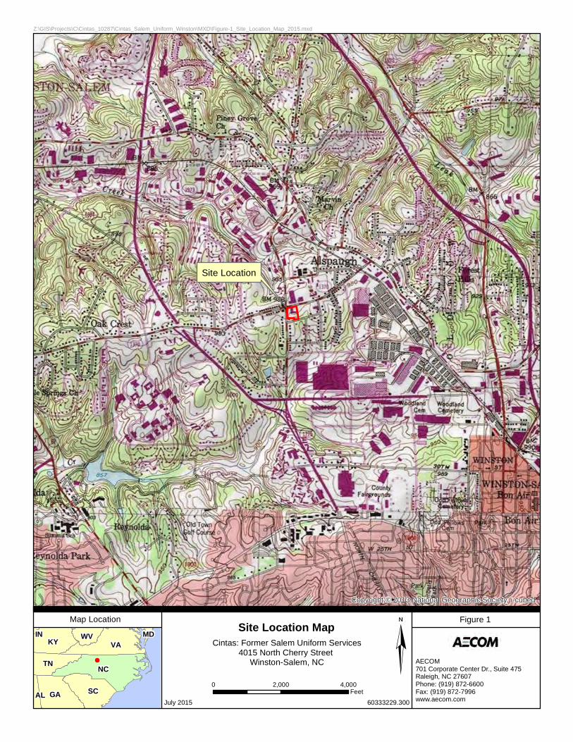
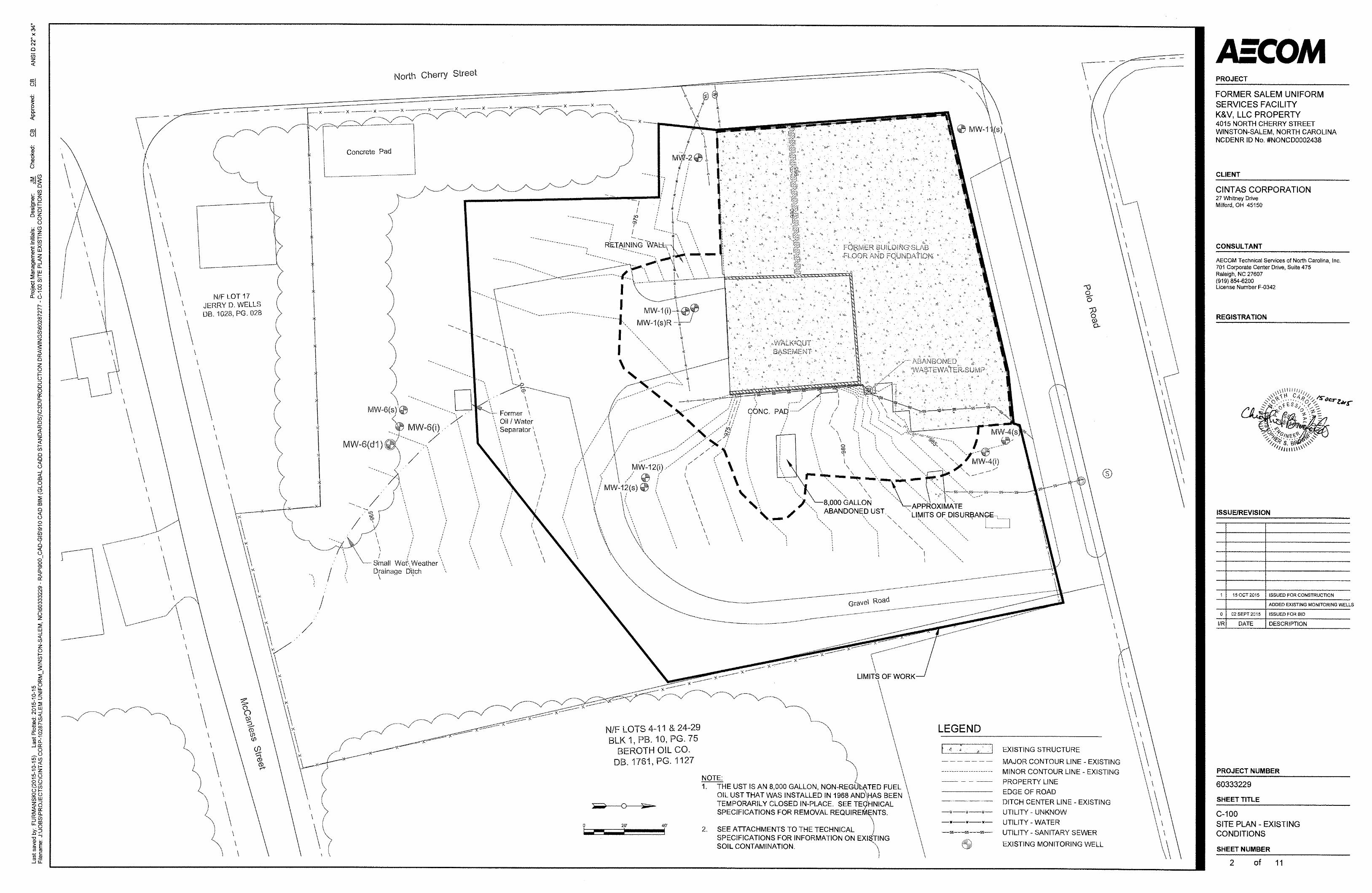
This Work Plan has been developed by URS Corporation – North Carolina, an affiliate of AECOM Technical Services Inc. (collectively AECOM) on behalf of Cintas Corporation (Cintas) to describe the project approach for proposed soil removal work at the Former Salem Uniform Site in Winston-Salem, North Carolina (the Site). The site location is shown on Figure 1-1. Section 1 provides an overview of the proposed work. Additional details about the project approach are provided in subsequent sections and include a summary of the detailed design for the work. The proposed excavation work was requested to occur by the Inactive Hazardous Site Branch (IHSB), and will be executed by Cintas and its contractors in a cooperative arrangement with the IHSB. The purpose of the proposed work is to remove or abate perceived risk at the Site associated with soil impacts that originated from former dry-cleaning operations. The perceived risk is related to potential, future exposure of site construction workers to impacted soils during a potential redevelopment of the Site and ongoing source release to groundwater.
1.1 Project Goals
The expectations for the exact amount of soil that must be removed to abate the perceived risk were not defined by the IHSB during the development of the design basis; nor could they be, because the future redevelopment scenario is not known and grading plans do not exist. Therefore, the goals of the proposed excavation work were articulated in the Design Basis Memorandum (AECOM, 2015), and are reproduced below with changes that reflect the actual design.
1. Goal 1: Excavate on-site soils that exceed the IHSB health-based preliminary site remedial goals (PSRGs) for industrial-commercial land use to a reasonable depth. This goal is compliance-driven. The excavation was designed to address exceedances of compounds of potential concern identified in the Remedial Investigation Report (AECOM, 2014), namely tetrachloroethene (PCE), naphthalene, lead, manganese, mercury, and phosphorus. Clean soil will be used to backfill the excavation to achieve positive surface water drainage and reduction of risk for dermal contact by subsurface workers in a redevelopment scenario. Future site work conducted beneath or outside of the excavation limits will still need to be managed in accordance with the site Brownfields Agreement.
2. Goal 2: To the extent that removal is technically practical and cost effective, remove soils onsite that are known to have concentrations of PCE that exceed the site-specific protection-of-groundwater (PoG) standard. This objective is business/value-driven and is expected to result in progress toward attainment of groundwater remediation goals that will be identified as part of future remedial action planning. Goal 2 will additionally prepare the site for future redevelopment now versus waiting to implement this remediation effort during redevelopment.
The figures included as Attachment B to the Design Basis Memorandum illustrated an aggressive conceptual design that met the stated goals and was used to develop the detailed design that is summarized in Section 2 of this Work Plan.
1.2 Background and Site History
1.2.1 Site History and Use
Salem Uniform Services previously operated an industrial uniform and laundry business at the Site from 1967 to 1983. In 1983, Cintas purchased the assets of Salem Uniform (which ceased to exist as a business entity) and Cintas continued operating a uniform laundering and services facility at the site until 1986. Both Salem Uniform Services and Cintas were lease tenants at the site; neither firm owned the Site property during their operations there. Other tenants have leased the Site property since 1986, including a restaurant equipment dealer, a lumber company, a used car dealership, and most recently the fertilizer manufacturing company Winston Weaver, Inc. (Weaver).
During their tenancy at the Site, Cintas owned and operated two petroleum underground storage tanks (USTs) that were used to fuel their fleet of service and delivery vehicles. The USTs were removed after Cintas vacated the property, and the subsequent environmental investigation conducted by the new property tenant detected both petroleum (fuel) hydrocarbons and the chlorinated solvent PCE in soil and groundwater at the Site.
1 Introduction and Background
AECOM Environment 1-2
Footer October 2015
The Site property is currently owned by K&V, LLC. Presently, the property is leased from K&V, LLC by Weaver. The property was most recently used to store pallets of bagged fertilizer and related lawn care products produced and packaged by Weaver at its nearby fertilizer manufacturing plant. Beginning in December 2009, Weaver ceased bringing new packaged fertilizer to the on-site building for storage, and by June 2010 the majority of the building had been emptied of the remaining fertilizer inventory. The facility building was demolished in December 2014 and Weaver has indicated that they no longer intend to use the property for future, large-scale storage of fertilizer. It is anticipated that the property will remain vacant in the near term.
1.2.2 Previous Investigations and Regulatory Status
Details and results of historical investigations at the Site have been summarized in various reports and work plans submitted by Cintas to the North Carolina Department of Environmental Quality (NCDEQ, formerly North Carolina Department of Environment and Natural Resources)-Division of Water Quality (DWQ) and Division of Waste Management (DWM) since 2003. Therefore, only a brief chronology of the historical investigations is included below. Within the most recent submittals to the DWM, the following documents also contained a concise historical summary of past investigations and summary of environmental sampling results at the Site:
Well Installation and Groundwater Monitoring Report, Former Salem Uniform Services Facility (ENSR, 2008)
Supplemental Assessment and Groundwater Monitoring Report, Former Salem Uniform Services Facility (AECOM, 2009)
Groundwater Monitoring Report for June 2010 Sampling Event (AECOM, 2010)
Work Plan for Supplemental Sampling of On-Site Media and Off-Site Pore Water (AECOM, 2011)
AECOM previously completed investigations for a Limited Site Assessment Report (ENSR, 2003) and a Comprehensive Site Assessment (CSA) on behalf of Cintas at the Site. A CSA Report (ENSR, 2006) was prepared and submitted to the NCDEQ-DWQ in June 2006. Following submittal of the CSA report, the NCDEQ reorganized several of its Departments, and as a result the Site was transferred to the IHSB of the NCDEQ-DWM Superfund Section. The NCDEQ-DWM notified Cintas of this site transfer in a letter dated April 26, 2007 and requested that a Voluntary Cleanup Site Checklist be completed to determine if the site was eligible to be placed in the Registered Environmental Consultant (REC) program of the IHSB. Based on results of new data collected by Cintas from 2008-2010, the NCDEQ-DWM has continued managing the Site’s Remedial Investigation work under their direct oversight in IHSB versus placing the Site in the REC program.
Cintas has performed semi-annual or annual groundwater and surface water sampling events since the Site was transferred to DWM-IHSB in 2007. A replacement monitoring well for MW-1(s) and a new upgradient monitoring well (MW-11s) were also installed on-site during that time period. Monitoring results reports for these sampling events are on file with NCDEQ. Prior to the current 2011 sampling event, AECOM last sampled groundwater and surface water at the Site in June 2010.
After the Site was transferred to DWM-IHSB, Cintas also conducted several phases of supplemental on-site soil investigations from January 2009 through March 2011. Additional subsurface soil gas sampling, as well as off-site crawlspace air sampling has also been performed by Cintas since 2007. The Combined Phase I and Phase II Remedial Investigation Report was also submitted on September 15, 2014 and was subsequently approved by the DWM-IHSB on October 24, 2014.
1.2.3 Brownfields Program Status
Concurrent with completion of the 2006 CSA activities described above, the Site property was also entered into the NCDEQ-DWM North Carolina Brownfields Program by the third party owner (K&V, LLC). K&V, LLC is currently the legal owner of the property, having purchased it from Alan H. Gwyn after the Brownfields Agreement was executed. K&V, LLC currently holds the Brownfield Redevelopment Agreement with the NCDEQ, which has placed certain deed and use restrictions on the property under the agreement. During the process of obtaining a Brownfields Agreement for the property, another consulting firm (Geoscience & Technology, P.A.) hired by the pending owner-developer performed separate Brownfields environmental investigations of the Site property as required by NCDEQ. The Site’s status in the Brownfields Program and its associated land use restrictions are recorded on the property deed with Forsyth County.

AECOM Environment 2-1
Footer October 2015
This section summarizes the most significant elements of the final excavation design. The excavation design drawings and specifications are attached as Appendix A and describe the components of the proposed excavation for which a contractor of AECOM will be responsible for executing. Additional components of the excavation work for which AECOM will be responsible are described in Section 4.0.
2.1 Overview
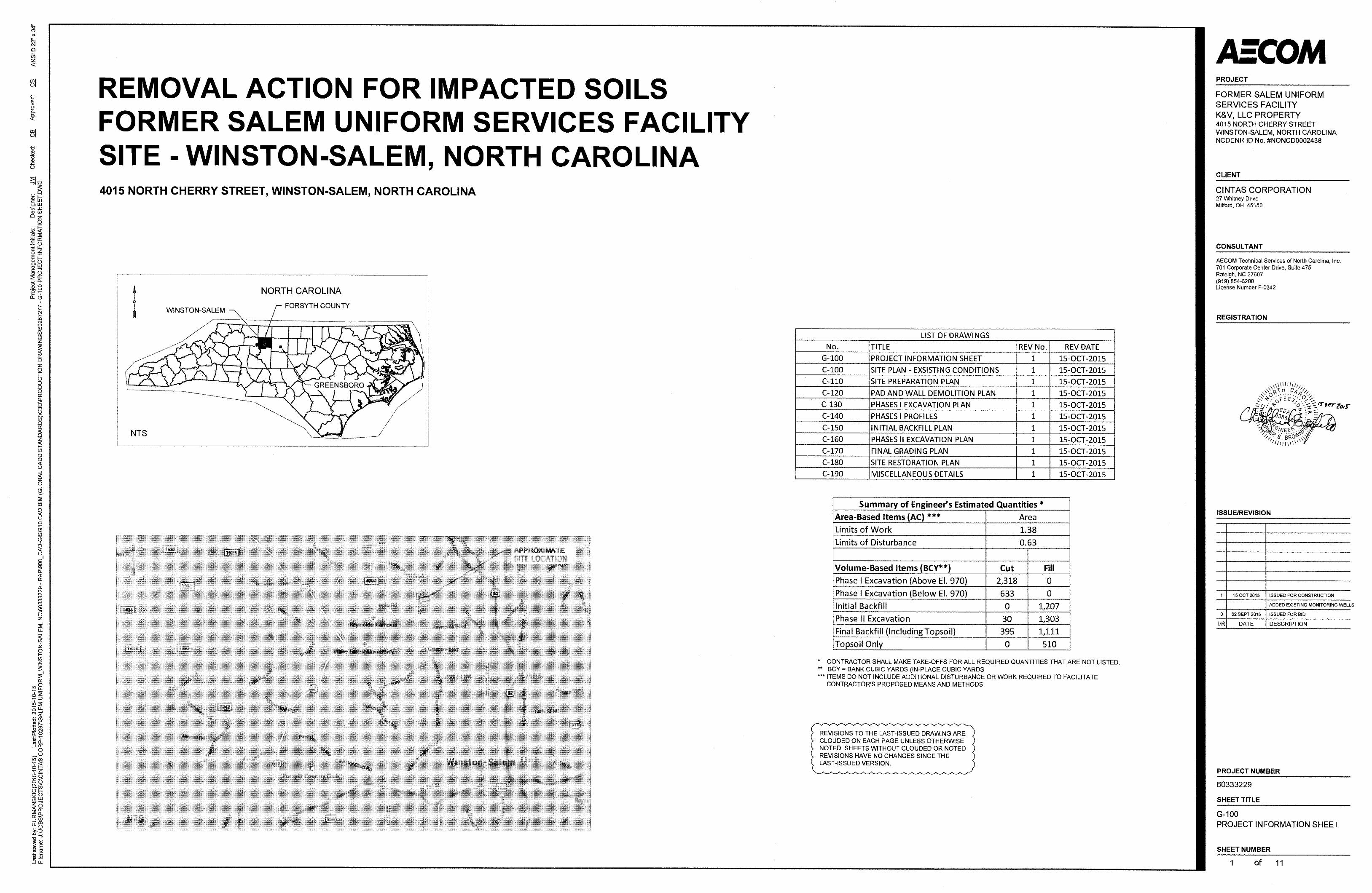
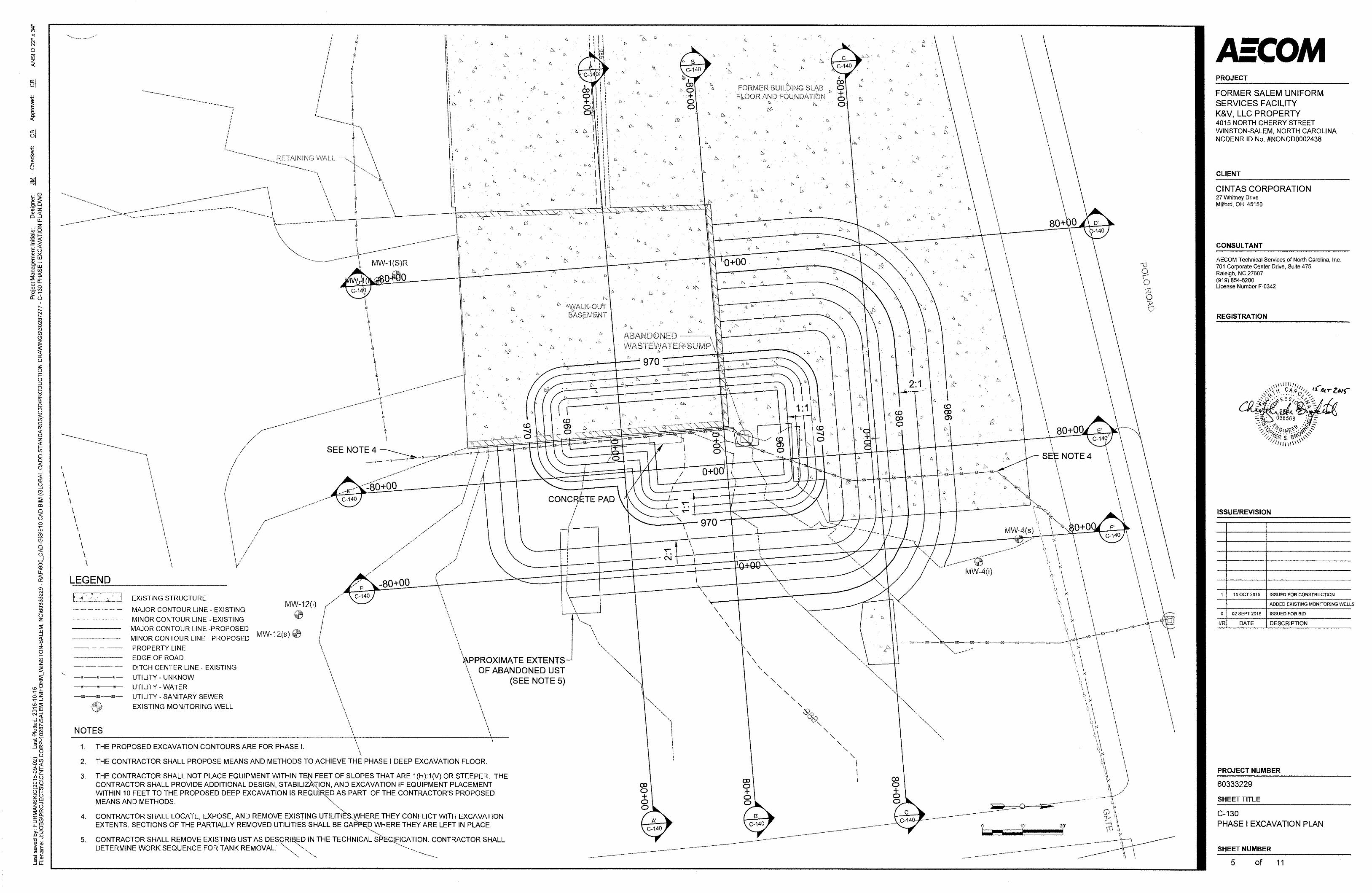
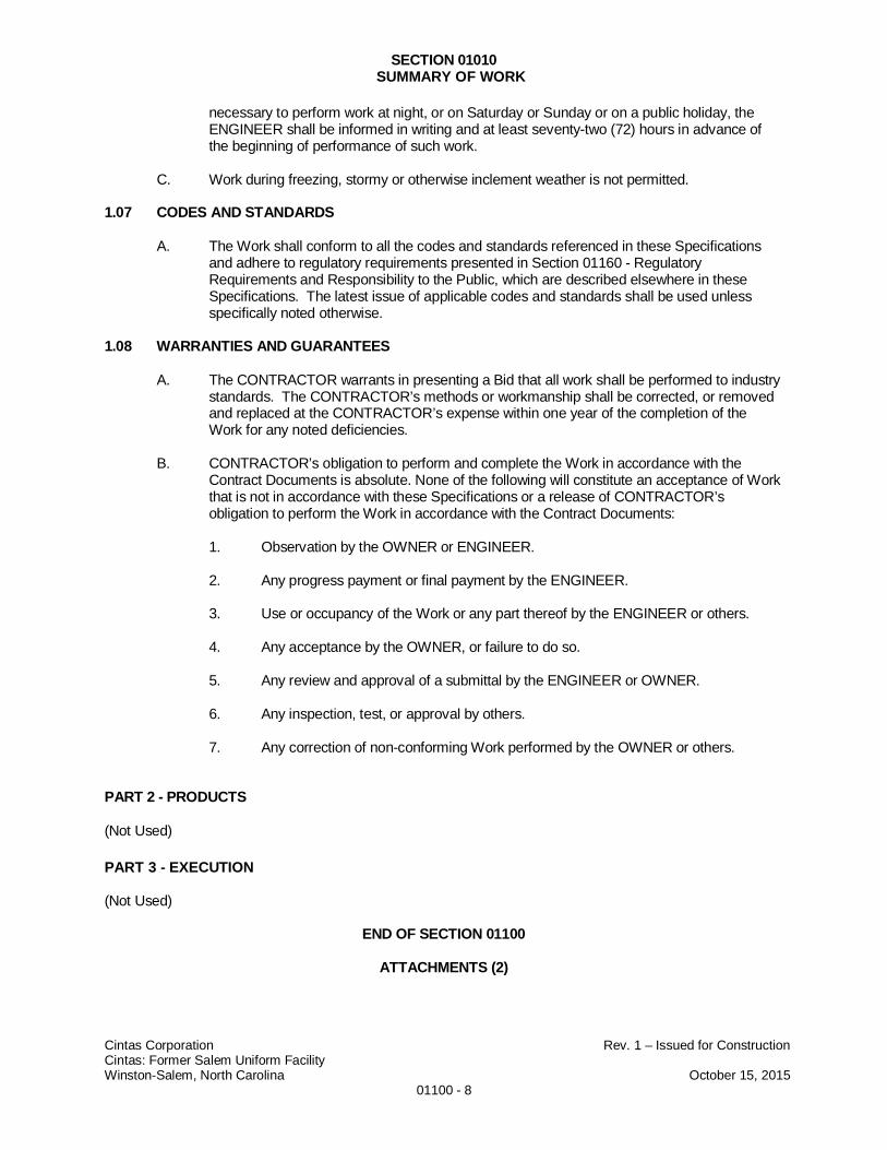
During the development of the detailed design, AECOM re-evaluated the excavation concepts presented in Attachment B to the Design Basis Memorandum to refine the amount of soil that will be excavated. Based on the re-evaluation, the excavation work was consolidated into two phases for simplified project delivery. During the first phase (Phase I), approximately 2,300 bank cubic yards of soil will be removed from the outside of selected foundation walls of the former site building, and an additional 600 bank cubic yards of material will be removed beneath the basement floor of the former site-building. The 600 bank cubic yard excavation beneath the former basement, which is approximately 10-feet deep, was optimized based on pre-excavation sample collection that is summarized on Figure 2-1. The removed material will be stockpiled, profiled, treated (as required) and re-profiled (as-required), and then hauled off-site for appropriate disposal. During the second phase, approximately 1,300 bank cubic yards of soil impacted with PCE at or above concentrations that could potentially leach to groundwater will be removed from the top two feet of surface soils at the site.
2.2 Contracting Approach
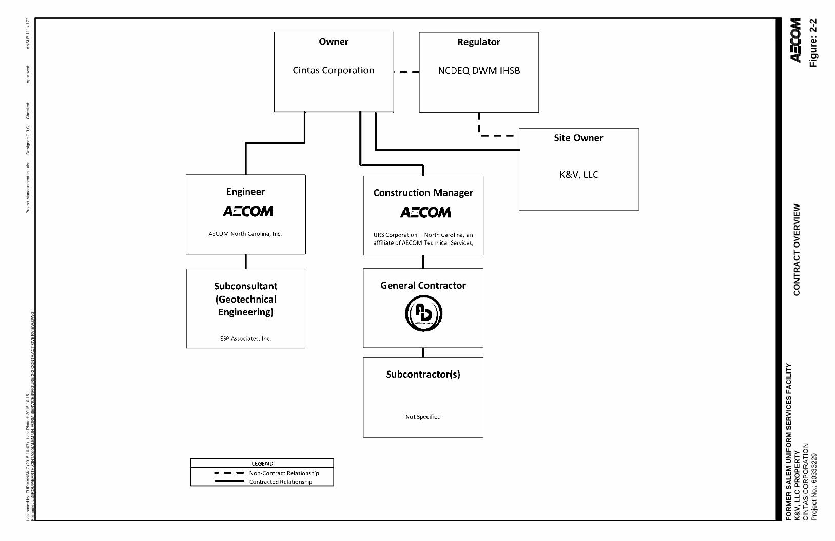
AECOM will subcontract the excavation work on behalf of Cintas to a licensed general contractor using a contract structure that is consistent with the construction-management-at-risk approach. In accordance with Title 21, Chapter 12 of the North Carolina Administrative Code, AECOM will manage construction under the general contracting license held by URS Corporation – North Carolina, a wholly owned affiliate of AECOM Technical Services, Inc. and referred to within as AECOM. AECOM will contract directly with Cintas and will serve as a turn-key manager for coordinating the environmental consulting portion of the work (described in Section 3) with the subcontracted portion of the work (described by the design documents provided as Appendix A).
2.2.1 Contracting Structure and Lines of Authority
A diagram of the proposed contract structure is provided as Figure 2-2. Cintas’ authority to perform the work at the Site was established by a May, 2015 addendum to a 2006 access agreement between K&V, LLC and Cintas that provided Cintas and its contractors with access to the Site for the purpose of performing soil borings, well installations, excavations, soil removal, building slab removal, and other environmental activities. AECOM’s authority to perform the work was established through a separate master services agreement to perform environmental engineering, consulting, and construction services. Through a separate agreement, AECOM also has the authority to act as Cintas’ agent for the purpose of arranging for the transport and/or disposal of Cintas’ waste.
AECOM (as Construction Manager) will have authority to execute the scope of work and managing any changes to the scope of work that occur during the execution of the project. AECOM will use a subcontractor (the General Contractor) to perform most of the site work components of the project and will provide general oversight of the General Contractor as an Owner’s Representative during the execution of the work. AECOM may also provide engineering oversight, and issue engineering field orders and work change directives in the role as designer (as Engineer).
The NCDEQ-DWM-IHSB will have the authority to directly intervene and to adjust the scope of work only in the case of imminent threats to the public or in the case of directing emergency response as asserted in North Carolina General Statutes 130A-310.5. For work that does not involve the direct management of imminent threats or emergency response, the NCDEQ-DWM-IHSB and Cintas will cooperatively negotiate any changes to the scope of the work that may be required.
2 Summary of Final Design
AECOM Environment 2-2
Footer October 2015
As provided by AECOM internal standard operating procedures, employees of work controlled by AECOM, its employees, and subcontracted work will have the authority to stop work in the event that an unsafe act or condition is observed. For this project, additional stop work authority will be observed for NCDEQ project observers, and for employees of the Site owner and Cintas. In the event that stop work requests are given by other project stakeholders, including but not limited to property neighbors, work will be temporarily stopped after the first order is issued and any disputes will be escalated through the contract chains of command to project managers, who will work cooperatively to resolve the dispute and to resume work. In the event that additional stop-work requests are issued by other non-contract project stakeholders or members of the general public, AECOM will observe and respond to the requests on a case-by-case basis.
2.2.2 Contractor’s Responsibilities
AECOM will hire a contractor to perform the demolition, excavation, treatment, transportation and disposal, and related work as described in the design documents included as Appendix A. AECOM’s contractor will be responsible for executing the work according to a schedule and price that is negotiated as part of the bid process.
2.2.3 AECOM’s Responsibilities
During implementation, AECOM’s non-contracted responsibilities will include several roles. One of the primary roles will be that of construction manager and, as part of this work, AECOM will oversee and manage the hired contractor at a “high level” to deliver the contracted work to Cintas within the negotiated schedule and time. AECOM will also be an owner’s representative when the owner is not on-site. As an owner’s representative, AECOM will observe the proposed work to ensure that it complies with the requirements of the design drawings and technical specifications provided as Appendix A. AECOM will also act as Cintas’ agent to review waste profiles and to sign on behalf of Cintas for the shipment wastes from the site, although Cintas will have ultimate authority to make proper waste determinations and to approve waste profiles.
2.3 Construction Sequence
The construction sequence shall be determined by AECOM’s contractor. Generally, the sequence shall be as follows:
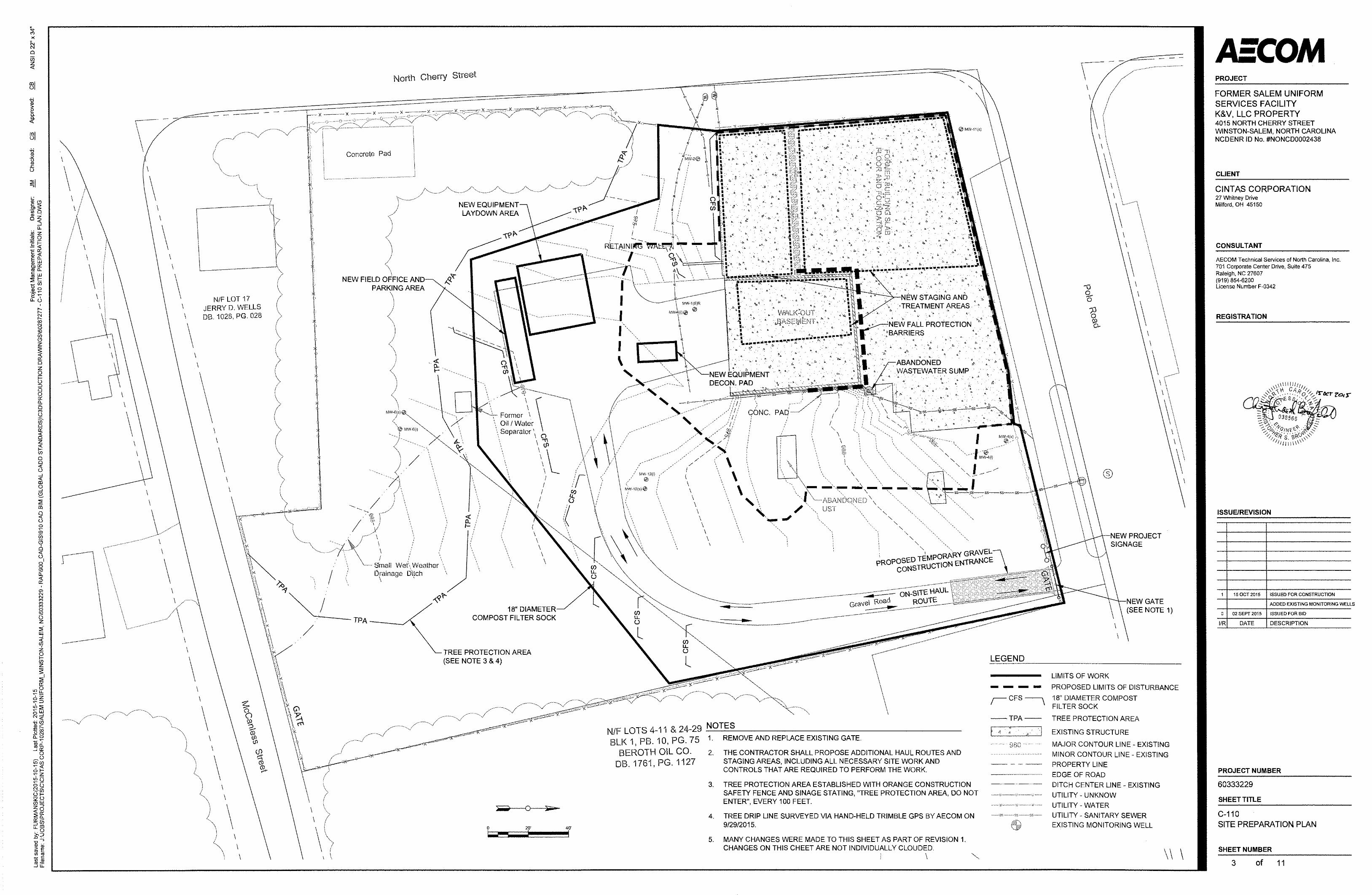
Site preparation including installation of all erosion and sedimentation controls, installation of temporary site facilities, and abandonment of selected site utilities
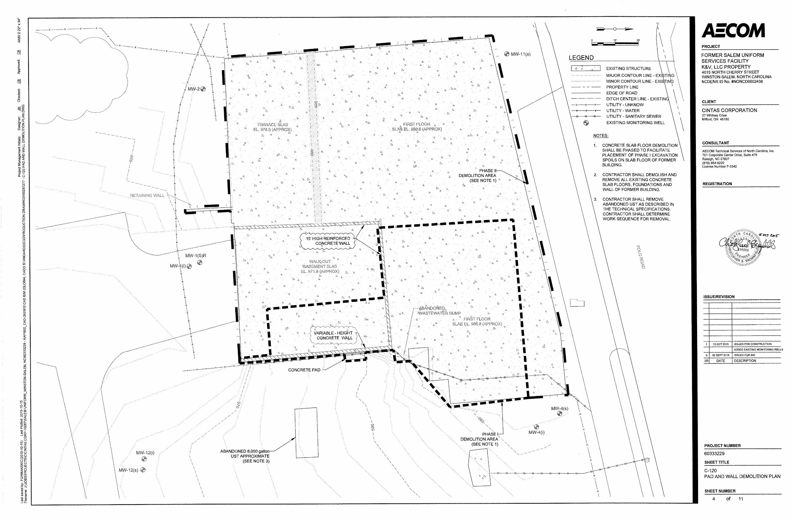
Partial demolition and removal of the existing slab and concrete/block wall (Phase I Excavation Area Only)
Excavation, stockpile, and stockpile management of Phase I impacted soils and excavation and removal of the 8,000-gallon unregistered UST
Initial backfill and compaction of the Phase I excavation area
Field-determination of characteristically hazardous soils (per NCDEQ protocol for hazardous soil characteristics)
On-site treatment of hazardous soils using a dilute, aqueous hydrogen peroxide procedure that will be specified by AECOM’s contractor
Sampling, profiling, and load-out of Phase I excavated soils
Demolition and removal of the remaining existing slab and concrete/block wall
Excavation, stockpile, and stockpile management of Phase II impacted soils
Final backfill, compaction, and grading of non-impacted soils within the limits of disturbance to achieve final grade
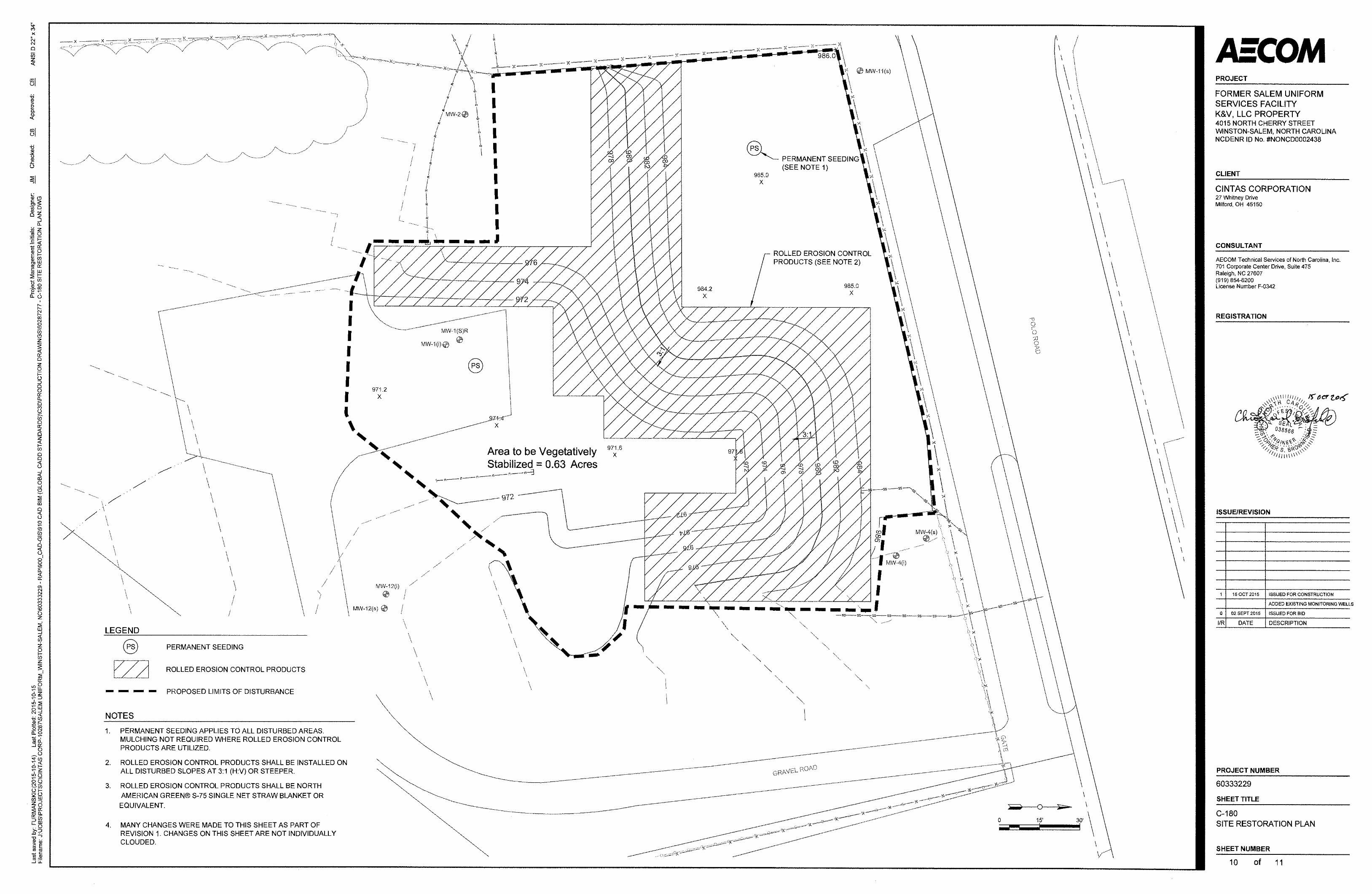
Stabilization of disturbed soils by re-vegetation
2.4 Detailed Design Elements
The following subsections identify elements of the detailed design that were not explicitly described in the design basis but were identified during the design process and are incorporated in the excavation scope of work.
2.4.1 Site Preparation and Controls
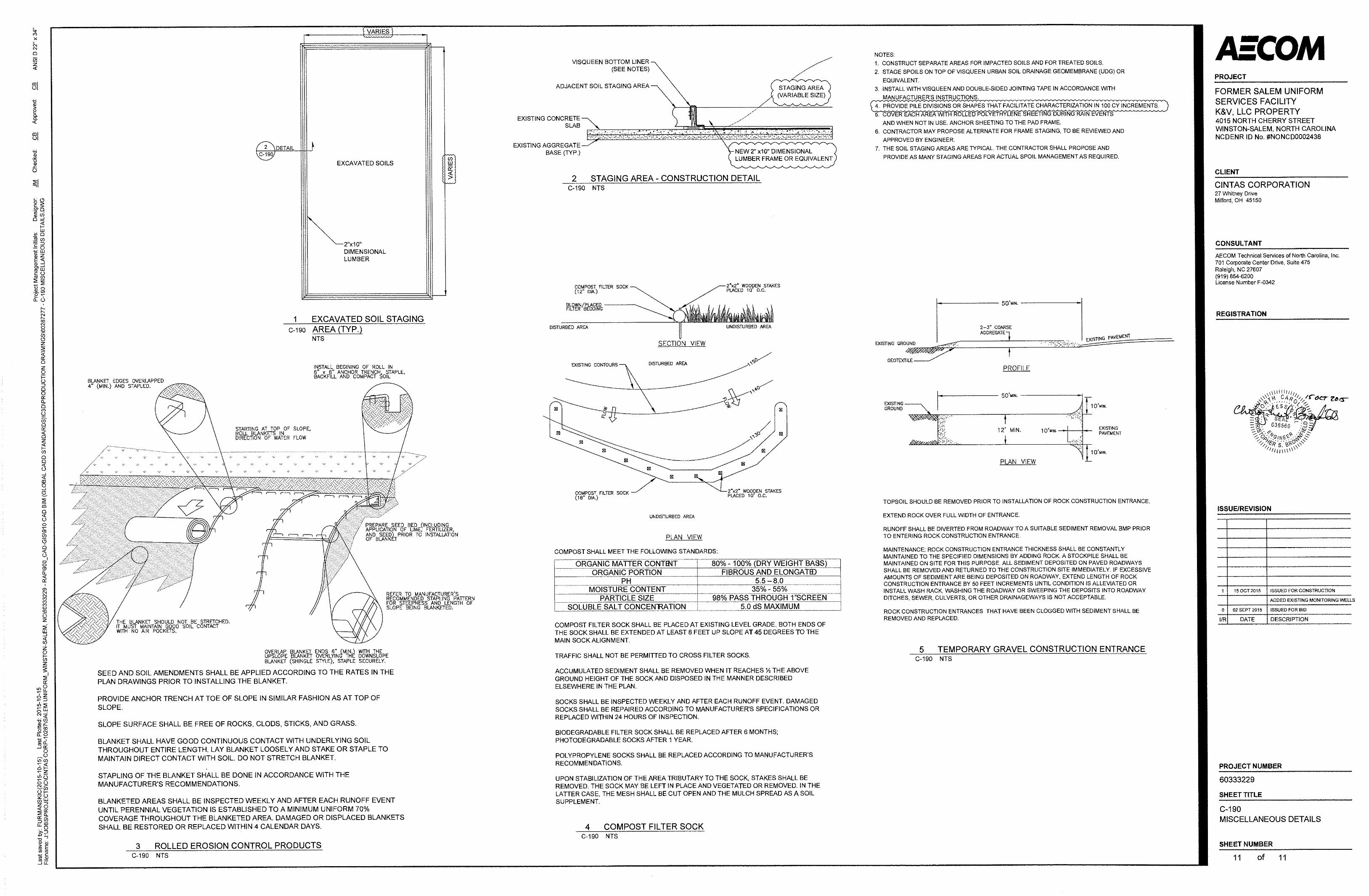
The Site Preparation will include the establishment of work zone delineation barriers, construction entrances and signs, stockpile staging areas, and load-out areas as shown on the drawings or described in the specifications. The erosion controls required for this project primarily include downgradient compost filter sock.

AECOM Environment 2-3
Footer October 2015
2.4.2 Utilities Demolition and Removal
A private utility locator was contracted by AECOM during the design phase to identify relict utilities associated with the building that formerly occupied the Site. The utility locator identified two water service lines, a sanitary sewer line, and one natural gas service line that formerly served the building. The lines were identified on the design drawings and instructions for a contractor to partially remove and decommission them are included on the plans and in the specifications.
The private utility locator was also able to approximately locate the extents of a former UST that was observed during a prior drilling effort. The extents of the UST are shown on the design drawings and instructions for a contractor to remove the UST are included on the drawings and in the specifications. The regulations that are applicable to the UST removal are identified in Section 2.3.
The likely location of former overhead electrical service and overhead telephone service was identified by the private utility locator along Cherry Street adjacent to the relict water meters but no overhead or buried wiring or cabling was observed or could be found extending beyond the Cherry Street right-of-way onto the Site property.
The private utility locator visually inspected and swept the majority of the proposed excavation area using ground-penetrating radar and was not able to infer the presence of other above-ground or below ground utilities.
2.4.3 Excavation and Waste Profiling
Excavation means and methods will be determined by AECOM’s contractor, but will generally involve the use of hydraulically-powered excavators, bulldozers, and support equipment (loaders and skid-steers). During Phase I of excavation, a portion of excavated soils will be removed from the excavation, screened for volatile organic compounds (VOCs) by AECOM’s contractor, and stockpiled according to the initial screening data. AECOM will sample stockpiled soils and subcontract the analysis of total chlorinated VOCs in those samples using United States Environmental Protection Agency (EPA) Methods 5035 and 8260B.
For stockpiled soils that contain less than 14 milligrams per kilogram (mg/kg) PCE, AECOM’s contractor will develop a non-hazardous waste profile in conjunction with a targeted disposal facility. AECOM will review the waste profile and obtain approval of the waste profile from Cintas.
For stockpiled soils that contain more than 14 mg/kg PCE, AECOM will either request the analytical laboratory to run a Toxicity Characteristic Leaching Procedure, EPA Method 1311, and compare the leachate values to constituent limits for characteristically hazardous waste; or AECOM will direct its contractor to treat the soils on-site using a peroxide mixing method.
2.4.4 On-Site Soil Treatment
Excavated soils that contain more than 60 mg/kg PCE will be treated on-site prior to transportation and land disposal. On-site treatment will generally be conducted in accordance with the guidance document Management of Remediation Waste Under RCRA (EPA, 1998) (“EPA guidance”). In accordance with industry-standard applications of on-site waste treatment practices according to EPA guidance, all waste treatment activities will be confined to the general area of contamination and management of the excavated waste material outside of the excavation footprint will be conducted entirely on the existing concrete slab to the maximum extent practical. When it is not practical to do so, AECOM will work on behalf of Cintas with NCDEQ to determine if additional sampling is warranted at the conclusion of the project to verify that contamination was not introduced to areas outside the previously delineated areas of contamination.
2.4.5 Backfill
Clean backfill will be used for backfilling excavations and for fill (where needed) as part of final grading operations. Clean backfill is specified in the technical specifications – Section 02110 Excavation, Removal, and Handling of Contaminated Materials, which is provided in Appendix A.
Backfill will be sourced from the Vulcan Materials, LP North Quarry in Winston-Salem, North Carolina.
2.4.6 Surface Structure Demolition and Disposal
Surface structure demolition requirements are shown on the design drawings provided in Appendix A. All existing surface structures will be removed as part of the project.
AECOM Environment 2-4
Footer October 2015
AECOM has conducted preliminary sampling of concrete debris to make pre-mobilization waste determinations on this material. AECOM’s contractor will profile, transport, and dispose of the concrete debris based on the sampling results.
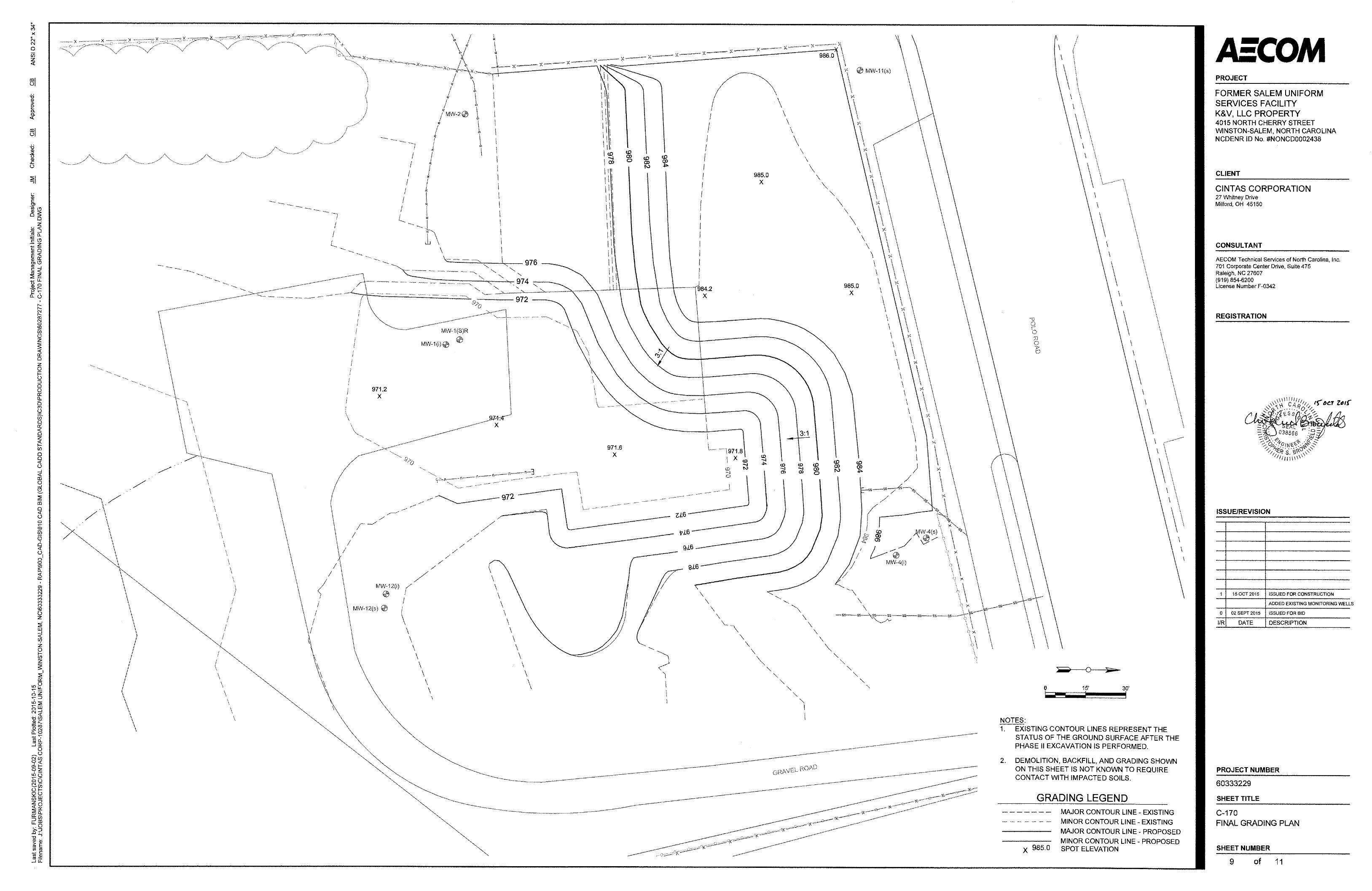
2.4.7 Final Grading
The final grading requirements are shown on the design drawings provided in Appendix A. The final grade was designed to provide positive surface drainage and to have a completely vegetated surface.
2.4.8 Waste Disposal
AECOM’s contractor will dispose of non-hazardous solid waste at either the Republic Landfill in Mt. Gilead, North Carolina or the City of Winston-Salem Hanes Mill Road Landfill, in Winston-Salem, North Carolina. It is not anticipated that hazardous solid waste will be generated as a result of the excavation activities. If hazardous solid waste is transported and disposed, AECOM will provide the appropriate profiles and manifests in the final report.
2.5 Other Applicable or Relevant and Appropriate Regulations
The existing 8,000-gallon UST will be assessed and removed by AECOM’s contractor in accordance with the NCDEQ, DWM, UST Section published guidelines.
2.6 Third Party Commitments
Third-party (i.e., non-contracted) commitments are summarized in Section 5 of this Work Plan.
2.7 Additional Remediation
AECOM anticipates that additional remediation of soils may be required to reduce concentrations of PCE in deep soils below the Industrial-Commercial PSRG, and generally outside of the excavation area below a depth of approximately 2 feet below ground surface to reduce concentrations of PCE below PoG action levels. AECOM‘s contractor will presumptively place remediation piping as shown in the design drawings included as Attachment A. The remediation piping may be used for a wide variety of future remedial strategies.
AECOM Environment 3-1
Footer October 2015
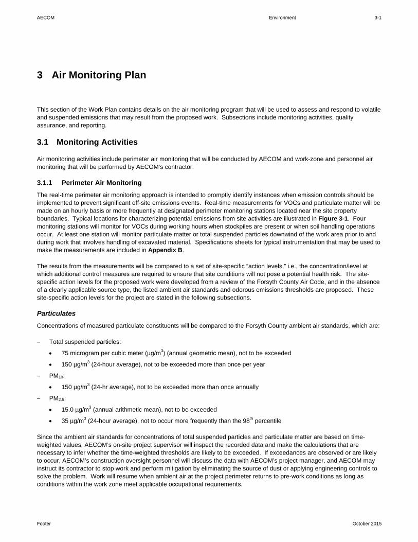
This section of the Work Plan contains details on the air monitoring program that will be used to assess and respond to volatile and suspended emissions that may result from the proposed work. Subsections include monitoring activities, quality assurance, and reporting.
3.1 Monitoring Activities
Air monitoring activities include perimeter air monitoring that will be conducted by AECOM and work-zone and personnel air monitoring that will be performed by AECOM’s contractor.
3.1.1 Perimeter Air Monitoring
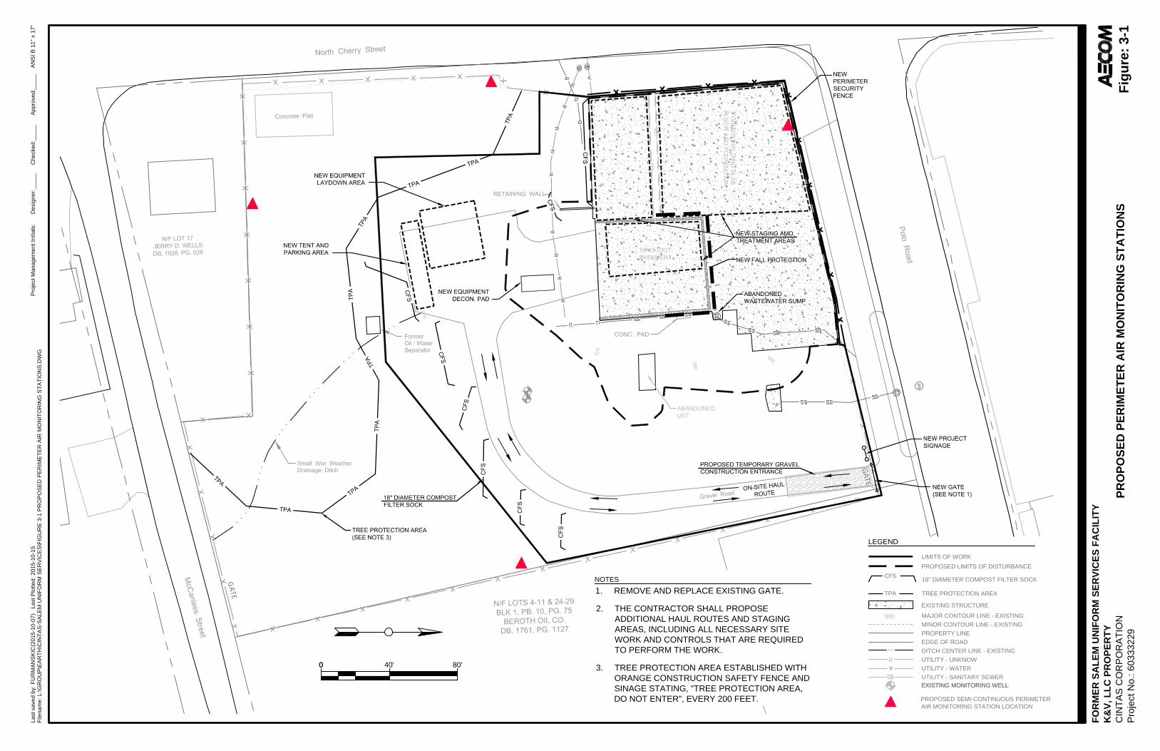
The real-time perimeter air monitoring approach is intended to promptly identify instances when emission controls should be implemented to prevent significant off-site emissions events. Real-time measurements for VOCs and particulate matter will be made on an hourly basis or more frequently at designated perimeter monitoring stations located near the site property boundaries. Typical locations for characterizing potential emissions from site activities are illustrated in Figure 3-1. Four monitoring stations will monitor for VOCs during working hours when stockpiles are present or when soil handling operations occur. At least one station will monitor particulate matter or total suspended particles downwind of the work area prior to and during work that involves handling of excavated material. Specifications sheets for typical instrumentation that may be used to make the measurements are included in Appendix B.
The results from the measurements will be compared to a set of site-specific “action levels,” i.e., the concentration/level at which additional control measures are required to ensure that site conditions will not pose a potential health risk. The site-specific action levels for the proposed work were developed from a review of the Forsyth County Air Code, and in the absence of a clearly applicable source type, the listed ambient air standards and odorous emissions thresholds are proposed. These site-specific action levels for the project are stated in the following subsections.
Particulates
Concentrations of measured particulate constituents will be compared to the Forsyth County ambient air standards, which are:
Total suspended particles:
75 microgram per cubic meter (µg/m3) (annual geometric mean), not to be exceeded
150 µg/m3 (24-hour average), not to be exceeded more than once per year
PM10:
150 µg/m3 (24-hr average), not to be exceeded more than once annually
PM2.5:
15.0 µg/m3 (annual arithmetic mean), not to be exceeded
35 µg/m3 (24-hour average), not to occur more frequently than the 98th percentile
Since the ambient air standards for concentrations of total suspended particles and particulate matter are based on time-weighted values, AECOM’s on-site project supervisor will inspect the recorded data and make the calculations that are necessary to infer whether the time-weighted thresholds are likely to be exceeded. If exceedances are observed or are likely to occur, AECOM’s construction oversight personnel will discuss the data with AECOM’s project manager, and AECOM may instruct its contractor to stop work and perform mitigation by eliminating the source of dust or applying engineering controls to solve the problem. Work will resume when ambient air at the project perimeter returns to pre-work conditions as long as conditions within the work zone meet applicable occupational requirements.
3 Air Monitoring Plan

AECOM Environment 3-2
Footer October 2015
Volatile Organic Compounds
Ambient air standards for VOCs in the Forsyth County Air Code do not exist, and the proposed construction operations related to the handling of solvent-impacted environmental media do not clearly fit into any of the categories of listed sources of emissions for which there are requirements for source registration/permitting, specific work practices, or emissions reduction. Therefore AECOM proposes to treat VOC emissions from the site as odorous emissions, which are regulated under Forsyth County Air Code, Section 3D-0522. Odorous emissions that are detected at the property boundary that are potentially harmful or irritating, or that unreasonably interfere with the activities of neighboring properties will be handled in accordance with the Forsyth County Air Code, Section 3D-0522.
Additionally, AECOM has held direct discussions with NCDEQ regarding perimeter air monitoring for VOCs. The Occupational Safety and Health Administration threshold limit value for work zone monitoring of PCE is 25 parts per million (ppm). AECOM and NCDEQ have chosen a perimeter air monitoring value of 7.5 ppm (8-hour average). If exceedances are observed or are likely to occur, AECOM’s construction oversight personnel will discuss the data with AECOM’s project manager, and AECOM may instruct its contractor to stop work and perform mitigation by eliminating the source of vapors or applying engineering controls to solve the problem. Work will resume when ambient air at the project perimeter returns to pre-work conditions as long as conditions within the work zone meet applicable occupational requirements.
3.1.2 Work Zone Monitoring
Work zone monitoring will be the responsibility of AECOM’s contractor to perform within the exclusion zone, the contaminant reduction zone, and the support zone. The product and performance requirements for work zone monitoring are described in the technical specifications, Section 01410 – Health and Safety Requirements, provided as Appendix A. The specific equipment and methods that will be used to meet the requirements of the technical specifications will be selected by AECOM’s contractor and are not described in this Work Plan.
3.1.3 Personnel Monitoring
Personnel monitoring will be the responsibility of AECOM’s contractor to perform within the exclusion zone. The product and performance requirements for work zone monitoring are described in the technical specifications, Section 01410 - Health and Safety Requirement, provided as Appendix A. The specific equipment and methods that will be used to meet the requirements of the technical specifications will be selected by AECOM’s contractor and are not described in this Work Plan.
3.2 Quality Assurance
AECOM will implement a quality assurance program to maintain an adequate level of confidence that the collected perimeter air monitoring data are accurate. An adequate level of confidence will be achieved by documenting instrument calibration and maintenance in accordance with the operations manuals for the selected equipment. Operations manuals for typical equipment are included as Appendix B.
AECOM’s contractor will be responsible for implementing a quality assurance program that is sufficient to meet the requirements of the technical specifications for work zone and personnel monitoring. Details of that program will be determined by AECOM’s contractor and are not provided in this work plan.
3.3 Reporting
Since no new source registration or permitting requirements have been identified for the project, regulatory reporting of monitoring data is not planned. AECOM will save perimeter air monitoring logs in the project files and may include the results in project completion reports if these data are determined to be necessary to present at the time of reporting.
AECOM Environment 4-1
Footer October 2015
AECOM is responsible for ensuring that the construction quality assurance program described in this section of the Work Plan is adequately executed. Components of the quality assurance program for the proposed work include soil confirmation sampling and backfill testing.
4.1 Soil Confirmation Sampling
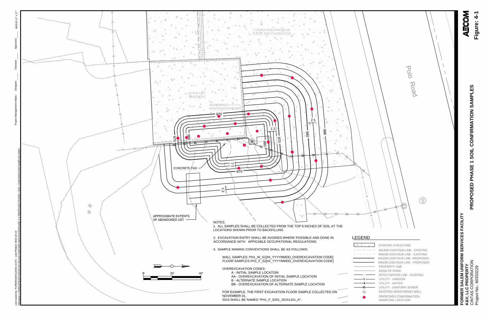
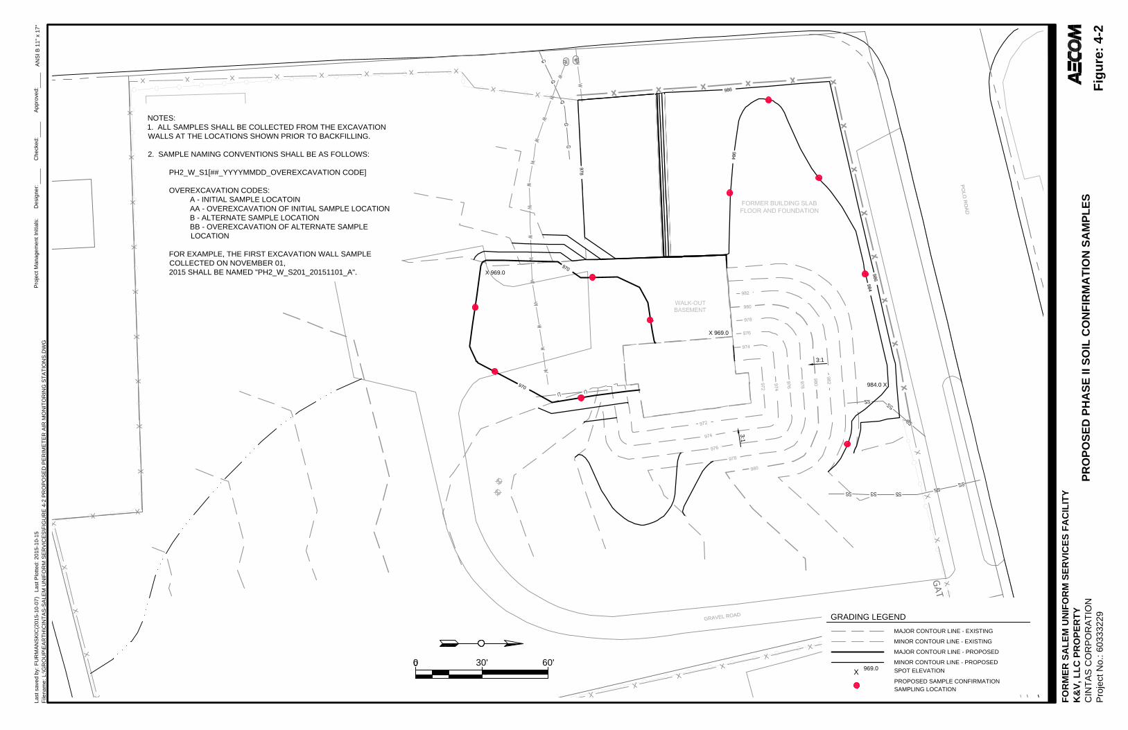
The locations of proposed confirmation samples are shown on Figure 4-1 and 4-2. AECOM will collect and subcontract the analysis of confirmation samples collected from the floor and walls of excavations. Confirmation samples will be collected and analyzed using EPA Methods 5035 and 8260B. The purpose of confirmation samples is to document areas of the Site where soil impacts exceed likely remedial goals and may require additional remediation. The final design summarized in Section 2 of this report is anticipated to achieve the project objectives, if executed completely; therefore, over-excavation is not planned. Nevertheless, the design that is provided is not intended to remove all impacted soil from the site; therefore, over-excavation may be conducted based on the results and timing of confirmation sampling and the overall project objectives, including cost.
4.2 Backfill Testing
Backfill source testing is the responsibility of AECOM’s contractor, and will be performed in accordance with Section 02300 – Earthwork and Section 02110 – Excavation, Removal, and Handling of Contaminated Material, respectively, in the technical specifications included as an Appendix A.
4 Construction Quality Assurance

AECOM Environment 5-1
Footer October 2015
General management of the relationship with community stakeholders for the proposed project is a shared responsibility between NCDEQ and Cintas. At their request, NCDEQ will take the lead role for project communication and the stewardship of any concerns that are expressed by community stakeholders. Cintas and AECOM will support NCDEQ by providing the necessary project information to make communications detailed and accurate, and by managing the project execution accountably and in accordance with this Work Plan.
5.1 Planned Communication with the Public
Prior to starting the work, NCDEQ will provide a written summary of the proposed work to property neighbors and other potential project stakeholders selected at the discretion of NCDEQ. NCDEQ will also advertise the occurrence of the project in a local newspaper prior to the start of the work. There are currently no planned communication events after the start of the project.
5.2 Unplanned Communication with the Public/Media
Unplanned communication that is required to provide additional project information to the public will be handled through NCDEQ. The project coordinator’s contact information is:
Melanie Bartlett Central Region, Inactive Hazardous Sites Branch Superfund Section, Division of Waste Management North Carolina Department of Environmental Quality Mailing Address: 1646 Mail Service Center Raleigh, NC 27699-1646 Physical Office Address: 217 West Jones Street Raleigh, NC 27603 Phone/Fax: 919-707-8373 Website: http://portal.ncdenr.org/web/wm/ Email: [email protected]
Unplanned communication that is required to provide additional project information to the media will also be handled through NCDEQ. The project spokesperson’s contact information is:
Cathy Akroyd Public Information Officer Division of Waste Management North Carolina Department of Environmental Quality Mailing Address: 1646 Mail Service Center Raleigh, North Carolina 27699-1646
Physical Office Address: 217 West Jones Street Raleigh, North Carolina 27603
5 Community and Public Relations

AECOM Environment 5-2
Footer October 2015
Phone/Fax: (919) 707-8234 Website: http://portal.ncdenr.org/web/wm/ Email: [email protected]
AECOM Environment 6-1
Footer October 2015
AECOM, 2014. Combined Phase I and Phase II Remedial Investigation Report, Former Salem Uniform Services Facility. AECOM Technical Services of North Carolina, Inc. September, 2014.
AECOM, 2015. Memorandum to Melanie Bartlett, NCDEQ-DWM. June 5, 2015.
ENSR, 2006. Comprehensive Site Assessment Report: Former Salem Uniform Services. ENSR Consulting and Engineering (NC), Inc., 2006.
EPA, 1998. Management of Remediation Wastes Under RCRA. EPA Doc. No 530-F-98-026. Office of Solid Waste and Emergency Response (5305W). October, 1998.
6 References

About AECOM With nearly 100,000 employees — including architects, engineers, designers, planners, scientists and management and construction services professionals — serving clients in more than 150 countries around the world following the acquisition of URS, AECOM is a premier, fully integrated infrastructure and support services firm. AECOM is ranked as the #1 engineering design firm by revenue in Engineering News-Record magazine’s annual industry rankings. The company is a leader in all of the key markets that it serves, including transportation, facilities, environmental, energy, oil and gas, water, high-rise buildings and government. AECOM provides a blend of global reach, local knowledge, innovation and technical excellence in delivering solutions that create, enhance and sustain the world’s built, natural and social environments. A Fortune 500 company, AECOM companies, including URS Corporation and Hunt Construction Group, had revenue of approximately $19.5 billion during the 12 months ended Sept. 30, 2014. More information on AECOM and its services can be found at www.aecom.com.
AECOM 701 Corporate Center Drive, Suite 475 Raleigh, North Carolina 27607 T: +1.919.854.6200 F: +1.919.854.6259

AECOM Environment
Footer October 2015
Figures
Copyright:© 2013 National Geographic Society, i-cubed
Map Location
July 2015 60333229.300
Site Location MapCintas: Former Salem Uniform Services
4015 North Cherry Street Winston-Salem, NC
Figure 1
AECOM701 Corporate Center Dr., Suite 475Raleigh, NC 27607Phone: (919) 872-6600Fax: (919) 872-7996www.aecom.com
0 2,000 4,000Feet
¦NC
VA
SCGA
KY
TN
WV
AL
MDIN
Site Location
Z:\GIS\Projects\C\Cintas_10287\Cintas_Salem_Uniform_Winston\MXD\Figure-1_Site_Location_Map_2015.mxd
brownfieldc
Text Box
-1

FO
RM
ER
S
AL
EM
U
NIF
OR
M S
ER
VIC
ES
F
AC
IL
IT
Y
K&
V, L
LC
P
RO
PE
RT
Y
CIN
TA
S C
OR
PO
RA
TIO
N
Project N
o.: 60333229
AN
SI B
11" x 17"
Last saved by: F
UR
MA
NS
KIC
(2015-10-07
) Last P
lotted: 2015-10-15
Project M
anagem
ent Initials:
Designer:
Checked:
Approved:
Filenam
e: L:\G
RO
UP
\E
AR
TH
\C
IN
TA
S-S
ALE
M U
NIF
OR
M S
ER
VIC
ES
\F
IG
UR
E 2-2 C
ON
TR
AC
T O
VE
RV
IE
W.D
WG
CO
NT
RA
CT
O
VE
RV
IE
W
Fig
ure
: 2
-2
C.J.C
.
00 40' 80'
LEGEND
MAJOR CONTOUR LINE - EXISTING
MINOR CONTOUR LINE - EXISTING
PROPERTY LINE
EDGE OF ROAD
DITCH CENTER LINE - EXISTING
EXISTING STRUCTURE
UTILITY - UNKNOW
UTILITY - WATER
UTILITY - SANITARY SEWER
CFS
18" DIAMETER COMPOST FILTER SOCK
980
EXISTING MONITORING WELL
1. REMOVE AND REPLACE EXISTING GATE.
2. THE CONTRACTOR SHALL PROPOSE
ADDITIONAL HAUL ROUTES AND STAGING
AREAS, INCLUDING ALL NECESSARY SITE
WORK AND CONTROLS THAT ARE REQUIRED
TO PERFORM THE WORK.
3. TREE PROTECTION AREA ESTABLISHED WITH
ORANGE CONSTRUCTION SAFETY FENCE AND
SINAGE STATING, "TREE PROTECTION AREA,
DO NOT ENTER", EVERY 200 FEET.
NOTES
TREE PROTECTION AREATPA
PROPOSED LIMITS OF DISTURBANCE
LIMITS OF WORK
FO
RM
ER
S
AL
EM
U
NIF
OR
M S
ER
VIC
ES
F
AC
IL
IT
Y
K&
V, L
LC
P
RO
PE
RT
Y
CIN
TA
S C
OR
PO
RA
TIO
N
Project N
o.: 60333229
AN
SI B
11" x 17"
Last saved by: F
UR
MA
NS
KIC
(2015-10-07
) Last P
lotted: 2015-10-15
Project M
anagem
ent Initials:
Designer:
Checked:
Approved:
Filenam
e: L:\G
RO
UP
\E
AR
TH
\C
IN
TA
S-S
ALE
M U
NIF
OR
M S
ER
VIC
ES
\F
IG
UR
E 3-1 P
RO
PO
SE
D P
ER
IM
ET
ER
A
IR
M
ON
IT
OR
IN
G S
TA
TIO
NS
.D
WG
PR
OP
OS
ED
P
ER
IM
ET
ER
A
IR
M
ON
IT
OR
IN
G S
TA
TIO
NS
Fig
ure
: 3
-1
_____
_____
_____
PROPOSED SEMI-CONTINUOUS PERIMETER
AIR MONITORING STATION LOCATION
EXISTING MONITORING WELL
00 20' 40'
LEGEND
MAJOR CONTOUR LINE - EXISTING
MINOR CONTOUR LINE - EXISTING
PROPERTY LINE
EDGE OF ROAD
DITCH CENTER LINE - EXISTING
EXISTING STRUCTURE
UTILITY - UNKNOW
UTILITY - WATER
UTILITY - SANITARY SEWER
1:1
1:1
CONCRETE PAD
2:1
2:1
MAJOR CONTOUR LINE -PROPOSED
MINOR CONTOUR LINE - PROPOSED
EXISTING MONITORING WELL
FO
RM
ER
S
AL
EM
U
NIF
OR
M S
ER
VIC
ES
F
AC
IL
IT
Y
K&
V, L
LC
P
RO
PE
RT
Y
CIN
TA
S C
OR
PO
RA
TIO
N
Project N
o.: 60333229
AN
SI B
11" x 17"
Last saved by: F
UR
MA
NS
KIC
(2015-10-07
) Last P
lotted: 2015-10-15
Project M
anagem
ent Initials:
Designer:
Checked:
Approved:
Filenam
e: L:\G
RO
UP
\E
AR
TH
\C
IN
TA
S-S
ALE
M U
NIF
OR
M S
ER
VIC
ES
\F
IG
UR
E 4-1 P
RO
PO
SE
D P
HA
SE
I S
OIL C
ON
FIR
MA
TIO
N S
AM
PLE
S.D
WG
PR
OP
OS
ED
P
HA
SE
1 S
OIL
C
ON
FIR
MA
TIO
N S
AM
PL
ES
Fig
ure
: 4
-1
_____
_____
_____
PROPOSED CONFIRMATION
SAMPLING LOCATION
NOTES:
1. ALL SAMPLES SHALL BE COLLECTED FROM THE TOP 6 INCHES OF SOIL AT THE
LOCATIONS SHOWN PRIOR TO BACKFILLING.
2. EXCAVATION ENTRY SHALL BE AVOIDED WHERE POSSIBLE AND DONE IN
ACCORDANCE WITH APPICABLE OCCUPATIONAL REGULATIONS.
3. SAMPLE NAMING CONVENTIONS SHALL BE AS FOLLOWS:
WALL SAMPLES: PH1_W_S1[##_YYYYMMDD_OVEREXCAVATION CODE]
FLOOR SAMPLES PH1_F_S2[##_YYYYMMDD_OVEREXCAVATION CODE]
OVEREXCAVATION CODES:
A - INITIAL SAMPLE LOCATOIN
AA - OVEREXCAVATION OF INITIAL SAMPLE LOCATION
B - ALTERNATE SAMPLE LOCATION
BB - OVEREXCAVATION OF ALTERNATE SAMPLE LOCATION
FOR EXAMPLE, THE FIRST EXCAVATION FLOOR SAMPLE COLLECTED ON
NOVEMBER 01,
2015 SHALL BE NAMED "PH1_F_S201_20151101_A".
00 30' 60'
GRADING LEGEND
MAJOR CONTOUR LINE - EXISTING
MINOR CONTOUR LINE - EXISTING
MAJOR CONTOUR LINE - PROPOSED
MINOR CONTOUR LINE - PROPOSED
X
969.0
SPOT ELEVATION
X 969.0
984.0 X
X 969.0
3:1
3:1
P
O
L
O
R
O
A
D
G
R
AV
EL R
O
AD
FO
RM
ER
S
AL
EM
U
NIF
OR
M S
ER
VIC
ES
F
AC
IL
IT
Y
K&
V, L
LC
P
RO
PE
RT
Y
CIN
TA
S C
OR
PO
RA
TIO
N
Project N
o.: 60333229
NOTES:
1. ALL SAMPLES SHALL BE COLLECTED FROM THE EXCAVATION
WALLS AT THE LOCATIONS SHOWN PRIOR TO BACKFILLING.
2. SAMPLE NAMING CONVENTIONS SHALL BE AS FOLLOWS:
PH2_W_S1[##_YYYYMMDD_OVEREXCAVATION CODE]
OVEREXCAVATION CODES:
A - INITIAL SAMPLE LOCATOIN
AA - OVEREXCAVATION OF INITIAL SAMPLE LOCATION
B - ALTERNATE SAMPLE LOCATION
BB - OVEREXCAVATION OF ALTERNATE SAMPLE
LOCATION
FOR EXAMPLE, THE FIRST EXCAVATION WALL SAMPLE
COLLECTED ON NOVEMBER 01,
2015 SHALL BE NAMED "PH2_W_S201_20151101_A".
AN
SI B
11" x 17"
Last saved by: F
UR
MA
NS
KIC
(2015-10-07
) Last P
lotted: 2015-10-15
Project M
anagem
ent Initials:
Designer:
Checked:
Approved:
Filenam
e: L:\G
RO
UP
\E
AR
TH
\C
IN
TA
S-S
ALE
M U
NIF
OR
M S
ER
VIC
ES
\F
IG
UR
E 4-2 P
RO
PO
SE
D P
ER
IM
ET
ER
A
IR
M
ON
IT
OR
IN
G S
TA
TIO
NS
.D
WG
PR
OP
OS
ED
P
HA
SE
II S
OIL
C
ON
FIR
MA
TIO
N S
AM
PL
ES
Fig
ure
: 4
-2
_____
_____
_____
PROPOSED SAMPLE CONFIRMATION
SAMPLING LOCATION

AECOM Environment
Footer October 2015
Appendix A. Design Drawings and Technical Specifications


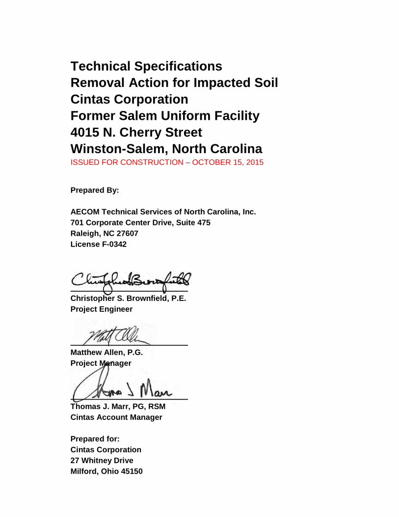
Technical SpecificationsRemoval Action for Impacted SoilCintas CorporationFormer Salem Uniform Facility4015 N. Cherry StreetWinston-Salem, North CarolinaISSUED FOR CONSTRUCTION – OCTOBER 15, 2015
Prepared By:
AECOM Technical Services of North Carolina, Inc.701 Corporate Center Drive, Suite 475Raleigh, NC 27607License F-0342
Christopher S. Brownfield, P.E.Project Engineer
Matthew Allen, P.G.Project Manager
Thomas J. Marr, PG, RSMCintas Account Manager
Prepared for:Cintas Corporation27 Whitney DriveMilford, Ohio 45150
SECTION 01010SUMMARY OF WORK
Cintas Corporation Rev. 1 – Issued for ConstructionCintas: Former Salem Uniform FacilityWinston-Salem, North Carolina October 15, 2015
01100 - 1
PART 1 - GENERAL
1.01 SECTION INCLUDES:
A. Project Description
B. Definitions
C. Contract Summary
D. Work Schedule
E. Codes and Standards
F. Warranties and Guarantees
1.02 PROJECT DESCRIPTION
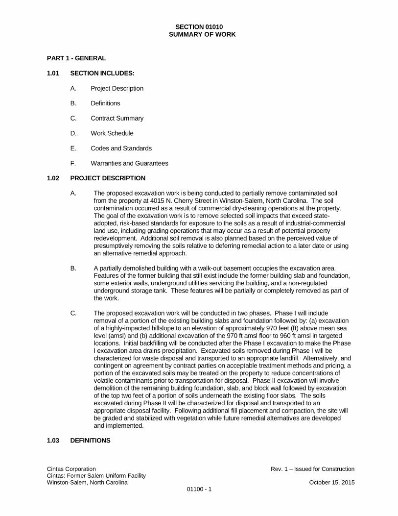
A. The proposed excavation work is being conducted to partially remove contaminated soilfrom the property at 4015 N. Cherry Street in Winston-Salem, North Carolina. The soilcontamination occurred as a result of commercial dry-cleaning operations at the property.The goal of the excavation work is to remove selected soil impacts that exceed state-adopted, risk-based standards for exposure to the soils as a result of industrial-commercialland use, including grading operations that may occur as a result of potential propertyredevelopment. Additional soil removal is also planned based on the perceived value ofpresumptively removing the soils relative to deferring remedial action to a later date or usingan alternative remedial approach.
B. A partially demolished building with a walk-out basement occupies the excavation area.Features of the former building that still exist include the former building slab and foundation,some exterior walls, underground utilities servicing the building, and a non-regulatedunderground storage tank. These features will be partially or completely removed as part ofthe work.
C. The proposed excavation work will be conducted in two phases. Phase I will includeremoval of a portion of the existing building slabs and foundation followed by: (a) excavationof a highly-impacted hillslope to an elevation of approximately 970 feet (ft) above mean sealevel (amsl) and (b) additional excavation of the 970 ft amsl floor to 960 ft amsl in targetedlocations. Initial backfilling will be conducted after the Phase I excavation to make the PhaseI excavation area drains precipitation. Excavated soils removed during Phase I will becharacterized for waste disposal and transported to an appropriate landfill. Alternatively, andcontingent on agreement by contract parties on acceptable treatment methods and pricing, aportion of the excavated soils may be treated on the property to reduce concentrations ofvolatile contaminants prior to transportation for disposal. Phase II excavation will involvedemolition of the remaining building foundation, slab, and block wall followed by excavationof the top two feet of a portion of soils underneath the existing floor slabs. The soilsexcavated during Phase II will be characterized for disposal and transported to anappropriate disposal facility. Following additional fill placement and compaction, the site willbe graded and stabilized with vegetation while future remedial alternatives are developedand implemented.
1.03 DEFINITIONS
SECTION 01010SUMMARY OF WORK
Cintas Corporation Rev. 1 – Issued for ConstructionCintas: Former Salem Uniform FacilityWinston-Salem, North Carolina October 15, 2015
01100 - 2
A. Whenever the following terms are used in these Specifications, it is understood that theyrepresent the following:
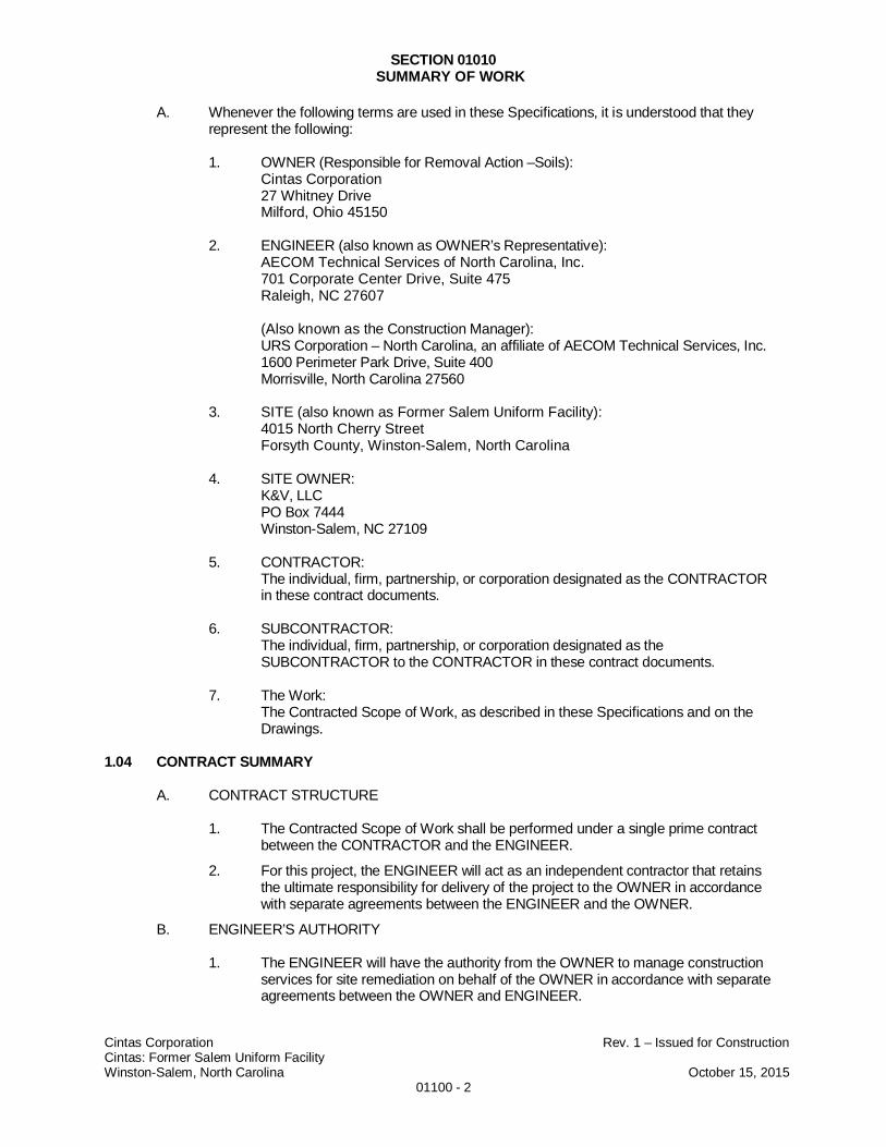
1. OWNER (Responsible for Removal Action –Soils):Cintas Corporation27 Whitney DriveMilford, Ohio 45150
2. ENGINEER (also known as OWNER’s Representative):AECOM Technical Services of North Carolina, Inc.701 Corporate Center Drive, Suite 475Raleigh, NC 27607
(Also known as the Construction Manager):URS Corporation – North Carolina, an affiliate of AECOM Technical Services, Inc.1600 Perimeter Park Drive, Suite 400Morrisville, North Carolina 27560
3. SITE (also known as Former Salem Uniform Facility):4015 North Cherry StreetForsyth County, Winston-Salem, North Carolina
4. SITE OWNER:K&V, LLCPO Box 7444Winston-Salem, NC 27109
5. CONTRACTOR:The individual, firm, partnership, or corporation designated as the CONTRACTORin these contract documents.
6. SUBCONTRACTOR:The individual, firm, partnership, or corporation designated as theSUBCONTRACTOR to the CONTRACTOR in these contract documents.
7. The Work:The Contracted Scope of Work, as described in these Specifications and on theDrawings.
1.04 CONTRACT SUMMARY
A. CONTRACT STRUCTURE
1. The Contracted Scope of Work shall be performed under a single prime contractbetween the CONTRACTOR and the ENGINEER.
2. For this project, the ENGINEER will act as an independent contractor that retainsthe ultimate responsibility for delivery of the project to the OWNER in accordancewith separate agreements between the ENGINEER and the OWNER.
B. ENGINEER’S AUTHORITY
1. The ENGINEER will have the authority from the OWNER to manage constructionservices for site remediation on behalf of the OWNER in accordance with separateagreements between the OWNER and ENGINEER.
SECTION 01010SUMMARY OF WORK
Cintas Corporation Rev. 1 – Issued for ConstructionCintas: Former Salem Uniform FacilityWinston-Salem, North Carolina October 15, 2015
01100 - 3
2. The ENGINEER has the authority to represent the OWNER in the absence of theOWNER.
3. The ENGINEER has the authority to act as an agent for the owner for the purposeof arranging for the transport and/or disposal of waste in accordance with separateagreements between the OWNER and ENGINEER.
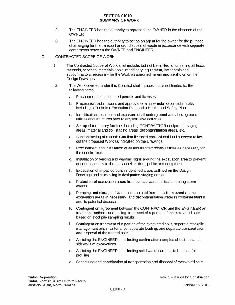
C. CONTRACTED SCOPE OF WORK
1. The Contracted Scope of Work shall include, but not be limited to furnishing all labor,methods, services, materials, tools, machinery, equipment, incidentals andsubcontractors necessary for the Work as specified herein and as-shown on theDesign Drawings.
2. The Work covered under this Contract shall include, but is not limited to, thefollowing items:
a. Procurement of all required permits and licenses.
b. Preparation, submission, and approval of all pre-mobilization submittals,including a Technical Execution Plan and a Health and Safety Plan.
c. Identification, location, and exposure of all underground and abovegroundutilities and structures prior to any intrusive activities.
d. Set-up of temporary facilities including CONTRACTOR equipment stagingareas, material and soil staging areas, decontamination areas, etc.
e. Subcontracting of a North Carolina-licensed professional land surveyor to lay-out the proposed Work as indicated on the Drawings.
f. Procurement and installation of all required temporary utilities as necessary forthe construction.
g. Installation of fencing and warning signs around the excavation area to preventor control access to the personnel, visitors, public and equipment.
h. Excavation of impacted soils in identified areas outlined on the DesignDrawings and stockpiling in designated staging areas.
i. Protection of excavation areas from surface water infiltration during stormevents.
j. Pumping and storage of water accumulated from rain/storm events in theexcavation areas (if necessary) and decontamination water in containers/tanksand its potential disposal.
k. Contingent on agreement between the CONTRACTOR and the ENGINEER ontreatment methods and pricing, treatment of a portion of the excavated soilsbased on stockpile sampling results.
l. Contingent on treatment of a portion of the excavated soils, separate stockpilemanagement and maintenance, separate loading, and separate transportationand disposal of the treated soils.
m. Assisting the ENGINEER in collecting confirmation samples of bottoms andsidewalls of excavations.
n. Assisting the ENGINEER in collecting solid waste samples to be used forprofiling
o. Scheduling and coordination of transportation and disposal of excavated soils.
SECTION 01010SUMMARY OF WORK
Cintas Corporation Rev. 1 – Issued for ConstructionCintas: Former Salem Uniform FacilityWinston-Salem, North Carolina October 15, 2015
01100 - 4
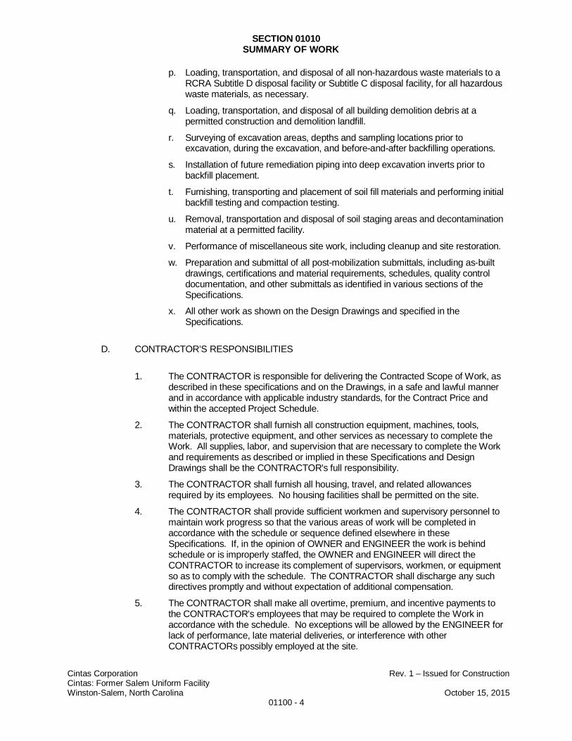
p. Loading, transportation, and disposal of all non-hazardous waste materials to aRCRA Subtitle D disposal facility or Subtitle C disposal facility, for all hazardouswaste materials, as necessary.
q. Loading, transportation, and disposal of all building demolition debris at apermitted construction and demolition landfill.
r. Surveying of excavation areas, depths and sampling locations prior toexcavation, during the excavation, and before-and-after backfilling operations.
s. Installation of future remediation piping into deep excavation inverts prior tobackfill placement.
t. Furnishing, transporting and placement of soil fill materials and performing initialbackfill testing and compaction testing.
u. Removal, transportation and disposal of soil staging areas and decontaminationmaterial at a permitted facility.
v. Performance of miscellaneous site work, including cleanup and site restoration.
w. Preparation and submittal of all post-mobilization submittals, including as-builtdrawings, certifications and material requirements, schedules, quality controldocumentation, and other submittals as identified in various sections of theSpecifications.
x. All other work as shown on the Design Drawings and specified in theSpecifications.
D. CONTRACTOR’S RESPONSIBILITIES
1. The CONTRACTOR is responsible for delivering the Contracted Scope of Work, asdescribed in these specifications and on the Drawings, in a safe and lawful mannerand in accordance with applicable industry standards, for the Contract Price andwithin the accepted Project Schedule.
2. The CONTRACTOR shall furnish all construction equipment, machines, tools,materials, protective equipment, and other services as necessary to complete theWork. All supplies, labor, and supervision that are necessary to complete the Workand requirements as described or implied in these Specifications and DesignDrawings shall be the CONTRACTOR's full responsibility.
3. The CONTRACTOR shall furnish all housing, travel, and related allowancesrequired by its employees. No housing facilities shall be permitted on the site.
4. The CONTRACTOR shall provide sufficient workmen and supervisory personnel tomaintain work progress so that the various areas of work will be completed inaccordance with the schedule or sequence defined elsewhere in theseSpecifications. If, in the opinion of OWNER and ENGINEER the work is behindschedule or is improperly staffed, the OWNER and ENGINEER will direct theCONTRACTOR to increase its complement of supervisors, workmen, or equipmentso as to comply with the schedule. The CONTRACTOR shall discharge any suchdirectives promptly and without expectation of additional compensation.
5. The CONTRACTOR shall make all overtime, premium, and incentive payments tothe CONTRACTOR's employees that may be required to complete the Work inaccordance with the schedule. No exceptions will be allowed by the ENGINEER forlack of performance, late material deliveries, or interference with otherCONTRACTORs possibly employed at the site.
SECTION 01010SUMMARY OF WORK
Cintas Corporation Rev. 1 – Issued for ConstructionCintas: Former Salem Uniform FacilityWinston-Salem, North Carolina October 15, 2015
01100 - 5
6. The CONTRACTOR shall adhere to all applicable tax laws under the State of NorthCarolina.
7. The CONTRACTOR shall obtain any federal, state, county, or local permits requiredin the performance of its Work, except as provided by the ENGINEER or OWNER.
8. Prior to Contract Award, any questions or assistance the CONTRACTOR mayrequest shall be directed to the ENGINEER and OWNER exclusively in writing.
9. By submitting a Bid for the Work, the CONTRACTOR acknowledges itself to beentirely familiar with the requirements prescribed by the State of North Carolina thatrelate to the Work, with regulations applicable to transporters of solid, industrial, andhazardous wastes as prescribed by the United States Environmental ProtectionAgency (USEPA), Comprehensive Environmental Response, Compensation, andLiability Act (CERCLA), Resource Conservation and Recovery Act (RCRA), andUnited States Department of Transportation (USDOT); with the rules andregulations of Occupational Safety and Health Administration (OSHA); and withlocal conditions, including weather, availability of supplies, and logistics. TheCONTRACTOR further acknowledges itself to be entirely qualified to perform theWork described by these Specifications and the Design Drawings.
10. The CONTRACTOR shall maintain the site completely free of refuse and debris atall times. The CONTRACTOR shall promptly comply with any directives from theENGINEER and OWNER regarding housekeeping. The CONTRACTOR shallprovide the appropriate containers at convenient locations for the disposal of paper,personal protective equipment, and other items of trash. Upon completion of theWork and before final payment, the CONTRACTOR shall completely remove alltools, equipment, supplies, materials, structures and debris from the site and leavethe premises clean. The CONTRACTOR shall be responsible for the hauling ofdebris and refuse to off-site disposal facilities that are permitted to receive the debrisand which are approved by the OWNER. Refuse shall be accumulated for aminimum of weekly disposal.
11. The CONTRACTOR shall be responsible for developing waste profile paperworkand obtaining approval for disposal of remediation waste from appropriate landfills.This responsibility includes the development of draft waste profiles that will beapproved and reviewed by the ENGINEER and the OWNER.
12. The CONTRACTOR shall be responsible for proper disposal all miscellaneouswaste (refuse, oil, lube, etc.) that is generated by the CONTRACTOR during thecontract life.
13. The CONTRACTOR shall construct and maintain separate personnel andequipment decontamination areas for the project duration as specified in Section01500 – Temporary Facilities and Controls and as shown on the Design Drawings.The areas will be utilized to decontaminate all equipment, vehicles, and personnelleaving the site which may have contacted hazardous materials. At the end of theproject, the CONTRACTOR shall dismantle and remove all structures associatedwith the decontamination areas. The structures shall be disposed in accordancewith applicable local, state, and federal regulations.
14. The CONTRACTOR’s communication to the United State Environmental ProtectionAgency (USEPA) or the North Carolina Department of Environment and NaturalResources (NCDENR) shall be submitted only upon the agencies’ request. Allcommunications with agencies shall be documented and communicated to theOWNER and ENGINEER in writing prior to the communication with the agencies.The CONTRACTOR shall not communicate with private residents or others duringthe Work at any time without prior approval of the ENGINEER.
SECTION 01010SUMMARY OF WORK
Cintas Corporation Rev. 1 – Issued for ConstructionCintas: Former Salem Uniform FacilityWinston-Salem, North Carolina October 15, 2015
01100 - 6
E. WORK BY OTHERS
1. The ENGINEER has conducted environmental characterization of the soils at thesite and that information is provided as Attachment A to this section.
2. The ENGINEER’s subconsultant has performed a geotechnical evaluation includinga slope stability analysis. The subconsultant’s report is provided as Attachment B tothis section.
3. The ENGINEER will collect and analyze soil and water samples needed for wasteprofile development and confirmation sampling as described in the Specifications.The CONTRACTOR shall aid in collection of samples as described in theSpecifications.
4. The ENGINEER and the OWNER will approve draft waste profiles developed by theCONTRACTOR based on sample data provided by the ENGINEER.
5. The ENGINEER will perform air monitoring required for worker health and safetyrequirements of the ENGINEER’S employees and for the general public. TheENGINEER will not perform air monitoring required for worker health and safetyrequirements for the CONTRACTOR’S employees and SUBCONTRACTORS.
6. The ENGINEER will be responsible for sampling and analysis required for the off-site disposal of contaminated soil and debris, and decontamination water.
7. The ENGINEER will be responsible for editing of waste profiles and for obtaining theOWNER’s consent for waste profiles for contaminated soil and decontaminationwater.
8. The ENGINEER will collect water samples for necessary analytical testing andprovide the results to the CONTRACTOR so that the CONTRACTOR candetermine appropriate disposal facility.
F. COORDINATION WITH OTHERS
1. There may be other Engineers, Contractors, and/or Regulators present at theproject site during performance of the Work. The CONTRACTOR shall make everyeffort reasonably possible to cooperate with these firms and personnel. Anydisputes shall be settled by and at the sole discretion of the ENGINEER andOWNER.
2. The CONTRACTOR shall coordinate and cooperate with the OWNER, theENGINEER, and all of the ENGINEER’S subcontractors to properly execute theWork.
3. The CONTRACTOR, as directed by the ENGINEER, shall assist the ENGINEER tocollect soil and water samples for confirmation analyses. Based on these results,the ENGINEER will further delineate the horizontal and vertical extent forCONTRACTOR’s excavation activities. The excavation areas are as shown on theDesign Drawings.
4. The CONTRACTOR shall coordinate with the ENGINEER to maintain adequatework flow while the ENGINEER’s analytical laboratory provides analyses that areneeded for the CONTRACTOR’S waste profile development.
5. The CONTRACTOR shall coordinate with permitted waste disposal facilities duringthe execution of the work to maintain accurate waste profiles and to ensure that theappropriate number of analytical samples is collected to satisfy the waste profilingrequirements of the disposal facility.
SECTION 01010SUMMARY OF WORK
Cintas Corporation Rev. 1 – Issued for ConstructionCintas: Former Salem Uniform FacilityWinston-Salem, North Carolina October 15, 2015
01100 - 7
1.05 SITE CONDITIONS
A. Existing Conditions
1. The known extents of environmental impacts in soils are provided in Attachment Ato this Section.
2. A report on the geotechnical properties of soils within the excavation area isincluded as Attachment B to this Section.
3. The known surface features, roadways, above-grade and below-grade structuresand utilities at the Site are shown on the Design Drawings. Not all structures,utilities, and other features may have been identified on the Design Drawings. TheOWNER, ENGINEER, and the SITE OWNER are not responsible for the accuracyand completeness of any such utility information or data relating to utilities orfacilities.
4. The CONTRACTOR shall verify existing conditions related to the presence ofutilities and structures prior to any subsurface work.
B. Site Access and Work Areas
1. Entrance to the project site for all deliveries, trucks, equipment, personnel,passenger cars and other traffic shall be through a new gate located along PoloRoad as depicted on the Design Drawings.
2. All work shall be conducted within the work area identified as the Extents ofExcavation Activities on the Drawings.
3. The CONTRACTOR shall be responsible for securing and maintaining site accessduring construction activities at the site.
4. Parking for the CONTRACTOR’s employees will only be permitted inCONTRACTOR parking designated areas at the project site.
C. Security
1. The Site is currently unsecured and shall be secured by the CONTRACTOR duringthe site preparation work.
2. Security for all CONTRACTOR equipment and material is the sole responsibility ofthe CONTRACTOR.
3. In addition, the CONTRACTOR shall notify all of its subcontractors prior to the startof Work that they are held responsible for the actions of their employees on theproject site, and responsible to assure that their employees remain in the immediateWork area.
1.06 WORK SCHEDULE
A. Work is permitted between the hours of 7:00 a.m. and 7:00 p.m. on Monday through Friday.
B. Night Work (after 7:00 pm or before 7:00 am), Saturday or Sunday work, and work on publicholidays are prohibited without prior approval from the ENGINEER. If it shall become
SECTION 01010SUMMARY OF WORK
Cintas Corporation Rev. 1 – Issued for ConstructionCintas: Former Salem Uniform FacilityWinston-Salem, North Carolina October 15, 2015
01100 - 8
necessary to perform work at night, or on Saturday or Sunday or on a public holiday, theENGINEER shall be informed in writing and at least seventy-two (72) hours in advance ofthe beginning of performance of such work.
C. Work during freezing, stormy or otherwise inclement weather is not permitted.
1.07 CODES AND STANDARDS
A. The Work shall conform to all the codes and standards referenced in these Specificationsand adhere to regulatory requirements presented in Section 01160 - RegulatoryRequirements and Responsibility to the Public, which are described elsewhere in theseSpecifications. The latest issue of applicable codes and standards shall be used unlessspecifically noted otherwise.
1.08 WARRANTIES AND GUARANTEES
A. The CONTRACTOR warrants in presenting a Bid that all work shall be performed to industrystandards. The CONTRACTOR’s methods or workmanship shall be corrected, or removedand replaced at the CONTRACTOR’s expense within one year of the completion of theWork for any noted deficiencies.
B. CONTRACTOR’s obligation to perform and complete the Work in accordance with theContract Documents is absolute. None of the following will constitute an acceptance of Workthat is not in accordance with these Specifications or a release of CONTRACTOR’sobligation to perform the Work in accordance with the Contract Documents:
1. Observation by the OWNER or ENGINEER.
2. Any progress payment or final payment by the ENGINEER.
3. Use or occupancy of the Work or any part thereof by the ENGINEER or others.
4. Any acceptance by the OWNER, or failure to do so.
5. Any review and approval of a submittal by the ENGINEER or OWNER.
6. Any inspection, test, or approval by others.
7. Any correction of non-conforming Work performed by the OWNER or others.
PART 2 - PRODUCTS
(Not Used)
PART 3 - EXECUTION
(Not Used)
END OF SECTION 01100
ATTACHMENTS (2)

SECTION 01010SUMMARY OF WORK
Cintas Corporation Rev. 1 – Issued for ConstructionCintas: Former Salem Uniform FacilityWinston-Salem, North Carolina October 15, 2015
01100 - 9
ATTACHMENT A
Environmental Characterization1
1Special Note: The attached document(s) were not prepared under the responsible charge of the engineer of record for this project. The
information provided in the attachment was prepared by AECOM on behalf of Cintas as part of the Remedial Investigation Report andsubsequent, supplemental site investigation work conducted in cooperation with NCDENR-HWS-IHSB.

SECTION 01010SUMMARY OF WORK
Cintas Corporation Rev. 1 – Issued for ConstructionCintas: Former Salem Uniform FacilityWinston-Salem, North Carolina October 15, 2015
01100 - 10
ATTACHMENT B
Geotechnical Engineer’s Analysis2
2Special Note: The attached document(s) were prepared by a licensed professional engineer in North Carolina under contract with the
engineer of record for this project.
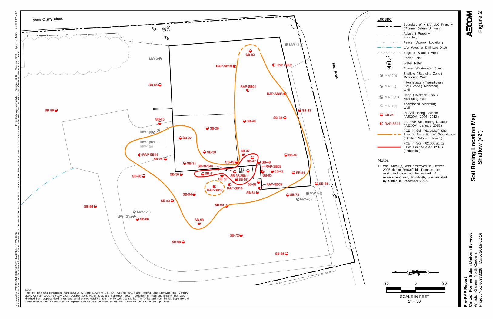
AN
SI
B 1
1"
x 17
"L
ast
sa
ved
by:
RO
BIN
SO
NK
1(2
01
5-0
2-1
6)
L
ast
Plo
tte
d: 2
01
5-0
2-1
6P
roje
ct M
an
ag
em
en
t In
itial
s:D
esi
gne
r:C
he
cked
:A
pp
rove
d:F
ilen
am
e: Z
:\C
AD
\PR
OJE
CT
S\C
\CIN
TA
S_
10
28
7\W
INS
TO
N-S
AL
EM
_N
C\F
OR
ME
R_
SA
LE
M_
UN
IFO
RM
\20
15
_P
RE
_R
AP
_M
IP_
WO
RK
_P
LA
N\D
WG
\CIN
TA
S_S
ALE
M_U
NIF
OR
M_W
INS
TO
N-S
ALE
M_N
C_P
RE
-RA
P_M
IP_F
IGU
RE
_2.D
WG
So
il B
ori
ng
Lo
cat
ion
Map
Sh
allo
w (
<2'
)F
igu
re 2
Da
te:
20
15
-02-
16
KLR
MB
D M
BD
Pre
-RA
P R
epo
rtC
inta
s:
Fo
rme
r S
ale
m U
nif
orm
Ser
vice
sW
inst
on
-Sa
lem
, N
orth
Car
olin
aP
roje
ct N
o.:
6033
3229
1" = 30'
3030
SCALE IN FEET
0
Note:This site plan was constructed from surveys by Slate Surveying Co., PA ( October 2003 ) and Regional Land Surveyors, Inc. ( January2004, October 2004, February 2008, October 2008, March 2013, and September 2013) . Locations of roads and property lines weredigitized from property deed maps and aerial photos obtained from the Forsyth County, NC Tax Office and from the NC Department ofTransportation. This survey does not represent an accurate boundary survey and should not be used for such purposes.
LegendBoundary of K & V, LLC Property( Former Salem Uniform )
Fence ( Approx. Location )
Shallow ( Saprolite Zone )Monitoring Well
Intermediate ( Transitional /PWR Zone ) MonitoringWell
Deep ( Bedrock Zone )Monitoring Well
Abandoned MonitoringWell
MW-6(i)
MW-6(d1)
MW-6(s)
MW-1(s)
Wet Weather Drainage Ditch
Adjacent PropertyBoundary
Edge of Wooded Area
Power Pole
Water MeterW
PCE in Soil ( 61 ug/kg ) SiteSpecific Protection of Groundwater
Notes1. Well MW-1(s) was destroyed in October
2005 during Brownfields Program sitework, and could not be located. Areplacement well, MW-1(s)R, was installedby Cintas in December 2007.
RI Soil Boring Location( AECOM, 2006 - 2012 )
SB-24
PCE in Soil ( 82,000 ug/kg )IHSB Health-Based PSRG( Industrial )
Pre-RAP Soil Boring Location( AECOM, January 2015 )
RAP-SB14
( Dashed Where Inferred )
Former Wastewater SumpS
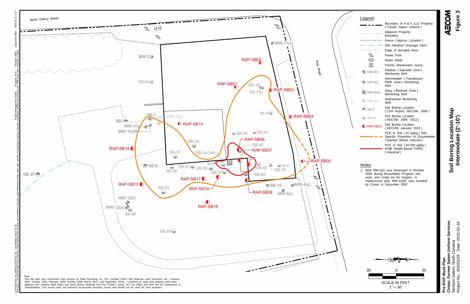
AN
SI B
11" x 17"
Last saved by: A
LLA
RD
G1
(2015-02-18
) Last P
lotted: 2015-02-18
Project M
anagem
ent Initials:
Designer:
Checked:
Approved:
Filenam
e: Z
:\C
AD
\P
RO
JE
CT
S\C
\C
IN
TA
S_10287\W
IN
ST
ON
-S
ALE
M_N
C\F
OR
ME
R_S
ALE
M_U
NIF
OR
M\2015_P
RE
_R
AP
_M
IP
_W
OR
K_P
LA
N\D
WG
\C
IN
TA
S_S
ALE
M_U
NIF
OR
M_W
IN
ST
ON
-S
ALE
M_N
C_P
RE
-R
AP
_M
IP
_F
IG
UR
E_3.D
WG
So
il B
orin
g L
oc
atio
n M
ap
In
te
rm
ed
ia
te
(2
'-1
0')
Fig
ure
3
Date: 2015-02-16
K
LR
M
BD
M
BD
Pre-R
AP
W
ork P
lan
Cin
tas: F
orm
er S
alem
U
nifo
rm
S
ervices
Winston-S
alem
, N
orth C
arolina
Project N
o.: 60333229
1" = 30'
3030
SCALE IN FEET
0
Note:
This site plan was constructed from surveys by Slate Surveying Co., PA ( October 2003 ) and Regional Land Surveyors, Inc. ( January
2004, October 2004, February 2008, October 2008, March 2013, and September 2013) . Locations of roads and property lines were
digitized from property deed maps and aerial photos obtained from the Forsyth County, NC Tax Office and from the NC Department of
Transportation. This survey does not represent an accurate boundary survey and should not be used for such purposes.
Legend
Boundary of K & V, LLC Property
( Former Salem Uniform )
Fence ( Approx. Location )
Shallow ( Saprolite Zone )
Monitoring Well
Intermediate ( Transitional /
PWR Zone ) Monitoring
Well
Deep ( Bedrock Zone )
Monitoring Well
Abandoned Monitoring
Well
MW-6(i)
MW-6(d1)
MW-6(s)
MW-1(s)
Wet Weather Drainage Ditch
Adjacent Property
Boundary
Edge of Wooded Area
Power Pole
Water Meter
W
Notes
1. Well MW-1(s) was destroyed in October
2005 during Brownfields Program site
work, and could not be located. A
replacement well, MW-1(s)R, was installed
by Cintas in December 2007.
PCE in Soil ( 61 ug/kg ) Site
Specific Protection of Groundwater
Soil Boring Location
( CSA Report, AECOM, 2006 )
SB-8
Soil Boring Location
( AECOM, 2006 - 2012 )
SB-24
PCE in Soil ( 82,000 ug/kg )
IHSB Health-Based PSRG
( Industrial )
Soil Boring Location
( AECOM, January 2015 )
RAP-SB14
( Dashed Where Inferred )
Former Wastewater SumpS
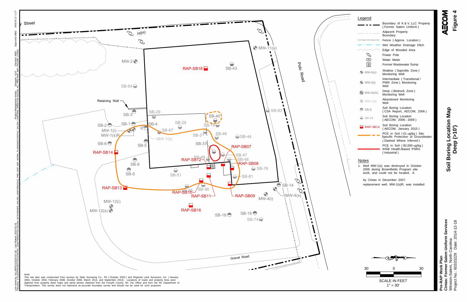
AN
SI B
11" x 17"
Last saved by: A
LLA
RD
G1
(2015-02-18
) Last P
lotted: 2015-02-18
Project M
anagem
ent Initials:
Designer:
Checked:
Approved:
Filenam
e: Z
:\C
AD
\P
RO
JE
CT
S\C
\C
IN
TA
S_10287\W
IN
ST
ON
-S
ALE
M_N
C\F
OR
ME
R_S
ALE
M_U
NIF
OR
M\2015_P
RE
_R
AP
_M
IP
_W
OR
K_P
LA
N\D
WG
\C
IN
TA
S_S
ALE
M_U
NIF
OR
M_W
IN
ST
ON
-S
ALE
M_N
C_P
RE
-R
AP
_M
IP
_F
IG
UR
E_4.D
WG
So
il B
orin
g L
oc
atio
n M
ap
De
ep
(>
10
')
Fig
ure
4
Date: 2014-12-18
K
LR
M
BD
M
BD
Pre-R
AP
W
ork P
lan
Cin
tas: F
orm
er S
alem
U
nifo
rm
S
ervices
Winston-S
alem
, N
orth C
arolina
Project N
o.: 60333229
1" = 30'
3030
SCALE IN FEET
0
Note:
This site plan was constructed from surveys by Slate Surveying Co., PA ( October 2003 ) and Regional Land Surveyors, Inc. ( January
2004, October 2004, February 2008, October 2008, March 2013, and September 2013) . Locations of roads and property lines were
digitized from property deed maps and aerial photos obtained from the Forsyth County, NC Tax Office and from the NC Department of
Transportation. This survey does not represent an accurate boundary survey and should not be used for such purposes.
Legend
Boundary of K & V, LLC Property
( Former Salem Uniform )
Fence ( Approx. Location )
Shallow ( Saprolite Zone )
Monitoring Well
Intermediate ( Transitional /
PWR Zone ) Monitoring
Well
Deep ( Bedrock Zone )
Monitoring Well
Abandoned Monitoring
Well
MW-6(i)
MW-6(d1)
MW-6(s)
MW-1(s)
Wet Weather Drainage Ditch
Adjacent Property
Boundary
Edge of Wooded Area
Power Pole
Water Meter
W
PCE in Soil ( 61 ug/kg ) Site
Specific Protection of Groundwater
Notes
1. Well MW-1(s) was destroyed in October
2005 during Brownfields Program site
work, and could not be located. A
replacement well, MW-1(s)R, was installed
by Cintas in December 2007.
Soil Boring Location
( CSA Report, AECOM, 2006 )
SB-8
Soil Boring Location
( AECOM, 2006 - 2009 )
SB-24
PCE in Soil ( 82,000 ug/kg )
IHSB Health-Based PSRG
( Industrial )
Soil Boring Location
( Dashed Where Inferred )
( AECOM, January 2015 )
RAP-SB14
Former Wastewater Sump
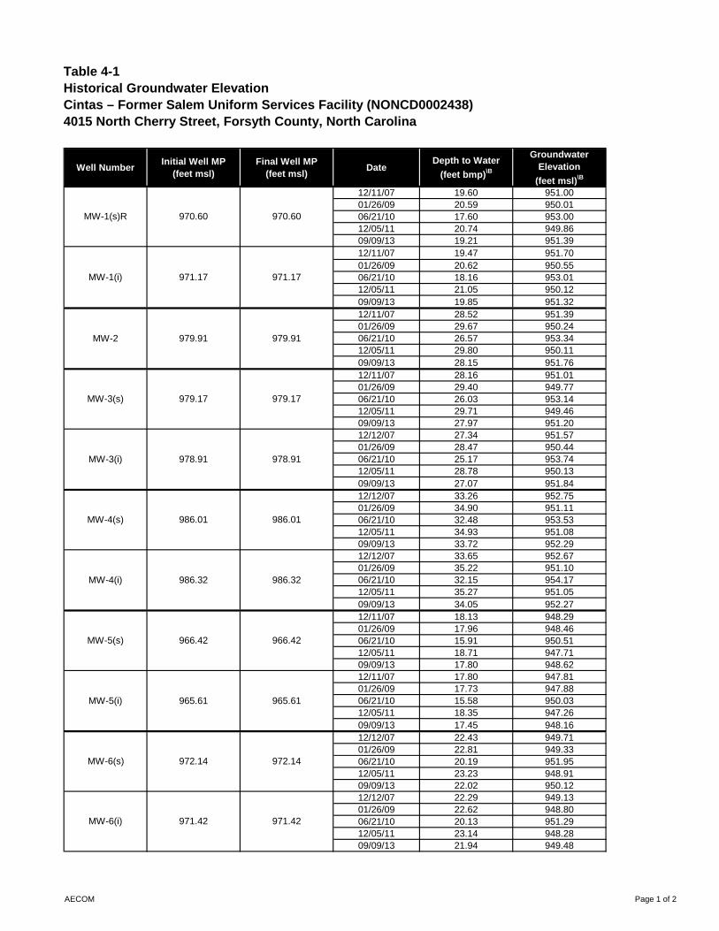
Table 4-1Historical Groundwater ElevationCintas – Former Salem Uniform Services Facility (NONCD0002438)4015 North Cherry Street, Forsyth County, North Carolina
Well NumberInitial Well MP
(feet msl)Final Well MP
(feet msl)Date
Depth to Water
(feet bmp)\B
Groundwater Elevation
(feet msl)\B
12/11/07 19.60 951.0001/26/09 20.59 950.0106/21/10 17.60 953.0012/05/11 20.74 949.8609/09/13 19.21 951.3912/11/07 19.47 951.7001/26/09 20.62 950.5506/21/10 18.16 953.0112/05/11 21.05 950.1209/09/13 19.85 951.3212/11/07 28.52 951.3901/26/09 29.67 950.2406/21/10 26.57 953.3412/05/11 29.80 950.1109/09/13 28.15 951.7612/11/07 28.16 951.0101/26/09 29.40 949.7706/21/10 26.03 953.1412/05/11 29.71 949.4609/09/13 27.97 951.2012/12/07 27.34 951.5701/26/09 28.47 950.4406/21/10 25.17 953.7412/05/11 28.78 950.1309/09/13 27.07 951.8412/12/07 33.26 952.7501/26/09 34.90 951.1106/21/10 32.48 953.5312/05/11 34.93 951.0809/09/13 33.72 952.2912/12/07 33.65 952.6701/26/09 35.22 951.1006/21/10 32.15 954.1712/05/11 35.27 951.0509/09/13 34.05 952.2712/11/07 18.13 948.2901/26/09 17.96 948.4606/21/10 15.91 950.5112/05/11 18.71 947.7109/09/13 17.80 948.6212/11/07 17.80 947.8101/26/09 17.73 947.8806/21/10 15.58 950.0312/05/11 18.35 947.2609/09/13 17.45 948.1612/12/07 22.43 949.7101/26/09 22.81 949.3306/21/10 20.19 951.9512/05/11 23.23 948.9109/09/13 22.02 950.1212/12/07 22.29 949.1301/26/09 22.62 948.8006/21/10 20.13 951.2912/05/11 23.14 948.2809/09/13 21.94 949.48
970.60970.60MW-1(s)R
MW-1(i) 971.17 971.17
MW-2
MW-6(s) 972.14 972.14
MW-6(i) 971.42 971.42
MW-3(i) 978.91 978.91
MW-4(s) 986.01 986.01
979.91 979.91
MW-3(s) 979.17 979.17
986.32
MW-5(s) 966.42 966.42
MW-5(i) 965.61 965.61
MW-4(i) 986.32
AECOM Page 1 of 2
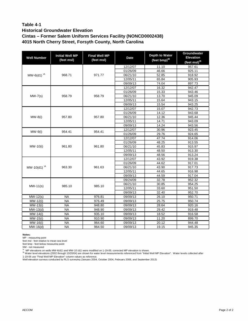
Table 4-1Historical Groundwater ElevationCintas – Former Salem Uniform Services Facility (NONCD0002438)4015 North Cherry Street, Forsyth County, North Carolina
Well NumberInitial Well MP
(feet msl)Final Well MP
(feet msl)Date
Depth to Water
(feet bmp)\B
Groundwater Elevation
(feet msl)\B
12/12/07 11.10 957.6101/26/09 46.66 925.1106/21/10 52.85 918.9212/05/11 65.84 905.9309/09/13 74.04 897.7312/12/07 16.32 942.4701/26/09 15.33 943.4606/21/10 13.70 945.0912/05/11 15.64 943.1509/09/13 15.54 943.2512/12/07 15.07 942.7301/26/09 14.12 943.6806/21/10 12.36 945.4412/05/11 14.71 943.0909/09/13 14.24 943.5612/12/07 30.96 923.4501/26/09 29.76 924.6512/12/07 47.74 914.0601/26/09 48.25 913.5506/21/10 45.83 915.9712/05/11 48.50 913.3009/09/13 48.56 913.2412/12/07 43.92 919.3801/26/09 44.62 917.0106/21/10 43.90 917.7312/05/11 44.65 916.9809/09/13 44.59 917.0409/24/09 32.78 952.3206/21/10 30.85 954.2512/05/11 33.60 951.5009/09/13 32.40 952.70
MW-12(s) NA 976.81 09/09/13 26.10 950.71MW-12(i) NA 976.49 09/09/13 25.75 950.74MW-13(i) NA 948.80 09/09/13 28.64 920.16MW-13(d) NA 948.90 09/09/13 29.42 919.48MW-14(i) NA 935.10 09/09/13 18.52 916.58MW-15(i) NA 910.90 09/09/13 11.20 899.70MW-16(i) NA 964.60 09/09/13 20.12 944.48MW-16(d) NA 964.50 09/09/13 19.15 945.35
Notes:MP - measuring pointfeet msl - feet relative to mean sea levelfeet bmp - feet below measuring pointNM - not measured\A MP elevations on wells MW-6(d1) and MW-10 (d1) were modified on 1-19-05; corrected MP elevation is shown.
Well elevation surveys conducted by RLS surveying (January 2004, October 2004, February 2008, and September 2013)
\B Water level elevations (2002 through 10/20/04) are shown for water level measurements referenced from "Initial Well MP Elevation". Water levels collected after 1-19-05 use "Final Well MP Elevation" column values as reference.
MW-9(i) 954.41 954.41
MW-10(i) 961.80
MW-6(d1) \A 971.77968.71
MW-7(s) 958.79 958.79
MW-8(i) 957.80 957.80
961.80
MW-10(d1) \A 963.30 961.63
MW-11(s) 985.10 985.10
AECOM Page 2 of 2
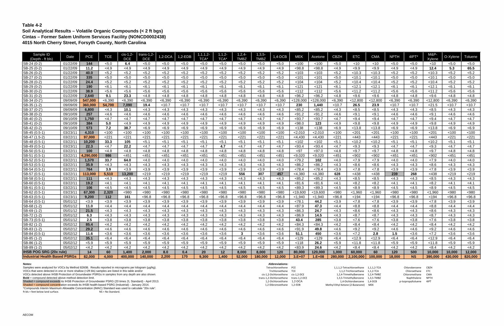
Table 4-2 Soil Analytical Results – Volatile Organic Compounds (< 2 ft bgs) Cintas – Former Salem Uniform Services Facility (NONCD0002438)4015 North Cherry Street, Forsyth County, North Carolina
Sample ID(Depth - ft bls)
Date PCE TCEcis-1,2-
DCEtrans-1,2-
DCE1,2-DCA 1,2-EDB
1,1,1,2-TCA*
1,1,2-TCA*
1,2,4-TMBZ
1,3,5-TMBZ
1,4-DCB MEK Acetone CBZH ETC CMA NPTH 4IPT*M&P-Xylene
O-Xylene Toluene
SB-24 (0-2) 01/22/09 144 <5.0 6.4 <5.0 <5.0 <5.0 <5.0 <5.0 <5.0 <5.0 <5.0 <100 <100 <5.0 <10 <10 <5.0 <5.0 <10 <5.0 <5.0SB-25 (0-2) 01/22/09 11.2 <4.9 <4.9 <4.9 <4.9 <4.9 <4.9 <4.9 <4.9 <4.9 <4.9 <98.8 <98.8 <4.9 <9.9 <9.9 <4.9 <4.9 12.4 5.3 65.5SB-26 (0-2) 01/22/09 40.0 <5.2 <5.2 <5.2 <5.2 <5.2 <5.2 <5.2 <5.2 <5.2 <5.2 <103 <103 <5.2 <10.3 <10.3 <5.2 <5.2 <10.3 <5.2 <5.2SB-27 (0-2) 01/22/09 335 <5.0 <5.0 <5.0 <5.0 <5.0 <5.0 <5.0 <5.0 <5.0 <5.0 <101 <101 <5.0 <10.1 <10.1 <5.0 <5.0 <10.1 <5.0 <5.0SB-28 (0-2) 01/22/09 24.4 <5.2 <5.2 <5.2 <5.2 <5.2 <5.2 <5.2 <5.2 <5.2 <5.2 <104 <104 <5.2 <10.4 <10.4 <5.2 <5.2 <10.4 <5.2 <5.2SB-29 (0-2) 01/22/09 190 <6.1 <6.1 <6.1 <6.1 <6.1 <6.1 <6.1 <6.1 <6.1 <6.1 <121 <121 <6.1 <12.1 <12.1 <6.1 <6.1 <12.1 <6.1 <6.1SB-30 (0-2) 01/22/09 38.9 <5.6 <5.6 <5.6 <5.6 <5.6 <5.6 <5.6 <5.6 <5.6 <5.6 <112 <112 <5.6 <11.2 <11.2 <5.6 <5.6 <11.2 <5.6 <5.6SB-31 (0-2) 01/22/09 2,640 9.1 23.3 <4.8 <4.8 <4.8 <4.8 <4.8 <4.8 <4.8 <4.8 <96.2 <96.2 <4.8 <9.6 <9.6 <4.8 <4.8 <9.6 <4.8 <4.8SB-34 (0-2') 09/09/09 547,000 <6,390 <6,390 <6,390 <6,390 <6,390 <6,390 <6,390 <6,390 <6,390 <6,390 <128,000 <128,000 <6,390 <12,800 <12,800 <6,390 <6,390 <12,800 <6,390 <6,390SB-35 (1-2) 09/09/09 360,000 54,700 7,090 19.4 <10.7 <10.7 <10.7 <10.7 <10.7 <10.7 <10.7 230 1,440 <10.7 26.5 23.9 <10.7 <10.7 <21.5 <10.7 <10.7SB-37 (0-2') 09/09/09 6,800 <4.3 10.1 <4.3 <4.3 <4.3 <4.3 <4.3 <4.3 <4.3 <4.3 <85.2 <85.2 <4.3 <8.5 <8.5 <4.3 <4.3 <8.5 <4.3 <4.3SB-38 (0-2) 09/10/09 257 <4.6 <4.6 <4.6 <4.6 <4.6 <4.6 <4.6 <4.6 <4.6 <4.6 <91.2 <91.2 <4.6 <9.1 <9.1 <4.6 <4.6 <9.1 <4.6 <4.6SB-40 (0-2) 09/10/09 1,750 <4.7 <4.7 <4.7 <4.7 <4.7 <4.7 <4.7 <4.7 <4.7 <4.7 <93.7 <93.7 <4.7 <9.4 <9.4 <4.7 <4.7 <9.4 <4.7 <4.7SB-41 (0-2) 09/10/09 384 5.0 <4.9 <4.9 <4.9 <4.9 <4.9 <4.9 <4.9 <4.9 <4.9 <98.0 123 <4.9 <9.8 <9.8 <4.9 <4.9 <9.8 <4.9 <4.9SB-42 (0-2) 09/10/09 573 7.2 38.7 <6.9 <6.9 <6.9 <6.9 <6.9 <6.9 <6.9 <6.9 <138 <138 <6.9 <13.8 <13.8 <6.9 <6.9 <13.8 <6.9 <6.9SB-45 (0.5-1) 03/23/11 4,310 <100 <100 <100 <100 <100 <100 <100 <100 <100 <100 <2,010 <2,010 <100 <201 <201 <100 <100 <201 <100 <100SB-47 (1.5-2) 03/22/11 97,000 <221 <221 <221 <221 <221 <221 <221 <221 <221 <221 <4,430 <4,430 <221 <443 <443 <221 <221 <443 <221 <221SB-48 (0.5-1) 03/22/11 10,200 33.3 105 <5.1 <5.1 <5.1 <5.1 <5.1 <5.1 <5.1 <5.1 <102 <102 <5.1 <10.2 <10.2 <5.1 <5.1 <10.2 <5.1 <5.1SB-49 (0.5-1) 03/23/11 22.3 <4.7 22.2 <4.7 <4.7 <4.7 <4.7 4.7 <4.7 <4.7 <4.7 <93.4 <93.4 <4.7 <9.3 <9.3 <4.7 <4.7 <9.3 <4.7 <4.7SB-50 (0.5-1) 03/22/11 100 <4.8 <4.8 <4.8 <4.8 <4.8 <4.8 <4.8 <4.8 <4.8 <4.8 <97 <97.0 <4.8 <9.7 <9.7 <4.8 <4.8 <9.7 <4.8 <4.8SB-51 (0.5-1) 03/22/11 4,290,000 986 <451 <451 <451 <451 <451 <451 <451 <451 <451 <9,020 <9,020 <451 <902 <902 <451 <451 <902 <451 <451SB-52 (0.5-1) 03/22/11 1,570 33.7 64.0 <4.0 <4.0 <4.0 <4.0 <4.0 <4.0 <4.0 <4.0 <79.2 102 <4.0 <7.9 <7.9 <4.0 <4.0 <7.9 <4.0 <4.0SB-53 (0.5-1) 03/22/11 35.9 <4.3 <4.3 <4.3 <4.3 <4.3 <4.3 <4.3 <4.3 <4.3 <4.3 <86.2 <86.2 <4.3 <8.6 <8.6 <4.3 <4.3 <8.6 <4.3 <4.3SB-54 (0.5-1) 03/22/11 764 3.9 <3.9 <3.9 <3.9 <3.9 <3.9 <3.9 <3.9 <3.9 <3.9 <78.4 <78.4 <3.9 <7.8 <7.8 <3.9 <3.9 <7.8 <3.9 <3.9SB-57 (0.5-1) 03/22/11 113,000 5,510 13,200 <219 <219 <219 <219 <219 556 307 457 <4,380 <4,380 628 <438 <438 239 268 <438 <219 <219SB-58 (0.5-1) 03/22/11 111 <4.3 <4.3 <4.3 <4.3 <4.3 <4.3 <4.3 <4.3 <4.3 <4.3 <85.2 <85.2 <4.3 <8.5 <8.5 <4.3 <4.3 <8.5 <4.3 <4.3SB-60 (0.5-1) 03/22/11 19.2 <4.1 <4.1 <4.1 <4.1 <4.1 <4.1 <4.1 <4.1 <4.1 <4.1 <81.6 <81.6 <4.1 <8.2 <8.2 <4.1 <4.1 <8.2 <4.1 <4.1SB-61 (0.5-1) 03/22/11 106 <4.5 <4.5 <4.5 <4.5 <4.5 <4.5 <4.5 <4.5 <4.5 <4.5 <89.3 <89.3 <4.5 <8.9 <8.9 <4.5 <4.5 <8.9 <4.5 <4.5SB-62 (0.5-1) 03/23/11 67,300 2,320 <980 <980 <980 <980 <980 <980 <980 <980 <980 <19,600 <19,600 <980 <1,960 <1,960 <980 <980 <1,960 <980 <980SB-63 (0.5-1) 03/23/11 9,200 112 161 <96.8 <96.8 <96.8 <96.8 <96.8 <96.8 <96.8 <96.8 <1,940 <1,940 <96.8 <194 <194 <96.8 <96.8 <194 <96.8 <96.8SB-64 (0.5-1) 05/01/12 <3.9 <3.9 <3.9 <3.9 <3.9 <3.9 <3.9 <3.9 <3.9 <3.9 <3.9 <78.1 44.2 <3.9 <7.8 <7.8 <3.9 <3.9 <7.8 <3.9 <3.9SB-68 (1-2) 05/01/12 11.0 <4.4 <4.4 <4.4 <4.4 <4.4 <4.4 <4.4 <4.4 <4.4 <4.4 <87.9 47.3 <4.4 <8.8 <8.8 <4.4 <4.4 <8.8 <4.4 <4.4SB-69 (1-2) 05/01/12 21.5 <4.3 <4.3 <4.3 <4.3 <4.3 <4.3 <4.3 <4.3 <4.3 <4.3 <86.3 24.7 <4.3 <8.6 <8.6 <4.3 <4.3 <8.6 <4.3 <4.3SB-72 (1-2) 05/01/12 6.3 <4.3 <4.3 <4.3 <4.3 <4.3 <4.3 <4.3 <4.3 <4.3 <4.3 <86.9 14.5 <4.3 <8.7 <8.7 <4.3 <4.3 <8.7 <4.3 <4.3SB-73 (0.5-1) 05/01/12 2.5 <3.8 <3.8 <3.8 <3.8 <3.8 <3.8 <3.8 <3.8 <3.8 <3.8 43.4 285 <3.8 <7.6 <7.6 <3.8 <3.8 <7.6 <3.8 <3.8SB-82 (1-2) 05/02/12 85.4 <4.2 <4.2 <4.2 <4.2 <4.2 <4.2 <4.2 <4.2 <4.2 <4.2 <84.3 <84.3 <4.2 <8.4 <8.4 <4.2 <4.2 <8.4 <4.2 <4.2SB-83 (1-2) 05/02/12 29.2 <4.6 <4.6 <4.6 <4.6 <4.6 <4.6 <4.6 <4.6 <4.6 <4.6 <91.9 49.8 <4.6 <9.2 <9.2 <4.6 <4.6 <9.2 <4.6 <4.6SB-84 (0.5-1) 05/02/12 11.6 <3.6 <3.6 <3.6 <3.6 <3.6 <3.6 <3.6 3 <3.6 <3.6 51.1 450 <3.6 <7.2 2.8 1.5 <3.6 <7.2 <3.6 <3.6SB-85 (1-2) 05/02/12 35.1 <6.4 <6.4 <6.4 <6.4 <6.4 <6.4 <6.4 <6.4 <6.4 <6.4 <129 <129 <6.4 <12.9 <12.9 <6.4 <6.4 <12.9 <6.4 <6.4SB-86 (1-2) 05/02/12 <5.9 <5.9 <5.9 <5.9 <5.9 <5.9 <5.9 <5.9 <5.9 <5.9 <5.9 <118 26.2 <5.9 <11.8 <11.8 <5.9 <5.9 <11.8 <5.9 <5.9SB-89 (1-2) 05/02/12 <4.2 <4.2 <4.2 <4.2 <4.2 <4.2 <4.2 <4.2 <4.2 <4.2 <4.2 <83.9 24.6 <4.2 <8.4 <8.4 <4.2 <4.2 <8.4 <4.2 <4.2
14 60 1,400 2,000 8.0 0.4 20 12 8,000 8,000 120 80,000 120,000 1,000 60,000 60 120 500 10,000 10,000 12,00082,000 4,000 400,000 140,000 2,200 170 9,300 1,400 52,000 180,000 12,000 3.E+07 1.E+08 280,000 2,100,000 100,000 18,000 NS 390,000 430,000 820,000
Notes: Abbreviations: Samples were analyzed for VOCs by Method 8260B. Results reported in micrograms per kilogram (µg/kg). Tetrachloroethene PCE 1,1,1,2‐Tetrachloroethane 1,1,1,2‐TCA Chlorobenzene CBZHVOCs that were detected in one or more shallow (<2ft bls) samples are listed in this table and/or Trichloroethene TCE 1,1,2‐Trichloroethane 1,1,2‐TCA Chloroethane ETCVOCs detected above IHSB Protection of Groundwater PSRGs in samples from any depth are also shown. cis‐1,2‐Dichloroethene cis‐1,2‐DCE 1,2,4‐Trimethylbenzene 1,2,4‐TMBZ Chloromethane CMABold = compound detected above method detection limit. trans‐1,2‐Dichloroethene trans‐1,2‐DCE 1,3,5‐Trimethylbenzene 1,3,5‐TMBZ Naphthalene NPTHShaded = compound exceeds its IHSB Protection of Groundwater PSRG (20 times 2L Standard) - April 2013. 1,2‐Dichloroethane 1,2-DCA 1,4‐Dichlorobenzene 1,4‐DCB p‐Isopropyltoluene 4IPTShaded = compound concentration exceeds its IHSB health-based PSRG (Industrial) - January 2014. 1,2‐Dibromoethane 1,2‐EDB Methyl Ethyl Ketone (2‐Butanone) MEK*Compounds Interim Maximum Allowable Concentration (IMAC) Standard was used to calculate "20x rule".ft bls = feet below land surface. NS = No Standard.
IHSB POG SRG (20x rule)Industrial Health Based PSRGs
AECOM
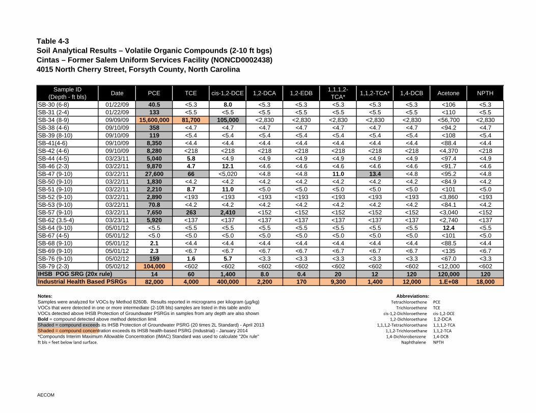
Table 4-3 Soil Analytical Results – Volatile Organic Compounds (2-10 ft bgs) Cintas – Former Salem Uniform Services Facility (NONCD0002438)4015 North Cherry Street, Forsyth County, North Carolina
Sample ID(Depth - ft bls)
Date PCE TCE cis-1,2-DCE 1,2-DCA 1,2-EDB1,1,1,2-TCA*
1,1,2-TCA* 1,4-DCB Acetone NPTH
SB-30 (6-8) 01/22/09 40.5 <5.3 8.0 <5.3 <5.3 <5.3 <5.3 <5.3 <106 <5.3SB-31 (2-4) 01/22/09 133 <5.5 <5.5 <5.5 <5.5 <5.5 <5.5 <5.5 <110 <5.5SB-34 (8-9) 09/09/09 15,600,000 81,700 105,000 <2,830 <2,830 <2,830 <2,830 <2,830 <56,700 <2,830SB-38 (4-6) 09/10/09 358 <4.7 <4.7 <4.7 <4.7 <4.7 <4.7 <4.7 <94.2 <4.7SB-39 (8-10) 09/10/09 119 <5.4 <5.4 <5.4 <5.4 <5.4 <5.4 <5.4 <108 <5.4SB-41(4-6) 09/10/09 8,350 <4.4 <4.4 <4.4 <4.4 <4.4 <4.4 <4.4 <88.4 <4.4SB-42 (4-6) 09/10/09 8,280 <218 <218 <218 <218 <218 <218 <218 <4,370 <218SB-44 (4-5) 03/23/11 5,040 5.8 <4.9 <4.9 <4.9 <4.9 <4.9 <4.9 <97.4 <4.9SB-46 (2-3) 03/22/11 9,870 4.7 12.1 <4.6 <4.6 <4.6 <4.6 <4.6 <91.7 <4.6SB-47 (9-10) 03/22/11 27,600 66 <5,020 <4.8 <4.8 11.0 13.4 <4.8 <95.2 <4.8SB-50 (9-10) 03/22/11 1,830 <4.2 <4.2 <4.2 <4.2 <4.2 <4.2 <4.2 <84.9 <4.2SB-51 (9-10) 03/22/11 2,210 8.7 11.0 <5.0 <5.0 <5.0 <5.0 <5.0 <101 <5.0SB-52 (9-10) 03/22/11 2,890 <193 <193 <193 <193 <193 <193 <193 <3,860 <193SB-53 (9-10) 03/22/11 70.8 <4.2 <4.2 <4.2 <4.2 <4.2 <4.2 <4.2 <84.1 <4.2SB-57 (9-10) 03/22/11 7,650 263 2,410 <152 <152 <152 <152 <152 <3,040 <152SB-62 (3.5-4) 03/23/11 5,920 <137 <137 <137 <137 <137 <137 <137 <2,740 <137SB-64 (9-10) 05/01/12 <5.5 <5.5 <5.5 <5.5 <5.5 <5.5 <5.5 <5.5 12.4 <5.5SB-67 (4-5) 05/01/12 <5.0 <5.0 <5.0 <5.0 <5.0 <5.0 <5.0 <5.0 <101 <5.0SB-68 (9-10) 05/01/12 2.1 <4.4 <4.4 <4.4 <4.4 <4.4 <4.4 <4.4 <88.5 <4.4SB-69 (9-10) 05/01/12 2.3 <6.7 <6.7 <6.7 <6.7 <6.7 <6.7 <6.7 <135 <6.7SB-76 (9-10) 05/02/12 159 1.6 5.7 <3.3 <3.3 <3.3 <3.3 <3.3 <67.0 <3.3SB-79 (2-3) 05/02/12 104,000 <602 <602 <602 <602 <602 <602 <602 <12,000 <602
14 60 1,400 8.0 0.4 20 12 120 120,000 12082,000 4,000 400,000 2,200 170 9,300 1,400 12,000 1.E+08 18,000
Notes: Abbreviations:Samples were analyzed for VOCs by Method 8260B. Results reported in micrograms per kilogram (µg/kg) Tetrachloroethene PCEVOCs that were detected in one or more intermediate (2-10ft bls) samples are listed in this table and/or Trichloroethene TCEVOCs detected above IHSB Protection of Groundwater PSRGs in samples from any depth are also shown cis‐1,2‐Dichloroethene cis‐1,2‐DCEBold = compound detected above method detection limit. 1,2‐Dichloroethane 1,2-DCAShaded = compound exceeds its IHSB Protection of Groundwater PSRG (20 times 2L Standard) - April 2013 1,1,1,2‐Tetrachloroethane 1,1,1,2‐TCAShaded = compound concentration exceeds its IHSB health-based PSRG (Industrial) - January 2014 1,1,2‐Trichloroethane 1,1,2‐TCA*Compounds Interim Maximum Allowable Concentration (IMAC) Standard was used to calculate "20x rule" 1,4‐Dichlorobenzene 1,4‐DCBft bls = feet below land surface. Naphthalene NPTH
IHSB POG SRG (20x rule)Industrial Health Based PSRGs
AECOM
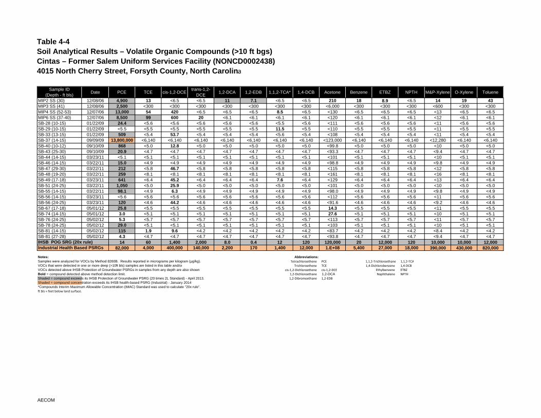
Table 4-4 Soil Analytical Results – Volatile Organic Compounds (>10 ft bgs) Cintas – Former Salem Uniform Services Facility (NONCD0002438)4015 North Cherry Street, Forsyth County, North Carolina
Sample ID(Depth - ft bls)
Date PCE TCE cis-1,2-DCEtrans-1,2-
DCE1,2-DCA 1,2-EDB 1,1,2-TCA* 1,4-DCB Acetone Benzene ETBZ NPTH M&P-Xylene O-Xylene Toluene
MIP2 SS (30) 12/08/06 4,900 13 <6.5 <6.5 11 7.1 <6.5 <6.5 210 18 8.9 <6.5 14 19 43MIP3 SS (41) 12/08/06 2,500 <300 <300 <300 <300 <300 <300 <300 <6,000 <300 <300 <300 <600 <300 <300MIP4 SS (52-53) 12/07/06 13,000 54 420 <6.5 <6.5 <6.5 8.5 <6.5 <130 <6.5 <6.5 <6.5 <13 <6.5 <6.5MIP6 SS (37-40) 12/07/06 8,500 99 600 20 <6.1 <6.1 <6.1 <6.1 <120 <6.1 <6.1 <6.1 <12 <6.1 <6.1SB-28 (10-15) 01/22/09 24.4 <5.6 <5.6 <5.6 <5.6 <5.6 <5.5 <5.6 <111 <5.6 <5.6 <5.6 <11 <5.6 <5.6SB-29 (10-15) 01/22/09 <5.5 <5.5 <5.5 <5.5 <5.5 <5.5 11.5 <5.5 <110 <5.5 <5.5 <5.5 <11 <5.5 <5.5SB-33 (13-15) 01/22/09 509 <5.4 53.7 <5.4 <5.4 <5.4 <5.6 <5.4 <108 <5.4 <5.4 <5.4 <11 <5.4 <5.4SB-37 (14-15) 09/09/09 13,800,000 <6,140 <6,140 <6,140 <6,140 <6,140 <6,140 <6,140 <123,000 <6,140 <6,140 <6,140 <12,280 <6,140 <6,140SB-40 (10-12) 09/10/09 868 <5.0 12.8 <5.0 <5.0 <5.0 <5.0 <5.0 <99.8 <5.0 <5.0 <5.0 <10 <5.0 <5.0SB-43 (25-30) 09/10/09 20.9 <4.7 <4.7 <4.7 <4.7 <4.7 <4.7 <4.7 <93.3 <4.7 <4.7 <4.7 <9.4 <4.7 <4.7SB-44 (14-15) 03/23/11 <5.1 <5.1 <5.1 <5.1 <5.1 <5.1 <5.1 <5.1 <101 <5.1 <5.1 <5.1 <10 <5.1 <5.1SB-46 (14-15) 03/22/11 15.0 <4.9 <4.9 <4.9 <4.9 <4.9 <4.9 <4.9 <98.8 <4.9 <4.9 <4.9 <9.8 <4.9 <4.9SB-47 (29-30) 03/22/11 212 <5.8 46.7 <5.8 <5.8 <5.8 <5.8 <5.8 <115 <5.8 <5.8 <5.8 <12 <5.8 <5.8SB-48 (19-20) 03/22/11 259 <8.1 <8.1 <8.1 <8.1 <8.1 <8.1 <8.1 <161 <8.1 <8.1 <8.1 <16 <8.1 <8.1SB-49 (17-18) 03/23/11 641 <6.4 45.2 <6.4 <6.4 <6.4 7.6 <6.4 <129 <6.4 <6.4 <6.4 <13 <6.4 <6.4SB-51 (24-25) 03/22/11 1,050 <5.0 25.9 <5.0 <5.0 <5.0 <5.0 <5.0 <101 <5.0 <5.0 <5.0 <10 <5.0 <5.0SB-55 (14-15) 03/22/11 98.1 <4.9 6.3 <4.9 <4.9 <4.9 <4.9 <4.9 <98.0 <4.9 <4.9 <4.9 <9.8 <4.9 <4.9SB-56 (14-15) 03/23/11 <5.6 <5.6 <5.6 <5.6 <5.6 <5.6 <5.6 <5.6 <112 <5.6 <5.6 <5.6 <11 <5.6 <5.6SB-56 (24-25) 03/23/11 120 <4.6 44.2 <4.6 <4.6 <4.6 <4.6 <4.6 <91.6 <4.6 <4.6 <4.6 <9.2 <4.6 <4.6SB-67 (17-18) 05/01/12 25.8 <5.5 <5.5 <5.5 <5.5 <5.5 <5.5 <5.5 14.3 <5.5 <5.5 <5.5 <11 <5.5 <5.5SB-74 (14-15) 05/01/12 3.0 <5.1 <5.1 <5.1 <5.1 <5.1 <5.1 <5.1 27.6 <5.1 <5.1 <5.1 <10 <5.1 <5.1SB-76 (24-25) 05/02/12 5.3 <5.7 <5.7 <5.7 <5.7 <5.7 <5.7 <5.7 <113 <5.7 <5.7 <5.7 <11 <5.7 <5.7SB-78 (24-25) 05/02/12 29.0 <5.1 <5.1 <5.1 <5.1 <5.1 <5.1 <5.1 <103 <5.1 <5.1 <5.1 <10 <5.1 <5.1SB-81 (14-15) 05/02/12 115 1.9 9.6 <4.2 <4.2 <4.2 <4.2 <4.2 <83.7 <4.2 <4.2 <4.2 <8.4 <4.2 <4.2SB-81 (27-28) 05/02/12 4.3 <4.7 <4.7 <4.7 <4.7 <4.7 <4.7 <4.7 <93.8 <4.7 <4.7 <4.7 <9.4 <4.7 <4.7
14 60 1,400 2,000 8.0 0.4 12 120 120,000 20 12,000 120 10,000 10,000 12,00082,000 4,000 400,000 140,000 2,200 170 1,400 12,000 1.E+08 5,400 27,000 18,000 390,000 430,000 820,000
Notes: Abbreviations:Samples were analyzed for VOCs by Method 8260B. Results reported in micrograms per kilogram (µg/kg). Tetrachloroethene PCE 1,1,2‐Trichloroethane 1,1,2‐TCAVOCs that were detected in one or more deep (>10ft bls) samples are listed in this table and/or Trichloroethene TCE 1,4‐Dichlorobenzene 1,4‐DCBVOCs detected above IHSB Protection of Groundwater PSRGs in samples from any depth are also shown. cis‐1,2‐Dichloroethene cis‐1,2‐DCE Ethylbenzene ETBZBold = compound detected above method detection limit. 1,2‐Dichloroethane 1,2-DCA Naphthalene NPTHShaded = compound exceeds its IHSB Protection of Groundwater PSRG (20 times 2L Standard) - April 2013. 1,2‐Dibromoethane 1,2‐EDBShaded = compound concentration exceeds its IHSB health-based PSRG (Industrial) - January 2014.*Compounds Interim Maximum Allowable Concentration (IMAC) Standard was used to calculate "20x rule".ft bls = feet below land surface.
IHSB POG SRG (20x rule)Industrial Health Based PSRGs
AECOM
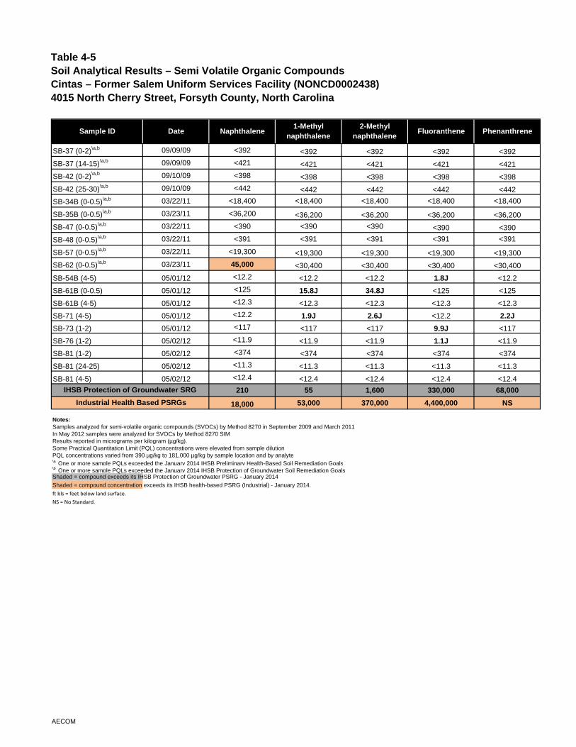
Table 4-5 Soil Analytical Results – Semi Volatile Organic Compounds Cintas – Former Salem Uniform Services Facility (NONCD0002438)4015 North Cherry Street, Forsyth County, North Carolina
SB-37 (0-2)\a,b 09/09/09 <392 <392 <392 <392 <392
SB-37 (14-15)\a,b 09/09/09 <421 <421 <421 <421 <421
SB-42 (0-2)\a,b 09/10/09 <398 <398 <398 <398 <398
SB-42 (25-30)\a,b 09/10/09 <442 <442 <442 <442 <442
SB-34B (0-0.5)\a,b 03/22/11 <18,400 <18,400 <18,400 <18,400 <18,400
SB-35B (0-0.5)\a,b 03/23/11 <36,200 <36,200 <36,200 <36,200 <36,200
SB-47 (0-0.5)\a,b 03/22/11 <390 <390 <390 <390 <390
SB-48 (0-0.5)\a,b 03/22/11 <391 <391 <391 <391 <391
SB-57 (0-0.5)\a,b 03/22/11 <19,300 <19,300 <19,300 <19,300 <19,300
SB-62 (0-0.5)\a,b 03/23/11 45,000 <30,400 <30,400 <30,400 <30,400
SB-54B (4-5) 05/01/12 <12.2 <12.2 <12.2 1.8J <12.2
SB-61B (0-0.5) 05/01/12 <125 15.8J 34.8J <125 <125
SB-61B (4-5) 05/01/12 <12.3 <12.3 <12.3 <12.3 <12.3
SB-71 (4-5) 05/01/12 <12.2 1.9J 2.6J <12.2 2.2J
SB-73 (1-2) 05/01/12 <117 <117 <117 9.9J <117
SB-76 (1-2) 05/02/12 <11.9 <11.9 <11.9 1.1J <11.9
SB-81 (1-2) 05/02/12 <374 <374 <374 <374 <374
SB-81 (24-25) 05/02/12 <11.3 <11.3 <11.3 <11.3 <11.3
SB-81 (4-5) 05/02/12 <12.4 <12.4 <12.4 <12.4 <12.4
210 55 1,600 330,000 68,000
18,000 53,000 370,000 4,400,000 NS
Notes:Samples analyzed for semi-volatile organic compounds (SVOCs) by Method 8270 in September 2009 and March 2011In May 2012 samples were analyzed for SVOCs by Method 8270 SIMResults reported in micrograms per kilogram (µg/kg). Some Practical Quantitation Limit (PQL) concentrations were elevated from sample dilutionPQL concentrations varied from 390 µg/kg to 181,000 µg/kg by sample location and by analyte\a One or more sample PQLs exceeded the January 2014 IHSB Preliminary Health-Based Soil Remediation Goals\b One or more sample PQLs exceeded the January 2014 IHSB Protection of Groundwater Soil Remediation GoalsShaded = compound exceeds its IHSB Protection of Groundwater PSRG - January 2014
Shaded = compound concentration exceeds its IHSB health-based PSRG (Industrial) - January 2014.
ft bls = feet below land surface.NS = No Standard.
IHSB Protection of Groundwater SRG
Date Naphthalene Phenanthrene
Industrial Health Based PSRGs
1-Methyl naphthalene
2-Methyl naphthalene
FluorantheneSample ID
AECOM
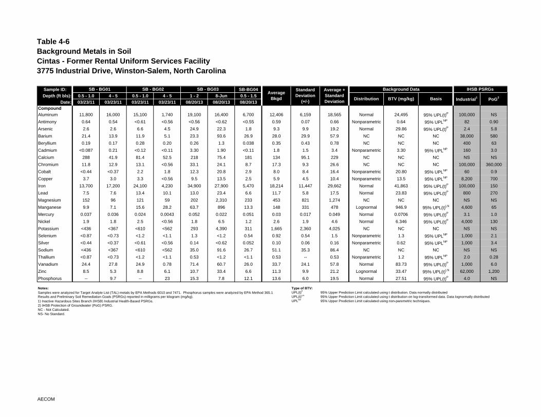
Table 4-6Background Metals in SoilCintas - Former Rental Uniform Services Facility3775 Industrial Drive, Winston-Salem, North Carolina
Sample ID: SB-BG04
Depth (ft bls): 0.5 - 1.0 4 - 5 0.5 - 1.0 4 - 5 1 - 2 8-Jun 0.5 - 1.5
Date: 03/23/11 03/23/11 03/23/11 03/23/11 08/20/13 08/20/13 08/20/13Compound
Aluminum 11,800 16,000 15,100 1,740 19,100 16,400 6,700 12,406 6,159 18,565 Normal 24,495 95% UPL(t)P 100,000 NS
Antimony 0.64 0.54 <0.61 <0.56 <0.56 <0.62 <0.55 0.59 0.07 0.66 Nonparametric 0.64 95% UPLNP 82 0.90
Arsenic 2.6 2.6 6.6 4.5 24.9 22.3 1.8 9.3 9.9 19.2 Normal 29.86 95% UPL(t)P 2.4 5.8
Barium 21.4 13.9 11.9 5.1 23.3 93.6 26.9 28.0 29.9 57.9 NC NC NC 38,000 580
Beryllium 0.19 0.17 0.28 0.20 0.26 1.3 0.038 0.35 0.43 0.78 NC NC NC 400 63
Cadmium <0.087 0.21 <0.12 <0.11 3.30 1.90 <0.11 1.8 1.5 3.4 Nonparametric 3.30 95% UPLNP 160 3.0
Calcium 288 41.9 81.4 52.5 218 75.4 181 134 95.1 229 NC NC NC NS NS
Chromium 11.8 12.9 13.1 <0.56 33.1 24.1 8.7 17.3 9.3 26.6 NC NC NC 100,000 360,000
Cobalt <0.44 <0.37 2.2 1.8 12.3 20.8 2.9 8.0 8.4 16.4 Nonparametric 20.80 95% UPLNP 60 0.9
Copper 3.7 3.0 3.3 <0.56 9.5 13.5 2.5 5.9 4.5 10.4 Nonparametric 13.5 95% UPLNP 8,200 700
Iron 13,700 17,200 24,100 4,230 34,900 27,900 5,470 18,214 11,447 29,662 Normal 41,863 95% UPL(t)P 100,000 150
Lead 7.5 7.6 13.4 10.1 13.0 23.4 6.6 11.7 5.8 17.5 Normal 23.83 95% UPL(t)P 800 270
Magnesium 152 96 121 59 202 2,310 233 453 821 1,274 NC NC NC NS NS
Manganese 9.9 7.1 15.6 28.2 63.7 896 13.3 148 331 478 Lognormal 946.9 95% UPL(t)LN 4,600 65
Mercury 0.037 0.036 0.024 0.0043 0.052 0.022 0.051 0.03 0.017 0.049 Normal 0.0706 95% UPL(t)P 3.1 1.0
Nickel 1.9 1.8 2.5 <0.56 1.8 6.5 1.2 2.6 1.9 4.6 Normal 6.346 95% UPL(t)P 4,000 130
Potassium <436 <367 <610 <562 293 4,390 311 1,665 2,360 4,025 NC NC NC NS NS
Selenium <0.87 <0.73 <1.2 <1.1 1.3 <1.2 0.54 0.92 0.54 1.5 Nonparametric 1.3 95% UPLNP 1,000 2.1
Silver <0.44 <0.37 <0.61 <0.56 0.14 <0.62 0.052 0.10 0.06 0.16 Nonparametric 0.62 95% UPLNP 1,000 3.4
Sodium <436 <367 <610 <562 35.0 91.6 26.7 51.1 35.3 86.4 NC NC NC NS NS
Thallium <0.87 <0.73 <1.2 <1.1 0.53 <1.2 <1.1 0.53 -- 0.53 Nonparametric 1.2 95% UPLNP 2.0 0.28
Vanadium 24.4 27.8 24.9 0.78 71.4 60.7 26.0 33.7 24.1 57.8 Normal 83.73 95% UPL(t)P 1,000 6.0
Zinc 8.5 5.3 8.8 6.1 10.7 33.4 6.6 11.3 9.9 21.2 Lognormal 33.47 95% UPL(t)LN 62,000 1,200
Phosphorus -- 9.7 -- 23 15.3 7.8 12.1 13.6 6.0 19.5 Normal 27.51 95% UPL(t)P 4.0 NS
Notes: Type of BTV:Samples were analyzed for Target Analyte List (TAL) metals by EPA Methods 6010 and 7471. Phosphorus samples were analyzed by EPA Method 365.1 UPL(t)P 95% Upper Prediction Limit calculated using t distribution. Data normally distributedResults and Preliminary Soil Remediation Goals (PSRGs) reported in milligrams per kilogram (mg/kg). UPL(t)LN 95% Upper Prediction Limit calculated using t distribution on log-transformed data. Data lognormally distributed1) Inactive Hazardous Sites Branch (IHSB) Industrial Health-Based PSRGs. UPLNP 95% Upper Prediction Limit calculated using non-paremetric techniques. 2) IHSB Protection of Groundwater (PoG) PSRG.NC - Not Calculated.NS- No Standard.
Industrial1 PoG2
IHSB PSRGsSB - BG01 SB - BG02 SB - BG03Average
Bkgd Distribution BTV (mg/kg) Basis
Background DataStandard Deviation
(+/-)
Average + Standard Deviation
AECOM
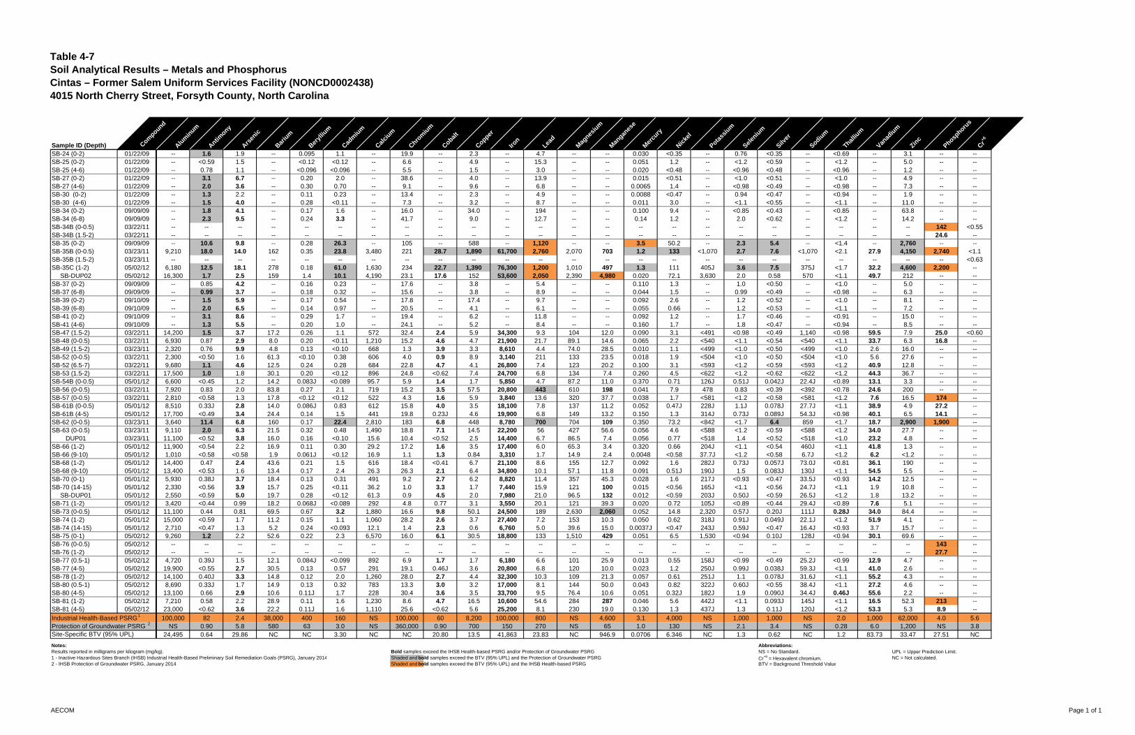
Table 4-7 Soil Analytical Results – Metals and Phosphorus Cintas – Former Salem Uniform Services Facility (NONCD0002438)4015 North Cherry Street, Forsyth County, North Carolina
Sample ID (Depth) Compound
Alum
inum
Antimony
Arsen
ic
Bariu
m
Beryl
lium
Cadm
ium
Calci
um
Chrom
ium
Cobalt
Copper
Iron
Lead
Mag
nesiu
m
Man
ganes
e
Mer
cury
Nicke
l
Potass
ium
Selen
ium
Silver
Sodium
Thalliu
m
Vanad
ium
Zinc
Phosphoru
s
Cr+6
SB-24 (0-2) 01/22/09 -- 1.6 1.9 -- 0.095 1.1 -- 19.9 -- 2.3 -- 4.7 -- -- 0.030 <0.35 -- 0.76 <0.35 -- <0.69 -- 3.1 -- --SB-25 (0-2) 01/22/09 -- <0.59 1.5 -- <0.12 <0.12 -- 6.6 -- 4.9 -- 15.3 -- -- 0.051 1.2 -- <1.2 <0.59 -- <1.2 -- 5.0 -- --SB-25 (4-6) 01/22/09 -- 0.78 1.1 -- <0.096 <0.096 -- 5.5 -- 1.5 -- 3.0 -- -- 0.020 <0.48 -- <0.96 <0.48 -- <0.96 -- 1.2 -- --SB-27 (0-2) 01/22/09 -- 3.1 6.7 -- 0.20 2.0 -- 38.6 -- 4.0 -- 13.9 -- -- 0.015 <0.51 -- <1.0 <0.51 -- <1.0 -- 4.9 -- --SB-27 (4-6) 01/22/09 -- 2.0 3.6 -- 0.30 0.70 -- 9.1 -- 9.6 -- 6.8 -- -- 0.0065 1.4 -- <0.98 <0.49 -- <0.98 -- 7.3 -- --SB-30 (0-2) 01/22/09 -- 1.3 2.2 -- 0.11 0.23 -- 13.4 -- 2.3 -- 4.9 -- -- 0.0088 <0.47 -- 0.94 <0.47 -- <0.94 -- 1.9 -- --SB-30 (4-6) 01/22/09 -- 1.5 4.0 -- 0.28 <0.11 -- 7.3 -- 3.2 -- 8.7 -- -- 0.011 3.0 -- <1.1 <0.55 -- <1.1 -- 11.0 -- --SB-34 (0-2) 09/09/09 -- 1.8 4.1 -- 0.17 1.6 -- 16.0 -- 34.0 -- 194 -- -- 0.100 9.4 -- <0.85 <0.43 -- <0.85 -- 63.8 -- --SB-34 (6-8) 09/09/09 -- 2.3 9.5 -- 0.24 3.3 -- 41.7 -- 9.0 -- 12.7 -- -- 0.14 1.2 -- 2.0 <0.62 -- <1.2 -- 14.2 -- --SB-34B (0-0.5) 03/22/11 -- -- -- -- -- -- -- -- -- -- -- -- -- -- -- -- -- -- -- -- -- -- -- 142 <0.55SB-34B (1.5-2) 03/22/11 -- -- -- -- -- -- -- -- -- -- -- -- -- -- -- -- -- -- -- -- -- -- -- 24.6 --SB-35 (0-2) 09/09/09 -- 10.6 9.8 -- 0.28 26.3 -- 105 -- 588 -- 1,120 -- -- 3.5 50.2 -- 2.3 5.4 -- <1.4 -- 2,760 -- --SB-35B (0-0.5) 03/23/11 9,210 18.0 14.0 162 0.35 23.8 3,480 221 28.7 1,890 61,700 2,760 2,070 703 1.2 133 <1,070 2.7 7.6 <1,070 <2.1 27.9 4,150 2,740 <1.1SB-35B (1.5-2) 03/23/11 -- -- -- -- -- -- -- -- -- -- -- -- -- -- -- -- -- -- -- -- -- -- -- -- <0.63SB-35C (1-2) 05/02/12 6,180 12.5 18.1 278 0.18 61.0 1,630 234 22.7 1,390 76,300 1,200 1,010 497 1.3 111 405J 3.6 7.5 375J <1.7 32.2 4,600 2,200 --
SB-DUP02 05/02/12 16,300 1.7 2.5 159 1.4 10.1 4,190 23.1 17.6 152 53,600 2,050 2,390 4,980 0.020 72.1 3,630 2.0 0.58 570 <1.1 49.7 212 -- --SB-37 (0-2) 09/09/09 -- 0.85 4.2 -- 0.16 0.23 -- 17.6 -- 3.8 -- 5.4 -- -- 0.110 1.3 -- 1.0 <0.50 -- <1.0 -- 5.0 -- --SB-37 (6-8) 09/09/09 -- 0.99 3.7 -- 0.18 0.32 -- 15.6 -- 3.8 -- 8.9 -- -- 0.044 1.5 -- 0.99 <0.49 -- <0.98 -- 6.3 -- --SB-39 (0-2) 09/10/09 -- 1.5 5.9 -- 0.17 0.54 -- 17.8 -- 17.4 -- 9.7 -- -- 0.092 2.6 -- 1.2 <0.52 -- <1.0 -- 8.1 -- --SB-39 (6-8) 09/10/09 -- 2.0 6.5 -- 0.14 0.97 -- 20.5 -- 4.1 -- 6.1 -- -- 0.055 0.66 -- 1.2 <0.53 -- <1.1 -- 7.2 -- --SB-41 (0-2) 09/10/09 -- 3.1 8.6 -- 0.29 1.7 -- 19.4 -- 6.2 -- 11.8 -- -- 0.092 1.2 -- 1.7 <0.46 -- <0.91 -- 15.0 -- --SB-41 (4-6) 09/10/09 -- 1.3 5.5 -- 0.20 1.0 -- 24.1 -- 5.2 -- 8.4 -- -- 0.160 1.7 -- 1.8 <0.47 -- <0.94 -- 8.5 -- --SB-47 (1.5-2) 03/22/11 14,200 1.5 3.7 17.2 0.26 1.1 572 32.4 2.4 5.9 34,300 9.3 104 12.0 0.090 3.1 <491 <0.98 <0.49 1,140 <0.98 59.5 7.9 25.0 <0.60SB-48 (0-0.5) 03/22/11 6,930 0.87 2.9 8.0 0.20 <0.11 1,210 15.2 4.6 4.7 21,900 21.7 89.1 14.6 0.065 2.2 <540 <1.1 <0.54 <540 <1.1 33.7 6.3 16.8 --SB-49 (1.5-2) 03/23/11 2,320 0.76 9.9 4.8 0.13 <0.10 668 1.3 3.9 3.3 8,610 4.4 74.0 28.5 0.010 1.1 <499 <1.0 <0.50 <499 <1.0 2.6 16.0 -- --SB-52 (0-0.5) 03/22/11 2,300 <0.50 1.6 61.3 <0.10 0.38 606 4.0 0.9 8.9 3,140 211 133 23.5 0.018 1.9 <504 <1.0 <0.50 <504 <1.0 5.6 27.6 -- --SB-52 (6.5-7) 03/22/11 9,680 1.1 4.6 12.5 0.24 0.28 684 22.8 4.7 4.1 26,800 7.4 123 20.2 0.100 3.1 <593 <1.2 <0.59 <593 <1.2 40.9 12.8 -- --SB-53 (1.5-2) 03/22/11 17,500 1.0 1.8 30.1 0.20 <0.12 896 24.8 <0.62 7.4 24,700 6.8 134 7.4 0.260 4.5 <622 <1.2 <0.62 <622 <1.2 44.3 36.7 -- --SB-54B (0-0.5) 05/01/12 6,600 <0.45 1.2 14.2 0.083J <0.089 95.7 5.9 1.4 1.7 5,850 4.7 87.2 11.0 0.370 0.71 126J 0.51J 0.042J 22.4J <0.89 13.1 3.3 -- --SB-56 (0-0.5) 03/22/11 7,920 0.83 2.0 83.8 0.27 2.1 719 15.2 3.5 57.5 20,800 443 610 198 0.041 7.9 478 0.83 <0.39 <392 <0.78 24.6 200 -- --SB-57 (0-0.5) 03/22/11 2,810 <0.58 1.3 17.8 <0.12 <0.12 522 4.3 1.6 5.9 3,840 13.6 320 37.7 0.038 1.7 <581 <1.2 <0.58 <581 <1.2 7.6 16.5 174 --SB-61B (0-0.5) 05/01/12 8,510 0.33J 2.8 14.0 0.086J 0.83 612 15.8 4.0 3.5 18,100 7.8 137 11.2 0.052 0.47J 228J 1.1J 0.078J 27.7J <1.1 38.9 4.9 27.2 --SB-61B (4-5) 05/01/12 17,700 <0.49 3.4 24.4 0.14 1.5 441 19.8 0.23J 4.6 19,900 6.8 149 13.2 0.150 1.3 314J 0.73J 0.089J 54.3J <0.98 40.1 6.5 14.1 --SB-62 (0-0.5) 03/23/11 3,640 11.4 6.8 160 0.17 22.4 2,810 183 6.8 448 8,780 700 704 109 0.350 73.2 <842 <1.7 6.4 859 <1.7 18.7 2,900 1,900 --SB-63 (0-0.5) 03/23/11 9,110 2.0 6.3 21.5 0.32 0.48 1,490 18.8 7.1 14.5 22,200 56 427 56.6 0.056 4.6 <588 <1.2 <0.59 <588 <1.2 34.0 27.7 -- --
DUP01 03/23/11 11,100 <0.52 3.8 16.0 0.16 <0.10 15.6 10.4 <0.52 2.5 14,400 6.7 86.5 7.4 0.056 0.77 <518 1.4 <0.52 <518 <1.0 23.2 4.8 -- --SB-66 (1-2) 05/01/12 11,900 <0.54 2.2 16.9 0.11 0.30 29.2 17.2 1.6 3.5 17,400 6.0 65.3 3.4 0.320 0.66 204J <1.1 <0.54 460J <1.1 41.8 1.3 -- --SB-66 (9-10) 05/01/12 1,010 <0.58 <0.58 1.9 0.061J <0.12 16.9 1.1 1.3 0.84 3,310 1.7 14.9 2.4 0.0048 <0.58 37.7J <1.2 <0.58 6.7J <1.2 6.2 <1.2 -- --SB-68 (1-2) 05/01/12 14,400 0.47 2.4 43.6 0.21 1.5 616 18.4 <0.41 6.7 21,100 8.6 155 12.7 0.092 1.6 282J 0.73J 0.057J 73.0J <0.81 36.1 190 -- --SB-68 (9-10) 05/01/12 13,400 <0.53 1.6 13.4 0.17 2.4 26.3 26.3 2.1 6.4 34,800 10.1 57.1 11.8 0.091 0.51J 190J 1.5 0.083J 130J <1.1 54.5 5.5 -- --SB-70 (0-1) 05/01/12 5,930 0.38J 3.7 18.4 0.13 0.31 491 9.2 2.7 6.2 8,820 11.4 357 45.3 0.028 1.6 217J <0.93 <0.47 33.5J <0.93 14.2 12.5 -- --SB-70 (14-15) 05/01/12 2,330 <0.56 3.9 15.7 0.25 <0.11 36.2 1.0 3.3 1.7 7,440 15.9 121 100 0.015 <0.56 165J <1.1 <0.56 24.7J <1.1 1.9 10.8 -- --
SB-DUP01 05/01/12 2,550 <0.59 5.0 19.7 0.28 <0.12 61.3 0.9 4.5 2.0 7,980 21.0 96.5 132 0.012 <0.59 203J 0.50J <0.59 26.5J <1.2 1.8 13.2 -- --SB-71 (1-2) 05/01/12 3,420 <0.44 0.99 18.2 0.068J <0.089 292 4.8 0.77 3.1 3,550 20.1 121 39.3 0.020 0.72 105J <0.89 <0.44 29.4J <0.89 7.6 5.1 -- --SB-73 (0-0.5) 05/01/12 11,100 0.44 0.81 69.5 0.67 3.2 1,880 16.6 9.8 50.1 24,500 189 2,630 2,060 0.052 14.8 2,320 0.57J 0.20J 111J 0.28J 34.0 84.4 -- --SB-74 (1-2) 05/01/12 15,000 <0.59 1.7 11.2 0.15 1.1 1,060 28.2 2.6 3.7 27,400 7.2 153 10.3 0.050 0.62 318J 0.91J 0.049J 22.1J <1.2 51.9 4.1 -- --SB-74 (14-15) 05/01/12 2,710 <0.47 1.3 5.2 0.24 <0.093 12.1 1.4 2.3 0.6 6,760 5.0 39.6 15.0 0.0037J <0.47 243J 0.59J <0.47 16.4J <0.93 3.7 15.7 -- --SB-75 (0-1) 05/02/12 9,260 1.2 2.2 52.6 0.22 2.3 6,570 16.0 6.1 30.5 18,800 133 1,510 429 0.051 6.5 1,530 <0.94 0.10J 128J <0.94 30.1 69.6 -- --SB-76 (0-0.5) 05/02/12 -- -- -- -- -- -- -- -- -- -- -- -- -- -- -- -- -- -- -- -- -- -- -- 143 --SB-76 (1-2) 05/02/12 -- -- -- -- -- -- -- -- -- -- -- -- -- -- -- -- -- -- -- -- -- -- -- 27.7 --SB-77 (0.5-1) 05/02/12 4,720 0.39J 1.5 12.1 0.084J <0.099 892 6.9 1.7 1.7 6,180 6.6 101 25.9 0.013 0.55 158J <0.99 <0.49 25.2J <0.99 12.9 4.7 -- --SB-77 (4-5) 05/02/12 19,900 <0.55 2.7 30.5 0.13 0.57 291 19.1 0.46J 3.6 20,800 6.8 120 10.0 0.023 1.2 250J 0.99J 0.038J 59.3J <1.1 41.0 2.6 -- --SB-78 (1-2) 05/02/12 14,100 0.40J 3.3 14.8 0.12 2.0 1,260 28.0 2.7 4.4 32,300 10.3 109 21.3 0.057 0.61 251J 1.1 0.078J 31.6J <1.1 55.2 4.3 -- --SB-80 (0.5-1) 05/02/12 8,690 0.33J 1.7 14.9 0.13 0.32 783 13.3 3.0 3.2 17,000 8.1 144 50.0 0.043 0.82 322J 0.60J <0.55 38.4J <1.1 27.2 4.6 -- --SB-80 (4-5) 05/02/12 13,100 0.66 2.9 10.6 0.11J 1.7 228 30.4 3.6 3.5 33,700 9.5 76.4 10.6 0.051 0.32J 182J 1.9 0.090J 34.4J 0.46J 55.6 2.2 -- --SB-81 (1-2) 05/02/12 7,210 0.58 2.2 28.9 0.11 1.6 1,230 8.6 4.7 16.5 10,600 54.6 284 287 0.046 5.6 442J <1.1 0.093J 145J <1.1 16.5 52.3 213 --SB-81 (4-5) 05/02/12 23,000 <0.62 3.6 22.2 0.11J 1.6 1,110 25.6 <0.62 5.6 25,200 8.1 230 19.0 0.130 1.3 437J 1.3 0.11J 120J <1.2 53.3 5.3 8.9 --
100,000 82 2.4 38,000 400 160 NS 100,000 60 8,200 100,000 800 NS 4,600 3.1 4,000 NS 1,000 1,000 NS 2.0 1,000 62,000 4.0 5.6NS 0.90 5.8 580 63 3.0 NS 360,000 0.90 700 150 270 NS 65 1.0 130 NS 2.1 3.4 NS 0.28 6.0 1,200 NS 3.8
24,495 0.64 29.86 NC NC 3.30 NC NC 20.80 13.5 41,863 23.83 NC 946.9 0.0706 6.346 NC 1.3 0.62 NC 1.2 83.73 33.47 27.51 NC
Notes: Abbreviations:Results reported in milligrams per kilogram (mg/kg). Bold samples exceed the IHSB Health-based PSRG and/or Protection of Groundwater PSRG NS = No Standard. UPL = Upper Prediction Limit.1 - Inactive Hazardous Sites Branch (IHSB) Industrial Health-Based Preliminary Soil Remediation Goals (PSRG), January 2014 Shaded and bold samples exceed the BTV (95% UPL) and the Protection of Groundwater PSRG Cr+6 = Hexavalent chromium. NC = Not calculated.2 - IHSB Protection of Groundwater PSRG, January 2014 Shaded and bold samples exceed the BTV (95% UPL) and the IHSB Health-based PSRG BTV = Background Threshold Value
Industrial Health-Based PSRG1
Protection of Groundwater PSRG 2
Site-Specific BTV (95% UPL)
AECOM Page 1 of 1
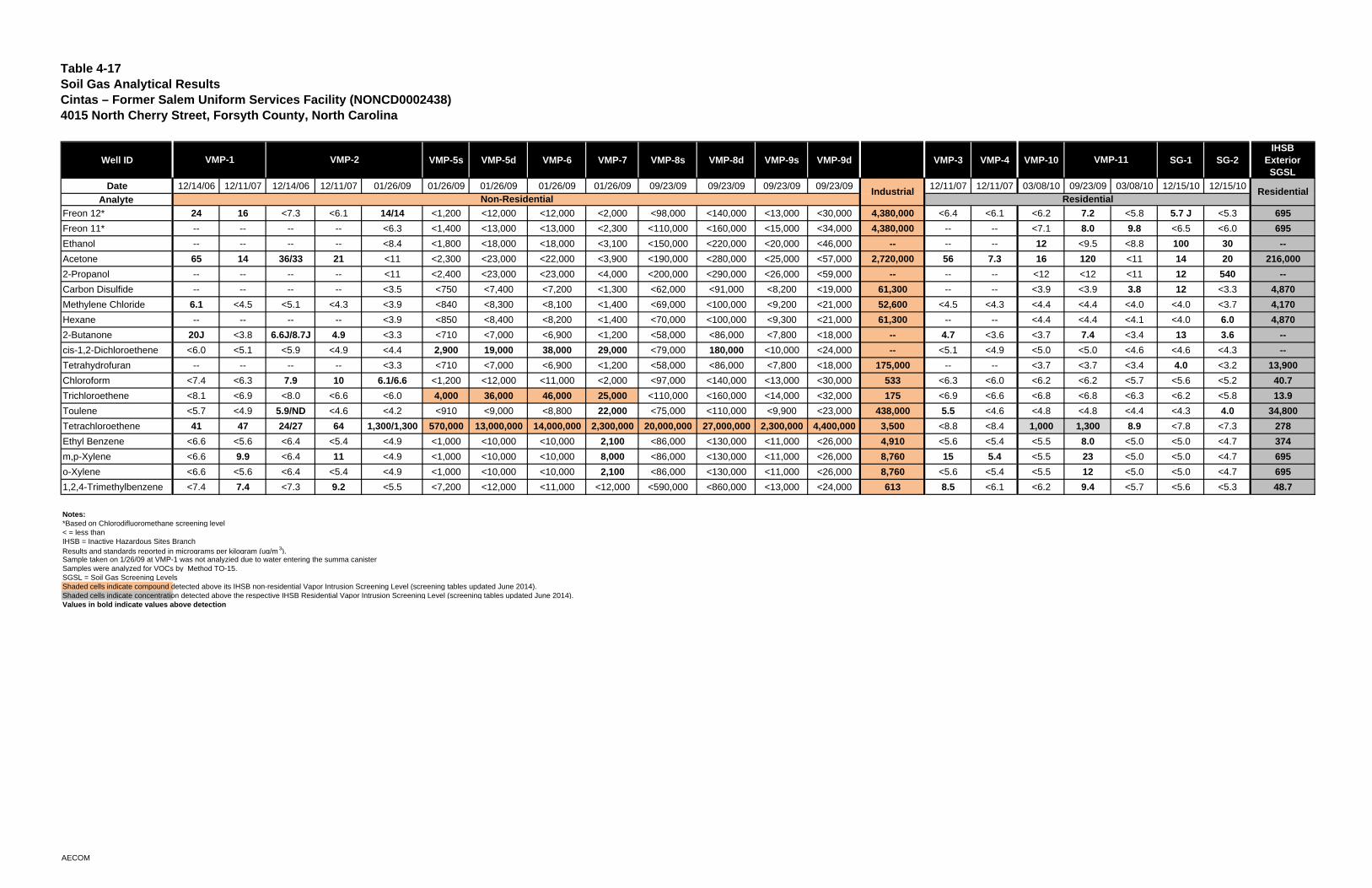
Table 4-17Soil Gas Analytical ResultsCintas – Former Salem Uniform Services Facility (NONCD0002438)4015 North Cherry Street, Forsyth County, North Carolina
Well ID VMP-5s VMP-5d VMP-6 VMP-7 VMP-8s VMP-8d VMP-9s VMP-9d VMP-3 VMP-4 VMP-10 SG-1 SG-2IHSB
Exterior SGSL
Date 12/14/06 12/11/07 12/14/06 12/11/07 01/26/09 01/26/09 01/26/09 01/26/09 01/26/09 09/23/09 09/23/09 09/23/09 09/23/09 12/11/07 12/11/07 03/08/10 09/23/09 03/08/10 12/15/10 12/15/10
Analyte
Freon 12* 24 16 <7.3 <6.1 14/14 <1,200 <12,000 <12,000 <2,000 <98,000 <140,000 <13,000 <30,000 4,380,000 <6.4 <6.1 <6.2 7.2 <5.8 5.7 J <5.3 695
Freon 11* -- -- -- -- <6.3 <1,400 <13,000 <13,000 <2,300 <110,000 <160,000 <15,000 <34,000 4,380,000 -- -- <7.1 8.0 9.8 <6.5 <6.0 695
Ethanol -- -- -- -- <8.4 <1,800 <18,000 <18,000 <3,100 <150,000 <220,000 <20,000 <46,000 -- -- -- 12 <9.5 <8.8 100 30 --
Acetone 65 14 36/33 21 <11 <2,300 <23,000 <22,000 <3,900 <190,000 <280,000 <25,000 <57,000 2,720,000 56 7.3 16 120 <11 14 20 216,000
2-Propanol -- -- -- -- <11 <2,400 <23,000 <23,000 <4,000 <200,000 <290,000 <26,000 <59,000 -- -- -- <12 <12 <11 12 540 --
Carbon Disulfide -- -- -- -- <3.5 <750 <7,400 <7,200 <1,300 <62,000 <91,000 <8,200 <19,000 61,300 -- -- <3.9 <3.9 3.8 12 <3.3 4,870
Methylene Chloride 6.1 <4.5 <5.1 <4.3 <3.9 <840 <8,300 <8,100 <1,400 <69,000 <100,000 <9,200 <21,000 52,600 <4.5 <4.3 <4.4 <4.4 <4.0 <4.0 <3.7 4,170
Hexane -- -- -- -- <3.9 <850 <8,400 <8,200 <1,400 <70,000 <100,000 <9,300 <21,000 61,300 -- -- <4.4 <4.4 <4.1 <4.0 6.0 4,870
2-Butanone 20J <3.8 6.6J/8.7J 4.9 <3.3 <710 <7,000 <6,900 <1,200 <58,000 <86,000 <7,800 <18,000 -- 4.7 <3.6 <3.7 7.4 <3.4 13 3.6 --
cis-1,2-Dichloroethene <6.0 <5.1 <5.9 <4.9 <4.4 2,900 19,000 38,000 29,000 <79,000 180,000 <10,000 <24,000 -- <5.1 <4.9 <5.0 <5.0 <4.6 <4.6 <4.3 --
Tetrahydrofuran -- -- -- -- <3.3 <710 <7,000 <6,900 <1,200 <58,000 <86,000 <7,800 <18,000 175,000 -- -- <3.7 <3.7 <3.4 4.0 <3.2 13,900
Chloroform <7.4 <6.3 7.9 10 6.1/6.6 <1,200 <12,000 <11,000 <2,000 <97,000 <140,000 <13,000 <30,000 533 <6.3 <6.0 <6.2 <6.2 <5.7 <5.6 <5.2 40.7
Trichloroethene <8.1 <6.9 <8.0 <6.6 <6.0 4,000 36,000 46,000 25,000 <110,000 <160,000 <14,000 <32,000 175 <6.9 <6.6 <6.8 <6.8 <6.3 <6.2 <5.8 13.9
Toulene <5.7 <4.9 5.9/ND <4.6 <4.2 <910 <9,000 <8,800 22,000 <75,000 <110,000 <9,900 <23,000 438,000 5.5 <4.6 <4.8 <4.8 <4.4 <4.3 4.0 34,800
Tetrachloroethene 41 47 24/27 64 1,300/1,300 570,000 13,000,000 14,000,000 2,300,000 20,000,000 27,000,000 2,300,000 4,400,000 3,500 <8.8 <8.4 1,000 1,300 8.9 <7.8 <7.3 278
Ethyl Benzene <6.6 <5.6 <6.4 <5.4 <4.9 <1,000 <10,000 <10,000 2,100 <86,000 <130,000 <11,000 <26,000 4,910 <5.6 <5.4 <5.5 8.0 <5.0 <5.0 <4.7 374
m,p-Xylene <6.6 9.9 <6.4 11 <4.9 <1,000 <10,000 <10,000 8,000 <86,000 <130,000 <11,000 <26,000 8,760 15 5.4 <5.5 23 <5.0 <5.0 <4.7 695
o-Xylene <6.6 <5.6 <6.4 <5.4 <4.9 <1,000 <10,000 <10,000 2,100 <86,000 <130,000 <11,000 <26,000 8,760 <5.6 <5.4 <5.5 12 <5.0 <5.0 <4.7 695
1,2,4-Trimethylbenzene <7.4 7.4 <7.3 9.2 <5.5 <7,200 <12,000 <11,000 <12,000 <590,000 <860,000 <13,000 <24,000 613 8.5 <6.1 <6.2 9.4 <5.7 <5.6 <5.3 48.7
Notes:*Based on Chlorodifluoromethane screening level< = less thanIHSB = Inactive Hazardous Sites BranchResults and standards reported in micrograms per kilogram (ug/m 3).Sample taken on 1/26/09 at VMP-1 was not analyzied due to water entering the summa canisterSamples were analyzed for VOCs by Method TO-15. SGSL = Soil Gas Screening LevelsShaded cells indicate compound detected above its IHSB non-residential Vapor Intrusion Screening Level (screening tables updated June 2014). Shaded cells indicate concentration detected above the respective IHSB Residential Vapor Intrusion Screening Level (screening tables updated June 2014). Values in bold indicate values above detection
VMP-1 VMP-2 VMP-11
ResidentialIndustrialResidentialNon-Residential
AECOM
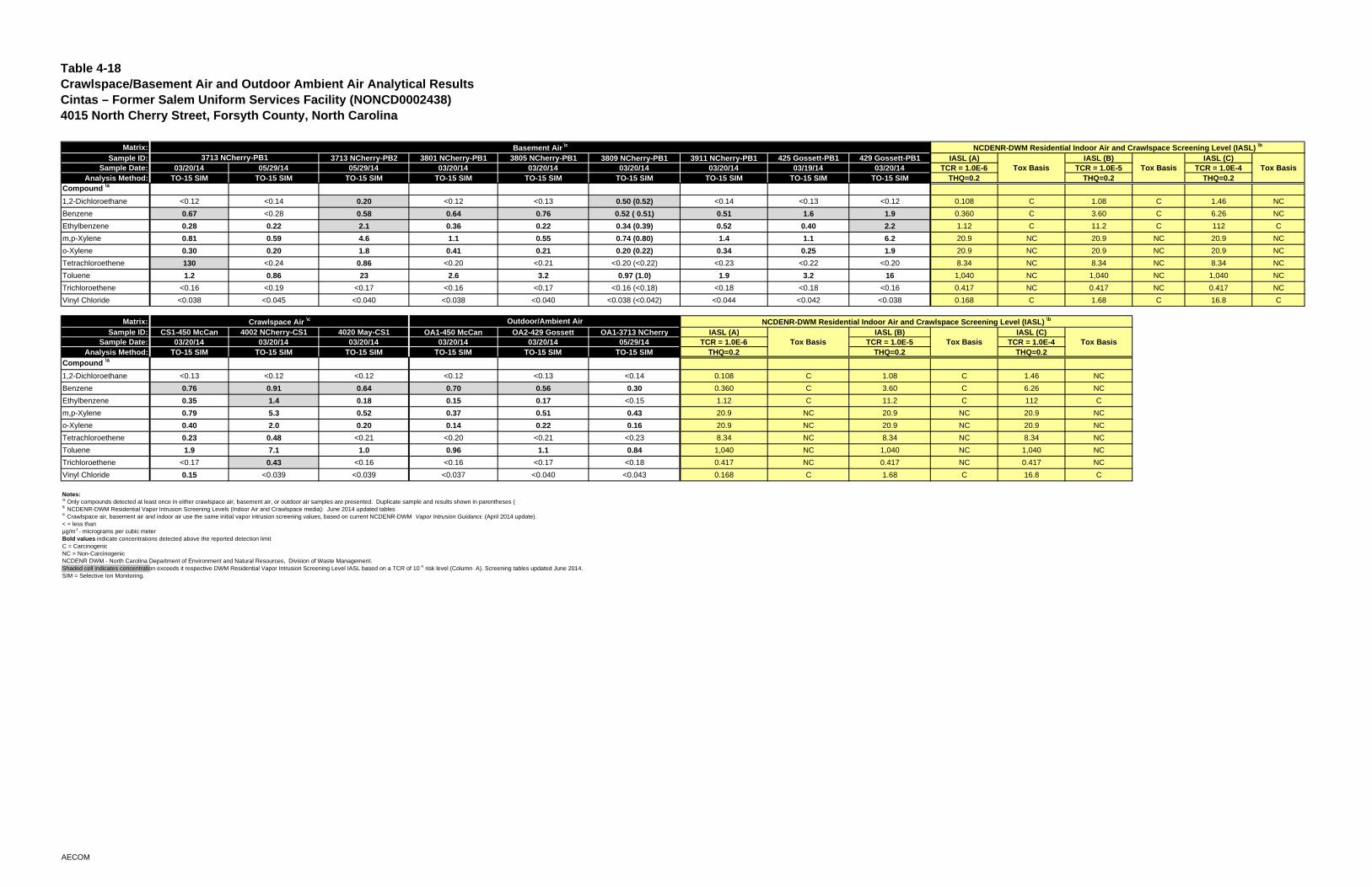
Table 4-18Crawlspace/Basement Air and Outdoor Ambient Air Analytical ResultsCintas – Former Salem Uniform Services Facility (NONCD0002438)4015 North Cherry Street, Forsyth County, North Carolina
Matrix:Sample ID: 3713 NCherry-PB2 3801 NCherry-PB1 3805 NCherry-PB1 3809 NCherry-PB1 3911 NCherry-PB1 425 Gossett-PB1 429 Gossett-PB1 IASL (A) IASL (B) IASL (C)
Sample Date: 03/20/14 05/29/14 05/29/14 03/20/14 03/20/14 03/20/14 03/20/14 03/19/14 03/20/14 TCR = 1.0E-6 TCR = 1.0E-5 TCR = 1.0E-4Analysis Method: TO-15 SIM TO-15 SIM TO-15 SIM TO-15 SIM TO-15 SIM TO-15 SIM TO-15 SIM TO-15 SIM TO-15 SIM THQ=0.2 THQ=0.2 THQ=0.2
Compound \a
1,2-Dichloroethane <0.12 <0.14 0.20 <0.12 <0.13 0.50 (0.52) <0.14 <0.13 <0.12 0.108 C 1.08 C 1.46 NC
Benzene 0.67 <0.28 0.58 0.64 0.76 0.52 ( 0.51) 0.51 1.6 1.9 0.360 C 3.60 C 6.26 NC
Ethylbenzene 0.28 0.22 2.1 0.36 0.22 0.34 (0.39) 0.52 0.40 2.2 1.12 C 11.2 C 112 C
m,p-Xylene 0.81 0.59 4.6 1.1 0.55 0.74 (0.80) 1.4 1.1 6.2 20.9 NC 20.9 NC 20.9 NC
o-Xylene 0.30 0.20 1.8 0.41 0.21 0.20 (0.22) 0.34 0.25 1.9 20.9 NC 20.9 NC 20.9 NC
Tetrachloroethene 130 <0.24 0.86 <0.20 <0.21 <0.20 (<0.22) <0.23 <0.22 <0.20 8.34 NC 8.34 NC 8.34 NC
Toluene 1.2 0.86 23 2.6 3.2 0.97 (1.0) 1.9 3.2 16 1,040 NC 1,040 NC 1,040 NC
Trichloroethene <0.16 <0.19 <0.17 <0.16 <0.17 <0.16 (<0.18) <0.18 <0.18 <0.16 0.417 NC 0.417 NC 0.417 NC
Vinyl Chloride <0.038 <0.045 <0.040 <0.038 <0.040 <0.038 (<0.042) <0.044 <0.042 <0.038 0.168 C 1.68 C 16.8 C
Matrix:Sample ID: CS1-450 McCan 4002 NCherry-CS1 4020 May-CS1 OA1-450 McCan OA2-429 Gossett OA1-3713 NCherry IASL (A) IASL (B) IASL (C)
Sample Date: 03/20/14 03/20/14 03/20/14 03/20/14 03/20/14 05/29/14 TCR = 1.0E-6 TCR = 1.0E-5 TCR = 1.0E-4Analysis Method: TO-15 SIM TO-15 SIM TO-15 SIM TO-15 SIM TO-15 SIM TO-15 SIM THQ=0.2 THQ=0.2 THQ=0.2
Compound \a
1,2-Dichloroethane <0.13 <0.12 <0.12 <0.12 <0.13 <0.14 0.108 C 1.08 C 1.46 NC
Benzene 0.76 0.91 0.64 0.70 0.56 0.30 0.360 C 3.60 C 6.26 NC
Ethylbenzene 0.35 1.4 0.18 0.15 0.17 <0.15 1.12 C 11.2 C 112 C
m,p-Xylene 0.79 5.3 0.52 0.37 0.51 0.43 20.9 NC 20.9 NC 20.9 NC
o-Xylene 0.40 2.0 0.20 0.14 0.22 0.16 20.9 NC 20.9 NC 20.9 NC
Tetrachloroethene 0.23 0.48 <0.21 <0.20 <0.21 <0.23 8.34 NC 8.34 NC 8.34 NC
Toluene 1.9 7.1 1.0 0.96 1.1 0.84 1,040 NC 1,040 NC 1,040 NC
Trichloroethene <0.17 0.43 <0.16 <0.16 <0.17 <0.18 0.417 NC 0.417 NC 0.417 NC
Vinyl Chloride 0.15 <0.039 <0.039 <0.037 <0.040 <0.043 0.168 C 1.68 C 16.8 C
Notes:\a Only compounds detected at least once in either crawlspace air, basement air, or outdoor air samples are presented. Duplicate sample and results shown in parentheses ( )\b NCDENR-DWM Residential Vapor Intrusion Screening Levels (Indoor Air and Crawlspace media): June 2014 updated tables\c Crawlspace air, basement air and indoor air use the same initial vapor intrusion screening values, based on current NCDENR-DWM Vapor Intrusion Guidance (April 2014 update).< = less thanµg/m3 - micrograms per cubic meterBold values indicate concentrations detected above the reported detection limitC = CarcinogenicNC = Non-CarcinogenicNCDENR DWM - North Carolina Department of Environment and Natural Resources, Division of Waste Management.Shaded cell indicates concentration exceeds it respective DWM Residential Vapor Intrusion Screening Level IASL based on a TCR of 10 -6 risk level (Column A). Screening tables updated June 2014. SIM = Selective Ion Monitoring.
Basement Air \c NCDENR-DWM Residential Indoor Air and Crawlspace Screening Level (IASL) \b
3713 NCherry-PB1Tox Basis Tox Basis Tox Basis
Crawlspace Air \c Outdoor/Ambient Air NCDENR-DWM Residential Indoor Air and Crawlspace Screening Level (IASL) \b
Tox Basis Tox Basis Tox Basis
AECOM
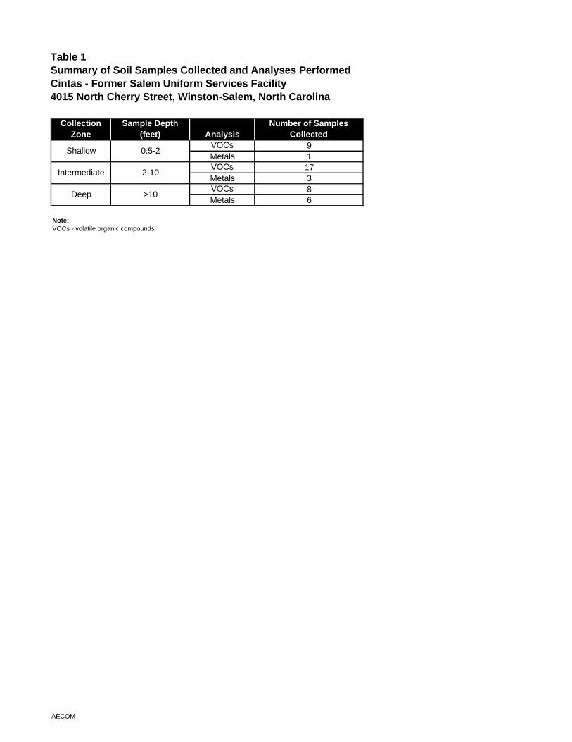
Table 1Summary of Soil Samples Collected and Analyses PerformedCintas - Former Salem Uniform Services Facility4015 North Cherry Street, Winston-Salem, North Carolina
Collection Zone
Sample Depth(feet) Analysis
Number of Samples Collected
VOCs 9Metals 1VOCs 17Metals 3VOCs 8Metals 6
Note:VOCs - volatile organic compounds
Shallow 0.5-2
Intermediate 2-10
Deep >10
AECOM
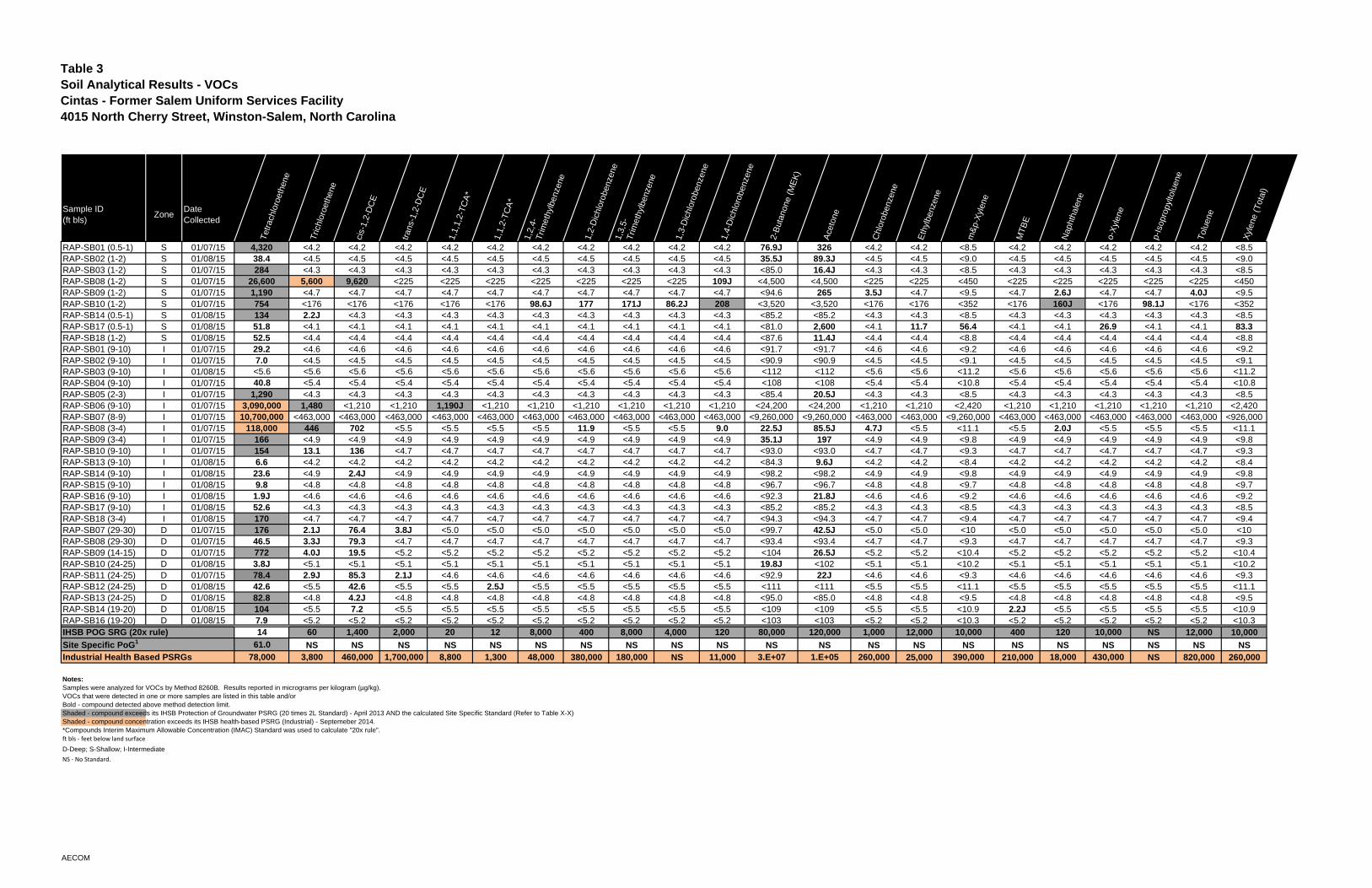
Table 3Soil Analytical Results - VOCsCintas - Former Salem Uniform Services Facility4015 North Cherry Street, Winston-Salem, North Carolina
Sample ID(ft bls)
ZoneDate Collected
Tet
rach
loro
ethe
ne
Tric
hlor
oeth
ene
cis-
1,2-
DC
E
tran
s-1,
2-D
CE
1,1,
1,2-
TC
A*
1,1,
2-T
CA
*
1,2,
4-T
rimet
hylb
enze
ne
1,2-
Dic
hlor
oben
zene
1,3,
5-T
rimet
hylb
enze
ne
1,3-
Dic
hlor
oben
zene
1,4-
Dic
hlor
oben
zene
2-B
utan
one
(ME
K)
Ace
tone
Chl
orob
enze
ne
Eth
ylbe
nzen
e
m&
p-X
ylen
e
MT
BE
Nap
htha
lene
o-X
ylen
e
p-Is
opro
pylto
luen
e
Tol
uene
Xyl
ene
(Tot
al)
RAP-SB01 (0.5-1) S 01/07/15 4,320 <4.2 <4.2 <4.2 <4.2 <4.2 <4.2 <4.2 <4.2 <4.2 <4.2 76.9J 326 <4.2 <4.2 <8.5 <4.2 <4.2 <4.2 <4.2 <4.2 <8.5RAP-SB02 (1-2) S 01/08/15 38.4 <4.5 <4.5 <4.5 <4.5 <4.5 <4.5 <4.5 <4.5 <4.5 <4.5 35.5J 89.3J <4.5 <4.5 <9.0 <4.5 <4.5 <4.5 <4.5 <4.5 <9.0RAP-SB03 (1-2) S 01/07/15 284 <4.3 <4.3 <4.3 <4.3 <4.3 <4.3 <4.3 <4.3 <4.3 <4.3 <85.0 16.4J <4.3 <4.3 <8.5 <4.3 <4.3 <4.3 <4.3 <4.3 <8.5RAP-SB08 (1-2) S 01/07/15 26,600 5,600 9,620 <225 <225 <225 <225 <225 <225 <225 109J <4,500 <4,500 <225 <225 <450 <225 <225 <225 <225 <225 <450RAP-SB09 (1-2) S 01/07/15 1,190 <4.7 <4.7 <4.7 <4.7 <4.7 <4.7 <4.7 <4.7 <4.7 <4.7 <94.6 265 3.5J <4.7 <9.5 <4.7 2.6J <4.7 <4.7 4.0J <9.5RAP-SB10 (1-2) S 01/07/15 754 <176 <176 <176 <176 <176 98.6J 177 171J 86.2J 208 <3,520 <3,520 <176 <176 <352 <176 160J <176 98.1J <176 <352RAP-SB14 (0.5-1) S 01/08/15 134 2.2J <4.3 <4.3 <4.3 <4.3 <4.3 <4.3 <4.3 <4.3 <4.3 <85.2 <85.2 <4.3 <4.3 <8.5 <4.3 <4.3 <4.3 <4.3 <4.3 <8.5RAP-SB17 (0.5-1) S 01/08/15 51.8 <4.1 <4.1 <4.1 <4.1 <4.1 <4.1 <4.1 <4.1 <4.1 <4.1 <81.0 2,600 <4.1 11.7 56.4 <4.1 <4.1 26.9 <4.1 <4.1 83.3RAP-SB18 (1-2) S 01/08/15 52.5 <4.4 <4.4 <4.4 <4.4 <4.4 <4.4 <4.4 <4.4 <4.4 <4.4 <87.6 11.4J <4.4 <4.4 <8.8 <4.4 <4.4 <4.4 <4.4 <4.4 <8.8RAP-SB01 (9-10) I 01/07/15 29.2 <4.6 <4.6 <4.6 <4.6 <4.6 <4.6 <4.6 <4.6 <4.6 <4.6 <91.7 <91.7 <4.6 <4.6 <9.2 <4.6 <4.6 <4.6 <4.6 <4.6 <9.2RAP-SB02 (9-10) I 01/07/15 7.0 <4.5 <4.5 <4.5 <4.5 <4.5 <4.5 <4.5 <4.5 <4.5 <4.5 <90.9 <90.9 <4.5 <4.5 <9.1 <4.5 <4.5 <4.5 <4.5 <4.5 <9.1RAP-SB03 (9-10) I 01/08/15 <5.6 <5.6 <5.6 <5.6 <5.6 <5.6 <5.6 <5.6 <5.6 <5.6 <5.6 <112 <112 <5.6 <5.6 <11.2 <5.6 <5.6 <5.6 <5.6 <5.6 <11.2RAP-SB04 (9-10) I 01/07/15 40.8 <5.4 <5.4 <5.4 <5.4 <5.4 <5.4 <5.4 <5.4 <5.4 <5.4 <108 <108 <5.4 <5.4 <10.8 <5.4 <5.4 <5.4 <5.4 <5.4 <10.8RAP-SB05 (2-3) I 01/07/15 1,290 <4.3 <4.3 <4.3 <4.3 <4.3 <4.3 <4.3 <4.3 <4.3 <4.3 <85.4 20.5J <4.3 <4.3 <8.5 <4.3 <4.3 <4.3 <4.3 <4.3 <8.5RAP-SB06 (9-10) I 01/07/15 3,090,000 1,480 <1,210 <1,210 1,190J <1,210 <1,210 <1,210 <1,210 <1,210 <1,210 <24,200 <24,200 <1,210 <1,210 <2,420 <1,210 <1,210 <1,210 <1,210 <1,210 <2,420RAP-SB07 (8-9) I 01/07/15 10,700,000 <463,000 <463,000 <463,000 <463,000 <463,000 <463,000 <463,000 <463,000 <463,000 <463,000 <9,260,000 <9,260,000 <463,000 <463,000 <9,260,000 <463,000 <463,000 <463,000 <463,000 <463,000 <926,000RAP-SB08 (3-4) I 01/07/15 118,000 446 702 <5.5 <5.5 <5.5 <5.5 11.9 <5.5 <5.5 9.0 22.5J 85.5J 4.7J <5.5 <11.1 <5.5 2.0J <5.5 <5.5 <5.5 <11.1RAP-SB09 (3-4) I 01/07/15 166 <4.9 <4.9 <4.9 <4.9 <4.9 <4.9 <4.9 <4.9 <4.9 <4.9 35.1J 197 <4.9 <4.9 <9.8 <4.9 <4.9 <4.9 <4.9 <4.9 <9.8RAP-SB10 (9-10) I 01/07/15 154 13.1 136 <4.7 <4.7 <4.7 <4.7 <4.7 <4.7 <4.7 <4.7 <93.0 <93.0 <4.7 <4.7 <9.3 <4.7 <4.7 <4.7 <4.7 <4.7 <9.3RAP-SB13 (9-10) I 01/08/15 6.6 <4.2 <4.2 <4.2 <4.2 <4.2 <4.2 <4.2 <4.2 <4.2 <4.2 <84.3 9.6J <4.2 <4.2 <8.4 <4.2 <4.2 <4.2 <4.2 <4.2 <8.4RAP-SB14 (9-10) I 01/08/15 23.6 <4.9 2.4J <4.9 <4.9 <4.9 <4.9 <4.9 <4.9 <4.9 <4.9 <98.2 <98.2 <4.9 <4.9 <9.8 <4.9 <4.9 <4.9 <4.9 <4.9 <9.8RAP-SB15 (9-10) I 01/08/15 9.8 <4.8 <4.8 <4.8 <4.8 <4.8 <4.8 <4.8 <4.8 <4.8 <4.8 <96.7 <96.7 <4.8 <4.8 <9.7 <4.8 <4.8 <4.8 <4.8 <4.8 <9.7RAP-SB16 (9-10) I 01/08/15 1.9J <4.6 <4.6 <4.6 <4.6 <4.6 <4.6 <4.6 <4.6 <4.6 <4.6 <92.3 21.8J <4.6 <4.6 <9.2 <4.6 <4.6 <4.6 <4.6 <4.6 <9.2RAP-SB17 (9-10) I 01/08/15 52.6 <4.3 <4.3 <4.3 <4.3 <4.3 <4.3 <4.3 <4.3 <4.3 <4.3 <85.2 <85.2 <4.3 <4.3 <8.5 <4.3 <4.3 <4.3 <4.3 <4.3 <8.5RAP-SB18 (3-4) I 01/08/15 170 <4.7 <4.7 <4.7 <4.7 <4.7 <4.7 <4.7 <4.7 <4.7 <4.7 <94.3 <94.3 <4.7 <4.7 <9.4 <4.7 <4.7 <4.7 <4.7 <4.7 <9.4RAP-SB07 (29-30) D 01/07/15 176 2.1J 76.4 3.8J <5.0 <5.0 <5.0 <5.0 <5.0 <5.0 <5.0 <99.7 42.5J <5.0 <5.0 <10 <5.0 <5.0 <5.0 <5.0 <5.0 <10RAP-SB08 (29-30) D 01/07/15 46.5 3.3J 79.3 <4.7 <4.7 <4.7 <4.7 <4.7 <4.7 <4.7 <4.7 <93.4 <93.4 <4.7 <4.7 <9.3 <4.7 <4.7 <4.7 <4.7 <4.7 <9.3RAP-SB09 (14-15) D 01/07/15 772 4.0J 19.5 <5.2 <5.2 <5.2 <5.2 <5.2 <5.2 <5.2 <5.2 <104 26.5J <5.2 <5.2 <10.4 <5.2 <5.2 <5.2 <5.2 <5.2 <10.4RAP-SB10 (24-25) D 01/08/15 3.8J <5.1 <5.1 <5.1 <5.1 <5.1 <5.1 <5.1 <5.1 <5.1 <5.1 19.8J <102 <5.1 <5.1 <10.2 <5.1 <5.1 <5.1 <5.1 <5.1 <10.2RAP-SB11 (24-25) D 01/07/15 78.4 2.9J 85.3 2.1J <4.6 <4.6 <4.6 <4.6 <4.6 <4.6 <4.6 <92.9 22J <4.6 <4.6 <9.3 <4.6 <4.6 <4.6 <4.6 <4.6 <9.3RAP-SB12 (24-25) D 01/08/15 42.6 <5.5 42.6 <5.5 <5.5 2.5J <5.5 <5.5 <5.5 <5.5 <5.5 <111 <111 <5.5 <5.5 <11.1 <5.5 <5.5 <5.5 <5.5 <5.5 <11.1RAP-SB13 (24-25) D 01/08/15 82.8 <4.8 4.2J <4.8 <4.8 <4.8 <4.8 <4.8 <4.8 <4.8 <4.8 <95.0 <85.0 <4.8 <4.8 <9.5 <4.8 <4.8 <4.8 <4.8 <4.8 <9.5RAP-SB14 (19-20) D 01/08/15 104 <5.5 7.2 <5.5 <5.5 <5.5 <5.5 <5.5 <5.5 <5.5 <5.5 <109 <109 <5.5 <5.5 <10.9 2.2J <5.5 <5.5 <5.5 <5.5 <10.9RAP-SB16 (19-20) D 01/08/15 7.9 <5.2 <5.2 <5.2 <5.2 <5.2 <5.2 <5.2 <5.2 <5.2 <5.2 <103 <103 <5.2 <5.2 <10.3 <5.2 <5.2 <5.2 <5.2 <5.2 <10.3IHSB POG SRG (20x rule) 14 60 1,400 2,000 20 12 8,000 400 8,000 4,000 120 80,000 120,000 1,000 12,000 10,000 400 120 10,000 NS 12,000 10,000
Site Specific PoG1 61.0 NS NS NS NS NS NS NS NS NS NS NS NS NS NS NS NS NS NS NS NS NSIndustrial Health Based PSRGs 78,000 3,800 460,000 1,700,000 8,800 1,300 48,000 380,000 180,000 NS 11,000 3.E+07 1.E+05 260,000 25,000 390,000 210,000 18,000 430,000 NS 820,000 260,000
Notes:Samples were analyzed for VOCs by Method 8260B. Results reported in micrograms per kilogram (µg/kg).VOCs that were detected in one or more samples are listed in this table and/orBold - compound detected above method detection limit.Shaded - compound exceeds its IHSB Protection of Groundwater PSRG (20 times 2L Standard) - April 2013 AND the calculated Site Specific Standard (Refer to Table X-X)Shaded - compound concentration exceeds its IHSB health-based PSRG (Industrial) - Septemeber 2014.*Compounds Interim Maximum Allowable Concentration (IMAC) Standard was used to calculate "20x rule".ft bls ‐ feet below land surface.
D-Deep; S-Shallow; I-Intermediate
NS ‐ No Standard.
AECOM
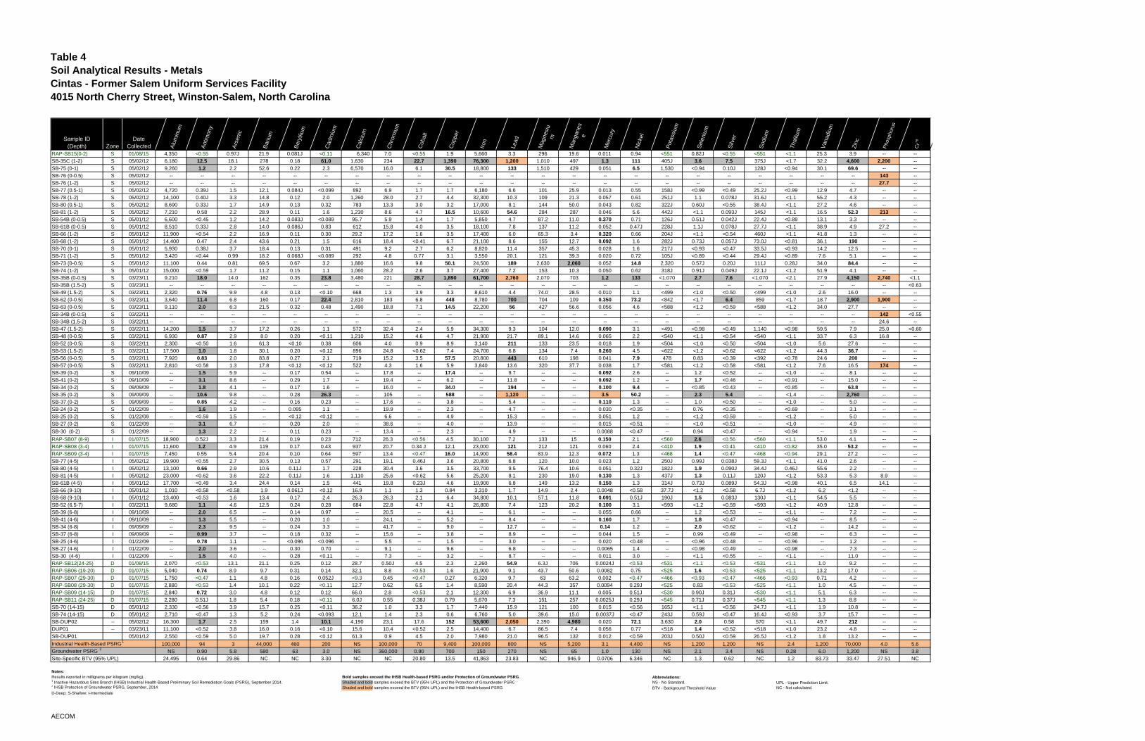
Table 4Soil Analytical Results - Metals Cintas - Former Salem Uniform Services Facility4015 North Cherry Street, Winston-Salem, North Carolina
Sample ID(Depth) Zone
Date Collected A
lum
inum
Ant
imon
y
Ars
enic
Bar
ium
Ber
ylliu
m
Cad
miu
m
Cal
cium
Chr
omiu
m
Cob
alt
Cop
per
Iron
Lead
Mag
nesi
um
Man
gane
se
Mer
cury
Nic
kel
Pot
assi
um
Sel
eniu
m
Silv
er
Sod
ium
Tha
llium
Van
adiu
m
Zin
c
Pho
spho
rus
Cr+6
RAP-SB15(0-2) S 01/08/15 4,350 <0.55 0.97J 21.9 0.081J <0.11 6,340 7.0 <0.55 1.9 5,660 3.3 296 19.6 0.011 0.94 <551 0.82J <0.55 <551 <1.1 25.3 3.9 -- --SB-35C (1-2) S 05/02/12 6,180 12.5 18.1 278 0.18 61.0 1,630 234 22.7 1,390 76,300 1,200 1,010 497 1.3 111 405J 3.6 7.5 375J <1.7 32.2 4,600 2,200 --
SB-75 (0-1) S 05/02/12 9,260 1.2 2.2 52.6 0.22 2.3 6,570 16.0 6.1 30.5 18,800 133 1,510 429 0.051 6.5 1,530 <0.94 0.10J 128J <0.94 30.1 69.6 -- --
SB-76 (0-0.5) S 05/02/12 -- -- -- -- -- -- -- -- -- -- -- -- -- -- -- -- -- -- -- -- -- -- -- 143 --
SB-76 (1-2) S 05/02/12 -- -- -- -- -- -- -- -- -- -- -- -- -- -- -- -- -- -- -- -- -- -- -- 27.7 --
SB-77 (0.5-1) S 05/02/12 4,720 0.39J 1.5 12.1 0.084J <0.099 892 6.9 1.7 1.7 6,180 6.6 101 25.9 0.013 0.55 158J <0.99 <0.49 25.2J <0.99 12.9 4.7 -- --
SB-78 (1-2) S 05/02/12 14,100 0.40J 3.3 14.8 0.12 2.0 1,260 28.0 2.7 4.4 32,300 10.3 109 21.3 0.057 0.61 251J 1.1 0.078J 31.6J <1.1 55.2 4.3 -- --
SB-80 (0.5-1) S 05/02/12 8,690 0.33J 1.7 14.9 0.13 0.32 783 13.3 3.0 3.2 17,000 8.1 144 50.0 0.043 0.82 322J 0.60J <0.55 38.4J <1.1 27.2 4.6 -- --
SB-81 (1-2) S 05/02/12 7,210 0.58 2.2 28.9 0.11 1.6 1,230 8.6 4.7 16.5 10,600 54.6 284 287 0.046 5.6 442J <1.1 0.093J 145J <1.1 16.5 52.3 213 --
SB-54B (0-0.5) S 05/01/12 6,600 <0.45 1.2 14.2 0.083J <0.089 95.7 5.9 1.4 1.7 5,850 4.7 87.2 11.0 0.370 0.71 126J 0.51J 0.042J 22.4J <0.89 13.1 3.3 -- --
SB-61B (0-0.5) S 05/01/12 8,510 0.33J 2.8 14.0 0.086J 0.83 612 15.8 4.0 3.5 18,100 7.8 137 11.2 0.052 0.47J 228J 1.1J 0.078J 27.7J <1.1 38.9 4.9 27.2 --
SB-66 (1-2) S 05/01/12 11,900 <0.54 2.2 16.9 0.11 0.30 29.2 17.2 1.6 3.5 17,400 6.0 65.3 3.4 0.320 0.66 204J <1.1 <0.54 460J <1.1 41.8 1.3 -- --
SB-68 (1-2) S 05/01/12 14,400 0.47 2.4 43.6 0.21 1.5 616 18.4 <0.41 6.7 21,100 8.6 155 12.7 0.092 1.6 282J 0.73J 0.057J 73.0J <0.81 36.1 190 -- --
SB-70 (0-1) S 05/01/12 5,930 0.38J 3.7 18.4 0.13 0.31 491 9.2 2.7 6.2 8,820 11.4 357 45.3 0.028 1.6 217J <0.93 <0.47 33.5J <0.93 14.2 12.5 -- --
SB-71 (1-2) S 05/01/12 3,420 <0.44 0.99 18.2 0.068J <0.089 292 4.8 0.77 3.1 3,550 20.1 121 39.3 0.020 0.72 105J <0.89 <0.44 29.4J <0.89 7.6 5.1 -- --
SB-73 (0-0.5) S 05/01/12 11,100 0.44 0.81 69.5 0.67 3.2 1,880 16.6 9.8 50.1 24,500 189 2,630 2,060 0.052 14.8 2,320 0.57J 0.20J 111J 0.28J 34.0 84.4 -- --
SB-74 (1-2) S 05/01/12 15,000 <0.59 1.7 11.2 0.15 1.1 1,060 28.2 2.6 3.7 27,400 7.2 153 10.3 0.050 0.62 318J 0.91J 0.049J 22.1J <1.2 51.9 4.1 -- --
SB-35B (0-0.5) S 03/23/11 9,210 18.0 14.0 162 0.35 23.8 3,480 221 28.7 1,890 61,700 2,760 2,070 703 1.2 133 <1,070 2.7 7.6 <1,070 <2.1 27.9 4,150 2,740 <1.1
SB-35B (1.5-2) S 03/23/11 -- -- -- -- -- -- -- -- -- -- -- -- -- -- -- -- -- -- -- -- -- -- -- -- <0.63
SB-49 (1.5-2) S 03/23/11 2,320 0.76 9.9 4.8 0.13 <0.10 668 1.3 3.9 3.3 8,610 4.4 74.0 28.5 0.010 1.1 <499 <1.0 <0.50 <499 <1.0 2.6 16.0 -- --
SB-62 (0-0.5) S 03/23/11 3,640 11.4 6.8 160 0.17 22.4 2,810 183 6.8 448 8,780 700 704 109 0.350 73.2 <842 <1.7 6.4 859 <1.7 18.7 2,900 1,900 --
SB-63 (0-0.5) S 03/23/11 9,110 2.0 6.3 21.5 0.32 0.48 1,490 18.8 7.1 14.5 22,200 56 427 56.6 0.056 4.6 <588 <1.2 <0.59 <588 <1.2 34.0 27.7 -- --
SB-34B (0-0.5) S 03/22/11 -- -- -- -- -- -- -- -- -- -- -- -- -- -- -- -- -- -- -- -- -- -- -- 142 <0.55
SB-34B (1.5-2) S 03/22/11 -- -- -- -- -- -- -- -- -- -- -- -- -- -- -- -- -- -- -- -- -- -- -- 24.6 --
SB-47 (1.5-2) S 03/22/11 14,200 1.5 3.7 17.2 0.26 1.1 572 32.4 2.4 5.9 34,300 9.3 104 12.0 0.090 3.1 <491 <0.98 <0.49 1,140 <0.98 59.5 7.9 25.0 <0.60
SB-48 (0-0.5) S 03/22/11 6,930 0.87 2.9 8.0 0.20 <0.11 1,210 15.2 4.6 4.7 21,900 21.7 89.1 14.6 0.065 2.2 <540 <1.1 <0.54 <540 <1.1 33.7 6.3 16.8 --
SB-52 (0-0.5) S 03/22/11 2,300 <0.50 1.6 61.3 <0.10 0.38 606 4.0 0.9 8.9 3,140 211 133 23.5 0.018 1.9 <504 <1.0 <0.50 <504 <1.0 5.6 27.6 -- --
SB-53 (1.5-2) S 03/22/11 17,500 1.0 1.8 30.1 0.20 <0.12 896 24.8 <0.62 7.4 24,700 6.8 134 7.4 0.260 4.5 <622 <1.2 <0.62 <622 <1.2 44.3 36.7 -- --
SB-56 (0-0.5) S 03/22/11 7,920 0.83 2.0 83.8 0.27 2.1 719 15.2 3.5 57.5 20,800 443 610 198 0.041 7.9 478 0.83 <0.39 <392 <0.78 24.6 200 -- --
SB-57 (0-0.5) S 03/22/11 2,810 <0.58 1.3 17.8 <0.12 <0.12 522 4.3 1.6 5.9 3,840 13.6 320 37.7 0.038 1.7 <581 <1.2 <0.58 <581 <1.2 7.6 16.5 174 --
SB-39 (0-2) S 09/10/09 -- 1.5 5.9 -- 0.17 0.54 -- 17.8 -- 17.4 -- 9.7 -- -- 0.092 2.6 -- 1.2 <0.52 -- <1.0 -- 8.1 -- --
SB-41 (0-2) S 09/10/09 -- 3.1 8.6 -- 0.29 1.7 -- 19.4 -- 6.2 -- 11.8 -- -- 0.092 1.2 -- 1.7 <0.46 -- <0.91 -- 15.0 -- --
SB-34 (0-2) S 09/09/09 -- 1.8 4.1 -- 0.17 1.6 -- 16.0 -- 34.0 -- 194 -- -- 0.100 9.4 -- <0.85 <0.43 -- <0.85 -- 63.8 -- --
SB-35 (0-2) S 09/09/09 -- 10.6 9.8 -- 0.28 26.3 -- 105 -- 588 -- 1,120 -- -- 3.5 50.2 -- 2.3 5.4 -- <1.4 -- 2,760 -- --
SB-37 (0-2) S 09/09/09 -- 0.85 4.2 -- 0.16 0.23 -- 17.6 -- 3.8 -- 5.4 -- -- 0.110 1.3 -- 1.0 <0.50 -- <1.0 -- 5.0 -- --
SB-24 (0-2) S 01/22/09 -- 1.6 1.9 -- 0.095 1.1 -- 19.9 -- 2.3 -- 4.7 -- -- 0.030 <0.35 -- 0.76 <0.35 -- <0.69 -- 3.1 -- --
SB-25 (0-2) S 01/22/09 -- <0.59 1.5 -- <0.12 <0.12 -- 6.6 -- 4.9 -- 15.3 -- -- 0.051 1.2 -- <1.2 <0.59 -- <1.2 -- 5.0 -- --
SB-27 (0-2) S 01/22/09 -- 3.1 6.7 -- 0.20 2.0 -- 38.6 -- 4.0 -- 13.9 -- -- 0.015 <0.51 -- <1.0 <0.51 -- <1.0 -- 4.9 -- --
SB-30 (0-2) S 01/22/09 -- 1.3 2.2 -- 0.11 0.23 -- 13.4 -- 2.3 -- 4.9 -- -- 0.0088 <0.47 -- 0.94 <0.47 -- <0.94 -- 1.9 -- --
RAP-SB07 (8-9) I 01/07/15 18,900 0.52J 3.3 21.4 0.19 0.23 712 26.3 <0.56 4.5 30,100 7.2 133 15 0.150 2.1 <560 2.6 <0.56 <560 <1.1 53.0 4.1 -- --RAP-SB08 (3-4) I 01/07/15 11,600 1.2 4.9 119 0.17 0.43 937 20.7 0.34 J 12.1 23,000 121 212 121 0.060 2.4 <410 1.9 <0.41 <410 <0.82 35.0 53.2 -- --RAP-SB09 (3-4) I 01/07/15 7,450 0.55 5.4 20.4 0.10 0.64 597 13.4 <0.47 16.0 14,900 58.4 83.9 12.3 0.072 1.3 <468 1.4 <0.47 <468 <0.94 29.1 27.2 -- --SB-77 (4-5) I 05/02/12 19,900 <0.55 2.7 30.5 0.13 0.57 291 19.1 0.46J 3.6 20,800 6.8 120 10.0 0.023 1.2 250J 0.99J 0.038J 59.3J <1.1 41.0 2.6 -- --
SB-80 (4-5) I 05/02/12 13,100 0.66 2.9 10.6 0.11J 1.7 228 30.4 3.6 3.5 33,700 9.5 76.4 10.6 0.051 0.32J 182J 1.9 0.090J 34.4J 0.46J 55.6 2.2 -- --
SB-81 (4-5) I 05/02/12 23,000 <0.62 3.6 22.2 0.11J 1.6 1,110 25.6 <0.62 5.6 25,200 8.1 230 19.0 0.130 1.3 437J 1.3 0.11J 120J <1.2 53.3 5.3 8.9 --
SB-61B (4-5) I 05/01/12 17,700 <0.49 3.4 24.4 0.14 1.5 441 19.8 0.23J 4.6 19,900 6.8 149 13.2 0.150 1.3 314J 0.73J 0.089J 54.3J <0.98 40.1 6.5 14.1 --
SB-66 (9-10) I 05/01/12 1,010 <0.58 <0.58 1.9 0.061J <0.12 16.9 1.1 1.3 0.84 3,310 1.7 14.9 2.4 0.0048 <0.58 37.7J <1.2 <0.58 6.7J <1.2 6.2 <1.2 -- --
SB-68 (9-10) I 05/01/12 13,400 <0.53 1.6 13.4 0.17 2.4 26.3 26.3 2.1 6.4 34,800 10.1 57.1 11.8 0.091 0.51J 190J 1.5 0.083J 130J <1.1 54.5 5.5 -- --
SB-52 (6.5-7) I 03/22/11 9,680 1.1 4.6 12.5 0.24 0.28 684 22.8 4.7 4.1 26,800 7.4 123 20.2 0.100 3.1 <593 <1.2 <0.59 <593 <1.2 40.9 12.8 -- --
SB-39 (6-8) I 09/10/09 -- 2.0 6.5 -- 0.14 0.97 -- 20.5 -- 4.1 -- 6.1 -- -- 0.055 0.66 -- 1.2 <0.53 -- <1.1 -- 7.2 -- --
SB-41 (4-6) I 09/10/09 -- 1.3 5.5 -- 0.20 1.0 -- 24.1 -- 5.2 -- 8.4 -- -- 0.160 1.7 -- 1.8 <0.47 -- <0.94 -- 8.5 -- --
SB-34 (6-8) I 09/09/09 -- 2.3 9.5 -- 0.24 3.3 -- 41.7 -- 9.0 -- 12.7 -- -- 0.14 1.2 -- 2.0 <0.62 -- <1.2 -- 14.2 -- --
SB-37 (6-8) I 09/09/09 -- 0.99 3.7 -- 0.18 0.32 -- 15.6 -- 3.8 -- 8.9 -- -- 0.044 1.5 -- 0.99 <0.49 -- <0.98 -- 6.3 -- --
SB-25 (4-6) I 01/22/09 -- 0.78 1.1 -- <0.096 <0.096 -- 5.5 -- 1.5 -- 3.0 -- -- 0.020 <0.48 -- <0.96 <0.48 -- <0.96 -- 1.2 -- --
SB-27 (4-6) I 01/22/09 -- 2.0 3.6 -- 0.30 0.70 -- 9.1 -- 9.6 -- 6.8 -- -- 0.0065 1.4 -- <0.98 <0.49 -- <0.98 -- 7.3 -- --
SB-30 (4-6) I 01/22/09 -- 1.5 4.0 -- 0.28 <0.11 -- 7.3 -- 3.2 -- 8.7 -- -- 0.011 3.0 -- <1.1 <0.55 -- <1.1 -- 11.0 -- --
RAP-SB12(24-25) D 01/08/15 2,070 <0.53 13.1 21.1 0.25 0.12 28.7 0.50J 4.5 2.3 2,260 54.9 6.3J 706 0.0024J <0.53 <531 <1.1 <0.53 <531 <1.1 1.0 9.2 -- --RAP-SB06 (19-20) D 01/07/15 5,040 0.74 8.9 9.7 0.31 0.14 32.1 8.8 <0.53 1.6 21,900 9.1 43.7 50.6 0.0082 0.75 <525 1.6 <0.53 <525 <1.1 13.2 17.0 -- --
RAP-SB07 (29-30) D 01/07/15 1,750 <0.47 1.1 4.8 0.16 0.052J <9.3 0.45 <0.47 0.27 6,320 9.7 63 63.2 0.002 <0.47 <466 <0.93 <0.47 <466 <0.93 0.71 4.2 -- --RAP-SB08 (29-30) D 01/07/15 2,880 <0.53 1.4 10.1 0.22 <0.11 12.7 0.62 6.5 1.4 8,590 20.4 44.3 357 0.0094 0.29J <525 0.83 <0.53 <525 <1.1 1.0 4.5 -- --RAP-SB09 (14-15) D 01/07/15 2,840 0.72 3.0 4.8 0.12 0.12 66.0 2.8 <0.53 2.1 12,300 6.9 36.9 11.1 0.005 0.51J <530 0.90J 0.31J <530 <1.1 5.1 6.3 -- --RAP-SB11 (24-25) D 01/07/15 2,280 0.51J 1.8 5.4 0.18 <0.11 6.0J 0.55 0.38J 0.79 5,670 7.3 151 257 0.0025J 0.29J <545 0.71J 0.37J <545 <1.1 1.3 8.8 -- --SB-70 (14-15) D 05/01/12 2,330 <0.56 3.9 15.7 0.25 <0.11 36.2 1.0 3.3 1.7 7,440 15.9 121 100 0.015 <0.56 165J <1.1 <0.56 24.7J <1.1 1.9 10.8 -- --
SB-74 (14-15) D 05/01/12 2,710 <0.47 1.3 5.2 0.24 <0.093 12.1 1.4 2.3 0.6 6,760 5.0 39.6 15.0 0.0037J <0.47 243J 0.59J <0.47 16.4J <0.93 3.7 15.7 -- --
SB-DUP02 -- 05/02/12 16,300 1.7 2.5 159 1.4 10.1 4,190 23.1 17.6 152 53,600 2,050 2,390 4,980 0.020 72.1 3,630 2.0 0.58 570 <1.1 49.7 212 -- --
DUP01 -- 03/23/11 11,100 <0.52 3.8 16.0 0.16 <0.10 15.6 10.4 <0.52 2.5 14,400 6.7 86.5 7.4 0.056 0.77 <518 1.4 <0.52 <518 <1.0 23.2 4.8 -- --
SB-DUP01 05/01/12 2,550 <0.59 5.0 19.7 0.28 <0.12 61.3 0.9 4.5 2.0 7,980 21.0 96.5 132 0.012 <0.59 203J 0.50J <0.59 26.5J <1.2 1.8 13.2 -- --
Industrial Health-Based PSRG1 100,000 94 3 44,000 460 200 NS 100,000 70 9,400 100,000 800 NS 5,200 3.1 4,400 NS 1,200 1,200 NS 2.4 1,200 70,000 4.0 5.6Groundwater PSRG 2 NS 0.90 5.8 580 63 3.0 NS 360,000 0.90 700 150 270 NS 65 1.0 130 NS 2.1 3.4 NS 0.28 6.0 1,200 NS 3.8Site-Specific BTV (95% UPL) 24,495 0.64 29.86 NC NC 3.30 NC NC 20.80 13.5 41,863 23.83 NC 946.9 0.0706 6.346 NC 1.3 0.62 NC 1.2 83.73 33.47 27.51 NC
Notes:Results reported in milligrams per kilogram (mg/kg). Bold samples exceed the IHSB Health-based PSRG and/or Protection of Groundwater PSRG. Abbreviations:
Shaded and bold samples exceed the BTV (95% UPL) and the Protection of Groundwater PSRG NS - No Standard. UPL - Upper Prediction Limit.2 IHSB Protection of Groundwater PSRG, September, 2014. Shaded and bold samples exceed the BTV (95% UPL) and the IHSB Health-based PSRG BTV - Background Threshold Value NC - Not calculated.D-Deep; S-Shallow; I-Intermediate
1 Inactive Hazardous Sites Branch (IHSB) Industrial Health-Based Preliminary Soil Remediation Goals (PSRG), September 2014.
AECOM
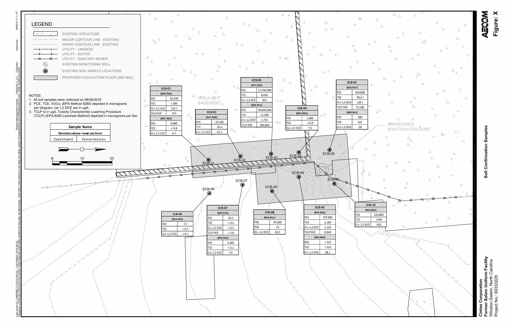

SLOPE STABILITY ANALYSIS FORMER SALEM UNIFORM SITE WINSTON SALEM,
NORTH CAROLINA
ESP PROJECT NO. E4B-DP35.300
Prepared For:
AECOM 710 Corporate Center Drive
Suite 475 Raleigh, North Carolina 27607
Prepared By:
ESP Associates, P.A. 7144 Weddington Rd. NW Suite 110
Concord, North Carolina 28027
June 3, 2015
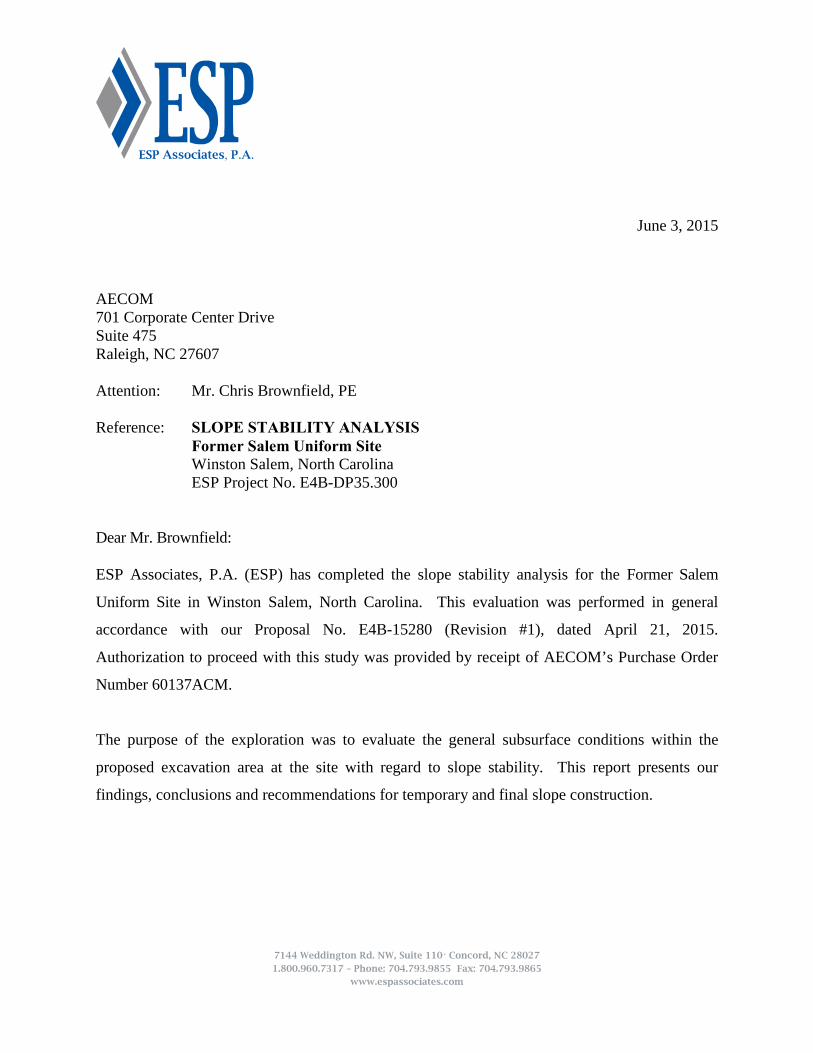
7144 Weddington Rd. NW, Suite 110• Concord, NC 28027
1.800.960.7317 – Phone: 704.793.9855 Fax: 704.793.9865 www.espassociates.com
June 3, 2015 AECOM 701 Corporate Center Drive Suite 475 Raleigh, NC 27607 Attention: Mr. Chris Brownfield, PE Reference: SLOPE STABILITY ANALYSIS Former Salem Uniform Site Winston Salem, North Carolina ESP Project No. E4B-DP35.300 Dear Mr. Brownfield: ESP Associates, P.A. (ESP) has completed the slope stability analysis for the Former Salem
Uniform Site in Winston Salem, North Carolina. This evaluation was performed in general
accordance with our Proposal No. E4B-15280 (Revision #1), dated April 21, 2015.
Authorization to proceed with this study was provided by receipt of AECOM’s Purchase Order
Number 60137ACM.
The purpose of the exploration was to evaluate the general subsurface conditions within the
proposed excavation area at the site with regard to slope stability. This report presents our
findings, conclusions and recommendations for temporary and final slope construction.
Slope Stability Analysis ESP Project No. E4B-DP35.300 Former Salem Uniform Site June 3, 2015
TABLE OF CONTENTS
1.0 INTRODUCTION ................................................................................................................ 1 1.1 SITE AND PROJECT DESCRIPTION ....................................................................... 1 1.2 PURPOSE OF SERVICES ........................................................................................... 1 2.0 EXPLORATION PROCEDURES ..................................................................................... 1 2.1 FIELD ............................................................................................................................ 1 2.2 LABORATORY ............................................................................................................ 2 3.0 SUBSURFACE CONDITIONS .......................................................................................... 2 3.1 PHYSIOGRAPHY AND AREA GEOLOGY ............................................................. 2 3.2 SUBSURFACE CONDITIONS ................................................................................... 3
3.3 SUBSURFACE WATER .............................................................................................. 4 4.0 SLOPE STABILITY ANALYSIS ....................................................................................... 4 4.1 METHODOLOGY ........................................................................................................ 4 4.2 RESULTS OF ANALYSIS ........................................................................................... 4 5.0 LIMITATIONS OF REPORT ............................................................................................ 5 APPENDIX A FIELD EXPLORATION & LABORATORY PROCEDURES BORING LOCATION PLAN, FIGURE 1 TEST BORING RECORDS (B-1 AND B-2) LEGEND TO SOIL CLASSIFICATION AND SYMBOLS CONSOLIDATED UNDRAINED TRIAXIAL TEST RESULTS SLOPE ANALYSIS DRAWING
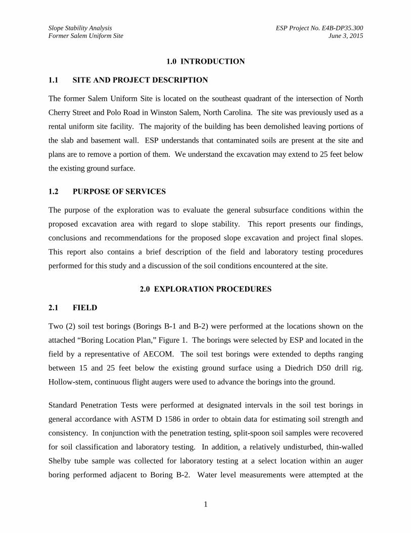
Slope Stability Analysis ESP Project No. E4B-DP35.300 Former Salem Uniform Site June 3, 2015
1
1.0 INTRODUCTION
1.1 SITE AND PROJECT DESCRIPTION The former Salem Uniform Site is located on the southeast quadrant of the intersection of North
Cherry Street and Polo Road in Winston Salem, North Carolina. The site was previously used as a
rental uniform site facility. The majority of the building has been demolished leaving portions of
the slab and basement wall. ESP understands that contaminated soils are present at the site and
plans are to remove a portion of them. We understand the excavation may extend to 25 feet below
the existing ground surface.
1.2 PURPOSE OF SERVICES The purpose of the exploration was to evaluate the general subsurface conditions within the
proposed excavation area with regard to slope stability. This report presents our findings,
conclusions and recommendations for the proposed slope excavation and project final slopes.
This report also contains a brief description of the field and laboratory testing procedures
performed for this study and a discussion of the soil conditions encountered at the site.
2.0 EXPLORATION PROCEDURES
2.1 FIELD
Two (2) soil test borings (Borings B-1 and B-2) were performed at the locations shown on the
attached “Boring Location Plan,” Figure 1. The borings were selected by ESP and located in the
field by a representative of AECOM. The soil test borings were extended to depths ranging
between 15 and 25 feet below the existing ground surface using a Diedrich D50 drill rig.
Hollow-stem, continuous flight augers were used to advance the borings into the ground.
Standard Penetration Tests were performed at designated intervals in the soil test borings in
general accordance with ASTM D 1586 in order to obtain data for estimating soil strength and
consistency. In conjunction with the penetration testing, split-spoon soil samples were recovered
for soil classification and laboratory testing. In addition, a relatively undisturbed, thin-walled
Shelby tube sample was collected for laboratory testing at a select location within an auger
boring performed adjacent to Boring B-2. Water level measurements were attempted at the
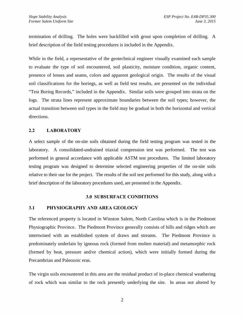
Slope Stability Analysis ESP Project No. E4B-DP35.300 Former Salem Uniform Site June 3, 2015
2
termination of drilling. The holes were backfilled with grout upon completion of drilling. A
brief description of the field testing procedures is included in the Appendix.
While in the field, a representative of the geotechnical engineer visually examined each sample
to evaluate the type of soil encountered, soil plasticity, moisture condition, organic content,
presence of lenses and seams, colors and apparent geological origin. The results of the visual
soil classifications for the borings, as well as field test results, are presented on the individual
“Test Boring Records,” included in the Appendix. Similar soils were grouped into strata on the
logs. The strata lines represent approximate boundaries between the soil types; however, the
actual transition between soil types in the field may be gradual in both the horizontal and vertical
directions.
2.2 LABORATORY A select sample of the on-site soils obtained during the field testing program was tested in the
laboratory. A consolidated-undrained triaxial compression test was performed. The test was
performed in general accordance with applicable ASTM test procedures. The limited laboratory
testing program was designed to determine selected engineering properties of the on-site soils
relative to their use for the project. The results of the soil test performed for this study, along with a
brief description of the laboratory procedures used, are presented in the Appendix.
3.0 SUBSURFACE CONDITIONS
3.1 PHYSIOGRAPHY AND AREA GEOLOGY The referenced property is located in Winston Salem, North Carolina which is in the Piedmont
Physiographic Province. The Piedmont Province generally consists of hills and ridges which are
intertwined with an established system of draws and streams. The Piedmont Province is
predominately underlain by igneous rock (formed from molten material) and metamorphic rock
(formed by heat, pressure and/or chemical action), which were initially formed during the
Precambrian and Paleozoic eras.
The virgin soils encountered in this area are the residual product of in-place chemical weathering
of rock which was similar to the rock presently underlying the site. In areas not altered by

Slope Stability Analysis ESP Project No. E4B-DP35.300 Former Salem Uniform Site June 3, 2015
3
erosion or disturbed by the activities of man, the typical residual soil profile consists of clayey
soils near the surface, where soil weathering is more advanced, underlain by sandy silts and silty
sands. The boundary between soil and rock is not sharply defined. This transitional zone termed
“partially weathered rock” is normally found overlying the parent bedrock. Partially weathered
rock is defined, for engineering purposes, as residual material with Standard Penetration
Resistances in excess of 100 blows per foot. Weathering is facilitated by fractures, joints and by
the presence of less resistant rock types. Consequently, the profile of the partially weathered
rock and hard rock is quite irregular and erratic, even over short horizontal distances. Also, it is
common to find lenses and boulders of hard rock and zones of partially weathered rock within
the soil mantle, well above the general bedrock level.
3.2 SUBSURFACE CONDITIONS Subsurface conditions as indicated by the borings generally consist of fill underlain by residual
soils. The residual soils have formed from the weathering of the parent bedrock. The
generalized subsurface conditions are described below. For more detailed soil descriptions and
stratifications at a particular boring location, the respective “Test Boring Record” should be
reviewed. The Test Boring Records are included in the Appendix.
Surface: A topsoil/grassmat layer approximately 2 to 3 inches thick was encountered at all the
boring locations.
Fill: Underlying the surface materials in the borings performed, fill soils were encountered
consisting of silty clay and sand. Standard Penetration Resistances (N-values) were not obtained
within the fill soils due to hand clearing for utilities. The fill extends to approximately 3.5 below
the existing ground surface.
Residuum Beneath the fill in the borings, residual soils were encountered consisting of stiff to
very stiff clayey silt and sandy clay and loose to medium dense silty sandy and sand. N-values
in the residuum varied between 8 and 25 blows per foot (bpf). The borings were terminated in
the residual soils at depths ranging between 15 and 25 feet below the existing ground surface.
Slope Stability Analysis ESP Project No. E4B-DP35.300 Former Salem Uniform Site June 3, 2015
4
3.3 SUBSURFACE WATER The borings were dry when water level measurements were attempted at the termination of
drilling. Hole cave-in depths ranged between 10.4 and 18.3 feet below the existing ground
surface. Hole cave-in depths may provide an indication of water present. The borings were
grouted once drilling was complete.
Subsurface water levels tend to fluctuate with seasonal and climatic variations, as well as with
some types of construction operations. Therefore, water may be encountered during construction
at depths not indicated during this study.
4.0 SLOPE STABILITY ANALYSIS
4.1 METHODLOGY The slope stability analysis was performed using Geo-Slope’s Slope/W (2007) program to model
the proposed excavation and calculate factors of safety for critical slip surfaces. Two-
dimensional limit equilibrium methodologies using Morgenstern-Price (1965) procedures were
used to satisfy equilibrium conditions.
4.2 RESULTS OF ANALYSIS Temporary Excavation
Based on our analysis of the soils encountered within the borings, the proposed temporary
excavation will remain stable on an approximately 1(H) to 1(V) slope for the short period that it
should remain open. All excavations should be conducted in a safe manner and comply with all
local, state and federal guidelines and codes. We recommend that all excavated soils be placed
at least 10 feet away from the edges of the excavation.
Permanent Slopes
For landscaping and mowing concerns, final project slopes should be designed to be 3 horizontal
to 1 vertical or flatter. Slopes can be designed as steep as 2 horizontal to 1 vertical; however,
soil erosion, slope sloughing and slope maintenance should be expected. The tops and bases of
all slopes should be located a minimum of 5 feet from structural and pavement limits. The fill
Slope Stability Analysis ESP Project No. E4B-DP35.300 Former Salem Uniform Site June 3, 2015
5
slopes should be adequately compacted and all slopes should be seeded and maintained after
construction.
Permanent Slope Construction
All fill used for slope construction should be placed in loose lifts not exceeding 8 inches in
thickness and compacted to a minimum of 95 percent of its Standard Proctor maximum dry
density. We recommend that field density tests, including one-point Proctor verification tests, be
performed on the fill as it is being placed at a frequency determined by an experienced
geotechnical engineer to verify the compaction criteria
5.0 LIMITATIONS OF REPORT
This report has been prepared in accordance with generally accepted geotechnical engineering
practice with regard to the specific conditions and requirements of this site. The conclusions and
recommendations contained in this report were based on the applicable standards of our practice
in this geographic area at the time this report was prepared. No other warranty, expressed or
implied, is made.
The analysis and recommendations submitted herein are based, in part, upon the data obtained
from the subsurface exploration. The nature and extent of variations between the borings will
not be known until construction is underway. If variations appear evident, then we request the
opportunity to re-evaluate the recommendations of this report. In the event that any changes in
the nature, design, or location of the structures are planned, the conclusions and
recommendations contained in this report will not be considered valid unless the changes are
reviewed and conclusions modified or verified in writing by ESP.
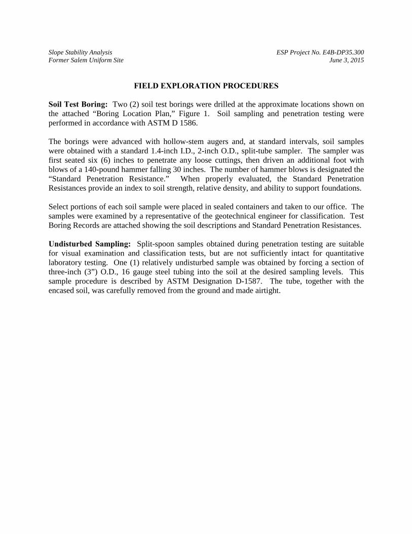
Slope Stability Analysis ESP Project No. E4B-DP35.300 Former Salem Uniform Site June 3, 2015
FIELD EXPLORATION PROCEDURES
Soil Test Boring: Two (2) soil test borings were drilled at the approximate locations shown on the attached “Boring Location Plan,” Figure 1. Soil sampling and penetration testing were performed in accordance with ASTM D 1586. The borings were advanced with hollow-stem augers and, at standard intervals, soil samples were obtained with a standard 1.4-inch I.D., 2-inch O.D., split-tube sampler. The sampler was first seated six (6) inches to penetrate any loose cuttings, then driven an additional foot with blows of a 140-pound hammer falling 30 inches. The number of hammer blows is designated the “Standard Penetration Resistance.” When properly evaluated, the Standard Penetration Resistances provide an index to soil strength, relative density, and ability to support foundations. Select portions of each soil sample were placed in sealed containers and taken to our office. The samples were examined by a representative of the geotechnical engineer for classification. Test Boring Records are attached showing the soil descriptions and Standard Penetration Resistances. Undisturbed Sampling: Split-spoon samples obtained during penetration testing are suitable for visual examination and classification tests, but are not sufficiently intact for quantitative laboratory testing. One (1) relatively undisturbed sample was obtained by forcing a section of three-inch (3”) O.D., 16 gauge steel tubing into the soil at the desired sampling levels. This sample procedure is described by ASTM Designation D-1587. The tube, together with the encased soil, was carefully removed from the ground and made airtight.
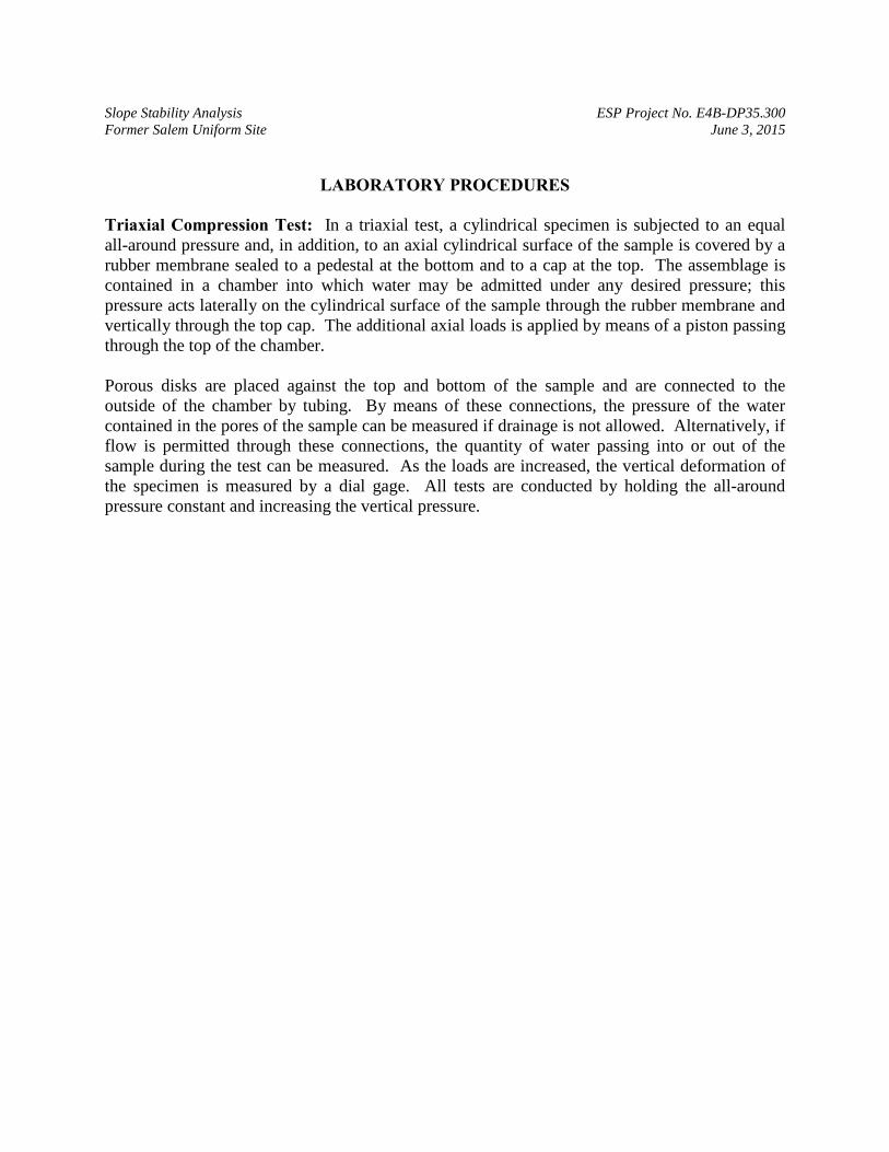
Slope Stability Analysis ESP Project No. E4B-DP35.300 Former Salem Uniform Site June 3, 2015
LABORATORY PROCEDURES
Triaxial Compression Test: In a triaxial test, a cylindrical specimen is subjected to an equal all-around pressure and, in addition, to an axial cylindrical surface of the sample is covered by a rubber membrane sealed to a pedestal at the bottom and to a cap at the top. The assemblage is contained in a chamber into which water may be admitted under any desired pressure; this pressure acts laterally on the cylindrical surface of the sample through the rubber membrane and vertically through the top cap. The additional axial loads is applied by means of a piston passing through the top of the chamber. Porous disks are placed against the top and bottom of the sample and are connected to the outside of the chamber by tubing. By means of these connections, the pressure of the water contained in the pores of the sample can be measured if drainage is not allowed. Alternatively, if flow is permitted through these connections, the quantity of water passing into or out of the sample during the test can be measured. As the loads are increased, the vertical deformation of the specimen is measured by a dial gage. All tests are conducted by holding the all-around pressure constant and increasing the vertical pressure.
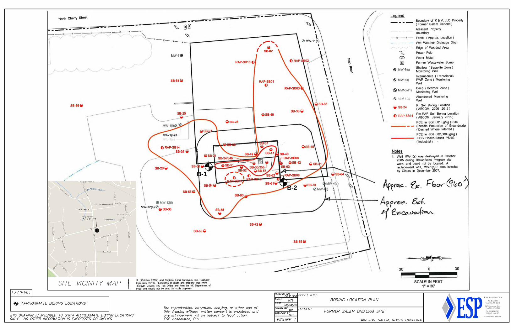
B-1
B-2
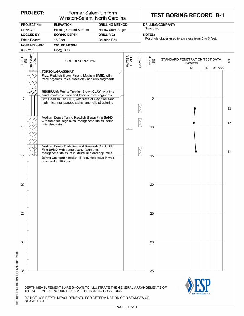
13
12
14
TOPSOIL/GRASSMATFILL: Reddish Brown Fine to Medium SAND, withtrace organics, mica, trace clay and rock fragments
RESIDUUM: Red to Tannish Brown CLAY, with finesand, moderate mica and trace of rock fragmentsStiff Reddish Tan SILT, with trace of clay, fine sand,high mica, manganese stains and relic structuring
Medium Dense Tan to Reddish Brown Fine SAND,with trace silt, high mica, manganese stains, somerelic structuring
Medium Dense Dark Red and Brownish Black SiltyFine SAND, with some quartz fragments,manganese stains, relic structuring and high mica
Boring was terminated at 15 feet. Hole cave-in wasobserved at 10.4 feet.
PAGE: 1 of 1
5
10
15
20
25
30
35
DE
PT
H(f
t) STANDARD PENETRATION TEST DATA(Blows/ft)
3010 907050
ES
P_T
BR
DP
35.3
00.G
PJ
LO
G-L
AB
.GD
T 6
/2/1
5
DEPTH MEASUREMENTS ARE SHOWN TO ILLUSTRATE THE GENERAL ARRANGEMENTS OFTHE SOIL TYPES ENCOUNTERED AT THE BORING LOCATIONS.
DO NOT USE DEPTH MEASUREMENTS FOR DETERMINATION OF DISTANCES ORQUANTITIES.
Former Salem UniformWinston-Salem, North Carolina
Deidrich D50
DRILLING METHOD:
DRILL RIG:
SaedaccoPROJECT No.:
PROJECT:
LOGGED BY:
DATE DRILLED:
ELEVATION:
BORING DEPTH:
WATER LEVEL:
Hollow Stem Auger
Post hole digger used to excavate from 0 to 5 feet.15 Feet
NOTES:
DRILLING COMPANY:
Dry@ TOB
Eddie Rogers
05/07/15
DP35.300 Existing Ground Surface
TEST BORING RECORD B-1
BP
F
SOIL DESCRIPTION
WA
TE
RLE
VE
L
DE
PT
H(f
t)
5
10
15
20
25
30
35
SA
MP
LE
GR
AP
HIC
LOG
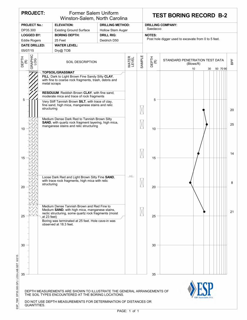
20
25
14
8
21
TOPSOIL/GRASSMATFILL: Dark to Light Brown Fine Sandy Silty CLAY,with fine to coarse rock fragments, trash, debris andmetal scraps
RESIDUUM: Reddish Brown CLAY, with fine sand,moderate mica and trace of rock fragments
Very Stiff Tannish Brown SILT, with trace of clay,fine sand, high mica, manganese stains and relicstructuring
Medium Dense Dark Red to Tannish Brown SiltySAND, with quartz rock fragment layering, high mica,manganese stains and relic structuring
Loose Dark Red and Light Brown Silty Fine SAND,with trace rock fragments, high mica with relicstructuring
Medium Dense Tannish Brown and Red Fine toMedium SAND, with high mica, manganese stains,reclic structuring, some quartz rock fragments (moistat 23 feet)Boring was terminated at 25 feet. Hole cave-in wasobserved at 18.3 feet.
PAGE: 1 of 1
5
10
15
20
25
30
35
DE
PT
H(f
t) STANDARD PENETRATION TEST DATA(Blows/ft)
3010 907050
ES
P_T
BR
DP
35.3
00.G
PJ
LO
G-L
AB
.GD
T 6
/2/1
5
DEPTH MEASUREMENTS ARE SHOWN TO ILLUSTRATE THE GENERAL ARRANGEMENTS OFTHE SOIL TYPES ENCOUNTERED AT THE BORING LOCATIONS.
DO NOT USE DEPTH MEASUREMENTS FOR DETERMINATION OF DISTANCES ORQUANTITIES.
Former Salem UniformWinston-Salem, North Carolina
Deidrich D50
DRILLING METHOD:
DRILL RIG:
SaedaccoPROJECT No.:
PROJECT:
LOGGED BY:
DATE DRILLED:
ELEVATION:
BORING DEPTH:
WATER LEVEL:
Hollow Stem Auger
Post hole digger used to excavate from 0 to 5 feet.25 Feet
NOTES:
DRILLING COMPANY:
Dry@ TOB
Eddie Rogers
05/07/15
DP35.300 Existing Ground Surface
TEST BORING RECORD B-2
BP
F
SOIL DESCRIPTION
WA
TE
RLE
VE
L
DE
PT
H(f
t)
5
10
15
20
25
30
35
SA
MP
LE
GR
AP
HIC
LOG
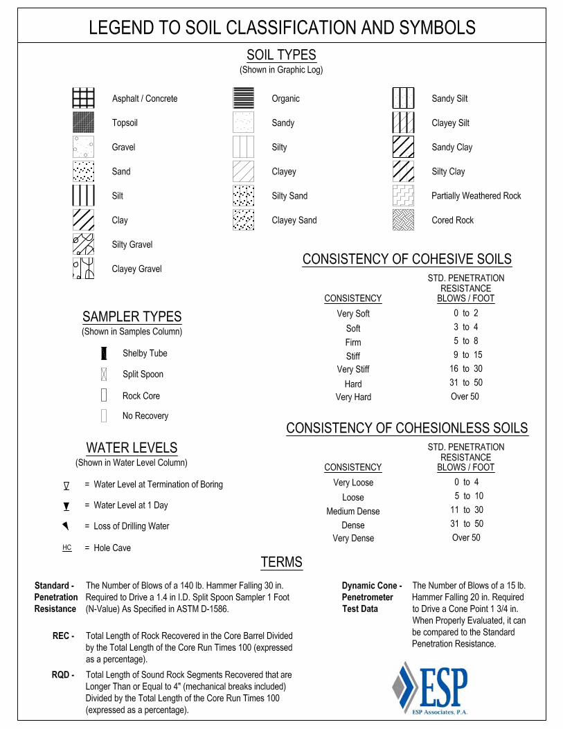
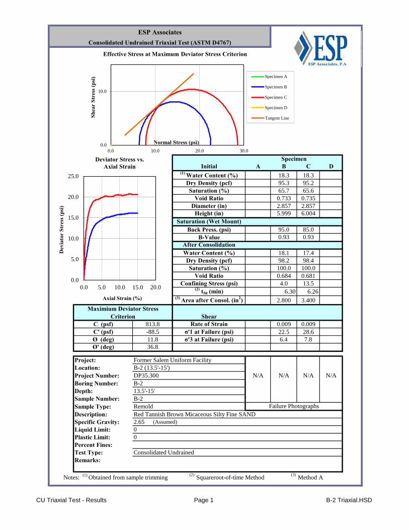
CU Triaxial Test - Results Page 1 B-2 Triaxial.HSD
A B C D18.3 18.395.3 95.265.7 65.60.733 0.7352.857 2.8575.999 6.004
95.0 85.00.93 0.93
18.1 17.498.2 98.4100.0 100.00.684 0.681
4.0 13.56.30 6.26
2.800 3.400
0.009 0.00922.5 28.66.4 7.8
Project: Former Salem Uniform FacilityLocation: B-2 (13.5'-15')Project Number: DP35.300 N/A N/A N/A N/ABoring Number: B-2Depth: 13.5'-15'Sample Number: B-2Sample Type: RemoldDescription: Red Tannish Brown Micaceous Silty Fine SANDSpecific Gravity: 2.65 (Assumed)
Liquid Limit: 0Plastic Limit: 0Percent Fines:Test Type: Consolidated UndrainedRemarks:
Notes: (1) Obtained from sample trimming(2)
Squareroot-of-time Method(3)
Method A
Maximium Deviator Stress Criterion
Ø' (deg)
813.8C (psf)C' (psf)Ø (deg)
Diameter (in)
Dry Density (pcf)
Saturation (Wet Mount)
B-ValueBack Press. (psi)
σ'1 at Failure (psi)
Void Ratio
Water Content (%)
Confining Stress (psi)
Rate of StrainShear
Failure Photographs
ESP AssociatesConsolidated Undrained Triaxial Test (ASTM D4767)
Height (in)
Specimen
36.8σ'3 at Failure (psi)
(1) Water Content (%)Initial
Dry Density (pcf)
-88.511.8
Saturation (%)Void Ratio
After Consolidation
Saturation (%)
(3) Area after Consol. (in2)
(2) t50 (min)
0.0
10.0
0.0 10.0 20.0 30.0
Shea
r St
ress
(psi
)
Normal Stress (psi)
Effective Stress at Maximum Deviator Stress Criterion
Specimen A
Specimen B
Specimen C
Specimen D
Tangent Line
0.0
5.0
10.0
15.0
20.0
25.0
0.0 5.0 10.0 15.0 20.0
Dev
iato
r St
ress
(psi
)
Axial Strain (%)
Deviator Stress vs. Axial Strain
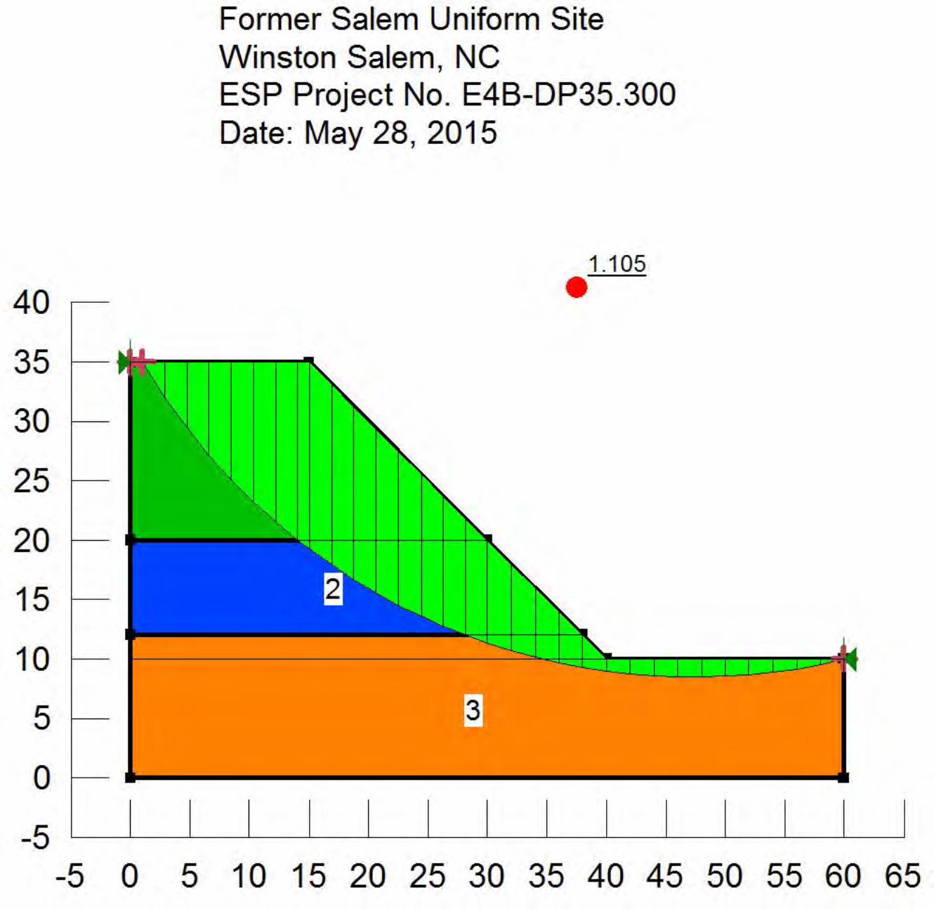

Greensboro7204 West Friendly Ave.
Suite GGreensboro, NC 27410
336.334.7724
Raleigh5121 Kingdom Way
Suite 208Raleigh, NC 27607
919.678.1070
Concord7144 Weddington Rd., NW
Suite 110Concord, NC 28027
704.793.9855
West Columbia101 Corporate Blvd.
Suite 109W. Columbia, SC 29169
803.705.2229
Wilmington211 Racine Drive
Suite 101Wilmington, NC 28403
910.313.6648
Pittsburgh651 Holiday Drive
Foster Plaza 5 Suite 300Pittsburgh, PA 15220
412.928.3228
Indianapolis11216 Fall Creek Rd.
Suite 107Indianapolis, IN 46256
317.306.0158
Tampa5025 W. Grace St.Tampa, FL 33607
770.823.8322
800.960.7317www.espassociates.com
ESP Corporate Offi ce3475 Lakemont Boulevard
Fort Mill, South Carolina 29708803.802.2440
MailingPO Box 7030
Charlotte, North Carolina 28241
SECTION 01150MEASUREMENT AND PAYMENT
Cintas Corporation Rev. 2 –Issued For ConstructionCintas: Former Salem Uniform FacilityWinston-Salem, North Carolina October 15, 2015
01150 - 1
PART 1 – GENERAL
1.01 SUMMARY
A. This section includes the administrative and procedural requirements necessary to prepareand process Applications for Payment.
B. Payment for Work performed under this Contract will be made as set forth herein and inaccordance with any conditions stipulated in the Contract between the OWNER,ENGINEER, and CONTRACTOR.
C. If a Contract is awarded on a combination of Items other than the total, the Work performedshall be complete and operable with each Item standing alone and in conformance with allprovisions of the Contract Documents.
D. There shall be no Work or cost added to an Item which has been included under any otherItem. The cost for each Item shall be all inclusive for that Item.
E. The Work included under each Item shall consist of providing and installing the materialsand/or equipment, complete, as enumerated below. Payment for each Item will be made atthe Lump Sum or Fixed Unit Price bid in accordance with the provisions of Sections 1.02and 1.03 of this section.
F. CONTRACTOR shall include in the price bid for each applicable Work Item listed in theschedule of prices, the cost of coordination, labor, health and safety measures, includingmaterials, tools and equipment, soil, material and equipment testing, repairs to the roadsdue to construction damage, dewatering (if required), protection of adjacent Work,maintenance of traffic, displacement, replacement and/or repair of damage to any existingutility and/or structure by CONTRACTOR activity, As-built drawings, code inspections,quality assurance and quality control and all other cost incurred as necessary to provide,complete in place, all Work required to complete each Item in the Bid Form.
G. Work Items included with each schedule of prices are described in the following paragraphs.
1.02 BASE BID WORK ITEMS
A. Item 1 – Pre-Construction Submittal Prep
1. Pre-Construction Submittal Prep shall consist of furnishing and obtaining approvalof all pre-constructional submittals, including all work required to revise andresubmit submittals that are determined to be deficient by the ENGINEER.
2. Price for this item shall be included as a lump sum price in the Bid Form for all of thesubmittals that are required.
3. Payment for this item shall be on a percent complete basis as determined by theCONTRACTOR and approved by the ENGINEER.
B. Item 2 – Project Management/General Contractor Fee
1. Project Management/General Contractor Fee includes all costs that will be chargedby the CONTRACTOR to administer the project according to the Project Schedule,including, but not limited to the use of site superintendents or construction
SECTION 01150MEASUREMENT AND PAYMENT
Cintas Corporation Rev. 2 –Issued For ConstructionCintas: Former Salem Uniform FacilityWinston-Salem, North Carolina October 15, 2015
01150 - 2
managers to organize, document, and manage the work, including implementationof the Contractor’s health and safety program.
2. Price for this item shall be included as a lump sum per-month unit price in the BidForm.
3. Payment for this item shall be based on the actual percent complete asdetermined by the CONTRACTOR and approved by the ENGINEER. Noadditional payment will be made for duration of the Work that extends beyondthe accepted project schedule between the date of mobilization and when theENGINEER determines that the Work has been substantially complete, up to theproject end date specified on the Project Schedule. Payment shall be made forpartial months by rounding up to the nearest half-month of services that are actuallydelivered. If the project is delayed beyond the project schedule, no payment shallbe made for this item unless such a payment is negotiated as Change Order inaccordance with the procedures in Section 01340 – Contract ModificationProcedures.
C. Item 3 - Mobilization and Demobilization
1. Mobilization shall consist of the furnishing of all Work, materials and operationsrequired for the assembling and setting up for the project, including, but not limitedto initial movement of personnel to the project site (after submittals are approvedand receipt of Notice to proceed); establishment of shops and plants; moving onand off site all construction equipment, hauling units, hoisting equipment,compressors and tools required to complete the Work; all other Work andoperations which must be performed prior to beginning Work on compensable Itemsof Work at the project site; and the cost of required insurance and bonds and anyother initial expenses required including, but not limited to submittal of all schedules,contractor quality control plan, contractor site safety plan, manufacturer'scertifications and product literature, and material analysis.
2. Demobilization shall consist of, but not be limited to removal of the furnishings of allWork, material, and equipment required for the assembling and setting up for theproject, including cleanup of project site to the final conditions required by theSpecifications and Drawings.
3. Price for this item shall be included as a lump sum price in the Bid Form for eachmobilization and demobilization that is required. Price for this item shall not exceed5 percent of the contractor’s base-bid price for the Work.
4. Payment for this item shall be on a percent complete basis as determined by theCONTRACTOR and approved by the ENGINEER.
D. Item 4 - Site Preparation
1. Site Preparation shall consist of all activities required to prepare the site forexcavation. Work under this item includes, but is not limited to the installation ofnew gates and improvements to the existing perimeter fencing, signage, theinstallation of sedimentation and erosion controls, the location and exposure of allutilities within the work area, the construction of staging and stockpile areas,clearing and grubbing, removal and disposal of the abandoned undergroundstorage tank, subcontracting of a pre-construction survey, and all other workrequired to prepare the site for excavation. Other work may include but is not
SECTION 01150MEASUREMENT AND PAYMENT
Cintas Corporation Rev. 2 –Issued For ConstructionCintas: Former Salem Uniform FacilityWinston-Salem, North Carolina October 15, 2015
01150 - 3
limited to the installation of temporary facilities, additional project entrances,additional staging areas, delineation of work zones, completion of any additionalgeotechnical design, installation of any sheet pile/shoring, or anything else that isnecessary to complete the Contracted Work.
2. Price for this Item shall be included as a combination of unit prices and lump sumprices as indicated on the Bid Form.
3. Payment for this Item shall be made per-item as indicated on the Bid form as eitheras a unit price or a percent complete basis. Quantities for unit price items shall bedetermined by progress surveys. Percentage completions for lump sum items shallbe determined by the CONTRACTOR and approved by the ENGINEER.
E. Item 5 – Block and Reinforced Concrete Wall, Foundation, and Pad Demolition
1. Work under this Item includes, but is not limited to all demolition and staging ofconcrete and block floors, walls, and foundation materials in a phased sequenceaccording to the Drawings and Specifications. Transportation and disposal of thedemolished materials are will be measured and paid under a separate work item.
2. Price for this Item shall be included as a lump-sum on the Bid Form.
3. Payment for this item shall be on a percent complete basis as determined by theCONTRACTOR and approved by the ENGINEER.
F. Item 6 – Phase I Excavation, Stockpiling and Stockpile Maintenance
1. Work under this Item includes, but is not limited to all excavation and handling ofcontaminated material as part of Phase-I excavation work in accordance with theDrawings and Specifications.
2. The estimated quantities in Items 6A and 6B are provided based on nominalexcavation depths and extents as shown on the Drawings and do not includeallowances for additional excavation that may be required to facilitate theCONTRACTOR’S means and methods that are selected to complete the Phase Iexcavation work.
3. The CONTRACTOR shall estimate any additional excavation quantity that isrequired to complete the Phase I excavation work under Item 6C.
4. Price for this Item shall be included as a per-bank cubic yard of excavated materialunit price on the Bid Form up to 1.5 times the estimated quantity of bank cubicyards, assuming Level D personal protective equipment is required.
5. Payment for this item will be on a unit price basis and the quantity for payment shallbe determined by progress surveys conducted by the CONTRACTOR’s licensedsurveyor, and as described in the Specifications. No additional payment will bemade for losses due to settlement, compaction, erosion, over-excavation, wastage,replacement of rejected materials, dewatering or inadequate protection.
G. Item 7 – Phase II Excavation, Stockpiling and Stockpile Maintenance
SECTION 01150MEASUREMENT AND PAYMENT
Cintas Corporation Rev. 2 –Issued For ConstructionCintas: Former Salem Uniform FacilityWinston-Salem, North Carolina October 15, 2015
01150 - 4
1. Work under this Item includes, but is not limited to all excavation and handling ofcontaminated material as part of Phase-II excavation work in accordance with theDrawings and Specifications.
2. The estimated quantity is provided based on nominal excavation depths and extentsas shown on the Drawings.
3. Price for this Item shall be included as a per-bank cubic yard of excavated materialunit price on the Bid Form up to 1.5 times the estimated quantity of bank cubicyards.
4. Payment for this item will be on a unit price basis and the quantity for payment shallbe determined by progress surveys conducted by the CONTRACTOR’S licensedsurveyor, and as described in the Specifications. No additional payment will bemade for losses due to settlement, compaction, erosion, over-excavation, wastage,replacement of rejected materials, dewatering or inadequate protection.
H. Item 8 – Progress/Final Surveys
1. Work under this Item includes, but is not limited to all subcontracting required for theCONTRACTOR’S surveyor to document construction progress and final siteconditions, including the determination of unit-price quantities for payment.
2. The estimated quantity is provided based on three progress surveys and one finalsurvey. The CONTACTOR shall strikethrough the estimated quantity and provide arevised quantity if the actual number of surveys will be different than the estimateprovided.
3. Price for this Item shall be included as a per-survey unit price on the Bid Form.
4. Payment for this item will be on a per-survey unit price basis.
I. Item 9 – Profiling, Loading, Transportation and Direct Disposal of Impacted Soil todesignated Subtitle C Disposal facility (Hazardous)
1. Work under this Item includes, but is not limited to the profiling, loading,transportation and direct (i.e. without off-site treatment) disposal of hazardous wastematerials, proper covered transport, manifesting, and ticketing, unloading anddisposal of impacted soils at an approved waste disposal facility all in accordancewith the Drawings and Specifications.
2. The estimated quantity is based on a tonnage equivalent to approximately 1,000 CYof soil material with a wet bulk density of 1.6 tons per cubic yard.
3. Price for this Item shall be included as a per-ton unit price on the Base Bid Form upto 1.5 times the quantity included on the Base Bid Form.
4. The actual quantity for payment will be determined by the actual weigh ticketsprovided by the disposal facility. No additional payment will be made for losses dueto improper containment of material during shipment or failure to treat material tobelow disposal facility requirements.
J. Item 10 – Profiling, Loading, Transportation and Disposal of Impacted Soil to designatedSubtitle D Disposal facility (Non-Hazardous)

SECTION 01150MEASUREMENT AND PAYMENT
Cintas Corporation Rev. 2 –Issued For ConstructionCintas: Former Salem Uniform FacilityWinston-Salem, North Carolina October 15, 2015
01150 - 5
1. Work under this Item includes, but is not limited to the profiling, loading,transportation and disposal of non-hazardous waste materials, proper coveredtransport, manifesting and ticketing, unloading, and disposal of impacted soils at anapproved waste disposal facility all in accordance with the Drawings andSpecifications.
2. The estimated quantity is based on a tonnage equivalent to 4,254 bank cubic yardstimes a wet bulk density of 1.6 tons per bank cubic yard of unexcavated material.
3. Price for this Item shall be included as a per-ton unit price in the Bid Form up to 1.5times the estimated number of tons. Pricing for additional units will be based onsupplemental bid items.
4. Payment will be determined by the actual weigh tickets provided by the disposalfacility. No additional payment will be made for losses due to improper containmentof material during shipment or failure to treat material to below disposal facilityrequirements.
K. Item 11 –Loading, Transportation and Disposal of Building Debris at a Construction andDemolition (C&D) Landfill facility
1. Work under this Item includes, but is not limited to the loading, transportation anddisposal of non-hazardous building material debris generated from the demolition ofthe block wall, foundation, and concrete pad at an approved construction anddemolition waste disposal facility all in accordance with the Drawings andSpecifications.
2. The quantity shall be estimated by the CONTRACTOR.
3. Price for this Item shall be included as a per-ton unit price in the Bid Form up to 1.5times the estimated number of tons. Pricing for additional units will be based onsupplemental bid items.
4. Payment will be determined by the actual weigh tickets provided by the disposalfacility. No additional payment will be made for losses due to improper containmentof material during shipment or failure to treat material to below disposal facilityrequirements.
L. Item 12 – New Remediation Piping, Turnkey
1. Work under this Item includes, but is not limited to installation of the newremediation piping in the floor of the Phase II Excavation as shown on theDrawings.
2. Price for this Item shall be included as a lump sum in the Bid Form
3. Payment for this item shall be made in lump-sum at the completion of the project.
M. Item 13 – Backfilling and Compaction
1. Work under this Item includes, but is not limited to all backfilling and compacting asindicated on the Drawings and in the Specifications. Materials under this Iteminclude, but are not limited to, clean fill and new topsoil.
SECTION 01150MEASUREMENT AND PAYMENT
Cintas Corporation Rev. 2 –Issued For ConstructionCintas: Former Salem Uniform FacilityWinston-Salem, North Carolina October 15, 2015
01150 - 6
2. The estimated quantity is provided based on the nominal excavation depths, extentsshown on the Drawings.
3. Price for this Item shall be included as per-bank cubic yard on the Bid Form up to1.5 times the estimated number of tons or bank cubic yards.
4. Payment for per-bank cubic yard items will be on a unit price basis and the quantityfor payment shall be determined by progress surveys and final surveys conductedby the CONTRACTOR’s licensed surveyor, and as described in the Specifications.No additional payment will be made for losses due to settlement, compaction,erosion, over-excavation, wastage, replacement of rejected materials, dewatering orinadequate protection.
N. Item 14 –Grading, Non-Impacted Material
1. Work under this Item includes, but is not limited to completion of final gradingactivities to achieve final grading surfaces as described in the Specifications andshown on the Drawings.
2. Price for this Item shall be included as a lump sum in the Bid Form
3. Payment for this item shall be made in lump-sum at the completion of the project.
O. Item 15 - Site Cleanup and Restoration
1. Work under this Item includes, but is not limited to furnishing and maintaining, for aone-year warranty period, the materials, equipment, and labor required torevegetate and cleanup and restore the site as indicated on the Drawings anddescribed in the Specifications.
2. Price for this Item shall be included as a combination of unit prices and lump sumprices as indicated on the Bid Form.
3. Payment for this Item shall be made per-item as indicated on the Bid form as eitheras a unit price or a percent complete basis. Quantities for unit price items shall bedetermined by progress surveys. Percentage completions for lump sum items shallbe determined by the CONTRACTOR and approved by the ENGINEER.
P. Item 16 - Project Closeout Submittals
1. Project Closeout Submittals shall consist of the furnishing of all Work, materials andoperations required for the preparation, submission, and approval of all othersubmittals, including, but not limited to Certificates and Affidavits, ConstructionProgress Reports, and Miscellaneous Data, as required by the Specifications andDrawings.
2. Price for this Item shall be included as a lump sum price in the Bid Form.
3. Payment for this item shall be on a percent complete basis as determined by theCONTRACTOR and approved by the ENGINEER.
1.03 ALTERNATE BID WORK ITEMS
SECTION 01150MEASUREMENT AND PAYMENT
Cintas Corporation Rev. 2 –Issued For ConstructionCintas: Former Salem Uniform FacilityWinston-Salem, North Carolina October 15, 2015
01150 - 7
A. Item 9-A – Turnkey On-Site Treatment, Stockpiling, Stockpile Maintenance, Re-Profiling,Loading, Transportation, and Disposal – Subtitle D
1. Work under this Item includes, but is not limited to the on-site treatment of a portionof excavated soil in accordance with the Specifications. Work under this item alsoincludes but is not limited to the handling of excavated material that is required fortreatment and subsequent stockpiling; the conditioning of excavated material fortreatment; the maintenance of stockpiled, treated material; and the profiling, loading,transportation, and disposal of non-hazardous, treated soil to an approved SubtitleD facility in accordance with the Specifications.
2. Work under this Item includes all preparation and support work required to facilitateon-Site treatment.
3. The estimated quantity is based on a tonnage equivalent to approximately 1,000 CYof soil material requiring treatment with a post-treatment wet bulk density of 1.6 tonsper cubic yard.
4. Price for this Item shall be an all-inclusive, turnkey per-ton unit price provided on theAlternate Bid Form up to 1.5 times the estimated number of units. Pricing foradditional units will be based on supplemental bid items.
5. The actual quantity for payment on per-ton items will be determined by the actualweigh tickets provided by the disposal facility. No additional payment will be madefor losses due to improper containment of material during shipment or failure to treatmaterial to below disposal facility requirements.
B. Item 11-A – Profiling, Loading, Transportation and Disposal of Building Debris to designatedSubtitle D Disposal facility (Non-Hazardous)
1. Work under this Item includes, but is not limited to the profiling, loading,transportation and disposal of non-hazardous building material debris generatedfrom the demolition of the block wall, foundation, and concrete pad at an approvedSubtitle D waste disposal facility all in accordance with the Drawings andSpecifications. Work shall include all waste manifesting and ticketing.
2. The quantity shall be estimated by the CONTRACTOR.
3. Price for this Item shall be included as a per-ton unit price in the Alternate Bid Formup to 1.5 times the estimated number of tons. Pricing for additional units will bebased on supplemental bid items.
4. Payment will be determined by the actual weigh tickets provided by the disposalfacility. No additional payment will be made for losses due to improper containmentof material during shipment or failure to treat material to below disposal facilityrequirements.
C. Item 11-B – Profiling, Loading, Transportation and Direct Disposal of Building Debris todesignated Subtitle C Disposal facility (Hazardous)
1. Work under this Item includes, but is not limited to the profiling, loading,transportation and direct (i.e. without off-site treatment) disposal of hazardousbuilding material debris generated from the demolition of the block wall, foundation,and concrete pad at an approved Subtitle C waste disposal facility all in accordance
SECTION 01150MEASUREMENT AND PAYMENT
Cintas Corporation Rev. 2 –Issued For ConstructionCintas: Former Salem Uniform FacilityWinston-Salem, North Carolina October 15, 2015
01150 - 8
with the Drawings and Specifications. Work shall include all waste manifesting andticketing.
2. The quantity shall be estimated by the CONTRACTOR.
3. Price for this Item shall be included as a per-ton unit price in the Alternate Bid Formup to 1.5 times the estimated number of tons. Pricing for additional units will bebased on supplemental bid items.
4. Payment will be determined by the actual weigh tickets provided by the disposalfacility. No additional payment will be made for losses due to improper containmentof material during shipment or failure to treat material to below disposal facilityrequirements.
1.04 SUPPLEMENTAL BID WORK ITEMS
A. Item 1 – Excavation Dewatering
1. Work under this Item includes, but is not limited to all materials, labor, equipment,required for removal of surface and groundwater from excavation areas andcontainerization in accordance with the Drawings and Specifications.
2. The estimated quantity is provided based on an assumed volume of 20,000 gallons.
3. Price for this Item shall be included as a per-thousand gallon unit price in theSupplemental Bid Form up to the estimated number of thousand gallons.
4. The actual quantity for payment will be determined by the geometry of the vessel(s)used to containerize the fluids and shall be documented by the CONTRACTOR.
B. Item 2 - Standby Time Exceeding 4 Hours Caused By Engineer/Owner
1. Work under this Item includes, but is not limited to the CONTRACTOR’s cost formaintaining materials, equipment, and personnel at the Site in the event that theOWNER or ENGINEER asks the CONTACTOR to stop work for reasons that areoutside of the CONTRACTOR’s control, exclusive of weather delays. Work underthis item does not include non-weather related delays that occur because of theCONTRACTOR’s execution of the work.
2. Price for this Item shall be included as a per half-day unit price in the SupplementalBid Form.
3. The actual quantity for payment will be documented by the CONTRACTOR andapproved by the ENGINEER.
C. Item 3 – Profiling, Loading, Transportation and Disposal of Impacted Soil to designatedSubtitle C Direct Disposal facility (Hazardous)
1. Work under this Item includes, but is not limited to the transportation and direct (i.e.without off-site treatment) disposal of hazardous waste materials, proper coveredtransport, manifesting, and ticketing, unloading and disposal of impacted soils at anapproved waste disposal facility all in accordance with the Drawings andSpecifications.

SECTION 01150MEASUREMENT AND PAYMENT
Cintas Corporation Rev. 2 –Issued For ConstructionCintas: Former Salem Uniform FacilityWinston-Salem, North Carolina October 15, 2015
01150 - 9
2. Price for this Item shall be included as a per ton unit price on the Supplemental BidForm for quantities in excess of 1.5 times the quantity estimated on the Base BidForm.
3. The actual quantity for payment will be determined by the actual weigh ticketsprovided by the disposal facility. No additional payment will be made for losses dueto improper containment of material during shipment or failure to treat material tobelow disposal facility requirements.
D. Item 4 –OSHA Level C Excavation Work
1. Work under this Item includes work in Level C PPE, including but not limited to theexcavation and handling of contaminated soils in accordance with the Drawings andSpecifications.
2. Price for this Item shall be included as a per-person, per-(8-hour) day unit price onthe Supplemental Bid Form.
3. The actual quantity for payment will be determined by the daily construction reports.Fractional days will be added together at the end of the project and the sum will berounded up to the nearest whole number.
E. Item 5 – Turnkey On-Site Treatment, Stockpiling, Stockpile Maintenance, Re-Profiling,Loading, Transportation and Disposal – Subtitle D
1. Work under this Item includes, but is not limited to the on-site treatment of a portionof excavated soil in accordance with the Specifications beyond what was estimatedas part of the alternate bid quantity. Work under this item also includes but is notlimited to the handling of excavated material that is required for treatment andsubsequent stockpiling; the conditioning of excavated material for treatment; themaintenance of stockpiled, treated material; and the profiling, loading,transportation, and disposal of non-hazardous, treated soil to an approved SubtitleD facility in accordance with the Specifications.
2. Work under this Item includes all preparation and support work required to facilitateon-Site treatment.
3. Price for this Item shall be included as an all-inclusive, turnkey per-ton unit price onthe Supplemental Bid Form for quantities in excess of 1.5 times the quantityestimated on the Alternate Bid Form.
4. The actual quantity for payment will be determined by the actual weigh ticketsprovided by the disposal facility. No additional payment will be made for losses dueto improper containment of material during shipment or failure to treat material tobelow disposal facility requirements.
5. The actual quantity for payment on per-bank cubic yard items will be determined byProgress Surveys based on the number of bank cubic yards of material that isplaced and compacted.
F. Item 6 – Off-site Treatment of Hazardous Soils by Subtitle C TSDF to Meet Land DisposalRestrictions
SECTION 01150MEASUREMENT AND PAYMENT
Cintas Corporation Rev. 2 –Issued For ConstructionCintas: Former Salem Uniform FacilityWinston-Salem, North Carolina October 15, 2015
01150 - 10
1. Work under this Item includes, but is not limited to the off-site treatment ofhazardous soils by a Subtitle C Treatment, Storage, or Disposal Facility to meet themore stringent of the land disposal restriction per Title 40 Code of FederalRegulations Part 268 or the disposal facility’s requirements.
2. Price for this Item shall be included as a per ton unit price on the Supplemental BidForm for all quantities. Minimum treatment volumes shall be stated in the bid.
3. The actual quantity for payment will be determined by the actual weigh ticketsprovided by the disposal facility. No additional payment will be made for losses dueto improper containment of material during shipment or failure to treat material tobelow disposal facility requirements.
G. Item 7 – Profiling, Loading, Transportation and Disposal of Impacted Soil to designatedSubtitle D Disposal facility (Non-Hazardous)
1. Work under this Item includes, but is not limited to the transportation and disposal ofnon-hazardous waste materials, proper covered transport, manifesting, andticketing, unloading and disposal of impacted soils at an approved waste disposalfacility all in accordance with the Drawings and Specifications.
2. Price for this Item shall be included as a per ton unit price on the Supplemental BidForm for quantities in excess of 1.5 times the quantity estimated on the Base BidForm.
3. The actual quantity for payment will be determined by the actual weigh ticketsprovided by the disposal facility. No additional payment will be made for losses dueto improper containment of material during shipment or failure to treat material tobelow disposal facility requirements.
1.05 PAYMENT PROCEDURE
A. Breakdown of Lump Sum and Fixed Unit Price Items:
1. Within seven (7) days after the OWNER or ENGINEER issues a Notice of Award,the CONTRACTOR shall submit to the ENGINEER, in a form approved by theENGINEER, a complete, detailed breakdown of all items awarded; i.e., a scheduleof values. The detailed breakdown shall include quantities with all anticipatedmaterial and labor costs for individual Work Items required to complete the WorkItem. Quantities estimated by the CONTRACTOR are for the purpose of providinga basis for realistic progress payments consistent with the actual performance of theWork. The project breakdown will be revised by the CONTRACTOR if theENGINEER so requests. Extra work will be paid in accordance with the provisionsof the Contract.
2. Payments will be made in accordance with the provisions of the Contract. TheCONTRACTOR may request periodic payments in accordance with the schedule ofvalues in the form of an Application for Payment. A monthly meeting will beconducted to discuss the Application for Payment. Submission for payment shall bemade to the ENGINEER. However, all payment requests will be made on the basisof the approved breakdown and accompanied by all supporting documentationrequired herein. No invoices shall be submitted to the OWNER or ENGINEER withthe exception of cost plus items.
SECTION 01150MEASUREMENT AND PAYMENT
Cintas Corporation Rev. 2 –Issued For ConstructionCintas: Former Salem Uniform FacilityWinston-Salem, North Carolina October 15, 2015
01150 - 11
3. Ten percent (10%) of each payment request will be retained by the OWNER untilthe Work has been completed, final verification and acceptance is performed, andfinal payment is made to the CONTRACTOR. At the sole discretion of theENGINEER, the percentage of retention may be reduced, if requested by theCONTRACTOR, approved by the ENGINEER, and awarded by the OWNER, priorto final payment. No retention will be withheld for cost plus items.
4. No payment shall be made for materials or equipment that are provided in a routinemanner as Work progresses. Such items are, and are not limited to, concrete, fuel,tools, dust preventive materials, protective devices such as tarps, etc.,CONTRACTOR's equipment rental, operating, or repair costs, lumber, stone,gravel, sand, or any material that is consumed as Work progresses.
PART 2 – PRODUCTS
(Not Used)
PART 3 – EXECUTION
(Not Used)
END OF SECTION 01150
SECTION 01160REGULATORY REQUIREMENTS AND RESPONSIBILITY TO THE PUBLIC
Cintas Corporation Rev. 1 – Issued For ConstructionCintas: Former Salem Uniform FacilityWinston-Salem, North Carolina October 15, 2015
01160 - 1
PART 1 - GENERAL
1.01 GENERAL REQUIREMENTS
A. At a minimum, the Work shall be performed in accordance with all of the requirements ofFederal and State of North Carolina regulations as enforced by the Environmental ProtectionAgency, the North Carolina Department of Environment and Natural Resources, theOccupational Health and Safety Administration, the North Carolina Department of Labor,and other applicable regulations and agencies.
B. In addition, the CONTRACTOR shall submit all necessary notices and obtain all permits andpay all fees and other costs that are required in connection with the Work; file all necessaryplans, prepare all documents and obtain all necessary approvals of all governmentaldepartments having jurisdiction except for those expressly designated as provided by theENGINEER. The CONTRACTOR shall obtain all required Certificates of Inspection andapproval for the Work and deliver these documents to the OWNER and ENGINEER, exceptas noted.
C. The CONTRACTOR shall include in the Work, without extra cost to the OWNER andENGINEER, labor, materials, equipment, services and drawings required to comply with allapplicable laws, ordinances, rules and regulations, whether or not shown in the Contract,Specifications, or Design Drawings.
D. The CONTRACTOR is expected to be familiar with all federal, state, local and municipallaws, ordinances, rules and regulations which in any manner affect those engaged oremployed in the Work, or the materials or equipment used in or upon the Work, or in anyway affect the Work, and no pleas of misunderstanding will be considered on account of theignorance thereof. The CONTRACTOR assumes all risk for performing the Work. If theCONTRACTOR discovers any provision in the Contract, Specifications, or Design Drawingswhich is contrary to, or inconsistent with, any such law, ordinance, rule or regulation, theCONTRACTOR shall forthwith report it to the ENGINEER in writing.
E. Hazard Communication Program: CONTRACTOR will be responsible for coordinating anyexchange of Material Safety Data Sheets (MSDS) or other hazard communicationinformation required to be made available to, or exchange between or among employees atthe site. CONTRACTOR shall compile and properly file MSDS for all materials furnished byCONTRACTOR or its SUBCONTRACTORs and suppliers.
F. The CONTRACTOR shall comply with all applicable provisions of North Carolina laws andcodes regulating the practice of general contracting.
1.02 SPECIFIC REQUIREMENTS
A. General Contracting
1. The CONTRACTOR shall maintain licensure as a General Contractor in NorthCarolina during the execution of the Work. The CONTRACTOR’s registration shallbe “unlimited” and the license classification shall be for Building or Specialty H(Grading and Excavating).
2. The CONTRACTOR shall notify the ENGINEER within five days of receiving anynotifications for disciplinary action or investigation for improper or illicit use of a
SECTION 01160REGULATORY REQUIREMENTS AND RESPONSIBILITY TO THE PUBLIC
Cintas Corporation Rev. 1 – Issued For ConstructionCintas: Former Salem Uniform FacilityWinston-Salem, North Carolina October 15, 2015
01160 - 2
license, or improper practice of general contracting, within the state of NorthCarolina or any other state in which the CONTRACTOR has performed work.
B. Emissions of Regulated Air Pollutants
1. The CONTRACTOR shall prevent emissions of regulated pollutants that result inviolations of ambient air quality standards at the Site property boundary. TheForsyth County Air Code shall be used to determine the ambient air qualitystandards.
2. The CONTRACTOR shall minimize emissions of regulated pollutants that result inviolations of ambient air quality standards within the Site property boundary. Whereindustrial exposure thresholds are exceeded, the CONTRACTOR shall reduceexposures or potential exposures to regulated pollutants in accordance withapplicable OSHA regulations.
C. Odorous Emissions
1. The CONTRACTOR shall prevent emissions of harmful or irritating odors, or odorsthat unreasonably interfere with surrounding activities, from extending beyond theSite property boundary.
2. If a dispute arises about the need to suppress nuisance odors, or the level ofreduction that is required, the dispute shall be arbitrated according to the provisionsof the Forsyth County Air Code.
D. Traffic Control and Permitting
1. The CONTRACTOR shall coordinate haul routes, any limitation on use of publicstreets, and obtain any needed permits or approvals for the use of the City ofWinston-Salem public roads.
2. Construction operations shall be planned and conducted to maintain adequatetraffic within and adjacent to the site, including but not limited to the following for theContract duration: furnishing, erecting and proper maintenance, removal anddisposal of traffic controls.
3. Vehicular access for ambulances, police and fire or other emergency equipmentshall be maintained at all times. When vehicular access is temporarily curtailed, itshall be the CONTRACTOR's responsibility to give adequate notice to affectedparties including, but not limited to the OWNER, ENGINEER, police departmenthaving jurisdiction for the site, fire department and emergency ambulance servicesprior to impairing access, and to provide means of temporary access when and ifrequired.
4. When traffic is interrupted, every effort shall be exercised to restore normal traffic assoon as practicable.
5. Furnishing, erecting, maintaining, relocating, removal and disposal of necessarysigns, barricades, cones, warning lights, and other traffic controls shall be inaccordance with local requirements and ordinances.

SECTION 01160REGULATORY REQUIREMENTS AND RESPONSIBILITY TO THE PUBLIC
Cintas Corporation Rev. 1 – Issued For ConstructionCintas: Former Salem Uniform FacilityWinston-Salem, North Carolina October 15, 2015
01160 - 3
6. The CONTRACTOR shall conduct all operations in a manner which complies withall applicable laws and ordinances and which will in no way discredit OWNER andENGINEER at any time.
E. Sanitary Provisions
1. The CONTRACTOR shall provide adequate sanitary facilities, as required by local,state and/or federal regulations, for the use of those employed on the Work. Suchfacilities will include, at a minimum, portable sanitary facilities, a water hand washingfacility. The CONTRACTOR shall provide facilities for site personnel and visitors.Such facilities shall be made available when the first employees arrive on site for theWork, and shall be constructed and maintained during the progress of Work insuitable numbers and at such points and in such a manner as may be required orapproved.
2. The CONTRACTOR shall maintain the sanitary facilities in a satisfactory andsanitary condition at all times and shall enforce their use. The CONTRACTOR shallrigorously prohibit the committing of nuisances on the site of the Work or onadjacent properties.
F. Intoxicating Liquors, Narcotics, Drugs and Weapons
1. The CONTRACTOR shall not sell and shall neither permit nor suffer the introductionor use of intoxicating liquors, narcotics or drugs upon or about the Work. Thoseunder the influence of intoxicating liquors, narcotics or drugs shall be immediatelyremoved from the site by the CONTRACTOR. Any delays in the performance of theWork or rework required as a result of such activities shall be the sole responsibilityof the CONTRACTOR and shall be performed by the CONTRACTOR at noexpense to the OWNER, SITE OWNER, or ENGINEER. The enforcement of thisrequirement shall be the responsibility of the CONTRACTOR.
2. The CONTRACTOR shall not sell or permit weapons of any type, as determined bythe OWNER or ENGINEER, upon or about the site property. The CONTRACTORshall remove confiscated weapons and persons in possession of these weaponsimmediately from the site. Any delays in the performance of the Work or reworkrequired as a result of such activities shall be the sole responsibility of theCONTRACTOR and shall be performed by the CONTRACTOR at no expense tothe OWNER, SITE OWNER, or ENGINEER. The enforcement of this requirementshall be the responsibility of the CONTRACTOR.
G. Protection of Property
1. All property along the line of the Work, or which is in the vicinity of, or is any wayaffected by the Work shall be protected and preserved from damage by theCONTRACTOR. Trees, fences, water or gas pipes, sewers, drains, conduits, polesor wires for electrical purposes, or other structures shall not be moved withoutconsent of the persons owning or controlling them except as specified by theENGINEER and/or indicated on the Design Drawings; and in crossing or workingnear them, they shall be sustained securely in place and shall be so treated as torender their condition as efficient and permanent as before.
2. Property damaged shall be immediately reported to the ENGINEER and theOWNER and, if directed to do so by the ENGINEER or the OWNER, propertydamage shall be repaired and restored at the expense of the CONTRACTOR, or if
SECTION 01160REGULATORY REQUIREMENTS AND RESPONSIBILITY TO THE PUBLIC
Cintas Corporation Rev. 1 – Issued For ConstructionCintas: Former Salem Uniform FacilityWinston-Salem, North Carolina October 15, 2015
01160 - 4
required, the CONTRACTOR shall make the necessary repairs. In case of failureon the part of the CONTRACTOR to restore such property as it deems necessary,the ENGINEER or OWNER will have repairs made and any cost thereof will bededucted from payments due or which may become due to the CONTRACTORunder this Contract.
3. The CONTRACTOR shall be responsible for determining the exact locations ofeach existing utility and structures within the Work areas using a subcontractedprivate utility locator. In addition, the North Carolina One-Call Center (800-632-4949) shall be contacted at least three working days prior to the beginning of theday of any excavation activities. Care shall be exercised during such location workto avoid damaging and/or disrupting the affected utility. The CONTRACTOR shallbe responsible for repairing, at its expense, un-intentional or malicious damages toany utilities and structures caused by CONTRACTOR’s work during construction.
4. The CONTRACTOR shall be responsible for exposing private utilities to be removedas part of the Work using hand-digging or vacuum excavation methods prior tomechanical removal of the utility.
5. When excavating in the proximity of a utility or structure, the OWNER shall benotified thereof sufficiently in advance so that the OWNER may accomplish anyspecial protective measure the CONTRACTOR deems necessary. Constructionoperations shall be so conducted as to facilitate access to utilities and structuresby the ENGINEER, SITE OWNER, OWNER, or their agents.
PART 2 - PRODUCTS
(Not Used)
PART 3 - EXECUTION
1. The CONTRACTOR shall determine the means and methods that are required to achieve thenecessary reduction in nuisance odors. The means and methods that are selected shall be the bestpractical means and methods for the treatment maintenance, and control of odors.
(Not Used)
END OF SECTION 01160
01300SUBMITTAL PROCEDURES
Cintas Corporation Rev. 1 – Issued For ConstructionCintas: Former RUS FacilityWinston-Salem, North Carolina October 15, 2015
01330 - 1
PART 1 - GENERAL
1.01 DESCRIPTION
A. This Section specifies the general methods and requirements of submissions applicable tothe following work-related submittals.
1. List of Submittals
2. Certificates and Affidavits
3. Samples for Testing
4. Material Test Results
5. Shop Drawings
6. Operation and maintenance literature
7. Other miscellaneous data for approval.
B. This Section also specifies procedures for turnover of the CONTRACTOR-prepared “as-built” drawings.
PART 2 - PRODUCTS
2.01 LIST OF SUBMITTALS
A. Within five (5) days after the CONTRACTOR is provided with the Notice to Proceed, theCONTRACTOR shall furnish the ENGINEER with a List of Submittals.
B. For each entry of the List of Submittals, reference to the Specifications and/or Drawings shallbe made, along with an indication of the type of submittal(s) which the CONTRACTOR plansto make to the OWNER and ENGINEER. More than one type of submittal may be required.The ENGINEER will approve the types of submissions offered, or request additional oralternative submissions. Types of submissions are listed below:
1. Planning Documents
2. Pre-Construction Survey
3. Sample for testing, approval or filing.
4. Certificate(s) and Accompanying Affidavit.
5. Miscellaneous Data.
C. The List of Submittals shall indicate all products which the CONTRACTOR believes will beincorporated in the Work. For each item on the List of Submittals, the CONTRACTOR shallindicate the proposed source of supply or manufacturer for that entry. Material Safety DataSheets (MSDS) will be required for all manufactured products brought to the Site by theCONTRACTOR.
D. The OWNER and ENGINEER will review the CONTRACTOR's proposed source of supplyor manufacturer for each entry and indicate acceptance or rejection of each, and return theList of Submittals to the CONTRACTOR within ten (10) calendar days.
01300SUBMITTAL PROCEDURES
Cintas Corporation Rev. 1 – Issued For ConstructionCintas: Former RUS FacilityWinston-Salem, North Carolina October 15, 2015
01330 - 2
E. The following listing enumerates submittal requirements stipulated herein and specifiedwithin other Sections of these Specifications. The listing may not include certain submittalrequirements located elsewhere in these Specifications, and therefore may not be deemedcomplete. All submittal requirements stipulated herein or elsewhere in the ContractDocuments and Specifications must be complied with. Items to be submitted include, butare not limited to, the following:
1. Insurance Certificates including naming ENGINEER, OWNER, and SITE OWNERon the insurance certificates
2. List of Submittals
3. Project Schedule
4. CONTRACTOR’s Site Specific Health and Safety Plan including certifications ofappropriate training certificates for all personnel eligible to perform the Work.
5. CONTRACTOR’s Technical Execution Plan
6. Copies of all Permits
7. Preconstruction Survey
8. Analytical test results for fill material as necessary and specified in theSpecifications.
9. Location of Borrow Pits
10. Certificates and Affidavits
a. Bills of Ladingb. Waste manifestsc. Weight Ticketsd. Destruction Certificates
11. Warranties and Guarantees
12. All Progress and Final survey drawings and data as specified in Section 01720including “As-Built” Drawings
2.02 SAMPLES
A. If the ENGINEER so requires, either prior to or after commencement of the Work, theCONTRACTOR shall submit samples of materials for such special tests, or for file purposes,as the OWNER and ENGINEER deems necessary to demonstrate that they conform to theSpecifications. Such samples shall be furnished, taken, stored, packed and shipped by theCONTRACTOR as directed.
B. All samples shall be packed so as to reach their destination in good condition, and shall belabeled to indicate the material represented, the name of the Work and location for which thematerial is intended, and the name of the CONTRACTOR submitting the sample. To ensureconsideration of samples, the CONTRACTOR shall notify the OWNER and ENGINEER byletter that the samples have been shipped and shall properly describe the same in the letter.
01300SUBMITTAL PROCEDURES
Cintas Corporation Rev. 1 – Issued For ConstructionCintas: Former RUS FacilityWinston-Salem, North Carolina October 15, 2015
01330 - 3
The letter shall also include submittal date, project name, contract number, sample number,and corresponding specifications and paragraph number for which the sample is submitted.The Letter of Notification shall be enclosed with the samples.
C. The CONTRACTOR shall submit data and samples, or place orders sufficiently early topermit consideration, inspection, testing, and approval before the materials and equipmentare needed for incorporation into the Work. The consequences of his failure to do so shallbe the CONTRACTOR's sole responsibility.
D. In order to demonstrate the proficiency of workmen or to facilitate the choice among severaltextures, type finishes, surfaces, etc., the CONTRACTOR shall provide such samples ofworkmanship as may be required.
E. When required, the CONTRACTOR shall furnish to the OWNER and ENGINEER duplicatesworn copies of manufacturer's shop or mill tests or reports from independent testinglaboratories relative to the materials, equipment performance ratings, and concrete data.
F. The cost of samples, sample testing, and analysis associated with the approval of proposedmaterials and/or methods shall be borne in their entirety by the CONTRACTOR
2.03 CERTIFICATES AND AFFIDAVITS
A. Where specified in the Specifications that a certificate or affidavit be submitted to theOWNER with a copy to the ENGINEER for a particular material, product or productcomponent, such submittals shall be made in accordance with the following:
1. Equipment, Materials, and Products: A Certificate of Compliance shall indicate thatthe equipment, material, product, or product component complies with therequirements of the Specifications, and it shall be accompanied by test resultsand/or other technical data substantiating such compliance. The certificate shall besupplied by the material supplier or product component manufacturer.
B. Each certificate shall include a signed sworn statement by an official of the companyoriginating the certificate attesting to the truth and accuracy of all information contained inthe certificate. If such attestation of truth and accuracy cannot be included in the certificateitself, it must be provided as an affidavit accompanying the certificate.
2.04 SHOP DRAWINGS
Not Required.
2.05 REQUESTS FOR INFORMATION
A. CONTRACTOR shall submit all requests for information to the OWNER and ENGINEER inwriting. Requests for information shall be numbered sequentially and shall include therelated Specifications Section number or Drawing number.
B. The ENGINEER, on behalf of the OWNER, will provide technical information includingrevisions to the Specifications or Drawings in writing, if required. The OWNER will provideinformation related to Contract and other administrative requirements.
C. CONTRACTOR shall request written confirmation of any interpretations or clarificationsprovided verbally by the OWNER or ENGINEER.
01300SUBMITTAL PROCEDURES
Cintas Corporation Rev. 1 – Issued For ConstructionCintas: Former RUS FacilityWinston-Salem, North Carolina October 15, 2015
01330 - 4
2.06 CONSTRUCTION “AS-BUILT” DRAWINGS
A. The CONTRACTOR shall maintain at the project site a complete set of project Drawings asissued with the Contract Documents. Reproducible hard copy of the project Drawings shallbe marked by the CONTRACTOR to show any and all deviations made by him duringconstruction. These drawings shall be labeled “’As-Built” with 1/2" high block letters, andsubmitted to the OWNER and ENGINEER at the completion of the project within seven (7)days after issuance or certificate of substantial completion by OWNER. All such revisionsshall be marked every week to keep the Drawings set current during the constructionprocess and prior to any item becoming inaccessible for an “As-Built” Drawing to beperformed. Any items of significance as depicted on the “As-Built” Drawings shall bediscussed in the progress meetings required by Section 01320.
B. The CONTRACTOR's set of project Drawings showing changes made during constructionshall be available to the OWNER and ENGINEER throughout the construction period, andshall be delivered to the OWNER and ENGINEER according to the requirements ofParagraph A, above.
2.07 MISCELLANEOUS DATA
A. Any other submittal required by these Specifications, but not directly addressed under thisSection, shall be submitted in accordance with the requirements for Requests forInformation.
PART 3 - EXECUTION
3.01 GENERAL
A. During the Pre-mobilization meeting, procedures for handling submissions will beestablished.
B. The project record documents, including all forms of submittals shall be stored separate fromdocuments used for construction.
C. CONTRACTOR shall submit all required data, plans, and reports specified in theseTechnical Specifications to the ENGINEER and OWNER for review and approval prior toinitiating work at the site. The ENGINEER, on behalf of OWNER, will be responsible forsubmitting data, work plans, and reports to the appropriate regulatory agencies. TheCONTRACTOR shall not contact or communicate with regulatory agencies unless otherwisedirected by the ENGINEER. No work shall be performed without the approval of theENGINEER.
3.02 REVISIONS AND APPROVAL PROCEDURES
A. Acceptance of a particular source of supply or manufacturer does not relieve theCONTRACTOR of his obligation to fulfill all requirements of the Specifications.
B. Subsequent to rejection of a particular source of supply or manufacturer, theCONTRACTOR shall submit to the OWNER and ENGINEER for approval within five (5)days after notification of such disapproval a different source of supply or manufacturer forthat product. The entire List of Submittals need not be resubmitted.
01300SUBMITTAL PROCEDURES
Cintas Corporation Rev. 1 – Issued For ConstructionCintas: Former RUS FacilityWinston-Salem, North Carolina October 15, 2015
01330 - 5
C. As an alternative to rejecting a particular source of supply for equipment, materials, orproducts, the OWNER and ENGINEER reserves the option to alter the type of submittalrequired for that product.
D. The CONTRACTOR shall not be awarded additional time in the schedule or payment foradditional work that is required to revise submittals to meet the requirements that areprescribed in the Specifications.
3.03 ALTERNATIVES TO SPECIFIED PRODUCTS
A. The Specifications may indicate the name of a manufacturer, a trade name, or a material tobe used in the Contract. Reference made to a particular product of the manufacturer ismade only to identify a particular design, quality, construction arrangement, or style.
B. Where the CONTRACTOR proposes to use a substitute product for that specified, theCONTRACTOR shall submit to the OWNER and ENGINEER, for approval, completeinformation on such substitute product including all necessary redesign of the structure,equipment, or any other part of the Specification requiring modification as a result of the useof the requested substitute. This submission shall be done as soon as possible, and at aminimum, in accordance with the schedule provided in Part 2.05 of this section. All suchredesign and all new drawings and detailing required as a result thereof shall be prepared bythe CONTRACTOR at its own expense, including regulatory permit acquisition for themodifications. Requests for additional compensation for such substitution will not beconsidered.
C. If the CONTRACTOR proposes to provide products as "or equals" to those specified, it shallbe the CONTRACTOR’s responsibility to furnish complete, specific detailed information tothe ENGINEER for acceptance from the manufacturer or supplier of the product theCONTRACTOR proposes to provide in which the requirements of the Specifications areshown to be met. This shall consist of a point-by-point comparison of the Specificationsrequirements which the product proposed to be provided. In the event the Specificationsmention a manufacturer, a point-by-point comparison of the product specified and thatproposed to be provided shall be furnished by the CONTRACTOR. The burden ofresponsibility in furnishing this information is with the CONTRACTOR. If incomplete orirrelevant data is submitted as evidence of compliance with this subparagraph, the requestfor approval to provide this specific substitute will not be considered.
END OF SECTION 01330
SECTION 01310PROJECT MANAGEMENT AND COORDINATION
Cintas Corporation Rev. 1 – Issued For ConstructionCintas: Former Salem Uniform FacilityWinston-Salem, North Carolina October 15, 2015
01310 - 1
PART 1 - GENERAL
1.01 SUMMARY:
A. This section includes the general requirements for the CONTRACTOR to manage theWork and to coordinate the work flow to maintain the project schedule.
1.02 MANAGEMENT
A. The CONTRACTOR has the obligation and responsibility at all times to plan, monitor,and manage all of its activities; anticipating and scheduling its staff, materials, and workmethods in a manner that is likely to ensure completion of the Work in accordance withthe terms and conditions of the Contract and at a rate that will allow it to be completedwithin the Contract Time.
1.03 COORDINATION:
A. CONTRACTOR shall coordinate scheduling, submittals, and Work of the variousSections of these Specifications to ensure an efficient and orderly sequence ofinterdependent construction elements, with provisions for accommodating Workperformed later.
B. The CONTRACTOR shall be responsible for the individual tasks as well as the overallcoordination of the work in accordance with the project schedule. The CONTRACTORshall obtain a schedule similar to the Contractor Progress Schedule from each of theirsub-contractors and shall be responsible for sub-contractors maintaining these schedulesand for coordinating any required schedule modifications.
C. CONTRACTOR shall be solely responsible for laying out the Work, including lines andgrades, and for the correctness thereof in accordance with the Specifications and DesignDrawings.
PART 2 – PRODUCTS
(Not Used)
PART 3 – EXECUTION
(Not Used)
END OF SECTION 01310
SECTION 01311CONSTRUCTION PROGRESS DOCUMENTATION
Cintas Corporation Rev. 1 – Issued For ConstructionCintas: Former Salem Uniform FacilityWinston-Salem, North Carolina October 15, 2015
01320 - 1
PART 1 - GENERAL
1.01 SUMMARY
A. Section includes administrative and procedural requirements for planning, monitoring,and documenting the progress of construction during performance of the Work.
1.02 SUBMITTALS
A. Construction progress documentation submittals shall include the following documents:
1. Project Schedule
2. Project Schedule Updates
3. Daily Construction Reports,
4. Health and Safety Reports,
5. Record Documents
1.03 DEFINITIONS
A. Activity: A discrete part of a project that can be identified for planning, scheduling,monitoring, and controlling the construction project. Activities included in a constructionschedule consume time and resources.
1. Critical Activity: An activity on the critical path that must start and finish on theplanned early start and finish times.
2. Predecessor Activity: An activity that precedes another activity in the network.
3. Successor Activity: An activity that follows another activity in the network.
B. Cost Loading: The allocation of the schedule of values for the completion of an activityas scheduled. The sum of costs for all activities must equal the total Contract Sumunless otherwise accepted by the ENGINEER.
C. CPM: Critical path method, which is a method of planning and scheduling a constructionproject where activities are arranged based on activity relationships. Networkcalculations determine when activities can be performed and the critical path of Project.
D. Critical Path: The longest connected chain of interdependent activities through thenetwork schedule that establishes the minimum overall Project duration and contains nofloat.
E. Event: The starting or ending point of an activity.
F. Float: The measure of leeway in starting and completing an activity.
1. Float time is not for the exclusive use or benefit of either Owner or Contractor,but is a jointly owned, expiring Project resource available to both parties asneeded to meet schedule milestones and Contract completion date.
2. Free float is the amount of time an activity can be delayed without adverselyaffecting the early start of the successor activity.
SECTION 01311CONSTRUCTION PROGRESS DOCUMENTATION
Cintas Corporation Rev. 1 – Issued For ConstructionCintas: Former Salem Uniform FacilityWinston-Salem, North Carolina October 15, 2015
01320 - 2
3. Total float is the measure of leeway in starting or completing an activity withoutadversely affecting the planned Project completion date.
4. Use of float suppression techniques such as software constraints, preferentialsequencing, special lead/lag logic restraints, extended activity times, or imposeddates, other than as required by the Contract, shall be cause for the rejection ofany schedule submitted by the CONTRACTOR.
G. Resource Loading: The allocation of manpower and equipment necessary for thecompletion of an activity as scheduled.
PART 2 – PRODUCTS
1.04 PROJECT SCHEDULE
A. Work and progress payments will not start without Project Schedule reviewed by theOWNER and ENGINEER and approved by the OWNER or the ENGINEER.CONTRACTOR shall submit a Project Schedule for approval prior to the Notice toProceed, and shall submit weekly Project Schedules during the Work in accordance withSpecifications Section 01330 - Submittal Procedures. The Project name and date ofSubmittal shall be written on each sheet.
B. The Project Schedule shall include each activity and, at a minimum, each activitydescription shall contain:
1. Activity name
2. Activity duration (in calendar days)
C. Activities
1. The Project Schedule shall identify all major construction activities and shallclassify the activities as one of the following types:
a. Critical Activity
b. Predecessor Activity
c. Successor Activity
2. The Project Schedule shall show all significant submittals, shipping, construction,installation, testing activities, milestones for start of Work, completion ofconstruction phases, and punch list.
3. Any utility service interruptions necessary to perform the Work shall be identified,including but not limited to power and water.
4. A separate activity shall be provided for each occasion where Work is to beperformed by others.
5. The Project Schedule shall identify permits and approvals that are theresponsibility of the CONTRACTOR.
6. The Project Schedule shall identify all SUBCONTRACTOR’s Work.
7. The Project Schedule shall identify OWNER and ENGINEER-furnished items andany work to be performed by the OWNER and/or the ENGINEER.
SECTION 01311CONSTRUCTION PROGRESS DOCUMENTATION
Cintas Corporation Rev. 1 – Issued For ConstructionCintas: Former Salem Uniform FacilityWinston-Salem, North Carolina October 15, 2015
01320 - 3
D. CONTRACTOR’s Project Schedule shall explain any additional information or codingused.
E. CONTRACTOR shall consider normal calendar year holidays, weather delays, long leaditems, review times, Project phasing, Project site conditions, and space availability inpreparing the Progress Schedule.
F. Acceptance of cost-loaded, startup Project Schedule will not constitute acceptance ofschedule of values for cost-loaded activities.
1.05 RECOVERY SCHEDULE
A. When Work is 14 or more calendar days behind the current accepted schedule, theCONTRACTOR shall submit a separate recovery schedule indicating means by whichContractor intends to regain compliance with the schedule. Indicate changes to workinghours, working days, crew sizes, and equipment required to achieve compliance, and adate by which recovery will be accomplished.
B. If, at any time, the Work is behind schedule with respect to the accepted ProjectSchedule, and if the Engineer believes there is a risk of the Work not being completedwithin the Contract Time as a result of such delay, the Contractor shall take all necessarymeasures to make up for such delay either by increasing staff or by amending its Workmethods, whichever is applicable, with no change to the Contract Price.
1.06 DAILY CONSTRUCTION REPORT
A. CONTRACTOR shall prepare a written Daily Construction Report in a format acceptableto the OWNER and ENGINEER. In addition to the hardcopy, an electronic copy of theDaily Construction Report in Microsoft Word or Excel format shall be provided at theENGINEER’s request. The Daily Construction Report shall be prepared for each dayCONTRACTOR is on the Project Site and submitted to the ENGINEER no later than10:00 A.M. on the next working day for the duration of the Project.
B. Daily Construction Reports shall include:
1. Number of workers and the names of the workers
2. Names of SUBCONTRACTORs and their on-site employees
3. Hours of work for each person or type of equipment and number of hours eachperson spent in Level C PPE.
4. Equipment on the Project site and materials furnished
5. Major work activities performed, and progress thereof, including estimatedamounts of specialty work, excavation, stockpiling, and backfilling workcompleted
6. Weather conditions, including daily rainfall totals and temperature
7. Unforeseen subsurface conditions
8. A list of Submittals transmitted to or received from the OWNER and ENGINEER
9. Meetings attended, including summary of CONTRACTOR’s Daily safetymeetings
10. Accidents, safety, and security issues
11. Tests and inspections performed and the results of tests and inspections
SECTION 01311CONSTRUCTION PROGRESS DOCUMENTATION
Cintas Corporation Rev. 1 – Issued For ConstructionCintas: Former Salem Uniform FacilityWinston-Salem, North Carolina October 15, 2015
01320 - 4
12. Quality control and data issues
13. Reasons for construction delays
14. Waste disposal documentation
C. The Daily Construction Reports may be used to substantiate claim for delay, impact, orchange, and shall contain sufficient information to document each potential impact.
1.07 HEALTH AND SAFETY REPORTS
A. CONTRACTOR’s Daily Construction Report shall include a summary of daily health andsafety meetings, conferences, issues, incidents, near losses, and actions taken toaddress and resolve health and safety issues.
B. CONTRACTOR shall immediately (within 30 minutes) verbally report to the OWNER andENGINEER the occurrence of any and all health and safety incidents, including but notlimited to injuries, incidents, and unsafe conditions. An Incident Report form, which isincluded in Specification Section 01410, shall be submitted to the OWNER andENGINEER within 48 hours of occurrence of the incident or near-loss. The OWNER orENGINEER will be the sole arbitrator of what is to be considered an incident or near-loss.
C. CONTRACTOR shall seek approval to move forward prior to start from ENGINEER, andreport to the OWNER and ENGINEER the occurrence of any situations requiring a permitor checklist for confined space entry or hot work (welding or torch cutting), and maintaindocumentation as specified in Specifications Section 01410.
D. Additional reporting requirements are provided in Specifications Section 01410.
1.08 RECORD DOCUMENTS
A. CONTRACTOR shall maintain in a safe place at the Project Site one copy of all WeighTickets, Drawings, Specifications, Health and Safety Plan, Addenda, Change Orders,Field Orders, Work Change Directives, Submittals, Laboratory Data, Daily ConstructionNotes, and written interpretations and clarifications, in good order and annotated to showall changes made during construction. These record documents shall be made availableto the OWNER and ENGINEER upon request.
B. During the course of the Work, CONTRACTOR shall maintain the following records up-to-date at the Project site at all times, and shall submit the following documents to theOWNER prior to final Application for payment:
1. General Records
a. CONTRACTOR’s Daily Construction Reports
b. Daily Safety Meeting minutes or notes
c. Health and Safety Incident (Accident) reports
d. Minutes of all other CONTRACTOR meetings
2. Test and Laboratory Analytical Results: One copy of all test and analyticalresults
3. Bills of Lading: One copy of all bills of lading for materials received
4. As-built Drawings: At the end of construction, the CONTRACTOR’s Surveyorshall prepare As-Built Drawings showing:
SECTION 01311CONSTRUCTION PROGRESS DOCUMENTATION
Cintas Corporation Rev. 1 – Issued For ConstructionCintas: Former Salem Uniform FacilityWinston-Salem, North Carolina October 15, 2015
01320 - 5
a. Locations and elevations of excavation and staging areas, confirmationsampling locations, erosion control measures, and decontamination pad;
b. Final Grade elevations.
PART 3 – EXECUTION
1.09 PROGRESS SCHEDULE REVIEWS, ACCEPTANCE, UPDATES, AND REVISIONS
A. Before the Notice-to-Proceed is issued, the CONTRACTOR shall submit a ProjectSchedule to the OWNER and ENGINEER and shall revise and resubmit the Projectschedule if it does not receive the OWNER approval. The schedule will be reviewed for:
1. A sequence of work that satisfies the requirements of the Contract Documentsand is reasonable and logical.
2. Activity durations, which are within an expected range, or can be justified, by theCONTRACTOR to the satisfaction of the OWNER and ENGINEER.
B. This review shall not be construed as an assignment of responsibility of performance tothe OWNER.
C. CONTRACTOR shall make all necessary revisions to the Project Schedule based on theOWNER’s and ENGINEER’s review and resubmit within two days of receipt of commentsfrom the OWNER and ENGINEER.
1. After the OWNER’s and ENGINEER’s review, CONTRACTOR shall use theProgress Schedule for planning, organizing, and directing the Work and reportingprogress.
2. The CONTRACTOR shall bear sole responsibility for ensuring completion of theWork as per agreed upon Project Schedule. Once the Project Schedule isagreed upon, it will become an enforceable component of the OWNER’sAdministrative Order on Consent.
3. The OWNER’s acceptance of the Project Schedule shall not transfer any of theCONTRACTOR’s responsibilities to the OWNER or ENGINEER. TheCONTRACTOR alone shall remain responsible for adjusting forces, equipment,and schedules to ensure completion of the Work within the time(s) specified inthe agreed upon project schedule.
D. Updates
1. CONTRACTOR shall keep the Project Schedule current during the project sothat it is an accurate indication of Project progress. Updates shall include anyField Orders, Work Change Directives, Change Orders, and delays.
2. At a minimum, the CONTRACTOR shall update the Project Schedule weekly.
3. Activity descriptions shall not be changed.
4. Any changes in the milestone dates must be approved, in writing, by theOWNER. Changes in milestone dates will not cause an extension of the projectcompletion date without the execution of a Change Order.
E. Revisions
1. In addition to weekly Progress Schedule submittals, CONTRACTOR shall revisethe Progress Schedule when additional work, delays, or accumulations of causes

SECTION 01311CONSTRUCTION PROGRESS DOCUMENTATION
Cintas Corporation Rev. 1 – Issued For ConstructionCintas: Former Salem Uniform FacilityWinston-Salem, North Carolina October 15, 2015
01320 - 6
indicate the Contract Times will be exceeded. CONTRACTOR shall submit awritten statement describing the cause of the delay.
2. The OWNER or ENGINEER will require a revised Progress Schedule when it isapparent that the CONTRACTOR’s schedule does not substantially match theactual progress and order of the Work as measured by:
a. Known delays will be reported to ENGINEER as soon as practical (nomore than 1 day from becoming aware of delay).
b. Critical path activities (or activities restrained by critical path activities),which have been accomplished
END OF SECTION 01320
SECTION 01340CONTRACT MODIFICATION PROCEDURES
Cintas Corporation Rev. 1 – Issued For ConstructionCintas: Former Salem Uniform FacilityWinston-Salem, North Carolina October 15, 2015
01340 - 1
PART 1 - GENERAL
1.01 SECTION INCLUDES
A. Contract TermsB. SubmittalsC. Change ProceduresD. Defect AssessmentE. AlternativesF. Correlation of CONTRACTOR Submittals
1.02 CONTRACT TERMS
A. The CONTRACTOR shall provide a bid for the Work as it is currently specified andidentify any assumptions made regarding the scope of work during the bidding processthat would affect cost or scheduling.
1.03 SUBMITTALS
A. The CONTRACTOR shall submit all documentation and correspondence regardingchanges in the Work in accordance with the procedures described in this section.
1.04 CHANGE PROCEDURES
A. Procedures for Changes in the Work
1. The ENGINEER may at any time make changes in the Drawings, Specifications,and requirements of the Work that the ENGINEER deems necessary or asdirected by the OWNER. Changes will be transmitted to the CONTRACTOR bythe ENGINEER using a Field Order, a Work Change Directive, or a ChangeOrder. The CONTRACTOR shall not make any changes to the Drawings orSpecifications except upon written order from the ENGINEER.
2. Field Order (form attached to this Section): The ENGINEER may make minormodifications to the Work and provide interpretations or clarifications which donot entail any change to the Contract Price or Contract Times through theissuance of a Field Order. The Field Order will include the date, name of personissuing it, the relevant Specification or Drawing number, and any additionalinformation necessary for documentation.
3. Work Change Directive (form attached to this Section): The ENGINEER mayorder an addition, deletion, or revision in the Work or respond to differing orunforeseen physical conditions under which the Work is to be performed, such asby adding or modifying quantities established under Bid Items, by issuance of aWork Change Directive. The Work Change Directive shall be signed by theENGINEER’s Site Construction Manager and by the CONTRACTOR. The WorkChange Directive shall include a description of the change to the Work, includingreference to the Specifications Section(s) and Drawing number(s), the method formeasurement of the Work covered by the unit price, and an estimate of theexpected resulting change to the Contract Price and Contract Time.
4. Change Order (form attached to this Section): A Change Order will be executedas specified in the Agreement as any necessary change to the Work thatCONTRACTOR will perform on the basis of a unit price or lump sum price for anew work item that is not included on the Bid Form.
SECTION 01340CONTRACT MODIFICATION PROCEDURES
Cintas Corporation Rev. 1 – Issued For ConstructionCintas: Former Salem Uniform FacilityWinston-Salem, North Carolina October 15, 2015
01340 - 2
5. The amount to be allowed to CONTRACTOR in excess of the Work Orderamount for the performance of additional work, unless being accomplished on aTime and Materials (T&M) basis or determined upon reference to an applicableunit price, shall be a lump sum agreed upon between parties.
6. In the event that the CONTRACTOR performs any work on a T&M basis,CONTRACTOR shall submit supporting documentation prior to the application forpayment as required in the Agreement.
7. If the ENGINEER and the CONTRACTOR are not able to agree as to theamount, either of money or time, to be allowed or deducted for any changes inthe Drawings, Specifications, or requirements for the Work or any Work Order, itshall, nevertheless, be the duty of the CONTRACTOR, upon written notice fromthe ENGINEER, to proceed immediately with the changes and continue the Workas directed by the ENGINEER.
B. CONTRACTOR Request for Change in Contract Price or Contract Time:
1. The CONTRACTOR shall maintain detailed records of Extra Work (as defined inthe Agreement) done on the basis of T&M. The CONTRACTOR shall includewith the Daily Construction Report itemized T&M Work for verification by theENGINEER each day that the CONTRACTOR performs Work on the basis ofT&M.
2. CONTRACTOR shall document each request for a change in cost or time withsufficient data to allow the ENGINEER evaluation of the request; and, if deemednecessary by the ENGINEER, CONTRACTOR shall provide the following typesof additional data to support computations in the following categories:
a. Quantities of products, labor, and equipment
b. Taxes, where applicable
c. Overhead and profit
d. Justification for any change in Contract Time
3. The CONTRACTOR shall support each claim for additional costs with thefollowing additional information for verification by the ENGINEER.
a. Origin and date of claim
b. Dates and times work was performed and by whom
c. Time records for labor and equipment solely applicable to claim
d. Invoices and receipts for products, equipment, and Subcontractors,similarly documented
1.05 DEFECT ASSESSMENT
A. The CONTRACTOR shall replace the Work, or portions of the Work, not conforming tospecified requirements.
B. If, in the opinion of the ENGINEER, it is not practical to remove and replace the Work, theENGINEER shall direct an appropriate remedy or adjust payment.
1.06 ALTERNATIVES
A. Accepted alternatives will be identified in the approved Project Schedule and through theChange Procedure.
SECTION 01340CONTRACT MODIFICATION PROCEDURES
Cintas Corporation Rev. 1 – Issued For ConstructionCintas: Former Salem Uniform FacilityWinston-Salem, North Carolina October 15, 2015
01340 - 3
B. The CONTRACTOR shall coordinate related work and modify execution, as required.
PART 2 - PRODUCTS
(Not used)
PART 3 - EXECUTION
3.01 CORRELATION OF CONTRACTOR SUBMITTALS
A. The CONTRACTOR shall promptly revise the Schedule of Quantities and Prices andApplication for Payment forms to record each authorized Work Change Directive orChange Order as a separate line item and adjust the Contract Price.
B. CONTRACTOR shall promptly revise the Project Schedule to reflect any change inContract Time, revise sub-schedules to adjust times for other items of work affected bythe change, and resubmit.
C. CONTRACTOR shall enter changes daily in project Progress Documentation describedin Specifications Section 01320.
END OF SECTION 01340
Contract Modification Forms Follow
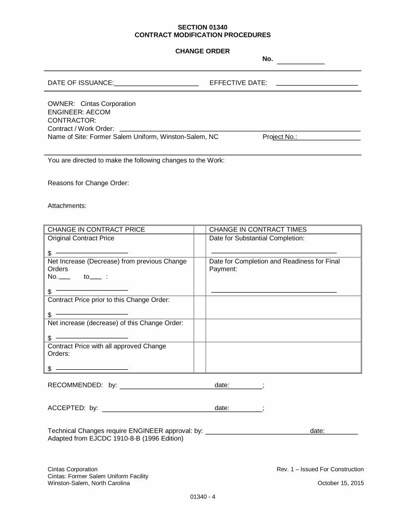
SECTION 01340CONTRACT MODIFICATION PROCEDURES
Cintas Corporation Rev. 1 – Issued For ConstructionCintas: Former Salem Uniform FacilityWinston-Salem, North Carolina October 15, 2015
01340 - 4
CHANGE ORDERNo.
DATE OF ISSUANCE: EFFECTIVE DATE:
OWNER: Cintas CorporationENGINEER: AECOMCONTRACTOR:Contract / Work Order:Name of Site: Former Salem Uniform, Winston-Salem, NC Project No.:
You are directed to make the following changes to the Work:
Reasons for Change Order:
Attachments:
CHANGE IN CONTRACT PRICE CHANGE IN CONTRACT TIMESOriginal Contract Price
$
Date for Substantial Completion:
Net Increase (Decrease) from previous ChangeOrdersNo. to :
$
Date for Completion and Readiness for FinalPayment:
Contract Price prior to this Change Order:
$Net increase (decrease) of this Change Order:
$Contract Price with all approved ChangeOrders:
$
RECOMMENDED: by: date: ;
ACCEPTED: by: date: ;
Technical Changes require ENGINEER approval: by: date:Adapted from EJCDC 1910-8-B (1996 Edition)
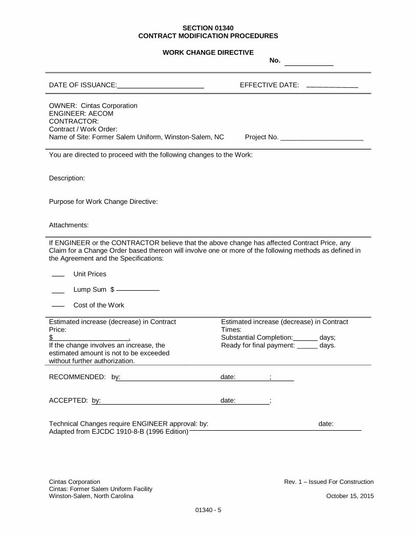
SECTION 01340CONTRACT MODIFICATION PROCEDURES
Cintas Corporation Rev. 1 – Issued For ConstructionCintas: Former Salem Uniform FacilityWinston-Salem, North Carolina October 15, 2015
01340 - 5
WORK CHANGE DIRECTIVENo.
DATE OF ISSUANCE: EFFECTIVE DATE:
OWNER: Cintas CorporationENGINEER: AECOMCONTRACTOR:Contract / Work Order:Name of Site: Former Salem Uniform, Winston-Salem, NC Project No. ______________________
You are directed to proceed with the following changes to the Work:
Description:
Purpose for Work Change Directive:
Attachments:
If ENGINEER or the CONTRACTOR believe that the above change has affected Contract Price, anyClaim for a Change Order based thereon will involve one or more of the following methods as defined inthe Agreement and the Specifications:
Unit Prices
Lump Sum $
Cost of the Work
Estimated increase (decrease) in ContractPrice:$ .If the change involves an increase, theestimated amount is not to be exceededwithout further authorization.
Estimated increase (decrease) in ContractTimes:Substantial Completion: days;Ready for final payment: days.
RECOMMENDED: by: date: ;
ACCEPTED: by: date: ;
Technical Changes require ENGINEER approval: by: date:Adapted from EJCDC 1910-8-B (1996 Edition)

SECTION 01340CONTRACT MODIFICATION PROCEDURES
Cintas Corporation Rev. 1 – Issued For ConstructionCintas: Former Salem Uniform FacilityWinston-Salem, North Carolina October 15, 2015
01340 - 6
FIELD ORDER FORM
F.O. NUMBER: PROJECT NUMBER:
DATE: SITE LOCATION:Former Salem Uniform– Winston-Salem, NC
ISSUED BY: COPIES TO:
Subject:
Specification or Drawing No:
Reason for Change:
Details of Change:
Technical Changes require ENGINEER approval: by: date:
SECTION 01410HEALTH AND SAFETY REQUIREMENTS
Cintas Corporation Rev. 1 – Issued For ConstructionCintas: Former RUS FacilityWinston-Salem, North Carolina October 15, 2015
01410 - 1
PART 1 - GENERAL
1.01 SUMMARY
A. Section includes Specifications and requirements for Health and Safety duringperformance of Work including identification of applicable Regulations, submittals,notification requirements, and Health and Safety execution Specifications.
1.02 REFERENCES
A. Applicable Regulations and publications include, but are not limited to, the following:
1. Code of Federal Regulations (CFR): Title 29 CFR Part 1910, OccupationalSafety and Health Standards; Title 29 CFR Part 1926, Safety and HealthRegulations for Construction Sites; Title 29 CFR Part 1904, Recording andReporting Occupational Injuries and Illnesses; Title 49 CFR Part 171, GeneralInformation, Regulations, and Definitions; and Title 49 CFR Part 172, HazardousMaterials Table, Special Provisions, Hazardous Materials Communications,Emergency Response Information, and Training Requirements.
2. NFPA, Flammable and Combustible Liquids Code, NFPA 30, most recentrevision.
3. USEPA, Standard Operating Safety Guidelines, November 1984.
4. NIOSH, "Manual of Analytical Methods", 3rd edition Volumes I and II, DHHS(NIOSH) Publication 84-100.
5. ANSI, Practices for Respiratory Protection, Z88.2, most recent version.
6. ANSI, Emergency Eyewash and Shower Equipment, Z358.1, 1981.
7. ANSI, Protective Footwear, Z41.1, 1983.
8. ANSI, Respirator Use Physical Qualification for Personnel, Z88.6, 1984.
9. ANSI, Practice for Occupational and Educational Eye and Face Protection,Z87.1, 1979.
10. NIOSH/OSHA/USCG/USEPA, Pub. No. 85-115, Occupational Safety and HealthGuidance Manual for Hazardous Waste Site Activities, DHHS/PHS/CDC/NIOSH,October 1985.
11. NIOSH Pocket Guide to Chemical Hazards, DHHS/PHS/CDC/NIOSH, June,2000 or most recent.
12. USEPA, Health and Safety Requirements for Personnel Engaged in FieldActivities, USEPA Order No. 14402.
13. USDOT Standards and Regulations, 49 CFR 171 and 49 CFR 172.
14. ACGIH, Threshold Limit Values and Biological Exposure Indices (most recentversion).
SECTION 01410HEALTH AND SAFETY REQUIREMENTS
Cintas Corporation Rev. 1 – Issued For ConstructionCintas: Former RUS FacilityWinston-Salem, North Carolina October 15, 2015
01410 - 2
Compendium of Methods for the Determination of Toxic Organic Compounds inAmbient Air, EPA/600/4-87-006, September 1986.
B. Where two or more Regulations/documents conflict, the one(s) offering the greatestdegree of protection shall apply.
1.03 CONTRACTOR’S RESPONSIBILITY FOR HEALTH AND SAFETY
A. The CONTRACTOR shall comply with any and all State, Federal and Local ordinancesand Regulations.
B. The CONTRACTOR shall be responsible for the safety of the CONTRACTOR’semployees, its SUBCONTRACTORs, suppliers, agents, inspectors, visitors, the generalpublic, and any others associated with or interacting with CONTRACTOR who provideslabor, goods, or other services on the site to chemical exposure.
C. The CONTRACTOR shall be responsible for emergency response planning andnotification, and for actual response to any and all emergencies that may occur during thecourse of the Work, including emergencies that may occur when CONTRACTOR is notpresent at the site.
D. The CONTRACTOR is responsible for understanding and acting in accordance with allrequirements of this Section and the ENGINEER’s Health and Safety Plan (HASP) for theProject.
E. The CONTRACTOR is responsible for creating and obtaining the ENGINEER’s approvalof a CONTRACTOR’S Site Specific Health and Safety Plan as described in this Section.
F. The CONTRACTOR shall be responsible for stability of excavations and embankmentscaused by the CONTRACTOR’s Work. CONTRACTOR shall designate one competentperson as defined in 29 CFR Part 1926, Subpart P, Excavations, to inspect anddocument excavation safety conditions daily, and to ensure excavation safety prior to anypersonnel entering an excavation.
G. The CONTRACTOR shall maintain an air monitoring program and an industrial hygieneprogram including the use of proper equipment for routine air monitoring, calibrationrecords, air monitoring results, and trained personnel. The air monitoring program shallmonitor personnel working in the exclusion zone as well as ambient air in the followingzones:
1. Exclusion zone
2. Contaminant reduction zone
3. Support zone
H. The CONTRACTOR shall designate an employee as a dedicated Site Safety and HealthOfficer (SSHO) on the Site during the Work.
1. The SSHO shall enforce the requirements of safety for all CONTRACTORpersonnel on site at all times. The SSHO shall ensure that all CONTRACTORand SUBCONTRACTOR personnel working at the site, and CONTRACTORvisitors, follow the HASP, including wearing the designated level of PPE at alltimes. If the SSHO elects to require a higher level of protection than thatspecified in the HASP, the extra costs associated with such higher level shall be
SECTION 01410HEALTH AND SAFETY REQUIREMENTS
Cintas Corporation Rev. 1 – Issued For ConstructionCintas: Former RUS FacilityWinston-Salem, North Carolina October 15, 2015
01410 - 3
borne by CONTRACTOR, unless such extra costs are approved in advance inwriting by the OWNER.
2. Prior to mobilization and continually through the duration of the Work, the SSHOshall inspect the site and document area-specific and worker-specific protectionrequirements.
3. After mobilization, the SSHO shall monitor activities and shall document the needfor additional worker protection as required, based on activities performed andAction Levels specified in the HASP.
4. The SSHO shall verify that all activities are performed in accordance with theHASP and all Federal, State, Local, and health and safety standards,Regulations, and guidelines.
1.04 ENGINEERS RESPONSIBILITY FOR HEALTH AND SAFETY
A. The ENGINEER shall be responsible for perimeter air quality monitoring of the Site at theSite boundary.
B. The ENGINEER’s responsibility and duty with regard to Health and Safety shall be limitedto the ENGINEER’s employees and to the OWNER’s requirements.
1.05 SUBMITTALS
A. Site-Specific Health and Safety Plan
1. The CONTRACTOR shall prepare and submit a HASP to the ENGINEER. TheCONTRACTOR shall follow all applicable local, state, and federal health andsafety standards, regulations and guidelines implemented through, but not limitedto, the OSHA, NIOSH, DOT, ACGIH, and USEPA. Where these are in conflict,the most stringent requirement shall be followed. The following points shall beaddressed in the CONTRACTOR’s HASP:
a. Site location, physical setting, and access.
b. Site history.
c. Site preparation issues.
d. Exposure pathways: inhalation, dermal contact, ingestion, etc.
e. Names of key personnel and alternates responsible for Health andSafety, including a CONTRACTOR Health and Safety Representativeand SSHO. The ENGINEER must approve the SSHO.
f. A Health and Safety risk or Job Safety and Hazard Analysis (JSHA)associated with each portion of the Work (i.e., details of basic job steps,list potential hazards or accidents and provide recommendations for safejob procedures). A sample JSHA is attached as an appendix to thisspecification section.
SECTION 01410HEALTH AND SAFETY REQUIREMENTS
Cintas Corporation Rev. 1 – Issued For ConstructionCintas: Former RUS FacilityWinston-Salem, North Carolina October 15, 2015
01410 - 4
g. Employee and SUBCONTRACTOR training assignments to assurecompliance with 29 CFR 1910.120.
h. A requirement that CONTRACTOR locate underground utilities andfacilities by utilizing the North Carolina One-Call Center and a third-party,private utility locator.
i. Personal protective equipment (PPE) to be used for each of the sitetasks and operations being conducted, as required by the personalprotective equipment program in 29 CFR 1910.120 and 29 CFR 1926.
j. Medical surveillance requirements in accordance with the program in 29CFR 1910.120.
k. Frequency and types of air monitoring, personnel monitoring, andenvironmental sampling techniques and instrumentation to be used bythe CONTRACTOR, including methods of maintenance and calibration ofmonitoring and sampling equipment.
l. Corrective actions and upgrading of personnel protection based onmonitoring of air, personnel, and environmental sampling, with specificAction Levels identified.
m. Site control measures in accordance with the control program required in29 CFR 1910.120 and 29 CFR 1926, including information on theexclusion zone (EZ), contamination reduction zone (CRZ), and supportzone (SZ).
n. Site security requirements.
o. Safe work practices, including information on:
i. General work practices.ii. Heavy equipment.iii. Equipment inspections.iv. Electrical hazards.v. Trip and fall hazards.vi. Trenches and excavations.vii. Utility and power line clearance.viii. Noise protection.ix. Sanitation.x. Site housekeeping.xi. Enforcement issues.
p. Decontamination procedures in accordance with 29 CFR 1910.120 andSpecifications Section 02130 – Site Decontamination.
q. An emergency response plan meeting federal, state, and localrequirements for safe and effective responses to emergencies, includingthe necessary PPE and other equipment. Explanation of potentialemergencies and contingency plan of action, including description of theroute to the nearest appropriate hospital, hospital route map, and postingof emergency telephone numbers at the site.
SECTION 01410HEALTH AND SAFETY REQUIREMENTS
Cintas Corporation Rev. 1 – Issued For ConstructionCintas: Former RUS FacilityWinston-Salem, North Carolina October 15, 2015
01410 - 5
r. A spill containment program meeting the requirements of all applicablelocal, state, and federal Health and Safety standards.
s. A list of Health and Safety and emergency equipment available on thesite.
t. A description of engineering controls used to reduce the hazards ofequipment operation and exposure to site hazardous chemicals.
u. Open trench excavation procedures and shoring procedures inaccordance with applicable OSHA Regulations. When in conflict themore stringent application shall be followed.
v. Procedures for earthwork near buried utilities, where hand diggingshould be performed within 24 inches of known utility lines.
w. Training for emergency response procedures in accordance with theENGINEER’s HASP.
x. Heat stress program in accordance with the ENGINEER’s HASP.
y. Cold stress program in accordance with the ENGINEER’s HASP.
z. Lockout/Tagout where the operation of machinery and/or equipment inwhich the unexpected energization or the release of stored energy couldcause injury to personnel.
aa. Required Tables:
i. Decontamination equipment requirements for each decontaminationstage.
ii. Sample tailgate safety meeting form.
bb. Required Figures:
i. Regional Location Map.ii. Site layout, including Exclusion Zone (EZ), Contaminant Reduction
Zone (CRZ), and Support Zone (SZ).iii. Health and safety program responsibility and chain of command.iv. Decontamination layout.
B. Daily Safety Reports
1. The CONTRACTOR shall submit Daily Safety Reports to the ENGINEER thatinclude, at a minimum:
a. The names of all CONTRACTOR and SUBCONTRACTOR personnelemployed at the site at any time during that day, and the names and duties ofkey personnel including CONTRACTOR’s Project Manager, ProjectSuperintendent, SSHO, and excavation-competent person.
b. A summary of all Health and Safety incidents describing any medicaltreatment that was provided during the day, the current Work status of any
SECTION 01410HEALTH AND SAFETY REQUIREMENTS
Cintas Corporation Rev. 1 – Issued For ConstructionCintas: Former RUS FacilityWinston-Salem, North Carolina October 15, 2015
01410 - 6
individuals affected, the names of individuals who may have observed theincident, and actions taken by CONTRACTOR to address the unsafe act orunsafe condition.
c. A summary of all Health and Safety near-misses or observations providingan opportunity for shared learning and future hazard avoidance. For anyHealth or Safety incident or near-miss, list the date, the nature of the incidentor near-miss, and the names of individuals involved. A near-miss form foruse in submitting near-misses is attached to this Section.
d. The total number of labor hours (including all CONTRACTORs andSUBCONTRACTORs) worked at the site during that day.
e. Internal Health and Safety audits performed by the CONTRACTOR as part ofthe CONTRACTOR’s HASP as described in 3.05A of this Section.
2. The CONTRACTOR’s Daily Safety Reports may be a component of the DailyConstruction Reports.
C. Certificates of Training
1. Prior to initiating Work, CONTRACTOR shall provide the ENGINEER withdocumentation of employee and applicable SUBCONTRACTOR training andmedical certifications required under 20 CFR 1910.120 as described in thisSection.
2. CONTRACTOR shall submit documentation of training and experience for thedesignated excavation-competent person. The excavation-competent personmust be approved by the ENGINEER for any excavation depth exceeding 4 feet.
D. Copies of Hot Work Permit
1. If hot work is required as part of the Work the CONTRACTOR shall submit a HotWork Permit, using the form attached to this Section, for any welding, torchcutting, or activities that generate sparks.
PART 2 - PRODUCTS
2.01 EQUIPMENT AND FACILITIES
A. The CONTRACTOR shall provide all equipment, temporary facilities, and qualifiedpersonnel required to perform activities on-site safely in accordance with all Regulationsand standards, and with the ENGINEER’s HASP.
2.02 TRAINING
A. CONTRACTOR shall ensure the following training has been to each worker:
1. Initial 40-hour HAZWOPER Safety training and current annual 8-hour refreshertraining (per 29 CFR 1910.120).
2. Eight-hour OSHA hazardous waste supervisory training (required for theCONTRACTOR’s Superintendent or SSHO).
SECTION 01410HEALTH AND SAFETY REQUIREMENTS
Cintas Corporation Rev. 1 – Issued For ConstructionCintas: Former RUS FacilityWinston-Salem, North Carolina October 15, 2015
01410 - 7
3. Enrollment in a medical monitoring program, with clearance within the previous12 months from a licensed physician allowing the worker to participate in fieldactivities and use respiratory protective equipment. CONTRACTOR shall notsubmit detailed medical information for employees.
4. Current respiratory fit testing certification.
5. Current CPR and first aid certification for at least two workers assigned to Workon the site.
6. For one who is assigned the role of a “competent person,” documentation ofsufficient and relevant training and experience to perform the assigned dutiesand responsibilities of that role. As defined in 29 CFR 1926.31, the competentperson shall be “one who is capable of identifying existing and predictablehazards, and who has authority to take prompt corrective measures to eliminatethem.” Relevant training and experience shall be in the same type of projectactivities included in the Work under this Contract.
B. CONTRACTOR shall designate one competent person as defined in 29 CFR Part 1926,Subpart P, Excavations, to inspect and document excavation safety conditions daily, andto ensure excavation safety prior to any personnel entering an excavation or performingwork in the area.
C. The CONTRACTOR’s SSHO shall, at a minimum, have at least 1 year of experience asan SSHO on an uncontrolled hazardous waste site, and have 40-hour OSHA HazardousWaste Operations and Emergency Response training and 8-hour OSHA Supervisortraining. Tenure of CONTRACTOR’s SSHO shall be subject to approval by theENGINEER; such approval not to be unreasonably withheld.
2.03 ENGINEERING CONTROLS
A. The CONTRACTOR shall provide the necessary engineering controls to sustainconcentrations of regulated chemicals below applicable occupational thresholds withinthe support zone. This may include the use of vapor-suppressing foams, plasticsheeting, forced ventilation, work phasing, or other product/method that theCONTRACTOR proposes and the ENGINEER approves.
B. The CONTRACTOR shall, at a minimum, provide the following engineering controls toreduce the hazards of equipment operation and exposure to site hazardous conditions:
1. Roll-over cages for bulldozers, back hoes, loaders, and tractors.
2. Back-up alarms for all trucks and moving equipment.
3. Wetting of soil or other means to control dust during the Work.
4. Decontamination of personnel and equipment in accordance with Section 02130– Site Decontamination.
5. Barricades for open trenches, excavations, and steep slopes.
6. Sloping, benching, shoring, drainage systems or other controls as necessary toensure stability of excavations and embankments
7. Cover all stock piles at the end of each work day with an impermeable cover tominimize contact with precipitation and disturbance or transport of stockpiled
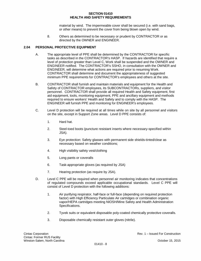
SECTION 01410HEALTH AND SAFETY REQUIREMENTS
Cintas Corporation Rev. 1 – Issued For ConstructionCintas: Former RUS FacilityWinston-Salem, North Carolina October 15, 2015
01410 - 8
material by wind. The impermeable cover shall be secured (i.e. with sand bags,or other means) to prevent the cover from being blown open by wind.
8. Others as determined to be necessary or prudent by CONTRACTOR or asdirected by the OWNER and ENGINEER.
2.04 PERSONAL PROTECTIVE EQUIPMENT
A. The appropriate level of PPE shall be determined by the CONTRACTOR for specifictasks as described in the CONTRACTOR’s HASP. If hazards are identified that require alevel of protection greater than Level C, Work shall be suspended and the OWNER andENGINEER notified. The CONTRACTOR’s SSHO, in consultation with the OWNER andENGINEER, will determine what actions are required prior to resuming Work.CONTRACTOR shall determine and document the appropriateness of suggestedminimum PPE requirements for CONTRACTOR’s employees and others at the site.
B. CONTRACTOR shall furnish and maintain materials and equipment for the Health andSafety of CONTRACTOR employees, its SUBCONTRACTORs, suppliers, and visitorpersonnel. CONTRACTOR shall provide all required Health and Safety equipment, firstaid equipment, tools, monitoring equipment, PPE and ancillary equipment and methodsrequired to ensure workers’ Health and Safety and to comply with the HASP. TheENGINEER will furnish PPE and monitoring for ENGINEER’s employees.
C. Level D protection will be required at all times while on site by all personnel and visitorson the site, except in Support Zone areas. Level D PPE consists of:
1. Hard hat.
2. Steel-toed boots (puncture resistant inserts where necessary-specified withinJSA).
3. Eye protection: Safety glasses with permanent side shields-tinted/clear asnecessary based on weather conditions;
4. High visibility safety vest/clothing
5. Long pants or coveralls
6. Task-appropriate gloves (as required by JSA)
7. Hearing protection (as require by JSA).
D. Level C PPE will be required when personnel air monitoring indicates that concentrationsof regulated compounds exceed applicable occupational standards. Level C PPE willconsist of Level D protection with the following additions:
1. Air purifying respirator, half-face or full-face (depending on required protectionfactor) with High Efficiency Particulate Air cartridges or combination organicvapor/HEPA cartridges meeting NIOSH/Mine Safety and Health AdministrationSpecifications.
2. Tyvek suits or equivalent disposable poly-coated chemically protective coveralls.
3. Disposable chemically resistant outer gloves (nitrile).
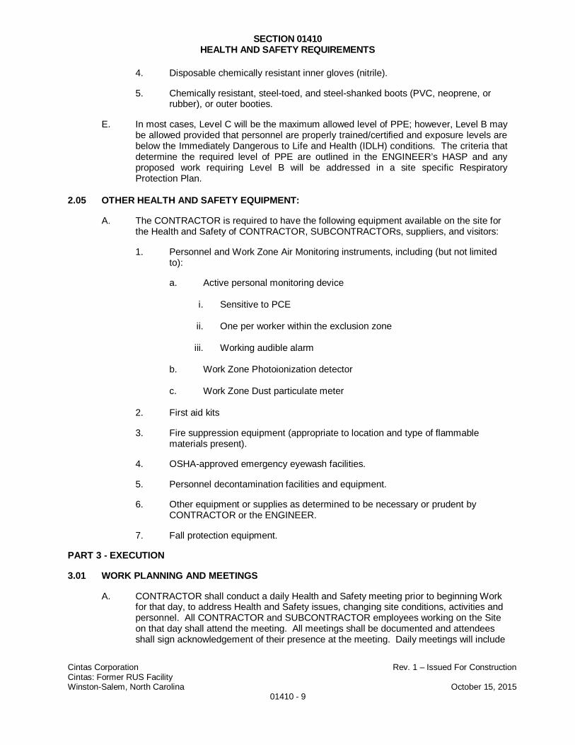
SECTION 01410HEALTH AND SAFETY REQUIREMENTS
Cintas Corporation Rev. 1 – Issued For ConstructionCintas: Former RUS FacilityWinston-Salem, North Carolina October 15, 2015
01410 - 9
4. Disposable chemically resistant inner gloves (nitrile).
5. Chemically resistant, steel-toed, and steel-shanked boots (PVC, neoprene, orrubber), or outer booties.
E. In most cases, Level C will be the maximum allowed level of PPE; however, Level B maybe allowed provided that personnel are properly trained/certified and exposure levels arebelow the Immediately Dangerous to Life and Health (IDLH) conditions. The criteria thatdetermine the required level of PPE are outlined in the ENGINEER’s HASP and anyproposed work requiring Level B will be addressed in a site specific RespiratoryProtection Plan.
2.05 OTHER HEALTH AND SAFETY EQUIPMENT:
A. The CONTRACTOR is required to have the following equipment available on the site forthe Health and Safety of CONTRACTOR, SUBCONTRACTORs, suppliers, and visitors:
1. Personnel and Work Zone Air Monitoring instruments, including (but not limitedto):
a. Active personal monitoring device
i. Sensitive to PCE
ii. One per worker within the exclusion zone
iii. Working audible alarm
b. Work Zone Photoionization detector
c. Work Zone Dust particulate meter
2. First aid kits
3. Fire suppression equipment (appropriate to location and type of flammablematerials present).
4. OSHA-approved emergency eyewash facilities.
5. Personnel decontamination facilities and equipment.
6. Other equipment or supplies as determined to be necessary or prudent byCONTRACTOR or the ENGINEER.
7. Fall protection equipment.
PART 3 - EXECUTION
3.01 WORK PLANNING AND MEETINGS
A. CONTRACTOR shall conduct a daily Health and Safety meeting prior to beginning Workfor that day, to address Health and Safety issues, changing site conditions, activities andpersonnel. All CONTRACTOR and SUBCONTRACTOR employees working on the Siteon that day shall attend the meeting. All meetings shall be documented and attendeesshall sign acknowledgement of their presence at the meeting. Daily meetings will include
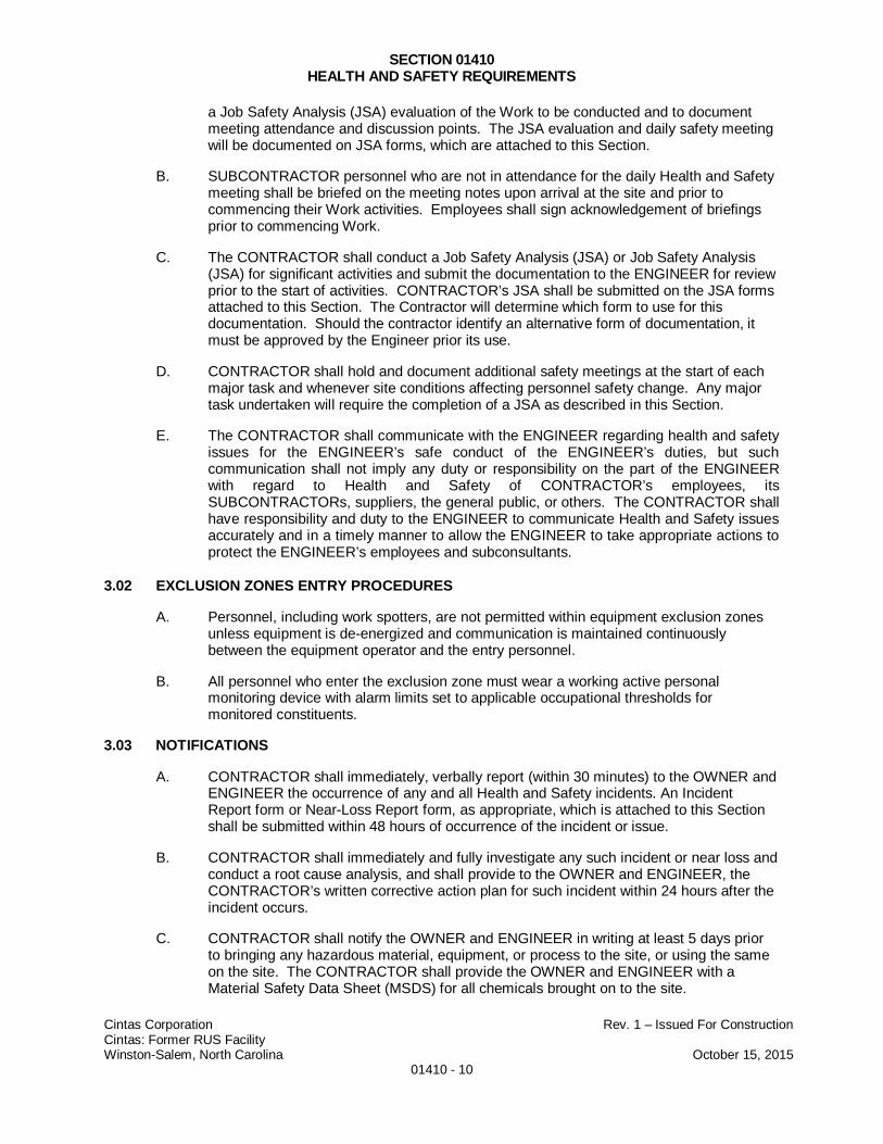
SECTION 01410HEALTH AND SAFETY REQUIREMENTS
Cintas Corporation Rev. 1 – Issued For ConstructionCintas: Former RUS FacilityWinston-Salem, North Carolina October 15, 2015
01410 - 10
a Job Safety Analysis (JSA) evaluation of the Work to be conducted and to documentmeeting attendance and discussion points. The JSA evaluation and daily safety meetingwill be documented on JSA forms, which are attached to this Section.
B. SUBCONTRACTOR personnel who are not in attendance for the daily Health and Safetymeeting shall be briefed on the meeting notes upon arrival at the site and prior tocommencing their Work activities. Employees shall sign acknowledgement of briefingsprior to commencing Work.
C. The CONTRACTOR shall conduct a Job Safety Analysis (JSA) or Job Safety Analysis(JSA) for significant activities and submit the documentation to the ENGINEER for reviewprior to the start of activities. CONTRACTOR’s JSA shall be submitted on the JSA formsattached to this Section. The Contractor will determine which form to use for thisdocumentation. Should the contractor identify an alternative form of documentation, itmust be approved by the Engineer prior its use.
D. CONTRACTOR shall hold and document additional safety meetings at the start of eachmajor task and whenever site conditions affecting personnel safety change. Any majortask undertaken will require the completion of a JSA as described in this Section.
E. The CONTRACTOR shall communicate with the ENGINEER regarding health and safetyissues for the ENGINEER’s safe conduct of the ENGINEER’s duties, but suchcommunication shall not imply any duty or responsibility on the part of the ENGINEERwith regard to Health and Safety of CONTRACTOR’s employees, itsSUBCONTRACTORs, suppliers, the general public, or others. The CONTRACTOR shallhave responsibility and duty to the ENGINEER to communicate Health and Safety issuesaccurately and in a timely manner to allow the ENGINEER to take appropriate actions toprotect the ENGINEER’s employees and subconsultants.
3.02 EXCLUSION ZONES ENTRY PROCEDURES
A. Personnel, including work spotters, are not permitted within equipment exclusion zonesunless equipment is de-energized and communication is maintained continuouslybetween the equipment operator and the entry personnel.
B. All personnel who enter the exclusion zone must wear a working active personalmonitoring device with alarm limits set to applicable occupational thresholds formonitored constituents.
3.03 NOTIFICATIONS
A. CONTRACTOR shall immediately, verbally report (within 30 minutes) to the OWNER andENGINEER the occurrence of any and all Health and Safety incidents. An IncidentReport form or Near-Loss Report form, as appropriate, which is attached to this Sectionshall be submitted within 48 hours of occurrence of the incident or issue.
B. CONTRACTOR shall immediately and fully investigate any such incident or near loss andconduct a root cause analysis, and shall provide to the OWNER and ENGINEER, theCONTRACTOR’s written corrective action plan for such incident within 24 hours after theincident occurs.
C. CONTRACTOR shall notify the OWNER and ENGINEER in writing at least 5 days priorto bringing any hazardous material, equipment, or process to the site, or using the sameon the site. The CONTRACTOR shall provide the OWNER and ENGINEER with aMaterial Safety Data Sheet (MSDS) for all chemicals brought on to the site.

SECTION 01410HEALTH AND SAFETY REQUIREMENTS
Cintas Corporation Rev. 1 – Issued For ConstructionCintas: Former RUS FacilityWinston-Salem, North Carolina October 15, 2015
01410 - 11
D. CONTRACTOR shall immediately notify the OWNER and ENGINEER in writing of anyhazard that CONTRACTOR discovers or observes on the site and corrective measuresplanned or taken to eliminate or minimize such hazard. Hazard reporting will becompleted as a Near Loss Report.
3.04 STOP WORK CONDITIONS
A. The following personnel and work zone action levels are explicit stop work conditions:
1. Exceedance of the Threshold Limit Vale (TLV)-short-term exposure limit(STEL) for 5 minutes in the breathing zone.
2. Exceedance of 50% of the threshold limit value (TLV)-Time Weighted Average(TWA) for a period of one hour.
3. Exceedance of 50% of the permissible exposure limit (PEL) for a period of onehour.
4. Nuisance odors in excess of the comfort level of staff performing the Work.
B. In the event of a health or safety risk as determined by the SSHO or otherCONTRACTOR personnel, or as determined by the ENGINEER, CONTRACTOR shallstop the work and shall not proceed with the Work until a method for handling the risk hasbeen determined in consultation with the ENGINEER and implemented.
3.05 EVALUATION OF PERFORMANCE
A. The CONTRACTOR shall routinely conduct internal safety audits on the Work site inaccordance with the ENGINEER’s HASP. The focus of these routine audits will be oncompliance with OSHA and local occupational safety Regulations.
END OF SECTION 01410
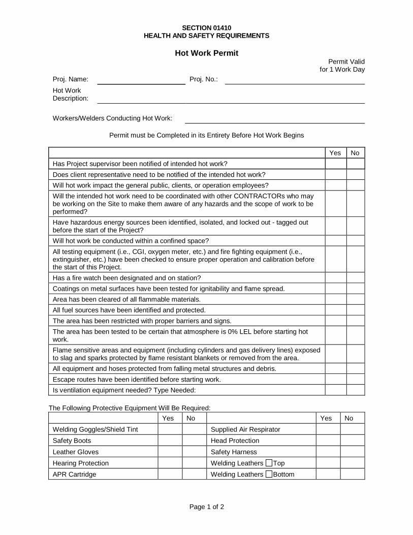
SECTION 01410HEALTH AND SAFETY REQUIREMENTS
Page 1 of 2
Hot Work PermitPermit Valid
for 1 Work Day
Proj. Name: Proj. No.:
Hot WorkDescription:
Workers/Welders Conducting Hot Work:
Permit must be Completed in its Entirety Before Hot Work Begins
Yes No
Has Project supervisor been notified of intended hot work?
Does client representative need to be notified of the intended hot work?
Will hot work impact the general public, clients, or operation employees?
Will the intended hot work need to be coordinated with other CONTRACTORs who maybe working on the Site to make them aware of any hazards and the scope of work to beperformed?
Have hazardous energy sources been identified, isolated, and locked out - tagged outbefore the start of the Project?
Will hot work be conducted within a confined space?
All testing equipment (i.e., CGI, oxygen meter, etc.) and fire fighting equipment (i.e.,extinguisher, etc.) have been checked to ensure proper operation and calibration beforethe start of this Project.
Has a fire watch been designated and on station?
Coatings on metal surfaces have been tested for ignitability and flame spread.
Area has been cleared of all flammable materials.
All fuel sources have been identified and protected.
The area has been restricted with proper barriers and signs.
The area has been tested to be certain that atmosphere is 0% LEL before starting hotwork.
Flame sensitive areas and equipment (including cylinders and gas delivery lines) exposedto slag and sparks protected by flame resistant blankets or removed from the area.
All equipment and hoses protected from falling metal structures and debris.
Escape routes have been identified before starting work.
Is ventilation equipment needed? Type Needed:
The Following Protective Equipment Will Be Required:
Yes No Yes No
Welding Goggles/Shield Tint Supplied Air Respirator
Safety Boots Head Protection
Leather Gloves Safety Harness
Hearing Protection Welding Leathers Top
APR Cartridge Welding Leathers Bottom
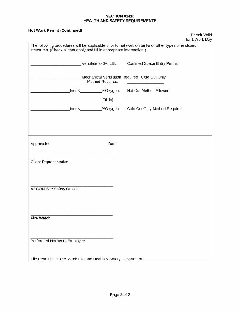
SECTION 01410HEALTH AND SAFETY REQUIREMENTS
Page 2 of 2
Hot Work Permit (Continued)Permit Valid
for 1 Work Day
The following procedures will be applicable prior to hot work on tanks or other types of enclosedstructures. (Check all that apply and fill in appropriate information.)
_______________________ Ventilate to 0% LEL Confined Space Entry Permit________________
_______________________ Mechanical Ventilation Required Cold Cut OnlyMethod Required: _________________
__________________Inert<__________%Oxygen: Hot Cut Method Allowed:__________________
(Fill In)
__________________Inert<__________%Oxygen: Cold Cut Only Method Required:
Approvals: Date:____________________
______________________________________Client Representative
______________________________________AECOM Site Safety Officer
______________________________________Fire Watch
______________________________________Performed Hot Work Employee
File Permit in Project Work File and Health & Safety Department

Page 1 of 2
AECOMSafety Task Analysis Review
(STAR)
Job Description:
List Tasks:
Completed By
Job Location:
Client Rep.:
Phone #:
List Hazards:
Company
Person(s) working on this task:
List Controls:
Date
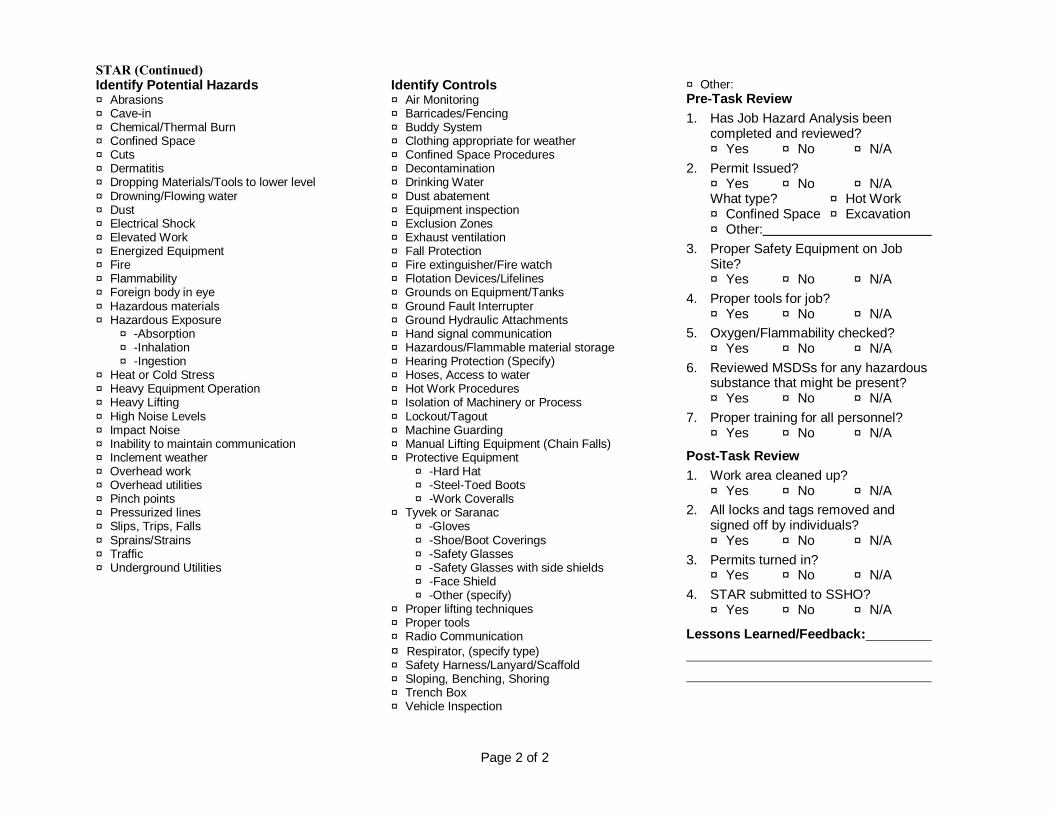
STAR (Continued)
Page 2 of 2
Identify Potential Hazards¨ Abrasions¨ Cave-in¨ Chemical/Thermal Burn¨ Confined Space¨ Cuts¨ Dermatitis¨ Dropping Materials/Tools to lower level¨ Drowning/Flowing water¨ Dust¨ Electrical Shock¨ Elevated Work¨ Energized Equipment¨ Fire¨ Flammability¨ Foreign body in eye¨ Hazardous materials¨ Hazardous Exposure¨ -Absorption¨ -Inhalation¨ -Ingestion
¨ Heat or Cold Stress¨ Heavy Equipment Operation¨ Heavy Lifting¨ High Noise Levels¨ Impact Noise¨ Inability to maintain communication¨ Inclement weather¨ Overhead work¨ Overhead utilities¨ Pinch points¨ Pressurized lines¨ Slips, Trips, Falls¨ Sprains/Strains¨ Traffic¨ Underground Utilities
Identify Controls¨ Air Monitoring¨ Barricades/Fencing¨ Buddy System¨ Clothing appropriate for weather¨ Confined Space Procedures¨ Decontamination¨ Drinking Water¨ Dust abatement¨ Equipment inspection¨ Exclusion Zones¨ Exhaust ventilation¨ Fall Protection¨ Fire extinguisher/Fire watch¨ Flotation Devices/Lifelines¨ Grounds on Equipment/Tanks¨ Ground Fault Interrupter¨ Ground Hydraulic Attachments¨ Hand signal communication¨ Hazardous/Flammable material storage¨ Hearing Protection (Specify)¨ Hoses, Access to water¨ Hot Work Procedures¨ Isolation of Machinery or Process¨ Lockout/Tagout¨ Machine Guarding¨ Manual Lifting Equipment (Chain Falls)¨ Protective Equipment¨ -Hard Hat¨ -Steel-Toed Boots¨ -Work Coveralls
¨ Tyvek or Saranac¨ -Gloves¨ -Shoe/Boot Coverings¨ -Safety Glasses¨ -Safety Glasses with side shields¨ -Face Shield¨ -Other (specify)
¨ Proper lifting techniques¨ Proper tools¨ Radio Communication¨ Respirator, (specify type)¨ Safety Harness/Lanyard/Scaffold¨ Sloping, Benching, Shoring¨ Trench Box¨ Vehicle Inspection
¨ Other:Pre-Task Review
1. Has Job Hazard Analysis beencompleted and reviewed?¨ Yes ¨ No ¨ N/A
2. Permit Issued?¨ Yes ¨ No ¨ N/AWhat type? ¨ Hot Work¨ Confined Space ¨ Excavation¨ Other:
3. Proper Safety Equipment on JobSite?¨ Yes ¨ No ¨ N/A
4. Proper tools for job?¨ Yes ¨ No ¨ N/A
5. Oxygen/Flammability checked?¨ Yes ¨ No ¨ N/A
6. Reviewed MSDSs for any hazardoussubstance that might be present?¨ Yes ¨ No ¨ N/A
7. Proper training for all personnel?¨ Yes ¨ No ¨ N/A
Post-Task Review
1. Work area cleaned up?¨ Yes ¨ No ¨ N/A
2. All locks and tags removed andsigned off by individuals?¨ Yes ¨ No ¨ N/A
3. Permits turned in?¨ Yes ¨ No ¨ N/A
4. STAR submitted to SSHO?¨ Yes ¨ No ¨ N/A
Lessons Learned/Feedback:
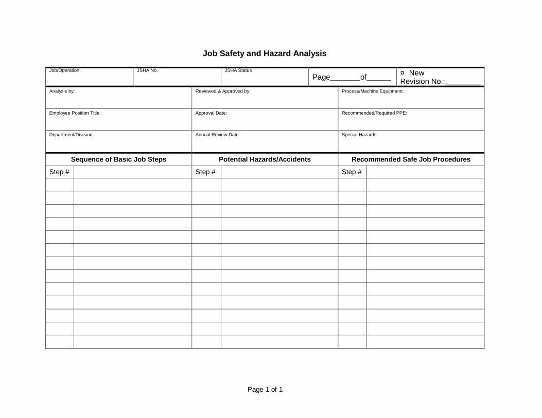
Page 1 of 1
Job Safety and Hazard Analysis
Job/Operation JSHA No. JSHA Status
Page of¨ NewRevision No.:
Analysis by: Reviewed & Approved by: Process/Machine Equipment:
Employee Position Title: Approval Date: Recommended/Required PPE:
Department/Division: Annual Review Date: Special Hazards:
Sequence of Basic Job Steps Potential Hazards/Accidents Recommended Safe Job Procedures
Step # Step # Step #
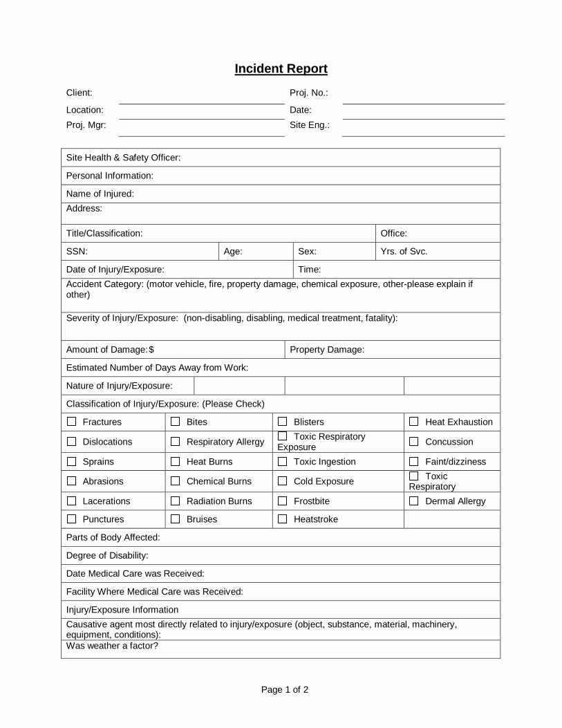
Page 1 of 2
Incident Report
Client: Proj. No.:
Location: Date:
Proj. Mgr: Site Eng.:
Site Health & Safety Officer:
Personal Information:
Name of Injured:
Address:
Title/Classification: Office:
SSN: Age: Sex: Yrs. of Svc.
Date of Injury/Exposure: Time:
Accident Category: (motor vehicle, fire, property damage, chemical exposure, other-please explain ifother)
Severity of Injury/Exposure: (non-disabling, disabling, medical treatment, fatality):
Amount of Damage: $ Property Damage:
Estimated Number of Days Away from Work:
Nature of Injury/Exposure:
Classification of Injury/Exposure: (Please Check)
Fractures Bites Blisters Heat Exhaustion
Dislocations Respiratory Allergy Toxic Respiratory
Exposure Concussion
Sprains Heat Burns Toxic Ingestion Faint/dizziness
Abrasions Chemical Burns Cold Exposure ToxicRespiratory
Lacerations Radiation Burns Frostbite Dermal Allergy
Punctures Bruises Heatstroke
Parts of Body Affected:
Degree of Disability:
Date Medical Care was Received:
Facility Where Medical Care was Received:
Injury/Exposure Information
Causative agent most directly related to injury/exposure (object, substance, material, machinery,equipment, conditions):Was weather a factor?
Incident Report (continued)
Page 2 of 2
Unsafe mechanical/physical/environmental conditions at time of exposure injury (be specific):
Personal factors (improper attitude, lack of knowledge or skill, slow reaction, fatigue):
Level of personal protective equipment specified in the Site Health & Safety Plan:
Modification:
Was injured person/persons using required PPE?
If not, how did the actual equipment used differ from that specified in the Site Health & Safety Plan?
What can be done to prevent a recurrence of this type of accident? (modification of equipment,mechanical changes, additional training, etc.):
Present a detailed narrative description of the injury/exposure. How did it occur? Why? Objects,equipment, tools used, circumstances, assigned duties, etc. (be specific):
Witnesses to injury/exposure (names and their eye witness accounts):
For Corporate Health & Safety Use Only
Temp. Total: Permanent Total: Death or Permanent Total:
Start Losing Time: Part of Body:
Return to Work: Percent Loss or Loss of Use:
Time Charge:
Name of Hospital:
Address:
Name of Physician:
Address:
Forward this form to the following: Health and Safety Department – Pittsburgh Human Resources Department – Concord Health & Safety Coordinator – Local Regional Manager – Local Operations Manager – Local

Page 1 of 1
Near-Miss Report
Name: Date:
Client: Proj. No:
I witnessed a near-miss this day at
Was appropriate PPE being worn: Yes No
The following is an account of what happened:
I believe this could have resulted in injury and/or damage to: (Check all that pertain)
Personnel Property Equipment
If these circumstances occurred:
I recommend the following actions to prevent this from occurring in the future:
Safety Standard Required Yes (Complete and Attach Safety Standard Form)No
Note: Use additional paper if required
SECTION 01420ENVIRONMENTAL PROTECTION
Cintas Corporation Rev. 1 – Issued For ConstructionCintas: Former RUS FacilityWinston-Salem, North Carolina October 15, 2015
01420 - 1
PART 1 - GENERAL
1.01 DESCRIPTION
A. The CONTRACTOR shall perform all Work in such manner so as to be in full compliancewith all federal, state, and local environmental requirements, and shall minimize the pollutingof air, water, or land, and within reasonable limits, control noise and minimize the generationand disposal of solid waste materials, as well as other pollutants.
1.02 PROTECTION OF LAND AREAS
A. Except for any work or storage area and access routes specifically assigned for the use ofthe CONTRACTOR, the land areas outside the limits of disturbance performed shall bepreserved in their present condition.
B. The CONTRACTOR shall confine its construction activities to areas defined for work on theDesign Drawings or specifically assigned for its use within the designated disturbed areas.Storage and related areas and access required temporarily by the CONTRACTOR in theperformance of the work will be coordinated with the OWNER and ENGINEER.
1.03 PROTECTION OF TREES AND SHRUBS
A. The CONTRACTOR shall not deface, injure or destroy trees or shrubs or their root systems,nor remove or cut them unless otherwise instructed by the OWNER or ENGINEER. Noropes, cables, or guys shall be fastened to or attached to any existing nearby trees foranchorages.
B. Any tree scarred or damaged by the CONTRACTOR's equipment or operations shall berestored as nearly as possible to its original condition. All scars made on trees notdesignated on the Design Drawings to be removed by construction operations shall becoated as soon as possible with an approved tree wound dressing. Trees that are toremain, either within or outside established clearing limits, that are damaged by theCONTRACTOR so as to be beyond saving, in the opinion of the CONTRACTOR and inconsultation with the OWNER and ENGINEER shall be immediately removed, if so directed,and replaced with a nursery-grown tree of the same species and size at no extra costs to theENGINEER or the OWNER.
1.04 PROTECTION OF WATER RESOURCES
A. The CONTRACTOR shall not dispose fuels, oils, bitumens, calcium chloride, acids orharmful materials, both on and off site and shall and comply with applicable federal, state,and local laws concerning pollution of rivers and streams. Special measures shall be takento prevent chemicals, fuels, oils, greases, bituminous materials, decontamination waters,herbicides, and insecticides from entering public waters.
B. Waste waters shall not be allowed to re-enter public waters.
1.05 WASTE DISPOSAL
A. The CONTRACTOR shall place all general debris and waste in an on-site storage areaand/or containers provided by the CONTRACTOR as directed by the ENGINEER asdesignated and directed by the OWNER. Land clearing materials shall be segregated andstockpiled in a separate area from that of general refuse. If any waste material is dumped in
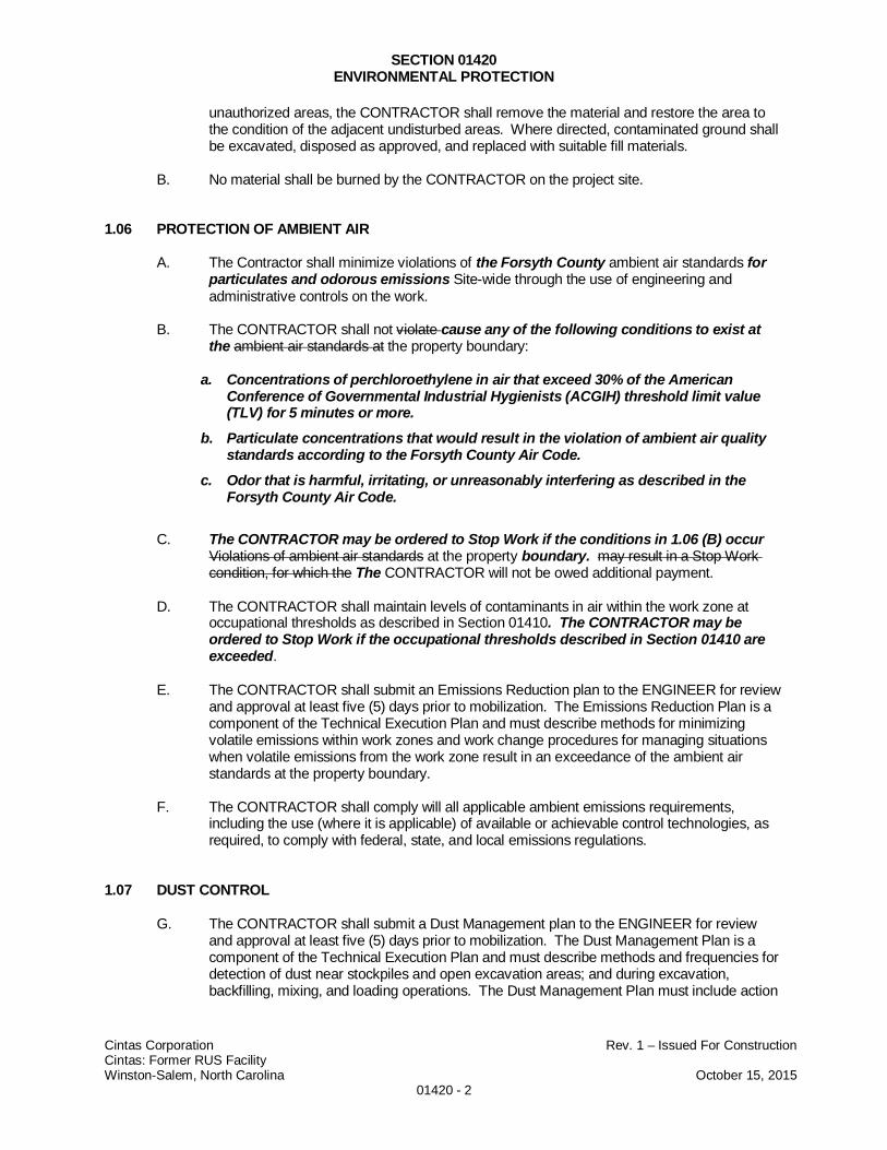
SECTION 01420ENVIRONMENTAL PROTECTION
Cintas Corporation Rev. 1 – Issued For ConstructionCintas: Former RUS FacilityWinston-Salem, North Carolina October 15, 2015
01420 - 2
unauthorized areas, the CONTRACTOR shall remove the material and restore the area tothe condition of the adjacent undisturbed areas. Where directed, contaminated ground shallbe excavated, disposed as approved, and replaced with suitable fill materials.
B. No material shall be burned by the CONTRACTOR on the project site.
1.06 PROTECTION OF AMBIENT AIR
A. The Contractor shall minimize violations of the Forsyth County ambient air standards forparticulates and odorous emissions Site-wide through the use of engineering andadministrative controls on the work.
B. The CONTRACTOR shall not violate cause any of the following conditions to exist atthe ambient air standards at the property boundary:
a. Concentrations of perchloroethylene in air that exceed 30% of the AmericanConference of Governmental Industrial Hygienists (ACGIH) threshold limit value(TLV) for 5 minutes or more.
b. Particulate concentrations that would result in the violation of ambient air qualitystandards according to the Forsyth County Air Code.
c. Odor that is harmful, irritating, or unreasonably interfering as described in theForsyth County Air Code.
C. The CONTRACTOR may be ordered to Stop Work if the conditions in 1.06 (B) occurViolations of ambient air standards at the property boundary. may result in a Stop Workcondition, for which the The CONTRACTOR will not be owed additional payment.
D. The CONTRACTOR shall maintain levels of contaminants in air within the work zone atoccupational thresholds as described in Section 01410. The CONTRACTOR may beordered to Stop Work if the occupational thresholds described in Section 01410 areexceeded.
E. The CONTRACTOR shall submit an Emissions Reduction plan to the ENGINEER for reviewand approval at least five (5) days prior to mobilization. The Emissions Reduction Plan is acomponent of the Technical Execution Plan and must describe methods for minimizingvolatile emissions within work zones and work change procedures for managing situationswhen volatile emissions from the work zone result in an exceedance of the ambient airstandards at the property boundary.
F. The CONTRACTOR shall comply will all applicable ambient emissions requirements,including the use (where it is applicable) of available or achievable control technologies, asrequired, to comply with federal, state, and local emissions regulations.
1.07 DUST CONTROL
G. The CONTRACTOR shall submit a Dust Management plan to the ENGINEER for reviewand approval at least five (5) days prior to mobilization. The Dust Management Plan is acomponent of the Technical Execution Plan and must describe methods and frequencies fordetection of dust near stockpiles and open excavation areas; and during excavation,backfilling, mixing, and loading operations. The Dust Management Plan must include action
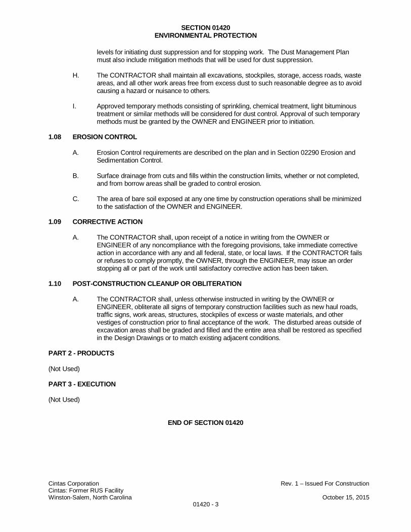
SECTION 01420ENVIRONMENTAL PROTECTION
Cintas Corporation Rev. 1 – Issued For ConstructionCintas: Former RUS FacilityWinston-Salem, North Carolina October 15, 2015
01420 - 3
levels for initiating dust suppression and for stopping work. The Dust Management Planmust also include mitigation methods that will be used for dust suppression.
H. The CONTRACTOR shall maintain all excavations, stockpiles, storage, access roads, wasteareas, and all other work areas free from excess dust to such reasonable degree as to avoidcausing a hazard or nuisance to others.
I. Approved temporary methods consisting of sprinkling, chemical treatment, light bituminoustreatment or similar methods will be considered for dust control. Approval of such temporarymethods must be granted by the OWNER and ENGINEER prior to initiation.
1.08 EROSION CONTROL
A. Erosion Control requirements are described on the plan and in Section 02290 Erosion andSedimentation Control.
B. Surface drainage from cuts and fills within the construction limits, whether or not completed,and from borrow areas shall be graded to control erosion.
C. The area of bare soil exposed at any one time by construction operations shall be minimizedto the satisfaction of the OWNER and ENGINEER.
1.09 CORRECTIVE ACTION
A. The CONTRACTOR shall, upon receipt of a notice in writing from the OWNER orENGINEER of any noncompliance with the foregoing provisions, take immediate correctiveaction in accordance with any and all federal, state, or local laws. If the CONTRACTOR failsor refuses to comply promptly, the OWNER, through the ENGINEER, may issue an orderstopping all or part of the work until satisfactory corrective action has been taken.
1.10 POST-CONSTRUCTION CLEANUP OR OBLITERATION
A. The CONTRACTOR shall, unless otherwise instructed in writing by the OWNER orENGINEER, obliterate all signs of temporary construction facilities such as new haul roads,traffic signs, work areas, structures, stockpiles of excess or waste materials, and othervestiges of construction prior to final acceptance of the work. The disturbed areas outside ofexcavation areas shall be graded and filled and the entire area shall be restored as specifiedin the Design Drawings or to match existing adjacent conditions.
PART 2 - PRODUCTS
(Not Used)
PART 3 - EXECUTION
(Not Used)
END OF SECTION 01420
SECTION 01500TEMPORARY FACILITIES AND CONTROLS
Cintas Corporation Rev. 1 – Issued For ConstructionCintas: Former RUS FacilityWinston-Salem, North Carolina October 15, 2015
01500 - 1
PART 1 - GENERAL
1.01 SUBMITTALS
A. In accordance with Section 01330 – Submittal Procedures
1.02 ACCESS AND DRAINAGE
A. The CONTRACTOR shall keep all natural drainage and water courses unobstructed orprovide equal courses effectively placed as indicated on the Drawings and in the TechnicalSpecifications, and prevent accumulations of surface water. The CONTRACTOR shallconstruct grades and stabilize access roads, and provide temporary mobilization, parkingand storage areas for use during construction within the areas shown on the DesignDrawings or as otherwise approved by the OWNER and ENGINEER.
B. Access roads and mobilization, parking, and storage areas shall be maintained in a stableand smooth condition throughout the life of the project.
C. CONTRACTOR shall designate an on-site parking area to accommodate personalvehicles of CONTRACTOR employees, the ENGINEER, OWNER, and visitors.Construction vehicles shall not be allowed in the areas designated for parking personalvehicles.
D. CONTRACTOR shall designate an area to be used for parking and maintenance ofconstruction vehicles and equipment.
1.04 TEMPORARY SANITARY FACILITIES
A. CONTRACTOR shall provide and maintain temporary portable chemical toilet facilities.The facilities shall be provided at time of Project mobilization and maintained in clean andsanitary condition until substantial completion. CONTRACTOR shall provide a sufficientnumber of portable toilets for CONTRACTOR and CONTRACTOR work crews, theENGINEER, the OWNER, and visitors in accordance with usage ratings. Location shallbe approved by the OWNER and ENGINEER.
B. CONTRACTOR shall provide and maintain in clean, good working order, a water handwashing facility for personal decontamination.
C. CONTRACTOR shall provide and maintain in clean, good working order an emergencydecontamination, eye wash station, and first aid/safety kits.
D. CONTRACTOR shall provide and maintain, in clean, good working order any otherpersonal decontamination facilities as directed by the OWNER or ENGINEER.
1.05 FIELD OFFICE
A. CONTRACTOR shall provide a temporary field office suitable for supervision and controlof the Work.
B. CONTRACTOR shall maintain a section of the field office for the ENGINEER’s on-siteemployee to work.

SECTION 01500TEMPORARY FACILITIES AND CONTROLS
Cintas Corporation Rev. 1 – Issued For ConstructionCintas: Former RUS FacilityWinston-Salem, North Carolina October 15, 2015
01500 - 2
C. The field office may be a mobile office trailer or framed tent structure. At a minimum, thefield office shall be adequately sized for conducting health and safety and planningmeetings. The field office shall also be sheltered from sunlight and precipitation.
D. The field office type and installation must comply with applicable federal, state, and localbuilding codes.
1.06 EQUIPMENT LAYDOWN AREA
A. An equipment lay down area is designated by the ENGINEER on the Design Drawings foruse by the CONTRACTOR for storage of its materials, tools, equipment, and other itemsnecessary for construction. The exact location and limits of the equipment layout area willbe designated in the field by the CONTRACTOR as approved by the ENGINEER. TheCONTRACTOR shall be fully responsible for the preparation of this area, its maintenance,and its security, including fencing and other means of security. Under no circumstances willthe OWNER or ENGINEER be responsible for the security of any property belonging to theCONTRACTOR, its SUBCONTRACTORs, or any of its work forces.
1.07 EROSION AND SILTATION CONTROL MEASURES
A. Adequate control of erosion and siltation of both a temporary and permanent nature onareas disturbed by the Work shall be provided under this Specification and/or subject to theapproval of the ENGINEER.
B. Erosion control requirements are described in Section 02290 Erosion and SedimentationControl.
1.08 EQUIPMENT DECONTAMINATION PAD
A. The CONTRACTOR shall be responsible for constructing the decontamination pad, andpumping and storing accumulated washdown water in the decontamination area on-site infrac tanks, as described in Section 02130 Decontamination and as shown on the Drawings.
1.09 FUEL STORAGE AND DISPENSING
E. CONTRACTOR shall store fuel on site only in approved containers that meet all relevantfire codes. The containers shall be stored in areas approved by the ENGINEER.
F. Extreme care shall be taken to prevent fuel spills. CONTRACTOR’s representative shallbe present at all times when equipment is being fueled. CONTRACTOR shall notify theENGINEER, the OWNER, and the local Fire Department and other authorities asrequired in the event of a spill. CONTRACTOR shall be prepared and shall providepersonal equipment and materials to immediately respond to fuel spills, and isresponsible for all costs of containing, removing and disposing of materials contaminatedby fuel spills.
G. CONTRACTOR shall provide and maintain absorbent materials, shovels, containers, andother appropriate materials for spill response and cleanup. Cleanup materials shall beappropriate for the type of fuels, oils, and other materials used.
H. CONTRACTOR shall not commingle waste materials caused by fueling or vehiclemaintenance activities with excavated contaminated soil generated by the Work.

SECTION 01500TEMPORARY FACILITIES AND CONTROLS
Cintas Corporation Rev. 1 – Issued For ConstructionCintas: Former RUS FacilityWinston-Salem, North Carolina October 15, 2015
01500 - 3
I. CONTRACTOR shall dispose of waste materials caused by fueling using appropriatemeasures and at no expense to the ENGINEER or the OWNER.
PART 2 - PRODUCTS
(Not Used)
PART 3 - EXECUTION
(Not Used)
END OF SECTION 01500
SECTION 01720SURVEYING
Cintas Corporation Rev. 1 – Issued For ConstructionCintas: Former Salem Uniform FacilityWinston-Salem, North Carolina October 15, 2015
01720 - 1
PART 1 - GENERAL
1.01 DESCRIPTION
A. The CONTRACTOR shall employ a competent Surveyor licensed in the State of NorthCarolina and require said Surveyor to establish all lines, elevations, reference marks,batterboards, etc., needed by the CONTRACTOR or the ENGINEER during the progressof the Work, and from time to time to verify such marks by instrument or other appropriatemeans.
B. All survey work shall be conducted by a third-party North Carolina Licensed LandSurveyor (i.e. not employed by the ENGINEER or the CONTRACTOR) and shall utilizerecognized engineering survey practices appropriate for obtaining the informationspecified.
C. Surveys shall be used as the basis for payment on several Work items.
D. Surveyor shall provide survey control for each stage of construction, and provide survey“As-Built” documentation for various components of construction. The Surveyor shallfurnish all labor, materials, tools, supervision, transportation, and equipment necessary toperform the project surveying work as specified as shown on the Design Drawings, and inaccordance with these Specifications.
1.02 SUBMITTALS
A. The CONTRACTOR shall submit copies of the Site Preconstruction Survey, ProgressSurveys, and Final Survey to the Engineer for approval.
B. The Preconstruction Survey is a pre-mobilization submittal. Progress and Final surveysare post-mobilization submittals.
C. CONTRACTOR shall submit all equipment calibration records, field notes, computations,data logger information, and other survey records taken as part of the surveys.
D. CONTRACTOR shall provide survey data electronically in AutoCAD and in tabulatedformats. All data points shall have horizontal and vertical data and reference point name,if appropriate. The ENGINEER, on behalf of the OWNER, will provide data formattingrequirements.
E. CONTRACTOR shall submit draft survey data directly to the ENGINEER. Final surveydata shall be submitted within 3 days of completion of the survey.
F. One electronic copy (AutoCAD) and three hard copies of the Preconstruction Survey,Progress Surveys, and Final (As-Built) Survey signed and sealed by the surveyorlicensed in the State of North Carolina shall be submitted to the ENGINEER within 7 daysof the completion of the field activities.
1.03 EXAMINATION
A. CONTRACTOR shall verify locations of survey benchmarks prior to starting Work.
B. CONTRACTOR shall promptly notify the ENGINEER of any discrepancies discovered.
1.04 SURVEY REFERENCE POINTS
A. CONTRACTOR’s surveyor shall establish temporary benchmark(s) and horizontal andvertical control for the Work.
SECTION 01720SURVEYING
Cintas Corporation Rev. 1 – Issued For ConstructionCintas: Former Salem Uniform FacilityWinston-Salem, North Carolina October 15, 2015
01720 - 2
B. CONTRACTOR shall locate and protect survey control and reference points duringconstruction.
PART 2 – PRODUCTS
2.01 PRE-CONSTRUCTION SURVEY
C. The Pre-Construction Survey scope-of-work shall include the following:
1. Conduct a Site-wide topographic and planimetric survey with 0.5-foot contoursand extents at least 25 feet beyond the site property boundaries in all directions.
2. Establish and/or verify the control points;
3. Establish boundaries of planned limits of disturbance, planned excavation areas,and planned decontamination area;
4. Establish initial excavation depths and extents;
5. Any other work lay out required by the CONTRACTOR to execute the Work.
2.02 PROGRESS SURVEYS
A. Progress Survey scopes-of-work shall include the following:
1. Survey extents and bottoms of Phase I excavation extents and depths, the intialbackfill extents and depths, the Phase II excavation extents and depths, the finalbackfill extents and depths;
2. Survey extents and bottoms of over-excavation areas;
3. Survey locations and elevations of confirmation samples;
4. Survey locations and elevations of all geotechnical (e.g. compaction) samples
5. Any other work completed by the CONTRACTOR.
B. The CONTRACTOR shall provide as many progress surveys as are required toadequately perform and document the Work for the purpose of payment.
C. Each Progress survey shall provide the surveyor’s sealed estimate of net cut and fillvolumes that were achieved since the previous survey.
2.03 FINAL (AS-BUILT) SURVEYS
A. The Final (As-Built) Survey scope-of-work shall include the following:
1. A topographic map of excavation areas (0.5-foot interval) and final grades andelevations after backfilling (0.5 foot interval);
2. Site-wide topography (0.5-foot intervals) extending 25 feet beyond the siteboundaries in all directions;
3. Location and elevation of excavation limits (showing excavation floor, headslopeand toeslope)
4. confirmation sample locations and elevations;
5. all other permanent changes that are made to site conditions existing prior toconstruction (such as modifications to treelines or pavements); and
SECTION 01720SURVEYING
Cintas Corporation Rev. 1 – Issued For ConstructionCintas: Former Salem Uniform FacilityWinston-Salem, North Carolina October 15, 2015
01720 - 3
6. The location and approximate elevation of all utility removals and abandonedterminations.
PART 3 – EXECUTION
3.01 SURVEY REQUIREMENTS
A. The Surveyor shall maintain lines and levels, layout, and locate the work utilizingrecognized engineering survey practices. A complete and accurate log of control andsurvey work must be maintained.
B. The Surveyor shall maintain lines and levels, layout, and locate the work utilizingrecognized engineering survey practices. A complete and accurate log of control andsurvey work must be maintained.
C. During the course of the Work, CONTRACTOR shall provide periodic submittals asrequired to support progress payment for excavation.
D. CONTRACTOR shall record the locations of all soil staging and management areas andsoil and geotechnical sampling locations in the excavation areas.
E. During the course of excavation, backfilling and site restoration Work, CONTRACTORpersonnel shall record elevations to signify that adequate soil removal has been obtainedand that site restoration is complete in the working areas as shown on the DesignDrawings.
F. CONTRACTOR shall promptly report to the OWNER and ENGINEER the loss ordestruction of any reference point or relocation required because of changes in grades orother reasons. CONTRACTOR shall replace dislocated reference points based onoriginal survey control. CONTRACTOR shall make no changes without prior writtennotice to the OWNER and ENGINEER.
G. The Work shall be executed in conformance with the lines and grades shown on theDesign Drawings, unless otherwise approved by the ENGINEER.
H. CONTRACTOR shall establish elevations, lines, and levels required for all sitepreparation excavations, backfilling, sampling locations, and site restoration items of theWork.
I. The survey instruments used shall be capable of reading to a precision of 0.01 ft and witha setting accuracy of 10 seconds of arc.
J. All survey drawings shall include topographic lines with sampling locations as necessaryto accurately represent conditions.
3.02 CONSTRUCTION TOLERANCES
A. Construction tolerances shall be as provided in the various sections of these Specifications,and as given below.
B. The ENGINEER, on behalf of OWNER, shall be permitted at all times to check the lines,elevations, reference marks, batterboards, etc., set by the CONTRACTOR, who will correctany errors in lines, elevations, reference marks, batterboards, etc., disclosed by such check.Such a check shall not be construed to be an approval of the CONTRACTOR's work andshall not relieve or diminish in any way the responsibility of the CONTRACTOR for theaccurate and satisfactory construction and completion of the entire Work.
D. The CONTRACTOR shall be aware of the surveying activities and shall account for them inthe construction schedule.

SECTION 01720SURVEYING
Cintas Corporation Rev. 1 – Issued For ConstructionCintas: Former Salem Uniform FacilityWinston-Salem, North Carolina October 15, 2015
01720 - 4
END OF SECTION 01720
SECTION 02110EXCAVATION, REMOVAL, AND HANDLING OF CONTAMINATED MATERIALS
Cintas Corporation Rev. 1 – Issued For ConstructionCintas: Former Salem Uniform FacilityWinston-Salem, North Carolina October 15, 2015
02110 - 1
PART 1 - GENERAL
1.01 DESCRIPTION
A. The requirements described in this Section apply to the phased excavation of contaminatedmaterial, the stockpiling required to test the contaminated material, the alternate work itemfor on-site treatment of excavated material, and hauling and loading required to prepare theexcavated material for transportation and disposal.
B. Requirements for the backfilling of excavations, the compaction of backfill material, andgrading operations are described in Section 02300 – Earthwork.
C. Requirements for the transportation and disposal of excavated material are described inSection 02120 – Transportation and Disposal.
1.02 DEFINITIONS
A. “Contaminated materials” as referenced in the description of this Section and in the titleSection 2110 – Excavation, Removal, and Handling of Contaminated Materials means anywaste material containing contamination at concentrations above the unrestricted on-siteuse level as defined by the most recent version of the North Carolina Contained-In PolicyGuidance Document.
B. “Subtitle C” used in reference to waste material means waste material that is considered ahazardous waste when it is disposed, as defined in 40 CFR 261.3 or applicable state or localjurisdiction.
C. “Subtitle D” used in reference to waste material means waste material that is considered anon-hazardous solid waste when it is disposed, as defined in 40 CFR 261.2 or applicablestate or local jurisdiction
D. “Waste material” consists of all excavated soils, refuse and debris, removed structures, orother undesirable materials that are intended for disposal.
1.03 REFERENCES
A. 29CFR1926.650-.652 Safety and Health Regulations for Construction
1.04 QUALITY ASSURANCE
A. All materials, procedures, operations, and methods shall be in strict conformance with theDrawings and Specifications. The placed fill and cover soils shall conform to the Drawingsand Specifications, except as otherwise authorized in writing by the ENGINEER onOWNER’s behalf.
1.05 SUBMITTALS
A. Technical Execution Plan
1. Responsibility: CONTRACTOR
2. Approval Timing: Pre-Mobilization
SECTION 02110EXCAVATION, REMOVAL, AND HANDLING OF CONTAMINATED MATERIALS
Cintas Corporation Rev. 1 – Issued For ConstructionCintas: Former Salem Uniform FacilityWinston-Salem, North Carolina October 15, 2015
02110 - 2
3. The CONTRACTOR shall submit a draft TEP containing, at a minimum, thecontents described in this section at the time of bid submission.
4. The CONTRACTOR shall describe the proposed methods of construction, includingdewatering, excavation, benching, shoring, and surveying for the various portions ofthe work. Review shall be for method only. The CONTRACTOR shall remainresponsible for the adequacy and safety of the methods.
5. The CONTRACTOR shall identify all additional stockpile areas that are required andshall describe the proposed details of construction.
6. The CONTRACTOR shall provide a narrative discussion of the waste stockpiling,profiling, on-site treatment, re-profiling, and load-out sequence. The discussionshall identify all assumptions that the CONTRACTOR makes about work andapprovals that will be provided by the ENGINEER. The discussion shall identify theexpected timing for the above-mentioned sequence.
PART 2 – PRODUCTS
[Not Used]
PART 3 – EXECUTION
3.01 GENERAL
A. The CONTRACTOR shall conduct excavations in a phased approach as implied on theDrawings and described in subpart 3.02 of this Section.
B. The CONTRACTOR shall provide all surveying of excavated and emplaced materials asdescribed in Section 01720 Surveying.
3.02 EXCAVATION
A. General
1. Excavations shall be performed in accordance with 29CFR 1926 OSHAConstruction Standards, or the requirements shown on the Drawings or written inthese Specifications, whichever is more stringent. Where requirements are notexplicitly stated on the Drawings or written in these Specifications, excavations shallbe performed in accordance with 29CFR1926 OSHA Construction Standards.
2. Prior to any personnel entering the excavation, a competent person as defined byOSHA standards for excavations shall perform a visual inspection of both theexcavation area and the area behind the slopes to determine if either any potentiallyhazardous situations exist or standing water is present in the excavation bottom. Apotentially hazardous situation includes, but is not limited to, the presence of anynew cracks behind the slope crest or any observed spalls or sloughs into theexcavation. If, in the opinion of the competent person, the cracks or sloughs indicatepotential larger instability, the OWNER and ENGINEER shall be notified andexcavation shall not proceed until a geotechnical engineer licensed to practiceprofessional engineering in North Carolina that is hired by the CONTRACTOR at noextra cost to the OWNER and ENGINEER performs an inspection of theexcavation.
SECTION 02110EXCAVATION, REMOVAL, AND HANDLING OF CONTAMINATED MATERIALS
Cintas Corporation Rev. 1 – Issued For ConstructionCintas: Former Salem Uniform FacilityWinston-Salem, North Carolina October 15, 2015
02110 - 3
3. Pump out and containerize any standing water in the base of the excavationfollowing heavy rainfall events before workers enter the excavation.
4. No soils shall be removed from the site except for those shown on the Drawings,unless otherwise instructed by the ENGINEER on behalf of the OWNER.
5. Structures, utilities, roadways, streams, and other facilities shall be protected fromdamage caused by excavation, settlement, lateral movement, undermining, wash-out and other hazards created by the earthwork operations or delivery of fillmaterials.
B. Phasing Requirements
1. The CONTRACTOR shall complete the excavation of contaminated materials in twophases. Material from Phase I shall be stockpiled and removed from the Site priorto the second phase of excavation, including all necessary on-Site treatment thatthe CONTRACTOR is directed to perform by the ENGINEER.
2. Phase I
a. The CONTRACTOR shall perform excavation to the lines and gradesshown on the Drawings.
b. The CONTRACTOR shall propose means and methods to perform thespecified Phase I excavation.
i. The CONTRACTOR shall not create temporary excavation slopesthat are steeper than 1(H):1(V).
ii. The CONTRACTOR shall not place equipment or excavated soilswithin ten feet of slopes that are 1(H):1(V) or steeper.
iii. The proposed means and methods shall include additionalexcavation, as necessary, to facilitate sample collection and backfillplacement.
iv. All additional excavation sidewalls shall be stabilized by sloping,shoring, benching, or other approved means to meet the sidewallslope specified in the attached Geotechnical Engineering Report.
c. The CONTRACTOR shall provide samples of soil material from theexcavation floor and sidewalls to the ENGINEER upon the ENGINEER’srequest.
d. The CONTRACTOR shall over-excavate soils as directed by theENGINEER based on excavation floor and sidewall sample concentrations.
e. Stockpiling and initial screening is required for these soils prior to disposaland, if it is used, on-Site treatment.
f. On-Site treatment of a portion of Phase I soils may be required asdescribed in this Section.
SECTION 02110EXCAVATION, REMOVAL, AND HANDLING OF CONTAMINATED MATERIALS
Cintas Corporation Rev. 1 – Issued For ConstructionCintas: Former Salem Uniform FacilityWinston-Salem, North Carolina October 15, 2015
02110 - 4
g. Stockpiling and waste profile development is required for these soils prior totransportation and disposal.
3. Phase II
a. The CONTRACTOR shall perform excavation to the lines and gradesshown on the Drawings.
b. The CONTRACTOR shall propose means and methods to perform thespecified Phase II excavation.
c. On-Site treatment of Phase II soils is not known to be required prior totransportation and disposal, but the CONTRACTOR shall provide treatmentif directed to do so by the ENGINEER based on initial waste profiling at thetime of waste generation.
d. Stockpiling and waste profile development is required for these soils prior totransportation and disposal.
C. Dewatering
1. Dewatering may be required to remove surface water that has entered excavationsor groundwater that has entered excavation because of an unanticipated rise ingroundwater elevation, or unanticipated over-excavation of impacted soils.
2. The CONTRACTOR shall employ run-on controls to minimize surface water fromdraining into excavations.
3. The CONTRACTOR shall provide and maintain proper equipment and facilities toremove all water entering excavations. Where required, design of an appropriatedewatering system will be the responsibility of the CONTRACTOR, submitted to theOWNER and ENGINEER for review prior to commencing work.
4. If required, dewatering shall at all times be conducted in such a manner as topreserve the undisturbed bearing capacity of the subgrade soils at proposed bottomof excavation.
5. The CONTRACTOR shall provide adequate on-site containment for any watergenerated during the Work. The CONTRACTOR shall be responsible for handlingthis water in accordance with Section 01110 – Summary of Work specifications. TheCONTRACTOR shall obtain ENGINEER’s approval prior to transporting any wateroff-site.
6. If dewatering equipment is required, removal of dewatering equipment shall beaccomplished after the system is no longer required; the material and equipmentconstituting the system shall be removed by the CONTRACTOR.
3.03 SCREENING, HAULING AND STOCKPILING
A. Screening
1. The CONTRACTOR shall screen excavated soils with a photoionization detectorprior to hauling and placement in stockpiles. The CONTRACTOR shall separate
SECTION 02110EXCAVATION, REMOVAL, AND HANDLING OF CONTAMINATED MATERIALS
Cintas Corporation Rev. 1 – Issued For ConstructionCintas: Former Salem Uniform FacilityWinston-Salem, North Carolina October 15, 2015
02110 - 5
the contaminated excavation spoils into presumed Subtitle C material andpresumed Subtitle D material as follows:
a. Site-Specific Subtitle C PID screening threshold: ≥ 500 ppm-v
b. Site-Specific Subtitle D PID screening threshold: < 500 ppm-v
B. Hauling
1. Excavated materials shall be transported to the CONTRACTOR staging areas asdesignated on the Drawings and as directed by the ENGINEER. Any loose materialon the undercarriages of trucks shall be removed prior to releasing the vehicle fromthe site.
2. The CONTRACTOR shall construct additional on-Site haul roads as required totransport excavated materials to the staging areas.
3. Hauling activities shall be conducted in a manner to minimize the potential forspreading of contaminated materials. Any contaminated material which isdeposited on clean areas or roadways shall be promptly removed and placed in thetransport vehicles and/or designated stockpiles.
C. Stockpiles
1. The minimum requirements for stockpile construction are shown on the drawings.Alternative stockpile construction must be proposed by the CONTRACTOR andapproved by the ENGINEER and meet the minimum requirements shown on theDrawings.
2. No contaminated materials shall be stockpiled in undesignated areas except asdirected by the ENGINEER. If additional stockpile areas are required, theCONTRACTOR shall submit sketches of stockpile location and construction to theENGINEER for approval.
3. If the CONTRACTOR provides on-Site treatment for a portion of the excavatedsoils, the CONTRACTOR shall stockpile treated material separately from non-treated material.
4. Stockpiles must be covered when not in use, overnight, prior to rainfall events, andduring periods of high wind, and all other times unless directed to do otherwise bythe ENGINEER.
5. The CONTRACTOR shall manage stockpiles to avoid the evolution of nuisanceodors or unsafe levels of contaminants emanating from the stockpiles. TheCONTRACTOR shall determine the means and methods of stockpile managementthat are required to achieve the applicable personnel and work zone requirementsas described in Section 01410 – Health and Safety Requirements.
6. The CONTRACTOR shall assist the ENGINEER in collecting subsamples forcompositing to conduct chemical composition analyses.
3.04 EX-SITU SOIL TREATMENT
A. If on-Site treatment is provided for excavated soils, it shall be provided entirely within anarea of disturbance approved by the ENGINEER. The area of disturbance shown on thedrawings is approved for use in providing treatment. All additional area required to treat
SECTION 02110EXCAVATION, REMOVAL, AND HANDLING OF CONTAMINATED MATERIALS
Cintas Corporation Rev. 1 – Issued For ConstructionCintas: Former Salem Uniform FacilityWinston-Salem, North Carolina October 15, 2015
02110 - 6
soils (including stockpiling and hauling) shall be proposed by the CONTRACTOR andapproved by the ENGINEER prior to implementation.
B. The ENGINEER will provide results of stockpile chemical composition analyses to theCONTRACTOR.
C. If directed to provide treatment for excavated soils, the CONTRACTOR shall provide on-sitetreatment for all excavated soil materials that contain concentrations of the followingconstituents at magnitudes greater than the following limits:
1. Tetrachloroethylene: ≥ 14 mg/kg (total) or ≥ 0.7mg/L (TCLP)
2. Naphthalene: ≥ 42 mg/kg (total) or ≥ 2.1mg/L (TCLP)
D. For excavated material that the CONTRACTOR treats, the CONTRACTOR shall providetreatment until concentrations of the following constituents are less than the followingmagnitudes:
1. Tetrachloroethylene: < 14 mg/kg (total) or < 0.7mg/L (TCLP)
2. Naphthalene: < 42 mg/kg (total) or < 2.1mg/L (TCLP)
E. To the extent practical, the CONTRACTOR shall not provide on-site treatment for soils withconcentrations that are less than the treatment requirements listed in 3.04(C B) of thisSection.
F. The CONTRACTOR shall characterize treated materials and segregate the materials intoone of the two types of stockpiles as follows:
1. Subtitle C Material
a. Tetrachloroethylene: ≥ 14 mg/kg (total) or ≥ 0.7mg/L (TCLP)
b. Naphthalene: ≥ 42 mg/kg (total) or ≥ 2.1mg/L (TCLP)
c. Lead: ≥ 100 mg/kg (total) or ≥ 5 mg/L (TCLP)
d. Mercury: ≥ 4 mg/kg (total) or ≥ 0.2 mg/L (TCLP)
2. Subtitle D Material
a. Tetrachloroethylene: < 14 mg/kg (total) or < 0.7mg/L (TCLP)
b. Naphthalene: < 42 mg/kg (total) or < 2.1mg/L (TCLP)
c. Lead: < 100 mg/kg (total) or < 5 mg/L (TCLP)
d. Mercury: < 4 mg/kg (total) or < 0.2 mg/L (TCLP)
G. On-Site re-use shall not be permitted for excavated material.
H. Treated, Subtitle D Material shall be stockpiled separately from untreated, Subtitle Dmaterial.
3.05 BACKFILLING, COMPACTION, AND GRADING
SECTION 02110EXCAVATION, REMOVAL, AND HANDLING OF CONTAMINATED MATERIALS
Cintas Corporation Rev. 1 – Issued For ConstructionCintas: Former Salem Uniform FacilityWinston-Salem, North Carolina October 15, 2015
02110 - 7
A. Backfilling, compaction, and grading requirements are described in Section 02300 –Earthwork.
3.06 EXCESS MATERIALS
A. No excavated materials shall be removed from the site, except as specified by the OWNERand ENGINEER. All general waste or debris shall be containerized on-site as directed bythe ENGINEER and disposed by the CONTRACTOR in accordance with the applicablelocal, state, and federal regulations. All clearing and grubbing waste and soil waste shall bedisposed as specified in the Technical Specifications.
END OF SECTION 02110
SECTION 02120TRANSPORTATION AND DISPOSAL
Cintas Corporation Rev. 1 – Issued For ConstructionCintas: Former RUS FacilityWinston-Salem, North Carolina October 15, 2015
02120 - 1
PART 1 – GENERAL
1.01 SUMMARY
A. This Section describes the requirements for off-Site transportation of waste materials fromthe Site.
B. Definitions of waste materials and contaminated materials are provided in Section 02110 –Excavation, Removal, and Handling of Contaminated Materials.
1.02 REGULATORY REQUIREMENTS
A. Publications and References
1. 40 CFR 61 National Emission Standards for Hazardous Air Pollutants
2. 40 CFR 261 Identification and Listing of Hazardous Waste
3. 40 CFR 262 Standards Applicable to Generators of Hazardous Waste
4. 40 CFR 263 Standards Applicable to Transporters of Hazardous Waste
5. 40 CFR 264 Standards for OWNERs and Operators of Hazardous WasteTreatment, Storage, and Disposal Facilities
6. 40 CFR 265 Interim Status Standards for OWNERs and Operators of HazardousWaste Treatment, Storage, and Disposal Facilities
7. 40 CFR 266 Standards for the Management of Specific Hazardous Wastes andSpecific Types of Hazardous Waste Management Facilities
8. 40 CFR 268 Land Disposal Restrictions
9. 49 CFR 107 Hazardous Materials Program Procedures
10. 49 CFR 172 Hazardous Materials Table, Special Provisions, Hazardous MaterialsCommunications, Emergency Response Information, and Training Requirements
11. 49 CFR 173 Shippers - General Requirements for Shipments and Packagings
12. 15A NCAC 13B North Carolina Solid Waste Rules
B. Duty to Comply
Work shall meet or exceed the minimum requirements established by applicable federal,state, and local laws and regulations. These requirements are amended frequently and theCONTRACTOR shall be responsible for complying with all revisions and amendments, asthey become effective. In the event that compliance exceeds the scope of work or conflictswith the requirements of these Specifications, the CONTRACTOR shall notify the OWNERand ENGINEER immediately.
1.03 SUBMITTALS
SECTION 02120TRANSPORTATION AND DISPOSAL
Cintas Corporation Rev. 1 – Issued For ConstructionCintas: Former RUS FacilityWinston-Salem, North Carolina October 15, 2015
02120 - 2
A. Proposed Landfills
1. The CONTRACTOR shall submit proposed landfill information, including but notlimited to the landfill name, owner, and licensed permit facility number to theENGINEER for approval with the bid for the work.
B. Technical Execution Plan
1. The CONTRACTOR shall submit, prior to the start of work, a Soil ManagementPlan as a component of the Technical Execution Plan detailing the manner inwhich excavated soils shall be managed at least five working days prior to the pre-construction meeting in accordance with Section 01330 – Submittals.
C. Spill Response (Contingency) Plan
1. At a minimum, the CONTRACTOR shall prepare, submit, and receive approval of aSpill Response Plan as a component of the Site Operations Plan in accordancewith the references listed in Section 1.02.A prior to mobilization.
2. Additional requirements of the Spill Response or Contingency Plan are to identifypersonnel and procedures for responding to unintended releases of hazardous orregulated materials, and to plan communications to local, trained first respondersthat may be called upon in the event of a release.
3. The CONTRACTOR shall include response actions, at a minimum, for releases offuels, oils, or greases stored on-Site as part of the Work, and all waste materialstransported to off-site treatment and/or disposal facilities.
D. Exception Reports:
1. In the event that a manifest copy documenting receipt of waste at the disposalfacility is not received within 35 days of shipment initiation, the CONTRACTORshall prepare and submit an exception report to the OWNER and ENGINEER.
E. Insurance:
1. The CONTRACTOR shall provide all insurance certificates as required in theContract Documents.
F. Shipping Documents and Waste Profiles:
1. The CONTRACTOR shall provide all transportation-related shipping documents tothe ENGINEER, including draft waste manifests, draft land disposal restrictionnotifications, draft bills of lading for hazardous and non-hazardous materials, listsof corresponding proposed labels, packages, marks, and placards to be used forshipment, and draft waste profiles for review a minimum of 10 days prior toanticipated pickup.
2. The CONTRACTOR shall furnish to the ENGINEER, prior to transporting waste;"generator copies" of waste manifests, land disposal restriction notifications, bills oflading, and approved waste profiles.
G. Weight Tickets

SECTION 02120TRANSPORTATION AND DISPOSAL
Cintas Corporation Rev. 1 – Issued For ConstructionCintas: Former RUS FacilityWinston-Salem, North Carolina October 15, 2015
02120 - 3
1. The CONTRACTOR shall submit copies of all weight tickets for disposal materials.The load weight shall be documented by the landfill or off-site disposal facilitycertified scale. Copies of the scale certification shall be submitted to theENGINEER during the start-up phase of the Project.
H. Certificates of Disposal, Destruction Certificates, and Manifest:
1. The CONTRACTOR shall provide certificates and manifests signed by allappropriate parties documenting the ultimate receipt and disposal of wastes within60 days of initial shipment and 30 days of the acceptance of the shipment. Receiptof these certificates and manifests will be required for final payment.
1.04 CONTRACTOR’S RESPONSIBILITIES
A. CONTRACTOR shall furnish all labor, material, containers, supervision, tools, bills of ladingand equipment required and provide for the storage, transportation, and disposal of allimpacted soils and all water and debris and other non-impacted waste generated during theimplementation of the Work (generally referred to as waste material).
B. The CONTRACTOR shall propose disposal landfills for waste materials removed from theSite.
C. The CONTRACTOR shall develop draft waste profiles for each waste stream that is sent toa disposal facility. The CONTRACTOR shall obtain approval of the waste profiles from theENGINEER, the OWNER, and the proposed disposal facility. The CONTRACTOR shallprovide all co-ordination that is required to obtain approval in a manner that complies withapplicable regulations and does not result in a schedule delay.
D. The CONTRACTOR shall transport the construction-and-demolition debris, non-hazardoussoils and/or water, and all hazardous soils and/or water, to the appropriate permitted facilityas indicated in this specification or otherwise approved by the ENGINEER, OWNER and ifnecessary, by USEPA and NCDENR. The CONTRACTOR shall verify that alternatedisposal facilities shall properly dispose of the material in accordance with all local, state,and federal regulations and requirements.
C. The CONTRACTOR shall be responsible for loading and transportation of the wastematerial to the permitted facility. Containers and appropriate liners shall be supplied by theCONTRACTOR. The CONTRACTOR shall be also be responsible to ensure that thedisposal facility disposes all of the waste material in accordance with all local, state, andfederal regulations and requirements.
D. The CONTRACTOR shall prepare, cover and transfer the containers used fortransportation, storage, treatment, and disposal of waste material of the CONTRACTOR.Upon unloading waste at the disposal facility, the CONTRACTOR shall properly clean allcontainers in accordance with all local, state, and federal regulations. All decontaminationwater generated from cleaning shall be properly disposed of in accordance with allregulatory requirements of the disposal facility.
1.05 QUALIFICATIONS
A. The CONTRACTOR's employees shall be trained to safely and effectively conduct theirassigned duties in accordance with all applicable federal and state regulations. TheCONTRACTOR's employees transporting hazardous materials or preparing hazardous
SECTION 02120TRANSPORTATION AND DISPOSAL
Cintas Corporation Rev. 1 – Issued For ConstructionCintas: Former RUS FacilityWinston-Salem, North Carolina October 15, 2015
02120 - 4
materials for transportation shall be trained, tested, and certified in accordance with 49 CFR172.
B. All employees of the CONTRACTOR’s subcontractors, including but not limited tosubcontracted waste hauling and transportation employees, shall have up-to-date OSHA40-Hour HAZWOPER training prior to entering the exclusion zone. Employees of theCONTRACTORS subcontractors must be incorporated into the CONTRACTORS airmonitoring program as described in Section 02120 – Health and Safety Requirements andmust be capable of wearing Level C PPE if necessary.
PART 2- PRODUCTS
2.01 LABELLING AND SPILL RESPONSE
A. The CONTRACTOR shall provide all materials required for the shipment, packaging,labeling, marking, placarding and transportation of wastes in conformance with the U.S.Department of Transportation standards. Details in these Specifications shall not beconstrued as establishing the limits of the CONTRACTOR's responsibility.
B. Markings
The CONTRACTOR shall provide markings for each waste package, freight container, andtransport vehicle consistent with all applicable requirements. Markings shall be capable ofwithstanding, without deterioration or substantial color change, a 180-day exposure toconditions reasonably expected to be encountered during container storage andtransportation.
C. Labeling
The CONTRACTOR shall provide primary and secondary labels for wastes consistent withall applicable requirements. Labels shall meet design specifications required by 49 CFR172, Subpart E, including size, shape, color, printing, and symbol requirements, ifapplicable. Labels shall be durable and weather resistant and capable of withstanding,without deterioration or substantial color change, a 180-day exposure to conditionsreasonably expected to be encountered during container storage and transportation.
D. Placards
For each off-site shipment of waste, the CONTRACTOR shall provide primary andsubsidiary placards consistent with all applicable requirements. Placards shall be providedfor each side and each end of bulk packaging, freight containers, transport vehicles, andrail cars requiring such placarding. Placards may be plastic, metal, or other materialcapable of withstanding, without deterioration, a minimum of 30-day exposure to openweather conditions and shall meet design requirements specified in 49 CFR 172, SubpartF, if applicable.
E. Spill Response Materials
The CONTRACTOR shall provide spill response materials including, but not limited to,containers, adsorbent, shovels, and personal protective equipment. Spill responsematerials shall be available at all times in which hazardous materials/wastes are beinghandled or transported. Spill response materials shall be compatible with the type ofmaterial being handled.

SECTION 02120TRANSPORTATION AND DISPOSAL
Cintas Corporation Rev. 1 – Issued For ConstructionCintas: Former RUS FacilityWinston-Salem, North Carolina October 15, 2015
02120 - 5
2.02 EQUIPMENT AND TOOLS
A. The CONTRACTOR shall provide miscellaneous equipment and tools necessary to handlehazardous materials and hazardous wastes in a safe and environmentally-sound manner.
PART 3 – EXECUTION
3.01 TRANSPORTING WASTE MATERIALS
A. The CONTRACTOR shall decontaminate each vehicle prior to leaving the exclusion zoneas specified in Section 02130-Decontamination as needed.
B. Each truck or roll-off container bound for an off-site, hazardous treatment and/or disposalfacility shall be covered with a heavy-duty tarpaulin secured to the top or sides of thevehicle or container and shall be lined on the interior sides and bottom with a full gauge,form-fitted, low-permeability liner that is at least 10 mils thick.
C. The CONTRACTOR shall require truck drivers to secure the tarpaulin over the load outsideof the Exclusion Zone.
D. The CONTRACTOR shall visually inspect each truck bound for an off-sitetreatment/disposal facility before it leaves the site to ensure that the tailgate and tarpaulinare secure and completely clean of debris.
E. The CONTRACTOR shall provide flaggers as necessary when haul trucks enter and exitthe public right-of-way to protect pedestrian and motoring safety.
F. The CONTRACTOR shall comply will all applicable federal, state, and local laws whiletransporting waste material between the Site and the disposal facility.
3.02 RECORDKEEPING
A. The CONTRACTOR shall be responsible for maintaining adequate records to supportinformation provided to the ENGINEER regarding exception reports, annual reports, andfinal reports. The CONTRACTOR shall be responsible for maintaining waste shipmentrecords for a minimum of 7 years from the date of shipment or any longer period requiredby any applicable federal, state, and local law or regulation, or any other provision of theseSpecifications.
3.03 SPILL RESPONSE
A. In the event of a spill or release of a pollutant or contaminant, the CONTRACTOR shallnotify the OWNER and ENGINEER immediately.
B. The CONTRACTOR shall comply with all applicable requirements of federal, state, or locallaws or regulations regarding any spill incident.
C. The CONTRACTOR shall promptly clean-up any spills of excavated material on public haulroutes, should they occur, with suitable equipment, in accordance with theCONTRACTOR’s Contingency Plan at no additional cost to the OWNER. Any directionfrom the OWNER/ENGINEER concerning a spill or release shall not be considered achange under the Contract.
END OF SECTION 02120
SECTION 02130DECONTAMINATION
Cintas Corporation Rev. 1 – Issued For ConstructionCintas: Former Salem Uniform FacilityWinston-Salem, North Carolina October 15, 2015
02130 - 1
PART 1 – GENERAL
1.01 SUMMARY
A. This section covers the decontamination of personnel and equipment as they move fromthe Exclusion or Work Zone through the Contaminate Reduction Zone into the SupportZones of the site.
1.02 SUBMITTALS
A. As part of the Technical Execution Plan, the CONTRACTOR shall submit aDecontamination Plan describing the decontamination procedures for personal hygieneand decontamination and for equipment decontamination, including emergencyequipment and first aid requirements to the OWNER and ENGINEER. CONTRACTORshall address comments from the ENGINEER. Construction activities shall not beinitiated until the decontamination procedures are approved by the OWNER and theENGINEER. CONTRACTOR shall provide the following information:
1. Number and locations of personnel and equipment decontamination facilities,and utility requirements for operations. Specification of facilities shall include anyfacilities necessary for changing into and out of any required PPE, plus storageand maintenance of the PPE.
2. Decontamination methods and equipment that shall be used in accordance withapplicable USEPA and NCDENR requirements, including detailed standardoperating procedures, frequencies at which those procedures are to be applied,and the supplies and materials necessary to accomplish decontamination ofpersonnel and equipment.
3. Procedures to prevent cross-contamination of clean areas.
4. Methods and procedures to minimize worker contact with contaminants duringremoval of personal protective equipment (PPE).
5. Procedures for inspection and decontamination of vehicles leaving the Site.
6. Procedures for disposal of personal PPE.
7. Procedures for the collection, treatment, and disposal of all decontaminationwater and residuals or other decontamination materials.
8. Procedures for minimizing generation of waste water.
PART 2 – PRODUCTS
(Not Used)

SECTION 02130DECONTAMINATION
Cintas Corporation Rev. 1 – Issued For ConstructionCintas: Former Salem Uniform FacilityWinston-Salem, North Carolina October 15, 2015
02130 - 2
PART 3 – EXECUTION
3.01 DECONTAMINATION FACILITIES
A. CONTRACTOR shall construct and maintain personnel and equipment decontaminationfacilities as shown on the Design Drawings or described in the CONTRACTOR’s Healthand Safety Plan as approved by ENGINEER.
B. CONTRACTOR shall provide delineation of the Contaminant Reduction Zone usingtemporary construction fencing as described in Section 02820. Signage shall be postedto the area delineation instructing vehicles to maintain specified haul routes throughcontrolled points of access that include decontamination facilities.
3.02 DECONTAMINATION OF VEHICLES AND EQUIPMENT
A. Decontamination shall take place on all vehicles and equipment that leave the exclusionzone.
B. CONTRACTOR shall inspect and decontaminate all vehicles and equipment that haveentered the Exclusion Zones upon exiting the Exclusion Zone. All decontamination shalltake place in the Decontamination Zone as specified in Specifications Section 01410 –Health and Safety Requirements.
C. Decontamination shall include removal of soil and residues from the chassis (whichincludes undercarriage, suspension, and tires and wheels) and other parts of the vehicleknown to have been contaminated or visually appearing to be contaminated.
D. CONTRACTOR shall take care while decontaminating vehicles to avoid contaminatingpersonnel, other parts of the vehicle or equipment, or the surroundings. Personnelinvolved in vehicle and equipment decontamination shall be dressed in the appropriatelevel of PPE as determined by the HASP. All personnel shall follow all applicable safetyprocedures described in Specifications Section 01410 – Health and SafetyRequirements.
3.03 PERSONNEL DECONTAMINATION
A. The CONTRACTOR shall establish a personnel decontamination area and ensure thatpersonnel who have entered the Exclusion Zone perform decontamination as required inSpecifications Section 01410 – Health and Safety Requirements prior to exiting theDecontamination Zone. The location of the personnel decontamination area will have tobe approved by the ENGINEER prior to its establishment.
B. The CONTRACTOR shall at a minimum clean the PPE including the boots and hard hatin the decontamination area.
3.04 EQUIPMENT DECONTAMINATION METHODS
A. Physical decontamination techniques shall include, but are not limited to, brushing andspraying with a pressure washer.
B. Brushing shall consist of removal of loose materials with the use of a broom and/orbrushes.
SECTION 02130DECONTAMINATION
Cintas Corporation Rev. 1 – Issued For ConstructionCintas: Former Salem Uniform FacilityWinston-Salem, North Carolina October 15, 2015
02130 - 3
C. A water pressure washer shall be used to provide application of water of sufficienttemperature, pressure, residence time, and agitation to remove soil and contaminatedresiduals from surfaces.
D. Surfactants and detergents must be approved by the OWNER/ENGINEER prior to use indecontamination operations.
E. All equipment decontamination procedures shall be performed on a low-permeability,bermed decontamination pad capable of holding the decontamination fluids applied toequipment.
F. CONTRACTOR shall manage decontamination residuals, including water, soil, residues,used PPE, and other materials removed during decontamination as specified inSection 3.06.
3.05 EMERGENCY EQUIPMENT AND FIRST AID REQUIREMENTS
A. The following items, as a minimum and as otherwise appropriate, shall be immediatelyavailable for on-site use:
1. First aid equipment and supplies approved by the Health and Safety Manager;
2. Emergency eye washes/showers which comply with ANSI Z358.1;
3. Spill control materials and equipment; and
4. Fire extinguishers.
3.06 MANAGEMENT OF DECONTAMINATION RESIDUALS
A. CONTRACTOR shall collect decontamination liquid and containerize for characterizationand disposal in accordance with applicable regulations.
B. CONTRACTOR shall dewater and collect decontamination solids. Dewatereddecontamination solids shall be managed with impacted soil and debris for appropriatetransportation and disposal.
C. CONTRACTOR shall manage contaminated PPE and dispose it off in accordance withapplicable regulations.
D. The ENGINEER, on behalf of the OWNER, will perform chemical analysis of the collecteddecontamination residuals. The ENGINEER will provide the analytical results to theCONTRACTOR who shall determine the requirements to hauled and dispose thedecontamination residuals off site.
END OF SECTION 02130
SECTION 02290
EROSION AND SEDIMENT CONTROL
Cintas Corporation Rev. 1 – Issued For ConstructionFormer Salem Uniform Services FacilityWinston-Salem, North Carolina October 15, 2015
02290 - 1
PART 1 - GENERAL
1.01 DESCRIPTION
A. The Work covered by this Section consists of furnishing all materials, equipment, tools andlabor to construct erosion and sediment control measures.
B. The Work to be performed includes, but is not limited to, compost filter sock and rollederosion control products (RECP) as specified herein and as shown on the Drawings.
1.02 RELATED WORK
A. Section 01300 Submittal Procedures
B. Seeding 02800 Seeding
C. Section 02200 Earthwork
C. Section 02210 Trenching and Backfilling
1.03 REFERENCES
North Carolina Department of Environment and Natural Resources, Division of LandResources, Sediment and Erosion Control Planning and Design Manual (May 2013).
1.04 QUALITY ASSURANCE
A. All materials, procedures, operations, and methods shall be in strict conformance with theDrawings and these Specifications, and shall be subjected to strict quality control monitoringas detailed herein. The installed erosion and sediment controls shall conform exactly to theDesign Drawings and these Specifications, except as otherwise authorized in writing by theENGINEER.
B. The CONTRACTOR shall comprehend and anticipate the quality control activities andaccount for these activities in the installation schedule.
1.05 SUBMITTALS
Product data shall be submitted as indicated in Section 01300 – SUBMITTALPROCEDURES.
PART 2 - PRODUCTS
2.01 EROSION AND SEDIMENT CONTROL MATERIALS
A. Compost Filter Sock
SECTION 02290
EROSION AND SEDIMENT CONTROL
Cintas Corporation Rev. 1 – Issued For ConstructionFormer Salem Uniform Services FacilityWinston-Salem, North Carolina October 15, 2015
02290 - 2
1. CONTRACTOR shall supply compost filter sock to control surface-water runoff andsediment. Acceptable material shall meet the following minimum specifications:
2. Compost Sock Fabric
a. Fabric material shall be 5 mil high density polyethylene (HDPE) with 3/8inch mesh openings.
b. Fabric shall be photodegradable and have an ultraviolet stability of 23percent of original strength at 1,000 hours.
c. Sock diameter shall be 18 inches.
d. Tensile strength shall be 26 pounds per square inch (psi).
e. Functional longevity shall be nine months.
3. Compost Standards
a. Organic matter content shall be 80 to 100 percent on a dry weight basis.
b. Organic portion shall be fibrous and elongated.
c. pH shall range from 5.5 to 8.0.
d. Moisture content shall range from 35 to 55 percent.
e. 98 percent of the particles shall pass through a 1 inch screen.
f. Soluble salt concentration shall be 5.0 deci Siemens per meter (dS/m)
4. CONTRACTOR shall submit manufacturer's product data to the ENGINEER forapproval.
B. Rolled Erosion Control Product
1. CONTRACTOR shall supply rolled erosion control product as indicated on thedrawings.
2. RECP shall be double netted and composed of straw, coconut, or a combination ofboth. Top netting should be ultraviolet stabilized and bottom netting biodegradable.RECP longevity shall be 24 months.
3. Anchoring devices shall be 11 gauge, 6 inch by 1 inch wide staples or 12 inch longwooden stakes.
SECTION 02290
EROSION AND SEDIMENT CONTROL
Cintas Corporation Rev. 1 – Issued For ConstructionFormer Salem Uniform Services FacilityWinston-Salem, North Carolina October 15, 2015
02290 - 3
4. CONTRACTOR shall submit manufacturer's product data to the ENGINEER forapproval.
PART 3 - EXECUTION
3.01 TRANSPORTATION, HANDLING AND STORAGE
A. Materials shall be handled in such a manner as to prevent damage to the material.Materials shall not be dropped or dragged over the ground. Any materials damaged shall bereplaced at no expense to the OWNER.
3.02 EROSION AND SEDIMENT CONTROL INSTALLATION AND MAINTENANCE
B. Compost Filter Sock:
1. CONTRACTOR shall install compost filter sock in accordance with thespecifications and installation instructions provided by the North Carolina Erosionand Sedimentation Control Planning and Design Manual or as directed by theENGINEER.
2. Compost filter sock shall be placed at existing level grade. Both ends of the sockshall be extended at least 8 feet up slope at 45 degrees to the main sock alignment.Stakes may be installed immediately downslope of the sock if so specified by themanufacturer. 2-inch by 2-inch wooden stakes shall be used anchor the sock every10 feet on center.
3. Accumulated sediment shall be removed with it reaches half the abovegroundheight of the sock. Socks shall be inspected weekly and after each runoff event.Damaged socks shall be repaired according to the manufacturer’s specifications orreplaced within 24 hours of inspection.
4. Upon stabilization of the tributary area to the sock, stakes shall be removed and themesh shall be cut open and mulch spread as a soil supplement.
C. Rolled Erosion Control Product
1. Slope surface shall be free of rocks, clods, sticks, grass clumps, trash, and otherobstructions. Seed and soil amendments shall be applied in accordance withSection 02800 - Seeding prior to installation of the RECP.
2. Place the RECP 2 to 3 feet over the top of the slope into an excavated trenchmeasuring 12 inched deep by 6 inches wide. Pin the RECP at 1 foot intervals alongthe bottom of the trench, backfill, and compact. Roll RECP down the slope.Maintain continuous contact with underlying soil throughout the entire length. Lay

SECTION 02290
EROSION AND SEDIMENT CONTROL
Cintas Corporation Rev. 1 – Issued For ConstructionFormer Salem Uniform Services FacilityWinston-Salem, North Carolina October 15, 2015
02290 - 4
RECP loosely and stake or staple to maintain direct contact with soil in a 3 footcenter to center pattern. Overlap adjacent rolls a minimum of 3 inches.
3. RECP areas shall be inspected weekly and after each runoff event until perennialvegetation is established to a minimum uniform 70 percent coverage throughout thecovered area. Damaged or displaced RECP shall be restored or replaced within 4calendar days.
END OF SECTION
SECTION 02300EARTHWORK
Cintas Corporation Rev. 1 – Issued For ConstructionCintas: Former Salem Uniform FacilityWinston-Salem, North Carolina October 15, 2015
02300 - 1
PART 1 - GENERAL
1.01 DESCRIPTION
A. The requirements described in this Section apply to backfilling, compacting, and grading.
B. Requirements for the excavation, removal of handling of contaminated materials, includingthe treatment of those materials, are described in Section 2110 – Excavation, Removal, andHandling of Contaminated Materials.
1.02 RELATED SECTIONS
A. Section 2110 – Excavation, Removal, and Handling of Contaminated Materials
1.03 DEFINITIONS
A. “Clean Granular Fill” consists of all soil materials utilized as initial fill to fill excavation areas,as required.
B. “Crushed Aggregate Fill” consists of all crushed coarse aggregate materials utilized as finalfill to restore excavated areas to the to the specified, final grade lines and stabilize surfacesadjacent to roadway pavements
C. “Open Grade Stone” consists of all graded coarse material utilized as future drainage orinfiltration layers.
D. “New Top Soil” consists of all imported soil materials utilized as final fill to restore excavatedareas to the specified, final grade lines and to support and enhance a vigorous vegetativecover.
E. “Contaminated materials” as referenced in the description of this Section and in the titleSection 2110 – Excavation, Removal, and Handling of Contaminated Materials means anywaste material containing contamination at concentrations above the unrestricted on-siteuse level as defined by the most recent version of the North Carolina Contained-In PolicyGuidance Document.
1.04 REFERENCES
A. ASTM D422 Standard Test Method for the Particle-Size Analysis of Soils
B. ASTM D698 Standard Test Methods for Laboratory Compaction Characteristics ofSoil Using Standard Effort (12,400 ft-lbf/ft
3 (600 kN-m/m3))
C. ASTM D1556 Standard Test Method for Density and Unit Weight of SoilIn Place by Sand-Cone Method
D. ASTM D1557 Standard Test Methods for Laboratory Compaction Characteristics ofSoil Using Modified Effort (56,000 ft-lbf/ft
3 (2,700 kN-m/m3))
E. ASTM D2216 Standard Test Method for Laboratory Determination of Water (Moisture)Content of Soil and Rock by Mass
F. ASTM D2487 Classification of Soils for Engineering Purposes (Unified Soil ClassificationSystem)
G. ASTM D2974 Standard Test Methods for Moisture, Ash, and Organic matter of Peat andOther Organic Soils
SECTION 02300EARTHWORK
Cintas Corporation Rev. 1 – Issued For ConstructionCintas: Former Salem Uniform FacilityWinston-Salem, North Carolina October 15, 2015
02300 - 2
H. ASTM D-6938 Standard Test Method for Density of Soil and Soil-AggregateIn Place by Nuclear Methods (Shallow Depth)
I. ASTM D-4972 Standard Test Method for pH of Soils
J. 29 CFR 1926.650-.652 Safety and Health Regulations for Construction
K. SW846 1311 Toxicity Characteristic Leaching Procedure
L. SW846 1312 Synthetic Precipitation Leaching Procedure
M. USEPA 8260B Volatile Organic Compounds by Gas Chromatography/Mass Spectrometry(GC/MS)
1.05 SUBMITTALS
A. Technical Execution Plan
1. Responsibility: CONTRACTOR
2. Approval Timing: Pre-Mobilization
3. Description: Proposed methods of construction, including filling/placement,compaction, surveying, and backfilling for the various portions of the work. Reviewshall be for method only. The CONTRACTOR shall remain responsible for theadequacy and safety of the methods.
B. Backfill Source Testing Results
1. Responsibility: CONTRACTOR
2. Approval Timing: Pre-Placement
3. Description:
i. Location of source
ii. Geotechnical and contaminant testing requirements are described inSection 3 - Execution
C. Compaction Testing Results
1. Responsibility: CONTRACTOR
2. Approval Timing: Prior to Demobilization
3. Description: compaction testing requirements are described in Section 3 -Execution.
1.06 QUALITY ASSURANCE
A. The CONTRACTOR shall hire an accredited laboratory to perform all laboratory analyses.The laboratory that performs the ASTM D422 and D698 tests shall be accredited to perform
SECTION 02300EARTHWORK
Cintas Corporation Rev. 1 – Issued For ConstructionCintas: Former Salem Uniform FacilityWinston-Salem, North Carolina October 15, 2015
02300 - 3
the requested analyses by the AASHTO Accreditation Program. The laboratory thatperforms SW846 and USEPA tests shall be accredited to perofrm the requested analysesby the National Environmental Laboratory Accreditation Conference (NELAC).
PART 2 – PRODUCTS
2.01 CLEAN FILL
A. SM, SC, ML, CL, MH, or CH per ASTM D2487
B. May not contain stones larger than two (2) inches, ice or snow, woody organic materials,trash, and other objectionable materials which may not be compressible or which cannot beproperly compacted.
C. Maximum plasticity index of 40.
D. Clean fill shall be derived from an off-site borrow source that it contains no detectable levelsof petroleum constituents, PCE; and does not contain concentrations of metals abovebackground levels
E. Clean fill may not be derived from on-Site excavated material that is treated to removehazardous constituents.
2.02 NEW TOPSOIL
A. SM, SC, ML, MH, or CH per ASTM D2487.
B. May not contain stones larger than two (2) inches, ice or snow, woody organic materials,trash, and other objectionable materials which may not be compressible or which cannot beproperly compacted.
C. Maximum plasticity index of 40.
D. New Topsoil may be derived from an off-site borrow source provided that the fill is notcontaminated with PCE above the site-specific protection of groundwater standard, andcontains no elevated levels of petroleum constituents or metals above background levels.
E. Clean fill may not be derived from on-Site excavated material that is treated to removehazardous constituents.
2.03 OPEN GRADE STONE (OGS)
A. Angular to sub-rounded coarse aggregate comprised of washed, individual stone fragments.
B. May not contain cracks, seams and other defects conducive to accelerated weathering.OGS shall be free from ice, snow, roots, sod, rubbish, and other deleterious or organicmatter.
C. OGS shall meet the specifications of Coarse Aggregate No. 57, as defined by the NorthCarolina Department of Transportation (NCDOT) Standard Specifications, and providedbelow.
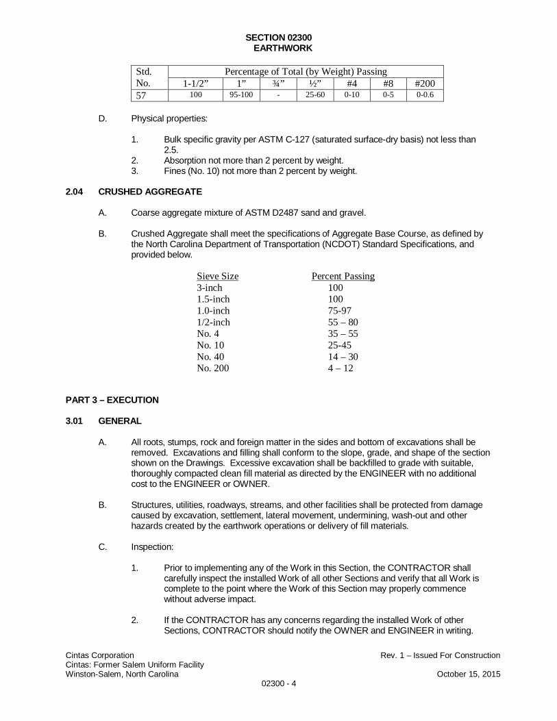
SECTION 02300EARTHWORK
Cintas Corporation Rev. 1 – Issued For ConstructionCintas: Former Salem Uniform FacilityWinston-Salem, North Carolina October 15, 2015
02300 - 4
Std.No.
Percentage of Total (by Weight) Passing1-1/2” 1” ¾” ½” #4 #8 #200
57 100 95-100 - 25-60 0-10 0-5 0-0.6
D. Physical properties:
1. Bulk specific gravity per ASTM C-127 (saturated surface-dry basis) not less than2.5.
2. Absorption not more than 2 percent by weight.3. Fines (No. 10) not more than 2 percent by weight.
2.04 CRUSHED AGGREGATE
A. Coarse aggregate mixture of ASTM D2487 sand and gravel.
B. Crushed Aggregate shall meet the specifications of Aggregate Base Course, as defined bythe North Carolina Department of Transportation (NCDOT) Standard Specifications, andprovided below.
Sieve Size Percent Passing3-inch 1001.5-inch 1001.0-inch 75-971/2-inch 55 – 80No. 4 35 – 55No. 10 25-45No. 40 14 – 30No. 200 4 – 12
PART 3 – EXECUTION
3.01 GENERAL
A. All roots, stumps, rock and foreign matter in the sides and bottom of excavations shall beremoved. Excavations and filling shall conform to the slope, grade, and shape of the sectionshown on the Drawings. Excessive excavation shall be backfilled to grade with suitable,thoroughly compacted clean fill material as directed by the ENGINEER with no additionalcost to the ENGINEER or OWNER.
B. Structures, utilities, roadways, streams, and other facilities shall be protected from damagecaused by excavation, settlement, lateral movement, undermining, wash-out and otherhazards created by the earthwork operations or delivery of fill materials.
C. Inspection:
1. Prior to implementing any of the Work in this Section, the CONTRACTOR shallcarefully inspect the installed Work of all other Sections and verify that all Work iscomplete to the point where the Work of this Section may properly commencewithout adverse impact.
2. If the CONTRACTOR has any concerns regarding the installed Work of otherSections, CONTRACTOR should notify the OWNER and ENGINEER in writing.
SECTION 02300EARTHWORK
Cintas Corporation Rev. 1 – Issued For ConstructionCintas: Former Salem Uniform FacilityWinston-Salem, North Carolina October 15, 2015
02300 - 5
Failure to notify the OWNER and ENGINEER prior to conducting Work within this orother Sections will be construed as CONTRACTOR’s acceptance of the relatedWork of all other Sections.
D. Prior to placement of backfill material, the CONTRACTOR shall demonstrate throughlaboratory analysis that samples of the following backfill materials meet the requirements ofthe material definition, as provided in Part 2- Products, at the following frequencies:
BACKFILL SOURCE TESTING REQUIREMENTS
PARAMETERASTM TEST
METHOD FREQUENCY FILL CLASSIFICATION
Soil ClassificationASTMD2487
One per 5,000 cy permaterial type persource
Clean Fill and New Top Soil
Particle-SizeAnalysis
ASTM D422One per 5,000 cy permaterial type persource
Clean Fill, Open GradeStone, Crushed Aggregate
Maximum DryDensity ASTM D698
One per material typeper source Clean Fill
Optimal MoistureContent ASTM D698
One per material typeper source Clean Fill
TCLP – PCE &TAL Metals
SW846 1311One per 5,000 cy permaterial type persource
Clean Fill and New Top Soil
Volatile OrganicCompounds
USEPA8260B
One per 5,000 cy permaterial type persource
Clean Fill and New Top Soil
3.02 EXCAVATION
A. Not Used – See Section 2110 – Excavation, Removal, and Handling of ContaminatedMaterials for excavation requirements.
3.03 STOCKPILING OF FILL MATERIAL
A. Stockpiles of clean fill and topsoil must be covered when not in use, overnight, prior torainfall events, and during periods of high wind, and all other times unless directed to dootherwise by the ENGINEER.
3.04 BACKFILLING AND COMPACTION
A. Initial Backfilling and Compaction - Excavations
1. Unless otherwise indicated on the Drawings, clean fill shall be used to backfillexcavations to within 6 inches of the final grades shown on the Drawings.
SECTION 02300EARTHWORK
Cintas Corporation Rev. 1 – Issued For ConstructionCintas: Former Salem Uniform FacilityWinston-Salem, North Carolina October 15, 2015
02300 - 6
2. Clean fill shall be placed in a maximum compacted lift of approximately 8 inches.Compaction shall be accomplished by remote-controlled, rolling and vibratory trenchcompaction equipment capable of achieving a minimum live load of 10,000 poundsper square foot. Compaction shall be conducted within the range of field moisturecontent that is within one percent below and three percent above optimum moisturecontent as determined by ASTM D-698. Field moisture content at the time ofplacement shall be determined by ASTM D-1556 or ASTM D-6938.
3. Each lift of clean fill shall be rolled and vibrated with compaction equipment aminimum of three times or until deflection is no longer visually observed by theENGINEER, whichever is greater.
4. The top two (2) feet of clean fill shall be compacted to at least 95 percent ofmaximum dry density as determined by ASTM D-698. Compaction shall bedetermined by ASTM D-1556 or ASTM D-6938 at frequency of 1 test per lift perexcavation location, and for each change in material type. One single-point proctorverification test shall be conducted per every twenty five field density samples onmaterial collected adjacent to the location where field density is determined.
5. A maximum 5 percent of all field moisture content test results are permitted outsidethe specified range. The outliers are, however, not permitted to be concentrated inone lift or one area, and no moisture content shall be less than 2 percent or morethan 4 percent of the optimum moisture content. The areal extent is at thediscretion of the ENGINEER.
6. A maximum 5 percent of all field dry density test results are permitted below thespecified compaction. The outliers are, however, not permitted to be concentrated inone lift or one area, and no dry density less than 85 percent as determined byASTM D-698 is permitted. The areal extent is at the discretion of the ENGINEER.
7. If the criteria set forth in (5) and (6) of this part have been exceeded, theCONTRACTOR shall remove the failing structural fill and replace, compact andgrade new, acceptable fill at no cost to the OWNER.
8. If the moisture content of the fill material is outside the accepted range, the soil shallbe wetted or dried, as appropriate.
9. Clean fill material that is too wet to permit compaction shall be removed andstockpiled or spread and allowed to dry. Drying may be assessed by disking,harrowing, or pulverizing until moisture content is reduced to a satisfactory level.
10. Clean fill material that is too dry shall be wetted uniformly so as to prevent freewater appearing on the surface during or subsequent to compaction operations.
B. Initial Backfilling and Compaction - Embankments
1. Unless otherwise indicated on the Drawings, clean fill shall be used to backfillembankments to within 6 inches of the final grades shown on the Drawings.
2. Clean fill shall be placed in a maximum compacted lift of approximately 8 inches.Compaction shall be accomplished by rolling and vibratory trench compactionequipment capable of achieving a minimum live load of 10,000 pounds per squarefoot. Compaction shall be conducted the range of field moisture content that iswithin one percent below and three percent above optimum moisture content asdetermined by ASTM D-698. Field moisture content at the time of placement shallbe determined by ASTM D-1556 or ASTM D-6938.
3. Clean fill shall be compacted to at least 95 percent of maximum dry density asdetermined by ASTM D-698. Compaction shall be determined by ASTM D-1556 orASTM D-6938 at frequency of 1 test per lift per 250 linear feet of embankment, and
SECTION 02300EARTHWORK
Cintas Corporation Rev. 1 – Issued For ConstructionCintas: Former Salem Uniform FacilityWinston-Salem, North Carolina October 15, 2015
02300 - 7
for each change in material type. One single-point proctor verification test shall beconducted for every twenty five field density tests on material harvested adjacent tothe location where field density is determined.
4. A maximum 5 percent of all field moisture content test results are permitted outsidethe specified range. The outliers are, however, not permitted to be concentrated inone lift or one area, and no moisture content shall be less than 2 percent or morethan 4 percent of the optimum moisture content. The areal extent is at thediscretion of the ENGINEER.
5. A maximum 5 percent of all field dry density test results are permitted below thespecified compaction. The outliers are, however, not permitted to be concentrated inone lift or one area, and no dry density less than 85 percent as determined byASTM D-698 is permitted. The areal extent is at the discretion of the ENGINEER.
6. If the criteria set forth in (4) and (5) of this part have been exceeded, theCONTRACTOR shall remove the failing structural fill and replace, compact andgrade new, acceptable fill at no cost to the OWNER.
7. If the moisture content of the fill material is outside the accepted range, the soil shallbe wetted or dried, as appropriate.
8. Clean fill material that is too wet to permit compaction shall be removed andstockpiled or spread and allowed to dry. Drying may be assessed by disking,harrowing, or pulverizing until moisture content is reduced to a satisfactory level.
9. Clean fill material that is too dry shall be wetted uniformly so as to prevent freewater appearing on the surface during or subsequent to compaction operations.
C. Final Backfilling and Compaction
1. Topsoil shall be used for final backfill to achieve the final grades shown on theDrawings.
2. Topsoil layers shall have a minimum compacted thickness of six (6) inches.
3. Topsoil shall be compacted using walk-behind, light duty vibrating compactionequipment or the tracks of excavation equipment to make at least two but not morethan five passes.
4. Topsoil shall be scarified prior to seeding as described in Section 02800 - Seeding.
D. At the end of each work day, the CONTRACTOR shall post warning signs and caution tapearound each area in which backfilling activities are not completed.
E. Fill material shall not be placed over a lift which has not been tested and approved by theENGINEER.
3.06 GRADING
A. Rough grading of the site shall be performed as required to establish a base upon whichnew topsoil can be adequately placed.
B. The CONTRACTOR shall smooth the finished surfaces for final grades to within 0.1 footabove or below the required final grading elevation indicated on the Drawings.
C. Constructed slopes shall be blended into existing undisturbed areas gradually in order toprovide neat, clean transition zones. Feathering of constructed slopes into existing gradesshall be accomplished to promote natural drainage and to eliminate surface-water pondingor flooding.
D. The right is reserved by the OWNER and ENGINEER to make minor adjustments orrevisions in lines or grades if found necessary as the work progresses, due to discrepancies
SECTION 02300EARTHWORK
Cintas Corporation Rev. 1 – Issued For ConstructionCintas: Former Salem Uniform FacilityWinston-Salem, North Carolina October 15, 2015
02300 - 8
on the drawings or in order to obtain satisfactory construction. Report any suspecteddiscrepancies to the OWNER and ENGINEER as soon as detected.
E. Equipment or vehicles shall not be allowed to travel in a single track or form ruts. Any ruts orirregularities formed shall be scarified and recompacted by the CONTRACTOR at itsexpense as required and directed by the OWNER or ENGINEER.
3.08 REWORK
A. If compaction or other tests indicate that any portion of the work does not meet the specifiedrequirements, then the CONTRACTOR shall remove that section, replace and recompact atno additional cost to the OWNER or the ENGINEER. Determinations of the extent ofremoval and the acceptability of the in-place fill materials will be made by the OWNER andENGINEER.
3.09 EXCESS MATERIALS
A. No excavated materials shall be removed from the site, except as specified by the OWNERand ENGINEER. All general waste or debris shall be containerized on-site as directed bythe ENGINEER and disposed by the CONTRACTOR in accordance with the applicablelocal, state, and federal regulations. All clearing and grubbing waste and soil waste shall bedisposed as specified in the Technical Specifications.
END OF SECTION 02300
SECTION 02800
FERTILIZING, SEEDING, AND MULCHING
Cintas Corporation Rev. 1 – Issued For ConstructionFormer Salem Uniform Services FacilityWinston-Salem, North Carolina October 15, 2015
02800 - 1
PART 1 - GENERAL
1.01 WORK INCLUDED
A. The work covered by this section consists of furnishing all materials, equipment, tools andlabor necessary for the fertilizing, seeding, and mulching of all existing and proposedvegetated areas disturbed at the site.
1.02 RELATED SECTIONS
A. Section 02200 – Excavation
B. Section 02290 – Erosion and Sediment Controls
1.03 REGULATORY REQUIREMENTS
A. All materials shall comply with applicable local, county, state, and federal requirements.
1.04 QUALITY ASSURANCE
A. Seed mixture shall be provided in containers showing percentage of seed mix, year ofproduction, net weight, date of packaging, and location of packaging.
B. Fertilizer shall be delivered to the site in unopened, clearly labeled containers, with thechemical composition of the fertilizer fully described on the label, along with the name andaddress of the Manufacturer.
C. The CONTRACTOR shall submit types of seed, fertilizer, and mulch expected to be used tothe OWNER and the ENGINEER for approval prior to installation.
1.05 DELIVERY, STORAGE, AND HANDLING
A. Grass seed mixture and fertilizer shall be delivered in sealed containers. Seed in damagedcontainers will not be accepted and shall be replaced at no additional expense to theOWNER or ENGINEER.
PART 2 - PRODUCTS
2.01 SEED MIXTURE
A. Seed shall consist of a mixture that provides both a temporary (fast-germinating) and apermanent vegetative cover. The following herbaceous plants shall be used forrevegetation:
1. Rye Grain (Immediate Stabilization/Nurse Crop)

SECTION 02800
FERTILIZING, SEEDING, AND MULCHING
Cintas Corporation Rev. 1 – Issued For ConstructionFormer Salem Uniform Services FacilityWinston-Salem, North Carolina October 15, 2015
02800 - 2
2. Kentucky 31 Tall Fescue (Primary Stabilization)
3. Virginia Wild Rye (Piedmont Native)
4. Soft Rush(Piedmont Native)
5. Shallow Sedge(Piedmont Native)
B. CONTRACTOR shall supply sufficient amounts of seed to perform the described work asspecified in Part 3 - Execution of this specification.
2.02 FERTILIZER
A. CONTRACTOR shall supply sufficient amounts of fertilizer to perform the described work asspecified in Part 3 - Execution of this specification.
2.03 MULCH
A. Mulch shall be dry, un-chopped, un-weathered, and come from wheat or oats.
B. Mulch shall be tacked using a liquid mulch binder as approved by the ENGINEER oralternatively a mulch anchoring tool.
C. CONTRACTOR shall supply sufficient amounts of mulch to perform the described work asspecified in Part 3 - Execution of this specification
PART 3 - EXECUTION
3.01 SOIL PREPARATION
A. Soils shall be graded in accordance with Specifications Section 02300 - Earthwork
B. Soil shall be loose and friable to a depth of at least 3 inches. The top layer of soil shall beloosened by raking or other acceptable means before seeding.
3.02 SEEDING AND SOIL AMMENDMENTS
A. Seed, fertilizer and mulch shall be applied uniformly at a rate specified below with a cycloneseeder, drill, cultipacker seeder, hydroseeder (slurry includes seed and fertilizer), or by handon a firm, moist seedbed. Maximum seeding depth shall be 1/4 inch on clayey soils and 1/2inch on sandy soils when using other than hydroseeder method of applications. Ifhydroseeding is used and the seed and fertilizer are mixed, they shall be mixed on-site andthe seeding shall be immediate without interruption.
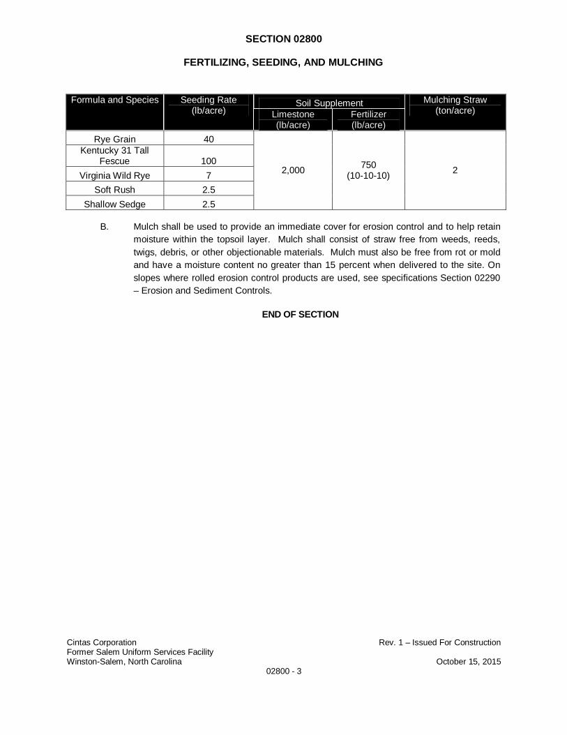
SECTION 02800
FERTILIZING, SEEDING, AND MULCHING
Cintas Corporation Rev. 1 – Issued For ConstructionFormer Salem Uniform Services FacilityWinston-Salem, North Carolina October 15, 2015
02800 - 3
Formula and Species Seeding Rate(lb/acre)
Soil Supplement Mulching Straw(ton/acre)Limestone
(lb/acre)Fertilizer(lb/acre)
Rye Grain 40
2,000750
(10-10-10)2
Kentucky 31 TallFescue 100
Virginia Wild Rye 7
Soft Rush 2.5
Shallow Sedge 2.5
B. Mulch shall be used to provide an immediate cover for erosion control and to help retainmoisture within the topsoil layer. Mulch shall consist of straw free from weeds, reeds,twigs, debris, or other objectionable materials. Mulch must also be free from rot or moldand have a moisture content no greater than 15 percent when delivered to the site. Onslopes where rolled erosion control products are used, see specifications Section 02290– Erosion and Sediment Controls.
END OF SECTION
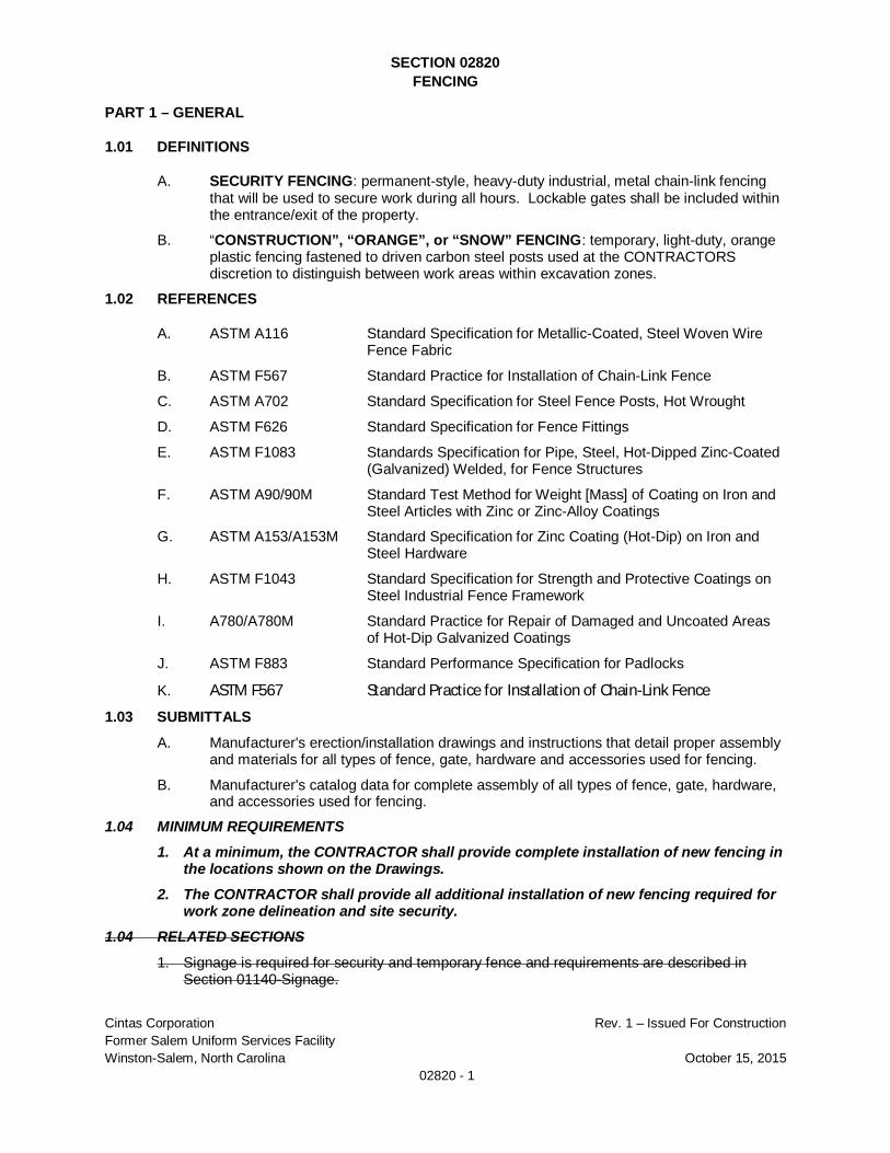
SECTION 02820FENCING
Cintas Corporation Rev. 1 – Issued For ConstructionFormer Salem Uniform Services FacilityWinston-Salem, North Carolina October 15, 2015
02820 - 1
PART 1 – GENERAL
1.01 DEFINITIONS
A. SECURITY FENCING: permanent-style, heavy-duty industrial, metal chain-link fencingthat will be used to secure work during all hours. Lockable gates shall be included withinthe entrance/exit of the property.
B. “CONSTRUCTION”, “ORANGE”, or “SNOW” FENCING: temporary, light-duty, orangeplastic fencing fastened to driven carbon steel posts used at the CONTRACTORSdiscretion to distinguish between work areas within excavation zones.
1.02 REFERENCES
A. ASTM A116 Standard Specification for Metallic-Coated, Steel Woven WireFence Fabric
B. ASTM F567 Standard Practice for Installation of Chain-Link Fence
C. ASTM A702 Standard Specification for Steel Fence Posts, Hot Wrought
D. ASTM F626 Standard Specification for Fence Fittings
E. ASTM F1083 Standards Specification for Pipe, Steel, Hot-Dipped Zinc-Coated(Galvanized) Welded, for Fence Structures
F. ASTM A90/90M Standard Test Method for Weight [Mass] of Coating on Iron andSteel Articles with Zinc or Zinc-Alloy Coatings
G. ASTM A153/A153M Standard Specification for Zinc Coating (Hot-Dip) on Iron andSteel Hardware
H. ASTM F1043 Standard Specification for Strength and Protective Coatings onSteel Industrial Fence Framework
I. A780/A780M Standard Practice for Repair of Damaged and Uncoated Areasof Hot-Dip Galvanized Coatings
J. ASTM F883 Standard Performance Specification for Padlocks
K. ASTM F567 Standard Practice for Installation of Chain-Link Fence
1.03 SUBMITTALS
A. Manufacturer's erection/installation drawings and instructions that detail proper assemblyand materials for all types of fence, gate, hardware and accessories used for fencing.
B. Manufacturer's catalog data for complete assembly of all types of fence, gate, hardware,and accessories used for fencing.
1.04 MINIMUM REQUIREMENTS1. At a minimum, the CONTRACTOR shall provide complete installation of new fencing in
the locations shown on the Drawings.2. The CONTRACTOR shall provide all additional installation of new fencing required for
work zone delineation and site security.1.04 RELATED SECTIONS
1. Signage is required for security and temporary fence and requirements are described inSection 01140-Signage.
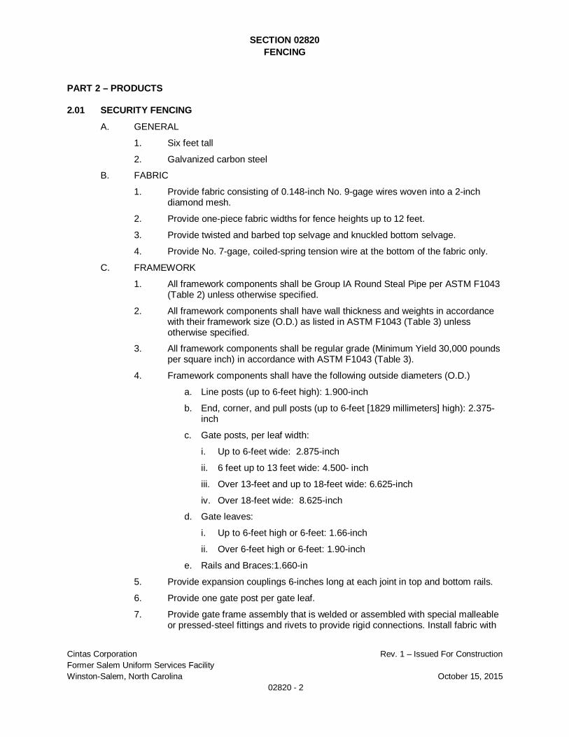
SECTION 02820FENCING
Cintas Corporation Rev. 1 – Issued For ConstructionFormer Salem Uniform Services FacilityWinston-Salem, North Carolina October 15, 2015
02820 - 2
PART 2 – PRODUCTS
2.01 SECURITY FENCING
A. GENERAL
1. Six feet tall
2. Galvanized carbon steel
B. FABRIC
1. Provide fabric consisting of 0.148-inch No. 9-gage wires woven into a 2-inchdiamond mesh.
2. Provide one-piece fabric widths for fence heights up to 12 feet.
3. Provide twisted and barbed top selvage and knuckled bottom selvage.
4. Provide No. 7-gage, coiled-spring tension wire at the bottom of the fabric only.
C. FRAMEWORK
1. All framework components shall be Group IA Round Steal Pipe per ASTM F1043(Table 2) unless otherwise specified.
2. All framework components shall have wall thickness and weights in accordancewith their framework size (O.D.) as listed in ASTM F1043 (Table 3) unlessotherwise specified.
3. All framework components shall be regular grade (Minimum Yield 30,000 poundsper square inch) in accordance with ASTM F1043 (Table 3).
4. Framework components shall have the following outside diameters (O.D.)
a. Line posts (up to 6-feet high): 1.900-inch
b. End, corner, and pull posts (up to 6-feet [1829 millimeters] high): 2.375-inch
c. Gate posts, per leaf width:
i. Up to 6-feet wide: 2.875-inch
ii. 6 feet up to 13 feet wide: 4.500- inch
iii. Over 13-feet and up to 18-feet wide: 6.625-inch
iv. Over 18-feet wide: 8.625-inch
d. Gate leaves:
i. Up to 6-feet high or 6-feet: 1.66-inch
ii. Over 6-feet high or 6-feet: 1.90-inch
e. Rails and Braces:1.660-in
5. Provide expansion couplings 6-inches long at each joint in top and bottom rails.
6. Provide one gate post per gate leaf.
7. Provide gate frame assembly that is welded or assembled with special malleableor pressed-steel fittings and rivets to provide rigid connections. Install fabric with
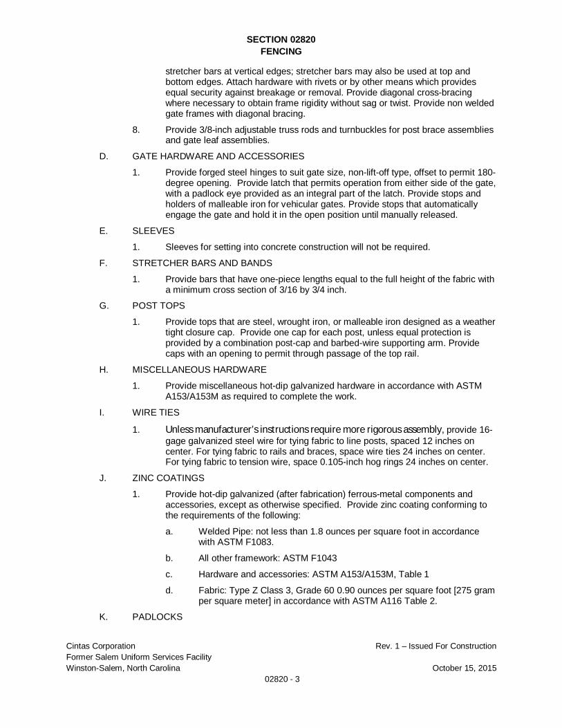
SECTION 02820FENCING
Cintas Corporation Rev. 1 – Issued For ConstructionFormer Salem Uniform Services FacilityWinston-Salem, North Carolina October 15, 2015
02820 - 3
stretcher bars at vertical edges; stretcher bars may also be used at top andbottom edges. Attach hardware with rivets or by other means which providesequal security against breakage or removal. Provide diagonal cross-bracingwhere necessary to obtain frame rigidity without sag or twist. Provide non weldedgate frames with diagonal bracing.
8. Provide 3/8-inch adjustable truss rods and turnbuckles for post brace assembliesand gate leaf assemblies.
D. GATE HARDWARE AND ACCESSORIES
1. Provide forged steel hinges to suit gate size, non-lift-off type, offset to permit 180-degree opening. Provide latch that permits operation from either side of the gate,with a padlock eye provided as an integral part of the latch. Provide stops andholders of malleable iron for vehicular gates. Provide stops that automaticallyengage the gate and hold it in the open position until manually released.
E. SLEEVES
1. Sleeves for setting into concrete construction will not be required.
F. STRETCHER BARS AND BANDS
1. Provide bars that have one-piece lengths equal to the full height of the fabric witha minimum cross section of 3/16 by 3/4 inch.
G. POST TOPS
1. Provide tops that are steel, wrought iron, or malleable iron designed as a weathertight closure cap. Provide one cap for each post, unless equal protection isprovided by a combination post-cap and barbed-wire supporting arm. Providecaps with an opening to permit through passage of the top rail.
H. MISCELLANEOUS HARDWARE
1. Provide miscellaneous hot-dip galvanized hardware in accordance with ASTMA153/A153M as required to complete the work.
I. WIRE TIES
1. Unless manufacturer’s instructions require more rigorous assembly, provide 16-gage galvanized steel wire for tying fabric to line posts, spaced 12 inches oncenter. For tying fabric to rails and braces, space wire ties 24 inches on center.For tying fabric to tension wire, space 0.105-inch hog rings 24 inches on center.
J. ZINC COATINGS
1. Provide hot-dip galvanized (after fabrication) ferrous-metal components andaccessories, except as otherwise specified. Provide zinc coating conforming tothe requirements of the following:
a. Welded Pipe: not less than 1.8 ounces per square foot in accordancewith ASTM F1083.
b. All other framework: ASTM F1043
c. Hardware and accessories: ASTM A153/A153M, Table 1
d. Fabric: Type Z Class 3, Grade 60 0.90 ounces per square foot [275 gramper square meter] in accordance with ASTM A116 Table 2.
K. PADLOCKS
SECTION 02820FENCING
Cintas Corporation Rev. 1 – Issued For ConstructionFormer Salem Uniform Services FacilityWinston-Salem, North Carolina October 15, 2015
02820 - 4
1. Provide padlocks conforming to ASTM F883, with chain.
PART 3 – EXECUTION
3.01 INSTALLATION OF SECURITY FENCING
A. GENERAL
1. Provide complete installation conforming to ASTM F567 unless specifiedotherwise in these Specifications.
2. Ensure initial grading and established elevations are complete prior tocommencing fence installation.
B. SETTING POSTS
1. Line posts may be driven into the ground in accordance with project-specificutility protection requirements if driving will not damage to the fence material andthe native ground will adequately support lateral loads.
2. All other posts other than line posts must be set in concrete.
3. Provide tops of footings that are trowel finished and sloped or domed to shedwater away from posts. Set hold-open devices, sleeves, and other accessories inconcrete. Keep exposed concrete moist for at least 7 calendar days afterplacement or cured with a membrane curing material, as approved.
C. BRACE ASSEMBLY
1. Provide bracing assemblies at end and gate posts and at both sides of cornerand pull posts, with the horizontal brace located at midheight of the fabric. Installbrace assemblies so posts are plumb when the diagonal rod is under propertension.
2. Provide two complete brace assemblies at corner and pull posts where requiredfor stiffness and as indicated.
D. FABRIC INSTALLATION
1. Provide fabric in single lengths between stretch bars with bottom barbs placedapproximately 1-1/2-inches above the ground line. Pull fabric taut and tied toposts, rails, and tension wire with wire ties and bands.
2. Install fabric on the security side of fence, unless otherwise directed. Ensurefabric remains under tension after the pulling force is released.
E. STRETCHER BAR INSTALLATION
1. Thread stretcher bars through or clamped to fabric 4 inches on center andsecured to posts with metal bands spaced 15 inches on center.
F. GATE INSTALLATION
1. Install gates plumb, level, and secure, with full opening without interference.Install ground set items in concrete for anchorage as recommended by the fencemanufacturer. Adjust hardware for smooth operation and lubricated wherenecessary.
G. TIE WIRES

SECTION 02820FENCING
Cintas Corporation Rev. 1 – Issued For ConstructionFormer Salem Uniform Services FacilityWinston-Salem, North Carolina October 15, 2015
02820 - 5
1. Provide tie wires that are U-shaped to the pipe diameters to which attached.Twist ends of tie wires not less than two full turns and bent so as not to present ahazard.
H. FASTENERS
1. Install nuts for tension bands and hardware on the side of the fence opposite thefabric side. Peen ends of bolts to prevent removal of nuts.
I. ZINC-COATING REPAIR
1. Clean and repair galvanized surfaces damaged by welding or abrasion, and cutends of fabric, or other cut sections with specified galvanizing repair materialapplied in strict conformance with the manufacturer's printed instructions.
J. TOLERANCES
1. Provide posts that are straight and plumb within a vertical tolerance of 1/4 inchafter the fabric has been stretched. Provide fencing and gates that are true to linewith no more than 1/2 inch deviation from the established centerline between lineposts. Repair defects as directed.
K. SITE PREPARATION
1. Clearing and Grading: Clear fence line of trees, brush, and other obstacles toinstall fencing. Establish a graded, compacted fence line prior to fencinginstallation.
L. ACCESSORIES INSTALLATION
1. Post Caps
a. Design post caps to accommodate top rail. Install post caps asrecommended by the manufacturer.
2. Padlocks
a. Provide padlocks for gate openings and provide chains that are securelyattached to gate or gate posts. Provide padlocks keyed alike, andprovide two keys for each padlock.
3.02 INSTALLATION OF OTHER FENCING
A. GENERAL
1. Provide complete installation conforming to the manufacturer’s specificationsunless specified otherwise in these Specifications.
2. Ensure initial grading and established elevations are complete prior tocommencing fence installation.
END OF SECTION 02820

AECOM Environment
Footer October 2015
Appendix B. Typical Air Monitoring Instrument Information

Rental – Portable Laser Aerosol Monitor
TSI DustTrak™ Aerosol Monitor
The DustTrak™ Aerosol Monitor is a portable, battery-operated laser photometer which gives you a real-time digital readout with the added benefits of a built-in data logger. Suitable for clean office set-tings as well as harsh industrial workplaces and outdoor applications, the DustTrak detects potential problems with airborne contaminants such as dust, smokes, fumes and mists.The DustTrak™ measures aerosols in a wide variety of environments, from offices and industrial workplaces to outdoor environmental and construction sites. TSI’s DustTrak provides reliable exposure assessment by measuring particle concentrations corresponding to PM10, PM2.5, PM1.0 or respirable size fractions.
CALL GEOTECH TODAY (800) 833-7958Geotech Environmental Equipment, Inc.
2650 East 40th Avenue • Denver, Colorado 80205(303) 320-4764 • (800) 833-7958 • FAX (303) 322-7242
email: [email protected] website: www.geotechenv.com
MODEL 8520 SPECIFICATIONSSensor Type...................................90° light scatteringRange.............................................0.001 to 100 mg/m3 (Calibrated to ISO 12103-1, A1 test dust)Resolution .....................................±0.1% of reading or ±0.001 mg/m3, whichever is greaterZero Stability .................................±0.001 mg/m3 over 24 hours using 10-second time-constantParticle Size Range ......................0.1 to approximately 10 micrometersFlow Rate Adjustable ...................1.4 to 2.4 l/min (1.7 nominally)Temperature Coefficient ..............+0.001 mg/m3 per °C ........................................................(for variations from temperature at which the DustTrak was zeroed)Operating Temperature ................32° F to 120° F (0°C to 50°C)Storage Temperature ....................-4° F to 140° F (-20°C to 60°C)Operating Humidity ......................0 to 95% rh (non-condensing)Time Constant ...............................Adjustable from 1 to 60 secondsData Logging .................................31,000 data points (21 days of logging once/minute)Logging Interval ............................Adjustable from 1 second to 1 hourPhysical External Dimensions ....8.7 in. x 5.9 in. x 3.4 in. (221 mm x 150 mm x 87 mm)Instrument Weight ........................3.3 pounds with batteries (1.5 kg)Serial Interface ..............................RS-232 1200 baudPower AC ................................................AC adapter (included) Battery .........................................Four C-size alkaline batteries (included) Battery Run-time .........................Alkaline 16 hoursAnalog Output Specifications Analog Output Voltage .................0 to 5 VDC Analog Output Scaling1 ...............0 to 100 mg/m3 ........................................................0 to 10.0 mg/m3 ........................................................0 to 1.00 mg/m3 ........................................................0 to 0.100 mg/m3
Output Impedance .......................0.01 ohmMaximum Output Current ............15 mAAlarm Output Specifications Type .............................................Non-latching, MOSFET solid state (polarized)2 analog switch Setpoint Range1 ..........................0.010 to 100 mg/m3 Maximum Voltage ........................15 VDC Maximum Current ........................1 Amp Deadband ....................................-5% of alarm setpoint Connector ....................................4-Pin, Mini-DIN connectorOptional Accessories ...................Model 8520-1 Environmental Enclosure
TSI DustTrak Rental.indd 12/17/08
1 User selectable through TRAKPROTM Data Analysis Software.2 See TSI Application Note ITI - 074 for important wiring information.
TSI DustTrak™ Rental Kit

E x p o s u r e M o n i t o r i n g
Model 8520 DUSTTRAK
TM Aerosol Monitor
TRAKPROTM Data Analysis Software enclosed
Operation and Service Manual
1980198, Revision R June 2006

Model 8520 DUSTTRAK
TM Aerosol Monitor
Operation and Service Manual
1980198, Revision R June 2006
SHIP/MAIL TO: TSI Incorporated 500 Cardigan Road Shoreview, MN 55126-3996 USA
U.S. Technical Support: (800) 874-2811/(651) 490-2811 Fax: (651) 490-3824
E-mail address:
[email protected] Website:
http://www.tsi.com
INTERNATIONAL Technical Support: (001 651) 490-2811
Fax: (001 651) 490-3824

Copyright ©
TSI Incorporated / 1994–2006 / All rights reserved.
Address
TSI Incorporated / 500 Cardigan Road / Shoreview, MN 55126 / USA
Fax No.
(651) 490-3824
Limitation of Warranty and Liability (effective July 2000)
Seller warrants the goods sold hereunder, under normal use and service as described in the operator's manual, shall be free from defects in workmanship and material for twenty-four (24) months, or the length of time specified in the operator's manual, from the date of shipment to the customer. This warranty period is inclusive of any statutory warranty. This limited warranty is subject to the following exclusions:
a. Hot-wire or hot-film sensors used with research anemometers, and certain other components when indicated in specifications, are warranted for 90 days from the date of shipment.
b. Parts repaired or replaced as a result of repair services are warranted to be free from defects in workmanship and material, under normal use, for 90 days from the date of shipment.
c. Seller does not provide any warranty on finished goods manufactured by others or on any fuses, batteries or other consumable materials. Only the original manufacturer's warranty applies.
d. Unless specifically authorized in a separate writing by Seller, Seller makes no warranty with respect to, and shall have no liability in connection with, goods which are incorporated into other products or equipment, or which are modified by any person other than Seller.
The foregoing is IN LIEU OF all other warranties and is subject to the LIMITATIONS stated herein. NO OTHER EXPRESS OR IMPLIED WARRANTY OF FITNESS FOR PARTICULAR PURPOSE OR MERCHANTABILITY IS MADE.
TO THE EXTENT PERMITTED BY LAW, THE EXCLUSIVE REMEDY OF THE USER OR BUYER, AND THE LIMIT OF SELLER'S LIABILITY FOR ANY AND ALL LOSSES, INJURIES, OR DAMAGES CONCERNING THE GOODS (INCLUDING CLAIMS BASED ON CONTRACT, NEGLIGENCE, TORT, STRICT LIABILITY OR OTHERWISE) SHALL BE THE RETURN OF GOODS TO SELLER AND THE REFUND OF THE PURCHASE PRICE, OR, AT THE OPTION OF SELLER, THE REPAIR OR REPLACEMENT OF THE GOODS. IN NO EVENT SHALL SELLER BE LIABLE FOR ANY SPECIAL, CONSEQUENTIAL OR INCIDENTAL DAMAGES. SELLER SHALL NOT BE RESPONSIBLE FOR INSTALLATION, DISMANTLING OR REINSTALLATION COSTS OR CHARGES. No Action, regardless of form, may be brought against Seller more than 12 months after a cause of action has accrued. The goods returned under warranty to Seller's factory shall be at Buyer's risk of loss, and will be returned, if at all, at Seller's risk of loss.
Buyer and all users are deemed to have accepted this LIMITATION OF WARRANTY AND LIABILITY, which contains the complete and exclusive limited warranty of Seller. This LIMITATION OF WARRANTY AND LIABILITY may not be amended, modified or its terms waived, except by writing signed by an Officer of Seller.
Service Policy
Knowing that inoperative or defective instruments are as detrimental to TSI as they are to our customers, our service policy is designed to give prompt attention to any problems. If any malfunction is discovered, please contact your nearest sales office or representative, or call TSI at (800) 874-2811 (USA) or (001 651) 490-2811 (International).
CONTENTS
SAFETY INFORMATION ................................................................
1 UNPACKING AND PARTS IDENTIFICATION .............................. 1 Unpacking the DUSTTRAK Aerosol Monitor ..................................... 1 Parts Identification for the DUSTTRAK Aerosol Monitor ................... 2
2 SETTING-UP .........................................................Supplying Power to the DUSTTRAK Aerosol Monitor ....................... 5
Installing the Batteries............................................................... 5 Using the AC Adapter ............................................................... 5
Instrument Setup ............................................................................. 6 Setting-up TRAKPRO Data Analysis Software ........................... 6 Connecting the DUSTTRAK Aerosol Monitor to the
Computer .......................................................Set-Up the Communications Port ............................................ 6 Setting the Real-Time Clock ..................................................... 7 Programming the Date/Time Using TRAKPRO Software .......... 8 Manually Setting the Real-Time Clock ..................................... 8
Connecting the Optional Portable Printer ....................................... 8 Connecting/Wiring the Analog/Alarm Output Connector ............... 9
3 OPERATION ..........................................................Overview ........................................................................................ 11 DUSTTRAK Aerosol Monitor Keypad Functions ............................. 11 ON/OFF Key .................................................................................. 11 SAMPLE Key ................................................................................. 12 TIME CONSTANT Key .................................................................. 12 Programming the Available Time Constants ................................ 13 STATISTICS Key ........................................................................... 13 PRINT Key ..................................................................................... 14 SAMPLING MODE Key ................................................................. 14
Survey Mode ........................................................................... 14 LOG Modes ............................................................................. 15
CLEAR MEMORY Key .................................................................. 15 LOGGING INTERVAL Key ............................................................ 15 Programming the Logging Intervals using TRAKPRO Software ... 16 and Keys ............................................................................. 17 CALIBRATE Key ........................................................................... 17 Display/Keypad Lockout Switch .................................................... 17 Remote Sampling .......................................................................... 17 Respirable Mass Sampling with the Cyclone ............................... 18 Using the Cyclone ......................................................................... 18 Using the 1.0 or 2.5 µm Inlet Conditioners .................................. 19 Using the 10 µm Nozzle ................................................................ 20 Analog Output ................................................................................ 21
i

ii
Alarm Output .................................................................................. 22 Alarm Output Specifications .................................................... 23 Programming the Alarm Setpoint ........................................... 24
Upgrading the DUSTTRAK Aerosol Monitor to Add Analog and Alarm Functions .......................................................................... 24
Identifying an Instrument with Analog/Alarm Functions ......... 24 Identifying an Instrument that may be Upgraded to Add
Analog/Alarm Functions ....................................................... 25 Identifying an Instrument That May Not Be Upgraded ........... 25
Programming Advanced Modes: LOG 2 and LOG 3 ................... 26 Sample Protocol for LOG 2 and LOG 3 Modes ............................ 29 Things You Should Know About Taking Pre-Programmed
Samples ...................................................................................... 30 Memory Considerations ................................................................. 31 Custom Calibrations ....................................................................... 31 Determining the Calibration Factor for a Specific Aerosol ............ 32 Setting Custom Calibration Factor from Keypad .......................... 33 Setting Custom Calibration Factors using TRAKPRO Software ..... 34 Converting Stored Data to Calibrated Data .................................. 35
4 MAINTENANCE ............................................................................ 37 Maintenance Schedule .................................................................. 37 Zero Checking/Re-Zeroing ............................................................ 38 Cleaning the 1.0 µm and 2.5 µm Inlet Conditioners ..................... 39 Cleaning the 10 µm Inlet and Sample Tube ................................. 40 Replacing the Internal Filters ......................................................... 41 Setting the Flow Rate .................................................................... 43 Cleaning the Cyclone .................................................................... 44 Storage Precautions ...................................................................... 44
5 TROUBLESHOOTING .................................................................. 45
A SPECIFICATIONS. ........................................................................ 49
B MODEL 8520-1 DUSTTRAK ENVIRONMENTAL ENCLOSURE OPERATION AND MAINTENANCE MANUAL .......................... 51 Unpacking the DUSTTRAK Environmental Enclosure .................... 51 Spare Parts .................................................................................... 51 Parts Identification: Environmental Enclosure ............................... 52
SETTING-UP ................................................................................. 54 Installing the Aerosol or Respirable Aerosol Inlet ......................... 54 Install Water Trap Bottle ................................................................ 56 Correct Placement of Velcro Straps .............................................. 57 Install DUSTTRAK Monitor into Environmental Enclosure .............. 57 Connecting Tubing ......................................................................... 59 Supplying Power to the DUSTTRAK Aerosol Monitor ..................... 59
Using the External Battery Pack ............................................. 60 Install External Battery Pack ................................................... 60
iii
Mounting to a Surveyor Tripod ...................................................... 61 Downloading a Data File ............................................................... 62 Real-Time Monitoring .................................................................... 62
TM Setting-up TRAKPRO Data Analysis Software ............................ 62
Transporting the Environmental Enclosure ...................................Wiring the Analog/Alarm Cable in the Enclosure ......................... 63
OPERATION ..........................................................Overview .............................................................
How to Properly Orient the Environmental Enclosure ................. 64 Changing and Re-charging the Battery Packs ............................. 6
Receiving Data from the DUSTTRAK Aerosol Monitor ................... 64 Zeroing the DUSTTRAK Aerosol Monitor .....................................
Setting the Flow Rate ....................................................Locking the Environmental Enclosure .......................................
Checklist for Sampling with the Environmental Enclosure ........... 66
MAINTENANCE .......................................................Daily Maintenance Checks ..............................................Cleaning the Aerosol Inlet ................................................
Cleaning the Respirable Aerosol Inlet .......................................When to Change the Battery ..............................................Replacing the Battery Pack ...............................................
Recharging the Battery Packs .............................................Battery Pack Life .......................................................
Emptying the Water Trap .................................................Storage Precautions ....................................................
TROUBLESHOOTING THE ENVIRONMENTAL ENCLOSURE ..........................................................
SPECIFICATIONS: ENVIRONMENTAL ENCLOSURE .............. 73
INDEX ................................................................................................... 75
AVAILABLE APPLICATION NOTES DUSTTRAK, Theory of Operation ...........................................ITI-036 Frequently Asked Questions: DUSTTRAK Aerosol
Monitor ..............................................................................ITI-039 Serial Interface Commands and Connections:
Model 8520 .......................................................................ITI-044 DUSTTRAK Analog Output .....................................................ITI-073 DUSTTRAK Alarm Output.......................................................ITI-074
To obtain any of the listed Application Notes, contact TSI at:
U.S. (800) 874-2811/(651) 490-2811, Fax: (651) 490-3824 International (001 651) 490-2811, Fax: (001 651) 490-3824

iv
These Application Notes can also be found under TSI’s web site: http://www.tsi.com
v
Safety Information
When operated according to the manufacturer’s instruction, this device is a Class I laser product as defined by U.S. Department of Health and Human Services standards under the Radiation Control for Health and Safety Act of 1968. A certification and identification label like the one shown below is affixed to each instrument.
There are no user-serviceable parts inside this instrument. Performing services other than those described in this manual may result in exposure to harmful (invisible) laser radiation. A warning label like the one shown below is affixed to the internal laser device.
W A R N I N G The DUSTTRAK monitor Alarm Output function should not be used to detect hazardous conditions or to provide an alarm for protecting human life, health, or safety.
!
DANGER: INVISIBLE LASER RADIATION WHEN OPEN. AVOID DIRECT EXPOSURE TO BEAM.
WARNING: NO USER SERVICEABLE PARTS INSIDE. REFER SERVICING
TO QUALIFIED PERSONNEL.
May, 2006
THIS LASER PRODUCT COMFORMS TO 21 CFR 1040.10 BUREAU OF RADIOLOGICAL HEALTH AND SAFETY REGULATIONS.
TSI INCORPORATED 500 CARDIGAN ROAD SHOREVIEW, MN 55126 USA

vi
1
Chapter 1
Unpacking and Parts Identification
Carefully unpack the Model 8520 DUSTTRAKTM Aerosol Monitor from the shipping container. Use the tables and illustrations below to make certain that there are no missing components. Contact TSI immediately if anything is missing or damaged.
Unpacking the DUSTTRAK Aerosol Monitor Compare all the components you received with those listed in the table below. If any parts are missing, contact TSI.
Quantity Item Description Part/Model 1 Model 8520 Aerosol Monitor 85201 Carrying Case 800686 4 C-size Alkaline Batteries 1208018 1 AC adapter
2613033 115 V, NEMA-1-15230 V, Eur., CEE 7/16 2613078 230 V, Great Britain 800169 240 V, Australian 2613105
1 Data Analysis Software CD-ROM 800700 1 Zero Filter 800663 1 Computer Cable, 9-pin to RJ-45 800563 1 25-Pin to 9-Pin Serial Cable Adapter 962003 1 Model 8520 DUSTTRAK Aerosol Monitor
Operation and Service Manual1980198
1 Calibration Certificate — 1 10 mm Nylon Dorr-Oliver Cyclone 800665 1 Flowmeter, 0–2.5 L/min 800669
4 feet Plastic Tubing, 1/4 in I.D. 800668 1 Small Screwdriver 800661 1 Sample Nozzle Removal Tool 800662 8 Spare Internal Filter Element 1602188 1 Wrist Strap 2913028 1 Shoulder Strap 2913120 1 Sample Nozzle Cleaning Brush 800699 10 Cotton Swab —1 Inlet Nozzle, 2.5 µm 1508112 1 Inlet Nozzle, 1.0 µm 1508113 1 Impactor Plate 1508114 1 Tube, Grease 801163 1 Analog Output/Alarm:connector, with cable 801652
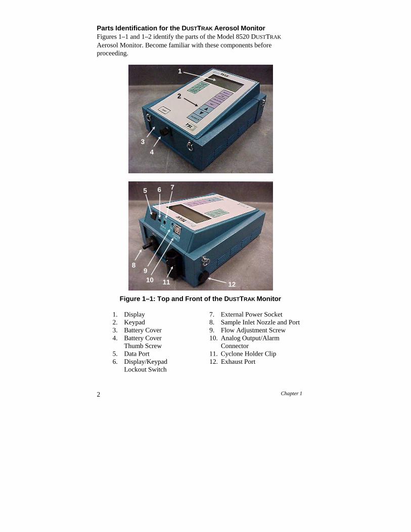
2 Chapter 1
Parts Identification for the DUSTTRAK Aerosol Monitor Figures 1–1 and 1–2 identify the parts of the Model 8520 DUSTTRAK
Aerosol Monitor. Become familiar with these components before proceeding.
Figure 1–1: Top and Front of the DUSTTRAK Monitor
1. Display 7. External Power Socket 2. Keypad 8. Sample Inlet Nozzle and Port 3. Battery Cover 9. Flow Adjustment Screw 4. Battery Cover
Thumb Screw 10. Analog Output/Alarm
Connector 5. Data Port 11. Cyclone Holder Clip 6. Display/Keypad
Lockout Switch 12. Exhaust Port
5 6 7
89 10 11 12
1
2
3
4
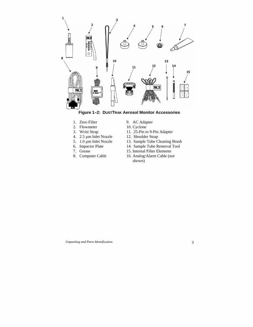
1 3
2 4 5 6 7
8 10 13
9 11 12 14
15
Figure 1–2: DUSTTRAK Aerosol Monitor Accessories
1. Zero Filter 9. AC Adapter 2. Flowmeter 10. Cyclone 3. Wrist Strap 11. 25-Pin to 9-Pin Adapter 4. 2.5 µm Inlet Nozzle 12. Shoulder Strap 5. 1.0 µm Inlet Nozzle 13. Sample Tube Cleaning Brush 6. Impactor Plate 14. Sample Tube Removal Tool 7. Grease 15. Internal Filter Elements 8. Computer Cable 16. Analog/Alarm Cable (not
shown)
Unpacking and Parts Identification 3

4 Chapter 1
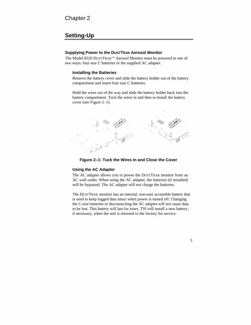
Chapter 2
Setting-Up
Supplying Power to the DUSTTRAK Aerosol Monitor The Model 8520 DUSTTRAKTM Aerosol Monitor must be powered in one of two ways: four size C batteries or the supplied AC adapter.
Installing the Batteries Remove the battery cover and slide the battery holder out of the battery compartment and insert four size C batteries.
Hold the wires out of the way and slide the battery holder back into the battery compartment. Tuck the wires in and then re-install the battery cover (see Figure 2–1).
Figure 2–1: Tuck the Wires In and Close the Cover
Using the AC Adapter The AC adapter allows you to power the DUSTTRAK monitor from an AC wall outlet. When using the AC adapter, the batteries (if installed) will be bypassed. The AC adapter will not charge the batteries.
The DUSTTRAK monitor has an internal, non-user accessible battery that is used to keep logged data intact when power is turned off. Changing the C-size batteries or disconnecting the AC adapter will not cause data to be lost. This battery will last for years. TSI will install a new battery, if necessary, when the unit is returned to the factory for service.
5
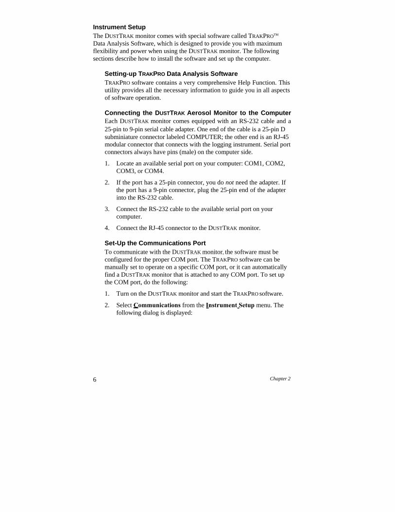
6 Chapter 2
Instrument Setup The DUSTTRAK monitor comes with special software called TRAKPROTM
Data Analysis Software, which is designed to provide you with maximum flexibility and power when using the DUSTTRAK monitor. The following sections describe how to install the software and set up the computer.
Setting-up TRAKPRO Data Analysis Software TRAKPRO software contains a very comprehensive Help Function. This utility provides all the necessary information to guide you in all aspects of software operation.
Connecting the DUSTTRAK Aerosol Monitor to the Computer Each DUSTTRAK monitor comes equipped with an RS-232 cable and a 25-pin to 9-pin serial cable adapter. One end of the cable is a 25-pin D subminiature connector labeled COMPUTER; the other end is an RJ-45 modular connector that connects with the logging instrument. Serial port connectors always have pins (male) on the computer side.
1. Locate an available serial port on your computer: COM1, COM2, COM3, or COM4.
2. If the port has a 25-pin connector, you do not need the adapter. If the port has a 9-pin connector, plug the 25-pin end of the adapter into the RS-232 cable.
3. Connect the RS-232 cable to the available serial port on your computer.
4. Connect the RJ-45 connector to the DUSTTRAK monitor.
Set-Up the Communications Port To communicate with the DUSTTRAK monitor, the software must be configured for the proper COM port. The TRAKPRO software can be manually set to operate on a specific COM port, or it can automatically find a DUSTTRAK monitor that is attached to any COM port. To set up the COM port, do the following:
1. Turn on the DUSTTRAK monitor and start the TRAKPRO software.
2. Select Communications from the Instrument Setup menu. The following dialog is displayed:
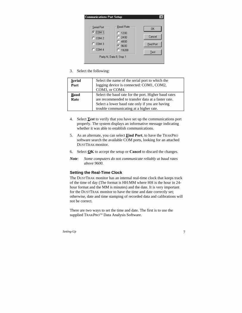
Setting-Up 7
3. Select the following:
Serial Port
Select the name of the serial port to which the logging device is connected: COM1, COM2, COM3, or COM4.
Baud Rate
Select the baud rate for the port. Higher baud rates are recommended to transfer data at a faster rate. Select a lower baud rate only if you are having trouble communicating at a higher rate.
4. Select Test to verify that you have set up the communications port properly. The system displays an informative message indicating whether it was able to establish communications.
5. As an alternate, you can select Find Port, to have the TRAKPRO
software search the available COM ports, looking for an attached DUSTTRAK monitor.
6. Select OK to accept the setup or Cancel to discard the changes.
Note: Some computers do not communicate reliably at baud rates above 9600.
Setting the Real-Time Clock The DUSTTRAK monitor has an internal real-time clock that keeps track of the time of day (The format is HH:MM where HH is the hour in 24- hour format and the MM is minutes) and the date. It is very important for the DUSTTRAK monitor to have the time and date correctly set; otherwise, date and time stamping of recorded data and calibrations will not be correct.
There are two ways to set the time and date. The first is to use the supplied TRAKPROTM Data Analysis Software.
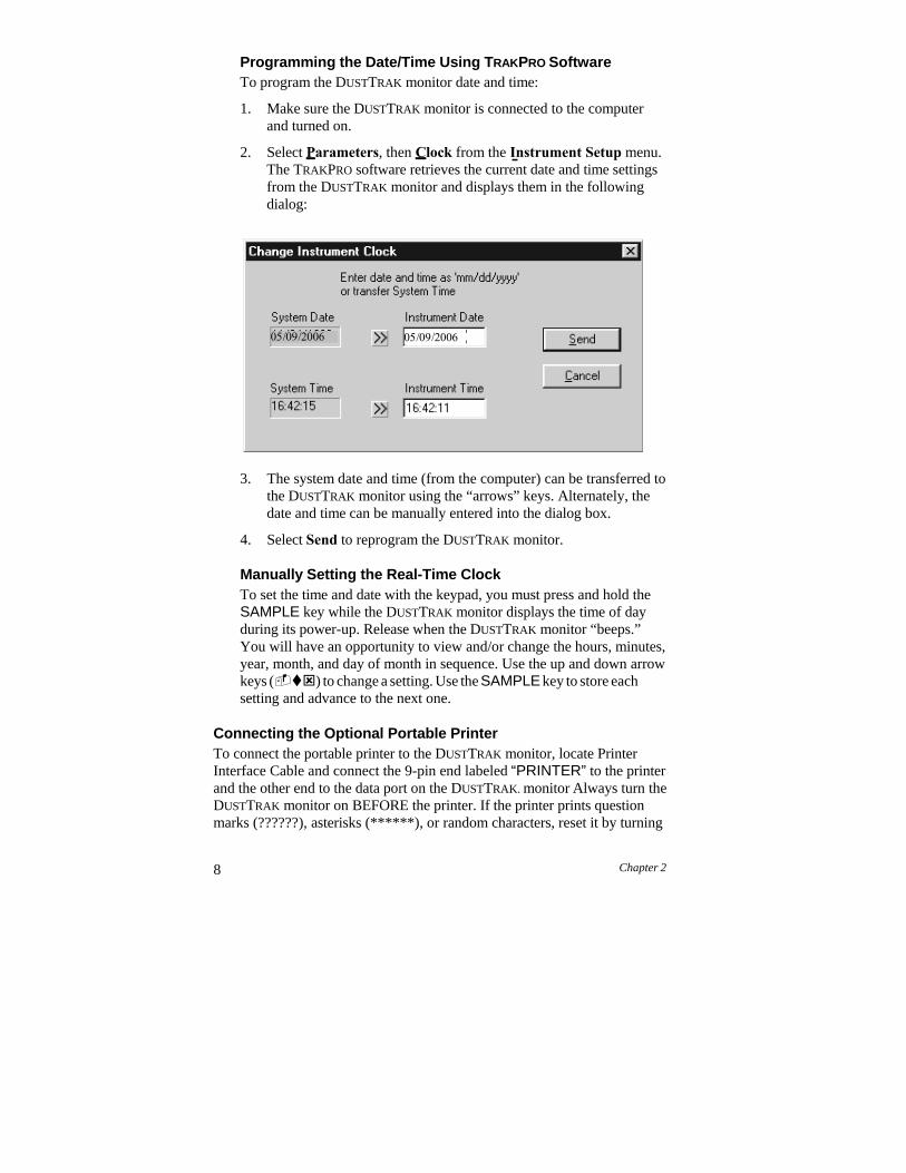
8 Chapter 2
Programming the Date/Time Using TRAKPRO Software To program the DUSTTRAK monitor date and time:
1. Make sure the DUSTTRAK monitor is connected to the computer and turned on.
2. Select Parameters, then Clock from the Instrument Setup menu. The TRAKPRO software retrieves the current date and time settings from the DUSTTRAK monitor and displays them in the following dialog:
3. The system date and time (from the computer) can be transferred to the DUSTTRAK monitor using the “arrows” keys. Alternately, the date and time can be manually entered into the dialog box.
4. Select Send to reprogram the DUSTTRAK monitor.
Manually Setting the Real-Time Clock To set the time and date with the keypad, you must press and hold the SAMPLE key while the DUSTTRAK monitor displays the time of day during its power-up. Release when the DUSTTRAK monitor “beeps.” You will have an opportunity to view and/or change the hours, minutes, year, month, and day of month in sequence. Use the up and down arrow keys () to change a setting. Use the SAMPLE key to store each setting and advance to the next one.
Connecting the Optional Portable Printer To connect the portable printer to the DUSTTRAK monitor, locate Printer Interface Cable and connect the 9-pin end labeled “PRINTER” to the printer and the other end to the data port on the DUSTTRAK. monitor Always turn the DUSTTRAK monitor on BEFORE the printer. If the printer prints question marks (??????), asterisks (******), or random characters, reset it by turning

Setting-Up 9
it off and then on again. If necessary, refer to the Portable Printer Operation and Service Manual.
Connecting/Wiring the Analog/Alarm Output Connector The Model 8520 DUSTTRAK Aerosol Monitor is capable of providing an analog output voltage signal that is proportional to the displayed concentration. It also contains a switch closure that is tied to an alarm value (see Chapter 3, “Operation,” for complete specifications and operational information for these features). The DUSTTRAK monitor is supplied with an output cable. The cable contains a 4-pin, mini-DIN connector. See Figure 2-2 below.
1. Analog Ground (-) 3. Alarm Positive (+) 2. Analog Output (+) 4. Alarm Ground (-)
Figure 2–2: Analog/Alarm Connector Pin-Outs
Since every application of this function will have unique requirements, the customer is responsible for making connections to their own equipment. The output cable contains a label, showing the wiring diagram/pin-outs.
Please see TSI Application Notes ITI-073 and ITI-074 for complete information and examples of wiring and using the Analog/Alarm Outputs. These Application Notes are available at the TSI website, http://www.tsi.com.
2 3
1 4

10 Chapter 2
+ –
Chapter 3
Operation
Overview The Model 8520 DUSTTRAKTM Aerosol Monitor has four modes of operation, Survey, LOG 1, LOG 2, and LOG 3. When the DUSTTRAK
monitor is first turned on it will be in Survey mode, which is used to display real-time readings and to determine statistics such as average, minimum, and maximum readings. LOG 1 mode is used to record individual data points for later analysis using a fixed protocol. LOG 2 and LOG 3 modes have a user- defined protocol, set up using TRAKPROTM Data Analysis Software. TRAKPRO software is used for analysis of data taken in any of the three LOG modes, but cannot be used on samples taken in Survey mode.
DUSTTRAK Aerosol Monitor Keypad Functions When pressing the keys on the front panel, the DUSTTRAK monitor beeps to confirm the function. If you press a key and the DUSTTRAK monitor does not beep, the DUSTTRAK monitor does not allow that function during the selected sampling mode.
ON/OFF Key Press the ON/OFF key to power the DUSTTRAK monitor. The DUSTTRAK
monitor immediately begins an internal self-check, while illuminating all the display digits and symbols. If a problem is detected, the display shows the message “SERVICE” along with a number to indicate that the DUSTTRAK
monitor requires servicing. Refer to the Chapter 5: “Troubleshooting,” for information regarding service numbers. If the “SERVICE” message appears, the DUSTTRAK monitor pauses until any key is pressed.
When the DUSTTRAK monitor completes its internal self-check, it displays the approximate percentage of battery life remaining. The DUSTTRAK
monitor displays the battery symbol
when the battery voltage becomes very low. After the battery symbol appears, the DUSTTRAK monitor runs for approximately 60 minutes before displaying the message “LO” (for a few seconds) and then automatically turning off. This feature is accurate for alkaline batteries only.
11
12 Chapter 3
CO2 SAMPLE
Note: The percentage life remaining will not be accurate for NiCd batteries. The battery symbol appears when battery voltage becomes low, but the DUSTTRAK monitor runs considerably less than 60 minutes before displaying the message “LO” and turning off.
Figure 3–1: DUSTTRAK Display with All Elements Shown
After displaying the percentage of battery life remaining, the current time set on the internal real-time clock is displayed. When the self-check is complete, the DUSTTRAK monitor will be in Survey mode.
SAMPLE Key Press the SAMPLE key to start/stop data sampling. The word “SAMPLE” appears in the upper right corner of the display while the DUSTTRAK monitor is taking a sample. When sampling is stopped, the DUSTTRAK monitor automatically scrolls through statistics for the sample that just ended.
TIME CONSTANT Key Momentarily press and release the TIME CONSTANT key to view the current time-constant. To change the time-constant, press and hold the key down. The available time-constant choices will scroll on the display. When the desired value is displayed, immediately release the key.
The time-constant is actually an averaging period. The DUSTTRAK monitor display is always updated every second. However, the reading displayed is the average reading over the last time-constant period. For example, if the current time-constant is set to 10-seconds, the display shows readings averaged over the previous 10 seconds, updated every second. This is also called a 10-second “moving average.”
As configured at the factory, the available time-constant values are 1, 5, 10, 15, and 30 seconds. The internal list of time-constant values can be altered using TRAKPRO Data Analysis Software supplied with the DUSTTRAK
monitor. The range of time constants allowed is 1–60 seconds. See the following instructions.
CALIBRATE ZERO RECORDING
HR:MN:SEC TEST ID LOG 123CO2 SAMPLEELAPSED TIME
PPM CONSTANT
°F°C AVERAGE
%RH MIN MAX
mg/m3 SERVICE
% MEMORY
Operation 13
Programming the Available Time Constants To program the list of time constants using TRAKPRO Data Analysis Software:
1. Make sure the DUSTTRAK monitor is connected to the computer and turned on.
2. Select Parameters, then Time Constants from the Instrument Setup menu. TRAKPRO software retrieves the current time constant settings from the DUSTTRAK monitor and displays them in the following dialog:
3. Enter a value for each of the five available time constants. (The range is limited to 1-60 seconds.)
4. Select Send.
The DUSTTRAK monitor is reprogrammed to offer the time constants you have specified.
STATISTICS Key Use the STATISTICS key to sequentially view the average, minimum, and maximum readings as well as the elapsed time of the most recently sampled data. If one of the LOG modes is active, a test identification number will be displayed also. Press the STATISTICS key once to display the average reading, again to display the minimum reading, again to display the maximum reading, and again to display the elapsed time for that sample (and again for the test ID if in LOG mode). If you press the STATISTICS key a fifth time (sixth time if in LOG mode), the DUSTTRAK monitor switches back into the currently selected measuring mode. You must sequence through all four statistic displays (i.e., press the STATISTICS key five
14 Chapter 3
times, six if in LOG mode) before the DUSTTRAK monitor goes back into the measuring mode.
PRINT Key Use the PRINT key to print information on the optional Portable Printer. The information printed will be different depending on what the DUSTTRAK
monitor is currently doing.
When the DUSTTRAK monitor is displaying real-time readings, pressing the PRINT key causes the reading to be printed along with the time and date. Each time the PRINT key is pressed, one reading will print. The reading printed reflects the current time-constant; therefore, it is the same as the displayed reading.
When the DUSTTRAK monitor is displaying any statistic, pressing the PRINT key causes the current statistics to print.
When the DUSTTRAK monitor is in one of the LOG modes and is idle (“%MEMORY” is displayed), pressing the PRINT key causes the logging setup for the current LOG mode to print.
During the power-up sequence, if you press and hold the PRINT key after the time is displayed, a printout will be generated showing certain system information (printer must be connected and turned on).
SAMPLING MODE Key The SAMPLING MODE key allows you to select among the four sampling modes: Survey, LOG 1, LOG 2, and LOG 3. Each time you press the SAMPLING MODE key, the DUSTTRAK monitor sequences to the next mode. When the DUSTTRAK monitor is in Survey mode, the current measurement will be shown on the display. When one of the LOG modes is selected, the LOG mode number, i.e. LOG 1, LOG 2, or LOG 3 will be displayed along with the percentage of free memory available.
Survey Mode When the DUSTTRAK monitor is first turned on, it will always be in Survey mode. Survey mode allows you to make real-time measurements of aerosol concentration, and to obtain statistics for that sample. The statistics include the average, minimum, and maximum values, as well as the elapsed time for that sample. Individual data points are not recorded (this can be done in any of the LOG modes). Each new sample taken in Survey mode clears the previous sample data from memory. Data taken in Survey mode remains in memory until another sample is made, or until samples are taken in one of the LOG modes. Turning the
Operation 15
DUSTTRAK monitor off will not erase data. Use the SAMPLE key to start and stop a sample.
LOG Modes There are three LOG modes: LOG 1, LOG 2, and LOG 3. When one of these modes is selected using the SAMPLING MODE key, the LOG mode number will be listed at the top of the display. The LOG modes allow you to record aerosol concentration data points for later retrieval and analysis using the software provided with the instrument.
Use the SAMPLE key to start and stop recording. The word “RECORDING” appears at the top of the display when recording is in progress.
The frequency that data is recorded can be set for LOG 1 mode with the LOGGING INTERVAL key. Use TRAKPRO software for LOG 2 and LOG 3 modes.
Data recorded using one of the LOG modes can only be erased by using the CLEAR MEMORY key. Turning the DUSTTRAK monitor off will not erase data. Recording another sample with one of the LOG modes without clearing memory first will cause new data to be added to the existing data (using a new test ID).
CLEAR MEMORY Key Use the CLEAR MEMORY key to erase all data. The CLEAR MEMORY key will not respond unless the DUSTTRAK monitor is first put into one of the three LOG modes by using the SAMPLING MODE key.
Note: Before clearing memory, you should first download the data to a computer through the TRAKPRO software. There is only one block of memory in the DUSTTRAK monitor. Clearing the memory for one LOG mode clears memory for all LOG modes.
To clear memory, press and hold the CLEAR MEMORY key until the countdown reaches zero, then release quickly. This prevents accidental erasure of data. Releasing the key too soon or too late prevents memory from being cleared.
LOGGING INTERVAL Key Use the LOGGING INTERVAL key to view or set the frequency/averaging period for recording data in LOG 1 mode or to view the current interval setting in LOG 2 and LOG 3 mode. Use TRAKPRO software to set the logging interval for LOG 2 and LOG 3 mode (see following section). The LOGGING INTERVAL key will not respond unless the DUSTTRAK monitor is first put into one of the three logging modes. Press the LOGGING

16 Chapter 3
INTERVAL key momentarily to view the current logging interval. Press and hold the LOGGING INTERVAL key to sequence through the available choices and release the key when the desired interval is on the display (LOG 1 mode only).
The logging interval is both a frequency and an averaging period. For example, when the logging interval is set to 30-minutes, readings will be recorded at 30-minute intervals. Each reading will be the average value measured over a 30-minute interval.
As shipped from the factory, the available logging intervals for LOG 1 mode are 1 second, 1 minute, 5 minutes, 15 minutes, and 30 minutes. Use the TRAKPRO Data Analysis Software to alter these values.
Programming the Logging Intervals using TRAKPRO Software To program the list of logging intervals available for LOG 1 mode:
1. Make sure the DUSTTRAK monitor is connected to the computer and turned on.
2. Select Parameters, then Logging Intervals from the Instrument Setup menu. TRAKPRO software retrieves the current logging intervals from the DUSTTRAK monitor and displays them in the following dialog:
3. Enter a value for each of the five available logging intervals (the range is from 1 second to 59 minutes and 59 seconds).
4. Select Send.
The DUSTTRAK monitor is reprogrammed to offer the logging intervals you have specified.
Operation 17
and Keys The two arrow keys are used to adjust readings when calibrating the DUSTTRAK monitor and for adjusting the time and date for the internal real- time clock.
CALIBRATE Key Use the CALIBRATE key to put the DUSTTRAK monitor into calibration mode. See Chapter 4, “Maintenance” for details on how to calibrate.
Display/Keypad Lockout Switch Recording data over extended time periods often requires leaving the DUSTTRAK monitor unattended. To reduce the risk of having an unauthorized person either intentionally or inadvertently interrupt the measurements, you can lock the display and keypad.
The lockout switch is on the backside of the DUSTTRAK monitor between the data port and the external power socket. It is a small slide switch and is recessed so that a pointed instrument must be used to move it.
With the switch in the right side position (nearest the power socket), all keypad and display functions will work normally. With the switch in the left side position (closest to the data port), the display and keypad will go into lockout mode. There are two ways to use the lockout switch. You can lock the keypad after recording starts, or you can put the switch into the lockout position prior to when recording starts. If you select the second method, you will be able to operate all functions normally until the SAMPLE key is pressed in one of the LOG modes. At that time the keypad automatically locks. When the display and keypad are locked, the display shows the words “RECORDING LOG X ” where “X” is the current LOG mode number.
Remote Sampling The DUSTTRAK Aerosol Monitor can be used for remote sampling by attaching a length of tubing to the inlet. For example, it can be set up for a test and hidden away where only the sample tubing extends into the area to be monitored. A 4-foot length of tubing is included with the DUSTTRAK
monitor for remote sampling purposes.
Note: Using a sampling tube longer than 4 feet is not recommended because particle transport losses in the tube may adversely affect the measurement. Also, do not use Teflon or silicone tubing because they can cause significant transport losses. Tygon® tubing is a good choice, as is metal tubing if it is grounded to dissipate static charges.
®Tygon is a registered trademark of Norton company.

18 Chapter 3
Respirable Mass Sampling with the Cyclone The 10-mm Nylon Dorr-Oliver Cyclone included with your aerosol monitor can be used to discriminate between the respirable fraction and other portions of the ambient aerosol. Four micrometers (µm) is internationally accepted as the 50 percent cut-off size for respirable aerosol mass. Particles larger than 4 µm impact onto the surfaces of the upper respiratory tract and cannot reach the lungs. The cyclone accessory provided with the DUSTTRAK
monitor is designed to provide a cut-off at 4 µm. This is specified as a 50 percent cut-off at 4 µm.
The cyclone works by forcing the particle-laden air sample to swirl inside the cyclone body. Larger (higher mass) particles cannot follow the air stream and become trapped, while smaller particles stay in the air stream and pass through. When using the cyclone, you can assume that all particles smaller than the cut-off size pass through and all larger particles become trapped in the grit pot.
The cut-off size for any cyclone is dependent on flow rate. It is very important that the sample flow rate through the DUSTTRAK monitor be set at 1.7 liters per minute (L/min). If some other flow rate is set, the cut-off size will not be at 4 µm.
Using the Cyclone To use the cyclone, be sure that you have the black inlet nozzle in place and that the blue impactor plate is removed from the inlet. Then you must adjust the sample flow rate to 1.7 L/min. See Chapter 4: “Maintenance,” for details.
After the flow rate is properly set, attach it to the DUSTTRAK monitor inlet port using the section of plastic tubing supplied with the cyclone. Slide the cyclone body into the holder provided on the back of the DUSTTRAK monitor. See Figure 3–2.
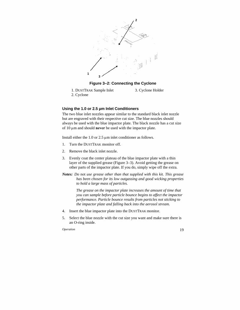
Operation 19
Figure 3–2: Connecting the Cyclone
1. DUSTTRAK Sample Inlet 3. Cyclone Holder 2. Cyclone
Using the 1.0 or 2.5 µm Inlet Conditioners The two blue inlet nozzles appear similar to the standard black inlet nozzle but are engraved with their respective cut size. The blue nozzles should always be used with the blue impactor plate. The black nozzle has a cut size of 10 m and should never be used with the impactor plate.
Install either the 1.0 or 2.5 m inlet conditioner as follows.
1. Turn the DUSTTRAK monitor off.
2. Remove the black inlet nozzle.
3. Evenly coat the center plateau of the blue impactor plate with a thin layer of the supplied grease (Figure 3–3). Avoid getting the grease on other parts of the impactor plate. If you do, simply wipe off the extra.
Notes: Do not use grease other than that supplied with this kit. This grease has been chosen for its low outgassing and good wicking properties to hold a large mass of particles.
The grease on the impactor plate increases the amount of time that you can sample before particle bounce begins to affect the impactor performance. Particle bounce results from particles not sticking to the impactor plate and falling back into the aerosol stream.
4. Insert the blue impactor plate into the DUSTTRAK monitor.
5. Select the blue nozzle with the cut size you want and make sure there is an O-ring inside.
2
1 3
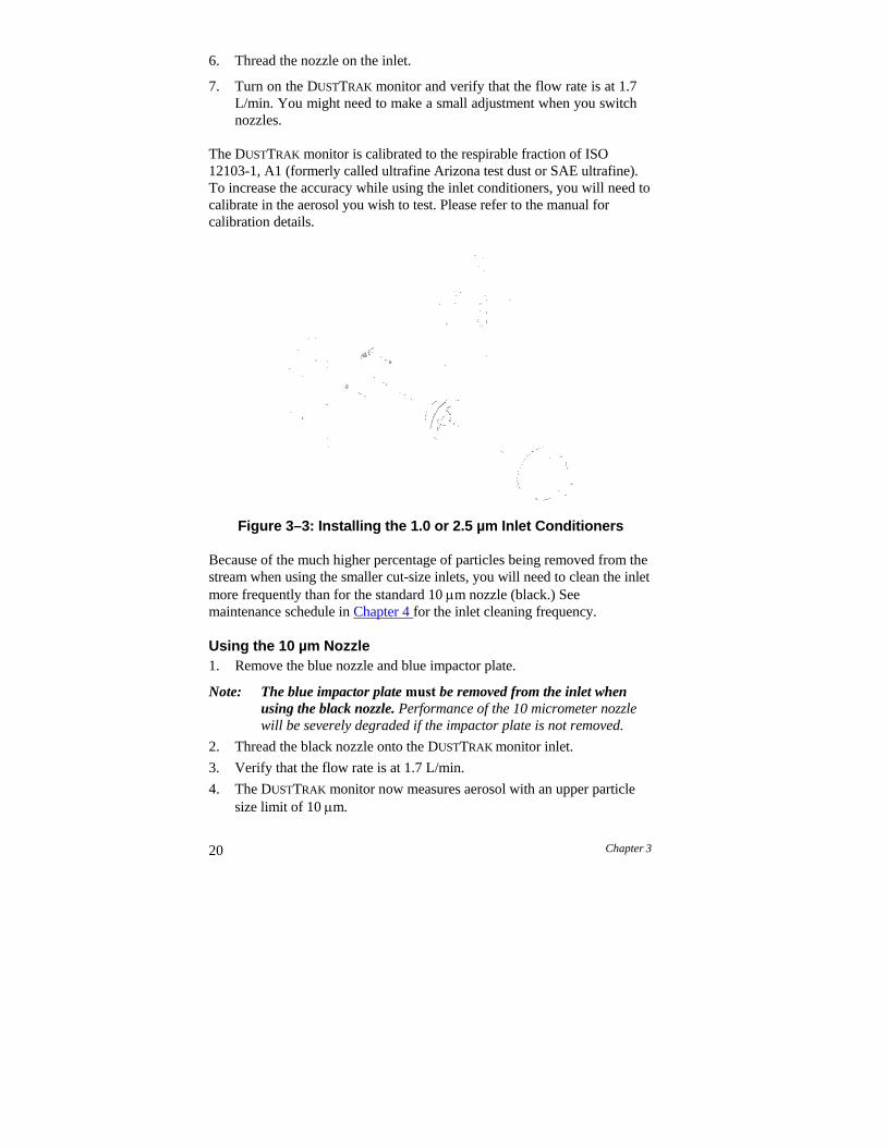
20 Chapter 3
6. Thread the nozzle on the inlet.
7. Turn on the DUSTTRAK monitor and verify that the flow rate is at 1.7 L/min. You might need to make a small adjustment when you switch nozzles.
The DUSTTRAK monitor is calibrated to the respirable fraction of ISO 12103-1, A1 (formerly called ultrafine Arizona test dust or SAE ultrafine). To increase the accuracy while using the inlet conditioners, you will need to calibrate in the aerosol you wish to test. Please refer to the manual for calibration details.
Figure 3–3: Installing the 1.0 or 2.5 µm Inlet Conditioners
Because of the much higher percentage of particles being removed from the stream when using the smaller cut-size inlets, you will need to clean the inlet more frequently than for the standard 10 m nozzle (black.) See maintenance schedule in Chapter 4 for the inlet cleaning frequency.
Using the 10 µm Nozzle 1. Remove the blue nozzle and blue impactor plate.
Note: The blue impactor plate must be removed from the inlet when using the black nozzle. Performance of the 10 micrometer nozzle will be severely degraded if the impactor plate is not removed.
2. Thread the black nozzle onto the DUSTTRAK monitor inlet.
3. Verify that the flow rate is at 1.7 L/min.
4. The DUSTTRAK monitor now measures aerosol with an upper particle size limit of 10 m.
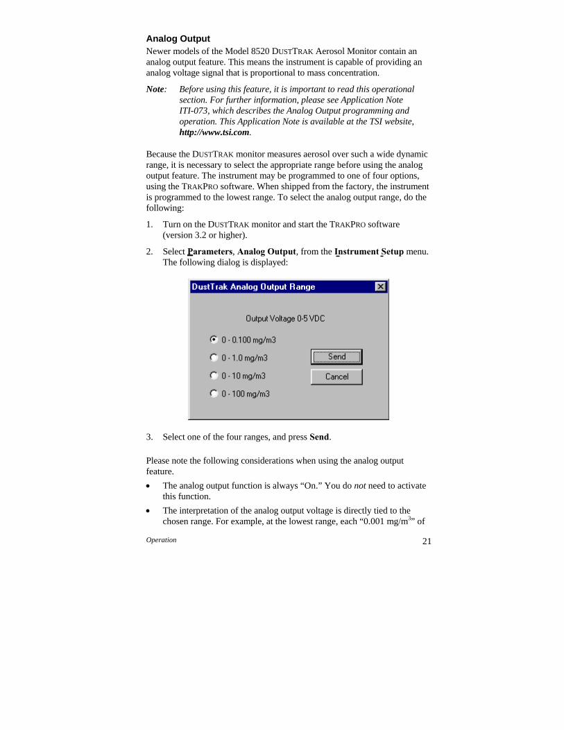
Operation 21
Analog Output Newer models of the Model 8520 DUSTTRAK Aerosol Monitor contain an analog output feature. This means the instrument is capable of providing an analog voltage signal that is proportional to mass concentration.
Note: Before using this feature, it is important to read this operational section. For further information, please see Application Note ITI-073, which describes the Analog Output programming and operation. This Application Note is available at the TSI website, http://www.tsi.com.
Because the DUSTTRAK monitor measures aerosol over such a wide dynamic range, it is necessary to select the appropriate range before using the analog output feature. The instrument may be programmed to one of four options, using the TRAKPRO software. When shipped from the factory, the instrument is programmed to the lowest range. To select the analog output range, do the following:
1. Turn on the DUSTTRAK monitor and start the TRAKPRO software (version 3.2 or higher).
2. Select Parameters, Analog Output, from the Instrument Setup menu. The following dialog is displayed:
3. Select one of the four ranges, and press Send.
Please note the following considerations when using the analog output feature.
The analog output function is always “On.” You do not need to activate this function.
The interpretation of the analog output voltage is directly tied to the chosen range. For example, at the lowest range, each “0.001 mg/m3” of
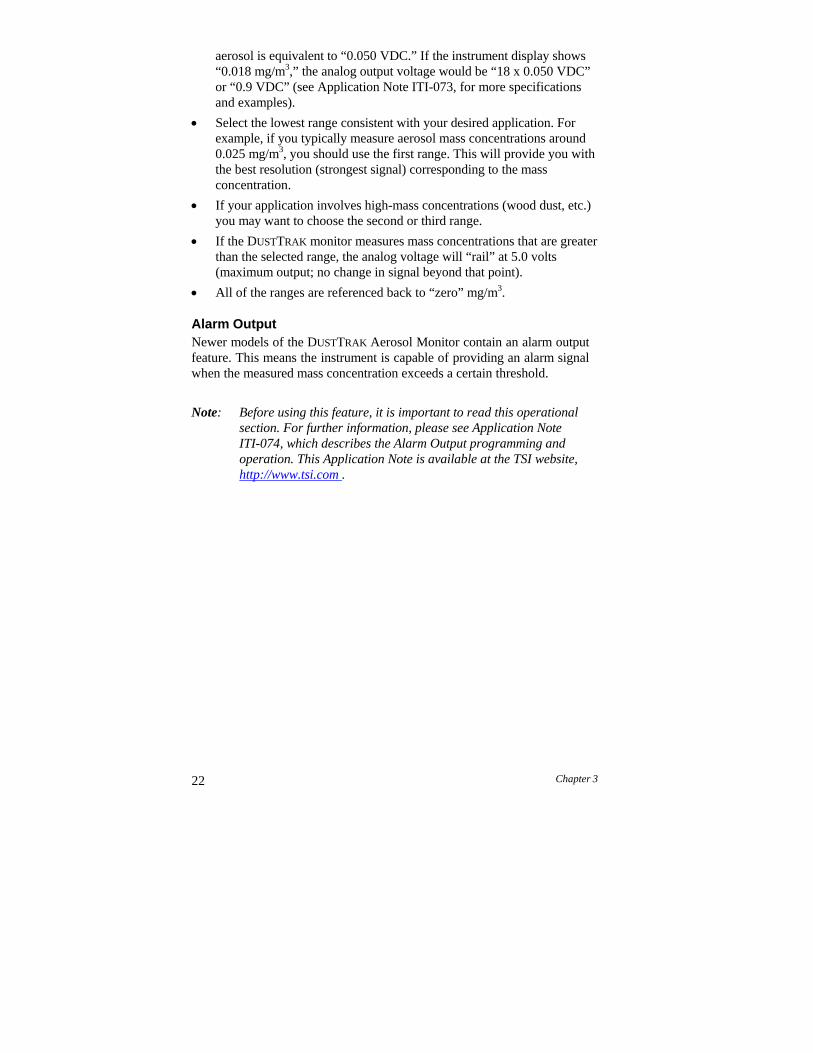
22 Chapter 3
aerosol is equivalent to “0.050 VDC.” If the instrument display shows “0.018 mg/m3,” the analog output voltage would be “18 x 0.050 VDC” or “0.9 VDC” (see Application Note ITI-073, for more specifications and examples).
Select the lowest range consistent with your desired application. For example, if you typically measure aerosol mass concentrations around 0.025 mg/m3, you should use the first range. This will provide you with the best resolution (strongest signal) corresponding to the mass concentration.
If your application involves high-mass concentrations (wood dust, etc.) you may want to choose the second or third range.
If the DUSTTRAK monitor measures mass concentrations that are greater than the selected range, the analog voltage will “rail” at 5.0 volts (maximum output; no change in signal beyond that point).
All of the ranges are referenced back to “zero” mg/m3.
Alarm Output Newer models of the DUSTTRAK Aerosol Monitor contain an alarm output feature. This means the instrument is capable of providing an alarm signal when the measured mass concentration exceeds a certain threshold.
Note: Before using this feature, it is important to read this operational section. For further information, please see Application Note ITI-074, which describes the Alarm Output programming and operation. This Application Note is available at the TSI website, http://www.tsi.com .
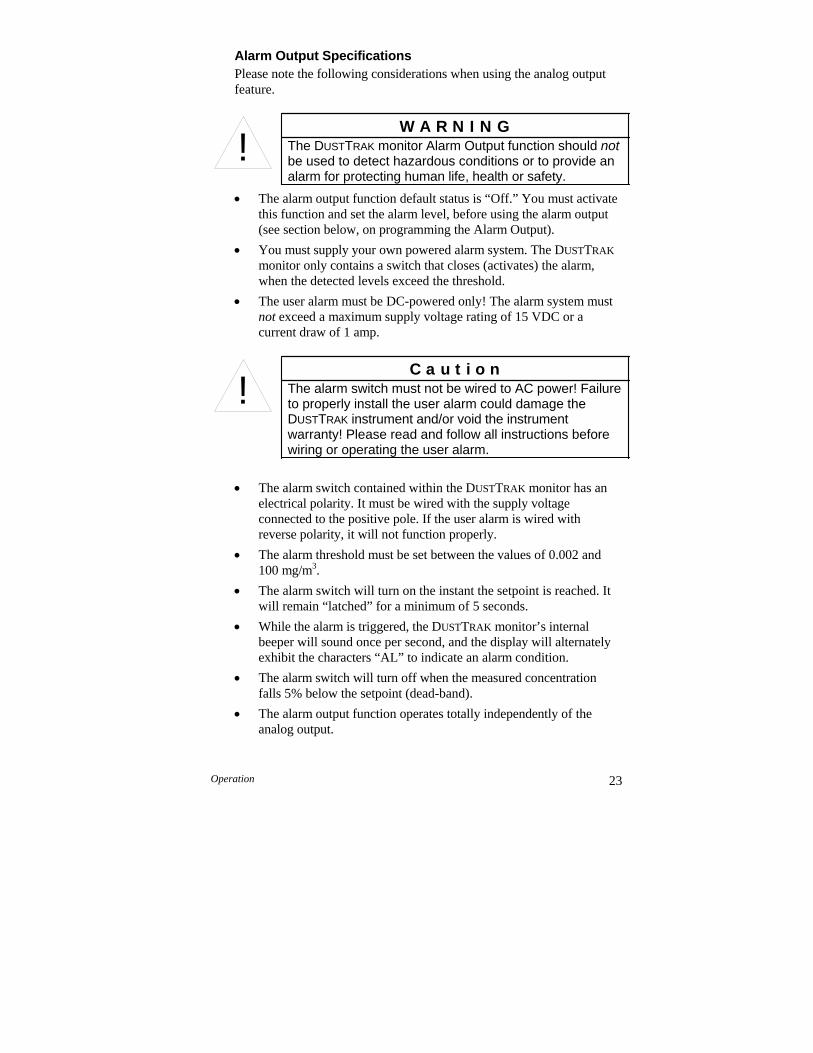
Operation 23
Alarm Output Specifications Please note the following considerations when using the analog output feature.
The alarm output function default status is “Off.” You must activate this function and set the alarm level, before using the alarm output (see section below, on programming the Alarm Output).
You must supply your own powered alarm system. The DUSTTRAK
monitor only contains a switch that closes (activates) the alarm, when the detected levels exceed the threshold.
The user alarm must be DC-powered only! The alarm system must not exceed a maximum supply voltage rating of 15 VDC or a current draw of 1 amp.
The alarm switch contained within the DUSTTRAK monitor has an electrical polarity. It must be wired with the supply voltage connected to the positive pole. If the user alarm is wired with reverse polarity, it will not function properly.
The alarm threshold must be set between the values of 0.002 and 100 mg/m3.
The alarm switch will turn on the instant the setpoint is reached. It will remain “latched” for a minimum of 5 seconds.
While the alarm is triggered, the DUSTTRAK monitor’s internal beeper will sound once per second, and the display will alternately exhibit the characters “AL” to indicate an alarm condition.
The alarm switch will turn off when the measured concentration falls 5% below the setpoint (dead-band).
The alarm output function operates totally independently of the analog output.
C a u t i o n The alarm switch must not be wired to AC power! Failure to properly install the user alarm could damage the DUSTTRAK instrument and/or void the instrument warranty! Please read and follow all instructions before wiring or operating the user alarm.
!
W A R N I N G The DUSTTRAK monitor Alarm Output function should not be used to detect hazardous conditions or to provide an alarm for protecting human life, health or safety.
!
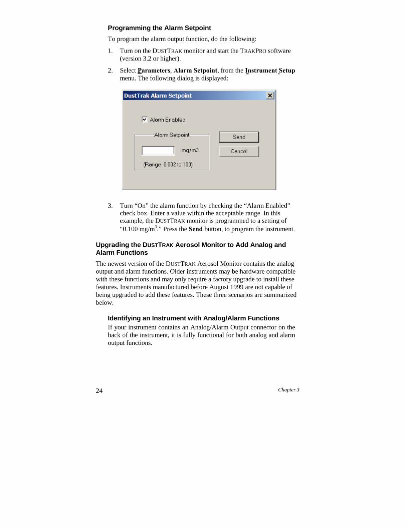
24 Chapter 3
Programming the Alarm Setpoint
To program the alarm output function, do the following:
1. Turn on the DUSTTRAK monitor and start the TRAKPRO software (version 3.2 or higher).
2. Select Parameters, Alarm Setpoint, from the Instrument Setup menu. The following dialog is displayed:
3. Turn “On” the alarm function by checking the “Alarm Enabled” check box. Enter a value within the acceptable range. In this example, the DUSTTRAK monitor is programmed to a setting of “0.100 mg/m3.” Press the Send button, to program the instrument.
Upgrading the DUSTTRAK Aerosol Monitor to Add Analog and Alarm Functions
The newest version of the DUSTTRAK Aerosol Monitor contains the analog output and alarm functions. Older instruments may be hardware compatible with these functions and may only require a factory upgrade to install these features. Instruments manufactured before August 1999 are not capable of being upgraded to add these features. These three scenarios are summarized below.
Identifying an Instrument with Analog/Alarm Functions If your instrument contains an Analog/Alarm Output connector on the back of the instrument, it is fully functional for both analog and alarm output functions.
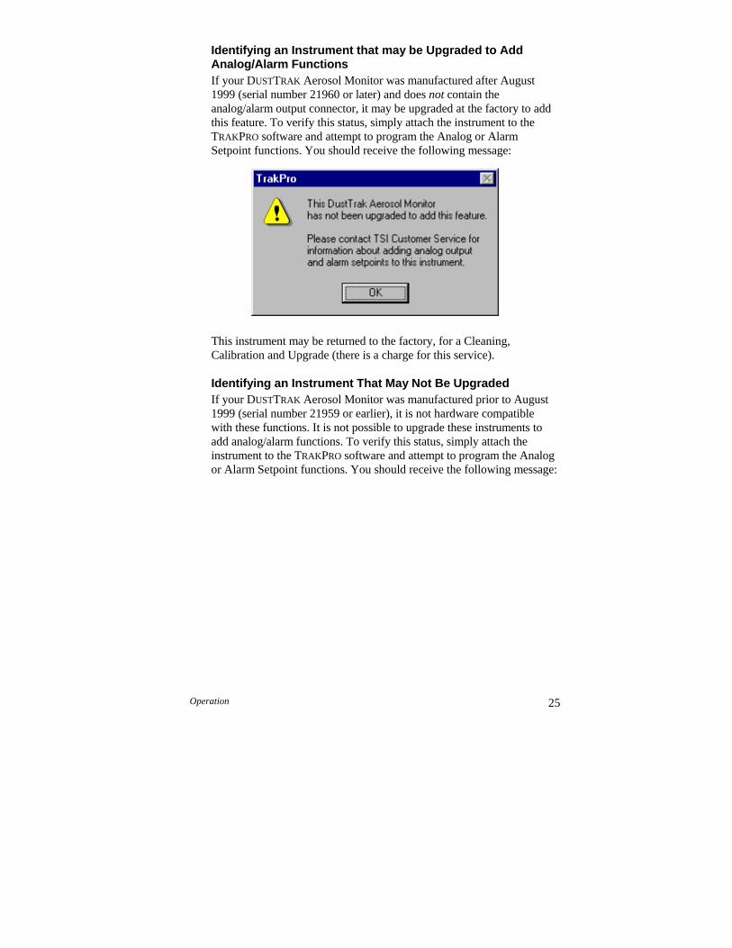
Operation 25
Identifying an Instrument that may be Upgraded to Add Analog/Alarm Functions If your DUSTTRAK Aerosol Monitor was manufactured after August 1999 (serial number 21960 or later) and does not contain the analog/alarm output connector, it may be upgraded at the factory to add this feature. To verify this status, simply attach the instrument to the TRAKPRO software and attempt to program the Analog or Alarm Setpoint functions. You should receive the following message:
This instrument may be returned to the factory, for a Cleaning, Calibration and Upgrade (there is a charge for this service).
Identifying an Instrument That May Not Be Upgraded If your DUSTTRAK Aerosol Monitor was manufactured prior to August 1999 (serial number 21959 or earlier), it is not hardware compatible with these functions. It is not possible to upgrade these instruments to add analog/alarm functions. To verify this status, simply attach the instrument to the TRAKPRO software and attempt to program the Analog or Alarm Setpoint functions. You should receive the following message:
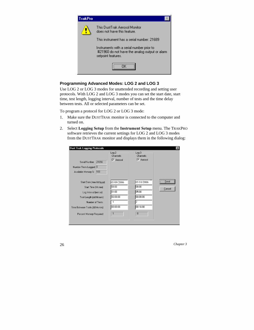
26 Chapter 3
Programming Advanced Modes: LOG 2 and LOG 3 Use LOG 2 or LOG 3 modes for unattended recording and setting user protocols. With LOG 2 and LOG 3 modes you can set the start date, start time, test length, logging interval, number of tests and the time delay between tests. All or selected parameters can be set.
To program a protocol for LOG 2 or LOG 3 mode:
1. Make sure the DUSTTRAK monitor is connected to the computer and turned on.
2. Select Logging Setup from the Instrument Setup menu. The TRAKPRO
software retrieves the current settings for LOG 2 and LOG 3 modes from the DUSTTRAK monitor and displays them in the following dialog:

Operation 27
The following table summarizes the information displayed in the DUSTTRAK Logging Protocols dialog box:
Serial Number Displays the serial number of the logging
instrument. Number of tests logged
Displays the number of tests currently logged and stored in the logging instrument.
Available Memory (%)
Displays the percent of available memory in the logging instrument.
LOG 2 and LOG 3 Mode Protocols Channels Displays the channels selected for sampling in
LOG 2 and LOG 3 modes.Start Date Displays the start date for LOG 2 and LOG 3
modes.Start Time Displays the start time for LOG 2 and LOG 3
modes.Log interval Displays the log interval for LOG 2 and LOG
3 modes.Test length Displays the test length for LOG 2 and LOG 3
modes.Number of tests Displays the number of tests for LOG 2 and
LOG 3 modes.Time between tests
Displays the time between tests for LOG 2 and LOG 3 modes.
Percent memory required.
Displays the percent of logger memory required to perform a LOG 2 or a LOG 3 mode sample. To store the results of a LOG 2 or LOG 3 mode sample, the Available Memory must be equal to or greater than the Percent memory required.
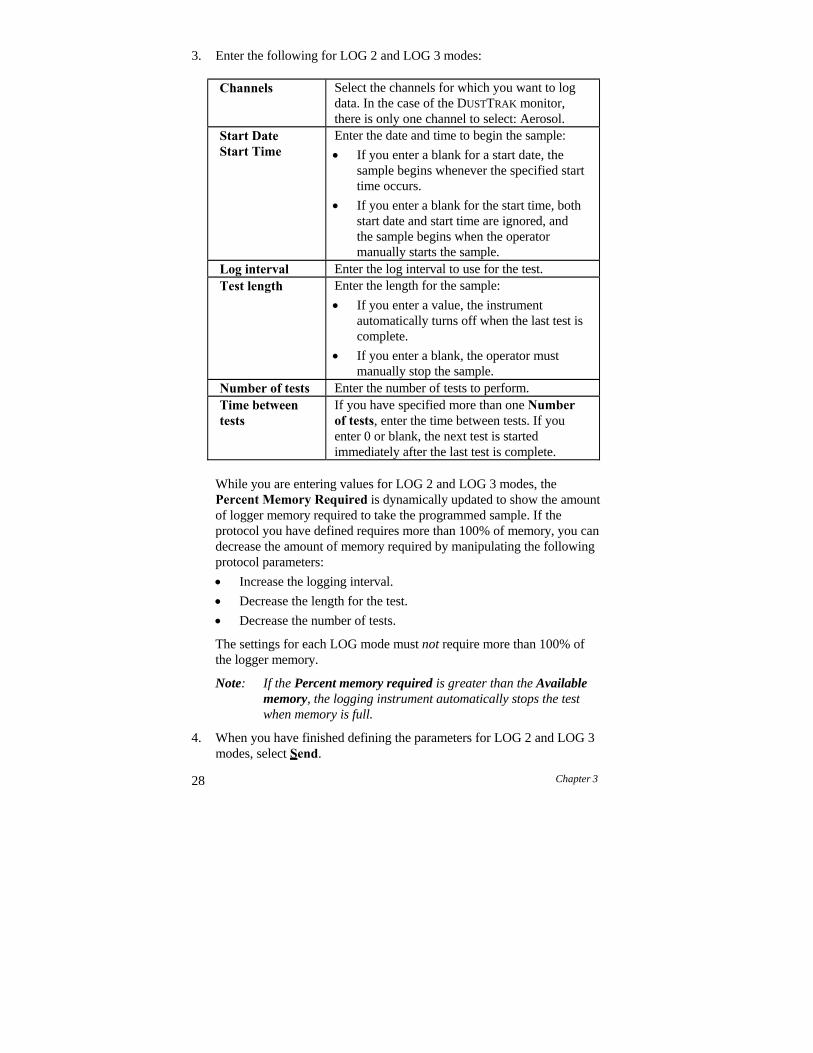
28 Chapter 3
3. Enter the following for LOG 2 and LOG 3 modes:
Channels Select the channels for which you want to log data. In the case of the DUSTTRAK monitor, there is only one channel to select: Aerosol.
Start Date Start Time
Enter the date and time to begin the sample:
If you enter a blank for a start date, the sample begins whenever the specified start time occurs.
If you enter a blank for the start time, both start date and start time are ignored, and the sample begins when the operator manually starts the sample.
Log interval Enter the log interval to use for the test.Test length Enter the length for the sample:
If you enter a value, the instrument automatically turns off when the last test is complete.
If you enter a blank, the operator must manually stop the sample.
Number of tests Enter the number of tests to perform.Time between tests
If you have specified more than one Number of tests, enter the time between tests. If you enter 0 or blank, the next test is started immediately after the last test is complete.
While you are entering values for LOG 2 and LOG 3 modes, the Percent Memory Required is dynamically updated to show the amount of logger memory required to take the programmed sample. If the protocol you have defined requires more than 100% of memory, you can decrease the amount of memory required by manipulating the following protocol parameters:
Increase the logging interval.
Decrease the length for the test.
Decrease the number of tests.
The settings for each LOG mode must not require more than 100% of the logger memory.
Note: If the Percent memory required is greater than the Available memory, the logging instrument automatically stops the test when memory is full.
4. When you have finished defining the parameters for LOG 2 and LOG 3 modes, select Send.
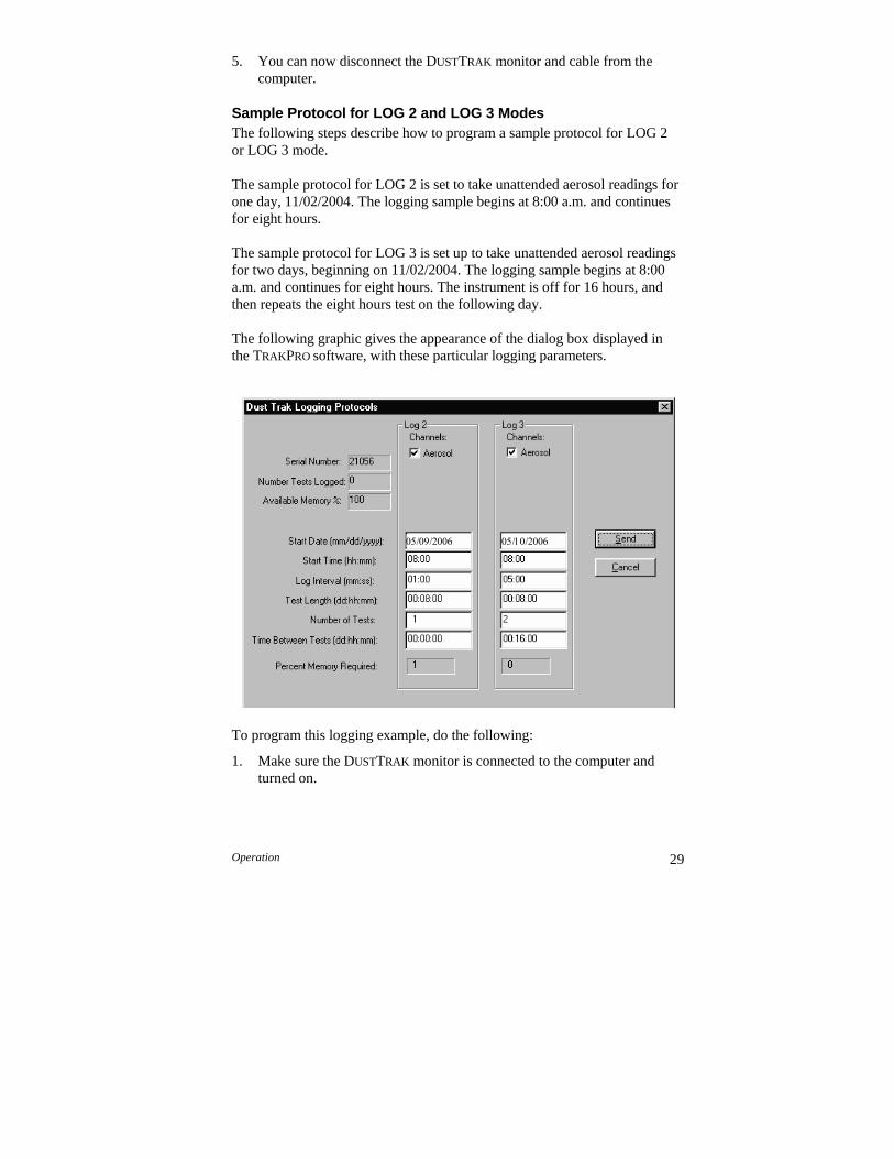
Operation 29
5. You can now disconnect the DUSTTRAK monitor and cable from the computer.
Sample Protocol for LOG 2 and LOG 3 Modes The following steps describe how to program a sample protocol for LOG 2 or LOG 3 mode.
The sample protocol for LOG 2 is set to take unattended aerosol readings for one day, 11/02/2004. The logging sample begins at 8:00 a.m. and continues for eight hours.
The sample protocol for LOG 3 is set up to take unattended aerosol readings for two days, beginning on 11/02/2004. The logging sample begins at 8:00 a.m. and continues for eight hours. The instrument is off for 16 hours, and then repeats the eight hours test on the following day.
The following graphic gives the appearance of the dialog box displayed in the TRAKPRO software, with these particular logging parameters.
To program this logging example, do the following:
1. Make sure the DUSTTRAK monitor is connected to the computer and turned on.
30 Chapter 3
2. Select Logging Setup from the Instrument Setup menu. The TRAKPRO
software retrieves the current settings for LOG 2 and LOG 3 modes from the DUSTTRAK monitor and displays them in the previous dialog.
3. Enter the following for LOG 2 and LOG 3:
Setting LOG 2 LOG 3Channels Aerosol AerosolStart Date 05/09/2006 05/10/2006Start Time 08:00 08:00Log interval 01:00 05:00Test length 00:08:00 00:08:00Number of tests 1 2Time between tests
00:00:00 00:16:00
4. Select Send. The logging instrument is programmed for the mode 2 and mode 3 protocols.
5. Note that the LOG 2 test requires 1% of the available memory and LOG 3 requires less than 1% of the memory. A total of 100% of the memory is available for use.
6. You can now disconnect your DUSTTRAK monitor from the computer. Refer to other sections of this Operation and Service Manual for details on making measurements using LOG 2 and LOG 3 modes.
After programming the DUSTTRAK monitor with the TRAKPRO Data Analysis Software, take the DUSTTRAK monitor to the desired location and turn it on. Put it into LOG 2 or LOG 3 mode (whichever you programmed) using the SAMPLING MODE key. Press the SAMPLE key to initiate the program.
If you have set a start time and/or date, the display toggles between the next “TEST ID” and the “ELAPSED TIME 0” message. If the test start time is greater than one minute away, the DUSTTRAK monitor shuts off until one minute before the test start time. This indicates that the DUSTTRAK monitor is waiting until the programmed start time and dates occur. To prevent tampering, lockout the display and keypad at this time.
Things You Should Know About Taking Pre-Programmed Samples If you press the SAMPLE key during programmed operation, the program terminates (unless the keypad is locked).
Operation 31
If the programmed start time/date has already passed, pressing the SAMPLE key has no effect. The program will never execute.
It is always best to enter both a start time and start date! However, setting the start time but no start date causes the DUSTTRAK monitor to start at the specified time regardless of the date. The instrument may not shut down prior to beginning logging.
If no start time is set, the DUSTTRAK monitor waits for you to press the SAMPLE key and then starts sampling immediately.
If no test length is set, the DUSTTRAK monitor takes samples continuously until the SAMPLE key is pressed to stop sampling or until memory is full.
When a pre-programmed test ends, the DUSTTRAK monitor automatically shuts off.
Memory Considerations The DUSTTRAK monitor has a great deal of memory and you will not normally have to be concerned with running out. The DUSTTRAK monitor can store more than 31,000 data points. Therefore 1% of memory is about 310 data points.
This should be considered when selecting a logging interval. Shorter logging intervals use memory more quickly than longer intervals.
The logging interval and the available memory determine the maximum possible duration of a data logging session. The equation below can be used to determine any memory, recording time or logging interval restraints.
% Memory Elapsed Time 315Logging Interval
(Note: Elapsed Time and Logging Interval are in units of minutes.) Custom Calibrations In most situations, the DUSTTRAK monitor with its built-in data logger can provide very good information on how the concentration of an aerosol changes for different processes over time. Factory calibration to the respirable fraction of standard ISO 12103-1, A1 test dust (formerly Arizona Test Dust) allows comparisons between measurements where the source or type of dust is predominately the same. Because optical mass measurements are dependent upon particle size and material properties, there may be times in which a custom calibration would improve your accuracy for a specific aerosol.
32 Chapter 3
The DUSTTRAK monitor has several features to aid in obtaining good accuracy for a particular aerosol.
The DUSTTRAK monitor’s custom calibration factor can be changed through the instrument keypad. All future readings from the DUSTTRAK
monitor will correspond to a specific aerosol until the calibration factor is changed back to the factory setting.
Custom calibration factors can be stored in a table and downloaded to the DUSTTRAK monitor using the TRAKPRO Data Analysis Software. All future measurements will correspond to a specific aerosol until the calibration factor is changed back to the factory setting.
A single set of logged data can be converted to data calibrated to a specific aerosol with the use of the TRAKPRO software. This conversion can be done by knowing either the true mass concentration for the logged data or the calibration factor for the aerosol. Future measurements will continue to be read and logged with the original calibration factor (normally 1.0) and will not be converted automatically.
All of these options require that you determine a true mass concentration (e.g., gravimetric analysis) for the aerosol you want to measure. The true mass concentration is used to calculate the custom calibration factor for that aerosol. Once you have a custom calibration factor, you can reuse it each time you make measurements in the same or similar aerosol environment.
Determining the Calibration Factor for a Specific Aerosol The DUSTTRAK monitor is factory calibrated to the respirable fraction of standard ISO 12103-1, A1 test dust. The DUSTTRAK monitor can be easily calibrated to any arbitrary aerosol by adjusting the custom calibration factor. The DUSTTRAK monitor’s custom calibration factor is assigned the value of 1.00 for the standard ISO test dust. This procedure describes how to determine the calibration factor for a specific aerosol. Using a value of 1.00 will always revert back to the factory calibration.
To determine a new calibration factor you need some way of accurately measuring the concentration of aerosol, hereafter referred to as the reference instrument. A gravimetric analysis is often the best choice, though it is limited to nonvolatile aerosols.
To make an accurate calibration you must simultaneously measure the aerosol concentration with the DUSTTRAK monitor and your reference instrument.
1. Zero the DUSTTRAK monitor as described in the Maintenance chapter.
Operation 33
2. Put the instrument in Log Mode 1.
3. Set the logging interval by pressing and holding the LOGGING INTERVAL button down. The default choices for the logging intervals can be reprogrammed using TRAKPRO software. One minute (i.e., “01:00”) is often a good choice.
4. Locate the DUSTTRAK monitor and the reference sampler together so that they are measuring from the same area.
5. Start sampling aerosol with both instruments at the same time.
Note: Greater accuracy will be obtained with longer samples. The time you permit for sampling often depends on the reference instrument and characteristics of the measured aerosol. It may take some time to collect sufficient aerosol onto a filter cassette for accurate gravimetric analysis. Refer to instructions of your reference instrument for sampling times.
6. Stop sampling with both instruments at the same time.
7. Record the DUSTTRAK monitor average concentration. Press the STATISTICS key to view the average for the last test. If you wish to determine a custom calibration factor for this test only, you can instead receive the data into the TRAKPRO software.
8. Determine the mass concentration in mg/m3 from your reference instrument. For gravimetric sampling this means having the gravimetric sample weighed.
9. Compute the new calibration constant, NewCal, using the following formula:
NewCal Reference Concentration CurrentCal
DustTrak Concentration The calibration factor, OldCal, can be obtained from the DUSTTRAK
monitor. In Survey mode, press and hold the CALIBRATE key down until the display counts down to zero. Release immediately when zero is reached and “CALIBRATE ZERO” appears on the display. If not, try again until it does. Press CALIBRATE again and the current calibration factor will be displayed with flashing up and down arrows. Record this value to make your calculation. Press CALIBRATE again to exit calibration mode.
Setting Custom Calibration Factor from Keypad
1. In Survey mode, press and hold the CALIBRATE key down until the DUSTTRAK monitor counts down to zero. Release the button
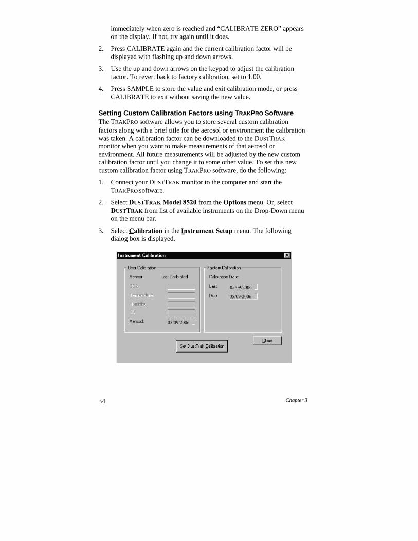
34 Chapter 3
immediately when zero is reached and “CALIBRATE ZERO” appears on the display. If not, try again until it does.
2. Press CALIBRATE again and the current calibration factor will be displayed with flashing up and down arrows.
3. Use the up and down arrows on the keypad to adjust the calibration factor. To revert back to factory calibration, set to 1.00.
4. Press SAMPLE to store the value and exit calibration mode, or press CALIBRATE to exit without saving the new value.
Setting Custom Calibration Factors using TRAKPRO Software The TRAKPRO software allows you to store several custom calibration factors along with a brief title for the aerosol or environment the calibration was taken. A calibration factor can be downloaded to the DUSTTRAK
monitor when you want to make measurements of that aerosol or environment. All future measurements will be adjusted by the new custom calibration factor until you change it to some other value. To set this new custom calibration factor using TRAKPRO software, do the following:
1. Connect your DUSTTRAK monitor to the computer and start the TRAKPRO software.
2. Select DUSTTRAK Model 8520 from the Options menu. Or, select DUSTTRAK from list of available instruments on the Drop-Down menu on the menu bar.
3. Select Calibration in the Instrument Setup menu. The following dialog box is displayed.
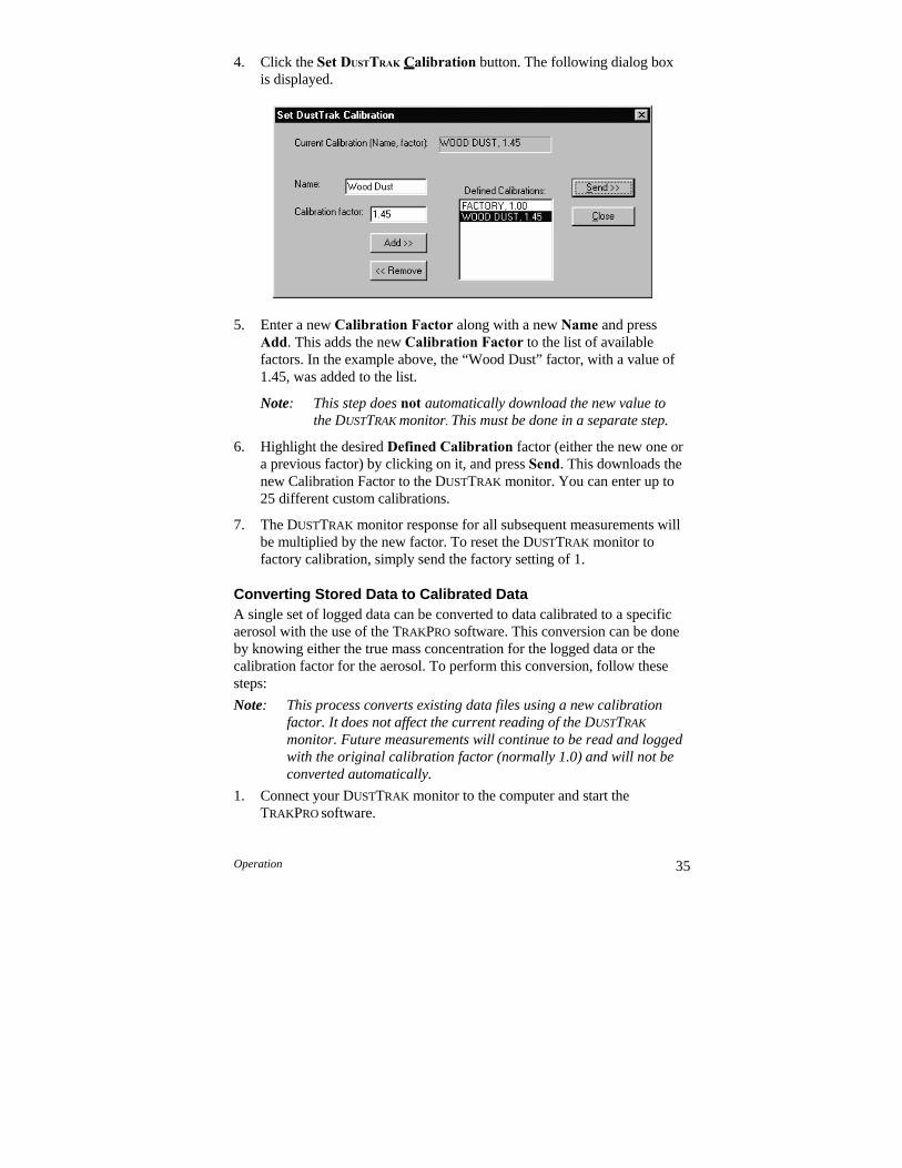
Operation 35
4. Click the Set DUSTTRAK Calibration button. The following dialog box is displayed.
5. Enter a new Calibration Factor along with a new Name and press Add. This adds the new Calibration Factor to the list of available factors. In the example above, the “Wood Dust” factor, with a value of 1.45, was added to the list.
Note: This step does not automatically download the new value to the DUSTTRAK monitor. This must be done in a separate step.
6. Highlight the desired Defined Calibration factor (either the new one or a previous factor) by clicking on it, and press Send. This downloads the new Calibration Factor to the DUSTTRAK monitor. You can enter up to 25 different custom calibrations.
7. The DUSTTRAK monitor response for all subsequent measurements will be multiplied by the new factor. To reset the DUSTTRAK monitor to factory calibration, simply send the factory setting of 1.
Converting Stored Data to Calibrated Data A single set of logged data can be converted to data calibrated to a specific aerosol with the use of the TRAKPRO software. This conversion can be done by knowing either the true mass concentration for the logged data or the calibration factor for the aerosol. To perform this conversion, follow these steps:
Note: This process converts existing data files using a new calibration factor. It does not affect the current reading of the DUSTTRAK
monitor. Future measurements will continue to be read and logged with the original calibration factor (normally 1.0) and will not be converted automatically.
1. Connect your DUSTTRAK monitor to the computer and start the TRAKPRO software.

36 Chapter 3
2. Select DustTrak Model 8520 from the Options menu under Software Configure. Or, select DustTrak from list of available instruments on the drop-down menu on the menu bar.
3. Open the file that contains the data to be converted. Highlight a single test within that data file.
4. Select Define DustTrak Calibration from the Options menu. The following dialog box is displayed.
5. Enter the New Mass Concentration value (in mg/m3). The New Calibration Factor is calculated and automatically updated. Press OK.
6. When you click OK, a new data set of the same name will be generated calibrated to the mass concentration that you entered. This data set will be appended to the same file. The original data remains.
7. If you want to adjust the data to a previously determined custom calibration factor without performing a gravimetric calibration, enter the new calibration factor. The New Mass Concentration automatically updates.
Chapter 4
Maintenance
The DUSTTRAK monitor can be maintained and calibrated in the field using the instructions below. Even so, TSI recommends that you return your DUSTTRAK monitor to the factory for annual calibration. For a reasonable fee, we will quickly clean and calibrate the unit and return it to you in “as new” working condition, along with a Certificate of Calibration. This “annual checkup” helps ensure that the DUSTTRAK monitor is always in good operating condition.
The DUSTTRAK monitor is factory calibrated to the standard ISO 12103-1, A1 test dust (formerly Arizona Test Dust). The calibration data is stored internally and cannot be accessed by you. This standard test dust is used because of its wide particle size distribution. This makes the internal calibration representative of an average of most types of ambient aerosol you might encounter.
For many applications, the factory calibration provides accurate measurements. There may be times when more accurate mass concentration data is needed because the aerosol being sampled is significantly different than the standard ISO test dust. To accommodate such a measurement, the DUSTTRAK monitor has been designed to allow for field calibration.
Note: There are no user-serviceable parts inside this instrument. TSI recommends that you return the DUSTTRAK monitor to the factory for any required maintenance or service not described in this manual.
Maintenance Schedule Your Model 8520 DUSTTRAK Aerosol Monitor requires maintenance on a regular basis. Table 4–1 lists the factory recommended maintenance schedule.
Some maintenance items are required each time the DUSTTRAK monitor is used or on an annual basis. Other items are scheduled according to how much aerosol is drawn through the instrument. For example, cleaning the inlet sample tube is recommended after 350 hours of sampling a 1 mg/m3
concentration of aerosol. This recommendation should be pro-rated according to how the instrument is used. 350 hours at 1 mg/m3 is the same amount of aerosol as 700 hours at 0.5 mg/m3 or 175 hours at 2 mg/m3, etc.
37

38 Chapter 4
When using the 1.0 or 2.5 m inlet nozzles you need to clean the inlet more frequently than for the standard 10 m nozzle (black) because of the much higher percentage of particles being removed from the stream. Table 4–1 represents estimates of how long you can run before cleaning is necessary. The actual time you can run between cleanings varies with the size distribution of particles you are measuring.
Table 4–1. Recommended Maintenance Schedule Item FrequencyPerform zero check Daily (or before long tests) Clean 1.0 m nozzle 5 hr. at 1 mg/m3*Clean 2.5 m nozzle 30 hr. at 1 mg/m3*Clean 10 m nozzle, inlet, and sample tube 350 hr. at 1 mg/m3*Replace internal filters 700 hr. at 1 mg/m3*Clean cyclone Before each useReturn to factory for cleaning and calibration
Annually
*Pro-rated, see discussion above.
The DUSTTRAK monitor keeps track of the accumulated amount of aerosol drawn through it since its last cleaning. When sample tube cleaning or internal filter replacement is due, the display shows the message “SERVICE 4” or “SERVICE 5,” respectively, during power-up. Press any key to bypass the message, but be sure to perform the maintenance procedures at your earliest convenience.
TSI recommends that you perform a zero check each day the DUSTTRAK
monitor is used, before running any extended tests, and after the instrument experiences a significant environmental change. Examples of significant environmental changes would be ambient temperature changes that exceed 15 F (8 °C) or moving from locations with high aerosol concentrations to low concentrations.
Zero Checking/Re-Zeroing
1. Put the DUSTTRAK monitor in Survey mode.
2. Put zero filter on aerosol sample inlet. See Figure 4–1.
3. Set the time-constant to 10 seconds. Press and hold the TIME CONSTANT key until “10” is displayed, then release.
4. Wait 10–60 seconds for displayed values to settle to zero.
5. If the displayed value is between -0.001 and +0.001 mg/m3, the DUSTTRAK monitor does not need adjustment. If the displayed value exceeds this limit, follow steps 7 to 9 below to re-zero the instrument.
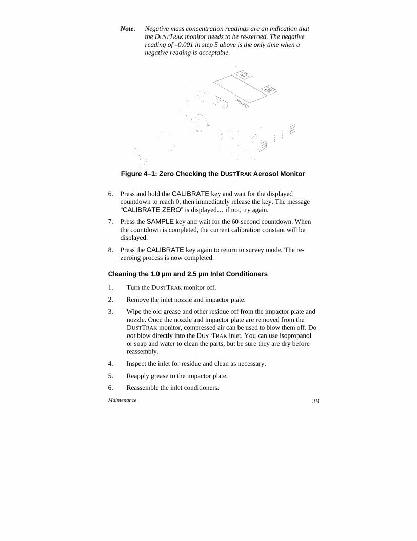
Maintenance 39
Note: Negative mass concentration readings are an indication that the DUSTTRAK monitor needs to be re-zeroed. The negative reading of –0.001 in step 5 above is the only time when a negative reading is acceptable.
Figure 4–1: Zero Checking the DUSTTRAK Aerosol Monitor
6. Press and hold the CALIBRATE key and wait for the displayed countdown to reach 0, then immediately release the key. The message “CALIBRATE ZERO” is displayed… if not, try again.
7. Press the SAMPLE key and wait for the 60-second countdown. When the countdown is completed, the current calibration constant will be displayed.
8. Press the CALIBRATE key again to return to survey mode. The re- zeroing process is now completed.
Cleaning the 1.0 µm and 2.5 µm Inlet Conditioners
1. Turn the DUSTTRAK monitor off.
2. Remove the inlet nozzle and impactor plate.
3. Wipe the old grease and other residue off from the impactor plate and nozzle. Once the nozzle and impactor plate are removed from the DUSTTRAK monitor, compressed air can be used to blow them off. Do not blow directly into the DUSTTRAK inlet. You can use isopropanol or soap and water to clean the parts, but be sure they are dry before reassembly.
4. Inspect the inlet for residue and clean as necessary.
5. Reapply grease to the impactor plate.
6. Reassemble the inlet conditioners.

40 Chapter 4
Cleaning the 10 µm Inlet and Sample Tube The aerosol inlet needs to be cleaned regularly. The inlet nozzle should be cleaned based on the schedule in Table 4–1 above or especially when changing from very high concentrations of aerosols to low concentrations. The “SERVICE 4” message will be displayed during power-up when nozzle cleaning is due. The DUSTTRAK monitor pauses when any of the service messages come on. Press any key to bypass the message and continue. The “SERVICE 4” message is a one-time indicator to remind you that inlet port cleaning is due. This message will automatically reset.
1. Move to a relatively clean environment. (Aerosol concentration less than 0.1 mg/m3.)
2. Turn the DUSTTRAK monitor off.
Figure 4–2: Exploded View of Inlet Assembly
3. Remove the sample inlet nozzle and O-ring. The O-ring will usually stay inside the nozzle.
4. Use the sample tube removal tool to unscrew the tube from the inside of the inlet port. The cross-pattern on one end of the tool mates with the end of the sample tube.
5. Use the hook end of the tool to pull the sample tube out of the inlet port.
6. Clean the sample tube and inlet port. A cotton swab can be used to clean the inside of the inlet port, cap, O-ring, and ends of the tube. The swabs can be dampened with water or a light solvent (e.g., isopropanol).
Note: Do not use compressed air to clean the inlet area. Compressed air forces particulates into the optics chamber and contaminates the optics.
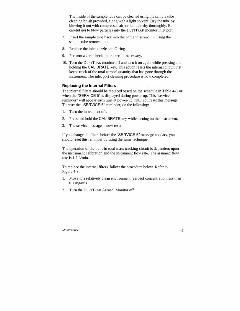
Maintenance 41
The inside of the sample tube can be cleaned using the sample tube cleaning brush provided, along with a light solvent. Dry the tube by blowing it out with compressed air, or let it air-dry thoroughly. Be careful not to blow particles into the DUSTTRAK monitor inlet port.
7. Insert the sample tube back into the port and screw it in using the sample tube removal tool.
8. Replace the inlet nozzle and O-ring.
9. Perform a zero check and re-zero if necessary.
10. Turn the DUSTTRAK monitor off and turn it on again while pressing and holding the CALIBRATE key. This action resets the internal circuit that keeps track of the total aerosol quantity that has gone through the instrument. The inlet port cleaning procedure is now completed.
Replacing the Internal Filters The internal filters should be replaced based on the schedule in Table 4–1 or when the “SERVICE 5” is displayed during power-up. This “service reminder” will appear each time at power-up, until you reset this message. To reset the “SERVICE 5” reminder, do the following:
1. Turn the instrument off.
2. Press and hold the CALIBRATE key while turning on the instrument.
3. The service message is now reset.
If you change the filters before the “SERVICE 5” message appears, you should reset this reminder by using the same technique.
The operation of the built-in total mass tracking circuit is dependent upon the instrument calibration and the instrument flow rate. The assumed flow rate is 1.7 L/min.
To replace the internal filters, follow the procedure below. Refer to Figure 4-3.
1. Move to a relatively clean environment (aerosol concentration less than 0.1 mg/m3).
2. Turn the DUSTTRAK Aerosol Monitor off.
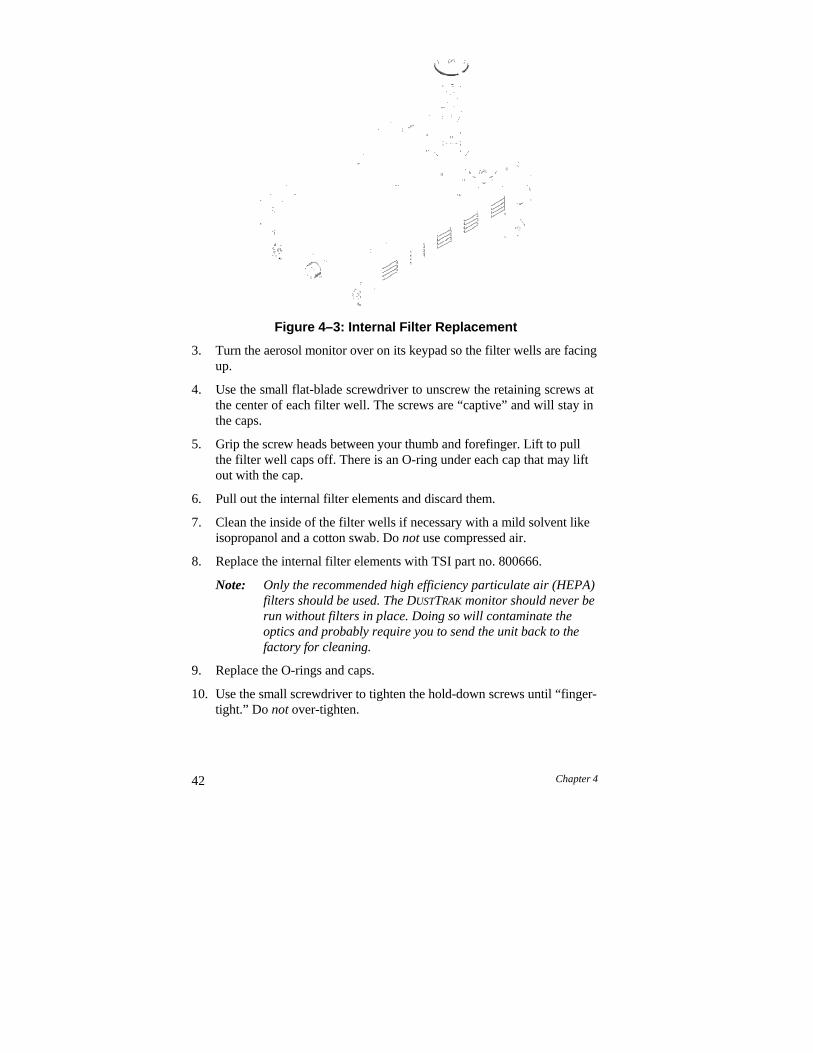
42 Chapter 4
Figure 4–3: Internal Filter Replacement
3. Turn the aerosol monitor over on its keypad so the filter wells are facing up.
4. Use the small flat-blade screwdriver to unscrew the retaining screws at the center of each filter well. The screws are “captive” and will stay in the caps.
5. Grip the screw heads between your thumb and forefinger. Lift to pull the filter well caps off. There is an O-ring under each cap that may lift out with the cap.
6. Pull out the internal filter elements and discard them.
7. Clean the inside of the filter wells if necessary with a mild solvent like isopropanol and a cotton swab. Do not use compressed air.
8. Replace the internal filter elements with TSI part no. 800666.
Note: Only the recommended high efficiency particulate air (HEPA) filters should be used. The DUSTTRAK monitor should never be run without filters in place. Doing so will contaminate the optics and probably require you to send the unit back to the factory for cleaning.
9. Replace the O-rings and caps.
10. Use the small screwdriver to tighten the hold-down screws until “finger- tight.” Do not over-tighten.
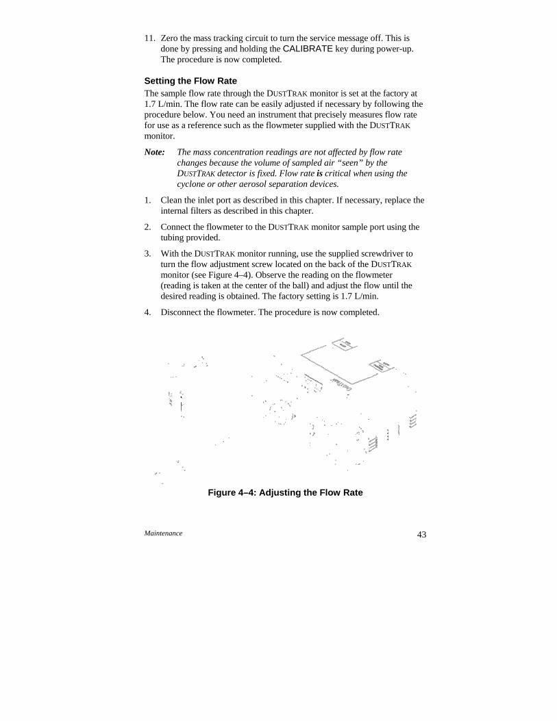
Maintenance 43
11. Zero the mass tracking circuit to turn the service message off. This is done by pressing and holding the CALIBRATE key during power-up. The procedure is now completed.
Setting the Flow Rate The sample flow rate through the DUSTTRAK monitor is set at the factory at 1.7 L/min. The flow rate can be easily adjusted if necessary by following the procedure below. You need an instrument that precisely measures flow rate for use as a reference such as the flowmeter supplied with the DUSTTRAK
monitor.
Note: The mass concentration readings are not affected by flow rate changes because the volume of sampled air “seen” by the DUSTTRAK detector is fixed. Flow rate is critical when using the cyclone or other aerosol separation devices.
1. Clean the inlet port as described in this chapter. If necessary, replace the internal filters as described in this chapter.
2. Connect the flowmeter to the DUSTTRAK monitor sample port using the tubing provided.
3. With the DUSTTRAK monitor running, use the supplied screwdriver to turn the flow adjustment screw located on the back of the DUSTTRAK
monitor (see Figure 4–4). Observe the reading on the flowmeter (reading is taken at the center of the ball) and adjust the flow until the desired reading is obtained. The factory setting is 1.7 L/min.
4. Disconnect the flowmeter. The procedure is now completed.
Figure 4–4: Adjusting the Flow Rate
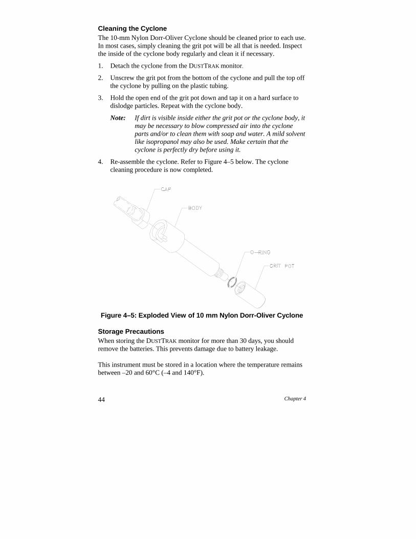
44 Chapter 4
Cleaning the Cyclone The 10-mm Nylon Dorr-Oliver Cyclone should be cleaned prior to each use. In most cases, simply cleaning the grit pot will be all that is needed. Inspect the inside of the cyclone body regularly and clean it if necessary.
1. Detach the cyclone from the DUSTTRAK monitor.
2. Unscrew the grit pot from the bottom of the cyclone and pull the top off the cyclone by pulling on the plastic tubing.
3. Hold the open end of the grit pot down and tap it on a hard surface to dislodge particles. Repeat with the cyclone body.
Note: If dirt is visible inside either the grit pot or the cyclone body, it may be necessary to blow compressed air into the cyclone parts and/or to clean them with soap and water. A mild solvent like isopropanol may also be used. Make certain that the cyclone is perfectly dry before using it.
4. Re-assemble the cyclone. Refer to Figure 4–5 below. The cyclone cleaning procedure is now completed.
Figure 4–5: Exploded View of 10 mm Nylon Dorr-Oliver Cyclone
Storage Precautions When storing the DUSTTRAK monitor for more than 30 days, you should remove the batteries. This prevents damage due to battery leakage.
This instrument must be stored in a location where the temperature remains between –20 and 60°C (–4 and 140°F).
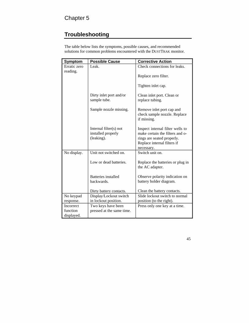
Chapter 5
Troubleshooting
The table below lists the symptoms, possible causes, and recommended solutions for common problems encountered with the DUSTTRAK monitor.
Symptom Possible Cause Corrective ActionErratic zero reading.
Leak. Dirty inlet port and/or sample tube.
Sample nozzle missing.
Internal filter(s) not installed properly (leaking).
Check connections for leaks.
Replace zero filter.
Tighten inlet cap. Clean inlet port. Clean or replace tubing.
Remove inlet port cap and check sample nozzle. Replace if missing.
Inspect internal filter wells to make certain the filters and o- rings are seated properly. Replace internal filters if necessary.
No display. Unit not switched on.
Low or dead batteries.
Batteries installed backwards.
Dirty battery contacts.
Switch unit on. Replace the batteries or plug in the AC adapter.
Observe polarity indication on battery holder diagram.
Clean the battery contacts.
No keypad response.
Display/Lockout switch in lockout position.
Slide lockout switch to normal position (to the right).
Incorrect function displayed.
Two keys have been pressed at the same time.
Press only one key at a time.
45
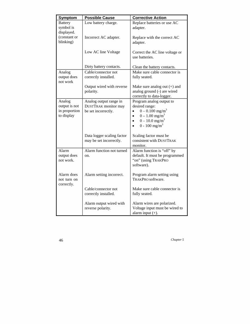
46 Chapter 5
Symptom Possible Cause Corrective ActionBattery symbol is displayed. (constant or blinking)
Low battery charge. Incorrect AC adapter.
Low AC line Voltage
Dirty battery contacts.
Replace batteries or use AC adapter.
Replace with the correct AC adapter.
Correct the AC line voltage or use batteries.
Clean the battery contacts.
Analog output does not work
Cable/connector not correctly installed.
Output wired with reverse polarity.
Make sure cable connector is fully seated.
Make sure analog out (+) and analog ground (-) are wired correctly to data-logger.
Analog output is not in proportion to display
Analog output range in DUSTTRAK monitor may be set incorrectly.
Data logger scaling factor may be set incorrectly.
Program analog output to desired range: 0 – 0.100 mg/m3
0 – 1.00 mg/m3
0 – 10.0 mg/m3
0 - 100 mg/m3
Scaling factor must be consistent with DUSTTRAK
monitor.Alarm output does not work.
Alarm does not turn on correctly.
Alarm function not turned on.
Alarm setting incorrect.
Cable/connector not correctly installed.
Alarm output wired with reverse polarity.
Alarm function is “off” by default. It must be programmed “on” (using TRAKPRO
software). Program alarm setting using TRAKPRO software.
Make sure cable connector is fully seated.
Alarm wires are polarized. Voltage input must be wired to alarm input (+).
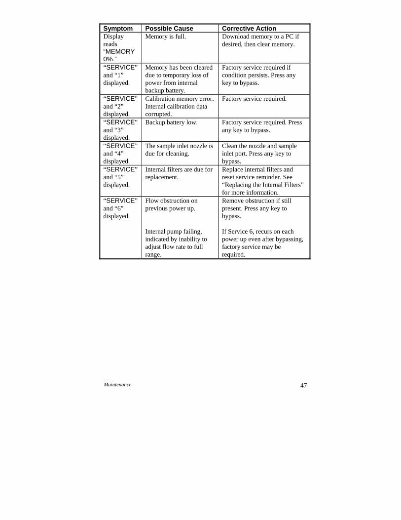
Symptom Possible Cause Corrective ActionDisplay reads “MEMORY 0%.”
Memory is full. Download memory to a PC if desired, then clear memory.
“SERVICE” and “1” displayed.
Memory has been cleared due to temporary loss of power from internal backup battery.
Factory service required if condition persists. Press any key to bypass.
“SERVICE” and “2” displayed.
Calibration memory error. Internal calibration data corrupted.
Factory service required.
“SERVICE” and “3” displayed.
Backup battery low. Factory service required. Press any key to bypass.
“SERVICE” and “4” displayed.
The sample inlet nozzle is due for cleaning.
Clean the nozzle and sample inlet port. Press any key to bypass.
“SERVICE” and “5” displayed.
Internal filters are due for replacement.
Replace internal filters and reset service reminder. See “Replacing the Internal Filters” for more information.
“SERVICE” and “6” displayed.
Flow obstruction on previous power up.
Internal pump failing, indicated by inability to adjust flow rate to full range.
Remove obstruction if still present. Press any key to bypass.
If Service 6, recurs on each power up even after bypassing, factory service may be required.
Maintenance 47
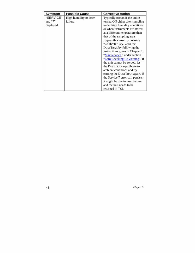
48 Chapter 5
Symptom Possible Cause Corrective Action“SERVICE” and “7” displayed.
High humidity or laser failure.
Typically occurs if the unit is turned ON either after sampling under high humidity conditions or when instruments are stored at a different temperature than that of the sampling area. Bypass this error by pressing “Calibrate” key. Zero the DUSTTRAK by following the instructions given in Chapter 4, “Maintenance,” under section “Zero Checking/Re-Zeroing”. If the unit cannot be zeroed, let the DUSTTRAK equilibrate to ambient conditions and try zeroing the DUSTTRAK again. If the Service 7 error still persists, it might be due to laser failure and the unit needs to be returned to TSI.
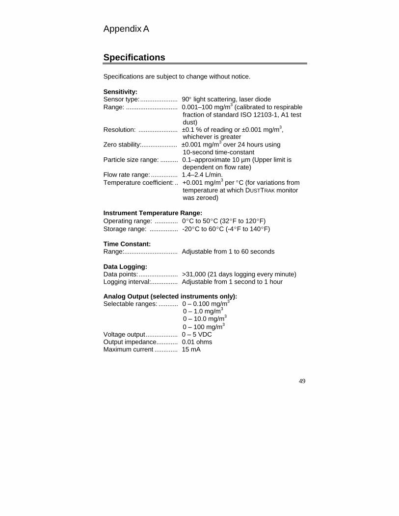
49
Appendix A
Specifications
Specifications are subject to change without notice.
Sensitivity: Sensor type: ..................... 90light scattering, laser diode Range: ............................. 0.001–100 mg/m3 (calibrated to respirable
fraction of standard ISO 12103-1, A1 test dust)
Resolution: ...................... ±0.1 % of reading or ±0.001 mg/m3, whichever is greater
Zero stability:.................... ±0.001 mg/m3 over 24 hours using 10-second time-constant
Particle size range: .......... 0.1–approximate 10 µm (Upper limit is dependent on flow rate)
Flow rate range: ............... 1.4–2.4 L/min. Temperature coefficient: .. +0.001 mg/m3 per C (for variations from
temperature at which DUSTTRAK monitor was zeroed)
Instrument Temperature Range: Operating range: ............. 0 C to 50 C (32 F to 120 F) Storage range: ................ -20 C to 60 C (-4 F to 140 F)
Time Constant: Range:.............................. Adjustable from 1 to 60 seconds
Data Logging: Data points: ...................... >31,000 (21 days logging every minute) Logging interval:............... Adjustable from 1 second to 1 hour
Analog Output (selected instruments only): Selectable ranges: ........... 0 – 0.100 mg/m3
0 – 1.0 mg/m3
0 – 10.0 mg/m3
0 – 100 mg/m3
Voltage output .................. 0 – 5 VDC Output impedance............ 0.01 ohms Maximum current ............. 15 mA
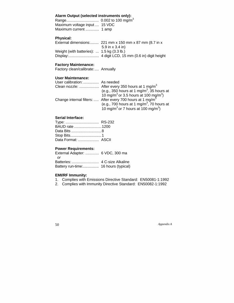
50 Appendix A
Alarm Output (selected instruments only): Range............................... 0.002 to 100 mg/m3
Maximum voltage input .... 15 VDC Maximum current ............. 1 amp
Physical: External dimensions:........ 221 mm x 150 mm x 87 mm (8.7 in x
5.9 in x 3.4 in) Weight (with batteries): ... 1.5 kg (3.3 lb.) Display:............................. 4 digit LCD, 15 mm (0.6 in) digit height
Factory Maintenance: Factory clean/calibrate: .... Annually
User Maintenance: User calibration: ............... As needed Clean nozzle: ................... After every 350 hours at 1 mg/m3
(e.g., 350 hours at 1 mg/m3, 35 hours at 10 mg/m3 or 3.5 hours at 100 mg/m3)
Change internal filters: ..... After every 700 hours at 1 mg/m3
(e.g., 700 hours at 1 mg/m3, 70 hours at 10 mg/m3 or 7 hours at 100 mg/m3)
Serial Interface: Type: ................................ RS-232 BAUD rate .......................... 1200 Data Bits ............................. 8 Stop Bits .............................. 1 Data Format: .................... ASCII
Power Requirements: External Adapter: ............. 6 VDC, 300 ma or
Batteries: .......................... 4 C-size Alkaline Battery run-time:............... 16 hours (typical)
EMI/RF Immunity: 1. Complies with Emissions Directive Standard: EN50081-1:1992 2. Complies with Immunity Directive Standard: EN50082-1:1992
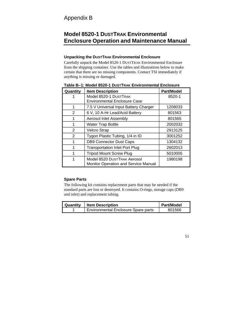
51
Appendix B
Model 8520-1 DUSTTRAK Environmental Enclosure Operation and Maintenance Manual
Unpacking the DUSTTRAK Environmental Enclosure Carefully unpack the Model 8520-1 DUSTTRAK Environmental Enclosure from the shipping container. Use the tables and illustrations below to make certain that there are no missing components. Contact TSI immediately if anything is missing or damaged.
Table B–1: Model 8520-1 DUSTTRAK Environmental Enclosure
Quantity Item Description Part/Model 1 Model 8520-1 DUSTTRAK
Environmental Enclosure Case 8520-1
1 7.5 V Universal Input Battery Charger 1208033 2 6 V, 10 A-Hr Lead/Acid Battery 801563 1 Aerosol Inlet Assembly 801565 1 Water Trap Bottle 2002032 2 Velcro Strap 2913125 2 Tygon Plastic Tubing, 1/4 in ID 3001252 1 DB9 Connector Dust Caps 1304132 1 Transportation Inlet Port Plug 2602013 1 Tripod Mount Screw Plug 5010005 1 Model 8520 DUSTTRAK Aerosol
Monitor Operation and Service Manual 1980198
Spare Parts The following kit contains replacement parts that may be needed if the standard parts are lost or destroyed. It contains O-rings, storage caps (DB9 and inlet) and replacement tubing.
Quantity Item Description Part/Model 1 Environmental Enclosure Spare parts 801566
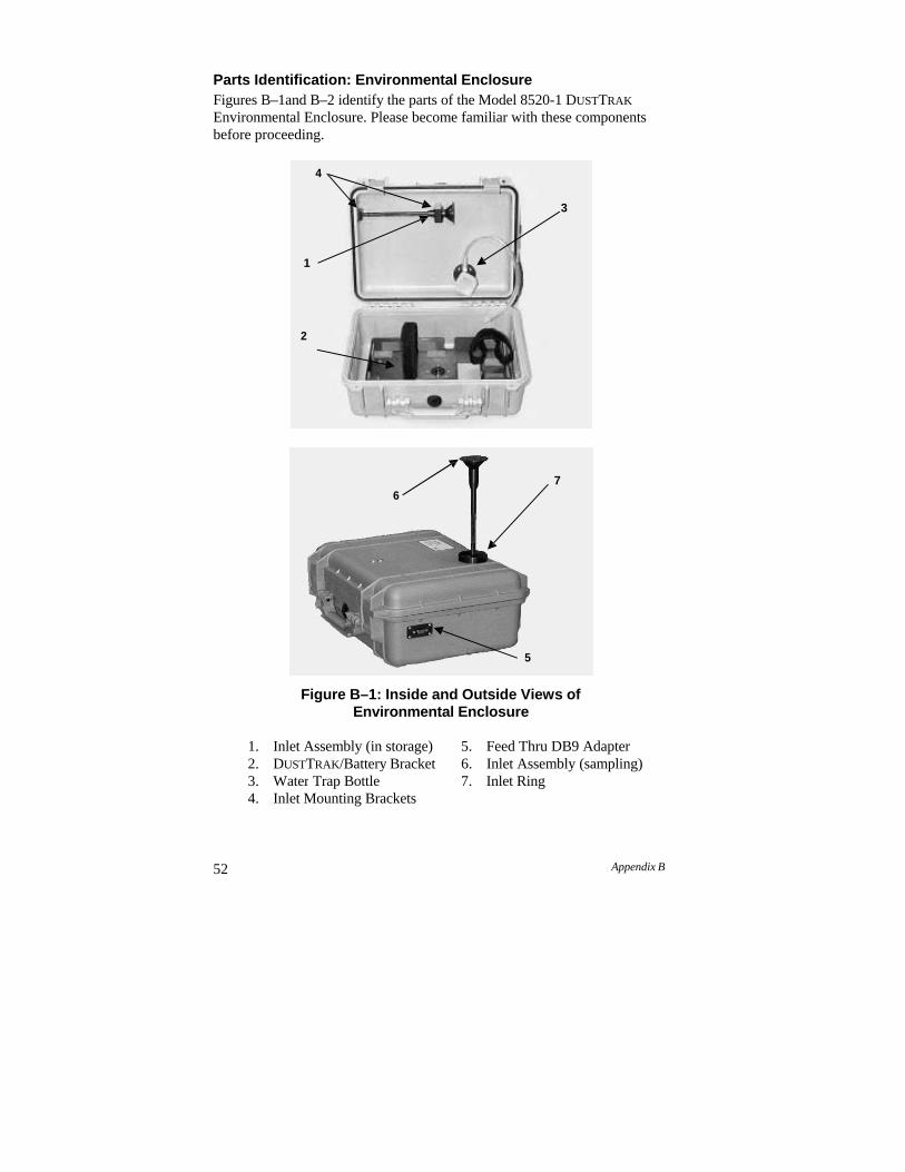
52 Appendix B
Parts Identification: Environmental Enclosure Figures B–1and B–2 identify the parts of the Model 8520-1 DUSTTRAK
Environmental Enclosure. Please become familiar with these components before proceeding.
Figure B–1: Inside and Outside Views of Environmental Enclosure
1. Inlet Assembly (in storage) 5. Feed Thru DB9 Adapter 2. DUSTTRAK/Battery Bracket 6. Inlet Assembly (sampling) 3. Water Trap Bottle 7. Inlet Ring4. Inlet Mounting Brackets
76
5
4
3
1
2
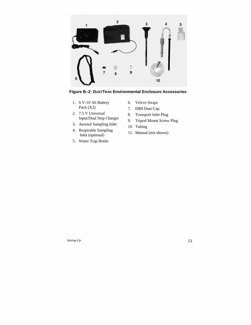
Setting-Up 53
Figure B–2: DUSTTRAK Environmental Enclosure Accessories
1. 6 V-10 Ah Battery Pack (X2)
2. 7.5 V Universal Input/Dual Step Charger
3. Aerosol Sampling Inlet
4. Respirable Sampling Inlet (optional)
5. Water Trap Bottle
6. Velcro Straps
7. DB9 Dust Cap
8. Transport Inlet Plug
9. Tripod Mount Screw Plug
10. Tubing
11. Manual (not shown)
54 Appendix B
Setting-Up
The setup of the Environmental Enclosure is an important part in allowing reliable and accurate sampling of aerosols in a wide range of conditions. TSI cannot ensure accurate measurements if any of the components are set up incorrectly. Damage to the enclosure or its components can result if these procedures are not followed.
Installing the Aerosol or Respirable Aerosol Inlet There are two inlet assemblies, either of which may be stored inside the lid of the Environmental Enclosure, allowing ambient aerosols to be sampled efficiently in a wide range of conditions. Proper installation into its sampling position ensures that the DUSTTRAK monitor measures an accurate ambient aerosol mass concentration. Follow these instructions to install either of the aerosol inlets:
Hold the inlet assembly by the knurled section on the tube and remove it from the holding bracket by unscrewing it (see Figure B-3).
Carefully slide the inlet through the upper mounting bracket and remove the inlet from the box.
Remove the Inlet Transport Plug from the top of the box.
C a u t i o n Always hold the inlet assembly by the knurled portion of the tube. Do not twist on the inlet assembly cap. !
C a u t i o n The enclosure is designed to be water resistant to rain or spray. It is not designed to be waterproof when immersed. Setting it in a pool of water will result in flooding the inner compartment with water. This will severely damage both your DUSTTRAK monitor and battery pack. Do not set the Environmental Enclosure in water!
!
W A R N I N G The DUSTTRAK monitor is not rated for intrinsic safety. The DUSTTRAK monitor, with the Environmental Enclosure, must never be operated under conditions where there is a risk of fire or explosion.
!
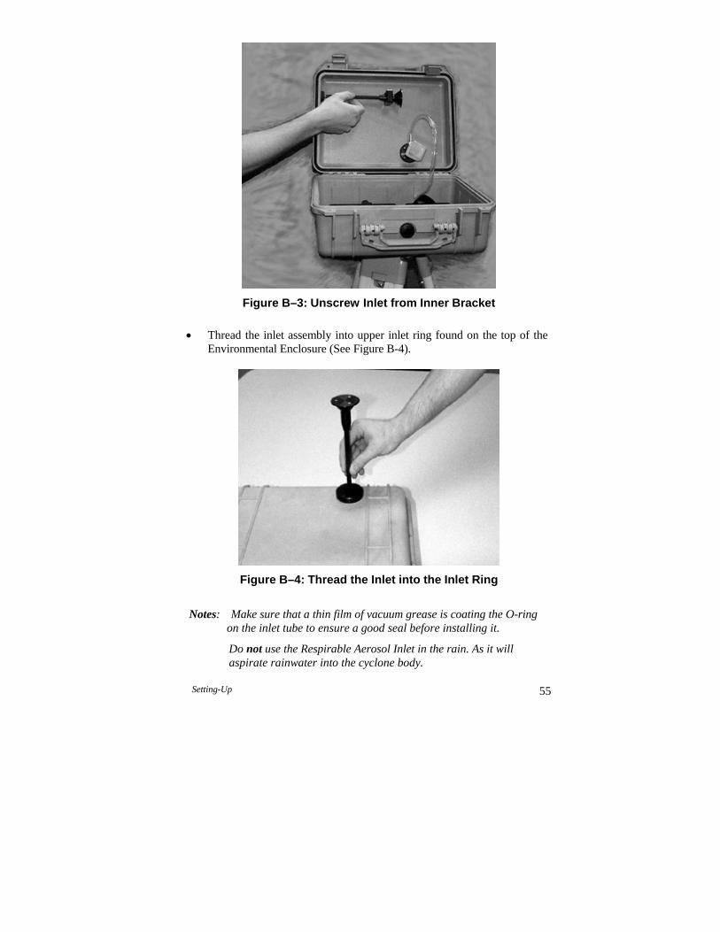
Setting-Up 55
Figure B–3: Unscrew Inlet from Inner Bracket
Thread the inlet assembly into upper inlet ring found on the top of the
Environmental Enclosure (See Figure B-4).
Figure B–4: Thread the Inlet into the Inlet Ring
Notes: Make sure that a thin film of vacuum grease is coating the O-ring on the inlet tube to ensure a good seal before installing it.
Do not use the Respirable Aerosol Inlet in the rain. As it will aspirate rainwater into the cyclone body.
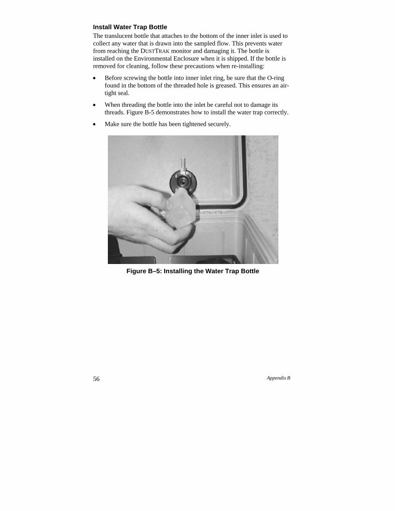
56 Appendix B
Install Water Trap Bottle The translucent bottle that attaches to the bottom of the inner inlet is used to collect any water that is drawn into the sampled flow. This prevents water from reaching the DUSTTRAK monitor and damaging it. The bottle is installed on the Environmental Enclosure when it is shipped. If the bottle is removed for cleaning, follow these precautions when re-installing:
Before screwing the bottle into inner inlet ring, be sure that the O-ring found in the bottom of the threaded hole is greased. This ensures an air- tight seal.
When threading the bottle into the inlet be careful not to damage its threads. Figure B-5 demonstrates how to install the water trap correctly.
Make sure the bottle has been tightened securely.
Figure B–5: Installing the Water Trap Bottle
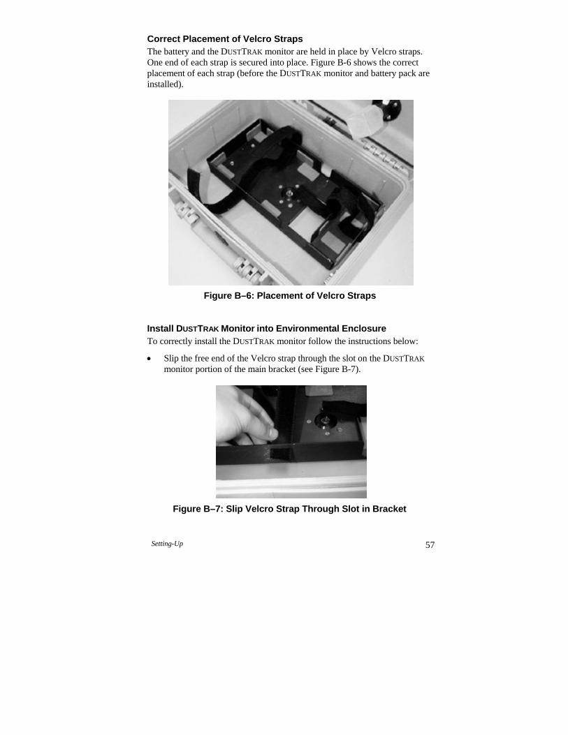
Setting-Up 57
Correct Placement of Velcro Straps The battery and the DUSTTRAK monitor are held in place by Velcro straps. One end of each strap is secured into place. Figure B-6 shows the correct placement of each strap (before the DUSTTRAK monitor and battery pack are installed).
Figure B–6: Placement of Velcro Straps Install DUSTTRAK Monitor into Environmental Enclosure To correctly install the DUSTTRAK monitor follow the instructions below:
Slip the free end of the Velcro strap through the slot on the DUSTTRAK
monitor portion of the main bracket (see Figure B-7).
Figure B–7: Slip Velcro Strap Through Slot in Bracket
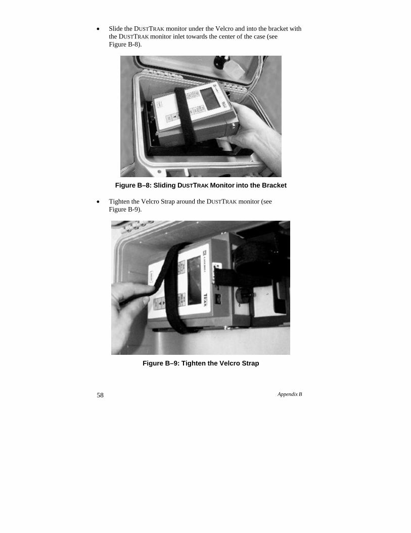
58 Appendix B
Slide the DUSTTRAK monitor under the Velcro and into the bracket with the DUSTTRAK monitor inlet towards the center of the case (see Figure B-8).
Figure B–8: Sliding DUSTTRAK Monitor into the Bracket Tighten the Velcro Strap around the DUSTTRAK monitor (see
Figure B-9).
Figure B–9: Tighten the Velcro Strap
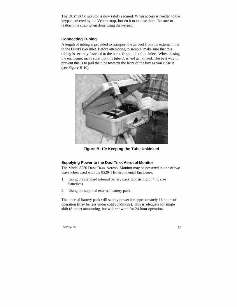
Setting-Up 59
The DUSTTRAK monitor is now safely secured. When access is needed to the keypad covered by the Velcro strap, loosen it to expose them. Be sure to reattach the strap when done using the keypad.
Connecting Tubing A length of tubing is provided to transport the aerosol from the external inlet to the DUSTTRAK inlet. Before attempting to sample, make sure that this tubing is securely fastened to the barbs from both of the inlets. When closing the enclosure, make sure that this tube does not get kinked. The best way to prevent this is to pull the tube towards the front of the box as you close it (see Figure B-10).
Figure B–10: Keeping the Tube Unkinked Supplying Power to the DUSTTRAK Aerosol Monitor The Model 8520 DUSTTRAK Aerosol Monitor may be powered in one of two ways when used with the 8520-1 Environmental Enclosure:
1. Using the standard internal battery pack (consisting of 4, C size batteries)
2. Using the supplied external battery pack.
The internal battery pack will supply power for approximately 16 hours of operation (may be less under cold conditions). This is adequate for single shift (8-hour) monitoring, but will not work for 24-hour operation.

60 Appendix B
Using the External Battery Pack The battery packs supplied with the Environmental Enclosure allow for extended use of the DUSTTRAK monitor. These battery packs enable the DUSTTRAK monitor to operate for at least 24 hours (even in cold conditions). The battery packs should be rotated and properly charged after each use, to ensure a prolonged lifetime (see Maintenance section for further information). Make sure that the internal C size batteries are installed correctly within the DUSTTRAK monitor to make it possible to continue sampling when changing the external battery packs.
Install External Battery Pack To correctly install the Battery Pack follow the instructions below:
Slip the free end of the Velcro strap through the slot on the battery pack portion of the main bracket (See Figure B-11).
Figure B–11: Slip Velcro Strap Through Slot.
Slide the battery pack into the correct space in the sheet metal bracket such that the leads are oriented up, and the PC board is in the upper left hand quarter.
Tighten the Velcro strap around the battery pack (See Figure B-12).
C a u t i o n TSI does not recommend using the standard AC adapter when operating outside. This device is not rated for external exposure.
!
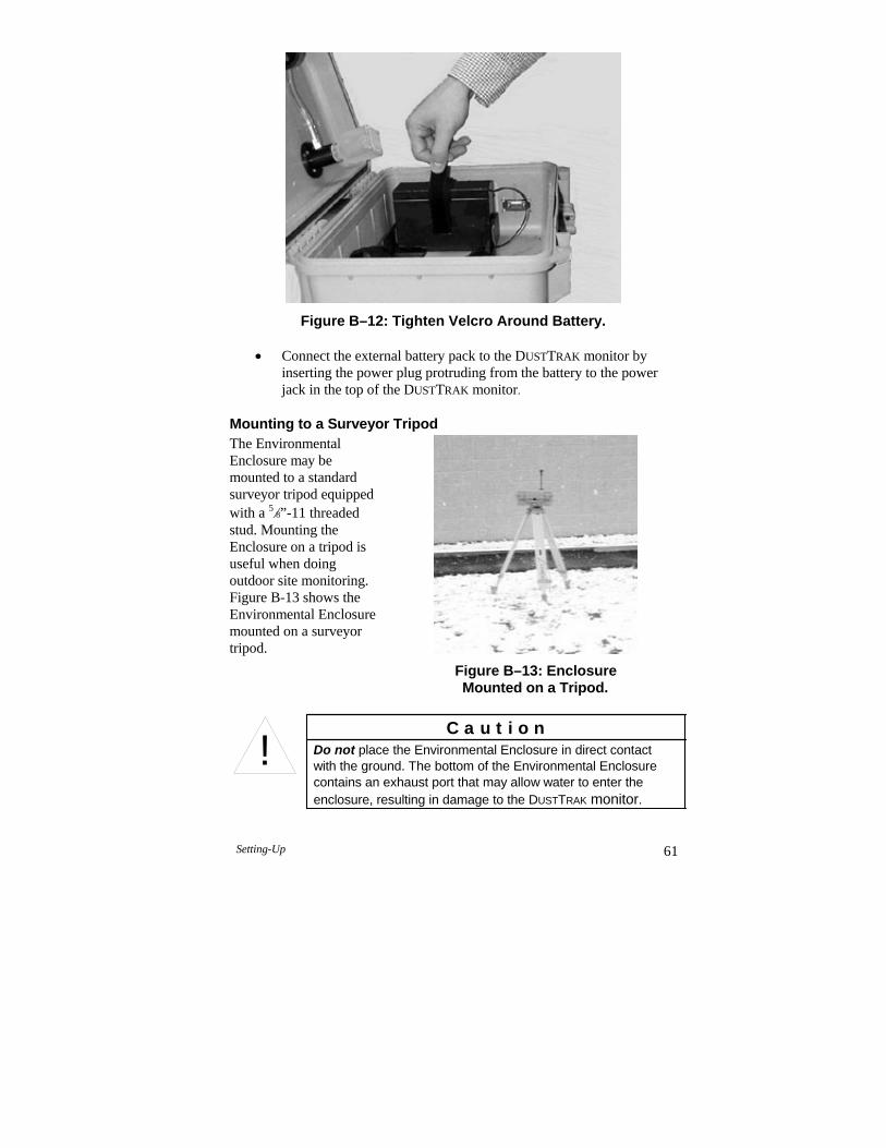
Setting-Up 61
Figure B–12: Tighten Velcro Around Battery.
Connect the external battery pack to the DUSTTRAK monitor by inserting the power plug protruding from the battery to the power jack in the top of the DUSTTRAK monitor.
Mounting to a Surveyor Tripod The Environmental Enclosure may be mounted to a standard surveyor tripod equipped with a 58”-11 threaded stud. Mounting the Enclosure on a tripod is useful when doing outdoor site monitoring. Figure B-13 shows the Environmental Enclosure mounted on a surveyor tripod.
Figure B–13: Enclosure Mounted on a Tripod.
C a u t i o n Do not place the Environmental Enclosure in direct contact with the ground. The bottom of the Environmental Enclosure contains an exhaust port that may allow water to enter the enclosure, resulting in damage to the DUSTTRAK monitor.
!
62 Appendix B
Downloading a Data File To download a file under normal data-logging operations, you would do the following:
Open the Environmental Enclosure.
Discontinue sampling.
Attach the supplied RJ45 to the RS-232 cable from the DUSTTRAK
monitor to a notebook computer.
Download the data file using TRAKPRO software (refer to Chapter 2 of this manual for further details).
Real-Time Monitoring The Environmental Enclosure comes equipped with an external DB9 connector. This allows the DUSTTRAK monitor to be connected to a computer for continuous real-time monitoring. To set up the Environmental Enclosure for real-time monitoring follow these instructions:
Connect the DUSTTRAK monitor to the DB9 connector, which is mounted on the inside of the enclosure, using the Computer Interface Cable provided with the DUSTTRAK monitor.
Attach a standard 9-pin serial cable (not supplied) from the DB9 connector on the outside of the enclosure to a computer serial port. The computer can be configured to query the DUSTTRAK monitor when in a terminal emulator mode. See Application Note ITI-044 for more information on these commands.
Setting-up TRAKPROTM Data Analysis Software Information on setting-up and using TRAKPRO software can be found in Chapter 2 of this manual.
Setting-Up 63
Transporting the Environmental Enclosure When transporting the Environmental Enclosure it is important to store its components correctly. The following steps should be taken to ensure that no damage is done to the enclosure or its components during transportation:
Unscrew the aerosol inlet from the top of the case, and install it into the inlet-mounting bracket inside the lid of the enclosure.
Insert the Inlet Transport Plug into the opening in the inlet ring in the top of the box.
Empty any water from the water trap.
Remove DUSTTRAK monitor and battery pack.
If mounted on a tripod, take the enclosure off the tripod and screw in the tripod mount plug.
Wiring the Analog/Alarm Cable in the Enclosure You may desire to install the Analog/Alarm cable to the DUSTTRAK monitor, when operated inside the Environmental Enclosure. The serial connector, installed in the side of the enclosure, may be used for this purpose.
Note: If additional penetrations are made into the wall of the enclosure, you should take precautions to install a sealing (water-tight) connector around the cable.
A t t e n t i o n The Environmental Enclosure is designed to protect equipment during stationary sampling only.
Do not transport or ship equipment inside the Environmental Enclosure.
!

64 Appendix B
Operation
Overview The DUSTTRAK Environmental Enclosure can be used in conjunction with the DUSTTRAK monitor for many different applications. Its primary use is in outdoor applications to give the DUSTTRAK monitor protection from the elements and the ability to sample efficiently in different wind speeds. The enclosure and extended-life battery may also be advantageous in indoor industrial applications, to provide additional security and protection to the DUSTTRAK monitor.
How to Properly Orient the Environmental Enclosure The Environmental Enclosure should be set up in a location where it can sample the particles of interest. It should be placed “out in the open,” away from obstructions which may affect wind currents. It should not, for example, be placed at the corner of a building, which would cause swirling wind currents and result in poor particle sampling.
The Environmental Enclosure should be used in wind conditions with speeds of 22 mph or less to obtain the most accurate readings. An increase in wind speed over 22 mph can decrease the sampling efficiency of the inlet to under the efficiency specified by PM-10 standards. If wind gusts of over 22 mph are present, the data collected is still valid, but be aware that the readings will be slightly lower than the actual mass concentration of aerosol present. See Application Note ITI-060 for more information on the wind speed dependency of the external inlet’s sampling characteristics.
Changing and Re-charging the Battery Packs The battery pack within the Environmental Enclosure should be changed every 24 hours of use during the daily maintenance check described in the Maintenance Section. A voltage cutoff switch will cut the power to the DUSTTRAK monitor when the battery voltage reaches 5.1 V. This ensures that the battery does not become deeply discharged. Preventing this condition will prolong the life of the battery.
Receiving Data from the DUSTTRAK Aerosol Monitor The DUSTTRAK monitor records data in either the manual sampling mode (LOG 1) or the programmable modes (LOG 2, LOG 3). See the DUSTTRAK
User Manual for more information on setting up the logging modes. The data can be downloaded by opening the Environmental Enclosure lid, attaching the supplied RJ45/RS-232 cable from the DUSTTRAK monitor to a computer COM port, and using the RECEIVE DATA command within the TRAKPRO software.
Operation 65
If desired, the DUSTTRAK RJ45 cable may be attached directly to the inside of the DB9 connector located on the side of the Environmental Enclosure. A serial cable (not supplied) may then be attached from the outside of the DB9 connector to the computer COM port.
Note: In order to download a data file the DUSTTRAK monitor cannot be in a sampling mode.
The primary use for the external DB9 connector is to facilitate real-time data monitoring. An external computer or data logger can be directly attached to the DUSTTRAK monitor, while still keeping the instrument inside its weatherproof enclosure. The DUSTTRAK monitor can be queried through a set of ASCII commands to provide periodic information.
Zeroing the DUSTTRAK Aerosol Monitor The DUSTTRAK monitor should always be zeroed before beginning a sample. See the instructions in Chapter 3 of this manual for more information. If possible, the instrument should be zeroed under stable ambient temperature conditions (since variations in temperature will have a small impact upon the DUSTTRAK monitor readings). If this is not possible (for example, 24-hour outdoor sampling, with wide temperature swings) the instrument should be kept closed inside the Environmental Enclosure. The thermal mass of the Enclosure will dampen out the affect of temperature swings, radiant heat, etc.
Note: See the DUSTTRAK monitor Specifications in Appendix A for more information on the temperature dependence.
In nearly all cases, the temperature impact upon the DUSTTRAK monitor reading is very small in comparison to the ambient particle concentration.
Setting the Flow Rate The aerosol inlet on the Environmental Enclosure was designed to operate at a 1.7 liters/minute flow rate. Before each sample, the flow rate should be verified and/or adjusted as described in the DUSTTRAK monitor Maintenance section (Chapter 4).
Locking the Environmental Enclosure To avoid theft of the DUSTTRAK monitor, when left inside the Environmental Enclosure, a padlock should be used to lock the box. There are two holes on the front of the box that allow for a standard padlock to be attached. A padlock is not supplied with the 8520-1.
66 Appendix B
Checklist for Sampling with the Environmental Enclosure Before beginning a sample check to see that all of the following conditions are satisfied:
The flow rate is set to 1.7 liters/minute.
All components are properly installed into the enclosure as described in the Setup section.
The DUSTTRAK monitor has been zeroed at the temperature at which it will be sampling (if possible).
The Environmental Enclosure has been put in a place clear of any obstructions that will affect the flow around the enclosure (putting it on a tripod is optional).
The Enclosure is not resting directly on the ground (no standing water).
The DUSTTRAK monitor has been set to the appropriate logging mode.
The Enclosure is locked shut to prevent theft or vandalism to instrument.
Plans have been made to check for maintenance and data collection every 24 hours after initial set up.
After the completion of monitoring, follow the procedures for transporting the Environmental Enclosure in the Setting-Up section of this appendix. This prevents the instrument from becoming damaged.
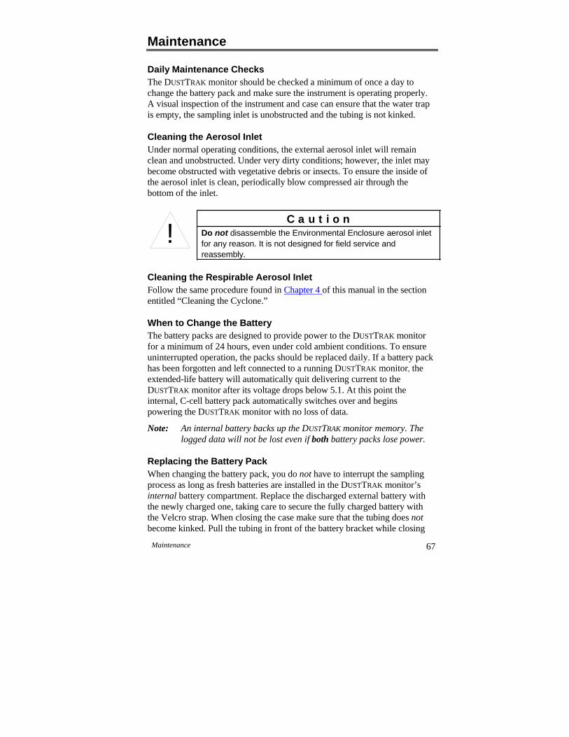
Maintenance 67
Maintenance
Daily Maintenance Checks The DUSTTRAK monitor should be checked a minimum of once a day to change the battery pack and make sure the instrument is operating properly. A visual inspection of the instrument and case can ensure that the water trap is empty, the sampling inlet is unobstructed and the tubing is not kinked.
Cleaning the Aerosol Inlet Under normal operating conditions, the external aerosol inlet will remain clean and unobstructed. Under very dirty conditions; however, the inlet may become obstructed with vegetative debris or insects. To ensure the inside of the aerosol inlet is clean, periodically blow compressed air through the bottom of the inlet.
Cleaning the Respirable Aerosol Inlet Follow the same procedure found in Chapter 4 of this manual in the section entitled “Cleaning the Cyclone.”
When to Change the Battery The battery packs are designed to provide power to the DUSTTRAK monitor for a minimum of 24 hours, even under cold ambient conditions. To ensure uninterrupted operation, the packs should be replaced daily. If a battery pack has been forgotten and left connected to a running DUSTTRAK monitor, the extended-life battery will automatically quit delivering current to the DUSTTRAK monitor after its voltage drops below 5.1. At this point the internal, C-cell battery pack automatically switches over and begins powering the DUSTTRAK monitor with no loss of data.
Note: An internal battery backs up the DUSTTRAK monitor memory. The logged data will not be lost even if both battery packs lose power.
Replacing the Battery Pack When changing the battery pack, you do not have to interrupt the sampling process as long as fresh batteries are installed in the DUSTTRAK monitor’s internal battery compartment. Replace the discharged external battery with the newly charged one, taking care to secure the fully charged battery with the Velcro strap. When closing the case make sure that the tubing does not become kinked. Pull the tubing in front of the battery bracket while closing
C a u t i o n Do not disassemble the Environmental Enclosure aerosol inlet for any reason. It is not designed for field service and reassembly.
!
68 Appendix B
the case to prevent this from occurring. To prevent long term damage and loss of capacity recharge the battery promptly after removing it.
Recharging the Battery Packs The following steps should be followed to correctly recharge the battery packs:
Disconnect the battery pack from the DUSTTRAK monitor and remove it from the Environmental Enclosure.
Take it to a protected area where it can be charged undisturbed for 12 to 15 hours.
Check on the bottom of the charger to see that the red voltage switch is set appropriately to either 115V or 230V.
Supply power to the charger. The green LED lights on the front of the charger.
Insert the power plug protruding from the battery pack into the output jack attached to the charger. The charger will now quick-charge the battery. This is indicated by an illuminated yellow LED.
Charging is complete when the yellow LED shuts off. A trickle charge will maintain the full charge. A fully discharged battery will require up to 15 hours to fully recharge.
Note: Do Not Store A Battery Pack That Has Not Been Fully Charged. Storing a discharged battery for any length of time will negatively affect the battery life.
Battery Pack Life Lead acid batteries have a finite life of about 300 charging cycles. This means that the two battery packs last around two years without need of replacement. This assumes that the batteries are being used to run a DUSTTRAK monitor every day, and that they are properly cared for and rotated daily. To help track battery lifetime, an In-service Date sticker has been attached to the front of the battery pack to inform you when each battery pack was shipped from TSI. Replacement battery packs may be ordered from TSI. See the previous section of this appendix on “Parts Identification” for more information.
Emptying the Water Trap If any water or moisture has accumulated in the water trap, be sure to unscrew the water trap from the internal inlet and empty it. Take care when removing and reinstalling the bottle to prevent damage to the threads. The bottle must be securely hand tightened to seal against the O-ring to prevent leaking.

Maintenance 69
Storage Precautions This instrument must be stored in a location where the temperature remains between –20 and 60°C (–4 and 140°F).
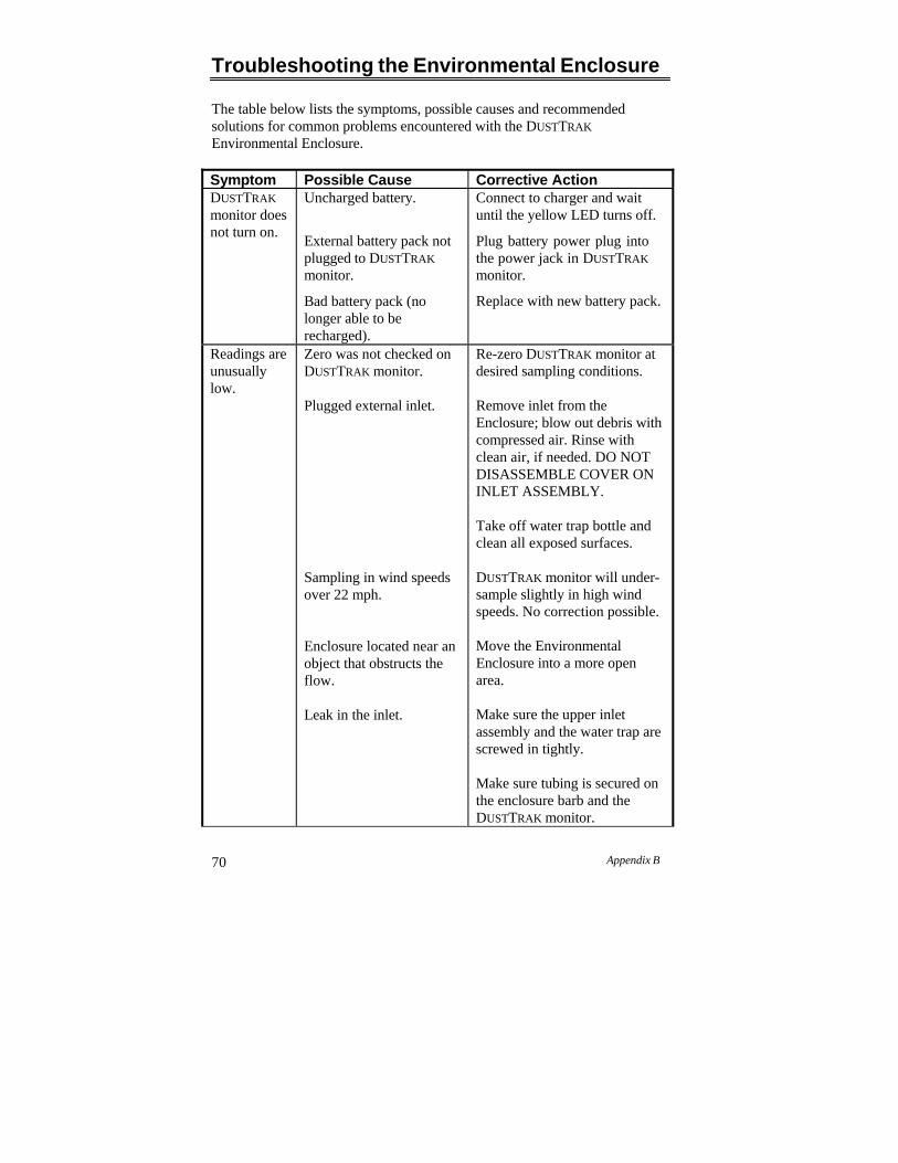
70 Appendix B
Troubleshooting the Environmental Enclosure
The table below lists the symptoms, possible causes and recommended solutions for common problems encountered with the DUSTTRAK
Environmental Enclosure.
Symptom Possible Cause Corrective ActionDUSTTRAK
monitor does not turn on.
Uncharged battery.
External battery pack not plugged to DUSTTRAK
monitor.
Bad battery pack (no longer able to be recharged).
Connect to charger and wait until the yellow LED turns off.
Plug battery power plug into the power jack in DUSTTRAK
monitor.
Replace with new battery pack.
Readings are unusually low.
Zero was not checked on DUSTTRAK monitor.
Plugged external inlet.
Sampling in wind speeds over 22 mph.
Enclosure located near an object that obstructs the flow.
Leak in the inlet.
Re-zero DUSTTRAK monitor at desired sampling conditions.
Remove inlet from the Enclosure; blow out debris with compressed air. Rinse with clean air, if needed. DO NOT DISASSEMBLE COVER ON INLET ASSEMBLY.
Take off water trap bottle and clean all exposed surfaces.
DUSTTRAK monitor will under- sample slightly in high wind speeds. No correction possible.
Move the Environmental Enclosure into a more open area.
Make sure the upper inlet assembly and the water trap are screwed in tightly.
Make sure tubing is secured on the enclosure barb and the DUSTTRAK monitor.
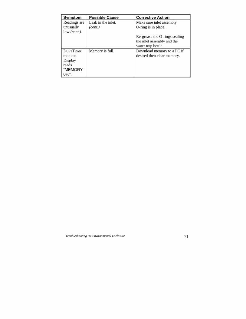
Symptom Possible Cause Corrective ActionReadings are unusually low (cont.).
Leak in the inlet. (cont.)
Make sure inlet assembly O-ring is in place.
Re-grease the O-rings sealing the inlet assembly and the water trap bottle.
DUSTTRAK
monitor Display reads “MEMORY 0%”.
Memory is full. Download memory to a PC if desired then clear memory.
Troubleshooting the Environmental Enclosure 71

73
Specifications: Environmental Enclosure
Specifications are subject to change without notice.
Sampling Conditions:
Operating Temperature: . 0 C to 50 C (32 F to 120 F)
Wind Speed: .................... 0 m/s to 10 m/s (0 mph to 22.5 mph)
Aerosol Concentration Range: ............................. 0.001–100 mg/m3 (calibrated to respirable
fraction of standard ISO 12103-1, A1 test dust)
Storage Temperature:...... -20 C to 60 C (-4 F to 140
Zero stability:.................... ±0.001 mg/m3 over 24 hours using 10-second time-constant
Particle size range: .......... 0.1–approximate 10 µm (Upper limit is dependent on flow rate)
Flow rate: ........................ 1.7 L/min.
Temperature coefficient: .. +0.001 mg/m3 per C (for variations from temperature at which DUSTTRAK monitor was zeroed)
Physical:
External dimensions:........ 406 mm x 330 mm x 191 mm (16 in. x 13 in. x 7.5 in.)
Weight (with battery and DUSTTRAK monitor): ......... 7.2 kg (15.8 lb.)
USER MAINTENANCE: Maintenance Check/ Data Collection:................ Daily
Clean inlet: ....................... Weekly or daily if concentrations of over 30 mg/cm3 are measured.
Re-grease O-rings: .......... As needed
Power Requirements: External Battery Pack: ..... 6 VDC, 10 Ah Battery
run-time: .............. 24–60 hours (typical)

75
Index
A
AC adapter, 3, 5 accessories, 3 adapter, 1 adjusting flow rate, 43 advanced modes, 26 aero filter, 3 aerosol monitor, 1
accessories, 3 components, 2 connecting to computer, 6 keypad functions, 11 maintenance, 37 parts identification, 2 setting up, 5 specifications, 49 troubleshooting, 45
alarm output, 22 specifications, 23
alarm output function default, 23 alarm setpoint
programming, 24 screen, 24
alarm switch, 23 alarm threshold, 23 alkaline batteries, 1 analog output, 21 analog output range screen, 21 analog output/alarm connector, 1 analog output/alarm thumb screw, 2 analog/alarm cable, 3 analog/alarm connector pin-outs, 9 analog/alarm output connector
connecting, 9 arrow keys, 17 available memory, 27 available time constants
programming, 13
B
battery cover, 2 battery installation, 5 baud rate, 7
C
calibrate key, 17 calibrated data
converted stored data, 35 calibration certificate, 1 calibration factor
for specific aerosol, 32 setting from keypad, 33
carrying case, 1 channels, 27, 28 Class I, v cleaning
cyclone, 44 inlet and sample tube, 40 inlet conditioner, 39
clear memory key, 15 communications port
setting up, 6 components, 2 computer cable, 1, 3 connecting analog/alarm output
connector, 9 connecting portable printer, 8 converting stored data to calibrated
data, 35 cotton swab, 1 custom calibrations, 31 cyclone, 3, 18, 44
cleaning, 44 respirable mass sampling, 18
cyclone holder clip, 2
D
data file environmental enclosure, 62
data port, 2 determining calibration factor for
specific aerosol, 32 display, 2 display/keypad lockout switch, 17
connector, 2
Index 76
E environmental enclosure, 51
aerosol inlet, cleaning, 67 aerosol monitor, 57 aerosol or respirable aerosol
inlet, 54 analog/alarm cable, 63 battery pack, 64 battery pack, recharging, 68 battery pack, replacing, 67 battery, charging, 67 checklist for sampling, 66 data file, 62 external battery pack, 60 flow rate, setting, 65 internal battery pack, 60 locking, 65 maintenance, 67 operation, 64 orienting, 64 parts identification, 52 power to aerosol monitor, 59 real-time monitoring, 62 receiving data, 64 respirable aerosol inlet,
cleaning, 67 setting up, 54 spare parts, 51 specifications, 73 storage precautions, 69 surveyor tripod, 61 transporting, 63 troubleshooting, 70 tubing, 59 unpacking, 51 velcro straps, 57 water traip, emptying, 68 water trap bottle, 56 zeroing, 65
exhaust port, 2 external power socket, 2
F
flow adjustment screw, 2 flow rate
adjusting, 43 setting, 43
flowmeter, 3
G–H grease, 3
I–J
impactor plate, 1, 3 inlet assembly, 40 inlet conditioner, 19
cleaning, 39 inlet nozzle, 1, 3 inlet tube
cleaning, 40 installing batteries, 5 instrument setup, 6 internal filter
replacing, 41 internal filter element, 1 internal filter elements, 3
K
keypad, 2 functions, 11
L
log interval, 27, 28 log mode, 15 logging interval key, 15 logging intervals
programming, 16 M
maintenance, 37 environmental enclosure, 67 schedule, 37
manually setting real-time clock, 8 memory considerations, 31 Model 8520. (see aerosol monitor)
N
newcal, 33 nozzle
10 µm, 20 number of tests, 27, 28 number of tests logged, 27 Nylon Dorr-Oliver cyclone. See also
cyclone
O oldcal, 33 on/off key, 11 operation, 11
environmental enclosure, 64 options menu, 34
P–Q
packing list, 1 parts identification, 2 percent memory required, 27 plastic tubing, 1 portable printer, 8 pre-programmed samples, 30 print key, 14 programming
advanced modes, 26 alarm setpoint, 24 available time constants, 13 date/time, 8
R
real-time clock manually setting, 8 setting, 7
real-time monitoring environmental enclosure, 62
remote sampling, 17 replacing internal filter, 41 respirable mass sampling with
cyclone, 18 re-zeroing, 38
S
safety information, v sample inlet nozzle, 2 sample key, 12 sample nozzle cleaning brush, 1 sample nozzle removal tool, 1 sample protocol, 29 sample tube
cleaning, 40 sample tube cleaning brush, 3 sample tube removal tool, 3 sampling mode key, 14
log mode, 15 survey mode, 14
sensitivity, 49 serial number, 27 serial port, 7 service policy, 2 setting custom calibration factor
keypad, 33 setting custom calibration factors
TRAKPRO software, 34 setting flow rate, 43 setting real-time clock, 7 setting up, 5
communications port, 6 environmental enclosure, 54 instrument, 6 TRAKPRO software, 6
shoulder strap, 1, 3 specifications, 49
alarm output, 23 environmental enclosure, 73
start date, 27, 28 start time, 27, 28 statistics key, 13 storage precautions, 44 survey mode, 14
T
test length, 27, 28 time between tests, 27, 28 time constant key, 12 TRAKPRO software
programming date/time, 8 programming logging intervals, 16 setting custom calibration
factors, 34 setting up, 6
troubleshooting, 45 environmental enclosure, 70
U–V
unpacking, 1 environmental enclosure, 51
upgrading, 24 using cyclone, 18 using inlet conditioners, 19
Index 77

Index 78
W–X–Y warning, v warranty, 2 wrist strap, 1, 3
Z zero checking, 38 zero filter, 1

TSI Incorporated 500 Cardigan Road, Shoreview, MN 55126 U.S.A. Telephone: 1-800-874-2811 (toll-free) or 651-490-2811, Fax: 651-490-3824, E-mail: [email protected]
P/N 1980198 Rev. R Copyright © 2006 by TSI Incorporated All rights reserved

ToxiRAE Pro User’s Guide
P/N G02-4009-000 Rev. C March 2013

© Copyright 2013 RAE Systems by Honeywell
ToxiRAE Pro User’s Guide
1
Contents Read Before Operating ................................................................................................... 3
1. General Information ........................................................................................................ 6 2. Specifications .................................................................................................................. 7 3. Available Electrochemical Sensors For ToxiRAE Pro ................................................... 8 4. Overview ......................................................................................................................... 9 5. User Interface .................................................................................................................. 9
5.1. Display Overview ........................................................................................ 10 5.2. Status Indicator Icons ................................................................................... 10
6. Charging The ToxiRAE Pro ......................................................................................... 11 6.1. Removing The ToxiRAE Pro From The Charging Cradle ......................... 12 6.2. Low Voltage Shutoff.................................................................................... 12
7. Turning The ToxiRAE Pro On ..................................................................................... 13 8. Turning The ToxiRAE Pro Off ..................................................................................... 14 9. Testing The Alarms (Manually).................................................................................... 14 10. Low Battery Warnings ................................................................................................ 15 11. Dead Battery Warning & Shutoff ............................................................................... 15 12. Operating The ToxiRAE Pro ...................................................................................... 16
12.1. Overview ...................................................................................................... 16 12.1.1. Normal Mode ................................................................................................ 16 12.1.2. Basic User Mode ........................................................................................... 17 12.1.3. Advanced User Mode ................................................................................... 18
12.2. Navigation In Normal Mode ........................................................................ 19 12.2.1. TWA, STEL, Peak ........................................................................................ 19 12.2.2. Date, Time, And Temperature ...................................................................... 19 12.2.3. Wireless Settings ........................................................................................... 19 12.2.4. Enter Communications and stop measurement? ........................................... 20
12.3. Programming................................................................................................ 20 12.4. Entering Programming Mode ...................................................................... 20
12.4.1. Navigating Programming Menus .................................................................. 22 12.5. Programming Menus .................................................................................... 22
12.5.1. Calibration..................................................................................................... 23 12.5.2. Alarm Setting ................................................................................................ 23 12.5.3. Datalog .......................................................................................................... 27 12.5.4. Monitor Setup ............................................................................................... 30
12.6. Exit (Exit Programming Mode) ................................................................... 36 13. Policy Enforcement ..................................................................................................... 36
13.1. Setting Policy Enforcement ......................................................................... 36 13.1.1. AutoRAE 2 Cradle ........................................................................................ 36 13.1.2. ToxiRAE Pro Desktop Cradle Or Travel Charger ........................................ 40
13.2. Deactivating Policy Enforcement ................................................................ 42 13.2.1. AutoRAE 2 Cradle ........................................................................................ 42 13.2.2. ToxiRAE Pro Desktop Cradle Or Travel Charger ........................................ 42
14. Bump Testing & Calibrating The ToxiRAE Pro ........................................................ 43 14.1. Bump Testing & Calibrating With An AutoRAE 2™ ................................. 43
14.1.1. Bump (Functional) Testing ........................................................................... 43 14.2. Calibration Adapter ...................................................................................... 44
ToxiRAE Pro User’s Guide
2
14.2.1. Connecting The Calibration Adapter ............................................................ 44 14.2.2. Disconnecting The Calibration Adapter ....................................................... 44
14.3. Zero Calibration ........................................................................................... 45 14.4. Span Calibration........................................................................................... 46
14.4.1. Changing Span Gas Concentration ............................................................... 47 15. Diagnostic Mode ......................................................................................................... 48
15.1. Entering Diagnostic Mode ........................................................................... 48 15.2. Navigating Diagnostic Mode ....................................................................... 48 15.3. Exiting Diagnostic Mode ............................................................................. 48
16. Alarm Signal Summary............................................................................................... 49 17. Downloading Datalogs And Performing PC-Based Instrument Configuration and Firmware Upgrades .................................................... 50 18. Maintenance ................................................................................................................ 51
18.1. Replacing the ToxiRAE Pro Li-Ion Battery ................................................ 51 18.2. Proper Battery Disposal ............................................................................... 54 18.3. Removing And Installing The Rubber Boot ................................................ 55 18.4. Filter Replacement ....................................................................................... 56 18.5. Replacing The Sensor .................................................................................. 57 18.6. Cleaning The Exterior .................................................................................. 58
18.6.1. Ordering Replacement Parts ......................................................................... 58 19. Troubleshooting .......................................................................................................... 59 20. Technical Support ....................................................................................................... 60 21. RAE Systems Contacts ............................................................................................... 60 22. Appendix A: Regulatory Information ......................................................................... 63
ToxiRAE Pro User’s Guide
3
WARNINGS Read Before Operating
This manual must be carefully read by all individuals who have or will have the responsibility of using, maintaining, or servicing this product. The product will perform as designed only if it is used, maintained, and serviced in accordance with the manufacturer’s instructions.
CAUTION! Never operate the monitor when the cover is removed. Remove the monitor top cap, rear cover, or battery only in an area known to be non-hazardous.
Product Registration Register your product online by visiting:
http://www.raesystems.com/support/product-registration
By registering your product, you can:
• Receive notification of product upgrades or enhancements • Be alerted to Training classes in your area • Take advantage of RAE Systems special offers and promotions
ToxiRAE Pro User’s Guide
4
WARNINGS Use only RAE Systems lithium-ion battery part number G02-3004-000 (3.7V, 1,800mAh). This instrument has not been tested in an explosive gas/air atmosphere having an oxygen concentration greater than 21%. Substitution of components may impair suitability for intrinsic safety. Replace batteries only in non-hazardous locations. STATIC HAZARD: Clean only with a damp cloth to avoid damage from electrostatic discharge.
For safety reasons this equipment must be operated and serviced by qualified personnel only. Read and understand this instruction manual completely before operating or servicing.
The monitor should be calibrated every time it does not pass a bump test, but no less frequently than every six months, depending on use and exposure to gas and contamination, and its operational mode.
The ToxiRAE Pro monitor is factory-preconfigured to a 30-day calibration interval, so it will go into calibration alarm if it is not calibrated for 30 days or more.
• Calibration intervals and bump test procedures may vary due to national legislation.
• RAE Systems recommends using RAE calibration gas cylinders containing the gas that is appropriate to the sensor you are using, and in the correct concentration.
ToxiRAE Pro User’s Guide
5
AVERTISSEMENT Utiliser seulement la batterie Lithium-ion RAE Systems référence G02-3004-000 (3.7V, 1,800mAh). Cet instrument n’a pas été testé dans une atmosphère de gaz/air explosive ayant une concentration d’oxygène plus élevée que 21%. La substitution de composants peut compromettre la sécurité intrinsèque. Ne changer les batteries que dans un emplacement désigné non dangereux. RISQUE D'ORIGINE ELECTROSTATIQUE: Nettoyer uniquement avec un chiffon humide. Pour des raisons de sécurité, cet équipement doit être utilisé et entretenu uniquement par un personnel qualifié. Étudier le manuel d’instructions en entier avant d’utiliser, ou d’entretenir l’équipement. Le ToxiRAE Pro est configuré en usine avec une période de calibration de 30 jours, si il n’est pas calibré durant cette période , il passe en alarme. • Une vérification d’étalonnage est définie par une exposition du détecteur au gaz
d’étalonnage qui doit déclencher le seuil d’alarmes bas. • Les périodes de calibration peuvent varier suivant les législations locales.
• RAE Systems recommande l’utilisation de gaz étalons de RAE Systems qui
contiennent le gaz approprié au capteur que vous utilisez et avec une concentration adéquate
ToxiRAE Pro User’s Guide
6
1. General Information ToxiRAE Pro is a personal wireless monitor for toxic gases and oxygen deficiency/enrichment. The ToxiRAE Pro can detect a broad range of gases—from carbon monoxide, hydrogen sulfide, and oxygen to ammonia, chlorine, and phosgene. The ToxiRAE Pro’s intelligent interchangeable sensors store calibration data, so if you need to monitor one gas one day and another gas the next, swapping the sensors in your ToxiRAE Pro is all it takes4. Key Features Wireless1. Personal. Proven • Wireless access to real-time instrument readings and alarm status from any location • Unmistakable five-way local and remote wireless notification of alarm conditions • Largest display in its class • Reliable, rugged, and intrinsically safe • Continuous datalogging capability • Fully automated bump testing and calibration with AutoRAE 2
2 • Easy to maintain with replaceable sensor and Lithium-ion battery • Wireless or non-wireless versions3 are available
1 Wireless functionality is currently offered in North America and Europe. Contact RAE Systems for availability in other regions.
2 Contact RAE Systems for availability. 3 Wireless versions have a functioning wireless modem and are ready for wireless deployments. “Non-
wireless” versions cannot be upgraded to wireless in the future. Additional equipment and/or software licenses may be required to enable remote wireless monitoring and alarm transmission.
ToxiRAE Pro User’s Guide
7
2. Specifications ToxiRAE Pro Specifications
Dimensions 118 mm x 60 mm x 30 mm (4.6" x 2.4" x 1.2")
Weight 220g (7.76 oz) Sensor Over 20 intelligent interchangeable field-replaceable electrochemical sensors
Battery Rechargeable Li-ion battery • Operating time > 30 hours (normal operation) • Recharge time < 4 hours through charging cradle
Display Graphical LCD display with white LED backlighting (activated when monitor is in alarm or with a button press)
Display Readout Real-time reading of concentrations in parts per million; battery status; datalogging on/off status; wireless on/off and reception quality; STEL, TWA, and peak values (as applicable)
Keypad 2 buttons for operation and programming Sampling Diffusion
Calibration Automatic with AutoRAE 2 Test and Calibration Station or manual Alarm Modes Wireless remote alarm notification, audible (95dB @ 30cm), vibration, visible
alarm (flashing bright red LEDs), and on-screen indication of alarm conditions • Additional diagnostic alarm and display message for low battery
Datalogging • Continuous Datalogging with a three-month capacity (at one-minute intervals) • User-configurable datalogging interval (from 1 to 3,600 seconds)
Communication and Data
Download
• Data download and instrument set-up on PC via charging and PC communication cradle • Data download via AutoRAE 2 Automated Test and Calibration Station • Wireless data and status transmission via built-in RF modem (optional)
Wireless Network RAE Systems Dedicated Wireless Network
Wireless Frequency
ISM license-free bands
Wireless Range (Typical)
300 feet (100 meters)
Operating Temperature
-4° to 131° F (-20° to 55° C)
Humidity 0 to 95% relative humidity (non-condensing) Dust and Water
Resistance IP-65 rating for dust and water ingress protection (validated by an independent test laboratory)
Hazardous Location
Approvals
US and Canada Class I, Div. 1; Groups A,B,C,D T4
Class I, Zone 0 A/Exia IIC T4 Europe ATEX: II 1G, Ex ia IIC Ga T4
IECEx: Ex ia IIC Ga T4 China Ex ia IIC T4
CE Compliance (European
Conformity)
EMC directive: 2004/108/EC R&TTE directive: 1999/5/EC ATEX directive: 94/9/EC
Warranty • Two years on non-consumable components and CO, H2S, and O2 sensors • One year on all other sensors, battery, and consumable parts
Specifications are subject to change.
ToxiRAE Pro User’s Guide
8
3. Available Electrochemical Sensors For ToxiRAE Pro The following sensors are available for use in the ToxiRAE Pro. Note: When replacing a sensor (even with the same type), the sensor may require conditioning before first use, in addition to typical warm-up time prior to normal operation. This can take from a few minutes to 24 hours, depending on the type of sensor. Refer to RAE Systems Technical Note TN-151 for information on electrochemical sensor replacement and maintenance. Sensor Range Resolution Ammonia (NH3) 0 to 100 ppm 1 ppm Carbon Monoxide (CO) 0 to 500 ppm 1 ppm Carbon Monoxide (CO), Extended Range
0 to 2,000 ppm 10 ppm
Carbon Monoxide (CO), H2 Compensated*
0 to 2,000 ppm 10 ppm
Chlorine (Cl2) 0 to 50 ppm 0.1 ppm Chlorine Dioxide (ClO2) 0 to 1 ppm 0.03 ppm Ethylene Oxide (EtO-A) 0 to 100 ppm 1 ppm Ethylene Oxide (EtO-B) 0 to 10 ppm 0.1 ppm Ethylene Oxide (EtO-C), Extended Range
0 to 500 ppm 10 ppm
Hydrogen (H2)* 0 to 1,000 ppm 2 ppm Hydrogen Chloride (HCl)* 0 to 15 ppm 0.2 ppm Hydrogen Cyanide (HCN) 0 to 50 ppm 0.5 ppm Hydrogen Fluoride (HF)* 0 to 10 ppm 0.1 ppm Hydrogen Sulfide (H2S) 0 to 100 ppm 0.1 ppm Hydrogen Sulfide (H2S), Extended Range
0 to 1,000 ppm 1 ppm
Methyl Mercaptan (CH3-SH)
0 to 10 ppm 0.1 ppm
Nitric Oxide (NO) 0 to 250 ppm 0.5 ppm Nitrogen Dioxide (NO2) 0 to 20 ppm 0.1 ppm Oxygen (O2) 0 to 30% Vol. 0.1% Vol. Phosgene (COCl2)* 0 to 1 ppm 0.02 ppm Phosphine (PH3) 0 to 20 ppm 0.1 ppm Phosphine (PH3), Extended Range*
0 to 1,000 ppm 1 ppm
Sulfur Dioxide (SO2) 0 to 20 ppm 0.1 ppm * Check with RAE Systems for availability.
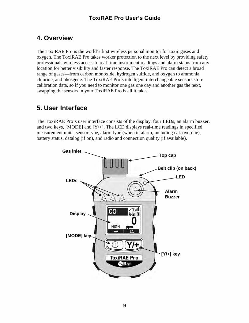
ToxiRAE Pro User’s Guide
9
4. Overview The ToxiRAE Pro is the world’s first wireless personal monitor for toxic gases and oxygen. The ToxiRAE Pro takes worker protection to the next level by providing safety professionals wireless access to real-time instrument readings and alarm status from any location for better visibility and faster response. The ToxiRAE Pro can detect a broad range of gases—from carbon monoxide, hydrogen sulfide, and oxygen to ammonia, chlorine, and phosgene. The ToxiRAE Pro’s intelligent interchangeable sensors store calibration data, so if you need to monitor one gas one day and another gas the next, swapping the sensors in your ToxiRAE Pro is all it takes.
5. User Interface The ToxiRAE Pro’s user interface consists of the display, four LEDs, an alarm buzzer, and two keys, [MODE] and [Y/+]. The LCD displays real-time readings in specified measurement units, sensor type, alarm type (when in alarm, including cal. overdue), battery status, datalog (if on), and radio and connection quality (if available).
[Y/+] key
[MODE] key
Gas inlet
Display
LEDs
Alarm Buzzer
Belt clip (on back)
LED
Top cap
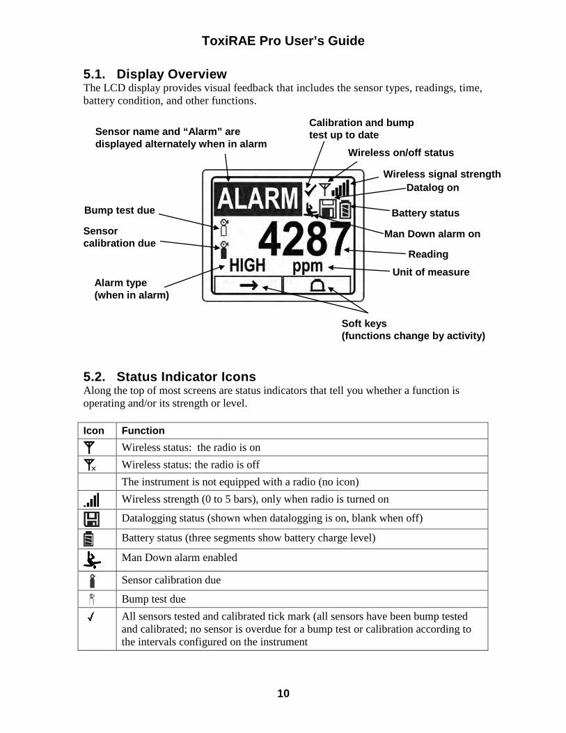
ToxiRAE Pro User’s Guide
10
5.1. Display Overview The LCD display provides visual feedback that includes the sensor types, readings, time, battery condition, and other functions.
5.2. Status Indicator Icons Along the top of most screens are status indicators that tell you whether a function is operating and/or its strength or level. Icon Function
Wireless status: the radio is on
Wireless status: the radio is off
The instrument is not equipped with a radio (no icon)
Wireless strength (0 to 5 bars), only when radio is turned on
Datalogging status (shown when datalogging is on, blank when off)
Battery status (three segments show battery charge level)
Man Down alarm enabled
Sensor calibration due
Bump test due
All sensors tested and calibrated tick mark (all sensors have been bump tested and calibrated; no sensor is overdue for a bump test or calibration according to the intervals configured on the instrument
Calibration and bump test up to date Sensor name and “Alarm” are
displayed alternately when in alarm Wireless on/off status
Wireless signal strength
Unit of measure
Soft keys (functions change by activity)
Alarm type (when in alarm)
Bump test due
Sensor calibration due
Reading
Man Down alarm on
Datalog on
Battery status
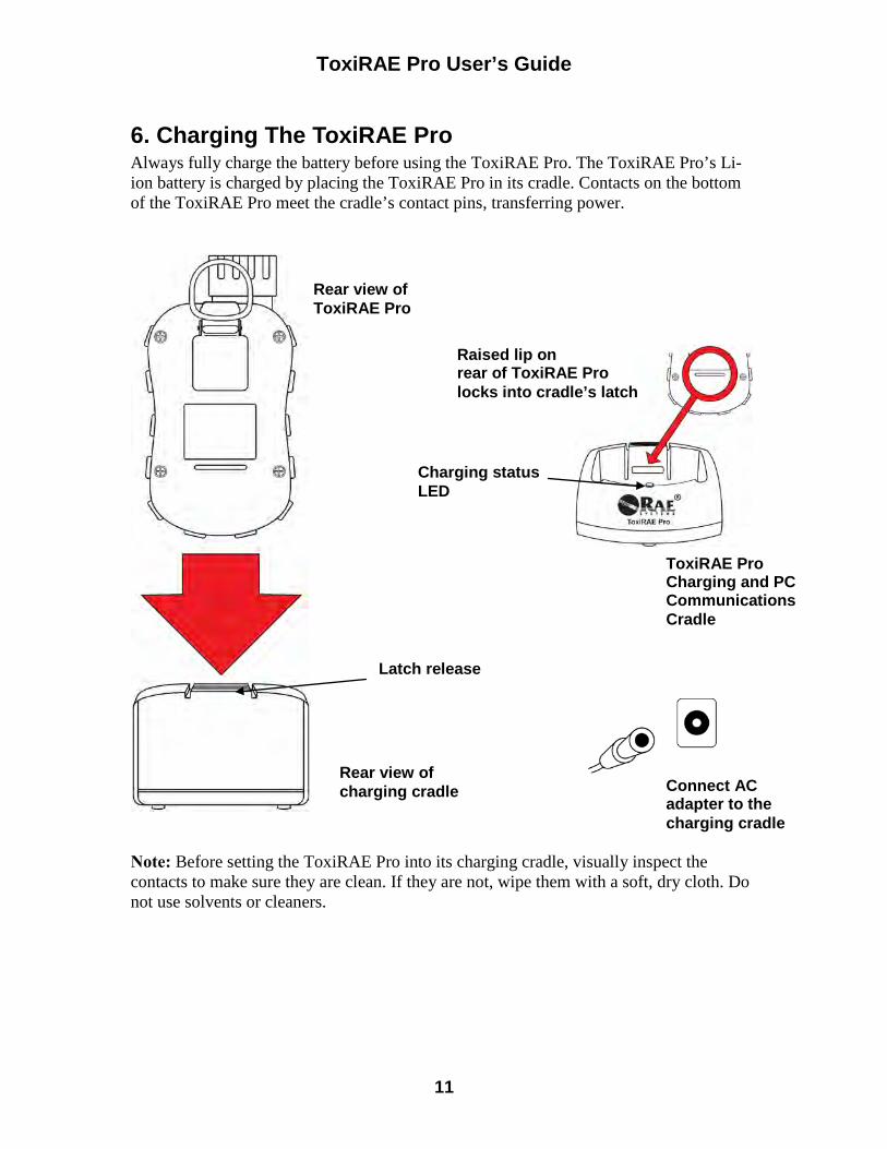
ToxiRAE Pro User’s Guide
11
6. Charging The ToxiRAE Pro Always fully charge the battery before using the ToxiRAE Pro. The ToxiRAE Pro’s Li-ion battery is charged by placing the ToxiRAE Pro in its cradle. Contacts on the bottom of the ToxiRAE Pro meet the cradle’s contact pins, transferring power.
Note: Before setting the ToxiRAE Pro into its charging cradle, visually inspect the contacts to make sure they are clean. If they are not, wipe them with a soft, dry cloth. Do not use solvents or cleaners.
Rear view of ToxiRAE Pro
ToxiRAE Pro Charging and PC Communications Cradle
Raised lip on rear of ToxiRAE Pro locks into cradle’s latch
Rear view of charging cradle
Charging status LED
Connect AC adapter to the charging cradle
Latch release
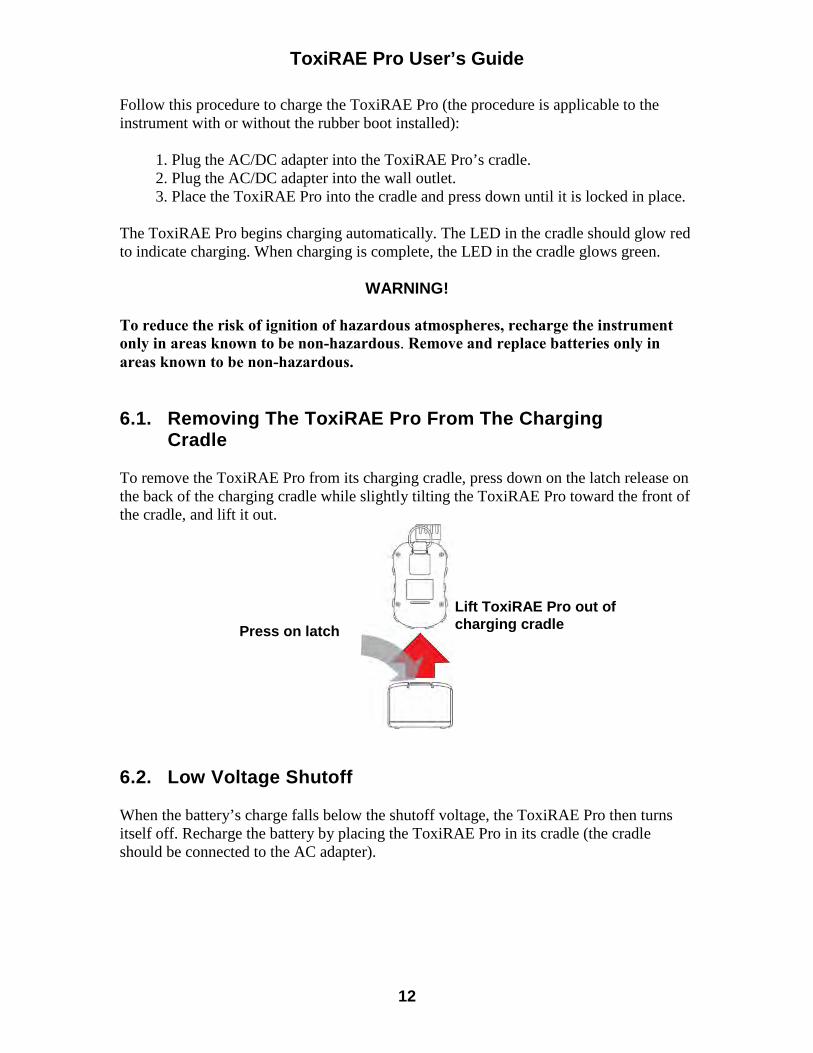
ToxiRAE Pro User’s Guide
12
Follow this procedure to charge the ToxiRAE Pro (the procedure is applicable to the instrument with or without the rubber boot installed): 1. Plug the AC/DC adapter into the ToxiRAE Pro’s cradle. 2. Plug the AC/DC adapter into the wall outlet. 3. Place the ToxiRAE Pro into the cradle and press down until it is locked in place.
The ToxiRAE Pro begins charging automatically. The LED in the cradle should glow red to indicate charging. When charging is complete, the LED in the cradle glows green.
WARNING! To reduce the risk of ignition of hazardous atmospheres, recharge the instrument only in areas known to be non-hazardous. Remove and replace batteries only in areas known to be non-hazardous. 6.1. Removing The ToxiRAE Pro From The Charging
Cradle To remove the ToxiRAE Pro from its charging cradle, press down on the latch release on the back of the charging cradle while slightly tilting the ToxiRAE Pro toward the front of the cradle, and lift it out.
6.2. Low Voltage Shutoff When the battery’s charge falls below the shutoff voltage, the ToxiRAE Pro then turns itself off. Recharge the battery by placing the ToxiRAE Pro in its cradle (the cradle should be connected to the AC adapter).
Press on latch
Lift ToxiRAE Pro out of charging cradle
ToxiRAE Pro User’s Guide
13
7. Turning The ToxiRAE Pro On To turn the ToxiRAE Pro on, press and hold [MODE] for 3 seconds. Caution: The alarm buzzer is very loud. During startup, you can mute most of the sound by holding a finger over the alarm buzzer port. Note: Never put tape over the alarm buzzer port to permanently mute it or otherwise limit the loudness of the buzzer. 1. When the ToxiRAE Pro turns on, the buzzer, vibration alarm, and LEDs are tested.
The firmware version is shown in the display (for example, “V1.00” indicates firmware version 1.00).
2. A battery test is performed. If the battery has sufficient charge, then the next step is a self test of the system. Note: If the battery is almost fully discharged, the message “Battery too low! Needs charging. Powering off!” shows in the display and the ToxiRAE Pro shuts off. You must charge the battery before you can use the instrument.
3. Self-testing is performed by the ToxiRAE Pro. Note: If one of the following error messages is displayed, shut off the ToxiRAE Pro by pressing [MODE]:
• Sensor error! • Wrong sensor!
If any of the following error messages occurs, you can either shut off the instrument by pressing [MODE], or continue to the next startup test by pressing [Y/+]:
• Real time clock error! • Memory error! • Sensor changed!
For any of these error types, try restarting the instrument. If the error message appears again after five more attempts to restart the instrument, consult the distributor from whom the instrument was purchased for technical support.
ToxiRAE Pro User’s Guide
14
4. After self-testing, two start-up options are available for the ToxiRAE Pro: Normal and Fast Start-up. The following information is displayed in sequence under Normal Start-up and skipped under Fast Start-up: • Sensor type • Sensor serial number • Date, time, and temperature • Calibration gas • Last calibration date • Measurement gas • User mode • Battery type, voltage, and shutoff voltage • Alarm mode • Buzzer enabled/disabled status • Light enabled/disabled status • Vibration alarm enabled/disabled status • Alarm settings for High, Low, STEL, and TWA (as applicable) • Datalog type and interval
5. Once the startup process is complete, a sensor warm-up screen is shown (with
countdown, if necessary; the countdown time may vary for different sensors). Then the main measurement screen is shown. The type of monitored hazard is displayed, with the current reading. The ToxiRAE Pro is now ready for use.
8. Turning The ToxiRAE Pro Off Press and hold [MODE]. In 2 seconds, a 5-second countdown to shutoff begins, accompanied by one buzzer beep per second. You must hold your finger on the key for the entire shutoff process. If you remove your finger from the key during the countdown, the shutoff operation is canceled and the ToxiRAE Pro continues normal operation.
When you see “Unit Off,” release your finger from the [MODE] key. The ToxiRAE Pro is now off.
9. Testing The Alarms (Manually) Under normal non-alarm conditions, the buzzer, vibration alarm, and LEDs can be tested at any time by pressing and holding [Y/+]. Important! If any of the alarms does not respond to this test, check the Alarm Settings. It is possible that any or all of the alarms have been turned off. If all the alarms are turned on, but one or more of them (buzzer, LED lights, or vibration alarm) does not respond to this test, do not use the instrument; contact your RAE Systems distributor for technical support.
ToxiRAE Pro User’s Guide
15
10. Low Battery Warnings If, during operation, the battery’s charge is low, the battery icon in the display screen turns empty and blinks once every second. At the same time, the following notifications occur every minute: the buzzer beeps and LEDs blink once, followed by a vibration and a screen message “Battery low! Shut off in X minutes.” The countdown to shutoff starts 10 minutes prior to automatic shutoff.
11. Dead Battery Warning & Shutoff If you turn on the ToxiRAE Pro and the battery’s charge is below its lowest threshold, the display shows this message:
Battery too low! Needs charging. Powering off!
It then automatically shuts off. You must charge the ToxiRAE Pro’s battery before you can continue to use this instrument. Important! Do not operate the ToxiRAE Pro again until its battery has been charged.
WARNING! To reduce the risk of ignition of hazardous atmospheres, charge the battery only in areas known to be non-hazardous.
ToxiRAE Pro User’s Guide
16
12. Operating The ToxiRAE Pro 12.1. Overview The ToxiRAE Pro has two operational modes:
• Normal — see page 16 for detailed instructions. • Diagnostic — see page 48 for detailed instructions.
The following is an overview of the two modes: Normal Mode is the default mode. It is accessed when you turn on the ToxiRAE Pro. Two sub-modes are available: Basic User and Advanced User. In Basic User, some restrictions are applied, including password protection that guards against entering Programming Mode by unauthorized personnel. In Advanced, there are no such access restrictions (you do not need a password), and it provides the indications and data you need most for typical monitoring applications. Diagnostic Mode is primarily intended for technicians to use during troubleshooting, although it also offers access to a few changeable parameters that you may rarely (if ever) need to change. A password is required to enter Diagnostic Mode (the password is the same as (and automatically kept in sync with) the one used to enter Programming Mode). The default password is 0000. To enter Diagnostic Mode, power the instrument off and then turn it back on by pressing and holding both the buttons. In Diagnostic Mode, ToxiRAE Pro displays readings in raw counts instead of units such as parts per million (ppm). It is not possible to switch to Programming from Diagnostic Mode without turning off the instrument first and then restarting it in the desired mode.
12.1.1. Normal Mode Normal Mode is the default mode of the ToxiRAE Pro when it is turned on. The selected sub-mode (Basic or Advanced) determines the number of screens that are accessible.
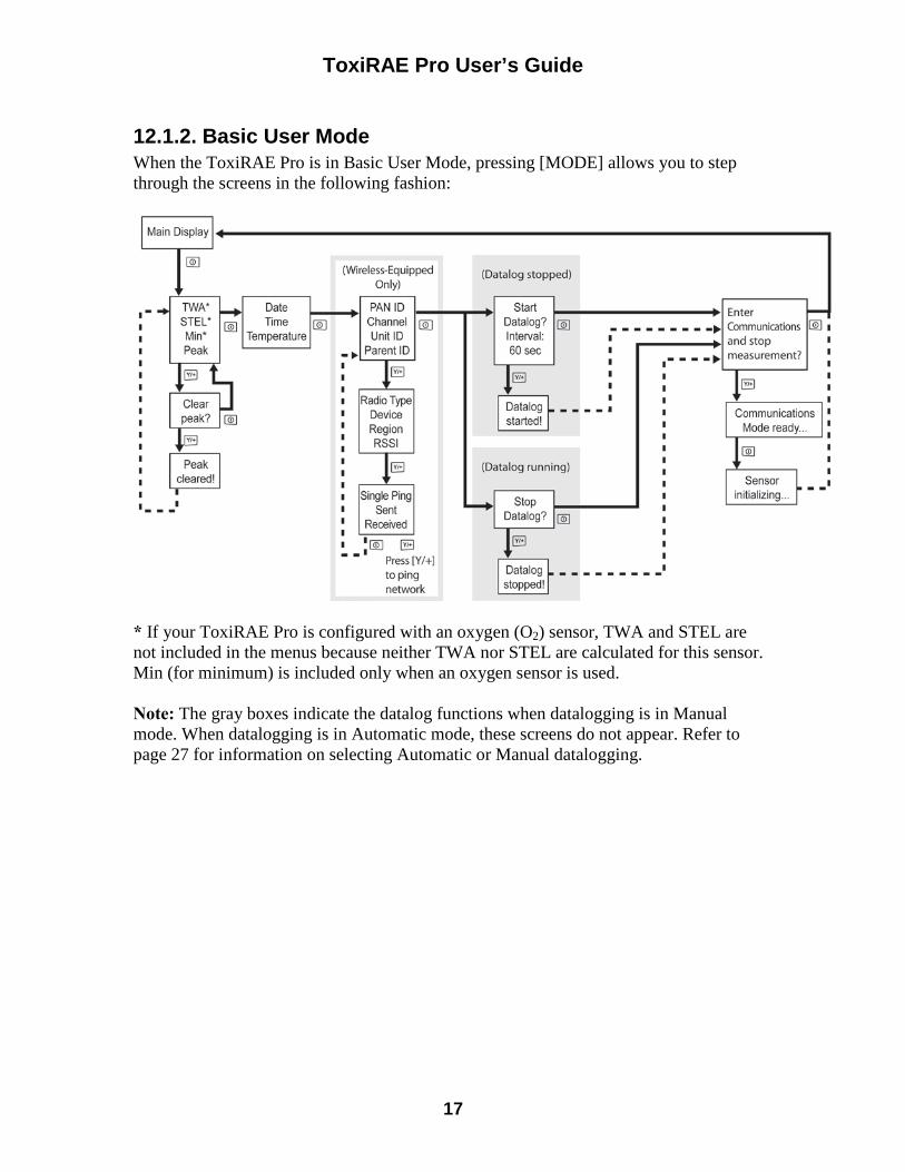
ToxiRAE Pro User’s Guide
17
12.1.2. Basic User Mode When the ToxiRAE Pro is in Basic User Mode, pressing [MODE] allows you to step through the screens in the following fashion:
* If your ToxiRAE Pro is configured with an oxygen (O2) sensor, TWA and STEL are not included in the menus because neither TWA nor STEL are calculated for this sensor. Min (for minimum) is included only when an oxygen sensor is used. Note: The gray boxes indicate the datalog functions when datalogging is in Manual mode. When datalogging is in Automatic mode, these screens do not appear. Refer to page 27 for information on selecting Automatic or Manual datalogging.
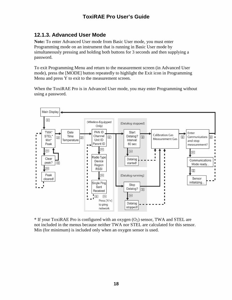
ToxiRAE Pro User’s Guide
18
12.1.3. Advanced User Mode Note: To enter Advanced User mode from Basic User mode, you must enter Programming mode on an instrument that is running in Basic User mode by simultaneously pressing and holding both buttons for 3 seconds and then supplying a password. To exit Programming Menu and return to the measurement screen (in Advanced User mode), press the [MODE] button repeatedly to highlight the Exit icon in Programming Menu and press Y to exit to the measurement screen. When the ToxiRAE Pro is in Advanced User mode, you may enter Programming without using a password.
* If your ToxiRAE Pro is configured with an oxygen (O2) sensor, TWA and STEL are not included in the menus because neither TWA nor STEL are calculated for this sensor. Min (for minimum) is included only when an oxygen sensor is used.
ToxiRAE Pro User’s Guide
19
12.2. Navigation In Normal Mode Step through the screens in Normal Mode by pressing [MODE]. Some screens allow actions on your part, such as clearing the data. In these instances, pressing [Y/+] performs the action.
12.2.1. TWA, STEL, Peak The first screen includes a readout for TWA, STEL, and Peak readings. TWA* The TWA (time-weighted average) reading is the average reading of the gas
concentration times that the monitor has been on, prorated to an 8-hour period. STEL* Short Term Exposure Limit (STEL) data based on 15-minute STEL values,
expressed in ppm or mg/m3. A STEL value is only displayed after the ToxiRAE Pro has been on for 15 minutes or longer. After exiting PC Communications mode, the STEL value is reset.
Peak The Peak value tells you the highest reading for the sensor since the ToxiRAE
Pro was turned on. Press [Y/+] twice to clear the Peak value. Note: If you do not press a key within 1 minute, the display reverts to the
normal reading.
* If your ToxiRAE Pro is configured with an oxygen (O2) sensor, TWA and STEL are not included in the menus because neither TWA nor STEL are calculated for this sensor. Press [MODE] to advance from screen to screen.
12.2.2. Date, Time, And Temperature The current Date is expressed as Month/Day/Year, with two digits for month and day, and four digits for the year. Below the date is the time, which is expressed as Hours/Minutes/Seconds, with two digits for each. The time is in 24-hour (military) format. Below the time is the internal temperature, which can be in degrees Fahrenheit or Celsius (settable in Programming Mode).
12.2.3. Wireless Settings The current wireless settings are shown here. These include the PAN ID, Channel, and Unit ID, which are helpful when creating or troubleshooting networks. Parent ID data does not apply.
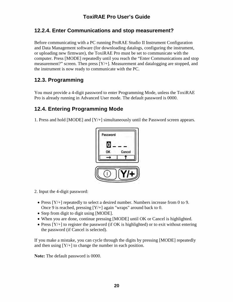
ToxiRAE Pro User’s Guide
20
12.2.4. Enter Communications and stop measurement? Before communicating with a PC running ProRAE Studio II Instrument Configuration and Data Management software (for downloading datalogs, configuring the instrument, or uploading new firmware), the ToxiRAE Pro must be set to communicate with the computer. Press [MODE] repeatedly until you reach the “Enter Communications and stop measurement?” screen. Then press [Y/+]. Measurement and datalogging are stopped, and the instrument is now ready to communicate with the PC. 12.3. Programming You must provide a 4-digit password to enter Programming Mode, unless the ToxiRAE Pro is already running in Advanced User mode. The default password is 0000. 12.4. Entering Programming Mode 1. Press and hold [MODE] and [Y/+] simultaneously until the Password screen appears.
2. Input the 4-digit password: • Press [Y/+] repeatedly to select a desired number. Numbers increase from 0 to 9.
Once 9 is reached, pressing [Y/+] again "wraps" around back to 0. • Step from digit to digit using [MODE]. • When you are done, continue pressing [MODE] until OK or Cancel is highlighted. • Press [Y/+] to register the password (if OK is highlighted) or to exit without entering
the password (if Cancel is selected).
If you make a mistake, you can cycle through the digits by pressing [MODE] repeatedly and then using [Y/+] to change the number in each position. Note: The default password is 0000.
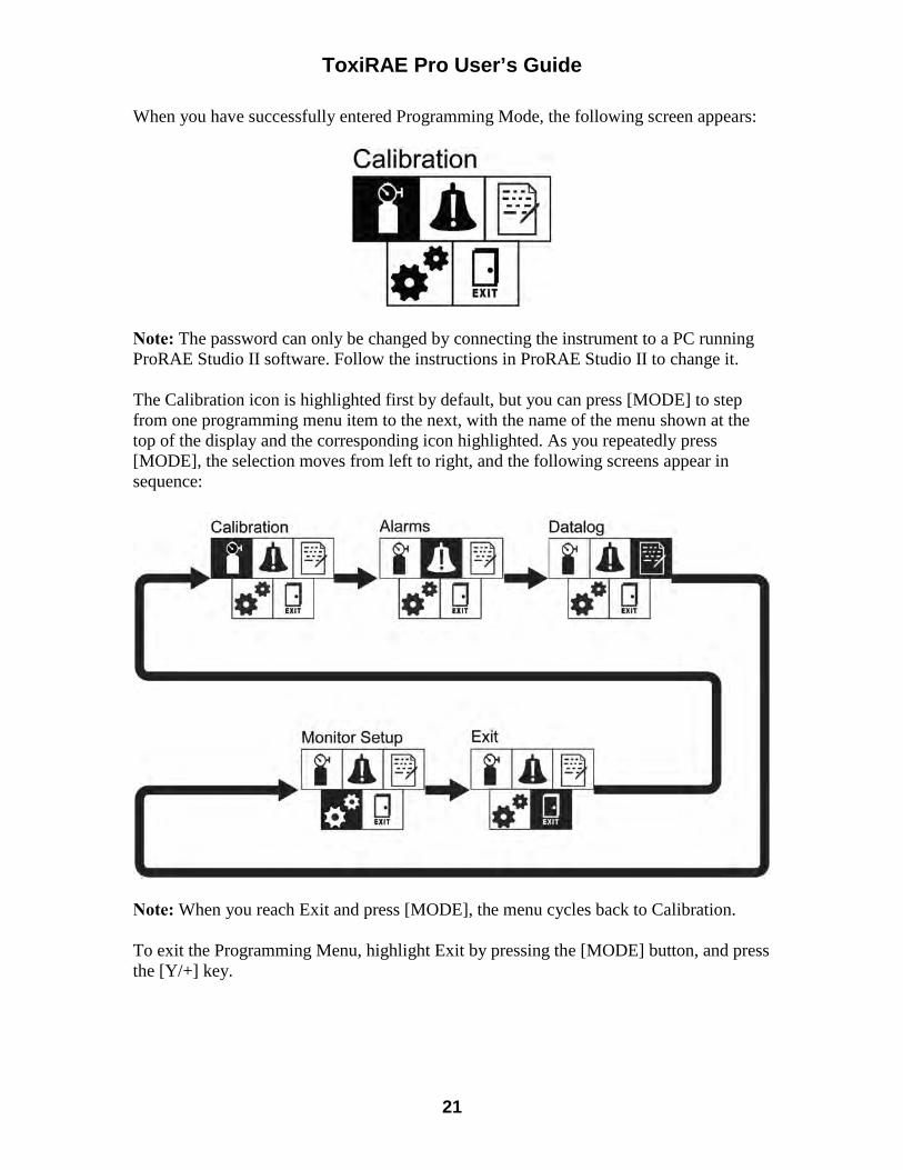
ToxiRAE Pro User’s Guide
21
When you have successfully entered Programming Mode, the following screen appears:
Note: The password can only be changed by connecting the instrument to a PC running ProRAE Studio II software. Follow the instructions in ProRAE Studio II to change it. The Calibration icon is highlighted first by default, but you can press [MODE] to step from one programming menu item to the next, with the name of the menu shown at the top of the display and the corresponding icon highlighted. As you repeatedly press [MODE], the selection moves from left to right, and the following screens appear in sequence:
Note: When you reach Exit and press [MODE], the menu cycles back to Calibration. To exit the Programming Menu, highlight Exit by pressing the [MODE] button, and press the [Y/+] key.
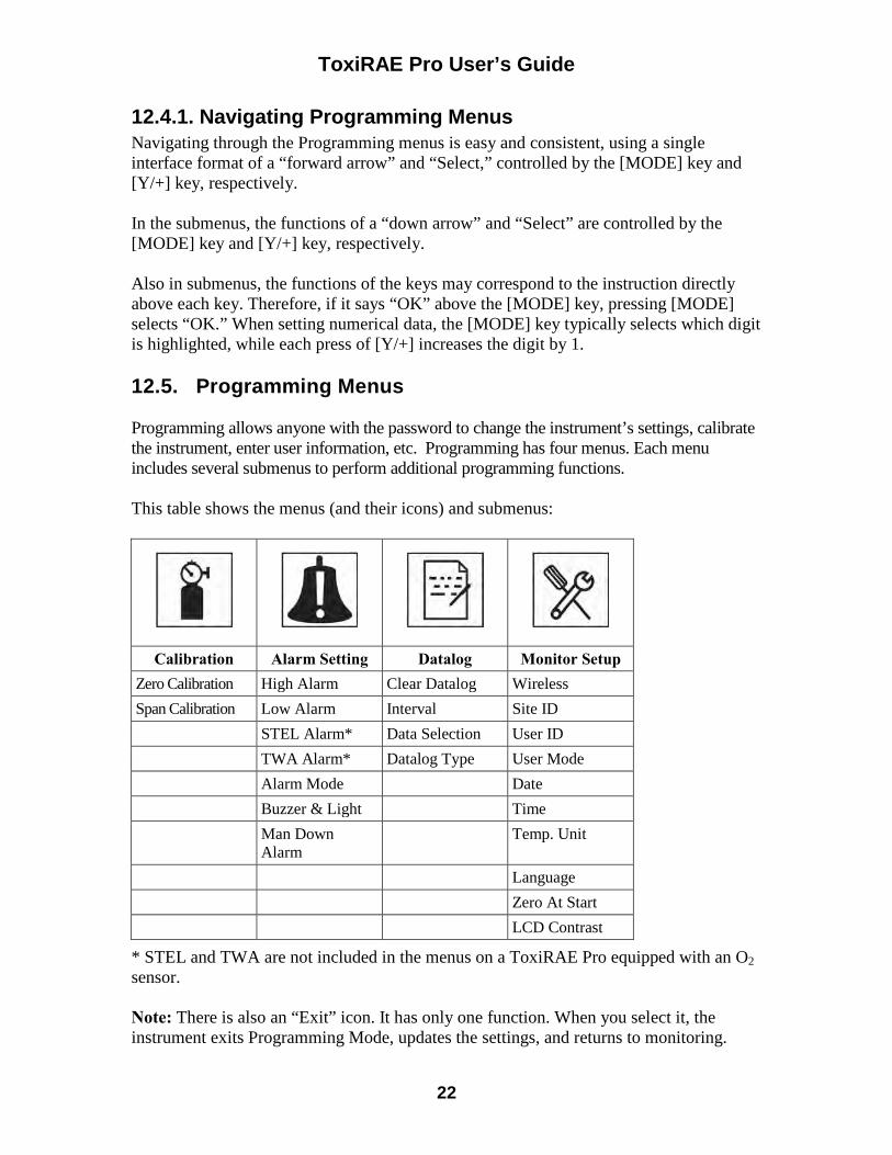
ToxiRAE Pro User’s Guide
22
12.4.1. Navigating Programming Menus Navigating through the Programming menus is easy and consistent, using a single interface format of a “forward arrow” and “Select,” controlled by the [MODE] key and [Y/+] key, respectively. In the submenus, the functions of a “down arrow” and “Select” are controlled by the [MODE] key and [Y/+] key, respectively. Also in submenus, the functions of the keys may correspond to the instruction directly above each key. Therefore, if it says “OK” above the [MODE] key, pressing [MODE] selects “OK.” When setting numerical data, the [MODE] key typically selects which digit is highlighted, while each press of [Y/+] increases the digit by 1. 12.5. Programming Menus Programming allows anyone with the password to change the instrument’s settings, calibrate the instrument, enter user information, etc. Programming has four menus. Each menu includes several submenus to perform additional programming functions. This table shows the menus (and their icons) and submenus:
Calibration Alarm Setting Datalog Monitor Setup Zero Calibration High Alarm Clear Datalog Wireless
Span Calibration Low Alarm Interval Site ID
STEL Alarm* Data Selection User ID
TWA Alarm* Datalog Type User Mode
Alarm Mode Date
Buzzer & Light Time
Man Down Alarm
Temp. Unit
Language
Zero At Start
LCD Contrast
* STEL and TWA are not included in the menus on a ToxiRAE Pro equipped with an O2 sensor. Note: There is also an “Exit” icon. It has only one function. When you select it, the instrument exits Programming Mode, updates the settings, and returns to monitoring.
ToxiRAE Pro User’s Guide
23
Once you enter Programming, the LCD displays the first menu, Calibration. Each subsequent menu is accessed by pressing [MODE] repeatedly until the desired menu is displayed. To enter a submenu of a menu, press [Y/+].
12.5.1. Calibration Two types of calibration are available: Zero (fresh air) and Span. In the Calibration submenu, select Zero or Span Calibration by pressing [MODE]. Once your choice is highlighted, press [Y/+]. Zero Calib The procedure for performing a zero calibration is covered on page 43. Span Calib The procedure for performing a basic span calibration is covered on page 46. Exit Press [Y/+] to exit. Calibration is exited, and Measurement is highlighted in the Programming Menu screen.
12.5.2. Alarm Setting High Alarm Set the High Alarm as follows:
1. In the High Alarm submenu, press [Y/+] repeatedly to select a desired number. Numbers increase from 0 to 9. Once 9 is reached, pressing [Y/+] again “wraps” around back to 0.
2. Press [MODE] to move to the next digit. 3. When you are satisfied with the number, press [MODE] until “OK” is
highlighted. 4. To save the new value, press [Y/+]. The value is saved, and the menu advances to
Low Alarm.
To exit without saving the new value:
1. Press [MODE] to advance to Cancel. 2. Press [Y/+] to exit the High Alarm submenu and advance to the Low Alarm
submenu.

ToxiRAE Pro User’s Guide
24
Low Alarm Set the Low Alarm as follows:
1. In the Low Alarm submenu, press [Y/+] repeatedly to select a desired number. Numbers increase from 0 to 9. Once 9 is reached, pressing [Y/+] again “wraps” around back to 0.
2. Press [MODE] to move to the next digit. 3. When you are satisfied with the number, press [MODE] until “OK” is highlighted. 4. To save the new value, press [Y/+]. The value is saved, and the menu advances to
STEL Alarm.
To exit without saving the new value:
1. Press [MODE] to advance to Cancel. 2. Press [Y/+] to exit the Low Alarm submenu and advance to STEL Alarm
submenu. STEL Alarm Set the STEL Alarm as follows (except if the ToxiRAE Pro has an O2 sensor; then there is no STEL Alarm):
1. In the STEL Alarm submenu, press [Y/+] repeatedly to select a desired number. Numbers increase from 0 to 9. Once 9 is reached, pressing [Y/+] again “wraps” around back to 0.
2. Press [MODE] to move to the next digit. 3. When you are satisfied with the number, press [MODE] several times until “OK”
is highlighted. 4. To save the new value, press [Y/+]. The value is saved, and the menu advances to
TWA Alarm.
To exit without saving the new value:
1. Press [MODE] to advance to Cancel. 2. Press [Y/+] to exit the STEL Alarm submenu and advance to the TWA Alarm
submenu. TWA Set the TWA Alarm as follows (except if the ToxiRAE Pro has an O2 sensor; then there is no TWA Alarm):
1. In the TWA Alarm submenu, press [Y/+] repeatedly to select a desired number. Numbers increase from 0 to 9. Once 9 is reached, pressing [Y/+] again “wraps” around back to 0.
2. Press [MODE] to move to the next digit. 3. When you are satisfied with the number, press [MODE] until “OK” is
highlighted.
ToxiRAE Pro User’s Guide
25
4. To save the new value, press [Y/+]. The value is saved, and the menu advances to Alarm Mode.
To exit without saving the new value:
1. Press [MODE] to advance to Cancel. 2. Press [Y/+] to exit the TWA Alarm submenu and advance to the Alarm Mode
submenu. Alarm Mode There are two selectable alarm types:
Auto Reset When an alarm is triggered and after the alarm condition is no longer present, the alarm stops and resets by itself.
Latch When the alarm is triggered, it will not cease until you manually turn it off. The latched setting only controls alarms for High Alarm and Low Alarm, not the STEL or TWA alarms. Note: To clear an alarm when the instrument is set to “Latched,” press [Y/+] when the main (measurement) display is shown.
1. Press [MODE] to step from one alarm type to the other.
2. Press [Y/+] to select an alarm type.
3. When you have completed your selection, press [MODE] until “Exit” is highlighted. Then press [Y/+] to save the change and exit to “Buzzer and Light.”
Buzzer & Light The buzzer, light, and vibration alarms can be programmed so that any combination, all, or none of them are activated when the ToxiRAE Pro goes into alarm. Important! If you program the ToxiRAE Pro so that no alarms are activated in an alarm condition, you may put yourself or your workers at risk of being exposed to a hazardous atmosphere and being unaware of it, as the indication of a dangerous condition will be limited to the concentration shown in the display and the name of the type of alarm flashing on the display.
1. Choose an alarm combination setting by pressing [MODE] until your choice is highlighted.
2. Press [Y/+] to select it. 3. Press [MODE] repeatedly until “Exit” is highlighted. 4. Press [Y/+] to register your selection and exit.
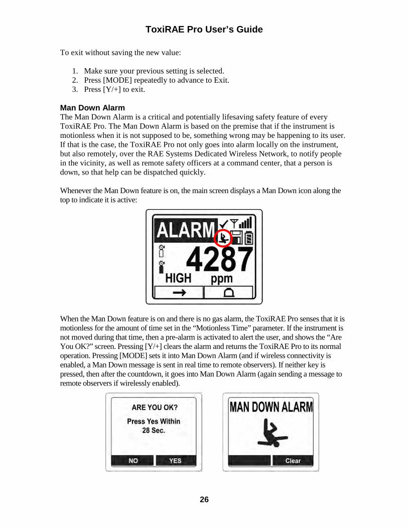
ToxiRAE Pro User’s Guide
26
To exit without saving the new value:
1. Make sure your previous setting is selected. 2. Press [MODE] repeatedly to advance to Exit. 3. Press [Y/+] to exit.
Man Down Alarm The Man Down Alarm is a critical and potentially lifesaving safety feature of every ToxiRAE Pro. The Man Down Alarm is based on the premise that if the instrument is motionless when it is not supposed to be, something wrong may be happening to its user. If that is the case, the ToxiRAE Pro not only goes into alarm locally on the instrument, but also remotely, over the RAE Systems Dedicated Wireless Network, to notify people in the vicinity, as well as remote safety officers at a command center, that a person is down, so that help can be dispatched quickly. Whenever the Man Down feature is on, the main screen displays a Man Down icon along the top to indicate it is active:
When the Man Down feature is on and there is no gas alarm, the ToxiRAE Pro senses that it is motionless for the amount of time set in the “Motionless Time” parameter. If the instrument is not moved during that time, then a pre-alarm is activated to alert the user, and shows the “Are You OK?” screen. Pressing [Y/+] clears the alarm and returns the ToxiRAE Pro to its normal operation. Pressing [MODE] sets it into Man Down Alarm (and if wireless connectivity is enabled, a Man Down message is sent in real time to remote observers). If neither key is pressed, then after the countdown, it goes into Man Down Alarm (again sending a message to remote observers if wirelessly enabled).
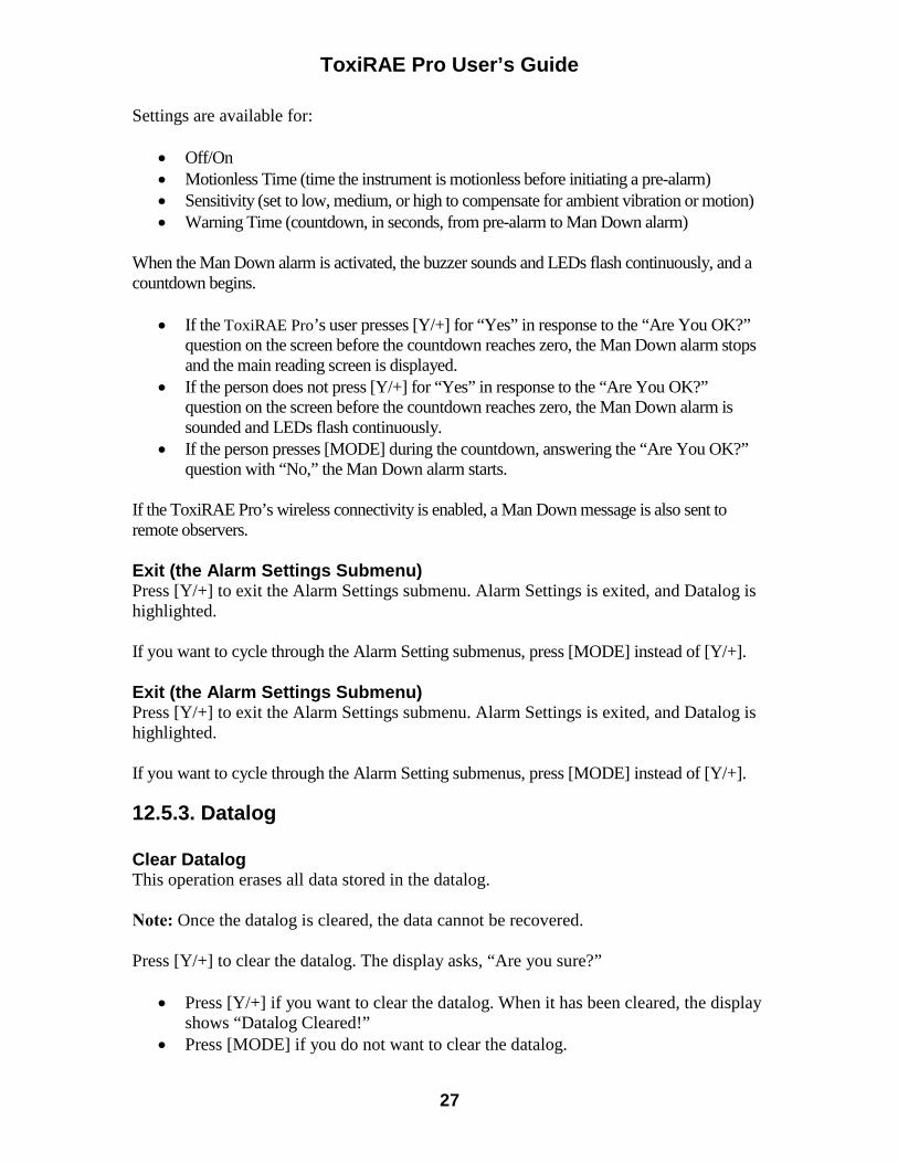
ToxiRAE Pro User’s Guide
27
Settings are available for:
• Off/On • Motionless Time (time the instrument is motionless before initiating a pre-alarm) • Sensitivity (set to low, medium, or high to compensate for ambient vibration or motion) • Warning Time (countdown, in seconds, from pre-alarm to Man Down alarm)
When the Man Down alarm is activated, the buzzer sounds and LEDs flash continuously, and a countdown begins.
• If the ToxiRAE Pro’s user presses [Y/+] for “Yes” in response to the “Are You OK?” question on the screen before the countdown reaches zero, the Man Down alarm stops and the main reading screen is displayed.
• If the person does not press [Y/+] for “Yes” in response to the “Are You OK?” question on the screen before the countdown reaches zero, the Man Down alarm is sounded and LEDs flash continuously.
• If the person presses [MODE] during the countdown, answering the “Are You OK?” question with “No,” the Man Down alarm starts.
If the ToxiRAE Pro’s wireless connectivity is enabled, a Man Down message is also sent to remote observers. Exit (the Alarm Settings Submenu) Press [Y/+] to exit the Alarm Settings submenu. Alarm Settings is exited, and Datalog is highlighted. If you want to cycle through the Alarm Setting submenus, press [MODE] instead of [Y/+]. Exit (the Alarm Settings Submenu) Press [Y/+] to exit the Alarm Settings submenu. Alarm Settings is exited, and Datalog is highlighted. If you want to cycle through the Alarm Setting submenus, press [MODE] instead of [Y/+].
12.5.3. Datalog Clear Datalog This operation erases all data stored in the datalog. Note: Once the datalog is cleared, the data cannot be recovered. Press [Y/+] to clear the datalog. The display asks, “Are you sure?”
• Press [Y/+] if you want to clear the datalog. When it has been cleared, the display shows “Datalog Cleared!”
• Press [MODE] if you do not want to clear the datalog.
ToxiRAE Pro User’s Guide
28
You are taken to the next submenu, Interval. Interval Intervals are shown in seconds. The default value is 60 seconds. The maximum interval is 3600 seconds, and the minimum is 1 second.
1. Press [Y/+] repeatedly to select a desired number. Numbers increase from 0 to 9. Once 9 is reached, pressing [Y/+] again “wraps” around back to 0.
2. Press [MODE] to advance to the next digit.
3. Repeat this process until the desired value is entered.
When you have completed your selections, press [MODE] repeatedly until “OK” is highlighted.
• To save the new value, press [Y/+]. • To cancel the changes and keep the settings as they were, press [MODE] to
highlight “Cancel.” Then press [Y/+]. You are taken to the next submenu, Data Selection. Data Selection Data Selection allows you to select which types of data are stored and made available when you download your datalog to a computer via ProRAE Studio II software. You can choose any or all of four types of data (you must choose at least one):
• Minimum • Average • Maximum • Real Time
1. Press [MODE] to step from one option to the next. The highlighter indicates your
choice. 2. Press [Y/+] to toggle your selection on or off (the check box indicates “on” with
an “X”). 3. When you have completed your selections, press [MODE] repeatedly until “Exit”
is highlighted. 4. Press [Y/+] to save the changes and exit.
ToxiRAE Pro User’s Guide
29
Datalog Type The instrument has two datalog types: Auto Collects datalog information when the instrument is sampling until the
datalog memory is full. Manual Datalogging occurs only when you manually initiate datalogging (see
below for details).
1. Press [MODE] to step from one option to the next. 2. Press [Y/+] to make your selection (the dark circle in the “radio button” indicates
that an option has been selected). 3. When you have completed your selection, press [MODE] until “Exit” is
highlighted. 4. Press [Y/+] to save your selection and exit.
About Manual Datalog
When the instrument is set to Manual Datalog, you can turn datalogging on and off from the main measurement display in the Normal Mode by pressing the [MODE] key three times.
• When you reach the screen that says “Start Datalog?” press [Y/+] to start it. You see “Datalog Started,” confirming that datalogging is now on.
• When you reach the screen that says “Stop Datalog?” press [Y/+] to stop it. You see “Datalog Stopped,” confirming that datalogging is now off.
Exit (the Datalog Submenu) Press [Y/+] to exit. Datalog is exited, and Monitor Setup is highlighted.
ToxiRAE Pro User’s Guide
30
12.5.4. Monitor Setup
Wireless There are seven Wireless parameters:
• Radio On/Off • PAN ID • Channel • Join Network • Interval • Off Network Alarm • Factory Reset
Radio On/Off This turns the wireless modem on or off. Note: Turning the radio off does not change any of the settings.
They are stored and ready for use the next time the wireless modem is turned on.
1. Choose an “On” or “Off” by pressing [MODE] until your choice is highlighted.
(The dark circle in the “radio button” indicates that an option has been selected). 2. Press [Y/+] to select it. 3. Press [MODE] repeatedly until “Exit” is highlighted. 4. Press [Y/+] to register your selection and exit.
To exit without saving the new value:
1. Make sure your previous setting is selected. 2. Press [MODE] repeatedly to advance to Exit. 3. Press [Y/+] to exit.
PAN ID All units on a network must be programmed with the same Pan ID
(Personal Network Identifier) to ensure communication compatibility. Important! The allowed range for Pan ID numbers is 001 through 999.
Choose and enter a 3-digit PAN ID: 1. Press [Y/+] and the display shows the current PAN ID. Example: “866.” The left-
most digit is highlighted.
2. Press [Y/+] repeatedly to select a desired number. Once 9 is reached, pressing [Y/+] again “wraps” around back to 0.
3. Press [MODE] to advance to the next digit.
Repeat this process until all eight characters of the new PAN ID are entered.
ToxiRAE Pro User’s Guide
31
To save your new PAN ID and exit, press [MODE] repeatedly until “OK” is highlighted. Then press [Y/+]. It says, “Applying settings…” and then “Settings applied successfully!” to indicate they have been registered. The menu now advances automatically to “Channel.”
Channel Every network operates on its own channel, between 01 and 10 (do not
use 00). If you need to know the network’s channel, check the EchoView Host’s setting. Note: In Europe, only Channel 11 can be used, and it is preset (it cannot be changed).
Choose and enter a 2-digit Channel: 1. Press [Y/+] and the display shows the current Channel. Example: “10.” The left-
most digit is highlighted.
2. Press [Y/+] repeatedly to select a desired number. Once 9 is reached, pressing [Y/+] again “wraps” around back to 0.
3. Press [MODE] to advance to the next digit.
Repeat this process until all eight characters of the new Channel are entered.
To save your new Channel number and exit, press [MODE] repeatedly until “OK” is highlighted. Then press [Y/+]. It says, “Applying settings…” and then “Settings applied successfully!” to indicate they have been registered. The menu now advances automatically to “Join Network.”
Join Network This screen is for joining an existing network. When you see this
screen, press [Y/+] to join, or [MODE] to exit without joining.
While searching for the network, the message “Joining network…” is displayed. If the network is found and successfully joined, then “Join network successful!” is displayed. Press [MODE] to acknowledge the connection and return to the Wireless menu. If the network is not joined, the display shows: “Join network failed!” You have two options: Exit and Retry. If you want to retry, check that your network setting is correct (matches the EchoView Host) and that the EchoView Host is turned on and operating. Then press [Y/+] to retry.
Interval This sets the amount of time between data transmissions to the
EchoView Host.
To change the Interval:
1. Press [MODE] to step from one option to the other. The highlighted option changes each time you press [MODE].
ToxiRAE Pro User’s Guide
32
2. Press [Y/+] to make your selection (the dark circle in the “radio button” indicates the option has been selected).
3. When you have completed your selection, press [MODE] repeatedly until “Exit” is highlighted.
4. Press [Y/+] to save your selection, exit the Interval menu, and advance to “Off Netwk Alarm.”
Off Netwk Alarm When this is enabled, the unit goes into alarm whenever an active
network connection is lost. This informs you that connectivity has been broken between the ToxiRAE Pro and the EchoView Host.
1. Choose “On” or “Off” by pressing [MODE] until your choice is highlighted. (the
dark circle in the “radio button” indicates that an option has been selected). 2. Press [Y/+] to select it. 3. Press [MODE] repeatedly until “Exit” is highlighted. 4. Press [Y/+] to register your selection and exit.
To exit without saving the new value:
1. Make sure your previous setting is selected. 2. Press [MODE] repeatedly to advance to Exit. 3. Press [Y/+] to exit.
Factory Reset Selecting this resets the wireless settings to their original factory
configurations.
CAUTION! A factory reset of the wireless settings deletes any customized settings and cannot be undone.
1. Press [Y/+] to select “Factory Reset.” You will see the message “Reset wireless
settings?” 2. Press [Y/+] for “Yes” or [MODE] for “Exit.” If you select “Exit,” the ToxiRAE
Pro exits without performing a factory reset. Exit (the Wireless Submenu) Press [Y/+] to exit. Wireless is exited, and Monitor Setup is highlighted.
Site ID Choose and enter an 8-digit alphanumeric Site ID to uniquely identify the particular site where the instrument is to be used. This Site ID is included in the datalog report.
1. Press [Y/+] and the display shows the current Site ID. Example: “SITE0001.” The left-most digit is highlighted.
2. Press [Y/+] repeatedly to select a desired character. Letters increase from current value to Z followed by digits from 0 to 9. Once 9 is reached, pressing [Y/+] again “wraps” around to the letter A. For the last four characters that must be numerical,
ToxiRAE Pro User’s Guide
33
numbers increase from 0 to 9. Once 9 is reached, pressing [Y/+] again “wraps” around back to 0.
Note: The last four characters must be numerals.
3. Press [MODE] to advance to the next character. Repeat this process until all eight characters of the new Site ID are entered.
To save your new Site ID and exit, press [MODE] repeatedly until “OK” is highlighted. Then press [Y/+].
User ID Enter an 8-digit alphanumeric User ID to uniquely identify a user. This User ID is included in the datalog report.
1. Press [Y/+] and the display shows the current User ID. Example: “USER0000.” The left-most character is highlighted.
2. Press [Y/+] repeatedly to select a desired character. Letters increase from current value to Z followed by digits from 0 to 9. Once 9 is reached, pressing [Y/+] again “wraps” around to the letter A.
3. Press [MODE] to advance to the next character.
Repeat this process until all eight characters of the new User ID are entered.
To save your new User ID and exit, press [MODE] repeatedly until “OK” is highlighted. Then press [Y/+].
User Mode The ToxiRAE Pro has two user modes:
Basic Basic users can only see and use a basic set of functions.
Advanced Advanced users can see all screens and take advantage of all available functions. Note: The default value for User Mode is Basic. To change the User Mode:
1. Press [MODE] to step from one option to the other. The highlighting changes each time you press [MODE].
2. Press [Y/+] to make your selection (the dark circle in the “radio button” indicates the option has been selected).
3. When you have completed your selection, press [MODE] repeatedly until “Exit” is highlighted.
4. Press [Y/+] to register your selection, exit the User Mode submenu and advance to Date.
ToxiRAE Pro User’s Guide
34
Date The Date is expressed as Month/Day/Year, with two digits for each (MM/DD/YY). The left-most digit is highlighted to indicate it is selected when you enter the Date submenu.
1. Press [Y/+] repeatedly to select a desired number. Numbers increase from 0 to 9. Once 9 is reached, pressing [Y/+] again “wraps” around back to 0.
2. Press [MODE] to advance to the next digit.
Repeat this process until all six digits of the new date are entered.
3. Press [MODE] repeatedly until “OK” is highlighted.
4. Press [Y/+] to save your selection and advance to Time. Note: If you do not want to save the change, press [MODE] repeatedly until “Cancel” is highlighted. Press [Y/+] to exit to Time without saving the changes.
Time The Time is expressed as Hours/Minutes/Seconds, with two digits for each. The time is in 24-hour (military) format of HH:MM:SS. The left-most digit is highlighted to indicate it is selected.
1. Press [Y/+] repeatedly to select a desired number. Numbers increase from 0 to 9. Once 9 is reached, pressing [Y/+] again “wraps” around back to 0.
2. Press [MODE] to advance to the next digit.
Repeat this process until all six digits of the new time are entered.
3. Press [MODE] repeatedly until “OK” is highlighted.
4. Press [Y/+] to save your selection, exit the Time submenu and advance to Temp. Unit. Note: If you do not want to save the change, press [MODE] until “Cancel” is highlighted. Press [Y/+] to exit to Temp. Unit without saving the changes.
ToxiRAE Pro User’s Guide
35
Temp. Unit The display unit of the internal temperature sensor can be switched between Fahrenheit and Celsius. To change the Temp. Unit:
1. Press [MODE] to step from one option to the other. The highlighted option changes each time you press [MODE].
2. Press [Y/+] to make your selection (the dark circle in the “radio button” indicates the option has been selected).
3. When you have completed your selection, press [MODE] repeatedly until “Exit” is highlighted.
4. Press [Y/+] to save your selection, exit the Temp. Unit menu, and advance to Language.
Language English is the default language, but other languages can also be selected for the instrument.
1. Press [MODE] to step from one option to the next. The highlighted option changes each time you press [MODE].
2. Press [Y/+] to make your selection (the dark circle in the “radio button” indicates this option has been selected).
3. When you have completed your selection, press [MODE] repeatedly until “Exit” is highlighted.
4. Press [Y/+] to save your selection, exit the Language submenu, and advance to Zero At Start.
Zero At Start When Zero At Start is turned on, the instrument starts with zero calibration every time it is turned on.
1. Press [MODE] to choose between “Off” and “On.” 2. Press [Y/+] to make your selection (the dark circle in the “radio button” indicates
your selection). 3. When you have completed your selection, press [MODE] repeatedly until “Exit”
is highlighted. 4. Press [Y/+] to save your selection, exit the Zero At Start submenu, and advance to
LCD Contrast. LCD Contrast The display’s contrast can be increased or decreased from its default setting. You may not need to ever change the default setting, but sometimes you can optimize the display to suit extreme temperature and ambient brightness/darkness conditions.
1. Press and hold [Y/+] to select a desired level of contrast. The range is 1 to 100. Once 100 is reached, pressing [Y/+] again "wraps" around back to 1.
ToxiRAE Pro User’s Guide
36
2. When you have completed your selection, press [MODE] repeatedly until “OK” is highlighted.
3. Press [Y/+] to save your selection, and exit the LCD Contrast. Note: If you do not want to save the change, press [MODE] repeatedly until “Cancel” is highlighted. Press [Y/+] to exit without saving the changes.
Exit (Monitor Setup Submenu) Press [Y/+] to exit. Monitor Setup is exited. Exit (to exit Programming Mode) is highlighted. 12.6. Exit (Exit Programming Mode) To exit Programming Mode and return to normal operation, press [MODE] until the Exit icon is highlighted. Press [Y/+] to exit. You will see “Updating Settings…” as changes are registered and the mode changes to normal operation.
13. Policy Enforcement The ToxiRAE Pro can be configured to enforce a facility/company’s requirements that calibration and/or bump testing be performed at specified intervals, and to warn the user that calibration/bump testing is required. In addition, it can require calibration or bump testing and not allow normal operation of the instrument unless calibration or bump testing is performed. If Policy Enforcement is enabled and if the instrument has been bump tested and calibrated in compliance with the policy settings, a check-mark icon is included along the top of the ToxiRAE Pro screen:
If Policy Enforcement is enabled, then after startup the ToxiRAE Pro displays a screen that informs the user that the instrument requires either a bump test or a calibration. If both are required, then they are shown in sequence. 13.1. Setting Policy Enforcement You must use ProRAE Studio II to make changes to Policy Enforcement settings. The procedure differs, depending on whether you are using an AutoRAE 2 Cradle, a ToxiRAE Pro Travel Charger, or a ToxiRAE Pro Desktop Cradle.
13.1.1. AutoRAE 2 Cradle Note: This procedure only works with a single AutoRAE 2 Cradle. It will not work with an AutoRAE 2 Controller.

ToxiRAE Pro User’s Guide
37
To program a ToxiRAE Pro via an AutoRAE 2 Cradle, you need ProRAE Studio II Instrument Configuration and Data Management Software, the AutoRAE 2 Cradle connected to a power source, and a USB PC communications cable. 1. Connect a USB cable between a PC with ProRAE Studio II and the AutoRAE 2
Cradle. 2. Apply power to the AutoRAE 2 Cradle. 3. Turn off the ToxiRAE Pro (or put the ToxiRAE Pro into PC Communications Mode)
and set it in the cradle. 4. Start ProRAE Studio II software on the PC. 5. Select “Administrator” and input the password (the default is “rae”). 6. Click “Detect the instruments automatically” (the magnifying glass icon with the
letter “A” in it). After a few seconds, the AutoRAE 2 Cradle is found and it is shown, along with its serial number:
7. Click on the icon to highlight it, and then click “Select.”
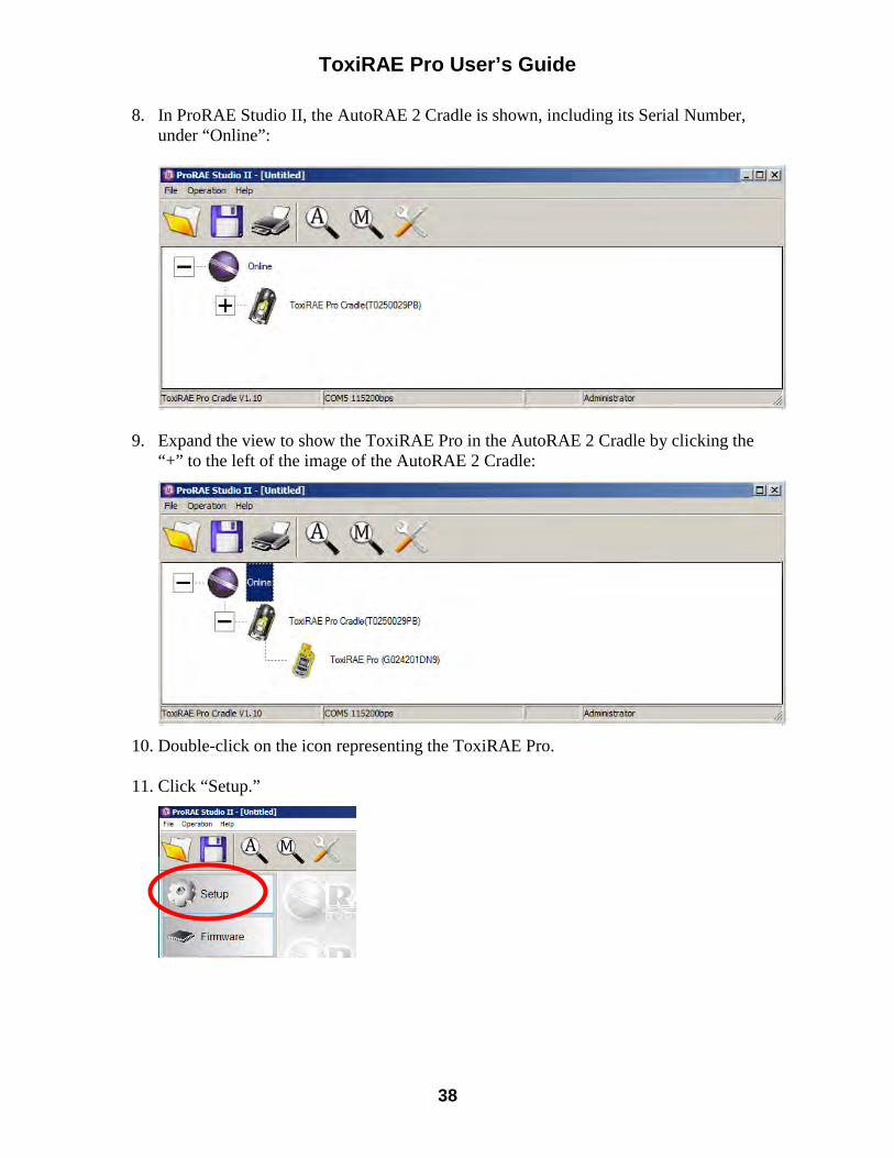
ToxiRAE Pro User’s Guide
38
8. In ProRAE Studio II, the AutoRAE 2 Cradle is shown, including its Serial Number, under “Online”:
9. Expand the view to show the ToxiRAE Pro in the AutoRAE 2 Cradle by clicking the
“+” to the left of the image of the AutoRAE 2 Cradle:
10. Double-click on the icon representing the ToxiRAE Pro. 11. Click “Setup.”
ToxiRAE Pro User’s Guide
39
12. In the menu that now appears on the left side, click “Policy Enforcement.” It is highlighted, and the Policy Enforcement pane is shown:
For “Must Calibrate” and “Must Bump,” you have the options of no enforcement or enforcement (including “Can’t Bypass,” and “Can Bypass”). Must Calibrate. The user is prompted to calibrate the instrument when calibration is due (as set by the calibration interval). There are two programmable options:
• Can’t Bypass. Unless calibration is performed, the instrument cannot be used, and the only option is to turn off the instrument.
• Can Bypass. If calibration is due but the user does not want to perform a calibration, the instrument can still be used.
Must Bump
• Can’t Bypass. Unless a bump test is performed, the instrument cannot be used, and the only option is to turn off the instrument.
• Can Bypass. If a bump test is due but the user does not want to perform one, the instrument can still be used.
ToxiRAE Pro User’s Guide
40
These are the screens that are shown on a ToxiRAE Pro after startup if “Can Bypass” is selected:
If “Can’t Bypass” is selected, the display looks like this, and only allows the options of performing the test or shutting down:
13.1.2. ToxiRAE Pro Desktop Cradle Or Travel Charger Make sure the AC adapter is connected and that a USB cable is connected to a computer running ProRAE Studio II. 1. Turn on the ToxiRAE Pro. 2. Hold down [MODE] and [Y/+] to enter Programming Mode. 3. Provide the password. 4. Press [MODE] until “Enter Communications Mode?” is displayed. 5. Press [Y/+]. The screen shows that it is ready by saying “Communications Mode
ready…” It is now ready to communicate with the computer running ProRAE Studio II. If you want to exit, press [MODE].
6. Start ProRAE Studio II. 7. Select “Administrator.” 8. Input the password (the default is “rae”). 9. Click “OK.” 10. Click “A” (detects instruments automatically). 11. Click on the instrument’s icon when it appears to highlight it. 12. Click “Select.” 13. Click “Setup.” 14. Click “Policy Enforcement.”
ToxiRAE Pro User’s Guide
41
The Policy Enforcement pane is shown:
You can select “Must Calibrate” and/or “Must Bump” and then set whether the user must perform the selected operation in order to use the instrument.
15. Once you have made your selections in ProRAE Studio II, you must upload the changes to the instrument. Click the icon labeled “Upload all settings to the instrument.”
16. A confirmation screen is shown. Click “Yes” to perform the upload, or “No” to abort.
Uploading takes a few seconds, and this progress bar is shown. You can abort the upload by clicking “Cancel.”
ToxiRAE Pro User’s Guide
42
17. Exit ProRAE Studio II. 18. Press [Y/+] on the ToxiRAE Pro to exit Communication Mode. 13.2. Deactivating Policy Enforcement
13.2.1. AutoRAE 2 Cradle To deactivate Policy Enforcement when using an AutoRAE 2 Cradle, follow the procedure for changing settings. See page 36 for details.
13.2.2. ToxiRAE Pro Desktop Cradle Or Travel Charger If the ToxiRAE Pro screen displays the message that it must be bump tested or calibrated, and if the option to bypass bump testing or calibration is not available, you should shut off the instrument and follow the procedure outlined here if you want to change the Policy Enforcement settings: 1. Use a USB cable to connect the ToxiRAE Pro in its Travel Charger or Desktop
Cradle to a computer running ProRAE Studio II. 2. Enter Diagnostic Mode on the ToxiRAE Pro (with the instrument turned off, press
and hold [Y/+] and [MODE] until it starts up. 3. After startup, enter the password when prompted (default is “0000”) and press
[MODE]. 4. Press [MODE] repeatedly until you see the “Enter Communications Mode?” screen. 5. Press [Y/+] to enter Communications Mode. 6. Start ProRAE Studio II. 7. Select “Administrator.” 8. Input the password (the default is “rae”). 9. Click “OK.” 10. Click “A” (detect instruments automatically). 11. Click on the instrument’s icon when it appears. 12. Click “Select.” 13. Click “Setup.” 14. Click “Policy Enforcement.” The Policy Enforcement pane is shown. 15. Deselect Policy Enforcement features you do not wish to use. 16. Click “Upload all settings to the instrument.”

ToxiRAE Pro User’s Guide
43
17. When you see this confirmation. Click “Yes.”
Uploading will take a few seconds, and this progress bar is shown:
18. When the upload is done, exit ProRAE Studio II. 19. Press [Y/+] on the ToxiRAE Pro to exit Communication Mode.
14. Bump Testing & Calibrating The ToxiRAE Pro Note: Calibration intervals and bump test procedures may vary due to national legislation. 14.1. Bump Testing & Calibrating With An AutoRAE 2™ Bump testing and calibrating a ToxiRAE Pro can be done with an AutoRAE 2 Automatic Test And Calibration Station. Follow all instructions in the AutoRAE 2 User’s Guide for successful bump testing or calibration.
14.1.1. Bump (Functional) Testing With the ToxiRAE Pro in Normal Mode:
1. Connect the calibration gas cylinder, flow regulator, and calibration adapter to the ToxiRAE Pro and start the gas flow.
2. Make sure the unit goes into alarm and that the buzzer produces at least two beeps per second, the LED lights flash on and off, and the vibration alarm functions. The display backlight should illuminate and an alarm message should be shown in the display.
3. Turn off the gas flow. 4. Remove the calibration adapter.

ToxiRAE Pro User’s Guide
44
Note: Bump testing and calibration can also be performed by using the RAE Systems AutoRAE 2 Automatic Test And Calibration Station. Refer to the AutoRAE 2 User’s Guide for instructions. 14.2. Calibration Adapter The ToxiRAE Pro is a diffusion monitor and must be calibrated using a fixed-flow regulator with a flow rate between 0.5 and 1.0 liters per minute. The ToxiRAE Pro is supplied with a special calibration adapter that covers the gas inlet. If the local air has impurities that might interfere with zero (fresh air) calibration, the calibration adapter and a cylinder of clean zero air should be used.
14.2.1. Connecting The Calibration Adapter The supplied Calibration Adapter has a removable insert to allow bump testing and calibration to be performed on the instrument regardless of whether it has a rubber boot installed. Use the Calibration Adapter without the insert to calibrate the instrument in the rubber boot, and with the insert to calibrate the instrument without the rubber boot on it.
1. Place the Calibration Adapter on the top cap of the ToxiRAE Pro by pressing it into place.
2. Attach the hose from the regulator/calibration gas cylinder to the Calibration Adapter’s inlet.
Caution! After calibration is complete, remove the Calibration Adapter. When monitoring, never operate the ToxiRAE Pro with the Calibration Adapter attached. If the Calibration Adapter is attached during normal operation, inconsistent and lower-than-normal readings will occur because of decreased concentration of the gas being monitored.
14.2.2. Disconnecting The Calibration Adapter After calibrating the ToxiRAE Pro, you must remove the Calibration Adapter by lifting it off the ToxiRAE Pro.
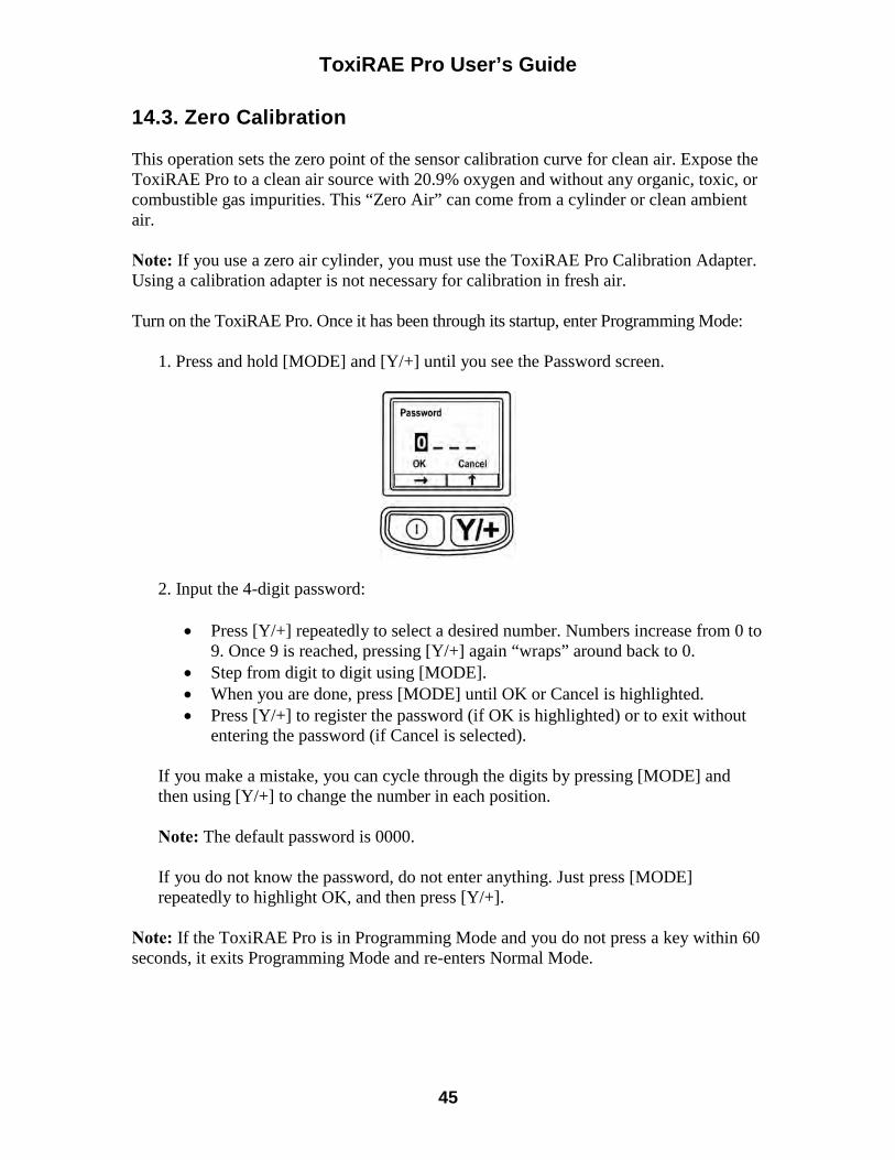
ToxiRAE Pro User’s Guide
45
14.3. Zero Calibration This operation sets the zero point of the sensor calibration curve for clean air. Expose the ToxiRAE Pro to a clean air source with 20.9% oxygen and without any organic, toxic, or combustible gas impurities. This “Zero Air” can come from a cylinder or clean ambient air. Note: If you use a zero air cylinder, you must use the ToxiRAE Pro Calibration Adapter. Using a calibration adapter is not necessary for calibration in fresh air. Turn on the ToxiRAE Pro. Once it has been through its startup, enter Programming Mode:
1. Press and hold [MODE] and [Y/+] until you see the Password screen.
2. Input the 4-digit password:
• Press [Y/+] repeatedly to select a desired number. Numbers increase from 0 to 9. Once 9 is reached, pressing [Y/+] again “wraps” around back to 0.
• Step from digit to digit using [MODE]. • When you are done, press [MODE] until OK or Cancel is highlighted. • Press [Y/+] to register the password (if OK is highlighted) or to exit without
entering the password (if Cancel is selected).
If you make a mistake, you can cycle through the digits by pressing [MODE] and then using [Y/+] to change the number in each position. Note: The default password is 0000. If you do not know the password, do not enter anything. Just press [MODE] repeatedly to highlight OK, and then press [Y/+].
Note: If the ToxiRAE Pro is in Programming Mode and you do not press a key within 60 seconds, it exits Programming Mode and re-enters Normal Mode.
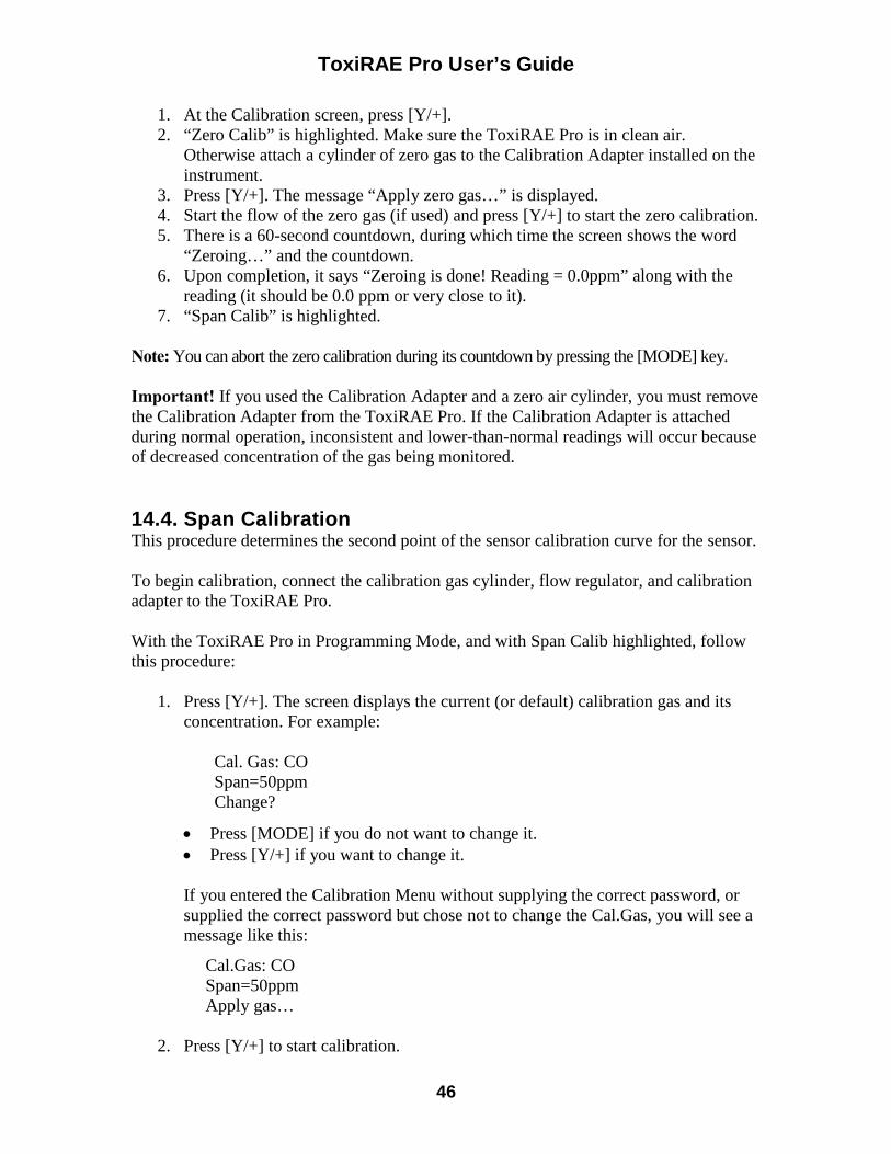
ToxiRAE Pro User’s Guide
46
1. At the Calibration screen, press [Y/+]. 2. “Zero Calib” is highlighted. Make sure the ToxiRAE Pro is in clean air.
Otherwise attach a cylinder of zero gas to the Calibration Adapter installed on the instrument.
3. Press [Y/+]. The message “Apply zero gas…” is displayed. 4. Start the flow of the zero gas (if used) and press [Y/+] to start the zero calibration. 5. There is a 60-second countdown, during which time the screen shows the word
“Zeroing…” and the countdown. 6. Upon completion, it says “Zeroing is done! Reading = 0.0ppm” along with the
reading (it should be 0.0 ppm or very close to it). 7. “Span Calib” is highlighted.
Note: You can abort the zero calibration during its countdown by pressing the [MODE] key. Important! If you used the Calibration Adapter and a zero air cylinder, you must remove the Calibration Adapter from the ToxiRAE Pro. If the Calibration Adapter is attached during normal operation, inconsistent and lower-than-normal readings will occur because of decreased concentration of the gas being monitored. 14.4. Span Calibration This procedure determines the second point of the sensor calibration curve for the sensor. To begin calibration, connect the calibration gas cylinder, flow regulator, and calibration adapter to the ToxiRAE Pro. With the ToxiRAE Pro in Programming Mode, and with Span Calib highlighted, follow this procedure:
1. Press [Y/+]. The screen displays the current (or default) calibration gas and its concentration. For example:
Cal. Gas: CO Span=50ppm Change?
• Press [MODE] if you do not want to change it. • Press [Y/+] if you want to change it.
If you entered the Calibration Menu without supplying the correct password, or supplied the correct password but chose not to change the Cal.Gas, you will see a message like this:
Cal.Gas: CO Span=50ppm Apply gas…
2. Press [Y/+] to start calibration.
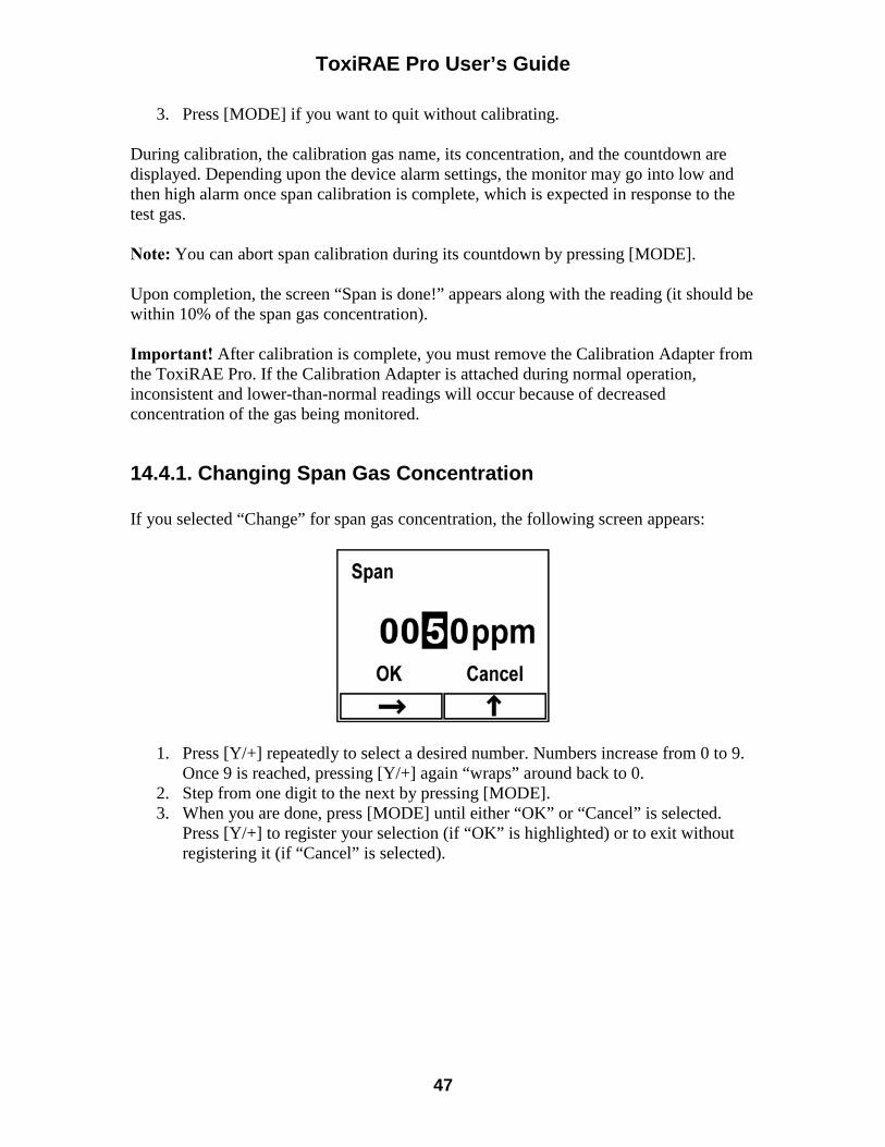
ToxiRAE Pro User’s Guide
47
3. Press [MODE] if you want to quit without calibrating. During calibration, the calibration gas name, its concentration, and the countdown are displayed. Depending upon the device alarm settings, the monitor may go into low and then high alarm once span calibration is complete, which is expected in response to the test gas. Note: You can abort span calibration during its countdown by pressing [MODE]. Upon completion, the screen “Span is done!” appears along with the reading (it should be within 10% of the span gas concentration). Important! After calibration is complete, you must remove the Calibration Adapter from the ToxiRAE Pro. If the Calibration Adapter is attached during normal operation, inconsistent and lower-than-normal readings will occur because of decreased concentration of the gas being monitored.
14.4.1. Changing Span Gas Concentration If you selected “Change” for span gas concentration, the following screen appears:
1. Press [Y/+] repeatedly to select a desired number. Numbers increase from 0 to 9. Once 9 is reached, pressing [Y/+] again “wraps” around back to 0.
2. Step from one digit to the next by pressing [MODE]. 3. When you are done, press [MODE] until either “OK” or “Cancel” is selected.
Press [Y/+] to register your selection (if “OK” is highlighted) or to exit without registering it (if “Cancel” is selected).
ToxiRAE Pro User’s Guide
48
15. Diagnostic Mode In Diagnostic Mode, the ToxiRAE Pro provides raw counts for sensor, battery, and other readings. Most of these screens are useful only to service technicians. Therefore, if you require information on Diagnostic Mode, refer to the ToxiRAE Pro Service Guide. The ToxiRAE Pro’s Diagnostic Mode can only be accessed at startup time. In Diagnostic Mode, ToxiRAE Pro displays readings in raw counts instead of units such as parts per million (ppm). 15.1. Entering Diagnostic Mode
1. With the ToxiRAE Pro turned off, press and hold both [MODE] and [Y/+]. 2. When the display turns on and the password screen appears, release the keys. 3. Enter the 4-digit password (the password is the same as the one for the
Programming Mode): • Step from one position in the four-character string to the other by pressing
[MODE]. • Press [Y/+] repeatedly to select a desired number. Numbers increase from 0 to 9. • Once 9 is reached, pressing [Y/+] again “wraps” around back to 0.
4. When you are done, press [MODE] until either OK or Cancel is selected. Press
[Y/+] to register the password (if “OK” is highlighted) or to exit without entering the password (if “Cancel” is selected).
15.2. Navigating Diagnostic Mode Step through Diagnostic Mode by pressing [MODE]. 15.3. Exiting Diagnostic Mode
1. Turn off the ToxiRAE Pro by pressing and holding [MODE]. There will be a standard shutoff countdown.
2. When the instrument shuts off, you will be alerted. Release your finger. Note: The next time you start ToxiRAE Pro, hold only [MODE], and it will automatically start in Normal Mode.
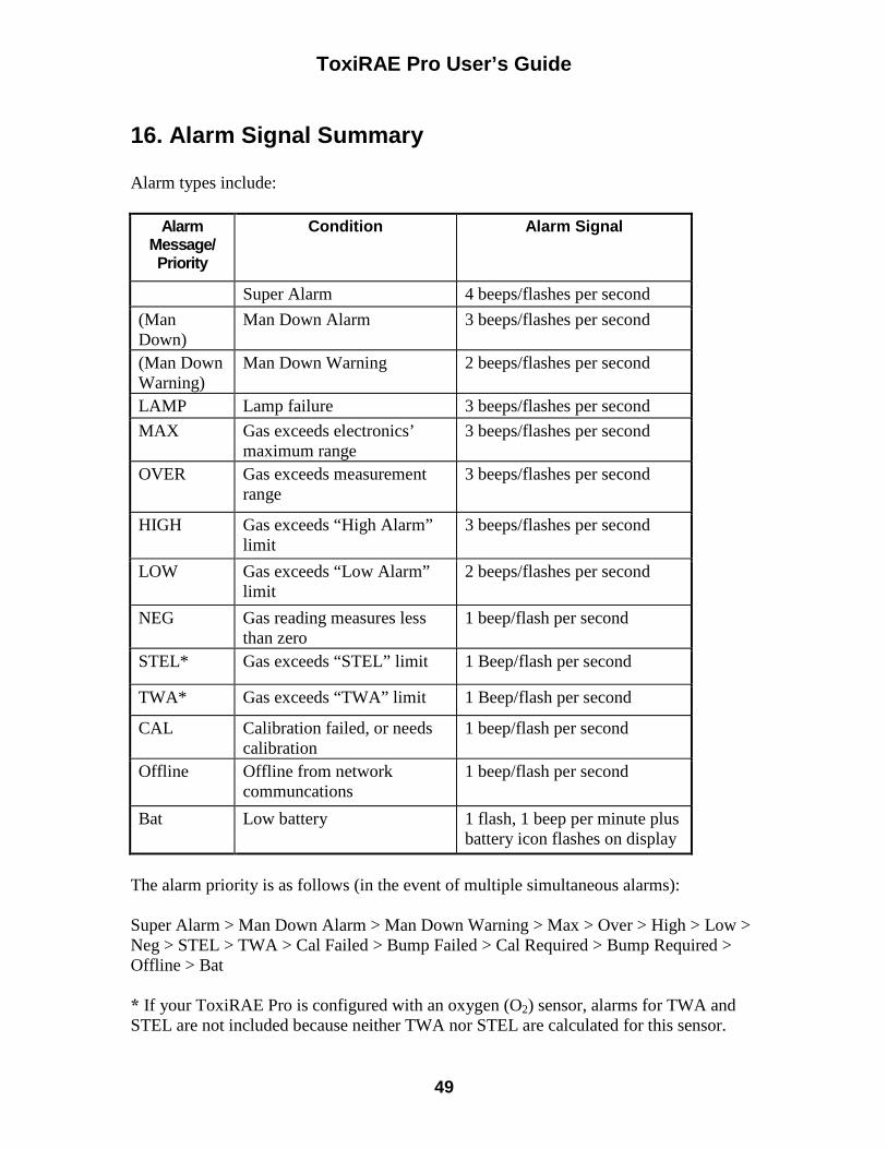
ToxiRAE Pro User’s Guide
49
16. Alarm Signal Summary Alarm types include:
Alarm Message/ Priority
Condition Alarm Signal
Super Alarm 4 beeps/flashes per second
(Man Down)
Man Down Alarm 3 beeps/flashes per second
(Man Down Warning)
Man Down Warning 2 beeps/flashes per second
LAMP Lamp failure 3 beeps/flashes per second
MAX Gas exceeds electronics’ maximum range
3 beeps/flashes per second
OVER Gas exceeds measurement range
3 beeps/flashes per second
HIGH Gas exceeds “High Alarm” limit
3 beeps/flashes per second
LOW Gas exceeds “Low Alarm” limit
2 beeps/flashes per second
NEG Gas reading measures less than zero
1 beep/flash per second
STEL* Gas exceeds “STEL” limit 1 Beep/flash per second
TWA* Gas exceeds “TWA” limit 1 Beep/flash per second
CAL Calibration failed, or needs calibration
1 beep/flash per second
Offline Offline from network communcations
1 beep/flash per second
Bat Low battery 1 flash, 1 beep per minute plus battery icon flashes on display
The alarm priority is as follows (in the event of multiple simultaneous alarms): Super Alarm > Man Down Alarm > Man Down Warning > Max > Over > High > Low > Neg > STEL > TWA > Cal Failed > Bump Failed > Cal Required > Bump Required > Offline > Bat * If your ToxiRAE Pro is configured with an oxygen (O2) sensor, alarms for TWA and STEL are not included because neither TWA nor STEL are calculated for this sensor.

ToxiRAE Pro User’s Guide
50
17. Downloading Datalogs And Performing PC-Based Instrument Configuration and Firmware Upgrades
The ToxiRAE Pro communicates with a PC running ProRAE Studio II Instrument Configuration and Data Management software (version 1.03 or higher) to download datalogs, configure the instrument, or upload new firmware. The ToxiRAE Pro must be connected to a PC through the supplied Charging / PC Communications Cradle and must be in the PC communications mode.
1. Make sure the Charging/PC Communications Cradle has power from its AC adapter (the LED on the front of the cradle should be illuminated).
2. Use the supplied PC Communications Cable (USB to mini-USB cable) to connect the Cradle to a PC.
3. Turn on the ToxiRAE Pro. Make sure it is running in Normal mode (with the main measurement screen with its reading showing).
4. Insert the ToxiRAE Pro in the cradle. 5. Activate the PC communications mode on the ToxiRAE Pro by pressing [MODE]
repeatedly, starting from the main measurement screen until you reach the “Enter PC Comm and stop measurement?” screen.
6. Press [Y/+]. Measurement and datalogging stop, and the instrument is now ready to communicate with the PC. The display now says “PC comm ready…”
7. Start up the ProRAE Studio II software, enter a password, and detect the instrument following the directions provided in the ProRAE Studio II User’s Manual.
8. Follow the instructions in the ProRAE Studio II User’s Manual to download the datalog, configure the instrument settings, or update the ToxiRAE Pro’s firmware.
9. When you are done, press [MODE] to exit the PC communications mode on the ToxiRAE Pro. The screen displays “Sensor initializing,” after which the instrument returns to operating in Normal mode.
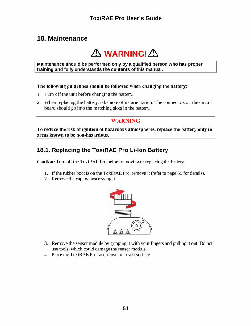
ToxiRAE Pro User’s Guide
51
18. Maintenance
WARNING! Maintenance should be performed only by a qualified person who has proper training and fully understands the contents of this manual.
The following guidelines should be followed when changing the battery: 1. Turn off the unit before changing the battery.
2. When replacing the battery, take note of its orientation. The connectors on the circuit board should go into the matching slots in the battery.
WARNING
To reduce the risk of ignition of hazardous atmospheres, replace the battery only in areas known to be non-hazardous. 18.1. Replacing the ToxiRAE Pro Li-Ion Battery Caution: Turn off the ToxiRAE Pro before removing or replacing the battery.
1. If the rubber boot is on the ToxiRAE Pro, remove it (refer to page 55 for details). 2. Remove the cap by unscrewing it.
3. Remove the sensor module by gripping it with your fingers and pulling it out. Do not use tools, which could damage the sensor module.
4. Place the ToxiRAE Pro face-down on a soft surface.
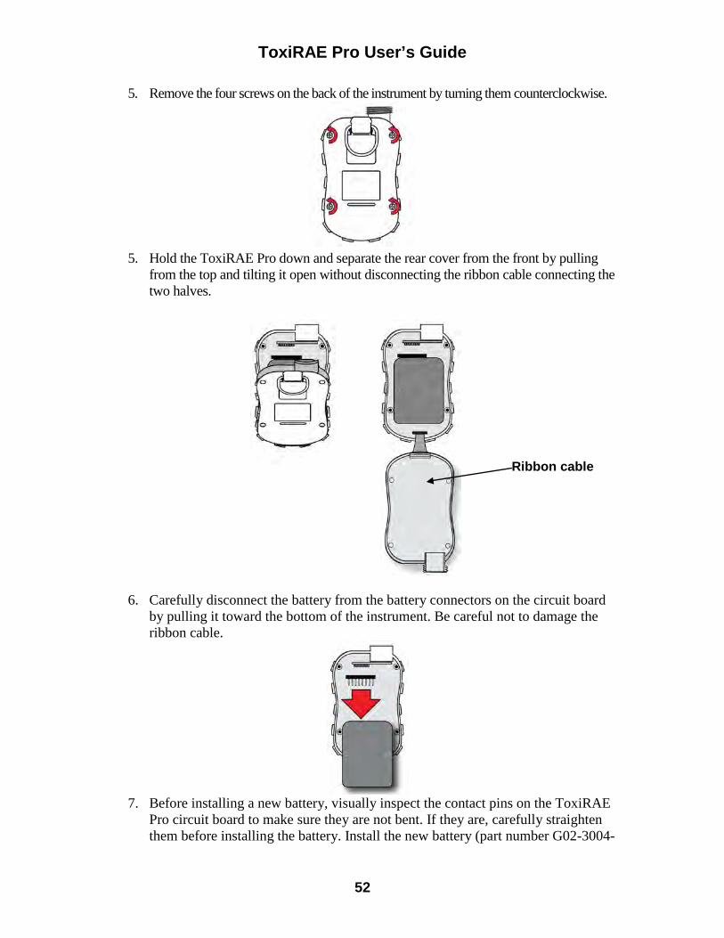
ToxiRAE Pro User’s Guide
52
5. Remove the four screws on the back of the instrument by turning them counterclockwise.
5. Hold the ToxiRAE Pro down and separate the rear cover from the front by pulling
from the top and tilting it open without disconnecting the ribbon cable connecting the two halves.
6. Carefully disconnect the battery from the battery connectors on the circuit board by pulling it toward the bottom of the instrument. Be careful not to damage the ribbon cable.
7. Before installing a new battery, visually inspect the contact pins on the ToxiRAE
Pro circuit board to make sure they are not bent. If they are, carefully straighten them before installing the battery. Install the new battery (part number G02-3004-
Ribbon cable
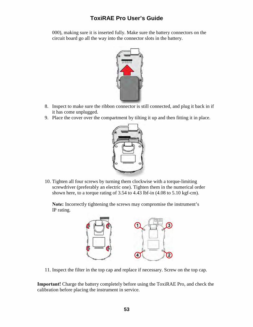
ToxiRAE Pro User’s Guide
53
000), making sure it is inserted fully. Make sure the battery connectors on the circuit board go all the way into the connector slots in the battery.
8. Inspect to make sure the ribbon connector is still connected, and plug it back in if
it has come unplugged. 9. Place the cover over the compartment by tilting it up and then fitting it in place.
10. Tighten all four screws by turning them clockwise with a torque-limiting
screwdriver (preferably an electric one). Tighten them in the numerical order shown here, to a torque rating of 3.54 to 4.43 lbf-in (4.08 to 5.10 kgf-cm).
Note: Incorrectly tightening the screws may compromise the instrument’s IP rating.
11. Inspect the filter in the top cap and replace if necessary. Screw on the top cap.
Important! Charge the battery completely before using the ToxiRAE Pro, and check the calibration before placing the instrument in service.
ToxiRAE Pro User’s Guide
54
18.2. Proper Battery Disposal
The Waste Electrical and Electronic Equipment (WEEE) directive (2002/96/EC) is intended to promote recycling of electrical and electronic equipment and their components at end of life. This symbol (crossed-out wheeled bin) indicates separate collection of waste electrical and electronic equipment in the EU countries. This product may contain one or more Nickel-metal hydride (NiMH), Lithium-ion, or Alkaline batteries. Specific battery information is given in this user guide. Batteries must be recycled or disposed of properly.
At the end of its life, this product must undergo separate collection and recycling from general or household waste. Please use the return and collection system available in your country for the disposal of this product. Sensor Specifications, Cross-Sensitivities, And Calibration Information For information on sensor specifications, cross-sensitivities, and calibration information, refer to RAE Systems Technical Note TN-114: Sensor Specifications And Cross-Sensitivities (available for free download from www.raesystems.com). All specifications presented in this Technical Note reflect the performance of standalone sensors. Actual sensor characteristics may differ when the sensor is installed in different instruments. As sensor performance may change over time, specifications provided are for brand-new sensors.
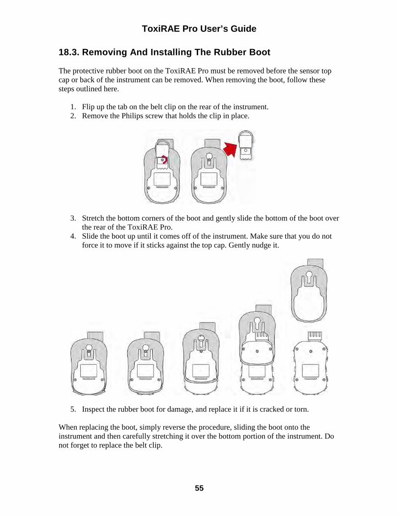
ToxiRAE Pro User’s Guide
55
18.3. Removing And Installing The Rubber Boot The protective rubber boot on the ToxiRAE Pro must be removed before the sensor top cap or back of the instrument can be removed. When removing the boot, follow these steps outlined here.
1. Flip up the tab on the belt clip on the rear of the instrument. 2. Remove the Philips screw that holds the clip in place.
3. Stretch the bottom corners of the boot and gently slide the bottom of the boot over the rear of the ToxiRAE Pro.
4. Slide the boot up until it comes off of the instrument. Make sure that you do not force it to move if it sticks against the top cap. Gently nudge it.
5. Inspect the rubber boot for damage, and replace it if it is cracked or torn. When replacing the boot, simply reverse the procedure, sliding the boot onto the instrument and then carefully stretching it over the bottom portion of the instrument. Do not forget to replace the belt clip.
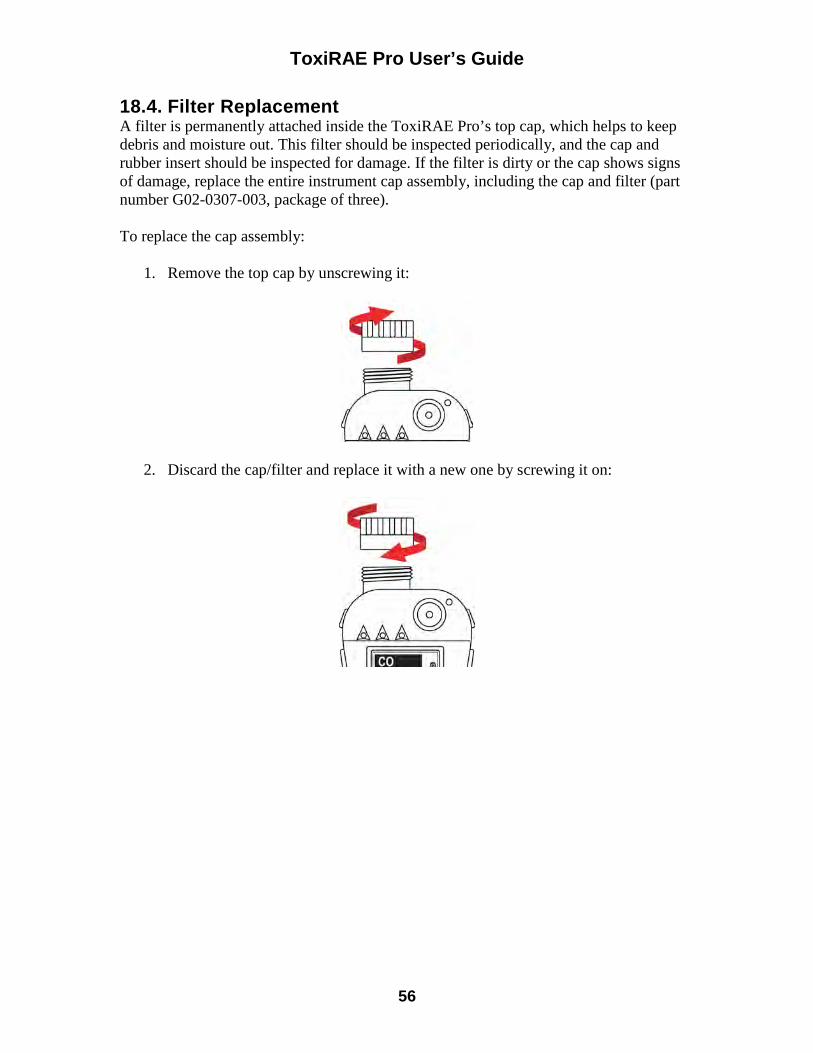
ToxiRAE Pro User’s Guide
56
18.4. Filter Replacement A filter is permanently attached inside the ToxiRAE Pro’s top cap, which helps to keep debris and moisture out. This filter should be inspected periodically, and the cap and rubber insert should be inspected for damage. If the filter is dirty or the cap shows signs of damage, replace the entire instrument cap assembly, including the cap and filter (part number G02-0307-003, package of three). To replace the cap assembly:
1. Remove the top cap by unscrewing it:
2. Discard the cap/filter and replace it with a new one by screwing it on:
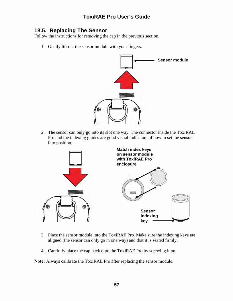
ToxiRAE Pro User’s Guide
57
18.5. Replacing The Sensor Follow the instructions for removing the cap in the previous section.
1. Gently lift out the sensor module with your fingers:
2. The sensor can only go into its slot one way. The connector inside the ToxiRAE Pro and the indexing guides are good visual indicators of how to set the sensor into position.
3. Place the sensor module into the ToxiRAE Pro. Make sure the indexing keys are aligned (the sensor can only go in one way) and that it is seated firmly.
4. Carefully place the cap back onto the ToxiRAE Pro by screwing it on.
Note: Always calibrate the ToxiRAE Pro after replacing the sensor module.
Sensor module
Match index keys on sensor module with ToxiRAE Pro enclosure
Sensor indexing key
ToxiRAE Pro User’s Guide
58
18.6. Cleaning The Exterior Occasional external cleaning of the instrument with a soft cloth is recommended. Do not use detergents or chemicals. If necessary, you can use a damp cloth (water only). It is a good idea to install the Calibration Adapter before cleaning the ToxiRAE Pro’s housing, to keep dirt, dust, or moisture away from the sensor openings and to keep the filter clean. Visually inspect the contacts at the base of the ToxiRAE Pro and on the charging cradle to make sure they are clean. If they are not, wipe them with a soft, dry cloth. Never use solvents or cleaners.
18.6.1. Ordering Replacement Parts If you need replacement parts, contact your local RAE Systems distributor. A list of authorized distributors is available online: http://www.raesystems.com
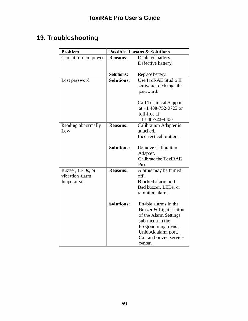
ToxiRAE Pro User’s Guide
59
19. Troubleshooting
Problem Possible Reasons & Solutions Cannot turn on power Reasons: Depleted battery.
Defective battery. Solutions: Replace battery.
Lost password Solutions: Use ProRAE Studio II software to change the password.
Call Technical Support
at +1 408-752-0723 or toll-free at +1 888-723-4800
Reading abnormally Low
Reasons: Calibration Adapter is attached. Incorrect calibration.
Solutions: Remove Calibration
Adapter. Calibrate the ToxiRAE Pro.
Buzzer, LEDs, or vibration alarm Inoperative
Reasons: Alarms may be turned off. Blocked alarm port. Bad buzzer, LEDs, or vibration alarm.
Solutions: Enable alarms in the
Buzzer & Light section of the Alarm Settings sub-menu in the Programming menu. Unblock alarm port. Call authorized service center.
ToxiRAE Pro User’s Guide
60
20. Technical Support To contact RAE Systems Technical Support Team: Monday through Friday, 7:00AM to 5:00PM Pacific (US) Time Phone (toll-free): +1 888-723-4800 Phone: +1 408-952-8461 Email: [email protected]
21. RAE Systems Contacts RAE Systems by Honeywell World Headquarters 3775 N. First St. San Jose, CA 95134-1708 USA Phone: +1 408.952.8200 Fax: +1 408.952.8480 E-mail: [email protected] Web Site: www.raesystems.com RAE Systems Technical Support Monday through Friday, 7:00AM to 5:00PM Pacific Time Phone: +1.408.952.8461 Email: [email protected] RAE Systems Europe ApS Kirstinehøj 23 A DK-2770 Kastrup Denmark Phone: +45 86 52 51 55 Fax: +45 86 52 51 77 [email protected] [email protected] [email protected] Web: www.raesystems.eu RAE Systems UK Ltd D5 Culham Innovation Centre Culham Science Centre Abingdon, Oxon OX14 3DB United Kingdom Phone: +44 1865408368 Fax: +44 1235531119
ToxiRAE Pro User’s Guide
61
Mobile: +44 7841362693 Email: [email protected] RAE Systems France ZI des Ayats 679390 MILLERY France Phone: +33 4 78 46 16 65 Fax: +33 4 78 46 25 98 Email: [email protected] Web: www.raesystems.fr RAE BeNeLux BV Hoofdweg 34C 2908 LC Capelle a/d IJssel The Netherlands Phone: +31 10 4426149 Fax: +31 10 4426148 Email: [email protected] Web: www.rae.nl RAE Systems Spain, s.l. Av. Remolar, 31 08820 El Prat de Llobregat Spain Phone: +34 933 788 352 Fax: +34 933 788 353 Mobile: +34 687 491 106 Email: [email protected] Web: www.raespain.com
RAE Middle East LOB 7, Ground Floor, Office 19, Jebel Ali Free Zone Dubai, United Arab Emirates Phone: +971.4.887.5562 Email: [email protected]
ToxiRAE Pro User’s Guide
62
RAE Systems (Hong Kong) Ltd. Room 8, 6/F, Hong Leong Plaza 33 Lok Yip Road Fanling, N.T, Hong Kong Phone: +852.2669.0828 Fax: +852.2669.0803 Email: [email protected]
RAE Systems Japan 403 Plaza Ochanomizu Bldg. 2-1 Surugadai Kanda Chiyoda-Ku Tokyo, Japan Phone: 81-3-5283-3268 Fax: 81-3-5283-3275 Email: [email protected]
RAE Systems Korea #1010, DaeMyungAnsVill First, Sang-Dong 412-2, Wonmi-Gu, Bucheon, Kyungki-Do, Korea Phone: 82-32-328-7123 Fax: 82-32-328-7127 Email: [email protected]

ToxiRAE Pro User’s Guide
63
22. Appendix A: Regulatory Information SAFETY INSTRUCTIONS
Read Before Operating
This manual must be carefully read by all individuals who have or will have the responsibility of using, maintaining, or servicing this product. The product will perform as designed only if it is used, maintained, and serviced in accordance with the manufacturer’s instructions. The user should understand how to set the correct parameters and interpret the obtained results.
CAUTION! Only use RAE Systems battery pack P/N: G02-3004-000 Do only charge the battery pack using RAE Systems charger outside hazardous area. Use of non-RAE Systems components will void the warranty and can compromise the safe performance of this product. Warning: Substitution of components may impair intrinsic safety. ToxiRAE Pro Marking The ToxiRAE Pro is certified according to the IECEx scheme, ATEX and CSA for US and Canada as protected by intrinsic safety. The ToxiRAE Pro is marked with the following information: RAE SYSTEMS 3775 N. 1st. St., San Jose CA 95134, USA ToxiRAE Pro Type PGM-1860. Serial No/barcode: XXXX-XXXX-XX
IECEx SIR 10.0096X Ex ia IIC T4 Ga
0575 II 1G SIRA 10 ATEX 2189X Ex ia IIC T4 Ga
2010 2360054 I.S. for Cl.I Dv 1, Grps A,B,C,D T-Code T4. Class I, Zone 0 A/Exia IIC T4 Only as to intrinsic safety for use in hazardous loc. Intrinsically safe/ Securite Intrinseque/Exia
-20º C < Tamb < +55º C; Um: 20V Battery pack: G02-3004-000 Warning: Read User’s Manual for Intrinsic Safety Precautions Warning: Substitution of components may impact intrinsically safety
ToxiRAE Pro User’s Guide
64
Operation Area and Conditions Hazardous Areas classified by Zones ToxiRAE Pro (PGM1860) are intended to be used in hazardous areas classified zone 0, zone 1 or zone 2, where gases of explosion groups IIA, IIB or IIC and T4 may be present. For North America and Canada the equipment can further be used in Class I, Zone 0. Hazardous Areas classified by Divisions ToxiRAE Pro is intended to be used in hazardous areas classified for Class I Div. 1 or 2, within the temperature range of -20º C to +55º C, where gases of explosion groups A, B, C or D and temperature code T4 may be present. Instruction For Safe Use Strictly follow the instructions for safe use. Application of the ToxiRAE Pro requires full understanding and strict observation of the instructions. Only use RAE Systems battery pack P/N: G02-3004-000 Do only charge the battery pack using RAE Systems charger outside hazardous area (Um: 20V). Use In Hazardous Areas Equipment which is intended for use in explosive atmospheres and which has been assessed and certified according to international regulations may be used only under specified conditions. The components may not be modified in any way. The appropriate regulations for service and repair must be properly observed during such activities.
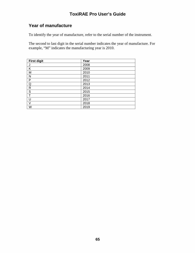
ToxiRAE Pro User’s Guide
65
Year of manufacture To identify the year of manufacture, refer to the serial number of the instrument. The second to last digit in the serial number indicates the year of manufacture. For example, “M” indicates the manufacturing year is 2010.
First digit Year J 2008 K 2009 M 2010 N 2011 P 2012 Q 2013 R 2014 S 2015 T 2016 U 2017 V 2018 W 2019

RAE Systems by Honeywell World Headquarters
3775 N. First St. San Jose, CA 95134-1708 USA
Phone: 408.952.8200 Fax: 408.952.8480
E-mail: [email protected]
Web Site: www.raesystems.com
P/N G02-4009-000 Rev. C March 2013
About AECOM With nearly 100,000 employees — including architects, engineers, designers, planners, scientists and management and construction services professionals — serving clients in more than 150 countries around the world following the acquisition of URS, AECOM is a premier, fully integrated infrastructure and support services firm. AECOM is ranked as the #1 engineering design firm by revenue in Engineering News-Record magazine’s annual industry rankings. The company is a leader in all of the key markets that it serves, including transportation, facilities, environmental, energy, oil and gas, water, high-rise buildings and government. AECOM provides a blend of global reach, local knowledge, innovation and technical excellence in delivering solutions that create, enhance and sustain the world’s built, natural and social environments. A Fortune 500 company, AECOM companies, including URS Corporation and Hunt Construction Group, had revenue of approximately $19.5 billion during the 12 months ended Sept. 30, 2014. More information on AECOM and its services can be found at www.aecom.com.
AECOM 701 Corporate Center Drive, Suite 475 Raleigh, North Carolina 27607 T: +1.919.854.6200 F: +1.919.854.6259


![North Carolina register [serial] - NC.gov](https://static.fdokumen.com/doc/165x107/6327f539e491bcb36c0b8a23/north-carolina-register-serial-ncgov.jpg)