Object-Oriented Technology Transfer to Multiprocessor System-Level Synthesis
10
Object-Oriented Technology Transfer to Multiprocessor System-Level Synthesis Pao-Ann Hsiung Institute of Information Science Academia Sinica, Taipei, Taiwan. Trong-Yen Lee and Sao-Jie Chen Department of Electrical Engineering National Taiwan University, Taipei, Taiwan. Abstract Technology transfers between software and hardware engineering date back to a decade and a half. Object- oriented technology from software engineering is one such successful transfer to hardware design. There is a natural correspondence between object-oriented con- cepts and hardware design. The work presented in this paper extends the basic application of object-oriented technology to system-level synthesis such that not only system modeling uses object-oriented technology, but the synthesis process itself is object-oriented. The basic object-oriented structures required for synthesis are de- fined. How designs can be reused by storing them in a design database and then retrieving them is explained. A simple implementation along with application example il- lustrate how object-oriented technology increases compo- nent design manageability, enforces synthesis efficiency, and saves design time and effort through the reuse of com- plete subsystems. 1 Introduction One successful technology transfer from software en- gineering to hardware design is the object-oriented (OO) design paradigm which first manifested itself in the form of system decomposition into modules, information hid- ing [Parnas 72], and program families [Parnas 76]. This success can be attributed to the natural concept of per- ceiving a hardware component as an individual class with characteristics and operations [Kumar 94]. In fact, we This research was supported by the National Science Coun- cil, Taipei, Taiwan under grant NSC 86-2221-E002-066. believe that the decomposition of a system into objects is better defined and more explicit in hardware than in software because a hardware system can be easily de- composed into components, while conventional software programs are often structured using procedures that are more control-oriented rather than object-oriented. As pointed out by Smith et al. [Smith 86]: “Parnas’ con- cepts of information hiding and design families may contribute to reducing the cost of design development and maintenance,” which was technically proved by the recently proposed Performance Synthesis Methodology (PSM) [Hsiung 96], an object-oriented system-level de- sign methodology for multiprocessor (MP) systems. System-level synthesis is the process of automatic transformation from a set of system specifications in- cluding architectural and performance requirements into a high-level architecture consisting of a description of the various components such as processors, memory, and the number of each component used. For example, the MI- CON system [Birmingham 89, Gupta 93], uses a hierar- chical select-and-interconnect methodology for system- level synthesis. System-level synthesis uses off-the-shelf building blocks [Tobias 81], which are similar to reusable library components in software engineering. These build- ing blocks can be modeled as classes of objects and then hierarchically classified based on the relationships be- tween the classes. In MICON, the parts from the compo- nent library are abstracted and organized into a functional hierarchy which is a directed, acyclic graph, leaf-nodes correspond to available physical parts and internal nodes are abstract parts. Several concepts of object-oriented design in software engineering can be applied to hardware synthesis. Some important concepts are described below. In the following, we assume that a class is an individual entity as in the OO technology and it contains attributes which may be data members or function members.
Transcript of Object-Oriented Technology Transfer to Multiprocessor System-Level Synthesis

Object-Oriented Technology Transfer to Multiprocessor System-LevelSynthesisy
Pao-Ann HsiungInstitute of Information Science
Academia Sinica, Taipei, Taiwan.
Trong-Yen Lee and Sao-Jie ChenDepartment of Electrical Engineering
National Taiwan University, Taipei, Taiwan.
Abstract
Technology transfers between software and hardwareengineering date back to a decade and a half. Object-oriented technology from software engineering is onesuch successful transfer to hardware design. There isa natural correspondence between object-oriented con-cepts and hardware design. The work presented in thispaper extends the basic application of object-orientedtechnology to system-level synthesis such that not onlysystem modeling uses object-oriented technology, but thesynthesis process itself is object-oriented. The basicobject-oriented structures required for synthesis are de-fined. How designs can be reused by storing them in adesign database and then retrieving them is explained. Asimple implementation along with application example il-lustrate how object-oriented technology increases compo-nent design manageability, enforces synthesis efficiency,and saves design time and effort through the reuse of com-plete subsystems.
1 Introduction
One successful technology transfer from software en-gineering to hardware design is theobject-oriented(OO)design paradigmwhich first manifested itself in the formof system decomposition into modules, information hid-ing [Parnas 72], and program families [Parnas 76]. Thissuccess can be attributed to the natural concept of per-ceiving a hardware component as an individual class withcharacteristics and operations [Kumar 94]. In fact, weyThis research was supported by the National Science Coun-cil, Taipei, Taiwan under grant NSC 86-2221-E002-066.
believe that the decomposition of a system into objectsis better defined and more explicit in hardware than insoftware because a hardware system can be easily de-composed into components, while conventional softwareprograms are often structured using procedures that aremore control-orientedrather thanobject-oriented. Aspointed out by Smith et al. [Smith 86]: “Parnas’ con-cepts of information hiding and design families maycontribute to reducing the cost of design developmentand maintenance,” which was technically proved by therecently proposedPerformance Synthesis Methodology(PSM) [Hsiung 96], an object-oriented system-level de-sign methodology for multiprocessor (MP) systems.
System-level synthesis is the process of automatictransformation from a set of system specifications in-cluding architectural and performance requirements intoa high-level architecture consisting of a description of thevarious components such as processors, memory, and thenumber of each component used. For example, the MI-CON system [Birmingham 89, Gupta 93], uses ahierar-chical select-and-interconnectmethodology for system-level synthesis. System-level synthesis usesoff-the-shelfbuilding blocks[Tobias 81], which are similar to reusablelibrary components in software engineering. These build-ing blocks can be modeled as classes of objects and thenhierarchically classified based on the relationships be-tween the classes. In MICON, the parts from the compo-nent library are abstracted and organized into a functionalhierarchy which is a directed, acyclic graph, leaf-nodescorrespond to available physical parts and internal nodesare abstract parts.1.1 Object-Oriented Technology andHardware Design
Several concepts of object-oriented design in softwareengineering can be applied to hardware synthesis. Someimportant concepts are described below. In the following,we assume that a class is an individual entity as in the OOtechnology and it contains attributes which may be datamembers or function members.

1. Class Encapsulation: Parnas’ concept of informa-tion hiding or encapsulation tries to hide the por-tion of design that is likely to change in the futureby modularization and restricting access to the in-ternal structure through specific functions. This issimilar to a hardware module, the internal archi-tecture of which is hidden from the other modules,and access to the module is limited to interactionsthrough interfaces or pins. The data members ofa class can be used to model the static characteris-tics and dynamic states of a hardware component.Similarly, the function members of a class can beused to describe the pins and module interactionsof a hardware component. For example, a DECAlpha-21064 processor can be modeled as a CPUclass with attributes specifying its clock speed, in-ternal cache size, etc. and functions for memoryread, memory write, etc.
2. Class Inheritance: Inheritance is a form of attributepropagation from one class to another by virtueof some kind of ancestor-descendent relationship.Though this concept was introduced in the object-oriented technology, yet it has been used by hard-ware designers since a long time. Hardware mod-ules of the same type or functionality often differin only a few aspects either structurally or behav-iorally. For example, the hypercube interconnnec-tion network and the mesh network are structurallydifferent, but they are both designed for data trans-fer or communication; thus they have some com-mon attributes such as the data transfer speed, thebandwidth, and the function of transmitting dataacross the network using some routing scheme. In-heritance thus avoids the undesired replication ofcomponent information and allow quick transfor-mation from existing classes to classes of new com-ponents.
3. Class Instances or Objects: The instantiation of aclass involves a valuation of its data attributes suchthat after each attribute is assigned a specific value,we will have a class instance or object. Differ-ent valuations lead to different objects. This cor-responds to the physical components that are avail-able for system design. For example, assigning dif-ferent values to the CPU clock cycle speed, we ob-tain different versions of the same type of CPU,that is Pentium-150, Pentium-166, and Pentium-200 with 150 MHz, 166 MHz, and 200 MHz clockcycles, respectively. Instantiation of a class is thusquite important in system-level synthesis as it is thefinal implementation step in the design flow.
4. Class Relationships: Two classes may be relatedby a relationship such asaggregation(assembly-component),generalization(superclass-subclass),anddependence(association). In the hardware per-
spective, aggregation corresponds to the composi-tion of sub-parts into a larger module, which iswhat designers do when creating a 64-bit adderfrom two 32-bit adders or constructing a process-ing subsystem from several CPUs, a local intercon-nection network, and some memory modules. Gen-eralization corresponds to the functional classifica-tion of hardware components. For example, Pow-erPC, Alpha, MIPS, SuperSPARC, and Pentium areall processors which are classified as subclasses ofthe moregeneralizedclass CPU. Dependence isrelated to how a particular component depends onanother component for mutual interactions and syn-chronizations. All the above relationships are use-ful guidelinesfor automatic design.
5. Hierarchical Structure of Design Families: Basedon class relationships, a hierarchy of classes can beconstructed. For example, a parallel computer de-sign is an aggregation of a memory subsystem, asystem interconnection network, and a processingsubsystem, all of which may further be an aggre-gation or generalization of other component partsmodeled as classes. This hierarchy represents areusable and useful library of components that canbe used for synthesis.
Section 2 lists some previous related work. A morecomplete account of how a system can be modeled usingobject-oriented techniques is presented in Section 3. Sec-tion 4 describes the manipulation of designs, their reuse,basic object-oriented structures used in system-level syn-thesis, and how designs are stored, retrieved, and reusedfrom a design database. Section 5 illustrates the imple-mentation of our concepts and the application of OO tech-niques. Section 6 concludes the paper with some futurework.
2 Previous Related Work
Modularization in VLSI design date back to 1983,when a research group called VMOD (Modular VLSI)[Brooks 84] explored the similarities and dissimilaritiesbetween the techniques of software engineering and hard-ware design. The group concluded that despite their cer-tain dissimilarities, two concepts of software change man-agement, namely Parnas’ information hiding and familiesof design could profitably be extended to VLSI design.This triggered researches in the application of modular-ization to VLSI design such as the Software Cost Reduc-tion (SCR) project [Parnas 85], Gross’ abstract interfacespecification of VLSI designs [Gross 85], and ADAS,a software/hardware codesign tool [Frank 85]. Besidesthese earlier work, only recently has this field of re-search gained attention again. OO is now being incorpo-rated into hardware description language such as VHDL
[Chung 90]. By making use of a behavioral hierarchy,some system-level synthesis specification languages suchas SpecCharts [Narayan 92] also have the flavor of the OOtechnology. MICON Synthesizer Version 1 [Gupta 93]uses a functional hierarchy for system-level design au-tomation. OO has also been combined with formal mod-eling techniques such as Petri Nets for system modeling[Lee 93] and synthesis [Hsiung 97].
Although researches on the application of OO tech-nology to hardware design have been going on and offsince the 1980’s, yet only recently an actual system-level synthesis methodology, calledPerformance Synthe-sis Methodology(PSM) [Hsiung 96], based on OO tech-niques was proposed. Following this, OO has also beenused recently in the formal modeling of the system-levelsynthesis methodology resulting in an extended high-level Petri Net calledMulti-token Object-oriented Bi-directional net(MOBnet) [Hsiung 97]. These recent pro-gresses show that efforts in this promising direction willbe quite fruitful in the near future.
3 Object-Oriented System Model
Having gone through the natural correspondence be-tween object-oriented concepts and hardware design,which are quite advantageous for system-level synthe-sis, we present a more detailed scheme of using the OOtechniques for system-level synthesis in this section. OOstructure, relationships, and operators are presented in thefollowing three subsections.3.1 Object-Oriented Structure
As far as notations and terminologies are concerned,we basically follow Rumbaugh’sObject Modeling Tech-nique (OMT) [Rumbaugh 91] which makes a clear dis-tinction among the object model, the dynamic model, andthe functional model. By modeling each component, ei-ther abstract or physical, as a class with relationships toother classes, aClass Hierarchy(CH) can be constructed,which is similar to Parnas’ hierarchical structure of designfamilies and Rumbaugh’s Object Model in OMT. We dis-tinguish the classes representing components into threekinds of nodes, namelyAggregate node(A-node),Gener-alized node(G-node), andPhysical node(P-node). Thisdistinction is made based on the relationship a class haswith its child classes, if any. An aggregate node is an as-sembly class representing something which is thewholein a “whole-part” relationship. A generalized node is asuperclass which is the parent in an “is-a” relationship. Aphysical node is a leaf node in the Class Hierarchy andrepresents some available physical component that can beused directly for design. This classification of classes intothree kinds of nodes allows easy selection of appropriate
design actions at each node which will be discussed insubsection 3.3.
A generic class has attributes including data membersand function members. We classify the data members ofa class intospecifications, pre-design characteristics, andpost-design characteristics, where a specification is a re-quirement, it may be a relation between several charac-teristics, a pre-design characteristic is one whose value isknown before design and a post-design characteristic isone whose value is known only after design. Some func-tion members are discussed in subsection 3.3.3.2 Object-Oriented Relationships
Three kinds of relationships serve as guidelines for de-sign automation, namelyaggregation, generalization, anddependence. Aggregation denotes the “whole/part” rela-tionship in which a component class is a “part-of” a classrepresenting the whole assembly. Generalization denotesthe relationship between a class and its one or more re-fined versions. The class being refined is called thesu-perclassand its refined versions are calledsubclasses. Of-ten the design characteristics of two adjacently-connectedcomponents in an MP system are interrelated such thatthe synthesis of one affects the other. This relationshipis modeled as the dependence relationship. Dependenceis further classified intoabsoluteandrelative. Absolutedependence is a dependence between thespecificationofone component and thepost-design characteristicof an-other component such that the former component mustwait for the latter to be completely synthesized before itcan begin synthesis. Relative dependence is a dependencebetween thespecificationsof two components such thatthe synthesis is possible only when the dependent spec-ification of the component to be synthesized has a valueassigned by querying the other component. An absolutedependence between the components restricts the orderin which the components are to be synthesized, whereasa relative dependence places no such restriction. For ex-ample, a Memory class is said to be absolutely dependenton a CPU class because the memory access time (m) canbe expressed in terms of the processor cycle time (p) asm = k�p, wherek is a constant and it is assumed thatmis a specification andp a post-design characteristic. Fur-ther, a Cluster Control Unit (CCU) and a System Inter-connect (SI) are relatively dependent because the CCUdata transfer rate(dCCU) and the SIdata transfer rate(dSI) are related asdSI = c� dCCU, wherec is a constantand it is assumed that bothdSI anddCCU are the requiredspecifications.
Each type of relationship allows us to perform differentsynthesis actions, thus the synthesis process is guided bythe relationships. When encountered with an aggregationrelationship, the class which is an aggregation of otherclasses can be synthesized by composing one or more in-

stances of its child classes. When a generalization rela-tionship is reached, the superclass representing a gener-alization of sub-classes can be implemented by selectingone or more of its child classes. This is the design-spaceexploration step in system-level synthesis. On encoun-tering a dependence relationship, a class checks with theclasses having dependence relationships with it to requestfor or submit data values before any other synthesis ac-tions are taken. Thus, the dependence relationship has thehighest priority among all relationships that a class mayhave with other classes. When it is an absolute depen-dence, that is, if a classA is absolutely dependent on aclassB, then classA must wait for the design completionof classB before classA can begin synthesis. When it isa relative dependence, that is, if classA is relatively de-pendent on a classB, then classA need not wait for classB, but it must have all its specification values assigned byquerying classB before classA can begin synthesis. Itis this kind of relationship that allows an object-orientedsynthesis system to design more than one component atthe same time, i.e. concurrent synthesis. An exampleof concurrent system-level synthesis isIntelligent Con-current Object-Oriented Synthesis(ICOS) methodology[Hsiung].3.3 Object-Oriented Operators
As mentioned in the previous subsections, differenttypes of classes and relationships allow different syn-thesis actions, we use object-oriented operators to rep-resent these actions. The target of these operations arethe classes in the Class Hierarchy. There are three op-erators, namelyiterator, generator, and updator corre-sponding to the three relationships aggregation, general-ization, and dependence, respectively. Fig. 1 shows thecorrespondence between object-oriented structure, rela-tionships, operators, and synthesis actions.
Object-OrientedStructure
dependent classes
A-node
G-node
assemblyclass
componentclasses
superclass
subclasses
Object-OrientedRelationship
aggregation synthesis
generalizationdesign spaceexploration
dependence
Synthesis Action
Object-OrientedOperator
iterator
generator
updator spec update
Figure 1. OO Structure, Relationships, Op-erators, and Synthesis Actions
“Iterator” is the actual synthesis operator, it is used atan A-node for synthesizing this aggregate class of com-ponents. Based on the specifications satisfaction of an
A-node, the iteratoriteratesthrough its child classes se-lecting some of them to be interconnected into the aggre-gate.
“Generator” is the design-space exploration operator,it is used at a G-node for implementing this generalizedclass of components. Based on the specifications satis-faction of a G-node, the generatorgeneratesa sequenceof classes ordered in the preference of their feasibility inimplementing the G-node. This order of feasibility pref-erence may be a simple cost-based heuristic as in PSM[Hsiung 96] or a fuzzy comparison of specifications as inICOS [Hsiung].
“Updator” is the query operator since its main job isto query others for specification values. This operator isquite essential for hardware consistency and feasible inte-gration. The updator operator is used by a class wheneverit has a dependence relationship with another class.3.4 Class Hierarchy
The above object-oriented structure dealt with how acomponent can be modeled as a class and how classes aredivided into three types; object-oriented relationships de-scribed how classes may be related and how relationshipsbe used to guide synthesis; and object-oriented operatorsdescribed what kinds of actions can be taken at differ-ent nodes. By modeling all the components of a systemas classes, we are thus able to construct a hierarchy ofclasses calledClass Hierarchy, where classes are inter-related by the object-oriented relationships. This hierar-chy is usually constructed apriori just like how a softwarelibrary is constructed for future use. An example of ClassHierarchy for a hierarchical parallel computer system isgiven in Fig. 2. The purpose of this hierarchy is to serveas a framework in which synthesis proceeds. The mainconcept of object-oriented synthesis can be briefly definedas follows: “Starting from the root node of a Class Hier-archy, which represents the computer system to be de-signed, wetraversedown the hierarchy using class rela-tionships as guidelines, choosing appropriate operators ateach node, performing corresponding actions, and synthe-sizing or implementing components along the hierarchy.”
4 Design Manipulation and Reuse
Given a Class Hierarchy representing the static struc-ture of a target machine, this section discusses how thevarious component designs represented by classes in thehierarchy can be manipulated dynamically during synthe-sis. An important concept of object-oriented technology,namelyclass reuse, is technically applied to hardware de-sign such that complete subsystems can be reused, thussaving design cost, time, and effort.
Design manipulation and reuse in an object-orientedenvironment is best discussed within the framework of

MemorySubsystem
SystemInterconnect
ProcessingSubsystem
ComputerSystem
Global ControlUnit
MainMemory
CacheMemory
Primary
Secondary
GloballlyShared
DistributedShared
GloballyDistributed
DistributedUnshared
SharedBus
MIN Cube ProcessorCluster
CCU LI SI InterfacePE
Scheduler I/O Intf. Buffer
Shared Bus MIN RISC CISCCube
Processor Local Memory
Cache RAM
I/OProcessor
I/OInterface
CCUInterface
A-node
G-node
P-node
MemoryController
Priority Time
Figure 2. Class Hierarchy
an actual system-level synthesis methodology. We useIntelligent Concurrent Object-Oriented Synthesis(ICOS)methodology [Hsiung], a newly proposed methodologyfor the synthesis of multiprocessor systems, which is dis-cussed briefly as follows. ICOS works in a fully object-oriented environment. As shown in Fig. 3, its main phasesareSpecification Analysis, Concurrent Design, andSys-tem Integration.
An ICOS designer inputs system-level specificationssuch as the type of processor, the memory organization,and the system interconnection scheme. After goingthrough the three design phases, ICOS outputs a synthe-sized MP consisting of system-level architecture descrip-tions. ICOS methodology uses several techniques includ-ing object-oriented modeling, design reuse through intel-ligent learning, fuzzy design-space exploration, and con-current synthesis to make the synthesis process more ef-ficient and feasible. As shown in Fig. 4, the main phase,namely Concurrent Design, is further divided into foursteps:specification update, component reuse by learning,component synthesis, anddesign storing.
When a designer is synthesizing a system using ICOS,the OO design environment must provide certain struc-tures for the methodology to use for dynamically manip-ulating the classes, instead of only referring to a staticClass Hierarchy. In this paper, we assume theconcur-
rentsynthesis scheme similar to that in ICOS, where morethan one component can undergo synthesis at the sametime. Concurrently synthesized components can com-municate specifications through the dependence relation-ships in CH. Besides CH, the OO design environmentmust be able to globally maintain a structure to broadcastthe current design status so that components that are con-currently undergoing synthesis may know exactly whatthe current design status is. Such a broadcast structure istheDesign Hierarchyas described in subsection 4.1. TheOO environment must also provide a sequencer for com-ponents to be designed, so that the synthesis methodologyknows which is the “next” component to begin synthe-sis. This is implemented as a queue structure called theDesign Queueas described in subsection 4.2. Anotherstructure that must be implemented in an OO design en-vironment is the design database used for design reuse.This is called theLearning Hierarchy(LH) and describedin subsection 4.4.4.1 Design Hierarchy
In order to keep track of all the design alternativesgenerated during synthesis, a hierarchy of currently syn-thesized classes, calledDesign Hierarchy(DH), is main-tained. It is animplementationof the Class Hierarchy, that

(3)
OODSM
Architecture specs
Performance specs
Synthesis specs
Specification Input
Specification Analysis
Class Hierarchy
SpecificationError?
Yes
Initiali zation:
AddDH(root), AppendDQ(root)
PopDQ
Component
Design ...DQempty?
No
No
No
No
Yes
rollbackpossible?
design
complete?
Yes
Yes
SynthesisRollback
Simulation andPerformanceEvaluation
Output BestArchitecture
Error: SynthesisImpossible
Component
Design
Component
Design
Component
Design
(2)
(1)
(1) Specification Analysis Phase (2) Concurrent Design Phase (3) System Integration Phase
Stop
Figure 3. ICOS Design Flow
is classes in CH are substituted byreal designs with spec-ifications. For example, Fig. 5 depicts a completed designalternative consisting of a shared-memory multiproces-sor architecture with 1024 processors interconnected bya generalized-cube multistage interconnection network,and 8 GB of main memory. Besides representing the cur-rent state of synthesis, it may be used for various otherpurposes.
1. Information Query: When a component under de-sign needs information related to the current designarchitecture, they can be answered by refering toDH. For example, an inquiry could be: “Is the cur-rent design using any secondary level cache?”
2. Synthesis Rollback: There may arise a situation inconcurrent synthesis where a particular componentcannot be synthesized under the currently derivedspecifications, at this point of synthesis, a rollbackof design steps could possibly alter or re-designsome previously designed components such that thespecifications related to the unsynthesizable com-ponent are relaxed and synthesis can proceed fur-ther. Rollback may also propagate from an unsyn-thesizable component upwards in the Design Hier-archy.
3. Design Completion Check: Design Hierarchy canalso indicate when a design alternative is completefor further processing such as simulation and per-
ClassHierarchy
(CH)
design storing
component synthesis
component reuse bylearning
specification update
node_type
Yes
No
A-node/P-node
G-node
learning successful?
ComponentDesign
end
LearningHierarchy
(LH)
Figure 4. ICOS Concurrent Component De-sign Phase
formance evaluation.
MemorySubsystem
SystemInterconnect
ProcessingSubsystem
ComputerSystem
Global ControlUnit
CubeMIN Cluster
No. = 8
GCUPSSSIMSS
CS
PE
No. = 128
SI IntfLICCU
Bus
Main Memory
Size = 8 GB
Figure 5. Design Hierarchy4.2 Design QueueDesign Hierarchy stores the components which have
already been synthesized, but there is a stage in the designlife-cycle where a component is already selected orreadyfor synthesis, but has to wait for its turn. At this stage, weneed a queue structure that holds the components whichare ready for synthesis. We call such a queue structureDesign Queue (DQ). After removing an A-node from thefront of the queue, it is synthesized into several compo-nent classes which have then to be appended to DQ. Af-ter removing a G-node from the front of the queue, it isimplemented into one or more specialized classes whichhave then to be appended to DQ. Whenever a P-node re-

sults from some component synthesis process, it is notappended to the queue, but instead it is instantiated intoactual physical instances.4.3 Design State
DH and DQ are global structures visible to all com-ponents. When a component is in DH or DQ, it is sup-posed to be in a “passive” state and when it is outsidethese structures, it is in an “active” state. The reason fordistinguishing between passive and active states mainlylies in the fact that a component represented by a classremains in anidle condition in DH or DQ, whereas itactively seeksto synthesize itself using appropriate op-erators and relationships as guidelines while outside DHor DQ. Figure 6 illustrates how a component can transitfrom passive to active and then back to a passive state.While active, a component first updates whatever speci-fications are needed, then it tries to reuse previously de-signed components. If no such components exists, it goeson to synthesize itself. At this point, it may encountera deadlock situation where it cannot complete synthesisdue to some unsatisfiable specification, it enters a rollbackstate which leads to the earlier specification update state.If a component is reused or synthesized successfully, itenters DH and remains in the passive state.
queued inDQ
(Passive)
remove from DQ
specificationupdate(Active)
componentreuse
(Active)
componentsynthesis(Active)
synthesisrollback(Active)
synthesized(Passive)
A-node/P-node
G-node
synthesisdeadlock
reuse successful
reuse notsuccessful
Figure 6. State Transition Diagram of aClass4.4 Design ReuseClass “reuse” in the object-oriented technology often
means how undesired replication is avoided through the
repetitive use of the same class. In this paper, reuse is dis-tinguished into two kinds:currentreuse andfuturereuse.Current reuse is defined as the repeated use of a class forthe same design in the current synthesis. For example, ahierarchical parallel computer architecture consisting of agroup of processor clusters, may have memory bothlo-cally in each cluster as well asglobally in the system;hence the Memory class can be reused for cluster andsystem by just re-assigning some attribute values suchas the memory size. Future reuse is defined as the stor-ing of a synthesized component in some design databasefor retrieval and use in future syntheses. For example,when a processing subsystem, satisfying certain given ar-chitecture and performance specifications, is synthesized,it may be stored so that whenever similar specificationsare given, that designed instance may be reused.
Current reuse can be accomplished by traversing theClass Hierarchy and identifying similar components. Fu-ture reuse needs a design database for storing synthesizedcomponent designs. One implementation of such a designdatabase is theLearning Hierarchyas described below.
4.4.1 Learning Hierarchy and Object Storing
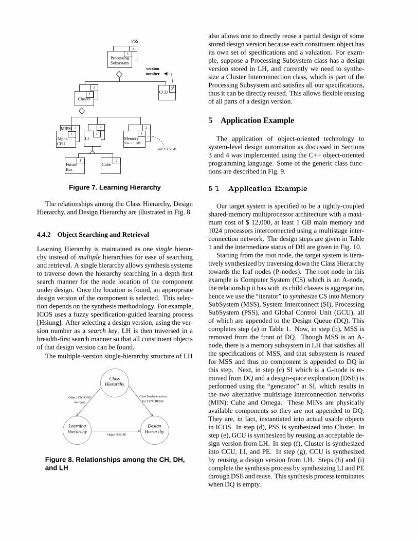
Learning Hierarchy (LH) is a hierarchy of synthesizedobjects instead of abstract classes as in the Class Hier-archy. Its main purpose is to store designs learnt fromprevious synthesis experiences for future reuse. An ex-ample of LH is given in Fig. 7. Adesign versionof acomponent is defined as one instance of the componentdesign satisfying a set of valuations for the specificationsof all constituent objects. For example, a Memory Sub-system class, an aggregate of main memory, cache mem-ory, and memory controller, may have a design versionwhich was synthesized satisfying specifications of 20 GBmain memory with 6 ns access time, 1 MB cache mem-ory with snoopy-write-invalidate coherence protocol anda memory controller costing $ 2,000. Each componentfrom CH may have one or more design versions storedin LH. Whenever a component, which may be completesubsystem, is synthesized, it is stored in LH as follows:
(a) Represent the component as a sub-tree of the ClassHierarchy.
(b) Each constituent object of the sub-tree will have auniquename as specified in CH, but thesamever-sion number, which is different from all other pre-viously assigned version numbers.
(c) All kinds of specifications, including architec-tural requirements, performance constraints, andsynthesis-related restrictions must be included withthe constituent objects along with the correspond-ing value assignments.
(d) Integrate the component into the current LH bystoring each constituent object in its correspondinglocation in the hierarchy.
MemorySize = 1 GB
LIMIPSCPU
ProcessingSubsystem
Cluster
PSS
MemorySize = 1 GB
LIAlphaCPU
FutureBus
CCU2
1
11
2
1
2
1
2
1
2
Cube2
2
Size = 1.5 GB
versionnumber
Figure 7. Learning Hierarchy
The relationships among the Class Hierarchy, DesignHierarchy, and Design Hierarchy are illustrated in Fig. 8.
4.4.2 Object Searching and Retrieval
Learning Hierarchy is maintained as onesingle hierar-chy instead ofmultiple hierarchies for ease of searchingand retrieval. A single hierarchy allows synthesis systemsto traverse down the hierarchy searching in a depth-firstsearch manner for the node location of the componentunder design. Once the location is found, an appropriatedesign version of the component is selected. This selec-tion depends on the synthesis methodology. For example,ICOS uses a fuzzy specification-guided learning process[Hsiung]. After selecting a design version, using the ver-sion number as asearch key, LH is then traversed in abreadth-first search manner so that all constituent objectsof that design version can be found.
The multiple-version single-hierarchy structure of LH
ClassHierarchy
LearningHierarchy
DesignHierarchy
Object REUSE
Class Implementation
for SYNTHESISObject STORING
for reuse
Figure 8. Relationships among the CH, DH,and LH
also allows one to directly reuse a partial design of somestored design version because each constituent object hasits own set of specifications and a valuation. For exam-ple, suppose a Processing Subsystem class has a designversion stored in LH, and currently we need to synthe-size a Cluster Interconnection class, which is part of theProcessing Subsystem and satisfies all our specifications,thus it can be directly reused. This allows flexible reusingof all parts of a design version.
5 Application Example
The application of object-oriented technology tosystem-level design automation as discussed in Sections3 and 4 was implemented using the C++ object-orientedprogramming language. Some of the generic class func-tions are described in Fig. 9.5.1 Application Example
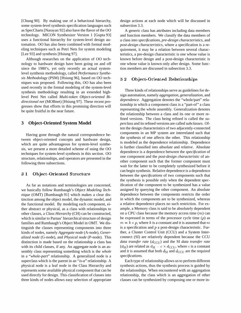
Our target system is specified to be a tightly-coupledshared-memory multiprocessor architecture with a maxi-mum cost of $ 12,000, at least 1 GB main memory and1024 processors interconnected using a multistage inter-connection network. The design steps are given in Table1 and the intermediate status of DH are given in Fig. 10.
Starting from the root node, the target system is itera-tively synthesized by traversing down the Class Hierarchytowards the leaf nodes (P-nodes). The root node in thisexample is Computer System (CS) which is an A-node,the relationship it has with its child classes is aggregation,hence we use the “iterator” tosynthesizeCS into MemorySubSystem (MSS), System Interconnect (SI), ProcessingSubSystem (PSS), and Global Control Unit (GCU), allof which are appended to the Design Queue (DQ). Thiscompletes step (a) in Table 1. Now, in step (b), MSS isremoved from the front of DQ. Though MSS is an A-node, there is a memory subsystem in LH that satisfies allthe specifications of MSS, and that subsystem isreusedfor MSS and thus no component is appended to DQ inthis step. Next, in step (c) SI which is a G-node is re-moved from DQ and a design-space exploration (DSE) isperformed using the “generator” at SI, which results inthe two alternative multistage interconnection networks(MIN): Cube and Omega. These MINs are physicallyavailable components so they are not appended to DQ.They are, in fact, instantiated into actual usable objectsin ICOS. In step (d), PSS is synthesized into Cluster. Instep (e), GCU is synthesized by reusing an acceptable de-sign version from LH. In step (f), Cluster is synthesizedinto CCU, LI, and PE. In step (g), CCU is synthesizedby reusing a design version from LH. Steps (h) and (i)complete the synthesis process by synthesizing LI and PEthrough DSE and reuse. This synthesis process terminateswhen DQ is empty.

generic.update_spec(){ if (generic.type==P-node) return 0; for each spec ∈ generic.SPEC do i = 0; while(spec=NULL) do if(last_dep_class()) break; query_spec(spec, dep_class[i++]; endwhile if(spec==NULL) query_user(spec); endfor}
generic.reuse(){ switch(generic.type){ case “A-node” : if(generic.synthesized) fsgl();
else return 0; break; case “G-node” : if(generic.synthesized) egl();
else return 0; break; }}
generic.synthesize(){ if(generic.type==A-node) synthesize() = iterate(); else if(generic.type==G-node) synthesize() = generate(); else synthesize() = NoOp();}
iterate(){ for each generic.child do if required(generic.child){ AddDH(generic.child); if((generic.child).type != P-node)
AppendDQ(generic.child); else instantify(generic.child); } explore_design_space(); endfor}
generate(){ for each generic.child do if(acceptable(generic.child) { AddDH(generic.child); if((generic.child).type != P-node) AppendQ(generic.child); else { instantify(generic.child); dse(); } } endfor}
Figure 9. Some Class Functions
Table 1. Illustrative Example Design Steps
Step Node CT Op Action DQ Status
(a) CS A itr synth fMSS,SI,PSS,GCUg(b) MSS A itr synth fSI,PSS,GCUg(c) SI G gen DSE fPSS,GCUg(d) PSS A itr synth fGCU,Clusterg(e) GCU A itr reuse fClusterg(f) Cluster A itr synth fCCU,LI,PEg(g) CCU A itr reuse fLI,PEg(h) LI G gen DSE fPEg(i) PE A itr reuse fg
CT = Class Type, itr = iterator, gen = generator, and synth = synthesis
The above example shows how classes are synthesizedor implemented in an object-oriented design environment.It also shows how the three hierarchies CH, DH, andLH are used for synthesis. A more elaborate synthesismethodology based on the object-oriented design envi-ronment presented in this paper can be found in [Hsiung].
6 Conclusion and Future Work
The intuitive correspondence between object-orientedtechnology in software engineering and hardware designin system-level synthesis was discussed, explored, and re-alized in a working object-oriented design environment.Besides the static modeling of components, it was shownhow classes can be dynamically manipulated during syn-thesis, what kind of structures or hierarchies are required
for synthesis, and how designs can be reused in the cur-rent synthesis as well as for future syntheses. Our initialconcepts were realized into an actual environment by im-plementing it and running examples. PSM [Hsiung 96]and ICOS [Hsiung] are two methodologies that have beenbased on this environment. MOBnet [Hsiung 97] was arecently proposed theoretical framework for such an OOdesign environment. All these go to show that our OOdesign environment is conceptually, technically, and the-oretically applicable to system-level synthesis.
Future work in this direction will try to incorporatesome further OO principles and engineering wisdoms.Hardware-software codesign is a field where OO will cer-tainly be a productive technology as both hardware andsoftware components can be modeled as classes which areimplementation independent.
References
[Birmingham 89] Birmingham, W. P., Gupta, A. P., andSiewiorek, D. P. (1989). The MICON system for com-puter design. InProc. 26th ACM/IEEE Design Au-tomation Conference, pages 135–140.
[Brooks 84] Brooks, F. R. J., Gross, R. R., and Heath,L. S. (1984). Transfer of software methodology toVLSI design. Technical Report TR 84-007, Univ. ofNorth Carolina, Chapel Hill.
[Chung 90] Chung, M. J. and Kim, S. (1990). An object-oriented VHDL design environment. InProc. 27th

LearningHierarchy
ClassHierarchy
MemorySubsystem
SystemInterconnect
ProcessingSubsystem
ComputerSystem
Global ControlUnit
CubeMIN
OmegaMIN
Cluster
Reuse
DSE
ComputerSystem
MemorySubsystem
SystemInterconnect
ProcessingSubsystem
ComputerSystem
Global ControlUnit
GCUPSSSIMSS
CS
step (b) – step (e)
step (f) – step (i)
step (a)
Reuse
PE SI IntfLICCU
Reuse Reuse
DSE
Bus
Figure 10. An Illustrative Example (intermediate DH status)
ACM/IEEE Design Automation Conference, pages431–436.
[Frank 85] Frank, G. A., Smith, C. U., and Cuadrado,J. A. (1985). An architecture design and assessmentsystem for software/hardware codesign. InProc. 22ndACM/IEEE Design Automation Conference.
[Gross 85] Gross, R. R. (1985).Using software technol-ogy to specify abstract interfaces in VLSI design. PhDthesis, Univ. of North Carolina at Chapel Hill. Dept.Computer Science Tech. Rep., TR-85-017.
[Gupta 93] Gupta, A. P., Birmingham, W. P., andSiewiorek, D. P. (1993). Automating the design ofcomputer systems.IEEE Trans. on CAD, 12(4):473–487.
[Hsiung] Hsiung, P.-A., Chen, C.-H., Lee, T.-Y., andChen, S.-J. ICOS: An intelligent concurrent object-oriented synthesis methodology for multiprocessorsystems. To appear inACM Trans. on Design Automa-tion of Electronic Systems.
[Hsiung 96] Hsiung, P.-A., Chen, S.-J., Hu, T.-C., andWang, S.-C. (1996). PSM: An object-oriented synthe-sis approach to multiprocessor system design.IEEETrans. on VLSI Systems, 4(1):83–97.
[Hsiung 97] Hsiung, P.-A., Lee, T.-Y., and Chen, S.-J.(1997). MOBnet: An extended Petri net model forthe concurrent object-oriented system-level synthesisof multiprocessor systems.IEICE Trans. on Informa-tion and Systems, E80-D(2):232–242.
[Kumar 94] Kumar, S., Aylor, J. H., Johnson, B. W., andWulf, W. A. (1994). Object-oriented techniques in
hardware design.IEEE Computer, 27(6):64–70.[Lee 93] Lee, Y. K. and Park, S. J. (1993). OPNets: An
object-oriented high-level Petri net model for real-timesystem modeling.Journal Systems Software, 20:69–86.
[Narayan 92] Narayan, S., Vahid, F., and Gajski, D. D.(1992). System specification with the SpecCharts lan-guage.IEEE Design and Test of Computers, pages 6–13.
[Parnas 72] Parnas, D. L. (1972). On the criteria to beused in decomposing systems into modules.Commun.ACM, 15(12):1053–1058.
[Parnas 76] Parnas, D. L. (1976). On the design and de-velopment of program families.IEEE Trans. on Soft.Eng., SE-2(1):1–9.
[Parnas 85] Parnas, D. L. (1985). The modular structureof complex systems.IEEE Trans. on Soft. Eng., SE-11(3):259–266.
[Rumbaugh 91] Rumbaugh, J., Blaha, M., Premerlani,W., Eddy, F., and Lorensen, W. (1991).Object-Oriented Modeling and Design. Prentice-Hall, Engle-wood Cliffs.
[Smith 86] Smith, C. U. and Gross, R. R. (1986). Tech-nology transfer between VLSI design and software en-gineering. InProc. of the IEEE, volume 74, pages 875–887.
[Tobias 81] Tobias, J. R. (1981). LSI/VLSI buildingblocks. IEEE Computer, 14(8):83–101.