
ICOS: an intelligent concurrent object-oriented synthesis methodology for multiprocessor systems
36
Copyright (C) 1997, 1998 by the Association for Computing Machinery, Inc. Permission to make digital or hard copies of part or all of this work for personal or classroom use is granted without fee provided that copies are not made or distributed for profit or direct commercial advantage and that copies show this notice on the first page or initial screen of a display along with the full citation. Copyrights for components of this work owned by others than ACM must be honored. Abstracting with credit is permitted. To copy otherwise, to republish, to post on servers, to redistribute to lists, or to use any component of this work in other works, requires prior specific permission and/or a fee. Permissions may be requested from Publications Dept, ACM Inc., 1515 Broadway, New York, NY 10036 USA, fax +1 (212) 869-0481, or [email protected]
Transcript of ICOS: an intelligent concurrent object-oriented synthesis methodology for multiprocessor systems

Copyright (C) 1997, 1998 by the Association for Computing Machinery, Inc.Permission to make digital or hard copies of part or all of this workfor personal or classroom use is granted without fee provided thatcopies are not made or distributed for profit or direct commercialadvantage and that copies show this notice on the first page orinitial screen of a display along with the full citation. Copyrightsfor components of this work owned by others than ACM must be honored.Abstracting with credit is permitted. To copy otherwise, to republish,to post on servers, to redistribute to lists, or to use any componentof this work in other works, requires prior specific permission and/ora fee. Permissions may be requested from Publications Dept, ACM Inc.,1515 Broadway, New York, NY 10036 USA, fax +1 (212) 869-0481, or [email protected]

ICOS: An Intelligent Concurrent Object-OrientedSynthesis Methodology for Multiprocessor SystemsyPao-Ann HsiungInstitute of Information ScienceAcademia Sinica, Taipei, Taiwan.andChung-Hwang Chen, Trong-Yen Lee, and Sao-Jie ChenDepartment of Electrical EngineeringNational Taiwan University, Taipei, Taiwan.The design of multiprocessor architectures basically di�ers from the uniprocessor systems in thatthe number of processors and their interconnection must be considered. This leads to an enor-mous increase in the design space exploration time which is exponential in the total numberof system components. The methodology proposed here, called Intelligent Concurrent Object-Oriented Synthesis (ICOS) methodology, makes feasible the synthesis of complex multiprocessorsystems through the application of several techniques that speed up the design process. ICOS isbased on Performance Synthesis Methodology (PSM), a recently proposed object-oriented systemlevel design methodology. Four major techniques: object-oriented design, fuzzy design-space ex-ploration, concurrent design, and intelligent reuse of complete subsystems are integrated in ICOS.First, object-oriented modeling and design, through the use of object-oriented relationships andoperators, make the whole design process manageable and maintainable in ICOS. Second, fuzzycomparison applied to the specializations or instances of components reduces the exponentialgrowth of design-space exploration in ICOS. Third, independent components from di�erent de-sign alternatives are synthesized in parallel, this design concurrency shortens the overall designtime. Lastly, the resynthesis of complete subsystems can be avoided through the application oflearning, thus making the methodology intelligent enough to reuse previous design con�gurations.Experiments show that all these applied techniques contribute to the synthesis e�ciency and thedegree of automation in ICOS.Categories and Subject Descriptors: J.6 [Computer-Aided Engineering]: Computer-aideddesign; I.2.6 [Arti�cial Intelligence]: Deduction|Knowledge acquisition; Analogies; I.2.3 [Ar-ti�cial Intelligence]: Deduction|Fuzzy reasoning; B.m [Miscellaneous]: Design managementGeneral Terms: Multiprocessor System Design, Design ReuseAdditional Key Words and Phrases: concurrent object-oriented system-level synthesis, fuzzydesign-space exploration, learningyThis research was supported by the National Science Council, Taipei, Taiwan under grant NSC85-2623-D002-015.

2 �1. INTRODUCTIONSynthesis is the process of automatic transformation from a set of logically higherlevel design speci�cations into a logically lower level design architecture. Corre-sponding to the levels of design details, we have di�erent levels of synthesis, such aslogic level, register-transfer level (RTL), algorithmic or high level, and system-level.At the logic level of synthesis, the designer inputs gate-level design speci�cationsand obtains physical level architecture. At the RTL, register transfer speci�ca-tions are given and gate level result obtained. At the algorithmic or high level,an algorithm describing a particular behavior is synthesized into an RTL designarchitecture. Finally, at the system level of synthesis, a description of system be-havior or a set of system-level speci�cations is transformed into an architecturaldescription of the system such as the processor type, the memory organization, andthe system interconnection network.With technology advances, the complexity of computer system architecture hasincreased to the extent that synthesis tools which automate the design process, ifnot indispensable, are becoming a necessity for meeting the ever shortening time-to-market requirement. Design methodologies for uniprocessor systems are quitemature, but system-level synthesis tools automating the design of such systems arestill under research and development. Compared to uniprocessor systems, multi-processor (MP) systems present much more design tradeo�s and challenges, hencethe design automation of MP systems is more imperative. Recently, PerformanceSynthesis Methodology (PSM) [Hsiung et al. 1996] was proposed as a successfulmethodology for MP systems. The target architectures considered in this paperare also parallel systems which include both tightly-coupled multiprocessors andloosely-coupled multicomputers.

� 3Multiprocessor system-level synthesis is a design automation process where start-ing from a set of system descriptions, performance constraints, and a cost bound, amultiprocessor architecture is synthesized by determining the number and type ofprocessors used, the processing cluster organization, the type of system intercon-nection, and the amount of memory with its logical and physical organization. Amultiprocessor synthesis system is di�erent from currently available uniprocessorsynthesis systems because the design of the target architecture now requires ex-ploring many more design alternatives and performance tradeo�s. A uniprocessorsystem has only one processing element, so currently available uniprocessor syn-thesis systems need only consider the type of processor and determine the amountof memory to use, whereas a multiprocessor system architecture has more thanone processor, so we must decide how many processors to use, how to interconnectthe processors using some interconnection network, determine the way in whichthe main memory is organized, and classify cache memory into local, primary,and secondary levels. All of these considerations are critical to the feasibility andperformance of the �nal synthesized architecture and they are not taken into con-sideration by uniprocessor synthesis systems. Furthermore, an important aspectof multiprocessor system synthesis is how the workloads are distributed into eachprocessor and the balancing of the processor workloads in order to maximize thesystem performance. This distribution and balancing of workloads mainly dependson the type and number of processors available, on how the processors are intercon-nected, and on the design of the global control unit which distributes workloads toeach cluster in a hierarchical MP system. All of these factors make the MP systemsynthesis special and di�erent from the conventional system synthesis.We de�ne an object-oriented (OO) synthesis as the design process in which systemparts are modeled as object classes interlinked by relationships in a hierarchy ofclasses and the desired system is synthesized by traversing the hierarchy, selectingappropriate object classes, and instantiating them. The rationale for using OO in

4 �synthesizing MP systems can be summarized as follows. First, since a large numberof variations of MP systems is possible due to the numerous ways in which pro-cessors may be clustered and interconnected and memories may be organized, theinheritance mechanism in the OO technology signi�cantly avoids the duplicationof design data to a much larger extent than in the conventional non-OO synthesis.Second, MP systems are often modularized through processor clustering for betterperformance and scalability, such modularization are very much in coherence withthe OO design technology. Design reuse plays an important role in modeling iden-tical clusters or modules and in reducing design time. Third, the design of complexMP systems requires a larger design hierarchy than uniprocessor systems, thus theconcept of hierarchical design process in the OO technology becomes more useful fordesign management and representation. Overall, the use of OO technology is moreadvantageous in designing MP systems than in designing uniprocessor systems.Conventionally, system parts were synthesized in a sequential fashion, for examplein PSM. When more than two components are allowed to be synthesized at thesame time, the design process is termed concurrent synthesis. In this paper, weconcentrate on concurrent synthesis and discuss its advantages.The design space in the synthesis of an architecture having n components is asubspace of Z2n, represented as D = fh(x1; y1); (x2; y2); : : : ; (xn; yn)i j xi; yi 2 Zg,whereZ is the set of non-negative integers. Each point in the 2n-dimensional integerdesign space represents a design alternative such that for the ith component, xi isthe integer label of a physical instantiation of the component and yi is the number ofxi used for the �nal design. The design space size (jDj) is thus the total number ofdesign alternatives for a system under design. If the average design time for a singledesign alternative is � , then the total time required for design-space exploration ofa design consisting of n components, each of which has m specializations, is:T (n) = �(m)n (1)

� 5A survey of previous and related work is given in Section 2. Section 3 presentsan overview of the concepts and techniques used in ICOS. The article will move onto describe the design methodology in Section 4. Implementation, design examples,and experimental observations are covered in Section 5. The last section concludesthe paper and describes some future work.2. PREVIOUS AND RELATED WORKA performance-driven, object-oriented synthesis methodology for the system-leveldesign of multiprocessor systems called Performance Synthesis Methodology (PSM)[Hsiung et al. 1996] was recently proposed. Prior to PSM, there were some relevantwork on automating the system-level design of computer systems, but they havebeen developed with a restricted scope of application, e.g., the MICON system[Birmingham et al. 1989; Gupta et al. 1993] and the Megallan system [Gadient andThomas 1993] did not explicitly take the MP features into consideration duringsystem synthesis; Mabbs and Forward [Mabbs and Forward 1994] analyzed theperformance of MR-1, a clustered shared memory MP, using a queueing modeland a lost request model; Chiang and Sohi [Chiang and Sohi 1992] evaluated thedesign choices for a Shared-Bus MP in a throughput-oriented environment usingCustomized Mean-Value Analysis. Distributed design-space exploration for high-level synthesis system was discussed by Dutta et al [Dutta et al. 1992].The incorporation of object-oriented concepts into computer-aided synthesis hasbeen discussed mainly in the literature [Lee and Park 1993; Kumar et al. 1994] andimplemented in a few hardware description language oriented design tools [Chungand Kim 1990]. Reuse of speci�cation through re�nement levels has been discussedby Antonellis and Pernice [Antonellis and Pernice 1995]. An example of learningused in the synthesis of VLSI systems is the Learning Apprentice for VLSI Design(LEAP) [Mitchell et al. 1985]. Besides this example, learning has been rarely usedin synthesis. Fuzzy logic has been widely used in the VLSI design such as in VLSIplacements [Rezaz and Gau 1990; Lin and Shragowitz 1992; Kang et al. 1994], but
6 �not in system-level synthesis tools. This paper illustrates how learning and fuzzylogic can be used for e�cient and intelligent synthesis.From Section 1, we know that an exhaustive search of the exponential designspace cannot be completed in a reasonable or acceptable time period. We thusneed to investigate techniques which could increase our design space exploratione�ciency without trading o� design quality. PSM used a cost-based heuristic toexplore design space, but this produced designs that are always the most expensiveones.The four techniques used in our methodology to improve synthesis e�ciencywithout trading o� design quality are summarized and the reasons we use them aredescribed as follows.(T1) Object-Oriented Design: the elementary application of object-oriented tech-niques in PSM is extended such that not only the system modeling but thewhole design process is also object-oriented, thus making the synthesis method-ology more consistent and complete.(T2) Fuzzy Design-Space Exploration: In order to produce more balanced designsas compared to those produced by PSM, a fuzzy design-space exploration algo-rithm that considers a global tradeo� of cost and performance factors is used,thus, not only producing more balanced designs, but also performing a moreoptimal search of the design-space.(T3) Concurrent Design: A concurrent component design method is adopted,rather than the sequential one used in PSM, mainly because synthesis e�-ciency can be improved. A component is not necessarily a physical one, it mayrepresent high-level system parts or subsystems and is often a design alternativewith respect to other components under design concurrently. Due to the largenumber of design alternatives, it is certainly desirable to concurrently synthe-size them. This is similar to the concurrent executions of two or more branchstatements in software, which leads to e�cient software execution. For exam-

� 7ple, if both mesh and cube interconnections satisfy the given speci�cations,then two design alternatives using di�erent interconnections can be designedconcurrently as their designs are independent of each other.(T4) Intelligent Reuse of Complete Subsystems: A substantial amount of designtime is saved through intelligent learning and reuse of the previously designedsystem parts which meet current speci�cations.In summary, ICOS basically uses various techniques to enhance the elementary PSMsuch that (1) the design process is completely object-oriented, (2) more balancedand optimal designs are produced, (3) the synthesis e�ciency is improved, and (4)substantial design time is saved through the intelligent design reuse.Referring to Equation (1), as far as the design-space exploration is concerned,techniques T1 reduces � , the average design time of a single component, throughe�cient synthesis; T2 reduces m, the number of specializations, by consideringonly a suitable number of instances for each component; T3 also reduces � byparallelizing the sequential design in PSM; and T4 reduces n, the total numberof components to be synthesized, as certain components reused by learning fromprevious experiences need not be synthesized again.3. CONCEPTS AND TECHNIQUESThis section presents the concepts and the background of our synthesis method-ology, Intelligent Concurrent Object-Oriented Synthesis (ICOS), in which systemparts are modeled as objects, the synthesis process is object-oriented, parts are con-currently synthesized, and previously synthesized parts that meet current speci�ca-tions are intelligently reused. The previous section discussed why these techniquesare used in ICOS, the following subsections discuss how system level synthesis canmake use of these techniques to improve design maintenance, increase synthesise�ciency, and decrease overall design time.

8 �3.1 System-Level Speci�cations and SynthesisAn ICOS designer describes the system (s)he desires through specifying require-ments at the system-level, which include architectural, performance, and synthesisspeci�cations.Architectural speci�cations mainly allow a designer to restrict the domain spaceby speci�cally indicating how a system part should be constructed. For exam-ple, the designer may explicitly specify that the target architecture should be ahypercube-connected one with at least 1024 processing elements and a maximumcost of $12,000. If some architectural details are left out by the designer, for in-stance, the amount of main and cache memories, then the synthesis system decideshow much memory to use and what kind of design alternatives are feasible. Forexample, one design alternative may be 16 MB of main memory and 1 MB of cachememory, while another design alternative could be 8 MB of main memory and 2MB of cache memory.Performance speci�cations include the minimum system power which is also thethroughput-utilization ratio, the minimum system scalability, reliability, and fault-tolerance, all of which are de�ned as in PSM [Hsiung et al. 1996]. Synthesis speci�-cations include the maximum number of design alternatives to consider for furtherdesign and the choice of whether to reuse previously learnt designs or to design asystem from scratch.System-level synthesis is a process which uses the above architecture, perfor-mance, and synthesis speci�cations as input and generates a set of feasible designalternatives satisfying all speci�cations. This could be an empty set if the speci�ca-tions cannot be satis�ed by any design alternative or the speci�cations themselvesare contradictory, for example, the total number of system processors exceed thecapacity of the interconnection network chosen (say a particular shared bus).

� 93.2 Object-Oriented DesignObject-oriented design includes object-oriented modeling and object-oriented syn-thesis, which contribute towards easier design maintenance and e�cient synthesis,respectively. Hardware components or subsystems can be naturally perceived asobjects and classi�ed into some class or classes.A successful application of object-oriented concepts and techniques in computersystem design was demonstrated in PSM. Apart from the normal features of anobject-oriented system, such as class encapsulation, attribute inheritance, poly-morphism, and part reuse, PSM introduced the use of object-oriented relationships(aggregation and generalization [Rumbaugh et al. 1991]) and operators (iterator[Shaw et al. 1981] and generator) for the system-level synthesis of multiprocessorsystems. Our current work, ICOS extends the use of object-oriented techniques insystem-level synthesis by introducing one more relationship: dependence and onemore operator: updator.Each component in a multiprocessor architecture is modeled by a class whichmay have speci�cations stipulated by the designer, pre-design characteristics whichare known before design, and post-design characteristics which are known only afterdesign. The classes are classi�ed into three types: A-node (aggregate node), G-node(generalized node), and P-node (physical node) depending on whether it representsan assembly of sub-classes, a super-class of some specialized classes, or a physicalclass that is available for direct integration and use, respectively. Three types ofrelationships are also de�ned, namely aggregation, generalization, and dependence,of which the former two are adopted from Rumbaugh's Object-Modeling Technique(OMT) [Rumbaugh et al. 1991] and dependence is a newly introduced one. Depen-dence mainly models how a component may depend on another component due tothe hardware-links between them. Two types of dependence are modeled: absolutedependence and relative dependence [Hsiung 1996].

10 �Memory
SubsystemSystem
InterconnectProcessingSubsystem
ComputerSystem
Global ControlUnit
MainMemory
CacheMemory
Primary
Secondary
GloballlyShared
DistributedShared
GloballyDistributed
DistributedUnshared
SharedBus
MIN Cube ProcessorCluster
CCU LI SI InterfacePE
Scheduler I/O Intf. Buffer
Shared Bus MIN RISC CISCCube
Processor Local Memory
Cache RAM
I/OProcessor
I/OInterface
CCUInterface
A-node
G-node
P-node
MemoryController
Priority Time Fig. 1. Class HierarchyUsing the classes and relationships described above, a hierarchy of classes calledClass Hierarchy (CH) is constructed, which can serve as o�-the-shelf building blocksfor synthesis. Class Hierarchy is de�ned as a multi-level, object-oriented, hierarchi-cally classi�ed repository storing parts of a multiprocessor system. An example ofCH is given in Fig. 1ICOS uses OO operators, namely iterator, generator, and updator for synthesis.The iterator is used to synthesize an A-node in the design process of ICOS. Ititerates through each child node of an A-node deciding whether to use it or not,this decision is based on the speci�cation satisfaction of the A-node. The generatoroperator is used to synthesize a G-node and instantiate a P-node. It generatesa number of acceptable specialized subclasses for a G-node or instances for a P-node, by traversing CH and checking which subclasses or instances best satisfythe speci�cation of a G-node or a P-node, respectively. Both the iterator and thegenerator operators will be used in the component synthesis step (Section 4.3.3).

� 11Updator is used to update a speci�cation of a node before the node begins synthesis,as explained in the speci�cation update step (Section 4.3.1).3.3 Concurrent SynthesisEncapsulating each system component as an individual class using OO techniquesinduces a certain degree of local autonomy such that a class is capable of activelysynthesizing itself by traversing down the hierarchy of CH until all leaf nodes areinstantiated. This is called self-synthesis. When two or more classes representingsystem parts or design alternatives actively synthesize themselves at the same time,the design process is called concurrent synthesis. Concurrent synthesis not onlyincreases synthesis e�ciency, but also saves design time as will be illustrated in thispaper.In the following, we will describe how more than one component may undergosynthesis at the same time in ICOS. Starting from a root class known as a ComputerSystem (CS), ICOS traverses CH and checks components for synthesis. A compo-nent class is said to be ready for synthesis as soon as all of its speci�cation values areavailable and updated. The synchronization between component design processes ismaintained by the dependence relationships in CH which control the design prece-dence order of component classes. For example, if a class A is absolutely dependenton a class B, then the synthesis of B must be completed before A can begin itssynthesis, and in the case of a relative dependence, A can begin synthesis as soonas its dependent speci�cation is updated by querying B.For modeling and solving problems induced by concurrency in synthesis, a high-level Petri net model was proposed and validated [Hsiung et al. 1997]. Due tospace consideration, the details of this Multi-token Object-Oriented Bi-directionnet (MOBnet) cannot be included in this paper, interested readers are advised torefer to [Hsiung et al. 1997] for a complete discussion.

12 �Machine Learning
Explanation Based Learning(EBL)
(analyzing positive example and derivingexplanations for successes and failures)
Similarity Based Learning(SBL)
(detecting similarities in a set of positiveexamples and dissimilarities between
positive and negative examples)
Empirical Rational Inductive Learning(acquisition of new
knowledge)
Deductive Learning(improvement of existing
knowledge)
Specification-Guided Learning(SGL)
Example-Guided Learning(EGL)Fig. 2. Machine Learning Classi�cation3.4 Intelligent SynthesisBy incorporating learning into the synthesis process, complete subsystems or systemparts that meet current design speci�cations can be reused from previous designexperiences, thus eliminating the repetition of similar design steps over and overagain and saving a substantial amount of design time.As shown in Fig. 2, machine learning is basically classi�ed into Similarity BasedLearning (SBL) and Explanation Based Learning (EBL) [Kodrato� 1988]. There aretwo kinds of SBLs: Empirical SBL and Rational SBL; and EBL includes InductiveLearning and Deductive Learning. Deductive Learning is further classi�ed intoSpeci�cation-Guided Learning (SGL) and Example-Guided Learning (EGL).ICOS applies SGL in its design process. In SGL, the speci�cations of somepreviously learnt designs are compared with the current user speci�cations and, ifacceptable, a previous design that best meets the current speci�cations is selected.Since numerous speci�cations have to be considered, ICOS fuzzi�es the comparisonbetween two component classes, this process is called Fuzzy Speci�cation-GuidedLearning (fuzzy SGL). Details of using fuzzy SGL in ICOS will be described inSection 4.3.2.

� 134. ICOS METHODOLOGYHaving gone through why and how techniques can be applied in system-levelsynthesis, an actual methodology, Intelligent Concurrent Object-Oriented Synthesis(ICOS) methodology, implementing the above concepts is presented in this section.As shown in Fig. 3, after a designer inputs system requirements using a speci�-cation language provided by ICOS, the methodology enters its three main phases:Speci�cation Analysis, Concurrent Design, and System Integration. Each of thesephases will be discussed in the following subsections and illustrated with a smallrunning example.4.1 Speci�cation LanguageThe ICOS speci�cation language is composed of three speci�cations: the architec-ture, the performance, and the synthesis speci�cations, described as follows:architecture:system: AT = fMPjSMjHybridg //MP=Msg. Passing, SM=Shared Mem.CT = fSIMDja-MIMDjs-MIMDg //s=synchronous, a=async.MT = fGSjDSjGDjDUjCacheg //G=Globally, D=Distributed, S=Shared,U=Unshared.SI = fBusjMINjHCjMeshj : : :g //MIN=Multistage Interconnection Network,HC=HyperCube.SP = Total System ProcessorsNC = Number of clusterscluster: PU = fRISCjCISCgCI = fBusjMINjHCjMeshj : : :gCP = Total Cluster Processorsperformance: MaxC, MinP, MinS, MinR, MinFsynthesis: NS, ML = fYesjNogIn the above architecture speci�cations, AT, CT, MT, SI, PU, and CI are thearchitecture type, control type, memory type, system interconnection, processingunit, and cluster interconnect. In the performance speci�cations, MaxC, MinP,MinS, MinR, andMinF are the maximum cost, minimum power, minimum scalabil-ity, minimum reliability, and minimum fault-tolerance. Of particular mention are:NS, the maximum number of specializations to be considered at the end of FuzzyDesign-Space Exploration of a G-node or P-node, and ML, the option whether anymachine learning is to be used. Observe that NS is used by the designer to control

14 �
(3)
OODSM
Architecture specs
Performance specs
Synthesis specs
Specification Input
Specification Analysis
Class Hierarchy
SpecificationError?
Yes
Initiali zation:
AddDH(root), AppendDQ(root)
PopDQ
Component
Design ...DQempty?
No
No
No
No
Yes
rollbackpossible?
design
complete?
Yes
Yes
SynthesisRollback
Simulation andPerformanceEvaluation
Output BestArchitecture
Error: SynthesisImpossible
Component
Design
Component
Design
Component
Design
(2)
(1)
(1) Specification Analysis Phase (2) Concurrent Design Phase (3) System Integration Phase
StopFig. 3. ICOS Design Flowthe size of the design-space explored at a G-node or P-node. If this speci�cation isnot given by the user, the system default value, MaxS (Equation (7)), will be used.As shown in Fig. 4, a small example will be used to illustrate each of the de-sign phases. The target system is a SIMD message-passing architecture with aMulti-stage Interconnection Network (MIN) or a Hypercube (HC) intercon-nection. The design speci�cations are as follows:

� 15architecture:system: AT = MP, CT = SIMD, SI = MIN _ HCcluster: PU = RISC, CI = Busperformance: MaxC = $10; 000;MinP = 8M ops;MinR = 0:9synthesis: ML = Yes
LearningHierarchy
MemorySubsystem
SystemInterconnect
ProcessingSubsystem
ComputerSystem
Global ControlUnit
Cache MainMemory
Primary
Secondary
DistributedUnshared
MIN Hypercube
ProcessorCluster
Processor I/OIntf
ClusterControlUnit Intf
FSGL
FDSE
ComputerSystem
MemorySubsystem
SystemInterconnect
ProcessingSubsystem
ComputerSystem
Global ControlUnit
MM
GCUPSSSIMSS
PC SC
DU
CS
Fig. 4. A Small Illustrative ExampleThis small example with the above speci�cations will be synthesized in the follow-ing subsections. Note that not all speci�cations need to be input by the designer.A check for completeness and compatibility has to be performed �rst.4.2 Phase I. Speci�cation AnalysisUser given speci�cations may contain logical, technical, or typographical errors,which must be detected and eliminated. ICOS begins with analyzing the designspeci�cations, which is mainly done using �rst-order logic rules and based on com-mon architecture assumptions. Some main assumptions are listed: a message-passing architecture is not supposed to share any global main memory, a shared-

16 �memory architecture should not use the direct-connection networks such as hyper-cube or mesh, the total number of system processors should be equal to the numberof clusters times the number of processors per cluster, the cost bound should be atleast the minimum cost of a uniprocessor system. Figure 5 shows how speci�cationerrors such as contradictions between speci�cations (e.g., AT and MT have incom-patible values assigned), unsatis�able speci�cations (e.g., SP 6= NC � CP), andincomplete speci�cations (e.g., CP, SP, and MaxC are all not given) are detected.The analysis is done per speci�cation category, as well as, between the architectureand the performance speci�cation categories. The purpose of this phase is to un-cover inconsistencies in the design speci�cations at the very beginning of the designprocess such that futile e�orts in synthesizing an impossible system are avoided.(a) architecture specification:
False Statements: (AT=MPA) ∧ !(MT=DU)(AT=SMA) ∧ (SI=HC)SP ≠ NC × CP
Implications: (AT=MPA) ⇒ (MT=DU)SP = NC × CP
(b) performance specification:False Statements: MaxC < USC
(c) synthesis specification:False Statements: NS ≤ 0
(d) architecture/performance specification:False Statements: MaxC < SP × LPC + LC(SI) + LC(MT)
Some assumptions:
USC:Uniprocessor System CostLPC:Least Processor CostLC(SI):Least Cost of System InterconnectionLC(MT):Least Cost of Memory Type
Fig. 5. Speci�cation AnalysisFor example, continuing with our small example some rules for analyzing itsspeci�cations are described in Fig. 5. Since the architecture type desired is mes-sage passing (AT = MP), we make necessary implication that the memory type isdistributed unshared (MT = DU). The analysis is performed under assumptionsthat USC = $1; 000;LPC = $500;LC(SI) = $150;LC(MT) = $150, where themeanings of USC, LPC, LC (SI ), and LC (MT ) have been given in the �gure.
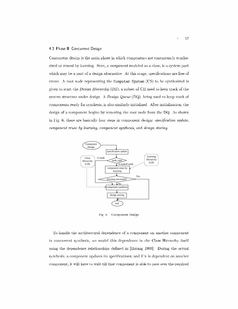
� 174.3 Phase II. Concurrent DesignConcurrent design is the main phase in which components are concurrently synthe-sized or reused by learning. Here, a component modeled as a class, is a system partwhich may be a part of a design alternative. At this stage, speci�cations are free oferrors. A root node representing the Computer System (CS) to be synthesized isgiven to start the Design Hierarchy (DH), a subset of CH used to keep track of thesystem structure under design. A Design Queue (DQ), being used to keep track ofcomponents ready for synthesis, is also similarly initialized. After initialization, thedesign of a component begins by removing the root node from the DQ. As shownin Fig. 6, there are basically four steps in component design: speci�cation update,component reuse by learning, component synthesis, and design storing.Class
Hierarchy(CH)
design storing
component synthesis
component reuse bylearning
specification update
node_type
Yes
No
A-node/P-node
G-node
learning successful?
ComponentDesign
end
LearningHierarchy
(LH)
Fig. 6. Component DesignTo handle the architectural dependence of a component on another componentin concurrent synthesis, we model this dependence in the Class Hierarchy itselfusing the dependence relationships de�ned in [Hsiung 1996]. During the actualsynthesis, a component updates its speci�cations; and if it is dependent on anothercomponent, it will have to wait till that component is able to pass over the required

18 �information to it. When performance constraints are violated at some stage ofsynthesis, a rollback process occurs in the bottom-up direction of the hierarchysuch that the component violating performance constraints send rollback messagesto its parent class and dependent classes, both of which in turn either re-synthesizethemselves or propagate rollback messages upwards in the Class Hierarchy. Thedetails of this rollback process can be found in [Hsiung et al. 1997].Synthesizing the small example as speci�ed earlier, the design steps are givenin Table I. The last column gives the resulting DQ obtained by synthesizing theready-for-synthesis object in that step (column 2). ICOS methodology stops whenDQ becomes empty, which occurs in a �nite number of steps as the number ofcomponents are �nite in a system.4.3.1 Speci�cation Update. A component class may have characteristics that de-pend on its parent class or dependent classes, hence it must update all of the relatedspeci�cations before the synthesis begins. This is done using the updator operator.A class queries its parent class, as well as, all the classes having a dependence rela-tionship with it, for any missing speci�cation values. After all the queries have beenanswered, if there are still some speci�cations that do not have values assigned, thedesigner of the system will be queried for the speci�c values. Once all speci�cationsof a class are updated, the class is considered to be ready for self-synthesis, whichis described in the following steps.4.3.2 Component reuse by learning. Before the actual synthesis, a componentclass checks whether learning from previous design experience is possible. In thisstep, fuzzy SGL is applied to an A-node.(a) Fuzzy Speci�cation-Guided Learning: The rationale of applying fuzzy SGL toan A-node is that if the design of a partial system, represented by an A-node, canbe substituted directly by some previously stored designs, the whole sub-tree rootedat that A-node need not be synthesized again.
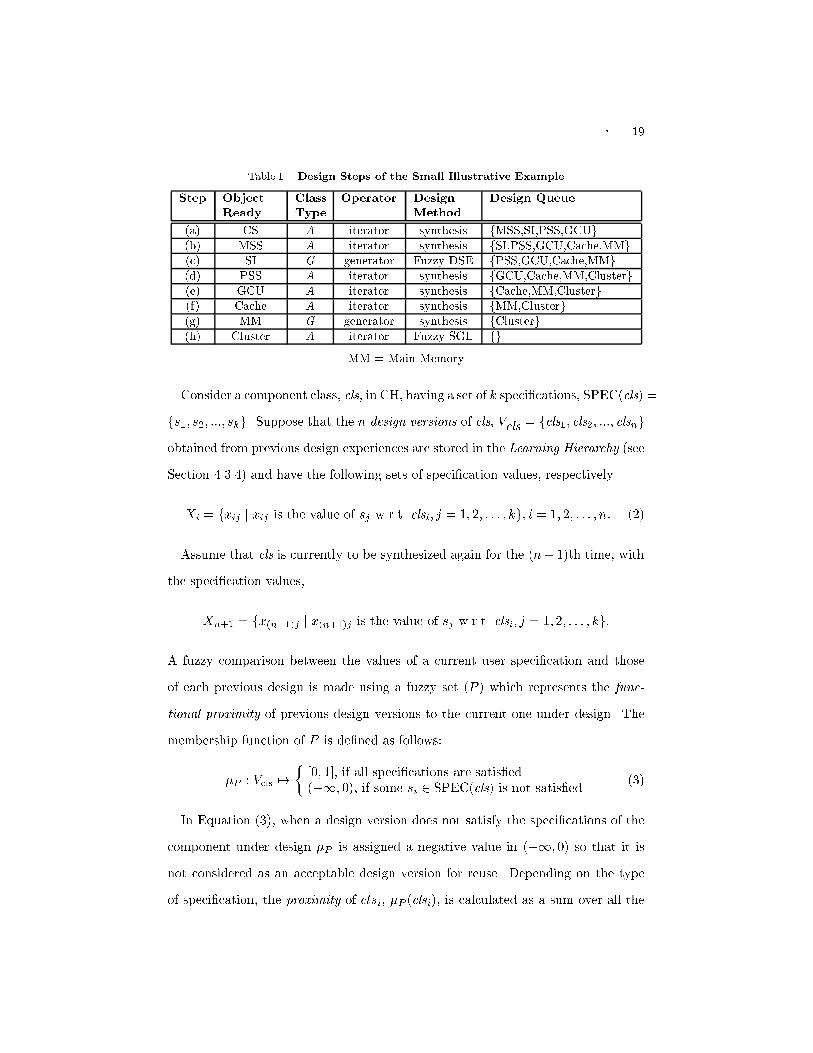
� 19Table I. Design Steps of the Small Illustrative ExampleStep ObjectReady ClassType Operator DesignMethod Design Queue(a) CS A iterator synthesis fMSS,SI,PSS,GCUg(b) MSS A iterator synthesis fSI,PSS,GCU,Cache,MMg(c) SI G generator Fuzzy DSE fPSS,GCU,Cache,MMg(d) PSS A iterator synthesis fGCU,Cache,MM,Clusterg(e) GCU A iterator synthesis fCache,MM,Clusterg(f) Cache A iterator synthesis fMM,Clusterg(g) MM G generator synthesis fClusterg(h) Cluster A iterator Fuzzy SGL fgMM = Main MemoryConsider a component class, cls, in CH, having a set of k speci�cations, SPEC(cls) =fs1; s2; :::; skg. Suppose that the n design versions of cls, Vcls = fcls1; cls2; :::; clsngobtained from previous design experiences are stored in the Learning Hierarchy (seeSection 4.3.4) and have the following sets of speci�cation values, respectively.Xi = fxij j xij is the value of sj w.r.t. clsi; j = 1; 2; : : : ; kg; i = 1; 2; : : : ; n: (2)Assume that cls is currently to be synthesized again for the (n+1)th time, withthe speci�cation values,Xn+1 = fx(n+1)j j x(n+1)j is the value of sj w.r.t. clsi; j = 1; 2; : : : ; kg:A fuzzy comparison between the values of a current user speci�cation and thoseof each previous design is made using a fuzzy set (P ) which represents the func-tional proximity of previous design versions to the current one under design. Themembership function of P is de�ned as follows:�P : Vcls 7! � [0; 1], if all speci�cations are satis�ed(�1; 0), if some si 2 SPEC(cls) is not satis�ed (3)In Equation (3), when a design version does not satisfy the speci�cations of thecomponent under design �P is assigned a negative value in (�1; 0) so that it isnot considered as an acceptable design version for reuse. Depending on the typeof speci�cation, the proximity of clsi, �P (clsi), is calculated as a sum over all the

20 � Table II. Types of Speci�cations and Partial Proximity ValuesType ofSpeci�cation ExampleSpeci�cations Partial Proximity �̂P (xij)Exact value orset enumeration AT, CT, MT,SI �1 if x(n+1)j 62 ENUMfxijgwj if x(n+1)j 2 ENUMfxijgMinimum value(lower bound) MinP, MinS,MinR, MinF �1 if xij < x(n+1)jwj xij�x(n+1)jM if xij � x(n+1)j & M > 0.0 if M = 0Maximum value(upper bound) MaxC, NS �1 if xij > x(n+1)jwj x(n+1)j�xijM if xij � x(n+1)j & M > 0.0 if M = 0Approximate value bu�er size wj (jx(n+1)j�xij j)�1M if x(n+1)j 6= xijwj if x(n+1)j = xijM = Max1�i�njx(n+1)j � xij j, wj is the weight associated with sj andPkj=1 wj = 1speci�cation values, �P (clsi) = kXj=1 �̂P (xij) (4)where �̂P (xij), the partial proximity of clsi corresponding to speci�cation sj , isde�ned in Table II for each type of speci�cation.Based on the type of speci�cation, there are di�erent ways to compare how twocomponents di�er with respect to a certain speci�cation. A weight (wj) is assignedto each speci�cation (sj) representing the importance of the speci�cation in the�nal design. The weights may be all equal, i.e., wj = 1=n, if all the speci�cationsare equally important. The speci�cations are classi�ed into four types: (1) exactvalue or set enumeration, e.g., the CPU must be a RISC CPU; (2) minimum valueor lower bound, e.g., the reliability should be at least 98.5%; (3) maximum valueor upper bound, e.g., the cost should be at most $ 100,000; and (4) approximatevalue, e.g., the bu�er size should be approximately 1 KB. In Table II, the value ofa speci�cation sj of a design version clsi in Vcls is denoted as xij and the currentlydesired speci�cation value is x(n+1)j . When a speci�cation sj is satis�able bya design version clsi, the comparison is made between the two values xij andx(n+1)j by a weighted normalized di�erence, such as wj xij�x(n+1)jM , where M is the

� 21Table III. Fuzzy Speci�cation-Guided Learning at the Cluster ClassDesign CP/NC MinP (MFlops) PU CI MaxC($) �PA 4 2.0 SuperSPARC Bus 4,200 �1:400B 3 1.8 PA-7100 MIN 3,000 �2:840C 2 1.0 MIPS-R4400SC Bus 2,500 �0:400D 2 1.1 PowerPC-601 Bus 1,200 0:620E 2 1.2 Alpha-21064 Bus 1,100 0:647F 2 1.1 PowerPC-601 MIN 1,500 �1:580G 2 1.0 Alpha-21064 Bus 1,000 0:613Current 2 1+ RISC Bus 1,200 1:000�P is calculated using Equation (4) and Table II.maximum di�erence over all the design versions in Vcls. When a speci�cation is notsatis�able, a negative value of �1 is assigned so as to eliminate the considering ofthat design version.The set of design versions considered to be similar to the current one underdesign is called the similarity set, �cls = fclsijclsi 2 Vcls ; �P (clsi) � �g, where � isa threshold value known as the degree of similarity. The higher the value of �, thesmaller is the cardinality of the similarity set, and hence, the greater is the degreeof similarity required between the design versions. If the similarity set is not empty,the design version having the maximum �P (clsi) is selected as the partial-design tobe reused for the object in the current synthesis.For example, step (h) in Table I involves a fuzzy SGL process at the Clusterclass, suppose the speci�cations of Cluster are: CP=NC = 2, MinP = 1 MFlopper 100% utilization, PU = RISC, CI = Bus, and MaxC = $1; 200. Notations aregiven in Section 4.1. Table III shows how fuzzy SGL is performed at the Clusterclass. Assuming � = 0:62, it is observed from Table III, that the similarity set�Cluster = fD;Eg, and E is the design with maximum �P , hence the design E isreused for the current Cluster synthesis.4.3.3 Component Synthesis. Any system part modeled as an individual class inCH is called a \component". Component synthesis is the core part of componentdesign. When no reuse by learning is possible or ML is set to \No" in the spec-

22 �i�cations, the component is synthesized in this step. A P-node can be viewed asa G-node at the leaf of the Class Hierarchy. Hence, the instantiation process of aP-node is similar to the synthesis process of a G-node because the instances of aP-node can be viewed as the specializations of a G-node.(a) Synthesis of an A-node: Recalling that an A-node has the aggregation typeof relationship with its child nodes, an object-oriented operator known as the it-erator is used to synthesize an A-node. The iterator iterates through each childnode deciding whether to use it or not, this decision is based on the speci�cationsatisfaction of the A-node. Child nodes to be used for synthesis are added to DH.If the child node is a P-node, it is instantiated, otherwise, it is appended to DQfor further synthesis. For example, steps (a), (b), (d), (e), and (f) in Table I, allsynthesize an A-node using iterator.(b) Synthesis of a G-node and Instantiation of a P-node: A Fuzzy Design-SpaceExploration (fuzzy DSE) method is used to select a suitable number of accept-able design components that are among the best specializations of a G-node (G-specialization) or instances of a P-node (P-instance). The object-oriented operatorused in fuzzy DSE is known as the generator, since it \generates" a suitable numberof acceptable specializations or instances.As shown in Equation (1), we know that the synthesis of computer systemsoften requires the exploration of a very large design-space containing several G-specializations or P-instances. Though the specializations or the instances of acomponent class have common functionality, yet the order of preference amongthem might be quite di�cult to determine. Often the comparison between twospecializations or two instances is not a crisp or clear one as one has to compareseveral di�erent speci�cations which have trade-o� relationships when certain goalsor constraints are considered. For example, a higher fault-tolerance would requirea higher total system cost.

� 23Modeling how a component a�ects each performance factor of the whole systemby a fuzzy membership function (Equation (5)) and composing these functions bya linear combination into a composite fuzzy membership function (Equation (6)),we can actually compare two components and determine the order of preferencewhen a selection is required.Each G-specialization or P-instance is assigned a penalty factor f which deter-mines its membership grade in a fuzzy decision set, D. Let Scls be a set of ac-ceptable specializations or instances for some class cls, fC1; C2; :::; Cng be a set ofconstraints, and fG1; G2; :::; Gmg be a set of goals, we de�ne the following mem-bership functions as mappings from Scls to a real number between 0 and 1.�Ci : Scls 7! [0; 1]; i = 1; 2; : : : ; n�Gj : Scls 7! [0; 1]; j = 1; 2; : : : ;m�D : Scls 7! [0; 1]; where D = CiLi;j Gj (5)where the penalty factor, which is the fuzzy membership function of the decisionset D, is de�ned as the linear combination (Li;j) of all �Ci and �Gj .f(s) = �D(s) = nXi=1 ui�Ci(s) + mXj=1 vj�Gj (s); nXi=1 ui + mXj=1 vj = 1;8s 2 Scls (6)where ui and vj are the weights associated with Ci and Gj , respectively. Animplementation example of Equation (6) will be given later in Equation (8).Using Equation (6), we can assign a partial order of preference to any set of spe-cializations or instances by assigning each specialization or instance with a penaltyfactor f and ordering them ascendingly by f . The specialization or instance withthe least penalty Mins2Sclsff(s)g is locally the best choice. To obtain more thanone �nal design alternative, a larger design space consisting of more than one spe-cialization or instance is explored. The greater the number of specializations orinstances considered, the larger will be the design space, and thus the lesser ef-�cient will be the synthesis process. This tradeo� between synthesis quality andsynthesis e�ciency has been experimentally explored and the result of this ex-perimentation indicates the following number of specializations (MaxS) to be an

24 �Table IV. Cost and Performance Assumptions for the Small Illustrative ExampleCharacteristics Bus MIN1 MIN2 MIN3 3-cubecapacity 8 8x8 8x8 8x8 8Cost ($) 50 100 110 110 120Power (bytes/s) 100 400 600 700 800Reliability 0.9 0.9 0.9 0.9 0.9Fault-Tolerance 0 0 0 0 0Scalability 0 0.5 0.5 0.5 0.4appropriate choice.MaxS = �����(s j s 2 Sg ; �D(s) � Ps2Sg �D(s)jSgj )����� (7)where S(g) is the set of acceptable G-specializations for g in DH. Similarly, Equa-tion (7) also holds for the case of P-instances.In fact, Equation (7) indicates that we should only consider the specializationsthat have their penalty factors not greater than the average penalty factor.For example, step (c) in Table I involves fuzzy DSE at System Interconnect(SI). Let si be a specialization of SI; implementing Equation (6), we de�ne thepartial fuzzy penalty factors corresponding to the constraint of Cost (C1) and thegoals of Power (G1), Reliability (G2), Fault Tolerance (G3), and Scalability (G4)as follows: �C1(si) = C(si)MaxC ; �G1(si) = MinPP(si) ; �G2(si) = MinRR(si) ;�G3(si) = MinFF(si) ; �G4(si) = MinSS(si) : (8)where MaxC, MinP, MinR, MinF, and MinS are the respective constraints and C,P, R, F, and S give the cost, power, reliability, fault-tolerance, and scalability ofthe specializations. These terms are de�ned in PSM [Hsiung et al. 1996]. Somecost and performance assumptions are given in Table IV.Assuming MaxC(SI) = $120, MinP(SI) = 400 bytes/s, MinR(SI) = 0.9, Table Vshows the penalty factors calculated for each SI specialization using Equations (6)and (8).Since s1 does not satisfy the power requirement, SSI = fs2; s3; s4; s5g, usingEquation (6) we get, P5i=2 �D(si)4 = 2:2934 = 0:57325. Thus, MaxS = jfs4; s5gj = 2.

� 25Table V. Penalty Factors for Fuzzy DSE at the SI ClassPenalty Factors Bus (s1) MIN1(s2) MIN2(s3) MIN3(s4) 3-Cube (s5)�C1(si) 0.005 0.01 0.011 0.011 0.012�G1 (si) 0 1 0.667 0.571 0.5�G2 (si) 1 1 1 1 1�D(si) 0.335 0.67 0.592 0.527 0.504Therefore, only two acceptable specializations fs4; s5g are considered for furthersynthesis.4.3.4 Step 4. Design Storing and Retrieval. ICOS uses a Learning Hierarchy(LH) for design storing. LH is a structure similar to CH, but has the capabilityto store multiple design versions of the same component class. If a componenthas been synthesized in a component synthesis step instead of having been reusedby learning from past experiences, then all its design information including thecomponent name, the speci�cation values, and the design details are stored in LHfor future reference and possible reuse. For example, Cache synthesized in step (f)of Table I will be stored in LH for future reuse.4.4 Phase III. System Integration PhaseIn this phase, the full system under design is integrated, simulated, and its per-formance evaluated. Since ICOS uses a concurrent synthesis approach, a �nalchecking for design completion is necessary, this is accomplished using the recentlyproposed Multi-token Object-oriented Bi-directional net (MOBnet) model [Hsiunget al. 1997]. If the design cannot be completed, synthesis rollback occurs with theaid of the MOBnet model to �nd other possible design alternatives. Due to spaceconsideration, design completion check and synthesis rollback are not describedhere. Interested readers are requested to refer to [Hsiung et al. 1997].Simulation and performance evaluation of the design alternatives are basicallythe same as those in PSM [Hsiung et al. 1996]. As in PSM, executable component

26 �models were created using the SES/Workbench� simulation tool [Scienti�c andEngineering Software, Inc. 1992]. This �nal evaluation of the design alternativeshas been extensively covered in PSM, hence, it is not elaborated upon in this paper.A design with the best performance is the �nal architecture output.5. IMPLEMENTATION AND DESIGN EXAMPLESAs shown in Fig. 7, the implementation of ICOS consists of four parts: a CHConstructor, a Synthesizer, a System Simulator, and an LH Maintainer. We imple-mented this methodology on a Sun SPARC Station-20 machine. The two hierar-chies, CH and LH, were implemented as object-oriented databases. Ease of objectaccess and quick relationship traversal were chief concerns during the implementa-tion of the hierarchies. A generic component class is speci�ed as follows.Class generic{protected:specifications: // specifications to be updatedspec1 = value1; // before synthesis startsspec2 = value2; ...pre-design characteristics: // characteristics with valuesprechar1 = value1; // known before designprechar2 = value2; ...post-design characteristics: // characteristics with valuespostchar1 = value1; // known only after designpostchar2 = value2; ...type = {A-node | G-node | P-node}; // type of nodesynthesized = {TRUE | FALSE}; // if it was ever synthesized beforepublic:generic(); // constructor functionupdate_spec(); // update specificationsreuse_by_learning(); // reuse by learningsynthesize(); // synthesize the generic componentstore_design(); // store synthesized designrollback(); // rollback the synthesis processupdate_postchars(); // update post-design characteristics} Some of the functions are shown in Fig. 8. The System Simulator constitutesexecutable SES/Workbench models. The performance of the design alternativeswere evaluated using the PSM Performance Estimation Formula, D = (P � S ��SES/Workbench is a registered trademark of Scienti�c and Engineering Software, Inc.
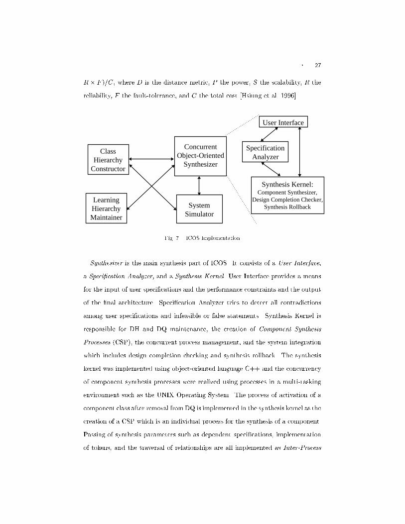
� 27R � F )=C, where D is the distance metric, P the power, S the scalability, R thereliability, F the fault-tolerance, and C the total cost [Hsiung et al. 1996].Class
HierarchyConstructor
LearningHierarchyMaintainer
ConcurrentObject-Oriented
Synthesizer
SystemSimulator
User Interface
SpecificationAnalyzer
Synthesis Kernel:Component Synthesizer,
Design Completion Checker,Synthesis RollbackFig. 7. ICOS ImplementationSynthesizer is the main synthesis part of ICOS. It consists of a User Interface,a Speci�cation Analyzer, and a Synthesis Kernel. User Interface provides a meansfor the input of user speci�cations and the performance constraints and the outputof the �nal architecture. Speci�cation Analyzer tries to detect all contradictionsamong user speci�cations and infeasible or false statements. Synthesis Kernel isresponsible for DH and DQ maintenance, the creation of Component SynthesisProcesses (CSP), the concurrent process management, and the system integrationwhich includes design completion checking and synthesis rollback. The synthesiskernel was implemented using object-oriented language C++ and the concurrencyof component synthesis processes were realized using processes in a multi-taskingenvironment such as the UNIX Operating System. The process of activation of acomponent class after removal from DQ is implemented in the synthesis kernel as thecreation of a CSP which is an individual process for the synthesis of a component.Passing of synthesis parameters such as dependent speci�cations, implementationof tokens, and the traversal of relationships are all implemented as Inter-Process

28 �generic.update_spec(){ if (generic.type==P-node) return 0; for each spec ∈ generic.SPEC do i = 0; while(spec=NULL) do if(last_dep_class()) break; query_spec(spec, dep_class[i++]; endwhile if(spec==NULL) query_user(spec); endfor}
generic.reuse(){ switch(generic.type){ case “A-node” : if(generic.synthesized) fsgl();
else return 0; break; case “G-node” : if(generic.synthesized) egl();
else return 0; break; }}
generic.synthesize(){ if(generic.type==A-node) synthesize() = iterate(); else if(generic.type==G-node) synthesize() = generate(); else synthesize() = NoOp();}
iterate(){ for each generic.child do if required(generic.child){ AddDH(generic.child); if((generic.child).type != P-node)
AppendDQ(generic.child); else instantify(generic.child); } explore_design_space(); endfor}
generate(){ for each generic.child do if(acceptable(generic.child) { AddDH(generic.child); if((generic.child).type != P-node) AppendQ(generic.child); else { instantify(generic.child); dse(); } } endfor}Fig. 8. Some Generic Class Functions in ICOSCommunications. A CSP is killed as soon as the self-synthesis of that componentis complete.The �rst illustrative example using the ICOS methodology has just been depictedalong with the presentation of ICOS in Section 4 and is concluded in the followingSection 5.1. Another synthesis example is given in Section 5.2. A list of otherapplication examples are given in Section 5.3. Some observations are presented inthe �nal subsection.5.1 Example 1. Synthesis of the Small Illustrative ExampleThe small illustrative example has been successfully synthesized through the threephases of ICOS as shown in Section 4. Table VI shows how the use of machinelearning in ICOS reduces the total number of nodes to be synthesized and how the
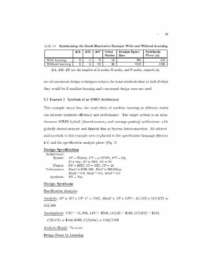
� 29Table VI. Synthesizing the Small Illustrative Example With and Without Learning#A #G #P TotalNodes Design SpaceSize SynthesisTime (s)With learning 6 2 8 16 384 558Without learning 9 5 16 30 1052 1200#A, #G, #P are the number of A-nodes, G-nodes, and P-nodes, respectively.use of concurrent design techniques reduces the total synthesis time to half of whatthey would be if machine learning and concurrent design were not used.5.2 Example 2. Synthesis of an MIMD ArchitectureThis example shows how the total e�ect of machine learning at di�erent nodescan increase synthesis e�ciency and performance. The target system is an asyn-chronous MIMD hybrid (shared-memory and message-passing) architecture withglobally shared memory and Shared Bus as System Interconnection. All abbrevi-ated symbols in this example were explained in the speci�cation language (Section4.1) and the speci�cation analysis phase (Fig. 5).Design Speci�cationArchitecture:System: AT = Hybrid, CT = a-MIMD, MT = GS,SI = Bus, SP = 1024, NC = 64Cluster: PU = RISC;CI = MIN;CP = 16Performance: MaxC = $700; 000, MinP = 500M ops,MinR = 0:9, MinF = 0:5, MinS = 0:5.Synthesis: ML = YesDesign Synthesis:Speci�cation Analysis:Analysis: SP = NC � CP, C > USC, MaxC > SP � LPC + LC(SI) + LC(MT) =512; 300.Assumptions: USC = $1; 000, LPC = $500, LC(SI) = $150, LC(MT) = $150,C(RAM) = $140=4MB, C(Cache) = $100=1MB.Analysis Result: No errorDesign Reuse by Learning:
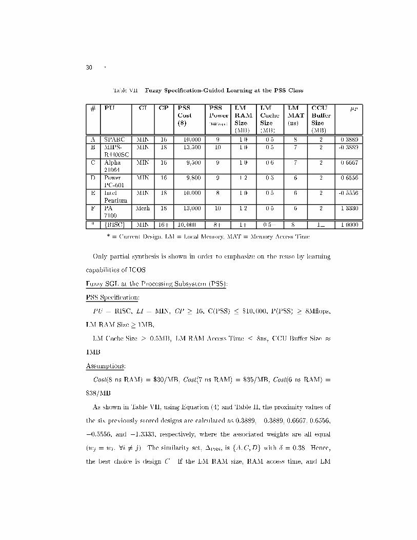
30 � Table VII. Fuzzy Speci�cation-Guided Learning at the PSS Class# PU CI CP PSSCost($) PSSPower(MFlops) LMRAMSize(MB) LMCacheSize(MB) LMMAT(ns) CCUBu�erSize(MB) �PA SPARC MIN 16 10,000 9 1.0 0.5 8 2 0.3889B MIPS-R4400SC MIN 18 13,500 10 1.0 0.5 7 2 -0.3889C Alpha-21064 MIN 16 9,500 9 1.0 0.6 7 2 0.6667D PowerPC-601 MIN 16 9,800 9 1.2 0.5 6 2 0.6556E IntelPentium MIN 18 10,000 8 1.0 0.5 6 2 -0.5556F PA-7100 Mesh 18 13,000 10 1.2 0.5 6 2 -1.3330* fRISCg MIN 16+ 10; 000� 8+ 1+ 0.5+ 8� 1� 1.0000* = Current Design, LM = Local Memory, MAT = Memory Access TimeOnly partial synthesis is shown in order to emphasize on the reuse by learningcapabilities of ICOS.Fuzzy SGL at the Processing Subsystem (PSS):PSS Speci�cation:PU = RISC, LI = MIN, CP � 16, C(PSS) � $10; 000, P(PSS) � 8M ops,LM RAM Size � 1MB,LM Cache Size � 0:5MB, LM RAM Access Time � 8ns, CCU Bu�er Size �1MB.Assumptions:Cost(8 ns RAM) = $30/MB, Cost(7 ns RAM) = $35/MB, Cost(6 ns RAM) =$38/MB.As shown in Table VII, using Equation (4) and Table II, the proximity values ofthe six previously stored designs are calculated as 0:3889, �0:3889, 0:6667, 0:6556,�0:5556, and �1:3333, respectively, where the associated weights are all equal(wj = wi; 8i 6= j). The similarity set, �PSS, is fA;C;Dg with � = 0:38. Hence,the best choice is design C. If the LM RAM size, RAM access time, and LM

� 31Cache size are given greater importance than the cost of PSS, i.e., wj = 1=9 forj = 1; 2; 3; 5; 9, w4 = 1=18 and wi = 7=54 for i = 6; 7; 8, then the proximity valuesare recalculated for A, C, and D as 0.3889, 0.6389, and 0.6704, respectively. In thiscase, D becomes the best design choice.Similarly, fuzzy SGL is performed at the MSS class. The saving of design timeand cost are as shown in Table VIII.Table VIII. Synthesizing Example 2 With and Without Learning#A #G #P TotalNodes Design SpaceSize SynthesisTime (s)With learning 4 1 4 9 128 392Without learning 9 4 15 28 512 1150#A, #G, #P are the number of A-nodes, G-nodes, and P-nodes.5.3 Other ExamplesThe sample designs synthesized by PSM in [Hsiung et al. 1996] were resynthesizedusing ICOS. Table IX compares the performance of PSM and ICOS in synthesizingsimilar designs.From Table IX, we observe that intelligent reuse by learning in ICOS has helpedto considerably reduce the total number of nodes synthesized, thus reducing theoverall design time by an appreciable amount. The number of nodes synthesized byPSM was two to three times larger than that required by ICOS. Due to concurrentdesign and intelligent reuse, the time required by ICOS to synthesize a completemultiprocessor system is approximately half to one-third of that required by PSM.This shows the e�ciency of ICOS over PSM in designing MP systems, when intel-ligent reuse by learning and concurrent synthesis is used along with object-orienteddesign.5.4 ObservationsSome observations are made from the examples given in this section.

32 � Table IX. Comparison between PSM and ICOSDesign AT CT MT SI SP NC MaxC(104$) MinPA Hybrid SIMD GD HC 10,240 2,560 1,150 10.5B Hybrid SIMD GD MIN 1,024 256 110 5.4C SM MIMD GS Bus 1,024 256 175 128D MP MIMD DU HC 512 218 60 2AT, CT, . . . are symbols from the speci�cation language of ICOSDesign CPSM CICOS SPSM SICOS TPSM TICOSA 32 15 480 120 605 300B 26 11 440 102 519 242C 29 11 400 100 580 250D 20 8 388 64 472 168CPSM , CICOS are the no. of components synthesized by PSM and ICOS, respectivelySPSM , SICOS are the design space sizes explored by PSM and ICOS, respectivelyTPSM , TICOS are the design time in seconds for PSM and ICOS, respectively.(1) Learning consistency:The similarity set �cls does not depend on the weights (wj) associated witheach speci�cation of cls. This shows that irrespective of the degree of impor-tance given to the di�erent speci�cations, the acceptable previous designs tobe considered for reuse by learning always remain the same.(2) Speci�cation tradeo�:By varying the weights associated with each speci�cation, the �tness of a �nalprevious design to be reused for the current application may vary. This showsthe exibility of ICOS learning which allows the designer to tradeo� amongvarious speci�cations.(3) Fuzzy ordering:Given numerous speci�cations of a design to be synthesized, it becomes verydi�cult to associate an ordering among the designs in the Learning Hierarchy.This ordering is necessary for selecting the most similar designs to be reused.Learning in ICOS accomplishes this by using a fuzzy proximity set.

� 33(4) Saving in design time:The number of nodes of each type (A, G, and P ) to be synthesized with andwithout learning varies greatly. As shown in the Small Illustrative Exampleand Example 2, learning during synthesis reduces the total number of nodesto be synthesized to approximately half (Table VI) or even one-third (TableVIII) of that which would be required if no learning was used, respectively.Considerable time and e�ort are thus saved.6. CONCLUSION AND FUTURE WORKThe design methodology, Intelligent Concurrent Object-Oriented Synthesis (ICOS)was presented and implemented. OO-based design representation and fuzzy search-ing were used in ICOS to successfully synthesize multiprocessor systems by consid-ering all the features of MP systems. Several representative design examples weresynthesized using ICOS and compared with those synthesized by PSM [Hsiung et al.1996]. The experimental results were in adherence to our initial motives.We have shown how a complete design methodology integrated the techniques ofOO, fuzzy logic, concurrent design, and machine learning in modeling and design,design-space exploration, synthesis process, and intelligent reuse, respectively. Eachof the four techniques contributes towards synthesis e�ciency. Consider the totaldesign time T (n) = �(m)n as given in Equation (1). Object-oriented and concurrentdesign reduces the average design time � of a single component by a factor ofapproximately 3. Fuzzy DSE, without trading o� the design quality, reduces thenumber of specializations (m) needed to be considered for further synthesis toMaxS, which is only half of the total number of specializations. Intelligent learningdrastically reduces the total number of nodes (n) synthesized to approximately n=2or even n=3 since reusing an A-node means the whole sub-tree rooted at the A-nodeneed not be synthesized again. Each of the four techniques helps to reduce somepart of the total design time. The upper bound of the total design time is nowTICOS(n) � �OO-CS(MaxS)nL , where �OO-CS is the average design time of a single

34 �component when the system is designed using OO and concurrent synthesis, MaxSis the number of specializations considered for fuzzy DSE (Equation (7)) and nL isthe total number of nodes needed to be synthesized when learning is used. TICOS(n)is signi�cantly smaller then T (n) even for a small system, with a small n.The excellent blend or integration of object-oriented techniques, concurrent syn-thesis, fuzzy logic, and machine learning has resulted in an e�cient and intelligentsynthesis approach to multiprocessor system design. Future research directions inthis �eld of multiprocessor system design automation will involve the explorationof the possibility of a hardware-software cosynthesis approach and the formulationof a formal theoretical base for system-level synthesis.ReferencesAntonellis, V. D. and Pernice, B. 1995. Reusing speci�cations through re�nement levels.Data and Knowledge Engineering 15, 2 (April), 109{133.Birmingham, W. P., Gupta, A. P., and Siewiorek, D. P. 1989. The MICON system forcomputer design. In Proc. 26th ACM/IEEE Design Automation Conference (1989). pp.135{140.Chiang, M. C. and Sohi, G. S. 1992. Evaluating design choices for shared bus multipro-cessors in a throughput-oriented environment. IEEE Trans. on Computers 41, 3 (March),297{317.Chung, M. J. and Kim, S. 1990. An object-oriented VHDL design environment. In Proc.27th. ACM/IEEE Design Automation Conference (1990). pp. 431{436.Dutta, R., Roy, J., and Vemuri, R. 1992. Distributed design-space exploration for high-level synthesis systems. In Proc. 29th. ACM/IEEE Design Automation Conference (1992).pp. 644{650.Gadient, A. J. and Thomas, D. E. 1993. A dynamic approach to controlling high-levelsynthesis CAD tools. IEEE Trans. on VLSI Systems 1, 3 (September), 328{341.Gupta, A. P., Birmingham, W. P., and Siewiorek, D. P. 1993. Automating the de-sign of computer systems. IEEE Transactions on Computer-Aided Design of IntegratedCircuits 12, 4 (April), 473{487.Hsiung, P.-A. 1996. System level synthesis for parallel computers. Ph. D. thesis, GraduateInstitute of Electrical Engineering, National Taiwan University, Taipei, Taiwan.Hsiung, P.-A., Chen, S.-J., Hu, T.-C., and Wang, S.-C. 1996. PSM: An object-orientedsynthesis approach to multiprocessor system design. IEEE Trans. on VLSI Systems 4, 1(March), 83{97.Hsiung, P.-A., Lee, T.-Y., and Chen, S.-J. 1997. MOBnet: An extended Petri net modelfor the concurrent object-oriented system-level synthesis of multiprocessor systems. IEICETrans. on Information and Systems E80-D, 2 (February), 232{242.Kang, E. Q., Lin, R.-B., and Shragowitz, E. 1994. Fuzzy logic approach to VLSI place-ment. IEEE Trans. on VLSI Systems 2, 4 (December), 489{501.Kodratoff, Y. 1988. Introduction to Machine Learning. Morgan-Kau�man.Kumar, S., Aylor, J. H., Johnson, B. W., and Wulf, W. A. 1994. Object-orientedtechniques in hardware design. IEEE Computer 27, 6 (June), 64{70.Lee, Y. K. and Park, S. J. 1993. OPNETS: An object-oriented high-level Petri-net modelfor real-time system modeling. Journal of Systems Software 20, 1 (January), 69{86.
� 35Lin, R. and Shragowitz, E. 1992. Fuzzy logic approach to placement problem. In Proc.29th. ACM/IEEE Design Automation Conference (1992). pp. 153{158.Mabbs, S. A. and Forward, K. E. 1994. Performance analysis of MR-1, a clustered shared-memory multiprocessor. Journal of Parallel and Distributed Computing 20, 2 (February),158{175.Mitchell, T. M., Mahadevan, S., and Steinberg, L. I. 1985. LEAP: A learning appren-tice for VLSI design. In Proc. 9th IJCAI (1985). pp. 573{580.Rezaz, M. and Gau, J. 1990. Fuzzy set based initial placement for ic layouts. In Proc.European Design Automation Conference (1990). pp. 655{659.Rumbaugh, J., Blaha, M., Premerlani, W., Eddy, F., and Lorensen, W. 1991. Object-Oriented Modeling and Design. Prentice-Hall.Scienti�c and Engineering Software, Inc. 1992. SES/Workbench User's Manual Release 2.1.Scienti�c and Engineering Software, Inc.Shaw, M., Wulf, W., and London, R., Eds. 1981. Abstraction and Veri�cation in Al-phard: Iteration and Generators (1981). Springer-Verlag.