Object-oriented modeling and simulation of flexible manufacturing systems: a rule-based procedure
26
Object-oriented modeling and simulation of flexible manufacturing systems: a rule-based procedure A. Anglani a , A. Grieco a , M. Pacella a, * , T. Tolio b a Dipartimento di Ingegneria dellÕInnovazione, Universit a degli Studi di Lecce, Via per Arnesano, Lecce, 73100, Italy b Dipartimento di Meccanica, Politecnico di Milano, Via Bonardi 9, Milano, 20133, Italy Received 15 December 2001; received in revised form 22 May 2002 Abstract Simulation by a software model, is one of the most frequently used techniques for the anal- ysis and design of manufacturing systems. In the software engineering research area, the ob- ject-oriented approach has fully demonstrated to be an effective technique with respect to the design and implementation phases of complex software projects. Even if object-oriented pro- gramming has proven to be a powerful technique, a systematic design method should also be used in order to implement reliable software, in particular in the development of simulation models. This paper presents a new procedure to develop flexible manufacturing system (FMS) simulation models, based on the UML analysis/design tools and on the ARENA â sim- ulation language. The two main features of the proposed procedure are the definition of a sys- tematic conceptual procedure to design FMS simulation models and of a set of rules for the conceptual model translation in a simulation language. The goal is to improve the software development efficiency through a rule-based approach and to add some of the fundamental object-oriented features to the ARENA â simulation environment. Ó 2002 Elsevier Science B.V. All rights reserved. Keywords: Manufacturing discrete-event simulation; Object-oriented programming; Flexible manufactur- ing systems * Corresponding author. Fax: +39-0832-320-279. E-mail address: [email protected] (M. Pacella). 1569-190X/02/$ - see front matter Ó 2002 Elsevier Science B.V. All rights reserved. PII:S1569-190X(02)00100-4 Simulation Modelling Practice and Theory 10 (2002) 209–234 www.elsevier.com/locate/simpat
-
Upload
independent -
Category
Documents
-
view
0 -
download
0
Transcript of Object-oriented modeling and simulation of flexible manufacturing systems: a rule-based procedure
Object-oriented modeling and simulationof flexible manufacturing systems:
a rule-based procedure
A. Anglani a, A. Grieco a, M. Pacella a,*, T. Tolio b
a Dipartimento di Ingegneria dell!Innovazione, Universit!aa degli Studi di Lecce, Via per Arnesano,Lecce, 73100, Italy
b Dipartimento di Meccanica, Politecnico di Milano, Via Bonardi 9, Milano, 20133, Italy
Received 15 December 2001; received in revised form 22 May 2002
Abstract
Simulation by a software model, is one of the most frequently used techniques for the anal-ysis and design of manufacturing systems. In the software engineering research area, the ob-ject-oriented approach has fully demonstrated to be an e!ective technique with respect to thedesign and implementation phases of complex software projects. Even if object-oriented pro-gramming has proven to be a powerful technique, a systematic design method should also beused in order to implement reliable software, in particular in the development of simulationmodels. This paper presents a new procedure to develop flexible manufacturing system(FMS) simulation models, based on the UML analysis/design tools and on the ARENA! sim-ulation language. The two main features of the proposed procedure are the definition of a sys-tematic conceptual procedure to design FMS simulation models and of a set of rules for theconceptual model translation in a simulation language. The goal is to improve the softwaredevelopment e"ciency through a rule-based approach and to add some of the fundamentalobject-oriented features to the ARENA! simulation environment." 2002 Elsevier Science B.V. All rights reserved.
Keywords: Manufacturing discrete-event simulation; Object-oriented programming; Flexible manufactur-ing systems
*Corresponding author. Fax: +39-0832-320-279.E-mail address: [email protected] (M. Pacella).
1569-190X/02/$ - see front matter " 2002 Elsevier Science B.V. All rights reserved.PII: S1569-190X(02 )00100-4
Simulation Modelling Practice and Theory 10 (2002) 209–234
www.elsevier.com/locate/simpat

1. Introduction
A flexible manufacturing system (FMS) is an integrated production system com-posed by a set of independent machining centers (MCs). An automatic part handlingsystem (PHS) interconnects the MCs to a group of part-storage locations such asloading/unloading positions and input/output bu!ers. An automatic tool handlingsystem (THS) interconnects the MCs to a group of tool-storage locations as toolmagazines, tool rooms, exchangers and spindles [10,16]. Either the PHS and THSmechanisms consist of one or more automated guided vehicles (AGVs) or transport-ers. A central supervisor (the FMS control software) monitors and manages thewhole system. Three di!erent kinds of object flows may be identified: the materialflows (physical objects as parts, tools, pallets and fixtures), the information flows(abstract objects that describe the system status), and the decision flows (abstract ob-jects that modify the system status) [12,22].
The FMSs are complex and expansive systems that require an accurate designingphase. In particular, it is important to examine closely the dynamic behavior of thedi!erent FMS components in order to predict the performance of the productionsystem. The simulation is an essential tool for the design and the operational perfor-mance analysis of complex systems that cannot be easily described by analytical ormathematical models [19]. In particular, in the manufacturing field, the simulationcan be used to configure the production system, or to select the more appropriatemanagement rules [17].
The rapid expansion of the simulation software market accounts for the popular-ity of this type of tool [14]. Various discrete-event simulation languages oriented tothe manufacturing environment are in use today. For example, ARENA! by SystemModeling [21] and AutoMod! by AutoSimulation [19] are two of the most com-monly used simulation languages at this moment both in the academic and in the in-dustrial field. These tools consist of a collection of high-level constructs allowing thedeveloper to achieve many of the tasks routinely required in the developing of a sim-ulation project. Since their abstractions are focused to represent independent entityflows between processes, each of these tools is commonly referenced to as transac-tion-oriented discrete-event language. On the other hand, the object-oriented (O-O)simulation languages are based on a set of object classes that model the behaviorof real system components. An example of O-O simulation language that has beenadopted in manufacturing is eM-Plant! by Tecnomatix. An O-O software systemoperates by allowing the objects to pass messages. Each message represents a requestto an object to perform certain functions.
Generally, an object model of a manufacturing system is designed by means of in-termediate steps in which the real system components are described in an abstractmode through three di!erent types of flows: materials, information, and decisions[6]. However, the implementation of the relative simulation model is a di"cult taskif the adopted approach does not guide the developers to associate their ideas of thesystem under study with the simulation tools. Indeed, in many of current simulationapproaches, despite the existence of well-developed tools, it is often di"cult to trans-
210 A. Anglani et al. / Simulation Modelling Practice and Theory 10 (2002) 209–234
form system requirements into the simulation program and the whole implementa-tion process is still carried in an intuitive manner.
This paper presents a new O-O procedure to implement FMS simulation models.The goal of the research is to provide developers of an integrated procedure that cov-ers the whole development process (from the domain analysis to the software imple-mentation). The modeling phase is based on the unified modeling language (UML)[7]. The UML is a set of notations that have been standardized in order to representobject-oriented software system. For the implementation phase, even if an object-ori-ented coding environment can be chosen, the ARENA! transaction-oriented simu-lation language has been selected in the proposed procedure. The main advantage ofa language such as ARENA! is that it is commonly used in the industrial field for thesimulation of manufacturing and material handling systems (MHSs).
In the following sections of this paper the presented procedure will be referencedto as UMSIS (UML Modeled SIMAN Implemented Simulation software) [2]. Theremainder of the paper is structured as follows. In Section 2, current literatureis analyzed. In Section 3, a brief overview of the tools exploited in the proposed pro-cedure, namely ARENA! and UML, is provided. The main features of UMSISare presented in Section 4. Section 5 describes in detail the conceptual modeldesign while the basic rules to translate the UML model in ARENA! code are illus-trated in Section 6. The application of UMSIS to develop a part of a FMS simula-tion model is demonstrated in Section 7.
2. Related researches
The choice of the O-O approach [4,11,25] to design manufacturing models ismainly due to the complex nature of the problem. This paradigm requires that thedevelopers identify a set of objects from the problem domain and express the oper-ations of the system as interactions (message passing) between these objects. In liter-ature, several O-O applications and methodologies for the manufacturing can befound [13,15,20,29]. Each author recognizes in the object orientation a valid ap-proach in order to develop manufacturing simulation model. The main advantageof the O-O approach is the possibility to translate each component of the real systemin an equivalent element of code: the object. With this feature, the developer mayachieve a better and faster transition of the conceptual model into the software im-plementation. Narayanan et al. [19] provide a review of the most di!used O-O meth-odologies to design manufacturing system software models. A framework of analysisfor production system modeling approaches is also proposed in their work.
Di!erent authors have proposed various modeling approaches that share a seriesof well-known object-oriented concepts despite the fact they express them in di!erentways with di!erent notations. For example, Chen and Lu [6] have presented an ob-ject-oriented methodology to design production system software-models by means ofthe Petri nets, the ERD (entity relationship diagram) and the IDEF0 (IntegratedDEFinition language for functional modeling). Wang [30] has suggested that an
A. Anglani et al. / Simulation Modelling Practice and Theory 10 (2002) 209–234 211
integrated approach is necessary in order to enhance the model designing e"ciency.Therefore, the author provides a methodology that is based on an integrated envi-ronment, which covers the whole implementation process by means of a rule-basedprocedure.
In the OOSIM methodology (Object-Oriented Simulation In Manufacturing[3,18]) the requirement analysis is conducted by means of two domain decomposi-tions: plant/control vs. processing/logistic. A method to model a general FMS behav-ior framework and a procedure to design the related object-oriented simulationmodel has been both presented by Kellert et al. [12]. The aim of the study is mainlyto show that the O-O approach, for FMS simulation, confers characteristics of gen-erality and modularity to the model and it allows the automatic translation into thesimulation language. For this purpose, a set of rules, for a systematic development ofSLAM II simulation code from a conceptual model, is provided. The work of Kellertet al. underlines the need to make reworking of conceptual models, developedthrough an object-oriented paradigm, into simulators that are implemented througha proven discrete event transaction-oriented simulation language.
In this work, the ARENA! simulation language has been used to developFMS simulation models. In the following section, a brief overview of both the ARE-NA! simulation language and of the adopted object-modeling notation UML is pro-vided.
3. Background of UMSIS tools: ARENA and UML
ARENA!, by System Modeling Corporation [21], is a graphical transaction-ori-ented language for the discrete-event simulation; it is one of the most commonly usedsimulation languages at this moment [1,8,15,23,26]. In the ARENA! software, thelanguage functionality is incorporated in the building blocks, called modules, withwhich simulation models can be implemented. Basing on type and level of function-ality, these modules are grouped together in panels called templates. In many cases, itis rather simple to build a running model from the high-level modules available in thelanguage. Nevertheless, it may be di"cult to implement a model if a required func-tion has not built in the language. Indeed, the native high-level ARENA! templatesmay not be su"cient to build any simulation models, and the developers need to im-plement their own object models in customized ARENA! modules.
The UML is a set of object-oriented modeling notations that have been standard-ized by the object management group in order to represent every kind of softwaresystem. [5,24,28]. It defines a meta-model based graphical notation that can be usedas a support for formal modeling [9,27]. The UML uses graphical notations to illus-trate a system specification, and since the specification is usually complex, there areseveral diagrams available to provide di!erent views (structural/static and behav-ioral/dynamic) of the analyzed system. The UML diagrams include use case dia-grams, class diagrams, interaction (sequence and collaboration) diagrams, statetransition diagrams, deployment diagrams, activity diagrams etc. In this paper, onlya subset of UML diagrams is used.
212 A. Anglani et al. / Simulation Modelling Practice and Theory 10 (2002) 209–234
The UML reflects some of the best modeling experiences and it incorporates no-tations that have been proven useful in practice. However, the UML in it-self doesnot address problems of how using such notations or how translating a conceptualmodel in a particular simulation language. Therefore, the implementation of a com-plex system model may be a non-trivial task for the non-expert developer, as well asfor the expert one.
The proposed procedure aims to guide the developer to implement FMS simula-tion models by means of the UML notation and the ARENA! language. More spe-cifically, the goal is to provide a design framework in which three developing toolsare integrated. The first one consists in a set of concepts that assist the developerin the domain analysis phase. The second tool is a group of rules that guide the de-veloper to translate a general model of the real system into the O-O model. Finally,the third tool is a set of rules that help the developer to code each object class into theARENA! language.
4. The UMSIS procedure
The proposed procedure, graphically illustrated in Fig. 1, is composed of four dis-tinct phases. While the first three ones aim to obtain a sound UML conceptual modelfor the actual FMS reference environment, in the fourth phase the remarks relatedwith the ARENA! simulation code (i.e. the formal model) implementation are re-ported.
UMSIS is based on specific abstraction concepts expressed by the UML notation.Two essential terms capture the essence of the UMSIS abstraction concepts: compo-nents and use cases. A manufacturing system can be considered as a group of di!er-ent interacting components that are properly combined in order to process rawmaterials. The components of a system react to events by executing activities basedon their roles and functions. When a component interacts with one another or re-sponds to events, it may employ inputs, consumes resources and generates outputs.Moreover, the component internal state may change as a result of interactions. Asimulation-system models these interactions, and it records their e!ects. The usecases are used to model interactions among components, each use case is considereda particular functionality of the system. A use case spells out the action or the se-quence of actions that a component should perform at the occurrence of certainevents. An action is a discrete activity that a component is able to perform. It usuallyentails the change of a component!s internal state.
The first step is the functional model design. It is developed through the UML usecase diagrams and it aims to identify the components and the use cases. The functionalmodel represents the system transformational aspects and it clarifies what the systemdoes (e.g. processing raw parts in order to obtain products) without specifying howit works (e.g. how parts are moved among MCs). In UMSIS, the use case diagramsare used in order to describe the high-level functionality for the modeled system.
The second step is the dynamic model design. It is developed by means of the UMLinteraction diagrams (both the sequence diagram and the collaboration diagram). In
A. Anglani et al. / Simulation Modelling Practice and Theory 10 (2002) 209–234 213
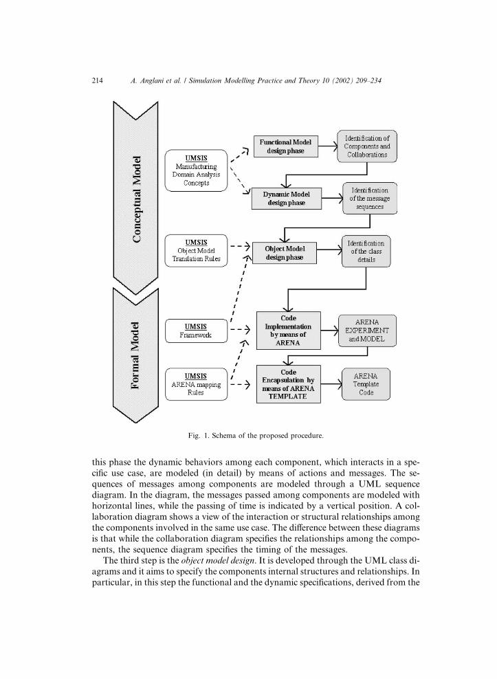
this phase the dynamic behaviors among each component, which interacts in a spe-cific use case, are modeled (in detail) by means of actions and messages. The se-quences of messages among components are modeled through a UML sequencediagram. In the diagram, the messages passed among components are modeled withhorizontal lines, while the passing of time is indicated by a vertical position. A col-laboration diagram shows a view of the interaction or structural relationships amongthe components involved in the same use case. The di!erence between these diagramsis that while the collaboration diagram specifies the relationships among the compo-nents, the sequence diagram specifies the timing of the messages.
The third step is the object model design. It is developed through the UML class di-agrams and it aims to specify the components internal structures and relationships. Inparticular, in this step the functional and the dynamic specifications, derived from the
Fig. 1. Schema of the proposed procedure.
214 A. Anglani et al. / Simulation Modelling Practice and Theory 10 (2002) 209–234

previous diagrams, are combined in order to obtain an appropriate objects classgroup. A class diagram specifies the object internal structure by defining for each ob-ject a specific name, the attributes, the methods and the relationships (such as inheri-tance, aggregation or association) with the other objects. A particular feature of theproposed procedure is that the object model designing is based on a set of rulesand on a general class framework. Such a framework enables to define an associationbetween the elements of a typical FMS and the equivalent object model, by derivingthe object attributes and methods from the functional and the dynamic model, respec-tively.
Since the developing of each phase may have e!ects on the previous ones, theUMSIS procedure should not be considered a sequential approach. Nevertheless,we suggest to build the dynamic model before the object model. Indeed, knowledgeabout messages between components can be derived simply by analyzing the real-system behavior (e.g. timing specifications). Afterwards, by applying the proposedrule-based method, developers can build the more appropriate information struc-ture. This is similar to a function-oriented approach, commonly used to buildreal-time software models (e.g. FMS control software). From our experience, thisapproach may be more suitable for non-expert developers.
After the conceptual model has been fully developed, the discrete-event simulatorsoftware is implemented in the fourth phase of the UMSIS procedure: the formalmodel implementation. Of course, in order to that, a proper object-oriented program-ming language can be selected (e.g. MODSIM by CACI or the general-purpose lan-guage C!!). In addition, UMSIS provides a procedure that allows coding thesimulation software in the ARENA! language. This procedure consists in a set ofrules allowing to code in a detailed way for each object both the MODEL and theconcerning EXPERIMENT. This code is then encapsulated in a customized moduleof a template that guarantees reusability of implemented software. The collection ofmodules represents resources available for use in future development tasks; their reuseoccurs when developing new systems or extending currently implemented systems.
5. The conceptual model implementation
The definition and implementation of manufacturing simulation software is not atrivial task. The complexity of the manufacturing environment makes di"cult basicquestions like to recognize the correct starting point in particular when a new simu-lation model must be built for the first time. The formal identification of the basicsimulation components and of their fundamental features may help to overcomethese di"culties.
Generally, a functional model shows the information flow inside a system: it de-scribes the resources and destinations of data as well as the activities of the transfor-mation functions. In the UMSIS functional model design phase a domain analysis isexecuted. The goal of this phase is to abstract the components of the system understudy and to represent the knowledge of the system functional rules in appropriateuses cases diagrams.
A. Anglani et al. / Simulation Modelling Practice and Theory 10 (2002) 209–234 215
The use case diagrams used in this phase are made up of actors that interact in usecases. The use case diagrams are hierarchically organized. In this way the developersmay focus their attention only on a limited set of system behaviors and the real sys-tem complexity may be described in subsequent steps of more detailed analysis. Themodel hierarchy depth (i.e. the number of diagram levels) depends on the details re-quired by the system analysis. Once identified, the system components are repre-sented by classes. The UML class stereotypes (actor and interface) are used torepresent the general roles of the components within the system, while UML use caseassociations are used to formalize the specific roles assumed in each use case.
Since the result of this important phase will reflect the developer view about theapplication domain, the proposed procedure provides a set of fundamental abstrac-tion concepts. This set may be considered as the general abstraction of the basicelements common to the main manufacturing environment. In detail, any FMS maybe decomposed into the following three sub-systems. The physical sub-system com-posed by machines, tools, transporters, storage facilities and operators. The informa-tion sub-system, which is in charge of storing, transmitting and communicating theinformation related to the system functioning and, finally, decision sub-system,which controls the physical sub-system.
Hence, any FMS can be considered as a set of managers that control a set of re-sources in order to perform some activities (as processing, movement and storage) ona set of materials (physical or information).
Two orthogonal role types are defined for each component. Indeed, each compo-nent has a specific role both in the whole system and in every single use case in whichit is involved. Consequently, each component has a single role in the system but itcan have di!erent roles in di!erent use cases.
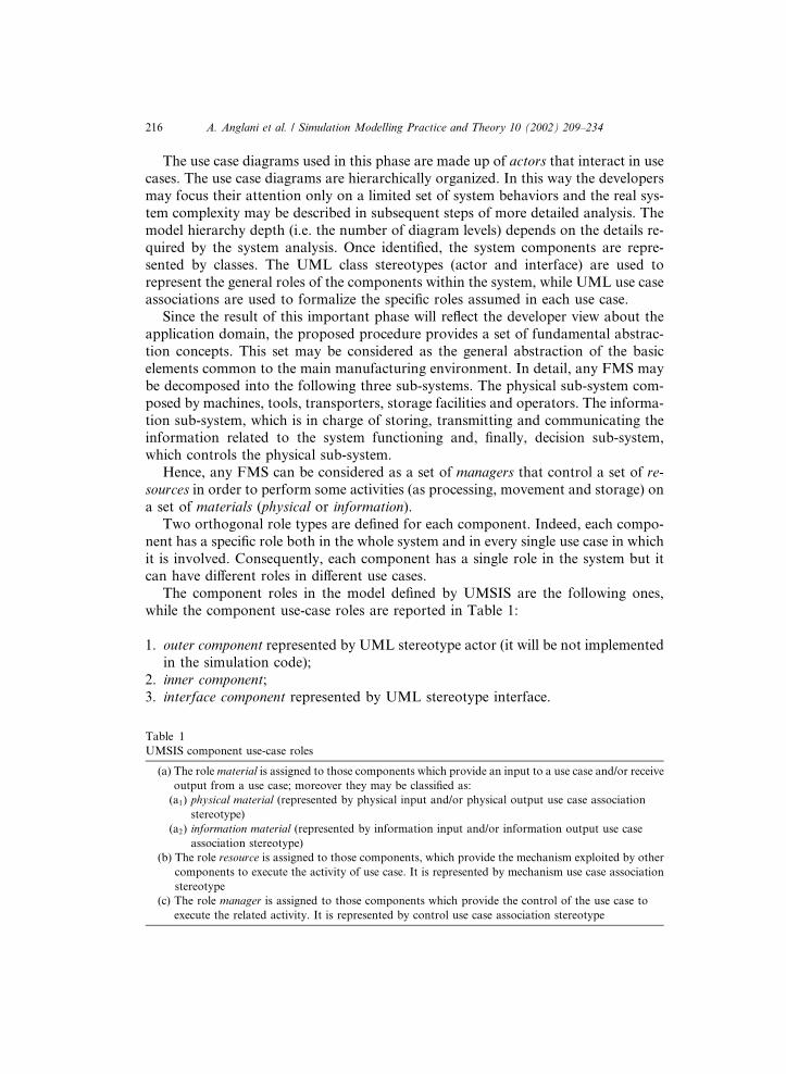
The component roles in the model defined by UMSIS are the following ones,while the component use-case roles are reported in Table 1:
1. outer component represented by UML stereotype actor (it will be not implementedin the simulation code);
2. inner component;3. interface component represented by UML stereotype interface.
Table 1UMSIS component use-case roles
(a) The role material is assigned to those components which provide an input to a use case and/or receiveoutput from a use case; moreover they may be classified as:(a1) physical material (represented by physical input and/or physical output use case association
stereotype)(a2) information material (represented by information input and/or information output use case
association stereotype)(b) The role resource is assigned to those components, which provide the mechanism exploited by other
components to execute the activity of use case. It is represented by mechanism use case associationstereotype
(c) The role manager is assigned to those components which provide the control of the use case toexecute the related activity. It is represented by control use case association stereotype
216 A. Anglani et al. / Simulation Modelling Practice and Theory 10 (2002) 209–234

The UMSIS concepts that are used for the domain analysis are schematically rep-resented by the following Fig. 2.
By adopting these concepts, the developer may represent the actual productionsystem under study in terms of several physical and information components, aug-mented by decision-making components. These last components are the ones ableto make decisions that a!ect the behavior of the system. The model will create a dy-namic operational plan in terms of time-phased decisions that need to be made todrive the system towards a desired state.
With the following list, a simple method of four steps is provided in order to de-sign the functional model. In this method, the classification of the components and ofthe use cases is obtained simply by means of the identification of the physical andinformation flows within the system. By means of the recognition of these flows, itmay be possible to apply the UMSIS abstraction concepts.
1. The physical flow identification: by employing a top–down analysis and a func-tional decomposition, the input/output relationships, among distinct activities(i.e. use cases) performed in the system, are identified by means of physical mate-rial flows. The resources used to actualize such activities should also be specifiedin the functional model.
2. The collaboration identification: any activity (i.e. use case) that has two or moreresources must be decomposing into sub-activities that are more detailed as toeach sub-activity has only one resource. An elementary use case will be referredas a collaboration.
Fig. 2. Functional model design tools.
A. Anglani et al. / Simulation Modelling Practice and Theory 10 (2002) 209–234 217
3. The decision flow identification: a manager for collaboration is identified by meansof a decision flow analysis.
4. The information flow identification: material flow analysis is completed by theidentification of information that each manager needs in order to control usecases.
The result of this first phase is the functional model, which is a static representa-tion of the system behavior without any explicit description of the activity sequences.In order to define the class structures in terms of attributes and operations, it is nec-essary to analyze the dynamic system behavior, during the execution of all the col-laborations. In the proposed procedure, this phase is defined as to the dynamicmodel design. This model describes the temporal evolution, for each component,of a specific collaboration, both in terms of sequences of events and of state trans-actions. The objective is to define what actions must be accomplished by each com-ponent and the derived e!ect, in term of component state changes. The UMLinteraction diagrams are suitable tools that can be used for a complete and detailedrepresentation of software dynamic specifications. Therefore, in this particularphase, no additional modeling procedure is provided by UMSIS. The interactiondiagrams are composed of components (objects) and interactions (messages and ac-tions). They show how use cases are performed in terms of interactions (messagessent) among a set of components. In order to achieve a more comprehensive analysis,another UML tool can be used: the state transition diagrams. They show the se-quence of states that a component goes through, the set of events that cause a tran-sition from one state to another, and finally, the actions that result from a statechange or from an interaction.
After the definition of the functional and the dynamic models, the following stepis to design the object model. In this model, the developer can recognize what objectclasses are involved in the simulator software. Furthermore, the relationship typol-ogies among the defined classes must be provided.
The object model is based on three categories of analysis.
• The class identification. Since class finding depends on the particular consider-ations of each developer, there is no standard method for finding all the classesin a system. In the proposed procedure, class finding through use cases diagramsand interaction diagrams is suggested.
• The class relationship identification. The relationships among classes are estab-lished because suitable generalizations or aggregations may lead in the possibilityof reusing the existing classes reducing furthermore the software developmenttime. Moreover, the generalization relationship may contribute to define newclasses.
• The class structure identification. The attributes and the methods of each class(i.e. the class structure) may be derived from the functional and thedynamic models. In particular, the attributes are mainly derived from the usecase diagrams, while the class methods may be derived from the interactiondiagrams.
218 A. Anglani et al. / Simulation Modelling Practice and Theory 10 (2002) 209–234
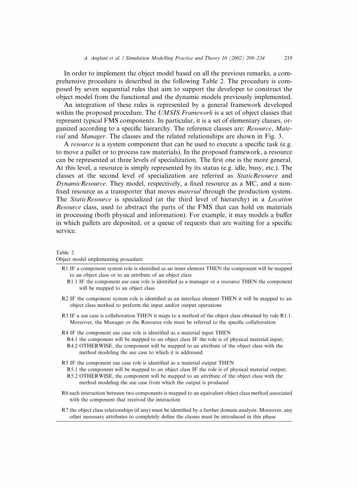
In order to implement the object model based on all the previous remarks, a com-prehensive procedure is described in the following Table 2. The procedure is com-posed by seven sequential rules that aim to support the developer to construct theobject model from the functional and the dynamic models previously implemented.
An integration of these rules is represented by a general framework developedwithin the proposed procedure. The UMSIS Framework is a set of object classes thatrepresent typical FMS components. In particular, it is a set of elementary classes, or-ganized according to a specific hierarchy. The reference classes are: Resource, Mate-rial and Manager. The classes and the related relationships are shown in Fig. 3.
A resource is a system component that can be used to execute a specific task (e.g.to move a pallet or to process raw materials). In the proposed framework, a resourcecan be represented at three levels of specialization. The first one is the more general.At this level, a resource is simply represented by its status (e.g. idle, busy, etc.). Theclasses at the second level of specialization are referred as StaticResource andDynamicResource. They model, respectively, a fixed resource as a MC, and a non-fixed resource as a transporter that moves material through the production system.The StaticResource is specialized (at the third level of hierarchy) in a LocationResource class, used to abstract the parts of the FMS that can hold on materialsin processing (both physical and information). For example, it may models a bu!erin which pallets are deposited, or a queue of requests that are waiting for a specificservice.
Table 2Object model implementing procedure
R1 IF a component system role is identified as an inner element THEN the component will be mappedto an object class or to an attribute of an object class
R1.1 IF the component use case role is identified as a manager or a resource THEN the componentwill be mapped to an object class
R2 IF the component system role is identified as an interface element THEN it will be mapped to anobject class method to perform the input and/or output operations
R3 IF a use case is collaboration THEN it maps to a method of the object class obtained by rule R1.1.Moreover, the Manager or the Resource role must be referred to the specific collaboration
R4 IF the component use case role is identified as a material input THENR4.1 the component will be mapped to an object class IF the role is of physical material input;R4.2 OTHERWISE, the component will be mapped to an attribute of the object class with the
method modeling the use case to which it is addressed
R5 IF the component use case role is identified as a material output THENR5.1 the component will be mapped to an object class IF the role is of physical material output;R5.2 OTHERWISE, the component will be mapped to an attribute of the object class with the
method modeling the use case from which the output is produced
R6 each interaction between two components is mapped to an equivalent object class method associatedwith the component that received the interaction
R7 the object class relationships (if any) must be identified by a further domain analysis. Moreover, anyother necessary attributes to completely define the classes must be introduced in this phase
A. Anglani et al. / Simulation Modelling Practice and Theory 10 (2002) 209–234 219

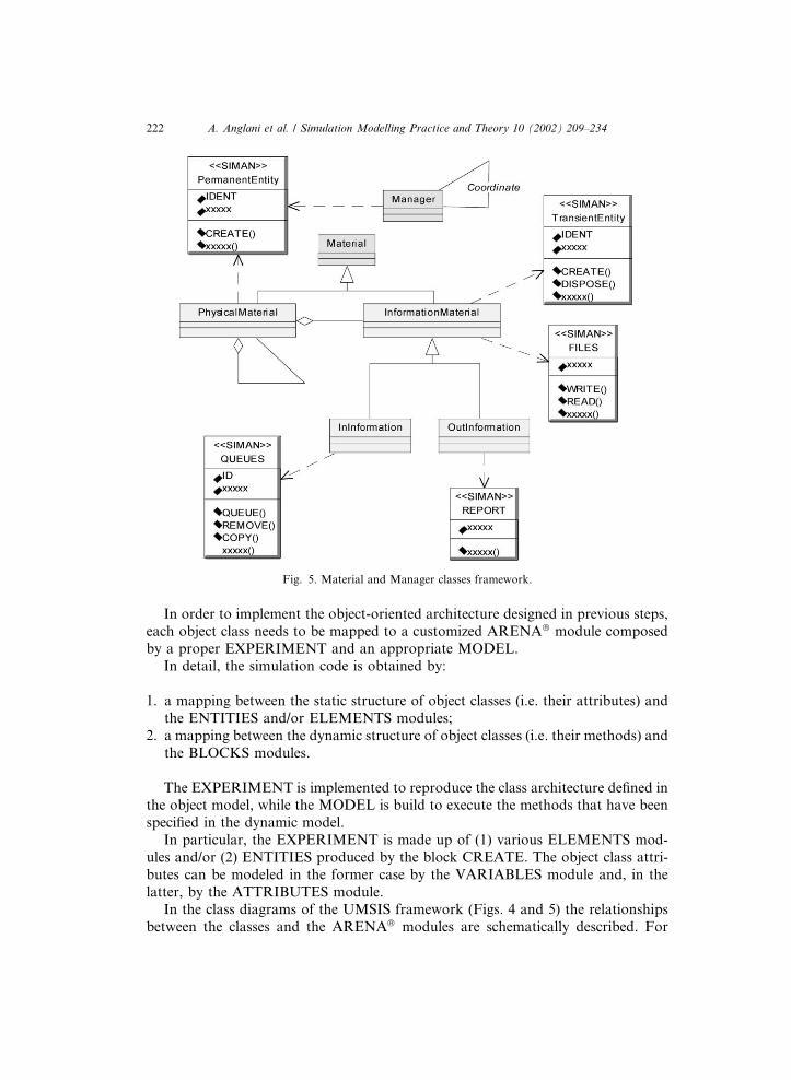
A Material is an object class on which a transformation process, during the sim-ulation, is performed from a raw material to a finished stage. The super type class, atthe first level is specialized into two subtypes PhysicalMaterial and InformationMa-terial. They model objects of physical and information nature respectively. At thethird level, the information material class is specialized into the InInformation andOutInformation on the base of their role respect to the simulation environment.
The decision control of the FMS is modeled by a set of Manager classes each su-pervises a specific resource and co-ordinates other manager classes. Indeed, a man-ager class is the active object of the simulation environment. The following Figs. 4and 5 show in detail the UMSIS framework.
6. The formal model design
In this paragraph, a procedure to translate the UML conceptual model into anARENA! formal model (i.e. a software simulation model) is proposed. The ARE-NA! version used is 3.5 (professional edition). Even if newer versions of this simu-lation language have been released, they are only of minor importance in the contextof this paper. A basic description of the ARENA! language is presented in Section 3.The reader is referenced to [21] for more details.
Generally, the simulation software of a complex production system such as FMScontains many modules with low functionality but high flexibility. For this reason,
Fig. 3. UMSIS framework architecture.
220 A. Anglani et al. / Simulation Modelling Practice and Theory 10 (2002) 209–234
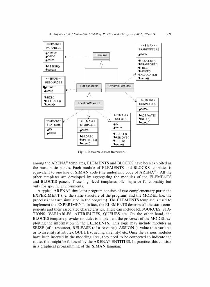
among the ARENA! templates, ELEMENTS and BLOCKS have been exploited asthe most basic panels. Each module of ELEMENTS and BLOCKS templates isequivalent to one line of SIMAN code (the underlying code of ARENA!). All theother templates are developed by aggregating the modules of the ELEMENTSand BLOCKS panels. These high-level templates o!er superior functionality butonly for specific environments.
A typical ARENA! simulator program consists of two complementary parts: theEXPERIMENT (i.e. the static structure of the program) and the MODEL (i.e. theprocesses that are simulated in the program). The ELEMENTS template is used toimplement the EXPERIMENT. In fact, the ELEMENTS describe all the static com-ponents and their associated characteristics. These can include RESOURCES, STA-TIONS, VARIABLES, ATTRIBUTES, QUEUES etc. On the other hand, theBLOCKS template provides modules to implement the processes of the MODEL ex-ploiting the information in the ELEMENTS. This logic may include modules asSEIZE (of a resource), RELEASE (of a resource), ASSIGN (a value to a variableor to an entity attribute), QUEUE (queuing an entity) etc. Once the various moduleshave been inserted in the modeling area, they need to be connected to indicate theroutes that might be followed by the ARENA! ENTITIES. In practice, this consistsin a graphical programming of the SIMAN language.
Fig. 4. Resource classes framework.
A. Anglani et al. / Simulation Modelling Practice and Theory 10 (2002) 209–234 221
In order to implement the object-oriented architecture designed in previous steps,each object class needs to be mapped to a customized ARENA! module composedby a proper EXPERIMENT and an appropriate MODEL.
In detail, the simulation code is obtained by:
1. a mapping between the static structure of object classes (i.e. their attributes) andthe ENTITIES and/or ELEMENTS modules;
2. a mapping between the dynamic structure of object classes (i.e. their methods) andthe BLOCKS modules.
The EXPERIMENT is implemented to reproduce the class architecture defined inthe object model, while the MODEL is build to execute the methods that have beenspecified in the dynamic model.
In particular, the EXPERIMENT is made up of (1) various ELEMENTS mod-ules and/or (2) ENTITIES produced by the block CREATE. The object class attri-butes can be modeled in the former case by the VARIABLES module and, in thelatter, by the ATTRIBUTES module.
In the class diagrams of the UMSIS framework (Figs. 4 and 5) the relationshipsbetween the classes and the ARENA! modules are schematically described. For
Fig. 5. Material and Manager classes framework.
222 A. Anglani et al. / Simulation Modelling Practice and Theory 10 (2002) 209–234
example, it can be noticed that the super-class "StaticResource! is derived from theclass RESOURCES (that is a module of the ARENA! basic template ELEMENTS).Yet, the same class " StaticResource! is also derived from the class VARIABLES (an-other module of the ARENA! basic template ELEMENTS) that is inherited by theclass "Resource!. In order to help the developer to implement the simulation softwarein Table 3 a useful set of mapping rules are derived from the UMSIS framework.
For example, if a class of the conceptual model (e.g. "Machine!) specializes a spe-cific UMSIS class (e.g. "StaticResource!), then the appropriated modules for theEXPERIMENT are those indicated in the associated column of Table 3 (i.e. VARI-ABLES and RESOURCES).
As may be noticed, the cardinality of the relationship between the UMSIS classesand the ARENA modules is of type "1 to n!. The multiplicity depends on the specificcase. For example, a class that is derived from the super-class "StaticResource! (e.g."Machine!) can be implemented just using the module RESOURCES. In this way, itis possible to code typical attributes of a "Machine! class. Nevertheless, the developerwould want to add more attributes (e.g. the status of machining) by means of theVARIABLES module.
Since collaborations has been coded as networks of BLOCKS modules, before ap-plying the mapping table, it should to be checked that the element that initiates a col-laboration has been coded into object classes derived from "Manager! or "Material!.In fact, as reported in Table 3, only "Manager! and "Material! classes map to a per-manent entity and only a permanent entity can generate a method entity (e.g. by aDUPLICATE block).
The ENTITIES can assume a double role, namely:
• object-entity, if it is used to code a specific object class; it can be a permanent en-tity ("Pentity! if it is never disposed during simulation) or a transient entity ("Ten-tity! on the contrary);
• method-entity, if it has been created only to active a specific process that models aclass method (a method-entity is a "Tentity!).
While an object-entity is used to code a specific object class instance, a method-entity is used to code an object-method invocation from another object. For exam-ple, in the case of a client-object that calls a server-object method with assignedparameters, the ARENA! implementation may be the following. The client createsa method-entity with some attributes set up in order to carry all the input parametersand sends this new method-entity to the proper ARENA! block sequence that mod-els the server-method. Each of this sequence has a starting block that is commonly aSTATION-block (to identify the object method) and an ending block that is nor-mally a DISPOSE-block (to stop the object method). In detail, starting block is usedto recognize both the method and the object, which is associated to, while endingblock is used to end the method-execution by destroying the method-entity. To rec-ognize the method it is necessary to send a method-entity to the proper STATIONblock. This is obtained naming each method STATION block with a name in a par-ticular format: "<Object Name>_<Class Name>_<Method Name>!. Furthermore,
A. Anglani et al. / Simulation Modelling Practice and Theory 10 (2002) 209–234 223
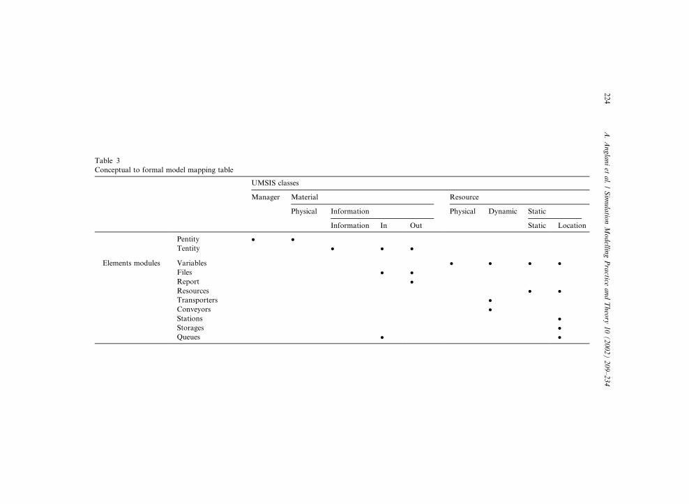
Table 3Conceptual to formal model mapping table
UMSIS classes
Manager Material Resource
Physical Information Physical Dynamic Static
Information In Out Static Location
Pentity " "Tentity " " "
Elements modules Variables " " " "Files " "Report "Resources " "Transporters "Conveyors "Stations "Storages "Queues " "
224A.Anglani
etal.
/Sim
ulationModelling
Practice
andTheory
10(2002)
209–234
each of these station blocks is labeled in a special format: "IN<station name>!; either"IN<Object Name>_<Class Name>_<Method Name>!.
The DUPLICATE module is the block that can be used to create a method-entityby a client-object-entity. Such an instruction allows duplicating an entity with all itsattribute values. In order to recall the client-entity that called the method, method-entity is marked with a special attribute named "IDENT_PARENT! that providesthe IDENT value of the object-entity that has generated it. Since each entity hasits specific IDENT value, server can recognize client i.e. to set some of its attributes(as the output method results). After a method-entity has been created, and sent tothe proper STATION block, the client-object-entity waits for the fulfillment of themethod execution in a WAIT block. The method execution completion is underlinedby a signal send by method-entity (coded by ARENA! SIGNAL block) before it willbe disposed. Since signal code must be exclusively associated with the client-object,its value is choosing equal to the IDENT (either IDENT_PARENT attribute of themethod entity).
Finally, the MODEL and the EXPERIMENT, which code the behavior of a par-ticular class may be encapsulated in a template that guarantees reusability of the im-plemented object class. The proposed procedure results in a particular ARENA!
programming approach in which the developer may build a simulation programby means of customized modules that do not need to be interconnected. The modulesare grouped in templates, and the resulting simulation software is a collection of in-stantiations of such modules (i.e. the objects). Each module interacts with the othersvia a message-passing schema rather than entity flows among independent processes.Moreover, each module encapsulates its inner working, which is hidden to a finaluser that can use it by means of a specific interface.
Furthermore, the implementation of a simulation program by means of custom-izes modules may provide the simulator of the O-O hierarchy feature. In fact, oncea "super-type! class is coded and packaged in a module of a specific template it canbe reused in order to build a "sub-type! module. This is obtained by includingin the ARENA! code of the "sub-type! module the template that contains the"super-type! one. The "sub-type! code is then implemented by adding the necessarycode to specialize its behavior without any modification to the "super-type! modulecode.
7. An UMSIS application example
In this section, the modeling procedure is illustrated by a simple case study. Thebasic description of the UML semantic used in the following diagrams is provided inSection 3; for a detailed explanation the reader is referenced to [5,28].
In the following application example, the reference environment is a FMS com-posed by several MCs and managed by a central supervisor. The main purpose ofan MC is to transform raw parts in final products. The overall-machining phase ex-ecuted by an MC on a part is composed by a sequence of elementary machining pro-cesses, referenced to as operations. The list of operations for each part is called the
A. Anglani et al. / Simulation Modelling Practice and Theory 10 (2002) 209–234 225
part program. Usually each operation is executed by means of a specific tool, and itrequires a certain amount of time. Parts are moved by the MHS between MCs andload/unload tables. The MHS is based on AGV managed by the central supervisor.The decisions of the central supervisor are based on a set of move requests each re-porting source–location and destination–location. When a part has been transportedby AGV system to a MC, the MC controller retrieves from the part program infor-mation about the machining operations (tool type, technological constraints etc.).When all operations are executed, the MC controller stores information about themachining process executed and it sends to the central supervisor a request of move-ment. In the remainder of this section the UMSIS procedure schematically describedin Fig. 1 is applied to build the simulation code of the MC.
The first phase is implementation of the functional model. This is obtained bymeans of the identification of physical and information flows within the system.
(1) Starting from previous description, two main functions (or use cases), namelyMANAGE PART FLOW and WORK, are identified. The former models themovement of the Part component using the PartTransporter resource. Whilethe Part component represents a "physical output! for the MANAGE PARTFLOW function (i.e. the change of position within the system) the PartTrans-porter component represents the "mechanism! that is used by the same function.The WORK function models the machining of Part. Hence, Part componentrepresents the "physical input! for WORK function, while the Machine representsthe "mechanism!. Since Part has a physical nature, it is modeled as a "physicalmaterial! while the PartTransporter and the Machine components are modeledas "resources! because they are used by other components.
(2) Each of the identified activities can be considered as an elementary collaborationindeed each of they is based on a single resource use.
(3) The MANAGE PART FLOW function has to be "controlled! by a specific "man-ager! component. This new component is called PartFlowManager.
(4) The information components in order to execute the activities are the following.(1) The Production Data component that models the information needed by thePartFlowManager component. (2) The System Performance component thatprovides the MC performance results. (3) The Part Program component, it re-ports for each part type the complete operation list. (4) The PartMoveRequestcomponent that represents the movement request from one position to anotherone.
While Production Data, System Performance and Part Program components aremodeled as interface components, the PartMoveRequest component represents an in-ternal information because it models an inner behavior of the system. The resultingfunctional model is illustrated in Fig. 6. It can be noticed that all the componentroles are defined by means of the class stereotypes and the association stereotypesthat have been discussed in Section 5.
Once defined the functional model, it is necessary to specify the dynamic view ofthe system behavior. The goal is reached by identifying the dynamic specification for
226 A. Anglani et al. / Simulation Modelling Practice and Theory 10 (2002) 209–234

each component and their relative interactions within a specific use case. The usecase that is analyzed in this example is the WORK use case.
In Fig. 7, the sequence diagram detailing the WORK use case is depicted whileFig. 8 shows the collaboration diagram. In particular, the collaboration diagramshows the relationships that occur between components in the WORK use case. Itmay be observed that the collaboration WORK is started by the Part component.
Fig. 6. Use case diagram for the application example.
Fig. 7. Sequence diagram for the WORK use case.
A. Anglani et al. / Simulation Modelling Practice and Theory 10 (2002) 209–234 227
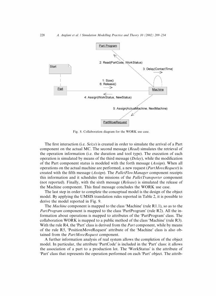
The first interaction (i.e. Seize) is created in order to simulate the arrival of a Partcomponent on the actual MC. The second message (Read) simulates the retrieval ofthe operation information (i.e. the duration and tool type). The execution of eachoperation is simulated by means of the third message (Delay), while the modificationof the Part component status is modeled with the forth message (Assign). When alloperations on the actual machine are performed, a new request (PartMoveRequest) iscreated with the fifth message (Assign). The PalletFlowManager component receiptsthis information and it schedules the missions of the PalletTransporter component(not reported). Finally, with the sixth message (Release) is simulated the release ofthe Machine component. This final message concludes the WORK use case.
The last step in order to complete the conceptual model is the design of the objectmodel. By applying the UMSIS translation rules reported in Table 2, it is possible toderive the model reported in Fig. 9.
The Machine component is mapped to the class "Machine! (rule R1.1), so as to thePartProgram component is mapped to the class "PartProgram! (rule R2). All the in-formation about operations is mapped to attributes of the "PartProgram! class. Thecollaboration WORK is mapped to a public method of the class "Machine! (rule R3).With the rule R4, the "Part! class is derived from the Part component, while by meansof the rule R5, "PositionMoveRequest! attribute of the "Machine! class is also ob-tained from the PartMoveRequest component.
A further information analysis of real system allows the completion of the objectmodel. In particular, the attribute "PartCode! is included in the "Part! class: it allowsthe association of a part to a production lot. The "WorkStatus! is the attribute of"Part! class that represents the operation performed on each "Part! object. The attrib-
Fig. 8. Collaboration diagram for the WORK use case.
228 A. Anglani et al. / Simulation Modelling Practice and Theory 10 (2002) 209–234
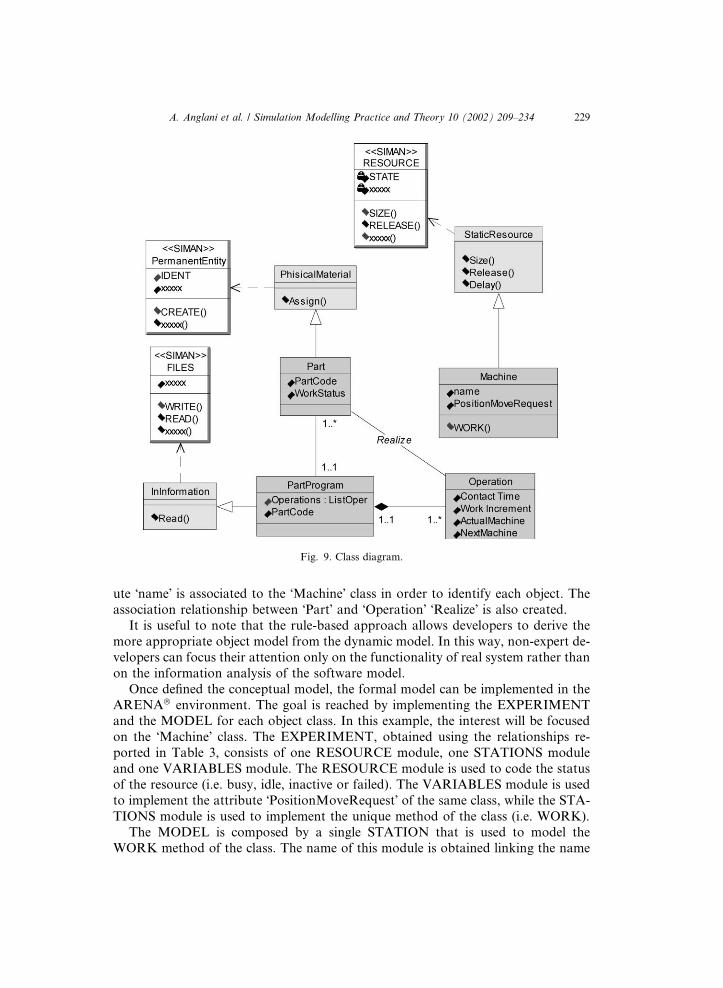
ute "name! is associated to the "Machine! class in order to identify each object. Theassociation relationship between "Part! and "Operation! "Realize! is also created.
It is useful to note that the rule-based approach allows developers to derive themore appropriate object model from the dynamic model. In this way, non-expert de-velopers can focus their attention only on the functionality of real system rather thanon the information analysis of the software model.
Once defined the conceptual model, the formal model can be implemented in theARENA! environment. The goal is reached by implementing the EXPERIMENTand the MODEL for each object class. In this example, the interest will be focusedon the "Machine! class. The EXPERIMENT, obtained using the relationships re-ported in Table 3, consists of one RESOURCE module, one STATIONS moduleand one VARIABLES module. The RESOURCE module is used to code the statusof the resource (i.e. busy, idle, inactive or failed). The VARIABLES module is usedto implement the attribute "PositionMoveRequest! of the same class, while the STA-TIONS module is used to implement the unique method of the class (i.e. WORK).
The MODEL is composed by a single STATION that is used to model theWORK method of the class. The name of this module is obtained linking the name
Fig. 9. Class diagram.
A. Anglani et al. / Simulation Modelling Practice and Theory 10 (2002) 209–234 229
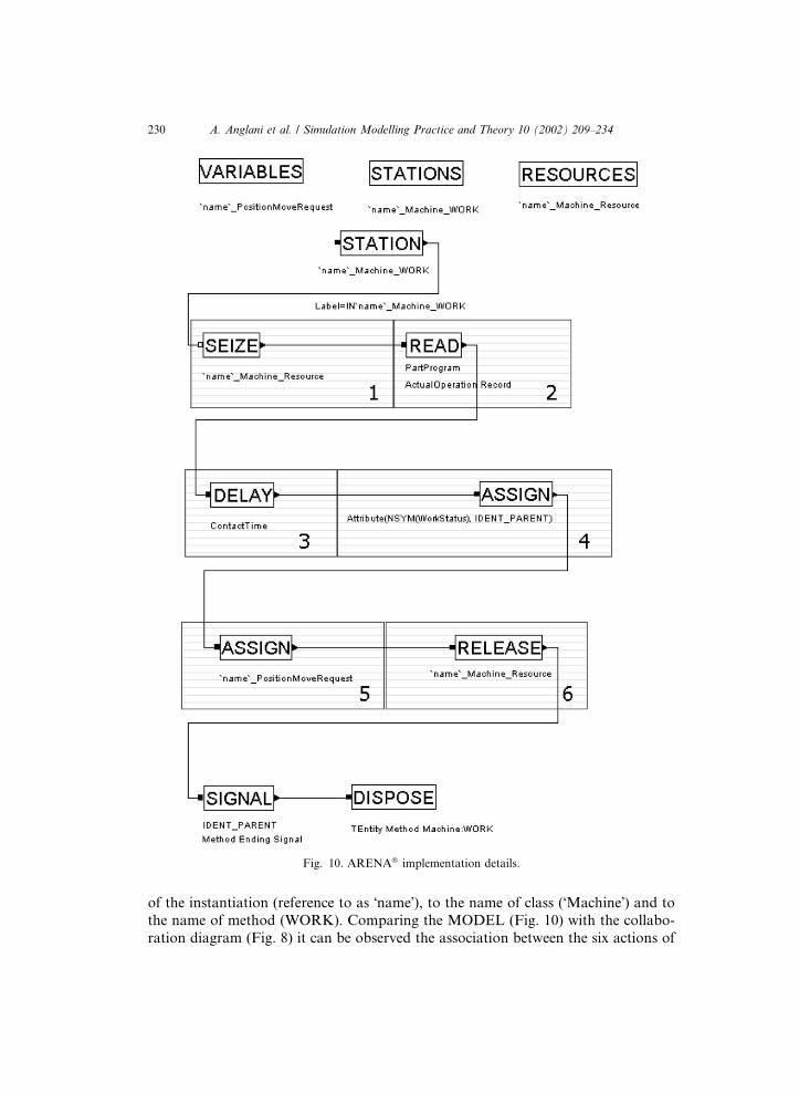
of the instantiation (reference to as "name!), to the name of class ("Machine!) and tothe name of method (WORK). Comparing the MODEL (Fig. 10) with the collabo-ration diagram (Fig. 8) it can be observed the association between the six actions of
Fig. 10. ARENA! implementation details.
230 A. Anglani et al. / Simulation Modelling Practice and Theory 10 (2002) 209–234

the method WORK and the modules of the BLOCKS template that have been used.Moreover, the final module SIGNAL is used to inform the calling object that themethod has been accomplished, while the module DISPOSE is used to end the meth-od running.
Fig. 10 depicts both the EXPERIMENT and MODEL that are implemented tosimulate the method WORK of the "Machine! class.
It can be observed in particular what the role of "PositionMoveRequest! is. It isequivalent to a public attribute of the class "Machine! that can be accessed by "Part-FlowManager! object for scheduling the AGV missions. The decision logic of suchan object, that for simplicity has not been included in the example, results as not de-pendent by the simulated layout. This is so because modules do not need to be con-nected for indicating the route that must be followed by entities. Developers needonly to place modules in the modeling area; next, they can implement an arbitrarydecision logic that interacts with the modules via a message-passing paradigm. Thisway of programming in ARENA! language is more close to object-orientation andit allows obtaining programs that can be re-utilized in various cases and for di!erentsimulation models.
Once the EXPERIMENT and the MODEL, that implement a particular class,have been built, the software code may be packaged in a specific template module.In the analyzed case study, the "Machine! class is coded into a customized ARENA!
module named MACHINE. Each instantiation of this module has a unique identifierthat is referenced to by means of the prefix "name!. This identifier is equivalent tothe attribute "name! of the "Machine! class. Fig. 11 shows the MACHINE module
Fig. 11. Two Machine module instantiations and relative dialogue window.
A. Anglani et al. / Simulation Modelling Practice and Theory 10 (2002) 209–234 231
interface obtained by means of the ARENA! template window. The dialog windowis usually divided into two sections. The first one reports the attributes of the classwhile the second the related methods. The first section of the MACHINE dialog win-dow shows the class attribute values, namely: the "name! and "PositionMoveRequest!values of the Machine object. Even if the users may assign the value of the attributename, they cannot modify the value of the "PositionMove! Request attribute. Indeedthis attribute reports only the name of a global VARIABLE that can be referred byother objects.
For each class "Machine!, more than one instantiation can be implemented. Fig.11 depicts two instantiations of the Machine class. Of course, each object instantia-tion of the Machine class will have a unique "name! (e.g. Machine 1 and Machine 2).The second section of the dialog window shows the labels for each method imple-mented by the object class. In this case is showed the label of the WORK method.To invoke the WORK method of the "Machine 2! object, an object-entity (i.e. a part)has to duplicate itself in a method entity that will be sent to the ARENA! block la-beled "INMachine 2_Machine_WORK!. This block is the STATION block named"Machine 2_Machine_WORK! implemented by the second instantiation of MA-CHINE module.
The use of the MACHINE module allows developers to model arbitrary layoutjust inserting modules in the modeling area. Each MACHINE module is character-ized by a specific attribute that indicates if AGV mission is required or not ("Position-MoveRequest!). The decision controller may analyze this information and,independently by system layout, it may schedule the AGV missions. As result, thesame decision code can be re-utilized for di!erent scenarios and di!erent simulationstudy.
8. Conclusions
In the field of FMS simulation, a need exists to develop a modeling procedure inwhich an object-oriented design phase is integrated to an implementation phase thatis made with a common transaction-oriented simulation language [12]. In this paper,a new procedure to develop FMS simulator software (UMSIS) is presented. Theobject is to formulate a new procedure for developing reusable, modifiable and ex-tendible discrete-event simulation-software using an object-oriented approach imple-mented in a transaction-oriented language.
The work involved here includes the use of UML for specifying the system!s re-quirements, a set of concepts to model FMSs, and a procedure that can be usedto automate the construction of ARENA! programs from UML specifications.
The proposed procedure aims responding to the need of simulation developer byidentifying the objectives of the model development and by guiding the modeler inthe execution of the process to achieve those objectives. UMSIS includes methods,techniques to accomplish individual tasks, and it prescribes an order in which eachtask is made.
232 A. Anglani et al. / Simulation Modelling Practice and Theory 10 (2002) 209–234
The procedure described in this paper has been used in a FMS simulation project.The authors would welcome suggestions and remarks for the use of UMSIS in dif-ferent contexts or for di!erent tasks.
Acknowledgements
The work described in the paper has been partially funded by Ministry of In-struction, University and Research (MIUR) of Italy project PRIN2000––prot.MM09164148_004 "Models for capacity planning in advanced manufacturing sys-tems!. The authors thank also the anonymous referees who have contributed to im-prove the quality of the paper.
References
[1] A.M.A. Al-Ahmari, K. Ridgway, An integrated modeling method to support manufacturing systemanalysis and design, Computers in Industry 38 (1999) 225–238.
[2] A. Anglani, A. Grieco, M. Pacella, Q. Semeraro, T. Tolio, SIMAN implementation of manufacturingmodel defined with UML: application to a real case, in: Proceedings of the 13th European SimulationMulticonference, Warsaw, Poland, 1999, pp. 194–199.
[3] D.A. Bodner, T. Govindaraj, L.F. McGinnis, C.M. Mitchell, An integrated approach to modelingdistributed manufacturing control and human operators, Proceedings of the 1995 IEEE InternationalConference on System, Man, and Cybernetics, Vancouver, Canada, 1995, pp. 3437–3442.
[4] G. Booch, Object-Oriented Analysis and Design with Application, second ed., Benjamin/Cummings,Menlo Park, CA, USA, 1994.
[5] G. Booch, J. Rumbaugh, I. Jacobson, The Unified Modelling Language User Guide, Addison-Wesley, Longman, Reading, MA, USA, 1999.
[6] K.Y. Chen, S.S. Lu, A petri-net and entity-relationship diagram based object-oriented design methodfor manufacturing systems control, International Journal of Computer Integrated Manufacturing 10(1–4) (1997) 17–28.
[7] C.A. Costa, J.A. Harding, R.I.M. Young, The application of UML and an open distributed processframework to information system design, Computers in Industry 46 (2001) 33–48.
[8] H. de Swaan Arons, C.A. Boer, Storage and retrieval of discrete-event simulation model, SimulationPractice and Theory 8 (2000) 555–576.
[9] R. France, A. Evans, K. Lano, B. Rumpe, The UML as a formal modeling notation, ComputersStandards and Interfaces 19 (1998) 325–334.
[10] A. Grieco, Q. Semeraro, T. Tolio, S. Toma, Simulation of tool and part flow in FMSs, InternationalJournal of Production Research 33 (3) (1995) 643–658.
[11] I. Jacobson, M. Christerson, P. Jonsson, G. Overgaard, Object-Oriented Software Engineering,Addison–Wesley, Longman, Reading, MA, USA, 1992.
[12] P. Kelleret, N. Tchernev, C. Force, Object-oriented methodology for FMS modelling and simulation,International Journal of Computer Integrated Manufacturing 10 (6) (1997) 405–434.
[13] R.E. King, K.S. Kim, AgvTalk: an object-oriented simulator for AGV systems, Computers inEngineering 28 (3) (1995) 575–592.
[14] P. Klingstam, P. Gullander, Overview of simulation tools for computer-aided production engineering,Computers in Industry 38 (1999) 173–186.
[15] G.L. Kov"aacs, S. Kop"aacsi, J. Nacsa, G. Haidegger, P. Groumpos, Application of software reuse andobject-oriented methodologies for modelling and control of manufacturing systems, Computers inIndustry 39 (1999) 177–189.
A. Anglani et al. / Simulation Modelling Practice and Theory 10 (2002) 209–234 233

[16] W.W. Luggen, Flexible Manufacturing Cells and Systems, Prentice Hall, New Jersey, USA, 1991.[17] R.D. Macredie, R.J. Paul, Simulation modelling in manufacturing system design: an overview,
International Journal of Manufacturing System Design 2 (3) (1995) 233–247.[18] S. Narayanan, D.A. Bodner, U. Sreekanth, T. Govindaraj, L.F. McGinnis, C.M. Mitchell, Modeling
control decision in manufacturing systems simulation using object, in: Proceeding of the 1994 IEEEInternational Conference on Systems, Man, and Cybernetics, San Antonio, USA, 1994, pp. 1392–1397.
[19] S. Narayanan, D.A. Bodner, U. Sreekanth, T. Govindaraj, L.F. McGinnis, C.M. Mitchell, Researchin object-oriented manufacturing simulations: an assessment of the state of the art, IIE Transaction 30(9) (1998) 795–810.
[20] C. Ou-Yang, T.Y. Guan, J.S. Lin, Developing a computer shop floor control model for a CIMsystem––using object modeling technique, Computers in Industry 41 (2000) 213–238.
[21] C.D. Pegden, R.E. Shannon, R.P. Sadowski, Introduction to Simulation Using ARENA, McGraw-Hill, New York, USA, 1995.
[22] H. Pierreval, On the simulation modelling of control activities in manufacturing systems, in:Proceedings of the 13th European Simulation Multiconference, Warsaw, Poland, 1999, pp. 439–445.
[23] T. Perera, K. Liyanage, Methodology for rapid identification and collection of input data in thesimulation manufacturing systems, Simulation Practice and Theory 7 (2000) 645–656.
[24] Press release, Object Management Group adopts Unified Modeling Language and Meta Object Faci-lity Specification, November 17, 1997, Available from <http://cgi.omg.org/news/pr97/umlpr.html>(January !02).
[25] J. Rumbaugh, M. Blaha, W. Premerlani, F. Eddy, W. Lorensen, Object-Oriented Modeling andDesign, Prentice Hall, New Jersey, USA, 1991.
[26] Y.J. Son, R.A. Wysk, Automatic simulation model generation for simulation-based real-time shopfloor control, Computers in Industry 45 (2001) 291–308.
[27] The UML Group, UML Metamodel, Version 1.1, Rational Software, Santa Clara, CA-95051, USA,September 1997.
[28] The UML Group, Unified Modeling Language, Version 1.1, Rational Software, Santa Clara, CA-95051, USA, July 1997.
[29] J.M. Usher, A tutorial and review of object-oriented design of manufacturing software systems,Computers in Engineering 30 (4) (1996) 781–798.
[30] L.C. Wang, An integrated object-oriented Petri net paradigm for manufacturing control systems,International Journal of Computer Integrated Manufacturing 9 (1) (1996) 73–87.
234 A. Anglani et al. / Simulation Modelling Practice and Theory 10 (2002) 209–234