Object Management Systems - eScholarship
195
ISSN 1055-1425 June 1995 This work was performed as part of the California PATH Program of the University of California, in cooperation with the State of California Business, Transportation, and Housing Agency, Department of Transportation; and the United States Department of Transportation, Federal Highway Administration. The contents of this report reflect the views of the authors who are responsible for the facts and the accuracy of the data presented herein. The contents do not necessarily reflect the official views or policies of the State of California. This report does not constitute a standard, specification, or regulation. CALIFORNIA PATH PROGRAM INSTITUTE OF TRANSPORTATION STUDIES UNIVERSITY OF CALIFORNIA, BERKELEY Object Management Systems UCB-ITS-PRR-95-19 California PATH Research Report Aleks Ohannes Göllü
-
Upload
khangminh22 -
Category
Documents
-
view
0 -
download
0
Transcript of Object Management Systems - eScholarship

ISSN 1055-1425
June 1995
This work was performed as part of the California PATH Program of theUniversity of California, in cooperation with the State of California Business,Transportation, and Housing Agency, Department of Transportation; and theUnited States Department of Transportation, Federal Highway Administration.
The contents of this report reflect the views of the authors who are responsiblefor the facts and the accuracy of the data presented herein. The contents do notnecessarily reflect the official views or policies of the State of California. Thisreport does not constitute a standard, specification, or regulation.
CALIFORNIA PATH PROGRAMINSTITUTE OF TRANSPORTATION STUDIESUNIVERSITY OF CALIFORNIA, BERKELEY
Object Management Systems
UCB-ITS-PRR-95-19California PATH Research Report
Aleks Ohannes Göllü

Object Management Systems
by
Aleks Ohannes G�oll�u
B.S. (Massachusetts Institute of Technology, Cambridge) 1987
M.S. (University of California, Berkeley) 1989
A dissertation submitted in partial satisfaction of the
requirements for the degree of
Doctor of Philosophy
in
Engineering-Electrical Engineering
and Computer Sciences
in the
GRADUATE DIVISION
of the
UNIVERSITY of CALIFORNIA at BERKELEY
Committee in charge:
Professor Pravin Varaiya, Chair
Professor Felix F. Wu
Professor James Pitman
1995


The dissertation of Aleks Ohannes G�oll�u is approved:
Chair date
date
date
University of California at Berkeley
1995


iii
To My Parents : : :
You wanted grandchildren,I give you a brainchild.
Not quite the same, but hey,there are no diapers to change.
and
To the late Bosphorus (millions B.C. - 1989 A.D.),the blue waters (now green) I used to swim in, and
the green (now pale concrete gray) hills I used to enjoy.


Object Management Systems
Copyright (1995)
by
Aleks Ohannes G�oll�u


1
AbstractObject Management Systems
byAleks Ohannes G�oll�u
Doctor of Philosophy in Engineering { Electrical Engineering and Computer SciencesUniversity of California at BerkeleyProfessor Pravin Varaiya, Chair
We describe a new approach for developing large-scale object-oriented software systems, called Ob-ject Management Systems (OMS). OMS are model-based applications used to simulate, evaluate,and control large-scale physical environments. Examples of such environments are transportationnetworks, telecommunications networks, power distribution networks, air tra�c control systems, andmanagement information systems. These environments are heterogeneous, dynamic, and distributed.
The OMS Object Model consists of the semantic data and process model components.The data model is used to specify entities, their input, output, and state attributes; their methods;and their constraints. The process model is used to specify how a collection of objects and theirrelationships evolve based on their state and their input-output interconnections.
The OMS development methodology consists of four stages: Domain Customization; Sys-tem Architecture; Application Development; and System Test. The �rst two stages customize theObject Model based on the application needs and deliver a Customized Object Model. The appli-cation developers further extend the Customized Object Model to an OMS Application.
Domain customization starts with the OMS Object Model and uses it to specify the rel-evant components of a particular application domain: objects, their relationships, constraints, be-havior, and observation and control channels; event propagation mechanisms, control strategies; anduser interfaces. System architecture uses the OMS Object Model to determine the optimal partition-ing of the deployed system with respect to distributed processing, distributed databasing, processand object migration strategies, concurrency control, and versioning. Application programming �llsin the details of object behaviors and control strategies keeping in mind the system constraints.
OMS Applications support con�guration, fault, performance, accounting, access and se-curity, resource, and planning management functions.
We demonstrate the methodology by implementing the SmartAHS simulation framework,a Customized Object Model. SmartAHS is used to capture di�erent Automated Highway Systemdesigns and benchmark scenarios and to generate performance metrics through micro-simulationof the designs. SmartAHS provides generic objects for modeling highways, vehicles, control andcommunication agents, and performance monitors. SmartAHS also provides a scheduling enginethat simulates time and event-driven object behaviors. The scheduler is con�gurable, and it cansimulate objects at di�erent time scales.
The California PATH Program at UC-Berkeley has proposed a hierarchical control archi-tecture that yields up to a four-fold increase in transportation capacity while enhancing safety. Wedemonstrate the use of SmartAHS by implementing elements of the PATH automation architecture.The resultant OMS Application is called SmartPATH.
Professor Pravin Varaiya, Chair


v
Contents
List of Figures ix
List of Tables xi
1 Introduction 1
1.1 Background : : : : : : : : : : : : : : : : : : : : : : : : : : : : : : : : : : : : : : : : : 11.2 The OMS Approach : : : : : : : : : : : : : : : : : : : : : : : : : : : : : : : : : : : : 3
1.2.1 The OMS Object Model : : : : : : : : : : : : : : : : : : : : : : : : : : : : : : 41.2.2 SmartDb : : : : : : : : : : : : : : : : : : : : : : : : : : : : : : : : : : : : : : 5
1.3 Automated Highway Systems, an OMS Application : : : : : : : : : : : : : : : : : : : 61.3.1 Evaluation using SmartAHS : : : : : : : : : : : : : : : : : : : : : : : : : : : : 71.3.2 Deployment using SmartAHS : : : : : : : : : : : : : : : : : : : : : : : : : : : 8
1.4 Roadmap : : : : : : : : : : : : : : : : : : : : : : : : : : : : : : : : : : : : : : : : : : 81.5 Acknowledgements : : : : : : : : : : : : : : : : : : : : : : : : : : : : : : : : : : : : : 8
2 Background 9
2.1 Desirable Software Features : : : : : : : : : : : : : : : : : : : : : : : : : : : : : : : : 92.1.1 Modularity : : : : : : : : : : : : : : : : : : : : : : : : : : : : : : : : : : : : : 92.1.2 Performance : : : : : : : : : : : : : : : : : : : : : : : : : : : : : : : : : : : : 92.1.3 Scalability : : : : : : : : : : : : : : : : : : : : : : : : : : : : : : : : : : : : : : 92.1.4 Openness : : : : : : : : : : : : : : : : : : : : : : : : : : : : : : : : : : : : : : 92.1.5 Robustness : : : : : : : : : : : : : : : : : : : : : : : : : : : : : : : : : : : : : 102.1.6 Ease-of-use : : : : : : : : : : : : : : : : : : : : : : : : : : : : : : : : : : : : : 10
2.2 Semantic Modeling : : : : : : : : : : : : : : : : : : : : : : : : : : : : : : : : : : : : : 102.3 Traditional Software Engineering Process : : : : : : : : : : : : : : : : : : : : : : : : 112.4 Object-Oriented Modeling Constructs : : : : : : : : : : : : : : : : : : : : : : : : : : 11
2.4.1 Entities and Instances : : : : : : : : : : : : : : : : : : : : : : : : : : : : : : : 112.4.2 Inheritance : : : : : : : : : : : : : : : : : : : : : : : : : : : : : : : : : : : : : 122.4.3 Polymorphism : : : : : : : : : : : : : : : : : : : : : : : : : : : : : : : : : : : 122.4.4 Extended Constructs : : : : : : : : : : : : : : : : : : : : : : : : : : : : : : : : 12
2.5 Object-Oriented Methodology : : : : : : : : : : : : : : : : : : : : : : : : : : : : : : : 132.5.1 Booch : : : : : : : : : : : : : : : : : : : : : : : : : : : : : : : : : : : : : : : : 132.5.2 Rumbaugh : : : : : : : : : : : : : : : : : : : : : : : : : : : : : : : : : : : : : 152.5.3 Shlaer-Mellor : : : : : : : : : : : : : : : : : : : : : : : : : : : : : : : : : : : : 152.5.4 General Comments : : : : : : : : : : : : : : : : : : : : : : : : : : : : : : : : : 16
2.6 Architectural Concepts : : : : : : : : : : : : : : : : : : : : : : : : : : : : : : : : : : : 162.6.1 Process Organization : : : : : : : : : : : : : : : : : : : : : : : : : : : : : : : : 172.6.2 Asynchronous vs. Synchronous Execution : : : : : : : : : : : : : : : : : : : : 17
2.7 Persistence Storage: RDBMS and OODBMS : : : : : : : : : : : : : : : : : : : : : : 172.7.1 RDBMS : : : : : : : : : : : : : : : : : : : : : : : : : : : : : : : : : : : : : : : 172.7.2 OODBMS : : : : : : : : : : : : : : : : : : : : : : : : : : : : : : : : : : : : : : 182.7.3 Choosing an OODBMS : : : : : : : : : : : : : : : : : : : : : : : : : : : : : : 19
2.8 Functional Categories : : : : : : : : : : : : : : : : : : : : : : : : : : : : : : : : : : : 202.8.1 Con�guration Management : : : : : : : : : : : : : : : : : : : : : : : : : : : : 20

vi
2.8.2 Fault and Event Management : : : : : : : : : : : : : : : : : : : : : : : : : : : 202.8.3 Performance Management : : : : : : : : : : : : : : : : : : : : : : : : : : : : : 202.8.4 Access and Security Management : : : : : : : : : : : : : : : : : : : : : : : : : 202.8.5 Financial Management : : : : : : : : : : : : : : : : : : : : : : : : : : : : : : : 202.8.6 Resource Management : : : : : : : : : : : : : : : : : : : : : : : : : : : : : : : 202.8.7 Planning and Design Management : : : : : : : : : : : : : : : : : : : : : : : : 20
2.9 Formal Modeling Methods : : : : : : : : : : : : : : : : : : : : : : : : : : : : : : : : : 212.9.1 Automata : : : : : : : : : : : : : : : : : : : : : : : : : : : : : : : : : : : : : : 212.9.2 Petri-Nets and Data Flow Diagrams : : : : : : : : : : : : : : : : : : : : : : : 222.9.3 Other representations : : : : : : : : : : : : : : : : : : : : : : : : : : : : : : : 22
2.10 Sample Software Frameworks : : : : : : : : : : : : : : : : : : : : : : : : : : : : : : : 232.10.1 Ptolemy : : : : : : : : : : : : : : : : : : : : : : : : : : : : : : : : : : : : : : : 232.10.2 COSPAN : : : : : : : : : : : : : : : : : : : : : : : : : : : : : : : : : : : : : : 232.10.3 CSIM : : : : : : : : : : : : : : : : : : : : : : : : : : : : : : : : : : : : : : : : 242.10.4 Other : : : : : : : : : : : : : : : : : : : : : : : : : : : : : : : : : : : : : : : : 24
2.11 Conclusions : : : : : : : : : : : : : : : : : : : : : : : : : : : : : : : : : : : : : : : : : 24
3 Sample Problems 25
3.1 Automated Highway Systems : : : : : : : : : : : : : : : : : : : : : : : : : : : : : : : 253.1.1 Underlying Concepts : : : : : : : : : : : : : : : : : : : : : : : : : : : : : : : : 263.1.2 Framework Requirements : : : : : : : : : : : : : : : : : : : : : : : : : : : : : 283.1.3 Distinguishing Problem Characteristics : : : : : : : : : : : : : : : : : : : : : 31
3.2 Power Distribution Systems : : : : : : : : : : : : : : : : : : : : : : : : : : : : : : : : 323.2.1 Entities in the Distribution Network : : : : : : : : : : : : : : : : : : : : : : : 333.2.2 Problem Nature and Requirements : : : : : : : : : : : : : : : : : : : : : : : : 36
3.3 Data Network Management Systems : : : : : : : : : : : : : : : : : : : : : : : : : : : 373.3.1 Standards : : : : : : : : : : : : : : : : : : : : : : : : : : : : : : : : : : : : : : 383.3.2 NMS Functional Categories : : : : : : : : : : : : : : : : : : : : : : : : : : : : 393.3.3 Suppliers : : : : : : : : : : : : : : : : : : : : : : : : : : : : : : : : : : : : : : 393.3.4 The Needs : : : : : : : : : : : : : : : : : : : : : : : : : : : : : : : : : : : : : : 40
4 Object Management Systems 41
4.1 Semantic Data Model : : : : : : : : : : : : : : : : : : : : : : : : : : : : : : : : : : : 414.1.1 Object Identi�er or Distinguished Name (DN) : : : : : : : : : : : : : : : : : 424.1.2 Attributes : : : : : : : : : : : : : : : : : : : : : : : : : : : : : : : : : : : : : : 424.1.3 Methods : : : : : : : : : : : : : : : : : : : : : : : : : : : : : : : : : : : : : : : 434.1.4 Constraints : : : : : : : : : : : : : : : : : : : : : : : : : : : : : : : : : : : : : 44
4.2 Semantic Process Model : : : : : : : : : : : : : : : : : : : : : : : : : : : : : : : : : : 444.2.1 Object Con�guration : : : : : : : : : : : : : : : : : : : : : : : : : : : : : : : : 454.2.2 The Method Run : : : : : : : : : : : : : : : : : : : : : : : : : : : : : : : : : : 464.2.3 Sequencer Entities : : : : : : : : : : : : : : : : : : : : : : : : : : : : : : : : : 464.2.4 Other Services : : : : : : : : : : : : : : : : : : : : : : : : : : : : : : : : : : : 47
4.3 Extended Constructs : : : : : : : : : : : : : : : : : : : : : : : : : : : : : : : : : : : : 484.3.1 Virtual Attributes : : : : : : : : : : : : : : : : : : : : : : : : : : : : : : : : : 484.3.2 Association and List-Association Attributes : : : : : : : : : : : : : : : : : : : 494.3.3 Relationships : : : : : : : : : : : : : : : : : : : : : : : : : : : : : : : : : : : : 504.3.4 Time and Event Driven Behavior : : : : : : : : : : : : : : : : : : : : : : : : : 514.3.5 Event Generation : : : : : : : : : : : : : : : : : : : : : : : : : : : : : : : : : : 54
4.4 OMS Process Phases : : : : : : : : : : : : : : : : : : : : : : : : : : : : : : : : : : : : 554.4.1 Domain Customization : : : : : : : : : : : : : : : : : : : : : : : : : : : : : : : 554.4.2 System Architecture : : : : : : : : : : : : : : : : : : : : : : : : : : : : : : : : 574.4.3 Application Development : : : : : : : : : : : : : : : : : : : : : : : : : : : : : 594.4.4 OMS Users : : : : : : : : : : : : : : : : : : : : : : : : : : : : : : : : : : : : : 60
4.5 Satisfying Functional Category Requirements : : : : : : : : : : : : : : : : : : : : : : 604.5.1 Con�guration management : : : : : : : : : : : : : : : : : : : : : : : : : : : : 604.5.2 Fault and event management : : : : : : : : : : : : : : : : : : : : : : : : : : : 61

vii
4.5.3 Performance management : : : : : : : : : : : : : : : : : : : : : : : : : : : : : 614.5.4 Access and security management : : : : : : : : : : : : : : : : : : : : : : : : : 614.5.5 Financial management : : : : : : : : : : : : : : : : : : : : : : : : : : : : : : : 614.5.6 Resource management : : : : : : : : : : : : : : : : : : : : : : : : : : : : : : : 614.5.7 Planning and design management : : : : : : : : : : : : : : : : : : : : : : : : : 61
4.6 OMS Evaluation Criteria : : : : : : : : : : : : : : : : : : : : : : : : : : : : : : : : : 624.6.1 Ease-of-Use : : : : : : : : : : : : : : : : : : : : : : : : : : : : : : : : : : : : : 624.6.2 Con icting Requirements : : : : : : : : : : : : : : : : : : : : : : : : : : : : : 64
5 Automated Highway Systems 65
5.1 SmartDb Implementation Platform : : : : : : : : : : : : : : : : : : : : : : : : : : : : 665.1.1 Tool Selection : : : : : : : : : : : : : : : : : : : : : : : : : : : : : : : : : : : : 665.1.2 Data Model : : : : : : : : : : : : : : : : : : : : : : : : : : : : : : : : : : : : : 675.1.3 Process Model : : : : : : : : : : : : : : : : : : : : : : : : : : : : : : : : : : : 685.1.4 Extended Object Model Constructs : : : : : : : : : : : : : : : : : : : : : : : 68
5.2 Domain Customization : : : : : : : : : : : : : : : : : : : : : : : : : : : : : : : : : : : 685.2.1 Data Model : : : : : : : : : : : : : : : : : : : : : : : : : : : : : : : : : : : : : 685.2.2 SmartAHS Modules : : : : : : : : : : : : : : : : : : : : : : : : : : : : : : : : 695.2.3 Process Model : : : : : : : : : : : : : : : : : : : : : : : : : : : : : : : : : : : 71
5.3 System Architecture : : : : : : : : : : : : : : : : : : : : : : : : : : : : : : : : : : : : 725.3.1 Process Structure : : : : : : : : : : : : : : : : : : : : : : : : : : : : : : : : : : 725.3.2 Time and Event Driven Simulation : : : : : : : : : : : : : : : : : : : : : : : : 735.3.3 Distribution Architecture : : : : : : : : : : : : : : : : : : : : : : : : : : : : : 745.3.4 Collecting Statistics : : : : : : : : : : : : : : : : : : : : : : : : : : : : : : : : 765.3.5 Veri�cation Support : : : : : : : : : : : : : : : : : : : : : : : : : : : : : : : : 765.3.6 Monotonic Inheritance : : : : : : : : : : : : : : : : : : : : : : : : : : : : : : : 77
6 SmartAHS Implementation 78
6.1 Domain Customization: Entities and Relationships : : : : : : : : : : : : : : : : : : : 796.1.1 SmartDb Classes : : : : : : : : : : : : : : : : : : : : : : : : : : : : : : : : : : 796.1.2 Highway Entities : : : : : : : : : : : : : : : : : : : : : : : : : : : : : : : : : : 826.1.3 Automation Devices : : : : : : : : : : : : : : : : : : : : : : : : : : : : : : : : 856.1.4 SmartObject : : : : : : : : : : : : : : : : : : : : : : : : : : : : : : : : : : : : 876.1.5 Vehicle : : : : : : : : : : : : : : : : : : : : : : : : : : : : : : : : : : : : : : : 876.1.6 Tra�c Entities : : : : : : : : : : : : : : : : : : : : : : : : : : : : : : : : : : : 89
6.2 System Architecture, Entity Speci�cations : : : : : : : : : : : : : : : : : : : : : : : : 916.2.1 Packets, Events, and Messages : : : : : : : : : : : : : : : : : : : : : : : : : : 916.2.2 Scheduling Mechanism : : : : : : : : : : : : : : : : : : : : : : : : : : : : : : : 936.2.3 Transmitters and Receivers Revisited : : : : : : : : : : : : : : : : : : : : : : 95
6.3 The State Machine Language : : : : : : : : : : : : : : : : : : : : : : : : : : : : : : : 986.3.1 Basic Syntax : : : : : : : : : : : : : : : : : : : : : : : : : : : : : : : : : : : : 986.3.2 Extended Syntax : : : : : : : : : : : : : : : : : : : : : : : : : : : : : : : : : : 1006.3.3 The Dynamics : : : : : : : : : : : : : : : : : : : : : : : : : : : : : : : : : : : 1036.3.4 State Machine Implementation : : : : : : : : : : : : : : : : : : : : : : : : : : 1036.3.5 Inputs and Outputs : : : : : : : : : : : : : : : : : : : : : : : : : : : : : : : : 1076.3.6 Usage : : : : : : : : : : : : : : : : : : : : : : : : : : : : : : : : : : : : : : : : 107
6.4 Graphical Object Editor : : : : : : : : : : : : : : : : : : : : : : : : : : : : : : : : : : 1086.4.1 Object Editor Grammar : : : : : : : : : : : : : : : : : : : : : : : : : : : : : : 1086.4.2 Editor Implementation : : : : : : : : : : : : : : : : : : : : : : : : : : : : : : : 112
6.5 Graphical Debugger : : : : : : : : : : : : : : : : : : : : : : : : : : : : : : : : : : : : 1136.5.1 Overall Architecture : : : : : : : : : : : : : : : : : : : : : : : : : : : : : : : : 1136.5.2 The GUI layer : : : : : : : : : : : : : : : : : : : : : : : : : : : : : : : : : : : 1136.5.3 The Pack Code-Generator : : : : : : : : : : : : : : : : : : : : : : : : : : : : : 1146.5.4 The Graphical Debugger Process : : : : : : : : : : : : : : : : : : : : : : : : : 115
6.6 Parametric Interfaces : : : : : : : : : : : : : : : : : : : : : : : : : : : : : : : : : : : : 1166.7 Naming Convention : : : : : : : : : : : : : : : : : : : : : : : : : : : : : : : : : : : : 116

viii
6.7.1 Highway Entities : : : : : : : : : : : : : : : : : : : : : : : : : : : : : : : : : : 1176.7.2 Vehicles : : : : : : : : : : : : : : : : : : : : : : : : : : : : : : : : : : : : : : : 1176.7.3 Automation Devices : : : : : : : : : : : : : : : : : : : : : : : : : : : : : : : : 1176.7.4 Scheduling Objects : : : : : : : : : : : : : : : : : : : : : : : : : : : : : : : : : 1186.7.5 States : : : : : : : : : : : : : : : : : : : : : : : : : : : : : : : : : : : : : : : : 118
6.8 Other Modules : : : : : : : : : : : : : : : : : : : : : : : : : : : : : : : : : : : : : : : 118
7 SmartPATH Implementation 119
7.1 Implementing SmartPATH Entities : : : : : : : : : : : : : : : : : : : : : : : : : : : : 1197.1.1 Creating Vehicles : : : : : : : : : : : : : : : : : : : : : : : : : : : : : : : : : : 1207.1.2 Creating Control Objects : : : : : : : : : : : : : : : : : : : : : : : : : : : : : 1227.1.3 Creating State Machines : : : : : : : : : : : : : : : : : : : : : : : : : : : : : : 1237.1.4 Creating Monitors : : : : : : : : : : : : : : : : : : : : : : : : : : : : : : : : : 1297.1.5 Specializing Sensors, Transmitters, and Receivers : : : : : : : : : : : : : : : : 129
7.2 Creating the Process Layers : : : : : : : : : : : : : : : : : : : : : : : : : : : : : : : : 1307.2.1 Physical Layer : : : : : : : : : : : : : : : : : : : : : : : : : : : : : : : : : : : 1307.2.2 Regulation Layer : : : : : : : : : : : : : : : : : : : : : : : : : : : : : : : : : : 1307.2.3 Coordination Layer : : : : : : : : : : : : : : : : : : : : : : : : : : : : : : : : : 1307.2.4 GUI Layer : : : : : : : : : : : : : : : : : : : : : : : : : : : : : : : : : : : : : : 130
7.3 Simulation Setup : : : : : : : : : : : : : : : : : : : : : : : : : : : : : : : : : : : : : : 1317.3.1 Highway Layout : : : : : : : : : : : : : : : : : : : : : : : : : : : : : : : : : : 1317.3.2 Tra�c Patterns : : : : : : : : : : : : : : : : : : : : : : : : : : : : : : : : : : : 1317.3.3 Roadside Automation : : : : : : : : : : : : : : : : : : : : : : : : : : : : : : : 1317.3.4 Vehicle Automation : : : : : : : : : : : : : : : : : : : : : : : : : : : : : : : : 1317.3.5 Simulation Granularity : : : : : : : : : : : : : : : : : : : : : : : : : : : : : : 1317.3.6 Simulation Parameters : : : : : : : : : : : : : : : : : : : : : : : : : : : : : : : 1347.3.7 The GUI Debugger : : : : : : : : : : : : : : : : : : : : : : : : : : : : : : : : : 1347.3.8 Running the Simulation : : : : : : : : : : : : : : : : : : : : : : : : : : : : : : 134
7.4 Implementation Critique : : : : : : : : : : : : : : : : : : : : : : : : : : : : : : : : : : 1357.4.1 Ease-of-use : : : : : : : : : : : : : : : : : : : : : : : : : : : : : : : : : : : : : 1357.4.2 AHS Requirements : : : : : : : : : : : : : : : : : : : : : : : : : : : : : : : : : 1367.4.3 Software System Requirements : : : : : : : : : : : : : : : : : : : : : : : : : : 1377.4.4 Performance Statistics : : : : : : : : : : : : : : : : : : : : : : : : : : : : : : : 137
8 Conclusions 141
8.1 The Object Model and SmartDb : : : : : : : : : : : : : : : : : : : : : : : : : : : : : 1418.2 SmartAHS Expansion Directions : : : : : : : : : : : : : : : : : : : : : : : : : : : : : 142
Bibliography 143
9 Appendix 149
9.1 C++ Overview : : : : : : : : : : : : : : : : : : : : : : : : : : : : : : : : : : : : : : : 1499.2 The Versant OODB : : : : : : : : : : : : : : : : : : : : : : : : : : : : : : : : : : : : 152
9.2.1 Versant Data Types : : : : : : : : : : : : : : : : : : : : : : : : : : : : : : : : 1529.2.2 Versant Limitations : : : : : : : : : : : : : : : : : : : : : : : : : : : : : : : : 153
9.3 The Traverser Class : : : : : : : : : : : : : : : : : : : : : : : : : : : : : : : : : : : : 1549.4 Sample State Machine : : : : : : : : : : : : : : : : : : : : : : : : : : : : : : : : : : : 160
9.4.1 The CoordSup state machine : : : : : : : : : : : : : : : : : : : : : : : : : : : 1609.4.2 The Generated Header File CS.h : : : : : : : : : : : : : : : : : : : : : : : : : 1609.4.3 The Generated Source File CS.C : : : : : : : : : : : : : : : : : : : : : : : : : 1629.4.4 The Generated File CSEntEx.C : : : : : : : : : : : : : : : : : : : : : : : : : : 168
9.5 Highway Creation Grammar : : : : : : : : : : : : : : : : : : : : : : : : : : : : : : : : 171

ix
List of Figures
1.1 Sample OMS execution sequence from left top to right bottom. (a) A Sample OMS.(b) Triggering Input. (c) State Transition. (d) End State. : : : : : : : : : : : : : : : 5
3.1 Layered Control Architecture. : : : : : : : : : : : : : : : : : : : : : : : : : : : : : : : 273.2 Hierarchy of Live Elements in Power Distribution : : : : : : : : : : : : : : : : : : : : 353.3 Possible Network Hierarchy : : : : : : : : : : : : : : : : : : : : : : : : : : : : : : : : 373.4 Available Network Services : : : : : : : : : : : : : : : : : : : : : : : : : : : : : : : : 383.5 NMS Software Architecture : : : : : : : : : : : : : : : : : : : : : : : : : : : : : : : : 40
4.1 Basic Entity : : : : : : : : : : : : : : : : : : : : : : : : : : : : : : : : : : : : : : : : : 424.2 A Sequencer Object : : : : : : : : : : : : : : : : : : : : : : : : : : : : : : : : : : : : 474.3 Directed Association : : : : : : : : : : : : : : : : : : : : : : : : : : : : : : : : : : : : 494.4 Symmetric Association : : : : : : : : : : : : : : : : : : : : : : : : : : : : : : : : : : : 494.5 Time and Event Driven Evolution Example : : : : : : : : : : : : : : : : : : : : : : : 51
5.1 SmartPATH Stages : : : : : : : : : : : : : : : : : : : : : : : : : : : : : : : : : : : : : 655.2 SmartAHS Speci�cation Sequence for Simulation Setup : : : : : : : : : : : : : : : : 705.3 Integrating Specialized Classes During Simulation Setup : : : : : : : : : : : : : : : : 735.4 SmartPATH Process Architecture. : : : : : : : : : : : : : : : : : : : : : : : : : : : : 745.5 Distributed Simulation : : : : : : : : : : : : : : : : : : : : : : : : : : : : : : : : : : : 755.6 Distributed Simulation : : : : : : : : : : : : : : : : : : : : : : : : : : : : : : : : : : : 75
6.1 Base Class Inheritance Hierarchy : : : : : : : : : : : : : : : : : : : : : : : : : : : : : 796.2 Class Hierarchy for Highway Entities : : : : : : : : : : : : : : : : : : : : : : : : : : 826.3 Containment Hierarchy for Highway Entities : : : : : : : : : : : : : : : : : : : : : : 836.4 The SmartObject and its containees. : : : : : : : : : : : : : : : : : : : : : : : : : : : 876.5 Logical Representation of Vehicle in Lane : : : : : : : : : : : : : : : : : : : : : : : : 886.6 Inheritance and Containment Hierarchy for Tra�c Entities : : : : : : : : : : : : : : 896.7 Class Hierarchy for Event Management Entities : : : : : : : : : : : : : : : : : : : : 916.8 Class Hierarchy for Scheduling Entities : : : : : : : : : : : : : : : : : : : : : : : : : 936.9 Containment Hierarchy for Scheduling Entities : : : : : : : : : : : : : : : : : : : : : 946.10 Class Hierarchy for Communication Entities : : : : : : : : : : : : : : : : : : : : : : : 966.11 Class Hierarchy for State Machine Entities : : : : : : : : : : : : : : : : : : : : : : : 1046.12 Containment Hierarchy for State Machine Entities : : : : : : : : : : : : : : : : : : : 1046.13 Editor Planes : : : : : : : : : : : : : : : : : : : : : : : : : : : : : : : : : : : : : : : : 1096.14 Relationship Nesting : : : : : : : : : : : : : : : : : : : : : : : : : : : : : : : : : : : : 1106.15 Relationship Nesting Types : : : : : : : : : : : : : : : : : : : : : : : : : : : : : : : : 1116.16 Ambiguous Relationship Containment : : : : : : : : : : : : : : : : : : : : : : : : : : 1116.17 The BUS construct : : : : : : : : : : : : : : : : : : : : : : : : : : : : : : : : : : : : : 1116.18 Graphical Debugger Architecture : : : : : : : : : : : : : : : : : : : : : : : : : : : : : 114
7.1 Class Hierarchy for MyVehicle components : : : : : : : : : : : : : : : : : : : : : : : 1207.2 Containment Hierarchy for MyVehicle components : : : : : : : : : : : : : : : : : : : 1227.3 Single Agent Vehicles Moving On Highway : : : : : : : : : : : : : : : : : : : : : : : : 138

x
7.4 2-Vehicle Platoons Moving On Highway : : : : : : : : : : : : : : : : : : : : : : : : : 1397.5 Single Agent Vehicles Moving On Highway with Hard-Coded Displacement : : : : : 1397.6 Memory Use of Simulation : : : : : : : : : : : : : : : : : : : : : : : : : : : : : : : : : 140

xi
List of Tables
2.1 Traditional Project Stages : : : : : : : : : : : : : : : : : : : : : : : : : : : : : : : : : 11
4.1 Stages and Key Players in OMS : : : : : : : : : : : : : : : : : : : : : : : : : : : : : : 554.2 Key OMS Users : : : : : : : : : : : : : : : : : : : : : : : : : : : : : : : : : : : : : : : 55
6.1 Relationships Among Highway Entities : : : : : : : : : : : : : : : : : : : : : : : : : : 846.2 Special Correspondents : : : : : : : : : : : : : : : : : : : : : : : : : : : : : : : : : : 1016.3 Boxes and Circles : : : : : : : : : : : : : : : : : : : : : : : : : : : : : : : : : : : : : : 112
7.1 Relationships within a Vehicle : : : : : : : : : : : : : : : : : : : : : : : : : : : : : : : 1207.2 The MyVehicle Constructor : : : : : : : : : : : : : : : : : : : : : : : : : : : : : : : : 1217.3 The CoordControl Constructor : : : : : : : : : : : : : : : : : : : : : : : : : : : : : : 1237.4 The CoordControl Connect Method : : : : : : : : : : : : : : : : : : : : : : : : : : : 1247.5 The RegControl Run Method : : : : : : : : : : : : : : : : : : : : : : : : : : : : : : : 1257.6 The MergeInit State Machine De�nition : : : : : : : : : : : : : : : : : : : : : : : : : 1267.7 The MergeInitSMInstanceState UpdateCorr Method : : : : : : : : : : : : : : : : : 1277.8 The CheckSMState Enter Method : : : : : : : : : : : : : : : : : : : : : : : : : : : : 1277.9 The AccelSMState Enter Method, Code Fragment : : : : : : : : : : : : : : : : : : : 1287.10 The AccelSMState Exit Method, Code Fragment : : : : : : : : : : : : : : : : : : : : 1287.11 The SetSMState Enter Method, Code Fragment : : : : : : : : : : : : : : : : : : : : 1287.12 The Camera Constructor : : : : : : : : : : : : : : : : : : : : : : : : : : : : : : : : : : 1297.13 The Camera Connect Method : : : : : : : : : : : : : : : : : : : : : : : : : : : : : : : 1307.14 Specialized Physical Layer Methods : : : : : : : : : : : : : : : : : : : : : : : : : : : 1317.15 Specialized Regulation Layer Methods : : : : : : : : : : : : : : : : : : : : : : : : : 1327.16 The Executable Creating the Scheduler Objects : : : : : : : : : : : : : : : : : : : : : 1337.17 The Executable to Run the Simulation : : : : : : : : : : : : : : : : : : : : : : : : : : 134
9.1 Sample C++ Class De�nition : : : : : : : : : : : : : : : : : : : : : : : : : : : : : : : 150


Acknowledgements 1
There are so many superlatives with which I can thank Prof. Pravin Varaiya, all havebeen used before, repeatedly. I say as much: In his absence, I would not have returnedto my PhD.
Professors Felix Wu, Jim Pitman and Jean Walrand served on my qualifying exam com-mittee or my reading committee. Among other things, Felix read the �rst and leastreadable draft of my thesis and Jean has revolutionized the concept of presentation forall of us.
Akash, Farokh, Praveen, John-Park, Delnaz, Daren, Grace, John, Yu-Kai, and Danielcontributed to this thesis not only with their discussions but also with their work.
Heather Brown, Annie Hay ick, Ferenc Kovac, and Katherina Law were shining beaconswhenever I was lost in the administrative maze.
Since I �rst joined, a couple of generations passed through 275m. It has always been,and still is, good company!
In return for a mere phone-call every fortnight, my parents have given me so much loveand care.
Finally, I thank all my friends, who are hidden in the following lines.
Three years pursuing a green card, three years pursuing PhD,more people, more places, more fragments ...
\Where is the window?", 7.2, the big blue, 90� lag, mohavi, sublet, \Make sure you eatthe shrimpies", Monterrey, French Hotel, Q, shear walls, become, Cabo, Roxie, not quitehoused, Sam's Cafe, no College Park, Cinnabar, nice clay dirt, FL Keys, not informant,ikkyu, aquila, tummy-tuck, ower boxes, Orbatello, dolmas, Jupiter, \once you cross theocean � � �", the roadblocks of Min and Max, cheese rolls, Harrah's, latte, 1812 San Pablo,many many more knees, p�hh (with a French accent), 18 �, INFJ, lingo, poha�ca, Nefeli,
Grizzly,� < >
> <
�, nutrition, BBQs, PokFuLam, Za'Ha'Dun, kurzum wurzum, chello, ich
m�ochte schwimmen gehen.
1This researchwas supportedas part of the California PATH programof the University of California, in cooperationwith the State of California Business, Transportation, and Housing Agency, Department of Transportation, and the
Army Research O�ce under contract DAAH04-94-9-0026.


1
Chapter 1
Introduction
Large engineering systems, such as telecommunication network management, highwayautomation, power distribution automation, factory automation, and air tra�c control systems,face the challenge of providing reliable services using scarce resources. Clients of such systemsdemand performance, safety, comfort, and e�ciency.
The problem is often compounded by physical resources that are saturated, ine�cientlyutilized, or technologically outdated. In many industries, failure to improve the performance of suchsystems results in signi�cant �nancial or social costs.
Due to the heterogeneity of the system elements and the large system size, the planningand control of such systems cannot always be done in a mathematical framework. Experimentationwith the actual physical system is often not feasible; in many cases the physical system is not yetbuilt. Furthermore, most real systems have an abundance of unstructured information, too manysuper uous details, no well-de�ned observation and control mechanisms, and no single access locationdue to their distributed nature.
Large-scale, complex software applications are needed to specify, simulate, evaluate, andmanage the behavior of such systems.
The speci�cation and implementation of such applications is more of an art than a well-structured process. There is a gap between the speci�cation and implementation constructs requiredto build such applications on the one hand, and the interfaces provided by database managementsystems and programming languages on the other hand. In the absence of the right tools, managingsystem complexity becomes time consuming and costly. There is a need for a formally sound semanticdata and process model that captures application level constructs for such systems. Furthermore,the model has to be structured to support partial system veri�cation whenever possible.
This thesis proposes and demonstrates an object-oriented data and process model and anend-to-end development process for speci�cation and implementation of large-scale real-life engineer-ing software applications, called Object Management Systems (OMS). OMS are used to simulate,evaluate, and control heterogeneous, dynamic, distributed physical environments.
The following sections of this chapter provide a summary of this thesis.
1.1 Background
Object Management Systems (OMS) are object-oriented software systems used to simu-late, evaluate, and control large-scale physical environments. Examples of such environments aretransportation networks, telecommunications networks, power distribution networks, air tra�c con-trol, and management information systems. These environments are heterogeneous, dynamic, anddistributed.
OMS provide the following functions.1
Con�guration Management|the ability to specify and control the con�guration of the physical environment;
1These functions are based on the OSI NM/Forum functional categories for network management [67].

2
Fault Management|the ability to detect faults and signi�cant events in the physical environment, to respond tothem with graceful degradation of system performance, and to recover from them;
Performance Management|the ability to track, optimize, and �ne-tune the physical system performance;
Accounting Management|the ability to account for physical system usage and charge the users according to pricingpolicies;
Access and Security Management|the ability to specify and control users' access to the physical system in a multi-user operatingenvironment;
Resource Management|the ability to provide an inventory of all physical system resources and to administer theirmaintenance schedules;
Planning Management|the ability to specify, simulate, and evaluate alternative physical system con�gurations andcontrol policies.
Three technological factors have a profound impact on the success of OMS for complexphysical environments:
� The data and process models used to describe the physical environment;
� The software tools used for implementing these models; and
� The software engineering processes followed to realize the system.
The data and process models capture the domain expertise required for describing and managing thephysical environment. Typical modeling approaches use relational databases for data modeling andprogramming languages for process modeling. In complex application domains, the object-orientedapproach is gaining popularity due to its superior modeling power. While the relational modelonly describes system state, the object model has the potential for describing both system state (ordata) and system behavior (or the processes), in an integrated manner.2 Yet this potential is rarelyexploited in practice, and the object model is often used only for data description.
Because it has been followed for a long time, the approach based on relational databasesand programming languages provides a mature set of software tools. Typically, relational databasesprovide an end-to-end development platform that includes the core database engine, modeling tools,such as form and report generators, and application development utilities. Furthermore, the rela-tional model has a powerful Structured Query Language (SQL) with a sound mathematical basis[29]. A standardized set of tools with a wide applicability is possible in this approach because ofthe structural simplicity of the relational model consisting solely of a collection of at, �xed-formattables. The popularity of this approach in today's applications can be attributed to the existence ofthese tools.
The role of tools in an object-oriented approach is even more signi�cant since the objectmodel is semantically richer than the relational model. However, the generality of the model itself hasprecluded the development of a standardized set of widely applicable tools, and the object databaseshave failed to converge to a standard query language such as SQL [33, 25]. The emerging objectdatabases are of two types: those tied closely to the relational model, such as Matisse and Postgres,or those tied closely to programming languages, such as Versant. The former provide enhancedrelational databases with an object interface, while the latter provide programming languages withpersistent objects. Another class of tools common today are translators between objects on the
2Refer to the object-orientedmethodologies described by Booch [11], Coad [14], Rumbaugh [16], Shlaer and Mellor
[18], amongst others.

3
program side and relational tuples on the storage side. While these tools are useful, application-level tools that implement semantic data and process models are sorely needed.
Typical software engineering life-cycles consist of the following stages: requirements analy-sis, functional speci�cation, system architecture, prototype development, system design, implemen-tation, integration, system test, release, and maintenance. The stages up to implementation aretreated as the �rst phase of the project and the subsequent stages up to system test are treated asthe second phase of the project. Most often, the output of the �rst phase is a design document andthe output of the second phase is the software system. A strictly waterfall approach [2] to softwaredevelopment treats these as sequential stages. In the object-oriented methodologies the stages withina phase and even the phases themselves are repeated cyclically to obtain the �nal software system.
While the software industry has gained a fair amount of expertise in managing and de-livering such projects, this phased approach has inherent risks which must be analyzed carefully.Ensuring coordination between the large number of project stages leads to management overhead.There are no streamlined mechanisms to ensure that what is implemented is what was designed.Poor coordination can lead to a \disconnect" between the domain experts involved in the �rst phaseand the system experts involved in the second phase. Finally, the sta�ng pro�le of the project istypically back-loaded, leaving little control over schedule slippage.
1.2 The OMS Approach
Standardized tools and processes can emerge if a model-based approach is adopted forthe development of software systems. For example, the relational model enabled the developmentof standardized tools such as SQL by restricting state descriptions to a tabular format. Such arestriction of modeling power constrains the class of applications to which these tools and processescan be applied.
In the OMS approach, we focus on an important class of applications, namely managementsystems that are used to control the behavior of heterogeneous, dynamic, and distributed physicalenvironments. For this class of applications, we develop the OMS Object Model, a powerful semanticdata and process model. We implement this model as the SmartDB software platform and customizeit for speci�c application domains|SmartAHS for automated highway systems, SmartPower forpower distribution management, and SmartNet for network management.
The OMS software engineering process consists of the following stages:
� Domain customization;
� System architecture;
� Application programming; and
� System test.
Domain customization starts with SmartDB (or one of the customized SmartDB platforms) and usesit to specify the relevant components of the physical environment: objects, their interrelationships,constraints, behavior, and observation and control channels; event propagation mechanisms; controlstrategies; and user interfaces. System architecture uses SmartDB to determine the optimal parti-tioning of the deployed system with respect to distributed processing, distributed databasing, processand object migration strategies, concurrency control, and versioning. Application programming �llsin the details of object behaviors and control strategies keeping in mind the system constraints.These stages are followed by the system test, release, and maintenance stages.
The OMS process provides signi�cant overlap between the di�erent stages of the softwarelife-cycle. The �rst two stages deliver a customization of the OMS object model along with anapplication architecture, all in software. Each stage successively re�nes the output of the previousstage using the OMS Tool Set. This integrated environment reduces project management overhead;the risk of a \disconnect" between domain experts and system experts is absent; and the sta�ngpro�le is fairly even throughout the project.

4
We reemphasize that the OMS approach achieves integrated models, tools, and processesby focusing on a speci�c, but large, class of applications such as transportation networks, telecom-munications networks, power distribution, air tra�c control, and management information systems,and by following a model-based approach to development.
1.2.1 The OMS Object Model
The OMS object model is derived from two streams of theoretical development: object-oriented modeling and mathematical systems theory. We give a brief description of the modelfeatures.
State
An object's attributes describe its state, inputs, and outputs. The system is an inter-connected collection of objects, and its state can be thought of as the state of individual objectsalong with their input-output interconnections. The system as a whole has inputs and outputscorresponding to the free inputs and outputs of objects in it.
Methods
The methods of an object are maps from its state and input to a new state and newoutputs. In addition, a method can specify new objects to be created, existing objects to be deleted,new input-output connections to be made, and existing input-output connections to be removed.
Each method also speci�es its triggering inputs and triggered outputs.
State Transitions
The system is activated by triggering some subset of its inputs. All object methodstriggered by these inputs are executed. The outputs of these executed methods themselves triggerother methods, which are then executed, and so on.
We require and impose conditions to ensure that this method execution sequence is unique(i.e., there are no race conditions and indeterminacies) and that it terminates.
If such an execution sequence satis�es all system constraints, then the system state at theend of the sequence is committed; otherwise it is rolled back to the beginning of the sequence andthe triggering input is discarded.
Constraints
Constraints of four types are de�ned:
� State constraints|constraints on the values of the state, inputs, and outputs of an individualobject;
� Connection constraints|constraints on establishment of input-output connections betweenobjects;
� Relationship constraints|state constraints expressed over several objects that are relatedthrough relationships; and
� Behavior constraints|state constraints that must be satis�ed before and after the executionof a single method of an object.
Figure 1-a shows a sample OMS with three interconnected objects. Figure 1-b shows atriggering input applied to the OMS and the method that it triggers. Figure 1-c shows the e�ectof the state transition caused by this triggering input: creating a new object and connecting itto existing objects through input-output relationships, and computing the triggered output of thesystem. Figure 1-d shows the resulting OMS state. Note the resemblance of this OMS data andprocess model to integrated circuit diagrams, output feedback control systems, Petri nets, and neuralnetworks.

5
Object1
Object2
Object3
OMS Engine
Object1
Object2
Object3
OMS Engine
Object4
FreeInputs Free
OutputsTriggeringInput
Create New Object and Connect it
SuccessiveMethodTriggerings
TriggeredOutputs
Checking ofconstraintsbefore commiting
Object1
Object2
Object3
OMS Engine
Object1
Object2
Object3
OMS Engine
Object4
state transition
FreeInputs Free
Outputs
Figure 1.1: Sample OMS execution sequence from left top to right bottom. (a) A Sample OMS. (b)Triggering Input. (c) State Transition. (d) End State.
1.2.2 SmartDb
SmartDB is a software implementation of the OMS Object Model. In addition to theimplementation of this austere model, SmartDB provides several additional features:
� It implements a relationship object and provides speci�c and useful relationships such as input-output, containment, views, agent-manager, client-server, and process layers; (A process layeris a collection of objects scheduled for execution at a common time- or event-granularity.)
� It implements objects such as events, sensors, actuators, schedulers, and users;
� It implements the OMS Engine, the machinery that executes the model dynamics. The OMSEngine provides an interface for creating and deleting objects, connecting and disconnectingthem, triggering methods, executing state transitions, checking constraints, propagating eventnoti�cations, and providing event- and time-based scheduling; and
� It provides system architecture tools for data distribution, process distribution, object migra-tion, process migration, packaging objects into process layers based on their scheduling re-quirements, versioning, concurrency control, backup and restore, schema evolution, and otherutilities.
Assumed Capabilities
SmartDB is middleware built on top of a persistent storage medium.It requires the following capabilities: persistent storage, schema generation, implicit re-
trieval, predicated queries, backup and restore, and commit and rollback.The following features are desired but not essential: versioning, data distribution with
location transparency, object migration, directory services, and concurrency control with lockingand deadlock detection.

6
The following features are useful but not essential: utilities for forms and reports, andon-line schema evolution.
SmartDB functionality is limited by the availability of these features.
Customized Extensions
We have customized SmartDB to form the SmartAHS and SmartPATH platforms forhighway system simulation and evaluation. SmartDB can also be customized for power distributionmanagement and telecommunications networks. We describe brie y the features of these SmartDBextensions.
SmartAHS|
Highway objects: lane segment, highway section, entry, exit, and zone. Vehicle objects: ve-hicle, engine, brakes, steering, sensors, transmitters, and receivers. Process layers: physical,regulation, coordination, link, and network. Data and processing distribution based on zones.
SmartPower|
Links: three phase, two phase, and single phase high voltage, medium voltage, and low voltagetransmission lines. Nodes: generators, transformers, loads, serial capacitors, parallel capaci-tors, and connectors (1{2, 2{1).
SmartNet|
Links: channels, facilities, circuits, packets, and services. Network elements: equipment, func-tions, modules, multiplexors, bu�ers, switches, terminals, and users. Process layers: physical,data link, network, transport, session, presentation, and application; Data and processing dis-tribution based on geographical regions. Sensors and actuators based on SNMP and CMIPprotocols [71, 55].
Implementation
Currently SmartDB is implemented using the C++ programming language, Versant Ob-ject Database, Tcl/Tk user interface tool kit, and the UNIX operating system.
The SmartAHS platform represents about ten person-years of e�ort, and the SmartPATHplatform represents another �fteen person-years of e�ort.
1.3 Automated Highway Systems, an OMS Application
Anybody who has driven across the Bay Bridge in San Francisco3 in late afternoon isacutely aware of highway congestion. Congestion occurs when demand for travel exceeds highwaycapacity. What's worse is that during congestion highway throughput falls below capacity. Intel-ligent Vehicle Highway System (IVHS ) proponents claim that a proper combination of control,communication, and computing technologies (3C) placed on the vehicle and on the highway canincrease highway untilization and driver safety.
The PATH Program at UC-Berkeley has proposed a hierarchical control architecture thatyields up to a four-fold increase in transportation capacity while enhancing safety. The architectureproposes a strategy of platooning several vehicles as they travel along the highway. The separation ofvehicles within a platoon is small (2m) while separation of platoons from each other is large (60m).The movement of vehicles is realized through simple maneuvers|merge, split, lane change, entry,and exit|that are coordinated.
The automation strategy of the PATH AHS architecture is organized in a control hierarchywith the following layers:
Physical Layer|
the automated vehicles and highways;
3Or any major highway in an urban area.

7
Regulation Layer|
control and observation subsystems responsible for safe execution of simple maneuvers such asmerge, split, lane change, entry, and exit;
Coordination Layer|
communication protocols that vehicles and highway segments follow to coordinate their strate-gies for achieving high capacity in a safe manner;
Link Layer|
control strategies that the highway segments follow in order to maximize throughput; and
Network Layer|
end-to-end routing so that vehicles reach their destinations without causing congestion.
To avoid single-point failures and to provide maximum exibility, the design proposesdistributed multi-agent control strategies. Each vehicle and each highway segment is responsiblefor its own control. However, these agents must coordinate with each other to produce the desiredbehavior of high throughput and safety.
There is a diversity of opinion about the implementation alternatives of highway \intel-ligence." Various other multilayer control strategies are suggested for guiding the vehicles alongthe highway in a partial or fully automated fashion. None of the proposed architectures has a\closed form" mathematical representation for proper evaluation. Furthermore, the evaluation ismultidimensional, including utilization, travel time, safety, comfort, implementation complexity etc.
An objective comparison of these proposals requires the existence of a uniform simulationframework in which these architectures can be speci�ed, simulated, and evaluated. The SmartAHScustomization of SmartDb provides such a framework.
The SmartPATH OMS is obtained when the PATH AHS architecture is implemented inSmartAHS.
1.3.1 Evaluation using SmartAHS
SmartAHS is used to capture di�erent AHS designs and benchmark scenarios and togenerate performance metrics through micro-simulation of the designs. The SmartPATH OMS isobtained when the PATH AHS architecture described above is implemented in SmartAHS.
SmartAHS provides generic objects for modeling highway con�guration, vehicles, controland communication agents, and performance monitors. SmartAHS also provides a scheduling enginethat simulates time- and event-driven object behaviors. The scheduler is con�gurable and it cansimulate objects at di�erent time scales. Vehicle movement, for example, may be scheduled everyhundred milliseconds and roadside controllers every �fteen seconds.
SmartPATH is obtained by specifying the PATH AHS design using SmartAHS. The designis given in terms of dynamical system models such as di�erential equations, �nite state machines, uid ows, and queueing networks, and it also speci�es sensors, actuators, transmitters, receivers,control and communication policies, and operating rules. The SmartPATH simulation setup consistsof the following speci�cations: highway con�guration, travel demand, highway automation devices,vehicle automation devices, the simulation scheduling policy, and automation device parameters.Automation devices consist of sensors, actuators, communications devices, and control agents. Sim-ulation runs are used to collect design performance metrics such as safety, productivity, comfort,and environmental impact, generated by monitoring the system state during the simulation runs.SmartAHS can be used to optimize design performance with respect to these metrics by tuningdesign parameters dynamically.
SmartPATH simulation performance depends on the time-granularity of the simulation. Ifthe integration routines used to calculate vehicle displacement are set to 5ms step size, and vehicleposition on the highway is updated every 100ms, 50 vehicles can be simulated in real-time on aSun Sparc 10 workstation. Simulation pro�les indicate that 80% of the simulation time is spent ontime-driven simulation of the di�erential equations that model vehicle dynamics.
A distributed processing version of SmartPATH is under implementation for problem scalesas large as 100,000 vehicles over 1000 miles of highways.

8
1.3.2 Deployment using SmartAHS
Once an AHS design is simulated, evaluated, and optimized, SmartAHS can be usedwith hardware emulators as well as actual hardware components instead of software sensors andactuators. This aids model validation and robustness testing of the control laws. For full deployment,the regulation layer control algorithms can be deployed in vehicles and the link and network layercontrol algorithms can be deployed on the roadside. In this environment, SmartAHS acts as areal-time distributed operating system for command control of the deployed AHS.
1.4 Roadmap
The scope of this thesis is the design and implementation of software frameworks thatfacilitate the speci�cation, simulation, and evaluation of hierarchical control architectures for diverseapplications. A general methodology is developed, and the methodology is used to build a softwareframework, SmartAHS, intended for highway automation architecture speci�cation and evaluation.
This thesis assumes the reader has some familiarity with object-oriented programminglanguages, automata theory, and databases. Chapter 2 summarizes some of the required backgroundin these areas and provides a survey of the state of the art.
Chapter 3 consists of three application area descriptions: 1) highway automation, 2) datanetwork management, and 3) power distribution systems.
Chapter 4 contains the OMS Object Model description and a discussion of the OMSprocess stages.
Chapters 5 and 6 discuss the implementation of the SmartAHS platform. Since the currentSmartDb implementation is quite limited most constructs that are discussed as part of Object Modelare implemented in SmartAHS.
Chapter 7 provides an overview of SmartPATH and use cases of SmartAHS.Chapter 8 contains the conclusions.An index is provided for all class, attribute, and method de�nitions in Chapters 7 and 8.
1.5 Acknowledgements
Above we've stated that SmartAHS re ects about ten person-years of e�ort. Clearly,the author was not the sole contributor to its implementation. As the scope and the problem sizeof dissertations grow, it becomes necessary that the work leading to a thesis, or several theses, isperformed by a team, rather than by isolated individuals.
This dissertation not only bene�ted from discussions with the people listed below, but,was actually built upon their work. As such, this dissertation requires an acknowledgements sectionwithin its actual body, rather than just one in its preamble.
Grace Liu contributed to some of the early prototypes.Yu-Kai Ng and John Park Hong implemented the graphical object editor discussed in
Section 6.4.Daren Lee implemented the graphical debugger discussed in Section 6.5.Daniel Wiesmann implemented the code-generators for the state machine language and
the parametric interfaces discussed in Sections 6.3.4 and 6.6. Daniel also ran most of the performancetests.
Praveen Hingorani implemented most of the base classes, the highway entities, the tra�centities, and the event generation and propagation mechanisms. Working with John Lygeros, healso implemented the regulation layer SmartPATH objects.
Farokh Eska� and Delnaz Khorrmabadi started this work with their implementation ofSmartPATH [36]. The future of the distributed version of SmartAHS now lies in Farokh's hands.
Akash Deshpande participated in numerous discussions that resulted in the current for-mulation of the Object Model.
Finally, Prof. Pravin Varaiya and Prof. Felix Wu have always provided sound advice andhave patiently read many earlier drafts of this thesis.

9
Chapter 2
Background
The following sections provide a brief overview of relevant background and state of theart in software and control engineering.
2.1 Desirable Software Features
There are some characteristics any software system should have. These are summarizedbelow.
2.1.1 Modularity
Modularity is a powerful design tool in software engineering or otherwise.Myers observes, \The act of partitioning a program into individual components can reduce
its complexity to some degree. : : : Although partitioning a program is helpful for this reason, amore powerful justi�cation for partitioning a program is that it creates a number of well de�ned,documented boundaries within the program. These boundaries, or interfaces, are invaluable in thecomprehension of the program" [4].
In OMS applications it is essential that the logical counterparts of physical entities arewell-encapsulated in independent modules.
2.1.2 Performance
Any software application has to meet some run-time performance requirement.On-line control applications have to meet real-time performance criteria. In particular the
sensory data has to be propagated from the physical system to the application; the data has to beprocessed within the application; and the control data has to be communicated back to the physicalsystem, all within an \acceptable" time frame.
In today's software technology faster hardware is always an easy way of buying betterperformance. However, a good design should yield good performance given the hardware at hand.
2.1.3 Scalability
A simulation framework that can simulate ten vehicles in real time but collapses if thenumber of vehicles exceed one hundred, is of limited use. A good application will scale with accept-able performance as the problem size grows.
2.1.4 Openness
Any well-designed large software application consists of many modules. If the interfaces ofthese modules are well-de�ned, if the modules can be accessed directly, and if they can be replacedwith third party components, an application is said to have an open architecture.

10
2.1.5 Robustness
A robust software application does not su�er from a single point of failure. A robustdesign would isolate the e�ects of incorrect use or localized errors.
2.1.6 Ease-of-use
The traditional approach to categorizing a modeling syntax gauges it along two axis: the�rst measures its expressiveness, the second measures how much a problem can be analyzed if it ismodeled in this syntax.
The Chomsky language hierarchy is well understood. It consists of:
� regular languages, implemented by �nite state automata;
� context-free languages, implemented by pushdown automata;
� context-sensitive languages, implemented by linear bounded automata;
� recursively enumerable sets, implemented by Turing Machines.
As we go down the list, the expressive power of a language goes up, but alas, the abilityto analyze a given speci�cation goes down. In particular most questions become undecidable. (Aquestion is said to be decidable if there is an algorithm that takes as input an instance of the problemand determines whether the answer to that instance is \yes" or \no".)
In the context of software applications the speci�cation language at hand usually hassu�cient power to be Turing equivalent and a third question emerges: how easy is it to express agiven problem in this syntax? Unfortunately there is no objective measure to answer this questionfor a given modeling syntax.
2.2 Semantic Modeling
Wegner [10] de�nes three categories of modeling paradigms:
� Object-Based Modeling: The modeling paradigm that requires all elements of interest tobe objects with clearly de�ned interfaces;
� Class-BasedModeling: The modeling paradigm that requires all objects to belong to classes.Classes are used as templates for objects;
� Object-Oriented Modeling: The modeling paradigm that categorizes the classes into ainheritance hierarchy.
As we move from object to class-based modeling a distinction between Meta-Data andData emerges. Meta-data, i.e, classes, serve as a template that de�ne how data looks like. Instancesof classes, i.e., the data, are the realization of meta-data.
As we move to object-oriented modeling, the distinction between the meta-data and databecomes weaker. After all, meta-data is also data of a given form; so classes can be considered to beinstances of a Meta-Class. However, most object-oriented programming language implementationsstill impose a separation between meta-data and data. In the remainder of this thesis we observe thisseparation and assume that the meta-data remain static as data is instantiated and manipulated.
Object Management Systems are object-oriented. We discuss object-oriented modelingconstructs in more detail in Section 2.4.

11
system analysis and functional speci�cation System Analysts, Domain Expertssystem architecture and high-level design System Architectsprototype implementation Developersdetailed design System Designersdevelopment Developersunit testing Developers and Testerssystem integration and system testing Developers and Testerssystem releasesystem support Maintenance Teamsystem use System Users
Table 2.1: Traditional Project Stages
2.3 Traditional Software Engineering Process
The development of large scale software systems can not be treated as one amalgamatedtask. Two main software production processes have evolved over the last decades; the traditionalwaterfall; [5, 6] and the circular object-oriented methodologies (OOM) [11, 16, 14, 18]. Table 2.1summarizes the basic stages of these processes and the skill set required for each stage. Clearlydi�erent interpretations of these methodologies may omit or reorder some of these stages.
Whereas the waterfall approach treats these as sequential tasks, the OOM repeats theanalysis through relase phases in several cycles until one converges to a good solution [2].
The deliverables of the analysis, functional speci�cation, high-level design and detail designphases consist of documentation only, and all implementation is left to the subsequent phases.Typical commercial software development results in a back-loaded process and the implementation,testing, and maintenance phases use up the largest amount of resources [3].
2.4 Object-Oriented Modeling Constructs
Booch observers, \As Rentsch correctly predicted, `My guess is that object-oriented pro-gramming will be in the 1980s what structured programming was in the 1970s. Everyone will be infavor of it. Every manufacturer will promote his products by supporting it. Every programmer willpractice it (di�erently). And no one will know just what it is' [9]. Rentsch's predictions still applyto the 1990s" [12].
Our architecture relies on the existence of object-oriented languages and databases and theabstractions they provide. In this section, we brie y highlight some of the main features of object-oriented methodology and programming language characteristics that make our design viable.
2.4.1 Entities and Instances
OO methodology makes it possible to encapsulate the characteristics and behavior ofphysical components as logical software objects. This organization provides natural boundaries formodularity. The logical counterpart of a particular component type is called a class or an entity; itcontains attributes and methods. Each occurrence of this type of component is then represented byan instance of this class.
This organization is particularly useful in control and simulation software, where thesoftware system structure has to mimic the underlying physical system. Once a mapping betweenphysical elements and their logical counterparts is established, research for control strategies canproceed without regard to the peculiarities of the physical objects themselves. Furthermore thesystem can be scaled just by creating more instances.

12
2.4.2 Inheritance
Classes are used to categorize similar instances. Inheritance provides a way of categorizingclasses and organizes them in a hierarchy of increasing specialization.
Inheritance provides a useful set of scoping rules that matches the \common sense" think-ing in real world. It supports modularity and reuse of meta-data.
A class which has direct instances is called a concrete class, otherwise it is an abstract
class. A subclass or a child inherits from a superclass or a parent. A superclass is sometimes calleda base class. Classes without subclasses are leaf classes.
Monotonic Inheritance
Inheritance is a mechanism of incremental re�nement. Many avors of inheritance exist.Under monotonic inheritance, every subclass must inherit each and every attribute and methodspeci�ed for its superclasses and may not cancel any of them. As part of inheritance a subclass mayadd attributes and methods; specialize the domains of superclass attributes; specialize the domainsof method return values; and specialize the method behaviors.
2.4.3 Polymorphism
Functional polymorphism is the ability to use classes and their children interchangeably.Every car, truck, and bus is a vehicle. (Clearly the converse is false.) This gives us the abilityto implement other software classes that know about the vehicle class only. These other softwareclasses then do not have to be modi�ed or extended, if we add the \semi" and the \taxicab" to thesubclasses of vehicle.
One question remains. Assume the vehicle class provides a generic \move" method thatgiven a jerk, computes a displacement. Assume vehicle subclasses specialize this method based ontheir speci�c dynamics. Assume a given object, say a \scheduler" in charge of moving vehicles,knows only about vehicles and invokes the move method on a vehicle, which happens to be a truck.Will the displacement be that of a vehicle or of a truck?
The answer points to the di�erence between dynamic and static type checking. If theimplementation language provides dynamic type checking (also called dynamic binding), it will atthe time of this action seamlessly determine that this particular vehicle is a truck and invoke thetruck's move method.
Another form of polymorphism is the signature polymorphism, also called overloading.The syntax and sequence of arguments supplied to a function together constitute the signature of afunction. Given two methods with the same name, signature polymorphism refers to invoking thecorrect method based on the argument list.
2.4.4 Extended Constructs
The constructs discussed in this subsection are not supported by any existing commercialobject-oriented programming language. A language with these constructs would simplify systemdesign, speci�cation, and implementation.
Most of these constructs are frequently used in network management applications [62,59]. Bapat [52] discusses them in his book that develops mechanisms for modeling communicationnetworks through the use of practical examples.
Object Identi�ers
Each object and each of its methods and attributes must have a unique object identi�er,called Distinguished Name (DN)1.
Most programming languages use a pointer to an object as the DN. However, the value ofa pointer is not persistent and an application usually must implement a di�erent naming convention.
1The DN and RDN terminology is borrowed from network management.

13
Assume a vehicle has a length and speed. A possible notation would use \Vehicle" as theDN of the entity, \Vehicle::Length" and \Vehicle::Speed" as the DN of the attributes.
The concept of a Relative Distinguished Name (RDN) is also important. The RDNuniquely identi�es a component within the Scope of a DN-pre�x. In the above example, \Vehi-cle::" is a DN-pre�x that de�nes the scope of a particular entity. \Length" and \Speed" are uniqueattribute RDN's within that scope.
A more complicated example is the DN of a particular vehicle instance's length. A pos-sible notation would be \Vehicle{Car1" for the instance, \Vehicle{Car1::Length" for the DN of theattribute value.
Virtual Attributes
A virtual attribute provides implicit access to the value of another attribute, which wecall its Source.
A virtual attribute speci�cation contains two components: 1) A Scope, an RDN, such as\Vehicle{.::Length" as in the above example and 2) a DN-Pre�x, the DN of another instance.
In this case, if the DN-Pre�x has the value \Vehicle{Car1", the value of this virtualattribute would be the length of vehicle car1.
Virtual attributes can be implemented in several ways. In an on-demand-update im-plementation the virtual attribute retrieves the value of its Source when accessed. It does so byconstructing the Source DN from the current value of the DN-Pre�x and the Scope. In an always-up-to-date scheme, the virtual attribute stores the value of its Source. In this case, the virtualattribute must be updated when the DN-Pre�x or the Source are updated.
It is possible to create cyclic dependencies with virtual attributes. Depending on thevirtual attribute dependencies, such dependencies can be detected at compile or at run time.
Associations
Associations are used to model binary relations. An association is very much like a bi-directional pointer, in fact in most applications a pair of pointers are used to implement associations.In the absence of an atomic association construct data integrity is compromised.
Consider the one-to-one positional relationship between two vehicles, \front/back" vehicle.Consider two vehicles v1 and v2, with v1 driving behind v2. If this relationship is implemented as anassociation, the moment v1 changes lane and moves behind v3, v2 will terminate the \back vehicle"relationship with v1. Otherwise, v3 may enter the \back vehicle" relationship with v1, while v2 stillhas v1 as its \back vehicle".
If relationships are modeled as entities an association construct is still needed to identifythe relationship between the relationship entity and its participants.
2.5 Object-Oriented Methodology
Several object-oriented methodologies have emerged over the last decade. These method-ologies generally provide a graphical notation that captures a design during the analysis and designstages of a project. The analysis and design notation is independent of the implementation platform,and currently no tools exist to convert the design into an implementation. Furthermore, there is nomechanism to validate a design other than through implementation.
This section serves as a summary of three such methodologies.
2.5.1 Booch
Booch states, \Object-oriented methodology is built upon a sound engineering foundation,whose elements we collectively call the object model. The object model encompasses the principlesof abstractions, encapsulation, modularity, hierarchy, typing, concurrency, and persistence" [12].
For object-oriented analysis and high level design, he provides an extensive notation. Thenotation is independent of the detailed design and implementation. In fact, many notation constructshave no implementation counterparts in any programming language.

14
The detailed design and implementation phases are expected to �nd some implementationof the system captured in the notation.
The Booch notation has the following components:
� class diagrams;
Class diagrams are used to specify classes, their attributes, methods, relationships and roles,the relationship cardinalities, class categories, containment and class nesting hierarchies, con-straints, and access restrictions.
� state transition diagrams;
A state may correspond to particular attribute value assignments of an object or it may haveindependent semantics. Transitions correspond to actions an object can take. State transitiondiagrams capture sequences of actions objects can take, based on their state. State transitiondiagrams allow transitions to be conditioned on attribute values and states to consist of statetransition diagrams.
� object diagrams;
Object diagrams are used to specify possible object2 con�gurations of the system, and thesequence of actions objects can take in these con�gurations. The notation contains constructsfor roles, keys, data ow, visibility, synchronization, and time budgets.
� interaction diagrams;
Interaction diagrams provide an alternative representation of object diagrams and are used totrace the execution sequences for a given set of objects.
� module diagrams; and
Module diagrams are used to show the allocation of classes and objects to modules in thephysical design of a system.
� process diagrams;
Process diagrams are used to show the allocation of processes to processors in the physicaldesign of a system.
The Booch notation has constructs to represent concepts from a variety of implementationalternatives. The range includes representations for procedures, for meta-data/data distinction, orfor treating meta-data as data.
In the Booch notation object relationships are denoted by arcs. However, none of thediagrams model the evolution of relationships. The instantiation relationship is denoted by arcs,but no constructs are provided to model the \deleting" relationship, nor are there any constructsthat specify why and how often instantiation takes place.
Booch distinguishes the macro and micro development processes.The macro process is the controlling framework of the micro process and consists of concep-
tualization, analysis, design, evolution, and maintenance. Conceptualization establishes the visionfor the idea and validates its assumptions through a throw-away prototype. Analysis provides amodel of the system behavior, what it does, and how it does it. Analysis is expected to delivera speci�cation of key desired and undesired behavior. The design creates an architecture for theevolving implementation, and establishes common tactical policies for the project. Evolution growsand changes the implementation though successive re�nement, ultimately leading to the productionsystem. Maintenance manages post-delivery evolution.
The micro process represents the daily activities of the developers. Classes and objectsand their semantics, relationships, and interfaces are identi�ed and implemented.
Booch admits that software engineering is still largely an art form.
2Booch uses the word object when referring to \Data". In an implementation where only instances are data,
objects are instances. In an implementation where both classes and instances are data, object refers to both.

15
2.5.2 Rumbaugh
The Object Modeling Technique (OMT) methodology employs three kinds of models aspart of the information model of the system [16]. These are:
� the object model;
� the dynamic model; and
� the functional model.
The object model is used to specify the static structure of objects.Object diagrams (these are similar to Booch's class diagrams) are used to capture classes,
attributes, methods relationships, aggregation and inheritance hierarchies and constraints.
The dynamic model is used to capture the input-output behavior of an application andthe interactions among objects within an application. In Rumbaugh's approach the input-outputdynamic model of a compiler is trivial: it has one input, a source �le, and one output, an executable.
State diagrams are used to capture the dynamic model. Like in Booch notation, a stateis an abstraction of the attribute values and the object's relationships and no formal notation isintroduced to de�ne a state. Conditional transitions are used to move from one state to anotherupon events; actions are generated as part of the transitions.
The functional model is used to capture the data transformations within an application.In Rumbaugh's approach the functional model of a persistent storage medium is trivial since it onlystores the data but does not alter it.
Data Flow Diagrams (DFDs) are used to capture the functional model of a system. DFDshave three types of nodes: processes that transform the data, actor objects that process and consumethe data, and data store objects that passively store the data. Data is moved among the nodes bydata ow arrows.
Rumbaugh claims that the three models of an application are orthogonal and does notprovide any constructs to connect them. However, clearly the states in a state diagram are derivedfrom the object model and the functional transformations depend on the data and the state. Thisgap is expected to be �lled during implementation.
Rumbaugh's notation is most suitable for object-oriented languages that distinguish meta-data and data. Unlike Booch, he does not introduce notation that supports objects that couldcorrespond to instances, classes, or meta-classes. As such he uses class diagrams only and does notrequire object diagrams.
Like the Booch notation, the OMT object diagrams provide constructs to model asso-ciations and instantiation relationships. However, there is no construct to capture the \delete"relationship, nor is there any way to describe dynamics of relationship evolution, instantiation ordeletion.
Rumbaugh separates system development into three stages: analysis, system design, andobject design. The analysis stage captures the problem statement, and the object, dynamic, andfunctional models in a design document. The system design phase generates a document describingthe structure of basic architecture for the system, as well as high level strategy decisions. Theobject design phase results in a document with detailed object, dynamic, and functional models.Implementation is not discussed.
2.5.3 Shlaer-Mellor
Like Rumbaugh, Shlaer and Mellor represent a system in three models. In their terminol-ogy these models are:
� the information model;
� the state model; and

16
� the process model.
The informationmodel, discussed in great length in [18], categorizes objects into domains3
and subdomains; describes entities, their attributes and associations, and the policies, rules, andphysical laws that prevail in the real world. A graphical notation is used to depict objects andtheir relationships. The information model corresponds to Booch's class and object diagrams, andRumbaugh's object model.
The state model, discussed in great length in [19], is concerned with the behaviors ofobjects and their relationships over time. Like Rumbaugh's dynamic model, the state model isrepresented by �nite state machines within classes. A formal representation of state machines isnot provided, rather, a set of concepts are discussed. These concepts include states, begin and endstates, events, actions, input events, output events, event sequences, event synchronization, timers,and monitors that govern event synchronization.
Shlaer and Mellor do address object creation and deletion, as well as, relationship evolu-tion. However, again, the discussion remains at the conceptual level. A state machine goes to itsbegin state when created, and it is deleted when it reaches its end state. Relationship evolution isrepresented by state machines.
The process model, described by Action Data Flow Diagrams (ADFD), further re�nes eachaction speci�ed in the state model. The ADFD consists of processes that represent unit operationswithin objects; the object data stores that represent the object attributes; and arcs that representthe event and data ow.
Shlaer and Mellor separate the development process into three major stages: analysis,design, and implementation.
The analysis phase partitions the system into domains and delivers the information, state,and process models.
The OODLE (Object Oriented Design LanguagE) notation is introduced as a language-independent design notation. The notation consists of the following components:
� Class diagrams that capture the external view of individual classes;
� class structure charts that show the internal structure and operations of the class;
� dependence diagrams that depict the relationships between classes; and
� inheritance diagrams that depict the class inheritance hierarchy.
Implementation is expected to transform the analysis and design results to actual runningcode.
2.5.4 General Comments
Many other object oriented methodologies exist. Among others, Coad [14], Jacobson [15],Schultz [17], Wirfs-Brock [20], and Buhr [13] have their avors of the OOM. However, like the threemethodologies described above, these methodologies target the analysis phase of a project and barelytouch the design. The primary products are documents that capture the analysis and design resultsin a general and loose notation. It is di�cult, if not impossible, to streamline the conversion of thesedocuments into actual implementations.
2.6 Architectural Concepts
This section de�nes some basic process and architectural concepts.
3Booch's modules

17
2.6.1 Process Organization
In a client-server architecture, processes have roles. A server responds to requests of manyclients. The client-server architecture can be organized as a tree, i.e., a client can act as a serverto other processes. In many applications the client-server architecture is used to separate the datastored in the server from the client user applications.
The agent-manager roles are frequently used in network management. A process thatprovides a direct access to a hardware component is called an agent. The manager uses the agent'sservices to access the hardware. Agent and manager roles can be nested. To access the hardware,an agent may actually use another agent. Furthermore, based on the operation, a process can actboth as an agent and as a manager .
The peer-to-peer architecture removes all role semantics. It refers to two communicatingprocesses.
2.6.2 Asynchronous vs. Synchronous Execution
Most conventional programming languages have a single execution thread. If the processstate is modeled as a piece of memory, a sequence of method invocations result in a sequence ofchanges in the process state. Once invoked, each method assumes full control, causes some statechange, and terminates. A method call usually corresponds to a line of code where the methodreturns a value and control is moved to the next line. Such a method invocation is usually calledsynchronous.
If a method call can cause state changes in a process after it returns it is called asyn-
chronous. True asynchronous execution requires the spawning of other processes that somehowshare the same state.
Asynchronous behavior can be implemented in a single threaded language. Usually amain control loop is used that invokes a series of methods in a loop. Some of these methodsresult in the creation of Events which are queued in some bu�er. Other methods, when invoked,process the bu�ers and deliver the events to their recipients. In this case, event delivery takes placeasynchronously.
2.7 Persistence Storage: RDBMS and OODBMS
2.7.1 RDBMS
The Entity-Relation (ER) model is well understood [27, 28, 29]. Like in the above dis-cussion an entity is a thing which can be distinctly identi�ed, and a relationship is an associationamong entities. In the ER model, relationships themselves are entities. Properties of entities aredescribed by attributes that can have arbitrary universe of discourse.
The entity-relationship model distinguishes meta-data and data.
In most implementations a three-schema architecture is used for metadata modeling lan-guages:
� Data De�nition Language (DDL), used to de�ne the global schema;
� View De�nition Language (VDL), used to de�ne the external schema;
� Storage De�nition Language (SDL), used to de�ne the internal schema for persistent storage.
A Data Manipulation Language (DML) is provided to manipulate the Data. The DML canbe a graphical or command-line driven. It can be a high level query language or provide interfacesto programming languages.
The entity-relationship model is implemented by Relational Database Management Sys-tems. The correspondence between the model and its implementation is summarized below:

18
Entity Database TableInstance Table RowAttribute Type Column TypeEntity Attribute Table ColumnEntity Name Table NameInstance Identity Primary Key Column of TableRelationships A secondary key column in a table, containing the
primary key of relationship participant
Major RDBMS providers include Informix, Ingres, Oracle, and Sybase.There are certain shortcomings of the RDBMS implementations. These are:
� Relationships are not implemented as entities, but rather as a reference to a primary key;
� There is no semantic support to identify the relationship type;
� There is no explicit construct for object identi�cation. The primary key is just any othercolumn with extended semantics;
� Attributes are restricted to atomic values. To represent sets one needs to resort to using asecondary table. To represent ordered lists, a separate column is needed to maintain the order;
� Complex entities, with many relationships and complex attributes, must be decomposed tomany tables, incurring access overhead.
Finally there are certain shortcomings of the entity-relationship model itself:
� There is no behavior description;
� There is no good model for cardinality and semantic constraints;
� There is no support for event management;
� There is an inherent impedance mismatch between the entity-relationship model and program-ming languages.
2.7.2 OODBMS
Object-oriented databases have evolved as an extension of object-oriented methodology.As yet, there is no formal object database model, but just manifestoes [25, 33]. The correspondencebetween basic OODBMS and RDBMS implementation constructs are summarized below:
Class Database TableInstance Table RowAttribute Type Column TypeClass Attribute Table ColumnClass Name Table NameObject Identi�er Primary Key Column of Table
Some OODBMSs provide association constructs.Most RDBMS providers have started to provide OODB constructs. Other OODMS
providers include GemStone, Matisse, O2, ODI's ObjectStore, Objectivity, Ontos, and Versant.There are two main implementation approaches to OODBMSs.The �rst approach extends an object-oriented language with persistence. A base class is
used to implement methods related to persistence. Pointers are replaced with an overloaded Link
construct that has similar syntax as pointers. Links have the additional capability of seamlesslyretrieving an object from disk if the object is not in memory. Other persistent list and set attributesare provided in an extension library that the user can treat as part of the language. Most commercialdatabases use this approach.

19
This approach simpli�es the integration of persistent storage into an application and re-moves the impedance mismatch that the ER model su�ers from. However, in the absence of standardlanguage extensions, the apparent seamless integration makes the application dependent on a par-ticular vendor's language extensions. Furthermore, in this approach the granularity of the save andretrieve operations is usually limited to object instances. There is no support for retrieving only asubset of attributes of an object.
The second approach is more closely tied to the relational model. The database is in-dependent of the programming language, but, provides an interface to save and retrieve objects.This approach makes it easier to treat persistence as an independent module and also providesconstructs for saving and retrieving parts of an object. However, by nature of the design, thereis an impedance mismatch between the persistence constructs and the programming language. Alldatabase operations have to be stated explicitly by the programmer.
The overall OODBMS model has a number of shortcomings:
� There is no relationship semantics;
� The behavior description is too unstructured;
� There is no inherent support for event management;
� There is no or limited support for aggregation and views;
� There is no standardized query language.
In the absence of more structured behavior description languages, it is unlikely that astandardized query language will ever emerge.
2.7.3 Choosing an OODBMS
There are many more services that a database management system has to provide. Theseare:
� Transaction management;
transaction logs, shared transactions, long transactions, check-pointing, check-out and check-insupport, atomicity, consistency.
� Concurrency management;
optimistic and pessimistic locking, deadlock detection, version control.
� Security management;
positive and negative authorization at class or instance level, users, user groups.
� Distribution support;
migration, directory services, distributed indexes, location independence, local autonomy.
� Architecture independence;
hardware, operating system, programming language independence.
� Schema evolution;
meta-data/data independence, adding, deleting, and modifying meta-data without losing ex-isting data.
� System management.
replication versioning, back-up and recovery.
Last but not least databases must have good performance.For a more complete treatment of object database features the reader is referred to [26, 32].
Some database comparisons can be found in [30, 24], however, the reader should always look for themost recent evaluations.

20
2.8 Functional Categories
OSI/NM Forum has identi�ed seven functional categories for network management4.These categories were summarized in the Introduction and can be used for many other applica-tion areas. We now list object model requirements that result from these functional categories.
2.8.1 Con�guration Management
In all applications a logical model for a physical system must be created. The logicalmodel must capture the entities in the system, their state, their inputs, outputs, interrelations, andbehavior.
Tools are needed to instantiate these entities and to create sets of instances with particularinterrelationships.
The logical model captures the possible behavior of objects. Other constructs are neededto control the behavior of collections of objects.
Logical counterparts of sensors and actuators are needed to specify the event and control ow. In particular constructs are needed to specify time and event driven evolution of the system.
2.8.2 Fault and Event Management
All physical systems have normal and degraded modes of operation; in the limit they fail.Constructs are needed to specify the di�erent modes of operation of a system. An event
creation mechanism is needed for identi�cation of possible faults and performance degradation.Other fault recovery constructs are needed that ensure that the system remains in normal mode andthat provide graceful recovery in case of faults. Finally an event noti�cation mechanism is neededto propagate events to fault recovery constructs.
2.8.3 Performance Management
A given system has to satisfy many, possibly con icting, performance requirements. Con-structs are needed to de�ne an evaluation criterion or evaluation criteria as needed.
Other constructs are needed to observe the behavior of a system and measure its perfor-mance based on evaluation criteria.
Finally constructs are needed that can adapt the system to changing evaluation criteriaand optimize its behavior.
2.8.4 Access and Security Management
An application has many users. It is crucial to restrict the access level of individual users.Users may be allowed to access certain types of entities only, certain instances only, or speci�coperations of speci�c instances only.
2.8.5 Financial Management
The users of the system are required to pay for the rendered services. Constructs areneeded to track system usage.
2.8.6 Resource Management
Constructs are needed to provide an inventory of all objects in the physical system and toadminister their maintenance schedules.
2.8.7 Planning and Design Management
Macroscopic planning decisions require the ability to specify, simulate, and evaluate alter-native physical system con�gurations and control policies.
4More recent work emphasizes the �rst �ve categories only.

21
2.9 Formal Modeling Methods
In Section 2.2 we discussed the trade-o� between the expressive power of a formalmodelingsyntax and the possibility of analyzing a problem modeled in that syntax.
Although most of this thesis is primarily concerned with facilitating the speci�cation andevaluation of control architectures through simulation, veri�cation of control algorithms is alwayspreferable. Simulation exercises the behavior of the system for a subset of possible inputs; veri�cationexercises it for all possible inputs, and can make absolute statements about the system.
Most large systems can not be veri�ed. However, partial veri�cation of a system is alwaysan option. In this case the challenge is to abstract the veri�able subset of a system in a formalmanner, such that the veri�ed abstraction still has a well-de�ned relation to the actual system.
In this section we provide an overview of some existing formal speci�cation models andtheir use in control and veri�cation of systems.
2.9.1 Automata
The least expressive yet most decidable and most popular formal syntax is that of FiniteState Machines (FSM).
A FSM is a �ve-tuple: (Q;�; q0; fqfg; �), where Q is a �nite set of states, � is a �nite setof possible events, q0 is the initial state, fqfg is the set of possible �nal states, and � : Q �� ! Q
is a partial function called state transition function.
To model a real system using FSMs, one sets up a correspondence between the possiblestates of the system and the states of the FSM. The state transition then de�nes the behavior ofthe system in response to certain events.
The language generated by a FSM is de�ned to be the set of all strings of events, calledtraces, that can be generated starting at the initial state and ending at a �nal state.5
FSM representations have been used to express the Discrete Event Control of systems.Most existing work follows a language approach. Given a desirable subset of the language generatedby an automaton, certain transitions of the automaton are disabled to restrict its language to thedesired subset [89]. The state based approach disables transitions to keep the automaton within adesired subset of automaton states [87].
FSMs have been widely studied. In particular one can decide whether the language gen-erated by two FSMs are the same, or if the language of an automaton is empty.
These results make FSMs suitable for veri�cation. If a complex system is modeled by aFSM, one can create a second FSM modeling undesirable event strings. If the language intersectionof the two FSMs is empty, one can conclude that the complex system does not exhibit the undesiredbehavior.
Analysis and veri�cation tools for �nite automata are readily available [95, 94].
FSMs can not represent continuous evolution. Several formalisms have evolved that extendthe FSM syntax with continuous components [74, 84]. Such extended FSM representations are calledHybrid Dynamical Systems [78].
Deshpande summarizes, \Hybrid systems are continuous variable, continuous time systemswith a phased operation. Within each phase the system evolves continuously according to thedynamical law of that phase, and when an event occurs, the system makes a transition from onephase to the next. Thus, hybrid systems display both discrete and continuous behavior. The discretebehavior consists of abrupt transitions between phases, and the continuous behavior consists ofsmooth ows within phases. The terms \modes," \locations," or \places" are also used to refer tothe phases of operation.
The state of the system can be thought of as a pair|the discrete state and the continuousstate. The discrete state identi�es a ow, and the continuous state identi�es a position in it. For atransition to take place, the discrete state and the continuous state together must satisfy a conditionthat enables the transition. Once a transition occurs, the discrete state and the continuous stateare changed abruptly. Then, until the next transition, the continuous state evolves according to the
5There are many other avors of FSM and FSM language de�nitions [86, 76].

22
ow identi�ed by the new discrete state. Thus, the discrete dynamics and the continuous dynamicsin uence each other" [77].
Most OMS applications are hybrid systems. The control of a continuous state dynamicalsystem or plant is often organized in several layers. At the lower layers, the plant is regulated inthe traditional manner: a controller continuously monitors the plant state or output and selects thereal time control input. At the upper layers, event-based supervisors are used that issue symboliccommands and receive symbolic responses indicating either the successful execution of the commandor the occurrence of an error condition.
Unfortunately very few analytic results are available for hybrid systems and many ques-tions concerning hybrid automata are proving to be undecidable.
Most analysis tools rely on proper abstraction of the continuous components of the modeland provide only partial system veri�cation. Simulation is used to explore the full behavior of theautomaton.
2.9.2 Petri-Nets and Data Flow Diagrams
Some of the ideas of the Object Model constructs proposed in this thesis are borrowedfrom Petri-Nets and Data Flow Diagrams.
A Petri Net is a four-tuple: (P; T;M;A), where P is the �nite set of places, T is the�nite set of transitions, M is the initial marking of the Petri Net, and A is two sets of directed arcsAi � P �T and Ao � T �P . Ai describes the arcs from places to transitions, Ao describes the arcsfrom transitions to places.
The state of a Petri Net at any instance is given by its mark, which is the number oftokens in each place. A transition ti can �re if all places having an arc to ti have a token. When atransition �res, it removes one token from each of its input places, and places one token in each ofits output places, places to which that ti has an arc.
There are many ways of de�ning Petri Net languages. It is known that they properlycontain FSMs, and that they overlap with context free grammars. The question whether a mark isreachable for a given Petri Net is decidable, yet the question whether two Petri Nets have the samereachability set is undecidable.
Petri Nets have found extensive use in the industry and academia. They are widely usedin many applications such as modeling of operating systems, job shops etc. Research in Petri Netsis still very active.
Data Flow Diagrams are widely used to describe the functional model of complex systems[5, 16, 18] in a graphical notation.
A Data Flow Diagram is given by a triple: (P;D;A), where P is a set of processes,representing some data transformation operation; D is a set of data stores, representing conceptualpersistent data storage elements; and A is a set of data ow arcs, carrying data among processesand data stores. The traces of directed arcs between processes and data stores describe the sequenceof transformations a unit data undergoes.
2.9.3 Other representations
Many other notational techniques exist for formal speci�cation of behavior.
Calculus of Communicating Sequences (CCS) [85], Communication Sequential Processes(CSP) [79] and Finitely Recursive Processes (FRP) [82] have a di�erent perspective than FSMs.The main concept they model is not the state of a device, but rather a process that has certaincharacteristics. This perspective has a more intuitive appeal if one wants to model processors thatrun in parallel.
Estelle, a name derived from Extended Transition Language, is a standardized formaldescription technique for the speci�cation of communication protocols and services [92].
LOTOS, a name derived from Language of Temporal Ordering Speci�cations, is a stan-dardized formal description technique which speci�es communication systems by de�ning the tem-poral relations between its externally visible interfaces [93].

23
SDL, Speci�cation and Description Language, is a language used for formal speci�cationof real-time, interactive, distributeed systems. SDL has been used for partial speci�cation of manytelecommunication systems [91].
DEVS (Discrete Event Dynamical System) [75, 80, 88, 90] formalisms are also widely usedin the computer science and arti�cial intelligence communities.
2.10 Sample Software Frameworks
In this section we summarize three software frameworks. Ptolemy is a data ow basedsimulation tool intended for signal processing applications. COSPAN is a veri�cation tool used forveri�cation of discrete event systems. CSIM provides basic scheduling constructs for modeling eventdriven evolution of processes.
None of these frameworks is suitable for implementation of object management systems,however, they may be used as components in some applications.
2.10.1 Ptolemy
Ptolemy is an object-oriented data ow based simulation tool [97]. Ptolemy objects, calledstars, are represented by inputs, outputs, and input-output maps. In Ptolemy, object interaction isgoverned by messages that are propagated across input-output connections. The Ptolemy schedulerimplements timely propagation of messages.
Ptolemy domains are used to capture the various evolution modes of objects. Objectevolution can be driven by time, by events, by data tokens or by a combination thereof.
A message queue domain is provided to exchange messages between objects that are notconnected, but the semantic support for this domain is limited. Unconnected objects share a blankpiece of memory that they can use arbitrarily.
Constructs do exists to dynamically alter the input-output connections between objectsduring a simulation run. However, these constructs are not well-integrated into the conceptualframework.
Ptolemy is particularly useful for speci�cation and simulation of data ow among a staticcon�guration of objects. It is not suitable for representing large number of objects with evolvingrelationships.
Object con�gurations are speci�ed with a graphical editor, and monitor objects are usedto observe the system output in graphical or �le format.
Ptolemy does not have a well-de�ned and e�cient interface for interacting with othersimulationpackages. Other constructs absent in the current implementationof Ptolemy are: dynamicactivation of monitors, persistence of simulation state, and distribution support. Veri�cation is notwithin the scope of Ptolemy.
Ptolemy is an active system still under development and some of these shortcomings maybe addressed in future releases.
2.10.2 COSPAN
COSPAN is a general-purpose software tool for coordination-speci�cation analysis. Itprovides an automaton description syntax and a set of operators to combine automata. The physicalsystem is described by a set of automata, with language LP . The desired behavior of the physicalsystem is described by a second set of automata with language LD. Conceptually, COSPAN veri�esthe correctness of the statement:
LP \ (LD)C = ; (2.1)
Here (LD)C denotes the complement of LD, i.e. the undesired behavior.
Har'El and Kurshan, the main developers of COSPAN, claim, \Typical applicationsof COSPAN include software development and hardware development for the implementation ofcontrol-intensive structures such as communication protocols; analysis of circuits (with arbitrary

24
feedback) at transistor or gate-level for race conditions and logical correctness; analysis of array pro-cessors for functional correctness; logical analysis of discrete-event models in economics, medicineand strategic planning.
Logical analysis consist of symbolic testing of a system for quite general user-de�nedbehavior (not simulation or execution of the system); as such, the analysis constitutes a mathematicalproof (or disproof) of the stated behavior of the system" [95].
2.10.3 CSIM
CSIM [96] is a general purpose, C-based, process-oriented environment, designed to sim-ulate a discrete event system. It is commonly used to simulate the behavior of data communicationnetworks and VLSI designs.
The primary unit of execution in CSIM is a process. Processes are initiated by other activeprocesses. Upon initiation, a process executes independently of its initiator. The main process issim and does not require initiation.
Processes can interact by sending, receiving, broadcasting, and setting events. A processcan wait for an event, or put itself on hold for a speci�ed time interval.
CSIM provides a quasi-parallel environment, i.e., simulation time does not advance untilall processes which are scheduled for the current time are activated, exercise their behavior, and arere-scheduled for a later time. However, the real or cpu time needed per unit of simulation increaseswith the number of processes present in the simulation.
There are experimental versions of CSIM that run on parallel machines. However, adistributed version of CSIM is not available.
2.10.4 Other
Most standard formal modeling languages such as Estelle, SDL, and LOTOS have im-plementations that are commercially or publically available. Current available implementations donot provide the necessary interfaces that would facilitate their e�cient incorporation into a largersimulation framework.
2.11 Conclusions
We have summarized desirable software features, semantic modeling constructs; softwareengineering processes; object-oriented analysis, design, and programming methodologies; relationaland object database management systems; state machine representations, Petri-nets, and data- ow diagrams; and software platforms that provide implementations of these various componenttechnologies.
The applications we address in this thesis require the integration of all these componenttechnologies into one uniform framework.
The OMS approach organizes and extends these technologies around an austere objectmodel and an end-to-end development process.

25
Chapter 3
Sample Problems
Object Management Systems (OMS) are object-oriented software systems used to simu-late, evaluate, and control large-scale physical environments. Examples of such environments aretransportation networks, telecommunications networks, power distribution networks, air tra�c con-trol, and management information systems. These environments are heterogeneous, dynamic, anddistributed.
In this chapter we provide an overview of three application domains: automated highways,power distribution automation, and network management.
3.1 Automated Highway Systems
Highway congestion is imposing an intolerable burden on many urban residents. It isestimated that lost productivity due to tra�c congestion costs $100 billion each year in the UnitedStates. Alongside congestion, safety continues to be a prime concern. In 1991, 41,000 persons diedin tra�c accidents, and more than 5 million persons were injured. The National Safety Councilestimates that in 1992, the cost of accidents totaled $157 billions.
Intelligent Vehicles and Highway Systems (IVHS) is a comprehensive program initiatedby the U.S. Government under the Intermodal Surface Transportation E�ciency Act of 1991 to im-prove safety, reduce congestion, enhance mobility, minimize environmental impact, save energy, andpromote economic productivity in the transportation system. The IVHS program combines severalmodern technologies, including information processing, communications, control, and electronics.IVHS has the following sub-programs.
Advanced Tra�c Management Systems
ATMS provides subsystem integration of tra�c management and control systems, and performsreal-time tra�c control to respond to dynamic tra�c conditions.
Advanced Traveler Information Systems
ATIS acquires and analyzes information about transportation network dynamically, and com-municates advisory information to travelers.
Advanced Vehicle Control Systems
AVCS uses computers, communications, and control systems in the vehicles and the highwaysto enhance vehicle control.
Commercial Vehicle Operations
CVO improves the safety and e�ciency of commercial vehicle and eet operations.
Advanced Public Transportation Systems
APTS integrate public transportation with vehicle-highway systems by using component tech-nologies from other functional areas.

26
Outside the U.S., there is substantial IVHS activity in Europe under the PROMETHEUS1
and the DRIVE2 projects, and in Japan under the RACS3, AMTICS4 and VICS5 projects.Modeling and simulation have been identi�ed as important steps in realizing these trans-
portation initiatives. The IVHS strategic plan [42] requires modeling and simulation in the followingareas: urban tra�c network models, tra�c system models, vehicle-road models, driver-vehicle mod-els, tra�c models with dynamic tra�c assignment, driving scenario simulation, and advanced vehiclecontrol systems (AVCS) architecture simulation. Such modeling and simulation environments wouldaddress the following seven functional categories:
Con�guration Management|the ability to specify a highway network con�guration, the tra�c patterns on it, and the vehicleand tra�c control strategies;
Fault Management|the ability to detect faults and signi�cant events such as accidents and congestion, and torespond to them with graceful degradation of highway performance and with automatic faultrecovery;
Performance Management|the ability to track, evaluate, optimize, and �ne-tune the transportation system performance;
Planning Management|the ability to specify and simulate alternative highway and tra�c con�gurations and controlstrategies for the purpose of planning;
Resource Management|the ability to provide an inventory of all highway and vehicle resources and to schedule themfor preventive maintenance;
Accounting Management|the ability to specify tolls and taxes, and to account for highway usage;
Access and Security Management|the ability to restrict access to information about the transportation system to authorizedusers only.
It is important to distinguish the actual control and communication design of an automa-tion strategy from its simulation and evaluation. The mandate of the automation strategy is toprovide cheap, safe, speedy, comfortable, and clean transportation. The objective comparison ofproposed alternatives is an independent task.
A software framework in which alternative IVHS strategies can be speci�ed, simulated,and uniformly evaluated is crucial for objective comparison of the proposed alternatives. The simu-lation framework would provide con�guration, fault detection, performance evaluation, and planningfunctionalities. The requirements of such a simulation framework are discussed in Section 3.1.2
3.1.1 Underlying Concepts
The organization of highway automation will embody the following concepts:
� layered control architecture,
� coordination of distributed control agents,
� combined discrete and continuous dynamical systems, known as hybrid systems, and theircontrol and veri�cation,
1Program for European Tra�c with Highest E�ciency and Unprecedented Safety2Dedicated Road Infrastructure for Vehicle Safety in Europe3Road/Automobile Communication System4Advanced Mobile Tra�c Information and Communication System5Vehicle Information and Communication System

27
Layered Control Architecture
In the layered control architecture proposed by Varaiya and Shladover [41, 39], vehiclesperform simple maneuvers such as merging into platoons, splitting from platoons, following theleader, changing lanes, and entry and exit. A vehicle executes complex end-to-end trajectories byperforming a sequence of such simple maneuvers. E�cient transportation throughput is achievedby tuning tra�c parameters such as platoon size and vehicle speed. The control strategies for suchbehavior are hierarchically organized in four layers: regulation layer, coordination layer, link layer,and network layer. These layers are shown in Figure 3.1.
planning &
vehicle
Neighbor NeighborVehicle
maneuvercomplete
sensorsignals
ordermaneuver
controlsignal
coordinationmessages
path, speed,pltn size
flow, density,incidents
Roadside
Vehicle
link
coordination
dyanmics
regulation
Network
system
system
routing table traffic info.
Figure 3.1: Layered Control Architecture.
Given a maneuver to perform, the vehicle follows a control strategy that regulates itsdynamical behavior to a trajectory that realizes that maneuver. Such control strategies constitutethe regulation layer. The maneuver to be followed by a vehicle at a given time is determined bycoordinating with other vehicles in the neighborhood. The control strategies used for such coor-dination constitute the coordination layer. The control strategies adapt their behavior based oninformation about highway tra�c conditions. The tra�c conditions on highway segments are moni-tored and controlled by road-side control elements, organized in the link layer. Finally, informationfrom individual highway segments is aggregated, and end-to-end routing and congestion control isaccomplished in the network layer.
The framework should allow the speci�cation of this and other layered control architec-tures.
Coordination of Distributed Control Agents
The layered scheme described above yields a distributed control strategy since each vehicleand each highway segment is responsible for its own control. At the same time, e�ective coordinationof these distributed control agents is essential for e�ciency and safety. The agents coordinate byfollowing simple heuristic rules. For example, when a vehicle senses another vehicle ahead of it, itrequests a merge with it to form a platoon. Forming a platoon increases the e�ciency of the highway.However, if the leading vehicle is already a part of a large platoon, it may refuse the merge requestsince inordinately large platoons are potentially unsafe. Such coordination strategies are modeledusing a Discrete Event System (DES) approach. The control agents communicate the discrete eventsto each other based on coordination protocols. Thus, communication mechanisms are essential bothfor gathering sensory information and for executing these coordination protocols.

28
The framework should allow the speci�cation of sensors, transmitters and receivers, andof communication protocols.
Veri�cation and Control of Hybrid Systems
Whereas the coordination strategies deal with discrete events, regulation strategies dealwith continuous evolution. For example, if a merge maneuver is to be executed, then the regulationlayer controller must �rst accelerate the vehicle, close the distance between itself and the vehicleahead of it, and �nally decelerate and follow at the same speed while maintaining a safe distance inbetween. Acceleration and braking, speed, and distance are continuous parameters that evolve incontinuous time. Thus, the discrete coordination event corresponding to the merge command andthe continuous regulation law corresponding to the merge trajectory must be dealt with together.A hybrid system approach is used to model the combined discrete and continuous behavior.
The framework should allow the speci�cation of both discrete and continuous behavior.
3.1.2 Framework Requirements
In this Section we list the functional, modeling, and software system requirements for asoftware framework that would facilitate the speci�cation, simulation, and objective evaluation ofhighway automation strategies. Part of the functional and modeling requirements are derived fromthe MITRE report [40].
Framework Users
The simulation framework will have several categories of users. These are:
� Control and Communication engineers;
These users design, implement, and test individual control and communication components.They need the ability to de�ne clear input and output interfaces for their components, and astraightforward mechanism for integrating their components into the overall system.
� System analysts;
These users test and evaluate automation strategies. They need the ability of integratingvarious control and communication components to evaluate their collective performance.
� System Planners.
These users select the automation strategy for deployment based on system analyst's evaluationresults.
Con�guration Management Requirements
The framework has to provide the following con�guration management functionalities toaddress the users' needs.
� Ability to represent arbitrary highways;
A set of highway objects must be provided for the creation of highway networks. A grammaror set of rules is needed that describes the valid ways of interconnecting highway objects.
� Ability to represent incoming and outgoing tra�c patterns;
Extensive work has been done for studying tra�c patterns for certain highways. A mechanismmust be provided to incorporate such information into the simulation. Such tra�c patternsmay also be generated by urban roadway simulators. Interoperability with other simulationpackages is essential.
� Ability to create vehicles consisting of many components;
Vehicles must be represented as composite objects. Di�erent control architectures will selecta di�erent set of automation components for vehicles.

29
� Ability to create roadside controllers consisting of many components;
Di�erent control architectures will select a di�erent set of automation components for theroadside. Therefore a composite roadside control mechanism is needed.
� Ability to have di�erent types of vehicles on the highway;
Not every vehicle on the highway will consists of exactly the same components. The dynamicsof a truck will be di�erent from that of an automobile.
� Ability to represent inter-vehicle and vehicle-to-roadside communication; and
Most automation strategies will employ some sort of inter-vehicle and vehicle to roadsidecommunication.
� Ability to de�ne tra�c rules.
A high level speci�cation language is needed to specify tra�c rules such as \no lane change inthis section". Any violations of these rules must be recorded by the framework.
Fault Management Requirements
The simulation framework does not provide fault recovery. Fault avoidance and faultrecovery are part of the control and communication architecture design.
The simulation framework provides fault detection and fault creation mechanisms:
� Ability to detect accidents;
Accidents and component failures are part of the physical system. The framework has to beable to detect accidents and take some action upon accident detection.
� Ability to create accidents.
Since the \Falling Rock Zone" is unlikely to be an explicit part of the simulation framework,there should be a means of inducing accidents and equipment failures, in order to evaluatehow various automation strategies cope with them.
Performance and Planning Requirements
The evaluation criteria for automation strategies are multidimensional, including utiliza-tion, travel time, safety, comfort, and implementation complexity, and cannot be speci�ed a priori.The framework must support:
� Ability to collect arbitrary statistics;
There should be a straightforward mechanism for collecting statistics about system state.
Modeling Requirements
Based on functional requirements we summarize a minimal list of entities that must bepresent in the simulation framework. Any highway automation architecture would depend on theexistence of these entities.
� Highway representation;
Lanes, lane splits, highways, highway splits, entries, exits are needed to represent highways.Geometric representations for curvature, incline and tilt are needed for realistic simulations.
� Vehicle representation;
Vehicles and specializations such as car, truck, bus etc., are needed.
� Control components;
Microsimulation takes place at vehicle component level. Representations of control componentssuch as lateral and longitudinal controllers are needed.

30
� Sensors;
Any automation strategy must rely on sensory input data to observe system state.
� Communication devices;
An automation strategy is likely to include communications, at least at the roadside controllevel.
� Monitor components;
The simulation framework is intended for evaluation. Monitors provide an interface betweenthe simulation and evaluation components.
Concepts such as platoons and carrier plates speci�c to automation architectures will beadded to this list as they emerge.
Validation and Deployment Requirements
The framework simulates logical models of physical objects. The framework should providea clear path between logical and physical representations:
� Ability to validate logical models;
The accuracy of simulation results are limited by the quality of component models. It shouldbe possible to test their accuracy against their physical counterparts.
� Deployability of component speci�cations;
In many cases the components used in simulation will correspond to planned or experimentalhardware. A migration path is required to convert the software speci�cations into hardwareelements.
Software System Requirements
In the introduction we argued that modularity, good performance, scalability, openness,and robustness are desirable characteristics for any software system. In this application these re-quirements appear in the following form:
� Ability to associate physical and logical representations: Modularity;
The framework models numerous physical components. Since the \components" have to beinterchangeable, their implementation, i.e., software encoding, must be self-contained.
Each such \logical" component will be deployed as a \physical" component as the IVHS systemmatures. This modularity will also facilitate model validation and deployment.
� Ability to add new components to the system with minimal code rewrite: Openness, Modu-larity, Robustness;
New vehicle and roadside components will be added to the framework as work progresses. Theincorporation of such new components should require minimal rewrite of any other existingsoftware.
Since separate groups may implement various control agents and since things won't workperfectly when these agents are �rst integrated in one system, the simulation framework hasto enforce strict boundaries between di�erent control agents. These boundaries can then beused to identify faulty control agents and to provide fault identi�cation.
� Ability to collect arbitrary statistics during simulation: Openness, Modularity;
Unless the full state of the system is visible, arbitrary statistics can not be collected. As partof evaluation support, the framework should be able to trace the behavior of any subset ofobjects for future review and replay. Such tracing information can also be used for animationsand for virtual reality display devices to measure driver responses.
There are many existing software packages for processing statistical data. The frameworkshould provide an open interface to interact with these packages.

31
� Ability to run simulations with acceptable performance: Performance;
For most purposes, the simulation does not have to be real-time. Indeed, no architecture canguarantee an upper bound on the simulation time of a given object, since this time greatlydepends on the amount of detail in the object model. A vehicle's position can be calculatedsimply as the third integral of its jerk, or, many state variables can be introduced to take theentire engine into account.
The simulation framework, however, does impose a lower bound on the simulation perfor-mance. Assume all vehicles move forward by one meter at each time increment with nofurther behavior. At each time increment the framework has to obtain these displacement val-ues for each vehicle and update their position on the highway. The time taken to perform such\bookkeeping" operations impose a lower bound by the framework for a single time increment.
The deployed system, on the other hand, has to satisfy many real-time requirements. A real-time operating system is needed within each vehicle and on the roadside to coordinate allsystem components. This task is beyond the scope of the simulation framework. However, oneshould keep in mind that the algorithms embedded in each system component have to meetreal-time requirements in the target hardware they will be deployed on.
� Ability to adjust simulation granularity: Modularity, Openness;
The framework should allow the users to specify di�erent levels of physical models to adjustmodel granularity. The framework is intended for micro-simulation, however, simulating de-tailed engine dynamics during ow calculations in a 500 mile highway is not very productive.The framework should also allow the user to adjust the granularity of time evolution. Timeincrements for vehicle position updates, or statistics collection should be variable.
� Ability to simulate up to 100.000 vehicles: Performance;
Not every simulation run will encompass 100.000 vehicles. But, system level simulation runsmust be capable of supporting large number of vehicles.
� Ability to specify system behavior in a straightforward language: Ease-of-use;
The behavior descriptions have time and event driven components. Suitable languages areneeded to express time and event driven behavior.
3.1.3 Distinguishing Problem Characteristics
We summarize framework requirements into the following four criteria that dictate certaindesign decisions:
� The modularity requirements dictate that we follow the object-oriented paradigm for systemspeci�cation and implementation;
� The openness requirements and the need to collect arbitrary statistics dictate that the simu-lation state be fully visible and can be saved in a persistent storage medium;
� Performance and modularity requirements dictate that simulation is distributed; and
� Inter-vehicle communication requirements eliminate static block diagram based simulationenvironments.
A number of component technologies were discussed in the previous chapter. These tech-nologies provide partial solutions, yet none meets all requirements. Object oriented methodologyprovides a start, but is to broad to be a solution. Databases meet some of the persistence re-quirements, yet, they do not provide any semantic support nor any application level speci�cationconstructs. Formal modeling methods are useful, but limited unless they are part of a broaderframework.
No existing simulation environment satis�es all four criteria; nor do they have a su�cientlyopen architecture that allows their proper customization to the application domain.
Object Management Systems, discussed in subsequent chapters, are designed to meet thesecriteria in one integrated uniform framework.

32
3.2 Power Distribution Systems
The electric utility industry throughout the world is undergoing fundamental changes.After decades of continuing decline in the price of electricity, the 1970's mark the beginning ofescalation of electricity costs. As a result, the electric power industry is being signi�cantly restruc-tured in order to adapt to increased competition, a harsher �nancial climate, new technologies, andheightened environmental concerns. Privatization of the power industry is a fact in England, Wales,Norway, and Chile, and in the US, it is being planned.
Two noteworthy features of this restructuring are:
� Organizational changes;
Internal reorganization of utility companies to improve accountability and to encourage en-trepreneurship; the entrance of independent power producers; and growing reliance on the partof regulatory authorities on market forces as a means to greater e�ciency.
� Move to di�erentiated services.
A reorientation of the utility industry's strategic mission from one of providing uniformly highquality power to all customers, to one, in which customer needs are assessed and services aretailored to match customer market segments.
Potential areas of major performance gains as a result of restructuring include:
� Reduced and deferred capital expenditures through better planning and equipment utilization;
� Reduced generation capacity expansion and fuel costs through greater use of wheeling, bettercoordinated inter-�rm economic dispatch, and demand management; and
� Increased revenues through an expanded set of value-enhanced and di�erentiated servicesmatched to customer needs.
Major performance improvements in power system operation can be achieved by extendingautomation to the level of lower voltage distribution systems and all the way to consumers. Onlysuch automated distribution systems can accommodate future expansion of enhanced demand-sidemanagement and customer service. It is estimated that billions of dollars could be saved by operatingthe distribution networks more e�ciently [51].
A comprehensive list of distribution automation functions is presented in [50]. Tradition-ally, automated power distribution network management functions are grouped under the followingcategories [45]:
� Supervisory Control and Data Acquisition (SCADA);
Normal operation SCADA functions are: feeder recon�guration to perform load balancingand loss minimization; and Voltage and Var6 control through capacitor switching, voltageregulation, and reactive power control.
Emergency response SCADA functions are: protection through adaptive relaying; feederswitching and sectionalizing; and customer restoration.
� Demand Side Management (DSM); and
DSM functions include power quality control, direct load control, remote metering, real-timepricing, priority service, and customer service.
� Automated Mapping (AM), Facilities Management (FM), and Geographic Information Sys-tems (GIS).
AM/FM/GIS functions include maintenance and work order management.
6Var, i.e., Reactive power is discussed in Section 3.2.1.

33
These domain speci�c functional categories can be reorganized under the seven functionalcategories of Section 2.8. Normal SCADA operation functions correspond to con�guration man-agement, emergency response SCADA functions correspond to fault management, DSM functionsprimarily cover �nancial management, and AM/FM/GIS functions correspond to resource manage-ment.
Power distribution management operations and their implementation are current topics ofresearch. The realization of these performance gains requires a vastly expanded capability to monitorand control the entire power network. The relative cost-e�ectiveness of proposed control, communi-cation, and computing architectures (3C) must be assessed before costly hardware implementationsare started. As in IVHS, the objective comparison of the various architectures requires the exis-tence of a uniform software framework in which these architectures can be speci�ed, simulated, andevaluated.
Once the distribution network architecture and the appropriate services are selected, aDistribution Network Management System is needed to manage the actual system. This applica-tion needs to monitor and control large number of points with di�erent ownerships and di�erentmanufacturer peculiarities, spreading over wide geographic areas in the power distribution system.
3.2.1 Entities in the Distribution Network
In this section we present a summary of power distribution system entities and their basiccharacteristics.
The purpose of the power distribution network is to distribute power from a generator tothe loads, i.e., customers. How the power ows through the distribution network is dictated by theobjects it has to ow through, the physical laws governing them, and the load demands.
For a distribution network, the following assumptions are made:
� All voltages and currents are sinusoidal;
� !, i.e, the frequency is �xed;
� power is delivered to a main distribution center, and then, it is radially distributed throughfeeders and laterals to various customers; and
� the transients of the distribution network are not relevant.
In a power distribution system, exact state information about every point in the networkis generally not be available. Some, hopefully su�cient amount of measurement data is used tocalculate or estimate the complete state of the network. The state of the system at a point of thedistribution network is given by a proper subset of the following power parameters:
� Vmax, the amplitude of the Voltage;
� Imax, the amplitude of the Current;
� �, the phase shift between Voltage and Current, where � is positive if current is lagging;
� P , the amplitude of the real (or active) power owing radially towards ground, measured inWatts, (W);
� Q, the amplitude of the reactive (or complex) power owing radially towards ground, measuredin VoltAmperes Reactive, (VAR); and
� R+ jX, the impedance looking radially towards ground.
Some of the relationships between these parameters are summarized below:

34
V (t) = Vmax cos(!t)I(t) = Imax cos(!t � �)p(t) = VmaxImax
2(cos(�) + cos(2!t� �))
= P (1 + cos(2!t)) �Q sin(2!t)
Imax = Vmax=pR2 +X2 = 2
pP 2 + Q2=Vmax
P = VmaxImax cos(�)
2
Q = VmaxImax sin(�)
2
� = arctanX=R = arctanQ=Pcos(�) = Rp
R2+X2
(3.1)
The value of cos(�) is referred to as the Power Factor. In power systems, it is desirableto have negative � values. If current is leading the voltage, constant voltage levels at a load can besustained over larger power consumption intervals, without altering voltage levels at the generators[43].
The distribution elements are best organized into three categories:
� Live Elements|all entities with power owing through them;
� Relay Elements|all entities that can perform operations on the Live Elements and/or on thenetwork in general; and
� Communication Elements|all entities that model the communication mechanism between themanagement centers and live and relay elements.
The relay and communication elements are particular to the control and communicationarchitectures.
The live elements have the following common characteristics:
� At their input and output ports they have a value for: P;Q; V; I;R;X; and �;
Some of these values are measured, others are derived, some, such as the impedance, can beknown from the physical model. Some output ports may be grounded.
� they have a transfer function that maps their inputs to outputs;
� the input ports are generally connected to output ports of other devices; and
� they have a maximum current and maximum voltage they can tolerate.
The duration, possibly zero, these values can be tolerated and the possible results of exceedingthese values must be modeled.
Live Elements can be further categorized based on their number of terminals:
� Inline elements, such as lines and serial capacitors, are two terminal devices;
� Terminal elements, such as loads and generators, have one of their terminals grounded; and
� Connectors, used to create branches and to recon�gure the distribution network, are three-terminal devices.
We now brie y discuss each category. A hierarchy of live elements is given in Figure 3.2.The details of these elements are discussed in [44].

35
Live Element
GeneratorSwitch
Load
Shunt Capacitor
Circuit Breaker
Terminal Element Connectors
Basic Connector
Binary Switch
Recloser
Sectionalizer
Fuse
Line
Serial Capacitor
Transformer
Inline Element
Figure 3.2: Hierarchy of Live Elements in Power Distribution
Inline Elements
Inline elements include lines, serial capacitors, transformers, and switches.A Line is the basic copper wire with an associated length and impedance R+ jX.Serial Capacitors are used to change the power factor of the system.Transformers are used to step up/down the voltage along the network. Common char-
acteristics of single phase transformers include their gain, their input impedance, and their outputimpedance. The gain is used to regulate voltage levels. Based on transformer type, it may be setmanually, remotely, or automatically by the transformer. The models for single-phase transformersare straightforward. More complex models are needed for di�erent three phase transformers andtheir possible connection types [48].
A Switch opens or closes a circuit and changes the network con�guration. The time,manner, and reason these operations are performed change based on switch type. Some switchtypes are:
� Fuse;
A fuse \burns", i.e., opens, when current through it exceeds a certain value for a certainduration. A fuse can be opened manually. If it burns, it needs to be replaced manually.
Sectionalizer;
A sectionalizer can be opened and closed manually when the circuit is not live. Opening asectionalizer during power ow may result in arching. A sectionalizer can not be controlledremotely.
Circuit breaker; and
A circuit breaker opens if current through it exceeds a certain value for a speci�ed time. Acircuit breaker can be opened and closed manually. Based on breaker type, it can be operatedremotely. Remote operation is achieved with a relay. Circuit breakers can be operated whenthe circuit is live; arching is either suppressed by plasma, or it is avoided by opening the circuitduring a zero crossing of the current.
Recloser.
A recloser is like a circuit breaker, however, it opens and closes itself. Reclosure time andalgorithm may be �xed or it may be programmable.

36
Terminal Elements
Terminal elements have one free terminal|their second terminal is grounded. They in-clude shunt capacitors, generators, and loads.
Shunt Capacitors are used to change the power factor of the system. Shunt capacitorsare switched in and out, based on power demand.
Generators are the source of power. Their characteristics include Pmax, Qmax, V gener-ated, fuel type, cost, etc.
A Load is an aggregated entity. An entire lateral circuit, an apartment complex, a factory,or a toaster oven can all be modeled as loads.
Loads come in various avors. Some loads are linear and can be represented as R+jX. Formost loads, the value R+ jX is time dependent. Other nonlinear loads may be directly dependenton the voltage levels or on the price of power. Loads may have priorities. Di�erent control strategiesmay be used to manage loads with various priority levels. To summarize all these characteristicsa load mixture can be represented by a function f(p; c; x; t), where p represents the load prioritymixture, c represents the control picked for each priority level, x represents the dependencies of theload value on other parameters, and t represents the time dependency,
Connectors
Connectors are three terminal devices.In a power distribution network, arbitrary number of branchings are possible at a given
point. However, each branch e�ects the power ow directly and has to be kept track of by numericalalgorithms [46] that solve for power parameters. A Basic Connector entity is used to model abranch. A basic connector has one input and two outputs.
Binary Switches are used to change the network con�guration. A binary switch has twoinputs and one output. At any given time, at most one input terminal is connected to the output.Special algorithms are needed to ensure that particular binary switch settings do not violate theradial network assumption.
3.2.2 Problem Nature and Requirements
The users', management, deployment, and software system requirements of power distri-bution systems are similar to that of highway automation systems and are not repeated here.
However, one distinguishing characteristic of the power system needs emphasis: a changein power demand at one point of the distribution network may have immediate e�ects on the entiredistribution network.
Unlike the highway system, the distribution network does not exhibit any inherent charac-teristics that simplify distributed simulation. Both the ow of power as well as certain managementdecisions depend on detailed information deep into the distribution network.
A hierarchical control architecture is needed to simplify both the system management andthe system simulation. Figure 3.3 suggests one such possible hierarchy.
Since any aggregation of loads is still a load, at the main feeder level laterals may betreated as loads. Such a lateral load can be viewed as an \agent" to the rest of the system. Thefeeder layer \manager" can then send management requests to these agents. This manger-agentrelationship can be extended recursively as the system requirements warrant.

37
Lateral Lateral
Generator Live Elements Live Elements Live Elements
Lateral Load
VGenerator Live Elements Live Elements Live Elements
Load Load
VGenerator Live Elements Live Elements Live Elements
Feeder Level
Lateral Level
Service Level
Figure 3.3: Possible Network Hierarchy
3.3 Data Network Management Systems
In the preface of his book, Bapat observes, \The growth of networking technologies in thepast few years has been explosive. Digital communication networks, once limited to moving databetween computers in universities and research laboratories, now permeate almost everywhere. Theexisting infrastructure of the worldwide telephone network, assiduously constructed over the lasthundred years to provide voice communication, is undergoing a radical transformation as digitaltechnologies are being deployed to provide improved quality and advanced services. In the worldtomorrow, it is not inconceivable that a combination of underlying transport technologies |wireless,analog wireline, and digital �ber among them| will combine to form a worldwide network intercon-necting o�ces, factories, residences, commercial establishments, transportation vehicles, and manyother entities. Technical reachability will impose almost no limit; actual reachability will only beconstrained by policy considerations such as security, con�dentiality, service deployment costs, andservice usage costs.
Clearly, the task of constructing communication networks of this magnitude is formidable.As with all complex systems, the best way to approach the construction task in a manner that ismanageable and understandable is to decompose the system and create a model for it" [52].
Information resources supported by multi-vendor, multi-technology international networksare a strategic and indispensable resource in today's corporations and government agencies. Thesenetworks form the backbone of the information management systems of these agencies and enablethem to communicate between their various operation cites. Automated bank tellers, credit cardauthorization systems, the ever-so-indispensable electronic mail and the World Wide Web all dependon communication networks. The need to maintain these networks with a high degree of reliabilitycoupled with the need to adapt them to ever changing requirements is central to their users' successand strategic competitiveness.
The heterogeneity of the network equipment and the complexity of the services they sup-port makes the maintenance and continual modi�cation of the networks a daunting task. NetworkManagement Systems (NMS) are needed to con�gure, secure, control, monitor, analyze, document,diagnose, and repair any of the components that constitute the network. A NMS must providecomplete and e�cient network management capabilities that are readily accessible to their users.
A plethora of services are available that provide varying degrees of latency and throughputfor data transmission, see Figure 3.4. Some of these services, such as Asynchronous Transmission

38
Mode (ATM) networks, Synchronous Optical Networks (SONET), and Switched Multimegabit DataService (SMDS) can actually be con�gured to meet speci�c service needs.
Bandwidth
Burstiness
SubDS0 DS0 DS1 DS3
High
Low DedicatedAnalogLines
DigitalDataServices
Frac.T1
T1
T3SONET
ATM
SMDSFrameRelayX.25
Dial-upAnalog ISDN
SwitchedT1
Figure 3.4: Available Network Services
3.3.1 Standards
To create some uniformity within which workable network management solutions canbe implemented, a number of standard organizations have come into existence. The two mainorganizations are the Internet Activities Board (IAB) and the International Standard Organization'sOSI/NM Forum.
While there is disagreement about the direction of these network management standards,the general assessment is that IAB's Internet protocol suit will provide the short-term solutionwhereas OSI will eventually supersede it to become a broadly accepted and widely applicable stan-dard solution [65].
Internet
The Internet suite of protocols were initially sponsored by the U.S. D.O.D. and D.A.R.P.A.,and grew out of ARPANET, which at the time connected a few dozen computer systems. Rose ob-serves: \The best term to use when describing the Internet protocols is focused. There was aproblem to solve, that of allowing a collection of heterogeneous computers and networks to commu-nicate [...] The Internet researchers made open systems a reality by limiting the problem, gaugingthe technology, and, by and large, making a set of well thought out engineering decisions" [65].
The Simple Network Management Protocol (SNMP) [55, 54] is now maintained by theInternet Activities Board and has quickly become a de facto industry standard for managing localarea networks. SNMP provides an application framework which runs on top of Transmission ControlProtocol/Internet Protocol (TCP/ IP) [56], and User Datagram Protocol (UDP) [64].
OSI
Open Systems Interconnection/Network Management Forum is responsible for the devel-opment of a broad set of network management standards. Unlike the Internet suite of protocols,these standards are aimed at a very wide spectrum of applications.
The OSI standards include:

39
� The seven layer decomposition of the communication architecture [66];
These layers (physical, data link, network, transport, session, presentation, and application)provide a widely accepted decomposition of the communication architecture.
� The Common Management Information Service (CMIS) de�nitions [70];
The de�nitions include the agent-manager roles for OSI network management elements and aset of management operations such as get, set, create, delete, event-report, and generic actions.
� The Common Management Information Protocol (CMIP) communications standard [71];
CMIP is the OSI counterpart of SNMP and implements the services de�ned by CMIS.
� The seven functional categories of Section 2.8 [67]; and
The network management interpretation of these functional categories are discussed below.
� A standard set of managed object de�nitions [68];
A set of \managed objects", such as network, circuit, service, facility, and equipment, arede�ned. These objects are organized in a class hierarchy. Their attributes, basic operations,and containment rules are speci�ed. A naming convention, based on the containment hierarchy,is developed.
Most of the OSI standards have evolved into ISO standards [69, 72, 73].
3.3.2 NMS Functional Categories
The seven functional categories of Section 2.8 correspond to the following NMS functions:
Con�guration management provides the necessary functionality to add and remove net-work objects to the system; to change the layout and connectivity of the network; and to set thecon�gurable parameters of network objects.
Fault management functions are responsible for monitoring and maintaining the network'shealth and for providing graceful fault recovery.
Performance mangement functions ensure the productive operation of the network. Theymeasure, �ne-tune, and optimize network performance.
Access and security management functions maintain the privacy and security of the userdata. Since parts of the network are leased to di�erent customers, the concepts of user, user groups,and user access levels are essential to a NMS.
Financial management functions track the network use and bill its users.
Resource Management functions provide an inventory of the hardware in the system andtrack their maintenance schedules.
Planning and Design Management is the process of deciding the future of a network.
3.3.3 Suppliers
Highway automation and power distribution automation, discussed in the previous sec-tions, are emerging technologies. Network management systems, on the other hand, have seen wideuse over the last decade.
Many commercial NMSs exist. Some of these applications, such as Bell Canada's MegaS-tream, GEC Plessy's NMCS, and Paradyne's NetCare, are element managers targeted at managingspeci�c hardware components.
IBM's NetView, HP's OpenView, Sun's SunNet, and Novell's Netware support the SNMPprotocol.
IBM's Netview and HP's OpenView claim CMIP compliance. British Telecom's Concertand AT&T's Accumaster were products aimed at supporting OSI standards.
The experiences the author gained when developing network management systems laidsome of the groundwork that lead to Object Management Systems [59, 60, 61, 62].

40
3.3.4 The Needs
Functional Gaps
The functionality of existing NMS is mostly limited to con�guration and fault manage-ment. Fault management still greatly depends on operator assistance and intuition.
Performance management generally relies on the existence of a number of prede�ned net-work con�gurations. These con�gurations are used based on the time of the day or load thresholdcrossings. Detailed information on the network load, actual packet travel times, and packet lossrates is not available.
Financial and resource management applications are not well integrated with other NMSfunctions. Independent applications are used to perform these operations. The billing of Internetuse is an active research topic [58].
Most network planning tools are experimental [63, 38].
Software Tools
All NMS use a similar software architecture, see Figure 3.5. A logical object model is usedto capture the elements in the network. The state of the network, derived from the logical model, isstored in a persistent storage medium, usually a RDBMS. A Management Information Base (MIB)is used to interface between the network, the persistence storage medium, and the user interface.
Most of the NMS functionality is implemented in the MIB.
PersistentStorage
The NetworkMIB
UserInterface
Figure 3.5: NMS Software Architecture
In Chapter 1, we stated that there is a gap between the interfaces provided by the databasemanagement systems and programming languages on the one hand, and the speci�cation and im-plementation constructs required to build engineering applications on the other hand.
There are no good commercial tools that �ll this gap. As a result, in a typical NMSdevelopment project, the major portion of the resources are spent on tedious implementation tasksand the actual NMS functionality is shortchanged.
Object Management Systems �ll this gap and help focus project resources on the designand implementation of actual domain speci�c application functionalities.

41
Chapter 4
Object Management Systems
This chapter describes the OMS methodology. The methodology consists of four stages:1) Domain Customization, 2) System Architecture 3) Application Development, 4) System Test.
The speci�cation and implementation of an Object Model precedes these stages. Thedomain customizers and system architects are expected either to select an existing Object Model orto develop one that suits their application needs. The �rst two stages customize the Object Modelbased on the application needs and deliver a Customized Object Model, or Customized OM. Theapplication developers further extend it to an OMS Application. The overall process is referred toas OMS.
In this chapter we �rst describe constructs that should be present in an Object Model.We distinguish between the data and process model of the Object Model. The data model is usedto specify entities, their input, output, and state attributes; their methods; and their constraints.The process model is used to specify how a collection of objects evolve based on their state andinput-output interconnections.
Next we describe the stages of the OMS process, and how the Object Model evolves inthese stages.
Then, we look at the system functional categories and discuss which portions of the func-tional categories are satis�ed by the Object Model in each process stage.
Finally we give evaluation criteria and a list of trade-o�s for systems built with thisapproach.
The Object Model and the OMS process borrow concepts from system theory; objectoriented analysis, design, and programmingmethodologies; Petri-nets, data- ow diagrams, and statemachine representations. Our contribution is in selecting the right concepts and in extending andorganizing them in an austere model and an end-to-end development process. The end result, theObject Management System, addresses the needs of a restricted, yet, large class of complex softwaresystems.
4.1 Semantic Data Model
In this section we describe data model constructs that should be present in the ObjectModel.
Since our goal is to implement software systems for speci�cation and control of systems,our model borrows concepts from both the object oriented paradigm and system theory. In classicalsystem theory objects have state, inputs, outputs, and maps that de�ne input to state and (input,state) to output behavior. These maps can be time or event driven, based on the nature of the system,and there is a domain of validity for the model. These objects are then interconnected in a staticcon�guration. In object oriented software methodology, objects are organized in a class hierarchy.Classes consist of attributes and methods, and correspond to entity descriptions. Instances of theseclasses are created, interconnected, modi�ed, and deleted as needed.
We combine these concepts. As in the object oriented methodology, we specify and im-plement entities in a class hierarchy that supports monotonic inheritance, functional polymorphism,

42
and dynamic binding. As in system theory we have an input-output representation of objects.In OMS, entities consist of the following components:
� name;
� state attributes;
� input attributes;
� output attributes;
� a set of methods from (input, state) to (state, output);
� a set of constraints that state, input and output attributes have to satisfy.Figure 4.1 shows the canonical representation of an entity. The concept of an entity
or a class is quite universal and was discussed in Section 2.4.1. We use the two terms class andentity interchangeably. Entities are logical representations of their physical counterparts. Vehicles,Lanes, RS232 Ports, Cats are all entities. Based on application requirements entities abstract andencapsulate the relevant characteristics of their physical counterparts.
Outputs Behavior Inputs
State
Constraints
Name
Figure 4.1: Basic Entity
Entities are organized in a class hierarchy. A subclass inherits all components of itssuperclass. It can add constraints, methods, and input, output, and state attributes. It can alsochange the methods, and add new inputs and outputs to the methods.
Entities represent the meta-data and their speci�cation is assumed to be static. Instancesare the realizations of entities and are created and deleted as needed. All instances of a given entityconstitute the extent of that entity.
In the following subsections, we describe the components of entities in more detail. Weuse the term object when we want to refer to both entities and instances.
4.1.1 Object Identi�er or Distinguished Name (DN)
Every object, and every component of an object must have a unique identi�er. Everyentity, every instance of an entity, every attribute of an instance of an entity, etc. has a DistinguishedName.
A particular naming convention has to be selected in the domain customization and systemarchitecture stages that supports the use of RDNs1.
4.1.2 Attributes
Attributes can be arbitrarily complex, they can be atomic or list valued, they can containDN values. Attributes only exist as components of an object. Entities de�ne the name and thedomain of each attribute. Instances assign them a particular value.
List attributes provide the constructs needed to treat each list element as an independentattribute. The number of elements in a list attribute is part of the list attribute value.
1DNs and RDNs were discussed in 2.4.4.

43
The particular object model implementation should provide a basic set of attribute domainde�nitions and supply a mechanism for de�ning new ones.
All attributes must provide an Update method for setting their value.
State Attributes
Every object has an internal state, given by a list of attributes. The weight of a person,the speed of a car are such state attributes.
The state is entirely internal to an object and can not be accessed by other objects.
If the DN of an instance is stored as a state attribute, its value cannot be used to accessthat instance directly. A connection with that instance must be created explicitly as discussed inSection 4.2.1.
Input and Output Attributes
The inputs and outputs represent the information shared by objects. This informationmay semantically correspond to shared state or the control one object exerts upon another.
Each input can be connected to at most one output. An output can be connected tomultiple inputs. An input takes on the value of the output it is connected to. The domain of anoutput attribute must be a subset of the domain of the input attribute to which it is connected.
We emphasize again that list attributes must provide the necessary mechanisms that treateach element in the list as a separate input/output. Each element in an input list attribute can beconnected to a di�erent output.
Consider a Statistic entity with a list of input Salaries and an AverageSalary output.The number of salaried employees in the department is variable; for each employee an independentSalary input is needed that can connect to that employee's salary output.
The input/output attributes have the following components:
Value output-DN For Inputs only: The DN of the output to which an inputis connected.
input-list-DN For Outputs only: The list of input DNs to which an out-put is connected.
Methods Connect used to establish connections.Disconnect used to terminate connections.Enable accessible to methods used to enable them.
The input-output attribute methods will be discussed in Section 4.2.1.
4.1.3 Methods
The behavior of objects is given by a set of methods. Each method speci�es a subsetof the named input attributes of an entity as its input and a subset of the named outputs as itsoutput. Each method de�nes a subset of its inputs as enabling inputs. This speci�cation is calledthe signature of a method.
The signature of a method, and the map from input to output values are speci�ed as partof the entity.
Since \an enabling input is enabled" is not ideal terminology, we borrow from Petri-Netsand say \a token is placed on an enabling input" to mean \an enabling input is enabled".
Methods are executed in instances. When all enabling inputs of a method in a giveninstance have a token, the method accesses the values of the input and state attributes of theinstance, derives the new state and output values, and sets the state and output attributes of theinstance to the derived values. A method can choose to place tokens on a di�erent subset of itsoutputs in each execution.
The language used to specify the maps from inputs to outputs can be arbitrary; the domaincustomization and system architecture stages may choose to specialize it.

44
4.1.4 Constraints
Constraints are used to specify both the valid states and the state transitions of instances.Like methods, they are speci�ed as part of the entity and executed in instances. They can be thoughtof as methods that map input, output, and state attribute values to TRUE or FALSE. State constraintsrestrict the universe of discourse of state, input, and output attributes. State transition constraintsrestrict the value assignments of methods.
Methods specify what an entity does, constraints specify what it should not do. Con-straints are usually speci�ed during the domain customization and system architecture stages. Theapplication developers then have the responsibility of implementing methods that obey the con-straints.
Note that since input/output attributes store the DN of the output/input to which they areconnected as part of their value, constraints can be used to restrict possible input-output connections.
The Object Model may or may not provide an exception mechanism. The decision aboutwhat to do when a constraint is violated is delegated to domain customization and system architec-ture stages.
Example Constraints
Example Constraints are:� State constraints;
These are constraints on the value of an attribute or a set of attributes.
1) Let Month be an entity with an integer attribute numDays corresponding to the number ofdays in a month. There is no 32nd day in any month.
2) Let Month be an entity with an integer attribute numDays corresponding to the number ofdays in a month, and a string attribute name corresponding to the name of the month. 31stof February does not exist.
3) Let Employee be an entity with a DN attribute Manager. The value of the DN can onlybelong to a manager instance and not to a month.
� Cardinality and participation, or connection, constraints;
These are constraints on the cardinality of list attributes.
1) Let myManager be a List-DN attribute of an Employee. Each employee must have at leastone manager.
2) Let myEmployees be a List-DN attribute of a Manager. Each manager must have at leastthree and at most ten employees.
� State transition, or behavior, constraints;
1) Qualitative: Let Car have two attributes EngineState and Speed. Speed can not change ifthe engine is turned o�.
2) Quantitative: Let Car have an attribute position. A car can not move ahead more than�fty meters within one transition.
4.2 Semantic Process Model
The data model provides the constructs to de�ne entities and their components. Theprocess model addresses the following issues: 1) where are all the objects located; 2) how areinstances created, deleted, connected, and disconnected; 3) how are outputs propagated; and 4) howare the initial inputs provided.
Objects are grouped into domains. An instance can be part of one and only one domain,whereas an entity can be part of several domains.
The Object Model provides a special object OMSEngine that is in charge of managing adomain. Each OMSEngine manages the evolution of the objects in its domain and provides methodsto create, delete, connect and disconnect them.

45
The OMSEngine has the following components:
Inputs Create List attribute. Consists of an entity DN and other values requiredfor initialization.
Delete List attribute. Consists of an instance DN and other values re-quired for termination.
Connect List attribute. Consists of two attribute DNs, input-providerand output-consumer.
Disconnect List attribute. Consists of two attribute DNs, input-providerand output-consumer.
EnableRun List Boolean attribute. Used to enable the method Run.
Outputs Data The value of this attribute contains information about the lastexecution sequence.
Methods DoCreate Method to create instances.DoDelete Method to delete instances.DoConnect Method to connect objects.DoDisconnect Method to disconnect objects.Run Method to carry out execution sequences
We now discuss the process model and the OMSEngine components in more detail.
4.2.1 Object Con�guration
The Connect and Disconnect attributes are used to change the input-output con�gurationof the system. These attributes contain two attribute DNs input-provider and output-consumer.
To establish input-output connections, an object must have a Connect output attributeconnected to the Connect input attribute of the OMSEngine2. To establish a connection the objectsets the values of input-provider and output-consumer and enables its output. Input-outputconnections are terminated the same way by using the Disconnect attribute.
The Create and Delete attributes are used to create and delete instances of entities. Thecreate attribute contains an entity DN, class-name, the delete attribute contains an instance DN,instance-name. Both attributes may contain other data used for initialization or termination ofinstances.
To create an instance of an entity, an object must have a Create output connected to theCreate input of the OMSEngine. The object sets the class-name and enables its output. Instancesare deleted the same way by using the Delete attribute and providing the instance-name.
Comments
Create and Delete can be implemented as entity methods. An object that wants tocreate an instance must then have an output attribute connected to the Create input attribute ofthe respective entity3. To delete an instance an object must have an output attribute connected tothe Delete input attribute of the instance.
These methods are expected to implement the necessary bookkeeping required for thecreation and deletion. Such bookkeeping includes proper initialization of the state of the instanceas part of creation, establishing/terminating the input-output connections of the new/late instance,and noti�cation of the OMSEngine.
Whenever possible, create and delete methods should be implemented in the domaincustomization and system architecture stages. Note that an object can create an instance of anentity only if it has an output connected to that entity.
An OMS Application consists of many interacting OMSEngines. The Object Model mustprovide constructs for connecting the inputs and outputs of objects in di�erent domains. This iseasily accomplished if the input-provider and output-consumer are not restricted to be in the
2Recall that the Connect and Disconnect input attributes of the OMSEngine are list attributes. Thus many objectscan connect to this input.
3Unlike all other input attributes, the Create input attribute is part of the entity itself.

46
domain of the same OMSEngine, and the OMSEngine has the ability to locate objects in otherdomains.
4.2.2 The Method Run
Based on our de�nition in Section 4.1.3, if a method executes, it may result in the executionof other methods until no more executions are possible. We call this an execution sequence.
In its most general form the execution sequence of a method may not be unique, can becyclic, and in�nite. Tokens may remain on inputs after termination. Furthermore, connect anddisconnect outputs discussed above may alter the execution path itself. The Object Model mustimpose restrictions to ensure that execution sequences are unique and �nite. A valid executionsequence that obeys these restrictions is called a transition.
The OMSEngine carries out execution sequences when its Run method is invoked. Thismethod determines if and what methods are enabled on the placement of tokens, propagating theoutput tokens of these methods, connecting and disconnecting inputs and outputs, creating anddeleting instances, checking that the execution sequence is valid, checking that the transition satis�edall the constraints, and accepting or rejecting the inputs.
Comments
The following restrictions ensure �nite and unique execution. When a method is executedit consumes all its input tokens, simultaneously updates its outputs, and simultaneously placestokens on its outputs. Every input connected to this output is updated and delivered one tokensimultaneously. If an execution enables several other methods, these are executed in arbitrarysequence. An execution sequence is valid if the executed methods had at most one update operationon their inputs (if �rst one input is updated and then another, this is considered two updates) andno connect and disconnects take place on inputs and outputs of executed methods. At the end of atransition all remaining tokens are removed. Roughly speaking this restricts execution sequences todirected trees.
Tokens are bookkeeping constructs; unconsumed tokens are removed at the end of eachtransition so as not to carry state information between transitions. State information shared betweentransitions can be encapsulated within an entity's state, inputs, or outputs.
There are several other ways of ensuring uniqueness. One could de�ne an executionsequence to be valid if no input of a method is modi�ed after it has been executed, generalizingexecution sequences to directed acyclic graphs. In this case one also must assume that if the executionof a method enables several other methods, these are executed simultaneously.
The execution sequence that a method generates depends on the internal state and inputsof objects. As such, even if all input-output connections of two systems are identical, the executionsequences may di�er. We emphasize that assuring valid execution sequences without further restric-tions is not a trivial task. The domain customization and system architecture stages are expectedto provide a mechanism to ensure valid execution sequences and, if necessary, provide an exceptionhandling mechanism to deal with execution sequences that are not valid.
One may �nish an execution sequence and then check if the constraints are satis�ed, orone may require that constraints are satis�ed at all times during the execution sequence. If thetransition is considered to be an \atomic" operation constraints should be checked at the end of theexecution sequence. In this case if several methods of an object are executed within one transition,the object is allowed to temporarily violate its constraints.
Checking for constraints adds a performance penalty to the system. Furthermore, duringdevelopment stages certain constraints are bound to be violated due to unimplemented behavior.The OMSEngine should provide an option to turn constraint checking o�.
4.2.3 Sequencer Entities
Consider an initial collection of objects in the domain of an OMSEngine, with a numberof unconnected inputs and outputs. Using the OMSEngine interface, any entity can connect to

47
these inputs, change their values, and place tokens on them, and invoke the Run method of theOMSEngine, possibly resulting in a transition.
Next, we need a construct with the ability to specify a sequence of transitions in thedomain of an OMSEngine.
The Sequencer objects are used to specify sequences of transitions. This object is describedin Figure 4.2.
Outputs
Inputs
State
Constraints
Name
Behavior
Domainof
OMSEngine
OMSEngine
Figure 4.2: A Sequencer Object
A sequencer connects to the EnableRun input and Data output of an OMSEngine. Thedomain of the OMSEngine with which a sequencer interacts is called the subdomain of the sequencer.The sequencer also connects to a number of input and output attributes in its subdomain. It placestokens on select inputs in its subdomain and invokes the Run method of the OMSEngine. Thisresults in a transition and produces a number of outputs. Based on output values, the sequencerdetermines the next set of tokens to be placed.
Sequencers themselves are in the domain of an OMSEngine and behave like any otherentity in that domain. However, their methods do not complete execution until they have executedthe proper transitions in their subdomain.
Sequencers are the key to creating hierarchical abstractions. What appears to be a singletransition within the domain of one OMSEngine may require several transitions in the domain ofanother. A scheduling mechanism for time and event driven behavior that uses sequencers and threedomains is discussed in Section 4.3.4.
The exact structure of Sequencer methods is chosen in the domain customization andsystem architecture stages based on application needs. One may choose state machines, programmingconstructs such as sequences, while-loops, if-then-else constructs, and, if needed, build an exceptionmechanism. The allowed nesting patterns for the domains and subdomains also depend on thenature of the application.
4.2.4 Other Services
So far we have provided the key ingredients for an Object Model. There are several otherservices that are needed to build OMS. These services are:
� Persistence;
The state of an OMS should be stored in some persistent storage medium.
� Query Language;
Data stored in the persistent storage medium should be accessible through a query language.
� Transactions, checkpointing, versioning;
These are standard persistent storage constructs. In particular, one should be able to save thestate history of instances.

48
� Multithreading, Concurrency;
A construct is needed that can enable several, possibly con icting, execution sequences simul-taneously.
� Object locking mechanisms;
In presence of multithreading, a locking mechanism is needed to guarantee the atomicity oftransitions.
� Parallelization;
It may be possible to parallelize the execution of an execution sequence. In presence of multi-threading, the execution of the transitions can be parallelized.
� Distribution Support;
We have not speci�ed how to access a given OMSEngine. A construct is needed to accessOMSEngines independent of their location.
� Object migration;
Instances should be able to move from the domain of one OMSEngine to another.
� Entity evolution;
Although we assumed that the entity de�nitions are static, eventually a mechanism is neededto add, remove, and modify entity de�nitions as application needs change.
� Veri�cation.
Whenever possible components of the OMS should be veri�ed. It may be possible to check ifthe execution sequences designed in the domain customization and system architecture stagesare always valid. Or, it may be possible to verify whether a given set of methods always ful�llthe entity constraints.
These constructs are expected to be provided either by the Object Model or by the Cus-tomized OM based on application needs.
4.3 Extended Constructs
In this section we present further constructs that provide semantic support and simplifysystem speci�cation. Although they can be composed from the constructs of the previous section, agiven Object Model implementation may provide them as atomic constructs.
Virtual attributes, associations, and relations are part of the data model. Time and eventdriven scheduling and event generation are part of the process model.
4.3.1 Virtual Attributes
Virtual attributes were discussed in 2.4.4. In OMS virtual input attributes can be usedto create implicit input-output connections between objects. The DN-Prefix of a virtual inputattribute is set to the value of another input DN attribute of the entity, its Scope is set to the RDNof an output attribute. The value of the output-DN of the input attribute is then derived from theDN-Prefix and the Scope.
Virtual attributes are not used for state or output attributes. Using them as state at-tributes would implicitly convert state into inputs. Using them as outputs would cause consistencyproblems if a virtual input were connected to a virtual output.
If virtual attributes are used, the Object Model has to provide an implementation thatensures proper output propagation.
The use of virtual attributes greatly simpli�es system speci�cation.Assume each Vehicle has a Regulator. Assume this relationship is captured by their
respective myRegulator and myVehicle input DN attributes. Assume the Regulator has two in-puts RSpeed and RAcceleration which should be connected to the Vehicle outputs VSpeed andVAcceleration.

49
Connecting a regulator instance to a vehicle instance requires 1) Setting the myRegulatorand myVehicle attributes, 2) Connecting the Speed and the Acceleration attributes. Virtualattributes save the speci�cation of the second step. If the Regulator's RSpeed and RAcceleration
inputs are virtual, with myVehicle as their DN-prefix, and VSpeed and VAcceleration as theirScope, setting the value of myVehicle attribute implicitly and consistently establishes the input-output connections.
4.3.2 Association and List-Association Attributes
In the example above the semantics of the problem requires that to maintain consistency ifthe myVehicle attribute of a Regulator is updateded, the myRegulator attribute of the previous andcurrent Vehicle instances are updated as well. A construct like an association discussed in Section2.4.4 is needed to simplify this operation and to ensure data integrity.
An association consists of two input attributes, one in each participating entity, and en-sures the consistency of these attributes. Assume that the myVehicle and myRegulator attributesin the above example are associations. If a Vehicle \CarX" has \RegulatorY" as its myRegulator,then \RegulatorY" is guaranteed to have \CarX" as its myVehicle.
The particular association speci�cation and implementation in an Object Model cannotviolate the assumption that an input is connected to at most one output. An input can either beimplicitly connected to the association, or to an outside output, but not both. We now discuss twopossible association semantics.
Directed Association
myNamemyVehicle myRegulatorVehicle
Regula-tor
Figure 4.3: Directed Association
In a directed association only one input attribute is implicitly connected to the association,the other input is \open" and can be connected to another output.
The association implicitly adds a DN output attribute to the entity with the open input.This attribute, myName, carries the DN of the instance. When the input attribute of this entity isupdated, the association reconnects the myName output as required.
Symmetric Association
myNamemyName myRegulatormyVehicleVehicleRegula-
tor
Figure 4.4: Symmetric Association
In a symmetric association both inputs are implicitly connected to the association output.As such, an external mechanism is required to atomically establish/terminate the necessary input-output connections. This mechanism can be provided by the OMSEngine, or it can be implementedas a method in some entity.

50
4.3.3 Relationships
A relationship is an ordered association between entities. The Vehicles in a Lane, Vehicleadjacent to another Vehicle, and a game consisting of two teams, a referee, a �eld, and a score arerelationships.
The association and list-association constructs of the previous subsection can expressordered on-to-one, one-to-many, and many-to-many relationships. However, they have no semanticsand cannot express more complex relationships such as a game.
Relationships are entities. A designated subset of their inputs keep track of the relationshipparticipants. These are association or list-association attributes whose domain is restricted to theDN values of instances participating in the relationship.
At this point we should revisit Figure 4.1 and further categorize the input attributes. Eachentity has a list of input attributes that keep track of the relationships it participates in. These areassociation attributes and are not necessarily used by any method. Each entity has a number ofvirtual input attributes. These inputs can not be connected to outputs directly, rather they createimplicit interconnections. The remaining inputs have no particular semantics.
We now de�ne some example relationships.
Membership
Class managers keep track of the extent, i.e., the members, of an entity.
Views
Views are useful constructs for providing access control to the outputs of an object. TheView of an instance may make selected outputs of its source instance accessible via its own outputs.
Input-Output Relations and Switches
Input-Output Relationships (IORs) are used to specify the connection structure of in-stances participating in the relationship. Their use is similar to that of virtual attributes. They areinitialized with a list of instances, and establish the necessary interconnections.
Switches are similar to IORs. However, they accept the output of the participating in-stances as inputs and implement methods that determine how to propagate them.
Switches enable us to create arbitrary input-output con�gurations without having to alterthe source and target entity speci�cations. Assume an entity x has three inputs, sometimes inputsone and two may be supplied by entity y, sometime inputs two and three by entity z. Furthermorein future we may introduce entity w, that supplies input one and three.
Composition or Containment
A complex entity can be composed of several other entities, its components. In this casethe complex entity contains its components.
A given entity can be contained in at most one entity.
Containment is sometimes used to specify the distinguished name of an instance. However,this is not an option if the container of an instance can change over its lifetime.
Aggregations
Aggregations provide us with the means of creating higher levels of abstractions of asystem.
Assume that the Lane entity has the output ContainedVehicles, a List-DN attribute.Assume that the Vehicle entity has the output speed. We de�ne the LaneStatistic relationshipas follows.

51
LaneStatistic
Inputs myLane An association attribute whose domain is restricted to Lane in-stance DNs.
theVehicles A virtual List-DN attribute, with myLane as DN-prefix andContainedVehicles as Scope.
theSpeeds A virtual List- oat attribute, with theVehicles as DN-prefixand speed as Scope.
Outputs averageSpeed A oat attribute.
Methods Go With input theSpeeds and output averageSpeed. When en-abled, calculates and outputs the average speed.
The outputs of the LaneStatistic instances can be the only outputs of a domain. The userof these outputs does not need to know how these statistics are generated. They can be results of amicrosimulation, actual physical data, or any other set of statistics.
4.3.4 Time and Event Driven Behavior
The Object Model constructs discussed so far do not enforce any particular implementationof time or event driven behavior. The Object Model should provide constructs for time and eventdriven scheduling that can be customized and con�gured by the Customized OM.
Below we provide a possible implementation of time and event driven evolution in threeOMSEngine layers.
CLOCK
TDS EDS
TDSR
TDOR
EDOR
EDSR
EventEntity
Three
Two
One
TDSM
EDSM
EDOMEDOM
State
Sample Instance
Figure 4.5: Time and Event Driven Evolution Example
OMSEngine One
The domain of OMSEngine One contains the bulk of the system. It has four specialrelationship entities TDSR, TDOR, EDSR, EDOR, an Event Entity, and a base class Base. All otherentities in OMSEngine One monotonically inherit from Base.
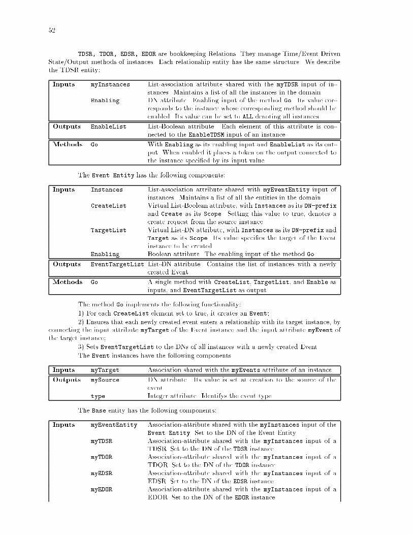
52
TDSR, TDOR, EDSR, EDOR are bookkeeping Relations. They manage Time/Event DrivenState/Output methods of instances. Each relationship entity has the same structure. We describethe TDSR entity:
Inputs myInstances List-association attribute shared with the myTDSR input of in-stances. Maintains a list of all the instances in the domain.
Enabling DN attribute. Enabling input of the method Go. Its value cor-responds to the instance whose corresponding method should beenabled. Its value can be set to ALL denoting all instances.
Outputs EnableList List-Boolean attribute. Each element of this attribute is con-nected to the EnableTDSM input of an instance.
Methods Go With Enabling as its enabling input and EnableList as its out-put. When enabled it places a token on the output connected tothe instance speci�ed by its input value.
The Event Entity has the following components:
Inputs Instances List-association attribute shared with myEventEntity input ofinstances. Maintains a list of all the entities in the domain.
CreateList Virtual List-Boolean attribute, with Instances as its DN-prefixand Create as its Scope. Setting this value to true, denotes acreate request from the source instance.
TargetList Virtual List-DN attribute, with Instances as its DN-prefix andTarget as its Scope. Its value speci�es the target of the Eventinstance to be created.
Enabling Boolean attribute. The enabling input of the method Go.
Outputs EventTargetList List-DN attribute. Contains the list of instances with a newlycreated Event.
Methods Go A single method with CreateList, TargetList, and Enable asinputs, and EventTargetList as output.
The method Go implements the following functionality:
1) For each CreateList element set to true, it creates an Event;
2) Ensures that each newly created event enters a relationship with its target instance, byconnecting the input attribute myTarget of the Event instance and the input attribute myEvent ofthe target instance;
3) Sets EventTargetList to the DNs of all instances with a newly created Event.
The Event instances have the following components.
Inputs myTarget Association shared with the myEvents attribute of an instance.
Outputs mySource DN attribute. Its value is set at creation to the source of theevent.
type Integer attribute. Identifys the event type.
The Base entity has the following components:
Inputs myEventEntity Association-attribute shared with the myInstances input of theEvent Entity. Set to the DN of the Event Entity.
myTDSR Association-attribute shared with the myInstances input of aTDSR. Set to the DN of the TDSR instance.
myTDOR Association-attribute shared with the myInstances input of aTDOR. Set to the DN of the TDOR instance.
myEDSR Association-attribute shared with the myInstances input of aEDSR. Set to the DN of the EDSR instance.
myEDOR Association-attribute shared with the myInstances input of aEDOR. Set to the DN of the EDOR instance.

53
EnableTDSM Virtual attribute, with myTDSR as DN-prefix, and EnableList
as its Scope. Enabling input for the Method TDSM.EnableTDOM Virtual attribute, with myTDOR as DN-prefix, and EnableList
as its Scope. Enabling input for the Method TDOM.EnableEDSM Virtual attribute, with myEDSR as DN-prefix, and EnableList
as its Scope. Enabling input for the Method EDSM.EnableEDOM Virtual attribute, with myEDOR as DN-prefix, and EnableList
as its Scope. Enabling input for the Method EDOM.myEvents List-association attribute shared with myTarget input of Events.
Contains Event instance DNs.eventTypes Virtual List-integer attribute with myEvents as its DN-prefix
and type as its Scope.
Outputs Create Boolean attribute. Connected to the CreateList input of theEvent Entity.
Target DN-attribute. Connected to the TargetList input of the EventEntity.
Methods TDSM With EnableTDSM its enabling input. Represents time drivenevolution. It is a method from Inputs to State.
TDOM With EnableTDOM its enabling input. Represents time drivenevolution. It is a method from (EnableTDOM, State) to Outputs.In particular it is connected to the Create and Target outputs.
EDSM With EnableTDSM, myEvents, eventTypes as input. Representsevent driven evolution. It is a method from Inputs to State.
EDOM With EnableTDOM as its enabling input. Represents time drivenevolution. It is a method from (EnableEDOM, State) to Outputs.In particular it is connected to the Create and Target outputs.
The inputs of the domain of OMSEngine One are the Enabling inputs of the four rela-tionship entities. The output is the EventTargetList output of the Event Entity.
OMSEngine Two
It consists of two Sequencing entities TDS, EDS, (Time and Event Driven Schedulers re-spectively) both treating the �rst OMSEngine as their subdomain.
The TDS has the following components:
Subdomain OMSEngine One
Inputs EnableTDS Boolean attribute. Enabling input of the method Go.
Subdomain
Outputs
EnableTDSR DN attribute. Connected to the Enabling input of theTDSR instance.
EnableTDOR DN attribute. Connected to the Enabling input of theTDOR instance.
Methods Go Has EnableTDS as its enabling input.
The Method Go has the following functionality:
1) Sets the EnableTDSR to \ALL" and places a token on it;
2) Upon completion of this transition, it sets the EnableTDOR to\ALL" and places a tokenon it;
3) Upon completion of this transition the method execution terminates.
The EDS has the following components:
Subdomain OMSEngine One
Inputs EnableEDS Boolean attribute. Enabling input of the method Go.
Subdomain
Inputs
EventTargetList List-DN attribute. Connected to EventTargetList ofEventEntity.

54
Subdomain
Outputs
EnableEDSR DN attribute. Connected to the Enabling input of theEDSR instance.
EnableEDOR DN attribute connected to the Enabling input of theEDOR instance.
EnableEventEntity Boolean attribute. Connected to the Enabling input ofthe Event Entity.
Methods Go Has EnableTDS as its enabling input.The method Go has the following functionality:1) It enables the Event Entity.2) It reads the EventTargetList output of the Event Entity and for each element in
this list:a) It sets EnableEDSR to the value of the element, and enables EnableEDSR.b) Upon completion of this transition, it sets EnableEDOR to the value of the element,
and enables EnableEDOR.4) It repeats the �rst two steps till the Event Entity outputs an empty EventTargetList.5) Upon completion of this transition does not generate any further tokens.The inputs of the domain of OMSEngineTwo are the EnableTDS and EnableEDS inputs
of the TDS and EDS instances. OMSEngineTwo has no outputs.
OMSEngine Three
The third OMSEngine consists of one Sequencing entity, with a single method. Whenenabled with an integer value n, this method goes in a loop of length n, enabling in each loop thetime and event driven scheduler of the second OMSEngine.
That's the overall time and event driven model.In this example, if the Event Entity keeps creating events the EDS executes in�nite number
of transitions in its subdomain. If this is not an acceptable behavior, one can restrict the numberof transitions the EDS executes when enabled, or specify a mechanism for termination after somenumber of transitions.
Other applications may have entities with di�erent time scales of evolution, or they mayrequire several iterations until the time driven evolution from all inputs to outputs may reach asteady state. The number of such iterations may be state dependent. Again, appropriate sequencerentities can be speci�ed in the domain of OMSEngine Two to implement the desired behavior.
4.3.5 Event Generation
Using these constructs one can represent event generation and propagation.Events are generated only if some object requests their creation. For event generation one
has to specify the proper entities that decide when to create the event.Events will be propagated if some object chooses to propagate them. For event propagation
one has to specify the proper entities that have the necessary information to decide how and to whichobjects to propagate the events.
Finally, if an object needs to be noti�ed of the creation of an event, it has to enter intoa relationship with the source for that event. If an object wants to be noti�ed of events that meetspeci�c conditions only, then a �lter entity has to be speci�ed that implements these conditions.The �lter can then enter a relationship with the source of the events and propagate the event to theobject if the conditions are met.

55
Domain Customization System Analysts, Domain ExpertsSystem Architecture System ArchitectsApplication Development, unit testing Development EngineersSystem Integration and System Test Testers and All other members
Table 4.1: Stages and Key Players in OMS
System Support Maintenance TeamOMS Operation Day-to-day system usersSystem Supervision Managers, SupervisorsPhysical System Operation Field Operators
Table 4.2: Key OMS Users
4.4 OMS Process Phases
In this section we describe the di�erent stages of speci�cation and implementation of anObject Management System and what each stage is expected to deliver. Our discussion emphasizeso�-line OMSs targeted at simulation and evaluation.
The OMS process consists of four major stages. These stages and the key players of eachstage are summarized in Table 4.1. Project management is beyond the scope of this thesis.
The domain customizer and system architect work closely together. They provide anObject Model speci�cation and implementation that provides the constructs discussed earlier in thischapter.
Using the Object Model the domain customizer speci�es all the entities in the system, theirinputs, outputs, relationships, constraints, and method interfaces. The system architect organizesthe entity speci�cations in a hierarchy of OMSEngines. Together they design the transition structure.The system architect is also responsible for the speci�cation and implementation of other constructssuch as exception handling, distribution, concurrency, etc., as the application needs dictate. Thedeliverable of these two stages is the Customized OM. Unlike in other methodologies, the CustomizedOM has an implementation, i.e., it is a running system with skeletal functionality.
The application developers implement entity behaviors, to meet the constraints speci�edby the domain customizers. They specialize the base class entities provided by the �rst stage andextend the customized OMS and to an OMS Application.
System test stage tests whether the OMS Application runs without violating any con-straints for allowed input patterns. This stage is not discussed in this thesis.
The OMS process is not strictly sequential. Although the �rst two stages have to delivera Customized OM before application development starts, this deliverable is not cast in stone. Asapplication development progresses, the customized OMS evolves with the emerging needs of the�nal application.
The OMS-based management system has several types of users summarized in Table 4.2.In the following subsections we discuss the activities that take place in each stage, their
deliverables, and the users of the OMS.
4.4.1 Domain Customization
The domain customizer speci�es the overall data and process model.Several methodologies are available for specifying the data model of a system. The domain
customizer picks his/her favorite and starts the OMS process by identifying the entities in the system,their state, input, and output attributes, their relationships, their constraints and their expectedbehavior.
The domain customizer decides how far these entities are speci�ed and implemented aspart of the Customized OM and how the OMS Application will specialize them for complete imple-mentation.

56
Once a �rst cut of the data model is available, the process model needs to be examined.For each entity several key questions should be answered:
� Identify cause of creation and deletion;
� Identify relationship evolution;
� Identify time scale of evolution;
� Specify constraints;
� Identify modes of operation;
� Ensure satisfaction of functional requirements and user needs.
Creation and Deletion
Recall that objects can be created and deleted only by objects that have the proper input-output connections with the OMSEngine for these operations.
The domain customizer speci�es the create/delete relations of objects. Failure to properlyrestrict the objects that have create/delete power results in haphazard evolution of the system.
The domain customizer also speci�es when and how frequently objects are created anddeleted. Instances of certain entities may be created once at system initialization time and neverdeleted. Other instances may be created and deleted very frequently.
Instance creation requires proper initialization of all input-output connections. Instancedeletion requires proper termination of all input-output connections. The domain customizer workswith the system architect to provide the proper constructs for object creation and deletion. Ifpossible, the domain customizer speci�es the create and delete methods of all entities. Subclassesspeci�ed by application developers may have to implement their own create and delete methods.
Relationship Evolution
Recall that two objects enter an input-output, or any other sort of, relation if a connectoutput is sent to the OMSEngine on their behalf. Such connections can be established only byobjects that can send the corresponding outputs to the OMSEngine. Furthermore these objectsneed to have su�cient information to establish proper connections.
The domain customizer speci�es the objects that are in charge of establishing/terminatingrelations. Failure to properly restrict the objects that have connect/disconnect power results inhaphazard evolution of the system.
The domain customizer also speci�es when and how frequently relationships change. Mostsystems have a set of objects and relationships that are either entirely static, or evolve at a muchslower time scale than the rest of the system.
The domain customizer works with the system architect to provide the proper constructsfor relationship creation. Whenever possible special modules are provided to initialize the staticrelationships.
Time Scale of Evolution
State evolution can be time or event driven. The domain customizer decides how torepresent time and event driven evolution.
Time driven entities change state with the passage of time. Clearly for a time drivenobject it is impossible to simulate every state change. Such simulation has to take place at somemeaningful sampling rate. The domain customizer has to determine this rate, i.e., the time scale ofevolution of time driven entities.
Event driven entities change state upon certain events. The domain customizer has tospecify the structure for event generation and event propagation. The domain customizer may beable to de�ne all events and messages or may delegate this task to application developers. In thephysical world, events have to be delivered through some medium. If a detailed model of the medium

57
is not part of the simulation, the domain customizer may choose to assign a time delay for eventdelivery. The response of an entity to an event may not be instantaneous. The domain customizerdetermines the event response time of entities.
In hybrid simulations, time scale applies to event driven objects as well. Delivery of eventsdoes not need to take place at every clock tick.
There is a trade-o� between the clock-rate and simulation performance. It is the respon-sibility of the domain customizer to work with the system architect and to select the right timescale of evolution for each entity. Sometimes, a sliding time scale must be used due to problemrequirements. Updating vehicle positions every hundred milliseconds may be acceptable in normalmode of operation. However, if detailed accident simulation is part of the requirements, vehiclesthat come together closer than one meter may have to change their time scale of evolution.
The domain customizer may choose to specify the time and/or event driven behavior ofselect physical entities. Most behavior speci�cation is delegated to application development.
Identi�cation of Operation Modes
Failures and undesired behavior are bound to be part of any physical system. The domaincustomizer identi�es the ideal and degraded modes of operation of the system.
The domain customizer designs entities that can identify failures and take corrective action.The detailed speci�cation and implementation of the behavior of these entities may be delegated toapplication development.
Functional Requirements and User Needs
The entire data and process model is developed with the functional requirements and userneeds in mind. This step merely performs a �nal check to ensure that these requirements and needsare indeed satis�ed.
The domain customizer ensures that the Customized OM and OMS Application are ad-dressing the needs of the users. A canonical advice to each domain customizer is to provide each userwith as much information as necessary but as little information as possible. The provided operationshave to be at the right level of granularity. For example, for frequent operations, simple and quickmethods are needed. It is important to understand what the users want to change, why they wantto change it, and how often they want to change it.
4.4.2 System Architecture
Working with the domain customizer the system architect �rst selects/develops a speci�-cation syntax for the Object Model, and develops an implementation of it. Given today's computertechnology the Object Model implementation starts with the selection of a hardware platform, anoperating system, a programming language, and a database management system.
Based on the application needs an of-the-shelf software tool may be available to implementthe Object Model. A more likely scenario is the use of several component tools that address variousaspects of the application needs.
A good system architect avoids tools that meet only part of the system requirements,but do not provide any obvious means of extensions to meet the rest. With today's rapid rateof technology evolution, using tools and platforms just because one is familiar with them is badengineering practice. Such tools provide a quick start to the project, resulting in false con�dence,and are a recipe for failure.
The system architect and domain customizer bootstrap from the Object Model and im-plement the Customized OM based on the domain customizer's entity speci�cations.
The system architect is responsible for delivering the Customized OM implementationthat meets all software requirements. In particular the system architect speci�es and implements 1)the data and process distribution architecture, 2) the time and event driven scheduling constructs,and 3) other constructs speci�ed in 4.2.4 and 4.3 that are not part of the Object Model but areneeded for the application at hand.
We now discuss some of the decisions facing the system architect.

58
Distribution Support
With the help of the domain customizer the system architect organizes objects into do-mains. The domain boundaries should be selected such that the interaction between domains isminimized. The domains provide natural boundaries for process distribution. However, sometimesmany or all domains may reside in the same process. Alternatively, if execution sequences can beparallelized, a single domain may be simulated in several processes.
In case of a distributed architecture, the system architect designs the proper mechanismsthat support the interaction among OMSEngines. These mechanisms include 1) data dictionaryservices to locate OMSEngines and objects; 2) output propagation; 3) migration support for objects.
If a domain is simulated in several processes the system architect must ensure that eachprocess has a consistent image of the domain.
Time and Event Driven Scheduling
With the help of the domain customizer, the system architect speci�es the execution andtransition sequences of the system. The system architect makes sure that the execution sequences arevalid and speci�es sequencer entities that implement time driven, event driven, or hybrid evolutionof objects.
Some applications may require a con�gurable simulation granularity. In this case someof the sequencer speci�cation must be delegated to later stages of OMS. The system architectimplements the necessary mechanisms to specialize sequencer behavior. These mechanisms mayvary from parameter speci�cation to specialization through inheritance.
Analysis Support and System History
The state of an object is given by its state, input, and output attribute values. The stateof a domain is given by the list of the entities and instances it contains, the particular input-outputconnections, and the state of these instances.
Most applications require the ability to record the state history of a single object, acollection of objects, or an entire domain. Clearly, saving the entire state of a domain after everytransition provides su�cient information, but this approach is infeasible in most applications due tosystem size. The system architect has to provide constructs to save and restore state at the rightlevel of granularity.
These constructs must provide a labeling mechanism that imposes an order to the recordedhistory. In some applications a global clock is used to represent time passage. The time stamp of theglobal clock may be used to label recorded history. However, if an object can participate in severaltransitions within the same time stamp a di�erent labeling mechanism is needed. For example, eventdriven objects may take several transitions at the same time stamp.
In some applications it su�ces to save the state history of individual objects. In this casea mechanism is needed to specify the objects whose state should be saved. In particular one shouldbe able to specify an object that may be created in the future. For time driven objects, state historyshould be recorded at appropriate time intervals. For event driven objects, state history should berecorded only if events occur.
The system architect must decide what to do with the recorded history of an object if thatobject is deleted. In most applications the recorded history of an object has to be saved even afterthe object ceases to exist. For example, in a simulation of vehicles on the highway, the state historyof the vehicle contains important statistical data that is needed even after the vehicle leaves thehighway. In fact, if one wants to replay the vehicle's state trajectory along the highway the vehicleinstance itself must be saved after it leaves the highway.
The system architect must decide what to do with the recorded history of an object if thatobject is migrated to another domain. The decision is based on how the recorded history is used. Ifthe state history is considered to be part of the object ,it should be migrated with the object, but,if it is considered to be part of the domain in which it was recorded, it should stay behind.

59
Specialized Maps
It is unlikely that one Object Model can provide the perfect speci�cation syntax for allapplication domains. Even within a given application, there usually are components with verydi�erent evolution models. For example, in hybrid systems, one �nds both state machine anddi�erential equation representations for object behavior. Other applications may require rule-basedinput-output maps.
Based on the application requirements, the system architect designs and implements ex-tended speci�cation languages and the necessary translators that convert speci�cations in theselanguages to the Object Model or the Customized OM constructs.
Veri�cation
OMS are used to simulate the complete behavior of the system at hand. A simulation runstarts at a speci�c initial condition and runs for �nite duration. Even after extensive simulations,only a subset of all possible OMS states are reached.
In general, absolute statements about OMS behavior are undecidable. For highway au-tomation, e.g., one usually cannot prove that a given architecture does not result in any accidents.
However, it is very desirable to get such results and to verify system behavior wheneverpossible. Such results can usually be obtained with simpli�ed or partial object models.
As discussed in Section 2.9.1, decidability results exist for discrete event systems; but,such results are very limited for hybrid systems.
In the previous subsection we stated that the system architect designs and implementsextended speci�cation languages to meet the needs of an application. These languages should bedesigned to facilitate partial system veri�cation.
Consider a hybrid system representation where the continuous behavior results in eventsthat e�ect the discrete evolution. If the speci�cation syntax has clear boundaries between its discreteand continuous components, partial veri�cation may be possible. The e�ects of the continuousbehavior can be replaced with a nondeterministic discrete automaton and the resulting system canbe translated into a syntax, such as COSPAN, for veri�cation.
An example of such a language is given in Section 6.3.
4.4.3 Application Development
The application developers are the users of the Customized OM. In most OMS applications,application developers include communication and control engineers who design proper local controlactions to ensure that the overall system evolves without violating any constraints. The applicationdevelopers bridge the gap between computer, communications, and control technologies. A detaileddiscussion of relevant communication and control technologies is beyond the scope of this thesis.
Based on application needs, the application developers specialize the entities of the Cus-tomized OM by adding state, input, and output attributes, methods, and constraints. Following theguidelines of the domain customizer and the system architect, application developers also implementthe appropriate interfaces for the OMS users.
The OMS approach greatly reduces application development time and increases softwarereliability.
The application developers are shielded from system level decisions since the skeleton ofan application is provided by the Customized OM. The application developers can focus on a smallset of objects, their inputs and outputs, and design the proper input-output behavior.
The specialized speci�cation maps of the Customized OM enable application developersto design in a language appropriate for their expertise, without loosing time to the peculiarities of aprogramming language. Code-generators are then used to reliably translate these speci�cations intoObject Model or Customized OM constructs.
Since the Customized OM is an actual running system, it provides the necessary harnessfor unit-testing. Application developers do not need to duplicate e�ort to create test-beds to testtheir objects, but rather, they integrate them directly into the Customized OM for unit-testing.

60
4.4.4 OMS Users
The users of the OMS Application can be classi�ed into several groups. These groups arediscussed brie y.
Support Sta�
Once the OMS is deployed the support sta� provides day-to-day support to other OMSusers. They explain the use of the OMS interfaces and identify possible shortcomings of the deployedsystem. These shortcomings are addressed in subsequent releases of the OMS.
OMS Operator
The OMS Operators are the daily users of the OMS. Based on their responsibilities theyuse speci�c subsets of OMS functionality.
If the OMS is targeted to simulation they run extensive simulations and evaluate thesystem behavior.
If the OMS is targeted to managing a deployed system, they monitor the behavior of thephysical system through the OMS interface and take microscopic control actions based on the adviceprovided by the OMS, their own intuition, and their level of authority.
In many applications they interact with Physical System Operators and coordinate theiractivities.
System Supervisor and Manager
System Supervisors and Managers are the occasional users of the OMS, but, have higherlevel of authority in terms of macroscopic decisions.
They exercise a wide range of OMS functionality, collect high level performance informa-tion about the system, and are in charge of planning management.
Physical System Operator
In the case of a deployed system, not all operations can be performed through the OMSinterfaces. A burnt transformer along a transmission line, for example, must be replaced physically.
The Physical System Operators have the responsibility to perform physical maintenanceactivities. Their e�orts are coordinated by the OMS Operators.
4.5 Satisfying Functional Category Requirements
In Section 2.8 we have discussed seven functional categories common to all Object Man-agement Systems and the constructs required to satisfy them. This Section discusses how the OMSapproach satis�es the requirements of these functional categories.
4.5.1 Con�guration management
The Object Model provides the ability to specify the logical model of a physical system.The OMSEngine provides the necessary constructs to create, delete, and interconnect
instances. The Customized OM provides specialized tools and interfaces for these operations.The application developers design and implement the entity methods that ensure that the
system evolves without violating the constraints speci�ed by the domain customizer.The event and control ow is speci�ed by the domain customizer and the system architect
as part of the execution sequence and the time and event driven scheduling design.If sensors and actuators are needed to interface with a physical system, these are speci�ed
as application layer entities. The methods of these entities encapsulate and abstract the details ofthe physical system interfaces.

61
4.5.2 Fault and event management
The di�erent modes of operation are part of system speci�cation in the Customized OMand the OMS Application.
The Object Model provides the necessary constructs for event creation and propagation.The domain customization and system architecture stages customize these constructs based onapplication needs and design entities responsible for the creation, propagation, and correlation ofevents. The event set used for fault identi�cation and recovery may be speci�ed by the domaincustomizer, by the application developers or by both.
Fault correlation and identi�cation are hard problems. Application developers specializethe entities responsible for event creation, propagation, and correlation to provide graceful faultrecovery.
4.5.3 Performance management
Monitor and aggregation entities are speci�ed to measure the performance of the system.These entities usually measure many di�erent performance parameters and delegate the speci�cationof the exact evaluation criteria as a function of these parameters to the OMS Application users.
Design and implementation of a system with good performance is a harder problem. Thedomain customization stage decomposes the performance management requirements and speci�es anumber of control entities that address localized performance criteria. Application developers designand implement the methods of these entities. The OMS Application is used to simulate and evaluatethe performance of the design. Based on simulation results the designs are re�ned until the requiredlevel of performance is reached.
4.5.4 Access and security management
The Object Model provides constructs to satisfy access and security management require-ments.
An object can restrict access to its inputs and outputs by allowing certain kinds of inter-connections only. An object can choose to provide restricted access by its views. Alternatively, auser relation can be created that is capable of connecting to speci�c entities or instances only. Theuser relation can be used to represent actual human users or other software entities.
The speci�c access and security management structure is designed and implemented inthe domain customization and application development stages.
4.5.5 Financial management
The ability to record history facilitates �nancial management. Since users can be repre-sented as entities their recorded state history can be converted into billing statements according tothe billing policy.
4.5.6 Resource management
Since the OMS Application provides an open interface, resource management functionscan easily be integrated into the overall system. Maintenance scheduling and inventory tracking canbe implemented by a set of entities that perform the required functions.
4.5.7 Planning and design management
Object Management Systems are designed for system speci�cation, simulation, and eval-uation. The con�guration, fault, and performance management functionalities facilitate planningand design management.

62
4.6 OMS Evaluation Criteria
An OMS has to address many con icting requirements. Each application developer andeach user has di�erent needs and there is no single metric that can assign a grade to the quality ofa Customized OM or an OMS Application.
So far we have discussed constructs that should be part of the Object Model and theCustomized OM. The expressive power is only the beginning of a good design, its ease-of-use iswhat makes the system succeed or fail. The ease-of-use is in direct con ict with the exibility andthe expressive power of the system. A system that has a single function can be operated by a singlebutton. The more operations it supports the more \buttons" one has to add.
The popularity of an application is usually a good measure of its overall quality. However,there are many factors that contribute to an application's popularity that are beyond our scope.These factors include its price, the availability of technical support, the vendor's reputation, theabsence of competition, etc.
This section addresses key criteria that determine the ease-of-use of a system and discussespotential trade-o�s for con icting software system requirements.
4.6.1 Ease-of-Use
Relevance of Entities
The entity de�nitions are expected to abstract and encapsulate the characteristics andbehavior of physical objects. The simplicity of a system is crucial for its ease-of-use. However,abstraction is aimed at hiding irrelevant information. Oversimpli�cation may lead to a neat, yetpractically useless system. Three questions should be asked of a Customized OM or an OMS:
� Does the model provide \real" concepts or are the constructs too far removed from the actualsystem;
� Is there a clear translation mechanism between the modeled entities and the actual physicalworld objects;
� Is there a match between the operations provided by the OMS and the operations possible inthe physical world?
Locality of Reference and Learning Curve
Application developers should be able to add entities and to specify and change behavior.The following questions should be asked of a Customized OM:
� How many entities/modules does one need to modify to perform these operations;
� How much does one need to know about other objects and the process model of the system;
� How many steps and how much time are required to integrate the changes?
The OMS Application users perform di�erent operations based on the application; how-ever, similar questions apply to the OMS Application. In particular one should ask:
� What's the minimum a user has to learn to start using the system;
� Do simplicity of operations match their frequency of use?
Ease of speci�cation
A Customized OM and an OMS Application should provide tools to simplify the speci�-cation tasks of application developers and system users. Such tools may include �nite state machinerepresentations, protocol speci�cation languages, di�erential equation solvers, and graphical editors.
The following questions should be asked of these tools:

63
� Is the tool suitable for the problem domain;
� Is it possible to specify an incorrect behavior/con�guration with the tool;
� What happens at run-time if an incorrect behavior/con�guration is speci�ed?
Ease of Evaluation
Both the application developer and the OMS Application users need services to facilitatesystem evaluation. These services should include:
� Ability to save a snapshot of system state;
� Ability to trace individual objects;
� Ability to \replay" traces;
� Ability to collect aggregate state information.
System Level Issues
The seven functional categories of Section 2.8 apply to the Customized OM and to thedevelopment of an OMS Application.
� Con�guration management;
Ability to mix and match Customized OM constructs to create OMS Applications, ability totrack and maintain releases and various versions of the Customized OM are example con�gu-ration management functions.
� Fault management;
The ability to prevent and detect faulty speci�cations and the ability to identify speci�cationerrors at run time are fault management functions. \Segmentation Fault" and \Bus Error"are, unfortunately, the most common software error events.
� Performance management;
For o�-line simulation the OMS does not need to meet real-time performance requirements. Infact, no architecture can guarantee an upper bound on the simulation time of a given object,since this time greatly depends on the application layer code. On the other hand, the lowerbound imposed by the Customized OM overhead has to be acceptable.
For on-line management, the OMS Application has to meet real-time performance require-ments. Events in the physical world must be communicated to the OMS Application; theseevents have to be delivered to the appropriate modules in the OMS Application which deter-mine the control actions; and �nally the control actions must be communicated back to thephysical system, all within an acceptable delay. Furthermore, the OMS Application must beable to handle worst-case event rates.
Memory and disk usage can also be categorized under performance management. Althoughmemory and disk space are getting cheaper, they still impose a constraint as complex appli-cations penetrate the lap-top computer market.
� Access and security management;
Not all application developers nor all users should be allowed to modify all parts of an appli-cation.
� Financial management;
Software licensing is a topic of its own and is beyond our scope.

64
� Resource Management;
The maintenance of a Customized OM and OMS Application includes the tracking of bugsand the upgrading of the software with evolving hardware platforms.
� Planning and Design Management;
Planning management includes the evolution of the Object Model and the various CustomizedOM frameworks.
4.6.2 Con icting Requirements
In this section we list some key con icting requirements in software systems.
� Object Model versus other requirements;
Adding more constructs to the Object Model usually results in sacri�cing performance andincreasing memory and disk usage. Complex constructs can also make an application error-prone. For example, if the meta-data is dynamic, one can change class de�nitions on-line.However, in this case it is not clear how much one can modify a class without having toremove all existing instances.
� Modularity versus other requirements;
If everything were implemented in one function using machine code, we would get fastestperformance. The more components one introduces, the more interfaces one needs to maintainand the larger the overall system gets.
� Performance versus other requirements;
One can usually trade-o� memory for performance. Scalability and distribution support requirebookkeeping mechanisms that add overhead. Robustness and openness require that there isminimal or no transient data; however, clearly recording system state at every step reducesperformance.

65
Chapter 5
Automated Highway Systems
In this chapter we discuss the domain customization and system architecture stages of anOMS that is targeted to Automated Highway Systems. The Object Model speci�cation and imple-mentation is called SmartDb, the Customized OM is called SmartAHS, the �nal OMS Application,used to implement the Varaiya/Shladover architecture, is called SmartPATH.
SmartPATH decomposes the IVHS modeling and simulation problem into the followingstages:
1. Parametrized modeling of the physical system and the control agents in an object orientedsemantic data model; Delivery of SmartAHS;
2. Design and implementation of various control and communication strategies;
3. Simulation of the discrete and continuous behavior of all the objects in the model, and opti-mization of the model parameters; Delivery of SmartPATH;
4. Evaluation of system performance according to speci�ed criteria;
5. Model validation and implementation of selected control strategies for deployment.
These stages are shown in Figure 5.1.
Simulation Framework Design
Implementation and Deployment
Performance Evaluation
Simulation and Optimization
Communication and Control Design
Figure 5.1: SmartPATH Stages
This thesis discusses the �rst step, namely the speci�cation and implementation of Smar-tAHS simulation framework. The actual design and implementation of control and communicationstrategies are beyond our scope. However, parts of SmartPATH are discussed in Chapter 7 toillustrate the use of SmartAHS.
The domain customizers and the system architects are responsible for delivering SmartDband SmartAHS. These roles are assumed by the author. In Section 3.1 we discussed the multi-layer control strategy for highway automation. This design constitutes signi�cant existing domain

66
customization e�ort. However, SmartAHS has to meet the needs of this or any other automationstrategy.
The application developers design and implement individual control and communicationcomponents. They provide parametric interfaces for adapting their control algorithms to evaluationcriteria. The application development team consists of control and communication engineers anddelivers SmartPATH.
Detailed evaluation is to be performed by system analysts. They select evaluation criteriaand run extensive simulations in SmartPATH to measure the performance of selected automationstrategies.
Based on the performance results and other social and political considerations an automa-tion strategy is selected for deployment by system planners.
This chapter discusses the early stages of the domain customization and system archi-tecture for SmartDb and SmartAHS, describes the implementation environment for SmartDb, andprovides a high level discussion of the data and process model for SmartAHS.
The implementation of SmartAHS is discussed in the next chapter.
5.1 SmartDb Implementation Platform
This subsection describes the selection process for the implementation platform compo-nents of SmartDb and SmartAHS. Most of the decisions are guided by concerns of practical imple-mentation.
5.1.1 Tool Selection
No existing simulation tool satis�es all the criteria summarized in Section 3.1.3. After areview of SmartPATH requirements the system architect and domain customizer decided on Sun-Sparc stations as the hardware platform, Unix as the operating system, C++ as the programminglanguage, Versant as the OODB, and Tcl/Tk as the graphics package for the SmartDb implemen-tation.
The reasons for these decisions are discussed brie y.
The need for an open architecture requires that the system state be fully and easilyaccessible. The need to collect arbitrary statistics during simulation requires that state be savedto a persistent storage medium during simulation. Since SmartDb is based on the object-orientedparadigm, the system architect decided to use an OODB to implement persistence. An OODBhas a well-de�ned interface, makes the simulation state visible to the user, and provides a defaultmechanism for any other simulation package to interface with SmartAHS.
A survey of the available object oriented databases suggested Versant as the OODB ofchoice. Versant's advantages over other current systems are discussed in Appendix 9.2. Since Versantprovides persistence through inheritance, making the base class of SmartAHS inherit from Versant'sPVirtual class achieves persistence for all entities. The PVirtual class provides the necessarymethods to make an object persistent.
Versant supports two object-oriented programming languages: C++ and SmallTalk. C++is a compiled language and supports only static entity de�nitions at run time. However, sinceSmartDb assumes static entity de�nitions, this limitation of C++ does not preclude its use. SinceSmallTalk is a proprietary language, and since C++ tools are more readily available in the commer-cial market, C++ was chosen as the implementation language for SmartDb.
Versant and C++ are only available on the Unix operating system and on SunSparcand Silicon Graphics (SGI) workstations. These restrictions are acceptable since these are goodplatforms for development. They provide computational power and operating system support forthe implementation of large multi-user multi-process distributed applications.
Unix is selected as the operating system. Since SunSparc has better support for softwaretools, it is selected as the hardware platform. This choice does not preclude the option of portingthe system to SGI in the future, if needed.

67
Finally the system architect selected the public domain graphical package Tcl/Tk for userinterface implementation. Tcl/Tk is an extensible, interpretive environment that supports inter-process communication. It runs on Unix/Sparc and Unix/SGI and supports a C/C++ interface.
These components implement only a subset of the constructs discussed in the previouschapter. The domain customizer and system architect bootstrap from SmartDb and provide theremaining constructs within SmartAHS.
The following subsections describe how these component tools are used to provide theObject Model constructs.
5.1.2 Data Model
As a programming language C++1 provides the constructs to de�ne classes, attributes,and methods. C++ distinguishes between private, protected, and public class components andsupports multiple inheritance, polymorphism, and dynamic binding. C++ does not provide fullmonotonic inheritance support. In particular, there is no syntax to restrict the domain of an at-tribute as part of specialization2. SmartAHS speci�cation depends on attribute specialization andits implementation provides work-arounds for this C++ de�ciency, as discussed in Section 5.3.6.
Versant libraries are summarized in appendix 9.2. The system architect bootstraps fromC++ constructs and Versant libraries and implements entities as C++ classes. Entity componentsare speci�ed as follows:
� Distinguished Name;
The Link construct provided by Versant, a persistent pointer, is used as the instance identi�erat runtime. The scoping rules of C++ provide all other constructs to identify individualcomponents of instances.
Links do not carry any semantic meaning. Furthermore, the value of a Link is de�ned atruntime only. An independent naming convention is developed to name all instances in thesystem. The naming convention is discussed in Section 6.7.
� State, input, and output attributes;
A distinction is made between static and dynamic state attributes.
The length of a car, the width of a lane, etc., constitute static state. Their values are initializedat instance creation time and not modi�ed during a simulation run. All static relationshipsand static state characteristics are implemented as class attributes.
The speed of a car, average density of a lane, etc., constitute dynamic state. The valuesof these attributes change during a simulation run. Dynamic state, inputs, and outputs areimplemented as independent classes, these classes also contain dynamic relationships amongobjects.
� Methods;
C++ methods are used to implement behavior. These methods do not support the input-output propagation described in the previous chapter. This issue is discussed in the processmodel.
� Constraints;
C++ is a strongly typed language. Each type de�nes the value domain of an attribute. Forexample, one can de�ne an enumerated data type, which is a �nite list of integers. Semanticconstraints and participation constraints are implemented by proper attribute type de�nitions.These constraints are enforced by the C++ compiler.
Other constraints are implemented as regular class methods.
1See Appendix 9.1 for a quick overview of the C++ programming language.2According to monotonic inheritance, discussed in Section 2.4.2, a subclass can restrict the domain of a base class
attribute. An attribute declared as float, for example, may be restricted to integer values only in the subclass.

68
5.1.3 Process Model
Execution Sequences and Transitions
C++ provides synchronous method calls only3. Input-output propagation among the baseclasses of SmartAHS is achieved by these synchronous method calls.
SmartAHS classes bootstrap from C++ methods and implement an asynchronous eventdelivery mechanism. SmartPATH classes are required to de�ne their inputs and outputs as separateclasses. Their public methods do not use arguments.
The OMSEngine
OMSEngine constructs are distributed to a collection of C++ classes.
Constructor and destructor methods are used in entities to specify create and delete meth-ods. The C++ language provides \new" and \delete" operators that are accessible to all objects.SmartAHS limits the use of these operators to speci�c entities only.
Input-output connections are maintained by SmartAHS classes. The Link construct ofVersant provides direct access to the instance it identi�es. As such access to the Link of an instanceprovides access to all its public components. SmartAHS de�nes input and output interfaces forentities and expects SmartPATH objects to use these interfaces rather then using Links for directaccess to objects.
Execution sequences and transitions for SmartPATH are designed and implemented aspart of SmartAHS. SmartAHS implements these constructs using the C++ methods.
Sequencing Objects
In C++, a method can call other methods. This gives sequencing power to all objects.SmartAHS delivers a framework where only scheduling objects act as sequencers.
5.1.4 Extended Object Model Constructs
Virtual attributes and associations are not used. Binary relations are implemented byLink, VVList and VVarray constructs of Versant. More complex relationships are represented byC++ classes.
The static relationships in the application are initialized in independent modules. Thesemodules guarantee relationship integrity. Dynamic relationships are maintained by SmartAHSclasses.
Time and event driven evolution constructs are part of SmartAHS.
5.2 Domain Customization
5.2.1 Data Model
After several iterations and continued discussions with the system architect, domain cus-tomizer categorized SmartAHS entities and drew the line between SmartAHS and SmartPATH asfollows:
SmartDb Entities
Two abstract base classes FrameworkObject and StatedObject are used as the base classof all SmartAHS classes. The base classes State, Input, and Output encapsulate the correspondingattributes of objects. These base classes are discussed in Section 6.1.1.
3Recall from Section 2.6.2 that a synchronous method call �nishes all computation before it delivers a return value,
whereas an asynchronous method call may continue computation after it delivers a return value.

69
Highway Entities
The description of highway networks is decomposed into smaller building blocks. Thehighway network is divided into Zones; each zone contains multiple highway Segments interconnectedusing Junctions. The highway segments are terminated using tra�c Sources and Sinks. Thehighway segments consist of Sections, Entrys, and Exits. Junctions and sections are divided intoLanes. Lanes can have curvature. The full implementation and speci�cation of highway entities arepart of SmartAHS. These classes are discussed in Section 6.1.2.
Vehicles
SmartAHS provides Vehicle as an abstract base class. It de�nes the input and outputattributes of a Vehicle and maintains its position within the highway. Application developers areexpected to inherit from Vehicle and specialize it according to automation strategy.
Vehicles are discussed in Section 6.1.5
Automation Devices
Entities used to achieve automation and performance evaluation are called automationdevices. SmartAHS provides them only as abstract base classes. Application developers are expectedto inherit from these classes and to specialize them. The specializations of these classes interact withother objects through their inputs and outputs only. Their evolution is managed by the time andevent driven scheduling objects.
These classes are discussed in Section 6.1.3.
Tra�c Entities
Entities used to create tra�c and vehicles are called tra�c entities. SmartAHS providesthem only as abstract base classes. These classes are discussed in Section 6.1.6.
SmartAHS de�nes the input and output attributes of Tra�c Entities and their methods.Application developers are expected to inherit from them and specialize these methods.
Scheduling Entities
These are sequencing entities used to implement time and event driven behavior. Smar-tAHS provides con�gurable scheduler base classes. Based on simulation granularity applicationdevelopers con�gure them with the help of a system architect.
These classes are discussed in Section 6.2.
State Machine Entities
A special language is used to implement event driven behavior of entities. SmartAHSprovides full speci�cation and implementation of this language.
The state machine language is discussed in Section 6.3.
5.2.2 SmartAHS Modules
The domain customizer also drew a line between the simulation setup and the simulationrun. The steps for simulation setup are summarized in Figure 5.2. These steps are:
Highway speci�cation
The highway network is created as part of the simulation setup and remains static duringa simulation run. The highway creation mechanism of SmartAHS is designed as an independentmodule. A graphical object editor (GOE) is used to create highways. This object editor is discussedin 6.4.
The GOE provides a meta-data de�nition language for the speci�cation of instantiableclasses, their possible relationships, and their attributes. The GOE interprets the meta-data and

70
Specify Highway
Specify Factory
Specify TrafficSelect Roadside
Controllers
Specify RuntimeParameters
Run Simulation
Build and LoadScheduler
Figure 5.2: SmartAHS Speci�cation Sequence for Simulation Setup
allows the user to create and connect instances and to set attributes, i.e., de�ne the data, accordingto the meta-data speci�cation.
Tra�c Pattern Speci�cation
Tra�c entities are used to specify incoming and outgoing tra�c patterns. An independentmodule is used to select speci�c tra�c entities for each simulation run.
Roadside Automation Device Speci�cation
Di�erent automation strategies will choose di�erent con�gurations of automation deviceson the highway. An independent module is used to con�gure a highway network with automationdevices.
Vehicle Automation Device Speci�cation
Di�erent automation strategies will choose di�erent con�gurations of automation devicesin the Vehicles. Application developers are expected to provide Factory entities that have thecapability of creating vehicles with the appropriate con�guration.
Factorys are discussed in Section 6.1.6.
Speci�cation of Simulation Granularity
The time step of each simulation, the degree of monitoring and evaluation, and the set ofobjects simulated in detail may vary for each simulation. A special module is used to con�gure thescheduling objects and to specify the simulation granularity.

71
Speci�cation of Simulation Parameters
Tra�c entities and automation devices may provide parametric interfaces. A special mod-ule is used to set these parameters before each simulation run.
5.2.3 Process Model
For the simulation run the domain customizer makes the following process model decisions:
Creation and Deletion
The highway network, the highway automation devices, and the tra�c patterns are createdas part of the simulation setup and remain static during a simulation run.
For Vehicles each control strategy is required to provide its own Factory that knows howto create the proper Vehicle types. During the simulation run, various types of Vehicles are createdby Factory entities in Generator objects based on incoming tra�c patterns. Vehicles leave thehighway at Absorber objects based on outgoing tra�c patterns. Outgoing vehicles are not deletedbut ushed to the database. Vehicle instantiation is further discussed in Sections 6.1.6 and 7.1.1.
Relationship Evolution
In SmartAHS all relations among highway entities and all relations among the objectswithin a Vehicle are set at creation time and remain static during a simulation run. The Vehiclehas a static relationship with the Entry/Source where it enters the highway and with its Exit/Sinkdestination. These relationships are initialized at creation time.
All relationships based on the location of Vehicles are dynamic.Vehicle position and the relationship between a Vehicle and its Lane are maintained by
SmartAHS as discussed in Sections 6.1.2 and 7.2.1.All other inter-vehicle relations are derived using Sensors and are discussed in Section
6.1.3. Sensors are also used to identify the receiver ids of objects in the sensing range.Packets are used for event driven communication. SmartAHS maintains the relationships
of Packets, i.e., it implements Packet delivery.
Time Scale of Evolution
In SmartAHS, object state evolution is driven by passage of time or by occurrence ofevents. SmartAHS provides distributed scheduling for time and event driven objects.
A global clock is used to de�ne the simulation time.Each time driven object speci�es the time step for its state evolution as a multiple of the
global clock step. Rapidly evolving objects, such as engines, change their state more frequently,while more passive objects, such as roadside link controllers, change their state at larger time steps.Time driven objects are capable of creating events.
Event driven objects exercise their behavior only when events are delivered to them.Events are generated by objects as output messages and are communicated to the addressed ob-jects as input messages. SmartAHS objects communicate using their transmitters and receivers.SmartAHS does not simulate a communication channel; it assumes reliable message transmission.Events are delivered at increments of the global clock time step. As such, event delivery is notinstantaneous, but happens within a �nite time interval.
Time and event driven evolution is implemented in a three layer hierarchy by the SystemArchitect discussed in Section 6.2.
Constraint Speci�cation
C++ is a strongly typed language, and it is used to restrict the attribute domains.SmartAHS does not specify other constraints. If needed constraints can be implemented
as special monitor entities that observe system state and state transitions and determine if anyconstraints are violated. These objects then become part of SmartAHS simulation.

72
Identi�cation of Operation Modes
The di�erent modes of operation are part of the semantics of individual automation strate-gies. As such the domain customizer identi�es a single undesired behavior: an Accident.
If two Vehicles occupy the same space, or they fall outside the highway boundaries, we havean Accident. Detailed accident simulation is not part of SmartAHS. SmartAHS detects accidents,and creates corresponding noti�cation events.
User Needs
The users of SmartAHS are control and communication engineers who will design andimplement the automation devices. They will use SmartAHS as a simulation tool to debug andimprove their designs. To this end they need graphical tools that simplify the display of the systemstate during simulation.
The users of SmartPATH will run extensive simulations, collect statistics, save and replaystate trajectories of objects. They, too, need a graphical tool for these tasks.
The graphical debugger that addresses these requirements is discussed in Section 6.5.Conceptually, the graphical debugger is another sequencing object that enables the user to executea sequence of transitions. In particular, it provides the following functionality:
� provides access to objects by name;
� displays object attributes in numerical or graphical format;
� allows users to set error levels of objects. Objects with higher error level print more detailedinformation;
� allows users to set the logging level of objects. Turning the logging on results in recording thestate history of an object;
� allows users to stop and start the simulation;
� replays the recorded history of objects.The replayer has �ve buttons: 1) Play; 2) Stop; 3) Step forward; 4) Step backward; and
5) Go to time. The last button takes an argument specifying the global clock time stamp.Finally the domain customizer determines how application developers extend SmartAHS
objects. Figure 5.3 describes how specialized classes become part of the simulation setup. Thedetails of application development are discussed in Chapter 7.
5.3 System Architecture
So far the domain customizer has addressed most modeling, con�guration, fault, andperformance management requirements of SmartAHS. The system architect addresses the softwareand system requirements.
5.3.1 Process Structure
The system requirements dictate that the simulation be distributed. The system architectuses the highway Zones as the basis for distribution. Distribution is discussed in Section 5.3.3.
Within a Zone all objects are simulated in a single process. This decision is based onperformance evaluation results of early prototype implementationswhere separation of the simulationof the various automation devices into independent processes resulted in poor performance. Theprototypes attempted to use the database as a blackboard that would always re ect the state ofa zone. The prototypes revealed that read/write database access duration for a zone with 2000vehicles is in the order of seconds. Since the simulation granularity requires that the global clocktime step be about 0.1 seconds, this observation made it infeasible to save the simulation state tothe database after every transition.

73
Specify Highway
Specify Factory
Specify TrafficSelect Roadside
Controllers
Specify RuntimeParamaneters
Run Simulation
Build and LoadScheduler
Vehicle AutomationDevices
Vehicle Factories:Cars, trucks, etc.
Traffic PatternGenerators
Gateways to othersimulation packages
RoadsideAutomation Devices
Specify and ConfigureSchedulers
Application ClassParameters
Figure 5.3: Integrating Specialized Classes During Simulation Setup
Modularity of simulation requires that the scheduling architecture itself be con�gurable.A given simulation should be able to select its own granularity and decide time scale of evolutionfor objects within the simulation.
After these observations the system architects started specifying the time and event drivenscheduling and event delivery mechanisms.
5.3.2 Time and Event Driven Simulation
This section describes how SmartAHS guarantees the timely evolution of each object andthe timely communication of events to objects. Distribution is deferred to the next section.
Time and Event driven simulation is achieved in a three layer architecture similar to theexample given in Section 6.2.
The bottom layer domain is de�ned by the highway Zone and all of its containees.The middle layer scheduling entities are called Process Layers. They are used to execute
the simulation of collections of objects that evolve at the same time steps or respond to the samecollection of events. The process layers themselves can be time or event driven.
The top layer domain contains a Process Coordinator. The process coordinator is in chargeof managing the execution of the middle layer scheduling objects, the process layers, and the GlobalClock.
The process coordinator schedules the execution of time driven process layers based ontheir time step and schedules the execution of event driven process layers if any events are raisedagainst them by an object.
The global clock represents the passage of time and de�nes the smallest time step of thesystem. All evolution takes place at discrete advancements of this clock. The clock value is accessibleto all objects in the system.
The clock also provides a timer service. Objects can send an event to the clock to registera timeout request. This request speci�es the number of time clicks after which the timer expires anda message to be delivered when it does. When scheduled for execution, the clock delivers timeout

74
events as part of its behavior.A process layer can do the following:
� simulate the time driven evolution of all instances of an object type;
� for all instances of an object type with an outstanding event, deliver the event and simulatethe event driven evolution.
If event driven objects are put in a time driven process layer, event delivery for theseobjects takes place only when the corresponding process layer is executed.
In a simulation run, the process coordinator executes the process layers according to theirtime step, which in turn execute the simulation of the objects they are responsible for.
Example
The process architecture that would implement the layered architecture proposed byVaraiya [41] is shown in Figure 5.4.
Process
Regulation Layer
Coordinator
Link Layer
Physical Layer
DomainImage
Coordination Layer
Network Layer
Global Clock
Events
Highway ZoneTime and Event DrivenProcess Layers
Process LayerCoordination
User
Figure 5.4: SmartPATH Process Architecture.
The physical layer is time driven and maintains the position of the vehicles on the highway.The regulation layer is time driven. It contains event driven regulation supervisors and
time driven maneuver objects. The supervisors switch between maneuvers based on incoming mes-sages from the coordination layer; the maneuvers control the behavior of the throttle, braking, andsteering actions and generate the vehicle displacement.
The coordination layer is time driven. It contains event driven coordination objects.Coordination objects in di�erent vehicles exchange messages to determine the maneuver a vehicleshould execute. These decisions are communicated to regulation layer supervisors through messages.
The link layer is time driven. It contains time driven link objects that set tra�c parameterssuch as target speed and average platoon size in highway sections.
The network layer is event driven. It is executed only if an accident occurs. Upon anaccident it recon�gures the routing tables.
5.3.3 Distribution Architecture
The need for a distributed architecture was identi�ed in the problem speci�cation. Thedistribution can be vehicle or highway based, i.e., a domain either consists of a given set of vehicles ora given subset of the highway network for simulation. Since locality of reference is better representedby highway network subsets the system architect chose to use the zone object as the basis fordistribution.
SmartAHS supports distributed simulation. Zones serve as the unit of distribution: dif-ferent zones can be distributed to di�erent processors; they have their own database and their own

75
clock. Since a vehicle can communicate with and sense other vehicles in its neighborhood only, com-munication between the distributed processors is restricted to objects in adjacent highway segments.This locality of reference enables e�cient distributed processing.
Distributed simulation is depicted in Figure 5.5. The boundary object between the lastsection of the previous zone and the the �rst section of the next zone coordinates communicationbetween the processors, ensures synchronization of simulation clocks on di�erent processors, andcontrols object migration between databases.
Section SectionSection Section
Zone 1 Zone 2
DB1 DB2
Boundary
Figure 5.5: Distributed Simulation
The locality of reference assumption only holds for vehicles and roadside control objects.Tra�c management centers, or network routing optimizers need a global view of the highway networkand hence need access to all zones. SmartAHS provides for time and event driven scheduling of suchExternal Global Processes. Figure 5.6 summarizes the distributed scheduling of time and eventdriven layers.
TDLL
EDLL
EDGLA
EEDGP
PC
...
TDGLA
ETDGP
TDLL
EDLL
EDGLA
PC
...
TDGLA
DB DB
Figure 5.6: Distributed Simulation
Time and Event Driven Global Layer Agents (TDGLA and EDGLA) are used within eachzone to coordinate the scheduling of the external processes.
An External Time Driven Global Process (ETDGP) exercises its behavior periodically.The TDGLA's in each zone are scheduled with this period and send a \Go" message to theirETDGP when scheduled. The ETDGP exercises its behavior after receiving the \Go" message fromall TDGLA's, and returns a \Done" message to all of them.
An External Event Driven Global Process (EEDGP) exercises its behavior upon an event.The EEDGP should exercise its behavior when all EDGLAs are scheduled. Since a local event in azone may require the scheduling of an EEDGP, its scheduling requires more coordination e�ort. Firstthe EDGLA with the event noti�es the EEDGP. The EEDGP in turn sends an event to all processcoordinators, requesting the scheduling of the EDGLA layer at every time click, until otherwisenoted. The process coordinator acknowledges this request upon receiving it. The EDGLAs senda \Go" message to the EEDGP when scheduled. The EEDGP responds to these messages witha \Don't Block" message until it receives the acknowledgements of all process coordinators. AnEDGLA returns control to its process coordinator if it receives the \Don't Block" message. After

76
receiving all acknowledgements, the EEDGP collects all the \Go" messages, exercises its behavior,and returns a \Done" message. At that point the EDGLA's cancel their scheduling request.
The details of distributed simulation are not discussed in this thesis. They can be foundin [34].
5.3.4 Collecting Statistics
The evaluation of system performance is achieved by monitor objects that collect statisticaldata. In most cases monitor objects need to record state histories for future statistical processing.
Versant provides a versioning mechanism that saves versions of objects. However, Versantdoes not support the migration of versioned objects. Since the state trajectories of vehicles needto be recorded, and since vehicles do migrate from one domain to the other, the system architectdesigned a state history recording mechanism as part of SmartAHS.
During a SmartAHS simulation the evolution of an object results in a change in its state,input, and output attributes only. Since state, input, and output attributes are implemented asindependent classes, an object's history can be recorded by versioning the state, input, and outputinstances. The object itself then can provide the necessary bookkeeping constructs to version, save,and restore their history. These bookkeeping constructs are implemented within base classes andfurther discussed in Section 6.1.1. Here we summarize the key features:
� The global clock is used to index the state history of objects;
� If an object takes several transitions at the same time stamp, a secondary index is used tolabel them;
� State history of objects is recorded only if their logging is turned on;
� Logging can be turned on through the graphical interface. The parametric interface can beused to turn logging on at object instantiation time;
� Objects keep track of the intervals during which their logging was turned on, i.e, their statewas recorded;
� Time driven objects record their state at every time click at which their state changes;
� Event driven entities record their state at every transition;
� Monitor objects have the ability to specify the frequency with which to save their history.
The recorded history is saved within the OODB and is accessible to any application.
5.3.5 Veri�cation Support
It is envisioned that the automation strategies will result in a hybrid control framework.Automation devices, such as coordination layer controllers, will use Discrete Event Controllers tospecify symbolic control actions. These controllers use events to interact with each other and toobserve the continuous evolution of the system.
The system architect and the domain customizer designed a special language, called StateMachine Language, to specify event driven behavior. This language distinguishes the events ex-changed among event driven controllers from events resulting from continuous behavior.
As such, it becomes possible to partially verify the discrete event behavior of the au-tomation devices. In the simulated environment, the events resulting from continuous behavior aredeterministic and result from actual simulation. In the veri�cation environment, these events aretreated as the nondeterministic component of state machines.
The state machine language is discussed in Section 6.3.

77
5.3.6 Monotonic Inheritance
C++ does not provide full monotonic inheritance support. This becomes a problem whenreferring to state, input, and output classes. The SmartAHS base class StatedObject de�nes arelation with the base class State. This relation must be de�ned at this level since base classmethods need to access it.
However, this relation needs to be specialized for each subclass. The Vehicle class musthave a relation with a VehicleState and not a LaneState. Furthermore, Vehicle's methods needaccess to the attributes de�ned in the VehicleState. The base class State can not have all theseattributes.
SmartAHS provides a work-around for this problem by introducing a new relation foreach subclass. The StatedObject has a relation named theState, the Vehicle introduces a relationnamed vehicleState, a Truck introduces a relation named truckState. The same TruckState
instance then participates in all three relations.

78
Chapter 6
SmartAHS Implementation
In this chapter we discuss the implementation of SmartAHS. SmartAHS uses the program-ming constructs1 provided by C++ and Versant to create a Customized OM. SmartAHS providesthe Object Model constructs described in Chapter 4 and the entity speci�cations for automatedhighways.
The reader should understand that SmartAHS is a \live" system that will evolve overtime. The entity speci�cations in this thesis serve as examples of the concepts discussed in earlierSections. For up-to-date documentation, the reader should always refer to the latest version of thereference manual and the user's guide of SmartAHS.
To maintain readability many details of entities are omitted. In particular:
� The distinctions between public, protected, and private components are not discussed;
� For all relations, SmartAHS entities provides speci�c Get and Set methods. If the relationshipis represented by a list, further methods such as Insert, Delete, Replace, and GetNumOf areprovided. These methods are not discussed;
� Most public methods implement their behavior with a number of private methods to maintainmodularity. In most cases the private methods are omitted.
A relationship between two entities is implemented by a Link attribute in each object. Ifthe object enters the same relationship with multiple objects a VVList attribute is used. In somecases explicit de�nition of the relationship attribute type is omitted.
For each object we describe the following components as appropriate:
� Static state relationship attributes;
� Static state value attributes;
� Dynamic state relationship attributes;
� Dynamic state value attributes;
� Inputs and Outputs; and
� Methods.
In the �gures instantiable classes are represented by ovals, abstract classes are representedby rectangles. In the class hierarchy diagrams, inheritance is indicated by an arrow from parentto child class. Since the containment hierarchy is a one-to-many relationship, in the containmenthierarchy diagrams, cardinality is indicated on the containee's side only.
We make an explicit distinction between static and dynamic attributes. The static at-tributes are part of the class, the dynamic attributes are in a separate class2. This separationfacilitates the recording of state history.
1The C++ and Versant constructs are summarized in Sections 9.1 and 9.2 respectively.2A pair of Links are used to establish the relationship between an object and its state.

79
SmartAHS base classes use C++ methods to communicate. For these methods we listtheir return value, their name, their list of arguments, and a brief description of their functionality.Unless otherwise noted, return values of methods that are of type int correspond to an error code.In the text we refer to methods by their name, e.g. Run(). If it is clear from context that Run is amethod, the parentheses may be omitted.
Many methods are de�ned in a base class and specialized in all subclasses in some spe-ci�c way. These methods are discussed only in the base class with a description of how they arespecialized.
SmartAHS base classes develop an input-output formalism for control devices. ExampleSmartPATH control objects are discussed in the next chapter.
6.1 Domain Customization: Entities and Relationships
SmartAHS speci�es abstract base classes for all objects and implements the leaf classesfor highway objects.
In this section we discuss the SmartDb, highway, vehicle, automation, and tra�c entities ofSmartAHS, their class hierarchy, their containment hierarchy, their relationships, their state, input,and output attributes, and their methods.
6.1.1 SmartDb Classes
We de�ne �ve abstract base classes: FrameworkObject, StatedObject, State, Input, andOutput. The SmartAHS inheritance hierarchy for base classes is described in Figure 6.1.
(from Versant PVirtual)
Vehicle
MonitorControlSmartObject
State
FrameworkObject
LaneContainer
StatedObject
ReceiverTransmitterSensor
.............
Output
.............
Input
.............
Projection
............. .......................................
.............
.............
Figure 6.1: Base Class Inheritance Hierarchy
FrameworkObject
FrameworkObject is the base class of the simulation framework. It de�nes some basicmethods that apply to all framework classes. These methods and their arguments are:
int SetName (const char* newName);
This method sets the name of the object to newName.
const char* GetName ();
This method returns the name of an object.

80
virtual int SetAttribute (const char *attrName
const char *attrValue);
This method sets the attrName attribute's value to attrValue. All subclasses should implementthis method for their attributes and conclude the method with an explicit call to their parent'sSetAttribute method.
virtual int SetRelation (Link<PVirtual> otherObject,
const char *relation,
const char *inputName,
const char *outputName);
This method establishes the relation between this and the otherObject. The inputName
and outputName specify the input and output to be connected. All subclasses should implementthis method for their relations and conclude the method with an explicit call to their parent'sSetRelation method.
virtual int GetContainees (LinkVstrAny & myContainees)
This method sets the contents of myContainees to all the containees of the object. All subclassesshould implement this method for their containees and conclude the method with an explicitcall to their parent's GetContainees method.
virtual int WakeUp (o u4b handle,
Link<Message> state);
This method is used to deliver a timeout to this object by BigBen. The request is identi�edby handle; state is passed to BigBen while registering the timeout request. This method isrevisited in Sections 6.3 and 6.2.2.
virtual int ProcessEvent (o u4b packetType);
This method is used to deliver events identi�ed by packetType. It is revisited in Sections 6.3and 6.2.2.
virtual int ProcessMsg (Link<Message> newMsg);
This method is used to deliver newMsg to the object. It is revisited in Sections 6.3 and 6.2.2.
virtual void Pack (char* request);
This method is used by the graphical debugger to display the static and dynamic state of theobject. It encodes all or part of the object in a standard format, based on request type. Thismethod is revisited in Section 6.5.
virtual LinkAny Duplicate ();
This method creates a deep copy of the object.
virtual int SetErrorLevel (o u1b newLevel);
This method sets the errorLevel attribute of the object to newLevel.
The attributes of FrameworkObject are errorLevel and name.
StatedObject
StatedObject captures the relation between an object and its State. This static relation-ship is de�ned by the currState and myObj attributes respectively. As discussed in Section 5.3.6C++ does not provide full monotonic inheritance support. Hence, subclasses of StatedObjectmayde�ne attribtues other than currState to identify the relationship between a StatedObject andits State. Examples, such as VehicleState, SMInstanceState, and LaneState, are discussed insubsequent sections.
The static attributes of StatedObject are:
StatedObject Static Attributes
Values
VEArray<o u4b> logIntervals Used to maintain intervals of recorded history.o u1b logLevel If it is set to greater than zero, logging is active.Relations
Link<State> currState Identi�es the State of the object.

81
Link<BigBen> myBigBen The clock used to register timeouts. This at-tribute is set by the instantiable leaf class.
VVArray<State> stateHistory Used to record history. Index corresponds totime stamp.
We said that the dynamic attributes of an object are stored in its State class. ThelogIntervals and stateHistory attributes do change during a simulation when the logLevel isturned on and o�. However, these attributes are not part of the dynamic State of an object sincethey do not e�ect the actual evolution of objects. Furthermore, if stateHistory were part of Stateit would have to record its own history. Future releases of SmartAHS may move the logLevel,logIntervals, and stateHistory attributes into an independent StateHistory class.
Key StatedObject methods are:
virtual int SaveState ();
This method duplicates the currState of the object if logLevel is greater than zero. It usesthe global clock to get the time stamp and inserts the duplicated state at the time stamp indexof stateHistory. If state has already been saved at this time stamp, the History object is usedto implement the necessary bookkeeping.
virtual int SetToTime (o u4b time);
This method restores currState to the State from the time index of the stateHistory.
virtual int SetLogLevel (o u1b newLevel);
This method sets the logLevel attribute to the value of newLevel. It implements the necessarybookkeeping to maintain logIntervals and to turn logging on or o�.
virtual o bool InLogIntervals (o u4b time);
This method returns true if State has been recorded at the speci�ed time.
virtual int Run ();
This method should be specialized by subclasses to implement time driven behavior.
State
This abstract base class has two static relationship attributes identifying its StatedObjectand its History. We document them below:
State Static Attributes
Relations
Link<History> myHist Identi�es its History.Link<StatedObject> myObj Identi�es the StatedObject.
The History object is used to implement a linked list structure for recording several statetransitions at the same time stamp. The �rst transition is inserted into the stateHistory arrayof the StatedObject at the index given by the time stamp. Subsequent transitions are saved in alinked list and chained along the sameClickState attribute of the myHist of the State.
The History class has the following static attributes:
History Static Attributes
Relations
Link<State> myState Used to identify the State owning the History.Link<State> sameClickState Next transition recorded at the given time click.eventId o u4b Secondary index identifying transition within the given
time stamp.
Inputs and Outputs
As illustrated in Figure 6.1 these objects share a base class called Projection. Input andOutput Projections are used by the State Machines only. Their discussion is deferred to Section6.3.5.

82
6.1.2 Highway Entities
Highway network description is decomposed into a number of highway entities. These are:Lane: A portion of the road wide enough for one vehicle.Section: A portion of the road consisting of several lanes.Junct2to1: A portion of the road, where two sections merge into one.Junct1to2: A portion of the road, where one section splits into two.EntrySection: A particular type of section where vehicles are allowed to enter the highway.ExitSection: A particular type of section where vehicles are allowed to leave the highway.
Segment: A consecutive set of sections that do not contain any junctions.Sink: An ending point for highways.Source: A beginning point for highways.Entry An on-ramp for entering the highway.Exit An o�-ramp for exiting the highway.Zone: A part of the highway network, containing sinks, sources, segments, and
junctions.The highway entities are organized in the inheritance hierarchy described in Figure 6.2.
Note that LaneContainer, Generator, Absorber, and Junction are introduced as abstract baseclasses. The SmartObject class is discussed in Section 6.1.4.
JunctionAbsorberGenerator
LaneContainer
StatedObject
SmartObject
Section
EntrySection
ExitSection SinkSource
ExitEntryZone
Segment
Lane
Junt2to1
Junct1to2
Figure 6.2: Class Hierarchy for Highway Entities
The containment hierarchy for these entities is given in Figure 6.3. Since the containmenthierarchy is a one-to-many relationship, cardinality is indicated on the containee's side only.
Finally a number of binary relationships among highway entities are summarized in Table6.1. These relationships specify how instances of highway classes can be connected to create highwaynetworks. The �rst column of the table has the attribute name that identi�es the relationship ina given class. Relationships are implemented by Link and VVList attributes; Table 6.1 omits theattribute type de�nitions. The second column identi�es the second class participating (or classesthat can participate) in the relationship. The third column of the table has the attribute name thatidenti�es the relationship in the second participant. If a relationship is between two instances of thesame class, the relationship is listed only once. The fourth column describes the cardinality of therelationship.
Cardinality is given as a : b where a; b 2 f0; 1; 0j1; n;mg. A cardinality of the form a : bdenotes that the �rst class can participate in a such relationships, whereas the second in b. ALaneContainer (LC) may be related zero or one LaneContainers through its prevLC1 relationship.The reciprocal of this particular relationship is nextLC1. A LaneContainer may be related to oneor zero LaneContainer's through its nextLC1 relationship.

83
LaneContainer
1..n
0..n
0..n
1
1..n
1..n
1..n
0..n1..n
0..n
1Lane
Section
Entry Exit
Junct1to2
EntrySection
ExitSection
Junt2to1Source
SinkSegment
Zone
Figure 6.3: Containment Hierarchy for Highway Entities
Some relationships are speci�ed in a base class and then specialized in subclasses. AGenerator, for example, further restricts the prevLC1 relationship and states that one Generator
can participate in zero such relationships.
A highway network consists of multiple Zones; the Zones provide the basis for distributionand de�ne domain boundaries. However, for simplicity, in what follows, we assume that the highwaynetwork consists of a single Zone.
Most highway entities have little behavior of their own and are used to create highwaynetworks only. Their behavior is derived from the automation devices they are con�gured with.
We now discuss the highway entity methods that are used by the physical layer schedulingobjects to create and move the Vehicles along the highway. These methods are revisited in Section7.2.1.
Lane
The static relationships of Lane were discussed above. The Lane's dynamic state at-tribtues are de�ned in the LaneState class. The Lane specializes the currState relationship ofStatedObject by its laneState attribute as discussed in Section 5.3.6. The LaneState attributesare:
LaneState Attributes
Relations
VVList<Vehicle> myVehicles List of Vehicles in the Lane.VVArray<Vehicle> cellArray List of Vehicles in the Lane indexed by their
position along the Lane.
The methods that are used to move the Vehicles along the highway are:
int MoveVehiclesInLane ();
This method updates the cellArray based on the current xP and yP values of the Vehicle, andsets the Vehicle's absDist, currLane, and cellId attributes. It moves Vehicles to the nextLaneContainer if they have moved beyond the end of this Lane.
The Lanes have curvature. The Vehicle movement methods encapsulate the curvature ofthe Lane, so methods and attributes regarding Lane curvature are not discussed.

84
Entity Relationship With Entity Reciprocal CardinalityLane prevLane Lane nextLane 0j1: 0j1Zone prevZones Zone nextZones n:mSegment prevLC Junction | Source nextSegment1 |
nextSegment21:1
nextLC Junction | Sink prevSegment1 |
prevSegment21:1
Lane Container prevLC1 LaneContainer nextLC1 0j1:0j1Junction prevSegment1 Segment nextLC 1:1
nextSegment1 Segment prevLC 1:1prevLC1 Section nextLC1 1:1nextLC1 Section prevLC1 1:1
Generator prevLC1 NONE 1:0Absorber nextLC1 NONE 1:0Section prevLC1 Junction | Section nextLC1 1:1Section nextLC1 Junction | Section prevLC1 1:1EntrySection prevLC2 Entry nextLC1 1:1ExitSection nextLC2 Exit prevLC1 1:1Junct2to1 prevSegment2 Segment nextLC 1:1
prevLC2 Section nextLC1 1:1Junct1to2 nextSegment2 Segment prevLC 1:1
nextLC2 Section prevLC1 1:1Sink prevSegment1 Segment nextLC 1:1
prevLC1 Section nextLC1 1:1Source nextSegment1 Segment prevLC 1:1
nextLC1 Section prevLC1 1:1Exit nextLC1 NONE 1:0
prevLC1 ExitSection nextLC2 1:1Entry nextLC1 ExitSection prevLC2 1:1
prevLC1 NONE 1:0
Table 6.1: Relationships Among Highway Entities

85
LaneContainer
LaneContainer provides one method for Vehicle movement int MoveVehicles(). Thismethod calls MoveVehiclesInLane() on each of the Lanes of the LaneContainer.
Generator
Generators are the creation source of Vehicles. They contain Factory and InTraffic
objects. (See Figure 6.6.) The Generator's state depends on its InTraffic's State.Generator provides one method: int GenerateVehicles(). When invoked this method
may create a new Vehicle. The InTraffic's AnyVehicle() method decides whether to create aVehicle and if so what type of Vehicle to create. The actual Vehicle creation is performed bythe Factory.
Absorber
All Vehicles eventually reach an Absorber and leave the highway. The Absorber containsan OutTraffic object which models the road conditions outside the highway. The Absorber's Statedepends on its OutTraffic's State.
The Absorber provides one method: int AbsorbVehicles(). This method implementsthe necessary bookkeeping for deactivating Vehicles, and invokes the OutTraffic's TakeVehiclemethod.
Vehicles that leave the highway are \deactivated" and written to database. DeactivationTerminates all state machines (See Section 6.3.4.) and sets the logLevel and errorLevel ofautomation devices to zero.
6.1.3 Automation Devices
Sensors, Controllers, Receivers, Transmitters, and Monitors are added to vehicles andto the roadside for automation and evaluation. These �ve entities are called automation devices.
Longitudinal and lateral Sensors provide information about the environment such as dis-tance and speed to the Vehicle in front, or to the left. Transmitters and Receivers are used forcommunicating with other objects. Example Control objects are regulators that determine speed,and coordinators that select maneuvers to perform. Monitors are read-only entities that collectstatistics.
SmartAHS provides only abstract base classes for these objects and expects the applicationdevelopers to fully develop their behavior in subclasses.
Control
Control objects use the Input and Output classes to de�ne their input and output at-tributes. None of their public methods take any arguments.
An Engine object in the Vehicle, for example, accepts xJerk and yJerk as inputs, andwhen enabled generates xP, xVel, xAccel, yP, yVel, and yAccel as outputs.
Control objects can be time driven, event driven, or both. The event driven controllersutilize state machines and their discussion is deferred to Section 6.3. The time driven controllersspecialize the Run() method. This method is invoked by the process layer in charge of schedulingthe extent of a given Control class. An example Run() method is discussed in Section 7.2.2.
Transmitter and Receiver
In SmartAHS transmitters and receivers are modeled as zero-delay devices that delivermessages with full reliability. Application developers have the ability to implement more detailedtransmitter and receiver models by specializing their methods,
The communication channel between objects is not part of SmartAHS simulation. Objectsestablish a communication link by using their Sensors. An object that wants to send a Message to

86
another object locates and identi�es its target using its Sensor. In particular the Sensor returns aLink to the ReceiverProxy of the target object.
Since transmitters and receivers are mainly used for event delivery we defer their discussionto Section 6.2.3.
Sensor
In SmartAHS Sensors are used to establish communication channels between objects. Tosend a Message to another object, the sender uses its Sensor to get the Receiver's identi�er.
SmartAHS provides a VehicleSensor that can locate the Vehicles to the front, back,
left, and right of a given Vehicle. The VehicleSensormodels a sensor with full accuracy withina given sensing distance. The sensing distance of the VehicleSensor is a runtime parameter.
Application developers can specialize the SmartAHS VehicleSensor and its methods toimplement more accurate sensor models.
The VehicleSensor has the following static attributes that set its sensing distance in eachdirection:
VehicleSensor Static Attributes
static o float frontDistance.static o float leftDistance.static o float rightDistance.static o float backDistance.
The VehicleSensor provides the following Method:
Link<Vehicle> GetVehicle (eSENSOR SIDE side,
eSENSOR LANE lane,
o float &deltaX,
o float &deltaVel) const;
This method determines the deltaX and deltaVel to the �rst Vehicle in the side direc-tion within the sensing range. eSENSOR SIDE and eSENSOR LANE are enumerated data types.side can be one of f eFront, eLeft, eBack, eRight g. lane can be one of f eThisLane,
eAdjacentLane, eNextToAdjacentLane g.
Subclasses of Sensor are implemented by application developers and specialize the meth-ods based on the accuracy of the particular sensor being modeled.
Monitor
Monitors are read only objects and their behavior does not e�ect the simulation. Theirexecution is scheduled on an as needed basis. The behavior of a Monitor is executed by invokingits Run() method.
Like with any other object, a process layer can be used to schedule the execution of allMonitors of a given type.
Alternatively, a single Monitor instance can be activated during simulation. In this casethe Monitor uses its myBigBen3 to periodically schedule its execution. A Monitor can be activatedthrough its parametric interface on instantiation or by using the graphical debugger.
The history of a Monitor is recorded like any other object. Turning the logging on for aMonitor automatically activates it.
The Monitor class implements the following methods:
virtual int SetErrorLevel (o u1b newLevel);
A Monitor is activated if newLevel is one or higher. A Monitor is deactivated if newLevel is zeroand logging is o�. When activated the Monitor registers a timeout request with its myBigBen.
3The BigBen class is described in Section 6.2.1

87
virtual int SetLogLevel (o u1b newLevel);
The logging of a Monitor is turned on if newLevel is one or higher. Turning logging on auto-matically activates the Monitor. If logging is turned on, the Monitor registers a timeout requestwith its myBigBen. Logging is turned o� if newLevel is zero.
virtual int WakeUp (o u4b handle,
Link<Message> state);
This method is invoked by myBigBen when a timeout request expires. The method invokes theRun() method. If logging is on, it invokes the SaveState() method. Finally, it registers a newtimeout request with the myBigBen.
virtual int Run ();
This method has no behavior in the base class and must be specialized by subclasses.
Subclasses of Monitor de�ne the particular State attributes for a Monitor and implementthe Run() method that sets the State values. The Monitor objects have free access to all objects'inputs, outputs, and state.
6.1.4 SmartObject
Automation devices are either on the roadside or in a Vehicle. We formalize this relation-ship with the abstract entity SmartObject. SmartObject and its containees are depicted in Figure6.4.
SensorMonitor TransmitterControl Receiver
SmartObject
1..n 0..n 1..n1..n1..n
Figure 6.4: The SmartObject and its containees.
The automation devices are specialized based on the automation strategy and based onthe type of SmartObject they are contained in. The particular relations among automation devicesin a given SmartObject are speci�ed by application developers.
6.1.5 Vehicle
The Vehicle is a composite object, i.e., it is composed of many other objects. Its stateand behavior is derived from its components. State attributes that are shared by its automationdevices are speci�ed in the VehicleState class. The Vehicle specializes its currState relation byits vehicleState attribute. The Vehicle does not distinguish between input, output, and stateattributes. Automation devices specify which attributes they treat as inputs and which ones asoutputs.
The Vehiclemoves along the highway. All relationships based on the location of Vehiclesare dynamic. At a given time a Vehicle is in a given cell of the cellArray of a given Lane. AVehicle's position in a Lane is given by a pair of coordinates xP and yP. These coordinates de�nethe location of its right front bumper. The Vehicle's position on the highway is maintained bySmartAHS classes. Although at a given time a Vehicle is in one cell of one Lane, its body can coverup to four cells, four Lanes, and two Sections. (See Fig 6.5).
Subclasses of Vehicle are expected to provide constructors that con�gure the Vehicle
with automation devices as discussed in Section 7.1.1.
Vehicle has a number of static state attributes these are:

88
Sections
Lanes
Cells
Vehicle Vehicle in cellArray
Lanes
Figure 6.5: Logical Representation of Vehicle in Lane
Vehicle Static Attributes
Value
o float length Vehicle length.o float width Vehicle width.Relations
PString origin The name of its generator.PString destination The name of its intended Absorber.Link<VehicleState> vehicleState A Link to its State.
VehicleState inherits from State. It contains basic continuous and discrete state infor-mation about Vehicles. Vehicle subclasses may use this class directly or subclass it further to addother attributes. Within a vehicle, automation devices can read and write VehicleState values.Between two Vehicles access is limited to Sensors only. VehicleState attributes are:
VehicleState Attributes
Values
o float xP x position in a cell array, used as input.o float yP y position in a cell array, used as input.o float xVel x Velocity, used as input.o float yVel y Velocity, used as input.o float xAccel x Acceleration, used as input.o float yAccel y Acceleration, used as input.o float xJerk x Jerk, used as input.o float yJerk y Jerk, used as input.o float absDist x position in a Lane.o float oldXP x position, used as output.o float oldXP y position, used as output.o float oldXVel x Velocity, used as output.o float oldYVel y Velocity, used as output.o float oldXAccel x Acceleration, used as output.o float oldYAccel y Acceleration, used as output.o float oldXJerk x Jerk, used as output.o float oldYJerk y Jerk, used as output.o float oldAbsDist x position in a Lane, used as output.Relations.Link<Lane> currLane The Lane it is contained in.o u4b cellId The cellArray index of the currLane.
The VehicleState maintains the current and the last continuous state attributes. Thecurrent values are set by appropriate control devices within the Vehicle. The last values are usedas outputs to other automation devices within the Vehicle or to Sensors in other Vehicles. Thecurrent values are copied to last values at the end of each physical layer transition.
A Vehicle's position on the highway is maintained by SmartAHS. In particular the Lanemethod MoveVehiclesInLane() sets the absDist, currLane, and cellId attributes of the Vehicle.
In the Varaiya/Shladover automation strategy a Vehicle is either a single agent or it isin a platoon. If a Vehicle is in a platoon, it can be a leader or a follower. At all times a Vehicle

89
is performing a maneuver. Sample maneuvers are lead, follow, split, merge, and lane change.The following attributes are added to VehicleState to support these concepts.
VehicleState Attributes for SmartPATH
Values
PString currManeuver Type of current maneuver, identi�ed bystate machine name
o bool amILeader True if Vehicle is a single agent or it is aplatoon leader.
Relations
VVList<ReceiverProxy> myPlatoon Identi�es the followers if Vehicle is a pla-toon leader.
Link<ReceiverProxy> myLeader Identi�es the platoon leader if Vehicle is afollower.
The automation devices are expected to maintain these attributes.
6.1.6 Tra�c Entities
Vehicles are created and deleted in the Generator and Absorber objects based on in-coming and outgoing tra�c patterns. The tra�c entities Factory, InTraffic, and OutTraffic areused to implement this functionality.
InTraffics are responsible for generating incoming tra�c patterns, OutTraffics are re-sponsible for generating outgoing tra�c patterns. These objects may in fact provide gateways toother urban tra�c simulation packages for more detailed tra�c modeling. Factory objects have theknowledge to create various types of Vehicles. The location of these entities in the inheritance andcontainment hierarchy is given in Figure 6.6.
Generator
OutTraffic
InTraffic
Factory
StatedObject
Absorber
1..n 1..n1..n
InTraffic OutTrafficFactory
Figure 6.6: Inheritance and Containment Hierarchy for Tra�c Entities
Factory
The abstract base class Factory provides one method:
virtual Link<Vehicle> MakeVehicle (VEH TYPE vehType);
This method creates a subclass of Vehicle identi�ed by vehType.
The vehType is an enumerated integer identifying the Vehicle subclass; the user of agiven subclass of Factory must know what Vehicle subclass a given vehType corresponds to.
Subclasses of Factory specialize the MakeVehicle()method and make an explicit call tothe constructor of a particular Vehicle subclass.
OutTra�c
The OutTraffic absorbs Vehicles leaving the highway. Its State re ects the conditionso� the highway. The Absorber's State depends on its OutTraffic's State.

90
It is the responsibility of the application developer to design control algorithms that wouldensure that the departing Vehicles meet the OutTraffic's requirements such as speed, spacing,maneuver etc.
The Absorber \deactivates" a Vehicle that leaves the highway and writes it to thedatabase.
An OutTraffic can model multiple lanes. It has the following virtual method:
virtual int TakeVehicle (Link<Vehicle> vehicle,
int laneId,
Link<Lane> containingLane);
This method moves vehicle from containingLane to the OutTraffic lane identi�ed by laneId.
InTra�c
The InTraffic generates Vehicles entering the highway, it determines the arrival rateand type of Vehicles. Its State re ects the conditions o� the highway.
It is the responsibility of the application developer to design control algorithms and check-in protocols that would ensure that the incoming Vehicles meet the highway requirements, such asspeed, spacing, and maneuver or the presence of certain automation devices.
An InTraffic can model multiple lanes. It has the following virtual method:
virtual Link<Vehicle> AnyVehicle (int laneId,
o u4b numOfLanes,
Link<LaneState> receiving);
Based on the receiving LaneState, this method may create a Vehicle in lane numOfLanes.Its return value is NULL if no Vehicle is created.

91
6.2 System Architecture, Entity Speci�cations
In this section we discuss the time and event driven scheduling mechanism implementedby SmartAHS.
6.2.1 Packets, Events, and Messages
This section describes the building blocks of inter-object communication. SmartPATHobjects communicate with Events or Messages. The base class Packet captures the common featuresof Events and Messages.
The creator of a Packet has the responsibility to set the Receiver of the Packet. It passesthe Packet to its Transmitter, which in turn puts it in an appropriate PacketBox.
All Packets are channeled through a PacketBox. Currently PacketBox is one big tableof Packets with little other behavior. In future releases, this object may support �lter processingfor event noti�cation.
Each PacketBox is in a process layer. When the process layer is scheduled for executioneach Packet is delivered to the speci�ed Receiver. This ensures that within an event driven processlayer only objects with an outstanding Packet exercise any behavior.
Objects can send Packets to themselves.The BigBen class provides a timer that delivers Packets after a speci�ed time interval.
To register a timeout request with a BigBen, an object speci�es a Packet and the number of timeclicks after which the Packet should be delivered.
Each BigBen is contained in a process layer or in the process coordinator. When a BigBenis advanced by a time step by its container, it is also asked to deliver all Packets that correspondto timeout requests that expire at that time.
We now discuss the classes involved in event delivery. The class hierarchy for these classesis given in Figure 6.7.
Packet
.............
FrameworkObject
StatedObject
MessageEvent
PacketBox BigBen
Figure 6.7: Class Hierarchy for Event Management Entities
Packet
The abstract base class Packet has the following relation attributes.
Packet Static Attributes
Relations
Link<Receiver> msgTo Packet to be sent to the Receiver identi�edby msgTo .
Link<Receiver> rspTo Receiver responds to the rspTo �eld of Packet
The fullType of a Packet is given by three parts Type, Subtype and Id. These �eldsare used for the categorization of Packets. Packet does not impose any semantics to them.

92
Currently Type is used to identify whether the Packet is a Message or an Event. Id isused to identify the particular Message or Event type. Subtype is not used.
The following static methods are provided to set and get the type of a packet:
static o u1b GetType (o u4b packetType);
This method returns the Type of a Packet given its full type.
static o u1b GetSubtype (o u4b packetType);
This method returns the Subtype of a Packet given its full type.
static o u4b GetId (o u4b packetType);
This method returns the Id of a Packet given its full type.
static o u4b MakePacketType (o u1b type, o u1b subtype, o u4b id);
This method constructs a full type given type, subtype, and id.
The Packet constructor takes the packet type as an argument.
Event
The Event class extends the Packet class by an o bool status attribute. This attributecan be used to set the event on or o�.
Message
The Message does not specialize the Packet class in any way. The subclasses of Messagespecialize it by adding attributes.
Message and its subclasses are instantiated by SMInstance objects as discussed in Section6.3.4. The subclass constructor is overloaded, the PLMessage, for example, is given below:
PLMessage (o u4b fullType
Link<SMInstance> csi);
The constructor uses the Inputs, Outputs, and the State of csi to derive the attributevalues of the PLMessage.
BigBen
The BigBen class implements clocks and provides timer services. Among other book-keeping constructs, the BigBenState has the attribute o u4b currTimeClick corresponding to thecurrent time.
BigBen has the following methods:
o u4b WakeMeUp (o u2b clicks,
Link<FrameworkObject> owner,
Link<Message> clientData);
The owner of the request, wants to be woken up in clicks time clicks with the clientData
Message. The return value is an identi�er for this request.
int ClearWakeUp (o u4b handle);
This method cancels the wake-up request identi�ed by handle.
o u4b GetTime ();
This method returns the value of the currTimeClick, i.e., the current time.
PacketBox
The PacketBox class stores and delivers Packets. The details of the bookkeeping con-structs are omitted.

93
6.2.2 Scheduling Mechanism
In SmartAHS the ProcessCoordinator manages the execution of process Layer objects.Arbitrary number of process Layers register with the ProcessCoordinator and specify the periodwith which they want to be scheduled. If a process Layer wants to be scheduled on an event drivenbasis, it sets its period to in�nity4.
The ProcessCoordinator loops through its Layers and executes them according to theirperiod. After every loop, it checks if there are any Events requesting the scheduling of event drivenLayers.
SmartAHS provides three abstract classes Traverser, EventDriver, and Hybrid thatsubclass Layer. Any Layer can request to be scheduled on a time or event driven basis.
All Layers contain a BigBen. They increment the BigBen when scheduled and ask it todeliver all outstanding timeouts.
The Traverser traverses the Zone from Sink to Source. For each LaneContainer alongthe traversal, it invokes a sequence of virtual methods. These methods are specialized by theTraverser subclasses and invoke the time driven evolution methods of the proper objects withinthe LaneContainer.
The EventDrivers contain a PacketBox and deliver all Packets in the PacketBox. Notethat the delivery of a Packet may result in more Packets being placed into the PacketBox inresponse to the delivered Packets.
The Hybrids exercise both time and event driven behavior.
The ProcessCoordinator and the Layers are Sequencers, as discussed in Section 4.2.3.The delivery of each timeout request in a Layer and the delivery of each Packet in an EventDriver
is considered to be a transition. Each virtual method on a LaneContainer in the Traverser corre-sponds to at least one transition. Subclass specializations of these methods may choose to executea number of transitions in these methods.
We now discuss the scheduling objects in more detail. Their inheritance hierarchy is givenin Figure 6.8. Their containment hierarchy is given in Figure 6.9.
TraverserEventDriver
Layer
SObject
Hybrid
FrameworkObject
............. ............. .............
ProcessCoordinator
Figure 6.8: Class Hierarchy for Scheduling Entities
SObject
This abstract base class contains a Link<Zone> myZone attribute identifying the Zone
that a given scheduling object is managing. It provides the necessary private methods for properinitialization of this attribute.
4In implementation, in�nity is just a very large number.

94
Traverser EventDriver
ProcessCoordinator
Hybrid
0..n 0..n 0..n
Layer
1
EventDriver
1
1
BigBenBigBen
Figure 6.9: Containment Hierarchy for Scheduling Entities
ProcessCoordinator
The ProcessCoordinator implements the main control loop. It allows a number of Layerobjects to register with it at a given period and manages the execution of these scheduling objects.The ProcessCoordinator also manages the global clock.
The ProcessCoordinator derives a duration from the periods of its Layers. Whenscheduled for execution, the ProcessCoordinator runs for duration clicks of the global clock.
The internal data structures that keep track of Layers, their periods, and execution timesare not discussed.
The ProcessCoordinator provides the following methods.
int Register (Layer* aLayer,
char* name,
o 4b period);
This method registers the named aLayer for execution with the speci�ed period.
int DeRegister (Layer* aLayer);
int DeRegister (char* layerName);
These methods stop the execution of the Layer identi�ed by aLayer or layerName.
int WakeUp (char* layerName,
int clicks);
This method schedules the layerName for execution in clicks time clicks. It is used for eventdriven layer scheduling.
int Ping (char* layerName);
This method schedules the layerName for immediate execution. This means that the layerNameexecution is scheduled and completed before this method returns. Ping is currently not used.
int virtual Go ();
This method schedules the ProcessCoordinator for execution. It runs for duration time clicksof the global clock, scheduling the execution of its Layers at each click, as appropriate.
Layer
The Layer abstracts the Go() method of its subclasses. It also holds common attributessuch as o 4b period, PString layername, and Link<BigBen> myBigBen.
The Layer subclasses have the responsibility of scheduling the execution of their myBigBenin their Go() method.
Traverser
The Go() method of the Traverser traverses the Zone from Sinks to Sources.5 For eachLaneContainer, it invokes three virtual methods: prepare, execute, and �nish.
The traversal guarantees the following conditions:
5Current implementation of the Traverser assumes that there are no loops within a Zone.

95
1. When a LaneContainer is executed its prevLCs will have already been prepared.
2. When a LaneContainer is executed its nextLCs will have already been executed, but not�nished.
For LaneContainers of type EntrySection and ExitSection, the Traverser also invokesprepare, execute, and �nish methods on the corresponding Entry and Exits.
The virtual methods of the Traverser are:
virtual Start ()
virtual End ()
virtual ELC (Link<LaneContainer> LC)
virtual PLC (Link<LaneContainer> LC)
virtual FLC (Link<LaneContainer> LC)
virtual EAbsorber (Link<Absorber> LC)
virtual PAbsorber (Link<Absorber> LC)
virtual FAbsorber (Link<Absorber> LC)
virtual EGenerator (Link<Generator> LC)
virtual PGenerator (Link<Generator> LC)
virtual FGenerator (Link<Generator> LC)
Start() is invoked before the Zone traversal is started, End() is invoked after the Zone
traversal is �nished. ELC,PLC and FLC are used for all LaneContainers that are not Generatorsand Absorbers. Special methods are used for these LaneContainer subtypes.6
These methods have no behavior in the Traverser, and its subclasses are expected tospecialize them as needed. The Physical layer, for example, uses the ELC() method to move eachVehicle in a LaneContainer based on the displacement generated in the Regulation layer. ThePhysical layer, a subclass of Traverser, is discussed in Section 7.2.1.
The exact traversal algorithm is not discussed here. The Traverser class code can befound in Appendix 9.3.
The execution of the myBigBen precedes the Zone traversal in the Go() method.
EventDriver
The EventDriver contains a PacketBox. Its Go() method delivers all Packets in thePacketBox until the PacketBox is empty. The delivery of a Packet may result in more Packetsbeing placed in the PacketBox. Current EventDriver implementation assumes that the applicationdevelopment will guarantee that Packet generation will terminate.
The execution of the myBigBen precedes the Packet delivery in the Go() method.
Hybrid
A Hybrid displays both Traverser and EventDriver behavior. It specializes the Start
method to schedule the execution of the contained EventDriver.
Note that, rather than multiply inheriting from Traverser and EventDriver, this classonly uses the EventDriver.
6.2.3 Transmitters and Receivers Revisited
The class hierarchy for communication entities is given in Figure 6.10.
We now discuss these classes.
6Note that the overloading implementation in C++ does not provide overloading based on subclass (signatureresolution takes place at compile time, not at run time.). As such the ELCmethod, for example, can not be overloadedto invoke the method of correct signature based on the LaneContainer subclass with which it is invoked. We have to
resort to using a di�erent method name.

96
InVehTransmitter
TransmitterReceiver
OutVehTransmitter
VehToRoadTransmitter
ReceiverProxy
Figure 6.10: Class Hierarchy for Communication Entities
Transmitter
Every Transmitter has a primary PacketBox identi�ed by the myPacketBox attribute.Unless otherwise speci�ed Packets are delivered to this PacketBox.
It provides three delivery methods
virtual int SendPacket (Link<Packet> packet);
This method puts the Packet in the myPacketBox.
virtual int SendPacket (Link<Packet> packet,
int destination)
This method is expected to be specialized by subclasses.
virtual int SendPacket (Link<Packet> packet,
char* layerName,
int destination)
This method is expected to be specialized by subclasses.
InVehTransmitter
This Transmitter specializes the third SendPacket method to properly channel theMessages within a Vehicle. It uses the Coordination layer and Regulation layer PacketBoxes.
OutVehTransmitter
This Transmitter is specialized to use the Coordination layer PacketBox for Packet
delivery.
Receiver
The abstract class Receiver provides one virtual method ReceivePacket(Link<Packet>)which is expected to be specialized by its subclasses.
ReceiverProxy
The ReceiverProxy implements a Receiver with a bu�er. Arbitrary number of classescan share a ReceiverProxy.
The ReceiverProxy provides two service modes: waiting mode and listening mode. Ob-jects register with the ReceiverProxy by specifying the service mode and the type of Packets theywant to listen to/wait for.
If an object is waiting for a Packet and the Packet arrives, the ReceiverProxy noti�esthe object.
If an object is listening to a Packet and the Packet arrives, the ReceiverProxy bu�ersthe Packet. If the object starts waiting for a Packet that has been bu�ered, it is immediately

97
delivered the bu�ered Packet. If the object stops listening to a Packet, any such bu�ered Packetsare discarded.
Between the two services, waiting has priority. If the same object is both listening to andwaiting for a Packet and the Packet arrives, the Packet is delivered to the object without bu�ering.
If several objects are waiting for the same Packet and the Packet arrives, each object isdelivered a duplicated copy of the Packet.
The methods Listen, ClearListen, Wait and ClearWait allow an object to use theservices of the ReceiverProxy. The bookkeeping methods of ReceiverProxy are not discussed.

98
6.3 The State Machine Language
Finite state machines are based on quintuples that de�ne state, alphabet, transitions,begin state, and end states. The quintuples de�ne a single automaton or state machine. Algebraicoperators are then used to build more complex automata from these basic quintuples. One suchoperator is the synchronous composition operator which requires that two automata take transitionsjointly if the transition is de�ned for a common symbol of their alphabet. Semantically this operatorcan also be interpreted as an input-output connection between two automata.
Extended automaton descriptions sometimes partition the alphabet into input, output,and internal symbols to represent input-output behavior. Again an operator is de�ned that syn-chronizes output generation and input consumption of two automata.
Recall the discussion in Section 2.2. Automata descriptions are object based. An automa-ton is rarely thought of as an instantiable class. System descriptions consist of a number of automatathat are combined with algebraic operators. Usually, the automata capture the behavior of objects,the algebraic operators represent their relationships. Such a static description has limitations inthose real life applications where the relationships themselves have to evolve.
Consider a number of vehicles moving on a highway. Assume each vehicle's behavior isgiven by an automaton with inputs and outputs. Assume each vehicle can interact with its front,back, left, and right vehicle. These other vehicles may be input providers or output consumers.At any given time the list of vehicles with which a given vehicle interacts depends on the physicalposition of vehicles on the highway; clearly, this list is not static.
In this example, assume the alphabet of the automaton describing a vehicle has a numberof input and output symbols. These symbols are independent of the other objects with which theyare communicated. To model such interaction among objects with traditional automata, one mustde�ne a new element of the alphabet for every pair of objects in the system. This results in anexplosion of alphabet size for large systems.
Hybrid automata are used to model systems with both continuous and discrete behavior.Whereas analysis and veri�cation tools are readily available for �nite automata, most questionsconcerning hybrid automata are proving to be undecidable. Most analysis tools rely on properabstraction of the continuous components of the model and provide only partial system veri�cation.Simulation is used to explore the full behavior of the hybrid automaton.
Unfortunately, the interoperation between the veri�cation and the simulation tools is lim-ited. A language used to represent the full behavior of a hybrid automaton is rarely compatible withthe languages used to represent veri�able abstractions. Manual translations from one representationsyntax into the other reduce the reliability of the veri�cation and simulation process.
In this section we de�ne an input-output based State Machine Language which distin-guishes a) the input-output representation of an automaton from the mechanism that establishes theinput-output interconnections; and b) the continuous behavior from the discrete behavior. Further-more, these automata are class based, i.e., the state machine descriptions correspond to instantiableentities.
Automata speci�ed in this language can be compiled to become SmartAHS entities forsimulation. Since in simulation both continuous and discrete behavior are fully exercised, automatabehavior in SmartAHS is deterministic.
Alternatively, these automata can be translated into COSPAN representations.7 Since theveri�cation tools exercise discrete behavior only, events and input-output recon�gurations resultingfrom continuous behavior become nondeterministic. Nonetheless, partial veri�cation of the discretebehavior of the original automaton is streamlined.
In the following, we describe the basic syntax for this language and its associated semantics.We then discuss its implementation and use in SmartAHS. The SmartAHS implementation of theSML language introduces syntactic sugar to facilitate speci�cation ease.
6.3.1 Basic Syntax
A State Machine (SM) class consists of the following components:
7Translation into COSPAN has not yet been carried out.

99
Machine Name The name of this instance.States The list of states.Input Events The inputs resulting from continuous behavior.Input Messages The inputs resulting from other SMs.Output Messages The outputs sent to other SMs.Active Partners List of variables to keep track of other SMs.Passive Partners List of variables to keep track of other SMs.Begin State Begin state for this SM.Transitions A set of transitions for this SM.
A Packet is de�ned as a triple, (Machine Name � Message � Machine Name).Consider the packet: (RspTo, message, MsgTo). It represents a message sent from the SM withmachine name RspTo to the SM with machine name MsgTo; message is an output message inRspTo, and is expected to be an input message in MsgTo.
An active partner is a state machine that initiates an input-output connection with thismachine by sending the �rst packet. A passive partner is a SM with which this machine initiates aconnection by sending the �rst packet.
The passive partners are set by a mechanism external to the SM.
A transition is de�ned as a quadruple,(FromState � Input Action � Output Actions � ToState).FromState and ToState are states. A transition is executed if its Input Action takes place. Aspart of the transition, the SM moves from the FromState to the ToState and generates the OutputActions.
An input action can have several forms. The speci�cation syntax and the associatedsemantics are described below:
ActivePartnerName:MessageName Transition is executed if a packet containing namedmessage arrives. The named active partner variableis set to the sender of the packet.
ActivePartnerName=MessageName Transition is executed if a packet containing namedmessage arrives and it is sent by the SM identi�edby the current value of the named active partnervariable.
PassivePartnerName=MessageName Transition is executed if a packet containing namedmessage arrives and it is sent by the SM identi�edby the current value of the named passive partnervariable.
PassivePartnerName=0 Transition is executed if the named passive partnervariable is not set (connected).
PassivePartnerName!=0 Transition is executed if the named passive partnervariable is set (connected).
InputEventName Transition is executed for named event.
An output action consists of a set of packets speci�ed with the syntax:
PartnerName:OutMessageName PartnerName is an active partner or passive partnervariable name and OutMessageName is an outputmessage.
The existence of a reliable channel is assumed. For each output action generated by a SMinstance, the channel delivers the packet to its recipient as an input action.
The semantics of a SM is simple. It is initialized to its Begin State. Based on incomingevents, incoming messages, or availability of connections it takes state transitions. As part of thesetransitions it generates output messages.
Two SM instances interact if one machine sends a packet to the other. Two de�nitions arepossible to specify what happens if a packet arrives at a SM for which no transition is de�ned at the

100
current state: 1) the packet is ignored, 2) the packet is queued until it can be used by a transition.Either de�nition is acceptable, however, the latter introduces a \bu�er state" and complicates thesemantics.8
The constructs used to create or delete SM instances, to set PassivePartner variables, andto generate Events are external to the SM. The speci�cation of a State Machine is independent ofthe nature of these constructs.
SM speci�cations can be veri�ed if passive and active partner value assignments are staticand event generation is assumed to be arbitrary and nondeterministic. However, in general, a moreaccurate model of event generation is needed to restrict the possible behavior of the SMs.
If SM speci�cations are simulated, passive partner value assignments and event generationare derived from simulated behavior.
Example
Above we did not introduce the complete speci�cation notation of a state machine, but,assuming that the notation is evident, we de�ne the \Hello Friend" state machine.
States Asleep, Awake, Chat, Tired;InputEvents WakeUp, FallAsleep;InputMessages Hello, Bye;OutputMessages Hello, Bye;ActivePartner AFriend;PassivePartner TheFriend;BeginState Asleep;TransitionsAsleep WakeUp () Awake;Awake TheFriend!=0 TheFriend:Hello Chat;Awake AFriend:Hello AFriend:Bye Awake;Chat TheFriend=Bye () Tired ;Chat AFriend:Hello AFriend:Bye Chat;Tired AFriend:Hello AFriend:Bye Tired;Tired FallAsleep () Asleep;
The external components of this machine wake it up, put it to sleep, and determine ifTheFriend is available to accept an input.
The messages exchanged with other sate machines keep it awake until this machine getsto chat with the TheFriend. Meanwhile, the machine reponds to other machines by saying Bye.Note that any state machine is capable of sending the Hello message, not only the \Hello Friend"machine instances.
In this speci�cation, a machinemay not fall asleep before it gets a response fromTheFriend.The State Machines do not use the packets to synchronize transitions. Sending a packet
does not guarantee an immediate transition at the recipient. As a result, a SM may be blocked whilewaiting for incoming packets. In the above example, if TheFriend is Asleep when the Hello packetis sent, the SM will not be able to leave the Chat state {assuming packets are not bu�ered.
6.3.2 Extended Syntax
The SmartAHS version of the state machine consists of more components. We restate theState Machine de�nition and give its SmartAHS interpretation.
MachineName The name of the State Machine.Children Any child SMs used by this machine.SMStates The list of state machine states.InputEvents The list of input events resulting from continuous behavior.InputMessages The list of input messages and their types.OutputMessages The list of output messages and their types.
8In SmartAHS the ReceiverProxy class is used to implement a bu�er.

101
Parent The Parent SM. Message is sent to Parent's proxy by InVehTransmitter.Child The Child SMs. Message is sent to Child's proxy by InVehTransmitter.REG Regulation Controller.
Message is sent to Regulation proxy by InVehTransmitter.COORD Coordination Controller.
Message is sent to Coordination proxy by InVehTransmitter.LINK The Link Layer Controller.
Message is sent to the current Link's proxy by VehToRoadTransmitter.PL The Platoon Leader. Message is sent to the Platoon Leader's Coordination
proxy by OutVehTransmitter.PLATOON All followers of a platoon. Message is sent to all following Vehicles' Coordina-
tion proxies by OutVehTransmitter.
Table 6.2: Special Correspondents
Correspondents List of variables to keep track of other SMs.BeginState Begin state for this SM.EndState End state for this SM.Timers List of timers used by this SM.Inputs Name of class inheriting from Input. Used for inputs to this SM.Outputs Name of class inheriting from Output. Used for outputs from this SM.Variables List of variables and their types used by this SM.Transitions The transitions for this SM.
Children are introduced to allow modularity. A SM can activate and deactivate a childSM.
A SMState9 consists of a name, an Enter()method, and an Exit()method. The methodsprovide the link between the automaton and the continuous evolution. These methods have accessto the inputs, outputs, variables, and the last incoming message. In particular the Enter methodsare responsible for generating the InputEvents.
In SmartAHS Messages are typed. A Message can be an instance of the Message classor one of its subclasses. A Message is identi�ed by its Message Id10. State machines use symbolicnames that correspond to numeric Packet Ids.
Active and Passive Partners are collectively called Correspondents. All correspondents areidenti�ed by their ReceiverProxy. Some Correspondent Names have prede�ned semantics. Thesecorrespondents, summarized in Table 6.2, are used without being declared.
Timers are used to register timeouts with the BigBen. Usually, if a Message is sent toanother object, a timer is registered to be able to take the necessary action in case of a delayedresponse.
When activated the state machine moves to its BeginState. Every state machine has anEndState. When deactivated the state machine moves to the EndState. There are no transitionsde�ned out of the EndState. A state machine is activated either at instantiation or by its parent, ifit has one.
Before we give the full speci�cation syntax of the SML we �rst de�ne some terms. Below* is used as Kleene Closure. Each occurring of \Name" refers to a unique name. Angle bracketsrefer to optional arguments. The bar refers to alternate options.
MessageClass Name Name can be \Message" or the name of any other class inher-iting from Message.
MessageId Name Symbolic name corresponding to a Message Id.VariableType Name This is any valid variable type in the programming environment.InitialCondition Name This is any valid value for the variable type it is used with.
9The word State is overloaded. State machine states are referred to as SMStates for clarity.10Recall from Section 6.2.1 that Message inherits from Packet and Packet has a Type, Subtype and Id.

102
FromState Name Transitions originate in these states. Name should be a state.ToState Name Transitions end in these states. Name should be a state.InAction See Below These are the inputs for which a transition is de�ned.OutAction See Below One of the Outputs generated during a transition.StartChild Name Name of Child SM activated during this transition.StopChild Name Name of Child SM deactivated during this transition.
A transition is de�ned as follows:FromState InAction OutActions ToState [StartChild [StopChild]]
Recall that in SmartAHS a Message has an Id and a RspTo �eld identifying its sender. An InActioncan have one of the following forms:
CorrName:MessageId Transition de�ned for Message Id. The named correspon-dent is set to the RspTo �eld of the Message.
CorrName=MessageId Transition de�ned for Message Id if Message is sent by thecurrent value of the named Correspondent.
EventName Transition de�ned for internally generated named Event.These Events are usually generated by the Enter methodof a SMState.
TimerName Transition de�ned if named Timer expires. Timeouts aredelivered by a BigBen instance.
At every transition several OutActions are generated. Each OutAction can have one ofthe following forms:
CorrName:MessageId The Message is sent to the named Correspondent.CorrName:Forward:[MessageId] The last incoming Message is forwarded to the named
Correspondent. Optionally the Id of the Message ischanged to MessageId.
TimerName:Value A timeout is registered with the BigBen, which will ex-pire in Value clicks. Named timer is used to identify therequest.
TimerName:Cancel The named timer is cancelled with the BigBen instanceof the SM.
OutActions is de�ned as \( OutAction (, OutAction)*)" or as \()" if no messages aregenerated.
The InAction and OutAction de�nitions are also used for their speci�cation syntax. Theoverall SM speci�cation syntax is given below:
MachineName: Name;[Children: Name (, Name)* ;]States: Name (, Name)* ;InputEvents: Name (, Name)* ;InputMessages: MessageClass:MessageId (,MessageClass:MessageId)* ;OutputMessages: MessageClass:MessageId (,MessageId:Name)* ;[Correspondents: Name (, Name)* ;]BeginState: Name;EndState: Name;[Timers: Name (, Name)* ;]Inputs: Name;Outputs: Name;[Variables: VariableType Name [InitialCondition] ,
(VariableType Name [InitialCondition])*; ]Transitions: (cr Transition)*
In the last line "cr" refers to carriage return.

103
6.3.3 The Dynamics
Each state machine is associated with a number of Transmitters and one ReceiverProxy.Messages are created as part of the output actions and passed to a Transmitter. The
Transmitters used for special correspondents are de�ned in Table 6.2. All other Messages are sentto the OutVehTransmitter.
Message delivery is asynchronous. The Transmitters place the Message in a PacketBox.Messages are delivered only when the PacketBox is scheduled for execution in a process layer.
Each SM and all its children share a ReceiverProxy11. They all pass the list of inputmessages they are listening to and/or waiting for to their ReceiverProxy. If a SM is waiting fora message and the message comes in, the proxy passes it to the SM. If the message is only beinglistened to, the proxy will hold the message until the SM starts waiting for it or stops listening to it.
When activated a state machine goes to its begin state. It starts listening to all its inputmessages and starts waiting for the messages for which the begin state has transitions.
A transition is executed if one of these messages comes in; if an input event is generated;or if a timeout happens.
The execution of a transition has several stages:
1. If there is a child SM to stop, it is deactivated;
2. If there is a child SM to start, it is activated;
3. All OutActions are generated;
4. The Exit method of the FromState is called;
5. The Enter method of the ToState is called.
The Enter and Exit methods provide access to external continuous behavior through theinputs, outputs, and variables of the State Machine. In particular the Enter method is responsiblefor creating InputEvents.
At this stage one of several things can happen:
� If an InputEvent is set by the Enter method that enables an immediate transition, the From-State clears the messages it was waiting for, and the new transition is executed;
� Else, if the From State and ToState are the same, nothing else happens;
� Else the FromState clears the messages it was waiting for and the ToState starts waiting forits messages. In this case, if a message is already present in the proxy, the correspondingtransition is executed.
If several Messages are present that the ToState waits for, the message with highest prioritydetermines the transition. The order of transitions in the state machine speci�cation assignsMessages priority.
When a SM is deactivated, it clears all the messages it was listening to, and goes to itsstop state.
6.3.4 State Machine Implementation
We have already discussed that State Machines are class based, i.e., a SM speci�cationcorresponds to an instantiable class. The SM implementation re ects this characteristic. Theabstract base classes SMState and SMAlgorithm implement the SM classes. The abstract base classSMInstance implements SM instances.12
A State Machine speci�cation is implemented by the following C++ classes:
11ReceiverProxy was discussed in Section 6.2.3.12The reader should not be confused by the fact that, as far as C++ is concerned, SMState, SMAlgorithm, and
SMInstance are all classes.

104
� An SMAlgorithm subclass is created that represents the SM Class;
� A SMState subclass is created for each SMState in the SML speci�cation;
� An SMInstance subclass is created that represents the SM instances;
� An SMInstanceState subclass is created that represents the SM instance state.
The class TransitionNode is used to represent transitions. This class is not specialized,and its instances are used to represent the transitions for each state.
The inheritance and containment hierarchy of these classes are given in Figure 6.11 and6.12 respectively.
SMState
SMAlgorithm
StatedObject
SMInstanceStateSMInstance
FrameworkObject
TransitionNode
Figure 6.11: Class Hierarchy for State Machine Entities
SMState
SMAlgorithm
SMInstanceState
SMInstance
0..n
1..n 1
Output
Input 1
1 TransitionNode
Figure 6.12: Containment Hierarchy for State Machine Entities
An SMAlgorithm contains several SMStates.
Each SMState contains a list of TransitionNodes de�ning the Events, Messages, andtimeouts (WakeUp calls) it responds to. In a given simulation process, only one instance of theseclasses exist, and they have no dynamic state.
Each TransitionNode instance is de�ned for a speci�c Packet (Event or Message). Ithas a �eld identifying the next SMState and the child SMs that need to be activated or deactivatedas part of the transition.
Each SMInstance has a reference to its SMAlgorithm and maintains a reference to itscurrSMState in its own SMInstanceState.
When a Packet arrives at the SMInstance, the currSMState is used to locate the correcttransition, to validate the Packet (InAction), and to generate new Packets (OutActions).
The details of these classes are discussed below.

105
TransitionNode
A TransitionNode has the following attributes.
TransitionNode Attributes
o u4b InEvent Packet Id, or timeout identi�er for which thetransition is de�ned
o u4b OutEvent If there are any OutAction to be generated this�eld is set to one.
Link<SMState> NextState The SMState this transition leads to.PString stopSM Name of child SM to stop.PString startSM Name of child SM to start.
Instances of TransitionNode are created with the appropriate values for each transitionof a SMState.
SMState
Each SMState is in charge of managing all its transitions. It contains a list of transitionsthat are expected to be speci�ed by its subclasses. These are:
SMState Attributes
VVList<TransitionNode> MsgList Transition list for Messages.VVList<TransitionNode> EventList Transition list for Events and timeouts.
The following methods are implemented by this class.
Link<TransitionNode> AcceptEvent (o u4b inEvent);
Given an input inEvent returns the corresponding TransitionNode.
Link<TransitionNode> AcceptMessage (o u4b inMessage);
Given an input inMessage returns te corresponding TransitionNode.
Link<Message> StartWait (Link<SMInstanceState> theState);
This method invokes GetProxy() on theState to get the ReceiverProxy. MsgList is registeredwith the ReceiverProxy in waiting mode.
The following virtual methods are expected to be implemented by the base classes. TheSMState class provides no implementation.
virtual int Enter (Link<SMInstanceState> theState,
Link<InputProjection> inputs,
Link<OutputProjection> outputs);
Using inputs, outputs, and theState this method implements arbitrary behavior. It mightgenerate an Event. This method is expected to be written by the user.
virtual int Exit (Link<SMInstanceState> theState,
Link<InputProjection> inputs,
Link<OutputProjection> outputs);
Using inputs, outputs, and theState this method implements arbitrary behavior. Thismethod is expected to be written by the user.
virtual int ProcessMessage (Link<SMInstanceState> theState);
This method processes the lastMessage in theState. Among other things it checks the RspTo�eld of the lastMessage against appropriate correspondents. The code of this method is auto-generated from the InAction speci�cation.
virtual int ProcessTimeout (o u4b handle,
Link<SMInstanceState> theState);
This method validates the timeout using the data in theState. The code of this method isauto-generated from the InAction speci�cation.

106
virtual int PostMessage (Link<SMInstanceState> theState);
This method posts Messages as appropriate using the data in theState. The code of thismethod is auto-generated from the OutAction speci�cation.
SMAlgorithm
The SMAlgorithm is primarily a data structure. The SMAlgorithm subclass code corre-sponding to a State Machine is auto-generated. An SMAlgorithm contains the following attributes:
SMAlgorithm Attributes
VVList<SMState> stateList The list of SMStates, set by subclasses.VEList<o u4b> eventList The list of Events, set by subclasses.VEList<o u4b> messageList The list of Messages, set by subclasses.Link<SMState> startState The StartState of the SM, set by subclasses.Link<SMState> stopState The StopState of the SM, set by subclasses.
The SMAlgorithm implements one method:
int StartListen (Link<SMInstanceState> inst);
This method invokes GetProxy on inst to get the ReceiverProxy. MsgList is registered withthe ReceiverProxy in listening mode.
SMInstanceState
The SMInstanceState is a specialization of the State class. Each State Machine fur-ther specializes this class to add its own attributes corresponding to the Variables �eld of the SMspeci�cation. The SMInstanceState has the following attributes:
SMInstanceState Attributes
Link<SMInstance> theInst The corresponding SMInstance.Link<SMState> currSMState The current SMState of this SMInstance.Link<SMInstance> curChild The current active child SM of this SMInstance.Link<SMInstance> theParent The parent SM of this SMInstance if any.Link<Message> lastMessage The most recent Message received by this SMInstance.o u4b directEvent The Enter methods of a SMState set this �eld to a
non-zero value corresponding to an Event id.
The SMInstanceState class provides a number of methods that provide access to theReceiver and Transmitters in a Vehicle. These are: GetProxy(), GetInVT(), GetOutVT(),GetLT().
Finally the SMInstanceState class has a virtual method, UpdateCorr(), that needs to beimplemented in the subclasses. This method is not auto-generated.
virtual int UpdateCorr ();
This method should use the Sensors in the Vehicle to set the PassivePartner CorrespondentReceiverProxys.
SMInstance
The SMInstance class provides the methods that govern the behavior of a State Machineinstance. Packets arrive through ProcessEvent(), ProcessMsg(), or WakeUp() methods. Thesemethods specialize the corresponding FrameworkObjectmethods and invoke the AcceptEvent() orthe AcceptMessage() method of the currSMState to locate the correct TransitionNode.The TransitionNode is then passed to the AcceptTransitionmethod for proper execution.
A SMInstance has the following attributes.

107
SMInstance Static Attributes
Link<SMAlgorithm> theAlg A reference to the State Machine class.Link<SMInstanceState> theState A reference to the State.Link<Input> inputs A reference to the Input.Link<Output> outputs A reference to the Output.VVList<SMInstance> myChildren The list of child SMInstances. Note that
this list is maintained in the SMInstance
and not in the SMAlgorithm.
Each subclass has a proper specialization of Input and Output classes.The SMInstance class implements the following methods:
virtual int AcceptTransition (Link<TransitionNode> myT);
This method implements the control loop described in Section 6.3.3.
virtual int Initialize ();
This method forces a transition to the StartState when the SM is activated.
virtual int Terminate ();
This method forces a transition to the StopState when the SM is deactivated.
The following methods are expected to be specialized by SMInstance subclasses. Thesemethods are all auto-generated.
virtual int ProcessEvent (o u4b newEvent);
This method processes Events and is auto-generated.
virtual int ProcessMsg (Link<Message> myMsg);
This method processes Messages and is auto-generated.
virtual int WakeUp (o u4b handle, Link<Message> state);
This method processes timeouts and is auto-generated.
6.3.5 Inputs and Outputs
Finally we discuss the Input and Output classes that are used by the State Machines.The Input class encapsulates all external information available to a SMInstance. In a Vehicle, thisinformation may include a Vehicle's internal state or other information accessible through Sensors.The Output class encapsulates all outputs a SMInstance generates.
These classes have the same base class: Projection. The Projection has one attribute,Link<FSMInstance> myFSM, identifying the State Machine of this Projection. It has one virtualmethod Update() which is expected to be specialized by its subclasses. Subclasses of Projectionare expected to add attributes that specify the input and output attributes. For an Input, thespecialized Update() method refreshes all input attribute values. For an Output, the specializedUpdate() method propagates the outputs.
In the current implementation, it is the application developer's responsibility to invokethe Update method when needed in the specialized Enter() and Exit() methods of an SMState.
6.3.6 Usage
Code Generation takes care of the SM construction and transition execution. The codegenerator also assigns numeric Ids to symbolic message and event names used by the state machines.
Users are expected to write the following components:� Actual implementation of Inputs, Outputs and specialized Messages;
� The Updateing of the Inputs and Outputs;
� Initialization of declared correspondents in the UpdateCorr() method.
� The implementation of the Enter() and Exit() methods for each SM state.For an example of a state machine speci�ed in State Machine Language and its SmartAHS
implementation the user is referred to Appendix 9.4.

108
6.4 Graphical Object Editor
In Chapter 4 we discussed how the Object Model provides the constructs for specifying thepossible relationships among objects at the entity level. The Graphic Object Editor (GOE) providesan environment for specifying the actual relationships among instances.
The GOE provides a meta-data de�nition language for the speci�cation of instantiableclasses, their possible relationships, and their attributes. The GOE interprets the meta-data andallows the user to create and connect instances and to set attributes, i.e., de�ne the data, accordingto the meta-data speci�cation.
The GOE is class based, i.e, it does not support inheritance. Its classes correspond toinstantiable classes in the Object Management System. The GOE is used to create initial con-�gurations of objects and is best suited for the speci�cation of the static relationships, the staticattributes, and the initial conditions of the dynamic relationships and attributes.
In the GOE, objects are represented by icons; each object icon has a number of input andoutput ports. Directed arcs are used to represent ordered binary relationships. A binary relationshipis established by connecting output and input ports. (More complex relationships can be representedby objects.)
The GOE consists of two columns: the class column and the instance column. Instantiationtakes place by clicking on a class icon in the class column and dragging and dropping it to the instancecolumn. A relationship is established by clicking on the corresponding output and input ports ofthe two participating instances.
The containment relationship has special semantics. Double-clicking on an instance iconopens a window with the containees of that instance. The containment hierarchy results in viewingplanes. In the highway grammar, for example, zones contain segments and junctions, segmentscontain sections, sections contain lanes. As such, at the highway plane, the editor displays the zonesand their interconnections. Opening a zone, places the user in the zone-contents plane, displayingthe segments and junctions of that zone. Opening a segment, places the user in the segment-contentsplane etc. This idea is illustrated in Figure 6.13.
The GOE supports relationships among instances that are part of di�erent containmenthierarchies. Consider two instances A and B, containing the instances A:1 and B:1 respectively. It ispossible to connect A:1 and B:1. As illustrated in Figure 6.13, the graphical editor allows connectionsbetween the output of an object and an output of its container. If the output of A:1 is connected tothe output of A and if the input of B:1 is connected the input of B the connection between A:1 andB:1 is channeled via the connection between A and B. In other words, the relationship (connection)between A and B nests the relationship between A:1 and B:1. This convention imposes a restrictionon connecting instances. Two instances can be connected only if they are in the same plane, or iftheir containers are connected.
In the graphical editor, double-clicking on a relationship displays its nested elements. Thisidea is illustrated in Figure 6.14.
Object attributes are displayed in independent windows. Clicking on a class icon displaysthe attributes and default values of that class. Clicking on an instance displays the attribute valuesof that instance.
6.4.1 Object Editor Grammar
So far we have discussed the main concepts of the object editor. We now introduce themeta-data grammar. A sample speci�cation �le that describes the highway editor can be foundin Appendix 9.5. Table 6.3 gives a simple example. The top layer consists of boxes. A boxcan contain arbitrary number of circles. Boxes are connected to boxes, circles are connected tocircles. The BoxOut-BoxIn relationship nests the relationship between the circles. The circle-to-circle relationship is intentionally named BoxOut-BoxIn to illustrate the need for a relationshipnesting type. A sensible design would use the names CircleOut and CircleIn for these ports. Thebus construct is discussed below.

109
Section
Lane
Exit Section
Entry Section
Entry
Exit
Segment
Junct2to1
Junct1to2
Sink
Source
Zone Zone Zone
Segment
Section Entry Section
Entry
Exit Section
Exit
Zone Plane
Segment Plane
Lane
Lane
Lane
Entry Section Plane
Junct2to1
SegmentSegment
Highway Plane
Class Icons for Each Plane Sample Planes and Contained Instances
Class Column Instance Column
Figure 6.13: Editor Planes
The Con�guration File
A con�guration �le consists of four elements:( Top Plane Classes, Classes, Relationships, Buses)
The top plane classes list the classes that are at the top viewing plane. Classes list the classde�nitions, relationships list relationship de�nitions, and buses list bus de�nitions.
Class
A class is de�ned by the following components:(Class Name, Instance Pre�x, Bitmap Name, Inputs, Outputs, Attributes, Containees).
Class name is the name of the class.
Instance pre�x is used to name instances. Each instance name consists of the name of itscontainer concatenated with its instance pre�x concatenated with an ordinal, e.g. the third circlein box \B5" is called \B5C3".
Bitmap name is used to identify an icon �le.An input consists of the following components:
(Input Name, C++ Information, Graphical Information, Cardinality).
The C++ information is used to translate input and output names to C++ relationship attributenames. In the above example, the BoxIn input is mapped to an attribute called boxIn. The graphicalinformation speci�es the location of the arc on the icon. The BoxOut output, for example, is on theright side (R = Right, L = Left, T = Top, B = Bottom) half way (0.5) from the top. Cardinalityspeci�es the number of such inputs this object can have.
An output consists of the following components:(Output Name, C++ Information, Graphical Information, Cardinality, Input Names).

110
Zone Zone
Segment
Section Entry Sect.
Entry
Exit Section
Exit
Zone-Zone Relationship
Segment-Segment Relationship
Junct2to1Segment
Segment
Highway Plane
Viewing Relationships
SegmentJunct1to2
SegmentSegment
Section SectionExit Section
Exit
Figure 6.14: Relationship Nesting
The input names �eld contains the names of the inputs this output is allowed to connect to. Thesenames are independent of class names.
An attribute consist of two components:(Attribute Name, Initial Value).
The current grammar does not provide attribute types. Attribute types can easily be introduced infuture versions.
A containee is given by a pair:(Class Name, Cardinality).
Containees specify the types of objects a given class can contain and how many of them it can/mustcontain.
Possible cardinality values are de�ned by the following set:f0, 0|1, 1, 0..n, 1..n, K..n, 0..N, 1..N, K..Ngwhere capital letters correspond to �xed integers. A box can contain arbitrary number of circles.
Relationship
A relationship is de�ned by the following components:(Output Name, Input Name, Nested Elements).
The input-output name pair de�nes the relationship. These names correspond to inputand output names.
A nested element is given by the following components:(Output Name, Input Name, Nesting Type)
The nested element is identi�ed by its input-output name pair. The nesting type is needed to avoidambiguities.
Consider Figure 6.15. The connection between the boxes on the left side, may containeither of the three relationships on the right. To make this representation unique a type is associatedwith each nested relationship. In Figure 6.15, the box-box relationship would contain the box-circlerelationship as type one, the circle-box relationship as type two, and the circle-circle relationship as

111
1
2
3
Figure 6.15: Relationship Nesting Types
type three. Note that both the circle-box and the box-circle relationships can contain the circle-circlerelationship (as type two and type one respectively). In the example of Table 6.3, the relationshipsbetween circles are nested as type 3.
The input-output name values of the nested elements of a relationship must be unique, i.e.,the same relationship can not be declared as a nested element twice. Furthermore, a relationshipis allowed to nest at most one instance of a relationship. Consider two sections on the highwaycontaining three lanes each. If all three lane-to-lane connections were nested by the section-to-section relationship, as depicted in Figure 6.16, it would be unclear which lane is connected towhich.
Lane
Lane
Lane
Lane
Lane
Lane
Figure 6.16: Ambiguous Relationship Containment
However, it is desirable to channel all lane-to-lane relationships through one section-to-section connection. Which leads us to our �nal construct, the Bus, illustrated in Figure 6.17.
Bus
Lane
Lane
Lane
Lane
Lane
Lane
Figure 6.17: The BUS construct
Buses come in pairs. The 1ToN bus has outputs that can connect to inputs; the NTo1 bushas inputs that outputs can connect to. A bus pair is given by two components:(Bus Name, Terminals)
The bus name identi�es the particular bus class.Each terminal is given by a triple:
(Input Name, Output Name, Cardinality)The input and output names identify the outputs and inputs that can be connected to
this bus. Cardinality identi�es the number of such relationships a bus can group.

112
// Top PlanefBoxg// Classesf
fBox B bitmaps/box.bmffBoxIn boxIn L .5 0..nggffBoxOut boxOut R .5 1 fBoxIngggffheight 5gfwidth 8ggffCircle 0..ngg
gfCircle C bitmaps/circle.bm
ffBoxIn circleIn L .5 1 1ggffBoxOut circleOut R .5 1 1 fBoxIngggffradius 2ggffgg
gg// Relationshipsf
fBoxOut-BoxIn f fBoxOut-BoxIn 3g ggg// Busesf
fCircleBus fBoxOut-BoxIn nggg
Table 6.3: Boxes and Circles
The output of an NTo1 bus of a given type can only connect to the input of a bus of thesame type. Therefore, if a bus connection is nested in a relationship this nesting can only be of typethree.
Bus-to-bus connections are not declared as nested relationships. A relationship nests abus-to-bus connection if it can nest all the terminal connections of the bus.
6.4.2 Editor Implementation
The editor is implemented using the Tcl/Tk graphics package. The current implementa-tion does not support cardinality constraints. It implements inputs and outputs with cardinality oneand buses with �xed number of ports. The editor implementation is not discussed here. A samplespeci�cation �le that describes the highway editor can be found in Appendix 9.5.

113
6.5 Graphical Debugger
Conceptually, the graphical debugger is another sequencing object that enables the userto collect outputs and to execute transitions. The graphical debugger enables the user to view theevolution of the system at instance level. In particular, it provides the following functionality:
� provides access to objects by name;
� displays object attributes in numerical or graphical format;
� allows users to set error levels of objects. Objects with higher error level print more detailedinformation;
� allows users to set the logging level of objects. Turning the logging on results in recording thestate history of an object;
� allows users to stop and start the simulation;
� replays the recorded history of objects.
The replayer has �ve buttons: 1) Play; 2) Stop; 3) Step forward one time click; 4) Stepbackward one time click; and 5) Go to time. The last button takes an argument specifying theglobal clock time stamp.
The following functionality is planned; however, it is not available in the current imple-mentation:
� provide write access to object attributes;
� provide an event generator to send events to objects;
� provide a view de�nition language to create composite objects within the graphical environ-ment;
� provide hooks in SmartDb classes to support instance level breakpoints in key object methods.
In this section we discuss the overall design of the graphical debugger. Its Tcl/Tk imple-mentation is not discussed.
6.5.1 Overall Architecture
The overall architecture of the graphical debugger is illustrated in Figure 6.18.The GUI layer acts as a proxy to the graphical debugger process (GDP). It maintains
the list of objects currently displayed by the GDP. When the GUI layer is scheduled, it \packs" allinformation regarding the objects currently displayed and sends it to the GDP. The GDP has theresponsibility to \unpack" this information and to display it on the screen. As the user speci�esnew requests through the display, such as retrieving an object by name, stopping the simulation etc,the GDP propagates these requests to the GUI layer. The GUI layer processes these requests whenscheduled.
An object can \pack" itself or send other textual information to the GDP.
6.5.2 The GUI layer
When a stop request is propagated to the GUI layer, it stops the simulation by simplygoing into a loop that reads further requests from the GDP. Simulation is continued when a startrequest is received.
When a get request is propagated to the GUI layer, it sets the errorLevel of that instanceto one. For time driven objects the GUI layer packs and sends the state information of these objectswhen scheduled. Event driven objects are expected to assume responsibility for packing themselvesand for sending state information only as their state changes. The AcceptTransition()method ofthe SMInstance class, for example, checks the errorLevel of the SMInstance and packs and sends

114
Various Layers
ProcessCoordinator
Various Layers
DomainImage
GUI Layer
Highway ZoneTime and Event DrivenProcess Layers
Process LayerCoordination
Simulation,
Tcl/Tk XWindows Display Process
t
v
Z6G1_V1 xVel
Z6G1_V1length
width
myControls
myMonitors
xVel
xAccel
myLane
5m
3m
==>
==>
20m/sec
0
Z6H1S1L1
Z6H1S1L1 cellArray
5 6 7 8 9
Set Error Level
Set Log Level
Get
View Options
Set
Control Panel
Start/Stop
Commit
Get
10
Graphical Debugger Process.
Request Translation
Data Unpacking
Request
Data Packing
Server Process
Client of Simulation, Server of Display.
Tracking
IPC Transmission
Merge Complete
Figure 6.18: Graphical Debugger Architecture
its state if necessary. Objects use the return value of the SetErrorLevel() method to indicate tothe GUI layer whether they are time or event driven.
The GUI layer recognizes SmartDb objects only. The methods it invokes on objects arerestricted to SetErrorLevel(), SetLogLevel(), and Pack(). Polymorphism ensures that properSmartAHS or SmartPATH object methods are invoked.
The Pack method must be specialized by each class. A special code-generator is im-plemented that can generate the Pack method of a class from its header �le speci�cation. Thecode-generator also generates a template �le that is interpreted at run time by the GDP.
6.5.3 The Pack Code-Generator
The code-generator works for arbitrary classes; however, the set of attributes it recognizesare �xed. It recognizes all elemental data types, arbitrary Links, VVLists, VELists, VVArrays,and VEArrrays. It knows to distinguish between the static and dynamic attributes of objects andbetween the relation and value attributes. Links, VVLists, VELists, VVArrays, and VEArrrays areinterpreted as relations. An object's attributes are treated as static, its State is treated as dynamic.Static attributes are packed only once when the get request is received; subsequent pack operationspack the state attributes only.

115
New entities can be integrated into the graphical debugger environment simply by runningthe code-generator on the header �le of the class.
6.5.4 The Graphical Debugger Process
The graphical debugger is implemented in Tcl/Tk. It recognizes the same set of attributesas the pack code-generator. It interprets the packed data using the template �le generated by thecode-generator.
It displays attributes in tabular or graphical format.In the tabular format all attributes of an object are displayed in one window. In Figure
6.18, \Z6G1 V1" is a Vehicle displayed in tabular format. The window is divided into six sub-windows. The �rst subwindow contains the instance's name and a menu button to select viewingoptions for the attributes. The second through fourth subwindows display static value, static rela-tionship, dynamic value, and dynamic relationship attribtues. The �fth subwindow displays eventsand messages generated by the instance. The sixth subwindow displays operation buttons. Thesecond through �fth subwindows can be scrolled independently; they can be closed and reopened.
Double-clicking on a relationship attribute opens a new window. In the case of a Link
attribute, an instance window is opened. In the case of a VVList attribute, the window displays a listof Links, denoted by icons. In the case of a VVArray attribute, the window displays an array, whereeach index may contain a Link. In Figure 6.18, the cellArray is a VVArray<Vehicle> attribute.
The user can choose to display numerical value attributes in graphical format. In thiscase, a new window is opened. In Figure 6.18, the xVel of the vehicle is displayed graphically. Thetemplate �le can be used to specify the labels of the graph axes.
Data Unpacking
A packed instance consists of a header identifying the class and the instance and an orderedlist of attribute values. The attribute order for each class is speci�ed in the template �le.
The template �le contains the class de�nitions. The template �le class de�nitions aresimilar to the corresponding C++ class de�nitions. Methods are omitted, graphical information isadded. Template �le class de�nitions support inheritance. Each class consists of its parent and anordered list of attributes. An attribute is given by its name, type, and default display driver.
Each attribute type can have several display drivers. Currently only text and x-t13 graphdrivers are supported. More complex drivers for VEArray, VEList, and complex attributes are underimplementation.
The template �le is interpreted by the GDP class manager which maintains a class de�-nition structure for each class.
Each instance window has its own manager. Upon initialization, the instance managerretrieves its class de�nition information from the class manager.
The instance manager maintains an independent list of display drivers for each attribute.Once the window is opened, the user may change the display format of attributes.
When a packet arrives at the GDP, based on its header, it is forwarded to the correspondinginstance manager. The instance manager forwards each attribute value to the proper display driver.
13x-t graphs are used for numerical attributes only. The attribute value is displayed over time.

116
6.6 Parametric Interfaces
Parametric interfaces are used to specify initial values of attributes at instantiation timeof an object.
SmartAHS provides a tool to simplify the speci�cation of parametric interfaces for ele-mental data types.
Each class is expected to declare its parameters in an independent \parameters" class.Parameter class de�nitions consist of elemental data type attributes. Each attribute must alsospecify its global default value.
A code-generator is provided that can read in parameter class de�nitions and produce thefollowing:
� A Read() function that can read in and interpret a parameter value �le;
� For each parameter class, say VehParams, a function of the formVehParams* GetVehParams(char* instanceName).
A parameter �le has entries of the form:ClassName*[InstanceName]*AttributeName*AttributeValue.
Here, ClassName identi�es the parameter class name, InstanceName identi�es an instance.If InstanceName is omitted, the entry speci�es a class level attribute default value.
The Read function parses the parameters �le and creates data structures with class andinstance level default attribute values.
The Get() method looks up the instanceName in the data structure. If any instance levelattribute values are provided, it uses these. Otherwise, if class level attribute values are provided,it uses these. Otherwise it uses the global defaults. It returns these values in a parameter classinstance, e.g. a VehParams instance.
The constructors of classes are expected to Get the default attribute values based on thespeci�c instance's name.
6.7 Naming Convention
The name of an object is an attribute in the FrameworkObject. The SetName() methodcan be used to set the name of an instance. Class constructors are overloaded; instance names canbe passed in as an argument, or a default naming mechanism may be used by a class to name itsinstances.
The naming convention is based on the static containment hierarchy of objects. Eachinstance's name consists of the concatenation of its container's name, a string identifying its classname, and an ordinal.
The containment hierarchy of highway and tra�c instances is static, as such, their namesare derived from the concatenation of their container's name, their class identi�er, and an ordinal.The Zone object provides the root for highway object names.
Vehicles are named by the Factory they are created in.The containment hierarchy within a SmartObject is static, as such, the names of the
automation devices and their containees are derived from the concatenation of their container'sname, their class identi�er, and an ordinal. The Vehicle or the particular highway object providethe root for automation device names.
Since scheduling objects are created for each Zone, the Zone name acts as the root ofscheduling objects.
Event, Message and Message subclass instances are not assigned unique names. Theseinstances usually take a name based on their class.
State, Input, and Output subclass instances are named after their StatedObject in-stance name.
The following subsections discuss the naming convention in more detail and present ex-amples.

117
6.7.1 Highway Entities
The highway and tra�c entity classes are identi�ed by short strings. These strings andexample instance names are given below:
Class Id ExamplesZone Z Z1, Z3, Z98Segment H Z1H1, Z3H12Sink AS Z1AS5, Z3AS2Source GS Z1GS12, Z13GS1Junct1to2 O Z1O3, Z2O5Junct2to1 T Z1T5Section S Z1H1S4, Z12H3S78EntrySection ES Z1H1ES4, Z12H3ES78ExitSection XS Z1H1XS4, Z12H3XS78Entry GE Z1H1GE12, Z13H12GE1Exit AE Z1H12AE5, Z3H1AE2Lane L Z1O3L1, Z1H1S1L1
The \G" of the Entry and Source class ids is a mnemonic for Generator, the \A" in Sink
and Exit, a mnemonic for Absorber.The tra�c entity names are derived from the concatenation of the containing Absorber
or Generator name and the particular tra�c entity identi�er. Example classes and their identi�ersare given below:
myInTra�c I Z6GS1I1myOutTra�c U Z6GS1U1myFactory F Z6GS1F1, Z6H1GE1F2
The application developers are responsible for selecting proper identi�ers for their tra�cobject specializations.
6.7.2 Vehicles
Vehicles are named by the Factorys they are created in. A Vehicle name consists of aFactory name and an ordinal, e.g. \Z6H1GE1F2 7" or \Z3GS2F1 12".
6.7.3 Automation Devices
Automation device names are created by concatenating the SmartObject name with aclass identi�er for the automation device and an ordinal. Automation devices are responsible fornaming their containees.
Some automation device class identi�ers and example instance names are given below:
InVehTransmitter INTX Z1GS1F1 1 INTX1OutVehTransmitter OUTTX Z1GS1F1 1 OUTTX1ReceiverProxy RCVR Z1GS1F1 1 RCVRReg, Z1GS1F1 1 RCVRCoordVehicleSensor SENS Z1GS1F1 1 SENSBasicCamera CAMERA Z1GS1F1 1 CAMERA1CoordControl CC Z1GS1F1 1 CC1RegControl RC Z1GS1F1 1 RC1
The automation devices have the responsibility to name their containees. For example,state machine instance names are derived by concatenating the containing controller's name withthe particular SMInstance name.

118
6.7.4 Scheduling Objects
There is a single instance of the ProcessCoordinator in a Zone; its name is a concate-nation of the Zone name and the class name, e.g. \Z1 ProcessCoordinator". Layers use a similarconvention. Their instance names are derived by concatenating the Zone name with the class name,e.g., \Z6 Physical".
The names of PacketBox and BigBen instances are created by concatenating the containingscheduling instance's name with the corresponding class name, e.g., :\Z6 Regulation BigBen",\Z1 Coordination PacketBox".
6.7.5 States
The names of State, Input, and Output instance are derived by concatenating theirStatedObject instance name with the corresponding subclass name.
6.8 Other Modules
Currently, the GOE does not support meta-data evolution, i.e., highway layouts createdwith di�erent highway editor speci�cations can not be shared. As a result the �rst three steps ofthe simulation setup must be combined.
Using the GOE meta-data language, the application developers are expected to extendthe highway editor speci�cation to include the newly created automation devices. The GOE is thenused to create the highway layout along with the automation devices and the tra�c entities.

119
Chapter 7
SmartPATH Implementation
7.1 Implementing SmartPATH Entities
In this section we give examples of State Machines, and Control, Monitor, and Traverser
subclasses. In particular we create the MyVehicle that is capable of performing merge, lead, andfollow maneuvers.
First we summarize how SmartAHS objects are extended.
� Control objects;
SmartAHS provides minimal de�nition of Control object interfaces. Control objects can bearbitrarily complex composite objects.
The virtual Run method is used to implement time driven behavior. Control objects areexpected to use state machines to implement event driven behavior.
� Monitor objects;
Each Monitor subclass has a specialized State consisting of attributes. Each Monitor sub-class specializes the Run method for time driven scheduling and implements the necessaryfunctionality to collect the data for the Monitor's State.
The Monitor subclasses can schedule themselves using the BigBen timers. This functionalityis implemented in the Monitor class.
Alternatively Monitor subclasses can receive Packets from other objects. In this case, theother objects must be implemented to send the Packets.
� Sensor, Transmitter, and Receiver objects;
SmartAHS de�nes the virtual method interfaces of these objects. Subclasses of these classeshave to provide the proper method implementations. Alternatively new virtual method inter-faces can be added. However, these interfaces would be used by SmartPATH objects only.
Currently Sensors are used to set the Inputs and Outputs of Control objects, and to collectthe data for Monitors. Transmitters and Receivers are used by state machines for Messagedelivery.
� State machines;
State machines are implemented in a special syntax and translated into C++ code. The appli-cation developer is expected to implement the Enter() and Exit() methods of the SMStatesubclasses and the UpdateCorr() method of the SMInstanceState subclass.
� Input, Output and Message objects;
Input and Output subclasses specialize the base class by adding attributes and by specializingthe Update() method. The relationship attributes specify the relationships from which thedata is derived, the value attributes specify the actual input and output values. The Update()method is responsible for propagating the inputs and outputs.

120
Entity Relationship With Entity CardinalityVehicleControl myProxy ReceiverProxy 1
myInVT InVehTransmitter 1myOutVT OutVehTransmitter 1
CoordControl regProxy ReceiverProxy 1RegControl coordProxy ReceiverProxy 1
Table 7.1: Relationships within a Vehicle
� Vehicles;
The Vehicle is a composite object. Application developers are expected to implement aconstructor that instantiates proper automation devices and initializes their relationships.
� Highway objects;
Application developers are not expected to specialize these classes. Any extesions to highwayclasses should become part of SmartAHS.
� InTraffic, OutTraffic, and Factory;
SmartAHS de�nes the virtual method interfaces of these objects. Subclasses of these classeshave to provide the proper method implementations. Alternatively new virtual method inter-faces can be added. However, these interfaces would be used by SmartPATH objects only.
� Scheduling objects.
SmartAHS de�nes the virtual method interfaces of three scheduling base classes. Speci�csublasses specialize these methods.
7.1.1 Creating Vehicles
The MyVehicle class is composed of many components.The class hierarchy for MyVehicle components is given in Figure 7.1. The �gure omits the
SMState and SMAlgorithm subclasses that are generated, as well as the Input and Output classesused by each state machine. The MyVehicle containment hierarchy is given in Figure 7.2. Thestatic relationships within a MyVehicle are given in Table 7.1. These methods use the L AS macro,discussed in Appendix 9.2, for safe type-casting.
RegControl
CoordControl
Control SMInstance
VehicleControl
CoordSupSMInstance
MergeManSMInstance
MergeRespSMInstance
MergeInitSMInstance
RegSupSMInstance
LeadManSMInstance
FollowManSMInstance
Figure 7.1: Class Hierarchy for MyVehicle components

121
MyVehicle::MyVehicle(char* name)
fLink<VehicleSensor> vehSensor = new Persistent VehicleSensor();
InsertSensor(vehSensor, 0, TRUE);
Link<InVehTransmitter> inXmitter = new Persistent InVehTransmitter();
InsertTransmitter(inXmitter, 0, TRUE);
Link<OutVehTransmitter> outXmitter = new Persistent OutVehTransmitter();
InsertTransmitter(outXmitter, 1, TRUE);
ReceiverProxy* coordRcvr = new Persistent ReceiverProxy();
InsertReceiver(coordRcvr, 0, TRUE);
ReceiverProxy* regRcvr = new Persistent ReceiverProxy();
InsertReceiver(regRcvr, 1, TRUE);
CoordControl* coordControl = new Persistent CoordControl();
InsertControl(coordControl, 0, TRUE);
RegControl* regControl = new Persistent RegControl();
InsertControl(regControl, 0, TRUE);
Camera* camera = new Persistent Camera();
InsertMonitor(camera, 0, TRUE);
myBigBen = ProcessCoordinator::GetBigBen("GLOBALBIGBEN");
coordControl->Connect();
regControl->Connect();
camera->Connect();
g
Table 7.2: The MyVehicle Constructor

122
MergeManSMInstance
RegSupSMInstance
LeadManSMInstance
FollowManSMInstance
1
1Camera
myVehicle
1
OutVehTransmitter
ReceiverProxy
InVehTransmitter
VehicleSensor
1
RegControl
CoordControl
1
1 2
CoordSupSMInstance
MergeRespSMInstance
MergeInitSMInstance
1
1
1
1
1
1
1
Figure 7.2: Containment Hierarchy for MyVehicle components
The Vehicle creation takes place in two stages. First all objects in the containment hier-archy are instantiated and their container-containee relationship is set. Then all other relationshipsof these objects are established. This two-stage creation is necessary, since a relationship betweentwo objects can only be established after they both have been instantiated.
The MyVehicle constructor instantiates and properly inserts automation devices into theMyVehicle. The Insert method sets the container-containment relationship. These objects' con-structors have the responsibility of recursively instantiating their containees. The VehicleSensor,InVehTransmitter, OutVehTransmitter and ReceiverProxy classes were discussed in the lastchapter. CoordControl, RegControl, and Camera are the speci�c Control and Monitor devicesused by MyVehicle. These classes are discussed below.
After all containees are instantiated, the MyVehicle constructor Connects its containees.The Connect method of each object has the responsibility of establishing its relationships, and therelationships of its containees.
The Vehicle constructor is given in Table 7.2.
7.1.2 Creating Control Objects
CoordControl
The CoordControl class consists of three state machines. These are the CoordSup, theMergeInit, and the MergeResp state machines. The CoordSup is the parent of the other two statemachines and has a supervisory role. It determines if and when to activate/deactivate the MergeInitand MergeResp state machines. The CoordSup is activated at instantiation and remains active untilthe MyVehicle leaves the highway.
The CoordControl constructor instantiates the state machines; the Connect method es-tablishes all initial relationships. The CoordControl object is strictly event driven; as such, it doesnot specialize the Run method.
The constructor of CoordControl is given as in Table 7.3; its Connect method is given inTable 7.4.
RegControl
The RegControl class consists of four state machines. These are the RegSup, the Merge-Man, the FollowMan, and the LeadMan state machines. The RegSup is the parent of the other threestate machines and has a supervisory role. Based on the requests sent by the coordination layer

123
CoordControl::CoordControl()
fCoordSupSMInstance* cSup1 = new Persistent CoordSupSMInstance();
InsertSM(cSup1);
MergeInitSMIInstance* MI1 = new Persistent MergeInitSMIInstance();
InsertSM(MI1);
MergeRespSMInstance* MR1 = new Persistent MergeRespSMInstance();
InsertSM(MR1);
/* Establish the parent child relationship among the state machines */cSup1->InsertChild(MI1);
cSup1->InsertChild(MR1);
layerName = ``COORD'';
regProxy = NULL LINK;
g
Table 7.3: The CoordControl Constructor
state machines, it determines which maneuver to activate. The RegSup is activated at instantiationand remains active until the MyVehicle leaves the highway. Upon activation, RegSup activates theLeadMan.
The constructor and the Connect methods of the RegControl class are similar to themethods of CoordControl and are omitted. However, since RegControl is both time and eventdriven RegControl specializes the Run method. The Run method delivers a click Event to theactive maneuver state machine. The RegControl Run method is given in Table 7.5.
7.1.3 Creating State Machines
Seven SMInstances, their Inputs, Outputs, and specialized Messages need to be de�ned.We discuss the MergeInitSMInstance only.
The MergeInit state machine de�nition is given in Table 7.6. The state machine codegenerator is used to translate this speci�cation into the MergeInitSMInstance class.
First, we introduce the specialized Messages, Inputs, and Outputs of the MergeInit statemachine, then we discuss its behavior.
MRMessage and MDMessage
The only specialized Message classes used by the MergeInit state machine are MRMessage,and MDMessage. They contain the following attributes:
MRMessage Attributes
o u1b platoonSize Size of platoon, one if single agent.
MDMessage Attributes
VVList<Receiver> myFollowers The new followers.
Assume platoon A initiates a merge with platoon B in front of it. A's leader sends theMRMessage containing the size of platoon A. (If a single agent initiates the maneuver, platoon size isone.) Using this size and other information the leader of platoon B determines if the merge should
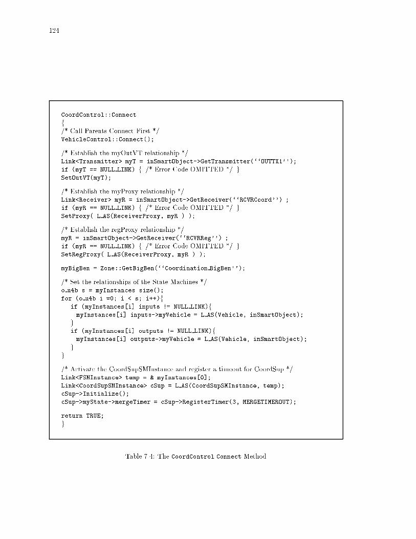
124
CoordControl::Connect
f/* Call Parents Connect First */VehicleControl::Connect();
/* Establish the myOutVT relationship */Link<Transmitter> myT = inSmartObject->GetTransmitter(``OUTTX1'');
if (myT == NULL LINK) f /* Error Code OMITTED */ gSetOutVT(myT);
/* Establish the myProxy relationship */Link<Receiver> myR = inSmartObject->GetReceiver(``RCVRCoord'') ;
if (myR == NULL LINK) f /* Error Code OMITTED */ gSetProxy( L AS(ReceiverProxy, myR ) );
/* Establish the regProxy relationship */myR = inSmartObject->GetReceiver(``RCVRReg'') ;
if (myR == NULL LINK) f /* Error Code OMITTED */ gSetRegProxy( L AS(ReceiverProxy, myR ) );
myBigBen = Zone::GetBigBen(``Coordination BigBen'');
/* Set the relationships of the State Machines */o u4b s = myInstances.size();
for (o u4b i =0; i < s; i++)fif (myInstances[i].inputs != NULL LINK)fmyInstances[i].inputs->myVehicle = L AS(Vehicle, inSmartObject);
gif (myInstances[i].outputs != NULL LINK)fmyInstances[i].outputs->myVehicle = L AS(Vehicle, inSmartObject);
gg
/* Activate the CoordSupSMInstance and register a timeout for CoordSup */Link<FSMInstance> temp = & myInstances[0];
Link<CoordSupSMInstance> cSup = L AS(CoordSupSMInstance, temp);
cSup->Initialize();
cSup->myState->mergeTimer = cSup->RegisterTimer(3, MERGETIMEROUT);
return TRUE;
g
Table 7.4: The CoordControl Connect Method

125
RegControl::Run() fLink<FSMInstance> mySup = & myInstances[0];
mySup->theState->curChild->ProcessEvent(TICK);
return TRUE;
g
Table 7.5: The RegControl Run Method
take place. When A completes the merge, it sends an MDMessage containing a list of the Vehiclesin platoon A. The leader of platoon A adds these Vehicles to its list of myFollowers.
CoordSupIn and MIOut
The specialized Input and Output classes used by MergeInit are CoordSupIn and MIOut.These classes contain the required information for the Enter and Exit methods to generate thenecessary internal Events.
The attributes of CoordSupIn are:
CoordSupIn Attributes
Relations
Link<Vehicle> sourceVehicle Inputs are derived from the sourceVehicle'sState.
Values
o bool amILeader True if platoon leader.o u1b platoonSize Size of platoon, one if single agent.o u1b targetPlatoonSize Preferred platoon size.Link<Receiver> myLeadersProxy If follower, leaders proxy.VVList<Receiver> myFollowers If leader, followers' proxys.
The attributes of MIOut are:
MIOut Attributes
Relations
Link<Vehicle> targetVehicle Outputs are propagated to targetVehicle'sState.
Values
o bool amILeader True if platoon leader.Link<Receiver> myLeadersProxy If follower, leaders proxy.
Both objects specialize the Update method. The Update method of CoordSupIn derivesthe values of the attributes, the Update method of MIOut propagates the values of the attributes tothe VehicleState. The Update methods are invoked in the specialized Enter and Exit methods ofthe SMState subclasses.
MergeInitSMInstance Behavior
The MergeInit state machine is activated by its parent, the CoordSup state machine. Aspart of activation, the parent sends the START Message.
The Initialize method of a SMInstance invokes the virtual UpdateCorr method of itsSMInstanceState. MergeInitSMInstanceState specializes this method and sets the correspondentvariable F for the front Vehicle using its Sensor. The UpdateCorr method is given in Table 7.7.

126
machineName: MergeInit;children: NULL;states: Idle, Check, ReqWait, Accel, Set;InputEvents: YES, NO;inputMessages: Message:START, Message:OK MERGE,
Message:DONT MERGE, Message:BUSY,Message:MERGE M DONE, Message:MERGE M FAILED;
outputMessages: MRMessage:MERGE REQUEST, Message:MERGE MAN,Message:LEAD MAN, Message:MERGE I DONE,Message:MERGE I FAILED, MDMessage:MERGE DONE,Message:MERGE FAILED;
beginState: Idle;correspondents: F, FLead;timers: miTimer;inputs: CoordSupIn;outputs: MIOut;
transitions:Idle Parent:START () Check
Check YES (F:MERGE REQUEST, miTimer:20) ReqWaitCheck NO (Parent:MERGE I FAILED) Idle
ReqWait FLead=OK MERGE (REG:MERGE MAN, miTimer:Cancel, AccelmiTimer:50)
ReqWait FLead=DONT MERGE (Parent:MERGE I FAILED, IdlemiTimer:Cancel)
ReqWait FLead=BUSY (Parent:MERGE I FAILED, IdlemiTimer:Cancel)
ReqWait miTimer (Parent:MERGE I FAILED) Idle
Accel REG:MERGE M DONE (miTimer:Cancel, SetFLead:MERGE DONE,Parent:MERGE I DONE)
Accel REG:MERGE M FAILED (FLead:MERGE FAILED, IdleParent:MERGE I FAILED,miTimer:Cancel)
Accel miTimer (FLead:MERGE FAILED, IdleParent:MERGE I FAILED,REG:LEAD MAN)
Set YES () Idle
Table 7.6: The MergeInit State Machine De�nition

127
MergeInitSMInstanseState::UpdateCorr() fLink<VehicleSensor> myS = L AS(VehicleSensor,
theInst->myController->GetSmartObject()->GetSensor("SENSBasic") );
double frontDist, frontVel;
Link<Vehicle> frontVeh = myS->GetVehicle(eFront, eThisLane, frontDist,
frontVel);
if (frontVeh == NULL LINK)f F = NULL LINK; gelse f F = frontVeh->GetReceiver("RCVRCoord"); greturn TRUE;
g
Table 7.7: The MergeInitSMInstanceState UpdateCorr Method
CheckSMState::Enter(Link<SMInstanceState> theState, Link<Input> i,
Link<Output> o)
fLink <MergeInitInstanceState> myState =
L AS(MergeInitInstanceState, theState);
Link <CoordSupIn> myIn = L AS(CoordSupIn, i);
Link <MIOut> myOut = L AS(MIOut, o);
/* User speci�ed code of the Enter method consists of the next two lines.
The wrapper is auto-generated. */
if (myState->F == NULL LINK) f myState->directEvent = NO; gelse f myState->directEvent = YES; g
return TRUE;
g
Table 7.8: The CheckSMState Enter Method
The Enter method of the CheckSMState is specialized to determine if there is a Vehicle
ahead. Its Enter method is given in Table 7.8.
If there is a Vehicle within the sensing distance a MERGE REQUEST Message is sent to thatVehicle, F. The response comes from the leader of F, or just F if it is a single agent.
If FLead, the leader of the front platoon, gives permission for the merge maneuver theregulation controller is asked to execute the merge maneuver.
The Enter and Exit methods of the AccelSMState are specialized to Update the outputsof the MergeInitSMInstance. If the merge maneuver is successful, the regulation layer automaticallyswitches to the follow maneuver which depends on the myLeadersProxy relationship. Therefore, itis necessary to set the State of the Vehicle to re ect the new myLeadersProxy. The Enter methodof SMAccelState updates the State of the Vehicle and sets its myLeadersProxy relationship. TheExit method reverses this operation in case the maneuver fails. The corresponding code fragmentsare given in Table 7.9 and 7.10.
If the maneuver is successful, the SetSMState's Entermethod is called to set the Vehicle'sState. The code fragment for this method is given in Table 7.11

128
myOut->myLeadersProxy = myState->FLead;
myOut->amILeader = FALSE;
myOut->Update();
Table 7.9: The AccelSMState Enter Method, Code Fragment
myOut->myLeadersProxy = NULL LINK;
myOut->amILeader = TRUE;
myOut->Update();
Table 7.10: The AccelSMState Exit Method, Code Fragment
myState->directEvent = YES;
myOut->amILeader = FALSE;
myOut->myLeadersProxy = myState->FLead;
myOut->Update();
Table 7.11: The SetSMState Enter Method, Code Fragment

129
Camera::Camera()
f/* Create the CameraState and establish the myCameraState relationship */
/* The state constructor establishes the myObj relationship */myCameraState = new Persistent CameraState(this);
/* Establish the currState relationship of StatedObject */currState = (State*)myState;
/* Hardcode sensing distance to 15 cellArray cells */frontDist = 15 + 1;
myBigBen = Zone::GetBigBen("Regulation BigBen");
g
Table 7.12: The Camera Constructor
7.1.4 Creating Monitors
Camera
The Camera object models a camera mounted on the front hood of a vehicle. It capturesinformation about the Vehicles ahead in its CameraState.
Most of Camera behavior is implemented by its parent, Monitor. Camera only specializesthe Run method to invoke the Update method of CameraState.
The Update method of CameraState uses the Camera's static relationships to derive thecurrent CameraState values.
The Camera has the following static attributes and relations:
Camera Static Attributes
Relations
Link<VehicleState> itsState The containing Vehicle's State.Link<Sensor> itsSensor The containing Vehicle's Sensor.Values
o u2b frontDist Distance within the vision of Camera.
The CameraState consists of the following attributes:
CameraState Attributes
Values
o float dxFront Distance di�erential with Vehicle ahead.o float dyFront Speed di�erential with Vehicle ahead.Relations
VVArray<Vehicle> frontVehicles Vehicles ahead within the next frontDist
meters.
The constructor and the Connect methods of the Camera are given in Table 7.12 and 7.13respectively. The Camera is turned on or o� through the graphical debugger.
7.1.5 Specializing Sensors, Transmitters, and Receivers
In this example myVehicle uses the SmartAHS communication and sensor devices. How-ever, one could specialize these objects simply by inheriting from them and specializing their virtual

130
Camera::Connect()
fif (inSmartObject == NULL LINK) f /* Error code OMITTED */ gLink<Vehicle> myVehicle = L AS( Vehicle, inSmartObject );
Link<State> temp = myVehicle->GetState();
if (temp == NULL LINK) f /* Error code OMITTED */ gitsState = L AS(VehicleState, temp);
itsSensor = L AS(VehicleSensor, myVehicle->GetSensor("SENSBasic"));
return TRUE;
g
Table 7.13: The Camera Connect Method
methods.
7.2 Creating the Process Layers
Four special process layers are created.
The Physical layer is used to update the position of a Vehicle on the highway. ThePhysical layer is actually part of SmartAHS.
The Regulation layer is used to generate the displacement of a Vehicle.
The Coordination layer is used to implement the coordination control layer.
The GUI layer is used to communicate with the graphical debugger.
7.2.1 Physical Layer
The Physical Layer subclasses the Traverser and specializes the methods EAbsorber(),EGenerator(), and ELC(). As shown in in Table 7.14, these methods invoke the LaneContainer
methods that implement Vehicle movement on the highway, Vehicle creation, and Vehicle re-moval.
7.2.2 Regulation Layer
The Regulation layer subclasses the Hybrid class. It contains the PacketBox for theRegControl state machines.
The Regulation layer also specializes the ELC method, to invoke the Run method of eachRegControl object.
The corresponding methods are in Table 7.15.
7.2.3 Coordination Layer
The Coordination class does not provide any specialized methods. It only sets the nameof the EventDriver to \Coordination".
7.2.4 GUI Layer
The GUI class directly inherits from the Layer class and specializes the Go method toexecute the appropriate graphical debugger code.

131
Physical::ELC(Link<LaneContainer> LC)fLC->MoveVehicles();
return 0;
g
Physical::EAbsorber(Link<Absorber> LC)fLC->AbsorbVehicles();
return 0;
g
Physical::EGenerator(Link<Generator> LC)fLC->GenerateVehicles();
return 0;
g
Table 7.14: Specialized Physical Layer Methods
7.3 Simulation Setup
We follow the steps outlined in Section 5.2.2
7.3.1 Highway Layout
A highway layout is created using the GOE.This layout is saved to a C++ �le and compiled to executable format. The executable is
run to place the highway into the database.
7.3.2 Tra�c Patterns
An InTraffic subclass is created that generates a MyVehicle every n time clicks, wheren is a con�gurable parameter. A Factory subclass is created that instantiates a myVehicle. Theseobjects are inserted into the highway.
7.3.3 Roadside Automation
No roadside automation devices are used for this simulation.
7.3.4 Vehicle Automation
The implementation of MyVehicle was discussed above.
7.3.5 Simulation Granularity
The implementation of the scheduling objects were discussed above. The executable thatinstantiates the scheduling objects is given in Table 7.16.
The ConfigFile object provides methods to get simulation parameters. It reads in asimulation parameters �le and returns the required information. Using the ConfigFile object, thisexecutable creates the scheduling object instances and names them.
Other simulation granularity is speci�ed through the simulation parameters.

132
Hybrid::Start()fmyEventDriver->Go();
return 0;
g
Regulator::ELC(Link<LaneContainer> LC)fVVList<Lane> theLanes = LC->GetLanes();
VVList<Vehicle> vehicleList;
Link<Vehicle> aVehicle;
Link<Control> aControl;
o u4b i, j;
i = 0;
while (i < myLanes.size()) fvehicleList = &myLanes[pos].GetVehicles();
j = 0;
while (j < vehicleList.size()) faVehicle = &vehicleList[j];
aControl = aVehicle->GetControl("RC1");
if (aControl == NULL LINK) f /* Error Code OMITTED */ gaControl->Run();
j++;
gi++;
greturn 0;
g
Table 7.15: Specialized Regulation Layer Methods

133
extern ConfigFile* CFO;
main(int argc, char **argv)
f
dom = new PDOM();
dom->beginsession(CFO->getMyDbName(), "session1");
InternalSynchronizer* myIS =
new Persistent InternalSynchronizer(CFO->getMyISName());
Physical* myP = new Persistent Physical();
myIS->Register(myP, myP->getName(), myP->getPeriod());
Regulator* myR = new Persistent Regulator();
myIS->Register(myR, myR->getName(), myR->getPeriod());
Coordination* myE = new Persistent Coordination();
myIS->Register(myE, myE->getName(), myE->getPeriod());
GUI* myGUI = new Persistent GUI(dom);
myIS->Register(myGUI, myGUI->getName(), myGUI->getPeriod());
dom->Commit();
g
Table 7.16: The Executable Creating the Scheduler Objects

134
extern ConfigFile* CFO;
main(int argc, char **argv) fint steps = atoi(argv[1]);
dom = new PDOM();
dom->beginsession(CFO->getMyDbName(), "session1");
PPredicate aPredicate = PAttribute("FrameworkObject::name") ==
CFO->getMyISName();
LinkVstr<InternalSynchronizer> IS =
PClassObj<InternalSynchronizer>.select(NULL, FALSE, aPredicate);
Link<InternalSynchronizer> myIS = IS[0];
for (int i = 1; i <= steps; i++)fmyIS->Go();
g
dom->Commit();
g
Table 7.17: The Executable to Run the Simulation
7.3.6 Simulation Parameters
The controllers used in this simulation do not use any parameters.The Physical and Regulation layers are run at every time click. The Coordination
and GUI layers are run every fourth time click. The time click step size is set to 0:1 seconds.The integration time step is set to 0:005 seconds. This information is speci�ed in the simulationparameters �le.
7.3.7 The GUI Debugger
The GUI debugger does not require any particular con�guration.
7.3.8 Running the Simulation
The executable that runs the simulation is in Table 7.17. Two inputs are read in fromthe simulation parameters �le: the name of the InternalSynchronizer to be simulated and thename of the database the simulation is stored in. Using this information the executable retrievesthe corresponding InternalSynchronizer instance from the database.
The ProcessCoordinator runs for duration time clicks every time its Go() method isinvoked. The main executable takes in an argument that speci�es how many times the Go() methodof the ProcessCoordinator should be invoked.
This particular executable chooses to Commit to database only at the end of simulation.

135
7.4 Implementation Critique
Evaluation criteria for a Customized OM and an OMS Application were discussed inSection 4.6. This section provides a critique of SmartAHS design and implementation. In particular,the SmartAHS must satisfy the requirements identi�ed in Section 3.1.2.
7.4.1 Ease-of-use
We discuss the requirements of Section 4.6 in the context of SmartAHS.
� Relevance of Entities;
SmartAHS attempts to provide abstractions for microsimulation. Most SmartAHS entitiesare \planned" objects; a process needs to be developed to convert software speci�cations intoactual physical components.
� Locality of reference and learning curve;
The developer of automation devices needs minimal understanding of the process model. Therequired information is limited to the inputs, outputs and the time scale of evolution of theobject.
The coordination between various automation devices requires more design e�ort.
The developer of scheduling objects, usually the system architect, needs a good understandingof the process model; however, in general the system architect is shielded from the details ofother objects.
Adding entities requires the writing and compiling of C++ code. The steps to integrate anew entity were summarized in Figure 5.3. The steps required to set up a simulation aremore streamlined. In particular, the parameter �le and the graphical debugger provide quickspeci�cation mechanisms.
� Ease of speci�cation;
A number of tools are provided to simplify system speci�cation. These tools have room forimprovement. In particular, better syntax checking is needed both for the state machine codegenerator and the GOE grammar parser. A new tool is needed to automatically convert contin-uous time di�erential equations into C++ programming constructs. Currently this conversionis manual.
� Ease-of-evaluation;
Monitor speci�cation syntax is C++. However, once a monitor entity is created its use isstraightforward. The use of the database simpli�es the recording and the replaying of systemstate.
� System level issues;
{ Con�guration management;
The GOE is a tool for creating instance con�gurations. As this tool matures, it willbe used to create automation strategies by mixing and matching existing entities. Acon�guration management tool is needed to track simulation runs. Other con�gurationmanagement problems are addressed by system utilities such as Revision Control System(RCS).
{ Fault management;
All C++ development tools can be used by SmartAHS. The graphical debugger aids infault management. Better syntax checking is needed both for the state machine codegenerator and the GOE grammar parser.

136
{ Performance management;
SmartAHS allows time driven objects to evolve at di�erent time scales. Event drivenschedulers execute the behavior of objects with outstanding events only. The users areallowed to set simulation granularity.
The client-server architecture makes it possible to run the graphical debugger and thesimulation on di�erent workstations.
Performance and memory use statistics are discussed in Section 7.4.4.
{ Access and security management;
Application developers do not need write access to the SmartAHS classes. Proper imple-mentation of SmartPATH will ensure that system users do not need write access to theSmartPATH classes.
{ Financial management;
Financial management is beyond the scope of this thesis.
{ Resource Management;
SmartAHS is designed to run on SunSparc and SGI platforms. Future releases shouldeliminate the dependence on the Versant database.
{ Planning and Design Management;
Both SmartDb and SmartAHS are expected to evolve over time.
7.4.2 AHS Requirements
This section summarizes requirements that are not fully addressed by SmartAHS.
� All user requirements are addressed;
� Con�guration requirements;
Actual speci�cation and implementation of automation devices and tra�c entities are left tothe application developer. The state machine language is designed to streamline protocolspeci�cations.
Currently, no special language is provided to de�ne tra�c rules. As these rules are betterunderstood a particular speci�cation language may emerge.
� Fault management requirements;
Accident detection is part of SmartAHS. Current version of the graphical debugger has a readonly interface. As the read-write interface is implemented, inducing component failures willbe streamlined.
� Performance and planning requirements;
Gateways need to be designed to interface with other packages.
� Modeling requirements;
Better geometric highway representation support is needed. Automation device speci�cationand implementation is left to application development.
� Validation and deployment;
A new automated process is needed to meet these requirements. The modularity of SmartAHSis expected to provide a head-start.
The state machine language provides veri�cation support.

137
7.4.3 Software System Requirements
A number of desirable software system characteristics were discussed in Section 2.1 andrevisited in Section 3.1.2. Here, these characteristics are discussed in the context of SmartAHS.
� Ability to associate physical and logical representations: Modularity;
The object-oriented approach and the OMS Object Model make SmartAHS a modular system.Actual and planned physical objects are well encapsulated in classes.
� Ability to add new components to the system with minimal code rewrite: Openness, Modu-larity, Robustness;
Application developers are able to add new objects by subclassing SmartAHS classes.
The application developer and the system user are both capable of composing complex objectsfrom simpler components.
Current SmartAHS architecture does not provide su�cient software fault isolation. Since allobjects are simulated in the same process, it may not always be possible to pinpoint the exactsource of a software failure. A more robust architecture would simulate each control layer ina di�erent process. However, this approach results in poor performance.
� Ability to collect arbitrary statistics during simulation: Openness, Modularity;
SmartAHS enables monitor objects to collect and store arbitrary statistics at run-time.
The entire simulation state can be saved in the OODB for later use. However, it is not practicalto save the entire state after every transition since the commit time of a zone with thousandvehicles is in the order of seconds.
� Ability to run simulations with acceptable performance: Performance;
Performance statistics are presented in the next section.
� Ability to adjust simulation granularity: Modularity, Openness;
The scheduling objects are con�gurable like any other object.
� Ability to simulate up to 100.000 vehicles: Performance;
A distributed version of SmartAHS is forthcoming. Current implementation introduces signif-icant overhead for distribution support. Distribution is discussed in more detail in [34].
7.4.4 Performance Statistics
In this section we provide performance results for several simulation runs. The simulationswere run on a Sparc10 workstation with 64Meg of memory.
Figures 7.3, 7.4, and 7.5 plot the amount of time taken for one second of highway simulationversus the number of vehicles simulated. The graphs have two curves; the �rst plots the total elapsedtime, the second plots the time taken up by the regulation layer.
The simulation is started with a 2km long empty highway and a new vehicle is createdevery 2 seconds. The 2km highway accommodates 500 vehicles. Hence, the curves level o� after 500vehicles.
Vehicle positions on the highway are updated every 0.1 seconds. The integration time stepis set at 0.005 seconds. The elapsed time is measured every 4 seconds of simulation time.
The �rst scenario, in Figure 7.3, uses the physical and regulation layers only. The vehiclesenter the highway, remain single agents, traverse the highway, and eventually leave the simulation.The regulation layer determines the vehicle displacements through integration, the physical layermoves the vehicles on the highway based on these displacements.
About 98.5% of simulation time is taken up by the integration routines in the regulationlayer and the two curves are barely distinguishable. The plot indicates that about 32 vehicles canbe simulated in real time.

138
Total Time
Regulation Time
Total Elapsed Time
Number of Vehicles
0.00
1.00
2.00
3.00
4.00
5.00
6.00
7.00
8.00
9.00
10.00
11.00
12.00
13.00
14.00
15.00
16.00
17.00
18.00
19.00
0.00 100.00 200.00 300.00 400.00 500.00
Figure 7.3: Single Agent Vehicles Moving On Highway
The second scenario, Figure 7.4, introduces the coordination layer. The coordination layeris scheduled twice a second. Vehicles enter the highway, try to merge with other vehicles, traversethe highway in platoons, and eventually leave the simulation. About 88% of elapsed time is takenup by the regulation layer. Platoons of size 2 are created. Since the displacement for a followervehicle in a platoon is based on the leader vehicle's displacement, less time is taken up in integrationroutines. As a result, about 55 vehicles are simulated in real time.
The third scenario, Figure 7.5, provides a measure for the framework simulation overhead.Only the physical and regulation layers are used. Instead of calculating the vehicle displacementthrough integration, the displacement is hardcoded to 2m. Still, the regulation layer takes up 75%of the total elapsed time. Framework bookkeeping, such as, creating vehicles, removing vehicles,traversing objects, maintaining the vehicle positions within a lane, etc. is limited to 25%.
Finally, Figure 7.6 displays the memory use of the simulation. The resident and total sizesof the program are plotted against the number of vehicles in the simulation.

139
Total Time
Regulation Time
Total Elapsed Time
Number of Vehicles0.00
0.50
1.00
1.50
2.00
2.50
3.00
3.50
4.00
4.50
5.00
5.50
6.00
6.50
7.00
7.50
8.00
8.50
9.00
9.50
10.00
0.00 100.00 200.00 300.00 400.00 500.00
Figure 7.4: 2-Vehicle Platoons Moving On Highway
Total Time
Regulation Time
Total Elapsed Time
Number of Vehicles0.00
0.10
0.20
0.30
0.40
0.50
0.60
0.70
0.80
0.90
1.00
1.10
1.20
1.30
1.40
1.50
0.00 100.00 200.00 300.00 400.00 500.00
Figure 7.5: Single Agent Vehicles Moving On Highway with Hard-Coded Displacement

140
Total Size
Resident Size
KBytes x 103
Number of Vehicles2.00
3.00
4.00
5.00
6.00
7.00
8.00
9.00
10.00
11.00
12.00
13.00
14.00
15.00
16.00
17.00
100.00 200.00 300.00 400.00 500.00
Figure 7.6: Memory Use of Simulation

141
Chapter 8
Conclusions
A summary of the thesis is provided in the Introduction.As we stated earlier SmartDb and SmartAHS are \live" systems that will evolve over time.
In this chapter we summarize some of the future evolution directions for the OMS Object Model,its SmartDb implementation, and the SmartAHS simulation framework.
8.1 The Object Model and SmartDb
The current SmartDb implementation supports only a subset of the Object Model con-structs. Most of the Object Model constructs are actually implemented as part of SmartAHS.
A number of modules that were discussed in Chapter 6 as part of SmartAHS shouldbecome application independent SmartDb constructs. Some of these modules are already quitegeneric, others require some design work to eliminate their dependency on the highway automationapplication. These modules are:
� The graphical object editor;
As the reader may have already noticed this module is generic and does not depend on thehighway application.
� The graphical debugger;
The graphical debugger is able to display any entity, so long its attributes are from a speci�cset. However, some work is required to be able to de�ne application domain speci�c attributesand attribute icons.
� State machine language; and
The code generator for the state machine language uses SmartAHS entities, such as Receiversand Transmitters, as target C++ classes. A more abstract SML syntax and a con�gurablecode generator is needed to make the SML part of SmartDb. Each Customized OM can thenprovide customizations of the SML.
� Time and event driven scheduling objects;
The Traverser traverses highways and is application speci�c. However, the concept of travers-ing a system for the extent of a class is generic. Similarly, Packets and PacketBoxes used bythe EventDrivers can be used by any application domain. Application independent time andevent driven scheduling mechanisms should become part of SmartDb.
As other specialized speci�cation languages emerge, such as di�erential equation solversand rule-based systems, their generic components should become part of SmartDb.
The current implementation of SmartDb does not have a clear interface with Versant anddepends on Versant data types. Although the use of Versant data types has initially speeded up theimplementation process, eventually, these data types should be replaced with vendor independentimplementations. Eventually SmartDb should eliminate its dependence on Versant entirely and workwith any persistent storage system.

142
8.2 SmartAHS Expansion Directions
An implementation critique of SmartAHS is provided in Section 7.4. Most suggestedimprovements are in the direction of \productizing" the SmartAHS simulation platform.
The current development e�orts for SmartAHS are:
� More domain speci�c objects;
More accurate sensor, transmitter, and receiver models, vehicle dynamics models and even-tually some standard automation devices should become part of SmartAHS. More highwayentities, such as bridges and tunnels, and more tra�c entities are being developed.
� Other specialized speci�cation languages;
These speci�cation languages may include di�erential equation solvers, rule-based speci�cationlanguages, or even tra�c rule speci�cation languages.
� Streamlining simulation setup;
Better graphical and command line interfaces are planned for simulation setup and monitorspeci�cation.
� Interfaces to other simulation and veri�cation platforms; and
SmartAHS has an open architecture that facilitates integration with other tools. However,such integration requires that the other tools be open as well. A SML-to-COSPAN translatoris under development. Integration with urban tra�c simulators is planned.
� SmartAHS Distribution.
A distributed version of SmartAHS is under development. Current implementation introducessigni�cant overhead for distribution support. Distribution is discussed in more detail in [34]

143
Bibliography
[1] \The Common Object Request Broker (CORBA): Architecture and Speci�cation",Object Management Group (OMG), Framingham, MA, Dec. 1991.
Software Engineering
[2] K. Beck, et.al.\Can Structured Methods Be Objecti�ed?",Panel discussion in Proceedings of OOPSLA '91.
[3] B. Boehm. Software Engineering Economics,Prentice-Hall, Engelwood Cli�s, NJ, 1981.
[4] G. Myers. Composite/Structured Design,New York Ny: Van Nostrand Reinhold, 1978, p21.
[5] Edward Yourdon and Larry Constantine. Structured Design,Yourdon Press, Englewood Cli�s, N.J., 1979.
[6] Edward Yourdon. Modern Structured Analysis,Yourdon Press, Englewood Cli�s, N.J., 1989.
Object Oriented Paradigm
[7] L. Cardelli and P. Wegner. \On Understanding Types, Data Abstraction, and Polymorphism",Computing Surveys, vol 17, no.4, 1985 pp. 471-522.
[8] Ralph E. Jonson. \How to Develop Frameworks",OOPSLA Tutorial Notes, ACM Press. 1993.
[9] T. Rentsch. \Object-Oriented Programming",SIGPLAN Notices vol 17(12), p 51.
[10] Peter Wegner. \Concepts and Paradigms of Object-Oriented Programming",ACM SIGPLAN OOPS Messenger, 1(1), Aug 1990.
Object Oriented Methodologies
[11] G. Booch. Object Oriented Design with Applications,Benjamin/Cummings, Redwood City, CA. 1991.
[12] [11] p 27.
[13] R.J.A. Buhr. Practical Visual Techniques in System Design: With Applications to Ada
Prentice-Hall, Englewood Cli�s, N.J., 1991.
[14] P. Coad and E. Yourdon. Object-Oriented Analysis,Yourdon Press, Englewood Cli�s, NJ. 1991.

144
[15] Ivar Jacobson et.al. Object-Oriented Software Engineering,Addison-Wesley, ACM Press, 1992.
[16] James Rumbaugh et.al. Object Oriented Modeling and Design,Prentice-Hall, Englewood Cli�s, N.J., 1991.
[17] Ron Schultz. \A Game Plan for OOD Developers",in Open Systems Today, Sept. 21 1992.
[18] Sally Shlaer and Stephen Mellor. Object-Oriented Systems Analysis: Modeling the World in
Data,Yourdon Press, Englewood Cli�s, N.J., 1988.
[19] Sally Shlaer and Stephen Mellor. Object-Oriented Systems Analysis: Modeling the World in
States,Yourdon Press, Englewood Cli�s, N.J., 1988.
[20] Rebecca Wirfs-Brock, B. Wilkerson, and L. Weiner. Designing Object-Oriented Software,Prentice Hall, Englewood Cli�s, N.J. 1990.
Object Oriented Programming Languages
[21] Margaret Ellis and Bjarne Stroustrup. The Annotated C++ Reference Manual,Addison-Wesley, Reading MA, 1990.
[22] Adele Goldberg and D. Robson. Smalltalk 80: The language and its Implementation,Addison-Wesley, Reading, Massachusetts, 1983.
[23] Stanley B. Lippman. C++ Primer,Addison-Wesley, Reading MA, 1991
Databases
[24] S. Ahmed, A. Wong, D. Sriram, and R. Logcher. \A Comparison of Object-Oriented DatabaseManagement Systems for Engineering Applications",Research Report R91-12, Massachusetts Institute of Technology, Intelligent Engineering SystemsLaboratory.
[25] M. Atkinson et.al. \The Object-Oriented Database System Manifesto",Proceedings of 1st Intn. Conf. on Deductive and Object-Oriented Databases Kyoto, Japan, Dec.1989
[26] Douglas K. Barry. \ODBMS Feature Listing",Object Magazine, January-February 1993, pp. 48-53.
[27] Edgar F. Codd. \A Relational Model for Large Shared Data Banks",Communications of the ACM, 13(60, pp. 377-387, Jun 1970.
[28] Edgar F. Codd. \Relational Completeness of Database Sublanguages",Data Base Systems, R. Rustin ed.,Prentice Hall, Englewood Cli�s, N.J. 1972.
[29] Chris J. Date. An Introduction to Database Systems,Addison-Wesley, Reading, Massachusetts, 1985.
[30] A.R. Hurson, S.H. Pakzad, and J. Cheng. \OODBMS: Evolution and Performance Issues",IEEE Computer Magazine, February 1993, pp. 48-60.
[31] Larry Lai and Leon Guzenda. \How to Benchmark an OODBMS",JOOP 1991.

145
[32] Bindu Rao. Object-Oriented Databases,McGraw Hill, 1994.
[33] M. Stonebreaker et.al. \Third Generation Data Base System Manifesto",Proceedings of IFIP DS-4 Workshop on Object-Oriented Databases Windermere, England, July1990.
Automated Highway Systems
[34] F. Eska�. Work in progressPhD thesis, UC Berkeley. June 1996.
[35] F. Eska� and P. Varaiya. \SmartPath: Automatic Highway Simulator"PATH Technical Memorandum, UC Berkeley. June 1992.
[36] F. Eska�, Delnaz Khorramabadi, and P. Varaiya, \An Automatic Highway System Simulator"Transportation Research -C Vol. 3, No, 1, pp. 1-17, 1995.
[37] A. G�oll�u, A. Deshpande, P. Hingorani, P. Varaiya. \SmartDb: An Object Oriented SimulationFramework for Highway Systems.",Fifth Annual Conference on AI, Simulation, and Planning in High Autonomy Systems, pp.244-251, Gainesville, Florida. 1994.
[38] Ivy Hsu and Jean Walrand. \Communication Requirements and Network Design for IVHS"PATH Technical Report, UCB-ITS-PWP-93-18.
[39] Steve Shladover et.al. \Automated Vehicle Control Developments in the PATH program",IEEE Trans. Vehicular Tech. Vol. 40. pp. 114-130. Feb. 1991.
[40] W.B. Stevens. \The Automated Highway System (AHS) Concept Analysis",MITRE Research Report MTR-93W0000123, (draft.), August 1993, McLean, Viriginia.
[41] Pravin Varaiya. \Smart Cars on Smart Roads: Problems of Control",IEEE Trans. Automatic Control Vol. 38, No 2. Feb. 1993.
[42] IVHS America. Strategic Plan for Intelligent Vehicle-Highway Systems in the United States.Report No IVHS-AMER-92-3. 20 May 1992.
Power Distribution Systems
[43] Arthur R. Bergen. Power System Analysis,Prentice-Hall, Englewood Cli�s, N.J, pp. 34-35.
[44] Matthew Brundjar. Power Distribution Management,Work in progress, Masters' thesis, UC Berkeley.
[45] William R. Cassel. \Distribution Management Systems: Functions and Payback",IEEE/PES 1992 Summer Meeting, Seattle, WA, July 12-16, 1992, 92 SM 450-7 PWRS.
[46] D. Chiang and M.E. Baran. \On the Existence and Uniqueness of Load Flow Solution for RadialDistribution Power Networks",IEEE Trans. on Circuits and Systems, Vol 37, No 3, pp. 410-416, March 1990
[47] Aleks G�oll�u and Felix F. Wu. \New Directions for Network Management",Proceedings of Distribution 2000. Melbourne, Australia. Electricity Supply Association of Aus-tralia.
[48] Y. Sekine, K.Takahashi, T.Sakaguchi. \Real-Time Simulation of Power System Dynamics"Proceedings of 11th Power Systems Computation Conference, Avignon France, pp. 3, August1993.

146
[49] Felix F. Wu and R. D. Masiello eds.;Special Issue on Computers in Power System Operation, Proceedings of the IEEE, Vol 75, pp.1553-1712, Dec 1987.
[50] EPRI Report. Guidelines for Evaluating Distribution Automation,Technical Report EL-3728, November 1984.
[51] IEEE Tutorial Course,Distribution Automation,IEEE Power Engineering Society 88EH0280-8-PWR 1988.
Network Management Systems
[52] Subodh Bapat. Object-Oriented Networks,Prentice Hall, Englewood Cli�s, N.J.
[53] Uyless D. Black. Network management standards : the OSI, SNMP, and CMOL protocols
McGraw-Hill, New York, 1992
[54] Uyless D. Black. Network management standards : SNMP, CMIP, TMN, MIBs, and object
libraries,McGraw-Hill, New York, 1994.
[55] J. Case, M. Fedor, M. Scho�stall, and J. Davin. \A Simple Network Management Protocol",Request for Comments 1098, DDN Network Information Center, SRI International, April, 1989
[56] Douglas E. Comer. Internetworking with TCP/IP Volume 1: Principles, Protocols, and Archi-
tecture,Prentice-Hall, Englewood Cli�s, N.J.,1991.
[57] Douglas E. Comer and David L. Stevens. Internetworking with TCP/IP Volume 2: Design,
Implementation, and Internals,Prentice-Hall, Englewood Cli�s, N.J.,1991.
[58] Richard J. Edell, Nick McKeown and Pravin Varaiya. \Billing Users and Pricing for TCPTra�c",To appear in IEEE Journal of Selected Areas in Communications, Special Issue on \Advances
in the Fundamentals of Networking."
[59] Aleks G�oll�u and D. Moen. \Building Large Network Management Systems with C++"Proceedings of OOPSLA. 1991.
[60] Aleks G�oll�u and W. Caplinger. \Performance Issues in Network Management Systems",Proceedings of Wescon 1992.
[61] Aleks G�oll�u, W. Caplinger, and D. Moen. \IMS a Network Management Integrator Compliantwith OSI/NM Forum",Proceedings Silicon Valley Networking Conference, April 1991
[62] Aleks G�oll�u and G. Caravias. \Network Management in a Heterogeneous Environment",Proceedings Wescon 91, San Francisco, California.
[63] Shau-Ming Lun, Felix Wu, Ning Xiao, and Pravin Varaiya. \NetPlan: An Integrated NetworkPlanning Environment",State of the Art in Performance Modeling and Simulation: Computer and CommunicationNetworks, Vol.1, Kluwer Academic Publisher, 1993.
[64] J. B. Postel. \User Datagram Protocol",Request for Comments 768, DDN Network Information Center, SRI International, August 1980.
[65] M. Rose. The Open Book, A Practical Perspective,Prentice Hall.

147
[66] OSI/Network Management Forum; \Basic Reference Model",International Electrotechnical Committee 1984.
[67] OSI/Network Management Forum; \Application Services",Forum 002; Issue 1; January 1989
[68] OSI/Network Management Forum; \Object Speci�cation Framework",Forum 003; Issue 1.0; September 1989
[69] \OSI Basic Reference Model",ISO 7498-1, 1992.
[70] \Common Management Information Service (CMIS) De�nition",ISO 9596-1, 1992.
[71] \Common Management Information Protocol, Part 1:Speci�cation",ISO 9596-1, 1992.
[72] \International Standardized Pro�les | OSI Management | Management Functions", Parts1-5,ISO ISP 12060, 1993.
[73] \Management Information Services | Structure of Management Information |" Parts 1-7,ISO 10165-1 to ISO 10165-7.
Formal Methods
[74] R. Alur, C. Courcoubetis, and D. Dill. \Model-Checking for Real Time Systems",Proceedings 5th IEEE Symp. on Logic in Computer Science, IEEE Computer Society Press,1990.
[75] F.J. Barros, M.T.Mendes, and B.P. Zeigler. \Variable DEVS | Variable Structure ModelingFormalism: An Adaptive Computer Architecture Application",Fifth Annual Conference on AI, Simulation, and Planning in High Autonomy Systems, pp.185-192, Gainesville, Florida. 1994.
[76] J. R. B�uchi. \On a decision method in restricted second order arithmetic",Proceedings of the International Congress on Logic, Methodology and Philosophy of Science,pages 1{11. Stanford University Press, 1962.
[77] Akash Deshpande. Control of Hybrid Systems,PhD. thesis, UC Berkeley 1994.
[78] Aleks G�oll�u and Pravin Varaiya. \Hybrid Dynamical Systems",Proceedings 28th Conf. on Decision and Control. Vol. 3, pp. 2708-2712, Tampa FL, December1989.
[79] C.A.R. Hoare. Communicating Sequential Processes,Prentice/Hall International, 1985
[80] G.P. Hong and T.G. Kim. \The DEVS Formalism: A Framework for Logical Analysis andPerformance",Fifth Annual Conference on AI, Simulation, and Planning in High Autonomy Systems, pp.170-178, Gainesville, Florida. 1994.
[81] John E. Hopcroft and Je�rey D. Ullman. Introduction to Automata Theory, Languages, and
Computations
Addison-Wesley, Reading Massachusetts, 1979

148
[82] Kemal Inan and Pravin Varaiya. \Finitely Recursive Process Models for Discrete Event Sys-tems,"IEEE Trans. Auto. Control, vol. AC-33, no. 7, pp. 626-639, July 1988.
[83] Kemal Inan and Pravin Varaiya. \Algebras of Discrete Event Models,"Proceedings of the IEEE, vol. 77, no. 1, pp. 24-38, January 1989.
[84] J. McManis and P. Varaiya. \Suspension Automata: A Decidable Class of Hybrid Automata",Proceedings 6th Workshop Computer-Aided Veri�cation, Stanford CA 1994.
[85] R.Milner. A Calculus of Communicating Systems,Springer-Verlag, 1980
[86] D.E. Muller. In�nite sequences and �nite machines.In Proceedings of the 4th Annual Symposium on Switching Circuit Theory and Logical Design,pages 3{16, IEEE, October 1963.
[87] C. M. �Ozveren. Analysis and Control of Discrete Event Dynamic Systems: A State Space
Approach.PhD thesis, MIT, 1989.
[88] H. Praehofer, F. Auernig, adn G. Resinger. \An Environment for DEVS-based multiformalismssimulation in Common Lisl/CLOS",Discrete Event Dynamic Systems: Theory and Application, 3(2):119-149, 1993.
[89] P. Ramadge and W. Wonham. Supervisory control of a class of discrete event processes,SIAM J. Control Optim., 25(1):206{230, January 1987.
[90] Bernard Zeigler. Multifacetted modeling and discrete event simulation,Academic Press, London, Orlando, 1984.
[91] \Speci�cation and Description Language SDL",International Telecommunications Union-T Rec.Z.100 1988.
[92] \Estelle { A Formal Description Technique Based on Extended State Transition Model"ISO9074, 1988
[93] \LOTOS { A Formal Description Technique Based on the Temporal Ordering of ObservationalBehavior"ISO8807, 1989
Simulation and Veri�cation Tools
[94] J.C. Fernandez, H. Garavel, L. Mounier, A. Rasse, C. Rodr��guez, and J. Sifakis. \A Toolboxfor the Veri�cation of LOTOS Programs",Proceedings of the 14th International Conference on Software Engineering, Melbourne, Aus-tralia, 192.
[95] Z. Har'El and R. P. Kurshan. COSPAN User's Guide,AT&T Bell Laboratories, Murray Hill, NJ, 1987.
[96] H. Schwetman. CSIM Reference Manual (Revision13),Microelectronics and Computer Technology Corporation, 3500 West Balcones Center Drive,Austin, TX 78759, 1989
[97] The Almagest. Ptolemy Manual Vol 1-4,Version 0.5.2, College of Engineering, UC Berkeley, 1995

149
Chapter 9
Appendix
9.1 C++ Overview
This section provides a quick overview of the C++ object model and its implementationof object-oriented constructs. The reader is recommended to read either [21] or [23] for a completetreatment.
C++ is everything C is and more; in particular it provides the \class" construct. A sampleclass de�nition can be found in Table 9.1.
C++ has many built-in data types. It enables the user to de�ne new types and new classes.Each class is a data type. (Clearly the converse is false.). Some C++ data types are summarizedbelow:
int integer.enum an enumerated set of integers, a name is assigned to each integer in the set.char a single character.float a oating point number.void any type.
C++ also provides some built-in operators. These are summarized below:
* The pointer operator.int* foo Declares foo as a pointer to an integer.*foo Assuming that foo is a pointer, it dereferences the pointer to
get the value.int* f(char*) A function that accepts a pointer to a character and returns a
pointer to an integer.
& The address operator.&foo Returns the address of foo.void f(int&) A function that takes in a reference to an integer. When in-
voked as f(foo), the argument passed to f is the address of (areference to) foo.
[] The array operator.int[] foo Declares foo as an array of integers.
new The instantiation operator.new Car Instantiates a Car.
delete The deletion operator.delete foo Deletes the instance foo.

150
class Car: public Vehicle
fpublic:
/* Two constructors. The constructor is overloaded. */Car(char* name);
Car();
/* The destructor */�Car();
/* Virtual Public Instance Method */virtual int Run();
/* Public Class Method */static int HowManyCars();
protected:
/* Protected Instance Method */int GetLength();
private:
/* Private static attribute, used to maintain cardinality of the extent */static int numberOfCars;
/* Private attribute */float length;
g;
Table 9.1: Sample C++ Class De�nition

151
sizeof(.) Returns the memory size of its argument in bytes.sizeof(int) Returns size of integer.
++ Increment operator.int foo; foo++ Equivalent to foo = foo +1
int* foo; foo++ Increments the pointer by sizeof(int). Considerint i; int[] bar;.If foo == &(bar[i]) then foo++ == &(bar[i++])
A class consists of its members, these are attributes and methods. Attributes can be ofany data type. Methods take arguments and return a value. C++ methods can take arguments byvalue and by reference. Methods have access to the attributes of their class.
Classes can declare their members to be private, protected, or public. Public members areaccessible to all other classes, protected members are accessible only to subclasses, private membersare only accessible within that class.
There are two special methods: the constructor and the destructor. They both must havethe same name as the class. The destructor name is preceded by �.
The constructor is invoked on the class to create instances. Declaring the constructor ofa class private makes the class abstract.
An instance of a class assigns values to the attributes. In C++, an instance is identi�edby a pointer to it. Methods are invoked on instances. The syntax to invoke a method isinstancePointer->methodName(arguments).When a method is invoked on an instance, it uses the attribute values of that instance.
A class may contain static members. Static attributes take on values within the class andare shared by the extent of the class. If they are public, other objects can access them with thesyntax:ClassName::attributeName.Static methods are invoked on the class. If they are public other objects can invoke them with thesyntax:ClassName::methodName(arguments).In the above example any class can invoke Car::HowManyCars(), however, Car::NumberOfCars isnot accessible to other classes.
C++ supports single and multiple inheritance. A subclass can add new attributes andmethods or specialize existing methods. Attribute specialization1, method argument specialization,and method return value specialization are not supported.
In the above example Car inherits all public and protected members of Vehicle and addsa number of methods and attributes of its own.
C++ provides signature overloading. Signature identi�cation takes place at compile time.However, two methods f(a) and f(b) have the same signature if b is a subclass of a. In the aboveexample the constructor is overloaded.
C++ provides dynamic binding and parametric polymorphism. If a method is declared tobe virtual it can be overwritten (specialized) in a subclass. At run-time C++ determines the propermethod to invoke based on the speci�c type of an instance. In the above example the Run methodis virtual.
1Here specialization refers to restricting the domain of an attribute

152
9.2 The Versant OODB
Bindu Rao observes \Versant is an object-oriented database system that is particularlyuseful when several teams work in parallel on di�erent parts of a project, project requirementschange over time, diverse activities must be tied together, a distributed environment is necessary,or complex data types are employed" [32].
Versant was chosen for the SmartAHS implementation for the following key reasons:
� Versant provides persistence through inheritance, as such the application developer does notneed to be aware of the persistent nature of the program;
� Versant provides a library of persistent data types such as lists and arrays. The use of theseconstructs speeds up the development process;
� Versant provides instance level locking which is essential for distributed simulation;
� Versant provides dirty reads which is essential for distributed simulation;
Other features of Versant are summarized in [32].
9.2.1 Versant Data Types
Versant provides a set of persistent data types. These are:
o 1b, o 2b, o 4b n-byte signed integer, an elemental type.o u1b, o u2b, o u4b n-byte unsigned integer, an elemental type.o double, o float oating point numbers, an elemental type.o bool Boolean TRUE or FALSE, an elemental type.Vstr<type> dynamic array of any of above elemental types.Link<class> persistent equivalent of a pointer.LinkVstr<class> array of links to persistent objects.BiLink<class, returnAttr> bidirectional link between 2 persistent objects.BiLinkVstr<class, returnAttr> array of bidirectional links.PString persistent string, used as part of a class.Vstring persistent stand-alone string.VVList<class> list of persistent objects.VVArray<class> array of persistent objects.VEList<type> list of persistent elemental types.VEArray<type> array of persistent elemental types.
The VVList, VEList, VVArray, and VEArray objects provide a number of methods theseare:
set(const VVList<type>&) Copies contents of passed in list to this listand drop its own contents.
o u4b size() const Returns number of elements in the list.o bool valid key(o u4b pos) const TRUE if pos is valid for this list.type first() const Returns �rst element of the list.type last() const Returns last element of the list.replace first(type elem) Replaces the �rst element with elem.replace last(type elem) Replaces the last element with elem.replace position(o u4b pos, type elem) Replaces the element at pos with elem.insert first(type elem) Inserts elem at �rst pos in list.insert last(type elem) Inserts elem at last pos in list.insert position(o u4b pos, type elem) Inserts elem before position pos.delete first() Deletes �rst element in list.delete last() Deletes last element in list.delete position(o u4b pos) Deletes the element in list at position pos.

153
Versant also provides a macro for safe type-casting. The lineLink<A> foo = L AS(derivedClass, baseClass);
converts the pointer baseClass to a member of class derivedClass and returns a pointer if possible.If the conversion is not possible, it raises an exception.
9.2.2 Versant Limitations
Versant is an evolving product. If the following limitations of Versant were addressed, theimplementation of SmartAHS would be improved and signi�cantly simpli�ed.
� Partial commits are not supported. In particular there is no construct to commit the extentof a class;
� Partial object retrieval is not possible;
� There are no distributed directory services;
� Versioned objects can't be migrated;
� Migration is not supported in shared sessions;
� The Link construct can't be subclassed to implement relationship semantics;
� The server does not provide events or triggers.

154
9.3 The Traverser Class
/*
* Copyright (c) 1994-1996 The Regents of the University of California.
* All rights reserved.
*
* Permission is hereby granted, without written agreement and without
* license or royalty fees, to use, copy, modify, and distribute this
* software and its documentation for any purpose, provided that the
* above copyright notice and the following two paragraphs appear in
* all copies of this software.
*
* IN NO EVENT SHALL THE UNIVERSITY OF CALIFORNIA BE LIABLE TO ANY PARTY FOR
* DIRECT, INDIRECT, SPECIAL, INCIDENTAL, OR CONSEQUENTIAL DAMAGES ARISING OUT
* OF THE USE OF THIS SOFTWARE AND ITS DOCUMENTATION, EVEN IF THE UNIVERSITY OF
* CALIFORNIA HAS BEEN ADVISED OF THE POSSIBILITY OF SUCH DAMAGE.
*
* THE UNIVERSITY OF CALIFORNIA SPECIFICALLY DISCLAIMS ANY WARRANTIES,
* INCLUDING, BUT NOT LIMITED TO, THE IMPLIED WARRANTIES OF MERCHANTABILITY
* AND FITNESS FOR A PARTICULAR PURPOSE. THE SOFTWARE PROVIDED HEREUNDER IS
* ON AN "AS IS" BASIS, AND THE UNIVERSITY OF CALIFORNIA HAS NO OBLIGATION TO
* PROVIDE MAINTENANCE, SUPPORT, UPDATES, ENHANCEMENTS, OR MODIFICATIONS.
*/
/*
Traverser.C
*/
/*
This is a simplified version of the actual Traverser.
This version works for one Zone only.
Also we need to resolve how to access the other database
*/
#include <Traverser.h>
#include <LaneContainer.h>
#include <Access.h>
#include <Sink.h>
#include <Source.h>
#include <Junct1to2.h>
#include <Junct2to1.h>
#include <Zone.h>
#include <Highway.h>
#include <Section.h>
#include <EntrySection.h>
#include <ExitSection.h>
#include <Entry.h>
#include <Exit.h>
#include <Lane.h>
#include <State.h>
#include <Vehicle.h>
extern "C" {
#include <unistd.h>
}
#include <cxxcls/try.h>
Implement PClassObj<Traverser>;
// =============================================================
Traverser::Traverser(char* name):
Layer(name)
{
// The following to be used for bookkeeping purposes
// Get number of Junct1to2s in my zone
myJ1to2size = (MyZone->GetJunct1to2s()).size();
// create array of integers representing them

155
myJ1to2s = new JSTATE[myJ1to2size];
// initialize list
for (int i = 0; i < myJ1to2size; i++){
myJ1to2s[i] = ZERO;
}
}
/**
Traverser::Traverser()
{
// The following to be used for bookkeeping purposes
// Get number of Junct1to2s in my zone
myJ1to2size = (MyZone->GetJunct1to2s()).size();
// create array of integers representing them
myJ1to2s = new JSTATE[myJ1to2size];
// initialize list
for (int i = 0; i < myJ1to2size; i++){
myJ1to2s[i] = ZERO;
}
}
**/
// =============================================================
Traverser::~Traverser()
{
}
// =============================================================
int
Traverser::Go()
{
o_u4b j;
Start();
// Get the List of Sinks
VVList<Sink> mySinks = MyZone->GetSinks();
o_u4b numSinks = mySinks.size();
for (j=0; j < numSinks; j++){
Link<Sink> currSink = &mySinks[j];
// Deals with boundary condition and then calls ZapHighway
ZapSink(currSink);
}
End();
return 0;
}
// =============================================================
int
Traverser::ZapHighway(Link<LaneContainer> inCurr,
Link<LaneContainer> inNext,
int alreadyExecuted){
Link<LaneContainer> currLC = inCurr;
Link<LaneContainer> nextLC = inNext;
o_u4b i;
LaneContainer *currLCPtr = inCurr;
LaneContainer *nextLCPtr = inNext;
Link<Highway> currHighway = (L_AS(Section, currLC))->GetHighway();
Highway *currHighwayPtr = currHighway;
// How many sections do I have to execute
o_u4b mySize = (currHighway->GetSections()).size() +
(currHighway->GetEntrySections()).size() +
(currHighway->GetExitSections()).size() - alreadyExecuted - 1;

156
// Now iterate thru the mySize sections in this segment
for (i=0; i < mySize; i++) {
Link<LaneContainer> prevLC = currLC->GetPrevLaneContainer1();
LaneContainer *prevLCPtr = prevLC;
ZapSection( prevLC, currLC, nextLC );
nextLC = currLC;
currLC = prevLC;
// prevLC set at beginning of loop
}
// We are about to hit the beginning of the segment
// Get the prevLC and delegate
Link<LaneContainer> prevLC = currLC->GetPrevLaneContainer1();
const char* myName = prevLC->class_name();
// Check and see if we hit a Highway boundary
if (!strcmp(myName, "Source")){ // I am a Source
// Deal with this elsewhere
ZapSource(L_AS(Source, prevLC), currLC, nextLC);
}
else if (!strcmp(myName, "Junct2to1")){
// We have to branch
ZapJunct2to1(L_AS(Junct2to1, prevLC), currLC, nextLC);
}
else if (!strcmp(myName, "Junct1to2")){
ZapJunct1to2(L_AS(Junct1to2, prevLC));
}
else {
exit(0);
}
}
// ==================================================================
int
Traverser::ZapSink(Link<Sink> currSink)
{
Sink *currSinkPtr = currSink;
Link<LaneContainer> prevLC = currSink->GetPrevLaneContainer1();
Link<LaneContainer> prevprevLC = prevLC->GetPrevLaneContainer1();
LaneContainer *prevLCPtr = prevLC;
LaneContainer *prevprevLCPtr = prevprevLC;
PAbsorber(currSink);
PrepareSection(prevLC);
EAbsorber(currSink);
PrepareSection(prevprevLC);
ExecuteSection(prevLC);
FAbsorber(currSink);
// We have executed one section
ZapHighway(prevprevLC, prevLC, 1);
return 0;
}
// ==================================================================
// ???????? Should prevLC had been cast as a Source
int
Traverser::ZapSource(Link<Source> mySource,
Link<LaneContainer> currLC, Link<LaneContainer> nextLC)
{
PGenerator(mySource);
ExecuteSection(currLC);
FinishSection(nextLC);

157
EGenerator(mySource);
FinishSection(currLC);
FGenerator(mySource);
return 0;
}
// =============================================================
int
Traverser::ZapJunct1to2(Link<Junct1to2> myJunct)
{
// Get its index -> check error
o_u4b myIndex = GetIndex( MyZone->GetJunct1to2s(), myJunct );
// Get its State
JSTATE myJState = myJ1to2s[myIndex];
if (myJState == ZERO){ // First time around
myJ1to2s[myIndex] = ONE; // Can't do much else now
return 0;
}
else if (myJState == ONE) { // Other side is done
myJ1to2s[myIndex] = ZERO;
// We have just found a Junct1to2 where the other side was marked
// Finish Both incoming Highways and move to the next one
Link<LaneContainer> nextLC1 = myJunct->GetNextLaneContainer1();
Link<LaneContainer> nextnextLC1 = nextLC1->GetNextLaneContainer1();
Link<LaneContainer> nextLC2 = myJunct->GetNextLaneContainer2();
Link<LaneContainer> nextnextLC2 = nextLC2->GetNextLaneContainer1();
Link<LaneContainer> prevLC = myJunct->GetPrevLaneContainer1();
Link<LaneContainer> prevprevLC = prevLC->GetPrevLaneContainer1();
PLC(myJunct);
ExecuteSection(nextLC1);
FinishSection(nextnextLC1);
ExecuteSection(nextLC2);
FinishSection(nextnextLC2);
PrepareSection(prevLC);
ELC(myJunct);
FinishSection(nextLC1);
FinishSection(nextLC2);
PrepareSection(prevprevLC);
ExecuteSection(prevLC);
FLC(myJunct);
// We have not executed any sections of the segment
ZapHighway(prevprevLC, prevLC, 1);
}
return 0;
}
// =============================================================
int
Traverser::ZapJunct2to1(Link<Junct2to1> myJunct,
Link<LaneContainer> inCurr, Link<LaneContainer> inNext){
Link<LaneContainer> prevLC1 = myJunct->GetPrevLaneContainer1();
Link<LaneContainer> prevprevLC1 = prevLC1->GetPrevLaneContainer1();
Link<LaneContainer> prevLC2 = myJunct->GetPrevLaneContainer2();
Link<LaneContainer> prevprevLC2 = prevLC2->GetPrevLaneContainer1();
PLC(myJunct);
ExecuteSection(inCurr);
FinishSection(inNext);

158
PrepareSection(prevLC1);
PrepareSection(prevLC2);
ELC(myJunct);
FinishSection(inCurr);
PrepareSection(prevprevLC1);
PrepareSection(prevprevLC2);
ExecuteSection(prevLC1);
ExecuteSection(prevLC2);
FLC(myJunct);
// Now recurse on both prev Highways
// Note that we have already executed one section
ZapHighway(prevprevLC1, prevLC1, 1);
ZapHighway(prevprevLC2, prevLC2, 1);
return 0;
}
// =============================================================
int
Traverser::ZapSection(Link<LaneContainer> prevLC,
Link<LaneContainer> currLC, Link<LaneContainer> nextLC ){
PrepareSection(prevLC);
ExecuteSection(currLC);
FinishSection(nextLC);
return 0;
}
// =============================================================
int
Traverser::PrepareSection(Link<LaneContainer> myLC){
const char* myName = myLC->class_name();
if (!strcmp(myName, "Section")){
PLC(myLC);
}
else if (!strcmp(myName, "EntrySection")){
PLC(myLC);
PGenerator( (L_AS(EntrySection, myLC))->GetEntry() );
}
else if (!strcmp(myName, "ExitSection")){
PAbsorber( (L_AS(ExitSection, myLC))->GetExit() );
PLC(myLC);
}
else{ // Ooooooops!
exit(0);
}
return 0;
}
// =============================================================
int
Traverser::ExecuteSection(Link<LaneContainer> myLC){
const char* myName = myLC->class_name();
if (!strcmp(myName, "Section")){
ELC(myLC);
}
else if (!strcmp(myName, "EntrySection")){
ELC(myLC);
EGenerator( (L_AS(EntrySection, myLC))->GetEntry() );
}
else if (!strcmp(myName, "ExitSection")){

159
EAbsorber( (L_AS(ExitSection, myLC))->GetExit() );
ELC(myLC);
}
else{
exit(0);
}
return 0;
}
// =============================================================
int
Traverser::FinishSection(Link<LaneContainer> myLC){
const char* myName = myLC->class_name();
if (!strcmp(myName, "Section")){
FLC(myLC);
}
else if (!strcmp(myName, "EntrySection")){
FLC(myLC);
FGenerator( (L_AS(EntrySection, myLC))->GetEntry() );
}
else if (!strcmp(myName, "ExitSection")){
FAbsorber( (L_AS(ExitSection, myLC))->GetExit() );
FLC(myLC);
}
else{ // Ooooooops!
exit(0);
}
return 0;
}
// =============================================================
int
Traverser::GetIndex(VVList<Junct1to2> myList, Link<Junct1to2> myObj){
o_u4b mySize = myList.size();
Link<Junct1to2> currJunct;
for (o_u4b i = 0; i < mySize; i++){
currJunct = &myList[i];
if (currJunct == myObj){
return i;
}
}
return -1;
}

160
9.4 Sample State Machine
9.4.1 The CoordSup state machine
machineName: CS;
children: CMI, CLCI, CMR, CLCR, CSR;
states: Idle, SetPL, MR, MI, AmILMR;
InputEvents: YES, NO;
inputMessages: MRMessage:MERGE_REQUEST, Message:MERGE_R_DONE,
Message:MERGE_R_FAILED, Message:MERGE_I_DONE,
Message:MERGE_I_FAILED, Message:SET_PL;
outputMessages: Message:BUSY, MRMessage:MERGE_REQUEST_F,
Message:START;
correspondants: aCar, otherCar, PL;
beginState: Idle;
inputs: CoordSupIn;
outputs: CoordSupOut;
timers: mergeTimer;
transitions:
Idle aCar=MERGE_REQUEST () AmILMR CMR NULL
Idle mergeTimer (Child:START) MI CMI NULL
Idle PL=SET_PL () SetPL NULL NULL
SetPL YES () Idle NULL NULL
AmILMR YES (Child:forward:MERGE_REQUEST_F) MR CMR NULL
AmILMR NO PL:forward Idle NULL NULL
MR otherCar=MERGE_REQUEST otherCar:BUSY MR NULL NULL
MR Child:MERGE_R_DONE () Idle NULL CMR
MR Child:MERGE_R_FAILED () Idle NULL CMR
MR mergeTimer mergeTimer:20 MR NULL NULL
MI otherCar=MERGE_REQUEST otherCar:BUSY MI NULL NULL
MI Child:MERGE_I_DONE () Idle NULL CMI
MI Child:MERGE_I_FAILED mergeTimer:10 Idle NULL CMI
9.4.2 The Generated Header File CS.h
#ifndef CS_H
#define CS_H
#include <iostream.h>
#include <FSM.h>
#include <FSMState.h>
#include <FSMInstance.h>
// State Classes
// ==========================================================================
class CSIdleState: public FSMState {
public:
CSIdleState();
~CSIdleState();
virtual int Enter(Link<FSMInst_State> theState,
Link<InputProjection> i, Link<OutputProjection> o);
virtual int Exit(Link<FSMInst_State> theState,
Link<InputProjection> i, Link<OutputProjection> o);
virtual int ProcessMessage(Link<FSMInst_State> theState);
virtual int PostMessage(Link<FSMInst_State> theState);

161
virtual int ProcessTimeout(o_u4b handle, Link<FSMInst_State> theState);
};
// ==========================================================================
class CSSetPLState: public FSMState {
public:
CSSetPLState();
~CSSetPLState();
virtual int Enter(Link<FSMInst_State> theState,
Link<InputProjection> i, Link<OutputProjection> o);
virtual int Exit(Link<FSMInst_State> theState,
Link<InputProjection> i, Link<OutputProjection> o);
virtual int ProcessMessage(Link<FSMInst_State> theState);
virtual int PostMessage(Link<FSMInst_State> theState);
virtual int ProcessTimeout(o_u4b handle, Link<FSMInst_State> theState);
};
// ==========================================================================
class CSMRState: public FSMState {
public:
CSMRState();
~CSMRState();
virtual int Enter(Link<FSMInst_State> theState,
Link<InputProjection> i, Link<OutputProjection> o);
virtual int Exit(Link<FSMInst_State> theState,
Link<InputProjection> i, Link<OutputProjection> o);
virtual int ProcessMessage(Link<FSMInst_State> theState);
virtual int PostMessage(Link<FSMInst_State> theState);
virtual int ProcessTimeout(o_u4b handle, Link<FSMInst_State> theState);
};
// ==========================================================================
class CSMIState: public FSMState {
public:
CSMIState();
~CSMIState();
virtual int Enter(Link<FSMInst_State> theState,
Link<InputProjection> i, Link<OutputProjection> o);
virtual int Exit(Link<FSMInst_State> theState,
Link<InputProjection> i, Link<OutputProjection> o);
virtual int ProcessMessage(Link<FSMInst_State> theState);
virtual int PostMessage(Link<FSMInst_State> theState);
virtual int ProcessTimeout(o_u4b handle, Link<FSMInst_State> theState);
};
// ==========================================================================
class CSAmILMRState: public FSMState {
public:
CSAmILMRState();
~CSAmILMRState();
virtual int Enter(Link<FSMInst_State> theState,
Link<InputProjection> i, Link<OutputProjection> o);
virtual int Exit(Link<FSMInst_State> theState,
Link<InputProjection> i, Link<OutputProjection> o);
virtual int ProcessMessage(Link<FSMInst_State> theState);
virtual int PostMessage(Link<FSMInst_State> theState);
virtual int ProcessTimeout(o_u4b handle, Link<FSMInst_State> theState);
};
// State Machine Classes
// ==========================================================================
class CSAlgorithm: public FSMAlgorithm {
public:
CSAlgorithm();
~CSAlgorithm();
private:
};
// ==========================================================================
class CSInstance: public FSMInstance {
public:
CSInstance();
~CSInstance();

162
Link<CSInst_State> myState;
static Link<CSAlgorithm> myAlg;
virtual int Reconnect();
};
// ==========================================================================
class CSInst_State: public FSMInst_State {
public:
CSInst_State();
~CSInst_State();
Link<Receiver> aCar;
Link<Receiver> otherCar;
Link<Receiver> PL;
o_u4b mergeTimer;
o_u4b lcTimer;
virtual int UpdateCorr();
};
#endif
9.4.3 The Generated Source File CS.C
#include <iostream.h>
#include <CS.h>
#include <Message.h>
#include <def.h>
#include <InVehTransmitter.h>
#include <Vehicle.h>
#include <MRMessage.h>
#include <Message.h>
#include <LinkMessage.h>
#include <MRMessage.h>
#include <CoordSupOut.h>
#include <CoordSupIn.h>
#include <Zone.h>
#include <ConfigFile.h>
extern ConfigFile *CFO;
Implement PClassObj<CSIdleState>;
Implement PClassObj<CSSetPLState>;
Implement PClassObj<CSMRState>;
Implement PClassObj<CSMIState>;
Implement PClassObj<CSAmILMRState>;
Implement PClassObj<CSAlgorithm>;
Implement PClassObj<CSInst_State>;
Implement PClassObj<CSInstance>;
CSIdleState::CSIdleState() {SetName("CSIdle");}
CSIdleState::~CSIdleState() {}
CSSetPLState::CSSetPLState() {SetName("CSSetPL");}
CSSetPLState::~CSSetPLState() {}
CSMRState::CSMRState() {SetName("CSMR");}
CSMRState::~CSMRState() {}
CSMIState::CSMIState() {SetName("CSMI");}
CSMIState::~CSMIState() {}
CSAmILMRState::CSAmILMRState() {SetName("CSAmILMR");}
CSAmILMRState::~CSAmILMRState() {}
// ==========================================================================
CSAlgorithm::CSAlgorithm() {
CSIdleState* myIdleStateObject= new Persistent CSIdleState;
CSSetPLState* mySetPLStateObject= new Persistent CSSetPLState;
CSMRState* myMRStateObject= new Persistent CSMRState;
CSMIState* myMIStateObject= new Persistent CSMIState;
CSAmILMRState* myAmILMRStateObject= new Persistent CSAmILMRState;

163
StateList.insert_last(*myIdleStateObject);
StateList.insert_last(*mySetPLStateObject);
StateList.insert_last(*myMRStateObject);
StateList.insert_last(*myMIStateObject);
StateList.insert_last(*myAmILMRStateObject);
startState = myIdleStateObject;
MessageList.insert_last(MERGE_REQUEST);
MessageList.insert_last(MERGE_R_DONE);
MessageList.insert_last(MERGE_R_FAILED);
MessageList.insert_last(MERGE_I_DONE);
MessageList.insert_last(MERGE_I_FAILED);
MessageList.insert_last(SET_PL);
EventList.insert_last(YES);
EventList.insert_last(NO);
EventList.insert_last(MI);
EventList.insert_last(MERGETIMEROUT);
myIdleStateObject->InsertMTransition
(MERGE_REQUEST, NOPOST , myAmILMRStateObject, "CMR", NULL);
myIdleStateObject->InsertETransition
(MERGETIMEROUT, POST , myMIStateObject, "CMI", NULL);
myIdleStateObject->InsertMTransition
(SET_PL, NOPOST , mySetPLStateObject, NULL, NULL);
mySetPLStateObject->InsertETransition
(YES, NOPOST , myIdleStateObject, NULL, NULL);
myAmILMRStateObject->InsertETransition
(YES, POST , myMRStateObject, "CMR", NULL);
myAmILMRStateObject->InsertETransition
(NO, POST , myIdleStateObject, NULL, NULL);
myMRStateObject->InsertMTransition
(MERGE_REQUEST, POST , myMRStateObject, NULL, NULL);
myMRStateObject->InsertMTransition
(MERGE_R_DONE, NOPOST , myIdleStateObject, NULL, "CMR");
myMRStateObject->InsertMTransition
(MERGE_R_FAILED, NOPOST , myIdleStateObject, NULL, "CMR");
myMRStateObject->InsertETransition
(MERGETIMEROUT, POST , myMRStateObject, NULL, NULL);
myMIStateObject->InsertMTransition
(MERGE_REQUEST, POST , myMIStateObject, NULL, NULL);
myMIStateObject->InsertMTransition
(MERGE_I_DONE, NOPOST , myIdleStateObject, NULL, "CMI");
myMIStateObject->InsertMTransition
(MERGE_I_FAILED, POST , myIdleStateObject, NULL, "CMI");
}
CSAlgorithm::~CSAlgorithm() {}
Link<CSAlgorithm> CSInstance::myAlg= NULL_LINK;
// ==========================================================================
CSInstance::CSInstance() {
SetName("CS");
if (myAlg == NULL_LINK) {
LinkVstr<CSAlgorithm> aAlg =
PClassObj<CSAlgorithm>.select(CFO->getMyDbName(), FALSE,
NULL_PREDICATE);
if (aAlg.size() > 0) {
if (aAlg[0] != NULL_LINK)
myAlg = aAlg[0];
}
else {
myAlg = new Persistent CSAlgorithm;
LinkVstrAny listOfObjects;
listOfObjects.add(myAlg);
myAlg->GetContainees(listOfObjects);
dom->gwriteobjs(listOfObjects);

164
for (o_4b i = 0; i < listOfObjects.size(); i++)
dom->downgradelock(listOfObjects[i], NOLOCK);
}
}
theAlg = (CSAlgorithm*)myAlg;
myState = new Persistent CSInst_State;
theState = (CSInst_State*)myState;
currState= (CSInst_State*)myState;
myState->theInst = this;
theState->curState = myAlg->startState;
outputs = new Persistent CoordSupOut;
outputs->SetFSM(this);
inputs = new Persistent CoordSupIn;
inputs->SetFSM(this);
myBigBen = Zone::GetBigBen("COORDBIGBEN");
dirty() ;
}
CSInstance::~CSInstance() {}
// Process Message Methods
// ==========================================================================
// ==========================================================================
int
CSMIState::ProcessMessage(Link<FSMInst_State> theState) {
Link<CSInst_State> myState= L_AS(CSInst_State, theState);
o_u4b msgID = myState->directEvent;
Link<Message> myMsg = myState->lastMessage;
o_bool retval=FALSE;
switch (msgID) {
case MERGE_I_FAILED:
{
if (myMsg->rspTo == myState->curChild->GetProxy())
retval=TRUE;
break;
}
case MERGE_I_DONE:
{
if (myMsg->rspTo == myState->curChild->GetProxy())
retval=TRUE;
break;
}
case MERGE_REQUEST:
{
myState->otherCar = myMsg->rspTo;
retval=TRUE;
break;
}
} // End of the Case
return retval;
}
// ==========================================================================
int
CSMRState::ProcessMessage(Link<FSMInst_State> theState) {
Link<CSInst_State> myState= L_AS(CSInst_State, theState);
o_u4b msgID = myState->directEvent;
Link<Message> myMsg = myState->lastMessage;
o_bool retval=FALSE;
switch (msgID) {
case MERGE_R_FAILED:
{
if (myMsg->rspTo == myState->curChild->GetProxy())
retval=TRUE;
break;
}
case MERGE_R_DONE:
{
if (myMsg->rspTo == myState->curChild->GetProxy())
retval=TRUE;
break;

165
}
case MERGE_REQUEST:
{
myState->otherCar = myMsg->rspTo;
retval=TRUE;
break;
}
} // End of the Case
return retval;
}
// ==========================================================================
int
CSAmILMRState::ProcessMessage(Link<FSMInst_State> theState) {
Link<CSInst_State> myState= L_AS(CSInst_State, theState);
o_u4b msgID = myState->directEvent;
Link<Message> myMsg = myState->lastMessage;
o_bool retval=FALSE;
return retval;
}
// ==========================================================================
int
CSSetPLState::ProcessMessage(Link<FSMInst_State> theState) {
Link<CSInst_State> myState= L_AS(CSInst_State, theState);
o_u4b msgID = myState->directEvent;
Link<Message> myMsg = myState->lastMessage;
o_bool retval=FALSE;
return retval;
}
// ==========================================================================
int
CSIdleState::ProcessMessage(Link<FSMInst_State> theState) {
Link<CSInst_State> myState= L_AS(CSInst_State, theState);
o_u4b msgID = myState->directEvent;
Link<Message> myMsg = myState->lastMessage;
o_bool retval=FALSE;
switch (msgID) {
case SET_PL:
{
myState->PL = myMsg->rspTo;
retval=TRUE;
break;
}
case SPLITF_REQUEST:
{
if (myMsg->rspTo == myState->PL)
retval=TRUE;
break;
}
case MERGE_REQUEST:
{
myState->aCar = myMsg->rspTo;
retval=TRUE;
break;
}
} // End of the Case
return retval;
}
// Post Message Methods
// ==========================================================================
// ==========================================================================
int
CSMIState::PostMessage(Link<FSMInst_State> theState) {
Link<CSInst_State> myState= L_AS(CSInst_State, theState);
o_u4b msgID = myState->directEvent;
Link<Message> myMsg;
o_bool retval=FALSE;
switch (msgID) {

166
case MERGE_I_FAILED:
{
myState->mergeTimer = myState->theInst->RegisterTimer(10, MERGETIMEROUT);
break;
}
case MERGE_REQUEST:
{
myMsg = new Persistent Message(MSG_TYPE, 0, BUSY);
myMsg->SetMsgTo(myState->otherCar);
myMsg->SetRspTo(myState->theInst->GetProxy());
myMsg->SetName("BUSY");
myState->theInst->GetOutVT()->SendPacket(myMsg);
retval=TRUE;
break;
}
}
return retval;
}
// ==========================================================================
int
CSMRState::PostMessage(Link<FSMInst_State> theState) {
Link<CSInst_State> myState= L_AS(CSInst_State, theState);
o_u4b msgID = myState->directEvent;
Link<Message> myMsg;
o_bool retval=FALSE;
switch (msgID) {
case MERGETIMEROUT:
{
myState->mergeTimer = myState->theInst->RegisterTimer(20, MERGETIMEROUT);
break;
}
case MERGE_REQUEST:
{
myMsg = new Persistent Message(MSG_TYPE, 0, BUSY);
myMsg->SetMsgTo(myState->otherCar);
myMsg->SetRspTo(myState->theInst->GetProxy());
myMsg->SetName("BUSY");
myState->theInst->GetOutVT()->SendPacket(myMsg);
retval=TRUE;
break;
}
}
return retval;
}
// ==========================================================================
int
CSAmILMRState::PostMessage(Link<FSMInst_State> theState) {
Link<CSInst_State> myState= L_AS(CSInst_State, theState);
o_u4b msgID = myState->directEvent;
Link<Message> myMsg;
o_bool retval=FALSE;
switch (msgID) {
case NO:
{
myMsg = myState->lastMessage;
myMsg->SetMsgTo(myState->PL);
myState->theInst->GetOutVT()->SendPacket(myMsg);
myState->lastMessage = NULL_LINK;
retval=TRUE;
break;
}
case YES:
{
myMsg = myState->lastMessage;
myMsg->SetMsgTo(myState->curChild->GetProxy());
myMsg->SetPacketType(Packet::MakePacketType(MSG_TYPE, 0,MERGE_REQUEST_F));
myState->theInst->GetInVT()->
SendPacket(myMsg, myState->theInst->GetLayerName(), CHILD);

167
myState->lastMessage = NULL_LINK;
retval=TRUE;
break;
}
}
return retval;
}
// ==========================================================================
int
CSSetPLState::PostMessage(Link<FSMInst_State> theState) {
Link<CSInst_State> myState= L_AS(CSInst_State, theState);
o_u4b msgID = myState->directEvent;
Link<Message> myMsg;
o_bool retval=FALSE;
return retval;
}
// ==========================================================================
int
CSIdleState::PostMessage(Link<FSMInst_State> theState) {
Link<CSInst_State> myState= L_AS(CSInst_State, theState);
o_u4b msgID = myState->directEvent;
Link<Message> myMsg;
o_bool retval=FALSE;
switch (msgID) {
case MERGETIMEROUT:
{
myMsg = new Persistent Message(MSG_TYPE, 0, START);
myMsg->SetMsgTo(myState->curChild->GetProxy());
myMsg->SetRspTo(myState->theInst->GetProxy());
myMsg->SetName("START");
myState->theInst->GetInVT()->
SendPacket(myMsg, myState->curChild->GetLayerName(), CHILD );
retval=TRUE;
break;
}
}
return retval;
}
// Process Timeout Methods
// ==========================================================================
// ==========================================================================
// ==========================================================================
int
CSMIState::ProcessTimeout(o_u4b handle, Link<FSMInst_State> theState) {
Link<CSInst_State> myState = L_AS(CSInst_State, theState);
o_u4b msgID = myState->directEvent;
o_bool retval=FALSE;
handle = 0;
return retval;
}
// ==========================================================================
int
CSMRState::ProcessTimeout(o_u4b handle, Link<FSMInst_State> theState) {
Link<CSInst_State> myState = L_AS(CSInst_State, theState);
o_u4b msgID = myState->directEvent;
o_bool retval=FALSE;
switch (msgID) {
case MERGETIMEROUT:
{
if (myState->mergeTimer== handle) {retval=TRUE; }
break;
} // End of the case
}
return retval;
}
// ==========================================================================
int
CSAmILMRState::ProcessTimeout(o_u4b handle, Link<FSMInst_State> theState) {

168
Link<CSInst_State> myState = L_AS(CSInst_State, theState);
o_u4b msgID = myState->directEvent;
o_bool retval=FALSE;
handle = 0;
return retval;
}
// ==========================================================================
int
CSSetPLState::ProcessTimeout(o_u4b handle, Link<FSMInst_State> theState) {
Link<CSInst_State> myState = L_AS(CSInst_State, theState);
o_u4b msgID = myState->directEvent;
o_bool retval=FALSE;
handle = 0;
return retval;
}
// ==========================================================================
int
CSIdleState::ProcessTimeout(o_u4b handle, Link<FSMInst_State> theState) {
Link<CSInst_State> myState = L_AS(CSInst_State, theState);
o_u4b msgID = myState->directEvent;
o_bool retval=FALSE;
switch (msgID) {
case MERGETIMEROUT:
{
if (myState->mergeTimer== handle) {retval=TRUE; }
break;
} // End of the case
}
return retval;
}
9.4.4 The Generated File CSEntEx.C
This �le contains the user provided modi�cations.
#include <iostream.h>
#include <CS.h>
#include <Message.h>
#include <def.h>
#include <InVehTransmitter.h>
#include <Vehicle.h>
#include <MRMessage.h>
#include <LinkMessage.h>
#include <Message.h>
#include <MRMessage.h>
#include <CoordSupIn.h>
#include <CoordSupOut.h>
int
CSIdleState::Enter(Link<FSMInst_State> theState,
Link <InputProjection> i,
Link <OutputProjection> o)
{
Link <CSInst_State> myState = L_AS(CSInst_State, theState);
Link <CoordSupIn> myIn = L_AS(CoordSupIn, i);
Link <CoordSupOut> myOut = L_AS(CoordSupOut, o);
return FALSE;
}
int
CSIdleState::Exit(Link<FSMInst_State> theState,
Link <InputProjection> i,
Link <OutputProjection> o)
{
Link<CSInst_State> myState = L_AS(CSInst_State, theState);
Link <CoordSupIn> myIn = L_AS(CoordSupIn, i);
Link <CoordSupOut> myOut = L_AS(CoordSupOut, o);

169
return FALSE;
}
int
CSSetPLState::Enter(Link<FSMInst_State> theState,
Link <InputProjection> i,
Link <OutputProjection> o)
{
Link <CSInst_State> myState = L_AS(CSInst_State, theState);
Link <CoordSupIn> myIn = L_AS(CoordSupIn, i);
Link <CoordSupOut> myOut = L_AS(CoordSupOut, o);
// ============================================
myOut->myLeadersProxy = myState->PL;
myOut->Update();
myState->directEvent = YES;
return TRUE;
// ============================================
}
int
CSSetPLState::Exit(Link<FSMInst_State> theState,
Link <InputProjection> i,
Link <OutputProjection> o)
{
Link<CSInst_State> myState = L_AS(CSInst_State, theState);
Link <CoordSupIn> myIn = L_AS(CoordSupIn, i);
Link <CoordSupOut> myOut = L_AS(CoordSupOut, o);
return FALSE;
}
int
CSMRState::Enter(Link<FSMInst_State> theState,
Link <InputProjection> i,
Link <OutputProjection> o)
{
Link <CSInst_State> myState = L_AS(CSInst_State, theState);
Link <CoordSupIn> myIn = L_AS(CoordSupIn, i);
Link <CoordSupOut> myOut = L_AS(CoordSupOut, o);
return FALSE;
}
int
CSMRState::Exit(Link<FSMInst_State> theState,
Link <InputProjection> i,
Link <OutputProjection> o)
{
Link<CSInst_State> myState = L_AS(CSInst_State, theState);
Link <CoordSupIn> myIn = L_AS(CoordSupIn, i);
Link <CoordSupOut> myOut = L_AS(CoordSupOut, o);
return FALSE;
}
int
CSMIState::Enter(Link<FSMInst_State> theState,
Link <InputProjection> i,
Link <OutputProjection> o)
{
Link <CSInst_State> myState = L_AS(CSInst_State, theState);
Link <CoordSupIn> myIn = L_AS(CoordSupIn, i);
Link <CoordSupOut> myOut = L_AS(CoordSupOut, o);
return FALSE;
}
int
CSMIState::Exit(Link<FSMInst_State> theState,
Link <InputProjection> i,
Link <OutputProjection> o)
{
Link<CSInst_State> myState = L_AS(CSInst_State, theState);
Link <CoordSupIn> myIn = L_AS(CoordSupIn, i);

170
Link <CoordSupOut> myOut = L_AS(CoordSupOut, o);
// ============================================
myState->UpdateCorr();
// ============================================
return FALSE;
}
int
CSAmILMRState::Enter(Link<FSMInst_State> theState,
Link <InputProjection> i,
Link <OutputProjection> o)
{
Link <CSInst_State> myState = L_AS(CSInst_State, theState);
Link <CoordSupIn> myIn = L_AS(CoordSupIn, i);
Link <CoordSupOut> myOut = L_AS(CoordSupOut, o);
// ============================================
myIn->Update();
if (myIn->amILeader == TRUE){
myState->directEvent = YES;
}
else {
myState->directEvent = NO;
}
return TRUE;
// ============================================
}
int
CSAmILMRState::Exit(Link<FSMInst_State> theState,
Link <InputProjection> i,
Link <OutputProjection> o)
{
Link<CSInst_State> myState = L_AS(CSInst_State, theState);
Link <CoordSupIn> myIn = L_AS(CoordSupIn, i);
Link <CoordSupOut> myOut = L_AS(CoordSupOut, o);
return FALSE;
}
CSInst_State::UpdateCorr() {
Link<InputProjection> In = theInst->inputs;
Link<CoordSupIn> myIn = L_AS(CoordSupIn, In);
// ============================================
myIn->Update();
PL = myIn->myLeadersProxy;
return TRUE;
// ============================================
}
CSInst_State::~CSInst_State() {}
CSInst_State::CSInst_State() {
aCar = NULL_LINK;
otherCar = NULL_LINK;
PL = NULL_LINK;
mergeTimer = 0;
lcTimer = 0;
}

171
9.5 Highway Creation Grammar
Note that the following �le does not use the C++ information �eld of a class speci�cation.This �led is set to \Wire".
{
Zone
}
{
{Zone Z bitmaps/highway/zone22.bm
{{ZoneIn Wire L .25 1 1} {ZoneIn Wire L .75 1 1}}
{{ZoneOut Wire R .25 1 1 {ZoneIn}} {ZoneOut Wire R .75 1 1 {ZoneIn}}}
{{}}
{{Junct2To1 I} {Junct1To2 I} {Segment I} {Sink I} {Source I}}
}
{Junct2To1 T bitmaps/highway/injunct.bm
{{JunctIn Wire L .25 1 1} {JunctIn Wire L .75 1 1}}
{{JunctOut Wire R .50 1 1 {SegmentIn SectionIn}}}
{{length 200}}
{{Lane I}}
}
{Junct1To2 O bitmaps/highway/outjunct.bm
{{JunctIn Wire L .50 1 1}}
{{JunctOut Wire R .25 1 1 {SegmentIn SectionIn}}
{JunctOut Wire R .75 1 1 {SegmentIn SectionIn}}}
{{length 200}}
{{Lane I}}
}
{Lane L bitmaps/highway/lane.bm
{{LaneIn Wire L .50 1 1}}
{{LaneOut Wire R .50 1 1 {LaneIn}}}
{{width 4}}
{}
}
{Segment H bitmaps/highway/segment.bm
{{SegmentIn Wire L .50 1 1}}
{{SegmentOut Wire R .50 1 1 {SegmentIn JunctIn SinkIn}}}
{{}}
{{Section I} {EntrySection I} {ExitSection} {Entry I} {Exit I}}
}
{Section S bitmaps/highway/section.bm
{{SectionIn Wire L .5 1 1}}
{{SectionOut Wire R .5 1 1 {SectionIn JunctIn SinkIn}}}
{{length 200}}
{{Lane I}}
}
{EntrySection ES bitmaps/highway/ensection.bm
{{EntryIn Wire B 0.15 1 1} {SectionIn Wire L .5 1 1}}
{{SectionOut Wire R .5 1 1 {SectionIn JunctIn SinkIn}}}
{{length 200}}
{{Lane I}}
}
{ExitSection XS bitmaps/highway/exsection.bm
{{SectionIn Wire L .5 1 1}}
{{SectionOut Wire R .5 1 1 {SectionIn JunctIn SinkIn}}
{ExitOut Wire B .85 1 1 {ExitIn}}}
{{length 200}}
{{Lane I}}
}
{Entry GE bitmaps/highway/source.bm
{}
{{EntryOut Wire R .5 1 1 {EntryIn}}}
{{length 200}}
{{Lane I}}
}
{Exit AE bitmaps/highway/sink.bm
{{ExitIn Wire L .5 1 1}}
{}
{{length 200}}

172
{{Lane I}}
}
{Source GS bitmaps/highway/source.bm
{}
{{SourceOut Wire R .5 1 1 {SegmentIn SectionIn}}}
{{length 200}}
{{Lane I}}
}
{Sink AS bitmaps/highway/sink.bm
{{SinkIn Wire L .5 1 1}}
{}
{{length 200}}
{{Lane I}}
}
}
# Relation list
{
{ZoneOut-ZoneIn
{{JunctOut-SegmentIn 3} {SegmentOut-SegmentIn 3}}
}
{SegmentOut-SegmentIn
{{SectionOut-SectionIn 3}}
}
{JunctOut-SegmentIn
{{JunctOut-SectionIn 1}}
}
{SegmentOut-JunctIn
{{SectionOut-JunctIn 2}}
}
{SegmentOut-SinkIn
{{SectionOut-SinkIn 2}}
}
{SourceOut-SegmentIn
{{SourceOut-SectionIn 1}}
}
{SourceOut-SectionIn
{{LaneOut-LaneIn 3}}
}
{JunctOut-SectionIn
{{LaneOut-LaneIn 3}}
}
{SectionOut-JunctIn
{{LaneOut-LaneIn 3}}
}
{SectionOut-SinkIn
{{LaneOut-LaneIn 3}}
}
{EntryOut-EntryIn
{{LaneOut-LaneIn 3}}
}
{ExitOut-ExitIn
{{LaneOut-LaneIn 3}}
}
{SectionOut-SectionIn
{{LaneOut-LaneIn 3}}
}
{LaneOut-LaneIn
{}
}
}
# Bus List
{
{MyBus {LaneOut-LaneIn LaneOut-LaneIn}}
}

173
Index
Absorber, 85AbsorbVehicles(), 85
BigBen, 92ClearWakeUp(), 92GetTime(), 92WakeMeUp(), 92
C++ Example, 150Camera, 129
Attributes, Dynamic, 129Attributes, Static, 129Camera(), 129Connect(), 130
Control, 85CoordControl, 122
Connect(), 124CoordControl(), 123
Coordination, 130CoordSupIn, 125
Attributes, 125
Event, 92EventDriver, 95
Factory, 85, 89MakeVehicle(), 89
FrameworkObject, 79Duplicate(), 80GetContainees(), 80GetName(), 79Pack(), 80ProcessEvent(), 80ProcessMsg(), 80SetAttribute(), 79SetErrorLevel(), 80SetName(), 79SetRelation(), 80WakeUp(), 80
Generator, 85GenerateVehicles(), 85
GUI, 130
Highway Entities, 82Relations, 84
History, 81Attributes, Static, 81
Hybrid, 95
Inputs, 81, 107Update(), 107
InTra�c, 85, 90AnyVehicle(), 90
Lane, 83Attributes, Dynamic, 83MoveVehiclesInLane(), 83
LaneContainer, 85MoveVehicles(), 85
Layer, 94
Main Executable, 134MDMessage, 123
Attributes, Static, 123MergeInitSMInstance, 125
AccelSMState Enter(), 128AccelSMState Exit(), 128CheckSMState Enter(), 127SetSMState Enter(), 128State Update(), 127
Message, 92MIOut, 125
Attributes, 125Monitor, 86
Run(), 87SetErrorLevel(), 86SetLogLevel(), 86WakeUp(), 87
MRMessage, 123Attributes, Static, 123
MyVehicle, 120MyVehicle(), 121
Outputs, 81, 107Update(), 107
OutTra�c, 85, 89TakeVehicle(), 90
Packet, 91Attributes, Static, 91GetId(), 92GetSubtype(), 92GetType(), 92MakePacketType(), 92
PacketBox, 92

174
Physical, 130Methods, 131
PLMessage, 92PLMessage(), 92
ProcessCoordinator, 94DeRegister(), 94Go(), 94Ping(), 94Register(), 94WakeUp(), 94
Receiver, 85, 96ReceiverProxy, 96ClearListen(), 97ClearWait(), 97Listen(), 97Wait(), 97
RegControl, 122Run(), 125
Regulation, 130Methods, 132
Scheduler Creation, 133Sensor, 86
Attributes, Static, 86GetVehicle(), 86
SMAlgorithm, 106Attributes, Static, 106StartListen(), 106
SmartObject, 87SMInstance, 106
AcceptTransition(), 107Attributes, Static, 106, 107Initialize(), 107ProcessEvent(), 107ProcessMsg(), 107Terminate(), 107WakeUp(), 107
SMInstanceState, 106GetInVT(), 106GetOutVT(), 106GetProxy(), 106UpdateCorr(), 106
SMState, 105AcceptEvent(), 105AcceptMessage(), 105Attributes, Static, 105Enter(), 105Exit(), 105PostMessage(), 105ProcessMessage(), 105ProcessTimeout(), 105StartWait(), 105
SObject, 93State, 81
Attributes Static, 81
State MachineSpecial Correspondents, 101
StatedObject, 80Attributes, Static, 80InLogIntervals(), 81Run(), 81SaveState(), 81SetLogLevel(), 81SetToTime(), 81
TransitionNode, 105Attributes, Static, 105
Transmitter, 85, 96InVehTransmitter, 96OutVehTransmitter, 96SendPacket(), 96
Traverser, 94Virtual Methods, 95
Vehicle, 87Attributes, Dynamic, 88, 89Attributes, Static, 88


![KLV-30MR1 - Error: [object Object]](https://static.fdokumen.com/doc/165x107/631786651e5d335f8d0a6a63/klv-30mr1-error-object-object.jpg)