![AutoCAD Crack Free Registration Code 2022 [New]](https://static.fdokumen.com/doc/165x107/633ddc36d497af1eca0ff28c/autocad-crack-free-registration-code-2022-new.jpg)
Numerical implementation of the eXtended Finite Element Method for dynamic crack analysis
15
Numerical implementation of the eXtended Finite Element Method for dynamic crack analysis Ionel Nistor, Olivier Pantale ´ * , Serge Caperaa L.G.P C.M.A.O – E.N.I.T, 47 Av d’Azereix BP 1629, 65016 Tarbes Cedex, France Received 18 September 2006; received in revised form 25 May 2007; accepted 8 June 2007 Available online 14 September 2007 Abstract A numerical implementation of the eXtended Finite Element Method (X-FEM) to analyze crack propagation in a structure under dynamic loading is presented in this paper. The arbitrary crack is treated by the X-FEM method without re-meshing but using an enrich- ment of the classical displacement-based finite element approximation in the framework of the partition of unity method. Several algo- rithms have been implemented, within an oriented object framework in C++, in the home made explicit FEM code. The new module, called DynaCrack, included in the dynamic FEM code DynELA, evaluates the crack geometry, the propagation of the crack and allow the post-processing of the numerical results. The module solves the system of discrete equations using an explicit integration scheme. Some numerical examples illustrating the main features and the computational efficiency of the DynaCrack module for dynamic crack propagation are presented in the last section of the paper. Ó 2007 Elsevier Ltd. All rights reserved. Keywords: Partition of unity; eXtended Finite Element Method; Finite element programming; Dynamic crack propagation; Dynamic energy release rate 1. Introduction The development of computational techniques for the analysis of dynamic fracture and their implementation in numerical codes are becoming more and more important in recent years. Such interest is motivated by the desire to predict both the initiation of a crack and its propagation through the structure under dynamic loading. This is a typ- ical case concerning impact applications where severe dynamic loading induces damage and fracture of the mate- rial. Several numerical approaches have been proposed in the last decades for analyzing some discontinuous phenom- ena, such as cracks and shear bands, occurring in structures under quasi-static or dynamic loading. The first category concerns the re-meshing methods that are usually used for modeling cracks or other strong dis- continuities in structures. Based on classical finite element method (FEM), the geometry is usually re-meshed at each time step during the discontinuity propagation. In the most recent developments, the re-meshing area has been limited to the immediate vicinity of the discontinuity to save com- putational time. Because of its simplicity (a standard FEM program and a re-meshing algorithm are sufficient to eval- uate crack initiation and propagation), different versions of this technique have been implemented in commercial codes, especially for quasi-static analysis. Nevertheless, several important drawbacks remain. The mesh dependence of the crack is one of the main. The user must have ‘‘a priori’’ knowledge of the response of the model in order to gener- ate an accurate initial mesh in the crack-tip region; beside that, the direction of the crack propagation is usually very sensitive with nodes alignment. Another important diffi- culty is the remapping of the data attached to physical points situated around the crack between the old mesh and the new one. For dynamic fracture problems, this approach remains quite difficult to apply. Discontinuity methods appeared as an innovating tech- nique to model crack growth using cohesive segments at 0965-9978/$ - see front matter Ó 2007 Elsevier Ltd. All rights reserved. doi:10.1016/j.advengsoft.2007.06.003 * Corresponding author. E-mail address: [email protected] (O. Pantale ´). URL: http://www.enit.fr (O. Pantale ´). www.elsevier.com/locate/advengsoft Available online at www.sciencedirect.com Advances in Engineering Software 39 (2008) 573–587
-
Upload
independent -
Category
Documents
-
view
0 -
download
0
Transcript of Numerical implementation of the eXtended Finite Element Method for dynamic crack analysis

Available online at www.sciencedirect.com
www.elsevier.com/locate/advengsoft
Advances in Engineering Software 39 (2008) 573–587
Numerical implementation of the eXtended Finite Element Methodfor dynamic crack analysis
Ionel Nistor, Olivier Pantale *, Serge Caperaa
L.G.P C.M.A.O – E.N.I.T, 47 Av d’Azereix BP 1629, 65016 Tarbes Cedex, France
Received 18 September 2006; received in revised form 25 May 2007; accepted 8 June 2007Available online 14 September 2007
Abstract
A numerical implementation of the eXtended Finite Element Method (X-FEM) to analyze crack propagation in a structure underdynamic loading is presented in this paper. The arbitrary crack is treated by the X-FEM method without re-meshing but using an enrich-ment of the classical displacement-based finite element approximation in the framework of the partition of unity method. Several algo-rithms have been implemented, within an oriented object framework in C++, in the home made explicit FEM code. The new module,called DynaCrack, included in the dynamic FEM code DynELA, evaluates the crack geometry, the propagation of the crack and allowthe post-processing of the numerical results. The module solves the system of discrete equations using an explicit integration scheme.Some numerical examples illustrating the main features and the computational efficiency of the DynaCrack module for dynamic crackpropagation are presented in the last section of the paper.� 2007 Elsevier Ltd. All rights reserved.
Keywords: Partition of unity; eXtended Finite Element Method; Finite element programming; Dynamic crack propagation; Dynamic energy release rate
1. Introduction
The development of computational techniques for theanalysis of dynamic fracture and their implementation innumerical codes are becoming more and more importantin recent years. Such interest is motivated by the desire topredict both the initiation of a crack and its propagationthrough the structure under dynamic loading. This is a typ-ical case concerning impact applications where severedynamic loading induces damage and fracture of the mate-rial. Several numerical approaches have been proposed inthe last decades for analyzing some discontinuous phenom-ena, such as cracks and shear bands, occurring in structuresunder quasi-static or dynamic loading.
The first category concerns the re-meshing methods thatare usually used for modeling cracks or other strong dis-continuities in structures. Based on classical finite element
0965-9978/$ - see front matter � 2007 Elsevier Ltd. All rights reserved.doi:10.1016/j.advengsoft.2007.06.003
* Corresponding author.E-mail address: [email protected] (O. Pantale).URL: http://www.enit.fr (O. Pantale).
method (FEM), the geometry is usually re-meshed at eachtime step during the discontinuity propagation. In the mostrecent developments, the re-meshing area has been limitedto the immediate vicinity of the discontinuity to save com-putational time. Because of its simplicity (a standard FEMprogram and a re-meshing algorithm are sufficient to eval-uate crack initiation and propagation), different versions ofthis technique have been implemented in commercial codes,especially for quasi-static analysis. Nevertheless, severalimportant drawbacks remain. The mesh dependence ofthe crack is one of the main. The user must have ‘‘a priori’’knowledge of the response of the model in order to gener-ate an accurate initial mesh in the crack-tip region; besidethat, the direction of the crack propagation is usually verysensitive with nodes alignment. Another important diffi-culty is the remapping of the data attached to physicalpoints situated around the crack between the old meshand the new one. For dynamic fracture problems, thisapproach remains quite difficult to apply.
Discontinuity methods appeared as an innovating tech-nique to model crack growth using cohesive segments at
574 I. Nistor et al. / Advances in Engineering Software 39 (2008) 573–587
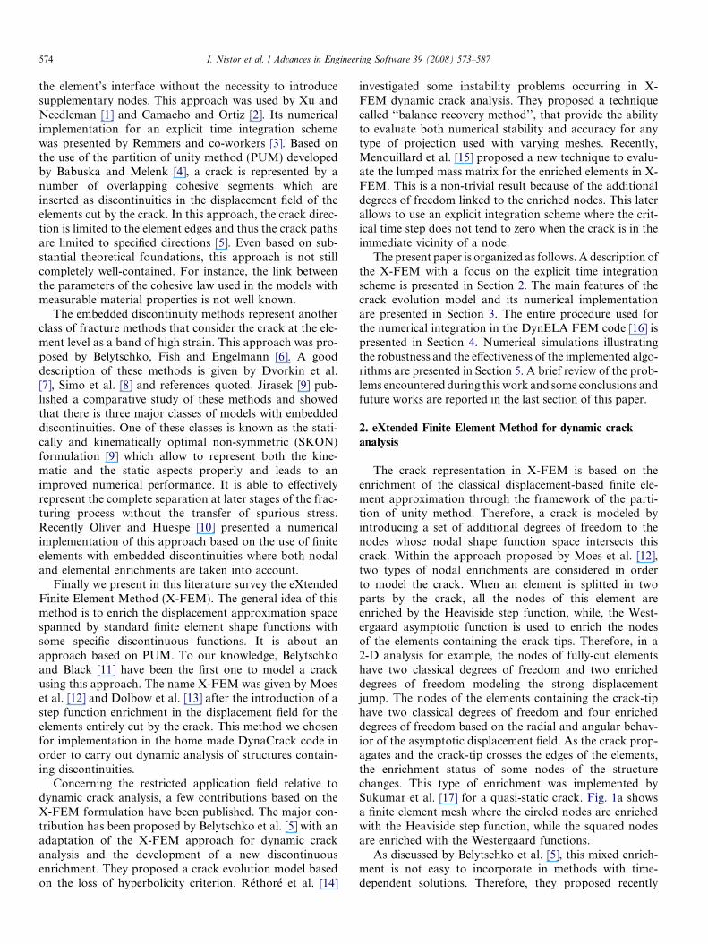
the element’s interface without the necessity to introducesupplementary nodes. This approach was used by Xu andNeedleman [1] and Camacho and Ortiz [2]. Its numericalimplementation for an explicit time integration schemewas presented by Remmers and co-workers [3]. Based onthe use of the partition of unity method (PUM) developedby Babuska and Melenk [4], a crack is represented by anumber of overlapping cohesive segments which areinserted as discontinuities in the displacement field of theelements cut by the crack. In this approach, the crack direc-tion is limited to the element edges and thus the crack pathsare limited to specified directions [5]. Even based on sub-stantial theoretical foundations, this approach is not stillcompletely well-contained. For instance, the link betweenthe parameters of the cohesive law used in the models withmeasurable material properties is not well known.
The embedded discontinuity methods represent anotherclass of fracture methods that consider the crack at the ele-ment level as a band of high strain. This approach was pro-posed by Belytschko, Fish and Engelmann [6]. A gooddescription of these methods is given by Dvorkin et al.[7], Simo et al. [8] and references quoted. Jirasek [9] pub-lished a comparative study of these methods and showedthat there is three major classes of models with embeddeddiscontinuities. One of these classes is known as the stati-cally and kinematically optimal non-symmetric (SKON)formulation [9] which allow to represent both the kine-matic and the static aspects properly and leads to animproved numerical performance. It is able to effectivelyrepresent the complete separation at later stages of the frac-turing process without the transfer of spurious stress.Recently Oliver and Huespe [10] presented a numericalimplementation of this approach based on the use of finiteelements with embedded discontinuities where both nodaland elemental enrichments are taken into account.
Finally we present in this literature survey the eXtendedFinite Element Method (X-FEM). The general idea of thismethod is to enrich the displacement approximation spacespanned by standard finite element shape functions withsome specific discontinuous functions. It is about anapproach based on PUM. To our knowledge, Belytschkoand Black [11] have been the first one to model a crackusing this approach. The name X-FEM was given by Moeset al. [12] and Dolbow et al. [13] after the introduction of astep function enrichment in the displacement field for theelements entirely cut by the crack. This method we chosenfor implementation in the home made DynaCrack code inorder to carry out dynamic analysis of structures contain-ing discontinuities.
Concerning the restricted application field relative todynamic crack analysis, a few contributions based on theX-FEM formulation have been published. The major con-tribution has been proposed by Belytschko et al. [5] with anadaptation of the X-FEM approach for dynamic crackanalysis and the development of a new discontinuousenrichment. They proposed a crack evolution model basedon the loss of hyperbolicity criterion. Rethore et al. [14]
investigated some instability problems occurring in X-FEM dynamic crack analysis. They proposed a techniquecalled ‘‘balance recovery method’’, that provide the abilityto evaluate both numerical stability and accuracy for anytype of projection used with varying meshes. Recently,Menouillard et al. [15] proposed a new technique to evalu-ate the lumped mass matrix for the enriched elements in X-FEM. This is a non-trivial result because of the additionaldegrees of freedom linked to the enriched nodes. This laterallows to use an explicit integration scheme where the crit-ical time step does not tend to zero when the crack is in theimmediate vicinity of a node.
The present paper is organized as follows. A description ofthe X-FEM with a focus on the explicit time integrationscheme is presented in Section 2. The main features of thecrack evolution model and its numerical implementationare presented in Section 3. The entire procedure used forthe numerical integration in the DynELA FEM code [16] ispresented in Section 4. Numerical simulations illustratingthe robustness and the effectiveness of the implemented algo-rithms are presented in Section 5. A brief review of the prob-lems encountered during this work and some conclusions andfuture works are reported in the last section of this paper.
2. eXtended Finite Element Method for dynamic crack
analysis
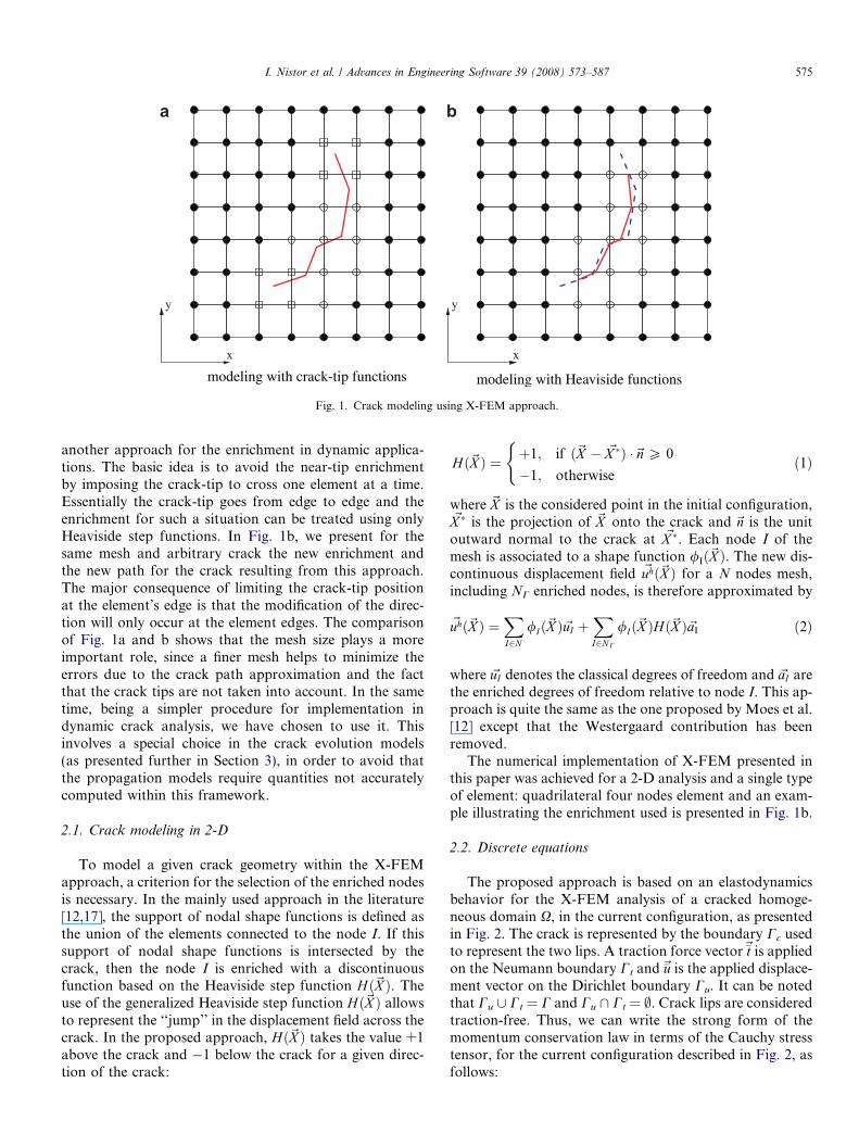
The crack representation in X-FEM is based on theenrichment of the classical displacement-based finite ele-ment approximation through the framework of the parti-tion of unity method. Therefore, a crack is modeled byintroducing a set of additional degrees of freedom to thenodes whose nodal shape function space intersects thiscrack. Within the approach proposed by Moes et al. [12],two types of nodal enrichments are considered in orderto model the crack. When an element is splitted in twoparts by the crack, all the nodes of this element areenriched by the Heaviside step function, while, the West-ergaard asymptotic function is used to enrich the nodesof the elements containing the crack tips. Therefore, in a2-D analysis for example, the nodes of fully-cut elementshave two classical degrees of freedom and two enricheddegrees of freedom modeling the strong displacementjump. The nodes of the elements containing the crack-tiphave two classical degrees of freedom and four enricheddegrees of freedom based on the radial and angular behav-ior of the asymptotic displacement field. As the crack prop-agates and the crack-tip crosses the edges of the elements,the enrichment status of some nodes of the structurechanges. This type of enrichment was implemented bySukumar et al. [17] for a quasi-static crack. Fig. 1a showsa finite element mesh where the circled nodes are enrichedwith the Heaviside step function, while the squared nodesare enriched with the Westergaard functions.
As discussed by Belytschko et al. [5], this mixed enrich-ment is not easy to incorporate in methods with time-dependent solutions. Therefore, they proposed recently
y
x
modeling with crack-tip functions
y
x
modeling with Heaviside functions
a b
Fig. 1. Crack modeling using X-FEM approach.
I. Nistor et al. / Advances in Engineering Software 39 (2008) 573–587 575
another approach for the enrichment in dynamic applica-tions. The basic idea is to avoid the near-tip enrichmentby imposing the crack-tip to cross one element at a time.Essentially the crack-tip goes from edge to edge and theenrichment for such a situation can be treated using onlyHeaviside step functions. In Fig. 1b, we present for thesame mesh and arbitrary crack the new enrichment andthe new path for the crack resulting from this approach.The major consequence of limiting the crack-tip positionat the element’s edge is that the modification of the direc-tion will only occur at the element edges. The comparisonof Fig. 1a and b shows that the mesh size plays a moreimportant role, since a finer mesh helps to minimize theerrors due to the crack path approximation and the factthat the crack tips are not taken into account. In the sametime, being a simpler procedure for implementation indynamic crack analysis, we have chosen to use it. Thisinvolves a special choice in the crack evolution models(as presented further in Section 3), in order to avoid thatthe propagation models require quantities not accuratelycomputed within this framework.
2.1. Crack modeling in 2-D
To model a given crack geometry within the X-FEMapproach, a criterion for the selection of the enriched nodesis necessary. In the mainly used approach in the literature[12,17], the support of nodal shape functions is defined asthe union of the elements connected to the node I. If thissupport of nodal shape functions is intersected by thecrack, then the node I is enriched with a discontinuousfunction based on the Heaviside step function Hð~X Þ. Theuse of the generalized Heaviside step function Hð~X Þ allowsto represent the ‘‘jump’’ in the displacement field across thecrack. In the proposed approach, Hð~X Þ takes the value +1above the crack and �1 below the crack for a given direc-tion of the crack:
Hð~X Þ ¼ þ1; if ð~X � ~X �Þ �~n P 0
�1; otherwise
(ð1Þ
where ~X is the considered point in the initial configuration,~X � is the projection of ~X onto the crack and ~n is the unitoutward normal to the crack at ~X �. Each node I of themesh is associated to a shape function /Ið~X Þ. The new dis-continuous displacement field ~uhð~X Þ for a N nodes mesh,including NC enriched nodes, is therefore approximated by
~uhð~X Þ ¼XI2N
/Ið~X Þ~uI þXI2NC
/Ið~X ÞHð~X Þ~aI ð2Þ
where ~uI denotes the classical degrees of freedom and ~aI arethe enriched degrees of freedom relative to node I. This ap-proach is quite the same as the one proposed by Moes et al.[12] except that the Westergaard contribution has beenremoved.
The numerical implementation of X-FEM presented inthis paper was achieved for a 2-D analysis and a single typeof element: quadrilateral four nodes element and an exam-ple illustrating the enrichment used is presented in Fig. 1b.
2.2. Discrete equations
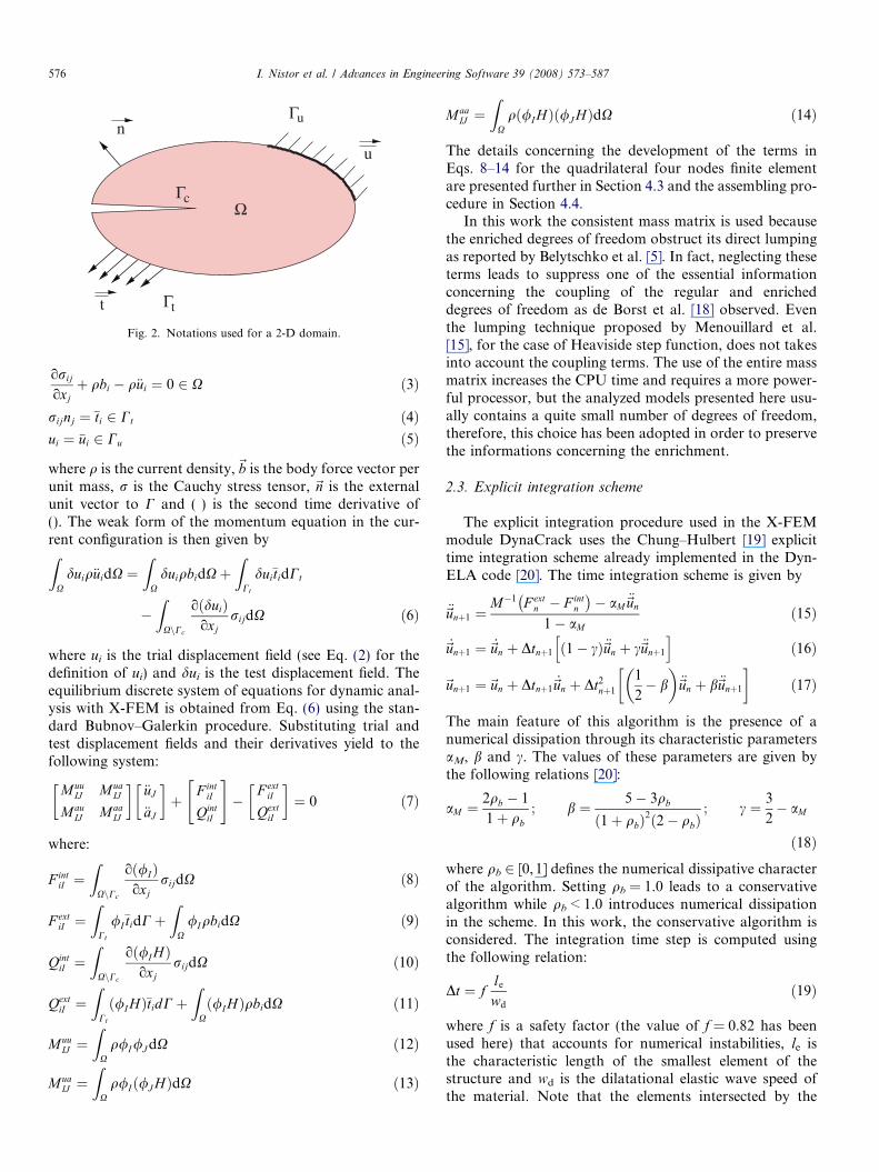
The proposed approach is based on an elastodynamicsbehavior for the X-FEM analysis of a cracked homoge-neous domain X, in the current configuration, as presentedin Fig. 2. The crack is represented by the boundary Cc usedto represent the two lips. A traction force vector~�t is appliedon the Neumann boundary Ct and~�u is the applied displace-ment vector on the Dirichlet boundary Cu. It can be notedthat Cu [ Ct = C and Cu \ Ct = ;. Crack lips are consideredtraction-free. Thus, we can write the strong form of themomentum conservation law in terms of the Cauchy stresstensor, for the current configuration described in Fig. 2, asfollows:
Γc
Γt
u
t
Γu
Ω
n
Fig. 2. Notations used for a 2-D domain.
576 I. Nistor et al. / Advances in Engineering Software 39 (2008) 573–587
orij
oxjþ qbi � q€ui ¼ 0 2 X ð3Þ
rijnj ¼ �ti 2 Ct ð4Þui ¼ �ui 2 Cu ð5Þ
where q is the current density,~b is the body force vector perunit mass, r is the Cauchy stress tensor, ~n is the externalunit vector to C and (ÆÆ) is the second time derivative of(). The weak form of the momentum equation in the cur-rent configuration is then given byZ
Xduiq€uidX ¼
ZX
duiqbidXþZ
Ct
dui�tidCt
�Z
XnCc
o duið Þoxj
rijdX ð6Þ
where ui is the trial displacement field (see Eq. (2) for thedefinition of ui) and dui is the test displacement field. Theequilibrium discrete system of equations for dynamic anal-ysis with X-FEM is obtained from Eq. (6) using the stan-dard Bubnov–Galerkin procedure. Substituting trial andtest displacement fields and their derivatives yield to thefollowing system:
MuuIJ Mua
IJ
MauIJ Maa
IJ
� �€uJ
€aJ
� �þ
F intiI
QintiI
" #�
F extiI
QextiI
� �¼ 0 ð7Þ
where:
F intiI ¼
ZXnCc
o /Ið Þoxj
rijdX ð8Þ
F extiI ¼
ZCt
/I�tidCþZ
X/IqbidX ð9Þ
QintiI ¼
ZXnCc
o /I Hð Þoxj
rijdX ð10Þ
QextiI ¼
ZCt
ð/I HÞ�tidCþZ
Xð/IHÞqbidX ð11Þ
MuuIJ ¼
ZX
q/I/J dX ð12Þ
MuaIJ ¼
ZX
q/Ið/J HÞdX ð13Þ
MaaIJ ¼
ZX
qð/IHÞð/J HÞdX ð14Þ
The details concerning the development of the terms inEqs. 8–14 for the quadrilateral four nodes finite elementare presented further in Section 4.3 and the assembling pro-cedure in Section 4.4.
In this work the consistent mass matrix is used becausethe enriched degrees of freedom obstruct its direct lumpingas reported by Belytschko et al. [5]. In fact, neglecting theseterms leads to suppress one of the essential informationconcerning the coupling of the regular and enricheddegrees of freedom as de Borst et al. [18] observed. Eventhe lumping technique proposed by Menouillard et al.[15], for the case of Heaviside step function, does not takesinto account the coupling terms. The use of the entire massmatrix increases the CPU time and requires a more power-ful processor, but the analyzed models presented here usu-ally contains a quite small number of degrees of freedom,therefore, this choice has been adopted in order to preservethe informations concerning the enrichment.
2.3. Explicit integration scheme
The explicit integration procedure used in the X-FEMmodule DynaCrack uses the Chung–Hulbert [19] explicittime integration scheme already implemented in the Dyn-ELA code [20]. The time integration scheme is given by
€~unþ1 ¼M�1 F ext
n � F intn
� �� aM
€~un
1� aMð15Þ
_~unþ1 ¼ _~un þ Dtnþ1 1� cð Þ€~un þ c€~unþ1
h ið16Þ
~unþ1 ¼~un þ Dtnþ1_~un þ Dt2
nþ1
1
2� b
� �€~un þ b€~unþ1
� �ð17Þ
The main feature of this algorithm is the presence of anumerical dissipation through its characteristic parametersaM, b and c. The values of these parameters are given bythe following relations [20]:
aM ¼2qb � 1
1þ qb; b ¼ 5� 3qb
1þ qbð Þ2 2� qbð Þ; c ¼ 3
2� aM
ð18Þwhere qb 2 [0, 1] defines the numerical dissipative characterof the algorithm. Setting qb = 1.0 leads to a conservativealgorithm while qb < 1.0 introduces numerical dissipationin the scheme. In this work, the conservative algorithm isconsidered. The integration time step is computed usingthe following relation:
Dt ¼ fle
wd
ð19Þ
where f is a safety factor (the value of f = 0.82 has beenused here) that accounts for numerical instabilities, le isthe characteristic length of the smallest element of thestructure and wd is the dilatational elastic wave speed ofthe material. Note that the elements intersected by the
I. Nistor et al. / Advances in Engineering Software 39 (2008) 573–587 577
crack are not taken into account for this computation inorder to avoid that the time step tend to zero when thecrack path is very close to an enriched node.
2.4. Cut elements partition
For the elements cut by the crack, a special procedure isapplied in X-FEM in order to integrate the discrete systemof equations. The main idea is not to perform a re-meshingof these elements by adding supplementary nodes on theintersecting points with the crack because this would becontrary to the main principle of X-FEM (modeling ofthe discontinuities without any dependence with the meshsize and orientation). The main accepted concept in X-FEM is the partitioning of these elements. A clear analysisof ‘‘element partitioning versus re-meshing’’ is provided bySukumar and Prevost [17]. The partitioning procedure inX-FEM is done for numerical integration purpose only,and no additional degrees of freedom are introduced intothe discrete space during this operation. Subdividing theseelements into triangles in 2-D was proposed by manyauthors [12,17,21], and several numerical integrationoptions were also presented. On the other way, an originalmethod to perform this integration without any subdivi-sion of the cut elements has been recently proposed by Ven-tura [22]. Special (higher-order) quadrature rules areusually used for the numerical integration of the elementsthat are partitioned in this way [12] like a six-point integra-tion rule for triangular elements.
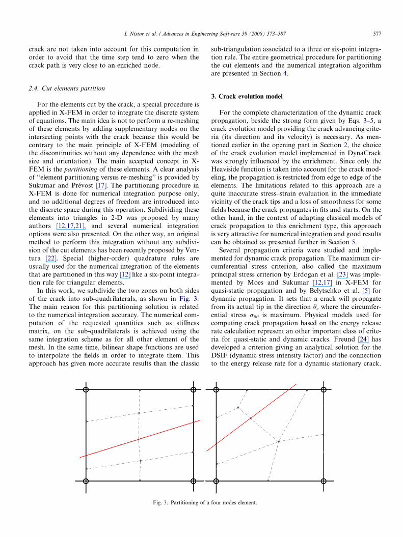
In this work, we subdivide the two zones on both sidesof the crack into sub-quadrilaterals, as shown in Fig. 3.The main reason for this partitioning solution is relatedto the numerical integration accuracy. The numerical com-putation of the requested quantities such as stiffnessmatrix, on the sub-quadrilaterals is achieved using thesame integration scheme as for all other element of themesh. In the same time, bilinear shape functions are usedto interpolate the fields in order to integrate them. Thisapproach has given more accurate results than the classic
Fig. 3. Partitioning of a
sub-triangulation associated to a three or six-point integra-tion rule. The entire geometrical procedure for partitioningthe cut elements and the numerical integration algorithmare presented in Section 4.
3. Crack evolution model
For the complete characterization of the dynamic crackpropagation, beside the strong form given by Eqs. 3–5, acrack evolution model providing the crack advancing crite-ria (its direction and its velocity) is necessary. As men-tioned earlier in the opening part in Section 2, the choiceof the crack evolution model implemented in DynaCrackwas strongly influenced by the enrichment. Since only theHeaviside function is taken into account for the crack mod-eling, the propagation is restricted from edge to edge of theelements. The limitations related to this approach are aquite inaccurate stress–strain evaluation in the immediatevicinity of the crack tips and a loss of smoothness for somefields because the crack propagates in fits and starts. On theother hand, in the context of adapting classical models ofcrack propagation to this enrichment type, this approachis very attractive for numerical integration and good resultscan be obtained as presented further in Section 5.
Several propagation criteria were studied and imple-mented for dynamic crack propagation. The maximum cir-cumferential stress criterion, also called the maximumprincipal stress criterion by Erdogan et al. [23] was imple-mented by Moes and Sukumar [12,17] in X-FEM forquasi-static propagation and by Belytschko et al. [5] fordynamic propagation. It sets that a crack will propagatefrom its actual tip in the direction hc where the circumfer-ential stress rhh is maximum. Physical models used forcomputing crack propagation based on the energy releaserate calculation represent an other important class of crite-ria for quasi-static and dynamic cracks. Freund [24] hasdeveloped a criterion giving an analytical solution for theDSIF (dynamic stress intensity factor) and the connectionto the energy release rate for a dynamic stationary crack.
four nodes element.
Γc+
Γc–
x 0y0Γ
ΓεVε
θ
n
0
V–Vε
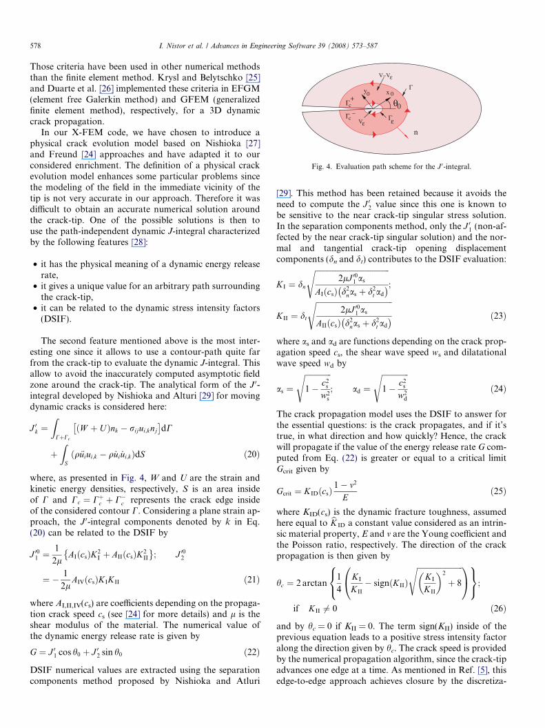
Fig. 4. Evaluation path scheme for the J 0-integral.
578 I. Nistor et al. / Advances in Engineering Software 39 (2008) 573–587
Those criteria have been used in other numerical methodsthan the finite element method. Krysl and Belytschko [25]and Duarte et al. [26] implemented these criteria in EFGM(element free Galerkin method) and GFEM (generalizedfinite element method), respectively, for a 3D dynamiccrack propagation.
In our X-FEM code, we have chosen to introduce aphysical crack evolution model based on Nishioka [27]and Freund [24] approaches and have adapted it to ourconsidered enrichment. The definition of a physical crackevolution model enhances some particular problems sincethe modeling of the field in the immediate vicinity of thetip is not very accurate in our approach. Therefore it wasdifficult to obtain an accurate numerical solution aroundthe crack-tip. One of the possible solutions is then touse the path-independent dynamic J-integral characterizedby the following features [28]:
• it has the physical meaning of a dynamic energy releaserate,
• it gives a unique value for an arbitrary path surroundingthe crack-tip,
• it can be related to the dynamic stress intensity factors(DSIF).
The second feature mentioned above is the most inter-esting one since it allows to use a contour-path quite farfrom the crack-tip to evaluate the dynamic J-integral. Thisallow to avoid the inaccurately computed asymptotic fieldzone around the crack-tip. The analytical form of the J 0-integral developed by Nishioka and Alturi [29] for movingdynamic cracks is considered here:
J 0k ¼Z
CþCc
ðW þ UÞnk � rijui;knj
� dC
þZ
Sq€uiui;k � q _ui _ui;kð ÞdS ð20Þ
where, as presented in Fig. 4, W and U are the strain andkinetic energy densities, respectively, S is an area insideof C and Cc ¼ Cþc þ C�c represents the crack edge insideof the considered contour C. Considering a plane strain ap-proach, the J 0-integral components denoted by k in Eq.(20) can be related to the DSIF by
J 001 ¼1
2lAIðcsÞK2
I þ AIIðcsÞK2II
�; J 002
¼ � 1
2lAIVðcsÞKIKII ð21Þ
where AI,II,IV(cs) are coefficients depending on the propaga-tion crack speed cs (see [24] for more details) and l is theshear modulus of the material. The numerical value ofthe dynamic energy release rate is given by
G ¼ J 01 cos h0 þ J 02 sin h0 ð22Þ
DSIF numerical values are extracted using the separationcomponents method proposed by Nishioka and Atluri
[29]. This method has been retained because it avoids theneed to compute the J 02 value since this one is known tobe sensitive to the near crack-tip singular stress solution.In the separation components method, only the J 01 (non-af-fected by the near crack-tip singular solution) and the nor-mal and tangential crack-tip opening displacementcomponents (dn and dt) contributes to the DSIF evaluation:
KI ¼ dn
ffiffiffiffiffiffiffiffiffiffiffiffiffiffiffiffiffiffiffiffiffiffiffiffiffiffiffiffiffiffiffiffiffiffiffiffiffiffiffi2lJ 001 as
AIðcsÞ d2nas þ d2
t ad
� �s;
KII ¼ dt
ffiffiffiffiffiffiffiffiffiffiffiffiffiffiffiffiffiffiffiffiffiffiffiffiffiffiffiffiffiffiffiffiffiffiffiffiffiffiffiffi2lJ 001 as
AIIðcsÞ d2nas þ d2
t ad
� �sð23Þ
where as and ad are functions depending on the crack prop-agation speed cs, the shear wave speed ws and dilatationalwave speed wd by
as ¼ffiffiffiffiffiffiffiffiffiffiffiffiffiffi1� c2
s
w2s
s; ad ¼
ffiffiffiffiffiffiffiffiffiffiffiffiffiffi1� c2
s
w2d
sð24Þ
The crack propagation model uses the DSIF to answer forthe essential questions: is the crack propagates, and if it’strue, in what direction and how quickly? Hence, the crackwill propagate if the value of the energy release rate G com-puted from Eq. (22) is greater or equal to a critical limitGcrit given by
Gcrit ¼ KID csð Þ1� m2
Eð25Þ
where KID(cs) is the dynamic fracture toughness, assumedhere equal to bK ID a constant value considered as an intrin-sic material property, E and m are the Young coefficient andthe Poisson ratio, respectively. The direction of the crackpropagation is then given by
hc ¼ 2 arctan1
4
KI
KII
� signðKIIÞ
ffiffiffiffiffiffiffiffiffiffiffiffiffiffiffiffiffiffiffiffiffiffiffiffiKI
KII
� �2
þ 8
s0@ 1A8<:9=;;
if KII 6¼ 0 ð26Þ
and by hc = 0 if KII = 0. The term sign(KII) inside of theprevious equation leads to a positive stress intensity factoralong the direction given by hc. The crack speed is providedby the numerical propagation algorithm, since the crack-tipadvances one edge at a time. As mentioned in Ref. [5], thisedge-to-edge approach achieves closure by the discretiza-

y
x
X
R
N
Fig. 5. Enriched element types definition.
Box 1 Partitioning algorithm
1. Compute the intersection points, xc1 and xc2;2. Build the {pi}i=1. . .4 xpoints using nodes
location;3. Compute the positive and negative centroids, C+
and C�;4. Get the median points, mj, for all sub-domain
segments;5. Build pointsPositifs and pointsNega-
tifs lists;6. Build Surf2D surfaces.
I. Nistor et al. / Advances in Engineering Software 39 (2008) 573–587 579
tion but the coarse meshes must be avoid. The numericalalgorithms implemented for computing the parameters ofthis crack evolution model will be presented in Section 4.
4. Numerical implementation of the DynaCrack module
The DynELA explicit finite element program [16] hasbeen used for the implementation of the X-FEM crackpropagation module. This FEM program is written inC++ and developed within an object-oriented program-ming (OOP) approach. This feature presents a very welldefined mechanism for modular design and re-use of code:in our case this has allowed to develop the new moduleDynaCrack, re-using several objects already implemented.Some new classes have been implemented and other havebeen specialized for this application using the inheritancemechanism. In the following sub-sections, we present themajor steps of this implementation, pointing out the char-acteristic keys of X-FEM. Concerning the notation, allkeywords related to the DynaCrack code such as the classnames, method names, object names . . . are written using atypewriter font.
4.1. Crack representation and implementation
The crack is represented by the class CrackFunctioncontaining a list of p + 1 points Xc = {xi}i2[0,p]. Within thisrepresentation, the two points x0 and xp are the crack tips.The initial crack at time t = 0 is defined through the inputdata file according to the initial geometry of the crack. TheCrackFunction class contains a dynamic list updatedwhen adding new points as the crack propagates.
One of the most useful method of this class returns thesign of the Heaviside function for any given point. Theso called method IsOnPositiveSide() returns a Bool-ean value: true for positive side (i.e. the Heaviside functionH = 1) and false for negative side (i.e. the Heaviside func-tion H = �1) based on geometric predicate evaluation.This is done by computing the projection of this point ontothe closest crack segment.
In the presented X-FEM approach, the mesh containsboth classical and enriched nodes, therefore, the classXNode, inherited from the class Node is used for handlingthe supplementary degrees of freedom (dof) correspondingto the enriched nodes. A specific flag XType is then used toidentify the status of the nodes. During the computation,the status of some nodes changes from normal to enrichedbecause of the crack propagation. The method getXR-
Type() is called at each integration time step and is usedto update the status of the elements. A method based on anefficient BoundingBox algorithm is used to find the nodesaround the crack. For all the elements of the structure threeflags are considered according to theirs status:
x elements
TypeX � enriched elements ðfrom 1 to 3 enriched nodesÞTypeR � completely cut elements ð4 enriched nodesÞTypeN � normal elements ðno enriched nodesÞ
8><>:
Fig. 5 illustrates this aspect for an X-FEM mesh; the en-riched nodes are the encircled ones. The two nodes at bothend of the edge where the crack-tip is situated are enrichedwith the Heaviside step function. In the approach proposedby Moes et al. [12] those two nodes are enriched using theWestergaard functions leading to the step function forh = p.
4.2. Partition algorithm
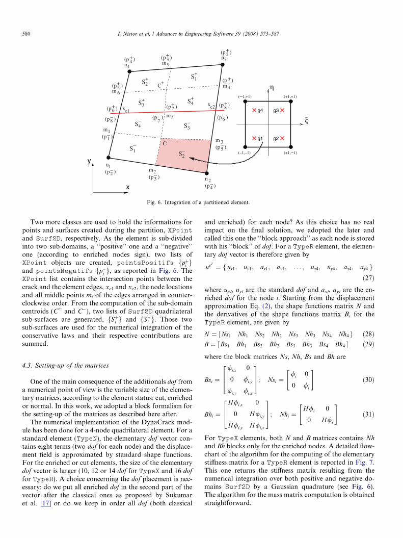
Once the elements status have been updated for the cur-rent time step, the partitioning of the so-called TypeR ele-ments is done using the methods of the XPartition class.An arbitrary crack geometry in a structure discretized with4-nodes quadrilateral finite elements leads to one of the twosituations for cut elements: the crack intersects two oppo-site or two adjoining edges (see Fig. 3 for more details).The algorithms implemented in the XPartition classcompute the partition of the elements. As an illustration,the algorithm for the partition of the element presentedin Fig. 6 is reported in Box 1.
n1
n 2
n3n4
m1
m2
m4
m5
m 6
m7
(p )+6
(p )+5
(p )+7
(p )+8
(p )+1
(p )+2
(p )+3(p )+
4
(p )–1
(p )–2
(p )–3
(p )–4
m 3(p )–
5
(p )–6(p )–
7(p )–8
C+
C
xc1xc2
S1+
S2+
S3+ S4
+
S1–
S2–
–
S3–
4S–
(–1,+1) (+1,+1)
(+1,–1)(–1,–1)
ξ
η
g1 g2
g3g4
x
y
Fig. 6. Integration of a partitioned element.
580 I. Nistor et al. / Advances in Engineering Software 39 (2008) 573–587
Two more classes are used to hold the informations forpoints and surfaces created during the partition, XPointand Surf2D, respectively. As the element is sub-dividedinto two sub-domains, a ‘‘positive’’ one and a ‘‘negative’’one (according to enriched nodes sign), two lists ofXPoint objects are created, pointsPositifs fpþi gand pointsNegatifs fp�j g, as reported in Fig. 6. TheXPoint list contains the intersection points between thecrack and the element edges, xc1 and xc2, the node locationsand all middle points ml of the edges arranged in counter-clockwise order. From the computation of the sub-domaincentroids (C+ and C�), two lists of Surf2D quadrilateralsub-surfaces are generated, fSþi g and fS�i g. Those twosub-surfaces are used for the numerical integration of theconservative laws and their respective contributions aresummed.
4.3. Setting-up of the matrices
One of the main consequence of the additionals dof froma numerical point of view is the variable size of the elemen-tary matrices, according to the element status: cut, enrichedor normal. In this work, we adopted a block formalism forthe setting-up of the matrices as described here after.
The numerical implementation of the DynaCrack mod-ule has been done for a 4-node quadrilateral element. For astandard element (TypeN), the elementary dof vector con-tains eight terms (two dof for each node) and the displace-ment field is approximated by standard shape functions.For the enriched or cut elements, the size of the elementarydof vector is larger (10, 12 or 14 dof for TypeX and 16 dof
for TypeR). A choice concerning the dof placement is nec-essary: do we put all enriched dof in the second part of thevector after the classical ones as proposed by Sukumaret al. [17] or do we keep in order all dof (both classical
and enriched) for each node? As this choice has no realimpact on the final solution, we adopted the later andcalled this one the ‘‘block approach’’ as each node is storedwith his ‘‘block’’ of dof. For a TypeR element, the elemen-tary dof vector is therefore given by
ueT ¼ ux1; uy1; ax1; ay1; . . . ; ux4; uy4; ax4; ay4f gð27Þ
where uxi, uyi are the standard dof and axi, ayi are the en-riched dof for the node i. Starting from the displacementapproximation Eq. (2), the shape functions matrix N andthe derivatives of the shape functions matrix B, for theTypeR element, are given by
N ¼ Ns1 Nh1 Ns2 Nh2 Ns3 Nh3 Ns4 Nh4½ � ð28ÞB ¼ Bs1 Bh1 Bs2 Bh2 Bs3 Bh3 Bs4 Bh4½ � ð29Þ
where the block matrices Ns, Nh, Bs and Bh are
Bsi ¼/i;x 0
0 /i;y
/i;y /i;x
264375; Nsi ¼
/i 0
0 /i
" #ð30Þ
Bhi ¼H/i;x 0
0 H/i;y
H/i;y H/i;x
264375; Nhi ¼
H/i 0
0 H/i
" #ð31Þ
For TypeX elements, both N and B matrices contains Nh
and Bh blocks only for the enriched nodes. A detailed flow-chart of the algorithm for the computing of the elementarystiffness matrix for a TypeR element is reported in Fig. 7.This one returns the stiffness matrix resulting from thenumerical integration over both positive and negative do-mains Surf2D by a Gaussian quadrature (see Fig. 6).The algorithm for the mass matrix computation is obtainedstraightforward.
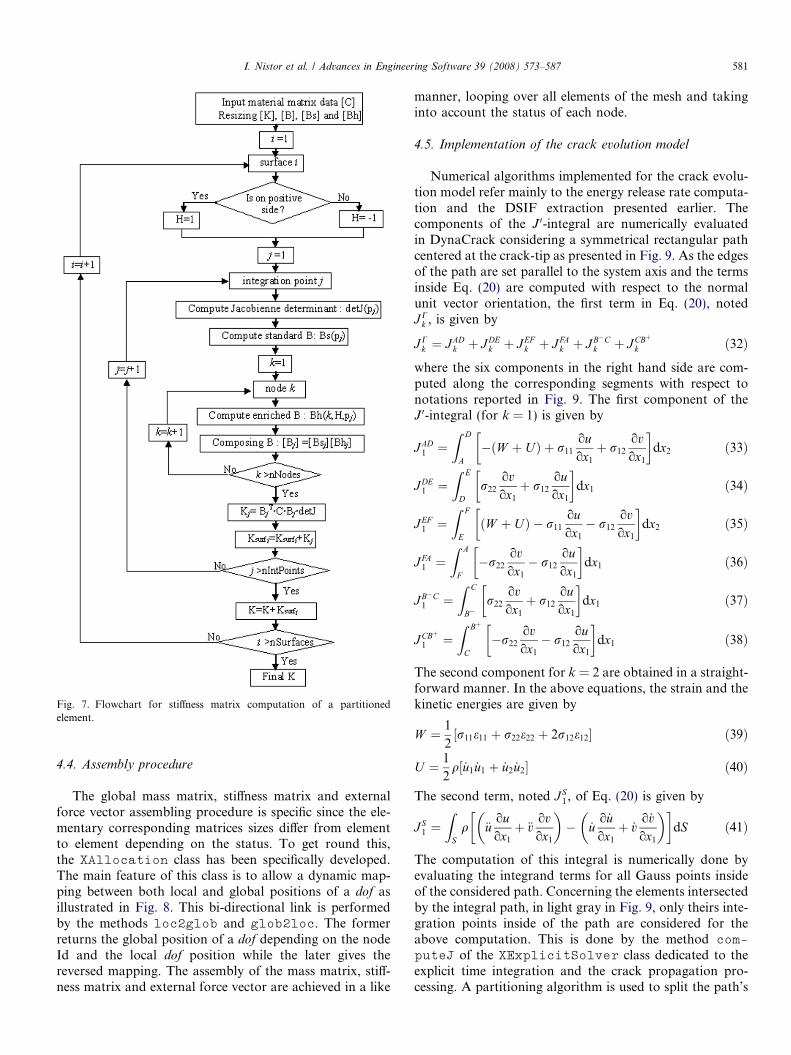
Fig. 7. Flowchart for stiffness matrix computation of a partitionedelement.
I. Nistor et al. / Advances in Engineering Software 39 (2008) 573–587 581
4.4. Assembly procedure
The global mass matrix, stiffness matrix and externalforce vector assembling procedure is specific since the ele-mentary corresponding matrices sizes differ from elementto element depending on the status. To get round this,the XAllocation class has been specifically developed.The main feature of this class is to allow a dynamic map-ping between both local and global positions of a dof asillustrated in Fig. 8. This bi-directional link is performedby the methods loc2glob and glob2loc. The formerreturns the global position of a dof depending on the nodeId and the local dof position while the later gives thereversed mapping. The assembly of the mass matrix, stiff-ness matrix and external force vector are achieved in a like
manner, looping over all elements of the mesh and takinginto account the status of each node.
4.5. Implementation of the crack evolution model
Numerical algorithms implemented for the crack evolu-tion model refer mainly to the energy release rate computa-tion and the DSIF extraction presented earlier. Thecomponents of the J 0-integral are numerically evaluatedin DynaCrack considering a symmetrical rectangular pathcentered at the crack-tip as presented in Fig. 9. As the edgesof the path are set parallel to the system axis and the termsinside Eq. (20) are computed with respect to the normalunit vector orientation, the first term in Eq. (20), notedJC
k , is given by
JCk ¼ J AD
k þ J DEk þ J EF
k þ J FAk þ J B�C
k þ J CBþ
k ð32Þwhere the six components in the right hand side are com-puted along the corresponding segments with respect tonotations reported in Fig. 9. The first component of theJ 0-integral (for k = 1) is given by
J AD1 ¼
Z D
A� W þ Uð Þ þ r11
ouox1
þ r12
ovox1
� �dx2 ð33Þ
J DE1 ¼
Z E
Dr22
ovox1
þ r12
ouox1
� �dx1 ð34Þ
J EF1 ¼
Z F
EW þ Uð Þ � r11
ouox1
� r12ovox1
� �dx2 ð35Þ
J FA1 ¼
Z A
F�r22
ovox1
� r12ouox1
� �dx1 ð36Þ
J B�C1 ¼
Z C
B�r22
ovox1
þ r12ouox1
� �dx1 ð37Þ
J CBþ
1 ¼Z Bþ
C�r22
ovox1
� r12
ouox1
� �dx1 ð38Þ
The second component for k = 2 are obtained in a straight-forward manner. In the above equations, the strain and thekinetic energies are given by
W ¼ 1
2r11e11 þ r22e22 þ 2r12e12½ � ð39Þ
U ¼ 1
2q _u1 _u1 þ _u2 _u2½ � ð40Þ
The second term, noted J S1, of Eq. (20) is given by
J S1 ¼
ZS
q €uouox1
þ €vovox1
� �� _u
o _uox1
þ _vo_vox1
� �� �dS ð41Þ
The computation of this integral is numerically done byevaluating the integrand terms for all Gauss points insideof the considered path. Concerning the elements intersectedby the integral path, in light gray in Fig. 9, only theirs inte-gration points inside of the path are considered for theabove computation. This is done by the method com-
puteJ of the XExplicitSolver class dedicated to theexplicit time integration and the crack propagation pro-cessing. A partitioning algorithm is used to split the path’s
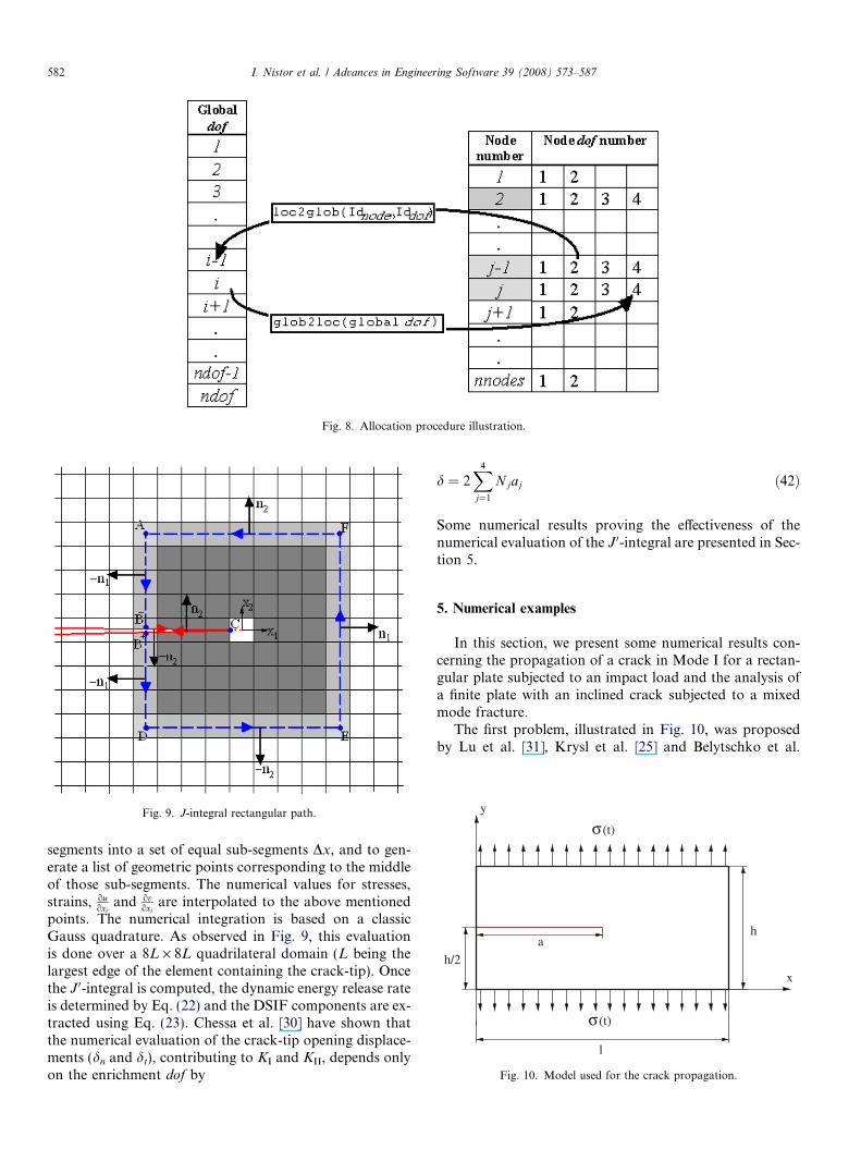
Fig. 8. Allocation procedure illustration.
Fig. 9. J-integral rectangular path.
(t)σ
(t)σ
h
x
y
l
h/2a
Fig. 10. Model used for the crack propagation.
582 I. Nistor et al. / Advances in Engineering Software 39 (2008) 573–587
segments into a set of equal sub-segments Dx, and to gen-erate a list of geometric points corresponding to the middleof those sub-segments. The numerical values for stresses,strains, ou
oxiand ov
oxiare interpolated to the above mentioned
points. The numerical integration is based on a classicGauss quadrature. As observed in Fig. 9, this evaluationis done over a 8L · 8L quadrilateral domain (L being thelargest edge of the element containing the crack-tip). Oncethe J 0-integral is computed, the dynamic energy release rateis determined by Eq. (22) and the DSIF components are ex-tracted using Eq. (23). Chessa et al. [30] have shown thatthe numerical evaluation of the crack-tip opening displace-ments (dn and dt), contributing to KI and KII, depends onlyon the enrichment dof by
d ¼ 2X4
j¼1
N jaj ð42Þ
Some numerical results proving the effectiveness of thenumerical evaluation of the J 0-integral are presented in Sec-tion 5.
5. Numerical examples
In this section, we present some numerical results con-cerning the propagation of a crack in Mode I for a rectan-gular plate subjected to an impact load and the analysis ofa finite plate with an inclined crack subjected to a mixedmode fracture.
The first problem, illustrated in Fig. 10, was proposedby Lu et al. [31], Krysl et al. [25] and Belytschko et al.
I. Nistor et al. / Advances in Engineering Software 39 (2008) 573–587 583
[32] using EFGM, by Duarte et al. [26] using GFEM, andby Belytschko et al. [5] using X-FEM among many others.Two uniform quadrilateral meshes are presented in thispaper to illustrate the independence of the crack propaga-
0
50
100
150
200
250
0 0.0005 0.001 0.0015 0.002
Ene
rgy
rele
ase
rate
G
Time (s)
fine meshcoarse mesh
theory
Fig. 11. Energy release rate time-history plot for the stationary crack.
Fig. 13. von Mises stress field
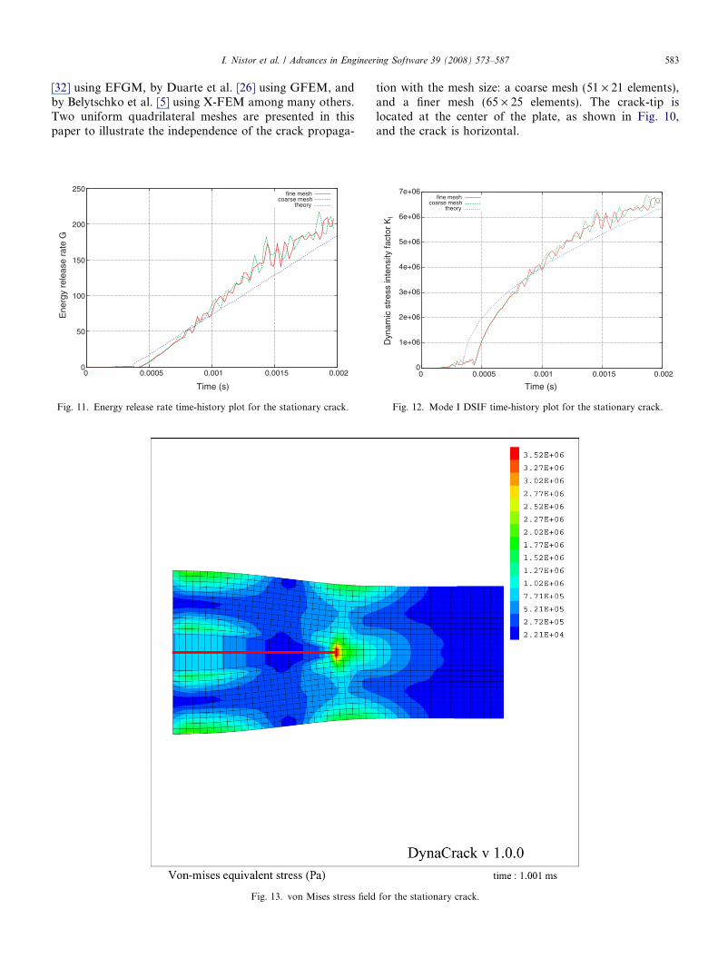
tion with the mesh size: a coarse mesh (51 · 21 elements),and a finer mesh (65 · 25 elements). The crack-tip islocated at the center of the plate, as shown in Fig. 10,and the crack is horizontal.
0
1e+06
2e+06
3e+06
4e+06
5e+06
6e+06
7e+06
0 0.0005 0.001 0.0015 0.002
Dyn
amic
str
ess
inte
nsity
fact
or K
I Time (s)
fine meshcoarse mesh
theory
Fig. 12. Mode I DSIF time-history plot for the stationary crack.
for the stationary crack.
584 I. Nistor et al. / Advances in Engineering Software 39 (2008) 573–587
A linear elastic material behavior with E = 200 GPa,m = 0.3 and q = 7833 kg/m3 is considered and a criticalvalue for fracture toughness KIDcrit
¼ 1:5 MPaffiffiffiffimp
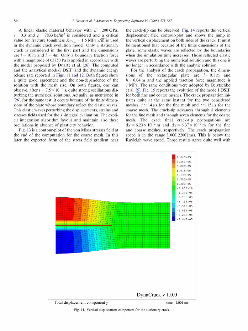
is usedin the dynamic crack evolution model. Only a stationarycrack is considered in the first part and the dimensionsare l = 10 m and h = 4m. Only a boundary traction forcewith a magnitude of 63750 Pa is applied in accordance withthe model proposed by Duarte et al. [26]. The computedand the analytical mode-I DSIF and the dynamic energyrelease rate reported in Figs. 11 and 12. Both figures showa quite good agreement and the non-dependence of thesolution with the mesh size. On both figures, one canobserve, after t = 7.5 · 10�4 s, quite strong oscillations dis-turbing the numerical solutions. Actually, as mentioned in[26], for the same test, it occurs because of the finite dimen-sions of the plate whose boundary reflect the elastic waves.This elastic waves perturbing the displacements, strains andstresses fields used for the J 0-integral evaluation. The expli-cit integration algorithm favour and maintain also theseoscillations in absence of plasticity behavior.
Fig. 13 is a contour-plot of the von Mises stresses field atthe end of the computation for the coarse mesh. In thislater the expected form of the stress field gradient near
Fig. 14. Vertical displacement comp
the crack-tip can be observed. Fig. 14 reports the verticaldisplacement field contour-plot and shows the jump inthe vertical displacement on both sides of the crack. It mustbe mentioned that because of the finite dimensions of theplate, some elastic waves are reflected by the boundarieswhen the simulation time increases. Those reflected elasticwaves are perturbing the numerical solution and this one isno longer in accordance with the analytic solution.
For the analysis of the crack propagation, the dimen-sions of the rectangular plate are l = 0.1 m andh = 0.04 m and the applied traction force magnitude is1 MPa. The same conditions were adopted by Belytschkoet al. [5]. Fig. 15 reports the evolution of the mode I DSIFfor both fine and coarse meshes. The crack propagation ini-tiates quite at the same instant for the two consideredmeshes, t ’ 14 ls for the fine mesh and t ’ 15 ls for thecoarse mesh. The crack-tip advances through 8 elementsfor the fine mesh and through seven elements for the coarsemesh. The exact final crack-tip propagations aredx = 6.23 · 10�2 m and dx = 6.37 · 10�2 m for the fineand coarse meshes, respectively. The crack propagationspeed is in the range [1000, 2200] m/s. This is below theRayleigh wave speed. Those results agree quite well with
onent for the stationary crack.
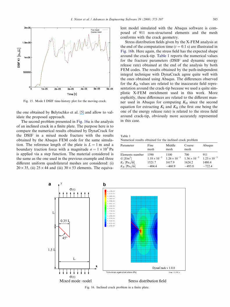
Fig. 15. Mode I DSIF time-history plot for the moving crack.
Table 1Numerical results obtained for the inclined crack problem
Parameter Finemesh
Middlemesh
Coarsemesh
Abaqus
Elements number 1590 1100 700 911G [J/m2] 1.18 · 10�3 1.26 · 10�3 1.36 · 10�3 1.23 · 10�3
KI ½Paffiffiffiffimp� 1521.7 1617.9 1624.2 1480.4
KII ½Paffiffiffiffimp� �404.4 �460.9 �493.8 �722.4
I. Nistor et al. / Advances in Engineering Software 39 (2008) 573–587 585
the one obtained by Belytschko et al. [5] and allow to val-idate the proposed approach.
The second problem presented in Fig. 16a is the analysisof an inclined crack in a finite plate. The purpose here is tocompare the numerical results obtained by DynaCrack forthe DSIF in a mixed mode fracture with the resultsobtained by the Abaqus FEM code for the same simula-tion. The reference length of the plate is L = 1 m and aboundary traction force with a magnitude r = 1 · 103 Pais applied via a step function. The material considered isthe same as the one used in the previous example and threedifferent uniform quadrilateral meshes are considered: (i)20 · 35, (ii) 25 · 44 and (iii) 30 · 53 elements. The equiva-
Fig. 16. Inclined crack pro
lent model simulated with the Abaqus software is com-posed of 911 non-structured elements and the meshconforms with the crack geometry.
Stress distribution fields given by the X-FEM analysis atthe end of the computation time (t = 0.1 s) are illustrated inFig. 16b. Here again, the stress field has the expected shapearound the crack-tip. Table 1 reports the numerical valuesfor the fracture parameters (DSIF and dynamic energyrelease rate) obtained at the end of the analysis by bothFEM codes. The results obtained by the path-independentintegral technique with DynaCrack agree quite well withthe ones obtained using Abaqus. The differences observedfor the KII values are related to the inaccurate field repre-sentation around the crack-tip because we used a quite sim-plistic X-FEM enrichment used in this work. Moreexplicitly, these differences are related to the different man-ner used in Abaqus for computing KII since the secondequation for extracting KI and KII (the first one being theone of the energy release rate) is related to the stress fieldaround crack-tip, obviously more accurately representedin this case.
blem in a finite plate.
586 I. Nistor et al. / Advances in Engineering Software 39 (2008) 573–587
6. Conclusions
The development of a dynamic crack propagation mod-ule based on the X-FEM approach and its implementationin an explicit finite element code has been presented in thispaper. Some specific algorithms have been developed andprogrammed using the C++ language in order to imple-ment the main features of the X-FEM. The main challengesof this work concerns the treatment of the dynamic nodesenrichments with additional degrees of freedom for the rep-resentation of the crack while this one propagates throughthe structure. The approach used for the numerical integra-tion of the mass and stiffness matrices and the vector forcehave also been presented with the retained approach tomanage of a variable size for the global degree of freedomvector. The implementation of a crack propagation crite-rion adapted to our specific crack-tip enrichment has alsobeen presented. Finally two numerical examples have alsobeen presented to show the effectiveness of the proposedalgorithms.
Concerning the results obtained for these numericalexamples, it was clearly pointed out that some supplemen-tary works on our code are needed in order to improvethem. First of all a new type of finite element (3-node trian-gle) will be tested for searching a better conditioning of theelementary matrix. The impact of the Westergaard crack-tip enrichment must be studied also to evaluate the poten-tial gain in accuracy. Several contributions on the dynamicanalysis using X-FEM were published since our worksbegan, especially concerning the numerical integrationschemes, and next we will try to apply some of such con-cepts recently developed in order to improve the time inte-gration algorithm.
Future works and further developments of this codeconcerns the initiation of the crack, i.e. the evolution froma continuous structure to a fissured one, the computationof the crack propagation within a plastic deformable bodyand the introduction of the contact between the lips of thecrack. The most recent developments concern a new for-malism for the treatment of the crack based on a mixedextended element free Galerkin (X-EFG) and a FEMmodel. The main advantage of this approach is to proposean implicit enrichment, i.e. no additional dof are used. Thismay allow to get round of some problems encountered inthis work, for example the mass matrix diagonalization.
References
[1] Xu XP, Needleman A. Numerical simulation of fast crack growth inbrittle solids. J Mech Phys Solids 1994;42:1397–434.
[2] Camacho GT, Ortiz M. Computational modeling of impact damagein brittle materials. Int J Solids Struct 1996;33:2899–938.
[3] Remmers, JC, Borst, R, Needleman, A. Simulation of fast crackgrowth using cohesive segments. In: VII international conference oncomputational plasticity, COMPLAS; 2003.
[4] Babuska I, Melenk JM. The partition of unity method. Int J NumerMeth Eng 1997;40:727–58.
[5] Belytschko T, Chen H, Xu J, Zi G. Dynamic crack propagation basedon loss of hyperbolicity and a new discontinuous enrichment. Int JNumer Meth Eng 2003;58:1873–905.
[6] Belytschko T, Fish J, Engelmann BE. A finite element with embeddedlocalisation zones. Comput Meth Appl Mech Eng 1988;70:59–89.
[7] Dvorkin EN. Finite elements with displacements interpolated embed-ded localization lines insensitive to mesh size and distorsions. Int JNumer Meth Eng 1990;30:541–64.
[8] Simo JC, Oliver J, Armero F. An analysis of strong discontinuitiesinduced by strain softening in rate-independent inelastic solids.Comput Mech 1993;12:277–96.
[9] Jirasek M. Comparative study on finite elements with embeddeddiscontinuities. Comput Meth Appl Mech Eng 2000;188:307–30.
[10] Oliver J, Huespe AE. Theoretical and computational issues inmodelling material failure in strong discontinuity scenarios. ComputMeth Appl Mech Eng 2004;193:3195–220.
[11] Belytschko T, Black T. Elastic crack growth in finite elements withminimal remeshing. Int J Numer Meth Eng 1999;45:601–20.
[12] Moes N, Dolbow J, Belytschko T. A finite element method forcrack growth without remeshing. Int J Numer Meth Eng 1999;46:131–50.
[13] Dolbow J, Moes N, Belytschko T. Discontinuous enrichment in finiteelements with a partition of unity method. Finite Elem Anal Des2000;36:235–60.
[14] Rethore J, Gravouil A, Combescure A. A stable numerical scheme forthe finite element simulation of dynamic crack propagation withremeshing. Comput Meth Appl Mech Eng 2004;193:4493–510.
[15] Menouillard T, Rethore J, Combescure A, Bung H. Efficient explicittime stepping of the extended finite element method (X-FEM). Int JNumer Meth Eng 2006;68(9):911–39.
[16] Pantale O. An object-oriented programming of an explicit dynamicscode: application to impact simulation. Adv Eng Softw2002;33(5):275–84.
[17] Sukumar N, Prevost JH. Modelling quasi-static crack growth withthe extended finite element method. Part I: Computer implementa-tion. Int J Solids Struct 2003;40:7513–37.
[18] Borst R, Remmers JJC, Needleman A. Mesh-independent discretenumerical representations of cohesive-zone models. Eng Fract Mech2006;73:160–77.
[19] Hulbert GM, Chung J. Explicit time integration for structuraldynamics with optimal numerical dissipation. Comput Meth ApplMech Eng 1996;137:175–88.
[20] Pantale O. Parallelization of an object-oriented FEM dynamics code:influence of the strategies on the speedup. Adv Eng Softw2005;36(6):361–73.
[21] Dolbow JE, Devan A. Enrichment of enhanced assumed strainapproximations for representing strong discontinuities: addressingvolumetric incompressibility and the discontinuous patch test. Int JNumer Meth Eng 2004;59:47–67.
[22] Ventura G. On the elimination of quadrature subcells for discontin-uous functions in the extended finite-element method. Int J NumerMeth Eng 2006;66:761–95.
[23] Erdogan F, Sih G. On the crack extention in plates under planeloading and traverse shear. J Basic Eng 1963;85:519–27.
[24] Freund LB. Dynamic fracture mechanics. Cambridge UniversityPress; 1998.
[25] Krysl P, Belytschko T. The element free Galerkin method fordynamic propagation of arbitrary 3-D cracks. Int J Nume Meth Eng1999;44:767–800.
[26] Duarte CA, Hamzeh ON, Liszka TJ, Tworzydlo WW. A generalizedfinite element method for the simulation of three-dimensionaldynamic crack propagation. Comput Meth Appl Mech Eng2001;190:2227–62.
[27] Nishioka T. Computational aspects of dynamic fracture in compre-hensive structural integrity. Elsevier; 2003.
[28] Nishioka T. Computational dynamic fracture mechanics. Int J Frac1997;86:127–59.

I. Nistor et al. / Advances in Engineering Software 39 (2008) 573–587 587
[29] Nishioka T, Atluri SN. On the computation of mixed-mode k-factorsfor a dynamically propagating crack, using path-independent inte-grals j’. Eng Frac Mech 1984;20:193–208.
[30] Chessa C, Belytschko T. A local space-time discontinuous finiteelement method. Comput Meth Appl Mech Eng 2006;195:1325–43.
[31] Lu YY, Belytschko T, Tabbara M. Element-free Galerkin method forwave propagation and dynamic fracture. Comput Meth Appl MechEng 1995;126:131–53.
[32] Belytschko T, Tabbara M. Dynamic fracture using element-freeGalerkin methods. Int J Numer Meth Eng 1996;39:923–38.