Numerical and experimental analysis of the impact of a nuclear spent fuel cask
7
Nuclear Engineering and Design 240 (2010) 706–712 Contents lists available at ScienceDirect Nuclear Engineering and Design journal homepage: www.elsevier.com/locate/nucengdes Numerical and experimental analysis of the impact of a nuclear spent fuel cask D. Aquaro, N. Zaccari ∗ , M. Di Prinzio, G. Forasassi Department of Mechanical, Nuclear and Production Engineering (DIMNP), Pisa University, Via Diotisalvi, Pisa, Italy article info Article history: Received 25 February 2009 Received in revised form 27 July 2009 Accepted 17 December 2009 abstract This paper deals with the numerical and experimental analyses of a shell type shock absorber for a nuclear spent fuel cask. Nine-meter free drop tests performed on reduced scale models are described. The results are compared with numerical simulations performed with FEM computer codes, considering reduced scale models as well as the prototype. The paper shows the results of a similitude analysis, with which the data obtained by means of the reduced scale models can be extrapolated to the prototype. Small discrepancies were obtained using large-scale models (1:2 and 1:6), while small-scale models (1:12) did not give reliable results. A 1:9 scale model provided useful information with a less than 20% error. © 2010 Elsevier B.V. All rights reserved. 1. Introduction Radioactive waste is shipped in casks designed to prevent the release of the radioactive material into the environment in normal as well as accidental conditions. The latter are established by the relevant rules (IAEA, 1985) by means of a series of experimental tests. The 9-m free drop test is the most severe mechanical test. The casks, weighing up to 100 ton, normally have shock absorbers to decrease the accelerations and the stresses during impact. Tests on reduced scale models were performed in Italy for the licensing of the LWR spent fuel cask, AGN1 (Aquaro and Forasassi, 1983, 1985). The renewal of the cask license required numerical simulations of the test conditions using advanced computer codes (MSC-MARC, 2003). The tests on the reduced scale models were simulated. More- over the 1:1 scale model was also numerically simulated and the results were compared with those obtained with the reduced scale models. In fact the similitude analysis defines scale laws, which per- mit to extrapolate the results obtained with reduced scale models to the prototype. This methodology is usually applied in the design and in the licensing of nuclear spent fuel casks as well as in the study of structures subjected to impulsive loadings (Duffey et al., 1984; Hillsdon, 1997; Shappert, 1989; Huerta, 1978; Berry, 1990). The aim of the study described in this paper was to verify the scale laws and the ability of the reduced scale models to describe the behaviour of the prototype in free drop tests. The reduced scale models are very interesting from a financial and practical point of view. In fact knowledge of scale laws enables various tests on the scale model to be carried out with an enormous financial saving. ∗ Corresponding author. E-mail address: [email protected] (N. Zaccari). The assessment has been performed by means of numerical sim- ulations, because advanced FEM codes and powerful computers permit to simulate accurately the behaviour of the structures under dynamic loads. In the following, we illustrate the numerical simulations of the drop tests and a similitude analysis that takes into consideration the main variables characterizing the dynamic behaviour of the examined cask. The AGN1 cask has two shell type shock absorbers designed to absorb the kinetic energy corresponding to 9 m free drop test. The cask weighs about 60 ton, with a radius of 1.5 and 6 m in length. The thickness of the cylindrical body is 335 mm. A stainless steel canister holds the spent fuel in place inside the cask. Fig. 1 shows the AGN1 cask. The cask must maintain its integrity (that is, its leak tightness and shielding characteristics) after the drop tests in order to not release radioactive material to the environment. Therefore the iner- tial loads on the main cask components (i.e. closures, valves) have to be limited. For this reason, the casks have impact limiters or shock absorbers which decrease the acceleration level on the cask components as well as on the spent nuclear fuel. The requirement that the maximum stresses on the cask components are in elastic regimen is verified limiting the maximum acceleration. This figure is connected to the dynamic response of the shock absorber. 2. Experimental tests Several impact configurations of the cask were examined in order to find the worst one. The model impacted the rigid target with different axis inclinations: - cask axis normal to the target (vertical impact); - cask axis parallel to the target (horizontal impact); 0029-5493/$ – see front matter © 2010 Elsevier B.V. All rights reserved. doi:10.1016/j.nucengdes.2009.12.018
-
Upload
independent -
Category
Documents
-
view
2 -
download
0
Transcript of Numerical and experimental analysis of the impact of a nuclear spent fuel cask

N
DD
a
ARRA
1
rartTtotTt2ormmtas1
stmvs
0d
Nuclear Engineering and Design 240 (2010) 706–712
Contents lists available at ScienceDirect
Nuclear Engineering and Design
journa l homepage: www.e lsev ier .com/ locate /nucengdes
umerical and experimental analysis of the impact of a nuclear spent fuel cask
. Aquaro, N. Zaccari ∗, M. Di Prinzio, G. Forasassiepartment of Mechanical, Nuclear and Production Engineering (DIMNP), Pisa University, Via Diotisalvi, Pisa, Italy
r t i c l e i n f o
rticle history:
a b s t r a c t
eceived 25 February 2009eceived in revised form 27 July 2009ccepted 17 December 2009
This paper deals with the numerical and experimental analyses of a shell type shock absorber for a nuclearspent fuel cask. Nine-meter free drop tests performed on reduced scale models are described. The resultsare compared with numerical simulations performed with FEM computer codes, considering reducedscale models as well as the prototype. The paper shows the results of a similitude analysis, with whichthe data obtained by means of the reduced scale models can be extrapolated to the prototype. Smalldiscrepancies were obtained using large-scale models (1:2 and 1:6), while small-scale models (1:12) did
1:9
not give reliable results. A. Introduction
Radioactive waste is shipped in casks designed to prevent theelease of the radioactive material into the environment in normals well as accidental conditions. The latter are established by theelevant rules (IAEA, 1985) by means of a series of experimentalests. The 9-m free drop test is the most severe mechanical test.he casks, weighing up to 100 ton, normally have shock absorberso decrease the accelerations and the stresses during impact. Testsn reduced scale models were performed in Italy for the licensing ofhe LWR spent fuel cask, AGN1 (Aquaro and Forasassi, 1983, 1985).he renewal of the cask license required numerical simulations ofhe test conditions using advanced computer codes (MSC-MARC,003). The tests on the reduced scale models were simulated. More-ver the 1:1 scale model was also numerically simulated and theesults were compared with those obtained with the reduced scaleodels. In fact the similitude analysis defines scale laws, which per-it to extrapolate the results obtained with reduced scale models
o the prototype. This methodology is usually applied in the designnd in the licensing of nuclear spent fuel casks as well as in thetudy of structures subjected to impulsive loadings (Duffey et al.,984; Hillsdon, 1997; Shappert, 1989; Huerta, 1978; Berry, 1990).
The aim of the study described in this paper was to verify thecale laws and the ability of the reduced scale models to describehe behaviour of the prototype in free drop tests. The reduced scale
odels are very interesting from a financial and practical point ofiew. In fact knowledge of scale laws enables various tests on thecale model to be carried out with an enormous financial saving.
∗ Corresponding author.E-mail address: [email protected] (N. Zaccari).
029-5493/$ – see front matter © 2010 Elsevier B.V. All rights reserved.oi:10.1016/j.nucengdes.2009.12.018
scale model provided useful information with a less than 20% error.© 2010 Elsevier B.V. All rights reserved.
The assessment has been performed by means of numerical sim-ulations, because advanced FEM codes and powerful computerspermit to simulate accurately the behaviour of the structures underdynamic loads.
In the following, we illustrate the numerical simulations of thedrop tests and a similitude analysis that takes into considerationthe main variables characterizing the dynamic behaviour of theexamined cask.
The AGN1 cask has two shell type shock absorbers designed toabsorb the kinetic energy corresponding to 9 m free drop test. Thecask weighs about 60 ton, with a radius of 1.5 and 6 m in length.The thickness of the cylindrical body is 335 mm. A stainless steelcanister holds the spent fuel in place inside the cask. Fig. 1 showsthe AGN1 cask.
The cask must maintain its integrity (that is, its leak tightnessand shielding characteristics) after the drop tests in order to notrelease radioactive material to the environment. Therefore the iner-tial loads on the main cask components (i.e. closures, valves) haveto be limited. For this reason, the casks have impact limiters orshock absorbers which decrease the acceleration level on the caskcomponents as well as on the spent nuclear fuel. The requirementthat the maximum stresses on the cask components are in elasticregimen is verified limiting the maximum acceleration. This figureis connected to the dynamic response of the shock absorber.
2. Experimental tests
Several impact configurations of the cask were examined in
order to find the worst one. The model impacted the rigid targetwith different axis inclinations:- cask axis normal to the target (vertical impact);- cask axis parallel to the target (horizontal impact);
D. Aquaro et al. / Nuclear Engineering and Design 240 (2010) 706–712 707
nt fue
-
-
astwtt
Ta1
Fsat
i
TM
Fig. 1. Nuclear spe
cask axis inclined by 23◦ compared to the target normal (cornerimpact);cask axis inclined by 30◦ compared to the target tangent (angleimpact).
Three scale models were considered (1:2, 1:6 and 1:9). The shockbsorbers were made of carbon steel (1:2 and 1:6 models) andtainless steel (1:6 and 1:9 models). In this paper, we consider onlyhe 9 m vertical impacts on 1:2 and 1:6 scale models performedith carbon steel shock absorbers. The drop height is fixed equal
o 9 m for these types of casks by the IAEA rules (IAEA, 1985) andherefore it has been maintained constant in all the tests.
The main characteristics of the shock absorbers are shown inable 1. The 1:6 shock absorbers have a 4% greater thickness and3% smaller diameter than those in an exact scale (referred to the:2 scale model).
The properties of the shock absorber material (carbon steel,e42D) are shown in Table 2. The material properties were mea-ured on samples extracted by the models. The little differences
re due to the manufacturing process as well as to the differenthickness of the samples.Figs. 2 and 3 show various results obtained in the verticalmpacts performed on 1:2 reduced scale models.
able 1ain characteristics of the shock absorbers.
.
Scalemodel
Material Absorberthickness s(mm)
Diameter �(mm)
Heighth (mm)
Weight(kg)
1:6 Fe42D 4.8 414 245 2671:2 Fe42D 13.9 1208 736 7156
l cask (scale 1:1).
Fig. 2 shows the acceleration and velocity time histories. Theshock absorbers were built by welding two symmetric shells, eachof which have toro-spherical and cylindrical parts. (The lower toro-spherical shell was drilled in order to weld a flange.) Maximumacceleration occurs when the shell (in contact with the target) iscrushed up to the cylindrical part. The accelerations subsequentlydecrease because the lower toro-spherical shell begins to deform.Again a second maximum acceleration occurs when this shell iscrushed until to the bottom cylindrical part.
The longitudinal and hoop strains of the shock absorbers weredetermined at four points using strain gauges connected to theinside of the shock absorber. Fig. 3 shows the longitudinal and hoopstrains for a 1:2 scale shock absorber.
The maximum strain recorded in the vertical impacts was lessthan 3%.
3. Similitude analysis
The scale model theory is based on dimensional analysis per-formed applying the Buckingham theorem (Buckingham, 1915).This method, applied at impact tests, has permitted to obtainexcellent accuracy between scale models and full scale impactdata (Aquaro and Forasassi, 1983; Duffey et al., 1984; Huerta,1978; Berry, 1990; Baker and Westine, 1978). The main variables,from which the phenomenon depends on, are grouped in non-
dimensional parameters which assume the same value for the scalemodel and the full scale prototype.In the examined case, the acceleration, a, transmitted by theshock absorber to the cask body can be considered as a function of
Table 2Material properties of the shock absorbers used in the tests.
Properties Scale 1:2 Scale 1:6
Yield strength (N/mm2) 349 × 106 309 × 106
Ultimate strength (N/mm2) 490 × 106 482 × 106
Modulus of resilience (N/mm2) 147 × 103 362 × 103
Maximum elongation (%) 30.5 31

708 D. Aquaro et al. / Nuclear Engineering and Design 240 (2010) 706–712
and ve
8
a
T
F
I
-
-
Fig. 2. Experimental acceleration
variables, the meanings of the which are illustrated in Table 3:
= f (m, g, H, �y, s, Z0, �Z, t)
he previous function can be written as follows:
(a, m, g, H, �y, s, Z0, �Z, t) = 0 (1)
n this analysis, we assume that:
The strain rate increases the static yielding stress of a constantfactor depending on the initial value of strain rate (Perrone, 1965).The effect of Young’s modulus is negligible because the shockabsorber is yielded with large plastic strain.
Fig. 3. Experimental strains of a
locity of 1:2 and 1:6 scale model.
We obtain from Eq. (1) that the relevant parameters for thephenomenon under study are m = 9. Applying the Buckingham Pitheorem, we can determine the dimensionless �i groups.
The Buckingham Pi theorem states that the relevant m = 9dimensional variables can be grouped into m − n = 9 − 3 = 6 dimen-sionless groups, �i (where n = 3 are the primary dimensions: L(length), M (mass) and T (time). Eq. (1) can thus be expressed as:
�(�1, �2, �3, �4, �5, �6) = 0.
There are infinite combinations of the six independent dimen-sionless groups (Table 4).
1:2 scale shock absorber.

D. Aquaro et al. / Nuclear Engineering a
Table 3Main physics variables and dimensional equations.
Physics variables Symbol Dimensional equations
Model mass m [M]Gravity acceleration g [L T−2]Drop height H [L]Yield strength �y [M L−1 T−2]Shock absorber thickness s [L]Characteristic dimension
(height of shock absorber)Z0 [L]
Shock absorber deformation �Z [L]Duration of impact t [T]Model acceleration a [L T−2]
Table 4Dimensionless groups.
No. Dimensionless groups
1 �1 = �Z
Z0
2 �2 = s
Z0
3 �3 = am
�ys2
4 �4 = t
√�ys
m
5 �5 = �Z�ys2
mgH
6 �6 = Z0sta1/2
�Z5/2
Table 5Shock absorber characteristics and experimental results.
Symbol of physic entities Scale model 1:2 Scale model 1:6
m (kg) 7156 267s (m) 0.0139 0.005Z0 0.736 0.245�y (Pa) 3.49E+08 3.09996E+08t (s) 0.049 0.0146
2
rvTmmsrcd
where D = 40 s and n = 4 are the values of the material constantsfor the carbon steel.
TD
amax (m/s ) 461.07 1275.3aavg 274.96 853.358�z (m) 0.3097 0.1064
Table 5 shows the characteristics of the shock absorbers and theesults (average values obtained in the tests). Table 6 illustrates thealues of the dimensionless groups calculated with the data fromable 5 and also reports the percentage deviation of the 1:6 scaleodel dimensionless groups compared to those of the 1:2 scaleodel. �2 is the ratio between two geometric characteristics of the
hock absorbers. The 8% deviation between the two scale models
epresents the tolerance level achievable in the manufacturing pro-ess of shock absorbers (hot forming). The deviations of the otherimensionless groups are lower than 8%.able 6imensionless groups corresponding to 9 m vertical impact of 1:2 and 1:6 reduced scale
Dimensionless groups Scale model 1:2
�1 = �Z
Z04.208E−01
�2 = s
Z01.889E−02
�3 = am
�ys22.916E+01
�4 = t
√�ys
m1.261E+00
�5 = �z �ys2
mgH3.308E−02
�6 = z0sta1/2
�z5/21.54E−01
nd Design 240 (2010) 706–712 709
Therefore the 8% deviation could be considered as the level ofaccuracy by means of which it is possible to extrapolate the resultsobtained on the reduced scale to the prototype.
From the dimensionless groups �1, �3 and �4 the scale laws canbe determined for the shock absorber displacement, the accelera-tion and the impact duration, respectively. In fact, indicating thescale factor with K, we obtain:
• from �1: �Z ∝ K• from �3: a ∝ K−1
• from �4: t ∝ K
This means that the displacement, �Z, and the impact duration,t, are decreased by the scale factor K for the reduced scale modelcompared to the prototype while the acceleration, a, is increasedby the scale factor K. The results shown in Table 6 also demonstratethat both the reduced scale models (1:2 and 1:6) are able to predictthe behaviour of the prototype with an acceptable accuracy.
In order to assess the previous assumption, numerical simula-tions of the shock absorber deformation were performed using aFEM computer code (MSC-MARC, 2003). Several shock absorbermodels were considered (1:1, 1:2, 1:6, 1:9 and 1:12 scale mod-els). First of all the numerical model was assessed by performingsimulations of the 1:2 and 1:6 reduced scale models (consideringthe geometric and mechanical properties of the tested samples)and comparing the results with the experimental ones. Numericalmodels of different scales were subsequently implemented and theresults were elaborated by calculating the dimensionless groups.The numerical simulations are illustrated in the following sections.
4. Numerical simulations of the dynamic deformation ofthe shock absorbers
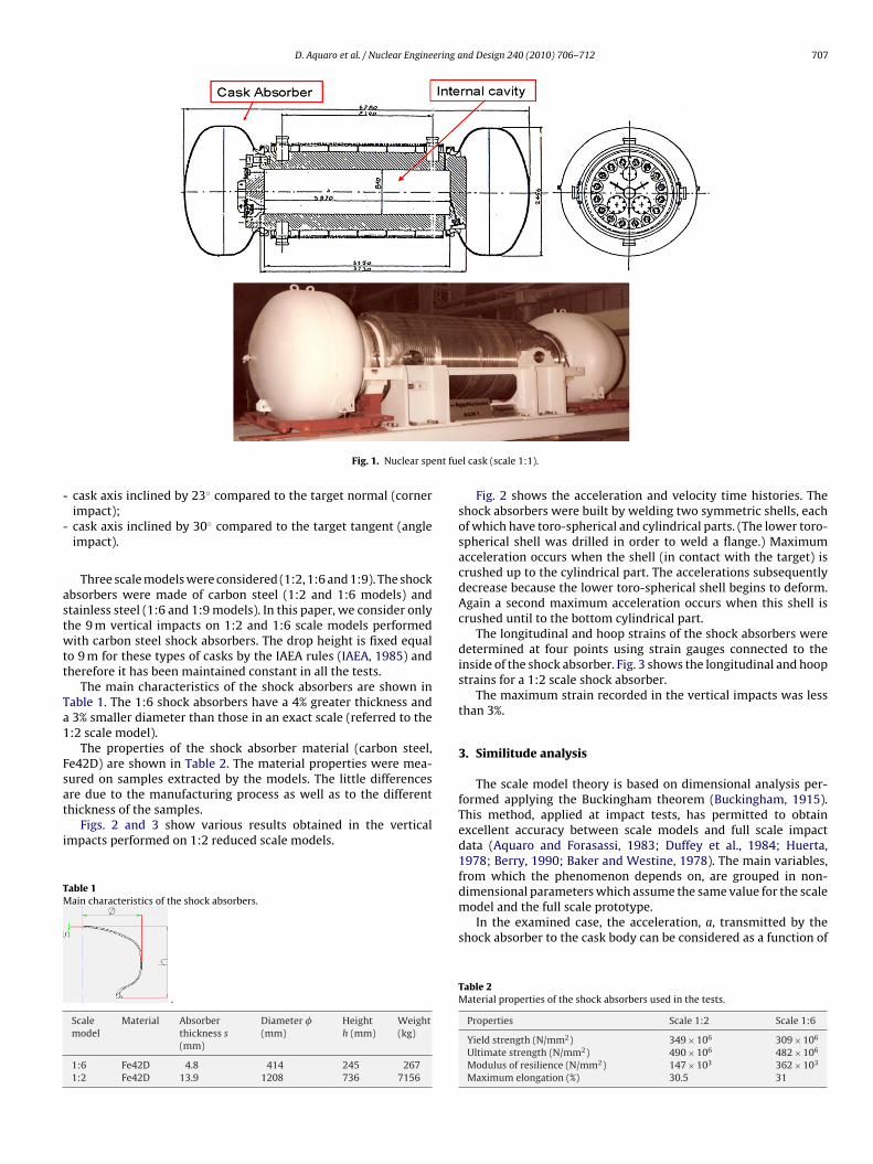
Given that the cask body remains in elastic regime during theimpact, the numerical model only simulated the shock absorberwith the body mass lumped in correspondence to the flange. Fig. 4illustrates the mesh of the 1:2 reduced scale model (3557 axialsymmetric elements with 4 nodes).
The strain rate effect on yield strength was considered using theCowper–Symonds relations (Perrone, 1965):
�y = �yst
[1 +
(ε̇
D
)1/n]
(2)
−1
Fig. 5 shows the deformation pattern of the shock absorber dur-ing a 9-m vertical impact. We can see three phases of deformationduring the impact:
models.
Scale model 1:6 Deviation of 1:6scale model (%)
4.343E−01 3.2%
2.041E−02 8%
2.940E+01 0.82%
1.189E+00 5.71%
3.498E−02 5.74%
1.51E−01 1.95%
710 D. Aquaro et al. / Nuclear Engineering a
Fig. 4. Mesh of the shock absorber.
Fig. 5. Deformation pattern and Von Mises stres
Fig. 6. Comparison between the experimental values of velocity and accelera
nd Design 240 (2010) 706–712
- phase I: the plastic deformation involves the impacted toro-spherical shell (a plastic hinge moves from the central part ofthe shock absorber to the cylindrical part);
- phase II: the plastic hinge reaches the cylindrical part;- phase III: the plastic deformation involves the toro-spherical shell
connected with the flange.
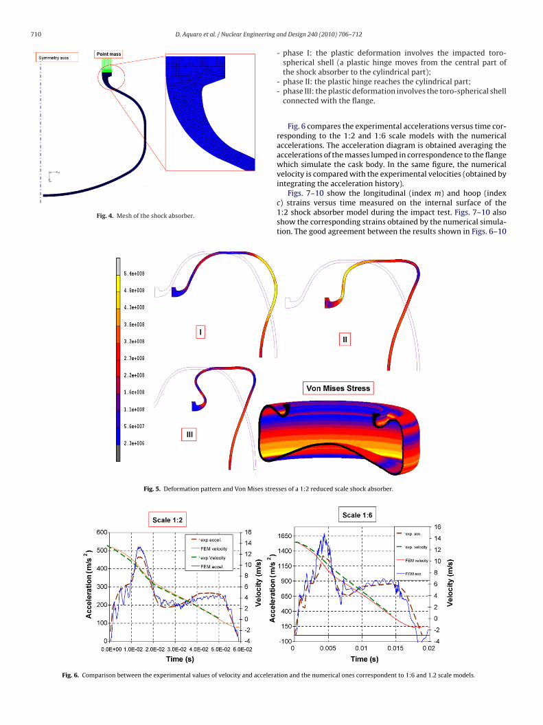
Fig. 6 compares the experimental accelerations versus time cor-responding to the 1:2 and 1:6 scale models with the numericalaccelerations. The acceleration diagram is obtained averaging theaccelerations of the masses lumped in correspondence to the flangewhich simulate the cask body. In the same figure, the numericalvelocity is compared with the experimental velocities (obtained byintegrating the acceleration history).
Figs. 7–10 show the longitudinal (index m) and hoop (indexc) strains versus time measured on the internal surface of the1:2 shock absorber model during the impact test. Figs. 7–10 alsoshow the corresponding strains obtained by the numerical simula-tion. The good agreement between the results shown in Figs. 6–10
ses of a 1:2 reduced scale shock absorber.
tion and the numerical ones correspondent to 1:6 and 1.2 scale models.

D. Aquaro et al. / Nuclear Engineering and Design 240 (2010) 706–712 711
Fig. 7. Longitudinal and hoop strains versus time of a 1:2 scale shock absorber(position 1c, 1m, 2c): comparison between experimental and numerical results.
Fig. 8. Longitudinal and hoop strains versus time of a 1:2 scale shock absorber(position 3c, 3m): comparison between experimental and numerical results.
Fig. 9. Longitudinal and hoop strains versus time of a 1:2 scale shock absorber(position 2m): comparison between experimental and numerical results.
Fig. 10. Longitudinal and hoop strains versus time of a 1:2 scale shock absorber(position 1c, 1m, 2c): comparison between experimental and numerical results.
Table 7Material properties of the numerical models.
Properties of the numerical models
Yield strength (N/mm2) 349 × 106
Ultimate strength (N/mm2) 490 × 106
Maximum elongation (%) 30.5
Table 8Input data and results corresponding to numerical models.
Symbol of Ph. entities Scale model 1:1 Scale model 1:2
M (kg) 57407 7176s (m) 0.0278 0.0139Z0 (m) 1.472 0.736�y (Pa) 3.49E+08 3.49E+08t (s) 0.1034 0.0484amax (m/s2) 258 461.07aavg (m/s2) 128 274.96�Z (m) 0.626 0.3097
Table 9Dimensionless groups for the examined scale models and deviations compared to the 1:1
Groups 1:1 scalemodel
1:2 scalemodel
1:2 scaledeviation (%)
1:6 scalemodel
1:6 scdevia
�1 0.426 0.421 1.17% 0.434 1.88�2 0.019 0.019 0% 0.019 0%�3 27.225 29.160 7.1% 29.400 7.99�4 1.345 1.261 6.25% 1.189 11.6%�5 0.033 0.033 0% 0.035 6%�6 0.154 0.154 0% 0.151 1.95
Cowper–Symonds constants n = 4, D = 40E-Modulus (N/mm2) 20.7 × 10³
Poisson coefficient 0.33
seemed to indicate that the numerical models were able to describethe behaviour of the shock absorber during vertical impact.
With the assessed model, numerical simulations were per-formed considering shock absorbers of different scales (1:1, 1:2,1:6, 1:9 and 1:12). The main objective was to verify the accuracyof scale laws we found for the various scale models. This analy-sis allowed us to identify the smallest scale model which couldbe used in the tests. The main characteristics of the numericalreduced scale models (thickness, mass, diameter, material prop-erties) were derived from those of the 1:2 scale model used in thetests. Table 7 contains the material properties used in the numer-ical simulations. Table 8 reports the input data and the numericalresults corresponding to the simulated scale models.
Table 9 reports the dimensionless groups for all the scale mod-els examined and the deviation compared to the 1:1 scale model
values. The values shown in Table 9 highlight that:- the shock absorber displacement (�1 dimensionless group) isestimated well from the 1:2 model (1.17% deviation) as well as
Scale model 1:6 Scale model 1:9 Scale model 1:12
265 78.5 33.130.0046 0.0031 0.00230.245 0.163 0.1223.49E+08 3.49E+08 3.49E+080.0143 0.011 5.51E−03
2072 2639.418 4452.5274.96 1197.404 2401.3
0.096 0.0632 0.03529
scale model values.
aletion (%)
1:9 scalemodel
1:9 scaledeviation (%)
1:12 scalemodel
1:12 scaledeviation (%)
% 0.386 9.39% 0.2881 67.62%0.019 0% 0.019 0%
% 31.461 15.56% 42.4121 55.78%1.221 9.22% 0.8614 35.95%0.027 18.18% 0.0226 31.51%
% 0.193 25.32% 0.3282 113.12%

7 ering a
-
-
lds
5
sTrlsevsm
h
12 D. Aquaro et al. / Nuclear Engine
from the 1:6 model (1.88% deviation). The 1:9 scale model has a9.39% deviation while the 1:12 scale model result is unreliable.the cask acceleration (�3 dimensionless group) is estimatedequally well from the 1:2 and 1:6 scale models, showing 7.1%and 7.99% deviations, respectively. The accuracy of the 1:9 scalemodel is lower (deviation 15.5%) but still acceptable.the impact duration (�4 dimensionless group) is estimated witha deviation of 6.25% and 11.6% by the 1:2 and 1:6 scale models,respectively. The 1:9 scale model has a deviation of 9.22% lowerthan the 1:6 scale model.
We can therefore conclude that the 1:12 scale model gives unre-iable results. The 1:9 scale model can be used and gives a maximumeviation of 15.5% for the parameters of interest. The 1:2 and 1:6cales are almost equivalent.
. Conclusions
We have outlined the experimental results and the numericalimulations of 9 m free drop tests for a nuclear spent fuel cask.he tests were performed on 1:2, 1:6 and 1:9 scale models. Theesults were extrapolated to the prototype on the basis of scaleaws determined by means of a similitude analysis. The numericalimulations were performed considering shock absorbers of differ-nt scales (1:1, 1:2, 1:6, 1:9 and 1:12). The main objective was to
erify the accuracy of the scale laws we had found for the variouscale models. This analysis enabled us to identify the smallest scaleodel to give reliable results in the experimental tests.The 1:12 scale model gave unreliable results, on the otherand the 1:9 scale model gave a maximum deviation of
nd Design 240 (2010) 706–712
15.5% for the parameters of interest (displacement, accelera-tion and impact duration). The 1:2 and 1:6 scales were almostequivalent.
The 1:6 scale model can therefore be used to determine thebehaviour of a cask in a 9-m free drop test. Useful information wasalso obtained from the 1:9 scale model even though the accuracywas lower than the 1:6 model.
References
Aquaro, D., Forasassi, G., 1983. Impact test on scale models of a shock absorber fora LWR spent fuel transport packaging. In: 7th Int. Conf. SMiRT, Chicago, USA,August 22–26.
Aquaro, D., Forasassi, G., 1985. Experimental analysis methods in the study ofa shock absorber under dynamic loads. In: 8th Int. Conf. SMiRT, Brussels,August.
Baker, W.E., Westine, P.S., 1978. Similarity Methods in Engineering Dynamics. Hay-den Book Company, Inc., Rochelle Park, NJ.
Berry, R.E., 1990. Justification for Using Scale Models for Impact Response Evaluationof the SST Transportation System, SAND90-2337.
Buckingham, E., 1915. Model experiments and the forms of empirical equations.Trans. ASME 37, 263–296.
Duffey, T.A., Cheresh, M.C., et al., 1984. Experimental verification of scaling laws forpunch-impact-loaded structures. Int. J. Impact Eng. 2 (1), 103–117.
Hillsdon, G.K., 1997. The dynamic response of scale models subjected to impactloading. SPIE 2869, 275–280.
Huerta, M., 1978. Analysis, Scale Modeling, and Full Scale Tests of a Truck Spent-Nuclear-Fuel Shipping System in High Velocity Impacts Against a Rigid Barrier,SAND77-0270. Sandia Lab.
IAEA, 1985. Regulations for the Safe Transport of Radioactive Material–SS N. 6. IAEA,
Vienna.2003. MSC-MARC – Vol. A – Theory and User information. MSC Software Corporation.Perrone, N., 1965. On a simplified method for solving impulsively loaded structures
of rate-sensitive materials. J. Appl. Mech. September, 489–492.Shappert, L.B., 1989. Cask Drop Testing and Analysis, CONF-890721-14. Oak Ridge
National Laboratory.