Numerical analysis of blast-induced wave propagation using FSI and ALEmulti-material formulations
9
International Journal of Rock Mechanics & Mining Sciences 45 (2008) 600–608 Numerical analysis of blast-induced wave propagation and spalling damage in a rock plate Zhi-liang Wang a, , Yong-chi Li a , J.G. Wang b a Department of Modern Mechanics, University of Science and Technology of China, Hefei, Anhui 230027, China b Centre for Protective Technology, National University of Singapore, 10 Kent Ridge Crescent 119260, Singapore Received 18 November 2006; received in revised form 20 July 2007; accepted 15 August 2007 Available online 17 October 2007 Abstract The paper focuses on the numerical analysis of blast-induced stress wave propagation and related spalling damage in a rock plate or wall. Firstly, a large-scale contact explosion is simplified as a one-dimensional (1-D) strain problem, and a cross-format centered finite- difference scheme is presented. Secondly, the finite-difference code is used to explore the wave propagation in a rock plate, and compared with the commercial software LS-DYNA. Thirdly, a continuum damage constitutive model for rock is introduced and successfully incorporated into the LS-DYNA through its user-defined subroutine. Coupling with the erosion technique, the improved LS-DYNA is used to simulate the blast-induced spalling damage at the back-side of rock plate. Numerical results show that the 1-D finite difference code is convenient and accurate. Also, the user-defined subroutine can well describe the process of spalling damage. r 2007 Elsevier Ltd. All rights reserved. Keywords: Rock plate; Contact explosion; 1-D strain wave; Finite difference method; Damage model; Erosion technique; Spalling damage 1. Introduction In the last few decades, plated structures have been interesting topics,and a large volume of data has been collected through well-organized parametric studies with either analytical or experimental method (or both). However, few studies have addressed dynamic problems, particularly for impact and explosion problems of brittle materials such as rock and concrete [1–4]. The analysis and design of reinforced protection structures against short-duration dynamic loadings like blast or impact have been extensively studied in recent years [3,5]. As is well known, the detonation of an explosive generates violent expansion of hot gases, producing a pressure wave that moves outward at high velocity from its source, and resulting in sharp stress gradients in structures. This may result in a wide range of strain rate in structures, causing spalling damage. Therefore, the blast-induced response of structures made of brittle materials is still a hot topic. In the design of protective structures, both reinforced concrete walls and rock plates are often used. They are expected to provide effective protection against stress-wave from accidental or intentional events. Fundamental char- acteristics of rock are that, in general, no significant plastic deformation is observed before failure. Rock has little toughness to arrest crack development. It has been found that short-duration high-magnitude blast loading signifi- cantly influences the response of rock [6]. Rock would be subjected to complex stress states which may produce different failure modes. For example, near the surface facing the explosive charge, the rock experiences dynamic compression. It may fail due to high compression. On the opposite side of the plate, the shock wave is reflected by the free surface and converted into a tensile wave. This tensile wave could cause tensile cracking if its material strength is reached. Because of low resistance of rock to tension, tensile spalling may be produced [3,7,8]. It is well recognized that spalling damage of the rock wall or plate on the inner side poses certain threat to the personnel and ARTICLE IN PRESS www.elsevier.com/locate/ijrmms 1365-1609/$ - see front matter r 2007 Elsevier Ltd. All rights reserved. doi:10.1016/j.ijrmms.2007.08.002 Corresponding author. Tel.: +86 551 360734; fax: +86 551 3606459. E-mail address: [email protected] (Z.-L. Wang).
-
Upload
independent -
Category
Documents
-
view
4 -
download
0
Transcript of Numerical analysis of blast-induced wave propagation using FSI and ALEmulti-material formulations

ARTICLE IN PRESS
1365-1609/$ - se
doi:10.1016/j.ijr
�CorrespondE-mail addr
International Journal of Rock Mechanics & Mining Sciences 45 (2008) 600–608
www.elsevier.com/locate/ijrmms
Numerical analysis of blast-induced wave propagation and spallingdamage in a rock plate
Zhi-liang Wanga,�, Yong-chi Lia, J.G. Wangb
aDepartment of Modern Mechanics, University of Science and Technology of China, Hefei, Anhui 230027, ChinabCentre for Protective Technology, National University of Singapore, 10 Kent Ridge Crescent 119260, Singapore
Received 18 November 2006; received in revised form 20 July 2007; accepted 15 August 2007
Available online 17 October 2007
Abstract
The paper focuses on the numerical analysis of blast-induced stress wave propagation and related spalling damage in a rock plate or
wall. Firstly, a large-scale contact explosion is simplified as a one-dimensional (1-D) strain problem, and a cross-format centered finite-
difference scheme is presented. Secondly, the finite-difference code is used to explore the wave propagation in a rock plate, and compared
with the commercial software LS-DYNA. Thirdly, a continuum damage constitutive model for rock is introduced and successfully
incorporated into the LS-DYNA through its user-defined subroutine. Coupling with the erosion technique, the improved LS-DYNA is
used to simulate the blast-induced spalling damage at the back-side of rock plate. Numerical results show that the 1-D finite difference
code is convenient and accurate. Also, the user-defined subroutine can well describe the process of spalling damage.
r 2007 Elsevier Ltd. All rights reserved.
Keywords: Rock plate; Contact explosion; 1-D strain wave; Finite difference method; Damage model; Erosion technique; Spalling damage
1. Introduction
In the last few decades, plated structures have beeninteresting topics,and a large volume of data has beencollected through well-organized parametric studies witheither analytical or experimental method (or both).However, few studies have addressed dynamic problems,particularly for impact and explosion problems of brittlematerials such as rock and concrete [1–4].
The analysis and design of reinforced protectionstructures against short-duration dynamic loadings likeblast or impact have been extensively studied in recentyears [3,5]. As is well known, the detonation of an explosivegenerates violent expansion of hot gases, producing apressure wave that moves outward at high velocity from itssource, and resulting in sharp stress gradients in structures.This may result in a wide range of strain rate in structures,causing spalling damage. Therefore, the blast-induced
e front matter r 2007 Elsevier Ltd. All rights reserved.
mms.2007.08.002
ing author. Tel.: +86551 360734; fax: +86 551 3606459.
ess: [email protected] (Z.-L. Wang).
response of structures made of brittle materials is still ahot topic.In the design of protective structures, both reinforced
concrete walls and rock plates are often used. They areexpected to provide effective protection against stress-wavefrom accidental or intentional events. Fundamental char-acteristics of rock are that, in general, no significant plasticdeformation is observed before failure. Rock has littletoughness to arrest crack development. It has been foundthat short-duration high-magnitude blast loading signifi-cantly influences the response of rock [6]. Rock would besubjected to complex stress states which may producedifferent failure modes. For example, near the surfacefacing the explosive charge, the rock experiences dynamiccompression. It may fail due to high compression. On theopposite side of the plate, the shock wave is reflected by thefree surface and converted into a tensile wave. This tensilewave could cause tensile cracking if its material strength isreached. Because of low resistance of rock to tension,tensile spalling may be produced [3,7,8]. It is wellrecognized that spalling damage of the rock wall or plateon the inner side poses certain threat to the personnel and

ARTICLE IN PRESS
Fig. 1. Schematic of problem: (a) contact explosion; (b) equivalent
loading.
Z.-L. Wang et al. / International Journal of Rock Mechanics & Mining Sciences 45 (2008) 600–608 601
equipment inside even if the structure itself does not sufferwhole failure.
Fig. 1(a) depicts a contact explosion problem, where thethickness of the explosive and rock plate are h1 and h2,respectively. By taking the sparse effect around theexplosive column into account, blast loading can beapproximated by the form shown in Fig. 1b. If thetransverse dimension of rock plate is much larger than itsthickness (that is, h5l) the response in the centre regionalong symmetry axis AB can be approximately described asa one-dimensional (1-D) strain problem. In the presentstudy, a complete equation system for a 1-D strain waveproblem is presented. A 1-D finite difference code based onthe cross-format centered difference scheme is thendeveloped. This finite difference code is employed toexplore the dynamic wave propagation in rock platesubjected to blast loading. The numerical results areafterward compared with the FE code LS-DYNA [9,10].Thirdly, one continuum damage model for rock isintroduced and succinctly implemented into the LS-DYNAprogram coupled with erosion technique. The spallingdamage on the back-side of a rock plate is simulated.Finally, some conclusions and remarks are drawn.
2. Development of cross-format centered difference program
Significant efforts have been devoted to the developmentof reliable algorithms for more realistic analysis ofstructures to understand the damage threat posed byexplosion or impact. Consequently, a variety of numericalalgorithms have been developed for the analysis ofdynamic responses of rocks subjected to blast loading,such as finite element method, discrete element method[11], coupled method of finite element and smooth particlehydrodynamics [12]. In this section, a cross-formatcentered finite-difference procedure is developed.
2.1. Explosive equation of state
In order to conveniently programming, the pressuregenerated by the chemical energy in an explosive isdescribed by the BKW equation of state [13]
ln p ¼ 1011expX4n¼0
an lnnð103V Þ
" #, (1)
where p is the pressure (in Pa), ai (i ¼ 0–4) are the explosiveparameters, and V the specific volume (inm3/kg).
2.2. Complete equation system for 1-D strain wave
propagation
If the transverse dimension of the rock plate is muchlarger than its thickness, the effect of lateral sparse wavescan be ignored. Thus, the explosion problem related to thesymmetry axis region can be regarded as a 1-D strainproblem [14]. Its complete equation system [15–17]includes:Motion equation:
qu
qt¼ �
qsx
qM. (2)
Continuity equation:
V ¼qx
qM. (3)
State equation:
p ¼ f ðV Þ. (4)
Velocity definition:
u ¼qx
qt. (5)
Elastic shear law:
qtqt¼ �
G qV
V qt. (6)
Yield criterion:
k ¼ jtj � 0:5Y . (7)
Shear stress:
t ¼t if ko0;Y2signðtÞ k40:
((8)
Artificial viscosity:
q ¼
aV
quqM
� �2DM2 if qu
qMo0;
0; quqM
X0;
((9)
dM ¼ r0 dX ¼ rdx, (10)
where t is time, X and x are the longitudinal Lagrange andEuler coordinate, respectively, u represents the longitudinalvelocity of the particle; r0 and r are the initial and currentdensity, V 0 and V are the initial and current specificvolume, a is the coefficient for quadric-type artificial
ARTICLE IN PRESS
Fig. 2. Horizontal schematic of 1-D strain problem.
Z.-L. Wang et al. / International Journal of Rock Mechanics & Mining Sciences 45 (2008) 600–608602
viscosity which is usually taken as 4.0, G denotes the shearmodulus, Y is the yield limit, M is the mass coordinate, andsx is the longitudinal compressive stress. Let syð¼ szÞ bethe tangential compression stress, in which case thehydrostatic pressure p and the maximum shear stress areexpressed as
p ¼ðsx þ 2syÞ
3, (11)
t ¼sx � sy
2. (12)
The isentropic Murnaghan state Eq. (14, 15) is used forrock in high temperature
p ¼K
gV 0
V
� �g
� 1
� �, (13)
where g is the polytropic index, and K is the bulk modulus.The isotropic /kinematic with von Mises criterion is
used to approximately model the plastic deformation ofrock [7,15].
The timestep corresponding to a second-order finite-difference scheme is determined as below:
For the smooth zone
Dt ¼ xVDMi
c. (14)
For the shock-wave zone
Dt ¼ xVDMi
4aDui
, (15)
where c represents the local sound velocity; 0oxp1. Thewhole calculation can favorably march forward whenz ¼ 0:9.
2.3. Self-simulation solution to detonation process
In order to reduce the calculation of detonation process,a self-simulation solution is adopted. The state variables ofdetonation products including V, u and x at the end ofdetonation are taken as initial conditions which can beobtained by solving the basic equations of detonationproducts as follows:
qVqt¼ qu
qM
quqt¼ �
qpqM
(. (16)
All parameters including V, u and p are regarded as thefunctions of the variable Z(=M/t). As thus, the partialdifferential equations in Eq. (16) can be transformed intothe following ordinary differential equations:
u0 þ ZV 0 ¼ 0
Zu0 þ c2
V2 V 0 ¼ 0
(, (17)
where the right superscript 0 denotes the differentialquotient with respect to Z, and c ¼
ffiffiffiffiffiffiffiffiffiffiffiffiffidp=dr
pis the sound
velocity of detonation products.
Substitution of the non-trivial solution c ¼ ZV into theabove sound-velocity equation yields V 0 ¼ �ð2Z=d2p=dV2Þ.the final differential equations for state parameters ofdetonation products can be written as [15,18–20]
Z0 ¼ 1
V 0 ¼ � 2Zd2p=dV2
u0 ¼ �ZV 0
x0 ¼ V h1D:
8>>>><>>>>:
(18)
At t0 ¼ h1=D, the known variables on the C-J wavefrontare
Z ¼ r0D V ¼ VCJ u ¼ uCJ ¼ D 1� V CJ=V0
� �x ¼ h1,
(19)
where h1 is the height of explosive (see Fig. 1(a)). underthese boundary values, the initial conditions of detonationproducts can be found by solving Eq. (18) with theRunge–Kutta method [20].Both the left-hand side of explosive and the right-hand
side of rock (see Fig. 2) are free face. Their correspondingboundary conditions are p ¼ 0 and sx ¼ 0, respectively. Onthe interface between rock and explosive, the displacementis continuous and p ¼ sx.
2.4. cross-format centered finite-difference method
A cross-format centered finite-difference scheme withsecond-order accuracy [17,21] is adopted here. In thisscheme, the velocity u is discretized at the grids of full-lattice of space and semi-lattice of time. It is denoted by
unþ1=2j . Specific volume, pressure, and shear stress are all
discretized at the grids of semi-lattice of space and full-lattice of time. They are denoted by Vn
jþ1=2, pnjþ1=2, and
tnjþ1=2. Artificial-viscosity is discretized at the grids of semi-
lattice of space and semi-lattice of time and denoted by
qnþ1=2jþ1=2 , which is one-order lower than other variables.
2.5. Simulation of 1-D strain-wave effect
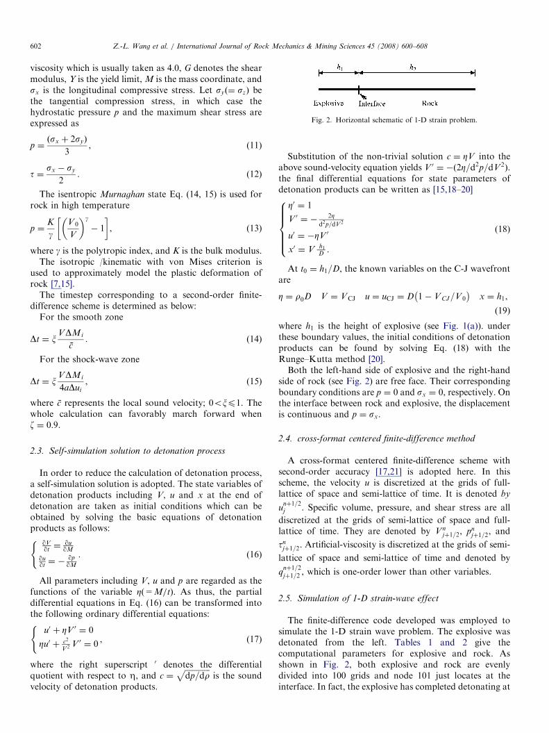
The finite-difference code developed was employed tosimulate the 1-D strain wave problem. The explosive wasdetonated from the left. Tables 1 and 2 give thecomputational parameters for explosive and rock. Asshown in Fig. 2, both explosive and rock are evenlydivided into 100 grids and node 101 just locates at theinterface. In fact, the explosive has completed detonating at
ARTICLE IN PRESS
Table 1
Parameters for modeling the TNT explosive
Basic parameters r (kg/m3) D�C�J (m/s) P��C�J (GPa) VC-J (m3/kg) E0 (GPa)
1630.0 6930.0 18.6 4.60e-4 6000.0
JWL parameters A (GPa) B (GPa) R1 R2 o373.8 3.747 4.15 0.90 0.35
BKW parameters a0 a1 a2 a3 a4�3.66524 �2.46714 0.22846 0.06050 �0.01930
*DC-J, the C-J detonation velocity; **PC-J, the C-J detonation pressure.
Table 2
Parameters of rock
r (kg/m3) E (GPa) v Y (MPa) a b ec g
2550.0 51.8 0.33 215.0 7.0e10 2.0 0.1411e-3 3.7
0 5 10 15 20 25 30 35 400
5
10
15
20
25
t (us)
p (G
Pa)
Fig. 3. Blast loading at the interface between explosive and rock.
0 5 10 15-8000
-6000
-4000
-2000
0
2000
u (m
/s)
x (cm)
0µs5µs 10µs 15µs
20µs
0 5 10 15-5
0
5
10
15
20
σ x (
GPa
)
x (cm)
0µs
5µs
10µs15µs
20µs
Fig. 4. numerical results of 1-D method: (a) Spatial distribution of stress-
waves; (b) Spatial distribution of velocity waves.
Z.-L. Wang et al. / International Journal of Rock Mechanics & Mining Sciences 45 (2008) 600–608 603
this position. Fig. 3 shows the blast pressure historyat the node 101. This pressure is obtained from the 1-Dmodel calculation for 5 cm high explosive with instantlydetonating.
Fig. 4(a) is the spatial distribution of axial stress sx. Thewave lies on the interface at the time of 0.0 ms and its peakvalue is 19.28GPa. This stress wave propagates from left toright along the rock and its wavefront almost approachesto the right-hand free face at t ¼ 15 ms. The peak value atthis time reduces to 12.34GPa. At time of 20 ms, thecompressive wave is changed into tensile wave in nature.the peak pressure dips to 6.12GPa while the maximumtensile stress is 2.08GPa. Dynamic fracture of rock occursunder this tensile stress. Fig. 4(b) shows the spatialpropagation of velocity waves. At t ¼ 0 ms, the wave-front is on the interface and its wave peak is 1703m/s.This wave almost reaches the X ¼ 14 cm grid at about15 ms. Obviously, the reflected tensile wave induces a
velocity platform at the curve tail for the t ¼ 20 ms case.This phenomenon is consistent to the mirror-mappingsuperposition theorem of velocity wave near a free sur-face [14].

ARTICLE IN PRESS
Fig. 5. Dimensions of rock for1-D strain problem in 3-D coordinate
system.
0 5 10 15 20-5
0
5
10
15
20
25
σ x (
GPa
)σ x
(G
Pa)
time (μs)
d=0cm
d=3cm
d=7cmd=5cm
d=9cm
0 5 10 15 200
5
10
15
20
25
time (μs)
d=0cm
d=3cmd=5cm
d=7cmd=9cm
Fig. 6. Comparison of waveform at different positions: (a) 1-D FDM
results; (b) LS-DYNA results.
Z.-L. Wang et al. / International Journal of Rock Mechanics & Mining Sciences 45 (2008) 600–608604
2.6. Verification of finite difference code
Owing to lack of experimental data, LS-DYNA is hereused to calibrate the above finite difference code. BecauseLS-DYNA is three-dimensional software, the 3-d config-uration for rock specimen corresponding to Fig. 2 is shownin Fig. 5. There are 100 divisions in the y-axis direction,thus each element being a cube of 0.1� 0.1� 0.1 cm. Thedisplacements in both x- and z-directions are fixed and allelements are permitted to move only in the y-direction.This is equivalent to the 1-D strain case. Besides, becauseLS-DYNA has no BKW state equation available forexplosive, that blast loading obtained from 1-D calculation(refer to Fig. 3) is directly applied on the interface to caterthe contact explosion.
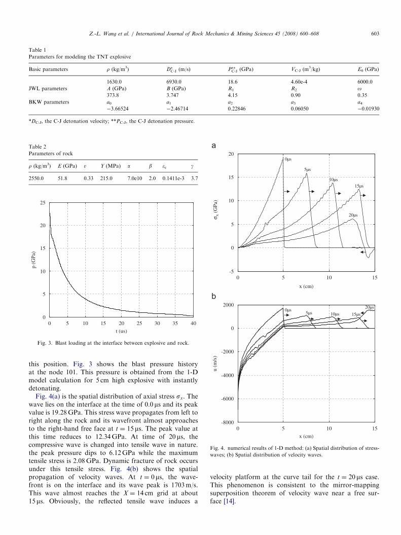
Fig. 6 is the comparison of time histories of axial stressat different positions d (the distance from observationpoint to the interface). They have a good correlation. Theattenuation is observed at different positions d. Forexample, the peak value of sx is 15.3GPa at d ¼ 3:0cm,and 12.6GPa at d ¼ 9:0cm. Fig. 7 shows the propagationprocess of stress waves along the rock column at threetypical times. At t ¼ 10.38 ms, the wavefront denoted asan arrow arrives at the middle of the rock while itapproaches to the right face at 17.78 ms. No reflectedtensile waves turn up for those two cases. However, thetensile stress can be detected in Fig. 7(c), its maximumvalue being 4:27� 10�2Mbar (i.e. 4.27GPa). This magni-tude of tensile stress will cause rock spallation and dynamicfracture.
3. One continuum damage model for rock
In the above calculations, high tension can be found onthe back-side of rock plate. If a tensile damage evolutionlaw along with spallation criterion is known, the dynamicfracture process of rock mass can be simulated.
As well recognized, rock mass contains geologicaldiscontinuities such as flaws and cracks. These disconti-nuities will grow in size as well as number under external
tensile stresses, causing the deterioration of rock stiffnessand strength and significantly affecting the dynamicresponses of rock. In this section, rock is assumed to behomogeneous, isotropic, continuous, and brittle. It has pre-existing microcracks. in terms of continuum damagemechanics, when a material point is subjected to stresses,it changes in volume and shape. The volumetric strain �v isregarded as a time-dependent variable, which determineswhether microcracks will be activated and evolved. Underexternal loadings, dynamic fracture of rock does not occurunless the stress is larger than its tensile strength. That is,a critical value �c for the volumetric strain �v exists forrock [22]
�c ¼1� 2v
Ess, (20)
ARTICLE IN PRESS
Fig. 7. Propagation of stress-waves along rock: (a) t ¼ 10.38ms; (b) t ¼ 17.78ms; and (c) t ¼ 21.36ms.
Z.-L. Wang et al. / International Journal of Rock Mechanics & Mining Sciences 45 (2008) 600–608 605
where E is the Young’s modulus, v is the Poisson’s ratioand ss is the tensile strength.
Obviously, microcracks will be activated and grown by ahigh stress level assuring �v4�c. Furthermore, the wholeevolution is possible only when the time duration of theapplied stress is long enough. In this regard, the crackdensity Cd is defined as [22,23]
Cd ¼ að�v � �cÞbt, (21)
where a and b are material constants, and t denotes time.In the model, the damage scalar D is assumed to take the
following form
D ¼ 1� expð�C2dÞ. (22)
The degraded Young’s modulus Ed for the damaged rock iscomputed as
Ed ¼ Eð1�DÞ. (23)
The incremental stress-strain relationship is given as:
Dsij ¼ KddijD�kk þ 2GdDeij, (24)
where Kd and Gd are, respectively, the degraded bulkmodulus and shear modulus, dij is the Kronecker deltafunction, Dsij are increments of stress tensor, D�kk and Deij
are increments of volumetric and deviatoric strains,respectively.The above tensile damage evolution law uses volumetric
strain as a criterion for microcrack initiation and growth. Itis valid only when a material point is in tension and thetotal volumetric strain is greater than the critical volu-metric strain. Otherwise, the von Mises yield criterion withplastic/kinematic hardening is used to model the stress-strain properties [22].The Poisson’s ratio is assumed to remain unchanged for
damaged body [24,25]. That is, all types of cracks areassumed to be generated equally during blast-induceddamage. If a brittle rock contains closed cracks, theeffective Poisson’s ratio is greater than its intrinsicPoisson’s ratio. However, when a body contains very flat,open cracks or equidimensional cavities, the effectivePoisson’s ratio is smaller than its intrinsic Poisson’s ratio.
4. Numerical simulation of rock tensile fracture
4.1. Implementation of damage model and erosion algorithm
The damage model described above was implemented asa user-defined material model into LS-DYNA. Theimplementation is strain driven. In a given timestep, the
ARTICLE IN PRESS
150
Z.-L. Wang et al. / International Journal of Rock Mechanics & Mining Sciences 45 (2008) 600–608606
inputs are the increments of total strain at the integrationpoints of each element. The computational subroutine thencalculates corresponding increments of stresses. Theupdated total stresses are then returned to the code. Thecomputation marches forward with the standard explicitintegration scheme in time domain.
In LS-DYNA, erosion of elements from the mesh can beperformed based on a user-defined criterion that signals theelimination of an element from finite element mesh. Thedynamic fracture criterion of rock mass is employed inthe implementation of the erosion technique to capture thefracture and material separation [3,9]. As a matter of fact,erosion algorithm is usually adopted to tackle the excessiveelement distortion problem and to herein model thefracture process of rock material.
A variety of criteria governing the ‘‘erosion’’ of thematerial can be chosen. In the present work, followingerosion criteria on tensile damage was incorporated intothe user-defined subroutine [7]
DtXf t, (25)
where f t is the critical value for tensile damage. CouplingEq. (25), the physical separation of the rock can besimulated. When the damages reach this critical value, theassociated element is immediately removed. The criticalvalues of the tensile damage can be determined by thecalibration of experimental data.
4.2. FE model
It is well recognized that classical Lagrangian finiteelement methods will confront difficulty in resolving largedeformations. In order to overcome this difficulty, arezoning or automatic re-mesh method is required for fluidmedia (for example, explosive and air) whereas they areCPU time consuming. Recently development such as ALEor Eulerian multi-material formulations in LS-DYNA canbe used as an alternative for the simulation of explosionproblem [9]: an Eulerian formulation for the fluid(explosive, air) and a Lagrangian formulation for the solid.
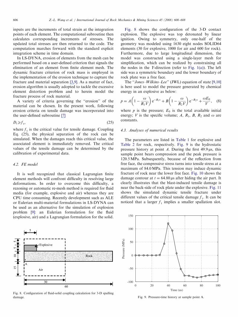
Fig. 8. Configuration of fluid-solid coupling calculation for 3-D spalling
damage.
Fig. 8 shows the configuration of the 3-D contactexplosion. The explosive was top detonated by linearignition. Owing to symmetry, only one-half of thegeometry was modeled using 1630 eight nodes SOLID64elements (30 for explosive, 1000 for air and 600 for rock).Furthermore, due to large longitudinal dimension, themodel was constructed using a single-layer mesh forsimplification, which can be realized by constraining allthe nodes in the Y-direction (refer to Fig. 1(a)). The leftside was a symmetric boundary and the lower boundary ofrock plate was a free face.The ‘‘Jones–Wilkins–Lee’’ (JWL) equation of state [9,10]
is here used to model the pressure generated by chemicalenergy in an explosive as below:
p ¼ A 1�o
R1V
� �e�R1u þ B 1�
oR2V
� �e�R2u þ
oE0
V, (8)
where p is the pressure; E0 is the total available initialenergy; V is the specific volume; A, R1, B, R2 and o areconstants.
4.3. Analyses of numerical results
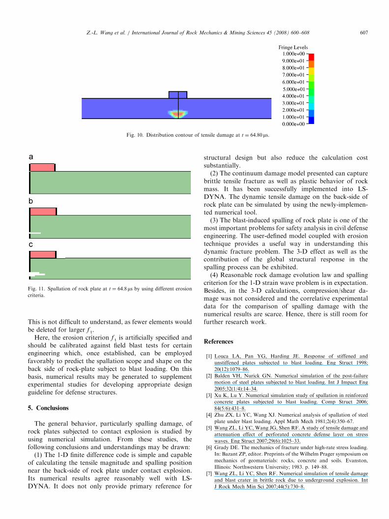
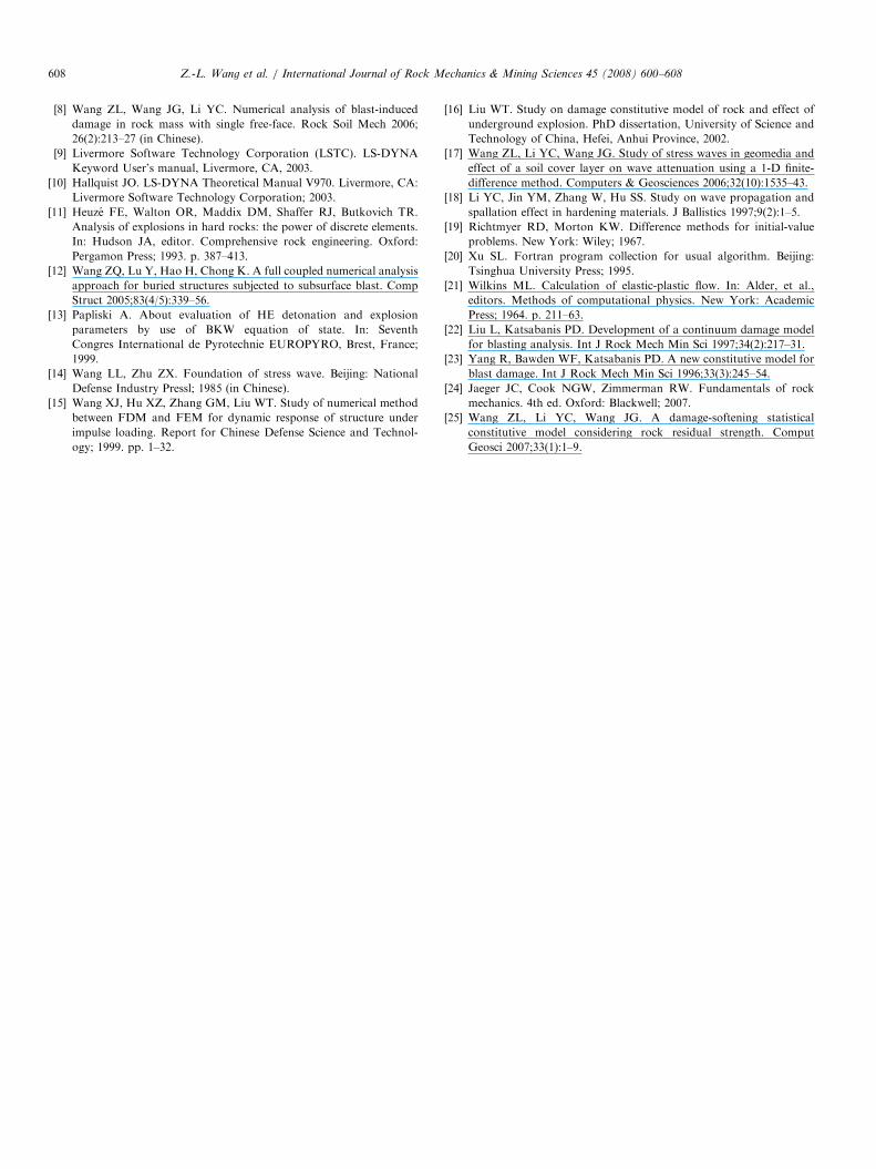
The parameters are listed in Table 1 for explosive andTable 2 for rock, respectively. Fig. 9 is the hydrostaticpressure history at point A. During the first 49.9 ms, thissample point bears compression and the peak pressure is120.5MPa. Subsequently, because of the reflection fromfree face, the compressive stress turns into tensile stress at amaximum of 84.0MPa. This tension may induce dynamicfracture of rock near the lower free face. Fig. 10 shows thedamage contour at t ¼ 64.80 ms after hiding the air part. Itclearly illustrates that the blast-induced tensile damage isnear the back-side of rock plate under the explosive. Fig. 11shows the simulated dynamic tensile fracture underdifferent values of the critical tensile damage f t. It can benoticed that a larger f t implies a smaller spallation slot.
0 20 40 60 80 100-100
-50
0
50
100
Time (us)
Pres
sure
(M
Pa)
Fig. 9. Pressure-time history at sample point A.
ARTICLE IN PRESS
Fig. 10. Distribution contour of tensile damage at t ¼ 64.80ms.
Fig. 11. Spallation of rock plate at t ¼ 64.8ms by using different erosion
criteria.
Z.-L. Wang et al. / International Journal of Rock Mechanics & Mining Sciences 45 (2008) 600–608 607
This is not difficult to understand, as fewer elements wouldbe deleted for larger f t.
Here, the erosion criterion f t is artificially specified andshould be calibrated against field blast tests for certainengineering which, once established, can be employedfavorably to predict the spallation scope and shape on theback side of rock-plate subject to blast loading. On thisbasis, numerical results may be generated to supplementexperimental studies for developing appropriate designguideline for defense structures.
5. Conclusions
The general behavior, particularly spalling damage, ofrock plates subjected to contact explosion is studied byusing numerical simulation. From these studies, thefollowing conclusions and understandings may be drawn:
(1) The 1-D finite difference code is simple and capableof calculating the tensile magnitude and spalling positionnear the back-side of rock plate under contact explosion.Its numerical results agree reasonably well with LS-DYNA. It does not only provide primary reference for
structural design but also reduce the calculation costsubstantially.(2) The continuum damage model presented can capture
brittle tensile fracture as well as plastic behavior of rockmass. It has been successfully implemented into LS-DYNA. The dynamic tensile damage on the back-side ofrock plate can be simulated by using the newly-implemen-ted numerical tool.(3) The blast-induced spalling of rock plate is one of the
most important problems for safety analysis in civil defenseengineering. The user-defined model coupled with erosiontechnique provides a useful way in understanding thisdynamic fracture problem. The 3-D effect as well as thecontribution of the global structural response in thespalling process can be exhibited.(4) Reasonable rock damage evolution law and spalling
criterion for the 1-D strain wave problem is in expectation.Besides, in the 3-D calculations, compression/shear da-mage was not considered and the correlative experimentaldata for the comparison of spalling damage with thenumerical results are scarce. Hence, there is still room forfurther research work.
References
[1] Louca LA, Pan YG, Harding JE. Response of stiffened and
unstiffened plates subjected to blast loading. Eng Struct 1998;
20(12):1079–86.
[2] Balden VH, Nurick GN. Numerical simulation of the post-failure
motion of steel plates subjected to blast loading. Int J Impact Eng
2005;32(1/4):14–34.
[3] Xu K, Lu Y. Numerical simulation study of spallation in reinforced
concrete plates subjected to blast loading. Comp Struct 2006;
84(5/6):431–8.
[4] Zhu ZX, Li YC, Wang XJ. Numerical analysis of spallation of steel
plate under blast loading. Appl Math Mech 1981;2(4):350–67.
[5] Wang ZL, Li YC, Wang JG, Shen RF. A study of tensile damage and
attenuation effect of perforated concrete defense layer on stress
waves. Eng Struct 2007;29(6):1025–33.
[6] Grady DE. The mechanics of fracture under high-rate stress loading.
In: Bazant ZP, editor. Preprints of the Wilhelm Prager symposium on
mechanics of geomaterials: rocks, concrete and soils. Evanston,
Illinois: Northwestern University; 1983. p. 149–88.
[7] Wang ZL, Li YC, Shen RF. Numerical simulation of tensile damage
and blast crater in brittle rock due to underground explosion. Int
J Rock Mech Min Sci 2007;44(5):730–8.
ARTICLE IN PRESSZ.-L. Wang et al. / International Journal of Rock Mechanics & Mining Sciences 45 (2008) 600–608608
[8] Wang ZL, Wang JG, Li YC. Numerical analysis of blast-induced
damage in rock mass with single free-face. Rock Soil Mech 2006;
26(2):213–27 (in Chinese).
[9] Livermore Software Technology Corporation (LSTC). LS-DYNA
Keyword User’s manual, Livermore, CA, 2003.
[10] Hallquist JO. LS-DYNA Theoretical Manual V970. Livermore, CA:
Livermore Software Technology Corporation; 2003.
[11] Heuze FE, Walton OR, Maddix DM, Shaffer RJ, Butkovich TR.
Analysis of explosions in hard rocks: the power of discrete elements.
In: Hudson JA, editor. Comprehensive rock engineering. Oxford:
Pergamon Press; 1993. p. 387–413.
[12] Wang ZQ, Lu Y, Hao H, Chong K. A full coupled numerical analysis
approach for buried structures subjected to subsurface blast. Comp
Struct 2005;83(4/5):339–56.
[13] Papliski A. About evaluation of HE detonation and explosion
parameters by use of BKW equation of state. In: Seventh
Congres International de Pyrotechnie EUROPYRO, Brest, France;
1999.
[14] Wang LL, Zhu ZX. Foundation of stress wave. Beijing: National
Defense Industry Pressl; 1985 (in Chinese).
[15] Wang XJ, Hu XZ, Zhang GM, Liu WT. Study of numerical method
between FDM and FEM for dynamic response of structure under
impulse loading. Report for Chinese Defense Science and Technol-
ogy; 1999. pp. 1–32.
[16] Liu WT. Study on damage constitutive model of rock and effect of
underground explosion. PhD dissertation, University of Science and
Technology of China, Hefei, Anhui Province, 2002.
[17] Wang ZL, Li YC, Wang JG. Study of stress waves in geomedia and
effect of a soil cover layer on wave attenuation using a 1-D finite-
difference method. Computers & Geosciences 2006;32(10):1535–43.
[18] Li YC, Jin YM, Zhang W, Hu SS. Study on wave propagation and
spallation effect in hardening materials. J Ballistics 1997;9(2):1–5.
[19] Richtmyer RD, Morton KW. Difference methods for initial-value
problems. New York: Wiley; 1967.
[20] Xu SL. Fortran program collection for usual algorithm. Beijing:
Tsinghua University Press; 1995.
[21] Wilkins ML. Calculation of elastic-plastic flow. In: Alder, et al.,
editors. Methods of computational physics. New York: Academic
Press; 1964. p. 211–63.
[22] Liu L, Katsabanis PD. Development of a continuum damage model
for blasting analysis. Int J Rock Mech Min Sci 1997;34(2):217–31.
[23] Yang R, Bawden WF, Katsabanis PD. A new constitutive model for
blast damage. Int J Rock Mech Min Sci 1996;33(3):245–54.
[24] Jaeger JC, Cook NGW, Zimmerman RW. Fundamentals of rock
mechanics. 4th ed. Oxford: Blackwell; 2007.
[25] Wang ZL, Li YC, Wang JG. A damage-softening statistical
constitutive model considering rock residual strength. Comput
Geosci 2007;33(1):1–9.