
Good Thoughts, Good Words, and Good (Trust) Deeds: Parsis, Risk, and Real Estate in Mumbai
Upload
khangminh22Category
view
5download
0
OFFICIAL
Nuclear Industry Aqueous Waste Management Good Practice Guidance
(Jacobs)
Direct Research Portfolio
Purchase Order: NDA021465
Date: December 2020
Contractor Ref: 208452-TR-0001
Issue: 1 (Contractor approved)

OFFICIAL
Nuclear Industry Aqueous Waste Management Good Practice Guidance Document i 10/12/2020
Preface
This report has been prepared by Jacobs under contract to the Nuclear Decommissioning Authority (NDA). The views expressed and conclusions drawn are those of the authors and do not necessarily represent those of NDA.
Conditions of publication
This report is made available under NDA’s Transparency Policy. In line with this policy, NDA is seeking to make information on its activities readily available, and to enable interested parties to have access to and influence on its future programmes. The report may be freely used for non-commercial purposes. However, all commercial uses, including copying and re-publication, require NDA’s permission. All copyright, database rights and other intellectual property rights reside with NDA. Applications for permission to use the report commercially should be made to the NDA’s Communications department at the address below. Although great care has been taken to ensure the accuracy and completeness of the information contained in this publication, NDA cannot assume any responsibility for consequences that may arise from its use by other parties.
© Nuclear Decommissioning Authority 2020. All rights reserved
Communications Department NDA Herdus House Westlakes Science and Technology Park Moor Row Cumbria CA24 3HU

OFFICIAL
Nuclear Industry Aqueous Waste Management Good Practice Guidance Document ii 10/12/2020
Executive Summary
Jacobs has developed this Good Practice Guidance (GPG) on the management of aqueous waste on behalf of the NDA. From 2018 to 2020, the project team engaged with waste producers and regulators from the nuclear industry through workshops and teleconferences. Production of this guidance was supported by the relevant Environment Agencies and the Office for Nuclear Regulation. The GPG has been produced to identify and facilitate consistent application of good practice within the UK nuclear industry regarding the management of aqueous waste.
The GPG aligns with existing guidance referred to throughout the document and in the references.
Case studies provided by waste producers are presented to give readers real-world examples of aqueous waste management activities and to demonstrate how challenges were overcome.
Keywords
Guidance, good practice, best practice, aqueous waste, effluent, waste management, water treatment, process control, containment, discharge, abatement, technologies, prevention, minimisation, sustainability.

OFFICIAL
Nuclear Industry Aqueous Waste Management Good Practice Guidance Document iii 10/12/2020
Contents 1. Introduction 1
Aims and intended readership 1 How to use this document 1 Definitions and key terms 1 Why is this guidance needed? 2 Scope and application of this guidance 3 Aqueous waste classification and sources of aqueous waste on UK nuclear sites 6
Classification of aqueous waste 6 Sources of radioactive or potentially radioactive aqueous waste on nuclear sites 6
Understanding requirements 7
2. Finding the solution 10
Finding the solution 11 Applying BAT/BPM 13 Demonstrating BAT/BPM 13 BAT/BPM considerations for aqueous waste management 14 Safety 17 ALARP 18 Hazardous properties of aqueous radioactive waste 19
Optimisation 20 Summary 22
3. Characterisation and monitoring 24
Introduction 24 Characterisation and monitoring objectives 25
Definitions 25 Characterisation objectives 25 Monitoring objectives 26 Characterisation and monitoring during the aqueous waste management process 27
Approaches to characterisation and monitoring 29 Approaches to characterisation 29 Approaches to monitoring 30
Understanding source terms 31 Influent source terms 32 Effluent source term 37 Accident source terms 39
Water supply and chemicals added to the process water 39 Planning for characterisation and monitoring 40
Data quality objectives 40 Characterisation 42 Monitoring 43 Sampling 44
Summary 46
4. How to avoid generating aqueous waste 47
Sustainable water and aqueous waste management 48 Methods to prevent or minimise aqueous waste generation 49
Prevention 49 Minimisation 51
Methods to re-use / recycle aqueous wastes 53 Summary 56
5. Technologies to treat aqueous waste 58

OFFICIAL
Nuclear Industry Aqueous Waste Management Good Practice Guidance Document iv 10/12/2020
Factors affecting the choice of treatment technique 58 Characteristics of the influent stream 62 Small quantities of low activity hazardous waste 62 Influent quantity and frequency of arisings 63 Secondary wastes 64 Site logistics, space, and infrastructure 66 Modular and mobile treatment plants 67 Backfitting of treatment techniques 67 Technology maturity 68 Health, safety and environment 69
Cost 70 Constraints on transport of aqueous waste 70
Overall design of the aqueous waste treatment process 71 Introduction 71 Pre-treatment 71 Removal of NAPLs 72 Precipitation 73 Removal of soluble organic contaminants 74 Filtration 76 Chemical extraction 77 Exclusion 78 Sorption 78
Emerging techniques 80 Speciality techniques 80
Purification train 81 Zero liquid discharge 82 Example configuration: condensate polishing plant (CPP) 83 Example configuration: water treatment plant 83 Example configuration: groundwater treatment plant 85 Example configuration: zero liquid discharge 86 Prevention of impacts of aqueous waste 87
Summary 89
6. Discharge and disposal 91
Introduction 91 Discharge, disposal, and storage of aqueous waste 93
Storage prior to discharge and disposal 93 Off-site Treatment and Disposal Conditions of Acceptance (CFA) 96
Permitting and authorisation applications 96 Environmental permits and authorisations 97
Assessment of discharge impacts 99 Radioactive discharges 99 Non-radioactive hazardous substances 101
Discharge locations for aqueous wastes 102 Monitoring of aqueous waste discharges 104
Meeting regulatory requirements 104 Quality management system for discharge monitoring 105
When to discharge aqueous wastes 109 Hydrological characteristics of the receiving environment 109 Operational considerations 110 Coincidental discharges 110 Sequential discharges 110
Discharge and disposal management and sentencing 111 Discharge Forecasting 111 Waste sentencing 111 Discharges accounting for compliance 114
Emergency response preparedness 114

OFFICIAL
Nuclear Industry Aqueous Waste Management Good Practice Guidance Document v 10/12/2020
Planning 114 Response 115 Recovery 116
Summary 117
7. Aqueous waste plant lifecycle management 119
Introduction 119 Plant design 119 Development of the design to meet requirements 123
Secondary Wastes 125 Development of the safety case in parallel with the development of the design 125 Chemical and process modelling 127 Containment and leak detection 128
Construction of the plant 134 Works testing and commissioning 134
Works testing 134 Commissioning 135
Plant operation 136 Decommissioning the plant 138 Summary 142
8. References 144
Appendix 1 – Relevant regulatory information 152
Appendix 2 – Description of water treatment technologies 163
Appendix 3 – Case studies 203

OFFICIAL
Nuclear Industry Aqueous Waste Management Good Practice Guidance Document vi 10/12/2020
List of Figures
Figure 1-1 Structure and scope of the current GPG. .......................................................... 4 Figure 1-2 List of key relevant obligations, policies, strategies, and guidance for aqueous
waste management. .......................................................................................... 9 Figure 2-1 Flow chart depicting a simplified approach to determining, implementing and
maintaining BAT, developed by the Environmental Agencies Requirements Working Group [7] ........................................................................................... 12
Figure 3-1 Characterisation and monitoring activities during the aqueous waste management process. ..................................................................................... 27
Figure 3-2 Characterisation approaches, reproduced from [35]. ....................................... 30 Figure 3-3 Overview of the waste characterisation planning process, reproduced from [33].
....................................................................................................................... 41 Figure 3-4 Overview of the waste monitoring planning process, adapted from [34] .......... 41 Figure 4-1 The waste hierarchy depicting the preferred approach to waste management. 47 Figure 4-2 Sustainable water/aqueous waste management. ............................................ 49 Figure 5-1 Basic configuration of a CPP. .......................................................................... 83 Figure 5-2 Typical arrangement of a water treatment plant. ............................................. 84 Figure 5-3 Possible arrangement of various technologies to treat contaminated water
stream. ............................................................................................................ 85 Figure 5-4 Common arrangement of a zero liquid discharge plant. .................................. 87 Figure 6-1 Cross-section of a Duckbill Valve. The upper pipe indicates normal flow of fluid,
and the lower pipe shows the stoppage of backflow. ..................................... 104 Figure 7-1 Illustration showing how the specifications of primary and secondary
containment may be determined. .................................................................. 129 Figure 7-2 Illustration showing the grading process........................................................ 133 Figure A.3.1 A simplified flow diagram of the water treatment system in use at the
Fukushima Daiichi accident site in Japan. Taken from IAEA (2015). [144] .... 219 Figure A.3.2 Some of the tanks for the storage of tritiated water on the Fukushima Daiichi
site. ............................................................................................................... 220
List of Tables
Table 2-1 BAT/BPM management factors for optimisation of releases from nuclear installations [12]. ............................................................................................. 15
Table 5-1 Summary of water treatment plant elements (example) .................................. 85 Table 5-2 Summary of groundwater treatment plant elements (example) ....................... 86 Table 5-3 Summary of zero liquid discharge plant elements (example)........................... 87 Table 6-1 Examples of the storage, discharge and disposal of aqueous waste. .............. 95 Table 7-1 Application of quality grades ......................................................................... 133

OFFICIAL
Nuclear Industry Aqueous Waste Management Good Practice Guidance Document vii 10/12/2020
List of Boxes
Box 1-1 Preparation and maintenance of this GPG ........................................................ 3 Box 1-2 Types of aqueous waste covered by the guidance ............................................ 5 Box 2-1 Aims of Chapter 2 ........................................................................................... 10 Box 2-2 Example attributes to consider for BAT/BPM assessments ............................. 16 Box 2-3 Key applicable legislation and licence conditions ............................................ 18 Box 2-4 Reasonably Practicable .................................................................................. 19 Box 2-5 Attribute Development Resources ................................................................... 21 Box 2-6 Key good practice points for finding a solution ................................................ 22 Box 2-7 Key pitfalls in finding a solution ....................................................................... 23 Box 3-1 Aims of Chapter 3 ........................................................................................... 24 Box 3-2 Why are source terms required? ..................................................................... 32 Box 3-3 Types of radionuclides present in aqueous waste streams (from [36]) ............ 33 Box 3-4 Types of hazardous non-radioactive substances present in aqueous waste
streams ........................................................................................................... 35 Box 3-5 Surfactants in aqueous waste ......................................................................... 36 Box 3-6 Typical aqueous effluent impurities and discharge characteristics subject to
discharge consent/permit ................................................................................ 38 Box 3-7 MCERTS ......................................................................................................... 44 Box 3-8 Key good practice points for characterisation and monitoring .......................... 46 Box 3-9 Key pitfalls in characterisation and monitoring ................................................ 46 Box 4-1 Aims of Chapter 4 ........................................................................................... 47 Box 4-2 Methods to prevent aqueous waste generation ............................................... 51 Box 4-3 Methods to prevent or minimise aqueous waste generation ............................ 53 Box 4-4 Examples of re-use or recycling of aqueous waste ......................................... 55 Box 4-5 Key good practice points to avoid generating aqueous wastes ....................... 56 Box 4-6 Key pitfalls to avoid generating aqueous wastes ............................................. 57 Box 5-1 Aims of Chapter 5 ........................................................................................... 58 Box 5-2 Criteria for selecting appropriate water treatment technologies ....................... 60 Box 5-3 Decontamination Factor (DF) .......................................................................... 61 Box 5-4 Operating Modes ............................................................................................ 63 Box 5-5 Secondary wastes produced from treatment of aqueous waste ...................... 65 Box 5-6 Gas generation ............................................................................................... 66 Box 5-7 Ion exchange media ........................................................................................ 69 Box 5-8 Common pre-treatment technologies .............................................................. 72 Box 5-9 Oil-contaminated wastes ................................................................................. 73 Box 5-10 Control of biological activity in aqueous waste ................................................ 76 Box 5-11 Ion exchange: capacity, selectivity coefficients, degradation ........................... 80 Box 5-12 Removal of carbonate from aqueous wastes .................................................. 82 Box 5-13 Zero Liquid Discharge Plants [63] ................................................................... 83 Box 5-14 Minimising impacts of aqueous waste. Example: S-35 .................................... 88 Box 5-15 Key good practice points for assessing technologies to treat aqueous waste .. 89 Box 5-16 Key pitfalls in assessing technologies to treat aqueous waste ......................... 90 Box 6-1 Aims of Chapter 6 ........................................................................................... 91 Box 6-2 Checklist of activities that should be completed prior to discharge .................. 92 Box 6-3 Operator self-monitoring of aqueous discharges to the environment: regulator’s
requirements ................................................................................................. 105 Box 6-4 Key points for Quality Assurance .................................................................. 108 Box 6-5 Key good practice points for discharge and disposal ..................................... 117 Box 6-6 Key pitfalls in discharge and disposal ............................................................ 118

OFFICIAL
Nuclear Industry Aqueous Waste Management Good Practice Guidance Document viii 10/12/2020
Box 7-1 Aims of Chapter 7 ......................................................................................... 119 Box 7-2 Key decommissioning considerations for the aqueous waste practitioner ..... 141 Box 7-3 Key good practice points for AWP lifecycle management .............................. 142 Box 7-4 Key pitfalls in AWP lifecycle management ..................................................... 143

OFFICIAL
Nuclear Industry Aqueous Waste Management Good Practice Guidance Document ix 10/12/2020
List of Abbreviations
ABWR Advanced Boiling Water Reactor ACOP Approved Code Of Practice ADAP Acid Dissolution Abatement Plant AEWG NWDRF Aqueous Effluent Working Group AGR Advanced Gas-cooled Reactor ALARA As Low As Reasonably Achievable ALARP As Low As Reasonably Practicable ALPS Advanced Liquid Processing System AWP Aqueous Waste Plant BAT Best Available Techniques BFW Boiling Feed Water BOD Biological Oxygen Demand BPEO Best Practicable Environmental Option BPM Best Practicable Means BREF BAT Reference (i.e. note, document) BSSD Basic Safety Standards Directive BWR Boiling Water Reactor CCF Common Cause Failure CCTV Closed Circuit Television CDM 2015 Construction, Design and Management Regulations 2015 CEA Commissariat à l´énergie atomique et aux énergies alternatives CEAR Compilation of Environment Agency Requirements CFA Conditions for Acceptance CIRIA Construction Industry Research and Information Association CLP Classification, Labelling and Packaging CoC Chain of Custody COD Chemical Oxygen Demand COMAH Control of Major Accident Hazards Regulations Coseq Co-60 sequestration COSHH Control of Substances Hazardous to Health CPP Condensate Polishing Plant CTMU Cooling Tower Make-Up DECC Department of Energy and Climate Change DNSR Defence Nuclear Safety Regulator DOG Dissolver Off-gas System DP Developed Principle DF Decontamination Factor DQO Data Quality Objectives DSEAR Dangerous Substances and Explosive Atmospheres Regulations
2002 EA Environment Agency EAN Engineering Advice Note EARP Enhanced Actinide Removal Plant EASR18 Environmental Authorisations (Scotland) Regulations 2018 ED Electrodialysis EDF Électricité de France EDF-E EDF-Energy EIA Environmental Impact Assessment

OFFICIAL
Nuclear Industry Aqueous Waste Management Good Practice Guidance Document x 10/12/2020
EIADR 99 Nuclear Reactors (Environmental Impact Assessment for Decommissioning) Regulations 1999
EMIT Examination, Maintenance, Inspection and Testing EPA Environmental Protection Agency EPR16 Environmental Permitting (England and Wales) Regulations 2016 EPRI Electric Power Research Institute eq/l Equivalents Per Litre EQS Environmental Quality Standards ERICA Environmental Risk from Ionising Contaminants: Assessment and
Management (software tool) EU European Union EURATOM European Atomic Energy Community FAT Factory Acceptance Testing FED Fuel Element Debris FMDT Final Monitoring Delay Tank GBP Great British Pounds GBR General Binding Rules GPG Good Practice Guidance GRR Guidance on the Requirements for Release from radioactive
substances regulation HAAR Highly Active Aqueous Raffinate HAL Highly Active Liquor HAW Higher Activity Wastes HEPA High Efficiency Particulate Activity filter HLW High Level Waste HSE Health and Safety Executive HSWA Health and Safety at Work Act IAEA International Atomic Energy Agency ICRP International Commission on Radiological Protection ILW Intermediate Level Waste IRRs Ionising Radiations Regulations 2017 ISO International Organisation for Standardisation IX Ion Exchange LCs Licence Conditions LETP Liquid Effluent Treatment Plant LFE Learning From Experience LIMS Laboratory Information Management System LLW Low Level Waste LoC Letter of Compliance MA Medium Active MAC Medium Active Concentrate MAETP Modular Active Effluent Treatment Plant MCERTS Monitoring Certification Scheme MOC Material Of Construction MSSS Magnox Swarf Storage Silo mSv Milli-Sievert μSv Micro-Sievert µS·cm-1 Micro-Siemens per centimetre MoD Ministry of Defence NAPL Non-Aqueous Phase Liquid NDA Nuclear Decommissioning Authority NEA Nuclear Energy Agency NIA 65 Nuclear Installations Act 1965

OFFICIAL
Nuclear Industry Aqueous Waste Management Good Practice Guidance Document xi 10/12/2020
NICoP Nuclear Industry Code of Practice NII Nuclear Installations Inspectorate (of HSE) NIGLQ Nuclear Industry Group for Land Quality NNL National Nuclear Laboratory Ltd NRW National Resources Wales NWP National Waste Programme NWDRF Nuclear Waste Decommissioning Research Forum OCNS Office of Civil Nuclear Security OECD Organisation for Economic Cooperation and Development OFC Organic Fine Chemicals ONR Office for Nuclear Regulation OoS Out of Scope OPEX Operational Experience OSPAR Oslo and Paris Convention on Protection of the Marine Environment
of the North East Atlantic PER Pressure Equipment Regulations PHE Public Health England POCO Post-Operation Clean Out PPC Pollution Prevention and Control PW Problematic Waste PWR Pressurised Water Reactor QA Quality Assurance QC Quality Control QMS Quality Management System QNL Quarterly Notification Level R&D Research and Development REACH Registration, Evaluation, Authorisation and Restriction of Chemicals REPs Radioactive substance regulation Environmental Principles REPPIR Radiation (Emergency Preparedness and Public Information)
Regulations 2019 RIFE Radioactivity in Food and the Environment RO Reverse Osmosis ROV Remotely Operated Vehicle RPA Radiation Protection Adviser RSR Radioactive Substances Regulation RWA Radioactive Waste Advisers RWM Radioactive Waste Management Ltd. RWMC Radioactive Waste Management Case SAC Strong Acid Cation SAPs Safety Assessment Principles (from ONR) SBA Strong Base Anion SEPA Scottish Environment Protection Agency SFAIRP So Far As Is Reasonably Practicable SFC Safety Function Class SIXEP Site Ion Exchange Plant SMR Small Modular Reactor SNIFFER Scotland and Northern Ireland Forum for Environmental Research SQEP Suitably Qualified and Experienced Personnel SSCs Systems, Structures, and Components SSSI Site of Special Scientific Interest STAR Stop, Think, Act, Review SVHC Substances of Very High Concern TAGs Technical Assessment Guides

OFFICIAL
Nuclear Industry Aqueous Waste Management Good Practice Guidance Document xii 10/12/2020
TBP Tributyl Phosphate THORP Thermal Oxide Reprocessing Plant TIGs Technical Inspection Guides TOC Total Organic Carbon TPP Tetraphenylphosphonium bromide TRL Technology Readiness Level UK United Kingdom USA United States of America UV Ultra-Violet VF Value Framework VLLW Very Low Level Waste WAC Weak Acid Cation WBA Weak Base Anion WENRA Western European Nuclear Regulations Association WMH Waste Management Hierarchy WRAT Waste Requiring Additional Treatments WTP Water Treatment Plant WVP Waste Vitrification Plant WWTP Waste Water Treatment Plant ZLD Zero Liquid Discharge
OFFICIAL
Nuclear Industry Aqueous Waste Management Good Practice Guidance Document xiii 10/12/2020
Glossary
Unless otherwise marked (*), all definitions in this glossary are reproduced from the 2018 version of the IAEA Safety Glossary [1].
Term Definition
activation The process of inducing radioactivity. Most commonly used to refer to the induction of radioactivity in moderators, coolants, and structural and shielding materials, caused by irradiation with neutrons.
activity The quantity A for an amount of radionuclide in a given energy state at a given time, defined as: A(t) = dN/dt, where dN is the expectation value of the number of spontaneous nuclear transformations from the given energy state in the time interval dt.
advection The movement of a substance or the transfer of heat by the motion of the gas (usually air) or liquid (usually water) in which it is present.
ageing General process in which characteristics of a structure, system or component gradually change with time or use.
ageing management
Engineering, operations and maintenance actions to control within acceptable limits the ageing degradation of structures, systems and components.
ALARA* As Low As Reasonably Achievable: in terms of this document, ALARA is a principle that should be applied to all aspects of the management of radioactive substances and wastes, including their disposal. This includes the management of radioactively contaminated land. ALARA implies going beyond what is simply practicable.
ALARP* As Low As Reasonably Practicable: in terms of this document, ALARP is a principle that is applied to demonstrate the risk has been reduced to the point that the cost of further reduction is not proportionate to the benefits gained from incurring the cost.
aqueous waste* In this guidance we do not provide a quantitative definition of aqueous waste (e.g. by defining a specified water content). Instead, aqueous waste is defined as any waste that is treated as such. For example, liquid arising from secondary wastes, e.g. dewatering, is included within the definition; it is irrelevant what the proportion of water is if the remediation approach is to use an aqueous waste treatment or disposal method.
authorisation The granting by a regulatory body or other governmental body of written permission for a person or organisation (the operator) to conduct specified activities.

OFFICIAL
Nuclear Industry Aqueous Waste Management Good Practice Guidance Document xiv 10/12/2020
barrier A physical obstruction that prevents or inhibits the movement of people, radionuclides or some other phenomenon (e.g. fire), or provides shielding against radiation.
becquerel (Bq) The SI unit of activity, equal to one (disintegration) per second.
biosphere That part of the environment normally inhabited by living organisms.
characterisation (of waste)
Determination of the physical, mechanical, chemical, radiological and biological properties of radioactive waste to establish the need for further adjustment, treatment or conditioning, or its suitability for further handling, processing, storage or disposal.
chemical precipitation*
A standard chemical method that can be used in the treatment of liquid wastes where radionuclides are removed from the liquid by either forming or being carried by the insoluble product of a chemical reaction made to occur within the liquid.
clearance level A value, established by a regulatory body and expressed in terms of activity concentration, at or below which regulatory control may be removed from a source of radiation within a notified or authorised practice.
cliff edge effect An instance of severely abnormal conditions caused by an abrupt transition from one status of a facility to another following a small deviation in a parameter or a small variation in an input value.
commissioning The process by means of which systems and components of facilities and activities, having been constructed, are made operational and verified to be in accordance with the design and to have met the required performance criteria.
containment Methods or physical structures designed to prevent or control the release and the dispersion of radioactive substances.
contamination Radioactive substances on surfaces, or within solids, liquids or gases (including the human body), where their presence is unintended or undesirable, or the process giving rise to their presence in such places.
control The function or power or (usually as controls) means of directing, regulating or restraining.
corrosion* Progressive surface dissolution of a material. A term generally used for metals. In radioactive waste management, it is also used for glasses and ceramic waste forms. Corrosion can be uniform over the surface of the material or non-uniform through enhanced corrosion in specific areas, e.g. in regions of mechanical stress or at physical discontinuities.
criticality The state of a nuclear chain reacting medium when the chain reaction is just self-sustaining (or critical), i.e. when the reactivity is zero.
decommissioning Administrative and technical actions taken to allow the removal of some or all of the regulatory controls from a facility.

OFFICIAL
Nuclear Industry Aqueous Waste Management Good Practice Guidance Document xv 10/12/2020
decontamination The complete or partial removal of contamination by a deliberate physical, chemical or biological process.
decontamination factor
The ratio of the activity per unit area (or per unit mass or volume) before a particular decontamination technique is applied to the activity per unit area (or per unit mass or volume) after application of the technique.
determinand* Determinands identify a property which can be measured on a sample or the sampling environment
discharge Planned and controlled release of (usually gaseous or liquid) radioactive substances to the environment.
dose A measure of the energy deposited by radiation in a target.
dose constraint A prospective and source-related value of individual dose that is used in planned exposure situations as a parameter for the optimisation of protection and safety for the source, and that serves as a boundary in defining the range of options in optimisation.
effluent* Gaseous or liquid radioactive materials which are discharged to the environment.
emergency A non-routine situation or event that necessitates prompt action, primarily to mitigate a hazard or adverse consequences for human life, health, property and the environment.
emergency preparedness
The capability to take actions that will effectively mitigate the consequences of an emergency for human life, health, property and the environment.
end state The state of radioactive waste in the final stage of radioactive waste management, in which the waste is passively safe and does not depend on institutional control.
environment The conditions under which people, animals and plants live or develop and which sustain all life and development; especially such conditions as affected by human activities.
facilities and activities
A general term encompassing nuclear facilities, uses of all sources of ionising radiation, all radioactive waste management activities, transport of radioactive material and any other practice or circumstances in which people may be subject to exposure to radiation from naturally occurring or artificial sources.
filtration* The separation of solids from liquids or gases by passing the mixture through the interstices of a suitable medium, for example filter paper, cloth or glass wool.
fissile* Capable of undergoing fission by interaction with slow neutrons.
fissile material Material containing any fissile nuclides; in particular U-233, U-235, Pu-239 and Pu-241, that are able to support a self-sustaining nuclear

OFFICIAL
Nuclear Industry Aqueous Waste Management Good Practice Guidance Document xvi 10/12/2020
chain reaction with neutrons of all energies, but predominantly with slow neutrons.
half-life, t½ For a radionuclide, the time required for the activity to decrease, by a radioactive decay process, by half.
hazard The potential for harm or other detriment, especially for radiation risks; a factor or condition that might operate against safety.
high level waste (HLW)
The radioactive material containing most of the fission products and actinides present in spent fuel — which forms the residue from the first solvent extraction cycle in reprocessing — and some of the associated waste streams; this material following solidification; spent fuel (if it is declared as waste); or any other waste with similar radiological characteristics.
immobilisation Conversion of waste into a waste form by solidification, embedding or encapsulation. The aim is to reduce the potential for migration or dispersion of radionuclides during handling, transport, storage and/or disposal.
intermediate level waste (ILW)
Radioactive waste that, because of its content, in particular its content of long-lived radionuclides, requires a greater degree of containment and isolation than that provided by near-surface disposal.
ion exchange* A usually reversible exchange of one ion with another, either on a solid surface, or within a lattice. A commonly used method for treatment of liquid waste.
ionising radiation For the purposes of radiation protection, radiation capable of producing ion pairs in biological material(s).
isolation The physical separation and retention of radioactive waste away from people and from the environment.
justification The process of determining for a planned exposure situation whether a practice is, overall, beneficial; that is, whether the expected benefits to individuals and to society from introducing or continuing the practice outweigh the harm (including radiation detriment) resulting from the practice.
licence Any authorisation granted by the regulatory body to the applicant to have the responsibility for the siting, design, construction, commissioning, operation or decommissioning of a nuclear installation.
licensee The licensee is the person or organisation having overall responsibility for a facility or activity.
life cycle management
Life management (or lifetime management) in which due recognition is given to the fact that at all stages in the lifetime there may be effects that need to be taken into consideration.
OFFICIAL
Nuclear Industry Aqueous Waste Management Good Practice Guidance Document xvii 10/12/2020
limit The value of a quantity used in certain specified activities or circumstances that must not be exceeded.
low level waste (LLW)
Radioactive waste that is above clearance levels, but with limited amounts of long-lived radionuclides.
maintenance The organised activity, both administrative and technical, of keeping structures, systems and components in good operating condition, including both preventive and corrective (or repair) aspects.
member of the public
For purposes of protection and safety, in a general sense, any individual in the population except when subject to occupational exposure or medical exposure. For the purpose of verifying compliance with the annual dose limit for public exposure, this is the representative person.
migration The movement of radionuclides in the environment as a result of natural processes.
minimisation (of waste)
The process of reducing the amount and activity of radioactive waste to a level as low as reasonably achievable, at all stages from the design of a facility or activity to decommissioning, by reducing the amount of waste generated and by means such as recycling and re-use, and treatment to reduce its activity, with due consideration for secondary waste as well as primary waste.
minimum detectable activity (MDA)
The radioactivity which, if present in a sample, produces a counting rate that will be detected (i.e. considered to be above background) with a certain level of confidence.
model An analytical or physical representation or quantification of a real system and the ways in which phenomena occur within that system, used to predict or assess the behaviour of the real system under specified (often hypothetical) conditions.
monitoring Continuous or periodic measurement of radiological and other parameters or determination of the status of a system.
nuclear facility A facility and its associated land, buildings and equipment in which radioactive materials are produced, processed, used, handled, stored or disposed of on such a scale that consideration of safety is required.
nuclear installation
A nuclear fuel fabrication plant, nuclear reactor (including subcritical and critical assemblies), research reactor, nuclear power plant, spent fuel storage facility, enrichment plant or reprocessing facility. This is essentially any authorised facility that is part of the nuclear fuel cycle except for radioactive waste management facilities.
nuclear licensed site*
The nuclear site licence granted by ONR is a legal document, issued for the full life cycle of the facility. It contains site-specific information, such as the licensee's address and the location of the site, and defines the number and type of installations permitted.
nuclear material Plutonium except that with isotopic concentration exceeding 80% in Pu-238; U-233; uranium enriched in the isotope 235 or 233; uranium

OFFICIAL
Nuclear Industry Aqueous Waste Management Good Practice Guidance Document xviii 10/12/2020
containing the mixture of isotopes as occurring in nature other than in the form of ore or ore residue; any material containing one or more of the foregoing.
nuclear safety The achievement of proper operating conditions, prevention of accidents and mitigation of accident consequences, resulting in protection of workers, the public and the environment from undue radiation risks.
off-site Outside the physical boundary of a site.
on-site Within the physical boundary of a site.
operation All activities performed to achieve the purpose for which an authorised facility was constructed.
operator Any person or organisation applying for authorisation or authorised and/or responsible for safety when undertaking activities or in relation to any nuclear facilities or sources of ionising radiation.
optimisation The process of determining what level of protection and safety makes exposures, and the probability and magnitude of potential exposures, ‘as low as reasonably achievable, economic and social factors being taken into account’ (ALARA).
partitioning* Separation, usually by chemical methods, of minor actinides from the reprocessing stream, for the purpose of appropriate further processing, storage and/or disposal.
performance assessment
Assessment of the performance of a system or subsystem and its implications for protection and safety at an authorised facility.
post operational clean out (POCO)*
POCO relates to the activities undertaken directly after commercial operations cease to remove residual activity and facilitate decommissioning of a nuclear facility.
pre-treatment Any or all of the operations prior to waste treatment, such as collection, segregation, chemical adjustment and decontamination.
procedure A series of specified actions conducted in a certain order or manner.
radioactive Exhibiting radioactivity; emitting or relating to the emission of ionising radiation or particles.
radioactive material
Material designated in national law or by a regulatory body as being subject to regulatory control because of its radioactivity.
radiological environmental impact assessment
Assessment of the expected radiological impacts of facilities and activities on the environment for the purposes of protection of the public and protection of the environment against radiation risks.
regulatory body An authority or a system of authorities designated by the government of a State as having legal authority for conducting the regulatory process, including issuing authorisations, and thereby regulating the nuclear, radiation, radioactive waste and transport safety.

OFFICIAL
Nuclear Industry Aqueous Waste Management Good Practice Guidance Document xix 10/12/2020
risk A multi-attribute quantity expressing hazard, danger or chance of harmful or injurious consequences associated with exposures or potential exposures. It relates to quantities such as the probability that specific deleterious consequences may arise and the magnitude and character of such consequences.
risk assessment Assessment of the radiation risks and other risks associated with normal operation and possible accidents involving facilities and activities.
safety case A collection of arguments and evidence in support of the safety of a facility or activity.
safety standards Standards issued pursuant to Article III(A)(6)8 of the Statute of the IAEA.
scenario A postulated or assumed set of conditions and/or events.
secondary waste Radioactive waste resulting as a by-product from the processing of primary radioactive waste.
shielding* A material interposed between a source of radiation and persons, equipment, or other objects in order to absorb radiation and thereby reduce radiation exposure.
sorption The interaction of an atom, molecule or particle with the solid surface at a solid–solution or a solid–gas interface.
source term* A description of the concentrations of hazardous substances (radioactive and non-radioactive) in the aqueous waste, together with a description of the physical and chemical properties of the aqueous waste that are relevant to its subsequent treatment and behaviour.
specific activity Of a radionuclide, the activity per unit mass of that nuclide.
storage The holding of radioactive sources, radioactive material, spent fuel or radioactive waste in a facility that provides for their/its containment, with the intention of retrieval.
system A set of components which interact according to a design so as to perform a specific (active) function, in which an element of the system can be another system, called a subsystem.
tank A portable tank (including a tank container), a road tank vehicle, a rail tank wagon or a receptacle that contains solids, liquids or gases, having a capacity of not less than 450 L when used for the transport of gases.
treatment Operations intended to benefit safety and/or economy by changing the characteristics of the waste. Three basic treatment objectives are: (a) Volume reduction; (b) Removal of radionuclides from the waste; (c) Change of composition. Treatment may result in an appropriate waste form.

OFFICIAL
Nuclear Industry Aqueous Waste Management Good Practice Guidance Document xx 10/12/2020
very low level waste
Radioactive waste that does not necessarily meet the criteria of exempt waste, but that does not need a high level of containment and isolation and, therefore, is suitable for disposal in landfill type near-surface repositories with limited regulatory control.
waste acceptance criteria
Quantitative or qualitative criteria specified by the regulatory body, or specified by an operator and approved by the regulatory body, for the waste form and waste package to be accepted by the operator of a waste management facility.
waste concentrate*
The product resulting from treatment (e.g. by evaporation or chemical precipitation) of a liquid waste solution.
waste form Waste in its physical and chemical form after treatment and/or conditioning (resulting in a solid product) prior to packaging.
waste generator The operating organisation of a facility or activity that generates waste.
waste management hierarchy (WMH)*
The waste hierarchy sets out the priority order for managing waste materials based on their environmental impacts, in which the preference is always to avoid producing waste in the first place. Opportunities to safely re-use or recycle materials are preferable to disposal.
worker Any person who works, whether full time, part time or temporarily, for an employer and who has recognised rights and duties in relation to occupational radiation protection.
zeolite* A generic term for a group of hydrated aluminosilicates of sodium, calcium, barium, strontium and potassium characterised by their easy and reversible loss of water of hydration. Many are also characterised by a significant ion exchange capacity.

OFFICIAL
Nuclear Industry Aqueous Waste Management Good Practice Guidance Document 1 10/12/2020
1. Introduction
Aims and intended readership
This document provides Good Practice Guidance (GPG) on the management of aqueous waste that is produced on UK nuclear sites, including nuclear defence sites, and that is contaminated or potentially contaminated with radioactivity. Some aspects of the GPG will be useful to non-nuclear sites that generate radioactive aqueous waste, such as hospitals.
This guidance is written for staff involved in the management of aqueous waste on nuclear sites. Such staff (‘aqueous waste practitioners’) will have varying knowledge, experiences and backgrounds. This document is therefore designed to:
• provide technicians and junior/new technical staff with a better understanding of aqueous waste management, and of specific issues relevant to aqueous waste management on UK nuclear sites;
• act as a ‘quick reference guide’ for more experienced technical staff by summarising key issues and signposting relevant existing guidance.
This guidance is non-prescriptive and does not constitute a formal regulatory standard. Nuclear site operators are not required to follow this guidance, although they are recommended to do so. Following this guidance will not in itself guarantee compliance with legal requirements. Following this guidance does not automatically mean that the regulators will approve an application for a nuclear site licence, a consent or agreement under the licence, or an environmental permit.
How to use this document
Throughout this document, a number of text boxes are included, separate from the main body text. These are of the following types:
Blue boxes are located at the start of each chapter. They contain information on what the chapter covers, state what knowledge the reader should be able to gain from the chapter and provide ‘navigation’ directions to key sections for more experienced technical staff.
Green boxes contain more detailed definitions of specific terms or expand on issues covered in the main body of the text.
Yellow boxes, located at the end of most chapters, summarise good practice points and identify potential pitfalls.
Definitions and key terms
A complete list of key terms and their definitions is provided in the glossary. The following terminology used in the guide may be different from that used in parts of the industry and is highlighted below to provide clarity and consistency.

OFFICIAL
Nuclear Industry Aqueous Waste Management Good Practice Guidance Document 2 10/12/2020
• ‘Treatment’ International Atomic Energy Agency (IAEA) guidance does not mention the term ‘abatement’, and as such the term ‘treatment’ is used in its place in this document.
• ‘Aqueous waste’ This guidance refers to ‘aqueous waste’ rather than ‘effluent’. See the glossary for its definition. ‘Effluent’ (or ‘influent’) is used to identify aqueous waste that flows out of (or into) a stage in the management process.
• ‘Feed water’, ‘process water’ and ‘aqueous waste’ A distinction is made between these types of water. In the context of this guidance, ‘feed water’ is the clean supply being used in a water treatment process. ‘Process water’ is water that serves a purpose in the treatment process, such as the pondwater within a fuel storage pond.
• ‘Technique’ In this guidance, ‘technique’ describes a way of treating aqueous waste or water for use as ‘feed water’. This usage aligns with environmental permit requirements and it also captures the ‘people’ and ‘processes’ aspects of water treatment, as well as plant technology.
Why is this guidance needed?
Appropriate aqueous waste management is a key component throughout the lifecycle of a nuclear facility. During operations, the UK nuclear sector has generally relied on large aqueous waste treatment processes designed and built in conjunction with the nuclear facilities they serve. As the UK industry increasingly transitions from nuclear operations to decommissioning and clean-up, the aqueous waste challenge will change in terms of volume and composition. These changes mean that new or modified aqueous waste management systems are required to support timely decommissioning and clean-up.
Currently, there is no consolidated nuclear sector practical guidance on aqueous waste management. Existing guidance is confined to high level principles, is site/operator-specific, or is detailed and limited in scope. In recent years, significant expertise and learning has been developed in technologies and techniques for aqueous waste prevention, solid waste exclusion from aqueous wastes, aqueous waste minimisation through process optimisation, and aqueous waste treatment processes. This document captures the learning and consolidates good practice in an industry-specific aqueous waste management GPG.
OFFICIAL
Nuclear Industry Aqueous Waste Management Good Practice Guidance Document 3 10/12/2020
Box 1-1 Preparation and maintenance of this GPG
The first version of this guidance was prepared by Jacobs during the period October 2018 to November 2020. The document was developed in conjunction with stakeholders across the UK nuclear industry including practitioners, supply chain, regulators and the Nuclear Decommissioning Authority (NDA), and with international organisations. A series of stakeholder workshops were held to discuss the structure, content and direction of the document at various stages of the document’s development.
This document will be maintained on the NDA Knowledge Hub and will be routinely updated to reflect developments in the approach to aqueous waste management.
Scope and application of this guidance
Box 1-2 identifies the types of aqueous waste that are covered by this GPG, and also those that are not. In summary, this GPG includes aqueous waste that is produced on UK nuclear sites, including nuclear defence sites, that is contaminated or potentially contaminated with radioactivity. Both radioactive and non-radioactive aspects of the aqueous waste are considered.
The guidance is applicable both to new aqueous waste treatment plants and to the use of existing treatments plants, either modified for new purposes or used for another purpose without modifications. Three scenarios are considered in subsequent chapters:
• ‘Current’ Making use of existing plants for another purpose without modifications to the plant.
• ‘Constrained’ Modifications to an existing plant, with limits on modifications that can be made because of available space, waste management strategy, or the management of waste ‘upstream’ or ‘downstream’ from the plant.
• ‘Blank canvas’ Design and construction of new plant.
Noting that the good practice is to avoid the creation of a waste in the first place (application of the waste management hierarchy (WMH), as stated in Figure 1-1), this guidance considers that it is good practice to maximise the use of existing assets.
The guidance is relevant to all scales of aqueous waste management; from small scale (e.g. individual drums) to large-scale (e.g. new plant).

OFFICIAL
Nuclear Industry Aqueous Waste Management Good Practice Guidance Document 4 10/12/2020
Figure 1-1 Structure and scope of the current GPG.
This GPG addresses the aqueous waste management process as shown in Figure 1-1. Existing guidance is signposted throughout this report.
All successful organisations learn from experience. In the nuclear industry, ‘Learning from Experience’ (LFE) is an integral part of the quality and safety culture and should be embedded in the aqueous waste management process. Opportunities for LFE should be identified and scheduled. As a baseline, this GPG recommends an LFE session at the end of each of the phases shown in Figure 1-1. LFE from relevant previous aqueous waste projects should be reviewed before embarking on a new aqueous waste management project.
In the process shown in Figure 1-1, limits for radioactive discharges should be defined after applying the principles of ALARP (As Low As Reasonably Practicable) and BAT/BPM (Best Available Techniques and/or Best Practicable Means) to prevent, minimise, treat and dispose of aqueous waste, rather than tolerating harm up to a limit. The limit would depend on the context: for a new business activity it is necessary to consider whether the new business is acceptable given the harm caused; for the management of existing waste the limit should take account of the risk that will arise if the waste is not dealt with. Time is also a consideration in this context – the path of action taken to manage an existing waste may solely be dependent upon time as a driver, for example if there are intolerable conditions in facilities. In all situations, the limit will need to take into account the impact of discharges on people and the environment.

OFFICIAL
Nuclear Industry Aqueous Waste Management Good Practice Guidance Document 5 10/12/2020
Box 1-2 Types of aqueous waste covered by the guidance
This GPG considers aqueous waste that is produced on UK nuclear sites, including nuclear defence sites, and that is contaminated or potentially contaminated with radioactivity. It considers:
• the full lifecycle of aqueous waste produced from treatment and process plants that handle or contain radioactive materials, with the exception of Highly Active Aqueous Raffinate (HAAR) – see below. It considers operational aqueous wastes, Post Operational Clean Out (POCO) aqueous wastes and decommissioning aqueous wastes;
• aqueous wastes from current and future reactor designs;
• surface water or groundwater that has collected in potentially contaminated facilities, drainage systems, and sumps, including those associated with radioactive waste disposal trenches and vaults;
• groundwater or surface water on/beneath nuclear sites that has come into contact with radioactive contamination and that has subsequently been intercepted to prevent unauthorised discharge or unacceptable environmental impact;
• all relevant characteristics and properties of the above aqueous wastes. In particular, it considers both radioactive and non-radioactive contaminants/ constituents.
This GPG excludes consideration of:
• HAAR, the first solvent extraction cycle of fuel reprocessing. HAAR is not included in the scope of this guidance because the approach to treating this waste (concentration by evaporation into Highly Active Liquor (HAL), interim storage in high integrity stainless steel tanks, and processing into a stable glass form by vitrification) is well-understood and does not directly lead to discharge to the environment [2];
• non-active aqueous wastes produced on nuclear sites, such as foul water, cooling water, and steam condensates;
• aqueous wastes produced on sites other than UK nuclear (including defence) sites. However, some aspects of the GPG will be useful to non-nuclear sites that generate radioactive aqueous waste, such as hospitals;
• management of surface water or groundwater, except as specified above.

OFFICIAL
Nuclear Industry Aqueous Waste Management Good Practice Guidance Document 6 10/12/2020
Aqueous waste classification and sources of aqueous waste on UK nuclear sites
Classification of aqueous waste
In the UK, solid radioactive wastes are classified in terms of the nature and concentration of radioactivity they contain and the heat they produce. There are no equivalent national definitions or categorisation methods for radioactively contaminated aqueous waste. This is because more-hazardous aqueous waste requires treatment to make it suitable for on-site storage in a stable form, discharge to the environment (as a liquid or gas), or disposal as solid waste. Aqueous waste definitions/categories are therefore developed at the site level based on site-specific considerations regarding the treatment process. However, it should be noted that environment agencies permit effluent transfers using the solid low level waste (LLW) - intermediate level waste (ILW) boundary values.
There are ongoing issues associated with sentencing aqueous waste that has an extremely low level of activity. There is no equivalent of the solid radioactive waste ‘Out of Scope (OoS)’ or de minimis values. Potentially, this means that aqueous waste can be unnecessarily categorised and managed as radioactive waste, leading to plants or processes being developed that are disproportionate to the hazard associated with such waste. Examples include barrier hand-washings, where contamination should not be present due to other controls put in place prior to hand washing (such as hand monitors, removal of gloves, etc.), and rainwater collected in bunds and sumps.
Currently, some aqueous waste is categorised as a ‘relevant liquid’. This is a specific category of aqueous waste for which threshold criteria for classifying solid waste as radioactive or non-radioactive can be applied to aqueous liquids for disposal purposes. Guidance on the classification of ‘relevant liquids’ is given in paragraphs 2.44 to 2.47 of [3]. Public Health England (PHE), on behalf of Government, is conducting a review of the regulatory regime for aqueous wastes. It is understood that this review may suggest changes associated with the definition of ‘relevant liquids’, consider the introduction of out of scope values for aqueous waste and consider revision to the aqueous waste exemption provisions.
Sources of radioactive or potentially radioactive aqueous waste on nuclear sites
On Advanced Gas-Cooled Reactor (AGR) stations, which are all currently operational, the main sources of radioactive aqueous waste are from reactor gas dryers (which remove water from the gas coolant to prevent the build-up of moisture), fuel storage ponds, and storage tanks that contain sludges and resins. The main sources of radioactive aqueous waste from the UK’s only current Pressurised Water Reactor (PWR) station (Sizewell B) are from the reactor coolant system / boron recycling system, the fuel storage pond, and the resin transfer, storage and encapsulation plant. For defence PWRs (submarines and Vulcan Naval Reactor Test Establishment), effluents arise from primary circuit decontamination and shore-side cooling provision during submarine maintenance.

OFFICIAL
Nuclear Industry Aqueous Waste Management Good Practice Guidance Document 7 10/12/2020
At Sellafield, radioactive aqueous waste arises from fuel reprocessing, materials and waste storage, decommissioning, processing of legacy wastes, and research and development (R&D) activities. The following are within the scope of this guidance: alkaline streams from fuel storage and retrieval of high hazard Magnox waste, acid streams from fuel reprocessing and some historical waste retrieval, and low active streams. As described in Box 1-2, Highly Active Aqueous Raffinate (HAAR), the first solvent extraction cycle of fuel reprocessing and the most significant highly active aqueous waste stream arising at Sellafield, is not included in the scope of this guidance.
In addition to the above, most UK nuclear sites produce aqueous waste that either contains low levels of radioactivity or which only has the potential to be radioactively contaminated at low levels. Such aqueous wastes can arise from:
• aqueous waste generated within radioactive designated areas, such as hand-washings and / or floor-washings, scrubbers in ventilation systems, and drain down of cooling water systems;
• stack condensates;
• desludging and rinsing out of effluent tanks;
• relatively small volume aqueous waste from process and decommissioning operations, including managing liquids of unknown origin;
• surface water (which includes rainwater) or groundwater that has entered and collected in potentially contaminated facilities, drainage networks, tanks, sumps and bunds (either operational or decommissioned);
• surface water or groundwater that has entered drainage systems and sumps associated with radioactive waste disposal trenches and vaults;
• groundwater that has become radioactively contaminated through contact with contaminated land or contaminated facilities, and which has subsequently been intercepted (e.g. by groundwater abstraction) to prevent an unauthorised discharge from the nuclear site. The intercepted groundwater, most likely together with various surface waters requiring discharge, would then be discharged from the site under an environmental permit.
A summary of the sources of aqueous radioactive waste, the effluent treatment techniques and trends in discharges for UK nuclear sites can be found in the UK’s Best Available Techniques reports to OSPAR [4].
Understanding requirements
Appendix 1 summarises UK policy for radioactive waste management and UK strategy for aqueous waste management on UK nuclear sites, plus further context from appropriate international agreements and directives. UK policy recognises that a balance needs to be found between on-site risks (including nuclear safety risks) and off-site impacts on people and the environment. This balance is considered further in Chapter 2. Section 6.3.1 provides guidance on compliance with the environmental permit through the application of BAT/BPM. Section 2.1.4 provides guidance on compliance with the Health and Safety at Work Act 1974 (HSWA74) through the principle of ALARP. Some further discussion of BAT/BPM and ALARP is also included in Appendix 1.

OFFICIAL
Nuclear Industry Aqueous Waste Management Good Practice Guidance Document 8 10/12/2020
BAT/BPM and ALARP are two separate constructs in law, with two separate scopes of application. A comprehensive balance (‘optimisation’) needs to consider both ALARP (as applied to on-site risk / safety) and BAT/BPM (which concerns environmental protection / off-site risk).
When considering the balance between on-site risks and off-site impacts in the context of aqueous waste management, it is important to recognise the wider contributions to safety and control of nuclear materials that liquids can make in systems. For example, they may provide cooling, shielding, moderation of neutrons, an environment for long-term storage (e.g. ponds), corrosion inhibition, or dust suppression during demolition. The identification of feasible options for the management of aqueous waste needs to take account of the contribution of aqueous systems to maintenance of nuclear safety and control of nuclear material (which are fundamental to the purpose for the system).
Figure 1-2 lists the main obligations, policies, strategies, and guidance for aqueous waste management, and links to Appendix 1 for descriptions and references regarding the documentation.

OFFICIAL
Nuclear Industry Aqueous Waste Management Good Practice Guidance Document 9 10/12/2020
Figure 1-2 List of key relevant obligations, policies, strategies, and guidance for
aqueous waste management.
Inte
rnati
on
al O
bli
gati
on
s &
Gu
idan
ce
UK
Str
ate
gy
U
K L
eg
isla
tio
n &
Gu
idan
ce
European
• The EURATOM Treaty
• EU Directives
• Western European Nuclear Regulations Association (WENRA)
• Changes due to Brexit
• NDA Strategy 2016
• Waste Management Hierarchy
• NDA Radioactive Waste Strategy, 2018
• Strategy for hazardous waste management, 2010
• UK Strategy for Radioactive Discharges
• Nuclear Liabilities Management Strategy, Ministry of Defence (MOD)
• Environmental Legislation and Guidance
• Environmental Protection Act 1990
• Environmental Permitting (England and Wales) Regulations 2016 (EPR16)
• Environmental Authorisations (Scotland) Regulations 2018 (EASR18)
• RSR: Principles of optimisation in the management and disposal of radioactive waste
• Guidance on Requirements for Release from the Radioactive Substances Regulation (GRR)
•
International
• Paris-Brussels Convention
• OSPAR Convention
• IAEA Standards and Guidance
• OECD Nuclear Energy Agency Effluent Release Options from Nuclear Installations
• Command Paper (Cm2919)
• Scotland HAW Policy, 2011
• Wales HAW Policy, 2015
UK
& D
evo
lve
d
Go
ve
rnm
en
t P
oli
cy
Regulatory Interface
• HAW Joint Regulatory Guidance (ONR, NRW, SEPA, EA)
• Nuclear Safety Legislation and Guidance
• The Health and Safety at Work Act 1974 (HSWA74)
• Nuclear Installations Act 1965 (NIA65)
• Nuclear Site License Conditions (LCs)

OFFICIAL
Nuclear Industry Aqueous Waste Management Good Practice Guidance Document 10 10/12/2020
2. Finding the solution
Box 2-1 Aims of Chapter 2
This chapter summarises the regulatory requirements that the aqueous waste practitioner must adhere to when determining an optimised aqueous waste management solution. The guidance also offers the reader a recommended methodology that can be used to identify and compare alternative options when developing a solution.
It is important to consider that the end solution will be dependent upon the starting point and the problem at hand. The guidance is intended to provide the reader with a decision-making framework that encourages critical thinking while considering radiological and conventional safety, environmental protection, technical and socio-economic factors.
The solution should be holistic in that it addresses the complete lifecycle of all aqueous wastes under consideration (see Figure 4-1 and Figure 4-2), and offers a balanced consideration of the relevant site-specific drivers and constraints. The solution should also be proportionate to the size and scale of the challenge.
As mention in the previous chapter, aqueous wastes on a nuclear site may arise from a variety of processes and activities. They can be variable in terms of their radioactivity content, and their other physical and chemical characteristics. Therefore there is no "one size fits all" solution, and an optimal management strategy needs to take account of many different factors and apply lifecycle considerations (Figure 4-1 and Figure 4-2) to prevent or minimise aqueous waste that will require disposal.
In general, there are two management endpoints routinely used for aqueous waste disposal:
• Controlled discharge to the environment via a pipeline to the sea, estuary, lake, or river. Controlled discharge is only suitable for aqueous wastes with low levels of activity. Any discharge must be permitted by the relevant environment agency, and within the permitted site discharge limits. Typically, an aqueous waste will undergo some form of treatment before disposal (e.g. filtration or pH control) to reduce its radioactivity content further and to mitigate against potential environmental harm.
• Immobilisation to form a passively safe solid wasteform that can be sent for permitted disposal to an appropriate disposal facility or stored until an appropriate disposal facility is available. The most commonly used immobilisation technique is grouting with a cementitious matrix, although other techniques are available. Immobilisation is typically used for aqueous wastes with higher levels of activity that exceed the permitted site discharge limits, or that have other physical and chemical characteristics that might cause undue harm to the environment.
In addition to these two routinely used management endpoints, other options are being developed and should be considered when developing an aqueous waste strategy. These alternatives include:
• Release to the atmosphere in gaseous or vapour form, e.g. by evaporation or thermal process such as incineration (although incineration is usually applied to non-aqueous phase liquids such as oils and solvents).

OFFICIAL
Nuclear Industry Aqueous Waste Management Good Practice Guidance Document 11 10/12/2020
• Reusing contaminated water on site, for example as a process feed to the formation of cement grout for waste immobilisation (see Chapter 4).
However, to date, these and other alternative options have only been used or considered in special circumstances (e.g. when discharge is not permitted), or for relatively small volumes of aqueous waste. Nonetheless, it is important that new developments are kept under consideration to ensure that BAT continue to be used.
When developing an aqueous waste management strategy, several initial questions need to be addressed and appropriate solutions identified.
The first question is “Can aqueous waste be prevented?”. For example, a choice of dry fuel storage over wet fuel storage will essentially eliminate aqueous waste generation. However, such nuclear process optioneering will be subject to consideration of a range of other factors.
The second question is "How can the volume of aqueous waste be minimised?". In general, reducing the volume of contaminated water and/or recycling or reuse is good practice, although care is needed to avoid unintended consequences. For example, transitioning from wet to dry decommissioning methods can reduce the volume of aqueous waste but can conversely lead to multiple solid waste-streams and an overall increase in waste volumes.
The third question is "Is discharge or immobilisation (or another alternative) the best solution for the disposal of residual aqueous waste?". Note that, over time, environmental protection criteria generally get more rigorous and this has led to a steady decrease in the activity that has been discharged to the environment. This trend is consistent with international conventions (e.g. OSPAR [5]) and Government policy as set out in the UK Discharge Strategy [6]. Although environmental discharge is a common practice, it may be expected that the downward trend will continue into the future. As such, there may be greater emphasis in an aqueous waste management strategy on achieving progressive reduction in discharges or seeking to avoid them altogether.
When seeking answers to these questions, the aqueous waste practitioner needs to consider multiple factors including the radiological safety of workers and the public, environmental protection, technical viability, and social and economic factors. This generally requires application of a recognised multi-attribute decision methodology such as BAT/BPM. They also need to seek solutions that are proportionate to the challenge being addressed.
In all cases, the chosen solution must be consistent with all applicable laws, regulations, and with the site-specific licence and permit conditions.
Note that on an operating or decommissioning site, more than one solution will generally need to be applied as part of an integrated and optimised aqueous waste management strategy, and it is usual for a site to discharge some aqueous wastes and immobilise others. The strategic question is: “What is the differentiating or bounding condition to sentence waste in either direction?”.
Finding the solution
In finding a solution, the aqueous waste practitioner should first seek to ensure that production of radioactive waste is prevented so far as is practicable. When the generation of aqueous wastes cannot be avoided, the activity and volume should be minimised. Chapter 4 provides further information on waste prevention and minimisation, including sustainable water and aqueous waste management, and application of the WMH.

OFFICIAL
Nuclear Industry Aqueous Waste Management Good Practice Guidance Document 12 10/12/2020
Figure 2-1 shows an example flowchart to demonstrate the many steps that are involved in implementing a solution. The exact process to find a solution will be dependent upon each separate case and the aqueous waste practitioner should take time to fully understand the issue at hand before beginning the search for a solution.
Characterisation (covered in Chapter 3) is a key step that serves to assemble relevant information and may be repeated several times in the overall process.
With relevant information and potential solutions identified, a selection process must be used to determine the best option that considers a broad spectrum of factors such as: the environment, health and safety, socio-economic effects, cost, and security. These factors are rarely in competition with each other, but in the event that they are, the decision maker will need to carefully consider the impacts across all these factors and build an evidence-based case to underpin the selected solution.
All solutions should also ensure they meet regulatory expectations by implementing concepts such as BAT/BPM and ALARP/ALARA (‘as low as reasonably achievable’), which are covered in subsequent sections.
Once a decision has been made and implemented it is important periodically to review the identified solution, as circumstances can change and new options may provide a more optimal solution.
Figure 2-1 Flow chart depicting a simplified approach to determining, implementing and maintaining BAT, developed by the Environmental Agencies Requirements Working Group [7]

OFFICIAL
Nuclear Industry Aqueous Waste Management Good Practice Guidance Document 13 10/12/2020
Applying BAT/BPM
The application of BAT/BPM is a key regulatory requirement. The processes required to identify and apply BAT under the Environmental Permitting (England and Wales) Regulations 2016 (EPR16) in England and Wales [8], and BPM under the Environmental Authorisations (Scotland) Regulations 2018 (EASR18) in Scotland [9], are considered to be equivalent by regulators.
In the context of radioactive waste management, the objective of BAT/BPM is to ensure that public exposure to ionising radiation is as low as reasonably practicable (ALARP) and discharges to the environment are as low as reasonably achievable (ALARA), giving due consideration to the costs (time, effort, and finances). The determination of BAT/BPM therefore requires the systematic and proportional consideration of options in order to determine the best solution. A key consideration in the determination of BAT/BPM is that the costs of achieving any further reduction in discharges or doses will not be grossly disproportionate to the benefit gained.
BAT/BPM is applicable to processes throughout the waste lifecycle, including generation, treatment, packaging and discharge/disposal through the design, operation and decommissioning stages of relevant plant. In the context of the EPR16/EASR18 regulatory framework, disposal of radioactive waste includes discharges to air and water, disposals to land, and disposals by transfer to another site. The application of BAT/BPM also encompasses any assay, sampling, measurement, operational practices, and analysis employed in these processes.
In the context of managing large volumes of aqueous wastes with low levels of activity, their discharge to the environment (via a pipeline to the sea, river or - less commonly - via sewer) is generally recognised and shown by precedence currently to be BAT/BPM, provided that proportionate measures are taken to reduce the radioactivity content in the discharged water. These measures may include installing an effluent treatment plant equipped with filtration or ion exchange systems, delay tanks or chemical means to regulate the pH of the water etc. The classification of specific measures as BAT needs to be assessed on a case-by-case basis. Chapter 6 provides descriptions of techniques that may be used to decontaminate aqueous wastes prior to their discharge.
Demonstrating BAT/BPM
As indicated in the preceding section, practicable measures to further reduce health, safety, and environmental impacts can be ruled out as not reasonable only if the money, time, effort, or other costs involved would be “grossly disproportionate” to the benefit from implementation. Similarly, the level of effort expended to determine BAT/BPM, and to record the identification process, should be proportional to the scale of the challenge, the range of options available, and the extent to which established good practice can be used to assist in the decision-making process.
Guidance [7] emphasises that there is no single ‘right way’ to identify BAT/BPM. However, all studies need to be based on evidence, quantified and verified where practicable and documented for transparency. The high-level approach to determining, implementing and maintaining BAT/BPM is outlined in the Nuclear Industry Code of Practice on BAT for the Management of the Generation and Disposal of Radioactive Wastes [10].

OFFICIAL
Nuclear Industry Aqueous Waste Management Good Practice Guidance Document 14 10/12/2020
The identification of BAT/BPM may be determined in a number of ways depending on the nature of the task, number of viable options and existence of previous precedents. Where BAT/BPM has already been established for a particular activity, reference to the applicable statutory requirement, industry guidance and/or previous study where the activity was determined as BAT/BPM can be used. Adequate justification for the relevance of precedence to the current situation must be provided. Where there is no established precedent, an independent assessment of viable options against a range of relevant attributes will be required.
It is not sufficient for an organisation to identify BAT/BPM at a conceptual stage and assume that this applies indefinitely. The relevant environmental regulator will require that appropriate governance is in place to ensure that the identified option is still providing an optimised solution [11]. This is likely to lead to the establishment of appropriate monitoring, maintenance and inspection regimes, and use of Suitably Qualified and Experienced Personnel (SQEP) to manage, operate, and maintain facilities throughout their lifecycle.
In this sense, BAT/BPM is not a one-stage process but must be considered continually during the lifetime of the activities that generate, treat, and dispose of wastes. Where incremental benefits can be accrued without a grossly disproportionate cost, there is a regulatory expectation that the necessary changes will be implemented. This is consistent with the general best practice approach to seek continuous improvement in waste management processes and a progressive reduction in discharges.
BAT/BPM considerations for aqueous waste management
The Organisation for Economic Cooperation and Development (OECD) 2003 report [12] identifies four broad environmental principles which can be used to guide the selection of BAT/BPM for aqueous waste release options from nuclear installations:
• the use of low-waste technology;
• the efficient use of resources;
• the prevention and reduction of the environmental impact of emissions; and
• the use of less hazardous substances.
These four principles are underpinned by the optimisation factors identified in Table 2-1.

OFFICIAL
Nuclear Industry Aqueous Waste Management Good Practice Guidance Document 15 10/12/2020
Table 2-1 BAT/BPM management factors for optimisation of releases from nuclear installations [12].
Use of low waste technology
Efficient use of resources
Reduced emissions Use of less hazardous substances
• Minimise the generation of radioactive wastes from the nuclear facility
• Radioactive wastes should be created in a manageable waste form
• Minimise treatment and conditioning necessary to safely store wastes
• Improve the eco-efficiency of the nuclear facility (e.g. emissions / energy input)
• Optimise both radioactive and non-radioactive impacts to reduce the environmental footprint of the facility
• Prioritise environmental expenditure to maximise the amount of radioactive pollution avoided for the amount invested
• Progressively reduce worker doses from waste treatment and conditioning processes
• Concentrate and contain environmentally persistent or bioaccumulative emissions
• Reduce transboundary geographic displacement of environmental impacts
• Minimise potential radioactive releases from credible accident conditions and their consequences for the environment
• Progressively reduce emissions
• Radioactive wastes should be created in a passively safe waste form
• Condition and immobilise unstable waste forms into a passively safe state
• Wastes should be capable of interim safe storage prior to final disposal in a repository
• Wastes should be capable of being stored in a monitorable and retrievable waste form
• Minimise stored radioactive wastes
Note that the OECD recommendations are consistent with the UK guidance on BAT/BPM, and there is not a requirement to make separate determinations using the two approaches.
The decision maker must make a balanced judgement on which factors are of most importance in the specific circumstances of the nuclear installation or process being considered.

OFFICIAL
Nuclear Industry Aqueous Waste Management Good Practice Guidance Document 16 10/12/2020
The identification of important systems, structures and components (SSCs) that contribute to the application or demonstration of BAT/BPM as environmental equipment may be useful to determine the examination, maintenance, inspection and testing (EMIT) schedule for a plant (including acceptance into service and calibration). However, it should also be used earlier in the process to inform the specification and procurement process and consideration of any initial trials to demonstrate viability.
Box 2-2 provides examples of some specific aqueous waste attributes that should be considered when determining the suitability of candidate treatment processes.
Box 2-2 Example attributes to consider for BAT/BPM assessments
When undertaking a BAT/BPM study, the following should be considered by the aqueous waste practitioner:
• Waste prevention and minimisation
• Quantity and frequency of unavoidable arisings
• The type and activity concentration of radioactive contamination
• Toxicity and complexity of arising
• Chemical make-up of the arising (including reactivity)
• pH and temperature of arising
• The presence of entrained solids and gases
• Other contaminants that are prohibited from discharge
• The decontamination factor (DF) required to meet discharge requirements
• The intended location and scheduling of the discharge
• Characteristics of receiving waters (mixing, dispersion), environmental pathways, and receptors
• The novelty of the proposed solution and any learning from experience (LFE) that can be implemented
• Minimisation of resource use and secondary waste generation
• Compliance with existing infrastructure, existing disposal routes, and permitted discharge levels
• The lifetime cost
• On-site treatment plant acceptance criteria
• Decommissioning requirements

OFFICIAL
Nuclear Industry Aqueous Waste Management Good Practice Guidance Document 17 10/12/2020
The operator must undertake an assessment to establish the optimum chosen discharge or disposal option. It is therefore crucial to understand the consequences of off-site options, e.g. off-site incineration or disposal, and compare them with on-site discharge options. An off-site solution should be implemented holistically, so as not to pass a problem on. For instance, if the preferred BAT/BPM option is off-site incineration, then depending on the waste facility and their capability it is important that the receiver company’s BAT option is aligned, e.g. incineration and not another disposal method. Section 3.5 covers assessments of the environmental impact of discharges. Chapter 6 covers discharge and disposal of aqueous wastes.
Safety
Nuclear safety should be considered at all stages of design, construction, commissioning, operation, maintenance, and decommissioning of any facility with the potential to use, handle, store, or transport radioactive material, including radioactive aqueous waste. Nuclear safety is the responsibility of nuclear site licensees, whose roles and obligations are defined under UK law. While some prescriptive rules and regulations do exist, the regulatory regime is primarily goal setting in nature, and encourages designers and operators towards continuous safety improvement and the minimisation of risk at all stages of a facility’s life.
The aqueous waste practitioner should understand the risks and hazards associated with each scenario and any solutions designed should consider relevant good practice and any options to reduce risk before being presented and scored on the basis of objective evidence. Options that reduce risk should only be rejected in the event of a genuine and evident gross disproportion.
The ONR is the statutory body that licenses and regulates nuclear sites in the UK, except for some Ministry of Defence (MoD) sites for which the State is the directing mind (e.g. Vulcan, Faslane, Coulport) due to crown immunity. As part of granting a site licence, the ONR sets a number of licence conditions it considers necessary or desirable in the interests of safety. These are the same for all licensed sites in the UK and can be found in the ONR handbook on site license conditions [13].
The aqueous waste practitioner should be aware of relevant safety regulations listed below:
• Ionising Radiations Regulations 2017 (IRR17) [14]
• Nuclear Reactors (Environmental Impact Assessment for Decommissioning) Regulations 1999 (EIADR 99) [15]
• Radiation (Emergency Preparedness and Public Information) Regulations 2019 (REPPIR 19) [16]
• Construction, Design and Management Regulations 2015 (CDM 2015); [17]
• Control of Major Accident Hazards Regulations 2015 (COMAH) [18]
• Carriage of Dangerous Goods (CDG) [19]
• Dangerous Substances and Explosive Atmospheres Regulations 2002 (DSEAR). [20]
• Control of Substances Hazardous to Health, 2002 (COSHH) [21]

OFFICIAL
Nuclear Industry Aqueous Waste Management Good Practice Guidance Document 18 10/12/2020
Relevant safety guidance is also available from other highly regulated industrial sectors, such as the chemical and offshore oil and gas industries. Other useful sources of information to consider are International Organization for Standardization (ISO) and British Standards. Box 2-3 describes some of the key legislation concerning the management of aqueous waste.
For new facilities, ONR will seek evidence of integration between the systems that generate, process, store, and consign radioactive wastes, and the intended disposal routes. Designs should aim to incorporate passive safety features where possible. It is important that the aqueous waste practitioner consider the broader contribution of aqueous materials to safety on a nuclear licensed site, which may include (but is not limited to) processes such as primary cooling of a reactor, cooling spent fuel in ponds, cleaning, neutron moderation, shielding, and chemical treatment.
Box 2-3 Key applicable legislation and licence conditions
• Nuclear Industry Act 1965 This provides ONR with the power to attach conditions to site licences (see below) in respect of the safe handling, treatment, and disposal of nuclear matter on the site.
• Nuclear Site Licence Conditions (LCs) There are 36 standard LCs attached to each nuclear site licence [13]. All LCs apply and are relevant to activities involving management of radioactive waste.
• Health and Safety at Work Act 1974 This places a fundamental duty on employers to ensure, SFAIRP, the health, safety and welfare at work of all their employees. It also imposes a duty on employers to ensure, SFAIRP, that persons not in their employment are not exposed to risks to their health or safety as a result of the activities undertaken.
• Radioactive Contaminated Land Regulations 2005 (amended in 2018) On nuclear licensed sites, radioactively contaminated land and groundwater are considered by ONR to be accumulations of nuclear matter. ONR has powers for regulating radioactively contaminated land relating to UK nuclear sites under NIA 65.
ALARP
The ‘Health and Safety at Work Act’ [22] places a duty on every employer to reduce risks associated with their operations ‘so far as is reasonably practicable’ (SFAIRP). The concept of SFAIRP is normally expressed in terms of reducing risks to ALARP.
A risk can be considered to have been reduced to ALARP when it is demonstrated that the ‘costs’ (sacrifice) of improving safety any further would be grossly disproportionate to the safety benefits that would accrue from implementing any identified improvement compared with the status quo [23].
ONR Technical Assessment Guide (TAG) 5 [23] provides guidance on the demonstration of ALARP, which includes a checklist in Annex 1 of the Appendix used by ONR inspectors to decide whether the key points have been addressed by the licensee in its ALARP argument. Guidance can also be found in a Nuclear Industry Good Practice Guide on The Application of ALARP to Radiological Risk [24], which highlights the expectation for a precautionary approach to uncertainties:

OFFICIAL
Nuclear Industry Aqueous Waste Management Good Practice Guidance Document 19 10/12/2020
"The precautionary principle applies where scientific evidence is insufficient, inconclusive or uncertain and preliminary scientific evaluation indicates that there are reasonable grounds for concern that the potentially dangerous effects on the environment, human, animal or plant health may be inconsistent with the high level of protection chosen by the EU".
The management of radioactive aqueous wastes often takes place on a site where other hazardous materials are stored or used. Practitioners should consider the impact of the handling, storage, and transportation of aqueous wastes on other activities taking place on the same site. This includes considering that decisions taken to reduce risk in the managing of aqueous wastes may inadvertently increase nuclear safety or environmental risks for other activities taking place on site, e.g. the safety of operating reactors at a nuclear power station or the delivery of high hazard risk reduction at the Sellafield site. There is a need for a strategic case to be constructed that ensures the approach is correct, rather than simply focussed on fulfilling a requirement or performing a procedure.
Box 2-4 Reasonably Practicable
The term ‘reasonably practicable’ sits in a hierarchy of legal requirements which, in order of precedence, are [25]:
• Absolute duty The words “shall” or “shall not”, used in statutory provisions, impose an absolute obligation to do, or not to do, the act in question.
• Practicable The obligation is to do what is necessary to reduce the risk regardless of the cost (in time or money). The measures must be possible in the light of current knowledge and invention.
• Reasonably practicable Allows consideration of other factors, such as social and economic factors, in determining whether or not something should be done.
Hazardous properties of aqueous radioactive waste
A hazard is something (e.g. an object, a property of a substance, a phenomenon, or an activity) that can cause adverse effects. A risk is the likelihood that a hazard will actually cause its adverse effects, together with a measure of the effect. The following section considers some of the properties of aqueous waste that could pose a hazard, and measures to mitigate these hazards [26].
The radioactive, chemical, physical, and biological properties of an aqueous waste should be understood to the extent that the hazardous nature of the waste and any reactions with other wastes or with containment systems in the waste treatment plant can be assessed. Further information on the hazardous properties of aqueous radioactive waste is given in subsection 3.4. A summary is given below:
OFFICIAL
Nuclear Industry Aqueous Waste Management Good Practice Guidance Document 20 10/12/2020
• Radioactivity Radionuclides are hazardous substances. The hazards depend on the nature of the radioactive decay (alpha, beta, gamma, and/or neutron) of the radionuclide, and the energy of any associated emission. The radionuclide content of the aqueous waste, and associated characteristics such as dose rate, should be known with sufficient accuracy and precision to manage the waste safely and within the limits for facilities and equipment in which they will be handled, stored, and/or transported. For aqueous wastes containing fissile radionuclides, the nature and quantity of these radionuclides, and any other waste components that may influence the neutron reactivity of the system (e.g. neutron moderating or absorbing material), should be known in sufficient detail to enable assessment of the criticality hazard and to facilitate safe management, safeguards, and disposal arrangements.
• Chemical properties Hazards to consider include toxicity, flammability, gas production, and corrosion.
• Physical properties Relevant hazards include the presence of any non-aqueous phase liquids (NAPLs) or pressurised gases that may form in the aqueous waste and the thermal power output of the waste.
• Biological properties Relevant hazards include microbial-induced production of significant volumes of gas and/or acidic species, and microbial-induced corrosion of metallic containments.
The aqueous waste practitioner should recognise that hazards may change over the lifecycle of a waste treatment plant. This is particularly the case during the transition from site operations to POCO and site decommissioning. The aqueous waste practitioner should also recognise the cross-disciplinary interests in managing radioactive aqueous waste (for example: reactor chemistry, process engineering, mechanical engineering, structural integrity, management of secondary wastes) and the full scope of associated obligations and requirements.
Optimisation
Optimisation is the process by which the management option is selected, and the practises applied, that best meet the full range of health, safety and environmental principles and criteria taking in to account all relevant (e.g. social and economic) factors. Different regulatory regimes use different terminology, e.g. ALARP/ALARA, BAT/BPM, however all of these involve the same process, i.e. making a judgement between options by comparing the benefits in terms of the safety and environmental protection against the cost in terms of time, effort and money [27].
A key challenge in managing radioactive aqueous waste is to achieve an appropriate balance between on-site and off-site contributions to risk. Aqueous waste practitioners need to provide an optimised, holistic overall argument that recognises the requirements of both ALARP and BAT/BPM. This requires considering collectively the equivalent objectives of both BAT and ALARP to achieve optimisation. Consequently, the aqueous waste practitioner should consider the construct of BAT/BPM in respect of environmental protection and off-site risk, whilst also applying the principle of ALARP to on-site risk. ALARP and BAT/BPM, stand alongside each other.

OFFICIAL
Nuclear Industry Aqueous Waste Management Good Practice Guidance Document 21 10/12/2020
It is important that the aqueous waste practitioner recognise that a management solution only requires one comprehensive options assessment to demonstrate that the chosen solution is consistent with the requirements for both BAT/BPM and ALARP, i.e. separate assessments for each regulator are not required.
Tools and approaches that employ multi-attribute decision analysis can be utilised by the aqueous waste practitioner to carry out a top down demonstration of: BAT and ALARP, process rationalisation, more efficient utilisation of resources, and the generation of more proportional outcomes. This is consistent with the Nuclear Industry Code Of Practice (NICoP) on BAT [7]. The NDA Value Framework (VF) is one example of such an approach and is described in Box 2-5.
Box 2-5 Attribute Development Resources
The NDA Value Framework (VF) [28] is one example of a multi-attribute decision analysis approach and has been developed to provide a tool that helps to meet the requirements for optimisation and optioneering across a broad range of applications. Whilst not specifically designed for the assessment of BAT/BPM or ALARP, the VF provides a potentially useful framework for the development of attributes.
At the highest level (Tier 1), the VF identifies the following factors:
• Health and Safety, which relates to the level of potential harm associated with implementing the option.
• Security, which considers a facility’s contents and the threats these contents could pose if they were illicitly acquired by malicious parties/actors.
• Environment, which relates to potential impacts on the local environment including the impact of radiological and non-radiological discharges on the public and wildlife, and potential contamination of groundwater and surface water.
• Risk / Hazard Reduction, which relates to factors that lead to a decreased risk or hazard after the implementation of an option.
• Socio-Economic Impacts, which consider how an option would affect the local community through changes in employment and investment.
• Finance, which considers both the full lifecycle cost of implementing an option and any financial benefits that the option generates.
• Enabling the Mission, which considers the extent to which an option helps the NDA to deliver its ultimate mission of safe, efficient, and cost-effective decommissioning of its sites (i.e. consideration of BAT/BPM throughout the lifetime of the process).
These ‘Tier 1’ headings are sub-divided into two subsequent tiers (Tier 2 and Tier 3), which focus on specific aspects of each higher tier factor. The VF is described in detail in [28] and [29]. It should be noted by the reader that the VF has been designed around the requirements of the NDA estate, so sites and facilities that fall outside of this remit should review this tool accordingly. A similar set of factors can be found in the BAT NICoP [7] and the LLW Repository Ltd. BAT/BPM Resource Guide [30].

OFFICIAL
Nuclear Industry Aqueous Waste Management Good Practice Guidance Document 22 10/12/2020
Engaging with the regulators early on in the optimisation process will provide aqueous waste practitioners with access to expertise and experience that will increase the probability of arriving at a holistic solution.
Summary
Box 2-6 Key good practice points for finding a solution
• The level of effort expended to identify and implement a solution should be proportionate to the scale of the issue to be resolved.
• Follow the waste hierarchy, looking to avoid the production of waste in the first instance before looking to maximise the use of existing facilities.
• Engage early with regulators and other relevant stakeholders.
• Emphasise broad, holistic’ thinking. Understand the context in which waste will be produced. There is often a trade-off between gaseous, aqueous and solid waste generation. A single facility/process should not be looked at in isolation; BAT/BPM and ALARP based on one facility/process may give a sub-optimal lifetime solution.
• Adopt a precautionary approach to management of uncertainty and ensure a transparent approach.
• BAT/BPM and ALARP should all be context specific. It is, for example, possible to quickly apply BAT/BPM and ALARP in an emergency.
• Consider the practicality of a centralised waste processing facility and the use of modular/mobile plant (e.g. for decommissioning).
• Good practice should be regularly reviewed as situations change, for example due to technological innovation, cost, and/or increased knowledge about a hazard.
• The requirements of site licence and site environmental permit conditions apply even where there is no immediate impact on people or the environment (e.g. leakage into a shielded secondary containment within the confines of a licensed site).
• When assessing whether a safety case or argument is ALARP, ONR TAG 5 [23] contains an ALARP checklist that can be used to judge if key points have been addressed.
• Guides for writing safety cases have been produced in references [31] and [32].
OFFICIAL
Nuclear Industry Aqueous Waste Management Good Practice Guidance Document 23 10/12/2020
Box 2-7 Key pitfalls in finding a solution
• What is BAT/BPM and ALARP for one aqueous waste or site might not be for another.
• BAT/BPM and ALARP evolve over time, so what was considered BAT/BPM and ALARP in the past may not be now.
• The lifetime of a BAT/BPM and ALARP argument may be affected by issues of maintenance and/or replacement.
• An unbalanced BAT/BPM-ALARP solution may lead to a disproportionate increase in on-site or off-site/environmental risks.
• Failure to recognise consequences of design option decisions.
• New techniques may have no standards but may have new hazards, and therefore good practice is not established.
• The unexpected production of problematic wastes.
• Developing unnecessarily complicated solutions under the banner of BAT/BPM and ALARP.
• Focussing on a single waste stream.
• Determining BAT/BPM and ALARP on the basis of affordability (e.g. annual budget limitations) instead of demonstrating gross disproportionality.
• Lack of, or poor demonstration of, gross disproportion (risk vs sacrifice).
• Making unjustified assumptions.
• If the risks are high, then the demonstration of BAT/BPM and ALARP needs to be more rigorous than if the risks are low. The degree of rigour should also depend on the consequence level.
OFFICIAL
Nuclear Industry Aqueous Waste Management Good Practice Guidance Document 24 10/12/2020
3. Characterisation and monitoring
Box 3-1 Aims of Chapter 3
To enable the aqueous waste practitioner to:
• understand the issues around appropriate and proportionate characterisation and monitoring of aqueous waste, water supply and associated chemicals added to the process water. The guidance recommends that the aqueous waste practitioner should seek advice from SQEP when developing specifications for characterisation and monitoring;
• understand the distinction between characterisation and monitoring and recognise where in the aqueous waste management process they are necessary;
• recognise that characterisation or monitoring of waste should always be undertaken for a purpose;
• recognise the benefits of a systematic process for planning characterisation and monitoring activities.
Introduction
This chapter provides guidance on characterisation and monitoring of the following types of liquids relevant to the management of aqueous waste:
• the water supply (‘feed water’ or ‘clean water’) used in any water treatment system and in any upstream nuclear process (e.g. fuel storage pond);
• the aqueous waste at various points during any waste treatment process. Subsection 1.6.2 lists the types of aqueous wastes that are considered in this GPG;
• the aqueous waste after any treatment and prior to discharge into the environment. If treated, this is described as the ‘effluent’ from the aqueous waste treatment process.
• In addition, characterisation may be performed on any problematic wastes1 that do not have an existing waste disposal route but may be suitable for disposal via aqueous waste routes.
This chapter focuses on aspects relevant to the aqueous waste practitioner. It references out extensively to existing guidance, in particular:
1 Problematic Waste (PW) includes Low Level Waste and Higher Activity Waste, and is defined as
waste for which no management route is available or currently planned in detail, or for which existing solutions are significantly suboptimal. This definition includes 'orphan waste' and Wastes Requiring Additional Treatment (WRATs).

OFFICIAL
Nuclear Industry Aqueous Waste Management Good Practice Guidance Document 25 10/12/2020
• Good Practice Guidance on Characterisation of Solid Radioactive Waste [33], which provides guidance on approaches to characterisation (see subsection 1.4.5 of [33]), approaches to sampling (see subsections 10.1 to 10.3 of [33]),selection of analytical techniques (see Section 9 and subsection 10.4 of [33]) and on quality management of characterisation programmes (introduced in subsection 3.3 of [33], and considered further in Section 4 of [33]).
• NICoP for routine water quality monitoring [34], which provides guidance on defining monitoring objectives (see Section 2 of [34]), designing monitoring programmes (see Sections 3 and 4 of [34]), choosing analytical suites/techniques (see Section 5 of [34]), collecting samples (see Sections 7 and 8 of [34]), assessing data (see Sections 9 and 10 of [34]), and quality assurance (QA) / quality control (QC) (see Section 11 of [34]). Although the NICoP is for surface water and groundwater monitoring, much of the guidance is also relevant for monitoring low activity aqueous waste.
Characterisation and monitoring objectives
Definitions
'Characterisation’ and ‘monitoring’ can each involve determination of physical, mechanical (e.g. in the case of aqueous sludges), chemical, radiological, and/or biological properties of the aqueous liquid. The same techniques are often used for both characterisation and monitoring. However, characterisation and monitoring are undertaken for different purposes.
• Characterisation The determination of previously unknown properties (’to establish the envelope’), undertaken to support decisions on the management of the aqueous waste. Characterisation should always be undertaken for a purpose; hence it is important to understand the objectives of characterising the water supply or aqueous waste.
• Monitoring The measurement of selected properties of a previously characterised aqueous waste or water supply at regular intervals over time to either confirm that the process is ‘within the envelope’ or to notify if things are changing. In the latter case, further characterisation may be required. Monitoring should be for a clearly defined purpose; criteria for assessment of results will have been defined so that results that are not in line with expectations can be identified and appropriate actions initiated.
Characterisation objectives
The main objectives of characterisation are summarised below.
• Support the prevention and minimisation of waste generation, including aqueous waste, from upstream nuclear process(es).
• Support evaluation of potential aqueous waste treatment options and select the optimum process. Evaluation and selection should consider:
− the requirements of the environment agencies to protect people and the environment (through demonstration of ALARA by use of BAT/BPM); and
− the requirements of ONR to ensure the safety of the workers and the public (through demonstration of ALARP).
• Not all aqueous waste will require treatment prior to storage, discharge or disposal.

OFFICIAL
Nuclear Industry Aqueous Waste Management Good Practice Guidance Document 26 10/12/2020
• Enable the design of the selected aqueous waste treatment process to be optimised. This includes aspects such as containment design, shielding design, dose uptake assessments, and consequence assessments.
• Determine the suitability of a water supply for use in a planned or operating water treatment system and any pre-treatment.
• Enable the safety and environmental impacts of any leaks (radioactive and/or chemical) from facilities and pipework to be determined and mitigated. Workers are likely to be the critical group for radiological consequences.
• Enable calculation of the impact of any discharged or disposed waste on the environment and human health.
• Confirm that the waste treatment process is performing as designed.
• Enable the treatment and disposal of aqueous problematic wastes.
Monitoring objectives
The main objectives of monitoring are summarised below.
• Determine the continuing suitability of a water supply for use in the waste treatment process and consider its use in downstream nuclear processes and aqueous waste treatment.
• Determine whether the composition of aqueous waste that is ‘influent’ to the waste treatment process remains within the planned design envelope2.
• Determine whether the effluent from a step in the waste treatment process remains within the limits established during the plant design process (i.e. ‘process effluent and operational control monitoring’ to demonstrate that operations and process plant giving rise to the discharge are performing as planned)2.
• Provide information to enable calculation, by subtraction, of the composition of any solid waste produced during a water treatment step.
• Ensure liquid discharges continue to comply with the requirements of the Environmental Permit.
• Optimise plant performance, for example by minimising discharges of waste arisings.
• Ensure that plant performance is not declining and that the plant is in a safe condition.
• Determine the integrity of primary containment, through monitoring of any leakage into secondary containments.
• Detect any abnormal discharges in order for the operator to take remedial actions, such as changing or shutting down operations and carrying out emergency monitoring of the receiving environment.
2 This monitoring is important both for worker safety and for the predicted performance of the waste
treatment process.

OFFICIAL
Nuclear Industry Aqueous Waste Management Good Practice Guidance Document 27 10/12/2020
Characterisation and monitoring during the aqueous waste management process
Figure 3-1 Characterisation and monitoring activities during the aqueous waste management process.
Characterisation is likely to be undertaken at several stages of the aqueous waste management process (see Figure 3-1).
• Prior to selecting the optimum waste treatment process and disposal route. Existing aqueous waste should be characterised. In addition, the expected characteristics and quantities of aqueous waste that would be generated during future waste retrieval, demolition, or decontamination operations should be determined. Water supply should be characterised to determine its suitability for potential aqueous waste management processes.
• Prior to designing a new waste treatment plant or modifying the design of an existing plant. Waste characterisation is required to develop the influent waste source term to the plant. Subsections 7.2 and 7.3 present guidance on the design of a waste treatment plant.
• During design and evaluation of treatment technologies, to include characterisation of any secondary wastes produced.
• During the commissioning phase of the waste treatment plant, to include characterisation of the aqueous waste that will be discharged to the environment.
• During plant operations
- characterisation of aqueous waste if there have been any events, fault conditions, or unexplained changes in effluent composition.

OFFICIAL
Nuclear Industry Aqueous Waste Management Good Practice Guidance Document 28 10/12/2020
- characterisation of aqueous waste if there have been any planned changes to the water treatment process, to confirm the consequence of the changed process on the aqueous effluent.
- characterisation of secondary wastes as required to optimise their subsequent management.
• During POCO, plant wash-out, or aqueous decontamination activities.
Characterisation is generally undertaken in ‘campaigns’ over short periods of time relative to the duration of the stage in the lifecycle. The volume of aqueous waste requiring characterisation can range from small scale (e.g. individual drums) to large scale (e.g. new plant).
In contrast, monitoring is a long-term activity undertaken principally during the operating phase of a waste management system (see Figure 3-1). Section 6 provides good practice on discharging liquid waste to the environment. Monitoring of liquid waste prior to discharge into the environment provides the last opportunity to ensure dose to the public is within agreed limits, as defined in the environmental permit. The importance of such monitoring is highlighted here and discussed further in Section 6. Failure to comply with the environmental permit through poor monitoring may result in:
• unauthorised discharges to the environment;
• increased dose uptake by critical groups / the public;
• unacceptable process variations;
• prosecution of the site licence holder.
Insufficient characterisation of the influent waste may lead to pessimistic assumptions about radionuclide content, which in turn could lead to over-conservatism in design (e.g. thicker shielding), operational philosophy and process selection (e.g. specifying unnecessarily high Decontamination Factors (DFs)). An inadequate understanding of the physical, chemical and biological properties of the influent waste (see subsection 3.4.1) can lead to selection of inappropriate technologies (including pre-treatment technologies) and poor plant performance such as solids sedimentation and filter blinding or erosion. Further information and guidance are presented in Section 5 and Appendix 23.
Money saved ‘up front’ through reducing waste characterisation is very small compared with extra costs that can be incurred later in plant design, construction and operation.
3 Subsection 5.1 describes the factors that influence the choice of treatment technology. Subsection
5.2 describes the overall design of the waste treatment process, including identifying common pre-treatment technologies to prepare a waste stream to allow the treatment technique to work efficiently. Appendix 2 describes a range of water treatment technologies, including technology-specific descriptions of the required characteristics of the input water

OFFICIAL
Nuclear Industry Aqueous Waste Management Good Practice Guidance Document 29 10/12/2020
Approaches to characterisation and monitoring
Characterisation and monitoring should always be for a purpose and should be proportionate to the problem being considered. Methods used to characterise or monitor the aqueous waste should be demonstrated to be BAT/BPM. Further guidance is given in Chapters 1 and 4 of [33]. The application of BAT/BPM means that one approach (e.g. characterisation by sampling and analysis, by in situ non-destructive assay or by calculation) does not need to be adopted over the whole waste management lifecycle. Likewise, it may be appropriate to use different measurement techniques at different stages of the monitoring process. For example, an inline turbidity meter may be used for real time monitoring of discharges, whilst formal recording of batch turbidity may be undertaken using liquor samples. Both measurements are valid for the situation in which they are used.
Approaches to characterisation
There are four approaches to the characterisation of aqueous waste, which are described below.
• Characterisation by sampling and analysis Sampling and analysis involves the collection of samples of the aqueous waste, and the subsequent analysis of those samples in the laboratory. Sampling and subsequent laboratory analysis generally becomes more difficult as the radionuclide activities in the aqueous waste increase, with consequent increase in both hazard and requirements to mitigate the hazard. It should be recognised that there are limited laboratory facilities for the analysis of higher activity aqueous wastes, and potential long lead times to obtain results.
• Characterisation by in-situ non-destructive assay For characterisation of aqueous waste, this guidance considers non-destructive assay to comprise a group of analysis techniques used for in-situ characterisation of the radiological, chemical, or physical properties of an aqueous waste without causing changes to the waste’s properties.
• Characterisation by calculation For aqueous waste, this guidance considers characterisation by calculation to comprise modelling of the process that generated the waste in order to infer properties of the waste. Tools that can be used for this purpose are listed in subsection 7.3.3.
• Characterisation by evaluation of existing information The characteristics of the aqueous waste may be inferred or estimated based on an understanding of relevant provenance and precedence. ‘Provenance’ concerns an understanding of where the waste has come from and the processes that have generated it; for example, interaction with solids and sludges. ‘Precedence’ concerns information (data, documents, experience) from other facilities and sites that have previously undertaken relevant characterisation of similar aqueous waste.
These approaches are illustrated in Figure 3-2, reproduced from [35], which also illustrates characterisation by provenance and precedence.

OFFICIAL
Nuclear Industry Aqueous Waste Management Good Practice Guidance Document 30 10/12/2020
Figure 3-2 Characterisation approaches, reproduced from [35].
At early stages in the facility lifecycle, before the aqueous waste has been generated, characterisation of the aqueous waste will be based on calculation or by review and evaluation of existing information. During the commissioning stage, aqueous waste (or non-active analogues of aqueous waste) will be produced. At this stage, characterisation will transition to sampling and analysis, by non-destructive assay, or by a combination of the two approaches. This transition may occur earlier, for example where test rig or pilot plant characterisation information is available from the design phase (see Figure 3-1).
Approaches to monitoring
As with characterisation, monitoring should always be for a purpose and should be proportionate to the problem being considered, as well as being demonstrated to be BAT/BPM. There are three broad approaches to monitoring aqueous waste, which are described below.
• On-line instrumentation These can provide real time continuous measurements, which allows process plant operators to be notified immediately of abnormal or potentially non-compliant aqueous waste compositions so that remedial action can be taken. Examples include pH and electrical conductivity probes on discharges to sewers to back up sentencing results, and gamma monitors on sea lines and individual plant discharge lines to assure sentencing decision making.
• Sampling and subsequent laboratory or field analysis Sampling can be sub-divided into the following approaches:
- Continuous sampling Samples from flowing aqueous waste streams are taken with in-situ sampling equipment to collect bulk or spot samples. The sampling rate may be time proportional or flow proportional.
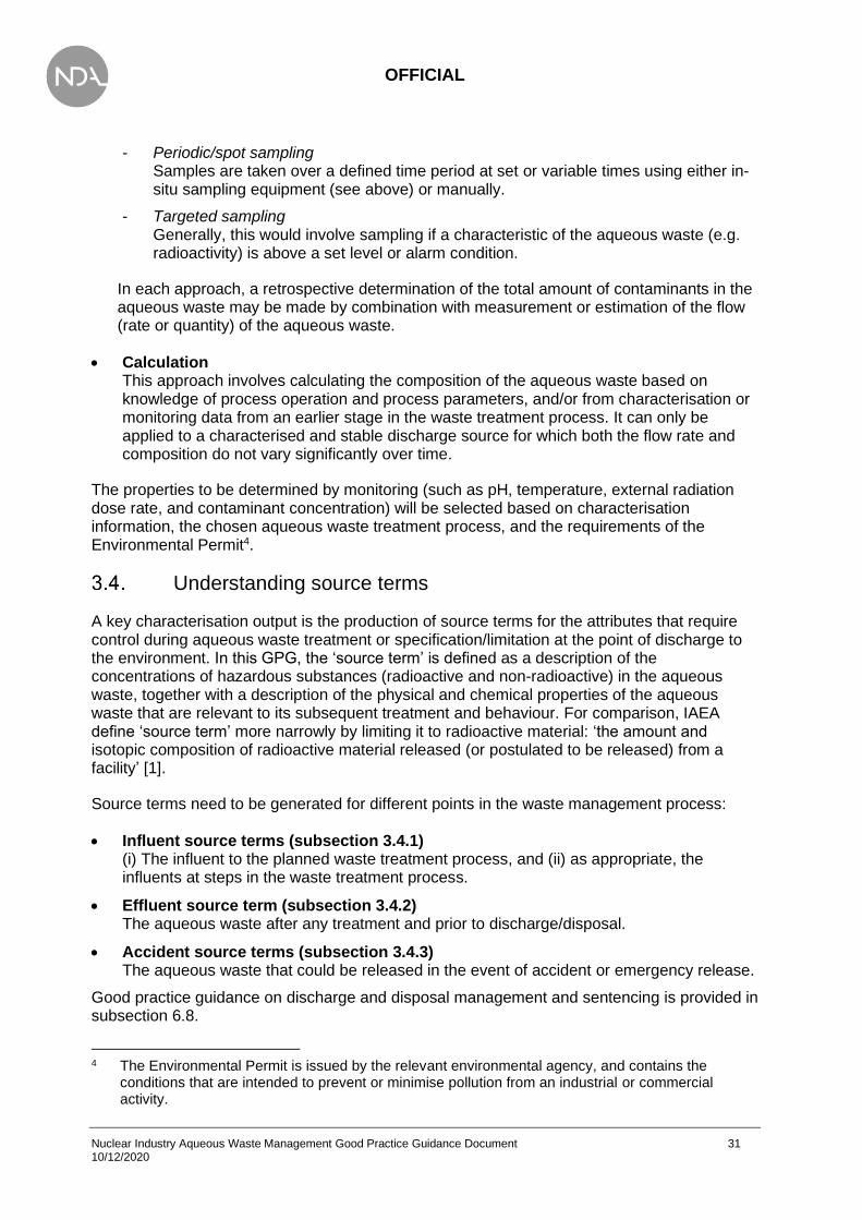
OFFICIAL
Nuclear Industry Aqueous Waste Management Good Practice Guidance Document 31 10/12/2020
- Periodic/spot sampling Samples are taken over a defined time period at set or variable times using either in-situ sampling equipment (see above) or manually.
- Targeted sampling Generally, this would involve sampling if a characteristic of the aqueous waste (e.g. radioactivity) is above a set level or alarm condition.
In each approach, a retrospective determination of the total amount of contaminants in the aqueous waste may be made by combination with measurement or estimation of the flow (rate or quantity) of the aqueous waste.
• Calculation This approach involves calculating the composition of the aqueous waste based on knowledge of process operation and process parameters, and/or from characterisation or monitoring data from an earlier stage in the waste treatment process. It can only be applied to a characterised and stable discharge source for which both the flow rate and composition do not vary significantly over time.
The properties to be determined by monitoring (such as pH, temperature, external radiation dose rate, and contaminant concentration) will be selected based on characterisation information, the chosen aqueous waste treatment process, and the requirements of the Environmental Permit4.
Understanding source terms
A key characterisation output is the production of source terms for the attributes that require control during aqueous waste treatment or specification/limitation at the point of discharge to the environment. In this GPG, the ‘source term’ is defined as a description of the concentrations of hazardous substances (radioactive and non-radioactive) in the aqueous waste, together with a description of the physical and chemical properties of the aqueous waste that are relevant to its subsequent treatment and behaviour. For comparison, IAEA define ‘source term’ more narrowly by limiting it to radioactive material: ‘the amount and isotopic composition of radioactive material released (or postulated to be released) from a facility’ [1].
Source terms need to be generated for different points in the waste management process:
• Influent source terms (subsection 3.4.1) (i) The influent to the planned waste treatment process, and (ii) as appropriate, the influents at steps in the waste treatment process.
• Effluent source term (subsection 3.4.2) The aqueous waste after any treatment and prior to discharge/disposal.
• Accident source terms (subsection 3.4.3) The aqueous waste that could be released in the event of accident or emergency release.
Good practice guidance on discharge and disposal management and sentencing is provided in subsection 6.8.
4 The Environmental Permit is issued by the relevant environmental agency, and contains the
conditions that are intended to prevent or minimise pollution from an industrial or commercial activity.

OFFICIAL
Nuclear Industry Aqueous Waste Management Good Practice Guidance Document 32 10/12/2020
Box 3-2 lists the main aqueous waste management activities that require an understanding of the source term. If the source term is incorrectly defined, there may be significant impacts to some or all of the safety of workers and the public, the environment, and subsequent steps in the aqueous waste treatment process.
Box 3-2 Why are source terms required?
Source terms support the following activities:
• Categorisation and minimisation of aqueous waste.
• Selection of appropriate aqueous waste treatment processes that ensure operational safety (ALARP) and process optimisation (ALARA/BAT/BPM).
• Capacity planning.
• Aqueous waste treatment plant design. For example:
− Shielding Assessment and design
− Dose Uptake Assessment
− ALARP Assessment
− Criticality Control. Attention needs to be paid to the potential for fissile radionuclides to be concentrated during the treatment process, for example in sludges
− Assessment of the potential and consequence of radiolysis (e.g. gas generation, degradation of organic materials and the catalysis of some reactions)
• Calculation of environmental consequences of aqueous waste discharges and disposals and of disposal of any secondary solid wastes generated.
• Determine consequences of accidents or accidental releases.
• Transport Assessment for aqueous waste transfers.
Influent source terms
Influent source terms could require characterisation of radiological, chemical, physical and, in some instances, biological properties. Monitoring of influent source terms will enable the variability of the source term to be established. An understanding of how solid or sludge waste interacts with supernate (i.e. aqueous waste) during waste retrieval operations may also be required. In this case, characterisation of the sludge, solid waste, and fuel alongside knowledge of its behaviour is essential. See [33] for guidance on the characterisation of solid radioactive waste.
3.4.1.1. Radiological properties
Box 3-3 presents typical radionuclides found in aqueous wastes produced on nuclear sites. Characterisation is particularly important for radionuclides that have high radiological impact (e.g. actinides, Co-60, Sr-90 and Cs-137), as a high degree of treatment may be necessary (depending on initial concentrations) for aqueous waste streams containing these radionuclides.

OFFICIAL
Nuclear Industry Aqueous Waste Management Good Practice Guidance Document 33 10/12/2020
Box 3-3 Types of radionuclides present in aqueous waste streams (from [36])
The radionuclides present in aqueous wastes produced on nuclear sites can be categorised as follows:
• Fission products The most notable are caesium and strontium (Cs-137 and Sr-90). A range of other fission products such as ruthenium (Ru-106) and technetium (Tc-99) may be present.
• Activation products These are formed by neutron activation of reactor materials, particularly structural steels, moderator materials and fuel cladding. The most radiologically significant is cobalt (Co-60).
• Actinides Uranium used as a nuclear fuel is an actinide. The most important actinides present in fuel after reactor operation are the isotopes of plutonium (e.g. Pu-239 and Pu-241) and americium (Am-241).
• Tritium Tritium (H-3) is formed as a ternary fission product in nuclear fuels or by neutron activation of impurities (mainly lithium) in a reactor moderator. Most tritium in PWRs is generated from neutron interactions with boric acid.
The different chemical and physical forms (or species) in which these radionuclides appear in an aqueous waste dictate the treatment methods required for their removal.
• Radionuclides as ions in aqueous solution These include simple ions (e.g. Cs+ or I-) and complex species (e.g. U(CO3)22+). The properties of the ionic species affect treatment methods involving ion exchange or precipitation.
• Radionuclides in particulate form These may be individual particles or agglomerates. Particulates range from large, readily settling particles to colloidal (non-settling) material which may not be readily removable by filtration. Radionuclides may be incorporated in particles by activation or by contamination. For the latter, it may occur through co-precipitation (e.g. in ferric oxyhydroxides) or by sorption onto particle surfaces.
• Tritium, usually as tritiated water It should be recognised that there are no commercial processes available for the removal of tritium from low level aqueous waste streams.
• Gases held in solution The solubilities of these gases depend primarily on conditions of temperature and pressure, and also on factors such as turbulence. Decreased pressure, increased temperature or more turbulence all result in release of gases from solution.
3.4.1.2. Physical properties
The physical properties of an aqueous waste will have a significant impact on the choice and performance of treatment process. Important physical properties are listed below (based on Table 2.2 from [37]).
OFFICIAL
Nuclear Industry Aqueous Waste Management Good Practice Guidance Document 34 10/12/2020
• Volume/rate of arising Determines the size of a new treatment facility and the nature (continuous, batch, intermittent) of the process. Alternatively, the size of an existing treatment facility would be used to dictate the flow rate.
• Density Stratification can result if aqueous waste streams with differing densities are not adequately mixed. This can affect the performance of liquid transfer systems. For mixed aqueous – NAPL waste (e.g. water – oil), the density of the NAPL will influence the ‘separability’ of the two fluids and the design of a separation process, for example whether the NAPL floats or sinks in the aqueous layer.
• Rheology Relevant for sludges, slurries and NAPLs, and affects the selection of pumping, solid settling, and filtration techniques. Reference [33] provides guidance on characterisation of radioactively contaminated sludges.
• Electrical conductivity Indicates the dissolved salt content of an aqueous liquid. If high, this could preclude some treatments such as the use of ion exchange.
• Suspended solids The size, shape, density and surface adsorption properties of particles dictate their behaviour in treatment systems. For example, particle size dictates the grades of filter required to remove them from the waste stream; size and density affect time for them to settle out in tanks or in a centrifuge. Surface characteristics affect tendencies of particles to agglomerate or stick to surfaces under different chemical conditions5. The surface adsorption properties will also determine how the particles react with radionuclides and chemicals present in the aqueous waste. See BS-EN-872 for further information.
• Turbidity Can indicate the level of suspended solids present, and the need for treatment (e.g. flocculation). However, note that turbidity is a measure of the ability to scatter light. It can be used to indicate the amount of suspended solid, but the relationship depends on the nature of the solid. Also, the presence of gas bubbles in a liquid will give a turbidity signal.
• Pressure This is normally equivalent to atmospheric pressure, but may be different for some treatment processes.
• Temperature Affects reaction rates and potential for volatilisation.
• Miscibility Relevant to mixed aqueous – NAPL waste. A NAPL that mixes with the aqueous phase will require a different process to those that separate readily. A mix of materials may result in colloids or emulsions that require treatment before the aqueous phase can be treated.
5 An understanding of particle characteristics is needed to understand: the need for mixing to keep
particles in suspension, flow conditions to achieve maximum settling, likelihood of settlement in tanks and pipework, the requirement for solids removal (e.g. settling filtration) prior to treatment, and the amounts of secondary sludges likely to be produced. Where particles are also radioactive, there is an additional reason to characterise non-radiological characteristics. For example, it can be important to understand the proportions of particulates and colloidal (non-settling) material.

OFFICIAL
Nuclear Industry Aqueous Waste Management Good Practice Guidance Document 35 10/12/2020
3.4.1.3. Chemical properties
The chemical properties of an aqueous waste will have a significant impact on the choice and performance of treatment process. Box 3-4 lists classes of hazardous chemical substances that may be found in aqueous wastes produced on nuclear sites.
Box 3-4 Types of hazardous non-radioactive substances present in aqueous waste streams
A wide range of hazardous non-radioactive substances may be present in aqueous wastes produced on nuclear sites. See Chapter 5 for further guidance on identifying, classifying and assessing hazardous waste properties. The list below is derived from [9]:
• Toxic or carcinogenic substances, such as trace metals;
• Oxidising or flammable substances;
• Corrosive substances, such as acids and bases;
• Persistent organic pollutants, such as solvents used in the waste treatment process. Examples are organohalogens and tributyl phosphate (TBP) in odourless kerosene; and
• Hydrocarbons, such as process oils and hydraulic fluids.
Control of these substances is covered by other EPR permits (installations, water discharge etc.).
Important chemical parameters are listed below (based on Table 2.3 from [37]).
• Chemical composition This is generally a primary factor in selecting an appropriate treatment process and any influent pre-conditioning process. It is likely to require understanding of major cations and anions but may also need understanding of the presence of (for example) minor ions or chelating agents, which may affect contaminant behaviour. Chemical composition is required to understand some or all of the following:
- toxicity of the waste, to ensure adequate protection to workers and the environment;
- reactivity if wastes are mixed. Undesirable chemical reactions include release of toxic gases, volatilisation resulting from temperature change, and the generation of bulk gases that could rupture containers through pressurisation;
- chemical stability. Degradation of constituents in the waste could produce solids, release gases or result in other changes that could complicate waste treatment;
- potential for the production of radioactive gases or volatiles (e.g. containing I-129 or C-14) as a result of change to pH;
- potential for complexation of contaminants with chelating agents, which could reduce the effectiveness of the treatment processes for removing contaminants from the aqueous waste;
- presence of surfactants such as glycol or hydrocarbons. Surfactants affect the likelihood of foaming or wetting and may interfere with some waste treatment techniques. See Box 3-5;

OFFICIAL
Nuclear Industry Aqueous Waste Management Good Practice Guidance Document 36 10/12/2020
- the organic content of the aqueous waste, including identifying the potential presence of NAPL. Aqueous wastes may need to be treated to reduce concentrations of dissolved organics or separate NAPLs.
• pH and pH buffering capacity pH is important both to the containment facilities and the aqueous waste treatment process. pH adjustment requires understanding of pH buffering capacity and may affect solubility and/or speciation of dissolved ions, including contaminants. Acids and alkalis are hazardous and will require careful handling.
• Hardness (presence of Ca2+ and Mg2+) / alkalinity Hardness of water supply (‘feed water’ or ‘clean water’) used in the treatment process is often relevant for ion exchange processes. Alkalinity is a measure of the resistance of a solution to changes in pH and affects pH buffering capacity.
• Redox potential / Eh Redox potential / Eh determines speciation and the behaviour of redox-sensitive elements in the aqueous waste. May also be important when waste streams are mixed, as unwanted chemical reactions or precipitation could result.
• Chemical oxygen demand (COD) The amount of oxygen required to completely oxidise all inorganic and organic components of the solution. This is an important parameter in redox treatments. Note that TOC can be used as an alternative parameter in some applications.
• Total dissolved solids/dry residue Important for evaporative processes.
• Biological oxygen demand (BOD) Although this is a biological measurement, it is used to identify the presence of organic compounds (a class of chemical contaminant) within the aqueous waste.
Box 3-5 Surfactants in aqueous waste
Surfactants can serve a variety of purposes, such as collapsing suspensions or colloids to promote settlement. However, surfactants can influence other processes and, consequently, their use in any treatment process requires care and planning to minimise the impact upon other treatment options. Several of the techniques described within this guidance are used to treat an aqueous phase, and a surfactant may interfere with their correct operation. For example:
• surfactants can inhibit ion transfer processes, including ion exchange and membranes, substantially reducing their performance. This is probably the most important aspect to consider;
• a surfactant that causes undesirable foaming could interfere with level control instrumentation, contaminate ventilation systems, and potentially affect pump performance;
• techniques that rely on evaporation of water may demonstrate a change in performance because of the change in surface tension caused by surfactants.

OFFICIAL
Nuclear Industry Aqueous Waste Management Good Practice Guidance Document 37 10/12/2020
3.4.1.4. Biological properties
The presence of organic material in the aqueous waste may lead to high BOD, which might affect treatment processes6. ‘Biofouling’ of filters or membranes and the accumulation of biofilms in pipe and vessels may also occur. Infectious or bio-toxic hazards may require a specific treatment step. For any or all these reasons, it may be appropriate to characterise the biological properties of aqueous wastes and suppress this biological activity as necessary.
Effluent source term
This section is concerned with aqueous waste after treatment and prior to/during discharge or disposal. The annex of IAEA General Safety Guide GSG-9 [38]) identifies that the effluent source term, prior to environmental discharge, could require characterisation of the following:
• the industrial process or activity and the assumptions made about the discharges it generates;
• radionuclide composition and chemical/physical form of the radionuclides. The latter is required to understand subsequent behaviour in the environment. These are also typically required characteristics of the influent (see subsection 3.4.1.1);
• chemical properties of the waste, such as concentrations of hazardous chemical substances, concentrations of non-hazardous chemical pollutants, electrical conductivity, and pH. These are also typically required characteristics of the influent (see subsection 3.4.1.3);
• physical properties of the waste, such as temperature, turbidity and suspended solids These are also typically required characteristics of the influent (see subsection 3.4.1.2);
• biological properties of the waste, such as BOD. These are also typically required characteristics of the influent (see subsection 3.4.1);
• routes of discharge and discharge points, including aspects such as exit velocity, and maximum and average discharge rates;
• the total amount of the various radionuclides expected to be discharged in one year;
• the expected time pattern of discharge, including the need for and likelihood of increased short-term discharges if a constant release rate cannot be assumed. Subsection 6.5 provides guidance on this.
The parameters to be monitored are typically associated with the acceptance criteria for the discharge permit/consent as issued and governed by the relevant environment agency with the additional requirement that BAT/BPM is applied to prevent and/or minimise discharges. Box 3-6 presents typical aqueous effluent impurities that are subject to discharge consent / permit. Monitoring data should be assessed to identify any time-dependent and weather-dependent trends in the monitored parameter values. Criteria for assessment of results will have been identified so that results that are not in line with expectations can be identified and appropriate actions initiated.
6 A wide range of organic debris may be found in aqueous waste, including plastics, paper, dead
animals, plant remains (including algae) and fish.
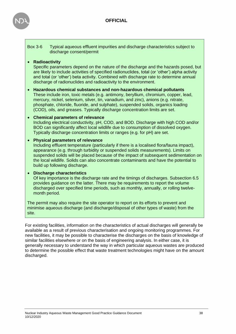
OFFICIAL
Nuclear Industry Aqueous Waste Management Good Practice Guidance Document 38 10/12/2020
Box 3-6 Typical aqueous effluent impurities and discharge characteristics subject to discharge consent/permit
• Radioactivity Specific parameters depend on the nature of the discharge and the hazards posed, but are likely to include activities of specified radionuclides, total (or ‘other’) alpha activity and total (or ‘other’) beta activity. Combined with discharge rate to determine annual discharge of radionuclides and radioactivity to the environment.
• Hazardous chemical substances and non-hazardous chemical pollutants These include iron, toxic metals (e.g. antimony, beryllium, chromium, copper, lead, mercury, nickel, selenium, silver, tin, vanadium, and zinc), anions (e.g. nitrate, phosphate, chloride, fluoride, and sulphate), suspended solids, organics loading (COD), oils, and greases. Typically discharge concentration limits are set.
• Chemical parameters of relevance Including electrical conductivity, pH, COD, and BOD. Discharge with high COD and/or BOD can significantly affect local wildlife due to consumption of dissolved oxygen. Typically discharge concentration limits or ranges (e.g. for pH) are set.
• Physical parameters of relevance Including effluent temperature (particularly if there is a localised flora/fauna impact), appearance (e.g. through turbidity or suspended solids measurements). Limits on suspended solids will be placed because of the impact of subsequent sedimentation on the local wildlife. Solids can also concentrate contaminants and have the potential to build up following discharge.
• Discharge characteristics Of key importance is the discharge rate and the timings of discharges. Subsection 6.5 provides guidance on the latter. There may be requirements to report the volume discharged over specified time periods, such as monthly, annually, or rolling twelve-month period.
The permit may also require the site operator to report on its efforts to prevent and minimise aqueous discharge (and discharge/disposal of other types of waste) from the site.
For existing facilities, information on the characteristics of actual discharges will generally be available as a result of previous characterisation and ongoing monitoring programmes. For new facilities, it may be possible to characterise the discharges on the basis of knowledge of similar facilities elsewhere or on the basis of engineering analysis. In either case, it is generally necessary to understand the way in which particular aqueous wastes are produced to determine the possible effect that waste treatment technologies might have on the amount discharged.

OFFICIAL
Nuclear Industry Aqueous Waste Management Good Practice Guidance Document 39 10/12/2020
Accident source terms
LC34 requires containment so far as reasonably practical irrespective of postulated consequences – to ensure control of nuclear material. Notwithstanding this, fault scenarios that could result in the unplanned release of aqueous waste, such as loss of containment or the emergency release of aqueous waste, should be identified. In addition, it should be recognised that loss of aqueous material may have broader impacts, such as loss of cooling or shielding (from water cover). However, such fault scenarios are considered outside the scope of this guidance.
The accidental or emergency release of aqueous waste into the environment (the ‘accident source term’) should be developed based on the relevant fault scenario. It is likely to be determined in terms of a fractional release using an existing radionuclide and hazardous chemical fingerprint. In these cases, the influent or effluent source term is used, together with a best estimate or range for the proportion of the source term released in the accident, to derive an accident source term. However, if the fault scenario results in fractionation of hazardous materials (e.g. radionuclides or hazardous chemical contaminants) into the released aqueous waste, this should be recognised when deriving the accident source term.
In the event of the accidental or emergency release of aqueous waste into the environment, the waste practitioner will be expected to produce a total activity loss estimate at short notice based on the volume and unit activity concentration. This underscores the need for regular process monitoring.
Water supply and chemicals added to the process water
Significant issues have occurred in the nuclear industry in the past because of inadequate characterisation and monitoring of the water supply (‘feed water’ and ‘process water’) or the poor specification and/or control of chemicals added to process water.
Inappropriate physical, chemical or biological composition/characteristics of feed water or process water can result in reduced waste treatment efficiency, potentially leading to a breach in the discharge consent. Characteristics/properties relevant to aqueous waste management are described in subsection 3.4.1. The required characterisation will depend on:
• the nature of the water supply. For example, ‘towns’ water supply, which will generally have been pre-treated to make it potable (e.g. by addition of chlorine), or ‘raw’ water, which comprises untreated water from the environment such as rainwater, surface water or groundwater; and
• the aqueous waste treatment processes under consideration. This would include characterisation of constituents in the feed/process water that could interact with contaminants in the waste or with chemical additives (e.g. through the formation of soluble complexes with radionuclides or through reduction or oxidation reactions) or that could foul or reduce the efficiency of membranes and resins.
Such characterisation would enable pre-treatment of the water supply, if necessary, to ensure the assumed ‘feed water’ condition to the water treatment plant is met. Subsequent monitoring would enable the stability of the feed water or process water to be determined.
Water treatment technologies are described in Appendix 2. Many can be used on both feed water/process water and aqueous waste streams. The technique-specific datasheets in Appendix 2 identify required physical and chemical characteristics of input water and, where
OFFICIAL
Nuclear Industry Aqueous Waste Management Good Practice Guidance Document 40 10/12/2020
appropriate, sub-divide the discussion into ‘feed water’ and ‘aqueous waste’. Examples where feed water may require pre-treatment include removal of suspended solids, chemical reduction of chlorine and reducing the hardness/alkalinity or COD of the water supply.
With regards to dosing of process water, issues have arisen with the corrosion of spent fuel, which has both safety and environmental implications. An historical example of inappropriate specification of chemicals added to process water was the use of NaOH with elevated chloride concentrations for caustic dosing of fuel storage pondwater [39]. Elevated chloride concentrations are known to substantially increase the rate of Magnox corrosion, which in turn is likely to lead to increased rate of fuel dissolution. To ensure such incidents do not occur in the future, it is important that the composition of chemicals to be added to the process water should be specified by a suitably qualified and experienced plant chemist or chemical engineer. This should ensure that the chemicals subsequently used in the plant do not contain components that could be detrimental to the aqueous waste management process.
Planning for characterisation and monitoring
Data quality objectives
The United States Environmental Protection Agency (EPA) Data Quality Objectives (DQO) process [40] is a systematic planning tool to determine the type, quantity and quality of data needed to support decisions. The DQO process was developed to guide the cost-effective and resource-effective acquisition of environmental data. It has since been adapted for use in the nuclear industry in many countries, including the UK, for a wider range of tasks.
There is no formal requirement to use DQO. However, for planning characterisation and monitoring, it is good practice to use a systematic process such as DQO to determine the information required and the best approach to acquiring that information.
The benefit of applying DQO is that it should ensure waste management decisions are made consistently on the basis of sufficient and appropriate data. For example, the number of samples that are needed to characterise or monitor wastes to an agreed level of confidence is determined, which means that the effort and expense of sampling and analysis is minimised and justifiable.
It is not the intention of this GPG to provide detailed guidance on characterising or monitoring aqueous radioactive waste. Guidance consistent with DQO is already available for both activities. For characterisation, the reader is recommended to follow the principles and approach for characterising solid radioactive waste as described in Section 4 of [33].
Figure 3-3 illustrates the waste characterisation planning process recommended in [33]. Much of the structure and guidance is also relevant to characterising aqueous waste. For monitoring (see Figure 3-4), the reader is referred to the process map and supporting guidance in Box 1.2 of the NICoP for routine water quality monitoring [34]. Although aqueous waste is not within the scope of that NICoP, much of the document is also relevant for aqueous waste.

OFFICIAL
Nuclear Industry Aqueous Waste Management Good Practice Guidance Document 41 10/12/2020
Figure 3-3 Overview of the waste characterisation planning process, reproduced from [33].
Figure 3-4 Overview of the waste monitoring planning process, adapted from [34]
Step 5. Is further characterisation information required to meet the characterisation objective?
Step 6. Develop the approach for characterising the waste
Step 4. Review and evaluate existing information
Step 8. Produce the documentation for waste characterisation
Step 7. Refine the boundaries of the study if appropriate. Repeat earlier steps as necessary
Step 1. State the problem and identify the key stakeholders
Step 2. Identify the characterisation objective
YesNo
Step 3. Determine the information required to achieve the characterisation objective
No YesIs further characterisation
needed?
Step 4. Determine the frequency and duration of monitoring
Step 1. Define monitoring objectives
Step 2. Determine monitoring locations
Step 3. Determine the analytical suite

OFFICIAL
Nuclear Industry Aqueous Waste Management Good Practice Guidance Document 42 10/12/2020
Some points of good practice for characterising and monitoring aqueous waste under planned operating conditions, and for collecting samples of aqueous waste, are given in the following subsections. Signposting to existing guidance is given where appropriate. Subsection 6.9 provides guidance on emergency response preparedness.
Characterisation
• Steps 1 and 2: State the problem and Identify the characterisation objective. The principal objectives for characterising aqueous waste are summarised in subsection 3.2.2; these should be referred to in developing problem statements and characterisation objectives. Also, see subsections 4.2 and 4.3 of Reference [33].
• Step 3: Determine the information required to achieve characterisation objective. Box 3-2 describes why an understanding of source terms is required. Box 3-3 and Box 3-4 describe the classes of hazardous substances that might be present in aqueous wastes relevant to this GPG. Subsections 3.4.1 to 3.4.3 describe the information required to characterise aqueous waste source terms. From these sources of information, and an understanding of the range of potentially suitable waste management options (see Chapter 5), it will be possible to define the information required to achieve the characterisation objective. It should be recognised that it will often be necessary to characterise solid wastes and sludges in order to estimate the compositions of aqueous wastes produced during future upstream processes and waste processing (pre-treatment, treatment and conditioning) operations; see Figure 1.1 of [33]. See subsection 4.4 of Reference [33], which includes guidance on developing questions that may be useful to help identify what characterisation information will be required. A useful final check is to confirm that each piece of information collected will be used in decision-making or in building the required understanding of the waste. If the information will not change the approach or decision, it should not be collected.
• Steps 4 and 5: Review and evaluate existing information and decide if additional information is required to meet the characterisation objective. This information should be reviewed and evaluated to determine whether it is of sufficient quality and quantity, and from suitable locations, to meet the characterisation objective. An understanding of acceptable uncertainty in the aqueous waste characteristics will be required to achieve this. Section 5 of Reference [33] provides guidance on the review and evaluation of existing information.
• Step 6: Develop the approach for collecting new information to characterise the waste. Approaches for collecting new information to characterise aqueous waste are described in subsection 3.3.1. The selection of an appropriate characterisation approach, or combination of approaches, to characterise solid radioactive waste, is discussed in subsection 4.7 of [33]. Most of the principles and issues are also relevant to the characterisation of aqueous waste. They include:
- the ease of obtaining aqueous waste samples (e.g. ease of access to install and maintain instrumentation and sampling equipment, or to take spot samples) and hazards/risks to workers during manual sample collection; and
- the practicability of measuring the required determinand (see [33] for further detail) at the required limit of detection through non-destructive analysis or on-line instrumentation. It should be recognised that the required limit of detection will depend on the characterisation objective. It is generally the case, particularly with non-radioactive determinands and with radionuclides that are not gamma-emitters, that significantly better limits of detection are achieved through laboratory analysis than through on-line analysis.

OFFICIAL
Nuclear Industry Aqueous Waste Management Good Practice Guidance Document 43 10/12/2020
• Steps 7 and 8: Refine the boundaries of the study, if appropriate, and produce the documentation for waste characterisation. Subsections 4.8 and 4.9 of [33] provide guidance on these subjects. All the guidance is relevant to the characterisation of aqueous waste.
Monitoring
3.6.3.1. Process monitoring
A key step in designing a process monitoring programme is to select parameters that provide information on the performance of the waste treatment process; see subsection 3.3.2 for further discussion. It is then necessary to determine the required limit of detection and to select an appropriate approach (see subsection 3.3.2) for collecting the data. Surrogate measurements should be considered (for both process and discharge monitoring) if it is not practicable to directly measure the determinand of interest at the required detection limit. The surrogate needs to have a stable relationship with the determinand (i.e. in a constant and known ratio) it is being used to replace; checks should be carried out periodically to ensure that the relationship has not changed.
An important consideration for monitoring is the time required to make the measurement. For laboratory analysis, this may be a significant constraint if the time is so long that it disrupts the operation of the water treatment plant. Longer measurement timescales may be tolerable for batch or intermittent treatment process, but not for continuous processes. For process monitoring on new waste treatment facilities (‘blank canvas’ scenario), live process monitoring and adjustment should be encouraged as part of good practice to effectively utilise the process units for treatment.
3.6.3.2. Discharge monitoring
The discharge monitoring system and monitoring schedule should be proportionate to the risk impact of the aqueous discharge, the complexity of the processes and potential for failure and unplanned releases. For example, continuous proportional samplers with on-line instrumentation are likely to be used where risks and consequences are highest, for example to detect faults in treatment plants with large radionuclide inventories. In contrast, periodic or spot sampling is likely to be used where risks and consequences are lower. Examples are discharges from facilities with smaller radionuclide inventories and discharges from plants with larger inventories during normal operations where there is confidence that the influents are tightly managed and the treatment process is well characterised and stable.
The Environment Agency (EA) has developed a number of Monitoring Certification Scheme (MCERTS) standards and specifications, which are described and referenced in Box 3-7. RSR and Environmental Permits require the site operator to have MCERTS for a range of measurements.

OFFICIAL
Nuclear Industry Aqueous Waste Management Good Practice Guidance Document 44 10/12/2020
Box 3-7 MCERTS
EA has developed a number of Monitoring Certification Scheme (MCERTS) standards and specifications. Relevant MCERTS standards are given below.
• Minimum requirements for the self-monitoring of effluent flow [41].
• Performance standards and test procedures for continuous water monitoring equipment. Part 1 Performance standards and test procedures for automatic water sampling equipment [42].
• Performance standards and test procedures for continuous water monitoring equipment. Part 2 Performance standards and test procedures for on-line monitors [43].
• Performance standards and test procedures for continuous water monitoring equipment. Part 3 Performance standards and test procedures for water flowmeters [44].
• Performance standards and test procedures for portable water monitoring equipment [45].
• Performance standard for organisations undertaking radio-analytical testing of environmental and waste waters [46].
• Performance standard for organisations undertaking sampling and chemical testing of water. Part 1 – Sampling and chemical testing of untreated sewage, treated sewage effluents and trade effluents [47].
Sampling
Most approaches to characterising or monitoring aqueous waste involve the collection of samples. Sample collection techniques are chosen based on the application (e.g. sampling from static or flowing water; sampling at surface or at depth in a water column) and on the hazards posed by the waste / material, its surroundings and the sampling equipment. Sampling may be undertaken manually or using automated processes. Typically, the sampling process is automated for high frequency and high radiation samples.
Key aspects are introduced below, with referencing to existing guidance documents where appropriate.
• Sampling lower activity aqueous waste. Hand-held devices such as dippers, syringe samplers or swing samplers can be used to collect discrete samples of lower activity wastes from close to the water surface. Peristaltic pumps, air- or vacuum-operated lifts and various types of bailers can be used to manually collect samples of lower activity from greater depth in a water column. For example, representative samples are taken from spent fuel ponds with good circulation using grab/dip samples at multiple positions in the pond. Fixed sampling points are used for manual collection of samples where frequent sampling is required, such as prior to the discharge of aqueous waste into the environment. Automated samplers can be used in monitoring programmes for continuous sampling (time proportional or flow proportional), periodic/spot sampling or targeted sampling. See subsection 3.3.2 for further information.

OFFICIAL
Nuclear Industry Aqueous Waste Management Good Practice Guidance Document 45 10/12/2020
• Sampling higher activity aqueous waste. Characterisation or monitoring of higher activity liquid waste typically involves automated collection of small samples inside shielded containers. A range of techniques is available to collect ‘liquid only’ samples or ‘slurry-liquid’ samples, including vacuum-operated slug lifts and dip samplers. Further guidance is given in [48]. Although the guidance is written for high-level radioactive waste, many of the techniques are also applicable to higher activity aqueous wastes considered in this guidance document. Sampling may be discrete or continuous. After collection, the aqueous waste sample is typically transferred in the shielded container to an on-site analytical testing laboratory licensed to handle such materials. The sample is then prepared for analysis in a glovebox or fume cupboard, depending on the hazard, prior to analysis of a representative subsample.
• Collecting representative samples. IAEA TECDOC-1537 (The Strategy and Methodology for Radioactive Waste Characterization) [49] states that the sampling process must be able to mix the waste to obtain representative samples at the sample point, and to transfer representatively both the sample and waste to the next unit operation. Care must be taken to avoid cross-contamination in sample lines, to avoid incomplete sampling (e.g. needles excluding solids that may be of interest) and to avoid perturbation of samples during collection (e.g. degassing or pH perturbation during vacuum- or air-operated lifts). The design of some storage tanks also allows for the agitation of tank contents to help obtain representative liquid samples.
• Sample preservation. Substantial guidance is available on the preservation of water samples for environmental analysis. For example, see Section 8 of [34]. Much of this guidance is also relevant to radioactive aqueous waste. It is often appropriate to collect and appropriately preserve a number of subsamples for the different analyses required. For example, samples for analysis of radioactive isotopes of iodine or carbon should not be acidified, as this causes volatilisation of these components.
• Chain of custody. A pro-forma Chain of Custody (CoC) should accompany samples and provide instructions to the analytical testing laboratory. Guidance on CoCs is given in subsections 11.4 and 11.5 of [34] and subsection 10.3.9 of [33].
• Quality Plan and a Sampling and Analysis Plan. A Quality Plan and a Sampling and Analysis Plan should be prepared for the sampling and analysis activities. Guidance for solid radioactive wastes is given in subsections 3.3 and 10.2.4 of [33]. Most of this guidance is also relevant to radioactive aqueous waste.
• SQEP and training requirements for samplers. Box 10-4 in [33] lists the competencies required by personnel involved in sampling solid radioactive waste. The same requirements apply to the sampling of radioactive aqueous waste.

OFFICIAL
Nuclear Industry Aqueous Waste Management Good Practice Guidance Document 46 10/12/2020
Summary
Box 3-8 Key good practice points for characterisation and monitoring
• Understand the distinction between characterisation and monitoring and their purposes, and recognise where in the aqueous waste management process they are necessary.
• Ensure that the requirements of environmental regulators (for example: ALARA using BAT/BPM, limits, permits) and ONR (for example: ALARP, Licence Conditions) are understood.
• Recognise that characterisation or monitoring of waste should always be undertaken for a purpose. Define the characterisation or monitoring objectives before designing the monitoring or characterisation programme.
• Use a systematic process for planning characterisation and monitoring activities, to ensure the objectives are achieved in the most efficient manner. Guidance is given in this chapter; relevant guidance can also be found in [33], [34] and [50].
• Understand the constraints of the aqueous waste treatment and discharge process on required turnaround of analytical measurements. Select appropriate analytical approaches accordingly.
Box 3-9 Key pitfalls in characterisation and monitoring
• The key pitfall concerns incorrect or inadequate definition of the source term (as influent waste, at stages during the treatment process, and at discharge into the environment). If the source term is incorrectly defined, there may be significant impacts to some or all of: the safety of workers and the public, the environment, and subsequent steps in the aqueous waste treatment process.
• Inappropriate approach to characterisation or monitoring, leading to objectives not being addressed or fully achieved. Examples are: taking of unrepresentative samples; inappropriate limits of detection, and long analysis turnaround times impacting on treatment or discharge process.
• Failure to account for uncertainties and/or omissions in characterisation or monitoring information. This would include a failure to take into account changes in the upstream process/waste which lead to changes in the aqueous waste. In the case of influent aqueous waste, this can lead to inappropriate or incomplete choice of waste treatment technique; for example, not recognising the need for settling to remove suspended solid. This can also lead to failure to identify, assess, and manage hazards and risks from the waste.
• Characterising only for radiological properties and not considering physical/chemical properties of the aqueous waste or presence and concentrations of hazardous non-radioactive substances. This is likely to produce inadequate information for selection and design of appropriate waste management techniques.

OFFICIAL
Nuclear Industry Aqueous Waste Management Good Practice Guidance Document 47 10/12/2020
4. How to avoid generating aqueous waste
Box 4-1 Aims of Chapter 4
This chapter provides the aqueous waste practitioner with considerations and examples of how to avoid generating aqueous waste in the first instance. The chapter also discusses methods to minimise, re-use, and recycle aqueous wastes.
The methods discussed acknowledge three different scenarios that an aqueous waste practitioner may be starting from: building a new plant, operating/modifying an existing plant, and re-use of an existing plant.
As outlined in the NDA’s Radioactive Waste Strategy [51], a waste practitioner should look to avoid generating waste wherever possible. This follows the principle of the waste hierarchy, depicted in Figure 4-1, in which waste prevention is the preferred approach for any given scenario.
Figure 4-1 The waste hierarchy depicting the preferred approach to waste management.
If waste generation is unavoidable, so far as is reasonably practicable, then the practitioner should look at minimisation, re-use of materials, and recycling to reduce volumes of waste where possible. Only if aqueous waste cannot be prevented, minimised, reused, recycled, or recovered should it be disposed of into the environment, and this must only be undertaken in a controlled and authorised manner. The principles of the waste hierarchy are summarised in a Good Practice Guide for the Application of the Waste Hierarchy [52].

OFFICIAL
Nuclear Industry Aqueous Waste Management Good Practice Guidance Document 48 10/12/2020
It is generally preferable to generate a solid radioactive waste rather than an aqueous radioactive waste where reasonably practicable, as per the concentrate and contain principle [53]. A solid waste form will contain the waste in a well-defined, manageable form that generally prevents dispersal into the environment and allows radioactive decay to minimise any impact.
Radioactive gaseous waste is the least preferable waste form due to rapid and easy dispersal in the environment. However, where the BAT/BPM and ALARP arguments allow, aqueous waste may be converted to solid waste by evaporation to dryness. However, evaporation of aqueous wastes can lead to radionuclides (e.g. tritium) being released into the environment. Considerations of which waste form is preferential should take account not only of the qualities of the waste, but also the potential benefits and detriments of the processes that give rise to/may treat the waste.
Factors to consider and the practicability of a solution will depend, in part, upon whether the aqueous waste practitioner is designing a new plant, operating or modifying an existing plant, or re-using an existing plant. However, in all eventualities, a holistic solution should be sought that carefully considers all wastes that may be produced and any issues that may affect other facilities or plant on the site.
Sustainable water and aqueous waste management
Building on the success of the waste management hierarchy, Government strategy is placing greater emphasis on resources [54] (waste prevention) and seeking to redesign waste out of the system, using the zero-waste hierarchy [55]. This aligns with global aspirations for sustainability that recognises the role of the circular economy in decoupling resource use from growth in consumption. Sustainable water and aqueous waste management seeks to ensure the water use system (from supply and use to treatment, reuse, and dispersion as last resort) is as efficient and effective as possible, and does not compromise the needs of future generations.
By considering aqueous waste management process as an integral part of a water use system, and considering the environmental, social and economic impacts of the process, it is possible to realise significant benefits and outcomes across the entire system. Practitioners should consider water and aqueous waste management within this wider framework of sustainability to maximise benefits and minimise impacts. For example, the failure to consider in the early planning stage the potential upstream prevention/minimisation of aqueous waste volumes can result in the construction and operation of an oversized effluent treatment plant with avoidable detrimental environmental, social, and economic impacts.
If a site applies the waste hierarchy appropriately to aqueous wastes, they will also be consistent with the Government's policy objectives for sustainable water management.

OFFICIAL
Nuclear Industry Aqueous Waste Management Good Practice Guidance Document 49 10/12/2020
Figure 4-2 Sustainable water/aqueous waste management.
Methods to prevent or minimise aqueous waste generation
A whole life-cycle approach to aqueous waste management should be adopted. Where reasonably practicable, prevention or minimisation of aqueous waste should be considered before treatment. Prevention and minimisation can be achieved by selecting processes that minimise or eliminate water usage and generation of waste streams, as well as preventing or minimising the release of radioactive specifies into process water.
It is important to consider what the process water is used for, e.g. primary coolant, cooling water (reactors), cooling water/shielding (fuel ponds and some waste silos), reprocessing, encapsulation processes, waste retrieval, POCO, and/or decontamination.
Prevention
Prevention is almost always preferable to minimisation and treatment, consistent with any waste hierarchy implementation. Even generation of low activity materials has an associated cost, whether it be from received dose to operator or public, engineering requirements, or public perception. Prevention of radioactive aqueous effluent is most efficiently achieved at the design phase, with early engagement with stakeholders and a holistic, whole-life approach that considers all wastes, both liquid and solid, and optimises the overall site waste management strategy.
Preventing aqueous waste can also be achieved using the techniques described below, which are summarised in Box 4-2.

OFFICIAL
Nuclear Industry Aqueous Waste Management Good Practice Guidance Document 50 10/12/2020
Process material selection can play an important part in preventing the formation of radionuclides that would require subsequent management. This includes materials used to construct nuclear process plant and equipment, as well as materials used within the nuclear processes; both of which will, or may, come into contact with process waters which will become aqueous waste. Common methods would be to use materials that cannot be readily activated, or in which the activation products are short-lived. The use of durable materials is also important to avoid contamination entering the aqueous phase through processes such as abrasion and/or corrosion, e.g. use of zirconium.
Similarly, good engineering design can prevent or reduce activation products by avoiding shine paths or designing systems that utilise a second loop (e.g. for heat energy transfer processes). Also, ensuring design conditions are always maintained until end of life can prevent the generation of waste.
Where reasonably practicable, dry processes can be used to prevent the generation of liquid waste. In particular, dry decontamination processes are available, including swabs, carbon dioxide, grit blasting and strippable coatings. Consideration should also be given to dry (as opposed to wet) storage of nuclear fuel, materials and waste. Where possible avoiding wet floor washing and using dry methods in active areas prevents the generation of potentially radioactive aqueous waste, where this is possible considering hygiene restrictions. It should be recognised that there are conventional safety challenges associated with these techniques [53].
However, it is important to recognise that there is a substantial difference in the opportunity to accomplish "prevention" between a purpose-built operational system or enclosed process plant, compared with activities like decommissioning where decisions often have trade-offs. For example, a decommissioning cutting operation may use water to cool surfaces or equipment and help with dust suppression, or not use water and rely on a closed environment and air filtration systems. The types of waste produced will change based on the decisions taken.
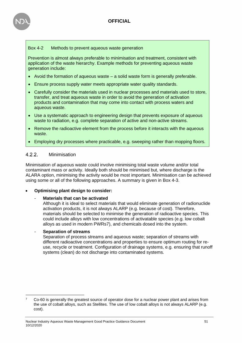
OFFICIAL
Nuclear Industry Aqueous Waste Management Good Practice Guidance Document 51 10/12/2020
Box 4-2 Methods to prevent aqueous waste generation
Prevention is almost always preferable to minimisation and treatment, consistent with application of the waste hierarchy. Example methods for preventing aqueous waste generation include:
• Avoid the formation of aqueous waste – a solid waste form is generally preferable.
• Ensure process supply water meets appropriate water quality standards.
• Carefully consider the materials used in nuclear processes and materials used to store, transfer, and treat aqueous waste in order to avoid the generation of activation products and contamination that may come into contact with process waters and aqueous waste.
• Use a systematic approach to engineering design that prevents exposure of aqueous waste to radiation, e.g. complete separation of active and non-active streams.
• Remove the radioactive element from the process before it interacts with the aqueous waste.
• Employing dry processes where practicable, e.g. sweeping rather than mopping floors.
Minimisation
Minimisation of aqueous waste could involve minimising total waste volume and/or total contaminant mass or activity. Ideally both should be minimised but, where discharge is the ALARA option, minimising the activity would be most important. Minimisation can be achieved using some or all of the following approaches. A summary is given in Box 4-3.
• Optimising plant design to consider:
- Materials that can be activated Although it is ideal to select materials that would eliminate generation of radionuclide activation products, it is not always ALARP (e.g. because of cost). Therefore, materials should be selected to minimise the generation of radioactive species. This could include alloys with low concentrations of activatable species (e.g. low cobalt alloys as used in modern PWRs7), and chemicals dosed into the system.
- Separation of streams Separation of process streams and aqueous waste; separation of streams with different radioactive concentrations and properties to ensure optimum routing for re-use, recycle or treatment. Configuration of drainage systems, e.g. ensuring that runoff systems (clean) do not discharge into contaminated systems.
7 Co-60 is generally the greatest source of operator dose for a nuclear power plant and arises from
the use of cobalt alloys, such as Stellites. The use of low cobalt alloys is not always ALARP (e.g. cost).
OFFICIAL
Nuclear Industry Aqueous Waste Management Good Practice Guidance Document 52 10/12/2020
- Corrosion control For materials containing activation and fission products (this includes process plant and equipment, feed materials used in nuclear processes, and stored nuclear fuel, materials, and waste), reducing the corrosion and abrasion rate will reduce the release of radionuclides into the water system. In addition, corrosion can release materials into the water system that can subsequently be activated in other parts of the system. For both these processes, control of the corrosion rate may be important in minimising aqueous waste but may introduce other (environmental) hazards, e.g. using hydrazine. It is important to consider a long term (preferably dry) storage or disposal route before the waste has started to corrode.
- Surface contamination The design of the plant can also have a significant impact on surface contamination caused by radionuclide build up on surfaces. Parameters such as surface finish have been shown to reduce the accumulation and corrosion rate (thereby reducing the generation of radionuclides) and also reduce the deposition of radionuclides onto a surface. This can be used to facilitate plant operation (e.g. reduces deposition of radionuclides in pipework) as well as facilitating decontamination if required. Note, however, that eventually impurities are likely to become incorporated into surface oxide layers (e.g. for stainless steel surfaces). Thus, the greatest benefit is obtained early in plant operation.
• The reduction of water use in a building Reducing the water quantity used, by managing and monitoring water supplies, can minimise the volume of water requiring treatment. For example, barrier handwashing volumes can be reduced by installing sensor taps and doing checks at the end of shifts to ensure taps/showers are not left running. In isolation, this will not reduce the total radionuclide inventory in aqueous waste but will offer other benefits, such as reducing throughput and maintenance in a plant or the size and cost of a new treatment plant.
• Use of evaporation to minimise volume of aqueous wastes This ensures that airborne/gaseous release is minimised/considered via BAT/BPM assessment.
• Plant operational controls and maintenance Good operational and chemical controls ensure a plant operates within its design parameters. During the operation of aqueous process plants, robust maintenance schedules will help prevent issues in aqueous processes. For example, maintaining building roofs, gutters, drains etc, will prevent water ingress into active areas or process plant. Another example is maintaining vent systems to avoid production of active condensate that needs management.
• Concentration of aqueous wastes using membrane separation, such as Reverse Osmosis (RO) and ultracentrifugation A RO system is the application of a very-fine-pore filter capable of removing dissolved solids and ionic species. It thus concentrates the activity into a smaller volume of liquid, minimising the volume of aqueous waste. More information on RO can be found in Box 5-2 and the relevant table in Appendix 2.
OFFICIAL
Nuclear Industry Aqueous Waste Management Good Practice Guidance Document 53 10/12/2020
• POCO and decommissioning Minimisation should be considered throughout the lifecycle of all processes and plant, including post-operational stages. This may involve the consideration of choice and use of decontamination techniques; the trade-off between the extent to which a decontamination technique is applied versus the reduction in activity; considering the end goal of a process, i.e. to bring activity of waste down to human-handling levels, or to decategorise solid waste to LLW from ILW.
Box 4-3 Methods to prevent or minimise aqueous waste generation
• Careful consideration of the materials used to store, transfer, and treat aqueous waste in order to:
− avoid activation and subsequent production of radioisotopes (especially of long-lived isotopes);
− avoid corrosion that releases material into the waste stream that may become activated in other parts of the system; and
− optimise the surface finish, preventing the deposition of radioisotopes in the system.
• Manage and monitor water usage, so as not to generate unnecessary waste.
• Employ processes to reduce the radioactive element before it interacts with the aqueous waste.
• System configuration to avoid cross-contamination.
• Minimising volume of aqueous waste, e.g. evaporation of higher activity aqueous streams allowing the concentrated aqueous waste to be vitrified or encapsulated in a cement matrix for storage as solid Intermediate Level Waste (ILW).
It is important to note that, in some circumstances, minimisation can cause problems; for example, undertaking a minimisation exercise can leave downstream or pre-discharge treatment plants over-specified and working inefficiently.
Methods to re-use / recycle aqueous wastes
Consideration should be given to opportunities to re-use or recycle aqueous wastes within a facility or to transfer the waste to another facility for re-use or recycling. In the context of this section, ‘re-use’ is defined as the direct re-utilisation of an aqueous waste for the same, or a different purpose, in its original form. Recycling is defined as the process of treating an aqueous waste into a material which can be used for its original or a different purpose after being treated. Re-use is higher in the waste management hierarchy and should be considered before recycling because, generally speaking, it will use less energy, generate less waste, and/or cost less.
Recycling or re-use can minimise use of resources and reduce effluent discharges. These opportunities should be identified as the facility or process is being planned. Disadvantages can include a degradation of the quality (e.g. a build-up of impurities) of the water, which then needs additional treatment to maintain its required quality, and the additional cost of treatment techniques to enable recycling and/or re-use.

OFFICIAL
Nuclear Industry Aqueous Waste Management Good Practice Guidance Document 54 10/12/2020
The issues related to re-using and recycling aqueous waste from nuclear facilities are summarised below (based on IAEA publication [52]). Box 4-4 gives examples of re-use or recycling of aqueous waste.
• Hazards and risks What are the hazards associated with the re-use/recycling process? What are the radiological consequences for workers, the public and the environment if the process fails? What is the consequence (e.g. public reputation) for the nuclear site operator if the process fails?
• Quantities of aqueous waste Depending on the circumstances, larger quantities of aqueous waste are likely to provide a better cost-benefit case, whereas the adaptation of a process for re-use/recycling of smaller waste quantities may be more difficult to justify.
• Technical feasibility The availability of technically and economically proven methods to aid the recovery, recycling and re-use of aqueous waste from a nuclear facility is essential. Most examples of re-use and recycling need to be implemented at the design stage as retrofitting existing plant for these types of processes would be very difficult.
• Release from regulatory control National regulations dictate the discharge/disposal limits for various radioisotopes and these release criteria may influence whether there is an economic case for re-use or recycling of the aqueous waste.
• Cost Factors to consider may include:
- cost of recycling or re-use;
- contingency planning for risk of unforeseen events;
- quality of recovered aqueous waste; i.e. can it be re-used/recycled in multiple facilities.
• Size of plant Large centralised facilities have high throughput, which offers economic incentives to re-use/recycle. However, these large facilities are often designed to accept waste from a number of waste streams, which may cause issues for re-use/recycling. Conversely, small plants have lower throughput but may be dedicated to specific waste streams, making the reverse arguments to large facilities. It is also important to consider how the size of a plant may affect downstream or pre-discharge treatment plants to ensure they are not over-specified and work efficiently.

OFFICIAL
Nuclear Industry Aqueous Waste Management Good Practice Guidance Document 55 10/12/2020
Box 4-4 Examples of re-use or recycling of aqueous waste
• Using radioactive aqueous waste as a process feed to the formation of cement grout for waste immobilisation.
• Energy recovery, e.g. using steam heat generated during incineration or evaporation.
• Recovery and re-use of additives used in clean-up and maintenance processes.
• Re-use of water with low radioactive contamination to dilute tie-down chemicals, which are applied to solid structures with surface contamination to tie-down/fix the contamination.
• Recycling of reactor coolant and/or moderator. Such systems will likely have a collection and testing schedule to monitor performance. Tested waste can be recycled back into the system or re-used in another process, to avoid immediate treatment or disposal.
• Recycle of additives and reactivity control materials. Many additives in clean-up systems and materials used during plant maintenance (e.g. B-10 enriched boric acid) are routinely recycled in commercial nuclear power plants and associated waste management facilities, after treatment to remove contamination.
• Recycle of fuel cooling pond water following heat removal avoids treatment costs and minimises effluent volume. This process is limited by carbonation (pH drift) or build-up of potentially aggressive species (anions) or competing cations and potentially radioactivity.

OFFICIAL
Nuclear Industry Aqueous Waste Management Good Practice Guidance Document 56 10/12/2020
Summary
Box 4-5 Key good practice points to avoid generating aqueous wastes
• Subject to an options assessment, prevention is usually better than minimisation of treatment.
• Avoid the formation of aqueous waste – a solid waste form is generally preferable.
• Carefully consider the materials used in the construction of an active nuclear facility that subsequently may lead to secondary aqueous waste generation, e.g. by corrosion of activated steels.
• Staff washing facilities should be installed with systems and sensors to reduce wastage.
• Look to utilise dry processes where practicable, e.g. sweeping floors in active areas rather than mopping.
• Good maintenance and operational controls contribute to preventing and minimising waste.
• Manage and monitor water usage, so as not to generate unnecessary waste.
• Re-use of water with low radioactive contamination in other processes, where appropriate.
• Re-use/recycling of aqueous waste reduces use of resources and aqueous waste discharges.
• Designing processes to be closed-loop systems (where possible) will inherently promote recycling.
• High-throughput systems offer opportunities for re-use and recycling, both from a technical and economical perspective.
• It is important to understand the end goal when considering which techniques to apply to a process, e.g. to reduce the categorisation of a waste from ILW to LLW, or to reduce the activity so that the waste is able to be manually handled.

OFFICIAL
Nuclear Industry Aqueous Waste Management Good Practice Guidance Document 57 10/12/2020
Box 4-6 Key pitfalls to avoid generating aqueous wastes
• Degradation of solid materials and build-up of impurities in the water can lead to additional treatment steps to maintain the required quality.
• Applying the waste management hierarchy at the cost of safety, e.g. sweeping floors instead of mopping in areas where contaminated dust may be inhaled. BAT/BPM and ALARP assessments should be conducted to ensure the most appropriate methods are employed.
• Minimisation, re-use, and recycling solutions can have negative downstream effects.
• Some processes may lead to the generation of secondary wastes.
• Re-use/recycling is not always a cost-effective option.
• Employing a technique to minimise, re-use, or recycle a waste stream that is not worth the effort in doing so; a cost-benefit analysis and consideration of ALARA and ALARP principles should be applied.

OFFICIAL
Nuclear Industry Aqueous Waste Management Good Practice Guidance Document 58 10/12/2020
5. Technologies to treat aqueous waste
Box 5-1 Aims of Chapter 5
Once a decision to treat an aqueous waste has been made, the next step is to develop the treatment process. Characterisation of the effluent informs the problem to be solved. A holistic approach then informs the required outcomes. There are a wide range of techniques available that can be utilised for a variety of aqueous waste compositions. Although there are a large number of techniques, these can be systematically down-selected to a small number which might work, and then comparative assessment made against a range of value drivers to identify a single option. This chapter provides the reader with:
• an understanding of how to select appropriate treatment techniques (subsection 5.1);
• an overview of the currently available treatment techniques relevant to aqueous systems: uses, advantages, disadvantages, requirements, considerations during selection, and qualitative cost information (subsection 5.2). Descriptions of the techniques are provided in Appendix 2;
• guidance on how treatment techniques might be connected together in a purification train (subsection 5.3).
Factors affecting the choice of treatment technique
This chapter presents:
• information affecting the choice of a treatment technique (this subsection)
• descriptions of possible treatment techniques (subsection 5.2 and Appendix 2)
• a description of how the purification train can be constructed, with examples (subsection 5.3).
This chapter should be read in conjunction with the other chapters, to ensure that the techniques chosen are consistent with BAT/BPM.
The techniques to manage radioactive aqueous waste are not generally specific to radionuclides and follow a similar design process to radioactive waste (recognising the unique hazard that radioactive substances can generate), and can be applied to all aqueous phases. A distinction has generally not been made about what effluent the technique is treating, unless relevant to a specific technique.
It should be noted that it is not practicable to define techniques to treat every possible effluent. A range of techniques may be applicable for the same contaminant that requires removal, with the sample matrix favouring or precluding one or several technologies. The information presented on the techniques is therefore not comprehensive and the final selection with require a detailed design prior to use.

OFFICIAL
Nuclear Industry Aqueous Waste Management Good Practice Guidance Document 59 10/12/2020
It is also worth mentioning that many of these technologies do not operate in isolation and interfaces with other technologies will exist. Interfaces with other plant items may also be necessary, especially if waste is routed from one process to another.
The selection of a technique for waste water treatment is generally determined by the characteristics of the water that requiring treatment and the required/intended characteristics to be achieved after treatment (this may involve a phase change, e.g. from a liquid to a solid). These characteristics should already be defined prior to technique identification, although an iterative process can sometimes be required as one technique is shown to be insufficient. These and other factors that may affect the selection of a treatment technique are discussed in subsections 0 to 5.1.11. Box 5-2 provides a brief summary.
OFFICIAL
Nuclear Industry Aqueous Waste Management Good Practice Guidance Document 60 10/12/2020
Box 5-2 Criteria for selecting appropriate water treatment technologies
• The choice of treatment option should be an outcome of multi-attribute assessment (e.g. BAT/BPM) that compares safety, environmental, technical, and socio-economic factors and finds an optimised solution. Some of the attributes to consider when selecting appropriate candidate treatment techniques for aqueous waste are as follows:
• For decontamination, identify what needs to be removed from the waste stream, to what level, and how much requires treatment (see Chapter 3).
• The techniques should be appropriate to the task requirements, avoiding undue complexity where appropriate while complying with BAT/BPM.
• A proven technique with operational experience (OPEX) would generally be preferable to an unproven technique, but significant benefits from new technologies may not be realised. The risk of using an ‘ideal’ but unproven technique (requiring significant R&D) should be compared against a proven but less effective technique. A technology readiness level (TRL) assessment can be used to facilitate this decision but should be used with caution, and low TRL techniques should not automatically be discounted. See subsection 5.1.8 for further guidance on TRL assessment.
• Fully understand the attributes and limitations of the technique and the nature and extent of any secondary waste. This should include operational experience and R&D requirements.
• Consider whether the technique will be effective for the specified application, and whether the required performance can be achieved (e.g. for decontamination, can it provide the required decontamination factor (DF)). See Box 5-3 for further details.
• Ensure that the technique is capable of meeting the extremes of the operational envelope required.
• Identify any limiting conditions of operation effects that may be associated with implementing the technique and assess whether these may arise during normal operation.
• Consider robustness of upscaling predictions.
• Use established disposal routes for the treated aqueous waste and any secondary waste produced wherever possible.
• Consider the operating conditions of the technique and whether this introduces onerous requirements (including safety). For example, high pressure may require increased design validation while high temperatures may increase power usage.
• Identify any other safety considerations (e.g. geometry for criticality control).
• Consider the suitability of commercially available (off the shelf) treatment techniques working in a nuclear environment (e.g. maintainability and safety integrity level).

OFFICIAL
Nuclear Industry Aqueous Waste Management Good Practice Guidance Document 61 10/12/2020
Box 5-3 Decontamination Factor (DF)
The performance of a treatment method for the removal of a contaminant from an aqueous waste stream is expressed as the DF. This is obtained from the relation:
𝐷𝐹 =concentration in the untreated aqueous waste stream
concentration in the treated aqueous waste stream
The higher the DF, the more efficient the treatment method is in removing the contaminant from the waste stream. DF is not an intrinsic property of a technique and is dependent upon the process design configuration and the process feeds.
The DF achieved by the treatment methodology may change over time due to two factors:
• The operation of the treatment process may change due to, for example, filters becoming blocked or exhaustion of ion exchange material. To take account of these changes, two expressions of DF are used:
The ‘instantaneous’ DF, i.e. the DF at any one point of time over the operating cycle of the treatment process. Instantaneous DFs usually refer to the DF achieved at the start of the operating cycle. Process monitoring is undertaken to monitor trends in the performance of the process and to determine when to commence a new operating cycle (i.e. onset of breakthrough in an ion exchange unit). It should not be assumed that the instantaneous DF at the start of a cycle will be higher than at the end of a cycle, as this can be technique dependent.
The ‘time-averaged’ DF, i.e. the average DF achieved over a single operating cycle of the treatment process. The time-averaged DF gives a more realistic and reliable indication of the overall efficiency of the treatment process through an operating cycle. It is important to understand how the DF behaves over time in real process conditions (supplier data may be the instantaneous DF under optimised conditions and may not reflect the average DF).
• A change in the waste stream. For example, the appearance of very fine particles may result in a decrease in the DF achieved by a specific grade of filter. Similarly, waste stream chemistry may affect the efficiency of ion exchange. For radionuclides of low solubility, the DF can vary with the concentration in the feed material.
Note the DF can be applied to a parameter of the waste stream, thus the DF may refer to radioactive contaminant removal or chemical contaminants and is likely to vary by nuclide/chemical. It is therefore important to understand the DF in relation to the contaminant of concern.

OFFICIAL
Nuclear Industry Aqueous Waste Management Good Practice Guidance Document 62 10/12/2020
Characteristics of the influent stream
Characterisation of the influent is required both to select an appropriate treatment technique and, through a detailed design stage, to optimise the selected technique for the specific treatment application. Chapter 3 provides guidance on both characterisation and monitoring. Characterisation will also inform whether additional pre-treatment steps are required. A simple example would be Co-60 removal from an aqueous stream contaminated with oil. Ion exchange would be an excellent technique to remove Co-60, which has low solubility in water, but oil will cause interference. Appendix 2 provides more information on species that may interfere with specific treatment techniques.
The purpose of an aqueous waste treatment plant may change over its lifetime. Identification of the changes to the composition is required and monitoring of the influent waste is necessary to ensure successful treatment of the waste stream.
It is important to recognise that sizing of a process needs to take account of more than volumetric flow requirements.
• Chemical reactions (kinetics and thermodynamics) An understanding of (for example) the speed of a reaction, the resulting changes in temperature, and by-products of the reaction, should be developed.
• Residence time Influenced by the kinetics of the process as well as physical processes. Residence time can be influenced by mixing, reaction rates and settling times.
• Shielding requirements A large plant (containing a large radionuclide inventory) may require full shielding. Small modular plant with loading limited to avoid high dose rates may enable worker access rather than remote activities. Subsection 5.1.6 discusses the advantages and disadvantages of modular plants.
Small quantities of low activity hazardous waste
It is important that the final treatment process for a waste is BAT/BPM and ALARA for discharges and ALARP for safety (as defined in Chapter 2). This can include utilising existing infrastructure (so long as it remains within the relevant legislative framework). In the UK, small volumes of low activity aqueous waste do not require a dedicated waste treatment plant, therefore the optimal decision may be to classify a waste as ‘hazardous’ and use a suitable contractor to treat or dispose of the waste. The BAT/BPM decision may be to utilise UK infrastructure. Existing infrastructure will have been designed and approved to reflect best practice and the appropriate design codes. This offers several technical and cost benefits, in that the higher performing infrastructure will be better able to achieve and demonstrate BAT/BPM and ALARA, while removing the need for a significant capital outlay. A typical example would be the use of incinerators, which are already subject to stringent standards and discharge limits, and therefore, if safely able to handle radioactive waste, offer a BAT/BPM approach. It is important to engage with hazardous waste companies to assess whether there is a suitable disposal route that can be utilised for a specific waste as the waste company can then provide further information on characterisation and transport requirements.

OFFICIAL
Nuclear Industry Aqueous Waste Management Good Practice Guidance Document 63 10/12/2020
Influent quantity and frequency of arisings
The quantity of aqueous waste requiring management should be considered at the design stage to ensure the process has sufficient capacity. The frequency and variability in volume of aqueous waste arisings should also be considered, two examples are: batch processing, where the process fluid is collected and periodically treated, and online processing, where the process fluid arises and is treated continuously. The main factors determining selection of online or batch processing are the rate of waste arisings and size constraints on the treatment plant.
Most of the treatment techniques described in this guidance can be operated in either online or batch processing modes. However, some treatment techniques are more suited to batch processes than online (and vice versa); frequency of waste arisings may therefore influence technique suitability, see Box 5-4. The operating regime of the treatment technique should also be considered at the design stage. The requirements will often be technique specific but should include through life asset management arrangements, power and resource consumption, off-line storage and maintenance, management arrangements, and SQEP staff.
Box 5-4 Operating Modes
Some treatment techniques are more suited to batch processes than on-line (and vice versa); effluent quantity may therefore influence technology suitability:
• Ion exchange (IX) This requires a flow of fluid and therefore lends itself well to online processes, although to achieve continuous availability multiple beds may be required once the IX media become exhausted. The IX process is also reversible (e.g. uptake of species being subsequently released) with a change in influent chemistry which can be utilised in either batch or online processes.
• Reverse osmosis (RO) This is commonly operated in an online fashion and although it could be used to treat fluid from a large holding tank, would require engineering changes to protect the membrane when not in operation as they perform best when operated in steady-state conditions. The technique will work in a batch process but maintenance and service life requirements should be considered.
• Flocculation This can also be operated in online or batch mode. An online mode requires careful dosing of the flocculant and consideration of reaction and residence time to maximise the efficiency. Flocculation is often operated in batch mode unless large quantities require treatment (such as those required by water utilities).
The following high-level considerations on plant sizing should be considered at the BAT/BPM stage.
• Implications of not being able to process sufficient aqueous waste A balance is required between sizing for the designed process and additional capacity to cope with fault scenarios.

OFFICIAL
Nuclear Industry Aqueous Waste Management Good Practice Guidance Document 64 10/12/2020
• Future operating regimes Applicable only where this is practicable to consider. It is difficult to reconfigure or retrofit a plant to treat a quantity of fluid outside of the design basis and although improvements in technology often offset this (such as improved filter design or increased capacity of ion exchange media), this cannot be guaranteed. Where possible consideration should be given to future changes in operations.
• Configuration to achieve the required performance Rather than an excessive performance requirement it may be better to have a more flexible plant with a slightly lower efficiency than vice versa.
The information on techniques presented in Appendix 2 can be utilised to scale down for smaller quantities of waste. Small quantities of aqueous waste can be easier to treat because there is less impact on overall site operations; a wider range of treatment approaches, including operations in a chemistry laboratory, can be considered. For example, a small drum of aqueous waste could be treated using ion exchange in a small column. This configuration is likely to be less affected by the presence of additional contaminants such as oil, as fouling of the ion exchange media is unlikely to impact upon the removal process on timescales typical of this ‘one-use’ system configuration.
A risk assessment is still required for smaller-scaled treatment processes, and mitigations may be required. For example, a small-scale treatment process may still produce hazardous off-gases requiring ventilation, but this may be manageable using a fume cupboard rather than a dedicated vent system. It should also be noted that laboratories may not be optimised for treating aqueous waste (for example, management systems or facilities) thus care should be taken that a process can be appropriately scaled down.
Secondary wastes
The processing of aqueous waste streams results in the production of secondary waste arisings. These secondary arisings are of two main types:
• Those specifically designed to incorporate the bulk of the activity removed from the waste stream. These include filters, spent ion exchange media, sludges, and concentrates arising from evaporation. The general design intent of any treatment process is that these secondary wastes have volumes that are as small as possible and incorporate as much of the activity from the initial waste stream as possible. Secondary wastes should also be consistent with appropriate waste acceptance criteria, e.g. letter of compliance for higher activity wastes (HAW), or Low Level Waste Repository waste acceptance criteria. The total activity and dose rate in the final waste volume should be considered as it may be beneficial to limit the total activity to facilitate waste handling and disposal, as this can also be heavily influenced by the economics of the disposal route.
• Those that arise from operation, refurbishment or maintenance of the treatment plant and include lubricating oils from pumps, etc. In addition, after final decommissioning of the treatment plant, contaminated pipework, etc., form secondary waste arisings. Waste water and ion exchange regenerants (acids and bases) also require consideration as these may be contaminated and require treatment or discharge.
The majority of aqueous waste treatment techniques produce a solid secondary waste, which then requires appropriate waste management. However, some technologies such as RO and electrodialysis produce an aqueous waste with a higher radioactivity content. This has practical implications in that such secondary aqueous waste requires further management, treatment and storage. Box 5-5 provides guidance on treatment of secondary waste.

OFFICIAL
Nuclear Industry Aqueous Waste Management Good Practice Guidance Document 65 10/12/2020
Box 5-5 Secondary wastes produced from treatment of aqueous waste
In a planned aqueous waste management process, secondary waste should have a viable treatment route available. Examples would include sending the reject from a RO membrane to an evaporator, solvent to a solvent treatment plant, wastes arising from supply water treatment, or a nominally clean fluid to a polishing plant. Consideration should also be given to off-site treatment.
It is not practicable within this guidance to define all options; however, a holistic view is required to avoid duplication of capability. In all cases, it is important to confirm that the receiving plant can accept the secondary waste without issue to its current design envelope.
Problematic wastes arise when secondary waste from aqueous waste treatment is incompatible with existing disposal routes. This may be caused by the chemical composition of the waste, by lack of information supporting long-term waste stability, or because no processing route currently exists. Note care is required before creating a new secondary waste without an approved disposal route. Examples of problematic wastes produced from treatment of radioactive aqueous waste include:
• high concentrations of boron preclude cement encapsulation;
• ion exchange media can present challenges with encapsulation due to the high moisture content.
Changes to processes or feeds can reduce the potential for problematic waste streams. Substitution of complex and organic liquids on plant can also reduce the potential for problematic wastes.
A Problematic Waste Toolkit is available on the NDA Knowledge Hub, providing a matrix to treat problematic waste. It can be accessed via: https://ecosystem.org.uk/groups/problematic-waste/pages/pw-toolkit
Access to this area of the Hub can be requested by contacting: [email protected]
Secondary wastes may also introduce new hazards. Some organic liquid wastes (such as solvents) may be flammable and their use will require additional protective measures such as appropriate ventilation and fire protection. In extreme cases, CO2, nitrogen, or other inert gas blanketing systems may be required. In some methods of treatment, gases may be generated, see Box 5-6. Treatment of gaseous wastes is outside the scope of this document, but the operator should consider and identify a suitable treatment or disposal route. Non-radioactive parts of radioactive wastes are regulated through condition c2.3.7 of the RSR permit application, which is covered further in section 6.4.2. Some secondary waste may also produce heat which would require regulating using measures such as appropriate cooling systems.

OFFICIAL
Nuclear Industry Aqueous Waste Management Good Practice Guidance Document 66 10/12/2020
Box 5-6 Gas generation
Gases may be generated in aqueous wastes by biological processes, chemical reactions (such as neutralisation reactions) and by radiolysis. These gases may be radioactive (e.g. containing C-14, tritium or radioactive iodine), may be flammable (e.g. containing hydrogen or methane) and/or may promote biological growth. Their presence can be prevented or minimised by managing these processes and reactions. For example, biological growth can be inhibited and controlled by use of appropriate materials. Radiolysis can be inhibited by limiting the exposure of the aqueous stream to radiation.
Gas can be entrained within the process, such as in the discharge of a tank or by mixing and can cause process problems such as frothing and damage to pumps. Gases can also be added to the process, such as for motive force (air eductors). Gas entrainment can be inhibited by good process design, such as controlling the low level on tanks, good mixing design and avoiding the use of air eductors.
If gas is present, it can be removed from the aqueous waste stream using various techniques, including well ventilated tanks, break pots, temperature or pressure cycling, cyclonic separation, or membrane separation.
Site logistics, space, and infrastructure
Different aqueous waste treatment techniques have different spatial requirements and require different plant operations. This may be inherent to the technique or it may be a function of the desired performance (e.g. size of filters). Conversely, the space requirements present on site may limit either the selection of technique or the performance of a technique. This should be considered at the BAT/BPM stage.
For each technique presented, the size and footprint can vary significantly dependent upon the design, e.g. RO units can be obtained in bench-top scale units as well as industrial plant sizes. Consequently, the space requirements of a plant depend heavily upon the performance required of the system, which in turn depends upon the characterisation of the waste stream requiring treatment and the performance requirements. Most technologies detailed within this document are also scalable (at the design stage). Appendix 2 contains further information on the scalability of each technique.
Different techniques will have differing service requirements from the site. Techniques may require an input of chemicals (e.g. water, dosing chemicals), electrical supplies, input gases, and drainage. Many of the techniques also require supporting operational processes to ensure continued efficient operations and, in the event of an accident, a quick and safe shutdown. Filters may need to be removed from the housing for cleaning, requiring sufficient access and headspace to allow the filter to be removed, transported, cleaned, and then reinstalled. An automated backflush may reduce the space requirements and operator costs but increase the initial capital cost. Space requirements for the entirety of the supporting operations therefore requires consideration.
Process intensification may also influence the design of the system. This is where a change to the system results in a reduction in size but delivers the same performance. This may be reduced equipment size or a switch to flow reactors. This should be considered as part of the design stage.

OFFICIAL
Nuclear Industry Aqueous Waste Management Good Practice Guidance Document 67 10/12/2020
Modular and mobile treatment plants
In recent years, there has been interest in what are termed ‘modular plants’ for treatment of aqueous wastes, particularly as sites move from operations to POCO [56] [57], and later to dismantling and site clean-up activities. Existing plant is generally designed for a specific purpose and, as the plant switches to POCO, the requirements on the plant change. It is favourable for these plants to be reconfigured for other feeds, but this is not always viable hence the interest in modular plant.
A modular plant can be defined as a flexible plant with modules that can be added or removed as required to account for a reduced or large treatment volume. This allows a plant to be scaled by including duplicate modules as the volume arisings increase, by including new treatment modules as the feed composition changes, or removing components for simpler feeds. If the decontamination factor is not sufficient, additional modules can be installed to provide increased tolerance to feed composition. However, there still needs to be space for modules to be installed and handled.
Some modular plant can also be mobile, and so can be moved around a site or transported between different sites. Suppliers can provide mobile plants installed onto trailers, which can be customised for the intended application. Such mobile treatment plants have found use on operating nuclear power plants as replacements for the main water treatment plant, either at times of increased demand or when the main plant is inoperable. They can be configured according to capacity, influent composition and discharge quality and often comprise an initial physical or chemical treatment stage followed by final treatment (e.g. electrodeionisation or mixed bed ion exchange resins). However, with these mobile plants, consideration of the same design standards as for fixed plants will be required.
Modular treatment plants are typically used in situations where the influent composition varies; for example, during POCO. Characterisation and monitoring of the influent aqueous waste stream, together with possible modification to plant operating conditions, will be necessary to ensure the plant performs as required. Residue from other waste streams also requires consideration.
Backfitting of treatment techniques
Where possible, it is desirable to make the most use of existing assets by repurposing existing equipment and effluent infrastructure, or by retrofitting techniques. Some techniques can be readily modified to achieve a different purpose by changing the consumables or plant operating conditions. This could include changing:
• Filter pore size;
• Dosing chemicals (e.g. different flocculant or coagulant);
• Ion exchange media (e.g. to one with different selectivity);
• Process conditions (e.g. increased residence time in a settling tank).
These are comparatively easy changes to make but could have a significant impact on the overall treatment process; for example, a reduced pore size in a filter could have an impact on differential pressure in the treatment plant and hence flows and pressures. The decision to change existing equipment to treat a new waste therefore requires careful consideration of a range of parameters, including the required capacity, treatment frequency and chemical composition.

OFFICIAL
Nuclear Industry Aqueous Waste Management Good Practice Guidance Document 68 10/12/2020
The above examples do not fundamentally change the design purpose of the plant. It is, however, also possible to retrofit a new technique to existing plant. Examples include:
• Replacement of a microfilter with a nanofiltration or RO membrane;
• Replacement of ion exchange media with an adsorbent;
• Repurposing a vessel, e.g. reduction instead of oxidation.
These examples would fundamentally change the purpose of the installed equipment but can be achieved with existing infrastructure so long as care is taken to assess the impact upon the system (for example: operating processes and procedures, materials, waste streams).
Technology maturity
The concept of TRL has been adopted by NDA [58]. Key messages from the NDA guide to TRL, which puts TRLs into a UK context with specific regard to nuclear decommissioning, are listed below.
• TRLs are a measure of technical risk where the proposed technology is being introduced into an operating plant at the present time. Care should be taken in interpretation if the technology is being developed for introduction at a future date. TRLs, by themselves, may not always relate clearly to risk, cost and schedule. It is also possible that TRLs can go down as well as up if the environment of the project changes. If TRLs are to be used, a project must agree specific, measurable and relevant descriptions for each TRL.
• TRLs relate to individual plant items. They do not suggest that the individual plant items can be integrated and will work together.
• TRLs do not indicate that a technology is right for the job or that application of the technology will result in successful development of the system.
• The TRL rating scale ranges from TRL 1 (the least ready: ‘the basic properties have been established’) to TRL 9 (the most ready: ‘the technology is being operationally used in an active facility’).
Care should be taken when assessing a technique, to make sure it is available for installation or use and therefore compatible with BAT.
Each of the techniques listed in Appendix 2 has been assigned a provisional TRL. This is intended to reflect the relative maturity but is not intended to convey an absolute maturity and this should be reviewed and assessed against the project requirements.
Care should be taken when including or discounting a technique because of its TRL. A very low TRL may require extensive research and development, and a higher TRL technique may be considered a lower risk option. However, a technique should not be discounted simply due to it being a low TRL. The NDA scale requires a technique to have been through active commissioning to achieve TRL 8 but many of the techniques for water treatment are dependent upon the chemical properties rather than the radioactive properties, and hence may not have been tested in a radioactive environment.
Techniques do not necessarily have to be nuclearised to be used for decommissioning of nuclear sites or treatment of radioactive wastes. However, the radiological risk arising from that technique would need considering.

OFFICIAL
Nuclear Industry Aqueous Waste Management Good Practice Guidance Document 69 10/12/2020
Generally, it is lower risk to select techniques that have been commercialised, and to use commercially available techniques and equipment. It should be recognised that some development may be unavoidable even when applying commercially available equipment, because the application is different to that demonstrated previously. Hence, a TRL should be used as a comparator, not as an absolute value. Note that it is not usually considered best practice to undertake R&D during the design stage.
Box 5-7 demonstrates several types of ion exchange media that are available for purchasing.
Box 5-7 Ion exchange media
Ion exchange is a widely used technique for treating aqueous wastes around the globe and is commonly used at nuclear installations for water purification and radioactive decontamination. For example, all operational UK nuclear power plants utilise ion exchange resins for water treatment, condensate polishing, and fuel pond impurity control.
Ion exchange media are an established and proven technique that is generally assumed to be TRL 9. In the UK, a variety of commercially ion exchange resins (‘techniques’) are used, including:
• assorted polymeric ion exchange resins, including:
− non-nuclear resins used in condensate polishing plant (CPP): Dupont Ambersep 9000, Dupont Amberjet 1500H, Dupont Amberjet 1600H, Purolite A500, Purolite SGC100x10;
− Dupont IRN 9652 for Sizewell B fuel pond impurity control;
− nuclear grade resins within the primary circuit of pressurised water reactors, including Dupont IRN 77 and IRN 78, Purolite NRW505.
• assorted inorganic ion exchange media, including:
− zeolites;
− Ionsiv;
− SrTreat for selective Sr removal;
− CsTreat for selective Cs removal.
− However, it should be recognised that the performance of ion exchange media can be impacted upon by several parameters (e.g. matrix, environment) thus assuming a TRL of 9 for ion exchange media may be misleading. This is why a definition or specification for the required TRL should be defined by the project.
Health, safety and environment
The health, safety and environmental implications of constructing, commissioning and operating each technique need considering at the design stage. Each technique will have associated hazards, while combining several techniques may introduce new hazards that require treatment. New hazards may include exothermic reactions, gases (e.g. hydrogen from radiolysis or tritium release), corrosives, harmful substances, etc.

OFFICIAL
Nuclear Industry Aqueous Waste Management Good Practice Guidance Document 70 10/12/2020
Relevant legislation is presented in subsection 2.1. The following legislation may also impact on the selection of appropriate treatment techniques:
REACH (Registration, Evaluation, Authorisation and restriction of CHemicals) is a European Regulation concerning the manufacture and safe use of chemicals [59]. As part of REACH, the use of certain chemicals (classed as Substances of Very High Concern, SVHC) is to be phased out over time. Common examples include hydrazine (a known carcinogen), several chromium compounds (carcinogens), and boric acid (toxic for reproduction). Although the use of these substances is generally still permitted, their use is restricted, and their availability may be limited in the future.
CLP (Classification, Labelling and Packaging) Regulation places requirements on the transport of substances and is closely related to REACH [60]. CLP is unlikely to affect the design of a system unless a secondary waste stream is being generated for processing off-site.
Control of Major Accident Hazards (COMAH) Regulations are aimed at reducing the risk arising from the storage and handling of hazardous chemicals on site.
Cost
Cost is a consideration when selecting an appropriate treatment technique and will vary dependent on factors such as the chosen technique, required performance, cost of managing secondary waste streams and scale of operation. It is essential to consider the whole-life cost:
• Capital cost Cost of design and construction of new plant or modification of existing plant. Influenced by stage in lifecycle. Biggest determinants are often shielding, criticality, and seismic qualification requirements. These can drive decisions regarding large plant versus smaller modular plants.
• Operating cost Level of effort required, consumables (e.g. water, chemicals) for plant, storage and disposal, utilities (e.g. electricity).
• Maintenance cost Costs associated with maintaining the technique, including non-tangible costs such as radiological exposure.
• Decommissioning cost The consideration of the final decommissioning cost should also be considered, as some techniques are easier to decommission than others. Furthermore, a disposal route will be required. Costs may also include land remediation.
Appendix 2 presents high-level qualitative information on technique costs.
Constraints on transport of aqueous waste
Research and development may be required for some waste streams or technologies. The amount of effort expended on R&D should be appropriate to the task and tailored to obtain useful data. An R&D programme typically consists of research (such as literature searches), laboratory scale testing, and then further scaling. Not all steps are required dependent upon the complexity but if steps are excluded then this should be recognised as a risk (e.g. laboratory trials can provide useful information but may not replicate site processes or waste composition, especially if a simulant is used). Further details are provided in Chapter 7.

OFFICIAL
Nuclear Industry Aqueous Waste Management Good Practice Guidance Document 71 10/12/2020
Secondary waste generated from the treatment process (see Section 5.1.4) will require either storage or treatment/disposal. The final disposal route (either on-site or off-site) and transport requirements should therefore be considered when designing the waste treatment plant. As well as constraints imposed on by transport regulations there could be international constraints on what waste can be transported across borders.
Overall design of the aqueous waste treatment process
Introduction
This section presents information and guidance to the aqueous waste practitioner on selection of aqueous waste treatment techniques. It is intended to help with the down-selection process by identifying a wide range of techniques (to avoid early elimination) while also not wasting time and effort by assessing and developing too many unsuitable techniques. It is important, however, that the design basis of the plant should have been identified as part of the BAT/BPM process and the plant designed to meet these requirements.
Appendix 2 provides further information on techniques. These techniques can often be scaled for small and large applications, although they may favour a certain scale. When scaling a technique, parameters in the engineering process may need to be changed; for example, design pressure, operating temperature, and flow rates. Further information is presented in the individual tables in Appendix 2 but is often application specific. This section applies to radioactive waste as well as supply water treatment; when applied to supply water treatment the same principles apply but without the nuclear considerations. Details on the secondary wastes generated are also presented in Appendix 2.
The section also discusses and provides guidance on problem solving associated with non-radiological aspects of aqueous waste treatment. Examples include too much surfactant, foaming, the presence of microbes, algal blooms, glycol in chillers, and the presence of organics/oils in aqueous wastes. Problem-solving associated with activity-related processes is not addressed because these issues tend to be too scenario specific.
Pre-treatment
An aqueous waste stream may benefit from a pre-treatment (sometimes alternatively called ‘pre-conditioning’) stage. Differentiating between pre-treatment and a stage in the water treatment process can be subjective. However, the intention of ‘pre-treatment’ is to prepare a waste stream to allow the treatment technique to work efficiently. Box 5-8 describes common pre-treatment techniques.

OFFICIAL
Nuclear Industry Aqueous Waste Management Good Practice Guidance Document 72 10/12/2020
Box 5-8 Common pre-treatment technologies
The need for any pre-treatment depends on the characteristics of the aqueous waste stream (including its chemical composition and the presence of any matrices, such as oil, incompatible with the treatment process) and the design criteria of the treatment plant. The pre-treatment requirements therefore vary on a case-by-case basis. Common pre-treatment options include:
• Removal of coarse particulates (screening) These are typically removed to prevent damage to other systems such as pumps.
• Removal of Non-Aqueous Phase Liquids (NAPLs) NAPLs can interfere significantly with aqueous waste treatment techniques, for example by creating a hydrophobic barrier across membranes. It is often necessary to remove NAPLs such as oil prior to treatment of the aqueous phase.
• Changing chemical conditions, such as pH Changes to chemical conditions are often required to allow another treatment process to work effectively. Note there is significant overlap with precipitation.
It is important to understand the design criteria of the treatment process and characterise the waste stream accordingly. This is particularly relevant when handling POCO streams, which are more likely to deviate from the ideal composition or the design criteria. Pre-conditioning to align a POCO waste stream with the plant requirements is often required.
Chemical hydrolysis (see Appendix 2 for details) is often categorised as a pre-treatment step because it can be used to remove organic and inorganic species that decompose under elevated pressure and temperature. The decomposition products remain within the solution and would require further treatment. It is worth noting that decomposition products may also be volatile, and that any organic species are likely to decompose into organic acids, potentially requiring neutralisation.
Removal of NAPLs
The separation of NAPLs from the aqueous phase is a persistent problem with no easy solution. The presence of a NAPL is most commonly observed as an oil layer on top of the aqueous phase but can also be present as a suspension or emulsion. The presence of NAPLs should be considered at the characterisation stage. The presence of NAPLs can impact on a large number of aqueous treatment techniques (see Box 5-9), and the process to remove it often depends upon the quantity of NAPL present within the aqueous waste. Due to their importance, NAPL removal is treated as a separate topic within this guidance.
The simplest method of NAPL removal is to allow the two layers to separate. This then allows each phase to be removed and treated separately. This is commonly used with oil and water, where oil typically settles on top of the aqueous phase. On a small scale, the bottom fraction can be removed using a drain. Larger scale applications may use skimmers to remove the upper fraction. These approaches require a clear differentiation between the two phases.
In cases where an emulsion has formed between the two materials (e.g. oil emulsion), the emulsion can often be collapsed. This may be achieved by a variety of methods:

OFFICIAL
Nuclear Industry Aqueous Waste Management Good Practice Guidance Document 73 10/12/2020
• Mechanical Mechanical removal of the water will remove the emulsion.
• Thermal Application of heat can collapse an emulsion by reducing the viscosity of the immiscible phases.
• Chemical A variety of chemicals can be added that will reduce the surface interactions and collapse the emulsion. These are typically surfactants and change the interaction between the two components, thereby facilitating removal of the layers. Note that this can be via a similar process to flocculants; thus, the terminology may be comparable.
• Electrical If the aqueous phase is conductive (e.g. high salt content) and exposed to an electrical current, the emulsion can collapse.
Once the emulsion has collapsed the layers can generally be separated as described above.
A further technique for removing insoluble contamination is a ‘pre-coat filter’. This is typically a candle-type filter that has a pre-coating of a filtration medium applied (for example, diatomaceous earth), which is optimised for a specific purpose. This can be used in-line with a process to remove trace quantities of impurities, such as small particulates and oil.
Although NAPL contamination in aqueous waste can generally be dealt with, prevention is significantly better than treating the arising waste. The process or plant should be designed to minimise NAPL ingress into the system and an appropriate care and maintenance regime should be implemented to prevent ingress, e.g. replacement of seals.
It should be noted that this document is focussed on aqueous wastes and is not intended to comprehensively document non-aqueous waste streams. Disposal of contaminated oil can be achieved using incineration and the presence of water does not preclude use of this route. Before separating a small amount of water from a NAPL such as oil, it is beneficial to consider disposal of the oil with the water.
Box 5-9 Oil-contaminated wastes
• The presence of NAPL can impact upon the performance of water treatment techniques, e.g. by creating a hydrophobic barrier across membranes.
• Removal is possible but can be challenging. Prevention is preferable and mixing of NAPL and aqueous wastes should be minimised.
• Selection of the appropriate technique will depend upon the level of contamination, the contaminants present, and decontamination factor required.
Precipitation
Once the process stream has been pre-conditioned and any NAPL separated, it is typical to reduce the quantity of soluble or suspended species in the aqueous phase through precipitation. Precipitation can be accomplished using several techniques. The appropriate precipitation method will depend on the performance required and on the ionic loading of the waste stream.
OFFICIAL
Nuclear Industry Aqueous Waste Management Good Practice Guidance Document 74 10/12/2020
• Flocculation and coagulation The addition of flocculants and coagulants to collapse colloids8 or encourage precipitation of suspended solids and soluble species in the form of (solid) floc.
• Electrocoagulation The formation of precipitates by electrolytically dissolving an electrode (typically an iron or aluminium anode). This is essentially an in-situ coagulant.
• Chemical precipitation Precipitation of dissolved species by changing the chemical environment, for example increasing pH above 7 to precipitate dissolved metals.
• Chemical reduction The addition of a reducing agent to cause precipitation.
• Chemical oxidation The addition of an oxidising agent to cause precipitation (the opposite of chemical reduction).
• Wet oxidation with H2O2 Chemical oxidation but using hydrogen peroxide.
• Wet air oxidation Chemical oxidation.
• Crystallisation Crystallisation involves the precipitation of species onto a solid phase. The solid phase promotes nucleation of ionic species, resulting in precipitation on the surface.
• Electrolysis Application of an electrical current to the solution (using inert electrodes) results in deposition upon the electrodes (e.g. metals on the cathode).
All these techniques will result in the precipitation of soluble species, which can then be removed as a solid waste, for example by filtration. Radioactive species are likely to become incorporated in the precipitate. The solid waste arising from the precipitation process is therefore likely to be radioactive.
Removal of soluble organic contaminants
Removal of dissolved organic compounds can be challenging and may require more complex treatment methods.
Methods include distillation, chemical oxidation (with or without an ultra-violet (UV) source) or extraction methods (e.g. solvent extraction). Larger organic molecules can be removed by utilising a suitable filter or membrane size, although the efficiency can vary. Organics can also be removed using coagulants. Polyaluminium chloride and polyaluminium hydroxysulphate have been shown to be effective for a wide range of organic species.
8 Colloids are very fine-grained particles (typically less than 1 µm) that remain in suspension and can
rapidly blind an ultrafiltration or nanofiltration membrane. Most filtration technologies would be ineffective for removing colloids. Instead, treatment to collapse the colloid may be required, for example coagulants or flocculants

OFFICIAL
Nuclear Industry Aqueous Waste Management Good Practice Guidance Document 75 10/12/2020
Dissolved organics can also be removed using activated charcoal. This is a simple and cost-effective technique that can also remove other species from the process stream (thus can generate solid radioactive waste). Activated charcoal avoids many of the complications of chemical additions, such as ozone that can produce hazardous by-products. Charcoal filters are also scalable to a wide range of applications.
Biological activity can present significant issues to continued plant operation, resulting in increased corrosion (e.g. sulphate-reducing bacteria), operational issues (e.g. algal blooms forming in fuel ponds reduce visibility and may form biofilms), health and safety challenges (e.g. legionella), or performance issues (e.g. biofouling). Box 5-10 summarises approaches to control biological activity in aqueous waste. Detailed guidance on prevention and treatment of biological growth is outside the scope of this report. Note that biological contamination may contain radioactive contamination.
Biological contamination should be considered during the design of a treatment process. This commonly includes legionella and requires compliance with the appropriate Approved Code Of Practice (ACOP) [61]. The risk from Legionnaires disease can be controlled by good design, for example, avoiding dead legs and sections that cannot be drained, which can lead to stagnation allowing microbial growth, and minimising the release of water droplets using drift eliminators.

OFFICIAL
Nuclear Industry Aqueous Waste Management Good Practice Guidance Document 76 10/12/2020
Box 5-10 Control of biological activity in aqueous waste
Controlling the biological activity in an aqueous waste can be a challenging task. Expert advice should be sought.
Biological contamination requires an initial bacterial colony, the appropriate environmental conditions (exclusion of light can inhibit biological growth for example) and an energy and nutrient source for the bacteria. Consequently, it is preferable to control biological contamination as an operational issue rather than via an effluent treatment process. The operating criteria should be chosen to minimise biological growth and deviations from these conditions rectified as soon as practicable.
Biological contamination can impair the performance of water treatment techniques. Membrane techniques can require treatment with biocides after sustained operation because of the formation of biofilms across a membrane or filter. Biofilms on ion exchange media can impair the removal process. In some cases, biological contamination cannot be readily avoided, and control should be integrated into the maintenance schedule, recognising that treatment with biocides requires special consideration.
If biocides are to be used, the consequences on other systems must be considered. Discharge of biocides to the environment is generally restricted, which may constrain their use or require treatment by the process plant. The impact of the biocide on the treatment plant also requires consideration. There is no guarantee that a treatment plant will adequately treat or remove the biocide and information should be sought from the biocide manufacturer on the composition, to allow assessment of its impact upon the treatment plant.
Biological contamination is not limited to large plants. If biological contamination occurs in small-scale treatments, then disposal of the biological contamination via a hazardous waste contractor may be the appropriate route rather than combining with an existing waste stream, which could subsequently impact on plant performance.
Note that the plant can be designed to prevent or minimise biological growths, including increased or turbulent flow to prevent the formation of biofilms, or installation of UV sources into the circuit. These options should be considered at the design stage.
Filtration
Filtration involves the removal of particulate from a process stream. Filtration may follow precipitation but filtration as part of the pre-conditioning may be appropriate if the particulate loading is very high. Several techniques, ranging in complexity, can be used for filtration. Filtration itself can be complicated as there may be various configurations (e.g. cross-flow), with the suitability varying subject to the waste stream.
The efficiency of filtration generally requires information on the particle size distribution and the amount of particulate. It is advisable to discuss with the filter manufacturers to ensure the filter is sized appropriately. Incorrect selection could prevent the treatment of the waste stream. For example, a small pore filter would remove a high percentage of particulate, but a high particulate loading would lead to filter blinding and a reduction on the process flow. A series of filters may therefore be required. Different designs of filters will be appropriate to different aqueous waste streams.

OFFICIAL
Nuclear Industry Aqueous Waste Management Good Practice Guidance Document 77 10/12/2020
A brief description of techniques to remove particulate from a process stream is presented below.
• Grit separation For example, coarse filters or drum screens. Note there is some overlap with screening (see Section 5.2.2).
• Sedimentation Separation of particulate by gravitation settling. When particulate forms a suspension, chemicals can be added (e.g. flocculants or coagulants) to encourage settling.
• Flotation For particulate that is buoyant with a flow of fine gas bubbles (e.g. nitrogen). Accumulations floating on the aqueous phase can then be separated.
• Filtration The removal of particulate by passing the aqueous phase through a porous medium. (note the driving force may vary, and could include pumps, vacuums, or gravity). Examples include filter membranes or sand filters. Note that charcoal filters can serve as adsorbents and filters.
• Microfiltration and ultrafiltration Passage of a fluid through a membrane, with the membrane acting as a sieve. Microfiltration and ultrafiltration differ from filtration in the size of the pores.
• Hydrocyclone A technique that separates suspended solids due to the shearing forces arising from a centrifugal force.
The filter should be specified according to the influent properties at the filter inlet, not the raw waste stream. Treatment of the waste to cause precipitation will result in an increased particulate loading. Methods for cleaning of filters have been developed (e.g. ultrasonics) that will facilitate maintaining the filter performance, thus reducing the secondary waste that is generated (note the filtered material will remain unchanged).
Chemical extraction
For aqueous applications, extraction techniques either extract the waste water or extract contaminants from the aqueous phase. Technologies are briefly described below.
• Extraction (solvent) The transfer of soluble contaminants from the waste water phase into a solvent.
• Pertraction The removal of contaminants by absorption into an organic agent separated by a membrane. The contaminants diffuse across the membrane into the organic agent.
• Distillation/Rectification The separation of contaminants by transferring into the vapour phase, which is then condensed. Note that this requires a difference in the boiling temperatures of the contaminants and the water.
• Evaporation The removal of water into the vapour phase. Once the solubility limit is reached, the contaminants will start precipitating in the water. A concentrated solution can be generated if evaporation is stopped before the solubility limit is reached.

OFFICIAL
Nuclear Industry Aqueous Waste Management Good Practice Guidance Document 78 10/12/2020
• Pervaporation Volatile contaminants are transferred across a membrane into the gas phase, with the gas phase usually kept under vacuum. Contaminants can be re-condensed.
• Stripping The waste water is brought into contract with a high flow of gas (typically air or steam) that transfers volatile species into the gas phase.
Extraction techniques offer several benefits, usually relating to volume reduction. Generally further treatment will be required, although evaporation can result in a solid waste if sufficient water is evaporated and the distillate could then be evaporated to produce a solid waste.
Exclusion
Exclusion processes such as nanofiltration, reverse osmosis (RO), and electrodeionisation rely on a membrane that excludes species. The use of membranes allows continuous operation of the system and produces a concentrated waste stream (the concentrate or reject) and a purified stream (the permeate).
• Nanofiltration and RO These are closely linked, with the difference primarily being the membrane sizes. Both techniques produce a purified water stream.
• Electrodialysis A electrical potential gradient is applied across the membrane that drives ions through the ion-permeable membranes.
• Electrodeionisation This technique utilises a mixture of ion exchange membranes, ion exchange resins and an electrical current to purify water. The initial process uses an electrical current to drive ionic species across the membrane (as per electrodialysis). The ionic impurities are removed by the ion exchange resin. The electrical current regenerates the resin. Consequently, high quality water is achieved without the use of large quantities of ion exchange resin and chemicals. It is commonly used to polish the RO permeate.
These techniques have found increasing use as their performance and reliability has improved. New techniques are continually being developed, for example the use of graphene [62]. The infrastructure requirements are relatively limited, although electricity costs can be significant, and large quantities of chemicals are not required. The main limitation for nuclear decontamination purposes is that the impurities remain in the aqueous phase, resulting in a more concentrated solution that requires further treatment. These techniques are therefore useful in generating ultra-pure water (either standalone or as polishing for ion exchange media) but are rarely a final treatment step. However, the concentrate can be recycled or treated using existing facilities, such as a distillation technique.
These exclusion technologies are susceptible to membrane fouling dependent upon the contaminants in the waste stream and consideration needs to be given on material stability in radioactive aqueous feeds.
Sorption
Adsorption is the process of adsorbing (chemically bonding to a material) a material to a stable adsorbent, typically in the solid phase. Broadly there are three common methods of achieving this.

OFFICIAL
Nuclear Industry Aqueous Waste Management Good Practice Guidance Document 79 10/12/2020
• Ion exchange Ion exchange media remove soluble ionic species and bind them to the solid phase. When operated correctly, this process can be considered irreversible but can be reversible depending upon the chemical environment. Box 5-11 presents further information.
• Adsorption Adsorption is the physical adherence or bonding of ions and molecules onto the surface of another phase. This is similar to ion exchange but contains a broader range of materials and is not limited to ionic species. A common adsorbent is activated charcoal, which has been shown to be efficient in removing a wide range of species. Adsorbents may be specific to a particular compound, offering good selectivity but a reduced application envelope.
• Absorption Absorption is a different process from adsorption, since molecules undergoing absorption are taken up by the volume, not by the surface.
• Crystallisation Crystallisation involves the precipitation of species onto a solid phase. The solid phase promotes nucleation of ionic species, resulting in precipitation on the surface.
Adsorption techniques result in a solid phase containing the radioactive material. They can be used for high concentration waste streams, although they generally have a limited capacity for removal. Therefore, they may not be able to treat the entire waste inventory. Alternatively, adsorption techniques are often used as a final purification step if combined appropriately with other techniques.

OFFICIAL
Nuclear Industry Aqueous Waste Management Good Practice Guidance Document 80 10/12/2020
Box 5-11 Ion exchange: capacity, selectivity coefficients, degradation
Ion exchange capacity is typically defined in the units of equivalents per litre (eq/l). One litre of ion exchange media with a capacity of 1 eq/l will remove one mole of charge, for example: 1 mole of chloride ions due to the -1 charge, or 0.5 moles of sulphate due to the -2 charge. This is the theoretical capacity and process conditions will affect this capacity.
Ion exchange is a reversible process. Removal of species depends upon the concentration of species and the selectivity coefficient of the species (a measurement of an IX medias preference for an ion,). A species with a higher selectivity coefficient will be removed in preference to a lower selectivity coefficient. Examples of selectivity coefficients are Co2+ = 2.59 and Na+ = 1.62 for 16% cross-linked resin.
As such, if a bed saturated with cobalt is exposed to sodium, then cobalt will be displaced from the media. Cobalt is divalent (charge +2) while sodium is monovalent (charge +1) and for every 2 sodium atoms removed from solution a cobalt atom will be released from the bed.
Organic-type ion exchange resins are susceptible to degradation from oxidising species. Furthermore, high radioactivity will damage the resins over time and lead to hydrogen generation. Storage of organic-type resins for long periods of time may require ventilation to prevent hazardous concentrations of hydrogen and may influence timescales for disposal to reduce the overall risk.
Emerging techniques
This guidance considers only established treatment techniques, as these have known applications and could therefore be considered as ‘good practice’. The document does not consider emerging techniques. However, innovative treatment techniques are being continually developed and trialled, and information on a selection of the most promising emerging techniques is maintained by the NDA. For further information on this topic, please contact [email protected].
Note that emerging techniques may also include integration of the aforementioned techniques into a single solution. These have not been considered within this document as they are often vendor specific, however there are also a large number of techniques being continually developed.
Speciality techniques
This document has focussed upon aqueous wastes commonly found in the nuclear industry. There are several techniques outside of those listed in this document that can be used with aqueous waste streams or treat a specific problem. These include the aforementioned NAPLs but also waste streams containing specific contaminants, such as nitrogen (as ammonia). Denitrification can be used to remove ammonia by aerobic nitrification (biological oxidation of ammonium to nitrite, then nitrate, followed by anoxic denitrification, where biological processes convert nitrate compounds to nitrogen gas).
This document is not intended to be exclusive and specific techniques or processes may exist that deal with specific compositions.

OFFICIAL
Nuclear Industry Aqueous Waste Management Good Practice Guidance Document 81 10/12/2020
Purification train
The techniques described in subsection 5.2 can be connected in various configurations, subject to the desired end goal and the composition of the aqueous waste. The correct combination of techniques cannot be chosen without adequate characterisation of the aqueous waste stream.
The following steps are typically required in a purification train:
• Pre-treatment This step is designed to condition the influent aqueous waste stream so that it becomes compatible with the treatment technique. For example, this may involve removal of large debris that could damage pumps, or removal of oil. Pre-treatment techniques may in other situations be classed as treatment techniques. Pre-treatment is of greater importance when an existing plant is being used for a new aqueous waste stream. Pre-treatment can also be considered as part of waste minimisation: where possible, it should be carried out in the waste generating facility e.g. to ensure that radionuclides stay in the solid form such as sludge by maintaining high pH and potentially using a settling aid.
• Coarse treatment and bulk removal In most situations, an aqueous waste stream will have an appreciable amount of suspended or dissolved material present. For suspensions, filters (or coagulants for colloids) will remove this material. Where a high concentration of dissolved solids is present, precipitation will result in a solid that can then be removed using a filtration technique.
• Polishing Once the bulk material has been removed, a final polishing step can be implemented that reduces contamination to tolerable levels. For the purposes of this guide, this is generally a sorption technique (e.g. ion exchange) although adsorption can also be used as a polishing technique in some applications.
Release of radioactive particulate from any of these stages should be considered. If an ion exchange polishing bed is installed, for example, then consideration should be given to installing a filter to trap fines loaded with radionuclides. Each stage is likely to add capital costs and to generate a waste product requiring disposal.
Note that it is important to distinguish between suspended and dissolved solids. Suspended solids can typically be removed using physical techniques (e.g. filtration or exclusion techniques) while dissolved solids require chemical processes (note that colloids may require one or the other, dependent upon the nature of the colloid). Waste streams are often a mixture, requiring different and sometimes complementary techniques.
The general approach with designing the purification train, especially with radioactive wastes, should be to minimise the number of steps by maximising the efficiency of the processes. The metrics of efficiency would vary dependent on the application but, typically, efficiency would be classed as the ability to purify the stream by removing species. For a radioactive aqueous waste, several parameters may influence the definition of efficiency:
• removal of radioactive substances (relative to removal of non-radioactive substances);
• treatment/residence time;
• dose rate of removed material (e.g. concentration effects);

OFFICIAL
Nuclear Industry Aqueous Waste Management Good Practice Guidance Document 82 10/12/2020
• final waste form; for example, ion exchange media can be problematic wastes;
• shielding. A reduced number of treatment steps reduces shielding requirements. Conversely, increased radionuclide concentrations in aqueous waste may increase shielding requirements.
The metrics for efficiency should be identified during the BAT/BPM stage.
Box 5-12 Removal of carbonate from aqueous wastes
The removal of carbonate from aqueous wastes is discussed here briefly to highlight the difficulty in removing some species from aqueous wastes. Water absorbs carbon dioxide from the atmosphere. Therefore, all water will have carbon dioxide present unless specific control measures are implemented, such as an inert atmosphere. Carbon dioxide forms an equilibrium in water involving carbonic acid, hydrogen carbonate, bicarbonate and dissolved carbon dioxide. Alkaline solutions are particularly susceptible to the absorption of carbon dioxide. It is therefore unlikely that carbonate can be completely excluded from a system open to the atmosphere.
The removal of carbonate can be optimised by changing the pH. An acidic pH shifts the speciation equilibrium towards carbon dioxide and carbonic acid. Application of a vacuum at this stage will allow carbonate species to be removed from the system efficiently. This approach is used in water treatment plants, where acidification occurs during the removal of cation species but before removal of anion species.
Conversely, it may be difficult to achieve a stable pH for an open system due to carbon dioxide absorption and a reduction in pH (i.e. acidic conditions). This may impact upon the efficiency of a technique where it is dependent upon the pH.
Zero liquid discharge
Technological improvements increase the efficiency and reliability of aqueous waste treatment techniques. There is a desire for new nuclear power plants to be zero discharge (as far as practicable).
Zero Liquid Discharge (ZLD) aims to prevent liquid discharges to the environment. This typically consists of a RO membrane combined with an evaporator of some form. The RO will produce clean water that can be recycled or re-used for plant processes while the reject can be discharged to an evaporator to generate a solid waste that can then be disposed of, significantly reducing liquid discharges.
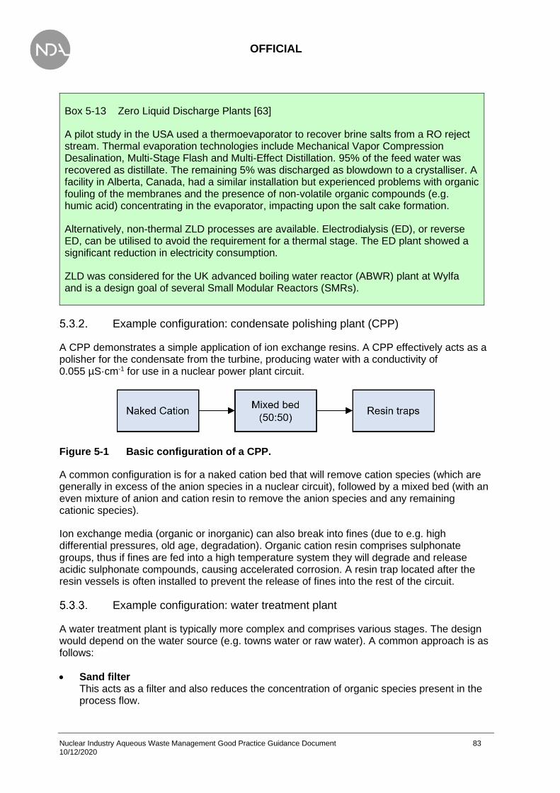
OFFICIAL
Nuclear Industry Aqueous Waste Management Good Practice Guidance Document 83 10/12/2020
Box 5-13 Zero Liquid Discharge Plants [63]
A pilot study in the USA used a thermoevaporator to recover brine salts from a RO reject stream. Thermal evaporation technologies include Mechanical Vapor Compression Desalination, Multi-Stage Flash and Multi-Effect Distillation. 95% of the feed water was recovered as distillate. The remaining 5% was discharged as blowdown to a crystalliser. A facility in Alberta, Canada, had a similar installation but experienced problems with organic fouling of the membranes and the presence of non-volatile organic compounds (e.g. humic acid) concentrating in the evaporator, impacting upon the salt cake formation.
Alternatively, non-thermal ZLD processes are available. Electrodialysis (ED), or reverse ED, can be utilised to avoid the requirement for a thermal stage. The ED plant showed a significant reduction in electricity consumption.
ZLD was considered for the UK advanced boiling water reactor (ABWR) plant at Wylfa and is a design goal of several Small Modular Reactors (SMRs).
Example configuration: condensate polishing plant (CPP)
A CPP demonstrates a simple application of ion exchange resins. A CPP effectively acts as a polisher for the condensate from the turbine, producing water with a conductivity of 0.055 µS·cm-1 for use in a nuclear power plant circuit.
Figure 5-1 Basic configuration of a CPP.
A common configuration is for a naked cation bed that will remove cation species (which are generally in excess of the anion species in a nuclear circuit), followed by a mixed bed (with an even mixture of anion and cation resin to remove the anion species and any remaining cationic species).
Ion exchange media (organic or inorganic) can also break into fines (due to e.g. high differential pressures, old age, degradation). Organic cation resin comprises sulphonate groups, thus if fines are fed into a high temperature system they will degrade and release acidic sulphonate compounds, causing accelerated corrosion. A resin trap located after the resin vessels is often installed to prevent the release of fines into the rest of the circuit.
Example configuration: water treatment plant
A water treatment plant is typically more complex and comprises various stages. The design would depend on the water source (e.g. towns water or raw water). A common approach is as follows:
• Sand filter This acts as a filter and also reduces the concentration of organic species present in the process flow.

OFFICIAL
Nuclear Industry Aqueous Waste Management Good Practice Guidance Document 84 10/12/2020
• Weak Acid Cation (WAC) resin The process flow is treated using a mixture of WAC resin. Weak resin has a higher capacity for ionic species than strong resin. Therefore, it is suitable to remove the bulk of material. It is also easier to regenerate than strong resin; this can be achieved using weak acid or base.
• Strong Acid Cation (SAC) resin The effluent is then treated using a SAC resin. This removes cationic species and, because the resin is in the hydrogen form, results in an acidic effluent. This bed can be regenerated using strong acid. The regenerant used for SAC can also be used to regenerate WAC.
• Vacuum degasser The process flow is degassed to remove carbon dioxide (and by extension carbonate species).
• Weak Base Anion (WBA) WBA is used to remove the bulk of the anionic species.
• Strong Base Anion (SBA) The flow is then treated using SBA to remove strongly dissociated anionic species.
• Polishing using SBA and SAC Finally, the process flow is treated using a mixture of SBA and SAC to polish the water before storage on site.
Figure 5-2 Typical arrangement of a water treatment plant.
Key factors to consider for the design of WTP that will use towns water are listed below.
• Towns water is dosed with chlorine (hypochlorite) to remove bacteria. Hypochlorite is an oxidant and can damage ion exchange resins. Therefore, pre-treatment using sulphite dosing may be required, thereby reducing the hypochlorite (and oxidising the sulphite) and protecting the resin from oxidising species.
• Efficient use of the strong resin acid and alkali regenerant (for the SAC and SBA respectively) includes re-use of the regenerants to regenerate the weak resin.
• Vacuum degassing to remove carbonate species is applied after the SAC because the effluent is then acidic, facilitating the removal of dissolved carbon dioxide.
• Polishing is then achieved using a mixed bed.
This arrangement of systems requires significant infrastructure in terms of resin handling facilities, resin regeneration and operator burden. The benefit of replacing several of these steps, and vessels, with a RO system is apparent, subject to the water quality required and resin used.

OFFICIAL
Nuclear Industry Aqueous Waste Management Good Practice Guidance Document 85 10/12/2020
Table 5-1 Summary of water treatment plant elements (example)
Technique Purpose Secondary Waste
Sand filter Reduced organics
Filter Particulate (when backwashed)
Cation resin Bulk cation species removal Acid with salts (when regenerated)
Spent resin when performance degrades (5-10 years for non-active)
Vacuum degasser Removal of dissolved gases None – gases discharged
Anion resin Removal of bulk anion species Base (when regenerated)
Spent resin when degraded
Mixed bed Polishing of process fluid Spent resins when degraded
Example configuration: groundwater treatment plant
The design shown in Figure 5-3 was developed to treat groundwater contaminated with radionuclides and volatile organic compounds.
Figure 5-3 Possible arrangement of various technologies to treat contaminated water stream.
The steps are shown below:
• Precipitation using pH adjustment By adjusting the pH to alkaline (>7), several species become insoluble and precipitate out. This is performed in a batch process, allowing the precipitate to settle to the bottom of the vessel.
• Coagulant and/or flocculant A coagulant and/or flocculant is added to form a floc and collapse suspensions or colloids. The floc is allowed to settle.
• Filtration The fluid is then filtered and routed through a granular activated carbon bed to remove organic species. This is followed by a second filter to retain any carbon mobilised from the bed.
• RO membrane and evaporator The process fluid is then routed to a RO membrane. The reject is sent to an evaporator to reduce the volume. This can either be evaporated to solids or to a sludge for encapsulation.

OFFICIAL
Nuclear Industry Aqueous Waste Management Good Practice Guidance Document 86 10/12/2020
Table 5-2 Summary of groundwater treatment plant elements (example)
Technique Purpose Secondary Waste
Precipitation (pH adjustment)
Reduced loading (with adjusted pH)
Solid precipitation (e.g. salts and metals)
Coagulant/flocculant Collapse colloids, reduce
suspended solids Floc
Filtration Removal of suspended solids Filtrand (the removed solid)
Filter (once permanently blinded)
Granular Activated Carbon (GAC)
Removal of organic compounds
Solid GAC for disposal (once performance degraded)
Note cleaning process will generate secondary waste
Filtration Trapping of GAC
Removal of suspended solids
Filter (note comparatively clean so rarely required)
GAC residue removed from filter
Reverse Osmosis Remove ionic species to produce
pure water Concentrated salt solution (the reject)
Evaporator Remove solute, producing either a slurry or solid (if evaporated to
dryness)
Solid or slurry Moisture vapour/steam
Example configuration: zero liquid discharge
A standard ZLD plant is presented below, showing how waste from other processes can be re-used to supply Boiler Feed Water (BFW) and Cooling Tower Make-Up (CTMU).

OFFICIAL
Nuclear Industry Aqueous Waste Management Good Practice Guidance Document 87 10/12/2020
Figure 5-4 Common arrangement of a zero liquid discharge plant.
The steps are shown below:
• Pre-treatment Pre-treatment is generally required, dependent on the characteristics of the influent, to protect the RO. RO membranes are prone to fouling from organic species and also operate best under specific conditions.
• Primary RO The RO membrane removes ionic species, with the reject (the more concentrated stream) being sent to either the brine concentrator, or a secondary RO membrane. A secondary RO can be installed to improve the recovery.
• Brine concentrator An evaporator functions as the brine concentrator, and results in the generation of a concentrated sludge or solid by evaporating the water from the concentrate.
• Crystalliser To achieve maximum efficiency, there is a let-down flow from the brine concentrator to a crystalliser. This causes the crystallisation of remaining dissolved solids in the process fluid.
This application has found use in newer power plants, for example for cooling towers, boiler blowdowns and process waste.
Table 5-3 Summary of zero liquid discharge plant elements (example)
Technique Purpose Secondary Waste
Pre-treatment
Protect the RO membrane from impurities in blowdown (e.g.
oxidising species, heavy particulate)
Dependent upon influent composition RO may require cleaning, resulting in
use of chemicals
Primary RO Purify aqueous stream Clean water re-used within system Reject sent to brine concentrator
Brine concentrator Removal of excess water,
reducing waste volume
Brine (solid) Evaporated water recycled to cooling
tower
Crystalliser Crystallisation of dissolved salts,
improving efficiency of brine concentrator
Crystallised solids, disposed of as solid waste
Sludge press Remove excess water
Produce compacted solid waste Solid material from influent
Prevention of impacts of aqueous waste
Once an aqueous waste has been generated, there are also techniques that can be applied that will reduce the impact on people and the environment of an effluent or discharge.
• Utilising radioactive decay of short half-life species is a common approach to reduce the level of radioactivity in the aqueous waste and subsequently reduce operator dose when handling the waste and simplify engineering requirements.

OFFICIAL
Nuclear Industry Aqueous Waste Management Good Practice Guidance Document 88 10/12/2020
• Fuel cooling in storage ponds allows decay of short-lived fission products prior to waste processing.
• Use of delay tanks to delay discharges. Delay tanks generally hold up waste until analysis is available but can also be to allow decay of short-lived radionuclides. The principle behind this approach is utilised in BWRs, which have large charcoal beds that serve to delay the discharge of radioactive species, such as iodine. The principles have also been applied to short-lived radionuclides (e.g. S-35, see Box 5-14) in aqueous waste streams, although consideration of the number of tanks required to achieve a suitable decay is required.
• ‘Storage’ of the effluent. The practicability of this approach depends upon an ALARP justification for further storage, and typically depends upon the radioisotope half-life, quantity to be stored, and the nature of the isotope.
Box 5-14 Minimising impacts of aqueous waste. Example: S-35
S-35 has a comparatively short half-life of 87 days. Decay storage of S-35 for this period would reduce the activity significantly and may simplify the final treatment option. If allowed to decay below a set activity, then discharge to the environment may be viable. Alternatively, treatment after partial decay would reduce:
• shielding requirements;
• process efficiency requirements (i.e. reduced S-35 removal).
However, large quantities could result in a significant number of vessels located on site, increasing the overall hazard.
As the radionuclide half-life increases, the viability of storage decreases. The half-life of tritium is approximately 12 years. Storage for this timescale is unlikely to be either practicable or ALARP given the relatively low radiological hazard arising from tritium.
Alternative approaches can be used where reasonably practicable.
• Separation of clean water processes from processes in contaminated areas (see Chapter 4). This would ensure that clean water does not become contaminated and can be treated as a non-active waste.
• Groundwater and rain infiltration into facilities should be prevented where practicable to reduce the generation of secondary aqueous wastes.
• The mixing of different types of aqueous waste (e.g. by physical, chemical and hazardous characteristics) should be avoided. Separate waste streams will allow appropriate levels of treatment to be applied to different types of aqueous waste9.
9 Aqueous wastes of different types and activity levels should not be blended specifically to reduce
the average radioactivity level of a waste stream in a larger volume of liquid. However, there are specific examples where blending of wastes is justified to optimise the process. This is the principle behind discharges of the AGR final delay tank. Aqueous waste from the drier towers is diluted using waste water from other systems to dilute the tritium concentration, facilitating handling and safe discharge.

OFFICIAL
Nuclear Industry Aqueous Waste Management Good Practice Guidance Document 89 10/12/2020
Summary
Box 5-15 Key good practice points for assessing technologies to treat aqueous waste
• The effective treatment of a waste requires consideration of a range of parameters.
• Characterisation of the waste stream is critical to determine which technique is (or techniques are) most appropriate.
• Consideration is needed of composition changes throughout life of the plant, as well as end of life decommissioning. Furthermore, it is prudent to consider fault scenarios.
• Multiple techniques will be required and should be arranged to achieve the required performance criteria as defined at the BAT/BPM stage.
• The required performance should be specified before design or treatment commences and will be defined during the BAT/BPM stage.
• Utilisation of existing facilities is beneficial, either on-site or national infrastructure. This can avoid duplication of existing facilities and utilise the experience and engineering expertise that exists within the wider industry.
• Operating experience should be drawn from all industries (not just the nuclear industry). New technologies are being continually developed that may offer improved performance and reduce for example secondary wastes.
• It is preferable for a technique to generate solid waste over liquid and gaseous waste where practicable.
• It is beneficial to minimise the generation of secondary wastes (e.g. contaminated chemicals, excessive water consumption).
• A new plant should be designed to be ALARA with respect to discharges and ALARP with regards to safety. Utilising existing plant or equipment can complicate this justification but should be considered in the context of the whole lifecycle.

OFFICIAL
Nuclear Industry Aqueous Waste Management Good Practice Guidance Document 90 10/12/2020
Box 5-16 Key pitfalls in assessing technologies to treat aqueous waste
• Over-engineering of the plant should be avoided to reduce maintenance costs and increase reliability.
• R&D or small-scale testing may be required for new waste effluents. Conducting simultaneous R&D and design carries risks.
• There is a balance to be struck between utilising new and existing techniques. Existing techniques are likely to have a proven track record but in focusing upon techniques with demonstrable performance, new improved techniques may be discounted.
• Although radioactive contamination does present a unique hazard, this does not mean that a technique must be nuclearised to be successful or useful.
• Pre-treatment may be required to bring the influent composition to within the design criteria, therefore requiring additional chemical dosing.
• Incorrect specification of influents / reagents / services (e.g. incorrect influent in commissioning trials) can invalidate the design of the plant or reduce the real-world performance of the design (e.g. R&D trials undertaken with a different flocculant).
• Generation of problematic wastes should be avoided where practicable (e.g. mixed oil – water wastes). Correct characterisation of the waste stream before design commences is critical to avoiding and minimising the generation of secondary waste.
• If an existing plant is considered for treatment of a new waste stream, the impact of the new waste stream must be considered – it cannot be assumed that the plant will provide the necessary performance. The impact on other site operations should be considered.
• Any waste generated from a treatment plant will require a final disposal route. It should be confirmed whether a Radioactive Waste Management Case (RWMC) exists for the wastes produced or an associated Letter of Compliance (LoC) from Radioactive Waste Management Ltd (RWM).
• The limits of a technique should be identified and understood at the design stage. The selection of a technique on the basis of too limited an examination can have the effect that environmental damage is not reduced, but displaced to another waste form, environmental medium, treatment process, or geographic location.
• Scaling from laboratory to plant scale should be undertaken with care.

OFFICIAL
Nuclear Industry Aqueous Waste Management Good Practice Guidance Document 91 10/12/2020
6. Discharge and disposal
Box 6-1 Aims of Chapter 6
This chapter identifies issues and presents good practice for operations concerned with the discharge or disposal of aqueous waste from UK nuclear sites. The intention is to provide guidance for aqueous waste practitioners that ensures final discharges and disposals are controlled, compliant, and made in a manner that protects people and the environment. After reading this chapter, the aqueous waste practitioner will understand:
• Discharge and disposal definitions;
• Storage of aqueous wastes on- and off-site;
• how to apply for an environmental permit (subsections 6.2 and 6.3);
• assessment of discharges on the human health and non-human biota (subsection 6.4);
• locations and timing of discharge of aqueous waste (subsections 6.5 and 6.7);
• monitoring and quality assurance requirements (subsection 6.6);
• management and sentencing of aqueous waste discharges (subsection 6.8);
• appropriate planning for emergencies (subsection 6.9);
Introduction
The site operator will use BAT/BPM to minimise the volume and activity of aqueous wastes for disposal. The BAT/BPM options assessment should already have been undertaken to determine the preferred option for discharge or disposal of the aqueous waste and considered the consequences of on-site options as well as off-site options (e.g. off-site incineration or discharge from an offsite authorised route). Guidance on the selection of the preferred option is provided in Chapters 2 and 4. Guidance on good practices for designing and implementing characterisation and monitoring of aqueous waste is provided in Chapter 3.
The starting point for this chapter is that the BAT/BPM case has already prepared the preferred option, the aqueous effluent (treated or otherwise) is characterised and planned to be fit for discharge or disposal from the site.
The main focus of the chapter is to provide good practices guidance relevant to the aqueous waste practitioner on discharge and disposal of aqueous waste to the environment, including permitting/authorisation applications and for enabling the discharge process. The chapter is generally intended to be relevant to the broad scope of discharges, from the small scale of individual drums to the large scale of the waste treatment plants. In the context of discharges, the guidance is valid for all new plant and pipelines, modification of existing plant and pipeline, and use of existing plant and pipelines. The guidance considers ‘how, ‘where’ and when’ to discharge aqueous waste:

OFFICIAL
Nuclear Industry Aqueous Waste Management Good Practice Guidance Document 92 10/12/2020
• How? How to design and implement a programme for discharging aqueous waste that both represents BAT/BPM and ensures compliance with the requirements of the environmental permit. Guidance and good practices on how to assess the environmental impact of discharges are provided in subsection 6.4. Guidance and good practices on how to monitor aqueous waste discharges are provided in subsection 6.6.
• Where? Consider whether aqueous waste can be discharged through existing infrastructure or whether new infrastructure or discharge location is required.
• When? Guidance and good practice on optimising the timing of discharges to minimise the environmental and human health impacts.
Box 6-2 summarises the activities that should have been completed prior to discharge. This information could be used in a readiness review or as a quality plan to ensure that all required actions have been completed.
Box 6-2 Checklist of activities that should be completed prior to discharge
An environmental permit to discharge the aqueous waste must be in place before any discharges take place.
• The following requirements are to be undertaken as part of the process to obtain the environmental permit or environmental authorisation:
• Consult the UK environmental regulators guidance on making an application (either new or to make a variation) for an environmental permit in England and Wales (under EPR2016, [8]), or environmental authorisation in Scotland (under EASR 2018, [9]). This guidance can be found at:
− https://www.gov.uk/government/collections/radioactive-substances-regulation-for-nuclear-sites
− https://www.sepa.org.uk/regulations/radioactive-substances/nuclear-industry/, see also the Scottish Environment Protection Agency (SEPA) document; EASR 2018 Authorisation guide for radioactive substance activities [64].
• Waste Management Hierarchy (WMH) principles will have been applied. Where practicable, generation of aqueous waste will have been prevented or minimised, and aqueous waste will have been recycled or re-used, see Chapter 4.
• An anticipated source term will have been produced for the aqueous waste to be discharged, see Chapter 3. The environmental permit will specify what is to be monitored and relevant limits.
• The treatment process, if any, for the aqueous waste, will have been demonstrated to be BAT/BPM and ALARP, see Chapter 2 and Chapter 5.
• The design and implementation of the discharge programme and associated monitoring programme will have been shown to be BAT/BPM, see Chapter 3.

OFFICIAL
Nuclear Industry Aqueous Waste Management Good Practice Guidance Document 93 10/12/2020
The above should be reviewed regularly to ensure all aqueous waste discharge activities remain BAT/BPM. If changes are required, then an application for varying the permit or authorisation will need to be made to the appropriate UK environmental regulator.
The following should be checked before final discharge of aqueous effluent:
• That the discharge will be fully compliant with the requirement of the environmental permit. Discharge must not take place unless this is confirmed.
• That plant performance during the treatment of the waste to be discharged has been satisfactory. This should be determined through the evaluation of trends in process monitoring data. If plant performance was not satisfactory, additional determinands in the final discharge may need to be monitored to determine whether the discharge will fully comply with permit requirements.
Discharge, disposal, and storage of aqueous waste
The critical element of discharge or disposal is that it is irrevocable and has an impact on the environment that must be controlled.
Discharge is the disposal of aqueous waste through dispersion into the environment.
Where it is shown to be BAT/BPM, aqueous waste may be disposed rather than discharged. Disposal generally or often requires the treatment of the aqueous radioactive waste to produce a solid radioactive waste, using methodologies such as incorporation of the liquid waste in cement, or by evaporation. The solid waste generated would then be stored or removed from the site in accordance with solid waste regulation and permits, further guidance on solid waste disposal is provided in [33]. Aqueous waste may also be incinerated to form a gaseous discharge rather than a solid waste.
Storage prior to discharge and disposal
The storage of aqueous waste on site is possible and sometimes required for the process. The storage location, containment, composition and quantity of the aqueous waste all carry a risk until the waste can be safely discharged or disposed of. For aqueous waste stored on site, the storage requirements are governed by the ONR or HSE under LC34 – Leakage and escape of radioactive material and radioactive waste [13], rather than the environmental regulators. Loss or leakage of the stored effluent would be treated as ‘loss of containment’ events, not as disposal or discharge, which are planned and controlled.
The site operator should ensure that storage systems are appropriate and are suitably maintained. This should include fit for purpose bunding as part of the storage tanks and vessels design and construction. Bunds should be able to hold at least 110% of the contents. Storage tanks and vessels should be made of compatible materials for the contents and of sufficient strength and structural integrity to ensure there are no leaks in normal use. The tanks and bunding and any associated instrumentation such as level gauges, pipework and valves, should be part of an equipment inspection and maintenance (see Section 2.1.3 on EMITs). The design should have a method to avoid drain down by gravity, for example a top off-take and/or isolating check valves.

OFFICIAL
Nuclear Industry Aqueous Waste Management Good Practice Guidance Document 94 10/12/2020
Furthermore, the site operator should have Emergency Preparedness arrangements in place which consider the likelihood of an event, such as a loss of containment, with mitigations in place to prevent or minimise the consequence of inadvertent release, and emergency procedures for the response required in an event. Further guidance on Emergency Preparedness is provided in Section 6.9.
Storage of aqueous waste prior to discharge or disposal, for example in waste holding tanks, should be avoided or limited as far as practicable to avoid the collation of significant waste quota on the site. However, storage may be required as part of the final preparation of the effluent for discharge, to ensure compliance with limits and for control of the release. For example, storage prior to discharge may be required to:
• allow storage of the effluent for a period to allow for radioactive decay of short-lived radioisotopes;
• ensure the correct hydrological conditions for discharge to the environment;
• allow for sampling and analysis to be completed;
• ensure due process for site authorisation to release the discharge is completed.
If applying BAT/BPM means discharge of the aqueous waste directly from the site to the environment is not acceptable, and an off-site solution is required, it may be possible to transfer the bulk aqueous discharge to an authorised off-site facility where it can be discharged to the environment instead (See Section 6.2.2 regarding off-site facility Conditions of Acceptance (CFA)). An example may be the transfer of tritiated water to an off-site facility, where it can be discharged to sea via a permitted discharge pipeline.
Aqueous radioactive waste should be minimised in terms of the radioactivity and volume to be disposed of to the environment or transferred to other offsite premises. The whole process should be carefully risk assessed, as many additional hazards may be introduced. In assessing the impact of a loss of containment en-route, for example, considerations might include:
• identifying how and where a loss of containment could occur;
• quantifying and understanding the risks of exposure to the public and environment;
• identification of drain locations on the route and at the initial and destination sites;
• identification of public services that may be impacted;
• identifying the safest route, and alternative routes if diversions are required;
• ensuring that emergency preparedness arrangements are suitable and in place.
All the hazards that may be encountered and the mitigations necessary during the transport from the initial site storage/collection point to the offsite facility and until the final discharge should be risk assessed.
Examples of storage, discharge and disposal processes are given in Table 6-1.

OFFICIAL
Nuclear Industry Aqueous Waste Management Good Practice Guidance Document 95 10/12/2020
Table 6-1 Examples of the storage, discharge and disposal of aqueous waste.
Process Type
Release of aqueous waste from the nuclear site into the environment. This can occur directly into surface waters, such as to a river, lake, estuary, or the sea, or into surface waters via an appropriate off-site engineered drainage system.
Discharge
On-site or off-site storage of aqueous waste. This could be temporary or longer-term storage. Examples include water and various supernates from sludge treatment, or storage of other aqueous based fluids in leak-proof containers or tanks.
An example is the use of decay storage for medium active (MA) liquors at Sellafield Ltd. These MA liquors used to be stored prior to discharge to allow for the decay of the short-lived radioisotopes. However, this practice has now been discontinued in favour of on-site disposal though encapsulation and vitrification of the wastes.
Another example of short-term on-site storage is the water removed from the gas circuit by gas driers in Advanced Gas Cooled Reactors (AGRs). The removed liquor accumulates in tanks at the gas drier outlet. The liquor is tritiated, and also contains radionuclides such as S-35. Two tanks can be rotated in and out of service. The online tank to the gas drier outlet collects the tritiated water over a period until full. Meanwhile the other tank (assumed full) can be sampled, and the contents periodically released to the environment according to the permit (typically to the sea) and the site procedure. The emptied tank is then on standby and available for duty when the first tank becomes full. There is always likely to be a quantity of liquor within the tanks at most times during plant operation.
Storage
On-site or off-site treatment of aqueous waste to generate a solid waste that can then be disposed of as solid radioactive waste in an authorised disposal facility. This approach is also suitable for non-active aqueous waste (outside the scope of this guidance) containing contaminants such as heavy metals.
Disposal
On-site or off-site treatment of aqueous waste to generate a gaseous waste, which can be discharged into the environment. A relevant example would be incineration of low activity aqueous wastes because of the presence of oils.
Discharge
Gaseous waste can also be a by-product of aqueous waste treatment, for example, as a result of the process treatment, or techniques such as evaporation. The evaporation of aqueous waste to reduce volume may also produce an amount of solid waste for disposal.
Discharge
OFFICIAL
Nuclear Industry Aqueous Waste Management Good Practice Guidance Document 96 10/12/2020
Off-site Treatment and Disposal Conditions of Acceptance (CFA)
Off-site aqueous waste discharge treatment plants or disposal streams facilities are also, obviously, subject to EA, Natural Resources Wales (NRW) and SEPA permits and authorisations for the waste handled and disposed on the site. Each facility will have documentation that details their ‘Conditions for Acceptance’ (CFA) requirements to ensure that radioactive waste arriving at the facility’s site is of a suitable condition to allow its receipt and disposal.
It is generally the consignors (i.e. the originating site delivering the waste) responsibility to ensure that the radioactive waste being delivered to the facility meets the facility’s CFA requirements. Consignors will also be expected to obtain their own permit or authorisation from the relevant environmental regulator for radioactive waste disposal at the waste disposal plant, however the waste service provider will often be able to provide advice and guidance on how to apply for this if required.
Conditions for acceptance will vary for the different aqueous waste treatment plants and the discharge streams available. As an example, the CFA may include the following:
• Definition of the discharge or disposal routes available., e.g. liquid disposal/handling, incineration.
• The types and amounts of aqueous radioactive wastes that are acceptable for disposal at the facility.
• The types of radioactive wastes that are not-acceptable for receipt, or types of waste that must be excluded in the packages (such as solid items, e.g. piping).
• Definitions of suitable container types, material, and size for the waste handling.
• Container labelling of originating location, contact details, content and hazard details, container weight.
• Waste should be covered by a current permit or authorisation issued by the appropriate environmental regulator, unless it is exempt from UK radioactive legislation.
• The consignor will be responsible for the arrangements to return any non-compliant consignment.
• Radioactivity limits that apply for acceptance.
• Maximum external dose rates from the consignment should be declared, and a list of the radionuclides and activity contained in the waste.
• If the radioactive waste is also a hazardous waste because of its other properties, it should be declared and treated as such additionally.
• Requirements for accompanying transport documentation, and in line with transport regulations.
Permitting and authorisation applications
The UK discharge strategy and review set out by UK government policy on radioactive discharges states: “the unnecessary introduction of radioactivity into the environment is undesirable, even at levels where doses to humans and other species are low and, on the basis of current knowledge, are unlikely to cause harm’ [6].
OFFICIAL
Nuclear Industry Aqueous Waste Management Good Practice Guidance Document 97 10/12/2020
The UK government has also issued guidance on the scope of and exemptions from the radioactive substances legislation in England, Wales and Northern Ireland, which provides exemption levels for aqueous radioactive waste [3].
As well as limits on aqueous discharges of specified radionuclides or radionuclide groups; there may also be conditions within the permit regarding aqueous wastes, e.g. apply BAT to exclude all entrained solids, gases and non-aqueous liquids from radioactive liquid waste prior to discharge to the environment.
There may also be conditions regarding disposal ‘in a manner so as to minimise the radiological effects on the environment’. This could mean that discharges into the sea are restricted to a ‘window’ of a few hours either side of high tide. This is considered further in Section 6.7.1.
Environmental permits and authorisations
Permitted and authorised discharges are made under the:
• Environmental Permitting (England and Wales) regulations 2016, (EPR 2016) [8], under which the EA or NRW, issue ‘Environmental Permits’;
• Environmental Authorisations (Scotland) Regulations 2018 (EASR 2018) [9], under which SEPA issue ‘Environmental Authorisations’.
The nuclear site operator must apply to the relevant UK environmental regulator for a permit to discharge radioactive aqueous waste. The environmental regulators can provide advice on how to apply for an environmental permit or authorisation for the discharge, and whether such a permit or authorisation is necessary. Early and regular engagement with the appropriate UK environmental regulator is welcomed and enables the building of trust and understanding, as well as allowing reasonable timescales to be able to understand the scope and requirements for a particular site, setting the basis for the application process whether for a new permit of a variation.
6.3.1.1. Standard Rules and General Binding Rules
The EA have produced a set of ‘standard rules’ for environmental permits, and SEPA have a set of ‘general binding rules’ (GBR) [64] for environmental authorisations These are sets of mandatory rules that cover specific activities described in EPR 2016 or EASR 2018. If the site meets one or more of these rule sets, and where a specific environmental risk is known, it can apply for a ‘standard permit’. The site must be able to comply with the standard rules set out in the permit and the EA generic risk assessment, or SEPA equivalent for the GBRs and environmental authorisation.
However, there is no set of standard rules for radioactive aqueous discharges to the environment, and there are no ‘standard rules permits’ for aqueous effluent discharges at existing nuclear sites in the UK; these sites all have bespoke permits. It is considered unlikely that a nuclear site will be able to comply with a ‘standard rule permit’ because of the multiple and interconnected activities on site.

OFFICIAL
Nuclear Industry Aqueous Waste Management Good Practice Guidance Document 98 10/12/2020
A ‘standard rules permit’ is an option where the environmental risks from a specific discrete activity are known. If the application is for a permit that will include more than one standard set of rules, then these must be carried out as discrete and self‐contained activities. Where multiple interconnected activities take place the risk increases, meaning that the generic risk assessments no longer apply, and a ‘standard rules permit’ is no longer appropriate. Therefore, to carry out multiple activities on the same site which are interconnected requires an application for a bespoke permit.
If the site operator is applying for more than one ‘standard rules permit’ the site operator will need to show how the rules sets are:
• not interconnected;
• are kept separate;
• are operated as discrete activities.
The regulator may ask for more information from the site operator to demonstrate how the activities are kept discrete unless the activities are clearly distinct from one another.
If the site operator is applying to add a ‘standard rules permit’ to an existing bespoke permit the environmental regulator will also expect the activity covered by the standard rules to be a discrete and self‐contained activity.
A ‘standard permit’ will not suffice if there are multiple activities on the site that interconnect. In these circumstances, the site should apply for a bespoke permit. Permits can be applied for online, providing the complete application form and full supporting documentation is also sent, further advice is available in reference [65].
6.3.1.2. Groundwater Activities
‘Groundwater activities’ include both those activities that require a permit, and those activities that are unlawful, for instance causing pollution to groundwater, whether deliberate or accidental. It is an offence to cause or knowingly permit a groundwater activity unless authorised by a permit or registered as exempt. There are no permitted discharges to ground in the UK for radioactively contaminated aqueous wastes. In some circumstances it is acceptable practice to discharge some non-radioactive aqueous wastes to ground, for example discharges of steam condensate may be discharged to ground to re-mineralise them, but these discharges will still require a ‘groundwater activities’ permit. The impacts of such discharges to ground on the mobilisation of any existing contamination in the ground should be considered. The Groundwater Directives [66] require that discharges of pollutants to groundwater are either prevented or limited to avoid or control groundwater pollution, to prevent the deterioration of the chemical status of groundwater bodies, and avoid environmentally significant and sustained upward trends in the concentration of pollutants in groundwater.
6.3.1.3. Water Discharge Activity Permit
The term ‘water discharge activity’ covers the discharge or entry to surface waters which are controlled waters (but not to groundwater) of any poisonous, noxious or polluting matter; waste matter; trade effluent or sewage effluent. It is an offence to cause or knowingly permit an entry or discharge to inland freshwaters, coastal waters or relevant territorial waters of any poisonous, noxious or polluting matter; waste matter; trade effluent or sewage effluent except under and to the extent authorised by an environmental permit. Guidance on Water Discharge

OFFICIAL
Nuclear Industry Aqueous Waste Management Good Practice Guidance Document 99 10/12/2020
Activities (WDA) environmental permitting is available [67], and the Environment Agency application form and guidance is available online:
• Environment Agency, Form EPB: Application for an environmental permit; Part B6 – New bespoke water discharge activity and groundwater (point source) activity, EPB6 Version 11, August 2020 [68]; and
• Environment Agency, Guidance notes on part B6 – New bespoke water discharge activity and groundwater activity (point source discharge) EPB6 Version 11, August 2020 [69].
WDAs may be carried out as part of the operation of a regulated facility, or another class of installation, which discharges to surface water, or it may be a stand-alone water discharge activity, such as a sewage effluent discharge from a building. Where it is part of the operation of a regulated facility or installation, any such discharge must at least comply with the requirements of a WDA permit.
WDAs include the discharge of trade or sewage effluent into the sea beyond the limits of relevant territorial waters where the effluent is discharged from land through a pipe, e.g. a long sea outfall.
WDA permitting requirements derive from the relevant directives and other legislation, as transposed in England and Wales. In the permitting process, the EA have to take due regard to any Statutory Guidance, Commission Recommendations and statements of Government policy and national strategies. As such Environmental Quality Standards (EQS) for water are set in a number of directives, and compliance with these is delivered through the environmental permits. These directives include:
• The Water Framework Directive;
• Fresh Fish Directive;
• Bathing Water Directive;
• Shellfish Water Directive;
• Dangerous Substances Directive; and
• Urban Wastewater Treatment Directive.
Assessment of discharge impacts
Radioactive discharges
6.4.1.1. Human radiological impact assessment
In England, the EA [70] provides an initial radiological assessment methodology that may be used by applicants for environmental permit authorisations for discharging radioactive waste to the environment. Equivalent methodologies have been produced by all the devolved environment agencies. The first stage in the methodology includes establishing the source term. Subsection 4.1 of reference [70] states that, for initial radiological assessment using default data:

OFFICIAL
Nuclear Industry Aqueous Waste Management Good Practice Guidance Document 100 10/12/2020
“Specific information on the releases to air, estuary/coastal water, river and sewer expressed on an annual basis (i.e. Bq/y) are required. This may be in the form of current annual limits, the proposed limits or recent annual discharge returns. In some cases, radionuclide-specific information may not be available, and the discharges may be expressed as other radionuclides, ‘other beta/gamma’, etc. In these cases, the most appropriate representative radionuclide should be selected. Default radionuclides that can be used for ‘other alpha’ and ‘other beta/gamma’ categories are given in Table 11 (of [70]).”
If the total dose from all the discharges and exposures, calculated by summing the initial assessment for each discharge route and the direct radiation, is less than 20 µSv/year, no further refinement of the effluent source term is required. Otherwise, a further refinement suggested by the EA for the generic assessment is to review how realistic any use of the generic ‘other alpha’ and ‘other beta/gamma’ categories has been. The radionuclides listed in Table 11 of [70] result in the highest doses in each category; the EA suggests that it may be appropriate to substitute these with different radionuclides if the typical mix of radionuclides that are normally discharged is known.
The final refinement recommended by the EA is to determine the need for a site-specific radiological assessment. If it is determined to be appropriate, information on the effluent discharge locations and the locations of habitation, water abstraction points and access points would be required. Constraints on effluent discharge locations will be a significant factor in determining what can be discharged; therefore, if this refinement is considered likely, potential existing or new discharge locations should be considered at an early stage in the planning process.
Nuclear site operators may develop company-specific procedures and assessment tools for radiological assessment of discharges of radioactive waste to the environment, based on the EA methodology and input data requirements [71]. Leaks that might occur should be assessed within a safety case and prepared in accordance with the expectations of ONR.
The approach to limiting radioactive discharges is framed by EPR16 and statutory guidance [72]. The detailed approach is set out within EA limit setting guidance [73]. Discharge limits are set to:
• ensure that the radiation exposure of members of the public is less than the statutory dose limits and constraints, and is ALARA;
• ensure the environment is protected; and
• provide a reference for the indication of operational discharge performance and the application of BAT/BPM to minimise discharges.
Regarding the last point, where there is sufficient alternative control on discharges, a limit may not be needed. Instead, notification thresholds may be set in the permit. An example would be where an operator is seeking to remove plant limits by putting in place much lower values for trending of normal discharges (plant notification levels), enabling the environmental regulator to see adverse trends much earlier.
When setting limits, regulators must ensure that the dose limit for members of the public of 1 mSv/year will not be exceeded in respect of regulated activities. Regard must also be given to the following maximum doses to individuals (dose constraint) that may result from a defined source, for use at the planning stage in radiological protection:

OFFICIAL
Nuclear Industry Aqueous Waste Management Good Practice Guidance Document 101 10/12/2020
• 0.3 mSv/year from any source from which radioactive discharges are made; or
• 0.5 mSv/year from the discharges from any single site.
In accordance with the statutory guidance, limits are based on the use of BAT/BPM by operators to minimise disposals and their impact, with the minimum headroom necessary to permit ‘normal’ operation or decommissioning of a facility. ‘Normal’ operation or decommissioning of a facility includes the relevant operational fluctuations, maintenance, shutdowns, restarts, trends and events that are expected to occur over the likely lifetime of the facility, consistent with the use of BAT/BPM. Account is also taken of where other key Government objectives need to be met, for example: the safe and timely decommissioning of redundant facilities, clean-up of the historical legacy of radioactive wastes, security of energy supply, maintaining defence nuclear and non-nuclear capabilities, use of radionuclides in medicine, and meeting the UK’s commitment to the objectives of the OSPAR Radioactive Substances Strategy, which is implemented by the UK Strategy for Radioactive Discharges [2].
6.4.1.2. Non-human biota assessment
The site operator may also be required to provide a dose assessment to non-human species residing in environmentally sensitive locations. For example, this might require dose assessments based on actual discharges over the last three years and on predicted discharges over the next three years.
Assessment may be undertaken using a software system such as ERICA, which enables the radiological risk to terrestrial, freshwater and marine biota to be calculated [74]. The EA and the devolved environment agencies are European partners that support and maintain the ERICA tool. Use of ERICA and the underpinning methodology for calculating doses to non-human biota is therefore acceptable to the EA and the devolved environment agencies.
Non-radioactive hazardous substances
Discharge of non-radioactive aqueous waste from site may be subject to discharge consent limits. These limits are specified in environmental permits or authorisations issued by the relevant environmental regulator.
The EA has produced guidance on risk assessments to support environmental permits. Overview guidance [75] identifies when a risk assessment is needed and how to undertake one. Detailed guidance on surface water risk assessment for an environmental risk assessment is given in [76], which also includes links to specified Environmental Quality Standards (EQS) for non-radioactive hazardous substances in estuarine and coastal waters and for freshwaters. There are EQS limits for non-radioactive pollutants discharged to the different waters, including for various heavy metals and organic species, amongst others. Hazardous pollutants are also known as specific substances. For the full listing of species please refer directly to the existing guidance [76] for assessment of discharges of non-radioactive hazardous pollutants into the environment.

OFFICIAL
Nuclear Industry Aqueous Waste Management Good Practice Guidance Document 102 10/12/2020
Nuclear site discharges may contain both radioactive and non-radioactive hazardous substances. BAT/BPM is required for the radioactive substances within discharges but is not legally required in the RSA permit for the non-radioactive substance’s aspect. However, there is an expectation that the non-radioactive hazardous substances should be controlled to a similar standard to the radioactive component in the Installations or Water Discharge Activities (WDA) Permit [67]. (See Section 6.3.1.3). If it were not for the presence of radioactivity in the discharge, a separate permit would still be required for the discharges from the site anyway. To enable this expectation the non-radioactive parts of radioactive wastes are regulated through condition c2.3.7 (regulation of non-radioactive hazards in radioactive waste) in the RSR permit application [77]. Under c2.3.7 the site operator is expected to carry on the activities in a manner so as to minimise the risk of pollution from any non-radioactive substances in, or any non-radiological properties of, the radioactive waste, except to the extent the risk is addressed in a separate environmental permit. Under c2.3.7 the environmental regulator may expect to see a nuclear operator working to the standards and limits defined by the Environmental Quality Standards (EQS) and subjected to risk assessment. The BAT/BPM assessment methodology is a good practice methodology to apply to the non-radioactive parts of the discharge to justify discharge concentrations where appropriate but is not legally required. Further guidance for operators on how to comply with c2.3.7 is provided at [78].
Subsection 2.1 of this good practice guide also describes how to apply BAT/BPM to prevent generation of aqueous waste and, where this is not possible, to minimise generation and discharge of aqueous waste to the environment.
Discharge locations for aqueous wastes
The design of an aqueous discharge system should include a proposed discharge location, and also consider the timings that that discharge can be utilised. The discharge location must be selected to ensure that radioactivity and other contaminants are effectively dispersed into the environment, and that the risk of re-concentration in bodies of water, sediment, or biota must be avoided. The use of existing locations should be considered wherever possible. Some nuclear sites may be able to select from several existing discharge pipelines, and it is probably easier to find a discharge location for a coastal site than for an inland site that would discharge to a river or lake (due to greater potential for dilution and discharge within the sea). The same conceptual issues apply in all cases.
As an example, all, except a very small fraction, of Sellafield site aqueous discharges are made via sea pipelines, which discharge about 2 km offshore into the Irish Sea. The discharge limits for the sea pipelines are the same as the site discharge limits. In comparison, the factory sewer and Calder interceptor sewer are planned to be subject to much lower (i.e. more stringent) annual plant notification levels, as they discharge closer to land at approximately 800 m offshore, at the confluence of two rivers in a tidal area [79].
Where no suitable discharge locations are in place, a new discharge feature must be designed. The design of the discharge location should ensure that the waste produces minimal impact to the outfall infrastructure and the environment. The following factors may influence the discharge location:
• Hydrological properties of the receiving water bodies (velocity, direction, fluxes, mixing). Flows of the water body and outfall should be in the same direction to reduce the potential for sediment build up in the vicinity of the discharge location.

OFFICIAL
Nuclear Industry Aqueous Waste Management Good Practice Guidance Document 103 10/12/2020
• Features of the proposed pipeline location, including the potential for flooding. Pipelines should not be located in areas prone to erosion. Discharges should not be located in an area where sediment is depositing.
• Environmental Impact Assessment (EIA) considerations (see subsections 3.3 and 3.4 of [80]), which would apply during planning of new discharge pipelines or amendments to existing discharge pipelines. For example, pipelines should avoid sensitive environmental habitats.
• Local planning considerations and the proximity of the proposed pipeline and discharge location to third party structures and infrastructure. Any interactions with existing structures and infrastructure may influence the discharge limits set by the environmental regulator. The possibility of third-party interaction and damage to the final discharge pipework and siting should also be considered. An example of a third-party interference impact to the final discharge point was at Devonport (see Appendix 3 – Case studies) when mooring lines damaged the final discharge pipe. The consequence of this damage meant that all effluent treatment onsite had to be stopped until it was repaired.
• Pipeline design aspects such as:
- screens to prevent fish, mammals, and debris from entering the system at the proposed discharge location (if required);
- maintenance of discharge infrastructure and sampling logistics;
- security of discharge infrastructure and susceptibility to sabotage;
- minimisation of potential dose scenarios, e.g. children playing in the outfall, fishing near the outfall;
- flap check valves to prevent back flow, or ingress of unwanted media (e.g. marine life) at the proposed discharge location (if required). A flap check valve allows flow to pass directly through in one direction and prevents flow from entering the other way. This design does not create a huge volume or pressure drop because of the fact that substances can flow straight through in one direction. An example of a flap check valve is a duckbill valve, and a schematic of its general operation is shown in Figure 6-1. Duckbill valves have been used at Dounreay, positioned at the diffuser on outlet lines, as an effective means of preventing backflow and marine life access back into the system.

OFFICIAL
Nuclear Industry Aqueous Waste Management Good Practice Guidance Document 104 10/12/2020
Figure 6-1 Cross-section of a Duckbill Valve. The upper pipe indicates normal flow of fluid, and the lower pipe shows the stoppage of backflow.
The UK environmental regulators will require a system for obtaining representative samples of the discharge for monitoring purposes to demonstrate that discharges are within the environmental permit or authorisation. Samples should be collected at the outfall location or as close as possible if the discharge location is outside the site boundary or cannot be accessed safely. The sample point location should be agreed with the regulator. Design of monitoring and sampling systems is discussed in subsection 3.6.1. For further information on outfall design, SEPA have an ‘Engineering in the Water Environment Good Practice Guide’ for intakes and outfalls, that is intended for use by those considering engineering activities in rivers or lochs in Scotland, to reduce the impact on the physical habitat (morphology) of rivers and lochs and to reduce the need for long-term maintenance and minimising cost [81].
Monitoring of aqueous waste discharges
This section presents relevant guidance for monitoring to aqueous waste practitioners. It also identifies the principal components of an appropriate Quality Management System (QMS) for self-monitoring of aqueous discharges to the environment.
Meeting regulatory requirements
The site operator is required to demonstrate to the environmental regulator that the monitoring programme for aqueous discharges uses BAT/BPM, meets the required monitoring objectives, is proportionate, and is optimised. Box 6-3 summarises the UK environmental regulators requirements for self-monitoring of aqueous discharges to the environment. Monitoring prior to discharge, including any sampling carried out wholly on the site, should also be carried out in accordance with a safety case and in compliance with the expectations of ONR. For example, IRR17 applies to workers required to carry out the monitoring / sampling.
OFFICIAL
Nuclear Industry Aqueous Waste Management Good Practice Guidance Document 105 10/12/2020
Box 6-3 Operator self-monitoring of aqueous discharges to the environment: regulator’s requirements
The environmental permit or environmental authorisation for an aqueous waste discharge specifies that sampling, measurements, tests, surveys, and calculations need to be undertaken to demonstrate permit compliance.
The environmental permit requires the site operator to use effective arrangements for self-monitoring, which use BAT/BPM and stand up to independent regulatory compliance assessment. In demonstrating that monitoring arrangements are BAT/BPM, operators need to apply standards for monitoring where these are available.
Additionally, operators should adopt and apply applicable guidance and relevant good practice, unless operators can justify that alternative measures provide a similar level of performance.
Operator self-monitoring of discharges should be carried out under an appropriate quality management system (QMS) to support the production of accurate and reliable results from all aspects of discharge monitoring. The QMS may be a standalone document or part of a larger set of arrangements, integrated into the existing management system.
The EA has produced internal technical guidance for nuclear regulators on monitoring of radioactive discharges to water from nuclear facilities [50]. The aim is to support regulators in their role of assessing compliance of operators with permit conditions. The guidance addresses design of a monitoring system, sampling locations, sampling systems, instruments, analysis and flow measurement. It is recommended that site operators review this guidance to ensure they understand and meet the requirements of environmental regulators.
The site operator should identify responsibilities for monitoring discharges. This can be achieved through the use of SQEP, such as Radioactive Waste Advisers (RWA), and an organisation chart with named staff against defined roles, responsibilities and authorities. For example, a Discharge Co-ordinator might be appointed.
Quality management system for discharge monitoring
The principal components of an appropriate QMS for self-monitoring of aqueous discharges to the environment are summarised below. The QMS should be proportionate to the hazards associated with the aqueous discharge. The complexity of the processes and the potential for failure and unplanned releases must also be considered. The QMS should also be flexible to allow for changes in anticipated discharges as a site transitions from operations to decommissioning, and any change in site management arrangements that may take place.
• A quality policy This policy statement should set out the organisation’s approach and commitment to achieving quality. This may include specific elements relevant to monitoring of discharges.
• Management responsibilities See above.

OFFICIAL
Nuclear Industry Aqueous Waste Management Good Practice Guidance Document 106 10/12/2020
• A quality manual This should document all aspects of the management system relevant to monitoring aqueous discharges. The quality manual should contain procedures for investigating unexpected results and anomalies, and for taking corrective action.
• Staff training Those undertaking any work relating to the monitoring programme should be suitably qualified and experienced to complete the task. On-going training should be provided and documented.
• Monitoring system design Sampling equipment and on-line instrumentation should be fit for purpose so that the objectives of the monitoring programmes can be achieved, in particular with regard to required levels of accuracy, availability, and reliability. Environmental equipment should be clearly identified, this includes containment, abatement and any equipment required for official measurement, or to meet legal requirements.
• Standards for monitoring and measurement There is a regulatory preference for monitoring and measurement to be accredited to EN ISO/IEC 17025 [82] but, if this is not reasonably practicable, equivalent quality standards should be applied as a minimum. The EA has published a Monitoring Certification Scheme (MCERTS) standard that provides an application of ISO/IEC 17025 specifically for radioanalytical testing of environmental and wastewater. See also subsection 3.6.3, and subsection 6.6.2.1.
• Procedures Written procedures should be produced for routine activities such as sample collection, operation of on-line instrumentation, laboratory analysis, discharge calculation or estimation, calibration, maintenance, and reporting. Procedures to cover handling of non-conformances, corrective actions, notification, and monitoring arrangements in the event of treatment or monitoring system failure should also be produced.
• Calibration On-line and laboratory-based sampling equipment and instrumentation should be calibrated at appropriate intervals using appropriate standards. Consider if EMITs are required (see Section 2.1.3).
• Asset control Adequate asset records, defects lists, and improvement plans for monitoring systems should be kept.
• Inspection and maintenance Monitoring systems should have appropriate safety and environmental categorisation. Maintenance schedules should be in place and followed to ensure that these systems have high reliabilities and planned contingencies for breakdown. Consider if EMITs are required (see Section 2.1.3).
• Sampling The appropriateness of sampling locations, equipment and methods for the taking of representative samples should be demonstrated at the plant commissioning stage.
• Bias, precision, and quality control (QC) Appropriate quality control arrangements should be in place for all measurement stages to identify bias or loss of precision of analytical techniques. Good practice is likely to include participation in inter-laboratory comparison exercises.
OFFICIAL
Nuclear Industry Aqueous Waste Management Good Practice Guidance Document 107 10/12/2020
• Internal audits The operator should carry out regular audits of the performance of the monitoring system. Any observations and corrective actions should be raised, and a system should be in place for ensuring they are addressed within agreed timescales.
• Records All relevant data, observations and results should be recorded in a manner that provides an auditable trail from raw data to calculated discharges. Results should be cross-checked where practicable by activity (mass) balance calculation. For example, the radioactivity calculated for the original source for disposal, may then be partitioned into several pathways, e.g. that removed due to the treatment processing, recycling, or other means; and that remaining in the final effluent for discharge. These should be of a similar magnitude to the original.
• Assessment and reporting of results Results should be reported in accordance with standardised reporting requirements (see subsection 6.6.2.2) and comparable against pre-determined levels to ensure that any exceedances of notification levels or permitted limits are recorded and appropriate actions are taken.
6.6.2.1. Quality assurance for sampling and analysis
Aspects specific to monitoring and analysis (e.g. application of MCERTS or other relevant standards, such as ISO) are discussed in Chapter 3, Box 3-7.
Sampling and analysis of the aqueous waste to be discharged should be fully described in a method statement or operational manual and should comply with the sampling quality plan. All procedures in use should be up-to-date and verified by an RWA. The sampling and analysis procedures that are required for the sentencing of the final aqueous waste tend to be similar to those employed for normal monitoring of the process streams within the facilities. The procedural guidance should define the types of analyses to be performed, the frequency and/or timing required, and an acceptable range for each parameter that should be measured and recorded.
Analysis results should be stored in a system such as a Laboratory Information Management System (LIMS). This will ensure that results, certificates, and any other necessary records can be tracked and compared with previous analysis, and to support any audit requirements to demonstrate control and compliance. Independent quality check information is also an important part of a quality control system, and will help to ensure analysis instrumentation setup and calibration is correct to ensure precision and accuracy for the sample results; it is easier to spot an instrument issue when trending QC samples over a period of time. Quality systems should be set by the operator but will be open for inspection by the regulators.
If validation of analytical results is required by the environmental regulator, this should be undertaken by an appropriately certified laboratory. Advice on selecting an analytical testing laboratory is provided in subsection 10.4 of [33].
Key good practices for quality assurance are summarised in Box 6-4.

OFFICIAL
Nuclear Industry Aqueous Waste Management Good Practice Guidance Document 108 10/12/2020
Box 6-4 Key points for Quality Assurance
• What quality checks are suitable for the required analysis?
• How often does a quality check need to be completed?
• How long do analysis data need to be tracked? Will it be long term or short term, how often will it be reviewed?
6.6.2.2. Standardised Reporting
The main guidance references that have been issued for the standardised reporting of discharges are:
• European Commission, “Commission Recommendation of 18 December 2003 on standardised information on radioactive airborne and liquid discharges into the environment from nuclear power reactors and reprocessing plants in normal operation,” 2003 [83].
• The Standardised Reporting of Radioactive Discharges Direction 2018 [84], to which a later reference, [85], is also applicable.
• Standardised Reporting of Radioactive Discharges from Nuclear Sites, Guidance 247_10_SD20, issue date 3/10/19 [86].
• Standardised Reporting of Radioactive Discharges from Nuclear Sites in Scotland, Radiological Monitoring Technical Guidance Note 1, October 2019, RS-JG-017 [87].
• The Standardised Reporting of Radioactive Discharges Direction 2018 [84] (also the subsequent document [85]) directs the environment agencies to require operators of nuclear power reactors and reprocessing plants, that are in normal operation, to provide a report for the radioactive airborne and liquid discharges in that year. This is known as ‘the reporting year’, and the report must include the discharged activity values of all radionuclides given in Annex 1 of Recommendation 2004/2/Euratom(c) [83]. The EA and SEPA have both issued internal guidance documents on standardised reporting, including for the assessment of radioactive discharges [86] (available on request from the Environment Agency) and [87].
A spreadsheet demonstrating results compliance may be suitable for helping collate data for the reports. Calculations and data should include:
• reporting period;
• operator name;
• dates and times of sampling;
• dates and times of analysis;
• uncertainties;
• detection limit of instrumentation;
• upper and lower limits of results; and
• longer-term trends.

OFFICIAL
Nuclear Industry Aqueous Waste Management Good Practice Guidance Document 109 10/12/2020
Anomalies in trends can highlight the need for corrective action or help manage the timing of the discharge. The detection limit is an ISO standard (ISO 11929:2019 series) and is defined as “the smallest true value of the measurand that is detectable, with a given probability of error, by the measuring method” [87].
If a measured sample is found to have a concentration below the detection limit, the best that can be confidently claimed is that the sample is below that limit. It cannot be asserted that that sample does not contain the analyte, as there remains a possibility that there is a finite concentration that is insufficient to be detected. In this case, where a radionuclide is reported as below the instrument detection level, the detection level value should be reported in line with the standardisation of discharge reporting requirements [86] and [87].
When to discharge aqueous wastes
The aqueous waste can either be released immediately into the environment as a continuous discharge or held in waste holding tanks to enable batch discharge (see also subsection 6.2.1 on storage). The decision is influenced by several factors:
• Minimising the environmental impact of the authorised discharges:
- taking account of the hydrological characteristics of the receiving environment (e.g. tidal state), see subsection 6.7.1;
- using coincident discharge of different aqueous waste streams, see subsection 6.7.3.
• Operational considerations see subsection 6.7.2.
• Ensuring safe discharge:
- using sequential discharge of different aqueous waste streams where they have a potential to react with each other, see subsection 6.7.4.
Modelling of different discharge methods may be used, before waste is discharged, to predict the dispersion of the discharge in the receiving water body. Modelling may use information on tidal impacts (tidal stream direction and flow, tidal height), intake/outfall interactions, velocity of the discharge, and outfall location.
Hydrological characteristics of the receiving environment
Discharges should be planned to ensure that adequate dispersion takes place in the receiving water body.
For the permit application and setting of the discharge limits, assessment of the discharge activity will have already been considered for the downstream interests and the environmental impact that could be influenced by the hydrological characteristics, including:
• Designated biodiversity and environmentally significant sites: Sites of Special Scientific Interest (SSSI), Special areas of Conservation and Special Protection Areas, and other local reserves.
• Fisheries and boating interests.
The environmental permit may specify how adequate dispersion is to be achieved.

OFFICIAL
Nuclear Industry Aqueous Waste Management Good Practice Guidance Document 110 10/12/2020
For marine or estuarine discharges, discharge may be made at specific times relative to the tidal cycle. Discharges are often scheduled to take place near or after high tide to use the outgoing tide, or indeed simply the depth of water (i.e. either side of the high-water point) to provide mixing and shielding. The direction and flowrate of the tidal stream at the outfall during the discharge is also important to plan for and understand, to ensure the expected dispersion of the aqueous waste and to minimise sedimentation close to the outlet. Also, so that downstream interests are protected, e.g. SSSIs.
A discharge may be required at a pre-determined volume, temperature and flowrate as dictated by dispersion modelling to ensure dilution and dispersion.
Operational considerations
Operational considerations that would favour batch discharge are listed below. Delay to minimise radiological hazard is discussed in subsection 5.3.6.
• Time required for analysis of the aqueous waste to confirm acceptability for discharge Batch release will be required if laboratory analysis of the aqueous waste is necessary before discharge. This constraint would not apply if waste could be considered suitable for discharge based on rapid on-line analyses or ‘indicator’ measurements.
• Requirement for any further treatment of waste prior to discharge For example, a requirement to reduce suspended solids. Settling tanks may be used in this instance to enable sedimentation until the waste meets permit requirements. Several tanks will be used to provide sufficient delay time to allow sedimentation to occur.
• Movement of aqueous waste from production point to discharge location
• Dispensations in place for specific operations For example during a plant outage.
Coincidental discharges
It may be BAT/BPM to discharge several aqueous waste streams in coincidence (at the same time) at a given discharge location. The potential benefit generally arises from mixing a small volume of higher activity aqueous waste into a larger volume of lower activity aqueous waste. The increased dispersion from mixing of effluents in this way may give some potential benefit, but it must be noted that such effluents will have already been assessed as acceptable for discharge as independent discharges. It is necessary to avoid falling foul of the ‘dilute and disperse’ philosophy, where other measures can be reasonably taken to reduce the waste and its hazard by other means.
Coincident discharge is generally not specified under the environmental permit but could further reduce environmental impact if implemented in certain cases. Hence, an RWA or member of the Corporate RWA from the nuclear site operator might give approval for coincidental discharges, based on reasonable judgement and if it safe and practically possible.
Sequential discharges
This section considers sequential discharge (one after the other) of two types of aqueous waste through the same discharge infrastructure. It is undertaken for one of two reasons:

OFFICIAL
Nuclear Industry Aqueous Waste Management Good Practice Guidance Document 111 10/12/2020
To prevent mixing of two aqueous waste where undesirable reactions would occur if mixed. For example, the Sellafield THORP Dissolver Off-gas System (DOG) stream and other potentially acidic batch discharges are segregated to prevent mixing that would produce C-14-containing gases.
To aid dispersion of a higher activity aqueous waste. For example, EDF-E stations discharge tritiated water (from gas driers) from holding tanks once it is confirmed that it is suitable to be released. A much larger volume of lower activity effluent is then discharged from the Final Monitoring Delay Tank (FMDT) in order to flush the system and disperse the tritiated water.
Discharge and disposal management and sentencing
Discharge Forecasting
Discharge Forecasting is a best practice tool that is used for predicting the discharges to enable the site to deliver its effluent management strategy. The ability to predict when discharges need to, and are expected to, happen will help the site additionally in planning for, and response to, changes to the normal routine, such as for a planned shutdown period, or perhaps due to seasonal changes, e.g. flooding may be a risk. There should also be a longer-term consideration, e.g. for discharges that may be required when a site or facility transitions to decommissioning, when potentially discharges may increase for a short time.
Whilst there will be always be some uncertainty and also assumptions based on the available knowledge at any one time, which should be noted, being able to predict the challenges that may arise that impact on the discharges is key to ensuring that appropriate treatment capabilities are in place to deliver an effective effluent management strategy. Information to support discharge forecasting may be based on sources of known data, previous experience, modelling, seasonal changes, and consideration of known events such as plant outages and key maintenance activities. Discharge forecasting is also beneficial in allowing variability in the permit via the application of BAT or BPM to manage uncertainties.
Comparisons of previous forecasts with actual discharges can be carried out, and even longer-term trends and comparisons of averages may be possible and compared with routine operational factors to assess performance. Year-on-year variation may be expected, but all radioactive discharges from civil nuclear facilities in the UK are required to be within limits as strictly specified by the UK regulators. In addition to limits on discharges, operators are also required to use the BAT in England and Wales or BPM and Best Practicable Environmental Option (BPEO) in Scotland and Northern Ireland to avoid or minimise their discharges. This approach to comparing trends and gathering data over time is useful in evaluation of the discharge techniques.
Waste sentencing
Sentencing is the step in the discharge process where the site operator decides whether the aqueous waste is compliant with the requirements of the environmental permit. If the decision is that the waste is compliant with permit requirements, it can be discharged. Otherwise, the waste is held pending further investigation.
Typically, waste sentencing will be based on measurement and evaluation of indicative parameters in the waste. These are parameters that can be measured relatively quickly (on-line, at the point of sampling or through rapid laboratory analysis) and that will provide confidence that the correct sentencing decision will be made. First, however, the operator must ensure:
OFFICIAL
Nuclear Industry Aqueous Waste Management Good Practice Guidance Document 112 10/12/2020
• that any samples collected, or on-line measurements made will be representative of the waste and take account of the volume of waste to be sentenced, and that;
• the choice of analysis techniques and instruments are based on the waste characteristics and on permit requirements (represent BAT/BPM). Note that where a radionuclide is reported as below the instrument detection level, the detection level value should be in line with the standardisation of discharge reporting requirements [87]. See also subsection 6.6.2.2.
Guidance on self-monitoring of aqueous waste discharges is provided in subsection 6.6 and more detail on MCERTS requirements are discussed in Chapter 3, Box 3-7.
Typical indicator parameters required to make a sentencing decision include:
• visual assessment for suspended solids and non-aqueous liquid e.g. oil or organic solvent (as may be required by a permit condition);
• pH (e.g. as specified in an installation’s permit) and depending on the nature of the discharge and where it is going (marine, estuarine coastal, freshwater etc). There may be a requirement to condition the treated discharge water prior to discharge to ensure that the pH is within a specific range (normally related to neutral range), some water treatment technologies are also described in Appendix 2;
• total activity (from total alpha and total beta measurements);
• specific radionuclide, radioelement, or where required by an installations permit, non-radioactive analyses, may be required dependent on the waste stream being discharged.
Upper limits are set by the environmental regulators for each indicative parameter to ensure compliance with the permit. In addition, the values of the indicative parameters should be compared with recent measured values to identify any trends that might indicate decreasing water quality of the discharges.
Comparison with any period-dependent notification levels that are set in the permit for specific radionuclides should be made. In this respect, regulators may wish to be notified of radionuclides for which significant short-term changes in plant performance and process control are shown by the level of discharges. To manage this expectation notification levels may be set. These are typically ‘Quarterly Notification Levels’ (QNLs) and relate to condition 4.3.7 of the permit template [73]. If applicable, the QNLs are set based on the expected level of discharges associated with the use of BAT/BPM, and would normally be set for a site based on:
• the typical levels of discharges, excluding abnormal events, over a quarter;
• the level of increased discharges that indicates significant deterioration of plant performance and process control to the extent that it is necessary for the operator to review the techniques used.

OFFICIAL
Nuclear Industry Aqueous Waste Management Good Practice Guidance Document 113 10/12/2020
Exceeding notification levels is not a breach of permit conditions, but failure to notify the exceedance of a notification is a breach. In normal operation of the plant or process there may be periods when QNLs (for example) may be exceeded for known and controlled purposes for short term and infrequent periods. Consider a limit that is set on a rolling 12-month period, based on monthly discharge reporting, the QNL may be exceeded but the overall impact should not breach the permit level. Often, this is likely to be related to a temporary, infrequent, but non-abnormal process change, such as an outage. For example, during a power plant reactor outage period, increased liquid radioactive waste discharges of specific radionuclides above that in normal power operation may be expected due to increased maintenance activities, increased laundry requirements, conditioning of the plant for return to service, or other outage activity. Plant operators should ensure that the proposed limits for aqueous discharges are presented in their new bespoke radioactive substance regulation (RSR) permit application [88] or in their variation permit application [89], or equivalent for the devolved agencies, and how they have been derived considering foreseeable plant operational aspects. This will inform the setting of the permit levels. The approach to limit setting on a rolling period can be beneficial to ensuring the processes are controlled to BAT/BPM and ALARP in the long term, and that the short term increases that are expected are tolerable and understood, and do not influence an overly high non-realistic limit being set overall.
Procedures for sentencing the final aqueous waste for discharge will be different based on whether the waste is discharged as batches or continuously discharged from the site.
• In the batch case, the final aqueous waste is held on site until approved for release, and then released within a specific period, which may also be subject to conditions such as flowrates, quantity, and localised environmental conditions such as the state of tide.
• For an aqueous waste that is continuously discharged from site, procedures need to ensure suitable and frequent sampling to ensure that all discharge parameters are within the specified envelope, and for record purposes, with representative times and sampling points modelled and understood. Continuously discharged plants are likely to be subject to an assurance regime to ensure that effluent meets the permit conditions. Permit conditions tend to be based on cumulative environmental impact over a period of time (e.g. rolling annual limit or quarterly notification levels) such that an excursion above normal would not breach the limit before investigation and rectification of any issue. Gross excursion, for example, bypassing a treatment process or a major failure, would be detected by in-line monitoring and lead to an immediate cessation of discharges.
In either case, the procedures may include specific guidance from the discharge consent permit that could be related to radioactivity limits, chemical constituents, allowable flow rates, dilution criteria, and outfall (discharge point) temperature. There may also be variability depending on seasonal effects.
The sentencing procedure should provide specific routing guidance, hold points, cautions and any other process limitations that may affect aqueous waste quality and compliance with the permit. Sampling and analysis of effluent prior to discharge should follow written procedures, see subsection 3.5. Controlled release procedures prior to discharge may include peer checking of the sampling and analysis process (for example, checking that proportional samplers are operating correctly by comparing the fill profiles of the main tank and sample tank), and additional approvals including signature(s) from the site responsible person(s). The operator’s discharge procedures are often reviewed and audited by the relevant environment agency. However, responsibility always lies with the permit holder.

OFFICIAL
Nuclear Industry Aqueous Waste Management Good Practice Guidance Document 114 10/12/2020
Discharges accounting for compliance
The relevant environment agency will provide a Compilation of Environment Agency Requirements (CEAR) regarding the information to be provided by the operator on the discharges for accounting purposes and for compliance with the permit. It is likely this will require additional analyses on samples of the aqueous waste after sentencing and discharge and may include the taking of duplicate and/or witnessed samples to allow the regulators to undertake independent check monitoring. It should be recognised that CEAR states what is needed for accounting and compliance purposes, whereas the operator decides what to monitor for sentencing [73].
A software system may also be used to track discharge analysis for notification levels, such as QNLs, and rolling discharge limits. Note that notification levels and rolling discharge limits may be phrased differently in different permits.
Emergency response preparedness
This section is concerned with preparedness and response for events that might lead to an unplanned discharge of aqueous waste because of a failure of the discharge management system which could relate to plant, process or human factors. For example, this could occur when the volume of aqueous waste requiring discharge/disposal exceeds the volume able to be stored leading to an overflow, or the occurrence of an unplanned discharge due to inadvertent discharge of the effluent before it is fit for discharge. These examples can result due to issues such as plant misalignment (e.g. a valve in the incorrect open or closed position) or from a leaking tank or vessel.
Depending on the nature of the event, the ONR and/or the environmental agencies can be the relevant regulator for unplanned events leading to offsite radioactive discharges. This is likely to be based whether an offence under Environmental Permitting (England and Wales) Regulations 2016 (EPR16) or Environmental Authorisations (Scotland) Regulations 2018 (EASR18) has been committed, and also in consideration of the nuclear site licence conditions. In these circumstances the most relevant nuclear site licence conditions are likely to be LC32 – Accumulation of radioactive waste, LC33 – Disposal of radioactive waste, and LC34 – Leakage and escape of radioactive material and radioactive waste [13].
Planning
An emergency response plan must be in place for the inadvertent loss of containment, or in the case of a release not consistent with that laid out in the consent agreement, for example a transient in the release.
Fault scenarios that might give rise to significant unplanned aqueous waste discharges because of a failure of the discharge management process include:
• loss of containment of the aqueous effluent (e.g. by failure of waste process pipework, storage tank or vessel, or plant misalignment) leading to loss to groundwater or surface water drains across the site, and to other unplanned discharge routes;
• ingress to the plant process from flooding, which can lead to loss of containment from the waste process;
• fire water from an event on site;

OFFICIAL
Nuclear Industry Aqueous Waste Management Good Practice Guidance Document 115 10/12/2020
• increased volumes of groundwater and surface water requiring management, because of high rainfall and/or high groundwater level;
• the quality of the planned aqueous waste discharge is outside the expected envelope;
• physical damage to the discharge line. This could either be a breach, which would result in discharge at an unconsented location, or a blockage, which would mean that the discharge infrastructure cannot be used. It could also be inadvertent or intentional damage caused by a third party (see also Section 6.4 about discharge locations).
Examples of practical measures that can be taken to mitigate the above events include:
• better understanding of the range of any surface water and groundwater volumes requiring management;
• inclusion of additional tank volume in the design of aqueous waste discharge infrastructure to address the likely fault scenarios;
• provision of temporary on-site storage capacity such on-site lagoons and storage tanks.
To plan a response to a specific fault scenario:
• the hazards involved with the scenario and with potential responses should be evaluated;
• the consequences of the unplanned discharge, based on the hazard evaluation, should be assessed. The consequences of environmental discharge both inside and outside of the site boundary should be considered;
• the impact on compliance with site licence conditions and the environmental permit should be determined;
• it is important for the site operator to engage with the regulator early in the planning process;
• ensure that the appropriate reporting to the UK regulators, including INF1 to the ONR and/or Sch5 to the EA or equivalent reporting for devolved administrations, is carried out.
Furthermore, the Environmental Permit may contain an agreement on emergency responses to certain fault scenarios for specific site processes and hazards. For example, the Sellafield permit has an additional component regarding the limits for the site ion exchange plant (SIXEP) process, and in the event of a reported malfunction of SIXEP an agreement on the emergency response is already considered for the specific scenario. The site operator should engage with regulators (ONR and the appropriate UK environmental regulators) to investigate the possibilities in the planning process for the plant design and agree the appropriate responses to specific faults scenarios. For example, alternative discharge routes may be identified.
Response
There will be several possible fault scenarios associated with a failure of the discharge management system. It is unlikely that all can be managed within a single emergency response plan. Further, there are likely to be too many variables (such as the state of the plant, meteorological and hydrological conditions, nature and location of the spillage etc.) to allow a prescriptive response to any particular fault scenario.

OFFICIAL
Nuclear Industry Aqueous Waste Management Good Practice Guidance Document 116 10/12/2020
Instead, a suite of principles should be developed to enable rapid initial decision-making on plant. A limited example of some principles may be as follows:
• Loss of liquid waste spills: Follow the ‘emergency spill response plan’ and:
- Stop work and prevent further spillage, e.g. close valves to stop further spillage, evacuate unnecessary personnel.
- Contain the loss of containment spillage using appropriate bunds, sand, spill kits, absorbent socks (minibooms), booms, pads, pillows, loose absorbents etc, appropriate also to the size of the loss of containment.
- Prevent further loss via routes such as drains, outfalls etc, e.g. place cover mats over drains, use spill barriers around drains, floating booms across outfall, skimming.
- Clean-up the spill. Caution handling radioactive/hazardous waste, ensure safe and secure storage until it can be safely disposed/consigned from site.
• Notify and record the environmental incident details to the site management and key personnel and the appropriate environmental regulatory agency. Other contacts may include local water authorities, local authority, marine fisheries, fire and rescue services or any other body that should be notified related to the site-specific location and nature of the discharge.
• Fire: In the event of a fire follow the site/office action plan and local fire evacuation procedures.
Using these principles, a flexible response based on the following steps is recommended: temporarily stop the discharge, gather the appropriate people together and review the information (with an RWA and the appropriate UK regulators if practicable), make a decision, and restart the discharge. A key early step is to notify the regulators that there has been an incident and the details of the potential or actual non-compliance. A written record of actions and decision making should be made, which can then be reviewed to ensure Learning from Experience (LFE). This approach is consistent with the STAR (Stop – Think – Act – Review) principle.
For example, a lagoon that discharges aqueous waste continuously receives an unexpected organic contaminant such as an oil or a paint that cannot be extracted fully using absorbent mats, or installed oil skimmers. In this situation, an appropriate strategy might be to: stop the discharge; allow the system to back up and concentrate the contaminants; and remove/ minimise as much of the organic contaminant by applying BAT/BPM, which may include use of booms to contain the spill, or skimming the surface. Then, within existing permit limits or with formal agreement with the relevant environmental regulator (EA, NRW or SEPA), discharge the contents of the lagoon in batches on tidal windows to achieve the maximum dispersion and allow the remaining contaminant to be slowly entrained into the tidal flow.
Recovery
Recovery after an event is outside the scope of this guidance. However, it is essential to review the event and subsequent responses to identify learning from the experience. As the nuclear site operator should incorporate LFE into all activities, it is expected that a standardised approach to LFE will already be in place. The outcome of LFE may be a recommendation to reconsider aspects of the existing discharge strategy or operations. If so, guidance in subsections 6.2.2 to 6.7 should be used to develop a revised strategy or operations that can be shown to be BAT/BPM.

OFFICIAL
Nuclear Industry Aqueous Waste Management Good Practice Guidance Document 117 10/12/2020
Summary
Box 6-5 Key good practice points for discharge and disposal
• Ensure approach to discharge/disposal is BAT/BPM. See subsection 2.1.
• Establishment of policies, plans, and standards for site discharge management. Planning for discharge forecasting is important to ensure effective effluent discharge management, particularly for large and complex sites.
• Control of resources: organisational change of personnel, succession planning and the training and qualification of personnel.
• Self-assessment, quality assurance, continuous improvement (learning from lessons/experience of the site/industry).
• Record-keeping and regulatory compliance.
• Consider coincident discharge to provide additional dispersion for smaller volume higher activity aqueous waste streams.
• Ensure monitoring of discharge is proportionate and meets regulators’ requirements in terms of sentencing. The sample size should be representative of the bulk sample. If the sample is not homogenous, multiple samples may be necessary.
• If the site operator deems that compliance with MCERTS is not practicable or appropriate, and compliance with MCERTS is not required by the permit, the operator should apply for a BAT/BPM-based derogation. Derogations are uncommon, but if approved should be recorded in the CEAR or equivalent document for devolved administrations.
• Ensure emergency response preparedness. Develop with some good practice points.
− Identify the fault scenarios and potential consequences.
− Learning from Experience (LFE). Obtaining, sharing and reviewing operating experience from local events, as well as from peers within the industry in the UK and worldwide (if possible) will help to understand likely scenarios and consequences. Sharing and review of LFE enables the prevention of similar and significant events and enables effective planning and mitigation methods to be anticipated and employed.
− Engage with the appropriate UK regulator(s) to determine the acceptable response to some faults.
− Retain flexibility.
− Use an approach such as STAR (stop, Think, Act and Review) for each key step during the response and for recovery. There are too many possible responses to build into a single response plan.
− Early notification to the appropriate UK regulators that there has been an incident and the potential or actual non-compliance details.
• Ensure quality plan for sampling and sentencing is followed.
• Sentencing is the clearance process that defines whether a substance is out of scope, exempt or radioactive. Sentencing may be dependent on waste route and waste type.

OFFICIAL
Nuclear Industry Aqueous Waste Management Good Practice Guidance Document 118 10/12/2020
− Where applicable, the history of the waste sentencing can be used to determine if waste can be discharged prior to full analysis.
− In addition to this, indicator analysis (total activity) may be used to determine if the waste can be discharged prior to the full analysis required. This is set by the operator and agreed by the regulator.
Box 6-6 Key pitfalls in discharge and disposal
• Failing to mitigate against some of the fault conditions that could result in unplanned discharges:
• Failing to exclude entrained solids from radioactive waste.
• Failing to seal against surface water/groundwater inflows into plant.
• Failing to plan for increased groundwater and surface water component of aqueous waste under certain weather conditions.
• Failing to contain waste in hold tanks.
− Damaged bunding, inadequate/incompatible bunding.
• Failing to prevent human error that could result in discharges out of permit conditions.
− Inadequate control on process.
− Inadequate systems in place for minimisation of intentional actions.
− Inadequate QC system.
− Poor environmental safety culture.
• Inflexibility in discharges, potential for being unable to respond to changing conditions.

OFFICIAL
Nuclear Industry Aqueous Waste Management Good Practice Guidance Document 119 10/12/2020
7. Aqueous waste plant lifecycle management
Box 7-1 Aims of Chapter 7
To provide relevant information to the aqueous waste practitioner on the overall plant lifecycle management of the treatment technologies described in the preceding chapters, from conception through to decommissioning. Other information (e.g. relevant to a design engineer) is signposted.
Introduction
This chapter highlights key issues and provides good practice relevant to the aqueous waste practitioner with respect to the overall plant lifecycle management (concept through to decommissioning). The aim here is not to provide generic guidance on plant lifecycle management, but to highlight specific considerations for an aqueous waste practitioner. The guidance is intended to be applicable for all three scenarios identified in Chapter 1.
The key steps in the life cycle of a treatment plant for radioactively contaminated aqueous waste are listed below.
• Plant design and development (concept through to detail design)
• Construction of the plant
• Works testing and commissioning
• Operation of the aqueous waste treatment plant, performance monitoring, maintenance and updates to the plant during the plant lifetime
• Decommissioning of the plant
This chapter considers all steps in the plant lifecycle for operation and construction, and is limited to dealing with generic operating guidance and construction effluents only.
Plant design
This section provides the practitioner with guidance in respect of what is required to establish a practical plant design in relation to identifying essential design requirements and incorporating sound design principles.
Chapter 2 and Chapter 5 provide guidance in identifying and evaluating candidate aqueous waste treatment technologies. Once the BAT/BPM solution has been identified, the requirements of the waste treatment plant with respect to quality of final treated effluent should be recorded, along with the volume and quality of the aqueous waste to be treated.
The design of an aqueous waste treatment plant depends on several factors:
• the volume of aqueous waste produced;

OFFICIAL
Nuclear Industry Aqueous Waste Management Good Practice Guidance Document 120 10/12/2020
• the timeframe over which the aqueous waste is produced;
• the characteristics of the aqueous waste (including variability of composition and volume);
• the required quality of the final treated effluent (considering downstream plant and discharge route).
In developing the specification of requirements, the process aims should be clearly defined and, where applicable, specific values applied. The following should be considered at the outset of the design process:
• As a guiding principle, liquid effluents should be segregated from one another at source and treated and stored separately depending on their characteristics This approach allows the effluents either to be reused and recycled or discharged as required. Treatment methods should employ BAT/BPM to ensure that as much of the effluent as possible can be recycled and reused. Where this is not possible, the discharges of dissolved and radioactive materials to the environment and their impact should be ALARP.
• The purpose of the aqueous treatment plant should be clearly stated For example, to treat the effluent sufficiently for it to be released/discharged safely to the environment within a discharge authorisation or to treat the effluent sufficiently for it to be re-used elsewhere.
• Identify the species to be removed and the extent required Realistic operational extremes and the potential for future changes to aqueous waste composition and discharge limits should be addressed. Failure to do this results in operational inflexibility and a lack of robustness to changes in operating conditions and/or aqueous waste composition. Underestimating the impact of changes in process parameters could lead to loss of performance. For example, it could result in increased discharges or more frequent filter backwashing/ion exchange bed changes and, in extreme cases, potential plant failure, e.g. fouling or erosion of RO filter membranes.
• Lack of characterisation data or poor-quality data (e.g. based on pessimistic assumptions of future wastes) could lead to over-conservatism in design, operational philosophy and process selection This could lead to over-specification, for example higher waste volumes, thicker shielding, higher DFs. It could also lead to poor plant performance, for example, solids sedimentation, filters blinding, erosion.
• Address the potential for possible future changes to discharge limits Consider possible changes in regulations or discharge limits to ensure a robust design, and changes in site activities such as transition from operations to decommissioning.
• Include adequate redundancy/flexibility Avoid a single failure stopping or causing major disruption to the plant/process.
• Do not mix aqueous waste streams with different activity concentrations unless beneficial to the process In general, the plant design should minimise the potential for the spread of contamination and creation of secondary radioactive waste. The plant and processes chosen should minimise the generation of secondary waste, e.g. spent ion exchanger and filters. However, blending of effluent streams may be beneficial to a process (i.e. providing a source of complimentary chemical species for example iron to promote precipitation/co-precipitation of actinides as in floc treatment) rather than condition with fresh chemicals.

OFFICIAL
Nuclear Industry Aqueous Waste Management Good Practice Guidance Document 121 10/12/2020
• Consider appropriate treatment and discharge routes for inactive effluents and active effluents Active effluents should not be diluted with inactive effluents.
• Determine whether a RWMC exists or is required for the wastes produced or an associated LoC from RWM Joint guidance from the ONR, EA, SEPA and NRW to nuclear licensees is given in [90].
• Address the Site Integrated Waste Management Plan/Strategy The site integrated waste management plan is a crucial element in terms of understanding the overall challenge and balancing the BAT/ ALARP arguments. A waste management plan should:
- outline effluent management (treatment and associated infrastructure and services) on a site;
- identify needs for the future development, expansion or upgrade of waste systems to accommodate changing needs;
- provide an estimate of the associated costs of the existing and planned system; and
- be maintained as it is an asset that can support and inform decisions about land use, infrastructure funding and any necessary permits and licensing. EA Permits now refer to a Waste Management Plan.
- The plan should seek to:
- produce an inventory of the wastewater management systems for the site;
- determine the current and future waste management needs of the site;
- identify options for addressing the needs and select an approach; and
- outline how the selected approach will be implemented and financed, including phasing and timescale.
It is important to establish the rate and frequency of generation of the active waste to be handled, especially the peak rate. The development of a flowsheet/flowsheet model is essential to illustrate this, and maintaining the flowsheet throughout the lifecycle of the plant ensures that it is reflective of what the plant’s current status is and what potentially its future status will be. Transitioning can present some risk but also opportunities to re-route streams and improve environmental performance.
Plants may operate as follows:
• steady continuous rate of generation;
• batch generation, that is effluent generated in discrete variable size batches over a short timescale, with periods in between when no effluent is generated; or
• some combination of steady continuous, variable continuous, and discrete batch generation, varying from day to day, week to week, month to month and, possibly, year to year.
The above will determine the design throughput of the plant, and will have a bearing on several design factors including:
• whether the plant is designed for a steady treatment flowrate, or has the capability to operate at more than one flowrate;

OFFICIAL
Nuclear Industry Aqueous Waste Management Good Practice Guidance Document 122 10/12/2020
• whether the treatment plant operates continuously or in discrete campaigns;
• how the plant is operated (e.g. daytime only, 24 hours/day);
• aqueous waste buffer storage capacity; and
• the design life of the treatment plant.
The decision on whether a treatment process will be operated continuously or batch-wise depends on:
• the generation rate and the volumes of the waste streams; and
• the unit operation throughput capacity relative to the average and peak rate, and on the nature of the process (i.e. batch times driven by chemical reaction times).
Batch-generated waste streams can also be treated in a continuous process or introduced at some point in a treatment line. Flowsheets and modelling can assist in such decision making by transitioning from well understood flowsheets with predictable performance parameters to address different challenges and uncertainty (i.e. POCO and decommissioning).
Waste treatment processes must usually be capable of treating waste at rates commensurate with the rate of waste production. Some waste treatment processes (such as those based on membrane technologies) have inherently low throughput and therefore require proportionally larger plants, with high capital costs, to handle large volumes of aqueous waste. Other processes, such as filtration, can be more easily adapted to provide large throughput. Hold-up and buffer tanks with batch processing may offer an answer where there is a significant mismatch between the short-term rate of waste arisings and the rate of processing.
The release/discharge of effluent to the environment will usually be to a lake, river, estuary or the sea. There may be restrictions on how the effluent is discharged to ensure that adequate dispersion takes place, see subsection 6.5. Modelling may be required to demonstrate that the discharged waste dilutes and disperses adequately due to the river or tidal flow. These requirements will dictate the need for buffer storage for the treated waste awaiting discharge and help size the discharge pipeline and pumping system.
The design of buffer storage provisions (i.e. volume/number of tanks) to enable controlled discharge to the environment needs to be based on the requirements of the discharge to the environment (e.g. specific windows of opportunity, 24h/day) and to the time required for sentencing, where required (i.e. for sampling, analysis and review).
Batch treatment requires interim storage of liquids in tanks and is used mainly in the following circumstances:
• Where different types of waste need to be treated in a single treatment plant equipped with a number of different processes. The various types of waste can be segregated at the front end of the plant (i.e. avoidance of mixing) and then fed forward and treated using some or all of the various process steps as required.
• Where blending of wastes from a number of sources is required to form a more consistent waste stream (in terms of activity or composition) for processing through a single treatment process.
• Where the volumes of waste arisings vary over time. In these cases, interim storage acts as a buffer that allows waste to be fed to treatment plant in a controlled manner. This can have benefits for plant sizing and performance.

OFFICIAL
Nuclear Industry Aqueous Waste Management Good Practice Guidance Document 123 10/12/2020
Continuous treatment is more appropriate to wastes arising from a single source or similar sources and having a relatively constant composition and volume.
Designing for decommissioning should be an integral component of the design process to minimise lifetime risk and costs by, as far as reasonably practicable, minimising the complexity and duration of decommissioning activities. For example, solid-poured concrete walls may increase the level of effort and cost associated with future removal of large components such as evaporators or tanks, requiring them to be segmented in situ rather than being removed as a single unit. Similarly, embedding piping in concrete or using buried pipe vaults or chases may increase the potential for unidentified leakage, necessitating soil remediation.
Lack of foresight in designing for decommissioning may lead to increased operator exposure to risk and significantly increase the cost and timescale of decommissioning. Future (new) plant decommissioning can be greatly facilitated by incorporating at the plant design stage the lessons learnt from previous decommissioning activities.
Development of the design to meet requirements
This section provides the practitioner with guidance in developing the plant design to meet requirements. It details essential design documentation and its purpose together with an appreciation of the requirements of the associated safety case and underpinning legislation.
Design development may be augmented by laboratory or pilot scale trials to develop aspects of a process, or to demonstrate performance and underpin the design. Limitations imposed to ensure safe monitoring, operations, and maintenance must be addressed. The following key deliverables should be produced to adequately specify the design intent:
• A process flowsheet Process flowsheets are key records that depict the design intent of a plant whilst forming the basis of demonstrating that “control of the process” is maintained. They are used to support and underpin the design, safety case development, operations (including written instructions) and modification to plants and processes. Flowsheets should specify relevant phases (liquid, solid and gas) and the associated mass, activity and energy balances for aqueous waste being treated and secondary wastes produced.
Characterisation data for aqueous waste and products as detailed in Chapter 3 is required to develop the flowsheet which should be maintained throughout the plant’s life.
• A process description To describe the process, interfaces, services, etc. Important topics to be considered are:
- Explanation of the treatment process/es as considered in Chapter 5.
- Handling of the materials used and generated within the process which will require appropriate characterisation data as considered in Chapter 3.
- Sampling, monitoring and discharge requirements as considered in Chapters 3 and 6.
- Interfaces such as donor plants, services, consumable supply (i.e. ion exchanger), consigning plants (and their respective Conditions for Acceptance) and ultimate disposal requirements as considered in Chapter 6.
OFFICIAL
Nuclear Industry Aqueous Waste Management Good Practice Guidance Document 124 10/12/2020
• A shielding assessment The activity content of the aqueous waste will determine the level of containment and shielding that is necessary to protect the workforce and the public. Some treatment processes can lead to considerable concentration of radionuclides present, which, if these are gamma-emitting, can lead to high radiation dose rates. Ion exchange processes are a good example of this effect. Sludge formation or scale build-up can also lead to high dose rates. The presence of significant concentrations of alpha species will necessitate more stringent containment requirements to prevent contamination spread. Characterisation and flowsheet data for aqueous waste and products as detailed in Chapter 3 is required to develop the shielding assessment.
• A Basis of Design This should address:
- the Plant design functional specification;
- process capacity (throughput, availability, and reliability) and decontamination factor;
- optimised decisions on specification and design (availability, reliability, and maintainability) need to be addressed in terms of waste minimisation, plant downtime, etc., and considered in the design, operation, and decommissioning of aqueous waste treatment systems. The ISO55000 standard for asset management [91] provides an overview of asset management, its principles and terminology, and the expected benefits from adopting asset management. Regulatory expectations of such an asset management system are given in LC28 Examination, Inspection, Maintenance and Testing [92];
- applicable regulatory requirements (safety and environmental) and industry standards;
- configuration of plant, physical dimensions, or available space boundaries;
- aqueous waste specification from all consignors including chemistry, activity, temperature, etc (see chapter 3);
- dose targets per annum including all aspects of occupational dose as well as dose to the public;
- definition of the wastes of concern, e.g. effluents with a discharge possibility and/or a given activity content (see chapter 3 and 6);
- identification of procedures for collection, treatment, and disposal of the waste;
- regulation of the waste discharge and disposal site selection and characterisation (which will place constraints on secondary waste conditioning and disposal options) (see chapter 3);
- definition of the discharge limits including (see chapter 6):
o the maximum permissible radioactivity concentration in the effluent;
o the maximum permissible flow rate of the effluent and total volume;
o the daily, monthly, and/or yearly radioactivity discharge levels both for total activity and for individual or groups of radionuclides;
o limits on non-radioactive pollutants such as pH, chemical components, solids loading, oil or organics content, etc. for environmental and public protection.
- Plant decommissioning: consider design provisions to facilitate decommissioning (see section 7.7).

OFFICIAL
Nuclear Industry Aqueous Waste Management Good Practice Guidance Document 125 10/12/2020
Secondary Wastes
Depending on the treatment technology adopted (see Chapter 5), secondary wastes are likely to be produced, i.e. spent filter sand/ion exchanger, RO/evaporator concentrate. Radioactive waste handling and storage poses challenges due to the inherent chemical and physical hazards of the waste. The design must consider how these streams need to be handled, sentenced and disposed of considering the available site infrastructure, i.e. storage, treatment and disposal routes. The site policy will determine the ultimate waste form, i.e. raw waste decay storage, immobilisation, drying and compaction etc.
For a large plant such as the Sellafield Site Ion Exchange Plant (SIXEP) which handles around 3000 m3 of aqueous effluent per day, storage of unconditioned spent filter sand/ion exchanger is the chosen option due to the scale of the operation. The plant filters and ion exchanges aqueous effluent to reduce the subsequent radioactive discharges to sea (primarily caesium and strontium). The secondary wastes produced are:
• Sludge backwashed from the sand filters
• Spent sand
• Spent ion exchanger
To maintain plant operation requires fluidisation and hydraulic transport of the media which is a critical aspect of the plants design and results in considerable water usage, buffer storage capacity and effluent handling. These requirements must be factored into the overall design.
In SIXEP 1000 m3 tanks are used to store the sludge, spent sand and spent ion exchanger. Typically, 50 m3 of aqueous waste is produced per backwash of a sand filter and per discharge of spent ion exchanger or sand. The spent sand and ion exchanger are stored together, separate from the sludge. Retrieval and subsequent disposal of the sludge, sand and ion exchanger is being pursued by Sellafield Ltd.
The EARP plant removes primarily alpha activity from various aqueous waste streams by chemical treatment followed by flocculation and ultrafiltration. The plant produces ultrafilter concentrate (ferric floc) which is encapsulated in cement and sent to interim storage. Transfer of thickened ferric floc (including metering to a drum) had to be considered along with encapsulation methods. Prevention of wear of the ultrafilters/pumps/pipework (i.e. grit removal) also had to be considered.
Smaller plants may be able to use modular units, i.e. cartridges with the media contained with the unit. Suitable mechanical handling systems are required to replace, and transfer spent units into appropriate storage. Innovative tools and techniques for the remote handling of waste may be required so that waste handling is more efficient.
Development of the safety case in parallel with the development of the design
On nuclear sites, all Licenced Conditions (LCs) need to be considered for the lifecycle of an aqueous waste treatment plant. The following LCs and associated Technical Assessment Guides are particularly relevant in development of the design:

OFFICIAL
Nuclear Industry Aqueous Waste Management Good Practice Guidance Document 126 10/12/2020
• LC4 Restrictions on Nuclear Matter on the site
• LC5 Consignment of Nuclear matter
• LC18 Radiological Protection
• NS-TAST-GD-038 Radiological Protection
• NS-TAST-GD-002 Radiation Shielding
• LC27 Safety Mechanisms, Devices and Circuits
• LC28 Examination, Inspection, Maintenance and Testing
• CNS-TAST-GD-5.2 Examination, Inspection, Maintenance and Testing
• LC32 Accumulation of Radioactive Waste
• LC33 Disposal of Radioactive Waste
• LC34 Leakage and Escape of Radioactive Material and Radioactive Waste
• LC35 Decommissioning
• NS-TAST-GD-026 Decommissioning
• NS-TAST-GD-003 Safety Systems
• NS-TAST-GD-021 Containment Chemical Plants
• NS-TAST-GD-022 Ventilation
• NS-TAST-GD-031 Safety related Systems and Instrumentation
• NS-TAST-GD-057 Design Safety Assurance
• NS-TAST-GD-058 Human factors integration
• NS-TAST-GD-059 Human Machine Interface
• NS-TAST-GD-067 Pressure Systems Safety
• NS-TAST-GD-089 Chemistry Assessment
• NS-TAST-GD-094 Categorisation of Safety Functions and Classification of Structures and Components
• NS-TAST-GD-036 (Rev 4) Diversity, Redundancy, Segregation and Layout of Mechanical Plant
In addition, the IAEA has published fundamental safety principles [93] to establish the fundamental safety objective, safety principles and concepts that provide the bases for the IAEA’s safety standards and its safety related programme. Related requirements are established in the Safety Requirements publications. Guidance on meeting these requirements is provided in the related Safety Guides such as the following:
• IAEA Safety Standards Series No. GSG-8, Radiation Protection of the Public and the Environment; which provides guidance on the framework for protection of the public and the environment;
• IAEA Safety Standards Series No. GSG-9, Regulatory Control of Radioactive Discharges to the Environment; which provides guidance on application of the principles of radiation protection and the safety objectives associated with the control of discharges and on the process for authorisation of discharges;

OFFICIAL
Nuclear Industry Aqueous Waste Management Good Practice Guidance Document 127 10/12/2020
• IAEA Safety Standards Series No. GSG-10, Prospective Radiological Environmental Impact Assessment for Facilities and Activities; which describes a framework and methodologies for prospective radiological environmental impact assessment.
One of the basic waste management principles requires that the safety of facilities generating and/or managing radioactive waste be appropriately assured during their lifetime. The design, construction, operation, and decommissioning of a waste-generating or waste-management facility should be carried out giving safety matters priority in order to achieve the design objectives, prevent accidents, and limit negative consequences should accidents occur. The design should be such as to provide, where appropriate, several levels of protection to limit any radiological consequences.
Waste treatment operations will introduce their own safety and environmental hazards and consequent risks. These must be considered in the overall acceptability of the operation of the treatment facility to internal and external regulators and other stakeholders. This is accomplished by identifying and evaluating all environmental hazards and consequent risks associated with a treatment facility.
Chemical and process modelling
This section provides the practitioner with an awareness of the model/modelling tools available in chemical and process modelling.
Chemical and process modelling can be used as tools and techniques to address the design, operations and troubleshooting of aqueous waste plant in the nuclear industry. There are benefits of modelling and simulation, such as repeatability, standardisation of approach, ability to solve large integrated problems, and to evaluate dynamic effects.
A flowsheet model used to develop the plant design could be developed further into a plant simulation to assist operators in evaluating potential changes in process parameters before implementation on the plant. Plant models are expensive to develop and require substantial underpinning, which normally requires supportive research and development studies to characterise the waste streams and develop the process to provide the parameters required by the model. Such models therefore tend to be limited to relatively large plants with varied aqueous waste streams and complex processes such as:
The Sellafield SIXEP plant model was used to optimise the number of ion exchange bed changes during the plant lifetime and to schedule high activity aqueous waste processing – e.g. the Silos Liquor Activity Reduction programme.
The Sellafield Site aqueous waste model was used to support the Sellafield Radioactive Substances Activities authorisation predicting aqueous waste discharges from multiple sources.
To aid the practitioner, the following list identifies a number of available predictive modelling techniques and tools:
• chemical models such PHREEQC (speciation, batch reaction, geochemical interactions), the National Physical Laboratory’s MTData (phase diagram software), Prode (flash, physical properties, reactions);
• engineering iterative analysis and design tools, e.g. MATLAB, GNU Octave, SAGE Python;

OFFICIAL
Nuclear Industry Aqueous Waste Management Good Practice Guidance Document 128 10/12/2020
• ‘niche’ software designed for individual aspects of process engineering, e.g. Hydraulic Analysis Limited’s Varisim™ for surge pressure / water hammer, Jacobs Veridian™ for pipe vibration and support, OLGA for multiphase flow, Pipenet for vent and simple fluid networks or standardised software suites such as ABB’s PAL;
• ‘traditional’ process simulators – Aspen HYSYS, gPROMS, DynoChem, Prosim Plus, Unisim;
• physical properties databanks, such as Aspen Properties, NIST Webbooks and computational engines such as Wolfram Alpha, online databanks such as Knovel, and Neural Learning packages for process optimisation, e.g. SimuDyne, NAPCON. There are also new opportunities developing for Chemical and Process Modelling optimisation using Artificial Intelligence and Machine Learning.
Containment and leak detection
This section provides the practitioner with guidance on the requirements of containment and associated leak detection. It identifies important containment principles and explains how a containment specification may be determined. Potential leak detection systems and associated instrumentation are also described.
7.3.4.1. Containment
Containment is the physical barrier(s) that enables aqueous waste to be processed safely without being released to the environment. It may be formed by multiple barriers, e.g. primary, secondary, and tertiary:
• primary containment refers to the vessel/pipe containing the aqueous waste;
• secondary containment applies to the bunding/confinement arrangements surrounding the primary vessel or pipe;
• tertiary containment is the prevention of aqueous waste escaping the site or contaminating the ground.
Only primary and secondary containment is considered in this guidance. Irrespective of plant scale (e.g. permanent large plant or temporary decommissioning skid), Figure 7-1 illustrates the steps involved in determining the specification of primary and secondary containment.

OFFICIAL
Nuclear Industry Aqueous Waste Management Good Practice Guidance Document 129 10/12/2020
Figure 7-1 Illustration showing how the specifications of primary and secondary containment may be determined.
At the outset, it should be recognised that a loss of containment is a loss of control of nuclear material, not just of aqueous waste. For a nuclear aqueous waste plant, there are numerous ONR LCs that need to be considered in developing the containment design and leak detection systems. LC32 and LC34, and associated technical Assessment Guides NS-TAST-GD-021 [94] and NS-TAST-GD-016 [95], have particular relevance. Permit conditions also apply, in particular around the use of BAT/BPM to minimise generation of waste.
The type of containment must meet the specific duty. These could range from containing large volumes of active aqueous waste in a plant, to laboratory quantities of radioisotopes. In such cases the containment approach ranges from stainless steel tanks located in stainless steel-lined thick-walled concrete cells, to ventilated gloveboxes located in controlled areas.
Wherever the radiological hazard is sufficiently high, the provision of all process vessels, storage ponds, piping, ducting, tanks, drains, flasks, and storage vessels used in activities with radioactive material or radioactive wastes should incorporate multiple containment barriers and leak detection, such that the largest reasonably foreseeable leakage from the primary containment for any design basis fault will be safely captured and identified.
General principles are given below.
• The aim of the aqueous waste practitioner will generally be to decontaminate the bulk of the aqueous waste and concentrate the activity into a relatively small volume. For example, it could be concentrated in a sludge vessel, an IX column, or on a filter. These are the first areas of the plant that are likely to require careful consideration for shielding.
Characteristics of Materials to be contained
Generation of Source Terms
Determine Shielding and Containment Requirements
Determine Risk / Consequence
of Leakage
Determine Safety and
Environmental Functions
Determine need for Ventilation
Determine Material of
Construction
Determine Build Quality Primary and Secondary Containment
Determine Design
Complexity
Regulations i.e. Pressure
Equipment Regulations
(PER)

OFFICIAL
Nuclear Industry Aqueous Waste Management Good Practice Guidance Document 130 10/12/2020
• Consideration should be given to minimising operator dose rates by distance and/or time of exposure, as well as through the use of shielding. Shielding can be costly and can complicate access for operations and maintenance. For example, rather than shielding a concentrated sludge pump and its associated valves and pipework, consider locating the pump in an area that does not normally need to be accessed by the plant operator (e.g. for isolation) and provide the pump with the ability to drain down and flush out remotely to minimise residual dose rates before pump maintenance is undertaken. In this case shielding is reduced to that surrounding the pump supply vessel.
• A plant/process should be capable of being emptied of radioactive waste by draining down or by transfer to another vessel and flushing with appropriate isolations to allow relatively unrestricted access for maintenance. Prevention of hold up due to vacuum formation in pipelines should be avoided by appropriate vent connections back to the primary containment to prevent potential loss of containment due to maloperation.
• Bottom outlets on vessels should be avoided where practicable to reduce the consequences of maloperation or equipment failure (e.g. valve failure) and reliance on isolations. Where bottom outlets cannot be avoided, an alternative emptying route should be provided to lessen the risk to operators during maintenance.
• No-maintenance pumping devices such as ejectors should be considered rather than mechanical pumps. Where these are not practicable, self-priming pumps should be considered and located where possible above vessels to allow drainage back to the vessel thus reducing the risk of failed isolations and facilitating maintenance.
Containment construction material should be appropriate for the operational conditions of the fluid to be contained and satisfy the required lifetime of the plant. Containment systems should be designed such that they accommodate all reasonably foreseeable changes in the characteristics of the stored radioactive material and/or radioactive waste throughout the required lifetime.
An appropriate Material of Construction (MOC) should be determined based on the physical, chemical, and radiochemical nature of the waste to be stored, including degradation processes such as irradiation and embrittlement. This should consider failure of components such as pipework, process vessels, and pipe bridges, especially where such equipment is subject to a harsh environment.
Material selection should also consider corrosion; fatigue failure of pipework and process vessels due to pressurisation, temperature changes, and/or seismic criteria (if relevant), which may occur wherever such equipment is subjected to cyclic operation; mechanical vibration; wide variations in temperature and/or pressure; long-term effects of high radiation fields, etc. The potential for erosion due to agitation of any solids present should be considered and appropriate mitigation (e.g. additional wall thickness or local wear pads) specified. Materials and surface finishes should be selected and maintained to be easily decontaminated. Generally, austenitic stainless steel is used for radioactive aqueous wastes. The Sandvik company provides extensive guidance on the performance of materials, particularly of stainless steel and duplex stainless steel, in numerous chemical substances [96].
The primary containment of a vessel should have an adequate capacity to fulfil its duty with enough ullage volume to provide a practical response time for high level alarms/trips without incurring an overflow. An appropriately sized overflow line (i.e. self-venting flow at maximum inflow rate) should be provided to avoid back flow of the stored contents into service lines (e.g. vessel vent or wash rings).

OFFICIAL
Nuclear Industry Aqueous Waste Management Good Practice Guidance Document 131 10/12/2020
The outlet of the overflow should be directed into a vessel, bund, or sump to contain the contents and prevent the spread of contamination. Secondary containment should have a capacity of at least 110% of the maximum credible leak (normally the capacity of the primary containment vessel) and should provide the appropriate structural strength and materials of construction. The integrity of the secondary containment should provide a watertight barrier. Operators should also consider the need for tertiary containment where necessary, following good practice laid out through the COMAH regime, e.g. CDOIF guidance.
7.3.4.2. Leak detection
There are several possible causes of leakage and escape of radioactive materials and wastes, which include inadequate design or modifications of containment systems, maloperation of plant, inadequately controlled experiments, operator error, and/or degradation of plant over time leading to failure of the containment.
A leak detection system should be provided to detect, locate, quantify, and monitor any leakage or escape of radioactive materials and/or radioactive wastes that may occur from any primary containment boundary during normal and accident conditions. Operational procedures should allow normal operations to be stopped in the event that a leak is discovered, and the potential exists for the situation to worsen. The procedures should also ensure that operators take appropriate action to minimise the risk to personnel in the vicinity. Containment safety functions should be ascribed to all Systems, Structures and Components (SSCs) that contribute to any of the multiple barriers in place, including the SSCs used in leak detection.
In association with the above, a reliable, effective, engineered recovery route to return leakage in secondary containment to primary containment or to an appropriate treatment route should be provided to enable any leakage to be recovered as soon as possible. These systems should be regularly tested in conjunction with the leak detection system.
Level instrumentation (with the associated alarms and trips) should be provided within primary and secondary containment to provide a means of inventory control, prevent overflow, and detect and minimise leakage. Where the radiological challenge is high, separate instruments should be specified for process and safety functions to improve integrity and allow trending to check accuracy and reliability.
Bubble-tube level systems are frequently used (pneumercators) within the nuclear industry for High Level Waste (HLW) and ILW applications. As only the stationary dip tube and the purged gas come into contact with the stored fluid, these systems are ideal for applications involving higher activity wastes. However, in secondary containment applications, the instrument location (e.g. sump) must contain water to provide submergence to enable the device to function and be calibrated. Controlled water top-up is also required to offset evaporation.
In less onerous environments where maintenance is allowed, tuning forks, capacitance, and conductivity probes have been used to monitor secondary containment. These devices do not need a wetted sump. However, testing and calibration will require a water addition and removal system.
In highly alkaline environments, there is evidence that dip pipes can become blocked because of reaction with air and formation of insoluble carbonates. In these applications, the use of nitrogen rather than air is advocated along with measures to recover from potential blockage.
OFFICIAL
Nuclear Industry Aqueous Waste Management Good Practice Guidance Document 132 10/12/2020
Radar, ultrasonic, and laser techniques are now also finding limited application in the nuclear industry as non-contact devices. Radar devices have been used when vigorous agitation is required. Ultrasonic devices have been used for controlling grout level in encapsulation drums. Laser devices have also been assessed for controlling grout level with some success. For practical application of laser devices, the fluid must be sufficiently opaque.
A representative sampling technique should be provided for inventory control to establish the contents of the primary containment and assist in determining potential sources of leakage to secondary containment. If a sump could collect leakage from various vessels it should also have sampling provision to help determine the potential source of the leakage. Analysis of contents is also important for plant decommissioning in determining the nature of the residual contents. The chosen discharge route for leakage collected must be appropriate for all potential sources of leakage.
7.3.4.3. Graded approach
The integrity of the containment and the associated safeguards are dependent upon the risk and consequences of a leak in terms of:
• nuclear safety;
• conventional health and safety;
• breach of site licence;
• environmental or statutory requirements;
• process losses.
Risk assessments should be carried out to determine the level of control that needs to be put in place to minimise the risk as not all activities carry the same risk. Guidance on assessing conventional Environmental Risks is given in IPC Guidance Note on Storage and Transfer of Materials for Scheduled Activities, ISBN: 1-84095-145-1, EPA, Ireland [97].
In determining a containment specification, a graded approach to Quality Assurance should be considered as presented in Figure 7-2 below (from [98]). A graded approach ensures that the appropriate levels of management system arrangements, including assurance and oversight, are deployed commensurate with the level of risk. The quality required by the containment specification should be proportionate to the significance of the risk:
• Class 1 Uncontrolled release of radioactivity (e.g. a non-isolatable component in the pressure circuit).
• Class 2 Major risk of a radiological hazard or high risk of serious injury, breach in site licence, major loss of production.
• Class 3 Minor risk of a radiological hazard, lower risk of serious injury, minor loss in production.
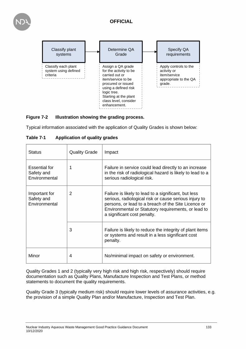
OFFICIAL
Nuclear Industry Aqueous Waste Management Good Practice Guidance Document 133 10/12/2020
Figure 7-2 Illustration showing the grading process.
Typical information associated with the application of Quality Grades is shown below:
Table 7-1 Application of quality grades
Status Quality Grade Impact
Essential for Safety and Environmental
1 Failure in service could lead directly to an increase in the risk of radiological hazard is likely to lead to a serious radiological risk.
Important for Safety and Environmental
2 Failure is likely to lead to a significant, but less serious, radiological risk or cause serious injury to persons, or lead to a breach of the Site Licence or Environmental or Statutory requirements, or lead to a significant cost penalty.
3 Failure is likely to reduce the integrity of plant items or systems and result in a less significant cost penalty.
Minor 4 No/minimal impact on safety or environment.
Quality Grades 1 and 2 (typically very high risk and high risk, respectively) should require documentation such as Quality Plans, Manufacture Inspection and Test Plans, or method statements to document the quality requirements.
Quality Grade 3 (typically medium risk) should require lower levels of assurance activities, e.g. the provision of a simple Quality Plan and/or Manufacture, Inspection and Test Plan.
Apply controls to the activity or item/service appropriate to the QA grade.
Assign a QA grade for the activity to be carried out or item/service to be procured or issued using a defined risk logic tree. Starting at the plant class level, consider enhancement.
Classify each plant system using defined criteria
Classify plant systems
Determine QA Grade
Specify QA requirements

OFFICIAL
Nuclear Industry Aqueous Waste Management Good Practice Guidance Document 134 10/12/2020
Construction of the plant
This section provides the practitioner with guidance on the handling of construction aqueous waste and preventing pollution during construction.
IAEA Specific Safety Guide SSG-38 [99] provides recommendations and guidance based upon international good practice and applies to the construction stage of new nuclear installations and to major modifications and refurbishment of existing nuclear installations. ONR LC19 deals with the Construction or Installation of New Plant. The purpose of LC19 is to maintain the integrity of the design of new plant that may affect safety and thus compliance with its nuclear safety case during the construction or installation phase.
Responsibility for preventing pollution during construction is the responsibility of those in control of the site. Management of activities and risks on site such as deliveries, oil, chemical storage, and emergencies is required to prevent pollution. The EA have produced ‘Pollution Prevention Guidelines’ [100] for site construction and decommissioning activities.
Drainage systems can act as a pathway to spread pollutants. Small amounts of pollutants (such as oil) can spread large distances in water. Drains can also make pollution invisible; a large-scale pollution incident can happen on site unknowingly. The location of drains on site, and where they lead, must be established (e.g. surface water, foul water). The following guidelines must be adhered to:
• measures must be taken to prevent polluting materials entering the drains;
• permission must be sought from the environmental regulator or the local sewerage provider before discharging anything other than clean uncontaminated surface water to a drain and other surface waters or groundwater. Note that an authorisation can take up to four months after submission of application;
• existing drainage on site should be identified by type and whether they have existing protection, e.g. oil separators such as interceptors and silt traps:
- surface water drains and soakaways;
- land drains;
- foul water and combined sewers.
• pollution risks should be identified, e.g. what types of pollution could enter the drains, such as silt-laden water, vehicle oil/fuel, or cement washing.
Works testing and commissioning
Works testing
This section provides the practitioner with guidance in relation to works testing and plant commissioning to enable safe and practical plant operation. It explains inactive and active commissioning, and the fundamental activities required to bring a plant into service.

OFFICIAL
Nuclear Industry Aqueous Waste Management Good Practice Guidance Document 135 10/12/2020
Works Testing is undertaken by the manufacturer, e.g. individual components, or in the assembly of process plant modules containing several components such as pumps, valves, instrumentation and pipework. Factory acceptance testing (FAT) at works is undertaken to demonstrate a limited set of performance parameters of the part or wholly assembled plant modules. At this stage, some operator training may also be possible, along with providing operating and maintenance instructions. The degree of works testing should be maximised as any issues can be more easily resolved at works rather than on site.
Site Testing is undertaken to demonstrate the correct construction of the plant and equipment including non-destructive testing of welds, hydrostatic pressure testing and electrical testing (point-to-point, continuity).
Commissioning
Non-active commissioning provides a demonstration of the whole plant. The final site non-active commissioning tests re-prove items tested during off-site functional acceptance tests, although now under final plant conditions rather than with the temporary plant connections that were used for the works tests.
Active commissioning follows the satisfactory completion of non-active commissioning and the necessary underpinning of safety documentation. As well as demonstrating the overall performance of the plant, a high level of performance monitoring across the plant together with health physics surveys is undertaken to establish detailed operating parameters such as:
• chemical/radiochemical contaminant removal efficiencies;
• system activity build-up and dose rates;
• secondary waste generation rates and characteristics.
LC21 deals with the Commissioning of New Plant. The purpose of LC21 is to ensure that adequate arrangements exist for the commissioning of a new plant or equipment or modified plant or process that may affect safety. These arrangements should:
• verify that structures, systems and components fulfil the design safety objectives through corresponding acceptance criteria;
• verify that the process and plant control interfaces interact and operate as required;
• determine the optimum plant settings for optimal plant performance;
• validate those operating procedures and surveillance procedures for which the commissioning tests provide representative activities and conditions;
• validate by testing/trial, so far as reasonably practicable, that the facilities surveillance and emergency procedures are adequate;
• familiarise the operating, maintenance, and technical staff with the operation of the plant or equipment;
• facilitate the collection of baseline data for equipment and systems for future reference.
• To commission plant and equipment, a clearly defined commissioning plan or philosophy is required which outlines:
• plant or system components;
• means to verify system effectiveness;

OFFICIAL
Nuclear Industry Aqueous Waste Management Good Practice Guidance Document 136 10/12/2020
• means to check all modes of monitoring and control;
• ability to simulate abnormal modes of operation.
The commissioning plan should be matched to the construction sequence and be prepared during detailed design along with the commissioning documentation. Every commissioning activity should have a specific commissioning document. The commissioning documents must be prepared and approved during detailed design stage to be available well before the start of commissioning to allow the Commissioning Team time to scrutinise them.
The commissioning documentation needs to be continually updated during commissioning to ensure that what was done during the commissioning process accurately reflects what was installed and any configuration changes (e.g. to software/firmware) have been adequately recorded. A detailed list of corrective actions and supporting notes should be maintained and the corrective actions closed out before operation.
Commissioning provides invaluable training to operators. It is important to note that a commissioning process may be applied to new plant, to modified existing plant, and to plant re-used for a different purpose with no modification.
Plant operation
This section provides the practitioner with guidance as to what the operator needs in relation to producing procedures to operate an aqueous waste plant and consideration of continual improvement and asset management requirements.
Operational readiness actions should all be completed in advance of planned operations including start-up testing, design validation and plant familiarisation by maintenance personnel. Commissioning activities not only require operators, but also initially provide a non-radiological environment to become familiar with the equipment and system interfaces.
All process technologies have operating bands and criteria that dictate specific actions. The technology specific requirements vary but should be integrated into the operating procedures with clear values and guidance for related actions.
Typical data or parameters that would be monitored for an aqueous waste plant include:
• Operating parameters such as pressure, flow, temperature;
• Chemistry parameters such as chemical impurities, pH, conductivity, TOC, organics;
• Activity and dose rate trends;
• Failure types and their frequency, mode and causal factors.
Operational procedures should address responses to abnormal events including out of tolerance performance parameters, alarms and alerts. The procedures should provide guidance for the following aspects of the response process:
• Notification;
• Actions;
• Recovery;
• Analysis and Documentation.

OFFICIAL
Nuclear Industry Aqueous Waste Management Good Practice Guidance Document 137 10/12/2020
Regardless of the notification requirements, procedures should require documentation of those actions including a summary of the communication, individual(s) contacted, and the date and time.
Event response actions will vary by technology and control mechanisms. Operating procedures should include specific instructions, typically in a separate event response chapter, for the required operator actions. Procedures should also provide event recovery actions, which may require specific instructions and/or procedures.
Similar to other operational aspects, shutdown requirements, considerations and procedures will vary by technology and application. In general, one of the most important aspects of the shutdown process is related to energy control including step wise decrease in electrical power, pressure, and temperature. The process may require a specific sequence for each action and may require controlling the rate at which pressure or temperature is reduced to ambient or otherwise specified values.
The reason for the shutdown may also dictate the extent of the process. For example, an unplanned shutdown may require a partial sequence to support a rapid recovery while a planned shutdown for maintenance or media replacement may require more complete actions and energy reductions.
In addition to the specific technology being adjusted, the process should also consider the impact the shutdown will have on, or how it will be affected by, upstream and downstream equipment and interconnected systems.
In addition to securing the energy source and/or isolating the equipment, shutdown operations may also include additional steps to place the equipment in a desirable condition. The extent of those actions can also be affected by the planned shutdown duration. Longer duration shutdowns may require steps to preclude media or equipment degradation.
The shutdown procedure and process should also consider the subsequent start-up of the equipment by minimising alterations to equipment and control configurations to the extent practical.
Safe, efficient operation of nuclear facilities is an important goal. Continual improvement of the processes of organisations have led to enhanced safety performance and efficiency benefits such as cost reductions and improved cycle times. Many organisations have experienced significant cost improvement largely by or through better financial management and a common
drive to reduce costs brought on by commercial pressures.
In conjunction with LFE from other operating plants/facilities continuous operational improvement should be considered at the outset of the project to improve plant performance and bring about the following benefits:
• Reduced production costs
• Improved quality
• Increased flexibility
• Increased throughput
The IAEA have produced a structured approach to the management of continual improvement for facilities and activities [101]. The document defines a structured approach for continual improvement and focuses on the way an organisation can improve its processes. It is
OFFICIAL
Nuclear Industry Aqueous Waste Management Good Practice Guidance Document 138 10/12/2020
recognised that there are many different approaches and methods available in the marketplace to improve processes. The methodology used described contains steps and practices that are common to many of those improvement strategies.
An Asset Management Plan as detailed in [91] for development and maintenance of key plant components should be prepared before operation. Preventative maintenance (as part of the operating procedures) may be required on a specific periodicity. The required performance parameters should be defined during the design and commissioning phase and be based on objectives, goals and equipment and media supplier recommendations.
Effective control and governance of assets by organisations is essential to realise value through managing risk and opportunity, in order to achieve the desired balance of cost, risk and performance. The regulatory and legislative environment in which organisations operate is increasingly challenging and the inherent risks that many assets present are constantly evolving.
The fundamentals of asset management when integrated into the broader governance and risk framework of an organisation, can contribute tangible benefits and leverage opportunities. Asset management translates the organisation’s objectives into asset-related decisions, plans and activities, using a risk-based approach.
The ONR have produced the following guidance in relation to plant operation:
• LC 23: Operating Rules [102]
• LC 24: Operating Instructions [103]
• LC 25: Operational Records [104]
• LC 26: Control and Supervision of Operations [105]
• LC 27: Safety Mechanisms, Devices and Circuits [106]
• LC 28: Examination, Inspection, Maintenance and Testing (EMIT) [92]
Decommissioning the plant
This section provides the practitioner with guidance as to how design features can facilitate the decommissioning process and that these features should be addressed in the early stages of design.
The IAEA and other industry organisations have produced numerous documents that provide detailed guidance for decommissioning including planning, execution, site remediation and waste disposition. Many of those documents are intended specifically for more complex activities than liquid treatment system decommissioning, but the general guidance, precautions and lessons learned provide valuable insights that can be adopted for decommissioning aqueous waste treatment systems. Several of the most pertinent IAEA and EA documents are listed below:
• Decommissioning of Nuclear Power Plants, Research Reactors and Other Nuclear Fuel Cycle Facilities (Specific Safety Guide) [107]
• Decommissioning of Facilities (General Safety Requirements) [108]
• Decommissioning of Nuclear Power Plants and Research Reactors [109]

OFFICIAL
Nuclear Industry Aqueous Waste Management Good Practice Guidance Document 139 10/12/2020
• Selection of decommissioning strategies: Issues and factors [110]
• The decommissioning of nuclear facilities. [111]
All 36 ONR standard LCs apply during decommissioning and are relevant to activities involving decommissioning on nuclear licensed sites; however, the following LCs and Technical Assessment Guides are of particular relevance:
• LC4 Control of Nuclear Matter
• LC6 Documents, Records, Authorities and Certificates
• LC15 Periodic Review
• LC18 Radiological Protection
• NS-TAST-GD-038 Radiological Protection
• LC22 Modifications
• LC25 Operational Records
• LC28 Examination, Inspection, Maintenance and Testing
• CNS-TAST-GD-5.2 Examination, Inspection, Maintenance and Testing
• LC32 Accumulation of Radioactive Waste
• LC33 Disposal of Radioactive Waste
• LC34 Leakage and Escape of Radioactive Material and Radioactive Waste
• LC35 Decommissioning
• NS-TAST-GD-026 Decommissioning
Designing for Decommissioning should be an integral component of the design process to minimise lifetime risk and costs by, as far as reasonably practicable, minimising the complexity and duration of decommissioning activities. For example, solid-poured concrete walls may increase the level of effort and cost associated with future removal of large components such as evaporators or tanks, requiring them to be segmented in situ rather than being removed as a single unit. Similarly, embedding piping in concrete or using buried pipe vaults or chases may increase the potential for unidentified leakage, necessitating soil remediation.
Lack of foresight in designing for decommissioning may lead to increased operator exposure to risk and significantly increase the cost and timescale of decommissioning. Future (new) plant decommissioning can be greatly facilitated by incorporating at the plant design stage the lessons learnt from previous decommissioning activities. See Box 7-2.
An aqueous waste treatment plant should be designed to minimise any residual aqueous waste within its tanks, vessels and pipework and to maximise the volume of aqueous waste treated by the existing plant during decommissioning.
Consideration should be given to potential decontamination reagents which are ideally compatible with the treatment process. Where this is not practicable the design should provide suitable connections to a temporary plant for treatment and or disposal, i.e. bowser if the activity is low enough or mobile treatment plant.

OFFICIAL
Nuclear Industry Aqueous Waste Management Good Practice Guidance Document 140 10/12/2020
The aqueous waste treatment plant design should include provisions to progressively empty/decontaminate vessels and minimise reagent usage and hence aqueous waste generation, i.e. first stage decontamination with used reagent followed by a second stage with clean reagent. The contents of each vessel should be transferrable to a predetermined vessel to interface with the existing aqueous waste process and/or a temporary treatment facility. There are a number of mobile, modular design, aqueous waste treatment plants which incorporate both filtration and ion exchange located within disposable canisters.
Consideration should be given to the addition of decontamination reagents, i.e. the use of appropriate tie-ins to service lines to allow reagent addition via vessel wash rings. All vessels should have appropriate emptying, i.e. ejector with an inlet as close to the vessel base as practical and wash provisions (if solids are present agitation as well). The final designated vessel should also have sampling facilities.

OFFICIAL
Nuclear Industry Aqueous Waste Management Good Practice Guidance Document 141 10/12/2020
Box 7-2 Key decommissioning considerations for the aqueous waste practitioner
The following should be considered as good practice when considering decommissioning in the plant design:
• Addressing ONR Licence Conditions.
• Creating and maintaining a strategy to recover and deal with the residual contents of the plant.
• Maintaining up to date and accurate documentation.
• Provision of agitation, sampling, and removal systems to facilitate emptying vessels. Minimising the volume of the residual contents of vessels after emptying.
• Provision of, washing, rinsing, reagent addition, venting, flushing, and draining systems with appropriate pipeline falls to facilitate decontamination.
• Provision of inspection ports for access for cameras, radiation monitors, remotely operated vehicles (ROVs), etc. to ascertain plant conditions such as:
− to allow radiation and contamination surveys of plant internals and externals. This will establish radiation fields and the potential need for local or system decontamination or temporary shielding during decommissioning activities;
− to assess residual contents and the extent of removal.
• Provision of aqueous waste treatment/disposal route during decommissioning.
• Retention of handling equipment, cranes, etc. to facilitate plant removal.
• Safe isolation of plant and equipment to protect the operator [112].
• Industrial safety during the decommissioning process. During process operation, abnormal events that may affect future decommissioning decisions and strategies should be thoroughly documented. This information will serve as a reference during decommissioning and will assist with developing an optimal decommissioning strategy.
• Preparation of a decommissioning plan. The plan, its execution performance and results should be carefully documented for future reference. The plan should:
− look for commonality across sites and programmes;
− seek LFE from other similar plant;
− seek innovative solutions;
− address areas of potential cost savings (storage, treatment, etc.).

OFFICIAL
Nuclear Industry Aqueous Waste Management Good Practice Guidance Document 142 10/12/2020
Summary
Box 7-3 Key good practice points for AWP lifecycle management
• Design for the whole plant lifecycle.
• Do not mix aqueous waste streams with different activities unless beneficial to the process and can demonstrate BAT/BPM.
• Address Site Integrated Waste Management Strategy.
• Address existing infrastructure, maximise the use of existing treatment and disposal routes.
• Include adequate redundancy/flexibility. Avoid a single failure stopping or causing major disruption to the plant/process.
• Prepare a Functional Specification.
• The plant design should minimise the potential for the spread of contamination and creation of secondary radioactive waste.
• The plant and processes chosen should minimise the generation of secondary waste, e.g. spent ion exchanger and filters.
• The specification of primary and secondary containment is based on a graded approach to QA, with material of construction, appropriate for the operational conditions of the fluid to be contained and satisfies the required lifetime of the plant.
• Provide adequate capacity of secondary containment (110%) of the capacity of the maximum credible leak.
• Provide adequate fluid level instrumentation (with the associated alarms and trips) within primary and secondary containment to prevent overflow and detect and minimise leakage. Provide clear operating instructions to provide an effective response to deal with alarms and trips.
• Provide an effective, engineered recovery route to return leakage in secondary containment to primary containment.
• Provide appropriate structural strength and materials of construction to contain the maximum credible leak.
• Prevent spurious leaks into secondary containment, i.e. provide watertight barrier.
• Provide inspection (e.g. CCTV, radiation monitors) measures to assess designated collection points (e.g. vessels and sumps).
• Provide adequate EMIT regime for Safety Function Classes (SFCs) and consider ageing management and obsolescence in conjunction with effective records management and review.
• Provision of appropriate sampling techniques to establish the contents of primary containment.
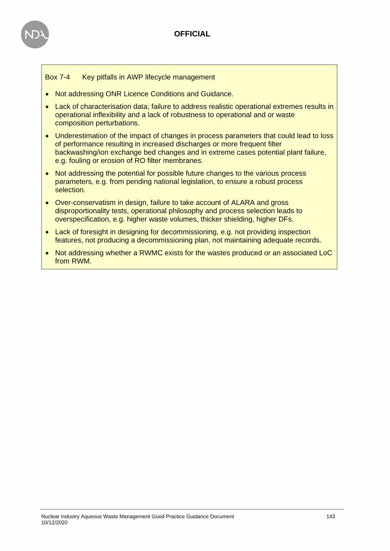
OFFICIAL
Nuclear Industry Aqueous Waste Management Good Practice Guidance Document 143 10/12/2020
Box 7-4 Key pitfalls in AWP lifecycle management
• Not addressing ONR Licence Conditions and Guidance.
• Lack of characterisation data; failure to address realistic operational extremes results in operational inflexibility and a lack of robustness to operational and or waste composition perturbations.
• Underestimation of the impact of changes in process parameters that could lead to loss of performance resulting in increased discharges or more frequent filter backwashing/ion exchange bed changes and in extreme cases potential plant failure, e.g. fouling or erosion of RO filter membranes.
• Not addressing the potential for possible future changes to the various process parameters, e.g. from pending national legislation, to ensure a robust process selection.
• Over-conservatism in design, failure to take account of ALARA and gross disproportionality tests, operational philosophy and process selection leads to overspecification, e.g. higher waste volumes, thicker shielding, higher DFs.
• Lack of foresight in designing for decommissioning, e.g. not providing inspection features, not producing a decommissioning plan, not maintaining adequate records.
• Not addressing whether a RWMC exists for the wastes produced or an associated LoC from RWM.
OFFICIAL
Nuclear Industry Aqueous Waste Management Good Practice Guidance Document 144 10/12/2020
8. References
[1] IAEA, “Safety Glossary - Terminology Used in Nuclear Safety and Radiation Protection,” IAEA, 2018.
[2] OSPAR, “Fourth periodic evaluation of progress towards the objective of the OSPAR radioactive substances strategy,” OSPAR, 2016.
[3] Department for Business, Energy and Industrial Strategy, “Scope of and exemptions from the radioactive substances legislation in England, Wales and Northern Ireland,” BEIS, London, 2018.
[4] OSPAR, “Part 1. UK Report on application of Best Available Techniques (BAT) in civil nuclear facilities (2012-2016) Implementation of PARCOM Recommendation 91/4 on radioactive discharges. Part 2 Summary of Radioactivity in Food and the Environment in the UK.,” 2017.
[5] European Commission, “The OSPAR Convention,” [Online]. Available: https://ec.europa.eu/environment/marine/international-cooperation/ regional-sea-conventions/ospar/index_en.htm. [Accessed 2 March 2020].
[6] Department for Business, Energy and Industrial Strategy, “2018 Review of 2009 UK Strategy for radioactive discharges,” BEIS, London, 2018.
[7] Environmental Agencies Requirements Working Group, “Best Available Techniques for the Management of the Generation and Disposal of Radioactive Wastes Good Practice Guidance, Issue 1,” EA, Bristol, 2010.
[8] UK Government, “The Environmental Permitting (England and Wales) Regulations 2016,” 2016.
[9] Scottish Government, “The Environmental Authorisations (Scotland) Regulations 2018,” 2018.
[10] Nuclear Industry Safety Directors Forum, “Nuclear Industry Code of Practice - Best Available Techniques (BAT) for the Management of the Generation and Disposal of Radioactive Wastes,” 2010.
[11] National Nuclear Laboratory, “A Review of the Best Available Techniques for Effluent Treatment at Sellafield, Issue 4,” 2015.
[12] NEA-OECD, “Effluent Release Options from Nuclear Installations - Technical Background and Regulatory Aspects,” Organisation for Economic Co-operation and Developmment, Paris, 2003.
[13] Office for Nuclear Regulation, “Licence condition handbook,” Bootle, 2018.
[14] UK Government, “The Ionising Radiations Regulations 2017,” 2017.
[15] UK Government, “Nuclear Reactors (Environmental Impact Assessment for Decommissioning) Regulations 1999,” 1999.
[16] UK Government, “The Radiation (Emergency Preparedness and Public Information) Regulations 2019,” 2019.
[17] UK Government, “The Construction (Design and Management) Regulations 2015,” 2015.
[18] Health and Safety Executive, “The Control Of Major Accident Hazards Regulations 2015,” 2015.
[19] UK Government, “The Carriage of Dangerous Goods (Amendment) Regulations 2019,” 2019.

OFFICIAL
Nuclear Industry Aqueous Waste Management Good Practice Guidance Document 145 10/12/2020
[20] UK Government, “The Dangerous Substances and Explosive Atmospheres Regulations 2002, No. 2776, Health and Safety,” Health and Safety Executive, 2002.
[21] Health and Safety Executive, “Control of Substances Hazardous to Health (COSHH),” 18 10 2018. [Online]. Available: http://www.hse.gov.uk/coshh/.
[22] UK Government, “Health and Safety at Work etc. Act 1974,” 1974.
[23] Office for Nuclear Regulation, “Nuclear Safety Technical Assessment Guide - Guidance on the Demonstration of ALARP (As Low As Reasonably Practicable), NS-TAST-GD-005, Revision 9,” 2018.
[24] Nuclear Industry Safety Directors Forum, “A Nuclear Industry Good Practice Guide - The Application of ALARP to Radiological Risk,” Industry Radiological Protection Co-ordination Group, 2012.
[25] Ministry of Defence, “QSEP - Jounrey to ALARP,” [Online]. Available: https://www.asems.mod.uk/sites/default/files/documents/20190221-ALARPJourney.pdf. [Accessed 2 March 2020].
[26] Office of Nuclear Regulation, Environment Agency, Scottish Environment Protection Agency and Natural Resources Wales, “The management of higher activity radioactive waste on nuclear licensed sites, Revision 2,” 2015.
[27] Joint guidance from the Office of Nuclear Regulation, the Environment Agency, the Scottish Environment Protection Agency and Natural Resources Wales to nuclear licensees, “The management of higher activity radioactive waste on nuclear licensed sites,” 2015.
[28] Nuclear Decommissioning Authority, “The Value Framework,” [Online]. Available: https://www.gov.uk/government/publications/nda-value-framework-how-we-make-decisions/explaining-the-value-framework. [Accessed 2 March 2020].
[29] Nuclear Decommissioning Authority, “NDA value framework: how we make decisions,” [Online]. Available: https://www.gov.uk/government/publications/nda-value-framework-how-we-make-decisions. [Accessed 3 March 2020].
[30] LLW Repository Ltd, “National Waste Programme - BAT / BPM Resource Guide, Guidance Document, NWP-REP-100-Issue 2,” LLW Repository Ltd, Drigg, 2018.
[31] Office for Nuclear Regulation, “Nuclear Safety Technical Assessment Guide - The Purpose, Scope, and Content of Saftey Cases, NS-TAST-GD-051, Revision 6,” 2019.
[32] The Nuclear Institute, “UK Nuclear Safety Case Forum Guide: How to Write a Usable Safety Case, Issue 1,” March 2014. [Online]. Available: https://www.nuclearinst.com/write/MediaUploads/SDF%20documents/Safety%20Case/UK_Nuclear_SC_Forum_guide_-_How_to_write_a_usable_Safety_Case_-_March_2014_.pdf. [Accessed 3 March 2020].
[33] Nuclear Decommissioning Authority, “Solid Radioactive Waste Characterisation Good Practice Guide,NDA015834, Issue 1,” 2019.
[34] Nuclear Decommissioning Authority, “Nuclear Industry Group for Land Quality. Nuclear Industry Code of Practice for routine water quality monitoring, Version 1,” 2015.
[35] NEA-OECD, Radiological characterisation from a waste and materials end-state perspective. Practices and experience, 2017.
[36] Environment Agency, “Abatement of radioactive releases to water from nuclear facilities, Technical Guidance A6,” EA, Bristol, 1999.
[37] International Atomic Energy Agency, “Treatment of low and intermediate level liquid waste. Draft,” 2018.

OFFICIAL
Nuclear Industry Aqueous Waste Management Good Practice Guidance Document 146 10/12/2020
[38] International Atomic Energy Agency, “Regulatory control of radioactive discharges to the environment Safety Guide, WS-G-2.3,” IAEA, Vienna, 2000.
[39] BNFL, “Sellafield Fuel Handling Plant update,” August 2003. [Online]. Available: webarchive.nationalarchives.gov.uk/20190701153929/https://www.hse.gov.uk/aboutus/ meetings/iacs/nusac/171003/p10.pdf. [Accessed 15 October 2020].
[40] United States Environmental Protection Agency, “Guidance of Systematic Planning Using the Data Quality Objectives Process, EPA QA/G-4,” 2006.
[41] Environment Agency, “MCERTS: Minimum requirements for the self-monitoring of effluent flow. Version 4.0,” August 2014.
[42] Environment Agency, “Performance Standards and Test Procedures for Continuous Water Monitoring Equipment. Part 1 Performance standards and test procedures for Automatic Water Sampling Equipment. Version 4,” April 2017.
[43] Environment Agency, “Performance standards and test procedures for continuous water monitoring equipment. Part 2 - Performance standards and test procedures for on-line monitors.,” August 2010.
[44] Environment Agency, “Performance Standards and Test Procedures for Continuous Water Monitoring Equipment. Part 3 Performance standards and test procedures for water flowmeters. Version 3,” July 2018.
[45] Environment Agency, “Performance standards and test procedures for portable water monitoring equipment. Version 2.1,” August 2010.
[46] Environment Agency, “Performance standard for organisations undertaking radio-analytical testing of environmental and waste waters. Version 3.0,” December 2018..
[47] Environment Agency, “Performance standard for organisations undertaking sampling and chemical testing of water. Part 1 – Sampling and chemical testing of untreated sewage, treated sewage effluents and trade effluents. Version 3,” December 2018.
[48] ASTM, “Standard guide for sampling radioactive tank waste. C1751-20,” ASTM International, West Conshohocken, PA 19428-2959, United States, 2020.
[49] IAEA, “Strategy and methodology for radioactive waste characterization, IAEA-TECDOC-1537,” IAEA, Vienna, 2007.
[50] Environment Agency, “Monitoring of radioactive discharges to water from nuclear facilities (draft): technical guidance,” 2019.
[51] UK Government, “Radioactive Waste Strategy September 2019,” 2019.
[52] International Atomic Energy Agency, “Recycle and reuse of materials and components from waste streams of nuclear fuel cycle facilities,” 2000.
[53] WRAP, “Cost-effective water saving devices and practices - for industrial sites,” 2005.
[54] UK Government, “Policy paper: Resources and waste strategy for England,” [Online]. Available: https://www.gov.uk/government/publications/resources-and-waste-strategy-for-england. [Accessed June 2020].
[55] Zero Waste Europe, “A Zero Waste Hierarchy for Europe,” [Online]. Available: https://zerowasteeurope.eu/2019/05/a-zero-waste-hierarchy-for-europe/. [Accessed June 2020].
[56] I. Crabbe and R. Keep, “The Design and Construction of a Modular, Transportable, Liquid Effluent Treatment Plant for Use in a NPP Undergoing Decommissioning,” in WM2014 Conference, Phoenix, 2014.
[57] International Atomic Energy Agency, “Mobile Processing Systems for Radioactive Waste Management,” IAEA, 2014, Vienna.
OFFICIAL
Nuclear Industry Aqueous Waste Management Good Practice Guidance Document 147 10/12/2020
[58] Nuclear Decommissioning Authority, “Guide to Technology Readiness Levels for the NDA estate and its supply chain, Issue 2,” November 2014.
[59] Health and Safety Executive, “Registration, Evaluation, Authorisation & restriction of CHemicals (REACH),” HSE, [Online]. Available: https://www.hse.gov.uk/reach/index.htm. [Accessed 26 February 2020].
[60] Health and Safety Executive, “The CLP Regulation,” Health and Safety Executive, [Online]. Available: https://www.hse.gov.uk/chemical-classification/legal/clp-regulation.htm. [Accessed 26 February 2020].
[61] Health and Safety Executive, “The control of legionella bacteria in water systems, Approved Code of Practice and guidance on regulations, L8 (Fourth Edition),” 2013.
[62] P. Davies et al, “The Potential Applications of Graphene (and Related Compounds) Relevant to the NDA’s Decommissioning Mission,” NDA, 2017.
[63] R. Singh, Membrane Technology and Engineering for Water Purification (Second Edition), Butterworth-Heinemann, 2015.
[64] Scottish Environment Protection Agency, “Environmental Authorisations (Scotland) Regulations 2018, Authorisation guide for radioactive substances activities,” 2020.
[65] Environment Agency, Department for Environment, Food and Rural Affairs, Natural Rsource Wales and 6 others, “Environmental managment. Environmental permits,” [Online]. Available: https://www.gov.uk/topic/environmental-management/environmental-permits. [Accessed 26 February 2020].
[66] Department for Environment, Food and Rural Affairs, “Environmental Permitting Guidance Groundwater Activities, For the Environmental Permitting (England and Wales) Regulations 2010,” 2010.
[67] Department for Environment, Food and Rural Affairs, “Environmental Permitting Guidance Water Discharge Activities, For the Environmental Permitting (England and Wales) Regulations 2010,” 2010.
[68] Envrionment Agency, “Form EPB: Application for an environmental permit; Part B6 – New bespoke water discharge activity and groundwater (point source) activity, EPB6 Version 11,” 2020.
[69] Environment Agency, “Guidance notes on part B6 – New bespoke water discharge activity and groundwater activity (point source discharge) EPB6 Version 11,” 2020.
[70] R. W. Allott, “Initial radiological assessment methodology: Part 1 - user report, SC030162/SR,” EA, Bristol, 2006.
[71] R. W. Allott, “Initial radiological assessment methodology: Part 2 - methods and input data, SC030162/SR2,” Environment Agency, Bristol, 2006.
[72] Department of Energy and Climate Change, “Statutory Guidance to the Environment Agency concerning the regulation of radioactive discharges into the environment,” 2009.
[73] Environment Agency, “Environmental Permitting Regulations (England and Wales) 2010. Criteria for setting limits on the discharge of radioactive waste from nuclear sites,” June 2012.
[74] Norwegian Radiation Protection Authority, “ERICA Assessment Tool,” [Online]. Available: http://erica-tool.com/erica/. [Accessed 19 February 2020].
[75] Department for Environment, Food and Rural Affairs and Environment Agency, “Guidance: Risk assessment for your environment permit.,” 1 February 2016. [Online]. Available: https://www.gov.uk/guidance/risk-assessments-for-your-environmental-permit#generic-risk-assessment-for-standard-rules-permits. [Accessed 18 February 2020].

OFFICIAL
Nuclear Industry Aqueous Waste Management Good Practice Guidance Document 148 10/12/2020
[76] Department of Environment, Food and Rural Affairs and Environment Agency, “Guidance: Surface water pollution risk assessment for your environmental permit,” 3 April 2018. [Online]. Available: https://www.gov.uk/guidance/surface-water-pollution-risk-assessment-for-your-environmental-permit. [Accessed 18 February 2020].
[77] Environment Agency, “Permit with Introductory note, The Environmental Permitting (England & Wales) Regulations 2016, Template, 247_10_SD06 Version 7,” 2016.
[78] Environment Agency, “Guidance: RSR permits for nuclear licensed sites: how to comply,” [Online]. Available: https://www.gov.uk/government/publications/rsr-permits-for-nuclear-licensed-sites-how-to-comply/rsr-permits-for-nuclear-licensed-sites-how-to-comply.
[79] Environment Agency, “Decision Document: Sellafield Ltd and Sellafield site,” Environment Agency, Bristol, 2020.
[80] Nuclear Decommissioning Authority, “Guidance on determining optimum decommissionig end states for off-site pipelines, NDA Report NDA020500,” February 2019.
[81] SEPA, “Engineering in the Water Environment Good Practice Guide Intakes and Outfalls, Second edition, August 2019, Document reference: WAT-SG-28,” 2019.
[82] International Organization for Standardization and International Electrotechnical Commission, “ISO/IEC 17025:2005 General requirements for the competence of testing and calibration laboratories,” 2005.
[83] European Commission, “Commission Recommendation of 18 December 2003 on standardised information on radioactive airborne and liquid discharges into the environment from nuclear power reactors and reprocessing plants in normal operation,” 2003.
[84] Department for Business, Energy & Industrial Strategy, “The Standardised Reporting of Radioactive Discharges Direction 2018,” 2018.
[85] Environment Agency, “Standardised Reporting of Radioactive Discharges from Nuclear Sites, LIT 17143,” 2020.
[86] Environment Agency and Scottish Environment Protection Agency , “Radiological Monitoring Technical Guidance Note 1 Standardised reporting of radioactive discharges from nuclear sites, Version 1.0,” May 2010.
[87] Scottish Environment Protection Agency, “Standardised reporting of radioactive discharges from nuclear sites, Radiological Monitoring Technical Guidance Note 1,” 2019.
[88] Environment Agency, “How to apply for an environmental permit Part RSR-B3 – New bespoke radioactive substances activity permit (nuclear site – open sources and radioactive waste),” EA, Bristol, 2016.
[89] Environment Agency, “Application for an environmental permit Part RSR-C3 – Variation to a bespoke radioactive substances activity permit (nuclear site, open sources and radioactive waste),” 2016. [Online]. Available: https://assets.publishing.service.gov.uk/government/uploads/system/uploads/attachment_data/file/527881/LIT_4970.pdf. [Accessed June 2020].
[90] Office of Nuclear Regulation, Environment Agency, Scottish Environment Protection Agency and Natural Resources Wales, “The management of higher activity radioactive,” 2015.
[91] International Organization for Standardization, “ISO 55000:2014 Asset management — Overview, principles and terminology,” 2014.
OFFICIAL
Nuclear Industry Aqueous Waste Management Good Practice Guidance Document 149 10/12/2020
[92] Office for Nuclear Regulation, “LC 28 Examination, Inspection, Maintenance and Testing,,” no. Revision 5, 2016.
[93] International Atomic Energy Agency, “Fundamental Safety Principles,” 2006.
[94] Office for Nuclear Regulation, “Nuclear Safety Technical Assessment Guide - Containment: Chemical Plants,” 2019.
[95] Office for Nuclear Regulation, “Nuclear Safety Technical Assessment Guide - Integrity of Metal Structures, Systems and Components, NS-TAST-GD-016 Revision 5,” 2017.
[96] Sandvik, “Technical centre,” Sandvik, [Online]. Available: https://www.materials.sandvik/en/materials-center/. [Accessed 27 February 2020].
[97] Environmental Protection Agency, “Guidance to Storage and Transfer of Materials for Scheduled Activities,” Environmental Protection Agency, 2020. [Online]. Available: https://www.epa.ie/pubs/advice/licensee/guidancetostorageandtransferofmaterialsforscheduledactivities.html. [Accessed 27 February 2020].
[98] B. Dart, “Graded Application of Quality Assurance in EDF Energy Nuclear Generation,” in IAEA Technical Meeting on Grading the Application of Management System requirements, Vienna, 23-27 January 2012.
[99] International Atomic Energy Agency, “Construction for Nuclear Installations, Specific Safety Guide SSG-38,” Vienna, 2015.
[100] Environment Agency, “Working at construction and demolition sites: PPG6, Pollution Prevention Guidelines, [Withdrawn on 14/12/2015],” 2012.
[101] International Atomic Energy Agency, “Management of continual improvement for facilities and activities: A structured approach,” 2006.
[102] Office for Nuclear Regulation, “LC 23 Operating Rules,” 2019.
[103] Office for Nuclear Regulation, “LC 24 Operating Instructions,” no. Revision 5, 2019.
[104] Office for Nuclear Regulation, “LC 25 Operating Records,” 2019.
[105] Office for Nuclear Regulation, “LC 26 Control and Supervision of Operations,” no. Revision 5, 2019.
[106] Office for Nuclear Regulation, “LC 27 Safety Mechanisms, Devices and Circuits,” no. Revision 4, 2018.
[107] International Atomic Energy Agency, “Decommissioning of Nuclear Power Plants, Research Reactors and Other Nuclear Fuel Cycle Facilities, IAEA Safety Standards Series No. SSG-47,” Vienna, 2018.
[108] International Atomic Energy Agency, “Decommissioning of Facilities, IAEA Safety Standards Series No. GSR Part 6,” Vienna, 2014.
[109] International Atomic Energy Agency, “Decommissioning of Nuclear Power Plants and Research Reactors, IAEA Safety Standards Series No. WS-G-2.1,” Vienna, 1999.
[110] International Atomic Energy Agency, “Selection of Decommissioning Strategies: Issues and Factors, IAEA-TECDOC-1478,” Vienna, 2005.
[111] Environment Agency and Natural Resources Wales, “The decommissioning of nuclear facilities,” 2010.
[112] Health and Safety Executive, “The safe isolation of plant and equipment,” Health and Safety Excecutive, [Online]. Available: https://www.hse.gov.uk/pUbns/priced/hsg253.pdf. [Accessed 27 February 2020].
[113] UK Government, “Nuclear Installations Act 1965 c. 57.,” 1965.
[114] Office for Nuclear Regulation, “ONR Resources: SAPs, TAGs and TIGs,” [Online]. Available: http://www.onr.org.uk/resources.htm. [Accessed 22 June 2020].

OFFICIAL
Nuclear Industry Aqueous Waste Management Good Practice Guidance Document 150 10/12/2020
[115] United Nations, “Convention on third party liability in the field of nuclear energy,” Paris, 1960.
[116] Nuclear Energy Agency, “Paris Convention on Nuclear Third Party Liability, NEA, OECD,” [Online]. Available: https://www.oecd-nea.org/law/paris-convention.html. [Accessed 2 March 2020].
[117] OSPAR, “Ministerial Meeting of the Oslo and Paris Commissions in Paris, 1992,” in Convention for the Protection of the Marine environment of the North-East Atlantic, 1992, 1992.
[118] OSPAR Commission, “OSPAR Convention,” [Online]. Available: https://www.ospar.org/convention. [Accessed 2 March 2020].
[119] International Atomic Energy Agency, “Joint Convention on the Safety of Spent Fuel Management and on the Safety of Radioactive Waste Management,” Vienna, 1997.
[120] International Atomic Energy Agency, “Principles of Radioactive Waste Management Safety Fundamentals, Safety Series No. 111-F,” Vienna, 1995.
[121] International Atomic Energy Agency, “Convention on Nuclear Safety,” Vienna, 1994.
[122] International Atomic Energy Agency, “IAEA Nuclear Energy Series: Policies and Strategies for Radioactive Waste Management,” Vienna, 2009.
[123] IAEA, “Radiation Protection and Safety of Radiation Sources: International Basic Safety Standards. General Safety Requirements Part 3.,” 2014.
[124] European Union, “Council Directive 2009/71/Euratom,” Luxembourg, 2009.
[125] European Union, “Council Directive 2014/87/Euratom,” Brussels, 2014.
[126] European Nuclear Saftey Regulators Group, “Nuclear Safety Directive,” ENSREG, [Online]. Available: http://www.ensreg.eu/nuclear-safety-regulation/eu-instruments/ Nuclear-Safety-Directive. [Accessed 02 March 2020].
[127] European Union, “Council Directive 2013/59/Euratom,” Brussels, 2013.
[128] European Commmision, “Radioactive waste and spent fuel,” European Commmsion, [Online]. Available: https://ec.europa.eu/energy/en/topics/nuclear-energy/ radioactive-waste-and-spent-fuel. [Accessed 2 March 2020].
[129] European Union, “Directive 2008/98/EC,” Strasbourg, 2008.
[130] European Union, “Directive (EU) 2018/851 of the European Parliment and of the Council,” Strasbourg, 2018.
[131] UK Government, “The United Kingdom’s exit from and new partnership with the European Union, Cm 9417,” Crown, 2017.
[132] Scottish Environment Protection Agency, Environment Agency and Natural Resources Wales, “Management of radioactive waste from decommissioning of nuclear sites: Guidance on Requirements for Release from Radioactive Substances Regulation,” SEPA, EA, NRW, 2018.
[133] Environment Agency, “Radioactive Substances Regulation – Environmental Principles, Regulatory Guidance Series, No. RSR 1,” EA, Bristol, 2010.
[134] Environment Agency, “Monitoring discharges to water: guidance on selecting a monitoring approach,” 2020.
[135] Department for Environment Food and Rural Affairs, “Guidance on applying the Waste Hierarchy,” 2011.
[136] Department of Energy & Climate Change, “UK Strategy for Radioactive Discharges (UKSRD09),” Department of Energy & Climate Change, London, 2009.

OFFICIAL
Nuclear Industry Aqueous Waste Management Good Practice Guidance Document 151 10/12/2020
[137] OSPAR Commission, “The North-East Atlantic Environment Strategy, Strategy of the OSPAR Commission for the Protection of the Marine Environment of the North-East Atlantic 2010–2020,” 2010.
[138] Department for Environment, Food and Rural Affairs, “A Strategy for Hazardous Waste Management in England,” 2010.
[139] Nuclear Decommissioning Authority, “Strategy, Efffective from April 2016,” 2016.
[140] Ministry of Defence, “Nuclear Liabilities, Management Strategy,” 2011.
[141] H. J. Lehr, Wiley's Remediation Technologies Handbook: Major Contaminant Chemicals and Chemical Groups, New York: Wiley, 2004.
[142] T. Brinkmann, G. G. Santonja, H. Yükseler, S. Roudier and L. D. Sancho, “Best Available Techniques (BAT) Reference Document for Common Waste Water and Waste Gas Treatment/Management Systems in the Chemical Sector, EUR 28112 EN, Joint Research Centre, European Commission,” European Union, 2016.
[143] Dupont Water Solutions, “Ultrafiltration (UF),” [Online]. Available: https://www.dupont.com/water/technologies/ultrafiltration-uf.html. [Accessed 3 March 2020].
[144] International Atomic Energy Agency, “The Fukushima Daiichi accident. Technical volume 1. Description and context of the accident. IAEA Report STI/PUB/1710,” International Atomic Energy Agency, Vienna , 2015.

OFFICIAL
Nuclear Industry Aqueous Waste Management Good Practice Guidance Document 152 10/12/2020
Appendix 1 – Relevant regulatory information
To accompany discussion of BAT/BPM, ALARP and Nuclear Safety throughout several chapters of this document, this appendix provides some further supporting discussion, prior to tabulating relevant information for:
• International agreements;
• EU directives;
• UK legislation and license conditions;
• UK guidance and guidelines; and
• UK waste management principles and strategies.
BAT/BPM and Environmental Considerations
The overarching requirements for an environmental permit in England and Wales arise from EPR2016 [8]. In Scotland environmental authorisation under EASR2018 applies [9]. More details of associated guidance are given in Box 6-2, and permitting and authorisation applications are discussed in more detail in Sections 6.3, including the key references and requirements that apply. BAT/BPM is an important part of the underlying justification.
As noted in Section 2.1.2, the identification of BAT/BPM may be determined in a number of ways depending on the nature of the task, number of viable options and existence of precedents, including relevant good practice [7]. Where BAT/BPM has already been established for a particular activity, reference to the applicable statutory requirement, industry guidance and/or previous study where the activity was determined as BAT/BPM can be used. However, BAT/BPM can evolve quickly and should be reviewed regularly to establish that any solution is still BAT/BPM. Adequate justification as to the applicability of the identified solution to the current situation must be provided. Where there is no established precedent, an independent assessment of viable options against a range of relevant attributes will be required. The high-level approach to determining, implementing and maintaining BAT/BPM is outlined in [10], while assurances will be required that BAT/BPM remain applicable as concepts develop (e.g. [11]).
The approach and definition of attributes for options assessment will be unique to each BAT/BPM study. Useful resources for consideration during the development of attributes are discussed in Box 2-2. It is important that the attributes selected cover all relevant issues, provide a true measure of performance, are independent from one another (thus avoiding ‘double-counting') and enable the effective discrimination of the options being considered. It is important that each study selects those attributes that are most applicable to its context. Factors that do not discriminate between options, or for which any consequences are insignificant, should be omitted. Attributes should be comparatively weighted in order to ensure that the relative importance of each attribute is taken into account during determination of BAT/BPM. A more qualitative approach, such as claim argument evidence may also be employed.

OFFICIAL
Nuclear Industry Aqueous Waste Management Good Practice Guidance Document 153 10/12/2020
In many cases, BAT/BPM studies will be constrained by one or more factors, depending upon the assessment context. Constraints act to limit the options that can be implemented.
‘Absolute’ constraints are constraints that, if not overcome, render an option unfeasible. Some absolute constraints are common to all options assessments; for example, an option must not breach a fundamental tenet of legislation.
Other constraints may be regarded as ‘conditional’ constraints. Conditional constraints may present significant challenges to implementing an option; the assessment process may well identify that conditional constraints need to be challenged or changed in order to enable implementation of the best solution.
Assumptions may also need to be made; particularly where long timescales are considered. Whatever the approach adopted, the process (and any underpinning constraints or assumptions) should be documented and justified following guidance such as that in Reference [10]. However, making assumptions introduces risks that need to be kept under review and may need to be managed. The risks might change or only apply during later lifecycle stages of the facility, e.g. that a specific solid waste route can be used.
ALARP and Nuclear Safety
Operators of nuclear facilities are required to comply with the Health and Safety at Work Act (HSWA) [22], which places a fundamental duty on employers to ensure, so far as is reasonably practicable, the health, safety and welfare at work of all their employees. It also imposes a duty on employers to ensure, so far as is reasonably practicable, that persons not in their employment are not exposed to risks to their health or safety as a result of the activities undertaken.
The Nuclear Installations Act 1965 (NIA65) [113] requires the licensing of sites that are to be used for certain (but not all) nuclear activities. The following LCs are particularly relevant to the management of aqueous wastes:
LC4: requires that no nuclear matter is stored on the site except in accordance with adequate arrangements made by the licensee for this purpose;
LC32: requires adequate arrangements for minimising, so far as is reasonably practicable (SFAIRP), the rate of production and total quantity of radioactive waste accumulated on the site at any time and for recording the waste so accumulated;
LC34: requires the licensee to ensure, SFAIRP, that radioactive material and radioactive waste on the site is at all times adequately controlled or contained so that it cannot leak or otherwise escape from such control or containment.
As part of compliance with nuclear site licence conditions, designers and operators must demonstrate to ONR that their facility is safe to operate. This demonstration is typically in the form of a ‘safety case’. The ONR expects a safety case to demonstrate that all potential hazards have been identified and assessed for the risk they might pose to workers and the public, and that the risks from these hazards have been reduced to ALARP (see subsection 2.1.5 on ALARP). Guidance on writing a safety case has been produced by the ONR [31] and by the UK Safety Case Forum Guide [32].

OFFICIAL
Nuclear Industry Aqueous Waste Management Good Practice Guidance Document 154 10/12/2020
ONR has established Safety Assessment Principles (SAPs), Technical Assessment Guides (TAGs) and Technical Inspection Guides (TIGs), developed as guidance for their inspectors, which are all published in the public domain to inform duty holders and other stakeholders of ONR’s regulatory expectations. Further detail on these guides, as well as the licence conditions, can be found on the ONR website [114].
International Agreements
Paris-Brussels Convention
The Paris Convention of 29 July 1960 [115] was set out to provide adequate compensation to the public for damage resulting from a nuclear incident and to ensure that the growth of the nuclear industry would not be hindered by bearing an intolerable burden of liability [116]. The Brussels Supplementary Convention was adopted in 1963 to provide for additional public funds.
The significance of the Paris Convention in this context is that it ensures that the operators of nuclear installations, who are in the best position to ensure the safety of their installations, are strictly liable for any failure in safety. It also ensures adequate and fair compensation for victims who suffer certain types of damage due to a nuclear incident (which could include permitted/authorised discharge) at a nuclear installation or during the transport of nuclear substances to and/or from that installation.
OSPAR Convention
The Convention for the Protection of the Marine Environment of the North-East Atlantic, or OSPAR Convention [117], is a mechanism by which 15 Governments and the EU cooperate to protect the marine environment of the North-East Atlantic.
The OSPAR Convention contains a series of Annexes that deal with several specific areas: (a) Prevention and elimination of pollution from land-based sources, (b) Prevention and elimination of pollution by dumping or incineration, (c) Prevention and elimination of pollution from offshore sources, (d) Assessment of the quality of the marine environment, (e) Annex on the protection and conservation of ecosystems and biological diversity of the maritime area [118].
The OSPAR Radioactive Substances Strategy is one of six strategies which set out the objectives and principles under the convention for the reduction of radioactivity concentrations in the marine environment [5].
IAEA Standards and Guidance
IAEA Joint Convention on The Safety of Spent Fuel Management and on The Safety of Radioactive Waste Management

OFFICIAL
Nuclear Industry Aqueous Waste Management Good Practice Guidance Document 155 10/12/2020
The UK is a Contracting Party of the IAEA Joint Convention [119], which imposes obligations to ensure that spent fuel and radioactive wastes are managed so as to adequately protect individuals, society and the environment. The obligations are based upon the 1995 IAEA ‘Principles of Waste Management’ [120] document and include the requirement for Contracting Parties to establish and maintain a legislative and regulatory framework. A Contracting Party is also obligated to provide a national report to each of the review meetings between Contracting Parties at least once every three years. The ONR leads for the UK on collating the contributions from industry and the environment agencies. This report must detail the Contracting Party’s implementation of the obligations required and its relevant spent fuel and radioactive waste management policies; spent fuel and radioactive waste management practices; and the criteria it uses to define and categorise radioactive waste.
The 1994 Convention on Nuclear Safety
The convention aims to legally commit participating states operating land-based nuclear power plants to maintain a high level of safety by setting international benchmarks (Articles) to which member states subscribe. These are based, to a large extent, on the principles contained in the IAEA safety fundamentals document The Safety of Nuclear Installations. The Articles cover, for instance, siting, design, construction, operation, the availability of adequate financial and human resources, the assessment and verification of safety, quality assurance and emergency preparedness.
The Convention requires contracting parties to submit reports on the implementation of their obligations for "peer review", both by written questioning and answering and to attend periodic review meetings of the parties. At present, these occur every three years. ONR leads, on behalf of the Department of Business, Energy and Industrial Strategy (BEIS) for the UK at these meetings. [121]
International Guidance
IAEA Standards and Guidance
IAEA Nuclear Energy Series: Policies and Strategies for Radioactive Waste Management
The Policies and Strategies for Radioactive Waste Management guidance document [122] sets out the key requisites of national policy and strategy for spent fuel and radioactive waste management and aims to help in facilitating safe implementation of all waste management activities through appropriate and systematic planning. It is aimed at organisations within each Member State tasked with preparing, drafting or updating national policies and strategies, as well as waste managers, operators of waste management facilities and regulators.
Radiation Protection and Safety of Radiation Sources: International Basic Safety Standards. General Safety Requirements Part 3.
The IAEA Basic Safety Standards [123] reflect an international consensus on what constitutes a high level of safety for protecting people and the environment from harmful effects of ionising radiation. Development and review of the IAEA standards involves the IAEA Secretariat and all Member States.

OFFICIAL
Nuclear Industry Aqueous Waste Management Good Practice Guidance Document 156 10/12/2020
OECD Nuclear Energy Agency Effluent Release Options from Nuclear Installations
The NEA is an international organisation that acts as a forum for its Member States to share technical expertise in the nuclear industry. The NEA objective in the areas of radioactive waste management and nuclear decommissioning, including nuclear legacy management, is to assist the Member States in the development of safe, sustainable and societally acceptable strategies for the overall management of all types of radioactive waste, including: spent fuel; wastes arising from the decommissioning of nuclear facilities; and legacy sites. Also, its aim is to provide governments and other relevant authorities with authoritative and reliable information on the political, strategic and regulatory aspects of the development of national programmes in these areas.
This report from the NEA examines and reviews the principles of ALARA and BAT, their implications to nuclear installations and their potential to further reduce effluent releases to achieve concentrations of radionuclides in the environment that are considered as “close to zero”. [12]
Western European Nuclear Regulations Association (WENRA)
The main objectives of WENRA are to develop a common approach to nuclear safety, to provide an independent capability to examine nuclear safety in new entrant countries and to be a network of chief nuclear safety regulators in Europe exchanging experience and discussing significant safety issues. Publications from WENRA, including those relating to its work on harmonisation of approaches to the regulation of safety, are available on the association's website.
ONR actively participates within WENRA, and the guidance it provides its inspectors is benchmarked against WENRA reference levels.
European Nuclear Safety Regulators Group (ENSREG)
ENSREG is an independent, expert advisory group composed of senior officials from the national nuclear safety, radioactive waste safety or radiation protection regulatory authorities and senior civil servants with competence in these fields from EU Member States and representatives of the European Commission. ENSREG’s role is to help to establish the conditions for continuous improvement and to reach a common understanding in the areas of nuclear safety and radioactive waste management.
European Union Directives
Nuclear Safety Directive (Directive 2009/71/EURATOM and amendment with 2014/87/EURATOM)
The Directive aims to maintain and promote the continuous improvement of nuclear safety. Member States shall provide for appropriate national arrangements for a high level of nuclear safety to protect workers and the general public against the dangers arising from ionising radiation from nuclear installations.
The Directive also states how Member States shall arrange at least every ten years for periodic self-assessments of their national framework and competent regulatory authorities and invite an international peer review of relevant segments of their national framework and/or authorities. [124] [125] [126].

OFFICIAL
Nuclear Industry Aqueous Waste Management Good Practice Guidance Document 157 10/12/2020
The Basic Safety Standards Directive (2013/59/Euratom) - BSSD
BSSD is an EU directive that sets out standards for radiation protection in Member States. The significance of the BSSD for radioactive waste management is in specification of requirements for practices, such as the release of material from regulatory control (activity concentration values for exemption or clearance of materials), that Member States transpose into national regulations.
The overall objective of radiation protection is to protect workers and the general public against the dangers arising from ionising radiation that result, or could result, from practices using radiation or radioactive substances, including the nuclear fuel cycle. The directive sets limits on the maximum radiation dose that individuals are legally allowed to receive under normal conditions. In addition to monitoring and limiting radiation doses, nuclear facilities and radioactive waste sites are required to ensure that any radiation doses received by the public and its workers are as low as reasonably achievable (ALARA). [125]
EU Radioactive Waste and Spent Fuel Management Directive
This Directive aims to ensure a high level of safety in Member States, avoiding undue burdens on future generations and enhancing transparency. It supplements the basic safety standards referred to in the Euratom Treaty regarding the safety of spent fuel and radioactive waste without conflicting with the precautions outlined in the Basic Safety Standards Directive. [127]
The Directive confirms that the ultimate responsibility falls upon Member States to manage the spent fuel and radioactive waste generated within their country. It includes establishing and maintaining national policies and frameworks and ensuring transparency and availability of required resources and fuel cycle policy within its boundaries. Under the supervision of its national competent regulatory authority, each nuclear licence holder is responsible for the safety of spent fuel and radioactive waste management. The storage of radioactive waste, including long-term storage, is a recognised interim solution, not an alternative to disposal. [128]
Waste Framework Directive (Directive 2008/98/EC)
The Waste Framework Directive sets the basic concepts and definitions related to waste management, such as definitions of waste, recycling, recovery. It explains when waste ceases to be waste and becomes a secondary raw material (so called end-of-waste criteria), and how to distinguish between waste and by-products. The Directive lays down some basic waste management principles: it requires that waste be managed without endangering human health and harming the environment, and in particular without risk to water, air, soil, plants or animals, without causing a nuisance through noise or odours, and without adversely affecting the countryside or places of special interest.
[129] with amendment in 2018 from Directive (EU) 2018/851 [130]

OFFICIAL
Nuclear Industry Aqueous Waste Management Good Practice Guidance Document 158 10/12/2020
UK Legislation & Licence Conditions
UK legislative changes due to EU and Euratom exit
In the White Paper CM 9417 [131], the UK Government indicated its intention to withdraw from the Euratom Treaty. Any EU law in place at that the end of the transition period (31 Dec 2020) will be retained in UK law and will continue to apply until such time as it is amended or revoked. Statutory Instruments (secondary legislation) will amend any retained laws to ensure they are effective and continue to operate properly. Further amendments to UK laws will be implemented when agreement has been reached over a number of key topics, such as how the UK will trade with others. It is expected that the UK regulatory environment will not change significantly as much of it is implemented in domestic legislation and aligns with international standards and guidance.
Environmental Permitting (England and Wales) Regulations 2016 (EPR16)
EPR16 [8] requires those carrying out certain types of activity to hold an environmental permit, covering a wide range of activities that release emissions to land, air and water, or that involve waste. The current regulations in force consolidate and replace the Environmental Permitting Regulations 2010, with further amendments made in 2019.
Environmental Authorisations (Scotland) Regulations 2018 (EASR18)
EASR18 [9] aims to deliver an integrated authorisation framework to integrate, as far as possible, the authorisation, procedural and enforcement arrangements relating to: water, waste management, radioactive substances, and pollution prevention and control.
There are a number of different types of authorisation available under the regulations, depending on the level of complexity and risk associated with an activity, the type of authorisation required will change to reflect that complexity or risk. The four types of authorisation are: general binding rules, notifications, registrations and permits.
The Health and Safety at Work Act 1974 (HSWA74)
The Health and Safety at Work Act 1974 [22] is the primary piece of legislation covering occupational health and safety in Great Britain. Enforcing the act is the responsibility of the HSE, together with local authorities (and other relevant enforcing authorities).
The Act sets out the general duties of employers. Section 2 and 3 sets out general safety requirements on all employers, and therefore covers the safety aspects for workers dealing with spent fuel and radioactive waste. It puts responsibilities on the employers to ‘ ensure, so far as is reasonably practicable, the health, safety and welfare at work of all his employees’ and to ‘conduct his undertaking in such a way as to ensure, so far as is reasonably practicable, that the persons not in his employment who may be affected thereby are not thereby exposed to risks to their health or safety’.
In the context of routine effluent discharges, the requirements to protect the public are vested in EPR16 (and relevant regulations) and regulation by the environment agencies.

OFFICIAL
Nuclear Industry Aqueous Waste Management Good Practice Guidance Document 159 10/12/2020
Ionising Radiations Regulations 2017 (IRR17)
These regulations [14], and their associated Approved Code of Practice, cover the protection of workers and the public from work activities involving ionising radiations. They include a general duty to keep exposures ALARP and, among other requirements, set limits on such exposure.
Nuclear Installations Act 1965 (NIA65)
NIA65 [113] has three key purposes:
It requires the licensing of sites which are to be used for the installation or operation of nuclear reactors (except reactors forming part of a means of transport) and certain other classes of nuclear installations which have been prescribed. "Nuclear installations" can also relate to those installations for which a licence is required under NIA 65 to install or operate them.
It provides for control, via permit, of processes for the enrichment of uranium and the extraction of plutonium or uranium from irradiated matter and the application of associated security measures.
It provides a special legal regime to govern the liability of nuclear site licensees towards third parties for certain kinds of damage caused by nuclear matter on, or coming from, their sites.
The nuclear site licence conditions [13] are born from these requirements and under The Energy Act 2013, ONR were established as a statutory corporation responsible for their enforcement.
Nuclear Site Licence Conditions (LCs)
NIA 65 requires ONR to attach to each nuclear site licence such conditions as it considers necessary or desirable in the interests of safety and ONR may attach conditions with respect to the handling, treatment and disposal of nuclear matter. The licence and LCs apply at all times throughout the life of a licensed nuclear site and therefore cover design, construction, commissioning, operation, maintenance, modifications, decommissioning etc. LCs provide the main basis for regulation by ONR.
Only three of the LCs are directly relevant to radioactive waste management [13]:
LC32 addresses accumulation of radioactive waste and prescribes implementation of adequate arrangements for mitigation and appropriate recording of the accumulated waste. Additionally, LC32 introduces the need for ONR approval of those arrangements.
LC33 addresses disposal of radioactive waste. The radioactive waste stored/accumulated on site must be disposed of as ONR may specify. Also, the process must comply with an environmental permit.
LC34 addresses leakage and escape of radioactive material and waste on the licensed site and that it is adequately controlled or contained at all times. This condition also applies to discharges or releases of radioactive waste in accordance with existing permits under the Environmental Permitting (England and Wales) Regulations 2016 (EPR16) regulations.

OFFICIAL
Nuclear Industry Aqueous Waste Management Good Practice Guidance Document 160 10/12/2020
Safety Assessment Principles (SAPs), Technical Assessment Guides (TAGs), Technical Inspection Guides (TIGs)
ONR has established SAPs, TAGs, and TIGs which apply to the assessment by ONR specialist inspectors of safety cases for nuclear facilities that may be operated by potential licensees, existing licensees, or other duty-holders. Although created for inspectors, they are published in the public domain for transparency and to provide information to licensees and duty holders regarding ONR's expectations of the nature and content of relevant technical elements of safety cases and security plans.
UK Guidance and Guidelines
HAW Joint Regulatory Guidance (ONR, NRW, SEPA, EA)
The management of higher activity radioactive waste on nuclear licensed sites guidance [26] was published jointly by the ONR, the EA, the SEPA and the NRW to nuclear licensees in 2015.
The Guidance sets out the regulatory process associated with the management of HAW on nuclear licensed sites in the UK; it makes clear that a licensee should produce an integrated waste strategy and outlines in broad terms what it should contain. The Guidance also describes regulatory expectations with respect to the production, content and review of Radioactive Waste Management Cases (RWMCs – these complement nuclear safety cases by indicating how the key elements of long-term safety and environmental performance will be delivered for the waste stream or streams covered). The overview of the relevant policy drivers, regulatory requirements and expectations relating to waste minimisation, characterisation and segregation is provided.
Guidance on Requirements for Release from the Radioactive Substances Regulation (GRR)
The GRR [132] is a multi-agency guidance document published as a draft in July 2018. The primary intended audience are operators of nuclear sites across the Great Britain that hold, or intend to hold, an environmental permit for the disposal of radioactive waste. The GRR describes what operators of nuclear sites need to do over the lifetime of the site in order that they can be released from the RSR when all activities, including the management of radioactive waste, have ceased.
There are several requirements set out by the guidance: (a) the requirement for optimised plans that outline the management of the radioactive wastes from decommissioning and clean-up of a nuclear site; (b) the standards that must be met if those optimised plans identify that radioactive wastes are best managed by on-site disposal; (c) the standards that a nuclear site must meet to enable it to be released from RSR.
RSR: Principles of optimisation in the management and disposal of radioactive waste
This guidance [133] gives an overview of the principles of optimisation in the management and disposal of radioactive waste from radioactive substances activities.
This guidance sets out the principles and framework for undertaking studies on optimisation and the identification of BAT. It refers to other guidance such as guidance on options studies and the assessment of radiological dose impacts, which operators may need to undertake as part of the overall assessment
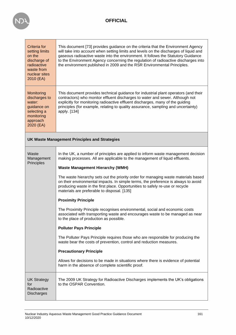
OFFICIAL
Nuclear Industry Aqueous Waste Management Good Practice Guidance Document 161 10/12/2020
Criteria for setting limits on the discharge of radioactive waste from nuclear sites 2010 (EA)
This document [73] provides guidance on the criteria that the Environment Agency will take into account when setting limits and levels on the discharges of liquid and gaseous radioactive waste into the environment. It follows the Statutory Guidance to the Environment Agency concerning the regulation of radioactive discharges into the environment published in 2009 and the RSR Environmental Principles.
Monitoring discharges to water: guidance on selecting a monitoring approach 2020 (EA)
This document provides technical guidance for industrial plant operators (and their contractors) who monitor effluent discharges to water and sewer. Although not explicitly for monitoring radioactive effluent discharges, many of the guiding principles (for example, relating to quality assurance, sampling and uncertainty) apply. [134]
UK Waste Management Principles and Strategies
Waste Management Principles
In the UK, a number of principles are applied to inform waste management decision making processes. All are applicable to the management of liquid effluents.
Waste Management Hierarchy (WMH)
The waste hierarchy sets out the priority order for managing waste materials based on their environmental impacts. In simple terms, the preference is always to avoid producing waste in the first place. Opportunities to safely re-use or recycle materials are preferable to disposal. [135]
Proximity Principle
The Proximity Principle recognises environmental, social and economic costs associated with transporting waste and encourages waste to be managed as near to the place of production as possible.
Polluter Pays Principle
The Polluter Pays Principle requires those who are responsible for producing the waste bear the costs of prevention, control and reduction measures.
Precautionary Principle
Allows for decisions to be made in situations where there is evidence of potential harm in the absence of complete scientific proof.
UK Strategy for Radioactive Discharges
The 2009 UK Strategy for Radioactive Discharges implements the UK’s obligations to the OSPAR Convention.

OFFICIAL
Nuclear Industry Aqueous Waste Management Good Practice Guidance Document 162 10/12/2020
The 2009 UK Strategy for Radioactive Discharges [136] implements the UK’s obligations under the OSPAR Commission’s Radioactive Substances Strategy [137] and provides a clear statement of the UK’s position on radioactive discharges, including aerial discharges. The strategy does not prescribe individual site limits for radioactive discharges; instead, it places the responsibility on regulators to ensure that the UK policy is implemented through the setting of appropriate discharge limits. In 2018 BEIS published a review of the 2009 Strategy for Radioactive Discharges [6]. The review took account of developments such as UK policy, commercial decisions and technological advances within the nuclear industry. The review confirmed that there was “clear evidence of progress being made by the UK” in meeting the outcomes described in the 2009 strategy.
Strategy for Hazardous Waste Management, 2010
The Strategy for Hazardous Waste Management [138] has been conceived to underpin the practical application of the revised Waste Framework Directive 2008/98/EC (WFD) and in particular the requirements that apply to hazardous waste in relation to the waste hierarchy, the treatment of hazardous waste, and the provision of infrastructure.
Hazardous waste is waste that may cause particular harm to human health or the environment. Such wastes contain one or more hazardous properties. The European Commission defines hazardous waste and such wastes are currently asterisked in the European Waste List (Commission Decision 2000/532/EC). The list is subject to periodic review by the European Commission.
NDA Strategy 2016
The NDA Strategy [139] describes the high-level approach to delivering the NDA mission. The strategy outlines key strategies for ensuring that the UK’s nuclear legacy sites are decommissioned and cleaned up safely, securely, cost-effectively and in ways that protect people and the environment.
A key NDA strategic objective is to reduce the environmental impact of radioactive liquid and gaseous discharges in accordance with the UK Strategy for Radioactive Discharges.
Nuclear Liabilities Management Strategy, Ministry of Defence (MOD)
The Nuclear Liabilities Management Strategy [140], published in 2011, sets out the high level approaches for the management of the MOD’s nuclear liabilities and consists of four key strategic themes: nuclear material; irradiated fuel; sites, facilities and submarines; and radioactive waste management.
It outlines the MOD’s commitment to continue to work with the NDA and other waste producers to ensure that the best value for money solutions are exploited for the UK. The strategy recognises that MOD will manage its HAW in accordance with the policies of the UK Government and the Devolved Administrations. This means some HAW will be disposed to the GDF or else managed in line with Scottish Government policy in near-surface facilities. Note that Scottish Government policy is applicable to certain HAW from sites that are subject to regulation under a radioactive substances permit.

OFFICIAL
Nuclear Industry Aqueous Waste Management Good Practice Guidance Document 163 10/12/2020
Appendix 2 – Description of water treatment technologies
Presented below are brief descriptions of assorted techniques that are suitable for water treatment. These are established water treatment technologies that have been proven to work in water treatment processes, but not necessarily nuclear applications. To reflect this, a technology readiness level (TRL) and an NDA TRL have been included, indicating the use in conventional and nuclear applications, respectively.
It should be recognised that the list below is not exhaustive. These technologies have been shown to be appropriate as best available technique (BAT) technologies (e.g. documented in the European Union BAT Reference (BREF) documents). There are several bespoke technologies available that are not documented, although several of these utilise variations of the below technologies (for example, 3M have developed the Empore Extraction disk that utilises sorbents or ion exchange materials embedded within a Teflon matrix). It is therefore possible that there is a vendor that implements the technologies below that are suitable for a given contaminant.
A useful resource is Wiley’s Remediation Technologies Handbook – Major Contaminant Chemicals and Chemical Groups [141], which provides a list of contaminants and technologies for a specified analyte.
Furthermore, new techniques are continually developed. This list is not intended to be exhaustive as new technologies will be developed that may be appropriate. Technologies that are low TRL (e.g. being developed in a research lab with a TRL of 6 or lower) have not been considered but would generally be expected to fall within the categories presented in subsection 5.2).
All of the technologies presented below can be applied to any aqueous waste stream (e.g. feedwater to minimise the waste generated, or waste water to prevent discharge of radioactive contamination). However, some techniques will be more appropriate than others for contaminated waste. For example, it may be inappropriate to treat aqueous phases with a high tritium concentration via distillation due to the gaseous tritium that requires treatment.
It is important to note however, that most techniques specified below result in the concentration of radioactive material, whether through particulate removal (e.g. filters), a more concentrated aqueous stream (e.g. RO) or removal of soluble species onto a solid material (e.g. ion exchange media). Consequently, when treating radioactive waste streams all will result in a local increase in dose rate as the radioactivity becomes more concentrated. Care when designing the system is required to ensure operator dose remains as low as reasonably practicable (ALARP).
The following technologies/techniques are presented in the tables below:

OFFICIAL
Nuclear Industry Aqueous Waste Management Good Practice Guidance Document 164 10/12/2020
• Grit Separation
• Coagulation/Flocculation
• Sedimentation
• Flotation
• Filtration
• Microfiltration/Ultrafiltration
• Oil-water Separation
• Hydrocyclone
• Electrocoagulation
• Nanofiltration/Reverse osmosis (RO)
• Electrodialysis
• Chemical Precipitation
• Chemical oxidation (pre)
• Wet Oxidation with Hydrogen Peroxide (pre)
• Wet Air Oxidation (pre)
• Chemical Reduction
• Electrolysis
• Adsorption
• Ion Exchange
• Crystallisation
• Extraction
• Pertraction
• Distillation/Rectification
• Evaporation
• Pervaporation
• Stripping
• Chemical Hydrolysis
• Electrodeionisation
The technologies presented have several headings:
• Description A summary of what the technology does. The following are also covered:
- What classes of contaminants is the technology used for? What sort of decontamination factors (DFs) are achievable if the technology is used in a stand-alone mode?
- If the technology is commonly linked to another technology (e.g. to increase overall DF), this is mentioned.
- At what stage of the treatment process is the technology generally used?
• Input constraints This describes the required physical and chemical characteristics of input water and information relevant on flows and batch/online operation. For example, separate into feed water and aqueous waste, are there constraints on solids, presence of oils, pH.
• Output The form of the main input waste stream after processing
• Secondary waste produced This describes the types of secondary waste produced, for example an additional liquid waste, precipitate, etc. Problematic waste that might be produced is also included; this may be a high-level flag of problems with the technology.
• Market availability See subsection 5.1.8 for discussion
• Logistics/space/infrastructure requirements Any issues with flexibility and scalability of the technology are identified.
• Advantages and disadvantages This summarises points made in preceding sections and includes additional points such as any hazards associated with the technology (e.g. high pressures, temperature, strong acids/bases) and any specific consequences of acute releases or chronic leaks.

OFFICIAL
Nuclear Industry Aqueous Waste Management Good Practice Guidance Document 165 10/12/2020
• Operational experience Principally, is it widely used with successful result; or a niche technology with many constraints on application?
• Costs A qualitative scale is used: low, medium, high.
• Applications Where available, high level information has been provided for example applications.

OFFICIAL
Nuclear Industry Aqueous Waste Management Good Practice Guidance Document 166 10/12/2020
Grit Separation
Technique Grit Separation (Coarse material removal)
Description The physical separation of solid grit particles, suspended in a liquid waste. This is performed as the presence of solid particles could disturb further treatment of the water, and lead to abrasion of components such as pumps.
TRL 9 NDA TRL 9
Input Water with a particulate burden with a large particle size distribution.
Output Water stream with sand and larger particle removed, however still containing smaller solid particles.
Secondary Waste
Removed solid particles, which need to be stored until disposal.
Market Availability
Common equipment, although the method of grit separation can vary significantly, including coarse filters to drum screens.
Infrastructure Size dependent – drum screens are typically large while coarse filters can be acquired from laboratory scale to industrial size. A single filter may not be sufficient however – a graded approach to filter size may be required to prevent blinding.
Advantages Removal of solids prevents possible damage to equipment, and allows further treatment processes to be carried out without being disturbed by suspended solids.
Disadvantages
Smaller solid particles are not removed, and follow the water stream. This is due to the removal process and typical flow rate (≈0.3 m/s), which could be altered to allow removal of smaller particles. The grit chamber contributes to noise and odour emissions, therefore enclosing the equipment may be necessary.
OPEX
Current grit separators are designed to remove sand and gravel from water. This means that smaller solid particulates are not removed and are carried on with the waste water stream. There are three different designs of grit chamber, to be used on water streams with different flow properties, showing grit separation to be a highly established technique. Most UK waste water treatment plants use this technique.
Costs Electricity is consumed in order to power the pumps and air jets. There are different designs available which will all vary in cost and will depend upon the application, type of particle, size, etc.
Applications Commonly used in non-nuclear applications (e.g. water treatment plants). Grit separation is also employed at the Magnox Chapelcross site to remove particulates from liquid effluent.

OFFICIAL
Nuclear Industry Aqueous Waste Management Good Practice Guidance Document 167 10/12/2020
Coagulation/Flocculation
Technique Coagulation/Flocculation
Description
The removal of suspended solids from waste water. This is often carried out in successive steps which are intended to overcome the forces stabilising the suspended particle, allowing particle collision and growth of floc. Coagulation destabilises the particles’ charge by neutralising their electrical surface charge using coagulants of an opposite charge. This causes the particles to stick together into large particles. Most coagulants are inorganic, however polymers are also becoming more widely used as coagulant aids. In order to be successful, high-energy rapid mixing is required, which fully disperses the coagulant and promotes more particle collisions. Flocculation is a gentle mixing stage, which aims at increasing the particle size. This requires careful control of the mixing velocity, in order to collide and bond with the microfloc particles, producing larger flocs. The flocs are then removed by sedimentation, air flotation or filtration.
TRL 9 NDA TRL 6-9
Input Waste water containing suspended solids.
Output Water stream with suspended solids removed. Solid waste in the form of a floc.
Secondary Waste
Removed solid floc.
Market Availability
Common technology that is well established in industrial water treatment processes. A wide range of flocculants and coagulants are available, but may require trialling to select the optimal material and maximise removal. Coagulation and flocculation are usually combined with other technologies.
Infrastructure
Can be performed in batch or continuous process. A batch process requires tanks for processing but is scalable for low to large quantities (note it may not be cost effective for very small quantities due to flocculant/coagulant and potential trials). Continuous processes are typically limited to large water treatment plants and require sufficient volume for complete reaction to occur.
Advantages Well established technique with many applications. Different coagulants and flocculants available, making coagulation and flocculation optimal for each waste stream.
Disadvantages
Careful control of the mixing velocity and amount of mix energy is required when producing the floc. Improper use can cause the floc to tear, which it is then difficult to re-form to its optimum size and strength Information on the charge, size, shape and density of the solid particles is necessary in order for coagulation and flocculation to be fully effective. Alternatively, laboratory testing may be required. Close process control required to prevent overdosing. Risk of downstream reactions (any unreacted chemicals reacting further down in the process e.g. leading to fouling). Consideration of compatibility of reagents with disposal routes.
OPEX Coagulation and flocculation is used within the chemical industry, the textile industry, the food industry, slaughterhouses and in the surface treatment of metals.
Costs
The main costs associated with this process are the chemicals required. These can vary largely but according to the Best Available Techniques (BAT) Reference Document for Common Waste Water and Waste Gas Treatment/Management Systems in the Chemical Sector (2010/75/EU) [142], the cost of chemicals is reported to be in the range of EUR 0.15-5 per kg, and the removal cost of the sludge is around EUR 500 per tonne (non-active). Other costs incurred are due to energy, maintenance and personnel.
Applications Flocculation is used at Sellafield in Effluent Distribution Tanks to process Magnox Swarf Storage Silo (MSSS) compartment liquor with high loading of non-settling solids. The output is a high pH liquor that is sent to SIXEP. This process is being
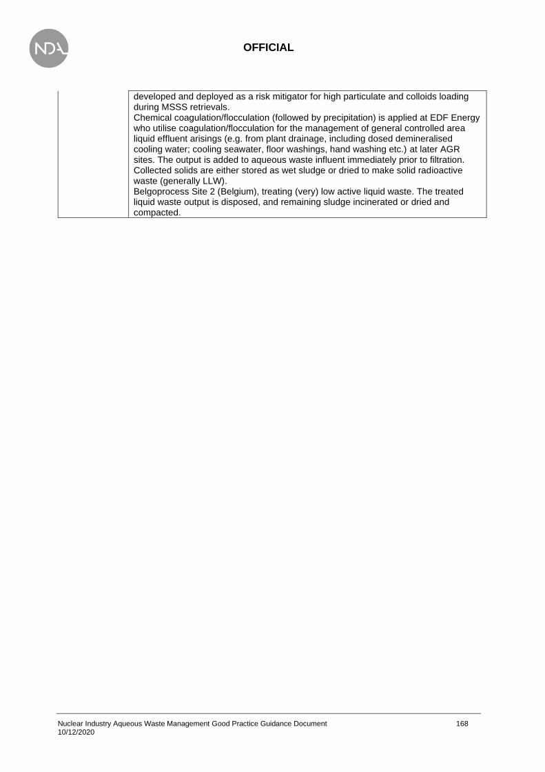
OFFICIAL
Nuclear Industry Aqueous Waste Management Good Practice Guidance Document 168 10/12/2020
developed and deployed as a risk mitigator for high particulate and colloids loading during MSSS retrievals. Chemical coagulation/flocculation (followed by precipitation) is applied at EDF Energy who utilise coagulation/flocculation for the management of general controlled area liquid effluent arisings (e.g. from plant drainage, including dosed demineralised cooling water; cooling seawater, floor washings, hand washing etc.) at later AGR sites. The output is added to aqueous waste influent immediately prior to filtration. Collected solids are either stored as wet sludge or dried to make solid radioactive waste (generally LLW). Belgoprocess Site 2 (Belgium), treating (very) low active liquid waste. The treated liquid waste output is disposed, and remaining sludge incinerated or dried and compacted.
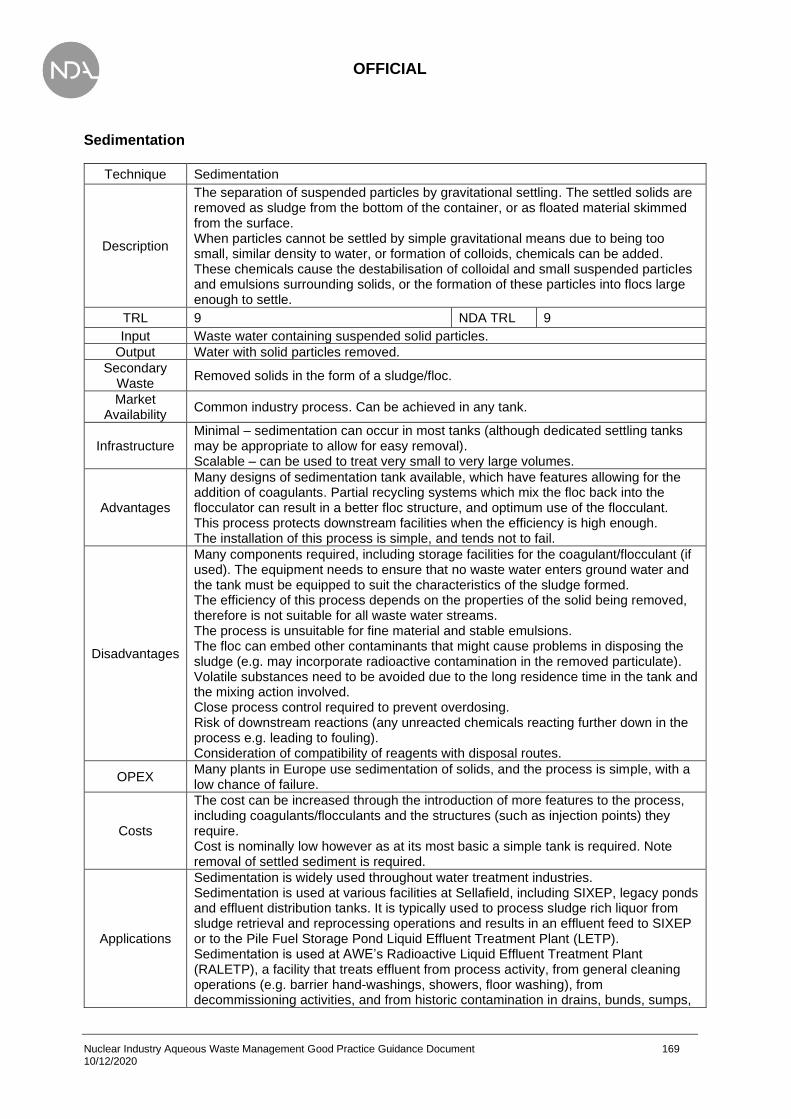
OFFICIAL
Nuclear Industry Aqueous Waste Management Good Practice Guidance Document 169 10/12/2020
Sedimentation
Technique Sedimentation
Description
The separation of suspended particles by gravitational settling. The settled solids are removed as sludge from the bottom of the container, or as floated material skimmed from the surface. When particles cannot be settled by simple gravitational means due to being too small, similar density to water, or formation of colloids, chemicals can be added. These chemicals cause the destabilisation of colloidal and small suspended particles and emulsions surrounding solids, or the formation of these particles into flocs large enough to settle.
TRL 9 NDA TRL 9
Input Waste water containing suspended solid particles.
Output Water with solid particles removed.
Secondary Waste
Removed solids in the form of a sludge/floc.
Market Availability
Common industry process. Can be achieved in any tank.
Infrastructure Minimal – sedimentation can occur in most tanks (although dedicated settling tanks may be appropriate to allow for easy removal). Scalable – can be used to treat very small to very large volumes.
Advantages
Many designs of sedimentation tank available, which have features allowing for the addition of coagulants. Partial recycling systems which mix the floc back into the flocculator can result in a better floc structure, and optimum use of the flocculant. This process protects downstream facilities when the efficiency is high enough. The installation of this process is simple, and tends not to fail.
Disadvantages
Many components required, including storage facilities for the coagulant/flocculant (if used). The equipment needs to ensure that no waste water enters ground water and the tank must be equipped to suit the characteristics of the sludge formed. The efficiency of this process depends on the properties of the solid being removed, therefore is not suitable for all waste water streams. The process is unsuitable for fine material and stable emulsions. The floc can embed other contaminants that might cause problems in disposing the sludge (e.g. may incorporate radioactive contamination in the removed particulate). Volatile substances need to be avoided due to the long residence time in the tank and the mixing action involved. Close process control required to prevent overdosing. Risk of downstream reactions (any unreacted chemicals reacting further down in the process e.g. leading to fouling). Consideration of compatibility of reagents with disposal routes.
OPEX Many plants in Europe use sedimentation of solids, and the process is simple, with a low chance of failure.
Costs
The cost can be increased through the introduction of more features to the process, including coagulants/flocculants and the structures (such as injection points) they require. Cost is nominally low however as at its most basic a simple tank is required. Note removal of settled sediment is required.
Applications
Sedimentation is widely used throughout water treatment industries. Sedimentation is used at various facilities at Sellafield, including SIXEP, legacy ponds and effluent distribution tanks. It is typically used to process sludge rich liquor from sludge retrieval and reprocessing operations and results in an effluent feed to SIXEP or to the Pile Fuel Storage Pond Liquid Effluent Treatment Plant (LETP). Sedimentation is used at AWE’s Radioactive Liquid Effluent Treatment Plant (RALETP), a facility that treats effluent from process activity, from general cleaning operations (e.g. barrier hand-washings, showers, floor washing), from decommissioning activities, and from historic contamination in drains, bunds, sumps,

OFFICIAL
Nuclear Industry Aqueous Waste Management Good Practice Guidance Document 170 10/12/2020
tanks etc. In concentrate tanks, solids settle out over several days, the supernatant being removed and pumped back through the evaporator system. Sedimentation is used at EDF Energy AGR sites. The input includes backwashing from filters; transfers of spent filter media (e.g. sand, ion exchange resin). The output includes aqueous supernatant sent forward for further treatment (e.g. filtration as a minimum; some supernatant streams are also subject to ion exchange). Sludges are stored wet under residual supernatant. Filters (e.g. sand) are backwashed to settling/sludge storage tank(s) when filter pressure differential limits are reached. Spent filter media (e.g. sand) are also transferred to the same sludge storage tank(s). Spent ion exchange media (e.g. resin) are similarly transferred to storage tank(s). Motive power for backwashing/transfers is aqueous liquid, so accumulated supernatant needs batch disposal when tank limits are reached and supernatant has 'settled'.

OFFICIAL
Nuclear Industry Aqueous Waste Management Good Practice Guidance Document 171 10/12/2020
Flotation
Technique Flotation
Description
The removal of solid or liquid particles using fine gas bubbles of nitrogen or fuel gas. The buoyant particles accumulate at the surface and are collected with skimmers. Flocculant additives can be introduced to support the flotation process, which as well as causing coagulation and flocculation, create a surface which is able to absorb the gas bubbles. There are three methods of flotation, which vary by the way that gas is added: vacuum flotation, induced gas flotation and dissolved gas flotation.
TRL 9 NDA TRL 6-8
Input Waste water stream containing solid and liquid contaminants.
Output Water stream with reduced contaminant concentration. Skimmed material (floc) of contaminant. Some escaped gas may also be present.
Secondary Waste
Skimmed material (floc) of contaminant(s).
Market Availability
Standard process within water treatment plants – no significant availability issues.
Infrastructure Infrastructure requirements can vary from a simple tank (if contaminants float without assistance) to requiring compress gas supplies, chemicals (flocculants and coagulants, if used) , and skimmers.
Advantages
Flotation can remove dyes, pigments, heavy metals and activated sludge biological waste, from waste water. A smaller volume and therefore cost associated with flotation than with sedimentation. It is also not affected by flow rate in the same way that sedimentation is. A high separation efficiency can be achieved (higher than with sedimentation). Flotation can be used to recover valuable and well as waste materials. Shorter residence times than with sedimentation, allowing for more volatile contaminants to be present. Greater control and adaptation of operating conditions, subject to the availability of more highly trained personnel.
Disadvantages
This process is not suitable for particles with poor settling characteristics. Oil and grease also cannot be removed by flotation. The pumps, mixer and compressor are sources of noise, therefore must be equipped with adequate containment measures. Clogging of valves is possible. Higher operating costs and energy consumption than sedimentation. May result in greater aerial activity from radioactive gas discharges (e.g. tritium).
OPEX Many industries use flotation, such as chemical, food, tank cleaning and refineries. More trained personnel are required for this process however the technology is well established and widely used.
Costs The cost varies widely and is dependent on purpose. There is also a factor of flow rate which affects the cost.
Applications None in the nuclear industry.

OFFICIAL
Nuclear Industry Aqueous Waste Management Good Practice Guidance Document 172 10/12/2020
Filtration
Technique Filtration
Description
The separation of solids from waste water effluents passing through a porous medium. Filtration is often used alongside other methods such as flotation and sedimentation, usually as the final separation technique. Common filter systems include: - Granular-medium filter, or sand filter which are used for low solid content. - Gravity drum filter, used for sewage treatment and the removal of activated sludge flocs. - Rotary vacuum filter, which is used for oily sludge dewatering and slop de-emulsification. - Membrane filter - Belt filter press which is mostly used for sludge dewatering, as well as liquid/solid separation operations - Filter press which is usually used for sludge dewatering, and is suitable for high solid content liquid/solid operations. Note that filters has been combined with other techniques (e.g. pre-coat filters) but are generally considered specialist applications.
TRL 9 NDA TRL 7 - 9
Input Waste water containing solid contaminants. The choice of filtration method of filtration depends on the input material, such as high or low soli content, oily sludge, or water based sludge.
Output Water with solids removed. Output is dependent on method used, but most will produce a solid sludge and a water/oil stream.
Secondary Waste
The removed solid sludge.
Market Availability
Filtration is a well-established technique but there are a large variety of different types of filters and filter sizes. Selection of the appropriate filter can be difficult and will require engagement with the manufacturer.
Infrastructure
Infrastructure can vary dependent upon the type of filter. A simple filter that relies on the driving pressure can be installed as a cartridge and used from laboratory scale to industrial waste treatment. Infrastructure will generally increase as the particle loading increases – may require larger filters or more frequent replacement. Methods are available to periodically remove particulate from the filters but requires further infrastructure (e.g. compressed air supplies). Filters in series may be required to prevent blinding, further increasing space requirements.
Advantages
Many methods of filtration available so the optimum method can be chosen for the waste stream. The residue from some kinds of filter such as the drum, or belt filter, can be recycled if it is not waste or requires further refinement. Sand filtration shows advantage over drum filtration as less backwash water is required. Many uses such as separation of heavy metal hydroxides to comply with discharge requirements, removal of sludge after sedimentation to improve the quality of biologically treated waste, and the recovery of free oil.
Disadvantages
The operating equipment can be a source of significant noise, therefore may need to be enclosed. Pressure filters, filter presses and a treatment system may be required if odorous substances are expected to be released.
OPEX Filtration is a relatively simple method, used in conjunction with more complex methods. There are many industries which used this method and the technology is well established.

OFFICIAL
Nuclear Industry Aqueous Waste Management Good Practice Guidance Document 173 10/12/2020
Costs Filtration is a relatively inexpensive methods, often used to complement other processes. Costs are relative to the volume of water to be treated.
Applications
Many sectors use filtration, including the nuclear industry. Filtration is used at Sellafield in the treatment of pond water from the fuel handling plant, First Generation Magnox Fuel Storage Plant, and from the Pile Fuel Storage Pond (PFSP). The filtered effluent is subsequently treated by ion exchange. Filtration is applied at EDF Energy sites (AGRs and PWR) for the treatment of general controlled area liquid effluent arising (plant drainage including dosed demineralised cooling water; cooling seawater, floor washings, hand-washings, showers, laundry, supernatant from settling tanks etc.). PWR effluent includes primary and secondary coolant. AGRs generally employ coarse filtration (e.g. sand filters) followed by finer filtration (e.g. candle filters, ceramic filters) to achieve general target of 5 micron. Sand filter waste is sent to sludge storage tanks for settling and wet storage. Cartridge/candle filters are dried to become dry radioactive waste (generally LLW or incineration to VLLW). The PWF uses only cartridge/candle filters. Filtration is used at the front end of AWE’s Radioactive Liquid Effluent Treatment Plant (RALETP), a facility which treats effluent from process activity, from general cleaning operations (e.g. barrier hand-washings, showers, floor washing), from decommissioning activities, and from historic contamination in drains, bunds, sumps, tanks etc. The facility uses a coarse basket filter (5 mm) before pump and 100 micron bag filter behind pump, prior to receipt tanks. Filtration is used at most Magnox sites in the processing of liquid effluent. At Chapelcross, coarse 410 micron and fine 100 micron filters are in use. At the Dungeness Modular Active Effluent Treatment Plant (MAETP), filtration is used for the removal of particulates to 5 micron.
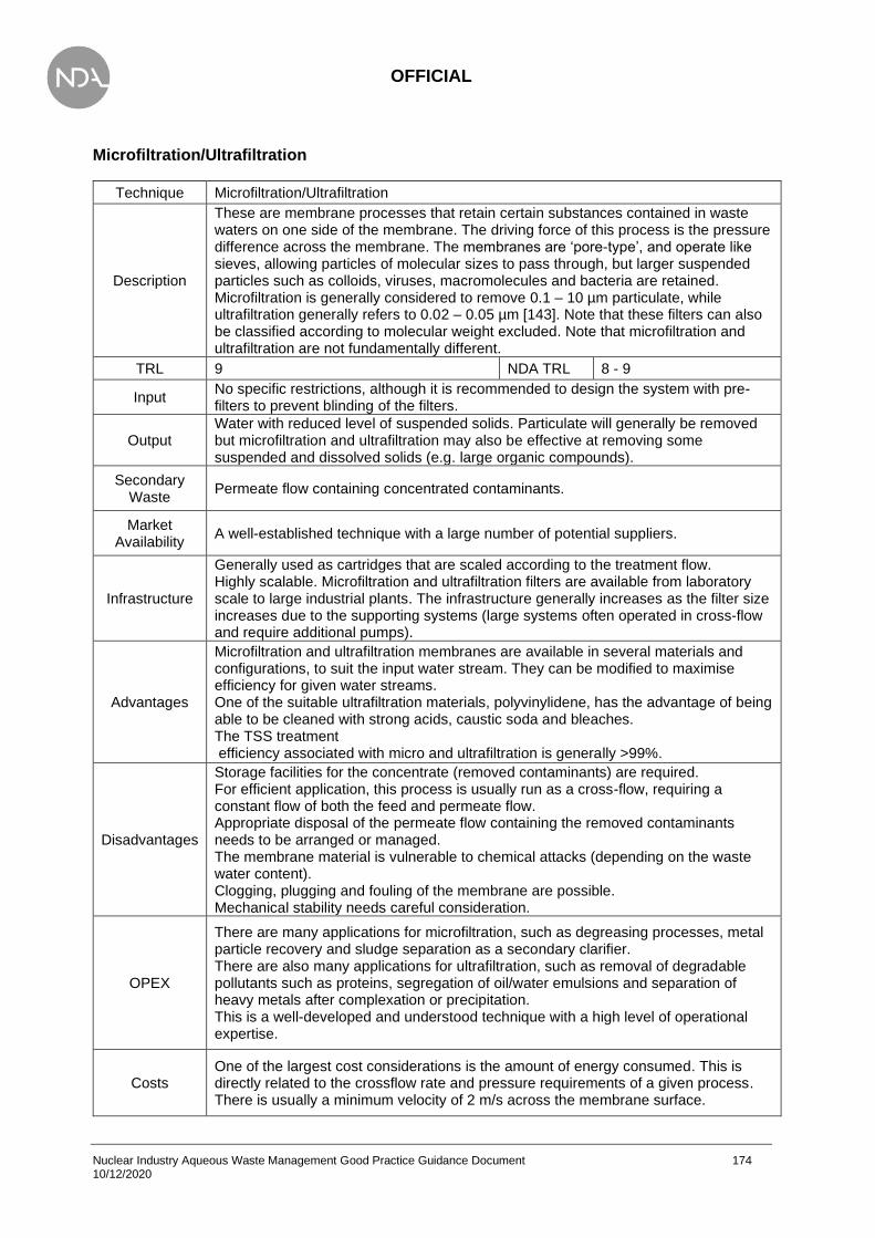
OFFICIAL
Nuclear Industry Aqueous Waste Management Good Practice Guidance Document 174 10/12/2020
Microfiltration/Ultrafiltration
Technique Microfiltration/Ultrafiltration
Description
These are membrane processes that retain certain substances contained in waste waters on one side of the membrane. The driving force of this process is the pressure difference across the membrane. The membranes are ‘pore-type’, and operate like sieves, allowing particles of molecular sizes to pass through, but larger suspended particles such as colloids, viruses, macromolecules and bacteria are retained. Microfiltration is generally considered to remove 0.1 – 10 µm particulate, while ultrafiltration generally refers to 0.02 – 0.05 µm [143]. Note that these filters can also be classified according to molecular weight excluded. Note that microfiltration and ultrafiltration are not fundamentally different.
TRL 9 NDA TRL 8 - 9
Input No specific restrictions, although it is recommended to design the system with pre-filters to prevent blinding of the filters.
Output Water with reduced level of suspended solids. Particulate will generally be removed but microfiltration and ultrafiltration may also be effective at removing some suspended and dissolved solids (e.g. large organic compounds).
Secondary Waste
Permeate flow containing concentrated contaminants.
Market Availability
A well-established technique with a large number of potential suppliers.
Infrastructure
Generally used as cartridges that are scaled according to the treatment flow. Highly scalable. Microfiltration and ultrafiltration filters are available from laboratory scale to large industrial plants. The infrastructure generally increases as the filter size increases due to the supporting systems (large systems often operated in cross-flow and require additional pumps).
Advantages
Microfiltration and ultrafiltration membranes are available in several materials and configurations, to suit the input water stream. They can be modified to maximise efficiency for given water streams. One of the suitable ultrafiltration materials, polyvinylidene, has the advantage of being able to be cleaned with strong acids, caustic soda and bleaches. The TSS treatment efficiency associated with micro and ultrafiltration is generally >99%.
Disadvantages
Storage facilities for the concentrate (removed contaminants) are required. For efficient application, this process is usually run as a cross-flow, requiring a constant flow of both the feed and permeate flow. Appropriate disposal of the permeate flow containing the removed contaminants needs to be arranged or managed. The membrane material is vulnerable to chemical attacks (depending on the waste water content). Clogging, plugging and fouling of the membrane are possible. Mechanical stability needs careful consideration.
OPEX
There are many applications for microfiltration, such as degreasing processes, metal particle recovery and sludge separation as a secondary clarifier. There are also many applications for ultrafiltration, such as removal of degradable pollutants such as proteins, segregation of oil/water emulsions and separation of heavy metals after complexation or precipitation. This is a well-developed and understood technique with a high level of operational expertise.
Costs One of the largest cost considerations is the amount of energy consumed. This is directly related to the crossflow rate and pressure requirements of a given process. There is usually a minimum velocity of 2 m/s across the membrane surface.
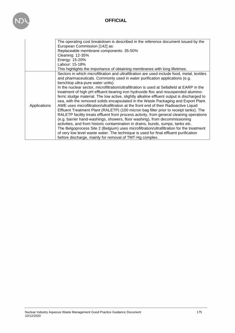
OFFICIAL
Nuclear Industry Aqueous Waste Management Good Practice Guidance Document 175 10/12/2020
The operating cost breakdown is described in the reference document issued by the European Commission [142] as: Replaceable membrane components: 35-50% Cleaning: 12-35% Energy: 15-20% Labour: 15-18% This highlights the importance of obtaining membranes with long lifetimes.
Applications
Sectors in which microfiltration and ultrafiltration are used include food, metal, textiles and pharmaceuticals. Commonly used in water purification applications (e.g. benchtop ultra-pure water units). In the nuclear sector, microfiltration/ultrafiltration is used at Sellafield at EARP in the treatment of high pH effluent bearing iron hydroxide floc and resuspended alumino-ferric sludge material. The low active, slightly alkaline effluent output is discharged to sea, with the removed solids encapsulated in the Waste Packaging and Export Plant. AWE uses microfiltration/ultrafiltration at the front end of their Radioactive Liquid Effluent Treatment Plant (RALETP) (100 micron bag filter prior to receipt tanks). The RALETP facility treats effluent from process activity, from general cleaning operations (e.g. barrier hand-washings, showers, floor washing), from decommissioning activities, and from historic contamination in drains, bunds, sumps, tanks etc. The Belgoprocess Site 2 (Belgium) uses microfiltration/ultrafiltration for the treatment of very low level waste water. The technique is used for final effluent purification before discharge, mainly for removal of TMT-Hg complex.

OFFICIAL
Nuclear Industry Aqueous Waste Management Good Practice Guidance Document 176 10/12/2020
Oil-water Separation
Technique Oil-water Separation
Description
The separation of oil and water can be achieved by gravity separation of free oil using separation equipment, and emulsion breaking using chemicals. Large slugs of oil can be treated using the American Petroleum Institute (API) separator, which consists of a large rectangular bed and a flight scraper which moves the sludge to a collection pit. There is also a skimming device which collects the oil. Another separator design is the Parallel Plate Interceptor (PPI), which is equipped with plates parallel to the current which enlarge the active surface area, and a skimming device. This, however, is not suitable for removing large slugs of oil. Finally, the Corrugated Plate Interceptor (CPI) has corrugated plate packs placed counter-current, and an oil skimming device. This is also not suitable for large slugs of oil, however, has a good separation efficiency. The skimming devices can be varied from being fixed pipe skimmers, rotating trough skimmers, or rotating disc/drum skimmers. Oil-water separation is usually followed by flotation, and used alongside coagulation/flocculation.
TRL 9 NDA TRL 6 - 9
Input Water-based liquid waste containing oil, grease and other non-soluble contaminants.
Output Water stream with reduced oil content. Separated oil.
Secondary Waste
Technique dependant, emulsion-breaking chemicals contaminated with oil may be present.
Market Availability
All options are well established and no issues with obtaining the technologies. Not all of the technologies listed in the description will have been used in the nuclear industry.
Infrastructure Infrastructure requirements vary based upon the method of oil separation.
Advantages There is an increase in efficiency from API, to PPI, to CPI concerning the removal of small oil droplets and the ratio of active surface area/ground area.
Disadvantages
Storage facilities for the skimmed oil and sludge are needed if the oil cannot be recycled. If not covered, oil-water separators are major contributors to VOC released in wastewater treatment systems. Whilst covering the surface significantly reduces VOC releases, it also can cause skimming problems, and makes the equipment more difficult to check on during operation. Waste gas is produced which needs to be treated in a treatment system, which should include adequate safety systems such as pressurised nitrogen. Soluble substances cannot be separated. PPIs and CPIs are susceptible to fouling, therefore require increased maintenance.
OPEX Oil-water separators are currently used in almost all petrochemical installations, as well as refineries. This is a well-developed and widely used technique.
Costs Where emulsion breaking is required, the cost is largely dependent on the volumes of chemicals required, and their cost per kilogram. The dosage can range from 0.5g/m3
to 1,000g/m3.
Applications
There are many examples of plants equipped with oil separators, for treatment of waste with calorific value, refining waste oils, and treatment of water-based liquid waste. The use of emulsion breaking is also used for the treatment of water-based liquid waste, and the physico-chemical treatment of solid and/or pasty waste. EDF Energy utilise oil-water separation techniques to treat general controlled area liquid effluent arising (plant drainage including dosed demineralised cooling water;

OFFICIAL
Nuclear Industry Aqueous Waste Management Good Practice Guidance Document 177 10/12/2020
cooling seawater, floor washings, hand-washing etc.) at their AGR and PWR sites. This includes use of a range of deployed equipment ranging from skimmers in sumps/tanks to oil/water separators/interceptors on effluent input lines to treatment plants. Considering the process outputs - general aqueous effluent minus oil is sent forward for further treatment (e.g. filtration as a minimum); The collected oil may be non-radioactive hazardous waste or radioactive waste organic liquid. Oil segregated from AGR gas dryer liquor is highly tritiated. Oil-water separation techniques are used at most Magnox sites. The Belgoprocess Site 1 (Belgium) uses oil-water separation for the treatment of oil/water residues. The oil fraction is removed by phase separation. For the removal of the floating oil phase, a separate suction pipe leads to an intermediate vessel where the oil is separated out. The oil fraction is then treated by absorption. The water fraction is treated by homogeneous cementation.

OFFICIAL
Nuclear Industry Aqueous Waste Management Good Practice Guidance Document 178 10/12/2020
Hydrocyclone
Technique Hydrocyclone
Description
A technique used to separate suspended solids with a diameter of 5-1000µm that are likely to sink and resistant to shearing forces. The particles are separated using centrifugal force, which is generated as the liquid enters the cyclone tangentially at high speeds and is accelerated by the conical middle section. The smaller the diameter of the cyclone, the greater the centrifugal force will be. Light components leave the hydrocyclone through the top, whilst heavier components are collected at the bottom.
TRL 9 NDA TRL 7
Input Water-based liquid waste containing suspended solids of 5-1000µm diameter. Consistent supply of feed required.
Output Water stream with reduced solid content.
Secondary Waste
Slurry which the removed solids form at the bottom of the cyclone.
Market Availability
Hydrocyclcones are a comparatively common technology outside of the nuclear industry.
Infrastructure A hydrocyclone vessel with associated pumps will be required. Generally not suitable for small scale water treatment (due to costs and size requirements).
Advantages
There are no moving components in a hydrocyclone as there are in centrifuges. Can be used to separate oil and water (minimum oil droplet size of 30µm) with a removal efficiency of 98%. Wide range of applications in many industries, such as removing waste from fruit juices.
Disadvantages Hydrocyclones do not generate as much centrifugal force as centrifuges, and are usually chosen when the suspended particles will settle in under two minutes. Over two minutes, and a centrifuge is used instead.
OPEX Used in many industries, with many uses available.
Costs
For a steel hydroclone used for oil separation, with standard instrumentation and an aqueous flow of 1000m3/d, the initial investment cost is reported by the Best Available Techniques (BAT) Reference Document for Common Waste Water and Waste Gas Treatment/Management Systems in the Chemical Sector (2010/75/EU) [142] as approximately EUR 250,000. This figure does not include the water pre-treatment, drainage, electrical and mechanical installation costs.
Applications
This technique is used at the Sellafield Segregated Effluent Treatment Plant for the treatment of low active low risk effluent with potential for active particles. The output is a low active low risk effluent. A similar technology was trialled for separation of particulate from a gas stream for the AGR stations. Ultimately it was not adopted due to Technology Readiness Level but was effective in principle.

OFFICIAL
Nuclear Industry Aqueous Waste Management Good Practice Guidance Document 179 10/12/2020
Electrocoagulation
Technique Electrocoagulation
Description
Electrocoagulation forms precipitates and compounds between colloids so these substances can be removed using further techniques. The coagulants are released by electrolytically dissolving an electrode (usually an Fe or Al anode). When dissolved, gas is released, which results in a flotation effect. This can be supported by the addition of a flocculant if necessary. Electroflotation can be used after electrocoagulation, which uses electrolysis to split water into H2 and O2, creating gas bubbles which ensure flotation. This is suited to small scale systems.
TRL 9 NDA TRL 7
Input Waste water stream containing suspended particles, colloids, oil, or other soluble and insoluble pollutants (specified below in Advantages).
Output Water stream with reduced contaminant concentration.
Secondary Waste
The removed, coagulated solid waste. Off-gases will be produced (oxygen and hydrogen), potentially requiring careful H&S consideration. Note that as hydrogen is generated release of gaseous tritium will likely occur.
Market Availability
An established technology.
Infrastructure Infrastructure such as electrodes are required, and these require replacement. There is a significant electrical cost to this technology.
Advantages
Many uses, can be used for the removal of: settleable, suspended and dissolved substances, colloidal particles, animal and plant oils and fats, organic compounds, nutrients, heavy metals in the form of oxides or insoluble precipitates, inorganic salts, and complex organic molecules such as colourants. Installation and operation are relatively easy, contains no or very few moving parts, and is operated electronically, keeping maintenance costs low. Compared to physico-chemistry, the output water contains fewer dissolved organic compounds. No chemicals are required due to the coagulant being contained in the anode. This eliminates the possibility of chemical overdose.
Disadvantages
Removal yields for metals, emulsions and colloids are comparable to classic physico-chemical treatment (coagulation and flocculation) despite the added cost of electricity. The anode needs to be replaced on a regular basis due to dissolution in the waste water. The cathode also undergoes passive reactions, which increases the resistance of the cell and decreases the yield over time. The addition of salts may be necessary in order to achieve the required conductivity. The potential reactions from using this technique could be complex and difficult to predict dependant on what and how many pollutants are present in the waste water. Therefore, laboratory tests are necessary to verify the applicability of the technique.
OPEX There are many uses and industries in which electrocoagulation is used. The operational expertise is well known, and this technique is simple to install and operate, making it accessible for plants of varying expertise.
Costs The costs are generally higher than other technologies. To treat a waste water flow of 4 m3/h with a load of ± 200mg metals/l. investment costs of approximately EUR 150,000 are estimated.
Applications Used in many sectors such as paint, gloss, varnish, printing-ink production and the surface treatment of metals. No large scale OPEX from the nuclear industry.

OFFICIAL
Nuclear Industry Aqueous Waste Management Good Practice Guidance Document 180 10/12/2020
Nanofiltration/Reverse Osmosis (RO)
Technique Nanofiltration/RO
Description
Nanofiltration (NF) and reverse osmosis (RO) membranes can hold back particles down to the size of organic molecules, and even ions. The liquid which passes through is the permeate, and the particles which are retained is the concentrate. The driving force for this process is the pressure difference across the membrane. Nanofiltration membranes allow water and single valence ions (fluorides, sodium, and potassium chloride) and nitrates to pass through, and retains multiple valence ions. RO membranes have the smallest pore size (< 0.002 µm) and allow water to pass through, whilst retaining all solutes. These two techniques are often used in combination with each other, and/or other post-treatment techniques for the permeate.
TRL 9 NDA TRL 7-9
Input Waste water containing dissolved contaminants.
Output Water containing only single valence ions (ultrafiltration) or reduced ions (RO).
Secondary Waste
Chemicals used to clean the membranes (these will now contain the contaminants). A concentrated waste stream (the reject) will be generated. Note this will require either recycling or further treatment.
Market Availability
NF and RO are well established technologies in water treatment but have historically been limited due to stability of the membranes and operability. Many of these issues have been overcome and can now provide high quality water suitable for polishing by IX resin.
Infrastructure
NF and RO require a membrane (typically installed into a housing) and a high driving pressure, therefore requiring pumps. Cleaning chemicals for the membrane may be required dependent upon the application. Although NF and RO can be utilised on a laboratory scale, the high driving pressures required can limit its effectiveness. Electrodeionisation (EDI) or electrodialysis (ED) may be the more appropriate technique for laboratory scale.
Advantages
Abatement efficiencies of over 97% are reported for several pollutants using nanofiltration (no information available for RO). The permeate and the concentrate can both be recycled, reducing the water usage and raw material consumption. Nanofiltration can be used to simultaneously recycle and reuse the permeate stream, whilst increasing the concentration of the contaminants to a level that further destructive techniques are feasible. RO produces high grade purity water, and the concentrate can be recycled and reused. Low operating temperatures and possibility of fully automated systems.
Disadvantages
Even when pre-treated, the membranes will foul and deteriorate in performance if cleaning is not ensured. This mean that the system needs to be designed in such a way that those modules can be taken offline and cleaned. Continuous monitoring of pressure difference and flow across the membrane is required. When using RO, salt solutions with low solubility tend to precipitate and cause fouling of the membrane. High pressures are required.
OPEX Ultrafiltration is currently used for the removal of pesticides in ground water, and the softening of water. RO is currently used for the desalting of seawater and manure processing.

OFFICIAL
Nuclear Industry Aqueous Waste Management Good Practice Guidance Document 181 10/12/2020
Costs
Energy consumption (one of the largest cost considerations), is directly related to the flow rate and pressure requirements. A minimum velocity of about 2 m/s across the membrane surface needs to be maintained. Higher pressures are used in RO therefore this process is more expensive than ultrafiltration. The membranes need to be replaced approximately every 5 years, even with cleaning and anti-fouling measures in place. Note that this will be extended as the technology matures and will also depend upon the influent composition.
Applications
RO was planned for the UK ABWR water treatment plant to remove the need for ion exchange resins, thereby reducing operator requirements, to facilitate the goal of a zero discharge plant. Reverse osmosis is in place at AWE’s Radioactive Liquid Effluent Treatment Plant (RALETP), a facility which treats effluent from process activity, from general cleaning operations (e.g. barrier hand-washings, showers, floor washing), from decommissioning activities, and from historic contamination in drains, bunds, sumps, tanks etc. The condensate from the evaporator can be passed through a reverse osmosis filter for final polishing. Although the capability exists at the RALETP, it has not been required based on current contamination levels; the Reverse Osmosis Plant has not been operational since January 2013 and no impact on discharges has been observed.

OFFICIAL
Nuclear Industry Aqueous Waste Management Good Practice Guidance Document 182 10/12/2020
Electrodialysis
Technique Electrodialysis (ED)
Description
Ions are transported through ion-permeable membranes from one solution to another under the influence of a potential gradient. The electrical charges on the ions allow them to be driven through the membranes when a voltage is applied between two end electrodes. The membranes have the ability to selectively transport ions of a chosen charge, therefore useful concentration, removal and separation of electrolytes can be achieved. Anion selective membranes and cation selective membranes are placed between the anode and cathode. In practice, hundreds of these membranes are placed alternately next to each other, between the anode and cathode. The solution that has high ionic concentration is the concentrate, and the solution of depleted ionic concentration is the dilutant. Note some of the limitations of ED have been overcome with EDI.
TRL 9 NDA TRL 7
Input Waste water stream containing ions. Note that membranes can become fouled thus suspended solids should be minimised.
Output Water stream with reduced ion content. Water quality often < 1.0 µS.cm-1.
Secondary Waste
Concentrate solutions, high in ion content.
Market Availability
An established technology but less common than RO on a large scale. The process is well understood and reliable thus has a high TRL but can still be affected by the influent composition.
Infrastructure ED requires membranes and an electrical supply.
Advantages Once the parameters have been optimised for a given process, the industrial installation does not need continued monitoring. Relatively simple to operate and maintain.
Disadvantages
The membranes require cleaning to avoid fouling and degradation in performance. Their lifespan is usually between 5 and 7 years. Electrodialysis needs to be operated below the current density limit to be energy efficient. As the water purity increases, the current required increases and causes arcing. ED is therefore limited in the water quality it can achieve.
OPEX
Costs
The major costs are associated with electricity use and membrane installation/replacement. In practice, 3,000ppm of dissolved substances is the limit between the cost effectiveness of using RO, or electrodialysis. For an installation which treats 10 m3 of waste water per day, an investment cost of EUR 200,000 and operating costs of EUR 50,000 per year can be expected.
Applications No information available.

OFFICIAL
Nuclear Industry Aqueous Waste Management Good Practice Guidance Document 183 10/12/2020
Chemical Precipitation
Technique Chemical Precipitation
Description
The chemical reaction to form particulates that can be separated from the water portion by an additional process such as sedimentation, air flotation and filtration. Precipitation may also be used to remove colloidal molecules. Heavy metals are usually precipitated out early in the treatment process to avoid dilution, whereas the precipitation of phosphorus is usually one of the final treatments. A precipitation facility usually consists of one or two stirred mixing tanks where the precipitation agent is added, a sedimentation tank, and storage tanks. Note this has similarities to flocculation and coagulants but is usually achieved by changing the chemical composition of the matrix (e.g. by increasing the pH). The property change of the matrix causes precipitation of a species, reducing the contaminant concentration.
TRL 9 NDA TRL 9
Input Water-based waste stream containing dissolved contaminants (usually heavy metals).
Output Water stream with reduced contaminant levels. Properties may have changed (e.g. alkaline pH).
Secondary Waste
Precipitant waste sludge. Note that the volume of secondary waste generated may increase depending upon the chemical added and quantity e.g. if lime is added then the lime will also require removal within the process stream, resulting in increased waste volume.
Market Availability
Standard technology for treating waste water. Dedicated chemicals are available but often knowledge of the waste stream will allow the relevant chemical to be identified and added.
Infrastructure
Batch processing will require reaction tanks while online systems will require dosing pumps and careful consideration of reaction time. The infrastructure for batch processing is therefore simple as chemicals can be added by hand if required, thus requiring only a tank. Process is scalable and can be completed on a laboratory scale. Laboratory trials may be prudent to optimise the process.
Advantages
Precipitation can be combined with or aided by other techniques, such as flocculation through the addition of further chemicals into the mixing tank. There are many precipitation and flocculation chemicals available, depending on what contaminants need to be removed. Achievable end concentrations for single metals using S2- 0.1-1 mg/l for copper, lead silver and cadmium. Precipitation can be applied to different stages of the waste water stream, depending upon the contaminants present and the other techniques being utilised.
Disadvantages
Conventional heavy metal precipitation using hydroxide has the drawbacks of; tending to redissolve upon increasing the pH above a certain value, and precipitation with hydroxide is incomplete in the presence of chelating agents such as EDTA. Achievable emissions for heavy metals vary greatly, depending on the particular situation possible. This makes quoting a particular efficiency difficult. Furthermore, final concentrations are difficult to determine due to various pollutants interacting with each other. Test jars are often needed to confirm the optimal treatment conditions as the proper chemical dosage cannot be calculated due to various factors affecting this. The precipitate is disposed of as a sludge and is classified as chemical waste if heavy metals are present.
OPEX
Precipitation is a simple and well established technique. There are many examples of plants and industries which have precipitation facilities as part of their waste water treatment. The equipment and chemicals are readily available, and often inexpensive (especially lime).

OFFICIAL
Nuclear Industry Aqueous Waste Management Good Practice Guidance Document 184 10/12/2020
Costs
Using lime as a precipitant keeps the costs low as this is an inexpensive chemical. Costs increase with use in more expensive chemicals, and larger volumes. There is an estimated investment cost of EUR <0.03 per m3, with no information available on operating costs, however, these are expected to be low as this is a self-operating, low-maintenance process.
Applications
There are many example plants. See page 211 of [142]. Chemical precipitation is used at the Sellafield EARP to treat acidic effluents from nuclear fuel reprocessing and POCO, effluent from salt evaporators and effluent from the solvent treatment plant. The output is a high pH floc-bearing effluent for ultrafiltration. AWE utilise chemical precipitation at their Radioactive Liquid Effluent Treatment Plant (RALETP), a facility which treats effluent from process activity, from general cleaning operations (e.g. barrier hand-washings, showers, floor washing), from decommissioning activities, and from historic contamination in drains, bunds, sumps, tanks etc. Nitric acid or sodium hydroxide is added to condition the tank before evaporation (adjusts pH). Chemical precipitation is used at the Belgoprocess Site 2 (Belgium) in the treatment of (very) low active liquid waste. The process is chemical coagulation/flocculation followed by precipitation. The treated liquid waste output is disposed and the remaining sludge incinerated or dried and compacted.
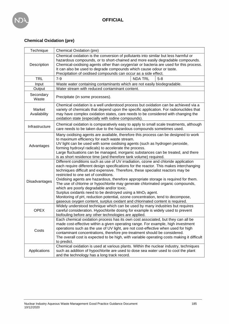
OFFICIAL
Nuclear Industry Aqueous Waste Management Good Practice Guidance Document 185 10/12/2020
Chemical Oxidation (pre)
Technique Chemical Oxidation (pre)
Description
Chemical oxidation is the conversion of pollutants into similar but less harmful or hazardous compounds, or to short-chained and more easily degradable compounds. Chemical-oxidising agents other than oxygen/air or bacteria are used for this process. It can also be used to degrade compounds which cause odour or taste. Precipitation of oxidised compounds can occur as a side effect.
TRL 7-9 NDA TRL 5-8
Input Waste water containing contaminants which are not easily biodegradable.
Output Water stream with reduced contaminant content.
Secondary Waste
Precipitate (in some processes).
Market Availability
Chemical oxidation is a well understood process but oxidation can be achieved via a variety of chemicals that depend upon the specific application. For radionuclides that may have complex oxidation states, care needs to be considered with changing the oxidation state (especially with iodine compounds).
Infrastructure Chemical oxidation is comparatively easy to apply to small scale treatments, although care needs to be taken due to the hazardous compounds sometimes used.
Advantages
Many oxidising agents are available, therefore this process can be designed to work to maximum efficiency for each waste stream. UV light can be used with some oxidising agents (such as hydrogen peroxide, forming hydroxyl radicals) to accelerate the process. Large fluctuations can be managed, inorganic substances can be treated, and there is as short residence time (and therefore tank volume) required.
Disadvantages
Different conditions such as use of UV irradiation, ozone and chloride application each require different design specifications for the reactor. This makes interchanging techniques difficult and expensive. Therefore, these specialist reactors may be restricted to one set of conditions. Oxidising agents are hazardous, therefore appropriate storage is required for them. The use of chlorine or hypochlorite may generate chlorinated organic compounds, which are poorly degradable and/or toxic. Surplus oxidants need to be destroyed using a MnO2 agent. Monitoring of pH, reduction potential, ozone concentration, tend to decompose, gaseous oxygen content, surplus oxidant and chlorinated content is required.
OPEX Widely understood technique which can be used by many industries but requires careful consideration. Hypochlorite dosing for example is widely used to prevent biofouling before any other technologies are applied.
Costs
Each chemical oxidation process has its own cost associated, but they can all be made cost-effective within a given operating range. For example, high investment operations such as the use of UV light, are not cost-effective when used for high contaminant concentrations, therefore pre-treatment should be considered. The overall cost is expected to be high, with variable operating costs making it difficult to predict.
Applications Chemical oxidation is used at various plants. Within the nuclear industry, techniques such as addition of hypochlorite are used to dose sea water used to cool the plant and the technology has a long track record.
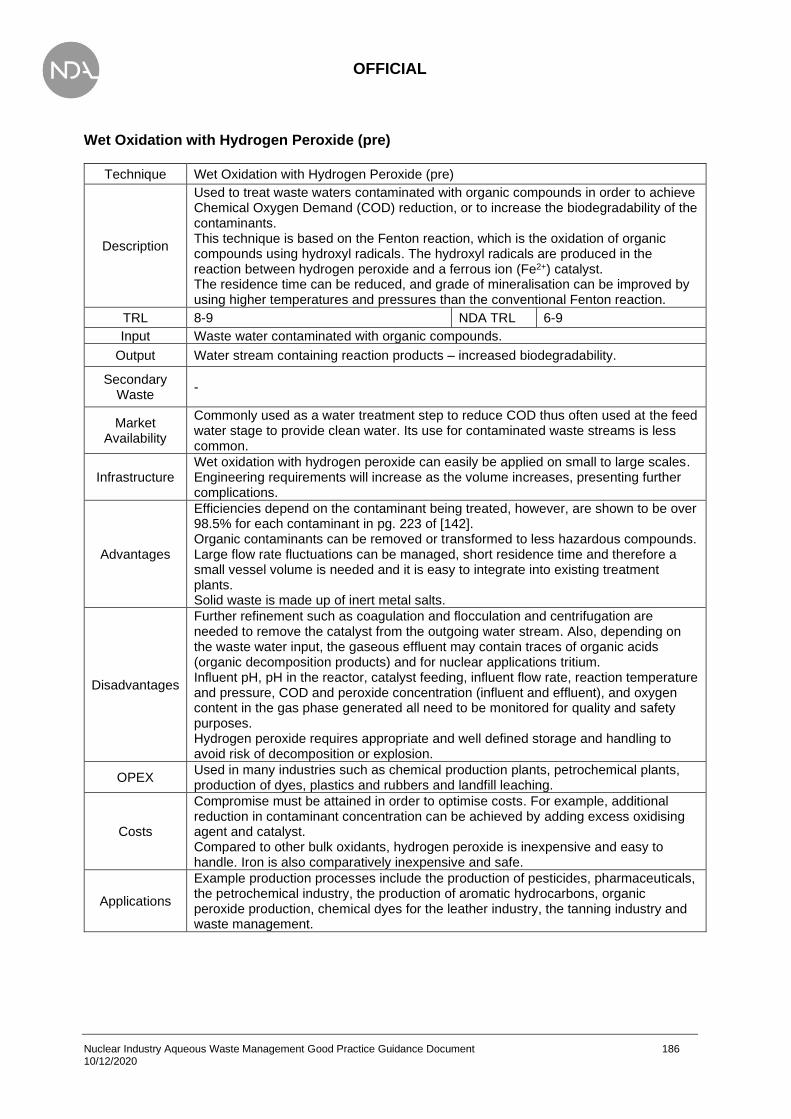
OFFICIAL
Nuclear Industry Aqueous Waste Management Good Practice Guidance Document 186 10/12/2020
Wet Oxidation with Hydrogen Peroxide (pre)
Technique Wet Oxidation with Hydrogen Peroxide (pre)
Description
Used to treat waste waters contaminated with organic compounds in order to achieve Chemical Oxygen Demand (COD) reduction, or to increase the biodegradability of the contaminants. This technique is based on the Fenton reaction, which is the oxidation of organic compounds using hydroxyl radicals. The hydroxyl radicals are produced in the reaction between hydrogen peroxide and a ferrous ion (Fe2+) catalyst. The residence time can be reduced, and grade of mineralisation can be improved by using higher temperatures and pressures than the conventional Fenton reaction.
TRL 8-9 NDA TRL 6-9
Input Waste water contaminated with organic compounds.
Output Water stream containing reaction products – increased biodegradability.
Secondary Waste
-
Market Availability
Commonly used as a water treatment step to reduce COD thus often used at the feed water stage to provide clean water. Its use for contaminated waste streams is less common.
Infrastructure Wet oxidation with hydrogen peroxide can easily be applied on small to large scales. Engineering requirements will increase as the volume increases, presenting further complications.
Advantages
Efficiencies depend on the contaminant being treated, however, are shown to be over 98.5% for each contaminant in pg. 223 of [142]. Organic contaminants can be removed or transformed to less hazardous compounds. Large flow rate fluctuations can be managed, short residence time and therefore a small vessel volume is needed and it is easy to integrate into existing treatment plants. Solid waste is made up of inert metal salts.
Disadvantages
Further refinement such as coagulation and flocculation and centrifugation are needed to remove the catalyst from the outgoing water stream. Also, depending on the waste water input, the gaseous effluent may contain traces of organic acids (organic decomposition products) and for nuclear applications tritium. Influent pH, pH in the reactor, catalyst feeding, influent flow rate, reaction temperature and pressure, COD and peroxide concentration (influent and effluent), and oxygen content in the gas phase generated all need to be monitored for quality and safety purposes. Hydrogen peroxide requires appropriate and well defined storage and handling to avoid risk of decomposition or explosion.
OPEX Used in many industries such as chemical production plants, petrochemical plants, production of dyes, plastics and rubbers and landfill leaching.
Costs
Compromise must be attained in order to optimise costs. For example, additional reduction in contaminant concentration can be achieved by adding excess oxidising agent and catalyst. Compared to other bulk oxidants, hydrogen peroxide is inexpensive and easy to handle. Iron is also comparatively inexpensive and safe.
Applications
Example production processes include the production of pesticides, pharmaceuticals, the petrochemical industry, the production of aromatic hydrocarbons, organic peroxide production, chemical dyes for the leather industry, the tanning industry and waste management.

OFFICIAL
Nuclear Industry Aqueous Waste Management Good Practice Guidance Document 187 10/12/2020
Wet Air Oxidation (pre)
Technique Wet Air Oxidation (pre)
Description
The reaction of oxygen in the aqueous phase under high pressure and temperature, used to increase the solubility of oxygen in water. This reaction often requires the use of a catalyst, and reaction products are dependent on the waste water content. Due to the large range of applications for this technique, separate process variants have been developed for high pressure and low pressure reactions. These process variants are defined by the temperature and pressure parameters, with the low pressure reaction operating at 30-200˚C and 0.2-2MPa, and the high pressure reaction operating at 150-340˚C and > 2MPa.
TRL 9 NDA TRL 7
Input Waste water stream with contaminants that are not readily biodegradable.
Output Water stream containing more degradable compounds.
Secondary Waste
Off-gas, depending on the contents of the waste water stream.
Market Availability
Wet air oxidation is a well-developed technology, and can be implemented easily. Operation at higher temperatures and pressures becomes more challenging and is less common.
Infrastructure Requires a supply of oxygen as well as suitable vessels (note these may be highly specialised dependent upon the approach adopted).
Advantages
No aqueous or solid secondary waste produced as contaminants remain in the water stream in the form of more easily degradable compounds. Wet air oxidation can be used to replace a central biological WWTP if the amount of waste water is too small to warrant a plant, reducing costs. Waste water with relatively high refractory COD concentrations can be treated. Inorganic compounds can either be eliminated, or transferred to less hazardous substances. Can be combined with other treatments.
Disadvantages
The contaminants aren’t removed from the water stream therefore further downstream treatment is often necessary to remove them. There are multiple limitations on contaminant concentrations which can be used in this process. Dioxins can be generated.
OPEX Well understood process, although careful consideration needs to be given to the species present in the aqueous phase (e.g. iodine has several oxidation states and volatility can change substantially).
Costs
The high temperatures and pressures required means that suitable equipment must be used, with metal parts operating up to 200˚C must be manufactured from titanium or its alloys with palladium, both of which are expensive metals. The overall cost is expected to be extremely high for several industries, mainly due to the specific equipment described above required. It can be readily applied to a smaller quantities in a laboratory however.
Applications No information available.

OFFICIAL
Nuclear Industry Aqueous Waste Management Good Practice Guidance Document 188 10/12/2020
Chemical Reduction
Technique Chemical Reduction
Description
The conversion of pollutants by chemical reducing agents into similar but less harmful or hazardous compounds. Common chemical reducing agents include: sulphur dioxide, sodium hydrogen sulphite, ferrous sulphate, sodium sulphide and amidosulphonic acid. The products of the reduction reaction can be more easily treated downstream, such as using precipitation units. Additional chemicals may be needed to remove excess reducing agent such as hypochlorite or hydrogen peroxide.
TRL 9 NDA TRL 6-9
Input Waste water stream with contaminants that are not readily removable or are harmful in a regular sewage system (inorganic compounds).
Output Water stream containing fewer harmful contaminants.
Secondary Waste
Off-gas, depending on the contents of the waste water stream.
Market Availability
Often used for feed water treatment to reduce the concentration of oxidising species in the influent (e.g. chlorine from towns water).
Infrastructure
Infrastructure requirements depend upon the reductant method chosen, but typically requires a pump and a feed tank of the reductant. This can be operated in an online dosing mode (if sufficient residence time can be guaranteed) or in batch process thus a reaction tank may be required.
Advantages Waste water over large concentration ranges can be treated.
Disadvantages Storage units for the reducing agents are required, which are hazardous substances. Gas formation is common, which then needs to undergo further treatment.
OPEX Chemical reduction is a well understood process on a small scale. Chemical reduction is used on some AGR water treatment plants to protect the ion exchange resins in the water treatment plant from oxidising species.
Costs Chemical reduction plants do not need to be especially sophisticated and expensive, and generally have low operating costs due to continuous/automatic processing
Applications
Used at several AGR stations to protect the ion exchange resins of the water treatment plant. Chemical reduction is used at Belgoprocess Site 1 (Belgium) in the treatment of effluent high in nitrates (NO3
-). The process is biological denitrification by reduction of NO3
- to N2.

OFFICIAL
Nuclear Industry Aqueous Waste Management Good Practice Guidance Document 189 10/12/2020
Electrolysis
Technique Electrolysis
Description
An electrical current is applied to a liquid using inert electrodes, resulting in an effective electron transfer in the electrolyte, causing chemical changes in the composition of the waste water. Any metals present in the water will be deposited on the cathode upon electron exchange. This process can be optimised by adding a charge selective membrane between the anode and cathode, allowing for selectivity of anions or cations.
TRL 9 NDA TRL 6-7
Input Waste water containing metal contaminants. Most effective when only one metal species is present in high concentrations.
Output Water stream containing a lower concentration of metal contaminants.
Secondary Waste
Gas may be generated at the electrodes (hydrogen and tritium).
Market Availability
A simple, well-established technology with low technology requirements.
Infrastructure Electrodes will be required but will require frequent replacement. Electrical supply to the electrodes,
Advantages
The purification yield is very high, with final metal ion concentrations of less than 0.1 mg/l achievable. The purified water and the separated metals can both be reused. Non-metal contaminants such as organic compounds can be degraded through oxidation and reduction reactions with the exchange of electrons.
Disadvantages High energy consumption when low final concentrations are required. Off-gases will be generated, potentially hazardous dependent upon the composition.
OPEX
Electrolysis is mainly applied in the metal industry for the purification of rinse waters from pickling tanks or galvanic baths. This involves the recuperation of metals and used electrolytes, disintoxication of nitrite and Cr(VI) and silver recuperation from fixing baths in the graphics sector.
Costs The cost of an electrolysis installation depends greatly on the electrodes used.
Applications No information available.

OFFICIAL
Nuclear Industry Aqueous Waste Management Good Practice Guidance Document 190 10/12/2020
Adsorption
Technique Adsorption
Description
A technique for removing adsorbable dissolved non-biodegradable or inhibitory pollutants from an aqueous waste stream. The adsorbent is selective and can be functionalised towards specific compounds, thus removing them from aqueous streams. Adsorption can be used as a guard filter after final facility treatments.
TRL 9 NDA TRL 7-9
Input Water free of particulates (avoids clogging of active surface).
Output Aqueous stream with significantly reduced impurity concentrations.
Secondary Waste
Spent adsorbent contaminated with removed species.
Market Availability
Adsorbents are generally a specific technology, requiring knowledge of the contaminant and of a suitable adsorbent as the adsorbents can be selective. The availability of adsorbents can therefore vary significantly.
Infrastructure The required infrastructure varies based upon the adsorbent but generally relies upon a vessel containing the adsorbent and a flow of the fluid.
Advantages
Some adsorbents (such as activated carbon), can be impregnated with additives in order to improve retention of certain species (e.g. adding an oxidant can improve retention of heavy metals). There are a large variety of adsorbents, allowing a range of impurities to be removed. Some are more selective than others, so a specific impurity can be targeted, or many all at once. Adsorbents can sometimes be regenerated to be reused.
Disadvantages
If the adsorbent is regenerated, aqueous secondary waste is produced. The desorption process concentrates the contaminants, which then need to be disposed of. The removal of pollutants which contain hazardous substances usually results in the incineration of the adsorbent, and regeneration is not advised. The adsorbent has a finite capacity, which when saturated, has to be replaced or regenerated. The efficiency of this process varies widely with waste water composition, and feed concentration. Data collected during the development of the United States Effluent Limit Guidelines show how effective the use of carbon is on individual waste streams. However, the data also showed the breakthrough of certain pollutants, even with careful monitoring, in particular, the presence of heavy metals.
OPEX There is significant OPEX available for the use of activated carbon in many power plants throughout Europe, for the treatment of water-based liquid waste. However, no nuclear sites have been identified for aqueous radionuclide removal.
Costs Cost is dependent on the choice of adsorbent. Activated carbon is most commonly used, which can be obtained at a low cost.
Applications No information available.

OFFICIAL
Nuclear Industry Aqueous Waste Management Good Practice Guidance Document 191 10/12/2020
Ion Exchange
Technique Ion Exchange
Description
A technique for exchanging ionic species in the aqueous phase with ionic species present on the ion exchange (IX) resins. There are several types of IX resins that suit different applications. Functionalised resins are also available that can offer higher selectivity for certain species. IX media is commonly used as a final treatment step using ‘strong’ ion exchangers. Ionic species removed will not be released except in the presence of strong acid or strong base thus suitable as a final removal technique. Ion exchange resin is typically operated in a deep bed configuration but can also be mounted in different configurations, e.g. a pre-coat filter. In a pre-coat filter, the ion exchange media is applied as a powder to a candle-type filter, offering very high efficiencies. The pre-coat can be materials other than ion exchange resins.
TRL 9 NDA TRL 9
Input
Water free of oil (can foul the resin). Strong oxidising agents can damage organic IX resins (although this is more important if being re-used). Removal of high particulate concentration is recommended.
Output Aqueous stream with significantly reduced ionic loading. Decontamination factors are typically 1000 (if correct resin is chosen).
Secondary Waste
Spent ion exchange media Regenerant (acid or base, if relevant) contaminated with the removed species if media is regenerated and reused.
Market Availability
Ion exchange media is widely available. There are several manufacturers, with several general and specific IX media available for use. Note that ionic species have varying selectivity coefficients for IX media thus the matrix may impact upon removal efficiency. It may be prudent to perform laboratory scale testing prior to use to confirm efficient removal.
Infrastructure
Infrastructure requirements scale according to mass of media required and whether regeneration is required (not recommended for removal of radioactive species). Can be performed on laboratory scale by installing IX media into a column and passing the solution through the resin. Applicable to feedwater and wastewater.
Advantages
Wide range of ion exchange media available, with quality and functionalisation to suit many applications. Several specialised resins are available designed to remove the common radionuclide species of interest (e.g. Cs-137, Co-60), although these often require careful use. Large amount of OPEX – established technology that is being actively developed (e.g. higher capacities, greater stability). Excellent decontamination factors achievable. Once removed ionic species are generally tightly bound, thus creating a solid secondary waste (rather than a secondary liquid waste). IX resins can be used for removal of high concentrations of salts (typically water treatment plants) by use of weak IX resins but will require frequent regeneration (the removal of the ionic species present on the resin). This may result in radioactive regenerant that then requires separate treatment.

OFFICIAL
Nuclear Industry Aqueous Waste Management Good Practice Guidance Document 192 10/12/2020
Disadvantages
Only functions with ionic species, although a deep bed also functions as a filter. Limited capacity for ionic species – once exhausted requires regeneration using acids or bases or disposal. IX media can be expensive subject to type, quality, or functionalisation. Specialised IX media can be expensive, and have long lead times. Performance can be impacted upon by other impurities in water thus consideration of feed quality required. Ionic removal is dependent upon the selectivity co-efficient and decontamination factor will be affected by competing ions. Performance can be impacted upon by a very high concentrations of competing ions e.g. contaminated seawater at Fukushima. Ion exchange media can degrade over time, including when exposed to radiations (particularly organic-type resins), thus long term storage requires further consideration (e.g. hydrogen generation). Radioactive species will become concentrated upon the IX resin, resulting in an increased dose rate to the operator. This will impact upon operational and shielding requirements at the end of life of the IX resin. The driver for most IX media has been higher capacity resin (i.e. able to remove more material) but lower capacity resin may be suitable in some applications, especially in mobile modular plants where the ion exchange loading is limited by shielding and manual handling requirements.
OPEX
Significant OPEX available across the nuclear industry. Widely used in power stations for water treatment (a conventional application). All modern power plants (e.g. Pressurised Water Reactors) utilise IX resins for control of primary circuit impurities. Specialised media are available for pond clean-up. Specialised resins have been developed and shown to be effective (e.g. Coseq, CsTreat, SrTreat). Several techniques available for handling spent IX resins (e.g. encapsulation, steam treatment).
Costs Costs for IX media can vary hugely depending upon: quantity of IX media required, type of media, quality, operating requirements, vessels. Characterisation of the process flow required before design to ensure a cost-effective design.
Applications
Ion exchange is used at various facilities at the Sellafield Site, including SIXEP, the PFSP LETP and the EARP. At SIXEP the technique is used to treat high-pH pond water from commercial and legacy fuel storage operations, sludge-rich effluent and medium active effluent generated during waste retrieval from high hazard legacy facilities. At the PFSP LETP, ion exchange is used in the treatment of pond water from the PFSP. At the EARP, ion exchange is used in the treatment of acidic effluents from nuclear fuel reprocessing and POCO, effluent from salt evaporators and from solvent treatment plant. Ion exchange is added during co-precipitation of the EARP feeds to improve performance on key radionuclide species. The outputs from these processes include spent sand and clinoptilolite stored for future retrieval and conditioning, effluent for sea discharge and spent ion exchange cartridges for future encapsulation. A high-pH floc-bearing effluent is also produced and subsequently treated by ultrafiltration. Ion exchange is utilised at EDF Energy AGR and PWR facilities, generally processing closed-loop demineralised water systems for maximised efficacy (e.g. AGR fuel cooling ponds). Some ion exchange is used on mixed effluent but efficacy often much reduced due to presence of sea water cooling (especially AGRs). The AGR spent resin is wet stored for plant lifetime. PWR spent resin is batch processed to disposable waste form. Ion exchange is in place at AWE’s Radioactive Liquid Effluent Treatment Plant (RALETP) for the further removal of impurities after the reverse osmosis filter but this has never been used. The primary purpose was to remove mercury contamination, but it has not been required based on current contamination levels. Ion exchange is also used at the Magnox Hunterston site to treat pond water.

OFFICIAL
Nuclear Industry Aqueous Waste Management Good Practice Guidance Document 193 10/12/2020
Crystallisation
Technique Crystallisation
Description
Crystallisation makes use of a fluidised bed of sand or minerals (seeds). The incoming waste stream is injected from the bottom, parallel to a chemical input stream. This is injected into the fluidised bed, with the contaminants reacting with the pellets which grow and move towards the bottom of the reactor, and the water being output at the top of the reactor. The seeds are periodically (usually once a day) discharged and replaced. It is the velocity of the influent waste water (40-120 m/h) which maintains the fluidised state.
TRL 8-9 NDA TRL 5-7
Input Waste water stream containing dissolved metal/anion contaminants.
Output Water stream with reduced contaminant level.
Secondary Waste
Sand/mineral seeds containing precipitant (metallic/anionic).
Market Availability
Used in non-nuclear applications but no application identified in the nuclear industry.
Infrastructure Infrastructure requirements are limited to a fluidised bed. Cost will be influenced by volume effluent.
Advantages
The fluidised bed provides a very high precipitation surface area, allowing almost all anion or metal content in the water stream to precipitate out. The chemical input stream contains a known, lower concentration of anions or metal. This allows for flexibility of the system, as higher or lower concentrations of waste can be treated by adjusting the ratio between the waste water stream and the chemical stream. This also allows the fluidised bed to be maintained, even when there is no input waste stream. No sludge or slurry arises as the salts are attached to the pellets. The pellets are also water-free and high purity so can often be recycled.
Disadvantages
This process is only applicable to ionic constituents which form insoluble salts. In order to achieve good removal results, the reagents necessary to form precipitates are added in overdosage. The system requires monitoring on multiple components, such as; the water flow, the concentration of metal/anion in the incoming waste stream, the dosage of the chemical stream, the pH and the concentration of the metal/anion in the output stream.
OPEX The process of precipitation is well understood and simple. There are many plants which have precipitation facilities in industries.
Costs The main costs associated with precipitation are the replenishment of chemicals, and the energy required for the pumps which are constantly required to be on.
Applications
• Recovery of zinc, nickel and/or tellurium in the production of rubber additives (Giesen and van der Molen 1996).
• Recovery of nickel and aluminium in the production of elastomers (Giesen and van der Molen 1996).
• Recovery of sodium sulphate in the production of chlor-alkali (COM 2014)
• Recovery of sodium nitrate in the production of metal catalysts (WWTP #05) (LAWA 2008)
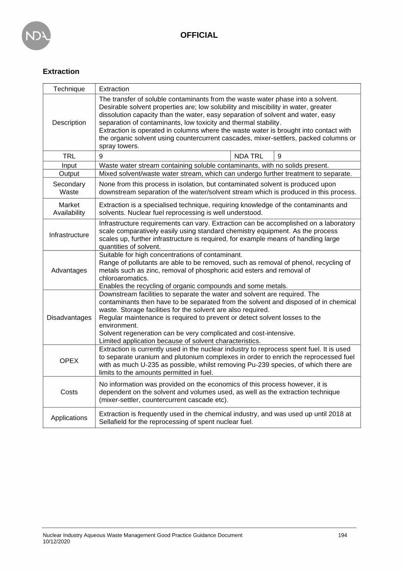
OFFICIAL
Nuclear Industry Aqueous Waste Management Good Practice Guidance Document 194 10/12/2020
Extraction
Technique Extraction
Description
The transfer of soluble contaminants from the waste water phase into a solvent. Desirable solvent properties are; low solubility and miscibility in water, greater dissolution capacity than the water, easy separation of solvent and water, easy separation of contaminants, low toxicity and thermal stability. Extraction is operated in columns where the waste water is brought into contact with the organic solvent using countercurrent cascades, mixer-settlers, packed columns or spray towers.
TRL 9 NDA TRL 9
Input Waste water stream containing soluble contaminants, with no solids present.
Output Mixed solvent/waste water stream, which can undergo further treatment to separate.
Secondary Waste
None from this process in isolation, but contaminated solvent is produced upon downstream separation of the water/solvent stream which is produced in this process.
Market Availability
Extraction is a specialised technique, requiring knowledge of the contaminants and solvents. Nuclear fuel reprocessing is well understood.
Infrastructure
Infrastructure requirements can vary. Extraction can be accomplished on a laboratory scale comparatively easily using standard chemistry equipment. As the process scales up, further infrastructure is required, for example means of handling large quantities of solvent.
Advantages
Suitable for high concentrations of contaminant. Range of pollutants are able to be removed, such as removal of phenol, recycling of metals such as zinc, removal of phosphoric acid esters and removal of chloroaromatics. Enables the recycling of organic compounds and some metals.
Disadvantages
Downstream facilities to separate the water and solvent are required. The contaminants then have to be separated from the solvent and disposed of in chemical waste. Storage facilities for the solvent are also required. Regular maintenance is required to prevent or detect solvent losses to the environment. Solvent regeneration can be very complicated and cost-intensive. Limited application because of solvent characteristics.
OPEX
Extraction is currently used in the nuclear industry to reprocess spent fuel. It is used to separate uranium and plutonium complexes in order to enrich the reprocessed fuel with as much U-235 as possible, whilst removing Pu-239 species, of which there are limits to the amounts permitted in fuel.
Costs No information was provided on the economics of this process however, it is dependent on the solvent and volumes used, as well as the extraction technique (mixer-settler, countercurrent cascade etc).
Applications Extraction is frequently used in the chemical industry, and was used up until 2018 at Sellafield for the reprocessing of spent nuclear fuel.
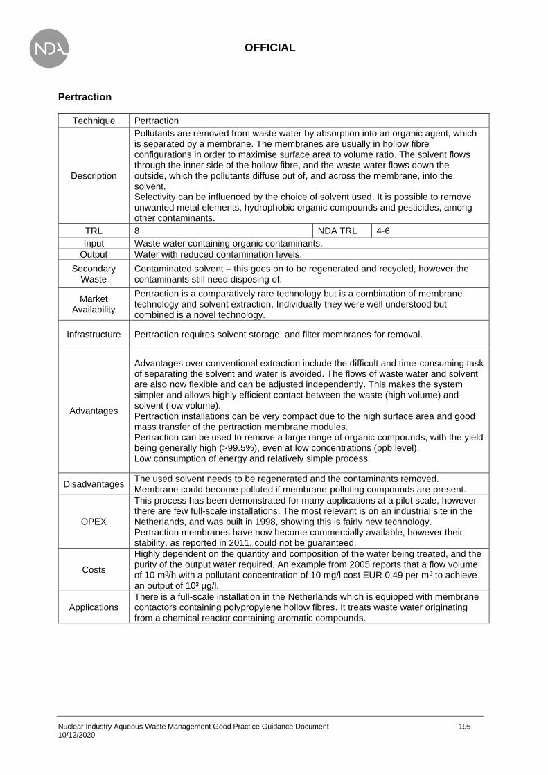
OFFICIAL
Nuclear Industry Aqueous Waste Management Good Practice Guidance Document 195 10/12/2020
Pertraction
Technique Pertraction
Description
Pollutants are removed from waste water by absorption into an organic agent, which is separated by a membrane. The membranes are usually in hollow fibre configurations in order to maximise surface area to volume ratio. The solvent flows through the inner side of the hollow fibre, and the waste water flows down the outside, which the pollutants diffuse out of, and across the membrane, into the solvent. Selectivity can be influenced by the choice of solvent used. It is possible to remove unwanted metal elements, hydrophobic organic compounds and pesticides, among other contaminants.
TRL 8 NDA TRL 4-6
Input Waste water containing organic contaminants.
Output Water with reduced contamination levels.
Secondary Waste
Contaminated solvent – this goes on to be regenerated and recycled, however the contaminants still need disposing of.
Market Availability
Pertraction is a comparatively rare technology but is a combination of membrane technology and solvent extraction. Individually they were well understood but combined is a novel technology.
Infrastructure Pertraction requires solvent storage, and filter membranes for removal.
Advantages
Advantages over conventional extraction include the difficult and time-consuming task of separating the solvent and water is avoided. The flows of waste water and solvent are also now flexible and can be adjusted independently. This makes the system simpler and allows highly efficient contact between the waste (high volume) and solvent (low volume). Pertraction installations can be very compact due to the high surface area and good mass transfer of the pertraction membrane modules. Pertraction can be used to remove a large range of organic compounds, with the yield being generally high (>99.5%), even at low concentrations (ppb level). Low consumption of energy and relatively simple process.
Disadvantages The used solvent needs to be regenerated and the contaminants removed. Membrane could become polluted if membrane-polluting compounds are present.
OPEX
This process has been demonstrated for many applications at a pilot scale, however there are few full-scale installations. The most relevant is on an industrial site in the Netherlands, and was built in 1998, showing this is fairly new technology. Pertraction membranes have now become commercially available, however their stability, as reported in 2011, could not be guaranteed.
Costs
Highly dependent on the quantity and composition of the water being treated, and the purity of the output water required. An example from 2005 reports that a flow volume of 10 m3/h with a pollutant concentration of 10 mg/l cost EUR 0.49 per m3 to achieve an output of 10³ µg/l.
Applications There is a full-scale installation in the Netherlands which is equipped with membrane contactors containing polypropylene hollow fibres. It treats waste water originating from a chemical reactor containing aromatic compounds.
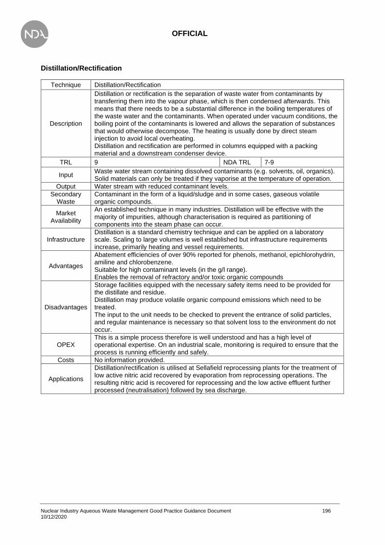
OFFICIAL
Nuclear Industry Aqueous Waste Management Good Practice Guidance Document 196 10/12/2020
Distillation/Rectification
Technique Distillation/Rectification
Description
Distillation or rectification is the separation of waste water from contaminants by transferring them into the vapour phase, which is then condensed afterwards. This means that there needs to be a substantial difference in the boiling temperatures of the waste water and the contaminants. When operated under vacuum conditions, the boiling point of the contaminants is lowered and allows the separation of substances that would otherwise decompose. The heating is usually done by direct steam injection to avoid local overheating. Distillation and rectification are performed in columns equipped with a packing material and a downstream condenser device.
TRL 9 NDA TRL 7-9
Input Waste water stream containing dissolved contaminants (e.g. solvents, oil, organics). Solid materials can only be treated if they vaporise at the temperature of operation.
Output Water stream with reduced contaminant levels.
Secondary Waste
Contaminant in the form of a liquid/sludge and in some cases, gaseous volatile organic compounds.
Market Availability
An established technique in many industries. Distillation will be effective with the majority of impurities, although characterisation is required as partitioning of components into the steam phase can occur.
Infrastructure Distillation is a standard chemistry technique and can be applied on a laboratory scale. Scaling to large volumes is well established but infrastructure requirements increase, primarily heating and vessel requirements.
Advantages
Abatement efficiencies of over 90% reported for phenols, methanol, epichlorohydrin, amiline and chlorobenzene. Suitable for high contaminant levels (in the g/l range). Enables the removal of refractory and/or toxic organic compounds
Disadvantages
Storage facilities equipped with the necessary safety items need to be provided for the distillate and residue. Distillation may produce volatile organic compound emissions which need to be treated. The input to the unit needs to be checked to prevent the entrance of solid particles, and regular maintenance is necessary so that solvent loss to the environment do not occur.
OPEX This is a simple process therefore is well understood and has a high level of operational expertise. On an industrial scale, monitoring is required to ensure that the process is running efficiently and safely.
Costs No information provided.
Applications
Distillation/rectification is utilised at Sellafield reprocessing plants for the treatment of low active nitric acid recovered by evaporation from reprocessing operations. The resulting nitric acid is recovered for reprocessing and the low active effluent further processed (neutralisation) followed by sea discharge.

OFFICIAL
Nuclear Industry Aqueous Waste Management Good Practice Guidance Document 197 10/12/2020
Evaporation
Technique Evaporation
Description
This technique is a distillation process as described in subsection 5.2.7, however the water is the volatile substance being taken into the vapour phase. The aim of this technique is to reduce the volume of the waste stream or to concentrate the contaminant liquor. Operating under vacuum reduces the boiling point of the water and enables the recycling of substances that would otherwise decompose.
TRL 9 NDA TRL 9
Input Waste water stream with contaminants of lower boiling point than water.
Output Contaminated waste residue left behind, evaporated water condensed into a separate tank. Note that volatile species will be lost during the evaporation process, and some evaporation of water will be lost thus tritium may be carried over.
Secondary Waste
Concentrated stream of contaminated waste with a high dissolved content Precipitation will eventually occur if water content is reduced sufficiently, resulting in a solid waste.
Market Availability
A standard technique that is well understood and a proven record for reducing the waste volume.
Infrastructure
Comparatively simple infrastructure requirements, with the most basic of processes requiring a tank with a heating element. A vacuum pump may be beneficial to reduce the boiling point and potentially reduce electricity costs. If radioactive gases are generated then may require further infrastructure (such as HVAC or condensers). Scalable – can be performed on a laboratory scale. Readily scales, although the supporting systems (e.g. HVAC) may complicate the scaling.
Advantages
The evaporated water is collected, then condensed, where it can be recycled. This method can also be used to recover valuable materials from water, which can then also be recycled. Depending on the influent and type of pollution, extraction can be around 99% effective. This process reduces the waste water amount and the volume of hazardous waste. Very high DF for many radionuclides but not volatile species.
Disadvantages
Storage facilities required for the residues before their disposal/recycling. Proper maintenance of the heat exchangers is crucial as fouling and corrosion disturb heat transfer and decrease efficiency. The concentration of contaminants in the in the condensate also needs to be monitored. When evaporation is being used to recover materials, pre-treatment such as addition of acids or bases is needed. Energy intensive and high capital cost.
OPEX Evaporation is a simple process which is widely used to recover valuable materials and remove contaminants from waste water streams.
Costs
The initial investment cost depends on the flow rate of the water passing through. A flow of 70 l/h is estimated to cost EUR 50,000 whereas a flow of 300 l/h would be EUR 155,000. No information on operating costs is available however a large portion of the expense will be for electricity.
Applications
Evaporation is used at Sellafield in reprocessing plants and the salt evaporator in the treatment of bulk sodium-nitrate-bearing effluent arising from reprocessing. The outputs include a concentrate for further treatment and low active effluent for neutralisation and sea discharge. Medium active evaporators are considered part of reprocessing operations. Closed Loop Hot Evaporation is used at AWE’s Radioactive Liquid Effluent Treatment Plant (RALETP), a facility which treats effluent from process activity, from general cleaning operations (e.g. barrier hand-washings, showers, floor washing), from decommissioning activities, and from historic contamination in drains, bunds, sumps, tanks etc. Water from the Receipt Tanks is heated to boiling in the evaporator vessel, generating steam. The steam is condensed back into water and is passed through the Reverse Osmosis Plant. Volatile species, such as tritium, are carried into the

OFFICIAL
Nuclear Industry Aqueous Waste Management Good Practice Guidance Document 198 10/12/2020
condensate. Insoluble species are retained as solids within the evaporator. This is the key process for minimising the activity in aqueous discharges and removing entrained solids. These solids are flushed into the Concentrate Tanks after an evaporation cycle. When required, the concentrate is transferred to another tank for storage prior to disposal by off-site incineration. Volume is not reduced, as water is condensed. The Austin plant in the Czech Republic also uses evaporation of waste water. Evaporation is used at Belgoprocess Site 1 (Belgium) in the treatment of medium active liquid waste, specifically a climbing film evaporator operating at negative pressure of -0,8 bar (0,2 bara). The distillates are sent to their denitrification installation, and the concentrates to homogeneous cementation.
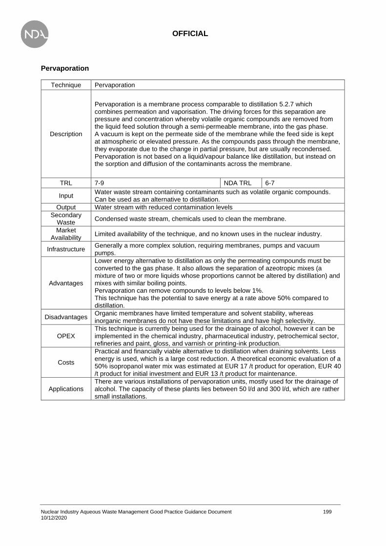
OFFICIAL
Nuclear Industry Aqueous Waste Management Good Practice Guidance Document 199 10/12/2020
Pervaporation
Technique Pervaporation
Description
Pervaporation is a membrane process comparable to distillation 5.2.7 which combines permeation and vaporisation. The driving forces for this separation are pressure and concentration whereby volatile organic compounds are removed from the liquid feed solution through a semi-permeable membrane, into the gas phase. A vacuum is kept on the permeate side of the membrane while the feed side is kept at atmospheric or elevated pressure. As the compounds pass through the membrane, they evaporate due to the change in partial pressure, but are usually recondensed. Pervaporation is not based on a liquid/vapour balance like distillation, but instead on the sorption and diffusion of the contaminants across the membrane.
TRL 7-9 NDA TRL 6-7
Input Water waste stream containing contaminants such as volatile organic compounds. Can be used as an alternative to distillation.
Output Water stream with reduced contamination levels
Secondary Waste
Condensed waste stream, chemicals used to clean the membrane.
Market Availability
Limited availability of the technique, and no known uses in the nuclear industry.
Infrastructure Generally a more complex solution, requiring membranes, pumps and vacuum pumps.
Advantages
Lower energy alternative to distillation as only the permeating compounds must be converted to the gas phase. It also allows the separation of azeotropic mixes (a mixture of two or more liquids whose proportions cannot be altered by distillation) and mixes with similar boiling points. Pervaporation can remove compounds to levels below 1%. This technique has the potential to save energy at a rate above 50% compared to distillation.
Disadvantages Organic membranes have limited temperature and solvent stability, whereas inorganic membranes do not have these limitations and have high selectivity.
OPEX This technique is currently being used for the drainage of alcohol, however it can be implemented in the chemical industry, pharmaceutical industry, petrochemical sector, refineries and paint, gloss, and varnish or printing-ink production.
Costs
Practical and financially viable alternative to distillation when draining solvents. Less energy is used, which is a large cost reduction. A theoretical economic evaluation of a 50% isopropanol water mix was estimated at EUR 17 /t product for operation, EUR 40 /t product for initial investment and EUR 13 /t product for maintenance.
Applications There are various installations of pervaporation units, mostly used for the drainage of alcohol. The capacity of these plants lies between 50 l/d and 300 l/d, which are rather small installations.

OFFICIAL
Nuclear Industry Aqueous Waste Management Good Practice Guidance Document 200 10/12/2020
Stripping
Technique Stripping
Description
The waste water is brought into contact with a high flow of a gas current in order to transfer volatile pollutants from the water phase into the gas phase. Volatile organic and inorganic compounds are transferred from waste water to waste gas, greatly increasing the surface area of the contaminated water exposed. The gases used are air and steam, and stripping can be performed with or without heating the stripping column. More-volatile pollutants are not heated and use air, whereas less-volatile compounds are removed using heat and steam.
TRL 9 NDA TRL 6-7
Input Waste water stream containing dissolved pollutants such as ammonia and methanol.
Output Water stream containing reduced pollutant levels.
Secondary Waste
Contaminated gas (air or steam).
Market Availability
A common technique in non-radioactive applications, comparable to some degassing technologies used in water treatment plants (i.e. vacuum degasser or nitrogen sparging). Care needs to be taken with radioactive wastes due to the gases released.
Infrastructure Using a compressed gas such as air or nitrogen requires little infrastructure (air compressor or nitrogen generator) while steam would require a boiler or electrical heaters.
Advantages
Strippers can be operated continuously or batch wise. The removed volatile organic compounds can be recycled to a production process. Can be used to remove a range of pollutants such as chlorinated hydrocarbons, ammonia, hydrogen sulphide, organic solvents, petrol, diesel fuel, low aromatics and phenol. High removal efficiency and low energy consumption.
Disadvantages
Not an individual process and requires at least downstream gas treatment. Often, the further gas treatment is more complex than the stripping process and the two need to be in balance with each other in order for the overall process to be efficient. Heat exchangers tend to foul under certain conditions therefore anti-fouling agents may need to be injected. Frequent column cleaning is necessary.
OPEX Used in a variety of plants and is a simple process with a non-complex set up.
Costs
Cost depends on whether steam or air is being used, with steam being more expensive both initially and the operate. All costs below are multiplied by a thousand. Steam: initial investment GBP 200-300, operating costs GBP 300-400 Air: initial investment GBP 70-100, operating costs GBP 15-20
Applications
An Organic Fine Chemicals (OFC) plant in Germany uses stripping for the pre-treatment of waste water from the production of pharmaceuticals. Another OFC plant in Germany uses stripping for the pre-treatment of waste water streams with high concentrations of purgeable halogenated organic compounds and solvents. An OFC plant in the Netherlands uses stripping for the pre-treatment of waste water for the removal of dichloromethane.

OFFICIAL
Nuclear Industry Aqueous Waste Management Good Practice Guidance Document 201 10/12/2020
Chemical Hydrolysis
Technique Chemical Hydrolysis
Description
The reaction of organic and inorganic constituents with water, causing them to break down into smaller compounds. In some cases, the reaction continues and produces short chained, easily biodegradable compounds. This usually requires ambient temperature and pressure, however, higher temperatures are sometimes required. This requires a heat exchanger system with preheating facilities for the waste input to be fitted to the reactor. In some cases, autoclaves may be required. Surplus acids or bases have to be neutralised after the treatment operation – requires additional instalments.
TRL 9 NDA TRL 9
Input
Water-based liquid waste, containing contaminants that are not easily biodegradable or have properties which are too harmful to allow them to be released into a common sewer. Example contaminants: halogenated organics, pesticides, organic cyanides, organic sulphides, organophosphates, carbamates, esters and amides.
Output Water containing degraded contaminants.
Secondary Waste
In some cases, contaminated waste gas.
Market Availability
A fundamental technique that relies upon thermal and pressure stability. Process is well understood, although requires an understanding of the species in the aqueous stream to ensure the correct pressure and temperature are utilised.
Infrastructure System needs to be able to achieve the pressure and temperature requirements for the aqueous waste stream. Chemical hydrolysis can be achieved in autoclaves or comparable systems thus can be utilised on a small (laboratory) scale.
Advantages
Chemical hydrolysis using strong bases or acids (e.g. NaOH, Ca(OH)2 or H2SO4), does not usually create cross-media transfer to be disposed of. Any released volatile material can be prevented by covering the vessel, or deducting the exhaust air to a waste gas treatment system.
Disadvantages
Chemical hydrolysis is a destructive technique. Further downstream treatment of the hydrolysed steam is required. The safety requirements of handling strong acids and bases are strict. Their use entails special corrosion-resistant material. They also require storage facilities which account for the hazardous potential of these substances. Quantitative degradation can be achieved, but the conditions of each treatment require pilot studies. Not suitable for substances requiring extreme operating conditions.
OPEX This technique is used most commonly in systems which remove biological waste
Costs
This is a high energy consumption process, which increases the cost. Also, the requirements of the sample such as an autoclave, or pressure vessel increase the cost significantly. The acid and base reagents can be obtained at a low cost (dependant on grade).
Applications
Chemical hydrolysis is utilised at the Sellafield solvent treatment plant. Outputs from the process include an aqueous effluent, which is further treated at the Sellafield Enhanced Actinide Removal Plant (EARP), and a solvent phase, which is sent for combustion.

OFFICIAL
Nuclear Industry Aqueous Waste Management Good Practice Guidance Document 202 10/12/2020
Electrodeionisation
Technique Electrodeionisation
Description
A water treatment technology that relies upon ion exchange membranes, ion exchange resin and an electrochemical cell to separate soluble ions from an aqueous waste stream. The application of an electrical current causes the movement of positively and negatively charged ions to negative and positive electrodes respectively (comparable to electrodialysis). This passes through the membrane, whereupon it is removed by ion exchange resin. The design of the membrane allows continuous regeneration of the resin. Several membranes are ‘sandwiched’ together. Water quality is good, able to achieve < 0.1 µS.cm-1. Typically used to polish RO permeate.
TRL 8-9 NDA TRL 6-7
Input Aqueous waste stream. The use of membranes requires low total dissolved solids (hardness <1 ppm CaCO3).
Output High quality water (< 0.1 µS.cm-1).
Secondary Waste
Reject waste stream containing concentrated waste.
Market Availability
Several suppliers available for EDI. Technology is a hybrid of ED and IX, each well established.
Infrastructure EDI typically supplied as cells or modules. Require an electrical supply to drive the process.
Advantages No chemicals utilised. Achieves high quality water.
Disadvantages
Generally used as a final polishing step (not suitable for high contaminant waste streams, consequently a moderately narrow pH operating range). Generates gases at the electrodes, requiring treatment or handling (hydrogen and oxygen).
OPEX No information available.
Costs Main cost is electricity, generally considered cost-effective if the requires waste stream input quality can be achieved.
Applications No information available.

OFFICIAL
Nuclear Industry Aqueous Waste Management Good Practice Guidance Document 203 10/12/2020
Appendix 3 – Case studies
Tc-99 Discharges from Sellafield
Sellafield
Background:
Reprocessing spent Magnox fuel at Sellafield results in the generation of a liquid waste “medium active concentrate” (MAC), containing fission products, including Tc-99, and actinides. MAC treatment was a dominant source of Tc-99 liquid discharges from the site, and prior to 1981 was discharged directly to sea following decay storage.
From 1981, discharges of MAC to sea were suspended and a decision made to retain MAC in storage tanks. The Enhanced Actinide Removal Plant (EARP) facility was later constructed and began operations in 1994 to remove actinides from discharges, including from stored MAC and new arisings. It was recognised that the treatment plant would not remove Tc-99.
Following an increase in the discharge limits for Tc-99 (from 10 TBq y-1 to 200 TBq y-1), both Tc-99 discharges and Tc-99 levels in the marine environment increased. This resulted in significantly increased Tc-99 concentrations in in lobsters, brown seaweeds and other environmental media in the Irish Sea and at more distant locations, for example, in Scandinavian coastal waters. This led to significant concern among stakeholders, such as those operating in the international seafood industry, and calls to reduce Tc-99 discharges.
The main challenges included:
Lack of common understanding of suitable treatment technologies to reduce Tc-99 in MAC discharges. The lack of a suitable treatment technology on site. Uncertainty regarding the disposability of solid end products from potential treatment options.
How were the challenges overcome?
The immediate response from British Nuclear Fuels plc (BNFL), the operator of Sellafield at that time, was to reduce the rate at which MAC was treated to lower annual discharges.
A full review of potential abatement techniques for Tc-99 was undertaken by the Environment Agency, focusing specifically on:
• Option 1: Re-route low-salt/high technetium fractions of MAC to vitrification (MAC Diversion).
• Option 2: Use organic chemical, tetraphenylphosphonium bromide (TPP) to precipitate technetium to enable its removal by ultrafiltration in EARP.
• Option 3: Construct a new ‘end of pipe’ abatement plant, using either ion exchange or chemical reduction, for the removal of Tc-99 from EARP effluent.

OFFICIAL
Nuclear Industry Aqueous Waste Management Good Practice Guidance Document 204 10/12/2020
Option 1 (MAC Diversion) was selected as the preferred option and was successfully implemented by BNFL in 2003. Residual MAC left in storage required an alternative treatment solution due to its high salt content which precluded vitrification as an option. Although Option 2 (TPP) was promising, there were concerns regarding disposability of the resulting solid end product in a repository as the chemical form of Tc-99 would be potentially mobile. This option was considered for further development, with the objective of creating a solid waste suitable for disposal. Option 3 was deemed far too costly in relation to likely benefits.
UK Nirex Ltd, at the time responsible for disposal of intermediate level wastes, re-evaluated the risks associated with the disposal of Tc-99 solid waste from TPP and concluded that this waste would not adversely impact the risk assessment for a repository.
BNFL then initiated a full-scale trial on the removal of Tc-99 from MAC liquor using TPP, testing the feasibility of the technique. The trial considered decontamination factors for a range of radionuclides, environmental impacts of TPP discharges, impacts associated with long-term use of EARP (e.g. corrosion) and the disposability of end products. Discharges of MAC were halted for a nine-month period whilst the trial was undertaken. The trial was a success, resulting in implementation of the technology at Sellafield, reduced discharge limits and wide acceptance internationally.
The approach led to:
• a significant reduction in Tc-99 and other radionuclide discharges;
• decline in Tc-99 levels in seafoods;
• radiation dose reduction (by ~30 µSv y-1);
• improved stakeholder relations.
How was good practice demonstrated?
Good practice demonstrated through the regulatory and management decisions undertaken to reduce a site-specific source of discharges, responding appropriately to stakeholder concerns.
Key lessons learned and additional outcomes:
This case study demonstrates the value of:
• Collaborative working between site and regulators to develop acceptable solutions.
• Implementing interim measures where necessary to reduce discharges whilst solution is being developed.
• Undertaking a comprehensive assessment of potential treatment technologies to inform the approach.
• Recognising the potential risks and opportunities associated with end product disposability.
• Undertaking comprehensive trials (where necessary) to inform approach, including assessment of a range of risk factors and potential outcomes.
• Demonstrating the case for implementation through suitable assessment and trial evidence.
• Responding appropriately to stakeholder concerns.

OFFICIAL
Nuclear Industry Aqueous Waste Management Good Practice Guidance Document 205 10/12/2020
Assessing the impact of additives and contaminants on an effluent plant
Sellafield Ltd and National Nuclear Laboratory Ltd (NNL)
Background:
The Conditions for Acceptance at effluent treatment plant prohibited sentencing of effluents containing materials such as oils or complexants which might impact the performance of sand bed filters or ion exchange materials during effluent treatment.
The primary objectives of the case were to assess the impact of additives and contaminants on an effluent plant. The focus of this assessment included identifying and mitigate the risk of excessive particulate challenge during waste retrieval operations in a high hazard facility upstream by dosing a settling aid.
The main challenges included:
A risk had been identified of introducing hydraulic fluid from waste retrieval equipment into the effluent stream under fault conditions. The risk impact needed assessing before decisions could be taken to use settling aids or to commence with waste retrieval operations.
How were the challenges overcome?
A combination of desktop and experimental/modelling assessments were used to perform a Risk impact assessment to demonstrate that the materials did not threaten the effluent plant performance.
R&D was undertaken to investigate the effect of rapid (flow cell) methods for testing impact on ion exchange material, trials on sand bed filter inactive rigs and benchtop filtration experiments, and chemical modelling of potential complexation effects. This assessment allowed the options to be differentiated, with the results as a qualifier for using the material in both cases.
How was good practice demonstrated?
Good practice was maintained by Sellafield Ltd and NNL technical experts. The implementation of the solution was independently reviewed through internal Sellafield Ltd formal technical governance (technical committee) and the permissioning process.
Key lessons learned and additional outcomes:
An approach focusing on early engagement between donor and treatment facilities enabled better consideration of the potential impact on the plant.
A number of techniques were used to assess the impact on facilities.
There were several technical reports of the experimental and desktop assessments produced, which could be made available to other operating companies.
OFFICIAL
Nuclear Industry Aqueous Waste Management Good Practice Guidance Document 206 10/12/2020
Managing feed uncertainty in legacy plant operations
Sellafield Ltd
Background:
SIXEP is an ion exchange plant that was designed to remove Cs+ and Sr2+ radioisotopes selectively from aqueous solutions in the presence of other common cations, particularly Na+. It consists of the following units, settling tanks that allow large particulates to settle from feed solutions before they are fed to the sand bed filter. Two sand bed filters that operate in parallel to remove suspended solids to protect the ion exchange beds from blinding and to reduce the soluble [Mg2+] in the columns. A carbonation tower, which adjusts the pH of the solution emerging from the sand bed from~11 to~7 to protect the clinoptilolite (naturally occurring zeolite) beds, which degrade at high pH. Two clinoptilolite beds, which operate in series (one lead bed and one lag bed). The contact time of effluent with the SIXEP clinoptilolite column is approximately 8 min, due to the very high flow rate. The influents are from nuclear fuel storage ponds and the washings from fuel de-canning operations. Contributions also come from other parts of the Sellafield site. Pond water purges account for the bulk of the feed to SIXEP (100 s of m3 /day) and consist of demineralised water that has been dosed with NaOH to increase the pH of the pond to at least 11.
There is significant uncertainty in the effluents challenge and impact on abatement facilities (SIXEP) when retrieving highly heterogenous waste from legacy facilities where limited characterisation has been possible. There are multiple effluent feeds (requiring blending and conditioning, principally for pH control) needing to conform to the SIXEP conditions for acceptance, which sets out a process envelope through donor plant quality plans.
The main challenges included:
The uncertainty requires careful management particularly as new operations are brought on-line. This case study focuses on New feeds which typically require a much greater level of scrutiny than well-established effluent feeds.
How were the challenges overcome?
Using previous learning from experience, the management arrangements for characterisation were developed to manage uncertainty.
Information was collected predominantly from Sellafield Ltd analytical data in routine pond water and process effluent samples using standard analytical methods and data interrogation through spreadsheets.
This included reducing the sampling frequency as confidence grew that sludge retrieval operations were generating effluent which was predictable and did not impact adversely on discharges to sea.
How was good practice demonstrated?
Good practice was maintained by Sellafield Ltd technical experts and demonstrated in the related plant management documents that were stored. The implementation of the solution was independently reviewed through internal Sellafield Ltd formal technical governance (technical committee).

OFFICIAL
Nuclear Industry Aqueous Waste Management Good Practice Guidance Document 207 10/12/2020
Key lessons learned and additional outcomes:
Being in a position to demonstrate robust management of a process envelope enables optimisation with low/minimal risk as confidence increases. This allows for better management of feed uncertainty in legacy plant operations.

OFFICIAL
Nuclear Industry Aqueous Waste Management Good Practice Guidance Document 208 10/12/2020
Hunterson A Modular Active Effluent Treatment Plant
Magnox
Background:
The Modular Active Effluent Treatment Plant (MAETP) was installed and commissioned around 2007 to process site effluent. It provided both filtration of suspended solids and ion exchange and was predominantly used to treat and discharge the effluent from the Cartridge Cooling Pond.
The purpose of this case is to describe the operational issues the MAETP was experiencing, describe the actions that have been taken to investigate these issues in order to define the extent of the problem and define the potential solutions.
The main challenges included:
The filtration medium vessel was opened up to investigate and it was found that it was coated in a brown “mud-like” material and clumping of the sand filter was evident. It was deemed that the material had accumulated over time and evidence of this material was found throughout the system.
An additional issue occurred with discharge authorisation whereby Alpha limits had been reduced and the level of Am-241 present would challenge the sites discharge authorisation limits if the issue continued.
How were the challenges overcome?
As the pond level was lowered and the bulk was de-sludged, the characteristics of the effluent changed dramatically and an increase in particulate was observed. Towards the end of cleaning and draining the pond the MAETP was suffering from a number of operational issues resulting in high differential pressure (dP) across the filtration system. Subsequent backwashing of the system would lower dP and processing continued. In addition, it was found that the Post Filter installed to protect the ION exchange element was blinding quickly. These were replaced twice in quick succession.
Operating the plant in this fashion culminated in a batch of treated effluent being processed through the plant to the onward Delay Tank which was considerably higher in radionuclides and particulate. This required a separate BPM study to enable discharge to Sea.
A new Post Filter was installed and plant reconfigured to recirculate from Ion exchange module to Buffer Tank, effectively creating a closed loop. The source of ‘cleaner’ effluent was introduced to clean the filtration system, reduce dP and flush the system. This effluent was then dumped to Filtered Solid Storage Tank.
An operating system was trialled whereby effluent was introduced into the Buffer Tank and processed through the Filtration system as closed loop. The effluent was sampled initially and processed for a given time period prior to being sampled again to ascertain particulate levels, with particular respect to Am-241 figures. Once predetermined figures were achieved effluent was recirculated through the Ion Exchange system and again brought back to the Buffer Tank and sampled.

OFFICIAL
Nuclear Industry Aqueous Waste Management Good Practice Guidance Document 209 10/12/2020
How was good practice demonstrated?
System Engineering liaised with Occupational Health Physicist, Chemist, Environment and Process Engineering to effectively create the closed loop batch processing system that focused on removing particulate. Results of sampling were confirmed and a final pass undertaken through the Full system prior to dispatch to the Delay Tank. A further sample was taken at this point to verify the effectiveness of new operating regime.
An Engineering Advice Note (EAN) was also produced detailing the recommended operation of the MAETP. This document was reviewed by Magnox subject matter experts.
The Options Assessment procedure was used to determine how to best process the Delay Tank with high readings. Part of this process was to justify how to prevent this issue from happening again.
OFFICIAL
Nuclear Industry Aqueous Waste Management Good Practice Guidance Document 210 10/12/2020
Aqueous Waste Treatment Plant, Aldermaston Site
AWE
Background:
The processes that use water at AWE can become contaminated with various substances, including uranium and plutonium. In the past, AWE has used a ferric flocculation method to treat radioactive effluent. By changing the pH and adding a ferric flocculant, metallic compounds agglomerate settling to a ferric hydroxide sludge. During this the solids were separated, and the water was filtered through sand before its final discharge. Altogether the process removed approximately 95% of radioactivity. The treated water was directed via the Pangbourne Pipeline, 11.5 miles of underground pipe, to the River Thames.
The main challenges included:
In the year 2000, the operational life of the Pangbourne Pipeline came to an end. AWE alongside the Environment Agency made a decision to close the pipeline by 1st April 2005.
This case study describes the approach taken by AWE in the management of radioactive effluent which enabled closure of the Pangbourne Pipeline and replacement of the ferric flocculation treatment process with a new Evaporation Waste Treatment Plant (WTP).
How were the challenges overcome?
AWE introduced a programme of activities in order to provide a more holistic approach to the management of effluent generated by the numerous facilities within the site. The main aspects of this approach included:
• Waste Characterisation;
• Waste Minimisation;
• Best Practicable Environmental Option (BPEO) study; and
• Implementation of BPEO.
How was good practice demonstrated?
Waste Characterisation
The implementation of effluent characterisation at source enabled a detailed understanding of the effluent arisings. Data was gathered on which donor facilities were producing radioactive effluent and how much effluent was being generated. Effluent samples were analysed to identify possible variations of the feed likely to enter the new WTP. This enabled production of the specification for the feed as an input into the design of the new WTP and made it possible to define the Waste Acceptance Criteria (WAC) for the WTP covering any new or existing donors. This aided the planning of the new plant and its processes.
Ministry of Defence © British Crown Copyright 2020/AWE

OFFICIAL
Nuclear Industry Aqueous Waste Management Good Practice Guidance Document 211 10/12/2020
Waste Minimisation
Several aqueous reduction measures were introduced to minimise the volume of discharges being managed as radioactive effluent as summarised below:
• Diversion of non-radioactive effluent - Various effluent sources were previously considered radioactive when they were not (confirmed during characterisation). Modifications to the effluent collection systems at donor facilities were made to divert non-radioactive effluent to more suitable trade drainage systems (away from the new WTP).
• Reduction of rainwater/groundwater ingress - It was demonstrated that a considerable amount of AWE’s effluent was rain or groundwater ingress into the collection systems. The key changes made included the decommissioning of the below ground effluent drainage transfer system, decommissioning of redundant collection systems, the replacement of open tanks with covered tanks and provision of over-head cover for bunds where practicable. These measures meant that rainwater/groundwater would not be treated unnecessarily within the new WTP.
• The use of dry techniques in decontamination during decommissioning instead of more traditional wet techniques.
The implementation of these measures led to a significant year on year reduction in the total volume of waste sent to the previous Liquid Effluent Treatment Plant (LETP) that discharged to the Pangbourne Pipeline. Between December 2000 and November 2005, low activity aqueous waste at AWE Aldermaston, reduced from 8,000m3 to 1,500m3 respectively. Waste minimisation measures reduced the effluent arisings by over 70% in less than four years.
Best Practicable Environmental Option (BPEO)
In 2000, a BPEO study was undertaken by AWE. It highlighted the best option for managing effluent was filtering it through a coarse strainer, then evaporate it using a Closed Loop Hot Evaporation and finally pass the resulting distilled water through Reverse Osmosis (RO) Membrane Filtration. The evaporation process produces a concentrate which contains both radiological and chemical contaminants this is now sent for incineration (not drummed with cement as per the original design). The key attributes of this treatment include: -
• Decontamination efficiency - The efficiency of evaporation and RO treatment process is between 99.9 and 99.99%.
• Robustness - It provides the flexibility to manage any fluctuations in the feed composition, whilst still providing high efficiency decontamination, without the need for substantial operator intervention to amend the process operating parameters.
• Simplicity - Relatively few process steps which results in a plant that is easy to control, operate and maintain.
• Operating costs - The simple and robust process allows for a significant amount of automation, reducing labour requirements and costs.
Ministry of Defence © British Crown Copyright 2020/AWE

OFFICIAL
Nuclear Industry Aqueous Waste Management Good Practice Guidance Document 212 10/12/2020
Evaporator Waste Treatment Plant (WTP) and Process Description
The process can treat one or more tanks of received effluent, temporarily storing the treated effluent for a short period of time. Sample analysis of the treated effluent is carried out to ensure its compliance with downstream WAC linked to discharge permit limits and notifications. Tritium is not removed by the process; however, levels are low and within permitted discharge limits.
The Benefits of AWEs Approach to Effluent Management
The benefits to AWEs holistic approach to the management of effluent include:
• A lower cost treatment plant with smaller footprint - The investment in appropriate waste minimisation measures allowed for the reduction in the plant and equipment size.
• Lower operating costs - A smaller plant and equipment allowed a reduction in energy and maintenance costs.
• High availability of plant - The availability was assured by the duplication of key equipment, the simple and robust treatment process and the lack of time-consuming modifications to the process or the need for re-treatment of batches.
• Security of discharge - The efficient treatment process enables the plant to confidently meet discharge permits / consent conditions and limits, providing confidence of its capability to meet future demands.
Summary
The operation of the WTP has been modified to support on-going waste minimisation. This includes:
• Bypassing of the RO plant - When sampling effluent before and after the RO system, the results showed no difference. This reduced both power, filter cost/disposal and chemicals.
• Concentrate is now sent for incineration rather than being drummed with cement, due to the low activity and solid content in the concentrate.
• Rainwater in sumps and bunds (with potential for radioactive contamination) is transferred to the trade waste drainage network as opposed to the WTP. Historical results show that levels are below World Health Organisation (WHO) drinking water screening levels. Annual reassurance monitoring is carried out.
• Reduction in radioactive effluent from production facilities due to the move to wet wipes.
Ministry of Defence © British Crown Copyright 2020/AWE
OFFICIAL
Nuclear Industry Aqueous Waste Management Good Practice Guidance Document 213 10/12/2020
Removal of Mercury (Hg) from wastewater
Belgoprocess, VMM
Background:
Since the beginning of 2014 a new discharge limit for mercury has been set (Hg < 0.5 µg/l), which is a factor 10 lower than the previous discharge limit.
The main challenges included:
In order to cope with this limit, Belgoprocess adopted a new method for the removal of mercury from wastewaters by means of complexing with TMT-15 followed by coagulation, sedimentation and ultrafiltration.
How were the challenges overcome?
In order to get a grasp of the magnitude of the problem, first the mercury needed to be analysed. Also, in the laboratory, to be able to detect such low levels of mercury, an adaptation to the measuring principle was made by adding K2Mn2O7 to the liquid prior to sampling to prevent Hg from adsorbing to the walls of the sampling vessel.
R&D was undertaken, with laboratory tests performed in order to determine the best possible scenario to remove mercury from the wastewater in such low concentrations. After the laboratory tests were successfully concluded, the new installation was put into place and commissioned after testing, both for the TMT dosage as well as for the ultrafiltration installation.
Key lessons learned and additional outcomes:
An important aspect to consider is that this method is only suitable for removal of ionic mercury and not of other forms (organic or elemental mercury). For the removal of elemental mercury, it is possible to do so by means of adsorption which is currently being tested in the laboratories at Belgoprocess.
Ministry of Defence © British Crown Copyright 2020/AWE

OFFICIAL
Nuclear Industry Aqueous Waste Management Good Practice Guidance Document 214 10/12/2020
Treatment of high nitrate medium active liquid waste
Belgoprocess, Commissariat à l´énergie atomique et aux énergies alternatives (CEA)
Background:
A historic waste stream of ~500 m3 medium activity waste at a Belgoprocess site contained a quantity of nitrates that prevented discharge to the environment.
The main challenges included:
In order to cope with this limit, a new specific homogeneous cementation formula that is able to cope with these high nitrate concentrates was required to condition the distillates, following a biological denitrification installation that also treated the distillates.
How were the challenges overcome?
By sampling the historic effluent, the best possible scenario was determined to treat this effluent. The sample was first evaporated to get the necessary distillates to perform the laboratory tests.
The concentrates resulting from the evaporation needed to be conditioned as well, leading to a research project being set up with CEA in France to determine a specific homogeneous cementation formula that is able to cope with these high nitrate concentrates.
After the laboratory tests were successfully concluded, the new biological denitrification installation was put into place and will be commissioned after the testing phase is concluded.
How was good practice demonstrated?
Laboratory tests were performed to determine which was the best principle to remove nitrates from a medium active waste effluent.
Options were differentiated for both the development of the denitrification installation using a literature reviews and laboratory tests.
For the homogeneous cementation, these tests were performed mainly at CEA in France. This will be subject to a peer-review before the commissioning phase.
Key lessons learned and additional outcomes:
Since the installations are not yet operational, real industrial experience still remains to be demonstrated.

OFFICIAL
Nuclear Industry Aqueous Waste Management Good Practice Guidance Document 215 10/12/2020
Babcock Marine Devonport Discharge Pipes
Babcock Marine Devonport
Background:
As Devonport is an operational Naval Base as well as a site that creates, processes, treats and disposes of Radioactive waste stream through its work in re-fuelling nuclear powered submarines, it has tidal wharfs where operational submarines are moored. Due to the river being tidal, the single authorised treated effluent discharge pipework is located at the junction of two wharfs. This is to ensure that when the treated effluent is discharged from the treatment facility in accordance with the Environment Agency Permit, the tide will be going out to Plymouth Sound and this will ensure sufficient dispersion and down river/out to sea flow.
Due to the mooring line arrangement of these two wharfs the mooring lines have to cross the discharge pipe. Due to this, the pipework was installed with a protective cowling, but over time the protective cowling has been damaged/pulled away by the mooring lines rubbing against it as a result of changes of tide state. This has over time exposed the discharge pipe to the mooring lines and elements. As the end of the discharge pipe/cowling arrangement was submerged 90% of the time, the extent of the damaged couldn’t be seen.
As the Nuclear Operations and Maintenance Manager for the Radioactive Waste Assets in Devonport, part if my remit is the treatment and discharge of radioactive effluent, which includes this discharge pipe.
The main challenges included:
From an onsite inspection the amount of damage was extensive and an immediate action was to stop all planned river discharges, to inform both the Waterfront Facility Manager (Navy) and my management chain.
In conjunction with this, an inspection by boat was arranged, with the view to ascertain the extent of the damage, and to determine a way to make safe. This was to avoid the section of damaged pipework from detaching itself from the wall and either floating down the river or having to be retrieved from the river bed.
As all river discharges were temporarily stopped, the resultant affect was to restrict/stop all effluent being receiving into the treatment plant and to start to prioritise effluent generation across site, to ensure major submarine projects where not effected
As the discharge pipework was on MoD land and a different licensed site, firstly permission had to be gained from the licence Site Manager and Navy. In addition, a specialist contractor who specialises in water based repair methods, had to be contacted. This was because there were no Suitably Qualified and Experienced Personnel (SQEP) on site.
How were the challenges overcome?
1) Numerous discussions and site visits where held with the external contractor as they were not used to working in radiologically controlled environment.
2) Advise was taken from the onsite Health Physics Department.
3) All the contractor documentation (Risk Assessments and Method Statements) were reviewed by a quorate group (Authorisation Group) and Health and Safety Department.

OFFICIAL
Nuclear Industry Aqueous Waste Management Good Practice Guidance Document 216 10/12/2020
4) The repair to the Discharge Pipe and installation of the protective cowling was undertaken with Babcock oversight.
5) Advice was sought from the Technical Authority on the best repair method and type of coupling to be used.
A TEEkay coupling (Mechanical Coupling) was used to join the existing pipe to the new section of pipe, this was used instead of welding due to the position of the pipework and the methodology which was used to undertake the repair, i.e. off a converted Landing Craft.
Advice was sought from the Technical Authority and Design Authority in the use of a TEEkay Coupling, as these had been traditionally used on Surface Ship Projects
The two options of pipe repair were to either socket weld or attach the new section of pipework using a TEEkay Coupling (Mechanical Coupling). Due to the time constraints, position of the existing pipework, physical environment and repair method it was decided to use the Mechanical Coupling. The damage to the discharge pipe was stopping all treated effluent discharges from the Effluent Treatment Plant and causing a direct effect on major submarine projects
How was good practice demonstrated?
The solution was independently reviewed by both the Technical and Design Authority as part of the repair process during the Internal Concession process, as the TEEkay Couple was classed as a temporary repair. Also, during the AG process, the Risk Assessment/Method Statement was reviewed by a quorate group which included independents.
Key lessons learned and additional outcomes:
As the discharge pipe is a single point of vulnerability on the Devonport Site, it should have been position in such a way the submarine mooring lines would not have damaged it. Also, when the positions of the mooring lines were permanently changed, the Radioactive Waste Management Group should have been consulted. The wharfs where built in the Victorian Era and were never designed to moor submarines and have a treated effluent discharge pipe in close proximity. When a change of use of infrastructure is implemented, all stakeholders need to be contacted and opinions/views sought.

OFFICIAL
Nuclear Industry Aqueous Waste Management Good Practice Guidance Document 217 10/12/2020
Bradwell Acid Dissolution Abatement Plant
Magnox
Background:
A process was developed and successfully employed by Magnox for processing Bradwell nuclear site Fuel Element Debris (FED), comprising fuel element cladding manufactured from magnesium metal alloyed with either zirconium (Zircalloy or ZR55) or aluminium (AL80), to achieve a ~80% reduction in the waste volume. The process comprised of two stages. In the first stage the FED was dissolved in nitric acid and in the second the magnesium rich liquor was abated for the radioactive species present (and associated heavy metal contamination) prior to discharge. The separated, concentrated, radioactive component was then despatched for disposal as solid waste. The abatement of the dissolved FED acid liquor required the development of a novel process and associated plant (Acid Dissolution Abatement Plant, ADAP).
Abatement Solution:
The abatement proceeded in two stages:
1) The acid liquor was made alkaline (pH 7.5) on a batch basis with aqueous sodium hydroxide. This resulted in the precipitation of the radioactive species present and associated heavy metals, together with the alloying metal in the Mg metal cladding, either zirconium or aluminium. The magnesium was left in solution. A flocculating agent was added (PolyGold AD987) to flocculate the precipitated solids, which then rapidly settled prior to being drawn off for filtration and disposal as a “filter cake”. Experimental studies10 demonstrated excellent removal of key species, reported in Table A, with the exception of Cesium-137 and Strontium-90 that remained in the supernatant. These were removed from the supernatant in the second stage of the process.
Table A.3.1 - Stage One Abatement of Principal Contaminants of Concern
Element/Radionuclide Classification
Elements/Radionuclides Assessed
% Abatement
Group III Al 95%
Transition Metals Series 1 Ti, Cr, Fe, 55Fe, Cu, Zn
Transition Metals Series 2 Zr, Cd
Group IV Si, Pb
Lanthanides Ce, Nd, 151Sm, 147Pm, 154Eu
10 “Behaviour of Radionuclide and Environmentally Significant Elements in Nuclear Fuel Element Debris (FED)”, Holmes C.G., Wickenden D., Caborn J. A., Harvey C. R., Hodge N. A., Lee D. F., Kralj B., Patel A., and Saunders C., Environmental Radiochemical Analysis V - Proceedings of the RSC 12th Internal Symposium on Nuclear and Environmental Radiochemical Analysis, Bath, UK, 2014 (ISBN 978-178262-155-3)

OFFICIAL
Nuclear Industry Aqueous Waste Management Good Practice Guidance Document 218 10/12/2020
Actinides U, 234U, 235+236 U, 238U, 238Pu, 239+240Pu, 241Pu, 241Am, 242Cm, 243+244Cm
Transition Metals Series 1 Co, 60Co, Ni, 63Ni 75%
Transition Metals Series 2 Ag, 108mAg
Group III B 10%
Transition Metals Series 1 Mn
Group IV S
Group 1 Cs, 137Cs < 5%
Group 2 Sr, 90Sr, Mg, Ca, 133Ba
2) The Cesium-137 (137Cs) and Strontium-90 (90Sr) was removed from the neutral supernatant by ion-exchange employing highly nuclide specific inorganic ion-exchange (IX) media, namely Co-Treat® (Fortnum) for the removal of 60Co, and Cs-Treat® (Fortnum) for the removal of 137Cs. The spent resin was then disposed of as solid ILW
Key lessons learned and additional outcomes:
Although the ADAP abatement process delivered its objective of removing all the key contaminants from the dissolved FED liquor, allowing the abated (magnesium nitrate rich) liquor to be discharged, the following key lessons were reported:
1) The ADAP design was predicated on advice that the FED was composed predominantly of zirconium alloyed magnesium metal cladding (ZR55). Subsequently the plant design employed an industry standard “filter-press” to remove the mechanically robust flocculated material that arose from the Stage One processing of dissolved ZR55 cladding. However, the waste stream was subsequently found during commissioning trials to contain significant quantities of aluminium alloyed magnesium metal cladding (AL80). The flocculated material containing precipitated aluminium hydroxide was not mechanically robust and proved challenging to collect; where the resultant filtered material possessed a high level of liquid (the supernatant from the filtration was circulated through the IX media to remove residual 137Cs, and 90Sr). This significantly slowed overall plant processing rates. In addition, a drying facility had to be built to dry the collected ILW sludge in-situ, before it was acceptable for disposition.
This highlights the importance of comprehensive waste-stream characterisation, and the value of good communication between engineering design teams and project waste specialists.
2) The IX treated liquor was found to be prone to secondary precipitation of residual metals resulting in the particulate loading approaching permitted discharge limits. Consequently, large holding tanks needed to be deployed to enable further settling and filtration prior to final discharge.

OFFICIAL
Nuclear Industry Aqueous Waste Management Good Practice Guidance Document 219 10/12/2020
Fukushima Daiichi Aqueous Waste Case Study
In 2011 an off-shore earthquake led to a large tsunami that inundated the site of the Fukushima Daiichi nuclear power station in eastern Japan. Electrical power was lost to the reactor cooling water system and that led to a hydrogen explosion and meltdown in 3 reactors.
As a direct consequence, sea water (from the tsunami) and groundwater (flowing through cracks in the reactor basement) came into direct contact with the melted fuel and damaged reactor components. This water became highly radioactive and began flowing out of the reactor building basement into the sea in an uncontrolled manner.
In an attempt to manage and decontaminate this water, the site operator constructed a complex water treatment facility (ALPS, Advanced Liquid Processing System). Over time, the ALPS has been upgraded and is currently comprised of several systems that include:
filtration systems to removal suspended particles and oils
caesium and strontium removal systems using ion-exchange / filtration / precipitation methods
multi-nuclide removal system using reverse osmosis (RO)
a desalination plant, necessary to allow the RO system to operate efficiently
In combination, the systems in ALPS are capable of reducing radionuclide concentrations down to very low (trace, ppm) levels with the exception of tritium. The extracted radionuclides are stored in shielded containers in concentrated form as sludges (precipitates) and ion-exchange substrates.
Figure A.3.1 A simplified flow diagram of the water treatment system in use at the
Fukushima Daiichi accident site in Japan. Taken from IAEA (2015). [144]

OFFICIAL
Nuclear Industry Aqueous Waste Management Good Practice Guidance Document 220 10/12/2020
Water management on site has since been supplemented with a frozen ice wall installed around the damaged reactors in an attempt to provide a physical and hydrological barrier to reduce the rate of water flow contacting the fuel.
One of the significant features of the ALPS is the very large rate of water treatment. Currently ALPS is processing around 220 m3/day water and, since its commissioning, the system has processed over 1 million m3 of contaminated water.
The water remaining after treatment through ALPS is stored in over 1000 tanks on the site, with an expected total volume of about 1.4 million m3 by the end of 2020. This water contains tritium that cannot be removed by the ALPS processes at an average concentration of around 0.73 MBq/l, with the total inventory of tritium being approximately 860 TBq (plus residual concentrations of other nuclides).
Figure A.3.2 Some of the tanks for the storage of tritiated water on the Fukushima Daiichi site.
There are ongoing discussions with regulators and stakeholders on how to manage the tritiated water, with two options being considered: discharge to the marine environment via an offshore pipeline, or discharge to the atmosphere by evaporation. Estimates suggest it will take almost 20 years to discharge the water by either method. Although the Japanese regulator has indicated that discharge to the sea may be allowable and could meet agreed radiological dose constraints, there is considerable local opposition to the proposal especially from fisherman.
Although the accident at Fukushima Daiichi is unlike anything that has happened in the UK, there are still several lessons learned from the Japanese experience that are relevant to consideration of managing aqueous wastes on UK nuclear sites:
Due to the accident, the source term was poorly understood and characterised. This made designing the aqueous waste treatment system very difficult. This stresses the importance of quality and timely characterisation and monitoring data. It should be noted that there have been several significant accidents on UK nuclear sites, and similar problems of uncertain source terms need to be addressed.

OFFICIAL
Nuclear Industry Aqueous Waste Management Good Practice Guidance Document 221 10/12/2020
The volume of water to be decontaminated and then stored is a major challenge. In particular, the large volume has created logistical problems for storage with almost the entire site covered in tanks. This emphasises the importance of volume reduction as an example of good practice.
Decontamination technologies can be very effective at reducing the concentrations of most radionuclides (with the exception of tritium). However, this is at the detriment of creating large quantities of highly active secondary wastes in the form of sludges and ion-exchange resins. There is now an urgent study underway to decide how to further treat these secondary wastes so they can be made into a passively safe stable waste suitable for storage and disposal. This illustrates the importance of thinking holistically and needing to balance risks from both aqueous and solid wastes.
It is very difficult to plan and achieve a zero discharge strategy, especially if there is a large inventory of nuclides such as tritium that cannot be readily concentrated and immobilised. Although progressive reduction in discharges is a good practice objective, most nuclear sites will need to adopt an optimised aqueous waste strategy that combines both discharge and immobilisation approaches during operations and decommissioning.
Deciding on an aqueous waste strategy is not always easy or obvious, and different stakeholders will have different views. Although discharge to the marine environment has historical precedence and is continued on all UK nuclear sites, the policy objective for progressive reductions in discharges will place greater emphasis on seeking alternative solutions that meet with broad stakeholder acceptance.
Copyright © 2022 FDOKUMEN