NTT 240/460 - HDT Lovato
130
NTT 240/460 Compact digital drive for AC and DC, rotary, linear and tubular, brushless, asynchronous, and DC permanent magnets motors at 230Vac and 400Vac with resolver or incremental/absolute encoder. Operation mode via Ether- cat CoE, Profinet RT, Profibus DPv0, Canopen®, ModbusRTU and I/O. INSTALLATION AND USER GUIDE
-
Upload
khangminh22 -
Category
Documents
-
view
0 -
download
0
Transcript of NTT 240/460 - HDT Lovato
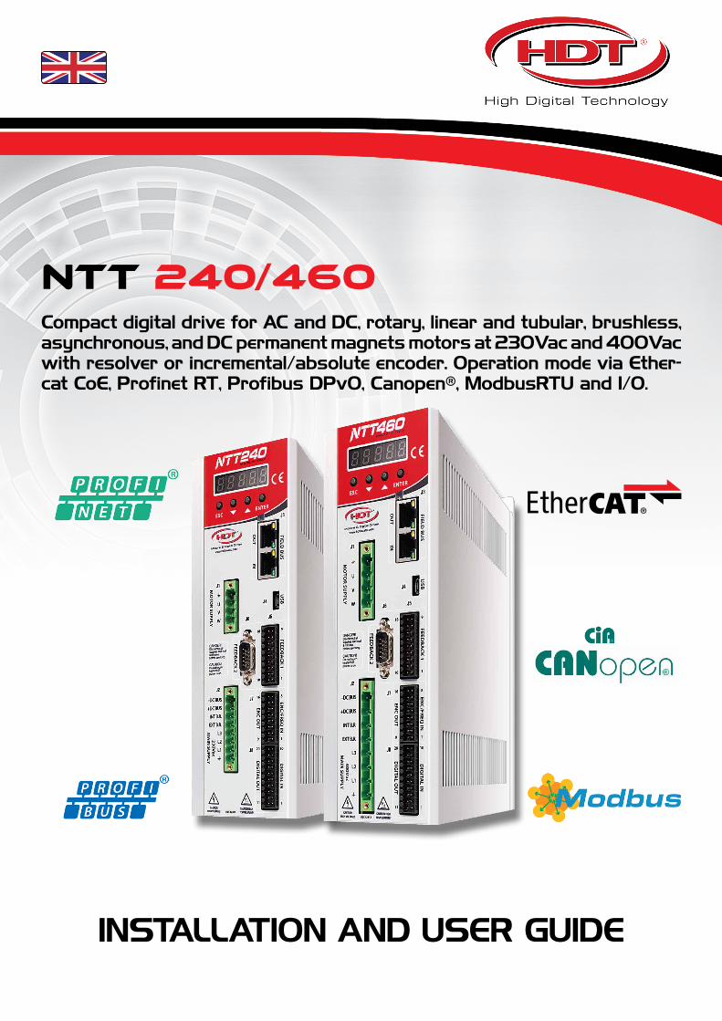
NTT 240/460Compact digital drive for AC and DC, rotary, linear and tubular, brushless, asynchronous, and DC permanent magnets motors at 230Vac and 400Vac with resolver or incremental/absolute encoder. Operation mode via Ether-cat CoE, Profinet RT, Profibus DPv0, Canopen®, ModbusRTU and I/O.
INSTALLATION AND USER GUIDE

2Installation and user guide
Rev: 4.0
NTT 240/460
Manual or NTT 240/460 drive changes
Manual Changes Description Manual, Drive and Caliper
Vers. FW Drive
Vers. SW Caliper
HW Vers. Drive
10/01/2019 Rev: 4.0 • First release for Caliper software suitable for NTT 240/460 drives. • 4.00 • 4.04
• 4.05
0 - 0
• V/Hz control for asynchronous motors. • 4.01 • 4.07
• 4.08
• Ethernet connector now available (not managed at the moment).
• J7 connector at pin 16: +24V supply for frequency output now available on request.
• 4.02 • 4.08
• 4.09
• 4.10
• 4.11
0-1
• External encoder loop management now added. • 4.05 • 4.12
• 4.13• Position software limit now added for Canopen operation mode. • 4.06
• Pressure control topology now added.
• Automatic convertion for IVT file from previous DGM series now added.
• 4.07 • 4.15
• Current offset for motor brake management now added. • 4.08
• Current limit management available with or without decimal.
• Display H6 menu moved in S9.
• 4.09
• 4.10
• 4.11
• 4.16
! It’s recommended to always verify drive firmware version in order to connect it to the related and correct Caliper version.

3
NTT 240/460
Installation and user guide
Rev: 4.0
Thanks for choosing this H.D.T. product.
www.hdtlovato.com
Read carefully this manual before using this product.
For continuous improvement, H.D.T. reserves the right to change features and specifications to manual and product without notice for the customer.
Any parts of this manual can not be reproduced in any way or transmitted without a write permission from the manufacturer.
Details of images, contained here in, may be different from real product.
All rights reserved.
Doc. NTT 240/460
Rev. N° 4.0
Date 10/01/2019
All trademarks belong to their respective owners.

4Installation and user guide
Rev: 4.0
NTT 240/460
Summary
Ch. 1 Safety Informations 71.01 Danger 71.02 Attention 81.03 Notes 81.04 Directives, marks and industrial standards 8
Ch. 2 Introduction 92.01 Description 92.02 Delivery ispection 92.03 Drive sizes and option configuration 102.04 NTT 240 drive features 122.05 NTT 460 drive features 132.06 Technical data 15
Ch. 3 Installation 193.01 Mechanical installation 193.02 Dimensions and side view 20
Ch. 4 Supply and quick start 234.01 Standard wiring for quick start 234.02 Fuses 244.03 External braking resistor 244.04 EMC Filter 244.05 External DC link power supply 254.06 DC bus reforming 25
Ch. 5 Wiring and connections 265.01 General description 265.02 J1 connector: motor power connection 285.03 J2 connector: drive power supply and braking resistor 305.04 J3 connector: EC and PN option configuration 325.05 J3 connector: CM option configuration 335.06 J3 connector: PB option configuration 345.07 J4 connector: drive settings 35
5.07.1 Using USB 2.0 HUB 355.08 J5 connector: Feedback 1 36
5.08.1 Wiring a H.D.T. motor with encoder feedback 385.09 J6 connector: Feedback 2 40
5.09.1 Wiring a H.D.T. motor with resolver feedback 41

5
NTT 240/460
Installation and user guide
Rev: 4.0
5.10 J7-8-9 connectors: Frequency, digital and analog I/O 425.10.1 J7 connector: frequency I/O 425.10.2 J8 connector: digital I/O 435.10.3 J9 connector: analog I/O 445.10.4 Cable per J7-8-9 45
5.11 J10 connector: RS485 465.12 J11 connector: logic supply and S.T.O. safety function 465.13 J12 connector: Ethernet 47
Ch. 6 Operation mode 486.01 Introducing Caliper 496.02 Caliper Data Monitor 516.03 Caliper Menu 52
6.03.1 Menu: ‘FIELD BUS’ item 536.03.2 Menu: ‘MOTOR DATA’ item and ‘FEEDBACK’ sub-menu 556.03.3 Menu: ‘ADVANCED SETUP’ item 616.03.4 Menu: ‘Control Set’ ‘Modbus’ ‘CanOpen’ ‘Ethercat’ ‘Profinet’ items 62
6.04 Emergency stop functions 716.04.1 FAULT REACTION function 716.04.2 HALT function 726.04.3 Safe Torque Off safety stop function 72
6.05 Factors 736.05.1 Factor calculation procedure 736.05.2 Custom Application 746.05.3 Custom Label 75
6.06 Display and keyboard 766.06.1 Keybord access parameters 77
6.07 Motor autophasing 826.08 Digital I/O 83
6.08.1 Digital I/O functions 856.09 Drive references 87
6.09.1 Main reference 876.09.2 Auxiliary references 88
6.10 Speed ramps 896.11 Motor brake 906.12 Braking resistor 926.13 Motor cogging torque compensation 936.14 Scope function 94
6.14.1 Scope: ‘CHANNEL SETTING’ 956.14.2 Scope: ‘PID SETTING’ and ‘WAVE GENERATOR’ 966.14.3 Scope: ‘TEST’ 966.14.4 Scope: ‘TRIGGER’ 97
6.15 Control topologies 986.15.1 Torque control 1006.15.2 Sensored speed control 1016.15.3 Sensorless speed control 1026.15.4 Position control: electronic gearbox mode 1036.15.5 Position control: positioner mode 1046.15.6 Position control: electronic cam mode 1056.15.7 Pressure control 106
6.16 Closed loop regulation tuning 1076.16.1 Current loop tuning 1076.16.2 Speed loop tuning 1086.16.3 Position observer tuning 110

6Installation and user guide
Rev: 4.0
NTT 240/460
6.17 Sensorless loop tuning 1116.17.1 Setting speed/current loop and motor parameters 1116.17.2 Setting sensorless parameters 1126.17.3 Sensorless loop tuning 113
Ch. 7 S.T.O. safety circuit 116
Ch. 8 Drive status and diagnostics 1208.01 Drive status 1208.02 Fieldbus status signaling 1208.03 Diagnostics 121
Ch. 9 Accessories 126

7
NTT 240/460Safety Informations
Installation and user guide
Rev: 4.0
Ch. 1 Safety Informations
Read carefully this manual before using NTT 240/460 drive.
Take care of this handbook and keep it at hand for later reference.
Please make sure that this handbook is delivered to the final customer and user.
Safety symbols used in this guide are described below:
DANGER:
This symbol means the possibility of serious body hazards due to electrical, thermal or mechanical shock.
!ATTENTION/WARNING:
This symbol means the possibility of damaging drive or other equipment.
!NOTES:
This symbol suggests auxiliary informations to ensure a correct operation for drive or other equipment.
1.01 Danger
• Never supply the drive without the cover and never remove the cover while supply is on.• Do not manipulate the drive with wet hands. Failure to observe this could lead to electrical shocks.• Keep a safety distance from the motor and the machine when the power is on and never touch the rotary parts
of the motor when it is in function.• When reset the alarms make sure that the signal of running is enabled in order to avoid unexpected start of the
motor. Fix up a separate emergency stop device. It exists the risk of injury.• Do not touch the terminals of the drive, the motor or the external braking resistance, while the power is on.
Failure to observe this could lead to electrical or thermal shocks.• Before starting wiring, ensure that all supplies are off and motor is stopped.• Always turn the device’s input off before starting any maintenance. Failure to observe this could lead to fires or
electrical shocks.• Disconnect all supplies before performing drive maintenance.• Always wait at least 8 minutes after turning off the input power before starting inspections. Make sure that LEDs
have been erased.Failure to observe this could lead to electrical shock.• The maintenance, the inspection and part replacement must be done by a designated person. Remove all the
metal accessories like watches, bracelets etc before beginning the job. Failure to observe this could lead to electrical shocks and injuries.
• Always turn the power off before inspecting the motor or machine. A potential is applied on the motor terminal even when the motor is stopped. Failure to observe this could lead to electrical shock.
• Ensure that supply voltage range mathes with drive features.

8Installation and user guide
Rev: 4.0
NTT 240/460 Safety Informations
1.02 Attention
• Earth cable must be wired according to safety standards of the Country where drive is installed.• Installation must be done by a designated person.• Always fix the drive before executing the wiring.• Install a protection circuit (fuses or magnetic contactor) on drive supply.• Do not connect an esternal supply on terminals U, V, W.• Ensure that the drive voltage correspond to the voltage of the supply.• Fix terminal screws with a correct fixing torque.• Connect correctly the output side (U,V,W). Failure to do so could cause the motor to rotate in reverse and the
machine to be damage.• If drive power supply is not connected, not connect motor cable if motor is rotating. It exists the danger to
damage the machine.• Not obstruct the entry and the escape of the air and not introduce stranger object. Fire danger exists.• Ensure the functionality of the motor as single unit before connecting it mechanically to the machine and verify
that the max speed of the motor are accepted from the machine. It exists the danger to hurt and to damage the machine.
• Never modify the drive.• Clean the drive with a vacuum cleaner. Do not use organic solvents. Failure to observe this could lead to burns
or damage.• For your safety, it is very important that any software update or service have to be done by our company.• When you have to throw away the drive, please dispose of this product as industrial waste, so respect standards
enforced by Country laws.
1.03 Notes
• Qualified electrical staff must execute installation and maintenance.• Earth cable must be wired according to safety standards of the Country where drive is installed.• The machine operator must receive an adapt preparation.• The drive may be source of radio-frequency noise if unprovided of the adequate mains filter.• Observe the drive specifiations and the warnings contained in this manual.• Always provide an adequate ventilation and keep clean the drive.• Avoid water or other liquid penetration inside the drive.• Connect adequate cable to the imput/output terminals.• Product in C2 cat. may be source of radio-frequency noise if used in public mains feeding voltage to habitation.• Product in C3 cat. is not suitable in public mains feeding voltage to habitation. The drive may be source of radio-
frequency noise.
1.04 Directives, marks and industrial standards
Standard/Mark Description
CEI EN 60204-1 Low voltage safety directive, 2006/95/CE.
CEI EN 61800-3 Product rule reffered to EMC 2004/108/CE directive.
CEI EN 60529 IP protection level.
CE CE marking.
!
!

9
NTT 240/460Introduction
Installation and user guide
Rev: 4.0
Ch. 2 Introduction
2.01 Description
NTT 240/460 digital servodrives replace the well known previous DGM series. The evolution version incorporates a last generation microcontroller that provides a doubled calculation performance, a quadruplicated analog to digital converter accuracy, resulting in an evolution for motor control and software application.According to drive selected configuration, functionality control takes place via the most advanced fieldbus comunication protocols, including ETHERCAT CoE, PROFINET RT, PROFIBUS, Canopen® and Modbus RTU, as well as the Input/Output operating mode (always available in each drive configuration).It allows control for AC and DC Brushless motors, type rotary, linear and tubular, asynchronous
motors and permanent magnets continuous current motors equipped with HALL sensors, incremental encoder with or without HALL sensors, absolute encoder on SSI serial protocol and resolver (optional), for position and speed feedback. An AC power supply, 230Vac singlephase or triphase and 400Vac triphase, or DC power supply from 250V to 360V for NTT 240 and from 400V to 700V for NTT 460, is requested for power stage and a second DC logic supply is requested for turning on the drive.NTT 240/460 can be set up with property software, Caliper, (compatible with Microsoft Windows® operative systems), that allows to enter all calibration settings, parameters saving and alarm management and, thanks to USB 2.0 comunication, to perform debug with realtime scope up to 100μs on 4 simultaneous channels.Head-on display allows to check drive state and to verify alarms/warnings, leading to a fast failure diagnostic.
2.02 Delivery ispection
For delivery ispection and storage:1. Remove drive from the packaging and check details on the label that confirm the drive correspond to the
one ordered. The label in on the heatsink side.2. Make sure that the product has not been damaged.3. If the drive is not to be used for a while after purchasing, it has to be stored, possibly with its shipment
covering, in a place with no humidity, absence of vibrations and far from water sprays.4. Always inspect the inverter before using after a long period storage.
DIGITAL BRUSHLESS SERVODRIVE
H.D.T.Srl www.hdtlovato.com Via Sile 8 - 36030 Monte di Malo - ITALYTel. +39.0445.602744 Fax. +39.0445.602668
Type
S.N.
A.C. PowerSupply
In
Ipk
NTT24036 CMR
__________
230Vac 50/60Hz
3.00A
6.00A
D.C. LogicSupply
Firmware
Hardware
Protection
Tested
24Vdc
V.VV
V - V
IP2X
XX
Product codeandSerial Number
Rated Current In
Peak Current Ipk
Drive Logic Supply
Firmware VersionHardware Version
Drive Power Supply
! It’s recommended to always verify drive firmware version in order to connect it to the related and correct Caliper version.

10Installation and user guide
Rev: 4.0
NTT 240/460 Introduction
2.03 Drive sizes and option configuration
The power available is covered by following models:
MODELOutput Current Dimension Power Voltage
Rated Maximum MechanicalSize
VAC / VDC
nominaliName Size Arms
NTT 240
1.5/3 1.5 3T0
230VAC / 300VDC
3/6 3 6
6/12 6 12 T1
10/20 10 20 T2
NTT 460
1.5/3 1.5 3 T0
400VAC / 540VDC
3/6 3 6 T1
6/12 6 12 T2
10/20 10 20T3
20/40 20 40
35/70 35 70
T445/90 45 90
45/150 45 150
75/150 75 150 T5
100/200* 100 200 *
150/300* 150 300 *
200/400* 200 400 *
Available configurations differ for fieldbus option and for secondary feedback desired and are shown below:
Label CONFIGURATION description
ST“STANDARD” (no installed option)I/O operation mode: analog, frequency and I/O commands.Feedback1 from incremental encoder with/without HALL and SSI absolute encoder.
ST R
“STANDARD” + “R” Feedback option installedI/O operation mode: analog, frequency and I/O commands.Feedback1 from incremental encoder with/without HALL and SSI absolute encoder.Feedback2 from resolver.
CM
“CM” Fieldbus option installedCanopen CiA402 or Modbus RTU operation mode.I/O operation mode: analog, frequency and I/O commands.Feedback1 from incremental encoder with/without HALL and SSI absolute encoder.
CM R
“CM” Fieldbus option + “R” Feedback option installedCanopen CiA402 or Modbus RTU operation mode.I/O operation mode: analog, frequency and I/O commands.Feedback1 from incremental encoder with/without HALL and SSI absolute encoder.Feedback2 from resolver.
*This model is under development. For information please contact our technical department.

11
NTT 240/460Introduction
Installation and user guide
Rev: 4.0
Label CONFIGURATION description
EC
“EC” Fieldbus option installedEthercat CoE operation mode.I/O operation mode: analog, frequency and I/O commands.Feedback1 from incremental encoder with/without HALL and SSI absolute encoder.
EC R
“EC” Fieldbus option + “R” Feedback option installedEthercat CoE operation mode.I/O operation mode: analog, frequency and I/O commands.Feedback1 from incremental encoder with/without HALL and SSI absolute encoder.Feedback2 from resolver.
PN
“PN” Fieldbus option installedProfinet RT operation mode.I/O operation mode: analog, frequency and I/O commands.Feedback1 from incremental encoder with/without HALL and SSI absolute encoder.
PN R
“PN” Fieldbus option + “R” Feedback option installedProfinet RT operation mode.I/O operation mode: analog, frequency and I/O commands.Feedback1 from incremental encoder with/without HALL and SSI absolute encoder.Feedback2 from resolver.
PB
“PB” Fieldbus option installedPROFIBUS DPv0 operation mode.I/O operation mode: analog, frequency and I/O commands.Feedback1 from incremental encoder with/without HALL and SSI absolute encoder.
PB R
“PB” Fieldbus option + “R” Feedback option installedPROFIBUS DPv0 operation mode.I/O operation mode: analog, frequency and I/O commands.Feedback1 from incremental encoder with/without HALL and SSI absolute encoder.Feedback2 from resolver.
Order code composition:
NTT 2 4 0 3 6 C
1 3
3 6
6 1 2
1 0 2 0
2 0 4 0
3 5 7 0
4 5 9 0
4 5 1 5 0
7 5 1 5 0
1 0 0 2 0 0
1 5 0 3 0 0
2 0 0 4 0 0
M R
ST
240
460
CM
EC
PN
PB
R
1.5/3
= 230Vac / 300Vdc
= Resolver
= CanOpen/ModBus
= No Fieldbus = EtherCat
= Pronet
= Probus
(blank) (blank)
= 400Vac / 540Vdc
EXAMPLE: NTT 230Vac - 3/6A - With CanOpen/Modbus option and Feedback R option
Current size:Drive type:
= No Feedback Option = No variations
NTT 240 36 CM R
Power supply voltage:
Fieldbus options:
Variations:Feedback options:

12Installation and user guide
Rev: 4.0
NTT 240/460 Introduction
2.04 NTT 240 drive features
NTT 240
Sizes 1.5/3 3/6 6/12 10/20
Rated power supplyVAC
1Ph 3Ph 1Ph 3Ph 1Ph 3Ph 3Ph
230VAC +/- 15% 50/60Hz
VDC 200VDC ÷ 360VDC
Rated current ARMS 1.5 3 6 10
Peak current (IPEAK) ARMS 3 6 12 20
Rated output power kW 0.5 1 1.5 3
Switching frequency kHz 10kHz
Forced ventilation - - √
Rated logic supplyVDC +24VDC ± 10%
VAMAX 15VA 18VA
Dimensions - T0 T1 T2
Internal braking resistor - - 39Ω 100W
External braking resistor * √
Internal EMC filter **√
(in appliance with 61800-3 cat. C2 - C3)
Safety function - STO SIL3 - Safe Torque Off for cat. 0 stop; realized with IEC EN 61800-5-2 law conformal and IEC61508 safety level conformal law.
Weight ~ Kg 1.8 2.4 2.7
H.D.T. motors suitable with NTT 240 drive -
MS04MMS06M
B05SB05MB05LB07S
MS04MMS06MMS08LB07SB07MB07L
MS08GB07LB07GB10SB10NB14K
B10NB10MB10LB10GB14KB14S
For information about additional optional, see “Ch. 9 Accessories” pag. 126. For information about H.D.T. AC brushless motors, refer to related manuals downloaded from internet corporate site:
www.hdtlovato.com
*Other major power resistors are available for heavy braking cycles: please, see additional optional or contact our technical department.
**Depending on drive size, H.D.T. provides external EMC filters.

13
NTT 240/460Introduction
Installation and user guide
Rev: 4.0
2.05 NTT 460 drive features
NTT 460
Sizes 1.5/3 3/6 6/12 10/20 20/40
Rated power supplyVAC
3Ph
400VAC +/- 15% 50/60Hz
VDC 400VDC ÷ 700VDC
Rated current ARMS 1.5 3 6 10 20
Peak current (IPEAK) ARMS 3 6 12 20 40
Rated output power kW 0.9 1.8 3 5 10
Switching frequency kHz 10kHz
Forced ventilation - - √
Rated logic supplyVDC +24VDC ± 10%
VAMAX 15VA 18VA
Dimensions - T0 T1 T2 T3
Internal braking resistor - - 100Ω 100W 82Ω 300W -
External braking resistor * √
Internal EMC filter **√
(in appliance with 61800-3 cat. C3)-
Safety function - STO SIL3 - Safe Torque Off for cat. 0 stop; realized with IEC EN 61800-5-2 law conformal and IEC61508 safety level conformal law.
Weight ~ Kg 1.8 2.4 2.7 5.7
H.D.T. motors suitable with NTT 460 -
B05SB05MB05LB07SB07M
B07MB07LB07GB10SB10N
B10NB10MB10LB10GB14KB14S
B10LB10GB14SB14NB14MB20S
B14MB20SB20MB20L
For information about additional optional, see “Ch. 9 Accessories” pag. 126. For information about H.D.T. AC brushless motors, refer to related manuals downloaded from internet corporate site:
www.hdtlovato.com
*Other major power resistors are available for heavy braking cycles: for information please contact our technical department.
**Depending on drive size, H.D.T. provides external EMC filters.

14Installation and user guide
Rev: 4.0
NTT 240/460 Introduction
NTT 460
Sizes 35/70 45/90 45/150 75/150***
100/200***
150/300***
200/400
Rated power supplyVAC
3Ph
400VAC +/- 15% 50/60Hz
VDC 400VDC ÷ 700VDC
Rated current ARMS 35 45 45 75 *** *** ***
Peak current (IPEAK) ARMS 70 90 150 150 *** *** ***
Rated output power kW 17 22 40 *** *** ***
Switching frequency kHz 5kHz *** *** ***
Forced ventilation - √
Rated logic supplyVDC +24VDC ± 10%
VAMAX 20VA 22VA *** *** ***
Dimensions - T4 T5 *** *** ***
Internal braking resistor - -
External braking resistor * √
Internal EMC filter ** -
Safety function - STO SIL3 - Safe Torque Off for cat. 0 stop; realized with IEC EN 61800-5-2 law conformal and IEC61508 safety level conformal law.
Weight ~ Kg 12 20 *** *** ***
H.D.T. motors suitable with NTT 460 -
B20SB20MB20LB20GB26SB26M
B20MB20LB20GB26SB26M
B20MB20LB20GB26SB26MB26LB26G
*** *** ***
For information about additional optional, see “Ch. 9 Accessories” pag. 126. For information about H.D.T. AC brushless motors, refer to related manuals downloaded from internet corporate site:
www.hdtlovato.com
*Other major power resistors are available for heavy braking cycles: for information please contact our technical department.
**Depending on drive size, H.D.T. provides external EMC filters.
***Not available at the moment.

15
NTT 240/460Introduction
Installation and user guide
Rev: 4.0
2.06 Technical data
NTT 240/460 TECHNICAL FEATURES
Control Fully digital ring regulation control:• Synchronous AC brushless rotary and linear motor: FOC control, SVM modulation, with
feedback or sensorless.• Asynchronous inductive rotary motor: V/Hz and FOC control, SVM modulation, with
feedback or sensorless.• Synchronous AC brushless rotary and linear motor: Trapezoidal modulation only with
HALL sensors.• Permanent magnets continuous current rotary motor with feedback.
Speed, torque, position and pressure reference:• via analog input or frequency input (pulse train).• single parameter or parameter table selectable via digital input o fieldbus.• with torque limit management.• with factors management useful to make easier convertions.• with change target on the fly.• with trapezoidal ramps or S ramps distinct for rotation direction.
Position feedback:• motor sensor (incremental or absolute encoder or resolver).• external incremental encoder.
Available filters:• Observer on motor feedback.• Notch filter on current reference.• Iq filter on quadrature current to motor.• PB filter in analog and digital input.
Motor autophasing procedure available for all feedback.Digital I/O fully programmable.Cogging motor compensation available for brushless motors.DC braking procedure available for asynchronous inductive motors.Motor mechanical brake management.Drive setting via Caliper software or via display and keypad (limited parameter set).
Protections anddiagnostics
Short-circuit of motore and between phase and earth.AC power supply overvoltage and undervoltage.Overpressure and underpressure.Phase lack and voltage lack for power supply.Digital I/O +24V voltage lack.Overcurrent limitation.Drive heatsink overtemperature (Fan dynamic management).Motor thermal image and motor PTC.Braking resistor thermal image.Resolver and Hall sensors/encoder damage.Safety stop input STO, Safe Torque Off.Drive status and alarms/warning occured shown via 5-digit display.Fieldbus status shown via LEDs and 5-digit display.
Operatingand storagecondition
Operating temperature: 0°C / +40°C.Storage and transport : -20°C / +70°C.Altitude: up to 1000m. For upper altitude, degrade drive by 1% each additional 100meters.Protection level: IP20.

16Installation and user guide
Rev: 4.0
NTT 240/460 Introduction
NTT 240/460 TECHNICAL FEATURES
Operatingmodes
INPUT / OUTPUT (always available for all drive configuration)1. Speed/Torque Control or Speed with Torque limit.2. Electronic Gearbox (CHA-B, CW-CCW, Pulse-Direction).3. Position: single, analog 12 bit, up to 64 target table via cyclic/acyclic target, via
digital input selection, via input start selection.4. Electronic Cam (CHA-B, Pulse-Direction, 576 points per cam, up to 8 cams).5. Pressure control.
CANOPEN® and MODBUS RTU (available only for CM or CMR options)
» Canopen® CiA301 e CiA402 up to 1Mbps and Sync up to 1ms
1. Electronic Gear2. Position Mode3. Velocity Mode4. Profile Velocity Mode5. Profile Torque Mode6. Homing Mode7. Interpolated Position Mode8. Cyclic Sync Position Mode9. Cyclic Sync Velocity Mode10. Cyclic Sync Torque Mode11. Touch Probe12. Pressure control
» Modbus RTU up to 57.6Kbps1. Speed/Torque Control and Speed with
Torque limit control.2. Electronic Gearbox (CHA-B, CW-CCW,
Pulse-Direction).3. Position: single, analog 12 bit, up to 64
target table via cyclic/acyclic target, via digital input selection, via input start selection.
4. Electronic Cam (576 points per cam, up to 8 cams).
5. Pressure control.
ETHERCAT CoE (available only for EC or ECR options) » Canopen® CiA301 and CiA402 over Ethercat Free Run, Sync Manager, DC up to 500μs:
1. Electronic Gear2. Position Mode3. Velocity Mode4. Profile Velocity Mode5. Profile Torque Mode6. Homing Mode7. Interpolated Position Mode8. Cyclic Sync Position Mode9. Cyclic Sync Velocity Mode10. Cyclic Sync Torque Mode11. Touch Probe12. Pressure control
PROFINET RT Realtime CC-A and CC-B (available only for PN or PNR options) » PROFIDRIVE
1. Speed control (AC1)2. Position in Program Mode (AC3)3. Position (manual AC3)4. Pressure control
PROFIBUS DPv0 (available only for PB or PBR options) » PROFIDRIVE
1. Speed control2. Position (single)3. Torque control4. Pressure control

17
NTT 240/460Introduction
Installation and user guide
Rev: 4.0
NTT 240/460 ELECTRICAL FEATURES
Output current IPEAK up to 2 seconds
Output frequency Up to 1000Hz
Digital output N° 6 PNP optoinsulated: OUT0 to OUT5 programmable• VDC < 30V and IMAX LOAD < 30mA for each output.
N° 1 clean contact relay: OUT6 programmable• VMAX_ISOL < 100V / IMAX LOAD < 1Amp / TC < 10ms (bounce time included).
Analog output N°2 single ended range ±10V DAC-10bit: AN1-AN2 programmable• Impedence = 100Ω.
Stabilizedsupply output
N°1 +10V, max 15mA (stabilized).N°1 -10V, max 15mA (stabilized).N°1 +24V, max 100mA (provided by logic supply +24V - 2V internal voltage drop).N°1 +5V, max 100mA (stabilized).
Digital input N° 8 PNP optoinsulated 10-30V: IN0 to IN7 programmable• Impedence ≥ 3.5kΩ.• IN6-IN7 are also Input Capture type.
N° 3 PNP not insulated 10-30V: IN8 to IN10 programmable• Impedence = 300kΩ.• derived from analog input converted to digital input.
Analog inputreference
N°1 main differential input range ±10V ADC 16bit: IN8• Impedence = 400kΩ.• available only if not used as digital input.
N°2 auxiliary differential input range ±10V ADC 12bit: IN9-IN10• Impedence = 400kΩ.• available only if not used as digital input.
Frequency inputreference
N°1 main optoinsulated input (2 x differential or single ended channels)• Line Driver 5V: impedence = 200Ω / up to 500kHz for each channel.• NPN/PNP 24V: internal 1.8kΩ pull-up resistor / up to 200kHz for each channel.
MainFeedback 1
Incremental Encoder with/without HALL sensors:• Supply: VDC = 5-9V adjustable with encoder sensing / IMAX LOAD < 200mA.• HALL sensors: single ended 0/+5V (120° sequence management).• Incremental Encoder (2 x differential or single ended channels)
1. Line Driver 5V: impedence 1kΩ / up to 2.5MHz for each channel.2. Push-Pull 5V: impedence 1kΩ / up to 400kHz for each channel.3. Open Collector 5V: up to 200kHz for each channel (with internal pull up resistor
with value equal to1kΩ).SSI Absolute Encoder:
• Supply: VDC = 5-9V adjustable with encoder sensing / IMAX LOAD< 300mA.• DATA Line Driver 5V: impedence = 220Ω.• CLOCK Line Driver 5V: IMAX LOAD = 20mA.• SSI binary code single and multiturn: up to 16bit in single-turn and 15bit in multi-turn,
including MSB used for sign management.
OptionalFeedback 2
Resolver: (available only with “R” option)• Supply: VAC = 6.5VRMS from 2 to 10 kHz / IMAX LOAD < 100mARMS.• Transformation Ratio: from 0.28 to 0.5.• Resolution: up to 16bit at 5000RPM.• Up to 8 pole pairs.

18Installation and user guide
Rev: 4.0
NTT 240/460 Introduction
NTT 240/460 ELECTRICAL FEATURES
Encoder output Output selectable between:• Feedback 1 encoder with/without zero index repetition.• Frequency input reference repetition.• Feedback 2 emulation encoder output.
Encoder Signals:• ABZ Line Driver 5V: internal supply / IMAX LOAD < 20mA for each channel.• ABZ Line Driver 12-24V: external supply up to 30V / IMAX LOAD < 20mA (only upon request:
contact our technical department).• GND and SHIELD connection.
Motor PTC N°2 PTC sensor: one for main feedback and other one for “R” feedback• PTC rated value ≤ 550Ω (low temperature).• Overtemperature PTC value ≥ 1400Ω.
USB 2.0 USB 2.0 port for drive setting via Caliper software• USB micro-AB port.
Ethernet Standard Ethernet port (not managed at present)• RJ45 shielded with leds.
MODBUS (RS485) MODBUS (RS485) port for comunication (not managed at present)• IN/OUT connection via screw terminal.

19
NTT 240/460Installation
Installation and user guide
Rev: 4.0
Ch. 3 Installation
3.01 Mechanical installation
Please follow the following instruction during the installation:1. Install the drive in a vertical and perpendicular position regarding the floor.2. Insure yourself that the environment temperature is comprised between 0 and 40° Celsius.3. Avoid the following conditions:
• Direct exposure to the solar light• Assemble in places with presence of powders, soil, particles of iron.• Assemble in places with corrosive gas, explosive gas or high grade of humidity.• Assemble in proximity of machines that generate vibrations.• Assemble in proximity or on inflammable matter (as wood) or not resistant to the heat.
4. Insure yourself that the driver will be assembled in a position that guarantee a correct ventilation, as shown in picture below.
T0 T1 T2 T3 T4 T5
>30
>50 >50 >50 >50
>60>60 >60
>60
>60>60
>50 >50
>100
>150>150
>150 >150
>30 >30 >30 >30 >30>50 >30
Vertical mounting. Dimension in mm.
Airow
Inlet Forced Airow
Vertical mounting. Dimension in mm.
FRONT VIEW
UPPER VIEW

20Installation and user guide
Rev: 4.0
NTT 240/460 Installation
3.02 Dimensions and side view
T0 T0 side view
T1 T2 T1-2 side view
231
,5
216
,5
241
,5
67,2
33,7
Ø4,5
Ø4,5 Ø4,5 40 40 15.3 15.3
83
231
,5
216
,5
241
,5
47,7
216
,5
231
,5
241
,5
93
58,7
173,5
188,5
Dimensions in mm.

21
NTT 240/460Installation
Installation and user guide
Rev: 4.0
Dimensions in mm.
T3 T3 side view
T4 T4 side view
Ø4,5
Ø6,5
87,6 20,9
131,5
268
288
297
,7
215,9
130 30
190
326
,2
354
306
267,37

22Installation and user guide
Rev: 4.0
NTT 240/460 Installation
T5 T5 side view
Ø6,5
329
352
379
183,6
249,6
34,5 286,9
Dimensions in mm.

23
NTT 240/460Supply and quick start
Installation and user guide
Rev: 4.0
Ch. 4 Supply and quick start
4.01 Standard wiring for quick start
CCW / DIR / CHA 24VCCW / DIR+ / CHA+CCW / DIR - / CHA -
CW / PULSE / CHB 24VCW / PULSE+ / CHB+CW / PULSE - / CHB -
+5VSHIELD
OUT A+OUT A -OUT B+OUT B -OUT Z+OUT Z -
0L+24VE
24V I/O+24V
IN0IN1IN2IN3IN4IN5
(input capture) IN6(input capture) IN7
0V I/O0V
OUT0OUT1OUT2OUT3OUT4OUT5
relay OUT6relay OUT6
24V INGND INSTO IN124V OUTSTO IN2
REF+REF -
AUX1+AUX1 -AUX2+AUX2 -SHIELD
0SAN1AN2
+10V- 10V
USB
NTT drive Control
J7J11
J2
J8
J9 1
2
3
4
5
6
7
8
9
10
11
12
1
2
3
4
5
6
7
8
9
10
11
12
13
14
15
16
17
18
19
20
L3 L2 L1 PE
CONTACTOR24VDC
Logic Supply
Fuse F1
AC Power Supply230Vac 1Ph230Vac 3Ph400Vac 3Ph
Noise Filter
!
1
2
3
4
5
PEL1L2L3EXT B.R.INT B.R.+DC BUS- DC BUS
+ -
IN1
IN2
PEUVW
J11
2
3
4
Fuse F2
ExternalBrakingResistor
Remove jumper if externalresistor is used
- Incremental Encoder and/or Hall- Absolute SSI encoder
Do not connect pin 2 if +24Vfrom control is used
ControldigitalOutput
ControldigitalInput
Do not connect pin 12 if +24Vfrom control is used
ExternalDC Link
Caliper microUSBlocal service and
rmware upgrade
Caliper Ethernetlocal service
Caliper Ethernetremote service
J4
ETHJ12
FB1J5
FB2J6
FIELDBUSIN/OUT
J3
Programmable relay clean contactfor output 6
ProgrammablePNP digitaloutput 0-5
ProgrammablePNP digitalinput 0-7
Stabilized voltage output for potenziometer
Programmable analog output
Analog GND
Main analog +/-10Vreference or
Pressure transducer
Auxiliary1 analog+/-10V reference
Auxiliary2 analog+/-10V reference
Digital GND
Digital +24V
D
A
1
2
3
4
5
6
7
8
9
10
11
12
13
14
15
16
Frequency reference:CW/CCW
PULSE/DIRENCODER
Line driver 5VLine driver 24V
Emulated Encoderfrom Feedback2
orRepetition Feedback1
orRepetition freq. reference
Line driver 5VLine driver 24V
MFEEDBACK
- Resolver- Sin/Cos and/or serial encoder
For detailed information about connection between ‘external control-drive-motor’, please see:• “Ch. 5 Wiring and connections” pag. 26• “6.15 Control topologies” pag. 98

24Installation and user guide
Rev: 4.0
NTT 240/460 Supply and quick start
4.02 Fuses
F1 must be ultra fast fuse.In order to choice a correct value for F1 with single phase and tri-phase line, please use formulas below, where PT is maximum output active power provided by drive and VACIN is minimum AC input line voltage at L1-2-3 pins:
In order to choice a correct value for F2 with DC line, please use formulas below, where PT is maximum output active power provided by drive and VACIN is minimum DC input voltage at +/-DC pins:
4.03 External braking resistor
If external braking resistor is used, please disconnet any internal resistor; please see “5.03 J2 connector: drive power supply and braking resistor” pag. 30.External braking resistor must be placed at 50mm far from drive at least and on a NOT inflammable matter also resistant to the heat.
Do not touch the insulated metal case of resistor, that could reach high temperature. Failure to observe this could lead to thermal shocks.
For information, please see “Ch. 9 Accessories” pag. 126. or contact our technical department.
4.04 EMC Filter
! Cat. C2 product may be source of radio-frequency noise if used in public mains feeding voltage to habitation. Only NTT 240 single phase with internal EMC filter is suitable to C2 cat. - A class.Cat. C3 product is not suitable in public mains feeding voltage to habitation. The drive may be source of radio-frequency noise. NTT 240/460 triphase with internal/external EMC filter is suitable to C3 cat.
To ensure IEC61800-3 law compliance, about line conducted emissions, in C2 cat. - A class, type 2 environment (industrial), please respect the instructions below:
• EMC input filter must be placed less than 300mm far from drive.• motor cable must be less than 5m lenght and stricly shielded: shield must be connect to both Power
Earth cable ends; shield must also be connect to drive Power Earth of motor connector (pin PE of J1).• part of input power supply cable, that from EMC filter goes to drive input power supply connector (J1),
must be shielded; shield must also be connect to drive Power Earth of input power supply connector (pin PE of J1).
• it’s recommended to use n°1 common mode toroid, with high permeability, to be inserted in power motor cable; to ensure a proper use, enter only and exclusively U-V-W motor cables through toroid hole.
• keep line cable at least 15cm far from load filter cable.• for longer motor cable, external EMC filter has principle diagramm shown below, in singlephase
topology:
LINE LOAD
L L’
N N’
PE
1 µF(X2) 1 µF(X2)
470kΩ 1W
47nF(Y2)
47nF(Y2)
2 x 4mH 2 x 25µH

25
NTT 240/460Supply and quick start
Installation and user guide
Rev: 4.0
To ensure IEC61800-3 law compliance, about line conducted emissions, in C3 category, type 2 ambient (industry), please respect the instructions below:
• EMC input filter must be placed less than 300mm far from drive.• motor cable must be less than 5m lenght fot NTT 460 and less than 10m for NTT 240; it must be stricly
shielded: shield must be connect to both Power Earth cable ends; shield must also be connect to drive Power Earth of motor connector (pin PE of J1).
• part of input power supply cable, that from EMC filter goes to drive input power supply connector (J2), must be shielded; shield must also be connect to drive Power Earth of input power supply connector (pin PE of J2).
• it’s recommended to use n°1 common mode toroid, with high permeability, to be inserted in power motor cable; to ensure a proper use, enter only and exclusively U-V-W motor cables through toroid hole.
• keep line cable at least 15cm far from load filter cable.• for longer motor cable, external EMC filter has principle diagramm shown below, in triphase topology:
LINE LOAD
L1 L’
L2 N’
PE
3 x (>2.2μF_X2) 3 x (>2.2μF_X2) 3 x (>2.2μF_X2)
>2μH
>2μH
>2μH
3 x (> 47nF_Y2)
3 x (>1.2mH) 3 x (>1mH)L3 L’
!NOTES:
• External H.D.T. EMC filter, depending on drive size, could supply more NTT 240/460 parallel drive. EMC input filter must be placed less than 300mm far from any drive and grounded to one point only.
• The actual EMC level may be different depending on the actual system configuration, wiring, and other conditions.
• For information about additional optional, see “Ch. 9 Accessories” pag. 126.
4.05 External DC link power supply
!Connect DC link only if DC ar AC supply is the same. If only DC link power supply is used, it’s mandatory to perform an external DC precharge procedure for all connected drives, limiting peak precharge current to 10Amps.If AC power supply with DC linked is used, it’s mandatory to connect AC power supply to all connected drives (external precharge is not necessary).If external braking resistor is used, connect it to only one drive.
4.06 DC bus reforming
After long storage periods (more than 1 year), it’s strongly recommended to perform the reforming procedure, providing voltage supply at step by step value up to rated value; using a variable transformer, provide first 30-50Vac for 30minutes, then increase value adding 30-50Vac avery 30minutes up to rated voltage.Hold the rated voltage for 1 hour at least, before starting the application.It’s also recommended to perform this procedure 1 time per year also if drive will not be used, in order to prevent rapid performance decreasing during next operation.

26Installation and user guide
Rev: 4.0
NTT 240/460 Wiring and connections
Ch. 5 Wiring and connections
5.01 General description
Position and name of connectors related to mechanical size are shown below:
T0 T1
T2 T3
T4 T5
J1
J3
J4
J5J6
J7
J8
J9
J10J11
J2
(optional)
(optional) J3(optional)
J3(optional) J3(optional)
J1 J4
J5J6
J7
J8
J11
J2
(optional)
J1 J4
J5J6
J7
J8
J11
J2
(optional)
J1
J4
J5J6
J7
J8
J11
J2
(optional)
J3(optional) J4
J5
J6 J7
J8
J9
J10
J11
J1
J2J2
(optional)
J3(optional)
J6
J1
(optional)
J12
J4
J5
J7
J8
J9
J12
J9
J10
J12
J9
J10
J12J9
J10
J12
J10
J11
J12

27
NTT 240/460Wiring and connections
Installation and user guide
Rev: 4.0
The table below describes connector function and shown their naming on front and upper graphic label related to mechanical size:
Connector Description Drive Graphic Labels
J1Motor supply output connectorU, V, W, PE
NTT 240 T0-1-2NTT 460 T0-1-2-3
J1
NTT 460 T4-5terminal marking
U V W
J2Input power supply for single phase, triphase line or DC link and internal/external braking resistor
NTT 240 T0-1-2NTT 460 T0-1-2-3
J2
NTT 460 T4-5terminal marking
+DC -DC RF L1 L2 L3
J3 Fieldbus comunicazion connector (optional)
NTT 240/460all size
J3
J4 USB Micro AB port for drive setting via Caliper on PC J4
J5 Feedback 1 from motor: encoder, HALL sensors J5
J6 Feedback 2 from motor: resolver and encoder (optional - feedback R) J6
J7 I/O connector: frequency input and encoder output buffered or emulated. J7
J8 I/O connector: digital input and output and re-lay clean contact. J8
J9 I/O connector: analog input and output J9
J10 RS485 Modbus comunication connector J10
J11 +24VDC logic supply and safety stop connector S.T.O., (Safe Torque Off, SIL3) J11
J12Ethernet comunication connector(available only for HW 0-1 or later drives)
J12
For information about drive mechanical size, see “2.03 Drive sizes and option configuration” pag. 10.

28Installation and user guide
Rev: 4.0
NTT 240/460 Wiring and connections
5.02 J1 connector: motor power connection
!Do not connect an external supply on terminals U, V, W.Do not connect cable when drive power supply is off and motor is rotating.Connect correctly U,V,W wiring both H.D.T. drive and motor:
Connector TYPEScrew connector for mechanical size T0-1-2-3, male connectionTerminal block for mechanical size T4-5
Utility U,V,W motor power connection
N° pinsMechanical size T0-1-2-3: 4 pins (3 motor phases + PE)Mechanical T4-5: 3 terminal block (motor phases) + screw for Power Earth (PE) eyelet
NTT240 T0-1-2front output
NTT460 T0-1-2front output
NTT460 T3lower output
NTT460 T4-5upper output
MADE in ITALY
FIELD BU
S
ENC O
UT
ENC/FREQ
IND
IGITA
L IN
DIG
ITAL O
UT
USBU
V
W
-DC BUS
+DC BUS
INT B.R.
EXT B.R.
L3
L2
L1
OUT
IN
FEEDBA
CK 1
J1
J3
J4
J5
J2
J7
J8 20
11
10
1
16
9
8
1
18
10
9
1
MADE in ITALY
FIELD BU
S
ENC O
UT
ENC/FREQ
IND
IGITA
L IN
DIG
ITAL O
UT
USB
U
V
W
-DC BUS
+DC BUS
INT B.R.
EXT B.R.
L3
L2
L1
OUT
IN
FEEDBA
CK 1
J1
J3
J4
J5
J2
J7
J8 20
11
10
1
16
9
8
1
18
10
9
1
-DC BUS
+DC BUS
INT B.R.
EXT B.R.
L3
L2
L1
J2
P EUVW
-DC
+DC RB
PE PEL3 L2 L1 W V U
-DC
+DC RB
PE PEL3 L2 L1 W V U
PIN J1 connector description
U Motor connection, U phase or +M pole for continuous current motor.
V Motor connection, V phase.
W Motor connection, W phase or -M pole for continuous current motor.
PE Power Earth connection , PE
The table below shows the power connection with H.D.T. motors:• B05 - B07 - B10 - B14 - B20 - BK20 - B26• BSP - BSD• MS04 - MS06 - MS08
J1 DRIVE
ID/COLOUR EXTENTION CABLE
MOTOR
B05-B07 B10-B14 B20-BK20-B26 BSP-BSD MS04-
MS06-MS08U U -1 / BLACK 1 A A / U 1 1V V - 2 / BLACK o GREY 3 B B / V 3 2W W - 3 / BLACK o BROWN 5 C C / W 4 3PE
+
SHIELD
YELLOW-GREEN + shield
(PE and SHIELD connected both side drive and motor)
6 D PE 2 4

29
NTT 240/460Wiring and connections
Installation and user guide
Rev: 4.0
Minimum cable section for motor cable is shown below related to drive power sizes:
Drive Power SizeMinimum Section
mm2 (AWG)Maximum Section
mm2 (AWG)
NTT 240 1,5/3 4 x 1 mm2 (AWG17) Shielded
2.5 mm2 (AWG13)NTT 240 3/6 4 x 1 mm2 (AWG17) Shielded
NTT 240 6/12 4 x 1.5 mm2 (AWG15) Shielded
NTT 240 10/20 4 x 2.5 mm2 (AWG13) Shielded
NTT 460 1,5/3 4 x 1 mm2 (AWG17) Shielded
2.5 mm2 (AWG13)NTT 460 3/6 4 x 1 mm2 (AWG17) Shielded
NTT 460 6/12 4 x 1.5 mm2 (AWG15) Shielded
NTT 460 10/20 4 x 2.5 mm2 (AWG13) Shielded6 mm2 (AWG9)
NTT 460 20/40 4 x 4 mm2 (AWG11) Shielded
NTT 460 35/70 4 x 6 mm2 (AWG9) Shielded + M6x16 exagonal screw16 mm2 (AWG5)
NTT 460 45/90 (45/150) 4 x 10 mm2 (AWG7) Shielded + M6x16 exagonal screw
NTT 460 75/150 4 x 25 mm2 (AWG3) Shielded + M6x16 exagonal screw 25 mm2 (AWG3)!
NOTES:• It’s mandatory to use shielded cables and to connect shield to PE terminal both drive and motor side.• To ensure a correct electric wiring, and for electric safety, use an adequate cap.• For cable lenght longer than 50meters, it could be necessary to use a triphase motor choke to grant
drive correct operation.• It’s recommended to perform motor autophasing procedure to ensure that connection is correct (it’s
mandatory if third party motor is used). Please see “6.07 Motor autophasing” pag. 82.• For information about H.D.T. AC brushless motors wiring (serie B05-B26, BSD10-BSD14 e MS04-MS08),
refer to technical manuals downloaded from internet corporate site:
www.hdtlovato.com

30Installation and user guide
Rev: 4.0
NTT 240/460 Wiring and connections
5.03 J2 connector: drive power supply and braking resistor
Connector TYPEScrew connector for mechanical size T0-1-2-3, male connectionTerminal block for mechanical size T4-5
Utility AC power supply, DC link and internal or external braking resistor connection.
N° pinsMechanical size T0-1-2-3: 8 pinsMechanical T4-5: 6 terminal block + screw for Power Earth (PE) eyelet
NTT240 T0-1-2front output
NTT460 T0-1-2front output
NTT460 T3front output
NTT460 T4-5upper output
MADE in ITALY
FIELD BU
S
ENC O
UT
ENC/FREQ
IND
IGITA
L IN
DIG
ITAL O
UT
USBU
V
W
-DC BUS
+DC BUS
INT B.R.
EXT B.R.
L3
L2
L1
OUT
IN
FEEDBA
CK 1
J1
J3
J4
J5
J2
J7
J8 20
11
10
1
16
9
8
1
18
10
9
1
MADE in ITALY
FIELD BU
S
ENC O
UT
ENC/FREQ
IND
IGITA
L IN
DIG
ITAL O
UT
USB
U
V
W
-DC BUS
+DC BUS
INT B.R.
EXT B.R.
L3
L2
L1
OUT
IN
FEEDBA
CK 1
J1
J3
J4
J5
J2
J7
J8 20
11
10
1
16
9
8
1
18
10
9
1
-DC BUS
+DC BUS
INT B.R.
EXT B.R.
L3
L2
L1
J2
P EUVW
-DC
+DC RB
PE PEL3 L2 L1 W V U
-DC
+DC RB
PE PEL3 L2 L1 W V U
PIN J2 connector description
- DC BUS DC link connection.Monitored Voltage: for information, see “8.03 Diagnostics” pag. 121.+ DC BUS
INT B.R.Internal braking resistor connection.In order to use internal resistor, connect ‘INT B.R.’ with ‘+DC BUS’ pin.Monitored Resistor: for information, see “8.03 Diagnostics” pag. 121.
EXT B.R.
Internal braking resistor connection.In order to use internal resistor, disconnect ‘INT B.R.’ with ‘+DC BUS’ pin, if present, and connect resistor between ‘EXT B.R.’ and ‘+DC BUS’ pin.Monitored Resistor: for information, see “8.03 Diagnostics” pag. 121.
L3 Drive AC power supply.For NTT 240 single phase power supply, it’s possible to connect phases into any 2 input of 3 available equally.Monitored Voltage: for information, see “8.03 Diagnostics” pag. 121.
L2
L1
PE Drive power connection, Power Earth (PE).

31
NTT 240/460Wiring and connections
Installation and user guide
Rev: 4.0
Minimum cable section for drive power supply cable is shown below related to drive power sizes:
Drive power sizeMinimun section1Ph - mm2 (AWG)
Minimum Section3Ph - mm2 (AWG)
Maximum Sectionmm2 (AWG)
NTT 240 1,5/3 1 mm2 (AWG17) 1 mm2 (AWG17)
2.5 mm2 (AWG13)NTT 240 3/6 1 mm2 (AWG17) 1 mm2 (AWG17)
NTT 240 6/12 2.5 mm2 (AWG13) 1.5 mm2 (AWG15)
NTT 240 10/20 - 2.5 mm2 (AWG13)
NTT 460 1,5/3 - 1 mm2 (AWG17)
2.5 mm2 (AWG13)NTT 460 3/6 - 1 mm2 (AWG17)
NTT 460 6/12 - 1.5 mm2 (AWG15)
NTT 460 10/20 - 2.5 mm2 (AWG13)6 mm2 (AWG9)
NTT 460 20/40 - 4 mm2 (AWG11)
NTT 460 35/70 -6 mm2 (AWG9) +M6x16 exagonal screw
16 mm2 (AWG5)
NTT 460 45/90 (45/150) -10 mm2 (AWG7) +M6x16 exagonal screw
NTT 460 75/150 -25 mm2 (AWG3) +M6x16 exagonal screw
25 mm2 (AWG3)
!NOTES:
• NTT 240/460 drives, that include internal resistor, are already equipped with bridge connection between INT. B.R. and +DC BUS pins.
• If AC power supply with external EMC filter is used, it’s recommended to use shielded cables.• If DC power supply or DC link is used, it’s mandatory to use shielded cables and to connect shield to PE
drive terminal.• To ensure a correct electric wiring, and for electric safety, use an adequate cap.
32Installation and user guide
Rev: 4.0
NTT 240/460 Wiring and connections
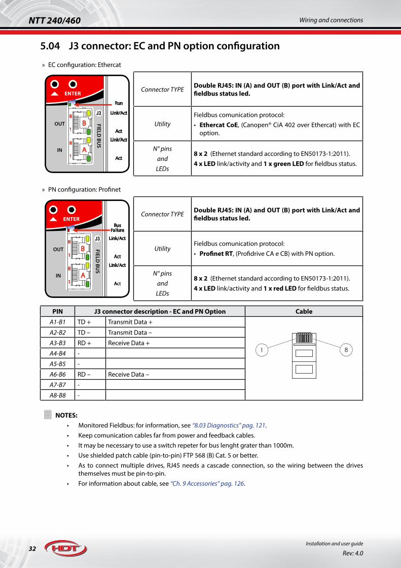
5.04 J3 connector: EC and PN option configuration
» EC configuration: Ethercat
FIELD BU
S
OUT
IN
J3
FIELD BU
S
OUT
IN
J3
FIELD BU
S
J3
FIELD BU
S
OUT
IN
J3
123456
B
A8
1
8
1
Act
Link/Act
Act
Run
Link/Act
Act
Link/Act
Act
Link/Act
BusFailure
B
A
1
8
1
8
B
A8
1
8
1
Connector TYPE Double RJ45: IN (A) and OUT (B) port with Link/Act and fieldbus status led.
UtilityFieldbus comunication protocol:• Ethercat CoE, (Canopen® CiA 402 over Ethercat) with EC
option.
N° pinsandLEDs
8 x 2 (Ethernet standard according to EN50173-1:2011).4 x LED link/activity and 1 x green LED for fieldbus status.
» PN configuration: Profinet
FIELD BU
S
OUT
IN
J3
FIELD BU
S
OUT
IN
J3
FIELD BU
S
J3
FIELD BU
S
OUT
IN
J3
123456
B
A8
1
8
1
Act
Link/Act
Act
Run
Link/Act
Act
Link/Act
Act
Link/Act
BusFailure
B
A
1
8
1
8
B
A8
1
8
1
Connector TYPE Double RJ45: IN (A) and OUT (B) port with Link/Act and fieldbus status led.
UtilityFieldbus comunication protocol:• Profinet RT, (Profidrive CA e CB) with PN option.
N° pinsandLEDs
8 x 2 (Ethernet standard according to EN50173-1:2011).4 x LED link/activity and 1 x red LED for fieldbus status.
PIN J3 connector description - EC and PN Option Cable
A1-B1 TD + Transmit Data +
81
A2-B2 TD - Transmit Data -
A3-B3 RD + Receive Data +
A4-B4 -
A5-B5 -
A6-B6 RD - Receive Data -
A7-B7 -
A8-B8 -!
NOTES:• Monitored Fieldbus: for information, see “8.03 Diagnostics” pag. 121.• Keep comunication cables far from power and feedback cables.• It may be necessary to use a switch repeter for bus lenght grater than 1000m.• Use shielded patch cable (pin-to-pin) FTP 568 (B) Cat. 5 or better.• As to connect multiple drives, RJ45 needs a cascade connection, so the wiring between the drives
themselves must be pin-to-pin.• For information about cable, see “Ch. 9 Accessories” pag. 126.

33
NTT 240/460Wiring and connections
Installation and user guide
Rev: 4.0
5.05 J3 connector: CM option configuration
FIELD BU
S
OUT
IN
J3
FIELD BU
S
OUT
IN
J3
FIELD BU
S
J3
FIELD BU
S
OUT
IN
J3
123456
B
A8
1
8
1
Act
Link/Act
Act
Run
Link/Act
Act
Link/Act
Act
Link/Act
BusFailure
B
A
1
8
1
8
B
A8
1
8
1
Connector TYPE Double RJ45: IN (A) and OUT (B) parallel connected ports
UtilityFieldbus comunication protocols:• Canopen® CiA301e CiA402• Modbus RTU
N° pins 8 x 2: A1-A8 and B1-B8 (CIA303 standard + Modbus RTU standard)
PIN J3 connector description - CM Option Cable
A1-B1 CAN H High Canopen® data
81
A2-B2 CAN L Low Canopen® data
A3-B3 GND Common Ground for Canopen®
A4-B4 MODBUS + + data for RS485 Modbus RTU
A5-B5 MODBUS - - data for RS485 Modbus RTU
A6-B6 -
A7-B7 Shortcircuit For possible external signal or supply
A8-B8 GND Common Ground for Modbus RTU
In order to ensure a correct operation for Canopen® Fieldbus comunication, please follow instruction below:• connect external 120Ω termination resistor• the table below shows Bus total lenght related to Baudrate:
Baudrate Bus total lenght
1 Mbit/s < 20m
500 kbit/s < 100m
250 kbit/s < 250m
125 kbit/s < 500m
50 kbit/s < 1000m
20 kbit/s < 2500m
10 kbit/s < 5000m!
NOTES:• Monitored Fieldbus: for information, see “8.03 Diagnostics” pag. 121.• Keep comunication cables far from supply and feedback cables.• It may be necessary to use a repeter or signal amplifier for bus lenght grater than 1000m.• Use shielded patch cable (pin-to-pin) FTP 568 (B) Cat. 5 or better.• As to connect multiple drives, RJ45 needs a cascade connection, so the wiring between the drives
themselves must be pin-to-pin.• Node id address is settable via keybord; please see “6.06 Display and keyboard” pag. 76.• For information about cable, see “Ch. 9 Accessories” pag. 126.

34Installation and user guide
Rev: 4.0
NTT 240/460 Wiring and connections
5.06 J3 connector: PB option configuration
FIELD BU
S
OUT
IN
J3
FIELD BU
S
OUT
IN
J3
FIELD BU
S
J3
FIELD BU
S
OUT
IN
J3
123456
B
A8
1
8
1
Act
Link/Act
Act
Run
Link/Act
Act
Link/Act
Act
Link/Act
BusFailure
B
A
1
8
1
8
B
A8
1
8
1
Connector TYPEPitch 3.5mm, male connectionMax cable section: 1mm2
Utility PROFIBUS Comunication with IN/OUT connection
N° pins 6
PIN J3 connector description - PB Option
1 PROFI+ + data for PROFIBUS comunication
2 PROFI- - data for PROFIBUS comunication
3 GND Common Ground for PROFIBUS comunication
4 PROFI+ + data for PROFIBUS comunication
5 PROFI- - data for PROFIBUS comunication
6 SHIELD Cable shield. This pin is connected to drive Power Earth (PE)!
NOTES:• Monitored Fieldbus: for information, see “8.03 Diagnostics” pag. 121.• Keep comunication cables far from supply and feedback cables.• It may be necessary to use a repeter or signal amplifier for bus lenght grater than 1000m.• Node id address is settable via keybord; please see “6.06 Display and keyboard” pag. 76.

35
NTT 240/460Wiring and connections
Installation and user guide
Rev: 4.0
5.07 J4 connector: drive settings
MADE in ITALY
FIELD BU
S
FEEDBA
CK 2
ENC O
UT
ENC/FREQ
IND
IGITA
L IN
DIG
ITAL O
UT
USB
OUT
IN
J3
J4
J6
J7
J8 20
11
10
1
16
9
8
1
5
16
1 5
1 1
Connector TYPE Micro USB AB type
Utility
USB 2.0 comunication protocol at 12Mbps.Setting operating modes, diagnostic and calibration via Caliper.Firmware upgrade.
N° pins Standard USB A type to micro-B type, shielded cable.
5.07.1 Using USB 2.0 HUBI’s allowed to use USB 2.0 HUBs in cascaded connection to visualize more axises with same PC. Tipical connection available between PC and NTT 240/460 drive, using USB HUBs, is shown below:
< 3m
< 1m
< 1m
< 3m
!
NOTES:• Not insulated connection: USB comunication ground and 0L drive ground are equipotential. Maximum
permitted voltage against Power Earth (PE) is 50V.• It’s strongly recommended to use USB shielded cables, whose lenght is less than 3m for single drive or
less than 1m for each drive connected to an USB HUB.• Keep USB comunication cables far from power and feedback cables.• It’s recommended to use shielded HUB with active supply if long distances are required.• Maximum number of installable USB devices is 128, but real displayable number is related to PC
hardware and used operating system.• It’s possible to connect all other H.D.T. drive families, that support USB, to the same HUB.• For information about cable, see “Ch. 9 Accessories” pag. 126.

36Installation and user guide
Rev: 4.0
NTT 240/460 Wiring and connections
5.08 J5 connector: Feedback 1
! To avoid motor feedback damage, befors connecting cables, please ensure that connection is correct and that drive is set correctly.
MADE in ITALY
FIELD BU
S
ENC O
UT
ENC/FREQ
IND
IGITA
L IN
DIG
ITAL O
UT
USB
U
V
W
-DC BUS
+DC BUS
INT B.R.
EXT B.R.
L3
L2
L1
OUT
IN
FEEDBA
CK 1
J1
J3
J4
J5
J2
J7
J8 20
11
10
1
16
9
8
1
18
10
9
1
Connector TYPEDouble row, pitch 3.5mm, male connectionMax cable section: 1mm2
UtilityMotor main Feedback.Incremental or absolute encoder and HALL sensors.
N° pins 18
PIN J5 connector description
1 A +Differential line driver (5V) input for incremental channel A.
2A -
A Single (5V) Open Collector and Push Pull input for incremental channel A.
3 B +Differential line driver (5V) input for incremental channel B.
4B -
B Single (5V) Open Collector and Push Pull input for incremental channel B.
5 Z + / CK+ Differential line driver (5V) input for channel Z of incremental encoder.Differential line driver (5V) output for CLOCK data for SSI absolute encoder.
6Z - / CK -
Z Single (5V) Open Collector and Push Pull input for incremental channel Z.
7 PTCDigital input for motor PTC. If motor is devoid of PTC, ensure to short pin 7 and 8.
8 PTC
9 +V_SENSE1 Supply voltage sensing input pin from encoder.
10 +V
Regulated encoder supply 5-9V for feedback 1.• for 5V encoder supply: if available, connect supply sensing pins (9 and 18 pin), otherwise,
leave them open circuit.• for encoder supply higher than 5V: perform short circuit between supply sensing pins (9
and 18 pin) to obtain 9V encoder supply.
11 0L Common Ground 0L for encoder supply and signals.
12 D -Differential line driver (5V) input for DATA for SSI absolute encoder.
13(HA) / D +
HA / (D +) HALL sensor A signal input
14 HB HALL sensor B signal input
15 HC HALL sensor C signal input
16 SHIELDEncoder and signal cable shield. This pin is connected to drive Power Earth (PE)
17 SHIELD
18 0L_SENSE1 Supply common groung sensing input pin from encoder.

37
NTT 240/460Wiring and connections
Installation and user guide
Rev: 4.0
Wiring connections and pins numbering for J5 connector is shown below, according to previous table:
10
18 9
1
10
18 9
1
!
Porre attenzione al gancio di inserzione del connet-tore prima di cablare la matassa: assicurarsi che sia orientato correttamente.
Tipical encoder wiring connections for J5 connector and incremental encoder variation wiring is shown below:
Drive
1kΩJ5 - 3
J5 - 4
1kΩJ5 - 5
J5 - 16/17
J5 - 6
DriveJ5 - 16/17
1kΩ
CH A
CH B
CH Z
+V
J5 - 1
J5 - 10
J5 - 2
Drive
1kΩJ5 - 3
J5 - 4
1kΩJ5 - 5
J5 - 16/17
J5 - 6
1kΩ
CH A-
CH B-
CK-/CH Z-
CH A+
CH B+
PTC
PTC
CK+/CH Z+
J5 - 1
J5 - 2
1kΩJ5 - 3
J5 - 4
1kΩJ5 - 5
J5 - 6
1kΩ
1kΩ
CH A
CH B
CH Z
+5E
J5 - 1
J5 - 10
J5 - 2Rext
Rext
RextJ5 - 7J5 - 8
J5 - 10
J5 - 110L
+V5-9VDC
+5V
J5 - 9J5 - 180L sense
+V sense
220ΩJ5 - 12
J5 - 13D+
D-
J5 - 13
J5 - 14Hall B
J5 - 14Hall C
Hall A
1kΩ
1kΩ
1kΩ
Line Driver incrementalEncoder connection
Open Collector incrementalEncoder connection
with internal Pull-up resistor
Open Collector incrementalEncoder connection
with external Pull-up resistor
External resistor must be dimensioned according to main feedbackencoder used.
Motor PTC
Encoder Supply
Motor/EncoderEarth Connection
!NOTES:
• Monitored Feedback: for information, see “8.03 Diagnostics” pag. 121.• Maximum permitted voltage for 0L against Power Earth (PE) is 50V.• Use shielded cable. Keep I/O cables far from supply and feedback cables.• To ensure a correct electric wiring, and for electric safety, strip the wire up to 6-8mm, or use an adequate
cap.• In order to use cable lenght between 50m and 100m, ti’s recommended to use incremental encoders
that allow not to exceed 250kHz, during application rated speed.• For absolute encoders, whose sum of single-turn and multi-turn bit is higher than 15, it’s recommended
to use cable lenght lower than 50meters.• It’s recommended to perform motor autophasing procedure to ensure that connection is correct (it’s
mandatory if third party motor is used). Please see “6.07 Motor autophasing” pag. 82.

38Installation and user guide
Rev: 4.0
NTT 240/460 Wiring and connections
5.08.1 Wiring a H.D.T. motor with encoder feedbackTables below show connection with H.D.T. Bxx, BSDxx and MSxx motor series with:
1. absolute SSI encoder for Bxx e BSDxx motors:• cod. 480*: ST 12bit + incremental channels (only Bxx series)• cod. 500*: MT 12bit and ST 17bit
J5 DRIVECONNECTOR
FUNCTION EXTENTION CABLECOLOUR
MOTORECONNECTOR
cod. 480 cod. 5001 A+ - GREEN 5
2 A - - BROWN 6
3 B+ - YELLOW 7
4 B - - ORANGE PINK 8
5 CK+ PURPLE 14
6 CK - WHITE/GREEN 13
7 PTC WHITE/YELLOW 17
8 PTC YELLOW/BROWN 2
9 - +V_SENSE1 BROWN/GREEN 16
10 +V RED 3
11 0L BLACK 4
12 D - RED/BLUE 12
13 D+ GREY 11
14 - - -
15 - - -
16 PE / Shielddrain or braid 1
17 PE / Shield
18 - 0L_SENSE1 GREY/PINK 15
2. incremental encoder for Bxx motors:• cod. 2* o 280*: 1024ppr with HALL sensors
J5 DRIVECONNECTOR
FUNCTIONEXTENTION CABLE
COLOURMOTORE
CONNECTOR1 A+ GREEN 5
2 A - BROWN 6
3 B+ YELLOW 7
4 B - ORANGE PINK 8
5 Z+ BLUE 9
6 Z - WHITE 10
7 PTC WHITE/YELLOW 17
8 PTC YELLOW/BROWN 2
9 - -
10 +V RED 3
11 0L BLACK 4
12 - - -
13 HA+ GREY 11
14 HB+ PURPLE 14
15 HC+ GREY/PINK 15
16 PE / Shielddrain or braid 1
17 PE / Shield
18 - -

39
NTT 240/460Wiring and connections
Installation and user guide
Rev: 4.0
3. incremental encoder for MS motor:• cod. 200*: 2500ppr with HALL sensors, output with flying MATE’N’LOK capsule (AMP 172171-1) and
plug (AMP 172163-1).
J5 DRIVECONNECTOR
FUNCTION
EXTENTION CABLE MOTOR
COLOURAMP
172163-1AMP
172171-1 ENCODER OUTPUTCABLE COLOURN. PIN
1 A+ GREEN 9 BLUE/BLACK
2 A - BROWN 10 BLUE
3 B+ YELLOW 11 GREEN
4 B - ORANGE PINK 12 GREEN/BLACK
5 Z+ BLUE 13 YELLOW
6 Z - WHITE 14 YELLOW/BLACK
7 PTC I motori della serie MS non prevedono il PTC.
Cortocircuitare il pin 7 e 8 sul connettore J5.8 PTC
9 +V_SENSE1 - - -
10 +V RED 1 RED
11 0L BLACK 2 BLACK
12 - - - -
13 HA+ GREY 7 WHITE
14 HB+ PURPLE 5 GREY
15 HC+ GREY/PINK 3 BROWN
16 PE / Shielddrain or braid 15 SHIELD
17 PE / Shield
18 0V_SENSE1 - - -!
NOTE:• incremental channels LD 5V, also using the absolute encoder cod. 480, can be sent to on PLC or CN via
J8 connector in order to close the position loop.• All pins of motor side and colours cable not mentioned are unused.
* For information about H.D.T. AC brushless motors wiring (serie B05-B26, BSD10-BSD14 e MS04-MS08), refer to technical manuals downloaded from internet corporate site:
www.hdtlovato.com

40Installation and user guide
Rev: 4.0
NTT 240/460 Wiring and connections
5.09 J6 connector: Feedback 2
! To avoid motor feedback damage, befors connecting cables, please ensure that connection is correct and that drive is set correctly.
MADE in ITALY
FIELD BU
S
FEEDBA
CK 2
ENC O
UT
ENC/FREQ
IND
IGITA
L IN
DIG
ITAL O
UT
USB
OUT
IN
J3
J4
J6
J7
J8 20
11
10
1
16
9
8
1
5
16
1 5
1 1
Connector TYPEHigh density D-Sub, male connectionMax cable section: 0.5mm2
UtilityFeedback 2 from motor: resolver.Only available with FEEDBACK R option.
N° pins 15
PIN J6 connector description
1 EXC +Differential line driver supply for Resolver excitation/primary winding.
2 EXC -
3 COS - COS - input from Resolver feedback.
4 COS + COS + input from Resolver feedback.
5 SEN - SEN - input from Resolver feedback.
6 SHIELD Encoder and signal cable shield. This pin is connected to drive Power Earth (PE).
7 - Do not use this connection.
8 PTC -Digital input for motor PTC. If motor is devoid of PTC, ensure to short pin 8 and 9.
9 PTC +
10 SEN + SEN + input from Resolver feedback.
11 -
Do not use this connection.
12 -
13 -
14 -
15 -!
NOTES:• Monitored Feedback: for information, see “8.03 Diagnostics” pag. 121.• Maximum permitted voltage for 0L against Power Earth (PE) is 50V.• Use shielded and twisted cable. Keep I/O cables far from supply and feedback cables.• It’s recommended to perform motor autophasing procedure to ensure that connection is correct (it’s
mandatory if third party motor is used). Please see “6.07 Motor autophasing” pag. 82.

41
NTT 240/460Wiring and connections
Installation and user guide
Rev: 4.0
Resolver wiring connections for J6 connector:
Drive
J6 - 6
EXC-
COS+
SEN+
EXC+
COS-
PTC
PTC
SEN-
J6 - 1
J6 - 2
J6 - 8J6 - 9
J6 - 3
J6 - 4
J6 - 5
J6 - 10
Resolver connection
Motor PTC
ResolverReference
Motor/ResolverEarth Connection
5.09.1 Wiring a H.D.T. motor with resolver feedbackTable below shows connection with H.D.T. B05-B07-B10-B14-B20-BK20-B26 and BSP-BSD motor series with resolver cod. 1*:
J6 DRIVECONNECTOR
FUNCTIONEXTENTION
CABLE COLOURRESOLVER CONNECTOR
B05-B07, BSP-BSD B10-B14-B20-B26 BK201 EXC + BIANCO 6 F 10
2 EXC - MARRONE 4 D 7
3 COS - GIALLO 2 B 5
4 COS + VERDE 1 A 6
5 SEN - ROSSO 3 C 4
6 SHIELD drenaggio o calza - - -
7 - - - - -
8 PTC - GRIGIO 7 H 9
9 PTC + ROSA 8 G 8
10 SEN + BLU 5 E 14
11 - - - - -
12 - - - - -
13 - - - - -
14 - - - - -
15 - - - - -!
NOTES:• All pins of motor side and colours cable not mentioned are unused.
* For information about H.D.T. AC brushless motors wiring (B05-B07-B10-B14-B20-BK20-B26 and BSP-BSD series), refer to technical manuals downloaded from internet corporate site:
www.hdtlovato.com

42Installation and user guide
Rev: 4.0
NTT 240/460 Wiring and connections
5.10 J7-8-9 connectors: Frequency, digital and analog I/O
5.10.1 J7 connector: frequency I/O
MADE in ITALY
FIELD BU
S
FEEDBA
CK 2
ENC O
UT
ENC/FREQ
IND
IGITA
L IN
DIG
ITAL O
UT
USB
OUT
IN
J3
J4
J6
J7
J8 20
11
10
1
16
9
8
1
5
16
1 5
1 1
Connector TYPEDouble row, pitch 3.5mm, male connectionMaximum cable section: 1mm2
UtilityFrequency main reference input.Emulated or buffered encoder output.
N° pins 16
PIN J7 connector description
1 CCW/DIR/CHA 24V
Frequencymainreferenceinput
Optoinsulated digital input for DIRECTION / CH A / CCW data.Line Driver 5V (pin 2-3) or NPN/PNP input (pin 1-3); see image below.
2 CCW/DIR/CHA +
3 CCW/DIR/CHA -
4 CW/PULSE/CHB 24VOptoinsulated digital input for PULSE / CH B / CW data.Line Driver 5V (pin 5-6) or NPN/PNP input (pin 4-6); see image below.
5 CW/PULSE/CHB +
6 CW/PULSE/CHB -
7 +5V Stabilized internal supply +5V (<100mA) for any external encoder.
8 SHIELD Encoder and signal cable shield. This pin is connected to drive Power Earth (PE).
9 OUT A +
Frequencyencoderoutput
Differential line driver (5V) output for buffered encoder or emulated encoder channel A (+24V available on request).10 OUT A -
11 OUT B + Differential line driver (5V) output for buffered encoder or emulated encoder channel B (+24V available on request).12 OUT B -
13 OUT Z + Differential line driver (5V) output for buffered encoder or emulated encoder channel Z (+24V available on request).14 OUT Z -
15 0L Ground 0L for I/O frequency signals and for supply +5V (pin 7) or +24VE (pin 16).
16 +24VEDo not use this connection with hardware “0-0” drives. Available on request.+24V input supply for frequency encoder output stage.
+Vcc = 24V
+Vcc = 24V
+Vcc = 24V
+Vcc = 24V
NPN FREQUENCY INPUT PNP FREQUENCY INPUT
LINE DRIVER FREQUENCY INPUT
Control
Control
+Vcc = 5V
CHB /DIR
CHA /PULSE
+Vcc = 5V
+5VEncoder Supply
Control orEncoder
1,9kΩ 1,9kΩ
1,9kΩ1,9kΩ
J7 - 1
J7 - 3
J7 - 4
J7 - 6
J7 - 8
Drive DriveJ7 - 1
J7 - 3
J7 - 4
J7 - 6
J7 - 8
160R
160R
J7 - 2
J7 - 3
J7 - 15 (0S)
J7 - 7
J7 - 5
J7 - 6
J7 - 8
Drive
LINE DRIVER ENCODER OUTPUT
+5V
CHA
J7 - 9
J7 - 10
J7 - 11
J7 - 12
J7 - 13
J7 - 14
(0S) J7 - 15
J7 - 8
Drive
CHB
CHZ
+
-
+
-
+
-
+Vcc = 5V
CHA
Control
CHB
CHZ

43
NTT 240/460Wiring and connections
Installation and user guide
Rev: 4.0
5.10.2 J8 connector: digital I/O
MADE in ITALY
FIELD BU
S
FEEDBA
CK 2
ENC O
UT
ENC/FREQ
IND
IGITA
L IN
DIG
ITAL O
UT
USB
OUT
IN
J3
J4
J6
J7
J8 20
11
10
1
16
9
8
1
5
16
1 5
1 1
Connector TYPEDouble row, pitch 3.5mm, male connectionMaximum cable section: 1mm2
UtilityProgrammable 10-30V digital I/O.Programmable clean contact relay output.
N° pins 20
PIN J8 connector description
1 +24V I/ODigital OUTx supply +24V voltage input.Monitored supply: for information, see “8.03 Diagnostics” pag. 121.
2 +24V +24V internal supply available for feeding voltage to digital OUTx (pin 1).
3 IN0
Optoinsulated PNP input also programmable related to chosen operating mode.For information, see “6.08.1 Digital I/O functions” pag. 85.
4 IN1
5 IN2
6 IN3
7 IN4
8 IN5
9 IN6
10 IN7
11 0V I/O Isolated Common Ground 0V_I/O for I/O signals.
12 0V Common Ground 0V for +24V
13 OUT0
Optoinsulated PNP output also programmable.For information, see “6.08.1 Digital I/O functions” pag. 85.
14 OUT1
15 OUT2
16 OUT3
17 OUT4
18 OUT5
19OUT6 relay
Programmable clean contact relay output.For information, see “6.08.1 Digital I/O functions” pag. 85.20
EXTERNAL SOURCE PNP OUTPUT
22kΩ
J8 - 11
J8 - 12
J8 - 2
J8 - 1
OUTxJ8 - 13/.. /18
+Vcc
Input
Rint
Control
IMAX_LOAD IMAX_LOAD
Drive
INTERNAL SOURCE PNP OUTPUT
EXTERNAL SOURCE PNP INPUT INTERNAL SOURCE PNP INPUT
22kΩ
+Vcc
Input
Rint
ControlDrive
+Vcc10-30V
Control
1,9kΩ
Drive
INxJ8 - 3/.. /10
J8 - 2
J8 - 12
J8 - 11 (0V_I/O)
+VccControl
+24V
0V
(0V_I/O) J8 - 11
J8 - 12
J8 - 2
J8 - 1
OUTxJ8 - 13/.. /18
+24V
+24V
0V
0V
1,9kΩ
Drive
INxJ8 - 3/.. /10
J8 - 2
J8 - 12
J8 - 11 (0V_I/O)
+24V
0V

44Installation and user guide
Rev: 4.0
NTT 240/460 Wiring and connections
5.10.3 J9 connector: analog I/O
J11
+24 IN
IN 1
+24 OUT
IN 2
GND IN
S.T.O.
LOGICSUPPLY
J9
12
7
AN
ALO
G I/
O
SHIELD
MOD-
MOD+
GND
MOD-
MOD+
MO
DBU
S
J10
J12
ETH
ERN
ET
5
4
3
2
1
6
1
654321
1
8
Connector TYPEDouble row, pitch 3.5mm, male connectionMaximum cable section: 1mm2
Utility Analog I/O
N° pins 12
PIN J9 connector description
1 REF +IN8
Analog differential IN8 ±10V input ADC 16bit for main reference.Also available as IN8 digital input (single ended PNP).For information, see “6.09 Drive references” pag. 87.2 REF -
3 AUX1 +IN9 Analog differential ±10V input ADC 12bit for auxiliary IN9-IN10 references.
Also available as IN9-IN10 digital input (single ended PNP).For information, see “6.09.2 Auxiliary references” pag. 88.
4 AUX1 -
5 AUX2 +IN10
6 AUX2 -
7 SHIELD Signal cable shield. This pin is connected to drive Power Earth (PE).
8 0S Common Ground 0L for analog I/O and stabilized +/-10V supply.
9 AN0Analog single ended ±10V programmable output DAC 10bit.
10 AN1
11 +10V Stabilized internal supply output +/-10V (< 15mA), usefull for feeding voltage to analog input via external potentiometer.12 -10V
Drive
Instrument
Drive
Control
200k
100k
100k
200k
ANALOG DIFFERENTIAL INPUT
+-
J9 - 2/4/6
(+10V) J9 - 11
J9 - 1/3/5
(0S) J9 - 8
(-10V) J9 - 12
(SHIELD) J9 - 7
100Ω
ANALOG OUTPUT
ANxJ9 - 9/10
(0S) J9 - 8
(SHIELD) J9 - 7
Drive
Control
200k
100k
100k
200k
ANALOG SINGLE ENDED INPUT
+-
J9 - 2/4/6
(+10V) J9 - 11
J9 - 1/3/5
(0S) J9 - 8
(-10V) J9 - 12
(SHIELD) J9 - 7

45
NTT 240/460Wiring and connections
Installation and user guide
Rev: 4.0
5.10.4 Cable per J7-8-9Wiring connections and pins numbering for J4 connector is shown below, according to previous table related to J8 connector (J7 and J9 connector cable are similar, but with different pin number):
11
20 10
1
11
20 10
1
!
Please ensure that insertion hook of connector is facing correctly.
!NOTES:
• 0L and 0S common ground are equipotential and maximum permitted voltage against Power Earth (PE) is 50V.
• Maximum permitted voltage for 0V, 0V_I/O against Power Earth (PE) is 100V.• Do not use +24V (pin 2 of J8) to directly engage motor brake.• Single ended PNP connection for analog references is to connect negative pins (pin 2-4-6 of J9)) to
0S ground (pin 8 of J9) and to connect signal to positive pins (pin1-3-5 of J9); this connection type is usefull if the external controller device has not differential analog output, but ±10V single ended only, and if this analog input is used as digital input.
• Keep I/O cables far from supply and feedback cables.• To ensure a correct electric wiring, and for electric safety, strip the wire up to 6-8mm, or use an
appropriate cap.• For frequency main reference input and analog input, it’s mandatory to use shielded cable.

46Installation and user guide
Rev: 4.0
NTT 240/460 Wiring and connections
5.11 J10 connector: RS485
J11
+24 IN
IN 1
+24 OUT
IN 2
GND IN
S.T.O.
LOGICSUPPLY
J9
12
7
AN
ALO
G I/
O
SHIELD
MOD-
MOD+
GND
MOD-
MOD+
MO
DBU
S
J10
J12
ETH
ERN
ET
5
4
3
2
1
6
1
654321
1
8
Connector TYPEPitch 3.5mm, male connectionMaximum cable section: 1mm2
UtilityRS485 serial comunication with IN/OUT. connection.(Not managed at the moment).
N° pins 6
PIN J10 connector description
1 D+ + data for RS485 comunication
2 D- - data for RS485 comunication
3 0L Common Ground for RS485 comunication
4 D+ + data for RS485 comunication
5 D- - data for RS485 comunication
6 SHIELD Cable shield. This pin is connected to drive Power Earth (PE)!
NOTES:• Not insulated: maximum permitted voltage for 0L against Power Earth (PE) is 50V.
5.12 J11 connector: logic supply and S.T.O. safety function
The cable for J1 is composed of logic supply voltage and STO safety circuit contacts (Safe Torque Off). For further information about safety circuit, please see “Ch. 7 S.T.O. safety circuit” pag. 116.
J11
+24 IN
IN 1
+24 OUT
IN 2
GND IN
S.T.O.
LOGICSUPPLY
J9
12
7
AN
ALO
G I/
O
SHIELD
MOD-
MOD+
GND
MOD-
MOD+
MO
DBU
S
J10
J12
ETH
ERN
ET
5
4
3
2
1
6
1
654321
1
8
Connector TYPEPitch 5mm, male connectionMaximum cable section: 2.5mm2
Utility +24VDC logic supply connection and safety function STO (Safe Torque Off).
N° pins 5
PIN J11 connector description
1 +24V IN Drive logic supply voltage. This voltage line is necessary to use NTT 240/460 drive.2 GND IN (0V)
3 IN1Redundant n°1 input channel for STO safety function.Monitored input: for information, see “8.03 Diagnostics” pag. 121.
4 +24V OUT Alimentazione del circuito di sicurezza STO, fornita dal drive.
5 IN2Redundant n°1 input channel for STO safety function.Monitored input: for information, see “8.03 Diagnostics” pag. 121.
!NOTES:
• Maximum permitted voltage for 0V against Power Earth (PE) is 100V.• NTT 240/460 drives are equipped with bridge connection between pin 3-4-5, on connector. To use
correctly the STO function, please disconnect bridge connection.

47
NTT 240/460Wiring and connections
Installation and user guide
Rev: 4.0
5.13 J12 connector: Ethernet
! Connection available only for hardware 0-1 o later versions.
J11
+24 IN
IN 1
+24 OUT
IN 2
GND IN
S.T.O.
LOGICSUPPLY
J9
12
7
AN
ALO
G I/
O
SHIELD
MOD-
MOD+
GND
MOD-
MOD+
MO
DBU
S
J10
J12
ETH
ERN
ET
5
4
3
2
1
6
1
654321
1
8
Connector TYPE RJ45 with Link and Activity LEDs
UtilityComunication protocol:• IEEE 802.3™ Compliant Ethernet 10/100 Base-T
(Not managed at the moment).
N° pins 8 (standard Ethernet secondo EN50173-1:2011).
PIN J12 connector description: Ethernet Cable
1 TD + Transmit Data +
81
2 TD - Transmit Data -
3 RD + Receive Data +
4 -
5 -
6 RD - Receive Data -
7 -
8 -!
NOTES:• Keep comunication cables far from power and feedback cables.• It may be necessary to use a switch repeter for bus lenght grater than 1000m.• Use shielded patch cable (pin-to-pin) FTP 568 (B) Cat. 5 or better.

48Installation and user guide
Rev: 4.0
NTT 240/460 Operation mode
Ch. 6 Operation mode
Operation mode supported by drive are listed below:
1. Input / Output (I/O): analog and digital input and output.2. Modbus RTU (for CM configuration only).3. Canopen® CiA301 and CiA402 protocol (for CM configuration only).4. Ethercat CoE CiA402 protocol (for EC configuration only).5. Profinet RT Profidrive protocol (for PN configuration only).6. Profibus Profidrive DPv0 (for PB configuration only).
Control topologies supported by drive, with rotary and linear or tubular motor type, are listed below:
1. Torque control via analog/inside input reference or via fieldbus parameter.2. Speed and Speed with Torque limit control via analog/inside/frequency/Table-selection input reference or via
fieldbus parameter.3. Sensorless speed control.4. Position control related to desired operation mode:
• Single Target positioner via analog reference or via single parameter.• Table Target Positioner up to 64 target: cyclic/acyclic target or via digital input selection or via input-start
selection.• Electronic Gearbox via frequency reference (CHA/CHB, pulse/direction and CW/CCW).• Electronic Cam via frequency reference (CHA/CHB, pulse/direction).
5. Pressure control via analog input references or via fieldbus parameter.
Main drive status, during operation, are shown below and are visible on display device (please see also “Ch. 8 Drive status and diagnostics” pag. 120):
• SWITCH-OFF state: drive will not provide torque to motor and shows Drive OK or FAULT condition.• SWITCH-ON state: drive will provide torque to motor in order to keep it stopped.• OPERATION ENABLED state: drive will follow speed, torque or position reference, depending on choosen control
topology.• Drive OK or FAULT condition: drive will show Drive OK condition, only when there are no active alarms. If an alarm
occurs, drive will show a FAULT condition.
Drive has a firmware that communicates with proprietary Caliper 4.0 software: the using of this software leads to:
• select the desired drive operation mode.• select the motor between rotary and linear or tubular type, with related feedback.• configure all motor and drive parameters.• save, modify or reload previous configured motor and drive parameters.• configure, reload, modify and save all parameters for drive integrated software applications.• monitor drive and motor during operation.• perform debug of the entire machine quickly viewing all parameter addresses related to Fieldbus operation
mode and emulating functionality and commands.• perform HALL sensors autophasing.• configure analog and digital I/O.• configure drive to react in alarm, emergency and safe stop conditions.• configure languages.• use Scope function.

49
NTT 240/460Operation mode
Installation and user guide
Rev: 4.0
6.01 Introducing Caliper
Caliper software requires a PC Windows98® or later and installation software pack can be downloaded from enterprise web site, after registration and login:
www.hdtlovato.com!During Caliper installation procedure, when Windows® gives message related to reliable installation USB driver origin, please accept all in order to go on with installation procedure; if not do so, Windows® will not reach H.D.T. drive and a new installation procedure is mandatory.
Caliper main window consists of:1. a Toolbar, located at the top, that, via drop-down menu, allows to set the correct Caliper type related to
drive connected; if a USB HUB 2.0 is used, it allows to connect with the desired drive. It allows to send to drive command signals, as SWITCH-ON, OPERATION ENABLED, RESET, emulating fieldbus protocol and I/O functions, and also to configure drive parameters in offline mode, perform HALL sensors autophasing and use Scope function.
2. a State bar, located at the lower, shows drive state and any active alarms, DC bus power supply voltage and firmware release for the connected drive.
3. a Data Monitor, located at the left column, gives information about connected drive size, actual drive operation mode (Fieldbus or I/O), actual control topology (Mode), motor speed and position parameters and drive current and temperature. Also actual digital I/O function and state (with a graphic view for state) is displayed.
4. a Menu, into a tree view, located at the right of Data Monitor, allows to set all drive parameters: operation mode selection (Field Bus menu item), motor and feedback Data parameters (Motor Data menu item), advanced setup parameters (Advanced Setup menu item) and control topology selection (menu item depends on desired operation mode in Field Bus menu item).
5. a Drive Data allows to configure Menu parameters directly, set desired Application related to Factors submenu and to visualize all parameter addresses related to Fieldbus operation mode.
1
3
2
4 5
Caliper 4.0 present version and later, extend compatibility with 3.xx previous version in order to use a unique software to configure all H.D.T. drive families that support it, selecting the correct Caliper version via drop-down menu into Toolbar. Present maual will describe Caliper 4.0 and later releases.
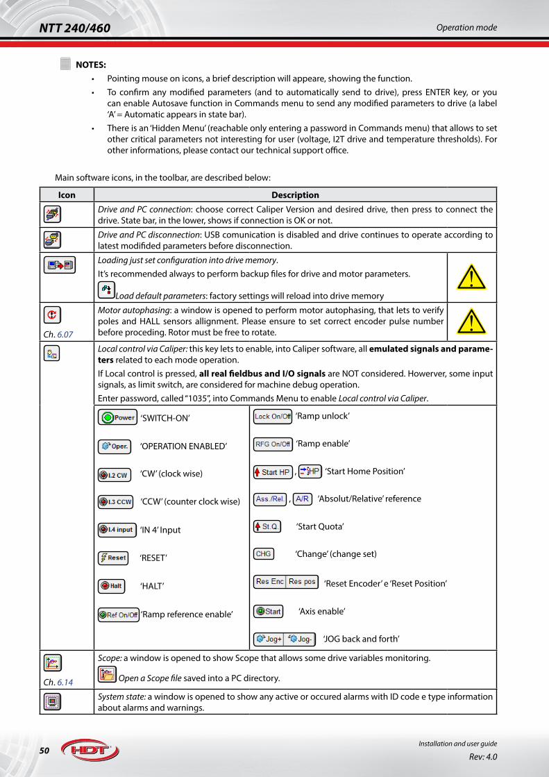
50Installation and user guide
Rev: 4.0
NTT 240/460 Operation mode
!NOTES:
• Pointing mouse on icons, a brief description will appeare, showing the function.• To confirm any modified parameters (and to automatically send to drive), press ENTER key, or you
can enable Autosave function in Commands menu to send any modified parameters to drive (a label ‘A’ = Automatic appears in state bar).
• There is an ‘Hidden Menu’ (reachable only entering a password in Commands menu) that allows to set other critical parameters not interesting for user (voltage, I2T drive and temperature thresholds). For other informations, please contact our technical support office.
Main software icons, in the toolbar, are described below:
Icon Description
Drive and PC connection: choose correct Caliper Version and desired drive, then press to connect the drive. State bar, in the lower, shows if connection is OK or not.
Drive and PC disconnection: USB comunication is disabled and drive continues to operate according to latest modifided parameters before disconnection.
Loading just set configuration into drive memory.It’s recommended always to perform backup files for drive and motor parameters.
Load default parameters: factory settings will reload into drive memory!
Ch. 6.07
Motor autophasing: a window is opened to perform motor autophasing, that lets to verify poles and HALL sensors allignment. Please ensure to set correct encoder pulse number before proceding. Rotor must be free to rotate. !Local control via Caliper: this key lets to enable, into Caliper software, all emulated signals and parame-ters related to each mode operation.If Local control is pressed, all real fieldbus and I/O signals are NOT considered. Howerver, some input signals, as limit switch, are considered for machine debug operation.Enter password, called “1035”, into Commands Menu to enable Local control via Caliper.
‘SWITCH-ON’
‘OPERATION ENABLED’
‘CW’ (clock wise)
‘CCW’ (counter clock wise)
‘IN 4’ Input
‘RESET’
‘HALT’
‘Ramp reference enable’
‘Ramp unlock’
‘Ramp enable’
, ‘Start Home Position’
, ‘Absolut/Relative’ reference
‘Start Quota’
‘Change’ (change set)
‘Reset Encoder’ e ‘Reset Position’
‘Axis enable’
‘JOG back and forth’
Ch. 6.14
Scope: a window is opened to show Scope that allows some drive variables monitoring.
Open a Scope file saved into a PC directory.
System state: a window is opened to show any active or occured alarms with ID code e type information about alarms and warnings.
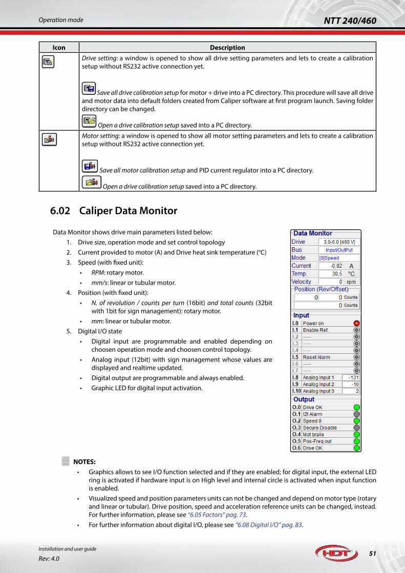
51
NTT 240/460Operation mode
Installation and user guide
Rev: 4.0
Icon Description
Drive setting: a window is opened to show all drive setting parameters and lets to create a calibration setup without RS232 active connection yet.
Save all drive calibration setup for motor + drive into a PC directory. This procedure will save all drive and motor data into default folders created from Caliper software at first program launch. Saving folder directory can be changed.
Open a drive calibration setup saved into a PC directory.
Motor setting: a window is opened to show all motor setting parameters and lets to create a calibration setup without RS232 active connection yet.
Save all motor calibration setup and PID current regulator into a PC directory.
Open a drive calibration setup saved into a PC directory.
6.02 Caliper Data Monitor
Data Monitor shows drive main parameters listed below:1. Drive size, operation mode and set control topology2. Current provided to motor (A) and Drive heat sink temperature (°C)3. Speed (with fixed unit):
• RPM: rotary motor.• mm/s: linear or tubular motor.
4. Position (with fixed unit):• N. of revolution / counts per turn (16bit) and total counts (32bit
with 1bit for sign management): rotary motor.• mm: linear or tubular motor.
5. Digital I/O state• Digital input are programmable and enabled depending on
choosen operation mode and choosen control topology.• Analog input (12bit) with sign management whose values are
displayed and realtime updated.• Digital output are programmable and always enabled.• Graphic LED for digital input activation.
!NOTES:
• Graphics allows to see I/O function selected and if they are enabled; for digital input, the external LED ring is activated if hardware input is on High level and internal circle is activated when input function is enabled.
• Visualized speed and position parameters units can not be changed and depend on motor type (rotary and linear or tubular). Drive position, speed and acceleration reference units can be changed, instead. For further information, please see “6.05 Factors” pag. 73.
• For further information about digital I/O, please see “6.08 Digital I/O” pag. 83.

52Installation and user guide
Rev: 4.0
NTT 240/460 Operation mode
6.03 Caliper Menu
In order to modify drive parameters, please ensure to:• enable USB connection with desired drive: if connection is missing, parameters can be set clicking Drive
setting key; then save configuration into PC directory in order to load it into drive memory during active USB connection.
• enable Local control via Caliper icon key (after entering “1035” password) and ensure to set drive state in SWITCH-OFF (disable related icon key).
Whenever a Menu item is selected, all relevant parameters appear into Drive Data window: to confirm any modified parameters (and to automatically send to drive), press ENTER key, or you can enable Autosave function in Commands menu to send any modified parameters to drive; last modified parameters highlighted in blue track.Menu items are listed below:
1. FIELD BUS: operation mode selection.2. MOTOR DATA: motor and feedback parameters settings.3. ADVANCED SETUP: regulator, filter, limiters settings and alarms managing.4. The fourth Menu item depends on the desired operation mode and can be set in:
• Control Set: I/O operatio.• Modbus: Modbus RTU operation.• CanOpen CiA301 e CanOpen CiA402: Canopen® operation.• Ethercat: Canopen® CiA301 and CiA402 over Ethercat operation.• Profinet and Profidrive: Profinet RT Profidrive operation.• Profidrive: Profibus Profidrive DPv0 operation.
For example, Control Set item into Menu, with its contents in Drive Data and during I/O operation, is shown below:
!NOTES:
• Control Set item allows an overview of choosen control type into a block diagram (see previous image). Each time a block is enabled (ramps, filter and limiters), these blocks appear inside block diagram in appropriate location.
• Into Drive Data window, a single block diagram can be selected and can be opened into a new window where main block parameters can be set, without looking for it into Advanced Setup (see image below):

53
NTT 240/460Operation mode
Installation and user guide
Rev: 4.0
6.03.1 Menu: ‘FIELD BUS’ item‘Field Bus’ item allows to:
• set drive name, usefull for identification between a multiple axis connection via USB HUB.• select the desired operation mode.
Operation mode: I/O (Input/Output)
During this operation mode, Control Set item is enable into Menu and lets to configure analog/digital input and desired control topology.
Operation mode: Modbus RTU
This screen allows to set fieldbus Address (up to 247) and comunication Baudrate (up to 57.6KBit).
A Time-out comunication alarm can be configure to report failure comunication after a time of inactivity.
Operation mode: Canopen® CiA301 and CiA402
This screen allows to set fieldbus Node (up to 127) and comunication Baudrate (up to 1Mbit).
A Time-out comunication alarm can be configure to report failure comunication after a time of inactivity.
Operation mode: Ethercat CoE CiA301 and CiA402
This screen allows to set “Station Alias” addressing type (up to 65536)

54Installation and user guide
Rev: 4.0
NTT 240/460 Operation mode
Modalità di funzionamento: Profinet RT Profidrive
This screen allows to set Device Name and IP Address for Profinet comunication.
Modalità di funzionamento: Profibus DPv0
This screen allows to set Node ID for Profibus Profidrive DPv0 comunication.
Operation mode is settable only if drive is in SWITCH-OFF state:• during Fieldbus operation, to ensure witch drive and motor parameters are settable, related to drive
state, please see related fieldbus user guide, downloadable from enterprise web site:
www.hdtlovato.com
• during I/O operation, parameters can be modified only via software Caliper; if parameter is not changeable, it will appear grey coloured and it will be not selectable.

55
NTT 240/460Operation mode
Installation and user guide
Rev: 4.0
6.03.2 Menu: ‘MOTOR DATA’ item and ‘FEEDBACK’ sub-menu‘Motor Data’ item allows to enter parameters and permanent magnets motor type connected to drive:
1. “PM rotary motor”: brushless permanent magnet rotative motor.2. “PM linear motor”: brushless permanent magnet linear motor.3. “Rotary, brushed DC motor”: brushed permanent magnet DC motor.4. “Induction V/Hz”: asynchronous motor (induction) with V/Hz control.
6.03.2.a Brushless permanent magnet rotative motor
It’s necessary to set correctly:• Nominal Speed• Nominal Current• Peak Current• Motor Poles: (up to 50poles).• I2T Time: motor I2T, default set to 10s.
All feedback supported are suitable for this motor type.Other choke parameters usefull for sensorless control.
6.03.2.b Brushless permanent magnet linear motor
It’s necessary to set correctly:• Nominal Speed• Nominal Current• Peak Current• Pole Pitch in mm.• I2T Time: motor I2T, default set to 10s.
All feedback supported are suitable for this motor type.Other choke parameters usefull for sensorless control.
6.03.2.c Brushed permanent magnet DC motor
It’s necessary to set correctly:• Nominal Speed• Nominal Current• Peak Current• I2T Time: motor I2T, default set to 10s.
All feedback supported are suitable for this motor type with exception for sensorless control.

56Installation and user guide
Rev: 4.0
NTT 240/460 Operation mode
6.03.2.d Asynchronous motor with V/Hz control
V/Hz control does not need any kind of feedback.First parameter set allows to enter motor data parameters usefull for a correct functionality; second parameter set allows to ender parameters for frequency jumps (if necessary) and V/Hz function curve.
!NOTES:
• Nominal Speed parameter units depends on choosen motor type (rotary and linear or tubular). For further informations, please see “6.05 Factors” pag. 73.
• I2T motor protection is settable and identifies a motor overload time limit: default set to 10s (setable from 1s a 3000s). If stress is too high, drive will provide an appropriate alarm/warning (FA 16) and will limit motor current equal to ‘Nominal Current’ parameter. The choice of this parameter is normally related to motor physical size.

57
NTT 240/460Operation mode
Installation and user guide
Rev: 4.0
‘Feedback’ sub-menu item allows to choose correct feedback and to enable motor cogging compensation:1. “Incr. Encoder without HALL” 2. “Incr. Encoder with HALL”3. “HALL only” 4. “Encoder SSI” (absolute encoder)5. “Sensorless”6. “Resolver” (with FEEDBACK R option only)
! Ensure to select correct feedback type before connecting to motor.All H.D.T. drives, in standard condition, that is no feedback reversing and default factors values (please see “6.05 Factors” pag. 73), consider that increasing feedback counter is related to a clockwise rotation of the motor, viewed by front shaft side.
6.03.2.e Incremental encoder with/without HALL sensors
It’s necessary to set correctly:• Pulse/Revolution: encoder pulse number per round.• Offset: offset encoder (only for HALL management)• Encoder input: set input type between Line Driver and
Open Collector/Push-Pull topology.
Other parameters are:• Reverse Feedback: encoder counter is reversed related to
motor rotation.• Cogging compensation: motor cogging mapping.
If incremental encoder without HALL sensors is used, after SWITCH-ON command, drive will perform a rotation angle, more or less evidence, related to real shaft position. I’s possible to perform this procedure at first start, at every start or at every reset command, as set into drop-down menu.If incremental encoder with HALL sensors is used, it’s mandatory to correctly set offset-encoder parameter, set to 0° for all H.D.T. motors; otherwise perform the autophasing procedure if third part motor is used (“6.07 Motor autophasing” pag. 82).Motor cogging map is available only if encoder provides zero index.Connection is located into J5 connector (please see “5.08 J5 connector: Feedback 1” pag. 36):
1. supply +V power to the feedback of used motor: +V (pin 10) and 0L (pin 11) and sensing pin if available (pin 9-18), otherwise leave them not connected for feedback at +5V or short-circuit them for feedback up to +9V.
2. connect the incremental signals: A+ (pin 1), A- (pin 2), B+ (pin 3), B- (pin 4).3. if available, connect three HALL signals: HA (pin 13), HB (pin 14) e HC (pin 15).4. if available, connect encoder zero index: Z+ (pin 5) and Z- (pin 6).5. if available, connect motor temperature sensor PTC (pin 7-8).
6.03.2.f HALL sensors only
For a trapezoidal control (DC brushless motors), only HALL sensors feedback is used. It’s necessary to enter offset parameter. Autophasing procedure is not available.Motor cogging map is not available.Connection is located into J5 connector (please see “5.08 J5 connector: Feedback 1” pag. 36):
1. supply +V power to the feedback of used motor: +V (pin 10) and 0L (pin 11) and sensing pin if available (pin 9-18), otherwise leave them not connected for feedback at +5V or short-circuit them for feedback up to +9V.
2. if available, connect three HALL signals: HA (pin 13), HB (pin 14) e HC (pin 15).3. if available, connect motor temperature sensor PTC (pin 7-8).

58Installation and user guide
Rev: 4.0
NTT 240/460 Operation mode
6.03.2.g SSI absolute encoder
It’s necessary to set correctly:• Bit single-Turn• Bit multi-Turn (if present).• Offset: offset encoder.
Other parameters are:• Reverse Feedback: encoder counter is reversed related to
motor rotation.• Cogging compensation: motor cogging mapping.
If SSI absolute encoder is used, it’s mandatory to correctly set offset-encoder parameter, set to 0° for all H.D.T. motors; otherwise, perform the autophasing procedure if third part motor is used (“6.07 Motor autophasing” pag. 82).For single-turn absolute encoders, set Bit multi-Turn to 0.It’s possible to set the “application offset” parameter related to encoder absolute 0 position: keep motor on desired position and press ‘Home’ key into sub-menu Feedback inside Drive Data, to store the offset (this parameter is mapped in every operation mode supported).Besides, it’s possible to connect encoders having single-turn and multi-turn resolutions higher than 16bit and 15bit respectively; if single-turn and multi-turn bit sum is higher than 31bit, drive provides an error. If single-turn bit are higher than 16bit, drive performs an automatic truncation of excess bits; by the way drive operates correctly, affecting offered resolution, limiting it to 16bit. Istantaneous real value for encoder absolute position is always visible.Motor cogging map is available.Connection is located into J5 connector (please see “5.08 J5 connector: Feedback 1” pag. 36):
1. supply +V power to the feedback of used motor: +V (pin 10) and 0L (pin 11) and sensing pin if available (pin 9-18), otherwise leave them not connected for feedback at +5V or short-circuit them for feedback up to +9V.
2. connect signals: CK+ (pin 5), CK - (pin 6), D - (pin 12) e D+ (pin 13).3. if available, it’s possible to connect the incremental signals: A+ (pin 1), A- (pin 2), B+ (pin 3), B- (pin 4).4. if available, connect motor temperature sensor PTC (pin 7-8).
6.03.2.h Sensorless
It’s necessary to perform a correct sensorless tuning to obtain desired performances for applications.
Other parameters are:• Reverse Feedback: encoder counter is reversed related to
motor rotation.
If brushless encoder is used, drive performs a start procedure with V/hz sensorless control to engage rotor position; then predictive FOC control is used.If asynchronous motor is used start procedureis not managed.All sub-window include sensorless parameters usefull for motor regulation and application desired performances:
• current, speed and phase covariance.• current noise.• start procedure set.• zero crossing speed and rotor lock current parameters.
For further information about sensorless loop tuning, please see “6.17 Sensorless loop tuning” pag. 111.
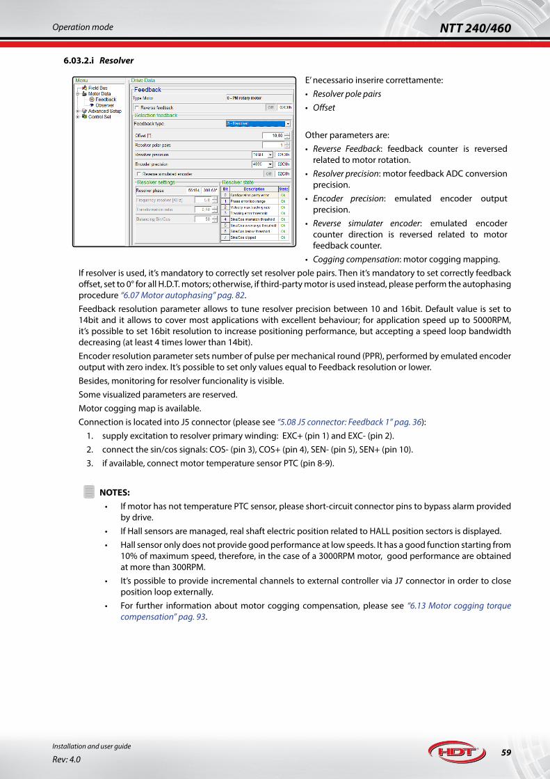
59
NTT 240/460Operation mode
Installation and user guide
Rev: 4.0
6.03.2.i Resolver
E’ necessario inserire correttamente:• Resolver pole pairs• Offset
Other parameters are:• Reverse Feedback: feedback counter is reversed
related to motor rotation.• Resolver precision: motor feedback ADC conversion
precision.• Encoder precision: emulated encoder output
precision.• Reverse simulater encoder: emulated encoder
counter direction is reversed related to motor feedback counter.
• Cogging compensation: motor cogging mapping.If resolver is used, it’s mandatory to correctly set resolver pole pairs. Then it’s mandatory to set correctly feedback offset, set to 0° for all H.D.T. motors; otherwise, if third-party motor is used instead, please perform the autophasing procedure “6.07 Motor autophasing” pag. 82.Feedback resolution parameter allows to tune resolver precision between 10 and 16bit. Default value is set to 14bit and it allows to cover most applications with excellent behaviour; for application speed up to 5000RPM, it’s possible to set 16bit resolution to increase positioning performance, but accepting a speed loop bandwidth decreasing (at least 4 times lower than 14bit).Encoder resolution parameter sets number of pulse per mechanical round (PPR), performed by emulated encoder output with zero index. It’s possible to set only values equal to Feedback resolution or lower.Besides, monitoring for resolver funcionality is visible.Some visualized parameters are reserved.Motor cogging map is available.Connection is located into J5 connector (please see “5.08 J5 connector: Feedback 1” pag. 36):
1. supply excitation to resolver primary winding: EXC+ (pin 1) and EXC- (pin 2).2. connect the sin/cos signals: COS- (pin 3), COS+ (pin 4), SEN- (pin 5), SEN+ (pin 10).3. if available, connect motor temperature sensor PTC (pin 8-9).!
NOTES:• If motor has not temperature PTC sensor, please short-circuit connector pins to bypass alarm provided
by drive.• If Hall sensors are managed, real shaft electric position related to HALL position sectors is displayed.• Hall sensor only does not provide good performance at low speeds. It has a good function starting from
10% of maximum speed, therefore, in the case of a 3000RPM motor, good performance are obtained at more than 300RPM.
• It’s possible to provide incremental channels to external controller via J7 connector in order to close position loop externally.
• For further information about motor cogging compensation, please see “6.13 Motor cogging torque compensation” pag. 93.
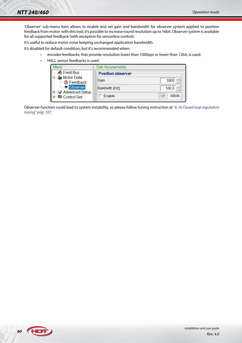
60Installation and user guide
Rev: 4.0
NTT 240/460 Operation mode
‘Observer’ sub-menu item allows to enable and set gain and bandwidth for observer system applied to position feedback from motor: with this tool, it’s possible to increase round resolution up to 16bit. Observer system is available for all supported feedback (with exception for sensorless control).It’s useful to reduce motor noise keeping unchanged application bandwidth.It’s disabled for default condition, but it’s recommended when:
• encoder feedbacks, that provide resolution lower than 1000ppr or lower than 12bit, is used.• HALL sensor feedbacks is used.
Observer function could lead to system instability, so please follow tuning instruction at “6.16 Closed loop regulation tuning” pag. 107.
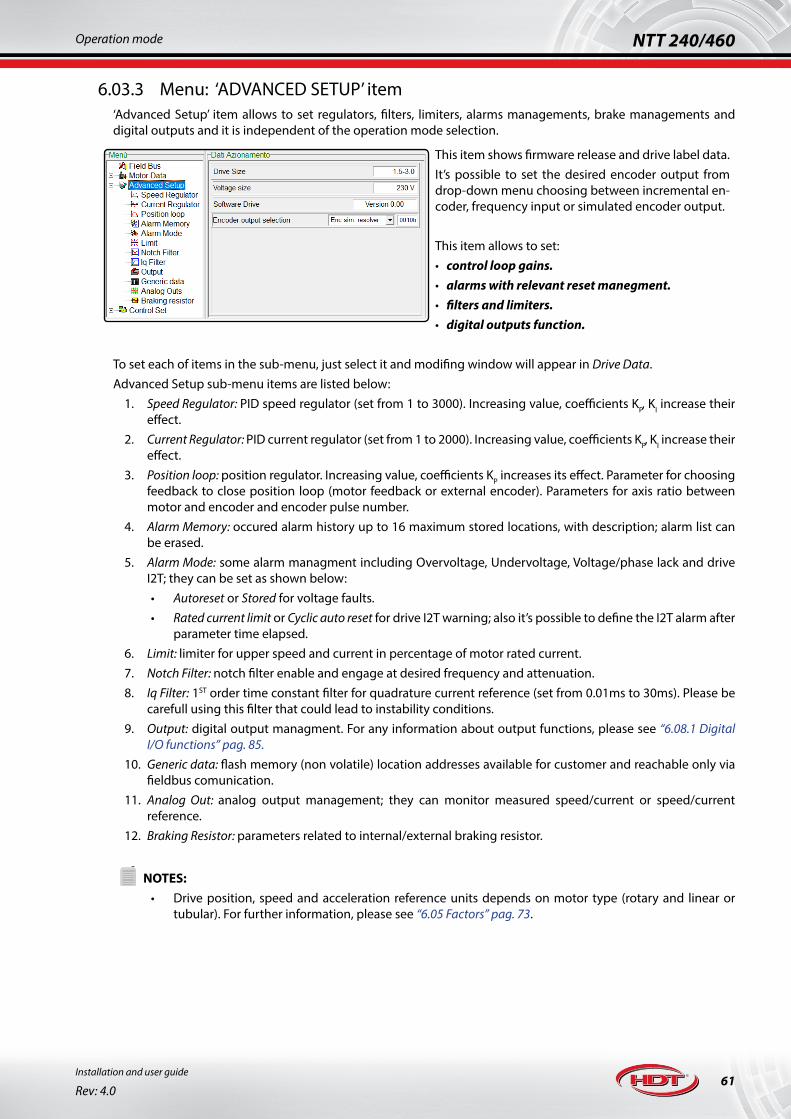
61
NTT 240/460Operation mode
Installation and user guide
Rev: 4.0
6.03.3 Menu: ‘ADVANCED SETUP’ item‘Advanced Setup’ item allows to set regulators, filters, limiters, alarms managements, brake managements and digital outputs and it is independent of the operation mode selection.
This item shows firmware release and drive label data.It’s possible to set the desired encoder output from drop-down menu choosing between incremental en-coder, frequency input or simulated encoder output.
This item allows to set:• control loop gains.• alarms with relevant reset manegment.• filters and limiters.• digital outputs function.
To set each of items in the sub-menu, just select it and modifing window will appear in Drive Data.Advanced Setup sub-menu items are listed below:
1. Speed Regulator: PID speed regulator (set from 1 to 3000). Increasing value, coefficients KP, KI increase their effect.
2. Current Regulator: PID current regulator (set from 1 to 2000). Increasing value, coefficients KP, KI increase their effect.
3. Position loop: position regulator. Increasing value, coefficients KP increases its effect. Parameter for choosing feedback to close position loop (motor feedback or external encoder). Parameters for axis ratio between motor and encoder and encoder pulse number.
4. Alarm Memory: occured alarm history up to 16 maximum stored locations, with description; alarm list can be erased.
5. Alarm Mode: some alarm managment including Overvoltage, Undervoltage, Voltage/phase lack and drive I2T; they can be set as shown below:• Autoreset or Stored for voltage faults.• Rated current limit or Cyclic auto reset for drive I2T warning; also it’s possible to define the I2T alarm after
parameter time elapsed.6. Limit: limiter for upper speed and current in percentage of motor rated current.7. Notch Filter: notch filter enable and engage at desired frequency and attenuation.8. Iq Filter: 1ST order time constant filter for quadrature current reference (set from 0.01ms to 30ms). Please be
carefull using this filter that could lead to instability conditions.9. Output: digital output managment. For any information about output functions, please see “6.08.1 Digital
I/O functions” pag. 85.10. Generic data: flash memory (non volatile) location addresses available for customer and reachable only via
fieldbus comunication.11. Analog Out: analog output management; they can monitor measured speed/current or speed/current
reference.12. Braking Resistor: parameters related to internal/external braking resistor.!
NOTES:• Drive position, speed and acceleration reference units depends on motor type (rotary and linear or
tubular). For further information, please see “6.05 Factors” pag. 73.

62Installation and user guide
Rev: 4.0
NTT 240/460 Operation mode
6.03.4 Menu: ‘Control Set’ ‘Modbus’ ‘CanOpen’ ‘Ethercat’ ‘Profinet’ itemsAs already described above, the 4th Menu item depends of operation mode selection. Drive parameters for the type of selected control are settable, including:
1. Desired control topology via drop-down menu inside Drive Data window.2. FACTORS setting: drive position, speed and acceleration reference units depends on motor type (rotary and
linear or tubular). For further information, please see “6.05 Factors” pag. 73.3. analog and digital I/O setting: digital output are manageble also via fieldbus parameter.4. all parameters related to desired control topology.!
NOTES:• To set all parameters via Caliper, ‘Local Controll via Caliper’ key must be enabled. Comunication
with Master controller is cut off.• For further information about fieldbus protocols, please see related fieldbus user guide, downloadable
from enterprise web site:
www.hdtlovato.com
6.03.4.a Input/Output operation mode: ‘Control Set’ items
• speed control (and speed with torque limit).• torque control.• electronic gearbox control (CHA/B, CW/CCW, Pulse/Direction).• position control (single target positioner, analog positioner, cyclic table selection positioner or via digital
input up to 64 target).• electronic cam control.• Pressure control.
For example, speed control with analog +/-10V input is shown below:
Control Set sub-menu items are listed below:1. Control setting: Stop mode management during Fault Reaction and HALT conditions. For further information,
please see “6.04 Emergency stop functions” pag. 71. Stop mode available are shown below (selectable from dropdown menu):• Disable power: motor inertia stop.• Ramp controlled stop and then disable power.• Ramp controlled stop keeping motor in standstill condition at power on.• Limit torque stop, setting desired torque limit.

63
NTT 240/460Operation mode
Installation and user guide
Rev: 4.0
2. Digital Input: drive digital input setting in I/O operation mode. For any other information about digital input functions, please see “6.08.1 Digital I/O functions” pag. 85.• Filter Input: input 1ST order filter parameters, in ms unit.
3. Factors: multiplier factors associated with input reference in order to modify scale resolution. Please see “6.05 Factors” pag. 73.
4. Position Setting: maximum admitted position error and maximum admitted recovery time setting; beyond these values drive provides an error/alarm condition.
5. Position: setting for all parameters related to desired position control between single target positioner, analog positioner, cyclic/acyclic table selection or via digital input or via input start up to 64 target. For further information, please see “6.09 Drive references” pag. 87 and “6.15.5 Position control: positioner mode” pag. 104.• Pos Parameter: profile setting and position procedure setting, software positive and negative limits and
Homing offset.• Position Jog: JOG setting.• Home Position: HOMING procedures and parameters. For further information, please see Modbus user
guide.• Pos. - Input X: index stop, at relative position, when event happens on INPUT X of drive I/O connector.
6. Main Speed: speed control and main speed reference setting between analog, inside, frequency or Tab-selection. For further information please see “6.09 Drive references” pag. 87 and “6.15.2 Sensored speed control” pag. 101 or “6.15.3 Sensorless speed control” pag. 102.• Aux Speed: auxiliary speed reference setting between analog, inside or torque limit.• Ramps: acceleration and deceleration ramp managment; linear ramp or S ramp (JERK parameter).
7. GearBox: gearbox axis rate management and engage and disengage settings; input type can be selected between CHA/B, CW/CCW, Pulse/Direction input reference. For turther information please see “6.09 Drive references” pag. 87 and “6.15.4 Position control: electronic gearbox mode” pag. 103.• Engaging: engaging phase parameter set• Disengaging: disengaging phase parameter set• Home position: HOMING procedures and parameters. For further information, please see Modbus user
guide.• Gearbox JOG: JOG setting.
8. Torque: torque control setting and input reference setting between analog and inside. For further information please see “6.09 Drive references” pag. 87 and “6.15.1 Torque control” pag. 100.
9. Electronic Cam: Cam table and all parameter setting. For further information, please see “6.09 Drive references” pag. 87 and “6.15.6 Position control: electronic cam mode” pag. 105.• Sync/Shift: isync parameter set and master/slave position shift setting.• Data Engaging: engaging phase parameter set• Data Disengaging: disengaging phase parameter set• Home position: HOMING procedures and parameters. For further information, please see Modbus user
guide.• Cam JOG: JOG setting.
10. Press: pressure reference accuracy setting and fullscale setting for speed and pressure reference and for pressure transducer. For further information please see “6.09 Drive references” pag. 87 and “6.15.7 Pressure control” pag. 106.• Setting: safety pressure threshold setting, beyond which the drive introduces set speed limit. Speed
variation is managed with ramp.• Limit: current and negative speed limit setting.• Alarm mode: overpressure and underpressure threshold setting and enabling.• Pressure Reg.: pressure ring regulators setting.• Ramps: pressure and speed ramps setting and enabling.• Output: analog output fullscale setting and output setting for pressure reached condition related to
pressure and time window parameter.

64Installation and user guide
Rev: 4.0
NTT 240/460 Operation mode
6.03.4.b Modbus RTU operation mode: ‘Modbus’ items
Control type and state machine in picture:• speed control (and speed with torque
limit).• torque control.• electronic gearbox control (CHA/B, CW/
CCW, Pulse/Direction).• position control (single target positioner,
analog positioner, cyclic table selection positioner or via digital input up to 64 target).
• electronic cam control.• pressure control.
During fieldbus operation mode, Caliper software shows all Modbus RTU parameter addresses, nearby the parameter.Same Modbus RTU protocol implemented inside NTT 240/460 drive is è compatible with all other H.D.T. drive families that support it.
Modbus sub-menu items are listed below:1. Control: Modbus RTU Control Word and Status Word informations.2. Control Set: control type selection.3. Control setting: Stop mode management during Fault Reaction, HALT conditions, comunication timeout and
speed reached with window parameters. For further information, please see “6.04 Emergency stop functions” pag. 71.Stop mode available are shown below (selectable from dropdown menu):• Disable power: motor inertia stop.• Ramp controlled stop and then disable power.• Ramp controlled stop keeping motor in standstill condition at power on.• Limit torque stop, setting desired torque limit.
4. Digital Input: drive digital input setting in Modbus RTU operation mode. For any other information about digital input functions, please see “6.08.1 Digital I/O functions” pag. 85.• Filter Input: input 1ST order filter parameters, in ms unit.
5. Factors: multiplier factors associated with input reference in order to modify scale resolution. Please see “6.05 Factors” pag. 73.
6. Position Setting: maximum admitted position error and maximum admitted recovery time setting; beyond these values drive provides an error/alarm condition.
7. Position: setting for all parameters related to desired position control between single target positioner, analog positioner, cyclic/acyclic table selection or via digital input or via input start up to 64 target. For further information, please see “6.09 Drive references” pag. 87 and “6.15.5 Position control: positioner mode” pag. 104.• Pos Parameter: profile setting and position procedure setting, software positive and negative limits and
Homing offset.• Position Jog: JOG setting.• Home Position: HOMING procedures and parameters.• Pos. - Input X: index stop, at relative position, when event happens on INPUT X of drive I/O connector.
8. Main Speed: speed control and main speed reference setting between analog, inside, frequency or Tab-selection. For further information please see “6.09 Drive references” pag. 87, and “6.15.2 Sensored speed control” pag. 101 or “6.15.3 Sensorless speed control” pag. 102.• Aux Speed: auxiliary speed reference setting between analog, inside or torque limit.• Ramps: acceleration and deceleration ramp managment; linear ramp or S ramp (JERK parameter).

65
NTT 240/460Operation mode
Installation and user guide
Rev: 4.0
9. GearBox: gearbox axis rate management and engage and disengage settings; input type can be selected between CHA/B, CW/CCW, Pulse/Direction input reference. For turther information please see “6.09 Drive references” pag. 87 and “6.15.4 Position control: electronic gearbox mode” pag. 103.• Engaging: engaging phase parameter set.• Disengaging: disengaging phase parameter set.• Home position: HOMING procedures and parameters.• Gearbox JOG: JOG setting.
10. Torque: torque control setting and input reference setting between analog and inside. For further information please see “6.09 Drive references” pag. 87 and “6.15.1 Torque control” pag. 100.
11. Electronic Cam: Cam table and all parameter setting. For further information, please see “6.09 Drive references” pag. 87 and “6.15.6 Position control: electronic cam mode” pag. 105.• Sync/Shift: isync parameter set and master/slave position shift setting.• Data Engaging: engaging phase parameter set• Data Disengaging: disengaging phase parameter set• Home position: HOMING procedures and parameters. For further information, please see Modbus user
guide.• Cam JOG: JOG setting.
12. Press: pressure reference accuracy setting and fullscale setting for speed and pressure reference and for pressure transducer. For further information please see “6.09 Drive references” pag. 87 and “6.15.7 Pressure control” pag. 106.• Setting: safety pressure threshold setting, beyond which the drive introduces set speed limit. Speed
variation is managed with ramp.• Limit: current and negative speed limit setting.• Alarm mode: overpressure and underpressure threshold setting and enabling.• Pressure Reg.: pressure ring regulators setting.• Ramps: pressure and speed ramps setting and enabling.• Output: analog output fullscale setting and output setting for pressure reached condition related to
pressure and time window parameter.

66Installation and user guide
Rev: 4.0
NTT 240/460 Operation mode
6.03.4.c Canopen® operation mode: Canopen CiA301 and Canopen CiA402 item
Control type and state machine in picture:• Position Mode• Velocity Mode• Profile Velocity Mode• Profile Torque Mode• Homing Mode• Interpolated Position Mode• Cyclic Sync Position Mode• Cyclic Sync Velocity Mode• Cyclic Sync Torque Mode• Touch Probe• Electronic Gear• Pressure control
During fieldbus operation mode, Caliper software shows all Canopen parameter addresses, nearby the parameter.Same Canopen protocol implemented inside NTT 240/460 drive is è compatible with all other H.D.T. drive families that support it.
Canopen CiA301 sub-menu items are listed below:1. Comunication Data: guard time setting and parameters saving in EEPROM (according to Canopen® standards).2. Alarms: alarms setting and erasing.3. RPDO MAP: RPDO map visualization.4. TPDO MAP: TPDO map visualization.
Canopen CiA402 sub-menu items are listed below:1. Control: Canopen® Control Word and Status Word informations.2. Factors: multiplier factors associated with input reference in order to modify scale resolution. Please see
“6.05 Factors” pag. 73.3. Control setting: Stop mode management during Fault Reaction, HALT conditions and comunication timeout.
For further information, please see “6.04 Emergency stop functions” pag. 71. Stop mode available are shown below (selectable from dropdown menu):• Disable power: motor inertia stop.• Ramp controlled stop and then disable power.• Ramp controlled stop keeping motor in standstill condition at power on.• Limit torque stop, setting desired torque limit.
4. Position Setting: maximum admitted position error and maximum admitted recovery time setting; beyond these values drive provides an error/alarm condition.
5. Digital Input: drive digital input setting in Modbus RTU operation mode. For any other information about digital input functions, please see “6.08.1 Digital I/O functions” pag. 85.• Filter Input: input 1ST order filter parameters, in ms unit.
6. Touch Probe: parameters for Touch Probe input setting. It’s possible to see Touch Probe status word inside Drive Data window.
7. Positioner: ramp topology and speed/position targets setting; position with its error visualization during operation.• Pos. - Input X: index stop, at relative position, when event happens on INPUT X of drive I/O connector.
8. Homing Mode: HOMING mode setting; zero search speed and switch search speed with acceleration parameter.
9. Profile Velocity: point to point speed targets setting; ramps and speed error window with timeout; speed visualization during operation.

67
NTT 240/460Operation mode
Installation and user guide
Rev: 4.0
10. Velocity Mode: speed reference and ramp setting; speed visualization during operation.11. Interpol. Mode: interpolator mode parameter visualization.12. Torque Mode: profile torque and torque reference setting; torque value visualization during operation.13. GearBox: gearbox axis rate management and engage and disengage settings; input type can be selected
between CHA/B, CW/CCW, Pulse/Direction input reference. For turther information please see “6.09 Drive references” pag. 87.• Engaging: engaging phase parameter set.• Disengaging: disengaging phase parameter set.
14. Press: pressure reference accuracy setting and fullscale setting for speed and pressure reference and for pressure transducer. For further information please see “6.09 Drive references” pag. 87 and “6.15.7 Pressure control” pag. 106.• Setting: safety pressure threshold setting, beyond which the drive introduces set speed limit. Speed
variation is managed with ramp.• Limit: current and negative speed limit setting.• Alarm mode: overpressure and underpressure threshold setting and enabling.• Pressure Reg.: pressure ring regulators setting.• Ramps: pressure and speed ramps setting and enabling.• Output: analog output fullscale setting and output setting for pressure reached condition related to
pressure and time window parameter.
6.03.4.d Ethercat operation mode: Ethercat item
Control type and state machine in picture:• Position Mode• Velocity Mode• Profile Velocity Mode• Profile Torque Mode• Homing Mode• Interpolated Position Mode• Cyclic Sync Position Mode• Cyclic Sync Velocity Mode• Cyclic Sync Torque Mode• Touch Probe• Electronic Gear• Pressure control
During fieldbus operation mode, Caliper software shows all Canopen (index and subindex) parameter addresses, nearby the parameter.Same Ethercat CoE protocol implemented inside NTT 240/460 drive is è compatible with all other H.D.T. drive families that support it.
Ethercat sub-menu items are listed below:1. DC Sync/Watchdog: syncronization type set view.2. Watch dog: process watchdog viewer.3. SyncManager: alarm setting and erasing.4. CanOpen CiA301 and CanOpen CiA402: see “6.03.4.c Canopen® operation mode: Canopen CiA301 and Canopen
CiA402 item” pag. 66. Following item added to submenu:• Sync Manager PDO: PDO map for sync manager operation.• Sync Man Synchro: all parameter related to syncronization.

68Installation and user guide
Rev: 4.0
NTT 240/460 Operation mode
6.03.4.e Profinet RT operation mode: Profinet e ProfiDrive items
Control type and state machine in picture:• Speed control (AC1)• Position control (AC3, program mode and
manual positioner)• Pressure control
During fieldbus operation mode, Caliper software shows all Profinet (PNU index and sub-index) parameter addresses, nearby the parameter.Same Profinet RT Profidrive protocol implemented inside NTT 240/460 drive is è compatible with all other H.D.T. drive families that support it.
Profinet sub-menu items are listed below:1. DU Ident: protocol PNU parameter useful to identify Drive Unit.2. DO Ident: protocol PNU parameter useful to identify Data Object.3. Access Service: identification for Base mode parameter Access of Profinet protocol.
Profidrive sub-menu items are listed below:1. Control: Profinet Profidrive Control Word and Status Word informations.2. Control setting: Stop mode management during Fault Reaction, HALT conditions and comunication timeout.
For further information, please see “6.04 Emergency stop functions” pag. 71. Stop mode available are shown below (selectable from dropdown menu):• Disable power: motor inertia stop.• Ramp controlled stop and then disable power.• Limit torque stop, setting desired torque limit.
3. Active map: active cyclic telegram structure and its number is displayed.4. Custom map: set-point, misures and other available parameters setting.5. Allarms: buffer memory for drive alarm event.6. Fault buffer: Profidrive buffer memory for drive alarm event.7. Factors: multiplier factors associated with input reference in order to modify scale resolution. Please see
“6.05 Factors” pag. 73.8. Digital Input: drive digital input setting in Profinet operation mode. For any other information about digital
input functions, please see “6.08.1 Digital I/O functions” pag. 85.• Filter Input: input 1ST order filter parameters, in ms unit.
9. Touch Probe: parameters for Touch Probe input setting. It’s possible to see Touch Probe status word inside Drive Data window.
10. Velocity Mode: speed reference and ramp setting; speed visualization during operation.

69
NTT 240/460Operation mode
Installation and user guide
Rev: 4.0
11. Position: setting for all parameters related to desired position control between manual positioner (single target) or program mode via 64 target parameters.• Pos Parameter: profile setting and position procedure setting, software positive and negative limits and
Homing offset.• Position Jog: JOG setting.• Home Position: HOMING procedures and parameters.• Pos. - Input X: index stop, at relative position, when event happens on INPUT X of drive I/O connector.
12. Press: pressure reference accuracy setting and fullscale setting for speed and pressure reference and for pressure transducer. For further information please see “6.09 Drive references” pag. 87 and “6.15.7 Pressure control” pag. 106.• Setting: safety pressure threshold setting, beyond which the drive introduces set speed limit. Speed
variation is managed with ramp.• Limit: current and negative speed limit setting.• Alarm mode: overpressure and underpressure threshold setting and enabling.• Pressure Reg.: pressure ring regulators setting.• Ramps: pressure and speed ramps setting and enabling.• Output: analog output fullscale setting and output setting for pressure reached condition related to
pressure and time window parameter.
6.03.4.f Profibus operation mode: ProfiDrive item
Control type and state machine in picture:• Speed control (PNU)• Position control (Single target)• Speed control (Analog reference)• Torque control (PNU)• Torque control (Analog reference)• Pressure control
During fieldbus operation mode, Caliper software shows all Profibus (PNU) parameter addresses, nearby the parameter.Same Profibus Profidrive protocol implemented inside NTT 240/460 drive is è compatible with all other H.D.T. drive families that support it.
Profidrive sub-menu items are listed below:1. Control: Profinet Profidrive Control Word and Status Word informations.2. Control setting: Stop mode management during Fault Reaction, HALT conditions and comunication timeout.
For further information, please see “6.04 Emergency stop functions” pag. 71. Stop mode available are shown below (selectable from dropdown menu):• Disable power: motor inertia stop.• Ramp controlled stop and then disable power.
3. Allarms: buffer memory for drive alarm event.4. Moving average: moving average operation on parameters inside “Drive data” window5. Factors: multiplier factors associated with input reference in order to modify scale resolution.Please see “6.05
Factors” pag. 73.

70Installation and user guide
Rev: 4.0
NTT 240/460 Operation mode
6. Digital Input: drive digital input setting in Profibus operation mode. For any other information about digital input functions, please see “6.08.1 Digital I/O functions” pag. 85.• Filter Input: input 1ST order filter parameters, in ms unit.
7. Digital speed: speed reference (PNU) and ramp setting; speed visualization during operation.8. Analog speed: analog speed reference and ramp setting; speed visualization during operation. For further
information, please see “6.09 Drive references” pag. 87.9. Position: setting for all parameters related to single target position control:
• Pos Parameter: profile setting and position procedure setting, software positive and negative limits and Homing offset.
• Position Jog: JOG setting.• Home Position: HOMING procedures and parameters.• Pos. - Input X: index stop, at relative position, when event happens on INPUT X of drive I/O connector.
10. Torque: torque reference (PNU or analog input) in percentage related to “Nominal Current” motor parameter; speed visualization during operation. For further information, please see “6.09 Drive references” pag. 87.
11. Press: pressure reference accuracy setting and fullscale setting for speed and pressure reference and for pressure transducer. For further information please see “6.09 Drive references” pag. 87 and “6.15.7 Pressure control” pag. 106.• Setting: safety pressure threshold setting, beyond which the drive introduces set speed limit. Speed
variation is managed with ramp.• Limit: current and negative speed limit setting.• Alarm mode: overpressure and underpressure threshold setting and enabling.• Pressure Reg.: pressure ring regulators setting.• Ramps: pressure and speed ramps setting and enabling.• Output: analog output fullscale setting and output setting for pressure reached condition related to
pressure and time window parameter.

71
NTT 240/460Operation mode
Installation and user guide
Rev: 4.0
6.04 Emergency stop functions
! In order to perform correctly the emergency stop functions, it’s mandatory that +24V for logic supply is available untill the procedure is completed.
For managing the emergency stop, drive provides some features that can change the operating status. Function are shown below:
1. FAULT REACTION function2. HALT function3. SAFE TORQUE OFF safety function
Drive operating status are shown below:• SWITCH-OFF status: drive does not provide current to motor and Drive OK or Fault condition is shown.
This status is reachable during operation when emergency stop procedure is active.• SWITCH-ON status: drive provides current to motor in standstill only if Drive OK or warning condition is
active. This status is reachable during operation when emergency stop procedure is active.• OPERATION ENABLED status: drive follows speed, torque or position reference, related to desired control
topology only if Drive OK or warning condition is active.Drive operating conditions are shown below:
• DRIVE OK or FAULT conditions: drive provides high active output for DRIVE OK condition when no alarms occured. If an alarm occurs, drive goes into FAULT condition and output is low.
• WARNING condition: some alarms allow the drive to enter the WARNING condition where motor control is available but only with limit performance or simply showing that an unusual situation is occured. To further information about alarms that cause warning condition, please see “Ch. 8 Drive status and diagnostics” pag. 120.
Emergency stop function during Modbus operation mode is shown below:
6.04.1 FAULT REACTION functionWith the FAULT REACTION function is possible to set drive management when an alarm occures.To further information about alarms that allow fault reaction function, please see “Ch. 8 Drive status and diagnostics” pag. 120.Settings for this function are shown below:
• Inertia stop: drive goes immediatly into SWITCH-OFF status disabling power to motor.• Ramp controlled stop, setting related ramp parameter, then drive goes into SWITCH-OFF status disabling
power to motor.• Limit torque stop, setting related torque limit parameter then drive goes into SWITCH-OFF status
disabling power to motor.

72Installation and user guide
Rev: 4.0
NTT 240/460 Operation mode
6.04.2 HALT functionHALT function is achieveable via digital input or via fieldbus operation mode and it’s available only when DRIVE OK (o WARNING) condition is active.Settings for this function are shown below:
• Inertia stop: drive goes immediatly into SWITCH-OFF status disabling power to motor.• Ramp controlled stop, setting related ramp parameter, then drive goes into SWITCH-OFF status disabling
power to motor.• Ramp controlled stop, setting related ramp parameter, then drive goes into SWITCH-ON status providing
current to motor in standstill.• Limit torque stop, setting related torque limit parameter then drive goes into SWITCH-OFF status
disabling power to motor.
During fieldbus operation mode, in addition to HALT, other emergency stop functions are available managing them via fieldbus that allow to set drive behaviour during particular operating conditions.These function are shown below:
• QUICK STOP, set via fieldbus control word, with slow and quick ramp, and managing the SWITCH-ON o SWITCH OFF status.
• COMUNICATION TIMOUT for managing the emergency stop when fieldbus comunication timeout occures.
Some settings are not available depending on operation mode.For further information about fieldbus emergency stop, please see related manuals available at enterprise website:
www.hdtlovato.com
6.04.3 Safe Torque Off safety stop functionSafe Torque Off hardware safety function is realized with IEC EN 61800-5-2 law reference conformal, 0 stop category, and with IEC61508 law reference for SIL3.The Safe Torque-Off (STO) feature of NTT 240/460 drive is made of a redundant electrical circuit designed to bring a drive to a state of safe torque absence. It is a feature used to prevent unexpected motor rotation in case of emergency without the necessity to interrupt power supply. When STO function is active, the servodrive and the motor are in a state of functional safety, which means that is impossible to cause an active rotation of motor shaft or, if it is alredy rotating, it stops by inertia.The safety stop category 0 is achieved with the immediate disconnection of electronic components (IGBT) capable of system energization, that cause an uncontrolled stop of the axis, by inertia.For further information about this function, please see “Ch. 7 S.T.O. safety circuit” pag. 116.
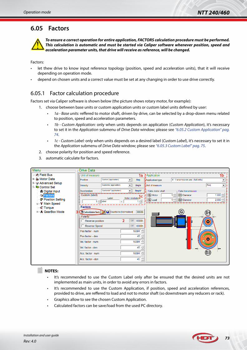
73
NTT 240/460Operation mode
Installation and user guide
Rev: 4.0
6.05 Factors
!To ensure a correct operation for entire application, FACTORS calculation procedure must be performed. This calculation is automatic and must be started via Caliper software whenever position, speed and acceleration parameter units, that drive will receive as reference, will be changed.
Factors:• let thew drive to know input reference topology (position, speed and acceleration units), that it will receive
depending on operation mode.• depend on chosen units and a correct value must be set at any changing in order to use drive correctly.
6.05.1 Factor calculation procedureFactors set via Caliper software is shown below (the picture shows rotary motor, for example):
1. choose between base units or custom application units or custom label units defined by user:• 1a - Base units: reffered to motor shaft, driven by drive, can be selected by a drop-down menu related
to position, speed and acceleration parameters.• 1b - Custom Application: only when units depends on application (Custom Application), it’s necessary
to set it in the Application submenu of Drive Data window; please see “6.05.2 Custom Application” pag. 74.
• 1c - Custom Label: only when units depends on a desired label (Custom Label), it’s necessary to set it in the Application submenu of Drive Data window; please see “6.05.3 Custom Label” pag. 75.
2. choose polarity for position and speed reference.3. automatic calculate for factors.
1a 1b
1c
2
3
!NOTES:
• It’s recommended to use the Custom Label only after be ensured that the desired units are not implemented as main units, in order to avoid any errors in factors.
• It’s recommended to use the Custom Application, if position, speed and acceleration references, provided to drive, are reffered to load and not to motor shaft (so downstream any reducers or rack).
• Graphics allow to see the chosen Custom Application.• Calculated factors can be save/load from the used PC directory.

74Installation and user guide
Rev: 4.0
NTT 240/460 Operation mode
Main units supported by drive are listed below:
Angular units Linear units Standard units
Position radians, deg cm, mm, μm, nm, inches, mils counts
Speed radians/s, deg/s cm/s, mm/s, μm/s, nm/s, inches/s, mils/s counts/s, RPM, RPS
Acceleration radians/s2, deg/s2 cm/s2, mm/s2, μm/s2, nm/s2, inches/s2, mils/s2 counts/s2, RPM/s, RPS/s!NOTES:
• There are other units, in the same drop-down menu, that allow to set tenths, cents and thousandth of main units.
6.05.2 Custom Application » In case of rotary motor, supported Custom Application can be selected by a drop-down menu and they are listed
below:1. Disk axis (angular measurement): application with angular units reffered directy to a load represented by a rotary
disk downstream any reducer. Set parameters are:• units• reducer ratio
2. Disk axis (angular measurement): application with linear units reffered directy to a load represented by a rotary disk downstream any reducer. Set parameters are:• units• reducer ratio• disk diameter
3. Axis conveyor belt (flat belt): application with linear units reffered directy to a load represented by an axis conveyor belt downstream any reducer. Set parameters are:• units• reducer ratio• dragged disk diameter
4. Axis conveyor belt (toothed belt): application with linear units reffered directy to a load represented by an axis conveyor belt downstream any reducer. Set parameters are:• units• reducer ratio• tooth number e tooth pitch
5. Transmission axis (flat belt): application with linear units reffered directy to a load represented by a transmission axis downstream any reducer. Set parameters are:• units• reducer ratio• disks diameters
6. Transmission axis (toothed belt): application with linear units reffered directy to a load represented by a transmission axis downstream any reducer. Set parameters are:• units• reducer ratio• toohtd disks number
7. Axis with worm: application with linear units reffered directy to a load represented by an axis with worm downstream any reducer. Set parameters are:• units• reducer ratio• screw pitch

75
NTT 240/460Operation mode
Installation and user guide
Rev: 4.0
8. Axis with hollow shaft motor: application with linear units reffered directy to a load represented by an axis with an hollow shaft motor. Set parameters are:• units• screw pitch
» In case of linear or tubular motor, the Custom Application is unique, and the calculation for Factors is equal to that described for rotary motor:
!NOTES:
• Some units, as nm, are not implemented in linear motor application; by the way, it can be created with Custom Label.
• Graphics allow to see the chosen Custom Application.• Calculated factors can be save/load from the used PC directory.
6.05.3 Custom LabelCustom Label allows user to set custom units related to a specified application. To define units, it’s allow to set:
• a ratio between number of desired revolutions to perform in order to reach target of specified application (in case of rotary motor).
• a ratio between number of desired pole pitch to perform in order to reach target of specified application (in case of linear or tubular motor).
This means that target quota, that user provides to drive, is equal to that set as number of revolution or number of pole pitch.An example of Custom Label setting is shown in the picture below:
Setting, as target (‘obj’), value ‘1’ and, as number of revolutions, value ‘28’, drive will perform 28 revolutions when user provides it , as target position, value ‘1’.
!NOTES:
• Custom Label settable parameters are 16bit (resolution at 65535).

76Installation and user guide
Rev: 4.0
NTT 240/460 Operation mode
6.06 Display and keyboard
Drive has 5-digit (7-segment) display, useful for rapid view of drive status and parameters, and a keybord for navigate the parameter set and for modify then in realtime during operation or during tuning procedure if PC is missing.
Menu L1 level (main)
Menu L2 level
Menu L3 level
Menu L4 level
Menu L5 level (parameter)
Parameter set is organized into levels and sub-levels, di-splayed during navigation.
The keyboard is formed by 4 buttons:• ESC: it leads to navigate escaping levels or sub-levels
and to escape from parameter without saving.• DIRECTIONAL INDICATORS (UP and DOWN): they lead
to navigate into levels or sub-levels and to modify parameters.
• ENTER: it leads to navigate entering levels or sub-levels and to select and save parameters.
After turn-on, drive shows installed firmware version for a few seconds; then it displays main display visualizatrion menu for primary drive parameters.
d.0000 Drive status (STOP, ENA, RUN, F xx and FA xx) d.0007 Absolute feedback position freezing when going out from Home sensor
d.0001 Motor speed in RPM d.0008 Drive current size
d.0002 Motor current in Ampere d.0009 Drive voltage size
d.0003 DC link voltage in Volt d.000A Reserved
d.0004 Drive Heatsink temperature in °C d.000b Pressure reference
d.0005 Position-rounds of the motor d.000C Measured pressure
d.0006 Position-offset-round of the motor!The amount of parameters that can be viewed and modified is limited to available number of 5-digit. For further information about these parameters, please see “6.06.1 Keybord access parameters” pag. 77. For a complete drive setting, please use Caliper 4 software (or newer).
To enter drive main setting menu, press ESC + ENTER at the same time; main menu in navigation are shown:
Menu M: motor parameter setting
Menu T: control topology setting
Menu U: speed control parameter setting
Menu C: torque control parameter setting
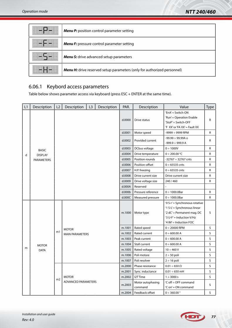
77
NTT 240/460Operation mode
Installation and user guide
Rev: 4.0
Menu P: position control parameter setting
Menu F: pressure control parameter setting
Menu S: drive advanced setup parameters
Menu H: drive reserved setup parameters (only for authorized personnel)
6.06.1 Keybord access parametersTable below shows parameter access via keyboard (press ESC + ENTER at the same time).
L1 Description L2 Description L3 Description PAR. Description Value Type
d
BASIC
DISPLAY
PARAMETERS
d.0000 Drive status
‘EnA’ = Switch-ON
‘Run’ = Operation Enable
‘StoP’ = Switch-OFF
‘F XX’ or ‘FA XX’ = Fault XX
R
d.0001 Motor speed -9999 ÷ 9999 RPM R
d.0002 Provided current-99.99 ÷ 99.99A o
-999.9 ÷ 999.9 AR
d.0003 DCbus voltage 0 ÷ 1000V R
d.0004 Drive temperature 0 ÷ 200.00 °C R
d.0005 Position-rounds -32767 ÷ 32767 cnts R
d.0006 Position-offset 0 ÷ 65535 cnts R
d.0007 H.P. freezing 0 ÷ 65535 cnts R
d.0008 Drive current size Drive current size R
d.0009 Drive voltage size 240 / 460 R
d.000A Reserved -
d.000b Pressure reference 0 ÷ 1000.0Bar R
d.000C Measured pressure 0 ÷ 1000.0Bar R
mMOTOR
DATA
m1MOTOR
MAIN PARAMETERS
m.1000 Motor type
‘0 S-r’ = Synchronous rotative
‘1 S-L’ = Synchronous linear
‘2 dC’ = Permanent mag. DC
‘3 U-F’ = Induction V/Hz
‘4 IM’ = Induction FOC
S
m.1001 Rated speed 0 ÷ 20000 RPM S
m.1002 Rated current 0 ÷ 600.00 A S
m.1003 Peak current 0 ÷ 600.00 A S
m.1004 Stall current 0 ÷ 600.00 A S
m.1005 Rated voltage 10 ÷ 460 V S
m.1006 Poli motore 2 ÷ 50 poli S
m.1007 Poli resolver 2 ÷ 16 poli S
m2MOTOR
ADVANCED PARAMETERS
m.2000 Phase resistance 0.01 ÷ 650 Ω S
m.2001 Sync. inductance 0.01 ÷ 650 mH S
m.2002 I2T Time 1 ÷ 3000 s S
m.2003Motor autophasing
command
‘C off = OFF command
‘C on’ = ON commandS
m.2004 Feedback offset 0 ÷ 360.00 ° S

78Installation and user guide
Rev: 4.0
NTT 240/460 Operation mode
L1 Description L2 Description L3 Description PAR. Description Value Type
tCONTROL
TOPOLOGIES- t - Control topologies
‘U’ = Speed
‘C’ = Torque
‘A’ = Electr. Gearbox
‘P’ = Position
‘E’ = Electr. Cam
‘F’ = Servo press
S
USPEED
CONTROL
U1MAIN
REFERENCE
U10 CHOICE U.1000Choose reference
type
‘0-AnL’ = Analog
‘1-Int’ = Inside
‘2-FrE’ = Frequency
‘3-tAb’ = Selection Table
S
U11 ANALOG REF.U.1100 Fullscale 0 ÷ 60000 RPM W
U.1101 Offset -999.9 ÷ 999.9 RPM W
U12 INTERNAL REF. U.1200 Target speed -9999 ÷ 9999 RPM W
U15FREQUENCY
REF.
U.1500 Pulse per round 128 ÷ 16384 S
U.1501 Input type
‘0 A-b’ = encoder ChA/ChB
‘1 F-d’ = Frequency/Direction
‘2 ImP’ = CW/CCW Pulse
S
U2AUXILIARY
REFERENCE
U20 CHOICE U.2000Choose reference
type
‘0-AnL’ = Analog
‘1-Int’ = Interno
‘2-LIm’ = Limite di Coppia
S
U21 ANALOG REF.U.2100 Fullscale 0 ÷ 60000 RPM W
U.2101 Offset -999.9 ÷ 999.9 RPM W
U22 INTERNAL REF. U.2200 Target speed -9999 ÷ 9999 RPM W
U23TORQUE
LIMIT
U.2300 Fullscale 0.0 ÷ 250.0% W
U.2301 Offset -100.0 ÷ 100.0% W
U24 ENABLE U.2400 Enable reference On/Off W
U3 RAMPS U30 ENABLEU.3005 Enable S-ramps On/Off W
U.3006 Enable linear ramps On/Off W
CTORQUE
CONTROL
C0 CHOICE C.0000Choose reference
type
‘0-AnL’ = Analog
‘1-Int’ = InsideS
C1 ANALOG REFERENCEC.1000 Fullscale 0.0 ÷ 250.0% W
C.1001 Offset -100.0 ÷ 100.0% W
C2 INTERNAL REFERENCE C.2000 Target torque -250.0 ÷ 250.0% W
P
POSITION
CONTROL
-
POSITIONER
P0 CHOICE P.1000Choose reference
type
‘0-SnG’ = Single target
‘1-AnL’ = Analog
‘2-tAb’ = Selection Table
‘3-CLC’ = Cyclic Table
‘4-t/S’ = Input start table
S
FPRESSURE
CONTROL
F1
FULLSCALE PARAMETERS FOR
PRESSURE REFERENCE AND
TRANSDUCER
F.1000 Speed reference 1 ÷ 9999 RPM W
F.1001 Speed ref. offset -999.9 ÷ 999.9 RPM W
F.1002 Pressure reference 1 ÷ 1000.0 bar W
F.1003 Pressure ref. offset -100.0 ÷ 100.0 bar W
F.1004 Transducer 1 ÷ 1000.0 bar W
F.1005 Transducer offset -100.0 ÷ 100.0 bar W
F.1006 Pressure reference accuracy
‘dEC 0’ without decimal
‘dEC 1’ with 1 decimalS
F2THRESHOLD SETTING FOR
POWER LIMITING
F.2000 Pressure threshold 0 ÷ 1000 bar W
F.2001 Hysteresis for F.2000 1 ÷ 50 bar W
F.2002 Speed threshold 0 ÷ 9999 RPM W
F.2003 Speed ramps 1 ÷ 60000 RPM/s W
F3 LIMITS
F.3000 Current limit 0.0 ÷ 1000.0 % W
F.3001 Negative speed -9999 ÷ 0 RPM W
F.3002 It acts on S.5002 parameter

79
NTT 240/460Operation mode
Installation and user guide
Rev: 4.0
L1 Description L2 Description L3 Description PAR. Description Value Type
F
PRESSURE
CONTROL
(continue)
F4
ANALOG OUTPUT MANAGEMENTF.4000 Pressure output 0 ÷ 1000 bar W
F.4001 Speed output 1 ÷ 9999 RPM W
DIGITAL OUTPUT MANAGEMENTF.4002 Pressure error 1 ÷ 1000 bar W
F.4003 Threshold time 1 ÷ 60000 ms W
F5ALARM MODE
THRESHOLD MANAGEMENT
F.5000 Overpressure 1 ÷ 1000 bar W
F.5001 Time for F.5000 1 ÷ 60000 ms W
F.5002 Enable F.5000 ON/OFF S
F.5003 Under pressure 1 ÷ 1000 bar W
F.5004 Time for F.5003 1 ÷ 60000 s W
F.5005 Enable F.5003 ON/OFF S
F6PRESSURE PID REGULATORS AND
EXPONENTIAL MULTIPLYER COEFFICIENTS
F.6000 KP Pressure 1 ÷ 32767 W
F.6001 Exponential for KP -16 ÷ 16 W
F.6002 KI Pressure 1 ÷ 32767 W
F.6003 Exponential for KI -16 ÷ 16 W
F.6004 KD Pressure 1 ÷ 32767 W
F.6005 Exponential for KD -16 ÷ 16 W
F7
PRESSURE RAMPS ON REFERENCE
F.7000 Acceleration 1 ÷ 60000 bar/s W
F.7001 Deceleration 1 ÷ 60000 bar/s W
F.7002 Jerk 0 ÷ 10000 ms W
F.7003 Ramp enable ON/OFF S
SPEED RAMPS ON REFERENCE
F.7004 Acceleration 1 ÷ 60000 RPM/s W
F.7005 Deceleration 1 ÷ 60000 RPM/s W
F.7006 Ramp enable ON/OFF S
SADVANCED
SETUP
S1PID
REGULATORS
S10 PID SPEED
S.1000 KP speed 1 ÷ 65535 W
S.1001 KI speed 0 ÷ 65535 W
S.1002 KD speed 0 ÷ 65535 W
S11 PID CORRENTE
S.1100 KP current 1 ÷ 65535 W
S.1101 KI current 0 ÷ 65535 W
S.1102 KD current 0 ÷ 65535 W
S12PID ASINCRONO
DI FLUSSO
S.1200 KP flux 0 ÷ 65535 W
S.1201 KI flux 0 ÷ 65535 W
S13PID ASINCRONO
DEFLUSSAGGIO
S.1300 KP flux weakening 0 ÷ 65535 W
S.1301 KI flux weakening 0 ÷ 65535 W
S14 PID POSIZIONE S.1400 KP posizione 0 ÷ 4000 W
S15ERRORE DI
POSIZIONE
S.1500 Error threshold 0 ÷ 65535 cnts W
S.1501 Threshold time 10 ÷ 10000 ms W
S3
ENCODER RESOLUTION
and
ALARMS
S.3000 Encoder output res. 256-1024-4096-16384 ppr S
S.3002Reset alarms
commandON/OFF W
S.3003 Alarm list Last 16 appeared alarms R
S.3004 Firmware version ‘SFX.XX’ firmware version R
S.3005 Feedback Reverse ON/OFF S
S.3006 Encoder output type
‘0 rIF’ frequency reference
‘1 SIM’ emulated enc. out
‘2 EnC’ motor encoder
S
S.3007 Enc. out. reverse ON/OFF S
S4 ALARM MODES.4002 STO alarm mode
‘oFF’ stored
‘on’ autoresetW
S.4008 Check 24V for I/O ON/OFF W

80Installation and user guide
Rev: 4.0
NTT 240/460 Operation mode
L1 Description L2 Description L3 Description PAR. Description Value Type
S
ADVANCED
SETUP
(continue)
S5 LIMITS
S.5000 Maximum speed 0 ÷ 20000 RPM W
S.5001 Maximum current 0.0 ÷ 1000.0 % W
S.5002 Limit current accu-racy
‘dEC 0’ without decimal
‘dEC 1’ with 1 decimalS
S7 FIELDBUS
S70 CHOICE S.7000 Fieldbus choice
‘0 Io’ Input/Output
‘1 mod’ Modbus
‘2 CAn’ Canopen
‘3 EtH’ Ethercat
‘4 Pnt’ Profinet
‘5 PrF’ Profibus
S
S71 MODBUS
S.7100 MODBUS address 1 ÷ 247 S
S.7101MODBUS parity
check
‘0 nuL’ null
‘1 EUE’ pari
‘2 odd’ dispari
S
S.7102 MODBUS baudrate‘9600’ - ‘14400’ - ‘19200’
‘38400’ - ‘57600’ - ‘115200’S
S.7103 Timeout 10 ÷ 4000 ms S
S.7104 Timout enable ON/OFF S
S72 CANOPEN
S.7200 CANOPEN address 1 ÷ 127 S
S.7201 CANOPEN baudrate‘10’ - ‘20’ - ‘50’ - ‘100’ - ‘125’
‘250’ - ’500’ - ‘800’ - ‘1000’S
S.7202 Timeout 10 ÷ 4000 ms S
S.7203 Timout enable ON/OFF S
S73 PROFIBUS S.7300 PROFIBUS address 1 ÷ 125 S
S74 ETHERCAT S.7400 ETHERCAT alias 1 ÷ 65535 S
S75 PROFINET
S.7500
192 . 168 . 1 . 10ADDRESS
Profinet IP address fields WS.7501
S.7502
S.7503
S.7510
255 . 255 . 255 . 1ADDRESS
Profinet Subnet Mask ad-dress fields W
S.7511
S.7512
S.7513
S.7520
192 . 168 . 1 . 1ADDRESS
Profinet Gateway address fields W
S.7521
S.7522
S.7523
S8 MOTOR BAKE
S.8000 Enable time 10 ÷ 2000 ms W
S.8001 Disable time 10 ÷ 2000 ms W
S.8002 Deceleration ramp 0 ÷ 60000 RPM/s W
S.8003 Brake enable speed 1 ÷ 500 RPM W
H6 BRAKING RESISTOR
H.6000 Ohmic value 10 ÷ 10000 Ω S
H.6001 Power rating 30 ÷10000 W S
H.6002 Overload time 1 ÷ 255 s S

81
NTT 240/460Operation mode
Installation and user guide
Rev: 4.0
L1 Description L2 Description L3 Description PAR. Description Value Type
HRESERVED
SETUP
H0 RESERVED PARAMETER ACCES H.0000 Password entering - W
H1 -
H.1002 I2T drive time 0.1 ÷ 25.0 s W
H.1003Voltage lack control
enableON/OFF S
H.1004 Switching frequency 2.0 ÷20.0 kHz W
H.1005 Heat temp. threshold 1.0 ÷ 200.0 °C W
H.1006 Fan enable threshold 0.0 ÷ 200.0 °C W
H.1007 Stop fan hysteresis 1.0 ÷ 200.0 °C W
H3 -
H.3000 DC braking threshold 15 ÷ 960 V W
H.3001 Hysteresis for H.3000 1 ÷ 125 V W
H.3002 DC max threshold 15 ÷ 960 V W
H.3003 Hysteresis for H.3002 1 ÷ 125 V W
H.3004 DC min threshold 5 ÷ 560 V W
H.3005 Hysteresis for H.3004 1 ÷ 125 V W
H4 I2T LIMIT FREQUENCY H.4000 I2T limit threshold 0.00 ÷10.00 Hz W
H5 ALARMS ERASING H.5000 Erase alarms ON/OFF W
Variable “Type” show:1. R = read only2. W = always write (STOP, ENA, RUN o FAULT)3. S = write only in STOP (or FAULT) drive status

82Installation and user guide
Rev: 4.0
NTT 240/460 Operation mode
6.07 Motor autophasing
Autophasing function allows drive to identify connected motor poles number and incremental encoder offset (all data are visible in ‘Motor Data’ item); ensure to perform autophasing procedure if a third parts motor is used, in order to grant a correct drive functionality.
If drive manages motor brake, its disengage is performed during autophasing function. In case of vertical axis load, please use an oppropriate external mechanic brake esterno and separate rotor from load. In the end of autophasing operation, motor brake will engage.
!Rotor MUST be free to rotate during autophasing function.Please set correct used motor encoder pulse number and motor rated current before performing autophasing.
Drive can perform autophasing also without HALL sensors in order to identify only connected motor poles number.
In the launching window, dove a motor current confirmation message appears and lets to enter correct data; also a free rotor message appears, as shown in the image below:
!NOTES:
• Modifing current data and encoder pulse number before performing autophasing, it lets to auto update related into Motor Data item, as shown in previous image.
• H.D.T. motors are normally phased at drive default value, so, during first start up, it is not necessary to perform autophasing.
Caliper software shows some information during autophasing operation, as shown in the image below:
During this operation, motor performs one complete turn at low speed, identifing total motor poles number; the graphic window shows istantaneous information about rotor position within turn.Press Start to perform autophasing.Autophasing can be stopped in any tyme pressing Stop key. An au-tophasing operation must have been complete at least, in order to ensure a drive correct operation with connected motor.If during autophasing motor runs in counterclockwise, (shaft side view), please invert two motor phases of cable connection.In the end, Caliper software will update motor poles number into ‘Mo-tor Data’ item and will automatically send data to drive.

83
NTT 240/460Operation mode
Installation and user guide
Rev: 4.0
6.08 Digital I/O
Digital input (also analog input used as digital input) and output ports are totally configurable with all theri input function, so they are not linked to hardware input position, exception for 2 input capture functions, as Touch Probe.To learn more about digital I/O functions according to choosen operation mode, please see “6.08.1 Digital I/O functions” pag. 85, and for information about I/O topology, please see “5.10 J7-8-9 connectors: Frequency, digital and analog I/O” pag. 42.Please remember that ‘Digital Input’ sub item is nested in Menu item releated to desired operation mode; for example, a kind of useful configuration for digital input functions, with related settings, during speed control in I/O operation mode is shown below:
Setting into window is shown below:• setting input 6 and 7 as analog or digital
input.• setting Power ON/OFF activation type
between Level or Edge of selected input signal.
• setting input function from dropdown menu and desired logic state.
Digital input functions are listed below:1. Power ON o Switch ON: motor locked in torque standstill condition command.2. Power ON/Reset: reset alarms and torque standstill condition joint command.3. Power/Operat.: torque standstill condition and reference enabled joint command.4. Power/Operat./ Reset: reset + torque standstill + reference enabled joint command.5. Enable Reference o Enable Operation: reference enabled command.6. Start Reference: Start position command.7. Halt: Halt command.8. Position Abs./Rel.: target conversion between absolute and relative and viceversa.9. Reset Alarms o Fault Reset: drive alarms reset command.10. Limit Switch CW and Limit Switch CCW: input for clockwise (CW) and counterclockwise limit switch (CCW).11. Home Switch: input for Home switch.12. Current limit 1 and Current limit 2: input for 1ST and 2ND torque limit at specified percentage value.13. Reverse Speed: reverse speed command.14. Home Position: start Home Position procedure command.15. JOG+ and JOG-: speed JOG command.16. Selection-Start: target table selection input and start per input-start position control.17. Reference Select(0-5): target table selection input via Modbus operation mode.18. Reset Index: cyclic positioner index reset.19. Position on Input X: index stop, at relative position, when event happens on defined Input.20. Measure position on In X: start/stop position measurement on defined input.21. Selection Cam: electronic cam table selection input.22. Input Sync Cam: electronic cam sync input.23. Input Sync Slave: electronic cam slave module sync input.

84Installation and user guide
Rev: 4.0
NTT 240/460 Operation mode
24. Position Phase Shift: input for performing axis posizion phase shift.25. Velocity Shift + and Velocity Shift -: input for performing axis speed phase shift.26. Touch Probe 1 and Touch Probe 2: Touch Probe 1 and 2 function input.
Output can be set into Advanced Setup as shown below:
Output is enabled for each operation mode supported by drive.Drive Data window lets choosing output port function and shows some function parameter.In order to enable function, please select it in the drop-down menu into Drive Data item.Digital output functions are available in every supported operation mode.
Output functions are listed below:1. Torque limit: if drive provides rated torque or reaches torque limit set as reference, output will switched to
an high state value.2. I2T Alarm: if drive identifies a drive or motor I2T alarm condition, output will switched to an high state value.3. Speed 0: if drive identifies a Zero Speed condition, output will switched to an high state value. Speed value
and timeout, beyond that it’s necessary to send alarm, can be set in Drive Data item.4. Target reached: output will switched to an high state value if drive identifies one of the following reached
target condition: target position reached, home position executed, cam completed and pressure reached.5. Mot. Brake: motor brake management and current offset parameter for vertical axis. To learn more about
this function, please see “6.11 Motor brake” pag. 90.6. Drive OK: high active logic signal for Drive OK status; output is disabled if any alarms occur.7. Secure Power disable: this function provides an high active output if both SPD contacts are correctly
opened; please see “Ch. 7 S.T.O. safety circuit” pag. 116.8. Pos-Freq. Out: this output provides a squared wave whose frequency is equal to a divider,
settable with a power of two, of motor position in turn (counts). Maximum allowable frequency for output is 2.5kHz so for using correctly thi function, please follow the formula shown below:
where NRPM.V (RPM) is the maximum speed reachable by the motor in the application, FBRESOLUTION is the feedback resolution (it equals to encoder pulse number multiplied by 4, if incremental encoder is used, whereas it equals to resolution due to number of bit if absolute encoder is used), and DIVMIN is the minimum allowable divider; so from Caliper drop-down menu, please choose an “Encoder count Divider”, DIV, higher than DIVMIN found value, to result in ENCOUT, that is the output resolution in CPR (counts per round).
9. Pos Output: available only for input-start position mode, it provides an output pulse, with time setting, when position is reached.
10. Homing attained: when any homing procedure is performed, output will switched to an high state value and it will remain untill next Homing procedure call (or drive turn off).
!NOTES:
• Digital output are also configurable to be controlled via fieldbus parameter in order to let controller to perform custom function.

85
NTT 240/460Operation mode
Installation and user guide
Rev: 4.0
6.08.1 Digital I/O functionsAvailable functions, during I/O operation mode and related control type, are shown in table below:
I/O Operation mode
Speed Torque Elect. Axis Position Elect. Cam Press
IN 0 Power ON
Power ON/Reset
Enable Reference
Reset Alarms
Current Limit 1
Current Limit 2
Halt
Reverse Speed
Limit Switch CW
Limit Switch CCW
Home Switch
Power ON
Power ON/Reset
Enable Reference
Reset Alarms
Current Limit 1
Current Limit 2
Halt
Power ON
Power ON/Reset
Enable Reference
Reset Alarms
Current Limit 1
Current Limit 2
Halt
Home position
Limit Switch CW
Limit Switch CCW
Home Switch
JOG+ JOG-
Pos. Phase Shift
Velocity Shift +
Velocity Shift -
Power ON
Power ON/Reset
Enable Reference
Reset Alarms
Current Limit 1
Current Limit 2
Halt
Home position
Limit Switch CW
Limit Switch CCW
Home Switch
JOG+ JOG-
Selection-Start
Position on Input X
Power ON
Power ON/Reset
Enable Reference
Reset Alarms
Current Limit 1
Current Limit 2
Halt
Home position
Limit Switch CW
Limit Switch CCW
Home Switch
JOG+ JOG-
Selection Cam
Velocity Shift +
Velocity Shift -
Input Sync Cam
Input Sync Slave
Power ON
Power ON/Reset
Enable Reference
Reset Alarms
Current Limit 1
Current Limit 2
Halt
Limit Switch CW
Limit Switch CCW
IN 1
IN 2
IN 3
IN 4
IN 5
IN 6
IN 7
IN 8*
IN 9*
IN 10*
DIR CHA - CCW - DIR - CHA - CCW - DIR - CHA - DIR -
PULSE CHB - CW - PULSE - CHB - CW - PULSE - CHB - PULSE -
Available functions, during Modbus RTU operation mode and related control type, are shown in table below:
MODBUS RTU Operation mode
Speed Torque Elect. Axis Position Elect. Cam Press
IN 0 Switch ON
Power/Operation
Pow./Op./Reset
Enable Operation
Fault Reset
Halt
Meas. pos. Input X
Limit Switch CW
Limit Switch CCW
Home Switch
Switch ON
Power/Operation
Pow./Op./Reset
Enable Operation
Fault Reset
Halt
Start reference
Meas. pos. Input X
Switch ON
Power/Operation
Pow./Op./Reset
Enable Operation
Fault Reset
Halt
Meas. pos. Input X
Limit Switch CW
Limit Switch CCW
Home Switch
Start reference
Home Position
JOG+ JOG-
Pos. Phase Shift
Velocity Shift +
Velocity Shift -
Switch ON
Power/Operation
Pow./Op./Reset
Enable Operation
Fault Reset
Halt
Meas. pos. Input X
Limit Switch CW
Limit Switch CCW
Home Switch
Start reference
Home Position
JOG+ JOG-
Selection-Start
Reference select (0-5)
Position Abs./Rel
Position on Input X
Switch ON
Power/Operation
Pow./Op./Reset
Enable Operation
Fault Reset
Halt
Meas. pos. Input X
Limit Switch CW
Limit Switch CCW
Home Switch
Start reference
Home Position
JOG+ JOG-
Selection Cam (0-2)
Velocity Shift +
Velocity Shift -
Input Sync Cam
Input Sync Slave
Switch ON
Power/Operation
Pow./Op./Reset
Enable Operation
Fault Reset
Halt
Start reference
Meas. pos. Input X
Limit Switch CW
Limit Switch CCW
IN 1
IN 2
IN 3
IN 4
IN 5
IN 6
IN 7
IN 8*
IN 9*
IN 10*
DIR CHA - CCW - DIR - CHA - CCW - DIR - CHA - DIR -
PULSE CHB - CW - PULSE - CHB - CW - PULSE - CHB - PULSE -

86Installation and user guide
Rev: 4.0
NTT 240/460 Operation mode
Available functions, during Canopen, Ethercat CoE, Profinet and Profibus operation mode are shown in table below:
Operation Mode
Canopen CiA402 Ethercat CoE CiA402 Profinet Profidrive Profibus DPv0
IN 0 Position on Input X - Measuring Position -
IN 1 Position on Input X - Measuring Position Limit Switch CW
IN 2 Limit Switch CW Limit Switch CCW
IN 3 Limit Switch CCW -
IN 4 Home Switch -
IN 5 Position on Input X - Measuring Position -
IN 6 Position on Input X - Measuring Position - Touch Probe 1 - Touch Probe 2 Home Switch
IN 7 Position on Input X - Measuring Position - Touch Probe 1 - Touch Probe 2 Position on Input X
DIR CHA - CCW - DIR (only for Electronic Gearbox) - -
PULSE CHB - CW - PULSE (only for Electronic Gearbox) - -!
NOTES:• Drive considers that an I/O port is activated when high level logic state is detected. For any information
about logic state levels, please see “2.06 Technical data” pag. 15. For further information about wiring, please see “5.10 J7-8-9 connectors: Frequency, digital and analog I/O” pag. 42
• * Input 8,9 and 10 are same hardware analog input; to use them as digital input, they must be enabled: single ended PNP connection for analog references is to connect negative pins (pin 2-4-6 of J9)) to 0S ground (pin 8 of J9) and to connect signal to positive pins (pin1-3-5 of J9).
• Function related to Position table selection (Selection Position from 0 to 5) and Cam table selection (Selection Cam from 0 to 2) have to be set manually during Modbus RTU operation mode.
• Please, see fieldbus user guides for any other detailes related to how to manage digital I/O (logic states or activation sequences).

87
NTT 240/460Operation mode
Installation and user guide
Rev: 4.0
6.09 Drive references
Drive acquires references, related to operation mode and control topology, from type shown below:1. Main reference2. Auxiliary AUX1 reference3. Auxiliary AUX2 reference
! Having the analog references a voltage range between -10V e +10V, zero condition is obtained when input voltage to drive pin port (pin 1-2, 3-4, 5-6 of J9 connector) equals to 0V. For further information about connections and about analog input topology, please see “5.10 J7-8-9 connectors: Frequency, digital and analog I/O” pag. 42.
6.09.1 Main referenceMain reference provides following features:
• speed control as IN8 analog speed reference (I/O and Modbus op. mode): pin 1-2 of J9 connector.• speed control as frequency speed reference (I/O and Modbus op. mode): pin 1 to 6 of J7 connector.• speed control as target speed table selection reference (I/O and Modbus op. mode).• torque control as IN8 analog torque reference (I/O, Modbus and Profibus op. mode): pin 1-2 of J9
connector.• position control as frequency position reference (‘elect. gearbox’ for I/O, Modbus, Canopen and Ethercat
op. mode and ‘electronic cam’ for I/O and Modbus op. mode): pin 1 to 6 of J7 connector.• position control as IN8 analog speed reference (I/O and Modbus op. mode): pin 1-2 of J9 connector., if
‘single target positioner’ or ‘analog positioner’ is used.• pressure control as analog IN8 pressure transducer reading feedback: pin 1-2 of J9 connector.
Topologies are shown below:1. Analog IN8: reference is feeded from external signal, whose voltage range lies between ±10V. Drive input
is a differential port (pin 1-2 of J9 connector).• In speed control, this signal feeds main speed reference related to settable parameters.• In torque control, this signal feeds percentage torque reference according to rated motor current data
(‘Nominal Current’ in Motor Data item).• In position control, if ‘single target positioner’ or ‘analog positioner’ is used, this signal feeds main speed
reference related to settable parameters into position sub-menu.• In pressure control, this signal feeds pressure transducer reading related to settable parameters into
press sub-menu.2. Inside: speed or torque reference is generated internally by drive and it’s constant. By the way, it can be
modified via Caliper software during operation or via fieldbus parameter.3. Frequency: speed or position reference is feeded from 2 frequency signals (pin 1 to 6 of J7 connector) with
these features:• PULSE - DIRECTION mode: a signal frequency provides to drive the position/speed refererce, whereas
the second one provides to drive the direction signal depending on high logic signal (forward motion) or low logic signal (backwards motion).
• EXTERNAL ENCODER CHA - CHB: external real or simulated encoder input. It’s recommended not to connect more than 2 drives on external encoder incremental channels in order to not overload it; in this case, please use a signal amplifier device every 2 drives connected.
• CW - CCW: a signal frequency provides to drive the position/speed refererce, whereas the second one provides to drive the ‘Start’ command (low logic signal). Depending on which of the two inputs receives the frequency signal, the drive controls motor in forward motion (CW) or in backwards motion (CCW).
4. Tab-Speed: reference is located into 64 target table with index selection via digital input or fieldbus parameters.

88Installation and user guide
Rev: 4.0
NTT 240/460 Operation mode
Analog input setting, related to a speed control, is shown in picture below:
Parameters to set are:• maximum absolute value for reachable speed
(back and forth operation) when analog input voltage value matches with ±10V scale value (example: ±3000RPM).
• speed offset useful to compensate any external signal offset.
• a low pass digital filter on external signal.
Information about istantaneous measured speed appears.
6.09.2 Auxiliary referencesAuxiliary reference AUX1/IN9 provides following features:
• speed control as auxiliary speed reference.• speed control as torque limit reference.• position control as analog position reference, if ‘analog positioner’ is used.• pressure control as analog/inside pressure reference.
Topologies are shown below:1. Analog IN9: reference is feeded from external signal, whose voltage range lies between ±10V. Drive input is
a differential port (pin 3-4 of J9 connector).• In auxiliary speed control, this signal is added to main speed reference and parameters to set are
maximum reachable speed (in absolute value) when analog input voltage value matches with ±10V scale value (example: ±3000RPM).
• In position control, setting minimum target position (equivalent -10V) and maximun target position (equivalent +10V) parameters, drive performs positioning between this two values following the 12 bit analog auxiliary reference range (±10V).
• In pressure control, this signal feeds pressure reference related to settable parameters into press sub-menu.
2. Inside: auxiliary reference is generated internally by drive and it’s constant. By the way, it can be modified via Caliper software during operation or via fieldbus parameter.
3. Torque limit: reference is used in speed control as torque limit value. Reference is feeded from external signal, whose voltage range lies between ±10V (pin 3-4 of J9 connector). Parameters to set are:• absolute torque value to load when analog input voltage value matches with +10V scale value
(example: 100%).• torque offset useful to compensate any external signal offset.
Auxiliary reference AUX2/IN10 (pin 5-6 of J9 connector) is available with all operatin modes and and provides following features:
• pressure control as analog/inside speed reference.
Topologies are shown below:1. Analog IN10: pressure transducer feedback is feeded from external signal, whose voltage range lies
between ±10V. Drive input is a differential port (pin 5-6 of J9 connector).• In pressure control, this signal feeds speed reference related to settable parameters into press sub-menu.
2. Inside: auxiliary reference is generated internally by drive and it’s constant. By the way, it can be modified via Caliper software during operation or via fieldbus parameter.

89
NTT 240/460Operation mode
Installation and user guide
Rev: 4.0
Analog input setting, related to auxiliary speed control, is shown in picture below:
Parameters to set are:• maximum added value for reachable
speed (back and forth operation) when analog input voltage value matches with ±10V scale value (example: ±3000RPM).
• speed offset useful to compensate any external signal offset.
Limit torque function, related to auxiliary speed control, is shown in picture below:
!NOTES:
• please pay attention to any activated digital input set for torque limit function.
6.10 Speed ramps
Acceleration and deceleration ramps management is enabled only with speed control in any operation mode. Drive performs ramps at any reference change.Acceleration and deceleration ramps enabling and setting are shown below:
After ramps enabling, acceleration and deceleration values must be set, as RPM/s, both clockwise (CW) that counterclockwise (CCW): so, knowing TRAMP-V time to reach NRPM-V operating speed, acceleration and deceleration parameters (RAMP-V) are provided by following formula:

90Installation and user guide
Rev: 4.0
NTT 240/460 Operation mode
Another ramp type supported by drive is the S ramp (Type S) that, besides just described parameters, uses a further parameter called JERK (RPM/s2); this last parameter, also called smooth factor, introduces another ramp coefficient related to acceleration and deceleration profile, and lets drive to smooth speed profile around reference change; knowing TRAMP-A time to reach RAMP-V parameter, acceleration and deceleration ramps (JERK or smooth factor) are provided by following formula:
Smooth factor effect on speed profile is shown below:
6.11 Motor brake
Motor brake function provides that drive, at any SWITCH-OFF command (load torque disabled), performs a ramp to stop load, before brake enabling and before leaving SWITCH-ON state.
!If application requires motor brake function, do NOT use a control feedback from incremental channel only (without HALL sensors) because, in this condition, drive needs to perform, at every SWITCH-ON command, a rotation angle, in order to align poles, more or less pronounced, depending on the rotor position in that moment.
!It’s recommended NOT to connect OUT-x output directly to motor brake command contact. Please use a mechanical contact (as a relay) or any other proper mechanical/electric contact as long as OUT-x current consumption is lower than limit imposed by drive electrical features.‘Time brake enable’ and ‘time brake disable’ must be appropriate to estimated time for brake handling.
Into Advanced Setup item, into Output sub-item, output OUT-x can be set for motor brake management (please see “6.08 Digital I/O” pag. 83 to learn about output setting), with features shown below:
1. convention used for output provides to ‘disable’ brake (disengage) at high logic signal and ‘enable’ brake (engage) at low logic signal.
2. ‘time brake enable’ and ‘time brake disable’ setting from 10 to 2000 ms.3. ‘speed brake enable’ setting: it is the speed target to enable brake.4. deceleration ramp setting, to reach speed target, at any SWITCH-OFF command (only with operating speed
grater than speed target).
During engaging brake, drive provides to stop load keeping block torque, after reaching speed target, and, at this time, it provides output signal; drive holds torque until ‘time brake enable’ set is expired.

91
NTT 240/460Operation mode
Installation and user guide
Rev: 4.0
During disengaging brake, drive provides to keep motor rated torque/current. When brake contact is really disengage, drive provides load proper torque/current in order to hold it until ‘time brake disable’ set is expired.During disengaging brake, any axis movements may occur, because of mechanical brake disable time and drive PID regulator smartness. For this reason, “Current Offset” parameter is available for pre-applying torque to motor during the brake disable time, in order to avoid axis movements when PID regulators start to operate.To use correctly the pre-torque function, follow the instruction below:
• set “Current Offset” parameter to 0.• disengage brake and read the current value provided by the drive to keep load.• write the current value (with sign value) into “Current Offset” parameter.
The timing-chart for motor brake function is described in the image below:
1 2 3 31 2
EnableTime
Stop rampExternalSpeed
ReferenceTargetSpeed
Output formotor brake
(OUT-x)
Enable/engage condition for motor brake
1 SWITCH-OFF command and stop-ramp perform
2 Enable motor blake and drive in SWITCH-ON
3 Drive in SWITCH-OFF
DisableTime
SpeedReference
Output formotor brake
(OUT-x)
Disable/disengage for motor brake
1 Command for SWITCH-ON + brake disable
2 Disable time is over and drive is ready to OPERATION ENABLED
3 Command for OPERATION ENABLED
Drive inSWITCH-ON
Drive inOPERATION ENABLED
Drive inSWITCH-OFF
Drive inSWITCH-ON
Drive inOPERATION ENABLED
Drive inSWITCH-OFF
Speed reference generated by drive to performbraking procedure
Output brake function setting and parameter described above are shown in the image below:
!NOTES:
• Drive performs stop following speed reference, not measured speed, in order to engage motor brake also during power stage failure conditions.
• Motor brake function is not available during torque control.• To ensure that pre-torque function works properly, it’s necessary that vertical axis load should be quite
constant during all machine working cycle.

92Installation and user guide
Rev: 4.0
NTT 240/460 Operation mode
6.12 Braking resistor
Into Advanced Setup item, into Braking Resistor sub-item, drive braking resistor parameters can be set. If braking resistor is provided by H.D.T., all parameters are will be default setting in NTT 240/460 drive.Parameters are shown below:
• Braking resistor value (from 10Ω to 10000Ω)• Nominal/rated power (from 30W to 3000W)• Overload time (from 1s to 255s): time until it’s possible to provide to braking resistor a power 10 times
grater than rated one.
!NOTES:
• To ensure operation during braking conditions, please enter correct parameters related to suitable resistor; please, pay attention to enter correct value to the Overload Time.
• Drive will provide alarm if theoretical calculation for thermal behaviour has detected an overheating of resistor due to an heavy braking cycle not supported by resistor features. For further information, please see “Ch. 8 Drive status and diagnostics” pag. 120.
• Other major power resistors are available for heavy braking cycles: for information please contact our technical department.

93
NTT 240/460Operation mode
Installation and user guide
Rev: 4.0
6.13 Motor cogging torque compensation
Motor cogging compensation function lets to get a better accuracy during a torque control reference following.Motor cogging mapping is valid:
• only for rotative motors.• only for absolute encoder feedback or at least for incremental encoder with zero index (mandatory).• only for the motor on witch the procedure was performed; in case of motor replacement or encoder
rephasing, a new procedure launch is required.
Mapping procedure must be performed only via Caliper software, then the enabling and disabling function can be reached also via fieladbus operation; before starting procedure, rotor must be free to rotate, so ensure to disconnect the load.
Mapping procedure is shown below:
!NOTES:
• Advise against using motor cogging compensation during a speed or position control.• If motor cogging compensation is uded with incremental encoder feedback without ZERO index,
procedure will be aborted.
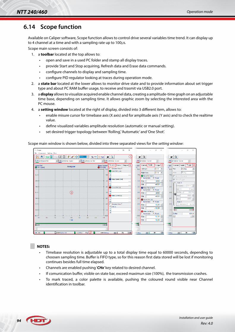
94Installation and user guide
Rev: 4.0
NTT 240/460 Operation mode
6.14 Scope function
Available on Caliper software, Scope function allows to control drive several variables time trend. It can display up to 4 channel at a time and with a sampling rate up to 100μs.Scope main screen consists of:
1. a toolbar located at the top allows to:• open and save in a used PC folder and stamp all display traces.• provide Start and Stop acquiring, Refresh data and Erase data commands.• configure channels to display and sampling time.• configure PID regulator looking at traces during operation mode.
2. a state bar located at the lower allows to monitor drive state and to provide information about set trigger type and about PC RAM buffer usage, to receive and trasmit via USB2.0 port.
3. a display allows to visualize acquired enable channel data, creating a amplitude-time graph on an adjustable time base, depending on sampling time. It allows graphic zoom by selecting the interested area with the PC mouse.
4. a setting window located at the right of display, divided into 3 different item, allows to:• enable misure cursor for timebase axis (X axis) and for amplitude axis (Y axis) and to check the realtime
value.• define visualized variables amplitude resolution (automatic or manual setting).• set desired trigger topology between ‘Rolling’, ‘Automatic’ and ‘One Shot’.
Scope main window is shown below, divided into three separated views for the setting window:
44
1
2
3
4
!NOTES:
• Timebase resolution is adjustable up to a total display time equal to 60000 seconds, depending to choosen sampling time. Buffer is FIFO type, so for this reason first data stored will be lost if monitoring continues besides full time elapsed.
• Channels are enabled pushing ‘CHx’ key related to desired channel.• If comunication buffer, visible on state bar, exceed maximun size (100%), the transmission crashes.• To mark traced, a color palette is available, pushing the coloured round visible near Channel
identification in toolbar.

95
NTT 240/460Operation mode
Installation and user guide
Rev: 4.0
Main scope icons, in the toolbar, are described below:
Icon Description
Open a saved Scope session: it opens a previous saved session.
Save current Scope session in a PC folder.
Start acquiring command: it starts data acquiring with selected sampling time.
Stop acquiring command.
Force Scope Trigger: this icon forces a start acquiring command at pressing. This key is enabled only after Start acquiring command pressed. Function is useful when trigger is set in ‘Automatic’ or ‘One shot’ mode and allow to crossover trigger setup into setting window.
Restart Trigger: only in ‘One Shot’ mode, it allows to restart waiting trigger; This key is enabled only after total acquiring time is elapsed.
Erase graph: it erases actual acquired data or, during monitoring, it restarts acquiring. Stored data will be lost.
Refresh graph: restart data acquiring.
!Scope channel setting: it opens a new window to set 4 channels to monitor, choosed from a preset list.It aalows to set channels desired sampling time too.
PID setting: it opens a new window to set PID regulator cefficients in realtime and to enable ‘Wave Generator’ function.
TEST: it opens a new window to set position target values (from 2 and up to 5 values) used to tune loop gain regulator parameters, in order to test all real automation system performances.
6.14.1 Scope: ‘CHANNEL SETTING’
Image nearby shows how to set sampling time and Scope channels, among which the main are:
• Speed reference and measured speed (RPM).
• Current referenceand measured current (A).
• Position reference, measured position and position error.
• DCbus measured voltage (V).• Torque limit (%).• Heatsink measured temperature (°C).• Drive and motor I2T (°C).• Digital I/O logic status.• Bit-word status for Modbus RTU and
Canopen® protocols.

96Installation and user guide
Rev: 4.0
NTT 240/460 Operation mode
6.14.2 Scope: ‘PID SETTING’ and ‘WAVE GENERATOR’
Scope allows to use a Wave Generator to create simulated input current/speed refe-rences simulati that drive has to follow.
Generated waveforms are settable as shown below:
• square wave• triangular wave• sinusoidal wave
SWITCH-ON, OPERATION ENABLED and RESET commands could be launched di-rectly in this window.
Speed/current reference is created setting desired operating speed/current and wa-veform period.
If the connected load permits it, speed/current and position regulators could be set in realtime in order to perform tuning for all automation system parameters. For further informations about gain loop tuning, please see “6.16 Closed loop regulation tuning” pag. 107.
6.14.3 Scope: ‘TEST’This function allows to set target postion values that drive has to cyclically reach: so this function performs a cyclic positioner simulator. It allows to set operation speed to reach during positioning and to set CW/CCW acceleration and deceleration ramps .
It allows to set:• up to 5 target position values.• following position profile, that can be set as standard ramps with related acceleration and deceleration
parameters, and as S ramps with JERK.• change target on the fly.• position target values, that can be set as number of turns (revolution parameter) or as angular/linear
target to perform respect to an initial offset position and to an operating speed.• JOG function, with related parameters.• Power ON, Test OFF, RESET, JOG and Start Quota commands, that could be launched directly in this
window.
If the connected load permits it, speed/current and position regulators could be set in realtime in order to perform tuning for all automation system parameters. For further informations about gain loop tuning, please see “6.16 Closed loop regulation tuning” pag. 107.

97
NTT 240/460Operation mode
Installation and user guide
Rev: 4.0
6.14.4 Scope: ‘TRIGGER’Trigger modes are listed below:
• Rolling: in this mode, Scope acquires continuously all enable channel data; trigger menu shown below is disabled.
• Automatic: in this mode, Scope acquires data every occured trigger condition; trigger menu is enabled in order to allow setting channel selection, trigger amplitude and position time fopr triggering.
• One Shot: in this mode, Scope acquires data once, only when desired condition trigger is occured; trigger menu is enabled in order to allow setting channel selection, trigger amplitude and position time fopr triggering.
Optional dinamic trigger (Enable Dinamic) allows to visualize data in realtime during acquiring.Buffer bar, shown at the low of trigger menu, allows to set total or partial data related to time axis up to maximum admitted acquiring time. Decreasing visualization time, only a part of acquired data is shown in Scope, while the resolution is unchanged.It’s recommended to set buffer bar correctly in order to view periodic signals in realtime.An example of trigger setting and related acquiring condition is shown below; acquiring condition is enabled on channels described below:
1. CH1 - Speed reference: this is the read reference provided to drive into the main speed reference input; trigger will acquire this channel when signal rises beyond threshold set into trigger set-up window.
2. CH2 - Measured speed: this signal is the motor speed reading.3. CH4 - Measured current: this signal is the supplied current reading.

98Installation and user guide
Rev: 4.0
NTT 240/460 Operation mode
6.15 Control topologies
Torque control: it allows to control the motor torque managed by an analog input reference or a fieldbus command. The provided torque reference is proportional to the rated torque of the motor.According to the type of reference you work with, in Caliper software it is possible to set different parameters, for example full-scale of analog input, optimal PID controlers for the application and the desired digital I/O.For further information, please see “6.15.1 Torque control” pag. 100.
Speed control: it allows to control the motor speed managed by an analog input, a frequency input or a fieldbus command.In I/O or Modbus operating mode, it is possible to use an additional analog auxiliary speed reference or a torque limit reference. Therefore, it is possible to work in speed control mode, limiting the maximum torque output by imposing a limit threshold.Also a sensorles speed control is possible for motor with no feedback on board.For further information, please see “6.15.2 Sensored speed control” pag. 101 and “6.15.3 Sensorless speed control” pag. 102.
Position control - electronic gearbox: it allows to set a transmission ratio between one or more motors, where a slave axis, or “follower”, follows a master axis according to a preset ratio. This ratio is set in the slave drive and can be freely changed.The movement of the master is measured with an encoder, which signal is sent to the input of the follower drive, that follows according the set ratio. The electronic gearbox replicates the mechanical transmission principle, in the same way that happens in a mechanical reducer/gearbox or in a recirculating ball screw or in a rack or a pulley and belt system.The transmission with mechanical reduction allows to change speed, to increase torque and helps to match inertia between motor and load. The electronic gearbox function, compared to mechanical reduction/gearbox, only regulates the speed but with the advantage of allowing to freely change and to eliminate backlash and deterioration typical of mechanical systems. It is possible to connect different slave axes to a single master axis, with different electrial gear ratio.When managing the electrical axis, it is important to calibrate the parameters of slave axis, especially response times, in order to not let the slave to be in late than master dynamics.For further information, please see “6.15.4 Position control: electronic gearbox mode” pag. 103.
Position control - electronic cam: it is a feature that replicate the concept of mechanical cam. The mechanical cam is an element with irregular shape (tipically ovoid) fixed to a rotating shaft of an axis and wihich moves another mechanical parts that follows and reproduces the profile.In the electronic cam, the mechanical regulation is replaced with electronics. A cam profile is defined via a X/Y table up to 576 interpolation points. Where the cam profile is fixed to master axis, in the electronic cam the profile is stored in the drive. The “slave” axis receives the space reference of the “master” axis and replicates the profile described in the table of X/Y points, generating the resulting motion. The signal of the master axis can come from an external encoder or from the signal of a simulated encoder of another servo axis.Up to 8 profiles are storable inside drive and they can be set via digital I/O; also it’s possible to freely change cam profiles via Modbus RTU fieldbus.The benefit of the electronic cam compared to the mechanical one is evident in the flexibility to manage more than one profile, to be able to modify the profile very easily in any moment and not least the reduction of mechanical backlash and the corresponding adjustments that follow.For further information, please see “6.15.6 Position control: electronic cam mode” pag. 105.

99
NTT 240/460Operation mode
Installation and user guide
Rev: 4.0
Position control - integrated positioner: the positioner application generates a speed profile to reproduce a motion trajectory with controlled acceleration and jerk, allowing accurate positioning. The profile calculation is performed in real time allowing to modify on-the-fly the position target. This allows to manage in a fast way different motion profiles.The positioner provides also a functionality called “index stop” that allows to perform a controlled position stop when a sensor signal is detected by a digital input of the drive during the execution of the trajectory.For further information, please see “6.15.5 Position control: positioner mode” pag. 104.Positioner application is divided into 4 selectable modes:• Single target positioner: this mode can be activated both with digital/analog input and with all fieldbuses. The
drive configured in this way allows to generate a trajectory profile only for a target defined as position target, with speed, acceleration, decelaration and jerk. The positions can be absolute or relative. Using the fieldbuses, all parameters can only be set on the fly by telegram; only the Modbus RTU allows to work with maximum flexibility using both modbus commands and digital/analog input commands. In case a fieldbus is not available, position and speed can be set in analog mode via the related input, while the other parameters can be set via Caliper software.
• Target table positioner: this mode can be activated both with digital/analog inputs and with Modbus RTU and ProfiNet RT. The positioner allows to manage a maximum of 64 targets. As with the single target, for each target it is possible to set position, speed, acceleration and jerk. The positions can be absolute or relative. The targets are wrote in a table on the drive via Caliper or via fieldbus. The targets can be executed individually or linked in different ways allowing to generate more complex profiles. It is possible to cycle automatically the series of linked targets and to interpose a waiting time between one target and the other.
• Cyclic positioner: this mode is similar to the target table positioner, with the difference that the targets are rigidly executed one after the other. The targets can be activated manually via I/O or via Modbus RTU. The option to make the sequence of set dimensions cyclical is provided.
• “Input-start” positioner: this mode allows to synchronize the starting of an axis with the position reached condition of another axis, without the necessity to use a PLC. It is different from the previous one because the input that selects the target or the group of linked targets also becomes the start command of the target itself. The “reached position” signal can be activated on each of the digital output of the drive. Therefore, connecting one of the output of reached target of a drive to the “input-start” digital input of another drive, it allows the synchronized starting of the latter. This mode only works with digital/analog inputs and with Modbus RTU fieldbus.
Pressure control - servo press application: designed expressly for applications that use servo-pumps like in presses and plastic injection machine, which are applications that combine an idraulic system with an electrical regulation via servodrive and brushless motor.By activating this mode on NTT 240/460 servodrives, three inputs are enabled: the first input for the speed reference signal is used to regolate the speed of a motor connected to a pump, and so the respective flow; the second input is enabled to receive the pressure reference signal, and the third input is enabled for the pressure transducer signal (pressure feedback). The two pressure signals are compared and the servodrive operates the control of speed to maintain the real pressure equal to the reference.The pairing of NTT 240/460 with a brushless servomotor. thanks to this application, allows to replace a traditional system with pump and asynchronous motor, obtaining an incredible benefit in the system efficiency and minimal response times that allow a very accurate control and repetibility with considerable improvement in the accuracy of moulding process.Energy consumption is drastically reduced, oil temperature is reduced (reducing also radiators system), idraulic system is simplified thanks to the elimination of proportional valve and the pressure and flow control is improved, that are reflected on the product quality.The drastic energy saving is due to the fact that NTT 240/460 allows to stop the motor maintaining the system pressure with a near-zero power consumption, while in the traditional systems with asynchronous motor , the motor heve to rotate at fixed speed around 1500rpm to maintain the system pressure even if the application is not working. Furthermore, among the motors, the brushless is the one with higher efficiency, with values around 95%. Not least, the system is much more silent and with lower size.For further information, please see “6.15.7 Pressure control” pag. 106.

100Installation and user guide
Rev: 4.0
NTT 240/460 Operation mode
6.15.1 Torque controlOperation conditions:• control is available with any supported motor type and with any supported feedback, except for sensorless (also
only Hall sensor feedback is not recommended).• main torque reference can be analog or inside reference and fieldbus reference available for I/O, Modbus,
Canopen, Ethercat and Pro operation mode.• about regulation, only current regulator is available.• brake motor management not available.• ramps not available.
During torque control mode, the percentage of set torque is reffered to motor parameter called ‘Nominal Current’.
The following image shows an example of setting of a torque control working with I/O mode, then you can set: • the type of reference: analog/inside mode in case of I/O and Modbus mode, or fieldbus prameters (in the case
shown in picture the reference of torque is analog).• the setting of full scale for the analog inputs.• optimal PID regulators for application.• desired digital I/O.
! In order to obtain a correct operation, please ensure to perform Factors calculation procedure: please see “6.05 Factors” pag. 73.
See “Ch. 5 Wiring and connections” pag. 26 for more details about connectors: » J5-6 connector: for feedback connection, see:
1. “6.03.2.e Incremental encoder with/without HALL sensors” pag. 572. “6.03.2.g SSI absolute encoder” pag. 583. “6.03.2.i Resolver” pag. 59
» J3 and J7-8-9 connector:1. provide the main torque reference in the differential input (pins 1-2 of J9). For details about input reference,
please see “6.09 Drive references” pag. 87.2. for fieldbus operation modes, connect J3 connector and see related fieldbus manuals for information about all
control topology parameters.3. connect the appropriate input and output signals (please see “6.08 Digital I/O” pag. 83).

101
NTT 240/460Operation mode
Installation and user guide
Rev: 4.0
6.15.2 Sensored speed controlOperation conditions:• control is available with any supported motor type and with any supported feedback (also Hall sensor feedback
is recommended for low performance application only).• main speed reference can be analog, inside or frequency reference and fieldbus reference available for any
operation mode.• auxiliary speed reference or torque limit reference are available for I/O and Modbus RTU operation mode only.• about regulation, speed/current regulators are available.• brake motor management is available.• trapezoidal ramps and “S”-ramps are available.
During speed control with torque limit, the percentage of set torque is reffered to motor parameter called ‘Nominal Current’.
The following image shows an example of setting of a speed control, with torque limit, working in Modbus RTU mode, then you can set:• the reference type: analog/inside/frequency/tab. selection for I/O and Modbus mode or or fieldbus prameters (in
the case shown in picture, speed and torque reference are analog).• full scale for analog analog inputs.• optimal PID regulators for application.• desired digital I/O.
! In order to obtain a correct operation, please ensure to perform Factors calculation procedure: please see “6.05 Factors” pag. 73.
See “Ch. 5 Wiring and connections” pag. 26 for more details about connectors: » J5-6 connector: for feedback connection, see:
1. “6.03.2.e Incremental encoder with/without HALL sensors” pag. 572. “6.03.2.f HALL sensors only” pag. 573. “6.03.2.g SSI absolute encoder” pag. 584. “6.03.2.i Resolver” pag. 59
» J3 and J7-8-9 connector:1. provide the main speed reference in the differential input (pins 1-2 of J9) or the frequency reference (pins
1 to 6 of J7) or fill the target speed table-selection. For details about input reference, please see “6.09 Drive references” pag. 87.
2. provide the auxiliary reference for torque limit control or for second speed reference (pin 3-4 of J9). For details about input reference, please see “6.09.2 Auxiliary references” pag. 88.
3. for fieldbus operation modes, connect J3 connector and see related fieldbus manuals for information about all control topology parameters.
4. connect the appropriate input and output signals (please see “6.08 Digital I/O” pag. 83).

102Installation and user guide
Rev: 4.0
NTT 240/460 Operation mode
6.15.3 Sensorless speed controlThis control topology is designed only for applications that require medium-low performance where speed and position accuracy are not strictly necessary.
Operation conditions:• control is available with rotary brushless or asynchronous motor type only.• main speed reference can be analog, inside or frequency reference and fieldbus reference available for any
operation mode.• auxiliary speed reference for I/O and Modbus RTU operation mode only.• about regulation, standard speed/current regulators are available and also sensorless regulators for brushless
and asynchronous motors.• brake motor management is not available.• trapezoidal ramps are available.
The following image shows an example of setting of a speed control working in Modbus RTU mode, then you can set:• the reference type, analog mode in case of Input / Output mode and Modbus RTU mode or internal mode in case
of fieldbus (in the case shown in picture, speed and torque reference are analog).• full scale for analog analog inputs.• optimal standard and sensorless PID regulators for application.• desired digital I/O.
! In order to obtain a correct operation, please ensure to perform Factors calculation procedure: please see “6.05 Factors” pag. 73.
See “Ch. 5 Wiring and connections” pag. 26 for more details about connectors: » J5-6 connector: for feedback connection, see:
1. “6.03.2.h Sensorless” pag. 58 » J3 and J7-8-9 connector:
1. provide the main speed reference in the differential input (pins 1-2 of J9) or the frequency reference (pins 1 to 6 of J7) or fill the target speed table-selection. For details about input reference, please see “6.09 Drive references” pag. 87.
2. provide the auxiliary reference for second speed reference (pin 3-4 of J9). For details about input reference, please see “6.09.2 Auxiliary references” pag. 88.
3. for fieldbus operation modes, connect J3 connector and see related fieldbus manuals for information about all control topology parameters.
4. connect the appropriate input and output signals (please see “6.08 Digital I/O” pag. 83).

103
NTT 240/460Operation mode
Installation and user guide
Rev: 4.0
6.15.4 Position control: electronic gearbox modeOperation conditions:• control is available with any supported motor type and with any supported feedback, except for sensorless (Hall
sensor feedback is not recommended).• main position reference can be only frequency reference: CHA-CHB, Pulse-Direction and CW-CCW. • control is available for I/O, Modbus RTU, Canopen and Ethercat operation mode.• about regulation, position/speed/current regulators are available.• brake motor management is available.• trapezoidal ramps are available.
The following image shows an example of I/O setting, then you can set:• axis ratio: numerator (NUM) and denominator (DEN).• master device pulse number (PULSEmaster): it provides to slave the information about master device pulse number.• engage, disengage and phase shift for slave axis parameters and also Homing and JOG parameters.• optimal PID regulators for application.• desired digital I/O.
Therefore, number per turn performed by slave device, depending on frequency signal received, is shown below:
Ratio between pulse number, read by slave drive (PULSEinput), and set master pulse number (PULSEmaster) provides information about axis position of master device, whereas ratio between NUM and DEN provides information about percentage axis position in turn of slave device related to master position in turn.
! In order to obtain a correct operation, please ensure to perform Factors calculation procedure: please see “6.05 Factors” pag. 73.
See “Ch. 5 Wiring and connections” pag. 26 for more details about connectors: » J5-6 connector: for feedback connection, see:
1. “6.03.2.e Incremental encoder with/without HALL sensors” pag. 572. “6.03.2.g SSI absolute encoder” pag. 583. “6.03.2.i Resolver” pag. 59
» J3 and J7-8-9 connector:1. provide the main position reference (pins 1 to 6 of J7). For details about input reference, please see “6.09
Drive references” pag. 87.2. for fieldbus operation modes, connect J3 connector and see related fieldbus manuals for information about all
control topology parameters.3. connect the appropriate input and output signals (please see “6.08 Digital I/O” pag. 83).
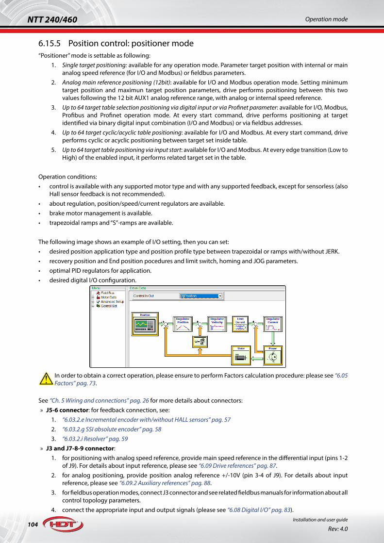
104Installation and user guide
Rev: 4.0
NTT 240/460 Operation mode
6.15.5 Position control: positioner mode“Positioner” mode is settable as following:
1. Single target positioning: available for any operation mode. Parameter target position with internal or main analog speed reference (for I/O and Modbus) or fieldbus parameters.
2. Analog main reference positioning (12bit): available for I/O and Modbus operation mode. Setting minimum target position and maximun target position parameters, drive performs positioning between this two values following the 12 bit AUX1 analog reference range, with analog or internal speed reference.
3. Up to 64 target table selection positioning via digital input or via Profinet parameter: available for I/O, Modbus, Profibus and Profinet operation mode. At every start command, drive performs positioning at target identified via binary digital input combination (I/O and Modbus) or via fieldbus addresses.
4. Up to 64 target cyclic/acyclic table positioning: available for I/O and Modbus. At every start command, drive performs cyclic or acyclic positioning between target set inside table.
5. Up to 64 target table positioning via input start: available for I/O and Modbus. At every edge transition (Low to High) of the enabled input, it performs related target set in the table.
Operation conditions:• control is available with any supported motor type and with any supported feedback, except for sensorless (also
Hall sensor feedback is not recommended).• about regulation, position/speed/current regulators are available.• brake motor management is available.• trapezoidal ramps and “S”-ramps are available.
The following image shows an example of I/O setting, then you can set:• desired position application type and position profile type between trapezoidal or ramps with/without JERK.• recovery position and End position pocedures and limit switch, homing and JOG parameters.• optimal PID regulators for application.• desired digital I/O configuration.
! In order to obtain a correct operation, please ensure to perform Factors calculation procedure: please see “6.05 Factors” pag. 73.
See “Ch. 5 Wiring and connections” pag. 26 for more details about connectors: » J5-6 connector: for feedback connection, see:
1. “6.03.2.e Incremental encoder with/without HALL sensors” pag. 572. “6.03.2.g SSI absolute encoder” pag. 583. “6.03.2.i Resolver” pag. 59
» J3 and J7-8-9 connector:1. for positioning with analog speed reference, provide main speed reference in the differential input (pins 1-2
of J9). For details about input reference, please see “6.09 Drive references” pag. 87.2. for analog positioning, provide position analog reference +/-10V (pin 3-4 of J9). For details about input
reference, please see “6.09.2 Auxiliary references” pag. 88.3. for fieldbus operation modes, connect J3 connector and see related fieldbus manuals for information about all
control topology parameters.4. connect the appropriate input and output signals (please see “6.08 Digital I/O” pag. 83).

105
NTT 240/460Operation mode
Installation and user guide
Rev: 4.0
6.15.6 Position control: electronic cam modeOperation conditions:• control is available with any supported motor type and with any supported feedback, except for sensorless (also
Hall sensor feedback is not recommended).• main position reference can be only frequency reference: CHA-CHB and Pulse-Direction• control is available for I/O and Modbus operation mode.• about regulation, position/speed/current regulators are available.• brake motor management is available.• trapezoidal ramps are available.
The following image shows an example of I/O setting, then you can set:• up to 8 cam tables and up to 576 points per cam with linear or cubic interpolation.• axis rate (Numerator e Denominator) and Master and Slave Module pulses for every cam.• engage, disengage and phase shift position parameters for slave axis, Homing and JOG parameters.• desired I/O configuration and optimal PID regulators for application.
This operating mode allows a control in space of axis related to a space reference acquired from encoder, conditioned by the values of “Encoder Numerator” and “Encoder Denominator”. This function can be used in application that require to follow special curves such as Packaging machines, Flying saw, Flying shear, Cut to Lenght and more.The “Master module” indicates master encoder pulse number used to calculate shape of cam profile. The result of the division of “Master module” and “Number of table points” gives the space range between two consecutive points of the table. The profile of the cam between two points is calculated using a cubic interpolation.The “Slave module” represent the excursion of the cam measured in terms of resolver pulses (the numbers of resolver pulses in a single revolution of the motor shaft is 65535), Every point of the cam table ( that can range from 0 to 65535) is multiply for the “Slave module” and divided for 65536, in this way every point of the cam table can take an effective value ranging from 0 and “Slave module ”.
! In order to obtain a correct operation, please ensure to perform Factors calculation procedure: please see “6.05 Factors” pag. 73.
See “Ch. 5 Wiring and connections” pag. 26 for more details about connectors: » J5-6 connector: for feedback connection, see:
1. “6.03.2.e Incremental encoder with/without HALL sensors” pag. 572. “6.03.2.g SSI absolute encoder” pag. 583. “6.03.2.i Resolver” pag. 59
» J3 and J7-8-9 connector:1. provide the main position reference (pins 1 to 6 of J7). For details about input reference, please see “6.09
Drive references” pag. 87.2. for fieldbus operation modes, connect J3 connector and see related fieldbus manuals for information about all
control topology parameters.3. connect the appropriate input and output signals (please see “6.08 Digital I/O” pag. 83).

106Installation and user guide
Rev: 4.0
NTT 240/460 Operation mode
6.15.7 Pressure controlOperation conditions:• control is available with any supported motor type and with any supported feedback, except for sensorless (also
Hall sensor feedback is not recommended).• control is available for all operation mode.• pressure transducer feedback is only available via analog input for all operation mode.• pressure and speed references via analog input or via fieldbus operation.• about regulation, pressure/speed/current regulators are available.• brake motor management is available.• trapezoidal ramps and “S” ramps are available for speed and pressure.
The following image shows an example of I/O setting, then you can set:• type and fullscale for pressure reference or feedback, and speed/pressure ramps.• speed, current and pressure limit, and overpressure and underpressure alarm threshold.• desired I/O configuration and optimal current/speed PID regulators for application.
• Pressure PID regulator management shown a further exponential (2^) multiplier parameter useful during the tuning of the pressure loop regulation to appreciate visible variations. Default parameter set is a good compromise for the most servo press applications.
! In order to obtain a correct operation, please ensure to perform Factors calculation procedure: please see “6.05 Factors” pag. 73.
See “Ch. 5 Wiring and connections” pag. 26 for more details about connectors: » J5-6 connector: for feedback connection, see:
1. “6.03.2.e Incremental encoder with/without HALL sensors” pag. 572. “6.03.2.g SSI absolute encoder” pag. 583. “6.03.2.i Resolver” pag. 59
» J3 and J7-8-9 connector:1. for I/O operation mode, please see “6.09 Drive references” pag. 87:
• provide pressure transducer feedback in the differential input +/-10V (pins 1-2 of J9).• provide pressure reference in the AUX1 differential input +/-10V (pins 3-4 of J9).• provide speed reference in the AUX2 differential input +/-10V (pins 5-6 of J9).
2. for fieldbus operation modes:• provide pressure transducer feedback in the differential input +/-10V (pins 1-2 of J9).• connect J3 connector and see related fieldbus manuals for information about all control topology
parameters.3. connect the appropriate input and output signals (please see “6.08 Digital I/O” pag. 83).

107
NTT 240/460Operation mode
Installation and user guide
Rev: 4.0
6.16 Closed loop regulation tuning
The tuning procedure is essential to obtain stability and performance of the entire controlled system; the drive, that performs the control, has PID controller both for the current loop that for the speed loop.To perform tuning, please use Caliper software and observe some variables with Scope during operation (see “6.14 Scope function” pag. 94).The following tuning procedure provides good results in most types of controlled systems, if following conditions are met:• drive must be able to provide motor rated current.• load inertia is 6 times grater than motor, maximum.
6.16.1 Current loop tuningIf drive controls an H.D.T. motor, the optimum PID current regulator setting is stored in a motor configuration file, in the directory to save data in PC used*.To perform PID current tuning, it is not essential that the load remains connected to the motor.
! If third parts motor is used, it’s recommended to perform motor autophasing both before and after the PID current tuning (see “6.07 Motor autophasing” pag. 82). Please use an appropriate mechanical brake, in the case of vertical axis load (safety condition required during current loop tuning, due to automatic 90° motor phase autoshifting in order to avoid providing torque.
To perform tuning, please do the following:1. generate a square wave current reference: use ‘Wave Generator’ function into Caliper software to create
desired reference (see “6.14 Scope function” pag. 94). Provide to drive a reference with rated motor current amplitude and period set between 0.05seconds and 0.1seconds.
In this operation, drive provides the rated motor current, so the motor could reach high case temperature.
2. PID current setting: parameters to set are KP e il KI.• set KI = 1: integral action erased.• increase gradually Kp until current resonance appears: in this condition, an evident current resonance
appears in Scope visualization (besides, this condition leads to a motor unusual noise).
• halve KP value: halving KP, system avoids oscillation in transient conditions.• increase gradually KI: increase until misured current variable accurately follows the desired current
reference. In any case, KI parameter should not be greater than 60% of KP previously set.
*To get PID current configuration data related to H.D.T. motor, please contact our technical department.

108Installation and user guide
Rev: 4.0
NTT 240/460 Operation mode
An optimal current loop tuning is shown in picture below:
At the end of PID current tuning, if a third parts motor is used, please perform a ‘Motor Autophasing’ (see “6.07 Motor autophasing” pag. 82).
!NOTES:
• KP and KI optimum values could vary greatly depending on application.• In high inertia systems, resonance may not occur at any KP values lower than maximum set value (2000).
In these cases, set KP equal to 1000 and increase KI until misured current variable accurately follows the desired current reference: repeat entire operation erasing KI and increasing KP at step of 200.
• In any case, it’s recommended to set KP ≤ 1800.
6.16.2 Speed loop tuningSpeed loop tuning must be performed with load connected because time constants depend on dinamic system to control.Speed loop tuning must be performed after current loop tuning and execution step are similar.
! It’s recommended to perform motor autophasing before speed loop tuning (see “6.07 Motor autophasing” pag. 82).
To perform tuning, please do the following:1. generate appropriate cyclic target position: use ‘TEST’ function into Caliper software to create desired
reference (see “6.14 Scope function” pag. 94). Set target position with appropriate acceleration and deceleration parameters according to system dinamic, as shown in the image below:
In these conditions, drive follows a speed and cyclic position reference with ramp parameters: please, pay attention to load during operation.

109
NTT 240/460Operation mode
Installation and user guide
Rev: 4.0
2. PID speed setting: parameters to set are KP e il KI.• set KI = 0: integral action erased.• increase gradually KP until until speed resonance appears: in this condition an evident speed error
and resonance appear in Scope visualization (besides, this condition leads to a motor unusual noise).
• halve KP value: halving KP, system avoids oscillation in transient conditions..• increase gradually KI: increase until misured speed variable accurately follows the desired speed
reference. In any case, KI parameter should not be greater than 40% of KP previously set.
When observing the behavior of the load corresponding to the reference changes, please keep a waveform responce as possible without overshoot (low gain set), but also with enough performance (high gain set). Therefore tuning is always the result of compromises between stability and performance.

110Installation and user guide
Rev: 4.0
NTT 240/460 Operation mode
Images below show tipical step of fisical closed loop system (current loop in the image at the low of graph and speed in the image above of graph).
• Step responce with low proporzional gain: internal current reference, provided by speed regulator, is too slow andlead to overshoots around the constant condition reference, before get stability.Note that, in correspondence with current reference variation (origin of the axes), current loop responds correctly without overshoots; then the problem is caused by speed control gain.
• Step responce with acceptable proporzional gain: current reference is fast enough and speed step responce shows anly one overshoot.In these cases, a too high integral gain, could leads to get more speed overshoots.
P
R
• Step responce with optimum gain:This condition leads to get performance and stability of system.
It’s recommended that noise amplitude R is lower than 15% of peak drive current value.
6.16.3 Position observer tuningObserver function allows to filter motor position information in order to reduce application noise due to speed loop ruggedness, while maintaining sufficiently static and dinamic performances. This function is very usefull when motor provide a low resolution feedback (lower than 1000ppr) or with Hall sensor only applications.Observer function is available with all supported feedback type (sensorless not supported).Position observer tuning must be performed with load connected to motor and only after speed loop tuning is correctly done.
Usefull parameters are a Gain and a Bandwidth; the major filtering effect is due to bandwidth parameter, while observer responce is due to gain parameter, whose default value is correctly set for a lot of application.For a correct and safety tuning, it’s recommended to start with high bandwidth value, for example 300Hz where observer filtering is very low, then decrease this parameter gradually untill the application noise reduction desired is obtained.
! Decreasing parameters excessively could lead to instability condition and to loss of motor controll, with consequently risk of damage equipment.

111
NTT 240/460Operation mode
Installation and user guide
Rev: 4.0
6.17 Sensorless loop tuning
The tuning procedure is necessary in order to obtain entire system stability; drive uses the internal current and speed loop regulator and the sensorless loop regulator together.To perform the procedure, Caliper software is necessary to observe some variables in Scope function during the drive operation (please see “6.14 Scope function” pag. 94).The following tuning procedure provides good results in most types of controlled systems, if following conditions are met:• drive must be able to provide motor rated current.• load inertia is 6 times grater than motor, maximum.• speed ramps must be enabled and lower than 5000RPM/s.
6.17.1 Setting speed/current loop and motor parameters » Regarding motor data, it’s necessary to enter these parameters into Motor Data menu:
• Motor PHASE resistor value in Ω. ATTENTION: If motor datasheet provides PHASE to PHASE resistor, please enter that halved parameter.
• Motor PHASE Inductance (Synchrony) in mH. ATTENTION: If motor datasheet provides PHASE to PHASE inductance, please enter that halved parameter.
• Magnetic flux (Magnet Flow) in Wb using the following formula:
In the previous formula, ‘Ke’ is motor e.m.f. parameter in Vs (Volt x second), ‘P’ is motor poles number.Just in case ‘Ke’ would not be directly provided into datasheet, please use formula below to get the correct parameter by motor e.m.f. (FEMRPM) given at a specified speed (RPM):
Motor data must be set as shown in the picture below:
» Regarding speed and current loop regulators, as main parameters are related to sensorless predictive control, speed and current PID must be set as low as possible in order to avoid to let the system to instability conditions; it’s recommended to set PID parameters (nel sottomenu Advanced Setup) as shown in the table below:
PID Speed Current
Kp 50 120
Ki 10 70
Kd 1 1

112Installation and user guide
Rev: 4.0
NTT 240/460 Operation mode
6.17.2 Setting sensorless parametersThe main window for sensorless setting parameters is shown in the image below, reporting default data:
Covariance-noise window shows sensorless regulation parameters sensorless:• Covariance current: sensorless regulation parameter; range between 0.01 and 650.00;• Covariance speed: sensorless regulation parameter; range between 0.01 and 650.00;• Covariance phase: sensorless regulation parameter; range between 0.0001 and 6.5000;• Current noise: sensorless regulation parameter; range between 0.01 and 650.00;
Parameters start window allows to set:• Starting current: current provided by drive to motor in order to guide the shaft to initial position; this
parameter is percentage related to Nominal current parameter.• Current ramp: ramp, in seconds, to reach starting current.• Initial speed: speed parameter, in RPM, beyond which drive changes control algorithm, from V/F to
sensorless.• Speed Hysteresis: it’s reffered to initial speed; this parameter is shown in RPM.• Speed ramp: ramp, in RPM/s, to reach initial speed from zero speed.• Initial delay: time parameter beyond which drive starts to follow speed reference; the delay is necessary
to let the motor shaft to reach the corrrect start position.
Setting windows allow to set:• Zero crossing mode parameter: it’s available as Continuous or Stop-Start. Continuous mode allows to cross
zero speed without the stop procedure, when a speed reference inversion occurs. Otherwise, Stop/Start mode let the drive to change into V/F control and perform the starting procedure in accordance with parameters shown into Parameters start window.
• Stationing current: when SWITCH-ON command is provided to drive, this parameter shows the 0 speed current that drive must provide to motor; this parameter is percentage related to Nominal current parameter.
• Fault measured speed: speed parameter, in RPM, beyond which drive provides alarm.

113
NTT 240/460Operation mode
Installation and user guide
Rev: 4.0
6.17.3 Sensorless loop tuning
! ATTENTION:• default data do not guarantee a correct sensorless tuning for any motors and must be used only for
initial conditions of the tuning procedure.• during procedure, drive could lose motor control engage and lead to an overrun rotation or to an
unexpected shutdown. Please take safety relatated actions.
For sensorless tuning procedure, it’s necessary to observe the following variables into Scope function of Caliper software:
• current reference• measured current.• speed reference.• measured speed.
» INITIAL PHASE: disconnect load and verify the correct motor phase connection.1. set an internal speed reference whose value must be positive and lower than default initial speed; so, for
example, 50RPM.2. enable the OPERATION ENABLE command neighter with digital input or with Caliper software.3. ensure that motor rotate in clockwise viewing it from shaft; otherwise turn off the drive and invert two
phases of motor, then re-execute 1-2-3 instruction points.
» MIDDLE PHASE: tuning with no load.4. set an internal speed reference whose value must be a bit higher than default initial speed; so, for example,
500RPM. In this condition, motor could rotate in a discontinuous way or even NOT rotate.5. enable the OPERATION ENABLE command and ensure that speed reference is actually brought to the
desired value set into instruction point 4. Otherwise increase or decrease Covariance current parameter; it’s recommended to increase or decrease with steps of 2-5 units. The initial sensorless setting example is shown below. In most cases:• for motor with a PHASE resistor lower than 0.8Ω and a PHASE inductance lower than 0.8mH, parameter
should be increased. When target is reached, please do not exceed beyond with the parameter setting.• for motor with a PHASE resistor higher than 0.8Ω and a PHASE inductance higher than 0.8mH, parameter
should be decreased. When target is reached, please do not exceed beyond with the parameter setting.

114Installation and user guide
Rev: 4.0
NTT 240/460 Operation mode
6. if, with procedure described into instruction point 5, it’s not easy to stabilize correctly the speed reference to the desired value set into instruction point 4, then reset the Covariance current parameter at default value (6) and increase Covariance phase parameter; it’s recommended to increase with steps of 0.01 units, untill the speed reference is correctly stabilized to the desired value set into instruction point 4. When target is reached, please do not exceed beyond with the parameter setting.
7. increase speed reference: for example 700-1000RPM.8. to further reduce the measured speed noise and current reference noise, increase or decrease Covariance
current parameter; it’s recommended to increase or decrease with steps of 2-5 units. In most cases:• for motor with a PHASE resistor lower than 0.8Ω and a PHASE inductance lower than 0.8mH, parameter
should be increased. When target is reached, please do not exceed beyond with the parameter setting.• for motor with a PHASE resistor higher than 0.8Ω and a PHASE inductance higher than 0.8mH, parameter
should be decreased. When target is reached, please do not exceed beyond with the parameter setting.9. if necessary, to reduce the measured current noise and consequently the measured speed noise, increase
or decrease Current noise parameter; it’s recommended to increase or decrease with steps of 2-5 units. In most cases:• for motor with a PHASE resistor lower than 0.8Ω and a PHASE inductance lower than 0.8mH, parameter
should be increased. When target is reached, please do not exceed beyond with the parameter setting.• for motor with a PHASE resistor higher than 0.8Ω and a PHASE inductance higher than 0.8mH, parameter
should be decreased. When target is reached, please do not exceed beyond with the parameter setting.10. if necessary, it’s possible to act further on Covariance phase parameter to reduce the no load current of the
drive; however, in this way the measured speed noise increases. This solution could be usefull with low power/current motors.
11. now perform again all instruction points 8-9-10, increasing the speed reference with steps of 200-500RPM untill the desired application speed is reached. Note that the tuning performed at 500RPM could NOT be excellent for 2000RPM and vice versa. It’s recommended to iterate the procedure with steps untill the desired speed is reached and then perform an excellent sensorless tuning. The picture below shows that setting is not excellent at 500RPM, but it’s excellent for speed higher than 1000RPM.
12. to further reduce the measured current noise and measured speed noise at 500RPM (see previous image), it’s possible to decrease Covariance current parameter again: but this solution does NOT guarantee that tuning will be excellent at 2000RPM. For this reason, the tuning procedure requires an iteration with increasing steps for speed reference, in order to avoid abnormal behaviours that may occur if the speed reference changes from 500RPM to 3000RPM without an excellent tuning in the range.

115
NTT 240/460Operation mode
Installation and user guide
Rev: 4.0
13. Covariance speed parameter takes effect only for output frequency above 500Hz. In applications where these frequencies or above are necessary, usually speed noise or speed resonance may occurs; it’s recommended to decrease Covariance speed parameter with step of 0.1 or 0.2 units untill the measured the speed is correctly stabilized to the desired value.
14. to increase performances during speed reference invertion, set zero crossing parameter to continuous value and perform an reference invertion. The speed sensorless control performs a commutation that may cause an abnormal rotation, during a zero crossing reference. Just in case the zero crossing may lead to drive alarms, with consequently loss of motor control, try to further decrease speed and current PID regulators (especially the integral action Ki) or set zero crossing parameter to stop/start value.
» END PHASE: load connected15. it’s possible to act further to all parameter described to get the excellent sensorles control tuning with load
connected agire ulteriormente sui parametri precedentemente descritti per ottenere un tuning ottimale in condizione di carico. In most cases, the excellent parameters with load are not much different to parameters get with no load, if the following conditions are met:• drive must be able to provide motor rated current.• load inertia is 6 times grater than motor, maximum.• speed ramps must be enabled and lower than 5000RPM/s.
!NOTES:
• factors are enabled: in order to ensure the correct function, it’s recommended to perform an automatic calculation; si veda “6.05 Factors” pag. 73.
• the use of sensorless control with ramps higher than 5000RPM are allowed, but, during fast transient reference changes, instability may occure; this instability condition may not occure with slower dynamics.
• into the scope function, it’s recommended to set fixed scale for all variables and, in order to observe the correct overlap of traces, it’s further recommended that scale for reference and related measured variables are the same.
• it’s recommended to keep visible on PC monitor both the main Caliper window and the Scope window appropriately scaled; in this way, it’s easy to set sensorless parameters on Caliper main window observing effects on scope window.

116Installation and user guide
Rev: 4.0
NTT 240/460 S.T.O. safety circuit
Ch. 7 S.T.O. safety circuit
S.T.O. safety circuit (Safe Torque Off) is realized with IEC EN 61800-5-2 law reference conformal, 0 stop category, and with IEC61508 law reference for SIL3.
The a.c. induction motor requires a rotating magnetic field to produce torque. This requires a threephase source of alternating current at the connections. The drive has a single internal d.c. power supply available which is converted to a.c. by a continuous active switching action of the six power semiconductor devices.
The Safe Torque-Off (STO) feature of NTT 240/460 drive is made of a redundant electrical circuit designed to bring a drive to a state of safe torque absence. It is a feature used to prevent unexpected motor rotation in case of emergency without the necessity to interrupt power supply. When STO function is active, the servodrive and the motor are in a state of functional safety, which means that is impossible to cause an active rotation of motor shaft or, if it is alredy rotating, it stops by inertia.
The safety stop category 0 is achieved with the immediate disconnection of electronic components (IGBT) capable of system energization, that cause an uncontrolled stop of the axis, by inertia.
It is usual, in the applications where there isn’t a drive equipped with STO, to secure the system interrupting the power supply using a contactor of adequate capacity. Using a STO it is possible to eliminate the contactor allowing economical advantage, space saving in the cabinet and achieving an higher level of integrity.
Principle diagram for drive without STO safety circuit is shown below:
Hardware enable
Interface µP PWMControl
Opto(6)
Power(6)
StopStart
UserI/O
Tomotor
The commutation signals are transmitted from the complex control circuit of the PWM to the IGBTs by optocouplers that use light-emitting diodes (LED) for the transmission of simple on/off commands through the electrical isolation barrier. In the Secure Power Disable system shown in Figure_2, the LED power is provided by a safety circuit from the two enable inputs (STO IN 1, STO IN 2). The switching sequence can reach the IGBTs only if the two enable inputs are present, or if therehas been a highly improbable combination of undetected errors, which allowed both the two enable inputs to receive power supply. If the STO signal is inactive, the drive is certainly disabled through the loss of power of the LEDs and by the microprocessor.!
NOTES:• Failure of an individual IGBT or their drive circuits either into the on or in the off state cannot generate
torque, but when a permanent magnet motor such as a servo motor is used, a single torque transient could be produced by a multiple IGBT failure. The motor can rotate at the maximun of 360°/p, where p is the number of poles.

117
NTT 240/460S.T.O. safety circuit
Installation and user guide
Rev: 4.0
Principle diagram for drive with STO safety circuit is shown below:
Interface µPPWM
ControlOpto
(6)Power
(6)
Stop
Start
STO1
STO2
UserI/O
Tomotor
Fail-safe Interface
1. Safety function Safe Torque Off (STO)When the two drive enable inputs STO IN 1, STO IN 2 are not connected, the drive is in a high integrity disabled state. It will not produce torque in the motor even if internal faults are present. The drive remains active: its internal circuits are working, parameters can be modify, signal inputs and outputs are active and it keeps communicating. Instead, when the twoenable inputs are connected to a digital level of +24V nominal, the drive operates normally.
2. How to use Safe Torque Off (STO)
ATTENTION!!!Normally, drive is provided with J11 connector with bridge cables between 3-4-5 pins; in this condition, user
shall not consider the drive to be in Safe State. In order to use correctly the Safety Function STO, please take off all bridge cables and wire external contacts.
Secure Power Disable is used in exactly the same way as a conventional enable input, so all existing applications remain the same. In addition it disables the drive with a very high integrity, so that it can be used in safety-related applications.
1+24V IN
2GND IN
3STO IN1
+24V OUT +24V OUT
STO IN2
4
5
1+24V IN
2
GND IN
GND STO
3STO IN1
+24V STO
STO IN2
4
5
J11 CONNECTOR(STO connection with internal supply)
J11 CONNECTOR(STO connection with external supply)
drive internal connection
It can also be used in other applications where a highly reliable disable function is required. For example, it is common for a start/stop function to use a simple reliable contactor latch circuit in order to avoid expensive, non-safety-related damage from inadvertent start-up. Secure Power Disable can eliminate the use of a contactor.
3. STO does not provide motor brakingIf a running drive is disabled, it immediately ends to produce torque, either motoring or braking. The motor continue to run by its inertia untill it stops.

118Installation and user guide
Rev: 4.0
NTT 240/460 S.T.O. safety circuit
4. STO does not provide electrical isolation of the drive output.If access is needed to the electrical connections of the motor circuit, an approved isolation device must isolate the drive power input. The required discharge time that must spent before access is permitted is usually about 10 minutes.
5. STO cannot detect if the two enable inputs have been energised both inadvertently.If both the two input channel STO IN 1, STO IN 2 have been inadvertently connected to a positive digital signal within the specified range, the drive will be enabled.The probability of this happening is very low. However, to ensure the maximun integrity, during installation the wiring must be protected from accidental contact with digital signals or supplies.
6. Special RequirementThe output of SDP should be monitored at every intervention of the safety circuit by user. If the STO output is not active, with both the two STO inputs de-energized, it means that at least one of the two safety circuits is faulty and therefore the drive must be send to repaired. STO output is managed by microcontroller and for this reason, it’s not considered as a secure output.STO output follows graphs below:
SPD IN 1 channel
SPD IN 2 channel
SPD output(OUT1-2)
SPD IN 1 channel
SPD IN 2 channel
SPD output(OUT1-2)
>5ms 100ms 100ms
FA08Safe State Drive not OKDrive OK Drive not OK
FA08Safe State
FA18 o FA23Avaria Hardware
De-energize condition for SPD IN 1 e SPD IN 2 channels
Drive not OKDrive OKDrive OK
>5ms 100ms
FA08Safe State
FA08Safe State
FA18 o FA23Avaria Hardware
Energize condition for SPD IN 1 e SPD IN 2 channels
Drive not OK
100ms
FA08Safe State
A special requirement is needed for the use of protected wiring to the two enable (STO IN 1, STO IN 2) inputs, in order to exclude the possibility of a short-circuit to a positive supply (see box below). Is reccomanded, under UNI EN ISO 13849-2 law, the use of protected wiring.
PROTECTED WIRINGProtected wiring is arranged so that no short circuit is credible to any source of voltage which might cause a
failure in the unsafe direction. A practical implementation is either: Fully segregated in dedicated trunking etc. or
Screened, with the screen connected to ground, in a positive-logic grounded control circuit.
7. Caratteristiche dei contatti esterniWith mechanical contacts, it’s mandatory that activation or deactivation latency time will be less than 100ms (including any rebounds for mechanical contacts within 20ms). It’s recommended to use contact that allows activation and deactivation delay to be less than 50ms, or please use contacts that are granted by external STO Safety Function approved modules.

119
NTT 240/460S.T.O. safety circuit
Installation and user guide
Rev: 4.0
8. Operations relating to the functions of the STO
STO INPUT STATUS DRIVE STATUS MOTOR BEHAVIOUR
DISPLAY SIGNALING
STO OUTPUT (OUTx)
DE-ENERGIZED
OPERATION ENABLED Stop by inertia FA08 1
SWITCH-ON Free FA08 1
SWITCH-OFF Free FA08 1
ENERGIZED
OPERATION ENABLED Turns RUN 0
SWITCH-ON Still in torque ENA 0
SWITCH-OFF Free STOP 0
9. Fault management on the STO circuitSTO circuit faults are detected when the STO input is de-energized.
STO CHANNEL DRIVE STATUS MOTOR
BEHAVIOURHOW TO
INTERVENTDISPLAY
SIGNALINGSTO OUTPUT
(OUTx)
STO IN1
OPERATION ENABLED Stop by inertia Repair needed FA18 0
SWITCH-ON Free Repair needed FA18 0
SWITCH-OFF Free Repair needed FA18 0
STO IN2
OPERATION ENABLED Stop by inertia Repair needed FA23 0
SWITCH-ON Free Repair needed FA23 0
SWITCH-OFF Free Repair needed FA23 0
For further information about drive status and error descriptions, please see “Ch. 8 Drive status and diagnostics” pag. 120.
ATTENTION!!!TURN ON THE MACHINE WITH THE STO1 AND STO2 INPUT SIGNALS DE-ENERGIZED
TO VERIFY THAT THE SAFETY CIRCUIT IS WIRING IN THE CORRECT WAY AND THAT IT IS INTACT WHITIN THE DRIVE:
FA08 ALARM MUST OCCURE AND THE STO OUTPUT MUST BE ACTIVE .

120Installation and user guide
Rev: 4.0
NTT 240/460 Drive status and diagnostics
Ch. 8 Drive status and diagnostics
8.01 Drive status
Main drive status, during operation, are visible on d.0000 display parameter, and description is shown below:
STATUS CONDITIONDISPLAYd.0000
DESCRIPTION
SWITCHOFF
Drive OK “STOP” Drive does not provide torque to motor and shows Drive OK condition.
FAULT - Warning “F xx” o “FA xx” Drive does not provide torque to motor and shows Fault condition or Warning condition.
SWITCHON
Drive OK “ENA” Drive keeps motor in standstill torque and shows Drive OK condition.
Warning “F xx” Drive keeps motor in standstill torque and shows Warning condition.
OPERATIONENABLED
Drive OK “RUN” Drive provides torque to motor following references and shows Drive OK condition.
Warning “F xx” Drive provides torque to motor following references and shows Warning condition.
8.02 Fieldbus status signaling
During Ethercat CoE and Profinet operation modes, other LEDs provide following bus status:• LINK and ACTIVITY (Green and Yellow LEDs on each port of J3 connector) show status for ethernet comunication.• state machine identification during Ethercat operation mode with green LED or Bus Failure identification during
Profinet operation mode with red LED.
ETHERCAT PROFINET
FIELD BU
S
OUT
IN
J3
FIELD BU
S
OUT
IN
J3
FIELD BU
SJ3
FIELD BU
S
OUT
IN
J3
123456
B
A8
1
8
1
Act
Link/Act
Act
Run
Link/Act
Act
Link/Act
Act
Link/Act
BusFailure
B
A
1
8
1
8
B
A8
1
8
1
FIELD BU
S
OUT
IN
J3
FIELD BU
S
OUT
IN
J3
FIELD BU
S
J3
FIELD BU
S
OUT
IN
J3
123456
B
A8
1
8
1
Act
Link/Act
Act
Run
Link/Act
Act
Link/Act
Act
Link/Act
BusFailure
B
A
1
8
1
8
B
A8
1
8
1
“RUN”(green)
LEDstatus
“BUS FAILURE”(red)
Inizialisation Off Active comunication link
Pre-Operational flashing Status OK / NO Comunication
Safe-Operational single flash -
Operational On No link available

121
NTT 240/460Drive status and diagnostics
Installation and user guide
Rev: 4.0
8.03 Diagnostics
Alarms (display view as “FA xx”) and warnings (display view as “F xx”) can be reset by related command, depending on set operation mode (RESET digital input or RESET key in Caliper software or RESET command in fieldbus operation). If logic supply is turned off, alarms/warnings will be reset.To learn error-code details, use Caliper software and see ‘Advanced Setup - Alarm Memory’ section.
!When an alarm occures, drive immediatly can stop providing current to motor or can perform the FAult Reaction precedure; instead, in some warning situations, drive can hold motor control (this feature can be set via Caliper software).
Alarms /warnings codes, descriptions and solutions are shown below:
ERROR ID DESCRIPTION SOLUTION RESETFAULTREACT.
EEPROMCORRUPTEDDATA
FA01 An error occured while attempting to read EEPROM memory data.Drive stops providing current and ‘Drive OK’ condition is disabled.
This alarm code may result in EE-PROM memory data loss.It requires a default data upload and then a new customer data upload, with riserved data too.
NO NO
CURRENTSENSORS
FA02 An error occured while attempting to read signals from inverter cur-rent sensors.Drive stops providing current and ‘Drive OK’ condition is disabled.
At least, one of inverter current sen-sors has failed.A repair from technical and designa-ting person is required.
NO NO
OVERCURRENT
FA03 Drive has detected an overcurrent condition in inverter current rea-ding signals.Drive stops providing current and ‘Drive OK’ condition is disabled.
Please remove U,V,W cable from dri-ve wirings and try OPERATION ENA-BLED status in this condition.If alarms still occures, a repair from technical and designating person is required.If alarm does not occure please en-sure:• any short-circuits between motor
phases or phase to Power Earth may occur.
• that current loop gain coefficients are correctly set.
YES NO
OVERVOLTAGE
FA04 Drive has detected an overvoltage condition in DC bus voltage rea-ding signals.Drive stops providing current and ‘Drive OK’ condition is disabled.
Please ensure that power supply vol-tage is within expected range.If alarm occures during braking ope-rations, try to connect an appropria-te external braking resistor.
YES NO
VOLTAGEFAULT
FA05 Drive has detected supply voltage fault or 2 phase lack for triphase supply, at least.Drive stops providing current and ‘Drive OK’ condition is disabled.
Disable alarm if drive is supplied by DC voltage.It’s possible to set:• AUTO RESET when 2 phases are
present at least (only with FA06 disabled).
• RESET signal request.
YES YES
PHASEFAULT
FA06 Drive has detected voltage fault for 1 phase of triphase supply.Drive stops providing current and ‘Drive OK’ condition is disabled.
Please, verify if power cables are OK or if input power supply fuses are OK.
YES YES
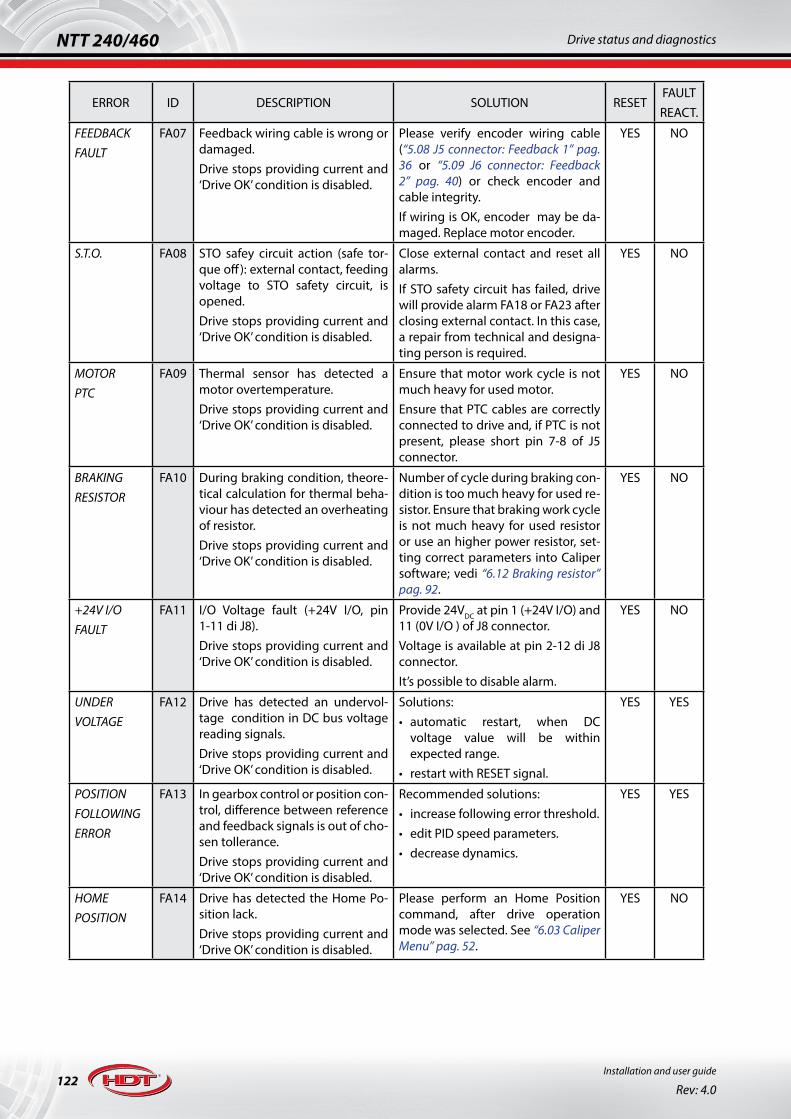
122Installation and user guide
Rev: 4.0
NTT 240/460 Drive status and diagnostics
ERROR ID DESCRIPTION SOLUTION RESETFAULTREACT.
FEEDBACKFAULT
FA07 Feedback wiring cable is wrong or damaged.Drive stops providing current and ‘Drive OK’ condition is disabled.
Please verify encoder wiring cable (“5.08 J5 connector: Feedback 1” pag. 36 or “5.09 J6 connector: Feedback 2” pag. 40) or check encoder and cable integrity.If wiring is OK, encoder may be da-maged. Replace motor encoder.
YES NO
S.T.O. FA08 STO safey circuit action (safe tor-que off): external contact, feeding voltage to STO safety circuit, is opened.Drive stops providing current and ‘Drive OK’ condition is disabled.
Close external contact and reset all alarms.If STO safety circuit has failed, drive will provide alarm FA18 or FA23 after closing external contact. In this case, a repair from technical and designa-ting person is required.
YES NO
MOTORPTC
FA09 Thermal sensor has detected a motor overtemperature.Drive stops providing current and ‘Drive OK’ condition is disabled.
Ensure that motor work cycle is not much heavy for used motor.Ensure that PTC cables are correctly connected to drive and, if PTC is not present, please short pin 7-8 of J5 connector.
YES NO
BRAKINGRESISTOR
FA10 During braking condition, theore-tical calculation for thermal beha-viour has detected an overheating of resistor.Drive stops providing current and ‘Drive OK’ condition is disabled.
Number of cycle during braking con-dition is too much heavy for used re-sistor. Ensure that braking work cycle is not much heavy for used resistor or use an higher power resistor, set-ting correct parameters into Caliper software; vedi “6.12 Braking resistor” pag. 92.
YES NO
+24V I/OFAULT
FA11 I/O Voltage fault (+24V I/O, pin 1-11 di J8).Drive stops providing current and ‘Drive OK’ condition is disabled.
Provide 24VDC at pin 1 (+24V I/O) and 11 (0V I/O ) of J8 connector.Voltage is available at pin 2-12 di J8 connector.It’s possible to disable alarm.
YES NO
UNDERVOLTAGE
FA12 Drive has detected an undervol-tage condition in DC bus voltage reading signals.Drive stops providing current and ‘Drive OK’ condition is disabled.
Solutions:• automatic restart, when DC
voltage value will be within expected range.
• restart with RESET signal.
YES YES
POSITIONFOLLOWINGERROR
FA13 In gearbox control or position con-trol, difference between reference and feedback signals is out of cho-sen tollerance.Drive stops providing current and ‘Drive OK’ condition is disabled.
Recommended solutions:• increase following error threshold.• edit PID speed parameters.• decrease dynamics.
YES YES
HOMEPOSITION
FA14 Drive has detected the Home Po-sition lack.Drive stops providing current and ‘Drive OK’ condition is disabled.
Please perform an Home Position command, after drive operation mode was selected. See “6.03 Caliper Menu” pag. 52.
YES NO

123
NTT 240/460Drive status and diagnostics
Installation and user guide
Rev: 4.0
ERROR ID DESCRIPTION SOLUTION RESETFAULTREACT.
I2TDRIVEWARNING
F15 Theoretical drive temperature, due to provided current to load, exceeded maximum threshold.Drive continuous to operate nor-mally, but maximum provided cur-rent is equal to drive rated current.
During initial start-up, please ensu-re a correct motor and drive wiring. Ensure that working cycle to be per-formed is not too much hard for se-lected drive.Ensure that control loop parameters (speed) are not heavy.If application allows, increase ramp times.
YES NO
I2TMOTORWARNING
F16 Theoretical motor temperature, due to provided current from dri-ve, exceeded maximum 100°C ΔT threshold.Drive continuous to operate nor-mally, but maximum provided current is equal to motor rated current.
Ensure that working cycle to be per-formed is not too much heavy for used motor.Ensure that control loop parameters (speed) are not heavy.If application allows, increase ramp times.Ensure that ‘I2T Time’ value, set in Motor Data section via Caliper, is correct for used motor.
YES NO
OVERSPEEDWARNING
F17 Maximum velocity value, set in Advanced Setup - Limiter section via Caliper, exceeded threshold.Drive continuous to operate nor-mally, showing warning condition.
Please ensure that ‘Speed Limit’ pa-rameter is at least 10% upper than maximum reachable speed.Ensure that speed loop parameters do not generate high speed over-shoot.
YES NO
CH1STO
FA18 Redundant n°1 channel of safety circuit is broken.
If external environment cable is cor-rectly set, a repair from technical and designating person is required.
NO NO
TARGETOUTSIDEWARNING
F19 During position control, drive has detected that position reached is different to target position.Drive continuous to operate nor-mally, showing warning condition.
Drive received an external signal and has been stopped during positio-ning; for this reason it was not able to reach target position.Verify if commands sent to drive are OK
YES NO
FIELDBUS FA20 Canopen® Node Guarding error occures or Time out error Modbus occures.Drive stops providing current and ‘Drive OK’ condition is disabled.Depending on settings, drive stops providing current or decele-rates in ramp.
Restore fieldbus comunication.See “5.05 J3 connector: CM option configuration” pag. 33.
YES YES
BROKENEEPROM
FA21 EEPROM memory does not re-spond.Drive stops.
A repair from technical and designa-ting person is required.
NO NO

124Installation and user guide
Rev: 4.0
NTT 240/460 Drive status and diagnostics
ERROR ID DESCRIPTION SOLUTION RESETFAULTREACT.
MOTORPHASES
F22 During motor autophasing, drive has detected a wrong wiring con-nection.If SWITCH-ON command is able, motor could run without control.
Depending on used motor, recom-mended solutions are:• H.D.T. motor: ensure the correct
wiring between drive and motor, then execute motor autophasing. See “5.02 J1 connector: motor power connection” pag. 28 e “6.07 Motor autophasing” pag. 82.
• Third party motor: invert 2 motor phases, then execute motor autophasing.
YES NO
CH2STO
FA23 Redundant n°2 channel of safety circuit is broken.
If external environment cable is cor-rectly set, a repair from technical and designating person is required.
NO NO
OVERTEMP.
FA24 Heatsink temperature exceeded maximum threshold.Drive stops providing current and ‘Drive OK’ condition is disabled.
Recommended solutions:• wait some minutes before
restarting drive.• ensure ambient temperature to be
lower than 40°C.
YES NO
HALL ENSORSSEQUENCE ERROR
FA25 Drive detected a wrong HALL se-quence.Drive stops providing current and ‘Drive OK’ condition is disabled.
Recommended solutions:• connect correctly HALL sensors.
YES NO
SPEEDERROR
FA26 In Canopen mode, in profile velo-city mode, drive detected a speed error depending on velocity win-dow and velocity window time parameters.Drive stops providing current and ‘Drive OK’ condition is disabled.
Recommended solutions:• increase velocity window and
velocity window time parameters.• if application allows, decrease
acceleration and deceleration ramp parameters.
• ensure that there are not any barriers or obstacles during movement.
YES NO
I2TDRIVEALARM
FA27 Theoretical drive temperature, due to provided current to motor, exceeded maximum threshold and drive continued to provide current beyond set time.Drive stops providing current and ‘Drive OK’ condition is disabled.
During initial start-up, please ensure a correct motor and drive wiring.Ensure that there are no obstacles along the axis stroke.
YES NO
I2TMOTORALARM
FA28 Theoretical motor temperature, due to provided current from dri-ve, exceeded maximum 100°C ΔT threshold and drive continued to provide current beyond set time.Drive stops providing current and ‘Drive OK’ condition is disabled.
Ensure that working cycle to be per-formed is not too much heavy for used motor.
YES NO
DC BUSSYMMETRY
FA29 Drive has detected that DC bus symmetry is out of range.Drive stops providing current and ‘Drive OK’ condition is disabled.
Disconnect power supply by the dri-ve immediatly.A repair from technical and designa-ting person is required.
YES NO

125
NTT 240/460Drive status and diagnostics
Installation and user guide
Rev: 4.0
ERROR ID DESCRIPTION SOLUTION RESETFAULTREACT.
OVERPRESSURE
FA30 Drive detected hydraulic over pressure condition from pressure transducer.Drive stops providing current and ‘Drive OK’ condition is disabled.
Ensure that transducer cable is whole and correct. Ensure also that transducer works properly.Check pressure parameter set into drive are correct.Ensure, via Caliper, that analog input reads correctly, otherwise a repair from technical and designating per-son is required.
YES NO
UNDERPRESSURE
FA31 Drive detected hydraulic under pressure condition from pressure transducer.Drive stops providing current and ‘Drive OK’ condition is disabled.
Ensure that transducer cable is whole and correct. Ensure also that transducer works properly.Check pressure parameter set into drive are correct.Ensure, via Caliper, that analog input reads correctly, otherwise a repair from technical and designating per-son is required.
YES NO

126Installation and user guide
Rev: 4.0
NTT 240/460 Accessories
Ch. 9 Accessories
Caliper 4 setup cable CODE: CNTPRG53Description
USB cable for drive setting and tuning via Caliper 4 software.Shielded, shield connected to both side of connector plugs.For any informations about connections, please see “5.07 J4 connector: drive settings” pag. 35.
Type: USB A to micro B shielded for USB 2.0
Poles: 5pin standard
Total lenght: 3m
Termination resistors for Canopen and Modbus CODE: CNTETH00Description
Termination resistors connection for Canopen and Modbus network.
Type: RJ45
Termination value:120Ω between CAN H to CAN L120Ω between MODBUS + to MODBUS -
Total lenght: 40mm
Multiple drives fieldbus wiring patch cable: CODE: CNTETH01Description
Multiple NTT 240/460 drives wiring cable for cascade connection in fieldbus operation.Shielded FTP Cat. 5E EIA/TIA568B.
Type: RJ45 / RJ45 Shielded FTP
Poles: 8 pin-to-pin EIA/TIA568B
Total lenght: 250mm

127
NTT 240/460Accessories
Installation and user guide
Rev: 4.0
EMC filters for NTT 460Description
Type: 2 x (3xCM) + 3 x (1xDM)
Note: dimension in mm.Bolt connection.
Rated current
CODETDC10 10A@40°C
TDC20 20A@40°C
EMC filters for NTT 460Description
PE
Terminals
Type: 3 x (3xCM) Note: dimension in mm and terminal connection
Rated current L1 L2 L3 L4 B1 B2 H1 Connection
CODE
CNW207/35 35A@40°C
335 320 305
400
60 35 150
4
CNW207/50 50A@40°C500 5
CNW207/65 65A@40°C
CNW207/80 80A@40°C
380 364 350 - 178 130 220
6
CNW207/100 100A@40°C 7
CNW207/150 150A@40°C8
CNW207/200 200A@40°C

128Installation and user guide
Rev: 4.0
NTT 240/460 Accessories
Braking external resistor for NTT 460 20/40 e 35/70 CODE: RF39R1300WDescription
30
215
60
197
500
Value 39Ω Note: dimension in mm.For 35/70 size, it’s recommended to use two same resistor parallel connected.
Rated/peakpower
300W / 1300W
Please contact H.D.T. technical/sales department for further resistance and power values.


VICENZA
TREVISO
VENEZIAMILANO
THIENE
MALO
SS46 SS46
A4VICENZA EST
VICENZA OVEST
VICENZA NORD
DUEVILLE
THIENESCHIO
PIOVENE
A4
A31
VALDAGNOPriabona
MONTE DI MALOSCHIO
VICENZA
Via S i le
MALO
SCHIO
HDTHDT
H.D.T. s.r.l.www.hdtlovato.com
via Sile 8, 36030 Monte di Malo (VI)Tel. +39. (0) 445.602744 r.a. – Fax +39. (0) 445.602668