NSIRC 2016 Annual Conference booklet - TWI Global
96
1 NSIRC Annual Conference 27-28 June 2016
-
Upload
khangminh22 -
Category
Documents
-
view
1 -
download
0
Transcript of NSIRC 2016 Annual Conference booklet - TWI Global

1
NSIRC Annual Conference27-28 June 2016

2
The National Structural Integrity Research Centre (NSIRC) was established in October 2012 with the aim of becoming the world centre for structural integrity research.
NSIRC is a state-of-the-art postgraduate engineering facility established and managed by structural integrity specialist TWI, working closely with lead academic partner Brunel University London, the Universities of Cambridge and Manchester, and a number of industrial partners. The collaborating partners provide academic excellence to address the need for fundamental research, as well as high-quality, industry-relevant training for the next generation of structural integrity engineers.
NSIRC is committed to high-quality teaching combined with industrial experience and student support.
NSIRC advances fundamental research to:• support the safe operation of products and structures• develop innovative, fit-for-purpose technologies and design rules• demonstrate solutions for long-term asset management.
This includes risk-based management, engineering critical assessment, non-destructive testing, structural health and condition monitoring, and health management for use in industrial applications.
Our VisionTo be a world-renowned
centre of industrially driven academic excellence in the
field of structual integrity.
NSIRC is funded by the Department for Business, Innovation and Skills (BIS) through its Regional Growth Fund (RGF) and The Higher Education Funding Council for England (HEFCE).
About NSIRC

3
Welcome to the second annual conference of the National Structural Integrity Research Centre (NSIRC). We are delighted to see so many of our academic partners and sponsors attending and we thank you for your continued support. We are looking forward to an interesting two days ahead.
The Centre is a postgraduate education and research centre established in 2012 to train over 500 postgraduate qualified engineers and employ 61 professionals in its first ten years. To date it has outperformed its objectives.
NSIRC has made significant strides towards achieving its long-term goals. Its major achievements include the following:
� providing the opportunity for 66 postgraduate and research students to work at a state-of-the-art facility to enhance their knowledge and make scientific breakthroughs
� launching the first Lloyd’s Register Foundation open call for PhD proposals, which recieved applications from over 20 Universities worldwide
� internationalising through partnerships with Universities in Malaysia, Lithuania, South Korea, Denmark and Singapore
� promoting the inclusion of underrepresented communities in engineering (eg 40 percent of NSIRC students are women against a UK engineering workforce representation of 9 percent);
� increasing our network of academic partners via signed agreements with 21 Universities to date � the graduation of the first cohort of MSc in Structural Integrity students at a memorable
ceremony held in December at Brunel University London.
Internationalisation is at the core of NSIRC; we partner with world-leading academic and industrial institutions to deliver excellent research. NSIRC continues to transform from a national research centre into the international research centre of choice for structural integrity.
Our continual improvement and ongoing success has been assured by the effort and dedication of the NSIRC, TWI and university staff, and the support of our sponsors. I would like to express my sincere gratitude to everyone involved.
Professor Tat-Hean Gan, NSIRC Research and Technology Director

44
Joanne CooperLibrarian
Jemma ForteyQAS
Laura Mur�nIntellectual Property
Nenad DjordjevicLecturer in Structural Integrity
Brunel University London
Tom de VuystSenior Lecturer in Structural Integrity
Brunel University London
Kevin HughesSenior Lecturer in Structural Integrity
Brunel University London
James CampbellReader in Structural IntegrityBrunel University London
Tat-Hean GanDirector of Technology
Alison DoddAdministrator
Eddie WattsLab Manager
Academic Staff based at NSIRC
Catherine WellsAdministrator
Brunel University London
Kim BarrattMarketing
Abbas MohimiOperations (technical)
Paul JonesLibrarian
Ameni LounissiOperations (procedures)
Heather ClaxtonOperations (procedures)
Emma TaylorHR Co-ordinator
Chellappan ThirunavukkarasuOperations (technical)
Tom CraddockCommercial O�cer
Lucy DayMarketing Administrator
Tariq SattarLSBIC Director
London South Bank (LSBU)
Stuart LemanskiSenior Lecturer in Stress Analysis
Coventry University
NSIRC Operations Team
Research at Brunel University LondonBrunel University London has a long history of collaboration with TWI, leading to the establishment of the Brunel Innovation Centre (BIC) in 2009. BIC is a joint venture between both institutions whose mission is to develop high quality research in the field of acoustic wave propagation, including non-destructive testing, signal and image processing, instrumentation, sensors and electronics, etc. Since its inception, BIC has participated in R&D projects in guided wave technology worth over £20M of funding and involving over 50 academic and industrial partners.
Brunel University London is the lead academic partner in NSIRC, having received £15M of funding from HEFCE in 2012 for its creation. Brunel currently has 30 PhD and 10 MSc students based at NSIRC. The research at Brunel is carried out within the Institute of Materials and Manufacturing, comprising the following themes:
structural integritymaterials characterisation and processingliquid metal engineeringmicro-nano manufacturingdesign for sustainable manufacturing
Our research on structural integrity is very diverse and includes topics such as structural health monitoring, damage detection, dynamic and high rate loading, ultrasound wave propagation in solids and structures, fatigue and fracture, composite materials, fluid-structure interaction.
www.brunel.ac.uk

54
Joanne CooperLibrarian
Jemma ForteyQAS
Laura Mur�nIntellectual Property
Nenad DjordjevicLecturer in Structural Integrity
Brunel University London
Tom de VuystSenior Lecturer in Structural Integrity
Brunel University London
Kevin HughesSenior Lecturer in Structural Integrity
Brunel University London
James CampbellReader in Structural IntegrityBrunel University London
Tat-Hean GanDirector of Technology
Alison DoddAdministrator
Eddie WattsLab Manager
Academic Staff based at NSIRC
Catherine WellsAdministrator
Brunel University London
Kim BarrattMarketing
Abbas MohimiOperations (technical)
Paul JonesLibrarian
Ameni LounissiOperations (procedures)
Heather ClaxtonOperations (procedures)
Emma TaylorHR Co-ordinator
Chellappan ThirunavukkarasuOperations (technical)
Tom CraddockCommercial O�cer
Lucy DayMarketing Administrator
Tariq SattarLSBIC Director
London South Bank (LSBU)
Stuart LemanskiSenior Lecturer in Stress Analysis
Coventry University
NSIRC Operations Team
Research at Brunel University LondonBrunel University London has a long history of collaboration with TWI, leading to the establishment of the Brunel Innovation Centre (BIC) in 2009. BIC is a joint venture between both institutions whose mission is to develop high quality research in the field of acoustic wave propagation, including non-destructive testing, signal and image processing, instrumentation, sensors and electronics, etc. Since its inception, BIC has participated in R&D projects in guided wave technology worth over £20M of funding and involving over 50 academic and industrial partners.
Brunel University London is the lead academic partner in NSIRC, having received £15M of funding from HEFCE in 2012 for its creation. Brunel currently has 30 PhD and 10 MSc students based at NSIRC. The research at Brunel is carried out within the Institute of Materials and Manufacturing, comprising the following themes:
structural integritymaterials characterisation and processingliquid metal engineeringmicro-nano manufacturingdesign for sustainable manufacturing
Our research on structural integrity is very diverse and includes topics such as structural health monitoring, damage detection, dynamic and high rate loading, ultrasound wave propagation in solids and structures, fatigue and fracture, composite materials, fluid-structure interaction.
www.brunel.ac.uk

6
“The NSIRC conference provides insight into the demands and interests
needed by industry”
- Jialin Tang, NSIRC PhD Student

7

BP and the National Structural Integrity Research Centre BP was the first company to become a founder sponsor of the Structural Integrity Research Foundation (SIRF) – beginning the latest chapter in a long history of collaboration between the company and TWI.
As one of the world’s leading oil and gas companies, BP operates in extremely demanding environments. It works in some of the deepest waters in the world, where reservoirs can be thousands of feet below the seabed, and with hot, highly pressurised corrosive fluids.
In such testing environments, the management of structural integrity is of critical importance. Now, through the SIRF-funded National Structural Integrity Research Centre (NSIRC), BP and TWI are developing new approaches and technologies that make the company’s work safer, more effective and more cost-efficient.
The relationship between BP and SIRF opens up further opportunities for research and innovation supporting topics that align with BP’s upstream facilities technology development programme. BP staff attend NSIRC once a month to provide a supervisory role to students, and help to direct the overall technical focus of SIRF through its position on the SIRF board.
This collaboration is defining the future of innovation in structural integrity, and BP will benefit through specialised equipment and industry-driven research carried out in NSIRC’s new, unique facilities.
www.bp.com
715,500
People directly engaged inSTEM enrichment achivities
through our funding
Life matters
Nobel Prize winner Prof Sir Andre Geim Published a paper in the prestigious Science journal citing Foundation-funded work using graphene as a membrane to separate isotopes of hydrogen, opening up further exciting applications such as in desalination.
RNLI
We’ve supported the sea survival training of 1,600 lifeboat volunteers
The Conversation
The Foundation-funded Technology Editor has written articles that have reached a digital audience of 3,500,000 people worldwide
Lloyd’s Register Foundation
Making an impact
Pusan National University The grant made by the Foundation that established KOSORI (The Korea Ship and Offshore Research Institute) has acted also as seed funding in obtaining $100 million from the Korean central and local governments for new 23.1ha test facilities.
Contact us: [email protected] Visit us: www.lrfoundation.org.uk
Lloyd’s Register Foundation (Reg. no. 7905861) is a limited company registered in England and Wales. Registered office: 71 Fenchurch Street, London EC3M 4BS, UK. A Registered Charity (Reg. no. 1145988).

10
Day One

11
Day One

12
Keynote Speaker Biographies - Day One
Professor Richard Clegg
Richard Clegg is the Managing Director of the Lloyd’s Register Foundation, a shareholder of the LR Group and one of largest charitable foundations in UK in terms of revenue, focussed on engineering science, research and education. He joined Lloyd’s Register in 2010 as Global Nuclear Director for the Energy business. He brings a wealth of experience from the nuclear sector and has worked in industry, academia and government in both the civil and defence sectors.
Before joining the Group, Richard was the Managing Director of the UK’s National Nuclear Centre of Excellence. His other posts include Chief Scientist and Board Director at the Atomic Weapons Establishment (AWE) and he was the founding Director of the Dalton Nuclear Institute at the University of Manchester. Richard worked for nearly 20 years for British Nuclear Fuels (BNFL) where he left as the Corporate Director of Science. His technical background is in radioactive waste disposal and environmental modelling.
Dolores Byrne OBE CEng
Dolores Byrne is chair of the IET Impact Engineering Fundraising Campaign. She is a Chartered Engineer and served as a Vice-President and Trustee of the IET from 2008 to 2011. Dolores has held senior positions in private and public sector engineering and technical services organisations in the defence, aerospace and security sectors. Until 2010 she was Managing Director of Innovation at QinetiQ.
Dolores has been a board member of the Skills Council for Science Engineering and Technology (SEMTA), a board member of SEEDA and chair of their Science Engineering and Industry Committee and a Vice-President and Trustee of the IOP. She is also a non-executive director at Sellafield Ltd and RSSB.

13
NSIRC Annual Conference - AgendaDay one: Monday 27 June 2016
Lecture Room 1Chair: Dr James Campbell
Jazeel Chukkan (N16-111)Investigation of shake-out effects on residual stress redistribution in ship structures
Martin Quinn (N16-112)Development of data-driven methods for the assessment of remaining life in process piping
BREAK
Longjie Wang (N16-113)Effect of yield discontinuity and biaxiality on fracture behaviour of pipeline girth welds subject to high plastic deformation
Wendy Wen (N16-114)Residual stresses in low transformation temperature welds
Renaud Bourga (N16-115)Investigation on crack development for leak-before-break assessment
LUNCH
Keynote Speaker - Engineering the FutureDr Dolores Byrne OBE
Yao Ren (N16-116)Effect of local post-weld heat treatment on the relaxation of residual stresses
WeeLiam Khor (N16-117)Measurement and prediction of CTOD in austenitic stainless steel
Tan Hwei Yang (N16-118)Survival analysis of steam traps and their applications using density regression
Francisco Arteche (N16-119)Influence of soil properties on corrosion pitting in underground pipelines
Poster Session / Networking (The Abington Room) CLOSE
10:40
11:05
11:30
11:50
12:15
12:40
13:05
14:00
14:40
15:05
15:30
15:55
16:20
17:30
Registration and Refreshments
Introduction and WelcomeProfessor Tat-Hean Gan
Keynote Speaker - Maximising the Value and Impact from ResearchProfessor Richard Clegg
9:00
9:30
10:00
Lecture Room 2Chair: Dr Kevin Hughes
Shengrun Shi (N16-121)Online structural integrity monitoring of railway infrastructure using acoustic emission
Peyman Amirafshari (N16-122)Development of a risk based approach to optimise NDE inspection regime for new built ships
Chair: Tom De Vuyst
Mohammad Taghipourfard (N16-123)Determining the effect of width of waisted section on waisted tensile test specimen
Linda Huang (N16-124)Development of statistical analysis methods for pattern recognition of AE data used in structural health monitoring
Jialin Tang (N16-125)An acoustic emission methodology for in service condition monitoring of wind turbine blades
Seyed Pedram (N16-126)Split-spectrum processing technique for high-resolution ultrasonic guided wave response
Saiful Tumin (N16-127)Characterisations of piezoelectric materials for use in UGW testing at high-temperatures
Antonio Romero (N16-128)Vestas V90-3MW wind turbine gearbox health assessment using a vibration-based condition monitoring system
Galatée Levadoux (N16-129)In-situ monitoring of composite structures using tool embedded capacitors
10:40
11:05
11:50
12:15
12:40
14:40
15:05
15:30
15:55

14
Investigation of shake-out effects on residual stress redistribution in ship structures
Jazeel ChukkanJazeel Chukkan received a Bachelor of Technology in Mechanical Engineering from the University of Calicut, India in 2012 and a Master of Technology in Welding Engineering from National Institute of Technology Trichy, India in 2014. During his Master’s, he did a one-year project involving the Indira Gandhi Centre for Atomic Research (IGCAR), India on numerical simulation of laser welding. In 2015, Jazeel began his PhD with Coventry University, sponsored by the Lloyd’s Register Foundation, studying the effects of shakedown on welded structures. His research interests are in the area of fatigue and fracture mechanics, residual stress measurements, welded structures and structural integrity.
TWI Supervisors: Dr Elvin Eren and Dr Guiyi Wu Academic Supervisors: Prof Michael Fitzpatrick and Prof Xiang Zhang TWI Supervisors: Dr Elvin Eren and Dr Guiyi Wu Academic Supervisors: Prof Michael Fitzpatrick and Prof Xiang Zhang TWI Supervisors: Dr Elvin Eren and Dr Guiyi Wu Academic Supervisors: Prof Michael Fitzpatrick and Prof Xiang Zhang Coventry UniversityCoventry UniversityCoventry University
Asset and Fracture ManagementAsset and Fracture ManagementAsset and Fracture Management2nd Year of PhD2nd Year of PhD2nd Year of PhD
I. INTRODUCTIONWelding is the primary joining technique used in ship structures, which contain many miles of geometrically-constrained welding resulting in complex residual stress distributions1. In subsequent operation, ship structures are exposed to complex cyclic loads and the residual stress distribution in stiffeners and plates are seen to be different from the as-welded state. They will have relaxed/redistributed according to the load levels in operation. One example of this is the elastic shakedown phenomenon which is a plastic deformation with a change in residual stress during the first few cycle followed by an elastic response2. Residual stress relaxation due to shakedown is often termed as shake-out of residual stress.
Of particular interest in ship structures are the flat bar stiffeners which are welded onto the bottom deck as load bearing members. The flat bar stiffeners in a double bottom configuration are critical to fatigue crack growth1. Although the structure is considered to be safe after elastic shake-down3, it is necessary to study shake-out effects for a better understanding of long-term hull stresses and fatigue crack growth.
The aim of this research project is therefore to study the effects of shakedown on residual stress redistribution and its consequence in the welds in the double bottom members of a ship structure. This is a difficult problem to model effectively because of the variability in materials properties associated with the weld.
Keywords: fatigue crack growth, residual stress relaxation, shakedown, ship structures, welding
II. METHODOLOGYBoth numerical and experimental programmes are expected to be employed in this project.
A. Numerical modellingSince the geometry of the double bottom is complex, it was decided to study lab coupons initially and then move up to a realistic complex design. The initial FE model geometries are butt and T-joints with and without cracks. As welded residual stresses are mapped into the FE model using SIGINI subroutine in Abaqus. As for the cracked models, the node release technique is employed to model crack propagation. The fatigue loading and shakedown analysis in the FE model are performed using Direct Cyclic Analysis (DCA) which is a quasi-static analysis where Fourier series is used with time integration of the non-linear material behaviour. This method avoids a significant numerical calculation time in the transient analysis4.
B. ExperimentalThe primary objective of the experiment is to validate the numerical models. Experiments for this project are in the design stage. The first phase of tests will be on butt joints, then on T-joints and finally a double bottom configuration. The specimens will be manufactured using ship structural steel (AH32-HSLA steels, yield strength= 315MPa) and ship welding procedures advised by Lloyd’s Register.
Neutron diffraction will be used for residual stress measurements. As the purpose of this work is to study redistribution of stresses in conjunction with cyclic loading, non-destructive techniques are required. Moreover, through-thickness residual stresses are required, hence the need for neutron diffraction measurements for these investigations.

15
Since the experiment requires a fatigue loading rig, neutron facilities having in-situ loading rig will be used for experiments. ENGIN-X in ISIS, Oxford is one among these facilities. As the required load for the test is above the capacity of the ENGIN-X loading rig (100 kN), a novel set-up as shown in Figure 1, which works on the same principle of a class-two lever will be used to amplify the load.be used to amplify the load.
Figure 1 Concept of Load multiplier.
III. RESULTS TO DATEA 2D plate of 100.50mm was modelled in ABAQUS as shown in Figure 2. The material properties used were taken from the literature5. The material under study was SM400 and Chaboche nonlinear mixed hardening rule was used. Equation [1] developed by Masubachi and Martin was mapped into the FE model as a longitudinal residual stress6. model as a longitudinal residual stress
Figure 2 2D plate DCA with Longitudinal residual stress.
[1]Where σ
y =230MPa is the yield strength and 20mm is the
width of the tensile residual stress zone in the weld plate.
A periodic cyclic load with constant amplitude and load ratio R=0.1 with a maximum stress of 1.2σ
y was
applied. As shown in Figure 3, input and output residual stresses in the FE model agree very well. Further, the residual stresses shakedown almost entirely during the initial cycles (Figure 3). A plot between stress-strain in the longitudinal direction is shown in Figure 4, which indicates that the structure achieves shakedown during the initial cycles.
IV. CONCLUSIONThe numerical model presented shows that with a particular load level, residual stresses are relaxed or redistributed. However, this FE model only considers longitudinal residual stress. It is expected that with both longitudinal and transverse residual stress,
REFERENCES1 Okawa, T., Sumi, Y., and Mohri, M. (2006) ‘Simulation-Based Fatigue Crack Management of Ship Structural Details Applied to Longitudinal and Transverse Connections’. Marine Structures 19 (4), 217-2402 Abdel-Karim, M. (2005) ‘Shakedown of Complex Structures According to various Hardening Rules’. International Journal of Pressure Vessels and Piping 82 (6), 427-4583 R5 (ed.) (2014) Assessment Procedure for the High Temperature Response of Structures. 3rd edn. : EDF Energy Nuclear Generation Ltd4 Manual, A. U. (2013) ‘Version 6.13-2’. Dassault Systémes Simulia Corp., Providence, Rhode Island, USA5 Lee, C., Chang, K., and Do, V. N. V. (2015) ‘Finite Element Modelling of Residual Stress Relaxation in Steel Butt Welds Under Cyclic Loading’. Engineering Structures 103, 63-716 Kou, S. (2003) Welding Metallurgy. 2nd ed.. edn. Hoboken, NJ. ; Chichester: Hoboken, NJ. ; Chichester : Wiley
Figure 3 Relaxation of residual stress after various cycles.
Figure 4 Stress-strain in longitudinal direction indicating shakedown.
the shakedown and residual stress redistribution will be slightly different as this influences the von Mises stresses in the plate. Moreover, the through-thickness variation of residual stress was not considered. These issues will be addressed in future models.
V. FUTURE PLANFuture work will be to model shakedown in 3D butt and T-joints, mapping both longitudinal and transverse residual stresses. Further, numerical simulation of shakedown models consisting of cracks will be done. The experimental validation of these models will be performed in future. Finally, the FEA of shakedown behaviour in the double bottom welds will be done.

16
Online structural integrity monitoring of railway infrastructure using acoustic emission
Shengrun ShiShengrun Shi graduated in 2012 from the University of Science and Technology Liaoning, China with a BEng in Metallurgy. During his undergraduate study, in 2011, due to his outstanding performance Shengrun won the National Scholarship awarded by the Ministry of Education. In 2012, Shengrun began an MRes in Materials Science and Engineering at the School of Metallurgy and Materials of the University of Birmingham, where he is now pursuing a PhD. Shengrun’s hope is that his research will effectively contribute to the improvement of reliability in the railway industry.
TWI Supervisor: Dr Slim Soua Academic Supervisor: Dr Mayorkinos PapaeliasTWI Supervisor: Dr Slim Soua Academic Supervisor: Dr Mayorkinos PapaeliasTWI Supervisor: Dr Slim Soua Academic Supervisor: Dr Mayorkinos PapaeliasUniversity of BirminghamUniversity of BirminghamUniversity of Birmingham
Condition and Structural Monitoring Condition and Structural Monitoring Condition and Structural Monitoring 2nd Year of PhD2nd Year of PhD2nd Year of PhD
I. INTRODUCTIONRails and cast manganese crossings in service may develop various types of defects caused by the environmental and loading conditions they sustain while in-service1-4. Structural defects, if not detected in time, can result in catastrophic failure causing disruption and possibly derailments. Figure 1 shows a typical example of total rail fracture caused by transverse cracking that initiates due to rolling contact fatigue cracking on the rail surface. Thus, it is highly desirable that a reliable condition monitoring technique is used to provide accurate evaluation of the structural integrity of rail track infrastructure. Acoustic emission (AE) is a passive condition monitoring technique that has been used in many industries and has the potential of being used effectively for railway asset monitoring as well5. effectively for railway asset monitoring as well
Figure 1 A typical example of transverse cracking
induced rail fracture1.
The objective of this research study is to investigate the capability of AE to monitor the damage evolution of railway infrastructure and more specifically rails, crossings and sleepers under both laboratory
Keywords: acoustic emission, defects, railway infrastructures, structural monitoring
and field conditions. In addition, to determine the optimum analysis approach for the AE signals obtained in order to effectively characterise damage initiation and subsequent evolution.
II. METHODOLOGYFatigue crack growth tests have been carried out on rail and cast manganese steel grade samples. All samples were pre-cracked using an Amsler 20KN Vibrophore electro-mechanical high frequency fatigue machine. A DARTEC 50kN servo-hydraulic universal test machine was used for fatigue testing of the pre-cracked samples. A sinusoidal loading pattern with a mean value of 1.65KN and ratio R of 0.1 were used during testing. Crack propagation was directly measured with a direct current potential drop (DCPD) instrument. The DCPD measured signals were then correlated to the AE data obtained for each of the samples tested. The commercial AE system employed during these tests was procured from Physical Acoustics Corporation (now Mistras). The customised system has been developed by researchers at the School of Metallurgy and Materials of the University of Birmingham and Krestos Limited, UK. These two systems were used simultaneously to monitor crack growth during fatigue testing. Two R50a resonant AE sensors with an operational frequency range of 100kHz-700kHz were used each connected to one of the AE systems employed.
III. RESULTSFigure 2 shows the AE activity captured with the PAC system with increasing crack length for one of the cast manganese steel samples tested in three-point fatigue. As it can be seen, with increasing

17
crack length more AE events with high amplitude (>55dB) occur.
Figure 2 Correlation between amplitude and crack length.
Figures 3 and 4 show the raw datasets and the moving RMS of the captured waveforms from the customised system for two different stages of the test on the same sample with window size set as 50. As it can be seen, after applying the moving RMS, the difference between crack growth peak and external noise has been greatly magnified and it is also very obvious that the damage evolution in the specimen is accurately reflected by the increasing amplitude of the moving RMS value. The RMS value at final stage is significantly larger than that at the initial stage.
a)
initial stage.
b) Figure 3 a) Raw dataset and b) moving RMS versus time at the initial stage.
IV. CONCLUSIONBoth the customised AE and commercial systems have the potential to be applied for the evaluation of the structural integrity of railway infrastructure based on the results obtained from the samples tested under laboratory conditions.
As the crack grows, the number of high amplitude AE events increases. However, attention should be
REFERENCES1 Cannon, D., et al., Rail defects: an overview. Fatigue & Fracture of Engineering Materials & Structures, 2003.26(10): p. 865-886.2 Remennikov, A.M. and S. Kaewunruen, A review of loading conditions for railway track structures due to train and track vertical interaction. Structural control and Health monitoring, 2008. 15(2): p. 207-234.3 Fletcher, D., F. Franklin, and A. Kapoor, Rail surface fatigue and wear. Wheel-Rail Interface Handbook, 2009: p. 280.4 Zerbst, U., K. Mädler, and H. Hintze, Fracture mechanics in railway applications––an overview. Engineering Fracture Mechanics, 2005. 72(2): p. 163-194.5 Papaelias, M.P., C. Roberts, and C. Davis, A review on non-destructive evaluation of rails: state-of-the-art and future development. Proceedings of the Institution of Mechanical Engineers, Part F: Journal of Rail and rapid transit, 2008. 222(4): p. 367-384.
a)
b) Figure 4 a) Raw dataset and b) moving RMS versus
time at the final stage.
paid to the possible variation caused by the inherent sensitivity of this technique. The moving RMS algorithm seems to be an effective tool for determining the influence of external noise and make accurate evaluation of the actual severity of defects present in railway infrastructure components.
V. FUTURE PLAN/DIRECTIONThe analysis on the data obtained so far will be continued. The current analysis methodology will be further improved. Tests are also planned to take place in the field with the support of Network Rail to evaluate the performance of the AE technique under actual operational conditions. During field trials rails and crossings known to be in good and deteriorated condition will be considered for evaluation.

18
Development of data-driven methods for the assessment of remaining life in process piping
Martin Quinn Martin graduated from NUI Galway in 2007. He worked in a manufacturing role in Ireland until 2009, moving to South-East Asia and starting an internship with TWISEA in January 2010. After spending 18 months there, he was seconded to the UK office for 6 months before eventually taking a full time role in 2012. Since then Martin has worked on various risk assessment projects for TWI and started his PhD with Brunel University in 2014.
TWI Supervisor: Dr Ujjwal Bharadwaj Academic Supervisor: Dr Bin WangTWI Supervisor: Dr Ujjwal Bharadwaj Academic Supervisor: Dr Bin WangTWI Supervisor: Dr Ujjwal Bharadwaj Academic Supervisor: Dr Bin WangBrunel University LondonBrunel University LondonBrunel University London
Asset and Fracture Integrity Management Asset and Fracture Integrity Management Asset and Fracture Integrity Management 1st Year of PhD1st Year of PhD1st Year of PhD
I. INTRODUCTIONThe petrochemical industry relies on a complex piping network to feed and remove a variety of chemicals, products and by-products to and from the refining process. As the pipework carries a wide range of fluids and is constructed from a variety of materials, they require regular inspection(1) in order to prevent failure prior to their scheduled replacement date.One of the most prominent factors contributing to this issue is internal thinning of the pipe wall. This occurs on most piping systems and usually ranges anywhere from between 10-2 mm/year and 1 mm/year. Occasionally however, due to extreme circumstances, accelerated corrosion rates up to 10 mm/year can be found.Where current thickness readings are available, these are used to make assessments of remaining thickness and the remaining life of the pipe. These readings are usually taken by an ultrasonic probe, although other methods such as radiography can be used.There may be many inspections performed on a piping system throughout its life. Once inspected,[1] may be used to predict the remaining life: RL =(Tc – Tmin) / CR [1]Where:RL is the remaining life in yearsTc is the current measured thickness in mmTmin is the thickness beyond which the pipe should be replaced in mm; shown as Treq in Figure1.
Keywords: artificial intelligence, bayesian methods, data-driven models, internal corrosion, probability of failure, process piping, remaining life assessment, statistical analyses.
CR is the rate at which the pipe is predicted to corrode in mm/yearA graphical representation of [1] is shown in figure 1. Tnom is the thickness at the time of commissioning of the piping system.
Figure 1 Remaining Life Calculation of a point on a piping system.
Figure 2 Schematic of a piping system with 16 CMLs.
In [1], if Tc and Tmin are known, CR can be estimated from a number of different sources such as:Short term corrosion rate: found by trending the most recent measurements in a given locationLong term corrosion rate: found by trending all measurements in a given location

19
Theoretical: Calculated from fluid properties such as PH, temperature, pressure etc.Aggregated results: Where more than one of these is considered and a maximum, average or factor of these values are taken, this is used where specific historical data is unavailable at a location, or where the future corrosion rate is not properly represented by the data, e.g. a change in operating parameters is expected to change the corrosion rate.A single piping is subdivided into many condition monitoring locations (CMLs), and a piping system may have anywhere between 10 and 1000 CMLs where [1] must be applied periodically.
II. THE PROBLEMIn many situations that require a Corrosion Rate (CR) to be determined, the value is often selected as a fixed value based on historical data and/or expert judgement and used in a remaining life model shown in [1]. This gives a deterministic result at a given CML with no reference to the degree of confidence or uncertainty in that result. Since repair to a single CML takes the entire system offline, all CMLs will be re-evaluated at a time when the minimum RL=0.A low RL may not necessarily mean that a CML has nearly reached its replacement thickness; it may be caused by a number of factors including lack of historical data resulting in a high level of conservatism being applied to the CR estimate. Conversely, there may be cases where there is strong evidence to support the low RL, for example if it is known that future operating conditions are going to be more favourable. This PhD seeks to develop approaches to help integrity assessors arrive at more realistic CR values and thereby increase the reliability of their predictions.
III. SOLUTION TO BE DEVELOPED IN THE PHDThe PhD aims to develop data-driven statistical and Artificial Intelligence (AI) algorithms to determine the remaining life of piping systems.
IV. APPROACH • The following steps will be undertaken:• Collation and formatting of the data that is
available (from about 400 CML locations in upstream and downstream systems), in a form required for analyses
• Preliminary analyses of the data• Review of statistical and AI algorithms and their
applications in relevant situations• Identification of tools and techniques to be
employed
REFERENCES1 API. API RP 581 Risk Based Inspection Technology. USA: API; 2008. 2.Sridhar N, Ayello F, Candreva F. Predicting the impact of corrosion under insulation. Manageing Ageing Plants. 2015:47-513.Jain S, Ayello F, Beavers JA, Sridhar N. Probabilistic model for stress corrosion cracking of underground pipelines using Bayesian networks. NACE International Publication 2013.4.Ayekki F, Sridhar N, Koch G, Khare V, Al-Methen AW, Safri S. Internal corrosion threat assessment of pipelines using Bayesian networks. NACE International Publication. 2013.5.Health and Safefy Executive U. Guidelines for use of statistics for analysis of sample inspection of corrosion; Prepared by TWI Ltd for HSE. UK. 2002.6.An D, Kim NH, Choi J-H. Practical options for selecting data-driven or physics-based prognostics algorithms with reviews. Reliability Engineering and System Safety. 2015;133:223-36.
• Comprehensive analyses of the data using identified statistical and AI techniques with comparison of results from competing techniques• Development of a remaining life model for piping systems
V. CURRENT STATUS OF WORK COMPLETE AND FINDINGS
PhD work so far has focused on collation of data, data analyses, and a review of potential techniques to be used in the development of remaining life algorithms.• Collation of data is almost complete with a very initial assessment of data on-going. Work undertaken so far is based on data acquired from over 400 upstream and downstream piping systems. Each system has properties such as stream and material data. Each CML has properties such as size, orientation, fitting type and thickness readings over a period of time. The data has been preliminarily been formatted using MS Excel to allow for it to be analysed using R software. A series of similarity tests are to be run in R to compile a network determining the similarity of piping systems between each other.• A review of statistical and AI techniques and their applications, including (2-5), is underway. The review has also covered the limitations of both physics-based and data-driven models as shown in (6).
VI FUTURE PLAN / DIRECTIONThe remaining work is to run a series of similarity analyses in R. The piping systems will then be grouped so that appropriate AI and statistical techniques can be applied and dominant factors contributing to internal corrosion identified. Potential techniques that will be investigated for application include Bayesian methods and Artificial Neural Networks (ANN).

20
Development of a risk based approach to optimise NDE inspection regime for new built ships
Peyman AmirafshariPeyman Amirafshari is a second-year PhD student at the Naval Architecture, Ocean and Marine Engineering Department of the University of Strathclyde, sponsored by the Lloyd’s Register Foundation. Prior to starting his PhD Peyman worked as a research assistant at the University of Strathclyde, particularly on the EC-funded project INCASS, which looked at risk based inspection planning in ships. Prior to this, Peyman earned his MSc in Structural Engineering at the University of Manchester and his BSc in Civil Engineering from Tehran Azad University, Iran.
TWI Supervisor: Dr Ujjwal Bharadwaj Academic Supervisors: Prof Nigel Barltrop and Dr Selda OterkusTWI Supervisor: Dr Ujjwal Bharadwaj Academic Supervisors: Prof Nigel Barltrop and Dr Selda OterkusTWI Supervisor: Dr Ujjwal Bharadwaj Academic Supervisors: Prof Nigel Barltrop and Dr Selda OterkusUniversity of StrathclydeUniversity of StrathclydeUniversity of Strathclyde
Asset and Fracture Integrity Management Asset and Fracture Integrity Management Asset and Fracture Integrity Management 2nd Year of PhD2nd Year of PhD2nd Year of PhD
I. INTRODUCTIONA typical ship may have tens of kilometres of welding. Shipyards that build ships have procedures for non-destructive examination such that appropriate weld quality in new built ships is maintained. As it is not feasible to inspect all weldments in the ship structure, partial examination is performed by selecting a number of checkpoints based on guidelines from classification bodies. Current rules and regulations specify an examination plan loosely based on stress analysis of the structure and expert judgment. This has resulted in significant discrepancy among rules from different classification societies. In this paper a risk and reliability based examination frame work is presented in order to optimise the number and location of examination checkpoints.
II. APPROACHRisk-based methods are particularly useful in the assessment of systems where prioritisation of inspection or maintenance action is required1. Once the risk that is associated with components or system is estimated, one can take action to mitigate the risk of failure of the components and the system as a whole. Risk assessment can be qualitative which normally involves extensive use of engineering judgment or quantitative which requires a significant amount of data and numerical estimation of failure probability of the structure. There is a continuum of approaches with some having , to a smaller or a larger extent, the attributes of both a purely quantitative approach and a purely qualitative approach2; a semi-quantitative approach is shown
Keywords: non-destructive examination, reliability, risk based inspection, ship building, weld quality
in2. The choice of the assessment depends on the availability of the data and assessment tools. Risk-based assessment usually involves the following steps3: 1. System definition: definition of structural
inspection objectives (strength, reliability, cost effectiveness, and environmental soundness), the definition of the structural system, the definition of needed information.
2. Hazards and failure scenarios 3. Risk assessment – assess failure probabilities
for corrosion, fatigue, buckling, and permanent deformation.
4. Decision analysis – define risk acceptance criteria, develop inspection strategies, assess probabilities of non-detection, perform decision analysis, assess inspection costs, optimise at the system level4.
III. FINDINGSA. System definition The system required for risk based analysis was defined:
Inspection objective:The inspection objectives were defined based on the goals the key stakeholders. Three key stakeholders involved in ship building were identified; 1. Ship owner2. Manufacturer3. Classification society.
Various individuals from those stakeholders were interviewed. Ship owners’ desire is to ensure that the structure is made as good as possible to reduce the long-term maintenance and through-life repair costs.
One way manufacturers try to reduce construction

21
expenditure is by reducing the amount of NDE that needs to be performed. They are interested to define the inspection based on their welding quality level.Classification Societies see NDE as a tool to ensure that the reliability of the ship is within acceptable limits.
Structural system:In general terms, ship structures consist of three structural members5; 1. Longitudinal members2. Transverse frames 3. Transverse bulkheads.
These elements are joined with fillet and butt welds (Figure 1).
Figure 1 Definition of Structural System.
Needed information:Information on NDE techniques, welding processes and defect data are key aspects for this study:
� NDE methods have been investigated through reviewing relevant codes and standards and series of discussion with surveyors and experts. The collected data specifies the proportion of different volumetric NDE for a shipyard. Figure 2 indicates that radiography is the main method of volumetric NDE with 87 percent of total volumetric examination.
� Weld defect characteristics such as defect size and defect rate are dependent on welding process5. Collected inspection data shows the type and proportion of different welding process and indicates that CO
2 welding is the
most common welding process in this shipyard possessing 96 percent all inspected welds (Figure 2). Defect data has also been collected and suggests that 59 percent of defects are cavity defects followed 24 percent of solid inclusion and 11% of cracks. More data will be used in future steps to analyse defect sizes and defect rates associated with deferent welding process, NDE method and structural component.
Figure 2 Proportion of volumetric examination type, Welding process and, Defect type.
REFERENCES1 ASME, “Risk Based Methods for Equipment Life Management,” 2003, vol. 41, p. 115.2 U. Bharadwaj and J. Wintle, “Risk-Based Optimization of Inspection Planning in Ships,” Journal of Ship Production and Design, vol. 27, no. 3, pp. 111–117, 2011.3 B. Ayyub, U. Akpan, P. Rushton, T. Koko, J. Ross, and J. Lua, “Risk-informed inspection of marine vessels,” 2002.4 API Recommended Practice 580 Risk Based Inspection. USA: API Publications, 2009.5 Y. Okumoto, Y. Takeda, M. Mano, and T. Okada, Design of ship hull structures: a practical guide for engineers. Springer Science & Business Media, 2009.
B. Hazards and failure scenarios definitionCorrosive environment, extreme sea wave, strong winds, continuous loading and unloading of the vessel, coating breakdown and water pressure has been identified as the main sources of hazard for ships. A failure scenario can be triggered by one or number of damage mechanisms for example fatigue can happen by itself due to stress concentration at a particular detail3.
IV. CONCLUSIONNew built ships are examined with NDE. There is a need to improve current methods of inspection planning. In this project, a frame work for risk based inspection of new built ships has been defined and four main steps have been specified: 1. System definition 2. Hazard and failure scenarios definition3. Risk Assessment4. Decision analysis.
Step one and two have been completed and required inspection data has been collected. The data provides information regarding NDE method, welding process and defects type which is prerequisite for risk based system definition. Additionally, defect size and rate data is being processed which will be used in future steps as an input to risk based framework to optimise inspection so that the through life reliability of ship is enhanced and quality of welding is taken into account.
V. FUTURE PLAN/DIRECTIONA. Risk assessmentDetermine components’ Performance Functions governing failure mode and subsequent failure probabilities.
B. Decision analysisOnce risk associated with all critical components is evaluated inspection necessity, extent and prioritisation can be assessed incorporating other limiting variables such as: target reliability, inspection capabilities, probabilities of non-detection, the sequence of fabrication and inspection, welding quality, human errors etc3.

22
Research at Coventry UniversityOur research in Manufacturing and Materials Engineering builds on our historical research strengths at Coventry, and adds new research teams through investment and growth. It integrates seamlessly with the Institute for Advanced Manufacturing and Engineering, our flagship collaboration with Unipart Manufacturing.
We aim to be the research partner of choice for the manufacturing industry adding value, effecting knowledge transfer, generating intellectual property and fostering new technologies. This is underpinned by our expertise in Metrology, Advanced Experimentation and proven models of effective collaboration with academic peers and industrial partners from all over the world.
Our expertise lies in the successful delivery of research into materials and manufacturing processes for enhanced product performance. Each of our seven research groups operate across three core manufacturing themes of Process, Materials and Product. These are:
• Future manufacturing• Functional materials• Materials, mechanics and measurement• Welding and joining• Metrology• Structural integrity• MagnetoHydroDynamics and Electromagnetic
Processing of Materials (MHD/EPM)
We are delighted to have been awarded three PhD studentships from the NSIRC following a call awarded by the Lloyd’s Register Foundation. We look forward to working with the Foundation, NSIRC and wider industry to come up with innovative ideas to solve the challenges on which the research call was based.
www.coventry.ac.uk/MME
Centre forManufacturing & Materials Engineering
TWI is one of the world’s foremost independent research and technology organisations, with expertise in materials joining and engineering and a history of solving problems in all aspects of manufacturing, fabrication and integrity management.
Established near Cambridge in 1946 and with facilities worldwide, it has a first-class reputation for service through teams of internationally respected consultants, scientists, engineers and support sta. The company has over 900 employees, and looks after the needs of 700 Industrial Member companies across 4500 sites in 80 countries.
Research and development
Advice and consultancy
Welding, inspection and testing
Manufacturing support and prototyping
Integrity management
Intellectual property licensing
Standards drafting
Software products and development
Information services
Online technical knowledge
Training and examination
Professional registration
TW| headquarters in Cambridge
World experts in materials joining and engineering technologies
www.twi-global.com

23
Research at Coventry UniversityOur research in Manufacturing and Materials Engineering builds on our historical research strengths at Coventry, and adds new research teams through investment and growth. It integrates seamlessly with the Institute for Advanced Manufacturing and Engineering, our flagship collaboration with Unipart Manufacturing.
We aim to be the research partner of choice for the manufacturing industry adding value, effecting knowledge transfer, generating intellectual property and fostering new technologies. This is underpinned by our expertise in Metrology, Advanced Experimentation and proven models of effective collaboration with academic peers and industrial partners from all over the world.
Our expertise lies in the successful delivery of research into materials and manufacturing processes for enhanced product performance. Each of our seven research groups operate across three core manufacturing themes of Process, Materials and Product. These are:
• Future manufacturing• Functional materials• Materials, mechanics and measurement• Welding and joining• Metrology• Structural integrity• MagnetoHydroDynamics and Electromagnetic
Processing of Materials (MHD/EPM)
We are delighted to have been awarded three PhD studentships from the NSIRC following a call awarded by the Lloyd’s Register Foundation. We look forward to working with the Foundation, NSIRC and wider industry to come up with innovative ideas to solve the challenges on which the research call was based.
www.coventry.ac.uk/MME
Centre forManufacturing & Materials Engineering
TWI is one of the world’s foremost independent research and technology organisations, with expertise in materials joining and engineering and a history of solving problems in all aspects of manufacturing, fabrication and integrity management.
Established near Cambridge in 1946 and with facilities worldwide, it has a first-class reputation for service through teams of internationally respected consultants, scientists, engineers and support sta. The company has over 900 employees, and looks after the needs of 700 Industrial Member companies across 4500 sites in 80 countries.
Research and development
Advice and consultancy
Welding, inspection and testing
Manufacturing support and prototyping
Integrity management
Intellectual property licensing
Standards drafting
Software products and development
Information services
Online technical knowledge
Training and examination
Professional registration
TW| headquarters in Cambridge
World experts in materials joining and engineering technologies
www.twi-global.com

24
Effect of yield discontinuity and biaxiality on fracture behaviour of pipeline girth welds subject to high plastic deformation
Longjie WangLongjie Wang has a bachelors degree in Oil and Gas Storage and Transportation from Chongqing University of Science and Technology in China. Before starting his PhD with Brunel University London, Longjie was awarded a masters degree in Pipeline Engineering at the University of Newcastle upon Tyne. Longjie’s PhD topic aims to provide strain-based fracture assessment strategies for pipeline girth welds subjected to high plastic deformation. He is keen to continue working in the field of structural integrity after completing his PhD.
TWI Supervisors: Dr Elvin Eren and Guiyi Wu Academic Supervisor: Dr Bin WangTWI Supervisors: Dr Elvin Eren and Guiyi Wu Academic Supervisor: Dr Bin WangTWI Supervisors: Dr Elvin Eren and Guiyi Wu Academic Supervisor: Dr Bin WangBrunel University LondonBrunel University LondonBrunel University London
Asset and Fracture Integrity Management Asset and Fracture Integrity Management Asset and Fracture Integrity Management 2nd Year of PhD2nd Year of PhD2nd Year of PhD
I. INTRODUCTIONPipeline girth welds may be subjected to high plastic deformation, for instance, when installed by reeling or subject to ground movements during operation in offshore applications. Conventional stress-based design methodologies based on fracture mechanics may not be the optimum assessment methods depending on the installation or operational conditions. Therefore, a number of research programmes have been devoted to the development of new strain-based design (SBD) techniques with the view of reducing inherent conservatism in the stress-based assessment methodologies. SBD becomes more complicated when yield discontinuity also known as Lüders plateau (see Figure 1) is considered. Lüders plateau is manifested with localised plastic deformation that propagates gradually through the strained body. It has been found to impose detrimental effects on the bending capacity and fracture behaviour of pipelines1-3.
This study aims at investigating the effect of Lüders plateau on fracture behaviour of pipeline girth welds containing flaws subject to tensile and bending loads and also internal pressure.
II. METHODOLOGYThis study utilises both experimental and numerical methods for the material characterisation and analysis of Lüders deforming material and its effect on crack driving force of pipeline girth welds. Firstly, tensile tests were carried out to characterise the material properties of the linepipe steel, API 5L X65, that was expected to exhibit Lüders plateau. The
Keywords: DIC, FEA, fracture behaviour, lüders plateau, strain-based design, surface-breaking crack
digital image correlation (DIC) technique presented in Figure 2 was employed to measure full-field strains during the evolution of Lüders banding phenomenon. during the evolution of Lüders banding phenomenon.
Figure 1 Measured stress-strain response of API 5L X65 linepipe steel and the up-down-up fit.
Figure 2 ARAMIS DIC apparatus at TWI.
Three dimensional finite element analyses (FEA) were also conducted using an ‘up-down-up’ constitutive model (as in 2, 4 see also Figure 1) that was adapted to the stress-strain response measured experimentally. The constitutive model was determined by matching the simulated macroscopic event with that observed in the experiment. Then, the calibrated constitutive model was used in FEA to study the fracture behaviour of

25
a pipe containing a circumferential surface-breaking crack, as shown in Figure 3.crack, as shown in Figure 3.
Figure 3 Simulated Lüders band in cracked pipe.
III. CURRENT FINDINGSBased on experimental and numerical work carried out on the standard tensile specimens, the following observations can be made:
� The ‘up-down-up’ constitutive model was demonstrated to well reproduce the macroscopic phenomenon of Lüders deformation (see Figure 4 and Figure 5).
� More severe strain localisation was found in material exhibiting Lüders plateau than that in continuous yielding material at a stress concentration in a component.
Figure 4 Lüders band propagation observed using DIC.
Figure 5 Lüders band propagation simulated using FEA.
When the so-called ‘up-down-up’ stress-strain curve was used in the fracture analysis of a pipe containing a surface-breaking flaw, a dramatic increase in crack driving force was found after net section yielding occurs. From the results obtained, the crack driving force calculated using ‘up-down-up’ stress-strain response was shown to be higher than that computed using a stress-strain response
REFERENCES1 Hallai, J.F. and Kyriakides, S., 2011. On the effect of Lüders bands on the bending of steel tubes. Part I: Experiments. International Journal of Solids and Structures, 48(24), pp.3275-3284.2 Hallai, J.F. and Kyriakides, S., 2011. On the effect of Lüders bands on the bending of steel tubes. Part II: analysis. International Journal of Solids and Structures, 48(24), pp.3285-3298.3 Nourpanah, N. and Taheri, F., 2011. Effect of Lüders Plateau on Fracture Response and Toughness of Pipelines Subject to Extreme Plastic Bending. Journal of Pressure Vessel Technology, 133(5), p.051701.4 Tsukahara, H. and Iung, T., 1998. Finite element simulation of the Piobert–Lüders behavior in a uniaxial tensile test. Materials Science and Engineering: A, 248(1), pp.304-308.
which neglects the upper yield stress (nominal curve in Figure 1), as shown in Figure 6.in Figure 1), as shown in Figure 6.
Figure 6 Evolution of CTOD with global strain of cracked pipe (parent material).
IV. CONCLUSIONSBased on the work performed so far, the following conclusions can be drawn:
� An ‘up-down-up’ stress-strain response with strain softening is necessary to simulate the Lüders banding phenomenon.
� In the presence of stress concentrators, plastic strains are more localised in discontinuously yielding material than in continuous yielding materials.
� Ignoring the upper yield stress in the stress-strain response of discontinuous yielding material may lead to an underestimate of the crack driving force, resulting in potential non-conservatism in fracture assessment.
V. FUTURE PLANThe next phase of study will explore the implications of the real stress-strain behaviour on girth welded pipes with and without internal pressure and subject to high plastic strains.
Experimental work is planned to undertake tensile testing of tri-layer sandwich specimens and round bar tensile specimens using DIC, fracture toughness testing of the parent material and the weldment and possibly large-scale pipe tests. FE work will aim at the examination of constraint conditions in the presence of discontinuous yielding and internal pressure induced biaxiality. Additionally, a parametric study of girth welded pipe containing surface-breaking and embedded cracks subjected to uniaxial/biaxial loading will be carried out.

26
Determining the effect of width of waisted section on waisted tensile test specimen
Mohammad TaghipourfardMohammad Taghipourfard joined the NSIRC PhD programme in 2014 after graduating from Brunel University London in 2013 with a BEng (First Class Honours) in Mechanical Engineering with Aeronautics. His final year project and internship were on Non-Contact Bearing Systems Based onAcoustic/Ultrasonic Levitation. Mohammad is in the second year of his PhD and working on the optimisation of waisted tensile test specimen geometry for short-term integrity assessment of butt fusion welds in PE pipes.
I. INTRODUCTIONThe first plastic pipes were installed in the mid-1930s, with their usage increasing rapidly in the 1950s. Plastics have steadily replaced clay, copper, asbestos-cement, aluminium, iron and concrete pipes in various applications. Polyethylene is employed in about 20% of the plastic pipe applications. High-density polyethylene (HDPE) pipes are used extensively for the transportation and distribution of natural gas, with over 80% of the new piping installations using HDPE.
There are a number of tests available for assessing the short-term performance of butt fusion welded joints in HDPE pipes. Previous work1, 2 has shown that the most discriminating short-term test is a tensile test a using waisted test specimen (Figure 1), such as those described in ISO 13953, EN 12814-2, EN12814-7 and WIS 4-32-08.
Most of these standards specify that the failureMost of these standards specify that the failure
Figure 1 Waisted tensile test specimen.
Keywords: butt fusion, mechanical testing, optimisation, polyethene pipe
mode should be ductile, rather than brittle or mixed (Figure 2). However, previous work2 has shown that, in this test, the most discriminating test parameter is the energy to break the specimen.the energy to break the specimen.
Figure 2 Three different types of failures in a waisted tensile test from left, brittle, mixed and ductile failure.
Since the values of energy to break are dependent on the wall thickness and specimen geometry, there is a need to optimise the specimen geometry in order to compare the weld integrity of pipes with different wall thicknesses.
In 1995, Wilson3 carried out tensile tests using a waisted specimen on 500mm SDR 11 PE 100 pipe where he varied the width of the waisted section.This work suggested that when the ratio of the width of waisted section to the thickness is 1, the energy to break value per cross sectional area is a maximum.
TWI Supervisors: Dr Mike Troughton and Dr Amir Khamsehnezhad Academic Supervisor: Prof Jim SongTWI Supervisors: Dr Mike Troughton and Dr Amir Khamsehnezhad Academic Supervisor: Prof Jim SongTWI Supervisors: Dr Mike Troughton and Dr Amir Khamsehnezhad Academic Supervisor: Prof Jim SongBrunel University LondonBrunel University LondonBrunel University London
Non-Destructive Technology Non-Destructive Technology Non-Destructive Technology 2nd Year of PhD2nd Year of PhD2nd Year of PhD

27
There are two limitations to this work. The first is that the width of the waisted section was limited to be equal or smaller that the thickness. The second limitation is that it is not clear that the increase in the energy to break per cross sectional area is only from the extension in the middle of the specimen and not elongation in holes.
II. DESIGN/METHODOLOGY/APPROACHTo understand the effect of width of the waisted section on the energy to break value per cross section area, two sets of experiments have been designed. The first experiment included 11 specimens, where the widths were varied from 2.5mm to 35m on 15mm thick HDPE flat sheet. Side plates were used in order assure that the measured energy to break values were only from the deformation at the waisted section (Figure 3a). The second experiment was also on 15mm thick PE100 sheet but side plates were not used (Figure 3b).were not used (Figure 3b).
Figure 3 Waisted tensile test set-up: a) with side plates and b)
without side plates.
III. FINDINGS / RESULTSThe effect of the side plates can be seen in Figure 4, where the same specimen geometry was used for the two different set-ups. In the presence of side plates, the failure occurs at 50mm extension and 830mJ/mm2 energy to break/CSA whereas without the side plates it fails at 80mm extension and 1365mJ/mm2.
Figure 4 Load-Deformation curve for 15 mm thick PE100 sheet with 15mm width of waisted section.
REFERENCES1 Brown C I and Troughton M J, 2004: ‘Qualifying long-term performance of butt fusion welds in PE pipes from short-term tests’. Plastics Pipes XII Conference, Baveno, Italy, 19-22 April.2 Chipperfield F A and Troughton M J, 1999: ‘Comparison of short-term coupon tests for assessing the performance of butt fusion welds in polyethylene pipes’. 16th International Plastic Pipe Fuel Gas Symposium, New Orleans, USA, 1-4 November.3 K.A.Wilson , ‘ Verification of butt fusion weld quality in large diameter PE100 water pipes’, 9th Int. Conf. on Plastic Pipes, Edinburgh, 18-21 September 1995
The effect of width of waisted section on the energy to break can be seen in Figure 5, where an increase in the width of the waisted section causes the energy to break per cross section area to also increase.
Figure 5 Total energy to break per cross section area using side plates and without side plates.
It can also be seen in Figure 5, that the energy to break value per cross section area is higher for the experiments without side plate.
IV. CONCLUSION/DISCUSSIONThis work suggests that, in contradiction to the finding by Wilson, energy to break per cross section area, does not reach a maximum value when the ratio of width of waisted section to thickness, equals one; it keeps on increasing as the ratio of width of waisted section to thickness increases.
The work also shows that the side plates eliminate any elongation in the pin loading hole and therefore provide a more realistic value of the energy to break the weld.
V. FUTURE PLAN/DIRECTIONDetermine the effect of radius of waisted section, diameter of loading holes, distance between the loading holes and wall thicknesses on the energy to break specimens cut from both sheet and pipes.

28
Residual Stresses in Low Transformation Temperature Welds
Wendy WenDi Wen graduated with a BEng in Materials Science and Engineering from Imperial College London in 2012. She began an MPhil by research in the Phase Transformation group of the Department of Materials Science and Metallurgy at the University of Cambridge and has been in the same research group since. Wendy’s first experience at TWI was in the summer of 2011, when she worked as a placement student in the Ferritic Steels section. She has also conducted a three-month research project at the Rolls-Royce UTC, University of Cambridge. Wendy’s research interests lie in materials characterisation and welding metallurgy.
TWI Supervisor: Dr Yanhui Zhang Academic Supervisor: Prof Sir Harry BhadeshiaTWI Supervisor: Dr Yanhui Zhang Academic Supervisor: Prof Sir Harry BhadeshiaTWI Supervisor: Dr Yanhui Zhang Academic Supervisor: Prof Sir Harry BhadeshiaUniversity of CambridgeUniversity of CambridgeUniversity of Cambridge
Fatigue Management Fatigue Management Fatigue Management 2nd Year of PhD2nd Year of PhD2nd Year of PhD
I. INTRODUCTIONThe detrimental consequences of tensile residual stresses (RS) on brittle fracture, corrosion properties and fatigue life of welded structures has long been recognized. It is well known that welding residual stresses can be partly relieved using thermal or mechanical post-weld treatments. In 1977, it was suggested that the volume expansion caused by the austenite to martensite phase transformation could be exploited to counter balance the thermal contractions during welding thermal cycles, particularly if the transformation occurs at an appropriately low temperature1. The extensive research that followed demonstrated that a range of novel filler alloys, now commonly known as ‘low-transformation temperature’ (LTT) alloys, are capable of generating compressive residual stresses in the weld metal and near-zero stresses at the fusion boundary2, 3.
However, with some exceptions, research efforts in recent decades have mostly been focused on simple bead-on-plate or single-pass depositions, instead of full-penetration joints found in actual engineering applications, where the weld is fabricated with multiple passes. This project is therefore devoted to studying butt- and fillet-type specimens, both produced using real welds. Furthermore, there are limited investigations of fatigue performance of LTT welds. By experimentally measuring residual stresses and performing fatigue
Keywords: LTT welding, residual stress, transformation plasticity, neutron diffraction, XRD
tests of both conventional and LTT welds, the project is aimed at comparing the residual stresses in three different welds (conventional, LTT and a commercially available stainless steel filler), determining the effect of residual stresses in welds on fatigue performance and assessing the commercial and engineering applicability of LTT filler alloys. Additionally, the project will attempt to characterise the crystallographic variant selection during the austenite-to-martensite transformation in LTT alloys under the influence of thermal stresses.
II. WELD PREPARATION AND RS MEASUREMENTSThe work presented here describes the study of residual stresses in the full-penetration butt welds that has been carried out so far.
Three types of filler alloys were used to produce the specimens: the LTT alloy known as LTT-M [4], a conventional filler alloy (Coreweld 89) and a commercially available stainless steel filler (ER410NiMo), which has a similar chemical composition, and hence transformation behavior as the LTT alloy. Six weld passes were deposited joining Weldox 700 plates by GMAW. Figure 1 schematically shows the deposition sequence for the multi-pass welding.
Figure 1 Deposition sequence of the full-penetration butt welds.

29
Residual stresses within the bulk of the material were measured using neutron diffraction at ISIS, Rutherford Appleton Laboratory, UK. The facility used was ENGIN-X, a strain scanner, which measured the lattice spacing by time-of-flight neutron diffraction. The surface residual stresses were measured by X-ray diffraction using the PULSTEC μ-X360n portable X-ray residual stress analyzer at the Open University, UK.
III. RESULTS OF RS MEASUREMENTS & DISCUSSIONThe lattice spacings measured by neutron diffraction were compared with those measured in a stress-free specimen to calculate the residual stress at each point of measurement. In the specimens produced using the LTT-M alloy and using 410NiMo, compressive residual stresses, particularly in the longitudinal welding direction were found within the weld region and heat-affected zone at depths of 2 mm, 5 mm, 8 mm and 11 mm from the baseline of the plate, while balancing tensile residual stresses are present near the fusion boundaries and in the heat-affected zones.
The results are consistent with the surface residual stresses measured by X-ray diffraction, shown in Figure 2.
Figure 2 Residual stresses in the surface of the welded specimens, in the longitudinal welding direction, measured by
X-ray diffraction.
Figure 2 also compares the surface residual stresses across the weld between the three consumables. It can be seen that the stresses across the entire weld region, including the heat-affected zones, are tensile in the conventional weld, whereas those in the weld metal of both the LTT and stainless welds fall into the compressive range.
The transformation from the face-centred cubic austenite phase to the body-centred cubic martensite during cooling was accompanied with a dilatational strain of 0.03 and shear strain of 0.265. This volume expansion compensated for the tensile
REFERENCES1 Jones, W.K.C. and P.J. Alberry, A model for stress accumulation in steels during welding, in Residual Stresses in Welded Construction and Theri Effects. 1977, Welding Institue Reprint: London. p. 15-26.2 Francis, J.A., et al., The effects of filler metal transforamtion temperature on residual stresses in a high strength steel weld. Journal of Pressure Vessel Technology, 2009. 131: p. 041401/1-041401/15.3 Ramjaun, T.I., Viable Welding Alloy for Mitigation of Residual Stress and Enhancement of Fatigue Resistance in Department of Materials Science and Metallurgy. 2014, University of Cambridge: Cambridge, UK.4 Karlsson, L. and L. Mráz. Increasing fatigue life with Low Transformation Temperature (LTT) welding consumables in XV ESAB Welding seminar 2011. Trnava, Slovakia.5 Bhadeshia, H.K.D.H. and R.W.K. Honeycombe, Steels: Microstructure and Properties. 3rd ed. 2006: Butterworth-Heinemann.
strains caused by the thermal contraction of the material during cooling. Since the transformation for both the LTT alloy and the stainless steel occurred at a relatively low temperature, which have been experimentally determined by dilatometry to be approximately 250 oC, the effect of volume expansion could be retained in the as-welded product, mitigating the tensile residual stresses produced by the welding process.
IV. CONCLUSIONSThe use of welding consumables that transform at low temperatures can introduce compressive residual stresses in the welded specimens thanks to volume expansion during phase transformation at low temperature. This can potentially improve the fatigue resistance of the welded joint.
However the improvements in residual stress distributions observed thus far are not exclusive to the specifically designed LTT-M alloy, but were also achieved by using the ER410NiMo stainless steel consumable, which has long been commercially available.
V. FUTURE PLAN/DIRECTIONFurther measurements of residual stresses will be carried out on another type of joint - fillet welds, which have already being prepared. The effect of the RS on fatigue performance of the three filler alloys will be investigated by performing fatigue testing of both the butt-welded and fillet welded plates under both constant and variable amplitude loading.
Further study of the variant selection during transformation will be undertaken in combination with the results of the residual stress measurements.

30
Development of statistical analysis methods for pattern recognition of AE data used in structural health monitoring
Linda HuangLinda graduated as a Bachelor of Mathematics and Statistics at Brunel University London; she undertook a final year project which consisted of implementing a modification of the Genetic algorithm (under the branch of artificial intelligence methods) for index tracking of market indices. She aspires to develop a sophisticated pattern recognition technique to address issues in autonomous systems suitable for applications in engineering problems and other fields if possible.
TWI Supervisor: Graham Edwards Academic Supervisor: Dr Keming YuTWI Supervisor: Graham Edwards Academic Supervisor: Dr Keming YuTWI Supervisor: Graham Edwards Academic Supervisor: Dr Keming YuBrunel University LondonBrunel University LondonBrunel University London
Condition and Structural Health MointoringCondition and Structural Health MointoringCondition and Structural Health Mointoring2nd Year of PhD2nd Year of PhD2nd Year of PhD
I. INTRODUCTIONThe potential of statistical methods being used to identify damage in structures for non-destructive testing and pattern recognition have been explored and recognised in notable cases [1, 2]. However, this is still to be achieved in the case of Acoustic Emission testing on composite materials being used in wind turbines.
With the increasing construction of wind turbines using composite materials, the majority being in remote areas and even offshore, more effective structural health monitoring (SHM) techniques are being developed to carry out real time in-service monitoring of these structures using Acoustic Emission (AE) testing. This passive technique is beneficial as there should be no need to schedule costly maintenance checks on a recurring basis – checks would only be necessary when a fault or anomalous AE signals are detected – consequently minimising service downtime, costs for personnel inspections, and increasing the likelihood of detecting early stages of structural failure before irrecoverable damage occurs. Furthermore, this will allow for online monitoring systems to run in real-time. However, it is necessary to improve the accuracy at the data analysis stage of AE signals and statistical approaches have yet to be explored in detail – particularly in the case of composite materials which are increasingly used in wind turbines – this is where the problem lies!
Keywords: acoustic emission, clustering, pattern recognition, unsupervised learning
Statistical methods have been investigated and implemented in attempts to tackle the problem of identifying true AE events with the presence of noise. The aim is to enhance the accuracy of the measured AE time-of-flight times, and improve the accuracy of AE localisation algorithms when testing inherently noisy structure such as glass fibre reinforced wind turbine blades.
II. DESIGN/METHODOLOGY/APPROACH The current study has so far focused on discriminating AE signals from noise. This was conducted under lab conditions using one piezoelectric AE sensor to transmit controlled pulses of acoustic energy to simulate AE events and one or more AE sensors to receive data. A vibration actuator was used to generate “noise”. The sensors and actuator were attached onto a carbon fibre reinforced polymer (CFRP) composite specimen of simple geometry initially, in preparation for data analysis acquired from more complicated shapes and dimensions. The sensors were positioned linearly for the simplicity of collecting data on a composite piece: 5 x 30 x 0.3 cm; two sensors were placed 7 cm from the ends of the specimen, and the other at the mid-point - the distance values were chosen arbitrarily. The threshold set for the sensors was 40 dB. Various pulse shapes and driving voltages were applied to the pulse transmitter. The data was acquired using a Vallen AE System and analysed using R (statistical software).
The aim was to identify whether there were any correlations between the parameters in response to

31
a true AE event. The main approach was to study the various parameters derived from the AE signals.
III. FINDINGS / RESULTSThis study currently presents findings from unsupervised learning methods – in particular, a nonparametric study using a clustering algorithm has been implemented. It was decided that a study of AE parameters appear to show that the changes in one would also be visible in another, but not necessarily showing a linear or direct relationship, this may be seen in Figure 1. This prompted the use of clustering which found the need to investigate this further.
IV. CONCLUSION/DISCUSSIONSimply using some statistical inference methods such as correlation analysis has proven that parameters show identifiable characteristics that influence the detection of anomalous AE signals. This is assumed to be evident in the presence of a damage mechanism releasing energy in the form of AE. However, to validate this assumption, further experiments in a controlled environment will be required.
V. FUTURE PLAN/DIRECTIONFuture work will include experiments in a more controlled environment, in which different sources of noise and AE will be created in a large glass fibre reinforced plate, where there will be high level of anisotropy to effect AE propagation times in different directions and fewer receiving reflections in the AE signals. Data will be acquired from these tests and will be analysed in order to identify patterns when attempting to discriminate the leading edge of AE events from noise. Discrimination of the leading edge of the AE data is crucial in AE event localisation.
Figure 1 Scatterplots from AE parameters from Data
when it will be necessary to perform supervised learning for pattern recognition. Furthermore, the The
REFERENCES[1] C.T. Ng, ‘On the selection of advanced signal processing techniques for guided wave damage identification using a statistical approach’, Engineering Structures, vol. 67, (2014), pp. 50-60. [2] A.K. Jain, R.P.W. Duin, J. Mao, ‘Statistical pattern recognition: A review’, Pattern Analysis and Machine Intelligence, IEEE Transactions on, vol. 22.1, (2000), pp. 4-37. [3] M. Kharrat, E. Ramasso, et al.,‘A Signal Processing Method for Hits Detection and Separation in High AE Activity Systems: Application to Composite Materials under Fatigue Tests’, EWSHM-7th European Workshop on Structural Health Monitoring. 2014. [4] V. Barat, S. Elizarov, I. Bolokhova, E. Bolokhov, ‘Application of ICI principle for AE data processing’, Journal AE, vol. 30, (2010), pp. 124-136.
results will be used as “training data”, developed statistical technique will be tested on AE data derived from monitoring crack growth in an actual wind turbine blade.

32
Investigation on crack development for leak-before-break assessment
Renaud BourgaRenaud Bourga graduated in 2013 from the Ecole Nationale d’Ingénieurs de Metz, France with an MEng degree and an MSc degree in Mechanical Engineering from the Univeristé de Lorraine, France. His previous work experience includes fluid-structure interaction at Ecole Polytechnique de Montréal, Canada and dynamic fracture testing via SHPB at Labps, France.Renaud started his PhD with Brunel University London in November 2014. His research interests include structural integrity, fitness-for-service, pressure equipment and cracks.
TWI Supervisors: Dr Philippa Moore and Yin Jin Janin Academic Supervisor: Dr Bin WangTWI Supervisors: Dr Philippa Moore and Yin Jin Janin Academic Supervisor: Dr Bin WangTWI Supervisors: Dr Philippa Moore and Yin Jin Janin Academic Supervisor: Dr Bin WangBrunel University LondonBrunel University LondonBrunel University London
Asset and Fracture Integrity Management Asset and Fracture Integrity Management Asset and Fracture Integrity Management 3rd Year of PhD3rd Year of PhD3rd Year of PhD
I. INTRODUCTIONLeak-Before-Break (LBB) analysis is an important fracture mechanics concept for the design and integrity evaluation of pressurised components. Fracture mechanics principles are used to demonstrate that a flaw will develop through-wall, allowing sufficient leakage to be detected before catastrophic rupture. Two available approaches are widely applied in the nuclear industry: simplified or detailed1. In a simplified analysis, an idealised through wall crack is typically postulated. Such assumption simplifies the analysis significantly. However, in reality, a surface crack grows through the wall thickness and breaks through at its deepest point. This results in a through-wall crack with different crack lengths on the internal and external surfaces. Investigation of the transition from surface to through-wall crack will be presented.
II. DESIGN/METHODOLOGY/APPROACHThree different aspects will be presented: (i) available solutions, (ii) observations from experiment and (iii) FEA results.
A. Analytical solutionsAvailable solutions from BS 79102 and API 579-1/ASME FFS-13 were explored and compared. Both through-wall and surface defects have been evaluated. These standards were selected as they are applicable to a wide range of industries
Keywords: crack opening area, fitness-for-service, leak-before-break, reference stress, stress intensity factor
and include a LBB procedure (Annex F in BS 7910, Part 9 in API 579-1/ASME FFS-1). Solutions have been compared to each other and to available experimental data4 (Figure 1).
Figure 1 Analytical vs. experimental results.
B. Experiments on PerspexObservations from experiments made on Perspex plate sample are reported. Surface defects have been introduced to 80% thickness and subjected to fatigue loading. The different stages of crack growth following the crack transition from surface to through-thickness defect could be identified from the fracture surface (Figure 2).the fracture surface (Figure 2).
Figure 2 Crack growth from surface (1/2) to through-wall defect growing in stages 3/4/5 before final failure, 6.

33
C. Finite Element AnalysesThe effect of crack shape idealisation on the stress intensity factors and crack opening areas were investigated for idealised and non-idealised geometries. Non-idealised crack shapes have been modelled assuming a straight crack front and different internal/external crack lengths (Figure 3). different internal/external crack lengths (Figure 3).
Figure 3 FEA - Pipe with an axial through-wall defect.
Models and analyses employed in this work were validated against existing solutions.
III. FINDINGS / RESULTSThe current findings from the three subsection presented in section II are given below:
� For a given axial defect, BS 7910 reference stress solutions tend to give greater results than those of API 579-1/ASME FFS-1 for both through-thickness and surface defects. Analyses of the solutions (axial surface defects) versus available from experimental data4 show that API 579-1/ASME FFS-1 is able to successfully distinguish between leak and break cases. On the other hand, BS 7910 gives more conservative results, assuming leak as a fail or fracture result. In terms of COA, the calculated values are similar for axial defects.
� Preliminary fatigue crack growth transitions have been obtained from Perspex samples. Differences between the crack lengths at inner and outer surfaces were investigated for four plates geometry. LBB behaviour has been observed in the thickest samples.
� For non-idealised geometries, the stress intensity factor from FEA is shown to be conservative compared to an idealised geometry. However Crack Opening Area is also shown to be lower for the different non-idealised geometries. This is important as Crack Opening Area has to be under-estimated to be conservative. (i.e. more fluid must actually leak than predicted to ensure detection in time).
IV. CONCLUSION/DISCUSSIONAxial defects, both surface and through-wall, were
REFERENCES1 R. Bourga, P. Moore, Y.-J. Janin, B. Wang, and J. Sharples, ‘Leak-before-break: Global perspectives and procedures’, International Journal of Pressure Vessels and Piping, vol. 129–130, pp. 43–49, 2015.2 BS 7910:2013 - Guide to methods for assessing the acceptability of flaws in metallic structures. London (BSI)3 API 579-1/ASME FFS-1 2007 Fitness-For-Service4 M. D. Rana and R. J. Selines, “Structural integrity assurance of high-strength steel gas cylinders using fracture mechanics,” Eng. Fract. Mech., vol. 30, no. 6, pp. 877–894, 1988.
evaluated. In the light of the results presented within this study, the following conclusions can be drawn:
� The reference stress solutions for pipes/cylinders containing axial flaws should be re-evaluated in order to enhance the assessment capability in BS 7910. Validation of the solutions against other data from industry or research papers that includes leak and break results would be beneficial in establishing a more accurate assessment of LBB. Further work to assess the effect of these difference on a full LBB case would be advantageous as well.
� Preliminary experiments on Perspex samples allow a better understanding of the shape development and thickness effect. Outcomes from these tests will help to develop further testing on metal samples.
� The influence of crack shape has been evaluated with FEA by varying the crack front location through thickness. The current findings highlight the significance of assessing a more realistic crack shape and should be considered in sensitivity studies while assessing LBB cases. Non-idealised geometries lead to a much lower crack opening area than idealised geometries. This has an important effect on the predicted leak rate, which will be much lower when cracks show non-idealised geometries.
V. FUTURE PLAN/DIRECTIONFuture work will involve fatigue experiments on metal plate specimens to confirm crack growth observations from Perspex plates. Investigation of more realistic crack shapes (non-straight crack front) would be beneficial in establishing a more accurate assessment of LBB. Study of the 80% to 100% thickness area with the help of FEA to provide a better understanding of the transition mechanisms. Recommendation will be made for a potential revision of BS 7910 Annex F.

34
An acoustic emission methodology for in service condition monitoring of wind turbine blades
Jialin TangJialin Tang received her Bachelor of Engineering degree in Aircraft Design Engineering from Northwestern Polytechnical University, China. She started her PhD with Brunel University London in December, 2013, based in the Condition and Structural Monitoring Section in TWI. Her PhD topic is aiming at using acoustic emission (AE) monitoring during the in-service monitoring of fibre composite wind turbine blade to detect the source damage events and assess the blade condition.
TWI Supervisor: Dr Slim Soua Academic Supervisor: Dr Cristinel MaresTWI Supervisor: Dr Slim Soua Academic Supervisor: Dr Cristinel MaresTWI Supervisor: Dr Slim Soua Academic Supervisor: Dr Cristinel MaresBrunel University LondonBrunel University LondonBrunel University London
Condition and Structural MointoringCondition and Structural MointoringCondition and Structural Mointoring3rd Year of PhD3rd Year of PhD3rd Year of PhD
I. INTRODUCTIONSuccess of a wind energy project relies on the reliability of a wind turbine system. To improve the reliability, it is important to identify critical components and characterize failure modes. Extensive attention has been given to the condition monitoring of blades [1]. The majority of wind turbine blades are made of fiberglass reinforced with polyester or epoxy resin. The common failure mechanisms relating to this composite material include debonding, delamination, fibre breakage and matrix cracking [2]. Fatigue damage progression is the main failure factor. Acoustic emission testing has become a recognised suitable and effective non-destructive technique to investigate and evaluate failure process in different structural components. The main advantage of AE over other condition monitoring techniques is that detected AE signals could be used to characterize the different damage mechanisms. A major challenge is to associate each signal to a specific AE source to a damage mechanism with a huge noisy amount of data originating from fatigue loading tests. In the recent years, pattern recognition (PR) techniques have been used for the identifications of failure modes in composites from AE data. The principle is to separate AE signals into a number of clusters (representative of k damage mechanisms), each AE signal can be represented by a vector composed of multiple relevant descriptors [5]. The AE waveform features including frequency, amplitude,
Keywords: acoustic emission, composite, fatigue, pattern recognition, wind turbine blade
duration and number of counts were found to be effective parameters to separate genuine populations of signals [3-6].In this PhD work, a laboratory study is reported of fatigue damage growth monitoring in a complete 45.7 m long wind turbine blade, AE data was collected throughout 21 days of cyclic loading which simulated realistic loading conditions in service. A new technique for detecting AE crack growth signals from wind turbine blades in the presence of accurate simulation of the noise to be expected from the blade when in service is described. The growth of delamination up to 0.3 m in length and channel cracking from this source was successfully detected from AE monitoring. By using the triangulation method, 29 AE event locations are clustered around the induced defect providing evidence of the growth of damage originating from this source. An approach of using PR methodology to characterize the damage mechanisms based on the AE data collected from operating turbine blades under realistic loading conditions in service is presented.
Figure 1 Wind turbine under test

35
II. DESIGN/METHODOLOGY/APPROACHWhen a crack propagation incident occurs this is considered as an ‘AE event’. This event leads to a wave that can be recorded by different sensors with delays that depend on the distance between the source and the sensors. The first step is to separate out the files with all the four sensors acquired at one burst signal under the processing threshold (45 dB). After this step, the number of initial database files was decreased from 9000 to 277. And then, an AE event was defined as when all four sensors are hit within the time it would take for an AE signal to travel from its source through the shortest and longest distances to the four sensors, which was 150-500 μs. This value was calculated by dividing the shortest and longest distance from defect to senor by an average acoustic wave propagation velocity (2100 m/s) in the blade. The wave velocity is validated using a pencil lead break test prior to the experiment. There are only 29 AE events left after this process.
III. FINDINGS / RESULTSAnalysis of the relative arrival times at the sensors by the triangulation method successfully determined the location of damage growth locations, these 29 AE events are clustered around the induced defect providing evidence of the growth of damage originating from this source.originating from this source.
Figure 2 Location of AE event sources obtained
IV. CONCLUSION/DISCUSSION• The crack growth signals were successfully
clustered around the induced defect providing evidence of the growth of damage originating from this source.
• The developed AE monitoring methodology shows excellent promise as an in-service blade integrity monitoring technique capable of providing early warnings of developing damage.
V. FUTURE PLAN/DIRECTIONIn structural health monitoring, localisation and characterisation of damage represent two main stages of the process. After successful defects localizations, it’s important to identify the failure
REFERENCES1[1] Larsen, Flemming Moeller, and Troels Sorensen. “New lightning qualification test procedure for large wind turbine blades.” Proceedings of International Conference on Lightning and Static Electricity, Blackpool, UK. 2003.[2] Jureczko, M. E. Z. Y. K., M. Pawlak, and A. Mężyk. “Optimisation of wind turbine blades.” Journal of materials processing technology 167.2 (2005): 463-471.[3] Babu, M. Ramamanohara, and TV Bhanu Prakash. “Characterisation of fiber failure mode in T-700 carbon fiber reinforced epoxy composites by acoustic emission testing.” Russian Journal of Nondestructive Testing 50.1 (2014): 45-57.[4] Njuhovic, E., et al. “Identification of interface failure mechanisms of metallized glass fibre reinforced composites using acoustic emission analysis.”Composites Part B: Engineering 66 (2014): 443-452.[5] Lorriot, T., et al. “An experimental criterion to detect onset of delamination in real time.” Journal of Composite Materials (2013): 0021998313495069.[6] Ramasso, Emmanuel, Vincent Placet, and Mohamed Lamine Boubakar. “Unsupervised consensus clustering of acoustic emission time-series for robust damage sequence estimation in composites.” Instrumentation and Measurement, IEEE Transactions on 64.12 (2015): 3297-3307.
modes. For composite materials, these mainly include fibre breakage, fibre–matrix debonding and matrix cracking. The use of AE has been investigated with the objective to characterize the different damage mechanisms.


Centre of Excellence Vibration Engineering
and Integrity Assessment TheInstituteofNoise&VibrationisacentreofexcellenceofUniversiti Teknologi Malaysia established in 1992 offeringtechnical services and industrial research of the University innoise&vibrationandseismicengineeringtoindustry.ItisaNationalHigherInstitutionCentreofExcellence(HiCoE),recognisedasareferralcentrebytheindustryandgovernmentagencies for noise & vibration and structural integrityassessment in the country. Personnel of the Institute areleadingauthoritiesinthisspecialisedfieldintheregion.The Institute is a self-financing autonomous business unit ofthe University. The Institute consists of highly experiencedacademic faculty members and full time consultingprofessionals uundertaking all technical services of theInstitute.Consultingprojectsandotherassignmentsareoftensecuredonareferralbasisfromtheindustryandgovernmentagencies.Ourdesignand investigationsaresupportedbyextensiveandcomprehensiveuseofcomputermodelingandanalysis.Weputinto practice our strong belief that there must be anengineeringbasisfordesignandproblemsolving -sothatkeyfeatures and/or root causes could be identified for costeffectivesolutionsandremedialsolutionscouldbedeveloped.Theformulationofsuchsolutionsanddesignoptionscanonlybe undertaken when supported by comprehensivemeasurements,analyticalandcomputationalanalysis.Being a technical service provider operating within anacademic and research eco-system, we have strong skills inpracticalproblemsolvinganddesign—gainedfrommorethan30yearsofhandsontrackprovenexperienceandcontinuousinvolvement in industry driven research. Our analytical,computational, modeling resources, track record andexperienceareamongthebestintheASEANregion.
Institute of Noise & Vibration
www.inv.com.my

38
Effect of local post-weld heat treatment on the relaxation of residual stresses
Yao Ren Yao Ren is currently a third-year PhD student pursuing her research at the department of Mechanical, Aerospace and Civil Engineering of Brunel University. After obtaining a Bachelor’s degree in Material Science and Welding Engineering in China, Yao continued her studies with a Master degree in Advanced Engineering Materials at the University of Manchester. She joined NSIRC and has been based in Asset and Fracture Integrity Management Group (AFM) of TWI since December 2013. Her current research work is focused on investigating various factors affecting the efficiency of local post-weld heat treatment in narrow-gap girth welded pipe spools.
TWI Supervisor: Dr Elvin Eren Academic Supervisor: Dr Bin WangTWI Supervisor: Dr Elvin Eren Academic Supervisor: Dr Bin WangTWI Supervisor: Dr Elvin Eren Academic Supervisor: Dr Bin WangBrunel University LondonBrunel University LondonBrunel University London
Asset and Fracture Integrity Management Asset and Fracture Integrity Management Asset and Fracture Integrity Management 3rd Year of PhD3rd Year of PhD3rd Year of PhD
I. INTRODUCTIONA weld joint consists of three metallurgically different regions, namely weld metal, heat affected zone (HAZ) and parent metal. Residual stresses are introduced during welding as a result of parent metal restraint on the shrinkage of hot weld metal during cooling due to the thermal expansion and contraction and/or simultaneous microstructural phase transformation [1].
In a weldment, residual stresses can possibly be as high as material’s yield strength or perhaps even higher at room temperature. The presence of welding induced residual stresses has implications on the structural integrity of the welded component. It is assumed in the current codes and standards, like BS7910 and R6, that the residual stresses act like secondary stresses, not contributing to plastic collapse but increasing the crack driving force and consequently the proximity to brittle fracture. Post weld heat treatment (PWHT), conventionally conducted in an enclosed furnace, can reduce residual stress levels in components. However, due to restricted equipment availability and structure geometry, fabrication requirements and working environment, local PWHT can be considered as an alternative substitute [2].
In current fitness for purpose standards BS7910 [3]
and R6 [4], advice is given on the relaxation of residual stresses as a function of PWHT conditions. However, the information regarding the degree of stress relief after local PWHT is still very limited and no quantitative guidance is given in current codes and standards. In this PhD work, the effect of local PWHT on residual
Keywords: girth weld, narrow gap, neutron diffraction, residual stress relaxation, post weld heat treatment.
stress relaxation in X65 narrow-gap girth welds [5] was investigated and the results obtained by characterising the residual stress state of this pipe were compared with the results obtained from the pipe spool which was furnace heat-treated. Residual stress evaluation was conducted non-destructively by neutron diffraction [6].
II. DESIGN/METHODOLOGY/APPROACHA: Welding fabrication: Four API 5L X65 steel pipe spools were fabricated using identical pipeline production procedures. The root pass was completed by using cold metal transfer (CMT) technique and the other five passes were fabricated by pulsed gas metal arc welding (PGMAW) process. The dimensions of the pipe pup piece are: the outside diameter is 355.6mm (14 inch.), the thickness is 19.05mm (3/4 inch.) and the length is 750mm. B: Post weld heat treatment: Post weld heat treatment was applied to four girth welded pipe spools. One was placed in the furnace for global heat treatment. The other three were locally post weld heat treated with flexible ceramic blanket in varied widths. During PWHT, parameters such as heating rate (200h/°C), soaking temperature (620°C) and time (1 hour), and cooling rate (200h/°C) for each pipe were monitored. C: Residual stress measurements using neutron diffraction: Residual stress states in pipe girth welds, both in as-welded condition and after post weld heat treatment, were assessed non-destructively by neutron diffraction on the KOWARI strain scanning instrument at Australian Nuclear Science and Technology Organization (ANSTO). Three line-scans were completed at 3mm below the outer surface (line 1), mid-thickness (line 2) and 3mm

39
above the inner surface (line 3) to generate full residual stress maps. Additionally, through wall thickness measurements were carried out at the weld centre and weld toe areas. Residual stresses were measured after PWHT at exactly the same locations (Figure 1). after PWHT at exactly the same locations (Figure 1).
Figure 1 Schematic overview of the welding procedure (left), macrograph of the weld cross section and measurement points in and in the vicinity of the weld center (right).
The principles of neutron diffraction are based on Bragg’s Law and Hooke’s Law. When neutron beam is diffracted on the stressed crystal plane, inter-plane lattice spacing d can be obtained if the beam wavelength λ and Bragg scattering angle θ are known. If the stress-free lattice spacing d
0 is known, the lattice
elastic strain ε in the direction of the scattering vector can be calculated via (1)
By knowing the principal strain, stresses can be obtained from the elastic strains measured along three mutually orthogonal directions. For instance the principal stress, σ
xx, along a direction ‘x’ is given by
(2) where E is Young’s modulus and ѵ is Poisson’s ratio of the material.
III. RESULTS. The results of the residual stress measurements in as-welded and after PWHT
conditions are discussed in [7] in a detailed manner. A representative excerpt of results is presented in Figure
2 where the hoop component of residual stresses obtained in as-welded and after PWHT conditions
are compared. Figure 2 indicates significant reduction in residual stress distributions after PWHT. The same trend -not shown in here- was also observed in the
axial component of residual stresses.
IV. CONCLUSION/DISCUSSIONGlobal furnace PWHT and local PWHT exhibited a similar relaxation profile in terms of the distribution and magnitude. Heating a pipe in a conventional furnace is still an ideal option for welding stress relaxation, however, local PWHT carried out along the circumference with appropriate heating procedure and parameters can be
REFERENCES1 E. J. Hearn, “Contact stress, residual stress and stress concentrations,” in Mechanics of materials-2 An introduction to the mechanics of elastic and plastic deformation of solids and structural materials, Third Edit., 1997, pp. 381–442.[2]D. N. Crofft, Heat treatment of welded steel structures. 1996. [3]BSI, “BS7910:2013 Guide to methods for assessing the acceptability of flaws in metallic structures,” 2013.[4]R6 PANEL. R6: Assessment of the integrity of structures containing defects. Revision 4, as amended. Gloucester: EDF Energy, 2014.[5]A. M. Paradowska, J. W. H. Price, R. Ibrahim, and T. R. Finlayson, “The effect of heat input on residual stress distribution of steel welds measured by neutron diffraction,” J. Achiev. Mater. Manuf. Eng., vol. 17, no. 1–2, pp. 385–388, 2006.[6]P. Withers and H. Bhadeshia, “Residual stress. Part 1–measurement techniques,” Mater. Sci. Technol., vol. 17, no. April, pp. 355–365, 2001.[7]Y. Ren, A. Paradowska, B. Wang, E. Eren, “Residual Stress State of X65 Pipeline Girth Welds Before and After Local and Furnace Post Weld Heat Treatment”, PVP2016-63378, Proc. of the ASME 2016 Pressure Vessels and Piping Conference, July 17-20, 2016, Vancouver, British Columbia, Canada.
an effective substitute for global PWHT.
V. FUTURE PLAN/DIRECTIONOn-going work in this PhD is focused on the prediction of residual stresses in as–welded condition and after PWHT. The accuracy of the welding model is planned to be optimised by comparing the neutron diffraction results and thermocouple and strain gauge readings. A parametric study considering various factors affecting the residual stress state in the as-welded condition and PWHT will be carried out for drawing quantitative conclusions on the effectiveness of stress relaxation by local PWHT.
a)
. b)Figure 2 Residual stress maps in hoop direction for “pipe 1 (local PWHT)” and “pipe 2 (furnace PWHT)” in (a) as-welded condition (b) after PWHT [7]

40
Split-spectrum processing technique for high-resolution ultrasonic guided wave response
Seyed PedramSeyed Pedram is an NSIRC PhD researcher at Brunel University London based in Plant Integrity Ltd. He is performing signal processing for industrial sectors. Seyed received a BSc in Electrical Engineering and Electronics from Azad University – Karaj and an MSc in Data Communication Systems from Brunel University London.
TWI Supervisor: Peter Mudge Academic Supervisors: Dr Lu Gan and Prof Wamadeva BalachandranTWI Supervisor: Peter Mudge Academic Supervisors: Dr Lu Gan and Prof Wamadeva BalachandranTWI Supervisor: Peter Mudge Academic Supervisors: Dr Lu Gan and Prof Wamadeva BalachandranBrunel University LondonBrunel University LondonBrunel University London
Plant IntegrityPlant IntegrityPlant Integrity3rd Year of PhD3rd Year of PhD3rd Year of PhD
I. INTRODUCTIONUltrasonic guided wave (UGW) systems are broadly used in several branches of industry, where the structural integrity is of concern. This paper employs the split-spectrum processing (SSP) technique in order to enhance the signal-to-noise ratio (SNR) and spatial resolution of UGW signals using the optimized filter bank parameters. An investigation is provided to clarify the sensitivity of SSP performance to the filter bank parameter values such as processing bandwidth and number of filters. As a result, the optimum values are estimated to significantly improve the SNR and spatial resolution. The proposed method is synthetically and experimentally compared with conventional approaches with the application of different SSP algorithms. The Polarity Thresholding (PT) and PT with Minimization (PTM) methods were found to give the best result and substantially improve the performances of SNR by an average of 13 dB.
II. DESIGN/METHODOLOGY/APPROACHLong range ultrasonic testing (LRUT) is an advanced Non-destructive testing (NDT) technique that employs ultrasonic guided waves (UGW) for the inspection of large complex structures such as pipes. This technique is widely employed in recent years in field inspection which can monitor long lengths of pipelines rapidly and identify defects from single test location 1. UGW operates at kHz range (20–100 kHz) to transmit the waves using a ring of dry-coupled transducers around the pipes. These waves propagate along the pipe and reflect back to the source of excitation when interacting with discontinuities along the structure. The transducers then record these reflections and mode conversions in order to produce a rectified A-Scan and locate the
Keywords: signal processing, signal-to-noise ratio, split spectrum processing, ultrasonic guided waves
structure features of interest 2, 3.
Hann windowed Sine waves are usually used in UGW inspections in order to reduce the transmitted bandwidth and consequently reducing the effect of dispersion. Figure 1a illustrates a 50 kHz 10-cycle Hann windowed sine wave as an excitation signal and Figure 1b shows its frequency spectrum.
Figure 1 UGW signal: excitation a) time domain, b) frequency domain signals, received c) time domain, d) frequency domain signals
A random synthesized 50 kHz received signal and its frequency spectrums containing some random/coherent noise are shown in Figures 1c-d respectively. In order to minimize the effects of any random noise or interference; the received signal is averaged over repeated tests4. A UGW response generally consists of a number of peaks that correspond to reflections from structural features under investigation, such as welds, defects, etc. The aim of LRUT technique is to transmit an axisymmetric wave mode in order to promote non-dispersive propagation; however, the interaction of the UGW signal with the non-axisymmetric features can cause mode conversions. These mode conversions along with waveguide geometric features results in generation of dispersive wave modes (DWMs). If a wave mode is dispersive, the different frequency components in the signal travel at different velocities so the signal duration increases which compromises the spatial resolution. In order to increase the SNR
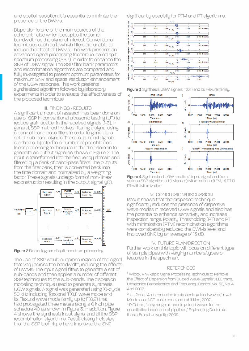
41
and spatial resolution, it is essential to minimize the presence of the DWMs.
Dispersion is one of the main sources of the coherent noise which occupies the same bandwidth as the signal of interest. Conventional techniques such as low/high filters are unable to reduce the effect of DWMs. This work presents an advanced signal processing technique, called split-spectrum processing (SSP), in order to enhance the SNR of UGW signal. The SSP filter bank parameters and recombination algorithms are compared and fully investigated to present optimum parameters for maximum SNR and spatial resolution enhancement of the UGW response. This work presents synthesized algorithm followed by laboratory experiments in order to evaluate the effectiveness of the proposed technique.
III. FINDINGS / RESULTSA significant amount of research has been done on use of SSP in conventional ultrasonic testing (UT) to reduce grain scatter in the received signals [1-3]. In general, SSP method involves filtering a signal using a bank of band pass filters in order to generate a set of sub-band signals. These sub-band signals are then subjected to a number of possible non-linear processing techniques in the time domain to generate an output signal as shows in Figure 2. The input is transformed into the frequency domain and filtered by a bank of band-pass filters. The outputs from the filter bank, then is converted back into the time domain and normalized by a weighting factor. These signals undergo form of non- linear reconstruction resulting in the output signal, y(t).
Figure 2 Block diagram of split-spectrum processing.
The use of SSP would suppress regions of the signal that vary across the bandwidth, reducing the effects of DWMs. The input signal filters to generate a set of sub-bands and then applies a number of different SSP techniques to the sub-bands. The dispersion modelling technique used to generate synthesis UGW signals. A signal was generated using 10-cycle 50 kHz including Torsional T(0,1) wave mode and its Flexural wave mode family up to F(6,2) that had propagated three meters along a 6 inch pipe schedule 40 as shown in Figure 3. In addition, Figure 4 shows the synthesis input signal and all the SSP recombination algorithms. Result clearly indicates that the SSP technique have improved the SNR
REFERENCES1 Wilcox, P, “A Rapid Signal Processing Technique to Remove the Effect of Dispersion from Guided Wave Signals”, IEEE trans. Ultrasonics Ferroelectrics and Frequency Control, Vol. 50, No. 4, April 2003.2 J. L. Rose, “An introduction to ultrasonic guided waves,” in 4th Middle east NDT conference and exhibition, 2007.3 P. Catton, “Long range ultrasonic guided waves for the quantitative inspection of pipelines,” Engineering Doctorate thesis, Brunel University, 2009.
significantly specially for PTM and PT algorithms.
Figure 3 Synthesis UGW signals: T(0,1) and its Flexural family.
Figure 4 Synthesized UGW results a) input signal, and from various SSP algorithms: b) Mean, c) Minimisation, d) FM, e) PT, f) PT with Minimization
IV. CONCLUSION/DISCUSSIONResult shows that the proposed technique significantly reduces the presence of dispersive wave modes in received UGW signals and also has the potential to enhance sensitivity and increase inspection range. Polarity Thresholding (PT) and PT with minimization (PTM) recombination algorithms were considerably reduced the DWMs level and improved SNR by an average of 13 dB.
V. FUTURE PLAN/DIRECTIONFurther work on this topic will focus on different type of sample pipes with varying numbers/types of features in the specimen.

42
Measurement and prediction of CTOD in austenitic stainless steel
WeeLiam Khor WeeLiam obtained a BEng in Mechanical Engineering from Brunel University in 2013. His first involvement with CTOD and fracture toughness was when he was completing his industrial placement at a fabrication yard. CTOD is a fracture parameter invented at TWI in the 1960s. Although it was well established in test standards (eg BS7448-1 and ASTM E1820), different assumption and definitions were employed by different parties. There remain uncertainties in the accuracy of CTOD estimation equations in some alloys.
TWI Supervisors: Dr Philippa Moore, Dr Henry Pisarki Academic Supervisor: Chris BrownTWI Supervisors: Dr Philippa Moore, Dr Henry Pisarki Academic Supervisor: Chris BrownTWI Supervisors: Dr Philippa Moore, Dr Henry Pisarki Academic Supervisor: Chris BrownBrunel University LondonBrunel University LondonBrunel University London
Asset and Fracture Integrity ManagementAsset and Fracture Integrity ManagementAsset and Fracture Integrity Management3rd Year of PhD3rd Year of PhD3rd Year of PhD
I. INTRODUCTIONFracture toughness is a fracture mechanics parameter used to classify the material’s resistivity to fracture. Three of the well-known fracture toughness parameters are K (stress intensity factor), J and CTOD (crack tip opening displacement, Fig 1). Fracture toughness is most commonly used in Engineering Critical Assessments (ECA), where the flaws found in structures would be evaluated using a fracture mechanics approach. The acceptability of the flaw size estimated is dependant on the fracture toughness value that can be assumed.
Figure 1 Definition of CTOD, as the displacement at the tip of a prepared crack in a SENB specimen at the point of unstable crack extension
Fracture toughness standards BS7448-1 [1] and ASTM E1820 [2] specify testing methods to estimate fracture toughness in single edge notched bend, SENB specimens. However the standards adopt different assumptions in the estimations which results in different values of CTOD. The Japan Welding Engineering Society (JWES) was
Keywords: austenitic stainless steel, CTOD, digital Image correlation, strain hardening
aware of this issue in relation to materials with a range of strain hardening coefficients and published research on an improved CTOD estimation . [3] This work presents findings on the validation of methods to determine CTOD for austenitic stainless steel with high strain hardening. Physical measuring techniques (silicone crack casting and digital image correlation, DIC) were used to investigate CTOD, and were compared to the BS 7448-1, ASTM E1820 and JWES estimations.
II. METHODBoth 2D imaging (DIC) and 3D methods (physical crack casting) were used to investigate CTOD. In addition to the experimental techniques, a standard SENB finite element model was used to predict CTOD. The DIC method used a unique paint speckle pattern applied to the side of the specimen, and an image was captured as the specimen was loaded. The images were then processed using GOM ARAMIS, where the equivalent surface CTOD (δ₅) was obtained (Fig 2).
Figure 2 Determination of (a) δ5 points based on (b) speckle pattern using DIC.

43
The 3-D replica of the crack was obtained by casting the specimen notch using 2-part silicone compound. The SENB specimen was loaded in displacement control, then held at constant displacement at the intended casting point. The silicone compound was the injected into the crack and left to cure. The casting was removed after it was cured and the procedure was repeated for the subsequent casting points under increasing displacement. The silicone replicated cracks (SRC) were sliced into 4 equal portions across the thickness of the specimen. CTOD was measured on the cross-section of the SRC using an optical microscope (Fig 3).
Figure 3 Definition of CTOD measured on the silicone crack
replica section.
III. FINDINGS CTOD varies across the thickness of the specimen confirmed from the SRC measurements. The δ₅ DIC CTOD gave good estimation of the surface CTOD measured from the SRC. A correlation was found for the CTOD measured in the middle of the thickness of the specimen and the δ₅ DIC CTOD (Fig 4).
Figure 4 Comparison between δ₅ DIC (CTOD at the specimen surface), δ SRC (b=0) (CTOD at the middle of the specimen), and δ SRC (b=±1) (CTOD at the edges of the specimen)
The standard CTOD estimation methods (BS 7448-1, ASTM E1820 and JWES) assume an average crack length, and were compared to the SRC CTOD measured in the middle of the thickness. An FE (finite element) model was used to predict CTOD. The BS 7448-1 estimation did not consider the effects of strain hardening in the estimation, whereas the FE model was not able to represent the actual crack propagation at larger deformation. This led these two
REFERENCES1 BSI (1991) BS 7448-1:1991 - Fracture mechanics toughness tests — Part 1: Method for determination of KIc, critical CTOD and critical J values of metallic materials. BSI.2 ASTM (2014) ASTM E1820-13 - Standard Measurement of Fracture Toughness. ASTM, 1-54.3. Kawabata T, Tagawa T, Sakimoto T, et al. (2016) Proposal for a new CTOD calculation formula. Engineering Fracture Mechanics. 159: 16-34.
methods to overestimate the SRC CTOD, considered to represent the actual CTOD in the specimen. The ASTM E1820 and JWES were within 15% underestimation of the SRC CTOD, which was more accurate compared to BS 7448-1 and the FE prediction. The ASTM E1820 estimation was better for lower CTOD, whereas the JWES estimation gave better estimation of larger CTOD (Fig 5).
Figure 5 Comparison of the silicone replica CTOD, δ SRC (b=0) to FE CTOD, δ FE (b=0) and standard CTOD estimations.
IV. CONCLUSION/DISCUSSIONThis work found a correlation between the CTOD estimated on the side and middle of the specimen to enable δ₅ DIC to be used with DIC in stainless steel specimens with large amounts of crack opening. The ASTM E1820 and JWES CTOD estimations were better alternatives to the BS 7448-1 for austenitic stainless steel, showing the improvement in the JWES method which accounts for strain hardening effects.
V. FUTURE PLAN/DIRECTIONMy PhD work on validating CTOD estimation methods will develop in the following areas:• The effect of rotational factor, rp on CTOD• Optimizing the CTOD estimation based on FE and SRC• m and η factor optimization based on SRC CTOD

44
Characterizations of piezoelectric materials for use in UGW at high temperatures
Saiful TuminSaiful Asmin obtained his BEng degree from Universiti Teknologi Malaysia (UTM) in 1999. He worked in the industry for a few years and joined a government agency, Majlis Amanah Rakyat (MARA), in 2002. In 2006 he went on to pursue an MEng in Mechatronics as a part-time student and graduated in 2012 from UTM. He applied a study leave from MARA to continue his PhD at Brunel University, London. His current research includes ultrasonic guided wave testing, ultrasonic transducers design for NDT, high-temperature condition monitoring and high-temperature piezoelectric materials.
TWI Supervisors: Prof. Tat-Hean Gan, Dr Abbas Mohimi Academic Supervisor: Dr Bin WangTWI Supervisors: Prof. Tat-Hean Gan, Dr Abbas Mohimi Academic Supervisor: Dr Bin WangTWI Supervisors: Prof. Tat-Hean Gan, Dr Abbas Mohimi Academic Supervisor: Dr Bin WangBrunel University LondonBrunel University LondonBrunel University London
Plant Integrity Plant Integrity Plant Integrity 2nd Year of PhD2nd Year of PhD2nd Year of PhD
I. INTRODUCTIONThere is a need to continuously monitor structural integrity of systems used in high temperatures, such as pipelines in power plants and oil refineries. These pipelines are in-service for prolonged period of time, with defects developing, often due to creep and fatigue effects. If the defects are undetected and rectified, they may lead to catastrophe accidents. In order to maintain the structural integrity of these pipelines, conventional Non-Destructive Testing techniques such as ultrasonic testing, eddy current testing and visual inspection are normally used. However, these NDT techniques can only be implemented during outages due to the lack of capability to inspect at high temperature [1]. Long range ultrasonic testing (LRUT) which employs ultrasonic guided waves (UGW) can be used to inspect pipelines for tens of metre from a single location [2]. However, current UGW can only be used at temperature up to 200°C, whereas the power plants and the oil refineries are operated at higher temperatures, typically higher than 250°C [3]. For this reason, new transducers that can operate at higher temperatures need to be developed. Many piezoelectric elements that possess the high temperature operating ability have been reported [4]. In this research project, modified bismuth titanate (MBIT) has been chosen due to its high Curie temperature (Tc) stability at high temperature [5]. Due to the lack of data on material properties of MBIT for continuous monitoring at high temperatures, impedance measurements have been carried out to obtain the elastic, dielectric and piezoelectric properties at temperature overtime. From the derived material properties a conclusion can be made about the
Keywords: high temperature, modified bismuth titanate (MBIT), UGW.
efficiency, sensitivity and mechanical stability of the MBIT at high temperature.
II. EXPERIMENT SETUPFive MBIT elements were used for impedance measurement at elevated temperature. MBIT samples of 3 mm x 13 mm x 0.5 mm (width, length, thickness) were tested at various temperature. Samples were cut for testing with the aspect ratio of 20:1 and 6:1 on the l/t and w/t configuration respectively, which is the minimum aspect ratio that can produce a reliable measurement [6]. The elements were coated with 100μm gold electrodes on the width, plane configuration. A jig that can withstand a high temperature was used, due to lack of commercially available devices / tweezer for high temperature impedance measurement [7]. The impedance analyzer, Agilent 4294A, was used to measure the MBIT elements inside a high temperature jig to retrieve the impedance-frequency response of the elements. A local area network (LAN) cable was used to connect the analyzer to a laptop for data acquisition. Impedance-frequency characteristic for the MBIT were first taken at 25°C. These characteristics were used as a baseline for the performance of the element. Then, increments of 25°C were applied for each impedance measurement up to 525°C. In addition, a constant temperature of 400°C was applied to one of the MBITs for a prolomged period of 30 days to inspect its material properties at this temperature overtime. The resonant, fr, and the anti-resonance, fa, capacitance value of the element (measured at 1kHz), the density and dimension of the MBIT were compiled and used to determine the elastic, dielectric and piezoelectric properties of the element at high temperature.

45
III. FINDINGS / RESULTSThe piezoelectric voltage constant, g15, the piezoelectric charge constant, d15, and the thickness shear coupling factor, k15, are the key parameters when describing the performance/behavior of the shear mode piezoelectric. The properties of d15 and g15 were used to describe how well the element will transmit and receive signals. k15 was used to represent the efficiency of the element to convert electrical energy to mechanical energy and vice versa. In order to obtain the values of the d15, g15 and k15, equations outlined in the British Standard BS EN:50324-2 [8] were used.
Figure 1 Impedance traces showing the effect of temperature on the fr and fa frequencies from 25°C to 525°C
Figure 1 shows the response for one the MBIT elements at tested temperature intervals. From the figure, it indicates that the impedance frequency response shifted from higher frequency to lower frequency when temperature increases. The impedance also begins to shrink as temperature increases and at 525°C the element starts to depolarize. In total, five MBIT elements were tested and the result have been averaged. From 25°C to 525°C, the calculated properties were close to the theoretical values given in the element datasheet [9]. From the result obtained, it is proven that the technique used is reliable in determining the element properties at high temperature. Therefore, the technique can be further used for characterization of the MBIT performance for long periods of time.One of the MBIT was tested at 400°C for a period of 30 days. The preliminary results showed that the MBIT element has stable material properties throughout the tested period.
Figure 2 a) d15, and g15, b) k15 of MBIT at 400°C for 30 days and c) result before and after 30 days tested at 400°C
REFERENCES[1]A. McNab, K. J. Kirk, and A. Cochran, “Ultrasonic transducers for high temperature applications,” IEE Proceedings - Science, Measurement and Technology, vol. 145, no. 5. p. 229, 1998.[2]S. Birch and F. Baker, “Long-Range Guided-Wave Ultrasonics: A New Age in Pipeline Inspection,” pp. 13–17, 2007.[3]Plant Integrity Ltd., “Teletest focus goes permanent,” 2008. [Online]. Available: http://www.twi-global.com/news-events/connect/2008/july-august-2008/teletest-focus-goes-permanent/.[4]D. Damjanovic, “Materials for high temperature piezoelectric transducers,” Curr. Opin. Solid State Mater. Sci., vol. 3, no. 5, pp. 469–473, Oct. 1998.[5]R. Kažys, a Voleišis, and B. Voleišienė, “High temperature ultrasonic transducers : review,” Ultrasound, vol. 63, no. 2, pp. 7–17, 2008.[6]T. Comyn and A. . Tavernor, “Aspect ratio dependence of d15 measurements in Motorola 3203 material,” J. Eur. Ceram. Soc., vol. 21, no. 1, pp. 9–12, Jan. 2001.[7]Keysight Technologies, “16334A Test Fixture (Tweeezers Contacts).” [Online]. Available: http://www.keysight.com. [Accessed: 18-Apr-2016].[8]British Standard, “Piezoelectric properties of ceramic materials and components - Part 2: Methods of measurement - Low power,” vol. 3, no. BS EN: 50324–2, 2002.[9]“Ionix Advanced Technologies.” [Online]. Available: http://ionixadvancedtechnologies.co.uk/. [Accessed: 13-Apr-2016].
From Figure 2a), it can be seen that the coefficient of d15 decreased from the initial value of 70.8 nC/N in the first 7 days then stabilised with an average value of 56.9 nC/N until the end of the test. Also in Figure 2a), shows that the piezoelectric voltage constant, g15, decreased from the initial value of 67 x 10-6 Vm/N in the first five days before stabilizing at around 56.6 x 10⁻⁶ Vm/N throughout the rest of the test. For the calculated thickness shear coupling factor, k15, the average efficiency was at 30% ± 5% at 400°C for 30 days. The MBIT was cooled down to 25°C after 30 days of testing at 400°C, and impedance measurement was carried out again. The fr and fa peaks were compared with previous peaks before the 30 day test. The result shows that exposure of 30 days at 400°C did not affected the material properties and thus it is stable.
IV. CONCLUSIONFour elements were tested up to 525°C and their piezoelectric properties were derived. One element was tested at 400°C for up to 30 days showing stable response. It can be concluded that MBIT is suitable for the development of high temperature transducers for continuous UGW testing.
V. FUTURE PLANMBIT will be further tested at high temperature overtime to observe the ultrasonic behaviour of MBIT.Fabrication of high temperature transducers using MBIT will be carrying out, which transmission and reception performance of these transducers will be evaluate at room and high temperatures.

The Welding InstituteGranta Park, Great Abington, Cambridge CB21 6AL
Tel: 01223 899000 | Email: [email protected] | Web: www.theweldinginstitute.com
The University of Strathclyde is a Leading International Technological University, and ‘a place of useful learning’ where we are recognised as being:
AmbitiousBold
CollaborativeInnovative
People-Oriented The Faculty of Engineering exemplifies this vision by delivering practical solutions to technical and business challenges for a wide range of local, national and international organisations. A key strength of Strathclyde is our commitment to collaboration between Departments and across Faculties to deliver holistic and innovative solutions. We regard our links with external organisations as a major strength.
We work closely with industrial and public sector colleagues on many knowledge exchange activities including; consultancy, continuing professional development (CPD), knowledge transfer partnerships and the formation of spin-out companies. This works for both as many of our staff often spend time on-site in industry and some industrial partners have engineers on-campus using our facilities working on collaborative projects.
The Faculty of Engineering at Strathclyde is one of the largest, best equipped engineering faculties in the UK and is the largest in Scotland. Our faculty comprises eight departments:
• Architecture• Biomedical Engineering• Chemical & Process Engineering• Civil & Environmental Engineering• Design, Manufacture & Engineering Management• Electronic & Electrical Engineering• Mechanical & Aerospace Engineering• Naval Architecture, Ocean & Marine Engineering
In addition there are specialist centres/institutes which include:
• The Advanced Forming Research Centre (AFRC)• The Advanced Materials Research Laboratory (AMRL)• The Advanced Nuclear Research Centre (ANRC)• The Power Networks Demonstration Centre (PNDC)• The Centre for Ultrasonic Engineering (CUE)• Strathclyde Space Institute• Scottish Institute for Remanufacture
First for Engineering
■ Engaged in ten Doctoral/Industrial Training Centres covering – Advanced Forming and Manufacture, Continuous Manufacture and Crystallisation, Future Power Networks and Smart Grids, Medical Device and Healthcare Technologies, Wind and Marine Energy Systems, Applied Photonics, Nuclear Engineering, Offshore Renewable Energy, Oil and Gas, Systems Engineering■ Research portfolio of 100 million and growing■ Over 250 Knowledge Transfer Partnerships to date■ Seven of our eight Engineering departments are ranked in the top 10 in the UK on research power (REF 2014)■ Three of our departments are ranked first in Scotland on research power (REF 2014)■ Over 5,500 engineering students of over 100 nationalities■ State-of-the-art laboratory and research facilities■ Largest undergraduate scholarship programme in the UK
Structural integrity research activities and capabilities are housed across most Departments as we engage with industry in a wide range of projects. These include advanced design of fatigue resistant high pressure pumps and seals to the life extension of aging oil and gas assets and pipelines through better understanding of the effects of erosion and corrosion to the design of new sensors for the detection of flaws and defects in new and legacy equipment and prognostic algorithms for future life prediction of plant and assets.
Faculty of EngineeringUniversity of StrathclydeRoom 5.25Royal College Building204 George StreetGlasgow G1 1XW
t: +44 (0)141 548 2749e: [email protected]: www.strath.ac.uk/engineeringtwitter: @StrathEng
Faculty of Engineering

Strathclyde
The Welding InstituteGranta Park, Great Abington, Cambridge CB21 6AL
Tel: 01223 899000 | Email: [email protected] | Web: www.theweldinginstitute.com
Student membership of The Welding Institute is free to NSIRC Students.
Being a member of a professional institution demonstrates that you are serious about your career and your professional development.
Student Associate MembershipStudent Associate Membership offers a route to students who wish to achieve professional membership and Engineering Council registration.
Engineering Council RegistrationThe Welding Institute is licensed to award Chartered Engineer (CEng), Incorporated Engineer (IEng), and Engineering Technician (EngTech) registration. We can assess and register appropriately qualified candidates for interim IEng and CEng registration.
We aim to support NSIRC students with the information and tools to develop and support their career and we always welcome feedback and new ideas.The Welding Institute offers student members access to career information, technical information and library services, industry news, reports and surveys, as well as the opportunity to attend branch meetings, technical group meetings, seminars and conferences.
We can offer advice, guidance and information relating to planning and supporting your professional development by helping you identify your goals and determining the skills and education you need.
The Welding Institute is proud to o�er a range of awards that are open to NSIRC students. These include: the Armourers and Brasiers best PhD or Eng Doc Student; the Armourers and Brasiers Best STEM Ambassador; and the Richard Dolby/Rolls-Royce Award. We also present the Armourers and Brasiers Student Travel awards annually.
For more information, visit www.theweldinginstitute.com or come along and discuss your membership options with one of our membership o�cers.
The University of Strathclyde is a Leading International Technological University, and ‘a place of useful learning’ where we are recognised as being:
AmbitiousBold
CollaborativeInnovative
People-Oriented The Faculty of Engineering exemplifies this vision by delivering practical solutions to technical and business challenges for a wide range of local, national and international organisations. A key strength of Strathclyde is our commitment to collaboration between Departments and across Faculties to deliver holistic and innovative solutions. We regard our links with external organisations as a major strength.
We work closely with industrial and public sector colleagues on many knowledge exchange activities including; consultancy, continuing professional development (CPD), knowledge transfer partnerships and the formation of spin-out companies. This works for both as many of our staff often spend time on-site in industry and some industrial partners have engineers on-campus using our facilities working on collaborative projects.
The Faculty of Engineering at Strathclyde is one of the largest, best equipped engineering faculties in the UK and is the largest in Scotland. Our faculty comprises eight departments:
• Architecture• Biomedical Engineering• Chemical & Process Engineering• Civil & Environmental Engineering• Design, Manufacture & Engineering Management• Electronic & Electrical Engineering• Mechanical & Aerospace Engineering• Naval Architecture, Ocean & Marine Engineering
In addition there are specialist centres/institutes which include:
• The Advanced Forming Research Centre (AFRC)• The Advanced Materials Research Laboratory (AMRL)• The Advanced Nuclear Research Centre (ANRC)• The Power Networks Demonstration Centre (PNDC)• The Centre for Ultrasonic Engineering (CUE)• Strathclyde Space Institute• Scottish Institute for Remanufacture
First for Engineering
■ Engaged in ten Doctoral/Industrial Training Centres covering – Advanced Forming and Manufacture, Continuous Manufacture and Crystallisation, Future Power Networks and Smart Grids, Medical Device and Healthcare Technologies, Wind and Marine Energy Systems, Applied Photonics, Nuclear Engineering, Offshore Renewable Energy, Oil and Gas, Systems Engineering■ Research portfolio of 100 million and growing■ Over 250 Knowledge Transfer Partnerships to date■ Seven of our eight Engineering departments are ranked in the top 10 in the UK on research power (REF 2014)■ Three of our departments are ranked first in Scotland on research power (REF 2014)■ Over 5,500 engineering students of over 100 nationalities■ State-of-the-art laboratory and research facilities■ Largest undergraduate scholarship programme in the UK
Structural integrity research activities and capabilities are housed across most Departments as we engage with industry in a wide range of projects. These include advanced design of fatigue resistant high pressure pumps and seals to the life extension of aging oil and gas assets and pipelines through better understanding of the effects of erosion and corrosion to the design of new sensors for the detection of flaws and defects in new and legacy equipment and prognostic algorithms for future life prediction of plant and assets.
Faculty of EngineeringUniversity of StrathclydeRoom 5.25Royal College Building204 George StreetGlasgow G1 1XW
t: +44 (0)141 548 2749e: [email protected]: www.strath.ac.uk/engineeringtwitter: @StrathEng
Faculty of Engineering
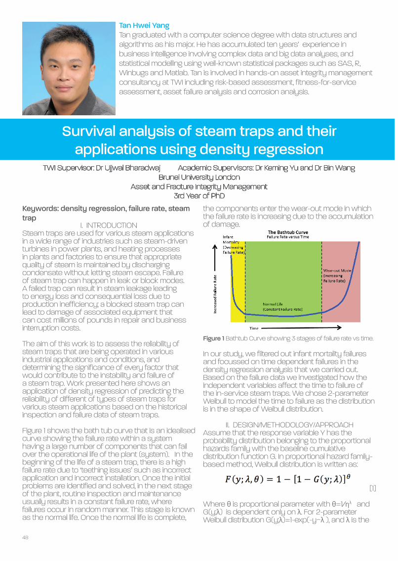
48
Survival analysis of steam traps and their applications using density regression
Tan Hwei Yang Tan graduated with a computer science degree with data structures and algorithms as his major. He has accumulated ten years’ experience in business intelligence involving complex data and big data analyses, and statistical modelling using well-known statistical packages such as SAS, R, Winbugs and Matlab. Tan is involved in hands-on asset integrity management consultancy at TWI including risk-based assessment, fitness-for-service assessment, asset failure analysis and corrosion analysis.
TWI Supervisor: Dr Ujjwal Bharadwaj Academic Supervisors: Dr Keming Yu and Dr Bin WangTWI Supervisor: Dr Ujjwal Bharadwaj Academic Supervisors: Dr Keming Yu and Dr Bin WangTWI Supervisor: Dr Ujjwal Bharadwaj Academic Supervisors: Dr Keming Yu and Dr Bin WangBrunel University LondonBrunel University LondonBrunel University London
Asset and Fracture Integrity Management Asset and Fracture Integrity Management Asset and Fracture Integrity Management 3rd Year of PhD3rd Year of PhD3rd Year of PhD
I. INTRODUCTIONSteam traps are used for various steam applications in a wide range of industries such as steam-driven turbines in power plants, and heating processes in plants and factories to ensure that appropriate quality of steam is maintained by discharging condensate without letting steam escape. Failure of steam trap can happen in leak or block modes. A failed trap can result in steam leakage leading to energy loss and consequential loss due to production inefficiency; a blocked steam trap can lead to damage of associated equipment that can cost millions of pounds in repair and business interruption costs.
The aim of this work is to assess the reliability of steam traps that are being operated in various industrial applications and conditions, and determining the significance of every factor that would contribute to the instability and failure of a steam trap. Work presented here shows an application of density regression of predicting the reliability of different of types of steam traps for various steam applications based on the historical inspection and failure data of steam traps.
Figure 1 shows the bath tub curve that is an idealised curve showing the failure rate within a system having a large number of components that can fail over the operational life of the plant (system). In the beginning of the life of a steam trap, there is a high failure rate due to ‘teething issues’ such as incorrect application and incorrect installation. Once the initial problems are identified and solved, in the next stage of the plant, routine inspection and maintenance usually results in a constant failure rate, where failures occur in random manner. This stage is known as the normal life. Once the normal life is complete,
Keywords: density regression, failure rate, steam trap
the components enter the wear-out mode in which the failure rate is increasing due to the accumulation of damage.
Figure 1 Bathtub Curve showing 3 stages of failure rate vs time.
In our study, we filtered out infant mortality failures and focussed on time dependent failures in the density regression analysis that we carried out. Based on the failure data we investigated how the independent variables affect the time to failure of the in-service steam traps. We chose 2-parameter Weibull to model the time to failure as the distribution is in the shape of Weibull distribution.
II. DESIGN/METHODOLOGY/APPROACHAssume that the response variable Y has the probability distribution belonging to the proportional hazards family with the baseline cumulative distribution function G. In proportional hazard family-based method, Weibull distribution is written as:
[1]
Where θ is proportional parameter with θ=1⁄ηλ and G(y;λ) is dependent only on λ. For 2-parameter Weibull distribution G(y;λ)=1-exp(-y^λ ), and λ is the

49
shape parameter.
The log linear model is used to model log(θ) as the linear regression function of x, thus:
[2]
Given the response Y and covariates x, {xi,Yi }ni=1): let θ
i≡θ(xi ) and S
i=-log(G(Yi;λ)) then 2θi Si~χ2
(2). As the distribution χ2 (2) is a special case of a Gamma distribution from a Gamma random variable, Γ. Gamma distribution is the maximum entropy probability distribution of Γ for which E(log(Γ))=ψ(shape-parameter)-log(1⁄((scale-parameter) )) is fixed, where ψ(t)=d log(Γ(t)))⁄dt is the digamma function. Therefore:
[3]
Where ψ’(t)=(d2 log(Γ(t))⁄(dt2 ), ψ(1)=-γ with the Euler-Mascheroni constant γ ~ 0.5772 and ψ’(1)=π2/6. Let:
[4]
Then we have the standard linear regression function:
[5]
The target regression model is as the following [6]: [6]
Given the time to failure data of steam trap (x,Y), we obtained the λ based on the following function [7] using Newton-Raphson method:
[7]
Once λ is known, by using the equation [4] we obtained the observed vector U from Ui=-log(G (Yi;λ))-γ, where (G(y;λ)=e-yλ), and γ~0.5772. Then the coefficients of density regression β were estimated via linear regression model with data (x,U).
IV. FINDINGS/RESULTSThe results of density regression analysis, we are able to check and compare the effect of each factor on the reliability of different types of steam traps in different steam applications. Figure 2 shows the probability of failure curves of different traps in different applications and failures.
REFERENCES1 Dang, W. and Yu, K. (2015) Density Regression Based on Proportional Hazards Family, Entropy 17, 3679-3691.2 Yonghui Liu (2008) On Equality of Ordinary Least Squares Estimator, Best Linear Unbiased Estimator and Best Linear Unbiased Predictor in the General Linear Model, Journal of Statistical Planning and Inference, 139, 1522-15293 Bharadwaj U. R. (2011) Risk Based Life Management of Offshore Structures and Equipment, Section 2.3, [Doctorate of Engineering]. Loughborough, UK, Loughborough University
Figure 2 Probability of failure of Trap A and B in different
applications.
In Figure 3, the curves show that there is no linear relationship between time to failure and pressure, in other words increasing pressure does not increase or decrease the characteristic life linearly.
Figure 3 Probability of failure of Trap A and B under different line
pressures.
IV. CONCLUSION/DISCUSSIONThe density regression is suitable for reliability analyses where multiple factors are required to be considered and estimated simultaneously. The result of this method can be used as a reference for the industry to match the correct type of steam trap with the steam application in order to achieve the optimized and cost-efficient system configuration. Besides that, it can also be used by steam trap manufacturers to design better products for various steam applications under different operating conditions.

50
Vestas V90-3MW wind turbine gearbox health assessment using a vibration-based condition monitoring system
Antonio RomeroAntonio Romero Camacho is an MSc electrical and electronics engineer from Castilla La Mancha University, Spain. He started at TWI in June 2013 as a placement student and then in January 2014 started a PhD with Brunel University London, researching ‘Condition monitoring in rotating machinery using vibration analysis’. In particular, Antonio is trying to improve current methodologies for fault detection in gearboxes using vibration analysis. He has worked on four different collaborative projects, all of them linked to rotating machinery fault diagnosis: VA-RCM, REMO, CMSWind and CMDrive.v
TWI Supervisor: Dr Slim Soua Academic Supervisor: Dr Bin WangTWI Supervisor: Dr Slim Soua Academic Supervisor: Dr Bin WangTWI Supervisor: Dr Slim Soua Academic Supervisor: Dr Bin WangBrunel University LondonBrunel University LondonBrunel University London
Condition and Structural Health Monitoring Condition and Structural Health Monitoring Condition and Structural Health Monitoring 3rd Year of PhD3rd Year of PhD3rd Year of PhD
I. INTRODUCTIONAn advanced condition monitoring system (CMS) has been developed as part of the CMSWind FP7 Project, partly funded by the European Commission, for the assessment of wind turbine rotating parts. The validation of the system is presented in this paper. It was carried out during field trials at Bandirma Wind Energy Power Plant on a Vestas V90-3MW Wind Turbine.
This integrated CMS, which utilizes three techniques specifically designed for wind turbines and their components, will improve wind turbine machinery reliability. This estimation is made from the fact that unnecessary maintenance and out of service wind turbines are reduced or even eliminated, improving reliability and operation. The work described in this manuscript will show the application of the CMSWind System for enabling the prompt detection of changes in the gearbox health using Vibration Analysis. A new methodology based on the development of a baseline profile for the promptly detection of arising defects and their worsening with time is proposed. The results demonstrate that the proposed method is effective in the health identification of wind turbine rotating machinery.
II. PROBLEM AND SOLUTION PROPOSEDTo keep the large number of wind turbines running safely, continuously and profitably is challenging. The industry still experiences premature turbine component failures, which lead to increases in the operation and maintenance (O&M) costs and subsequently, the downtime of turbines. O&M costs are attracting greater attention as there is a need for the industry to reduce turbine downtime, increase
Keywords: condition monitoring, drivetrain, gearbox, maintenance, reliability, vibration analysis, wind turbine
reliability and decrease the cost of the energy (COE).
Wind turbine gearboxes tend to fail more prematurely than those in any other applications (2 to 11 years out of the desired 20 years). Although it is well documented in literature that the failure rate of mechanical components is lower than that of the electrical subsystems in comparison, mechanical failures still create unplanned maintenance, long turbine downtimes due to gearbox replacement and rebuild and increase the warranty reserves. Based on the data compiled in the Wind Stats Newsletter covering 2003 to 2009, gearboxes are the subsystem that causes the highest downtimes1. As part of the research to increase the reliability of gearboxes, the Vestas V90 gearbox is chosen as the main targeted subsystem of this study.
III. MONITORING STRATEGY BASED IN VIBRATION ANALYSIS
The monitoring system was installed in a gearbox of a wind turbine nacelle for data collection from May 2015 until October 2015. The proposed solution methodology includes 5 phases (see Figure 1). In phase one, the data acquisition system gathers a vibration signal every 30 minutes. The data is checked and signals are conditioned when it is required. The access to the operating parameters (rotor speed and power output) is given by the operator. These parametric outputs are continuously acquired and are synchronized with the vibrational signatures using the timestamps in phase two.
Figure 1 Monitoring Strategy Flow Chart.

51
Phase 3 is focused on the feature extraction from the acceleration signals and the clustering of these parameters using a binning process. In phase 4 is where the baseline is generated, setting up the normal operation limits of the machine being studied. The machine can start being monitored in phase 5, where the current measurements are compared with the limits previously established. Alarms are generated when the current data does not fall within the baseline.
Figure 2 Monitoring Strategy Flow Chart.
IV. BASELINE ALGORITHMThe algorithm which builds the baseline of the machine being monitored is a continuous statistical process based on a convergence criterion. The baseline process stops when the moving average error (EMA) is lower than a 2%. That must be fulfilled in the next ten measurements within that bin. When the convergence criterion is satisfied the baseline process is finished and the monitoring stage starts.
Figure 3 Monitoring Strategy Flow Chart.
The next step in the baseline generation process is to set up the normal operation condition limits. They will establish whether or not the process is under control. The purpose is to provide a representative vibration level across a range of rotor speeds, for improving the reliability of wind turbines and thereby helping define appropriate vibration limits. The action limits are set so that 99.8% of samples lie within them when the mean is on target. For the warning limit, it was chosen at 1.96 (~2) times the standard deviation only 5% of the values should be outside the limits if the features under study are in the same condition as when the signature was calculated.
REFERENCES1 Jelali M., Control Performance management in Industrial Automation: Assesment. diagnosis and improvement of control loop performance, Springer, 2013.2 Kusiak A and Li W. The prediction and diagnosis of wind turbine faults. Renewable Energy 2011; 36:16-23.3 Hill R., Stinebaugh J., Briand D., Wind Turbine Reliability: A Database and Analysis Approach, Sandia Report, February 2008.4 Sheng S., 2011, Wind Turbine Drivetrain Condition Monitoring, Power Point Presentation, NREL/NWTC, U.S.A.
For the action limit, it is set up at 3.09 (~3) times the standard deviation. Therefore, the warning and action limits are set:
Warning Limit = μ ± 2σAction Limit = μ ± 3σ
At this final stage, the new data gathered is plotted in front of the limits predetermined to evaluate the health of the machinery. New RMS values falling out of the limits is a clear indication of a process out of target. Nevertheless, it does not necessarily mean that is due to a malfunction or defect within the turbine. In this case, it is compulsory to wait until the next measurement. If the following value is still outside, then action needs to be taken. If however, the next measurement falls inside the limits, the outlier is considered as a false alarm, assuming that the process is on target.
Therefore the results shown in Figure 4 are a good tool for describing the acceptable levels of vibration of the machine regarding the rotor speed of the wind turbine.
Figure 4 Monitoring using a 3 months established baseline.
V. CONCLUSION/DISCUSSIONThe baseline generated and shown in this paper can be defined as an identification profile of the machinery. It will be used as a reference during life monitoring of this wind turbine. The algorithm will be able to identify RMS deviations from the average RMS target, allowing the operator to take preventive decision concerning the wind turbine safety. In view of the result it can be ensured that the method still indicating a healthy status of the machinery when a set of new healthy data was applied to it.

54
In-situ monitoring of composite structures using tool embedded capacitors
Galatée LevadouxGalatée Levadoux completed her Master’s at TWI and went on to study for an industrial PhD. She graduated with both an MSc in Research in Chemistry and Physics of Materials from the University of Bordeaux 1 and a degree in Chemistry and Physics (equivalent to an MSc) specialised in nano and microtechnology from the Graduate School of Chemistry, Biology and Physics of Bordeaux. Galatée was attracted to her topic because of its potential application to the renewable energies sector and the broadness of knowledge in both chemistry and physics it requires. She hopes her work will improve the reliability of clean energies, increasing their attractiveness.
TWI Supervisor: Dr Chris Worrall Academic Supervisors: Dr Trevor Benson, Dr Ana Vukovic and Prof Philip Sewell TWI Supervisor: Dr Chris Worrall Academic Supervisors: Dr Trevor Benson, Dr Ana Vukovic and Prof Philip Sewell TWI Supervisor: Dr Chris Worrall Academic Supervisors: Dr Trevor Benson, Dr Ana Vukovic and Prof Philip Sewell University of NottinghamUniversity of NottinghamUniversity of Nottingham
Adhesives Composites and SealantsAdhesives Composites and SealantsAdhesives Composites and Sealants2nd Year of PhD2nd Year of PhD2nd Year of PhD
I. INTRODUCTIONWith the increasing scarcity of fossil fuels, the need for reliable and affordable sources of energy is growing stronger. In particular, wind turbines are becoming more and more popular. Materials with better properties are needed, processes with increased reliability are required, and a deeper knowledge of the physical phenomena taking place along the fabrication and utilisation chain is crucial to ensure the reliability and efficiency of these new ways of harvesting energy. Nonetheless, in the United Kingdom alone, 1500 wind turbine accidents and incidents have been reported between 2010 and 20151.
The largest number of accident is by far due to blade failure. As the most frequent cause of these failures can be linked to an improper cure of the composite blade material, blade reliability issues should be considered at an early stage during their manufacture to prevent the loss in production and the associated costs of subsequent failures in service2.
The aim of the present project is to develop an advanced network monitoring technique to improve the manufacturing quality of large composite pieces employing dielectrometry, a well-known monitoring technique that has been used in the composite industry for decades. The dielectric properties of the composite resin change drastically during the curing process, hence monitoring their variations can provide valuable information through the whole resin curing cycle3, 4, 5. The most common types of dielectric sensor are parallel plate configuration
Keywords: composite, cure, defect, dielectric, infusion, modelling,
and interdigitated sensors. However, none of these relatively small sensors are suitable for the control of large scale composite parts as it would require too many of them to collect data along the whole structure. The present research project proposes to develop a new kind of dielectric sensor network embedded in the cure tool to ensure the monitoring of the entire blade during the whole making process. The sensor would take the shape of an array of copper wires embedded in a matrix placed on top of the mould.
II. DESIGN/METHODOLOGY/APPROACHTo achieve the research goal, two main objectives have been identified. A new tooling system for manufacturing very large composite structures has to be developed, incorporating a dielectric cure monitoring system directly in the tool. In parallel, a simulation of the whole cure and cure monitoring process is to be built.
In order to make samples to test the sensor prototype, glass fibre/epoxy composite plates have been manufactured using the resin infusion process. All materials have been supplied by PRF Composite Materials. The epoxy resin RS-M135 coupled with the RS-MH134 fast hardener are used with a plain weave 800g/m2 ER006 Woven Glass Roving reinforcement fabric. In the experimental work, six layers of 210x210 mm reinforcement are laid on a metal plate covered with a PTFE tool release film. A typical resin infusion process is then carried out. The fabric is covered with an infusion mesh, a release film and finally the vacuum bag, kept in place with tacky tape. After testing the vacuum of the bag several times, the resin is drawn in, the tubes are clamped and the composite is left to cure at ambient temperature for 24 hours.

55
The modelling work is conducted using the COMSOL Multiphysics software v.5.2 with the AC/DC module applying Maxwell equations [1], [2] and [3] for a frequency of 1kHz. Two flat copper wires (3 x 0.5 x 250mm) separated by a 40mm gap are modelled. One wire is considered as grounded (0V); the second kept at a potential of 5V. These two wires are embedded in a 160 x 2 x 250mm block representing a PEEK matrix. On top of that block sits another 160 x 40 x 250mm block representing the glass fibre/epoxy composite. The relative permittivities (ε) of the PEEK and composite are 4.9 and 3.6 respectively. The whole model is surrounded by a background volume of 400 x 200 x 500mm having the properties of air. An “electrical insulation” [4] boundary condition is used.
B. Equations
[1]
[2]
[3]
[4]with: E electric field intensity, D electric flux density, J current density, V electric potential, σ electrical conductivity, ω frequency, Qj external current source, Je externally generated
current density, n outer normal to the boundary and j2=-1
III. FINDINGS / RESULTSThe two composite samples manufactured display poorly impregnated areas at the end of the plate furthest from the resin entry point. Increasing the infusion time from two minutes to 6 minutes does not seem to solve the problem.
Initial modelling work exhibits a potential distribution and electric field pattern coherent with what is expected (Figure 1).
Figure 1 Electric field and potential distribution in the composite above the two wires; streamline: electric field,
contour: electric potential (V)
REFERENCES1 Caithness Windfarm Information Forum, Summary of Wind Turbine Accident data to 31 December 2014, Caithness Windfarm Information Forum, 2014. 2 D. S. Cairns, J. Nelson and T. Riddle, “Wind Turbine Composite Blade Manufacturing: The Need for Understanding Defect Origins, Prevalence, Implications and Reliability,” Sandia National Laboratories, Springfield, 2011.3 H. G. Kim and D. G. Lee, “Dielectric cure monitoring for glass/polyester prepreg composites,” Composite Structures, vol. 57, no. 1-2, pp. 91-99, July 2002. 4 D. Kranbuehl, D. Hood, Y. Wang, G. Boiteux, F. Stephan, C. Mathieu, G. Seytre, A. Loos and D. McRae, “In situ monitoring of polymer processing properties,” Polymers for Advanced Technologies, vol. 8, no. 2, pp. 93-99, February 1997. 5 G. M. Maistros and C. B. Bucknall, “Modeling The Dielectric Behavior Of Epoxy-Resin Blends During Curing,” Polymer Engineering and Science, vol. 34, no. 20, pp. 1517-1528, 1994.
IV. CONCLUSION/DISCUSSIONCurrently, the samples made with the previously described method present areas with uneven wetting. More trials are needed to obtain samples perfectly manufactured with a good consistency. In the meantime, optical microscopy investigation has been carried out without conclusive results. The sample cutting technique needs to be improved to prevent damage to fibres, which can degrade the quality of the microscopy images. In addition, to investigate the defects in the full volume of the composite and not only at the surface, micro x-ray CT scanning of the samples will be envisaged.
The models built with COMSOL are showing sensible results, but these must be confirmed against an analytical solution before moving forward. The next step is to include temperature and frequencies dependent relative permittivities for the PEEK and composite to take into account their variation in the real process and adding partially cured defects in the composite part.
V. FUTURE PLAN/DIRECTIONThe dielectric monitoring of the curing process for large composite parts is a tangible solution to enhance the quality of the final product.
In the upcoming years, several tasks have to be completed. A way to improperly cure composite samples is to be determined in order to test the sensor prototype response. The limitations of the dielectric sensor have to be determined as well, such as its sensitivity and the field penetration depth. To that extent, the modelling work will provide a powerful tool once the whole sensor can be modelled. More importantly, further information is to be collected on the composite studied, not only about its dielectric properties, cured and uncured, but also on its use during the wind turbine blades manufacturing process itself. Establishing an industrial partnership with a wind turbine blade manufacturer will be beneficial.

Influence of soil properties on corrosion pitting in underground pipelines
Francisco ArtecheFrancisco Arteche graduated with an MEng degree from the UCLM University (Spain) in Mechanical Engineering. He joined TWI’s Risk-Based Inspection team in 2013 working on various projects, and performing RBI on pressure equipment and pipes in order to provide appropriate strategies for mitigating risk within offshore upstream oil and gas industry. Francisco is a third-year PhD student at Brunel University London and his project is focused on data analysis and its interpretation to improve remaining life assessments, in particular for onshore pipelines.
TWI Supervisor: Dr Ujjwal Bharadwaj and Chi Lee Academic Supervisor: Dr Keming YuTWI Supervisor: Dr Ujjwal Bharadwaj and Chi Lee Academic Supervisor: Dr Keming YuTWI Supervisor: Dr Ujjwal Bharadwaj and Chi Lee Academic Supervisor: Dr Keming YuBrunel University LondonBrunel University LondonBrunel University London
Asset and Fracture Integrity Management Asset and Fracture Integrity Management Asset and Fracture Integrity Management 3rd Year of PhD3rd Year of PhD3rd Year of PhD
I. INTRODUCTIONAll underground pipelines are subject to corrosion where the protective coating is damaged and there are inadequate levels of cathodic protection (CP).
Pitting corrosion is a serious damage mechanism because of the high rate at which a pipe wall can be perforated. Pitting corrosion is a phenomenon difficult to understand from a electrochemical point of view due to the complex relationship between variables that affect soil corrosivity.
That is why statistical approaches have been preferred over analytical analysis in order to address pitting corrosion modelling.
Corrosion in underground pipelines is a function of electrolyte, aeriation, electrical and other factors (such as biological activity)1. In this research, data is analysed using statistical analysis techniques in order to determine the relative influence of these factors on corrosion pitting.
II. METHODOLOGYThis research analyses data from more than 60,000 external corrosion defects along nearly 2,000 km of underground pipelines. At each defect, the maximum pit depth was measured. Soil properties like pH, moisture content and bulk density are available. The mineral content of the soil was used to classify its texture: sand, loam, peat and clay.
Keywords: external corrosion, GEV distribution, pitting corrosion, prediction model, quantile regression, underground pipelines
A. Multiple Regression (MLR)First, multiple regression was applied to the data obtained to predict the influence of soil parameters on the maximum pit depth corrosion process.
Figure 1 GEV distribution fitting to the measured maximum pit depths.Average maximum pit depth (ymax) was considered to be the function of six linear predictors: chlorine, sulphur and carbon concentrations, pH, moisture and bulk density which was modelled by assuming a linear function as follows:
[1]Equation [1] defines a straight line. The parameter α is the intercept, and εi represents the error of this mode estimation. The parameters βi (i=1,…,p) represent the expected increment in the response ymax per unit change in the independent variables xi
B. Generalized Extreme ValuesFigure 1 shows the distribution of all the measured maximum pit depths. The characteristic right-skewed distribution commonly observed for maximum corrosion penetration was also observed in this study. The generalised extreme value (GEV) distribution fitted to
maximum pit depth corrosion process.

the observed data is also shown in Figure 1. The GEV distribution is defined as:
[2]where ξ, μ and σ are the shape, location and scale parameters of the distribution, respectively.
Since the probability density function of the maximum pit depth is not symmetric (it has a positive skewness), quantile regression seems to be the most suitable approach to estimate the influence of the independent variables on the dependent variable.
C. Quantile RegressionQuantile regression is a method for determining relationships between variables for all portions of a probability distribution. While multiple regressions provides a summary for the means of the distributions corresponding to the set of regressors, quantile regression helps to compute several different regression curves corresponding to the various percentage points of the distributions and thus provides a complete picture of the data.
The τth quantile divides the area under the probability density into two parts: one with area below the τth quantile and the other with area (1- τ). Therefore, the MLR for the τth quantile will be represented by [3]:
[3]where τε(0,1), ατ and βi
τ (i=1,…,p) are model parameters that need
to be estimated.
III. RESULTSA. Multiple RegressionFour different models (Table 1) show the results of the multiple regression model specified by [1].
Table 1 Spider diagram model for durability evaluation of highly repelelnt surfaceshighly repelelnt surfaces
These regression results show that these models can explain 12% of variation in the data, and the models are, therefore, not a good predictor of maximum pit depth.
B. Quantile RegressionResults from the quantile regression model using [3] are shown in Figure 2. The covariates include carbon, chlorine
REFERENCES1 M. Romanoff. ‘Underground Corrosion’, US Government Printing Office (1957).
and sulphur composition, pH, moisture and bulk density.
The regression coefficients express the change in the expected quantile when the factor is present. The grey shading indicates the 95th point-wise confidence intervals about the coefficients. The solid horizontal line is the estimate from an ordinary least squares regression and the dashed horizontal lines are the corresponding 95% confidence interval.
Figure 2 Plots of the coefficients βiτ of quantile
regression for the quantiles τ of the maximum pit depth.
IV. CONCLUSIONWhile the MLR model identifies the change in the conditional mean of the dependent variable (maximum pit depth) associated with a change in the regressors (independent variables), the quantile regression model specifies changes in the conditional quantiles. Therefore, the quantile regression model can be considered an extension of the multiple regression models.
Overall, quantile regression estimates suggest that: The effect of bulk density, pH, carbon and sulphur
concentrations on pit depth is lower at lower levels of pit depth and higher as pit depth increases.
Pit depth increases with the soil bulk density, carbon and sulphur concentration. However, it decreases with the pH, thus, there is a correlation between soil acidity and corrosivity which increases for deep pits.
Moisture content has a negative influence in corrosion pitting, however it doesn’t present a specific shape along the quantile spectrum.
V. FUTURE PLANThe following are recommended for further work:
Implementation of the corrosion model developed by Romanoff:
[4] Application of generalized extreme values regression
by integrating the soil parameters in the shape, location and scale parameters.

56
AberdeenThe University of Aberdeen is ranked consistently among the top 1% of the world’s universities and 37th in the Times Higher global rankings for ‘international outlook’ - second highest Scottish university.
55th out of 750 world universities (top university in Scotland) for research performance (based on the proportion of research appearing in the top 10% of international journals) - CWTS Leiden Ranking 2015
85% of our Engineering research assessed through the UK’s Research Excellence Framework (REF14) is ‘world leading’ or ‘internationally excellent’
• Dynamics of deep-sea, near-bed environment, and implications for subsea installations and operations
• Novel materials in subsea engineering• Safe burial depth of pipelines installed in Arctic regions• Modelling and analysis of vortex-induced vibrations of slender marine structures. • Hydroelastic response of a riser to the impact of a breaking wave• Enhanced reliability assessment of subsea structures in extreme environments
utilising in-situ monitoring data• Subsea sensors and instrumentation• Decommissioning
Research Focus and Capabilities
scotland’s NUMBER 1for engineeringranked as Scotland’s number 1 School of General Engineering in the 2016/17 Complete University Guide rankings
Our School of Engineering is one of the fastest growing, progressive Schools in the country, delivering a comprehensive suite of undergraduate and postgraduate degree programmes and an internationally recognised portfolio of research activity.
www.abdn.ac.uk/engineering www.facebook.com/AbdnUniCoPS twitter.com/AbdnUniCoPSwww.abdn.ac.uk/engineering www.facebook.com/AbdnUniCoPS twitter.com/AbdnUniCoPSwww.abdn.ac.uk/engineering www.facebook.com/AbdnUniCoPS twitter.com/AbdnUniCoPS
Home to the Lloyd’s Register Foundation Centre for Safety and Reliability Engineering
eng advert.indd 1 09/05/2016 09:19:13

The University of Aberdeen is ranked consistently among the top 1% of the world’s universities and 37th in the Times Higher global rankings for ‘international outlook’ - second highest Scottish university.
55th out of 750 world universities (top university in Scotland) for research performance (based on the proportion of research appearing in the top 10% of international journals) - CWTS Leiden Ranking 2015
85% of our Engineering research assessed through the UK’s Research Excellence Framework (REF14) is ‘world leading’ or ‘internationally excellent’
• Dynamics of deep-sea, near-bed environment, and implications for subsea installations and operations
• Novel materials in subsea engineering• Safe burial depth of pipelines installed in Arctic regions• Modelling and analysis of vortex-induced vibrations of slender marine structures. • Hydroelastic response of a riser to the impact of a breaking wave• Enhanced reliability assessment of subsea structures in extreme environments
utilising in-situ monitoring data• Subsea sensors and instrumentation• Decommissioning
Research Focus and Capabilities
scotland’s NUMBER 1for engineeringranked as Scotland’s number 1 School of General Engineering in the 2016/17 Complete University Guide rankings
Our School of Engineering is one of the fastest growing, progressive Schools in the country, delivering a comprehensive suite of undergraduate and postgraduate degree programmes and an internationally recognised portfolio of research activity.
www.abdn.ac.uk/engineering www.facebook.com/AbdnUniCoPS twitter.com/AbdnUniCoPS
Home to the Lloyd’s Register Foundation Centre for Safety and Reliability Engineering
eng advert.indd 1 09/05/2016 09:19:13
KTU National Innovation and Entrepreneurship Centre
Kaunas University of Technology (KTU) is famous for its long term contacts with the business people, a large technology-related studies, and wide research spectrum. In order to make these long-term and close relationships with business people from Lithuania and foreign companies, KTU National Innovation and Entrepreneurship Centre (NIEC) was established. KTU NIEC helps to develop new startups, create businesses, also organizes events which encourage students to create new innovative ideas.
KTU NIEC has an Open Access Management portal (APCIS) which is a site, catalog, and management system for accessing all the resources available in University:
• About 1000+ R&D “smart specialization” services • 800+ of R&D equipment • More than 150 inventions and prototypes
Each year over 400 business companies entrust KTU with their R&D needs!
Contact us: Dr. Kęstutis Morkūnas Head of Open Access Office KTU NIEC K. Barsausko st. 59 LT-51423 Kaunas LITHUANIA Phone:+370 695 37 440 E-mail: [email protected] www.ktu.lt/ivc lt.linkedin.com/in/drkestutismorkunas/
Centre for Offshore Research and Engineering (CORE), National University of Singapore (NUS)
About: CORE was established in 2003 as a Research Centre in the Faculty of Engineering at the National University of Singapore. CORE’s mission is to be a leading Centre in research & development, and education and manpower training for the advancement of the offshore and marine industry. The strategic thrusts of CORE are to: (a) develop strategic research and development programmes that result in knowledge generation and intellectual property creation, (b) develop education programmes and manpower training for the offshore and marine industry, and (c) actively promote R&D collaboration with industry, research institutes and tertiary institutions to transform Singapore into an offshore and marine hub of global significance. Educational Programmes: The Faculty of Engineering, National University of Singapore provides a wide spectrum of educational opportunities at the undergraduate level for specializations in offshore engineering, and offshore oil and gas technology. At the graduate level, a Master of Science in Offshore Technology with the opportunity to specialize in Subsea Engineering and Petroleum Engineering, and a PhD programme in Offshore Technology are offered. Strategic Research Focus: CORE has fostered strong and sustainable research collaborations with the industry partners, government agencies and international research institutes, via joint industry projects and multi-disciplinary research programmes. The primary research thrust areas aim to develop innovative solutions and systems for the next-generation developments in the offshore oil and gas industry, which include: deep-water technology, subsea systems, arctic technology, and seafloor and subsurface engineering. Contact Persons: Professor Chow, Yean Khow, Executive Director, [email protected]; Professor Choo, Yoo Sang, Lloyd’s Register Foundation Chair Professor, Director (Research), [email protected] Website: http://www.eng.nus.edu.sg/core
58
Day Two

59
Day Two

60
Sir Harry Bhadeshia FREng FRS
Speaker Biographies - Day Two
Harry Bhadeshia has carried out important work on the theory of solid state phase transformations, in particular the prediction and verification of microstructural development in multicomponent steels. He has made a major contribution to the understanding of the complex bainitic transformation by developing and using thermodynamic theory to show that different modes of transformation have measurable influences on the final microstructure.
He has also used the theory to design novel steels which should be resistant to wear and impact deformation, work that has helped in the large-scale manufacture of new rail steels. A similar approach has led him to produce a model for the microstructure on the fusion zone of steel welds, which is now widely used in research laboratories and in industry. He is the author of the sole textbook on the bainitic transformation in steels.
Library for student use at
NSIRC

61
NSIRC Annual Conference - AgendaDay Two: Tuesday 28 June 2016
Lecture Room 1Chair: Dr Shiladitya Paul
Pierfranco Reccagni (N16-211)Hydrogen-induced microstructure modification in multi-pass TIG welded grade 2205 duplex stainless steel
Tahsin Kassam (N16-212)Effect of alumina purity and Ag-Cu-Ti braze preform thickness on the microstructure, mechanical and nanomechanical properties of alumina-to-alumina brazed joints
BREAK
Laura Vivar (N16-213)Impact of silica nanoparticles on corrosion protection of steel
Anna Wojodyla-Cieslak (N16-214) New assessment criteria for durability evaluation of highly repellent surfaces
LUNCH
Dorothy Winful (N16-215)The behaviour of high strength steel under fire conditions
Geoff Lunn (N16-216)Measuring particle properties in the plume of a wire flame spray gun
Networking
Awards Ceremony
CLOSE
10:20
10:45
11:10
11:30
11:55
12:20
13:30
13:55
14:20
15:30
16:00
Registration and Refreshments
WelcomeProfessor Tat-Hean Gan
Keynote Speaker - Extremely Complex ProblemsSir Harry Bhadeshia
9:00
9:30
9:40
Lecture Room 2Chair: Dr Jon Blackburn
Maxime Bolut (N16-221)Innovative approach for laser welding of grade 2205 duplex stainless steel
Colin Ribton (N16-222)Genetic algorithms for automatic optimisation of electron beam processing guns
Muhammad Shaheer (N16-223)Effect of welding parameters on the integrity and structure of butt fusion welds in HDPE pipes
David Williams (N16-224)Use of cold atmospheric plasma (CAP) as a pre treatment for bonding metals
Sergio Malo (N16-225)Dispersion compensation and barker-coded pulse compression method applied to ultrasonic guided waves testing
Maria Kogia (N16-226)High temperature electromagnetic acoustic transducer for guided wave testing
The Conversation Workshop (by invitation only)
10:20
10:45
11:30
11:55
13:30
13:55
14:20

62
Hydrogen-induced microstructure modification In multi-pass TIG welded grade 2205 duplex stainless steel
Pierfranco Reccagni Pierfranco joined the Corrosion and Protection Centre at the University of Manchester in 2013, where he completed his master’s degree in corrosion engineering and later started his current PhD project with TWI. Pierfranco recieved his bachelor’s degree in materials engineering at the Polytechnic school of his hometown, Milan. Before moving to the UK he has been working in the automotive industry and hopes he will be back to that field once he completes his PhD.
TWI Supervisors: DrQing Lu, Dr Mike Gittos Academic Supervisor: Dr Dirk L. EnglebergTWI Supervisors: DrQing Lu, Dr Mike Gittos Academic Supervisor: Dr Dirk L. EnglebergTWI Supervisors: DrQing Lu, Dr Mike Gittos Academic Supervisor: Dr Dirk L. EnglebergUniversity of ManchesterUniversity of ManchesterUniversity of Manchester
Stainless Steel and non-Ferrous SectionStainless Steel and non-Ferrous SectionStainless Steel and non-Ferrous Section2nd Year of PhD2nd Year of PhD2nd Year of PhD
I. INTRODUCTIONDuplex stainless steels (DSSs) resistance to environment-assisted cracking relies on their microstructure, consisting of ideally equal amounts of austenite and ferrite [1]. Precipitates - such as sigma (±) and chi (±) phases, chromium nitrides and carbides - can be formed during welding and affect the microstructure resistance to environment-assisted cracking. Another risk associated with welding is the local alteration of the austenite:ferrite balance in heat affected zone and in the weld cap.Hydrogen induced cracking (HIC) is known to be a risk also for duplex stainless steel when exposed to hydrogen sources, such as the cathodic protection systems often used in subsea application [2]. Hydrogen absorption has been shown to promote changes in the duplex steel microstructure, with hydrogen-induced martensite formation occurring in austenite [3] and needle-shaped deformation structure forming in ferrite [4].In order to understand and prevent HIC, it is important to identify the susceptible sites for the onset of cracks and to correlate them with the hydrogen-induced microstructural changes. In this work, the microstructure of a 2205 DSS weld has been fully characterised and the effects of hydrogen on the microstructure investigated with different techniques.
II. EXPERIMENTALA. Microstructure characterizationThe material used was a 2205 grade DSS in the
Keywords: duplex stainless steel, environment-assisted cracking, hydrogen-embrittlement, weld microstructure
form of two pipe sections joined with TIG welding in 7 passes. Samples were prepared for metallographic inspection by mechanical grinding and polishing (up to 0.25 μm) followed by a fine polishing with OP-S silica suspension. The microstructure was characterized with optical microscopy and with EBSD (Electron Back-Scattered Diffraction).B. Hydrogen EmbrittlementCathodic polarization was used to introduce hydrogen in the microstructure. A cathodic current of 20mA/cm2, generated with an ACM Instruments galvanostat, was applied to the material in a 0.1M solution of H2SO4 at room temperature.Minitensile samples were EDM machined (Figure 1) from the weld in order to expose the heat affected zone, the weld and the not affected material at the same time.The hydrogen content at different charging times has been measured on different coupons (7 x 4 x 1.5 mm) by melt extraction method with an ELTRA OH200 hydrogen analyser. The hydrogen content against charging time has been measured both on coupons from the parent material and from the weld.
Figure 1 Geometry of the minitensile samples machined from the weld.
The effects of hydrogen have been observed both

63
on the material without external strain applied and on the material exposed to strain in order to accelerate cracking. The strain has been applied using a static tensile rig and the extent of the deformation estimated by means of optical images.
III. RESULTSThe effects of hydrogen have been initially observed on the non-strained material. After two hours, the activation of slip systems in the austenite and the formation of needle-like relieves in the ferrite were already evident, both in the weld and in the parent material (see Figure 2 ). With longer charging times, the density of these defect increased. However, no cracking was observed.cracking was observed.
Figure 2 SEM image of the parent material after 6 hours of hydrogen charging (20mA/cm2 in 0.1M H2SO4)
The same charging conditions were used to charge a tensile sample under strain. After 20 hours of cathodic charging, at 4% strain, the sample was removed from the tensile rig and analysed. SEM was used for imaging and EBSD maps were produced to confirm the phase identification. The strain and the increase in hydrogen exposure time resulted in more marked protrusions appearing in ferrite (Figure 3).protrusions appearing in ferrite (Figure 3).
Figure 3 Combined effect of strain and hydrogen charging (4% strain, 20 hours charging at 20mA/cm2 in 0.1M H2SO4). SEM images of the parent material (a) and the weld (b).
This time, the protrusions in ferrite were accompanied by signs of decohesion (Figure 4) in different points that were consistently distributed on the whole surface.
REFERENCES[1] R. A. Cottis and R. C. Newman, Stress Corrosion Cracking Resistance of Duplex Stainless Steels. Health and Safety Executive - Offshore Technology Report, 1993.[2] A. Bahrami and P. Woollin, “Hydrogen induced stress cracking of duplex stainless steel subsea components,” in ASME 2010 29th International Conference on Ocean, Offshore and Arctic Engineering: Volume 6, 2010, no. i, pp. 13–22.[3] A. Barnoush, M. Zamanzade, and H. Vehoff, “Direct observation of hydrogen-enhanced plasticity in super duplex stainless steel by means of in situ electrochemical methods,” Scr. Mater., vol. 62, no. 5, pp. 242–245, Mar. 2010.[4] A. Głowacka, M. J. Woźniak, G. Nolze, and W. A. Świątnicki, “Hydrogen Induced Phase Transformations in Austenitic-Ferritic Steel,” Solid State Phenom., vol. 112, pp. 133–140, 2006.
Figure 4 Decohesion on the ferrite protrusions.
IV. DISCUSSIONHydrogen embrittlement is known to affect mainly the ferritic phase, but the mechanism of the cracks initiation and progression is still matter of debate. Evidence of a possible link between the hydrogen induced modifications in ferrite and the nucleation of cracks indicates that these microstructural changes may be an intermediate step in cracking.
V. FUTURE PLAN/DIRECTIONThe nature of the microstructural changes will be investigated with higher resolution techniques. The role of these transformations in cracking will be explored combining SEM imaging with in-situ strain tests. SKPFM (Scanning-Kelvin Probe Force Microscopy) will be used to describe how the difference in electrochemical potential between the two phases evolves at different levels of hydrogen content. The final aim is to get a comprehensive description of how HIC cracks progress through the microstructure, in order to understand the mechanism underlying hydrogen embrittlement in 2205 duplex stainless steels.

64
Innovative approach for laser welding of grade 2205 duplex stainless steel
Maxime BolutAfter specialising in optics and electronic and graduating from an engineering school in France (Polytech Paris Sud) from the University of Paris Sud 11, Maxime worked for two years as a technical engineer support for Safran. In late 2014, he joined Brunel London University and started a PhD aiming to address challenges with high-power laser beam welding regarding the complexity of selected application’s processes and the resulting weld integrity. Tailoring the energy distribution of the laser beam will potentially achieve higher-quality welds and improve the tolerance of laser welding processes.
TWI Supervisor: C.Y. Kong Academic Supervisors: Dr P. R. Hobson, Dr K.A. CashellTWI Supervisor: C.Y. Kong Academic Supervisors: Dr P. R. Hobson, Dr K.A. CashellTWI Supervisor: C.Y. Kong Academic Supervisors: Dr P. R. Hobson, Dr K.A. CashellBrunel University LondonBrunel University LondonBrunel University London
Laser SectionLaser SectionLaser Section2nd Year of PhD2nd Year of PhD2nd Year of PhD
I. INTRODUCTIONDuplex stainless steel (DSS) grade 2205 is used for critical applications like nuclear waste containers and in ship building [1]. The material’s outstanding properties in term of corrosion resistance and strength are due to its dual phase microstructure of ferrite and austenite which must remain in balanced proportion. Welds resulting in a low ferrite content (< 30 %) can reduce the resistance to stress corrosion cracking (SCC) whereas a large proportion of ferrite (> 70 %) can decrease the toughness and resistance to pitting corrosion. However, it was reported that when the ferrite at the weld is within the range of 30 to 70 %, these detrimental effects are less significant [2]. It is therefore critical to maintain the ferrite balance in this range in order to maintain the desired corrosion and mechanical properties. In manufacturing, laser welding is a versatile joining solution which has recently seen an increase in research interest as it offers both speed and flexibility. Recent progress in fiber laser technology has made it possible to combine good beam quality and high energy stability [3], producing welds with significantly lower heat input than other welding processes such as TIG or MAG. While laser welding’s low heat input helps improve weld quality and reduce stresses, it also results in higher cooling rate of the material which may prevent sufficient austenite phase to form in the weld region.
Keywords: Duplex stainless steel, Diffractive optics, Energy distribution, Fibre laser welding, Grade 2205
II. DESIGN/METHODOLOGY/APPROACHThis research programme includes an investigation into the important parameters affecting fibre laser welding of grade 2205 DSS, with particular focus given to the critical issue of phase transformation during laser welding. The Design of Experiment approach is used to assess the effect of the welding parameters (i.e. spot size, power, focus position, welding speed, and shielding gases) and optimise the process. The microstructure of the welded sample is evaluated through point counting. Innovative ways to influence the phase transformation are investigated such as dual beam welding and the use of diffractive optics to tailor the energy distribution during welding.to tailor the energy distribution during welding.
Figure A Fibre laser attached to the welding head and artistic representation of the laser beam.
B. Laser and Sensors The laser used in this study is an ytterbium-doped (Yb-fibre) laser. It operated at a wavelength of 1070 ± 10 nm, with a maximum power output of 5 kW. Fig.A.

65
shows the laser set-up. Laser power is measured using an Ophir power meter (model 10K-W-BB-45) and the beam intensity distribution is measured with a Prometec beam profiler (model UF-100). The temperature changes at the sample’s surface during welding are measured using a Lumasense infrared pyrometer (model IMPAC IPE 140).
III. FINDINGSExperiments using grade 2205 DSS plates with a thickness of 3 and 6 mm showed that focus position has little impact on the phase balance while power and welding speed are determinant factors. The use of nitrogen as a shielding gas was demonstrated to be preferable compared to argon as it helps the formation of austenite and results in a more balanced microstructure. Yet, it was established that autogenous laser welding cannot achieve the desirable phase balance at the weld location. The use of diffractive optic splitting of the incoming laser beam to combine welding and post-heating in a single pass was shown to extend the cool-down of the material resulting in a ferrite content which was still outside of the 30-70 % range but lower than conventional laser welding. Fig.B. summarized the DOE results.
Figure B. The use of Diffractive Optical Element to influence the
material microstructure.
IV. CONCLUSION AND DIRECTIONSIt has been demonstrated that changing the energy distribution of the laser beam during welding can influence the resulting microstructure at the weld.
REFERENCES [1] International Molybdenum Association (IMOA), Practical Guidelines for the Fabrication of Duplex Stainless Steels, 3rd ed. London, UK: IMOA, 2014.[2] R. A. Walker and T. G. Gooch, “Pitting Resistance of Weld Metal for 22Cr-5Ni Ferritic-Austenitic Stainless Steels,” Br. Corros. J., vol. 26, no. 1, pp. 51–59, 1991.[3] L. Quintino, A. Costa, R. Miranda, D. Yapp, V.Kumar, and C. Kong, “Welding with high power fiber lasers – A preliminary study,” Mater. Des., vol. 28, pp. 1231–1237, 2007.
Future work will include practical experiments with dual beam welding in combination with computational modelling to establish the energy distribution required to achieve the balanced microstructure when welding grade 2205 DSS.

66
The effect of alumina purity and Ag-Cu-Ti Braze preform thickness on the microstructure, mechanical and nanomechanical properties
of alumina-to-alumina brazed joints
Tahsin Ali KassamFollowing his graduation from University College London with an MEng in Engineering with Business Finance in 2009, Tahsin completed an MRes in the Science and Engineering of Materials at the University of Birmingham in 2010. Thereafter, he worked in international business development for a leading materials testing manufacturer before commencing a role as a materials development engineer in the hardfacing repair of forging dies. During his PhD, he won the IOP East Anglia branch, ‘3 Minute Wonder’ competition’ and also received the Armourers and Brasiers Gauntlet Trust Travel Award as well as Brunel University’s Vice-Chancellor’s Travel Prize. Tahsin successfully registered as a member of TWI (MWeldI) in March 2014 and recently achieved chartered engineer (CEng) status in February 2016.
TWI Supervisor: Dr Nicholas Ludford Academic Supervisor: Dr Hari Babu NadendlaTWI Supervisor: Dr Nicholas Ludford Academic Supervisor: Dr Hari Babu NadendlaTWI Supervisor: Dr Nicholas Ludford Academic Supervisor: Dr Hari Babu NadendlaBrunel University LondonBrunel University LondonBrunel University London
Specialist Materials and Joining Specialist Materials and Joining Specialist Materials and Joining 3rd Year of PhD3rd Year of PhD3rd Year of PhD
I. INTRODUCTIONRefractoriness, electrical insulation, wear and corrosion resistance makes alumina suitable for use in a wide range of applications e.g. abrasives, vacuum feedthroughs, high voltage insulation and protective linings. Industrial exploitation of ceramics such as alumina often requires ceramic-to-ceramic and ceramic-to-metal joining. Active metal brazing (AMB) is a single step liquid state joining process (commonly conducted in vacuum), whereby a braze alloy that contains an active element e.g. titanium (Ti) in a silver-copper-titanium (Ag-Cu-Ti) braze alloy can reactively wet to an otherwise chemically inert ceramic surface. The joining mechanism in this system relies on the diffusion of Ti to the joint interfaces which leads to the formation of two reaction layers, a nm-thick TiO layer on the alumina side of the interface and a Ti3Cu3O layer on the braze side of the interface. Several process parameters including the peak brazing temperature, dwell time and the active braze alloy (ABA) composition, can significantly affect interfacial chemistry and joint strength. In the literature, the Ag-Cu-Ti braze volume selected in the formation of alumina-to-alumina brazed joints is usually reported in terms of foil thickness typically varying from 50 to 200 μm. The aim of this study was to investigate the effect of Ag-Cu-Ti preform thickness on the microstructure and mechanical properties of alumina-to-alumina brazed joints made using 96.0 and 99.7 wt.% Al2O3.
II. DESIGN/METHODOLOGY/APPROACHTwo commercially available grades of polycrystalline alumina, D-96 (96.0 wt.% Al2O3 ) and D-100 (99.7 wt.% Al2O3) were used to produce standard and short test
Keywords: advanced ceramics, alumina, brazing, joining, joint strength, preform thickness, TICUSIL®
bars. All test bars were ground and chamfered according to ASTM C1161. Alumina-to-alumina brazed joints whereby short test bars were brazed to themselves were prepared by first arranging the test bars into butt-joint assemblies. For each joint assembly, a braze preform was placed between the faying surfaces of the two short test bars. The braze preforms where mechanically punched from 0.05, 0.1 and 0.15 mm thick foils of a commercially available active braze alloy, TICUSIL®, with composition 68.8Ag-26.7Cu-4.5Ti wt.%. The joint assemblies were vertically supported in a bespoke stainless steel fixture (Figure 1).
Figure 1 Brazing fixture used to support short test bars in butt-
joint configuration.
Brazing was performed in a vacuum furnace at a pressure of at least 1 x 10⁻⁵ mbar. A peak brazing temperature of 850 °C and a dwell time of 10 minutes followed a 10 minute isothermal soak at 750 °C. Heating and cooling rates were 10 °C/min and 5 °C/min respectively. The mechanical strengths of standard test bars and brazed joints were evaluated using four-point bend testing at ambient temperature according to ASTM C1161. Depth-controlled nanoindentation tests were also performed to evaluate the variation in nanohardness distribution in the microstructure of joints made using 50

67
and 100 μm thick TICUSIL® preforms. III. FINDINGS / RESULTS
The average reaction layer and brazed joint thicknesses of both D-96 and D-100 joints were observed to increase with increasing TICUSIL® preform thickness (Table 1).
Table 1 Properties of alumina-to-alumina brazed joints
Whilst the nominal composition of TICUSIL® remained unchanged with increasing preform thickness, the relative amount of Ti available to diffuse to the joint interfaces increased. Hence, at a sub-liquidus brazing temperature of 850 °C complete diffusion of Ti to the joint interfaces occurred in joints made using 50 μm thick TICUSIL® preforms. As the TICUSIL® preform thickness was increased to 100 μm, however, Ti was retained in the braze interlayer as Cu-Ti phases throughout both D-96 and D-100 brazed joints. This was due to the excellent affinity which Ti has towards Cu. In these joints and due to the poor affinity which Ti has towards Ag, a Ti-depleted Ag-rich phase was observed at the joint edges [1].
The average strengths of both D-96 and D-100 brazed joints were observed to increase with increasing TICUSIL® preform thickness (Figure 2). This may have occurred due to the following mechanisms:• Better joint filling achieved by thicker preforms• Improved interfacial reactions indicated by an increase
in the reaction layer thickness• Reduction in thermally induced residual stress at joint
interfaces due to a decrease in the overall coefficient of thermal expansion (CTE) of the braze alloy
• Better accommodation of thermally induced residual stresses provided by a thicker braze interlayer
Figure 2 Average joint strengths (MPa) and brazed joint thicknesses (μm) of D-96 and D-100 brazed joints made using
50 to 150 μm thick TICUSIL® preforms.
The variation in nanohardness distribution in joints made using 50 and 100 μm thick TICUSIL® preforms was evaluated by performing a grid of indents across the brazed microstructures (Figure 3). The indents were made to a controlled depth of 50 nm.
REFERENCES1 T. A. Kassam, N. Hari Babu, N. Ludford, ‘The Effect of Post-grinding Heat Treatment of Alumina and Ag-Cu-Ti Braze Preform Thickness on the Microstructure and Mechanical Properties of Alumina-to-Alumina Brazed Joints, Journal of Materials Engineering and Performance, vol. 25, (2016), in print
Figure 3 Depth-controlled nanoindentation results showing nanohardness distribution across D-96 joints made using 50 and 100 μm thick TICUSIL® preforms.
The presence of relatively harder Cu-Ti phases (10.30 GPa) in an otherwise ductile braze interlayer consisting of Ag-rich (2.00 GPa) and Cu-rich (4.40 GPa) phases may have reinforced the joints. Further, Ag-rich outflow may have improved ductility at the joint edges. These additional mechanisms may have further contributed to the increase in joint strength observed with increasing TICUSIL® preform thickness, in both D-96 and D-100 brazed joints. D-96 brazed joints made using 150 μm thick TICUSIL® preforms achieved an average joint strength of 269 MPa with consistent failure in the ceramic. In comparison, D-100 brazed joints made using 150 μm thick TICUSIL® preforms achieved 202 MPa. Following sintering, both grades of alumina were prepared in the same way. The main difference between the two grades of alumina was that D-96 consisted of ~3.2 wt.% silica (SiO2) as the main secondary phase. Transmission electron microscopy (TEM) analysis was used to observe an interaction between this secondary phase and Ti in the Ti3Cu3O reaction layer which may have improved interfacial reactions and further strengthened D-96 brazed joints.
IV. CONCLUSION/DISCUSSION• An increase in the TICUSIL® preform thickness,
from 50 to 150 μm led to an increase in the average strengths of D-96 and D-100 brazed joints by 98.3 % and 24.0 % respectively.
• Incomplete diffusion of Ti to the joint interfaces occurred in both D-96 and D-100 brazed joints made using 100 and 150 μm thick TICUSIL® preforms. An improvement in joint strength was observed due to the formation of relatively hard Cu-Ti phases reinforcing the braze interlayer and Ag-rich outflow improving ductility at the joint edges.

68
Genetic algorithms for automatic optimisation ofelectron beam processing guns
Colin RibtonColin Ribton’s roles at TWI have involved him in the computer modelling of electron optics and high-voltage components, the design of high voltage power supplies, the design and optimisation of radiation shielding, real-time control system architecture, and the design of digital and analogue electronics. In particular, he has been involved in the development of equipment and processes to manufacture major components in power generation, nuclear, aerospace and medical applications. He is presently a Technology Consultant in the Electron Beam section group where he is active in promoting electron beam technology for new applications.
Academic Supervisor: Prof Wamadeva BalachandranAcademic Supervisor: Prof Wamadeva BalachandranAcademic Supervisor: Prof Wamadeva BalachandranBrunel University LondonBrunel University LondonBrunel University London
Electron Beam Electron Beam Electron Beam 3rd Year of PhD3rd Year of PhD3rd Year of PhD
I. INTRODUCTIONElectron beam guns are now being used for a wide variety of industrial processes where the beams generated carry out welding, texturing, material curing and most recently three-dimensional printing. Each process has specific requirements and constraints requiring in each case a bespoke electron beam gun design. This is usually being carried out by a trial and error process where the designer puts submits a tentative design to a computer simulation program which provides trajectory plots of the electron beam. Over the operating range of the gun, these trajectory plots can be compared with the beam requirements for the process and the suitability of the design can be assessed. Normally this would be an iterative process where the design is progressively modified to gradually improve the beam characteristics.
Trial and error design is necessary for electron guns as the geometry of a gun cannot be derived from the required beam trajectories. Within this work it is proposed that the design method can be automated by using meta-heuristic optimisation algorithms, where the gun geometry is treated as an input variable, and a quantified measure of the beam suitability (also derived from this research) is called the solution function. It should be noted that each call to the solution function requires a gun geometry to be simulated and electron trajectories to be plotted and then analysed against the process requirements. The time that this call takes is of course very dependent on the software and hardware used, but within this work typically this
Keywords: design, electron, evolutionary, gun computation takes about one minute.
Optimisation algorithms could adjust multiple input variables that describe the gun geometry and examine the suitability of the solution function, which is a measure of the beam’s fitness for purpose. There are many different types of algorithm available, and they are often inspired by natural processes. They include particle swarm optimisation, ant colony optimisation, simulated annealing and evolutionary algorithms. The most suitable optimisation method can be selected by considering its efficiency (i.e. the number of calls to the solution function), and its ability to find the optimum solution even in a problem space where there may be many local optima.
Within this work, an optimisation algorithm has been specifically developed for electron gun design. An example is given of the application of an evolutionary genetic algorithm to the design of the plasma cathode electrodes. This design has been optimised for a material cutting application where the beam is required to be highly intense at short working distance.
II. DESIGN/METHODOLOGY/APPROACHElectron gun analysis is carried out by calculating or simulating the electrostatic field in the gun. There are many electron optical analysis programs available. An example of one solution is shown in Figure 1. The progressive improvement in computing power that is readily available has reduced the computation time required by at least two orders of magnitude. This makes viable the use of optimisation algorithms, which necessarily require many electron optical solutions to be computed.

69
Figure 1 Example of a 2D solution of an electron gun showing the geometry in cross section and the electron
beamlet trajectories.
B. ResultsA genetic algorithm can be implemented with the following steps. The electron gun design must be encoded to form a gene which entirely describes the electrode geometry. Initially, a population of randomly generated designs is created. Each of these is analysed by calling the solution function and is given a score. The highest scoring designs are selected and the lower scoring designs are discarded. The selected group then undergoes genetic processes such as random mutation and gene swapping. Gene swapping will cause geometric features from two of the high scoring parent designs to be blended into an offspring design. Mutation will occasionally cause variation in geometric features. The genetic processes are carried out to produces a new population. The process then repeats with a call to the solution function for each offspring member of the population, scoring, selection and genetic processes to give the new generation. As the score is a quantified measure of the suitability of the design for the application, once a member of the population achieves a score beyond a preset threshold the design process is deemed complete.
A number of special adaptations were carried out to the genetic optimisation algorithm in order to make the design process as efficient as possible. The genetic code contained a record of each designs ancestry to allow study of the evolutionary process for future improvements.
III. FINDINGS / RESULTSThe process described in the previous section has been applied to the RF excited plasma cathode gun geometry and the anode geometry is given as an example. For an electron beam cutting application, the required beam was intense at focus, but also of low angle to pass through a narrow bore lens in the proposed system. This points towards a high brightness beam (> 5000 Amm-2sr-1 ) , ideally
REFERENCES1 Ribton, C., Balachandran, W. 2015: Development of an Evolutionary Algorithm for Design of Electron Guns for Material Processing. IJCCI (ECTA): 138-148
having a diameter of 4mm at the lens centre plane, 150mm from the cathode.
It is necessary to combine several factors into a single score for the tentative design. This is achieved using weighting factors and capping the score contribution from some beam characteristics.
The evolutionary parameters used are critical to the efficiency of the optimisation algorithm. These were studied in earlier work1 .
The optimisation algorithm progress was monitored by plotting the best score for each generation, see Figure 2.
The graph shows that there were incremental improvements in the best score for many generations and on one occasion a step improvement. The optimisation algorithm has been run several times with similar trends in the best score, where this occurs when both the characteristics amalgamated in the score are optimised simultaneously.
Figure 2 The best fitness score in successive generations.
IV. CONCLUSION/DISCUSSIONFrom the work carried out the following conclusions can be drawn:
� A genetic algorithm has been developed suitable for the automatic optimisation of electron gun designs that generate specific electron beam characteristics
� The algorithm provides a fast and more efficient way to design electron guns
V. FUTURE PLAN/DIRECTIONFurther work will be carried out on the algorithm and parameters for efficient solution of electron gun design optimisation.

The London South Bank Innovation Centre (LSBIC) is a collaboration with TWI Ltd, the National Structural Integrity Research Centre and London South Bank University to research and develop automation and robotics for non-destructive testing. It is based in the premises of TWI and began operating last year in July 2015.
The Centre focusses on developing mobile robots that provide access to very large and vertical safety critical structures to deploy a range of non-destructive testing techniques. The Centre’s research has previously won eleven awards for innovation in industrial robotics and has been selected by the Royal Society and the Royal Academy of Engineering for its science and engineering exhibitions.
LSBIC’s wall-climbing and swimming prototype NDT robots developed together with TWI during previous European framework programmes are now being engineered toward the final technology readiness levels with grants from the Horizon 2020 Fast Track to Innovation Pilots. LSBIC is on course to commercialize at least two robotic NDT systems within the next three years. One mobile system will operate in oil and petrochemical storage tanks to detect corrosion and pitting on the floors and walls of the tanks while submerged in liquids. The other will climb on wind towers to inspect blades using shearography..In addition, the Centre will R&D Automated NDT in the TRL1-3 region to underpin the work of TWI to its 700 industrial members and identify their future needs.
Other objectives are to develop intelligent automated NDT to improve the quality and probability of defect detection and to develop autonomous robot deployment systems that can perform NDT with minimum intervention by human operators
More fundamental research in robotics and automation is being performed by PhD students funded by NSIRC, the Lloyds Register Foundation and London South Bank university.

Ultrasound Research Institute ofKaunas University of Technology
ScopeKaunas University of Technology (KTU), the largest technical university in the Baltic States, is the second largest institution of higher education of Lithuania. The Ultrasound Institute represents majority of ultrasonic research groups at Kaunas University of Technology. Ultrasound research spans over 55 years of activity, with more than 1000 publications and over 150 patents.
The Ultrasound Institute successfully participated and participates in 24 FP5, FP6 and FP7 projects. The main area of interest covers development of new advanced ultrasonic measurement, imaging and non-destructive techniques for extreme conditions (high temperatures, strong radioactive radiation, high pressure and chemical activity) and non-conventional applications of NDT, monitoring and quality control. Those techniques are oriented to solve the complicated questions related to the construction safety and human health.
ActivityWe possess unique know-how and experience in the following fields:
• ultrasonic measurements and imaging in high temperature environments; • ultrasonic long range testing techniques using ultrasonic guided waves; • air-coupled NDT ultrasonic technologies;• signal processing and modelling in ultrasonic measurements and imaging;• material characterization, process control and medical applications;• X-ray computed microtomography.
Development of new advanced ultrasonic measurement and non- destructive techniques includes:• Feasibility study (fundamentals, modelling, experiments, signal and data processing);• Development of measurement techniques including a software;• Development of pilot version of instrumentation/technique including transducers;• Development of industrial version of instrumentation for in situ measurements.
High temperature transducers(no cooling up to 450°C)
In-line process control of melted plastic (up to
250°C)
Air- coupled transducers for guided waves in composites
Contact us: Prof. habil. dr. Rymantas Jonas KažysUltrasound Research InstituteKaunas University of TechnologyK. Barsausko st. 59, LT-51423 Kaunas, LITHUANIAPhone: +370-37 351162E-mail: [email protected]://ultrasound.ktu.edu http://ktu.lt/umi/en/

72
Impact of silica nanoparticles on corrosion protection of steel
Laura VivarLaura Vivar Mora received her MScEng in Chemical Engineering from University of Castilla La Mancha (Spain) with a specialisation in Process Engineering. In October 2014 she joined TWI and NSIRC where she is studying for a PhD with the University of Leeds, sponsored by the Lloyd’s Register Foundation. Laura’s research is focused on the influence of nanomaterials in coatings for corrosion protection of steel. She received the Armourers and Brasiers’ Gauntlet Trust’s award for Best First-Year PhD Student in 2015.
TWI Supervisors: Dr Sanjeev Naik and Aurelie Rexach Academic Supervisor:s Prof Anne Neville and Dr Richard BarkerTWI Supervisors: Dr Sanjeev Naik and Aurelie Rexach Academic Supervisor:s Prof Anne Neville and Dr Richard BarkerTWI Supervisors: Dr Sanjeev Naik and Aurelie Rexach Academic Supervisor:s Prof Anne Neville and Dr Richard BarkerUniversity of LeedsUniversity of LeedsUniversity of Leeds
Specialist Materials and Joining Specialist Materials and Joining Specialist Materials and Joining 2nd Year of PhD2nd Year of PhD2nd Year of PhD
I. INTRODUCTIONThe corrosion of steel as a result of chemical or electrochemical reactions with its service environment is a spontaneous process and can compromise the materials integrity and impact not only the asset, but also the environment and people if no measures are taken to prevent or control it.
The most common way in which steel is treated to prevent corrosion and the problems associated with its effects is via the use of specialised coatings.
One of the most promising routes to develop high performance anti-corrosion systems is the use of nanotechnology in coatings. Previous literature has shown that the use of nano-additives can aid corrosion protection as well as lead to more durable coatings, with improved mechanical and barrier properties, scratch resistance and a lower tendency for blistering and delamination.
The goal of the present work is to create a polysiloxane-based coating and modify it with silica nanoparticles to study the corrosion behaviour of carbon steel protected with these nano-enabled coatings.
II. DESIGN/METHODOLOGY/APPROACHA. Polysiloxane-based coatingsPolysiloxane-based coatings are obtained by the sol-gel process, which involves hydrolysis and condensation of metal alkoxides (precursors), such
Keywords: coatings, nanoadditives, nanoparticle surface treatment, polysiloxane-based coating, silica nanoparticles
as tetraethylorthosilicate (TEOS), in the presence of acid or base as a catalyst1, 2.
This study started with TES40, which is the oligomeric form of TEOS. However, when used alone it was difficult to create a film-forming coating. (Pure inorganic films with thickness more than a few microns are usually not easily formed using sol-gel chemistry and are fragile and crack easily at thickness greater than a few microns). For this reason, a second silane, 3-GPTMS (3-glycidoxypropyltrimethoxysilane), was added to help with the formation of the matrix. This precursor has two components, glycidoxy (organic) and silicon alkoxy (inorganic) groups; and a hybrid coating based on TES40 and GPTMS can be used to increase the density and flexibility of the coating.
Three different TES40/GPTMS molar ratios (1/0.6, 1/0.9 and 1/1.8) were tried in order to develop coatings initially without nanoparticles. It was found that a TES40/GPTMS molar ratio of 1/1.8 provided the most uniform coating. The formulation was applied by bar coating onto the substrate (Q-panels made of low-carbon steel).
Once the matrix was optimised, silica nanoparticles were introduced into the TES40/GPTMS based formulation. Experiments were run with non-functionalised silica nanoparticles at different loading levels (1, 3, 5 and 10wt%; wt% calculated as the ratio of silica to weight of silica+GPTMS+TES40 in the formulation) and functionalised silica at 10%wt.

73
B. Silica nanoparticles: PreparationSilica nanoparticles for this study are prepared by the Stöber process, which produces mono-modal spherical silica nanoparticles by an ammonia catalysed reaction of tetraethoxysilane (TEOS) in alcohols as solvent1. The Stöber silica dispersion made at TWI is a 4.3wt% dispersion in IMS and has a mean particle size (Z-average) of 25nm.
C. Silica particles: Surface functionalisationSilica nanoparticles made by Stöber method were surface-treated with GPTMS to make them more compatible with the matrix and to prevent/reduce agglomeration of nanoparticles during incorporation into the coating formulation.
0.43g of GPTMS was added to 100g of silica dispersion prepared by Stöber method, giving a mass ratio of 0.1g GPTMS/g silica in the dispersion. The pH value of the solution was adjusted with acetic acid to be between 3-5. This solution was mixed for a few minutes and then heated at 65°C for 18h.
D. Characterisation of coatingsCoating characterisation was carried out by thickness measurement, water contact angle and FTIR measurements, among others. Corrosion resistance of the coated samples was examined by exposing them to a salt fog atmosphere generated by spraying 5wt% aqueous NaCl solution at 35±2 °C following the protocols of ASTM B117, using a salt spray chamber Ascott CC1000ip.
III. FINDINGS / RESULTSSalt spray results showed that adding nanoparticles has improved coating performance compared to the base matrix, showing as well greater corrosion resistance with an increase in loading level, with the best performance shown at 10wt% silica incorporation.
Coatings that incorporated the silica nanoparticles functionalised with GPTMS showed better corrosion performance than those after 72h of salt spray, as can be seen in Figure 1.
IV. CONCLUSION/DISCUSSIONIt was found that the introduction of non-treated silica nanoparticles led to improvement of barrier properties which may be due to enhanced thickness and reduced porosity.
When same silica nanoparticles are treated with GPTMS, it can be seen an improvement in corrosion protection. Meaning that functional group, epoxide,
REFERENCES1 Stober, W., Fink, A., and Bohn, E., 1968. Controlled growth of monodisperse silica spheres in the micron size range, Journal of Colloid and Interface Science, 26 (1), pp. 62-69.2 Hench, L. L., West, J. K., 1990. The Sol-Gel process, Chemical Reviews, 90, (1), pp. 33-72.3 Eslami-Farsani, R., Khosravi, H., Fayazzadeh, S., 2015 Using 3-glycidoxypropyltrimethoxysilane functionalized SiO2 nanoparticles to improve flexural properties of glass fibers/epoxy grid-stiffened composite panels. International Journal of Chemical, Molecular, Nuclear, Materials and Metallurgical Engineering, 9 (12), pp. 1377-1380.4 Kang, S., Hong, S., Choe, C. R., Park, M., Rim, S., Kim, J., 2001. Preparation and characterization of epoxy composites filled with functionalized nanosilica particles obtained via sol-gel process. Polymer, 42 (3), pp. 879-887.
Figure 1 Salt spray results after 24h (above) and 72h (below). From left to right: polysiloxane-based matrix, matrix with 10% non-functionalised silica, matrix with
10% functionalised-silica.
successfully grafted onto the surface of silica nanoparticles after modification (which was confirmed by FTIR), producing a strong interface between matrix and nanoparticles. The epoxide groups also help to suppress aggregation due to their enhanced resin-wettability, which is in line with other investigations3, 4.
It can be concluded that at the 10wt% loading, incorporation of functionalised silica nanoparticles into polysiloxane-based coatings led to better corrosion protection after 72 hours in the NSS chamber than incorporation of the same wt% of non-functionalised silica.
V. FUTURE PLAN/DIRECTIONThis work will continue trying to find the optimum loading level of functionalised silica as well as optimum level of functionalisation which improves the corrosion performance of this coating. Other nanoparticles will also be studied, like ceria, which can take an active role in corrosion prevention due to its multiple oxidation states.

74
Effect of welding parameters on the weld microstructure, the short-term and long-term Integrity of butt fusion welds in PE pipes
Muhammad ShaheerMuhammad Shaheer graduated from Brunel University London in 2013 with a BEng (first-class honours) in Mechanical Engineering with Aeronautics, completing a 1 year industrial placement as an FEA analyst in the Numerical Modelling and Optimisation section at TWI Ltd as part of the degree. He is a MWeldI professional member of The Welding Institute and working towards full chartered registration. Muhammad is also an active member of the Young Members’ Committee of the Welding and Joining Society.
TWI Supervisors: Dr Mike Troughton and Dr Amir Khamsehnezhad Academic Supervisor: Prof Jim SongTWI Supervisors: Dr Mike Troughton and Dr Amir Khamsehnezhad Academic Supervisor: Prof Jim SongTWI Supervisors: Dr Mike Troughton and Dr Amir Khamsehnezhad Academic Supervisor: Prof Jim SongBrunel University LondonBrunel University LondonBrunel University London
Non-Destructive Technology Non-Destructive Technology Non-Destructive Technology 3rd Year of PhD3rd Year of PhD3rd Year of PhD
I. INTRODUCTIONPolyethylene (PE) pipes are being used increasingly in many traditional industries as an alternative to metallic pipes. Even the safety conscious and conservative nuclear industry is now using plastic pipes in safety critical applications. The weakest part of every pipe system is the welded joint. A number of standards are available that define the butt fusion butt fusion welding procedure for PE pipes. Although the material is the same, the welding parameters defined by different standards are very different. For approval by the national regulatory bodies (in particular NRC in US, ONR in UK and ASN in France) proof is required from the industry that welded pipe systems will last for the design life of the system1, 2. The aim of this PhD is to determine which PE pipe welding procedure produces welded joints with the best short-term and long-term performance.
II. METHODOLOGYThere are several standard welding procedures that overlap between industries and countries. The following welding procedures (Figure 1) are being used in conjunction with various mechanical tests to investigate the effect a broad range of welding parameters has on the short-term and long-term integrity of butt fusion joints: 1. WIS 4-32-08 (UK)2. DVS 2207-1 (Germany)3. PPI TR-33, ideal (USA)
Keywords: butt fusion, HDPE pipe, hot plate welding, mechanical testing, polyethylene, welding procedure
4. PPI TR-33, acceptable (USA)5. High pressure low temperature (Non-standard)6. High pressure high temperature (Non-standard)High pressure high temperature (Non-standard)
Figure 1 Fusion pressure versus heater temperature plot of
the different welding procedures used in this study.
Seven welds in 180mm SDR11 PE100 pipe were made in accordance with each welding procedure; three welds to be tested using the whole pipe tensile creep rupture (WPTCR) test and four welds to be used to determine the short-term integrity of the joints according to coupon tests suggested by the different standards. A minimum of five specimens were extracted and tested using the guided side bend (ASTM WK24244 draft standard), high-speed tensile impact (ASTM F2634-10) and waisted tensile (BS EN 12814-7) test methods.
III. RESULTS AND DISCUSSIONThe circumferential position that the test specimens were extracted from did not influence the energy to

75
break values.
All specimens for the guided side bend test method passed the test criteria which required ductile bending at 90o. The test was extended until the maximum displacement allowed by the test jig, forcing bend angles of 140o. All specimens remained ductile and showed no sign of cracking. Therefore, the guided side bend test was not able to distinguish between the welding procedures.
Each specimen for the high-speed tensile impact failed in the parent material in a ductile manner. Therefore, this test was also not able to distinguish between the different welding procedures (Figure 2).
Figure 2 Example of high-speed tensile impact specimen after testing.
The waisted tensile test forced the failures at the weld; the specimens from all welding procedures failed in a ductile manner. The values of energy to break the specimen for each welding procedure is shown Figure 3. The welds made according to the DVS standard had the lowest average energy to break, which was determined to be statistically lower than the values obtained from welds made according to PPI procedures. according to PPI procedures.
Figure 3 Waisted tensile test results.
REFERENCES1 Troughton, M. J & Booth, G., 2000. Structural integrity of butt fusion welded PE pipes – A Review, Cambridge2 Troughton, M., 2010. A comparison of mechanical test methods for butt fusion joints in PE pipes, Calgary, Alberta, NACE International
Long-term integrity of the butt fusion welds made according to above mentioned procedures is being investigated using TWI’s unique testing facility according to European standard 12814-3. The whole pipe tensile creep rupture (WPTCR) test is currently ongoing.
IV. CONCLUSIONAmong the completed mechanical tests, the tensile impact and the guided side bend test have not been able to distinguish between different welding procedures, since either all of the failures occurred in the parent material or the test specimens satisfied the pass criteria. The waisted tensile test suggests that the welds made according to the DVS welding procedure had a significantly lower energy to break compared to welds made according to the PPI welding procedure.
V. FUTURE PLAN � Separate the energy to break values from the
waisted tensile test into before-yield and after-yield stages for detailed analysis
� Complete the WPTCR long-term mechanical test � Disseminate results via journal publications

76
New assessment criteria for durability evaluation of highly repellent surfaces
Anna Wojdyla-Cieslak Anna Wojdyla-Cieslak received her MScEng in Chemical Engineering with specialisation in Fuel Technology in 2010 from AGH University of Science and Technology, Poland. During the period 2011-2012 she worked at the SHR Research Timber Institute in Netherlands, where she gained experience in silicon chemistry and coating technology. In 2013 she joined TWI and NSIRC, where she is involved in European and UK funded collaborative projects and is being sponsored by TWI to undertaken a PhD degree in assessment of advanced coatings and surface treatments at Brunel University in London.
TWI Supervisor: Dr Alan Taylor Academic Supervisor: Prof Ian W. BoydTWI Supervisor: Dr Alan Taylor Academic Supervisor: Prof Ian W. BoydTWI Supervisor: Dr Alan Taylor Academic Supervisor: Prof Ian W. BoydBrunel University LondonBrunel University LondonBrunel University London
Specialist Materials and Joining Specialist Materials and Joining Specialist Materials and Joining 3rd Year of PhD3rd Year of PhD3rd Year of PhD
I. INTRODUCTIONEmerging technologies for nanostructured easy-clean coatings (superhydrophobic, oleophobic, anti-soiling, anti-icing, self-cleaning etc.) have significant potential for the development of very high performance surfaces with benefits to the transportation, construction and power generation sectors. The chemistry and physics of such materials is relatively well-understood. Nevertheless, the lack of retention of functional capability in such coatings is widely recognized as the primary barrier to industrial adoption1. Moreover, the lack of clear understanding of wear mechanisms and the lack of recognized standard procedure enables comparison between various easy-clean coatings hamper further progress of designing effective highly repellent surfaces.
In this study, novel approach for applicability evaluation of advanced coatings was introduced. These new assessment criteria focus on validation the relationship between initial wetting characteristics of the coating, its lifetime and retention of repellency when exposed to mechanical damage. Based on obtained data, global figure of merit of easy-clean coatings was identified and new classification system was established in order to accelerate the research uptake.
Keywords: abrasion, coatings, durable, easy-clean, repellency
II. DESIGN/METHODOLOGY/APPROACHA. MaterialsEight different highly repellent surfaces, including two commercial products and six TWI formulations were fabricated and assessed in this study2,3.
B. MethodsKey coatings properties were identified and group into six categories, including initial repellency, lipophobicity, visual appearance in pristine state, ability to resist abrasion, ability to retain main functional performance and ability to withstand chemical environments.
III. FINDINGS / RESULTSSpider diagram was proposed as a tool to plot multi-variable coating categories (Fig. 1). Each branch from diagram was divided into 10 points, so each single property is so scaled that its highest numerical value does not exceed 10.
Figure 1 Spider diagram model for durability evaluation of
highly repelelnt surfaces.

77
Performance indices were introduced in order to compare different material categories between different coating systems. Performance index for specified coating for specified group of properties (PICi) was calculated according the equation [1].
[1]The symbol PG corresponds to number of points scored by specific coating (C) in specific group of properties (i=1a, 1b, 1c, 2, 3 or 4 part of spider diagram). MPG is the maximum value that
can be scored in this specified group of properties.
The data from spider diagrams and performance indices were transferred into figure of merit (Fig.2). Proposed model of figure of merit allows on a direct comparison between three key coating parameters that are crucial for highly repellent surfaces, namely initial repellency, abrasion resistance and ability to retain main functional performance.
Figure of merit approach corresponds to classical composition-structure-property relationship. It was found that surface structure plays a crucial role in final performance of the coating. Direct (abrasion resistance) and indirect (retention ratio) durability was found to be strongly linked to initial roughness profile.
Figure 2 Figure of merit approach comparing coating repellency, abrasion resitance and retention ratio
The best combination of properties in terms of durability and repellency were achieved by surfaces with relatively high number of arithmetic means of surface profile and very symmetric roughness distribution. Therefore, the ability to design highly repellent surfaces through strict control of initial roughness profile opens new promising direction in materials development, where advanced multifunctional coatings can be design by approach.
IV. CONCLUSION/DISCUSSIONA multi-variable approach for advanced materials assessment was introduced in this study. This novel method allows for comparison between
REFERENCES1 A.M. Wojdyla, G.G. Durand, A. Taylor, Ian W. Boyd, ‘Advanced low energy durable coatings’, International Journal of Energy Research 39 165 – 171 (2015)2 A. Taylor, G.G. Durand, ‘Durable anti-fouling/anti-icing coatings: New strategy development’, Surfair Congress (2014)3 A. Taylor, G.G. Durand, M. Alvarez, N. Sid, S. Mycock, ‘Functionalisation methods for metal oxides particles’, Patent Application GB 1521301.0
different coating families and helps to categorize them in terms of performance characteristics. Three key coating parameters (repellency, abrasion resistance and retention ratio) were identified and the relation between them was represented in a form of figure of merit. The progress in testing and classification criteria of repellent coatings enables further development of next generation of materials. This novel knowledge-based approach for highly repellent coatings validation has the potential to accelerate uptake. The findings open a promising new direction in materials development, where advanced coatings and surface treatments can be developed by design, reducing the number of development iterations, ultimately leading to reduced cost and development time. New assessment criteria can be used as a basis for development of a standard, which would allow direct comparison between different families of highly repellent surfaces.
V. FUTURE PLAN/DIRECTIONDifferent coatings families, different substrates could be investigated. Future work is recommended to investigate the role of surface roughness under different abrasive wear-mode types. New assessment criteria could be linked to different form of coating durability, such as fatigue, corrosion and thermal wear.

78
Use of cold atmospheric plasma (CAP) as a pre treatment for bonding metals
David WilliamsDavid Williams studied aerospace engineering (MEng) at the University of Surrey. His final year project was a study on the flame treatment of polypropylene. David is in his third year of studying an engineering doctorate in materials at the University of Surrey, and is on track for completion in September 2017. He is in the process of publishing a paper based on this work, which should be published by the end of August 2016. David has experience in surface analysis such as XPS, SIMS and microscopy.
TWI Supervisor: Dr Ewen Kellar Academic Supervisors: Prof John Watts and Dr David JessonTWI Supervisor: Dr Ewen Kellar Academic Supervisors: Prof John Watts and Dr David JessonTWI Supervisor: Dr Ewen Kellar Academic Supervisors: Prof John Watts and Dr David JessonUniversity of SurreyUniversity of SurreyUniversity of Surrey
Adhesives, Composites and Sealants Adhesives, Composites and Sealants Adhesives, Composites and Sealants 3rd Year of PhD3rd Year of PhD3rd Year of PhD
I. INTRODUCTIONA current issue faced by many industries is to maintain performance while reducing mass or energy consumption in the manufacturing process.
An option for designers is to use a multi material approach where the material for each component can be selected based on the component and not on the ease of manufacture. A key issue with this approach is how to join the different materials together.
Mechanical fastening and welding are two options for joining materials but both have drawbacks. The first with increased mass due to requiring thicker sections. The latter has a problem with joining dissimilar materials especially those with different melting temperatures.
Finally, there is adhesive bonding which has been used for high value added, low production volume manufacturing for many years but it now seeing more use in mainstream industry. The principal advantage of adhesives is that they can join dissimilar materials effectively. This can lead to increased materials selection for designing a structure.
The largest disadvantage of structural bonding however is that metals are difficult to bond; they
Keywords: adhesion, cold atmospheric plasma, surface analysis, stainless steel, titanium
require a pre-treatment to enable an effective bond to be performed. This is usually based on a wet chemical treatment such as acid or alkaline etching.
This aim of this project is to investigate if cold atmospheric plasma (CAP) can be used to replace the wet chemical treatments used currently.
Cold atmospheric plasma has a range of benefits compared to chemical processes:It is a dry process which means there are fewer
process steps to undertake after the treatment.It is a low energy process, this immediately reduces
the impact on the environment and cost. A further benefit of is the low temperature of the plasma plume (~40°C)
The system is very versatile, allowing for several varieties of plasma chemistry allowing for many potential effects on the surface.
This aim has been investigated and the effect of the plasma on the surface has been examined using several techniques to understand the process.
II. METHODOLOGY316 stainless steel and titanium-6Al-4V have been used to date to test the efficacy of the process. The testing has been broken down into two main areas, the chemistry of the process, using X-ray Photoelectron Spectroscopy (XPS), optical Emission Spectroscopy (OES) and mechanical testing such as single lap shear and wedge tests.

79
III. RESULTS AND DISCUSSIONResults reported previously demonstrated that plasma treating grit blasted stainless steel results in a stronger lap shear joint compared to using a chemical process; these data are shown in Figure 1.chemical process; these data are shown in Figure 1.
Figure 1 Lap shear test results for 316 stainless steel.
Work conducted since this experiment has shown that there is also a substantial improvement in the bond durability of grit blasted and plasma treated stainless steel. The wedge test demonstrated that the durability was similar in performance to that of grit blasted and chemically etched stainless steel, this data is shown in Figure 2. The data shows that the crack dos not propagate through the bond as quickly compared to untreated.quickly compared to untreated.
Figure 2 Boeing wedge test data for 316 stainless steel.
A further durability test was undertaken in the form of an aged lap shear test; this was to test the degradation of the joint as a whole, and not the crack interface. Figure 3 shows that there is a reduction in bond strength across the board. The plasma treated samples outperformed the chemically etched samples and the grit blasted only.chemically etched samples and the grit blasted only.
Figure 3 Aged lap shear test data. Legend is number of
hours in humidity chamber (98%RH, 50°C).
Further work is planned in this area to extend the aging time beyond 1 week (168 hours).
Initial trials on titanium have also been conducted. The data for this is shown in Figure 4 currently plasma treatment performs closely to alkaline etched material. This gap is expected to reduce as testing continues.testing continues.
Figure 4 Lap shear results for titanium-6Al-4V.
Analysis has been undertaken to further understand the plasma and its effect on the surface. These include chemicals analysis of the plasma plume and the surface pre and post treatment.
Currently, the proposed mechanism which influences the adhesion strength of metals treated with atmospheric plasma split between:
� a reduction in contamination, supported by reduced carbon peak in the XPS of treated material;
� modification of the metal oxide which is shown by changes in the oxygen peak and some subtle changes in the XPS iron peak.
IV. FUTURE PLANAs a result of the doping of the plasma with several different species there is a large amount of work to cover the effect of each of the plasma compositions on stainless steel and titanium.
V. CONCLUSIONThe results to date show an increase in bond strength and retention in durability over acid etched 316 stainless steel.
This is resulting from a reduction in the carbon contamination on the surface and also a modification of the oxide layer.
Titanium bond strength is also increased.
This may be the beginning of a truly universal pre-treatment for multi material adhesive bonding.

Plant Integrity Ltd, manufacturer of Teletest Focus+, guided wave non-destructive testing equipment for the detection of corrosion in areas classed inaccessible for inspection by conventional non-destructive methods.
Plant Integrity LtdGranta Park, Great Abington, Cambridge CB21 6AL United Kingdom
Tel: +44 (0)1223 893994 E-mail: [email protected] Web: www.plantintegrity.com
Advanced capability Practical, user friendly unit and collar design
for fast inspection Longitudinal and torsional modes on one tool Wi-Fi communication Automated data collection Low frequency ultrasound of 20-100kHz Temperature range -40oC to +125oC Pipe size range 1.5 to 48 inches Rapid screening of in-service degradation 100% coverage from single access point,
covering distances of 30-180m either way
Typical end-user and niche applications Road and river crossings Finned tube Offshore risers High temperature Jetty lines Tank floor
Services and products
equipment inspection CSWIP certified Level 1, 2 and 3 training on-site support, mentoring and rental bespoke solutions
GLOBAL GUIDED WAVE TESTINGPRODUCT LEADERSHIP AWARD
2014
‘Teletest Focus+ boasts advanced capabilities that differentiate it from any other products in the market in terms of its design and functionality. It has clearly set the benchmark in the industry for innovation.’ Frost & Sullivan
82
The behaviour of high strength steel under fire conditions
Dorothy WinfulDorothy Winful is currently in the second year of her PhD investigating the fire behaviour of high-strength steels with Brunel University London and TWI. She is an industrial case award student sponsored by the UK Engineering and Physical Sciences Research Council and TWI and conducts most of her research at TWI. Prior to starting her PhD in October 2014, Dorothy completed an integrated master’s (MEng) in General Engineering at Leicester University with first-class honours and was awarded the Institution of Mechanical Engineers best student and project prize in July 2014.
TWI Supervisors: Adrienne Barnes and Richard Pargeter Academic Supervisor: Dr Katherine CashellTWI Supervisors: Adrienne Barnes and Richard Pargeter Academic Supervisor: Dr Katherine CashellTWI Supervisors: Adrienne Barnes and Richard Pargeter Academic Supervisor: Dr Katherine CashellBrunel University LondonBrunel University LondonBrunel University London
Materials, Performance and Ferrous AlloysMaterials, Performance and Ferrous AlloysMaterials, Performance and Ferrous Alloys2nd Year of PhD2nd Year of PhD2nd Year of PhD
During the conceptual design stage of a project, the selection of materials and structural schemes are often governed by the requirement for solutions to be economically viable whilst equally providing a positive contribution towards the environment and society. High strength steels (HSS, defined here as materials with yield strength between 460 and 700 N/mm2 in accordance with the Eurocode Part 1-12 [1]) have the potential to make a positive contribution towards these demands by reducing the material usage and hence weight of structural elements when employed in appropriate applications. Lighter structures lead to smaller foundations, reduced transportation costs and potentially reduced construction times and costs, as well as lower CO2 emissions and energy use during construction.
One of the issues preventing more widespread use of HSS in structures is the lack of reliable information relating to the response of these materials at elevated temperature. Although the Eurocode does include a section for HSS1, the guidance for fire design is based on experiments on steel with yield strengths below 460 N/mm2. For HSS, there are limited data in the literature (eg 2, 3) that present the effects of temperature on the mechanical properties
Keywords: Eurocode 3, fi re, high strength steel, structures
in terms of reduction factors. Whilst the loss of strength and stiffness during a fire is inevitable, a recent review highlighted that the strength and stiffness of HSS at elevated temperature are directly related to the alloying elements and processing route employed4. This implies that by choosing particular alloying elements and processing routes, possible metallurgical effects such as secondary (or precipitation) hardening could potentially be utilised to retard the loss of strength and stiffness of HSS during a fire, therefore buying valuable evacuation time. However, because limited metallurgical analysis was presented in the literature, the influence of strengthening mechanisms such as precipitation hardening on the performance of HSS at elevated temperature is not clear. In this context a primary aim of this work is to provide engineers and designers with essential and reliable information to support the safe design of fire resistant structures made from HSS. A further aim of the work is to develop a detailed understanding of the effects of steel alloying and processing routes on the structural response of HSS in fire as these are likely to have a strong influence on the degradation of mechanical properties.

83
This presentation will summarize the work done to date which includes a series of isothermal elevated temperature tests on commercially-available HSS grades presented in Table 1.
Table 1 Grades of commercial HSS included in the programme
Steel Grade fy (N/mm2) Manufacturing process
A S690QL 690Quenched and
tempered
B S700MC 700Thermo-mechanical
control process + cold - formed
C S690QL 690Quenched and
tempered
Based on the findings of this study, data of the following mechanical properties are presented: proportional limit (f
p,θ), elastic modulus (Ea,θ) and
effective yield strength (fy,θ) based on the total strain
level at 2% (in accordance with the Eurocode approach). The results are compared with available results in the literature and also the Eurocode values5. The tests described are part of a larger programme which includes anisothermal testing as well as detailed metallurgical studies.
REFERENCES1 EN 1993-1-12, “Eurocode 3 Design of Steel Structures - Part 1-12: Additional Rules for the Extension of EN 1993 up to Steel Grades S700,” CEN, (2007).2 J. Chen, B. Young and B Uy, “Behaviour of High Strength Structural Steel at Elevated Temperatures,” J. Struct. Eng., vol. 132 (12): (2006), pp. 1948-1954.3 Q. Xiang, F. Biljaard, and H. Kolstein, “Dependence of Mechanical Properties of High Strength Steel S690 on Elevated Temperatures,” Constr. Build. Mater., vol. 30 (2012), pp 73-79.4 D. A. Winful, K. A. Cashell, A. M Barnes and R. J. Pargeter, “High Strength Steel in Fire” Proceedings of CONFAB, the first International Conference on Structural Safety under Fire & Blast, Glasgow, Scotland. ASRANet Ltd, (2015), pp. 105-114.5 EN 1993-1-2, “Eurocode 3. Design of Steel Structures – Part 1 - 2: General Rules - Structural Fire Design,” CEN, (2005).

86
Measuring particle properties in the plume of a wire flame spray gun
Geoff LunnNSIRC PhD student studying at Nottingham University and funded by an EPSRC Industrial CASE award and embedded within the Surface Engineering section at TWI. His work focusses on improving adhesion of thermal spray coatings on challenging substrates. Part of this involves investigating the in-flight particle characteristics of thermal spray particles.After graduating with a MEng in Mechanical Engineering from the University of Southampton he worked in the aerospace industry, initially working in thermal spray, then moving into munitions’ safety before taking up the NSIRC studentship.
TWI Supervisor: Dr Melissa Riley Academic Supervisor: Prof Graham McCartneyTWI Supervisor: Dr Melissa Riley Academic Supervisor: Prof Graham McCartneyTWI Supervisor: Dr Melissa Riley Academic Supervisor: Prof Graham McCartneyUniversity of NottinghamUniversity of NottinghamUniversity of Nottingham
SurfacingSurfacingSurfacing3rd Year of PhD3rd Year of PhD3rd Year of PhD
I. INTRODUCTIONThermal spray processes are used to deposit relatively thick coatings (~10μm – 5mm) onto components to improve their surface properties. The processes work by projecting a high speed (30 – 800m.s-1) stream of small (5 - 100μm diameter) [1 & 2] molten/semi-molten particles at the component. The assembly of particles, often referred to as the thermal spray plume, impact the surface, forming splats (Figure 1). Coherent coatings are formed by a succession of splats being deposited on top of one another.Thermal spray processes are distinguished by how they produce this thermal spray plume eg via combustion processes or electrical means (arc or plasma). In the case of wire flame spray (Figure 2), feedstock wire is fed into a flame burning at the end of a nozzle. The heat from the flame melts the tip of the wire, this molten tip is broken-up and propelled toward the component by the combustion process and a compressed atomising gas (typically air).Properties of the final coating are dependent on many factors including the properties of the particles within the plume (e.g. velocity, size and temperature) [3], thus measuring their properties is important in order to optimise the coating. Several techniques, and commercial systems have been developed to enable monitoring of these particles. Traditionally, wire flame spray has been used in low cost applications where optimising performance through particle diagnostic measurements has been of little interest. However,
Keywords: thermal spray, particle diagnostics, wire fl ame spray, wire breakup.
recently there has been interest in using wire flame spray techniques for high technology applications where quality control and knowledge of the plume is vital.
Figure 1 Isolated aluminium splats deposited on a polished steel surface.
Figure 2 Schematic illustration of a wire flame spray gun.
Thus, this study seeks to better understand what is happening within the wire flame spray plume by studying in detail particle and plume behaviour.
II. METHODOLOGYThis study investigated the plume of a typical wire flame spray system (Mark 73, Metallisation, Dudley, UK) spraying a typical feedstock (industrially pure

87
aluminium wire). Particle properties (i.e. size, velocity and location) were monitored within the plume using a commercially available thermal spray diagnostic system (Spraywatch®, Oseir, Tampere, Finland). Furthermore, particle properties also examined by collecting particles on impact with a substrate using a technique known as a “wipe test” (e.g. Figure 1).The particle diagnostic equipment was also used to photograph the wire-tip breakup (Figure 3). The images were analysed in conjunction with collected spray particles which solidified in flight (i.e. did not splat on a component and deform), eg Figure 4.
III. FINDINGS / RESULTSWire tip images show that the wire tapers toward a point (Figure 3). The images indicate that this taper is covered by a pool of molten metal, implied by surface waves highlighted by the arrows. Protruding off the end of the taper is a ligament of molten metal (boxed area, Figure 3) which has been transported there by the force of the combustion process and atomising gas. It is held together by surface tension until eventually the molten metal ligament detaches releasing the spray particles into the gas stream. These observations are in line with [4 & 5] who studied wire break up in arc or high velocity spray processes. SEM images of the atomised aluminium that solidified in flight, Figure 4, show the particles remain irregular and distended during flight rather than spheroidising in flight as may be expected for surface energy minimisation.Velocity measurements of the plume show that mean velocities along the centreline approach 300 m.s-1 (faster than would be expected for this process). Measured diameters are consistent at around~70μm; however it is likely that the equipment is only detecting the larger particles in the plume, skewing the average. This is validated by volume measurements of splats indicating an average particle diameter of ~10μm. In addition to monitoring the plume at a typical location, readings were taken at over 100 different measurement locations. By combining this data with more localised analysis of particles, velocity and size maps were produced (eg Figure 5). It is evident that the width of the plume increases with increasing stand-off distance, but remains relatively narrow throughout the measured domain. The velocity of the particles within the plume increases with stand-off distance up to around 70mm then reaches a plateau value, before starting to gradually decrease at around 140mm. However the velocity remains high over the entire measured range. The velocity is shown to be the highest within the central portion of
REFERENCES[1] Pawlowski, L (2008). The Science and Engineering of Thermal Spray Coatings. 2nd ed. Wiley.[2] Davis, J.R. and Committee, A.S.M.I.T.S.S.T. (2004). Handbook of Thermal Spray Technology.ASM International.[3] Martin Friis, Christer Persson, Jan Wigren, Influence of particle in-flight characteristics on the microstructure of atmospheric plasma sprayed yttria stabilized ZrO2, Surface and Coatings Technology, Volume 141, Issues 2–3, 18 June 2001, Pages 115-127[4] N.A. Hussary and J.V.R. Heberlein. 2007. Effect of System Parameters on Metal Breakup and Particle Formation in the Wire Arc Spray Process. Journal of Thermal Spray Technology, 16(1), pp. 140-152.[5] Neiser, R.A. et al. (1995). Wire melting and droplet atomization in a HVOF jet. In Advances in Thermal Spray Science & Technology. Houston, 1995. 99 - 104.
the plume, decreasing radially from the centre. The velocity measurements were shown to be relatively insensitive atomising gas settings within the range tested
Figure 3 High contrast image of aluminium wire breakup in wire flame spray plume.
Figure 4 SEM image of collected aluminium particles
Figure 5 Speed map of particles detected in the wire flame spray plume. IV. CONCLUSIONS• Collected particles are smaller than indicated by
particle diagnostics • Plume particles are elongated and not spherical• Velocities in the plume are faster than expected
~300m.s-1• Particle velocities decrease radially from a maximum
along the centreline of the plume• Measured particle properties are relatively insensitive
to varied parameters, indicating the process is robust to small changes in investigated process parameters

Dispersion Compensation and Barker-Coded Pulse Compression Method Applied to Ultrasonic Guided Waves Testing
Sergio MaloSergio Malo Peces graduated with an MEng degree in Industrial Engineering from the University of Castilla-La Mancha, Spain. He joined Brunel Innovation Centre (BIC) in 2014 as a Project Technical Assistant working on various UK and EU government funded research projects, participating in electronic hardware design and CAD design. Sergio is a second year PhD student at Brunel University London based in BIC where he is part of the Smart Non-Destructive Testing team.
TWI Supervisor: Prof Tat-Hean Gan Academic Supervisors: Dr Makis Livadas and Dr Cristinel MaresTWI Supervisor: Prof Tat-Hean Gan Academic Supervisors: Dr Makis Livadas and Dr Cristinel MaresTWI Supervisor: Prof Tat-Hean Gan Academic Supervisors: Dr Makis Livadas and Dr Cristinel MaresBrunel University LondonBrunel University LondonBrunel University LondonBrunel Innovation CentreBrunel Innovation CentreBrunel Innovation Centre
2nd Year of PhD2nd Year of PhD2nd Year of PhD
I. INTRODUCTIONUltrasonic guided waves (UGW) is a worldwide testing technique applied in many industrial applications for NDT and SHM solutions. Its capacity to cover long range of inspection from a single point of inspection and its ability for early stage defect detection make this technique highly important. However its multimode behaviour and dispersive nature can degrade the signals and complicate their analysis. Different investigations have studied how to solve these limitations by improving the electronic hardware, transducer technology or by using novel digital signal processing (DSP) approaches.
This research presents a DSP algorithm that uses of Barker code as an excitation waveform and combines pulse compression (PuC) and dispersion compensation techniques applied to UGW testing. Details of how these two methods are implemented, and both experimental and analytical results are presented in this research.
II. METHODOLOGYA. Pulse compressionPuC is a post-processing method that has been employed in many different applications, such as radar or diagnostic ultrasound, with the aim of increasing the excitation power introduced by the waveform by keeping the resolution constant. For NDT and SHM applications using guided waves, PuC represents an alternative to the common use of windowed tone burst by using coded excitation waveforms. The autocorrelation properties of these coded waveforms are used to improve the time/space resolution of the signals. For this reason
Keywords: Barker code, cross-correlation, dispersion compensation, pulse compression, ultrasonic guided waves, UGW
a signal with good autocorrelation properties is needed. Different waveforms have been previously employed such as Chirp, MLS, Golay codes or Barker codes1, 2. This research focuses on the study of Barker-coded sequences as PuC excitation waveform. In order to compress the signals, the received signals are correlated with the original Barker code signal (reference signal) increasing the SNR and the space/time resolution, this process is also called matched filter.
B. Dispersion compensation The dispersion nature of a mode causes the wave to spread out in time and space during its propagation through the structure. This can complicate the signal analysis especially in a multimode scenario. Various investigations have implemented dispersion compensation techniques in order to avoid or mitigate the effect of the dispersion3. The presented technique uses the a priori information provided by the dispersion curves to compensate the signals before the matched filter is applied.
III. RESULTSA. CharacterizationBarker code is a phase modulated binary sequence of M terms1 with low autocorrelation side lobes. The relation between the length M and the side lobe levels is given by 20 log (1⁄M). Barker code sequences are implemented as a sinusoid and an example of a signal and its autocorrelation properties are shown in Figure 1.
The autocorrelation function and frequency spectrum of different Barker code sinusoids have been tested in order to find the most appropriate for its application to UGW testing.

Figure 1 13-Bits Barker-code 50kHz sinusoid (left), autocorrelation function of 13-Bits Barker-code 50kHz sinusoid
(right).
Figure 2 Simulated signal for a 2.15m aluminium rod pulse echo configuration, 13-Bits Barker code excitation. Blue: raw data, red: compensated and compressed signal for L(0,1) at 4.3m distance, green: compensated and compressed signal for F(1,1) at 4.3m distance.
B. SynthesisTo study the performance of both techniques in a multimode scenario the simulation of the propagation of guided waves on a 2.15 meter long aluminium rod has been implemented in Matlab® software. The information of the propagation velocity of each mode has been obtained from the dispersion curves obtained with the use of Disperse® software. Figure 2 shows the performance of a 13-cycles Barker code signal after dispersion compensation for both L(0,1) and F(1,1). These results show how the time resolution of the different returning echoes is highly improved. A Dirac-like function is obtained for each case which provides information about the corresponding time of arrival (ToA) of each wave package. For the case of F(1,1) a Dirac-like function is also obtained corresponding to the first returning echo. This signal also shows how at the corresponding ToA of the first L(0,1) returning echo, according to the dispersion curves information, no Dirac-like spike is received. This is produced by the over compensation of the wave-package.
C. Experimental resultsIn order to evaluate the performance of the method in a real condition environment, a pulse-echo experiment was carried out on a 2.15 meter long aluminium rod. For the excitation of the signals a Teletest® unit and Teletest piezoelectric transducers were used.
REFERENCES1 Z. Zhou, B. Ma, J. Jiang, G. Yu, K. Liu, D. Zhang, and W. Liu, ‘Application of wavelet filtering and Barker-coded pulse compression hybrid method to air-coupled ultrasonic testing’, Nondestructive Testing and Evaluation, vol. 29, no. 4, pp. 297-314, 2014.2 M. Yucel, S. Fateri, M. Legg, A. Wilkinson, V. Kappatos, C. Selcuk, and T.-H. Gan , ‘Coded Waveform Excitation for High-Resolution Ultrasonic Guided Wave Response’, IEEE Trans On Industrial Informatics, vol. 12, no. 1, pp. 257–266 2016.3 P. D. Wilcox, ‘A rapid signal processing technique to remove the effect of dispersion from guided wave signals’, IEEE Trans Ultrason Ferroelectr Freq Control, vol. 50, no. 4, pp. 419–27, 2003.
Figure 3 Experimental data for a 2.15m aluminium rod pulse echo configuration 13-Bits Barker code excitation. Blue: raw data, red: compensated and compressed signal for L(0,1) at 4.3m distance, green: compensated and compressed signal
for F(1,1) at 4.3m distance.
As in the previous case, for L(0,1) compensated and compressed signal a clear Dirac-like function is obtained at the expected ToA (Figure 3). For the case of F(1,1) the compressed signals show a peak value at the expected ToA of the F(1,1) returning echo. However also another wave-package at the ToA for L(0,1) is obtained.
IV. CONCLUSION/DISCUSSIONThe research presents Barker code excitation waveform as an alternative to the common use of tone burst signals. These results show the potential of the technique for its application in UGW testing. In addition, the capacity of the technique for mode discrimination according to the dispersion of each mode is presented.
V. FUTURE PLAN/DIRECTIONThe following work will be carried out in the future:
� Further investigation regarding the excitability of the coded signals by the transducer
� Comparison of Barker-coded excitation with other coded waveforms such as chirp or Golay code
� Implementation of both methods in an iterative algorithm for defect detection
� Application of these methods in other complex cases, on structures with highly attenuated conditions.

88
High temperature electromagnetic acoustic transducer for guided wave testing
Maria Kogia Maria Kogia is a third year PhD student at Brunel University London. She obtained her MSc in Electrical and Computer Engineering from the University of Patras, Greece in 2012. Before her PhD studies, she focused more on computer science; she studied pattern recognition, digital signal processing and VLSI circuits. Her dissertation topic was related to non-destructive testing and more particularly to real-time post processing of acoustic emission signals. In her PhD studies Maria has developed a novel water cooled electromagnetic acoustic transducer (EMAT) for guided wave testing at high temperatures.
TWI Supervisor: Prof Tat-Hean Gan Academic Supervisor: Prof Wamadeva BalachandranTWI Supervisor: Prof Tat-Hean Gan Academic Supervisor: Prof Wamadeva BalachandranTWI Supervisor: Prof Tat-Hean Gan Academic Supervisor: Prof Wamadeva BalachandranBrunel University LondonBrunel University LondonBrunel University LondonBrunel Innovation CentreBrunel Innovation CentreBrunel Innovation Centre
3rd Year of PhD3rd Year of PhD3rd Year of PhD
I. INTRODUCTIONIn nuclear, solar thermal and oil industries, many critical components, such as pipelines and pressure vessels, operate at high temperatures and can suffer from creep and thermomechanical fatigue1. As a result, they are likely to get damaged and their replacement and maintenance costs are high. Non-Destructive Testing (NDT) is required for their structural integrity assessment.
GWT using novel electromagnetic acoustic transducers (EMATs) is proposed for the inspection of large structures operating at high temperatures. To date, high temperature EMATs have been developed only for thickness measurements and they are not suitable for GWT2. A pair of water-cooled EMATs capable of exciting and receiving Shear Horizontal (SH0) waves for GWT with optimal high temperature properties (up to 500 °C) has been developed. Thermal and Computational fluid dynamic (CFD) simulations of the EMAT design have been performed and experimentally validated from ambient temperature to 500°C.
II. DESIGN/METHODOLOGY/APPROACHThe EMAT was designed so that the temperature of the coil and the magnets remain below their Maximum Operating Temperature (MOT). Given that the coil is directly exposed to heat and its spacing from the magnets is usually less than 1 mm, its cooling becomes a challenge. Conductive materials, with MOT higher than 500°C, can be used for the manufacturing of the coil like constantan. Ceramics should be also added to the coil to impede the heat
Keywords: electromagnetic acoustic transducer, EMAT, guided wave testing, high temperature inspection
transfer from the specimen. However, EMATs are very sensitive to lift-off variations. Consequently, the thickness of any material added to the coil should be as small as possible so that both the coil will be efficiently protected from the heat and the electromagnetic coupling will be maximized. The optimum thickness of the thermal insulation was investigated via thermal simulations.
The temperature of the magnets should be maintained below 200 °C, so that both Nd-Fe-B and SmCo magnets can be used. The heat transmitted to the magnets must therefore be removed via a cooling system designed into the EMAT. Optimal flow velocity and inlet temperature of the coolant were identified via CFD simulations. Figure 1 shows the steps followed in this study.
Figure 1 Methodology graph
B. EquationsEMATs comprise a permanent magnet (or electromagnet) for generating a static magnetic field, and a coil. An alternating current in the coil generates a dynamic magnetic field that induces eddy currents
in the surface of the specimen. The eddy current electrons experience a force due to both their motion in the static field and the varying total field. If the specimen is a conductive, non-ferromagnetic, the dominant force is the Lorentz force, equal to the product of the eddy current density and the total magnetic field.
[1]where FL is Lorentz force, Je is the eddy current density, Bst is the static magnetic field and Bdyn refers to the dynamic magnetic field.
Periodic Permanent Magnets (PPM) EMATs can excite/receive SH0. They are made of an array of magnets of alternating magnetization directions, all normal to the sample surface. Straight wires are under the magnets and carry current of perpendicular direction to the magnetic field. A PPM EMAT designed for high temperature GWT is analyzed in this paper.
III. FINDINGS / RESULTSDuring the first set of simulations, the temperature of the specimen was set to 100 °C. No Kapton encapsulated the coil. The thickness of the alumina layers (tc) was increased gradually in simulations from zero with a step of 0.25 mm until the thermal response of the EMAT essentially plateaued. The maximum thickness was 1 mm due to lift-off limitations. It was found that the thermal properties of the EMAT plateaued after 0.75 mm ceramic thickness and thus it was chosen as the minimum thickness of each alumina layer. When Kapton was added to the coil structure, the time required for the EMAT components to reach their maximum temperature increased significantly.
The CFD simulations showed that the velocity of the coolant can affect the thermal response of the EMAT greatly. The optimum flow velocity for this system in terms of power requirement is 3 m/s. However, the inlet temperature of the coolant did not influence the thermal properties of the EMAT significantly. An optimum coolant temperature of 10 °C can be freely chosen since the minimum temperature of the magnets is below 200 °C. Figure 2 shows the temperature of coil and magnets as the temperature rises for the optimal EMAT design under the optimum operating conditions.
Figure 2 Coil and magnets temperature against temperature rise

89
in the surface of the specimen. The eddy current electrons experience a force due to both their motion in the static field and the varying total field. If the specimen is a conductive, non-ferromagnetic, the dominant force is the Lorentz force, equal to the product of the eddy current density and the total magnetic field.
[1]where FL is Lorentz force, Je is the eddy current density, Bst is the static magnetic field and Bdyn refers to the dynamic magnetic field.
Periodic Permanent Magnets (PPM) EMATs can excite/receive SH0. They are made of an array of magnets of alternating magnetization directions, all normal to the sample surface. Straight wires are under the magnets and carry current of perpendicular direction to the magnetic field. A PPM EMAT designed for high temperature GWT is analyzed in this paper.
III. FINDINGS / RESULTSDuring the first set of simulations, the temperature of the specimen was set to 100 °C. No Kapton encapsulated the coil. The thickness of the alumina layers (tc) was increased gradually in simulations from zero with a step of 0.25 mm until the thermal response of the EMAT essentially plateaued. The maximum thickness was 1 mm due to lift-off limitations. It was found that the thermal properties of the EMAT plateaued after 0.75 mm ceramic thickness and thus it was chosen as the minimum thickness of each alumina layer. When Kapton was added to the coil structure, the time required for the EMAT components to reach their maximum temperature increased significantly.
The CFD simulations showed that the velocity of the coolant can affect the thermal response of the EMAT greatly. The optimum flow velocity for this system in terms of power requirement is 3 m/s. However, the inlet temperature of the coolant did not influence the thermal properties of the EMAT significantly. An optimum coolant temperature of 10 °C can be freely chosen since the minimum temperature of the magnets is below 200 °C. Figure 2 shows the temperature of coil and magnets as the temperature rises for the optimal EMAT design under the optimum operating conditions.
Figure 2 Coil and magnets temperature against temperature rise
REFERENCES1 M. Kogia, C. Liang, A. Mohimi, V. Kappatos, T.H. Gan, W. Balachandran, C. Selcuk, ‘ Electromagnetic Acoustic Transducers applied to high temperature plates for potential use in solar thermal industry’, Appl. Sci., vol. 5, (2015), pp. 1715–1734.2 V.F. Hernandez, ‘Pulsed-electromagnet EMAT for high temperature applications’ Ph.D. Thesis, Department of Physics, University of Warwick, Warwick, UK, 2011.
The EMAT was tested regarding its GWT on a mild steel, square plate of 1m edge and 3mm thickness and on a stainless steel, square plate of 1.25m edge and 3mm thickness. A pair of EMATs was attached on the plate in a pitch catch configuration with 30cm distance in between them. The temperature increased from ambient to 500oC. Figure 3a-c show the signal received when the Nd-Fe-B and SmCo EMAT were attached on the mild steel plate at ambient temperature, 250oC and 500oC respectively and Figure 3d shows how the amplitude drops as the temperature rises. Both EMATs inspected steel and stainless steel successfully up to 500oC. Figure 4 presents the temperature of coil and magnets as they were measured during all set of experiments; the cooling system kept the temperature of the EMAT components under their MOT. Figure 4 validates the simulation results.
Figure 3 Signal received at (a) ambient temperature (b) 250oC (c) 500oC (d) amplitude drop against temperature rise
Figure 4 Measured coil and magnets temperature against temperature rise
IV. CONCLUSIONA novel EMAT was theoretically and experimentally evaluated for GWT at room and high temperatures. The new EMATs were successfully tested in all cases validating their use in inspection of high-temperature structures.
V. FUTURE PLAN/DIRECTIONFurther experiments on the guided wave performance of this EMAT over long periods of time will be conducted and a detailed characterization at both room and high temperature made.

90
Affordable luxury satisfying you and your delegates
Plenty of free parking so you can arrive relaxed
Flexible catering to ensure your speakers won’t need to rush
Easy to use audio visual allowing you to be efficient and in control
Food and refreshments to promote delegate concentration
T: 01223 899572 | E: [email protected] | W: www.grantacentre.co.uk
Granta Park, Gt Abington, Cambridge, CB21 6AL

91
Academic Affiliations
NSIRC is a joint initiative between TWI and Brunel University London, alongside world-leading Universities. NSIRC students are affiliated to a University and recieve one-on-one supervision throughout their PhD.
List of Affiliations:
Brunel University London
Coventry University
Cranfield University
Kaunas University of Technology
London South Bank University
Loughborough University
Pusan National University
Sheffield Hallam University
Tianjin University
University of Aberdeen
University of Birmingham
University of Cambridge
University of Edinburgh
University of Greenwich
University of Kuala Lumpur
University of Leeds
University of Leicester
University of Manchester
University of Nottingham
University of Southampton
University of Strathclyde
University of Surrey
University of Technology, Malaysia
Sponsors:
Affordable luxury satisfying you and your delegates
Plenty of free parking so you can arrive relaxed
Flexible catering to ensure your speakers won’t need to rush
Easy to use audio visual allowing you to be efficient and in control
Food and refreshments to promote delegate concentration
T: 01223 899572 | E: [email protected] | W: www.grantacentre.co.uk
Granta Park, Gt Abington, Cambridge, CB21 6AL

92
Notes

93
Notes

94
Notes

95
Notes

96
t
© 2016, National Structural Integrity Research Centre (NSIRC Ltd.), Granta Park, Great Abington, Cambridge, CB21 6AL, United Kingdom, Tel: +44 (0)1223 899000, E-mail: [email protected], Web: www.nsirc.co.uk
Find us on