
NQ66230.pdf - Bibliothèque et Archives Canada
358
AN INVESTIGATION OF SHAFT CURRENT IN A LARGE SLEEVE BEARING INDUCTION MACHINE BY RAYMOND ONG K. J., B.Sc, M.Sc, P.Eng., M.I.E.E.E., A.M.1.E.E A Thesis Submitted to the School of Graduate Studies in Partial Fulfiilment of the Requirements for the Degree Doctor of Philosopby McMaster Univeristy 8 Copyright by Raymond Ong, March 1999.
-
Upload
khangminh22 -
Category
Documents
-
view
3 -
download
0
Transcript of NQ66230.pdf - Bibliothèque et Archives Canada

AN INVESTIGATION OF SHAFT CURRENT
IN
A LARGE SLEEVE BEARING INDUCTION MACHINE
BY
RAYMOND ONG K. J. , B.Sc, M.Sc, P.Eng., M.I.E.E.E., A.M.1.E.E
A Thesis
Submitted to the School of Graduate Studies
in Partial Fulfiilment of the Requirements
for the Degree
Doctor of Philosopby
McMaster Univeristy
8 Copyright by Raymond Ong, March 1999.
National Library 191 of,,, Bibliothèque nationale du Canada
Acquisitions and Acquisitions et Bibliographie Services services bibliographiques 395 WeUington Street 395. nie Wellington OttawaON KlAOW ûttawa ON K1A ûN4 Canada callada
The author has granted a non- L'auteur a accordé une licence non exclusive licence ailowing the exclusive permettant à la National Library of Canada to Bibliothèque nationale du Canada de reproduce, loan, distribute or sell reproduire, prêter, distribuer ou copies of this thesis in microform, vendre des copies de cette thèse sous paper or electronic fomats. la fome de microfichelfilm, de
reproduction sur papier ou sur format electronique.
The author retains ownership of the L'auteur conserve la propriété du copyright in this thesis. Neither the droit d'auteur qui protège cette thèse. thesis nor substantial extracts from it Ni la thèse ni des extraits substantiels may be printed or othenirise de celle-ci ne doivent être imprimés reproduced without the author's ou autrement reproduits sans son permission. autons ation .

SHAFT CURRlENT IN A LARGE SLEEVE BEARING INDUCTION MACHINE

DOCTOR OF PHILOSOPHY ( 1999) ( EIectncal Engineering )
McMaster University Hamilton, Ontario
TITLE: An Investigation of Shaft Current in a Large Sleeve Bearing Induction Machine
AUTHOR: Raymond Ong K.J, B.Sc. ( Elect. Eng ) ( Southampton University, U.K.), M-Sc ( Elect. Eng ) (Queen's. University, Canada )
SUPERVISOR: Professor Raymond David Findlay, Ph.D. ( University of Toronto ) P.Eng, FIEEE.
NUMBER OF PAGES: XXIV, 332
ABSTRACT
Irregularities in the magnetic circuits of machines may result in spurious voltages
that lead to sh& currents through the shaft, bearings, bearing supports and closing
through the machine framework. The IEEE Standard Test Procedure for Polyphase
Induction Motors and Generators discusses the shaft current and presents a
measurement method for recording either the voltage across the ends of the shaft or the
current. This thesis discusses an alternative measurement approach and its application to
the identification of shaft current in a large induction machine.
Possible causes of shafi current are discussed. The magnetomotive force-permeance
approach is used in the determination of the possible causes.
An eight pole 261 1 kW oil ring lubricated induction motor which exhibited signs of
bearing damage due to shafi current was used in a series of experiments conducted to
evaluate the cause@) of the bearing damage. The new method of shaft current
measurement, known as the Rogowski Coi1 Method, was applied to this machine. The
expenments included oil analysis and microscopic analysis of the bearing. The
experiments showed that the main cause of the shaft current is the presence of joints
between stator lamination segments. Saturation accentuates the magnitude of shafi
current. The Rogowski coi1 method is shown to be reliable; it does not disturb the shaft
curent conducting circuit. Furthemore, it requires little maintenance, unlike the
arnmeter/brush method.
Oil ring delivers oïl to the bearing. An oil film will develop between the shaft journal
and the bearing. The oil fiim acts as an insulator against shaft current. It is thus
important that sufficient quantity of oil is delivered to the bearing and an oil film is
developed as quickly as possible to minimize the shaft current. Hence, the perforniance
of the oil ring is studied. The Rogowski method is used to study the performance of the
oïl ring. The oil ring is determined to slip early with respect to the shaft. As a result. the
amount of oïl delivered to the bearing is determined to be less than calculated. The
proposed method is simple, reiiable and less labor intensive than other methods. Patent
application for this method is being filed.
A method of minimizing shaft current is descnbed following the experimental work
to determine the cause@) of the shafl current. Patent application for this rnethod is being
filed.
The present on-line monitoring system utilizes the spectral analysis of the stator
current to determine stator and rotor faults in alternating current machines. The
Rogowski coi1 method c m be used as an alternative on-Iine monitoring system for such
faults.

ACKNOWLEDGMENT
I wish to express my heartfelt gratitude to my supervisor, Prof. R. D. Findlay for his
support and encouragement. 1 would like to thank the other members of my supervisory
committee - Prof. B. Szabados, Prof. 3. H. Dableh and Mr. J.H. Dyrnond.
The financial support of General Electric Canada through an award of a study
scholarship is deeply appreciated. 1 would like to thank Mr. Bob Guest for his support
of the award and Mr. Ron Osborne for the extension of the award and financial gan t to
conduct the experimental work at General Electric Peterborough. 1 would also like to
thank the test department of General Electric Peterborough for the support in the
conduct of the experimental work. Mk. J. V. Kay and Mr. P. McKema, my colleagues at
General Electric Peterborough, are greatly acknowledged for their CO-operation and
encouragement.
Last but definitely not the least, 1 wouId like to thank my wife, Janice Ong, for her
patience and support.

TABLE OF CONTENTS
ABSTRACT
ACKNOWEDGMENTS
LIST OF SYMBOLS
LIST OF FIGURES
LIST OF TABLES
CHAPTER 1 : INTRODUCTION
1 .O Introduction
1.1 Shaft Current ProbIem Definition
1.2 Organization of the Thesis
1.3 Contributions of the Present Work
C W T E R 2: REVIEW OF THE SHAFT CURRENT PHENOMENON
2 .O Introduction
2.1 Ongin Of Shafi Current Phenornenon
2.1.1 Shaft Current Due toAlternating Voltages Induced in the Shaft
2.1 -2 ShaR Current Due to Shaft Flux
2.1.3 Shaft Current Due to Potential Between Shaft and
III
v
XII
XVI
XXIII
1
1
2
3
4
0
6
6
7
11
14 Ground

2.2 Additional Factors Influencing Shaft Voltage and Shaft Cuxrent
2.2.1 Types of Lubrication
2.2.2 Energy per Square Metre
2.2.3 Shafl End-Play Movement
2.2.4 Rotor Construction
2.3 Charactenstics of Shaft Voltage and Current
2.4 Recognition of Shafk Current
2.5 Summary
CHAPTER 3: MEASUREMENT OF SHAFT CURRENT
3.0 Introduction
3.1 Methods of Shaft Current Measurement
3.1.1 Shunt/Ammeter Method
3.1.2 Justification of the use of Rogowski Coil
3.1.3 Rogowski Coil Method
3.2 Theory of the Rogowski Coil
3.3 Test ControI Conditions
3.4 Set Up For the Measurement of Shaft Current
3 -5.1 Rogowski Coil and Flux Coil
3 -5.2 Slip Ring and Recording Equipment
3.5 -3 Spectrum Analyzer
3.5.4 Isolation Amplifier

3.5 Shafi Current Measurement Method Test Results 45
3.6 Summary 56
CHAPTER 4: HARMONIC WAVEFORMS AND THEIR EFFECTS ON 58 SHAFT CURRENT
4.0 Introduction 58
4.1 Effects of Stator Spatial Harmonics and Armature Reaction 58 on Shafl Current
4.2 Effects of Slotted Stator on Shaft Current 68
4.3 Effects of Slotted Rotor on Shaft Current 7 1
4.4 Effects of Slotted Stator and Rotor on Shafi Current 73
4.5 Effects of Saturation on Shafi Current 76
4.6 Summary 84
CHAPTER 5: ROTOR CONDITIONS AND THEIR EFFECTS ON 86 SHAFT CURRENT
5 .O Introduction 86
5.1 Effects of Eccentricity on Shafi Current 86
5.1.1 Derivation of Air Gap Flux Density 92
5.2 Effects of Spatial Harmonies and Eccentricities on 99 Shafi Current
5.3 Effects of Saturation and Eccentricities on Shaft Current 10 1
5.4 Effects of Inter-bar Current on Shaft Current 1 04
5.5 Effects of Broken or Fractured Rotor Bars 0 1 2 Shaft Current 107
5.5.1 Itzhak Kerszenbaum's Analysis I l 0
5.5.2 Deleroi's Analysis 112
CHAPTER 6: DESIGN OF EXPERIMENT AND RESULTS
6.0 Introduction
6.1 Purpose of the Experimental Work
6.2 Design of Experiment
6.2.1 Mechanical Test
6.2.2 Acceleration Test
6.2.3 Locked Rotor Test
6.2.4 Bearing Insulation Test
6.3 Initia1 Experimental Control Conditions
6.4 Experimental Results
6.4.1 Air Gap Measurement
6.4.2 Oil and Bearing Damage Analysis
6.4.3 Shaft Current Measurement
6.4.3.1 Both Bearings Non-Insulated, End Play Movement, No-Load Condition, Oil Ring Lubncation
6.4.3.2 DE Bearing Non-hsulated, ODE Bearing hsulated, End Play Movement, No-Load Condition, Oil Ring Lubrication.
6.4.3.3 DE Bearing Non-Insulated, ODE Bearing Insulated, End Play Movement, No-Luad Condition, Forced Oil Lubncation.
6.4.3.4 DE Bearïng Non-InsuIated, ODE Bearing Insulated, Locked Rotor Condition, Oil Ring Lubncation.
6.4.4 S haft Voltage Measurement
6.4.5 Shaft Flux Measuement
6.4.6 Variation With Bearing Insulation Thickness
6.4.7 Shaft End Play Movement Factor
6.4.8 SaturationEffect
6.4.9 Spider Arm and Frarne Flux Measurement
6.4.10 Locked Rotor Torque and Current Measurement
6.4.1 1 Oil Ring Performance
6.5 Stator Current Measurement
6.6 Shaft Voltage Prediction Rules
6.7 Summary
CHAPTER 7: CONCLUSIONS
7.0 Introduction
7.1 Summary of the Thesis
7.2 Major Contributions Of the Thesis
7.3 Suggestions For Future Research
REFERENCES
APPENDIX 1 TEST MACHINE DATA
APPENDIX 2 BEARING AND LUBRICATION
A2.0 Types of Lubrication
A2.1 Performance Characteristics of Bearing Oil Ring

A22 Factors Affecting the Performance of Oil Ring
A2.3 Characteristics of Bearing, Lubrication Oil and Oii Ring Used in the Test
Aî.3.l Specification of Lead Based Babbitî
A2.3.2 Specification of Oil Ring Material- Bronze
A 2 4 Factors Affecting the Life of Bearing
APPENDIX 3 CALIBRATION OF ROGOWSKI COIL
A3.0 Calibration Procedure and Result
APPENDE 4 WINDING FACTOR
A4.0 Distribution and Pitch Factors
APPENDIX 5 UNBALANCED MAGNETIC PULL
A5 .O Determination of Avoidance Condition
APPENDE 6 AIR GAP ECCENTRICITY
PSPENDUC 7 PUi3LISHED PAPERSRATENTSIAWARDS
REFERENCES

LIST OF SYMBOLS
A
B
C
d
e
E
f
H
1
J
r$
&
m
MMF
n,
n,
fivn
N
Cross Section
Flux Density
Contour
Distance between the Rotor Center and the Rotation Center
Instantaneous E.M.F.
Peak E.M.F.
Frequency
Magnetic Field Strength
Current
Number of joints
Pitch Factor or Chord Factor
Distribution Factor
Number of Phases
Magnetomotive Force
Turns Density, Number of Turns Per Unit Length
Stator Winding Spatial Harmonic Order
Stator Winding Tirne Harxnonic
Number of Turns
XII

Nst Nurnber of Turns in Series Per Phase
P Pole Pairs
P Poles
R1 Stator Bore Radius
R2 Rotor Outer Radius
R R2 Number of Rotor Slots
& ShudAmmeter Resistance
KiI Resistance of the Shaft
Rn Resistance of the 0i1 Film
% Bearing Insdation Resistance
Conuection Contact Resistance
Nurnber of Stator Slots
Number of Stator Slots Per Pole Pair
Slip
Q>k Instantaneous Flux Linking the km Tum of the N-Tum Coi1
Angular Displacement of the Stator Winding , Electrical Radian; Angle between the Stator Datum and an Arbitrary Point on the Rotor
Length of the Air Gap
Nurnber of Slots Per Pole Per Phase
o, q, P, q. h, K,. Harmonic Order 5 8

Rotor Slot Angle, 2 n; /R
Pole Pair Hannonic Order
Permeability of Free Space, 4 n x 1 O-' Wm
Magnetomotive Force ( MMF )
Penneance
Reluctance
Phase Angle between Stator Air Gap Field and Rotor Air Gap Field
Mean Air Gap Length
Eccentricity, A Fraction Less than Unity
Phase Angle
Coefficient
Wavelength
Rotor Angular Velocity , (y) 0,
Supply Frequency
Saturation Hannonic Order
Dynamic Eccentricity Wannonic Order
Static Eccentricity Harmonic Order
Induced S M Voltage
Speed of Stator Fundamental Field
Speed of Stator Haxmonic Field
Speed of Rotor Harmonic Field

f i
K
DE
ODE
Frequency of Induced Rotor Harmonic Current
Spatial Position of the Rotor Bar
Drive End
Opposite Drive End

LIST OF FIGURES
FIGURE
Shaft Current Due to AIternating Flux.
Locaiised Bearing Current Due to Shaft Flux.
Oil Ring on the Shaft Journal.
Typical Bearing Damage Due to Shafi Current.
Schematic of Ammeter Method.
Simplified Representation of Machine Under Test.
Rogowski Coil, Amplifier Unit and Test Machine.
Location of Rogowski Coil in the Induction Machine.
Collecter Ring Installed on ODE of the Shaft of the Induction Mac hine.
Outline of Rogowski Coil.
261 1 kW Induction Machine Experirnentd Test Set-Up.
Cutaway View of the Machine Under Test.
Cross Sectional View of the Machine Under Test.
Shaft Current Waveform and Spectrum At 20%V, 80%V and 100%V, Measured Using the Shunt~Ammeter Method, Both Bearings Non-Insulated, Oil Ring Lubncation.
Shaft Current Wavefonn and Spectnim At 20%V, 80%V and 100%V, Measured Using the Rogowski Coil Method, Both Bearings Non-Insulated, Oil Ring Lubrication.
PAGE
8
12
17
28
33
34
37
38
38
Development of Air Gap Field and Armature Reaction In Induction Machine.
Squirrel Cage Winding Mesh Current.
Rotor Current Phasor Representation.
Typical B-H Charactenstics of Lamination Steel.
Air Gap Flux Distribution With and Without Saturation.
Classification of Harmonies in Induction Machine.
Static Eccentricity.
D ynamic Eccentricity .
No Eccentricity.
Air Gap Permeance Coefficients.
Representation of Inter-Bar Current and Axial Flux.
Healthy Rotor and Current Distribution.
Broken Rotor Bar and End Rings and Current Distributions.
Bearing Babbitt Damage.
Rub Marks on the Shaft Journal and Darkened Colored Oil.
Microscopic View of the Area 1 in Figure 6.1.
Microscopic View of the Area 2 in Figure 6.1.
Microscopic View of the Area 3 in Figure 6.1.
Microscopic View of the Area 4 in Figure 6.1.
Microscopic View of the Area 5 in Figure 6.1.

6.8 Air Gap Measurement at Both Drive End and Opposite Drive End Sections as viewed f?om DE.
6.9 Contaminants in DE Bearing Housing; Induction Machine Driven Unenergized for Four Hours.
6.10 Contaminants in ODE Bearing Housing; Induction Machine Driven Unenergized for Four Hours.
6.1 1 Contaminants in DE Bearing Housing; Induction Machine Energized at 60% Rated Line Voltage and Ran for an Hour.
6.12 Contaminants in ODE Bearing Housing; Induction Machine Energized at 60% Rated Line Voltage and Ran for an Hour.
6.13 Waveform of Rogowski Coil Shaft Current Measurement at Rated Motor Line Voltage, Shaft End Play Movement, Both Bearings Non-Insulated, Oil Ring Lubncation.
6.14: Waveform and Spectrum Plot of Shaft Current Measured Dwing Initial Start of Acceleration and Prior to Oil Film Development.
6-15 Spectnim Plot of DE Rogowski Coil Shaft Current Waveform During Initial Start of Acceleration and Pnor to Oil Film Development, Shaft End Play Movement, Both Bearings Non- Insulated, Oil Ring Lubrication.
6.16 Spectrum Plot of DE Rogowski Coil Shaft Current Wavefonn Following Oil Development & Pnor to Rated Speed, Shaft End Play Movernent, Both Bearings Non-Insulated, Oil Ring Lubncation.
6.17 Spectrum Plot of DE Rogowski Coil Shaft Current Waveform Dunng Steady State No-Load Condition, Shafi End Play Movement, Both Bearings Non-Insulated, Oil Ring Lubrication.
6.18 Waveforms of DE Rogowski Coil Shafi Current Measurernent At 20% and 80% of Motor Rated Line Voltage, Shafi End Play Movement, Both Bearings Non-lnsulated, Oil Ring Lubncation.

6.19 DE Rogowski Coil Shafi Current Measurement: Three Oil Film Development, Shafi End Play Movement, Both Bearings Non- Insulated, Oil Ring Lubrication.
6.20 Wavefoms of DE Rogowksi Coil Shaft Current Measurement at 20%, 80% and 100% of Motor Rated Line Voltage, Shaft End Play Movement, DE Bearing Non-Insulated, ODE Bearing Insulated, Oii Ring Lubrication.
6.2 1 S p e c t m Plot of DE Rogowski Coil Shafi Current Wavefonn During Initial Start of Acceleration, Shafi End Play Movement, DE Bearing Non-Insulated, ODE Bearing Insulated, Oil Ring Lubrication.
6.22 Spectrum Plot of DE Rogowski Coil Shaft Current Wavefom During Steady State No-Load Condition, Shafi End Play Movement, DE B earing Non-Insulated, ODE B earing Insulated, Oil Ring Lubrication.
6.23 DE Rogowski Coil S haft Current Measurement : Transient versus Steady State, Shaft End Play Movement, DE Bearing Non-Insulated, ODE Bearing Insulated, Oil Ring Lubrication.
6.24 Waveforms of DE Rogowski Coil Shaft Current Measurement at 20%, 80% and 100% of Motor Rated Line Voltage, Shafi End Play Movement, DE Bearing Non-Insulated, ODE Bearing Insulated, Forced Lubrication.
6.25 S p e c t m Plot of DE Rogowski Coil Shaft Current Waveform During Initial Start of Acceleration, Shafi End Play Movement, DE Bearing Non-hsulated, ODE Bearing Insulated, Forced Lubncation.
6.26 Spectnim PIot of DE Rogowksi Coi1 Shaft Current Waveform 162 During Steady State No-Load Condition, Shaft End Play Movement, DE Bearing Non-Insulated, ODE Bearing Insulated, Forced Lubrication,
6.27 DE Rogowski Coi1 Shaft Current Measurement: Transient 163 versus Steady State, Shaft End Play Movement, DE Bearing Non-Insulated, ODE Bearing Insulated, Forced Lubrication.

6.28 DE Rogowski Coil Sh& Current Measurement At 20%, 80% and 100% of Motor Line Voltage, Locked Rotor Condition, DE Bearing Non-Insulated, ODE Bearing Insulated, Oil Ring Lubncation.
6.29: Close-Up View of the Shaft Cwent Waveform and S p e c t m Plot, 20%, 80% and 100% of Motor Line Voltage, Locked Rotor Condition, DE Bearing Non-Insulated, ODE Bearing Insulated, Oil Ring Lubrication.
6.30 Rogowski Coil Sh& Current Measurement, Locked Rotor Condition, 60 Hz Component, DE Bearing Non-Insulated, ODE Bearing Insulated, Oil Ring Lubrication.
6.3 1 Shaft Voltage Measurement At 20%, 80% and 100% of Motor Line Voltage, Steady State No-Load Condition, DE Bearing Non-Insulated, ODE Bearing Insulated, Oil Ring Lubrication.
6.32 Shaft Voltage Mea~u~ement At Steady S tate No-Load Condition, DE Bearing Non-Insulated, ODE Bearing Insulated, Oil Ring Lubrication.
6.33 Shaft Voltage Measurement At Steady State No-Load Condition, DE Bearing Non-Insulateci, ODE Bearing Insulated, Forced Lubrication.
6.34 Shaft Voltage Measurement At Motor Rated Line Voltage, Steady State No-Load Condition, DE Bearing Non-Insulated, ODE Bearing Insulated: Before and Afier Stator Repiled.
6.3 5 Shaft Voltage Measured End to End During Locked Rotor Condition, DE Bearing Non-Insulated, ODE Bearing Insulated, 0i1 Ring Lubrication.
6.36 Shafi Flux Coil Induced Voltage Measurements, Both Bearings Bearings Non Insulated, Shaft End Play Movement, Oil Ring. Lubrication.
6.37 Spectmm of ShaA Flux Coil Induced Voltage Waveform of Fig. 6.36 During Initial Start of Acceleration and S teady State No-Load Condition.
Shaft Flux Coil Induced Voltage, Shaft End Play Movement, Both Bearings Non-Insulated, Oil Ring Lubncation.
Shaft Flux Coi1 Induced Voltage Measurement, Locked Rotor Condition, 60 Hz Component, DE Bearing Non-Insulated, ODE Bearing Insulated, Oil Rùig Lubncation.
Sh& Flux Coil Induced Voltage, Machine At Magnetic Center, DE Bearing Non-Insulated, ODE Bearing Insulated, Oil Ring Lubrication.
S haft Current Measurement for Di fferent B earing Insulation Thickness, DE Bearing Non-Insulated, ODE Bearing Insulated Insulated, Shafl End Play Movement, Oil Ring Lubncation.
Shaft Current Measurement for Di fFerent Machine Position Conditions.
Stator Tooth Flux Coil Induced Voltage, Transient Condition, Shaft Play Movement, Both Bearings Non-Insulated, Oil k g . Lubrication.
Stator Tooth Flux Coil Induced Voltage, Steady State No-Load Condition, Shaft End Play Movement, Both Bearings Non- Insulated, Oil Ring Lubrication.
Shafi Spider Arm Flux Coil Induced Voltage Ratio: Shaft End Play versus Magnetic Center, DE Bearing Non-Insulated, ODE Bearing Insulated, Oil Ring Lubncation.
Frarne Flux Density, 60 Hz Component, DE Bearing, Non- Insulated, ODE Bearïng InsuIated, OiI Ring Lubrication.
Log-Log Scale of Locked Rotor Torque, Current and Power versus Voltage.
Linear Scale of Locked Rotor Torque versus Voltage.
Shaft Speed At Which Oil Film Begins to Develop For Different Motor Line Voltage S tarts.
6.50 Motor Phase Current Waveform At 20%, 80% and 100% of Motor Rated Line Voltage and Spectral Analyses.
6.5 1 Simplified S tep-by Step Pictoriai Representation of Circulating Flux.
6.52 Design of Experiments to Determine the Cause(s) of Bearing Damage
A6.1 Air Gap Eccentricity

LIST OF TABLES
TABLE
DE and ODE Rogowski Coi1 Shaft Current Measurement.
Ammeter Method Shaft Current Measurement.
Shaft Voltage Measurement.
Harmonic Terms Due Armature Reaction
Air Gap Fields of Induction Motor Under Normal Operating Condition.
Other Hannonic Poles Pairs and Corresponding Frequencies.
Air Gap Fields of Induction Motor Under Rotor Fault Conditions.
Oil Analysis of Clean Oil Sarnple and Discolored Oil Samples Taken fiom the Test Motor.
Shaft Speed At Which Oil Film Begins to develop For Different Voltage Start Condition
Speed Range Over Which Shafi Current Measurement are Averaged.
Causes and Predicted Frequency Components, Steady State No- Load Condition
Calculated Shaft Speeds At Start of Ring Slip Region and Full Film. Ring Drive
Test Shaft Speeds At Start of Ring Slip Region and Fu11 Film Ring Drive.
Shaft Voltage Prediction Rules.
PAGE
57
57
57
69
85
85
118
132
147
147
232
266
267
290

A3.1 DE Rogowski Coil Calibration Data
A3.2 ODE Rogowski Coil Calibration Data
CHAPTER 1
INTRODUCTION
1.0 INTRODUCTION
Three phase induction motors are by far the most comrnon prime movers in industry
today. Many of these motors which may be as large as 30 MW, are used in critical
applications in industries such as petrochemical, pulp and paper, mining and steel
manufacture. Any sudden failure of a machine can have a drastic financial loss due to
production down time. As well there may be safety implications. The majority of al1 rotor
and stator failures are caused by a combination of various stresses that act on these two
components. Austin Bonnett et al [ 1, 2 ] categorize these stresses as thermal, magnetic,
dynamic, mechanical and environrnental. During recent years, there have been
improvements in the design and manufacture of windings, accomplished pnmarily
through the development of improved insulation materials and treatment processes. The
expected life of the stator has improved significantly. However, the rotor design and
manufacture remains basically unchanged. Hence, rotor failures account for a large
percentage of the total induction motor failures. One of the principal causes of rotor
failures is bearing failures which have increased with change in size and design. A survey
of failures in induction machines in the oïl industry by O.V. Thorsen et al [ 3 ] indicated

bearing failures count for the rnajority of the failures, at least fifty percent. Many bearings
are being operated at increased loads, temperature and speed. The increased operating
conditions have resulted in mechanical stress and electrical current failure of the bearings.
Shaft current phenornenon is increasingly troubling as the size of the machine has
increased and with increased application of variable speed drive.
1.1 SHAFT CURRENT PROBLEM DEFINITION
Shaft voltages which aise fiom a variety of sources ofien produce darnaging currents
in rotating machine components such as the shaft journal, bearings, gears and seals. As
the size of the rotating machine increases the magnitudes of the shaft voltage and current
increase. Shafi voltage generated in the machine appears across the oil film between the
shaft journal and the bearing. The magnitude of this voltage may exceed the breakdown
voltage of the oil film resuiting in arcing between the shaft journal surface and the
bearing babbitt. The main consequence of the arcing is pitting of the shaft and the
bearing. An additional consequence of the arcing is the deterioration of the lubricating
oil through a carbonization process. The bearing Wear and deterioration of the oil
accelerate the mechanical Wear, hence they aid in further destruction of the bearing. The
bearing will then experience increased loading and increased bearing temperature. The
bearing capability is further reduced by the higher temperature. Finally, the damaged
bearing needs to be replaced, otherwise the process train which includes the electrical
machine, wiII suffer catastrophic failure with consequently severe damage.

In diagnosing shafl currents in electrical machines, research has focused on the
machines with anti-friction bearings or high speed turbo-machinery with static excitation.
The magnitude of shaft current is measured by a closed circuit involving a shunt or an
ammeter [ 4 1. Also, the measurement is usually done during steady state running
conditions. It is toward further understanding of the ongin of shaft current in machines
with medium range speed and oil lubncation that the work of which this thesis is a
record, is concerned. There are two primary objectives, the first being the development of
an accurate method of measuring the shaft current and second, the development of an
analytical basis for the prediction of shaft current. Al1 the tests which were performed
were laid out in a systematic approach to validate the causes and measurement of shaft
current.
1.2 ORGANIZATION OF THE THESIS
The origins of shaft current are described in Chapter 2. The chapter begins with
background materials, reviewing published work on its origin, addressing the different
types of shafi current and discussing their effect on the bearing and shaft. Recognition of
shaft current is discussed.
Chapter 3 addresses the problem of present state of the art in measuring shaft current
accurately. This leads to a novel method of shaft current measurement. The new method
is not only reliable but requires little maintenance and is not circuit load dependent.
Further the method can be used as part of on-line monitoring system for the eIectrica1
machine.

In Chapter 4, with the aid of the magnetomotive force-permeance theory, the possible
harmonic contents of the shafi current are determined. Chapter 4 includes a description
of armature reaction. This description provides for fiirther development of the shaft
voltage prediction rule. The remainder of the chapter is devoted to a discussion of how
the effect of non-smooth air gap due to stator and rotor slotting, and non-hear effects
may be accounted for in the shaft voltage prediction rule.
Chapter 5 deals with the state of the rotor condition specifically in induction machine.
Again using the magnetomotive force-permeance theory, the effect of rotor condition
specifically eccentricity and broken bar on shaft current is explained and accounted for in
the shafl voltage prediction rule.
In Chapter 6, the design of the expenment is explained, defining the methodology used
in the investigative work so as to arrive at the main cause or causes of the bearing
damage. Based on the works in the Chapters 4 and 5, the results are analyzed and finally
a conclusion is reached.
1.3 CONTRIBUTIONS OF PRESENT WORK
The objectives of the work presented in this thesis includes:
1. Developing an accurate and appropriate method of measuring shaft current. This
includes specification for the experimental set-up required to measure the shaft
current at al1 load conditions. It also includes experiments to determine the harmonic
contents of shaft current.

2. Developing an analytical theory that assists in shaft voltage prediction.
3. Establishing a systematic methodology to analyze and determine the causes of shaft
current.
4. Explaining methodologies to rninimize the magnitude of shafl current during transient
cperation. A proposed rnethod is the subject of a patent application.
5. Developing an accurate method for the determination of the performance of the oil
ring. A proposed method is the subject of a patent application. The importance of oil
delivery for bearing lubrication by the oil ring is explained.

CHAPTER 2
REVIEW OF THE SHAFT CURRENT PHENOMENON
2.0 INTRODUCTION
In this chapter the cment understanding of the shaft current phenomenon is
discussed. The possible causes of shaft current are evaluated together with recognized
cnticisms of each cause. These are followed by discussion on additional factors that
could effect the occurrence of shafk current. The characteristics of shaft voltage and
current are presented for completeness of understanding of shaft current phenomenon.
Finally, to distinguish bearing damage due to shaft current from damages that are of
mechanical or chemicai nature, recognition of shaft current effect is discussed.
2.1 ORlGlN OF SHAFT CURRENT PHENOMENON
If it were possible to design a perfectiy balanced and symmetrical machine, no shaft
current would exist. Shaft current exists when flux associated witti unbalanced magnetic
fields links the shaft and causes shaft voltage. This voltage will tend to circulate the
current through the shaft, across the bearing oil film, through the machine base and
thence back through the other bearing. The unbalanced magnetic fields may be due to
manufacturing variations such as rotor static or dynamic eccentricity, axial cooling holes

in the stator andor rotor laminations, shaft keyways and joints between segmenta1
laminations. Furthennore, these fields can mise when there is a net current in the stator
winding: the current path is axial along the stator frame to one bearing end, via the oil
fiim to the rotor shaft and back to the stator h e and the other bearing end. The net
current resulting fiom the two coi1 sides of each phase winding having different currents,
can be attributed to parasitic capacitive leakage current. The parasitic capacitive leakage
current is generally srnall when the machine is fed fiom a single fiequency sinusoidal
voltage source. However, the leakage current must be senously considered in inverter-fed
machines. Unbalanced magnetic fields due to supply unbaiance and unbalanced magnetic
pull ( U.M.P.) generally occur in the transient condition.
The principal causes of shaft current are listed in the sections following.
2.1.1 Shaft Current Due to Alternating Voltages Induced in the Shaft [ 5 - 14 ]
Unbalanced magnetic fields in altemating current machines will cause current to be
induced in the shaft. This unequal distribution of the magnetic field can result from the
introduction of unequal distributions of joints in the stator core. The reluctances of the
flux paths through the joints are higher than for other paths. The magnitudes of magnetic
field densities in the flux paths through the joints will be Iess dense than other paths.
Thus there will be flux surrounding the shaft, as s h o w in Figure 2.1. If it varies in
density or the shaft rotates, a voltage will be induced. This unequal distribution of flux
generally occurs in sectionalized stators. Alger and Samson [ 5 ] evolved a shafi current
prediction nile. This rule, expressed in equation 2.1, states, " The use of segmenta1

Figure 2.1: Shaft Current Due to Alternating Flux

punching on the stator will cause shafi currents if the ratio of twice the number of joints,
J, to the number of poles, P, or four times the number of segments over the number of
poles, expressed as a fraction reduced to its lowest terms, has an odd number for its
numerator, A ". The number of joints is the number of segments per circle, S,, times the
number of layers before the pattern repeats, generaily 2.
where B is the lowest common denominator and A and B are whole numbers.
The fiequency of the shafi current is equal to A x f where f i s the line fiequency. No shaft
current will appear if the numerator, A, is even. If the ratio is unity, ail poles share
equally in the production of the circulating flux and shaft voltage. However, if the ratio is
a fiaction, only a portion of pole surfaces will be covered, leading to a net circulating
flux. The greater the denominator of the fraction the lower will be the shaft voltage. For
the case shown in Figure 2.1, with A=3 and B=l we expect shaft voltage at 180 Hz.
Alger did not extend his rule to include spatial and time harmonic effects or saturation
effects. In Chapter 4 the harmonic effects and saturation effects are explained and
discussed. Negligible shaft current will appear no matter how irregular the flw waveform
due to tooth pulsations, harmonies or saturation, if the joints in the stator core are
uniforrn such that the numerator of the ratio, A, is even. There is a lack of detail on the
marner in which circulation of flux anses. Hence, the shaft voltage prediction rule as
applied to the test machine, will be explained pictorially in Chapter 6.
Asymmetrical magnetic fields may also occur due to differences in the spaces
between the ends of laminations and the non syrnmetrical distribution of slots. The
non-çymmeûical distribution of slots will result in an unbalanced magnetic field that
surrounds the shaft. Buchanan 1 7 1 and Lauders [ 13 ] remarked that varying punching
segment permeabilities can result in magnetic asymrnetries in the same manner as joints
arising fiom segmental punching design. Uniform pemeability in each flux path is
impossible to obtain due to geometry, inconsistencies in rnanufacturing, etc. and
consequently, as the flux pattern shih amund the machine, the varying reluctance will
result in changes in the magnitude of the flux. However, we will ignore this factor in this
study since there is some evidence that it is insignificant in the occurrence of shafi
current [ 7. 13 1.
In assembling the stator core and the rotor core, the segments or ring punchings are
arranged in such a way that the small variations in thickness which occur during
manufacture are equally distributed. Otherwise, spongy sections will result which will
basically have the same effect as an uneven air-gap. In practice, the effects of spongy
sections are mitigated by rotating the laminations at nine degree steps as the segmentai or
ring punching is manufactured.
Axial ventilation holes in the stator core are considered as another source of rnagnetic
asymmetries unless they are located symmetrically with respect to the poles.
The fundamental, third, fifth and seventh h m o n i c s are the main fiequency
components in shaft potentials caused by rnagnetic asymmetries. The rotor eccentricity

distorts the magnetic field fûrther, contributing to an enhanced effect on the shafi voltage
magnitude. Chapter 5 describes the types of rotor conditions such as rotor eccentricity
that can cause stray flux in the shaft and resulting in localized bearing current as the shaft
rotates.
2.1.2 Shafi Currents due to Shaft FIux [ 5,9,13 ]
Any unbalanced magnetic field [ 5 ] surrounding the shaft will cause the shaft to be
magnetized. These shaft fluxes, as shown in Figure 2.2, &se in al1 electrical machines
because of asyrnmeîries in the electricd and rnagnetic circuits of the machines due to
tolerames in the manufacturing process. If a coi1 is wound around the shaft of an
electricai machine, these fluxes will induce in it a voltage by Faraday's Law. The
magnetic fluxes will pass from the shaft to the bearing, through the h e of the machine
and thence to the other bearing. Hence, these fluxes cut the bearing surface as the shaft
rotates. establishing a potential dong the length of the journal. A localized bearing
current results ( See Figure 2.2 ). This current passes from the shaft at one end of the
journal across the oil film to the bearing surface, dong the bearing surface, across the oil
film and back to the shaft at the other end of the same journal. Insulation of the bearing
from the housing will be of little use. It will oniy increase the magnetic reluctance of the
flux path but will not stop the locaiized current within the bearing [ 5 1.
In machine with parallel-connecte0 stator winding, the use of complete circuit rings
which surround the shaft may result in shaft magnetization. Generally, these rings are
placed at one end of the machine. The shaft flux at this end of the machine will be of


higher magnitude than that at the other end of the machine. Net shafl flux results. It is
thus important that the use of complete circuit rings surrounding the shaft be avoided.
Segmental circuit rings are preferred.
Tavner et al [ 15 ] exarnined the importance of winding design on the axial flux in
laminated stator core. Three windings designs were studied namely concentric winding,
distnbuted winding with diarnond ends and helical winding. In their study, it was clear
that with large winding overhang the core end axial flux is large and the flux decreases as
the winding overhang or core bore radius is reduced. They found that when the winding
overhang is greater than 50% of the core bore radius the intemal distribution of the core
axial flux is independent of winding geometry and design. This implies that any
screening beyond the stator winding will not result in large axial flux densities. For
winding overhang less than fifty percent of the core bore radius the distribution is
dependent on winding radius. An industrial 8 pole induction machine, described in
Appendix 1, was used in the present work. This machine has a stator winding overhang
greater than fi@ percent of the core bore radius. The rotor bar overhangs the end of the
rotor core and is close to the stator overhang as shown in Figure 2.2. There was no
screening of the flux fkom the rotor parts to prevent axial flux in the shaft.
Tavner et al also concluded that the core axial flux penetration increases in a
segmented core. This is due to the segmented core current which completes its circuit at
the butt joints between segments. Thus, the effectiveness of eddy currents in suppressing
axial flux is reduced. Hence. in the 8 pole segmented core induction machine, Appendix
1, the axial flux will penetrate more deeply into the core. However, some of this end
winding flux will flow axially in the shah through the rotor retaining ring, rotor end ring
and rotor flange. The stator winding overhang is long and close to these rings. Hence,
there will be sufficient arnount of end winding flux flowing axially in the shaft to the
bearings and then to the frame.
Another source of shaft flux is magnetic particle inspection which is cornrnonly
carried out to detemine the existence of cracks in the shaft. Magnetic particle inspection
tends to generate residual magnetism on the shaft. Without subsequent demagnetization,
the shaft may be sufficiently magnetized.
Sohre and Nippes [ 1 6, 1 7 ] reported that a shafl having a flux density of 0.0003 Tesla
will operate satisfactorily without the damaging effect of localized bearing current. They
proposed this level of flux density based on their works on high speed turbo-rnachinery.
They pointed out that as the peripheral velocity of shaft increases with size of machine,
the induced voltage causing the localized bearing current will increase. The acceptable
level of flux density proposed by Sohre and Nippes is relatively close to the level of
0 .O002 Tesla proposed by Costello [ 1 8 1.
2.1.3 Shaft Current due to Potential between Shaft and Ground [ 5,11, 13, 19 - 23 ]
It is conceivable that by electrostatic effects, the potential of the rotor of an electric
machine can be raised above the ground potential. On reaching a certain value the
potential discharges through the oil film of the bearing. If the rotor circuit is grounded
elsewhere, a short circuit can occur through the bearings.

In the electrostatic effect, the charges build up on the shafl until the potential is high
enough to pierce the oil film [ 19, 20 1. Charge is dissipated through the bearing causing
momentary current. If the source of charge is maintained, a process of alternate charging
and discharging wil1 continue indefinitely. Constant repetition of such discharge may
result in bearing pitting.
Electrostatic effects are greatly influenced by humidity and surface conditions
[ 21-23 1. Hence, measurements of the electrostatic potentiais are apt to be extremely
erratic. Generally, the usual eiectrostatic potential sources do not produce sustained large
currents. The intermittent charging and discharging, if continued for a suficient penod of
time. can produce enough bearing darnage to cause failure. Some of the most common
causes of potential caused by particles impinging are charges that result fiom moisture
particles in wet stearn and fkom dust particles. In this process, charges of opposite sign to
the striking particles are left on the object which has been struck.
In the electrostatic case of potential developed by charged lubricant, the lubricant
being a relatively poor conductor may become charged as the lubricant passes through a
filter with small passages. The molecules may remain charged even after passing through
a considerable length of grounded piping system. When the potential becomes high
enough the charge may be dissipated through the oil film.
Belt driven machines may be subjected to bearing current damage caused by
electrostatic potential build-up by the charged belts. The charges originating at the point
where the belt leaves the pulley may be carried on the surface of the belt and deposited

on the load pulley. The rate at which the charge is dissipated is equal to the rate at
which the charge is deposited given the same conditions at both pulleys. Should these
conditions be different a charge may build up on the shaft if the shaft is insulated by an
oil film. The charge developed may dissipate through the bearings. In induction machine,
the shaft curent onginating fiom electrostatic charge is not usually a concem [ 2 1 1.
2.2 ADDITIONAL FACTORS INFLUENCING SHAFT VOLTAGE AND SHAFT CURRENT
2.2.1 Types of Lubrication
In an altemating current machine, electromotive force may be present whether the
machine is ninning or at rest, its magnitude depending on the relative values of the stator
fluxes for the standing and ninning conditions. The value of bearing current due to shaft
E.M.F. will decrease rapidly when the machine is running as the oil film is established.
The high proportion of current at low speed can be explained by the fact that the
resistance of the oi1 film decreases with decreasing speed. This oil film resistance does
not remain constant. Had it been so, the shaft current could have decreased
proportionately with speed or fiequency for the constant flux, variable fiequency case.
In an oil ring lubricated machine the oil ring rides on the shaft journal, Figure 2.3 and
its bottom half is submerged in oil. There is metal-to-metal contact between the shaft
journal and the oil ring. Also when the rotor is at rest, there is no oil film between the
shaft and the bearing. On energizing the motor, the oil ring initially follows the shaft
journal as the shaft rotates. The oil ring carries the oil fiom the bottom of the bearing
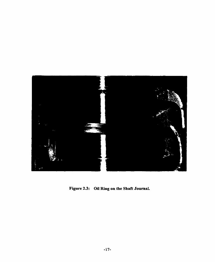
Figure 2.3: Oil Ring on the Shaft JournaI.
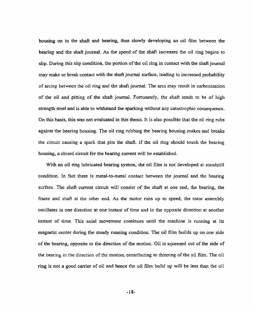
housing on to the shaft and bearing, thus slowly developing an oil film between the
bearing and the shaft journal. As the speed of the shaft increases the oil ring begins to
slip. During this slip condition, the portion of the oil ring in contact with the shaft journal
rnay make or break contact with the shaft journal surface, leading to increased probability
of arcing between the oiI ring and the shaft journal. The arcs may result in carbonization
of the oil and pitting of the shaft journal. Fortunately, the shaft tends to be of high
strength steel and is able to withstand the sparking without any catastrophic consequence.
On this basis, this was not evaluated in this thesis. It is also possible that the oil ring rubs
against the bearing housing. The oil ring rubbing the bearing housing makes and breaks
the circuit causing a spark that pits the shaft. I f the oil ring should touch the bearing
housing, a closed circuit for the bearing current will be established.
With an oil ring lubricated bearing system, the oil film is not developed at standstill
condition. In fact there is metal-to-metal contact between the journa1 and the bearing
surface. The shaft current circuit will consist of the shaft at one end, the bearing, the
frame and shaft at the other end. As the motor nuis up to speed, the rotor assembly
oscillates in one direction at one instant of time and in the opposite direction at another
instant of time. This axial movement continues until the machine is running at its
magnetic center during the steady ninning condition. The oil film buiIds up on one side
of the bearing, opposite to the direction of the motion. Oil is squeezed out of the side of
the bearing in the direction of the motion, contnbuting to thiming of the oil film. The oil
ring is not a good carrier of oil and hence the oil film build up will be less than the oil

film thinning. The shaft journal rides on a reduced oil film thickness. The oil film will
break and make correspondingly when the rotor assernbly is in the opposite direction of
motion. The back and forth shaft axial rnovement will gradually slow down till the
machine rotates at its magnetic center. This make and break of oil film phenomenon
continues until oil film stability is reached during steady state nuining condition. This
phenomenon is a cause of arcing on the bearing surface. Appendix 2 describes the oil
ring performance and lists the factors affecting the life of the bearing. It alro includes
some of the characteristics of the bearing, lubrication oil and oil ring used in the test
machine.
With a forced lubncated bearing system an oil film is developed between the shaft
journal and the bearing surface. The bearing current will not damage the bearing as no
make and break condition of the current arises. As the motor runs up to speed, the end
play movement wiII cause the oil film thickness to v q until it stabilizes to an average
value. It is this oil film variation that could possibly lead to make and break of the shaft
current circuit and hence lead to possible arcing at the bearing. However, this possibility
is less than for the case of an oil ring lubrication system. In Chapter 6, the importance of
build-up of oïl film to limit the magnitude of shaft current will be shown.
In machines where the bearing clearance is insuficient, the oil film rnay not be
distributed uniformly. Hence even though the current is small, about one ampere, bearing
damage can happen because the oil film may insulate a certain percentage of the bearîng,
forcing the small cument through the remaining non-insulated area. The oil film rnay not
be thick enough to virtually insulate the shaft fiom the bearings and prevent the bearing
current.
2.2.2 Energy per Square Meter [ 6,8,9 ]
E.G. Merrick [ 6 ] and Adler [ 8 ] reported that tests done at A.E.G. in Stadslau
showed that when the current density exceeds 15 to 20 arnperes per square decimeter of
the bearing surface the shaft is damaged. As long as the current density is less than 15
amperes per square decimeter o d y the bearing is damaged; the shafr will not be harmed.
A current density cnterion was used because it is difficult to calculate the bearing
currents due to varying contact resistance between the shaft and the bearing. Pearce
[ 9 ] comrnented that this cnterion is a probable means of determining the hannful effect
of bearing current. The power energy density criterion was not evaluated as part of the
objectives of the thesis. Adler [: 8 ] commented that bearing surface is a factor in the
determination of the seventy of the bearing current. A smooth bearing surface will
expenence lower beanng current than a rough bearing surface. Furthemore, Adler
concluded that bearing current will be larger at rest than when the machine is running.
This decrease in cwrent when running is due to increased resistance caused by a better
supply of oil between the contact surfaces.
Insulation of over 3.18 millimeters [ 9 ] is said to be sufficient to prevent the
establishment of current as the shaft voltage never reaches more than 10 volts. This
insulation is placed under the pedestal or bracket assembly. However, as can be

demonstrated in an experiment conducted on a 8 pole induction machine, Appendix 1,
insulation as thin as 0.762 millimeter may be sufficient.
Bearing darnage may occur over a relatively short time of a few seconds, or take
several years. The magnitude of the current density dictates the time taken for the bearing
destruction. In the expenmental work conducted on a 8 pole induction machine, the
bearing damage occurred during starting of the machine. In previous work, the steady
state phenornenon was assurned. At steady state running condition the oïl film stabilizes
to an average value. There is no make and break of the flow of current and no arc
phenomenoe The bearing is darnaged generally due to arcing of the bearing current
across the bearing clearance from the journal to the bearing.
2.2.3. Shaft End Play Movement ( 10, 12,24 ]
Wagner [ 10 1. Riggs [ 12 ] and Rosenberg 1 24 ] stated that shaft end-play movement
can cause bearing current to occur. During start-up of the machine, the rotor assembly
moves axially forward and back as the motor accelerates to mted speed. During this shaft
axial movement, if the shaft collar or shoulder runs fiee of the bearing ends, the oil films
in the two bearings are in series. If the oil films are thick enough, they can effectiveiy
break the current path. If the collar or shoulder rubs its bearing, only the film in the other
bearing offers resistance to shaft current. Hence, the latter oil film may fail and bearing
current results. The authors offered no experimental evidence to support the contention
that shaft end play movement influences shaft current.

This end play movement effect is not a significant factor as long as the bearings are
insulated. In fact, in the 8 pole induction machine with an insulated bearing, as the
machine accelerates to steady state running condition with end play movement, the shafi
current decays faster to a steady state value than when the machine accelerates with
negligible or no end-play movement. The back and forth shafi axial motion probably aids
the built-up of the oil film even though there is increased possibility of make and break
of the oii film thickness that will cause shaft current to arc across the oil film to the
bearing babbitt.
2.2.4 Rotor Construction [ 5 ]
Alger [ 5 ] considered a segmented type rotor construction to be of little importance in
considering how to avoid shaft current as the slip frequency voltage due to the rotor
segments is small compared with the line fiequency voltage. This is true. However, other
considerations of rotor construction must be evaluated such as non-insulated rotor bar,
saturation of the bridge above the rotor slot and shaft spider design. Non-insulated rotor
bar design is generally a nom. With this design there wiIl be inter-bar current
circumferentially, encircIing the shaft and hence contributing to shaft flux. In this thesis,
the effect of inter-bar current is mentioned in Chapter 5.

2.3 CHARACTERISTICS OF SHAFT VOLTAGE AND CURRENT
A number of characteristics of shaf? voltage and current have been observed by
previous investigators [ 5-28 1. Characteristics of the shaft voltage are surnmarized as
follows:
1. For a given size of machine and degree of saturation, the magnitude of this voltage
will be proportional to the ratio, A B in equation ( 2.1 ) times speed divided by the
number of poles. The frequency of the voltage will be equal to the numerator of the
segmenta1 punching ratio times Iine frequency.
2. The shafi voltage wilI increase rapidly with the rating of the machine, al1 other factors
remaining equal. According to the magnetic equivalent of Ohms' law, flux is
proportional to magnetomotive force and inversely proportional to reluctance. As the
rating of the machine increases, the core size of the machine increases and hence the
reluctance of the stator core decreases. The reluctance of splits in the stator will be a
greater proportion of the total stator reluctance. Hence, circulating flux increases and
shafi voltage increases correspondingly. As the machine size increases with the rating
of the machine, greater constructional asymmetries, sagging of the stator core and the
rotor core and saturation arise. These factors influence the increase in the magnitude
of shaft voltages.
3. Shaft voltage wifl be greater in machines with smaller air-gaps. The reluctance of the
joint represenl a greater proportion of the magnetomotive force for constant flux.
The ratio of the rnagnetic field strength of the air gap to the total magnetic field

strength is small. Thus, the induction machine will be more likely to suffer such
currents than the synchronous machine which has a larger air gap. The larger the
diarneter and the larger the nurnber of poles in the machine the srnailer the ratio of
:JI,,. the reluctance corresponding to the flux in the split stator where the split occurs,
to %,, the reluctance corresponding to the flux in the split stator where there is no
split. Hence, the circulating flux which is proportional to the ratio of %,/!JI, will
decrease. Shafi current due to this effect tends to be more pronounced in high speed
machines with few poles.
4. Shafi E.M.F. will build up rapidly with saturation initially until the entire magnetic
circuit becomes saturated. As the permeability of the magnetic circuit approaches that
of air, the reluctance of the joints has little influence on the total reluctance of the
magnetic circuit, and the shaft voltage begins to drop off. For a complete discussion,
see Chapter 6. Line fiequency shaft currents are nearly proportional to voltage at low
flux densities. They decrease less rapidly with saturation. Multiple-frequency shaft
currents have low values at reduced voltages.
5. Shaft current is approximately the same at no-load as at the full load condition [ 2 1 1.
Shaft voltages caused by magnetic asymmetnes and static-excitation systems do not
change in magnitude with changes in the load. This was clearly observed by Verma
et al [ 21-23 1. Only shaft potentials of electrostatic origin appear to change
considerably with changes in the load. The electrostatic voltage on the shafi
decreased linearly with reduction of the load and disappeared completely at about

half of full load in the measurement on a turbo-generator. Electrostatic voltages are
erratic in nature. They depend on several factors such as flow and conditions of
steam, load changes, source impedance, stearn flow rates and many other design
variables that determine the resistance in the circuit to ground.
2.4 RECOGNITION OF SHAFT CURRENT
Bearing darnage may be of mechanical, chernical or electrical ongin. Thus, it is
important that an inspection of the damaged bearing be camied out under a microscope.
Michael Costello [ 18 ] and Boyd and Kaufman [ 25, 26 ] provided information on the
recognition of bearing current darnage, origin and detection of this current and
control procedures. Bearing current damage can be classified into four types: 1) Frosting;
2) Pitting; 3) Spark Tracks; 4) Welding.
A fiosted surface is characterized by very small individual "craters" which average
about 25 micrometers in diameter. This is smaller than many of the surface scratches.
The bottoms of these craters are round and shiny. Frosting generally occurs dunng
voltage discharge and is cornmonly referred to as " electric discharge machining "
( EDM ) or electrolysis. Frosted surfaces rnay be of electrical origin or chemical origin.
Chernical attack gives a simiiar appearance to frosting, distinguished by the fact that the
arcs are smaller, not as deep and dull. It may be necessary to use X-ray spectroscopy to
determine whether the frosting surface is due to chemical contamination or electroIysis.
Pitting results in craters that are generally much larger in size ( 200 micrometer to
about 250 micrometers in diarneter ) than for frosting. The bottoms of the pits are
rounded m d have the smooth shiny appearance of having been melted. Pitting is a more
serious f o m of darnage than fiosting. tnitially, each pit is a separate crater and more or
less circular in shape. As the pitting process continues, the pits begin to overlap, tending
to destroy the clear evidence of their origin. Pits caused by corrosion or by foreign
particles are usually of irregular form and have du11 appearance. They are spaced at
regular intemals circumferentially over a portion of the bearing. Such pits are almost
invariably accompanied by circurnferential scratches. Also, although these non-electrical
pits have smooth bottorns they do not have the melted appearance of electrical pits.
Electrical pi& on the joumal are usually considerably smaller than those on the bearing.
The joumal is not readily destroyed by mechanical pitting. This is because the joumal is
generaily harder than the bearing.
Spark tracks are very irregular in nature and are often askew to the direction of
rotation. The bottom of the tracks are sometimes melted and they have sharp corners. In
contrast, dirt particles would leave rounded corners. The depth of the spark track is
generally the same over its entire surface. There are occasions when the shaft journal
exhibits absence of electrical discharge marks while electrical discharge is obvious on the
bearing surface as shown in Figure 2.4. Figure 2.4 ( a ) shows uneven darkened thick
marks on the upper part of the lower half of the bearïng assembly. Microscopic view of
the damaged area as shown in Figure 2.4 ( b ) indicates splatters of bearing babbia. It
appears that the babbitt was blasted out of the bearing surface by momentary electrical
discharge. On M e r examination of the darnaged area, molten Crater with spark tracks
were observed as shown in Figure 2.4 ( c ).
Welding of parts such as bearing housing splits and bearing pads occurs when a great
amount of current in order of hundreds of amperes passes through these parts. They are
obvious to the naked eye.
2.5 SUMMARY
Shafi current generally arises due to asymmetries of the magnetic flux path. The
magnitude of the shaft current is measured using an ammeter in the connection between
one end of the shafi and its other end. It will be demonstrated in Chapter 3 that this
method is fairly inaccurate. A new novel method of shaft current measurement is
proposed in Chapter 3.
Equation ( 2.1 ) does not take into account harmonics such as stator slot harmonics,
rotor slot harmonics and saturation. Furthemore, air gap eccentricities are not
considered. The effect of eccenhicity was bnefly mentioned in the study by Rosenberg
[ 24 ] and 0. Haus [ 14 1. There was no analytical determination of the effect. Hsu [ 27 ]
reported that shaft voltage increases under greater eccentricities when the stator and rotor
axes are parallel. In Chapters 4 and 5, effects of harmonics and air gap eccentricities are
considered in the application of equation ( 2.1 ) to determine the occurrence of shaft
current.

Figure 2.4 (a): A Close-Up View of the Bottom of the Bearing Showing the Damage at the Upper Part of the Bearing.
Figure 2.4: Typical Bearing Damage Due to Shaft Current.
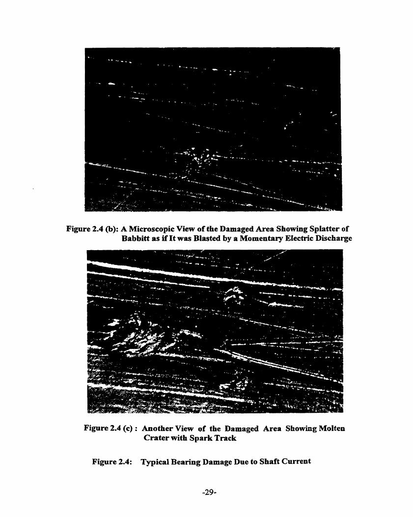
Figure 2.4 @): A Microscopic View of the Damaged Area Showing Splatter of Babbitt as if It was Blasted by a Momentary Electric Discharge
Figure 2.4 (c) : Another View of the Damaged Area Showing Molten Crater with Spark Trnck
Figure 2.4: Typical Bearing Damage Due to Shaft Current
It is important to separate mechanical causes fiom electrical causes of bearing darnage.
Microscopic inspection of the bearing needs to be carried out to determine the cause of
beanng daniage. Oil analysis will assist in the determination of the presence of shaft
current. However, it will be demonstrated in Chapter 6 that oil analysis can be
inconclusive.
The maximum acceptable levels of shaft residual flux proposed by Costello, Sohre
and Nippes are the only published values available. These Ievels were a result of their
work on high speed turbo-machinery ( speeds equal to or greater than 3600 rpm ) and
hence for speed equal to or less than 1800 rpm, the level proposed may be on the low
side. The levels are only to be used as a guide to minimize locaiized bexing current.

CHAPTER 3
MEASUREMENT OF SHAFT CURRENT
3.0 INTRODUCTION
Magnetic asymmetries rnay result in a voltage from end to end of the shaft of a large
induction machine. These asymmetries may arise due to the jointing of segmented
punchings around the core of the machine, stacking of segments, rotor eccentncity, rotor
or stator sag, and other anomalies during manufacture. However, there is evidence that
shaft voltage occurs on al1 rotating electrical machines to a greater or lesser degree. There
is also the possibility that other factors such as build-up of electrostatic charge rnay, in
some applications involving PWM inverters, give rise to bearing current.
IEEE Standard 1 12-1991 [ 4 ] describes end-to-end shaft voltage measurernent
techniques. It states that shaft current can be measured by substituting an ammeter in the
circuit. This method yields an incorrect measurement for shaft current. The test machine
used for this work is a large, eight pole induction motor. During initial conventional
commercial testing, it was found to have discolored oil and damaged bearings.
Examination of the bearing babbitt showed the characteristic stitch marks with round
shiny bottom craters associated with shaft currents. In this case the oil was clean at the
start of the test, and precautions had been taken to insulate the bearings against the

possible development of shafi current. Bearing insulation both before and afier the tests
was above f 0,000 R; hence there was no apparent cause for the bearing darnage.
However, it is conceivable that a small voltage could be established end-to-end across
the shaft. On start-up, before the establishment of an oil film, this small voltage couid
lead to a relatively high shaft current. On establishment of the oil film, the interruption of
the shaft current could then lead to a very high component of induced voltage, resulting in
breakdown of the oil film with the consequent damage to the oil and bearing as shown in
Figure 2.4. The problem is then to develop a measurement program to establish that shafi
voltages did indeed occur and to detemine the magnitude of such shaft voltage along
with the resulting bearing or shaft current.
In this chapter the different conventional methods of shaft measurement and the
proposed Rogowski coil method are discussed. The theory and justification of the
proposed Rogowski coil method are described in detail. Finally test results will
demonstrate that the Rogowski coil method is a preferred method of shaft current
measurement.
3.1 METHODS OF SHAFT CURRENT MEASUREMENT
Two types of shaft current measurement were evaluated. They are the shunt /ammeter
method and the Rogowski Coi1 method.
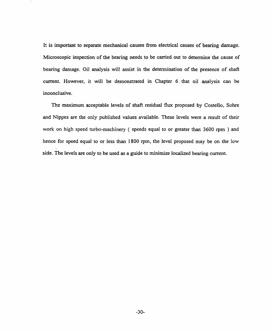
3.1.1 Shunt/Ammeter Method
The shunt/afnmeter method uses a low resistance moving coi1 type ammeter placed in
series with the shaft as illustrated in Figure 3.1.
Induction Machine Drive End Shaft
I
@ m e t e r Size AWG 2 Cable
Figure 3.1: Schematic of Ammeter Method
Shaft current measurement varies inversely with the size of the cable. The bigger the
size of the cable and hence reduced cable resistance, the larger is the shaft current. The
shaft current measured is load dependent. No attempt was made to define a load
dependence relationship. After a trial period, a cable of size AWG 2 was determined to be
practical and appropnate for stable shaft current measurement. The comection of the
cable to the two ends of the shaft can be done through a bmsh assembly but this is not
feasible due to space limitation as a result of the installation of the Rogowski coils on
both ends of the motor and a collecter ring on the opposite drive end of the shaft. Instead,
inch wide copper braided wires wound on the ends of rectangular pieces of wood and
connected to the AWG 2 cable, were held in firm contact with the two ends of the shaft.
A low resistance ammeter was inserted in the circuit to rneasure the shaft current. This
method is considered unreliable as the introduction of the comection fiom one end of the

shaft to the ammeter and then to the other end of the shaft results in a low impedance
path for the shaft current. Without this extemal comection there is no path for the shafi
current as both bearings are insulated. A detailed explanation is given in Section 3.1.2.
3.1.2 JUSTIFICATION OF THE USE OF ROGOWSKI COL
IEEE standard 112 indicates the use of a low resistance ammeter in the measurement
of shaft current. The ammeter method disturbs the shaft current conducting circuit of the
machine as indicated in Figure 3.2 by providing a low resistance path through the shunt
resistance or the ammeter resistance.
Resistance,
+Bearing Insulation < Resistance, % Oil Film Resistance,
1 1 ( Order of kilo-ohms )
%
-..-.-..-. Ammeter Method *. . . i :
Rogowski Coil Measurement i! -8
Figure 3.2: Simplified Representation of Machine Under Test

This can be shown as follows:
Applying Kirchhoff s law to the heavy lined circuit in Figure 3.2, we obtain
Vi = 1, ( %+% +%) ( 3 . 1 1
where Vi is the induced shaft voltage,
4, the resistance of the shaft,
% the resistance of the oil film,
and R,, the bearing insulation resistance.
The bearing insulation resistance is at least of the order of kilo-ohms, greater than the
shaft resistance and oiI film resistance and hence equation ( 3.1 ) can be simplified as
vi = 4 % ( 3.2
Equation ( 3.2 ) indicates the shaft current to be of small magnitude.
Using the ammeter rnethod, shown in Figure 3.2 as the dashed circuit to measure
shaft cunent, the voltage-cwent relationship can be obtained as
Vi = 1s ( & + K + K I ( 3.3
where R, is the shunt or ammeter resistance and R, the comection contact resistance.
The arnmeter resistance is of the order of rnilli-ohms. With the negligible magnitude of
the shaft resistance and ammeter resistance, the shaft current has been arnplified. The
arnplified shaft current does not represent the m e value of the machine. The
amplification of this cunent through the arnmeter rnethod can cause secondary effects on
the shaft and the bearing.

With the Rogowski coil mounted tightly around the shaft on the inboard end of the
bearing bracket assembly, the current measured is the tme rms current in the shaft. Hence,
the direct approach to the measurement of shaft current was abandoned in favor of the
Rogowski coil method.
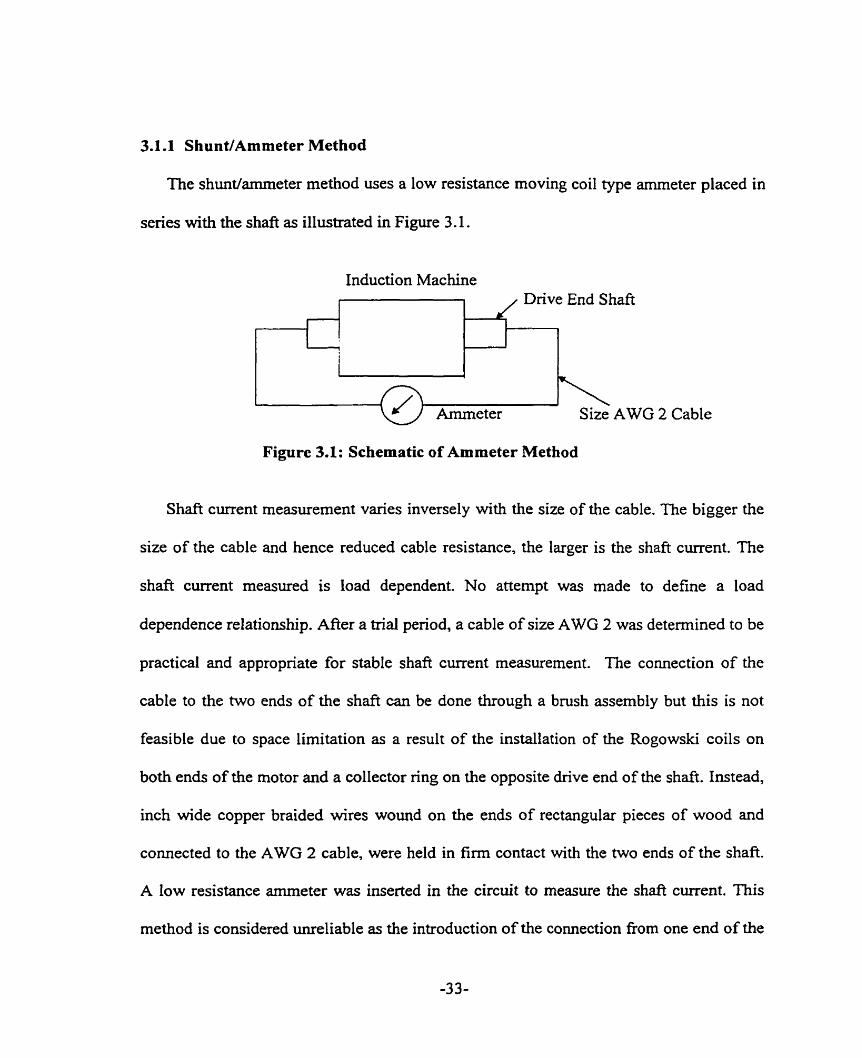
3.16 Rogowski Coi1 Method
In the Rogowski coil method, two Rogowski coils, Figure 3.3, were installed around
the shaft close to the rotor bore on both ends of the shafi as shown in Figure 3.4. The
voltage outputs fiom the coils were connected to the collecter or slip ring fiom which
connection was made to an isolator and then to a recording system. The isolator is used to
ensure that there is no grounding anywhere in the connection fiom the Rogowski coil to
the recording system. A two inch diarneter shafi hole was drilled from one end of the
shafi to the other end. The insulated coaxial cable extension from the Rogowski coil runs
in this hole to the slip ring. In this manner, the influence of interference is further
reduced. The slip ring was installed on an insulated adapter on the opposite drive end of
the shaft, Figure 3.5. Al1 connection cables are coaxial type to reduce noise interference.
3.2 THEORY OF THE ROGOWSKI COlL [ 29 ]
The Rogowski coil consists of a solenoid of fine wire uniforrnly wound on a flexible
non-magnetic tube of which the two ends are brought together to form a butt joint. The
coil is basically an air core transformer with a uniformly wound secondary. Hence, the
core does not saturate, providing for a linear coil input-output relationship. The coil is
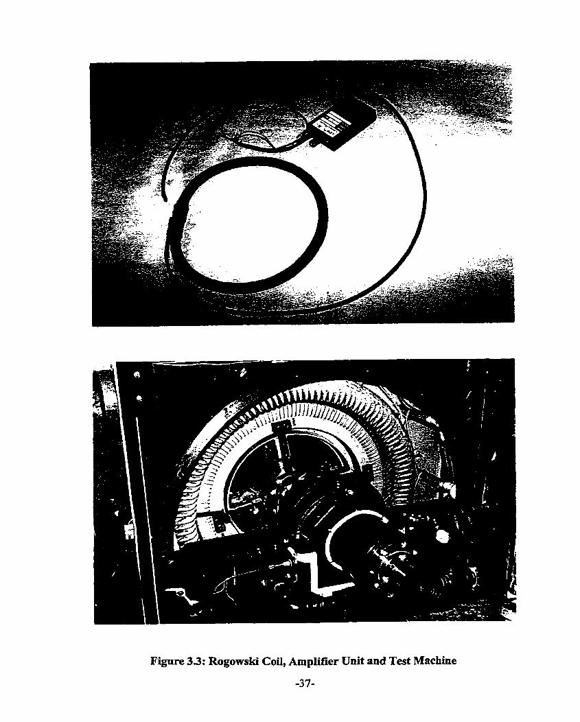
Figure 3.3: Rogowski Co& Amplifier Unit and Test Machine

Figure 3.4: Location of Rogowski Coi1 in the Induction Machine
Figure 3.5: Colleetor Ring Installed on ODE of the Shaft of the Induction Machine -3 8-

wound tightly around the conductor carrying the current, in this case the shaft. There is
no disturbance of the conducting circuit unlike the case when the shuntkmmeter circuit
is used. The coil output voltage is proportional to the time rate of change of current. An
outiine of the Rogowski coil is shown in Figure 3.6.
Coil cross section, A
Closed Contour, C
1
Figure 3.6: Outline of Rogowski Coil
Consider an N t u . coil carrying a time varying current i. Let H, be the component of
magnetic field strength tangential to the closed contour and hence normal to the coil cross
section A. Also, let H, be the component of the field normal to surface S. Applying
Faraday's law to the Rogowski coil, the induced instantaneous E.M.F. in the coils is
given by
e = -
where Or. is the instantaneous flux linking the kt" tum of the N-tum coil.
Substituting for O k , equation ( 3.4 ) becomes
-3 9-
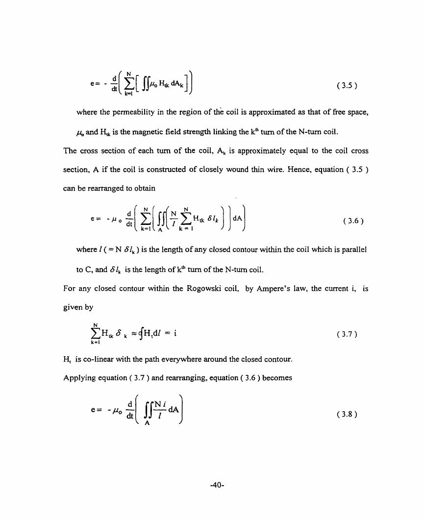
where the permeability in the region of the coil is approximated as that of free space,
A and H, is the magnetic field strength linking the kfh turn of the N-tum coil.
The cross section of each turn of the coil, Al is approximately equal to the coil cross
section, A if the coi1 is constructed of closely wound thin wire. Hence, equation ( 3.5 )
can be rearranged to obtain
where 2 ( = N 61, ) is the length of any closed contour within the coil which is parallel
to C, and 61, is the length of k* turn of the N-tum coil.
For any closed contour within the Rogowski coil, by Arnpere's law, the current i, is
given by
H, is CO-linear with the path everywhere around the closed contour.
Applying equation ( 3.7 ) and rearranging, equation ( 3.6 ) becomes
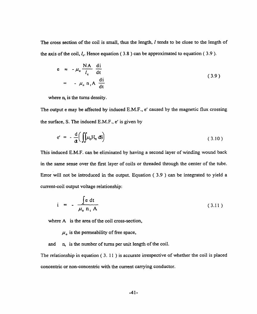
The cross section of the coil is smaii, thus the length, I tends to be close to the length of
the axis of the coil, 2,. Hence equation ( 3.8 ) can be approximated to equation ( 3.9 ).
where n, is the turns density.
The output e may be affected by induced E.M.F., et caused by the magnetic flux crossing
the surface, S. The induced E.M.F., et is given by
This induced E.M.F. can be eliminated by having a second layer of winding wound back
in the sarne sense over the f ~ s t layer of coils or threaded thmugh the center of the tube.
Error will not be introduced in the output. Equation ( 3.9 ) can be integrated to yield a
current-coi1 output voltage relationship:
where A is the area of the coil cross-section,
p, is the permeability of fiee space,
and n, is the number of tums per unit length of the coil.
The relationship in equation ( 3. 1 1 ) is accurate irrespective of whether the coil is placed
concentric or non-concentric with the curent carrying conductor.

For a sinusoidal current having a peak value I resulting in a peak output voItage, E, of
fiequency a, equation ( 3.1 1 ) becomes
E
Area A is relativeiy small compared to the area of the loop formed by the closed coiI.
3.3 TEST CONTROL CONDITIONS
Prior to the test, control conditions were set to ven@ the accuracy of the Rogowski
Coi1 rnethod of shaft current rneasurement. These conditions were devised to minimize
any known extenuating factors on the magnitude of shaft current:
1. The rnotor bearings have new lead babbitt. Any contamination in the bearing
babbitting process was removed by running the motor for four hours a few times.
Contamination in the bearing babbitt tends to revise the charactenstics of the oïl, thus
influencing the magnitude of the shafl current. The oil is generally discolored by the
contamination.
2. One comrnon barre1 of Harmony ISO VG 68 oil was used for al1 tests. This is to
ensure that the oil condition would not constitute a factor in the investigation.
3. The Rogowski coi1 was calibrated on the shaft pnor to the test and after the test. The
DE and ODE Rogowski coils have calibration values of 1 1.02A.V and 13.72AN,
respectively as determined in Appendix 3 compared to the manufacturer's quoted
value of 1 O A N .
3.4 SET UP FOR THE MEASUREMENT OF SHAFT CURRENT
3.4.1 Rogowski Coi1 and Flux Coi1
The Rogowski coil was wound tightly around the shaft on the inboard end of the
bearing bracket assembly at both the drive end and opposite drive end of the machine to
measure shaft current. The Rogowski coil output leads are brought through a two inch
hole in the shaft, to an eighteen channel slip ring which was mounted on the opposite
drive end of the shaft. In addition to the Rogowski coil output leads, leads from the flux
coil mounted on the shaft and the spider amis were brought out to terminal blocks and
then to the slip ring. The terminal blocks are installed on the outer surface of a textolite
mounting adapter. Flux coils were mounted on both the drive end and opposite drive of
the shafi to measure shaft flux. The flux coils installed axially on the spider a r m s measure
the radial flux.
3.4.2 Slip Ring and Recording Equipment
A high accuracy, low noise slip ring with thirty six circuits ( eighteen channels ) as
shown in Figure 3.7 was installed on the ODE of the shaft. The slip ring was mounted on
an insulating adapter assembly to reduce the effects of possible ground loop. The adapter
assembly is made of textolite.
A video cassette recorder as shown in Figure 3.7 was used to store the data
throughout the test. The recorder is a compact lightweight fourteen channel system that
covers the range from DC to 10 H z in 7 tape speeds, although a tape speed of 38.1 cm/s
was selected. The specifications gave a signal to noise ratio of 49 dB.

Machine Under Test Signais From Rotating Sensors via Slip Ring Signals From Stationary Sensors Mounted on the ODE of the Machine
8 Channel Isolation Amplifier
Two 14 Channel Video Cassette Recorders .il/
Spectrum Analyzer
Figure 3.7: 2611 kW Induction Machine Experimental Test Set-Up
3.4.3 Spectrum AnaIyzer
A spec tm analyzer provided for Iive acquisition, anaiysis and display of waveform
signals. This device is an eight channel 100 kHz dynarnic signal analyzer with four
selectable fiequency resolutions. The noise floor is greater than 90 dB fiom below fidl
s a l e 0.1V to 20V full scale. Three types of windows or weighting selections are
available - Rectangular, Flat top and Hanning. Rectangular windowing has good
fiequency resolution but poor amplitude accuracy. The flat top windowing has poor
fiequency resolution but good amplitude accuracy. Hanning is a good compromise
between rectangular and flat top windowing. Details of the specifications of the signal
analyzer can be found in [ 30 1.
3.4.3 Isolation Amplifier
The Gould 8 channel Isolation Amplifier as shown in Figure 3.7 serves as an interface
module between the collector ring and the video cassette recorder and the s p e c t m
analyzer, providing for input-to-output isolation without the wony of creating ground
loops. This is especially important as any ground loop will provide a path for the shaft
current to flow.
3.5 SHAFT CURRENT MEASUREMENT METHOD TEST RESULTS
In medium and large alternating current machines, both bearings are normally
insulated. The test machine bearings are insulated, the insulation materiai placed on the
back of the steel bearing surface which sits on the bearing housing support. During
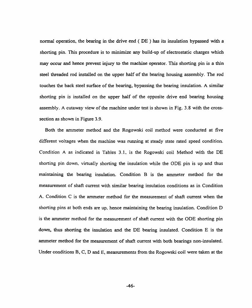
normal operation, the bearing in the drive end ( DE ) has its insulation bypassed with a
shorting pin. This procedure is to minimize any build-up of electrostatic charges which
may occur and hence prevent injury to the machine operator. This shorting pin is a thin
steel threaded rod instailed on the upper haif of the bearing housing assembly. The rod
touches the back steel surface of the bearing, bypassing the bearing insulation. A similar
shorting pin is installed on the upper half of the opposite drive end bearing housing
assembly. A cutaway view of the machine under test is shown in Fig. 3.8 with the cross-
section as shown in Figure 3.9.
Both the amrneter method and the Rogowski coi1 method were conducted at five
different voltages when the machine was m i n g at steady state rated speed condition.
Condition A as indicated in Tables 3.1, is the Rogowski coil Method with the DE
shorting pin d o m , virtually shorting the insulation while the ODE pin is up and thus
maintaining the bearing insulation. Condition B is the amrneter method for the
measurement of shaft curent with similar bearing insulation conditions as in Condition
A. Condition C is the arnmeter method for the measurement of shafi current when the
shorting pins at both ends are up. hence maintaining the bearing insulation. Condition D
is the arnmeter method for the measurement of shaft current with the ODE shorting pin
d o m , thus shorting the insulation and the DE bearing insulated. Condition E is the
arnmeter method for the measurement of shaft current with both bearings non-insulated.
Under conditions B, C, D and E, measurernents from the Rogowski coil were taken at the
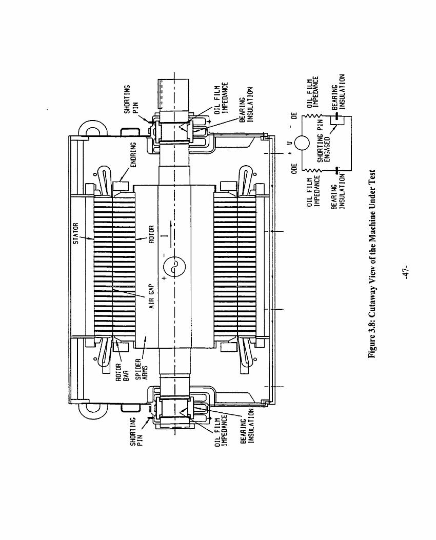
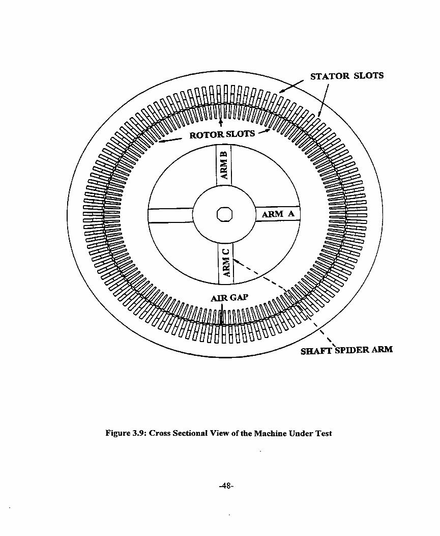
Figure 3.9: Cross Sectional View of the Machine Under Test
same time as the ammeter reading was taken. The measurements shown in Table 3.1. are
approxirnately sirnilar to the ammeter readings, shown in Tables 3.2.
Condition A meascrements in Table 3.1 and Condition B measurements in Tables 3.1
and 3 -2, clearly indicate the influence of a closed shaft current circuit. Figures 3.10 and
3.1 1 indicate that the ammeter method provided a path for the zero sequence current
which wouid not have been present in the test machine with either or both bearings
insulated. Figure 3.10 ( a, i ) indicates a non-sinusoidal shaft current waveform whereas
Figures 3.10 ( b,
spectral analysis
Hz, 120 Hz and
percent of motor
i ) and ( c, i ) show harmonic sinusoidal waveforms. Figure 3.10 (a, ii ),
of Figure 3.10 ( a, i ), indicates dominant fiequency components of 60
180 Hz. The 120 Hz component is due to the core vibration. At 20
rated line voltage, the stator teeth are not saturated. Hence, the 180 Hz
component is not due to saturation but due to joints in the stator core. This conclusion is
demonstrated in Chapter 6. Figures 3.10 ( b, ii ) and ( c, ii ) show dominant fiequency
component of 180 Hz. The magnitude of the 180 Hz shaft current component at 80
percent of motor rated line voltage, Figure 3.01 ( b, ii ), is the maximum value measured
using the ammeter method. With the Rogowski coi1 method, the shaft current
measurements indicate a rotor m i n g fiequency of 15 Hz as the dominant fiequency.
The magnitudes of the shafi current in Figures 3.1 1 ( a, i ), ( b, i ) and ( c, i ) are
negligible compared to the vaiues obtained in Figures 3.10 ( a. i ), ( b. i ) and ( c, i ). The
dominant 180 Hz fiequency components observed in Figures 3.10 ( a, ii ), ( b, ii) and
( c, ii ) are considerably negligible in Figures 3.1 1 ( a, ii ), ( b, ii ) and ( c, ii ).

i) Shaft Current Waveform
h.111.3 Y:4.Qo2m O&IO.lSm Vp
ii) Spectrum Plot
a) Shaft Current Waveform and Spectmm Plot at 2O%V
Figure 3.10: Shaft Current Waveform and Spectrum At 2O%V, 80%V and 100%V, Measured Using the ShuntAbumeter Method, Both Bearings Non-Insulated, Oil Kng Lubrication.
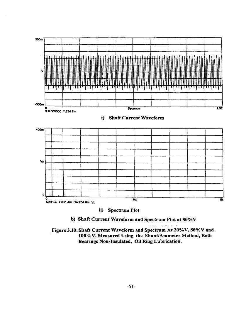
i) Shaft Current Waveform
ii) Spectmm PIot
b) Shaft Current Waveform and Spectmm PIot at 80%V - - - -
Figure 3.10: Shaft Current Waveform and Spectrum At 2O%V, 80%V and lOO%V, Measured Using the ShunVAmmeter Method, Both Bearings Non-Insulated, OiI Ring Lubrîcation.

- x a m m i) Shaft Current Waveform
ii) Spectrum Plot
c) Shaft Current Waveform and Spectmrn Plot at 100%V
Figure 3.10: Shaft Current Waveform and Spectrum At 20%V, 80%V and 10O0AV, Measured Using the ShudAmmeter Method, Both B e a ~ g s Non-Insulated, Oil Ring Lubrïcation.
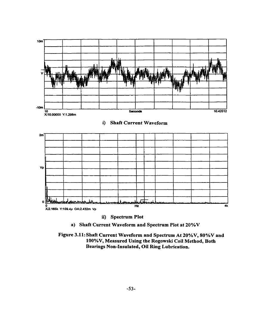
i) Shaft Current Waveform
0 l-k 4k XSY65k Y:109.4p 0AZ432m Vp
ii) Spectrum Plot
a) Shaft Current Waveform and Spectrum Plot at 20%V
Figure 3.11: Shaft Current Waveform and Spectmm At 20%V, 80°hV and 100%V, Measured Using the Rogowski Coi1 Method, Both Bearings Non-Insulated, Oit Ring Lubrication.
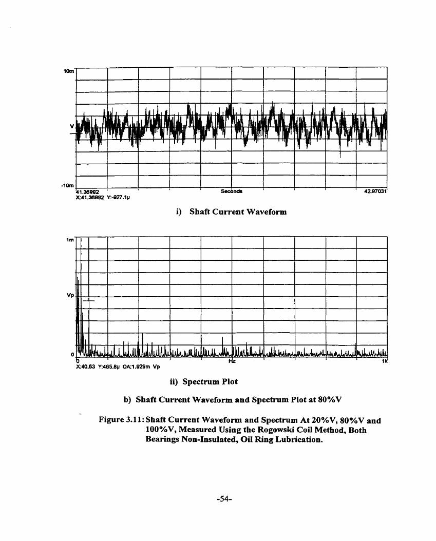
i) Shaft Current Waveform
ii) Spectrum Plot
b) Shaft Current Waveform and Spectrum Plot at 80%V
Figure 3.1 1: Shaft Current Waveform and Spectmm At 20%V, 80%V and 100%V, Measured Using the Rogowski Coi1 Method, Both Bearings Non-Insulated, OiI Ring Lubrication.

i) Shaft Current Waveform
X15.00 Y:1.815m Ok3.187m Vp
ii) Spectrum Plot
c) Shaft Current Waveform and Spectmm Plot at 100%V - - - . -
Figure 3.11: Shaft Current Waveform and Spectrum At 20%V, 80%V and 100%V, Measured Using the Rogowski Coil Method, Both Bearings Non-Insulated, Oïl Ring Lubrication.

Condition B measurements clearly indicate that the bearing insulation is in good
condition, othenvise the readings fiom the Rogowski coil will be higher than the ammeter
reading. Condition C measurements verify the accuracy of the Rogowski coil. The
Rogowski coil measures a sirnilar magnitude of shaft current as the arnmeter. Condition
D measurements verified the conclusion fiom Condition B measurements.
The oïl film behaves as an insulator and limits the magnitude of shaft current to a
negligible value; otherwise the Rogowski coil would have indicated a higher shaft current
magnitude compared to the reading fiom the ammeter in Condition E. There is negligible
difference between the two values. As the fiequency of the shaft current increases. the oil
film may break down, hence the oil film done wilI not be suffrcient to limit the
magnitude of sh& current. In this case the bearings need to be insulated or a shah ground
bmsh installed to bypass the shaft current and limit the arnount of shaft current to the
bearings.
It is seen fiom Table 3.1 that the magnitude of shafi current is a maximum at 80
percent of rnotor rated line voltage. Table 3.2 indicates a similar shaft current
phenornenon. Likewise the corresponding shaft voltage magnitude as seen in Table 3.3, is
a maximum at that motor line voltage.
3.6 SUMMARY
The Rogowski coil shafi current measurement [ 3 1 ] does not disturb the conducting
circuit and is not load dependent. Hence, the shaft current rneasured is an accurate
assessment. Furthermore, this method of measurement can be used as an on-line

monitoring systern providing indication of deterioration of bearing insulation or oil. The
Rogowski coi1 shaft curent monitoring is inexpensive and does not require penodic
maintenance as with the shafi ground brush used in the amrneter method.
Motor Line Voltage Shaft Current ( A )
Condition A - DE Condition B - DE Condition C - DE Condition D - DE Condition E - DE ;
1 I 1 I 1
Condition E - ODE 1 0.83 1 1.79 1 11.93 1 21.20 1 15.13
Condition B - ODE Condition C - ODE
TABLE 3.1 : DE and ODE Rogowski Coi1 Shaft Current Measurement
20% Rated Volt 0.15 0.85 0.89 0.8 1 0.88
Condition A - ODE 1 0.13 0.82 0.84
TABLE 3.2 : Ammeter Method Shaft Current Measurement
40% Rated Volt 0.16 1.84 1.84 1.86 1.86
Condition D - ODE 0.84
Motor Line Voltage
0.15 10.19 1.77 I .78
Shaft Ciment ( A )
Condition B Condition C Condition D Condition E
100 % Rated Volt 0.67
60% Rated Volt O. 18 12.1 12.03 12.10 12.05
1 .78
Motor Line Voltage
TABLE 3 3 : Shaft Voltage Measurement
0.20 11.98 11.92
20% Rated Volt 0.84 0.88 0.84 0.88
Shafi Voltage End-to-End ( V )
Condition A
80% Rated Volt 0.19
0.14
22.20 22.54 22.39 22.45
11.95
100% Rated Volt 0.13 15.84 15.81 15.85 15.93
21.18 21.21
20% Rated Volt .
0.05
15.04 15.03
21.13
40% Rated Volt 1.84 1.84 1.88 1.84
15.05
60% Rated Volt 12.40 12.28 12.28 12.32
80% Rated Volt 22.16 22.28 22.12 22.12
100% Rated Voit 15.60 15.80 15.64 15.76
80% Rated Volt 0.86
40% Rated Volt 0.1 1
60% Rated Volt 0.66

CHAPTER 4
HARMONIC WAVEFORMS AND THElR EFFECTS ON SHAFT CURRENT
4.0 INTRODUCTION
In this chapter, various forms of harmonic waveforms will be evaluated to determine
the presence of shafi current. A rnagnetomotive-permeance wave approach is used in the
evaluation. This approach is based on the fact that the magnetomotive force and the air
gap permeance can be considered as an infinite series of sinusoidal traveling waves [ 32 1.
This approach predicts the order of the harmonics accurately. However, the amplitudes of
the traveling wave harmonics computed by this analytical approach is not sufficiently
accurate. Furthemore. this approach does not account for the effects of iron saturation.
Iron saturation plays an important role in detennining the air gap flux density. Hence, this
approach is used only to provide quick determination of the presence of shaft current.
4.1 EFFECTS OF STATOR SPATIAL HARMONICS AND ARMATURE REACTION ON SHAFT CURRENT
The magnetic field distribution in the air gap of an electric machine is influenced by
several factors such as slotting, saturation and rotor eccentricity. Slotting causes the
magnetomotive force ( MMF ) to stagger around the circurnference of the gap,

consequently the MMF wave has harmonic contents superimposed on the fundamental.
Rotor eccentricity and iron saturation give rise to air gap penneance harmonies. Figure
4.1 shows the establishment of air gap field in a three phase electrical machine.
Symmetrical rn-phase. frequency f supply
I
Figure 4.1: Development of Air Gap Field and Armature Reaction in Induction Machine
Stator Current Stator Current frequency f
Consider a three phase electrical machine fed fiom a symmetxical supply of angular
fiequency, o. The three groups of windings of N, tums per phase are mutually displaced
Stator MMF Stator MMF
--
U" order c'h order ph order air gap field air gap field air gap field
A
Rotor Current Rotor Current frequency, s, f
-

dong the circumference by the angle 2dm. The three phase currents set up an MMF
varying with time. This MMF is staggered round the circurnference. Thus, in addition to
the fiuidamental pole pair number, p, space harmonics of poles pair number up is
produced. The magneromotive force. J produced by a 3-phase winding [ 32, 33 ] is given
by
or in generai for an m phase winding:
where p is the number of pole pairs of the fûndamentai field,
m is the nurnber of phases of the stator winding,
N, is the nurnber of turns in series per phase,
K,, is the pitch factor or chording factor for the v " harmonics,
K, is the distribution factor for the v '' harmonics,
u is the spatial or phase belt harmonic order and
Q is the angular displacement of the stator winding, electrical radian.
Phase belt harmonics of order 5, 7, 1 1, etc. are generally present while the third harmonic
and its multiples are eliminated. The permeance of the air gap is not uniform, altered by
slotting, saturation and rotor position. The constant term of the air gap permeance is given
by equation ( 4.3 ).

The permeance of the air gap per unit area, P, = EL 6
where jt, = 4 ir x 1 O-' W m
and 6 = length ofthe air gap, m.
An infinite senes of air gap flux density waves produced by the interaction of the
MMF waves with the constant term of the permeance wave acts on the rotor winding and
induces in the winding voltages having identical order of harmonies. The uth order air gap
flux density is obtained as the product of the correspondicg MMF and the air gap
permeance per unit area as given in equation ( 4.4 ).
where q, = the nurnber of dots per pole per phase,
u = ( l + î m ~ , ) ,d
K, = O, f l , e,...
The air-gap flux density produced by the stator current induces currents in the squirrel
cage rotor windings at slip fiequency given by
s,f = [ 1- u (1-s)] f ( 4-5 1
Space harmonic order, u is to be taken as positive for fonvard revolving fields and
negative for backward revolving fields [ 33 1.
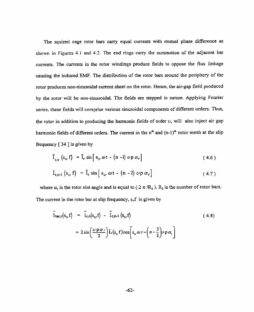
The squirrel cage rotor bars carry equal currents with muhial phase difference as
shown in Figures 4.1 and 4.2. The end rings carry the summation of the adjacent bar
currents. The currents in the rotor windings produce fields to oppose the flux linkage
causing the induced EMF. The distribution of the rotor bars around the periphery of the
rotor produces non-sinusoidal current sheet on the rotor. Hence, the air-gap field produced
by the rotor will be non-sinusoidal. The fields are stepped in nature. Applying Fourier
series. these fields will comprise various sinusoidai components of different orders. Thus,
the rotor in addition to producing the harmonic fields of order u, will also inject air gap
harmonic fields of different orden. The current in the n" and (n-1)" rotor mesh at the slip
fiequency [ 34 ] is given by
- - Ir." ( ~ , f ) = 1,sin [ su o t - (n -1) o p a r ] ( 4-6 )
- - I r ( f) = Ir sin S, w t - (n -2) o p a,] [ ( 4-7
where cr, is the rotor slot angle and is equal to ( 2 rr IR, ). R, is the nurnber of rotor bars.
The current in the rotor bar at slip fiequency, s,f is given by
- - - 1bar,r(sVf) = lr,n(sUf) - Ir,"-I (sUf)

Mesh 1 2 ......
Figure 4.2: Squirrei Cage Winding Mesh Current
Figure 4.3: Rotor Current Phasor Representation
The incremental change in the flux density distribution at the location of the rth rotor bar
is obtained as

The resultant stepped flux density distribution produced by the rotor will have harmonic
orders Ç
Resoiving into a Fourier series, the coefficient of t h e r order harmonic term in the senes
expansion is determined as:
1-s where 8, =n-o-t.
The coefficients will have non zero values only when satisfiing the following
relationship:
where Kj = 0, + 1, -i- 2, ...

The induced rotor flux density of c6 order is given as:
The rotor slot harmonics of the order of
are especiall y disturbing because these
(4.14 )
harmonics have the same distribution and pitch
factor as the main wave, as shown in Appendix 2.
The terni ( u = 1 + 2 rn K., ) in the harmonic order ç equation is always an odd number.
Since u is also odd, therefore
R2 Ki p = even number
R* K- - = integer ' 2~
in order that out of these rotor flux density waves, those with order equal to that of the
stator flux density waves react on the corresponding stator flux density harmonics
( armature reaction ). The remaining waves are called residual rotor flux density waves.
These residual rotor fields will induce currents of different fiequencies in the stator
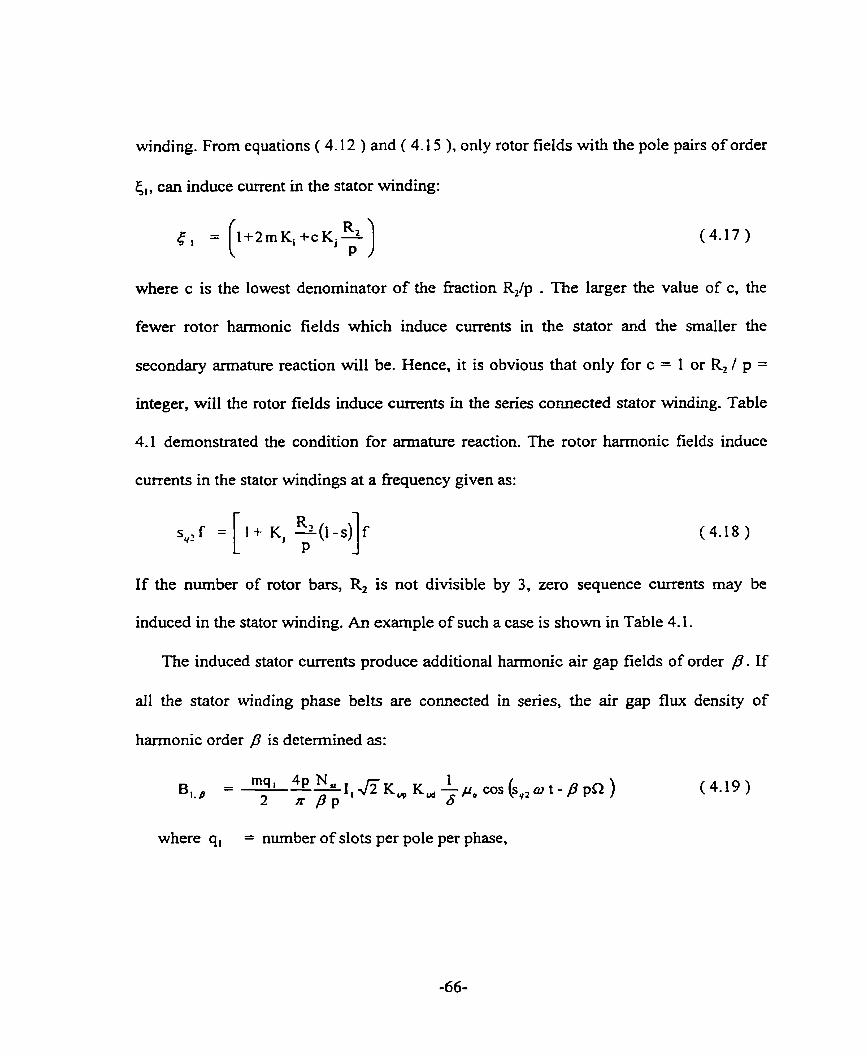
winding. From equations ( 4.12 ) and ( 4.15 ). only rotor fields with the pole pairs of order
ci, can induce current in the stator winding:
where c is the lowest denominator
(4.17 )
of the fraction R2/p . The larger the value of c, the
fewer rotor harmonic fields which induce currents in the stator and the smaller the
secondary armature reaction will be. Hence, it is obvious that only for c = 1 or R, / p =
integer, will the rotor fields induce currents in the series c o ~ e c t e d stator winding. Table
4.1 demonstrated the condition for armature reaction. The rotor harmonic fields induce
currents in the stator windings at a frequency given as:
If the number of rotor bars, R, is not divisible by 3, zero sequence currents may be
induced in the stator winding. An example of such a case is shown in Table 4.1.
The induced stator currents produce additional harmonic air gap fields of order P . If
al1 the stator winding phase bel& are connected in senes, the air gap flux density of
hamonic order ,O is determined as:
where q, = number of slots per pole per phase,

and K, = 0,+1,+2 ,...
The air gap flux density acts on the squirrel cage, inducing in it voltages having
identical order of harmonics. The induced voltages drive currents in the closed rotor
circuit depending on the impedance of the rotor winding. This impedance is a fûnction of,
among other things, the fiequency, nurnber of rotor slots, the permeability, shape of the
slot, etc. Owing to the rotor slotting and following the procedure from equation ( 4.4 ) to
equation ( 4.12 ) a new set of rotor flux density waves can be obtained. This process of
armature reaction continues until the steady state air gap flux distribution is established.
Oberretl [ 34,35 J analyzed this successive interaction of stator and rotor MMFs up to, in
some cases, a fourth order of armature reaction However, it is sufficient not to consider
other sets of flux density waves beyond that given in equation ( 4.18 ) as their magnitudes
are negligible. This process of mutual interaction of the stator MMF and rotor MMF,
cdled multiple armature reactions is illustrated in Figure 4.1. The stator air gap harmonics
induce currents in the rotor windings at different slip frequencies. Their magnitudes
depend on the cage winding arrangement. The non-sinusoidal current distribution of the
rotor produces additional harmonics in the air gap. These haxmonic air gap fields
generated by the rotor induce current in the stator windings at fiequencies related to the
number of rotor bars and speed of the rotor.

4.2 EFFECTS OF SLOTTED STATOR ON SHAFT CURRENT
Besides the fundamentai term the air gap flux density in an induction machine
contains higher spatial haxmonics. The amplitudes of the higher harmonics of the air gap
flux density decrease as the order of harmonics increase because their winding factors
decrease. This is. however, not tnie for slot harmonics. The winding factor [ 36 ] for the
slot hannonics is equal to the winding factor for the fundamental as shown in Appendix
4. Hence the higher slot harmonic components of the air gap flux density are not
negligible. The presence of stator slots bordering the air gap modulates the fundamental
flux wave.
The fundamental stator winding MMF [ 32 ] is given as:
Stator MMF, 3 ( C2, t ) = 3mf cos (a - pl2) ( 4.20 )
where R is the angle between the stator datum and an arbitrary point on the rotor.
The haxmonic permeance wave of slotted stator, p, = g~, cos (h S R) ( 4.21 )
where S is the number of stator slots and h is the stator slot harmonic number = O, I I ,
&2, *3... .
Hence, the stator slot modulated air gap flux density is given as
g. smf, =Ph = 3,,, COS {o t - } X pu,, COS SR )
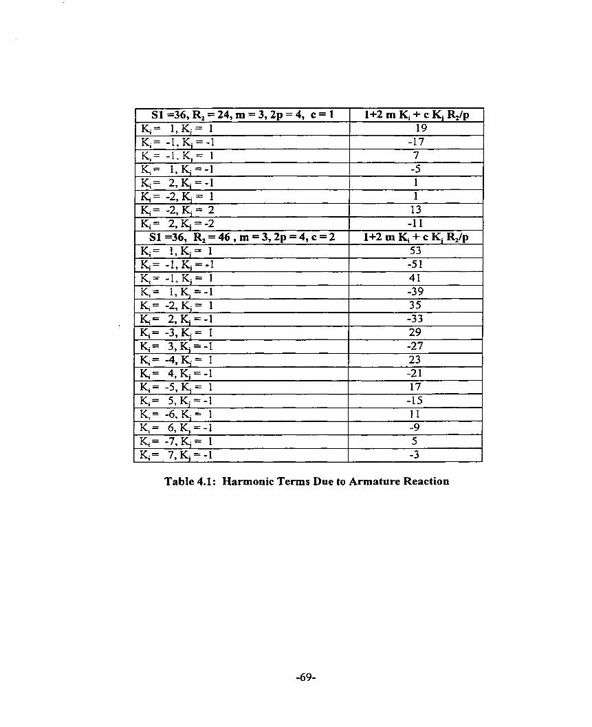
Table 4.1: Harmonie Terms Due to Armature Reaction

The stator fundamental slot harmonic permeance wave has 2s poles and is stationary. The
modulation of the fundamental air gap field creates two additionai rotating fields, one
with ( h S - p ) pole pairs rotating backward and the other with ( h S + p ) pole pairs
rotating forward. These pole pair fields need to be considered in the determination of the
occurrence of shaft currents. Thus, we will have shaft current when the fraction consisting
of twice the number of joints divided by the stator slot harmonic field poles, reduced to its
lowest term, has an odd number in the numerator. The shaft current frequency is the odd
numerator multiple of the supply frequency. That is, equation 2.1 must take into account
the additional rotating field created by the stator slots.
These flux density waves could also be produced by the interaction of the component
of the MMF wave due to stator current discretization with the average or dc component of
the air-gap permeance:
The interaction of the MMF wave due to the stator current discretization with variation in
the air-gap permeance resulting fiom stator slots will result in the air-gap flux density
waves given by equation ( 4.24 ).

The first two tems of equation ( 4.24 ) are the 2nd order harmonic components of stator
slot modulated air gap flux density.
4.3 EFFECTS OF SLOTTED ROTOR ON SHAFT CURRENT
The flux density induced in the slotted rotor by the rotating fundamental stator MMF
field is given by the product of this MMF and the permeance wave due to the rotor
slotting .
The fundamental stator winding MMF is given as
Stator MMF, 3 ( Q, t ) = gsmr COS (a - ( 4.25 )
where i2 is the angle between the stator datum and an arbitrary point on the rotor.
The harmonic permeance wave of çlotted rotor, = @, cos (@ (a -art} ) ( 4.26 ) nw
where R is the number of rotor slots and q the rotor dot harmonic number = +I, kî,..
Hence, the rotor slot modulated air gap flux density is given by equation ( 4.27 ).

COS { RU, -a , ) t + ( ~ q + n} - - %mf *ah + 1 (4.27)
2 cos { ( - q R w , + o ) t + ( ~ q - &2}
The air gap flux density induces corresponding current harmonics in the stationary
stator winding:
These harmonics reveal themselves as a pair of 'side fiequencies' disposed on either
side of the rotor slot ripple carrier frequencies. Harmonic fields as represented by
( q R + p ) and ( q R - p ) pole pair fields may give nse to components of shaft voltage and
hence shaft current. Hence, we will have shaft current when the ratio of twice the nurnber
of joints divided by the harmonic field poles reduced to its lowest term has an odd
number in the numerator. The shaft current fiequency is the odd numerator multiple of the
frequency indicated above. Further to the two additional rotating fields set up by the stator
slots, equation ( 2.1 ) is to be expanded to include the harmonic fields created by the rotor
slots.
Like the stator slot harmonics the rotor slot hamionics are not directly af5ected by the
stator pitch factor. These harmonics however are affected by the rotor skew factor.

The interaction of the component of the MMF wave due to rotor current discretization
with the air gap permeance variation due to rotor slotting and rotor motion results in air
gap flux density described by equation ( 4.29 )
The 3rd and 4th terms in equaîion ( 4.29 ) are the 2nd order harmonic components of the
rotor siot rnodulated air gap flux density.
- 3 r ~ h @rsf - 2
4.4 EFFECTS OF SLOTTED STATOR AND ROTOR ON SHAFT CURRENT
The flux density induced in the slotted rotor by the rotating stator MMF field is given
by the product of this MMF and the permeance wave due the stator and rotor slotting.
The fundamentai stator winding MMF is given as:
Stator MMF. 9 ( R, t ) = ZSmr cos (mt - p ~ ) ( 4.30 )
c o s ( o t - P R ) +
cos ({o + 2 ~ ~ o , } t - ( 2 ~ + p ln)+
where fi is the angle between the stator d a m and an arbitrary point on the rotor.
The harmonic permeance of an air gap bounded by a slotted stator and a smooth rotor is
given by equation ( 4.22 ) and the permeance of air gap bounded by a slotted rotor and a
( 4.29 )

smooth stator is given by equation ( 4.26 ). When both stator and rotor are sloned the total
reluctance of the air gap is expressed as
- and g is the average air gap. where @g - -
g
The corresponding total permeance of the air gap is the reciprocal of its total reluctance
- 1 - - - - 6 r s w k3sswPg P srs\s ( 4.32 )
91 ssm ( ~ a w + ~ s s w ) pg - PSW prsw
The first tenn in the denominator is constant while the second term is a senes of variable
components. The pexmeance equation can be reduced approximately to equation (4.33 ).
- @m - P m @snu ( 4.33 )
Hence, the harmonic permeance wave of slotted stator and rotor, @ ,,,, can be expressed
as equation ( 4.34 ).
where R is the nurnber of rotor slots, q is the rotor slot harmonic number = 0, +1, f2,
k3,. . . and h is stator slot harmonic number = O, It 1, +3., +3 ,...
Hence. the air gap flux density due to the slotted stator and rotor is given by equation
( 4.35 ).
The stator slot hamonic order h is equal to the rotor slot hamonic order q for interaction
to occur. Equation ( 4.35 ) can also be produced by the interaction of the stator slot
harmonic MMF and the rotor slot harmonic permeance as shown in equation ( 4.36 ).
The harmonic order h is equai to q so that the interaction can occur.
Furthemore, equation ( 4.36 ) c m be obtained by considering the interaction of the
component of the MMF due to rotor slotting and motion with the permeance wave due to
stator slotting as described by equation ( 4.37 ).

where Mm,, = ( Z m f prrh )/2
4.5 EFFECTS OF SATURATION ON SHAFT CURRENT
Magnetic saturation may be understood graphicaily by examining Figure 4.4 which
shows the mean values of magnetic flux density ( B ) versus magnetic field intensity
( H ) for a typical lamination steel. Magnetic field intensity is considered as the input to
the system with magnetic flux density as its output. Magnetic field intensity is
proportional to the applied curent. At any point on the cuve, the ratio of magnetic flux
density to magnetic field intensity is the permeability, p. The curve may be divided into
several regions. The first part of the curve, the region of low H, is nearly linear, rneaning
that the flux density is directly proportional to the magnetic field intensity. The
permeability is constant. As the magnetic field intensity is increased, the limit of ability of
the iron to support the magnetic field is reached, as indicated by the knee of the curve. At


this point the permeability starts to decrease. Beyond this knee, in the region of high H,
the iron becomes saturated, meaning that an increase in magnetic fieId intensity produces
negligible increases in magnetic flux density. A situation may arise when the permeability
of the iron is approximately equai to the permeability of air on further increase in
magnetic field intensity .
Magnetic saturation [ 37 - 41 ] is an inevitable feature in almost al1 electromagnetic
devices. In a polyphase altemating current induction machine, when a sinusoidally
distnbuted magnetomotive ( MMF ) force wave is applied to its air gap, the waveform of
the air gap flux density is not usudly sinusoidal as it is distorted by rnagnetic saturation of
the teeth and cores of both stator and rotor. Saturation of the teeth causes the air gap flux
density to be flat topped as shown in Figure 4.5. Saturation of the cores tends to produce a
flat topped peripheral distribution of the flux density in the core [ 38 ] and hence causes
the air gap flux density to peak. This can be explained by the fact that the flux in the core
is the space integral of the flux in the air gap; that is the air gap flux density is
proportional to the space derivative of the core flux. If the denvative of the flat topped
core flux distribution peaks so will the air gap flux density. The action of a saturated core
in the case where both the core and the teeth are saturated is such that it opposes the effect
of the saturated teeth, depending on the relative degrees of saturation of both regions. In
al1 practical machines, the teeth are more saturated than the core [ 38,39 1.
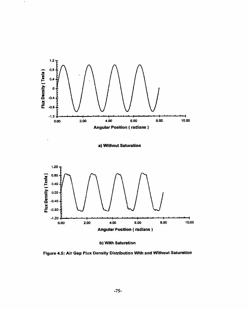
-.- 0.00 200 4-00 6.00 8.00 10.00
Angular Position ( radians )
a) Without Saturation
0.00 200 4.00 6.00 8.00 10.00
Angular Position ( radians )
b) With Saturation
Figure 4.5: Air Gap Flux Density Distribution Wth and Without Saturation

Magnetic saturation causes saturation harmonics [ 40,41 1. These harmonics are very
different from the t h e hannonics due to solid state power supplies and the spatial
harmonics due to non-ideal winding distribution and slotting. They are not excited by a
harmonic MMF in the air gap. The fiux density produced by the fundamental air gap
MMF is by far the largest component present in the teeth and cores. This fundamental
MMF wave is therefore responsible for producing the saturation harmonics. The
saturation harmonics travel with the same rotational speed in the air gap as the
fundarnenta1. They are of odd orders ody. The third hamionic is the largest and rnost
important. The s6, Th and other non-triplen saturation harmonic effects are darnpened by
the wye comected stator winding. The wye connected stator winding represents a low
impedance circuit to darnpen the effect of the non- triplen harmonic air gap flux density.
Therefore, the resultant air gap harmonic field due to this interaction is small. For the
third hannonic, no stator current exists to counteract the time rate of change of air gap
flux density. Hence, rotor third harmonic cments are induced. These induced currents
will distort the magnetizing MMF distribution in the air gap. The resultant saturation
harmonic air gap flux induces voltages in the stator winding at multiples of supply
fiequencies. When the stator winding is three phase star comected, the triplen harmonic
voltages in each phase are CO-phasal and can be ignored.
The saturation harmonic content is high when the teeth are highly saturated and the
core is not saturated. Saturation is generally largest at no-load conditions when the slip is
small and hence there is negligible damping of these saturation harmonics by these

induced rotor currents. If the supply to the motor is kept constant at the rated values, as
the load is increased and the slip increases, the phase difference between the applied load
and the primary impedance drop decreases. Hence, the machine becornes less satmted.
If, however, the motor is operated at rated voltage and the supply current is allowed to
Vary with slip fiom the no-load to the locked rotor condition, saturation harmonics are
virtually the same at no-load up to the rated full load but increase as the motor line current
increases with increasing slip towards the locked-rotor condition.
The spatial distribution of air-gap flux density influenced by saturation somewhat
resembles a square wave as shown in Figure 4.5. This wave can be approximated by a
Fourier series with odd spatial harmonics:
B,(R) = B,as(pR)+B,oos(3 pR)+B,,cos(5pR)+B,,m(7pR)+.'.-.( 4.38 )
Each of these harmonic waves rotates at the same speed and in the same direction as the
fundamental. Hence the flux density waveform influenced by saturation is
B sat ( a )
lgnoring higher
= BI COS(@ t - p R ) + B , , cos(3 c N - 3 pR )+ ( 4.39 )
B, ~ 0 ~ ( 5 m t - 5 p C 2 ) + B , , COS(^ a - 7 p R ) + ...
harmonics, the flux density wave of harmonic order of 3p due to
magnetic saturation is
B,, (R ) = B,. , cos (30 t - 3 p ~ ) ( 4.40 )
The harmonic traveling wave of equation ( 4.39 ) can be obtained fiorn the MMF-
permeance wave approach. In the 8 pole machine, there are eight regions of high flux
density in the stator teeth where saturation is most likely to occur. In each of these areas,
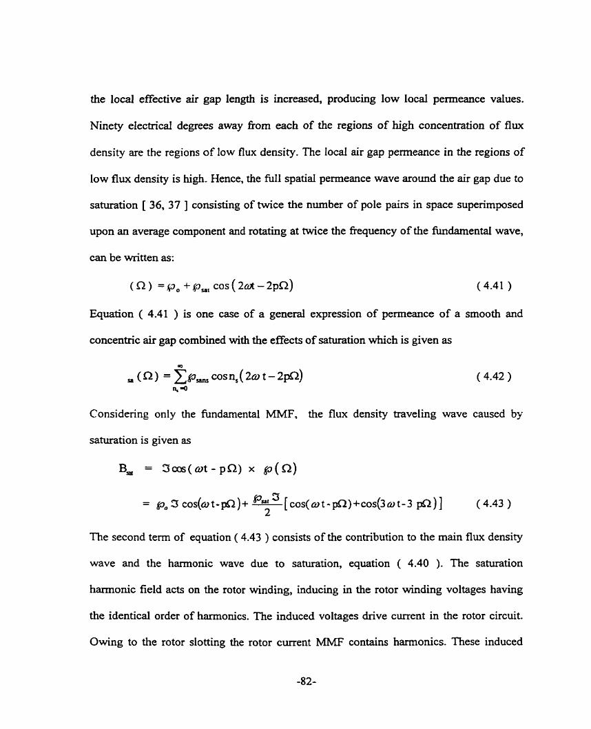
the local effective air gap length is increased, producing low local permeance values.
Ninety electrical degrees away from each of the regions of high concentration of flux
density are the regions of low flux density. nie local air gap permeance in the regions of
low flux density is high. Hence, the full spatial permeance wave around the air gap due to
saturation [ 36, 37 ] consisting of twice the number of pole pairs in space superimposed
upon an average component and rotating at twice the frequency of the kdamental wave,
can be written as:
(a) =p, +gmt C O S ( Z C * - ~ ~ R ) (4.41 )
Equation ( 4.41 ) is one case of a general expression of permeance of a smooth and
concenttic air gap cornbined with the effects of saturation which is given as
Considering only the fundamental MMF, the flux density traveling wave caused by
saturation is given as
B, = 3cos(ot - P R ) x p ( ~ )
The second term of equation ( 4.43 ) consists of the contribution to the main flux density
wave and the harmonic wave due to saturation, equation ( 4.40 ). The saturation
harmonic field acts on the rotor winding, inducing in the rotor winding voltages having
the identical order of harmonics. The induced voltages drive current in the rotor circuit.
Owing to the rotor slotting the rotor current MMF contains harmonics. These induced

rotor harmonic MMF waves interact with the permeance of the air gap to generate a new
set of air gap flux density waves. Out of these flux density waves, those waves of order
equal to that of the stator saturation harmonic field react on the corresponding stator flux
density harmonics. This phenornenon is defined earlier as armature reaction. The
remaining waves called residual rotor flux density waves induce voltage in the stator
winding with frequency different fiom that of the supply network fiequency. Each current
component due to the induced stator winding voltage gives rise to new stator MMF
harmonics, a part of which reacts on the residual rotor flux density waves while the
rernaining part constitutes the stator residual flw density. This armature reaction process
[ 34. 35 ] continues until the steady state air gap flux density is obtained. The residual
rotor dot harmonic fields due to saturation are given as
B,, = B, c o s ( ~ ~ o t - L t p x )
R where = 3 + KjL(l-s) P
K, R, and 4, = 3 +- P
In some machines the 5" and 7<h harmonic saturation components are significant and must
be considered. Hence the residual rotor slot hannonic field will have slot harmonic
contents and pole pair numbers given by equation ( 4.45 )

K. R2 and Arat = Ki +
P
where K. = 3, 5 and 7 and K, = l ,Z,3 ...
4.6 SUMMARY
The important harmonics in induction machines are classified as shown in Figure 4.6.
These harmonics contribute to the losses of the machine and affect the torque
characteristics of the machine. Furthennore these hannonics, as sumrnarized in Tables 4.2
and 4.3 need to be carefully considered in the shaft voltage prediction nile given in
equation ( 2.1 ).
Space Harmonics
I
Stator Winding Distribution Slotting Saturation
Stator Rotor hS + 1 - qR + 1 -
u = ( I + 2 * ) p P
Rotor MMF Hannonics
Figure 4.6: Classification of Harmonics in Induction Machine

Ongin of Fields
Winding fields
Equation ( 4.4 )
Saturation fields
Equation ( 4.43 )
Pnmary Fields
Table 4.2: Air Gap Fields of Induction Motor
1 EQUATIONS 1
Armature Reaction Fields
1 Equation ( 4.19 )
Stator Slots Modulated Fields
Equation ( 4.22 )
Stator Slots Modulated Field
and 3d Hannonie Current
Rotor Slots Modulated Fields
Equation ( 4.28 )
Stator and Rotor Slots
Modulated Fields
Equation ( 4.3 6 )
Harmonic Fields Caused by Darnping Rotor Current
Pole Pairs Frequency { 1+[y ~~(l-s)/~]}f
y= O, I l , e,...
Jndcr NomaI Operating Condition.
POLE PAIR FREQUENCY
Table 4.3: Other Harmonic Pole Pairs and Corresponding Frequencies.
CHAPTER 5
ROTOR CONDITIONS AND THElR EFFECTS ON SHAFT CURRENT
5.0 INTRODUCTION
Many failures in squirrel cage induction machine are associated with cage integrity.
Bonnett and Soukup [ 42 ] cited severai kinds of stresses, namely thermal, dynarnic and
mechwcal as reasons for rotor cage failures. A majonty of diagnostic techniques
developed thus fa., are dependent on detecting a twice slip fkequency modulation in the
speed or torque. This twice slip fiequency side- band around the fundamentai is also
evidently present in the line current of the machine.
This chapter wiI1 examine how these three types of rotor conditions, narnely the rotor
eccentricity condition, non-insulated rotor bar condition and broken bar fault condition
may contribute to the magnitude of shaft current. These conditions will also generate stray
flux that can circulate around the shaft and hence cause localized bearing current. The
broken bar fault condition is an abnormal phenornenon.
5.1 EFFECTS OF ECCENTRICITY ON SHAFT CURRENT
One of the most comrnon problems in rotating machinery installations is vibration.
Lateral shaft vibrations - rotor dynamic motions perpendicular to the machine rotational

axis, are the rnost cornmon type of vibrations. These vibrations generally are due to bearing
Wear or fracture. bent rotor shaft, shaft misalignment, operation at whirl/whip condition,
etc. These causes result in rotor static and dynmic eccentricities as shown in Figures 5.1
and 5.2. Figure 5.3 indicates the operation of a machine with no eccentricity.
Static eccentricity is the condition existing when the axis of the rotor is displaced fiom
the axis of the stator by a distance, E Zim where 6, is the mean air gap length and E is a
fiaction less than unity. A uniform air gap pattern is maintained throughout the rotation.
The rotor is turning on its own axis. Static eccentricity can be caused by stator core ovality
or incorrect positioning of the rotor or stator. The magnetizing and mutual inductances of
the stator phases are different for the three phases but they are constant. However, the rotor
magnetizing and mutual inductances wiIl be a function of the rotor position and will be
varying with time.
Dynamic eccentricity is present when the air gap length pattern rotates with the rotor.
The center of the rotor is not at the center of rotation. Dynamic eccentncity is a function of
space and time. A bent shaft, bearing Wear or mechanical resonance at critical speeds could
result in dynarnic eccentricity of the rotor. The magnetizing and rnutual inductances of the
stator phases will be a fiinction of the rotor position whereas the inductances of the rotor
will be a constant but different for the three phases.
Salon et. al. [ 43 ] showed that in an induction machine which has a small air gap, a
non-uniform air gap due to rotor eccentncity distorts the air gap flux density distribution
and results in unbalanced magnetic puil ( U.M.P.) and other additional magnetic forces

directed both radidly and tangentially. Using the finite element method, they demonstrated
that circulating current between paraIlel windings in an asymrnetrical induction machine
reduces the U.M.P. and other magnetic forces. The reduction can be explained in that the
inductance is lower in those circuits located where the air gap is larger than nominal,
relative to the inductance of circuits located where the air gap is smaller than nominal.
With the circuits connected to the sarne voltage, the currents in the circuits facing the larger
air gap are slightly larger than those facing the smaller air gap. The circulating current
tends to smooth out the distortion in the air gap flux density distribution with the net effect
of reduction of additional magnetic £lux and magnetic force waves generated by the non-
uniform air gap. These circulating damping currents would not be observed in the line
current spectnun shce they are circulating currents within the stator winding. Stavrou and
Penman [ 44 ] observed side band currents due to static eccentricity and concluded that the
dot harmonies variation, as a function of eccentricity, in the phase currents depends on the
combination of stator and rotor slots and the number of poles. It does not depend on the
first order permeance. Bradford [ 45 ] and Dorrell [ 46 ] indicated that the side-band
currents increase rapidly as the motor is loaded. Furthemore Dorrell [ 47 ] found that the
upper side-band currents due to the dynarnic eccentricity decrease as the motor is loaded.
He also stated that there is a decrease in lower side band current fiom no-load to full load
when there is either a nominal zero dynamic or static eccentricity. If substantial degrees of
both types of eccentricity are present, there is little change in the lower side band current

fiom no-load to full-load. This contrats with the upper side band which decreases in
magnitude when both types of eccentricity are present.
In static eccentncity. a uniform air gap pattern is maintained throughout the rotation.
Each point on the stator experiences a constant magnetic pull.
center of rotation = center of rotor center of stator bore
Figure S. 1: Static Eccentricity
In dynarnic eccentricity, as the rotor rotates, the air gap length pattern rotates with the
rotor such that each point on the stator will experience a strong magnetic pull followed 180
mechanical degree by the weaker magnetic pull.

center of rotor center of rotation = center of stator bore
Figure 5.2: Dynamic Eccentricity
center of rotation = center of rotor center of rotor = center of stator bore
Figure 5.3 : No Eccentricity

The presence of ecceneicity gives rise to higher harmonies which are responsible for
the following effects:
1 - Unbalanced magnetic pull ( U.M.P. )
2. Vibration and noise
3. Shaft current
4. Parasitic Torque
A consequence of stationary asymmetry of the air gap will be an unbalanced magnetic
pull between rotor and stator surfaces due to the magnetic forces, tending to pull the
surfaces together on the side that has the smaller air gap. The unbalanced magnetic pull
alters the eccentricity level of the machine. The incremental increase in the eccentricity
level, AE depends on the extent to which the shaft moves, bends and defoms under the
action of forces acting on it. The increase in eccentricity level is considered constant as
long as the unbalanced magnetic pull is determined to be a constant force. Robinson [ 48 ]
explained that though a constant force, the attraction force is greater between the stator and
rotor surfaces on the side with the small air gap when the poles of the rotating flux wave
are on the eccentricity axis. Furthexmore, this attraction force will go through 2 cycles of
force for every cycle of voltage; that is the force has a varying component with twice line
frequency. The poles of the rotating flux are on the eccentricity axis as long as the
inequality of the air gap remains constant, that is the stator and rotor do not move sideways
relative to each other under the influence of force.

For srnail levels of eccentricity, as the force on one side decreases to its minimum
value, the rotor moves to the other side under the action of spring and passes the center of
the stator bore. As the opposite pole of the flux wave appears on the eccentricity a i s the
force will be directed to the opposite side. As a result of this effect, the rotor moves once to
one side and then to the opposite side in one cycle of voltage. This type of motion
constitutes a line fiequency vibration. Thus, it is clear that very slight asymrnetry of the
rotor may not of itself cause anything but a variation of the unbalanced magnetic pull on
the eccentricity axis and lead to a change of the eccentricity level as a function of the speed
of rotation.
The survey of published work on unbalanced magnetic pull in rotating electric machine
by P. Von Kaehne [ 49 ] highlighted three causes of unbaianced magnetic pull namely, slot
combinations, faults in supply or in machine windings, and eccentricity and saturation.
Unbalanced magnetic pull occurs when the air gap field contains two harmonic fields
with pole pairs differing by one. The two harmonic fields could be two stator fields, two
rotor fields or one stator with one rotor field. To avoid unbalanced magnetic puil, the slot
difference between the stator and rotor slots should avoid certain values as shown in
Appendix 5.
5.1 .l Derivation of Air gap Flux Density
The air gap of an eccentric rotor, 6 (S2 ), descnbed in detail in Appendix 6, is given in
equation ( 5.1 ).

where R1 is the stator bore radius, R2 the rotor outer radius and d the distance
between the rotor center and the rotation center
The rotor eccentricity E is
where 6, , the mean or average air gap length is equal to ( R1 -EU ).
Hence, the air gap of an eccentric rotor is descnbed as
where E, is the rotor static eccentricity and E* is the rotor dynamic eccentricity.
The air gap permeance @ ( R ) [ 43 ] is expressed as:
The air gap penneance function can be developed in tenns of a Fourier series. If the
function is approximated by the first two harmonic components of the Fourier senes, the
air gap permeance can be written as:
n ,+ A , COS (a)+ a, COS (2 a)+ tn
A, COS (a -or t)+ a, COS 2(~2 -or t )

where
The complete Fourier senes of air gap permeance takes the form
where
where 0 5 E, , Ed

In p-pole pair machines, the fundamental component of MMF distribution can be
expressed as:
3 ( Q , t) = 3, c o ~ ( o t - p Q ) ( 5-7
For p > 1 the fundamental flux density component c m be expressed as
P o R3, BP (4 t) = - cos ( ~ t - ~ n )
(fi) p
The value of I I G( R ) in equation ( 5.5 ) is substituted into equation ( 5.8 ) to obtain
I cos
A cos ut p 2 Z;! + +-[ 2n O COS { ~ t - ( ~ + 2 ) ( ) Q} ' 1
where the rotor angular velocity a, = w where o is the supply fiequency and p is the
pole pair.

In addition to the main field with p pole pain there are two additional fields with
( p + 1 ) and ( p f 2 ) pole pairs. These pole pain pulsate at fiequencies f, ( f + f , )and
( fi 2f , ). Looking at the 8 pole machine, we have in addition to the four pole pair field a
three pole pair field and a five pole pair field. There will be shaft current due to the
harmonic fields when the hction consisting of the ratio of twice the number of joints to
the harmonic field poles when reduced to its lowest terms contains an odd numerator.
The coefficients of the Fourier series produced by the inversion of the air gap length
when only static or dynamic eccentricity is present, are expressed in equation ( S.6a ) and
Figure 5.4, where it is clear that at 50% eccentricity the first hamionic has a magnitude of
about 0.62 on the normalized plot and the second harmonic is 27% of the first harmonic.
Hence only the p and ( p k I ) field components need to be considered.
The p and ( p f 1 ) fields will induce EMF's into the rotor cage and hence produce
rotor MMF waves. In ternis of the rotor reference h e the rotor MMF waves can be
expressed as:
Equation ( 5.10 ) shows that when s « 1, static eccentricity induces ( p + 1 ) pole pair
MMF waves in the rotor with current fiequency approximately o/p while the dynamic


eccentricity induced ( p i 1 ) pole pair MMF waves have slip fiequency current
components. Thus, at close to synchronous speed, that is at no load, the second term of
equation ( 5.9 ) is damped by the rotor. The fourth term in equation ( 5.9 ) represents the
stator fields at close to synchronous speed, not darnped by the rotor current. As shown by
Dorrell [ 46 1, dynamic eccentricity induced unbalanced magnetic pull at no load is much
higher than that due to static eccentricity. As the load increases, the unbalance magnetic
pull decreases. The fourth term in equation ( 5.9 ) is damped by the rotor current.
The rotor MMF waves will generate equivalent field components. When these field
components are modulated by the air gap eccentricity, p-pole pair air gap field components
are generated which wiII induce non-supply fkquency EMF's in the stator windings. To
obtain these components, the rotor ( p + 1 ) MMF waves in stator coordinates are
multiplied by the fundamental air gap penneance. The rotor MMF waves are converted to
stator reference frames using the coordinate relationship fi2 = C? - ut . The modulated
field components are
The rotor MMF waves due to static eccentricity are modulated by the dynamic eccentricity
air gap permeance and vice versa in order to obtain the p pole pair field components and
the suppl y fiequency side-bands.
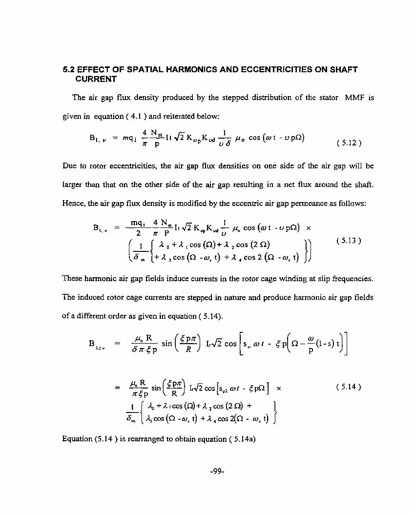
5.2 EFFECT OF SPATIAL HARMONICS AND ECCENTRICITIES ON SHAFT CURRENT
The air gap flux density produced by the stepped distribution of the stator MMF is
given in equation ( 4.1 )and reiterated below:
Due to rotor eccentricities, the air gap flux densities on one side of the air gap will be
iarger than that on the other side of the air gap resulting in a net flux around the shaft.
Hence, the air gap flux density is modified by the eccentric air gap permeance as follows:
These harmonic air gap fields induce currents in the rotor cage winding at slip fiequencies.
The induced rotor cage currents are stepped in nature and produce harmonic air gap fields
of a different order as given in equation ( 5.14).
Equation (5.14 ) is rearranged to obtain equation ( 5.14a)
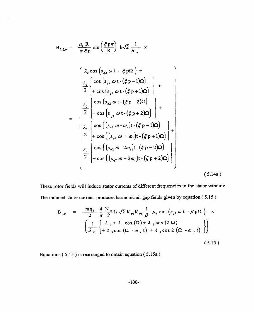
cos (s,, o t - ( c p - 2)~)
4 1 COS ( (sq2 - f%)f - (r P - w) -
These rotor fields will induce stator currents of different fiequencies in the stator winding.
The induced stator curent produces harmonic air gap fields given by equation ( 5.15 ).
Equations ( 5.15 ) is rearranged to obtain equation ( 5.15a )

5.3 EFFECTS OF SATURATION AND ECCENTRICITY ON SHAFT CURRENT
Ignoring armature reaction. the residual rotor slot harmonic field due to saturation and
eccentricity is given by equation ( 5.1 6 ).
- B,, - L w s ( M , CCC: Ot -&,a) where
and
- K j R kt., - - P + 3 + ( d ) ( 5.I6b )
In some machines the Sm and 7m harmonic components are significant and must be

considered. Hence, the residual
and pole pair numbers given by
R X as- = k i t Kj - ( 1 - P
K , R
rotor dot harmonic field will have slot harmonic contents
- J L t , CC= - - + k i + (1 k :)
P
where k, = 3 , s and 7 and K, = i , 2 , 3 , . . .
Equation ( 5.16 ) is one component of a generalized set of hamonics that could be
obtained fiom consideration of slotted rotor and stator, saturation and eccentricity.
~ o l l o w i n ~ the procedure in Chapter 4 in which the permeances due to rotor and stator
slotting were combined, equations ( 4.33 ), ( 4.41 ) and ( 5.6 ) give the general total
penneance as
+ hS + k, + k,, + 2 n , p ) ~ (5.17)
- ( ( q ~ f k, )a, f 2 n , o ) t
The air gap magnetomotive force consists of a series of waves generated by the currents in
the stator and rotor, given by equation (5.18 ). Phase angle and skew are neglected.

The air gap flux density distribution [ 49, 50 1, given as the product of permeance and
MMF is expressed as:
where
In the case of static eccentricity alone, the use of the first permeance hannonic had
been suggested as a means of estimating the degree of eccentricity [ 5 1, 52 1. This is
erroneous because Stavrou et. al. [ 44 ] demonstrated that the increase in the slot harmonic
components depend on the values of permeances, k, of order 1 S-R 1 and 1 S-R-2p 1 or
1 R-S-2p 1. For combinations of slots and poles giving a permeance of an order which is
greater than 6, Figure 5.4 indicates that the effects wili be so small that it is difficult to
detect any changes until the levels of eccentricity approach or even exceed seventy percent.
In the case of pure dynarnic eccentricity, currents of { [R t 11 (1 -s )/p I l f f fiequencies
do not appear in the stator winding as fields with { p+l } pole pairs cannot induce such

currents in the stator winding. However, previous research [ 51, 52 ] had shown the
presence of such harmonics which can only be explained by the fact that a combination
of a small arnount of static and dynamic eccentricities are usudly present and able
to induce currents of such fiequencies. Stavrou et. al. [ 44 ] showed that the side-
bands which appear in the stator current are ( [ R &( R R S ) ] ( 11- )/p f 1 }f and
{ [ R + ( R tS 12p ) ] (1- s)/ p tl }f. This means that additional side-bands of slot
harmonics that are induced in the stator winding depends on the number of rotor and stator
slots, and the number of poles. Their amplitudes depend on the variation of the
corresponding penneance components, k, of order 1 R + S ] and 1 R + S f 2p 1. Again fkom
Figure 5.4, it is shown that until a threshold value of dynamic eccentricity is reached, there
will be minimal variations of these orders of harrnonic components in the phase current.
5.4 EFFECTS OF INTER-BAR CURRENTS ON SHAFT CURRENTS
Inter-bar currents exist in the rotor as long as the bars are not insulated, the end ring
resistance is large and the inter-bar impedance is small. The inter-bar currents, aiso known
as cross-path currents do not follow the path in the cage. The current path is from bar to bar
or nom bar to shafl through the iron. The inter-bar impedance is usually considered as pure
uniformly distributed contact resistance between the cage and the lamination. Results of
measurements published by Christofides [ 53 ] show that the inter-bar impedance is almost
independent of frequency for fkequencies up to several hundreds of hertz. The reactive
component of the inter-bar impedance is small when compared with the resistive
component. Thus, the inter-bar impedance is largely resistive for fkequencies within the
nomal operating condition of the machine. This is especiaily true in machines with
aluminurn cages wherein partial insulation is achieved via oxidation of the alurninum. The
oxidation may not be uniform and hence there will be large variations in the magnitude of
the insulation for different points in the sarne rotor. The oxidation build up on the bar
surfaces gives nse to higher barkore contact resistance. The contact resistance becomes
non-linear [ 53 ] when large inter-bar currents flow. When the motor is running at rated
speed the contact resistance may be assurned to be linear.
In large machines, the reactive component of the inter-bar impedance may be, in certain
cases, of similar magnitude to that of the resistive component and thus may not be
neglected [ 54 1. Weppler [ 54 ] takes into account the effect of inter-bar currents by using a
complex skew factor for the fundamental wave and higher harmonies.
When a squirrel cage machine is running, a net induced voltage exists which acts
across the iron between adjacent bars. If the insulation between bars and iron is imperfect,
this voltage will cause circulating currents fiom bar to bar across the rotor iron, resulting in
axial flux dong the shaft as shown in Figure 5.5.
A study by Kerszenbaum and Landy [ 55 ] showed that there is a substantial increase in
inter-bar currents in machines with broken bars if the bars are not insulated. The low ratio
of inter-bar to rotor bar impedance is shown to be the cause of the large inter-bar currents
in non-insuiated cages having broken bar a d o r end rings. The inter-bar currents vary with
the slip and rnay be large in highly rated machine. This inter-bar current, if substantial, can

Figure 5.5: Representation of Interbar Current and Axial Fliu

result in axial flux flowing in the shaft. Further work by Walliser and Landy [ 56 j showed
that the fundamental fiequency side-bands do indeed get smaller if the inter-bar currents
are present in the rotor. They suggested that current side-bands higher up in the fiequency
s p e c t m are present and m u t be monitored in order to obtain a more accurate indication
of the existence of the broken bars.
Bearing insulation is only effective against shaft current but not so with axial flux.
Axial flux can be reduced by installation of a copper ring around the shaft. However, this
method of axial flux reduction is only effective against the fundamental component of the
axial shafi flux; it does not eliminate the high fiequency component of the axial flux.
Locaiized bearing current is present in a machine with axial shaft flux. The localized
voltage developed across the thin oil film may be sufficient to break down the oïl fiim and
hence shah currents arc across the bearing clearance and damage the babbitt surface.
5.5 EFFECTS OF BROKEN OR FRACTURED ROTOR BARS ON SHAFT CURRENT
Electromagnetic asymrnetries in an induction machine give rise to additional time
harmonies in the spectrum of the stator winding current. If the rotor of a machine is
completely symmetrical with no broken bars as shown in Figure 5.6, the forward rotating
fields add while the backward rotating fields cancel. However, an asymmetrical rotor will
not result in al1 the backward rotating fields being canceled. The effects of these backward
rotating fields are used to detect broken bars. Broken or fractured bars and end rings as
shown in Figure 5.7, induce stray flux mainly at the rotor core end. As a result the motors
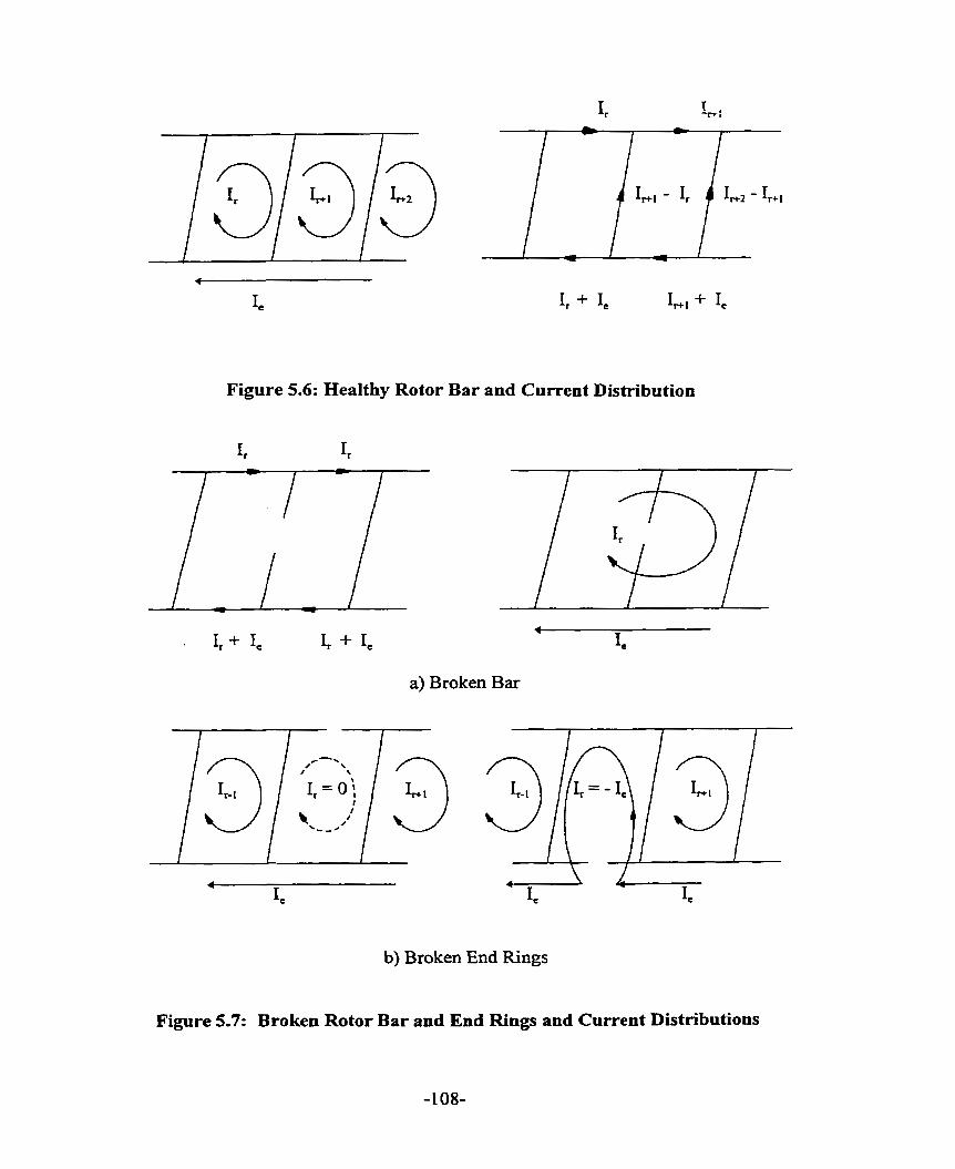
Figure 5.6: Healthy Rotor Bar and Current Distribution
a) Broken Bar
b) Broken End Rings
Figure 5.7: Broken Rotor Bar and End Rings and Current Distributions

can expenence excessive vibration, noise and arcing during motor starting. It is important
to ensure that the stray flux on the rotor shaft is minimum. Excessive amount of this
homopolar flux can cause localized bearing currents in the journal-bearing region. These
effects become noticeable when the incipient fault grows to involve several broken bars.
A broken bar may be distinguished from a rotating asymmetry by analysis of the high
fkequency content. An asymmetry will typically result in smooth variation of the air gap
flux density and hence the upper harmonic content will be low. On the other hand, a broken
bar, a localized effect, will result in large upper harmonies [ 57, 58 1. The fundamental
component of broken bar fields is always two pole. This fundamental component may be
resolved into oppositely directed traveling waves of 2 pole Iength and slip fiequency. For 2
pole motor, the fundamental forward rotating wave will have the same speed as the normal
slip rotor current wave and will be lost in the normal line fiequency components. The
counter-rotating wave wïll be traveling at slip speed in the opposite direction, giving nse to
twice slip fiequency lower side-band of the line fiequency. For a machine with 4 or more
poles, the fundamental fault flux waves will be traveling much slower than the normal
fluxes and will appear as a lower side-band near line fiequency .
The rotor fault analysis by Itzhak Kerszenbaurn [ 59 ] and Deleroi [ 60 ] are important to
the understanding of the effects of rotor conditions on shaft current and are repeated in this
chapter.
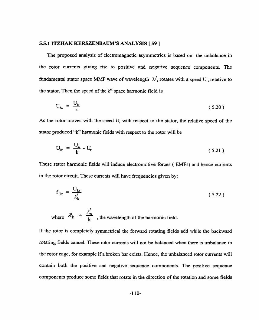
5.5.1 ITZHAK KERSZENBAUM'S ANALYSIS [ 59 ]
The proposed analysis of electromagnetic asymrnetries is based on the unbalance in
the rotor currents giving rise to positive and negative sequence components. The
fundamental stator space MMF wave of wavelength hzs rotates with a speed U, relative to
the stator. Then the speed of the kh space harmonic field is
As the rotor moves with the speed Ur with respect to the stator, the relative speed of the
stator produced "k" harmonic fields with respect to the rotor will be
These stator harmonic fields will induce electromotive forces ( EMFs) and hence currents
in the rotor circuit. These currents will have fkequencies given by:
4 where AL - - k . the wavelength of the harmonic field.
If the rotor is completely symmetrical the forward rotating fields add while the backward
rotating fields cancel. These rotor currents will not be balanced when there is imbalance in
the rotor cage, for example if a broken bar exists. Hence, the unbalanced rotor currents will
contain both the positive and negative sequence components. The positive sequence
components produce some fields that rotate in the direction of the rotation and some fields

that rotate backwards. The negative sequence field components will produce fields that
rotate in the opposite rotation to the positive sequence produced fields. The speed of these
components relative to the rotor is given as
where z, the rotor harmonic order, is equal to 6g + 1 and g equals O, + 1, t2, S.. .
With respect to the stator the speeds of these waves are:
The +/- signs take account of the respective direction of rotation of the field due to the
positive and negative sequence rotor currents. These currents in the rotor circuit will induce
EMF and hence current back into the stator prirnary winding. These induced currents will
have fiequencies given by
1k1 [k(z+1) (1 - s ) f 1) fi = - u
?S z k is ( 5.25 )
Considering the case of space harmonics of stator magnetomotive force ( MMF ) to be
equal to the rotor harmonics, a condition necessary for the production of torque, the
fiequencies of the induced currents in the stator winding due to both positive and negative
sequence currents in the rotor circuit are by equation (5.26 ).

where f = Uis / h!.
The fiequencies given in equation ( 5.26 ) are similar to fiequencies of the spectral
components in the air gap flux as given by Deleroi [ 60 1:
where v = (6 g + 1) p and g = O, +1, +2, +?, etc.
5.5.2 DELEROI'S ANALYSIS [ 60 ]
In his analysis, Deleroi descnbes the rotor as a set of meshes, each mesh having
identicai impedances. Each mesh consists of resistance and leakage reactance of the rotor
bars, end-ring sections as well as air gap field inductances. He M e r assumes that the
stator currents are decoupled fiom the rotor, that is, there is no reaction on or fiom the
stator current distribution. He assumes that the air gap is smooth on both sides, that is slot
permeance variation is negiected. Skew is assumed to be zero and end effects are
neglected. Al1 the magnetics are assumed to be linear, that is no saturation, so that
superposition applies. By the principle of superposition, the current in the broken bar is
assumed to be the sum of the currents in that bar if it were not damaged, and a fault current
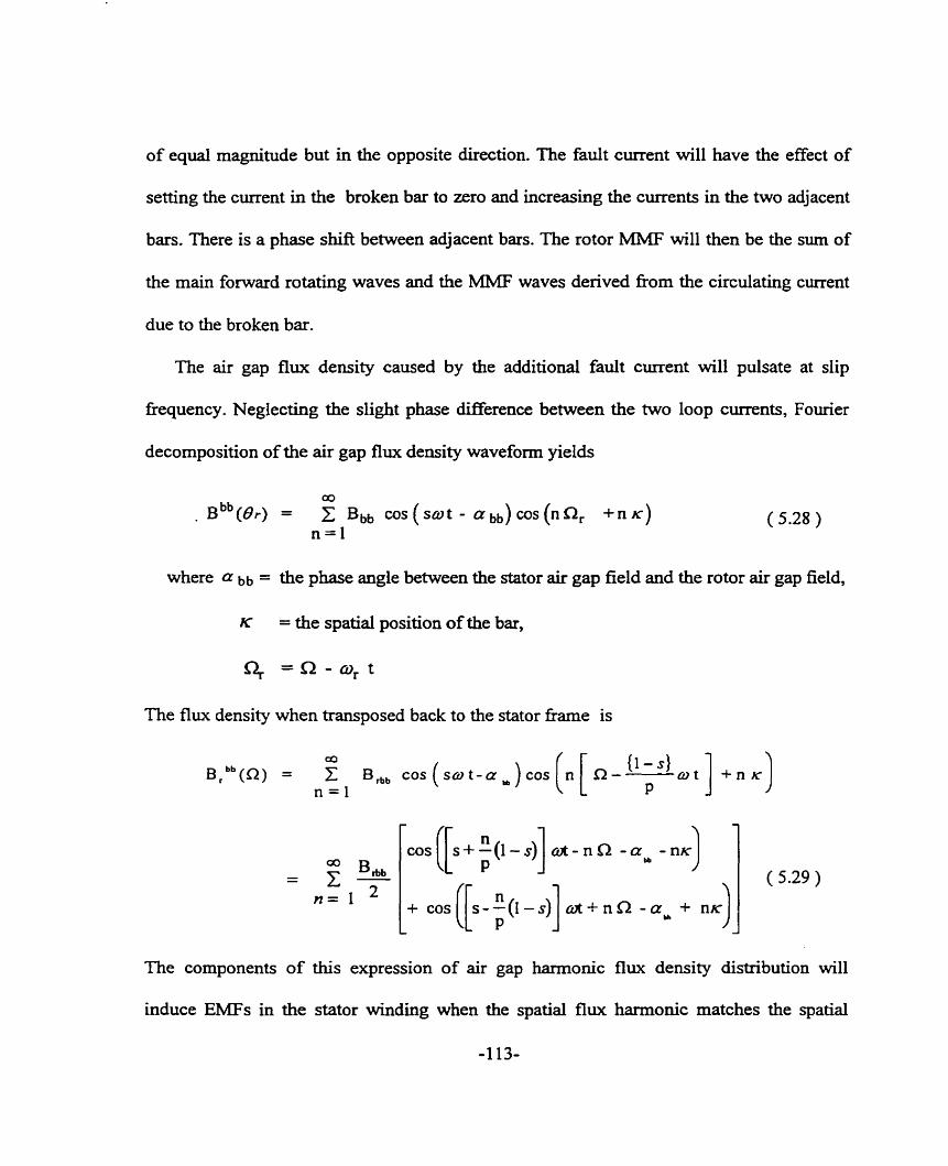
of equal magnitude but in the opposite direction. The fauit current will have the effect of
setting the current in the broken bar to zero and increasing the currents in the two adjacent
bars. There is a phase shift between adjacent bars. The rotor MMF will then be the sum of
the main foward rotating waves and the MMF waves derived fiom the circulating current
due to the broken bar.
The air gap flux density caused by the additional fault current will pulsate at slip
fiequency. Neglecting the slight phase ciifference between the two loop cments, Fourier
decomposition of the air gap flw density waveform yields
where a bb = the phase angle between the stator air gap field and the rotor air gap field,
K = the spatial position of the bar,
q =a-@, t
The flu: u density when transposed back to the stator fiame i
The components of this expression of air gap harmonic flux density distribution will
induce EMFs in the stator winding when the spatial flux harrnonic matches the spatial
-1 13-

winding harmonic. The main winding harmonic pole pair is p and hence equation ( 5.29 )
simplifies to equation ( 5.30 ).
Equation ( 5.30 ) indicates that (1-2s) f sideband currents are produced in the stator
winding. The sideband current has a magnitude that is proportional to the air gap flux and
hence the line voltage at a set speed. Torque ripple and saturation effects are considered
negligible in the analysis. This equation verifies the research by Williamson [ 61 ] who
showed that in neglecting sahiration, the lower sidebands are dominant.
With low inertia, the torque ripple effect must be considered. As reported by Dorrell
[ 62 1, the effect of the torque ripple at twice the slip frequency results in the production of
lower and upper sideband currents of the same fiequency as shown in equation ( 5.3 1 )
When the line voltage is hi& or when the inertia is low, thïs torque ripple will
attenuate the lower side-band current in the stator winding. The upper side-band current
will dominate. In the case of low voltage or high inertia the lower side-band current
dominates. Thomson et. al. [ 63, 64 ] and Tavner [ 65 ] amved at the same conclusion of
upper and lower side-bands given in equation ( 5.3 1 ).
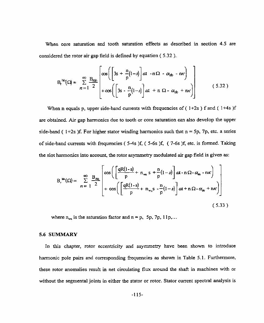
When n equals p, upper side-band currents with fiequencies of ( 1+2s ) f and ( 1+4s )f
are obtained. Air gap harmonics due to tooth or core saturation can also develop the upper
side-band ( 1+2s )f. For higher stator winding harmonics such that n = 5p, 7p, etc. a senes
of side-band currents with fiequencies ( 5-4s )f, ( 5-6s )f, ( 7-6s )f, etc. is formed. Taking
the slot hamionics into account, the rotor asymmetry modulated air gap field is given as:
When core saturation and tooth saturation effects as descnbed in section 4.5 are
considered the rotor air gap field is defined by equation ( 5.32 ).
( 5.33 )
where n, is the saturation factor and n = p, 5p, 7p, 1 1 p,. . .
a h hh(4 = Z 1 n=I
5.6 SUMMARY
In this chapter, rotor eccentricity and asymrnetxy have been shown to introduce
h m o n i c pole pairs and corresponding fiequencies as shown in Table 5.1. Furthemore,
these rotor anomalies result in net circulating flux around the shaft in machines with or
without the segmenta1 joints in either the stator or rotor. Stator current spectral analysis is
- p]. -.cl -a&, --) -
( 5.32 ) +m([.--(l-i]d P + n n - % -
commonly used to detect the presence of these anomalies. In Chapter 6, the spectrd
analyses of the measured shaft voltage, c m n t and flux wilI be used as indications of the
rotor fault conditions. From Table 5.1 it is clear that as the nurnber of poles increases the
effect of rotor eccentricity on the magnitude of shaft current decreases.

h L + 4
8
C-
2 + ICI

CHAPTER 6
DESIGN OF EXPERIMENT AND RESULTS
6.0 INTRODUCTlON
It has been well known since the 1900's that shaft current exists in electrical machines.
Many authos [ 5-14 ] have described the causes and preventive methods as outlined in
Chapter 2. However, the experimental results of many of these authors were not presented. In
the limited nurnber of experimental results presented, the sh& current measurement was
camed out by inserthg an ammeter in the circuit or using a shafi nding shunt. A novel
method of shafl current measurement as descnbed by the authors [ 66 - 67 ] in Chapter 3 was
used in the experimental work. This method was demonstrated to be accurate compared to the
conventional methods such as the ammeter method or the shunt method. The conventional
methods disturb the conducting circuit.
Previously, the limited number of expenmental results were based on research work on
small ac machines operating on grease lubricated anti-fiction bearing systems. There were no
expenmental results on large oil lubricated machines. The experimental work camied out in
this chapter addresses this. A large oil ring Iubncated machine, Appendix 1, was used. Also,
the measurement was done based on steady state ninning conditions. The transient condition
was not considered. The importance of oil film development during the transient condition
will be demonstrated in this chapter.

The objective of each of the tests is given and the results of each test are Mly discussed in
relation to the hypotheses given in Chapters 4 and 5.
6.1 PURPOSE OF THE EXPERIMENTAL WORK
A large 3 phase, 8 pole, 261 1 kW, 4000V and 60 Hz induction motor with segmental
punchings on the stator and ring punchings on the rotor was used in the experimental work.
This machine exhibits symptoms of shafi currents as dernonstrated by the damage to the
babbitt of both bearings of Figure 6.1 and the rub marks on the shafl journal of Figure 6.2
( a ). Visual inspection of the lead-based bearing babbitt reveals spark tracks, stitch tracks and
scotch marks in the circled areas numbered 1 to 5 of Figures 6.1 ( a ) and ( b ). Figure 6.2 ( b )
shows the discolored oil that may possibly be due to oxidation or contamination by arc debris.
Further investigation of the circled areas of the bearing babbitt under the microscope by the
metallurgist confirms the spark track and also the pitting of the bearing babbitt. The darnages
observed under 60X microscopic view were photographed as shown in Figures 6.3 - 6.7.
Figure 6.3 is an example of pitting-type damage to this large induction machine's bearings.
Pitting has round shiny bottoms. Figure 6.4 is an example of spark tracks with molten craters.
Figures 6.5 - 6.7 are example of stitch tracks caused possibIy by intermittent arcings. A
possible consequence of arcing across the shaft journal and the bearing is the deterioration of
the lubncation oïl and the contamination of the lubrication oil by the arc debris. The
lubrication oil is discolored with contamination observed at the bottom of the oil surnp. As
such a set of experiments were designed to determine the possibie causes of the bearing
damage - mechanical or electrical in nature.

b) DE Bearing
Figure 6.1: Bearing Babbitt Damage.
-121-

a) Rub Marks O n the Shaft Journal.
b) Darkened Colored OiL
Figure 6.2: Rub Marks on the Shaft Journal and Darkend Colored Oïl

Figure 63: Microscopic View of the Area 1 in Figure 6.1
Figure 6.4: Microscopic View of the Area 2 in Figure 6.1
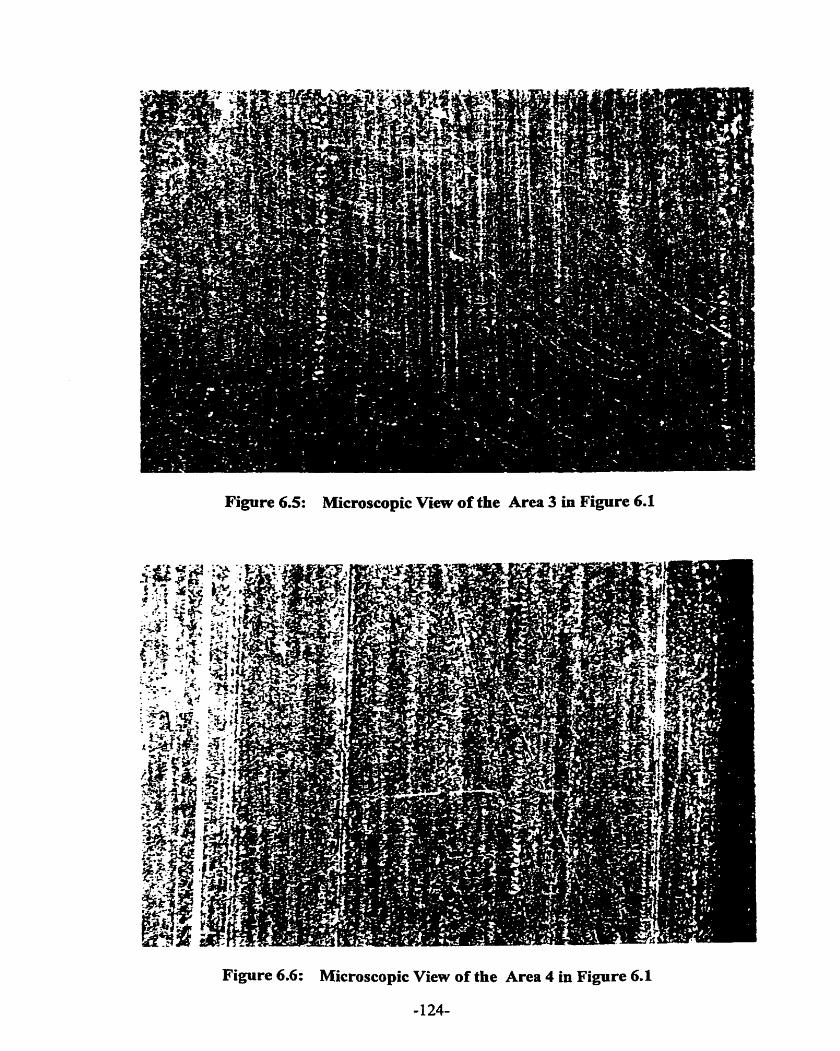
Figure 6.5: Microscopic View of the Area 3 in Figure 6.1
Figure 6.6: Microscopic View of the Area 4 in Figure 6.1
-124-
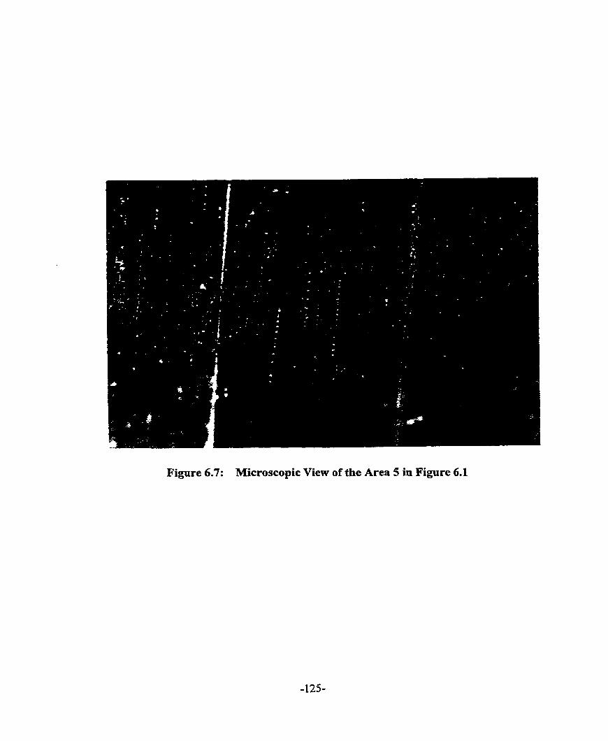
Figure 6.7: Microscopie View of the Area 5 in Figure 6.1

6.2 DESIGN OF EXPERIMENT
The experimental work consists of determining the cause of the bearing damage -
mechanical or electrical in nature and determining the factors contributing to the cause(s) of
the bearing damage:
6.2.1 MechanicaI Test
A mechanical no-load test was conducted to determine whether the cause of the bearing
damage was mechanical in nature. In this test, the test machine is brought up to no-load steady
state running condition using a dc motor. The test machine is de-energized throughout the test.
An oil sample was collected and an oil analysis was conducted to detennine possible
oxidation of oil. The bearings are inspected to determine any damage.
6.2.2 AcceIeration Tests
In f i s series of tests, the magnitude and harmonic components of shaft current were
measured. These tests provide useful information on the possible causes of shaft c u ~ ~ e n t -
joints, eccentricity, saturation, etc.
1. Detemining the magnitude and harmonic components of shaft voltage and current in the
test motor with non-insulated oil ring lubricated sleeve bearings. In this test, the shafk
current was measured fiom start of acceleration to no-load steady state m i n g condition.
The measurement provides information on the magnitude of shaft current pnor to oil film
development and following oil film development and steady state m i n g condition. This
information assists in the assessrnent of the performance of the oil ring to deliver

~ ~ c i e n t oil to lubricate the bearing and build up an oil film to open circuit the shaft
current path.
2. Determining the magnitude and harmonic components of shafi current in the test motor
with insulated oil ring lubncated sleeve bearings; only the opposite drive end ( ODE )
bearing is insulated. The rnotor accelerates to no load speed with the rotor held at
magnetic center throughout the speed range. A dc motor is coupled to the test motor in
order that the rotor is held at magnetic center throughout the speed range. An insulated
spacer is installed between the two shaft ends to ensure no closed circuit for shaft current
flow. This test, together with the test with allowed shaft end play movement, helps in the
understanding of the effect of end play motion prior to machine running at its magnetic
center, on the occilrrence and magnitude of shaft current.
3. Determining the magnitude and harmonic components of shaft current in the test motor
with insulated oil ring lubricated sleeve bearings; only the opposite drive end ( ODE )
bearing is insulated. The motor initially is de-energized; a dc motor is used to accelerate
the test motor to no load speed. The dc motor is de-energized and the test motor
decelerates to around 50 rpm at which tirne the test motor is energized. Throughout the
test the dc motor is coupled to the test induction machine. A tachometer was instdled on
the ODE of the drive motor to monitor the speed of the test machine. The test results
enable the determination of the effectiveness of this method of built-up of oil film prior to
start of acceleration of the test motor.
4. Determining the magnitude and harmonic components of shaft currents in the test motor
with insulated oil ring lubricated sleeve bearings and shaft end play movement. Only the

opposite drive end bearing is insulated. This test will provide an indication of the
effectiveness of the insulation used.
5. Determining the magnitude of shaft current in the test motor with forced lubricated sleeve
bearings, oil rings instalkd, DE bearing non-insulated and ODE bearing insulated. This
test will demonstrate that forced Iubrication is not necessary as long as the bearing
insufation is effective.
6.2.3 Locked Rotor Tests
1. Determining the magnitude and harmonic components of shafi current in the test motor
with insulated oil ring lubncated sleeve bearing; only the opposite drive end bearing is
insulated. The insulated drive end bearing is shorted through a shorting pin.
2. Determining the locked rotor torque and current. This test will provide an indication of
the saturation of the machine during transient condition.
6.2.4 Bearïng Insulation Thickness Tests
1. Determining the magnitude and harmonic components of shaft c m n t in the test motor
with insulated oïl ring lubricated sleeve bearing; only the opposite drive end bearing is
insulated. The insulated drive end bearing is shorted through a shorting pin. The bearing
insulation thickness was varied in this test. Initially, the insulation test was performed on
the machine with 0.762 mm bearing insulation design. Material was removed from the
bearing insulation to obtain 0.381 mm and 0.254 mm bearing insulation designs. Metallic
shims were used to replace the material removed. Tests was conducted at 60%, 80% and
100% of rated voltage.
6.3 INITIAL EXPERIMENTAL CONTROL CONDITIONS
Initial experimental conditions were rigorously controlled to ensure that consistent results
are obtained, minimizing as much as possible the influence of randornness in the controlIable
factors. These conditions are:
1) A new set of bearings was used in the experimental work since any Wear in the bearing
babbitt can lead to bearing failure.
2) uiitially the machine sits at its magnetic center position prior to acceleration of the
machine. There is a complete circuit rùig on the opposite drive end of the machine. Each
phase of the machine has four parailel circuits which are connected to the circuit nng. The
magnitude of shaft flux will be uifluenced by the initial position of the shaft.
3) Clean new ISO VG 68 turbine oil flom the sarne oil d r u . was used for each test.
Contamination in the oil may cause the bearing darnage, enhancing the probability of shafi
current flow.
4) A11 sensor leads are shielded with shields connected to a cornmon grounding point.
5) All tests were conducted using the same 60 Hz sinusoidal supply source with negligible
harmonic contents. This condition is necessaxy to ensure that the supply is not a factor in
the bearing damage.
6) nie Rogowski coi1 installed on the shaft was calibrated pnor to the test. This is to
ensure that the correct proportionality constant is available for accurate shaft current
measurement .

6.4 EXPERIMENTAL RESULTS
6.4.1 AIR GAP IVEASUREMENT
During the set-up of the machine for test, the air gap of the test machine was measured. The
air gap of the test machine was measured at four locations, 90 degrees apart and at both ends
of the machine. Then the machine was rotated 90 degrees manually and the air gap measured
again. In this manner, the nominal air gap value could be obtained. The designed air gap value
is 2.54 mm.
2.413 mm, 2.461 mm * 2.489 mm, 2.471 mm*
2.235 mm, 2.248 mm*
* Rotor rotated 90 degrees
Drive End Section
2.1 08 mm 2.198 mm*
2.235 mm 2.241 mm*
2.286 mm, 2.3 11 mm *
2.108 mm 2.134 mm 2.166 mm* 2.186 mm*
Opposite Drive End Section
Figure 6.8: Air Gap Measurements at Drive End and Opposite Drive End Sections as Viewed From the Drive End.
The eccentricity of the machine is determined as a measure of air-gap symrnetry deviation
based on the direct measurement carried out at the end sections of the stator bore, the formula
being as in equation ( 6.1 )
Sm, is the maximum air gap measured and 60 the average air gap.
Based on equation ( 6.1 ) the drive end measurement indicates average air gap of 2.248 mm
and air gap eccentricity of 7.34 % while the opposite drive end measurement shows average
air gap of 2.254 mm and air gap eccentricity of 7.04%. A feeler gauge is used to determine the
air gap. The thickness of the feeler gauge was deterrnined to be accurate to within + 0.00254
mm. Due to the epoxy layer on the rotor surface and stator bore surface, the errors on the air
gap measurements at the four positions cannot be specifically stated. Hence, it is necessary to
rotate the rotor 90 degrees manually and then measure the air gap again. The drive end
average air gap is 2.279 mm and the opposite drive end average air gap is 2.292 mm. The air
gap eccentricities are 7.95% and 7.83%, respectively.
The effect of eccentricities on the magnitude of shaft current in this test machine is
negligible. As was detemined in Chapter 5, the effect of eccentricities is a factor in the
magnitude of shafi current only when the air gap eccentricities is at least 50%. Also, in
Chapter 5, it was determined that as the number of poles of machine increases the effect of
eccentricities decreases. The test machine is an 8 poIe induction motor with 120 stator slots
and 142 rotor slots. From Figure 5.4, considering static eccentncity or dynamic eccentricity,
the effect of 7.95% eccentricity is negligible with permeance of orders of 14 or ( S-R-2p ) and
22 or ( S-R ). Hence, variation in the dot harmonies due to static eccentricity or side-bands
due to dynamic eccentricity were not observed in the motor line current. Eccentricity is not a
factor in the development of the shaft voltage.

6.4.2 01L AND BEARING DAMAGE ANALYSIS
Clean oil samples and discolored oil sarnples were collected and analyzed to determine the
possibility of oxidation of the lubncation oil and the constituents of the contamination
[ 66,67 1. The analysis resuits are given in Table 6.1.
The contaminants in the oil were separated by centrifuge and washed with petroleum ether
to remove the oil. The material was then fired to b m off the organic matter. Finally the
residue was andyzed using Scanning Electron MicroscopyEnergy Dispersive Spectrometer.
The residue was obsewed under microscope and photographed.
Test Motor 1 I
Test 1
Neutralization Number (ASTM D974-87) (mg KOWg)
ODE Oil
324 69
ISO VG 68
Saybolt Viscosity (SUS) Kinematic ~iscosity(mm~/s) (ASTM D88-8 1) ISO Viscosity Grade
Fe, Pb, Cu Ca, Na, Si, Al, CI
3 19 68
ISO VG 68
Elernental Analysis
Test 2
294 63
ISO VG 68
DE Oil
Ca, Si, Al, Na, S, Cl
308 66
ISO VG 68
Pb, Fe, Na, Ca, Si, Al, CI,
Ca, Al, Si, Pb, Cl, Na
ODE 0i1
32 1 67
ISO VG 68
Fe, Pb, Cu, Ca, Si, Al, Cl, Na
Table 6.1 : Oil Analysis of Clean Oïl Sample and Discolored Oil Samples Taken From the Test Motor; DE - Drive End and ODE - Opposite Drive End.
Pnor to test, a direct current motor was used to drive the induction machine up to rated
no-load speed. The induction machine was not energized. The steady state ninning test ( Test
1 in Table 6.1 ) lasted for four hours. Foilowing the test, the oils in the DE and ODE oil sump
were found to be milky colored. The oil was collected fiom both sumps and analyzed. The
contaminants in the oil as shown in Figures 6.9 and 6.10 were also analyzed. The bearings
were not damaged. It c m be concluded that the cause of the bearing damage is not of
mechanical nature; rather it is due to the presence of shaft current. The test was repeated for
six hours until the oil in the oil sump was no longer discolored and there were no
contaminants found in the oil. This test serves to minimize the influence of mechanicd design
on the validity of the test proper to determine the existence of shaft current.
Following the above test procedure, the induction machine with its ODE bearing insulated
was started at 60%V and accelerated to the steady state no-load condition. The steady state
no-load condition ( Test 2 in Table 6.1 ) lasted for an hou. The oil was found to be
" darkened " in color and contained contaminants as shown in Figures 6.1 1 and 6.12. The
bearings were inspected and the bearing babbitts were found to be damaged. The damage on
the bearing babbitt was viewed under microscope. The bearing damage is electrical in nature,
pointing to shaft current as the cause of the damage. This is so in spite of the conclusion of the
oil analysis in the next paragraph that indicates there was no oxidation of oïl.
The maximum neutralization value for the ISO VG 68 oil used is 0.2 mg KOH/g. Its
viscosity range at 40°C is 61.0 to 75.0 rnrn2/s. The oil analysis from both tests indicates no
oxidation of oil, otherwise the neutralization nurnber would increase beyond 0.2 mg KOWg
and kinematic visosity above 75.0 mm2/s. Calcium and silicon present as silicates may

Fipre 6.9: Contaminants in DE Bearing Housing; Induction Machine Driven Unenergised for Four Hours.
Figure 6.10: Contaminants in ODE Bearing Housing; Induction Machine Driven Unenergised for Four Hours.
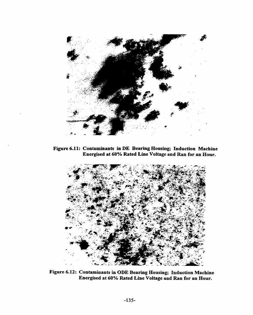
Figure 6.11: Contaminants in DE Bearing Housing; Induction Machine Energised at 60% Rated Line Voltage and Ran for an Hour.
- -
Figure 6.12: Contaminants in ODE Beariog Housing; Induction Machine Energised at 60% Rated Line Voltage and Ran for an Hour.

originate from the bearing insulation. Alurninum was present in al1 the oil sarnples including
the clean unused oil. The presence of aluminum may be due to the oil itself or as an oxide
from the sarnple container. The lead rich particles likely comes corn the lead base babbitt.
The copper particles onginate fiom the bronze oil ring. These contaminants caused the oil to
have "darkened " color.
6.4.3 SHAFT CURRENT MEASUREMENT
6.4.3.1 Both Bearings Non-Insulated, End-Play Movement, No-Load Condition, Oil Ring Lubrication.
The large induction machine has both bearings insulated. Ln this test, the grounding pins at
both the DE and ODE housing were screwed down, touching the metallic base of the bearings
and hence bypassing the insulating materials of the bearings. Then the large induction
machine, both bearings non-insulated, is accelerated at no load rated condition to rated speed.
The Rogowski coil induced voltage wavefoxm shown in Figure 6.13 indicates that pnor to
partial developrnent of an oil film, the average value of shaft current is 90A. Note that power
is applied at time t = 1.Gls. The shaft current occurs in the period t 4 .61s to t = 1.90s with
subsequent reduction in the current following development of the oil film. At close to
standstill condition, tliere is metal-to-metal contact between the shaft journal and the bearing
surface. An oil film had not developed. Figures 6.14 ( a, i ) and ( b, i ) show the expanded
scale of the DE and ODE siiaft current waveform prior to the development of the oil film. The
DE Rogowski coil has a calibration scale of 11.02 mV/A while the ODE Rogowski coil has a
calibration scale of 13.72 mV/A. As expected, both Rogowski coils produce similar

a) DE Rogowski Coii Shaft Current Measurement.
b) ODE Rogowski Coil Shaft Current Measurement
Figure 6.13: Waveform of Rogowski Coil Shaft Current Measurement at Rated Motor Line Voltage, Shaft End Play Movement, Both Bearings Non-Insulated, Oil Ring Lubrication.
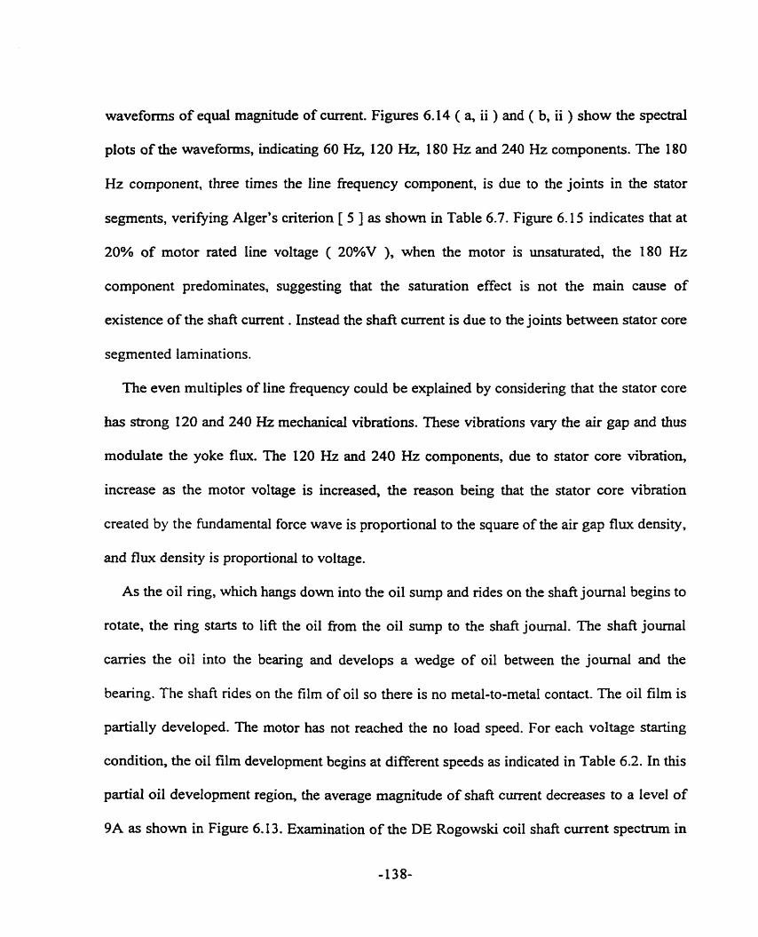
waveforms of equal magnitude of current. Figures 6.14 ( a, ii ) and ( b, ii ) show the spectral
plots of the waveforms, indicating 60 H z , 120 H z , 180 Hz and 240 Hz components. The 180
Hz component, three tirnes the line fiequency component, is due to the joints in the stator
segments, verifying Alger's criterion [ 5 ] as s h o w in Table 6.7. Figure 6.15 indicates that at
20% of motor rated line voltage ( 20%V ), when the motor is unsaturated, the 780 Hz
component predominates, suggesting that the saturation effect is not the main cause of
existence of the shaft current . Instead the shaft current is due to the joints between stator core
segmented laminations.
The even multiples of line fiequency could be explained by considering that the stator core
has strong 120 and 240 Hz mechanicd vibrations. These vibrations vary the air gap and thus
moduiate the yoke flux. The 120 Hz and 240 Hz components, due to stator core vibration,
increase as the motor voltage is increased, the reason being that the stator core vibration
created by the fundamental force wave is proportional to the square of the air gap flux density,
and flux density is proportional to voltage.
As the oil ring, which hangs down into the oil sump and ides on the shaft journal begins to
rotate, the ring starts to lie the oil fiom the oil sump to the shaft journal. The shaft journal
carries the oil into the bearing and develops a wedge of oil between the joumal and the
bearing. The shafl rides on the film of oil so there is no metal-to-metal contact. The oil film is
partially developed. The motor has not reached the no load speed. For each voltage starting
condition, the oil film development begins at different speeds as indicated in Table 6.2. In this
partial oil development region, the average magnitude of shaft current decreases to a level of
9A as shown in Figure 6.13. Examination of the DE Rogowski coi1 shaft current spectrum in

i) Shaft Current Waveform
ii) Spectrum Plot
a) DE Rogowski Coi1 Shaft Current Waveform and Spectrum Plot
Figure 6.14: Waveform and Spectrum Plot of Shaft Current Measured During Initial Start of Acceleration and Prior to Oil Film Development.
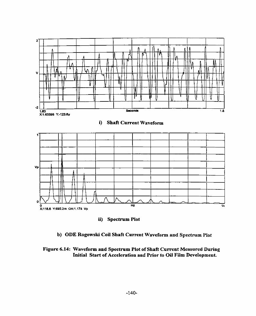
i) Shaft Current Waveform
ii) Spectrum Plot
b) ODE Rogowski Coi1 Shaft Current Waveform and Spectmm Plot
Figure 6.14: Waveform and Spectmm Plot of Shaft Current Measured During Initial Start of Acceleration and Prior to Oil Film Development.
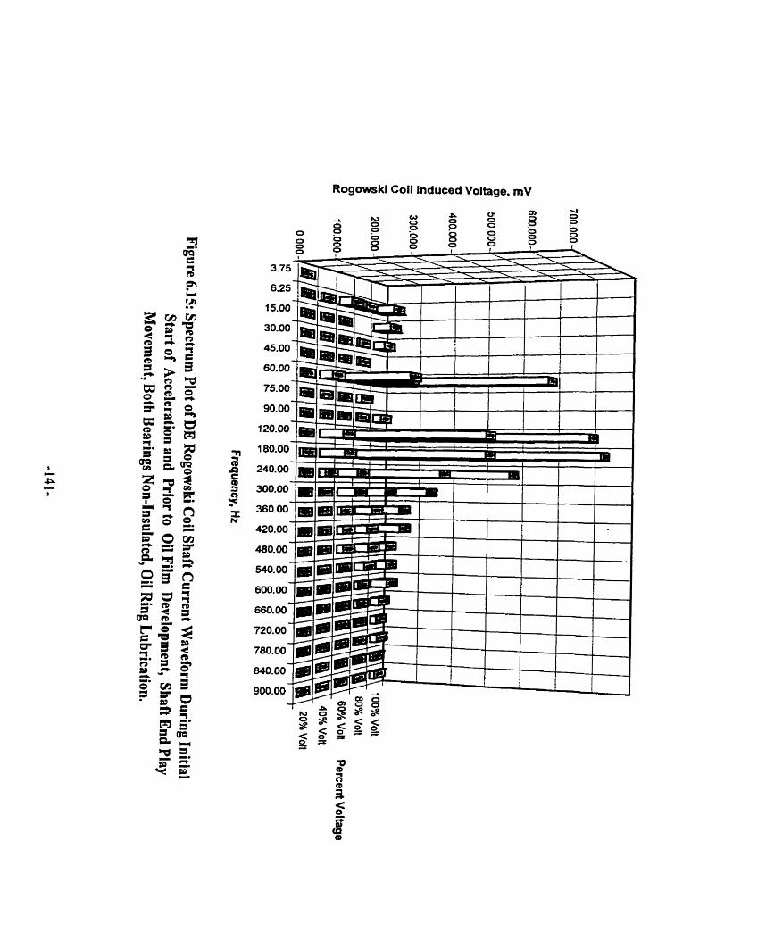
Rogowski Coil lnduced Voltage, mV

Figure 6.16 shows that the partial oil film reduces the high fiequency components
considerably. At steady state no-load condition, the average magnitude of the shafi current is
reduced to 0.22A. The shafi current spectnun is presented in Figure 6.17 which shows the
dominant frequency to be 15 Hz. This fiequency is the rotor ninning fiequency. The oil film is
sufficiently developed at steady state rated no-load speed. This is the full oil film region. The
oil film impedance is effective in reducing the average magnitude of the shaft current. It is
thus important that consistent oil film be developed sufficiently. In this way, the extent of the
bearing damage can be minimized.
Figure 6.16. a spectral plot of the DE Rogowski coi1 shaft current wavefom, shows that
when there is partial oil film development and the oil film thickness is consistent, the high
frequency components are reduced to negligible magnitudes, see for exarnple frequencies of
540 Hz and above. However, if there is a make-and-break of oil film phenornenon resulting in
inconsistent oil film thickness, the high fiequency shaft current components remain significant
but at reduced values. See for exarnple the 180 Hz, 240 Hz and 300 Hz components at 80%V.
The insulating effectiveness of the inconsistent oiI film is reduced. At steady state no-load
conditions, when a full oil film condition exists, the reduced high fiequency components, for
example 180 Hz, 240 Hz and 300 Hz, are fiirther reduced as shown in Figure 6.17.
At 20%V. the oil ring speed follows the shaft speed and there is no slippage of the oil
ring. Oil is delivered consistently to the bearings. Hence, current spikes were not observed in
Figures 6.18 ( a ) and ( b ). The Rogowski coil-induced voltage waveforms at 80%V as shown
in Figures 6.18 ( c ) and ( d ) indicate spikes in the period t = 0.57s to t 4 . 3 4 s as a result of

Rogowski Coil Induced Voltage, mV


4ûm
v
-- 411
40m O - 472 X23.5996 Y:-8.778m
a) DE Rogowski Coi1 Shaft Current Measurement, 20% of Motor Rated Line Voltage.
v
I 1 1 1 1 ' I I I I I II' I I I
b) ODE Rogowski Coi1 Shaft Current Measurement, 20% of Motor Rated Line Voltage.
Figure 6.18: Waveforms of DE Rogowski Coi1 Shafi Current Measurement At 20% and 80% of Motor Rated Line Voltage, Shaft End Play Movement, Both Bearings Non-Insulated, Oil Ring Lubrication.
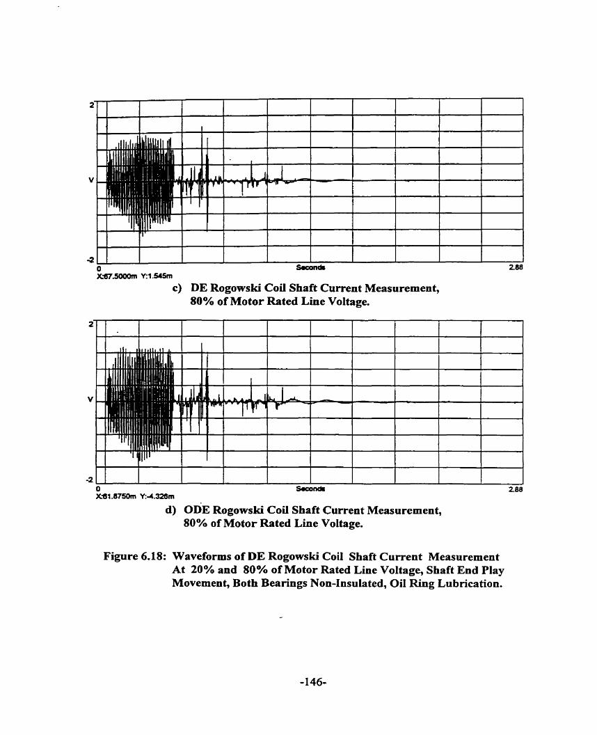
-2 O W n & KW.5ûüûm Y:1 S45m
c) DE Rogowski Coi1 Shaft Current Measurement, 80% of Motor Rated Line Voltage.
d) ODE Rogowski Cod Shaft Current Measurement, 80% of Motor Rated Line Voltage.
Figure 6.18: Waveforms of DE Rogowski Coi1 Shaft Current Measurement At 20% and 80% of Motor Rated Line Voltage, Shaft End Play Movement, Both Bearings Non-Insulated, Oil Ring Lubrication.

the make and-break of oil film phenornenon discussed previously. This phenornenon is a
result of the oil ring slippage with respect to the shaft and hence inconsistent oil film
thickness.
Figure 6.19 surnmarizes the rms shaft current measured in the three oil film development
regions. The measurements in the no oil film region and the partial oil film region were
averaged over a range of speed. Table 6.3 shows the range of speed over which the
measurements were averaged.
Table 6.2: Shaft Speeds At Which Oil Film Begins to Develop for Different Voltage Start Conditions.
Speed at Which Oil Film Begins to Deveio~. mm
80%V 204.5
1OO%V 167.14
Table 6.3: Speed Range Over Which Shaft Current Measurement are Averaged.
Region
No Oil Film Partial Oil Film
6.4.3.2 DE Bearing Non-Insulated, ODE Bearing Insulated, End-Play Movement, No- Load Condition, Oil Ring Lubrication
With the ODE beating insdated and bearing oil ring lubricated, at close to standstill
20%V 32.53
60%V 88.71
Speed Range ( rpm )
condition, the magnitudes of shafe currents at al1 voltages except 20%V were reduced, as
40%V 5 1.43
shown in Figures 6.20 ( a ) - ( f ). The shaft current waveforms at 20%V as shown in Figures
1 OO%V O - 1 19.97 167.14 - 674.4
6.20 ( a ) and ( b ) resemble those obtained in the partial oil development region of the test
60%V O - 88.71 88.71 - 249.98
80%V O - 80.6 204.5 - 5 18.72
with non-insulated bearings of Figures 6.1 8 ( a ) and ( b ). At low voltage starting conditions,
- 147-
40%V O - 38.78 51.43 - 1 15.89
20%V O - 18.20 32.53 - 58.14

.No Oil Film Region
.Partial Oil Film Region
20%V 40%V 60%V 80%V 1 OO%V
Percent of Motor Rated Llne Voltage
Figure 6.19: DE Rogowski Coil Shaft Current Measurement: Three Oil Film Development Regions, Shaft End Play Movement, Both Bearings Non-lnsulated, Oil Ring Lubrication.

O Suon& X4 O.ôOl6 Y:-1 .tOZm
a) DE Rogowski Coii Shaft Current Measurement, 20% of Motor Rated Line Voltage.
I
30m a X ~ 0 . ~ 1 6 V:4.3mn
b) ODE Rogowski Coil Shaft Current Measurement, 20% of Motor Rated Line Voltage.
Figure 6.20: Waveforms of DE Rogowski Coil Shaft Current Measurement at 20%, 80% and 100% of Motor Rated Line Voltage, Shaft End Play Movement, DE Bearing Non-Insulated, ODE Bearing Insulated, Oil Ring Lubrication.

c) DE ~ o ~ o w s k i Coil Shaft Current Measurement, 80% of Motor Rated Line Voltage.
d) ODE Rogowski Coil Shaft Current Measurement, 80% of Motor Rated Line Voltage.
Figure 6.20: Waveforms of DE Rogowski Coü Shaft Current Measurement at 20%, 80% and 100% of Motor Rated Line Voltage, Shaft End Play Movement, DE Bearing Non-Insulated, ODE Bearing Insulated, Oil Ring Lubrication.

-;100m 1 Sw6nd. l I 4 . R
X 3 a 2 S 8 m Y S r n
e) DE Rogowski Coil Shaft Current Measurement, 100% of Motor Rated Line Voltage.
f ) ODE Rogowski Coil Shaft Current Measurement, 100% of Motor Rated Line Voltage.
Figure 6.20: Waveforms of DE Rogowski Coil Shaft Current Measurement at 20%, 80% and 100% of Motor Rated Line Voltage, Shaft End Play Movement, DE Bearing Non-Insulated, ODE Bearing Insulated, OiI Ring Lubrication.

the oil ring speed follows the shafl speed and delivers oïl to the bearing. Besides, the
magnitude of shaft current at low voltage due to joints in the segmented laminations is smail.
The consistent oil film developed is suficient to reduce the shafi current. Hence, we can Say
that at low voltage starting conditions. bearing insulation may not be required and bearing
damage due to shaft current is minimal. The shafi current waveforms at 80%V as shown in
Figures 6.20 ( c ) and ( d ) show no current spikes that were observed in Figures 6.1 8 ( c ) and
( d ). We may conclude that the bearing insulation prevented these spikes fiom o c c ~ g .
Hence, it can be said that the bearing insulation is more effective than the oïl film in reducing
the shaft current. Relying on the oil film alone to prevent bearing damage due to shaft current
is not recommended especially for starting conditions of 40%V and above.
The magnitude of sh& currents measured during transient conditions for across-the-Iine
rated voltage start as shown in Figures 6.20 ( e ) and ( f ), are smaller than those obtained in
the partial oil development region of the test with non-insulated bearings of Figures 6.13 ( a )
and ( h ). The average value of the shaft current is 3.6A, approximately forty percent of the
value obtained with both bearings non-insulated and during partial oil development as s h o w
in Figure 6.13. Furthemore, this 3.6A shaft current is small compared to the 90A shafl
current obtained with both bearings non-insulated and prior to oil development. This finding
reaffirms the recomrnendation that bearing insulation is required to reduce shaft current. The
spectntm plot of the shaft current waveform dunng acceleration ( transient phase ) as s h o w
in Figure 6.21, shows negligible high hamonic cornponents. The 180 Hz component. also
known as the zero sequence component, has been reduced to a negligible magnitude. Also, at
80%V when the shafl voltage is at its maximum, the zero sequence component of the shaft


current has been reduced considerably by the bearing insulation. The insulation at the ODE
bearing breaks the shaft current circuit and hence the through path for the zero sequence
component.
At rated no Ioad speed and rated voltage, the peak magnitude of the shaft current waveforxn
is reduced to 0.1 8A as shown in Figures 6.20 ( e ) and ( f ), approximating the value obtained
with both brarings non-insulated and full oil film development. This indicates that during the
steady state mnning condition when the oil film is fuily developed to a consistent thickness,
the oil film is sufficient to act as an insulator of shaft current. However, it is possible that a
variation in the Ioad condition may cause a corresponding variation in oil film thickness and
thus lead to the possibility of large shaft currents and the resultant bearing darnage. The shaft
current spectxum shown in Figure 6.22 indicates a dominant 15 Hz component which is the
rotor running fiequency. The 180 Hz component and its odd multiples are negligible.
Figure 6.23 demonstrates that bearing damage, if any, will be more likely to occur during
the transient condition than during the steady state runnïng condition, the reason being that at
transient condition the magnitude of shaft current is large compared to that obtained at steady
state running condition. It is thus recommended that fiequent starts at rated voltage be limited
to reduce the probability of bearing damage.
6.4.3.3 DE Bearing Non-Insulated, ODE Bearing InsuIated, End-Play Movement, No- Load Condition, Forced Lubrication
With forced lubricated sleeve bearings, oil ring installed and the ODE bearing insulated,
the magnitudes of the measured shaft currents as shown in Figure 6.24 during transient and
steady state conditions are approximately equal to the corresponding values obtained with oil


a) DE Rogowski Coi1 Shaft Current Measurement, 20% of Motor Rated Line Voltage.
, . . - - - 7 .,,,... - ,......,,,.... ..", . - 1 , .
l -5Qm.
O Seconds 472 X O Y:O
b) ODE Rogowski Coil Shaft Current Measurement, 20% of Motor Rated Line Voltage.
Figure 6.24: Waveforms of DE Rogowski Coil Shaft Current Measurement at 20%, 80% and 100% of Motor Rated Line Voltage, Shaft End Play Movement, DE Bearing Non-Insulated, ODE Bearing lnsulated, Forced Lubrication.

c) DE Rogowski Coil Shaft Current Measurement, 80% of Motor Rated Line Voltage.
d) ODE Rogowski Coil Shaft Current Measurement, 80% of Motor Rated Line Voltage.
Figure 6.24: Waveforms of DE Rogowski Coil Shaft Current Measurement at 20%, 80% and 100% of Motor Rated Line Voltage, Shaft End Play Movement, DE Bearing Non-Insulated, ODE Bearing Insulated, Forced Lubrication.

e) DE Rogowski Coi1 Shaft Current Measurement, 100% of Motor Rated Line Voltage.
f) ODE Rogowski Coi1 Shaft Current Measurement, 100% of Motor Rated Line Voltage.
Figure 6.24: Waveforms of DE Rogowski Coi1 Shaft Current Measurement at 20%, 80% and 100% of Motor Rated Line Voltage, Shaft End Play Movement, DE Bearing Non-Insulated, ODE Bearing InsuIated, Forced Lubrication.
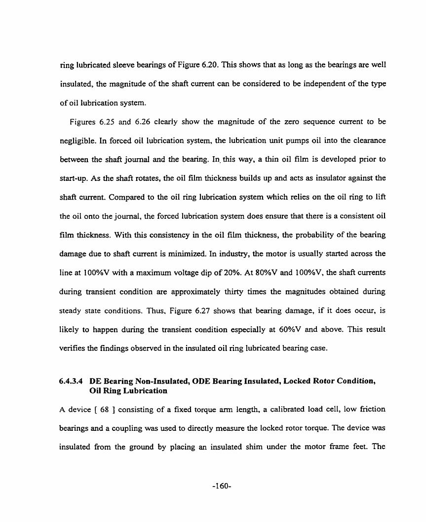
ring lubricated sleeve bearings of Figure 6.20. This shows that as long as the bearings are well
insulated, the magnitude of the shaft current can be considered to be independent of the type
of oil lubrication system.
Figures 6.25 and 6.26 cleariy show the magnitude of the zero sequence current to be
negligible. In forced oil lubncation system, the lubrication unit pumps oil into the clearance
between the shafl journal and the bearing. In. this way, a thin oil film is developed prior to
start-up. As the shaft rotates, the oil film thickness builds up and acts as insulator against the
shaft current. Compared to the oil ring lubrication system which relies on the oil ring to lift
the oil ont0 the journal, the forced lubrication system does ensure that there is a consistent oil
film thickness. With this consistency in the oil film thickness, the probability of the bearing
damage due to shaft current is minimized. In indusûy, the motor is usually started across the
line at 100%V with a maximum voltage dip of 20%. At 80%V and 100%V, the shafl currents
during transient condition are approximately thirty times the magnitudes obtained during
steady state conditions. Thus, Figure 6.27 shows that bearing darnage, if it does occur, is
likely to happen during the transient condition especially at 60%V and above. This result
venfies the findings observed in the insulated oil ring lubncated bearing case.
6.4.3.4 DE Bearing Non-Insulated, ODE Bearing Insulated, Locked Rotor Condition, Oil Ring Lubrication
A device [ 68 ] consisting of a fixed torque arm length, a calibrated load cell, low fiction
bearings and a coupling was used to directly measure the locked rotor torque. The device was
insulated fiom the ground by placing an insulated shim under the motor frame feet. The


Percent of Motor Rated Line Voltage
Figure 6.27: DE Rogowski Coil Shaft Current Measurement:Transient venus Steady State, Shaft End Play Movement, DE Bearing Non-Insulated, ODE Bearing Insulated, Porced Lubrication.

locked rotor torque test was conducted at various voltages. To allow for voltage rarnp-up plus
time for the voltage, current, torque and power readings to stabilize, a minimum test time of
eight to ten seconds is required. The shaft current and shaft voltage were measured during this
time period. Figures 6.28 ( a ) - ( c ) show the shaft current measured at 20%, 80%V and
100%V. Figures 6.29 ( a, i ) - ( c, i ) show a close-up view of the shaft current waveform
obtained at Iocked rotor condition. The spectrurn plots of these shafi current waveforms as
shown in Figures 6.29 ( a, ii ) - ( c, ii ) indicate a dominant 60 Hz component. The zero
sequence current is negligible, limited by the bearing insulation. The magnitudes of these
60 Hz sh& current components at various voltages as shown in Figure 6.30 are approxirnately
equal to those obtained during the initial start-up of motor acceleration with either oil ring
Iubrîcation or forced lubncation and ODE bearing insulated of Figures 6.23 and 6.27.
6.4.4 S H A F T VOLTAGE MEASUREMENT
Shaft voltages are measured end to end, drive end to ground and opposite drive end to
ground. A voltmeter is used in the measurement. At the same time the shaft voltage
waveforms are stored in a spectrum analyzer. The time and fiequency domains of these
waveforms O btained at 20%V, 80%V and 1 00%V are presented in Figure 6.3 1 . The voltage
fiom one end of the shafi to the other end was measured. In addition, voltages from the DE of
the shaft to ground and the ODE of the shafi to ground were measured. In the three cases, the
180 Hz voltage component was the dominant frequency component. The presence of the 180
Hz shaft voltage component at 20%V as shown in Figures 6.3 1 ( a, ii) - ( c, ii ) indicates that
the flux surrounding the shaft and causing the shaft voltage, is due to the presence of joints in
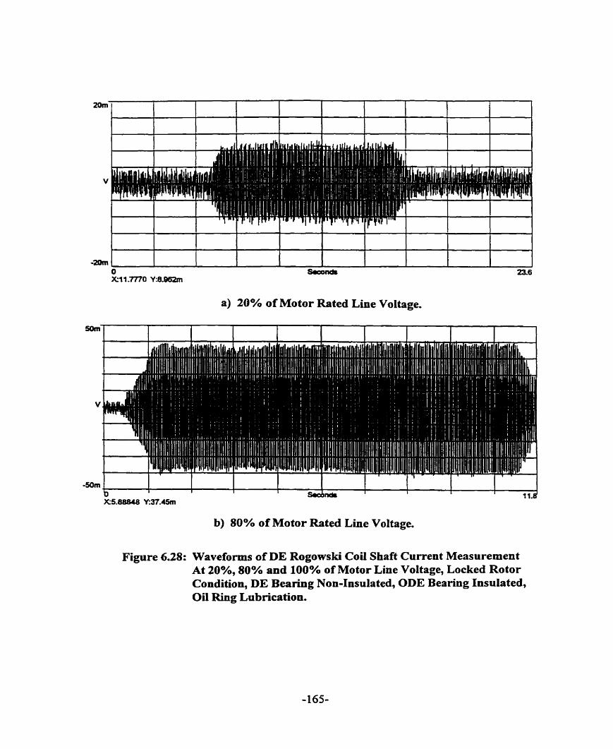
a) 20% of Motor Rated Line Voltage.
b) 80% o f Motor Rated Line Voltage.
Figure 6.28: Waveforms of DE Rogowski Coi1 Shaft Current Measurement At 20%, 80% and 100% of Motor Line Voltage, Locked Rotor Condition, DE Bearing Non-Insulated, ODE Bearing Insulated, Oil Ring Lubrication.
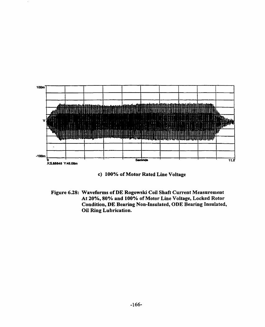
c) 100% of Motor Rated Line Voltage
Figure 6.28: Waveforms of DE Rogowski Coi1 Shaft Current Measurement At 20%, 80% and 100% of Motor Line Voltage, Locked Rotor Condition, DE Bearing Non-Insulated, ODE Bearing Insulated, Oil Ring Lubrication.
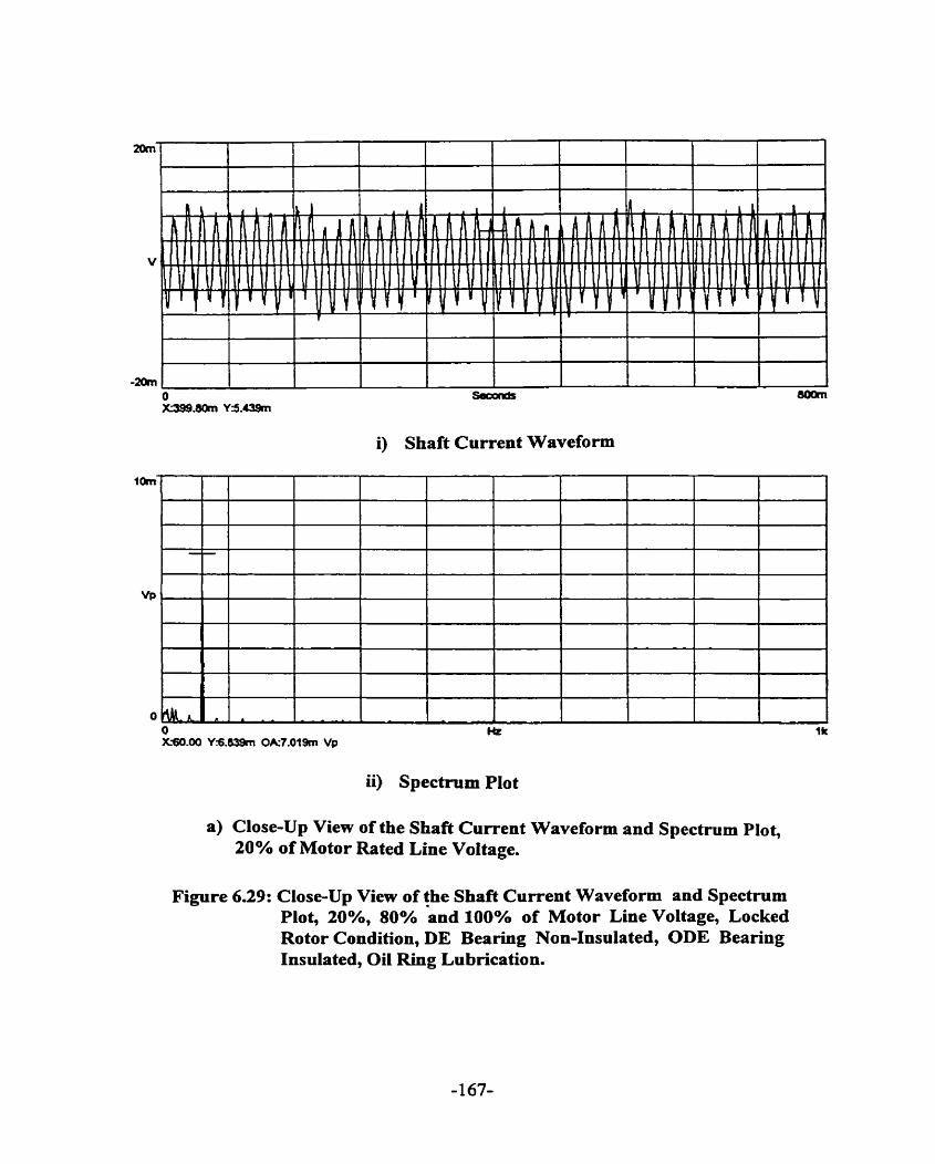
i) Shaft Current Waveform
ii) Spectrurn Plot
a) Close-Up View of the Shaft Current Waveform and Spectmm Plot, 20% of Motor Rated Line Voltage.
Figure 639: Close-Up View of the Shafi Current Waveform and Spectmm Plot, 20%, 80% %nd 100% of Motor Line Voltage, Locked Rotor Condition, DE Bearing Non-Insulated, ODE Bearing Insulated, Oil Ring Lubrication.
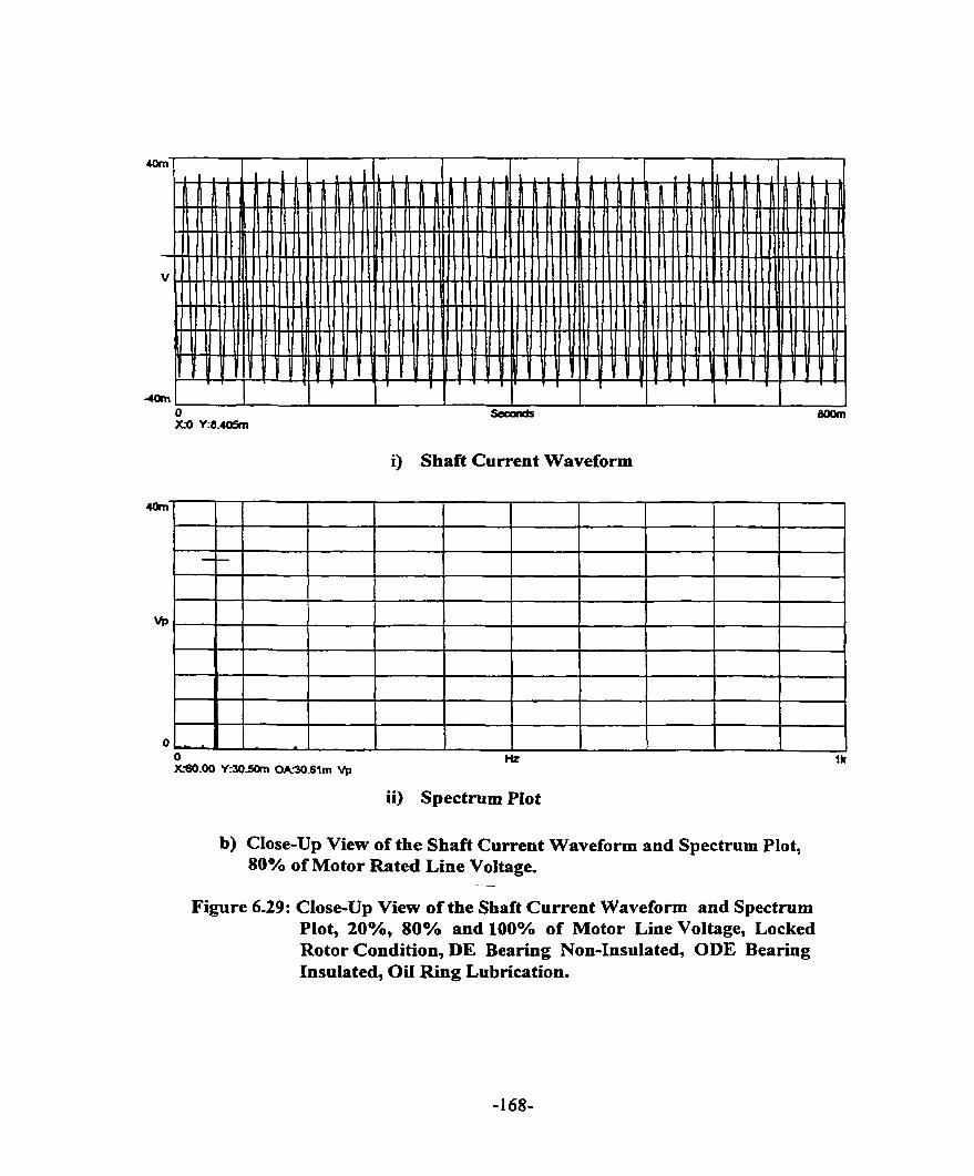
i) Shaft Current Waveform
ii) Spectrum Plot
b) Close-Up View of the Shaft Current Waveform and Spectrum Plot, 80% of Motor Rated Line Voltage.
--
Figure 6.29: Close-Up View of the Shaft Current Waveform and Spectmm Plot, 20%, 80% and 100% of Motor Line Voltage, Locked Rotor Condition, DE Bearing Non-Insulated, ODE Bearing Insulated, Oil Ring Lubrication.

c) Close-Up View of the Shaft Current Waveform and Spectrum Plot, 100% of Motor Rated Line Voltage.
i) Shaft Current Waveform
-4 A
1 Hz 1k CS0.M Y:3721m 0-7.4% Vp
ii) Spectrum Plot
Figure 6.29: Close-Up View of the Shaft Current Waveform and Spectmm Plot, 20%, 80% and 100% of Motor Line Voltage, Locked Rotor Condition, DE Bearing Non-InsuIated, ODE Bearing Insulated, Oil Ring Lubrication.

Percent of Motor Rated Line Voltage
Figure 6.30: Rogowski Coil Shaft Current Measurement During Locked Rotor Condition, 60 Hz Component, DE Bearing Non-Insulated, ODE Berring Insulated, Oil Ring Lubrication.

i) Shaft Voltage Waveform
ii) Spectnim Plot
a) Shaft Voltage Waveform and Spectmm Plot, End-End Measurement, 20% of Motor Rated Line Voltage.
Figure 6.31: Shaft Voltage Measurement At 20%, 80% and 100% of Motor Line Voltage, Steady State No-Load Condition, DE Bearing Non-Insulated, ODE Bearing Insulated, Oil Ring Lubrication.

i) Shaft Voltage Waveform
ii) Spectrum Plot
b) Shaft Voltage Waveform and Spectmm Plot, DE-GND Measurement, 20% of Motor Rated Line Voltage.
Figure 6.31: Shaft Voltage Measurement At 2O%, 80% and 100% of Motor Line Voltage, Steady State No-Load Condition, DE Bearing Non-Insulated, ODE Bearing Insulated, Oil Ring Lubrication.

i) Shaft Voltage Waveform
ii) Spectrum Plot
c) Shaft Voltage Waveform and Spectmm Plot, ODE-GND Measurement, 20% of Motor Rated Line Voltage.
Figure 6.31: Shaft Voltage Measurement At 20%, 80% and 100% of Motor Line Voltage, Steady State No-Load Condition, DE Bearing Non-Insulated, ODE Bearing Insulated, Oil Ring Lubrication.
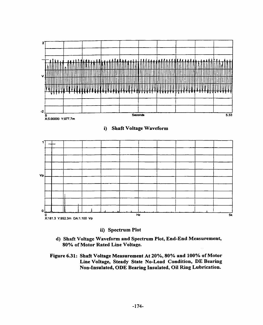
i) Shaft Voltage Waveform
ii) Spectmm Plot
d) Shaft Voltage Waveform and Spectrum Plot, End-End Measurement, 80% of Motor Rated Line Voltage.
Figure 6.31: Shaft Voltage Measurement At 20°h, 80% and 100% of Motor Line Voltage, Steady State No-Load Condition, DE Bearing Non-Insulated, ODE Bearing Insulated, Oil Ring Lubrication.
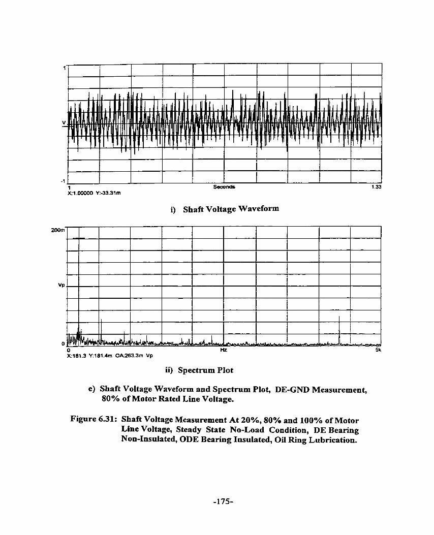
Seconds
i) Shaft Voltage Waveform
ii) Spectmm Plot
e) Shaft Voltage Waveform and Spectmm Plot, DE-GND Measurement, 80% of Motor Rated Line Voltage.
Figure 6.31: Shafi Voltage Measurement At 20°A, 80% and 100% of Motor Line Voltage, Steady State No-Load Condition, DE Bearing Non-Insulated, ODE Bearing Insulated, Oil Ring Lubrication.

i) Shaft Voltage Waveform
ii) Spectrum Plot
f) Shaft Voltage Waveform and Spectrum Plot, ODE-GND Measurement, 80% of Motor Rated Line Voltage.
Figure 6.31: Shaft Voltage Measurement At 20%, 80% and 100% of Motor Line Voltage, Steady State No-Load Condition, DE Bearing Non-Insulated, ODE Beariug Insulated, Oil Ring Lubrication.

i) Shaft Voltage Waveform
g) Shaft Vo 100% of
ii) Spectrum Plot
ltage Waveform and Spectrum Plot, End-End Measurement, Motor Rated Line Voltage.
Figure 6.31: Shaft Voltage Measurement At 20%, 80% and 100% of Motor Line Voltage, Steady State No-Load Condition, DE Bearing Non-Insulated, ODE Bearing Insulated, Oil Ring Lubrication.

5.9 Seconds 623 X5.00000 Y:-39.49m
i) Shafi Voltage Waveform
ii) Spectmm Plot
h) Shaft Voltage Waveform and Spectrum Plot, DE-GND Measurement, 100% of Motor Rated Line Voltage.
Figure 6.31: Shaft Voltage Measurement At 20°A, 80% and 100% of Motor Line Voltage, Steady State No-Load Condition, DE Bearing Non-Insulated, ODE Bearing Insulated, Oil Ring Lubrication.

i) Shaft Voltage Waveform
ii) Spectrum Plot
i) Shaft Voltage Waveform and Spectrum Plot, ODE-GND Measurement, 100% of Motor Rated Line Voltage.
Figure 6.31: Shaft Voltage Measurement At 20%, 80% and 100°h of Motor Line Voltage, Steady State No-Load Condition, DE Bearing Non-Insuiated, ODE Bearing Insulated, Oil Ring Lubrication.

the stator laminations and not due to saturation. The motor teeth do not saturate at 20%V. This
finding is consistent with the Rogowski coi1 shaft current measurement conducted with both
bearïngs non-insulated. At 60%V and higher of Figures 6.3 1 ( d ,ii) - ( r, ii ), odd multiples of
180 Hz were also observed, indicating the effect of saturation. In Figure 6.32 ( a ), the shaft
voltage initially increases with voltage, peaks at 80%V and decreases as the motor line
voltage is fùrther increased. The test machine is operating in saturation condition at this
voltage. From 20%V to 40%V the rate of rise of shafi voltage is small. From 40%V to 60%V,
the rate of rise of shaft voltage measured end to end is the highest. Thereafter, the rate of nse
of shaft voltage decreases. Figures 6.32 ( b ) - ( d ) summarize the fkequency components of
the shaft voltage, listing the 180 Hz as the dominant frequency followed by 540 Hz and 900
Hz. The magnitude of shaft voltage measured from the drive end of the shafe to ground as
shown in Figures 6.32 ( a ) and ( c ) is expected to be much smaller than that measured fiom
the opposite drive end of the shaft to ground of Figures 6.32 ( a ) and ( d ). The reason is that
the drive end bearing is non-insulated while the opposite drive end bearing is insulated.
The shaft voltage was also measured when the machine was operating with forced bearing
lubrication. The shaft voltages measured end to end at different voltage Ievels, illustrated in
Figure 6.33, did not differ much fiom those in Figure 6.32 ( a ). As seen in Figure 6.33, both
the DE to ground voltage and ODE to ground voltage increase gradually fiom 40%V to
8O%V. The voltages measured at 80%V and 90%V in both cases of bearing lubrications are
approximately the same. In the forced bearing lubrication case, after 90%V the ODE to
ground voltage decreases substantiaIl y fiom approximately 0.3 8V to 0.20V. The ODE bearing

20% V 40%V 60%V 80%V 90%V 1OO%V
Percent of Motor Rated Llne Voltage
a) Magnitude
Figure 6.32: Shaft Voltage Measurement At Steady State No-Load Condition, DE Bearing Non-Insulated, ODE Bearing Insulated, Oil Ring Lubrication.
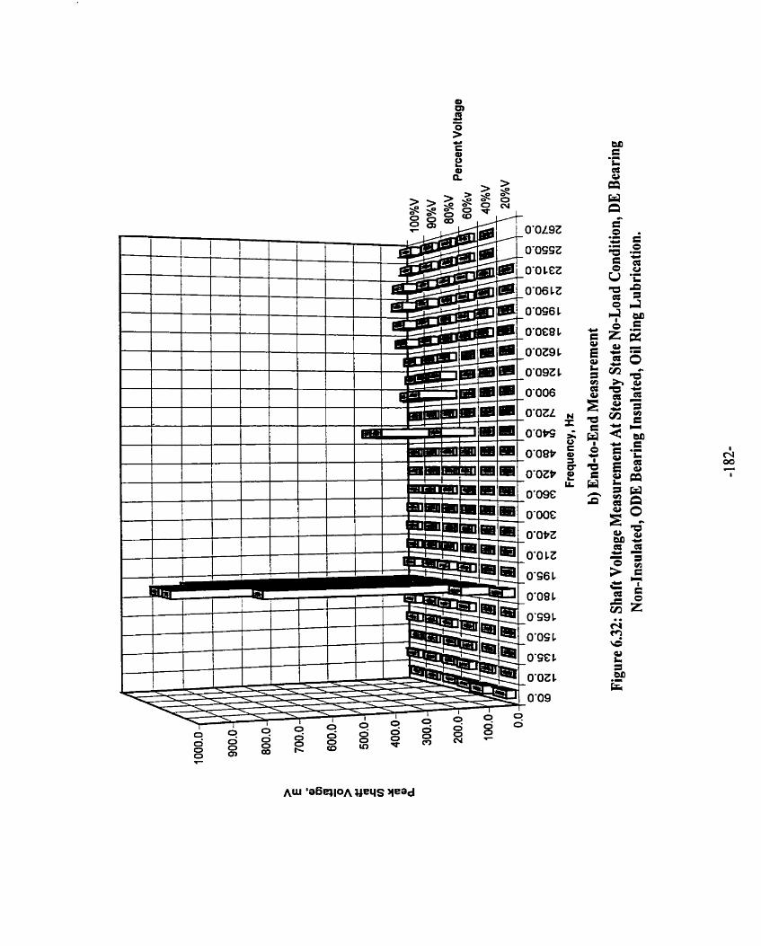
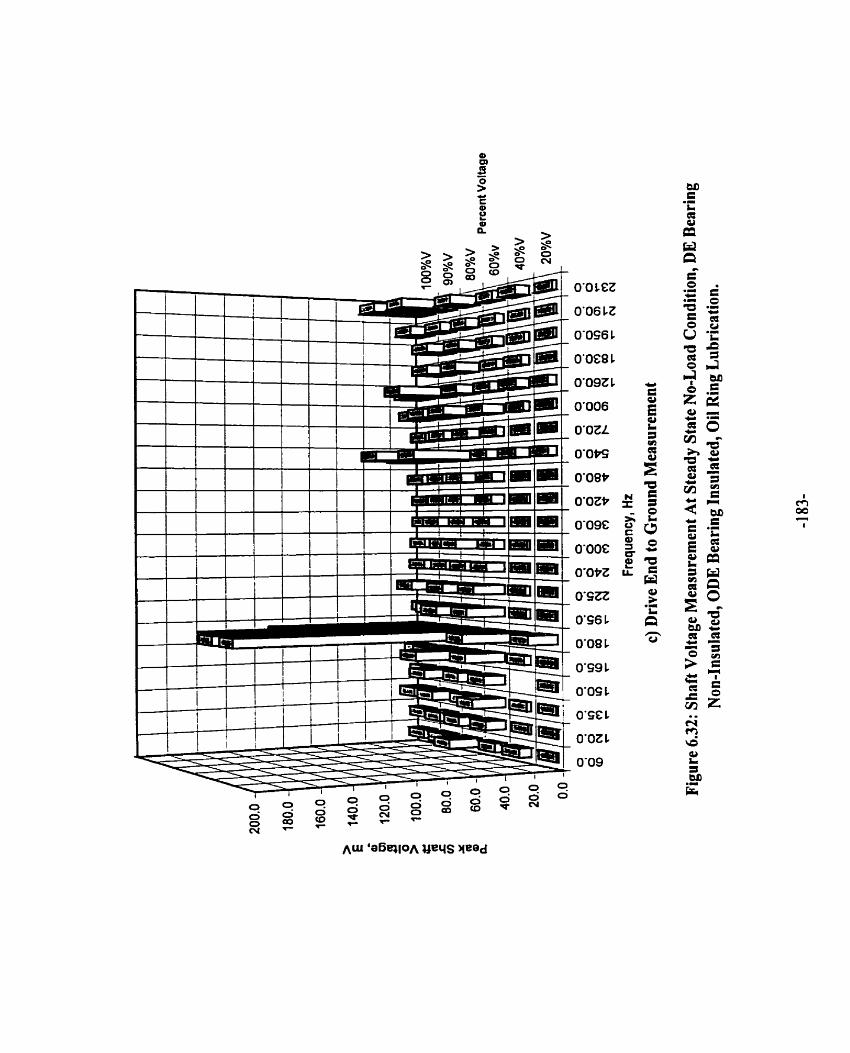

œ
!? - s u E Q> 2
0-0 LEZ
0'06 1 Z
0'086 1
O'OE8 1
O'OZ9 1
O'O9Z L
0'006
O'OZL
0'0~
0-om
O'OZ*
0'09C
O'OOE
0-o*z
O'ÇZZ
0-0 CZ
036 1
0'08 1
O'Ç9 t
0-0s t
0-SC 1
O'OZ 1
0'09

is insulated, and there is a counter-acting voltage built-up due to the oil film fiom the forced
lubrication. This may have reduced the voltage level.
In 1989, following the procedure expIained by Alger [ 5 1, a new machine of similar design
( except that the stator core has twice times the number of joints ) was built. The shafi voltage
results are compared with the results obtained fiom this test machine as shown in Figure 6.34.
Figure 6.34 indicated that the shaft voltage measured end to end and ODE to ground have
decreased by a factor of 2 for the rebuilt stator core. The DE to ground voltage remains
approximately constant. When the number of joints was doubled, the numerator of the
equation ( 2.1 ) becomes even and hence shaft current will not appear.
As expected in Figure 6.35 ( a ), the spectral plot of the shaft voltage rneasured during
locked rotor. showed 180 Hz condition as the dominant frequency. Comparing Figure 6.35
( b ) with Figure 6.32 ( a ) or Figure 6.33, the shaft voltage measured during locked rotor
condition is smaller than during no-load ninning condition. This reduction is attributed to the
reaction of the rotor current in reducing the higher harmonies.
6.4.5 SHAFT FLUX MEASUREMENT
Shaft flux coils are installed on the DE and ODE of the shaft at the inboard of the bearing
housing. Figures 6.36 ( a ) - ( f ) show the shaft flux induced voltage waveform of the DE and
ODE shaft flux coi1 in the test machine with non-insulated bearings at 20%V, 80%V and
100%V. These figures reveal that the magnitude of shaft flux during the transient running
condition is at least seventy times larger than that during the steady state running condition.
Also, the magnitude of shaft flux measured at the ODE is greater than that measured at the
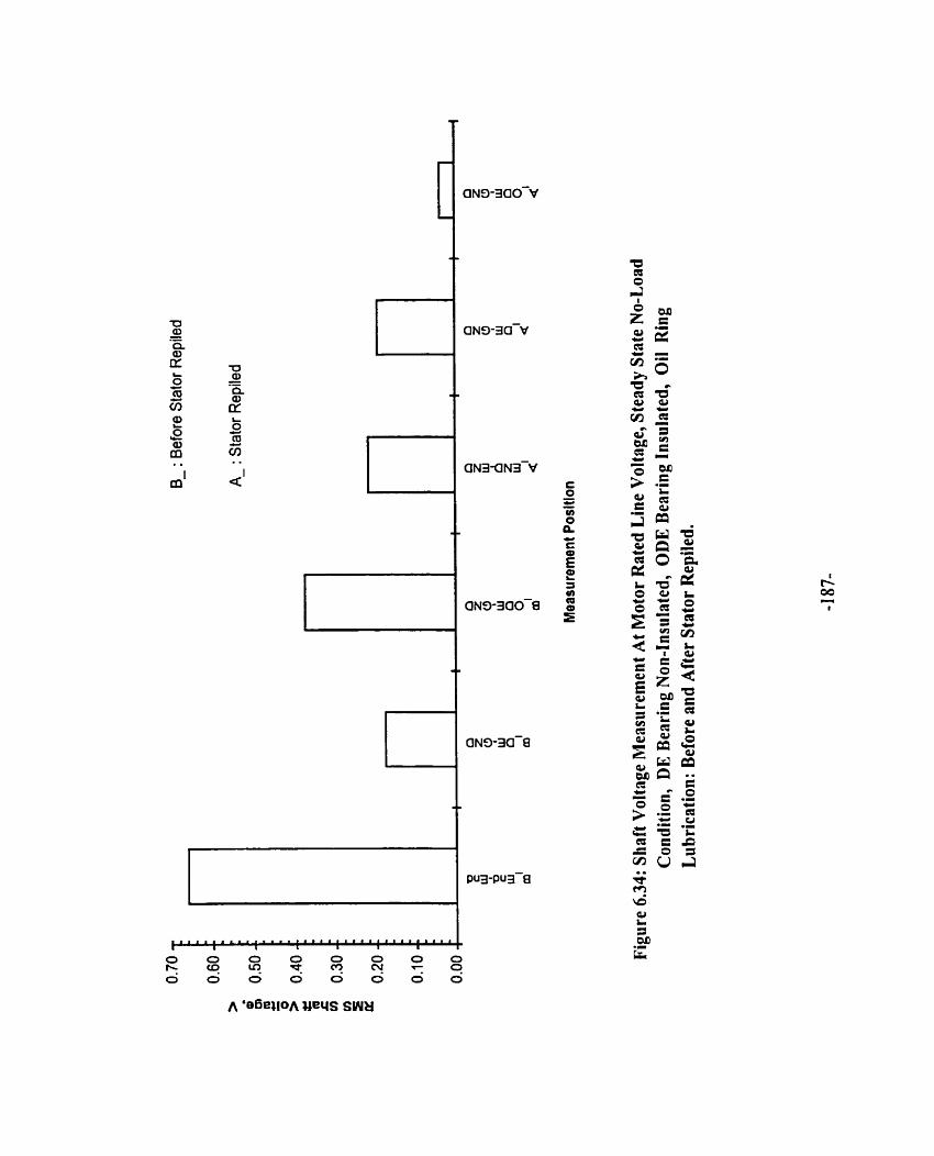
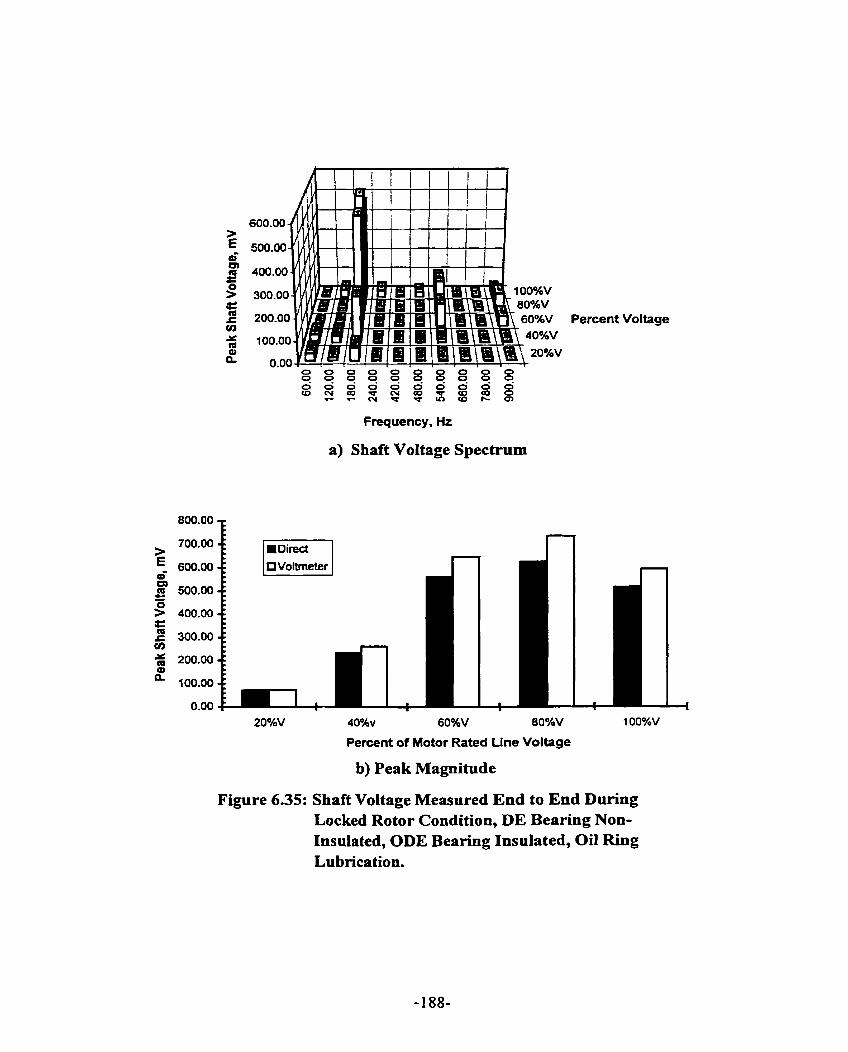
Frequency, Hz
a) Shaft Voltage Spectrum
Percent of Motor Rated Line Voltage
b) Peak Magnitude
Percent Voltage
Figure 6.35: Shaft Voltage Measured End to End During Locked Rotor Condition, DE Bearing Non- Insulated, ODE Bearing Insulated, Oil Ring Lu brication.

I 1 h1.1 II.. Ji i l r . . 1
I
b) ODE Shaft Flux Coi1 Induced Voltage, 20% of Motor Rated Line Voltage.
-m.
Figure 6.36: Shaft Flux Coi1 Induced Voltage Measurement, Both Bearings Non-Insulated, Shaft End Play Movement, Oil Ring Lubrication.
D 1 472 X326484 t-2163m
a) DE Shaft Flux Coi1 Induced Voltage, 20% of Motor Rated Line Voltage.
Il
I 1
!

c) DE Shafi Flux Coil Induced Voltage, 80% of Motor Rated Line Voltage.
d) ODE Shafi Flux Coil Induced Voltage, 80% of Motor Rated Line Voltage.
Figure 6.36: Shaft FIux Coil Induced Voltage Measurement, Both Bearings Non-Insulated, Shaft End Play Movement, Oil Ring Lubrication

e) DE Shaft Flux Coii Induced Voltage, 100% of Motor Rated Line Voltage.
f) ODE Shaft Flux Coil Induced Voltage, 100% of Motor Rated Line Voltage.
Figure 6.36: Shaft Flux Coil Induced Voltage Measurement, Both Bearings Non-Insulated, Shaft End Play Movement, Oil Ring Lubrication

DE. John Sohre [ 17 ] and Michaef Costello [ 18 ] indicated that the maximum shaft residual
flux density should not be more than 0.0003 Tesla. They based their work on high speed
turbo-machinery. However. in our case. peak values of shaft flux densities of 0.000758 Tesla
and 0.000479 Tesla were measured at the DE and ODE respectively during the transient
running condition. These values exceeded the maximum residual flux density suggested by
Sohre et al. Figures 6.37 ( a ) - ( 1 ) show the DE and ODE shaft flux coil induced voltage
waveforms and their corresponding spectrum plots during transient condition and steady state
no-load condition at 20% V. 80%V and 100%V. The spectrum plots of the flux coil induced
voltage waveforms indicate a fundamental component only, that is 60 Hz and the test machine
is oper&ting at medium speed. There is no requirement to demagnetize the shaft. During
steady state no-load conditions, the magnitude of the fundamental component of shaft flm
density is less than the maximum residual flux density. Figures 6.38 ( a ) - ( d ) summarize the
spectrum analyses of the shafi flux waveforms measured dunng transient and steady state
r u ~ i n g conditions. Figures 6.38 ( e ) and ( f ) show that the shaft flux at the ODE measures at
a higher magnitude than that at the DE. This difference is attributed to the circulation of
currents in the cornplete circuit rings which surround the shaft and are located at the ODE.
Comparing Figure 6.38 ( e ) with Figure 6.38 ( f ), it is observed that at steady state no-load
condition. the difference between uie DE and ODE shaft flux is not as significant as the
difference obtained during the transient condition.
At Iocked rotor condition of Figure 6.39, as expected, the magnitudes of shaft fluxes are
close to those measured during the transient acceleration condition ( close to locked rotor
condition ) of the test machine.

%3.37031 Y:lZ3.6)i
i) Shaft Flux Coi1 Induced Voltage Waveform
ii) Spectrum Plot
a) DE Shaft Flux Coil Induced Voltage, Transient Condition, 20% of Motor Rated Line Voltage.
Figure 6.37: Spectrum of Shaft Flux Coil Induced Voltage Waveform of Fig. 6.36 During Initial Start of Acceleration and Steady State No-Load Condition.

-1om 41 -36992 X41.36992 YAt65.31~
i) Shaft Flux Coil Induced Voltage Waveform
x60.00 Y.231.8~ 0&1.601m Vp
ii) Spectrum Plot
b) DE Shaft Flux Coil Induced VoItage, Steady State No-Load Condition, 20% of Motor Rated Line Voltage.
Figure 6.37: Spectrum of Shaft Flux Coi1 Induced Voltage Waveform of Fig. 6.36 During Initial Start of Acceleration and Steady State No-Load Condition.

i) Shaft Flux Coil Induced Voltage Waveform
Ü) Spectrurn Plot
c) ODE Shaft Flux Coil Induced Voltage, Transient Condition, 20% of Motor Rated Line Voltage.
Figure 637: Specmim of Shaft Flux Coi1 Induced Voltage Waveform of Fig. 636 Durhg Initial Start of Acceleratioa and Steady State No-Load Condition.

i) Shaft Flux Coil Induced Voltage Waveform
d) ODE Shaft Flux Coil Induced Voltage, Steady State No-Load Condition, 20% of Motor Rated Line Voltage.
Figure 6.37: Spectrum of Shaft Flux Coil Induced Voltage Waveform of Fig. 636 During Initial Start of Acceleration and Steady State No-Load Condition.
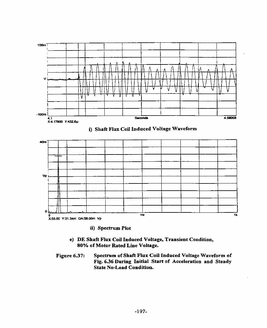
i) Shaft Flux Coil Induced Voltage Waveform
ii) Spectrum Plot
e) DE Shaft Flux Coil Induced Voltage, Transient Condition, 80% of Motor Rated Line Voltage.
Figure 637: Spectrum of Shaft Flux Coii Induced Voltage Waveform of Fig. 636 During Initial Start of Acceleration and Steady State No-Load Condition.
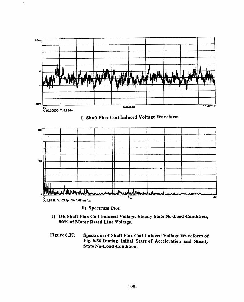
i) Shaft Flux Coil Induced Voltage Waveform
ii) Spectmm Plot
f ) DE Shaft Flux Coil Induced Voltage, Steady State No-Load Condition, 80% of Motor Rated Line Voltage.
Figure 6.37: Spectmm of Shaft Flux Coil Induced Voltage Waveform of Fig. 636 During Initial Start of Acceleration and Steady State No-Load Condition.

2Wm
v
-zoom
g) ODE Shaft Flux Coil Induced Voltage, Transient Condition, 80% of Motor Rated Line Voltage.
l j l
A A i A
1 III I I
I I liI"lVV h J b v lu I '1 I
4.1 saC0nd.m
0)-
Figure 637: Spectrum of Shaft Flux Coi1 Induced Voltage Waveform of Fig. 636 During Initial Start of Acceleration and Steady State No-Load Condition.
X4.17920 W8û3.51~
i) Shaft Flux Coil Induced Voltage Waveform
O Hz l k h-60.00 K46.56m OAS3.80rn Vp
ü) Spectmm Plot
i A A 1 - -

i) Shaft Flux Coil Induced Voltage Waveform
ii) Spectrum Plot
h) ODE Shaft Flux Coü Induced Voltage, Steady State No-Load Condition, 80% of Motor Rated Line Voltage.
Figure 637: Spechvm of Shaft Flux Coil Induced Voltage Waveform of Fig. 636 During Initial Start of Acceleration and Steady State No-Load Condition.

-1 OOm OOOm - 1.4 X3S0.0Wm Y:3.0Wm
i) Shaft Flux Coil Induced Voltage Waveform
ii) Spectrum Plot
i) DE Shaft Flux Coi1 Induced Voltage, Transient Condition, 100% of Motor Rated Line Voltage.
Figure 637: Spectrum of Shaft Flux Coil Induced Voltage Waveform of Fig. 6.36 During Initial Start of Acceleration and Steady State No-Load Condition.

i) Shaft Flux Coi1 Induced Voltage Waveform
O I k X180.0 YZ3-7v OAr1.950m Vp
ii) Spectmm Plot
j) DE Shaft Flux Coü Induced Voltage, Steady State No-Load Condition, 100% of Motor Rated Line Voltage.
Figure 6.37: Spectrum of Shaft Flux Coi1 Induced Voltage Waveform of Fig. 6.36 During Initial Start of Acceleration and Steady State No-Load Condition.

i) Shaft Flux Coi1 Induced Voltage Waveform
ii) Spectrum Plot
k) ODE Shaft Flux Coi1 Induced Voltage, Transient Condition, 100% of Motor Rated Line Voltage.
Figure 6.37: Spectrum of Shaft Flux Coii Induced Voltage Waveform of Fig. 6.36 During Initial Start of Acceleration and Steady State No-Load Condition.

i) Shafi Flux Coil Induced Voltage Waveform
ii) Spectmm Plot
1) ODE Shaft Flux Coil Induced Voltage, Steady State No-Load Condition, 100% of Motor Rated Line Voltage.
Figure 6.37: Spectrum of Shafi Flux Coil Induced Voltage Waveform of Fig. 6.36 During Initial Start of Acceleration and Steady State No-Load Condition.


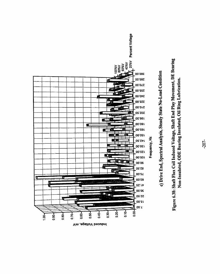


Percent of Motor Rated Line Voltage
e) Magnitude, Transient Condition
Figure 6.38: Shaft Flux Coi1 lnduced Voltages, Shaft End Play Movement, DE Bearing Non-Insulated, ODE Bearing Insulated, Oil Ring Lubrication.

Percent of Motor Rated Line Voltage
f) Magnitude, Steady State No-Lord Condition.
Figure 6.38: Shaft Flux Coi1 Induced Voltages, Shaft End Play Movement, DE Bearing Non-Insulated, ODE Bearing Insulated, Oil Ring Lubrication

Percent of Motor Rated Llne Voltage
Figure 6.39: Shaft Flux Coil Indiiced Voltage Meiisurement, Locked Rotor Condition, 6082 Component, DE Bearing Non-Insulrted, ODE Bearing Insulated, Oil Ring Li1 brication.

When the motor is held at magnetic center, spectral analyses of the measured shaft f l u e s at
both the DE and ODE as shown in Figures 6.40 ( a ) - ( d ), reveal harmonic components
similar to the spectral analyses of the measurements perfonned when the motor is allowed the
limited shaft end play movement. Furtherrnore, the magnitudes of the shafi flux coi1 induced
voltages at magnetic center condition and shafi end-play rnovement condition of Figures 6.40
( e ) and ( f ) are comparatively similar. It can be concluded that shaft end play movement
which occurs during the acceleration of the motor had negligible effect on the magnitude of
shaft flux. The shaft end play is measured to be 22.86 mm
6.4.6 VARIATION WITH BEAIUNG INSULATION THICKNESS
Figure 6.41 shows the variation of magnitude of shaft current with bearing insulation
thickness. As a result of this investigation, we cm conclude that in this test machine, the
bearing insulation thickness could be reduced to half its value with minimal detrimental
consequence. Further investigation is required for a definitive conclusion of bearing insulation
thickness that is required for al1 machine ratings.
6.4.7 SHAFT END-PLAY MOVEMENT FACTOR
In Chapter 2, it was mentioned that with end play movement and without bearing
insulation, the probability of shaft curent will increase due to the contact of the shaft journal
with the bearing housing. However, in an oil ring lubricated machine with insulated bearing,
end play movement assists in the build-up of the oil film. This results in a reduced increase of
shaft current when the oil ring slippage occurs and a faster decay of the shaft current as the
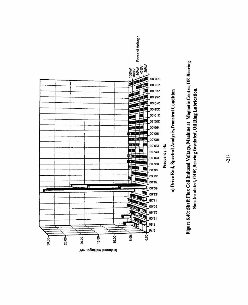


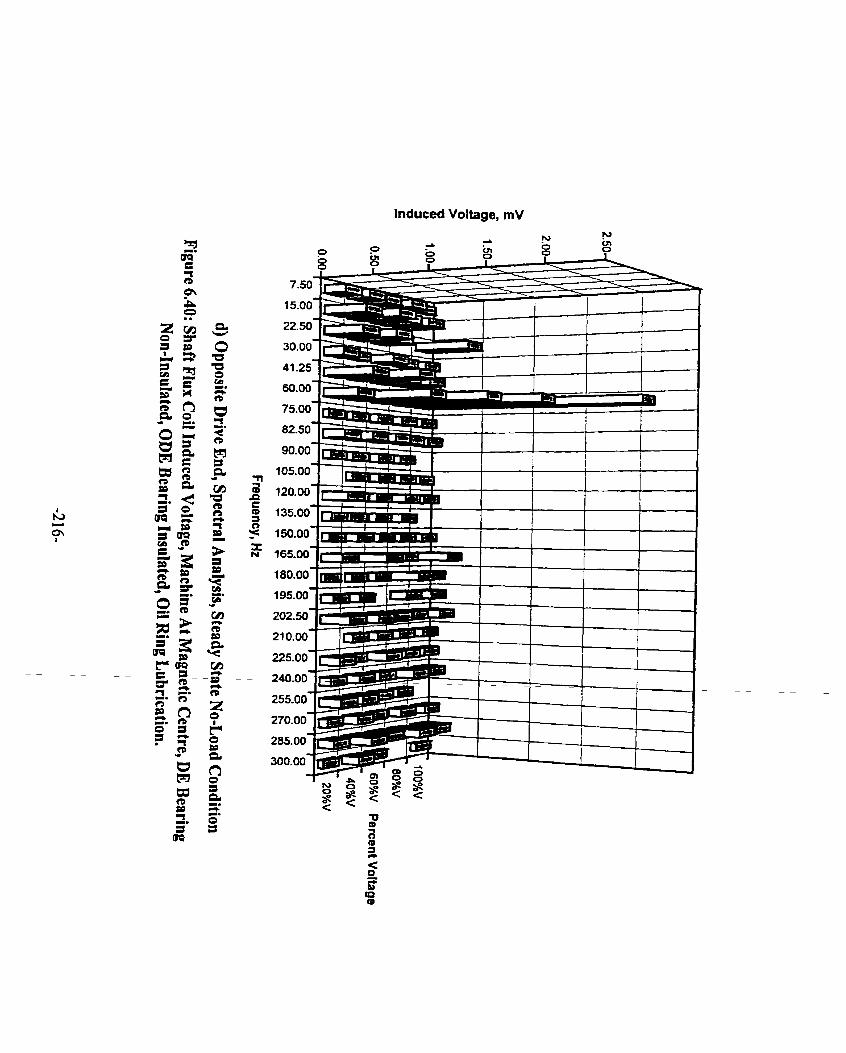
lnduced Voltage, mV

Percent of Motor Rated Llne Voltage
e) Magnitude, Transient Condition.
Figure 6.40: Shaft Flux Coi1 Induced Voltages, Machine At Magnetic Centre, DE Rearing Non-Insulated, ODE Bearing Insulated, Oil Ring Lubrication.
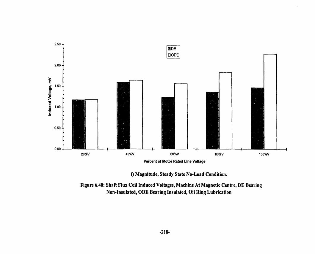
Percent of Motor Rated Line Voltage
I) Magnitude, Steady State No-Load Condition.
Figure 6.40: Shaft Flux Coi1 Induced Voltages, Machine At Magnetic Centre, DE Bearing Non-Insulated, ODE Bearing Insulated, Oil Ring Lubrication
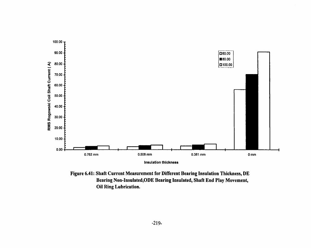
0,762 mm 0.508 mm 0.381 mm O mm
lnsulation thtckness
Figure 6.41: Shaft Current Measurement for Different Bearing Insulation Thickness, DE Bearing Non-Insulated,ODE Bearing Insulated, Shaft End Play Movement, Oil Ring Lubrication.

machine reaches steady state no-Ioad speed. This fïnding is shown in Figures 6.42 ( a ) - ( e ).
End play movement to some extent helps to reduce the slippage of the oil ring and hence oil is
delivered quickly to the journal from the inside surface of the oil ring. However, the end play
movement has the effect of thinning the oil film on the side of the bearing in the direction of
motion and building up oil film in the opposite direction. As the shaft oscillates axially. this
phenornenon of thinning and build up of the oil film increases the probability of breakdown of
the oil film, resulting in shafi current. This effect is small in a machine with limited end play.
The total end play of this machine is measured to be 22.86 mm. The axiai shaft oscillation
occurs during acceleration of the motor. A change of load can aiso cause this oscillation.
For ail voltage starting conditions, at close to standstill condition, there is metal-to metal
contact between the bearing and the shaft. Shaft current is detected in the closed circuit
involving the shaft, the bearing and the machine h e . As the shaft speed increases, initially
the oil ring speed foilows the shafi speed. An oil film is developed. Shaft current decreaçes as
s h o w in Figures 6.42 ( a ) - ( e ). On M e r increase of the shaft speed, the oil ring slips and
the thickness of the oil film becomes inconsistent. Shaft current increases. When the machine
reaches rated no-load speed, the oil film is sufficient to reduce the shaft current.
6.4.8 SATURATION EFFECT
Flux coils were Iocated on the stator tooth closest to the air gap at the DE, center and ODE
of the stator as shown in Figure 3.8. Each of the 3 coils was wrapped around a packet of
larninations. Figure 6.43 shows the transient magnitudes of the flux coi1 induced voltage
harmonies in per unit of the 20%V fundamental value. The third, fifth, seventh and ninth
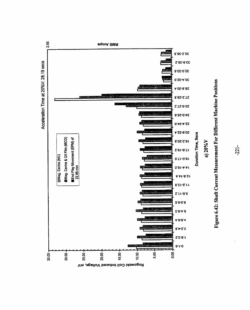
8'9C-t'SC
ZFC-S'CE
9'EC-O'ZC
O'ZG-P'OC
P'OEB'BZ
B'BZ-Z'LZ
0'9 L P Y 1


Rogowski Coil lnduced Voltage, mV
RMS Amps

Rogowski Coil lnduced Voltage, mV
RMS Amps a a,
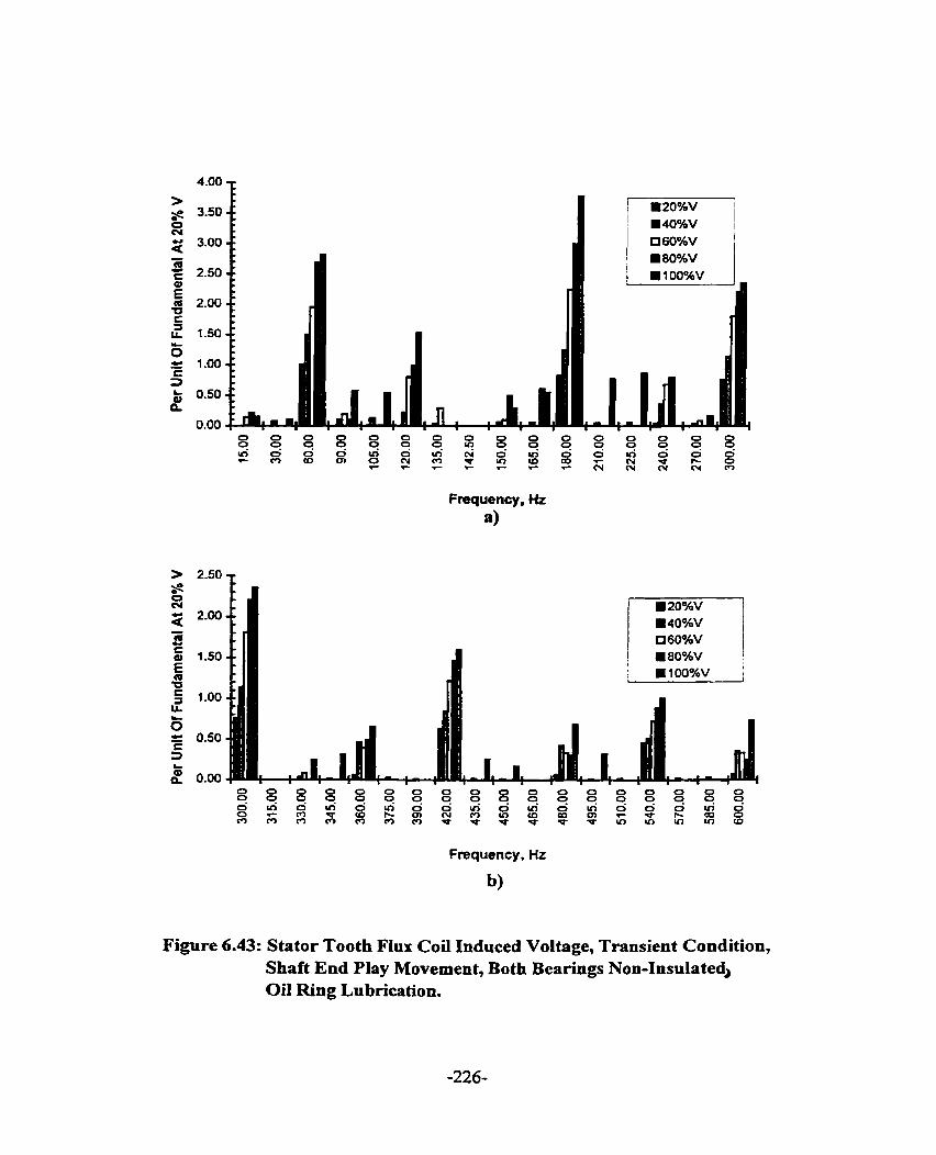
Frequency, Hz
a)
Frequency, Hz
b)
Figure 6.43: Stator Tooth Flux Coi1 Induced Voltage, Transient Condition, Shaft End Play Movement, Both Bearings Non-InsulatedJ Oil Ring Lubrication.

Frequency, Hz
c)
II' - ' I
Frequency, Hz
4 Figure 6.43: Stator Tooth Flux Coi1 Induced Voltage, Transient Condition,
Shaft End Play Movement, Both Bearings Non-Insulated, Oil Ring Lubrication.

Frequency, Hz
e)
Frequency, Hz
f )
Figure 6.43: Stator Tooth FIux Coi1 Induced Voltage, Transient Condition, Shaft End Play Movement, Both Bearings Non-Insulated, Oil Ring Lubrication.

Frequency,
€9
Figure 6.43: Stator Tooth Flux Coil Induced Voltage, Transient Condition, Shaft End Play Movement, Both Bearings Non-Insulated, 0ii Ring Lubrication.

harmonics are significant. The second, fourth, tenth, and twelfth hamionics are also observed,
though negligible. As the voltages increase fiom 20%V to 100%V the significant harmonics
increase, the exception being that the third harmonic increases initially but decreases after
8O%V. At 60%V, the third harmonic and the fundamental are of comparable value.
During the steady state running condition as shown in Figure 6.44, the significant
harmonics observed in the initial start of acceleration becorne negligible. Frequency
components of about 1950,2070 Hz and 2190 Hz are significant due to a combination of rotor
dot harmonics, saturation harmonics and stator fundamental MMF, as indicated in Table 6.4.
6.4.9 SPIDER ARMS AND FRAMlE FLUX MEASUREMENTS
Flux coils each of 5 tums and covering an area of 50.8 mm by 939.8 mm, were
mounted secwely on three shaft spider arms, Iabeled "Arm A", "Arm B" and "Arm C" as
shown in Figure 3.8 to measure the radial flux. From Figures 6.45 ( a ) - ( f ), it can be seen
that at 20%V, 40%V and 6O%V, there is a difierence between the shafi flux on the spider
arms opposite each other, that is Arm B and Arm C, when the machine accelerates at its
magnetic center. This difference is not as large as it was when the measurement was
conducted with the machine dlowed shaft end play movement. The dc motor holding the
machine at its magnetic center assists in minimizing the effects of radial magnetic puII. Radial
magnetic pull is largest at the standstill condition. As well, eccentricity is reduced under these
circumstances. At the steady state no-load condition, both the magnetic center case and the
shaft end-play movement case have approximately the same difference.

Frequency, HZ
a)
Frequency , Hz
b)
Figure 6.44: Stator Tooth Flux Coi1 Induced Voltage, Steady State No-Load Condition, Shaft End Play Movement, Both Bearings Non- Insulated, Oil Ring Lubrication.
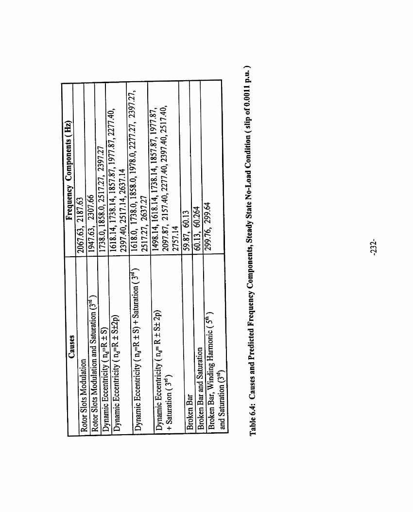

Arm ClAm A, Arm BIAnn A (mV)

a a a

I C: O -
t'P 1-8'Z 1 5 a - 8 2
8'2 C-Z' 1 C

Ttme Duration (secs) Acceleration Tirne: 5.87 secs
d) Magnetic Center, 40%V
Figure 6.45: Shaft Spider Arm Radial Flux Coi1 Induced Voltage Ratio: Shaft End Play Vesus Magnetic Center, DE Bearing Non-Insulated, ODE Bearing Insulated, Oil Ring Lubrication.
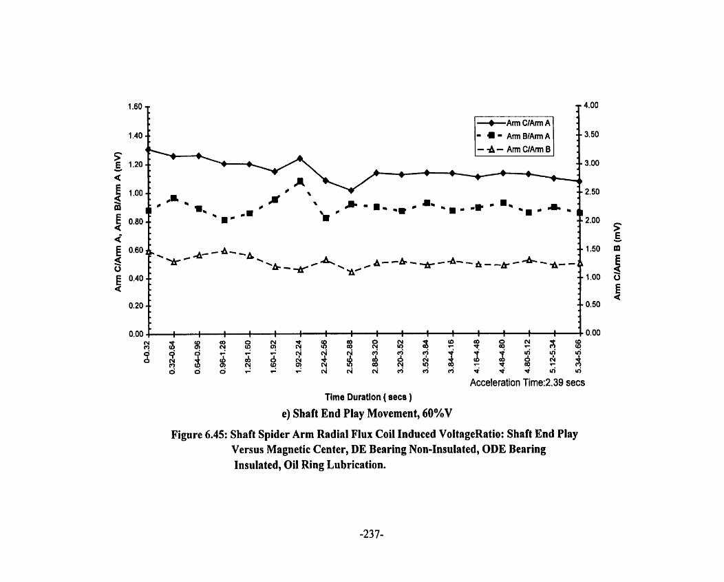
Figure 6.45: Shaft Spider Arm Radial Flux Coil Induced VoltageRatio: Shaft End Play Versus Magnetic Center, DE Bearing Non-Insulated, ODE Bearing Insulated, Oil Ring Lubrication.

f) Magnetic Center, 60%V
Figure 6.45: Shaft Spider Arm Radial Flux Coi1 Induced Voltage Ratio: Shaft End Play Versus Magnetic Center, DE Bearing Non-Insulated, ODE Bearing Insulated, Oil Ring Lubrication.

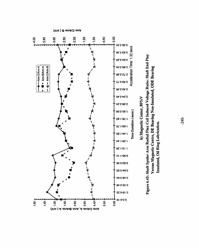


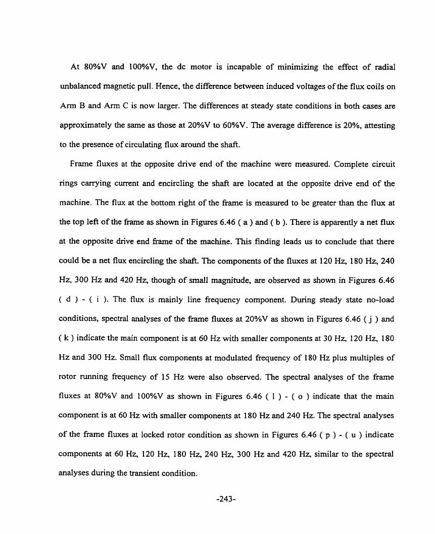
At 80%V and 1 0 0 W , the dc motor is incapable of minimizing the effect of radial
unbaianced rnagnetic pull. Hence, the difference between induced voltages of the flux coils on
A m B and A m C is now larger. The differences at steady state conditions in both cases are
approximately the same as those at 20%V to 60%V. The average difference is 20%, attesting
to the presence of circulating flux around the shafe.
Frame fluxes at the opposite drive end of the machine were measured. Complete circuit
rings carrying current and encircling the shaft are located at the opposite drive end of the
machine. The flux at the bottom right of the h e is measured to be greater than the flux at
the top left of the fiame as shown in Figures 6.46 ( a ) and ( b ). There is apparently a net flw
at the opposite drive end frame of the machine. This finding leads us to conclude that there
could be a net flux encircling the shaft. The components of the £luxes at 120 Hz, 180 Hz, 240
Hz, 300 Hz and 420 Hz, though of small magnitude, are observed as s h o w in Figures 6.46
( ci ) - ( i ). The flux is mainly fine fkequency component. During steady state no-load
conditions, spectral analyses of the frame fluxes at 20%V as shown in Figures 6.46 ( j ) and
( k ) indicate the main component is at 60 Hz with smaller components at 30 Hr 120 Hz, 180
Hz and 300 Hz. Small flux components at modulated fiequency of 180 Hz plus multiples of
rotor running frequency of 15 Hz were also observed. The spectral analyses of the frame
fluxes at 80%V and lOO%V as shown in Figures 6.46 ( 1 ) - ( O ) indicate that the main
component is at 60 Hz with smaller components at 180 Hz and 240 Hz. The spectral analyses
of the frame fluxes at locked rotor condition as shown in Figures 6.46 ( p ) - ( u ) indicate
components at 60 Hz, 120 Hz, 180 Hz, 240 Hz, 300 Hz and 420 Hz, similar to the spectral
analyses during the transient condition.
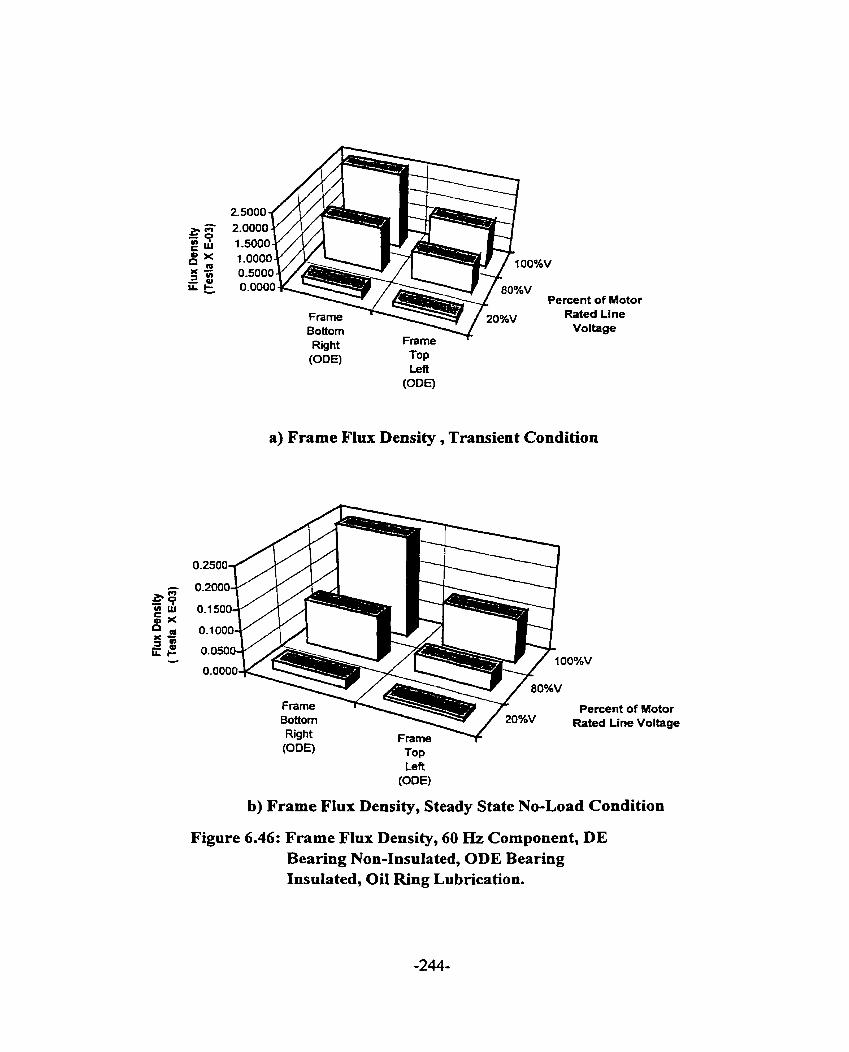
Percent of Motor Rated Line
Voltage
a) Frame FIux Density , Transient Condition
Percent of Motor O/OV Rated Line Voltage
TOP Left (ODE)
b) Frame Flux Density, Steady State No-Load Condition
Figure 6.46: Frame FIux Density, 60 Hz Component, DE Bearing Non-Insulated, ODE Bearing InsuIated, OiI Ring Lubrication.

1 OO%V
v
Percent of Motor Rated Une Voltage
TOP Left
(ODE)
c) Frame Flux Density, Locked Rotor Condition
Figure 6.46: Frame Flux Density, 60 Hz Component, DE
- - - - -
Bearing Non-Insulated, ODE Bearing InsulateiX, BilRîigLubricatiion~ - - - -
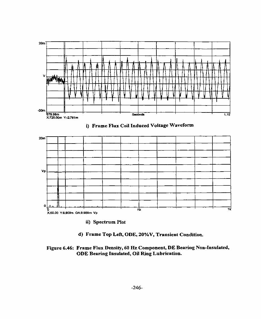
i) Frame Flux Coi1 Induced Voltage Waveform
ii) Spectmm Plot
d) Frame Top Left, ODE, 20%V, Transient Condition.
Figure 6.46: Frame Flux Density, 60 Hz Component, DE Bearing Non-Insulated, ODE Bearing Insulated, Oil Ring Lubrication.

i) Frame Flux Coi1 Induced Voltage Waveform
ii) Spectmm Plot
e) Frame Bottom Right, ODE, 20%V, Transient Condition.
Figure 6.46: Frame Flux Density, 60 Hz Component, DE Bearing Non-Insulated, ODE Bearing Insulated, Oil Ring Lubrication.

i) Frame Flux Coi1 Induced Voltage Waveform
XS9.38 Y:62.69m 0A64.42m Vp
ii) Spectrum Plot
f ) Frame Top Left, ODE, 80%V, Transient Condition.
Figure 6.46: Frame Flux Density, 60 Hz Component, DE Bearing Non-Insulated, ODE Bearing Insulated, 0i1 Ring Lubrication.

i) Frame Flux Coü Induced Voltage Waveform
g) Frame Bottom Right, ODE, 80%V, Transient Condition.
Figure 6.46: Frame Flux Density, 60 Hz Component, DE Bearing Non-Insulated, ODE Bearing Insulated, Oil Ring Lubrication.
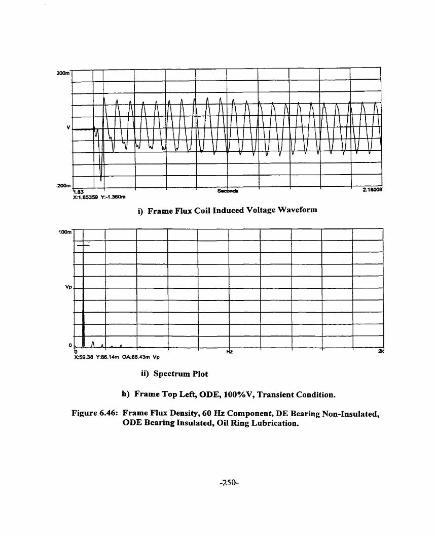
i) Frame Flux Coil Induced Voltage Waveform
ii) Spectmm PIot
h) Frame Top Left, ODE, 100%V, Transient Condition.
Figure 6.46: Frame Flux Density, 60 Hz Component, DE Bearing Non-Insulated, ODE Bearing Insulated, Oil Ring Lubrication.

i) Frame Flux Coi1 Induced Voltage Waveform
i) Frame Bottom Right, ODE, 100%V, Transient Condition.
Figure 6.46: Frame Flux Density, 60 Hz Component, DE Bearing Non-Insulated, ODE Bearing Insulated, Oil Ring Lubrication.

i) Frame Flux Coi1 Induced Voltage Waveform
ii) Spectmm Plot
j) Frame Top Left, ODE, 20%V, Steady State No-Load Condition.
Figure 6.46: Frame Flux Density, 60 Hz Component, DE Bearing Non-Insulated, ODE Bearing Insulated, Oil Ring Lubrication.
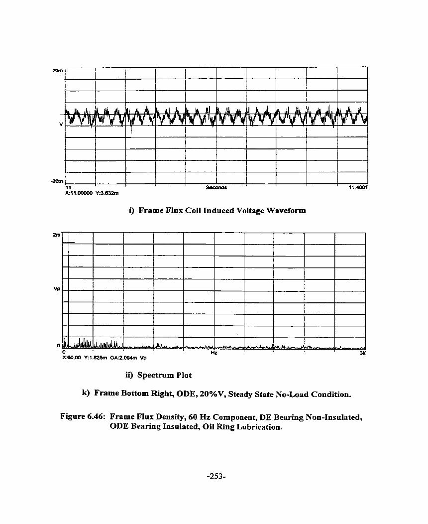
i) Frame Flux Coi1 Induced Voltage Waveform
ii) Spectrum Plot
k) Frame Bottom Right, ODE, 20%V, Steady State No-Load Condition.
Figure 6.46: Frame Flux Density, 60 Hz Component, DE Bearing Non-Insulated, ODE Bearing Insulated, Oil Ring Lubrication.
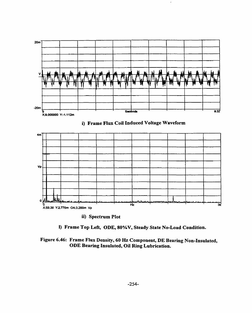
i) Frame Flux Coi1 Induced Voltage Waveform
ii) Spectmni Plot
1) Frarne Top Left, ODE, 80%V, Steady State No-Load Condition.
Figure 6.46: Frame Flux Density, 60 Hz Component, DE Bearing Non-Insulated, ODE Bearing Insulated, Oil Ring Lubrication.
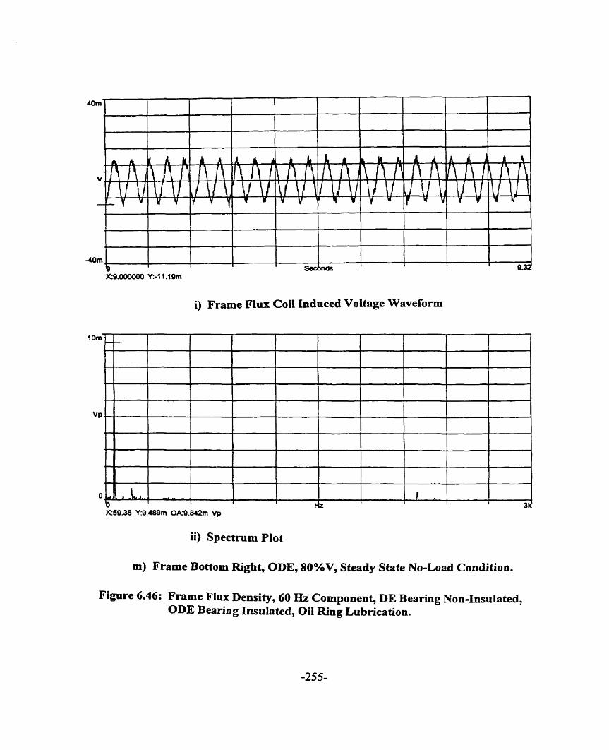
i) Frame Flux Coi1 Induced Voltage Waveform
ii) Spectmm Plot
m) Frame Bottom Right, ODE, 80%V, Steady State No-Load Condition.
Figure 6.46: Frame Flux Density, 60 Hz Component, DE Bearing Non-Insulated, ODE Bearing Insulated, Oil Ring Lubrication.

X8.000000 Y:-1 0.75m
i) Frame Flux Coi1 Induced Voltage Waveform
ii) Spectmm Plot
n) Top Left, ODE, 100%V, Steady State No-Load Condition.
Figure 6.46: Frame Flux Density, 60 Hz Component, DE Bearing Non-Insulated, ODE Bearing Insulated, Oil Ring Lubrication.
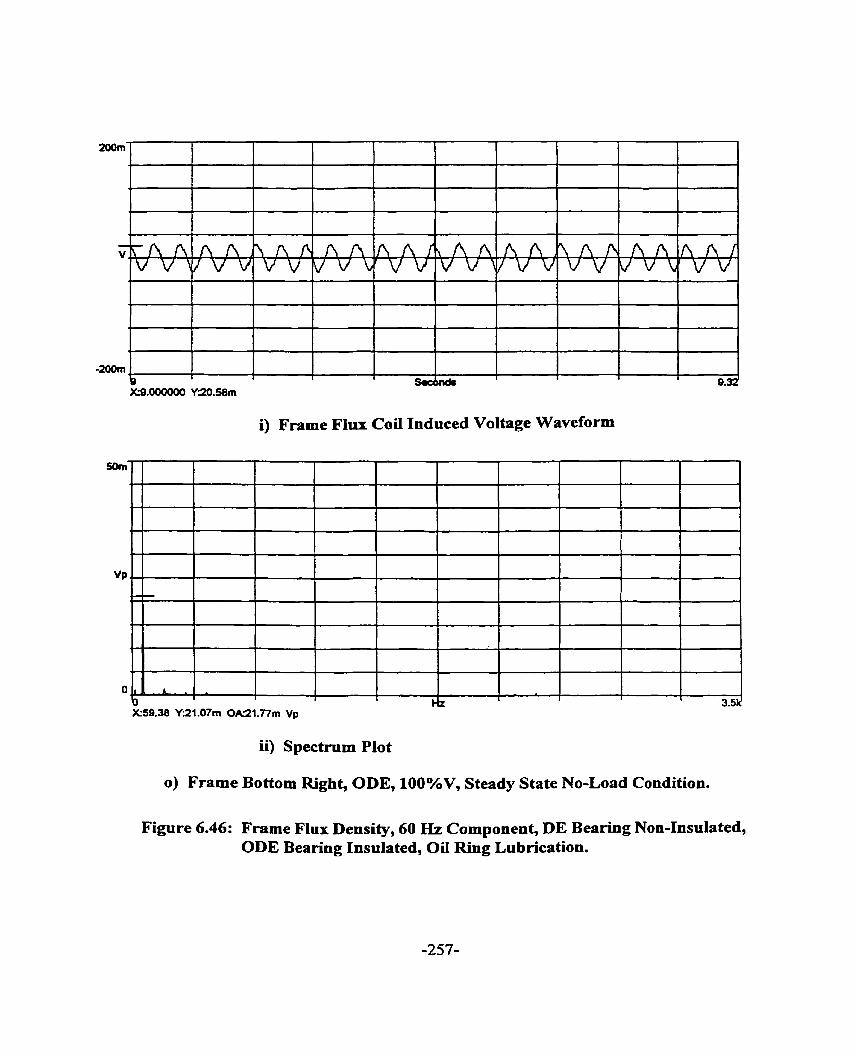
X%,000000 YZû.58m
i) Frame Flux Coi1 Induced Voltage Waveform
ii) Spectrum Plot
O) Frame Bottom Right, ODE, 100%V, Steady State No-Load Condition.
Figure 6.46: Frame Flux Density, 60 Hz Cornponent, DE Bearing Non-Insulated, ODE Bearing Insulated, Oil Ring Lubrication.
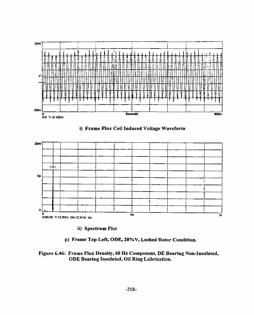
i) Frame Flux Coii Induced Voltage Waveform
Figure 6.46: Frame Flux Density, 60 Hz Component, DE Bearing Non-Insulated, ODE Bearing Insulated, OiI Ring Lubrication.
--
I I
A - - O Hz l k X60.00 Y:12.BSm 0k12.91m Vp
ii) Spectrum Plot
p) Frame Top Left, ODE, 20°hV, Locked Rotor Condition.
A - -
I
1 I I I

i) Frame Flux Coi1 Induced Voltage Waveform
ii) Spectrum Plot
q) Frame Bottom Right, ODE, 20%V, Locked Rotor Condition.
Figure 6.46: Frame Flux Density, 60 Hz Component, DE Bearing Non-Insulated, ODE Bearing Insulated, Oil Ring Lubrication.

i) Frame Flux Coi1 Induced Voltage Waveform
X60.00 Y57.35m OA67.lun Vp
ii) Spectrum Plot
r) Frame Top Left, ODE, 80%V, Locked Rotor Condition.
Figure 6.46: Frame Flux Density, 60 & Component, DE Bearing Non-Insulated, ODE Bearing Insulated, Oil Ring Lubrication.
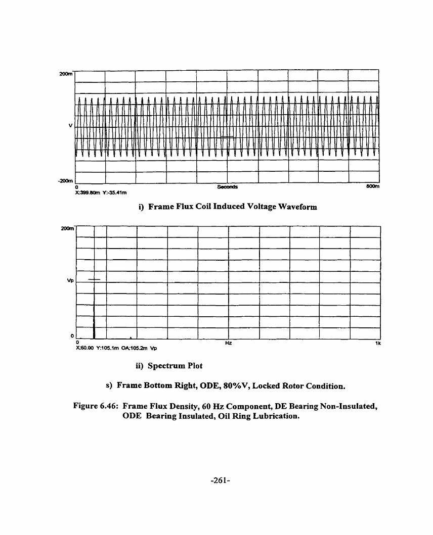
i) Frame Flux Coi1 Induced Voltage Waveform
ii) Spectmm Plot
s) Frame Bottom Right, ODE, 80%V, Locked Rotor Condition.
Figure 6.46: Frame Flux Density, 60 Hz Component, DE Bearing Non-Insulated, ODE Bearing Insulated, Oil Ring Lubrication.
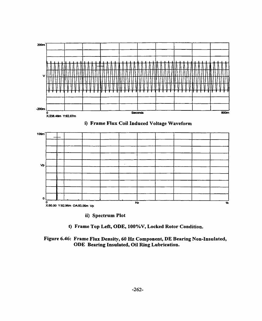
i) Frame Flux Coi1 Induced Voltage Waveform
ii) Spectrum Plot
t) Frame Top Left, ODE, 100%V, Locked Rotor Condition.
Figure 6.46: Frame Flux Density, 60 Hz Component, DE Beanng Non-Insulated, ODE Bearing Insulated, Oil Ring Lubrication.

i) Frame Flux Coi1 Induced Voltage Waveforrn
ii) Spectrum Plot
u) Frame Bottom Right, ODE, 100%V, Locked Rotor Condition.
Figure 6.46: Frame Flux Density, 60 Hz Component, DE Bearing Non-Insulated, ODE Bearing Insulated, Oil Ring Lubrication.
6.4.10 LOCKED ROTOR TORQUE AND CURRENT MEASUREMENT [ 68 ]
Locked rotor torque and current were meanired at different voltages and plotted in Figure
6.47. From Figure 6.47 the dopes of the c w e s for the locked rotor torque and current were
determined and found to be 2.44 and 1.14, respectively. Theoretically, without saturation, the
slope of the torque c w e is 2.0 ( torque is proportional to the square of the voltage ) and that
of the current is 1.0 ( cment is proportional to the voltage ). Saturation begins to occur at
40%V as seen in Figure 6.48. Saturation needs to be considered in the detennination of the
occurrence of shaft current especially during starting of the motor. It is during starting of the
motor that the probability of bearing damage due to sh& current is highest. The higher the
harmonic content present as a result of saturation, the higher the probability of the shafl
current punching through the bearing insulatioa In Section 6.4.7, during transient conditions,
the main harmonic component was determined to be the zero sequence component.
6.4.11 OIL RING PERFORMANCE [ 69- 72 ]
Each bearing in the tested machine had an oil ring nding on the shaf? journal as shown in
Figure 2.3. The oil ring had an imer diarneter of 254.0 mm and width of 19.05 mm. The oil
ring weighs 758.2 grams and rides on a shaft journal of 165.1 mm with fifieen percent of the
oil ring diarneter immersed in oil which has kinematics viscosity of 63.0 mm2/s. The shaft
journal peripheral velocity is 7.8 m/s, less than the practical oil ring upper Iimit of 14 m/s
[ 71 1, above which oil ring bearing design is not used. Al1 the data are substituted into
equations ( A2-2 ), ( A2-7 ) and ( A240 ) and the results are tabulated in Table 6.5.

1.00E+03
Voltage
Figure 6.47: Log-log Scale of Locked Rotor Torque, Current and Power versus Voltage.
O 500 1000 1500 2000 2500 3000 3500 4000
Voltage , V
Figure 6.48: Linear Scale of Locked Rotor Torque Versus Voltage

- 1 Ratio of (b) to (a) 1 2.94 1 Shaft Speed At Start Of Ring Slip Region (a) Shaft Speed At Start of Full Film Ring Drive ( b)
1 Lemon et al [ 69 1 Ratio 1 2.90 1
96 RPM 282 RPM
Table 6.5: Calculated Shaft Speed At Start of Ring Slip Region and Fu11 Film Ring Drive
D. C. Lemon and E.R. Booser [ 69 1, R. Baudry and L. M. Tichvinsky [ 70 ] and G. B.
Karelitz [ 73 ] provided some details of the elaborate experirnental apparatus set-up designed
to duplicate as closely as possible the normal operation of the oïl ring in a bearing housing.
Generaily, the speed of the ring was detemiined by counting and timing the passages of a
white mark on the ring and the speed of the journal was measured by a stroboscope. An
alternative method of measuring the shaft speed at different lubrication regions is to measure
the shaft speed and the shaft current of the machine during different motor line voltage starts,
as the machine accelerates from zero speed to no load speed. A tachometer was installed on
the shaft end to measure the speed during the starting condition. A stroboscope was used to
determine the no load speed.
At low motor line voltage star& the motor accelerates slowly. The oil ring speed is able to
follow the shaft speed and oil film develops quickly between the shaft journal and the bearing.
The shaft current measured during the initial start of the motor will decrease when the oil film
is developed between the shaft journal and the bearing. There is a linear relationship between
the shaft speed at which oil film develops and the motor line voltage in this low motor line-
voltage region.
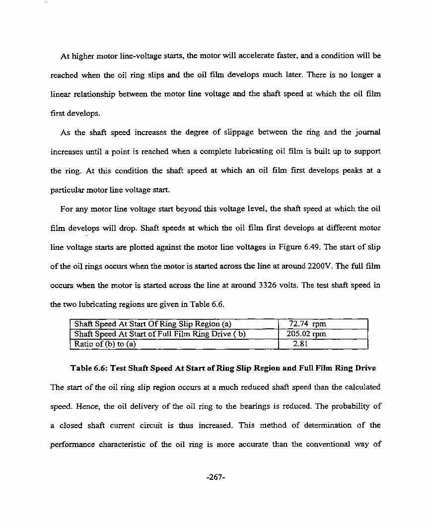
At higher motor line-voltage starts, the motor will accelerate faster, and a condition will be
reached when the oil ring slips and the oil film develops much later. There is no longer a
linear relationship between the motor line voltage and the shaft speed at which the oil film
first develops.
As the shaft speed increases the degree of slippage between the ring and the journal
increases until a point is reached when a complete lubncating oil film is built up to support
the ring. At this condition the shaft speed at which an oil film first develops peaks at a
particular motor line voltage start.
For any motor line voltage start beyond this voltage level, the shaft speed at which the oil
fiIm develops will &op. Shaft speeds at which the oil film fust develops at different motor
line voltage starts are plotted against the motor line voltages in Figure 6.49. The start of slip
of the oil rings occurs when the motor is started across the line at around 2200V. The full film
occurs when the motor is started across the line at around 3 326 volts. The test shaft speed in
the two lubncating regions are given in Table 6.6.
- - 1 Ratio of (b) to (a) 1 2.8 1 1
Shaft Speed At Start Of Ring Slip Region (a) Shaft Speed At Start of Full Film Ring Drive ( b)
Table 6.6: Test Shaft Speed At Start of Ring Slip Region and Full Film Ring Drive
The start of the oil ring slip region occurs at a rnuch reduced shafi speed than the calculated
speed. Hence, the oil delivery of the oil ring to the bearings is reduced. The probability of
a closed shaft current circuit is thus increased. This method of determination of the
performance characteristic of the oil ring is more accurate than the conventional way of
72.74 rpm 205.02 rpm
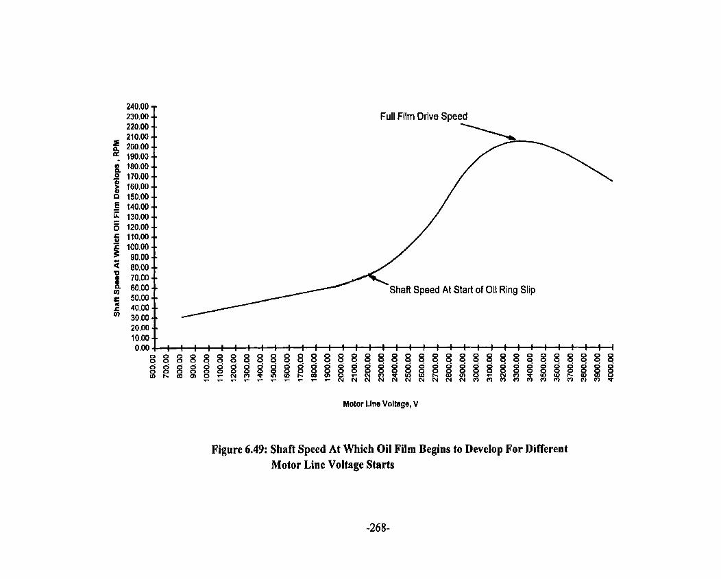
Motor Llne Voltage, V
Figure 6.49: Shaft Speed At Which Oil Film Begins to Develop For Different Motor Line Voltage Starts

determining the full film ring drive speed which is counting the number of revolutions of the
oil ring and timing the counts. The ring slip region speed is calculated fiom Lemon's ratio
f 68 1-
6.5 STATOR CURRENT MEASUREMENT.
Many diagnostic techniques to detect machine faults are based on stator current spectral
analysis. In this thesis, spectral analyses of shaft current and voltage and shafl flux were
utilized as alternatives to the current spectral analysis. In order to venfy further the
conclusions reached in the alternative analyses, the stator current was rneasured and andyzed.
Figures 6.50 ( a ) - ( c ) are the measured stator current waveforrns at 20%, 80% and 100% of
motor rated Iine voltage. Each of these wavefoxms were anaiyzed at three conditions - close to
standstill condition, mid-way of transient condition and steady state condition, as shown in
Figures 6.50 ( d ) - ( 1 ). mese figures clearly indicate 60 Hz component. Frequencies caused
by eccentricity and broken bar were not detected, confirming the conclusions reached fiom the
shaft voltage and cument measurements, shaft flux measurement and air gap measurement.
6.5 SHAFT VOLTAGE PFtEDICTION RULES
From Table 6.7, it is now clear that the shaft current in this machine is clearly due to the
joints between the lamination segment. The resulting flux circulation around the shaft can be
explained in a simplified step-by step representation of flux as illustrated in Figure 6.51.
There is no circulating flux at zero load angle as defined in Figure 6.51 ( a ). The net
circulating flux rotates clockwise as the load angle is increased. Figures 6.51 ( b ) - ( e )

a) Stator Current Waveform, 20% of Motor Rated Line Voltage
b) Stator Current Waveform, 80% of Motor Rated Line Voltage
Figure 6.50: Motor Phase Current Waveform At 20%, 80% and 100% of Motor Rated Line Voltage and Spectral AnaIyses.

c) Stator Current Waveform, 100% of Motor Rated Line Voltage
Figure 6.50: Motor Phase Current Waveform At 20%, 80% and 100% of Motor Rated Line Voltage and Spectral Analyses.

i) Stator Current Waveform
ii) Spectmm Plot
d) Stator Current, Close to Standstill Condition, 20% of Motor Rated Line Voltage
Figure 6.50: Motor Phase Current Waveform At 20%, 80% and 100% of Motor Rated Line Voltage and Spectral Anaiyses.

i) Stator Current Waveform
ii) Spectmm Plot
e) Stator Current, Mid-Way of Transient Condition, 20% of Motor Rated Line Voltage
Figure 6.50: Motor Phase Current Waveform At 20%, 80% and 100% of Motor Rated Line Voltage and Spectral Analyses.

r) Stat ii) Spectnim Plot
20m
f) Stator Current, Steady State No-Load Condition, 20% of Motor Rated Line Voltage
I
-tom,
Figure 6.50: Motor Phase Current Waveform At 20%, 80% and 100% of Motor Rated Line Voltage and Spectral Analyses.
41- 1 - 1 s o d ü i - ' 1 - 1297031'
~41.36992 Y:S624m
i) Stator Current Waveform
I ~ ~ ~ ~ ~ q p p Q ~ ~ ~ r n t r n I

i) Stator Current Waveform
ii) Spectmm Plot
g) Stator Cumnt, Close to Standstill Condition, 80% of Motor Rated Line Voltage
Figure 6.50: Motor Phase Current Waveform At 20%, 80% and 100% of Motor Rated Line Voltage and Spectral Analyses.

i) Stator Current Waveform
ii) Spectrum Plot
h) Stator Current, Mid-Way of Transient Condition, 80% of Motor Rated Line Voltage
Figure 6.50: Motor Phase Current Waveform At 20%, 80% and 100% of Motor Rated Line Voltage and Spectral Analyses.

Som
10 X10.00000 Y:-PlBm
i) Stator Current Waveform
ii) Spectmm Plot
i) Stator Current, Steady State No-Load Condition, 80% of Motor Rated Line Voltage
Figure 6.50: Motor Phase Current Waveform At 20%,80% and 100% of Motor Rated Line VoItage and Spectral Analyses.
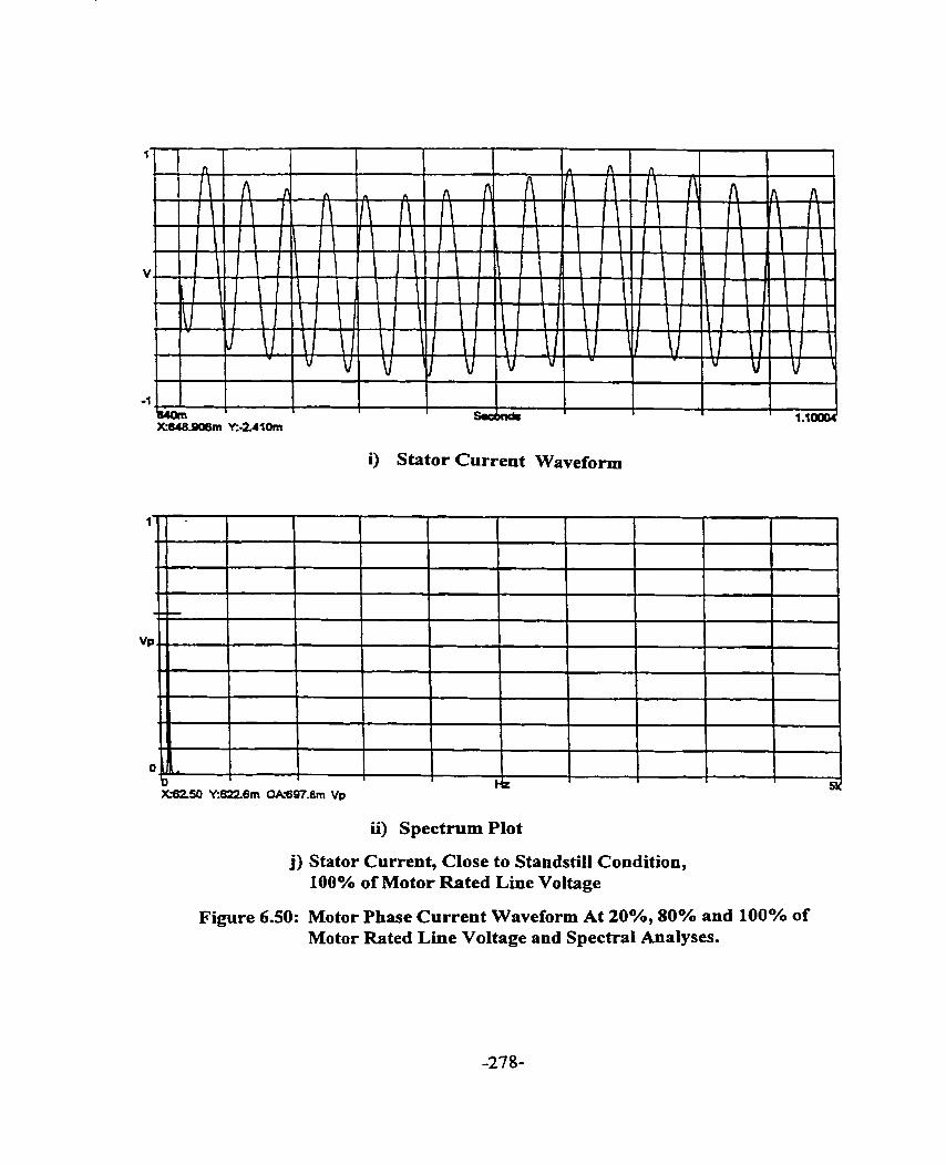
i) Stator Current Waveform
ii) Spectrum Plot
j) Stator Current, Close to Standstiil Condition, 100% of Motor Rated Line Voltage
Figure 6.50: Motor Phase Current Waveform At 20%, 80% and 100% of Motor Rated Line Voltage and Spectral Analyses.

1
1 hz 51) XS2.50 Y:619.5m OA684.8m Vp
ii) Spectrum Plot
k) Stator Current, Mid-Way of Transient Condition, 100% of Motor Rated Line Voltage
Figure 6.50: Motor Phase Current Waveform At 20%, 80% and 100% of Motor Rated Line Voltage and Spectral Analyses.

i) Stator Current Waveform
1) Stator Current, Steady State No-Load Condition, 100% of Motor Rated Line Voltage
Figure 6.50: Motor Phase Current Waveform At 20%, 80% and 100% of Motor Rated Line Voltage and Spectral Analyses.
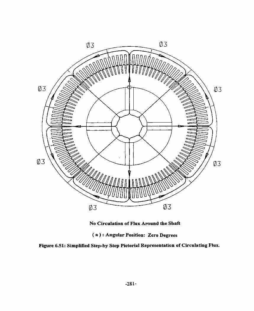
No Circulation of Flux Around the Sbaft
( a ) : Angular Position: Zero Degrees
Figure 6.51: Simplitïed Step-by Step Pictorial Representation of Circulating Flux.

Figure 6-51 ( b ): Figure 6.51 ( c ) + Figure 6.51 ( d )
( b ) : Angular Position: Ten Degrees
Figure 6.51: Simplified Step-by Step Pictorial Representation of Circulating Flux.
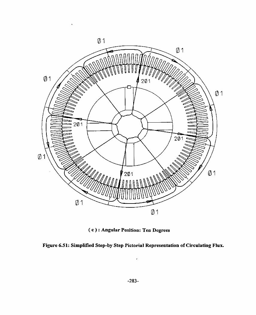
( c ) : AnguIar Position: Ten Degrees
Figure 6.51: Simplifîed Step-by Step Pictorial Representation of Circulating Flux.

Figure 6.51 ( d ): Figure 6.51 ( e ) + Figure 6 5 1 ( f )
( d ) : Angular Position: Ten Degrees
Figure 6.51: Simpiified Step-by Step Pictorial Representation of Circulating Flux.

( e) : Anguiar Position: Ten Degrees
Figure 6.51: Simplified Step-by Step Pictorial Representation of Circulating Flux.
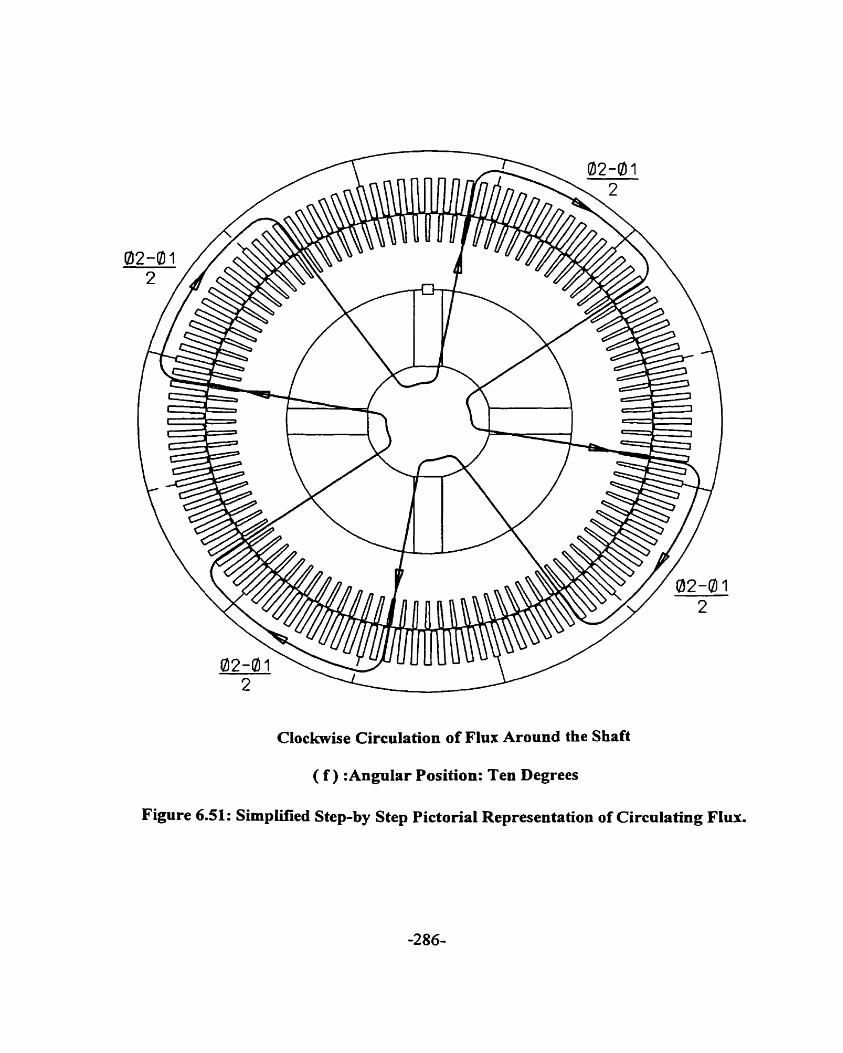
Clockwise Circulation of Flux Around the Shaft
( f ) :AnguIar Position: Ten Degrees
Fipre 6.51: Simpüfied Step-by Step Pictonal Representation of Circulating Flux.
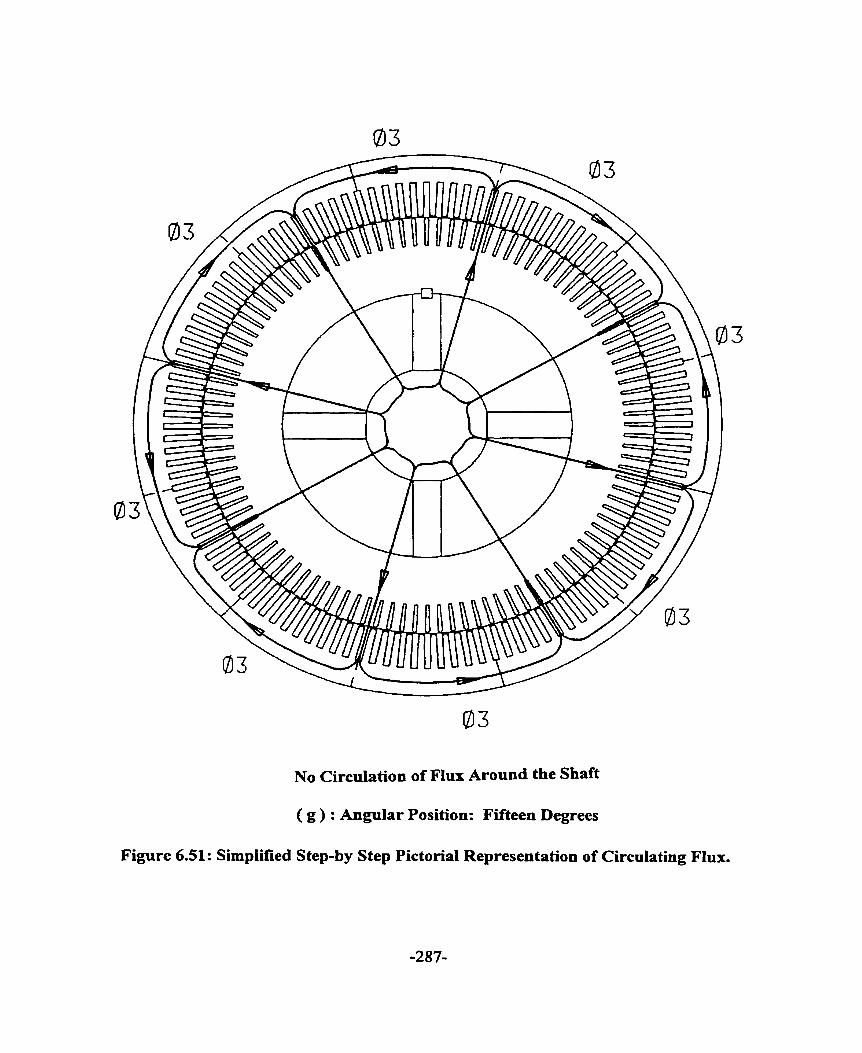
03
No Circulation of Flux Around the S b f t
( g ) : Angular Position: Fifteen Degrees
Figure 6.51: Simplified Step-by Step Pictorial Representation of Circulating Flux.

illustrate how net circulating flux arises. At a load angle of 15 degrees as shown in Figure
6.51 ( f ), the net fiux is zero. On further increase of load angle as shown in Figure 6.51 ( g ),
there is net circulating flux, but in the counter clockwise direction. The net zero flux repeats at
multipIes of 15 degrees. The rate of change of flux during acceleration of the machine is high.
The induced shafi voltage is high. As the machine approaches rated no Ioad speed, the rate of
change of flux decreases and hence the shaft voltage and shaft current reduce.
The preceding discussion indicates that shaft current is pronounced during acceleration of
the motor and hence implies that a speedy development of oil film is required. The oil ring
must carry suficient oil fiom the oil reservoir for built up of oil film.
6.6 SuMMARY
The experiment was conducted systematically to separate the mechanical cause from the
electrical cause of bearing damage as s h o w in Figure 6.52. The bearing darnage was
determined to be due to shafe current. Based on the analyses in Chapters 4 and 5 and applying
Alger's rule as given by equation ( 2.2 ), shaft voltage and current prediction rules are
formulated as shown in Table 6.7. Shaft cument of 180 Hz was determined. Review of Tables
4.1, 4.2, 5.1, 6.4 and 6.7 indicates that the shaft current component of three times the Iine
frequency is due to joints of the segmental punching. Eccentncity is small and the effect is
small in this 8 pole induction machine. The magnitude of shaft current is small with oil ring
lubricated or forced lubricated sleeve bearing provided the bearing is well insulated. Also, it
has been shown that the probability of bearing damage due to shaft current is the highest
during initial start of acceleration. During the start-up condition, the oil film has a high
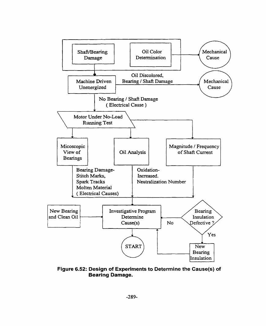
ShafîfBearing Oil Color Darnage Determination
T Oil Discolored, Machine Driven Bearing / Shaft Darnage
Unenergized
1 ( Electrical Cause ) +
Motor Under No-Load RuIining Test
Micoscopic View of B earings
Oil Analysis : CI Magnitude / Frequency of Shaft Current
J
Bearing Darnage- Stitch Marks,
Investigative Program
Oxidation- Increased.
Spark Tracks Molten Material
Neutralization Number
Figure 6.52: Design of Experiments to Determine the Cause(s) of
( Electrical Causes) v t
l
and Clean Oil
Bearing Damage.
P Determine Cause(s) No
New B earing
Insulation


tendency to make and break and hence result in arcs fiom the shaft to the bearing. Hence, it is
important that the design of the oil ring be considered to obtain sufficient build up of oil film
between the shaft and the bearing and the oil film thickness is sufficient that the make and
break of oil film phenornenon does not &se. End play movement is noi a factor in the
development of the shafl voltage. In fact, as long as the bearing insulation is effective, end
play movement hastens the decay of the transient shafi current. Based on the results obtained
in this Chapter, the following remedies for avoidance of shaft current are proposed:
1. The combination of poles and joints as indicated by the shaft cwent prediction rule
must be followed to determine the potential of occurrence of shafi current.
2. Allow for reasonable end play of the shaft so that metallic contact between the shafi
and the bearing lining does not arise. The oil films in the two bearings are then
electrically in series thus reducing the shaft cunrent value. It was determined in the
experiment that the end play, in fact has a darnping effect on the magnitude of the shafl
current in the case of insulated bearings.
3. If segments alone are the cause of shaft currents, the most desirable rnethod of avoiding
the currents is to use offset segments. This is accomplished by piling the first iayer of
punchings with lap joints in the usual way and then piling the next layer of punchings
in the marner that this layer's lap joints are located one quarter of the punching
segment arc fiom the first layer's lap joints. For the next two layers, the same process is
repeated with the punchings piled upside down. If the dovetail tags are set at 1/8 and
518 positions, the number of slots per segments must be a multiple of 4 for the offset

segment method to be workable. The offset segment method is a preferred method as it
gives better core loss, lower yoke reluctance and a more solid core construction.
4. A highly polislied bearing will give a very low coefficient of fiction. This is very
important in high speed machines. Any increase in the roughness of the shafi will
increase this coefficient and may result in bearing currents and hence bearing failure.
5. It is important to insulate al1 machine parts that have the high probability of contact with
the shafi journal including bearing and connection to the bearings such as oil piping and
bearing resistatice temperature detector connection. This will break any shafi circuit that
could develop.
6. Where possible, the oil film thickness is increased to reduce the Wear rate substantially.
Other measures that are effective in the reduction of the magnitude of shaft current include the
following:
1. A copper collar encircles the slialt with the collar wound with a ring winding being fed
with suitable line frequency voltage such that an altemating flux is set up whose
phase opposes the circulating flux. This method removes the fundamental frequency
component but does not remove the higlier frequency components.
2. N-on-magnetic bearing housing or equivalent rnay be used to increase the reluctance
of the flux pntli. However, tliis remedy may not be cost effective to the motor
manufacturer. This iiieasure was carried out on another machine.
3. A ring wound coi1 encircling the stator yoke is fed with a line fi-equency current of such
a phase angle as to nearly cancel the magnetic field set up by the joints.

4. Low contact resistance brushes with ample capacity may be used. The use of brush
riding may be limited by space. Furthermore, maintenance of the brush is required. The
use of brus11 riding is considered the last resort.
Chapter 7
CONCLUSIONS
7.0 INTRODUCTION
Motor bearing failures traditiodly were presumed to be related to mechanical factors.
The high rate of bearing failure due to shaft current has driven continuing research to
establish the causes of shaft current and non-invasive on-line motor diagnostics. An
understanding of the physical ongin of the shaft current is essential if induction
machines are to be designed with minimal probability of shaft current and without
bearing damage. Furthemore, a proper understanding of the causes of the shaft cument
c m assist in the development of non-invasive on-line motor diagnostics. For this purpose,
a 261 1 kW induction machine exhibiting symptorns of shaft current was studied. In this
chapter. the research objectives are reviewed, the major achievernents and contributions
are sumrnarized, and suggestions for future research are presented.
7.1 SUMMARY OF THE THESIS
The main objective of this thesis was to investigate the causes of the shaft current in a
large squirrel cage induction motor. In surveying the literature, it became evident that the
method of measurement of shafi current is inadequate, as the conventional method as
outlined in IEEE 112 standard [ 4 ] disturbs the circulating current loop between the shaft

and the ground. The conventional method does not rneasure the cunent in the path
involving the shaft. the bearing and the frame. Also, the survey indicates that the shaft
voltage prediction does not take into the account the effects of slotting, eccentricity,
broken bars or inter-bar currents. Furtherrnore, the survey indicates that much of the
research work was done on small induction machines operating on grease-lubricated anti-
fiction bearing systems. The previous research work was carried out during steady state
operating condition. The transient condition was neglected.
The new method of shaft current measurement discussed in this work is reliable,
requinng no maintenance, unlike the shaft ground brush method. The new method
provides for reasonably accurate prediction of the magnitudes and frequencies of the sh&
currents. The Rogowski coi1 method, described in detail in Chapter 3, is also not load-
dependent unlike the ammeter method. This proposed method of shaft cwrent
measurement, when used with a spectnim analyzer and a video recording system,
provides for a reliable on-line monitoring system. In Chapters 4 and 5, the analytical
method based on the interaction of the MMF and permeance waves and taking into
account the effects of slotting, eccentricity, broken bars and inter-bar currents, etc. has
been developed to produce prediction niles to detexmine the occurrence of sh& current.
The understanding gained by investigating these effects led to the development of a
diagnostic procedure for detecting shaft current and determining its causes. The
diagnostic procedure recommended for an on-line monitoring system includes the
measurement of the spectra of both the shafi current and the stator current.

The shafi current measurement results outlined in Chapter 6 confirmed that the shaft
current phenomenon is a serious problem during the transient condition. During the
transient condition, when the oil film has not fully developed to a consistent thickness,
the probability of bearing damage due to the shaft current is increased. The experimentai
results, shown in Chapter 6, indicated the importance of oil film development and the
consequence of variation of oil film thickness. The performance of the oïl ring to deliver
oil to the bearing is essential for the proper operation and life expectancy of the bearing.
In Chapter 6, an important characteristic of the oil ring was detemiined in a novel
inexpensive manner using the Rogowski coi1 method. This method is the subject of a
patent application. The experirnental result fiom the novel test indicates that the empirical
calculation currently used tends to be optimistic. This method of determination of oil ring
performance is much more accurate than the conventional method. The conventional
method is the determination of the full film drive shaft speed by measuring the time it
takes for a specified number of revolutions of the oïl ring. Then, the oil ring slip region
shaft speed is caiculated fiom Lemon's ratio [ 69 1.
7.2 MAJOR CONTRIBUTIONS OF THE THESlS
In this work, a wide range of issues relevant to the understanding of the shaft current
phenomenon and shafl current measurement techniques were studied. Improved analysis
and measuring technique were developed. The major contributions may be summarized
as follows:

1. An alternative accurate method of measuring shaft current had been proposed.
This method is the first known application of the Rogowski coi1 to the shaft
current rneasurement. The method was presented at the IEEE Power Engineering
Society Meeting in February 2-6 1997 in New York and subsequently published
in the IEEE Transactions on Energy Conversion [ 3 11. The Rogowksi coi1 method
is accurate, having a linear input-output relationship. Error fiom strong magnetic
field due to sources other than the current to be measured, is eliminated.
Furthermore, this method of shaft current rneasurement does not disturb the
circulating current loop. The method is maintenance fiee and can be used as part
of an on-line monitoring system. The method is being pursued for use in
alternating current adjustable speed drives within General Elecûic. Furthermore,
the method has generated great interest among the memben of NEMA working
group on standards for such drives.
2. A magnetomotive force-permeance approach was proposed to account for effects
due to armature reaction, slotting, saturation, eccentricity and broken bars. As a
result, shafi voltage prediction rules were proposed.
3. A method of minimizing the shaft current, especially during the transient
condition was proposed. There has been a brief but pertinent discussion of this
method. A patent application based on the method is being filed.
4. An alternative novel inexpensive method of determining the performance
characteristics of the oil ring is proposed. This novel method utilizes the proposed

sh& current measurement technique. A patent application for this method is
being filed.
5. An on-line monitoring system incorporating the Rogowski coi! is proposed. The
systern is based on the analysis of stator phase current spectra and the shaft
voltage and current spectra. Where it is possible to install a shaft flux coil, the
shaft flux is to be measured as it also provides indication of the machine faults.
7.3 SUGGESTIONS FOR FUTURE RESEARCH
A number of aspects relevant to the shaft current phenomenon and shaft current
measurement technique need to be explored in the future. The fo1Iowing suggestions are
made based on the developments in this thesis research:
1. The various causes of shaft current have been surveyed in this project. A finite
element modeling of the electrical machine should be carried out to provide for
accurate determination of the magnitude of the shaft current. The amplitudes of the
harmonic waves predicted by the magnetomotive force-permeance approach is not
sufficiently accurate given the senes approximation. The fhite element modeling will
provide the design engineer prior knowledge of the probability of occurrence of shafi
current and the current magnitude before the machine is built.
2. The Rogowski coil used in the shaft current measurement has a -3 dB fiequency
response of 8 Hz to 100 kHz. In order to use this method in an ac adjustable speed
drive. the frequency response needs to be extended to at least 5 MHz. This work is
underway and progressing.
3. In Chapter 6, it was determined that the bearing insulation thickness could be
reduced. However, it is necessary to carry out more tests over a wide range of
machines before a definitive conclusion on the reduction of insulation thickness can
be reached. Also, one type of bearing insulation was used. The bearing insulation
system used is labor intensive. Tests on other types of insulation systems are required
for determination of an effective low cost bearing insulation system.
4. Oil ring performance is a fùnction of temperature and viscosity of the oil, oil ring
immersion level, thickness of the oiI ring, solid or split design oil ring, oil ring groove
and oil ring material. The Rogowski method should be used to design a much
improved oil ~g which will deliver the required arnount of oil to the bearing.

TEST MACHINE
A1.O MACHINE DATA

APPENDIX 2
BEARING AND LUBRICATION
A2.0 TYPES OF OIL LUBRICATION
Hydrodynamic lubncation, also called full film or fluid lubrication, is the phenornenon
of the load carrying surfaces of the bearing being separated by a relatively thick film of
lubncant so as to prevent metal-to-metal contact. This lubrication requires the existence
of an adequate supply at al1 times. In this form of lubrication the moving surface pulls the
lubricant into a wedge -shaped zone at a velocity ~ ~ c i e n t l y high to create the pressure
necessary to separate the surfaces against the load on the bearing. The oil film between
the shaft journal and the bearing serves not only as a lubricant but as an insulator against
shaft current. It is important to maintain continuous oil film; any make and break of oil
film will result in arcing from the shaft journal to the bearing. Hence, the bearing can be
pitted. The damaged bearing will cause the motor bearing vibration to increase and in
turn the bearing temperature will increase. Increase in the bearing temperature will reduce
the viscosity of the oil and the motor bearing vibration will increase M e r . This domino
effect can be catastrophic.
Two types of hydrodynamic Iubncation systems are available - self contained bearing
lubrication system [ 69, 70 ]and pressure-fed bearing lubrication system. The self

contained bearing lubrication system is characterized as a single unit comprising the
bearing housing, hydrodynamic journal, Iubricant circulating system and a heat
exchanger unit. Th= self contained bearing lubrication system is limited to modest
machine shaft speeds whereas the pressure fed bearing lubncation system is widely used
in high speed machinery. Also, the minimum oil film thickness between the shaft
surfaces and self lubricated bearings is much smailer than in the pressure-fed bearings. Of
the lubncation circulating systems comrnonly used in self contained system, the oil ring
lubrication system is most popular. In such system the preferred bearing proportions
[ 71 ] are as follows:
1. Ratio of net bearing working length to shaft journal diameter, L/d is between 0.6 and
1.1.
2. Ratio of oïl ring bore diameter to shaft journal diameter, D/d , is between 1 -5 and 2.0.
A2.1 PERFORMANCE CHARACTERISTICS OF BEARING OIL RING
Oil rings have been used for the lubrication of the bearing for many years. Its
simplicity and ruggedness make it economical and it requires little maintenance. An
adequate lubncant supply [ 72 ] is one of the requisites for satisfactory operation of a
Auid film bearing. It is thus important to consider the factors affecting oil delivery of the
oil ring bearing. The speed of the oïl ring is the most important factor affecting the oil
delivery in an oïl ring lubncation system.

At very low speed the ring follows the journal. The amount of oil delivered increases
with speed in this low speed region called the solid friction region. In this region the oil
delivery is a function of the ring velocity V and oil viscosity v [71 1.
Q = 2.74 p v O"' V"
= 2.74 p v (DN)')
where Q is the volume of oil delivered, m3/s,
D is the inside diameter of the oil ring, m,
p is the length of penphery of oil ring cross section from which the oil is
delivered, (width of ring riding on the journal), m,
v is kinematics viscosity, m2/s
and N is the rotationai speed of the oil ring, rps.
Several factors were not considered in the above equation. They are the surface tension of
the oil, the oil ring centrifuga1 action, variations in ring immersion and the weight of the
ring. In the "no-slip" range the ring speed (N) and the shaft journal speed (n) are simply
related as follows:
where d is the shaft journal diameter, m
and D is the inside diameter of the oil ring, m
When the viscous oil drag on the lower arc of the ring begins to exceed the driving
fiction force from the rotating journal the oil ring begins to slip. The slip speed of the oil
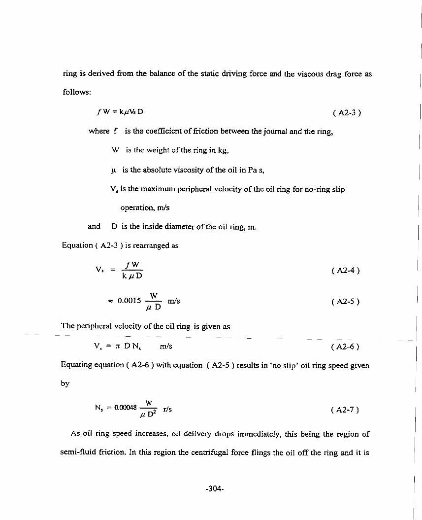
ring is derived from the balance of the static dnving force and the viscous drag force as
follows:
where f is the coefficient of fiction between the journal and the ring,
W is the weight of the ring in kg,
is the absolute viscosity of the oil in Pa s,
V, is the maximum peripheral velocity of the oil ring for no-ring slip
operation, m/s
and D is the inside diameter of the oil ring, m.
Equation ( A2-3 ) is rearranged as
The penpheral velocity of the oil ring is given as - - - - - - - - - - - - - - - -
V, = x DN, d s
Equating equation ( A . - 6 ) with equation ( A2-5 ) results in 'no slip' oil ring speed given
As oïl ring speed increases, oil delivery drops irnmediately, this being the region of
semi-fluid friction. In this region the centrifuga1 force flings the oil off the ring and it is

lost for lubrication purposes. As the ring speed increases further, a transition ring speed
will be reached when the oil delivery of the oil ring no longer follows equation ( A2-1 ).
This transition speed is given as follows:
Nt = 446 E- 05 z6dn v - ~ r/s ( A2-9 )
As the journal speed increases, the partial oil film generated between the ring and the
journal reduces the coefficient of fiction and hence decreases the driving force. A point
will be reached when the full lubricating oil film is built up to support the oil ring. This
fidl film drive ring speed can be calculated fiom Lemmon and Booser [ 69 ]
where Nf is the full film drive ring speed, rps,
nf- is the full film drive shafi journal speed, rps,
d is the shafi journal diameter, m,
D is the oil ring inner diameter, m,
Kd is the correction factor for the different oil immersion depths
and v is the oil absolute viscosity in Pa. S.
Lemrnon et al [ 691 determined that the full film drive shafi journal speed is 2.9 times the
shaft speed at start of oil ring slip, N,.

A2.2 FACTORS AFFECTING THE PERFORMANCE OF OIL RING
The amount of oil delivered by the oil ring decreases rapidly with an increase in
temperature of the oil. This can be explained by the fact that the viscosity of the hot oil
decreases and hence the fiiction force exerted by the oil film on the oil ring decreases
correspondingly. The oil is thrown off the ring by the centrifugai force before it is entered
in the radial clearance between the sh& journal and the bearing surface.
As show by Karelitz [ 73 ] , the transition speed at which slip of the ring begins is
higher with heavier rings and more oil is delivered in the spray by the oil ring to the
bearing. A heavier ring results in diinner oil film between the ring and the shafi journal
with more oit consequently being squeezed out fiom the inner surface of the ring to the
bearing .
An increase in submersion of the oil ring tends to decrease the oil delivery and the ring
speed though not significantly as shown by Lemmon et al [ 69 ] .
A2.3 CHARACTERISTICS OF B E M N G , LUBRICATION OIL AND OIL RING USED IN THE TEST
A2.3.1 SPECIFICATION OF LEAD BASED BABBXTT
-3 O6-
Bearing L/d ratio Bearing D/d ratio Bearing Babbitt Oil Ring Material Oil Ring Lubncation Oil
0.523 1.6667 Lead Base Leaded Brass ( Bronze ) Split Smooth Design; No grooves ISO VG 68

A2.3.2 SPECIFICATION OF 011, RING MATEFUAL - BRONZE
1 - Element
Arsenic ( As ) Antirnony ( Sb ) Copper ( Cu ) Tin ( Sn ) Lead
A2.4 FACTORS AFFECTING THE LIFE OF BEARING
Specification 0.76- 1.25 % 18.0 - 19.0 % 0.15 - 0.50 % 1.0 - 2.0 % Rernainder
Element Copper ( Cu ) Zinc (Zn) Lead ( Pb ) Iron ( Fe) Other Im~urities
The life of a bearing assembly is dependent upon an number of inter-related factors
S pecification 55.0 -60.0 % Remainder 2.0-3.8 % 0.35 % 0.50 %
8 Loading
Temperature
8 Type ofOil
0 Quality of Oil
8 Maintenance practices
Bearhg overioading accelerates the bearing Wear if the design limit is exceeded.
Higher bearing temperature can reduce the viscosity of the oil and may affect the
lubncation of the bearing. Higher temperature may also promote oxidation and other
chemical change in the oil.
A25 PHYSICAL AND CHEMICAL PROPERTIES OF INDUSTRIAL MINEXAL OILS AFFECTING LUBRICATION [ 74 - 79 ]
The physical properties of lubricants are attributable primarily to the structure of the
lubncant base oïl stock. The chemical properties of the finished or formulated lubricants
are due to the additive packages and the response of the base stocks to the additive
package.
Lubncation oils have long chah hydrocarbon structures. Viscosity may be visualized
as a result of physical interaction of molecules when subjected to flow. Viscosity is the
property of a fluid that causes it to resist flow. It is by far the most significant property
for establishing the thickness. pressure and temperature of an oil film in hydrodynamic
lubrication. The oil film thickness increases with viscosity. Viscosity is also in equations
for calculating the Sommerfeld number and power loss for hydrodynamic bearings.
Viscosity decreases as the temperature uicreases because the molecules vibrate more and
interact less. ASTM D445 covers the rnethod of determining the oi1 viscosity. Viscosity
is useful in identifiing the grades of oil and for following the performance of oils in
service. An increase in viscosity usually indicated that the oil has deteriorated somewhat
through oxidation.

The viscosity index (VI ) [ 75 ] is a commonly used expression of the lubricating oil's
change of viscosity with temperature. The higher the viscosity index the smaller the
relative change in viscosity with temperature. Viscosity increases with pressure because
the molecules are squeezed together forcing greater interaction. The higher the
temperature the lower the viscosity increases due to pressure. Lubncating oils are
subjected to wide ranges of temperature in service. At high temperature the viscosity of
an oil may drop to point where the lubricating film strength is insufficient to carry the
load and breaks down, allowing some f o m of metal-to-metal contact and severe Wear.
Any make and break of metal-to-metal contact between the shaft journal and bearing can
lead to arcing between the bearing surface and the shaft journal due to shaft current
passage. At other extreme of temperature the oil rnay become too viscous for proper
circulation of the oil in the clearance between the journal and the bearing. In this case a
thick oil film develops which l a d s to more bearing Wction loss. This loss translates to
higher temperature of the oil and thus oil thinning. Finally a stable oil film condition will
be reached. During the initial unstable oil film condition the variation in the oil film to
some extent is similar to a make and break of metal-to-metal contact. There is that
possibility of arc between the bearing surface and the shaft journal. Hence a wide
variation in viscosity with temperature is to be avoided.
Depending on its source, additive content and refining procedures a lubricating oil will
exhibit certain acid or alkaline ( base ) characteristics. A measure of the acidic or alkaline
constituents in the lubricating oil may be derived fkom the product's neutralization

number. The neutraiization nurnber is widely used as one critenon of used oil quaIity.
The used oil's neutrdization number must be compared with the nurnber of new oil. The
neutralization number xnay be determined colorimetrically ( ASTM D974 ) or
potentiornetrically ( ASTM D664 ). ASTM D974 gives the total acid number ( TAN )
only. ASTM D664 gives both total acid number and total base number ( TBN ). TBN
provides a measure of the remaining amount of protective alkaline agents place in the oil
to neutralize the acids. The arnount and the rate of change of this nurnber will provide an
indication of oxidation and the rate of oxidation. A hi& value of TAN and low value of
TBN when compared to the value for fkesh oil, is generally indicative of oxidation. Acids
are formed during oxidation of the oil.
Contaminants such as water, dirt and metallic particles are common in lubricating oils.
Contaminant particles are discrete objects ranging in size fiom sub-micron to well above
1 00 micron-meter.

A3.0 Calibration Procedure and Result
Calibration of the Rogowski coil was done following installation on the shaft. The
calibration procedure involved the use of a current generator, replacing the ammeter in
the circuit as shown in Figure 3.6. The Rogowski coil was calibrated at a number of
fkequencies as shown in Tables A6.1 and A6.2. The drive end Rogowski coi1 had a
calibration value of 11 .O2 millivolts per ampere at ail fkequencies fiom 8 Hz to 4 kHz.
The opposite drive end Rogowski coil had a calibration value of 13.72 millivolts per
ampere at the same range of fkequencies.

average
Table A3.1 : DE Rogowski Coi1 Calibration Data

Amperes 1 2 3 5 7 10 1 2 3 5 7 10 1 2 3 5 7 10 1 2 3 5 7 10 1 2 3 5 7 10 1 2 3 5 7 10
- -
average
Table A3.2 : ODE Rogowski Coi1 Calibration Data

APPENDIX 4
WINDING FACTOR
A4.0 DISTRIBUTION AND PITCH FACTORS
M e n the winding has more than one coil, the total MMF for a given harmonic cannot be
found simply by muItiplying the value of the MMF produced by one coil with the number
of coils in the winding. In distributed winding the MMFs of adjacent coils have equal
amplitudes when the number of tums are equal but they are shifted to each other in the air
gap by an angle, a,. The total MMF for a given harmonic can be obtained by the vector
addition of the corresponding harmonic produced by each coil. The winding factor is
defined as the ratio between the effective and the total number of tums in a winding. This
factor [ 35,36 ] is written as

where q = number of slot per poles per phase,
a, = electricd angle between the slots, radians
y = coi1 pitch, m
T, = pole pitch, m
and a, = ny/r,, coi1 pitch, radians.
The angle a, , the electrical angle between the slots , is defined as
where S is the number of stator slots,
b is the nurnber of phase belts,
p is the pole pairs,
and T, = slot pitch, m.
The pitch factor for dot harmonics follows from first terni in equation ( A4-1 ) by
substituting S, i 1 for n where S, is the number of stator slots per pole pair:
C -
= sin [E] The pitch factor for the dot harmonics is equal to the pitch factor for the fundamental.
Hence the winding factor for the dot harmonics is equal to the winding factor for the
fundamental.

The distribution factor for slot harmonics follows fiom second term in equation
( A4-1 ) by substituting S, + 1 for n where S , is the number of stator dots per pole pair
The distribution factor for the slot harmonics is equal to the distribution factor for the

UNBALANCED MAGNETIC PULL
A5.0 DETERMINATION OF AVOIDANCE CONDITION
Unbalanced magnetic pull is defined as the net radial force between the stator and rotor
of an electric machine resulting fiom a difference in the air gap flux densities on opposite
sides of the machine. For example, if the rotor and stator slot numbers differ by only one,
radial magnetic pull can occur during the starting penod. In this case when a rotor tooth is
centered on a stator tooth, at the dianletncalIy opposite point a rotor tooth is centered on a
stator dot. Hence, a one slot difference between rotor and stator should be avoided. This
can be verîfied by reviewing the radial force wave created by multiplying the harmonic
permeance air gap flux density and the constant average permeance air gap flux density.
The permeance wave of a slotted stator is the surn of the average pemeance and the
harmonic permeance, desribed as:
ka, = P o + +63s-(hq ( A54 )
where p , is the constant average pemeance and
63, is the half amplitude penneance variation due to stator slot openings.

Similarly, if there are R rotor slots and taking the center of a stator tooth as the
reference point the permeance wave of the slotted rotor is given as:
4% = Po + 6% COS ( q q ~ - or t] )
The combined air gap permeance wave due to the sIotted stator and rotor is
( AS-3 )
The air gap MMF considenng spatial harmonic up to 7'harmonic and stator slot
harmonics is given as:
3 = ~ c o s ( ~ ~ - o t ) + ~ c o s ( 5 ~ ~ + o t ) + ~ c o s ( 7 ~ ~ - o t )
The air gap flux density is given as the product of the air gap permeance and the air
gap MMF.

The first major component of equation ( A54 ) is the product of the fundamental
MMF and the uniform component of air gap permeance. The next group of the
components are the product of the mmf harmonies and the uniform component of air gap
permeance. The other group of components are the products of the fundamental MMF
and the air gap permeance.
The components of flux wliich are the products of fundamental mmf and the
penneance hannonics are:
A +-gs ( 3 ~ { c o s ( ~ R - ~ s + ~ ] ~ - [ ~ R o ,+O]~)+COS(~R-~S-~]R-[~RW r - ~ ] t) )
4 P o A
+ - g s k {cos~~~R+~s+P]Q-[~Rw ,+O]~)+COS(~R+~S-~]R-[~RO ,-O] t)} 4@0
( A5-6 )
The components of flux which are the products of MMF hannonics and the unifom
( average) components of penneance are:
B~~ = ~ ~ ~ { c o s ( ~ n - o t ) ) + B ~ . { ~ ~ ( S ~ R + ~ t )}
+ C p , , { c o ~ ( 7 ~ ~ - o t ) } + D g ~ ~ { c o s ( [ h ~ - ~ ] ~ - w t ) 1 + Eiq, { cos ( [ h ~ + ~ ] ~ + o t ) }
The magnetic pull is proportional to square of air gap flux density. The tems of
interest in the force wave created by multiplying the two flux density expressions, B,,,
and B,, are given in eqiiation ( A5-8 ).

The force wave equation is simplified as
From equation ( A5-9 ) it can be seen that a 2 pole wave will exist if
To avoid the existence of 2 pole force the following condition is necessary

AIR GAP ECCENTRICITY
A6.0 CALCULATION OF THE AIR-GAP OF AN ECCENTRIC ROTOR.
In Figure A6.1, the stator core is considered as a circle with the equation
This equation is expanded to obtain
x2 + y2 = lX12 -2 A x - A ~
Let 2 = x 2 + J
Hence, equation ( A6-2 ) is rearranged as
2 + 2 A z COS a + COS n = R , ~ - (1 -COS R ) ( ~ 6 - 5 )
z + A c o s R = ~ , d 1 + A ' / R , ~ ( cos2S2-1)
Induction machine is normally designed with the center of the rotor at or very close to
the center of the stator core, i.e. A « RI
Therefore 4 1 +A~/R, ' ( cos2R-1) = 1
and hence z = RI - A cos i2
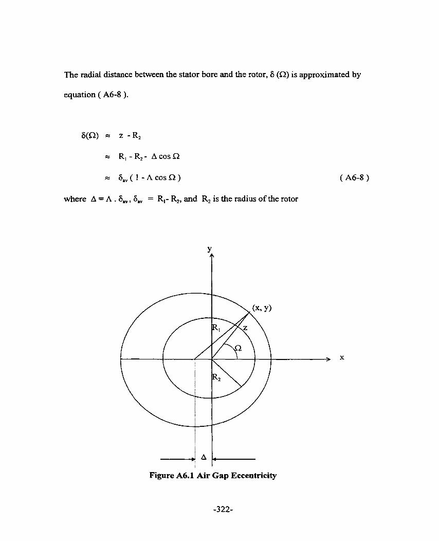
The radial distance between the stator bore and the rotor, 6 (a) is approximated by
equation ( A6-8 ).
6(Q) = z - R,
R,-R,- AcosS2
= 6,(1 - A c o s Q )
where A = A . a,, 6 , = R,- R,, and R, is the radius of the rotor

PUBLISHED PAPERSIPATENTSIAWARDS
A7.0 PUBLISHED PAPERS
1. R. Ong, J. H. Dyrnond, R D. Findlay, " A Cornparison of Techniques For Measurement of Shaft Currents in Rotating Machines, " IEEE Transactions on Energy Conversion, Vol. 12, No. 4, Dec. 1997, Pages 363-367.
2. R Ong, J. N. Dymond, R D. Findlay, B. Szabados, " Shaft Current Measurement of a Large Induction Motor Using the Rogowski Coi1 Method, " IEEE International Symposium on Diagnostics for Electr id Machines, Power Electronics and Drives, Carry-le-Rouet, France, Sept. 1-3 1997, Pages 23-26.
3. R Ong, J. H. Dymond, R. D. Findlay, B. Szabados, " Shaft Current Phenornenon: Experimental Testing and Analysis of a Large Induction Machine, " Proceedings of the IASTED International Conference on High Technology in the Power Industry '97, Oct. 27-30 1997, Orlando, Florida, Pages 241-246.( Approved for publication in International Journal of Power and Energy Systerns; Paper No. 203- 2126 )
4. R.D. Findlay, R.Ong, J.H. Dymond, " Some Aspects of Detexmination of Shafr Current in Large Induction Motors, " 4'h International Workshop on Electrical and Magnetic Fields, Marseille, France, 12- 1 5 May 1 998, Pages 27-32.
5. J. H. Dyrnond, Raymond Ong, Peter McKenna, " Locked Rotor and Acceleration Testing of Large Induction Machines - Methods, Problems and Interpretation of the Results, " IEEE Petroleurn and Chernical Industry Conference, Sept. 1998, Paper No. PCIC-98-07 (Approved for publication in IEEE Transactions on Industry Applications ).
6. R. Ong, J. H. Dyrnond, J. V. Kay, R. D. Findlay, B. Szabados, " Impact of Oil Lubrication on the Magnitude of Shaft Current in a Large Oil Ring Lubricated Induction Machine, " ICEM' 98, Istanbul, Turkey, 2-4 Sept 1998.
7. R. Ong, J. H. Dymond, R D. Findlay, B. Szabados, " Systematic Practical Approach to the Study of Bearing Damage in a Large Oil Ring Lubricated Induction Machine," Accepted for Presentation at IEEE Petroleum and Chemical Industry Conference 2 999, San Diego, U.S.A. ( Approved for publication in IEEE Transactions on Industry Applications ).
8. R. Ong, J. H. Dymond, R. D. Findlay, B. Szabados, " Significance of Joints Due to Lamination Segmentation on Shaft Currents in Induction Machine," Submitted for Presentation at IEEE International Electrical Machines and Drives Conference 1999, Seattle, Washington ( Subrnitted for publication in IEEE Transaction on Energy Conversion )
A7.1 PATENTS
1. Minuninng Shaft Currents in Dynamoelectric Machines, Patent Filing Reference No. GECAN 3 182, Filed Nov 25 1998.
2.. Rogowski Method to Determine Performance of OiI Ring, Patent Filing Reference No. GECAN 3 183, Filed Feb 22 1999.
A7.2 AWARDS
1. Minimizing Shaft Currents in Dynamoelectric Machines, Patent Filing Reference No. GECAN 3182, Filed Nov 25 1998, Judged the Best Patent in the First Inventor Category in General Electric Industrial Systems' Patent Cornpetition.

REFERENCES
A. Bonnetî, G. C. Soukup, " Cause and Analysis of Stator and Rotor Failures in Three-Phase Squirrel-Cage Induction Motors, " IEEE Trans. On Industry Applications, Vol. 28, No. 4, July/Aug. 1992, Pages 92 1-936.
A. Bonnett, G. C. Soukup, " Analysis of Rotor Failures in Squirrel-Cage Induction Motors, " IEEE T m . On Industry Applications, Vol. 24, No. 6 , NovIDec 1988, Pages 1124-1130.
O, V. Thorsen, M. Dalva, " A Survey of Faults on Induction Motors In Offshore Oil Lndustry, Petrochemicd Industry, Gas Terminais and Oil Refineries, " IEEE PCIC 1 994, Paper No. PCIC-94-01, Pages 1-9.
IEEE Standard 112 - 1991, IEEE Standard Test Procedure for Polyphase Induction Motors and Generators, IEEE Standard, 1 99 1.
P. L. Alger, H. W. Samson, " Shaft Currents in Electric Machines, " Transactions AIEE, Feb. 1924, Vol. 43, Pages 235- 245.
E. G. Merrick, " Bearing Currents, " General Elecîric Review, Oct. 19 14, Pages 936-94 1.
W. Buchanan, " Currents in Bearings of Electric Generators, " The Electrician, May 19 1 5, Pages 266-267.
L. Adler, " The Ongin and Prevention of Currents in Bearings, " The Electrician, Vol. 65, June 1910, Pages 315-317.
C. T. Pearce, " Bearhg Currents - Their Origin and Prevention, " The Electric Journal, Vol. XXIV, No. 8, Aug. 1927, Pages 372-376.
M. E. Wagner, " Bearing Currents - Their Causes and Means of Prevention, " Power, Vol. 72, Nov. 1930, Pages 798-80 1.
F. Barozzi, " Shaft Currents in Electric Machines, " ElettrotecnicaJol. 26, No. 1 1, June 1939, Pages 402-407 ( In Italian) , ( The Electrical Research Association Ref. Trans. IB2111).
L. W. Riggs, " How Much Shaft Current Can a Bearing Carry Safeiy, " Power, Vol. 88, Feb. 1944, Pages 103-105.
[13] A. H. Lauders, " Shafl Currents in Engine Driven Generators, " Diesel Power and Diesel Transportation, Feb. 1950, Pages 56-60.
[14J 0. Haus, " Shaft Voltages and Bearing Currents, Their Cause, EfYect and Remedial Measures, " Elektrotech. 2. ( ETZ ), ( A), Vol. 85, No. 4, Feb. 1964, Pages 106-1 12, ( In German ), ( The Electrical Research Association Ref. Trans. IB2 194 ).
[15] P. J. Tavner, J. Penman, R. L. Stoll, H. O. Lorch, " Influence of Winding Design on the Axial Flux in Laminated Stator Cores, " IEE Proceedings, Pt. B, Vol. 125, Oct 1978, Pages 948-956.
[16] J. S. Sohre, P. 1. Nippes, " Electromagnetic Shaft Currents and Demagnetization of Rotors of Turbine and Cornpressors, " 7<h Turbomachinery Symposium, Dec. 1978, Texas A & M University, College Station, Texas.
[17] J. S. Sohre, P. 1. Nippes, " Electromagnetic Shaft Currents in Turbomachinery - An Update, Part II : Magnetics and Dernagnetization, " 25th Symposium on Safety in Amrnonia Plants and Related Facilities, American Institute of Chernical Engineers, Portland, Oregon, Aug 17-20, 1978.
[18] Michael J. Costello, " Shaft Voltages and Rotating Machînery, " IEEE Transaction on Industry Applications, Vol. 29, No. 2, Mar./Apr. 1993, Pages 41 9- 426.
[19] C. Ammann, K. Reichert, R. Joho, 2. Posedel, " Shaft Voltages in Generators with Static Excitation Systems - Problems and Solution, " IEEE Transactions on Energy Conversion, Vol. 3, No. 2, Jun. 1988, Pages 409-41 9.
[20] C. Arnmann, K. Reichert, Z. Posedel, " Shaft Voltages in Turbosets: Operating Experience With RC-Grounding Device and New Possibilities For Monitoring the Condition of Turbogenerators, " International Conference on Evolution of S ynchronous Machine, Aug. 1 99 1.
[21] S. P. Verma, R. S. Girgis, R. J. Fleming, " Shaft Potential and Bearing Currents in Modem Turbogenerators : Darnages and Means of Prevention, " Canadian Electrical Association Spring Meeting 1 98 1, Rotating Machines Subsection, Toronto.

[22] S. P. Verma, R. S. Girgis, R. J. Fleming, " The Problems and Failures Caused by Shaft Potentiais and Bearing Currents in Turbogenerators, " International Conference on Large High Voltage Electric System, CIGRE Session, 1980, Paper 11-10.
[23] S. P. Verma, Vikas Gupta, " Shaft Potentids in Modem Turbogenerators With Particular Reference to Static Excitation, " Electrical Machines - Design and Application, IEE Publication No. 254, Sept. 1985, Pages 156- 162.
[24] L. T. Rosenberg, " Eccentncity, Vibration and Shafi Currents in Turbine Generator, " Transaction AIEE, Vol. 74, Part III, 1955, Pages 38-41.
[25] J. Boyd, H. N. KaufÏnan, " The Conduction of Current in Bearings, " ASLE Transaction, Vol. 2, No. 1, 1959, Pages 67-77.
1261 J. Boyd, H. N. K a h a n , " The Causes and the Control of Electncal Currents in Bearings, " Lubrication Engineering, Jan. 1 959, Pages 28-3 5.
[27] John S. Hsu, Jan Stein, " Effects of Eccentricities on Shaft Signals studied through Windingless Rotors, " IEEE Transactions on Energy Conversion, Vol. 9, No. 3, Sept. 1994, Pages 564-571.
[28] P. Von Kaehne, " Shaft Voltages and Bearing Currents - A Survey of Published Work, " The EIectrical Research Association Report No. 5030, 1964.
[29] R.L Stoll, " Method of Measuring Altemating Currents Without Disturbing the Conducting Current, " Proceedings IEE, Vol. 122, No. 10, Oct. 1975, Pages 1 166- 1168.
[30] Signal Processing Systems, " Installation and Operation Manual- ProSeries Mode1 SA390 Dynarnic Signal Analyser, " Publication No. 22623 Rev. A, Jun. 5, 1996.
[31] R. Ong, J. H. Dymond, R. D. Findlay, " A Cornparison of Techniques For Measurement of Shaft Currents in Rotating Machines, " IEEE Transactions on Energy Conversion, Vol. 12, Dec. 1997, Pages 363-367.
[32] Paul L. Cochran, " Polyphase Induction Motors, " Marcel Dekker Inc., 1989.
1331 P. L. Alger, " Induction Machines, " Gordon and Breach Science Publishers, 2nd Edition, 1970.
K. Oberretl, " The Field Harmonic Theory of the Squirrel Cage Motor, Taking Multiple Annature Reaction into account, " Archiv Für Elektrotechnik, Vol. 49, 1965, Pages 343-364 ( in Geman ).
K. Oberretl, " Field Harmonic Theory of the Slip Ring Motor Taking Multiple Armature Reaction into Account, " IEE Proceedings., Vol. 1 17, No. 8, Aug. 1970, Pages 1667-1674.
V. Ostovic, " Cornputer-Aided Analysis of Electric Machines, " Prentice Hall, 1994.
B. Heller and V. Hamata, " Harmonic Field Effects in Induction Machines, " Czechoslovak Academy of Sciences, Prague 1977.
C. H. Lee, " Saturation Harmonies of Polyphase Induction Machines, " Transactions AIEE, Vol. 80, Oct. 196 1, Pages 597-603.
B. J. Chalrners, R. Dogson, " Waveshapes of Flux Density in Polyphase Induction Motor Under Saturated Conditions, " IEEE Transactions on Power Apparatus and Systems, Vol. 90, No. 2, MadApr 1971, Pages 564-569.
Y. Liao, T. Lipo, " EEect of Sahiration Third Harmonic on the Performance of Squirrel Cage Induction Machines, " Electric Machines and Power Systems, Vol. 22,1994, Pages 155-171.
J. Hsu, S. P. Lioy B. T. Lin, W.F. Weldon, " Losses Influenced by Third Harmonic Flux in Induction Motors, IEEE Transactions on Energy Conversion, Vol. 6, No. 3, Sept. 199 1, Pages 461-468.
A. Bomert, G. C. Soukup, " Analysis of Rotor Failures in Squirrel Cage Induction Motors, " IEEE Transactions on Industrial Applications, Vol. 24, No. 6, 1988 Pages 1124-1 130.
S. Sdon, M. DeBortoli, D. Burrow, C. Slavic, " Calcdation of Circulating Current Between Parallel Windings in Induction Motors with Eccentric Rotors by Finite Element Method, " Proceedings of ICEM '92, Manchester, UK, Pages 371- 375.
A. Stavrou, J. Penman, " The On-Line Quantification of Air-Gap Eccentricity in Induction Machines, " Proceedings of ICEM '94, Paris, France, Sept. 1994, Pages 26 1-266.

[45] M. Bradford, " Unbalanced Magnetic Pull in a 6-pole Induction Motor, " IEE Proceedings, Vol. 1 15 (1 l), 1968, Pages 16 19-1 627.
[46] D. G. Dorrell, " The Effects of Dynamic Rotor Eccentricity in Cage Induction Motors, " Proceedings of UPEC '94, University College Galway, Galway, Ireland, Sept. 1994, Pages 402-405.
[47] D. G. Dorrell, W. T. Thomson, S. Roach, " Combined Effects of Static and Dynarnic Eccentricity on Air Gap Flux Waves and the Application of Current Monitoring to Detect Dynamic Eccentricity in 3-Phase Induction Motors, " IEE Electricai Machines and Drive, Conference Publication No. 412, Sept 1995, Pages 151-155.
[48] R.C. Robinson, " Line Frequency Magnetic Vibration of AC Machines, " AIEE Trans. on Power Apparatus and Systems, Vol. 8 1, 1963, Pages 675 - 679.
[49] P. Von Kaehne, " Unbalanced Magnetic Pull in Rotating Electrical Machines, " Electrical Research Association Report No. Z/T142, 1963.
[SOI A. J. Ellison, S. J. Yang, " Effects of Rotor Eccentncity on Acoustic Noise fkom Induction Machines, " Proceedings IEE, Vol. 1 18, No. 1, 1 97 1, Pages 1 74- 1 84.
[51] J. R. Cameron, W. T. Thomson, A. B. Dow, " Vibration and Current Monitoring for Detecting air gap eccentricity in Large Induction Motors, " Proceedings EE, Vol. 133, Pt. B, No. 3, 1986, Pages 155 - 163.
[52] J. R. Carneron, W. T. Thomson, A. B. Dow, " On Line Current Monitoring of Induction Motors- A Method for Calculating the level of Air Gap Eccentricity, " Proceedings IEE Cod. EMDA, 1987, Pages 173-1 78.
[53] N. Christofides, " Origins of Load Losses in Induction Motors with Cast Aluminum Rotors, " Proceeding IEE, Vol. 1 12, No. 12, 1965, Pages 23 17-2332.
[54] R. Weppler, " Influence of Inter-bar Rotor Currents on the Performance of Single Phase and Polyphase Induction Motors, " Siemens Forsch. U. Entwickl. Ber. Bd. 4, 1975, Nr. 2, Pages 84-89.
1551 1. Kerszenbaum, C. F. Landy, " The Existence of Large Inter-bar Currents in the Three Phase Squirrel Cage Motors with Rotor Bar andor End-Ring Faults, " IEEE Transactions on Power Apparatus and Systems, Vol. 103, No. 7, 1984, Pages 1854-1 862.

R. F. Walliser, C. F. Landy, " Determination of Inter-bar Current Effects in the Detection of Broken Bars in Squirrel Cage Induction Motors, " IEEE Transactions on Energy Conversion, Vol. 9, No. 1, 1994, Pages 152-158.
C. Hargis, B. G. Gaydon, K. Karnash, " The Detection of Rotor Defects in Induction Motors, " IEE Intemational Conference on Electrical Machines Design and Applications, 1982, Pages 2 16-220.
G. B. Kliman, R A. Koegl, J. Stein, R. D. Endicott, M. W. Madden, " Noninvasive Detection of Broken Bars in Operating Induction Motors," IEEE Transactions on Energy Conversion, Vol. 3, No. 4, 1988, Pages 873-879.
1. Keezenbaum, " The Behaviour of Three-Phase Squirrel Cage Induction Motors with Unbalance in the Rotor Impedance; In Particular Two Pole Motors, " Ph-D. Dissertation, Johannesburg, S. m c a , 1983.
W. Deleroi, " Squirrel Cage Motor with Broken Bar in the Rotor - Physical Phenomena and their Experimental Açsessment, " Proceedings of ICEM '82, Budapest, Hungary, Sept. 1982, Pages 767-770.
S. Williamson, A. C. Smith, " Steady State Analysis of Three Phase Cage Motors with Rotor Bar and End Ring Faults,," IEE Proceedings, Pt. B, Vol. 129, May 1982, Pages 93-100.
D. G. Dorrell, N. C. Patterson, J. F. Watson, " The Causes and Quantification of Sideband Currents for Use in Rotor Fault Detection Systems for Cage Induction Motors, " Proceedings of ICEM '96, Virgo, Spain, Pages 414 - 419.
W. T. Thomson, D. R. Rankin, " Case Histones of Rotor Winding Fault Diagnosis in Induction Motors," 2" International Condition Monitoring Conference, University College Swansea, March 1 987.
W. T. Thomson, " On Line Current Monitoring To Diagnose Shafi Misalignment in Three Phase Induction Motor Drive Systems, " Proceedings of ICEM '94, Vol. 2, Paris, France, Sept. 1994, Pages 23 8-243.
P. J. Tavner, J. Penman, " Condition Monitoring of Electrical Machines, " John Wiley & Sons Inc., 1987.

R. Ong, J. H. Dymond, R. D. Findlay, B. Szabados, " Shafi Current Measurement of a Large Induction Motor Using the Rogowski Coi1 Method, " IEEE International Symposium on Diagnostics for Electrical Machines, Power Electronics and Drives, Carry-le-Rouet, France, Sept. 1 997, Pages 23 -26.
R. Ong, J. H. Dymond, R. D. Findlay, B. Szabados, " Shaft Current Phenornenon: Experirnental Testing and Analysis of a Large Induction Machine," Proceedings of the IASTED International Conference on High Technology in the Power Industry '97, Oct. 27-30 1997, Orlando, Florida., Pages 241-246.
J. H. Dymond, Raymond Ong, Peter McKenna, " Locked Rotor and Acceleration Testing of Large Induction Machines - Methods, Problems and Interpretation Of the Results, " IEEE Petroleum and Chernical lndustry Conference, 1998, Paper No. PCIC-98-07.
D. C. Lemon, E. R. Booser, " Bearing Oil Ring Performance, " Transactions of the ASME, Journal of Basic Engineering, Vol. 82, Series D, No. 2, June 1960, Pages 327-334.
R- Baudry, L.M. Tichvinsb, " Performance of Oil Rings- Results of test on Various Special Types of Rings, " Mechanicd Engineering, Feb. 1927, Pages 89- 92.
R. C. Elwell, " Self Contained Bearing Lubrication: Rings, Disks and Wicks, " CRC Handbook of Lubrication & Tribology, Volume III, Chapter 9, Pages 5 15- 532.
H. J. Connors, " An Analysis of the Effect of Lubricant Supply Rate on the Performance of the 360' Journal Bearing, " ASLE Transactions, No. 5, 1962, Pages 404-4 1 7.
G. B. Karelitz, " Performance of Oil Ring Bearings, " Transaction ASME, Vol. 52, 1930, Pages 57-70.
Imperia1 Oil Limited, " Product Information- Lubricants and Specialties, " 4h Edition, 1 980.
D. Godfiey, W. R. Herguth, " Physical and Chernical Properties of Industrial Mineral Oils Affecting Lubrication, Part 1, " Lubrication Engineering, Vol. 5 1, No. 5, May 1995, Pages 397-400.

[76] D. Godfiey, W. R. Herguth, " Physicai and Chemical Properties of Industrial Mineral Oils Affecthg Lubrication, Part 2, " Lubrication Eng inee~g , Vol. 51, No. 6, June 1995, Pages 493-496.
[77] D. Godfkey, W. R. Herguth, " Physical and Chemical Properties of Industrial Mineral Oils Meeting Lubrication, Part 3, " Lubrication Engineering, Vol. 51, No. 10, Oct. 1995, Pages 825-828.
[78] D. Godfiey, W. R. Herguth, " Physical and Chemical Properties of Industrial Mineral Oils Anecting Lubrication, Part 4, " Lubrication Engineering, Vol. 5 1, No. 12, Dec. 1995, Pages 977-979.
[79] D. Godfiey, W. R Herguth, " Physical and Chemical Properties of Industrial Mineral Oils Affecting Lubrication, Part 5, " Lubrication Engineering, Vol. 52, No. 2, Feb. 1996, Pages 145-148.