Nouvelles architectures de nano-systèmes polymères ... - CORE
217
Nouvelles architectures de nano-syst` emes polym` eres conducteurs ` a base de m´ elanges de nanocharges conductrices Mohammad Jouni To cite this version: Mohammad Jouni. Nouvelles architectures de nano-syst` emes polym` eres conducteurs `a base de m´ elanges de nanocharges conductrices. Mat´ eriaux. INSA de Lyon, 2013. Fran¸cais. <NNT : 2013ISAL0148>. <tel-01249399> HAL Id: tel-01249399 https://tel.archives-ouvertes.fr/tel-01249399 Submitted on 4 Jan 2016 HAL is a multi-disciplinary open access archive for the deposit and dissemination of sci- entific research documents, whether they are pub- lished or not. The documents may come from teaching and research institutions in France or abroad, or from public or private research centers. L’archive ouverte pluridisciplinaire HAL, est destin´ ee au d´ epˆ ot et ` a la diffusion de documents scientifiques de niveau recherche, publi´ es ou non, ´ emanant des ´ etablissements d’enseignement et de recherche fran¸cais ou ´ etrangers, des laboratoires publics ou priv´ es.
-
Upload
khangminh22 -
Category
Documents
-
view
1 -
download
0
Transcript of Nouvelles architectures de nano-systèmes polymères ... - CORE

Nouvelles architectures de nano-systemes polymeres
conducteurs a base de melanges de nanocharges
conductrices
Mohammad Jouni
To cite this version:
Mohammad Jouni. Nouvelles architectures de nano-systemes polymeres conducteurs a base demelanges de nanocharges conductrices. Materiaux. INSA de Lyon, 2013. Francais. <NNT :2013ISAL0148>. <tel-01249399>
HAL Id: tel-01249399
https://tel.archives-ouvertes.fr/tel-01249399
Submitted on 4 Jan 2016
HAL is a multi-disciplinary open accessarchive for the deposit and dissemination of sci-entific research documents, whether they are pub-lished or not. The documents may come fromteaching and research institutions in France orabroad, or from public or private research centers.
L’archive ouverte pluridisciplinaire HAL, estdestinee au depot et a la diffusion de documentsscientifiques de niveau recherche, publies ou non,emanant des etablissements d’enseignement et derecherche francais ou etrangers, des laboratoirespublics ou prives.

INSA de LYON
ANNEE: 2013 Numéro d’ordre : 2013ISAL0148
THESE
Pour l’obtention du grade de docteur de
L’Institut National des Sciences Appliquées de Lyon
INSA de Lyon
Discipline : Science des Matériaux Présentée et soutenue publiquement par
Mohammad JOUNI
9 décembre 2013
Nouvelles Architectures des Nano-Systèmes Polymères Conducteurs à base de mélange de Nanocharges
Conductrices
Directeurs de thèse Dr Gisèle BOITEUX, Directeur de Recherches CNRS (Codirecteur de thèse)
Dr Valérie MASSARDIER, Maitre de conférences, INSA de Lyon (Directeur de thèse)
Jury
Dr. Michel BARDET (Ingénieur-Chercheur CEA Grenoble, Examinateur)
Dr. Abderrahim BOUDENNE (Maître de conférences à l’Université Paris-Est, Invité)
Pr. Philippe DEMONT (Professeur à l’Université Paul SABATIER Toulouse III, Rapporteur)
Dr. David DJURADO (Directeur de Recherches CNRS, CEA Grenoble, Invité)
Pr. Jean-François FELLER (Professeur à l’Université de Bretagne Sud, Rapporteur)
Cette thèse est accessible à l'adresse : http://theses.insa-lyon.fr/publication/2013ISAL0148/these.pdf © [M. Jouni], [2013], INSA de Lyon, tous droits réservés

INSA Direction de la Recherche - Ecoles Doctorales – Quinquennal 2011-2015
SIGLE ECOLE DOCTORALE NOM ET COORDONNEES DU RESPONSABLE
CHIMIE
CHIMIE DE LYON http://www.edchimie-lyon.fr Insa : R. GOURDON
M. Jean Marc LANCELIN Université de Lyon – Collège Doctoral Bât ESCPE 43 bd du 11 novembre 1918 69622 VILLEURBANNE Cedex Tél : 04.72.43 13 95 [email protected]
E.E.A.
ELECTRONIQUE, ELECTROTECHNIQUE, AUTOMATIQUE http://edeea.ec-lyon.fr Secrétariat : M.C. HAVGOUDOUKIAN [email protected]
M. Gérard SCORLETTI Ecole Centrale de Lyon 36 avenue Guy de Collongue 69134 ECULLY Tél : 04.72.18 65 55 Fax : 04 78 43 37 17 [email protected]
E2M2
EVOLUTION, ECOSYSTEME, MICROBIOLOGIE, MODELISATION http://e2m2.universite-lyon.fr Insa : H. CHARLES
Mme Gudrun BORNETTE CNRS UMR 5023 LEHNA Université Claude Bernard Lyon 1 Bât Forel 43 bd du 11 novembre 1918 69622 VILLEURBANNE Cédex Tél : 06.07.53.89.13 e2m2@ univ-lyon1.fr
EDISS
INTERDISCIPLINAIRE SCIENCES-SANTE http://www.ediss-lyon.fr Sec : Samia VUILLERMOZ Insa : M. LAGARDE
M. Didier REVEL Hôpital Louis Pradel Bâtiment Central 28 Avenue Doyen Lépine 69677 BRON Tél : 04.72.68.49.09 Fax :04 72 68 49 16 [email protected]
INFOMATHS
INFORMATIQUE ET MATHEMATIQUES http://infomaths.univ-lyon1.fr Sec :Renée EL MELHEM
Mme Sylvie CALABRETTO Université Claude Bernard Lyon 1 INFOMATHS Bâtiment Braconnier 43 bd du 11 novembre 1918 69622 VILLEURBANNE Cedex Tél : 04.72. 44.82.94 Fax 04 72 43 16 87 [email protected]
Matériaux
MATERIAUX DE LYON http://ed34.universite-lyon.fr Secrétariat : M. LABOUNE PM : 71.70 –Fax : 87.12 Bat. Saint Exupéry [email protected]
M. Jean-Yves BUFFIERE INSA de Lyon MATEIS Bâtiment Saint Exupéry 7 avenue Jean Capelle 69621 VILLEURBANNE Cedex Tél : 04.72.43 83 18 Fax 04 72 43 85 28 [email protected]
MEGA
MECANIQUE, ENERGETIQUE, GENIE CIVIL, ACOUSTIQUE http://mega.ec-lyon.fr Secrétariat : M. LABOUNE PM : 71.70 –Fax : 87.12 Bat. Saint Exupéry [email protected]
M. Philippe BOISSE INSA de Lyon Laboratoire LAMCOS Bâtiment Jacquard 25 bis avenue Jean Capelle 69621 VILLEURBANNE Cedex Tél :04.72 .43.71.70 Fax : 04 72 43 72 37 [email protected]
ScSo
ScSo* http://recherche.univ-lyon2.fr/scso/ Sec : Viviane POLSINELLI Brigitte DUBOIS Insa : J.Y. TOUSSAINT
M. OBADIA Lionel Université Lyon 2 86 rue Pasteur 69365 LYON Cedex 07 Tél : 04.78.77.23.86 Fax : 04.37.28.04.48 [email protected]
*ScSo : Histoire, Géographie, Aménagement, Urbanisme, Archéologie, Science politique, Sociologie, Anthropologie
Cette thèse est accessible à l'adresse : http://theses.insa-lyon.fr/publication/2013ISAL0148/these.pdf © [M. Jouni], [2013], INSA de Lyon, tous droits réservés

What if we could assemble the basic ingredients of life the way nature does it, atom by atom and molecule by molecule?
Richard FEYNMAN
Cette thèse est accessible à l'adresse : http://theses.insa-lyon.fr/publication/2013ISAL0148/these.pdf © [M. Jouni], [2013], INSA de Lyon, tous droits réservés

à ma MERE
Cette thèse est accessible à l'adresse : http://theses.insa-lyon.fr/publication/2013ISAL0148/these.pdf © [M. Jouni], [2013], INSA de Lyon, tous droits réservés

Remerciements Ce travail de thèse a été réalisé au laboratoire d’ingénierie des matériaux polymères
sur deux de ses sites (IMP@LYON1 et IMP@INSA) en collaboration avec CEA-Grenoble.
Je tiens tout d’abord à remercier Professeur Philippe CASSAGNAU, directeur du laboratoire IMP@LYON1 pour m’avoir accueilli dans ce laboratoire.
Je remercie les membres de jury qui me font l’honneur de juger ces trois années de recherche.
Je tiens à exprimer mes remerciements à mes deux directrices de thèse, Valérie MASSARDIER et Gisèle BOITEUX pour m’avoir soutenu pendant ces trois années. Je leur suis également reconnaissante car elles m’ont donné l’opportunité de présenter mes travaux au bout du monde à plusieurs reprises.
Je remercie également Fernande BOISSON responsable du service RMN à l’IMP@INSA pour son aide et sa disponibilité tout au long de ce travail de thèse.
Un témoignage de ma profonde reconnaissance s’adresse aux docteurs Jérôme FAURE-VINCENT et David DJURADO pour leurs aides fructueux et contributions scientifiques pendant mes travaux au Laboratoire d’Electronique Moléculaire, Organique et Hybride (LEMOH) au Service de Structures et Propriétés d’Architectures Moléculaires (SPrAM) au CEA-Grenoble.
Je suis très reconnaissant pour les docteurs Abderrahim BOUDENNE et Bertrand GARNIER pour leur aide et collaboration fructueuse pour les mesures des conductivités thermiques.
Un grand merci au docteur Pavol FEDERKO pour son aide et plus particulièrement ses idées impliquées dans l’étude des phénomènes du transport électronique.
Je tiens aussi à remercier très sincèrement docteur Michel BARDET, responsable du Laboratoire Résonance Magnétique (LRM) au Service de Chimie Inorganique et Biologique (SCIB) au CEA-Grenoble qui était toujours à l’écoute malgré son emploi du temps bien rempli.
Un merci particulier au docteur Vincent MAUREL de m’avoir accueilli et encadré avec enthousiasme au cours de mon stage de master 2 au CEA-Grenoble. Je lui dois beaucoup de choses pour m’avoir bien initié au domaine de la recherche.
J’adresse mes remerciements à tous les membres de l’IMP@LYON1, stagiaires, thésards, Post-Doc, personnels, techniciens et permanents pour leur amitié et amabilité.
Je remercie ma famille et tous mes amis d’être toujours proches de moi.
Enfin, ce sera plus qu’un remerciement à mes parents pour l’éducation que j’ai reçue de leur part, et sans qui je n’aurai pas pu accomplir tout le chemin qui m’a mené jusqu'à cette thèse.
Cette thèse est accessible à l'adresse : http://theses.insa-lyon.fr/publication/2013ISAL0148/these.pdf © [M. Jouni], [2013], INSA de Lyon, tous droits réservés

Résumé
Résumé
Le domaine de nanocomposites polymères conducteurs a fait l’objet de nombreux travaux et
recherches, vu que ces matériaux présentent un fort potentiel pour de nombreuses applications
concernant différents secteurs. Toutefois, malgré les progrès et les résultats obtenus pour
l’instant, les performances de ce type des matériaux restent insuffisantes pour certaines
applications qui peuvent requérir l’association de diverses propriétés (électriques, thermiques,
blindage électromagnétique…). Dans cette thèse, on détaille l’élaboration et la caractérisation
de nanocomposites polymères conducteurs. Deux types de nanocharges conductrices
(nanotubes de carbone (MWCNTs) et nanoparticules d’argent (Ag-NPs)) ont été dispersées
soit dans un polymère thermoplastique (polyéthylène PE), soit dans une matrice
thermodurcissable (résine époxy amine). Les nanocomposites polymères conducteurs obtenus
ont présenté de bonnes propriétés électriques et thermiques ainsi qu’une bonne tenue
mécanique favorisée par des taux de charges relativement faibles. La thèse a non seulement
étudié des propriétés fondamentales d’un point de vue expérimental mais aussi plus théorique
avec de la modélisation. Entre autres, on a pu analyser les mécanismes de conduction à très
basses température dans ce type de composites. Les propriétés en termes de conductivité
thermique se sont révélées cohérentes avec celles obtenues en conductivité électrique. Des
propriétés de blindage électromagnétique de nos composites à base de PE ont été mis en
évidence par résonance magnétique nucléaire (RMN).
Cette thèse est accessible à l'adresse : http://theses.insa-lyon.fr/publication/2013ISAL0148/these.pdf © [M. Jouni], [2013], INSA de Lyon, tous droits réservés

Abstract
Abstract
Conductive polymer nanocomposites have been the object of intense researches and
investigations recently. In fact, these materials have shown a great potential to be useful for
many applications including different sectors. However, despite the promising results reported
at the moment in this area, there is still a lack in the performance which can be improved by
synchronization of their properties. In this PhD work, we present the preparation and full
characterization of conductive polymer nanocomposites. Two kinds of conductive nanofillers
(carbon nanotubes (MWCNTs) and silver nanoparticles (Ag-NPs)) have been dispersed either
in a thermoplastic polymer (polyethylene PE), or in a thermoset matrix (epoxy amine). The
conductive polymer nanocomposites obtained exhibit good electrical and/or thermal
properties with conserving the mechanical properties ensured by low fillers fraction. The
study was not only based on experimental characterizations but also on modulation to analyze
the charge carrier transport at very low temperature in these systems to provide successful
understanding to some basic properties which are still actually not fully investigated.
Electrical properties are in good agreement with thermal properties. Electromagnetic shielding
of our PE based nanocomposites have been studied by Nuclear Magnetic Resonance (NMR).
Cette thèse est accessible à l'adresse : http://theses.insa-lyon.fr/publication/2013ISAL0148/these.pdf © [M. Jouni], [2013], INSA de Lyon, tous droits réservés

Cette thèse est accessible à l'adresse : http://theses.insa-lyon.fr/publication/2013ISAL0148/these.pdf © [M. Jouni], [2013], INSA de Lyon, tous droits réservés

Table de Matières Introduction .......................................................................................................................................1
Chapitre 1 : Synthèse bibliographique ...................................................................................7
Abréviations ..........................................................................................................................................8
I.1 Les nanocomposites à matrice polymère - Eléments de base ................................................9
I.1.1 Les matrices polymères ............................................................................................................ 9
I.1.1.1 Les polymères thermoplastiques ...................................................................................... 9
I.1.12 Les polymères thermodurcissables ................................................................................. 10
I.1.1.3 Les élastomères ................................................................................................................ 11
I.I.2 Les nanoparticules ................................................................................................................... 11
I.1.2.1 Effet « Nano-Scale » .......................................................................................................... 12
I.1.2.2 Classification des NPs ....................................................................................................... 13
I.2 Les Nanotubes de carbone.........................................................................................................14
I.2.1 Découverte ............................................................................................................................... 15
I.2.2 Synthèse de CNTs .................................................................................................................... 15
I.2.2.1 Méthode de l’ arc électrique............................................................................................. 15
I.2.2.2 Ablation Laser ................................................................................................................... 16
II.2.2.3 Dépôt de Carbone en phase Vapeur (Chemical Vapor Deposition, CVD) .................... 17
I.2.3 Structure ................................................................................................................................... 19
I.2. 4 Propriétés physiques des CNTs ............................................................................................. 21
I. 2.4.1 Propriétés électriques des CNTs .................................................................................... 21
I.2.4.2 Propriétés Thermiques des CNTs .................................................................................... 22
I.2.4.3 Propriétés mécaniques des nanotubes de carbone ....................................................... 24
I.3 Elaboration de nanocomposites polymères conducteurs (NCPCs)....................................24
I.3.1 Elaboration en solution ........................................................................................................... 25
I.3.2 Polymérisation In-Situ ............................................................................................................ 25
I.3.3 Elaboration à l’état fondu ........................................................................................................ 25
I.4. Conduction et phénomènes de transport thermique et électronique..............................26
I.4.1 Conduction et transport thermique ....................................................................................... 26
I.4.1.1 Transport thermique dans les composites polymères .................................................. 26
I.4.1.2 Modulation de la conductivité thermique dans les composites polymères ................. 27
I.4.2 Conduction électronique dans les composites polymères ................................................... 28
I.4.2.1 Théorie de la percolation électrique ............................................................................... 28
Cette thèse est accessible à l'adresse : http://theses.insa-lyon.fr/publication/2013ISAL0148/these.pdf © [M. Jouni], [2013], INSA de Lyon, tous droits réservés

I.4.2.2 Mécanismes de conduction électroniques ...................................................................... 32
I.4.2.3 Observation sur les mécanismes de conduction dans les composites polymères conducteurs étudiés dans la littérature ..................................................................................... 36
I.5 Données de la Littérature sur les NCPC...................................................................................38
I.5.1 Propriétés électriques ............................................................................................................. 39
I.5.1.1 NCPC à base de CNTs ........................................................................................................ 39
I.5.1.2 NCPCs à base de Ag-NPs ................................................................................................... 43
I.5.2 Propriétés thermiques ............................................................................................................ 45
I.5.2.1 Conductivités thermiques de NCPCs à base de CNTs .................................................... 45
I.5.2.2 Conductivités thermiques des NCPCs à base d’autres charges ..................................... 47
I.5.3 Propriétés électriques de NCPCs avec mélange de nanocharges ........................................ 48
I.6 References…………..………………………………………………….......……………………......……………...…………......54
ChapitreII :Article 1………………………………………………………………………………………………………….........66
Nouveaux Nanocomposites Polyéthylène/Nanotubes de Carbone Multi-parois Préparés à l’Etat Fondu avec Faible Seuil de Percolation Electrique..........................................................................................66
Introduction-Résumé…………………………………….…………………………………………………………………………….......67
Chapitre III :Article 2...................................................................................................................95
Propriétés Electriques et Thermiques des Composites Polyéthylène/Nanoparticules d’argent............95
Introduction-Résumé.......................................................................................................................... .96
Chapitre IV : Article 3................................................................................................................127
Amélioration des Conductivités Electriques et Thermiques de Composites Polyéthylène/MWCNT par Addition des Nanoparticules d’Argent................................................................................................127
Résumé................................................................................................................................................128
ChapitreV :Article 4....................................................................................................................150
Phénomènes de Transport Electronique dans les Nanocomposites Polymères faiblement Chargés avec Nanotubes de Carbone Multi-parois ......................................................................................... .........150
Introduction-Résumé...........................................................................................................................151
ChapitreVI :Article5....................................................................................................................182
Caractérisation des Composites Polymères Conducteurs par RMN du Solide : Mise en Evidence d’un Effetd’Ecran........................................................................................................................................182
Introduction-Résumé...........................................................................................................................183
Conclusion.....................................................................................................................................206
Cette thèse est accessible à l'adresse : http://theses.insa-lyon.fr/publication/2013ISAL0148/these.pdf © [M. Jouni], [2013], INSA de Lyon, tous droits réservés

Introduction
1
Introduction
L’ingénierie de la matière à des échelles inférieures à 100 nanomètres en vue
d’accéder à des fonctions et des propriétés dépendantes de la taille peut définir le terme
« nanotechnologies ». Depuis la mise en œuvre des nanomatériaux et les premiers travaux qui
s’y rattachent, le domaine des nanotechnologies fait l’objet de recherches intenses des points
de vue fondamental et applicatif (voir Figure 1)
Figure 1. Nombre annuel de publications scientifiques dans les domaines des nanotechnologies et nanomatériaux associés [1].
De leur coté, les nanocomposites polymères (NCPs) constituent une catégorie qui
présente un intérêt particulier dans ce domaine. En effet, les polymères peuvent prendre de
multiples formes et présentent d’autres caractéristiques spécifiques (légère densité, faisabilité,
faible coût, biocompatibilité dans certains cas…) qui leur confèrent des avantages précieux
par rapport à d’autres matériaux en particulier en terme d’élaboration de nanocomposites
multifonctionnels pour des applications dans divers secteurs (automobile, électronique,
médecine, nutrition…) [2-5].
Pour répondre aux exigences requises dans des applications nécessitant des matériaux
à propriétés conductrices (électriques et/ou thermiques), les nanocomposites polymères
conducteurs (NCPCs) représentent un large champ assez prometteur [2, 6-8]. Parmi les
nanocharges conductrices, les nanotubes de carbone (CNTs) occupent une place particulière à
cause de leurs excellentes propriétés électriques, thermiques et mécaniques combinées avec
Cette thèse est accessible à l'adresse : http://theses.insa-lyon.fr/publication/2013ISAL0148/these.pdf © [M. Jouni], [2013], INSA de Lyon, tous droits réservés

Introduction
2
leur grand facteur de forme. Ces derniers permettent aux matrices polymères isolantes
faiblement chargées en CNTs d’avoir un changement remarquable au niveau des propriétés
physiques à faible taux de charges lors de l’élaboration du NCP.
De nombreux travaux portant sur la dispersion de CNTs dans des matrices polymères
ont montré une nette amélioration des propriétés conductrices de la matrice polymère à faible
concentration en CNTs [9, 10]. Cependant la valeur maximale de conductivité électrique
trouvée dans les matrices thermoplastiques chargées en CNTs (~ 10-4 S/cm) reste un peu
limitée et parfois insuffisante pour certains types d’applications. Une autre alternative pour
atteindre des niveaux de conductivité supérieurs est l’utilisation de nanoparticules métalliques
(argent, cuivre…). En revanche, le taux de charges assez élevé requis pour la percolation de
particules sphériques (16 vol.%) [11] ne joue pas en faveur de la conservation des propriétés
mécaniques initiales de la matrice polymère.
Pour répondre à ce défi et s’orienter vers des nouveaux NCPCs, une stratégie peut être
apliquée qui est celle de l’association de plusieurs charges conductrices avec différents
facteurs de forme. Dans ce travail de thèse, des CNTs et des nanoparticules d’argent (Ag-
NPs) ont été choisis comme nanocharges conductrices. En effet, Les CNTs présentent un
grand facteur de forme avec d’excellentes propriétés électriques et thermiques, des
caractéristiques favorables pour présenter un changement des propriétés conductrices de la
matrice polymère à faibles taux de charges, tandis que la haute conductivité métallique de
l’argent peut constituer un autre atout pour le NCPC.
Le but de ce travail de thèse portera sur l’élaboration et la caractérisation de NCPCs
faiblement chargés à base de i) nanotubes de carbone, ii) nanoparticules d’argent et iii)
assemblage de ces deux nanocharges. Deux types de matrices (thermoplastique et
thermodurcissable) ont été utilisés. De nombreuses méthodes de caractérisations
conventionnelles sont appliquées pour étudier les propriétés de ces nanocomposites. En plus,
la RMN solide a été utilisée pour caractériser les interactions charge/matrice. En effet, la
RMN solide est capable de relever des informations à l’échelle moléculaire sur les
interactions entre les nano charges et les chaines de polymère, en étudiant les processus de
relaxation de noyaux tels qu’hydrogène, carbone...
Par ailleurs, afin d’étudier les mécanismes de transport électronique mis en jeu dans
les différents nanocomposites préparés, l’étude s’attachera à l’analyse des mécanismes de
conduction électronique à basses températures et à leur modélisation dans le but d’en
Cette thèse est accessible à l'adresse : http://theses.insa-lyon.fr/publication/2013ISAL0148/these.pdf © [M. Jouni], [2013], INSA de Lyon, tous droits réservés

Introduction
3
connaitre plus sur le mode de conduction qui gouverne le transport électronique au sein du
composite.
Ce manuscrit est constitué de six chapitres dont cinq en structure d’articles publiés :
Le premier chapitre comporte une étude bibliographique générale sur les NCPCs à
base de charges conductrices. Dans un premier temps, on détaillera l’intérêt d’utiliser des
nanoparticules et la description des caractéristiques particulières des CNTs. Ensuite les
différentes voies d’élaboration de ces systèmes, avec une synthèse sous forme de tableaux
comportant des données de la littérature sur les propriétés électriques et thermiques des
NCPCs à base de charges conductrices ont été décrites en vue d’assurer des éléments
comparatifs avec notre étude. Cette partie sera précédée par une vision sur la conduction et les
propriétés de transport électriques et thermique dans les composites à matrice polymère.
Le deuxième chapitre porte sur l’élaboration à l’état fondu de nanocomposites
PE/MWCNT. Deux mini extrudeuses ont été utilisées pour cette étude afin de connaître l’effet
de la vitesse de cisaillement sur les propriétés électriques. Les résultats obtenus ont mis en
évidence la présence de faibles seuils de percolation électrique dans les deux cas. L’étude
morphologique ainsi que les propriétés thermiques et mécaniques dynamiques ont également
été étudiées dans ces systèmes.
Le troisième chapitre focalise sur les propriétés électriques et la modélisation des
propriétés thermiques de composites PE/Ag-NPS. L’élaboration de ces composites a été
réalisée par extrusion à l’état fondu, selon le même protocole que celui des PE/MWCNT. Le
seuil de percolation électrique obtenu (10 vol. %) a constitué un avantage au point de vue
mécanique par rapport aux composites polymères chargés avec des particules sphériques. Les
conductivités électriques obtenues sont supérieures à celles des composites PE/MWCNT.
Le but du quatrième chapitre cumule les objectifs demandés dans les chapitres 2 et
3. Dans ce chapitre, des composites hybrides PE/MWCNT/Ag-NPs ont été élaborés. Les
propriétés électriques ont été assurées par un faible seuil de percolation et de bonnes
conductivités électriques dans ces composites suite au mélange des deux types de charges. La
conductivité thermique de ces composites hybrides a également été étudiée et comparée à
ceux des composites binaires.
Le cinquième chapitre correspond à une étude et à des analyses détaillées des
mécanismes de conduction électronique dans les NCPCs chargés avec des MWCNTs.
Cette thèse est accessible à l'adresse : http://theses.insa-lyon.fr/publication/2013ISAL0148/these.pdf © [M. Jouni], [2013], INSA de Lyon, tous droits réservés

Introduction
4
D’abord, l’étude des propriétés électriques à la température ambiante des composites
Epoxy/MWCNT a été effectuée après une description de la préparation de ces composites.
Ensuite les conductivités électriques des composites PE/MWCNT et Epoxy/MWCNT ont été
mesurées par la technique quatre points à très basses températures en utilisant l’hélium
liquide. Les modélisations originales des phénomènes de transport électronique nous ont
permis de conclure que les phénomènes de transport sont décrits par différents régimes dans
les deux matrices. En effet, il a été possible de montrer que la matrice époxy constitue un
avantage pour assurer un chemin de conduction à faible taux de charge par rapport à la
matrice PE. Ce point constitue une originalité particulière vu qu’il n’était pas abordé dans la
littérature.
Le sixième chapitre correspond à une caractérisation par RMN solide-haute
résolution des composites conducteurs. Ce travail est particulièrement intéressant du fait des
difficultés rencontrées dans la littérature pour ce type de caractérisation en raison de la
présence de particules conductrices et espèces paramagnétiques (cas des CNTs). Un nouveau
phénomène lié à l’apparition d’un effet d’écran dû aux particules conductrices et qui limite
l’absorption du signal radiofréquence a été détecté et modélisé.
A la fin de ces résultats, une conclusion est donnée à l’ensemble de ces travaux en
proposant également des perspectives de travail.
Cette thèse est accessible à l'adresse : http://theses.insa-lyon.fr/publication/2013ISAL0148/these.pdf © [M. Jouni], [2013], INSA de Lyon, tous droits réservés

Introduction
5
Références
[1] Milanez DH, Amaral RMd, Faria LILd, Gregolin JAR. Assessing nanocellulose developments using science and technology indicators. Materials Research. 2012;16:635-641.
[2] Rajesh, Ahuja T, Kumar D. Recent progress in the development of nano-structured conducting polymers/nanocomposites for sensor applications. Sensors and Actuators B: Chemical. 2009;136(1):275-286.
[3] Thostenson ET, Ren Z, Chou T-W. Advances in the science and technology of carbon nanotubes and their composites: a review. Composites Science and Technology. 2001;61(13):1899-1912.
[4] Feller JF, Roth S, Bourmaud A. Conductive polymer composites: Electrical, thermal, and rheological study of injected isotactic poly(propylene)/long stainless-steel fibers for electromagnetic interferences shielding. Journal of Applied Polymer Science. 2006;100(4):3280-3287.
[5] Tung TT, Feller J-F, Kim T, Kim H, Yang WS, Suh KS. Electromagnetic properties of Fe3O4-functionalized graphene and its composites with a conducting polymer. Journal of Polymer Science Part A: Polymer Chemistry. 2012;50(5):927-935.
[6] Bandaru PR. Electrical Properties and Applications of Carbon Nanotube Structures. Journal of Nanoscience and Nanotechnology. 2007;7(4-5):1239-1267.
[7] Dresselhaus M, Dresselhaus G, Avouris P, Ajayan P, Zhou O. Applications of Carbon Nanotubes. Carbon Nanotubes: Springer Berlin Heidelberg; 2001. p. 391-425.
[8] Droval G, Glouannec P, Salagnac P, Feller J-F. Electrothermal Behavior of Conductive Polymer Composite Heating Elements Filled with Ceramic Particles. Journal of Thermophysics and Heat Transfer. 2008;22(4):545-554.
[9] Bauhofer W, Kovacs JZ. A review and analysis of electrical percolation in carbon nanotube polymer composites. Composites Science and Technology. 2009;69(10):1486-1498.
[10] Spitalsky Z, Tasis D, Papagelis K, Galiotis C. Carbon nanotube-polymer composites: Chemistry, processing, mechanical and electrical properties. Progress in Polymer Science. 2010;35(3):357-401.
[11] Balberg I. A comprehensive picture of the electrical phenomena in carbon black/polymer composites. Carbon. 2002;40(2):139-143.
Cette thèse est accessible à l'adresse : http://theses.insa-lyon.fr/publication/2013ISAL0148/these.pdf © [M. Jouni], [2013], INSA de Lyon, tous droits réservés

6
Cette thèse est accessible à l'adresse : http://theses.insa-lyon.fr/publication/2013ISAL0148/these.pdf © [M. Jouni], [2013], INSA de Lyon, tous droits réservés

Chapitre I : Synthèse bibliographique
7
Chapitre I : Synthèse bibliographique
Synthèse bibliographique
Cette thèse est accessible à l'adresse : http://theses.insa-lyon.fr/publication/2013ISAL0148/these.pdf © [M. Jouni], [2013], INSA de Lyon, tous droits réservés

Chapitre I : Synthèse bibliographique
8
Abréviations
Ag-NPs Nanoparticules d’argent C60 Fullerènes CNT Nanotube de carbone CVD Deposition Chimique en phase Vapeur GNP Graphène HDPE Polyéthylène haute densité HDPE-H Polyéthylène haute densité de haute masse moléculaire HDPE-L Polyéthylène haute densité de faible masse moléculaire HDPE-M Polyéthylène haute densité de masse moléculaire moyenne LDPE Polyéthylène basse densité LLDPE Polyéthylène basse densité linéaire MDPE Polyéthylène de densité moyenne MXD6 Poly(méta-xylène adipamide) MWCNT Nanotube de carbone multi-parois NCP Nanocomposites polymère NCPC Nanocomposite polymère conducteur NPs Nanoparticules P3HT Poly(3-Hexylthiophène) PA Polyamide PA6 Polyamide 6 PA11 Polyamide 11 PA12 Polyamide 12 PA66 Polyamide 66 PANI-PSS Polyaniline-poly(styrène acide sulfonique) PBT Polybutylène téréphtalate PC Polycarbonate PC-H Polycarbonate de haute masse moléculaire PC-L Polycarbonate de faible masse moléculaire PC-M Polycarbonate de masse moléculaire moyenne PCL Polycaprolactone PE Polyéthylène PET Polyéthylène téréphtalate PE-UHMW Polyéthylène ultra haute masse moléculaire PMMA Polyméthacrylate de méthyle PP Polypropylène PS Polystyrène SEPS Styrène-Ethylène-Polypropylène-Styrène SWCNT Nanotube de carbone mono-paroi
Cette thèse est accessible à l'adresse : http://theses.insa-lyon.fr/publication/2013ISAL0148/these.pdf © [M. Jouni], [2013], INSA de Lyon, tous droits réservés

Chapitre I : Synthèse bibliographique
9
I.1 Les nanocomposites à matrice polymère - Eléments de base Généralement, on définit un composite comme un matériau constitué à partir de
l’assemblage de plusieurs éléments (au moins deux éléments). Dans la plupart des cas, ce
matériau peut se décrire comme une dispersion (organisée ou non) d’une ou plusieurs
matières particulaires ou fibrillaires (appelée phase dispersée ou renfort, généralement les
charges) dans une matière appelée matrice servant de liant ou de support pour les charges.
Cette dernière peut être, par exemple, une céramique, un métal ou un polymère. Dans le cas
d’une matrice polymère et de charges dont une des dimensions est à l’échelle nanométrique,
le composite prend le nom de « nanocomposite à matrice polymère » (NCP).
I.1.1 Les matrices polymères Les polymères sont définis comme des macromolécules engendrées par la répétition
d’une unité structurale appelée « monomère ». Cet assemblage de chaînes macromoléculaires
de haute masse moléculaire confère au polymère des propriétés physico-chimiques
particulières à l’état macroscopique. Ainsi la mise en œuvre de ce type de matériaux semble
facile compte tenu des températures spécifiques qui caractérisent l’état du polymère (solide,
caoutchoutique, fondu…).
Des nombreuses publications et revues ont montré que le type de matrice polymère
peut avoir un rôle important sur les propriétés finales du NCP [1, 2].
Dans le domaine des NCPs, on rencontre le plus souvent trois types de matrices polymères :
Les thermoplastiques, les thermodurcissables, et les élastomères. La différence principale
entre les polymères thermoplastiques et les polymères thermodurcissables réside dans la façon
dont le polymère s’élabore à partir des monomères. Dans ce qui suit, on va expliquer
brièvement ces différentes catégories.
I.1.1.1 Les polymères thermoplastiques
Un polymère thermoplastique est formé à partir de l’assemblage de chaînes linéaires
ou légèrement ramifiées, les chaînes des polymères thermoplastiques sont caractérisées par la
présence de pontages physiques par liaisons hydrogènes et faibles forces d’interaction qui
relient les chaînes macromoléculaires entre elles (forces de Van Der Waals, interactions
électrostatiques,…). De ce fait, il peut être remis en forme après chauffage.
Les polymères thermoplastiques se divisent en deux catégories, les thermoplastiques
amorphes et les thermoplastiques semi-cristallins :
Cette thèse est accessible à l'adresse : http://theses.insa-lyon.fr/publication/2013ISAL0148/these.pdf © [M. Jouni], [2013], INSA de Lyon, tous droits réservés

Chapitre I : Synthèse bibliographique
10
a) Les thermoplastiques amorphes : les thermoplastiques amorphes se distinguent par
l’absence d’ordre à grande échelle, ils sont transparents. Les thermoplastiques amorphes sont
caractérisés par une température spécifique que l’on appelle température de transition
vitreuse (Tg) au dessus de laquelle ils passent à l’état caoutchoutique. Le polycarbonate (PC),
polystyrène (PS) et le polyméthacrylate de méthyle (PMMA) sont des exemples de polymères
amorphes.
b) Les thermoplastiques semi-cristallins : les thermoplastiques semi-cristallins sont
caractérisés par l’existence d’un certain ordre à longue distance. Les polymères semi-
cristallins possèdent des zones cristallines (sphérolites) et des zones amorphes (voir Figure I.1
), le taux de cristallinité dépend de la nature des produits (monomères) qui forment le
polymère et de l’ordre de la structure des chaines polymères. Ce taux peut atteindre des
valeurs assez élevées (90 %).
Dans les polymères semi-cristallins, on trouve, en plus de la Tg, une température de fusion
des zones cristallines (Tf). Les parties cristallines ne s’écoulent pas à Tg mais fondent à Tf. Le
polyéthylène (PE), le polypropylene (PP), et le polyamide (PA) sont des exemples de
thermoplastiques semi-cristallins.
Figure I.1. Représentation schématique montrant la présence des phases cristalline et amorphe dans un polymère semi-cristallin.
I.1.12 Les polymères thermodurcissables
Dans les polymères thermodurcissables, les chaînes macromoléculaires sont liées entre elles
par des nœuds de réticulation. On parle dans ce cas de pontages chimiques qui relient les
Cette thèse est accessible à l'adresse : http://theses.insa-lyon.fr/publication/2013ISAL0148/these.pdf © [M. Jouni], [2013], INSA de Lyon, tous droits réservés

Chapitre I : Synthèse bibliographique
11
chaînes macromoléculaires, résultats d’une réaction chimique lors de l’élaboration du
polymère. Contrairement aux polymères thermoplastiques, ce type de polymère ne peut pas
être remis en forme après cuisson et ils ne sont pas recyclables.
La réaction chimique qui introduit ces pontages est une réticulation qui forme un réseau
tridimensionnel. Les polyuréthanes et les résines époxy sont des exemples de polymères
thermodurcissables. Dans le cas des résines époxy, la formation du réseau tridimensionnel se
fait grâce à un durcisseur.
I.1.1.3 Les élastomères
Les élastomères sont une famille de polymères qui présente de bonnes propriétés élastiques.
Leur nom usuel est le caoutchouc. Les élastomères supportent de très grandes déformations
qui résultent de changements de conformations des macromolécules très mobiles. Ils ont une
température de transition vitreuse inferieure à la température ambiante et ils sont
généralement amorphes. Contrairement aux polymères thermoplastique et thermodurcissable,
les élastomères ne possèdent pas de zone de striction et leur déformation permanente peut
atteindre une valeur de 300%.
I.I.2 Les nanoparticules
I.1.2.1 Effet « Nano-Scale »
Par contraste avec les microcomposites conventionnels où les dimensions typiques des
particules sont de l’ordre de plusieurs micromètres, les NCP comportent des charges qui ont
au moins une de leurs trois dimensions à l’échelle nanométrique (<100 nm). En plus de leur
petite taille, la caractéristique principale de nanoparticules (NPs) est leur énorme surface
spécifique. Par une simple représentation schématique (Figure I.2), on peut illustrer cette
caractéristique. Considérons un cube de 1 cm d’arrête (l’équivalent d’un morceau de sucre à
peu près), on peut le subdiviser étape par étape en 1021 cubes de 1 nm d’arrête chacun, ce qui
correspond à une surface spécifique de 6000 m2 (surface d’un terrain de football).
Cette thèse est accessible à l'adresse : http://theses.insa-lyon.fr/publication/2013ISAL0148/these.pdf © [M. Jouni], [2013], INSA de Lyon, tous droits réservés

Chapitre I : Synthèse bibliographique
12
Figure I.2. Modèle simple pour illustrer la surface spécifique des NPs [3].
En raison de cette grande surface spécifique, l’échange à l’interface entre le polymère et les
NPs est assez important. Il en résulte un grand transfert des propriétés des NPs vers la matrice
polymère. En effet les propriétés de l’interface affectent ou dominent les propriétés
macroscopiques. Pour bien mettre en évidence cet effet, la Figure I.3 présente la surface à
l’interface pour une gamme de particules de différents diamètres et facteurs de forme (l/d).
Cette représentation montre que les particules offrent une surface d’échange à l’interface
d’autant plus élevée que leurs dimensions s’approchent de l’échelle nanométrique.
Figure I.3. Aire de l’interface calculée par unité de volume V (nm-1) en assimilant une forme cylindrique de longueur (l) et de diamètre (d) pour des particules de différents diamètres et facteurs de forme (l/d). Les argiles exfoliées (montmorillonites ou Laponites), les NPs sphériques et les nanotubes de carbone-monoparoi (SWCNT) présentent une aire à l’interface plus élevée jusqu’à quatre ordres de grandeur, que les particules conventionnelles, comme les fibres de verre, pour la même fraction volumique [4].
Cette thèse est accessible à l'adresse : http://theses.insa-lyon.fr/publication/2013ISAL0148/these.pdf © [M. Jouni], [2013], INSA de Lyon, tous droits réservés

Chapitre I : Synthèse bibliographique
13
I.1.2.2 Classification des NPs L’ingénierie des nanomatériaux basée sur l’usage des NPs permet de classer les NPs
en deux catégories selon leurs formulation et composition chimique. Ainsi, on peut distinguer
les nanomatériaux inorganiques comme les NPs métalliques ou les NPs d’oxydes métalliques
par exemple, et les nanomatériaux organiques constitués essentiellement de composés
carbonés (noir de carbone, fullerènes, nanotubes de carbone…). La Figure I.4 présente une
classification non exhaustive de NPs selon leurs propriétés physiques et chimiques.
Figure I.4. Classification de nanoparticules selon leurs propriétés physiques et chimiques [5].
Dans les NCPs, l’utilisation de NPs, que ce soit dans leur état initial ou modifié, est en
énorme développement pour chercher des propriétés et des applications plus sophistiquées
[6]. Pour leurs propriétés dans les secteurs qui nécessitent des propriétés électriques et/ou
thermiques, les NPs conductrices occupent une place particulière pour l’élaboration de NCPC.
Les NPs conductrices peuvent être organiques ou inorganiques comme on l’a déjà décrit.
Dans notre étude, seuls les nanotubes de carbones multi-parois (MWCNTs) ont été utilisés
dans la famille des NPs organiques, vu leurs excellentes propriétés électriques, thermiques et
mécaniques. Les NPs d’argent (Ag-NPs) ont également été utilisées en raison de leurs
propriétés conductrices de type métallique.
Cette thèse est accessible à l'adresse : http://theses.insa-lyon.fr/publication/2013ISAL0148/these.pdf © [M. Jouni], [2013], INSA de Lyon, tous droits réservés

Chapitre I : Synthèse bibliographique
14
I.2 Les Nanotubes de carbone
I.2.1 Découverte En 1985 Smalley [7] publia dans le journal Nature la découverte d’une nouvelle forme
allotropique de carbone qui a constitué un point de départ pour de nouvelles voies de
recherche dans le domaine des matériaux carbonés. Ce matériau consiste en une cage
moléculaire formée d’atomes de carbone et connue sous le nom de « fullerène ». Le C60
constitue la molécule la plus stable de cette famille. Il est composé de 60 atomes de carbone
liés entre eux par une hybridation sp2 pour former des structures hexagonales ou pentagonales
(voir Figure I.5).
Figure I.5. Modèle moléculaire de la structure de fullerène C60 [8].
Six ans après la découverte des fullerènes, Iijima identifia en 1991 pour la première fois les
nanotubes de carbones multi-parois couramment dénomés par l’abréviation « MWCNTs »
(Multi Walled Carbon Nanotubes en anglais) alors qu’il observait par microscopie
électronique à transmission à haute résolution les sous-produits de la synthèse des fullerènes
par la méthode dite "arc électrique" [9]. En 1993, les nanotubes de carbone mono-paroi
(Single Walled Carbon Nanotubes, SWCNTs) ont été synthétisés par Iijima selon la même
méthode, en utilisant des catalyseurs métalliques entre deux électrodes de carbone entre
lesquelles se produit l’arc électrique [10, 11]. Le terme « CNTs » est utilisé pour représenter
les nanotubes de carbone en général.
Depuis leur découverte en 1991, les CNTs font l’objet de recherches intenses, du point
de vue fondamental ou appliqué. Il suffit de voir le nombre d’articles publiés ainsi que les
Cette thèse est accessible à l'adresse : http://theses.insa-lyon.fr/publication/2013ISAL0148/these.pdf © [M. Jouni], [2013], INSA de Lyon, tous droits réservés

Chapitre I : Synthèse bibliographique
15
brevets déposés récemment en relation avec ce sujet pour remarquer l’intérêt de la
communauté scientifique pour ces matériaux (Figure I.6).
Figure I.6. Croissance du nombre de références portant sur les CNTs pour la période 2000-2010 [12].
I.2.2 Synthèse de CNTs
I.2.2.1 Méthode de l’ arc électrique Les premiers CNTs ont été synthétisés par Ijima par la méthode dite de l’arc électrique
(arc discharge) [9]. Cette méthode initialement utilisée pour la production de C60 est
considérée parmi les plus faciles pour produire les CNTs. Par contre, elle produit des
mélanges de produits carbonés qui nécessitent de séparer les CNTs des suies et impuretés
catalytiques. Le principe de cette technique consiste à mettre deux électrodes de graphite
(source de carbone) dans une enceinte contenant une atmosphère inerte (hélium ou argon)
sous faible pression (50-700 mbar) (Figure I.7). Un courant continu d’intensité directe 50-
100A produit par une différence de potentielle de 20 V environ entre les deux électrodes
provoque l’évaporation du carbone d’une électrode et son dépôt sur l’autre du fait de la haute
de température créée [13, 14].
Cette thèse est accessible à l'adresse : http://theses.insa-lyon.fr/publication/2013ISAL0148/these.pdf © [M. Jouni], [2013], INSA de Lyon, tous droits réservés

Chapitre I : Synthèse bibliographique
16
Figure I.7. Configuration expérimentale de la technique de l’arc électrique.
En fonction des paramètres expérimentaux (voir figure Figure I.8), il est possible d’avoir une
croissance sélective de SWCNTs ou de MWCNTs.
I.2.2.2 Ablation Laser
Cette technique a été mise en évidence par Smalley et son groupe à l’université de
Rice aux Etats Unis en 1995 [15]. L’appareil utilisé est représenté sur la Figure I.8. Une
source laser pulsée ou continue est utilisée pour vaporiser une source de graphite dans un four
à 1200 0C. Le four est rempli avec les gaz hélium ou argon pour garder une pression de 650
mbar. L’évaporation du graphite produit des CNTs et d’autres impuretés. La technique de
l’ablation laser ressemble à celle de l’arc électrique au vu des mélanges de catalyseurs et de
gaz utilisés. Cette technique fut la première à permettre l’obtention de grandes quantités de
CNTs.
Cette thèse est accessible à l'adresse : http://theses.insa-lyon.fr/publication/2013ISAL0148/these.pdf © [M. Jouni], [2013], INSA de Lyon, tous droits réservés

Chapitre I : Synthèse bibliographique
17
Figure I.8. Représentation schématique de l’appareil d’ablation laser utilisé pour la production des CNTs [15].
II.2.2.3 Dépôt de Carbone en phase Vapeur (Chemical Vapor Deposition, CVD)
La technique CVD consiste à faire la pyrolyse d’hydrocarbures gazeux (acétylène,
méthane…) sur un catalyseur métallique (Co, Ni, Fe, et Pt). La source de carbone en phase
gazeuse est décomposée sous l’action d’une énergie, comme celle délivrée par un plasma ou
un filament de résistance thermique. Les atomes de carbone réactifs obtenus après
décomposition diffusent vers le substrat des catalyseurs métalliques. A ce niveau là, le
phénomène de croissance des CNTs peut commencer (voir Figure I.9).
Le mécanisme de croissance des CNTs n’est pas exactement connu. Cependant, plusieurs
théories le décrivent [16]. L’un des mécanismes probables comporte deux étapes.
Premièrement, le précurseur des CNTs et fullerènes, C2, est formé sur la surface des particules
métalliques des catalyseurs. A partir de ces particules de carbure métastable, des bâtonnets de
carbone sont formés rapidement. Dans une seconde étape, les bâtonnets subissent une
graphitisation de leurs parois. Ce mécanisme est basé sur des observations en microscopie
électronique à transmission in-situ [17].
Cette thèse est accessible à l'adresse : http://theses.insa-lyon.fr/publication/2013ISAL0148/these.pdf © [M. Jouni], [2013], INSA de Lyon, tous droits réservés

Chapitre I : Synthèse bibliographique
18
Figure I.9. Visualisation d’un mécanisme possible pour la croissance des CNTs [16].
Avec le mécanisme représenté ci-dessus (Figure I.9), la croissance des filaments de carbone
peut se faire à partir de la surface des particules métalliques de catalyseurs où le catalyseur
métal reste attaché au substrat (‘ base growth’ ou ‘extrusion’) ou par une croissance entre le
substrat et les particules métalliques qui se détachent du substrat et se localisent sur la tête des
filaments de carbone en croissance (tip-growth). En fonction de la taille des particules
catalytiques, il est possible de créer une orientation préférentielle vers la formation de
SWCNTs ou les MWCNTs.
Contrairement aux méthodes d’ablation laser et d’arc électrique, la CVD ne nécessite pas de
températures élevées (650-900 0C) [18], ce qui peut constituer un avantage. Un bon
alignement ainsi que le contrôle des diamètres des CNTs sont possibles avec cette technique.
Afin de conclure sur les différences entre ces trois techniques, leurs principaux
avantages et inconvénients, le Tableau I.1 résume les points essentiels abordés dans cette
partie.
Cette thèse est accessible à l'adresse : http://theses.insa-lyon.fr/publication/2013ISAL0148/these.pdf © [M. Jouni], [2013], INSA de Lyon, tous droits réservés

Chapitre I : Synthèse bibliographique
19
Méthode Arc électrique Ablation Laser CVD
Découverte Ebbesen et Ajayan, NEC, Japan 1992
Smalley, Rice, 1995 Endo, Université de Shinshu, Nagano, Japan
Principe Utilisation de deux électrodes de graphite sous tension. Le carbone s’évapore et se dépose sur l’une des électrodes.
Vaporisation d’une source de graphite (cible) par une source laser. Conditions spécifiques pour produire préférentiellement des SWCNTs
Source de carbone placée dans un four et décomposée en phase gazeuse sur un substrat. Les CNTs se forment par recombinaison des atomes de carbone réactifs.
Rendement 30-90 % Maximum 70 % 20-100 %
SWCNTs Tubes courts avec un diamètre de 0.6-1.4 nm.
Long faisceaux de CNTs (5-20 microns), avec un diamètre individuel de 1-2 nm.
Tubes longs avec un diamètre de 0.6-4 nm.
MWCNTs Tubes courts avec un diamètre intérieur de 1-3 nm et extérieur de 10 nm environ.
Technique chère pour la synthèse de MWCNTs .
Tubes longs avec des diamètres variant entre 10 et 240 nm
Avantages Production aisée de SWCNTs (avec quelques défauts) et MWCNTs. Production de MWCNTs sans catalyseur, pas très onéreuse.
SWCNTs avec bon contrôle des diamètres et faibles défauts. Bonne pureté des produits de réaction.
Facile à mettre en œuvre sur le plan industriel. Production de longs CNTs, avec taux de pureté élevé. Procédé simple, diamètre des SWCNTs contrôlable,.
Inconvénients Tubes courts avec taille et direction aléatoires. Nécessite une bonne purification
Technique chère parce qu’elle requiert l’utilisation de lasers et équipements de haute puissance.
CNTs sont souvent des MWCNTs avec quelques défauts.
Tableau I.1. Résumé des méthodes les plus connues ainsi que leur efficacité pour la synthèse des CNTs.
I.2.3 Structure L’assemblage des atomes de carbone en une configuration hexagonale dans une
structure bidimensionnelle (une seule couche en 2D d’une épaisseur d’un atome de carbone)
constitue un feuillet de graphène (Figure I.10). En enroulant un ou plusieurs feuillets de
graphène sur eux-mêmes, on obtient un CNT. Dans le cas d’un seul feuillet de graphène
enroulé sur lui même, le CNT obtenu est un SWCNT. L’enroulement de plusieurs feuillets de
graphène conduit à un MWCNT.
Les différentes façons d’enrouler les feuillets de graphène conduisent à différentes
géométries ou structures de CNTs [19]. Ces géométries sont définies par le vecteur chiral
Cette thèse est accessible à l'adresse : http://theses.insa-lyon.fr/publication/2013ISAL0148/these.pdf © [M. Jouni], [2013], INSA de Lyon, tous droits réservés

Chapitre I : Synthèse bibliographique
20
𝐶ℎ qui lie les deux atomes de carbone de départ et de fin jusqu'à ce qu’ils coïncident après
enroulement (voir Figure I.11).
Figure I.10. Représentation schématique d’un feuillet de graphène.
Le vecteur chiral 𝐶ℎ est défini par :
𝐶ℎ = 𝑛 𝑎1 + 𝑚 𝑎2 I.(1)
Où 𝑛 et 𝑚 sont les deux coefficients de deux vecteurs ( 𝑎1 𝑒𝑡 𝑎2 ) du réseau hexagonal et
prennent des valeurs entières avec 𝑚 ≤ 𝑛.
Selon les nombres 𝑛 et 𝑚, les CNTs sont classés en trois catégories :
- Structure Zig-Zag, lorsque 𝑛 = 0 ou 𝑚 = 0 (voir Figure I.11)
- Structure Armchair, lorsque 𝑛 = 𝑚
- Structure Chirale, si 𝑛 ≠ 𝑚
La chiralité a un grand impact sur les propriétés de transport, surtout les propriétés
électroniques. Les structures chaises des SWCNTs sont métalliques avec un écart entre les
niveaux d’énergie (band gap) de 0 eV [19]. Par contre si (n –m) est un multiple de trois, le
SWCNT est semi-métallique. Dans le cas où (n –m) est différent d’un multiple de trois, il est
semi-conducteur.
Cette thèse est accessible à l'adresse : http://theses.insa-lyon.fr/publication/2013ISAL0148/these.pdf © [M. Jouni], [2013], INSA de Lyon, tous droits réservés

Chapitre I : Synthèse bibliographique
21
Figure I.11. Représentation schématique qui montre les différentes façons d’enrouler un feuillet de graphène selon le vecteur chiral Ch et les structures de CNTs associées.
I.2. 4 Propriétés physiques des CNTs Les propriétés physiques des CNTs viennent largement de leur structure
unidimensionnelle constituée d’atomes de carbone liés en hybridation sp2. Dans les sections
suivantes on abordera brièvement les propriétés et caractéristiques essentielles de ces
matériaux prometteurs dans de nombreux domaines.
I. 2.4.1 Propriétés électriques des CNTs
Comme on l’a vu précédemment, un CNT est constitué d’un feuillet de graphène
enroulé sur lui-même. Puisque le graphène possède une structure hexagonale, chaque atome
de carbone a trois autres voisins et quatre électrons de valence. Trois de ces électrons de
valence (i.e., 2s, 2px, et 2py) sont hybridés en sp2 pour former les liaisons σ avec les atomes de
carbone adjacents constituant ainsi le squelette de graphène. Le quatrième électron (2pz)
contribue à la liaison π qui est orientée perpendiculairement au plan du feuillet de graphène
dont les électrons sont plus mobiles sur le réseau. Ces derniers entrent en jeu dans la
conduction électronique. Les études ainsi que les modélisations faites sur ces matériaux ont
Cette thèse est accessible à l'adresse : http://theses.insa-lyon.fr/publication/2013ISAL0148/these.pdf © [M. Jouni], [2013], INSA de Lyon, tous droits réservés

Chapitre I : Synthèse bibliographique
22
montré que les bandes de valence et conduction de graphène se rejoignent, résultant d’un gap
nul entre les niveaux d’énergie de valence et de conduction [20].
En raison de cette caractéristique, on peut s’attendre à d’excellentes propriétés
électriques des CNTs. De nombreuses études sur le transport électronique dans les MWCNTs
[21, 22] ou SWCNTs [23, 24] individuels ont été rapportées dans la littérature. Wei et al. [25]
ont observé une densité de courant ~ 109 A/cm dans un MWCNT individuel. Le Tableau I.2
rassemble des valeurs de conductivités électriques trouvées dans la littérature. La divergence
dans les valeurs vient des incertitudes et difficultés durant les mesures expérimentales dans ce
type de manipulations à l’échelle nano.
Ref Type de CNT
Conductivité électrique, σ (S/m)
Méthode de mesure
Remarques
[26] SWCNT
1.0 ×10⁶ Quatre fils
[27] SWCNTs (film)
1.0 ×10⁵ Quatre fils Mesure dans le plan du film
[26] MWCNT
1.0-2.0 ×10³ Quatre fils
[28] MWCNT 1.9 ×10⁵
Deux fils
[29] MWCNT 5.2×10⁴-1.9 ×10⁵
Deux fils
[30] MWCNT 1.7 ×101-1.9 ×10⁷ Quatre fils Basée sur déposition du Tungstène par lithographie
Tableau I.2 Valeurs de la conductivité électrique des CNT mesurée expérimentalement.
Il faut noter que les défauts de structure des CNTs peuvent modifier les propriétés de transport
électronique [31, 32]. Les CNTs avec des arrangement périodiques en pentagones, hexagones
et heptagonesprésentent un comportement métallique ou superconducteur [33].
I.2.4.2 Propriétés Thermiques des CNTs
En plus de leurs propriétés électriques, les CNTs ont montré qu’ils jouissent de bonnes
propriétés de conduction thermique. De nombreuses investigations ont porté une attention
particulière à cette propriété [34, 35]. Similairement aux autres matériaux- non métalliques, le
transport de l’énergie thermique va se produire via un mécanisme de conduction par phonons.
Ce mécanisme est influencé par différents paramètres comme le nombre de phonons actifs, la
longueur des distances libres pour la diffusion des phonons, ainsi que d’autres processus…
[36, 37]. Les mesures directes et quantitatives des propriétés de transport thermique dans les
Cette thèse est accessible à l'adresse : http://theses.insa-lyon.fr/publication/2013ISAL0148/these.pdf © [M. Jouni], [2013], INSA de Lyon, tous droits réservés
Chapitre I : Synthèse bibliographique
23
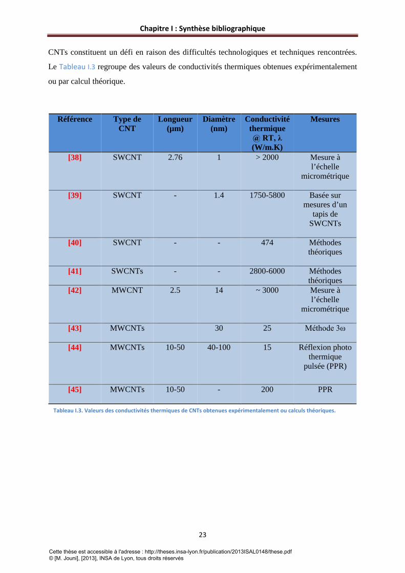
CNTs constituent un défi en raison des difficultés technologiques et techniques rencontrées.
Le Tableau I.3 regroupe des valeurs de conductivités thermiques obtenues expérimentalement
ou par calcul théorique.
Référence Type de CNT
Longueur (µm)
Diamètre (nm)
Conductivité thermique @ RT, λ (W/m.K)
Mesures
[38] SWCNT 2.76 1 > 2000 Mesure à l’échelle
micrométrique
[39] SWCNT - 1.4 1750-5800 Basée sur mesures d’un
tapis de SWCNTs
[40] SWCNT - - 474 Méthodes
théoriques
[41] SWCNTs - - 2800-6000
Méthodes théoriques
[42] MWCNT 2.5 14 ~ 3000 Mesure à l’échelle
micrométrique
[43] MWCNTs 30 25
Méthode 3ω
[44] MWCNTs 10-50 40-100 15 Réflexion photo thermique
pulsée (PPR)
[45] MWCNTs 10-50 - 200 PPR
Tableau I.3. Valeurs des conductivités thermiques de CNTs obtenues expérimentalement ou calculs théoriques.
Cette thèse est accessible à l'adresse : http://theses.insa-lyon.fr/publication/2013ISAL0148/these.pdf © [M. Jouni], [2013], INSA de Lyon, tous droits réservés

Chapitre I : Synthèse bibliographique
24
Il a été montré que la conductivité thermique des CNTs dépend encore de l’arrangement
(enroulement des feuillets de graphène), des dimensions des CNT et des défauts de structure
ainsi que de la présence d’impuretés dans les CNTs [46-48].
I.2.4.3 Propriétés mécaniques des nanotubes de carbone
La structure des CNTs prévoit qu’ils ont des modules d’Young assez élevés. Depuis
leur découverte, des études sur le comportement mécanique de ces objets ont été effectuées.
Cependant, pour les mêmes raisons citées ci-dessus, l’interprétation directe de ces propriétés
mécaniques est difficile. Des mesures directes sur les SWCNTs en utilisant une force de
flexion avec un microscope à force atomique (AFM) ont révélé un module de Young entre
0.32 et 1.47 TPa [49]. Concernant les MWCNTs, Treacy et al ont fait une mesure indirecte
sur un MWCNT à partir de son énergie vibrationnelle et ont trouvé une valeur entre 1 et 1.8
TPa [8].
Le Tableau I.4, donne les valeurs de modules d’Young obtenus avec des CNTs.
Référence Type de CNT Module de Young (E)
[50] SWCNTs 1.25 TPa
[49] SWCNTs 13<E<52 GPa
[51] MWCNT 1.8±1.4 TPa
[52] MWCNTs 1.28 TPa
[53] MWCNTs 1.72±0.64 TPa
[54] MWCNTs 0.91 TPa
[55] MWCNTs 270<E<950 GPa
Tableau I.4. Module d‘ Young pour quelques MWCNTs et SWCNTs reportés dans la littérature.
I.3 Elaboration de nanocomposites polymères conducteurs (NCPCs) Selon le type de NPs, l’élaboration de NCPC peut se faire de différentes manières.
Plusieurs méthodes d’élaboration des NCPC ont été décrites dans la littérature. Les procédés
choisis semblent avoir une grande influence sur les caractéristiques des NCPC car ils
influencent la dispersion des NPs et, par conséquent, les propriétés finales du composite.
Cette thèse est accessible à l'adresse : http://theses.insa-lyon.fr/publication/2013ISAL0148/these.pdf © [M. Jouni], [2013], INSA de Lyon, tous droits réservés

Chapitre I : Synthèse bibliographique
25
Des revues [2, 19] relèvent les stratégies les plus couramment utilisées pour préparer des
NCPC à base de CNTs. Ainsi, de nombreux résultats sur les propriétés électriques et
mécaniques sont reportés dans les références [1, 2, 19].
Cependant, afin d’avoir une vision claire sur les principales méthodes d’élaboration des
NCPC et leurs différences, les méthodes les plus utilisées sont rapidement décrites ci-après.
I.3.1 Elaboration en solution La démarche la plus connue pour préparer les NCPCs en solution est de mélanger le polymère
et les NPs dans le même solvant. Cette méthode comprend trois étapes [2, 19] . Premièrement,
les NPs sont dispersés dans un solvant compatible. Dans un deuxième temps, on mélange le
polymère avec les NPs (à température ambiante ou élevée). La troisième étape consiste en une
évaporation du solvant pour former un film de NCPC.
Vues les grandes forces d’interactions entre les NPs, une dispersion de ces dernières avec une
assistance mécanique (bain à ultra-sons) est souhaitable. L’inconvénient majeur de cette
méthode est qu’elle utilise un solvant et, par conséquent, elle n’est applicable que pour un
nombre limité de polymères.
I.3.2 Polymérisation In-Situ La stratégie de cette méthode consiste à disperser les NPs dans les monomères avant la
polymérisation de ces derniers. Dans la plupart des cas, les NPs peuvent être fonctionnalisées
pour jouer le rôle de macro amorceurs pour la polymérisation de monomères. L’avantage
principal de cette technique est qu’elle permet de produire des polymères chimiquement liés
avec les NPs. Cette technique permet de réaliser des NCPCs avec une bonne dispersion des
NPs. En revanche, elle implique la synthèse du polymère à partir des monomères, ce qui peut
être un frein sur le plan industriel. En plus, des impuretés peuvent être générées pendant le
processus de synthèse, ce qui implique une purification [2].
I.3.3 Elaboration à l’état fondu L’élaboration de composites à l’état fondu utilise une température élevée,
généralement au dessus de la température de fusion du polymère.
En général, le mélange se fait en appliquant des forces de cisaillement intenses pour disperser
les charges dans la matrice polymère. Plusieurs procédés de mélange sont cités dans la
littérature pour mettre en œuvre les composites à l’état fondu. Le mélange peut s’effectuer par
Cette thèse est accessible à l'adresse : http://theses.insa-lyon.fr/publication/2013ISAL0148/these.pdf © [M. Jouni], [2013], INSA de Lyon, tous droits réservés

Chapitre I : Synthèse bibliographique
26
des machines telles que calandre, mélangeur interne ou par extrusion en utilisant une
extrudeuse mono ou bi-vis.
L’élaboration de composites à matrice polymère à l’état fondu, considérée comme la
technique la plus employée, est pratiquée parce qu’elle ne nécessite pas d’utilisation de
solvant. Elle est applicable à la plupart des polymères thermoplastiques. C’est un procédé
facile et répandu dans l’industrie. Par contre, l’inconvénient majeur peut être le faible état de
dispersion des charges. D’autre part, cette technique n’est pas adaptée à l’incorporation de
grandes quantités de charges en raison de la haute viscosité induite.
Dans notre étude, on a utilisé cette technique dans le but d’élaborer des NCPCs à base
de polyéthylène haute densité chargé avec des MWCNTs et des Ag-NPs. Les résultats sont
décrits dans les chapitres suivants.
Dans le paragraphe suivant, on parlera de la conduction et des phénomènes de transport
électronique dans les composites polymères conducteurs afin d’avoir une vision globale et
une bonne compréhension sur ce sujet.
I.4. Conduction et phénomènes de transport thermique et électronique
I.4.1 Conduction et transport thermique
I.4.1.1 Transport thermique dans les composites polymères Le transfert thermique dans les matériaux implique le transport de l’énergie par des porteurs
d’énergie. En phase gazeuse ce phénomène s’assure par diffusion. Dans les liquides, l’énergie
peut être transportée par diffusion des molécules. Dans les solides, et particulièrement le cas
des polymères ce mécanisme est provoqué par les phonons vu que le mouvement libre des
électrons n’est pas possible [56]. Pour prévoir théoriquement la conductivité thermique des
polymères, l’équation usuelle définie par Debye est généralement utilisée sous la forme
suivante :
λ =Cpυ𝑙
3 I(2)
où Cp est la capacité spécifique thermique, υ est la vitesse moyenne des phonons et l est le
chemin libre de phonon.
Cette thèse est accessible à l'adresse : http://theses.insa-lyon.fr/publication/2013ISAL0148/these.pdf © [M. Jouni], [2013], INSA de Lyon, tous droits réservés

Chapitre I : Synthèse bibliographique
27
Pour les polymères amorphes, l est une constante très faible. La cristallinité des polymères
affecte leurs conductivités thermiques et cette dernière augmente avec le taux de cristallinité
comme reporté dans une étude sur le polytetrafluoroethylene (PTFE) [57].
Malgré la faible conductivité des polymères ni chargés ni dopés, on peut améliorer leur
conductivité pour leur utilisation dans différentes applications industrielles comme les cartes
des circuits imprimés pour l’électronique de puissance, les échangeurs de chaleur, les
appareils et machines électroniques. Tous ces enjeux justifient l’utilisation des composites
polymères pour relever ces défis.
Afin de réaliser de tels composites polymères thermiques où l’implication des charges est
déterminante, le choix et le type des charges revêtent une importance majeure. Les charges
métalliques peuvent permettre d’accéder à des composites avec de bonnes propriétés
thermiques mais également à des bonne conductivités électriques [58-60]. Cependant
l’inconvénient majeur est l’augmentation de la densité du composite.
L’utilisation de charges céramiques a montré encore son efficacité pour les matériaux
électroniques. Plusieurs céramiques comme le nitrure d’aluminium (AlN), le nitrure de bore
(BN) et le carbure de silicium (SiC) ont attiré l’attention à cause de leur haute conductivité
thermique et de leur résistance électrique [61]. Par contre, il y a des facteurs limitant
l’utilisation de ce type de charges comme la densité maximale de remplissage [62], la taille et
les dimensions des particules [63, 64], le traitement de surface [65] et les méthodes de
mélange [66].
Les charges carbonées représentent, parmi d’autres, une famille prometteuse pour la
réalisation de composites polymères avec de bonnes propriétés thermiques. Ces charges
offrent à la fois de bonnes conductivités thermiques et de faibles densités. Le graphite, noir de
carbone et les fibres de carbone sont bien connus parmi les charges carbonées. Le graphène et
les CNTs ont fait l’objet de nombreuse recherches et études après la découverte de leur
excellentes propriétés de conduction thermique.
I.4.1.2 Modélisation de la conductivité thermique dans les composites polymères Différents modèles ont été développés pour prédire la conductivité thermique dans les
composites polymères [67-69]. On s’intéressera dans cette partie à définir les deux modèles
de base qui représentent les limites supérieures et inférieures (upper and lower bounds) de la
conductivité thermique.
Cette thèse est accessible à l'adresse : http://theses.insa-lyon.fr/publication/2013ISAL0148/these.pdf © [M. Jouni], [2013], INSA de Lyon, tous droits réservés
Chapitre I : Synthèse bibliographique
28
La loi de mélange où le modèle parallèle implique que chaque phase contribue
indépendamment à la conductivité globale. Ce modèle est proportionnel à la fraction
volumique et peut être modélisé à l’aide de la formule suivante :
λc = λpφp + λmφm I(3)
où λc, λp, λm sont les conductivités thermique du composite, des particules ou charges et de
la matrice polymère respectivement. φp et φm sont les fractions volumiques de la charge et
de la matrice polymère respectivement. Le modèle parallèle maximise la contribution de la
phase conductrice et fait l’hypothèse d’un contact parfait entre les particules conductrices
dans un réseau percolant. Ce modèle a montré son applicabilité dans le cas de composites à
base de fibres dans une direction parallèle aux fibres. Mais, généralement, il surestime la
conductivité thermique pour un grand nombre de composites d’autres types.
Le deuxième modèle est le modèle en série qui fait l’hypothèse de l’absence de contact direct
entre les particules, ainsi que, la contribution de la phase conductrice dépend de la région
polymère qui entoure ces particules. La conductivité du composite est décrite par l’expression
suivante :
1λ𝑐
= 𝜑𝑝λ𝑝
+ 𝜑𝑚λ𝑚
I(4)
La plupart des résultats expérimentaux trouvés se situent entre ces deux modèles avec un
rapprochement vers le modèle en série.
Cependant, d’autres modèles prenant en compte d’autres facteurs, comme la géométrie des
particules et leurs formes se sont révélés pertinents pour estimer la conductivité thermique du
composite. Davantage de détails seront donnés dans les résultats décrits au chapitre 3.
I.4.2 Conduction électronique dans les composites polymères
I.4.2.1 Théorie de la percolation électrique La base théorique fondamentale pour décrire et modéliser le comportement conducteur
dans les CPC est la théorie de la percolation électrique. Le phénomène de percolation peut
être visualisé par un simple scenario décrit dans la Figure I.12. Les sites élémentaires
(représentés par des traits) correspondent aux charges dans le cas d’un composite à matrice
polymère. La probabilité pour créer un réseau percolant responsable d’une transition d’un état
vers un autre dépend de la concentration des charges. Cette transition s’effectue au delà d’un
Cette thèse est accessible à l'adresse : http://theses.insa-lyon.fr/publication/2013ISAL0148/these.pdf © [M. Jouni], [2013], INSA de Lyon, tous droits réservés

Chapitre I : Synthèse bibliographique
29
taux critique de concentration en charges, connu sous le terme, seuil de percolation pc. Dans le
cas des charges conductrices, on parle d’une transition isolant-conducteur à pc et d’une
percolation dite électrique.
Figure I.12. Illustration du phénomène de percolation (création de liens entre charges) dans une matrice polymère pour former un composite polymère conducteur. Les traits colorés représentent les charges conductrices.
Aux faibles concentrations de charges, les particules conductrices dispersées dans la
matrice sont isolées, il en résulte l’absence de contact direct et, par conséquent, pas de lien
entre les différentes charges conductrices (Figure I.12). Au fur et à mesure que la
concentration de particules conductrices augmente, la probabilité d’avoir des connexions
directes à longue échelle augmente, jusqu’à arriver à la concentration pc où une augmentation
brutale de la conductivité électrique du polymère est observée (voir Figure I.13).
Figure I.13. Représentation schématique montrant le passage d'un état isolant à un état conducteur suite à la création d'un réseau percolant de charges conductrices.
Cette thèse est accessible à l'adresse : http://theses.insa-lyon.fr/publication/2013ISAL0148/these.pdf © [M. Jouni], [2013], INSA de Lyon, tous droits réservés

Chapitre I : Synthèse bibliographique
30
Pour des concentrations supérieures à pc, l’augmentation de la conductivité devient
limitée suite à la formation du réseau percolant dans toutes les directions.
Au delà de pc, la conductivité du composite évolue en fonction de la fraction
volumique des charges conductrices, en suivant une loi de puissance décrite par l’équation
suivante [70]:
𝜎~ (𝑝 − 𝑝𝑐)𝑡 pour p > pc I(5)
Où p est la fraction volumique de charges, pc est la fraction correspondant à la
percolation et t est un exposant lié aux dimensions du système étudié, t prend la valeur ~2
pour une percolation statistique en trois dimensions [71].
Il a été montré des points de vue expérimental et théorique que le seuil de percolation
pc, dépend fortement du facteur de forme des charges conductrices. Des divergences dans les
valeurs de seuils de percolation électriques sont à prévoir pour le même type de charge. En
effet, le type de matrice et le procédé jouent un rôle à ce niveau également.
Généralement, dans le cas des particules sphériques, une valeur de 16 vol.% est prévue
pour pc [72]. Cette valeur peut être mesurée expérimentalement en prenant l’exemple
présenté dans la Figure I.14.
Figure I.14. Exemple d'une étude expérimentale qui révèle un pourcentage de 16 % nécessaire pour former un réseau percolant dans le cas de particules conductrices sphériques.
Cette thèse est accessible à l'adresse : http://theses.insa-lyon.fr/publication/2013ISAL0148/these.pdf © [M. Jouni], [2013], INSA de Lyon, tous droits réservés
Chapitre I : Synthèse bibliographique
31
Cette expérience permet d’obtenir la valeur réelle pour la percolation électrique en 3D dans le
cas de particules sphériques. Elle consiste à mettre des billes d’aluminium conductrices et de
verre isolantes dans un cylindre en verre; dans un second temps, un champ électrique est
appliqué et l’intensité du courant à travers le système est mesurée. Si on répète cette
expérience en augmentant la fraction volumique des sphères conductrices (sphères
d’aluminium) en les mélangeant, on verra que le système devient conducteur pour une valeur
de 16 vol.%. C’est la valeur qu’on peut aussi obtenir si on applique une théorie de probabilité.
En d’autres termes, ça veut dire que le premier chemin percolant est statiquement formé à
cette valeur déjà définie par le seuil de percolation.
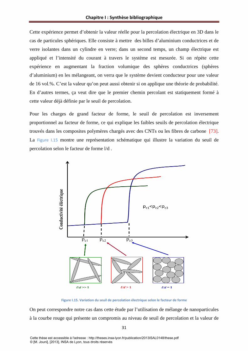
Pour les charges de grand facteur de forme, le seuil de percolation est inversement
proportionnel au facteur de forme, ce qui explique les faibles seuils de percolation électrique
trouvés dans les composites polymères chargés avec des CNTs ou les fibres de carbone [73].
La Figure I.15 montre une représentation schématique qui illustre la variation du seuil de
percolation selon le facteur de forme l/d .
Figure I.15. Variation du seuil de percolation électrique selon le facteur de forme
On peut correspondre notre cas dans cette étude par l’utilisation de mélange de nanoparticules
à la courbe rouge qui présente un compromis au niveau de seuil de percolation et la valeur de
Cette thèse est accessible à l'adresse : http://theses.insa-lyon.fr/publication/2013ISAL0148/these.pdf © [M. Jouni], [2013], INSA de Lyon, tous droits réservés

Chapitre I : Synthèse bibliographique
32
la conductivité si on prend en compte que les particules sphériques représentées dans la figure
ci-dessous sont assimilées aux particules métalliques de conductivité électrique plus élevée
que les CNTs.
La valeur théorique de pc , peut être estimée par la théorie du volume exclu. Dans le cas des
charges avec un grand facteur de forme comme les CNTs, la fraction au seuil de percolation
est liée au facteur de forme par la relation suivante [74]:
𝑝𝑐 = 0.6𝑎
I(6)
où 𝑎 est le facteur de forme (l/d) des CNTs.
I.4.2.2 Mécanismes de conduction électroniques Dans un matériau donné, la conduction électronique ainsi que les phénomènes de
transport de charges suivent des mécanismes différents selon la nature du système étudié.
Souvent, on distingue les solides ordonnés et les systèmes désordonnés. Dans le cas des
solides ordonnés, les états électroniques sont délocalisés, les propriétés électriques résultent
de la répartition des électrons dans les bandes d’énergie (bande de conduction et bande de
valence) (voir Figure I.16).
Figure I.16. Diagramme de répartition des bandes d'énergies dans un solide ordonné.
La conductivité électrique du matériau est donnée par l’expression suivante :
𝜎 = 𝑛𝑞𝜇 I(7)
Où 𝑛 représente la densité de porteurs de charge, 𝑞 la charge élémentaire et µ la mobilité des
porteurs de charges.
Cette thèse est accessible à l'adresse : http://theses.insa-lyon.fr/publication/2013ISAL0148/these.pdf © [M. Jouni], [2013], INSA de Lyon, tous droits réservés

Chapitre I : Synthèse bibliographique
33
Dans le cas d’un métal, la bande de conduction et la bande de valence se recouvrent, les
électrons peuvent se déplacer entre les atomes, ce qui explique que les métaux sont
conducteurs. Le nombre d’électrons est constant et la conductivité augmente lorsque la
température diminue et ne dépend que de la mobilité des électrons. En effet, le transport de
charges est limité par les vibrations du réseau (phonons, interactions électron-électron, et
collisions électron-électron).
Au contraire des métaux, dans les isolants, il existe un gap d’énergie (Eg ≈ 5 eV) qui sépare la
bande de valence de celle de conduction et qui est définie comme une bande interdite au
passage des électrons, le déplacement des électrons n’est donc plus possible et par conséquent
la conduction est impossible. Les semi-conducteurs présentent un état intermédiaire entre les
matériaux conducteurs et les matériaux isolants. Dans les semi-conducteurs, la hauteur de la
bande interdite est plus faible que dans le cas des isolants (Eg≈ 1-3 eV), la conductivité est
faible mais augmente significativement avec la temperature. En effet, l’énergie thermique est
capable d’exciter les électrons facilitant ainsi leur passage vers la bande de conduction. La
conductivité dépend donc du nombre de porteurs de charge et elle décroit d’une manière
exponentielle avec la décroissance de la température en suivant la relation ci-après :
𝜎~ 𝜎0exp(− 𝐸𝑔2𝑇𝐾𝐵
) I(8)
où KB est la constante de Boltzmann.
Dans les matériaux généralement caractérisés par la présence de régions conductrices où de
longs chemins conducteurs sont séparés par une légère barrière isolante (cas des composites
polymères conducteurs), le système est dit désordonné. A cause du désordre existant, les
états électroniques ne peuvent plus être considérés comme délocalisés et les électrons
occupent alors des états localisés dans la bande interdite et proches du niveau Fermi. Il a été
montré que la conduction électronique peut se faire selon deux mécanismes, le premier
explique le mouvement des électrons au-delà d’une barrière de potentiel par des ‘sauts’
( hopping ), les sauts peuvent avoir lieu à distance variable (modèl VRH : Variable Range
Hopping ) [75] et le deuxième est lié au passage des électrons via une légère barrière par effet
tunnel (modèle QMT : Quantum Mechanical Tunneling ) [76] (voir Figure I.17) [77].
Cette thèse est accessible à l'adresse : http://theses.insa-lyon.fr/publication/2013ISAL0148/these.pdf © [M. Jouni], [2013], INSA de Lyon, tous droits réservés
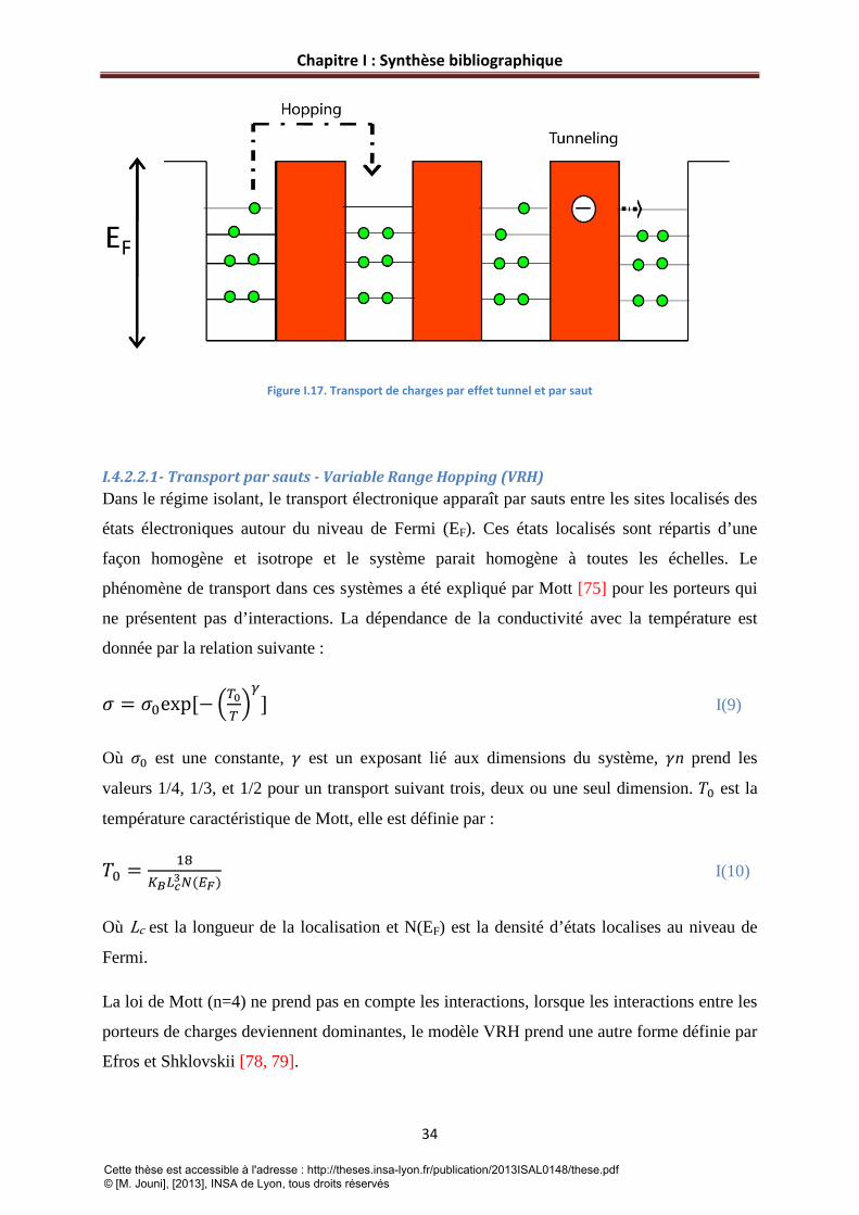
Chapitre I : Synthèse bibliographique
34
Figure I.17. Transport de charges par effet tunnel et par saut
I.4.2.2.1- Transport par sauts - Variable Range Hopping (VRH) Dans le régime isolant, le transport électronique apparaît par sauts entre les sites localisés des
états électroniques autour du niveau de Fermi (EF). Ces états localisés sont répartis d’une
façon homogène et isotrope et le système parait homogène à toutes les échelles. Le
phénomène de transport dans ces systèmes a été expliqué par Mott [75] pour les porteurs qui
ne présentent pas d’interactions. La dépendance de la conductivité avec la température est
donnée par la relation suivante :
𝜎 = 𝜎0exp[−𝑇0𝑇𝛾
] I(9)
Où 𝜎0 est une constante, 𝛾 est un exposant lié aux dimensions du système, 𝛾n prend les
valeurs 1/4, 1/3, et 1/2 pour un transport suivant trois, deux ou une seul dimension. 𝑇0 est la
température caractéristique de Mott, elle est définie par :
𝑇0 = 18𝐾𝐵𝐿𝑐3𝑁(𝐸𝐹)
I(10)
Où Lc est la longueur de la localisation et N(EF) est la densité d’états localises au niveau de
Fermi.
La loi de Mott (n=4) ne prend pas en compte les interactions, lorsque les interactions entre les
porteurs de charges deviennent dominantes, le modèle VRH prend une autre forme définie par
Efros et Shklovskii [78, 79].
Cette thèse est accessible à l'adresse : http://theses.insa-lyon.fr/publication/2013ISAL0148/these.pdf © [M. Jouni], [2013], INSA de Lyon, tous droits réservés

Chapitre I : Synthèse bibliographique
35
𝜎 = 𝜎0exp[−𝑇0′
𝑇12] I(11)
Où 𝑇0′ = 𝛽1𝑒2
𝐾𝐵𝐿𝑐𝜀 est la température caractéristique d’Efros et Shklovskii, e est la charge de
l’électron, 𝜀 est la constante diélectrique, et 𝛽1 = 2.8 (contante numérique).
V.4.2.2.2- Transport par effet tunnel – Fluctuation Induced Tunneling Dans les matériaux désordonnés, il y a une variété de systèmes comme les composites
conducteurs, semi-conducteurs désordonnés ou semi-conducteurs organiques dopés dans
lesquels la conduction des électrons est délocalisée et permet de passer à travers des distances
assez larges par comparaison à la dimension de l’atome. Pour ces systèmes, la conduction
électronique est plutôt dominée par des transferts d’électrons entre des larges segments
conducteurs que par saut (conduction par hopping). Ce mécanisme de conduction caractérise
le passage des électrons via un gap isolant entre les sites conducteurs par l’effet tunnel défini
par Sheng [76]. Le modèle décrit la conduction dans un système de désordre hétérogène où il
y a répartition de sites conducteurs dans un réseau isolant.
Suivant la taille des segments conducteurs (îlots), Sheng developpe deux modèles différents
pour expliquer le passage des électrons par effet tunnel au travers de zones isolantes.
V.4.2.2.3 Le modèle CELT
Le modèle CELT (Charging Energy Limited Tunneling) montre que la conductivité est
limitée par l’énergie électrostatique induite lors du transfert d’un électron d’un segment
conducteur à un autre. Le modèle CELT repose par conséquent sur l’hypothèse que l’énergie
de charge (énergie correspondant à l’ajout ou au retrait d’un électron du site conducteur) est
supérieure à l’énergie thermique. Le transfert par effet tunnel entre les sites conducteurs est
alors décrit par une dépendance de la conductivité en fonction de la température en suivant la
forme :
𝜎 = 𝜎0exp[−𝑇0𝑇12] I(12)
D’après l’équation I.(12) on peut identifier que l’expression donnée par le modèle CELT est
identique à celle établie par le modèle d’Efros et Shklovski pour la conduction dans les
systèmes homogènes.
Cette thèse est accessible à l'adresse : http://theses.insa-lyon.fr/publication/2013ISAL0148/these.pdf © [M. Jouni], [2013], INSA de Lyon, tous droits réservés

Chapitre I : Synthèse bibliographique
36
V.4.2.2.4 Le modèle FIT (Fluctuation Induced Tunneling)
Dans le cas où la distance entre les sites conducteurs est faible, et l’énergie thermique est
supérieure à l’énergie de charge, le saut d’un électron d’un site conducteur vers un autre peut
se faire sans excitation thermique mais par fluctuations thermiques au sein des sites
conducteurs qui engendrent un champ électrique facilitant le passage des électrons via les
barrières isolantes. La conductivité électrique s’écrit alors sous la forme :
𝜎 = A𝑒𝑥𝑝(− 𝑇1𝑇+𝑇2
) I(13)
Où 𝑇1 = 𝑤𝐴𝜀02
8𝜋𝐾𝐵
𝑇2 = 2𝑇1𝜋𝜒𝑤
Avec 𝜒 = 2𝑚𝑉0ℎ2
et 𝜀0= 4𝑉0𝑒𝑤
, avec 𝑚 et 𝑒 la masse et la charge de l’electron, 𝑉0 la barrière
de potentiel et 𝑤 la distance entre les deux porteurs de charges ( largeur de gap).
Dans le modèle FIT, A est une constante, 𝑇1 est la température à laquelle les fluctuations
thermiques deviennent suffisamment grandes pour permettre aux porteurs de charge de
franchir la barrière de potentiel et 𝑇2 est la température en dessous de laquelle l’effet tunnel
est indépendant des fluctuations thermiques. A très basse température (T tend vers zéro), le
modèle FIT prévoit une indépendance de la conductivité avec la température
I.4.2.3 Observation sur les mécanismes de conduction dans les composites polymères conducteurs étudiés dans la littérature Pour atteindre les applications diverses visées par les NCPCs, l’étude de leurs propriétés de
transport dans une large gamme de températures semble essentielle [80, 81]. Cette étude doit
assurer une compréhension fondamentale des phénomènes de transport électronique dans ces
systèmes. Une telle analyse doit comporter une description détaillée sur la fiabilité
d’utilisation de l’un des modèles cités ci-dessus par rapport à l’autre pour identifier le
mécanisme de conduction mis en jeu. En d’autres termes, il ne sera pas judicieux de valider
l’existence d’un mode de transport décrit par un modèle déterminé tant que ce dernier ne
constitue pas une interprétation justifiée. On peut être amener à entrer en contradiction avec
les résultats publiés sur ce sujet.
Cette thèse est accessible à l'adresse : http://theses.insa-lyon.fr/publication/2013ISAL0148/these.pdf © [M. Jouni], [2013], INSA de Lyon, tous droits réservés

Chapitre I : Synthèse bibliographique
37
Par exemple, E.Lgazik et al. [82] ont étudié les mécanismes de conduction dans les
composites PA/MWCNT. Ils ont montré que la conduction était décrite par le model FIT
malgré les faibles indications liées aux valeurs trouvées pour les paramètres de l’équation
I(13). Leur résultat a exclu la présence du modèle VRH suite à un ajustement non réussi des
données expérimentales. Cependant, cette conclusion ne peut pas être pertinente vu que leur
mesure de la conductivité en fonction de la température a été réalisée seulement jusqu'à celle
de l’azote liquide, ce qui peut constituer une lacune pour avoir une vraie analyse où la
variation de la température doit correspondre à un intervalle plus grand (jusqu’aux
températures de l’hélium liquide). Une autre observation pouvant relever d’un problème
similaire se retrouve dans les travaux de F.Marcq et al [83] sur des composites
Epoxy/MWCNT où des composites hybrides chargés avec MWCNT et microparticules
d’argent. La loi de Mott paraît décrire le mécanisme de conduction par l’équation I(9) avec un
exposent de 1/4 caractéristique d’un transport en 3D (voir Figure I.18 ).
Figure I.18. Variation de la conductivité électrique des composites Epoxy/MWCNT et Epoxy/MWCNT/µAg en fonction de T-1/4 (Modèle de Mott) [83].
La Figure I.18 montre que les résultats expérimentaux étaient cohérents avec la loi de Mott.
Cependant cette observation ne prouve pas que cette loi soit valide jusqu'à des températures
très basses vu que les mesures ont été faites avec l’azote liquide. Un contre exemple de cette
Cette thèse est accessible à l'adresse : http://theses.insa-lyon.fr/publication/2013ISAL0148/these.pdf © [M. Jouni], [2013], INSA de Lyon, tous droits réservés

Chapitre I : Synthèse bibliographique
38
situation peut être trouvé dans les travaux de B.Sundaray et al [84] sur des composites PANI-
PEO chargés avec des SWCNTs (voir Figure I.19).
Figure I.19. Dépendance de la conductivité électrique en fonction de la température pour des composites PANI-PEO/SWCNT avec différents taux de SWCNTs. Le fit a été réalisé avec le modèle FIT. L’insertion montre le fit avec la loi de VRH pour un exposant 1/2 et une divergence de la loi à basses température [84].
L’exemple décrit dans le graphe ci-dessus montre que le modèle VRH est applicable dans un
intervalle de température, alors que le modèle FIT est valable pour toute la gamme des
températures.
Afin de réaliser une étude pertinente des mécanismes de conduction dans les composites
polymères conducteurs de nos travaux de thèse, la dépendance de la conductivité en fonction
de la température a été mesurée par la technique quatre points dans un cryostat d’hélium
liquide assurant une descente en température jusqu'à 4 K. Nous avons montré que plusieurs
régimes de conduction électronique sont présents en fonction de la température. L’analyse
détaillée de cette étude sera abordée dans le chapitre 4.
I.5 Données de la Littérature sur les NCPC Etant donné que le domaine des NCPCs est en pleine progression [85-88] cette partie
de notre travail présente une synthèse de données de la littérature, relatives aux propriétés
électrique et thermique des NCPCs. Alors qu’il existe un nombre important de travaux sur
Cette thèse est accessible à l'adresse : http://theses.insa-lyon.fr/publication/2013ISAL0148/these.pdf © [M. Jouni], [2013], INSA de Lyon, tous droits réservés
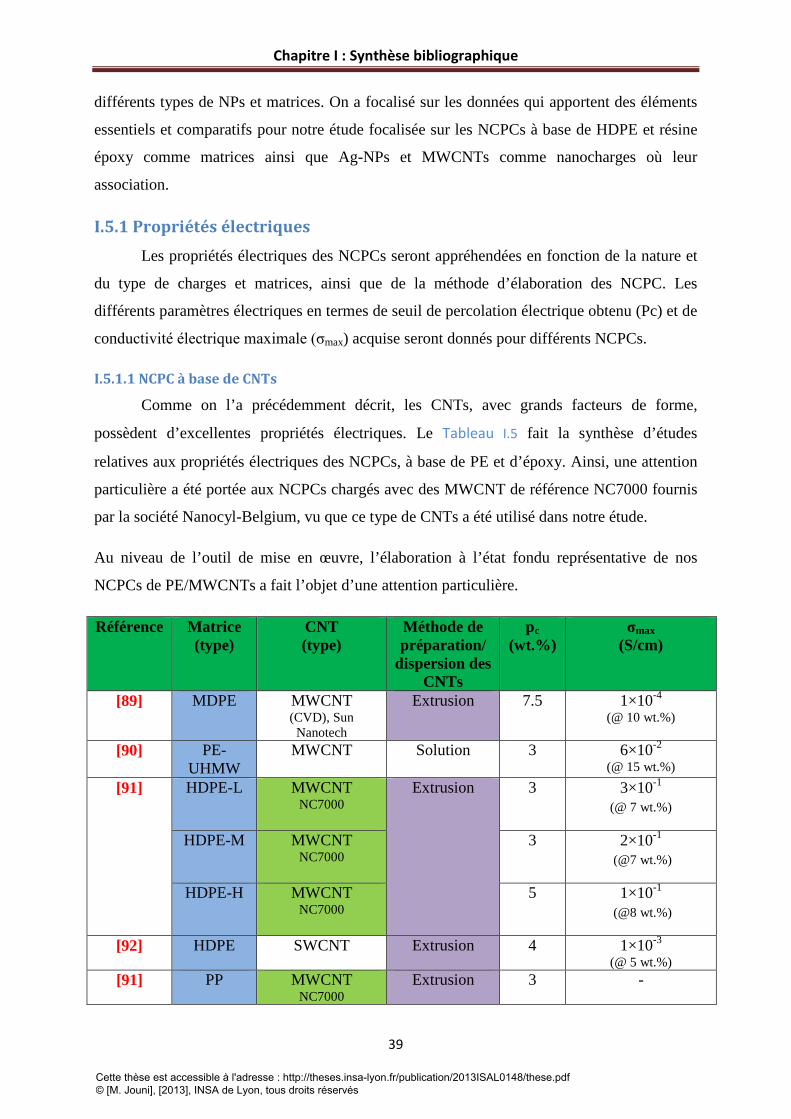
Chapitre I : Synthèse bibliographique
39
différents types de NPs et matrices. On a focalisé sur les données qui apportent des éléments
essentiels et comparatifs pour notre étude focalisée sur les NCPCs à base de HDPE et résine
époxy comme matrices ainsi que Ag-NPs et MWCNTs comme nanocharges où leur
association.
I.5.1 Propriétés électriques Les propriétés électriques des NCPCs seront appréhendées en fonction de la nature et
du type de charges et matrices, ainsi que de la méthode d’élaboration des NCPC. Les
différents paramètres électriques en termes de seuil de percolation électrique obtenu (Pc) et de
conductivité électrique maximale (σmax) acquise seront donnés pour différents NCPCs.
I.5.1.1 NCPC à base de CNTs
Comme on l’a précédemment décrit, les CNTs, avec grands facteurs de forme,
possèdent d’excellentes propriétés électriques. Le Tableau I.5 fait la synthèse d’études
relatives aux propriétés électriques des NCPCs, à base de PE et d’époxy. Ainsi, une attention
particulière a été portée aux NCPCs chargés avec des MWCNT de référence NC7000 fournis
par la société Nanocyl-Belgium, vu que ce type de CNTs a été utilisé dans notre étude.
Au niveau de l’outil de mise en œuvre, l’élaboration à l’état fondu représentative de nos
NCPCs de PE/MWCNTs a fait l’objet d’une attention particulière.
Référence Matrice (type)
CNT (type)
Méthode de préparation/
dispersion des CNTs
pc (wt.%)
σmax (S/cm)
[89] MDPE MWCNT (CVD), Sun
Nanotech
Extrusion 7.5 1×10⁻⁴
(@ 10 wt.%)
[90] PE-UHMW
MWCNT Solution 3 6×10⁻²
(@ 15 wt.%)
[91]
HDPE-L MWCNT NC7000
Extrusion
3 3×10⁻¹ (@ 7 wt.%)
HDPE-M MWCNT NC7000
3 2×10⁻¹ (@7 wt.%)
HDPE-H MWCNT NC7000
5 1×10⁻¹ (@8 wt.%)
[92] HDPE SWCNT Extrusion 4 1×10⁻³
(@ 5 wt.%) [91] PP MWCNT
NC7000 Extrusion 3 -
Cette thèse est accessible à l'adresse : http://theses.insa-lyon.fr/publication/2013ISAL0148/these.pdf © [M. Jouni], [2013], INSA de Lyon, tous droits réservés

Chapitre I : Synthèse bibliographique
40
[93] PP MWCNT NC7000
Extrusion 1.6 1.10-4 (@ 5wt.%)
[94] PP MWCNT NC7000
Extrusion 2 1×10⁻¹ (@ 10 wt.%)
[95] PA6 MWCNT NC7000
Extrusion 2 <10-3
(@ 4 wt.%) [96] PA6 MWCNT
NC7000 Extrusion 2.5 10-3
(@ 5 wt.%) PA66 MWCNT
NC7000 Extrusion 1 10-3
(@ 5 wt.%) [97] PA66 MWCNT
NC7000 (dispersion avec surfactant)
Extrusion 0.1-0.25
1×10⁻¹ (@ 4 wt.%)
[91]
PA11 MWCNT NC7000
Extrusion 5 1×10⁻¹ (@ 8 wt.%)
PA12 MWCNT NC7000
Extrusion 3 7.9×10⁻³ (@ 5 wt.%)
[98] PA12 MWCNT NC7000
Extrusion 0.7 ~ 10-3 (@ 5 wt.%)
Future Carbon CNT-MW-K
1.3 <10-3 (@ 5 wt.%)
Baytubes C150P
2.1 1×10⁻³ (@ 5 wt.%)
Printex XE2
4.3 1×10⁻³ (@ 5 wt.%)
[99] PET MWCNT NC3150
Polymérisation in situ (P- IS)
0.06 2.83×10⁻³ (@ 2.5 wt.%)
MWCNT NC3153
(fonctionnalisation- OH)
~ 0.5 -
MWCNT NC3150
Extrusion 0.1-2 -
MWCNT NC3150
Extrusion 0.06 -
[100] P3HT MWCNT NC7000
Solution 0.1 <10-2 (@ 30 wt.%)
[101] PCL MWCNT
NC7000 Extrusion
0.37 ~ 1
(@ 2.7 wt.%) [102] PMMA MWCNT
NC7000 Extrusion 0.5
(vol.%) 5×10⁻¹
(@ 5.2 vol.%)
[103] PC MWCNT NC7000
Extrusion
0.5 1×10⁻¹ (@ 5 wt.%)
[91] PC-L MWCNT NC7000
Extrusion 1 -
Cette thèse est accessible à l'adresse : http://theses.insa-lyon.fr/publication/2013ISAL0148/these.pdf © [M. Jouni], [2013], INSA de Lyon, tous droits réservés

Chapitre I : Synthèse bibliographique
41
PC-M MWCNT NC7000
1 -
PC-H MWCNT NC7000
3 -
[104] Epoxy (Biphenol
A)
MWCNT NC7000
Agitation à chaud
0.024 3×10⁻³
(@ 1wt.%)
[105] Epoxy (Biphenol
A)
NC 3100 Mélangeage-Cuisson
≤0.1 4.3×10⁻³ (@ 1 wt.%)
NC 3101 (COOH-fonctionnalisés)
~ 0.5 4.7×10⁻⁴
(@ 4 wt.%) [106] Epoxy MWCNT (CVD) Agitation 0.5 5×10⁻²
(@ 3 wt.%) [107] Epoxy SWCNT
(CVD) Agitation 0.08 2×10⁻²
(@ 0.4 wt.%) [108] Epoxy SWCNT (Laser) Ultrasons 0.005 2×10⁻²
(@ 0.1 wt.%) Nos
travaux PE MWCNT
NC7000 Extrusion
0.39
(vol.%)/0.72
(wt.%)
6.3×10⁻⁵ (@ 5 vol.%)
Epoxy (Biphenol
A)
MWCNT Mélange-Cuisson
0.05 (vol.%)/ 0.082 (wt.%)
5×10⁻⁴
(@ 0.7 vol.%)
Tableau I.5. Résultats publiés dans la littérature sur les propriétés électriques des NCPC chargés avec des CNTs.
Le tableau montre une divergence et une grande variation de résultats pour une même matrice
ou un même type de charge. Ces résultats expérimentaux montrent que le seuil de percolation
électrique et la conductivité maximale dépendent de la nature de la matrice, du type de CNTs
et du procédé de mise en œuvre, facteurs généralement considérés comme très influent.
Cependant, si on interprète plus en détails, il nous semble encore que des différences sont
présentes, même dans le cas où la nature de la matrice, le type de CNTs et la méthode
d’élaboration du composite ont été fixés. Ces observations se manifestent par exemple pour
des composites à base de PE et MWCNT [91], PC/MWCNT [91], PP/MWCNT [91, 93, 94].
Pour chacune de ces familles, les mêmes types de matrice et CNTs ont été utilisés. Si on
prend chaque cas séparément, on arrive plus ou moins à expliquer cette variation. Dans [91] la
variation du seuil de percolation observée peut être justifiée par la différence entre les
caractéristiques de chaque PE. Le PE haute densité avec une grande masse moléculaire a
donné un seuil de percolation plus élevé. Donc, dans ce cas on ne parle pas de la nature de la
Cette thèse est accessible à l'adresse : http://theses.insa-lyon.fr/publication/2013ISAL0148/these.pdf © [M. Jouni], [2013], INSA de Lyon, tous droits réservés
Chapitre I : Synthèse bibliographique
42
matrice, mais plutôt de ses caractéristiques physico-chimiques comme l’effet de la viscosité
dans les travaux reportés par Socher et al [109]. En effet, les matrices moins visqueuses
peuvent être plus favorables pour la dispersion des CNTs.
Le cas de PP/MWCNT demeure plus délicat à analyser. En plus des différentes
caractéristiques physico chimiques de chaque PP, il faut noter que les paramètres de mise en
œuvre par extrusion ne sont pas identiques en particulier la température d’extrusion et la
vitesse de rotation des bis-vis.
Le cas de PC/MWCNT est proche de celui de PE/MWCNT décrit ci-dessus. La matrice
possédant la plus haute masse moléculaire correspond à un seuil de percolation plus élevé.
L’utilisation des mélanges maitres où les CNTs sont déjà bien dispersés dans la matrice
polymère (Masterbatch) a montré son efficacité par rapport à l’utilisation directe des CNTs
sous forme des poudres. En plus, du point de vue sécurité, on réduit les problèmes liés à
l’exposition où à la manipulation des CNTs.
Donc en plus des différences générales au niveau de la nature de matrice, type de CNTs et la
méthode employée pour élaborer le composite polymère conducteur, il existe d’autres facteurs
liés aux détails plus approfondis qui ont une influence. Ceci prouve qu’il ne faut pas être
limité en analysant où interprétant un résultat concernant un composite polymère conducteur.
En examinant le tableau Tableau I.5 , plusieurs conclusions peuvent encore être tirées :
A) Les matrices amorphes offrent des seuils de percolation plus bas et des niveaux de
conductivités supérieurs aux matrices semi-cristallines. Ce point sera mieux expliqué dans le
chapitre 4 où l’analyse des phénomènes de transport électronique à basses températures nous
a permis de comprendre la différence entre les composites à base d’ époxy (amorphe) et ceux
à base de PE (semi-cristallin) au niveau de la formation du réseau percolant.
B) Au niveau de la méthode d’élaboration, des seuils de percolation relativement plus faibles
sont à prévoir avec les méthodes en solution ou la polymerisation in situ (P-IS) que dans les
mélanges préparés à l’état fondu. Mais il faut noter que de faibles seuils de percolation sont
aussi observés dans les NCPCs élaborés à l’état fondu (voir tableau).
C) Les MWCNTs (NC7000) semblent efficaces pour donner de bonnes conductivités
électriques .
Cette thèse est accessible à l'adresse : http://theses.insa-lyon.fr/publication/2013ISAL0148/these.pdf © [M. Jouni], [2013], INSA de Lyon, tous droits réservés

Chapitre I : Synthèse bibliographique
43
D) Le dernier point important concerne la fonctionnalisation des CNTs. Les résultats
montrent clairement que cette dernière a un mauvais impact sur les propriétés électriques des
NCPC [99, 105]. Ce phénomène peut être expliqué par l’altération de la structure (hybridation
sp2) du CNT qui peut inhiber ou limiter le transport électronique.
Afin de valoriser les résultats de nos travaux, la dernière ligne du tableau (en rouge) collecte
les propriétés électriques des composites Epoxy/MWCNT et PE/MWCNT préparés dans le
cadre de ce travail de thèse. Les composites PE/MWCNT présentent un faible seuil de
percolation qui peut être considéré très bas si on considère que ces composites ont été
préparés par mélange à l’état fondu. Plusieurs raisons comme le taux de cristallinité de PE ou
la bonne dispersion des MWCNTs au sein du Masterbatch utilisé pour cette étude peuvent
être à l’origine du ce résultat comme il sera détaillé au chapitre 2. En ce qui concerne les
composites Epoxy/MWCNT, le seuil de percolation obtenu est comparable à ceux d’autres
travaux rapportés dans la littérature. On peut donc conclure que nos composites chargés avec
des MWCNTs présentent des bonnes propriétés conductrices avec un faible taux de charges.
I.5.1.2 NCPCs à base de Ag-NPs
Les Ag-NPs sont utilisés pour leurs excellentes propriétés de conduction électrique qui
est de type métallique. Elles peuvent généralement apporter au NCP un niveau de
conductivité plus haut que ce qu’on peut attendre avec les NCPs à base de CNTs où la
conduction électrique est réalisée par un transport électronique. Le Tableau I.6 collecte des
résultats de travaux publiés dans la littérature sur les NCPs chargés avec des Ag-NPs. Les
résultats qui portent sur l’étude des propriétés électriques de NCPCs à base de polyéthylène et
Epoxy comme matrices et Ag-NPs comme nanocharges sont peu nombreux.
Ref Matrice Charge Procédée pc (vol.%)
σmax (S/cm)
Remarques
[110] HDPE Ag-NPs (150 nm)
Extrusion 17.4 10-3-10-2
(@ 24 vol.%)
PBT 13.8 10-3-10-2
(@ 24 vol.%) MXD6 17.4 10-3-10-2
(@ 25 vol.%) [111] Epoxy
(Bisphénol A) Ag-NPs
Solution Pas
observé (@ 20 wt.%)
-
[112] Epoxy
Ag-NPs
- - 1.8 101
(@ 60 wt.%) Deux types de fonctionnalisat
ions Ag-NPs (fonctionnalisés-1)
1.8 10-5
(@ 70 wt.%)
Cette thèse est accessible à l'adresse : http://theses.insa-lyon.fr/publication/2013ISAL0148/these.pdf © [M. Jouni], [2013], INSA de Lyon, tous droits réservés

Chapitre I : Synthèse bibliographique
44
Ag-NPs
(fonctionnalisés-2
1.5 103
(@ 70 wt.%)
[113] SEPS Ag-NPs (100nm)
Solution 16 ~5.5 (@ 20 vol.%)
PP Ag-NPs (100nm)
Solution 15 ~ 5.8 (@ 20 vol.%)
[114] PANI-PSS Ag-NPs
Solution - - Polymérisation à partir de monomère σ~ 4×10⁻⁴
(s/cm) Nos
travaux HDPE Ag-NPs
(100nm) Extrusion 9.9 5.8 10-2
(@ 22 vol.%)
Tableau I.6. Propriétés électriques des NCPCs à base d’Ag-NPs.
Contrairement aux NCPCs à base de CNTs, le tableau Tableau I.6 montre que les seuils de
percolation électrique sont beaucoup plus élevés avec les Ag-NPs. Ceci est prévisible, vu que
les Ag-NPs sont des particules sphériques alors que les CNTs ont un grand facteur de forme
qui facilite la formation du réseau percolant. Balberg [72] a montré qu’un taux de charge de
16 vol.% est nécessaire pour assurer la percolation électrique dans le cas de particules de
géométrie sphérique bien définie (cas de la référence [110] pour les matrices HDPE et
MX6D). Cependant, des écarts par rapport à cette valeur sont à prévoir dans le cas d’une
mauvaise dispersion ou d’une forme non sphérique des particules. En effet, le modèle de
Balberg décrit la situation idéale résultant d’une bonne dispersion de particules bien
sphériques.
L’autre point à tirer du tableau est la conductivité maximale atteinte. Des valeurs relativement
plus élevées sont obtenues avec des Ag-NPs par rapport à des NCPCs à base de CNTs. L’effet
de la fonctionnalisation reste un peu flou, vu l’écart trouvé dans la référence [112] où les
auteurs n’ont pas cité le type de traitement chimique utilisé. En effet les Ag-NPs ont été
fonctionnalisées par différents surfactants dont la composition chimique n’a pas été donnée.
Les composites PE/Ag-NPs préparés dans cette thèse présentent un point avantageux par
rapport à ceux collectés dans ce tableau. Le seuil de percolation (9.9 vol.%) est beaucoup plus
faible que celui prévu théoriquement dans le cas de particules sphériques (16 vol.%), ce qui
correspond à un double intérêt scientique et économique pour ces composites. L’interprétation
de ce résultat sera donné dans le chapitre 3.
Cette thèse est accessible à l'adresse : http://theses.insa-lyon.fr/publication/2013ISAL0148/these.pdf © [M. Jouni], [2013], INSA de Lyon, tous droits réservés

Chapitre I : Synthèse bibliographique
45
Au niveau de valeurs de conductivité, une valeur maximale de 5.8 10-2 S/cm a été trouvée
pour un taux de 22 vol.% en argent. Cette valeur tombe dans l’intervalle d’incertitude des
valeurs trouvées pour ce type de composites.
I.5.2 Propriétés thermiques Le transfert thermique dans les composites à matrice polymère est généralement assuré
par la diffusion des phonons [115]. Dans cette partie, on s’intéressera aux propriétés de
conduction thermique de NCPC à base de CNTs, puisque ces derniers ont été utilisés pour
élaborer des NCPCs à base de HDPE et d’époxy. On rapporte aussi des résultats relatifs à des
composites chargés avec d’autres types de charges métalliques, céramiques ou autres….
I.5.2.1 Conductivités thermiques de NCPCs à base de CNTs
Malgré les bonnes propriétés thermiques des CNTs, l’amélioration des propriétés de
conduction thermique de la matrice polymère reste encore très loin des niveaux qu’on peut
avoir en conductivité électrique des NCPCs chargés avec des CNTs où on observe
généralement un seuil de percolation électrique au-delà duquel une nette augmentation de la
conductivité électrique, de plusieurs décades, est obtenue dans le composite. Ce phénomène
peut être expliqué par une différence beaucoup plus faible entre la conductivité thermique de
la charge et de la matrice par rapport à la différence entre les conductivités électriques. En
plus, les mécanismes de conduction électriques et de transfert thermiques ne sont pas les
mêmes. En effet, le transfert thermique dans les NCPCs chargés avec des CNTs dépend de
plusieurs paramètres. L’interface influence le transfert thermique : la résistance à l’interface
polymère-CNT ainsi que les résistances de contact CNT-CNT limitent le transfert thermique
entre les CNTs et la matrice polymère. La dispersion, l’alignement et la cristallinité du
polymère jouent également des rôles déterminants dans la conductivité thermique des NCPs
[115]. Le Tableau I.7, présente sur des exemples de travaux relatifs aux conductivités
thermiques de NCPCs chargés avec des CNTs.
Ref Matrice CNT-Type λm (w/mK)
λf (w/mK)
λc (w/mK)
Amélioration (%)
Remarques
[116] Epoxy (Biphenol A)
MWCNT 0.255 ~ 600 0.29 (@ 0.5 wt.%)
14
SWCNT (traités
chimiquement)
0.25 (@ 0.5 wt.%)
-2 λc < λp
[117] Epoxy (Biphenol A)
MWCNT 0.48 740 0.88 (@ 0.5 wt.%)
83
Cette thèse est accessible à l'adresse : http://theses.insa-lyon.fr/publication/2013ISAL0148/these.pdf © [M. Jouni], [2013], INSA de Lyon, tous droits réservés

Chapitre I : Synthèse bibliographique
46
MWCNT (fonctionnalisés)
0.82 (@ 0.5 wt.%)
71
[118]
Epoxy (Biphenol A)
MWCNT 0.242
~200 ~0.251 (@ 0.3 wt.%)
3.7
MWCNT (fonctionnalisés)
~200 ~0.245 (@ 0.5 wt.%)
1.3
SWCNT - ~0.243 (@ 0.3 wt.%)
0.4
[119] Epoxy SWCNT 0.18 -
0.21 (@ 0.5 wt.%)
16
SWCNT (Longueur réduite)
0.18 0.25 (@ 0.5 wt.%)
38
[120] LDPE SWCNT 0.26 3000 1.8 (@ 20 vol.%)
592
HDPE 0.5 3.5 (@ 20 vol.%)
600
[121] PVDF SWCNT 0.233 2000 0.537 (@ 49 vol.%)
130
[122] PMMA MWCNT ~ 0.24 - 3.44 (@ 4 wt.%)
1333
SWCNT - 2.43 (@ 1 wt.%)
912
Nos travaux
HDPE MWCNT 0.333 - 0.782 (@ 5 vol.%)
134
Epoxy MWCNT 0.229 - 0.271 (@ 0.7 vol.%)
18
Tableau I.7. Données de la littérature portant sur les conductivités thermiques de NCPCs à base des CNTs.
En observant le Tableau I.7, on voit bien que l’amélioration des propriétés thermiques du NCP
est assez modérée par rapport à celle de la conductivité thermique intrinsèque des CNTs.
Celle-ci peut être due aux raisons citées ci-dessus. Au niveau de la matrice, il est à priori
judicieux de dire que les époxys présentent une amélioration plus faible que les autres
matrices puisqu’il faut prendre en compte le taux final de charges. La fonctionnalisation des
CNTs n’a pas montré d’efficacité pour améliorer la conductivité thermique des NCP [116-
118]. Cette information paraît cohérente avec le Tableau I.5 qui détaille les propriétés
électriques des NCPCs chargés avec des CNTs et qui a montré un effet défavorable de la
fonctionnalisation des CNTs sur les propriétés électriques des NCPCs.
Les composites PE/MWCNT préparés par nos travaux offrent des bonnes conductivités
thermiques si on prend en compte la valeur maximale atteinte à 5 vol.% (amélioration de 134
%). On observe des valeurs plus élevées dans [120], mais ces valeurs ont été mesurées pour
des concentrations beaucoup plus grandes en CNTs (20 vol.%). Les composites
d’époxy/MWCNT ne présentent pas une grande amélioration (voir annexe 1). Ce résultat
semble cohérent avec les composites époxy/CNT décrits dans le tableau ci-dessus.
Cette thèse est accessible à l'adresse : http://theses.insa-lyon.fr/publication/2013ISAL0148/these.pdf © [M. Jouni], [2013], INSA de Lyon, tous droits réservés

Chapitre I : Synthèse bibliographique
47
I.5.2.2 Conductivités thermiques des NCPCs à base d’autres charges
En plus des CNTs, d’autres types de charges ont été utilisées dans des matrices
polymères afin d’atteindre des propriétés thermiques améliorées et de nombreux travaux sur
des particules métalliques ou d’oxyde-métallique (Al, Cu, Al2O3…) ont été réalisés. Les
travaux (Tableau I.8) sur les NCPs chargés avec des Ag-NPs ou des nanocharges métalliques
sont peu nombreux.
L’amélioration de la conductivité thermique dans ces composites paraît nettement
supérieure à celle dans le cas des NCPs chargés avec des CNTs. Les époxys relatifs aux
références [123-125] présentent d’excellentes conductivités thermiques. Au niveau de la
matrice PE, l’amélioration est encore bonne avec les charges micrométriques. Pour les mêmes
types de charge et matrice, la conductivité thermique a augmenté en diminuant la taille des
charges. C’est encore le cas des époxys nano- chargés avec les Ag-NPs par rapport aux
particules d’argent classiques.
Ref Matrice Charge λm (w/mK)
λf (w/mK)
λc (w/mK)
Amélioration (%)
Remarques
[126] LDPE Cu (< 30µm)
0.31 - 0.72 (@ 24 vol.%)
132
LLDPE (Linéaire)
0.36 0.76 (@ 24 vol.%)
111
[127] LLDPE (Linéaire)
Al (7µm) ~0.26
1.23 1.23 (@ 70 wt.%)
37
Al (20µm) 1.15 1.15 (@ 70 wt.%)
34
[128] LDPE Al2O3
30 0.25
0.4 (@ 50 wt.%)
60
[129] LDPE SiC (4µm) 0.32 35-70 0.64(@ 50 wt.%)
100
SiC (13µm) 0.57(@ 50 wt.%)
78
SiC (21µm) 0.52(@ 50 wt.%)
63
[130] LDPE C60 0.27 0.4 0.18 (@ 10 wt.%)
-33 λc<λm
[131] HDPE GNP (Exfoliés)
0.28 - 0.8-0.9 (@ 15 vol.%)
186-221
[132] HDPE Al(<20µm)
- - 0.6 (@ 30 vol.%)
-
[124] Epoxy (Ep 112)
Ag-NPs (20nm)
0.2 429 27 (@ 30 vol.%)
~13.4E3
Cette thèse est accessible à l'adresse : http://theses.insa-lyon.fr/publication/2013ISAL0148/these.pdf © [M. Jouni], [2013], INSA de Lyon, tous droits réservés

Chapitre I : Synthèse bibliographique
48
Ag-NPs (80nm)
23 (@ 30 vol.%)
~11.4E3
[125] Epoxy (Bisphénol
A)
Al (2µm) 0.22 - 1.03 (@ 48 vol.%)
368
[123] Epoxy (Bisphénol
A
BN (0.6-1.2µm)
0.202 - 1.052 (@ 60 wt.%)
421
[133] Epoxy (Bisphénol
A
Ag - - ~2 (@ 23 vol.%)
-
Nos traveaux
HDPE Ag-NPs (100nm)
0.333 430 2.13 (@ 22 vol.%)
540
Tableau I.8. Conductivités thermiques de NCPCs avec différents types de charges
Le tableau montre une excellente amélioration de la conductivité thermique des matrices. La
valeur la plus élevée correspond aux matrices PE présentes dans le tableau quelle que soit la
particule et sa taille. Cette valeur est supérieure aux valeurs trouvées pour les composites
Epoxy/Al, Epoxy/BN et Epoxy/Ag présentes dans les références [123, 125, 133]. Cependant
les composites Epoxy/Ag de la référence [124] présentent des niveaux de conductivité
thermique plus élevés. Les raisons peuvent être liées aux tailles nanométriques de l’argent
utilisé. A savoir encore que la résine époxy utilisée est de nature différente ce qui peut
expliquer l’écart des résultats.
I.5.3 Propriétés électriques de NCPCs avec mélange de nanocharges Récemment et dans le but d’avoir des composites polymères conducteurs de hautes
performances, l’idée d’introduire plusieurs charges qui présentent des caractéristiques ou des
propriétés physiques différentes peut sembler prometteuse [134-136]. L’intérêt d’appliquer
une telle stratégie se traduit par l’amélioration des propriétés des composites polymères et le
gain économique associé suite à un effet de synergie qui peut se manifester via cette
combinaison.
L’utilisation de mélange de charges pour améliorer la conductivité électrique et/ou
thermique des composites polymères montre des résultats intéressants et parfois supérieurs
par rapport aux composites conventionnels chargés avec un seul type de charge. Cependant,
les propriétés finales du composite dépendent fortement des dimensions des charges
incorporées ainsi que de leur nature (organique, métallique, inorganique…). En effet les
dimensions et la nature des charges interviennent dans la dispersion et l’interaction à
l’interface avec la matrice polymère.
Cette thèse est accessible à l'adresse : http://theses.insa-lyon.fr/publication/2013ISAL0148/these.pdf © [M. Jouni], [2013], INSA de Lyon, tous droits réservés

Chapitre I : Synthèse bibliographique
49
En plus des interactions entre la charge et la matrice qui jouent un rôle dans le cas des
composites polymères avec un seul type de charge, les interactions entre les particules doivent
aussi être prises en compte dans le cas des composites hybrides.
Grâce à leurs excellentes propriétés physiques et à leur structure unidimensionnelle,
les CNTs constituent une particularité pour l’élaboration de composites conducteurs avec un
faible seuil de percolation électrique. Les travaux rapportés dans la littérature témoignent bien
du potentiel de ces particules pour préparer des NCP faiblement chargés avec de bonnes
propriétés électriques. Cependant, on peut avoir une faible dispersion des CNTs au sein de la
matrice due aux fortes interactions CNT-CNT qui limitent l’interaction à l’interface entre
CNT et matrice polymère.
Malgré les bonnes propriétés acquises suite à l’incorporation des CNTs dans les
matrices polymères, des tentatives pour relever les défis décrits ci-dessus et provoquer des
performances plus élevées ont été mises en place. Une de stratégies consiste à combiner les
CNTs avec d’autres charges dans le but de réaliser une synergie en vue d’une amélioration par
rapport aux composites chargés seulement avec des CNTs. Une meilleure dispersion des
charges peut être obtenue grâce aux interactions entre les particules [137].
Socher et al [138] ont montré que la combinaison de noirs de carbone (NC) avec des
MWCNTs conduit à une meilleure dispersion de ces derniers dans la matrice de PA12, due à
l’effet de synergie de ces deux types de charges. La combinaison des CNTs avec des NC dans
les époxys a démontré son efficacité. Un faible seuil de percolation électrique est obtenu
lorsque les deux charges sont introduites ensembles dans la matrice [139]. D’autres travaux
ont indiqué que la présence d’argile conduit à la réduction du seuil de percolation électrique
dans les composites époxy/CNT [140].
La combinaison des CNTs avec d’autres particules métalliques a fait l’objet d’une
attention particulière ces dernières années. Des niveaux de conductivités plus élevés peuvent
être atteints puisque ces particules possèdent une conductivité de type métallique. L’intérêt de
cette association peut être expliqué par les différents rôles joués par ces deux types de
charges. En effet, les CNTs assurent un faible seuil de percolation alors que les particules
métalliques contribuent à l’augmentation de la conductivité. Donc, le mélange de CNTs avec
des nanoparticules métalliques au sein de la matrice polymère ouvre la voie à l’élaboration de
composites polymères conducteurs faiblement chargés qui jouissent d’un faible seuil de
Cette thèse est accessible à l'adresse : http://theses.insa-lyon.fr/publication/2013ISAL0148/these.pdf © [M. Jouni], [2013], INSA de Lyon, tous droits réservés

Chapitre I : Synthèse bibliographique
50
percolation électrique et de bonnes propriétés conductrices résultant de l’association de deux
particules avec deux types de conductivités (électriques et électroniques).
Cependant, l’amélioration souhaitée par le mélange simultanément des charges peut
rester parfois restreinte si l’effet de synergie positive qui devrait avoir lieu suite à cette
combinaison ne se produit pas. Le composite peut avoir des propriétés électriques plus faibles.
Liang et al [141] ont trouvé un seuil de percolation électrique plus élevé en ajoutant des
MWCNTs que lorsqu’ils ont introduit aussi des Al-NPs oxydeés dans les composites
LDPE/MWCNT. Ce phénomène s’explique par une couche d’oxyde sur la surface des
particules d’aluminium qui limite le contact électrique entre elles. Sumfleth et al [142] n’ont
pas observé d’effet de synergie au niveau des propriétés électriques et du seuil de percolation
dans les composites hybrides Epoxy/NC/MWCNT par rapport aux composites binaires
d’époxy chargés seulement avec des MWCNTs. Dans leur cas, le seuil de percolation a
toujours été dominé par le taux de MWCNTs et le NC a raccourci la taille des CNTs.
De nouvelles voies basées sur la décoration de la surface de CNTs avec des
nanoparticules métalliques ont été récemment rapportées dans la littérature [143-145]. Cette
méthode implique la création de groupes fonctionnels pour améliorer les interactions entre les
nanoparticules métalliques et les CNTs. L’intérêt est d’avoir de meilleures interactions entre
les deux types de charges à l’échelle nanométrique pour conduire à une nanocharge hybride
présentant des caractéristiques différentes des deux charges. P-S Ma et al [117] ont comparé
les résultats de propriétés électriques dans des nanocomposites à base d’époxy en utilisant des
CNTs fonctionnalisés et ceux décorés avec des Ag-NPs. La conductivité électrique des
composites chargés avec des CNTs décorés était plus élevée. La présence d’Ag-NPs a peut
être conduit à un meilleur transport électronique en diminuant la résistance de contact entre
les CNTs.
Par ailleurs, l’association de charges nanométriques et micrométrique a permis une
amélioration de la conductivité thermique de résines époxy [137, 146]. La combinaison de
MWCNTs avec des particules d’aluminium dans des matrices époxy a conduit à une
augmentation de la conductivité thermique [147, 148]. Sanada et al [148] ont montré le
potentiel de nanocharges pour améliorer la conductivité thermique de composites chargés
avec des charges micrométriques. Ils ont également mis en évidence que l’addition de
MWCNTs augmente la conductivité thermique des composites chargés avec des particules
Cette thèse est accessible à l'adresse : http://theses.insa-lyon.fr/publication/2013ISAL0148/these.pdf © [M. Jouni], [2013], INSA de Lyon, tous droits réservés

Chapitre I : Synthèse bibliographique
51
d’aluminium et que la conductivité thermique augmente avec le facteur de forme des
MWCNTs.
Comme on l’a déjà fait pour les autres parties décrites ci-dessus, on s’intéressera dans
ce paragraphe à compiler quelques résultats (Tableau I.9) qui portent sur les propriétés
électriques des composites hybrides.
Ref Matrice Charges Méthode de préparation/
dispersion des CNTs
pc une
charge (wt.%)
σ une
charge (S/cm)
pc charges hybrides (wt.%)
σ charges hybrides (S/cm)
[141] LDPE MWCNTs+ Al-NPs
Extrusion 8 (MWCNT)
5×10⁻⁸
( @ 8 wt.% MWCNT)
11 (MWCNT)
5×10⁻⁸
(@ 11 wt.% MWCNT-
10 wt.% Al-NPs)
[149] PP MWCNT+ Ag-NPs
Extrusion 3 (MWCNT)
~ 1×10⁻⁶
( @ 3 wt.% MWCNT)
2 (MWCNT)
~ 1×10⁻⁶
(@ 2 wt.% MWCNT-
10 wt.% Ag-NPs)
[150] PCL SWCNTs+ Ag-NPs
Solution 1 (SWCNT)
~1×10⁻⁸
( @ 1 wt.% SWCNT)
1 (SWCNT)
5×10⁻⁶
(@ 1 wt.% SWCNT-15 wt.% Ag-
NPs) [117] Epoxy
(Bisphenol A)
MWCNTs+ Ag-NPs
Solution 0.1 (MWCNT)
1×10⁻⁴
( @ 0.5 wt.% MWCNT)
0.1 (MWCNT)
8×10⁻¹
(@ 0.5 wt.% MWCNT-
decorated Ag-NPs)
[138] PA12 MWCNTs+ CB
Extrusion 0.9 (MWCNT)
1.7×10⁻⁴
( @ 3 wt.% MWCNT)
0.9 (MWCNT)
1×10⁻²
(@ 3 wt.% MWCNT-3 wt.%
CB) [151] HDPE MWCNTs+
CB Extrusion 15
(CB) 1×10⁻¹⁰
( @ 20 wt.% CB)
<15 (CB)
1×10⁻⁴
(@ 20 wt.% CB-1 wt.% MWCNT)
[142] Epoxy (Biphenol
A)
MWCNTs+ CB
Agitation- Cuisson
0.025 (MWCNT)
- 0.03 (MWCNT+CB)
-
Nos travaux
HDPE MWCNTs+
Ag-NPs
Extrusion 0.4 vol.%
(MWCNT)
6.3E-5
(@ 5vol.% MWCNT)
0.4 vol.%
(MWCNT)
5E-3
(@5vol.% MWCNT-3 vol%
Ag-NPs)
Tableau I.9. Propriétés électriques des NCPCs hybrides avec mélange de nanocharges conductrices.
Cette thèse est accessible à l'adresse : http://theses.insa-lyon.fr/publication/2013ISAL0148/these.pdf © [M. Jouni], [2013], INSA de Lyon, tous droits réservés

Chapitre I : Synthèse bibliographique
52
Avant d’entrer dans l’analyse du tableau, il faut considérer que l’incorporation de CNTs dans
des composites hybrides a été retenue dans l’espoir de diminuer les seuils de percolation
électrique nécessaires dans le ca des charges métalliques sphériques. Vu que les CNTs ont un
grand facteur de forme, on peut arriver à créer un réseau percolant des charges conductrices
avec des taux plus faibles. Au contraire, comme on l’a déjà expliqué, les particules
métalliques contribuent à l’obtention de bonnes propriétés électriques. A savoir que
l’utilisation de 60 wt.% d’Al-NPs et Ag-NPs dans les références [141, 149] n’était pas
suffisante pour obtenir une conductivité satisfaisante. Dans certains cas, les Ag-NPs seules ne
permettent pas d’obtenir un NCPC sans ajout de CNTs [150].
Le Tableau I.9 montre qu’une synergie positive associée au mélange de deux charges n’est
pas toujours atteinte. On arrive parfois à avoir des seuils de percolation plus élevés dans le cas
des composites ternaires [141, 142]. Néanmoins, cet effet dépend des interactions entre les
deux charges mais encore des interactions entre les charges et la matrice polymère. Des
niveaux de conductivité plus élevés sont obtenus suite à des associations de charges hybrides
(voir tableau).
Les composites hybrides de PE/MWCNT/Ag-NPs de nos travaux de thèse présentent des
seuils de percolation bas comme dans le cas des composites binaires de PE/MWCNT, ce qui
montre que la formation du réseau percolant est assurée par la présence des MWCNTs qui
possèdent un grand facteur de forme. L’addition d’un faible taux d’Ag-NPs (3 vol.%) a
contribué à l’amélioration de la conductivité électrique. Un gain de deux décades est obtenu
par rapport aux composites PE/MWCNT.
Le choix de mélanger des charges conductrices n’a pas été limité aux charges nanométriques.
L’utilisation d’argent micrométrique combiné avec des CNTs a montré un effet de synergie.
En revanche, cet effet était observable à haut taux de particules métalliques (supérieur à 15
vol.%) ce qui ne peut pas être favorable pour la bonne tenue des propriétés mécaniques [135].
D’autre types des composites polymères conducteurs ont été préparés sans addition de
charges conductrices mais plutôt en mélangeant la matrice polymère avec d’autres polymères
conducteurs intrinsèques comme la PANI. Ravati et al. [152] ont réussi à préparer un
composite polymère conducteur avec un faible seuil de percolation à partir de cinq matrices
polymères différentes. La PANI a joué le rôle de réseau percolant avec des morphologies
particulière obtenues avec d’autres matrices (PMMA, HDPE, PVDF, PS).
Cette thèse est accessible à l'adresse : http://theses.insa-lyon.fr/publication/2013ISAL0148/these.pdf © [M. Jouni], [2013], INSA de Lyon, tous droits réservés

Chapitre I : Synthèse bibliographique
53
Les résultats de la bibliographie justifient l’utilisation de CNTs et de nanoparticules d’argent
dans le cadre de cette thèse.
Cette thèse est accessible à l'adresse : http://theses.insa-lyon.fr/publication/2013ISAL0148/these.pdf © [M. Jouni], [2013], INSA de Lyon, tous droits réservés

Chapitre I : Synthèse bibliographique
54
I.6 References [1] Bauhofer W, Kovacs JZ. A review and analysis of electrical percolation in carbon nanotube polymer composites. Composites Science and Technology. 2009;69(10):1486-1498.
[2] Spitalsky Z, Tasis D, Papagelis K, Galiotis C. Carbon nanotube-polymer composites: Chemistry, processing, mechanical and electrical properties. Progress in Polymer Science. 2010;35(3):357-401.
[3] Goesmann H, Feldmann C. Nanoparticulate Functional Materials. Angewandte Chemie International Edition. 2010;49(8):1362-1395.
[4] Bockstaller MR, Mickiewicz RA, Thomas EL. Block Copolymer Nanocomposites: Perspectives for Tailored Functional Materials. Advanced Materials. 2005;17(11):1331-1349.
[5] Peralta-Videa JR, Zhao L, Lopez-Moreno ML, de la Rosa G, Hong J, Gardea-Torresdey JL. Nanomaterials and the environment: A review for the biennium 2008-2010. Journal of Hazardous Materials. 2011;186(1):1-15.
[6] Rahman A, Ali I, Al Zahrani SM, Eleithy RH. A review of the applications of nanocarbon polymer composites. NANO. 2011;6(3):185-203.
[7] Kroto HW, Heath JR, O'Brien SC, Curl RF, Smalley RE. C60: Buckminsterfullerene. Nature. 1985;318(6042):162-163.
[8] Fragneaud B. Synthesis and characterization of polymer/carbon nanotubes composites: Impact of polymer grafting on the surface of CNxMWCNTs on the electrical and mechanical properties of the nanocomposites. Lyon: INSA de Lyon; 2006.
[9] Iijima S. Helical microtubules of graphitic carbon. Nature. 1991;354(6348):56-58.
[10] Bethune DS, Klang CH, de Vries MS, Gorman G, Savoy R, Vazquez J, Beyers R. Cobalt-catalysed growth of carbon nanotubes with single-atomic-layer walls. Nature. 1993;363(6430):605-607.
[11] Iijima S, Ichihashi T. Single-shell carbon nanotubes of 1-nm diameter. Nature. 1993;363(6430):603-605.
[12] Golnabi H. Carbon nanotube research developments in terms of published papers and patents, synthesis and production. Scientia Iranica. 2012;19(6):2012-2022.
[13] Daenen M, Fouw RD, Hamers B, Jansen PGA, Schouteden K, Veld M. The Wondrous World of Carbon Nanotubes. Eindhoven University of Technology; 2003.
[14] Ebbesen TW, Ajayan PM. Large-scale synthesis of carbon nanotubes. Nature. 1992;358(6383):220-222.
[15] Guo T, Nikolaev P, Thess A, Colbert DT, Smalley RE. Catalytic growth of single-walled manotubes by laser vaporization. Chemical Physics Letters. 1995;243(1,2):49-54.
[16] Sinnott SB, Andrews R, Qian D, Rao AM, Mao Z, Dickey EC, Derbyshire F. Model of carbon nanotube growth through chemical vapor deposition. Chemical Physics Letters. 1999;315(1,2):25-30.
[17] Yasuda A, Kawase N, Mizutani W. Carbon-Nanotube Formation Mechanism Based on in Situ TEM Observations. The Journal of Physical Chemistry B. 2002;106(51):13294-13298.
Cette thèse est accessible à l'adresse : http://theses.insa-lyon.fr/publication/2013ISAL0148/these.pdf © [M. Jouni], [2013], INSA de Lyon, tous droits réservés

Chapitre I : Synthèse bibliographique
55
[18] Yudasaka M, Kikuchi R, Ohki Y, Ota E, Yoshimura S. Behavior of Ni in carbon nanotube nucleation. Applied Physics Letters. 1997;70(14):1817-1818.
[19] Moniruzzaman M, Winey KI. Polymer Nanocomposites Containing Carbon Nanotubes. Macromolecules. 2006;39(16):5194-5205.
[20] Saito R, Dresselhaus G, Dresselhaus MS. Physical Properties Of Carbon Nanotubes. 1st ed: World Scientific Publishing Company; 1998.
[21] Bachtold A, Strunk C, Salvetat J-P, Bonard J-M, Forro L, Nussbaumer T, Schonenberger C. Aharonov-Bohm oscillations in carbon nanotubes. Nature. 1999;397(6721):673-675.
[22] Schönenbergerr C, Bachtold A, Strunk C, Salvetat JP, Forro L. Interference and Interaction in multi-wall carbon nanotubes. Applied Physics A. 1999;69(3):283-295.
[23] Tans SJ, Devoret MH, Groeneveld RJA, Dekker C. Electron-electron correlations in carbon nanotubes. Nature. 1998;394(6695):761-764.
[24] Tans SJ, Verschueren ARM, Dekker C. Room-temperature transistor based on a single carbon nanotube. Nature. 1998;393(6680):49-52.
[25] Wei BQ, Vajtai R, Ajayan PM. Reliability and current carrying capacity of carbon nanotubes. Applied Physics Letters. 2001;79(8):1172-1174.
[26] Ebbesen T. Chapter 5: Sheets, cones, balls and tubes. In: Setton R, Bernier P, Lefrant S, editors. Carbon molecules and materials: Taylor and Francis; 2002. p. 179-200.
[27] Sreekumar TV, Liu T, Kumar S, Ericson LM, Hauge RH, Smalley RE. Single-Wall Carbon Nanotube Films. Chemistry of Materials. 2002;15(1):175-178.
[28] Ando Y, Zhao X, Shimoyama H, Sakai G, Kaneto K. Physical properties of multiwalled carbon nanotubes. International Journal of Inorganic Materials. 1999;1(1):77-82.
[29] Wei B, Spolenak R, Kohler-Redlich P, Ruhle M, Arzt E. Electrical transport in pure and boron-doped carbon nanotubes. Applied Physics Letters. 1999;74(21):3149-3151.
[30] Ebbesen TW, Lezec HJ, Hiura H, Bennett JW, Ghaemi HF, Thio T. Electrical conductivity of individual carbon nanotubes. Nature. 1996;382(6586):54-56.
[31] Bachtold A, Fuhrer MS, Plyasunov S, Forero M, Anderson EH, Zettl A, McEuen PL. Scanned Probe Microscopy of Electronic Transport in Carbon Nanotubes. Physical Review Letters. 2000;84(26):6082-6085.
[32] Dresselhaus MS, Dresselhaus G, Charlier JC, Hernández E. Electronic, thermal and mechanical properties of carbon nanotubes. Philosophical Transactions of the Royal Society of London Series A: Mathematical, Physical and Engineering Sciences. 2004;362(1823):2065-2098.
[33] Terrones H, Terrones M, Hernãndez E, Grobert N, Charlier JC, Ajayan PM. New Metallic Allotropes of Planar and Tubular Carbon. Physical Review Letters. 2000;84(8):1716-1719.
[34] Fischer JE. Carbon nanotubes: structure and properties. In: Gogotsi Y, editor. Carbon nanomaterials. New York: Taylor and Francis Group; 2006. p. 51-58.
Cette thèse est accessible à l'adresse : http://theses.insa-lyon.fr/publication/2013ISAL0148/these.pdf © [M. Jouni], [2013], INSA de Lyon, tous droits réservés

Chapitre I : Synthèse bibliographique
56
[35] Ruoff RS, Lorents DC. Mechanical and thermal properties of carbon nanotubes. Carbon. 1995;33(7):925-930.
[36] Ishii H, Kobayashi N, Hirose K. Electron-phonon coupling effect on quantum transport in carbon nanotubes using time-dependent wave-packet approach. Physica E: Low-dimensional Systems and Nanostructures. 2007;40(2):249-252.
[37] Maultzsch J, Reich S, Thomsen C, Dobardžić E, Milošević I, Damnjanović M. Phonon dispersion of carbon nanotubes. Solid State Communications. 2002;121(9,10):471-474.
[38] Yu C, Shi L, Yao Z, Li D, Majumdar A. Thermal Conductance and Thermopower of an Individual Single-Wall Carbon Nanotube. Nano Letters. 2005;5(9):1842-1846.
[39] Hone J, Whitney M, Piskoti C, Zettl A. Thermal conductivity of single-walled carbon nanotubes. Physical Review B. 1999;59(4):R2514-R2516.
[40] Gu Y, Chen Y. Thermal conductivities of single-walled carbon nanotubes calculated from the complete phonon dispersion relations. Physical Review B. 2007;76(13):134110.
[41] Lindsay L, Broido DA, Mingo N. Lattice thermal conductivity of single-walled carbon nanotubes: Beyond the relaxation time approximation and phonon-phonon scattering selection rules. Physical Review B. 2009;80(12):125407.
[42] Kim P, Shi L, Majumdar A, McEuen PL. Thermal Transport Measurements of Individual Multiwalled Nanotubes. Physical Review Letters. 2001;87(21):215502.
[43] Yi W, Lu L, Dian-lin Z, Pan ZW, Xie SS. Linear specific heat of carbon nanotubes. Physical Review B. 1999;59(14):R9015-R9018.
[44] Yang DJ, Zhang Q, Chen G, Yoon SF, Ahn J, Wang SG, Zhou Q, Wang Q, Li JQ. Thermal conductivity of multiwalled carbon nanotubes. Physical Review B. 2002;66(16):165440.
[45] Yang DJ, Wang SG, Zhang Q, Sellin PJ, Chen G. Thermal and electrical transport in multi-walled carbon nanotubes. Physics Letters A. 2004;329(3):207-213.
[46] Kasuya A, Saito Y, Sasaki Y, Fukushima M, Maedaa T, Horie C, Nishina Y. Size dependent characteristics of single wall carbon nanotubes. Materials Science and Engineering: A. 1996;217-218(0):46-47.
[47] Maeda T, Horie C. Phonon modes in single-wall nanotubes with a small diameter. Physica B: Condensed Matter. 1999;263-264(0):479-481.
[48] Popov VN. Theoretical evidence for T1/2 specific heat behavior in carbon nanotube systems. Carbon. 2004;42(5-6):991-995.
[49] Yu M-F, Files BS, Arepalli S, Ruoff RS. Tensile Loading of Ropes of Single Wall Carbon Nanotubes and their Mechanical Properties. Physical Review Letters. 2000;84(24):5552-5555.
[50] Krishnan A, Dujardin E, Ebbesen TW, Yianilos PN, Treacy MMJ. Young modulus of single-walled nanotubes. Physical Review B. 1998;58(20):14013-14019.
[51] Treacy MMJ, Ebbesen TW, Gibson JM. Exceptionally high Young's modulus observed for individual carbon nanotubes. Nature. 1996;381(6584):678-680.
Cette thèse est accessible à l'adresse : http://theses.insa-lyon.fr/publication/2013ISAL0148/these.pdf © [M. Jouni], [2013], INSA de Lyon, tous droits réservés

Chapitre I : Synthèse bibliographique
57
[52] Wong EW, Sheehan PE, Lieber CM. Nanobeam Mechanics: Elasticity, Strength, and Toughness of Nanorods and Nanotubes. Science. 1997;277(5334):1971-1975.
[53] Pan ZW, Xie SS, Lu L, Chang BH, Sun LF, Zhou WY, Wang G, Zhang DL. Tensile tests of ropes of very long aligned multiwall carbon nanotubes. Applied Physics Letters. 1999;74(21):3152-3154.
[54] Demczyk BG, Wang YM, Cumings J, Hetman M, Han W, Zettl A, Ritchie RO. Direct mechanical measurement of the tensile strength and elastic modulus of multiwalled carbon nanotubes. Materials Science and Engineering: A. 2002;334(1,2):173-178.
[55] Yu M-F, Lourie O, Dyer MJ, Moloni K, Kelly TF, Ruoff RS. Strength and Breaking Mechanism of Multiwalled Carbon Nanotubes Under Tensile Load. Science. 2000;287(5453):637-640.
[56] Majumdar A. Microscale transport phenomena. In: Rohsenow W, Hartnett J, Cho Y, editors. Handbook of heat transfer 3rd. New York: McGraw-Hill; 1998. p. 81-88.
[57] Price DM, Jarratt M. Thermal conductivity of PTFE and PTFE composites. Thermochimica Acta. 2002;392-393(0):231-236.
[58] Boudenne A, Ibos L, Fois M, Majesté JC, Géhin E. Electrical and thermal behavior of polypropylene filled with copper particles. Composites Part A: Applied Science and Manufacturing. 2005;36(11):1545-1554.
[59] Mamunya YP, Davydenko VV, Pissis P, Lebedev EV. Electrical and thermal conductivity of polymers filled with metal powders. European Polymer Journal. 2002;38(9):1887-1897.
[60] Tlili R, Cecen V, Krupa I, Boudenne A, Ibos L, Candau Y, Novák I. Mechanical and thermophysical properties of EVA copolymer filled with nickel particles. Polymer Composites. 2011;32(5):727-736.
[61] Ishida H, Rimdusit S. Very high thermal conductivity obtained by boron nitride-filled polybenzoxazine. Thermochimica Acta. 1998;320(1-2):177-186.
[62] Ohashi M, Kawakami S, Yokogawa Y, Lai G-C. Spherical Aluminum Nitride Fillers for Heat-Conducting Plastic Packages. Journal of the American Ceramic Society. 2005;88(9):2615-2618.
[63] Mu Q, Feng S, Diao G. Thermal conductivity of silicone rubber filled with ZnO. Polymer Composites. 2007;28(2):125-130.
[64] Yu S, Hing P, Hu X. Thermal conductivity of polystyrene–aluminum nitride composite. Composites Part A: Applied Science and Manufacturing. 2002;33(2):289-292.
[65] Gu J, Zhang Q, Dang J, Zhang J, Yang Z. Thermal conductivity and mechanical properties of aluminum nitride filled linear low-density polyethylene composites. Polymer Engineering & Science. 2009;49(5):1030-1034.
[66] Zhou W, Qi S, An Q, Zhao H, Liu N. Thermal conductivity of boron nitride reinforced polyethylene composites. Materials Research Bulletin. 2007;42(10):1863-1873.
[67] Bigg DM. Thermal conductivity of heterophase polymer compositions. Thermal and Electrical Conductivity of Polymer Materials: Springer Berlin Heidelberg; 1995. p. 1-30.
Cette thèse est accessible à l'adresse : http://theses.insa-lyon.fr/publication/2013ISAL0148/these.pdf © [M. Jouni], [2013], INSA de Lyon, tous droits réservés

Chapitre I : Synthèse bibliographique
58
[68] Wang J, Carson JK, North MF, Cleland DJ. A new structural model of effective thermal conductivity for heterogeneous materials with co-continuous phases. International Journal of Heat and Mass Transfer. 2008;51(9-10):2389-2397.
[69] Zhou H, Zhang S, Yang M. The effect of heat-transfer passages on the effective thermal conductivity of high filler loading composite materials. Composites Science and Technology. 2007;67(6):1035-1040.
[70] Stauffer D, Aharony A. Introduction to Percolation Theory. London: Taylor & Francis; 1994.
[71] Gingold DB, Lobb CJ. Percolative conduction in three dimensions. Physical Review B. 1990;42(13):8220-8224.
[72] Balberg I. A comprehensive picture of the electrical phenomena in carbon black/polymer composites. Carbon. 2002;40(2):139-143.
[73] Yin XH, Kobayashi K, Yoshino K, Yamamoto H, Watanuki T, Isa I. Percolation conduction in polymer composites containing polypyrrole coated insulating polymer fiber and conducting polymer. Synthetic Metals. 1995;69(1-3):367-368.
[74] Foygel M, Morris RD, Anez D, French S, Sobolev VL. Theoretical and computational studies of carbon nanotube composites and suspensions: Electrical and thermal conductivity. Physical Review B. 2005;71(10).
[75] Mott NF. Conduction in non-crystalline materials. Philosophical Magazine. 1969;19(160):835-852.
[76] Sheng P. Fluctuation-induced tunneling conduction in disordered materials. Physical Review B. 1980;21(6):2180-2195.
[77] Lonjon A. Nanocomposite Conducteur Polymere/Nanofils Metaliques: Elaboration et Analyse des Propriétés Physiques. Toulouse: Université de Toulouse; 2010.
[78] Efros AL. Coulomb gap in disordered systems. Journal of Physics C: Solid State Physics. 1976;9(11):2021.
[79] Efros AL, Shklovskii BI. Coulomb gap and low temperature conductivity of disordered systems. Journal of Physics C: Solid State Physics. 1975;8(4):L49.
[80] El Sawi I, Olivier PA, Demont P, Bougherara H. Processing and electrical characterization of a unidirectional CFRP composite filled with double walled carbon nanotubes. Composites Science and Technology. 2012;73(0):19-26.
[81] Ulański J, Kryszewski M. Electrical Conductivity in Heterogeneous Organic Polymeric Systems. Polish Journal of Chemistry. 1995;69:651-673.
[82] Logakis E, Pandis C, Peoglos V, Pissis P, Pionteck J, Pötschke P, Micusik M, Omastova M. Electrical/dielectric properties and conduction mechanism in melt processed polyamide/multi-walled carbon nanotubes composites. Polymer. 2009;50(21):5103-5111.
[83] Marcq F. Elaboration, caractérisation et vieillissement d’adhésifs conducteurs hybrides époxy/microparticules d’argent/nanotubes de carbone. Toulouse: Université Toulouse III; 2012.
Cette thèse est accessible à l'adresse : http://theses.insa-lyon.fr/publication/2013ISAL0148/these.pdf © [M. Jouni], [2013], INSA de Lyon, tous droits réservés

Chapitre I : Synthèse bibliographique
59
[84] Sundaray B, Choi A, Park YW. Highly conducting electrospun polyaniline-polyethylene oxide nanofibrous membranes filled with single-walled carbon nanotubes. Synthetic Metals. 2010;160(9-10):984-988.
[85] Brook I, Mechrez G, Suckeveriene RY, Tchoudakov R, Narkis M. A novel approach for preparation of conductive hybrid elastomeric nano-composites. Polym Adv Technol. 2013;24(8):758-763.
[86] Kumar B, Castro M, Feller JF. Poly(lactic acid)-multi-wall carbon nanotube conductive biopolymer nanocomposite vapour sensors. Sensors and Actuators B: Chemical. 2012;161(1):621-628.
[87] Suckeveriene RY, Mechrez G, Filiba OH, Mosheev S, Narkis M. Synthesis of hybrid polyaniline/carbon nanotubes nanocomposites in toluene by dynamic interfacial inverse emulsion polymerization under sonication. Journal of Applied Polymer Science. 2012;128(3):2129-2135.
[88] Suckeveriene RY, Zelikman E, Mechrez G, Narkis M. Literature review: conducting carbon nanotube/polyaniline nanocomposites. Reviews in Chemical Engineering. 2011;27(1-2):15-21.
[89] McNally T, Pötschke P, Halley P, Murphy M, Martin D, Bell SEJ, Brennan GP, Bein D, Lemoine P, Quinn JP. Polyethylene multiwalled carbon nanotube composites. Polymer. 2005;46(19):8222-8232.
[90] Xi Y, Yamanaka A, Bin Y, Matsuo M. Electrical properties of segregated ultrahigh molecular weight polyethylene/multiwalled carbon nanotube composites. Journal of Applied Polymer Science. 2007;105(5):2868-2876.
[91] Ha H, Ha K, Kim SC. An empirical equation for electrical resistivity of thermoplastic polymer/multi-walled carbon nanotube composites. Carbon. 2010;48(7):1939-1944.
[92] Zhang Q, Rastogi S, Chen D, Lippits D, Lemstra PJ. Low percolation threshold in single-walled carbon nanotube/high density polyethylene composites prepared by melt processing technique. Carbon. 2006;44(4):778-785.
[93] Micusik M, Omastova M, Pionteck J, Pandis C, Logakis E, Pissis P. Influence of surface treatment of multiwall carbon nanotubes on the properties of polypropylene/carbon nanotubes nanocomposites. Polym Adv Technol. 2011;22(1):38-47.
[94] Pötschke P, Krause B, Stange J, Munstedt H. Elongational Viscosity and Foaming Behavior of PP Modified by Electron Irradiation or Nanotube Addition. Macromolecular Symposia. 2007;254(1):400-408.
[95] Kodgire PV, Bhattacharyya AR, Bose S, Gupta N, Kulkarni AR, Misra A. Control of multiwall carbon nanotubes dispersion in polyamide6 matrix: An assessment through electrical conductivity. Chemical Physics Letters. 2006;432(4-6):480-485.
[96] Krause B, Pötschke P, Häußler L. Influence of small scale melt mixing conditions on electrical resistivity of carbon nanotube-polyamide composites. Composites Science and Technology. 2009;69(10):1505-1515.
[97] Krause B, Petzold G, Pegel S, Pötschke P. Correlation of carbon nanotube dispersability in aqueous surfactant solutions and polymers. Carbon. 2009;47(3):602-612.
[98] Socher R, Krause B, Boldt R, Hermasch S, Wursche R, Pötschke P. Melt mixed nano composites of PA12 with MWNTs: Influence of MWNT and matrix properties on macrodispersion and electrical properties. Composites Science and Technology. 2011;71(3):306-314.
Cette thèse est accessible à l'adresse : http://theses.insa-lyon.fr/publication/2013ISAL0148/these.pdf © [M. Jouni], [2013], INSA de Lyon, tous droits réservés

Chapitre I : Synthèse bibliographique
60
[99] Logakis E, Pissis P, Pospiech D, Korwitz A, Krause B, Reuter U, Pötschke P. Low electrical percolation threshold in poly(ethylene terephthalate)/multi-walled carbon nanotube nanocomposites. European Polymer Journal. 2010;46(5):928-936.
[100] Musumeci AW, Silva GG, Liu J-W, Martens WN, Waclawik ER. Structure and conductivity of multi-walled carbon nanotube/poly(3-hexylthiophene) composite films. Polymer. 2007;48(6):1667-1678.
[101] Villmow T, Kretzschmar B, Pötschke P. Influence of screw configuration, residence time, and specific mechanical energy in twin-screw extrusion of polycaprolactone/multi-walled carbon nanotube composites. Composites Science and Technology. 2010;70(14):2045-2055.
[102] Logakis E, Pandis C, Pissis P, Pionteck J, Pötschke P. Highly conducting poly(methyl methacrylate)/carbon nanotubes composites: Investigation on their thermal, dynamic-mechanical, electrical and dielectric properties. Composites Science and Technology. 2011;71(6):854-862.
[103] Pegel S, Pötschke P, Petzold G, Alig I, Dudkin SM, Lellinger D. Dispersion, agglomeration, and network formation of multiwalled carbon nanotubes in polycarbonate melts. Polymer. 2008;49(4):974-984.
[104] Kovacs JZ, Velagala BS, Schulte K, Bauhofer W. Two percolation thresholds in carbon nanotube epoxy composites. Composites Science and Technology. 2007;67(5):922-928.
[105] Guadagno L, De Vivo B, Di Bartolomeo A, Lamberti P, Sorrentino A, Tucci V, Vertuccio L, Vittoria V. Effect of functionalization on the thermo-mechanical and electrical behavior of multi-wall carbon nanotube/epoxy composites. Carbon. 2011;49(6):1919-1930.
[106] Bai JB, Allaoui A. Effect of the length and the aggregate size of MWNTs on the improvement efficiency of the mechanical and electrical properties of nanocomposites-experimental investigation. Composites Part A: Applied Science and Manufacturing. 2003;34(8):689-694.
[107] Barrau S, Demont P, Maraval C, Bernes A, Lacabanne C. Glass Transition Temperature Depression at the Percolation Threshold in Carbon Nanotube–Epoxy Resin and Polypyrrole–Epoxy Resin Composites. Macromolecular Rapid Communications. 2005;26(5):390-394.
[108] Bryning MB, Islam MF, Kikkawa JM, Yodh AG. Very Low Conductivity Threshold in Bulk Isotropic Single-Walled Carbon Nanotube–Epoxy Composites. Advanced Materials. 2005;17(9):1186-1191.
[109] Socher R, Krause B, Müller MT, Boldt R, Pötschke P. The influence of matrix viscosity on MWCNT dispersion and electrical properties in different thermoplastic nanocomposites. Polymer. 2012;53(2):495-504.
[110] Rybak A, Boiteux G, Melis F, Seytre G. Conductive polymer composites based on metallic nanofiller as smart materials for current limiting devices. Composites Science and Technology. 2010;70(2):410-416.
[111] Vescovo L, Sangermano M, Scarazzini R, Kortaberria G, Mondragon I. In-situ-Synthetized Silver/Epoxy Nanocomposites: Electrical Characterization by Means of Dielectric Spectroscopy. Macromolecular Chemistry and Physics. 2010;211(17):1933-1939.
[112] Jiang H, Moon K-S, Lu J, Wong CP. Conductivity enhancement of nano silver-filled conductive adhesives by particle surface functionalization. Journal of Electronic Materials. 2005;34(11):1432-1439.
Cette thèse est accessible à l'adresse : http://theses.insa-lyon.fr/publication/2013ISAL0148/these.pdf © [M. Jouni], [2013], INSA de Lyon, tous droits réservés
Chapitre I : Synthèse bibliographique
61
[113] Karttunen M, Ruuskanen P, Pitkänen V, Albers W. Electrically Conductive Metal Polymer Nanocomposites for Electronics Applications. Journal of Electronic Materials. 2008;37(7):951-954.
[114] Neelgund GM, Hrehorova E, Joyce M, Bliznyuk V. Synthesis and characterization of polyaniline derivative and silver nanoparticle composites. Polymer International. 2008;57(10):1083-1089.
[115] Han Z, Fina A. Thermal conductivity of carbon nanotubes and their polymer nanocomposites: A review. Progress in Polymer Science. 2012;36(7):914-944.
[116] Moisala A, Li Q, Kinloch IA, Windle AH. Thermal and electrical conductivity of single- and multi-walled carbon nanotube-epoxy composites. Composites Science and Technology. 2006;66(10):1285-1288.
[117] Ma PC, Tang BZ, Kim J-K. Effect of CNT decoration with silver nanoparticles on electrical conductivity of CNT-polymer composites. Carbon. 2008;46(11):1497-1505.
[118] Gojny FH, Wichmann MHG, Fiedler B, Kinloch IA, Bauhofer W, Windle AH, Schulte K. Evaluation and identification of electrical and thermal conduction mechanisms in carbon nanotube/epoxy composites. Polymer. 2006;47(6):2036-2045.
[119] Wang S, Liang R, Wang B, Zhang C. Dispersion and thermal conductivity of carbon nanotube composites. Carbon. 2009;47(1):53-57.
[120] Haggenmueller R, Guthy C, Lukes JR, Fischer JE, Winey KI. Single Wall Carbon Nanotube/Polyethylene Nanocomposites: Thermal and Electrical Conductivity. Macromolecules. 2007;40(7):2417-2421.
[121] Xu Y, Ray G, Abdel-Magid B. Thermal behavior of single-walled carbon nanotube polymer-matrix composites. Composites Part A: Applied Science and Manufacturing. 2006;37(1):114-121.
[122] Hong W-T, Tai N-H. Investigations on the thermal conductivity of composites reinforced with carbon nanotubes. Diamond and Related Materials. 2008;17(7-10):1577-1581.
[123] Gu JW, Zhang QY, Dang J, Xie C. Thermal conductivity epoxy resin composites filled with boron nitride. Polym Adv Technol. 2011;23(6):1025-1028.
[124] Pashayi K, Fard HR, Lai F, Iruvanti S, Plawsky J, Borca-Tasciuc T. High thermal conductivity epoxy-silver composites based on self-constructed nanostructured metallic networks. Journal of Applied Physics. 2012;111(10):104310-104316.
[125] Zhou WY. Effect of coupling agents on the thermal conductivity of aluminum particle/epoxy resin composites. Journal of Materials Science. 2011;46(11):3883-3889.
[126] Luyt AS, Molefi JA, Krump H. Thermal, mechanical and electrical properties of copper powder filled low-density and linear low-density polyethylene composites. Polymer Degradation and Stability. 2006;91(7):1629-1636.
[127] Zhou W. Thermal and Dielectric Properties of the Aluminum Particle Reinforced Linear Low-Density Polyethylene Composites. Polymer Engineering and Science. 2011;51(5):917-924.
[128] Zhang S, Ke Y, Cao X, Ma Y, Wang F. Effect of Al2O3 fibers on the thermal conductivity and mechanical properties of high density polyethylene with the absence and presence of compatibilizer. Journal of Applied Polymer Science. 2012;124(6):4874-4881.
Cette thèse est accessible à l'adresse : http://theses.insa-lyon.fr/publication/2013ISAL0148/these.pdf © [M. Jouni], [2013], INSA de Lyon, tous droits réservés
Chapitre I : Synthèse bibliographique
62
[129] Ren F, Ren P-g, Di Y-y, Chen D-m, Liu G-g. Thermal, Mechanical and Electrical Properties of Linear Low-Density Polyethylene Composites Filled with Different Dimensional SiC Particles. Polymer-Plastics Technology and Engineering. 2011;50(8):791-796.
[130] Salikhov TK, Tabarov SK, Rashidov D, Tuichiev S, Hussein A. Effect of C-60 fullerene additions on the thermal conductivity of low-density polyethylene films. Technical Physics. 2011;56(4):570-572.
[131] Jiang X, Drzal LT. Multifunctional high-density polyethylene nanocomposites produced by incorporation of exfoliated graphene nanoplatelets 2: Crystallization, thermal and electrical properties. Polymer Composites. 2012;33(4):636-642.
[132] Chifor V, Tekiner Z, Turker M, Orban R. An experimental investigation of properties of polyethylene reinforced with Al powders. Journal of Zhejiang University-Science A. 2011;12(8):583-592.
[133] Bjorneklett A, Halbo L, Kristiansen H. Thermal conductivity of epoxy adhesives filled with silver particles. International journal of adhesion snd adhesives. 1992;12(2):99-104.
[134] Lee G-W, Park M, Kim J, Lee JI, Yoon HG. Enhanced thermal conductivity of polymer composites filled with hybrid filler. Composites Part A: Applied Science and Manufacturing. 2006;37(5):727-734.
[135] Marcq F, Demont P, Monfraix P, Peigney A, Laurent C, Falat T, Courtade F, Jamin T. Carbon nanotubes and silver flakes filled epoxy resin for new hybrid conductive adhesives. Microelectronics Reliability. 2011;51(7):1230-1234.
[136] Tien H-W, Huang Y-L, Yang S-Y, Wang J-Y, Ma C-CM. The production of graphene nanosheets decorated with silver nanoparticles for use in transparent, conductive films. Carbon. 2011;49(5):1550-1560.
[137] Yang K, Gu M. Enhanced thermal conductivity of epoxy nanocomposites filled with hybrid filler system of triethylenetetramine-functionalized multi-walled carbon nanotube/silane-modified nano-sized silicon carbide. Composites Part A: Applied Science and Manufacturing. 2010;41(2):215-221.
[138] Socher R, Krause B, Hermasch S, Wursche R, Potschke P. Electrical and thermal properties of polyamide 12 composites with hybrid fillers systems of multiwalled carbon nanotubes and carbon black. Composites Science and Technology. 2011;71(8):1053-1059.
[139] Ma P-C, Liu M-Y, Zhang H, Wang S-Q, Wang R, Wang K, Wong Y-K, Tang B-Z, Hong S-H, Paik K-W, Kim J-K. Enhanced Electrical Conductivity of Nanocomposites Containing Hybrid Fillers of Carbon Nanotubes and Carbon Black. ACS Applied Materials & Interfaces. 2009;1(5):1090-1096.
[140] Liu L, Grunlan JC. Clay Assisted Dispersion of Carbon Nanotubes in Conductive Epoxy Nanocomposites. Advanced Functional Materials. 2007;17(14):2343-2348.
[141] Liang G, Tjong SC. Electrical Conducting Behavior of Polyethylene Composites Filled with Self-Passivated Aluminum Nanoparticles and Carbon Nanotubes. Advanced Engineering Materials. 2007;9(11):1014-1017.
[142] Sumfleth J, Adroher X, Schulte K. Synergistic effects in network formation and electrical properties of hybrid epoxy nanocomposites containing multi-wall carbon nanotubes and carbon black. Journal of Materials Science. 2009;44(12):3241-3247.
Cette thèse est accessible à l'adresse : http://theses.insa-lyon.fr/publication/2013ISAL0148/these.pdf © [M. Jouni], [2013], INSA de Lyon, tous droits réservés

Chapitre I : Synthèse bibliographique
63
[143] Dai K, Shi L, Fang J, Zhang Y. Synthesis of silver nanoparticles on functional multi-walled carbon nanotubes. Materials Science and Engineering: A. 2007;465(1-2):283-286.
[144] Guo DJ, Li HL. Highly dispersed Ag nanoparticles on functional MWNT surfaces for methanol oxidation in alkaline solution. Carbon. 2005;43(6):1259-1264.
[145] Reddy KR, Sin BC, Ryu KS, Kim J-C, Chung H, Lee Y. Conducting polymer functionalized multi-walled carbon nanotubes with noble metal nanoparticles: Synthesis, morphological characteristics and electrical properties. Synthetic Metals. 2009;159(7-8):595-603.
[146] Zhou T, Wang X, Cheng P, Wang T, Xiong D, Wang X. Improving the thermal conductivity of epoxy resin by the addition of a mixture of graphite nanoplatelets and silicon carbide microparticles. Express polymer letters. 2013;7(7):585-594.
[147] Choi S, Im H, Kim J. Flexible and high thermal conductivity thin films based on polymer: Aminated multi-walled carbon nanotubes/micro-aluminum nitride hybrid composites. Composites Part A: Applied Science and Manufacturing. 2012;43(11):1860-1868.
[148] Sanada K, Tada Y, Shindo Y. Thermal conductivity of polymer composites with close-packed structure of nano and micro fillers. Composites Part A: Applied Science and Manufacturing. 2009;40(6-7):724-730.
[149] Liang GD, Bao SP, Tjong SC. Microstructure and properties of polypropylene composites filled with silver and carbon nanotube nanoparticles prepared by melt-compounding. Materials Science and Engineering B-Solid State Materials for Advanced Technology. 2007;142(2-3):55-61.
[150] Fortunati E, D'Angelo F, Martino S, Orlacchio A, Kenny JM, Armentano I. Carbon nanotubes and silver nanoparticles for multifunctional conductive biopolymer composites. Carbon. 2011;49(7):2370-2379.
[151] Lee J-H, Kim SK, Kim NH. Effects of the addition of multi-walled carbon nanotubes on the positive temperature coefficient characteristics of carbon-black-filled high-density polyethylene nanocomposites. Scripta Materialia. 2006;55(12):1119-1122.
[152] Ravati S, Favis BD. Low percolation threshold conductive device derived from a five-component polymer blend. Polymer. 2010;51(16):3669-3684.
Cette thèse est accessible à l'adresse : http://theses.insa-lyon.fr/publication/2013ISAL0148/these.pdf © [M. Jouni], [2013], INSA de Lyon, tous droits réservés

64
Cette thèse est accessible à l'adresse : http://theses.insa-lyon.fr/publication/2013ISAL0148/these.pdf © [M. Jouni], [2013], INSA de Lyon, tous droits réservés

65
La suite de ce manuscrit correspond à des chapitres structurés sous forme d’articles
publiés ou soumis. Chaque chapitre/article est précédé d’une introduction/résumé en
français qui explique le contexte et les principaux résultats obtenus. Des annexes placées
à la fin de certains articles apportent des compléments.
Chapitre II- Article 1
M. Jouni, G. Boiteux, V. Massardier. New Melt Mixing Polyethylene Multiwalled Carbon
Nanotube Nanocomposites with very Low Electrical Percolation Threshold
(Polymers for Advanced Technologies Journal), 2013. DOI: 10.1002/pat.3164
Chapitre III- Article 2
M. Jouni, A. Boudenne, G. Boiteux, V. Massardier, B. Garnier, A. Serghei. Electrical and
Thermal Properties of Polyethylene/Silver Nanoparticle Composites. Journal of Polymer
Composites, 2013, 34(5), 778-786. DOI: 10.1002/pc.22478
Chapitre IV- Article 3
M. Jouni, A. Boudenne, G. Boiteux, V. Massardier, B. Garnier. Enhancement of the Electrical
and Thermal Conductivities of Polyethylene Carbon Nanotube Composites by addition of
Silver Nanoparticles. (Submitted in Composite Part A: Applied Science and Manufacturing),
2013
Chapitre V- Article 4
M. Jouni, J. Faure-Vincent, D. Djurado, P. Fedorko, G. Boiteux, V. Massardier. Charge
Carrier Transport in Multiwalled Carbon Nanotube Polymer Nanocomposites. (Submitted in
Carbon), 2013
Chapitre VI- Article 5
M. Jouni, A. Buzlukov, A. Eddari, M. Bardet, G. Boiteux, V. Massardier, F. Boisson. Solid-
State NMR on Conductive Polymer Composites : Skin Effect Observation. (Submitted in
Composites Sciences and Technology), 2013
Cette thèse est accessible à l'adresse : http://theses.insa-lyon.fr/publication/2013ISAL0148/these.pdf © [M. Jouni], [2013], INSA de Lyon, tous droits réservés
Chapitre II : Nouveaux Nanocomposites Polyéthylène/Nanotubes de Carbone Multi-parois Préparés à l’Etat Fondu à Faible Seuil de Percolation Electrique
66
Chapitre II : Article 1
Nouveaux Nanocomposites Polyéthylène/Nanotubes de Carbone Multi-parois Préparés à l’Etat Fondu à
Faible Seuil de Percolation Electrique
Cette thèse est accessible à l'adresse : http://theses.insa-lyon.fr/publication/2013ISAL0148/these.pdf © [M. Jouni], [2013], INSA de Lyon, tous droits réservés

Chapitre II : Nouveaux Nanocomposites Polyéthylène/Nanotubes de Carbone Multi-parois Préparés à l’Etat Fondu à Faible Seuil de Percolation Electrique
67
Introduction-Résumé
Dans la partie bibliographique de ce travail de thèse, on a montré que pour qu’une
conduction électrique soit assurée dans un composite, un réseau continu (percolant) doit être
formé entre les charges. Le taux de charges pour réaliser ce réseau dépend fortement de leur
facteur de forme, un grand facteur de forme se révélant favorable. Entre autres, les nanotubes de
carbone (CNTs) présentent un intérêt particulier, car, en plus de leur grand facteur de forme, ils
présentent d’excellentes propriétés électriques, mécaniques et thermiques.
Dans ce chapitre, on présente l’élaboration à l’état fondu de NCPCs faiblement chargés à
base de polyéthylène et nanotubes de carbone multi-parois (MWCNTs). L’intérêt d’utiliser un tel
procédé se manifeste dans sa simplicité et sa facilité tant sur un plan industriel qu’économique.
En plus il est pratique pour les polymères difficilement solubles comme le cas du polyéthylène
qui est couramment utilisé dans les industries des thermoplastiques. La préparation de ces
composites a été effectuée par extrusion en diluant un mélange maitre commercial (Masterbatch)
de PE/MWCNT (15 wt.%). Deux mini-extrudeuses bi-vis à taux de cisaillement differents ont
été utilisées pour atteindre cet objectif afin de savoir si le taux de cisaillement a une grande
influence sur le seuil de percolation. Ceci constitue une originalité par rapport aux résultats déjà
publiés dans la littérature et qui montrent l’influence des conditions des mises en œuvre sur les
propriétés des matériaux.
L’étude de la microstructure de ces composites a montré une bonne dispersion des
MWCNTs dans les deux cas. Ensuite, l’analyse des propriétés électriques des composites
préparés nous a permis de mettre en évidence la présence d’un faible seuil de percolation
électrique (pc~0.4 vol.%, 0.72 wt.%) quelque soit l’extrudeuse utilisée. Cette valeur de pc peut
Cette thèse est accessible à l'adresse : http://theses.insa-lyon.fr/publication/2013ISAL0148/these.pdf © [M. Jouni], [2013], INSA de Lyon, tous droits réservés

Chapitre II : Nouveaux Nanocomposites Polyéthylène/Nanotubes de Carbone Multi-parois Préparés à l’Etat Fondu à Faible Seuil de Percolation Electrique
68
être considérée parmi les plus bas trouvés dans la littérature si on prend en compte le cas des
mélanges à l’état fondu en partant d’une matrice très isolante comme le PE. L’autre point conclu
concerne la similarité des valeurs dans les deux cas. L’investigation détaillée des propriétés
électriques ainsi l’analyse de morphologie ont montré la similarité entre les deux séries préparés
avec les différentes extrudeuses. Ce qui conduit à conclure que le taux de cisaillement n’avait pas
une grande influence dans notre cas.
En plus des propriétés électriques, on s’est intéressé à l’étude des propriétés thermiques et
dynamiques mécaniques de ces composites pour en savoir plus sur l’effet de l’incorporation des
MWCNTs sur ces propriétés. L’addition des MWCNTs n’a pas abouti à un changement au
niveau des températures de fusion, par contre ce n’était pas le cas pour les températures de
cristallisation où un décalage vers des températures plus élevées a été observé dans les
composites par rapport à la matrice non chargée. Ce qui révèle la présence d’un effet nucléant
dont les MWCNTs sont à son origine.
L’analyse dynamique mécanique a mis en évidence la présence les bonnes propriétés
mécaniques expliquées par une augmentation des modules de conservation avec l’addition des
MWCNTs qui renforcent ces matériaux.
Finalement, les composites PE/MWCNTs préparés dans le cadre de ce travail ont
présenté de bonnes propriétés électriques, mais aussi une bonne conservation de leurs propriétés
mécaniques qui a été assurée par une limitation du taux de charges suite à l’utilisation des
MWCNTs.
Cette thèse est accessible à l'adresse : http://theses.insa-lyon.fr/publication/2013ISAL0148/these.pdf © [M. Jouni], [2013], INSA de Lyon, tous droits réservés

Chapitre II : Nouveaux Nanocomposites Polyéthylène/Nanotubes de Carbone Multi-parois Préparés à l’Etat Fondu à Faible Seuil de Percolation Electrique
69
II. Article 1 (Polymers for Advanced Technologies Journal) New Melt Mixing Polyethylene Multiwalled Carbon Nanotube Nanocomposites with very
Low Electrical Percolation Threshold
Cette partie constitue une publication du Journal Polymer for Advanced Technologies dont la
référence :
Jouni M, Boiteux G, Massardier V. New melt mixing polyethylene multiwalled carbon nanotube
nanocomposites with very low electrical percolation threshold. Polymer for Advanced
Technologies. 2013. DOI: 10.1002/pat.3146.
II.1 Abstract
The present work focuses on the study of the electrical properties of high density polyethylene
(HDPE)/multiwalled carbon nanotube (MWCNT) nanocomposites. The samples were produced
by melt mixing by diluting a masterbatch of HDPE/MWCNT using two types of mini-extruders
in order to see the influence of the shear processing on the electrical properties. The dielectric
relaxation spectroscopy (DRS) was used for the investigation of the electrical properties in the
studied samples. The composites dc conductivity (𝜎𝑑𝑐) follows the scaling low derivate from the
percolation theory of the form 𝜎𝑑𝑐~ (𝑝 − 𝑝𝑐)𝑡. A low electrical percolation (𝑝𝑐 ≈ 0.3 −
0.4 𝑣𝑜𝑙. %) was found in both cases. The critical exponent 𝑡 had a value very close to the
theoretical one for a percolation network in three dimensions (𝑡 ≈ 2 ). The analysis of the
morphology of the nanocomposites showed a good and homogeneous dispersion of the fillers in
the PE matrix. The effect of the incorporation of MWCNTs on the dynamic mechanical and
thermal behaviors were also presented. The MWCNTs have improved the mechanical properties
of the polyethylene matrix and increased the crystallization temperatures.
Cette thèse est accessible à l'adresse : http://theses.insa-lyon.fr/publication/2013ISAL0148/these.pdf © [M. Jouni], [2013], INSA de Lyon, tous droits réservés

Chapitre II : Nouveaux Nanocomposites Polyéthylène/Nanotubes de Carbone Multi-parois Préparés à l’Etat Fondu à Faible Seuil de Percolation Electrique
70
II.2 Introduction
Due to their high electrical, mechanical and thermal properties, carbon nanotubes have
been the object of intense researches in the last two decades [1]. Among important investigations
in this field, the elaboration of materials based on the incorporation of carbon nanotubes in
polymers has been considered as a promising area for the generation of multifunctional
composites which serve for special requirements in a large domain of applications. In fact, the
high aspect ratio of carbon nanotubes combined with their exceptional electrical properties can
lead to an enhancement in electrical conductivity of polymer matrix at low fillers concentration
(low electrical percolation threshold), by comparing with other fillers [2, 3] without
compromising mechanical or other properties, required in parallel for some applications.
Subsequently, materials with low cost and high performance can be produced in this case [4].
Carbon nanotube polymer composites (CNTPC) can cover a large part of applications in
electronics, automotive, aerospace and other sectors. These composites can also be used in the
field of electromagnetic interference (EMI) shielding and electrostatic dissipation (EDS) [5, 6].
The important challenge during the preparation of (CNTPC) is still the dispersion of the
fillers within the polymer matrix. Carbon nanotubes have tendency to form agglomerates and
clusters due to their high specific surface area, and the strong Van Der Waals interactions
between their particles. As a consequence, the electrical conductivity and the concentration
required for the electrical percolation threshold in the final composite can be significantly
changed because the dispersion of MWCNTs and the interfacial interaction between fillers and
matrix becomes limited. Further that, this effect can cause dramatic consequences on the
mechanical properties, since more amounts of fillers will be needed to achieve the percolated
Cette thèse est accessible à l'adresse : http://theses.insa-lyon.fr/publication/2013ISAL0148/these.pdf © [M. Jouni], [2013], INSA de Lyon, tous droits réservés

Chapitre II : Nouveaux Nanocomposites Polyéthylène/Nanotubes de Carbone Multi-parois Préparés à l’Etat Fondu à Faible Seuil de Percolation Electrique
71
structure. The electrical percolation threshold depends on many other factors such as type of
carbon nanotubes (SWCNTs or MWCNTs), aspect ratio, kind of matrix (thermoplastic or
thermoset polymer), method of preparation and processing conditions [7, 8].
According to the literature [1, 8], a wide number of procedures for the production of
(CNTPC) are defined by in-situ polymerization, preparation by solution using a solvent, and melt
blending. The later is the more employed and practiced procedure because it is a free-solvent
method, suitable for almost thermoplastic polymers and easy for use in industries for commercial
applications. However, the disadvantage remains the level of dispersion of fillers.
In this paper, we present the melt blending of HDPE/MWCNT nanocomposites by
diluting a masterbatch of HDPE/MWCNT. The masterbatch used was produced by optimizing
the processing conditions to control the electrical properties and to be served for specific
applications such as electrical dissipation (EDS). It was an interesting point to see in particularly,
the effect of the “extruder-shear processing couple” on the electrical properties of the final
composites while fixing the other parameters (temperature, mixing time…). For this reason, two
types of co-rotating twin-screw mini-extruders with different profiles were used for the
preparation of two series of composites. The electrical properties of the prepared samples were
studied by dielectric relaxation spectroscopy (DRS). A low electrical percolation threshold (𝑝𝑐)
was found to be between 0.3 and 0.4 vol.% in both cases. This value can be considered as low if
we survey on the results reported in the literature for PE/MWCNT composites produced by melt
mixing. The study of the morphology of the nanocomposites showed a good dispersion of carbon
nanotubes within the polymer matrix. Dynamic mechanical analyses (DMA) were also
performed to see the effect of the addition of MWCNTs on the mechanical properties of the
Cette thèse est accessible à l'adresse : http://theses.insa-lyon.fr/publication/2013ISAL0148/these.pdf © [M. Jouni], [2013], INSA de Lyon, tous droits réservés
Chapitre II : Nouveaux Nanocomposites Polyéthylène/Nanotubes de Carbone Multi-parois Préparés à l’Etat Fondu à Faible Seuil de Percolation Electrique
72
composites. The thermal properties of the composites were also studied by differential scanning
calorimetry measurements (DSC). The effect of MWCNTs on all the properties can be
established as will be discussed below.
II.3 Experimental
II.3.1 Materials
A commercial masterbatch “PLASTICYL HDPE 1501” containing 15 weight percent
(wt.%) MWCNTs in high - density polyethylene (HDPE) was obtained from Nanocyl, Belgium.
The MWCNTs in the masterbatch are NC7000 and have the specifications given by TEM as
follows: average length 1.5 µm, average diameter 9.5 nm, the purity is more than 90%. The
surface area is around 250-300 m2/g. The NC7000 are produced by chemical vapor deposition
(CVD).
The polyethylene used in the masterbatch is a high-density polyethylene (HDPE). It is
produced by Borealis, (Ref: PEMG9641b). The polymer has a narrow molecular weight
distribution, a density of 0.964, melt flow index (MFI) of 8g/10min and a melting point of 135
°C. The crystalline content (Xc) of the polymer is 70 % given by DSC measurements.
II.3.2 Composites processing
The nanocomposites of PE/MWCNT were prepared in the melt state by dilution of the
masterbatch with the polyethylene, using two different co-rotating twin-screw mini-extruders
(Haake minilab II and Micro 15 Twin-Screw DSM Research). The volume capacity of the Haake
minilab II is 7 cm3, however it is 15 cm3 for the Micro 15 Twin-Screw DSM Research. The shear
rate for each extruder can be calculated using the following formula = 𝐴 × 𝑁. Where 𝐴 is a
Cette thèse est accessible à l'adresse : http://theses.insa-lyon.fr/publication/2013ISAL0148/these.pdf © [M. Jouni], [2013], INSA de Lyon, tous droits réservés

Chapitre II : Nouveaux Nanocomposites Polyéthylène/Nanotubes de Carbone Multi-parois Préparés à l’Etat Fondu à Faible Seuil de Percolation Electrique
73
constant related to the shape and geometry of the screws and 𝑁 is the rotation speed. The values
of 𝐴 are 28.0 and 15.7 for Haake minilab II and Micro 15 Twin-Screw DSM Research
respectively. This gives a higher shear rate value by ~1.8 for the Haake minilab II in comparison
to the Micro 15 Twin-Screw DSM Research at a fixed rotation speed. The following processing
conditions were used: 80 rpm as rotation speed, 10 min for mixing time, and the temperature was
fixed at 170 ºC. For the reliability of the comparison between the two extruders, these processing
conditions were fixed in both cases.
The final concentration of MWCNTs in the polyethylene matrix varied from 0.2 to 3 volume
percent (vol.%) for the composites prepared with the Haake minilab II and up to 5 vol.% for the
composites produced by the Micro 15 Twin-Screw DSM Research with respect of the order of
concentrations. In fact, due to the high viscosity induced by increasing the amount of MWCNTs
during the mixing step, it was not possible to make 5 vol.% sample with the Haake minilab II
extruder. The samples are named H-PE/xCNT and M-PE/xCNT for the composites prepared with
Haake minilab II and Micro 15 Twin-Screw DSM Research respectively, where x is the volume
percentage of the MWCNTs in the final composite. As an example, H-PE/1.8CNT is the
PE/MWCNT sample prepared with the Haake minlab II and has the concentration of 1.8 vol.%
of MWCNTs.
For the characterization of the composites, the extruded strands were pressed using a
SERVITEC Polystat 200T press at 180 ºC for 7 min and under a pressure of 75 kN. Samples of ≈
0.5 mm thickness were obtained for electrical characterizations.
Cette thèse est accessible à l'adresse : http://theses.insa-lyon.fr/publication/2013ISAL0148/these.pdf © [M. Jouni], [2013], INSA de Lyon, tous droits réservés

Chapitre II : Nouveaux Nanocomposites Polyéthylène/Nanotubes de Carbone Multi-parois Préparés à l’Etat Fondu à Faible Seuil de Percolation Electrique
74
II.3.3 Characterizations
II.3.3.1 Morphological characterization
The characterization of the morphology and the microstructure of the prepared samples as
well as the dispersion of the fillers in the nanocomposites were carried out using Scanning
Electron Microscopy (SEM QUANTA 250). The samples were cut with an ultramicrotome. The
surface of specimens was sputter-coated with a thin gold layer to avoid charging during scanning
electron microscopy imaging. The accelerating voltage was 10 kV.
II.3.3.2 Electrical Characterizations
The investigation of electrical properties of the nanocomposites was carried out by
dielectric relaxation spectroscopy (DRS). The measurements were done at room temperature by
using a Novocontrol alpha analyzer in the frequency range 10-1 – 107 Hz. The sample of
thickness ≈ 0.5 mm was placed between the two plates of the capacitor. An electric field was
applied, and then the complex dielectric permittivity 𝜀(𝜔)∗ = 𝜀′ − 𝑖𝜀′′ was determined as a
function of the frequency. The real part of the complex electrical conductivity was obtained by
the following equation [9]:
𝜎′(𝜔) = 𝜀0𝜔𝜀′′(𝜔) II(1)
where 𝜔 is the angular frequency (𝜔 =2πf), 𝜀′′(𝜔) is the imaginary part of the complex
permittivity and 𝜀0 is the permittivity of the free space with a value of 8.85×10⁻¹² F.m-1.
II.3.3.3 Dynamic Mechanical Analysis
Dynamic-mechanical analysis (DMA) was performed for PE/MWCNT nanocomposites
using a Q800 (TA instruments, USA) in the single cantilever mode with an oscillating amplitude
Cette thèse est accessible à l'adresse : http://theses.insa-lyon.fr/publication/2013ISAL0148/these.pdf © [M. Jouni], [2013], INSA de Lyon, tous droits réservés

Chapitre II : Nouveaux Nanocomposites Polyéthylène/Nanotubes de Carbone Multi-parois Préparés à l’Etat Fondu à Faible Seuil de Percolation Electrique
75
of 20µm in the temperature range [-145; +80 ºC] with an heating rate of 2 K/min. Bar shaped
specimens with dimensions 17 mm × 12 mm × 0.9 mm were cut from the compressed samples.
The storage modulus E', and the loss factor tan δ were determined as a function of temperature at
a frequency of 1 Hz.
II.3.3.4 Thermal properties
The melting and crystallization behaviors as well as the effect of the presence of
MWCNTs were investigated with a Q10 (TA instruments, USA) differential scanning
calorimeter under a nitrogen atmosphere. The samples were equilibrated at 25 ºC for 3 min
before being heated up to 170 ºC, with a rate of 10 ºC/min, held for 3 min at this temperature,
then cooled at 10 ºC/min to 25 ºC, held for 3min then reheated at 10 ºC/min to 170 ºC. These
cooling and heating steps were adopted to ensure complete melting of crystalline content and to
remove the thermal history. From the second run, the thermograms were used to obtain the
melting peak temperature (Tm). The crystallization peak temperature (Tc) and heat of fusion
(∆Hf) of composites were also determined.
II.3 Results and discussion
II.3.1. Morphological characterization
The morphology and the microstructure as well as the state of dispersion of MWCNT
fillers in PE/MWCNT nanocomposites were studied by scanning electron microscopy on the
surfaces of selected specimens. Figure II.1 shows SEM images for two magnification levels for
the nanocomposites of H-PE/1.8CNT (Figure II.1-a, c) and M-PE1.8CNT (Figure II.1-b, d). Both
samples have the same content of MWCNTs (1.8 vol.%) which is widely above the critical
Cette thèse est accessible à l'adresse : http://theses.insa-lyon.fr/publication/2013ISAL0148/these.pdf © [M. Jouni], [2013], INSA de Lyon, tous droits réservés

Chapitre II : Nouveaux Nanocomposites Polyéthylène/Nanotubes de Carbone Multi-parois Préparés à l’Etat Fondu à Faible Seuil de Percolation Electrique
76
concentration needed to achieve the electrical percolation described in section II.3.2. Taking into
account the melt mixing method used here for the preparation of the nanocomposites, all
micrographs indicate relatively a good level of dispersion of MWCNTs (white points) within the
PE matrix and, the MWCNTs are uniformly distributed. However, the presence of small bundles
of MWCNTs can be observed after magnification from Figure II.1-c, d (see solid circles).
Figure II.1. . SEM images of the samples of PE/MWCNT nanocomposites at two magnification levels. (a, c) H-PE/1.8CNT. (b, d) M-PE/1.8CNT. Solid circles denote the presence of bundles of MWCNTs. b
Cette thèse est accessible à l'adresse : http://theses.insa-lyon.fr/publication/2013ISAL0148/these.pdf © [M. Jouni], [2013], INSA de Lyon, tous droits réservés
Chapitre II : Nouveaux Nanocomposites Polyéthylène/Nanotubes de Carbone Multi-parois Préparés à l’Etat Fondu à Faible Seuil de Percolation Electrique
77
SEM images show that the dispersion state is approximately the same for both samples, and no
significant difference between the mixing extruders efficiency on the dispersion of MWCNTs
could be established from this analysis of the microstructure. However, a small effect can be
observed in the case of M-PE/1.8CNT. In fact, the population of MWCNTs appears to be lower
in the case of the M-PE/1.8CNT than H-PE1.8/CNT (see Figure II.1-c, d). Since the concentration
is the same in both cases, it seems that MWCNTs are more packed by the matrix in the case of
M-PE/1.8CNT.
Usually, using melt mixing methods for the preparation of polymer multiwalled carbon nanotube
composites does not have the advantage on other methods for the good dispersion of MWCNTs.
In such methodology, the formation of aggregates of MWCNTs [10] is also expected. But it is
useful to remind that, in this work, an initial masterbatch of PE/MWCNT produced by
optimizing the processing conditions was used which is very efficient for the dispersion of
MWCNTs. E. Logazis et al [11] also obtained a good dispersion of MWCNT fillers in a
polyamide matrix when they prepared their composites by melt mixing from a commercial
masterbatch. In our case the good dispersion of MWCNT fillers could be the reason for the low
electrical percolation obtained in this study.
II.3.2 Electrical properties
The real part (𝜎′) of the complex electrical conductivity was registered versus frequency
(𝑓) at room temperature in Figure II.2-a,b for both series (H-PE/CNT and M-PE/CNT). Two
distinct behaviors can be observed depending on the concentration of MWCNTs. First, a linear
dependence of 𝜎′ with the frequency showing a typical capacitor behavior for insulating
materials. Secondly, above a critical concentration of MWCNTs, a frequency region of constant
Cette thèse est accessible à l'adresse : http://theses.insa-lyon.fr/publication/2013ISAL0148/these.pdf © [M. Jouni], [2013], INSA de Lyon, tous droits réservés

Chapitre II : Nouveaux Nanocomposites Polyéthylène/Nanotubes de Carbone Multi-parois Préparés à l’Etat Fondu à Faible Seuil de Percolation Electrique
78
conductivity (dc plateau) starts to appear which corresponds to the dc conductivity (𝜎𝑑𝑐) in the
nanocomposite where 𝜎′ becomes independent of the frequency below a characteristic onset
frequency (𝑓𝑐) known as the frequency of transition from dc to ac conductivity [12]. The
frequency dependence of ac conductivity at constant temperature can be described by the
following equation:
𝜎′(𝜔) = 𝜎(0) + 𝜎𝑎𝑐(𝜔) = 𝜎𝑑𝑐 + 𝐴𝜔𝑠 II(2)
Where 𝑤 is the angular frequency, 𝜎𝑑𝑐 is the frequency independent conductivity (dc
conductivity at 𝜔 → 0), 𝐴 is a temperature dependent constant and s is an exponent dependent on
both frequency and temperature with values 0 ≤ s ≤1. This behavior is well known for a large
variety of materials and was noted by Jonscher as “Universal Dynamic Response” (UDR) [13].
The dc plateau is extended to higher frequency as the concentration of MWCNTs increases. For
the composites highly loaded with MWCNTs (3 or 5 vol.% as example), 𝜎′ is still independent
in a wide frequency range.
Cette thèse est accessible à l'adresse : http://theses.insa-lyon.fr/publication/2013ISAL0148/these.pdf © [M. Jouni], [2013], INSA de Lyon, tous droits réservés
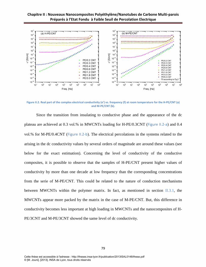
Chapitre II : Nouveaux Nanocomposites Polyéthylène/Nanotubes de Carbone Multi-parois Préparés à l’Etat Fondu à Faible Seuil de Percolation Electrique
79
Figure II.2. Real part of the complex electrical conductivity (σ') vs. frequency (f) at room temperature for the H-PE/CNT (a) and M-PE/CNT (b).
Since the transition from insulating to conductive phase and the appearance of the dc
plateau are achieved at 0.3 vol.% in MWCNTs loading for H-PE/0.3CNT (Figure II.2-a) and 0.4
vol.% for M-PE/0.4CNT (Figure II.2-b). The electrical percolations in the systems related to the
arising in the dc conductivity values by several orders of magnitude are around these values (see
below for the exact estimation). Concerning the level of conductivity of the conductive
composites, it is possible to observe that the samples of H-PE/CNT present higher values of
conductivity by more than one decade at low frequency than the corresponding concentrations
from the serie of M-PE/CNT. This could be related to the nature of conduction mechanisms
between MWCNTs within the polymer matrix. In fact, as mentioned in section II.3.1, the
MWCNTs appear more packed by the matrix in the case of M-PE/CNT. But, this difference in
conductivity becomes less important at high loading in MWCNTs and the nanocomposites of H-
PE/3CNT and M-PE/3CNT showed the same level of dc conductivity.
Cette thèse est accessible à l'adresse : http://theses.insa-lyon.fr/publication/2013ISAL0148/these.pdf © [M. Jouni], [2013], INSA de Lyon, tous droits réservés
Chapitre II : Nouveaux Nanocomposites Polyéthylène/Nanotubes de Carbone Multi-parois Préparés à l’Etat Fondu à Faible Seuil de Percolation Electrique
80
For the exact estimation of the electrical percolation (𝑝𝑐), the well known scaling law from the
percolation theory [14] was applied to the experimental values of 𝜎𝑑𝑐:
𝜎𝑑𝑐~ (𝑝 − 𝑝𝑐)𝑡 𝑓𝑜𝑟 𝑝 > 𝑝𝑐 II(3)
Where 𝜎𝑑𝑐 is the dc conductivity of the composite, 𝑝 is the MWCNTs volume content, 𝑝𝑐 is the
critical volume fraction at percolation and 𝑡 a critical exponent related to the dimensions of the
system. A value of 𝑡 ≈ 2 is predicted theoretically for a statistical percolation network in three
dimensions [15].
The values of the dc conductivity are extrapolated from the plot of 𝜎′ versus the frequency in
Figure II.2 (𝜎𝑑𝑐 = 𝜎′(𝜔 → 0)) and plotted versus MWCNTs volume content, then equation II(3)
was fitted to the experimental data for 𝑝 > 𝑝𝑐. The best fittings were obtained for 𝑝𝑐1= 0.30 ±
0.10, 𝑡1= 2.02 ± 0.09 and 𝑝𝑐2= 0.39 ± 0.10 and 𝑡2= 1.99 ± 0.05 for the series of H-PE/CNT and
M-PE/CNT respectively (solid lines in Figure II.3). The values of 𝑝𝑐 are in agreement with the
results displayed in Figure II.2-a, b which showed that the electrical percolation was reached
around 0.3 and 0.4 vol.% in MWCNTs for both series when the dc plateau appears. These values
of 𝑝𝑐 are from the lowest values reported in the literature for PE/MWCNT composites or
thermoplastic polymers especially if we consider that the processing method in this work is
based on melt mixing.
Cette thèse est accessible à l'adresse : http://theses.insa-lyon.fr/publication/2013ISAL0148/these.pdf © [M. Jouni], [2013], INSA de Lyon, tous droits réservés

Chapitre II : Nouveaux Nanocomposites Polyéthylène/Nanotubes de Carbone Multi-parois Préparés à l’Etat Fondu à Faible Seuil de Percolation Electrique
81
Figure II.3. dc conductivity (σdc) vs. MWCNTs content for the composites above pc. The solid lines show the best fits obtained according to equation 3. (a) H-PE/CNT and (b) M-PE/CNT.
T McNally et al [10] obtained a value of 7.5 wt. % for the electrical percolation in medium
density polyethylene filled with multiwalled carbon nanotubes prepared by melt compounding,
also a value of 1.4 vol.% was found in the work of Y.Xi et al in PE/MWCNT composites
prepared using paraffin as solvent [16]. High values were also obtained in thermoplastic matrices
such as polypropylene. I. Dubnikova et al [17] studied the effect of multiwalled carbon
nanotubes dimensions on the electrical and mechanical properties of PP/MWCNT composites
prepared by melt mixing. They used three types of MWCNT having different aspect ratio and
they found different values for the electrical percolation depending on the dimensions of the
MWCNT. But, in all cases, the values were above the electrical percolation obtained in the
present work. Another study with polypropylene as matrix filled with MWCNTs was focused on
the effect of the surface treatment of MWCNT on the electrical conductivity and reported values
between 3 and 6 wt.% in both cases when using pristine or modified MWCNT [18]. In our case,
Cette thèse est accessible à l'adresse : http://theses.insa-lyon.fr/publication/2013ISAL0148/these.pdf © [M. Jouni], [2013], INSA de Lyon, tous droits réservés
Chapitre II : Nouveaux Nanocomposites Polyéthylène/Nanotubes de Carbone Multi-parois Préparés à l’Etat Fondu à Faible Seuil de Percolation Electrique
82
the nanocomposites of PE/MWCNT are prepared by melt mixing, so that the values of 𝑝𝑐 can be
considered as low if one looks at the publications survey on this field [7, 8]. Another interesting
point here is the small difference between 𝑝𝑐1 and 𝑝𝑐2 (0.3 for 0.39 respectively). This
demonstrates that both extruders lead approximately to the same results (if we take into account
the standard error from the fitting procedure) and the shear rate here, does not show a strong
impact on the critical concentration needed for the electrical percolation threshold.
The other parameter obtained by the fitting procedure of equation II(3) is the exponent 𝑡 ,
our values for 𝑡1 = 2.02 and 𝑡2 = 1.99 are very close to the expected theoretical one (𝑡 = 2)
for a statistical percolation in three dimensions [15]. This result reveals that MWCNTs are
statistically dispersed in the PE matrix, and in agreement with the study of the morphology of the
nanocomposites (section II.3.1). Add that, the conduction mechanism is ensured by the formation
of physical paths of MWCNTs which make direct contact between MWCNTs, getting the
universal value of 𝑡 and reflecting a statistical percolation in the system. Nonuniversal values of
the exponent 𝑡 have been found in the literature for many systems [19-21]. High values for
exponent 𝑡 were obtained for polyethylene terephthalate [22] and polyamide [23] matrices. The
higher values of 𝑡 could be due to the fact that the electrical conduction is not allowed due to the
absence of the physical contact between conductive fillers and the conduction is achieved by
tunneling effect. In this case a wide inter-particle distance can lead to a nonuniversal value of 𝑡
as described by Balberg [24, 25]. Moreover, the formation of aggregates and non statistical
distribution in 3D of the particles involve a shift in values of 𝑡.
Cette thèse est accessible à l'adresse : http://theses.insa-lyon.fr/publication/2013ISAL0148/these.pdf © [M. Jouni], [2013], INSA de Lyon, tous droits réservés

Chapitre II : Nouveaux Nanocomposites Polyéthylène/Nanotubes de Carbone Multi-parois Préparés à l’Etat Fondu à Faible Seuil de Percolation Electrique
83
The theoretical 𝑝𝑐 value can also be estimated using the exclusion volume theory. In the
case of fillers with high aspect ratio such as CNT, the aspect ratio is related to the critical volume
fraction at the percolation by the following equation [26]:
𝑝𝑐 = 0.6𝑎
II(4)
Where 𝑎 is the aspect ratio of the filler, in present work the MWCNT used in this study has the
following dimensions: average length l=1.5 µm and average diameter d= 9.5nm. The associated
aspect ratio (a=l/d) is around 158, and a theoretical value of ≈ 0.38 is obtained for 𝑝𝑐 which is
also in agreement with the values found by equation II.(3) and by the electrical measurements
displayed in Figure II.2.
According to equation II.(2), the parameter s can be determined by fitting the equation
with the experimental data of the curves of 𝜎′(𝑓) displayed in Figure II.2-a, b (see solid line in
Figure II.2-b as an example). Above the concentration of 0.6 vol.%, the frequency dependence ac
conductivity region where the power law is observed is too limited to determine the s values.
Also, the fit was not successful for the H-PE/0.3CNT sample because it is on the margins of the
percolation threshold. The results of fitting are reported in Table II.1. The s values are very close
for the corresponding concentrations with 0.85≤s≤0.95 which is characteristic for hopping in
disordered materials [27]. More indication for the similarity of results obtained from the two
types of extruders also takes place here.
Sample H-PE/0.4 CNT H-PE/0.6 CNT M-PE/0.4 CNT M-PE/0.6 CNT
s 0.86 ± 0.001 0.95 ±0.003 0.85 ± 0.002 0.90 ± 0.002
Cette thèse est accessible à l'adresse : http://theses.insa-lyon.fr/publication/2013ISAL0148/these.pdf © [M. Jouni], [2013], INSA de Lyon, tous droits réservés

Chapitre II : Nouveaux Nanocomposites Polyéthylène/Nanotubes de Carbone Multi-parois Préparés à l’Etat Fondu à Faible Seuil de Percolation Electrique
84
Table II.1. Values of the exponent s for the samples indicated in the table. (obtained from the fit of equation 2 to the experimental data).
The relative low value of 𝑝𝑐 obtained in this study is worth being investigated, since
higher values for 𝑝𝑐 for PE/MWCNT composites prepared with such methods [10] have been
found in literature as mentioned above. In this study, there can be two possible explainations.
First, as described above (sections II.2.1 and II.3.1), an initial masterbatch of PE/MWCNT
produced with optimized conditions (high shear processing…), was used to prepare our samples
by dilution in the melt state. This procedure can lead to improve the dispersion of MWCNTs in
the PE matrix involving a low electrical percolation (see Annex II.1). The SEM images (Figure
II.1) show that MWCNTs are homogenously and well dispersed. This result is in agreement with
those of Y.Li et al [28] in a study showing the effect of high shear processing on the dispersion
of MWCNTs in a thermoplastic elastomer. In another similar study, G-X Chen [29] showed a
lower electrical percolation for MWCNTs dispersed in a PVDF matrix prepared by Ultra-high
shear processing than for the same composites prepared by low-shear processing.
The second reason is the effect of the crystalline-matrix on the conductivity of thermoplastic or
semi-crystalline polymer composites. Many reviews in the literature detailed the results of the
electrical conductivity in polymer composites filled with CNT prepared by different procedures,
and showed that the nature of the matrix and its crystallinity play a significant role on the final
properties of the composites [7, 8, 30]. In general, amorphous systems such as epoxy systems
lead to a lower electrical percolation and higher conductivity than semi-crystalline composites.
The conditions of crystallization can influence the electrical properties of the composites. The
later can play a role in this study since the polyethylene has a high crystalline content (see
Tableau II.2). It can indicate that the creation of big crystallites can eject the MWCNTs at the
Cette thèse est accessible à l'adresse : http://theses.insa-lyon.fr/publication/2013ISAL0148/these.pdf © [M. Jouni], [2013], INSA de Lyon, tous droits réservés

Chapitre II : Nouveaux Nanocomposites Polyéthylène/Nanotubes de Carbone Multi-parois Préparés à l’Etat Fondu à Faible Seuil de Percolation Electrique
85
periphery of the growing crystallites, where their local concentration becomes higher and this
facilitates the formation of the network and decreases the value of 𝑝𝑐 .
II.3.3 Thermal properties
In the current and next section, only the M-PE/CNT nanocomposites were characterized
since we are interesting in general by the effect of MWCNT on the mechanical and thermal
behaviors of PE/MWCNT nanocomposites.
The effects of the addition of MWCNTs on the melting and crystallization behaviors of
PE/MWCNT nanocomposites were investigated by differential scanning calorimetry. Figure II.4-
a presents the second run of melting peak temperatures for PE and three selected
nanocomposites. The thermograms of PE/MWCNT nanocomposites have the same shape and,
the addition of MWCNTs has no effect on the melting temperatures of the nanocomposites.
However, the effect of MWCNTs is more significant on the values of crystallization
temperatures as one can observe in Figure II.4-b, the peaks of crystallization temperatures shift to
higher temperatures suggesting that MWCNTs have a nucleating effect for the PE crystallization.
Such observations were done in the literature [17] for the thermoplastic matrix. The DSC results
for all composites prepared in this paper are summarized in Tableau II.2. The crystallinity (Xc) in
the matrix can be calculated using the following equation [11]:
𝑋𝑐 = ∆𝐻𝑓(1−𝜑)𝛥𝐻0
× 100 II(5)
Cette thèse est accessible à l'adresse : http://theses.insa-lyon.fr/publication/2013ISAL0148/these.pdf © [M. Jouni], [2013], INSA de Lyon, tous droits réservés

Chapitre II : Nouveaux Nanocomposites Polyéthylène/Nanotubes de Carbone Multi-parois Préparés à l’Etat Fondu à Faible Seuil de Percolation Electrique
86
Where ∆Hf is the enthalpy of fusion (J/g), ∆H0 is the enthalpy of fusion for theoretically 100 %
crystalline PE, and 𝜑 is the weight fraction of MWCNTs in the nanocomposite. The ∆H0 of PE
used in this study is 293 J/g [31].
Figure II.4. Melting (a) and crystallization (b) thermograms for the composites of M-PE/CNT. Compositions of which are indicated on the plot.
From Tableau II.2, one can see that the crystalline content increased for the composites lightly
loaded in MWCNTs, then decreased for the composites for intermediate contents and, rised
again for high loading in MWCNTs (3 and 5 vol.%). These observations are consistent with the
results reported in the literature [10, 17] and could be explained by the difference in the structure
and size of nucleating sites induced by the addition of MWCNTs and maybe affected by their
concentration.
Cette thèse est accessible à l'adresse : http://theses.insa-lyon.fr/publication/2013ISAL0148/these.pdf © [M. Jouni], [2013], INSA de Lyon, tous droits réservés

Chapitre II : Nouveaux Nanocomposites Polyéthylène/Nanotubes de Carbone Multi-parois Préparés à l’Etat Fondu à Faible Seuil de Percolation Electrique
87
II.3.4 Dynamic mechanical properties
The dynamic mechanical properties of PE/MWCNT nanocomposites were studied by
dynamic mechanical analysis (DMA) in a broad temperature range between -145 and 80 ºC at
fixed frequency of 1 Hz. The storage modulus E' and loss factor tan δ are presented versus the
temperature in Figure II.5-a and Figure II.5-b respectively. The storage modulus for all
PE/MWCNT nanocomposites was higher than that of PE alone, suggesting that MWCNTs have
a reinforcing effect. This enhancement can be explained by the strong interactions between
MWCNT and the PE matrix due to the high surface area of MWCNT. Moreover, the curves
present two relaxation zones, the first one occurs around -112 ºC which is related to the glass-
rubbery transition, and defines the glass transition temperature (known as the temperature at
which the tan δ peak occurs), this relaxation is described as the α relaxation [32] and the second
Sample Tm( 0C) ∆Hm(J/g ) Tc( 0C) Xc(%)
PE 135 207 118.3 70.1
M-PE/0.2 CNT 135.5 216 119.9 74.0
M-PE/0.3 CNT 135.1 216 120.2 74.1
M-PE/0.4 CNT 135 216 120.3 74.2
M-PE/0.6 CNT 135.4 199 120.9 68.7
M-PE/1.2 CNT 135.3 200 120.8 69.7
M-PE/1.8 CNT 135.2 197 120.7 69.5
M-PE/3.0 CNT 134.7 197 121.1 71.0
M-PE/5.0 CNT 134.0 195 121.5 72.8
Table II.2. Melting temperatures (Tm), crystallization temperature (Tc), heat of fusion (∆Hm) and crystalline contents (Xc) for PE and M-PE/CNT nanocomposites.
Cette thèse est accessible à l'adresse : http://theses.insa-lyon.fr/publication/2013ISAL0148/these.pdf © [M. Jouni], [2013], INSA de Lyon, tous droits réservés
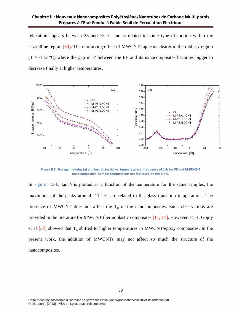
Chapitre II : Nouveaux Nanocomposites Polyéthylène/Nanotubes de Carbone Multi-parois Préparés à l’Etat Fondu à Faible Seuil de Percolation Electrique
88
relaxation appears between 25 and 75 ºC and is related to some type of motion within the
crystalline region [33]. The reinforcing effect of MWCNTs appears clearer in the rubbery region
(T > -112 ºC) where the gap in E' between the PE and its nanocomposites becomes bigger to
decrease finally at higher temperatures.
Figure II.5. Storage modulus (a) and loss factor (b) vs. temperature at frequency of 1Hz for PE and M-PE/CNT nanocomposites. Sample compositions are indicated on the plots.
In Figure II.5-b, tan δ is plotted as a function of the temperature for the same samples, the
maximums of the peaks around -112 ºC are related to the glass transition temperatures. The
presence of MWCNT does not affect the Tg of the nanocomposites. Such observations are
provided in the literature for MWCNT thermoplastic composites [11, 17]. However, F. H. Gojny
et al [34] showed that Tg shifted to higher temperatures in MWCNT/epoxy composites. In the
present work, the addition of MWCNTs may not affect so much the structure of the
nanocomposites.
Cette thèse est accessible à l'adresse : http://theses.insa-lyon.fr/publication/2013ISAL0148/these.pdf © [M. Jouni], [2013], INSA de Lyon, tous droits réservés

Chapitre II : Nouveaux Nanocomposites Polyéthylène/Nanotubes de Carbone Multi-parois Préparés à l’Etat Fondu à Faible Seuil de Percolation Electrique
89
II.4 Conclusion
In this paper, two series of polyethylene/multiwalled carbon nanotube nanocomposites
have been produced by diluting a masterbatch of PE/MWCNT using two different mini-
extruders. The investigation of the electrical properties in the prepared samples was carried out
by dielectric relaxation spectroscopy (DRS). As a result, both systems showed a convergence in
electrical properties. A low electrical percolation was found to be around 0.3~0.4 vol.%
indicating that, the shear rate has not a strong impact on the electrical properties in the present
systems. Morphological characterizations show a good dispersion of the MWCNT fillers in the
PE matrix in both cases. The incorporation of MWCNTs was accompanied by an improvement
on the dynamic mechanic properties as demonstrated by DMA analysis. Also the crystallization
behavior has been affected and the crystallization temperatures shift to higher values after the
addition of MWCNTs.
Cette thèse est accessible à l'adresse : http://theses.insa-lyon.fr/publication/2013ISAL0148/these.pdf © [M. Jouni], [2013], INSA de Lyon, tous droits réservés
Chapitre II : Nouveaux Nanocomposites Polyéthylène/Nanotubes de Carbone Multi-parois Préparés à l’Etat Fondu à Faible Seuil de Percolation Electrique
90
II.5 References [1] Moniruzzaman M, Winey KI. Polymer Nanocomposites Containing Carbon Nanotubes. Macromolecules. 2006;39(16):5194-5205.
[2] Al-Saleh MH, Sundararaj U. A review of vapor grown carbon nanofiber/polymer conductive composites. Carbon. 2009;47(1):2-22.
[3] Du J-H, Bai J, Cheng H-M. The present status and key problems of carbon nanotube based polymer composites. Express Polymer letters. 2007;1(5):253-273.
[4] Prasher RS, Chang J-Y, Saucius I, Narasimhan S, Chau D, Chrysler G, Myers A, Prstic S, Hu C. Nano and Micro Technology-Based Next Generation Package-Level Cooling Solutions. Intel Technology Journal. 2005;9(4):285-296.
[5] Li C, Thostenson ET, Chou T-W. Sensors and actuators based on carbon nanotubes and their composites: A review. Composites Science and Technology. 2008;68(6):1227-1249.
[6] Xu H, Anlage SM, Hu L, Gruner G. Microwave shielding of transparent and conducting single-walled carbon nanotube films. Applied Physics Letters. 2007;90(18):183119-183113.
[7] Bauhofer W, Kovacs JZ. A review and analysis of electrical percolation in carbon nanotube polymer composites. Composites Science and Technology. 2009;69(10):1486-1498.
[8] Spitalsky Z, Tasis D, Papagelis K, Galiotis C. Carbon nanotube-polymer composites: Chemistry, processing, mechanical and electrical properties. Progress in Polymer Science. 2010;35(3):357-401.
[9] Kremer F, Schöenhals A. Broadband dielectric spectroscopy. Berlin: Springer; 2003.
[10] McNally T, Pötschke P, Halley P, Murphy M, Martin D, Bell SEJ, Brennan GP, Bein D, Lemoine P, Quinn JP. Polyethylene multiwalled carbon nanotube composites. Polymer. 2005;46(19):8222-8232.
[11] Logakis E, Pandis C, Peoglos V, Pissis P, Stergiou C, Pionteck J, Pötschke P, Mičušík M, Omastová M. Structure–property relationships in polyamide 6/multi-walled carbon nanotubes nanocomposites. Journal of Polymer Science Part B: Polymer Physics. 2009;47(8):764-774.
[12] Dyre JC, Schroder TB. Universality of ac conduction in disordered solids. Reviews of Modern Physics. 2000;72(3):873-892.
[13] Jonscher AK. Universal Dielectric Response. Nature. 1977;267(5613):673-679.
[14] Stauffer D, Aharony A. Introduction to Percolation Theory. London: Taylor & Francis; 1994.
[15] Gingold DB, Lobb CJ. Percolative conduction in three dimensions. Physical Review B. 1990;42(13):8220-8224.
[16] Xi Y, Yamanaka A, Bin Y, Matsuo M. Electrical properties of segregated ultrahigh molecular weight polyethylene/multiwalled carbon nanotube composites. Journal of Applied Polymer Science. 2007;105(5):2868-2876.
Cette thèse est accessible à l'adresse : http://theses.insa-lyon.fr/publication/2013ISAL0148/these.pdf © [M. Jouni], [2013], INSA de Lyon, tous droits réservés
Chapitre II : Nouveaux Nanocomposites Polyéthylène/Nanotubes de Carbone Multi-parois Préparés à l’Etat Fondu à Faible Seuil de Percolation Electrique
91
[17] Dubnikova I, Kuvardina E, Krasheninnikov V, Lomakin S, Tchmutin I, Kuznetsov S. The Effect of Multiwalled Carbon Nanotube Dimensions on the Morphology, Mechanical, and Electrical Properties of Melt Mixed Polypropylene-Based Composites. Journal of Applied Polymer Science. 2010;117(1):259-272.
[18] Micusik M, Omastova M, Pionteck J, Pandis C, Logakis E, Pissis P. Influence of surface treatment of multiwall carbon nanotubes on the properties of polypropylene/carbon nanotubes nanocomposites. Polym Adv Technol. 2011;22(1):38-47.
[19] Antonucci V, Faiella G, Giordano M, Nicolais L, Pepe G. Electrical properties of single walled carbon nanotube reinforced polystyrene composites. Macromolecular Symposia. 2007;247:172-181.
[20] Pötschke P, Abdel-Goad M, Alig I, Dudkin S, Lellinger D. Rheological and dielectrical characterization of melt mixed polycarbonate-multiwalled carbon nanotube composites. Polymer. 2004;45(26):8863-8870.
[21] Sandler JKW, Kirk JE, Kinloch IA, Shaffer MSP, Windle AH. Ultra-low electrical percolation threshold in carbon-nanotube-epoxy composites. Polymer. 2003;44(19):5893-5899.
[22] Logakis E, Pissis P, Pospiech D, Korwitz A, Krause B, Reuter U, Pötschke P. Low electrical percolation threshold in poly(ethylene terephthalate)/multi-walled carbon nanotube nanocomposites. European Polymer Journal. 2010;46(5):928-936.
[23] Logakis E, Pandis C, Peoglos V, Pissis P, Pionteck J, Pötschke P, Micusik M, Omastova M. Electrical/dielectric properties and conduction mechanism in melt processed polyamide/multi-walled carbon nanotubes composites. Polymer. 2009;50(21):5103-5111.
[24] Balberg I. Tunneling and nonuniversal conductivity in composite materials. Physical Review Letters. 1987;59(12):1305-1308.
[25] Balberg I. A comprehensive picture of the electrical phenomena in carbon black/polymer composites. Carbon. 2002;40(2):139-143.
[26] Foygel M, Morris RD, Anez D, French S, Sobolev VL. Theoretical and computational studies of carbon nanotube composites and suspensions: Electrical and thermal conductivity. Physical Review B. 2005;71(10).
[27] Kilbride BE, Coleman JN, Fraysse J, Fournet P, Cadek M, Drury A, Hutzler S, Roth S, Blau WJ. Experimental observation of scaling laws for alternating current and direct current conductivity in polymer-carbon nanotube composite thin films. Journal of Applied Physics. 2002;92(7):4024-4030.
[28] Li YJ, Shimizu H. High-shear processing induced homogenous dispersion of pristine multiwalled carbon nanotubes in a thermoplastic elastomer. Polymer. 2007;48(8):2203-2207.
[29] Chen GX, Li YJ, Shimizu H. Ultrahigh-shear processing for the preparation of polymer/carbon nanotube composites. Carbon. 2007;45(12):2334-2340.
Cette thèse est accessible à l'adresse : http://theses.insa-lyon.fr/publication/2013ISAL0148/these.pdf © [M. Jouni], [2013], INSA de Lyon, tous droits réservés

Chapitre II : Nouveaux Nanocomposites Polyéthylène/Nanotubes de Carbone Multi-parois Préparés à l’Etat Fondu à Faible Seuil de Percolation Electrique
92
[30] Logakis E, Pandis C, Pissis P, Pionteck J, Pötschke P. Highly conducting poly(methyl methacrylate)/carbon nanotubes composites: Investigation on their thermal, dynamic-mechanical, electrical and dielectric properties. Composites Science and Technology. 2011;71(6):854-862.
[31] Wunderlich B. Macromolecular Physics 3. New York: Academic Press; 1980.
[32] Gedde W. Polymer Physics. London: Chapman & Hall; 1995.
[33] Khonakdar HA, Wagenknecht U, Jafari SH, Hassler R, Eslami H. Dynamic mechanical properties and morphology of polyethylene/ethylene vinyl acetate copolymer blends. Advances in Polymer Technology. 2004;23(4):307-315.
[34] Gojny FH, Schulte K. Functionalisation effect on the thermo-mechanical behaviour of multi-wall carbon nanotube/epoxy-composites. Composites Science and Technology. 2004;64(15):2303-2308.
Cette thèse est accessible à l'adresse : http://theses.insa-lyon.fr/publication/2013ISAL0148/these.pdf © [M. Jouni], [2013], INSA de Lyon, tous droits réservés

93
Annexe II.A.1
Study of the dispersion state of MWCNT in PE/MWCNT masterbatch
As discussed above, one of the reasons involving the low electrical percolation was related to the
initial dispersion of MWCNTs within the PE matrix when using Masterbatch. Therefore, it was
evident to examine the dispersion level of MWCNTs in the initial masterbatch. Figure VI.A.1
presents the SEM images of the extruded masterbatch of PE/MWCNT used to prepare the
composites in chapter II. It is possible to observe that this masterbatch has a good level of
dispersion of MWCNTs.
Figure II.A.1. SEM images at two magnification levels for the masterbatch of PE/MWCNT (PLACTICYL HDPE 1501). The images show a good dispersion of MWCNT within the PE matrix
Cette thèse est accessible à l'adresse : http://theses.insa-lyon.fr/publication/2013ISAL0148/these.pdf © [M. Jouni], [2013], INSA de Lyon, tous droits réservés

94
Cette thèse est accessible à l'adresse : http://theses.insa-lyon.fr/publication/2013ISAL0148/these.pdf © [M. Jouni], [2013], INSA de Lyon, tous droits réservés

Chapitre III : Propriétés Electriques et Thermiques des Composites Polyéthylène/Nanoparticules d’argent
95
Chapitre III : Article 2
Propriétés Electriques et Thermiques des Composites Polyéthylène/Nanoparticules d’argent
Cette thèse est accessible à l'adresse : http://theses.insa-lyon.fr/publication/2013ISAL0148/these.pdf © [M. Jouni], [2013], INSA de Lyon, tous droits réservés

Chapitre III : Propriétés Electriques et Thermiques des Composites Polyéthylène/Nanoparticules d’argent
96
Introduction-Résumé
Les NCPCs qui présentent des propriétés de conduction électrique et thermique peuvent trouver
des applications sophistiquées où la combinaison des leurs propriétés physiques (mécaniques,
électriques, blindage électromagnétique…) est un atout majeur.
En partant d’une matrice polymère isolante telle que le polyéthylène, la réalisation de ce type de
composite nécessite l’usage de charges possèdant de bonnes conductivités électrique et
thermique afin d’assurer un gain maximal de ces propriétés. Pour ce type d’applications, l’argent
qui associe conductivité électrique élevée et excellente conduction thermique:s’est révélè être un
bon candidat.
D’autre part, dans le cas des composites polymères, on doit combiner des charges ou des
particules avec la matrice polymère. Les particules nanométriques offrent un intérêt particulier
en raison de leurs caractéristiques spécifiques, dont leur taille nanométrique et leur grande
surface spécifique, qui leur permettent d’être très efficaces au niveau du transfert de leurs
propriétés physiques vers la matrice polymère du fait de la grande surface d’échange à
l’interface. Donc, au vu des raisons citées ci-dessus, notre choix s’est porté sur des
nanoparticules d’argent (Ag-NPs) pour la préparation de composites électriquement et
thermiquement conducteurs.
Dans ce chapitre, on présente l’élaboration par extrusion à l’état fondu de composites
polyéthylène haute densité chargés avec des nanoparticules d’argent (PEHD/Ag-NPs) dans le but
d’avoir des matériaux électriquement et thermiquement conducteurs. Plusieurs fractions
Cette thèse est accessible à l'adresse : http://theses.insa-lyon.fr/publication/2013ISAL0148/these.pdf © [M. Jouni], [2013], INSA de Lyon, tous droits réservés

Chapitre III : Propriétés Electriques et Thermiques des Composites Polyéthylène/Nanoparticules d’argent
97
volumiques d’Ag-NPs ont été introduites dans la matrice polymère. On résume les résultats
obtenus par les points suivants :
1) L’influence de la dispersion d’Ag-NPs dans une matrice PE sur les propriétés
thermiques a été étudiée par calorimétrie différentielle à balayage (DSC). L’addition d’Ag-NPs
n’a pas entraîné de changement au niveau des températures de fusion des composites. Par contre,
cette addition a légèrement affecté les températures de cristallisation. Ceci peut s’expliquer par
un léger effet nucléant des Ag-NPs au cours de la cristallisation.
2) L’étude des propriétés électriques a montré la présence de bonnes conductivités
électriques avec un seuil de percolation relativement bas (pc~ 10 vol.%) par rapport aux valeurs
trouvées dans le cas de particules sphériques. Cette valeur peut s’expliquer par la formation d’un
réseau percolant des Ag-NPs favorisée par leurs agglomérations et leur forme géométrique non
parfaitement sphérique si on se réfère à l’étude de leur morphologie et de leur microstructure.
3) La conductivité thermique a montré que l’addition d’Ag-NPs a significativement
contribué à l’amélioration de la conductivité thermique (λ) qui peut atteindre 2 W.K-1.m-1.
Ensuite, on a modélisé la conductivité thermique à l’aide de différents modèles basiques comme
les modèles série et parallèle qui décrivent la conduction thermique dans le composite en se
basant sur la conductivité thermique de chacun des constituants. Ce type de modèle a montré ses
limites pour évaluer l’évolution de la conductivité thermique en fonction de la fraction
volumique des Ag-NPs. D’autres modèles prenant en compte la forme des particules et le taux de
charges ont permis une meilleure description de nos composites.
Cette thèse est accessible à l'adresse : http://theses.insa-lyon.fr/publication/2013ISAL0148/these.pdf © [M. Jouni], [2013], INSA de Lyon, tous droits réservés
Chapitre III : Propriétés Electriques et Thermiques des Composites Polyéthylène/Nanoparticules d’argent
98
Par contre, en ce qui concerne la capacité thermique, une loi de mélange décrivant la variation
linéaire de la capacité thermique du composite en fonction de la fraction massique d’Ag-NPs,
s’est révélée pertinente.
Cette thèse est accessible à l'adresse : http://theses.insa-lyon.fr/publication/2013ISAL0148/these.pdf © [M. Jouni], [2013], INSA de Lyon, tous droits réservés

Chapitre III : Propriétés Electriques et Thermiques des Composites Polyéthylène/Nanoparticules d’argent
99
III. Article 2 (Journal of Polymer Composites) Electrical and Thermal Properties of Polyethylene/Silver Nanoparticle Composites
Cette partie constitue une publication du Journal of Polymer Composites dont la référence :
Jouni M, Boudenne A, Boiteux G, Massardier V, Garnier B, Serghei A. Electrical and thermal
properties of polyethylene/silver nanoparticle composites. Polymer Composites. 2013 ;
34(5) :778-786
III.1 Abstract
The concentration dependence of specific heat, electrical and thermal conductivities of
nanocomposites based on high density polyethylene (HDPE) filled with silver nanoparticles have
been investigated. The composites filled with high filler content show high electrical and thermal
conductivities. The dielectric relaxation spectroscopy (DRS) was used to investigate the
electrical properties in the studied systems. The scaling law of electrical percolation was used for
an exact estimation of the percolation threshold (𝑝𝑐). A low electrical percolation threshold was
found in the investigated composites. The rule of mixture was sufficient for the prediction of the
specific heat dependence of HDPE-Ag nanocomposites as a function of the weight filler content.
The basic models of the thermal conductivity have a tendency to underestimate the measured
values for the low and high filler concentrations.
Cette thèse est accessible à l'adresse : http://theses.insa-lyon.fr/publication/2013ISAL0148/these.pdf © [M. Jouni], [2013], INSA de Lyon, tous droits réservés

Chapitre III : Propriétés Electriques et Thermiques des Composites Polyéthylène/Nanoparticules d’argent
100
III.2 Introduction
In the last 20 years, important researches have been performed for the development of
nanocomposite systems allowingthe generation of new materials which can be used in many
application domains (i.e. aerospace, electronics, automotive, health care, construction, building
and consumer products with great economic and ecological benefits).
These new materials combine the effects of two or more elements, where the final properties will
depend extremely on the type, concentration, size, shape of the filler, and in the other hand on
the processing conditions and microstructure of the composite [1-5].
A wide range of fillers such as organic, inorganic, metallic or non-metallic particles can be used
for the enhancement of the physical properties of the composite. Depending on the final required
properties, nanoparticles are chosen for their chemical composition, specific size at nanoscale
level, and their high specific surface area. The later makes them very good candidates for
specific applications which cannot be realized by using microsized particles [6].
Polymers are widely used as matrices because they are easy to process, have a light density
and exhibit very interesting physical and mechanical properties. However, their insulating
features will prevent any applications when higher electrical or/and thermal conductivity are
required. To overcome this drawback, a lot of investigations were performed by incorporating
metallic particles in the polymers [7-10]. Indeed, the electrical conductivity of metallic particles
is higher by many orders of magnitude than those of other fillers. However, the enhancement in
thermal conductivity is still less pronounced, and more related to different mechanisms of
conductivity in the composites [4, 11-14].
Cette thèse est accessible à l'adresse : http://theses.insa-lyon.fr/publication/2013ISAL0148/these.pdf © [M. Jouni], [2013], INSA de Lyon, tous droits réservés

Chapitre III : Propriétés Electriques et Thermiques des Composites Polyéthylène/Nanoparticules d’argent
101
Silver nanoparticles have already been used to improve the physical properties of the
polymer composites to meet special requirements in electronic sector such as Positive
Temperature Coefficient (PTC) materials for current limiting devices [15, 16] and liquid crystal
(LC) polymers [17]. Another application of silver nanoparticles is the incorporation into
household goods, e.g. in refrigerators to prevent growth of hazardous microorganisms on the
refrigerator walls [12, 18-20]. Also silver filled polymer composites were used as conductive
adhesives [21]. Very often, the big challenge in preparing conductive polymer composites is to
achieve the highest electrical and/or thermal conductivity with the lowest possible filler fraction
to avoid a dramatic change on the mechanical properties, and save the economic gain. However,
it is difficult to change one property without affecting the others. Therefore, very often a
compromise between the requirements has to be found.
The present work, presents the behavior of electrical and thermal conductivities of
polyethylene/silver nanoparticles nanocomposites. The nanofillers were incorporated in the
polymer matrix by melt compounding to get composites with thermal and electrical behaviors
properties. The idea is to obtain a new generation of nanocomposites with good performance, but
also with the minimum contribution of fillers needed to achieve this goal (i.e. to reduce the high
density and the price). The electrical properties of the composites were investigated by dielectric
relaxation spectroscopy. The results showed the presence of low electrical percolation threshold
in the system (10 vol. %). The thermal conductivity in the composites was carefully analyzed
and compared to basics model. An agreement was found to some of them. The morphology and
thermal properties were also studied as will be discussed below.
Cette thèse est accessible à l'adresse : http://theses.insa-lyon.fr/publication/2013ISAL0148/these.pdf © [M. Jouni], [2013], INSA de Lyon, tous droits réservés

Chapitre III : Propriétés Electriques et Thermiques des Composites Polyéthylène/Nanoparticules d’argent
102
III.3 Experimental
III.3.1 Materials and composites preparation
High - density polyethylene (HDPE) was purchased from Borealis, (Ref: PEMG9641b). The
polymer has a narrow molecular weight distribution, a density of 0.964, a melt flow index (MFI)
of 8g/10min and a melting point of 135 °C. The crystalline content (Xc) of the polymer is 70 %,
given by DSC measurements.
The silver nanoparticles were used as conducting fillers for the preparation of conductive
polymer composites. Silver Nanoparticles with an average diameter APS=100nm were supplied
by American Elements (Ref: AG-M-03M-NP.100N). Figure III.1 presents a SEM image of silver
nanoparticles as received. The silver nanoparticles have tendency to aggregate due to their high
specific surface area.
Polyethylene silver nanoparticles composites were prepared by melt mixing using a co-
rotating twin-screw mini-extruder (Micro 15 Twin-Screw DSM Research) at 170 0C for 15 min
at a mixing speed of 100 rpm. These processing conditions were optimized after many tests to
find the best conditions for a better dispersion of the fillers.First, the polymer was introduced
inside the extruder to get its molten state, and then silver nanoparticles were gradually added to
the molten polyethylene to obtain a good dispersion of the filler in matrix. The extruded strands
were pressed using a SERVITEC Polystat 200T press at 180 0C for 5 min and under a pressure of
50 kN. Following the above procedure, square samples of 0.5mm and 0.8mm thicknesses were
obtained for electrical and thermal characterizations respectively. The samples were coated by
two thin aluminum films on the surfaces to ensure a good electrical contact with the electrodes
Cette thèse est accessible à l'adresse : http://theses.insa-lyon.fr/publication/2013ISAL0148/these.pdf © [M. Jouni], [2013], INSA de Lyon, tous droits réservés

Chapitre III : Propriétés Electriques et Thermiques des Composites Polyéthylène/Nanoparticules d’argent
103
during the electrical measurements. The final concentration of PE/Ag composites varied from 0
to 22 vol. %. The samples are coded with the abbreviation PE-xAg where x means the volume
percentage (vol.%) of fillers in the matrix.
Figure III.1. SEM image of the as received silver nanoparticles powder.
III.3.2 Morphological characterizations
Scanning electron microscopy (SEM, Hitachi S-800) was used to study the morphology of
PE/Ag composites. The fractured surface of specimens was sputter-coated with a thin gold layer
to avoid charging during scanning electron microscopy imaging. The accelerating voltage was 10
kV. Concerning the fillers, the observation was done directly on small quantity of powder.
III.3.3 Differential scanning calorimetry
The melting and crystallization of the HDPE matrix, as well as the effect of the
incorporation of silver nanoparticles on the thermal properties of the final composites were
investigated with a Q10 (TA instruments, USA)-differential scanning calorimeter under a
Cette thèse est accessible à l'adresse : http://theses.insa-lyon.fr/publication/2013ISAL0148/these.pdf © [M. Jouni], [2013], INSA de Lyon, tous droits réservés
Chapitre III : Propriétés Electriques et Thermiques des Composites Polyéthylène/Nanoparticules d’argent
104
nitrogen atmosphere. From the pressed samples, specimens for DSC measurements were cut.
The weight of the samples varied from 5 to 10 mg. The samples were maintained at 25 ºC for 3
min before being heated up to 170 ºC, with a rate of 10 ºC/min, held for 3 min at this
temperature, then cooled at 10 ºC/min to 25 ºC, held for 3min then reheated at 10 ºC/min to 170
ºC. These second cooling step and third heating step were adopted to ensure complete melting of
crystalline content and to remove the thermal history during the first run. The thermograms were
used to obtain the melting temperature (Tm), and crystallization temperature (Tc), the heats of
fusion (∆Hf) and the enthalpy of crystallization (∆Hc) of each composite.
III.3.4 Density measurements
The density measurements (ρ) were carried out with square-plate samples which were used
for thermal measurements. An A340 Mettler precision balance was used to measure the mass and
a calliper rule for the sample sizes. The dependence of the specific density of the composites on
the volume filler content is important for checking the quality of the samples. It is clear that
composite samples are well processed, i.e. a good homogeneity is reached without air bubbles in
the sample or unfilled pores at the polymer/filler interface.
III.3.5 Electrical conductivity
The dielectric relaxation spectroscopy (DRS) was used to study the electrical-dielectric
properties of PE/Ag composites. The measurements were done at room temperature in the
frequency range 10-1 – 107 Hz by using a Novocontrol alpha analyzer. The applied ac voltage
was 0.2V and the electrode has a 3cm diameter. In this technique, the sample is located between
Cette thèse est accessible à l'adresse : http://theses.insa-lyon.fr/publication/2013ISAL0148/these.pdf © [M. Jouni], [2013], INSA de Lyon, tous droits réservés

Chapitre III : Propriétés Electriques et Thermiques des Composites Polyéthylène/Nanoparticules d’argent
105
the two plates of a capacitor. The complex permittivity (𝜀∗ = 𝜀′ − 𝑖𝜀′′) is registered while
applying an alternative voltage.
The frequency-dependence of ac conductivity (real part,𝜎′) is given by the following equation
[22] :
𝜎′(𝜔) = 𝜀0𝜔𝜀′′(𝜔) III(1)
Where 𝜔 is the angular frequency (𝜔 =2πf), 𝜀′′(𝜔) is the imaginary part of the complex
permittivity and 𝜀0= 8.85×10⁻¹² F.m-1 is the permittivity of the free space.
In this paper, the spectra of the real part of the complex conductivity (𝜎′) and of the imaginary
part of the complex permittivity (𝜀′′ ) are presented.
III.3.6 Thermal conductivity
Thermal conductivity (λ) was measured using an experimental device which was designed
for the measurement of low and average thermal conductivity from 0.1 to 5 Wm-1K-1on small
samples with 15x15 mm2 section and thickness from 0.1 to 10mm. The experimental procedure
represents an extension of the normalized hot guarded plate (HGP) method [23] . A heat source
and a heat sink (an electrical heater and two heat exchangers with thermostated baths) are located
respectively on the bottom and top surfaces of the sample. This setup generates a temperature
gradient in the thickness direction of the sample. The main characteristic of the experiment
concerns the use of an active guard that allows the thermal flux, dissipated by the heat source, to
flow entirely through the sample. In fact, a temperature controller cancels the heat flux from the
electric heater to the heat source-heat exchanger by adjusting the electric heating in order to
Cette thèse est accessible à l'adresse : http://theses.insa-lyon.fr/publication/2013ISAL0148/these.pdf © [M. Jouni], [2013], INSA de Lyon, tous droits réservés

Chapitre III : Propriétés Electriques et Thermiques des Composites Polyéthylène/Nanoparticules d’argent
106
obtain its temperature as close as possible to the one of the heat source heat exchanger (see
Figure III.2).
Figure III.2. Experimental setup for thermal conductivity.
The parallelism between upper and lower plates of the experimental setup was achieved using
guides for vertical displacement, that were controlled by a pneumatic jack in order to ensure an
adjustable pressure P on both sides of the sample (typically 4 bar). Thermal resistances between
sample and heat source and, between sample and heat sink, were minimized by spreading
thermal grease on the top and bottom sides of the sample, the effect of thermal grease on thermal
conductivity measurement being previously studied [23].
III.3.7 Specific heat
The density is found using the sample dimensions and weight (see section III.4.3). The
specific heat (cp) measurements are performed using a microcalorimeter Perkin Elmer DSC Pyris
with a -70°C cryostat. Before heat capacity measurement, the DSC device is calibrated with a 32
mg sapphire reference sample. The operating conditions were: initial isotherm at 5 °C and final
isotherm at 65 °C with a heating rate of 10 °C/min. The sample weights were between 8 and 20
mg.
Cette thèse est accessible à l'adresse : http://theses.insa-lyon.fr/publication/2013ISAL0148/these.pdf © [M. Jouni], [2013], INSA de Lyon, tous droits réservés

Chapitre III : Propriétés Electriques et Thermiques des Composites Polyéthylène/Nanoparticules d’argent
107
III.4 Results and discussion
III.4.1 Morphology of the composites
The morphology and microstructure of the silver filler and composites were studied by
scanning electron microscopy. Figure III.1 shows the SEM image of silver nanoparticles as
received, the silver nanoparticles are strongly attached due to their high surface area. Fig. 3shows
the SEM micrographs of fractured surface of PE-10Ag sample which is a sample with a
concentration just above the electrical percolation threshold (determined in section III.2.4.4).
Figure III.3-a shows that silver nanoparticles have tendency to form conductive paths (continuous
network). The presence of large particles due to agglomerates of silver nanoparticles is also
observed. This effect is expected especially when the composite is prepared by the melt mixing
method. Figure III.3-b presents the magnification of white rectangle in Figure III.3-a, the most
important indication to take into account here is the aspect of silver nanoparticles in the matrix.
Indeed, one can see some particles separated and their spherical shape can be observed.
However, it can be seen that silver nanoparticles are linked continuously like “soft particles”
with no “spot contacts”, this phenomena could be the reason for low electrical percolation in the
system (see section III.2.4.4) if one takes into account the hypothesis of contact resistance [24]
in comparison with composites filled with hard spherical particles [25].
Cette thèse est accessible à l'adresse : http://theses.insa-lyon.fr/publication/2013ISAL0148/these.pdf © [M. Jouni], [2013], INSA de Lyon, tous droits réservés

Chapitre III : Propriétés Electriques et Thermiques des Composites Polyéthylène/Nanoparticules d’argent
108
Figure III.3. (a) SEM micrographs of frozen-fractured surface of PE-10Ag. (b) with higher magnification on white rectangle.
III.4.2 DSC results
The effect of the incorporation of silver nanoparticles on the melting and nonisothermal
crystallization of the PE/Ag composites was investigated by DSC measurements. Figure III.4-a, b
shows typical thermograms for selected samples containing different concentrations of silver
nanoparticules. The addition of silver nanoparticles does not have any effect on the melting peak
temperatures of the composites, and Tm seems to be the same for all the composites as for the
unfilled polyethylene (see Figure III.4-a). In Figure III.4-b, the crystallization thermograms are
presented. A small shift in Tc can be observed for the samples highly loaded in silver. This
indicates that silver nanoparticlesslightly affect the crystallization behavior of this PE matrix. On
the contrary, silver nanoparticles may act as nucleating agents for other matrices. Such an
Cette thèse est accessible à l'adresse : http://theses.insa-lyon.fr/publication/2013ISAL0148/these.pdf © [M. Jouni], [2013], INSA de Lyon, tous droits réservés

Chapitre III : Propriétés Electriques et Thermiques des Composites Polyéthylène/Nanoparticules d’argent
109
observation was also found in the literature for a polypropylene matrix [26]. Also, the nucleating
effect was observed for PE matrices but with other fillers such as carbon
Figure III.4. DSC thermograms of PE-Ag composites (a) Melting and (b) Crystallization thermograms.
nanotubes (CNT) [27]. In agreement with our study, the silver nanoparticles also showed a weak
effect on the crystallization behavior in the work published by D.W Chae et al, where they
studied this phenomena with Poly(vinylidene fluoride) as a matrix [28].
It should be important to note that in the thermograms, the area of ∆Hf and ∆Hc peaks decreases
with the content of silver nanoparticles. This was expected since more silver nanoparticles are
added and less fraction of polyethylene matrix is still present in the composites.
III.4.3 Specific volume measurements
The numerical and theoretical models for the estimation of both electrical and thermal
conductivities of composites are always presented as a function of the volume fraction of fillers.
The knowledge of the filler specific weight fraction in the composites is also important for the
presentation of the results of the specific heat. In fact, in this case and contrarily to the case with
Cette thèse est accessible à l'adresse : http://theses.insa-lyon.fr/publication/2013ISAL0148/these.pdf © [M. Jouni], [2013], INSA de Lyon, tous droits réservés

Chapitre III : Propriétés Electriques et Thermiques des Composites Polyéthylène/Nanoparticules d’argent
110
electrical and thermal conductivities, the law of mixtures may indicate the linear dependence of
the composite specific heat as a function of the weight fraction. The correspondence between the
filler weight fraction and the filler volume fraction is given in Table III.1 for all the composite
samples. The uncertainties on the specific heat measurements of the composites are less than 1%
compared to the calibration with the standard sapphire disc.
Sample reference Ag volume fraction (%)
Ag weight fraction (%)
HDPE 0 0 PE-3Ag 3 25 PE-5Ag 5 36 PE-10Ag 10 46 PE-12Ag 12 60 PE-14Ag 14 64 PE-18Ag 18 70 PE-22Ag 22 75
Table III.1. The samples of PE-Ag composites used for the determination of the specific heat and their corresponding volume and weight percent.
III.4.4 Electrical characterizations The dielectric relaxation spectroscopy (DRS) was used to investigate the electrical-dielectric
properties of PE/Ag composites. Figure III.5-a shows the dependence of ac conductivity (𝜎′) as a
function of frequency for PE-Ag samples with different concentrations. Usually, when the
frequency dependence of ac conductivity for conductive polymer composites is registered, two
behaviors are expected [17], the linear dependence of the ac conductivity with the frequency for
composites which have a concentration below the electrical percolation threshold, this behavior
indicates the insulating state of the composites. For the composites with a concentration above
the electrical percolation threshold, 𝜎′ shows a plateau region (dc plateau), which is considered
as dc conductivity. This is related to the change of conduction mechanisms [29]. In Figure III.5-a,
Cette thèse est accessible à l'adresse : http://theses.insa-lyon.fr/publication/2013ISAL0148/these.pdf © [M. Jouni], [2013], INSA de Lyon, tous droits réservés

Chapitre III : Propriétés Electriques et Thermiques des Composites Polyéthylène/Nanoparticules d’argent
111
the composites filled with 7 vol.% or less in silver nanoparticles show a stable dependence of 𝜎′
with frequency indicating a typical capacitor behavior. Contrarily, when the Ag content increases
(10 vol. % or more), the ac conductivity (values at low frequency) increases by more than ten
orders of magnitude showing that the electrical percolation threshold (𝑝𝑐) in the system was
achieved.𝜎′became independent of frequency which is characteristic of transition from the
insulator to conductive behavior. These results indicate that the value of electrical percolation
threshold is between 7 and 10 vol.% in silver nanoparticles. It should be important to note that
for the composites with high content in silver nanoparticles (18 and 22 vol. %), it was not
possible to get reasonable values of conductivity at high frequency (f >105 Hz) because of the
high conductivity in these samples. In fact, the use of Novocontrol with these operating
conditions where the sample is used with the sandwich configuration, is not suitable for high
conductivity values (more than 10-2 S/cm) [30].
Figure III.5. (a) ac Conductivity (real part, σ') vs frequency for the samples indicated on the plot. (b) Dielectric loss (imaginary part of the complex permittivity, ε'').
Cette thèse est accessible à l'adresse : http://theses.insa-lyon.fr/publication/2013ISAL0148/these.pdf © [M. Jouni], [2013], INSA de Lyon, tous droits réservés

Chapitre III : Propriétés Electriques et Thermiques des Composites Polyéthylène/Nanoparticules d’argent
112
The scaling law of electrical percolation was used for an exact estimation of the percolation
threshold (𝑝𝑐). The concentration dependence of dc conductivity can be described by the
following equation [31]:
𝜎𝑑𝑐~ (𝑝 − 𝑝𝑐)𝑡 𝑓𝑜𝑟 𝑝 > 𝑝𝑐 III(2)
Where 𝜎𝑑𝑐 is the dc conductivity of the composite, 𝑝 is the Ag content (vol. %), 𝑝𝑐 is the volume
content at the percolation threshold and 𝑡 is a critical exponent related to the dimension of the
system. A value of 𝑡 =2 is predicted theoretically for a statistical percolation network in three
dimensions [32].
The extrapolated values of the dc conductivity (𝜎𝑑𝑐 = 𝜎′(𝜔 → 0)) were plotted as a
function of Ag content (Figure III.6), and the experimental data were fitted using the above
equation. The best linear fit for 𝜎𝑑𝑐 versus (𝑝 − 𝑝𝑐) in log-log scale was found for 𝑝𝑐= 9.9 ± 0.2
and 𝑡=2.4 ± 0.1 (see insertion in Figure III.6). The solid line in Figure III.6 was calculated from
equation III(2) using these fit values for 𝑝𝑐and 𝑡. The value of 𝑝𝑐 is in agreement with the value
(10 vol. %) obtained in the plot of frequency dependence of ac conductivity in Figure III.5-a. The
value of 𝑡 is very close to the one predicted theoretically and it can be expected that the system
contains a three-dimensional percolation network.
Cette thèse est accessible à l'adresse : http://theses.insa-lyon.fr/publication/2013ISAL0148/these.pdf © [M. Jouni], [2013], INSA de Lyon, tous droits réservés
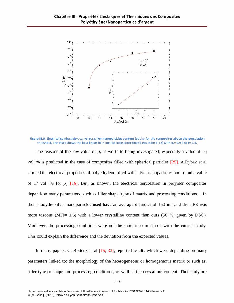
Chapitre III : Propriétés Electriques et Thermiques des Composites Polyéthylène/Nanoparticules d’argent
113
Figure III.6. Electrical conductivity, σdc versus silver nanoparticles content (vol.%) for the composites above the percolation threshold. The inset shows the best linear fit in log-log scale according to equation III (2) with pc= 9.9 and t= 2.4.
The reasons of the low value of 𝑝𝑐 is worth to being investigated; especially a value of 16
vol. % is predicted in the case of composites filled with spherical particles [25]. A.Rybak et al
studied the electrical properties of polyethylene filled with silver nanoparticles and found a value
of 17 vol. % for 𝑝𝑐 [16]. But, as known, the electrical percolation in polymer composites
dependson many parameters, such as filler shape, type of matrix and processing conditions… In
their studythe silver nanoparticles used have an average diameter of 150 nm and their PE was
more viscous (MFI= 1.6) with a lower crystalline content than ours (58 %, given by DSC).
Moreover, the processing conditions were not the same in comparison with the current study.
This could explain the difference and the deviation from the expected values.
In many papers, G. Boiteux et al [15, 33], reported results which were depending on many
parameters linked to: the morphology of the heterogeneous or homogeneous matrix or such as,
filler type or shape and processing conditions, as well as the crystalline content. Their polymer
Cette thèse est accessible à l'adresse : http://theses.insa-lyon.fr/publication/2013ISAL0148/these.pdf © [M. Jouni], [2013], INSA de Lyon, tous droits réservés

Chapitre III : Propriétés Electriques et Thermiques des Composites Polyéthylène/Nanoparticules d’argent
114
composites were based on polypropylene and polymer blends of polypropylene with
copolyamides as matrices, and were filled with iron or silver particles. They showed that the
conditions of crystallization can influence the electrical properties of the composites. The later
can play a role in our study since our polyethylene has a high crystalline content. It can indicate
that the creation of big crystallites can eject silver nanoparticles at the periphery of the growing
crystallites, where their local concentration becomes higher and this facilitates the formation of
the network and decreases the value of 𝑝𝑐. In another study based on PVDF filled with
multiwalled carbon nanotubes, the processing conditions had an effect on the crystallization of
the composites, and the composites with higher crystalline contents showed higher values of
conductivity and lower electrical percolation [34]. Also, the effect of the dispersion of fillers has
to be considered in the investigation of the electrical properties. L Vescovo et al [35] studied the
electrical properties of epoxy composites filled with silver nanoparticles by dielectric relaxation
spectroscopy. They showed that, a good dispersion of silver nanoparticles inside an epoxy matrix
does not lead to see percolation phenomena in the system and, the composite didn’t show any
conductive paths between the particles. In the present study, the agglomerates of silver
nanoparticles could be the reason for the formation of a conductive network at low volume
fractions. Further, a complementary explanation of the decrease in resistivity and the value of
electrical percolation isgiven by R Strümpler [24] who explained the effects which contribute to
the contact resistance between particles and which can be assigned to the “constriction
resistance” and “tunneling resistance” phenomena. He concluded that the particles with no
“contact spots” lead to a decrease in constriction resistance, which involves a decrease in the
resistivity of the composite. Here, as mentioned above (section III.2.3.1), the aspect of silver
Cette thèse est accessible à l'adresse : http://theses.insa-lyon.fr/publication/2013ISAL0148/these.pdf © [M. Jouni], [2013], INSA de Lyon, tous droits réservés

Chapitre III : Propriétés Electriques et Thermiques des Composites Polyéthylène/Nanoparticules d’argent
115
nanoparticles in the matrix without “contact spots” could be the reason for the increasing of the
conductivity and the decrease of the percolation threshold.
Figure III.5-b shows the dielectric loss (𝜀′′) versus frequency at room temperature for the
same samples indicated on the plot of Figure III.5-a. Two kinds of curves can be observed; the
first set is for the samples which have a concentration below the percolation threshold (2, 3, 5
and 7 vol. %). In this case,𝜀′′ is constant and not dependent of frequency. This means that the
dielectric behavior of the composites is not affected since the samples have filler contents below
the one needed for the electrical percolation. However, when the percolation threshold is over
crossed, a linear dependence of 𝜀′′with frequency can be observed, with a slope of -1 indicating
that the material is losing its dielectric nature because of the presence of the conductive network
of silver nanoparticles [36].
III.4.5 Thermal conductivity
The experimental values of thermal conductivity of PE-Ag composites and their statistical
uncertainties are presented in Figure III.7 as a function of Ag filler volume percent. We notice an
increase of thermal conductivity with increasing Ag volume fraction. This increase is
foreseeable, since silver particles have a higher thermal conductivity than the PE matrix.
A similar effect was observed by Krupa et al [20], where the incorporation of 22 vol.% of
particles based on a polyamide core and a silver shell filled in the HDPE matrix, allows a three
times increase of the thermal conductivity compared to neat matrix. Likewise, Tlili et al [10]
show an increase by 4 of the thermal conductivity of the composite with the incorporation of 30
vol.% of graphite. In our case, the increase of the thermal conductivity, is higher (about 4.5) for
Cette thèse est accessible à l'adresse : http://theses.insa-lyon.fr/publication/2013ISAL0148/these.pdf © [M. Jouni], [2013], INSA de Lyon, tous droits réservés

Chapitre III : Propriétés Electriques et Thermiques des Composites Polyéthylène/Nanoparticules d’argent
116
22 vol.%. Therefore, the use of silver seems to be an interesting way to enhance the heat transfer
properties of polymer composite materials.
Figure III.7. Experimental data of PE-Ag thermal conductivity versus Ag filler volume fraction. The solid lines represent the models used for the fitting of the values of thermal conductivity.
In order to analyze well our results, it can be useful to say that the thermal conductivity is
one of the thermophysical quantity most used in the field of thermal science to model heat
transfers of composite materials. For over a century, many relationships have been proposed to
predict the effective thermal conductivity of composite materials. Many theoretical, semi-
empirical, empirical and numerical models were developed to predict the value of this effective
conductivity based on the characteristics of each component and sometimes on the dispersion
and shape of the inclusions [37].
Cette thèse est accessible à l'adresse : http://theses.insa-lyon.fr/publication/2013ISAL0148/these.pdf © [M. Jouni], [2013], INSA de Lyon, tous droits réservés
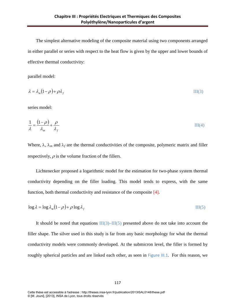
Chapitre III : Propriétés Electriques et Thermiques des Composites Polyéthylène/Nanoparticules d’argent
117
The simplest alternative modeling of the composite material using two components arranged
in either parallel or series with respect to the heat flow is given by the upper and lower bounds of
effective thermal conductivity:
parallel model:
( ) fm ρλρλλ +−= 1 III(3)
series model:
( )fm λρ
λρ
λ+
−=
11 III(4)
Where, λ, λm and λf are the thermal conductivities of the composite, polymeric matrix and filler
respectively, ρ is the volume fraction of the fillers.
Lichtenecker proposed a logarithmic model for the estimation for two-phase system thermal
conductivity depending on the filler loading. This model tends to express, with the same
function, both thermal conductivity and resistance of the composite [4].
( ) fm λρρλλ log1loglog +−= III(5)
It should be noted that equations III(3)–III(5) presented above do not take into account the
filler shape. The silver used in this study is far from any basic morphology for what the thermal
conductivity models were commonly developed. At the submicron level, the filler is formed by
roughly spherical particles and are linked each other, as seen in Figure III.1. For this reason, we
Cette thèse est accessible à l'adresse : http://theses.insa-lyon.fr/publication/2013ISAL0148/these.pdf © [M. Jouni], [2013], INSA de Lyon, tous droits réservés

Chapitre III : Propriétés Electriques et Thermiques des Composites Polyéthylène/Nanoparticules d’argent
118
apply the most basically and simplified approach considering that the composites are filled with
spherical particles.
Hashin and Shtrikman developed an alternate variational principle for heterogeneous
materials. Their method introduces a reference material, and bases the subsequent development
on the differences between this reference material and the actual composites [1, 37, 38]. Their
variational principle gives both the upper and lower bounds by making appropriate choices of the
reference material. In our case (Polymer composites), the filler is more thermally conductive
than the matrix, so choosing the filler as the reference material gives an upper bound and
choosing the matrix as the reference material gives a lower bound [1, 37, 38].
( )mmf
m
dtλρ
λλ
ρλλ−
+−
+=11 III(6)
The parameter dt is the dimension of the system and defines the shape of the filler (for spheres,
dt= 3).
Bruggeman model was originally established for the calculation of the dielectric permittivity
of heterogeneous materials [1, 37, 38]. This model has subsequently been widely used for
predicting the thermal conductivity of composite materials:
dt
eff
m
mf
efff
1
1
−
−=−
λλ
λλλλ
ρ III(7)
Where λeff is the thermal conductivity of the composite, the value of dt depends on the shape of
the fillers used: dt = 3 for spherical fillers. So, in this case, we obtain:
Cette thèse est accessible à l'adresse : http://theses.insa-lyon.fr/publication/2013ISAL0148/these.pdf © [M. Jouni], [2013], INSA de Lyon, tous droits réservés

Chapitre III : Propriétés Electriques et Thermiques des Composites Polyéthylène/Nanoparticules d’argent
119
( )( ) 3
31)/(1
−−−=
uu mf
meff
λλρλλ III(8)
with ( ) ( ) 3
133
2
2
271)/(1
42
−−++= mf
m
f
m
fuλλρ
λ
λλλ
III(9)
In Figure III.7, the thermal conductivities values obtained using basic models presented
above are presented and are compared to measurements upon the filler volume fraction. The
calculations of the effective thermal conductivity were performed using the experimental value
of the HDPE matrix thermal conductivity (km =0.47 Wm-1K-1) and a value of the fillers thermal
conductivity (kf = 430 Wm-1K-1) [20]. From this figure, it is clear from one hand, that the lower
estimation bound (series model) and thermal Hashin and Shtrikman model underestimate the
measured values. On the other hand, it is foreseeable that the upper bound (parallel model) will
overestimate the experimental data.
We notice that both Lichtenecker and Bruggeman models show close values to the measured
data of thermal conductivity of HDPE-Ag composites. However, no conclusion can be
formulated on the efficiency of the models for the prediction of the thermal conductivity used in
our case; since the modeling of metal filled polymers is a very complex task which requires the
measurement of several parameters which are sometimes difficult to obtain (parameters about the
microstructure, thermal contact resistance...). As observed and discussed above in the case of
electrical conductivity, the formation of agglomerates of silver nanoparticles could be the reason
for a non-homogeneous repartition of fillers in the polymeric matrix and consequently a reason
for the increase of the effect of the thermal contact resistance particle/particle and
Cette thèse est accessible à l'adresse : http://theses.insa-lyon.fr/publication/2013ISAL0148/these.pdf © [M. Jouni], [2013], INSA de Lyon, tous droits réservés

Chapitre III : Propriétés Electriques et Thermiques des Composites Polyéthylène/Nanoparticules d’argent
120
particle/matrix. Further works in mathematical modeling, in experimental characterization at
microscale and in microstructure analysis could provide better prediction models for properties
of metallic particle filled polymers.
III.4.6 The specific heat capacity
The specific thermal capacities obtained from DSC measurements are shown in Figure III.8
as a function of the filler weight concentration.
Figure III.8. Specific Heat versus filler weight fraction for PE-Ag composites samples.
As expected, a linear dependence of the specific heat upon the weight filler fraction is
observed for these composites. Theoretical cp values were computed according to the rule of
mixture given by equation III(10) considering a two-phase system and using cp values of HDPE
(cp,m) and silver (cp,f) equal to 1743 (measured value for HDPE matrix) and 233 Jkg-1K-1 [39]
respectively:
Cette thèse est accessible à l'adresse : http://theses.insa-lyon.fr/publication/2013ISAL0148/these.pdf © [M. Jouni], [2013], INSA de Lyon, tous droits réservés

Chapitre III : Propriétés Electriques et Thermiques des Composites Polyéthylène/Nanoparticules d’argent
121
ffpmmpp wcwccc ,, += III.(10)
Where wm, and wf are weight fractions of HDPE and silver. This theoretical curve was added to
Fig. 8. A good agreement between experimental and theoretical data was reached.
III.5 Conclusion
A new type of electrically and thermally conductive composites based on the HDPE as
matrix and silver nanoparticles as fillers was prepared and investigated. The composites filled
with high filler content were highly electrically and thermally conductive. The electrical
properties of the investigated systems were studied by dielectric relaxation spectroscopy (DRS).
A value of 10 vol.% was found for the electrical percolation threshold, and the system showed a
percolation in three dimensions according to the scaling law of the electrical percolation. The
DSC measurements of the prepared composites showed that the incorporation of silver
nanoparticles does not lead to significant changes on the crystallization and melting behaviors of
the PE matrix.
The thermal conductivity measured values were compared to some basic theoretical models,
where these thermal conductivity models underestimate the experimental values for low and
higher filler concentration. It seems that the use of basic modeling for estimating the effective
thermal conductivity of composite materials is not always an easy task. Indeed, it is necessary
that the thermal conductivity models take into account several complex parameters that can
affect the heat transfer parameters such as microstructure, thermal contact resistance,... On the
other hand, it was clearly shown that the rule of mixtures is sufficient to predict the behavior of
Cette thèse est accessible à l'adresse : http://theses.insa-lyon.fr/publication/2013ISAL0148/these.pdf © [M. Jouni], [2013], INSA de Lyon, tous droits réservés

Chapitre III : Propriétés Electriques et Thermiques des Composites Polyéthylène/Nanoparticules d’argent
122
the specific heat of polymers filled with metal particles. The results of the current study showed
that these composites could be good candidates for the use in many requested domains.
Cette thèse est accessible à l'adresse : http://theses.insa-lyon.fr/publication/2013ISAL0148/these.pdf © [M. Jouni], [2013], INSA de Lyon, tous droits réservés

Chapitre III : Propriétés Electriques et Thermiques des Composites Polyéthylène/Nanoparticules d’argent
123
III.6 References [1] Boudenne A, Ibos L, Candau Y. Chapter 10.Thermophysical Properties of Multiphase Polymer Systems. Handbook of Multiphase Polymer Systems: John Wiley & Sons, Ltd; 2011. p. 387-423.
[2] Garnier B, Agoudjil B, Boudenne A. Chapter 19. Metallic Particle-Filled Polymer Microcomposites. In: Sabu T, Kuruvilla J, Koichi G, Malhotra S.K, editors. Polymer Composites: Volume 1: Wiley-VCH Verlag GmbH & Co. KGaA; 2012. p. 575-612.
[3] Krupa I, Chodák I. Physical properties of thermoplastic/graphite composites. European Polymer Journal. 2001;37(11):2159-2168.
[4] Mamunya YP, Davydenko VV, Pissis P, Lebedev EV. Electrical and thermal conductivity of polymers filled with metal powders. European Polymer Journal. 2002;38(9):1887-1897.
[5] Merhari L. Hybrid nanocomposites for nanotechnology electronic, optical, magnetic and biomedical applications. New York: Springer; 2009.
[6] Goesmann H, Feldmann C. Nanoparticulate Functional Materials. Angewandte Chemie International Edition. 2010;49(8):1362-1395.
[7] Karttunen M, Ruuskanen P, Pitkänen V, Albers W. Electrically Conductive Metal Polymer Nanocomposites for Electronics Applications. Journal of Electronic Materials. 2008;37(7):951-954.
[8] Luyt AS, Molefi JA, Krump H. Thermal, mechanical and electrical properties of copper powder filled low-density and linear low-density polyethylene composites. Polymer Degradation and Stability. 2006;91(7):1629-1636.
[9] Mamunya YP, Muzychenko YV, Pissis P, Lebedev EV, Shut MI. Percolation phenomena in polymers containing dispersed iron. Polymer Engineering & Science. 2002;42(1):90-100.
[10] Tlili R, Boudenne A, Cecen V, Ibos L, Krupa I, Candau Y. Thermophysical and Electrical Properties of Nanocomposites Based on Ethylene–Vinylacetate Copolymer (EVA) Filled with Expanded and Unexpanded Graphite. International Journal of Thermophysics. 2010;31(4):936-948.
[11] Boudenne A, Ibos L, Fois M, Majesté JC, Géhin E. Electrical and thermal behavior of polypropylene filled with copper particles. Composites Part A: Applied Science and Manufacturing. 2005;36(11):1545-1554.
[12] Cecen V, Boudenne A, Ibos L, Novák I, Nógellová Z, Prokeš J, Krupa I. Electrical, mechanical and adhesive properties of ethylene-vinylacetate copolymer (EVA) filled with wollastonite fibers coated by silver. European Polymer Journal. 2008;44(11):3827-3834.
[13] Krupa I, Cecen V, Tlili R, Boudenne A, Ibos L. Thermophysical properties of ethylene-vinylacetate copolymer (EVA) filled with wollastonite fibers coated by silver. European Polymer Journal. 2008;44(11):3817-3826.
Cette thèse est accessible à l'adresse : http://theses.insa-lyon.fr/publication/2013ISAL0148/these.pdf © [M. Jouni], [2013], INSA de Lyon, tous droits réservés

Chapitre III : Propriétés Electriques et Thermiques des Composites Polyéthylène/Nanoparticules d’argent
124
[14] Tlili R, Cecen V, Krupa I, Boudenne A, Ibos L, Candau Y, Novák I. Mechanical and thermophysical properties of EVA copolymer filled with nickel particles. Polymer Composites. 2011;32(5):727-736.
[15] Boiteux G, Boullanger C, Cassagnau P, Fulchiron R, Seytre G. Influence of Morphology on PTC in Conducting Polypropylene-Silver Composites. Macromolecular Symposia. 2006;233(1):246-253.
[16] Rybak A, Boiteux G, Melis F, Seytre G. Conductive polymer composites based on metallic nanofiller as smart materials for current limiting devices. Composites Science and Technology. 2010;70(2):410-416.
[17] Nikonorova NA, Barmatov EB, Pebalk DA, Barmatova MV, Domãnguez-Espinosa G, Diaz-Calleja R, Pissis P. Electrical Properties of Nanocomposites Based on Comb-Shaped Nematic Polymer and Silver Nanoparticles. The Journal of Physical Chemistry C. 2007;111(24):8451-8458.
[18] Božanić DK, Dimitrijević -Branković S, Bibić N, Luyt AS, Djoković V. Silver nanoparticles encapsulated in glycogen biopolymer: Morphology, optical and antimicrobial properties. Carbohydrate Polymers. 2011;83(2):883-890.
[19] Božanić DK, Trandafilović LV, Luyt AS, Djoković V. 'Green’ synthesis and optical properties of silver-chitosan complexes and nanocomposites. Reactive and Functional Polymers. 2010;70(11):869-873.
[20] Krupa I, Boudenne A, Ibos L. Thermophysical properties of polyethylene filled with metal coated polyamide particles. European Polymer Journal. 2007;43(6):2443-2452.
[21] Jiang H, Moon K-s, Li Y, Wong CP. Surface Functionalized Silver Nanoparticles for Ultrahigh Conductive Polymer Composites. Chemistry of Materials. 2006;18(13):2969-2973.
[22] Kremer F, Schöenhals A. Broadband dielectric spectroscopy. Berlin: Springer; 2003.
[23] Danes F, Garnier B, Dupuis T. Predicting, Measuring, and Tailoring the Transverse Thermal Conductivity of Composites from Polymer Matrix and Metal Filler. International Journal of Thermophysics. 2003;24(3):771-784.
[24] Strümpler R, Glatz-Reichenbach J. Feature Article Conducting Polymer Composites. Journal of Electroceramics. 1999;3(4):329-346.
[25] Balberg I. A comprehensive picture of the electrical phenomena in carbon black/polymer composites. Carbon. 2002;40(2):139-143.
[26] Chae DW, Kim BC. Physical Properties of Isotactic Poly(propylene)/Silver Nanocomposites: Dynamic Crystallization Behavior and Resultant Morphology. Macromolecular Materials and Engineering. 2005;290(12):1149-1156.
[27] McNally T, Pötschke P, Halley P, Murphy M, Martin D, Bell SEJ, Brennan GP, Bein D, Lemoine P, Quinn JP. Polyethylene multiwalled carbon nanotube composites. Polymer. 2005;46(19):8222-8232.
Cette thèse est accessible à l'adresse : http://theses.insa-lyon.fr/publication/2013ISAL0148/these.pdf © [M. Jouni], [2013], INSA de Lyon, tous droits réservés

Chapitre III : Propriétés Electriques et Thermiques des Composites Polyéthylène/Nanoparticules d’argent
125
[28] Chae DW, Hong SM. Dynamic crystallization behavior, morphology, and physical properties of highly concentrated poly(vinylidene fluoride)/silver nanocomposites. Journal of Polymer Science Part B: Polymer Physics. 2010;48(22):2379-2385.
[29] Alig I, Lellinger D, Dudkin SM, Pötschke P. Conductivity spectroscopy on melt processed polypropylene/multiwalled carbon nanotube composites: Recovery after shear and crystallization. Polymer. 2007;48(4):1020-1029.
[30] Logakis E, Pandis C, Pissis P, Pionteck J, Pötschke P. Highly conducting poly(methyl methacrylate)/carbon nanotubes composites: Investigation on their thermal, dynamic-mechanical, electrical and dielectric properties. Composites Science and Technology. 2011;71(6):854-862.
[31] Stauffer D, Aharony A. Introduction to Percolation Theory. London: Taylor & Francis; 1994.
[32] Gingold DB, Lobb CJ. Percolative conduction in three dimensions. Physical Review B. 1990;42(13):8220-8224.
[33] Boiteux G, Mamunya YP, Lebedev EV, Adamczewski A, Boullanger C, Cassagnau P, Seytre G. From conductive polymer composites with controlled morphology to smart materials. Synthetic Metals. 2007;157(24):1071-1073.
[34] Ke K, Wang Y, Zhang K, Luo Y, Yang W, Xie B-H, Yang M-B. Melt viscoelasticity, electrical conductivity, and crystallization of PVDF/MWCNT composites: Effect of the dispersion of MWCNTs. Journal of Applied Polymer Science. 2011;125(S1):E49-E57.
[35] Vescovo L, Sangermano M, Scarazzini R, Kortaberria G, Mondragon I. In-situ-Synthetized Silver/Epoxy Nanocomposites: Electrical Characterization by Means of Dielectric Spectroscopy. Macromolecular Chemistry and Physics. 2010;211(17):1933-1939.
[36] Xi Y, Yamanaka A, Bin Y, Matsuo M. Electrical properties of segregated ultrahigh molecular weight polyethylene/multiwalled carbon nanotube composites. Journal of Applied Polymer Science. 2007;105(5):2868-2876.
[37] Nicolais L, Borzacchiello A, Stuart ML. Encyclopedia of Composites: Wiley; 2012.
[38] Mottram J, Taylor R. Thermal transport properties. In: Lee SM, editor. International Encyclopedia of Composites. New York: Wiley-Vch Publishers 1991.
[39] Wypych G. Handbook of Fillers, 2nd edn. 2 ed. Toronto: ChemTec Publishing; 2000.
Cette thèse est accessible à l'adresse : http://theses.insa-lyon.fr/publication/2013ISAL0148/these.pdf © [M. Jouni], [2013], INSA de Lyon, tous droits réservés

126
Cette thèse est accessible à l'adresse : http://theses.insa-lyon.fr/publication/2013ISAL0148/these.pdf © [M. Jouni], [2013], INSA de Lyon, tous droits réservés

Chapitre IV : Amélioration des Conductivités Electriques et Thermiques des Composites Polyéthylène/MWCNT par Addition des Nanoparticules d’Argent
127
Chapitre IV : Article 3
Amélioration des Conductivités Electriques et Thermiques de Composites Polyéthylène/MWCNT par
Addition des Nanoparticules d’Argent
Cette thèse est accessible à l'adresse : http://theses.insa-lyon.fr/publication/2013ISAL0148/these.pdf © [M. Jouni], [2013], INSA de Lyon, tous droits réservés

Chapitre IV : Amélioration des Conductivités Electriques et Thermiques des Composites Polyéthylène/MWCNT par Addition des Nanoparticules d’Argent
128
Introduction-Résumé
Dans le chapitre II, on a présenté l’élaboration et la caractérisation de NCPCs PE/MWCNT à
faible seuil de percolation, favorisé par la présence de MWCNTs qui ont un grand facteur de
forme.
Dans ce chapitre, on focalisera nos recherches sur l’élaboration, par extrusion à l’état fondu, de
composites polymères conducteurs en se basant sur le concept de mélange de nanocharges
conductrices. En d’autres termes, au vu des résultats encourageants précédemment obtenus
(chapitres II et III), nous avons associé nos deux charges afin d’élaborer des composites
hybrides. En effet, les MWCNTs avec leur grand facteur de forme peuvent favoriser la formation
d’un réseau percolant de charges à faible taux. De leur coté, les Ag-NPs peuvent apporter des
propriétés électriques et/ou thermiques élevées aux composites hybrides.
Après l’étude morphologique de la microstructure, l’étude et l’analyse des propriétés physiques
sont comparées par rapport à celles des composites binaires de PE/MWCNT pour observer avec
précision la différence obtenue suite à la combinaison de ces deux charges.
Même avec une fraction volumique d’Ag-NPs de 3 vol.%, largement inférieur au seuil de
percolation électrique des composites PE/Ag-NPs (10 vol.%), ce taux a permis d’augmenter
fortement la conductivité électrique de nos composites ternaires PE/CNT/Ag-NPs pour obtenir
une conductivité maximale de l’ordre de 5×10⁻³ S/cm (pour 5 vol.% de MWCNTs), soit deux
décades de plus de ce qui est obtenu avec le mélange homologue sans Ag-NPs. Ce niveau de
conductivité est requis pour un certain nombre d’applications. Le faible taux d’argent ajouté
Cette thèse est accessible à l'adresse : http://theses.insa-lyon.fr/publication/2013ISAL0148/these.pdf © [M. Jouni], [2013], INSA de Lyon, tous droits réservés

Chapitre IV : Amélioration des Conductivités Electriques et Thermiques des Composites Polyéthylène/MWCNT par Addition des Nanoparticules d’Argent
129
permet de ne pas altérer les propriétés mécaniques du composite. Au niveau de la percolation
électrique, cette dernière a été obtenue à 0.4 vol.% de MWCNT, comme dans le cas des
composites binaires de PE/MWCNT, ce qui confirme que le grand facteur de forme des
MWCNTs est à l’origine de la création du réseau percolant. Au niveau des phénomènes de
transport électronique, une étude sur ces systèmes hybrides a révélé des mécanismes de
conduction similaires au composites PE/MWCNT (voir chapitre V pour le cas des PE/MWCNT
et Annexe IV.A.1)
Concernant la conductivité thermique, les Ag-NPs ont contribué à l’amélioration de la
conductivité thermique des composites PE/MWCNT.
Cette thèse est accessible à l'adresse : http://theses.insa-lyon.fr/publication/2013ISAL0148/these.pdf © [M. Jouni], [2013], INSA de Lyon, tous droits réservés

Chapitre IV : Amélioration des Conductivités Electriques et Thermiques des Composites Polyéthylène/MWCNT par Addition des Nanoparticules d’Argent
130
IV. Article 3 (soumis dans Composites : Part A)
Enhancement of the Electrical and Thermal Conductivities of Polyethylene Carbon
Nanotube Composites by addition of Silver Nanoparticles
Cette partie constitue une publication du Journal Composites Part A : Applied Sciences and
Manufacturing dont la référence serait:
Jouni M, Boudenne A, Boiteux G, Massardier V, Garnier B. Enhancement of the Electrical and
Thermal Conductivities of Polyethylene Carbon Nanotube Composites by addition of Silver
Nanoparticles. 2013
IV.1 Abstract
Electrically and thermally conductive high density polyethylene (HDPE) composites filled with
hybrid fillers, multiwall carbon nanotubes (MWCNTs) and silver nanoparticles, have been
prepared. The investigation of the electrical and thermal properties was compared to
PE/MWCNT binary composites. Addition of 3 vol. % of silver nanoparticles allows an increase
of the maximum electrical conductivity of PE/MWCNT composites by two orders of
magnitudes. However, as for binary composites, the electrical percolation threshold (𝑃c) was
reached at 0.4 vol.%. The silver nanoparticles were also contributed in the enhancement of the
thermal conductivity of PE/MWCNT composites. The dielectric properties of ternary composites
were also studied and demonstrated a high dielectric loss (ε").
Cette thèse est accessible à l'adresse : http://theses.insa-lyon.fr/publication/2013ISAL0148/these.pdf © [M. Jouni], [2013], INSA de Lyon, tous droits réservés

Chapitre IV : Amélioration des Conductivités Electriques et Thermiques des Composites Polyéthylène/MWCNT par Addition des Nanoparticules d’Argent
131
IV.2 Introduction
The research on multifunctional polymer composites/nanocomposites is still growing,
aiming at creating new materials with high performances. Among large investigations in this
field, the production of thermally and electrically conductive polymer composites takes a special
place because of the possibility to use such functional materials in a large variety of applications
including many sectors (microelectronic devices, automotive, biomedical applications…) [1, 2].
Recently, an increasing number of works have focused on the studies and the use of
conductive fillers to improve the thermal and electrical properties of polymer matrices [3-8].
Beyond a wide range of fillers, the nanosized particles are chosen for their chemical structure,
specific size at nanoscale level, and high surface area making them very efficient for the
interaction exchange at the interface with the polymer matrix. Consequently, the physical
properties of composite can be improved by the incorporation of nanoparticles within the
polymer matrix [9]. With the knowledge of various kinds of conductive nanoparticles, carbon
nanotubes have particularly attracted the attention of scientists and researchers [10, 11]. In fact,
due to their high electrical, thermal and mechanical properties combined with their high aspect
ratio, carbon nanotubes can change significantly the properties of the polymer matrix at low
fillers loading (low percolation threshold) leading to conserve the main characteristics of
polymer matrix. Despite the excellent thermal and electrical properties of CNT, the electrical and
thermal conductivities of CNT based polymer composites are still insufficient for some types of
applications when higher values are needed. One of the substitutions is the use of conductive
metallic particles which are more adapted to achieve this goal [4, 12]. However, the high density
Cette thèse est accessible à l'adresse : http://theses.insa-lyon.fr/publication/2013ISAL0148/these.pdf © [M. Jouni], [2013], INSA de Lyon, tous droits réservés

Chapitre IV : Amélioration des Conductivités Electriques et Thermiques des Composites Polyéthylène/MWCNT par Addition des Nanoparticules d’Argent
132
of such particles causes a drawback to maintain the advantageous mechanical or suitable
characteristics of polymer matrix.
As a strategy to limit this problem, the incorporation within the polymer matrix of both
kind of fillers seems to be an interesting way to elaborate lightly loaded hybrid filled polymer
composites. Indeed, CNT with their high aspect ratio allow the formation of conductive
pathways at lower filler concentrations. Moreover, the addition of metallic nanoparticles
involves an increase of the thermal or/and electrical conductivities.
Many papers in the literature have discussed the use of CNT combined with metallic
particles as methodology for the enhancement of electrical and thermal conductivities of polymer
composites [13-17]. But, the results showed a limitation in the improvement, especially the
thermal conductivity which can be related to different mechanisms of conductions in the
composites [5, 18]. Distinct from other metallic particles, silver is known as the more conductive
metal. In addition, few works reported the combination of both silver and CNT fillers showing
promising results [19, 20].
In the present study electrically and thermally conductive high density polyethylene
composites filled with silver nanoparticles and multiwalled carbon nanotubes (MWCNTs) were
produced by melt mixing using twin-screw mini-extruder. The electrical and thermal
conductivities were carefully investigated and compared to binary composites of polyethylene
filled with MWCNTs. The effect of the addition of silver nanoparticles on the final properties of
ternary composites was observed. The results displayed a low electrical percolation threshold
governed by conductive pathways created from the MWCNT networks. The silver nanoparticles
Cette thèse est accessible à l'adresse : http://theses.insa-lyon.fr/publication/2013ISAL0148/these.pdf © [M. Jouni], [2013], INSA de Lyon, tous droits réservés

Chapitre IV : Amélioration des Conductivités Electriques et Thermiques des Composites Polyéthylène/MWCNT par Addition des Nanoparticules d’Argent
133
have improved the maximum values of electrical conductivity by two orders of magnitude and
increased the thermal conductivity of ternary composites comparing to their homologous
PE/MWCNT binary composites.
IV.3 Experimental
IV.3.1 Materials
A commercial masterbatch “PLASTICYL HDPE 1501” containing 15 wt.% MWCNT in
high - density polyethylene (HDPE) was obtained from Nanocyl, Belgium. The masterbatch is
produced by high shear processing. The MWCNTs present in the masterbatch are NC7000
produced by chemical vapor deposition (CVD), with purity higher than 90%. They have the
following specifications: average length 1.5 µm, average diameter 9.5 nm given by TEM, the
purity is more than 90%. The surface area is around 250-300 m2/g.
The silver nanoparticles were used as conducting metallic fillers for the preparation of
hybrid conductive polymer composites. Silver nanoparticles with an average diameter
APS=100nm were supplied by American Elements (Ref: AG-M-03M-NP.100N). The silver
nanoparticles have tendency to aggregate due to their high surface area.
IV.3.2 Composites processing
In a previous work, binary nanocomposites of polyethylene filled with MWCNTs were
prepared by melt mixing using co-rotating twin-screw mini-extruder (Micro 15 Twin-Screw
DSM Research). More detail can be found in [21]. The results showed a low electrical
percolation threshold (~ 0.4 vol.%) in the studied samples. For the ternary composites of hybrid
polyethylene filled with both MWCNTs and silver nanoparticles, a similar two steps procedure
was used. First, the polyethylene was mixed with MWCNTs in the extruder to obtain a
Cette thèse est accessible à l'adresse : http://theses.insa-lyon.fr/publication/2013ISAL0148/these.pdf © [M. Jouni], [2013], INSA de Lyon, tous droits réservés

Chapitre IV : Amélioration des Conductivités Electriques et Thermiques des Composites Polyéthylène/MWCNT par Addition des Nanoparticules d’Argent
134
homogeneous dispersion of MWCNTs, and in a second step, small parts of silver nanoparticles
were gradually added to the molten PE/MWCNT to get a good dispersion of silver particles in
the final PE/MWCNT/Ag ternary composites. The mixing was performed at a rotational speed of
100 rpm with 15 min duration and a 170°C prescribed temperature.
The concentration of silver nanoparticles was fixed at 3 vol. % in the ternary composites.
In order, to see the effect of the addition of silver nanoparticles on the final properties of the
ternary composites, the amount of MWCNTs was varied in the same range as for binary
composites of PE/MWCNT reported in [21]. The ternary composites are named PE/xCNT/3Ag
where x is the volume percentage of the MWCNTs in the final composite.
For composites characterization, the extruded strands were pressed using a SERVITEC
Polystat 200T press at 180 ºC for 7 min under a pressure of 75 kN. Following this procedure,
samples with thicknesses about 0.5 mm and 0.9 mm were obtained for electrical and thermal
conductivities characterizations respectively.
IV.3.3 Characterizations
IV.3.3.1 Morphological characterization
The characterization of the morphology and the microstructure of the prepared samples as
well as the dispersion of fillers in ternary composites were carried out using Scanning Electron
Microscopy (SEM, QUANTA 250). The specimens were cut with an ultramicrotome. The
surface was sputter-coated with a thin gold layer to avoid charging during scanning electron
microscopy imaging. The accelerating voltage was 10 kV.
VI.3.3.2 Density measurements
Cette thèse est accessible à l'adresse : http://theses.insa-lyon.fr/publication/2013ISAL0148/these.pdf © [M. Jouni], [2013], INSA de Lyon, tous droits réservés

Chapitre IV : Amélioration des Conductivités Electriques et Thermiques des Composites Polyéthylène/MWCNT par Addition des Nanoparticules d’Argent
135
The density measurements (ρ) were carried out with square-plate samples which were used
for thermal measurements. A Mettler-Toledo TM AT61 delta range balance was used to measure
the mass and a calliper rule for the sample sizes. The dependence of the specific density of the
composites on the volume filler content is important for checking the quality of the samples. It is
clear that composite samples are well processed, i.e. a good homogeneity is reached without air
bubbles in the sample or unfilled pores at the polymer/filler interface.
IV.3.3.3 Thermal conductivity measurements
Thermal conductivity (λ) was measured using an experimental device which was designed
for the measurement of low and average thermal conductivity from 0.1 to 5 Wm-1K-1on small
samples with 15x15 mm2 section and thickness from 0.1 to 10 mm. The experimental procedure
represents an extension of the normalized hot guarded plate (HGP) method [20]. A heat source
and a heat sink (an electrical heater and two heat exchangers with thermostated baths) are located
respectively on the bottom and top surfaces of the sample. This setup generates a temperature
gradient in the thickness direction of the sample. The main characteristic of the experiment
concerns the use of an active guard that allows the thermal flux, dissipated by the heat source, to
flow entirely through the sample. In fact, a temperature controller cancels the heat flux from the
electric heater to the heat source-heat exchanger by adjusting the electric heating in order to
obtain its temperature as close as possible to the one of the heat source heat exchanger.
The parallelism between upper and lower plates of the experimental setup was achieved using
guides for vertical displacement, that were controlled by a pneumatic jack in order to ensure an
adjustable pressure P on both sides of the sample (typically 4 bar). Thermal resistances between
sample and heat source, as well as between sample and heat sink, were minimized by spreading
Cette thèse est accessible à l'adresse : http://theses.insa-lyon.fr/publication/2013ISAL0148/these.pdf © [M. Jouni], [2013], INSA de Lyon, tous droits réservés

Chapitre IV : Amélioration des Conductivités Electriques et Thermiques des Composites Polyéthylène/MWCNT par Addition des Nanoparticules d’Argent
136
thermal grease on the top and bottom sides of the sample, the effect of thermal grease on thermal
conductivity measurement being previously studied [22].
IV.3.3.4 Electrical Characterizations
The investigation of electrical and dielectric properties of ternary composites was carried
out by dielectric relaxation spectroscopy (DRS). The measurements were carried out at room
temperature by using Novocontrol alpha analyzer in the frequency range 10-1 – 107 Hz. The
sample was placed between the two plates of capacitor. An electric field was applied, and then
the complex dielectric permittivity 𝜀(𝜔)∗ = 𝜀′ − 𝑖𝜀′′ is registered as a function of frequency.
The real part of the complex electrical conductivity was obtained by the following equation [23]:
𝜎′(𝜔) = 𝜀0𝜔𝜀′′(𝜔) IV(1)
Where 𝜔 is the angular frequency (𝜔 =2πf), 𝜀′′ is the imaginary part of the complex permittivity
and 𝜀0= 8.85×10⁻¹² F.m-1 is the permittivity of free space.
In this paper, the spectra of the real part of the complex conductivity (𝜎′) and the imaginary part
of the complex permittivity (𝜀′′, dielectric loss) are presented.
IV.4 Results and discussion
IV.4.1 Microscopy results
Figure IV.1-a shows a SEM image of PE/0.4 CNT/3Ag sample. As first observation, one
can see that silver nanoparticles are agglomerated and packed in individual groups. No direct
connections between silver nanoparticles are detected at high scale and only separated groups of
silver nanoparticles are observed. The MWCNTs are located between the isolated silver groups
and could be connected with them. More details can be found in Figure IV.1-b after magnification
Cette thèse est accessible à l'adresse : http://theses.insa-lyon.fr/publication/2013ISAL0148/these.pdf © [M. Jouni], [2013], INSA de Lyon, tous droits réservés
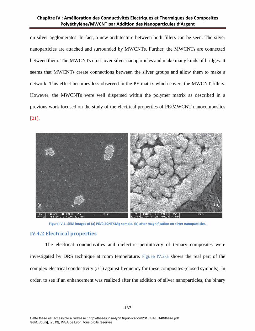
Chapitre IV : Amélioration des Conductivités Electriques et Thermiques des Composites Polyéthylène/MWCNT par Addition des Nanoparticules d’Argent
137
on silver agglomerates. In fact, a new architecture between both fillers can be seen. The silver
nanoparticles are attached and surrounded by MWCNTs. Further, the MWCNTs are connected
between them. The MWCNTs cross over silver nanoparticles and make many kinds of bridges. It
seems that MWCNTs create connections between the silver groups and allow them to make a
network. This effect becomes less observed in the PE matrix which covers the MWCNT fillers.
However, the MWCNTs were well dispersed within the polymer matrix as described in a
previous work focused on the study of the electrical properties of PE/MWCNT nanocomposites
[21].
Figure IV.1. SEM images of (a) PE/0.4CNT/3Ag sample. (b) after magnification on silver nanoparticles.
IV.4.2 Electrical properties
The electrical conductivities and dielectric permittivity of ternary composites were
investigated by DRS technique at room temperature. Figure IV.2-a shows the real part of the
complex electrical conductivity (𝜎′ ) against frequency for these composites (closed symbols). In
order, to see if an enhancement was realized after the addition of silver nanoparticles, the binary
Cette thèse est accessible à l'adresse : http://theses.insa-lyon.fr/publication/2013ISAL0148/these.pdf © [M. Jouni], [2013], INSA de Lyon, tous droits réservés

Chapitre IV : Amélioration des Conductivités Electriques et Thermiques des Composites Polyéthylène/MWCNT par Addition des Nanoparticules d’Argent
138
nanocomposites of PE/MWCNT are also presented in this figure (open symbols) for better
comparison.
Figure IV.2. (a) Electrical part of the complex electrical conductivity versus frequency at room temperature for binary composites of PE/MWCNT (open symbols) and ternary composites (closed symbols) of PE/MWCNT/3Ag indicated on the plot. The content of silver nanoparticles was was fixed at 3 vol.% in all ternary composites. (b) dc conductivity (σdc) against MWCNTs content at room temperature for binary and ternary composites. The solid line shows the best fit according to equation IV.(1).
The loading of silver nanoparticles was fixed at 3 vol.% , which is much lower than the
electrical percolation threshold in polyethylene filled with silver nanoparticles obtained in a
previous study [24], however the percentage in MWCNTs was varied in the same order like
binary composites reported in [21]. Depending on the concentration of fillers, two distinct
behaviors can be observed. First, a linear dependence of 𝜎′ with the frequency showing a typical
capacitor behavior for insulating materials. Secondly, above a critical concentration of
conductive fillers, a dc plateau appears below a critical frequency (fc), where the conductivity is
independent of frequency indicating the transition from insulating to conducting phase [25].
The addition of silver nanoparticles does not reduce the content of MWCNT required for the
electrical percolation threshold (Figure IV.2-a), which is obtained at 0.4 vol.% in MWCNTs
Cette thèse est accessible à l'adresse : http://theses.insa-lyon.fr/publication/2013ISAL0148/these.pdf © [M. Jouni], [2013], INSA de Lyon, tous droits réservés

Chapitre IV : Amélioration des Conductivités Electriques et Thermiques des Composites Polyéthylène/MWCNT par Addition des Nanoparticules d’Argent
139
loading in ternary composites (closed up triangle symbols) as for binary composites ( open up
triangle symbols). Moreover, no dc plateau was found for ternary composites for the samples
loaded with less than 0.4 vol.% in MWCNTs indicating that the samples are not conductive.
It is also possible to conclude that the creation of conductive pathways is still dominated by the
formation of MWCNTs networks since MWCNTs have a higher aspect ratio comparing to
spherical silver nanoparticles. Such conclusions were reported in the literature for hybrid fillers
composites [26, 27]. The electrical percolation was achieved at 0.4 vol.% of MWCNTs in ternary
composites as for binary composites and no synergistic effect by means of decreasing of the
electrical percolation threshold using combination of hybrid fillers could be considered or taken
into account here. However the incorporation of silver nanoparticles can lead to a better charge
transport and higher conductivities in the system considering that silver nanoparticles are
localized between MWCNTs or participate in the connections of MWCNTs involving a decrease
in contact resistance. A study on polyamide 12 filled with carbon black and multiwalled carbon
nanotubes showed a similar effect and the addition of carbon black particles leaded to an
enhancement in the electrical conductivity of the ternary composites [26]. However, other works
demonstrated a synergistic effect when silver particles and carbon nanotubes are used as hybrid
fillers [19, 20]. F.Marcq et al [28] reported the results obtained in epoxy adhesives filled with
silver flakes and carbon nanotubes and showed a synergistic effect at high loadings of silver
fillers. In our case, ternary composites with higher amount of silver nanoparticles are under
investigation as a second work to study this phenomenon.
For a better observation of the enhancement arising from the incorporation of silver
nanoparticles on the electrical conductivity of ternary composites, the dc conductivities of binary
Cette thèse est accessible à l'adresse : http://theses.insa-lyon.fr/publication/2013ISAL0148/these.pdf © [M. Jouni], [2013], INSA de Lyon, tous droits réservés

Chapitre IV : Amélioration des Conductivités Electriques et Thermiques des Composites Polyéthylène/MWCNT par Addition des Nanoparticules d’Argent
140
and ternary composites above the electrical percolation threshold were plotted against MWCNTs
content in Figure IV.2-b. The values of dc conductivity are extrapolated from the plot of 𝜎′ versus
frequency presented in Figure IV.2-a (𝜎𝑑𝑐 = 𝜎′(𝜔 → 0)). As can be seen in Figure IV.2-b, the
difference observed in conductivity level between binary and corresponding ternary composites
is well clear and significant. As an example, the PE/0.4CNT/3Ag sample shows a slight
difference in electrical conductivity comparing to its binary homologous. This difference
increases since more MWCNTs are introduced and the gap of conductivity level between binary
and ternary composites for the same percentage in MWCNTs grows more and more. Finally, two
orders of magnitude in conductivity values are observed between PE/5CNT and PE/5CNT/3Ag.
The effect of addition of silver nanoparticles can appear clearer by comparing PE/3CNT and
PE/1.2CNT/3Ag samples that have the same value of conductivity despite the difference in
MWCNTs loading (1.2 vol.% for 3 vol.% respectively).
For the exact calculation of the electrical percolation (𝑝𝑐) of MWCNTs in ternary
composites, the well known scaling law from the percolation theory [29] was applied to the
experimental values of 𝜎𝑑𝑐:
𝜎𝑑𝑐~ (𝑝 − 𝑝𝑐)𝑡𝑓𝑜𝑟 𝑝 > 𝑝𝑐 IV(2)
Where 𝜎𝑑𝑐 is the dc conductivity of the composite, 𝑝 is the volume content of the fillers,𝑝𝑐 is
the critical volume fraction at percolation and 𝑡 a critical exponent related to the dimensions of
the system. A value of 𝑡 ≈ 2 is predicted theoretically for a statistical percolation network in
three dimensions [30].The best fit (solid line in Figure IV.2-b) of the experimental data with the
above equation gives 𝑝𝑐= 0.39 ±0.02 in MWCNTs content and 𝑡 = 2.6 ±0.01. The values of these
Cette thèse est accessible à l'adresse : http://theses.insa-lyon.fr/publication/2013ISAL0148/these.pdf © [M. Jouni], [2013], INSA de Lyon, tous droits réservés

Chapitre IV : Amélioration des Conductivités Electriques et Thermiques des Composites Polyéthylène/MWCNT par Addition des Nanoparticules d’Argent
141
parameters were calculated for the binary nanocomposites of PE/MWCNT reported in previous
study (𝑝𝑐= 0.39 and 𝑡 = 1.99 ) [21]. Both cases indicate a low electrical percolation threshold in
MWCNTs loading with the same value of 𝑝𝑐= 0.39, which is a further indication that the
electrical percolation threshold in ternary composites was dominated by MWCNTs content as
mentioned above. Concerning the value of 𝑡 in ternary composites, the small shift from the
predicted one (𝑡=2) can be related to the formation of the aggregates of silver nanoparticles.
Another interesting point to be further discussed is the maximum value of conductivity.
The higher conductivity obtained in ternary composites has a value around ≈ 5×10⁻³ S/cm. Such
values are needed for some specific applications such as EMI shielding [31] and others
applications based on electromagnetic waves shielding properties [32]. One should notice that
the PE matrix used in this study is one of the more insulating thermoplastic polymers. It has the
advantage of being a very good candidate for such applications as it is easy to process and
commonly used.
Figure IV.3 shows the dielectric loss (𝜀′′) versus frequency at room temperature for
ternary composites. Complementary to the curves of 𝜎′(𝑓) , the two behaviors for insulating and
conductive samples are distinct on the plots. 𝜀′′ is independent of frequency in a wide range for
the compositions below the percolation threshold. This result comes from the fact that the
dielectric behavior of the composites is not affected since the samples have filler contents below
the critical concentration needed for the electrical percolation. However, when the percolation
threshold is over crossed, a linear dependence of 𝜀′′ with frequency can be observed, with a
slope of -1 indicating that the material is losing its dielectric nature because of the presence of
the conductive networks formed by the combination of fillers.
Cette thèse est accessible à l'adresse : http://theses.insa-lyon.fr/publication/2013ISAL0148/these.pdf © [M. Jouni], [2013], INSA de Lyon, tous droits réservés

Chapitre IV : Amélioration des Conductivités Electriques et Thermiques des Composites Polyéthylène/MWCNT par Addition des Nanoparticules d’Argent
142
Figure IV.3. Dielectric loss versus frequency at room temperature for the hybrid composites of PE/CNT/3Ag.
IV.4.3 Thermal conductivity properties
The thermal conductivity values of PE/MWCNT and PE/MWCNT3Ag nanocomposites
are presented in Figure IV.4. One can notice a sharp increase in heat transfer performance (99 %)
when 0.6 vol.% of MWCNT are incorporated in the PE matrix. Such observations were found in
the literature for MWCNT based thermoplastic composites as presented by Han in a review
focused on thermal conductivity of CNT for various polymer matrices [33]. An insight in the
effective thermal conductivity of these kinds of composites can be found in a recent work of
Mazov et al [34] where the authors have described the effects of several parameters such as CNT
distribution, alignment and interfacial resistance on the thermal conductivity. The good
improvement of the thermal conductivity of PE/MWCNT can be related to the polymer
crystallinity as it has been observed by Haggenmueller et al [35] in a study on high and low
density PE filled with SWCNTs. They assume that the interfacial thermal contact resistances are
less important when the PE is highly crystalline which correspond to the case of the PE used in
this work (70%).
Cette thèse est accessible à l'adresse : http://theses.insa-lyon.fr/publication/2013ISAL0148/these.pdf © [M. Jouni], [2013], INSA de Lyon, tous droits réservés

Chapitre IV : Amélioration des Conductivités Electriques et Thermiques des Composites Polyéthylène/MWCNT par Addition des Nanoparticules d’Argent
143
Figure IV.4. Thermal conductivities of PE/MWCNT and PE/MWCNT/3Ag composites.
Addition of silver nanoparticles (3 vol.%) to PE/MWCNT nanocomposites have showed
an improvement on the final thermal properties. It appears that the presence of silver
nanoparticules enhances significantly the heat transfer within the composites. Depending on the
concentration of MWCNTs, the addition of 3 vol.% of silver nanoparticles leads to an increase in
the effective thermal conductivity ranging from 4 to 20% (Table IV.1) with an average value of
12%. In [24], M. Jouni et al have obtained a 95% enhancement of the effective thermal
conductivity after the incorporation of a 3 vol.% of silver nanoparticles in HPDE. Then, in this
work, it seems that no synergetic effect appears by the addition of both types of filler (MWCNT
and Ag nanoparticles) to the PE matrix. On the contrary, synergetic effects due to the addition of
metallic nanoparticles in a thermoplastic matrix filled with CNT have been reported elsewhere
[36].
Cette thèse est accessible à l'adresse : http://theses.insa-lyon.fr/publication/2013ISAL0148/these.pdf © [M. Jouni], [2013], INSA de Lyon, tous droits réservés

Chapitre IV : Amélioration des Conductivités Electriques et Thermiques des Composites Polyéthylène/MWCNT par Addition des Nanoparticules d’Argent
144
MWCNT volume fraction (%) 0 0.2 0.4 0.6 1.2 1.8 3 5
Thermal conductivity of PE/CNT (W.m-1.K-1) 0.333 0.593 0.655 0.663 0.707 0.717 0.757 0.782
Thermal conductivity of PE/CNT/3Ag (W.m-1.K-1)
0.649 0.714 0.738 0.72 0.737 0.805 0.823 0.924
Thermal conductivity enhancement* (%)
95
20 13 9 4 12 9 18
Table IV.1. Thermal conductivities of PE/MWCNT and PE/ CNT/3Ag composites versus CNT volume fraction (%).*% = 100(λPE/CNT/3Ag -λPE/CNT)/λPE/CNT
IV.5. Conclusion
To summarize, hybrid composites based on high density polyethylene filled with
multiwalled carbon nanotubes and silver nanoparticles have been prepared by melt mixing. The
electrical and thermal conductivities where carefully investigated and compared to binary
composites of PE/MWCNT. The ternary composites showed a low electrical percolation
threshold 𝑝𝑐 = 0.39 resulting from the conductive networks created by MWCNT fillers rather
than silver spherical nanoparticles. The incorporation of silver nanoparticles at low fraction (3
vol.%) leads to an enhancement in the dc-conductivity values of ternary composites by two
orders of magnitude at higher loadings of MWCNTs. An improvement in thermal conductivity
was also found after the addition of silver nanoparticles. The results do not show a synergistic
effect from the combination of both fillers. However, the enhancement in thermal and electrical
properties seems to be more related to the nature of the conductive silver nanoparticles metallic
fillers.
Cette thèse est accessible à l'adresse : http://theses.insa-lyon.fr/publication/2013ISAL0148/these.pdf © [M. Jouni], [2013], INSA de Lyon, tous droits réservés
Chapitre IV : Amélioration des Conductivités Electriques et Thermiques des Composites Polyéthylène/MWCNT par Addition des Nanoparticules d’Argent
145
IV.6 References
[1] Merhari L. Hybrid nanocomposites for nanotechnology electronic, optical, magnetic and biomedical applications. New York: Springer; 2009.
[2] Rajesh, Ahuja T, Kumar D. Recent progress in the development of nano-structured conducting polymers/nanocomposites for sensor applications. Sensors and Actuators B: Chemical. 2009;136(1):275-286.
[3] Han C, Gu A, Liang G, Yuan L. Carbon nanotubes/cyanate ester composites with low percolation threshold, high dielectric constant and outstanding thermal property. Composites Part A: Applied Science and Manufacturing. 2010;41(9):1321-1328.
[4] Luyt AS, Molefi JA, Krump H. Thermal, mechanical and electrical properties of copper powder filled low-density and linear low-density polyethylene composites. Polymer Degradation and Stability. 2006;91(7):1629-1636.
[5] Mamunya YP, Davydenko VV, Pissis P, Lebedev EV. Electrical and thermal conductivity of polymers filled with metal powders. European Polymer Journal. 2002;38(9):1887-1897.
[6] Moniruzzaman M, Winey KI. Polymer Nanocomposites Containing Carbon Nanotubes. Macromolecules. 2006;39(16):5194-5205.
[7] Tlili R, Boudenne A, Cecen V, Ibos L, Krupa I, Candau Y. Thermophysical and Electrical Properties of Nanocomposites Based on Ethylene–Vinylacetate Copolymer (EVA) Filled with Expanded and Unexpanded Graphite. International Journal of Thermophysics. 2010;31(4):936-948.
[8] Zhou W, Zuo J, Ren W. Thermal conductivity and dielectric properties of Al/PVDF composites. Composites Part A: Applied Science and Manufacturing. 2012;43(4):658-664.
[9] Goesmann H, Feldmann C. Nanoparticulate Functional Materials. Angewandte Chemie International Edition. 2010;49(8):1362-1395.
[10] Bauhofer W, Kovacs JZ. A review and analysis of electrical percolation in carbon nanotube polymer composites. Composites Science and Technology. 2009;69(10):1486-1498.
[11] Spitalsky Z, Tasis D, Papagelis K, Galiotis C. Carbon nanotube-polymer composites: Chemistry, processing, mechanical and electrical properties. Progress in Polymer Science. 2010;35(3):357-401.
[12] Mamunya YP, Muzychenko YV, Pissis P, Lebedev EV, Shut MI. Percolation phenomena in polymers containing dispersed iron. Polymer Engineering & Science. 2002;42(1):90-100.
[13] Choi S, Im H, Kim J. Flexible and high thermal conductivity thin films based on polymer: Aminated multi-walled carbon nanotubes/micro-aluminum nitride hybrid composites. Composites Part A: Applied Science and Manufacturing. 2012;43(11):1860-1868.
Cette thèse est accessible à l'adresse : http://theses.insa-lyon.fr/publication/2013ISAL0148/these.pdf © [M. Jouni], [2013], INSA de Lyon, tous droits réservés

Chapitre IV : Amélioration des Conductivités Electriques et Thermiques des Composites Polyéthylène/MWCNT par Addition des Nanoparticules d’Argent
146
[14] Lee G-W, Park M, Kim J, Lee JI, Yoon HG. Enhanced thermal conductivity of polymer composites filled with hybrid filler. Composites Part A: Applied Science and Manufacturing. 2006;37(5):727-734.
[15] Liang G, Tjong SC. Electrical Conducting Behavior of Polyethylene Composites Filled with Self-Passivated Aluminum Nanoparticles and Carbon Nanotubes. Advanced Engineering Materials. 2007;9(11):1014-1017.
[16] Sanada K, Tada Y, Shindo Y. Thermal conductivity of polymer composites with close-packed structure of nano and micro fillers. Composites Part A: Applied Science and Manufacturing. 2009;40(6-7):724-730.
[17] Tang L-C, Wan Y-J, Peng K, Pei Y-B, Wu L-B, Chen L-M, Shu L-J, Jiang J-X, Lai G-Q. Fracture toughness and electrical conductivity of epoxy composites filled with carbon nanotubes and spherical particles. Composites Part A: Applied Science and Manufacturing. 2013;45(0):95-101.
[18] Boudenne A, Ibos L, Fois M, Majesté JC, Géhin E. Electrical and thermal behavior of polypropylene filled with copper particles. Composites Part A: Applied Science and Manufacturing. 2005;36(11):1545-1554.
[19] Fortunati E, D'Angelo F, Martino S, Orlacchio A, Kenny JM, Armentano I. Carbon nanotubes and silver nanoparticles for multifunctional conductive biopolymer composites. Carbon. 2011;49(7):2370-2379.
[20] Liang GD, Bao SP, Tjong SC. Microstructure and properties of polypropylene composites filled with silver and carbon nanotube nanoparticles prepared by melt-compounding. Materials Science and Engineering B-Solid State Materials for Advanced Technology. 2007;142(2-3):55-61.
[21] Jouni M, Massardier V, Boiteux G. New Melt Mixing Polyethylene Multiwalled Carbon Nanotube Nanocomposites with very Low Electrical Percolation Threshold. Polymer for Advanced Technologies. 2013.DOI: 10.1002/pat.3164.
[22] Danes F, Garnier B, Dupuis T. Predicting, Measuring, and Tailoring the Transverse Thermal Conductivity of Composites from Polymer Matrix and Metal Filler. International Journal of Thermophysics. 2003;24(3):771-784.
[23] Kremer F, Schöenhals A. Broadband dielectric spectroscopy. Berlin: Springer; 2003.
[24] Jouni M, Boudenne A, Boiteux G, Massardier V, Garnier B, Serghei A. Electrical and thermal properties of polyethylene/silver nanoparticle composites. Polymer Composites. 2013;34(5):778-786.
[25] Dyre JC, Schroder TB. Universality of ac conduction in disordered solids. Reviews of Modern Physics. 2000;72(3):873-892.
[26] Socher R, Krause B, Hermasch S, Wursche R, Potschke P. Electrical and thermal properties of polyamide 12 composites with hybrid fillers systems of multiwalled carbon nanotubes and carbon black. Composites Science and Technology. 2011;71(8):1053-1059.
Cette thèse est accessible à l'adresse : http://theses.insa-lyon.fr/publication/2013ISAL0148/these.pdf © [M. Jouni], [2013], INSA de Lyon, tous droits réservés

Chapitre IV : Amélioration des Conductivités Electriques et Thermiques des Composites Polyéthylène/MWCNT par Addition des Nanoparticules d’Argent
147
[27] Sumfleth J, Adroher X, Schulte K. Synergistic effects in network formation and electrical properties of hybrid epoxy nanocomposites containing multi-wall carbon nanotubes and carbon black. Journal of Materials Science. 2009;44(12):3241-3247.
[28] Marcq F, Demont P, Monfraix P, Peigney A, Laurent C, Falat T, Courtade F, Jamin T. Carbon nanotubes and silver flakes filled epoxy resin for new hybrid conductive adhesives. Microelectronics Reliability. 2011;51(7):1230-1234.
[29] Stauffer D, Aharony A. Introduction to Percolation Theory. London: Taylor & Francis; 1994.
[30] Gingold DB, Lobb CJ. Percolative conduction in three dimensions. Physical Review B. 1990;42(13):8220-8224.
[31] Logakis E, Pandis C, Pissis P, Pionteck J, Pötschke P. Highly conducting poly(methyl methacrylate)/carbon nanotubes composites: Investigation on their thermal, dynamic-mechanical, electrical and dielectric properties. Composites Science and Technology. 2011;71(6):854-862.
[32] Dubnikova I, Kuvardina E, Krasheninnikov V, Lomakin S, Tchmutin I, Kuznetsov S. The Effect of Multiwalled Carbon Nanotube Dimensions on the Morphology, Mechanical, and Electrical Properties of Melt Mixed Polypropylene-Based Composites. Journal of Applied Polymer Science. 2010;117(1):259-272.
[33] Han Z, Fina A. Thermal conductivity of carbon nanotubes and their polymer nanocomposites: A review. Progress in Polymer Science. 2012;36(7):914-944.
[34] Mazov IN, Ilinykh IA, Kuznetsov VL, Stepashkin AA. Thermal conductivity of polypropylene-based composites with multiwall carbon nanotubes with different diameter and morphology. Journal of Alloys Compound. 2013.
[35] Haggenmueller R, Guthy C, Lukes JR, Fischer JE, Winey KI. Single Wall Carbon Nanotube/Polyethylene Nanocomposites: Thermal and Electrical Conductivity. Macromolecules. 2007;40(7):2417-2421.
[36] Pak SY, Kim HM, Kim SY, Youn JR. Synergistic improvement of thermal conductivity of thermoplastic composites with mixed boron nitride and multi-walled carbon nanotube fillers. Carbon. 2012;50(13):4830-4838.
Cette thèse est accessible à l'adresse : http://theses.insa-lyon.fr/publication/2013ISAL0148/these.pdf © [M. Jouni], [2013], INSA de Lyon, tous droits réservés
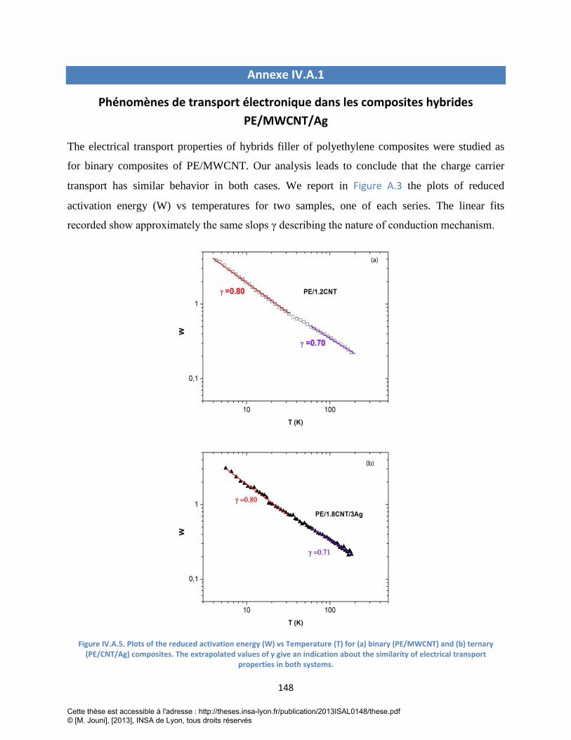
148
Annexe IV.A.1
Phénomènes de transport électronique dans les composites hybrides PE/MWCNT/Ag
The electrical transport properties of hybrids filler of polyethylene composites were studied as
for binary composites of PE/MWCNT. Our analysis leads to conclude that the charge carrier
transport has similar behavior in both cases. We report in Figure A.3 the plots of reduced
activation energy (W) vs temperatures for two samples, one of each series. The linear fits
recorded show approximately the same slops γ describing the nature of conduction mechanism.
Figure IV.A.5. Plots of the reduced activation energy (W) vs Temperature (T) for (a) binary (PE/MWCNT) and (b) ternary (PE/CNT/Ag) composites. The extrapolated values of γ give an indication about the similarity of electrical transport
properties in both systems.
Cette thèse est accessible à l'adresse : http://theses.insa-lyon.fr/publication/2013ISAL0148/these.pdf © [M. Jouni], [2013], INSA de Lyon, tous droits réservés

149
Cette thèse est accessible à l'adresse : http://theses.insa-lyon.fr/publication/2013ISAL0148/these.pdf © [M. Jouni], [2013], INSA de Lyon, tous droits réservés

Chapitre V: Phénomènes de Transport Electronique dans des Nanocomposites Polymères Faiblement Chargés avec Nanotubes de Carbone Multi-Parois
150
Chapitre V : Article 4
Phénomènes de Transport Electronique dans des
Nanocomposites Polymères faiblement Chargés avec
Nanotubes de Carbone Multi-parois
Cette thèse est accessible à l'adresse : http://theses.insa-lyon.fr/publication/2013ISAL0148/these.pdf © [M. Jouni], [2013], INSA de Lyon, tous droits réservés
Chapitre V: Phénomènes de Transport Electronique dans des Nanocomposites Polymères Faiblement Chargés avec Nanotubes de Carbone Multi-Parois
151
Introduction-Résumé
De nombreuses publications sur les nanocomposites polymères conducteurs ont montré
l’influence de différents facteurs sur les propriétés finales de conduction des composites.
Ainsi, les différents travaux dans ce domaine ont révélé que les matrices amorphes sont
généralement plus favorables que les semi-cristallines pour conduire à des nanocomposites
polymères conducteurs à faible seuil de percolation.
Malgré les nombreuses investigations basées sur l’étude des morphologies
(microstructure, effet de la cristallinité) et d’autres facteurs déterminants comme le type
d’interactions charge/matrice, il ne semble pas y avoir d’étude fondamentale visant à
expliquer l’origine de cette différence.
Dans ce contexte, et dans le but de donner une vision plus approfondie, il nous a semblé
intéressant d’entreprendre l’étude des mécanismes de conduction électronique. En effet, ce
genre d’investigation permet une analyse détaillée des phénomènes de transport électronique,
à l’origine des propriétés électriques des nanocomposites polymères conducteurs.
Dans ce chapitre, dans un premier temps, on présentera la méthode d’élaboration des
composites Epoxy/MWCNT qui a permis d’avoir un faible seuil de percolation électrique.
Ensuite, on étudiera les phénomènes de transport de nanocomposites polymères conducteurs,
à base de deux matrices (polyéthylène haute densité et résine époxy) chargées avec des
MWCNTs. L’étude des mécanismes de conduction dans ces deux systèmes a été faite par la
modélisation de la variation de la conductivité électrique en fonction de la température. Les
mesures ont été faites avec la technique des quatre points dans une large gamme de
températures en descendant jusqu’à 4K par l’intermédiaire d’hélium liquide, température
rarement étudiée dans la littérature, afin d’élargir l’étude aux basses températures. Plusieurs
Cette thèse est accessible à l'adresse : http://theses.insa-lyon.fr/publication/2013ISAL0148/these.pdf © [M. Jouni], [2013], INSA de Lyon, tous droits réservés

Chapitre V: Phénomènes de Transport Electronique dans des Nanocomposites Polymères Faiblement Chargés avec Nanotubes de Carbone Multi-Parois
152
modèles classiques (VRH-Variable Rang Hopping, Fluctuation Induced Tunneling-FIT) déjà
bien décrits dans la littérature ont été appliqués à nos résultats expérimentaux en vue
d’identifier la nature du transport dans ces composites. Malheureusement, aucun de ces
modèles n’a été adapté pour interprêter la variation de la conductivité en fonction de la
température et par conséquent pour déterminer la nature du transport électronique. Ceci nous
a contraint à développer un nouveau modèle basé sur une équation permettant de mettre en
évidence la coexistence de deux régimes de transport électronique en fonction du domaine de
température. L’analyse des paramètres de l’équation du modèle en fonction de la fraction
volumique de MWCNTs nous a permis d’extraire des informations importantes et
fondamentales pour comprendre les différences entre les deux types de matrice du point de
vue de la formation du réseau percolant. Il a été possible de comprendre pourquoi les matrices
amorphes peuvent être plus favorables à un type de conduction électronique à faible taux de
charges que ne le sont les polymères semi-crystallins.
Les essais pour préparer des composites Epoxy/MWCNT/Ag conducteurs n’ont
malheureusement pas abouti à des résultats ayant permis de disperser l’argent à l’échelle
nanométrique. Nous avons aussi été confrontés à la décantation des nanoparticules d’argent.
De plus, une autre raison est liée à la qualité du second lot des nanoparticules d’argent acheté
chez « American Elements » et qui devait présenter les mêmes caractéristiques que celui
utilisé pour la préparation des composites hybrides PE/MWCNT/Ag. Une analyse de
morphologie (voir annexe A.V.1) ainsi que des mesures électriques ont été réalisées pour
conclure finalement à des différences significatives entre les deux lots. Néanmoins, malgré
tout ca on a pu mesurer la conductivité thermique de quelques échantillons hybrides. Les
résultats correspondants seront communiqués dans l’annexe A.V.2.
Cette thèse est accessible à l'adresse : http://theses.insa-lyon.fr/publication/2013ISAL0148/these.pdf © [M. Jouni], [2013], INSA de Lyon, tous droits réservés

Chapitre V: Phénomènes de Transport Electronique dans des Nanocomposites Polymères Faiblement Chargés avec Nanotubes de Carbone Multi-Parois
153
III. Article 4 (Soumis dans Journal of Carbon) Charge Carrier Transport and Low Electrical Percolation Threshold in Multiwalled
Carbon Nanotube Polymer Nanocomposites
Cette partie constituera une publication du Journal of Carbon dont les auteurs :
Jouni M, Faure-Vincent J, Djurado D, Federko P, Boiteux G, Massardier V.
V.1 Abstract Electrical transport properties of multiwall carbon nanotube (MWCNT) polymer
nanocomposites based on epoxy and high density polyethylene (HDPE) as matrices have been
studied. The composites have been prepared from masterbatchs by dilution. Low electrical
percolation thresholds of 0.05 and 0.4 vol.% of carbon nanotubes in epoxy and HDPE
matrices were found respectively. The analysis of the temperature dependence of dc-
conductivity shows that the charge transport is fully described as the combination in series of
one-dimensional (1-D) and three-dimensional (3-D) variable range hopping (VRH) regimes.
The transport is limited by the 1D-VRH regime in the low temperatures limit and by the 3D-
VRH regime at room temperature. The analysis of the VRH parameters when the overall
volume fraction of MWCNT decreases reveals two distinct situations. In the epoxy the local
characteristics of the masterbatch remain practically unchanged and a percolating network is
maintained even at very low volume fractions; in the HDPE matrix, the density of the
MWCNT bundles packing decreases as revealed by the strong variation of the Mott
temperature parameter. Our results indicate that the amorphous polymers are probably more
promising candidates than the polycrystalline ones to get MWCNT polymer nanocomposites
with low electrical percolation threshold.
Cette thèse est accessible à l'adresse : http://theses.insa-lyon.fr/publication/2013ISAL0148/these.pdf © [M. Jouni], [2013], INSA de Lyon, tous droits réservés

Chapitre V: Phénomènes de Transport Electronique dans des Nanocomposites Polymères Faiblement Chargés avec Nanotubes de Carbone Multi-Parois
154
V.2 Introduction
The researches and investigations on carbon nanotubes polymers composites
(CNTPC) have extremely increased since the discovery of carbon nanotubes (CNTs) by Ijima
[1, 2]. CNTPC exhibit various properties useful for applications in different sectors, such as
automotive, aeronautic, and aerospace industries [3-5]. The electrical and magnetic properties
of CNTs also enable CNTPC to be functional materials in use for electrostatic dissipation
(ESD) and electromagnetic interference (EMI) shielding depending on the level of the
electrical conductivity [6-8]. When compared with other nanofillers, the main advantage of
using CNTs consists in taking profit of their high aspect ratio. Subsequently, an enhancement
of the composite macroscopic properties at low fillers loading can be achieved. In this respect,
we are here particularly interested in exploring the possibility to obtain conducting
composites containing as low as possible volume fraction of MWCNTs dispersed into an
insulating polymer matrix.
Despite the numerous studies already published in this field of research, some of the most
basic properties of these materials are still not fully understood or investigated. In particular,
detailed studies of the transport properties by analyzing the temperature dependence of dc
conductivity are not common and only partial, dispersed and not easily comparable data are
available in the literature. These investigations are very useful when discussed in relationship
with morphological characteristics of the materials and more particularly by considering the
way the CNTs are dispersed into the polymer matrix, the degree of connections between
CNTs and the degree of crystallinity of the polymer matrix. Not far from this point, earlier
studies on CNTPC have shown that the electrical transport properties are very sensitive to the
extent of dispersion of CNTs in the polymer matrix [9].
Cette thèse est accessible à l'adresse : http://theses.insa-lyon.fr/publication/2013ISAL0148/these.pdf © [M. Jouni], [2013], INSA de Lyon, tous droits réservés

Chapitre V: Phénomènes de Transport Electronique dans des Nanocomposites Polymères Faiblement Chargés avec Nanotubes de Carbone Multi-Parois
155
In many papers focusing on the electrical transport properties in conductive composites,
the authors evidenced a charge transport between randomly distributed localized states
obeying to either a variable range hopping (VRH) mechanism, or by tunneling through
potential barriers of various heights due to local temperature fluctuations which is well known
as fluctuation induced tunneling (FIT) mechanism [10-13]. However, FIT or VRH models are
not always successful to fully describe the temperature dependence of dc conductivity [14].
In this contribution, electrical transport properties of multiwalled carbon nanotubes
(MWCNTs) polymer nanocomposites based on high density polyethylene (HDPE) and epoxy
as matrices have been studied. Highly conducting composites have been obtained with
electrical percolation thresholds as low as pc=0.4 and 0.05 volume percent (vol.%) in
thermoplastic and thermoset matrices respectively making them promising materials for use in
a wide range of applications. We show that the dc-conductivity temperature dependence can
be well reproduced in the whole temperature range (4 – 300 K) by assuming the coexistence
of two “VRH like” regimes. These two regimes alternatively dominate the conductivity,
namely 1D-VRH at low temperatures and 3D-VRH regime at room temperature. Moreover
we analyze the evolution of microscopic parameters of transport as a function of the volume
fraction of CNTs contained in the samples. This analysis reveals important differences of
characteristics between the two families of composites which can be directly related to their
respective morphologies.
V.3 Experimental
V.3.1 Materials and composites preparation
The composites of Polyethylene / Multiwalled Carbon Nanotubes (PE/MWCNT) were
prepared by melt mixing starting from a masterbatch of polyethylene containing 15 weight
Cette thèse est accessible à l'adresse : http://theses.insa-lyon.fr/publication/2013ISAL0148/these.pdf © [M. Jouni], [2013], INSA de Lyon, tous droits réservés

Chapitre V: Phénomènes de Transport Electronique dans des Nanocomposites Polymères Faiblement Chargés avec Nanotubes de Carbone Multi-Parois
156
percent (wt.%) of MWCNTs " PLASTICYL HDPE 1501 " supplied from Nanocyl. The
composites were prepared by extrusion. All details about the materials, processing conditions
and characterization techniques can be found in reference [15].
The nanocomposites of Epoxy/MWCNT were prepared starting from a commercial
masterbatch "Graphistrength C S1-25" containing 25 wt.% of MWCNTs in a base epoxy resin
DiGlycidil-Ether Bisphenol-A (DGEBA) supplied by Arkema. The MWCNTs in the
masterbatch are "Graphistrength C 100" MWCNTs with purity > 90%. They are produced by
Catalytic Chemical Vapor Deposition (CCVD) and specified with an average diameter of 10-
15 nm and a length varying between 0.1 and 10 µm. The cure agent is based on amine-
hardener 4,4´-diaminophenyl sulfone (DDS). The polymer matrix used to make the dilution of
the masterbatch was a bisphenol-A-based epoxy resin (Araldite LY 556) obtained from
Huntsman Advanced Materials.
Samples of Epoxy/MWCNT nanocomposites of different filler concentrations were
produced in the following way. First, the "Graphistrength C S1-25" masterbatch was diluted
with an appropriate amount of Araldite LY 556 by stirring with a rotor disk at 2000 rpm for 8
h at room temperature to obtain a good dispersion of MWCNTs filler. Then, the DDS
hardener was mixed with the diluted samples at 135 °C for ~ 30 min in a reactor under
degassing. The mixing ratio of hardener/epoxy was 32/100 in weight. Then, the mixtures were
cast in rectangular holes cut in a 1.3mm thick metal support placed in between two Teflon
sheets. The samples were then cured by two heating cycles at 150 and 220 °C for 2 and 3 h
respectively. In this paper, the composites of PE/MWCNT and Epoxy/MWCNT are named
PE/pCNT and Epoxy/pCNT respectively, where p represents the volume percentage of
MWCNT in the final composite.
Cette thèse est accessible à l'adresse : http://theses.insa-lyon.fr/publication/2013ISAL0148/these.pdf © [M. Jouni], [2013], INSA de Lyon, tous droits réservés
Chapitre V: Phénomènes de Transport Electronique dans des Nanocomposites Polymères Faiblement Chargés avec Nanotubes de Carbone Multi-Parois
157
V.3.2 Characterizations
V.3.2.1 Microstructure analysis
The morphology and the dispersion state of the MWCNTs fillers in the epoxy
nanocomposites were characterized using Scanning Electron Microscopy (Hitachi S-800).
The samples were cryo-fractured in liquid nitrogen. The surface of specimens was sputter-
coated with a thin gold layer to avoid charging during scanning electron microscopy imaging.
The accelerating voltage was 10 kV.
V.3.2.2 Electrical properties
Ac measurements
Room temperature electrical measurements have been carried out by dielectric
relaxation spectroscopy (DRS), using a Novocontrol alpha analyzer in the frequency range 10-
1 – 107 Hz. The samples have been first coated by two thin aluminum layers to ensure a good
electrical contact with the electrodes. The measurements are performed by placing the sample
between two metallic plates by applying an alternative electrical field. The complex dielectric
permittivity ''')(* εεωε i−= is determined as a function of the frequency. The real part of the
complex electrical conductivity is obtained from the below equation [16]
𝜎′(𝜔) = 𝜀0𝜔𝜀′′(𝜔) V(1)
where 𝜔 is the angular frequency (𝜔 =2πf with f the applied signal frequency), 𝜀′′(𝜔) is
the imaginary part of the complex permittivity and 𝜀0 is the permittivity of the free space with
a value of 8.85×10⁻¹² F.m-1.
Temperature dependence of dc conductivity
Cette thèse est accessible à l'adresse : http://theses.insa-lyon.fr/publication/2013ISAL0148/these.pdf © [M. Jouni], [2013], INSA de Lyon, tous droits réservés

Chapitre V: Phénomènes de Transport Electronique dans des Nanocomposites Polymères Faiblement Chargés avec Nanotubes de Carbone Multi-Parois
158
To perform the temperature dependence of dc conductivity measurements, rectangular
samples (≈ 30×4×h mm3) were cut from the prepared samples. The typical thickness h was
around 0.5 and 1.3 mm for PE/MWCNT and Epoxy/MWCNT composites respectively. The
electrical measurements were performed using the standard four probe method by
combination of a Keithley 220 current source and Keithley 6512 electrometer. The
temperature was varied with performance from 4K up to 300K using a dynamic helium flow
cryostat Oxford Instruments CF 1200 D.
V.4 Results and discussion
V.4.1 Microstructure and MWCNTs dispersion
Figure V.1-a, b show the SEM images for Epoxy/0.4CNT and PE/1.8CNT samples. Both
concentrations are above the electrical percolation threshold as will be demonstrated in the
next section. The sample of Epoxy/0.4CNT exhibits aggregates and networks of MWCNTs.
The common observation is the presence of two more or less segregated phases in the
composites: the insulating polymer with and without MWCNTs. A similar observation about
the dispersion of MWCNTs in the PE matrix was also reported in our previous study [15]
indicating also the presence of CNT rich / poor zones (see Figure V.1-b).
Cette thèse est accessible à l'adresse : http://theses.insa-lyon.fr/publication/2013ISAL0148/these.pdf © [M. Jouni], [2013], INSA de Lyon, tous droits réservés
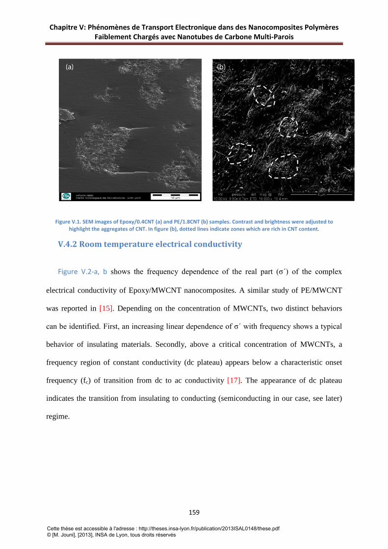
Chapitre V: Phénomènes de Transport Electronique dans des Nanocomposites Polymères Faiblement Chargés avec Nanotubes de Carbone Multi-Parois
159
Figure V.1. SEM images of Epoxy/0.4CNT (a) and PE/1.8CNT (b) samples. Contrast and brightness were adjusted to highlight the aggregates of CNT. In figure (b), dotted lines indicate zones which are rich in CNT content.
V.4.2 Room temperature electrical conductivity
Figure V.2-a, b shows the frequency dependence of the real part (σ´) of the complex
electrical conductivity of Epoxy/MWCNT nanocomposites. A similar study of PE/MWCNT
was reported in [15]. Depending on the concentration of MWCNTs, two distinct behaviors
can be identified. First, an increasing linear dependence of σ´ with frequency shows a typical
behavior of insulating materials. Secondly, above a critical concentration of MWCNTs, a
frequency region of constant conductivity (dc plateau) appears below a characteristic onset
frequency (fc) of transition from dc to ac conductivity [17]. The appearance of dc plateau
indicates the transition from insulating to conducting (semiconducting in our case, see later)
regime.
Cette thèse est accessible à l'adresse : http://theses.insa-lyon.fr/publication/2013ISAL0148/these.pdf © [M. Jouni], [2013], INSA de Lyon, tous droits réservés

Chapitre V: Phénomènes de Transport Electronique dans des Nanocomposites Polymères Faiblement Chargés avec Nanotubes de Carbone Multi-Parois
160
Figure V.2. ac conductivity (real part, σ’) versus frequency for (a) Epoxy/MWCNT and (b) PE/MWCNT nanocomposites. Sample compositions are indicated on the graphs.
Generally, the frequency dependence of ac conductivity at constant temperature can be
described by the equation:
𝜎′(𝜔) = 𝜎(0) + 𝜎𝑎𝑐(𝜔) = 𝜎𝑑𝑐 + 𝐴𝜔𝑠 V(2)
Where 𝜔 is the angular frequency, 𝜎𝑑𝑐 is the frequency independent part of the
conductivity, A is a constant and the exponent s is comprised between 0 and 1 depending on
the frequency range. This behavior is well known for a large variety of materials and was
noted by Jonscher as “Universal Dynamic Response” (UDR) [18]. It is worth to be noted that
σdc and s depend on temperature.
Since the transition from insulating to conducting regime (appearance of dc plateau)
was reached in the Epoxy/0.05CNT sample, the electrical percolation threshold (pc) related to
the arising of the dc conductivity by several orders of magnitude (9 orders) is very close to
0.05 vol.% which can be considered as very low value. For a more precise calculation of pc in
the Epoxy/MWCNT composites, the following scaling law of the percolation theory giving
the dependence of dc conductivity with the volume fraction of conductive fillers can be used:
Cette thèse est accessible à l'adresse : http://theses.insa-lyon.fr/publication/2013ISAL0148/these.pdf © [M. Jouni], [2013], INSA de Lyon, tous droits réservés

Chapitre V: Phénomènes de Transport Electronique dans des Nanocomposites Polymères Faiblement Chargés avec Nanotubes de Carbone Multi-Parois
161
𝜎𝑑𝑐~ (𝑝 − 𝑝𝑐)𝑡 𝑓𝑜𝑟 𝑝 > 𝑝𝑐 V(3)
where dcσ is the dc conductivity of the composite, p is the MWCNTs volume content, cp
is the critical volume fraction at percolation and t a critical exponent related to the
dimensionality of the system.
The extrapolated values of dc conductivity ( ))0(' →= ωσσ dc are plotted as a function of
MWCNTs content in the Figure V.3, and the experimental data are fitted using equation V(3).
The best linear fit for dcσ versus ( )cpp − in log-log scale was found for 001.0049.0 ±=cp
and 𝑡 = 2.24±0.01 (see insert Figure V.3). The value of pc can be considered as low if
compared with the results reported in the literature for Epoxy/bisphenol-A/MWCNT
composites [19-21] (pc ~ 0.1-0.5 vol.%). However, lower values for cp have been reported
when CNTs are aligned or in the case of single walled CNTs [22, 23].
Similarly, for PE/MWCNT nanocomposites, an electrical percolation threshold pc= 0.4
vol.% and an exponent t =1.99 were found in the previous study [15]. This value of pc=0.4
vol.% can be considered from the lowest reported for PE/CNT composites [24-26].
Figure V.3. dc conductivity vs MWCNTs volume content p for (a) Epoxy/MWCNT and (b) PE/MWCNT nanocomposites. The inset shows the best fit in log-log scale according to equation V(3) with pc=0.049 and t=2.24.
Cette thèse est accessible à l'adresse : http://theses.insa-lyon.fr/publication/2013ISAL0148/these.pdf © [M. Jouni], [2013], INSA de Lyon, tous droits réservés

Chapitre V: Phénomènes de Transport Electronique dans des Nanocomposites Polymères Faiblement Chargés avec Nanotubes de Carbone Multi-Parois
162
The values of the exponent 𝑡 = 2.24 and 𝑡 = 1.99 (Epoxy/MWCNT and PE/MWCNT
composites respectively) are close to the theoretical value 𝑡 = 2 suggesting a statistical
percolation in three dimensions [27]. Divergences from the expected value (𝑡 = 2) have been
frequently reported [28, 29].
V.4.3 DC conductivity and charge carriers transport
V.4.3.1 Temperature dependence
Figure V.4-a, b shows the temperature dependence of dc conductivity for Epoxy/pCNT
(p=0.1, 0.2, 0.4, 0.7) and PE/pCNT (p=0.6, 1.8, 5.0 and 8.5 for the masterbatch) samples in a
log-log scale in the temperature range (4 300 K). It has not been possible to measure the
masterbatch of the epoxy based composite due to a too high viscosity preventing the
fabrication of solid samples. We note that samples below 0.1 vol.% for Epoxy/MWCNT are
too resistive at low temperatures to perform electrical measurements.
Figure V.4. dc conductivity vs T for Epoxy/MWCNT (a) and PE/MWCNT (b) in log-log scale. Samples compositions are indicated on the plots dc conductivity vs temperature. The solid line shows the fit according to equation V(6).
In all cases the conductivity is an increasing, semiconductor-type function of temperature.
This shape of curves is relatively simple and does not suggest a specific physical
Cette thèse est accessible à l'adresse : http://theses.insa-lyon.fr/publication/2013ISAL0148/these.pdf © [M. Jouni], [2013], INSA de Lyon, tous droits réservés

Chapitre V: Phénomènes de Transport Electronique dans des Nanocomposites Polymères Faiblement Chargés avec Nanotubes de Carbone Multi-Parois
163
interpretation without a deeper analysis. We started the analysis by studying the “reduced
activation energy” [30, 31].
𝑊(𝑇) = 𝑑 𝑙𝑛𝜎𝑑𝑐𝑑 ln 𝑇
= 𝑑 𝑙𝑛𝜎𝑑𝑐𝑑𝑇
𝑇 V(4)
A log-log plot of W as a function of T is a good starting point for the analysis of σdc(T).
For example, it proved to be very useful in identifying the metal-insulator transition in highly
doped conducting polymers at low temperatures [32]. Generally, in the low temperature limit
𝑇 → 0, three types of behavior of the dependence logW vs logT can occur in the case of an
increasing σdc(T): i) if lim𝑇→0 𝜎𝑑𝑐 (𝑇) ≠ 0, then log W is an increasing function of log T, ii) if
σdc(T) is a power law, the log W is constant and iii) if lim𝑇→0 𝜎𝑑𝑐 (𝑇) = 0 and if σdc(T) is not a
power law, then log W is a decreasing function of log T. In the frame of (iii), a special case
can occur: iv) when σdc(T) is of the stretched exponential type
𝜎𝑑𝑐∝ exp[−𝑇0𝑇γ
] V(5)
where T0 and γ are positive constants, then log W vs log T is a decreasing linear function
with the slope (−γ).
The dependences of log W vs log T of Epoxy/0.2CNT and PE/1.2CNT are shown in
Figure V.5 as typical examples.
Cette thèse est accessible à l'adresse : http://theses.insa-lyon.fr/publication/2013ISAL0148/these.pdf © [M. Jouni], [2013], INSA de Lyon, tous droits réservés

Chapitre V: Phénomènes de Transport Electronique dans des Nanocomposites Polymères Faiblement Chargés avec Nanotubes de Carbone Multi-Parois
164
Figure V.5. Plots of the reduced activation energy (W) vs T in Log-Log scale showing the evidence of two VRH regimes (two different exponents).
The Figure V.5 shows a dependence of the type (iii) and clearly rules out the possibilities
(i) and (ii). This means that e.g. the FIT model, which leads to σdc (T) of the type (i), can be
excluded as a possible mechanism of the conductivity in our composites. A more detailed
examination of the dependences in Figure V.5 reveals that they have two approximately linear
parts which can be fitted by straight-lines with the slopes (-γ) ~- 0.74 (below T ~ 30K) and
(–γ) ~ - 0.47 (over T ~ 80K) in the case of the epoxy based composite. In the case of PE
based composite the value 0.71 is found for γ in the 4 – 30 K temperature range and γ∼ 0.53 at
temperatures above 80K.
Two linear regions in the curves in Figure V.5 suggest that a combination of two
functions of the type (iv) with different exponents γ could describe the observed dependence
σdc(T) in the studied composites. We therefore tried to fit σdc(T) with functions corresponding
to two simple possibilities: two resistances in parallel or two resistances in series. From these
Cette thèse est accessible à l'adresse : http://theses.insa-lyon.fr/publication/2013ISAL0148/these.pdf © [M. Jouni], [2013], INSA de Lyon, tous droits réservés
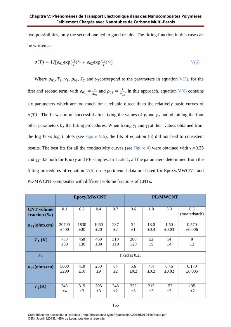
Chapitre V: Phénomènes de Transport Electronique dans des Nanocomposites Polymères Faiblement Chargés avec Nanotubes de Carbone Multi-Parois
165
two possibilities, only the second one led to good results. The fitting function in this case can
be written as
𝜎(𝑇) = 1/[𝜌01exp(𝑇1𝑇
)𝛾1 + 𝜌02exp(𝑇2𝑇
)𝛾2] V(6)
Where 𝜌01, 𝑇1, 𝛾1, 𝜌02, 𝑇2 and 𝛾2correspond to the parameters in equation V(5), for the
first and second term, with 𝜌01 = 1𝜎01
and 𝜌02 = 1𝜎02
. In this approach, equation V(6) contains
six parameters which are too much for a reliable direct fit to the relatively basic curves of
𝜎(𝑇) . The fit was more successful after fixing the values of 𝛾1and 𝛾2 and obtaining the four
other parameters by the fitting procedures. When fixing γ1 and γ2 at their values obtained from
the log W vs log T plots (see Figure V.5), the fits of equation (6) did not lead to consistent
results. The best fits for all the conductivity curves (see Figure 4) were obtained with γ1=0.25
and γ2=0.5 both for Epoxy and PE samples. In Table 1, all the parameters determined from the
fitting procedures of equation V(6) on experimental data are listed for Epoxy/MWCNT and
PE/MWCNT composites with different volume fractions of CNTs.
Epoxy/MWCNT PE/MWCNT
CNT volume fraction (%)
0.1 0.2 0.4 0.7 0.6 1.8 5.0 8.5 (masterbatch)
𝝆𝟎𝟏(ohm.cm) 20700 ±400
1830 ±30
1060 ±20
237 ±2
34 ±1
18.0 ±0.4
1.50 ±0.03
0.570 ±0.006
𝑻𝟏 (K) 730 ±50
450 ±30
460 ±30
310 ±10
200 ±20
52 ±9
14 ±4
9 ±2
𝜸𝟏 fixed at 0.25
𝝆𝟎𝟐(ohm.cm) 5600 ±200
410 ±10
250 ±9
64 ±2
5.6 ±0.2
4.4 ±0.2
0.46 ±0.02
0.170 ±0.005
𝑻𝟐(K) 343 ±4
315 ±3
303 ±3
248 ±2
322 ±3
213 ±3
152 ±3
135 ±2
Cette thèse est accessible à l'adresse : http://theses.insa-lyon.fr/publication/2013ISAL0148/these.pdf © [M. Jouni], [2013], INSA de Lyon, tous droits réservés

Chapitre V: Phénomènes de Transport Electronique dans des Nanocomposites Polymères Faiblement Chargés avec Nanotubes de Carbone Multi-Parois
166
𝜸𝟐 fixed at 0.5
Table V.1. Parameters obtained from the fitting procedures of equation V(6) to the experimental data
Since in the studied material quasi 1-D objects (CNTs or bundles of CNTs) are
embedded in a 3-D matrix, it is reasonable to adopt the interpretation of this result in the
framework of a model based on a combination of 1-D (γ=0.5) and 3-D (γ = 0.25) variable
range hopping (VRH) processes [33]. The 3-D VRH can then be interpreted as hopping
between the CNTs or, more probably, between the CNT bundles. The 1-D VRH can
correspond to hopping along the CNTs or CNT bundles, between their more conducting
(more doped or less disordered) regions. The 1-D behavior has already been reported and was
interpreted as charge hopping through the 1-D MWCNTs [34]. 3D-VRH regime was also
observed in composites [12] and Yosida and Oguro identified this behavior as conduction
within the CNT bundles (intrabundle hopping) or between the CNT bundles (interbundle
hopping) in the case of nanoporous materials composed of CNTs only [35]. Nevertheless, the
coexistence in a broad temperature range of the two resistivity mechanisms linked in series
has never been reported. In our model, the conducting path might be a succession of 1-D
hopping along the CNTs (CNT bundles) and occasional 3-D hopping between the CNTs
(CNT bundles).
To better illustrate the respective role played by the 3-D and 1-D components in the
equation V(6), Figure V.6 shows the resulting fit of equation V(6) and its two components
separately.
Cette thèse est accessible à l'adresse : http://theses.insa-lyon.fr/publication/2013ISAL0148/these.pdf © [M. Jouni], [2013], INSA de Lyon, tous droits réservés

Chapitre V: Phénomènes de Transport Electronique dans des Nanocomposites Polymères Faiblement Chargés avec Nanotubes de Carbone Multi-Parois
167
Figure V.6. Simulation of global function of equation V(6) and its components in comparison with experimental data.
For reason of clarity, Figure V.6 only shows the results for Epoxy/0.1CNT and
PE/0.6CNT. The results for other samples are qualitatively similar and our conclusions stand
for both Epoxy and PE samples at all CNT contents. From these plots, it is clear that the
equation V(6) gives full description of the temperature dependence of dc conductivity as the
sum of two functions corresponding to two VRH regimes. These results highlight that the two
temperature regions in Figure V.5 cannot be studied separately, with only one predominant
mechanism in each of them. Instead, a combination of two mechanisms has to be considered
in the whole temperature range. From this model, it is expected two general conclusions for
the limiting behavior: i) in the low temperature limit of the model, lim𝑇→0𝜌02exp(𝑇2𝑇 )𝛾2
𝜌01exp(𝑇1𝑇 )𝛾1= ∞ ,
in the low temperature limit the transport is expected to be limited by the γ2-term resistance,
i.e. by the 1D-VRH and ii) at the high temperature limit T→∞, σ(T) should tend to a constant
value 1𝜌01+𝜌02
. This behavior is well confirmed in Figure V.6. When T→0, the charge transport
(represented by the resistivity) is fully governed by the 1D-VRH term, the relative
contribution of the 3D-VRH term to the total resistivity is negligible for T<10K. As for the
high temperature limit, the analysis of the fit results (see Table 1) shows that for any CNTs
Cette thèse est accessible à l'adresse : http://theses.insa-lyon.fr/publication/2013ISAL0148/these.pdf © [M. Jouni], [2013], INSA de Lyon, tous droits réservés

Chapitre V: Phénomènes de Transport Electronique dans des Nanocomposites Polymères Faiblement Chargés avec Nanotubes de Carbone Multi-Parois
168
volume fraction, 𝜌01 > 𝜌02; which means that, at temperature close to the room temperature
the conductivity tends to a value close to 1𝜌01
and the transport is mainly limited by the 3D-
VRH. In the frame of our interpretation, this result means that in the low temperature limit,
the charge transport is limited by the resistance of the CNTs (CNT bundles), while at
temperatures close to the room temperature it is limited by the hopping between CNTs (CNT
bundles).
V.4.3.2 CNTs volume fraction dependence
Another aspect of the problem is the dependence of the conductivity and its parameters
on the volume fraction of the conducting filler p. Above the percolating threshold pc we
observe the typical dependence σ(p) of a percolating system for both Epoxy/MWCNT and
PE/MWCNT samples (see Equation V (3)). At the same time, the σ(T) analysis shows that the
conductivity in all studied samples is driven by hopping processes of the VRH type even at
room temperature. Accordingly it means that ultimately the inter-bundles charge transfer in a
“continuous” percolating network of CNTs is also dominated by a VRH process. The
presence of the 3D-VRH component at room temperature suggests that, in the CNTs rich
semiconducting regions, the CNT bundles may not be in direct contact and not form a
homogeneous conducting medium with the transport only limited by the resistance of the
CNTs.
In such conditions, increasing the overall volume fraction of CNTs p can induce i) an
increase of the relative volume of the semiconducting region, keeping the local volume
fraction of CNTs in the semiconducting region approximately constant, ii) an increase of the
local volume fraction of CNTs in the semiconducting region, keeping the relative volume of
the semiconducting region approximately constant, iii) a combination of these two effects.
This can be experimentally tested by studying the dependence of 1/T1 on p. In the VRH, this
Cette thèse est accessible à l'adresse : http://theses.insa-lyon.fr/publication/2013ISAL0148/these.pdf © [M. Jouni], [2013], INSA de Lyon, tous droits réservés

Chapitre V: Phénomènes de Transport Electronique dans des Nanocomposites Polymères Faiblement Chargés avec Nanotubes de Carbone Multi-Parois
169
quantity is related to the activation energy and length of hops experienced by the charge
carriers. It is proportional to the local density of states at the Fermi level, therefore also to the
local concentration of the hopping sites and consequently also (in a first approximation) to the
local volume fraction of CNTs. Considering 1/T2, it reflects the properties of individual CNTs
(CNT bundles), it should in principle be independent on their local (and therefore also overall)
volume fraction in the composite. We note that the considerations above hold if the
morphology of individual CNTs (CNT bundles) does not depend on the local volume fraction
of CNTs in the composite.
The dependences of 1/T1, 1/T2 on p are shown in Figure V.7 for both nanocomposites.
Figure V.7. Inverse (1/T) of Mott characteristic temperatures vs volume fraction of MWCNTs. (a) Epoxy and (b) PE matrix.
We observe a strong variation only in the case of 1/T1 of PE/MWCNT. The linear fit
of 1/T1vs p with the intercept 0 is also shown in this case. This result clearly indicates that the
local volume fraction of CNTs is approximately proportional to the overall volume fraction p.
In other words, in PE/MWCNT the effect of increasing the overall volume fraction of CNTs p
is of the type (ii) or (iii). In all other cases the variation is weak (negligible in comparison
with 1/T1 of PE/MWCNT). The approximately constant value of 1/T1 in Epoxy/MWCNT
indicates that in this composite the increase of the overall volume fraction of CNTs p results
Cette thèse est accessible à l'adresse : http://theses.insa-lyon.fr/publication/2013ISAL0148/these.pdf © [M. Jouni], [2013], INSA de Lyon, tous droits réservés

Chapitre V: Phénomènes de Transport Electronique dans des Nanocomposites Polymères Faiblement Chargés avec Nanotubes de Carbone Multi-Parois
170
from the effect (i). The approximately constant value of 1/T2 in both composites is a support
for the model in which the conductivity of individual CNTs (bundles) is independent of their
volume fraction in the composite.
This analysis leads to the conclusion that the composites Epoxy/MWCNT and
PE/MWCNT behave very differently from the point of view of the evolution of the
morphology of the percolating semiconducting phase when the overall volume fraction of
CNTs p is decreased. In Epoxy/MWCNT when decreasing p, this semiconducting phase
keeps similar properties independently of its local volume and of eventual changes in shape
and forms a percolating network even at very low p. In PE/MWCNT, on the contrary, the
local properties of this phase, especially the local volume fraction of CNTs, strongly vary
with p. With decreasing p, CNTs (bundles) are less and less densely packed within a quasi-
constant volume in this case. It is noticeable that even in the masterbatch with a high
concentration of CNTS (8.5 vol%), all the electrical characteristics are consistently recovered
as a function of the CNTs content.
The difference of behaviors of the two composites can be explained by the noticeable
difference of structure of the two polymer matrices. Epoxy is a typical amorphous polymer.
When the masterbatch with CNTs is diluted with the unfilled epoxy resin, it remains
practically segregated and unchanged (see Figure 1-a), likely because during the process when
the amorphous matrix solidifies, it can accommodate it easily.
The situation is fundamentally different in PE, where, during the crystallization
process, the CNTs (bundles) are confined to the amorphous regions surrounding the
crystallites [36]. We have checked by X-ray diffraction measurements that the degree of
crystallinity (80% in weight) is not changed by varying the CNT content p from 0 to 8.5
vol%. Since the available volume of the amorphous regions is limited, increasing the number
Cette thèse est accessible à l'adresse : http://theses.insa-lyon.fr/publication/2013ISAL0148/these.pdf © [M. Jouni], [2013], INSA de Lyon, tous droits réservés

Chapitre V: Phénomènes de Transport Electronique dans des Nanocomposites Polymères Faiblement Chargés avec Nanotubes de Carbone Multi-Parois
171
of the CNTs (bundles) in the composite results in increasing the density of their packing, i.e.
increasing their local volume fraction, as observed in our work.
It was argued that segregating the conducting phase into a limited percolating volume
surrounding the insulating matrix could be efficient way to decrease the percolation threshold
and increase the conductivity of the polymer/CNT composites [37, 38]. Both of our
composites have indeed low percolation thresholds and form segregated phases. Nevertheless,
in Epoxy/MWCNT the percolation threshold is much lower than in PE/MWCNT composites.
The semicrystalline character of PE matrix seems to reduce significantly the efficiency of
charge transfer along the percolating path especially in constrained spaces separating different
semi-conducting domains. That may result in a “bottleneck effect” for charge carriers. More
generally, our results indicate that using a polymer/CNT masterbatch is an efficient method to
prepare conducting polymer/CNT composites and that for the composites prepared by this
way the amorphous polymers are probably more promising candidates than the
semicrystalline ones.
Cette thèse est accessible à l'adresse : http://theses.insa-lyon.fr/publication/2013ISAL0148/these.pdf © [M. Jouni], [2013], INSA de Lyon, tous droits réservés

Chapitre V: Phénomènes de Transport Electronique dans des Nanocomposites Polymères Faiblement Chargés avec Nanotubes de Carbone Multi-Parois
172
V.5 Conclusion
In this study, we have compared electrical properties of two families of polymer
matrix/CNTs nanocomposites: one made with an amorphous Epoxy matrix, the other one with
semicrystalline PE matrix. For both, we found a low electrical threshold if compared with
state of the art. However in Epoxy the threshold is ten times smaller (0.05 vol%) than in PE
(0.4 vol%). Above percolation threshold, the study of the conductivity as a function of the
temperature has revealed a typical semiconducting VRH behavior of the nanocomposites.
This result shows that MWCNTs cannot be considered as classical metallic nanofillers in
these composites. In the framework of this model we have shown that the semiconducting
behavior of the MWCNT/polymer nanocomposites can be described in fact by a combination
of a 1D and 3D VRH regimes in series. The first one predominates the macroscopic electrical
behavior at the low temperature limit T→0K while the second one dominates at high
temperatures close to room temperature. We propose that these two components correspond to
intra and inter CNTs bundles charge carriers hopping. Because of the difference of
morphology between the two matrices, amorphous for Epoxy and semicrystalline for PE, the
local volume fraction of segregated CNTs rich domains does not evolve the same way when
the CNTs content is decreased. While it does not change significantly in Epoxy, by contrast
this local volume fraction decreases in a quasi-proportional way in PE , starting from the
situation prevailing in the masterbatch. We have shown that this fact is directly reflected by
the evolution of the Mott temperature parameter T1 found in PE based nanocomposites at
different CNTs contents. Finally, the macroscopic electrical behavior of these composites is
highly conditioned by the way these more or less dense semiconducting domains are
connected each other all along the percolating path. From this point of view, in the present
Cette thèse est accessible à l'adresse : http://theses.insa-lyon.fr/publication/2013ISAL0148/these.pdf © [M. Jouni], [2013], INSA de Lyon, tous droits réservés

Chapitre V: Phénomènes de Transport Electronique dans des Nanocomposites Polymères Faiblement Chargés avec Nanotubes de Carbone Multi-Parois
173
case, it seems that the choice of an amorphous matrix as Epoxy gives the best result in terms
of efficiency of these connections resulting in a very low electrical percolation threshold.
Cette thèse est accessible à l'adresse : http://theses.insa-lyon.fr/publication/2013ISAL0148/these.pdf © [M. Jouni], [2013], INSA de Lyon, tous droits réservés

Chapitre V: Phénomènes de Transport Electronique dans des Nanocomposites Polymères Faiblement Chargés avec Nanotubes de Carbone Multi-Parois
174
V.6 References
[1] Iijima S. Helical microtubules of graphitic carbon. Nature. 1991;354(6348):56-58.
[2] Golnabi H. Carbon nanotube research developments in terms of published papers and patents, synthesis and production. Scientia Iranica. 2012;19(6):2012-2022.
[3] Merhari L. Hybrid nanocomposites for nanotechnology electronic, optical, magnetic and biomedical applications. New York: Springer; 2009.
[4] Rahman A, Ali I, Al Zahrani SM, Eleithy RH. A review of the applications of nanocarbon polymer composites. NANO. 2011;6(3):185-203.
[5] Rajesh, Ahuja T, Kumar D. Recent progress in the development of nano-structured conducting polymers/nanocomposites for sensor applications. Sensors and Actuators B: Chemical. 2009;136(1):275-286.
[6] Al-Saleh MH, Sundararaj U. A review of vapor grown carbon nanofiber/polymer conductive composites. Carbon. 2009;47(1):2-22.
[7] Logakis E, Pandis C, Pissis P, Pionteck J, Pötschke P. Highly conducting poly(methyl methacrylate)/carbon nanotubes composites: Investigation on their thermal, dynamic-mechanical, electrical and dielectric properties. Composites Science and Technology. 2011;71(6):854-862.
[8] Prasher RS, Chang J-Y, Saucius I, Narasimhan S, Chau D, Chrysler G, Myers A, Prstic S, Hu C. Nano and Micro Technology-Based Next Generation Package-Level Cooling Solutions. Intel Technology Journal. 2005;9(4):285-296.
[9] Moniruzzaman M, Winey KI. Polymer Nanocomposites Containing Carbon Nanotubes. Macromolecules. 2006;39(16):5194-5205.
[10] Connor MT, Roy S, Ezquerra TA, Baltá Calleja FJ. Broadband ac conductivity of conductor-polymer composites. Physical Review B. 1998;57(4):2286-2294.
[11] Mdarhri A, Brosseau C, Zaghrioui M, El Aboudi I. Electronic conduction and microstructure in polymer composites filled with carbonaceous particles. Journal of Applied Physics. 2012;112(3):034118-034113.
[12] Sangeeth CSS, Kannan R, Pillai VK, Menon R. Charge transport in functionalized multi-wall carbon nanotube-Nafion composite. Journal of Applied Physics. 2012;112(5):053706-053706.
[13] Chauvet O, Benoit JM, Corraze B. Electrical, magneto-transport and localization of charge carriers in nanocomposites based on carbon nanotubes. Carbon. 2004;42(5-6):949-952.
[14] Sundaray B, Choi A, Park YW. Highly conducting electrospun polyaniline-polyethylene oxide nanofibrous membranes filled with single-walled carbon nanotubes. Synthetic Metals. 2010;160(9-10):984-988.
Cette thèse est accessible à l'adresse : http://theses.insa-lyon.fr/publication/2013ISAL0148/these.pdf © [M. Jouni], [2013], INSA de Lyon, tous droits réservés

Chapitre V: Phénomènes de Transport Electronique dans des Nanocomposites Polymères Faiblement Chargés avec Nanotubes de Carbone Multi-Parois
175
[15] Jouni M, Boiteux G, Massardier V. New melt mixing polyethylene multiwalled carbon nanotube nanocomposites with very low electrical percolation threshold. Polym Adv Technol. 2013;24(10):909-915.
[16] Kremer F, Schöenhals A. Broadband dielectric spectroscopy. Berlin: Springer; 2003.
[17] Dyre JC, Schroder TB. Universality of ac conduction in disordered solids. Reviews of Modern Physics. 2000;72(3):873-892.
[18] Jonscher AK. Universal Dielectric Response. Nature. 1977;267(5613):673-679.
[19] Kovacs JZ, Velagala BS, Schulte K, Bauhofer W. Two percolation thresholds in carbon nanotube epoxy composites. Composites Science and Technology. 2007;67(5):922-928.
[20] Guadagno L, De Vivo B, Di Bartolomeo A, Lamberti P, Sorrentino A, Tucci V, Vertuccio L, Vittoria V. Effect of functionalization on the thermo-mechanical and electrical behavior of multi-wall carbon nanotube/epoxy composites. Carbon. 2011;49(6):1919-1930.
[21] Bai JB, Allaoui A. Effect of the length and the aggregate size of MWNTs on the improvement efficiency of the mechanical and electrical properties of nanocomposites-experimental investigation. Composites Part A: Applied Science and Manufacturing. 2003;34(8):689-694.
[22] Bryning MB, Islam MF, Kikkawa JM, Yodh AG. Very Low Conductivity Threshold in Bulk Isotropic Single-Walled Carbon Nanotube–Epoxy Composites. Advanced Materials. 2005;17(9):1186-1191.
[23] Sandler JKW, Kirk JE, Kinloch IA, Shaffer MSP, Windle AH. Ultra-low electrical percolation threshold in carbon-nanotube-epoxy composites. Polymer. 2003;44(19):5893-5899.
[24] Ha H, Ha K, Kim SC. An empirical equation for electrical resistivity of thermoplastic polymer/multi-walled carbon nanotube composites. Carbon. 2010;48(7):1939-1944.
[25] McNally T, Pötschke P, Halley P, Murphy M, Martin D, Bell SEJ, Brennan GP, Bein D, Lemoine P, Quinn JP. Polyethylene multiwalled carbon nanotube composites. Polymer. 2005;46(19):8222-8232.
[26] Zhang Q, Rastogi S, Chen D, Lippits D, Lemstra PJ. Low percolation threshold in single-walled carbon nanotube/high density polyethylene composites prepared by melt processing technique. Carbon. 2006;44(4):778-785.
[27] Gingold DB, Lobb CJ. Percolative conduction in three dimensions. Physical Review B. 1990;42(13):8220-8224.
[28] Logakis E, Pissis P, Pospiech D, Korwitz A, Krause B, Reuter U, Pötschke P. Low electrical percolation threshold in poly(ethylene terephthalate)/multi-walled carbon nanotube nanocomposites. European Polymer Journal. 2010;46(5):928-936.
[29] Logakis E, Pandis C, Peoglos V, Pissis P, Pionteck J, Pötschke P, Micusik M, Omastova M. Electrical/dielectric properties and conduction mechanism in melt processed polyamide/multi-walled carbon nanotubes composites. Polymer. 2009;50(21):5103-5111.
[30] Zabrodskii AG. Electrical-Conductivity of heavily doped compensated N-type Germanium produced by neutron doping Soviet Physics Semiconductors-Ussr. 1980;14(6):670-676.
Cette thèse est accessible à l'adresse : http://theses.insa-lyon.fr/publication/2013ISAL0148/these.pdf © [M. Jouni], [2013], INSA de Lyon, tous droits réservés

Chapitre V: Phénomènes de Transport Electronique dans des Nanocomposites Polymères Faiblement Chargés avec Nanotubes de Carbone Multi-Parois
176
[31] Zabrodskii AG, Zinov'eva KN. Low-temperature conductivity and metal-insulator transition in compensate n-Ge. Sov Phys JEPT. 1984;59(2):425-432.
[32] Menon R, Yoon HG, Moses D, Heeger A. Metal-Insulator Transition in Doped Conducting Polymers. In: Skotheim T, Elsenbaumer R, Reynolds J, editors. Handbook of Conducting Polymers, Second Edition. New York1998.
[33] Mott NF, Davis EA. Electronic processes in non-crystalline materials. New York: Oxford; 1979.
[34] Kim HM, Choi M-S, Joo J, Cho SJ, Yoon HS. Complexity in charge transport for multiwalled carbon nanotube and poly(methyl methacrylate) composites. Physical Review B. 2006;74(5):054202.
[35] Yosida Y, Oguro I. Variable range hopping conduction in bulk samples composed of single-walled carbon nanotubes. Journal of Applied Physics. 1999;86(2):999-1003.
[36] Jol S, Fenouillot F, Rousseau A, Masenelli-Varlot K, Gauthier C, Briois J-F. Drastic Modification of the Dispersion State of Submicron Silica during Biaxial Deformation of Poly(ethylene terephthalate). Macromolecules. 2007;40(9):3229-3237.
[37] Mamunya Y. Carbon Nanotubes as Conductive Filler in Segregated Polymer Composites - Electrical Properties. In: Yellampalli S, editor. Carbon Nanotubes - Polymer Nanocomposites 2011. p. 173-196.
[38] Mamunya YP, Levchenko VV, Rybak A, Boiteux G, Lebedev EV, Ulanski J, Seytre G. Electrical and thermomechanical properties of segregated nanocomposites based on PVC and multiwalled carbon nanotubes. Journal of Non-Crystalline Solids. 2010;356(11-17):635-641.
Cette thèse est accessible à l'adresse : http://theses.insa-lyon.fr/publication/2013ISAL0148/these.pdf © [M. Jouni], [2013], INSA de Lyon, tous droits réservés

178
Annexe V.A.1
Clichés MEB réalisées sur deux type des nanoparticules d’argent
La Figure V.A.8 montre la différence au niveau de la morphologie entre les deux lots des
nanoparticules d’argent utilises pour préparer nos composites. Malheureusement, l’argent
obtenu pour préparer les composites à base d’époxy ne présente pas la meme morphologie
ainsi les caractéristiques physiques. Ce qui nous a constitué une des difficultés pour préparer
des composites Epoxy/MWCNT/Ag avec des bonnes propriétés électriques.
Figure V.A.8. Clichées MEB des deux lots des nanoparticules d’argent utilisés dans le cadre de préparation des composites à base de PE (image à gauche) et Epoxy (image à droite).
Cette thèse est accessible à l'adresse : http://theses.insa-lyon.fr/publication/2013ISAL0148/these.pdf © [M. Jouni], [2013], INSA de Lyon, tous droits réservés

179
Annexe V.A.2
Conductivités thermique des composites Epoxy/MWCNT et Epoxy/MWCNT/Ag
La Figure V.A.9 montre la variation des conductivités thermiques des composites
Epoxy/MWCNT préparés dans le cadre de cette étude. On peut bien remarquer que
l’incorporation des MWCNT ne contribue que faiblement à une augmentation de la
conductivité thermique par rapport à celle de l’époxy non chargée. Les composites
PE/MWCNT (voir chapitre II) présentaient un comportement différent. Cependant, il faut
prendre en compte que les fractions volumiques des MWCNTs ajoutées dans le cas d’époxy
sont beaucoup plus faibles que le cas de PE. Ceci rend les mesures plus sensibles et la
comparaison non judicieuse. Enfin, il faut rappeler que plusieurs facteurs comme la
cristallinité, la résistance à l’interface entre polymère et charge et la polarité de matrice
(époxy ≠ PE)... jouent un rôle assez important dans la prédiction des conductivités thermiques
des composites polymères.
Figure V.A.9. Conductivité thermique des composites Epoxy/MWCNT préparés dans le cadre de ce travail de thèse.
La Figure V.A.10 montre l’évolution de la conductivité thermique dans les composites
hybrides Epoxy/MWCNT/Ag. Il est possible d’observer que les composites hybrides ont une
conductivité thermique supérieure à celle de l’époxy. L’addition d’argent pour une même
Cette thèse est accessible à l'adresse : http://theses.insa-lyon.fr/publication/2013ISAL0148/these.pdf © [M. Jouni], [2013], INSA de Lyon, tous droits réservés

180
concentration en MWCNTs a aboutit à une amélioration supplémentaire (voir échantillons
Epoxy/0.2CNT/1Ag et Epoxy/0.2CNT/3Ag). Mais d’autre part, on peut remarquer que la
contribution des MWCNTs à la conductivité thermique est significativement modifiée en
présence d’argent. Ceci se manifeste par des valeurs similaires des conductivités thermiques
dans les échantillons Epoxy/0.4CNT/3Ag et Epoxy/0.2CNT/5Ag. Ces observations nous
montrent que la conduction thermique dans ces composites hybrides est relativement
différente de la conduction électrique pour laquelle l’argent n’a pas apporté de contribution
significative .
Figure V.A.10. Conductivité thermique des composites hybrides Epoxy/MWCNT/Ag. L'indice numérique avant les symboles "CNT" et "Ag" indique le pourcentage volumique de ces charges.
Cette thèse est accessible à l'adresse : http://theses.insa-lyon.fr/publication/2013ISAL0148/these.pdf © [M. Jouni], [2013], INSA de Lyon, tous droits réservés

181
Cette thèse est accessible à l'adresse : http://theses.insa-lyon.fr/publication/2013ISAL0148/these.pdf © [M. Jouni], [2013], INSA de Lyon, tous droits réservés

Chapitre VI : Caractérisation des Composites Polymères Conducteurs par RMN du Solide : Mise en Evidence d’un Effet d’Ecran
182
Chapitre VI : Article 5
Caractérisation des Composites Polymères Conducteurs par RMN du Solide : Mise en Evidence d’un Effet d’Ecran
Cette thèse est accessible à l'adresse : http://theses.insa-lyon.fr/publication/2013ISAL0148/these.pdf © [M. Jouni], [2013], INSA de Lyon, tous droits réservés

Chapitre VI : Caractérisation des Composites Polymères Conducteurs par RMN du Solide : Mise en Evidence d’un Effet d’Ecran
183
Introduction-Résumé
La Résonance Magnétique Nucléaire (RMN) est une technique bien connue pour son
potentiel de caractérisation à l’échelle moléculaire. Dans le cas des composites polymères, la
RMN est généralement utilisée pour fournir des informations sur la structure chimique et
moins fréquemment sur les interactions charges/matrices. Pour les études focalisées sur les
interactions entre charges et matrice polymère, on préfèrera la RMN à l’état solide pour éviter
les pertes d’interactions dues à la dissolution de l’échantillon en RMN liquide.
Cependant, cette spectroscopie n’a souvent pas pu être utilisée pour caractériser des
composites polymères conducteurs, en particulier à cause de la présence de charges
conductrices comme les MWCNTs qui peuvent contenir des espèces paramagnétiques.
Cette partie concerne l’utilisation de la RMN solide en vue de caractériser nos
nanocomposites polymères conducteurs. Etant donné le nombre très limité de publications qui
traitent de ce sujet, on s’intéressera à l’application de la RMN solide pour étudier les
domaines et dynamiques moléculaires dans nos composites de PE/MWCNT et PE/Ag-NPs.
Malgré les différents types de difficultés relatives à ce type de manipulations, on a réussi à
extraire des informations importantes qui seront reliées aux autres analyses faites par les
méthodes de caractérisation classique des composites polymères conducteurs. Une
compréhension plus concrète a été établie entre structure et propriétés.
De plus, et dans le contexte un peu particulier et original de ce sujet, on a pu interpréter un
nouveau phénomène lié à la diminution du signal RMN avec la fraction volumique des Ag-
NPs dans le cas des composites PE/Ag-NPs. Cette diminution a été attribuée à l’apparition
d’un effet d’écran dû aux particules d’argent qui cause une absorption du signal
radiofréquence, que l’on a pu modéliser.
Cette thèse est accessible à l'adresse : http://theses.insa-lyon.fr/publication/2013ISAL0148/these.pdf © [M. Jouni], [2013], INSA de Lyon, tous droits réservés

Chapitre VI : Caractérisation des Composites Polymères Conducteurs par RMN du Solide : Mise en Evidence d’un Effet d’Ecran
184
VI. Article 5 (Soumis dans Composites Science and Technology)
Solide State NMR on Conductive Polymer Composites: Skin Effect Observation
Cette partie correspond à une soumission de publication au Journal Composites Science
and Technology of dont la référence pourrait être :
Jouni M, Boisson F, Bardet M, Buzlukov A, Eddari A, Massardier V, Boiteux G Solide State NMR on Conductive Polymer Composites: Skin Effect Observation.
VI.1 Abstract
High-resolution solid state Nuclear Magnetic Resonance (NMR) combined with other
investigations was applied to provide essential informations on conductive polymer
composites based on high density polyethylene (HDPE) as matrix and multiwalled carbon
nanotubes (MWCNTs) or silver nanoparticles (Ag-NPs) as fillers. All composites were
prepared by melt mixing using extrusion process and characterized electrically. By studying
the general features of NMR spectra and the molecular dynamic from NMR relaxation
parameters, it was possible to get structural informations about the organization and
dispersion of fillers. Due to the paramagnetic or conductive nature of the fillers, a loss of
NMR signal with increasing the amount of fillers was found. In the case of silver
nanoparticles, this phenomenon was attributed to a skin effect caused by the conductive
properties of fillers limiting the adsorption of radiofrequency.
Cette thèse est accessible à l'adresse : http://theses.insa-lyon.fr/publication/2013ISAL0148/these.pdf © [M. Jouni], [2013], INSA de Lyon, tous droits réservés

Chapitre VI : Caractérisation des Composites Polymères Conducteurs par RMN du Solide : Mise en Evidence d’un Effet d’Ecran
185
VI.2 Introduction
Conductive polymer composites (CPCs) have been recently the object of intense
researches [1-4]. The large potential applications and advantages of these composites select
them to be privileged on many other materials [5-7]. Indeed, CPCs can serve in many sectors
involving particular physical characteristics such as electric dissipation and electromagnetic
shielding interference (EMI) for use in automotive and aerospace domains.
Despite the large number of papers published in this area [8-12], there are still some
important investigations which have not been published as most of studies reported the
electrical properties of these composites as basic results. A better description can be given
when the later are interpreted in the scope of polymer microstructure and the
organization/dispersion of conductive fillers. Some papers discuss the application of NMR as
a characterization technique for interactions between filler and matrix in polymer composites
[13-17], but there were very few reports concerning CPCs [18]. A reason for this limitation
could be due to the conductive filler itself as reported in a previous study on
polyurethane/carbon fibers composites where the paramagnetic residues of CNFs caused
severe difficulties for NMR observations [18]. Also, there is no paper focused on the
characterization of CPCs when metallic fillers are involved. We believe that solid state NMR
can also be applied in this case to complete investigations carried out with other techniques
(electrical measurements, morphology and microstructure…), giving informations at the
molecular level on the interactions between polymer chains and fillers when studying the
chemical changes and the relaxation parameters of the polymer matrix [19-21] .
In this work, 13C NMR spectra were recorded using either direct excitation (HPDEC-MAS) or
proton to carbon cross polarization (CP-MAS) experiments under magic angle spinning on
Cette thèse est accessible à l'adresse : http://theses.insa-lyon.fr/publication/2013ISAL0148/these.pdf © [M. Jouni], [2013], INSA de Lyon, tous droits réservés

Chapitre VI : Caractérisation des Composites Polymères Conducteurs par RMN du Solide : Mise en Evidence d’un Effet d’Ecran
186
two types of conductive polymer composites (PE/MWCNT and PE/Ag-NPs). The effect of
the incorporation of the conductive fillers on the chemical shift and line width was observed
and discussed. From the 13C magnetization build-up curves recorded under CP MAS
condition as a function of the CP contact time, the proton spin lattice relaxation time in
rotating frame T1ρ(H), and the cross polarization transfer time (TCH) were computed. These
time constants are known to be related to the molecular dynamics of the polymer chains [22].
Moreover, the effect of the amounts of conductive fillers on those constants and on the whole
observed NMR signal was also studied in details;
VI.3 Experimental
VI.3.1 Samples preparation and composition
Two series of polymer composites were investigated by solid-state NMR in this study.
The first is HDPE filled with multiwalled carbon nanotubes (MWCNTs) which are
conductive fillers with high aspect ratio ( l/d~ 160), and the second series is HDPE filled with
silver nanoparticles (Ag-NPs) with an average diameter advanced photo system = 100nm. All
composites were produced in melt state by extrusion using corotating twin-screw
miniextruder (Micro 15 Twin-Screw DSM research) to obtain conductive polymer
composites. More details about the preparation and characterization can be found in [23, 24].
Table VI.1 presents the composition of the samples studied by solid-state NMR. The fillers
loading are given in volume fraction (percentage) which is more reliable for the explanation
and the interpretation of the data obtained from NMR and electrical conductivity
characterizations.
Cette thèse est accessible à l'adresse : http://theses.insa-lyon.fr/publication/2013ISAL0148/these.pdf © [M. Jouni], [2013], INSA de Lyon, tous droits réservés

Chapitre VI : Caractérisation des Composites Polymères Conducteurs par RMN du Solide : Mise en Evidence d’un Effet d’Ecran
187
Series PE/MWCNT PE/Ag-NPS
Fillers loading (vol. %)
0 0.5 8.5 0 2 5 10 20
Table VI.1. Composition of studied composites
VI.3.2 Experimental RMN setup
High-resolution solid-state 13C NMR spectra were mainly recorded on a BRUKER
AVANCE DSX 200 MHz spectrometer operating at 50.3 MHz for 13C, using the combination
of proton to carbon cross-polarization, high-power proton decoupling and magic angle
spinning (CP/MAS) methods. The spinning rate was set in the range of 5000 Hz. The 1H
radio-frequency field strength was set to give proton pulse duration around 3.1 us; the same
value was used for the dipolar decoupling process. The 13C radio frequency field strength was
obtained by matching the Hartman–Hahn condition. Recording 1024 transients with contact
time and recycle delay, respectively of 1 ms and 3s represented standard conditions. The
chemical shift values were obtained via the glycine carbonyl signal, set at 176.03 ppm relative
to tetramethylsilane (TMS). In order to record quantitative data 13C spectra were recorded
with direct 13C excitation with high power proton decoupling during the NMR signal
acquisition experiment. A 60 s recycling delay was used to assure a complete relaxation of
13C magnetizations.
In order to obtain T1ρH and TCH values, the carbon magnetization build-up under CP
conditions was performed by varying the contact times values from 10us to 20ms and worked
out as described in the experimental section of one of our previously published article [21].
From these experiments, T1ρH and TCH were computed by using simplex fitting program
(SIMFIT) provided by Bruker. Dilution was performed by grinding the sample in a mortar
with silica. Both compounds were precisely weighted, and the amount of material used to fill
the 7 mm diameter rotors was also weighted. Therefore, the NMR signal areas were
Cette thèse est accessible à l'adresse : http://theses.insa-lyon.fr/publication/2013ISAL0148/these.pdf © [M. Jouni], [2013], INSA de Lyon, tous droits réservés

Chapitre VI : Caractérisation des Composites Polymères Conducteurs par RMN du Solide : Mise en Evidence d’un Effet d’Ecran
188
normalized taking into account the mass of polymer in each rotor and the number of transients
acquired for each NMR experiment. Spectrum deconvolution were carried out with DIMFIT
program developed by Massiot et al [25].
VI.4 Results and discussion
VI.4.1 General features of 13 C NMR spectra
The 13C HPDEC-MAS spectrum of the pristine HDPE is shown in Figure VI.1. A 60 s
recycling delay was used which allows to record quantitative data. Deconvolution of the full
signal leads to two distinct peaks (green and blue lines) at 32 and 31 ppm, assigned to the
crystalline and amorphous phases respectively. Such attribution was confirmed by CPMAS
spectrum (not shown here) in which the carbon signal intensity of crystalline part was clearly
enhanced. The crystalline domain contribution was found to be larger than the amorphous
one. It is consistent with the results from X-ray and DSC experiments which showed a high
crystalline content in this PE.
Figure VI.1. HPDEC- MAS solid state NMR spectrum of the neat high density polyethylene. Line 1 and 2 represent the contributions of crystalline and amorphous phases respectively.
Cette thèse est accessible à l'adresse : http://theses.insa-lyon.fr/publication/2013ISAL0148/these.pdf © [M. Jouni], [2013], INSA de Lyon, tous droits réservés

Chapitre VI : Caractérisation des Composites Polymères Conducteurs par RMN du Solide : Mise en Evidence d’un Effet d’Ecran
189
Figure VI.2-a, b shows the HPDEC-MAS spectra of two polyethylene composites,
HDPE/MWCNT loaded with 8.5 vol.% and PE/Ag-NPs loaded with 2 vol.%. As the whole
NMR signal has been normalized for all samples to the amount of polymer inside the rotor, by
comparing with the spectrum of the pristine polyethylene (Figure VI.1), significant decreases
of the signal intensities were recorded for most of the filled PE (see Table VI.2). However, a
third peak with very small intensity was also observed around 33 ppm in the case of PE/Ag-
NPs composites. This peak was almost undetectable in the unfilled PE because of its very low
intensity. The origin of this peak could be related to the monoclinic phase of HDPE as
reported previously [26].
Figure VI.2. 13C HPDEC-MAS spectrum of (a) PE/MWCNT (8.5 vol.%) and (b) PE/Ag-NPs (2 vol.%)
VI.4.2 Line widths, chemical shifts and normalized areas
The values of signal shifts and widths for all composites are listed in Table VI.2. On the
first hand, the chemical shifts of carbon signals for all lines were not altered by the
incorporation of conductive fillers in both types of composites. This means that the chemical
Cette thèse est accessible à l'adresse : http://theses.insa-lyon.fr/publication/2013ISAL0148/these.pdf © [M. Jouni], [2013], INSA de Lyon, tous droits réservés

Chapitre VI : Caractérisation des Composites Polymères Conducteurs par RMN du Solide : Mise en Evidence d’un Effet d’Ecran
190
environments of analyzed carbon atoms are not drastically modified and no strong
interactions between polymer matrix and fillers can be depicted. However the addition of
fillers leads to a broadening of the signals in both cases. Such findings have been reported for
thermoplastic polyurethane matrix filled with carbon fibers and assigned to the difference of
magnetic susceptibility between the fillers and polymer matrix [18]. Note that such
interactions should be averaged by the spinning at the magic angle which means that the
broadening is probably due to hyperfine interactions. The increase in the broadening of
signals when increasing MWCNTs concentration compared to a merely stable widening in the
case of PE/Ag-NPs suppose different behaviors of fillers in both types of composites. In the
case of PE/MWCNT samples, the intrinsic paramagnetic properties of MWCNTs are clearly
the origin of this broadening. However, in the case of PE/Ag-NPs, an increase in the line
width is recorded after addition of Ag-NPs, but this variation is not proportional to the filler
content. When adding Ag-NPs, the width of the line 2 corresponding to the amorphous phase
is much more broaden than the width of crystalline phase. In order, to better understand the
structural changes caused by nanoparticles addition, the proton spin lattice relaxation time in
the rotating frame T1ρ(H), and the cross polarization transfer time (TCH) were measured for
both composites.
Line 1- Signal (crystalline phase)
Line 2- signal (amorphous phase)
Line 3-signal Normalized entire Area
Sample Shift (ppm)
Width (Hz)
Shift (ppm)
Width (Hz) Shift (ppm)
Width (Hz)
PE 32 47.5 31 103.4 NA NA 0,076
0.5-CNT 32 51.0 31 113.3 NA NA 0.076
8.5-CNT 32 109.7 31 241.7 NA NA 0.054
2-Ag 32 53.5 31 165.6 33 78.0 0,063
5-Ag 32 45.1 31 149.4 33 75.0 0,062
10-Ag 32 46.9 31 179.4 33 69.0 0,060
Cette thèse est accessible à l'adresse : http://theses.insa-lyon.fr/publication/2013ISAL0148/these.pdf © [M. Jouni], [2013], INSA de Lyon, tous droits réservés

Chapitre VI : Caractérisation des Composites Polymères Conducteurs par RMN du Solide : Mise en Evidence d’un Effet d’Ecran
191
20-Ag 32 61.8 31 167.3 34 43.9 0,039
Table VI.2. 13 C signal shifts, widths and normalized areas for PE/MWCNT and PE/Ag-NPs composites. Values are taken from 13C HPDEC-MAS NMR experiments
VI.4.3 Proton spin-lattice relaxation T1ρ(H) and cross polarization TCH
times
The fitting of the NMR data was carried out either with one component model or two
components model [27, 28] . The two components model is more realistic since it takes into
account the hypothesis of the occurrence of two molecular domains, which can be easily
justified on the base of the qualitative observation of signals assigned to amorphous and
crystalline domains. Indeed, fits are much better with the two components model. However,
even with a two components model, both domains can be characterized with a single T1ρH.
That indicates that the protons of both domains are interacting through their dipolar coupling
leading to proton spin diffusion in the entire material. This behavior is observed for all the
samples. On the other hand, two TCH values, TCHlong and TCHshort for line 2 and line 1
respectively, are necessary to fit the experimental data recorded by NMR. All measured
values of T1ρ and TCH are reported in Table 3.
The TCH values for the composites of PE/MWCNT do not show a significant change with
the fillers concentration and are in the same range of the neat polyethylene. Moreover, the
relative ratios of both domains remain in the same range 0.3-0.48 of the starting PE. It means
that the molecular dynamics of the composites were not affected by the addition of MWCNTs
since the cross polarization times between the hydrogen and carbon nucleus are not
significantly changed.
In the case of PE/Ag-NPs composites, the values of TCHlong increase significantly while a
drastic decrease in the values of TCHshort can be noticed, these changes appear to be rather
Cette thèse est accessible à l'adresse : http://theses.insa-lyon.fr/publication/2013ISAL0148/these.pdf © [M. Jouni], [2013], INSA de Lyon, tous droits réservés

Chapitre VI : Caractérisation des Composites Polymères Conducteurs par RMN du Solide : Mise en Evidence d’un Effet d’Ecran
192
independent on the amount of fillers. Moreover, the ratio of the molecular domain
corresponding to long TCH increased significantly, compared with starting material, and is
found almost identical 0.8 for all the concentrations of Ag-NPs. This increase in TCHlong
values indicates an increase in molecular mobility in the amorphous part of the composites,
despite the addition of hard metallic particles while the crystalline domains appear to become
more rigid with shorter TCH values [29]. It seems that free polymer chains with higher
molecular mobility than polyethylene alone are formed in the amorphous phase. This can be
attributed to the fact that parts/groups of polymer chains are surrounded by silver particles
which form aggregates and limit the interactions of polymer chains at long scale .
Supplementary information about molecular dynamics can be provided from the proton
spin-lattice relaxation time in the rotating frame T1ρH [30, 31]. The composites of PE/Ag-NPs
exhibit a significant decrease of T1ρH and this decrease is the same for all Ag-NPs contents.
For PE/MWCNT composites, T1ρH decreases strictly with increasing MWCNT fillers content.
The T1ρH is known to allow the characterization of multicomponent materials as a bulk with
its different domains. T1ρH values increase with the degree of crystallinity or with the degree
Samples PE/MWCNT PE/Ag
Fillers loading (vol.
%)
0 0.5 8.5 0 2 5 10 20
TCH(µs) 43.7 43.3 42.5 43.7 121.4 133.7 133.9 274.4
TCH long(µs) 175.3 129.5 174.0 175.3 230.7 250.0 212 274
TCH short(µs) 20.1 16.8 25.6 20.1 8.5 9.1 9.0 9.8
T1ρH(ms) 61.6 55.0 29.0 61.6 45.4 45.0 42.0 41.1
Table VI.3. Proton spin-lattice relaxation time T1ρH and cross polarization TCH time of PE/MWCNT and PE/Ag-NPs composites
Cette thèse est accessible à l'adresse : http://theses.insa-lyon.fr/publication/2013ISAL0148/these.pdf © [M. Jouni], [2013], INSA de Lyon, tous droits réservés

Chapitre VI : Caractérisation des Composites Polymères Conducteurs par RMN du Solide : Mise en Evidence d’un Effet d’Ecran
193
of ordering of the polymer chains. On the contrary, a T1ρH decrease may indicate either an
amorphous state or a decrease in the degree of ordering. In the present case, the main
conclusions are the following; for PE/MWCNT composites a steady decrease is observed for
composites following the addition of MWCNTs fillers. This decrease in the T1ρH is easily
assigned to the paramagnetic effects of the MWCNTs present in these composites. For
PE/Ag-NPs composites, the values remain in the range of 40-45ms for all the tested
concentrations. When considering the morphology of these composites given by scanning
electron microscopy (Figure VI.3), it is clear that the dispersions of MWCNT fillers within the
polymer matrix are better than those of silver nanoparticles. Therefore the single decrease of
T1ρH in the case of PE/Ag-NPs could be related to the introduction of inhomogeneity while
Ag-NPs were incorporated. Inhomogeneity was mainly due to the formation of silver
aggregates. Another indication about the difference in homogeneity between both composites
can be provided from the electrical characterizations which showed a lower electrical
percolation (10 vol.%,) than the expected one for spherical particles (16 vol.%) for the PE/Ag-
NPs composites [24]. On the contrary, the PE/MWCNT composites showed a value for
electrical percolation threshold near the theoretical one [23].
Cette thèse est accessible à l'adresse : http://theses.insa-lyon.fr/publication/2013ISAL0148/these.pdf © [M. Jouni], [2013], INSA de Lyon, tous droits réservés

Chapitre VI : Caractérisation des Composites Polymères Conducteurs par RMN du Solide : Mise en Evidence d’un Effet d’Ecran
194
Figure VI.3. Scanning electron microscopy of (a) PE/MWCNT composite (1.8 vol %) and (b) PE/Ag-NPs composite (5 vol %). PE/MWCNT composite shows more homogeneity than PE/Ag one where aggregates of silver particles are
observed (denoted by solid circles).
VI.4.4 Conductivity dependence of NMR signal
The conductivity and NMR signal intensity are displayed in Figure VI.4 for PE/Ag-NPs
composites. Depending on the concentration of Ag-NPs, a decrease in NMR signal by two
drops is observed. The first significant decrease occurs for 2 vol.% and then is more slower
from 2 until 10 vol.%. The second important drop happens at the critical concentration for the
transition from insulator to conductive phase (electrical percolation threshold at 10 vol.%). It
seems that NMR signal intensity of the PE carbons is not only influenced by the conductive
nature of Ag-NPs, but also by its electrical properties depending on the volume fraction of
conductive Ag-NPs in the matrix. More about this phenomenon will be detailed in the next
section by introducing the concept of skin effect limiting the absorption of the radio
frequency. It should be noticed that in the case of PE/MWCNT, the paramagnetic residues
induce more difficulties to investigate this effect.
Cette thèse est accessible à l'adresse : http://theses.insa-lyon.fr/publication/2013ISAL0148/these.pdf © [M. Jouni], [2013], INSA de Lyon, tous droits réservés

Chapitre VI : Caractérisation des Composites Polymères Conducteurs par RMN du Solide : Mise en Evidence d’un Effet d’Ecran
195
Figure VI.4. Normalized NMR-signal intensities and samples dc-conductivities vs filler concentration of PE/Ag-NPs composites
VI.4.5 NMR signal loss and skin effect
Due to the presence of fillers with either paramagnetic or conducting properties, the
composites were analyzed after dilution with silica by mechanical grinding in order to be able
to tune the CPMAS probe and to spin the 7 mm diameter rotors to the desired spinning rate.
This technique is based on our previous works on paramagnetic materials [28]. Despite the
samples were diluted (90 wt.%) in silica as explained previously, we still observed significant
disappearance of the NMR signal.
Therefore, the mechanical grinding in silica with 90 wt.% dilution was not sufficient to
suppress the signal attenuation which means this phenomenon was not only due to
macroscopic interactions between fillers and HDPE chains. For PE/MWCNT the presence of
paramagnetic MWCNT centers can clearly explain a bleaching of signal in the proximity of
the paramagnetic particles. The loss of NMR signal observed with silver nanoparticles that are
Cette thèse est accessible à l'adresse : http://theses.insa-lyon.fr/publication/2013ISAL0148/these.pdf © [M. Jouni], [2013], INSA de Lyon, tous droits réservés

Chapitre VI : Caractérisation des Composites Polymères Conducteurs par RMN du Solide : Mise en Evidence d’un Effet d’Ecran
196
not paramagnetic (see Figure VI.5) has been correlated to radiofrequency absorption by skin
effect.
Figure VI.5. NMR signal intensity vs Ag vol.% for PE/Ag-NPs composites. The columns show the loss of NMR signal.
The skin effect created by Ag-NPs has to be calculated at 200MHz and 50 MHz which are
the proton and carbon resonance frequencies in a 4.7 T magnetic field. The calculations are
performed using the equation VI(1) and the values are listed in Table VI.4:
Skin depth= δs= 2𝜌2𝜋𝑓𝜇0 𝜇𝑟
VI (1)
Where 𝜌 is the bulk resistivity of silver which has the value of 1.5 10-8 Ω.m, 𝑓 is the
frequency (Hz), 𝜇0 is the permeability constant of 4π.10-7 H.m-1 and 𝜇𝑟 is the relative
permeability usually ~1.
Cette thèse est accessible à l'adresse : http://theses.insa-lyon.fr/publication/2013ISAL0148/these.pdf © [M. Jouni], [2013], INSA de Lyon, tous droits réservés

Chapitre VI : Caractérisation des Composites Polymères Conducteurs par RMN du Solide : Mise en Evidence d’un Effet d’Ecran
197
Frequency (Hz) Skin effect (m)
13C 5.00E+07 8,7217E-6
1H 2.00E+08 4,36085E-6
Table VI.4. Skin effect values calculated for Ag-NPs at the resonance frequencies of 13C and 1H.
From the above table values, it clearly appears that the skin effects corresponding to the
radio frequency pulses are compatible with the 3 mm internal radius of the rotor used for the
NMR measurement as with the size of the silver particle diameter that is in the range of 100
nm. The thickness (wall size) of an equivalent cylinder that can be formed if all the silver
particles are localized at the internal surface of the rotor- cylinder (theoretical model 1) has
been calculated as depicted in Figure VI.6.
Silver nanoparticles content (vol.%)
Ag vol inside rotor (m3)
Internal radius-R1 (m)
Wall size (m)
2 2,11E-9 2,99E-3 4,76E-6
5 4,81E-9 2,98E-3 1,32E-5
10 8,40E-9 2.97E-3 2,45E-5
20 1,34E-8 2.95E-3 4,03E-5
Table VI.5. Wall size for Ag-NPs at the surface of the rotoraccording to model 1.
The values of wall sizes reported in Table VI.5 have to be compared with the skin effect
values in Table VI.4. With this simple model, we are able to predict that all composites should
exhibit a decrease in NMR signal by partial absorption of proton or carbon radio frequency
through the Ag-NPs except for the sample of PE/Ag-NPs ( 2 vol.%) for carbon frequency
resonance for which the wall size is smaller than the 13C skin effect.
Cette thèse est accessible à l'adresse : http://theses.insa-lyon.fr/publication/2013ISAL0148/these.pdf © [M. Jouni], [2013], INSA de Lyon, tous droits réservés

Chapitre VI : Caractérisation des Composites Polymères Conducteurs par RMN du Solide : Mise en Evidence d’un Effet d’Ecran
198
Figure VI.6. Schematic representations of the localization of silver nanoparticles responsible of the skin effect (orange zones) inside the rotor according to each model. (left)Model1: all silver is localized at the surface of the cylinder-
rotor. (right) Model 2: silver nanoparticles are localized at a distance R1 from the center of the rotor (2D observation).
Figure VI.7 presents the NMR signal areas according to the wall size. It can be clearly
observed that there is no strictly loss in NMR signal intensity with the linear increase of the
calculated wall size according to model 1. Other features than only the conductive nature of
Ag-NPs could be set to explain such observations.
Cette thèse est accessible à l'adresse : http://theses.insa-lyon.fr/publication/2013ISAL0148/these.pdf © [M. Jouni], [2013], INSA de Lyon, tous droits réservés

Chapitre VI : Caractérisation des Composites Polymères Conducteurs par RMN du Solide : Mise en Evidence d’un Effet d’Ecran
199
Figure VI.7. Evolution of the normalized NMR signal areas with the wall size calculated according to model 2.
Another approach consisting in the calculation of the volume of material not seen by
NMR radio frequency due to skin effect has been performed (theoretical model 2). Both seen
and masked volumes of polyethylene could be calculated using theoretical model depicted in
Figure VI.6 in which Ag-NPs are localized at a distance R1 of the center of the rotor. In this
model the radius R1 and R2 correspond to the masked volume of HDPE and the global
masked volume (HDPE+Ag) respectively. Then the thickness (wall size according to model
2) of Ag-NPs can be obtained. The Table VI.6 shows the radius and thickness calculated for all
composite contents.
Ag-NPs (vol.%)
NMR signal
Corresponding analyzed volume (m3)
Masked volume (m3)
Ag thickness (m)
0 0,075 4,81E-7 2,63E-11 0
2 0,063 4,02E-7 7,92E-8 1,63E-5
5 0,062 3,97E-7 8,40E-8 3,65E-5
Cette thèse est accessible à l'adresse : http://theses.insa-lyon.fr/publication/2013ISAL0148/these.pdf © [M. Jouni], [2013], INSA de Lyon, tous droits réservés

Chapitre VI : Caractérisation des Composites Polymères Conducteurs par RMN du Solide : Mise en Evidence d’un Effet d’Ecran
200
10 0,059 3,75E-7 1,06E-7 5,70E-5
20 0,038 2,46E-7 2,35E-7 6,10E-5
Table VI.6. Calculations of the skin effect performed on the signal loss according to model 2.
Figure VI.8 displays the variation of NMR signal areas and Ag-NPs thickness for all
PE/Ag-NPs composites. As the wall size values are already above the theoretical 13C skin
effect for 2% Ag content, the increase of Ag-NPs amount between 2 and 10 vol.% seems to
lead only to an increase of Ag thickness with an almost constant skin effect due to the
conductive nature of the filler. For the composition loaded with more than 10 vol.% of Ag-
NPs which is the value of the electrical percolation threshold in PE/Ag-NPs composites, it is
like that silver thickness remains constant while a superimposed skin effect is induced by the
Ag-NPs leading to the second drop of signal intensity. Therefore, the hypothesis involving the
combination of both, the conductive nature of fillers and the electrical percolation network as
reasons for the NMR signal decrease becomes more reliable.
Figure VI.8. Evolution of NMR signal area and Ag-NPs thickness calculated according to model 2 vs Ag-NPs (vol.%) content.
Cette thèse est accessible à l'adresse : http://theses.insa-lyon.fr/publication/2013ISAL0148/these.pdf © [M. Jouni], [2013], INSA de Lyon, tous droits réservés

Chapitre VI : Caractérisation des Composites Polymères Conducteurs par RMN du Solide : Mise en Evidence d’un Effet d’Ecran
201
VI.5 Conclusion
In this study, we demonstrated the potential of solid State NMR as a structural
technique to provide complementary information on the structure at the molecular level of
conductive polymer composites filled with MWCNT and Ag-NPs. By studying the molecular
dynamic of polymer chains, signal intensities and chemical shifts, it was possible to correlate
the provided NMR data with the morphological analysis. The PE/MWCNT and PE/Ag-NPs
composites do not show the same behaviors concerning the dispersion and the organization of
fillers. The NMR signal intensities decreased with increasing the amount of conductive fillers.
This phenomenon was attributed to the skin effect of silver nanoparticles in the case of
PE/Ag-NPs and was investigated in details using simple models in attempt to correlate the
loss of NMR signal and the electrical properties of the composites.
VI.6 References
[1] Fortunati E, D'Angelo F, Martino S, Orlacchio A, Kenny JM, Armentano I. Carbon nanotubes and silver nanoparticles for multifunctional conductive biopolymer composites. Carbon. 2011;49(7):2370-2379.
[2] Rybak A, Boiteux G, Melis F, Seytre G. Conductive polymer composites based on metallic nanofiller as smart materials for current limiting devices. Composites Science and Technology. 2010;70(2):410-416.
[3] Moniruzzaman M, Winey KI. Polymer Nanocomposites Containing Carbon Nanotubes. Macromolecules. 2006;39(16):5194-5205.
[4] Merhari L. Hybrid nanocomposites for nanotechnology electronic, optical, magnetic and biomedical applications. New York: Springer; 2009.
[5] Bandaru PR. Electrical Properties and Applications of Carbon Nanotube Structures. Journal of Nanoscience and Nanotechnology. 2007;7(4-5):1239-1267.
[6] Rahman A, Ali I, Al Zahrani SM, Eleithy RH. A review of the applications of nanocarbon polymer composites. NANO. 2011;6(3):185-203.
Cette thèse est accessible à l'adresse : http://theses.insa-lyon.fr/publication/2013ISAL0148/these.pdf © [M. Jouni], [2013], INSA de Lyon, tous droits réservés

Chapitre VI : Caractérisation des Composites Polymères Conducteurs par RMN du Solide : Mise en Evidence d’un Effet d’Ecran
202
[7] Sanjinés R, Abad MD, Vâju C, Smajda R, Mionić M, Magrez A. Electrical properties and applications of carbon based nanocomposite materials: An overview. Surface and Coatings Technology. 2011;206(4):727-733.
[8] Bauhofer W, Kovacs JZ. A review and analysis of electrical percolation in carbon nanotube polymer composites. Composites Science and Technology. 2009;69(10):1486-1498.
[9] Golnabi H. Carbon nanotube research developments in terms of published papers and patents, synthesis and production. Scientia Iranica. 2012;19(6):2012-2022.
[10] Marcq F, Demont P, Monfraix P, Peigney A, Laurent C, Falat T, Courtade F, Jamin T. Carbon nanotubes and silver flakes filled epoxy resin for new hybrid conductive adhesives. Microelectronics Reliability. 2011;51(7):1230-1234.
[11] Mdarhri A, Brosseau C, Zaghrioui M, El Aboudi I. Electronic conduction and microstructure in polymer composites filled with carbonaceous particles. Journal of Applied Physics. 2012;112(3):034118-034113.
[12] Cecen V, Boudenne A, Ibos L, Novák I, Nógellová Z, Prokeš J, Krupa I. Electrical, mechanical and adhesive properties of ethylene-vinylacetate copolymer (EVA) filled with wollastonite fibers coated by silver. European Polymer Journal. 2008;44(11):3827-3834.
[13] Kwiatkowski J, Whittaker AK. Molecular motion in nanocomposites of poly(ethylene oxide) and montmorillonite. Journal of Polymer Science Part B: Polymer Physics. 2001;39(14):1678-1685.
[14] Luo H, Klüppel M, Schneider H. Study of Filled SBR Elastomers Using NMR and Mechanical Measurements. Macromolecules. 2004;37(21):8000-8009.
[15] Mirau PA, Lyons M. Intermolecular Interactions and Dynamics in Polymer/C60 Blends. Macromolecules. 2009;43(2):625-629.
[16] Pang W, Fan C, Zhu Q. Solid-state high-resolution 13C NMR study on the interphase in lamellar semi-crystalline polymers. European Polymer Journal. 2001;37(12):2425-2428.
[17] Umek P, Huskić M, Škapin AS, Florjančič U, Zupančič B, Emri I, Arčon D. Structural and mechanical properties of polystyrene nanocomposites with 1D titanate nanostructures prepared by an extrusion process. Polymer Composites. 2009;30(9):1318-1325.
[18] Powers DS, Vaia RA, Koerner H, Serres J, Mirau PA. NMR Characterization of Low Hard Segment Thermoplastic Polyurethane/Carbon Nanofiber Composites. Macromolecules. 2008;41(12):4290-4295.
[19] Bruno Rocha e Silva M, Tavares MIsB, Oliveira da Silva E, Neto RPC. Dynamic and structural evaluation of poly(3-hydroxybutyrate) layered nanocomposites. Polymer Testing. 2013;32(1):165-174.
[20] Rodrigues T, Tavares Ms, Soares I, Moreira A. The characterization of high-density polyethylene/organoclay nanocomposites. JOM. 2009;61(1):38-41.
[21] Bardet M, Foray MF, Maron S, Goncalves P, Trân QcK. Characterization of wood components of Portuguese medieval dugout canoes with high-resolution solid-state NMR. Carbohydrate Polymers. 2004;57(4):419-424.
Cette thèse est accessible à l'adresse : http://theses.insa-lyon.fr/publication/2013ISAL0148/these.pdf © [M. Jouni], [2013], INSA de Lyon, tous droits réservés
Chapitre VI : Caractérisation des Composites Polymères Conducteurs par RMN du Solide : Mise en Evidence d’un Effet d’Ecran
203
[22] McBrierty V. Solid polymers: a challenge for NMR. Solid State Nuclear Magnetic Resonance. 1997;9(1):21-27.
[23] Jouni M, Boiteux G, Massardier V. New melt mixing polyethylene multiwalled carbon nanotube nanocomposites with very low electrical percolation threshold. Polym Adv Technol. 2013:DOI: 10.1002/pat.3164.
[24] Jouni M, Boudenne A, Boiteux G, Massardier V, Garnier B, Serghei A. Electrical and thermal properties of polyethylene/silver nanoparticle composites. Polymer Composites. 2013;34(5):778-786.
[25] Massiot D, Fayon F, Capron M, King I, Le Calvé S, Alonso B, Durand J-O, Bujoli B, Gan Z, Hoatson G. Modelling one- and two-dimensional solid-state NMR spectra. Magnetic Resonance in Chemistry. 2002;40(1):70-76.
[26] Li W, Hou L, Chen Z. An NMR Investigation of Phase Structure and Chain Dynamics in the Polyethylene/Montmorillonite Nanocomposites. Journal of Nanomaterials. 2013;2013:10.
[27] Bardet M, Gerbaud G, Doan Cu, Giffard M, Hediger S, De Paëpe Gl, Trân Qc-Ki. Dynamics property recovery of archaeological-wood fibers treated with polyethylene glycol demonstrated by high-resolution solid-state NMR. Cellulose. 2012;19(5):1537-1545.
[28] Bardet M, Gerbaud G, Giffard M, Doan C, Hediger S, Pape LL. 13C high-resolution solid-state NMR for structural elucidation of archaeological woods. Progress in Nuclear Magnetic Resonance Spectroscopy. 2009;55(3):199-214.
[29] Hoh K-P, Ishida H, Koenig JL. Silicon-29 solid-state nuclear magnetic resonance spectroscopy of composite interfaces. Polymer Composites. 1990;11(2):121-125.
[30] Arantes TM, Leão KV, Tavares MIsB, Ferreira AG, Longo E, Camargo ER. NMR study of styrene-butadiene rubber (SBR) and TiO2 nanocomposites. Polymer Testing. 2009;28(5):490-494.
[31] Motaung TE, Saladino ML, Luyt AS, Chillura Martino DF. The effect of silica nanoparticles on the morphology, mechanical properties and thermal degradation kinetics of polycarbonate. Composites Science and Technology. 2012;73(0):34-39.
Cette thèse est accessible à l'adresse : http://theses.insa-lyon.fr/publication/2013ISAL0148/these.pdf © [M. Jouni], [2013], INSA de Lyon, tous droits réservés

205
Cette thèse est accessible à l'adresse : http://theses.insa-lyon.fr/publication/2013ISAL0148/these.pdf © [M. Jouni], [2013], INSA de Lyon, tous droits réservés
Conclusion
206
Conclusion
Dans cette thèse, nous avons élaboré des nanocomposites polymères conducteurs
(NCPCs) à faibles taux de charges avant de procéder à des caractérisations et modélisations
de leurs propriétés.
Le premier travail préliminaire a consisté en une étude bibliographique assez large sur
ce domaine. Les travaux y sont souvent présentés sous forme de tableaux synthétiques de
nombreux résultats de la littérature. Il résulte de cette étude qu’une synergie positive associée
au mélange de deux charges, conduisant à des niveaux de conductivité élevés, peut être
atteinte et que les interactions, non seulement entre les deux charges mais encore entre les
charges et la matrice polymère jouent un rôle important.
Dans la première partie expérimentale, des nanocomposites ont été préparés, à partir
de mélanges maîtres commerciaux constitués de polyéthylène haute densité (HDPE) et de
nanotubes de carbone multi-parois (MWCNTs) dilués dans du HDPE, à l’état fondu. Les
légères différences de taux de cisaillement correspondant aux deux mini-extrudeuses utilisées
n’ont pas influencé les seuils de percolation électriques très faibles (~ 0.4 vol. %) dans les
deux cas.
Dans une deuxième partie, des nanoparticules d’argent (Ag-NPs) ont été dispersées
dans du polyéthylène. L’utilisation de nanoparticules d’argent a permis d’obtenir de
meilleures conductions électriques et thermiques que dans le cas des composites
PE/MWCNT. Par contre, comme prévu, le seuil de percolation de ces composites est plus
élevé (10 vol.%). Néanmoins, ce seuil reste plus bas que celui attendu dans le cas de
l’utilisation de particules sphériques (16 vol.%).
La troisième partie est relative à la préparation de composites hybrides
PE/MWCNT/Ag pour avoir à la fois des nanocomposites conducteurs faiblement chargés et
présentant de bonnes propriétés conductrices. Comparativement aux composites binaires de
PE/MWCNT, l’addition d’argent a permis d’améliorer les conductivités électriques et
thermiques de ces composites. Par contre, le seuil de percolation électrique a toujours été
significativement influencé par la présence de MWCNTs. Une valeur minimale de 0.4 vol.%
Cette thèse est accessible à l'adresse : http://theses.insa-lyon.fr/publication/2013ISAL0148/these.pdf © [M. Jouni], [2013], INSA de Lyon, tous droits réservés

Conclusion
207
de MWCNT, qui correspond au seuil de percolation de nos composites binaires PE/MWCNT,
était nécessaire.
La quatrième partie se focalise sur une étude fondamentale et originale des
mécanismes de conduction électronique dans des composites amorphes (Epoxy/MWCNT) et
semi-cristallins (PE/MWCNT). Après préparation de composites à faible seuil de percolation
électrique, on a étudié les phénomènes de transport en mesurant la variation de la conductivité
à très basse température (4 K) en utilisant l’hélium liquide. Dans un second temps, plusieurs
modèles ont été envisagés en vue d’identifier la nature de la conduction électronique. Notre
étude a permis de conclure que les modèles classiques utilisés ne sont pas adaptés pour donner
une description complète de la nature et du type de conduction électronique correspond à
deux régimes de transport différents selon la gamme de températures étudiée. Nous avons
alors développé un modèle en vue d’apporter une interprétation plus pertinente. De plus, une
analyse poussée a été nécessaire pour montrer que les matrices amorphes permettent d’avoir
un seuil de percolation plus faible que les matrices semi-cristallines.
La dernière partie concerne l’utilisation de la RMN solide haute résolution pour
caractériser les propriétés de blindage électromagnétique de nos composites polymères
conducteurs. On a ainsi pu observer et modéliser la diminution du signal RMN dans le cas de
composites PE/Ag due à un effet d’écran « skin effect » qui limite l’absorption du signal
RMN.
Parmi les perspectives de ce travail de thèse, on peut envisager des études de
mécanismes de conduction électronique d’autres types de composites et il pourra être
profitable d’étudier les modes de transport dans des composites hybrides PE/MWCNT/Ag et
Epoxy/MWCNT/Ag.
Du point de vue du procédé de mise en œuvre de composites thermoplastiques,
l’utilisation d’une extrudeuse à haute vitesse de cisaillement pourrait permettre de diminuer
encore le seuil de percolation de composites PE/MWCNT.
Concernant les composites à base d’époxy, une architecture avec décoration de
nanoparticules d’argent avec des MWCNTs devrait permettre d’élaborer des composites PE
ou Epoxy/MWCNT/Ag-NPs encore plus performants.
Cette thèse est accessible à l'adresse : http://theses.insa-lyon.fr/publication/2013ISAL0148/these.pdf © [M. Jouni], [2013], INSA de Lyon, tous droits réservés

208
Cette thèse est accessible à l'adresse : http://theses.insa-lyon.fr/publication/2013ISAL0148/these.pdf © [M. Jouni], [2013], INSA de Lyon, tous droits réservés