Normal sonographic development of the central nervous ...
14
PRENATAL DIAGNOSIS Prenat Diagn 2009; 29: 326–339. Published online 10 November 2008 in Wiley InterScience (www.interscience.wiley.com) DOI: 10.1002/pd.2146 REVIEW Normal sonographic development of the central nervous system from the second trimester onwards using 2D, 3D and transvaginal sonography Ana Monteagudo* and Ilan E. Timor-Tritsch Division of Obstetrical and Gynecological Ultrasound, Department of Obstetrics and Gynecology, Professor of Obstetrics and Gynecology, NYU School of Medicine, 530 First Avenue NB9N26, New York, NY 10016, USA The developmental changes of the fetal central nervous system (CNS) during the second and third trimesters, specifically the brain, relate mostly to changes in size. However, other changes do occur in the fetal brain during the second and third trimester such as: the union of the cerebellar hemispheres, development of the corpus callosum (CC), and increasing complexity of the cerebral cortex. These changes follow a well-defined developmental timeline recognizable by sonography. The fetal neuroscan can be divided into a ‘basic scan’ which is performed transabdominally and a ‘targeted Exam or neurosonogram’ which uses a multiplanar approach, which preferably should be performed transvaginally. During the ‘basic scan’, several brain structures are imaged in addition to obtaining important biometric measurements. The ‘neurosonogram’ is a more extensive or detailed fetal study during which the emphasis is on the addition of coronal and sagittal planes. The easiest way to obtain these planes, if the fetus is in a cephalic presentation, is the transvaginal route. Three-dimensional (3D) sonography should, if possible, be performed transvaginally using the multiplanar approach. An added benefit of 3D sonography is the ability to display and render the volume in a variety of ways which may enhance the detection of pathology. Copyright 2008 John Wiley & Sons, Ltd. KEY WORDS: neurosonography; transvaginal sonography INTRODUCTION Sonography is the best and most used tool to docu- ment, study and understand the anatomy, pathology and developmental changes of the fetal central nervous sys- tem (CNS). Over the past 30 years, as the technology has evolved so has our understanding and our ability to image the fetal brain. When the first ultrasound (US) machines were introduced, the bony skull was the first to be imaged; this enabled the development of nomograms of fetal growth. Since at that time only transabdomi- nal probes were used, the fetal brain was studied using only or mostly the axial planes. One major draw back was that as the gestational age increased, the density (ossification) of the cranial bones increased; therefore, the hemisphere close to the transducer appeared blurred permitting to study mainly the hemisphere distal to the probe which was clearly imaged. The introduction of the transvaginal probes allowed us to place the transducer in close proximity to the head and obtain coronal and sagit- tal views through the acoustic window provided by the fontanels and sutures. This way both hemispheres could be seen simultaneously (Monteagudo et al., 1991). The *Correspondence to: Ana Monteagudo, Division of Obstetrical and Gynecological Ultrasound, Department of Obstetrics and Gynecology, Professor of Obstetrics and Gynecology, NYU School of Medicine, 530 First Avenue NB9N26, New York, NY 10016, USA. E-mail: [email protected] drawback of the transvaginal technique was that the axial plane could rarely be imaged and that serial sections had to be obtained one at a time. At present, volume scanning (3D sonography) allows us to scan transabdominally or transvaginally, obtaining images in all three classic scan- ning planes and thus giving us the ability to view the brain through serial sections in all three classic planes as well as in any other desired planes of our choice (Monteagudo et al., 2000). In addition, several post- processing features assist us in highlighting pathology that may not be otherwise obvious. Therefore, in current obstetrical scanning, especially as it relates to the fetal CNS, multiple technical approaches are simultaneously used (i.e. 2D and 3D transabdominal and transvaginal sonography). THE FIRST TRIMESTER A detailed description of the CNS in the first trimester is not the central topic of this review; however, before we proceed several important issues about the development of the CNS necessary to set the stage for this review should be mentioned. The first trimester ends at the 14th week of the pregnancy. It is during this period of its development, that the CNS undergoes tremendous transformation. The embryo starts as a flat disc that undergoes cranial, Copyright 2008 John Wiley & Sons, Ltd. Received: 1 July 2008 Revised: 25 September 2008 Accepted: 25 September 2008 Published online: 10 November 2008
-
Upload
khangminh22 -
Category
Documents
-
view
0 -
download
0
Transcript of Normal sonographic development of the central nervous ...

PRENATAL DIAGNOSISPrenat Diagn 2009; 29: 326–339.Published online 10 November 2008 in Wiley InterScience(www.interscience.wiley.com) DOI: 10.1002/pd.2146
REVIEW
Normal sonographic development of the central nervoussystem from the second trimester onwards using 2D, 3Dand transvaginal sonography
Ana Monteagudo* and Ilan E. Timor-TritschDivision of Obstetrical and Gynecological Ultrasound, Department of Obstetrics and Gynecology, Professor of Obstetrics andGynecology, NYU School of Medicine, 530 First Avenue NB9N26, New York, NY 10016, USA
The developmental changes of the fetal central nervous system (CNS) during the second and third trimesters,specifically the brain, relate mostly to changes in size. However, other changes do occur in the fetal brainduring the second and third trimester such as: the union of the cerebellar hemispheres, development of thecorpus callosum (CC), and increasing complexity of the cerebral cortex. These changes follow a well-defineddevelopmental timeline recognizable by sonography.
The fetal neuroscan can be divided into a ‘basic scan’ which is performed transabdominally and a‘targeted Exam or neurosonogram’ which uses a multiplanar approach, which preferably should be performedtransvaginally. During the ‘basic scan’, several brain structures are imaged in addition to obtaining importantbiometric measurements. The ‘neurosonogram’ is a more extensive or detailed fetal study during which theemphasis is on the addition of coronal and sagittal planes. The easiest way to obtain these planes, if the fetus isin a cephalic presentation, is the transvaginal route. Three-dimensional (3D) sonography should, if possible, beperformed transvaginally using the multiplanar approach. An added benefit of 3D sonography is the ability todisplay and render the volume in a variety of ways which may enhance the detection of pathology. Copyright 2008 John Wiley & Sons, Ltd.
KEY WORDS: neurosonography; transvaginal sonography
INTRODUCTION
Sonography is the best and most used tool to docu-ment, study and understand the anatomy, pathology anddevelopmental changes of the fetal central nervous sys-tem (CNS). Over the past 30 years, as the technologyhas evolved so has our understanding and our abilityto image the fetal brain. When the first ultrasound (US)machines were introduced, the bony skull was the first tobe imaged; this enabled the development of nomogramsof fetal growth. Since at that time only transabdomi-nal probes were used, the fetal brain was studied usingonly or mostly the axial planes. One major draw backwas that as the gestational age increased, the density(ossification) of the cranial bones increased; therefore,the hemisphere close to the transducer appeared blurredpermitting to study mainly the hemisphere distal to theprobe which was clearly imaged. The introduction of thetransvaginal probes allowed us to place the transducer inclose proximity to the head and obtain coronal and sagit-tal views through the acoustic window provided by thefontanels and sutures. This way both hemispheres couldbe seen simultaneously (Monteagudo et al., 1991). The
*Correspondence to: Ana Monteagudo, Division of Obstetricaland Gynecological Ultrasound, Department of Obstetrics andGynecology, Professor of Obstetrics and Gynecology, NYUSchool of Medicine, 530 First Avenue NB9N26, New York, NY10016, USA. E-mail: [email protected]
drawback of the transvaginal technique was that the axialplane could rarely be imaged and that serial sections hadto be obtained one at a time. At present, volume scanning(3D sonography) allows us to scan transabdominally ortransvaginally, obtaining images in all three classic scan-ning planes and thus giving us the ability to view thebrain through serial sections in all three classic planesas well as in any other desired planes of our choice(Monteagudo et al., 2000). In addition, several post-processing features assist us in highlighting pathologythat may not be otherwise obvious. Therefore, in currentobstetrical scanning, especially as it relates to the fetalCNS, multiple technical approaches are simultaneouslyused (i.e. 2D and 3D transabdominal and transvaginalsonography).
THE FIRST TRIMESTER
A detailed description of the CNS in the first trimester isnot the central topic of this review; however, before weproceed several important issues about the developmentof the CNS necessary to set the stage for this reviewshould be mentioned.
The first trimester ends at the 14th week of thepregnancy. It is during this period of its development,that the CNS undergoes tremendous transformation. Theembryo starts as a flat disc that undergoes cranial,
Copyright 2008 John Wiley & Sons, Ltd. Received: 1 July 2008Revised: 25 September 2008
Accepted: 25 September 2008Published online: 10 November 2008

DEVELOPMENT OF THE CNS BEYOND THE FIRST TRIMESTER 327
lateral and caudal folding. This process is completedby approximately the 6th postmenstrual week.
Using sonography, we can begin to examine the devel-oping embryonic brain from the 7th postmenstrual week,when the head becomes discernible from the rest of thebody and the primitive embryonic ventricular system canbe imaged. The 8th postmenstrual week reveals the fourconvoluted sequential sonolucencies in the embryonichead that correspond to the telencephalon, diencephalon,mesencephalon and metencephalon. From approximatelythe 9th postmenstrual week, the fetal period begins andthe falx cerebri and the choroid plexuses (CPs) in thelateral ventricles can be imaged; these are importantlandmark in the development of the CNS.
SECOND AND THIRD TRIMESTERDEVELOPMENTAL CHANGES OF THE FETAL
BRAIN
The second trimester begins during the 14th week ofthe pregnancy and extends through the 27th week of thegestation. During the second and the third trimesters, theCNS slows its developmental pace. However, this periodis characterized by an unparalleled growth of the brainvolume; there is nearly a 40-fold increase in the weightof the brain between the end of the embryonic period andbirth (O’Rahilly and Muller, 2008). In addition, some ofthe brain structures, which began their developmentaljourney during the first trimester, continue to evolve orchange through the second and third trimester. Somestructures may not reach their full ‘mature state’ untilseveral months after the birth of the infant. Changes thatoccur in the fetal brain are: the union of the cerebellarhemispheres, development of the corpus callosum (CC),the cerebral cortex, which becomes thickly populatedby neuronal migration and more complex, the insulawhich becomes buried by the opercula. There is abackward projection of the occipital lobes and formationof the posterior horns (PHs) of the lateral ventricles,development of gyri and sulci, and asymmetry of theright and left hemispheres (O’Rahilly and Muller, 2008).Some of these changes can be imaged by US especiallythose that relate to the CC, cavum septi pellucidi (CSP),ventricular system, cerebellum, vermis, and finally thedevelopment of gyri and sulci.
Before we go over the developmental changes thatoccur in the fetal brain during the second and thirdtrimesters of pregnancy, it is imperative to review theanatomy of the brain using the multiplanar approach.The multiplanar approach (which in fact means scrollingor navigating within the acquired volume of the brain inthe orthogonal planes) should always be used when brainpathology is present or suspected.
SONOGRAPHIC NEURO-ANATOMY IN THEAXIAL, CORONAL AND SAGITTAL PLANES
The axial plane is the most frequently used plane inobstetrics, since this is the plane in which the biometricmeasurements of the head [e.g. biparietal diameter
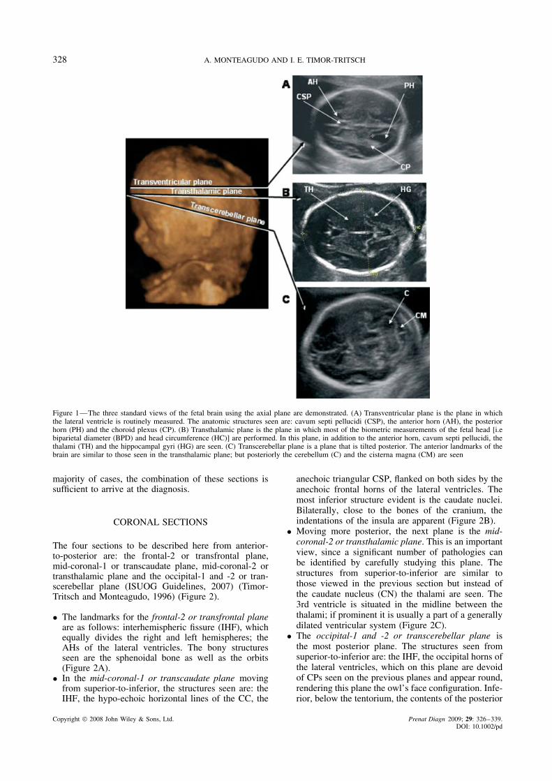
(BPD)] are performed. The three most clinically usefullevels or sections at which the axial images are producedare: transventricular, transthalamic and transcerebellar(ISUOG Guidelines, 2007) (Figure 1).
• The landmarks for the transventricular axial planefrom anterior-to-posterior are as follows: the CSP,flanked in each side by the anterior horns (AHs)of the lateral ventricles; caudally the PHs of thelateral ventricle, which contain the hyperechoic CPs.The walls of the ventricles are echogenic and areclearly demarcated by the fluid contained within theventricles. At this level, the lateral ventricles aremeasured at its widest part; at the level of the glomus.In this section, the CP is seen filling bilaterallythe cavity of the ventricles. The calipers are placedperpendicular to the axis of the ventricles touchingthe inner aspect. A measurement of up to 10 mm isdeemed normal (Almog et al., 2003) (Figure 1A).
• Inferior to the transventricular plane, the transtha-lamic plane can be obtained. The landmarks fromanterior-to-posterior are: the frontal horns of the lat-eral ventricles, CSP, thalami and the hippocampalgyri (HG). It is at this level that most of the bio-metric measurements of the head are obtained: BPD,head circumference (HC) and occipitofrontal diameter(OFD) (Figure 1B).
• The transcerebellar axial plane is inferior to thetransthalamic plane and is slightly tilted posteriorly toadequately image the posterior fossa. The landmarksfrom anterior-to-posterior are: frontal horns of thelateral ventricles, CSP, thalami, cerebellum, and thecerebello-peduncular cistern [cisterna magna (CM)].A CM measuring greater than 10 mm is consideredabnormal; also considered abnormal is the lack ofits visualization strongly suggesting a spinal defect(Figure 1C).
In contrast to the axial plane easily obtainable bytransabdominal sonography, the coronal and sagittalplanes are easier to obtain by transvaginal sonography;that is, if the fetus is in cephalic presentation. However,transabdominally the frontal suture can be used as anacoustic window to obtain the transfrontal view of thebrain. This view can be use to image the median brainstructures such as CC, CSP, and cerebellum (Visentinet al., 2001). This view can be routinely obtained duringthe screening anatomical scan; however, when a targetedneuroscan is performed the transvaginal route providesbetter resolution especially if the fetus is in a cephalicpresentation.
When scanning transvaginally, the sections areobtained through the anterior fontanelle or one of thesutures of the skull; therefore, both hemispheres canbe effectively imaged therefore compared to each otherfor symmetry. Although, a large number of coronal aswell as sagittal sections are technically possible, con-centrating only on four coronal and two sagittal sectionswill yield valuable and diagnostically necessary addi-tional information to those obtained by the axial sections(Timor-Tritsch and Monteagudo, 1996; Monteagudo andTimor-Tritsch, 1997; ISUOG Guidelines, 2007). In the
Copyright 2008 John Wiley & Sons, Ltd. Prenat Diagn 2009; 29: 326–339.DOI: 10.1002/pd
328 A. MONTEAGUDO AND I. E. TIMOR-TRITSCH
Figure 1—The three standard views of the fetal brain using the axial plane are demonstrated. (A) Transventricular plane is the plane in whichthe lateral ventricle is routinely measured. The anatomic structures seen are: cavum septi pellucidi (CSP), the anterior horn (AH), the posteriorhorn (PH) and the choroid plexus (CP). (B) Transthalamic plane is the plane in which most of the biometric measurements of the fetal head [i.ebiparietal diameter (BPD) and head circumference (HC)] are performed. In this plane, in addition to the anterior horn, cavum septi pellucidi, thethalami (TH) and the hippocampal gyri (HG) are seen. (C) Transcerebellar plane is a plane that is tilted posterior. The anterior landmarks of thebrain are similar to those seen in the transthalamic plane; but posteriorly the cerebellum (C) and the cisterna magna (CM) are seen
majority of cases, the combination of these sections issufficient to arrive at the diagnosis.
CORONAL SECTIONS
The four sections to be described here from anterior-to-posterior are: the frontal-2 or transfrontal plane,mid-coronal-1 or transcaudate plane, mid-coronal-2 ortransthalamic plane and the occipital-1 and -2 or tran-scerebellar plane (ISUOG Guidelines, 2007) (Timor-Tritsch and Monteagudo, 1996) (Figure 2).
• The landmarks for the frontal-2 or transfrontal planeare as follows: interhemispheric fissure (IHF), whichequally divides the right and left hemispheres; theAHs of the lateral ventricles. The bony structuresseen are the sphenoidal bone as well as the orbits(Figure 2A).
• In the mid-coronal-1 or transcaudate plane movingfrom superior-to-inferior, the structures seen are: theIHF, the hypo-echoic horizontal lines of the CC, the
anechoic triangular CSP, flanked on both sides by theanechoic frontal horns of the lateral ventricles. Themost inferior structure evident is the caudate nuclei.Bilaterally, close to the bones of the cranium, theindentations of the insula are apparent (Figure 2B).
• Moving more posterior, the next plane is the mid-coronal-2 or transthalamic plane. This is an importantview, since a significant number of pathologies canbe identified by carefully studying this plane. Thestructures from superior-to-inferior are similar tothose viewed in the previous section but instead ofthe caudate nucleus (CN) the thalami are seen. The3rd ventricle is situated in the midline between thethalami; if prominent it is usually a part of a generallydilated ventricular system (Figure 2C).
• The occipital-1 and -2 or transcerebellar plane isthe most posterior plane. The structures seen fromsuperior-to-inferior are: the IHF, the occipital horns ofthe lateral ventricles, which on this plane are devoidof CPs seen on the previous planes and appear round,rendering this plane the owl’s face configuration. Infe-rior, below the tentorium, the contents of the posterior
Copyright 2008 John Wiley & Sons, Ltd. Prenat Diagn 2009; 29: 326–339.DOI: 10.1002/pd

DEVELOPMENT OF THE CNS BEYOND THE FIRST TRIMESTER 329
Figure 2—Using transvaginal sonography the fetal brain is scanned using four serial coronal planes. (A) Frontal-2 or transfontal plane; this is avery anterior plane that cuts through the orbits. The brain structures seen are the anterior lobe of the brain separated into two equal parts by theinterhemispheric fissure (IHF). (B) Mid-coronal-1 or transcaudate plane is slightly posterior to the frontal-2 plane. The anatomic landmarks seenfrom top to bottom are: the interhemispheric fissure (IHF), the corpus callosum (CC), the cavum septi pellucidi (CSP), anterior horns (AH) andcaudate nucleus (CN) to each side of the CSP and the insula (INS) just below the fetal cranium. (C) Mid-coronal-2 or transthalamic plane. Manyof the anatomic landmarks seen on the mid-coronal-1 are seen in this plane as well. However, the thalami (TH) replace the candate nucleus.Occasionally, the third ventricle can be seen as a slit-like anechoic structure between the thalami. (D) Occipital-1 and 2 or transcerebellar plane.In this posterior plane, the posterior horns (PH) of the lateral ventricles appear as rounded structures devoid of the choroid plexus. Below theposterior horn, the posterior fossa is seen containing the cerebellum (C) and the cisterna magna (CM)
fossa are seen: the cerebellum, the vermis and thecerebello-peduncular cistern (CM) (Figure 2D).
SAGITTAL SECTIONS
The two clinically significant sagittal sections are themedian plane and the two left-and-right oblique-1 orparasagittal planes (Figure 3).
• The right-and left-oblique-1 or parasagittal planesreveal the anterior, posterior and at times the infe-rior horns of the lateral ventricle and are seenas an inverted ‘C’ containing the echogenic CPs(Figure 3A).
• The median plane is one of the most importantand diagnostically useful planes depicting all of themidline structures, namely the CC, pericallosal artery(PCA) (using power Doppler evaluation), locatedsuperior to and hugging the CC, the area of the3rd ventricle. The tela choroidea (TC) covering thethalamus (locus of the germinal matrix prone to
hemorrhage), the quadrigeminal plate and cistern(frequent place of arachnoid cysts). Sectoring moreposteriorly, the vermis of the cerebellum, the 4thventricle and the CM can be seen (Figure 3B).
VOLUME OR MULTIPLANAR SONOGRAPHY: 3DULTRASOUND
Volume sonography is better known as 3D sonography;it shortens the process of obtaining the serial sagittaland coronal sections (Monteagudo et al., 2000; Timor-Tritsch et al., 2000a). There are differences between theplanes obtained by two-dimensional (2D) transvaginalor transabdominal sonography from 3D transvaginalsonography. Using 2D US, all sections arise from asingle point (the transducer tip) usually at the anteriorfontanelle, and fan-out in a radial fashion; the planesare oblique to one another. However, when using 3Dtransvaginal sonography the sections derived from thevolume are parallel to each other similar to thoseobtained by computed tomography (CT) or magnetic
Copyright 2008 John Wiley & Sons, Ltd. Prenat Diagn 2009; 29: 326–339.DOI: 10.1002/pd

330 A. MONTEAGUDO AND I. E. TIMOR-TRITSCH
Figure 3—The sagittal plane is seen mostly when transvaginal sonography is used. (A) Oblique-1 or parasagittal plane is a very useful planesince the three components of the lateral ventricles can be seen: the anterior horn (AH), the posterior horn (PH) and the inferior horn (IH). Inaddition, the thalami and the choroid plexus are also evident in this section. (B) Median or mid-sagittal plane is an essential plane since thecorpus callosum (CC) can be seen in its entirety. Below the corpus callosum the anechoic cavum septi pellucidi (CSP) is seen, as well as thearea where the third ventricle (3V) is located between the two portions of the thalami; the tela choroidea (TC) is the choroid plexus of the thirdventricle. Posteriorly the posterior fossa is seen, the most echogenic structure present is the vermis (V) of the cerebellum, the fourth ventricle(4V) is an anechoic, triangular in shape and is located anterior to the vermis and the cisterna magna (CM) is the anechoic area between the backof the vermis and the cranium. Using color Doppler the pericallosal artery (PCA) is seen
resonance imaging (MRI) (Figure 4). The images of thesections that are below the fontanelle and sutures havehigher resolution than those that are more lateral or distalfrom the acquisition plane. Another difference betweenthe 2D and 3D transvaginal sonography is that with 3Dsonography a reconstructed axial plane (the C -plane)is possible; therefore, all three scanning planes canbe simultaneously displayed on the screen (orthogonalplanes) (Figure 5). The user can scroll to navigate in acontinuous fashion through each plane at will.
HOW IS TRANSVAGINAL ORTRANSABDOMINAL 3D NEUROSONOGRAPHY
DONE?
Acquisition, storage and display are the three basic stepsin performing a 3D US study. This section will reviewthese basic steps.
Step 1: Data acquisition:This first step (the data acquisition) is the most important
step in the process of creating clinically diagnosticimages. Remember that poor quality 2D images willcreate poor quality 3D images! Therefore it is notonly worth, but also mandatory to optimize the
Figure 4—Three dimensional rendered faces are used to demonstratethe difference between the direction of the transvaginally generated2D planes and those studied from a 3D volume of the brain.(A) Whenscanning using 2D US through the anterior fontanelled, the planesarise from a single point (fontanenlle) and fan-out laterally. Thesectional planes are comparable to those obtained by neonatal trans-fontanelle imaging. (B) Successive planes obtained using 3D volumescanning are parallel to each other similar to those obtained whenusing a CT or an MRI
grayscale 2D image. Once the brain is clearly seen onthe screen, several volumes should be captured; if the
Copyright 2008 John Wiley & Sons, Ltd. Prenat Diagn 2009; 29: 326–339.DOI: 10.1002/pd

DEVELOPMENT OF THE CNS BEYOND THE FIRST TRIMESTER 331
Figure 5—After a brain volume has been acquired, the three orthog-onal planes are displayed; in ‘box A’—the coronal section, in ‘boxB’—the sagittal with the fetus facing the left side of the screen andin ‘box C’—the axial
volume is being captured transvaginally one shouldbe in the sagittal plane and one in the coronal plane.The volume acquired in the sagittal plane enablesa diagnostic view of the structures in the medianplane. The one acquired in the coronal plane permitsscrolling in the coronal plane. The ‘reconstructed’plane; in this case the axial, may be of somewhatlower resolution; however, it still is instrumental inmaking clinically relevant observations. When thevolumes are captured transabdominally, we obtainone in the axial plane at the level of the BPD and thesecond either in the coronal or sagittal depending onthe fetal position. We display the orthogonal planes onthe screen as follows: in box A, the coronal section ofthe head; in box B, the median sagittal with the fetalface facing the box A and box C, the axial sectionwith the posterior fossa being superior on the screen(Figure 5).
Step 2: Data Storage.The volume data is stored in the computer as a volume
of data points in a Cartesian system and can be reusedto display images using different technologies.
Step 3: DisplayThere are multiple displays that may enhance certain
features of the volume and assist in making theclinical diagnosis. We have arranged the displays inthe order that we usually use them.
Multiplanar imaging (orthogonal planes) is the firsttype of display that we use. The three scanning planes(sagittal, coronal and axial) can simultaneously be dis-played at right angles to each other on the US monitor. Inthis display, it is possible to scroll or navigate in a con-tinuous fashion through each plane at will. If the volumewas obtained either in a coronal or sagittal plane, theaxial plane generated is a reconstructed plane (Figure 5).
The tomographic display is useful since it allowsvisualization of multiple parallel slices at differentspacing through a volume at the same time on theUS screen; therefore, serial sections of any of the
Figure 6—Tomographic display showing serial coronal sections fromanterior (A) to posterior (P). The central picture is highlighted by thebox around it and the thicker white line. The marker dot is seen inthe midline on the corpus callosum. The slices between the intervalis 3 mm. Arrows point to the occiput
Figure 7—This figure shows a tomographic display of Sagittalsections. Similar to Figure 7, the central picture is highlighted bythe box around it and the thicker white line. The marker dot is inthe midline on the corpus callosum and the slice interval is 3 mm.However, the arrows point to the right and left side of the face;therefore both right (R) and left (L) of the median sections are seen
planes similar to those seen by CT or MRI are possible(Figures 6 and 7).
The thick slice display in which the selected area ofthe volume is collapsed into a 2D image can enhanceedges, improve contrast detection and at times givemore depth to the image (Figure 8). Volume contrastimaging (VCI ) is another software application enablingthe display of a number of slices ‘collapsed’ into one2D picture enhancing tissue borders. The thick slice andthe VCI are essentially the same. Thick slice renderingrequires several steps: placing a rendering box on theorthogonal planes, narrowing it to a minimum anddisplaying the rendered image, which represents the 2D(thick slice) ‘image of many collapsed 2D images’. Thisprocess basically is an edge enhancement process. VCIis essentially the same process, which is achieved bytouching one of the control knobs. It represents the 2D
Copyright 2008 John Wiley & Sons, Ltd. Prenat Diagn 2009; 29: 326–339.DOI: 10.1002/pd

332 A. MONTEAGUDO AND I. E. TIMOR-TRITSCH
Figure 8—The thick slice display is demonstrated. The box showsthe selected area of the volume in all three planes which has been‘collapsed’ into a 2D image with enhanced edges, contrast andapparently more depth to the image (lower right image)
(collapsed) image of a certain number of 2D slices. Itis possible to control the slice thickness from 2–5-mmthick slices.
3D sonoangiography which enables selective imagingof blood vessels after a 3D acquisition of a poweror color Doppler containing volume is very useful,especially in agenesis of CC where absence of the PCAaids in the diagnosis (Figure 9).
The inversion mode is one in which the selected fluidfilled areas of the acquired volume can be ‘inverted’and therefore, the areas, which were initially anechoicbecome echogenic. The on-screen appearance is that of acast representing the fluid filled space—in this case thelateral ventricles. This is useful in cases of hydrocephalyin which the ventricles are enlarged with cerebral spinalfluid (CSF) (Figure 10).
Surface rendering is the most widely known display.The surface features can be seen and recognized resem-bling a photograph (e.g. the face) (Figures 1–4). Thisis useful since certain brain anomalies are associated
Figure 9—The 3D sonoangiography display allows selective imagingof blood vessels after a 3D acquisition of a power or color Dopplercontaining volume has been acquired. Arrows represent the perical-losal artery
Figure 10—In the inversion rendering a selected, fluid filled areas ofthe acquired volume (in this case: ventricles) can be seen, which wereinitially anechoic thus become echogenic. (A) A parasagittal view ofthe on-screen appearance of the ‘cast’ like fluid filled space of thelateral ventricle. (B) The ‘inverted’ image now demonstrates the twoventricles parallel to each other. Between the two, the interventricularforamina connecting to the third ventricle can be appreciated
with facial dysmorphism, such as is the case with alobarholoprosencephaly.
The X-ray, maximum (‘bone’) or transparency modeallows selective imaging of the fetal cranium (or bones),as well as defining the sutures. In neurosonography, thisis probably the display that is least used. In contrast,when searching for anomalies of the bony skeleton thisis an invaluable tool.
At this point, we will review the developmentalchanges of fetal brain that occur during the second andthird trimesters of pregnancy. It is relevant to pointout that many of the developmental changes of thebrain follow a very specific and defined developmentaltimeline. Therefore, establishing the correct gestationalage of the fetus is the key to the correct interpretationof the anatomy seen.
THE CORPUS CALLOSUM
The CC, the CSP and the cingulate gyrus are devel-opmentally very closely related. On the median sectionthe CC is located between the cingulate gyrus, whichis above it and the CSP, which is below it. The CCarises from the commissural plate and is a pathway offibers that connect the cerebral hemispheres with eachother. Initially, the CC is a compact mass of tissue, butas the pregnancy progresses it significantly lengthens insize. The CC develops in a front-to-back (or rostral-to-occipital) fashion creating a cover over the roof ofthe third ventricle; the underlying portion of the com-missural plate becomes thinned and forms the septumpellucidum (O’Rahilly and Muller, 1992, 2001). Thedevelopment of CSP is closely associated with that ofthe CC; there cannot be a CSP without a covering CC;however, a CC can be present in the absence of the CSPsuch as in septo-optic dysplasia (Figures 11 and 12).
Transvaginal 2D and 3D sonography allows imagingof the CC relatively quickly and easily; however,this can also be done by transabdominal sonography.Sonographically, the CC is anechoic. When color or
Copyright 2008 John Wiley & Sons, Ltd. Prenat Diagn 2009; 29: 326–339.DOI: 10.1002/pd
DEVELOPMENT OF THE CNS BEYOND THE FIRST TRIMESTER 333
A B C
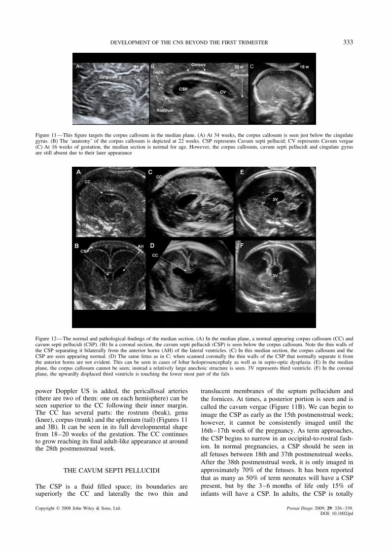
Figure 11—This figure targets the corpus callosum in the median plane. (A) At 34 weeks, the corpus callosum is seen just below the cingulategyrus. (B) The ‘anatomy’ of the corpus callosum is depicted at 22 weeks. CSP represents Cavum septi pellucid; CV represents Cavum vergae(C) At 16 weeks of gestation, the median section is normal for age. However, the corpus callosum, cavum septi pellucidi and cingulate gyrusare still absent due to their later appearance
Figure 12—The normal and pathological findings of the median section. (A) In the median plane, a normal appearing corpus callosum (CC) andcavum septi pellucidi (CSP). (B) In a coronal section, the cavum septi pellucidi (CSP) is seen below the corpus callosum. Note the thin walls ofthe CSP separating it bilaterally from the anterior horns (AH) of the lateral ventricles. (C) In this median section, the corpus callosum and theCSP are seen appearing normal. (D) The same fetus as in C; when scanned coronally the thin walls of the CSP that normally separate it fromthe anterior horns are not evident. This can be seen in cases of lobar holoprosencephaly as well as in septo-optic dysplasia. (E) In the medianplane, the corpus callosum cannot be seen; instead a relatively large anechoic structure is seen. 3V represents third ventricle. (F) In the coronalplane, the upwardly displaced third ventricle is touching the lower most part of the falx
power Doppler US is added, the pericallosal arteries(there are two of them: one on each hemisphere) can beseen superior to the CC following their inner margin.The CC has several parts: the rostrum (beak), genu(knee), corpus (trunk) and the splenium (tail) (Figures 11and 3B). It can be seen in its full developmental shapefrom 18–20 weeks of the gestation. The CC continuesto grow reaching its final adult-like appearance at aroundthe 28th postmenstrual week.
THE CAVUM SEPTI PELLUCIDI
The CSP is a fluid filled space; its boundaries aresuperiorly the CC and laterally the two thin and
translucent membranes of the septum pellucidum andthe fornices. At times, a posterior portion is seen and iscalled the cavum vergae (Figure 11B). We can begin toimage the CSP as early as the 15th postmenstrual week;however, it cannot be consistently imaged until the16th–17th week of the pregnancy. As term approaches,the CSP begins to narrow in an occipital-to-rostral fash-ion. In normal pregnancies, a CSP should be seen inall fetuses between 18th and 37th postmenstrual weeks.After the 38th postmenstrual week, it is only imaged inapproximately 70% of the fetuses. It has been reportedthat as many as 50% of term neonates will have a CSPpresent, but by the 3–6 months of life only 15% ofinfants will have a CSP. In adults, the CSP is totally
Copyright 2008 John Wiley & Sons, Ltd. Prenat Diagn 2009; 29: 326–339.DOI: 10.1002/pd
334 A. MONTEAGUDO AND I. E. TIMOR-TRITSCH
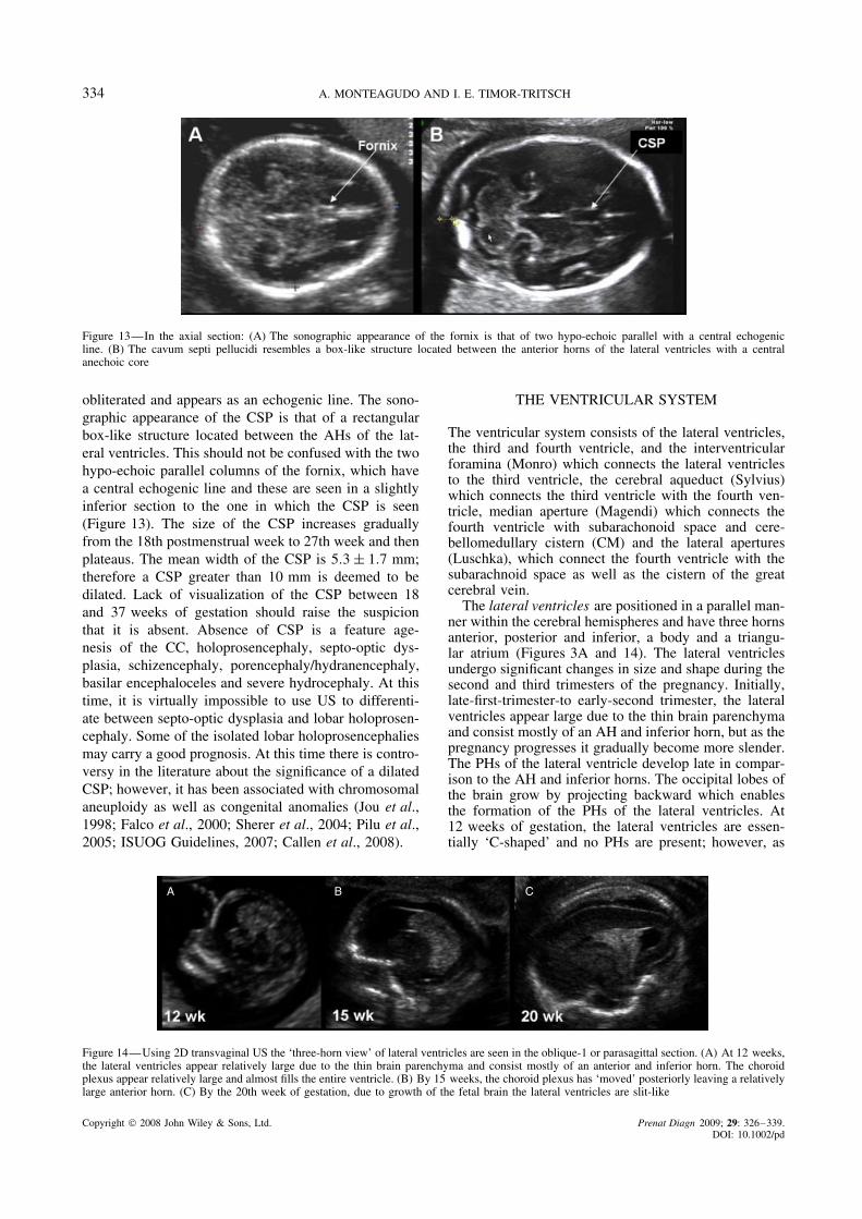
Figure 13—In the axial section: (A) The sonographic appearance of the fornix is that of two hypo-echoic parallel with a central echogenicline. (B) The cavum septi pellucidi resembles a box-like structure located between the anterior horns of the lateral ventricles with a centralanechoic core
obliterated and appears as an echogenic line. The sono-graphic appearance of the CSP is that of a rectangularbox-like structure located between the AHs of the lat-eral ventricles. This should not be confused with the twohypo-echoic parallel columns of the fornix, which havea central echogenic line and these are seen in a slightlyinferior section to the one in which the CSP is seen(Figure 13). The size of the CSP increases graduallyfrom the 18th postmenstrual week to 27th week and thenplateaus. The mean width of the CSP is 5.3 ± 1.7 mm;therefore a CSP greater than 10 mm is deemed to bedilated. Lack of visualization of the CSP between 18and 37 weeks of gestation should raise the suspicionthat it is absent. Absence of CSP is a feature age-nesis of the CC, holoprosencephaly, septo-optic dys-plasia, schizencephaly, porencephaly/hydranencephaly,basilar encephaloceles and severe hydrocephaly. At thistime, it is virtually impossible to use US to differenti-ate between septo-optic dysplasia and lobar holoprosen-cephaly. Some of the isolated lobar holoprosencephaliesmay carry a good prognosis. At this time there is contro-versy in the literature about the significance of a dilatedCSP; however, it has been associated with chromosomalaneuploidy as well as congenital anomalies (Jou et al.,1998; Falco et al., 2000; Sherer et al., 2004; Pilu et al.,2005; ISUOG Guidelines, 2007; Callen et al., 2008).
THE VENTRICULAR SYSTEM
The ventricular system consists of the lateral ventricles,the third and fourth ventricle, and the interventricularforamina (Monro) which connects the lateral ventriclesto the third ventricle, the cerebral aqueduct (Sylvius)which connects the third ventricle with the fourth ven-tricle, median aperture (Magendi) which connects thefourth ventricle with subarachonoid space and cere-bellomedullary cistern (CM) and the lateral apertures(Luschka), which connect the fourth ventricle with thesubarachnoid space as well as the cistern of the greatcerebral vein.
The lateral ventricles are positioned in a parallel man-ner within the cerebral hemispheres and have three hornsanterior, posterior and inferior, a body and a triangu-lar atrium (Figures 3A and 14). The lateral ventriclesundergo significant changes in size and shape during thesecond and third trimesters of the pregnancy. Initially,late-first-trimester-to early-second trimester, the lateralventricles appear large due to the thin brain parenchymaand consist mostly of an AH and inferior horn, but as thepregnancy progresses it gradually become more slender.The PHs of the lateral ventricle develop late in compar-ison to the AH and inferior horns. The occipital lobes ofthe brain grow by projecting backward which enablesthe formation of the PHs of the lateral ventricles. At12 weeks of gestation, the lateral ventricles are essen-tially ‘C-shaped’ and no PHs are present; however, as
A B C
Figure 14—Using 2D transvaginal US the ‘three-horn view’ of lateral ventricles are seen in the oblique-1 or parasagittal section. (A) At 12 weeks,the lateral ventricles appear relatively large due to the thin brain parenchyma and consist mostly of an anterior and inferior horn. The choroidplexus appear relatively large and almost fills the entire ventricle. (B) By 15 weeks, the choroid plexus has ‘moved’ posteriorly leaving a relativelylarge anterior horn. (C) By the 20th week of gestation, due to growth of the fetal brain the lateral ventricles are slit-like
Copyright 2008 John Wiley & Sons, Ltd. Prenat Diagn 2009; 29: 326–339.DOI: 10.1002/pd
DEVELOPMENT OF THE CNS BEYOND THE FIRST TRIMESTER 335
pregnancy progresses the PHs grow and at the 18th weekof gestation a clearly defined PH is seen (Figure 14).
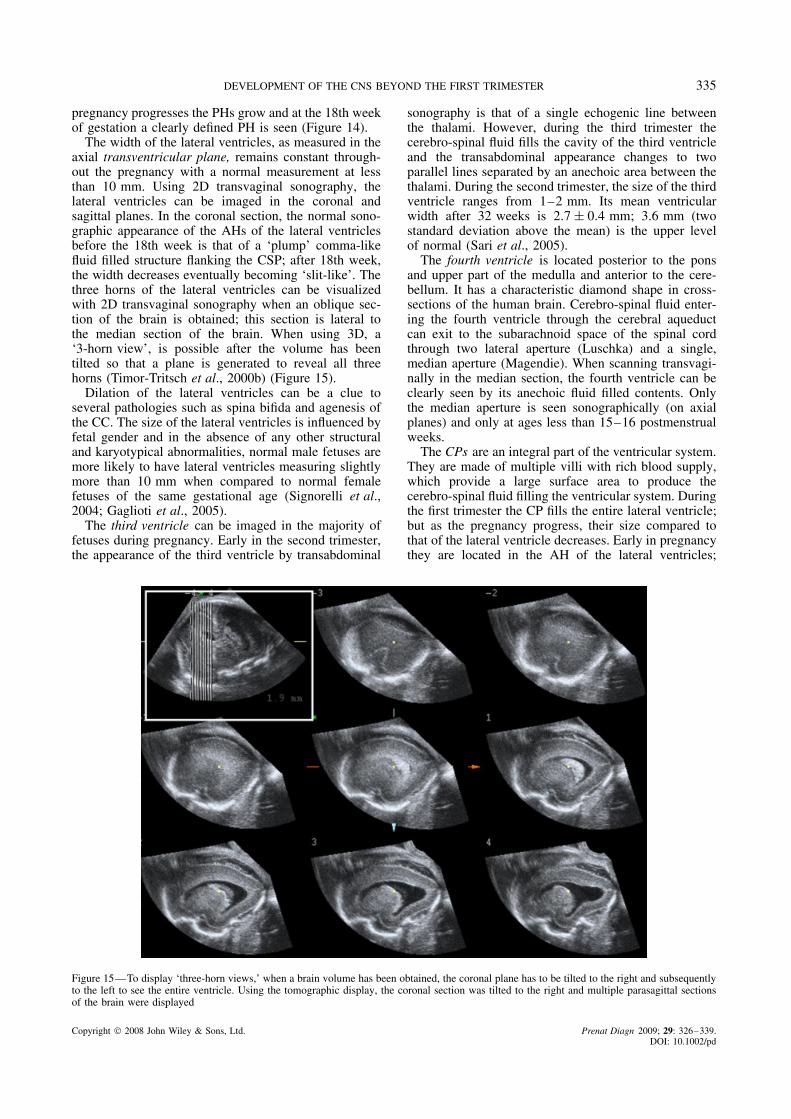
The width of the lateral ventricles, as measured in theaxial transventricular plane, remains constant through-out the pregnancy with a normal measurement at lessthan 10 mm. Using 2D transvaginal sonography, thelateral ventricles can be imaged in the coronal andsagittal planes. In the coronal section, the normal sono-graphic appearance of the AHs of the lateral ventriclesbefore the 18th week is that of a ‘plump’ comma-likefluid filled structure flanking the CSP; after 18th week,the width decreases eventually becoming ‘slit-like’. Thethree horns of the lateral ventricles can be visualizedwith 2D transvaginal sonography when an oblique sec-tion of the brain is obtained; this section is lateral tothe median section of the brain. When using 3D, a‘3-horn view’, is possible after the volume has beentilted so that a plane is generated to reveal all threehorns (Timor-Tritsch et al., 2000b) (Figure 15).
Dilation of the lateral ventricles can be a clue toseveral pathologies such as spina bifida and agenesis ofthe CC. The size of the lateral ventricles is influenced byfetal gender and in the absence of any other structuraland karyotypical abnormalities, normal male fetuses aremore likely to have lateral ventricles measuring slightlymore than 10 mm when compared to normal femalefetuses of the same gestational age (Signorelli et al.,2004; Gaglioti et al., 2005).
The third ventricle can be imaged in the majority offetuses during pregnancy. Early in the second trimester,the appearance of the third ventricle by transabdominal
sonography is that of a single echogenic line betweenthe thalami. However, during the third trimester thecerebro-spinal fluid fills the cavity of the third ventricleand the transabdominal appearance changes to twoparallel lines separated by an anechoic area between thethalami. During the second trimester, the size of the thirdventricle ranges from 1–2 mm. Its mean ventricularwidth after 32 weeks is 2.7 ± 0.4 mm; 3.6 mm (twostandard deviation above the mean) is the upper levelof normal (Sari et al., 2005).
The fourth ventricle is located posterior to the ponsand upper part of the medulla and anterior to the cere-bellum. It has a characteristic diamond shape in cross-sections of the human brain. Cerebro-spinal fluid enter-ing the fourth ventricle through the cerebral aqueductcan exit to the subarachnoid space of the spinal cordthrough two lateral aperture (Luschka) and a single,median aperture (Magendie). When scanning transvagi-nally in the median section, the fourth ventricle can beclearly seen by its anechoic fluid filled contents. Onlythe median aperture is seen sonographically (on axialplanes) and only at ages less than 15–16 postmenstrualweeks.
The CPs are an integral part of the ventricular system.They are made of multiple villi with rich blood supply,which provide a large surface area to produce thecerebro-spinal fluid filling the ventricular system. Duringthe first trimester the CP fills the entire lateral ventricle;but as the pregnancy progress, their size compared tothat of the lateral ventricle decreases. Early in pregnancythey are located in the AH of the lateral ventricles;
Figure 15—To display ‘three-horn views,’ when a brain volume has been obtained, the coronal plane has to be tilted to the right and subsequentlyto the left to see the entire ventricle. Using the tomographic display, the coronal section was tilted to the right and multiple parasagittal sectionsof the brain were displayed
Copyright 2008 John Wiley & Sons, Ltd. Prenat Diagn 2009; 29: 326–339.DOI: 10.1002/pd
336 A. MONTEAGUDO AND I. E. TIMOR-TRITSCH
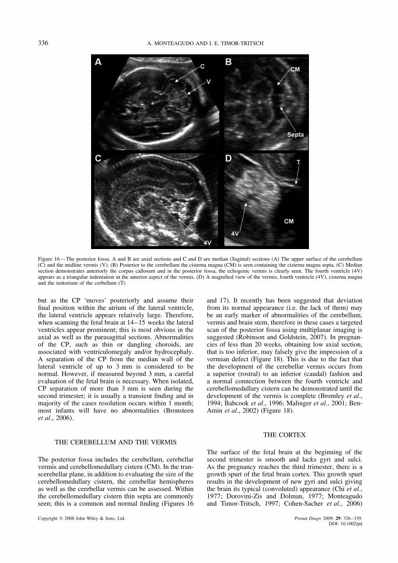
Figure 16—The posterior fossa. A and B are axial sections and C and D are median (Sagittal) sections (A) The upper surface of the cerebellum(C) and the midline vermis (V). (B) Posterior to the cerebellum the cisterna magna (CM) is seen containing the cisterna magna septa. (C) Mediansection demonstrates anteriorly the corpus callosum and in the posterior fossa, the echogenic vermis is clearly seen. The fourth ventricle (4V)appears as a triangular indentation in the anterior aspect of the vermis. (D) A magnified view of the vermis, fourth ventricle (4V), cisterna magnaand the tentorium of the cerbellum (T)
but as the CP ‘moves’ posteriorly and assume theirfinal position within the atrium of the lateral ventricle,the lateral ventricle appears relatively large. Therefore,when scanning the fetal brain at 14–15 weeks the lateralventricles appear prominent; this is most obvious in theaxial as well as the parasagittal sections. Abnormalitiesof the CP, such as thin or dangling choroids, areassociated with ventriculomegaly and/or hydrocephaly.A separation of the CP from the median wall of thelateral ventricle of up to 3 mm is considered to benormal. However, if measured beyond 3 mm, a carefulevaluation of the fetal brain is necessary. When isolated,CP separation of more than 3 mm is seen during thesecond trimester; it is usually a transient finding and inmajority of the cases resolution occurs within 1 month;most infants will have no abnormalities (Bronsteenet al., 2006).
THE CEREBELLUM AND THE VERMIS
The posterior fossa includes the cerebellum, cerebellarvermis and cerebellomedullary cistern (CM). In the tran-scerebellar plane, in addition to evaluating the size of thecerebellomedullary cistern, the cerebellar hemispheresas well as the cerebellar vermis can be assessed. Withinthe cerebellomedullary cistern thin septa are commonlyseen; this is a common and normal finding (Figures 16
and 17). It recently has been suggested that deviationfrom its normal appearance (i.e. the lack of them) maybe an early marker of abnormalities of the cerebellum,vermis and brain stem, therefore in these cases a targetedscan of the posterior fossa using multiplanar imaging issuggested (Robinson and Goldstein, 2007). In pregnan-cies of less than 20 weeks, obtaining low axial section,that is too inferior, may falsely give the impression of avermian defect (Figure 18). This is due to the fact thatthe development of the cerebellar vermis occurs froma superior (rostral) to an inferior (caudal) fashion anda normal connection between the fourth ventricle andcerebellomedullary cistern can be demonstrated until thedevelopment of the vermis is complete (Bromley et al.,1994; Babcook et al., 1996; Malinger et al., 2001; Ben-Amin et al., 2002) (Figure 18).
THE CORTEX
The surface of the fetal brain at the beginning of thesecond trimester is smooth and lacks gyri and sulci.As the pregnancy reaches the third trimester, there is agrowth spurt of the fetal brain cortex. This growth spurtresults in the development of new gyri and sulci givingthe brain its typical (convoluted) appearance (Chi et al.,1977; Dorovini-Zis and Dolman, 1977; Monteagudoand Timor-Tritsch, 1997; Cohen-Sacher et al., 2006)
Copyright 2008 John Wiley & Sons, Ltd. Prenat Diagn 2009; 29: 326–339.DOI: 10.1002/pd

DEVELOPMENT OF THE CNS BEYOND THE FIRST TRIMESTER 337
Figure 17—Using the tomographic display, serial sections through the posterior fossa are seen. Note the rounded bilateral posterior horns (PH)of the lateral ventricle. Inferiorly the posterior fossa is imaged. C represents cerebellum
Figure 18—At 16 weeks, tomographic sections of the posterior fossa. (A) A most superior section; the marker dot (cyan) is seen over the vermis.(B) In approximately the midsection of the cerebellum, both the cerebellar hemispheres are evident connected by the echoic vermis (in cyan themarker dot is over the area of the vermis). (C) A most inferior section; a gap appears to be between the cerebellar hemispheres where the fourthventricle connects with the cisterna magna. Although, it appears that the vermis is missing, at this gestational age this is a normal finding
(Figure 19). Sonographic identification of the sulci andgyri lags behind the anatomical evaluation as muchas 4–6 weeks. The 28–30 weeks of gestation is the
most active sonographic period in respect to corticaldevelopment (Cohen-Sacher et al., 2006). As the gyri,sulci and fissures appear and deepen, there is an increase
Copyright 2008 John Wiley & Sons, Ltd. Prenat Diagn 2009; 29: 326–339.DOI: 10.1002/pd

338 A. MONTEAGUDO AND I. E. TIMOR-TRITSCH
Figure 19—Transvaginal US demonstrating the median plane (A) At 16 weeks of gestation, the surface of the median plane is relatively smooth,lacking any gyri and sulci. (B) At 34 weeks of gestation, the median plane of this fetus demonstrates many interlacing echoic lines whichrepresent the sulci
Figure 20—The insula. (A) A transabdominal scan at the level of the thalami demonstrating the insula (arrow). (B) A transvaginal scan slightlyposterior to the mid-coronal-2 or transthalamic plane demonstrating the insula
in linear bright echoes at the surface of the brain. Thisresult from the echogenicity of the pia matter and thepia arachnoid complex (soft-brain coverings).This canbest be imaged on a median section of the fetal brain.Using transvaginal and transabdominal sonography, thegestational age at which several sulci and fissures arefirst sonographically apparent are: the callosal sulcusfrom the 14th postmenstrual week; the parieto-occipitaland calcarine fissures from 18 weeks; the cingulategyrus and cingulate sulcus from 24 to 26 weeks.
The region of the insula and the lateral sulcus anatom-ically appears as a linear groove at the 13th gestationalweek and by 18 gestational weeks it becomes macro-scopically identifiable. Sonographically, the area of theinsula and lateral sulcus first appears as a smooth inden-tation on the lateral surface of the brain at around17–18 weeks (Monteagudo and Timor-Tritsch, 1997;Toi et al., 2004; Cohen-Sacher et al., 2006; Afif et al.,2007). As the pregnancy progresses the shape of theinsula relative to the deepening lateral sulcus (oper-cularization) takes the shape of an obtuse angle andeventually an acute angle (Toi et al., 2004) (Figure 20).As the growth spurt of the brain proceeds and opercu-larization advances, the insula is buried by the parietal(anterior) and temporal (posterior) opercula; this processis not complete until term (Govaert et al., 2004).
CONCLUSIONS
The fetal brain compared to other organ systems con-tinues to evolve and grow during the fetal period andbeyond. The complexity of this development results ina variety of malformations that at times appear verychallenging to diagnose. However, we believe that thekey to correctly diagnose these malformations lie inunderstanding the embryology, remembering that ges-tational age is crucial in the development of certainstructures and lastly being very familiar with the nor-mal anatomy of the brain in all three scanning planes.Three-dimensional US generates volumes which can beevaluated using a variety of planes and rendering modal-ities will become an indispensable tool to evaluate thedeveloping brain.
REFERENCES
ISUOG Guidelines. 2007. Sonographic examination of the fetal centralnervous system: Guidelines for performing the ‘basic examination’and the ‘fetal neurosonogram’. Ultrasound Obstet Gynecol 29:1109–1116.
Afif A, Bouvier R, Buenerd A, Trouillas J, Mertens P. 2007.Development of the human fetal insular cortex: Study of thegyration from 13 to 28 gestational weeks. Brain Struct Funct 212:3-4335-346.
Almog B, Gamzu R, Achiron R, Fainaru O, Zalel Y. 2003. Fetallateral ventricular width: What should be its upper limit? A
Copyright 2008 John Wiley & Sons, Ltd. Prenat Diagn 2009; 29: 326–339.DOI: 10.1002/pd

DEVELOPMENT OF THE CNS BEYOND THE FIRST TRIMESTER 339
prospective cohort study and reanalysis of the current and previousdata. J Ultrasound Med 22: 139–143.
Babcook CJ, Chong BW, Salamat MS, Ellis WG, Goldstein RB.1996. Sonographic anatomy of the developing cerebellum: Normalembryology can resemble pathology. AJR Am J Roentgenol 166:2427–2433.
Ben-Amin M, Perlitz Y, Peleg D. 2002. Transvaginal sonographicappearance of the cerebellar vermis at 14–16 weeks’ gestation.Ultrasound Obstet Gynecol 19: 2208–2209.
Bromley B, Nadel AS, Pauker S, Estroff JA, Benacerraf BR. 1994.Closure of the cerebellar vermis: Evaluation with second trimesterus. Radiology 193: 3761–3763.
Bronsteen R, Lee W, Vettraino I, Balasubramaniam M, Comstock C.2006. Isolated choroid plexus separation on second-trimestersonography: Natural history and postnatal importance. J UltrasoundMed 25: 3343–3347.
Callen PW, Callen AL, Glenn OA, Toi A. 2008. Columns of thefornix, not to be mistaken for the cavum septi pellucidi on prenatalsonography. J Ultrasound Med 27: 125–131.
Chi JG, Dooling EC, Gilles FH. 1977. Gyral development of thehuman brain. Ann Neurol 1: 186–193.
Cohen-Sacher B, Lerman-Sagie T, Lev D, Malinger G. 2006. Sono-graphic developmental milestones of the fetal cerebral cortex: Alongitudinal study. Ultrasound Obstet Gynecol 27: 5494–5502.
Dorovini-Zis K, Dolman CL. 1977. Gestational development of brain.Arch Pathol Lab Med 101: 4192–4195.
Falco P, Gabrielli S, Visentin A, Perolo A, Pilu G, Bovicelli L. 2000.Transabdominal sonography of the cavum septum pellucidum innormal fetuses in the second and third trimesters of pregnancy.Ultrasound Obstet Gynecol 16: 6549–6553.
Gaglioti P, Danelon D, Bontempo S, Mombro M, Cardaropoli S,Todros T. 2005. Fetal cerebral ventriculomegaly: Outcome in 176cases. Ultrasound Obstet Gynecol 25: 4372–4377.
Govaert P, Swarte R, De Vos A, Lequin M. 2004. Sonographicappearance of the normal and abnormal insula of reil. Dev MedChild Neurol 46: 9610–9616.
Jou HJ, Shyu MK, Wu SC, Chen SM, Su CH, Hsieh FJ. 1998.Ultrasound measurement of the fetal cavum septi pellucidi.Ultrasound Obstet Gynecol 12: 6419–6421.
Malinger G, Ginath S, Lerman-Sagie T, Watemberg N, Lev D,Glezerman M. 2001. The fetal cerebellar vermis: Normaldevelopment as shown by transvaginal ultrasound. Prenat Diagn21: 8687–8692.
Monteagudo A, Reuss ML, Timor-Tritsch IE. 1991. Imaging thefetal brain in the second and third trimesters using transvaginalsonography. Obstet Gynecol 77: 127–132.
Monteagudo A, Timor-Tritsch IE. 1997. Development of fetal gyri,sulci and fissures: A transvaginal sonographic study. UltrasoundObstet Gynecol 9: 4222–4228.
Monteagudo A, Timor-Tritsch IE, Mayberry P. 2000. Three-dimen-sional transvaginal neurosonography of the fetal brain: ‘navigating’in the volume scan. Ultrasound Obstet Gynecol 16: 4307–4313.
O’Rahilly R, Muller F. 1992. Human Embryology & Teratology.Wiley-Liss Inc.: New York.
O’Rahilly R, Muller F. 2001. In Ultrasonography of the Prenataland Neonatal Brain, Ilan AM, Timor-Tritsch E, Cohen HL (eds).McGraw-Hill, Health Professions Division: New York; 1–12.
O’Rahilly R, Muller F. 2008. Significant features in the early prenataldevelopment of the human brain. Ann Anat 190: 2105–2118.
Pilu G, Tani G, Carletti A, Malaigia S, Ghi T, Rizzo N. 2005.Difficult early sonographic diagnosis of absence of the fetal septumpellucidum. Ultrasound Obstet Gynecol 25: 170–172.
Robinson AJ, Goldstein R. 2007. The cisterna magna septa: Vestigialremnants of blake’s pouch and a potential new marker for normaldevelopment of the rhombencephalon. J Ultrasound Med 26:183–195.
Sari A, Ahmetoglu A, Dinc H, et al. 2005. Fetal biometry: Size andconfiguration of the third ventricle. Acta Radiol 46: 6631–6635.
Sherer DM, Sokolovski M, Dalloul M, Santoso P, Curcio J, Abu-lafia O. 2004. Prenatal diagnosis of dilated cavum septum pellu-cidum et vergae. Am J Perinatol 21: 5247–5251.
Signorelli M, Tiberti A, Valseriati D, et al. 2004. Width of the fetallateral ventricular atrium between 10 and 12 mm: A simplevariation of the norm? Ultrasound Obstet Gynecol 23: 114–118.
Timor-Tritsch IE, Monteagudo A. 1996. Transvaginal fetal neu-rosonography: Standardization of the planes and sections byanatomic landmarks. Ultrasound Obstet Gynecol 8: 142–147.
Timor-Tritsch IE, Monteagudo A, Mayberry P. 2000a. Three-dimen-sional ultrasound evaluation of the fetal brain: The three horn view.Ultrasound Obstet Gynecol 16: 4302–4306.
Timor-Tritsch IE, Monteagudo A, Mayberry P. 2000b. Three-dimen-sional ultrasound evaluation of the fetal brain: The three horn view.Ultrasound Obstet Gynecol 16: 4302–4306.
Toi A, Lister WS, Fong KW. 2004. How early are fetal cerebral sulcivisible at prenatal ultrasound and what is the normal pattern ofearly fetal sulcal development? Ultrasound Obstet Gynecol 24:7706–7715.
Visentin A, Pilu G, Falco P, Bovicelli L. 2001. The transfrontal view:A new approach to the visualization of the fetal midline cerebralstructures. J Ultrasound Med 20: 4329–4333.
Copyright 2008 John Wiley & Sons, Ltd. Prenat Diagn 2009; 29: 326–339.DOI: 10.1002/pd