Nonlinear control of the doubly-fed induction generator in wind power systems
9
Nonlinear control of the doubly-fed induction generator in wind power systems Orlando Soares a , Henrique Gonçalves b , Anto ´ nio Martins b, * , Adriano Carvalho b a Instituto Polite ´cnico de Bragança, Campus de Santa Apolo ´nia, Apartado 1038, 5301-854 Bragança, Portugal b Faculdade de Engenharia da Universidade do Porto, Rua Dr Roberto Frias, 4200-465 Porto, Portugal article info Article history: Received 23 April 2009 Accepted 18 December 2009 Available online 2 March 2010 Keywords: Doubly-fed induction generator Neural network control Power flow Voltage ride-through Wind energy abstract This paper describes the models of a wind power system, such as the turbine, generator, power elec- tronics converters and controllers, with the aim to control the generation of wind power in order to maximize the generated power with the lowest possible impact in the grid voltage and frequency during normal operation and under the occurrence of faults. The presented work considers a wind power system equipped with the doubly-fed induction generator and a vector-controlled converter connected between the rotor and the grid. The paper presents comparative results between proportional-integral controllers and neural networks based controllers, showing that better dynamic characteristics can be obtained using neural networks based controllers. Ó 2009 Elsevier Ltd. All rights reserved. 1. Introduction The aim of the control system of a wind turbine is to obtain an automatic and secure operation of the turbine using an optimized flow of the generated power. This will reduce operation costs, produce a consistent dynamic response and improve the quality of power. Also, it helps in the assurance of the safety for the maxi- mization of the energy captured due to the decrease of the turbine load. The present development in the wind power generation domain is strong on the development of methods and technologies capable of providing the generation of energy based on systems using the asynchronous induction generator. This development is only possible with the association of the electric machine with power electronics converters capable of imposing to this type of machine conditions of variable speed for the actual power levels of produced energy [1]. In this scenario of integrated production, based on variable speed asynchronous machines, there are needed methods capable of controlling the system imposing an optimal power flow in the electric machine according to certain conditions of the rotor speed [2–4]. The application of artificial intelligence techniques in the fields of the power electronics and control systems has been growing. These techniques, based on intelligent systems such as fuzzy logic, neural networks, genetic algorithms and particle swarm optimi- zation, need a large database and knowledge that together will describe the functioning with a logical analysis, instead of a math- ematical analysis to control systems and to make possible the taking of decisions. Some application examples of such intelligent techniques in wind energy control systems can be referred: fuzzy logic control of a variable-speed wind generation system that uses a cage-type induction generator and a back-to-back full power converter [5], optimal design using particle swarm optimization of proportional-integral controllers for the Doubly-Fed Induction Generator (DFIG) is presented in [6]. Actually, Neural Networks (NN) tend to be applied in the field of power electronics and control systems. The recognized advantages of using non-linear controllers to control non-linear systems are the main reason for using NN-based controllers in the DFIG system, represented in Fig. 1 . Among others, the main characteristics of the DFIG system are: it uses of a small power converter; it is an economical way to obtain variable speed and supply reactive power; it increases the energy capture at low wind speeds; it has reduced torque loads in the drive-train thus making the whole mechanical construction simple and guarantee increased reliability [1]. In this research work it is presented an application of neural networks in vector control systems for a DFIG used in a wind power system. This technology is relatively new in this type of application, and it will be used to substitute conventional controllers. For the vector control system a feed forward back propagation neural network is used in order to substitute some parts of the vector control system. They are used to estimate and provide the reference signals to control the system variables. Each neural * Corresponding author. Tel.: þ351 22 5081816; fax: þ351 22 5081443. E-mail address: [email protected] (A. Martins). Contents lists available at ScienceDirect Renewable Energy journal homepage: www.elsevier.com/locate/renene 0960-1481/$ – see front matter Ó 2009 Elsevier Ltd. All rights reserved. doi:10.1016/j.renene.2009.12.008 Renewable Energy 35 (2010) 1662–1670
-
Upload
independent -
Category
Documents
-
view
0 -
download
0
Transcript of Nonlinear control of the doubly-fed induction generator in wind power systems

lable at ScienceDirect
Renewable Energy 35 (2010) 1662–1670
Contents lists avai
Renewable Energy
journal homepage: www.elsevier .com/locate/renene
Nonlinear control of the doubly-fed induction generator in wind power systems
Orlando Soares a, Henrique Gonçalves b, Antonio Martins b,*, Adriano Carvalho b
a Instituto Politecnico de Bragança, Campus de Santa Apolonia, Apartado 1038, 5301-854 Bragança, Portugalb Faculdade de Engenharia da Universidade do Porto, Rua Dr Roberto Frias, 4200-465 Porto, Portugal
a r t i c l e i n f o
Article history:Received 23 April 2009Accepted 18 December 2009Available online 2 March 2010
Keywords:Doubly-fed induction generatorNeural network controlPower flowVoltage ride-throughWind energy
* Corresponding author. Tel.: þ351 22 5081816; faxE-mail address: [email protected] (A. Martins).
0960-1481/$ – see front matter � 2009 Elsevier Ltd.doi:10.1016/j.renene.2009.12.008
a b s t r a c t
This paper describes the models of a wind power system, such as the turbine, generator, power elec-tronics converters and controllers, with the aim to control the generation of wind power in order tomaximize the generated power with the lowest possible impact in the grid voltage and frequency duringnormal operation and under the occurrence of faults. The presented work considers a wind powersystem equipped with the doubly-fed induction generator and a vector-controlled converter connectedbetween the rotor and the grid. The paper presents comparative results between proportional-integralcontrollers and neural networks based controllers, showing that better dynamic characteristics can beobtained using neural networks based controllers.
� 2009 Elsevier Ltd. All rights reserved.
1. Introduction
The aim of the control system of a wind turbine is to obtain anautomatic and secure operation of the turbine using an optimizedflow of the generated power. This will reduce operation costs,produce a consistent dynamic response and improve the quality ofpower. Also, it helps in the assurance of the safety for the maxi-mization of the energy captured due to the decrease of the turbineload.
The present development in the wind power generation domainis strong on the development of methods and technologies capableof providing the generation of energy based on systems using theasynchronous induction generator. This development is onlypossible with the association of the electric machine with powerelectronics converters capable of imposing to this type of machineconditions of variable speed for the actual power levels of producedenergy [1].
In this scenario of integrated production, based on variablespeed asynchronous machines, there are needed methods capableof controlling the system imposing an optimal power flow in theelectric machine according to certain conditions of the rotor speed[2–4].
The application of artificial intelligence techniques in the fieldsof the power electronics and control systems has been growing.These techniques, based on intelligent systems such as fuzzy logic,
: þ351 22 5081443.
All rights reserved.
neural networks, genetic algorithms and particle swarm optimi-zation, need a large database and knowledge that together willdescribe the functioning with a logical analysis, instead of a math-ematical analysis to control systems and to make possible thetaking of decisions. Some application examples of such intelligenttechniques in wind energy control systems can be referred: fuzzylogic control of a variable-speed wind generation system that usesa cage-type induction generator and a back-to-back full powerconverter [5], optimal design using particle swarm optimization ofproportional-integral controllers for the Doubly-Fed InductionGenerator (DFIG) is presented in [6].
Actually, Neural Networks (NN) tend to be applied in the field ofpower electronics and control systems. The recognized advantagesof using non-linear controllers to control non-linear systems arethe main reason for using NN-based controllers in the DFIG system,represented in Fig. 1. Among others, the main characteristics of theDFIG system are: it uses of a small power converter; it is aneconomical way to obtain variable speed and supply reactivepower; it increases the energy capture at low wind speeds; it hasreduced torque loads in the drive-train thus making the wholemechanical construction simple and guarantee increased reliability[1]. In this research work it is presented an application of neuralnetworks in vector control systems for a DFIG used in a wind powersystem. This technology is relatively new in this type of application,and it will be used to substitute conventional controllers.
For the vector control system a feed forward back propagationneural network is used in order to substitute some parts of thevector control system. They are used to estimate and provide thereference signals to control the system variables. Each neural

Fig. 1. Wind power system based on the DFIG.
Fig. 3. Drive-train model.
O. Soares et al. / Renewable Energy 35 (2010) 1662–1670 1663
network is designed, trained and tested as a part of the controlsystem with the aim of optimizing the production of energy, takinginto account the quality of the power delivered to the grid. Theneural networks are used to generate the references for the rotor-side and grid-side converters, decoupling the machine active andreactive powers.
A comprehensive review on the use of NN in renewable energysystems can be found in [7]. Emphasis is given to solar energysystems but other renewable energies are also covered. However,it is verified that the use of neural networks has not been widelyused in the field of wind energy. In [8] it is presented a controlsystem based on neural networks to generate a value for theaerodynamic power coefficient, CP. A similar work is presented in[9]. It is in this context that this work gives its contribution, pre-senting a control strategy using neural networks to generate thereference parameters to the control system. The active and reac-tive operating point changes during normal operation or, in thecase of fault occurrence, linear controllers can’t provide an enoughdamping or an acceptable performance. To avoid this drawbackvoltage and power regulators based on neural networks areintroduced, offering more advantages than non-linear adaptivecontrollers in terms of robustness, performance, learning capa-bility and greater flexibility. Thus, it is demonstrated that NN-based controllers can be implemented and used in real timecontrol of wind energy conversion systems. The implementedsystem revealed to be more robust and with a superior perfor-mance than systems using traditional control methods likeproportional-integral ones.
Fig. 2. Power coefficient curves of a wind turbine.
2. System models
2.1. Turbine and drive-train
The power coefficient of a wind turbine, CP, is defined as theratio of the turbine power to the power available in the wind; itrepresents the aerodynamic performance of the turbine. The powercoefficient is a highly non-linear function of the tip-speed ratio, l,and blade-pitch angle, b. So, for the determination of the aero-dynamic power and torque a set of curves for each turbine is used,as shown in Fig. 2. Each curve can be understood as a set of theturbine CP(l) curve for different values of the pitch angle b. Eachoperation point CP(l) with a particular b represents one equilibriumcondition. Thus, the representation of the CP(l, b) curves is usedconsidering that the turbine is in equilibrium in each point of itsoperation. In those conditions, the aerodynamic power is given bythe following expression [10]:
Pae ¼12
rpR2v3CPðl; bÞ (1)
where r is the air density, R the radius of the turbine and v the windspeed.
The tip-speed-ratio is given by
l ¼ uRv
(2)
where u represents the rotational speed of the wind turbine.The drive-train mechanical model, shown in Fig. 3, is described
by its space-state equations [11]. The mechanical drive-train isa typical two-mass model connected through a flexible low speedaxle and being modelled by a stiffness constant, kv, and a dampingcoefficient, cv. One of the masses used in the model represents thehigh inertia side of the turbine (the blades and the turbine axle), JT,and the other mass represents the smaller inertia associated withthe generator. The model also includes a gear ratio with the valueof 1/h. The drive-train behaviour is given by (3) and (4):
�_x ¼
24 0 0 1
0 0 1�kv
JT0 �cv
JT
35xþ
264
1h 00 0cs
hJT
1JT
375u (3)
Fig. 4. Back-to-back converter connecting the DFIG to the grid.

Fig. 5. Back-to-back converter average model: a) grid-side converter; b) rotor-sideconverter.
Fig. 7. Grid-side converter control diagram.
O. Soares et al. / Renewable Energy 35 (2010) 1662–16701664
y ¼
24 kv
h 0 cv
h
0 1 01 0 1
35xþ
24�cv
h2 00 00 0
35u (4)
with the input variable u ¼ ½urTm�T , output variablesy ¼ ½Tavv qm um�T and state variables x ¼ ½qkqmum�T .
2.2. Doubly-fed induction generator
The model of the asynchronous machine uses the Park equations[12], expressing the variables in the dq reference system, rotatingwith the speed of the stator voltage (synchronous frame). Using thesame notation used by Ong [13], the voltage equations of the statorcircuit and of the rotor can be written of the following form:8>><>>:
vqs ¼ rsiqs þ ulds þdlqs
dt
vds ¼ rsids � ulqs þ dldsdt
v0s ¼ rsi0s þ dl0sdt
(5)
Fig. 6. General DFIG control structure.
>>< n0qr ¼ r0ri0qr þ ðu� urÞl0dr þdlqr
dt0
8>>:
0
n0dr ¼ r0ri0dr � ðu� urÞl0qr þdldrdt
n00r ¼ r0ri00r þdl00rl00r
dt
(6)
Assuming the usual approximations for this system, the devel-oped electromagnetic torque is given by:
Tem ¼32
p2
hl0qsi
0dr � l0dri0qr
iz
32
p2
Lm
hi0driqs� i0qrids
i(7)
The rotor movement equation is obtained equating the accel-erating torque to the inertia torque and friction:
Tem � Tm ¼ JGdur
dtþ Dur (8)
2.3. Back-to-back converter
The two three-phase converters, shown in Fig. 4, are modelled inthe dq reference frame using the average converter model, [14],represented in Fig. 5. The converter model is obtained through theanalysis of operation of each converter arm. The converter averagemodel is the appropriate one for the purposes of this work; theother two alternatives, instantaneous model and phasor model, are
Fig. 8. Rotor-side converter control diagram.

Table 1NN layers parameters.
1st hidden layer 2nd hidden layer Output layer
Activationfunction – 4
Symmetricsigmoidal
Symmetricsigmoidal
Linear
Parameter – g 2,0 2,0 –Parameter – a 2,0 2,0 –Parameter – c �1,0 �1,0 –
Learning coefficient – h 0,05Momentum – a 0,9
Table 2Rotor-side controller NN architecture.
1st Hidden Layer 2nd Hidden Layer Output Layer
Number of neurons 15 10 2Time delays 7 3 2
Number of inputs 7 inputsNumber of input-output
training pairs80.000
Number of iterations 1633Final error <9,98E-6
O. Soares et al. / Renewable Energy 35 (2010) 1662–1670 1665
used to study other phenomena with very different time scales [14].The operation of the grid-side converter is described by theequations:
ddt
�IdIq
�¼ 1
La
�VdVq
�þ"�Ra
Lau
�u �RaLa
#�IdIq
�� 1
La
�dddq
�VDC (9)
dVDC
dt¼ 1
C
�dd dq
�� IdIq
�� VDC
RC(10)
being the dd and dq the converter duty cycles and R the resistanceequivalent to the power flow in the DC bus.
The operation of the rotor-side converter is described similarlyas the previous converter, as expressed in (11), being VDC an inde-pendent variable.
ddt
�I0dI0q
�¼ � 1
L0a
�V 0dV 0q
�þ
24�R0a
L0a�u
u �R0aL0a
35� I0d
I0q
�þ 1
L0a
�d0dd0q
�VDC (11)
The grid angular position q ¼ ut is obtained by means of a Phase-Locked Loop (PLL) available in the Matlab/Simulink environment.
The global converter control of the DFIG system can beimplemented under the generic diagram presented in Fig. 6. Theback-to-back converter has two control modules, one for the rotorof the generator and another for the grid connection. The gener-ator and the back-to-back converter have been modelled inorthogonal dq components in order to use a vector control systemwith decoupled control of the active and reactive powers in eachconverter.
The rotor-side converter has the independent control of theactive and reactive power flow on the rotor as the main objective.The two powers are not directly controlled but through the rotorcurrent. An appropriate control of the rotor-side converter allowsthe magnetization of the generator through the rotor winding [15].The grid-side converter keeps the DC voltage regulated and thusassures the active power flow coming from or going into the rotorconverter. It usually operates with unity power factor; so the totalreactive power exchange with the grid is made only through thestator of the generator.
Fig. 9. NN-based controller of
2.4. Wind system control strategies
Generally, the main goals of the control strategies for windturbines are [16]:
� To maximize the produced energy;� To guarantee a secure functioning of the turbine;� To minimize the operation and maintenance costs through the
load reduction and life time increase.
With the global park controller, it is intended to control thepower delivered by each turbine-generator unit in a way to opti-mize the operation of the wind park, delivering the maximumactive power to the grid in optimum conditions of quality of serviceand safety. Also it is intended to control the reactive power flowaccording to the specified needs and restrictions from dispatch.
Thus, with the use of an adequate control strategy it is possibleto [17]:
� Control the active power supplied by the turbine in order tooptimize the operating point;� Limit the active power in case of high wind speed;� Control the reactive power flow between the generator and the
grid, especially in the case of weak grids, where voltage fluc-tuations can occur;� Guarantee the quality of service of the wind park, namely the
grid voltage;� Minimize the wind park exploration and maintenance costs.
2.5. Grid-side converter control
As stated before, the main objective of the grid-side converter isto keep a constant DC-link voltage independent of the value anddirection of the rotor power flow. For this, a vector control strategywith a reference frame aligned with the stator voltage position isused. This allows independent control of the active and the reactivepower between the converter and the grid.
For the internal control loop it is necessary to design theProportional-Integral (PI) controllers’ parameters, which are
the rotor-side converter.
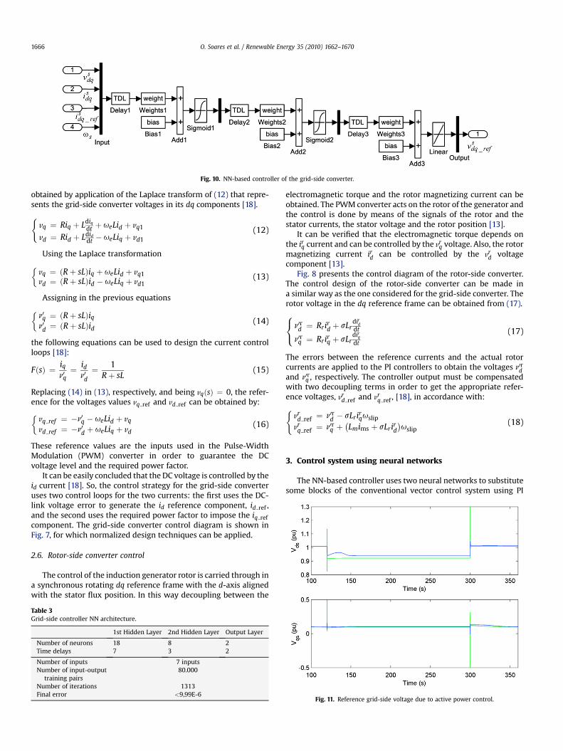
Fig. 10. NN-based controller of the grid-side converter.
O. Soares et al. / Renewable Energy 35 (2010) 1662–16701666
obtained by application of the Laplace transform of (12) that repre-sents the grid-side converter voltages in its dq components [18].(
vq ¼ Riq þ Ldiq
dt þ ueLid þ vq1
vd ¼ Rid þ Ldiddt � ueLiq þ vd1
(12)
Using the Laplace transformation�vq ¼ ðRþ sLÞiq þ ueLid þ vq1vd ¼ ðRþ sLÞid � ueLiq þ vd1
(13)
Assigning in the previous equations
�n0q ¼ ðRþ sLÞiqn0d ¼ ðRþ sLÞid
(14)
the following equations can be used to design the current controlloops [18]:
FðsÞ ¼ iqn0q¼ id
n0d¼ 1
Rþ sL(15)
Replacing (14) in (13), respectively, and being vqðsÞ ¼ 0, the refer-ence for the voltages values vq ref and vd ref can be obtained by:�
vq ref ¼ �n0q � ueLid þ vq
vd ref ¼ �n0d þ ueLiq þ vd(16)
These reference values are the inputs used in the Pulse-WidthModulation (PWM) converter in order to guarantee the DCvoltage level and the required power factor.
It can be easily concluded that the DC voltage is controlled by theid current [18]. So, the control strategy for the grid-side converteruses two control loops for the two currents: the first uses the DC-link voltage error to generate the id reference component, id ref ,and the second uses the required power factor to impose the iq refcomponent. The grid-side converter control diagram is shown inFig. 7, for which normalized design techniques can be applied.
2.6. Rotor-side converter control
The control of the induction generator rotor is carried through ina synchronous rotating dq reference frame with the d-axis alignedwith the stator flux position. In this way decoupling between the
Table 3Grid-side controller NN architecture.
1st Hidden Layer 2nd Hidden Layer Output Layer
Number of neurons 18 8 2Time delays 7 3 2
Number of inputs 7 inputsNumber of input-output
training pairs80.000
Number of iterations 1313Final error <9,99E-6
electromagnetic torque and the rotor magnetizing current can beobtained. The PWM converter acts on the rotor of the generator andthe control is done by means of the signals of the rotor and thestator currents, the stator voltage and the rotor position [13].
It can be verified that the electromagnetic torque depends onthe irq current and can be controlled by the vr
q voltage. Also, the rotormagnetizing current ird can be controlled by the vr
d voltagecomponent [13].
Fig. 8 presents the control diagram of the rotor-side converter.The control design of the rotor-side converter can be made ina similar way as the one considered for the grid-side converter. Therotor voltage in the dq reference frame can be obtained from (17).8<: n0rd ¼ Rrird þ sLr
dird
dt
n0rq ¼ Rrirq þ sLrdir
q
dt
(17)
The errors between the reference currents and the actual rotorcurrents are applied to the PI controllers to obtain the voltages n0rdand n0rq , respectively. The controller output must be compensatedwith two decoupling terms in order to get the appropriate refer-ence voltages, vr
d ref and vrq ref , [18], in accordance with:(
vrd ref ¼ n0rd � sLrirquslip
vrq ref ¼ n0rq þ
�Lmims þ sLrird
�uslip
(18)
3. Control system using neural networks
The NN-based controller uses two neural networks to substitutesome blocks of the conventional vector control system using PI
Fig. 11. Reference grid-side voltage due to active power control.

Fig. 12. Reference rotor-side voltage due to active power control. Fig. 14. Reference grid-side voltage due to reactive power control.
O. Soares et al. / Renewable Energy 35 (2010) 1662–1670 1667
controllers. These neural networks were developed in the Matlab/Simulink environment and will allow to present comparativeresults between systems operated with PI controllers and withNNs-based controllers. A brief description of them follows.
The output of the used general sigmoid activation function isgiven by
yðnÞ ¼ a
1þ e�gvjðnÞþ c (19)
where a, c and g are parameters allowing to obtain symmetric orasymmetric functions with different profiles [19] and njðnÞ is theneuron activity.
In order to have a fast learning process and to avoid localminima without increasing the error after it has been decreaseda momentum factor is used. During the training the weightbetween two neurons is updated according to
wjiðnþ 1Þ ¼ wjiðnÞ þ DwjiðnÞ þ a�wjiðnÞ �wjiðn� 1Þ
�(20)
where a is the momentum term, with a positive value less than one.The change in a synaptic weight is given by the general
expression
Fig. 13. Active power and reactive power due to active power control.
Dwjiðnþ 1Þ ¼ hdjðnÞyiðnÞ (21)
where h is the learning coefficient, d is the neuron j output error andy is the neuron i output; the learning coefficient has also a positivevalue less than one.
The used learning patterns are input-output pairs selected fromseveral simulations with the machine being controlled by the linearcontrollers. These patterns cover different conditions, normal andfaulty ones. In normal conditions the machine operates in threespeed ranges: 1 – a speed range below the synchronism speed, withthe rotor-side converter supplying active power to the rotor; 2 – ina zone near the synchronism speed, with almost zero active powerflow and 3 – in a range above the synchronism speed, where theturbine-generator supplies active power to the grid through thestator and the rotor converters.
The faulty conditions used to obtain learning data are: asym-metric short circuit near the connection to the grid; asymmetricshort circuit far from the grid connection; and symmetric voltagesag.
The used error function is the sum of the average quadratic errorbeing the learning stop criteria 3000 iterations or an error of 10�5.The learning algorithm updates the values of the weights and bias
Fig. 15. Reference rotor-side voltage due to reactive power control.

Fig. 16. Active power and reactive power due to reactive power control. Fig. 18. Reference rotor-side voltage due to a phase-to-earth fault.
O. Soares et al. / Renewable Energy 35 (2010) 1662–16701668
values according to the gradient descendent with momentumfactor and adaptive learning ratio, indicated in Table 1, as well as theactivation functions used in each layer and the respectiveparameters.
A dynamic NN-based controller with feed forward architecturecan be obtained using different Time Delays (TDL) in the input and inthe intermediate layers. In this way distinct time horizons are coveredand the all variables (input and inner ones) have dynamics [19].
3.1. NN-Based controllers’ architecture
The structure of the rotor-side controller is shown in Fig. 9. Forthe rotor-side controller it was used a 7–15–10–2 neural networkconfiguration as is shown in Table 2, where the inputs are the actualstator and rotor currents, the rotor-side reference currents and therotor angular speed; the outputs are the reference voltages tocontrol the rotor-side converter.
For the grid-side controller it was used a 7–18–8–2 neuralnetwork configuration as is shown in Fig. 10 with the mainparameters in Table 3, where the inputs are the actual statorcurrents, the grid-side reference currents, and the angularfrequency us; the outputs are the reference voltages to control thegrid-side converter.
Fig. 17. Reference grid-side voltage due to a phase-to-earth fault.
In the neural network training [19], the learning algorithmupdates the values of the weights and bias according to thegradient descendent method with momentum factor and adaptivelearning ratio, also indicated in the tables. The sampling frequencyis 20 kHz. The number of time delays used in each layer of theneural networks has been adjusted as a result of severalsimulations.
4. Results
4.1. Active power control
In a first test it is intended to verify the response of the systemgenerator/converter due to a variation of the active power flow [allresults are presented in the per unit (p.u.) system]. This variationconsisted in applying a negative pulse of amplitude DP ¼ 0.2 p.u.The reference voltage signals for the controllers of the grid-side androtor-side converters are registered in Figs. 11 and 12, [the NN-based controllers in the blue colour and PI controllers in thegreen colour]. Fig. 13 shows the active power and reactive powerflow.
The maximum error verified between the two types of control isless than 0.5%. However, the responses of the NN-based controllerspresent, generally, lower transient amplitudes and faster evolution
Fig. 19. Active and reactive power to a phase-to-earth fault.

Fig. 20. Reference grid-side voltage due to voltage sag. Fig. 22. Active and reactive power due to voltage sag.
O. Soares et al. / Renewable Energy 35 (2010) 1662–1670 1669
to steady state. This behaviour is also verified in the main electricaland mechanical variables, where it is verified faster responses andlower transient effects.
4.2. Reactive power control
In this case it is intended to change the reference value of thereactive power in two steps: a first positive of 0.2 p.u., and a secondone of �0.4 p.u. Figs. 14 and 15 show the reference voltagesgenerated by the current regulators for the controllers of the grid-side and the rotor-side converters with the two control methods.The active and reactive power flows are presented in Fig. 16.
It can be verified that the behaviour of the two control systemsis similar. The response of the NN, face to the response of PIcontrollers presents, generally, lower transients.
4.3. Phase-to-earth fault
A phase-to-earth fault in a line of the electrical network locatednear the wind park occurred at t ¼ 180 s with a duration of 180 ms.The fault impedance was 1 mU. Figs. 17 and 18 show again thereference voltages to control the grid-side and rotor-sideconverters, respectively, with NNs and PIs controllers.
Fig. 21. Reference rotor-side voltage due to voltage sag.
During the fault period, it was verified that the NNs responsepresents better results than the system using PI controllers; besidethe peaks already related previously in the transitions, they presenta lesser ripple. It is important to relate that in the direct componentof the stator voltage with PI controllers the peaks can reach about1.7 p.u. and that can cause some unwanted effects in the electronicdevices used in the converters.
In Fig. 19 it can be verified that the disturbances caused in theactive power and reactive power delivered to the grid are smootherwith the use of the NNs.
4.4. Voltage ride-through
Finally, an voltage sag at the generator terminals has beenconsidered with a magnitude of 0.5 p.u. and a duration of 0.5 s. Thesame controls generated by the PI controllers and by the NN-basedcontrollers are shown in Fig. 20 for the grid-side converter and inFig. 21 for the rotor-side converter. Fig. 22 presents the active andreactive power flow in the stator-side converter. As a result of thevoltage sag, the controllers react fast adjusting the convertervoltage to the current requirements and limitations. The activepower flow to the grid is naturally reduced and the rotor starts toaccelerate; after fault clearing the system returns to its normaloperating conditions.
Consistently, the two NN-based controllers have better responsewith fast dynamics and less oscillatory behaviour. Also, smallersettling times can be observed.
5. Conclusion
The proposed neural networks had been successfully trained asa part of the vector control system to estimate the grid-side androtor-side converters reference voltages. The resulting controllersproved to have good characteristics in different operating condi-tions as was verified in the presented results.
Comparisons between systems with PI controllers and systemswith NN-based controllers showed some differences between thetwo approaches. It can be noticed the following positive andadvantageous aspects with the NN-based controllers: transientregimes present small peaks, or absence of them in some cases;faster system responses, reaching the steady state condition inshorter time.
Thus, it was demonstrated that the DFIG grid-side and rotor-sideconverters control voltages can be obtained using NN-based

O. Soares et al. / Renewable Energy 35 (2010) 1662–16701670
controllers; these are a strong alternative to linear controllers andcan substitute them with the referred advantages.
References
[1] Ackermann T, editor. Wind power in power systems. London: John Wiley andSons, Ltd.; 2005.
[2] Tapia A, Tapia G, Ostolaza JX, Saenz JR. Modeling and control of a wind turbinedriven doubly fed induction generator. IEEE Transactions on Energy Conver-sion 2003;18(2):194–204.
[3] Tapia A, Tapia G, Ostolaza JX. Reactive power control of wind farms for voltagecontrol applications. Renewable Energy 2004;29:377–92.
[4] Hopfensperger B, Atkinson DJ, Lakin RA. Stator-flux-oriented control ofa doubly-fed induction machine with and without position encoder. IEEProceedings – Electric Power Applications 2000;147(4):241–50.
[5] Simoes MG, Bose BK, Spiegel RJ. Design and performance evaluation ofa fuzzy-logic-based variable-speed wind generation system. IEEE Transactionson Industry Applications 1997;33(4):956–65.
[6] Qiao W, Venayagamoorthy GK, Harley RG. Design of optimal PI controllers fordoubly fed induction generators driven by wind turbines using particle swarmoptimization. In: Proc. International Joint Conference on Neural Networks, Sher-aton VancouverWall Centre Hotel, Vancouver, BC, Canada. July 2006: p.1982–1987.
[7] Kalogirou SA. Artificial neural networks in renewable energy systems applica-tions: a review. Renewable and Sustainable Energy Reviews 2001;5(4):373–401.
[8] Chedid R, Mrad F, Basma M. Intelligent control of a class of wind energy conver-sion systems. IEEE Transactions on Energy Conversion 1999;14(4):1597–604.
[9] Ro K, Choi H-H. Application of neural network controller for maximum powerextraction of a grid-connected wind turbine system. Electrical Engineering2005;88:45–53.
[10] Walker JF, Jenkins N. Wind energy technology. London: John Wiley and Sons,Ltd; 1997.
[11] Sørensen P, Hansen A, Janosi L, Bech J, Bak-Jensen B. Simulation of interactionbetween wind farm and power systems. Risø National Laboratory Report;2001; Roskilde, Risø-R-1281.
[12] Fitzgerald AE, Kingsley C, Umans S. Electric machinery. New York: McGraw-Hill Book Company Inc; 2003.
[13] Ong C. Dynamic simulation of electrical machinery: using Matlab/Simulink.New Jersey: Prentice Hall; 1998.
[14] Krein PT, Bentsman J, Bass RM, Lesieutre BL. On the use of averaging for theanalysis of power electronics systems. IEEE Transactions on Power Electronics1990;5(2):182–90.
[15] Muller S, Deicke M, De Doncker RW. Doubly-fed induction generator systemsfor wind turbines. IEEE Industry Applications Magazine; May–June 2002:26–33.
[16] Slootweg JG, Polinder H, Kling WL. Representing wind turbine electricalgenerating systems in fundamental frequency simulations. IEEE Transactionson Energy Conversion 2003;18(4):516–24.
[17] Slootweg JG, Kling WL. Modelling wind turbines for power system dynamicssimulations: an overview. Wind Engineering 2004;28(1):7–26.
[18] Pena R, Clare JC, Asher GM. Doubly fed induction generator using back-to-backPWM converters and its application to variable-speed wind-energy genera-tion. IEE Proceedings – Electric Power Applications 1996;143(3):231–41.
[19] Demuth H, Beale M. Neural network toolbox for use with MATLAB. User’sguide. Natick: The MathWorks, Inc.; 1992.