NJ-series Robot Integrated System Startup Guide
356
Machine Automation Controller NJ-series Robot Integrated System Startup Guide NJ501-R£££ AC1-152000 RL4-£££££££ RX4-£££££££ O049-E1-04
-
Upload
khangminh22 -
Category
Documents
-
view
3 -
download
0
Transcript of NJ-series Robot Integrated System Startup Guide

Machine Automation ControllerNJ-seriesRobot Integrated System
Startup Guide
NJ501-R£££AC1-152000RL4-£££££££RX4-£££££££
O049-E1-04

NOTE
1. All rights reserved. No part of this publication may be reproduced, stored in a retrieval system, ortransmitted, in any form, or by any means, mechanical, electronic, photocopying, recording, orotherwise, without the prior written permission of OMRON.
2. No patent liability is assumed with respect to the use of the information contained herein.Moreover, because OMRON is constantly striving to improve its high-quality products, the infor-mation contained in this manual is subject to change without notice.
3. Every precaution has been taken in the preparation of this manual. Nevertheless, OMRON as-sumes no responsibility for errors or omissions.Neither is any liability assumed for damages resulting from the use of the information contained inthis publication.
Trademarks• Sysmac and SYSMAC are trademarks or registered trademarks of OMRON Corporation in Japan
and other countries for OMRON factory automation products.• Microsoft, Windows, Excel, Visual Basic, and Microsoft Edge are either registered trademarks or
trademarks of Microsoft Corporation in the United States and other countries.
• EtherCAT® is registered trademark and patented technology, licensed by Beckhoff AutomationGmbH, Germany.
• ODVA, CIP, CompoNet, DeviceNet, and EtherNet/IP are trademarks of ODVA.
• The SD and SDHC logos are trademarks of SD-3C, LLC.
Other company names and product names in this document are the trademarks or registered trade-marks of their respective companies.
Copyrights• Microsoft product screen shots used with permission from Microsoft.• The CAD data in inCAD Library is used with permission from MISUMI Corporation. Copyright of any
of information in CAD data belongs to MISUMI Corporation or its respective manufacturer.MISUMI Corporation may not offer all parts in each application design. Available parts can only bepurchased separately not as a unit shown in each application design. MISUMI Corporation does notguarantee quality, accuracy, functionality, safety or reliability for the combination of the parts in eachapplication example.
• This product incorporates certain third party software. The license and copyright information associ-ated with this software is available at http://www.fa.omron.co.jp/nj_info_e/.

IntroductionThank you for purchasing an NJ-series Robot Integrated CPU Unit.
This guide describes the startup procedure of the "Robot Integrated System" that contains NJ-seriesRobot Integrated CPU Unit and Omron robots and the basic operating procedure of the Sysmac Stu-dio using a simple machine model. You can learn the basics of the Robot Integrated System in a shorttime while you operate the system according to this guide.
For information on wiring and operation settings of NJ-series Robot Integrated CPU Unit, IPC Applica-tion Controller, robots and their peripheral devices, refer to Related Manuals on page 22.
This guide does not contain safety information and other details required for actual use of the prod-ucts. Thoroughly read and understand the manuals for all of the devices that are used in this guide toensure that the system is used safely. Review the entire contents of these materials, including all safe-ty precautions, precautions for safe use, and precautions for correct use.For safety instruction of the robot and details on robot use, refer to the Robot Safety Guide (Cat. No.I590).
Intended AudienceThis manual is intended for the following personnel, who must also have knowledge of electrical sys-tems (an electrical engineer or the equivalent).• Personnel in charge of introducing FA systems.• Personnel in charge of designing FA systems.• Personnel in charge of installing and maintaining FA systems.• Personnel in charge of managing FA systems and facilities.Also, this manual is intended for the personnel, who understand the following contents.• Personnel who understand the programming language specifications in international standard IEC
61131-3 or Japanese standard JIS B 3503, for programming*1.
• Personnel who understand the specifications of NJ-series CPU Unit and know how to use it*1.
• Personnel who understand basic operation procedure of the Sysmac Studio*1.• Personnel who have attended the industrial robot seminar held by Omron or have equivalent knowl-
edge.• Personnel in charge of working with a robot and well knowing how to handle the robot.
*1. For information of the international standard IEC 61131-3 and basic operation procedure of NJ-series CPUUnit and Sysmac Studio, refer to the Relevant Technical Guides on page 25.
Applicable ProductsThis manual covers the following products.• NJ-series Robot Integrated CPU UnitNJ501-R£££
• SCARA robot eCobra 600/800RL4-£££££££
• IPC Application Controller
Introduction
1NJ-series Robot Integrated System Startup Guide (O049)

AC1-152000
Introduction
2 NJ-series Robot Integrated System Startup Guide (O049)
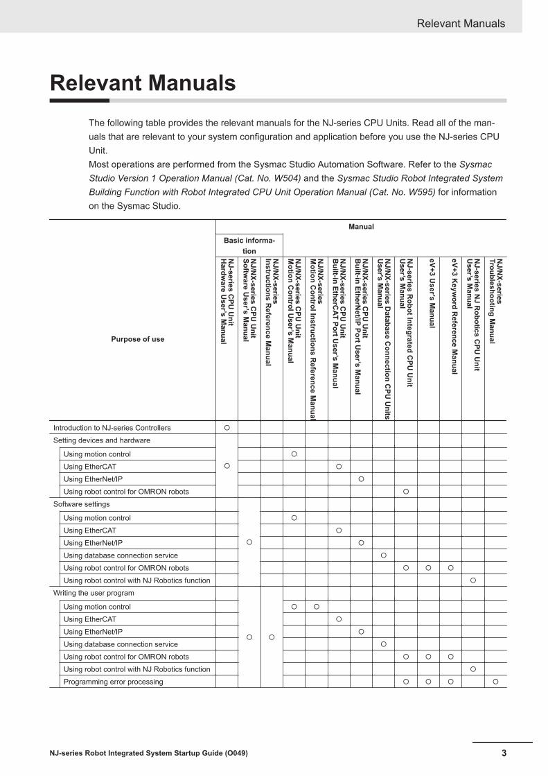
Relevant ManualsThe following table provides the relevant manuals for the NJ-series CPU Units. Read all of the man-uals that are relevant to your system configuration and application before you use the NJ-series CPUUnit.Most operations are performed from the Sysmac Studio Automation Software. Refer to the SysmacStudio Version 1 Operation Manual (Cat. No. W504) and the Sysmac Studio Robot Integrated SystemBuilding Function with Robot Integrated CPU Unit Operation Manual (Cat. No. W595) for informationon the Sysmac Studio.
Manual
Basic informa-tion
Purpose of use
NJ-series C
PU U
nitH
ardware U
ser’s Manual
NJ/N
X-series CPU
Unit
Software U
ser’s Manual
NJ/N
X-seriesInstructions R
eference Manual
NJ/N
X-series CPU
Unit
Motion C
ontrol User’s M
anual
NJ/N
X-seriesM
otion Control Instructions R
eference Manual
NJ/N
X-series CPU
Unit
Built-in EtherC
AT Port User’s M
anual
NJ/N
X-series CPU
Unit
Built-in EtherN
et/IP Port User’s M
anual
NJ/N
X-series Database C
onnection CPU
Units
User's M
anual
NJ-series R
obot Integrated CPU
Unit
User ’s M
anual
eV+3 User’s M
anual
eV+3 Keyw
ord Reference M
anual
NJ-series N
J Robotics C
PU U
nitU
ser’ s Manual
NJ/N
X-seriesTroubleshooting M
anual
Introduction to NJ-series Controllers ¡
Setting devices and hardware
¡
Using motion control ¡
Using EtherCAT ¡
Using EtherNet/IP ¡
Using robot control for OMRON robots ¡
Software settings
¡
Using motion control ¡
Using EtherCAT ¡
Using EtherNet/IP ¡
Using database connection service ¡
Using robot control for OMRON robots ¡ ¡ ¡
Using robot control with NJ Robotics function ¡
Writing the user program
¡ ¡
Using motion control ¡ ¡
Using EtherCAT ¡
Using EtherNet/IP ¡
Using database connection service ¡
Using robot control for OMRON robots ¡ ¡ ¡
Using robot control with NJ Robotics function ¡
Programming error processing ¡ ¡ ¡ ¡
Relevant Manuals
3NJ-series Robot Integrated System Startup Guide (O049)
Manual
Basic informa-tion
Purpose of use
NJ-series C
PU U
nitH
ardware U
ser’s Manual
NJ/N
X-series CPU
Unit
Software U
ser’s Manual
NJ/N
X-seriesInstructions R
eference Manual
NJ/N
X-series CPU
Unit
Motion C
ontrol User’s M
anual
NJ/N
X-seriesM
otion Control Instructions R
eference Manual
NJ/N
X-series CPU
Unit
Built-in EtherC
AT Port User’s M
anual
NJ/N
X-series CPU
Unit
Built-in EtherN
et/IP Port User’s M
anual
NJ/N
X-series Database C
onnection CPU
Units
User's M
anual
NJ-series R
obot Integrated CPU
Unit
User ’s M
anual
eV+3 User’s M
anual
eV+3 Keyw
ord Reference M
anual
NJ-series N
J Robotics C
PU U
nitU
ser’ s Manual
NJ/N
X-seriesTroubleshooting M
anual
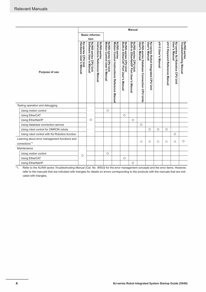
Testing operation and debugging
¡
Using motion control ¡
Using EtherCAT ¡
Using EtherNet/IP ¡
Using database connection service ¡
Using robot control for OMRON robots ¡ ¡ ¡
Using robot control with NJ Robotics function ¡
Learning about error management functions and
corrections*1 r r r r r ¡
Maintenance
¡Using motion control ¡
Using EtherCAT ¡
Using EtherNet/IP ¡
*1. Refer to the NJ/NX-series Troubleshooting Manual (Cat. No. W503) for the error management concepts and the error items. However,refer to the manuals that are indicated with triangles for details on errors corresponding to the products with the manuals that are indi-cated with triangles.
Relevant Manuals
4 NJ-series Robot Integrated System Startup Guide (O049)

Manual Structure
Page StructureThe following page structure is used in this manual.
4-9
4 Installation and Wiring
NJ-series CPU Unit Hardware User’s Manual (W500)
sti
nU
gni
tn
uo
M
3-4
4
s tn
en
op
mo
C r
ellor
tn
oC
gni
tc
en
no
C
1-3-
4
4-3 Mounting Units
The Units that make up an NJ-series Controller can be connected simply by pressing the Units together
and locking the sliders by moving them toward the back of the Units. The End Cover is connected in the
same way to the Unit on the far right side of the Controller.
1 Join the Units so that the connectors fit exactly.
2 The yellow sliders at the top and bottom of each Unit lock the Units together. Move the sliders
toward the back of the Units as shown below until they click into place.
Precautions for Correct UsePrecautions for Correct Use
4-3-1 Connecting Controller Components
Connector
Hook Hook holes
Slider
Lock
Release
Move the sliders toward the back until they lock into place.
Level 1 heading
Level 2 heading
Level 3 headingLevel 2 heading
A step in a procedure
Manual name
Special information
Level 3 heading
Page tab
Gives the current
headings.
Indicates a procedure.
Icons indicate
precautions, additional
information, or reference
information.
Gives the number
of the main section.
This illustration is provided only as a sample. It may not literally appear in this manual.
The sliders on the tops and bottoms of the Power Supply Unit, CPU Unit, I/O Units, Special I/O
Units, and CPU Bus Units must be completely locked (until they click into place) after connecting
the adjacent Unit connectors.
Manual Structure
5NJ-series Robot Integrated System Startup Guide (O049)

Special InformationSpecial information in this manual is classified as follows:
Precautions for Safe UsePrecautions on what to do and what not to do to ensure safe usage of the product.
Precautions for Correct UsePrecautions on what to do and what not to do to ensure proper operation and performance.
Additional InformationAdditional information to read as required.This information is provided to increase understanding or make operation easier.
Version InformationInformation on differences in specifications and functionality for Controller with different unit versionsand for different versions of the Sysmac Studio is given.
Precaution on TerminologyIn this manual, "download" refers to transferring data from the Sysmac Studio to the physical Control-ler and "upload" refers to transferring data from the physical Controller to the Sysmac Studio.For the Sysmac Studio, "synchronization" is used to both "upload" and "download" data. Here,"synchronize" means to automatically compare the data for the Sysmac Studio on the computer withthe data in the physical Controller and transfer the data in the direction that is specified by the user.
Manual Structure
6 NJ-series Robot Integrated System Startup Guide (O049)

Sections in this Manual
Sections in this Manual
7NJ-series Robot Integrated System Startup Guide (O049)
1
2
3
A
1
2
3
4
Appendicies
Implementation Example of Static Pick-and-place
Equipment
Before You Begin
Overview
13
4Implementation Example of Dynamic Pick-and-place
Equipment
A

CONTENTSIntroduction .............................................................................................................. 1
Intended Audience...........................................................................................................................................1Applicable Products .........................................................................................................................................1
Relevant Manuals..................................................................................................... 3
Manual Structure...................................................................................................... 5Page Structure.................................................................................................................................................5Special Information ..........................................................................................................................................6Precaution on Terminology ..............................................................................................................................6
Sections in this Manual ........................................................................................... 7
Terms and Conditions Agreement........................................................................ 11Warranty, Limitations of Liability .................................................................................................................... 11Application Considerations ............................................................................................................................12Disclaimers ....................................................................................................................................................12
Safety Precautions................................................................................................. 14Definition of Precautionary Information..........................................................................................................14Symbols .........................................................................................................................................................14WARNING......................................................................................................................................................15Cautions.........................................................................................................................................................15
Precautions for Safe Use ...................................................................................... 16
Precautions for Correct Use ................................................................................. 17
Regulations and Standards .................................................................................. 18
Versions .................................................................................................................. 19Checking Versions .........................................................................................................................................19
Related Manuals..................................................................................................... 22
Relevant Technical Guides.................................................................................... 25
Terminology............................................................................................................ 26
Revision History..................................................................................................... 27
Section 1 Overview1-1 Features of Robot Integrated System..................................................................................1-2
1-1-1 Features of the NJ-series Robot Integrated CPU Unit ................................................................1-21-1-2 Features of the EtherCAT-compatible OMRON robots ...............................................................1-21-1-3 Features of the Sysmac Studio Automation Software.................................................................1-2
1-2 System configuration to build in this guide ........................................................................1-31-3 System Configuration for Static Pick-and-place Equipment .............................................1-41-4 Operations of Static Pick-and-place Equipment.................................................................1-6
1-4-1 Operating Specifications .............................................................................................................1-6
CONTENTS
8 NJ-series Robot Integrated System Startup Guide (O049)

1-4-2 Operating Modes for Equipment .................................................................................................1-7
1-5 System Configuration for Dynamic Pick-and-place Equipment........................................1-81-6 Operations of Dynamic Pick-and-place Equipment..........................................................1-10
1-6-1 Operating Specifications ...........................................................................................................1-101-6-2 Operating Modes for Equipment ...............................................................................................1-11
1-7 Hardware...............................................................................................................................1-121-8 Software................................................................................................................................1-14
1-8-1 Sysmac Studio ..........................................................................................................................1-141-8-2 Application Manager .................................................................................................................1-14
1-9 User Program .......................................................................................................................1-161-9-1 Types of Method to Create User Program ................................................................................1-161-9-2 Proper Use of Sequence Control Program and V+ Program ....................................................1-161-9-3 Command and Data Flow .........................................................................................................1-17
Section 2 Before You Begin2-1 Installing the Sysmac Studio ................................................................................................2-2
Section 3 Implementation Example of Static Pick-and-placeEquipment
3-1 Program Specifications for Static Pick-and-place Equipment ..........................................3-23-1-1 When Operations are Controlled with Sequence Control Program.............................................3-33-1-2 When Operations are Controlled with V+ Program...................................................................3-10
3-2 Basic Startup Procedures ...................................................................................................3-173-3 Programming and Simulation Procedures ........................................................................3-19
3-3-1 Creating a Project File...............................................................................................................3-193-3-2 Creating the EtherCAT Network Configuration..........................................................................3-203-3-3 Creating a Sequence Control Program .....................................................................................3-223-3-4 Creating V+ Programs...............................................................................................................3-283-3-5 Placing 3D Shape Data.............................................................................................................3-353-3-6 Starting Simulation ....................................................................................................................3-653-3-7 Teaching Positions ....................................................................................................................3-663-3-8 Setting up Automatic Loading of V+ Programs and Variables at Power ON.............................3-773-3-9 Running the Program and Checking Operation ........................................................................3-81
3-4 Installing and Wiring the System .......................................................................................3-863-4-1 Wiring the Robot Integrated CPU Unit and the EtherCAT Digital I/O Terminal .........................3-863-4-2 Setting the Node Address of the EtherCAT Digital I/O Terminal ...............................................3-873-4-3 Wiring the EtherCAT Digital I/O Terminal and the Robot...........................................................3-873-4-4 Setting the EtherCAT Node Address of the Robot ....................................................................3-883-4-5 Wiring the Robot Integrated CPU Unit and the Computer ........................................................3-883-4-6 Wiring the Robot, T20 Pendant and the Front Panel ................................................................3-893-4-7 Wiring the EtherCAT Digital I/O Terminal and Solenoid Valve ..................................................3-90
3-5 Setup Procedure for Actual System...................................................................................3-923-5-1 Connecting Online.....................................................................................................................3-923-5-2 Transferring Settings and Programs .........................................................................................3-943-5-3 Teaching....................................................................................................................................3-963-5-4 Executing Program to Check Operation..................................................................................3-108
Section 4 Implementation Example of Dynamic Pick-and-placeEquipment
4-1 Program Specifications for Dynamic Pick-and-place Equipment .....................................4-3
CONTENTS
9NJ-series Robot Integrated System Startup Guide (O049)

4-1-1 Program Structure.......................................................................................................................4-3
4-2 Basic Startup Procedures ...................................................................................................4-124-3 Programming and Simulation Procedures ........................................................................4-15
4-3-1 Creating a Project File...............................................................................................................4-154-3-2 Creating the EtherCAT Network Configuration..........................................................................4-164-3-3 Creating V+ Programs...............................................................................................................4-194-3-4 Writing a Sequence Control Program........................................................................................4-234-3-5 Placing 3D Shape Data.............................................................................................................4-304-3-6 Creating a Pack Manager Sample ............................................................................................4-534-3-7 Creating C# Programs ..............................................................................................................4-814-3-8 Setting up Automatic Loading of V+ Programs and Variables at Power ON.............................4-834-3-9 Executing Program to Check Operation....................................................................................4-87
4-4 Installing and Wiring the System .......................................................................................4-934-4-1 Wiring the Robot Integrated CPU Unit and the EtherCAT Digital I/O Terminal .........................4-944-4-2 Setting the Node Address of the EtherCAT Digital I/O Terminal ...............................................4-944-4-3 Wiring the EtherCAT Digital I/O Terminal and Inverter’s EtherCAT Communications Unit........4-954-4-4 Setting the Node Address of Inverter’s EtherCAT Communications Unit..................................4-954-4-5 Wiring the Inverter’s EtherCAT Communications Unit and Robot.............................................4-954-4-6 Setting the EtherCAT Node Address of the Robot ....................................................................4-964-4-7 Wiring the Robot, T20 Pendant and the Front Panel ................................................................4-964-4-8 Wiring the Robot and Encoder ..................................................................................................4-984-4-9 Wiring the EtherNet/IP Port on the Robot Integrated CPU Unit ................................................4-994-4-10 Wiring Between the IPC Application Controller, Display, and Camera....................................4-1004-4-11 Wiring the Camera and Robot.................................................................................................4-1004-4-12 Wiring the EtherCAT Digital I/O Terminal and Solenoid Valve ................................................4-101
4-5 Operation Check on the Actual System...........................................................................4-1034-5-1 Communications Setup ...........................................................................................................4-1034-5-2 Online Connection...................................................................................................................4-1104-5-3 Transferring Settings and Programs ....................................................................................... 4-1114-5-4 Setting up the Camera ............................................................................................................4-1154-5-5 Running a Sequence Control Program and V+ Program........................................................4-1264-5-6 Turning Robot High Power ON ...............................................................................................4-1284-5-7 Calibrating the Belt ..................................................................................................................4-1304-5-8 Calibrating the Sensor.............................................................................................................4-1354-5-9 Setting the Locator ..................................................................................................................4-1464-5-10 Teaching Idle, Pick, and Place Positions.................................................................................4-1514-5-11 Running the Program to Check the Operation ........................................................................4-154
AppendicesA-1 Designing Example of the Safety Functions for the Pick-and-place Equipment............ A-2
A-1-1 Pick-and-place Equipment Configuration................................................................................... A-2A-1-2 Hazards...................................................................................................................................... A-4A-1-3 Protective Measure .................................................................................................................... A-4A-1-4 Safety Functions ........................................................................................................................ A-4A-1-5 Safety System Configuration and Devices................................................................................. A-5A-1-6 Installation and Wiring................................................................................................................ A-7A-1-7 Settings and Programming....................................................................................................... A-13
A-2 How to Use 3D Visualizer ................................................................................................... A-21A-2-1 Set the 3D Visualizer to the Float Mode................................................................................... A-21A-2-2 Rotate the Viewpoint ................................................................................................................ A-23A-2-3 Translate the Viewpoint ............................................................................................................ A-25A-2-4 Zoom-in and Zoom-out............................................................................................................. A-26
A-3 Setting Items on the Sysmac Studio and the Setting Targets ........................................ A-28A-4 Using Troubleshooting Functions..................................................................................... A-29
CONTENTS
10 NJ-series Robot Integrated System Startup Guide (O049)

Terms and Conditions Agreement
Warranty, Limitations of Liability
Warranties
Exclusive WarrantyOmron’s exclusive warranty is that the Products will be free from defects in materials and work-manship for a period of twelve months from the date of sale by Omron (or such other period ex-pressed in writing by Omron). Omron disclaims all other warranties, express or implied.
LimitationsOMRON MAKES NO WARRANTY OR REPRESENTATION, EXPRESS OR IMPLIED, ABOUTNON-INFRINGEMENT, MERCHANTABILITY OR FITNESS FOR A PARTICULAR PURPOSE OFTHE PRODUCTS. BUYER ACKNOWLEDGES THAT IT ALONE HAS DETERMINED THAT THEPRODUCTS WILL SUITABLY MEET THE REQUIREMENTS OF THEIR INTENDED USE.
Omron further disclaims all warranties and responsibility of any type for claims or expenses basedon infringement by the Products or otherwise of any intellectual property right.
Buyer RemedyOmron’s sole obligation hereunder shall be, at Omron’s election, to (i) replace (in the form originallyshipped with Buyer responsible for labor charges for removal or replacement thereof) the non-com-plying Product, (ii) repair the non-complying Product, or (iii) repay or credit Buyer an amount equalto the purchase price of the non-complying Product; provided that in no event shall Omron be re-sponsible for warranty, repair, indemnity or any other claims or expenses regarding the Productsunless Omron’s analysis confirms that the Products were properly handled, stored, installed andmaintained and not subject to contamination, abuse, misuse or inappropriate modification. Returnof any Products by Buyer must be approved in writing by Omron before shipment. Omron Compa-nies shall not be liable for the suitability or unsuitability or the results from the use of Products incombination with any electrical or electronic components, circuits, system assemblies or any othermaterials or substances or environments. Any advice, recommendations or information given orallyor in writing, are not to be construed as an amendment or addition to the above warranty.
See http://www.omron.com/global/ or contact your Omron representative for published information.
Limitation on Liability; EtcOMRON COMPANIES SHALL NOT BE LIABLE FOR SPECIAL, INDIRECT, INCIDENTAL, OR CON-SEQUENTIAL DAMAGES, LOSS OF PROFITS OR PRODUCTION OR COMMERCIAL LOSS IN ANY
Terms and Conditions Agreement
11NJ-series Robot Integrated System Startup Guide (O049)

WAY CONNECTED WITH THE PRODUCTS, WHETHER SUCH CLAIM IS BASED IN CONTRACT,WARRANTY, NEGLIGENCE OR STRICT LIABILITY.
Further, in no event shall liability of Omron Companies exceed the individual price of the Product onwhich liability is asserted.
Application Considerations
Suitability of UseOmron Companies shall not be responsible for conformity with any standards, codes or regulationswhich apply to the combination of the Product in the Buyer’s application or use of the Product. At Buy-er’s request, Omron will provide applicable third party certification documents identifying ratings andlimitations of use which apply to the Product. This information by itself is not sufficient for a completedetermination of the suitability of the Product in combination with the end product, machine, system, orother application or use. Buyer shall be solely responsible for determining appropriateness of the par-ticular Product with respect to Buyer’s application, product or system. Buyer shall take application re-sponsibility in all cases.
NEVER USE THE PRODUCT FOR AN APPLICATION INVOLVING SERIOUS RISK TO LIFE ORPROPERTY OR IN LARGE QUANTITIES WITHOUT ENSURING THAT THE SYSTEM AS A WHOLEHAS BEEN DESIGNED TO ADDRESS THE RISKS, AND THAT THE OMRON PRODUCT(S) ISPROPERLY RATED AND INSTALLED FOR THE INTENDED USE WITHIN THE OVERALL EQUIP-MENT OR SYSTEM.
Programmable ProductsOmron Companies shall not be responsible for the user’s programming of a programmable Product, orany consequence thereof.
Disclaimers
Performance DataData presented in Omron Company websites, catalogs and other materials is provided as a guide forthe user in determining suitability and does not constitute a warranty. It may represent the result ofOmron’s test conditions, and the user must correlate it to actual application requirements. Actual per-formance is subject to the Omron’s Warranty and Limitations of Liability.
Change in SpecificationsProduct specifications and accessories may be changed at any time based on improvements and oth-er reasons. It is our practice to change part numbers when published ratings or features are changed,or when significant construction changes are made. However, some specifications of the Product may
Terms and Conditions Agreement
12 NJ-series Robot Integrated System Startup Guide (O049)

be changed without any notice. When in doubt, special part numbers may be assigned to fix or estab-lish key specifications for your application. Please consult with your Omron’s representative at anytime to confirm actual specifications of purchased Product.
Errors and OmissionsInformation presented by Omron Companies has been checked and is believed to be accurate; how-ever, no responsibility is assumed for clerical, typographical or proofreading errors or omissions.
Terms and Conditions Agreement
13NJ-series Robot Integrated System Startup Guide (O049)

Safety Precautions
Definition of Precautionary InformationThe following notation is used in this manual to provide precautions required to ensure safe usage ofthe NJ-series Robot Integrated CPU Unit.The safety precautions that are provided are extremely important for safety. Always read and heed theinformation provided in all safety precautions.The following notation is used.
Indicates a potentially hazardous situation which, if not avoided, could result in death or serious injury. Additionally, there may be severe property damage.
Indicates a potentially hazardous situation which, if not avoided, may result in minor or moderate injury, or property damage.
WARNING
Caution
Symbols
The circle and slash symbol indicates operations that you must not do.The specific operation is shown in the circle and explained in text.This example indicates that disassembly is prohibited.
The triangle symbol indicates precautions (including warnings).The specific operation is shown in the triangle and explained in text.This example indicates a precaution for electric shock.The triangle symbol indicates precautions (including warnings).The specific operation is shown in the triangle and explained in text.This example indicates a general precaution.The filled circle symbol indicates operations that you must do.The specific operation is shown in the circle and explained in text.This example shows a general precaution for something that you must do.
Safety Precautions
14 NJ-series Robot Integrated System Startup Guide (O049)

WARNING
WARNING
Refer to the following manuals for warnings.• NJ-series CPU Unit Hardware User’s Manual (Cat. No. W500)• NJ-series Robot Integrated CPU Unit User’s Manual (Cat. No. O037)
Cautions
Caution
Refer to the following manuals for cautions.• NJ-series CPU Unit Hardware User’s Manual (Cat. No. W500)• NJ-series Robot Integrated CPU Unit User’s Manual (Cat. No. O037)
Safety Precautions
15NJ-series Robot Integrated System Startup Guide (O049)

Precautions for Safe UseRefer to the following manuals for precautions for safe use.• NJ-series CPU Unit Hardware User’s Manual (Cat. No. W500)• NJ-series Robot Integrated CPU Unit User’s Manual (Cat. No. O037)
Precautions for Safe Use
16 NJ-series Robot Integrated System Startup Guide (O049)

Precautions for Correct UseRefer to the following manuals for precautions for correct use.• NJ-series CPU Unit Hardware User’s Manual (Cat. No. W500)• NJ-series Robot Integrated CPU Unit User’s Manual (Cat. No. O037)
Precautions for Correct Use
17NJ-series Robot Integrated System Startup Guide (O049)

Regulations and StandardsRefer to the following manuals for regulations and standards.• NJ-series CPU Unit Hardware User’s Manual (Cat. No. W500)
Additional Information
The Robot Integrated CPU Unit is not a robot control device that is defined in ISO 10218-1.Therefore, the Robot Integrated CPU Unit does not comply with the robot regulations andstandards.Refer to the OMRON robot manuals for information on the OMRON robot itself.
Regulations and Standards
18 NJ-series Robot Integrated System Startup Guide (O049)

VersionsHardware revisions and unit versions are used to manage the hardware and software in NJ-seriesUnits and EtherCAT slaves. The hardware revision or unit version is updated each time there is achange in hardware or software specifications. Even when two Units or EtherCAT slaves have thesame model number, they will have functional or performance differences if they have different hard-ware revisions or unit versions.
Checking VersionsYou can check versions on the ID information indications or with the Sysmac Studio.
Checking Unit Versions on ID Information IndicationsThe unit version is given on the ID information indication on the side of the product.
NJ501-R£00The ID information on the NJ-series NJ501-R300 CPU Unit is shown below.
ID information indication
NJ501 - Ver.1.££
PORT1 MAC ADDRESS: ££££££££££££
PORT2 MAC ADDRESS: ££££££££££££
Lot No. DDMYY£ xxxx
Unit model
Lot number Serial number MAC address
Unit version
HW Rev. £
RC Ver.1.££
Hardware revision
R300
Robot Control Function
Module version
Note The hardware revision is not displayed for the Unit that the hardware revision is in blank.
Versions
19NJ-series Robot Integrated System Startup Guide (O049)

Checking Unit Versions with the Sysmac StudioYou can use the Sysmac Studio to check unit versions.
Checking the Unit Version of an NJ-series CPU UnitYou can use the Production Information while the Sysmac Studio is online to check the unit versionof a Unit. You can do this for the CPU Unit, CJ-series Special I/O Units, and CJ-series CPU BusUnits. You cannot check the unit versions of CJ-series Basic I/O Units with the Sysmac Studio.
1 Double-click CPU Rack under Configurations and Setup - CPU/Expansion Racks in theMultiview Explorer. Or, right-click CPU Rack under Configurations and Setup - CPU/Expansion Racks in the Multiview Explorer and select Edit from the menu.The Unit Editor is displayed.
2 Right-click any open space in the Unit Editor and select Production Information.The Production Information Dialog Box is displayed.
Changing Information Displayed in Production Information Dialog Box
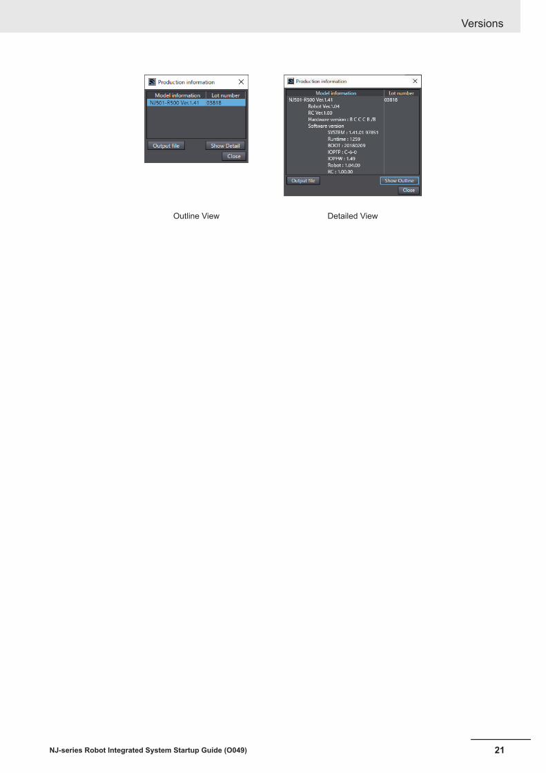
1 Click the Show Detail or Show Outline Button at the lower right of the ProductionInformation Dialog Box.The view will change between the production information details and outline.
Outline View Detailed View
The information that is displayed is different for the Outline View and Detail View. The DetailView displays the unit version, hardware revision, and various versions. The Outline View dis-plays only the unit version.
Note The hardware revision is separated by “/” and displayed on the right of the hardware version. Thehardware revision is not displayed for the Unit that the hardware revision is in blank.
Changing Information Displayed in Production Information Dialog Box
1 Click the Show Detail or Show Outline Button at the lower right of the ProductionInformation Dialog Box.The view will change between the production information details and outline.
Versions
20 NJ-series Robot Integrated System Startup Guide (O049)
Outline View Detailed View
Versions
21NJ-series Robot Integrated System Startup Guide (O049)

Related ManualsThe following are the manuals related to this manual. Use these manuals for reference.
Manual name Cat. No. Model numbers Application DescriptionNJ-series CPU UnitHardware User's Manual
W500 NJ501-££££NJ301-££££NJ101-££££
Learning the basicspecifications of theNJ-series CPU Units,including introductoryinformation, design-ing, installation, andmaintenance.Mainly hardware in-formation is provided.
An introduction to the entire NJ-seriessystem is provided along with the follow-ing information on the CPU Unit.• Features and system configuration• Introduction• Part names and functions• General specifications• Installation and wiring• Maintenance and inspection
NJ/NX-series CPU UnitSoftware User’s Manual
W501 NX701-££££NX102-££££NX1P2-££££NJ501-££££NJ301-££££NJ101-££££
Learning how to pro-gram and set up anNJ/NX-series CPUUnit.Mainly software infor-mation is provided.
The following information is provided on aController built with an NJ/NX-series CPUUnit.• CPU Unit operation• CPU Unit features• Initial settings• Programming based on IEC 61131-3
language specificationsNJ/NX-series InstructionsReference Manual
W502 NX701-££££NX102-££££NX1P2-££££NJ501-££££NJ301-££££NJ101-££££
Learning detailedspecifications on thebasic instructions ofan NJ/NX-seriesCPU Unit.
The instructions in the instruction set (IEC61131-3 specifications) are described.
NJ/NX-series CPU UnitMotion Control User’s Manual
W507 NX701-££££NX102-££££NX1P2-££££NJ501-££££NJ301-££££NJ101-££££
Learning about mo-tion control settingsand programmingconcepts.
The settings and operation of the CPUUnit and programming concepts for mo-tion control are described.
NJ/NX-seriesMotion Control InstructionsReference Manual
W508 NX701-££££NX102-££££NX1P2-££££NJ501-££££NJ301-££££NJ101-££££
Learning about thespecifications of themotion control in-structions.
The motion control instructions are descri-bed.
NJ/NX-seriesCPU Unit
Built-in EtherCAT® PortUser’s Manual
W505 NX701-££££NX102-££££NX1P2-££££NJ501-££££NJ301-££££NJ101-££££
Using the built-inEtherCAT port on anNJ/NX-series CPUUnit.
Information on the built-in EtherCAT portis provided.This manual provides an introduction andprovides information on the configuration,features, and setup.
NJ/NX-seriesCPU Unit
Built-in EtherNet/IP™ PortUser’s Manual
W506 NX701-££££NX102-££££NX1P2-££££NJ501-££££NJ301-££££NJ101-££££
Using the built-inEtherNet/IP port onan NJ/NX-seriesCPU Unit.
Information on the built-in EtherNet/IP portis provided.Information is provided on the basic setup,tag data links, and other features.
NJ-seriesRobot Integrated CPU UnitUser’s Manual
O037 NJ501-R£££ Using the NJ-seriesRobot IntegratedCPU Unit.
Describes the settings and operation ofthe CPU Unit and programming conceptsfor OMRON robot control.
Related Manuals
22 NJ-series Robot Integrated System Startup Guide (O049)

Manual name Cat. No. Model numbers Application DescriptionSysmac StudioRobot Integrated SystemBuilding Function with RobotIntegrated CPU Unit Opera-tion Manual
W595 SYSMAC-SE2£££SYSMAC-SE200D-64
Learning about theoperating proceduresand functions of theSysmac Studio toconfigure Robot Inte-grated System usingRobot IntegratedCPU Unit.
Describes the operating procedures of theSysmac Studio for Robot Integrated CPUUnit.
Sysmac StudioRobot Integrated SystemBuilding Function with IPCApplication Controller Opera-tion Manual
W621 SYSMAC-SE2£££SYSMAC-SE200D-64
Learning about theoperating proceduresand functions of theSysmac Studio toconfigure Robot Inte-grated System usingIPC Application Con-troller.
Describes the operating procedures of theSysmac Studio for IPC Application Con-troller.
Sysmac Studio3D Simulation Function Oper-ation Manual
W618 SYSMAC-SE2£££SYSMAC-SA4£££-64
Learning about anoutline of the 3D sim-ulation function of theSysmac Studio andhow to use the func-tion.
Describes an outline, execution proce-dures, and operating procedures for the3D simulation function of the Sysmac Stu-dio.
eV+3User’s Manual
I651 NJ501-R£££ Operating the OM-RON robot with the V+ program.
Describes the V+ language to control theOMRON robots.
eV+3Keyword Reference Manual
I652 NJ501-R£££ Operating the OM-RON robot with the V+ program.
Describes V+ keywords that are used inthe V+ language.
eCobra 600 and 800 Robotwith EtherCAT User’s Guide
I653 RL4-116££££RL4-216££££
Using the eCobra. Describes the eCobra.
i4L Robots with EtherCAT Us-er’s Manual
I659 RS4-2063£££RS4-2064£££RS4-2065£££
Using the i4L. Describes the i4L.
i4H Robots with EtherCAT Us-er’s Manual
I661 RS4-2066£££RS4-2067£££RS4-2068£££
Using the i4H. Describes the i4H.
Viper 650 and 850 Robot withEtherCAT User’s Guide
I654 RL6-206££££ Using the Viper. Describes the Viper.
iX3 565 Robot with EtherCATUser’s Guide
I655 RX3-206££££ Using the iX3. Describes the iX3.
iX4 650 H/HS and 800 H/HSRobot with EtherCAT User’sGuide
I656 RX4-216££££ Using the iX4. Describes the iX4.
Robot Safety Guide I590 RL4-£££££££RS4-£££££££RL6-£££££££RX3-£££££££RX4-£££££££
Learning how to usethe OMRON robotsafely.
Describes how to use the OMRON robotsafely.
Teaching PendantT20User’s Manual
I601 10046-010 Operating the OM-RON robot with ateaching pendant.
Describes the setup, operation, and usermaintenance for the Teaching PendantT20.
IPC Application ControllerUser’s Manual
I632 AC1-152000 Using the IPC Appli-cation Controller.
Describes the IPC Application Controller.
NJ/NX-seriesDatabase Connection CPUUnitsUser’s Manual
W527 NX701-££20NX102-££20NJ501-££20NJ101-££20
Using the databaseconnection servicewith NJ/NX-seriesControllers.
Describes the database connection serv-ice.
Related Manuals
23NJ-series Robot Integrated System Startup Guide (O049)

Manual name Cat. No. Model numbers Application DescriptionNJ-seriesNJ Robotics CPU UnitUser’s Manual
W539 NJ501-4£££NJ501-R£££
Controlling robotswith NJ-series CPUUnits.
Describes the functionality to control ro-bots.
NJ/NX-seriesTroubleshooting Manual
W503 NX701-££££NX102-££££NX1P2-££££NJ501-££££NJ301-££££NJ101-££££
Learning about theerrors that may bedetected in anNJ/NX-series Con-troller.
Concepts on managing errors that may bedetected in an NJ/NX-series Controllerand information on individual errors aredescribed.
Sysmac Studio Version 1Operation Manual
W504 SYSMAC-SE2£££
Learning about theoperating proceduresand functions of theSysmac Studio.
Describes the operating procedures of theSysmac Studio.
NX-seriesPosition Interface UnitsUser’s Manual
W524 NX-EC0£££NX-ECS£££NX-PG0£££
Learning how to useNX-series PositionInterface Units.
The hardware, setup, and functions for theNX-series Incremental Encoder InputUnits, SSI Input Units, and Pulse OutputUnit are described.
AC Servomotors/Servo Drives1S-series with
Built-in EtherCAT® Communi-cations User's Manual
I586 R88M-1£R88D-1SN£-ECT
Learning how to usethe Servomotors/Servo Drives withbuilt-in EtherCATCommunications.
Describes the hardware, setup methodsand functions of the Servomotors/ServoDrives with built-in EtherCAT Communica-tions.
I621 R88M-1AL£/ -1AM£R88D-1SAN£-ECT
AC Servomotors/Servo DrivesG5 Series with
Built-in EtherCAT® Communi-cations User's Manual
I576 R88M-K£R88D-KN£-ECT
Learning how to usethe AC Servomotors/Servo Drives withbuilt-in EtherCATCommunications.
Describes the hardware, setup methodsand functions of the AC Servomotors/Servo Drives with built-in EtherCAT Com-munications.The Linear Motor Type models and dedi-cated models for position control are avail-able in G5-series.
I577 R88L-EC-£R88D-KN£-ECT-L
Related Manuals
24 NJ-series Robot Integrated System Startup Guide (O049)
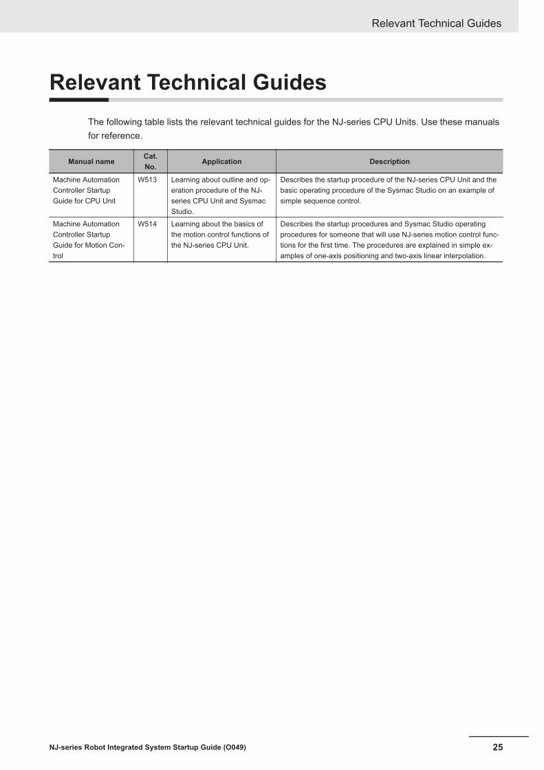
Relevant Technical GuidesThe following table lists the relevant technical guides for the NJ-series CPU Units. Use these manualsfor reference.
Manual nameCat.No.
Application Description
Machine AutomationController StartupGuide for CPU Unit
W513 Learning about outline and op-eration procedure of the NJ-series CPU Unit and SysmacStudio.
Describes the startup procedure of the NJ-series CPU Unit and thebasic operating procedure of the Sysmac Studio on an example ofsimple sequence control.
Machine AutomationController StartupGuide for Motion Con-trol
W514 Learning about the basics ofthe motion control functions ofthe NJ-series CPU Unit.
Describes the startup procedures and Sysmac Studio operatingprocedures for someone that will use NJ-series motion control func-tions for the first time. The procedures are explained in simple ex-amples of one-axis positioning and two-axis linear interpolation.
Relevant Technical Guides
25NJ-series Robot Integrated System Startup Guide (O049)

TerminologyThis section describes the terms that are used in this manual.
Term Descriptioncontinuous-path mo-tion
A motion to move continuous operations smoothly without stopping motion of the OM-RON robot.
IEC 61131-3 lan-guage
A programming language to write a sequence control program.
robots controllableby NJ Robotics func-tion
Specify the controllable robots by the data processing for robot in the Motion ControlFunction Module of the NJ-series CPU Unit.The controllable robot consists of the 1S-series or G5-series Servomotor/Servo Drivewith built-in EtherCAT communications and the robot arm that is prepared by the cus-tomer.
TCP A tip (Tool Center Point) defined in each OMRON robot.The target position or path can be specified based on the TCP.
TIO Refers to digital input and output signals to use arm tip tools for OMRON SCARA robots(i4H, i4L).
V+ keyword A generic term for instructions that are used during a V+ program and monitoring com-mand.
V+ language A programming language for OMRON robot control.V+ task A task that can execute a V+ program.V+ program A control program written in the V+ language.OMRON robot Specifies the OMRON robot controllable from the Robot Integrated CPU Unit.
The robot consists of the robot amplifier and the robot arm connected to the robot ampli-fier.
shared variable A variable that can be shared between the sequence control program and V+ program.sequence controlprogram
A control program written in IEC 61131-3 language including the motion control.
configured eV+ ver-sion
An eV+ version that is set by the eV+ version configuration function.It is set for both the Robot Integrated CPU Unit and an OMRON robot.
hardware servo A servo system built into the robot amplifier.user program A generic term for the collection of programs written in the ladder diagram, ST, and V+
languages.remote encoder Specifies the encoder which sets the motion control axis as the external encoder for ro-
bot control.recipe A set of product type data in the customer’s system.recipe change Specifies that the product data and information (recipe) related to the production proc-
ess are changed.The target recipe for the Robot Integrated CPU Unit is a property from the present val-ues of variables and a vision sensor.
local encoder Specifies the encoder connected to the encoder input port on the OMRON robot.Robot Control Func-tion Module
Software to perform robot control that is installed in the Robot Integrated CPU Unit.
robot control instruc-tions
FB instructions written in the sequence control program to control the OMRON robots.They include an instruction to directly control the OMRON robots and an instruction toexecute or abort V+ programs assigned to the V+ tasks.
Robot IntegratedCPU Unit
A CPU Unit that supports control function for the OMRON robot with the NJ-series CPUUnit.
Terminology
26 NJ-series Robot Integrated System Startup Guide (O049)

Revision HistoryA manual revision code appears as a suffix to the catalog number on the front and back covers of themanual.
O049-E1-04
Revision code
Cat. No.
Revisioncode Date Revised content
01 August 2020 Original production02 December 2020 • Added description on dynamic pick-and-place equipment.
• Corrected mistakes.03 October 2021 Corrected mistakes.04 March 2022 Corrected mistakes.
Revision History
27NJ-series Robot Integrated System Startup Guide (O049)

Revision History
28 NJ-series Robot Integrated System Startup Guide (O049)
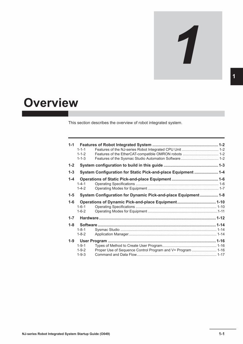
1Overview
This section describes the overview of robot integrated system.
1-1 Features of Robot Integrated System .......................................................... 1-21-1-1 Features of the NJ-series Robot Integrated CPU Unit .................................... 1-21-1-2 Features of the EtherCAT-compatible OMRON robots ................................... 1-21-1-3 Features of the Sysmac Studio Automation Software..................................... 1-2
1-2 System configuration to build in this guide ................................................ 1-31-3 System Configuration for Static Pick-and-place Equipment ..................... 1-41-4 Operations of Static Pick-and-place Equipment ......................................... 1-6
1-4-1 Operating Specifications ................................................................................. 1-61-4-2 Operating Modes for Equipment ..................................................................... 1-7
1-5 System Configuration for Dynamic Pick-and-place Equipment ................ 1-81-6 Operations of Dynamic Pick-and-place Equipment.................................. 1-10
1-6-1 Operating Specifications ............................................................................... 1-101-6-2 Operating Modes for Equipment ....................................................................1-11
1-7 Hardware....................................................................................................... 1-121-8 Software ........................................................................................................ 1-14
1-8-1 Sysmac Studio .............................................................................................. 1-141-8-2 Application Manager...................................................................................... 1-14
1-9 User Program ............................................................................................... 1-161-9-1 Types of Method to Create User Program..................................................... 1-161-9-2 Proper Use of Sequence Control Program and V+ Program ........................ 1-161-9-3 Command and Data Flow.............................................................................. 1-17
1-1NJ-series Robot Integrated System Startup Guide (O049)
1

1-1 Features of Robot Integrated SystemThe robot integrated system is a system to integrate the sequence control and robot control into aController, network, and software.
Motion controlSequence controlNJ-seriesRobot Integrated CPU Unit
IEC programming
Safety devices Machine vision
Servo Drives and Inverters
I/O controls
EtherCAT control network
Sysmac StudioAutomation Software
Robots
V+ program
Robot control V+ language
The system consists of the NJ-series Robot Integrated CPU Unit, the OMRON robots that supportEtherCAT communications, and the Sysmac Studio Automation Software.
1-1-1 Features of the NJ-series Robot Integrated CPU UnitThe sequence control and the robot control can be executed with a CPU Unit. This allows you to de-sign interface easily between the sequence control and robot control and reduce the design time andthe adjustment time at startup.
1-1-2 Features of the EtherCAT-compatible OMRON robotsThe robots and peripheral devices can connect to the same EtherCAT network. The operations for therobots and the peripheral devices can be handled in the same time axis with the synchronization func-tion of the EtherCAT, so wait time for asynchronous operation or variations of timing are reduced. Thisenables you to reduce the tact time, identify an error cause during operation, and make predictive con-trol for the operations of peripheral devices.
1-1-3 Features of the Sysmac Studio Automation SoftwareThe sequence control and the robot control can be developed with a software. It is easy to perform theadvance verification on paper because the system operations to use with the sequence control androbot control can be simulated with the 3D model.
1 Overview
1-2 NJ-series Robot Integrated System Startup Guide (O049)

1-2 System configuration to build in thisguide
NJ-series Robot Integrated System Startup Guide (hereinafter referred to as “this guide”) describesexamples of building a static pick-and-place equipment and a dynamic pick-and-place equipment.
An equipment to move a workpiece that is placed at the specified position to the target position iscalled a static pick-and-place equipment in this guide.
An equipment that picks up a workpiece being moved on the conveyor and places it at the specifiedposition is called a dynamic pick-and-place equipment. The pickup position is automatically deter-mined from the position detected by the camera and encoder.To control multiple Omron robots and manage the recipes, IPC Application Controller is connected tothe equipment via Ethernet. Select and use the IPC Application Controller, industrial cameras, and beltencoders required for the functions explained in 1-8-2 Application Manager on page 1-14.
The figure below illustrates the devices to be used for each equipment.
IPC Application Controller
GigE/PoE
Industrial camera
Computer
Ethernet
Sysmac Studio
Robot Integrated CPU Unit
EtherCAT
EtherCAT-enabled Omron robot
XBELTIO
XMCP
XIO
XSYSTEM XFP
XUSR
Front panel
T20 Pendant
Safety circuit
Belt encoder
EtherCAT Digital I/O TerminalInverter's EtherCAT Communications Unit
External device
Industrial Ethernet switch
Static pick-and-place equipment
Dynamic pick-and-place equipment
1 Overview
1-3NJ-series Robot Integrated System Startup Guide (O049)
1-2 System configuration to
build in this guide
1

1-3 System Configuration for Static Pick-and-place Equipment
This section describes the system configuration for the static pick-and-place equipment that is ex-plained in this guide.An equipment to move a workpiece that is not moved at the specified position to the target position iscalled a static pick-and-place equipment in this guide."XUSR" in the following figure is a wiring to the safety circuits. Refer to A-1 Designing Example of theSafety Functions for the Pick-and-place Equipment on page A-2, and design the safety circuits re-quired for the actual equipments.
(P)
(G)
(C)
(B) (A)
(S)
(E)
(D)
(R)
(O)
(N)
(M)
(Q)
(F)
(H)
(J)
(I)
(L)
(K)
100 to 240 VAC
85 to 264VAC, 6.5A
Single phase, AC200 to 240VAC, 10A
XMCP
XFP
XUSR*1
The parts that are used in the system configuration are given below.
1 Overview
1-4 NJ-series Robot Integrated System Startup Guide (O049)

Letter Name Model VersionA Robot Integrated CPU Unit NJ501-R300 Ver.1.41B Power Supply Unit NJ-PA3001 ---C SCARA Robot
eCobra 600 ProRL4-2166000 3.0 0-0 Edit A1
D Ethernet cable*1 --- ---
E Computer (Sysmac Studio) --- ---F EtherCAT Digital I/O Terminal GX-MD3218 ---G Ethernet cable*1 --- ---
H Ethernet cable*1 --- ---
I T20 Pendant 10046-010 3.0.0.1J T20 Adapter Cable ---K Front Panel 90356-10358 ---L Front Panel Cable ---M XSYSTEM Cable Assembly Incudes in the RL4-2166000. ---N AC Power Cable 04118-000 ---O DC Power Cable 04120-000 ---P 24 VDC Power Supply 150 W S8FS-G15024CD ---Q Solenoid valve Selects depending on the workpiece. ---R Vacuum pad ---S Vacuum ejector ---
*1. Use a twisted-pair cable (double shielding with aluminum tape and braiding) of category 5 (100BASE-TX) orhigher.
1 Overview
1-5NJ-series Robot Integrated System Startup Guide (O049)
1-3 System C
onfiguration forStatic Pick-and-place Equipm
ent
1

1-4 Operations of Static Pick-and-placeEquipment
This section describes the operating specifications and procedures for the static pick-and-place equip-ment.
1-4-1 Operating SpecificationsThis equipment picks up a workpiece that is not moving on the conveyor A and transfers it to thespecified position on the conveyor B.
Workpiece
Conveyor A: static state
Conveyor B: static state
The following figure shows a specific operation for a robot.
Robot wait position (P1)
(1) (7)
(2) (3) (5) (6)(4)
Workpiece pick-up approach point (P2)
Workpiece pick-up position (P3)
Workpiece place position (P5)
Workpiece place approach point (P4)
Number Description of operation(1) Move from the robot wait position (P1) to the workpiece pick-up approach point (P2) in joint interpola-
tion operation.(2) Move from the workpiece pick-up approach point (P2) to the workpiece pick-up position (P3) in linear
interpolation operation.(3) Move from the workpiece pick-up position (P3) to workpiece pick-up approach point (P2) in linear in-
terpolation operation.(4) Move from the workpiece pick-up approach point (P2) to the workpiece place approach point (P4) in
joint interpolation operation.(5) Move from the workpiece place approach point (P4) to the workpiece place position (P5) in linear in-
terpolation operation.(6) Move from the workpiece place position (P5) to the workpiece place approach point (P4) in linear in-
terpolation operation.(7) Move from the workpiece place approach point (P4) to the robot wait position (P1) in joint interpola-
tion operation.
1 Overview
1-6 NJ-series Robot Integrated System Startup Guide (O049)

Additional Information
The operations for conveyor A and B are not described in this guide. Program it by the custom-er according to the operating specifications of actual equipments.
1-4-2 Operating Modes for EquipmentAssume that this equipment have two operating modes, manual operation and automatic operationmodes.Perform teaching in manual operation, and execute the actual pick-and-place operations in automaticoperation.
1 Overview
1-7NJ-series Robot Integrated System Startup Guide (O049)
1-4 Operations of Static Pick-
and-place Equipment
1
1-4-2 Operating M
odes for Equipment

1-5 System Configuration for DynamicPick-and-place Equipment
This section describes the system configuration for the dynamic pick-and-place equipment to build inthis guide.In this guide, an equipment that picks up a workpiece being moved on the conveyor and places it atthe specified position is called a dynamic pick-and-place equipment. The pickup position is automati-cally determined from the position detected by the camera and encoder."XUSR" in the following figure is a wiring to the safety circuits. Design the safety circuits required forthe actual equipments.The Y-adapter cable in the figure below is a cable to connect with the encoders. Since there is onlyone encoder used in this equipment, connect the encoder extension cable to one side only. No encod-er is connected to the other side.
(P)
(G)(C)
(B) (A)
(S)
(W)
(X)(Z)
(T) (U)
(D)
(R)(O)(N)
(M)
(Q)
(F) (H) (J)
(I)
(L)
(K)
100 to 240 VAC
85 to 264 VAC, 6.5A
85 to 264 VCA, 6A
Single-phase, 200 to 240
Connect an encoder for another
conveyor to this side.
XMCP
XFP
XUSR
DB15m
Force/EXPIO
RS-232C
*1
(E)
(V)
(Y)
(AA)
(AB)
(AC)
(AG)
(AH)
(AI)
(AJ)
(AK)
(AL)
(AE) (AD)(AF)
The parts that are used in the system configuration are given below.
1 Overview
1-8 NJ-series Robot Integrated System Startup Guide (O049)

Letter Name Model VersionA Robot Integrated CPU Unit NJ501-R300 Ver.1.43B Power Supply Unit NJ-PA3001 ---C Ethernet cable*1 --- ---
D Industrial Ethernet switch W4S1-03B ---E Ethernet cable*1 --- ---
F Computer (Sysmac Studio) --- ---G Ethernet cable*1 --- ---
H IPC Application Controller AC1-152000 Ver.2.00I DVI Cable --- ---J Display --- ---K Camera Cable (GigE Cat.6) 10m 24114*2 ---L Camera ---M Power I/O Cable ---N Ethernet cable*1 --- ---
O EtherCAT Digital I/O Terminal GX-MD3218 ---P Solenoid valve Select a bellow-shape valve with suitable vacuum pres-
sure to the workpiece.---
Q Vacuum ejector ---R Vacuum pad ---S Ethernet cable*1 --- ---
T EtherCAT Communications Unit 3G3AX-MX2-ECT ---U Inverter*3 Select an applicable model from the Multi-function Com-
pact Inverter MX2-series V1 type.---
V Belt conveyor*3 --- ---
W Ethernet cable*1 --- ---
X Parallel RobotiX4 650H, IP65, P30
RX4-2166020 4.0.C1
Y T20 Pendant 10046-010 3.0.0.1Z T20 Adapter Cable ---AA Front Panel 90356-10358 ---AB Front Panel Cable ---AC XSYSTEM Cable Assembly Included in the RL4-2166000. ---AD Encoder IP65 09742-001 ---AE Encoder extension cable 5m ---AF Y-Adapter Cable 3m 09443-000 ---AG XBELT IO Cable 0.6m 13463-000 ---AH XIO Breakout Cable 04465-000 ---AI AC Power Cable 04118-000 ---AJ DC Power Cable 04120-000 ---AK 24 VDC Power Supply 150 W S8FS-G15024CD ---AL 24 VDC Power Supply 120W S8VK-S12024 ---
*1. Use a twisted-pair cable (double shielding with aluminum tape and braiding) of category 5 (100BASE-TX) orhigher.
*2. Select a camera with the appropriate imaging range and resolution for the belt width and the workpiece.*3. Refer to the Multifunction Compact Inverter User's Manual (Cat. No. I585) for the circuits around the inverter
and connection to the belt conveyor.
1 Overview
1-9NJ-series Robot Integrated System Startup Guide (O049)
1-5 System C
onfiguration for Dy-
namic Pick-and-place Equipm
ent
1

1-6 Operations of Dynamic Pick-and-place Equipment
This section describes the operating specifications and procedures for the dynamic pick-and-placeequipment.
1-6-1 Operating SpecificationsThis equipment picks up a workpiece that is moving on the conveyor A after a camera detects it, andplaces it to the specified position on the conveyor B.
Conveyor A
Conveyor B
Camera
EncoderEncoder
WorkpieceWorkpiece
The following figure shows a specific operation for a robot.
Robot wait position
(1)
*1*1
(2) (3) (5) (6)
(7)
(4)
Workpiece pick-up approach point (P2)
Workpiece pick-up position (P3)
Workpiece place position (P5)
Workpiece place approach point (P4)
*2 *2
*1. When there is no workpiece to pick up on the conveyor and no item is detected by the camera, therobot once moves from the workpiece pick-up approach point (P2) or workpiece pick-up position (P3)to the robot wait position (P1). While the camera is detecting the workpiece, operation from (2) to (7) isrepeatedly performed.*2. In above operation digram, both of the transit points of the robot in approaching to the workpieceand departing from the workpiece are called "workpiece pick-up approach point (P2)". The function ofthe Pack Manager allows you to set the transit positions in approaching to the workpiece and movingaway from the workpiece to different locations. Similarly, you can set different locations for "workpieceplace approach point (P4)".
Number Description of operation(1) Move from the robot wait position (P1) to the workpiece pick-up approach point (P2) in linear interpo-
lation operation.
1 Overview
1-10 NJ-series Robot Integrated System Startup Guide (O049)

Number Description of operation(2) Move from the workpiece pick-up approach point (P2) to the workpiece pick-up position (P3) in linear
interpolation operation.(3) Move from the workpiece pick-up position (P3) to workpiece pick-up approach point (P2) in linear in-
terpolation operation.(4) Move from the workpiece pick-up approach point (P2) to the workpiece place approach point (P4) in
linear interpolation operation.(5) Move from the workpiece place approach point (P4) to the workpiece place position (P5) in linear in-
terpolation operation.(6) Move from the workpiece place position (P5) to the workpiece place approach point (P4) in linear in-
terpolation operation.(7) Move from the workpiece place approach point (P4) to the workpiece pick-up approach point (P2) in
linear interpolation operation.
The "approach point" is the same as "approach location" and "depart location" that are used with thePack Manager described in 4-3-6 Creating a Pack Manager Sample on page 4-53.
Additional Information
The operations for conveyor B are not described in this guide. Program it by the customer ac-cording to the operating specifications of actual equipment.
1-6-2 Operating Modes for EquipmentAssume that this equipment have two operating modes, manual operation and automatic operationmodes.Perform teaching in manual operation, and execute the actual pick-and-place operations in automaticoperation.
1 Overview
1-11NJ-series Robot Integrated System Startup Guide (O049)
1-6 Operations of D
ynamic Pick-
and-place Equipment
1
1-6-2 Operating M
odes for Equipment

1-7 HardwareThe following table shows an overview of each hardware in the system configuration.Refer to the manual for the specific product for details.
Hardware Model Description StaticDy-na-mic
Robot Inte-grated CPUUnit
NJ501-R£££ A CPU Unit that integrates the sequence controland robot control. To use the robot control function,you must insert the included SD Memory Card.
¡ ¡
EtherCAT-compatibleOMRON robot
RL£-£££££££ OMRON’s SCARA robot that supports EtherCAT. ¡ ¡
RX£-£££££££ OMRON’s parallel robot that supports EtherCAT. ¡ ¡
Computer --- A computer that the Sysmac Studio AutomationSoftware to make the settings for the robot inte-grated system and perform debugging is installed.*1
¡ ¡
Front Panel 90356-10358 A control panel for a robot. The panel has switchesto change modes, enable the high power, andmake a emergency stop.
¡ ¡
T20 Pendant 10046-010 A teaching pendant for a robot. Use the pendantfor teaching coordinates. It has the built-in E-Stopbutton and built-in enable switch as safety func-tions.
¡ ¡
Safety circuits --- The safety circuits that consist of safety I/O devi-ces, a Safety Controller, etc. Refer to A-1 Design-ing Example of the Safety Functions for the Pick-and-place Equipment on page A-2 for details.
¡ ¡
Connectedexternal devi-ces
--- I/O devices connected to the digital I/O terminalsof the robot.
¡ ¡
EtherCATslaves
--- EtherCAT slaves such as digital I/O, servos, andinverters.
¡ ¡
IndustrialEthernetswitch
W4S1-£££ This is used for branching the Ethernet network. --- ¡
IPC Applica-tion Controller
AC1-152000 An industrial computer. The computer executespre-installed softwares for the robot control system(Application Manager). It has a interface for con-necting a camera (PoE port).
--- ¡
Industrialcamera
24114-£££ A camera for sensing an image. The camera canconnect to the IPC Application Controller to detectand inspect a workpiece.
--- ¡
Inverter 3G3MX2-A££££-V1 An inverter to control a belt conveyor. Select anapplicable model from the Multi-function CompactInverter MX2-series V1 type.
--- ¡
EtherCATCommunica-tions Unit
3G3AX-MX2-ECT A communications unit to be attached for Ether-CAT communications.
--- ¡
1 Overview
1-12 NJ-series Robot Integrated System Startup Guide (O049)

Hardware Model Description StaticDy-na-mic
Conveyor Belt SVKN-100-1000-25-T100-IM-9-H-A
A belt conveyor of MISUMI Corporation for con-veying workpieces.
--- ¡
Encoder kitIP65
09742-001 An encoder mounted on the belt conveyor. --- ¡
*1. Refer to the Sysmac Studio Robot Integrated System Building Function with Robot Integrated CPU UnitOperation Manual (Cat. No. W595) for information on the recommended operating environment for the com-puter.
1 Overview
1-13NJ-series Robot Integrated System Startup Guide (O049)
1-7 Hardw
are
1

1-8 SoftwareThis section describes an overview of each software in the system configuration.Use the Sysmac Studio as a development environment for the robot integrated system and ApplicationManager as a runtime to control the application.
1-8-1 Sysmac StudioThe Sysmac Studio provides development environment for a robot integrated system on a computer.
Precautions for Correct Use
For a robot integrated system, use the 64-bit edition DVD (SYSMAC-SE200D-64) with the Sys-mac Studio version 1.££. You cannot use the 32-bit edition DVD (SYSMAC-SE200D).
The Sysmac Studio has the following functions.
Function DescriptionRobot controlfunction
A function to make settings and create a program to control a robot with the Robot Integrat-ed CPU Unit and IPC Application Controller. To use this function, you need a license for theStandard Edition (SYSMAC-SE2££L).
3D simulationfunction
A function to perform a 3D simulation including robots and peripheral devices. To use thisfunction, you need a license with the 3D Simulation Option (SYSMAC-SA4££L-64).
Refer to the Sysmac Studio Robot Integrated System Building Function with Robot Integrated CPUUnit Operation Manual (Cat. No. W595) for information on the robot control function in the SysmacStudio and the Sysmac Studio 3D Simulation Function Operation Manual (Cat. No. W618) for informa-tion on the 3D simulation function.
Additional Information
Refer to A-3 Setting Items on the Sysmac Studio and the Setting Targets on page A-28 for in-formation on which hardware setting corresponds to the items on the Multiview Explorer of theSysmac Studio.
1-8-2 Application ManagerThe Application Manager is one of the functions for ACE that is a software pre-installed in the IPC Ap-plication Controller.The Application Manager has following functions.
Function DescriptionProcess Manag-er
Determines which robot will use for a workpiece automatically, and performs the variance ofloads.
Recipe Manager Manages the robot control parameters for the product type change of a workpiece.Robot VisionManager
Detects a workpiece position and inspect the appearance by sensing an image with a cam-era. To enable this function, you must mount the USB Dongle (20410-000 or 20433-000) onthe IPC Application Controller.
Pack Manager Executes packing applications that are created in the application sample. To enable thisfunction, you must mount the USB Dongle (20409-000 or 20433-000) on the IPC ApplicationController.
1 Overview
1-14 NJ-series Robot Integrated System Startup Guide (O049)

Precautions for Correct Use
The ACE has a function as a development environment of a robot system with the Smart Con-troller EX, but it cannot be used as a development environment of a robot integrated system.Use the Sysmac Studio to develop the robot integrated system.
1 Overview
1-15NJ-series Robot Integrated System Startup Guide (O049)
1-8 Software
1
1-8-2 Application Manager

1-9 User ProgramThe user program for robot control is created in the Sysmac Studio.There is more than one method to create a user program. Realize applications to use with programscreated by multiple methods.
1-9-1 Types of Method to Create User ProgramThe following table shows the types of method to create a user program.
Method DescriptionSequencecontrol pro-gram
The user program that is operated in the Robot Integrated CPU Unit can be programmed withthe language that is defined in IEC61131-3. The robots are controlled with robot control instruc-tions and system-defined variables for robot control.This program is suitable for operating simple robot motions or controlling with robots and periph-eral devices.Ladder diagram is used in this guide.
V+ program The user program that is operated in the Robot Integrated CPU Unit can be programmed with V+language. The language is a programming language for robot control for the OMRON robots.The robots can be controlled using V+ keywords.In addition, you can use ACE Sight V+ keywords and V+ module API to call and use the func-tions of the Application Manager.This program is suitable for using various robot control.
C# program The user program that is operated in the IPC Application Controller can be programmed with C#language. Use this program when the functions of the Application Manager are called and used.
Applicationsample
You can create an application sample on the interactive setup wizard. The application sample in-cludes the settings and programs for the IPC Application Controller and Robot Integrated CPUUnit.The Pack Manager sample is used in this guide.
1-9-2 Proper Use of Sequence Control Program and V+ ProgramThe following shows proper use of the sequence control program and V+ program.• The sequence control program manages the status, errors, and interlocks of the entire system in-
cluding sequence control and robot control.• The robot control is performed with a combination of the sequence control program and the V+ pro-
gram.• The sequence control program performs the control other than robot control.
A typical example of differences for robot control that can be used in the sequence control programand the V+ program is given below.The sequence control program can use a part of the control that is available in the V+ program.
1 Overview
1-16 NJ-series Robot Integrated System Startup Guide (O049)

Classification ItemApplicability ( if applicable, the specified method is
described.)Sequence control program V+ program
Robot operations Joint interpolation operation RC_MoveDirect *1 MOVE
Linear interpolation operation RC_MoveLinear *1 MOVES
Circular interpolation opera-tion
Not possible. MOVEC
Jog operation Not possible. JOGJoint coordinate system oper-ation
Not possible. JMOVE
Tool coordinate system opera-tion
Not possible. APPRO/DEPART/ALIGN
Robot’s coordinate Flange surface _RC_RBT[*].TCPActPos *2 HERE
Coordinates of the tool centerpoint
_RC_RBT[*].TCPActPos *2
(RC_SetToolTransform *1)
HERE(TOOL)
Joint coordinates for each ax-is
_RC_RBT[*].JointActPos *2 #PHERE
Other functions Robot built-in I/O _RC_RBT_IO[*].XIO *2 SIGNAL/SIG
Expanded robot I/O _RC_RBT_IO[*].IOBlox1 *2
_RC_RBT_IO[*].IOBlox2 *2SIGNAL/SIG
Teaching Not possible. Position variablesEnd effector operation _RC_RBT_IO[*].RO *2 SIGNAL/SIG
Robot position latching Not possible. LATCHLocal encoder latch Not possible. DEVICECooperation with ApplicationManager
Not possible. ACE Sight V+ key-wordV+ Module API
*1. This is a robot control instruction.*2. This is a system-defined variable for robot control.
Refer to the NJ-series Robot Integrated CPU Unit User’s Manual (Cat. No. O037) for detailed informa-tion when a robot is controlled with a sequence control program.Refer to the eV+3 User's Manual (Cat. No. I651) and eV+3 Keyword Reference Manual (Cat. No.I652) for detailed information when a robot is controlled with a V+ program.
1-9-3 Command and Data Flow
This section describes the flow of commands and data for the sequence control program, V+ program,Application Manager, and robot.
The sequence control program can control robots with robot control instructions, robot variables, androbot I/O variables.Since the taught position data is stored in the position variable of the V+ program, to use it in the se-quence control program, V+ programs need to be called from RC_ExecVpPrgTask and the positiondata must be copied to the shared variables.
1 Overview
1-17NJ-series Robot Integrated System Startup Guide (O049)
1-9 User Program
1
1-9-3 Com
mand and D
ata Flow

Robot Integrated CPU Unit
Sequence control program
V+ program
Shared variables(Teaching position variable, etc.)
OMRON robot
Robot control instructions
Robot variables, robot I/O variables
Start, stop, or monitor V+tasks
The V+ program can control robots with V+ keywords, signal numbers, and V+ variables.In addition, the V+ program can execute the functions of the Application Manager in the IPC Applica-tion Controller with ACE Sight V+ keywords and V+ module API.The V+ program is launched and stopped by RC_ExecVpPrgTask from the sequence control program.
IPC Application Controller
Process manager
Recipe Manager
ACE Sight
PackXpert
Application Manager
C# program
ACE
...
Robot Integrated CPU Unit
Sequence control program
V+ program
Shared variables(Execution status for the sequence control program, etc.)
OMRON robot
V+ keywords
Signal numbers, V+ variables
Co
mm
an
ds, d
ata
Start, stop, ormonitorV+ tasks
Refer to the NJ-series Robot Integrated CPU Unit User’s Manual (Cat. No. O037) for details on therobot control function and shared variables in the sequence control program.Refer to the eV+3 User's Manual (Cat. No. I651) and eV+3 Keyword Reference Manual (Cat. No.I652) for details on the robot control function in the V+ program.
1 Overview
1-18 NJ-series Robot Integrated System Startup Guide (O049)
2Before You Begin
This section describes the installation procedure of the Sysmac Studio.
2-1 Installing the Sysmac Studio ........................................................................ 2-2
2-1NJ-series Robot Integrated System Startup Guide (O049)
2

2-1 Installing the Sysmac StudioThe Sysmac Studio Ver.1.££ 64-bit edition DVD (SYSMAC-SE200D-64) is the Support Software thatyou use for the Robot Integrated System. On it, you can set up the configurations and parameters, youcan create programs, and you can debug and simulate operation.
1 Set the Sysmac Studio installation disk into the DVD-ROM drive.The setup program is started automatically and the Select Setup Language Dialog Box is dis-played.
2 Select the language to use, and then click the OK button.The Sysmac Studio Setup Wizard is started.
3 Follow the instructions given by the Setup Wizard to complete the installation.
4 Restart the computer when the installation is completed.
Additional Information
• Refer to the Sysmac Studio Robot Integrated System Building Function with Robot IntegratedCPU Unit Operation Manual (Cat. No. W595) for information on the system requirements forthe computer to which you install the Sysmac Studio.
• Refer to the Sysmac Studio Version 1 Operation Manual (Cat. No. W504) if you are unable toinstall the Sysmac Studio with the above instructions.
2 Before You Begin
2-2 NJ-series Robot Integrated System Startup Guide (O049)
3Implementation Example of StaticPick-and-place Equipment
This section describes the implementation example of the static pick-and-place equip-ment.An equipment to move a workpiece that is not moved at the specified position to thetarget position is called a static pick-and-place equipment in this guide.This example can realize with the sequence control program and V+ program.
3-1 Program Specifications for Static Pick-and-place Equipment .................. 3-23-1-1 When Operations are Controlled with Sequence Control Program................. 3-33-1-2 When Operations are Controlled with V+ Program ....................................... 3-10
3-2 Basic Startup Procedures ........................................................................... 3-173-3 Programming and Simulation Procedures ................................................ 3-19
3-3-1 Creating a Project File................................................................................... 3-193-3-2 Creating the EtherCAT Network Configuration.............................................. 3-203-3-3 Creating a Sequence Control Program ......................................................... 3-223-3-4 Creating V+ Programs................................................................................... 3-283-3-5 Placing 3D Shape Data ................................................................................. 3-353-3-6 Starting Simulation ........................................................................................ 3-653-3-7 Teaching Positions ........................................................................................ 3-663-3-8 Setting up Automatic Loading of V+ Programs and Variables at Power ON. 3-773-3-9 Running the Program and Checking Operation ............................................ 3-81
3-4 Installing and Wiring the System................................................................ 3-863-4-1 Wiring the Robot Integrated CPU Unit and the EtherCAT Digital I/O
Terminal......................................................................................................... 3-863-4-2 Setting the Node Address of the EtherCAT Digital I/O Terminal ................... 3-873-4-3 Wiring the EtherCAT Digital I/O Terminal and the Robot............................... 3-873-4-4 Setting the EtherCAT Node Address of the Robot ........................................ 3-883-4-5 Wiring the Robot Integrated CPU Unit and the Computer............................. 3-883-4-6 Wiring the Robot, T20 Pendant and the Front Panel .................................... 3-893-4-7 Wiring the EtherCAT Digital I/O Terminal and Solenoid Valve....................... 3-90
3-5 Setup Procedure for Actual System........................................................... 3-923-5-1 Connecting Online......................................................................................... 3-923-5-2 Transferring Settings and Programs.............................................................. 3-943-5-3 Teaching ........................................................................................................ 3-963-5-4 Executing Program to Check Operation...................................................... 3-108
3-1NJ-series Robot Integrated System Startup Guide (O049)
3

3-1 Program Specifications for StaticPick-and-place Equipment
The program specifications are described if operations of static pick-and-place equipment are control-led with the sequence control program and if the operations are controlled with the V+ program.A flow chart of a program is given below. Refer to 1-4-1 Operating Specifications on page 1-6 for infor-mation on the positions of P1 to P5 in the flow chart.
Robot calibration
Update position data
Move to P1
Stop vacuuming
Wait for a certain time
Move to P4
Move to P1
Detach the robot
Start
End
Move to P2
Move to P3
Start vacuuming
Move to P5
Attach a robot
Wait for a certain time
Move to P2
Move to P4
3 Implementation Example of Static Pick-and-place Equipment
3-2 NJ-series Robot Integrated System Startup Guide (O049)

There are two ways to program the static pick-and-place equipment; one is to control with a sequencecontrol program, and the other is to control with a V+ program. Create the program in either way.For information on how to create a program, refer to 3-3 Programming and Simulation Procedures onpage 3-19.
3-1-1 When Operations are Controlled with Sequence Control Pro-gram
The program specifications when operations of static pick-and-place equipment are controlled with thesequence control program are described below.
The program consists of the following programs.
Program name Language DescriptionMain Sequence control program (Ladder diagram) Main programRun Sequence control program (Ladder diagram) Operating programloccopy V+ program Variable copy program
Shared VariablesThe following table shows a list of shared variables that are used in this program.
No. Variable name Data type Description1 eLoc_Wait ARRAY[0..5] OF
LREALUse the variable to send the robot wait position from the V+ pro-gram to the sequence control program.
2 eLoc_Place ARRAY[0..5] OFLREAL
Use the variable to send the robot place position from the V+ pro-gram to the sequence control program.
3 eLoc_Pick ARRAY[0..5] OFLREAL
Use the variable to send the robot pick-up position from the V+ pro-gram to the sequence control program.
4 eBool_Exe BOOL Use the variable to check that the execution of a V+ task is startedin the sequence control program.
Sequence Control ProgramThis section describes the sequence control program to control the static pick-and-place equipment.The sequence control program is used to register global variables and create two programs, "Main"(main program) and "Run" (operating program).
Global VariablesRegister the global variables that are used in the sequence control program.
3 Implementation Example of Static Pick-and-place Equipment
3-3NJ-series Robot Integrated System Startup Guide (O049)
3-1 Program Specifications for Static Pick-and-place
Equipment
3
3-1-1 When O
perations are Controlled w
ith Sequence Control Program

Main program (Main)"Main" (main program) is used to monitor the status of the following robots and EtherCAT DigitalI/O Terminals and determine whether the automatic operation can start.Refer to the manual for each device for details on variables.
No. Variable name Description1 _EC_PDSlavTbl[1] Check that the communications of the EtherCAT Digital I/O Termi-
nal are established.2 _RC_RBT[0].DrvStatus.Run-
ModeCheck that the communications between the Robot Integrated CPUUnit and the robot are established.
3 GetRCError Check whether an error caused by the Robot Control FunctionModule exists.
3 Implementation Example of Static Pick-and-place Equipment
3-4 NJ-series Robot Integrated System Startup Guide (O049)

No. Variable name Description4 _RC_RBT[0].DrvStatus.ESTOP Check whether the robot is in ESTOP state.5 _RC_RBT[0].DrvStatus.Manual Check that the operating mode of the robot is Manual mode.6 _RC_RBT[0].DrvStatus.Power-
EnabledCheck that the robot high power is enabled.
A program is described below.
Operating program (Run)"Run" (operating program) is used to operate a robot.A program is described below.
3 Implementation Example of Static Pick-and-place Equipment
3-5NJ-series Robot Integrated System Startup Guide (O049)
3-1 Program Specifications for Static Pick-and-place
Equipment
3
3-1-1 When O
perations are Controlled w
ith Sequence Control Program

//ArmConfig;Arm.LeftyRighty :=_eRC_LEFTY_RIGHTY#_rcRighty;Arm.AboveBelow :=_eRC_ABOVE_BELOW#_rcAbove;Arm.Flip :=_eRC_FLIP#_rcFlip;//Reserved := [4(16#0)]);
//MotionParams(Direct);MPD.VelocityProfile :=_eRC_VELOCITY_PROFILE#_rcTrapezoidal;MPD.VelocityRatio :=100;MPD.AccelerationRatio :=50;MPD.DecelerationRatio :=50;MPD.NullingTolerance :=_eRC_NULLING_TOLERANCE#_rcFineTolerance;MPD.SingleTurn :=_eRC_SINGLE_TURN#_rcMultipleTurn;//Reserved : [8(16#0)]);
//MotionParams(Linear);MPL.VelocityProfile :=_eRC_VELOCITY_PROFILE#_rcTrapezoidal;MPL.VelocityMode :=_eRC_VELOCITY_MODE#_rcRatio;MPL.VelocityRatio :=100;MPL.RotationVelocityRatio :=100;MPL.Velocity :=0;MPL.AccelerationRatio :=50;MPL.DecelerationRatio :=50;MPL.NullingTolerance :=_eRC_NULLING_TOLERANCE#_rcFineTolerance;MPL.SingleTurn :=_eRC_SINGLE_TURN#_rcMultipleTurn;//Reserved : [4(16#0)]);
//BufferMode;BM_Bu :=_rcBuffered;BM_Bl :=_rcBlending;
//PositionMode;PM :=_rcAbsolute;
//APPROACH and DEPART Height [mm];UpDownDist :=40;
3 Implementation Example of Static Pick-and-place Equipment
3-6 NJ-series Robot Integrated System Startup Guide (O049)

Loc_PickVia[0] := eLoc_Pick[0];Loc_PickVia[1] := eLoc_Pick[1];Loc_PickVia[2] := eLoc_Pick[2]+UpDownDist;Loc_PickVia[3] := eLoc_Pick[3];Loc_PickVia[4] := eLoc_Pick[4];Loc_PickVia[5] := eLoc_Pick[5];
Loc_PlaceVia[0] :=eLoc_Place[0];Loc_PlaceVia[1] :=eLoc_Place[1];Loc_PlaceVia[2] :=eLoc_Place[2]+UpDownDist;Loc_PlaceVia[3] :=eLoc_Place[3];Loc_PlaceVia[4] :=eLoc_Place[4];Loc_PlaceVia[5] :=eLoc_Place[5];
3 Implementation Example of Static Pick-and-place Equipment
3-7NJ-series Robot Integrated System Startup Guide (O049)
3-1 Program Specifications for Static Pick-and-place
Equipment
3
3-1-1 When O
perations are Controlled w
ith Sequence Control Program

3 Implementation Example of Static Pick-and-place Equipment
3-8 NJ-series Robot Integrated System Startup Guide (O049)

V+ ProgramThe V+ program that is required for controlling operations of the static pick-and-place equipment in thesequence control program is described below.The V+ program is used to register global variables and create two programs, "loccopy" (variable copyprogram) and "auto" (read program).
Global VariablesRegister the global variables that are used in the V+ program.
3 Implementation Example of Static Pick-and-place Equipment
3-9NJ-series Robot Integrated System Startup Guide (O049)
3-1 Program Specifications for Static Pick-and-place
Equipment
3
3-1-1 When O
perations are Controlled w
ith Sequence Control Program

Variable Copy Program (loccopy)"loccopy" (variable copy program) is used to copy the global variables in the V+ program to theshared variables with the sequence control program.A program is described below.
.PROGRAM loccopy() GLOBAL gl.pick, gl.place, gl.wait EXTERNAL eloc_pick[] EXTERNAL eloc_place[] EXTERNAL eloc_wait[] EXTERNAL ebool_exe ; Copy location data to external variables DECOMPOSE eloc_pick[] = gl.pick DECOMPOSE eloc_place[] = gl.place DECOMPOSE eloc_wait[] = gl.wait ebool_exe = TRUE.END
Read Program"auto" (read program) is used to read the V+ program and global variables from the SD MemoryCard to main memory.Refer to 3-3-8 Setting up Automatic Loading of V+ Programs and Variables at Power ON on page3-77 for information on "auto" (read program).
3-1-2 When Operations are Controlled with V+ ProgramThe program specifications when operations of static pick-and-place equipment are controlled with theV+ program are described below.
The program consists of the following programs.
Program name Language DescriptionMain Sequence control program (Ladder diagram) Main programrun V+ program Robot commands send programsupervisor V+ program Status monitoring program
Precautions for Correct Use
The V+ program continues to run even if the Robot Integrated CPU Unit goes into PROGRAMmode. The supervisor detects the Controller’s PROGRAM mode and stops the robot motionand V+ programs.
3 Implementation Example of Static Pick-and-place Equipment
3-10 NJ-series Robot Integrated System Startup Guide (O049)

Shared VariablesThe following table shows a list of shared variables that are used in the sequence control program.
No. Variable name Data type Description1 eBool_ExeT1 BOOL Use the variable to check that the execution of V+ task 1 is started in the
sequence control program.2 eBool_ExeT2 BOOL Use the variable to check that the execution of V+ task 2 is started in the
sequence control program.3 eBool_Mode BOOL Use the variable to check the operating mode in the Robot Integrated CPU
Unit in the V+ program.4 eBool_Reset BOOL Use the variable to check that the reset button is pressed during automatic
operation in the V+ program.
Sequence Control ProgramThis section describes the sequence control program required for controlling the operation of the staticpick-and-place equipment with the V+ program.The sequence control program is used to register global variables and create "Main", a main programthat monitors the status of peripheral devices and determines whether the automatic operation canstart.
Global VariablesRegister the global variables that are used in the sequence control program.
3 Implementation Example of Static Pick-and-place Equipment
3-11NJ-series Robot Integrated System Startup Guide (O049)
3-1 Program Specifications for Static Pick-and-place
Equipment
3
3-1-2 When O
perations are Controlled w
ith V+ Program
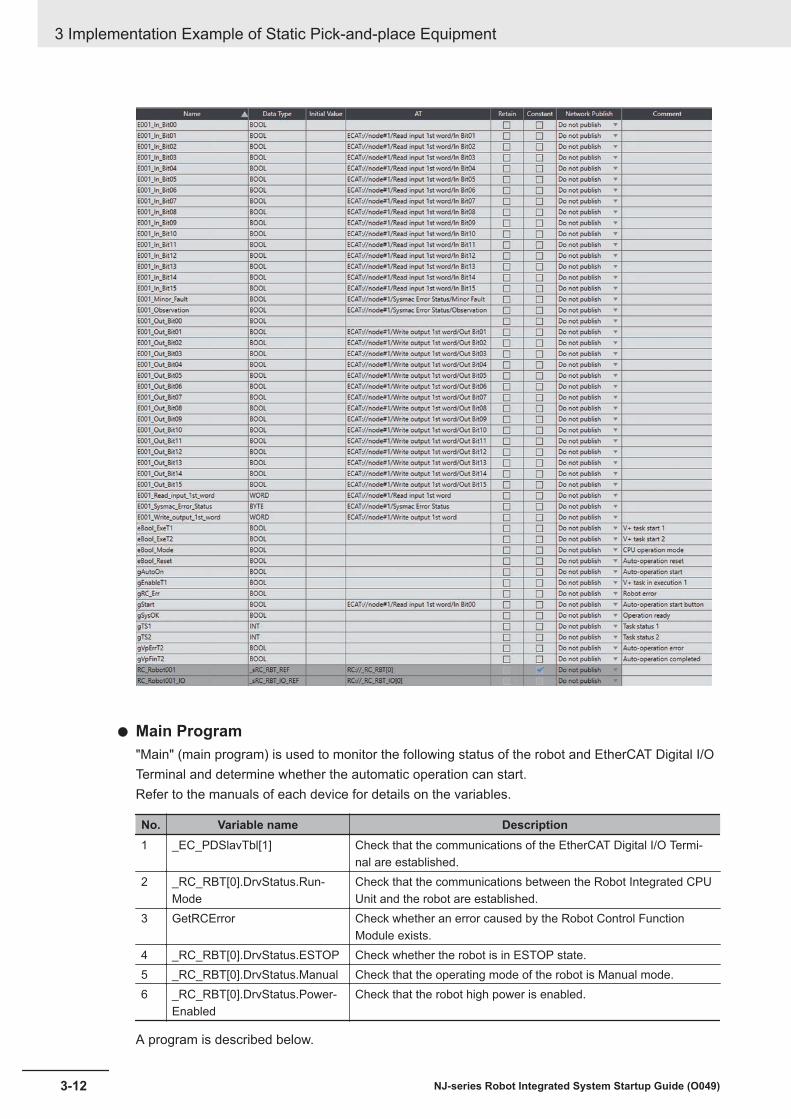
Main Program"Main" (main program) is used to monitor the following status of the robot and EtherCAT Digital I/OTerminal and determine whether the automatic operation can start.Refer to the manuals of each device for details on the variables.
No. Variable name Description1 _EC_PDSlavTbl[1] Check that the communications of the EtherCAT Digital I/O Termi-
nal are established.2 _RC_RBT[0].DrvStatus.Run-
ModeCheck that the communications between the Robot Integrated CPUUnit and the robot are established.
3 GetRCError Check whether an error caused by the Robot Control FunctionModule exists.
4 _RC_RBT[0].DrvStatus.ESTOP Check whether the robot is in ESTOP state.5 _RC_RBT[0].DrvStatus.Manual Check that the operating mode of the robot is Manual mode.6 _RC_RBT[0].DrvStatus.Power-
EnabledCheck that the robot high power is enabled.
A program is described below.
3 Implementation Example of Static Pick-and-place Equipment
3-12 NJ-series Robot Integrated System Startup Guide (O049)

V+ ProgramThis section describes the V+ program to control the static pick-and-place equipment.The V+ program is used to register global variables and create three programs, "run" (robot com-mands send program), "run.checkmode" (V+ program stop program), and "auto" (read program).
3 Implementation Example of Static Pick-and-place Equipment
3-13NJ-series Robot Integrated System Startup Guide (O049)
3-1 Program Specifications for Static Pick-and-place
Equipment
3
3-1-2 When O
perations are Controlled w
ith V+ Program

Global VariablesRegister the global variables that are used in the V+ program.
Robot Commands Send Program"run" (robot commands send program) is used to send robot commands to execute the static pick-and-place operations.A program is described below.
.PROGRAM run(); ABSTRACT: Pick and place program AUTO ar.speed, ar.accel, ar.wait_on, ar.wait_off, ar.dist, ar.loc[5], al.safe EXTERNAL ebool_exet2 ebool_exet2 = TRUE; Set parameter ar.speed = 100 ; Speed ratio per full speed [%] ar.accel = 50 ; Accel ratio per full speed [%] ar.wait_on = 0.5 ; Wait time for air-on [sec] ar.wait_off = 0.2 ; Wait time for air-off [sec] ar.dist = 40 ; Approach and deppart distance [mm]; Calculate and set temporary destination DECOMPOSE ar.loc[] = HERE SET al.safe = TRANS(ar.loc[0],ar.loc[1],DZ(gl.wait),ar.loc[3],ar.loc[4],ar.loc[5]);Prepare robot motion ready CALIBRATE ATTACH () SPEED ar.speed, ar.speed ALWAYS ACCEL ar.accel, ar.accel; Approach/Move to wait position MOVES al.safe MOVE gl.wait BREAK; Approach/Move to pick position APPRO gl.pick, ar.dist MOVES gl.pick BREAK;Suctioning on and waiting SIGNAL 4001 WAIT.EVENT ar.wait_on;Depart/Approach/MOVE to palce position DEPART ar.dist APPRO gl.place, ar.dist
3 Implementation Example of Static Pick-and-place Equipment
3-14 NJ-series Robot Integrated System Startup Guide (O049)
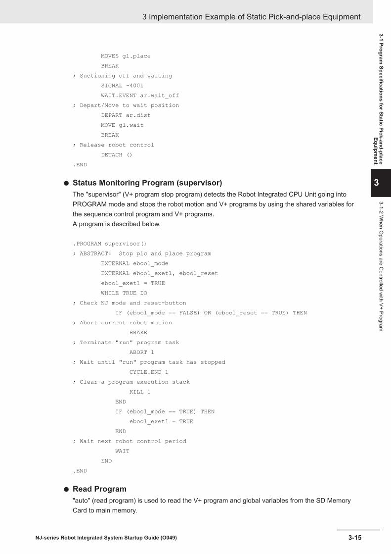
MOVES gl.place BREAK; Suctioning off and waiting SIGNAL -4001 WAIT.EVENT ar.wait_off; Depart/Move to wait position DEPART ar.dist MOVE gl.wait BREAK; Release robot control DETACH ().END
Status Monitoring Program (supervisor)The "supervisor" (V+ program stop program) detects the Robot Integrated CPU Unit going intoPROGRAM mode and stops the robot motion and V+ programs by using the shared variables forthe sequence control program and V+ programs.A program is described below.
.PROGRAM supervisor(); ABSTRACT: Stop pic and place program EXTERNAL ebool_mode EXTERNAL ebool_exet1, ebool_reset ebool_exet1 = TRUE WHILE TRUE DO; Check NJ mode and reset-button IF (ebool_mode == FALSE) OR (ebool_reset == TRUE) THEN; Abort current robot motion BRAKE; Terminate "run" program task ABORT 1; Wait until "run" program task has stopped CYCLE.END 1; Clear a program execution stack KILL 1 END IF (ebool_mode == TRUE) THEN ebool_exet1 = TRUE END; Wait next robot control period WAIT END.END
Read Program"auto" (read program) is used to read the V+ program and global variables from the SD MemoryCard to main memory.
3 Implementation Example of Static Pick-and-place Equipment
3-15NJ-series Robot Integrated System Startup Guide (O049)
3-1 Program Specifications for Static Pick-and-place
Equipment
3
3-1-2 When O
perations are Controlled w
ith V+ Program

Refer to 3-3-8 Setting up Automatic Loading of V+ Programs and Variables at Power ON on page3-77 for information on "auto" (read program).
3 Implementation Example of Static Pick-and-place Equipment
3-16 NJ-series Robot Integrated System Startup Guide (O049)

3-2 Basic Startup ProceduresThis section gives an overview of the basic startup procedures to build a static pick-and-place system.First, program a machine operation, configure and check the settings using the simulator, and then runthe system for fine-tuning the operation.
No. Procedure Description Reference1 Programming and Sim-
ulation ProceduresCreating a project Create a project file in the Sysmac
Studio.page3-19
2 Creating the networkconfiguration
Create the EtherCAT Network Configu-ration and add a robot on the network.
page3-20
3 Writing the programs Create a sequence control programand V+ programs.
page3-22page3-28
4 Placing 3D shape data Place 3D shape data and make theoperating range of the robot visible onthe 3D Visualizer.
page3-35
5 Starting simulation Activate the simulation function andstart to simulate the robot motion.
page3-65
6 Teaching (Simulation) Use the simulation function of the Sys-mac Studio for teaching the positions.
page3-66
7 Running the program(Simulation)
Run the sequence control program onthe simulator of the Sysmac Studio.
page3-81
8 Installing and Wiringthe System
Wiring the Robot Inte-grated CPU Unit and theEtherCAT Digital I/O Ter-minal
Wire the Robot Integrated CPU Unitand the EtherCAT Digital I/O Terminal.
page3-86
9 Setting the node addressof the EtherCAT DigitalI/O Terminal
Set the EtherCAT node address of theEtherCAT Digital I/O Terminal.
page3-87
10 Wiring the EtherCAT Dig-ital I/O Terminal and therobot
Wire the EtherCAT Digital I/O Terminaland the robot.
page3-87
11 Setting the EtherCATnode address of the ro-bot
Set the EtherCAT node address of therobot.
page3-88
12 Wiring the Robot Inte-grated CPU Unit and thecomputer
Wire the Robot Integrated CPU Unitand the computer.
page3-88
13 Wiring the robot, T20pendant and the frontpanel
Wire the robot and the T20 pendant,as well as the robot and the front pan-el.
page3-89
14 Wiring the EtherCAT Dig-ital I/O Terminal and thesolenoid valve
Wire the EtherCAT Digital I/O Terminaland the solenoid valve.
page3-90
3 Implementation Example of Static Pick-and-place Equipment
3-17NJ-series Robot Integrated System Startup Guide (O049)
3-2 Basic Startup Procedures
3

No. Procedure Description Reference15 Setup Procedure for
Actual SystemGoing online Place the Sysmac Studio online with
the Robot Integrated CPU Unit.page3-92
16 Transferring settings andprograms
Download the programs and settingsin the Sysmac Studio project file to theRobot Integrated CPU Unit.
page3-94
17 Teaching (On the actualequipment)
Operate the robot to check and correctthe teaching data.
page3-96
18 Running the programs(On actual equipment)
Let the robot operate automatically ac-cording to the programs.
page3-108
3 Implementation Example of Static Pick-and-place Equipment
3-18 NJ-series Robot Integrated System Startup Guide (O049)
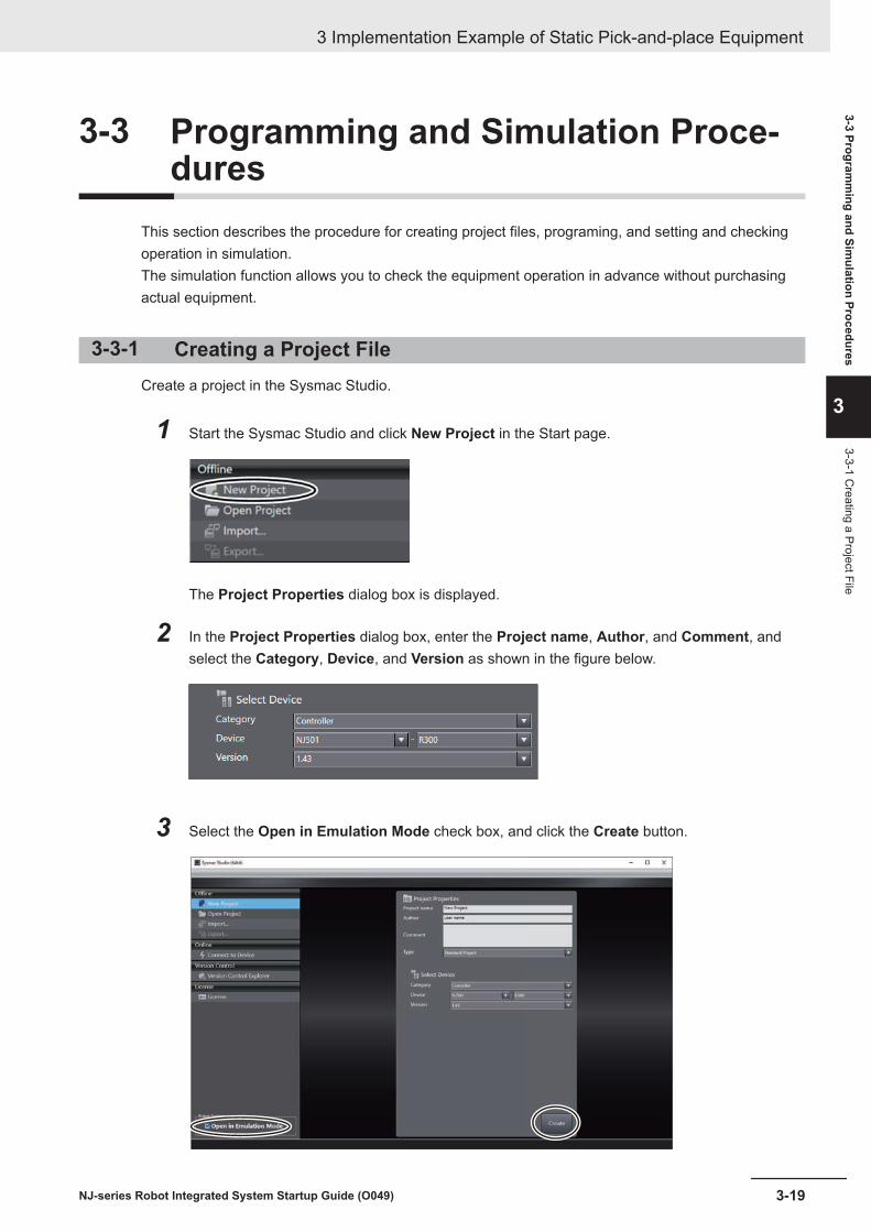
3-3 Programming and Simulation Proce-dures
This section describes the procedure for creating project files, programing, and setting and checkingoperation in simulation.The simulation function allows you to check the equipment operation in advance without purchasingactual equipment.
3-3-1 Creating a Project FileCreate a project in the Sysmac Studio.
1 Start the Sysmac Studio and click New Project in the Start page.
The Project Properties dialog box is displayed.
2 In the Project Properties dialog box, enter the Project name, Author, and Comment, andselect the Category, Device, and Version as shown in the figure below.
3 Select the Open in Emulation Mode check box, and click the Create button.
3 Implementation Example of Static Pick-and-place Equipment
3-19NJ-series Robot Integrated System Startup Guide (O049)
3-3 Programm
ing and Simulation Procedures
3
3-3-1 Creating a Project File

A project file is created and the following window is displayed.
3-3-2 Creating the EtherCAT Network ConfigurationCreate the EtherCAT network configuration and add a robot on the network.
1 Click Configurations and Setup in the Multiview Explorer.
Setting items are displayed under Configurations and Setup in the tree.
2 Double-click EtherCAT under Configurations and Setup in the Multiview Explorer. Or right-click EtherCAT under Configurations and Setup and select Edit from the menu.
3 Implementation Example of Static Pick-and-place Equipment
3-20 NJ-series Robot Integrated System Startup Guide (O049)
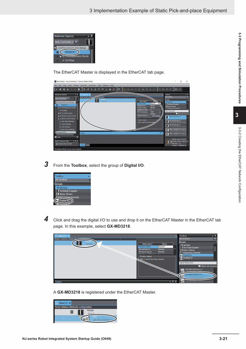
The EtherCAT Master is displayed in the EtherCAT tab page.
3 From the Toolbox, select the group of Digital I/O.
4 Click and drag the digital I/O to use and drop it on the EtherCAT Master in the EtherCAT tabpage. In this example, select GX-MD3218.
A GX-MD3218 is registered under the EtherCAT Master.
3 Implementation Example of Static Pick-and-place Equipment
3-21NJ-series Robot Integrated System Startup Guide (O049)
3-3 Programm
ing and Simulation Procedures
3
3-3-2 Creating the EtherC
AT Netw
ork Configuration

5 From the Toolbox, select the group of Robot.
6 Select and drag the robot to use and drop it on the GX-MD3218 in the EthercAT tab page.Here, select eCobra 600 Pro.
An eCobra 600 Pro is added under the GX-MD3218.
3-3-3 Creating a Sequence Control ProgramThis section provides the procedure for creating a sequence control program.For details on the program to create, refer to 3-1 Program Specifications for Static Pick-and-placeEquipment on page 3-2.
Creating Device VariablesCreate device variables to control solenoid valves.You need to create device variables to use sequence control programs for controlling static pick-and-place operation.This setting is not required if you use V+ programs for controlling the operation.
3 Implementation Example of Static Pick-and-place Equipment
3-22 NJ-series Robot Integrated System Startup Guide (O049)

1 Double-click I/O Map under Configurations and Setup in the Multiview Explorer.
The I/O Map tab page is displayed.
2 Tap the icon to the left of GX-MD3218.
The I/O ports of the GX-MD3218 are displayed.
3 Right-click on the GX-MD3218 and select Create Device Variable from the menu.
Device variables are automatically registered for the I/O ports of the GX-MD3218.
3 Implementation Example of Static Pick-and-place Equipment
3-23NJ-series Robot Integrated System Startup Guide (O049)
3-3 Programm
ing and Simulation Procedures
3
3-3-3 Creating a Sequence C
ontrol Program

Defining Global VariablesDefine global variables used as the position data in the sequence control program.
1 Double-click Global Variables under Programming - Data in the Multiview Explorer. Or, right-click Global Variables under Programming - Data and select Edit from the menu.
The global variable table is displayed.
2 Press the Insert key in the global variable table, or right-click in the global variable table andselect Create New from the menu.
3 Enter or select setting for each item, and then press the Enter key.
3 Implementation Example of Static Pick-and-place Equipment
3-24 NJ-series Robot Integrated System Startup Guide (O049)

For information on global variables to register, refer to Sequence Control Program on page 3-3if the system is controlled by the sequence control program or Sequence Control Program onpage 3-11 when it is controlled by the V+ program.
The global variable is registered.
Creating Ladder Diagram ProgramsThis section describes how to create the ladder diagram programs.
1 Right-click Program0 under Programming - POUs - Programs in the Multiview Explorer andselect Rename from the menu.
This allows you to edit the name of the sequence control program.
2 Enter the name of the sequence control program.The name of the sequence control program is changed.
3 Double-click the section to edit.
The variable table and Ladder Editor are displayed in the Edit Pane.
3 Implementation Example of Static Pick-and-place Equipment
3-25NJ-series Robot Integrated System Startup Guide (O049)
3-3 Programm
ing and Simulation Procedures
3
3-3-3 Creating a Sequence C
ontrol Program

4 Enter the program in the Ladder Editor. Internal and external variables are automatically regis-tered when they are entered in the program.For information on the programs, refer to Sequence Control Program on page 3-3 if the systemis controlled by the sequence control program or Sequence Control Program on page 3-11when it is controlled by the V+ program.
To create more than one sequence control program, perform the following steps.
5 Right-click Programs under Programming - POUs in the Multiview Explorer, and then selectAdd - Ladder from the menu.
Program0 is added under Programs.
6 Click the icon displayed to the left of Program0 under Programming - POUs - Programs inthe Multiview Explorer.
Section0 is added under Program0.
3 Implementation Example of Static Pick-and-place Equipment
3-26 NJ-series Robot Integrated System Startup Guide (O049)

7 Returns to step 1 and repeat the above steps.
Assigning Programs to TasksIn this section, assign the ladder diagram programs to tasks of the Robot Integrated CPU Unit.In this guide, multiple ladder diagram programs are used to control the static pick-and-place equip-ment, so it is necessary to assign the programs to tasks.When the equipment is controlled by the V+ Program, only one ladder diagram program is used andyou do not need to perform the steps in this section.
1 Double-click Task Settings under Configurations and Setup in the Multiview Explorer.
The Task Settings tab page is displayed.
2 Click the Program Assignment Settings button ( ) in the Edit Pane.
3 Click the + button.
3 Implementation Example of Static Pick-and-place Equipment
3-27NJ-series Robot Integrated System Startup Guide (O049)
3-3 Programm
ing and Simulation Procedures
3
3-3-3 Creating a Sequence C
ontrol Program

A new row is added for the program to assign.
4 Select a name of the program to use from the list of the Program name.
The name of the selected program is displayed.
3-3-4 Creating V+ ProgramsThis section provides the procedure for creating the V+ programs.For details on the program to create, refer to 3-1 Program Specifications for Static Pick-and-placeEquipment on page 3-2.
3 Implementation Example of Static Pick-and-place Equipment
3-28 NJ-series Robot Integrated System Startup Guide (O049)

Setting V+Digital I/OTo control EtherCAT Slaves by V+ programs, you must assign V+ digital I/Os.This setting is required to control the operation of the static pick-and- place equipment with the V+ pro-gram. If you use sequence control programs for controlling the operation, this setting is unnecessary.
1 In the Multiview Explorer, select new_Controller_0 from the device list.
2 Click the icon to the left of Robot Control Setup in the Multiview Explorer.
The setting items are displayed in the tree view as shown below.
3 Double-click Robot Common Settings.
The Robot Common Settings tab page is displayed.
3 Implementation Example of Static Pick-and-place Equipment
3-29NJ-series Robot Integrated System Startup Guide (O049)
3-3 Programm
ing and Simulation Procedures
3
3-3-4 Creating V+ Program
s

4 Click the + button in the Robot Common Settings tab page.
A row for registering a new V+ digital I/O is added.
5 Click the drop-down list for Device in the newly added row, and then select Node:1 GX-MD3218(E001).
6 Click the drop-down list for Port in the same row, and select Out Bit00.
3 Implementation Example of Static Pick-and-place Equipment
3-30 NJ-series Robot Integrated System Startup Guide (O049)

7 Enter 4001 for V+Digital I/O.
Defining Global VariablesDefine the global variables for use in the V+ program.Here, the procedure to create a variable gl.wait is given below as an example, which is a global varia-ble used in the V+ program in 3-1-1 When Operations are Controlled with Sequence Control Programon page 3-3.
1 In the Multiview Explorer, select RobotControlSettings from the device list.
2 Double-click Variables under Programming in the Multiview Explorer.
A tab page to edit variables is displayed in the Edit Pane so that you can register variables.
3 Click the + button.
3 Implementation Example of Static Pick-and-place Equipment
3-31NJ-series Robot Integrated System Startup Guide (O049)
3-3 Programm
ing and Simulation Procedures
3
3-3-4 Creating V+ Program
s

The Add New Variable table is displayed.
4 Input a variable name.
For information on global variables to register, refer to V+ Program on page 3-9 if the system iscontrolled by the sequence control program or V+ Program on page 3-13 when it is controlledby the V+ program.
5 Select Locations from the list of variable types.
6 Select R1Cobra600 from the list for the robot.
3 Implementation Example of Static Pick-and-place Equipment
3-32 NJ-series Robot Integrated System Startup Guide (O049)

7 Click the Accept button.
The variable gl.wait is added to the table.
Creating V+ ProgramsThis section describes the procedure to create V+ programs.
1 In the Multiview Explorer, select RobotControlSettings from the device list.
2 Right-click V+ Modules under Programming in the Multiview Explorer, and select Add NewModule from the menu.
3 Implementation Example of Static Pick-and-place Equipment
3-33NJ-series Robot Integrated System Startup Guide (O049)
3-3 Programm
ing and Simulation Procedures
3
3-3-4 Creating V+ Program
s

In the tree of the Multiview Explorer, program0 - program0 are added under V+ Modules,which allows you to edit the name of the V+ program.
3 Enter the name of the V+ program.The name of the V+ program is changed.
4 Double-click the program to edit.
A tab page to edit the V+ program is displayed in the Edit Pane.
3 Implementation Example of Static Pick-and-place Equipment
3-34 NJ-series Robot Integrated System Startup Guide (O049)
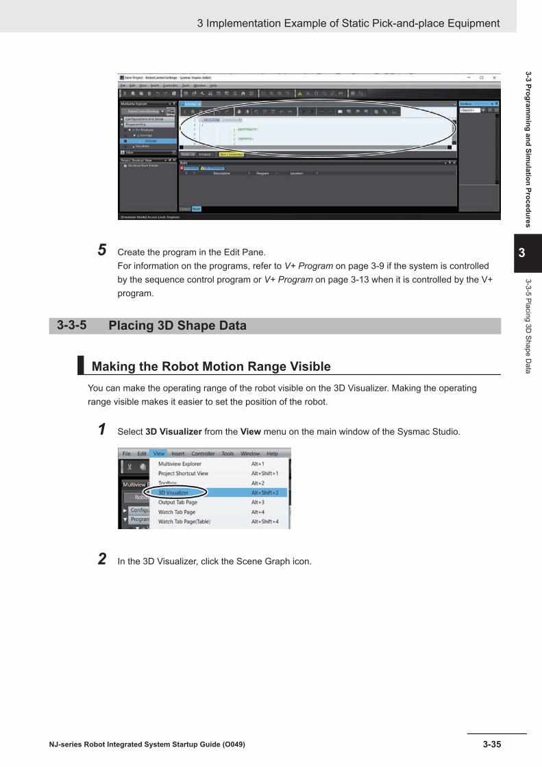
5 Create the program in the Edit Pane.For information on the programs, refer to V+ Program on page 3-9 if the system is controlledby the sequence control program or V+ Program on page 3-13 when it is controlled by the V+program.
3-3-5 Placing 3D Shape Data
Making the Robot Motion Range VisibleYou can make the operating range of the robot visible on the 3D Visualizer. Making the operatingrange visible makes it easier to set the position of the robot.
1 Select 3D Visualizer from the View menu on the main window of the Sysmac Studio.
2 In the 3D Visualizer, click the Scene Graph icon.
3 Implementation Example of Static Pick-and-place Equipment
3-35NJ-series Robot Integrated System Startup Guide (O049)
3-3 Programm
ing and Simulation Procedures
3
3-3-5 Placing 3D Shape D
ata

Note The 3D Visualizer is in Float mode state in this procedure. For information on Float mode, refer to A-2-1 Set the 3D Visualizer to the Float Mode on page A-21.
The Scene Graph dialog box is displayed.
3 In the Visibility tab page, select the Work Volume check box located underRobotControlSettings - R1Cobra600.
The 3D Visualizer illustrates the robot’s operating range in gray.
3 Implementation Example of Static Pick-and-place Equipment
3-36 NJ-series Robot Integrated System Startup Guide (O049)

4 Click the Close button in the Scene Graph dialog box.
Importing 3D CAD DataImport the 3D CAD data of the conveyors as 3D shape data to the Sysmac Studio.This section describes the procedure to import the 3D CAD data of Conveyor A and Conveyor B usedin the equipment model in 1-4 Operations of Static Pick-and-place Equipment on page 1-6.
1 Select Application Manager from the Insert menu on the main window of the Sysmac Studio.
The Add Device dialog box is displayed.
3 Implementation Example of Static Pick-and-place Equipment
3-37NJ-series Robot Integrated System Startup Guide (O049)
3-3 Programm
ing and Simulation Procedures
3
3-3-5 Placing 3D Shape D
ata

2 Select Category, Device, and Version as shown in the figure below, and then click the OKbutton.
ApplicationManager0 is added to the drop-down list at the top of the Multiview Explorer
Additional Information
Application Manager added by this operation can only be used for simulation. Do not use it foractual device
3 Click Configurations and Setup in the Multiview Explorer.
Setting items are displayed under Configurations and Setup in the tree.
3 Implementation Example of Static Pick-and-place Equipment
3-38 NJ-series Robot Integrated System Startup Guide (O049)

4 Right-click 3D Visualization.The menu commands are displayed.
5 From the menu, select Add - CAD Data.
The Import CAD File wizard starts.
6 Select Open my own CAD file.
7 Click the Next button.
3 Implementation Example of Static Pick-and-place Equipment
3-39NJ-series Robot Integrated System Startup Guide (O049)
3-3 Programm
ing and Simulation Procedures
3
3-3-5 Placing 3D Shape D
ata

8 Click the Open File button.
The Open dialog box is displayed.
9 Select 3D CAD data to import, and then click the Open button.In this example, you select the conveyor of MISUMI Corporation whose model number isSVKN-100-1000-25-T100-IM-9-H-A for the Conveyor A. You can import the 3D CAD data withthe file name extension “stp”.
3 Implementation Example of Static Pick-and-place Equipment
3-40 NJ-series Robot Integrated System Startup Guide (O049)

The Open dialog box is closed and import of 3D CAD data starts automatically.
When the import completes, the assemblies of the import 3D CAD data is displayed in theImport CAD File wizard.
Additional Information
Align the conveyor top to the U face. Click the +90 Yaw button or +90 Pitch button to changethe orientation of the conveyor.If you use positioned and oriented CAD data, this operation is not necessary.
10 Click the buttons in the following order; +90 Yaw, +90 Pitch, +90 Yaw, +90 Pitch and +90PitchThe conveyor top comes to the U face.
3 Implementation Example of Static Pick-and-place Equipment
3-41NJ-series Robot Integrated System Startup Guide (O049)
3-3 Programm
ing and Simulation Procedures
3
3-3-5 Placing 3D Shape D
ata

11 Select the parts to add for simulation, and click the Next button.
The Import CAD File wizard is closed and the main window is displayed again.
12 Check that CAD Data0 is added under Configurations and Setup - 3D Visualization in theMultiview Explorer.
13 Perform step 4 and later to import the 3D CAD data of the Conveyor B.In the Multiview Explorer, CAD Data1 is added under Configurations and Setup - 3DVisualization.
3 Implementation Example of Static Pick-and-place Equipment
3-42 NJ-series Robot Integrated System Startup Guide (O049)

The 3D CAD Data for Conveyor A and Conveyor B are now imported.
Placing 3D Shape Data on the 3D VisualizerPlace the imported 3D shape data in the appropriate position on the 3D Visualizer.When 3D shape data is imported, the 3D shape data is positioned so that it has the same coordinateorigin as the robot coordinate system. Therefore, it is necessary to move the 3D shape data to theappropriate position.This section describes the procedure to place Conveyor A used in the equipment model in 1-4 Opera-tions of Static Pick-and-place Equipment on page 1-6 as an example.
Additional Information
For information on setting up in the 3D Visualizer and translating the point of view in the 3D Vis-ualizer, refer to the A-2 How to Use 3D Visualizer on page A-21.
1 Select 3D Visualizer from the View menu on the main window of the Sysmac Studio.
The 3D Visualizer is displayed on the right side of the main window.
3 Implementation Example of Static Pick-and-place Equipment
3-43NJ-series Robot Integrated System Startup Guide (O049)
3-3 Programm
ing and Simulation Procedures
3
3-3-5 Placing 3D Shape D
ata

2 In the 3D Visualizer, select the imported 3D shape data with the mouse cursor and right-click it.The menu commands are displayed.
Additional Information
When you move the mouse cursor on the 3D shape data in the 3D Visualizer, the name of the3D shape data /ApplicationManager0/CAD Data0 is displayed.
3 Select Edit Workspace Position from the menu.
The Move icon consisting of colored arrows, a purple circle, and faces is displayed on the ori-gin of the 3D shape data.
4 Drag one of the arrows, faces, or the purple circle and drop it on the place to move the 3Dshape data.
3 Implementation Example of Static Pick-and-place Equipment
3-44 NJ-series Robot Integrated System Startup Guide (O049)

The Move icon has red, green, and blue arrows, which represent the X-axis, Y-axis, and Z-axis,respectively. The red face shows the YZ plane, the green face shows the ZX plane, and theblue face shows the XY plane.
You can drag an arrow to move the 3D shape data along the axis. Or, use the face icon tomove the 3D shape data on the corresponding plane. You can also move the 3D shape dataindependently from the axis direction by dragging the purple circle.
Additional Information
When the Move icon is hidden, click the 3D shape data to display it.
5 Right-click the 3D shape data you are moving in the 3D Visualizer.The menu commands are displayed.
6 Select Edit Workspace Position from the menu to clear the selection.
3 Implementation Example of Static Pick-and-place Equipment
3-45NJ-series Robot Integrated System Startup Guide (O049)
3-3 Programm
ing and Simulation Procedures
3
3-3-5 Placing 3D Shape D
ata

7 Right-click the 3D shape data in the 3D Visualizer.The menu commands are displayed.
8 Select Edit Workspace Orientation from the menu.
The Rotate icon is displayed on the 3D shape data.
9 Drag and drop the handle of the Rotate icon to rotate the 3D shape data around the axis to anappropriate orientation.The icon has red, green, and blue handles, which represent rotation around the X-axis, Y-axis,and Z-axis, respectively.
3 Implementation Example of Static Pick-and-place Equipment
3-46 NJ-series Robot Integrated System Startup Guide (O049)

10 Right-click the 3D shape data to adjust the orientation in the 3D Visualizer.The menu commands are displayed.
11 Select Edit Workspace Orientation from the menu to clear the selection.
12 Right-click the 3D shape data that you were adjusting the orientation in the 3D Visualizer.The menu commands are displayed.
13 Select Direct Position Edit from the menu.
The input fields for editing the position of the 3D shape data is displayed.
3 Implementation Example of Static Pick-and-place Equipment
3-47NJ-series Robot Integrated System Startup Guide (O049)
3-3 Programm
ing and Simulation Procedures
3
3-3-5 Placing 3D Shape D
ata

14 Enter values in mm in the X, Y, and Z fields to move the 3D shape data to an appropriate posi-tion.The position of the 3D shape data changes according to the input values.
15 Click the Edit Workspace Orientation icon.
The input fields for editing the orientation of the 3D shape data is displayed.
16 Enter values in degree in the input fields for Yaw, Pitch, and Roll to adjust the orientation of the3D shape data.The orientation of the 3D shape data changes according to the input values.
3 Implementation Example of Static Pick-and-place Equipment
3-48 NJ-series Robot Integrated System Startup Guide (O049)

17 In the 3D Visualizer, right-click the 3D shape data that you adjusted the position and orienta-tion.The menu commands are displayed.
18 Select Direct Position Edit from the menu to clear the selection.
Precautions for Correct Use
Refer to the Sysmac Studio 3D Simulation Function Operation Manual (Cat. No. W618) for de-tails on coordinate system in the 3D Visualizer.
19 Perform step 2 and later to adjust the position and orientation of the CAD Data1 of Conveyor B.
The 3D shape data of Conveyor A and Conveyor B are now placed in the appropriate positions in the3D Visualizer.
3 Implementation Example of Static Pick-and-place Equipment
3-49NJ-series Robot Integrated System Startup Guide (O049)
3-3 Programm
ing and Simulation Procedures
3
3-3-5 Placing 3D Shape D
ata

Setting the 3D Information of the Robot’s End-effectorSet the 3D information of the Robot’s end-effector.
1 Select RobotControlSettings from the device list in the Multiview Explorer.
2 Click Configurations and Setup in the Multiview Explorer.
Setting items are displayed under Configurations and Setup in the tree.
3 Double-click Robots.
Setting items are displayed under Robots in the tree.
3 Implementation Example of Static Pick-and-place Equipment
3-50 NJ-series Robot Integrated System Startup Guide (O049)
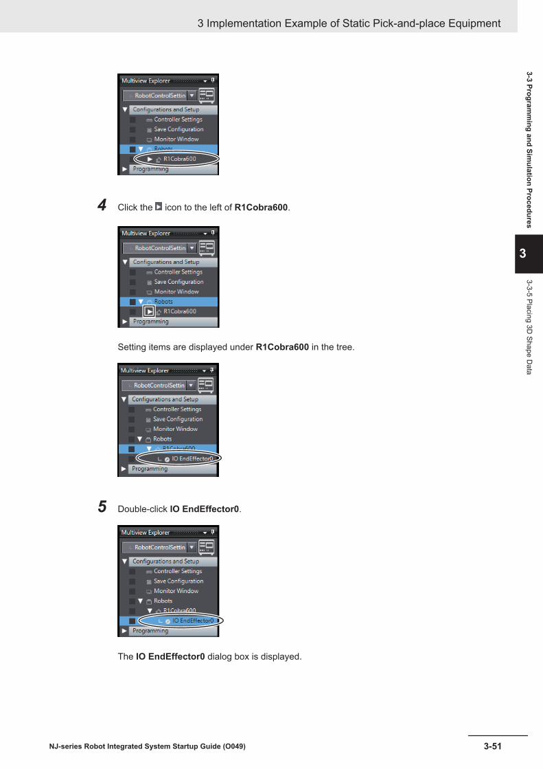
4 Click the icon to the left of R1Cobra600.
Setting items are displayed under R1Cobra600 in the tree.
5 Double-click IO EndEffector0.
The IO EndEffector0 dialog box is displayed.
3 Implementation Example of Static Pick-and-place Equipment
3-51NJ-series Robot Integrated System Startup Guide (O049)
3-3 Programm
ing and Simulation Procedures
3
3-3-5 Placing 3D Shape D
ata

6 Set the length of the tool in the Z direction of the Tip Offset.In this example, enter the value as an example that the tool length is 50mm.Set Tip Radius, as required.
The end-effector of the set size is displayed on the 3D Visualizer.
3 Implementation Example of Static Pick-and-place Equipment
3-52 NJ-series Robot Integrated System Startup Guide (O049)

Activating Collision Detection FunctionThe collision detection function detects the contacts in simulation that may occur between the robotand other 3D shape data, such as objects imported as 3D CAD data. If the robot may contact withother 3D shape data, you need to change the layout of the robot or the 3D shape data, or modify themovement of the robot.In this section, the setting procedure to detect a contact between the robot, Conveyor A and ConveyorB is given. Because the collision detection function checks whether 3D shape data may conflict be-tween groups, you create two groups; Group 0, which includes the robot, and Group 1, which includesConveyor A and Conveyor B.
Precautions for Correct Use
In this guide, the target of collision detection is the robot. When the 3D shape data is placed atthe tool center point, collision detection of that 3D shape data is also required. For the operationprocedure for the 3D shape data placed at the tool center point, refer to the Sysmac Studio 3DSimulation Function Operation Manual (Cat. No. W618).
1 Select 3D Visualizer from the View menu on the main window of the Sysmac Studio.
The 3D Visualizer is displayed on the right side of the main window.
3 Implementation Example of Static Pick-and-place Equipment
3-53NJ-series Robot Integrated System Startup Guide (O049)
3-3 Programm
ing and Simulation Procedures
3
3-3-5 Placing 3D Shape D
ata
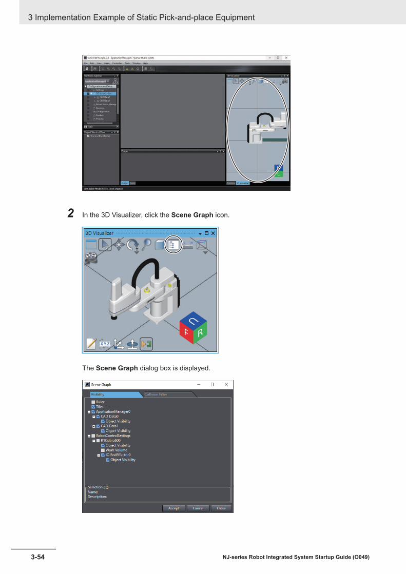
2 In the 3D Visualizer, click the Scene Graph icon.
The Scene Graph dialog box is displayed.
3 Implementation Example of Static Pick-and-place Equipment
3-54 NJ-series Robot Integrated System Startup Guide (O049)

3 Click the Collision Filter tab.
4 Click the + button in the Collision Filter Group Items column for the Collision Filter Group.
A new row with the Collision Filter Group Name set as Group0 is added on the SceneGraph dialog box.
5 Repeat step 4 above.
3 Implementation Example of Static Pick-and-place Equipment
3-55NJ-series Robot Integrated System Startup Guide (O049)
3-3 Programm
ing and Simulation Procedures
3
3-3-5 Placing 3D Shape D
ata

A new row with the Collision Filter Group Name set as Group1 is added on the SceneGraph dialog box.
6 Click the ... button in the Collision Filter Group Items column for Group0 - [0].
The Select a collision filter group item dialog box is displayed.
3 Implementation Example of Static Pick-and-place Equipment
3-56 NJ-series Robot Integrated System Startup Guide (O049)

7 Select new_Controller_0 - RobotControlSettings - Robots - R1Cobra600 - Entire Robot inthe tree, and then click the Select button.
The Select a collision filter group item dialog box closes and the Scene Graph dialog box isdisplayed again. R1Cobra600, Entire Robot is registered as the Collision Filter Group Itemsfor Group0 - [0].
8 Click the + button in the Collision Filter Group Items column for Group 0.
3 Implementation Example of Static Pick-and-place Equipment
3-57NJ-series Robot Integrated System Startup Guide (O049)
3-3 Programm
ing and Simulation Procedures
3
3-3-5 Placing 3D Shape D
ata

A new row [1] is added under Group 0.
9 Click the ... button in the Collision Filter Group Items column for Group 0 - [1].
3 Implementation Example of Static Pick-and-place Equipment
3-58 NJ-series Robot Integrated System Startup Guide (O049)

The Select a collision filter group item dialog box is displayed.
10 Select new_Controller_0 - RobotControlSettings - Robots - R1Cobra 600 - IOEndEffector0 in the tree, and then click the Select button.
3 Implementation Example of Static Pick-and-place Equipment
3-59NJ-series Robot Integrated System Startup Guide (O049)
3-3 Programm
ing and Simulation Procedures
3
3-3-5 Placing 3D Shape D
ata

The Select a collision filter group item dialog box closes and the Scene Graph dialog box isdisplayed again. IO EndEffector0(R1Cobra600) is registered as the Collision Filter GroupItems for Group0 - [1].
11 Click the ... button in the Collision Filter Group Items column whose Collision Filter GroupName is Group1 - [0].
3 Implementation Example of Static Pick-and-place Equipment
3-60 NJ-series Robot Integrated System Startup Guide (O049)

The Select a collision filter group item dialog box is displayed.
12 Select ApplicationManager0 - 3D Visualization - CAD Data0 from the tree, and then click theSelect button.
The Select a collision filter group item dialog box closes and the Scene Graph dialog box isdisplayed again. CAD Data0 is registered to the Collision Filter Group Items column forGroup1 - [0].
3 Implementation Example of Static Pick-and-place Equipment
3-61NJ-series Robot Integrated System Startup Guide (O049)
3-3 Programm
ing and Simulation Procedures
3
3-3-5 Placing 3D Shape D
ata

13 Click the + button in the Collision Filter Group Items column for Group1.
A new row for [1] is added under Group1.
3 Implementation Example of Static Pick-and-place Equipment
3-62 NJ-series Robot Integrated System Startup Guide (O049)

14 Follow the step 11 to 12 to register CAD Data1 for Group1 - [1].CAD Data1 is registered to the Collision Filter Group Items column for Group1 - [1].
15 Check that the Valid check boxes are all selected. If there is a check box not selected, click itto select.
3 Implementation Example of Static Pick-and-place Equipment
3-63NJ-series Robot Integrated System Startup Guide (O049)
3-3 Programm
ing and Simulation Procedures
3
3-3-5 Placing 3D Shape D
ata

16 Click the Accept button.A collision filter configuration is saved.
17 Click the Close button in the Scene Graph dialog box.
The Scene Graph dialog box is closed.
Now, the settings for checking the conflict between the robot, Conveyor A, and Conveyor B have beencompleted.
3 Implementation Example of Static Pick-and-place Equipment
3-64 NJ-series Robot Integrated System Startup Guide (O049)

3-3-6 Starting Simulation
Enabling Robot Simulation FunctionEnable the simulation function of the Sysmac Studio.To simulate the operation of the robot, open the project file in EMULATION mode.
If you want to know whether the project file opened on the Sysmac Studio is in EMULATION mode ornot, check the status bar on the main window. When you see [Emulation Mode] Access Level:Engineer on the status bar, the project is opened in EMULATION mode.
If the project is opened in a different mode, click the Enable emulation mode icon on the toolbar tochange to EMULATION mode.
1 In the Multiview Explorer, select new_Controller_0 from the device list.
2 Select Run from the Simulation menu.The screen below is displayed while the simulator is starting.
3 Implementation Example of Static Pick-and-place Equipment
3-65NJ-series Robot Integrated System Startup Guide (O049)
3-3 Programm
ing and Simulation Procedures
3
3-3-6 Starting Simulation

After this screen is closed, the lower part of the toolbar in the main window turns yellow-green.
3-3-7 Teaching PositionsThis section describes the procedure to use the simulation function of the Sysmac Studio for teachingthe positions.The target of teaching in this equipment model is the wait position of the robot and the pick-up andplace positions of the workpiece.
Robot wait positionRobot wait position
Conveyor A: static state
Conveyor B: static state
Robot wait position
Workpiece pick-up positionWorkpiece pick-up positionWorkpiece pick-up position
Workpiece place positionWorkpiece place positionWorkpiece place position
You can operate the robot during the simulation in either of the following two ways. Select one of thefollowing depending on the positioning accuracy required for operation and movement.• Manipulate the tool center point of the robot with the mouse in the 3D Visualizer• Manipulate each axis of the robot in V+ Jog Control pane
Additional Information
• To move the robot to its approximate position, it is convenient to use the mouse and move thetool center point of the robot on the 3D Visualizer.
• To move the robot precisely to its correct position, manipulate each axis of the robot in the V+Jog Control pane
3 Implementation Example of Static Pick-and-place Equipment
3-66 NJ-series Robot Integrated System Startup Guide (O049)

When teaching positions to the robot, you must store the position data of the robot in the V+ positionvariables. Here, create the following position variables.
Variable name Data type Application Corresponding IECvariable
gl.pick Location Has the data of workpiece pick-up position. eLoc_pickgl.place Location Has the data of workpiece place position. eLoc_placegl.wait Location Has the data of robot wait position. eLoc_wait
Manipulating the Robot with the Mouse in the 3D VisualizerThis section describes the procedure to manipulate the tool center point of the robot with the mouse inthe 3D Visualizer. This operation is suitable for determining rough position and posture, because thetool center point of the robot moves to follow the mouse cursor, enabling intuitive robotic operation.
1 Select 3D Visualizer from the View menu on the main window of the Sysmac Studio.
The 3D Visualizer is displayed on the right side of the main window.
3 Implementation Example of Static Pick-and-place Equipment
3-67NJ-series Robot Integrated System Startup Guide (O049)
3-3 Programm
ing and Simulation Procedures
3
3-3-7 Teaching Positions
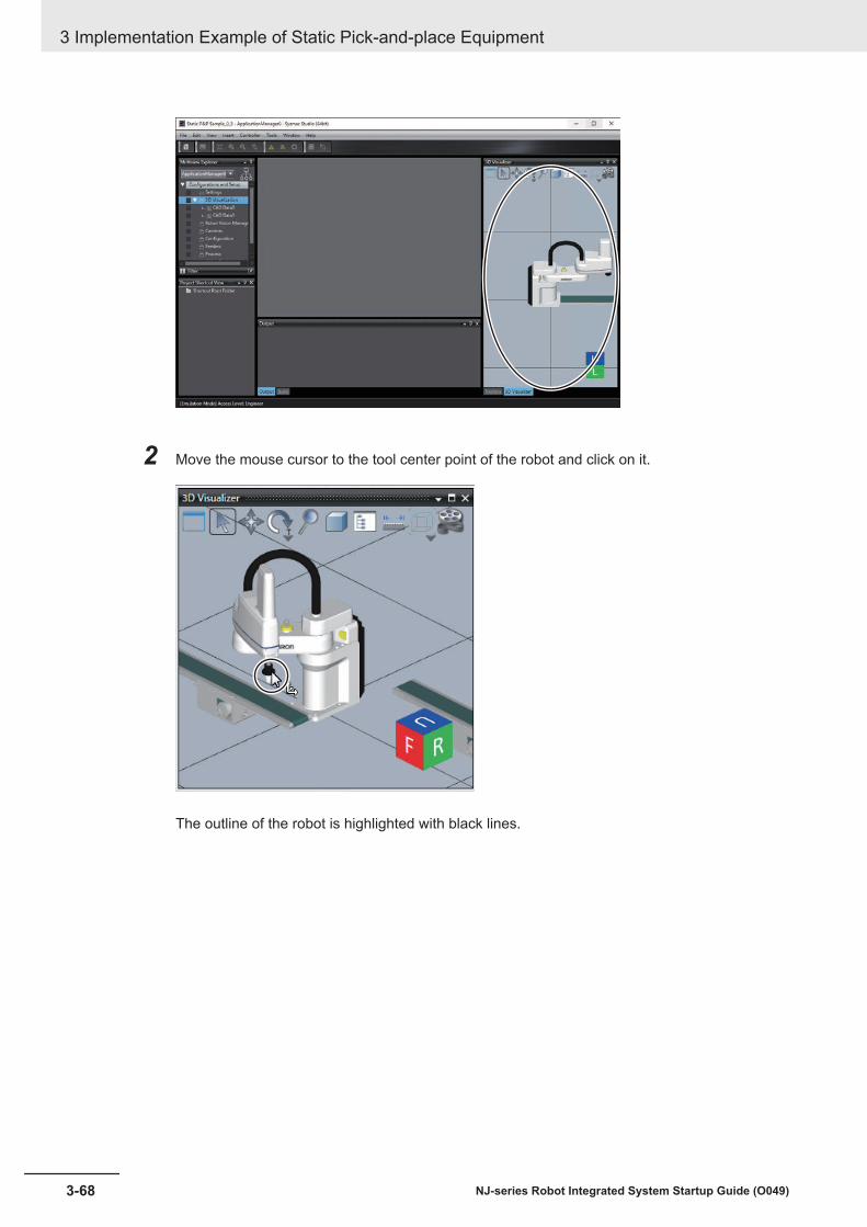
2 Move the mouse cursor to the tool center point of the robot and click on it.
The outline of the robot is highlighted with black lines.
3 Implementation Example of Static Pick-and-place Equipment
3-68 NJ-series Robot Integrated System Startup Guide (O049)

3 Drag the mouse cursor.The tool center point moves to follow the mouse cursor.
4 Move the tool center point to the position where it overlaps the conveyor, which is the positionyou specify.The collision detection function set in Activating Collision Detection Function on page 3-53 de-tects a collision between the end-effector and the conveyor, and the color of them changes togray.
3 Implementation Example of Static Pick-and-place Equipment
3-69NJ-series Robot Integrated System Startup Guide (O049)
3-3 Programm
ing and Simulation Procedures
3
3-3-7 Teaching Positions
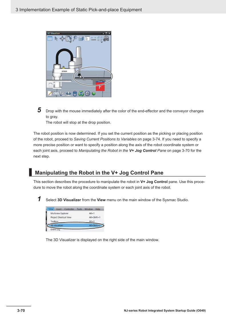
5 Drop with the mouse immediately after the color of the end-effector and the conveyor changesto gray.The robot will stop at the drop position.
The robot position is now determined. If you set the current position as the picking or placing positionof the robot, proceed to Saving Current Positions to Variables on page 3-74. If you need to specify amore precise position or want to specify a position along the axis of the robot coordinate system oreach joint axis, proceed to Manipulating the Robot in the V+ Jog Control Pane on page 3-70 for thenext step.
Manipulating the Robot in the V+ Jog Control PaneThis section describes the procedure to manipulate the robot in V+ Jog Control pane. Use this proce-dure to move the robot along the coordinate system or each joint axis of the robot.
1 Select 3D Visualizer from the View menu on the main window of the Sysmac Studio.
The 3D Visualizer is displayed on the right side of the main window.
3 Implementation Example of Static Pick-and-place Equipment
3-70 NJ-series Robot Integrated System Startup Guide (O049)

2 Select RobotControlSettings from the device list in the Multiview Explorer.
3 Select V+ Jog Control from the View menu on the main window.
The V+ Jog Control pane appears on the right side of the main window.
3 Implementation Example of Static Pick-and-place Equipment
3-71NJ-series Robot Integrated System Startup Guide (O049)
3-3 Programm
ing and Simulation Procedures
3
3-3-7 Teaching Positions

4 From the drop-down list of Jog Control on V+ Jog Control pane, select the coordinate systemof World, Joint, or Tool.When World is selected, positions of the robot can be specified in the robot coordinate system,and when Joint is selected, the position can be set in the coordinate system of the joint. SelectTool for specifying the position in the coordinate system of the tool center point.In this example, select World.
5 Click one of the lamps of Jog Control in the V+ Jog Control pane.The lamp clicked turns green. The robot can be moved along the coordinate axis of the illumi-nated lamp.Select the Z lamp in this example.
3 Implementation Example of Static Pick-and-place Equipment
3-72 NJ-series Robot Integrated System Startup Guide (O049)

6 Press and hold the arrow button labeled or of Jog Control in the V+ Jog Control pane.
The labels and on the arrow buttons represent positive or negative directions on the
specified coordinate system. For example, the arrow in the figure below indicates positive di-rection in the robot coordinate system.
X
Y
Z
While the arrow button is kept pressed, the robot moves along the specified axis of the coordi-nate system.
3 Implementation Example of Static Pick-and-place Equipment
3-73NJ-series Robot Integrated System Startup Guide (O049)
3-3 Programm
ing and Simulation Procedures
3
3-3-7 Teaching Positions
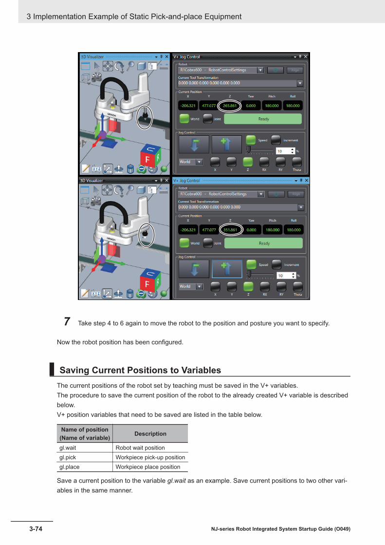
7 Take step 4 to 6 again to move the robot to the position and posture you want to specify.
Now the robot position has been configured.
Saving Current Positions to VariablesThe current positions of the robot set by teaching must be saved in the V+ variables.The procedure to save the current position of the robot to the already created V+ variable is describedbelow.V+ position variables that need to be saved are listed in the table below.
Name of position(Name of variable) Description
gl.wait Robot wait positiongl.pick Workpiece pick-up positiongl.place Workpiece place position
Save a current position to the variable gl.wait as an example. Save current positions to two other vari-ables in the same manner.
3 Implementation Example of Static Pick-and-place Equipment
3-74 NJ-series Robot Integrated System Startup Guide (O049)

1 Click Location in the V+ Jog Control pane.
The field to set the position variable is displayed.
2 Selects a variable that you want to set the current position or an element of the array variablefrom the drop-down list.
3 Implementation Example of Static Pick-and-place Equipment
3-75NJ-series Robot Integrated System Startup Guide (O049)
3-3 Programm
ing and Simulation Procedures
3
3-3-7 Teaching Positions

The variable name and values set in the selected variable are displayed.
Select the variable gl.wait.
3 Click the Here button of Location in the V+ Jog Control pane.
3 Implementation Example of Static Pick-and-place Equipment
3-76 NJ-series Robot Integrated System Startup Guide (O049)

The current position is registered to the value of the selected variable.
Now you have registered the current position of the robot to the V+ variable.
Additional Information
When the sequence control program controls the robot operation, the variable copy program"loccopy" copies the position variables of the V+ program to the shared variables of the se-quence control program.
3-3-8 Setting up Automatic Loading of V+ Programs and Variables atPower ON
The V+ programs that you created and V+ global variables are not automatically loaded to the RobotIntegrated CPU Unit by default settings of the project when power to the Robot Integrated CPU Unit isturned ON.
3 Implementation Example of Static Pick-and-place Equipment
3-77NJ-series Robot Integrated System Startup Guide (O049)
3-3 Programm
ing and Simulation Procedures
3
3-3-8 Setting up Automatic Loading of V+ Program
s and Variables at Power O
N

This section describes the setting procedure for automatically loading the V+ programs and V+ globalvariables to the Robot Integrated CPU Unit when its power is turned ON.If you want to control the operation with the sequence control program, step 4 to 6 are unnecessary.
1 Select RobotControlSettings from the device list in the Multiview Explorer.
2 Click Configurations and Setup in the Multiview Explorer.
Setting items are displayed under Configurations and Setup in the tree.
3 Double-click Save Configuration.
The Save Configuration tab page is displayed in the Edit Pane.
3 Implementation Example of Static Pick-and-place Equipment
3-78 NJ-series Robot Integrated System Startup Guide (O049)

When the V+ programs are used to control the operation, proceed to step 4.If the system is controlled by the sequence control program, proceed to step 7.
4 Make sure that supervisor is not selected for Program to Execute and click the button on theright.
The Select the startup program dialog box appears.
5 Select supervisor under supervisor and click the Select button.
6 Enter 0 to Task Number.
3 Implementation Example of Static Pick-and-place Equipment
3-79NJ-series Robot Integrated System Startup Guide (O049)
3-3 Programm
ing and Simulation Procedures
3
3-3-8 Setting up Automatic Loading of V+ Program
s and Variables at Power O
N

7 Click the Generate Auto Module button in the Save Configuration tab page.
The module name auto is added to the module list in the Save Configuration tab page. In thetree of the Multiview Explorer, V+ Modules - auto are added under Programming.
8 Select Save from the File menu.
3 Implementation Example of Static Pick-and-place Equipment
3-80 NJ-series Robot Integrated System Startup Guide (O049)
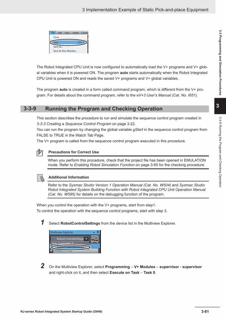
The Robot Integrated CPU Unit is now configured to automatically load the V+ programs and V+ glob-al variables when it is powered ON. The program auto starts automatically when the Robot IntegratedCPU Unit is powered ON and reads the saved V+ programs and V+ global variables.
The program auto is created in a form called command program, which is different from the V+ pro-gram. For details about the command program, refer to the eV+3 User's Manual (Cat. No. I651).
3-3-9 Running the Program and Checking OperationThis section describes the procedure to run and simulate the sequence control program created in 3-3-3 Creating a Sequence Control Program on page 3-22.You can run the program by changing the global variable gStart in the sequence control program fromFALSE to TRUE in the Watch Tab Page.The V+ program is called from the sequence control program executed in this procedure.
Precautions for Correct Use
When you perform this procedure, check that the project file has been opened in EMULATIONmode. Refer to Enabling Robot Simulation Function on page 3-65 for the checking procedure.
Additional Information
Refer to the Sysmac Studio Version 1 Operation Manual (Cat. No. W504) and Sysmac StudioRobot Integrated System Building Function with Robot Integrated CPU Unit Operation Manual(Cat. No. W595) for details on the debugging function of the program.
When you control the operation with the V+ programs, start from step1.To control the operation with the sequence control programs, start with step 3.
1 Select RobotControlSettings from the device list in the Multiview Explorer.
2 On the Multiview Explorer, select Programming – V+ Modules – supervisor - supervisorand right-click on it, and then select Execute on Task – Task 0.
3 Implementation Example of Static Pick-and-place Equipment
3-81NJ-series Robot Integrated System Startup Guide (O049)
3-3 Programm
ing and Simulation Procedures
3
3-3-9 Running the Program
and Checking O
peration

The V+ program supervisor starts to run in Task 0.
3 In the Multiview Explorer, select new_Controller_0 from the device list.
4 Select 3D Visualizer from the View menu on the main window of the Sysmac Studio.
3 Implementation Example of Static Pick-and-place Equipment
3-82 NJ-series Robot Integrated System Startup Guide (O049)

The 3D Visualizer is displayed on the right side of the main window.
5 Select Watch Tab Page from the View menu on the main window.
The Watch (Project)1 tab page appears at the bottom of the main window.
6 Type gStart in the Name column on the Watch (Project)1 tab page.The Online value column displays the current value of False for the internal variable gStart inProgram0.
3 Implementation Example of Static Pick-and-place Equipment
3-83NJ-series Robot Integrated System Startup Guide (O049)
3-3 Programm
ing and Simulation Procedures
3
3-3-9 Running the Program
and Checking O
peration

7 Click the TRUE button in the Modify column for the variable gStart in the Watch (Project)1tab page.
The robot starts to move and pauses at the workpiece pick-up position in the 3D Visualizer.
The robot moves to workpiece
pick-up position and pauses.
After that, the robot restarts operation from the workpiece pick-up position, moves to the robotwait position via the workpiece place position, and stops.
The robot moves to the workpiece pickpup position and puauses.
After that, it moves to the robot wait position and stops.
During operation, check that the robot does not turn gray in locations other than the workpiecepick-up position and workpiece place position. If the color changes to gray, the robot and theconveyor are interfering with each other. In that case, refer to Manipulating the Robot in the V+Jog Control Pane on page 3-70 and move the workpiece pick-up approach point or the work-piece place approach point to a higher position by teaching.
3 Implementation Example of Static Pick-and-place Equipment
3-84 NJ-series Robot Integrated System Startup Guide (O049)

When the highlight color of the robot and end-effector changes to gray during the
transportation, the robot or end-effector is in contact with the conveyor.
Modify the ascending and descending distance.
Now you finished checking operation of the sequence control program and V+ programs.
3 Implementation Example of Static Pick-and-place Equipment
3-85NJ-series Robot Integrated System Startup Guide (O049)
3-3 Programm
ing and Simulation Procedures
3
3-3-9 Running the Program
and Checking O
peration
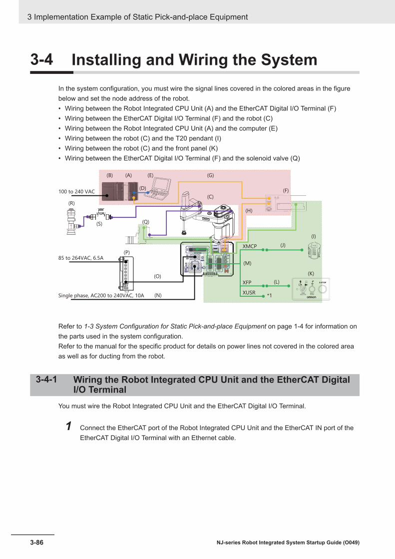
3-4 Installing and Wiring the SystemIn the system configuration, you must wire the signal lines covered in the colored areas in the figurebelow and set the node address of the robot.• Wiring between the Robot Integrated CPU Unit (A) and the EtherCAT Digital I/O Terminal (F)• Wiring between the EtherCAT Digital I/O Terminal (F) and the robot (C)• Wiring between the Robot Integrated CPU Unit (A) and the computer (E)• Wiring between the robot (C) and the T20 pendant (I)• Wiring between the robot (C) and the front panel (K)• Wiring between the EtherCAT Digital I/O Terminal (F) and the solenoid valve (Q)
(P)
(G)
(C)
(B) (A)
(S)
(E)
(D)
(R)
(O)
(N)
(M)
(Q)
(F)
(H)
(J)
(I)
(L)
(K)
100 to 240 VAC
85 to 264VAC, 6.5A
Single phase, AC200 to 240VAC, 10A
XMCP
XFP
XUSR*1
Refer to 1-3 System Configuration for Static Pick-and-place Equipment on page 1-4 for information onthe parts used in the system configuration.Refer to the manual for the specific product for details on power lines not covered in the colored areaas well as for ducting from the robot.
3-4-1 Wiring the Robot Integrated CPU Unit and the EtherCAT DigitalI/O Terminal
You must wire the Robot Integrated CPU Unit and the EtherCAT Digital I/O Terminal.
1 Connect the EtherCAT port of the Robot Integrated CPU Unit and the EtherCAT IN port of theEtherCAT Digital I/O Terminal with an Ethernet cable.
3 Implementation Example of Static Pick-and-place Equipment
3-86 NJ-series Robot Integrated System Startup Guide (O049)

3-4-2 Setting the Node Address of the EtherCAT Digital I/O TerminalYou must set the EtherCAT node address of the EtherCAT Digital I/O Terminal.
1 Use the switches on the EtherCAT Digital I/O Terminal to set the EtherCAT node address.To set the node address to 1, set the x10 switch to 0 and the x1 switch to 1.
Node address setting (×10)
Node address setting (×1)
0 1
23
456
78
90 1
23
456
78
9
Precautions for Correct Use
Set the EtherCAT node address of the EtherCAT Digital I/O Terminal to be the same as thenode address set in 3-3-2 Creating the EtherCAT Network Configuration on page 3-20.
3-4-3 Wiring the EtherCAT Digital I/O Terminal and the RobotYou must wire the EtherCAT Digital I/O Terminal and the robot.
1 Connect the EtherCAT OUT port of the EtherCAT Digital I/O Terminal and the EtherCAT IN porton the interface panel of the robot with an Ethernet cable.
3 Implementation Example of Static Pick-and-place Equipment
3-87NJ-series Robot Integrated System Startup Guide (O049)
3-4 Installing and Wiring the System
3
3-4-2 Setting the Node Address of the EtherC
AT Digital I/O
Terminal

Precautions for Correct Use
Refer to the NJ/NX-series CPU Unit Built-in EtherCAT Port User’s Manual (Cat. No. W505) fordetails on the Ethernet cable to be used.
3-4-4 Setting the EtherCAT Node Address of the RobotYou must set the EtherCAT node address of the robot.
1 Use the switches on the interface panel of the robot to set the EtherCAT node address.To set the node address to 2, set the x256 switch to OFF, the x16 switch to 0, and the x1 switchto 2.
Precautions for Correct Use
Set the EtherCAT node address of the robot to be the same as the node address set in 3-3-2 Creating the EtherCAT Network Configuration on page 3-20.
Refer to the manual for your robot on how to set the node address.
3-4-5 Wiring the Robot Integrated CPU Unit and the ComputerYou must wire the Robot Integrated CPU Unit and the computer.
1 Connect the built-in EtherNet/IP port of the Robot Integrated CPU Unit and the computer withan Ethernet cable.
3 Implementation Example of Static Pick-and-place Equipment
3-88 NJ-series Robot Integrated System Startup Guide (O049)

3-4-6 Wiring the Robot, T20 Pendant and the Front PanelYou must wire the robot and the T20 pendant, as well as the robot and the front panel. Use an XSYS-TEM cable assembly, a T20 adapter cable, and a front panel cable for wiring.
1 Connect the robot and the XSYSTEM cable assembly.
2 Connect the XMCP connector (Red) of the XSYSTEM cable assembly and the T20 adapter ca-ble.
3 Connect the T20 adapter cable to the T20 pendant.
3 Implementation Example of Static Pick-and-place Equipment
3-89NJ-series Robot Integrated System Startup Guide (O049)
3-4 Installing and Wiring the System
3
3-4-6 Wiring the R
obot, T20 Pendant and the Front Panel

4 Connect the XFP connector (Green) of the XSYSTEM cable assembly and the front panel ca-ble.
5 Connect the front panel cable and the front panel.
3-4-7 Wiring the EtherCAT Digital I/O Terminal and Solenoid ValveYou must wire the EtherCAT Digital I/O Terminal and the solenoid valve.Refer to the manuals for the EtherCAT Digital I/O Terminal and the solenoid valve for details on thecable wiring, and make the cable appropriately in accordance with the wiring diagrams and specifica-tions.
1 Make the cable so that the solenoid valve will behave as shown in the table below.
Output value of Digital I/O Terminal Solenoid valve behaviorFALSE Duct is closedTRUE Duct is open
2 Wire the EtherCAT Digital I/O Terminal and the solenoid valve.
3 Implementation Example of Static Pick-and-place Equipment
3-90 NJ-series Robot Integrated System Startup Guide (O049)

Solenoid valve
3 Implementation Example of Static Pick-and-place Equipment
3-91NJ-series Robot Integrated System Startup Guide (O049)
3-4 Installing and Wiring the System
3
3-4-7 Wiring the EtherC
AT Digital I/O
Terminal and Solenoid Valve

3-5 Setup Procedure for Actual SystemThis section describes the procedures for checking operation and adjusting the system on the actualsystem.Check operation with the simulation function before you check operation on the actual system.
Precautions for Correct Use
When you operate the robot in MANUAL mode with the T20 pendant, you must plug the iCSCommissioning Jumper into the XBELTIO connector and change the setting for the Teach Re-strict. Refer to the eCobra 600 and 800 Robot with EtherCAT User’s Guide (Cat. No. I653) fordetails.
3-5-1 Connecting OnlineThe computer and the Robot Integrated CPU Unit are connected online.
1 Turn ON the power supplies to the Robot Integrated CPU Unit and the robot.
2 Click new_Controller_0 from the device list in the Multiview Explorer of the Sysmac Studio.
3 Select Controller - Communications Setup from the menu bar in the main window.
The Communications Setup dialog box is displayed.
3 Implementation Example of Static Pick-and-place Equipment
3-92 NJ-series Robot Integrated System Startup Guide (O049)

4 Click the Direct connection via Ethernet from the Communication type, and then click the OKbutton.
The Communications Setup dialog box is closed.
5 Click the Disable emulation mode icon in the toolbar.
The confirmation dialog box for Disable emulation mode is displayed.
6 Click the OK button.The main window is displayed again after the Sysmac Studio returns to the menu screen.
7 Select Controller - Online from the menu bar.
Precautions for Correct Use
Depending on the status of the connected Robot Integrated CPU Unit, the dialog box for writingthe CPU Unit name or checking the serial ID is displayed. Refer to the Sysmac Studio Version 1Operation Manual (Cat. No. W504) for details.
When it is online, the yellow line is displayed on the top of the edit pane.
3 Implementation Example of Static Pick-and-place Equipment
3-93NJ-series Robot Integrated System Startup Guide (O049)
3-5 Setup Procedure for Actual System
3
3-5-1 Connecting O
nline
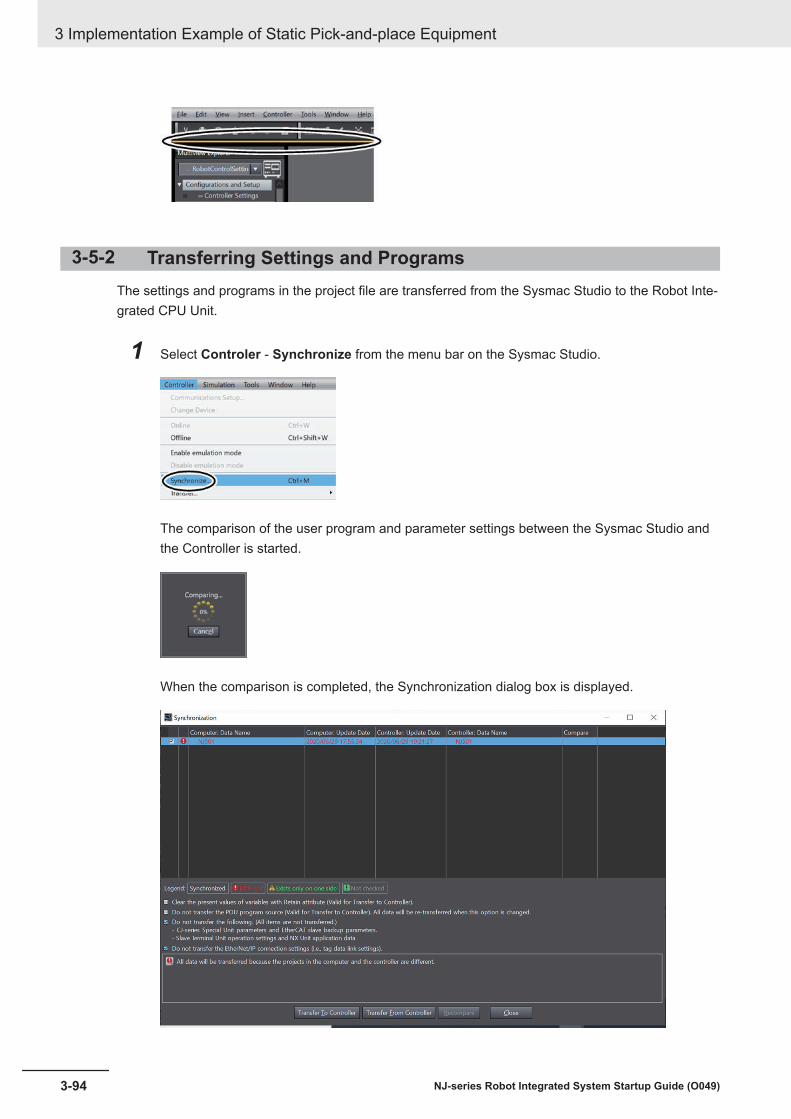
3-5-2 Transferring Settings and ProgramsThe settings and programs in the project file are transferred from the Sysmac Studio to the Robot Inte-grated CPU Unit.
1 Select Controler - Synchronize from the menu bar on the Sysmac Studio.
The comparison of the user program and parameter settings between the Sysmac Studio andthe Controller is started.
When the comparison is completed, the Synchronization dialog box is displayed.
3 Implementation Example of Static Pick-and-place Equipment
3-94 NJ-series Robot Integrated System Startup Guide (O049)

2 Click the Transfer to Controller button.
3 Confirm that "The Synchronization process successfully finished." is diaplayed, and then clickthe Close button.
4 Confirm that the Robot Integrated CPU Unit is turned ON normally.The status of indicators for normal operation is given below.
Indicators StatusRUN indicator Lit green
3 Implementation Example of Static Pick-and-place Equipment
3-95NJ-series Robot Integrated System Startup Guide (O049)
3-5 Setup Procedure for Actual System
3
3-5-2 Transferring Settings and Programs

Indicators StatusERROR indicator Not litNET RUN Lit greenNET ERR Not litLINK/ACT Flashing
Built-in EtherCAT port
5 Confirm that the robot is turned ON normally.The status of indicators for normal operation is given below.
Indicators StatusRUN indicator Lit greenERR indicator Not lit
3-5-3 TeachingA robot is operated actually to check and correct teaching data.Move the robot to the teaching position set in the simulation operation actually, and adjust the positionif necessary. The teaching position data is saved in the SD Memory Card so that the data is retainedafter the power supply to the Robot Integrated CPU Unit is turned OFF.The T20 pendant is used for teaching. Refer to the Teaching Pendant T20 User’s Manual (Cat. No.I601) for information on the specifications of the T20 pendant.Place a workpiece where you plan to pick it up before performing the teaching operation.
Turning Robot High Power ONThe robot high power is turned ON.
1 Change the operating mode switch on the front panel to Manual Mode.
3 Implementation Example of Static Pick-and-place Equipment
3-96 NJ-series Robot Integrated System Startup Guide (O049)

Manual Mode
Operating mode switch
Auto Mode
2 Press the enable switch on the T20 pendant to Position 2 (half-way).
3 Press the Robot Power button while the enable switch is kept in Position 2 (half-way).
The Robot Power button on the front panel flashes.
4 Press the Robot Power button on the front panel.The robot high power is turned ON and the Robot Power button is lit.
If you release the enable switch (Position 1) or press the enable switch further from Position 2 (half-way) to Position 3, the robot high power will be turned OFF.
3 Implementation Example of Static Pick-and-place Equipment
3-97NJ-series Robot Integrated System Startup Guide (O049)
3-5 Setup Procedure for Actual System
3
3-5-3 Teaching

Precautions for Correct Use
If it is necessary to move the robot, follow the procedure above to turn ON the high power.
Adjusting Teaching Position in Simulation OperationThe teaching position that is set in setup procedure with the simulation operation is adjusted to matchthe actual place position. The robot actually moves to the teaching position set in the simulation opera-tion, and correct the position if there are differences between teaching position and expected position.Use the following procedure to adjust position according to the travel route of the robot. You must ad-just the wait position and approach position more than once.
Position name(Variable name) Description Order of adjustment
gl.wait Robot wait position 1, 4gl.pick Workpiece pick-up position 2gl.place Workpiece place position 3
Precautions for Correct Use
Perform the adjustment in the above order in the table. If the adjustment is performed in differ-ent order, the robot may move to the unintended travel route and contact to the equipmentssuch as a conveyor, and then the devices may be damaged.
1 Confirm that the T20 pendant displays the HOME1 screen.
2 Press the F4 button (Next>) twice.
3 Implementation Example of Static Pick-and-place Equipment
3-98 NJ-series Robot Integrated System Startup Guide (O049)

The HOME3 screen is displayed.
3 Press the F1 button (Maint).
The SYSTEM MAINTENANCE screen is displayed.
3 Implementation Example of Static Pick-and-place Equipment
3-99NJ-series Robot Integrated System Startup Guide (O049)
3-5 Setup Procedure for Actual System
3
3-5-3 Teaching
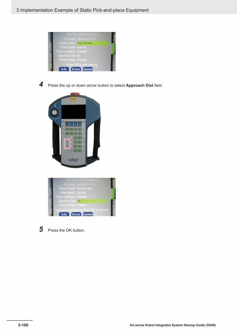
4 Press the up or down arrow button to select Approach Dist field.
5 Press the OK button.
3 Implementation Example of Static Pick-and-place Equipment
3-100 NJ-series Robot Integrated System Startup Guide (O049)

6 Press the up or down arrow button to change the value of Approach Dist field. You can selectthe height to rise and fall in the range of 1 to 200 mm.
Assume that the value of height to rise and fall is 40 in this step.
7 Press the OK button.
3 Implementation Example of Static Pick-and-place Equipment
3-101NJ-series Robot Integrated System Startup Guide (O049)
3-5 Setup Procedure for Actual System
3
3-5-3 Teaching

8 Press the MENU button to back to HOME1 screen.
9 Press the F2 button (Loc).
The AVAILABLE LOCATIONS screen is displayed.
3 Implementation Example of Static Pick-and-place Equipment
3-102 NJ-series Robot Integrated System Startup Guide (O049)
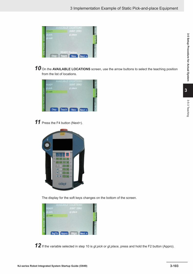
10 On the AVAILABLE LOCATIONS screen, use the arrow buttons to select the teaching positionfrom the list of locations.
11 Press the F4 button (Next>).
The display for the soft keys changes on the bottom of the screen.
12 If the variable selected in step 10 is gl.pick or gl.place, press and hold the F2 button (Appro).
3 Implementation Example of Static Pick-and-place Equipment
3-103NJ-series Robot Integrated System Startup Guide (O049)
3-5 Setup Procedure for Actual System
3
3-5-3 Teaching

The robot moves linearly to the top of the selected position.
13 Press and hold the F1 button (JogTo).
The robot moves linearly to the selected position.
14 When the robot moves to the selected position, release the F1 button (JogTo).If there is no problem with the position and posture after the move, proceed to step 20. If youadjust the position and posture, perform step 15 and later.
15 Press the F4 button (Next>) and then F2 button (Teach).
3 Implementation Example of Static Pick-and-place Equipment
3-104 NJ-series Robot Integrated System Startup Guide (O049)

The TEACH screen for the selected location is displayed.
16 Press the Jog Mode button until the desired mode is displayed in the Jog Mode Indicator area.Assumes that the adjustment of the position in World Mode is performed in this step, and pressthe button until WORLD is displayed.
17 Press the JOINT/AXIS CONTROL button to move the robot to the desired position and pos-ture.The following table shows the relationship between coordinate axes in World Mode and JOINT/AXIS CONTROL button.
Letter Description JOINT/AXIS CONTROL buttonA +X (X direction) XB +Y (Y direction) YC +Z (Z direction) ZD +RZ, CCW (RZ rotation) RZ
3 Implementation Example of Static Pick-and-place Equipment
3-105NJ-series Robot Integrated System Startup Guide (O049)
3-5 Setup Procedure for Actual System
3
3-5-3 Teaching

A
B
D
C
18 Press the OK button.
The value of position is updated to the current robot position.
19 Press the F2 (Loc) button and then F4 button (Next>).The AVAILABLE LOCATIONS screen is displayed again.
3 Implementation Example of Static Pick-and-place Equipment
3-106 NJ-series Robot Integrated System Startup Guide (O049)

20 If the variable selected in step 10 is gl.pick or gl.place, press and hold the F2 button (Appro).
The robot moves linearly to the top of the selected position.
21 If there are still positions left to adjust, return to step 10.
Saving Teaching Position in SD Memory CardThe teaching position data is saved in the SD Memory Card so that the data is retained after the pow-er supply to the Robot Integrated CPU Unit is turned OFF.
Precautions for Correct Use
If the power supply to the Robot Integrated CPU Unit turned OFF without saving position data inthe SD Memory Card, the adjusted position data is lost, and then the robot may perform unin-tended operations the next time that the CPU Unit is started. Perform this procedure if you per-form teaching on the actual system.
1 Click RobotControlSettings from the device list in the Multiview Explorer of the Sysmac Stu-dio.
3 Implementation Example of Static Pick-and-place Equipment
3-107NJ-series Robot Integrated System Startup Guide (O049)
3-5 Setup Procedure for Actual System
3
3-5-3 Teaching

2 Click the Pull from V+ Memory icon in the toolbar of the Multiview Explorer.
3 Select Configurations and Setup - Save Configuration in the Multiview Explorer.
4 Click the Save To Controller button in the Save Configuration tab page.
5 Click File - Save from the menu bar.
3-5-4 Executing Program to Check OperationThe robot operation before the automatic operation is checked according to the program.
1 Change the operating mode switch on the front panel to Auto Mode.
3 Implementation Example of Static Pick-and-place Equipment
3-108 NJ-series Robot Integrated System Startup Guide (O049)

Manual Mode
Operating mode switch
Auto Mode
2 Press the Robot Power button on the front panel.
ROBOT POWER button
The Robot Power button flashes. Press the Robot Power button again. Then, the Robot Powerbutton lights up and the robot high power turns ON.
ROBOT POWER button
3 Select View - Watch Tab Page from the menu bar in the main window of the Sysmac Studioon the computer.
The Watch tab page is displayed under the main window.
3 Implementation Example of Static Pick-and-place Equipment
3-109NJ-series Robot Integrated System Startup Guide (O049)
3-5 Setup Procedure for Actual System
3
3-5-4 Executing Program to C
heck Operation
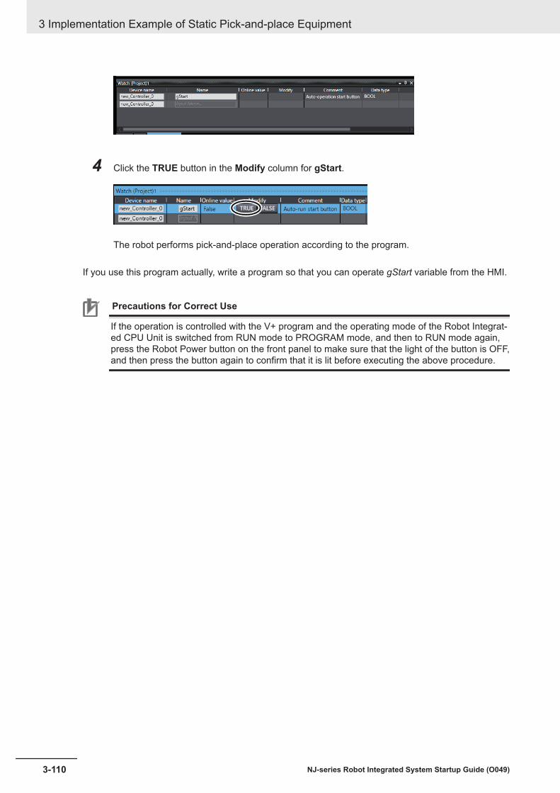
4 Click the TRUE button in the Modify column for gStart.
The robot performs pick-and-place operation according to the program.
If you use this program actually, write a program so that you can operate gStart variable from the HMI.
Precautions for Correct Use
If the operation is controlled with the V+ program and the operating mode of the Robot Integrat-ed CPU Unit is switched from RUN mode to PROGRAM mode, and then to RUN mode again,press the Robot Power button on the front panel to make sure that the light of the button is OFF,and then press the button again to confirm that it is lit before executing the above procedure.
3 Implementation Example of Static Pick-and-place Equipment
3-110 NJ-series Robot Integrated System Startup Guide (O049)

4Implementation Example of Dy-namic Pick-and-place Equipment
This section describes the implementation example of the dynamic pick-and-placeequipment.
4-1 Program Specifications for Dynamic Pick-and-place Equipment ............. 4-34-1-1 Program Structure ........................................................................................... 4-3
4-2 Basic Startup Procedures ........................................................................... 4-124-3 Programming and Simulation Procedures ................................................ 4-15
4-3-1 Creating a Project File................................................................................... 4-154-3-2 Creating the EtherCAT Network Configuration.............................................. 4-164-3-3 Creating V+ Programs................................................................................... 4-194-3-4 Writing a Sequence Control Program............................................................ 4-234-3-5 Placing 3D Shape Data ................................................................................. 4-304-3-6 Creating a Pack Manager Sample ................................................................ 4-534-3-7 Creating C# Programs................................................................................... 4-814-3-8 Setting up Automatic Loading of V+ Programs and Variables at Power ON. 4-834-3-9 Executing Program to Check Operation........................................................ 4-87
4-4 Installing and Wiring the System................................................................ 4-934-4-1 Wiring the Robot Integrated CPU Unit and the EtherCAT Digital I/O
Terminal......................................................................................................... 4-944-4-2 Setting the Node Address of the EtherCAT Digital I/O Terminal ................... 4-944-4-3 Wiring the EtherCAT Digital I/O Terminal and Inverter’s EtherCAT
Communications Unit .................................................................................... 4-954-4-4 Setting the Node Address of Inverter’s EtherCAT Communications Unit...... 4-954-4-5 Wiring the Inverter’s EtherCAT Communications Unit and Robot ................. 4-954-4-6 Setting the EtherCAT Node Address of the Robot ........................................ 4-964-4-7 Wiring the Robot, T20 Pendant and the Front Panel .................................... 4-964-4-8 Wiring the Robot and Encoder ...................................................................... 4-984-4-9 Wiring the EtherNet/IP Port on the Robot Integrated CPU Unit .................... 4-994-4-10 Wiring Between the IPC Application Controller, Display, and Camera........ 4-1004-4-11 Wiring the Camera and Robot..................................................................... 4-1004-4-12 Wiring the EtherCAT Digital I/O Terminal and Solenoid Valve..................... 4-101
4-5 Operation Check on the Actual System................................................... 4-1034-5-1 Communications Setup ............................................................................... 4-1034-5-2 Online Connection........................................................................................4-1104-5-3 Transferring Settings and Programs.............................................................4-1114-5-4 Setting up the Camera .................................................................................4-1154-5-5 Running a Sequence Control Program and V+ Program ............................ 4-1264-5-6 Turning Robot High Power ON ................................................................... 4-1284-5-7 Calibrating the Belt ...................................................................................... 4-1304-5-8 Calibrating the Sensor................................................................................. 4-135
4-1NJ-series Robot Integrated System Startup Guide (O049)
4

4-5-9 Setting the Locator ...................................................................................... 4-1464-5-10 Teaching Idle, Pick, and Place Positions..................................................... 4-1514-5-11 Running the Program to Check the Operation ............................................ 4-154
4 Implementation Example of Dynamic Pick-and-place Equipment
4-2 NJ-series Robot Integrated System Startup Guide (O049)

4-1 Program Specifications for DynamicPick-and-place Equipment
This section describes the program specifications to control the dynamic pick-and-place equipment.For information on how to create a program, refer to 4-3 Programming and Simulation Procedures onpage 4-15.
4-1-1 Program StructureThis section describes the specifications of the program to control the dynamic pick-and-place equip-ment.The program consists of the following programs.
Program Name Language DescriptionMain Sequence control program (Ladder di-
agram)Main program
ConveyerControl Sequence control program (Ladder di-agram)
Operating program for the conveyor
RobotControl Sequence control program (Ladder di-agram)
Program for automatic operation of the robot
px.start V+ program A program to call C# program for startingpx.stop V+ program A program to call C# program for stoppingsupervisor V+ program Status monitoring program for the robotcontrol V+ program Regular processing program for the robot operationauto V+ program Startup processing program for the robot operationPM_Start C# program Startup program of the Process ManagerPM_Stop C# program Stop program of the Process Manager
The role of each program and peripheral devices are as follows.
Robot Integrated CPU Unit IPC Application Controller
auto
LaunchStatus
monitoring
Launch
Launch LaunchLaunch
Operation commandRobot
CameraI/O TerminalInverter
Launch/stop In execution
Shoot image of workpiece
StopLaunch
Operation ready or not
Conveyor drive ON/OFF
command
Solenoid valve open/close instruction
Conveyor drive ON/OFF
Inverter run command
Launch
Main
RobotControl
supervisor
control
px.start
px.stop PM_Stop
PM_Start
Process Manager
ConveyerControl
4 Implementation Example of Dynamic Pick-and-place Equipment
4-3NJ-series Robot Integrated System Startup Guide (O049)
4-1 Program Specifications for D
ynamic Pick-and-place Equipm
ent
4
4-1-1 Program Structure

In this equipment, Pack Manager sample is used to program the pick-and-place operation.If you use the Pack Manager sample, you can operate the robot by using the Process Manager func-tion of the IPC Application Controller. It eliminates the need to create complex programs for process-ing to work with peripheral devices. However, you need to make the V+ programs and C# programs tostart or stop the Process Manager.Process Manager can be started or stopped by calling the C# program, which is executed by the IPCApplication Controller, from the V+ program that is running on the Robot Integrated CPU Unit.Process Manager's solenoid valve opening/closing instruction is written to outputs of V+ Digital I/O.They are assigned to the contacts of the EtherCAT I/O Slave by the V+ Digital I/O Settings functionand are output from those contacts.Process Manager's conveyor drive ON/OFF instruction is written to the output of V+ Digital I/O. The V+ program for regular processing, "control", polls for the status of the conveyor drive ON/OFF instruc-tion and writes it to the shared variable. In addition, the sequence control program "ConveyerControl"polls for the shared variables, converts them to operational instructions (ON/OFF instructions, velocitycommand, and rotational directions), and outputs them to the inverter.
Sequence Control ProgramThis section describes the sequence control program to control the dynamic pick-and-place equip-ment.In the sequence control program, register global variables and create three programs, "Main" (mainprogram), "ConveyerControl", and "RobotControl".
Global VariablesRegister the global variables that are used in the sequence control program.
The following variables are automatically generated in the I/O Map tab page.
Name Data type CommentE002_Command WORD Inverter run commandE002_Frequency_reference UINT Inverter target frequencyE002_Status WORD Inverter statusE002_Output_frequency_monitor UINT Inverter frequency monitorE002_Sysmac_Error_Status BYTE Inverter Sysmac error
Register the variables below yourself.
Name Data type Commente_conveyor_dir BOOL Conveyor revere commande_conveyor_run BOOL Conveyor run commande_conveyor_spd BOOL Conveyor fast run commande_is_run_mode BOOL Operation modegRC_Err BOOL Robot control errorgReset BOOL Auto-operation stoppedgStart BOOL Auto-operation startedgSysOK BOOL Operation readyeBool_exeT1 BOOL supervisor in executiongEnableT1 BOOL supervisor executable
4 Implementation Example of Dynamic Pick-and-place Equipment
4-4 NJ-series Robot Integrated System Startup Guide (O049)

The following variables are automatically generated when a robot is added to the system configura-tion.
Name Data type CommentRC_Robot001 _sRC_RBT_REF iX4 650HRC_Robot001_IO _sRC_RBT_IO_REF iX4 650H I/O
Main program (Main)"Main" (main program) is used to monitor the status of the robot and judge whether the automaticoperation can start.An example of a program is provided below.
Operating Program (ConveyerControl)"ConveyerControl" (operating program) makes the inverter start running on receiving a command.During automatic operation, the ON/OFF command is sent to the Inverter according to the convey-or drive ON/OFF instruction from the Process Manager.An example of a program is provided below.
4 Implementation Example of Dynamic Pick-and-place Equipment
4-5NJ-series Robot Integrated System Startup Guide (O049)
4-1 Program Specifications for D
ynamic Pick-and-place Equipm
ent
4
4-1-1 Program Structure

Operating Program (RobotControl)"RobotControl" (operating program) runs automatically on receiving a command.An example of a program is provided below.
V+ ProgramThis section describes the V+ program to control the dynamic pick-and-place equipment.
4 Implementation Example of Dynamic Pick-and-place Equipment
4-6 NJ-series Robot Integrated System Startup Guide (O049)

In this section, you create five V+ programs: "px.start" to call the C# program for starting the ProcessManager, "px.stop" to call the C# program for stopping the Process Manager, the status monitoringprogram "supervisor", the regular processing program "control", and the startup processing program"auto".
V+Digital I/OCommunications between multiple V+ programs or between V+ programs and external EtherCATDigital I/O Terminals are performed via V+ Digital I/Os.The I/O number to be used is shown below. Set No.4001 from the V+Digital I/O Settings.
Range Number Applications1-96 Outputs Not used1001-1096 Inputs 1001 Latch number2001-2999 Soft Signals 2001 Run the belt conveyor
2002 Switch fast/slow control of the belt conveyor2003 Run the belt conveyor backward
3001-3004 Robot Signals Not used4001-4032 External 4001 Solenoid valve open (GX-MD3218 OUT0)
Program to Call C# Program for Starting (px.start)This section describes the program to call the C# programs for starting the Process Manager.An example of a program is provided below.
Additional Information
You cannot use the program with Sysmac Studio version 1.42. Use the program with SysmacStudio version 1.43 or higher.On Sysmac Studio ver.1.42, go online with the IPC Application Controller, selectApplicationManager1 - C# Program - PM_Start and click the Start button on the Task StatusControl pane.
.PROGRAM px.start() GLOBAL $ip AUTO REAL status TYPE "Start PM_Start"
4 Implementation Example of Dynamic Pick-and-place Equipment
4-7NJ-series Robot Integrated System Startup Guide (O049)
4-1 Program Specifications for D
ynamic Pick-and-place Equipm
ent
4
4-1-1 Program Structure

CALL rm.execute3($ip, "/ApplicationManager1/PM_Start", "Execute", 0, $args[], 3, status) IF status < 0 THEN TYPE "Failed to execute: error code ", status END.END
Program to Call C# Program for Stopping (px.stop)This section describes the program to call the C# program for stopping the Process Manager.An example of a program is provided below.
Additional Information
You cannot use the program with Sysmac Studio version 1.42. Use the program with SysmacStudio version 1.43 or higher.On Sysmac Studio ver.1.42, go online with the IPC Application Controller, selectApplicationManager1 - C# Program - PM_Stop and click the Start button on the Task StatusControl pane.
.PROGRAM px.stop() GLOBAL $ip AUTO REAL status TYPE "Start PM_Stop" CALL rm.execute3($ip, "/ApplicationManager1/PM_Stop", "Execute", 0, $args[], 3, status) IF status < 0 THEN TYPE "Failed to execute: error code ", status END.END
Status Monitoring Program (supervisor)The status monitoring program (supervisor) monitors the regular processing program "control" toensure that the program does not stop abnormally while the sequence control is in RUN mode.When it detects sequence control going into PROGRAM mode, it stops the regular processing con-trol program "control" and the Application Manager.
4 Implementation Example of Dynamic Pick-and-place Equipment
4-8 NJ-series Robot Integrated System Startup Guide (O049)

An example of a program is provided below.The variable ebool_exet1 is a flag that indicates that the V+ program is executable. The sequencecontrol program monitors the status of this variable, and starts automatic operation when the V+program is ready to run.
.PROGRAM supervisor() EXTERNAL e_is_run_mode, ebool_exet1 AUTO REAL p_is_run_mode GLOBAL $ip $ip = "127.0.0.1" p_is_run_mode = e_is_run_mode WHILE TRUE DO IF e_is_run_mode THEN IF TASK(1,3) <> 4 THEN EXECUTE 3 control() END ebool_exet1 = TRUE ELSE IF TASK(1,3) <> 0 THEN ABORT 3 CYCLE.END 3 KILL 3 END IF p_is_run_mode THEN BRAKE CALL px.stop() END END p_is_run_mode = e_is_run_mode WAIT END.END
Regular Processing Program (control)Regular processing program is a program that performs a routine processing. If it fails to start, itautomatically restarts. The routine processing includes the process of writing values of V+ digitalI/O signals to the shared variables with the sequence control program.A program is described below.
.PROGRAM control() EXTERNAL e_conveyor_run EXTERNAL e_conveyor_spd EXTERNAL e_conveyor_dir WHILE TRUE DO e_conveyor_run = SIG(2001) e_conveyor_spd = SIG(2002) e_conveyor_dir = SIG(2003)
4 Implementation Example of Dynamic Pick-and-place Equipment
4-9NJ-series Robot Integrated System Startup Guide (O049)
4-1 Program Specifications for D
ynamic Pick-and-place Equipm
ent
4
4-1-1 Program Structure

RELEASE END.END
Startup Processing Program (auto)The startup processing program, auto, reads the V+ programs and global variables from the SDMemory Card to the main memory and starts the status monitoring program.Since this program is automatically generated, you don’t need to write a program.
C# ProgramsThis section describes the C# programs to control the dynamic pick-and-place equipment.
Startup Program of Process Manager (PM_Start)This program launches the Process Manager.An example of a program is provided below.
using Ace.Server.Xpert.PackXpert;using Ace.Services.NameLookup;using Ace.Client.ApplicationManager.AutoConnect;using Ace.Server;using System;using System.Collections.Generic;using System.Diagnostics;
namespace Ace.Custom { public class Program { public INameLookupService ace; public void Main() { Trace.WriteLine("Script Starting"); IProcessManager processManager = (IProcessManager) ace[ "/ApplicationManager1/Process Manager"]; processManager.Start(); } }}
Stop Program of Process Manager (PM_Stop)This program stops the Process Manager..An example of a program is provided below.
using Ace.Server.Xpert.PackXpert;using Ace.Services.NameLookup;using Ace.Client.ApplicationManager.AutoConnect;using Ace.Server;using System;using System.Collections.Generic;
4 Implementation Example of Dynamic Pick-and-place Equipment
4-10 NJ-series Robot Integrated System Startup Guide (O049)

using System.Diagnostics;
namespace Ace.Custom { public class Program { public INameLookupService ace; public void Main() { Trace.WriteLine("Script Starting"); IProcessManager processManager = (IProcessManager) ace[ "/ApplicationManager1/Process Manager"]; processManager.Stop(); } }}
Precautions for Correct Use
The contents of the text string "/ApplicationManager1/Process Manager" in each C# programdiffer depending on the language used when you created the project file. SelectApplicationManager1 from the device list in the Multiview Explorer and selectConfigurations and Setup - Process - Process Manager. Drag and drop it onto the C# editor,and an appropriate text string is automatically selected.
4 Implementation Example of Dynamic Pick-and-place Equipment
4-11NJ-series Robot Integrated System Startup Guide (O049)
4-1 Program Specifications for D
ynamic Pick-and-place Equipm
ent
4
4-1-1 Program Structure

4-2 Basic Startup ProceduresThis section gives an overview of the basic startup procedures to build a dynamic pick-and-place sys-tem.First, program a machine operation, configure and check the settings using the simulator, and then runthe system for fine-tuning the operation.
No. Procedure Description Reference1 Programming and
Simulation Proce-dures
Creating a project Create a project file in the SysmacStudio.
page 4-15
2 Creating the networkconfiguration
Create the EtherCAT network config-uration and register an EtherCATDigital I/O Terminal, an inverter, anda robot on the network.
page 4-16
3 Writing V+ programs Create the V+ programs. page 4-194 Writing a sequence
control programCreate a sequences control pro-gram.
page 4-23
5 Placing 3D shape data Place 3D shape data and make theoperating range of the robot visibleon the 3D Visualizer.
page 4-30
6 Creating a Pack Man-ager sample
Configure the robot settings, camerasettings, and conveyor settings byusing the simulation function andperform teaching.
page 4-53
7 Writing C# programs Create the C# programs. page 4-818 Running the program
(Simulation)Run the sequence control programon the simulator of the Sysmac Stu-dio.
page 4-87
4 Implementation Example of Dynamic Pick-and-place Equipment
4-12 NJ-series Robot Integrated System Startup Guide (O049)

No. Procedure Description Reference9 Installing and Wiring
the SystemWiring the Robot Inte-grated CPU Unit andEtherCAT Digital I/OTerminal
Wire the Robot Integrated CPU Unitand the EtherCAT Digital I/O Termi-nal.
page 4-94
10 Setting the node ad-dress of the EtherCATDigital I/O Terminal
Set the EtherCAT node address ofthe EtherCAT Digital I/O Terminal.
page 4-94
11 Wiring the EtherCATDigital I/O Terminal andInverter’s EtherCATcommunications unit
Wire the EtherCAT Digital I/O Termi-nal and the EtherCAT communica-tions unit of the Inverter.
page 4-95
12 Setting the node ad-dress of the Inverter’sEtherCAT communica-tions unit
Set the EtherCAT node address ofthe EtherCAT communications unitof the Inverter.
page 4-95
13 Wiring the Inverter’sEtherCAT communica-tions unit and robot
Wire the EtherCAT communicationsunit of the Inverter and the robot
page 4-95
14 Setting the EtherCATnode address of the ro-bot
Set the EtherCAT node address ofthe robot.
page 4-96
15 Wiring the robot, T20pendant, and front pan-el
Wire the robot and the T20 pendant,as well as the robot and the frontpanel. Use an XSYSTEM cable as-sembly, a T20 adapter cable, and afront panel cable for wiring.
page 4-96
16 Wiring the robot andencoder
Wire the robot and the encoder. page 4-98
17 Wiring the EtherNet/IPPort on the Robot Inte-grated CPU Unit
Wire between the Robot IntegratedCPU Unit and the industrial Ethernetswitch, between the industrial Ether-net switch and the computer, and be-tween the industrial Ethernet switchand the IPC Application Controller.
page 4-99
18 Wiring the IPC Applica-tion Controller and dis-play and camera
Wire between the IPC ApplicationController and the display, and be-tween the IPC Application Controllerand the camera.
page 4-100
19 Wiring the camera androbot
Wire the camera and the robot. page 4-100
20 Wiring the EtherCATDigital I/O Terminal andsolenoid valves
Wire the EtherCAT Digital I/O Termi-nal and the solenoid valves.
page 4-101
4 Implementation Example of Dynamic Pick-and-place Equipment
4-13NJ-series Robot Integrated System Startup Guide (O049)
4-2 Basic Startup Procedures
4

No. Procedure Description Reference21 Operation Check on
the Actual SystemCommunication set-tings
Configure the communication set-tings for connecting Sysmac Studioon the computer and the devices.
page 4-103
22 Going online Connect Sysmac Studio online withthe Robot Integrated CPU Unit.
page 4-110
23 Transferring settingsand programs
Download the programs and settingsin the Sysmac Studio project file tothe Robot Integrated CPU Unit andthe IPC Application Controller.
page 4-111
24 Camera settings Set the properties of the camera. page 4-11525 Running the sequence
control program and V+program
Run the sequence control programand V+ programs.
4-5-5 Running aSequence Con-trol Programand V+ Pro-gram on page4-126
26 Turning robot high pow-er ON
Turn ON the robot high power. Turning RobotHigh Power ONon page 3-96
27 Calibrating the belt Perform belt calibration. 4-5-7 Calibrat-ing the Belt onpage 4-130
28 Sensor calibrations Calibrate the sensor. 4-5-8 Calibrat-ing the Sensoron page 4-135
29 Setting the Locator Set the Locator. 4-5-9 Settingthe Locator onpage 4-146
30 Teaching idle, pick, andplace positions (On ac-tual equipment)
Operate the robot actually to checkand correct teaching data.
page 4-151
31 Running the programs(On actual equipment)
Check the operation of the systembefore starting the automatic opera-tion.
page 4-154
4 Implementation Example of Dynamic Pick-and-place Equipment
4-14 NJ-series Robot Integrated System Startup Guide (O049)

4-3 Programming and Simulation Proce-dures
This section describes the procedure for creating project files, programing, and setting and checkingoperation in simulation.The simulation function allows you to check the equipment operation before purchasing actual equip-ment.
4-3-1 Creating a Project FileCreate a project in the Sysmac Studio.
1 Start the Sysmac Studio and click New Project in the Start page.
The Project Properties dialog box is displayed.
2 In the Project Properties dialog box, enter the Project name, Author, and Comment, andselect the Category, Device, and Version as shown in the figure below.
3 Select the Open in Emulation Mode check box, and click the Create button.
4 Implementation Example of Dynamic Pick-and-place Equipment
4-15NJ-series Robot Integrated System Startup Guide (O049)
4-3 Programm
ing and Simulation Procedures
4
4-3-1 Creating a Project File

A project file is created and the following window is displayed.
4-3-2 Creating the EtherCAT Network ConfigurationCreate the EtherCAT network configuration and register an EtherCAT Digital I/O Terminal, an inverter,and a robot on the network.
1 Click Configurations and Setup in the Multiview Explorer.
Setting items are displayed under Configurations and Setup in the tree.
2 Double-click EtherCAT under Configurations and Setup in the Multiview Explorer. Or right-click EtherCAT under Configurations and Setup and select Edit from the menu.
4 Implementation Example of Dynamic Pick-and-place Equipment
4-16 NJ-series Robot Integrated System Startup Guide (O049)
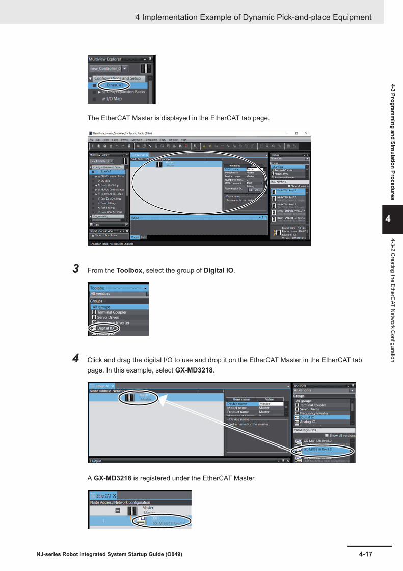
The EtherCAT Master is displayed in the EtherCAT tab page.
3 From the Toolbox, select the group of Digital IO.
4 Click and drag the digital I/O to use and drop it on the EtherCAT Master in the EtherCAT tabpage. In this example, select GX-MD3218.
A GX-MD3218 is registered under the EtherCAT Master.
4 Implementation Example of Dynamic Pick-and-place Equipment
4-17NJ-series Robot Integrated System Startup Guide (O049)
4-3 Programm
ing and Simulation Procedures
4
4-3-2 Creating the EtherC
AT Netw
ork Configuration

5 From the Toolbox, select the group of Frequency Inverter.
6 Select and drag the inverter to use and drop it on the GX-MD3218 in the EthercAT tab page. Inthis example, select 3G3AX-MX2-ECT.
A 3G3AX-MX2-ECT is added under the GX-MD3218.
7 From the Toolbox, select the group of Robot.
8 Select and drag the robot to use and drop it on the 3G3AX-MX2-ECT in the EthercAT tabpage. In this example, iX4 650H, IP65, P30 is selected.
4 Implementation Example of Dynamic Pick-and-place Equipment
4-18 NJ-series Robot Integrated System Startup Guide (O049)

An iX4 650H, IP65, P30 is added under the 3G3AX-MX2-ECT in the EtherCAT tab page.
4-3-3 Creating V+ ProgramsThis section provides the procedure for creating the V+ programs.For details on the program to create and allocation of V+ digital I/Os, refer to V+ Program on page 4-6.
V+Digital I/O SettingsTo control EtherCAT Slaves by V+ programs, you must assign V+ digital I/Os.
1 In the Multiview Explorer, select new_Controller_0 from the device list.
2 Click the icon to the left of Robot Control Setup in the Multiview Explorer.
4 Implementation Example of Dynamic Pick-and-place Equipment
4-19NJ-series Robot Integrated System Startup Guide (O049)
4-3 Programm
ing and Simulation Procedures
4
4-3-3 Creating V+ Program
s
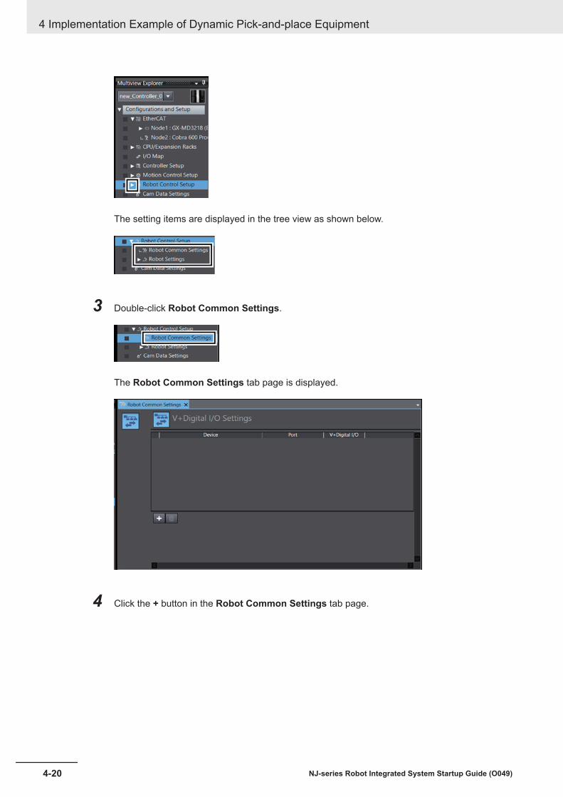
The setting items are displayed in the tree view as shown below.
3 Double-click Robot Common Settings.
The Robot Common Settings tab page is displayed.
4 Click the + button in the Robot Common Settings tab page.
4 Implementation Example of Dynamic Pick-and-place Equipment
4-20 NJ-series Robot Integrated System Startup Guide (O049)
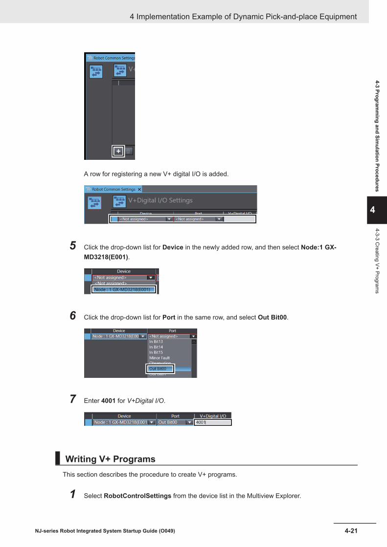
A row for registering a new V+ digital I/O is added.
5 Click the drop-down list for Device in the newly added row, and then select Node:1 GX-MD3218(E001).
6 Click the drop-down list for Port in the same row, and select Out Bit00.
7 Enter 4001 for V+Digital I/O.
Writing V+ ProgramsThis section describes the procedure to create V+ programs.
1 Select RobotControlSettings from the device list in the Multiview Explorer.
4 Implementation Example of Dynamic Pick-and-place Equipment
4-21NJ-series Robot Integrated System Startup Guide (O049)
4-3 Programm
ing and Simulation Procedures
4
4-3-3 Creating V+ Program
s
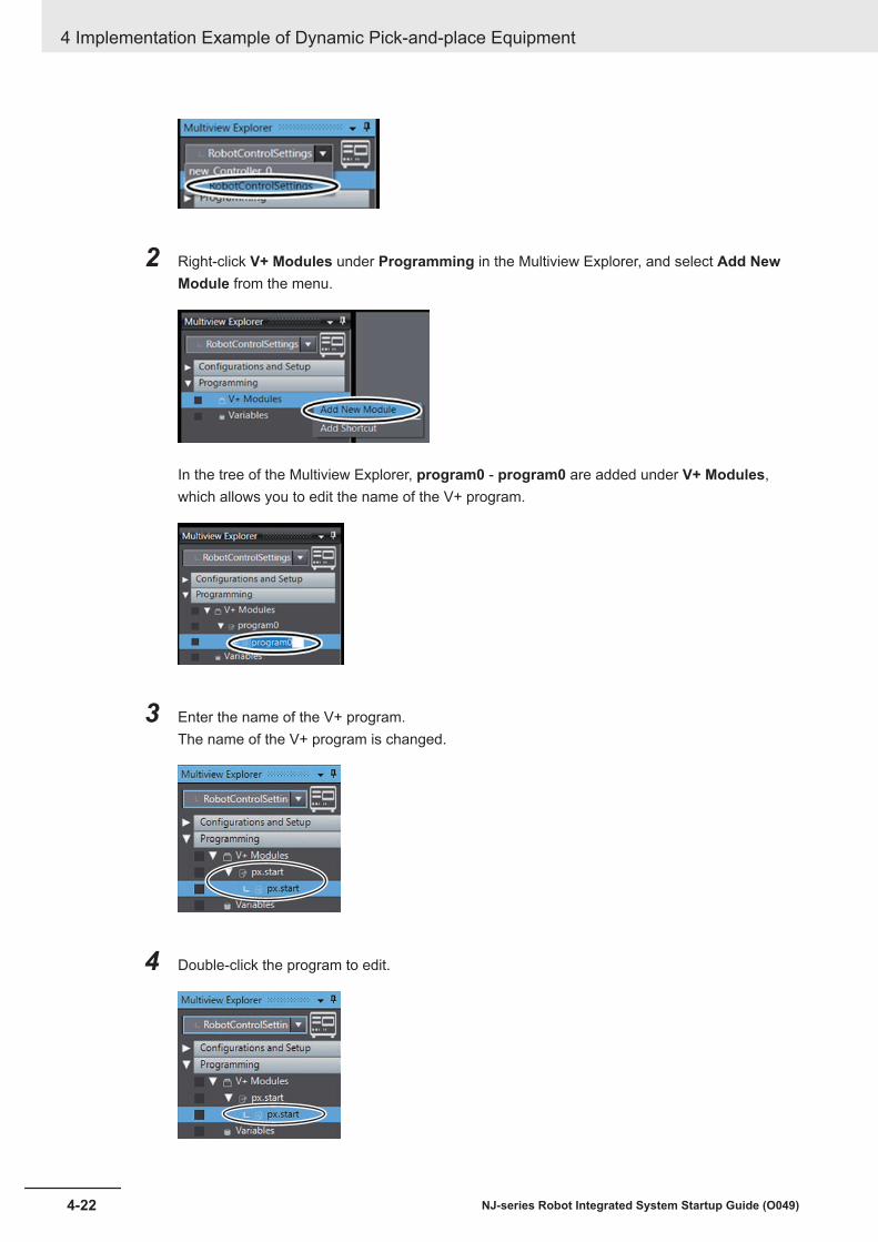
2 Right-click V+ Modules under Programming in the Multiview Explorer, and select Add NewModule from the menu.
In the tree of the Multiview Explorer, program0 - program0 are added under V+ Modules,which allows you to edit the name of the V+ program.
3 Enter the name of the V+ program.The name of the V+ program is changed.
4 Double-click the program to edit.
4 Implementation Example of Dynamic Pick-and-place Equipment
4-22 NJ-series Robot Integrated System Startup Guide (O049)

A tab page to edit the V+ program is displayed in the Edit Pane.
5 Create the program in the Edit Pane.For details on the program to create, refer to V+ Program on page 4-6.
6 Go back to step 2 and create another V+ program by repeating the sequence of operations.
4-3-4 Writing a Sequence Control ProgramThis section provides the procedure for creating a sequence control program.For details on the program to create and allocation of V+ digital I/Os, refer to Sequence Control Pro-gram on page 4-4.
Creating Device VariablesCreate device variables to control the inverter.
1 In the Multiview Explorer, select new_Controller_0 from the device list.
2 Double-click I/O Map under Configurations and Setup in the Multiview Explorer.
The I/O Map tab page is displayed in the Edit Pane.
4 Implementation Example of Dynamic Pick-and-place Equipment
4-23NJ-series Robot Integrated System Startup Guide (O049)
4-3 Programm
ing and Simulation Procedures
4
4-3-4 Writing a Sequence C
ontrol Program

3 In the I/O Map tab page, click the icon to the left of 3G3AX-MX2-ECT in the Port column.
Setting items are displayed under 3G3AX-MX2-ECT in the tree.
4 Right-click on the 3G3AX-MX2-ECT in the Port column of the I/O Map tab page and selectCreate Device Variable from the menu.
The device variable is created.
4 Implementation Example of Dynamic Pick-and-place Equipment
4-24 NJ-series Robot Integrated System Startup Guide (O049)
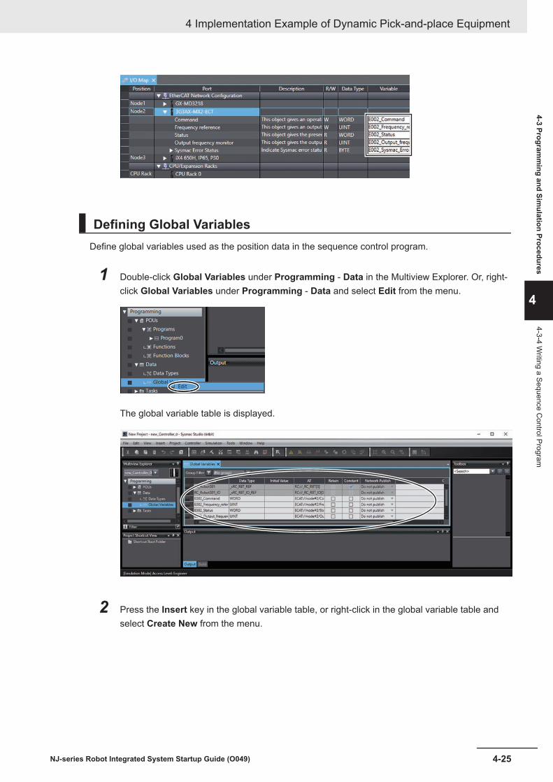
Defining Global VariablesDefine global variables used as the position data in the sequence control program.
1 Double-click Global Variables under Programming - Data in the Multiview Explorer. Or, right-click Global Variables under Programming - Data and select Edit from the menu.
The global variable table is displayed.
2 Press the Insert key in the global variable table, or right-click in the global variable table andselect Create New from the menu.
4 Implementation Example of Dynamic Pick-and-place Equipment
4-25NJ-series Robot Integrated System Startup Guide (O049)
4-3 Programm
ing and Simulation Procedures
4
4-3-4 Writing a Sequence C
ontrol Program

3 Enter or select setting for each item and press the Enter key.
Refer to Sequence Control Program on page 4-4 for the global variables to register.
The global variable is registered.
Creating Ladder Diagram ProgramsThis section describes how to create the ladder diagram programs.
1 Right-click Program0 under Programming - POUs - Programs in the Multiview Explorer andselect Rename from the menu.
This allows you to edit the name of the sequence control program.
2 Enter the name of the sequence control program.The name of the sequence control program is changed.
4 Implementation Example of Dynamic Pick-and-place Equipment
4-26 NJ-series Robot Integrated System Startup Guide (O049)

3 Double-click the section to edit.
The variable table and Ladder Editor are displayed in the Edit Pane.
4 Enter the program in the Ladder Editor. Internal and external variables are automatically regis-tered when they are entered in the program.For details on the program to create, refer to Sequence Control Program on page 4-4.
To create more than one sequence control program, perform the following steps.
5 Right-click Programs under Programming - POUs in the Multiview Explorer, and then selectAdd - Ladder from the menu.
Program0 is added under Programs.
6 Click the icon displayed to the left of Program0 under Programming - POUs - Programs inthe Multiview Explorer.
4 Implementation Example of Dynamic Pick-and-place Equipment
4-27NJ-series Robot Integrated System Startup Guide (O049)
4-3 Programm
ing and Simulation Procedures
4
4-3-4 Writing a Sequence C
ontrol Program

Section0 is added under Program0.
7 Returns to step 1 and repeat the above steps.
Assigning Programs to TasksIn this section, assign the ladder diagram programs to tasks of the Robot Integrated CPU Unit.In this guide, multiple ladder diagram programs are used to control the dynamic pick-and-place equip-ment, so it is necessary to assign the programs to tasks.When the equipment is controlled by the V+ Program, only one ladder diagram program is used andyou do not need to perform the steps in this section.
1 Double-click Task Settings under Configurations and Setup in the Multiview Explorer.
The Task Settings tab page is displayed.
2 Click the Program Assignment Settings button ( ) in the Edit Pane.
4 Implementation Example of Dynamic Pick-and-place Equipment
4-28 NJ-series Robot Integrated System Startup Guide (O049)

3 Click the + button.
A new row is added for the program to assign.
4 Select a name of the program to use from the list of the Program name.
The name of the selected program is displayed.
5 Perform step 3 and later for RobotControl.
4 Implementation Example of Dynamic Pick-and-place Equipment
4-29NJ-series Robot Integrated System Startup Guide (O049)
4-3 Programm
ing and Simulation Procedures
4
4-3-4 Writing a Sequence C
ontrol Program
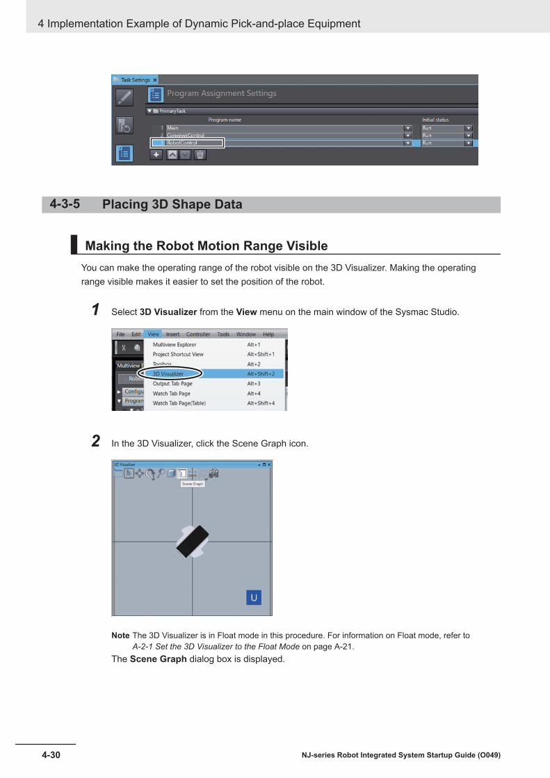
4-3-5 Placing 3D Shape Data
Making the Robot Motion Range VisibleYou can make the operating range of the robot visible on the 3D Visualizer. Making the operatingrange visible makes it easier to set the position of the robot.
1 Select 3D Visualizer from the View menu on the main window of the Sysmac Studio.
2 In the 3D Visualizer, click the Scene Graph icon.
Note The 3D Visualizer is in Float mode in this procedure. For information on Float mode, refer to A-2-1 Set the 3D Visualizer to the Float Mode on page A-21.
The Scene Graph dialog box is displayed.
4 Implementation Example of Dynamic Pick-and-place Equipment
4-30 NJ-series Robot Integrated System Startup Guide (O049)

3 In the Visibility tab page, select the Work Volume check box located underRobotControlSettings - R1iX4_650P30.
The 3D Visualizer illustrates the robot’s operating range in gray.
4 Click the Close button on the Scene Graph dialog box.
4 Implementation Example of Dynamic Pick-and-place Equipment
4-31NJ-series Robot Integrated System Startup Guide (O049)
4-3 Programm
ing and Simulation Procedures
4
4-3-5 Placing 3D Shape D
ata
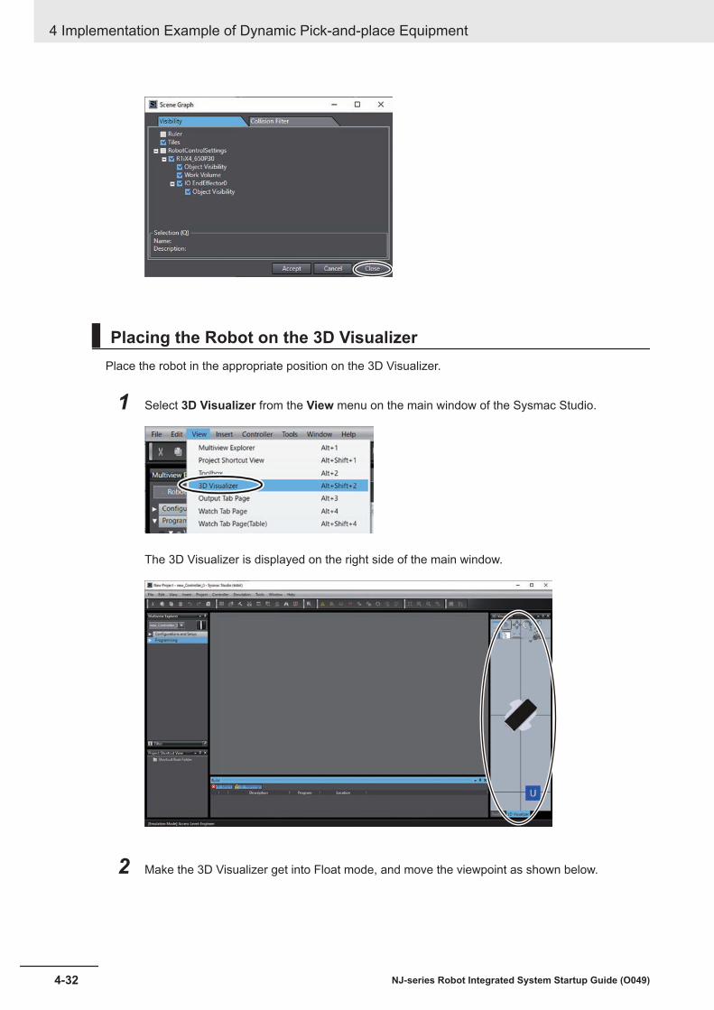
Placing the Robot on the 3D VisualizerPlace the robot in the appropriate position on the 3D Visualizer.
1 Select 3D Visualizer from the View menu on the main window of the Sysmac Studio.
The 3D Visualizer is displayed on the right side of the main window.
2 Make the 3D Visualizer get into Float mode, and move the viewpoint as shown below.
4 Implementation Example of Dynamic Pick-and-place Equipment
4-32 NJ-series Robot Integrated System Startup Guide (O049)
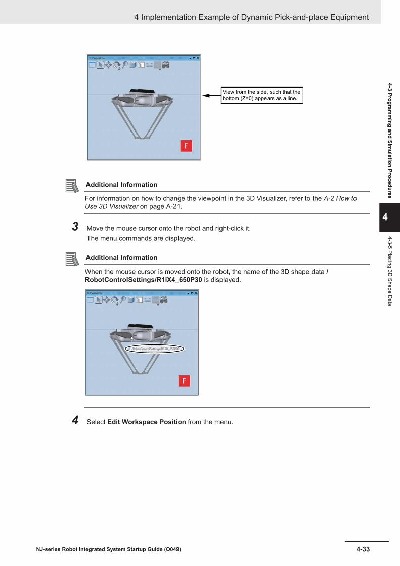
View from the side, such that the
bottom (Z=0) appears as a line.
Additional Information
For information on how to change the viewpoint in the 3D Visualizer, refer to the A-2 How toUse 3D Visualizer on page A-21.
3 Move the mouse cursor onto the robot and right-click it.The menu commands are displayed.
Additional Information
When the mouse cursor is moved onto the robot, the name of the 3D shape data /RobotControlSettings/R1iX4_650P30 is displayed.
4 Select Edit Workspace Position from the menu.
4 Implementation Example of Dynamic Pick-and-place Equipment
4-33NJ-series Robot Integrated System Startup Guide (O049)
4-3 Programm
ing and Simulation Procedures
4
4-3-5 Placing 3D Shape D
ata

The Move icon consisting of colored arrows, a purple circle, and faces is displayed on the ori-gin of the 3D shape data.
Additional Information
The Move icon has red, green, and blue arrows, which represent the X-axis, Y-axis, and Z-axis,respectively. The red face shows the YZ plane, the green face shows the ZX plane, and theblue face shows the XY plane.
Z
YX
YZ
XY
XZ
You can drag an arrow to move the 3D shape data along the axis.Or, use the face icon to move the 3D shape data on the corresponding plane. You can alsomove the 3D shape data independently from the axis direction by dragging the purple circle.
4 Implementation Example of Dynamic Pick-and-place Equipment
4-34 NJ-series Robot Integrated System Startup Guide (O049)
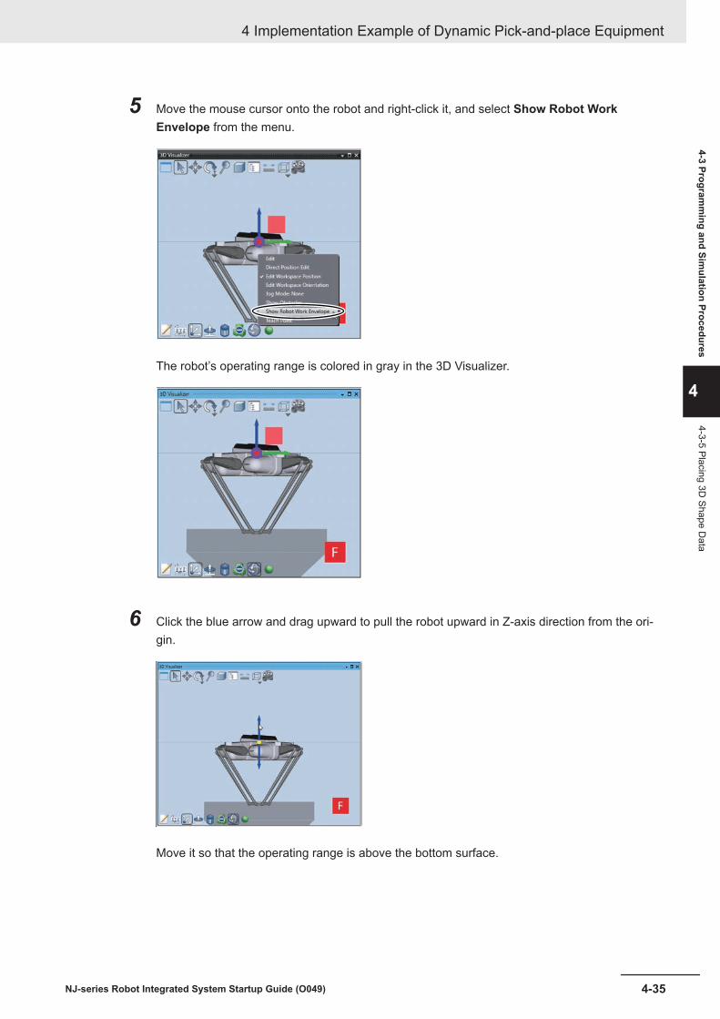
5 Move the mouse cursor onto the robot and right-click it, and select Show Robot WorkEnvelope from the menu.
The robot’s operating range is colored in gray in the 3D Visualizer.
6 Click the blue arrow and drag upward to pull the robot upward in Z-axis direction from the ori-gin.
Move it so that the operating range is above the bottom surface.
4 Implementation Example of Dynamic Pick-and-place Equipment
4-35NJ-series Robot Integrated System Startup Guide (O049)
4-3 Programm
ing and Simulation Procedures
4
4-3-5 Placing 3D Shape D
ata

Additional Information
You can zoom in on the 3D Visualizer to see the operating range more clearly.You can also check the position on the X, Y, and Z axes in numbers by clicking the DirectPosition Edit icon.
For information on how to zoom in or zoom out in the 3D Visualizer, refer to the A-2-4 Zoom-inand Zoom-out on page A-26.
Importing 3D CAD Data and Placing It on the 3D VisualizerImport the 3D CAD data of the conveyors as 3D shape data to the Sysmac Studio.This section describes the procedure to import the 3D CAD Data of Conveyor A and Conveyor B to beused as equipment models and place them on the 3D Visualizer.
1 Select Application Manager from the Insert menu on the main window of the Sysmac Studio.
The Add Device dialog box is displayed.
4 Implementation Example of Dynamic Pick-and-place Equipment
4-36 NJ-series Robot Integrated System Startup Guide (O049)

2 Select an item from the drop-down list of Category, Device, and Version as shown in the fig-ure below, and then click the OK button.
ApplicationManager0 is added to the drop-down list at the top of the Multiview Explorer
Additional Information
Application Manager added by this operation can only be used for simulation. Do not use it foractual device.
3 Click Configurations and Setup in the Multiview Explorer.
Setting items are displayed under Configurations and Setup in the tree.
4 Implementation Example of Dynamic Pick-and-place Equipment
4-37NJ-series Robot Integrated System Startup Guide (O049)
4-3 Programm
ing and Simulation Procedures
4
4-3-5 Placing 3D Shape D
ata

4 Right-click 3D Visualization.The menu commands are displayed.
5 From the menus, select Add - CAD Data.
The Import CAD File wizard starts.
6 Select Open my own CAD file check box.
7 Click the Next button.
4 Implementation Example of Dynamic Pick-and-place Equipment
4-38 NJ-series Robot Integrated System Startup Guide (O049)

8 Click the Open File button.
The Open dialog box is displayed.
9 Select a 3D CAD data to import, and then click the Open button.In this example, you select the conveyor of MISUMI Corporation whose model number isSVKN-100-1000-25-T100-IM-9-H-A for the Conveyor A. You can import the 3D CAD data withthe file name extension “stp”.
4 Implementation Example of Dynamic Pick-and-place Equipment
4-39NJ-series Robot Integrated System Startup Guide (O049)
4-3 Programm
ing and Simulation Procedures
4
4-3-5 Placing 3D Shape D
ata
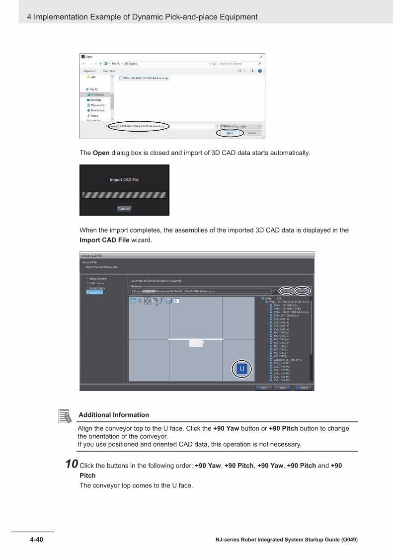
The Open dialog box is closed and import of 3D CAD data starts automatically.
When the import completes, the assemblies of the imported 3D CAD data is displayed in theImport CAD File wizard.
Additional Information
Align the conveyor top to the U face. Click the +90 Yaw button or +90 Pitch button to changethe orientation of the conveyor.If you use positioned and oriented CAD data, this operation is not necessary.
10 Click the buttons in the following order; +90 Yaw, +90 Pitch, +90 Yaw, +90 Pitch and +90PitchThe conveyor top comes to the U face.
4 Implementation Example of Dynamic Pick-and-place Equipment
4-40 NJ-series Robot Integrated System Startup Guide (O049)

11 Select the parts to add for simulation, and click the Next button.
The Import CAD File wizard is closed and the main window is displayed again.
12 Check that CAD Data0 is added under Configurations and Setup - 3D Visualization in theMultiview Explorer.
13 Place the conveyor A in the same manner as in Placing the Robot on the 3D Visualizer onpage 4-32.
4 Implementation Example of Dynamic Pick-and-place Equipment
4-41NJ-series Robot Integrated System Startup Guide (O049)
4-3 Programm
ing and Simulation Procedures
4
4-3-5 Placing 3D Shape D
ata
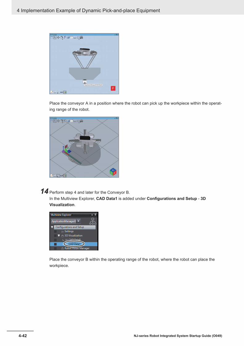
Place the conveyor A in a position where the robot can pick up the workpiece within the operat-ing range of the robot.
14 Perform step 4 and later for the Conveyor B.In the Multiview Explorer, CAD Data1 is added under Configurations and Setup - 3DVisualization.
Place the conveyor B within the operating range of the robot, where the robot can place theworkpiece.
4 Implementation Example of Dynamic Pick-and-place Equipment
4-42 NJ-series Robot Integrated System Startup Guide (O049)
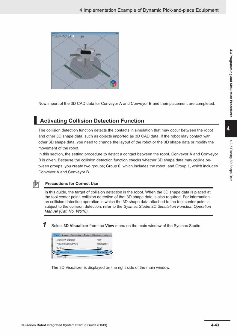
Now import of the 3D CAD data for Conveyor A and Conveyor B and their placement are completed.
Activating Collision Detection FunctionThe collision detection function detects the contacts in simulation that may occur between the robotand other 3D shape data, such as objects imported as 3D CAD data. If the robot may contact withother 3D shape data, you need to change the layout of the robot or the 3D shape data or modify themovement of the robot.In this section, the setting procedure to detect a contact between the robot, Conveyor A and ConveyorB is given. Because the collision detection function checks whether 3D shape data may collide be-tween groups, you create two groups; Group 0, which includes the robot, and Group 1, which includesConveyor A and Conveyor B.
Precautions for Correct Use
In this guide, the target of collision detection is the robot. When the 3D shape data is placed atthe tool center point, collision detection of that 3D shape data is also required. For informationon collision detection operation in which the 3D shape data attached to the tool center point issubject to the collision detection, refer to the Sysmac Studio 3D Simulation Function OperationManual (Cat. No. W618).
1 Select 3D Visualizer from the View menu on the main window of the Sysmac Studio.
The 3D Visualizer is displayed on the right side of the main window.
4 Implementation Example of Dynamic Pick-and-place Equipment
4-43NJ-series Robot Integrated System Startup Guide (O049)
4-3 Programm
ing and Simulation Procedures
4
4-3-5 Placing 3D Shape D
ata
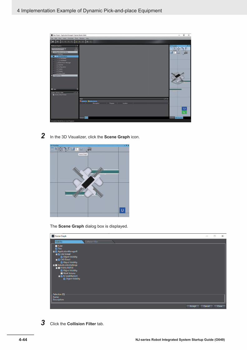
2 In the 3D Visualizer, click the Scene Graph icon.
The Scene Graph dialog box is displayed.
3 Click the Collision Filter tab.
4 Implementation Example of Dynamic Pick-and-place Equipment
4-44 NJ-series Robot Integrated System Startup Guide (O049)

4 Click the + button in the Collision Filter Group Items column for the Collision Filter Group.
A new row with the Collision Filter Group Name set as Group0 is added on the SceneGraph dialog box.
5 Repeat step 4 above.A new row with the Collision Filter Group Name set as Group1 is added on the SceneGraph dialog box.
4 Implementation Example of Dynamic Pick-and-place Equipment
4-45NJ-series Robot Integrated System Startup Guide (O049)
4-3 Programm
ing and Simulation Procedures
4
4-3-5 Placing 3D Shape D
ata

6 Click the ... button in the Collision Filter Group Items column for Group 0 - [0].
The Select a collision filter group item dialog box is displayed.
7 Select new_Controller_0 - RobotControlSettings - Robots - R1iX4_650P30 - Entire Robotin the tree, and then click the Select button.
4 Implementation Example of Dynamic Pick-and-place Equipment
4-46 NJ-series Robot Integrated System Startup Guide (O049)

The Select a collision filter group item dialog box closes and the Scene Graph dialog box isdisplayed again. R1iX4_650P30, Entire Robot is registered in the Collision Filter GroupItems column for Group0 - [0].
8 Click the + button in the Collision Filter Group Items column for Group 0.
4 Implementation Example of Dynamic Pick-and-place Equipment
4-47NJ-series Robot Integrated System Startup Guide (O049)
4-3 Programm
ing and Simulation Procedures
4
4-3-5 Placing 3D Shape D
ata

A new row [1] is added under Group 0.
9 Click the ... button in the Collision Filter Group Items column for Group 0 - [1].
The Select a collision filter group item dialog box is displayed.
4 Implementation Example of Dynamic Pick-and-place Equipment
4-48 NJ-series Robot Integrated System Startup Guide (O049)

10 Select new_Controller_0 - RobotControlSettings - Robots - R1iX4_650P30 - IOEndEffector0 in the tree, and then click the Select button.
The Select a collision filter group item dialog box closes and the Scene Graph dialog box isdisplayed again. IO End effector 0 (R1iX4_650P30) is registered in the Collision FilterGroup Items colimn for Group0 - [1].
11 Click the ... button in the Collision Filter Group Items column of the row whose CollisionFilter Group Name is Group 1 - [0].
4 Implementation Example of Dynamic Pick-and-place Equipment
4-49NJ-series Robot Integrated System Startup Guide (O049)
4-3 Programm
ing and Simulation Procedures
4
4-3-5 Placing 3D Shape D
ata

The Select a collision filter group item dialog box is displayed.
12 Select ApplicationManager0 - 3D Visualization - CAD Data0 from the tree, and then click theSelect button.
The Select a collision filter group item dialog box closes and the Scene Graph dialog box isdisplayed again. CAD Data0 is registered to the Collision Filter Group Items column forGroup 1 - [0].
4 Implementation Example of Dynamic Pick-and-place Equipment
4-50 NJ-series Robot Integrated System Startup Guide (O049)

13 Click the + button in the Collision Filter Group Items column for Group 1.
A new row [1] is added under Group 1.
14 Follow the step 8 to 10 to register CAD Data1 for Group 1 - [1].CAD Data1 is registered to the Collision Filter Group Items column for Group 1 - [1].
4 Implementation Example of Dynamic Pick-and-place Equipment
4-51NJ-series Robot Integrated System Startup Guide (O049)
4-3 Programm
ing and Simulation Procedures
4
4-3-5 Placing 3D Shape D
ata

15 Check that the Valid check boxes are all selected. If there is a check box not selected, click itto select.
16 Click the Accept button.A collision filter configuration is saved.
17 Click the Close button in the Scene Graph dialog box.
4 Implementation Example of Dynamic Pick-and-place Equipment
4-52 NJ-series Robot Integrated System Startup Guide (O049)

The Scene Graph dialog box is closed.
Now, the settings for checking for collision between the robot and Conveyor A, and between the robotand Conveyor B have been completed.
4-3-6 Creating a Pack Manager SampleThis section describes the procedure to create a Pack Manager sample.The operations flow is as follows.
Activating the Robot's Simulation Function
Configuring the Robot
Start
Finish
Configuring the Camera, Conveyor, and Encoder
Selecting a Configuration
Teaching Positions
Additional Settings
Enabling Robot Simulation FunctionEnable the simulation function of the Sysmac Studio.To simulate the operation of the robot, open the project file in EMULATION mode.
4 Implementation Example of Dynamic Pick-and-place Equipment
4-53NJ-series Robot Integrated System Startup Guide (O049)
4-3 Programm
ing and Simulation Procedures
4
4-3-6 Creating a Pack M
anager Sample

If you want to know whether the project file opened on the Sysmac Studio is in EMULATION mode ornot, check the status bar on the main window. When you see [Emulation Mode] Access Level:Engineer on the status bar, the project is opened in EMULATION mode.
If the project is opened in a different mode, click the Enable emulation mode icon on the toolbar tochange to EMULATION mode.
1 In the Multiview Explorer, select new_Controller_0 from the device list.
2 Select Run from the Simulation menu.The screen below is displayed while the simulator is starting.
After this screen is closed, the lower part of the toolbar in the main window turns yellow-green.
4 Implementation Example of Dynamic Pick-and-place Equipment
4-54 NJ-series Robot Integrated System Startup Guide (O049)

Selecting a ConfigurationSelect the configuration of the robot and peripheral devices.Decide whether to use the pallet function, belt encoder, and camera in pick-and-place operation.Details of the features and information on how to select them are given below.In this guide, pick operation uses the belt encoder and camera, and the pallet function is not used.
Letter Opera-tion Function Content
A Pick Pallet You can choose whether the pick position is considered a palette or not.If this function is selected, a workpiece can be picked from each row/column ofthe palette.
B Pick Encoder You can choose whether to use the belt encoder for adjusting the pick position.Select this to pick a workpiece that flows on the belt conveyor.
C Pick Camera You can choose whether to use the camera for adjusting the pick position.Select this to pick a workpiece on the conveyor and the posture of the workpieceis not constant.
D In con-veyance
Camera You can choose whether to adjust the placing position by using the camera in anupward-facing position.Select this to place workpieces in the same orientation on the unloading sideconveyor.
E Place Pallet You can choose whether the placing position is considered a palette or not.If this function is selected, workpieces can be placed in each row/column of thepalette.
F Place Encoder You can choose whether to use the belt encoder for adjusting the placing posi-tion.Select this to place workpieces in an evenly spaced alignment on the unloadingside conveyor.
G Place Camera You can choose whether to use a camera for adjusting the placing position.Select this to place workpieces to fit a particular pattern.
The table below lists the pick configurations.A, B, and C in the table above represent pick operations.
SelectionsConfiguration name
A B CYes Yes Yes No configuration available
Create a Pack Manager sample and change the Process Manager settings by referenc-ing the Sysmac Studio Robot Integrated System Building Function with Robot IntegratedCPU Unit Operation Manual (Cat. No. W595).
Yes Yes None At a pallet located by a belt latch sensorYes None Yes No configuration available
Create a Pack Manager sample and change the Process Manager settings by referenc-ing the Sysmac Studio Robot Integrated System Building Function with Robot IntegratedCPU Unit Operation Manual (Cat. No. W595).
Yes None None At a fixed palletNone Yes Yes On a belt located with a camera
4 Implementation Example of Dynamic Pick-and-place Equipment
4-55NJ-series Robot Integrated System Startup Guide (O049)
4-3 Programm
ing and Simulation Procedures
4
4-3-6 Creating a Pack M
anager Sample

SelectionsConfiguration name
A B CNone Yes None With a fixed mounted cameraNone None Yes With a belt latch sensorNone None None At a fixed position
The table below lists the configurations for correction after picking.D in the table above represents operation after picking.
SelectionsConfiguration name
DYes No, do not refine the position of the part.None Yes, refine the position of the part using a camera.
The table below lists the configurations for placing.E, F, and G in the table above represent placing operations.
SelectionsConfiguration name
E F GYes Yes Yes No configuration available
After creating the Pack Manager sample, refer to Sysmac Studio Robot IntegratedSystem Building Function with Robot Integrated CPU Unit Operation Manual (Cat. No.W595) and change the Process Manager settings.
Yes Yes None At a pallet located by a belt latch sensorYes None Yes No configuration available
After creating the Pack Manager sample, refer to Sysmac Studio Robot IntegratedSystem Building Function with Robot Integrated CPU Unit Operation Manual (Cat. No.W595) and change the Process Manager settings.
Yes None None At a fixed palletNone Yes Yes On a belt located with a cameraNone Yes None With a fixed mounted cameraNone None Yes With a belt latch sensorNone None None At a fixed position
1 Click new_Controller_0 from the device list in the Multiview Explorer of the Sysmac Studio.
2 Select Application Sample - Pack Manager Sample from the Insert menu on the main win-dow of the Sysmac Studio.
4 Implementation Example of Dynamic Pick-and-place Equipment
4-56 NJ-series Robot Integrated System Startup Guide (O049)

Precautions for Correct Use
If the configuration of the Pack Manager Sample is not completed until the last teaching or it iscanceled, you need to start over from the first step of the flow to create the Pack ManagerSample. If ApplicationManager1 has been registered in the device list of the Multiview Explor-er through the execution of the Pack Manager sample, delete ApplicationManager1 oncewith the Delete key and start the procedure again.
Pick and Place Sequence: Select Configuration dialog box is displayed.
3 Click the Next button at the bottom right of the dialog box.
4 Implementation Example of Dynamic Pick-and-place Equipment
4-57NJ-series Robot Integrated System Startup Guide (O049)
4-3 Programm
ing and Simulation Procedures
4
4-3-6 Creating a Pack M
anager Sample
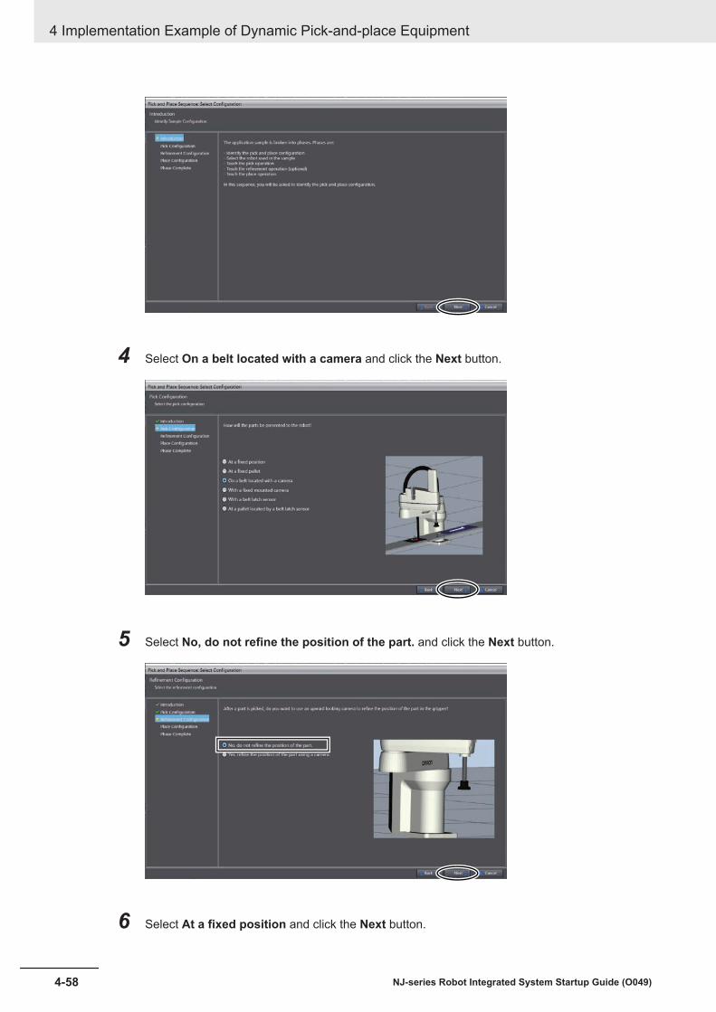
4 Select On a belt located with a camera and click the Next button.
5 Select No, do not refine the position of the part. and click the Next button.
6 Select At a fixed position and click the Next button.
4 Implementation Example of Dynamic Pick-and-place Equipment
4-58 NJ-series Robot Integrated System Startup Guide (O049)

7 Click the Finish button.
The dialog box closes and Pick and Place Sequence: Phase 1/3 - Select Robot dialog box isdisplayed.
Configuring the RobotIn this section, select the robot and end effector to use for the Pack Manager and teach the wait posi-tions.
1 In the Introduction page, click the Next button.
4 Implementation Example of Dynamic Pick-and-place Equipment
4-59NJ-series Robot Integrated System Startup Guide (O049)
4-3 Programm
ing and Simulation Procedures
4
4-3-6 Creating a Pack M
anager Sample

2 In the Select Robot page, confirm that R1iX4_650P30 is selected and click the Next button.
3 In the Select the End-Effector page, confirm that IO EndEffector0 is selected and click theNext button.
4 Implementation Example of Dynamic Pick-and-place Equipment
4-60 NJ-series Robot Integrated System Startup Guide (O049)

4 The Robot Power ON dialog box may appear. In that case, click the Power button and selectthe Next button at the bottom right of the dialog box.
5 Register the signal number of the robot built-in I/Os which are used to control the vacuum pad.Enter the value -4001 to Open and 4001 to Close in the Outputs field of the Digital I/OSignals. They are Open signals of the solenoid valve that was allocated in V+Digital I/O onpage 4-7.
6 Set 50mm as the offset value from the TCP to the vacuum pad tip in the Z direction. Enter0.000 0.000 50.000 0.000 0.000 0.000 in the Tool Offset.
4 Implementation Example of Dynamic Pick-and-place Equipment
4-61NJ-series Robot Integrated System Startup Guide (O049)
4-3 Programm
ing and Simulation Procedures
4
4-3-6 Creating a Pack M
anager Sample
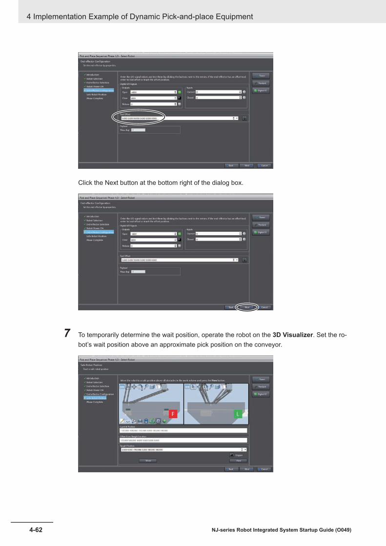
Click the Next button at the bottom right of the dialog box.
7 To temporarily determine the wait position, operate the robot on the 3D Visualizer. Set the ro-bot’s wait position above an approximate pick position on the conveyor.
4 Implementation Example of Dynamic Pick-and-place Equipment
4-62 NJ-series Robot Integrated System Startup Guide (O049)

Precautions for Correct Use
If the wait position is specified out of the belt window set in Configuring the Camera, Conveyor,and Encoder on page 4-65, a belt window violation error will occur during tracking and thetracking will fail. Assume the approximate position of the belt window, and determine the waitposition above the position that fits within the belt window.
After completing the tentative setting of the wait position, proceed to the next step.
8 Click the Here button at the bottom right of the dialog box.
The value in the Taught Position is changed to the value of the current position.
9 Click the Next button at the bottom right of the dialog box.
4 Implementation Example of Dynamic Pick-and-place Equipment
4-63NJ-series Robot Integrated System Startup Guide (O049)
4-3 Programm
ing and Simulation Procedures
4
4-3-6 Creating a Pack M
anager Sample

10 Click the Finish button at the bottom right of the dialog box.
Pick and Place Sequence: Phase 1/3 - Select Robot dialog box closes and PickConfiguration dialog box pops up.
4 Implementation Example of Dynamic Pick-and-place Equipment
4-64 NJ-series Robot Integrated System Startup Guide (O049)

Configuring the Camera, Conveyor, and Encoder
1 Click the Next button at the bottom right of the dialog box.
2 In the Application Manager Settings dialog box, confirm that the IP Address is set to127.0.0.1 and click the Next button.
3 In the system configuration of this guide, the 24114 Basler camera is used. Make sure thatBasler Camera is selected and click the Next button at the bottom right of the dialog box.
4 Implementation Example of Dynamic Pick-and-place Equipment
4-65NJ-series Robot Integrated System Startup Guide (O049)
4-3 Programm
ing and Simulation Procedures
4
4-3-6 Creating a Pack M
anager Sample

4 Click the Next button at the bottom right of the dialog box.
5 Select a row for the encoder 0 from the list as determined in this guide. Encoder No. 1 of thewiring connector corresponds to encoder 0 on this dialog box.For information on wiring, refer to the 4-4-8 Wiring the Robot and Encoder on page 4-98.
4 Implementation Example of Dynamic Pick-and-place Equipment
4-66 NJ-series Robot Integrated System Startup Guide (O049)

6 Click the Next button at the bottom right of the dialog box.
7 Allocate the operation signals of the conveyor, assigned by V+ Digital I/O Settings in this guide.Enter values in the On/Off, Fast/Slow, and Reverse/Forward fields in the center of the win-dow.Set 2001 to On/Off, 2002 to Fast/Slow, and 2003 to Reverse/Forward.For allocation of V+ digital I/Os, refer to V+Digital I/O on page 4-7.
4 Implementation Example of Dynamic Pick-and-place Equipment
4-67NJ-series Robot Integrated System Startup Guide (O049)
4-3 Programm
ing and Simulation Procedures
4
4-3-6 Creating a Pack M
anager Sample

8 Click the Next button at the bottom right of the dialog box.
9 Determine the position of the conveyor, Upstream Limit, Pick Limit, Downstream Limit,and Belt Width.
A B C
Conveyor A
Convey B
Camera
Encoder
WorkpieceWorkpiece
4 Implementation Example of Dynamic Pick-and-place Equipment
4-68 NJ-series Robot Integrated System Startup Guide (O049)

Letter Item DescriptionA Upstream
LimitThe limit position upstream of the conveyor to make a pick operation.The robot does not pick at the conveyor position upstream from the UpstreamLimit.
B Pick Limit The reference limit position downstream of the conveyor to make a pick opera-tion.When the placement is completed, the robot specifies the next workpiece to pickand calculates the pick position. At that time, workpieces that exist downstreamfrom the Pick Limit are excluded from the pick target.
C Down-stream Lim-it
The limit position downstream of the conveyor to make pick operation.The robot does not pick at the conveyor position downstream from theDownstream Limit.
You can set the points by a drag and drop operation on the 3D Visualizer or by directly enteringdata in numeric entry fields of Belt Control. Set the points in either way.
• Dragging and Dropping on the 3D VisualizerRefer to A-2 How to Use 3D Visualizer on page A-21 and the Sysmac Studio RobotIntegrated System Building Function with IPC Application Controller Operation Manual (Cat.No. W621) for operation procedure of the 3D Visualizer.The conveyor can be moved by dragging and dropping the green, red, and blue arrows.
The Upstream Limit is the position indicated by the purple point and the green arrow (originof Belt Transformation and Y-axis).The Pick Limit is indicated by a purple line and the Downstream Limit by a blue line. ThePick Limit and Downstream Limit can be moved by dragging and dropping the yellow ar-row.
4 Implementation Example of Dynamic Pick-and-place Equipment
4-69NJ-series Robot Integrated System Startup Guide (O049)
4-3 Programm
ing and Simulation Procedures
4
4-3-6 Creating a Pack M
anager Sample

Position them within the operating range of the robot.
Pick Limit Downstream Limit
The belt width can be changed with the yellow arrow indicated in the frame in the figure be-low.
• Directly entering data in the fields of Belt Control
The Upstream Limit is the same point as the origin of Belt Transform. Therefore, enter off-set distance from the world coordinate in the input fields of Belt Transformation.Enter relative distance from the Upstream Limit in mm to Pick Limit and DownstreamLimit input fields.Input Belt Width to the Belt Window Width input field in mm.Enter the value of encoder scale (mm/encoder) in the Encoder Scale input field.
10 Click the Next button at the bottom right of the dialog box.
4 Implementation Example of Dynamic Pick-and-place Equipment
4-70 NJ-series Robot Integrated System Startup Guide (O049)

11 Click the ON/OFF button to turn it ON, and then click the Start Tracking button to check thatthe robot can successfully track along the conveyor. If no problem was found, click the Nextbutton at the bottom right of the dialog box.
12 Make sure that the right latch number has been selected , and then click the Next button.
4 Implementation Example of Dynamic Pick-and-place Equipment
4-71NJ-series Robot Integrated System Startup Guide (O049)
4-3 Programm
ing and Simulation Procedures
4
4-3-6 Creating a Pack M
anager Sample
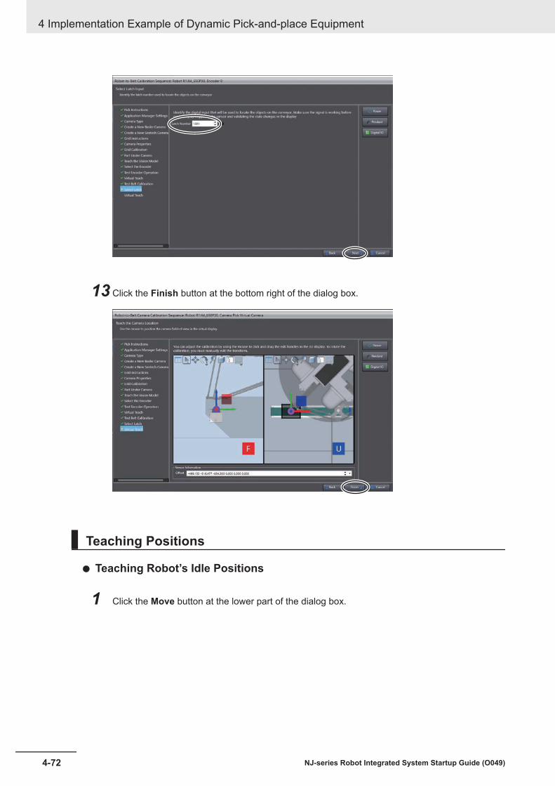
13 Click the Finish button at the bottom right of the dialog box.
Teaching Positions
Teaching Robot’s Idle Positions
1 Click the Move button at the lower part of the dialog box.
4 Implementation Example of Dynamic Pick-and-place Equipment
4-72 NJ-series Robot Integrated System Startup Guide (O049)

The robot moves to the robot’s idle position.
2 Adjust it to a position from where the robot can be moved to the pick and place positions inlinear interpolation. After the adjustment, click the Here button.
3 Click the Next button at the bottom right of the dialog box.
4 Implementation Example of Dynamic Pick-and-place Equipment
4-73NJ-series Robot Integrated System Startup Guide (O049)
4-3 Programm
ing and Simulation Procedures
4
4-3-6 Creating a Pack M
anager Sample
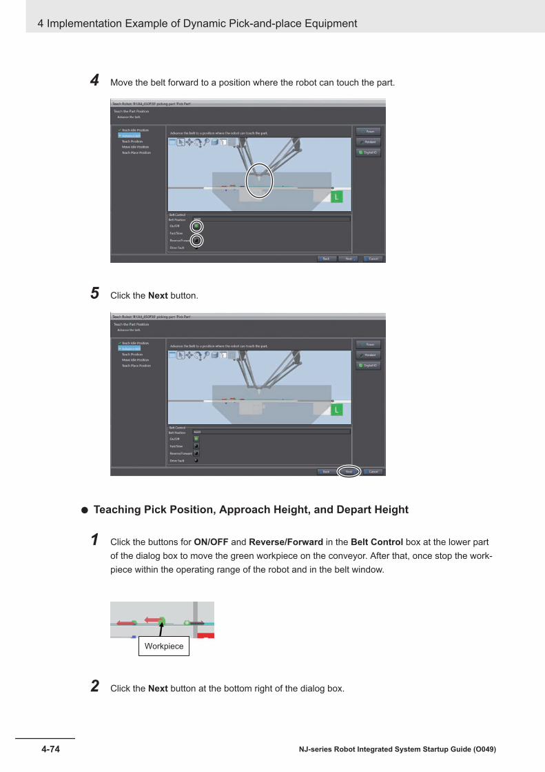
4 Move the belt forward to a position where the robot can touch the part.
5 Click the Next button.
Teaching Pick Position, Approach Height, and Depart Height
1 Click the buttons for ON/OFF and Reverse/Forward in the Belt Control box at the lower partof the dialog box to move the green workpiece on the conveyor. After that, once stop the work-piece within the operating range of the robot and in the belt window.
Workpiece
2 Click the Next button at the bottom right of the dialog box.
4 Implementation Example of Dynamic Pick-and-place Equipment
4-74 NJ-series Robot Integrated System Startup Guide (O049)

3 Click the Move button at the lower part of the dialog box.
The robot moves so that the tool center point is at the lowermost part of the workpiece on theconveyor.
4 Move the robot in the Z-axis direction so that the end-effector tip is on the top of the workpiece.
4 Implementation Example of Dynamic Pick-and-place Equipment
4-75NJ-series Robot Integrated System Startup Guide (O049)
4-3 Programm
ing and Simulation Procedures
4
4-3-6 Creating a Pack M
anager Sample

5 Click the Here button.
6 Enter the elevation distance that the robot moves to or moves from the workpiece pick-up posi-tion in the Approach Height and Depart Height input fields of Taught Position.
Check the operation by moving the robot to the set heights by pressing the Approach andDepart buttons.
4 Implementation Example of Dynamic Pick-and-place Equipment
4-76 NJ-series Robot Integrated System Startup Guide (O049)
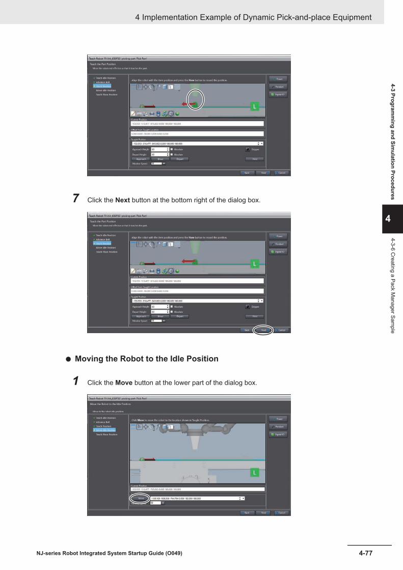
7 Click the Next button at the bottom right of the dialog box.
Moving the Robot to the Idle Position
1 Click the Move button at the lower part of the dialog box.
4 Implementation Example of Dynamic Pick-and-place Equipment
4-77NJ-series Robot Integrated System Startup Guide (O049)
4-3 Programm
ing and Simulation Procedures
4
4-3-6 Creating a Pack M
anager Sample

When the robot moves to the idle position, click the Next button at the bottom right of the dia-log box.
Teaching Place Position, Approach Height, and Depart Height
1 Operate the robot in the 3D Visualizer and move it to the workpiece place position on the con-vener.If the tool center point and the conveyor come into contact, the outlines of the tool center pointand conveyor are highlighted. Determine the place position with reference to the highlighting.
When the tool tip and the conveyor come into contact, outlines of them are highlighted.
2 Click the Here button at the bottom right of the dialog box.
4 Implementation Example of Dynamic Pick-and-place Equipment
4-78 NJ-series Robot Integrated System Startup Guide (O049)

The values of the current position is set to the Taught Position box. If you want to fine tunethe taught position, modify the value in the Taught Position and click the Move button to movethe robot.
3 Enter the elevation distance of the workpiece place approach point in the Approach Heightand Depart Height input fields of Taught Position.
Check the operation by moving the robot to the set heights by pressing the Approach andDepart buttons.
4 Implementation Example of Dynamic Pick-and-place Equipment
4-79NJ-series Robot Integrated System Startup Guide (O049)
4-3 Programm
ing and Simulation Procedures
4
4-3-6 Creating a Pack M
anager Sample

4 Click the Finish button at the bottom right of the dialog box.
Teaching dialog box closes and ApplicationManager1 is added to the drop-down list of theMultiview Explorer.
Additional Settings
Setting for Active ControlTo activate the conveyor control from the Pack Manager, perform the following.
4 Implementation Example of Dynamic Pick-and-place Equipment
4-80 NJ-series Robot Integrated System Startup Guide (O049)

1 In the Multiview Explorer, select ApplicationManager1 from the device list.
2 Select Configurations and Setup - Processes in the Multiview Explorer and double-clickPick Belt.
3 Select the Active Control check box for Belt Control.
4-3-7 Creating C# ProgramsThis section describes the procedure to create C# programs. For details on the program to create, re-fer to C# Programs on page 4-10.
1 In the Multiview Explorer, select ApplicationManager1 from the device list.
4 Implementation Example of Dynamic Pick-and-place Equipment
4-81NJ-series Robot Integrated System Startup Guide (O049)
4-3 Programm
ing and Simulation Procedures
4
4-3-7 Creating C
# Programs

2 Right-click Programs under Programming in the Multiview Explorer.The menu commands are displayed.
3 From the menu, select Add - C# Program.
A new program C# Program0 is added under Programs.
4 Right-click the C# Program0 and select Rename from the menu.
This allows you to edit the name of the C# Program0.
5 Enter PM_Start for the program name and press the Enter key.The name of the C# program is changed to "PM_Start".
6 Double-click the program that was added.
4 Implementation Example of Dynamic Pick-and-place Equipment
4-82 NJ-series Robot Integrated System Startup Guide (O049)

A tab page to edit the program is displayed in the Edit Pane.
7 Repeat the operations from step 3 to step 6 to create the programs PM_Start and PM_Stopdescribed in C# Programs on page 4-10.
Precautions for Correct Use
The contents of the text string that represents the Process Manager in each C# program differdepending on the language of OS used when you created the project file. SelectApplicationManager1 from the device list in the Multiview Explorer, and then selectConfigurations and Setup - Process - Process Manager. Drag and drop it onto the C# editor,and an appropriate text string is automatically entered.
4-3-8 Setting up Automatic Loading of V+ Programs and Variables atPower ON
The V+ programs that you created and V+ global variables are not automatically loaded to the RobotIntegrated CPU Unit by default settings of the project when power to the Robot Integrated CPU Unit isturned ON.This section describes the setting procedure for automatically loading the V+ programs and V+ globalvariables to the Robot Integrated CPU Unit when its power is turned ON.
1 Select RobotControlSettings from the device list in the Multiview Explorer.
4 Implementation Example of Dynamic Pick-and-place Equipment
4-83NJ-series Robot Integrated System Startup Guide (O049)
4-3 Programm
ing and Simulation Procedures
4
4-3-8 Setting up Automatic Loading of V+ Program
s and Variables at Power O
N
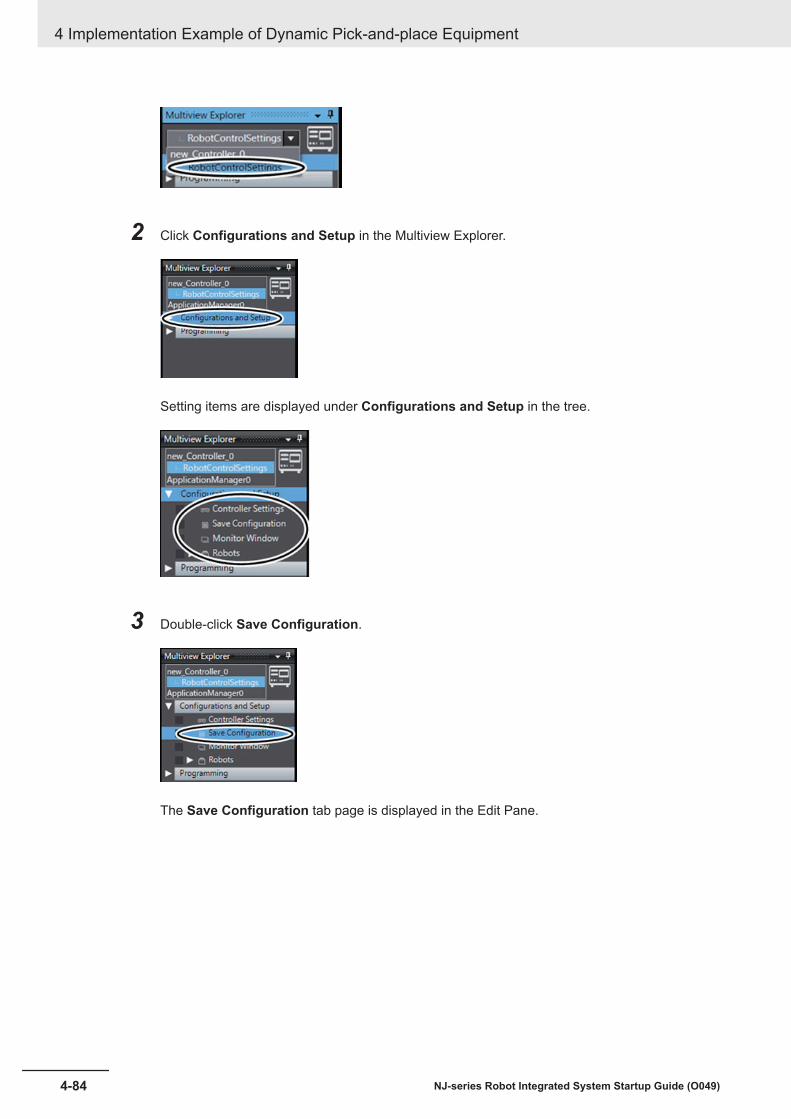
2 Click Configurations and Setup in the Multiview Explorer.
Setting items are displayed under Configurations and Setup in the tree.
3 Double-click Save Configuration.
The Save Configuration tab page is displayed in the Edit Pane.
4 Implementation Example of Dynamic Pick-and-place Equipment
4-84 NJ-series Robot Integrated System Startup Guide (O049)
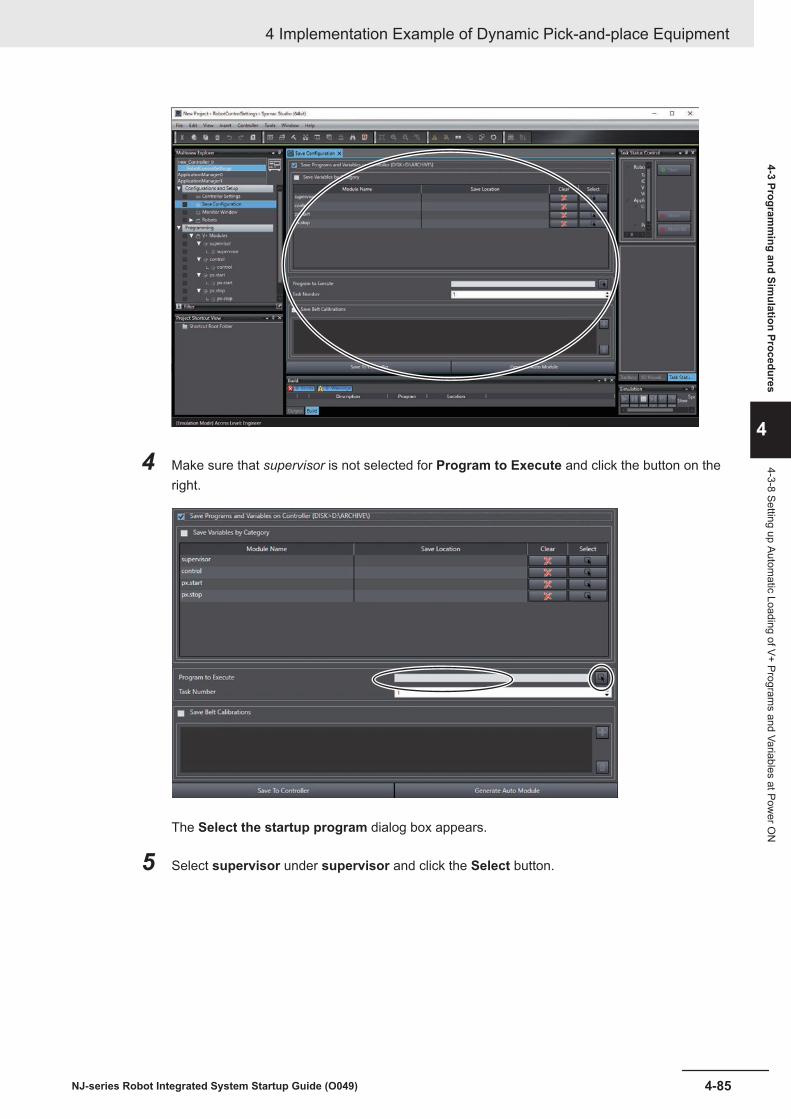
4 Make sure that supervisor is not selected for Program to Execute and click the button on theright.
The Select the startup program dialog box appears.
5 Select supervisor under supervisor and click the Select button.
4 Implementation Example of Dynamic Pick-and-place Equipment
4-85NJ-series Robot Integrated System Startup Guide (O049)
4-3 Programm
ing and Simulation Procedures
4
4-3-8 Setting up Automatic Loading of V+ Program
s and Variables at Power O
N

6 Enter 2 to Task Number.
7 Click the Generate Auto Module button in the Save Configuration tab page.
The module name auto is added to the module list in the Save Configuration tab page. In thetree of the Multiview Explorer, V+ Modules - auto are added under Programming.
4 Implementation Example of Dynamic Pick-and-place Equipment
4-86 NJ-series Robot Integrated System Startup Guide (O049)

8 Click File - Save from the menu bar.
The Robot Integrated CPU Unit is now configured to automatically load the V+ programs and V+ glob-al variables when it is powered ON. The program auto starts automatically when the Robot IntegratedCPU Unit is powered ON and reads the saved V+ programs and V+ global variables.
The program auto is created in a form called command program, which is different from the V+ pro-gram. For details about the command program, refer to the eV+3 User's Manual (Cat. No. I651).
4-3-9 Executing Program to Check OperationThis section describes the procedure to run and simulate the sequence control program created in 4-3-4 Writing a Sequence Control Program on page 4-23.You can run the program by changing the global variable gStart in the sequence control program fromFALSE to TRUE in the Watch Tab Page.The V+ program is called from the sequence control program executed in this procedure.
Precautions for Correct Use
When you perform this procedure, check that the project file has been opened in EMULATIONmode. Refer to Enabling Robot Simulation Function on page 3-65 for the checking procedure.
4 Implementation Example of Dynamic Pick-and-place Equipment
4-87NJ-series Robot Integrated System Startup Guide (O049)
4-3 Programm
ing and Simulation Procedures
4
4-3-9 Executing Program to C
heck Operation
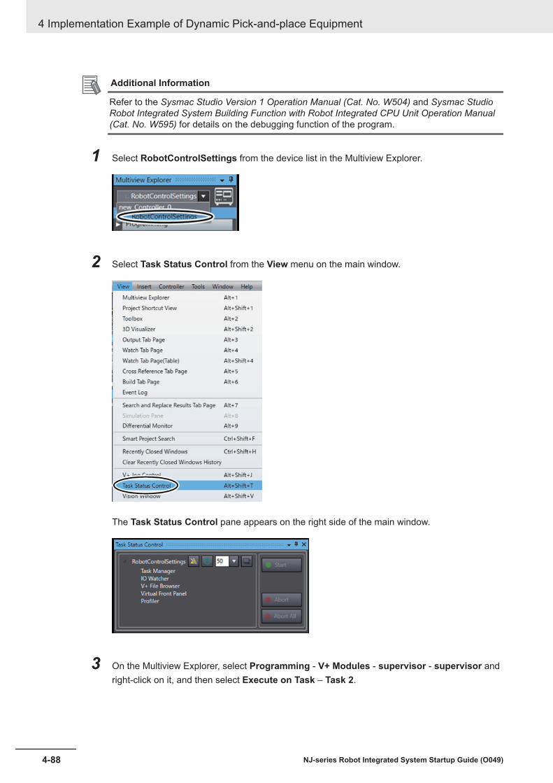
Additional Information
Refer to the Sysmac Studio Version 1 Operation Manual (Cat. No. W504) and Sysmac StudioRobot Integrated System Building Function with Robot Integrated CPU Unit Operation Manual(Cat. No. W595) for details on the debugging function of the program.
1 Select RobotControlSettings from the device list in the Multiview Explorer.
2 Select Task Status Control from the View menu on the main window.
The Task Status Control pane appears on the right side of the main window.
3 On the Multiview Explorer, select Programming - V+ Modules - supervisor - supervisor andright-click on it, and then select Execute on Task – Task 2.
4 Implementation Example of Dynamic Pick-and-place Equipment
4-88 NJ-series Robot Integrated System Startup Guide (O049)

The V+ program supervisor starts to run in Task 2 and the control launches in Task 3.
4 In the Multiview Explorer, select new_Controller_0 from the device list.
5 Select 3D Visualizer from the View menu on the main window of the Sysmac Studio.
4 Implementation Example of Dynamic Pick-and-place Equipment
4-89NJ-series Robot Integrated System Startup Guide (O049)
4-3 Programm
ing and Simulation Procedures
4
4-3-9 Executing Program to C
heck Operation
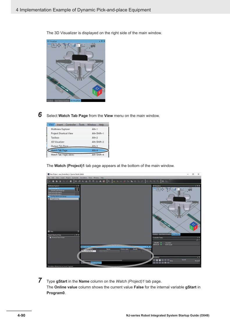
The 3D Visualizer is displayed on the right side of the main window.
6 Select Watch Tab Page from the View menu on the main window.
The Watch (Project)1 tab page appears at the bottom of the main window.
7 Type gStart in the Name column on the Watch (Project)1 tab page.The Online value column shows the current value False for the internal variable gStart inProgram0.
4 Implementation Example of Dynamic Pick-and-place Equipment
4-90 NJ-series Robot Integrated System Startup Guide (O049)

8 Click the TRUE button in the Modify column for the variable gStart in the Watch (Project)1tab page.
The robot starts operating and picks the part in the 3D Visualizer.
The robot moves to the workpiece pick position and picks the workpiece.
After that, the robot moves to the robot wait position via the workpiece place position, and per-forms pick and place operation repeatedly.
The robot moves to the workpiece place position to place the workpiece, and then goes to the position for picking up the next workpiece via the robot wait position.
During operation, check that the robot does not turn gray in locations other than the workpiecepick-up position and workpiece place position. If the color changes to gray, the robot and theconveyor are interfering with each other. In that case, refer to Teaching Pick Position, Ap-proach Height, and Depart Height on page 4-74 and move the workpiece pick-up approachpoint or the workpiece place approach point to a higher position by teaching.
4 Implementation Example of Dynamic Pick-and-place Equipment
4-91NJ-series Robot Integrated System Startup Guide (O049)
4-3 Programm
ing and Simulation Procedures
4
4-3-9 Executing Program to C
heck Operation

When the highlight color of the robot and end-effector changes to gray during the transportation, the robot or end-effector is in contact with the conveyor. Modify the ascending and descending distance.
Now you can run the sequence control program on the actual equipment.
4 Implementation Example of Dynamic Pick-and-place Equipment
4-92 NJ-series Robot Integrated System Startup Guide (O049)

4-4 Installing and Wiring the SystemIn the system configuration, you must wire the signal lines covered in the colored areas in the figurebelow and set the node address of the robot.• Wiring between the Robot Integrated CPU Unit (A), EtherCAT Digital I/O Terminal (O), EtherCAT
communications unit of the Inverter (T), and robot (X)• Wiring between the Robot Integrated CPU Unit (A), industrial Ethernet switch (D), computer (F), and
IPC Application Controller (H).• Wiring between the robot (X), T20 pendant (Y), front panel (AA), and encoder (AD)• Wiring between the IPC Application Controller (H), display (J), and camera (L).• Wiring between the EtherCAT Digital I/O Terminal (O) and robot (C)• Wiring between the camera (L) and robot (X)• Wiring between the EtherCAT Digital I/O Terminal (O) and solenoid valve (P)
(P)
(G)(C)
(B) (A)
(S)
(W)
(X)(Z)
(T) (U)
(D)
(R)(O)(N)
(M)
(Q)
(F) (H) (J)
(I)
(L)
(K)
100 to 240 VAC
85 to 264 VAC 6.5A
85 to 264 VAC 6A
Single-phase, 200 to 240 VAC, 10A
Connect an encoder for another
conveyor to this side.
XMCP
XFP
XUSR
DB15m
Force/EXPIO
RS-232C
*1
(E)
(V)
(Y)
(AA)
(AB)
(AC)
(AG)
(AH)
(AI)
(AJ)
(AK)
(AL)
(AE) (AD)(AF)
Refer to 1-5 System Configuration for Dynamic Pick-and-place Equipment on page 1-8 for informationon the parts used in the system configuration.Refer to the manual for the specific product for details on power lines not covered in the colored areaas well as for ducting from the robot.
4 Implementation Example of Dynamic Pick-and-place Equipment
4-93NJ-series Robot Integrated System Startup Guide (O049)
4-4 Installing and Wiring the System
4
4-4-1 Wiring the R
obot Integrated CPU
Unit and the EtherC
AT Digital I/O
Terminal

4-4-1 Wiring the Robot Integrated CPU Unit and the EtherCAT DigitalI/O Terminal
You must wire the Robot Integrated CPU Unit and the EtherCAT Digital I/O Terminal.
1 Connect the EtherCAT port of the Robot Integrated CPU Unit and the EtherCAT IN port of theEtherCAT Digital I/O Terminal with an Ethernet cable.
4-4-2 Setting the Node Address of the EtherCAT Digital I/O TerminalYou must set the EtherCAT node address of the EtherCAT Digital I/O Terminal.
1 Use the switches on the EtherCAT Digital I/O Terminal to set the EtherCAT node address.To set the node address to 1, set the x10 switch to 0 and the x1 switch to 1.
Node address setting (×10)
Node address setting (×1)
0 1
23
456
78
90 1
23
456
78
9
Precautions for Correct Use
Set the EtherCAT node address of the EtherCAT Digital I/O Terminal to be the same as thenode address set in 3-3-2 Creating the EtherCAT Network Configuration on page 3-20.
4 Implementation Example of Dynamic Pick-and-place Equipment
4-94 NJ-series Robot Integrated System Startup Guide (O049)

4-4-3 Wiring the EtherCAT Digital I/O Terminal and Inverter’s EtherCATCommunications Unit
Wire the EtherCAT Digital I/O Terminal and EtherCAT Communications Unit of the Inverter.
1 Connect the EtherCAT OUT port of the EtherCAT Digital I/O Terminal and the EtherCATIN port on the EtherCAT Communications Unit with an Ethernet cable.
Communications
connector (IN)
Communications
connector (OUT)
4-4-4 Setting the Node Address of Inverter’s EtherCAT Communica-tions Unit
This section describe the settings of the EtherCAT node address of the EtherCAT CommunicationsUnit of the inverter.
1 Set the switches for the EtherCAT node address on the EtherCAT Communications Unit of theinverter.To set the node address to 2, set the x10 switch to 0 and the x1 switch to 2.
Node address setting (x1)
Node address setting (x10)
Precautions for Correct Use
Set the EtherCAT node address of the inverter to be the same as the node address set in 3-3-2 Creating the EtherCAT Network Configuration on page 3-20.
4-4-5 Wiring the Inverter’s EtherCAT Communications Unit and RobotIn this section, wire the EtherCAT communications unit of the inverter and the robot.
4 Implementation Example of Dynamic Pick-and-place Equipment
4-95NJ-series Robot Integrated System Startup Guide (O049)
4-4 Installing and Wiring the System
4
4-4-3 Wiring the EtherC
AT Digital I/O
Terminal and Inverter’s EtherC
AT Com
munications U
nit

1 Connect the EtherCAT OUT port of the EtherCAT Communications Unit and the EtherCAT INport on the interface panel of the robot with an Ethernet cable.
Communications
connector (IN)
Communications
connector (OUT)
Precautions for Correct Use
Refer to the NJ/NX-series CPU Unit Built-in EtherCAT Port User’s Manual (Cat. No. W505) fordetails on the Ethernet cable to be used.
4-4-6 Setting the EtherCAT Node Address of the RobotSet the EtherCAT node address of the robot.
1 Set the EtherCAT node address with the switches on the interface panel of the robot.To set the node address to 3, set the x256 switch to OFF, the x16 switch to 0, and the x1 switchto 3.
Precautions for Correct Use
Set the EtherCAT node address of the robot to be the same as the node address set in 4-3-2 Creating the EtherCAT Network Configuration on page 4-16.
Refer to the manual for your robot on how to set the node address.
4-4-7 Wiring the Robot, T20 Pendant and the Front PanelYou must wire the robot and the T20 pendant, as well as the robot and the front panel. Use an XSYS-TEM cable assembly, a T20 adapter cable, and a front panel cable for wiring.
1 Connect the robot and the XSYSTEM cable assembly.
4 Implementation Example of Dynamic Pick-and-place Equipment
4-96 NJ-series Robot Integrated System Startup Guide (O049)

2 Connect the XMCP connector (Red) of the XSYSTEM cable assembly and the T20 adapter ca-ble.
3 Connect the T20 adapter cable to the T20 pendant.
4 Connect the XFP connector (Green) of the XSYSTEM cable assembly and the front panel ca-ble.
5 Connect the front panel cable and the front panel.
4 Implementation Example of Dynamic Pick-and-place Equipment
4-97NJ-series Robot Integrated System Startup Guide (O049)
4-4 Installing and Wiring the System
4
4-4-7 Wiring the R
obot, T20 Pendant and the Front Panel

4-4-8 Wiring the Robot and EncoderWire the robot and the encoder. Use a XBELTIO cable, a Y-adapter cable, and an encoder extensioncable for wiring.
1 Connect the XBELTIO cable to the robot.
2 Connect the XBELTIO cable’s DB connector and the Y-adapter cable.
3 Connect the encoder extension cable to the connector labeled [1] of the Y-adapter cable.
4 Implementation Example of Dynamic Pick-and-place Equipment
4-98 NJ-series Robot Integrated System Startup Guide (O049)
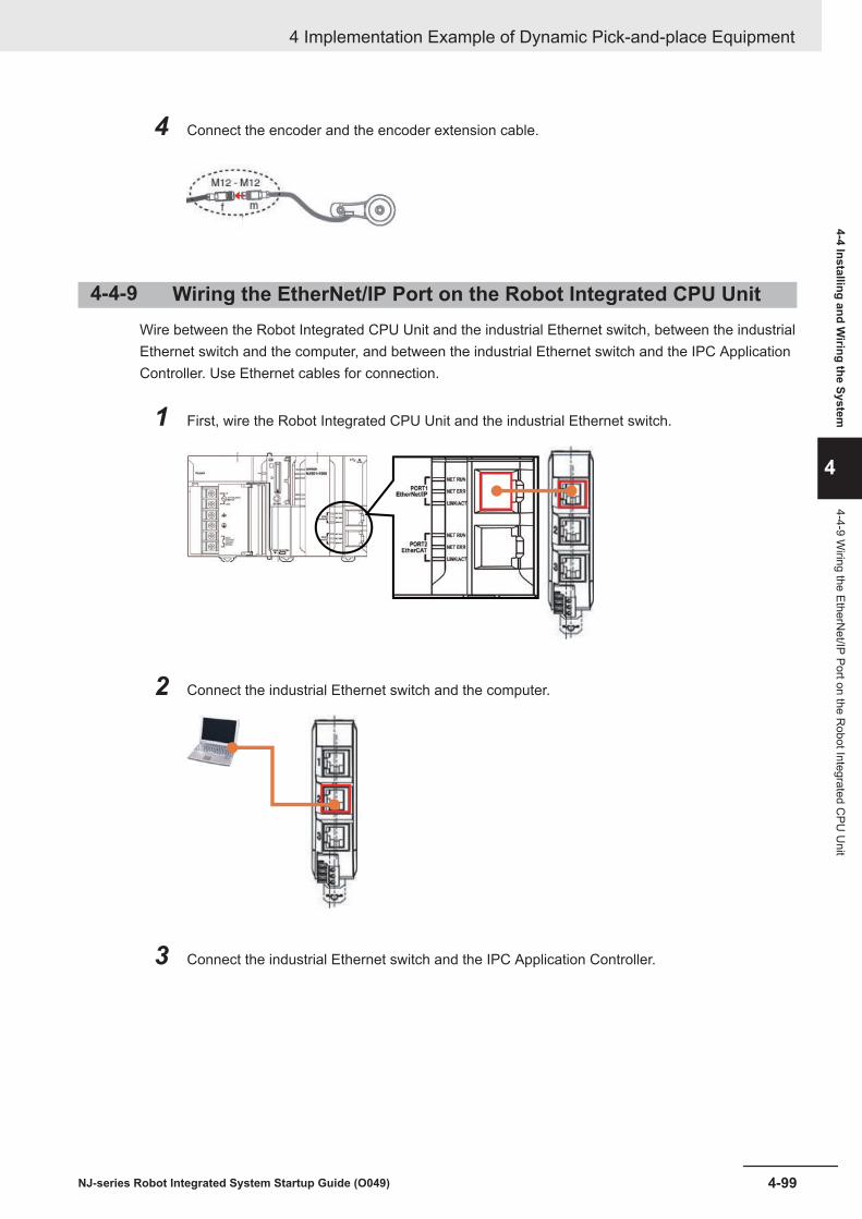
4 Connect the encoder and the encoder extension cable.
4-4-9 Wiring the EtherNet/IP Port on the Robot Integrated CPU UnitWire between the Robot Integrated CPU Unit and the industrial Ethernet switch, between the industrialEthernet switch and the computer, and between the industrial Ethernet switch and the IPC ApplicationController. Use Ethernet cables for connection.
1 First, wire the Robot Integrated CPU Unit and the industrial Ethernet switch.
2 Connect the industrial Ethernet switch and the computer.
3 Connect the industrial Ethernet switch and the IPC Application Controller.
4 Implementation Example of Dynamic Pick-and-place Equipment
4-99NJ-series Robot Integrated System Startup Guide (O049)
4-4 Installing and Wiring the System
4
4-4-9 Wiring the EtherN
et/IP Port on the Robot Integrated C
PU U
nit

4-4-10 Wiring Between the IPC Application Controller, Display, andCamera
Wire between the IPC Application Controller and the display, and between the IPC Application Control-ler and the camera. Use a DVI cable and a camera cable for wiring.
1 Connect the DVI ports on the IPC Application Controller and the display with a DVI cable.
Precautions for Correct Use
Refer to the IPC Application Controller User’s Manual (Cat. No. I632) for information on the DVIcable.
2 Connect the PoE ports on the IPC Application Controller and the camera with a camera cable.
4-4-11 Wiring the Camera and RobotWire the camera and the robot. Use a power I/O cable and a XIO breakout cable for wiring.
1 Connect the camera and the power I/O cable.
4 Implementation Example of Dynamic Pick-and-place Equipment
4-100 NJ-series Robot Integrated System Startup Guide (O049)

2 Wire the power I/O cable and the XIO breakout cable. Make a connector or relay with a termi-nal block as shown in the following wiring diagram.
XIO breakout cable
Power I/O cable
Yellow
Red/black
White/black
Gray
Red
White
3 Connect the XIO breakout cable and the robot.
Precautions for Correct Use
Refer to Configuring the Camera, Conveyor, and Encoder on page 4-65 for the installation loca-tion of the camera. You must install the camera between the upstream limit set by the softwareand the entrance of the conveyor.
4-4-12 Wiring the EtherCAT Digital I/O Terminal and Solenoid ValveYou must wire the EtherCAT Digital I/O Terminal and the solenoid valve.Refer to the manuals for the EtherCAT Digital I/O Terminal and the solenoid valve for details on thecable wiring, and make the cable appropriately in accordance with the wiring diagrams and specifica-tions.
1 Make the cable so that the solenoid valve will behave as shown in the table below.
4 Implementation Example of Dynamic Pick-and-place Equipment
4-101NJ-series Robot Integrated System Startup Guide (O049)
4-4 Installing and Wiring the System
4
4-4-12 Wiring the EtherC
AT Digital I/O
Terminal and Solenoid Valve

Output value of Digital I/O Terminal Solenoid valve behaviorFALSE Duct is closedTRUE Duct is open
2 Wire the EtherCAT Digital I/O Terminal and the solenoid valve.
Solenoid valve
4 Implementation Example of Dynamic Pick-and-place Equipment
4-102 NJ-series Robot Integrated System Startup Guide (O049)

4-5 Operation Check on the Actual Sys-tem
This section describes the procedures for checking operation and adjusting the system on the actualsystem.Check operation with the simulation function before you check operation on the actual system.
Precautions for Correct Use
When you operate the robot in MANUAL mode with the T20 pendant, you must plug the iCSCommissioning Jumper into the XBELTIO connector and change the setting for the Teach Re-strict. Refer to iX4 650 H/HS and 800 H/HS Robot with EtherCAT User’s Guide (Cat. No. I656)for details.
4-5-1 Communications Setup
Setting Up Sysmac Studio to Communicate with the Robot Integrat-ed CPU Unit
Set up Sysmac Studio installed on your PC to communicate with the Robot Integrated CPU Unit.In this section, IP address of the EtherNet/IP port on the Robot Integrated CPU Unit to connect to thecomputer is set to 192.168.250.1.Also set the IP address of the camera to the IPC Application Controller in advance. For procedure toset the IP address of the camera to the IPC Application Controller, refer to Appendix A of theAutomation Control Environment (ACE) Version 4 User’s Manual (Cat. No. I633).
1 Boot up the Sysmac Studio.
2 Clear the Open in Emulation Mode check box at the bottom left of the start page.
3 Click the Open Project tab.
4 Implementation Example of Dynamic Pick-and-place Equipment
4-103NJ-series Robot Integrated System Startup Guide (O049)
4-5 Operation C
heck on the Actual System
4
4-5-1 Com
munications Setup

A list of created projects is shown in the Projects window.
4 Click the New Project on the project list, which you have created in 4-3-1 Creating a ProjectFile on page 4-15.
4 Implementation Example of Dynamic Pick-and-place Equipment
4-104 NJ-series Robot Integrated System Startup Guide (O049)
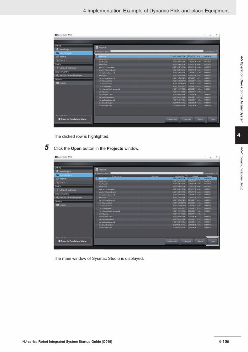
The clicked row is highlighted.
5 Click the Open button in the Projects window.
The main window of Sysmac Studio is displayed.
4 Implementation Example of Dynamic Pick-and-place Equipment
4-105NJ-series Robot Integrated System Startup Guide (O049)
4-5 Operation C
heck on the Actual System
4
4-5-1 Com
munications Setup
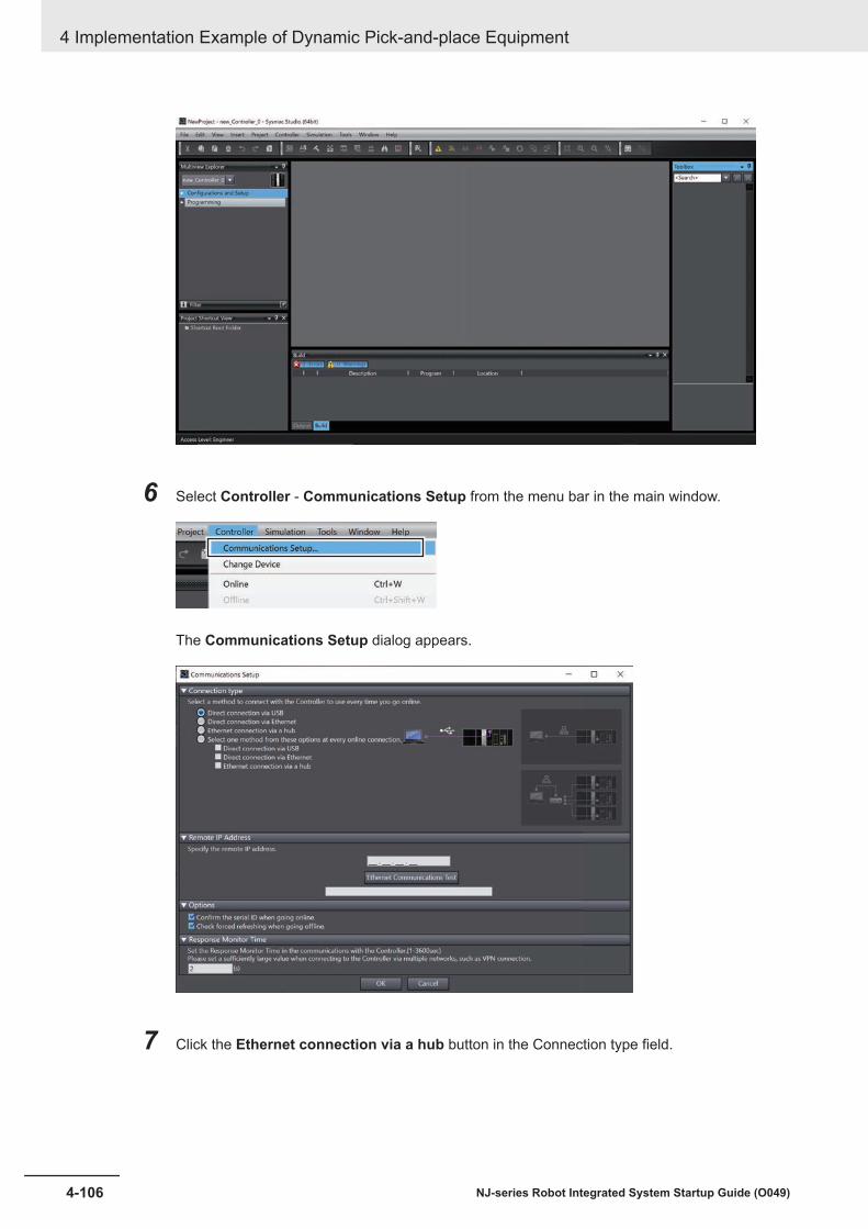
6 Select Controller - Communications Setup from the menu bar in the main window.
The Communications Setup dialog appears.
7 Click the Ethernet connection via a hub button in the Connection type field.
4 Implementation Example of Dynamic Pick-and-place Equipment
4-106 NJ-series Robot Integrated System Startup Guide (O049)

8 Enter 192.168.250.1, the IP address of the Robot Integrated CPU Unit, in the Remote IPAddress box
9 Click the OK button at the bottom
4 Implementation Example of Dynamic Pick-and-place Equipment
4-107NJ-series Robot Integrated System Startup Guide (O049)
4-5 Operation C
heck on the Actual System
4
4-5-1 Com
munications Setup
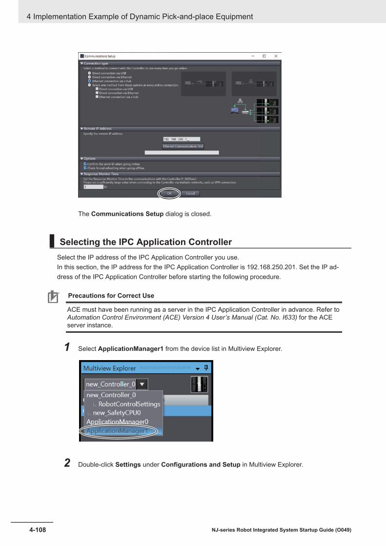
The Communications Setup dialog is closed.
Selecting the IPC Application ControllerSelect the IP address of the IPC Application Controller you use.In this section, the IP address for the IPC Application Controller is 192.168.250.201. Set the IP ad-dress of the IPC Application Controller before starting the following procedure.
Precautions for Correct Use
ACE must have been running as a server in the IPC Application Controller in advance. Refer toAutomation Control Environment (ACE) Version 4 User’s Manual (Cat. No. I633) for the ACEserver instance.
1 Select ApplicationManager1 from the device list in Multiview Explorer.
2 Double-click Settings under Configurations and Setup in Multiview Explorer.
4 Implementation Example of Dynamic Pick-and-place Equipment
4-108 NJ-series Robot Integrated System Startup Guide (O049)
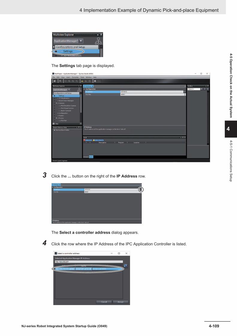
The Settings tab page is displayed.
3 Click the ... button on the right of the IP Address row.
The Select a controller address dialog appears.
4 Click the row where the IP Address of the IPC Application Controller is listed.
4 Implementation Example of Dynamic Pick-and-place Equipment
4-109NJ-series Robot Integrated System Startup Guide (O049)
4-5 Operation C
heck on the Actual System
4
4-5-1 Com
munications Setup

5 Click the Accept button.
The Select a controller address dialog is closed.
4-5-2 Online Connection
Connecting Sysmac Studio to the Robot Integrated CPU Unit On-line
Establish an online connection between Sysmac Studio and the Robot Integrated CPU Unit.
1 In the Multiview Explorer, select new_Controller_0 from the device list.
2 Click Controller - Online from the menu bar.
Additional Information
Depending on the status of the connected Robot Integrated CPU Unit, the dialog box for writingthe CPU Unit name or checking the serial number is displayed. Refer to Sysmac Studio Version1 Operation Manual (Cat. No. W504) for details.
When it is online, the yellow line is displayed on the top of the Edit Pane.
4 Implementation Example of Dynamic Pick-and-place Equipment
4-110 NJ-series Robot Integrated System Startup Guide (O049)

Going Online with the IPC Application ControllerConnect the IPC Application Controller and Sysmac Studio online.
1 Select ApplicationManager1 from the device list in Multiview Explorer.
2 Click Controller - Online from the menu bar.
When it is online, the yellow line is displayed on the top of the Edit Pane.
4-5-3 Transferring Settings and ProgramsTo operate a conveyor belt programmatically, download programs and settings in the Sysmac Studioproject file to the Robot Integrated CPU Unit.
1 In the Multiview Explorer, select new_Controller_0 from the device list.
4 Implementation Example of Dynamic Pick-and-place Equipment
4-111NJ-series Robot Integrated System Startup Guide (O049)
4-5 Operation C
heck on the Actual System
4
4-5-3 Transferring Settings and Programs

2 Click Controller - Mode - PROGRAM Mode from the menu bar.
3 Follow the instructions in the confirmation dialog, then click the Yes button.
4 Select Controller - Synchronization from the menu bar on the Sysmac Studio.
Comparison of programs and settings in Sysmac Studio and the Controller starts.When the comparison is completed, the Synchronization dialog box is displayed.
5 Select the check box for NJ501.
4 Implementation Example of Dynamic Pick-and-place Equipment
4-112 NJ-series Robot Integrated System Startup Guide (O049)

6 Click the Transfer to Controller button.
7 The following confirmation dialog box appears. Click the Yes button.
8 Confirm that the message "The Synchronization process successfully finished" is displayed.Then click the Close button.
4 Implementation Example of Dynamic Pick-and-place Equipment
4-113NJ-series Robot Integrated System Startup Guide (O049)
4-5 Operation C
heck on the Actual System
4
4-5-3 Transferring Settings and Programs

9 Confirm that the Robot Integrated CPU Unit has started normally.Indicator statuses under a normal operation are given below.
Indicator StatusRUN indicator Lit in greenERROR indicator OffNET RUN Lit in greenNET ERR OffLINK/ACT Blinking
Built-in EtherCAT port
10 Confirm that the robot has started normally.Indicator statuses under a normal operation are given below.
Indicator StatusRUN indicator Lit in greenERR indicator Off
4 Implementation Example of Dynamic Pick-and-place Equipment
4-114 NJ-series Robot Integrated System Startup Guide (O049)

11 Confirm that the IPC Application Controller has started normally.Indicator statuses under a normal operation are given below.
Indicator StatusPWR indicator Lit in greenERR indicator Off
4-5-4 Setting up the Camera
Adding a Camera to Use
1 Select ApplicationManager1 in Multiview Explorer.
2 Select a camera type.
1) Click Configurations and Setup to expand.
2) Right-click Cameras to display the context menu.
4 Implementation Example of Dynamic Pick-and-place Equipment
4-115NJ-series Robot Integrated System Startup Guide (O049)
4-5 Operation C
heck on the Actual System
4
4-5-4 Setting up the Cam
era

3) Select Add - Basler Camera.
The Create Basler Device wizard appears.
3 Make sure that IP Address is set to the IP address of the IPC Application Controller and clickthe Next button.
4 Select the camera you use from the device list.
4 Implementation Example of Dynamic Pick-and-place Equipment
4-116 NJ-series Robot Integrated System Startup Guide (O049)
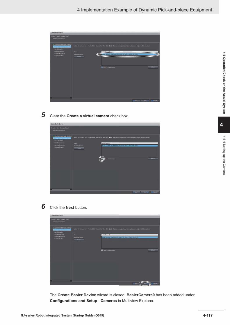
5 Clear the Create a virtual camera check box.
6 Click the Next button.
The Create Basler Device wizard is closed. BaslerCamera0 has been added underConfigurations and Setup - Cameras in Multiview Explorer.
4 Implementation Example of Dynamic Pick-and-place Equipment
4-117NJ-series Robot Integrated System Startup Guide (O049)
4-5 Operation C
heck on the Actual System
4
4-5-4 Setting up the Cam
era
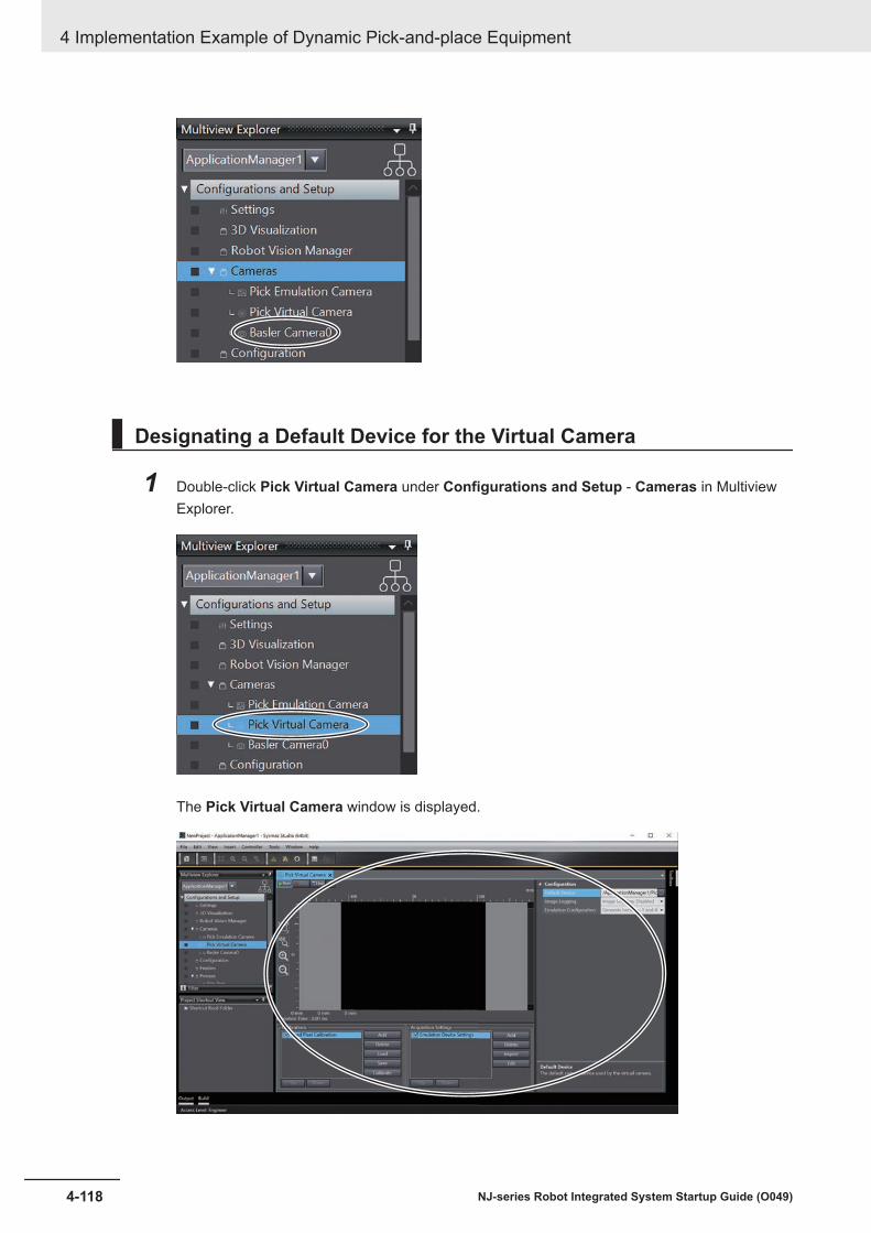
Designating a Default Device for the Virtual Camera
1 Double-click Pick Virtual Camera under Configurations and Setup - Cameras in MultiviewExplorer.
The Pick Virtual Camera window is displayed.
4 Implementation Example of Dynamic Pick-and-place Equipment
4-118 NJ-series Robot Integrated System Startup Guide (O049)
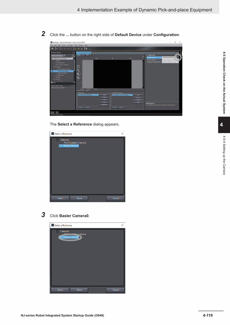
2 Click the ... button on the right side of Default Device under Configuration.
The Select a Reference dialog appears.
3 Click Basler Camera0.
4 Implementation Example of Dynamic Pick-and-place Equipment
4-119NJ-series Robot Integrated System Startup Guide (O049)
4-5 Operation C
heck on the Actual System
4
4-5-4 Setting up the Cam
era
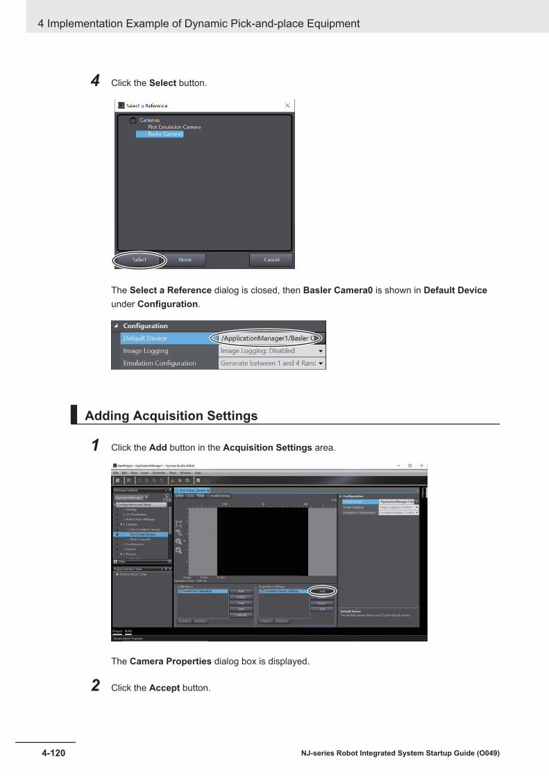
4 Click the Select button.
The Select a Reference dialog is closed, then Basler Camera0 is shown in Default Deviceunder Configuration.
Adding Acquisition Settings
1 Click the Add button in the Acquisition Settings area.
The Camera Properties dialog box is displayed.
2 Click the Accept button.
4 Implementation Example of Dynamic Pick-and-place Equipment
4-120 NJ-series Robot Integrated System Startup Guide (O049)

Basler Pylon acA1300-30gc Device Settings is added.
An image taken by the camera can be shown.For example, the display is seen as illustrated below when the calibration grid is in the shootingrange.
Adding the Grid Calibration
1 Click the Add button in the Calibration area.
4 Implementation Example of Dynamic Pick-and-place Equipment
4-121NJ-series Robot Integrated System Startup Guide (O049)
4-5 Operation C
heck on the Actual System
4
4-5-4 Setting up the Cam
era
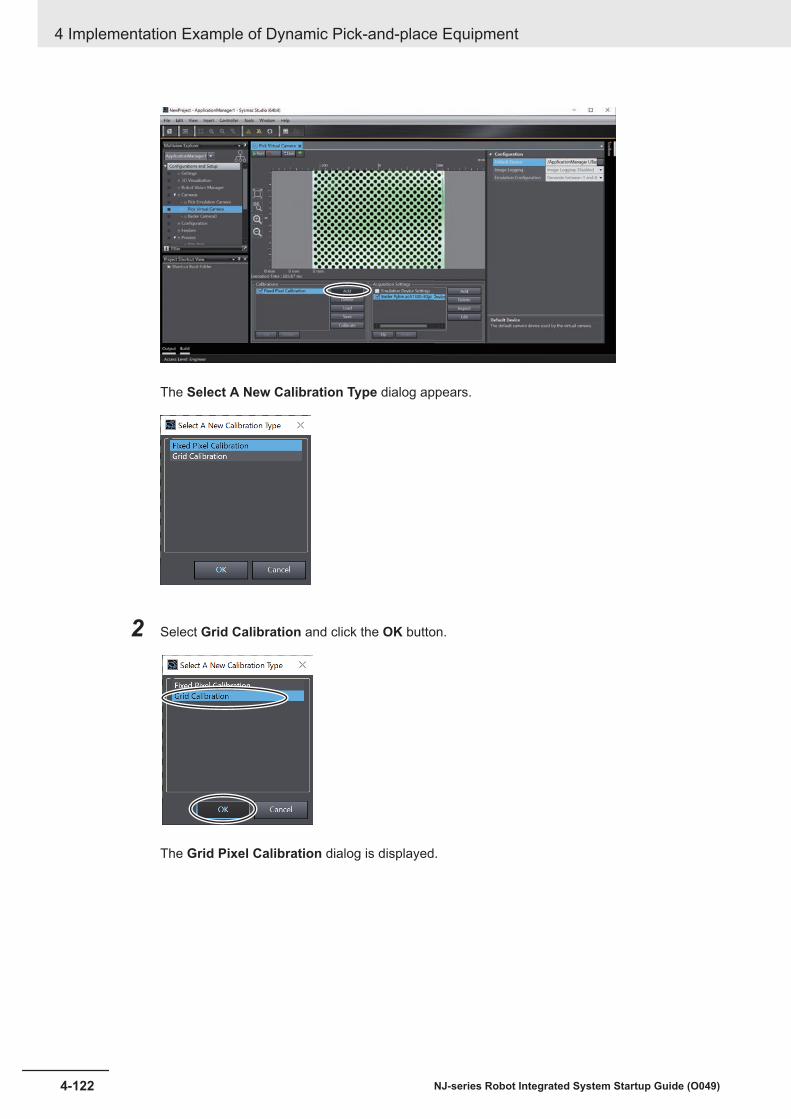
The Select A New Calibration Type dialog appears.
2 Select Grid Calibration and click the OK button.
The Grid Pixel Calibration dialog is displayed.
4 Implementation Example of Dynamic Pick-and-place Equipment
4-122 NJ-series Robot Integrated System Startup Guide (O049)
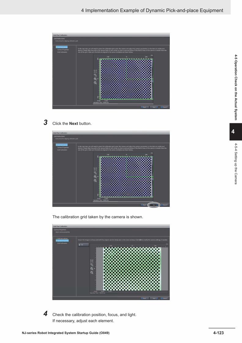
3 Click the Next button.
The calibration grid taken by the camera is shown.
4 Check the calibration position, focus, and light.If necessary, adjust each element.
4 Implementation Example of Dynamic Pick-and-place Equipment
4-123NJ-series Robot Integrated System Startup Guide (O049)
4-5 Operation C
heck on the Actual System
4
4-5-4 Setting up the Cam
era

5 Click the Edit button if dots are not clearly displayed.
The Camera Properties dialog is shown. Configure properties so that dots get clear. Thenclick the Accept button to close the Camera Properties dialog.
6 Click the Next button.
The dialog for grid calibration is displayed.
4 Implementation Example of Dynamic Pick-and-place Equipment
4-124 NJ-series Robot Integrated System Startup Guide (O049)

7 Enter a dot pitch value of the calibration grid in use into the Dot Pitch box.
In this manual, 10.00 is entered in the box because the calibration grid whose dot pitch is 10mm is used to explain the procedure.
8 Click the Calibration button.
4 Implementation Example of Dynamic Pick-and-place Equipment
4-125NJ-series Robot Integrated System Startup Guide (O049)
4-5 Operation C
heck on the Actual System
4
4-5-4 Setting up the Cam
era

Calibration is performed.
Yellow points in the black dots mean the calibration has been successfully done. If yellowpoints are not shown, click the Back button to return to Step 4, then re-adjust properties so thatthe dots get clear.
9 Click the Finish button.
The Grid Pixel Calibration dialog is closed.
4-5-5 Running a Sequence Control Program and V+ ProgramTo operate the conveyor belt for a calibration, run a sequence control program and V+ program.
1 Select Operation Mode - RUN Mode from the Controller menu.
2 Select View - Task Status Control from the menu bar.
4 Implementation Example of Dynamic Pick-and-place Equipment
4-126 NJ-series Robot Integrated System Startup Guide (O049)

The Task Status Control pane is displayed.
3 Select RobotControlSettings from the device list in the Multiview Explorer.
4 Right-click Programming - V+ Modules - supervisor - supervisor, then click Execute onTask - Task 2.
The supervisor and control of the V+ program is executed in Task2 and Task 3 respectively.
4 Implementation Example of Dynamic Pick-and-place Equipment
4-127NJ-series Robot Integrated System Startup Guide (O049)
4-5 Operation C
heck on the Actual System
4
4-5-5 Running a Sequence C
ontrol Program and V+ Program

5 Select Watch Tab Page from the View menu on the main window.
The Watch (Project)1 tab page appears at the bottom of the main window.
6 Click the TRUE button in the Modify column for the variable gStart in the Watch (Project)1tab page.
The program runs.
4-5-6 Turning Robot High Power ONThe robot high power is turned ON.
1 Change the operating mode switch on the front panel to Manual Mode.
4 Implementation Example of Dynamic Pick-and-place Equipment
4-128 NJ-series Robot Integrated System Startup Guide (O049)

Manual Mode
Operating mode switch
Auto Mode
2 Press the enable switch on the T20 pendant to Position 2 (half-way).
3 Press the Robot Power button while the enable switch is kept in Position 2 (half-way).
The Robot Power button on the front panel flashes.
4 Press the Robot Power button on the front panel.The robot high power is turned ON and the Robot Power button is lit.
If you release the enable switch (Position 1) or press the enable switch further from Position 2 (half-way) to Position 3, the robot high power will be turned OFF.
4 Implementation Example of Dynamic Pick-and-place Equipment
4-129NJ-series Robot Integrated System Startup Guide (O049)
4-5 Operation C
heck on the Actual System
4
4-5-6 Turning Robot H
igh Power O
N

Precautions for Correct Use
If it is necessary to move the robot, follow the procedure above to turn ON the high power.
4-5-7 Calibrating the BeltCalibrate the belt.
1 Select ApplicationManager1 from the device list in Multiview Explorer.
2 Double-click Process Manager under Configurations and Setup - Process in Multiview Ex-plorer.
The Process Manager tab page is displayed.
3 In the Belt Calibrations pane, click the row where the belt you calibrate is.
4 Implementation Example of Dynamic Pick-and-place Equipment
4-130 NJ-series Robot Integrated System Startup Guide (O049)

4 Click the Calibrate button in Belt Calibrations.
The Robot-to-Belt Calibration Sequence dialog is displayed.
5 Make sure that the right end effector has been selected , and then click the Next button.
4 Implementation Example of Dynamic Pick-and-place Equipment
4-131NJ-series Robot Integrated System Startup Guide (O049)
4-5 Operation C
heck on the Actual System
4
4-5-7 Calibrating the Belt
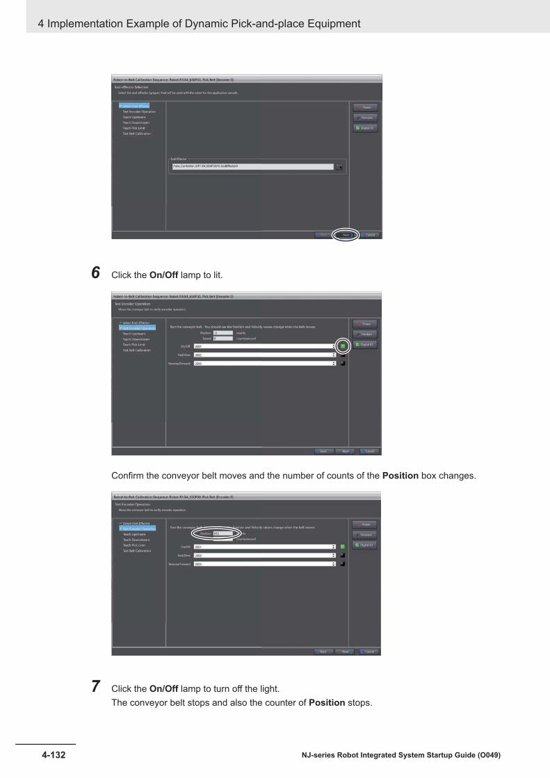
6 Click the On/Off lamp to lit.
Confirm the conveyor belt moves and the number of counts of the Position box changes.
7 Click the On/Off lamp to turn off the light.The conveyor belt stops and also the counter of Position stops.
4 Implementation Example of Dynamic Pick-and-place Equipment
4-132 NJ-series Robot Integrated System Startup Guide (O049)

8 Click the Next button.The Teach Upstream Limit dialog appears.
9 Put the target on the upstream limit point on the belt.
10 Operate the robot with the T20 Pendant to move it to the upstream limit point.
Additional Information
It is also possible to move the robot in the V+ Jog Control window, which is displayed througha click of the Pendant button.
11 Click the Here button.
The present robot position is set to the Taught Robot Location box.
4 Implementation Example of Dynamic Pick-and-place Equipment
4-133NJ-series Robot Integrated System Startup Guide (O049)
4-5 Operation C
heck on the Actual System
4
4-5-7 Calibrating the Belt
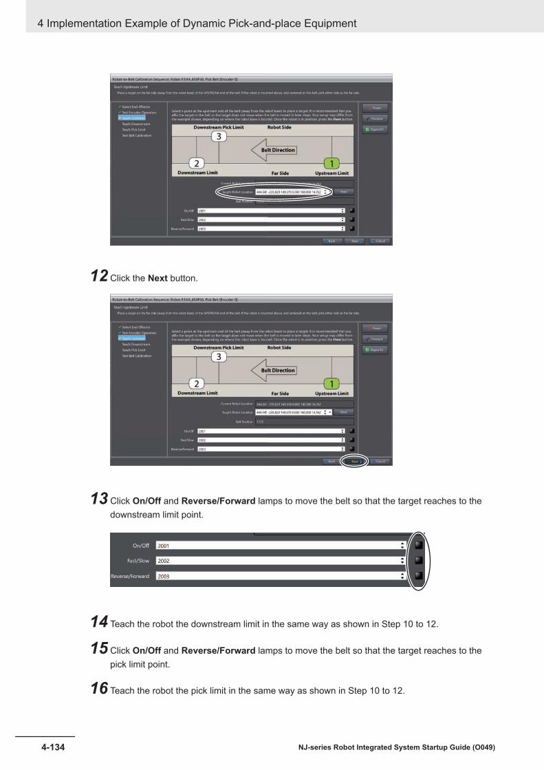
12 Click the Next button.
13 Click On/Off and Reverse/Forward lamps to move the belt so that the target reaches to thedownstream limit point.
14 Teach the robot the downstream limit in the same way as shown in Step 10 to 12.
15 Click On/Off and Reverse/Forward lamps to move the belt so that the target reaches to thepick limit point.
16 Teach the robot the pick limit in the same way as shown in Step 10 to 12.
4 Implementation Example of Dynamic Pick-and-place Equipment
4-134 NJ-series Robot Integrated System Startup Guide (O049)

17 Change the operating mode to Auto mode from Manual mode on the front panel, and click thePower button. When the Robot Power button on the front panel flashes, press it to turn on therobot high power.
18 Move the robot to the upstream of the belt, then click the Start Tracking button in BeltTransform in the Test Belt Calibration window.
The robot moves as the belt moves.
19 Click the Stop Tracking button if you have confirmed the robot moved as the belt moved.
The tracking operation stops.
20 Click the Finish button.The Robot-to-Belt Calibration Sequence dialog is closed.
4-5-8 Calibrating the SensorCalibrate the sensor.
Additional Information
• The procedure in this section includes steps for detecting the target. It is for position detectionrequired for calibration of the sensor. For settings of the locater model to detect an actual tar-get, refer to 4-5-9 Setting the Locator on page 4-146.
• If the target cannot be detected, adjust the camera's shooting environment or the acquisitionsettings. Refer to the Automation Control Environment (ACE) Version 4 User's Manual (Cat.No. I633) for information on the acquisition settings of the virtual camera.
1 Select ApplicationManager1 from the device list in Multiview Explorer.
4 Implementation Example of Dynamic Pick-and-place Equipment
4-135NJ-series Robot Integrated System Startup Guide (O049)
4-5 Operation C
heck on the Actual System
4
4-5-8 Calibrating the Sensor

2 Double-click Process Manager under Configurations and Setup - Process in Multiview Ex-plorer.
The Process Manager tab page is displayed.
3 In the Sensor Calibrations pane, click the row where the sensor you calibrate is.
4 Implementation Example of Dynamic Pick-and-place Equipment
4-136 NJ-series Robot Integrated System Startup Guide (O049)

4 Click the Calibrate button in Sensor Calibrations.
The Robot-to-Belt Camera Calibration Sequence dialog is displayed.
5 Make sure that the right end effector has been selected , and then click the Next button.
4 Implementation Example of Dynamic Pick-and-place Equipment
4-137NJ-series Robot Integrated System Startup Guide (O049)
4-5 Operation C
heck on the Actual System
4
4-5-8 Calibrating the Sensor

6 Click the Live button and place the target in the camera view while watching the displayed im-age.
7 Click the Stop button.
The green frame which specify a target is shown.
4 Implementation Example of Dynamic Pick-and-place Equipment
4-138 NJ-series Robot Integrated System Startup Guide (O049)

8 Drag and drop the green frame, and scale it to box a target.
9 Click the Run button.
Features of the boxed target are detected.
4 Implementation Example of Dynamic Pick-and-place Equipment
4-139NJ-series Robot Integrated System Startup Guide (O049)
4-5 Operation C
heck on the Actual System
4
4-5-8 Calibrating the Sensor

10 Click the Crop button.
The boxed target is displayed in an enlarged image.
11 Click the Center button.
4 Implementation Example of Dynamic Pick-and-place Equipment
4-140 NJ-series Robot Integrated System Startup Guide (O049)

A yellow marker is displayed at the center of the detected target.
If the detected center point is wrong, drag and drop the arrows of the marker for adjustment.
12 Click the Train button.
Features are detected.
4 Implementation Example of Dynamic Pick-and-place Equipment
4-141NJ-series Robot Integrated System Startup Guide (O049)
4-5 Operation C
heck on the Actual System
4
4-5-8 Calibrating the Sensor

Clear the Included check boxes of unnecessary features of the target. The color of edgeswhose Included check boxes have been cleared turn to red from green. After clearing thecheck boxes, click the Update button.
13 Click the Next button.
Locations of all targets are detected, and a magenta markers appear around the center of tar-gets.
4 Implementation Example of Dynamic Pick-and-place Equipment
4-142 NJ-series Robot Integrated System Startup Guide (O049)
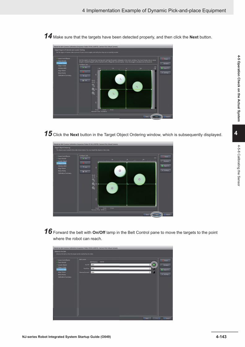
14 Make sure that the targets have been detected properly, and then click the Next button.
15 Click the Next button in the Target Object Ordering window, which is subsequently displayed.
16 Forward the belt with On/Off lamp in the Belt Control pane to move the targets to the pointwhere the robot can reach.
4 Implementation Example of Dynamic Pick-and-place Equipment
4-143NJ-series Robot Integrated System Startup Guide (O049)
4-5 Operation C
heck on the Actual System
4
4-5-8 Calibrating the Sensor

17 Click the Next button.
18 Operate the robot with the T20 Pendant so that its end effector touch the marked target.
Additional Information
It is also possible to move the robot in the V+ Jog Control window, which is displayed througha click of the Pendant button.
19 Click the Here button.
20 Click the Next button.
4 Implementation Example of Dynamic Pick-and-place Equipment
4-144 NJ-series Robot Integrated System Startup Guide (O049)
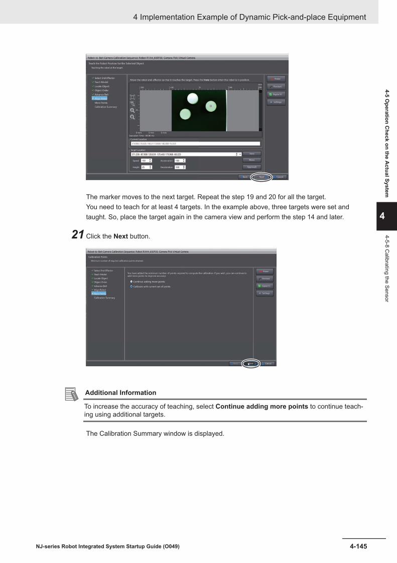
The marker moves to the next target. Repeat the step 19 and 20 for all the target.You need to teach for at least 4 targets. In the example above, three targets were set andtaught. So, place the target again in the camera view and perform the step 14 and later.
21 Click the Next button.
Additional Information
To increase the accuracy of teaching, select Continue adding more points to continue teach-ing using additional targets.
The Calibration Summary window is displayed.
4 Implementation Example of Dynamic Pick-and-place Equipment
4-145NJ-series Robot Integrated System Startup Guide (O049)
4-5 Operation C
heck on the Actual System
4
4-5-8 Calibrating the Sensor

22 Click the Finish button.
The Robot-to-Belt Camera Calibration Sequence dialog is closed.
4-5-9 Setting the LocatorSet up the Locator.
Additional Information
Refer to the Automation Control Environment (ACE) Version 4 User's Manual (Cat. No.I633) fordetails of the following items.
Item References in Cat. No. I633About the configuration items of the locater model (Pick LocaterModel in this section) for defining the shape and features of the tar-get
Locator Model Configuration Itemsin Vision Tools
About the properties of the detected target, which are defined bythe locator’s configuration items
Locator Configuration Items inVision Tools
1 Select ApplicationManager1 from the device list in Multiview Explorer.
4 Implementation Example of Dynamic Pick-and-place Equipment
4-146 NJ-series Robot Integrated System Startup Guide (O049)

2 Double-click Pick Locator Model under Configurations and Setup - Vision Tools in Multi-view Explorer.
3 Pick Locator Model tab page is displayed. Click the Live button and place the target in thecamera view while watching the displayed image. Click the Stop button, and then the NewImage button.
The image is fixed and the green frame appears on the image.
4 Implementation Example of Dynamic Pick-and-place Equipment
4-147NJ-series Robot Integrated System Startup Guide (O049)
4-5 Operation C
heck on the Actual System
4
4-5-9 Setting the Locator

4 Drag and drop the green frame, and scale it to box a target.
5 Click the Train button.
Features of the target are detected and indicated with green lines.
4 Implementation Example of Dynamic Pick-and-place Equipment
4-148 NJ-series Robot Integrated System Startup Guide (O049)

6 Click the Crop button.
The boxed target is displayed in an enlarged image.
If the detected position and features are not appropriate, adjust them in the way described in 4-5-8 Calibrating the Sensor on page 4-135.
7 Double-click Pick Locator under Configurations and Setup - Vision Tools in Multiview Ex-plorer.
4 Implementation Example of Dynamic Pick-and-place Equipment
4-149NJ-series Robot Integrated System Startup Guide (O049)
4-5 Operation C
heck on the Actual System
4
4-5-9 Setting the Locator

The model you have created is registered to the Models pane.
A target in the green frame is detected in the Pick Locator tab page, and a magenta markerappears around the center of the detected target.
8 Drag and drop the green frame, and expand it to an entire shooting range.
4 Implementation Example of Dynamic Pick-and-place Equipment
4-150 NJ-series Robot Integrated System Startup Guide (O049)

Locations of all the target in the green frame are recognized.
4-5-10 Teaching Idle, Pick, and Place Positions
1 Select ApplicationManager1 from the device list in Multiview Explorer.
2 Double-click Process Manager under Configurations and Setup - Process.
4 Implementation Example of Dynamic Pick-and-place Equipment
4-151NJ-series Robot Integrated System Startup Guide (O049)
4-5 Operation C
heck on the Actual System
4
4-5-10 Teaching Idle, Pick, and Place Positions

The Process Manager tab page is displayed.
3 Select a process from the Processes list.
1) Click the Teach button at the right of the list.
4 Implementation Example of Dynamic Pick-and-place Equipment
4-152 NJ-series Robot Integrated System Startup Guide (O049)

The Teaching a Process dialog box is displayed.
4 Click the Finish button.
The teaching window appears.
5 Adjust each teaching following instructions shown in the window.Adjustment can be performed in the same way as simulation.
4 Implementation Example of Dynamic Pick-and-place Equipment
4-153NJ-series Robot Integrated System Startup Guide (O049)
4-5 Operation C
heck on the Actual System
4
4-5-10 Teaching Idle, Pick, and Place Positions
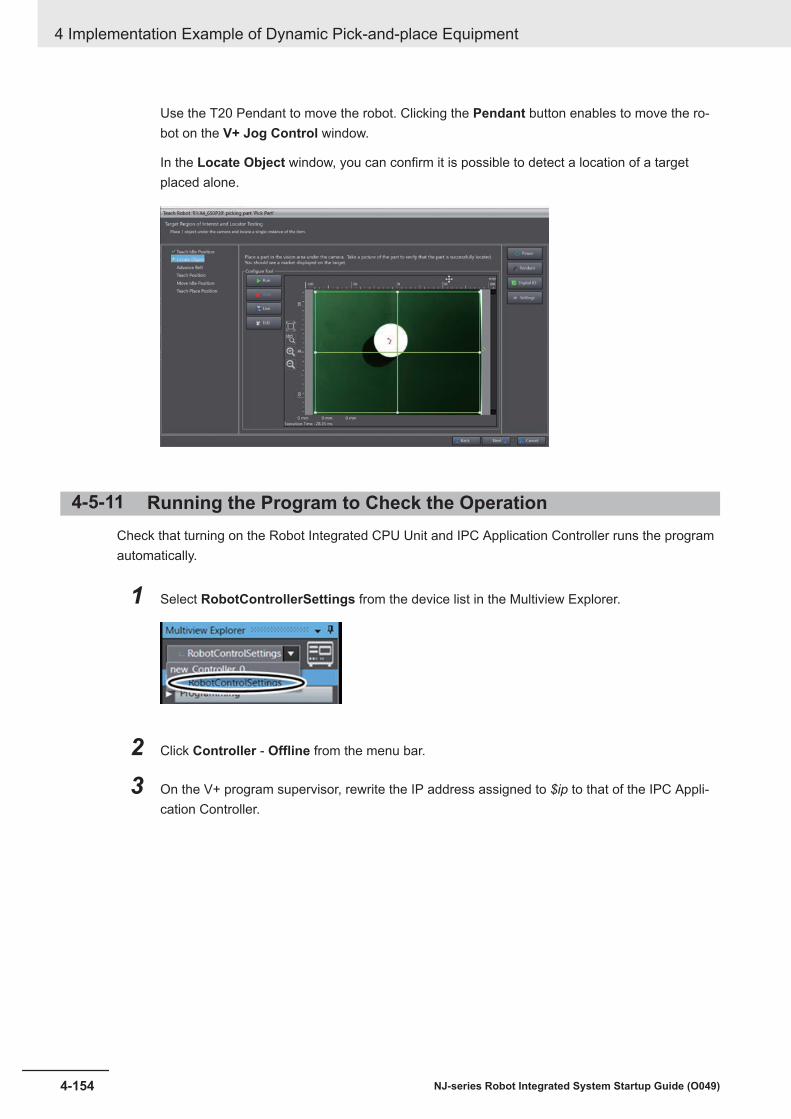
Use the T20 Pendant to move the robot. Clicking the Pendant button enables to move the ro-bot on the V+ Jog Control window.
In the Locate Object window, you can confirm it is possible to detect a location of a targetplaced alone.
4-5-11 Running the Program to Check the OperationCheck that turning on the Robot Integrated CPU Unit and IPC Application Controller runs the programautomatically.
1 Select RobotControllerSettings from the device list in the Multiview Explorer.
2 Click Controller - Offline from the menu bar.
3 On the V+ program supervisor, rewrite the IP address assigned to $ip to that of the IPC Appli-cation Controller.
4 Implementation Example of Dynamic Pick-and-place Equipment
4-154 NJ-series Robot Integrated System Startup Guide (O049)

In case the IPC Application Controller IP address is 192.168.250.201, rewrite it as illustrated inthe screen shot below.
4 Click Controller - Online from the menu bar.Sysmac Studio goes online.
5 Click the synchronization icon in the toolbar.
The Synchronization window is displayed.
4 Implementation Example of Dynamic Pick-and-place Equipment
4-155NJ-series Robot Integrated System Startup Guide (O049)
4-5 Operation C
heck on the Actual System
4
4-5-11 Running the Program
to Check the O
peration

6 Check the supervisor box under Programs.
7 Click the Transfer To Target button.
The supervisor program is transferred to the Robot Integrated CPU Unit.
4 Implementation Example of Dynamic Pick-and-place Equipment
4-156 NJ-series Robot Integrated System Startup Guide (O049)

8 Click the Close button.The Synchronization window is closed.
9 Select ApplicationManager1 from the device list in Multiview Explorer.
10 Click Configurations and Setup - Configuration - Add - Controller Connection Startup.
Controller Connection Startup0 is added under Configuration.
4 Implementation Example of Dynamic Pick-and-place Equipment
4-157NJ-series Robot Integrated System Startup Guide (O049)
4-5 Operation C
heck on the Actual System
4
4-5-11 Running the Program
to Check the O
peration

11 Double-click Controller Connection Startup0.
Controller Connection Startup0 tab page is displayed.
12 Click the + button.
The Select a Reference dialog appears.
4 Implementation Example of Dynamic Pick-and-place Equipment
4-158 NJ-series Robot Integrated System Startup Guide (O049)

13 Select Controller Settings, then click the Select button.
/new_Controller_0/Controller Settings is added to the Controller Connection Startup0 tabpage.
14 Click the synchronization icon in the toolbar.
The Synchronization window is displayed.
4 Implementation Example of Dynamic Pick-and-place Equipment
4-159NJ-series Robot Integrated System Startup Guide (O049)
4-5 Operation C
heck on the Actual System
4
4-5-11 Running the Program
to Check the O
peration

15 Click the Transfer To Target button.
The settings and program is transferred to the destination IPC Application Controller.
16 Click the Close button.
4 Implementation Example of Dynamic Pick-and-place Equipment
4-160 NJ-series Robot Integrated System Startup Guide (O049)

The Synchronization window is closed.
17 Disconnect Sysmac Studio (offline) to the Robot Integrated CPU Unit and IPC Application Con-troller.To go offline, select Offline instead of Online in the processes described in Connecting Sys-mac Studio to the Robot Integrated CPU Unit Online on page 4-110 and Going Online with theIPC Application Controller on page 4-111.
18 Power off the Robot Integrated CPU Unit and IPC Application Controller.
19 Power on the Robot Integrated CPU Unit and IPC Application Controller.
20 Boot up ACE as a server in the IPC Application Controller.Refer to Automation Control Environment (ACE) Version 4 User’s Manual (Cat. No.I633) for theACE server instance.
21 Establish an online connection between Sysmac Studio and the Robot Integrated CPU Unit.Refer to Connecting Sysmac Studio to the Robot Integrated CPU Unit Online on page 4-110 forthe procedure to connect online.
22 Set TRUE to gStart in the Watch (Project)1 tab page.
Refer to 4-5-5 Running a Sequence Control Program and V+ Program on page 4-126 for howto open the Watch tab page.
23 Turn on the robot high power on the robot front panel.
1) Switch the front panel to Auto mode.
4 Implementation Example of Dynamic Pick-and-place Equipment
4-161NJ-series Robot Integrated System Startup Guide (O049)
4-5 Operation C
heck on the Actual System
4
4-5-11 Running the Program
to Check the O
peration

Manual Mode
Operating mode switch
Auto Mode
2) Press the Robot Power button.The Robot Power button blinks.
3) Press the Robot Power button again.
The robot high power turns ON, then the dynamic pick-and place program runs automatically.The carrying conveyor A operates.
Encoder IP65
Camera
(1) Upstream Limit
(2) Pick Limit (1) Downstream Limit
24 Put a part at the upstream of the conveyor A.
Encoder IP65
Camera
(1) Upstream Limit
(2) Pick Limit (1) Downstream Limit
Workpiece
25 Check that the robot works as described in the following.
1) The robot moves to the upstream limit point when the camera detects the part, then pause.
4 Implementation Example of Dynamic Pick-and-place Equipment
4-162 NJ-series Robot Integrated System Startup Guide (O049)

Encoder IP65
Camera
(1) Upstream Limit
(2) Pick Limit (1) Downstream Limit
Workpiece
2) The part is carried to the upstream limit point, then the robot picks up the part and place iton the conveyor B.
Encoder IP65
Camera
(1) Upstream Limit
(2) Pick Limit (1) Downstream Limit
Workpiece
26 Repeat Step 24 to 25 to check the robot works as described in the following.The robot repeats picking and placing the parts detected subsequently.
Encoder IP65
Camera
(1) Upstream Limit
(2) Pick Limit (1) Downstream Limit
4 Implementation Example of Dynamic Pick-and-place Equipment
4-163NJ-series Robot Integrated System Startup Guide (O049)
4-5 Operation C
heck on the Actual System
4
4-5-11 Running the Program
to Check the O
peration

4 Implementation Example of Dynamic Pick-and-place Equipment
4-164 NJ-series Robot Integrated System Startup Guide (O049)

AAppendices
A-1 Designing Example of the Safety Functions for the Pick-and-place Equipment............................................................................................. A-2
A-1-1 Pick-and-place Equipment Configuration ........................................................A-2A-1-2 Hazards ...........................................................................................................A-4A-1-3 Protective Measure .........................................................................................A-4A-1-4 Safety Functions..............................................................................................A-4A-1-5 Safety System Configuration and Devices ......................................................A-5A-1-6 Installation and Wiring .....................................................................................A-7A-1-7 Settings and Programming............................................................................A-13
A-2 How to Use 3D Visualizer ........................................................................... A-21A-2-1 Set the 3D Visualizer to the Float Mode........................................................A-21A-2-2 Rotate the Viewpoint .....................................................................................A-23A-2-3 Translate the Viewpoint .................................................................................A-25A-2-4 Zoom-in and Zoom-out..................................................................................A-26
A-3 Setting Items on the Sysmac Studio and the Setting Targets ................ A-28A-4 Using Troubleshooting Functions............................................................. A-29
A-1NJ-series Robot Integrated System Startup Guide (O049)
A

A-1 Designing Example of the SafetyFunctions for the Pick-and-placeEquipment
This section describes the designing example of the safety functions for the pick-and-place equipment.
Precautions for Correct Use
You must implement the actual safety measures based on the Robot Safety Guide (Cat. No.I590) and risk assessment. In addition, it is necessary to consider the performance level andsafety distances of the equipment while it conforms to the safety standards.
A-1-1 Pick-and-place Equipment ConfigurationThe configuration of the pick-and-place equipment inclusive of the safety devices is shown in the tablebelow.
Appendices
A-2 NJ-series Robot Integrated System Startup Guide (O049)

(C)
(A)
(D)
(E)
(F)
(G)
(B)
(N)
(M)
(L)
(O)
Front
Back
(K)
(J)
(I)
(H)
Appendices
A-3NJ-series Robot Integrated System Startup Guide (O049)
A-1 D
esigning Example of the Safety Functions for the Pick-and-place Equip-
ment
A
A-1-1 Pick-and-place Equipment C
onfiguration

Letter NameA Safety door switch 2B Safety light curtain 2 (Emitter)C Emergency stop pushbutton switch 1D RobotE Belt conveyor (Unload side)F Safety light curtain 2 (Receiver)G Reset switchH Enable switch on T20 pendantI E-STOP button on T20 pendantJ E-STOP button on front panelK Belt conveyor (Load side)L Safety light curtain 1 (Receiver)M Safety light curtain 1 (Emitter)N Emergency stop pushbutton switch 2O Safety door switch 1
A-1-2 HazardsThe movable parts of the robot are the mechanical hazards in the system configuration described inthis section.
A-1-3 Protective MeasureYou must assume the cases in which the hazards are approached from each side of the pick-and-place equipment.The safeguarding to each case is implemented as shown in the table below.
Equipment side Approached case Safeguarding Safety deviceBack --- Fixed guard ---Front Adjustment/ maintenance Movable guard Safety door switchLoading side Loading Opto-electronic protective device Safety light curtainUnload side Unloading Opto-electronic protective device Safety light curtain
In addition to the safeguarding, the emergency stop switches as the complementary protective meas-ures are placed at positions accessible from each side of the equipment.
Equipment side Complementary protective measure Safety deviceBack Emergency stop switch Emergency stop pushbutton switchFront Emergency stop pushbutton switch
E-STOP button on T20 pendantE-STOP button on front panel
A-1-4 Safety FunctionsYou must decide the safety function of each safety device for the case it operated.The functions need to be decided for each operating mode of the OMRON robot.
Appendices
A-4 NJ-series Robot Integrated System Startup Guide (O049)

Auto ModeSet the safety functions when the operating mode of the OMRON robot is in Auto mode as shown inthe table below.
Safety device Safety function RecoveryEmergency stop pushbutton switch 1 Stop the robot when pressed High power ON after resettingEmergency stop pushbutton switch 2 Stop the robot when pressed High power ON after resettingSafety light curtain 1 Stop the robot when the beam is inter-
ruptedHigh power ON
Safety light curtain 2 Stop the robot when beam is interrupted High power ONSafety door switch 1 Stop the robot when the door is open High power ON after resettingSafety door switch 2 Stop the robot when the door is open High power ON after resettingE-STOP button on front panel Stop the robot when pressed High power ON after resettingE-STOP button on T20 pendant Stop the robot when pressed High power ON after resettingEnable switch on T20 pendant --- ---
Manual ModeSet the safety functions when the operating mode of the OMRON robot is in Manual mode as shownin the table below.
Safety device Safety function RecoveryEmergency stop pushbutton switch 1 Stop the robot when pressed ResetEmergency stop pushbutton switch 2 Stop the robot when pressed ResetSafety light curtain 1 --- ---Safety light curtain 2 --- ---Safety door switch 1 --- ---Safety door switch 2 --- ---E-STOP button on front panel Stop the robot when pressed ResetE-STOP button on T20 pendant Stop the robot when pressed ResetEnable switch on T20 pendant Stop the robot when not pressed or fully pressed pass-
ing the middle positionHigh power ON
A-1-5 Safety System Configuration and DevicesYou must select the safety system configuration and devices for it to achieve the safety functions.
Safety System ConfigurationThe safety system configuration in this guide uses an NX-series EtherNet/IP Coupler Unit and NX-ser-ies Safety Control Units.
Appendices
A-5NJ-series Robot Integrated System Startup Guide (O049)
A-1 D
esigning Example of the Safety Functions for the Pick-and-place Equip-
ment
A
A-1-5 Safety System C
onfiguration and Devices

EtherNet/IP Coupler Unit
Safety CPU Unit
Safety Input Unit
Safety Output Unit
Safety door
switches
Reset
switchEmergency stop
switches
OMRON robot
XFP
Front panel
XMCP
XUSR
Safety light curtains
T20 Pendant
Safety relays
Unit power supply
(24 VDC)
I/O power supply
(24 VDC)
Configuration DevicesThe safety system configuration in this guide uses the devices shown in the table below.
Appendices
A-6 NJ-series Robot Integrated System Startup Guide (O049)

Name Model Manufac-turer Description
EtherNet/IP CouplerUnit
NX-EIC202 OMRON A Coupler Unit that supports EtherNet/IP.This Unit can compose a Slave Terminal by connecting withan NX Unit.
Safety CPU Unit NX-SL3300 OMRON A Unit that runs safety programs.Safety Input Unit NX-SIH400 OMRON A Unit to be connected with safety input devices.Safety Output Unit NX-SOD400 OMRON A Unit to be connected with safety output devices.Safety Light Curtain F3SG OMRON A photoelectric safety sensor. This sensor detects human
entry to hazardous area.Safety Door Switch D40A OMRON A non-contact safety door switch. This switch detects open
and close of the entrance door to hazardous area.Reset Switch A22-H
£-10MOMRON A reset switch. This switch is used to manually recover the
equipment from the stop state after the safety function oper-ated.
Emergency StopPushbutton Switch
A22E OMRON An emergency stop switch.
Safety Relay G7SA OMRON A safety relay.Unit Power Supply S8VK OMRON A 24 VDC power supply. This control power supply is for the
EtherNet/IP Coupler Units and the NX Units.I/O Power Supply S8VK OMRON A 24 VDC power supply. This power supply is for the I/O cir-
cuits of the NX Units and the connected external devices.
A-1-6 Installation and WiringThis section describes the installation and wiring related to the safety functions for the pick-and-placeequipment.The NX Unit configuration of the EtherNet/IP Slave Terminal and the wiring diagram of the safety devi-ces are described in this guide.Refer to the following manual for details on installing and wiring the actual devices.• NX-series Safety Control Unit User’s Manual (Cat. No. Z930)• NX-series EtherNet/IP Coupler Unit User’s Manual (Cat. No. W536)• eCobra 600 and 800 Robot with EtherCAT User’s Guide (Cat. No. I653)• T20 Pendant User's Guide (Cat. No. I601)
NX Unit ConfigurationCompose the EtherNet/IP Slave Terminal by the connection order shown in the figure below.
Appendices
A-7NJ-series Robot Integrated System Startup Guide (O049)
A-1 D
esigning Example of the Safety Functions for the Pick-and-place Equip-
ment
A
A-1-6 Installation and Wiring

Wiring the Power SuppliesThe power supply wirings and grounding for the EtherNet/IP Coupler Unit are shown in the figure be-low.
IOV
UG
UV
IOG
UV
UG
A1
A8
B1
B8
Unit power supply(20 VDC)
I/O power supply(5 to 24 VDC)
Ground of 100 W or less
• Connect the + terminal (24 VDC) of the Unit power supply to A1 or B1.• Connect the - terminal (0 VDC) of the Unit power supply to A3 or B3.• Connect the + terminal (5 to 24 VDC) of the I/O power supply to A5.• Connect the - terminal (0 VDC) of the I/O power supply to B5.• Connect the ground line to A7 or B7.
Appendices
A-8 NJ-series Robot Integrated System Startup Guide (O049)
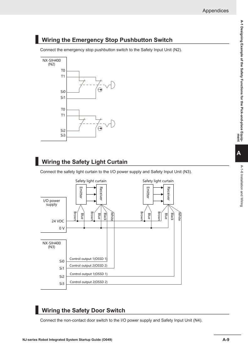
Wiring the Emergency Stop Pushbutton SwitchConnect the emergency stop pushbutton switch to the Safety Input Unit (N2).
NX-SIH400
(N2)
Si3
Si2
Si1
Si0
T1
T0
T1
T0
Wiring the Safety Light CurtainConnect the safety light curtain to the I/O power supply and Safety Input Unit (N3).
NX-SIH400(N3)
I/O power supply
Bro
wn
Bro
wn
Bro
wn
Bro
wn
Blu
e
Blu
e
Bla
ck
Wh
ite
Wh
ite
Bla
ck
Blu
e
Blu
e
Em
itter
Rece
iver
Em
itter
Rece
iver
Safety light curtain
Control output 1(OSSD 1)
Control output 2(OSSD 2)
Control output 1(OSSD 1)
Control output 2(OSSD 2)
Safety light curtain
Si3
Si2
Si1
Si0
0 V
24 VDC
Wiring the Safety Door SwitchConnect the non-contact door switch to the I/O power supply and Safety Input Unit (N4).
Appendices
A-9NJ-series Robot Integrated System Startup Guide (O049)
A-1 D
esigning Example of the Safety Functions for the Pick-and-place Equip-
ment
A
A-1-6 Installation and Wiring

NX-SIH400(N4)
I/O power supply
Non-contact door switch Non-contact door switch
Non-contact door switch input
Non-contact door switch output
Non-contact door switch input
Non-contact door switch output
Si3
Si2
Si1
Si0
T0
T1
0V
24 VDC
Bro
wn
Blu
e
Bla
ck
Wh
ite
Bro
wn
Blu
e
Bla
ck
Wh
ite
Wiring the Reset SwitchConnect the reset switch to the Safety Input Unit (N5).
NX-SIH400
(N5)
Si0
T0
Wiring the RobotConnect the robot to the Safety Output Unit (N6), Safety Input Unit (N5) and safety relays.The outputs of the Safety Output Unit (N6) and the inputs of the robot cannot be directly connected,therefore they are connected through the safety relays.Use the contact a of each safety relay L1 to L4.
Appendices
A-10 NJ-series Robot Integrated System Startup Guide (O049)

NX-SOD400(N6)
Robot
Line emergency stop CH1
Line emergency stop CH2
Muted safety gate CH1
Muted safety gate CH2
User emergency stop CH1
User emergency stop CH2
XUSR-3
XUSR-16
XUSR-4
XUSR-17
XUSR-5
XUSR-18
XUSR-6
XUSR-19
XUSR-1
XUSR-14
XUSR-2
XUSR-15
So0
L1
L2
L3
L4
G
So1
G
So2
G
So3
G
Appendices
A-11NJ-series Robot Integrated System Startup Guide (O049)
A-1 D
esigning Example of the Safety Functions for the Pick-and-place Equip-
ment
A
A-1-6 Installation and Wiring
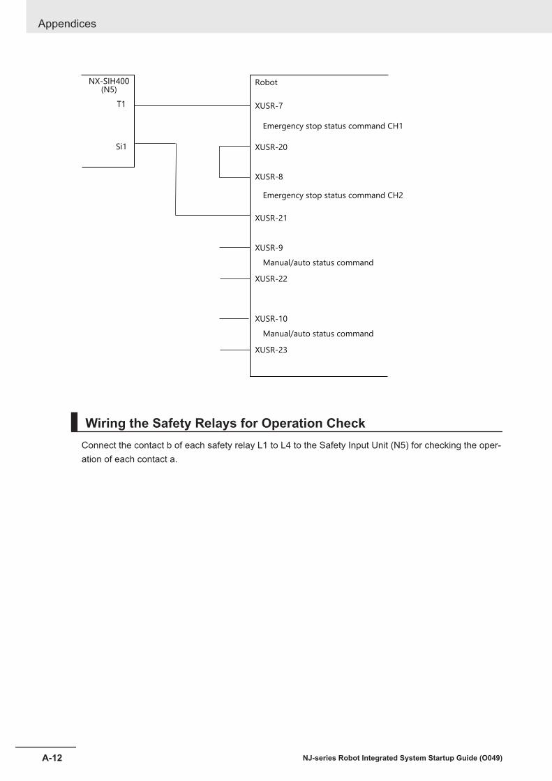
NX-SIH400(N5)
Robot
Emergency stop status command CH1
Emergency stop status command CH2
XUSR-7
XUSR-20
XUSR-8
XUSR-21
Manual/auto status command
XUSR-9
XUSR-22
Manual/auto status command
XUSR-10
XUSR-23
Si1
T1
Wiring the Safety Relays for Operation CheckConnect the contact b of each safety relay L1 to L4 to the Safety Input Unit (N5) for checking the oper-ation of each contact a.
Appendices
A-12 NJ-series Robot Integrated System Startup Guide (O049)
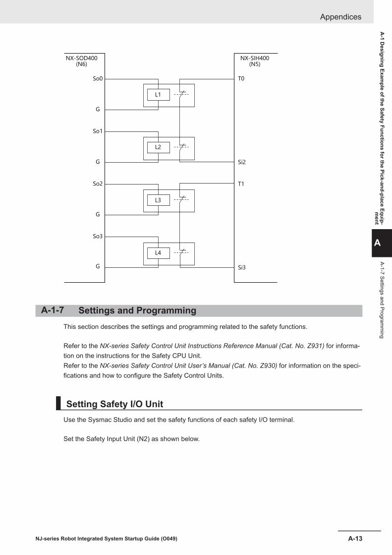
NX-SOD400
(N6)
NX-SIH400
(N5)
So0 T0
Si2
T1
Si3
G
So1
G
So2
G
So3
G
L1
L2
L3
L4
A-1-7 Settings and ProgrammingThis section describes the settings and programming related to the safety functions.
Refer to the NX-series Safety Control Unit Instructions Reference Manual (Cat. No. Z931) for informa-tion on the instructions for the Safety CPU Unit.Refer to the NX-series Safety Control Unit User’s Manual (Cat. No. Z930) for information on the speci-fications and how to configure the Safety Control Units.
Setting Safety I/O UnitUse the Sysmac Studio and set the safety functions of each safety I/O terminal.
Set the Safety Input Unit (N2) as shown below.
Appendices
A-13NJ-series Robot Integrated System Startup Guide (O049)
A-1 D
esigning Example of the Safety Functions for the Pick-and-place Equip-
ment
A
A-1-7 Settings and Programm
ing

Set the Safety Input Unit (N3) as shown below.
Set the Safety Input Unit (N4) as shown below.
Set the Safety Input Unit (N5) as shown below.
Appendices
A-14 NJ-series Robot Integrated System Startup Guide (O049)

Set the Safety Output Unit (N6) as shown below.
Registering Device VariablesUse the Sysmac Studio and set the device variables of each Safety I/O Unit.
Appendices
A-15NJ-series Robot Integrated System Startup Guide (O049)
A-1 D
esigning Example of the Safety Functions for the Pick-and-place Equip-
ment
A
A-1-7 Settings and Programm
ing

Safety ProgramsUse the Sysmac Studio to create variables and programs as shown below.
Create variables as shown below.
Appendices
A-16 NJ-series Robot Integrated System Startup Guide (O049)

Create programs as shown below.
Appendices
A-17NJ-series Robot Integrated System Startup Guide (O049)
A-1 D
esigning Example of the Safety Functions for the Pick-and-place Equip-
ment
A
A-1-7 Settings and Programm
ing

Appendices
A-18 NJ-series Robot Integrated System Startup Guide (O049)

Appendices
A-19NJ-series Robot Integrated System Startup Guide (O049)
A-1 D
esigning Example of the Safety Functions for the Pick-and-place Equip-
ment
A
A-1-7 Settings and Programm
ing

Appendices
A-20 NJ-series Robot Integrated System Startup Guide (O049)

A-2 How to Use 3D VisualizerThis section describes methods to manipulate the viewpoint on a robot simulation.Operations are performed on the 3D Visualizer in Sysmac Studio.
A-2-1 Set the 3D Visualizer to the Float ModeThe 3D Visualizer is displayed in the Dock mode by default in Sysmac Studio.
To enlarge the 3D Visualizer, display it in the Float mode, then resize it.
1 Right-click the 3D Visualize tab, then select Float from the menu.
The 3D Visualizer gets into the Float mode.
Appendices
A-21NJ-series Robot Integrated System Startup Guide (O049)
A-2 H
ow to U
se 3D Visualizer
A
A-2-1 Set the 3D Visualizer to the Float M
ode

2 Click on the 3D visualizer frame and drag it until the 3D Visualizer gets large enough.
The 3D Visualizer is enlarged.
Appendices
A-22 NJ-series Robot Integrated System Startup Guide (O049)

A-2-2 Rotate the ViewpointThe following two methods are available to rotate the viewpoint:• Using the 3D View Switching Tool• Using the Rotate icon
This section provides the information about these two methods to rotate the viewpoint in the 3D Visu-alizer.
3D View Switching ToolThe 3D View Switching Tool displayed at the right bottom of the window allows to switch the viewpoint.The 3D View Switching Tool consists of three elements: Face, Corner, and Edge.The operation procedure is illustrated with an example.
1 Put the mouse pointer over the right edge of U. Then the pointed place turns black.
2 Click it, then the view is switched so that the clicked side faces you.
Appendices
A-23NJ-series Robot Integrated System Startup Guide (O049)
A-2 H
ow to U
se 3D Visualizer
A
A-2-2 Rotate the View
point

Clicking the left corner changes the view as shown below.
Rotate iconThis section describes how to rotate the viewpoint by using the Rotate icon of the 3D Visualizer.
1 Click the Rotate icon on the 3D Visualizer.
An icon that shows the mouse pointer can rotate the viewpoint appears.
2 Press and hold down the left button of the mouse, then drag to the direction you want to rotatethe viewpoint.
Appendices
A-24 NJ-series Robot Integrated System Startup Guide (O049)

Drag upward: Move the viewpoint downwardDrag downward: Move the viewpoint upwardDrag to the right: Move the viewpoint to the leftDrag to the left: Move the viewpoint to the right
There are two modes in rotation.
Mode DescriptionTumbler rotation A 3D shape data can be viewed from any angle.Turntable rotation The viewpoint can be rotated clockwise or counterclockwise around the Z-axis of
the world coordinate system. Or the 3D shape data can be viewed in the range of±90° vertically.
A-2-3 Translate the ViewpointThis section describes how to move the viewpoint on the 3D Visualizer.Move the viewpoint downward so that you can see the entire robot.
1 Click the Translate icon on the 3D Visualizer.
Appendices
A-25NJ-series Robot Integrated System Startup Guide (O049)
A-2 H
ow to U
se 3D Visualizer
A
A-2-3 Translate the Viewpoint

An icon that shows the mouse pointer can translate the viewpoint on the 3D Visualizer ap-pears.
2 Press and hold down the left button of the mouse, then drag to the direction you want to trans-late the viewpoint.
Additional Information
In addition to the operation mentioned above, pressing the mouse wheel and dragging to an in-tended direction can translate the viewpoint.
A-2-4 Zoom-in and Zoom-outThis section describes how to zoom in or out on the 3D Visualizer.
1 Click the Zoom icon on the 3D Visualizer.
An icon that shows the mouse pointer can zoom appears.
2 Press and hold down the left button of the mouse, then drag it.Drag to the right: Enlarge the size (Zoom-in)Drag to the left: Reduce the size (Zoom-out)
Appendices
A-26 NJ-series Robot Integrated System Startup Guide (O049)

Additional Information
Rotating the mouse wheel also enables zoom-in or -out.The position of the mouse pointer represents the center of zooming in or out.
Appendices
A-27NJ-series Robot Integrated System Startup Guide (O049)
A-2 H
ow to U
se 3D Visualizer
A
A-2-4 Zoom-in and Zoom
-out

A-3 Setting Items on the Sysmac Studioand the Setting Targets
The correspondences between the items in the Multiview Explorer of the Sysmac Studio and eachhardware are provided below.If you select ApplicationManager0 for the device in the Multiview Explorer, the settings for the Appli-cation Manager of the IPC Application Controller are available. If you select new_Controller_0, thesettings for a sequence control program of the Robot Integrated CPU Unit, and if you selectRobotControlSettings, the settings for a V+ program of the Robot Integrated CPU Unit are available.Refer to the product manuals for details.
IPC Application Controller
Process Manager
Recipe Manager
ACE Sight
Pack Manager
Application Manager
ACE
...
Robot Integrated CPU Unit
Sequence control program
V+ program
Robot control parameters
Robot setting files
Sysmac Studio
Setting items in the MultiView Explorer Setting target
Appendices
A-28 NJ-series Robot Integrated System Startup Guide (O049)

A-4 Using Troubleshooting FunctionsRefer to the Sysmac Studio Robot Integrated System Building Function with Robot Integrated CPUUnit Operation Manual (Cat. No. W595) for the operation procedure of the troubleshooting functionson the Sysmac Studio.
Appendices
A-29NJ-series Robot Integrated System Startup Guide (O049)
A-4 U
sing Troubleshooting Functions
A

Appendices
A-30 NJ-series Robot Integrated System Startup Guide (O049)


Authorized Distributor:
In the interest of product improvement, specifications are subject to change without notice.
Cat. No. O049-E1-04 0322
© OMRON Corporation 2020 - 2022 All Rights Reserved.
OMRON Corporation Industrial Automation Company
OMRON ELECTRONICS LLC2895 Greenspoint Parkway, Suite 200 Hoffman Estates, IL 60169 U.S.A.Tel: (1) 847-843-7900/Fax: (1) 847-843-7787
Regional Headquarters
OMRON EUROPE B.V.Wegalaan 67-69, 2132 JD HoofddorpThe NetherlandsTel: (31)2356-81-300/Fax: (31)2356-81-388
Contact: www.ia.omron.com
Kyoto, JAPAN
OMRON ASIA PACIFIC PTE. LTD.No. 438A Alexandra Road # 05-05/08 (Lobby 2), Alexandra Technopark, Singapore 119967Tel: (65) 6835-3011/Fax: (65) 6835-2711
OMRON (CHINA) CO., LTD.Room 2211, Bank of China Tower, 200 Yin Cheng Zhong Road, PuDong New Area, Shanghai, 200120, ChinaTel: (86) 21-5037-2222/Fax: (86) 21-5037-2200