NH1800 Maintenance Guide - Atlantic ATM LLC
211
NH1800 Maintenance Guide Copyrightⓒ Nautilus Hyosung Inc. 2009 All right reserved
-
Upload
khangminh22 -
Category
Documents
-
view
1 -
download
0
Transcript of NH1800 Maintenance Guide - Atlantic ATM LLC
NH1800 Maintenance Guide
Copyright Nautilus Hyosung Inc. 2009 All right reserved
NH-1800
Revision Record
Date Page Version Description of Change
June 2009 All 1.0 New Publication
NH-1800
Table Of Contents
Chapter 1. Overview
1.1. About the NH-1800 ...................................................................................................................1-2
1.2. Features .....................................................................................................................................1-2
Chapter 2. Safety Warnings
2.1. Safety Precautions .....................................................................................................................2-2
2.2. Description of Precaution Symbols ............................................................................................2-3
Chapter 3. System Configuration
3.1. External Appearance ..................................................................................................................3-2
3.2. H/W Configuration ......................................................................................................................3-3
Chapter 4. User Handling Unit
4.1. Appearance / Functional Diagram ..............................................................................................4-2
4.2. Monitor .......................................................................................................................................4-3
4.3. Function Key Pad ...................................................................................................................4-29
4.4. Customer Display Keys ........................................................................................................4-32
Chapter 5. Body Unit
5.1.Control Electronics........................................................................................................................5-2
5.2. Main Power Supply ..................................................................................................................5-23
Chapter 6. Cash Dispenser Unit
6.1. Appearance and Functional Diagram .........................................................................................6-2
6.2. Unit Block Diagram ....................................................................................................................6-5
6.3. Module and Sensor Replacement ..............................................................................................6-6
6.4. Adjustment Standard ..............................................................................................................6-19
6.5. Oiling Standard .......................................................................................................................6-20
6.6. Cleaning Standard ..................................................................................................................6-21
NH-1800
6.7. Setting Specifications .............................................................................................................6-22
6.8. Cable Connection Diagram ......................................................................................................6-23
6.9. Interface Specifications ............................................................................................................6-24
Optional A. Cash Dispenser Unit : CDU-M type ............................................................................6-26
Chapter 7. Magnetic Card Unit (MCU)
7.1. Specification .............................................................................................................................7-2
7.2. Repair and Maintenance ..........................................................................................................7-7
Chapter 8. Receipt Printer
8.1. Appearance/Arrangement Plan ..................................................................................................8-2
8.2. Repair and Maintenance ............................................................................................................8-5
Chapter 9. Vault Unit
9.1. Dial Lock ...................................................................................................................................9-2
9.2. Electronic Lock ...........................................................................................................................9-6
9.3. Electronic Lock (∥) ................................................................................................................9-11
9.4. Cencon Lock ............................................................................................................................9-13
Chapter 10. Consumable Part Specifications
10.1. List of Expendable Parts ........................................................................................................10-2
10.2. Receipt Paper ........................................................................................................................10-2
10.3. Magnetic Card ........................................................................................................................10-6
Chapter 11. Error Code and Troubleshooting
11.1. Error Code and Troubleshooting ............................................................................................11-2
11.2. Additional Error Code for the Optional Cash Dispenser with 2,000 Cassette .......................11-21
NH-1800 1. Overview
1-1
Chapter 1. Overview
NH-1800 1. Overview
1-2
1. Overview
1.1 About the NH-1800
The NH-1800 is designed to meet the everyday demands of immediate cash needs for individuals
with a compact size to fit in virtually any place. This Automated Teller Machine (ATM) is connected to
a network processor to verify accounts and any other inquires through the insertion of a customer’s
card. The NH-1800 is easy to use, easy to service and is able to support customer’s needs.
1.2 Features
H/W Features
Mechanical combination lock
Electronic combination lock (optional)
7 inch wide TFT LCD
480 234 Resolution of back-lit LCD
Dial-up telephone line instead of expensive leased line
1,000 new notes capacity (USD)
2,000 /4,000 (2CSTx2,000) new notes cassette (optional)
DIP type magnetic card reader Support IC card (EMV Level-1, optional)
Automated receipt printer paper loading
Thermal receipt printer for high speed printing with graphics
Modular design for easy maintenance
Functional Features
Electronic journal with up to 2,000 transactions, up/down loading supported
Supports English, Spanish, French, Korean and Japanese
Detailed average history report feature
Quick setup feature
Advertisement feature for store promotion
Error code description for easy to service
NH-1800 1. Overview
1-3
This manual is designed to provide maintenance guidelines for NH -1800 and provide detailed
description of the following:
System configuration
Specification of each Module
- Customer Handling Unit
- Control Electronics
- Power Supply
- Cash Dispenser
- Magnetic Card Reader
- Receipt Printer
- Vault Unit
Replacement parts
Consumable parts
NH-1800 2. Safety Warnings
2-1
Chapter 2. Safety Warnings
NH-1800 2. Safety Warnings
2-2
2. Safety Warnings
2.1 Safety Precautions
Please read the following instructions before operating equipment.
Operate equipment in the order outlined in this manual.
Follow precautions indicated in this manual, as well as the equipment itself.
Failure to properly address these precautions may lead to injury or damage to the product.
Avoid operations not addressed in this manual.
Improper use of the secondary lock feature will reduce the security level of the ATM.
If you cannot remedy system problems using the methods outlined in this manual, please refer to
contact information listed in the manual.
Any change or modifications in construction of this device which are not expressly
approved by the party responsible for compliance could void the user’s authority to operate the
equipment.
Note : This equipment has been tested and found to comply with the limits for a Class A digital
device, pursuant to part 15 of the FCC Rules. These limits are designed to provide
reasonable protection against harmful interference when the equipment is operated in a
commercial environment. This equipment generates, uses, and can radiate radio frequency
energy and, if not installed and used in accordance with the instruction manual, may cause
harmful interference to radio communications. Operation of this equipment in a residential
area is likely to cause harmful interference in which case the user will be required to correct
the interference at his own expense.
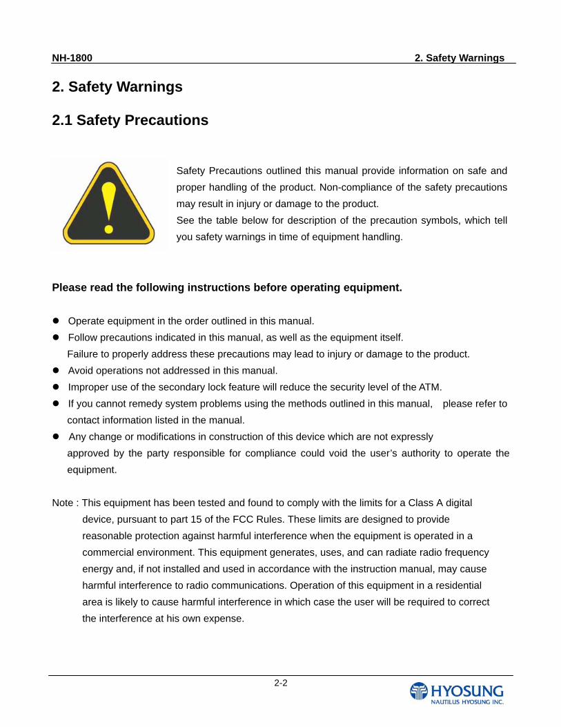
Safety Precautions outlined this manual provide information on safe and
proper handling of the product. Non-compliance of the safety precautions
may result in injury or damage to the product.
See the table below for description of the precaution symbols, which tell
you safety warnings in time of equipment handling.
NH-1800 2. Safety Warnings
2-3
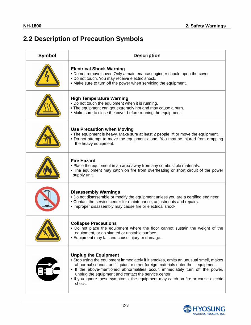
2.2 Description of Precaution Symbols
Symbol Description
Electrical Shock Warning • Do not remove cover. Only a maintenance engineer should open the cover. • Do not touch. You may receive electric shock. • Make sure to turn off the power when servicing the equipment.
High Temperature Warning • Do not touch the equipment when it is running. • The equipment can get extremely hot and may cause a burn. • Make sure to close the cover before running the equipment.
Use Precaution when Moving • The equipment is heavy. Make sure at least 2 people lift or move the equipment. • Do not attempt to move the equipment alone. You may be injured from dropping
the heavy equipment.
Fire Hazard • Place the equipment in an area away from any combustible materials. • The equipment may catch on fire from overheating or short circuit of the power supply unit.
Disassembly Warnings • Do not disassemble or modify the equipment unless you are a certified engineer. • Contact the service center for maintenance, adjustments and repairs. • Improper disassembly may cause fire or electrical shock.
Collapse Precautions • Do not place the equipment where the floor cannot sustain the weight of the
equipment, or on slanted or unstable surface. • Equipment may fall and cause injury or damage.
Unplug the Equipment • Stop using the equipment immediately if it smokes, emits an unusual smell, makes
abnormal sounds, or if liquids or other foreign materials enter the equipment. • If the above-mentioned abnormalities occur, immediately turn off the power,
unplug the equipment and contact the service center. • If you ignore these symptoms, the equipment may catch on fire or cause electric
shock.
NH-1800 2. Safety Warnings
2-4
CAUTION!!
1. TO REDUCE THE RISK OF FIRE, USE ONLY No. 26 AWG OR LARGER
TELECOMMUNICATION LINE CORD
2. RISK OF EXPLOSION IF BATTERY IS REPLACED BY AN INCORRECT
TYPE. DISPOSED OF USED BATTERIES ACCORDING TO THE INSTRUCTIONS
3. FOR PLUGGABLE EQUIPMENT, THE SOCKET-OUTLET SHALL BE INSTALLED NEAR
THE EQUIPMENT AN SHALL BE EASILY ACCESSIBLE
4. THE EQUIPMENT IS TO BE SECURED TO THE BUILDING STRUCTURE BEFORE
OPERATION
NH-1800 3. System Configuration
3-1
Chapter 3. System Configuration
NH-1800 3. System Configuration
3-2
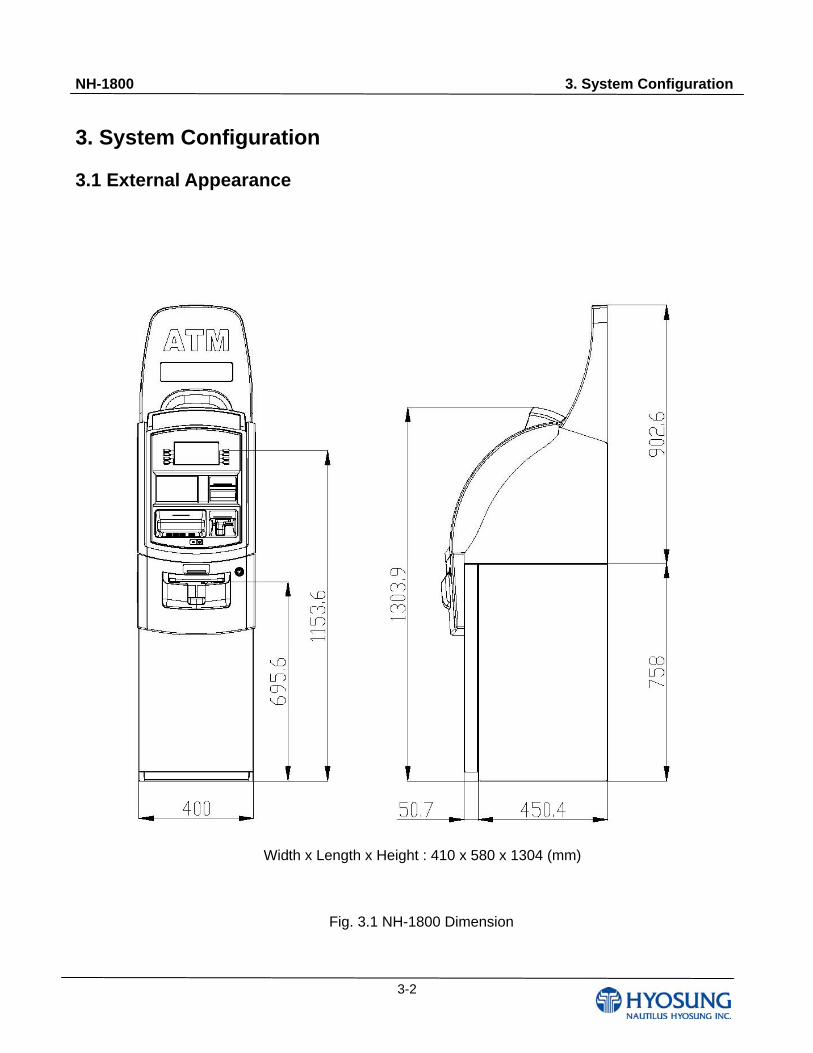
3. System Configuration
3.1 External Appearance
Fig. 3.1 NH-1800 Dimension
Width x Length x Height : 410 x 580 x 1304 (mm)
NH-1800 3. System Configuration
3-3
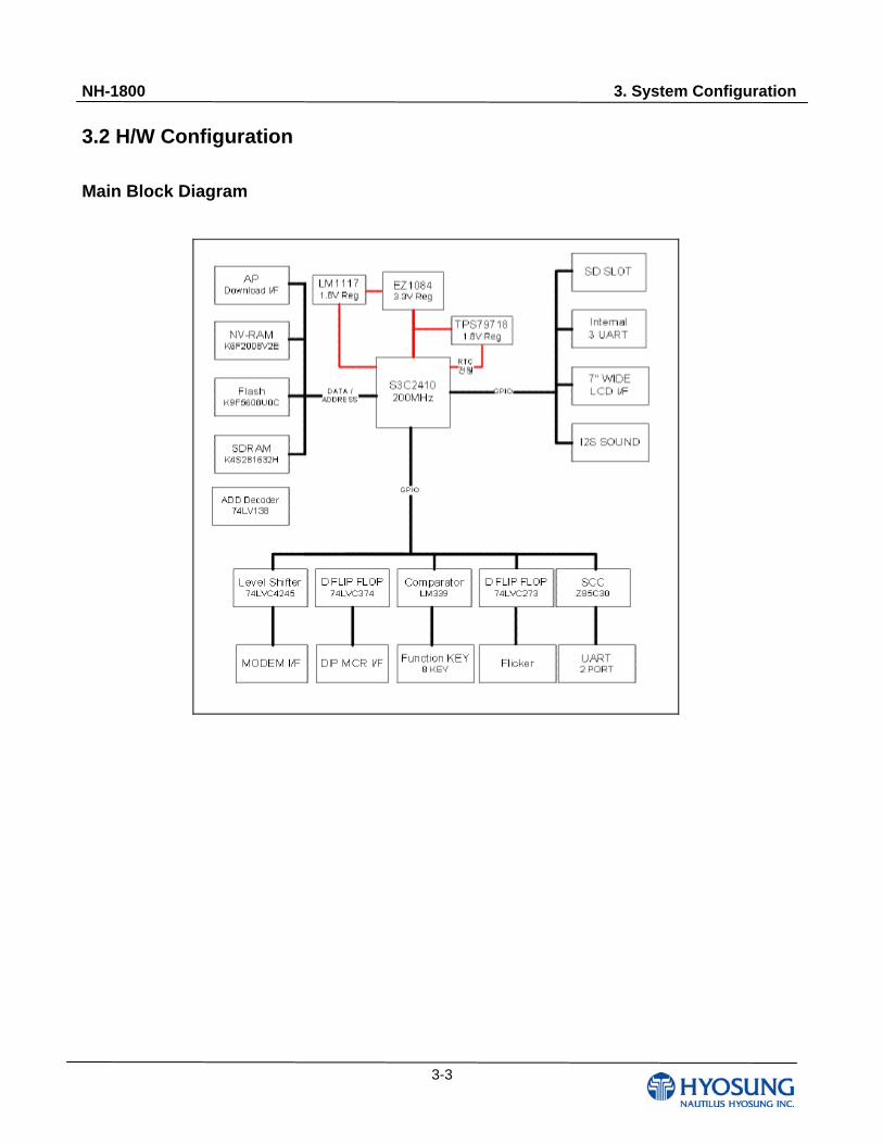
3.2 H/W Configuration Main Block Diagram
NH-1800 3. System Configuration
3-4
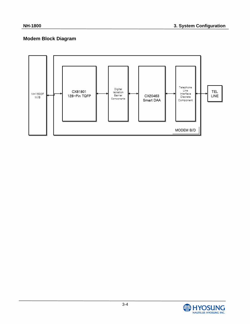
Modem Block Diagram
NH-1800 4. Customer Handling Unit
4-1
Chapter 4. Customer Handling Unit
NH-1800 4. Customer Handling Unit
4-2
4. Customer Handling Unit
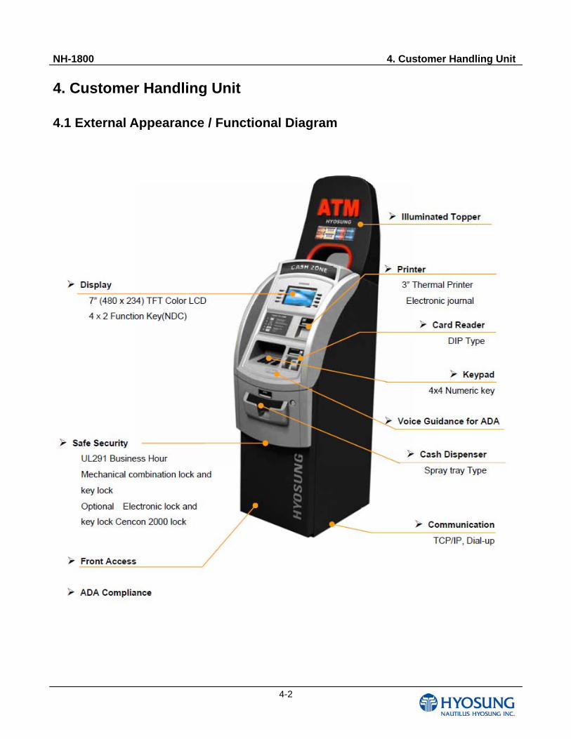
4.1 External Appearance / Functional Diagram
NH-1800 4. Customer Handling Unit
4-3
4.2 Monitor (LCD)
4.2.1 General Description
*Description
LTE700WQ-F05 is a TMR (Transmissive with Micro Reflective) type color active matrix TFT (Thin
Film Transistor) liquid crystal display(LCD) that uses amorphous silicon TFT as a switching devices.
This model is composed of a TFT-LCD module, a driver circuit and a back-light unit. The resolution
of a 7.0" contains 480x234(RGB) dots and can display up to 16.7 M colors. 12 o'clock direction is the
optimum viewing angle.
*Features
-triple-gate & Dual ASG
-Transmissive with Micro Reflective type and back-light with CCFL are available.
-TN (Twisted Nematic) mode.
-Dot/column inversion mode.
-24bit RGB Interface
-DE (Data Enable) & SYNC mode
-DE, Vsync, Hsync, DOTCLK
*Applications
-Display terminals for PMP (Portable Multi media Player), Portable CNS (P-CNS), MP3 application
products.
-Display terminals for AV application products.
NH-1800 4. Customer Handling Unit
4-4
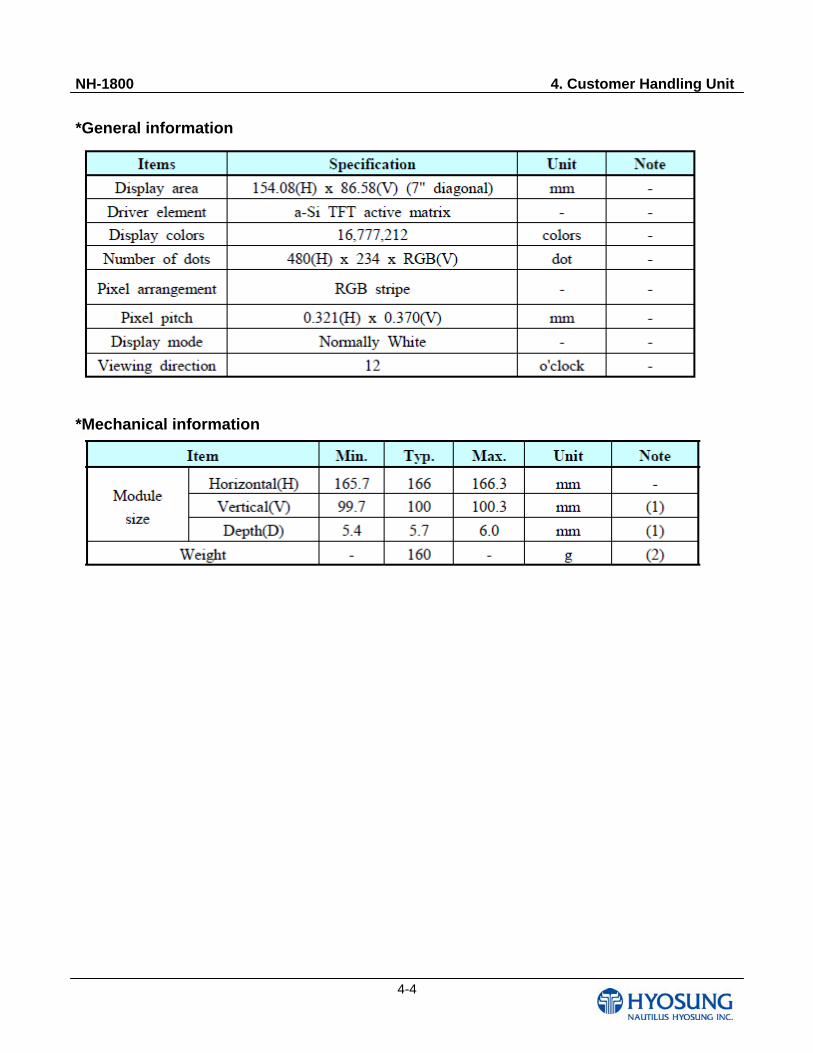
*General information
*Mechanical information
NH-1800 4. Customer Handling Unit
4-5
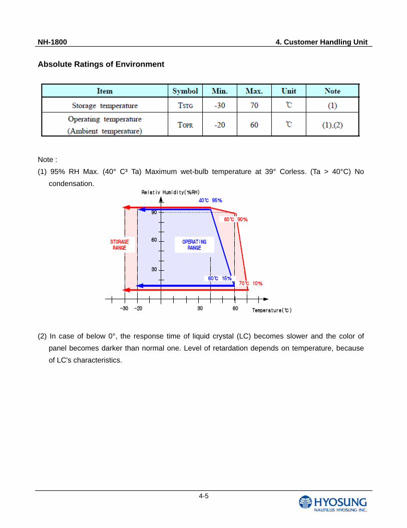
Absolute Ratings of Environment
Note :
(1) 95% RH Max. (40° C³ Ta) Maximum wet-bulb temperature at 39° Corless. (Ta > 40°C) No
condensation.
(2) In case of below 0°, the response time of liquid crystal (LC) becomes slower and the color of
panel becomes darker than normal one. Level of retardation depends on temperature, because
of LC's characteristics.
NH-1800 4. Customer Handling Unit
4-6
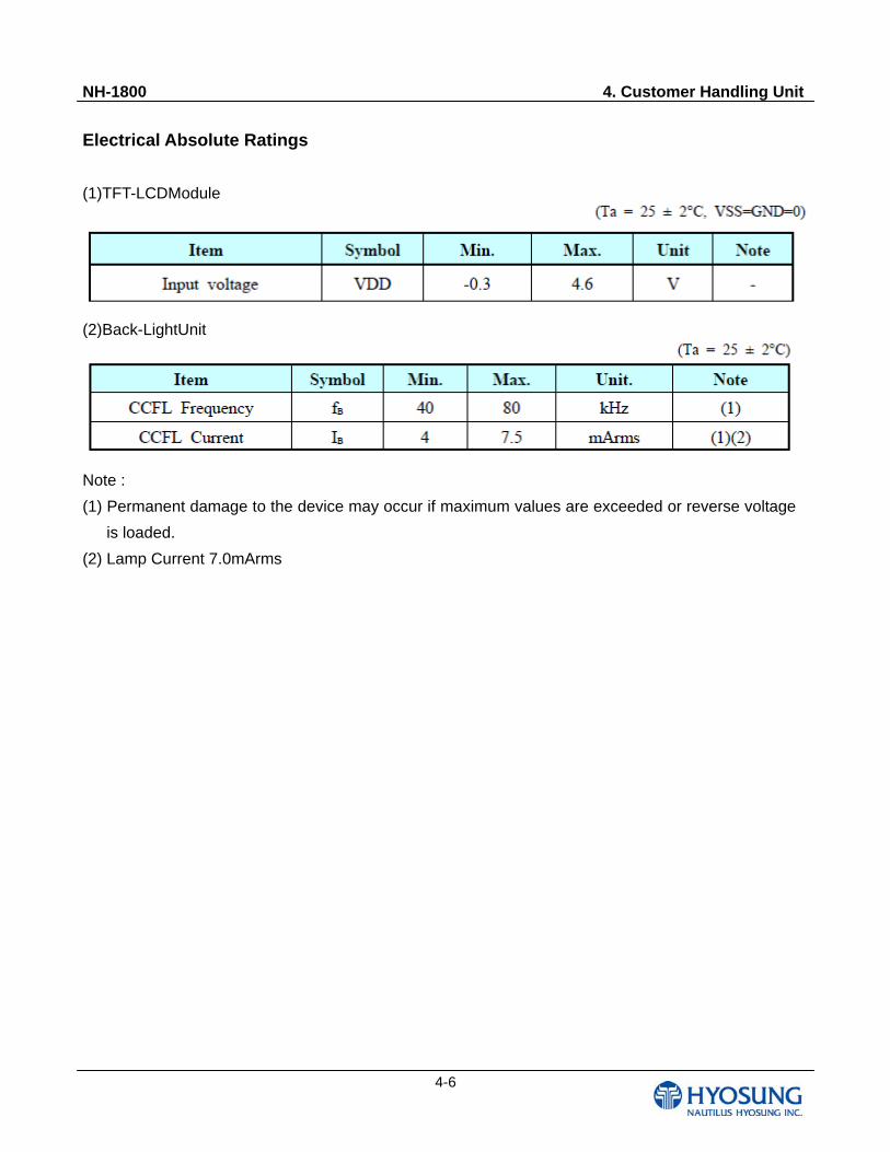
Electrical Absolute Ratings
(1)TFT-LCDModule
(2)Back-LightUnit
Note :
(1) Permanent damage to the device may occur if maximum values are exceeded or reverse voltage
is loaded.
(2) Lamp Current 7.0mArms
NH-1800 4. Customer Handling Unit
4-7
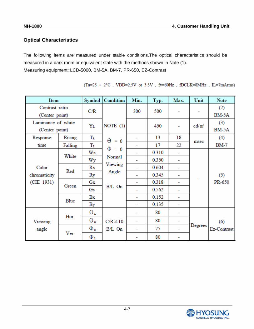
Optical Characteristics
The following items are measured under stable conditions.The optical characteristics should be
measured in a dark room or equivalent state with the methods shown in Note (1).
Measuring equipment: LCD-5000, BM-5A, BM-7, PR-650, EZ-Contrast
NH-1800 4. Customer Handling Unit
4-8
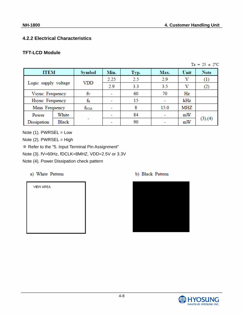
4.2.2 Electrical Characteristics
TFT-LCD Module
Note (1). PWRSEL = Low
Note (2). PWRSEL = High
※ Refer to the "5. Input Terminal Pin Assignment"
Note (3). fV=60Hz, fDCLK=8MHZ, VDD=2.5V or 3.3V
Note (4). Power Dissipation check pattern
NH-1800 4. Customer Handling Unit
4-9
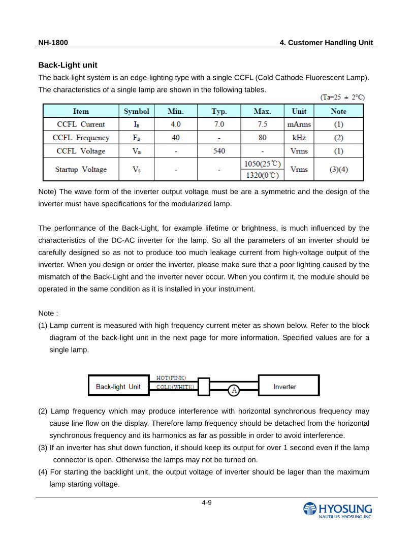
Back-Light unit
The back-light system is an edge-lighting type with a single CCFL (Cold Cathode Fluorescent Lamp).
The characteristics of a single lamp are shown in the following tables.
Note) The wave form of the inverter output voltage must be are a symmetric and the design of the
inverter must have specifications for the modularized lamp.
The performance of the Back-Light, for example lifetime or brightness, is much influenced by the
characteristics of the DC-AC inverter for the lamp. So all the parameters of an inverter should be
carefully designed so as not to produce too much leakage current from high-voltage output of the
inverter. When you design or order the inverter, please make sure that a poor lighting caused by the
mismatch of the Back-Light and the inverter never occur. When you confirm it, the module should be
operated in the same condition as it is installed in your instrument.
Note :
(1) Lamp current is measured with high frequency current meter as shown below. Refer to the block
diagram of the back-light unit in the next page for more information. Specified values are for a
single lamp.
(2) Lamp frequency which may produce interference with horizontal synchronous frequency may
cause line flow on the display. Therefore lamp frequency should be detached from the horizontal
synchronous frequency and its harmonics as far as possible in order to avoid interference.
(3) If an inverter has shut down function, it should keep its output for over 1 second even if the lamp
connector is open. Otherwise the lamps may not be turned on.
(4) For starting the backlight unit, the output voltage of inverter should be lager than the maximum
lamp starting voltage.
NH-1800 4. Customer Handling Unit
4-10
(5) Because the inverter uses high voltage, please disconnect it from the power before assembling
or disassembling.
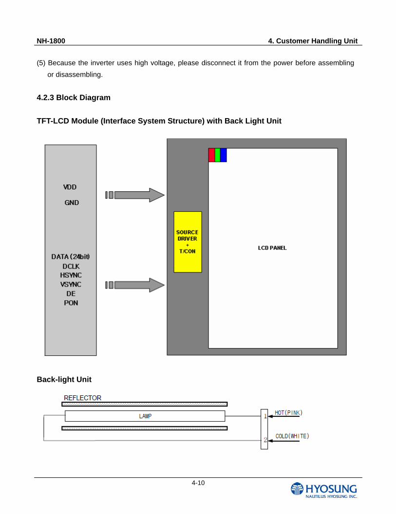
4.2.3 Block Diagram
TFT-LCD Module (Interface System Structure) with Back Light Unit
Back-light Unit
NH-1800 4. Customer Handling Unit
4-11
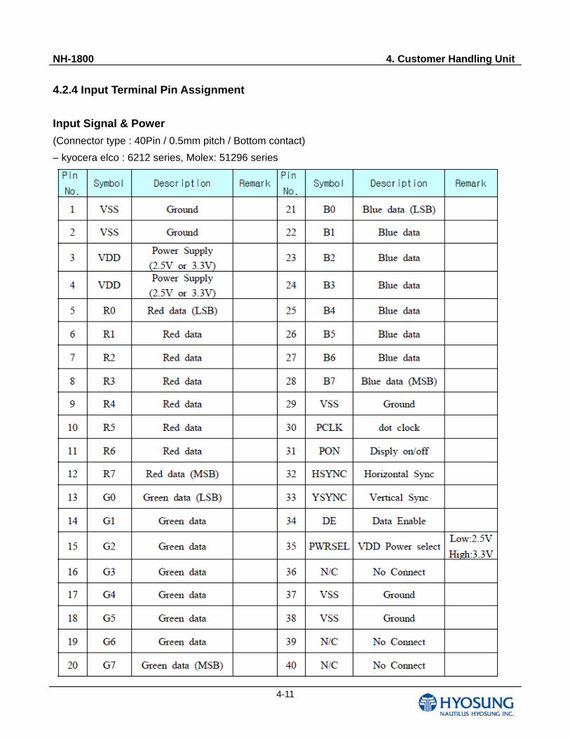
4.2.4 Input Terminal Pin Assignment
Input Signal & Power
(Connector type : 40Pin / 0.5mm pitch / Bottom contact)
– kyocera elco : 6212 series, Molex: 51296 series
NH-1800 4. Customer Handling Unit
4-12
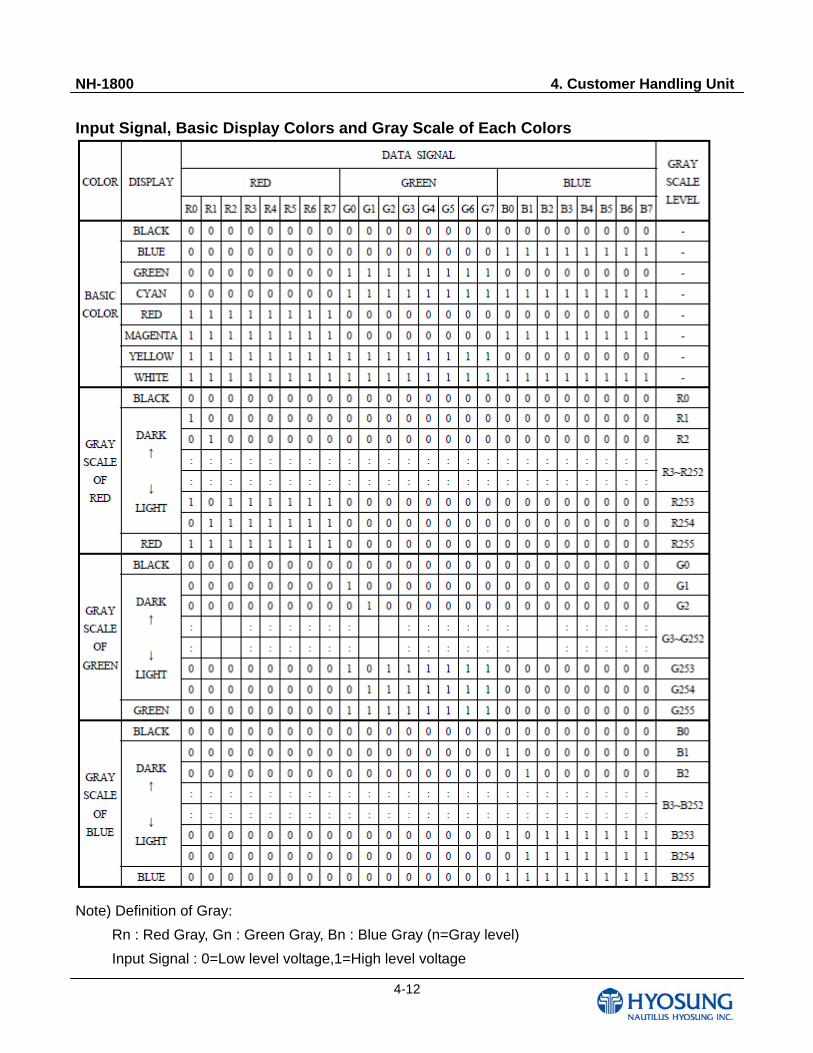
Input Signal, Basic Display Colors and Gray Scale of Each Colors
Note) Definition of Gray:
Rn : Red Gray, Gn : Green Gray, Bn : Blue Gray (n=Gray level)
Input Signal : 0=Low level voltage,1=High level voltage
NH-1800 4. Customer Handling Unit
4-13
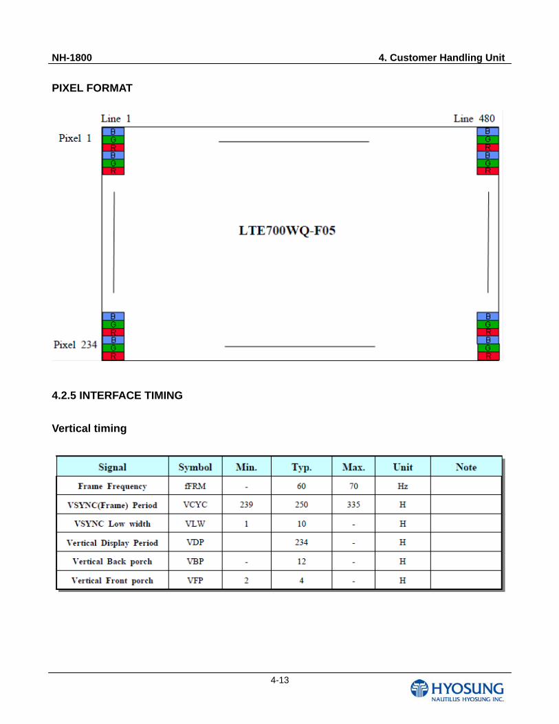
PIXEL FORMAT
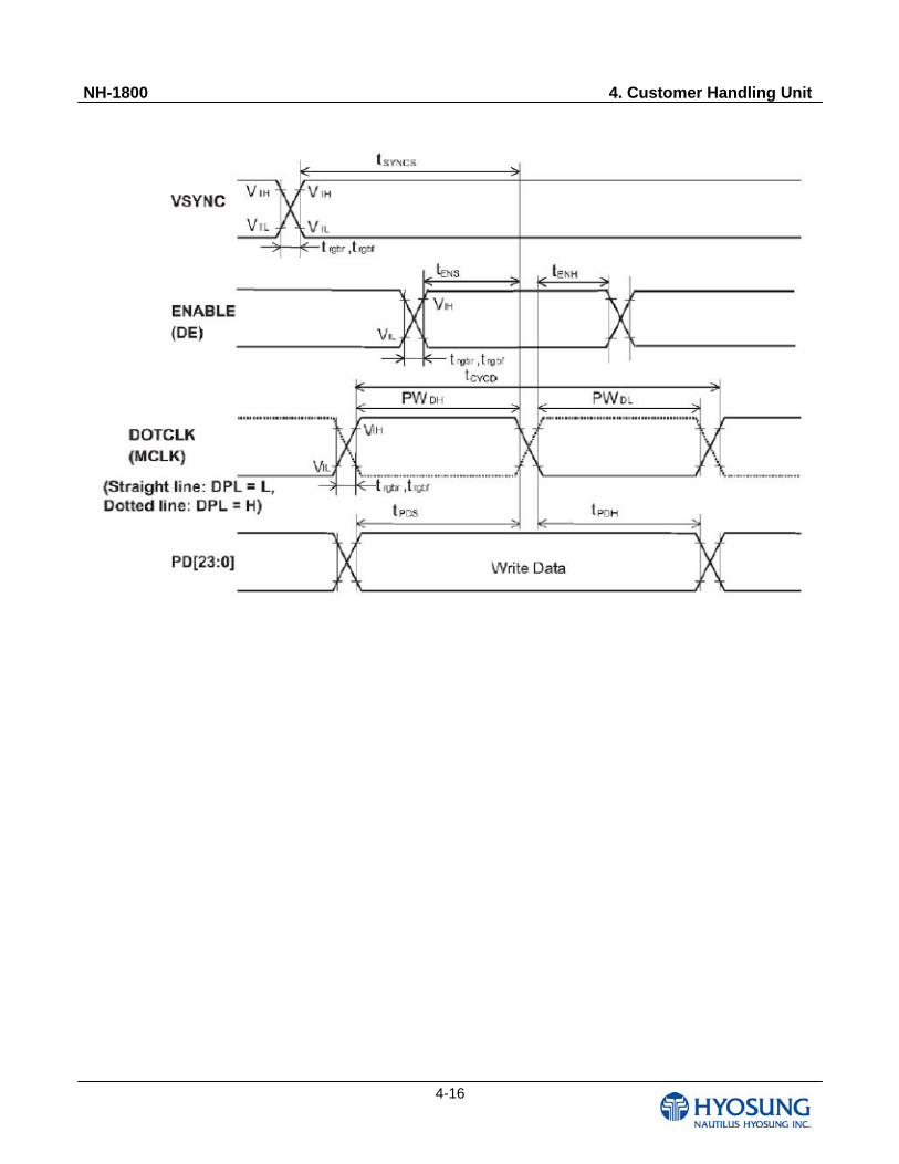
4.2.5 INTERFACE TIMING
Vertical timing
NH-1800 4. Customer Handling Unit
4-14
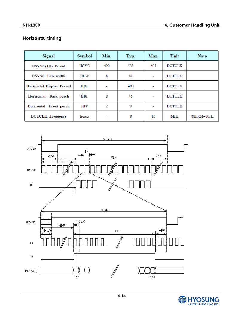
Horizontal timing
NH-1800 4. Customer Handling Unit
4-15
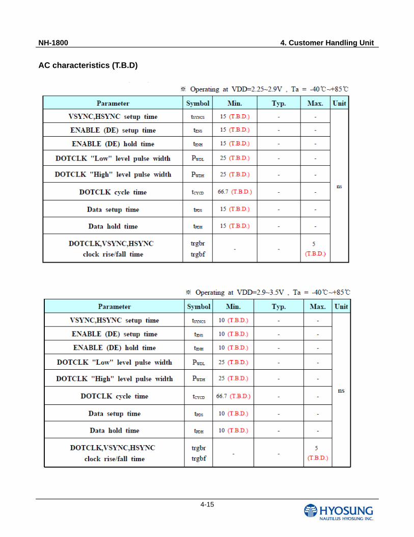
AC characteristics (T.B.D)
NH-1800 4. Customer Handling Unit
4-16
NH-1800 4. Customer Handling Unit
4-17
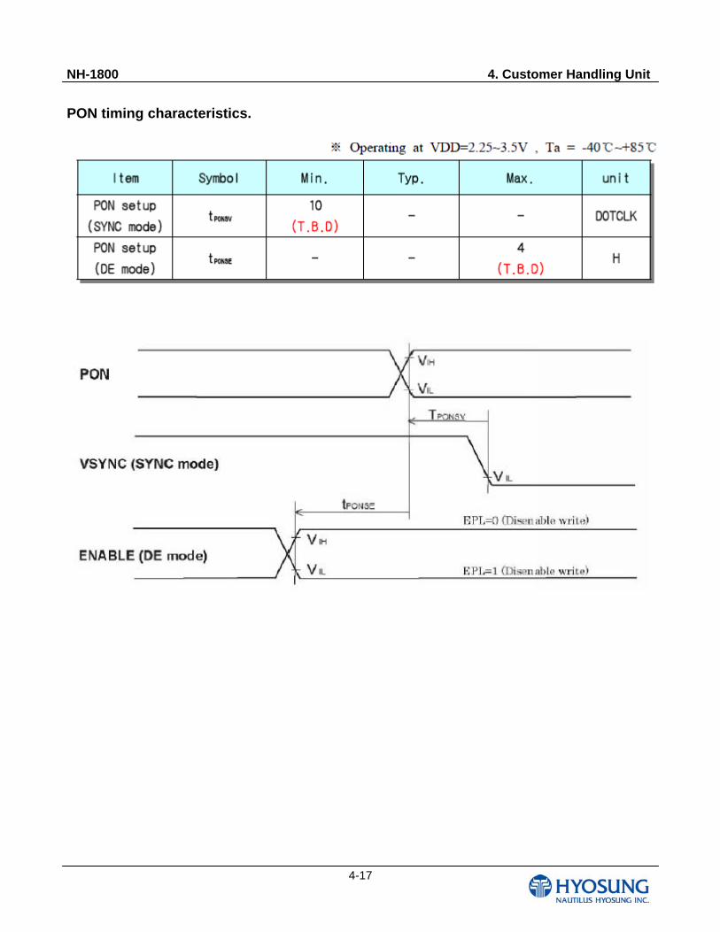
PON timing characteristics.
NH-1800 4. Customer Handling Unit
4-18
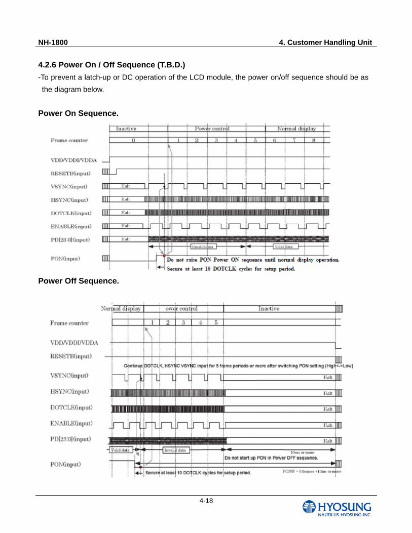
4.2.6 Power On / Off Sequence (T.B.D.)
-To prevent a latch-up or DC operation of the LCD module, the power on/off sequence should be as
the diagram below.
Power On Sequence.
Power Off Sequence.
NH-1800 4. Customer Handling Unit
4-19
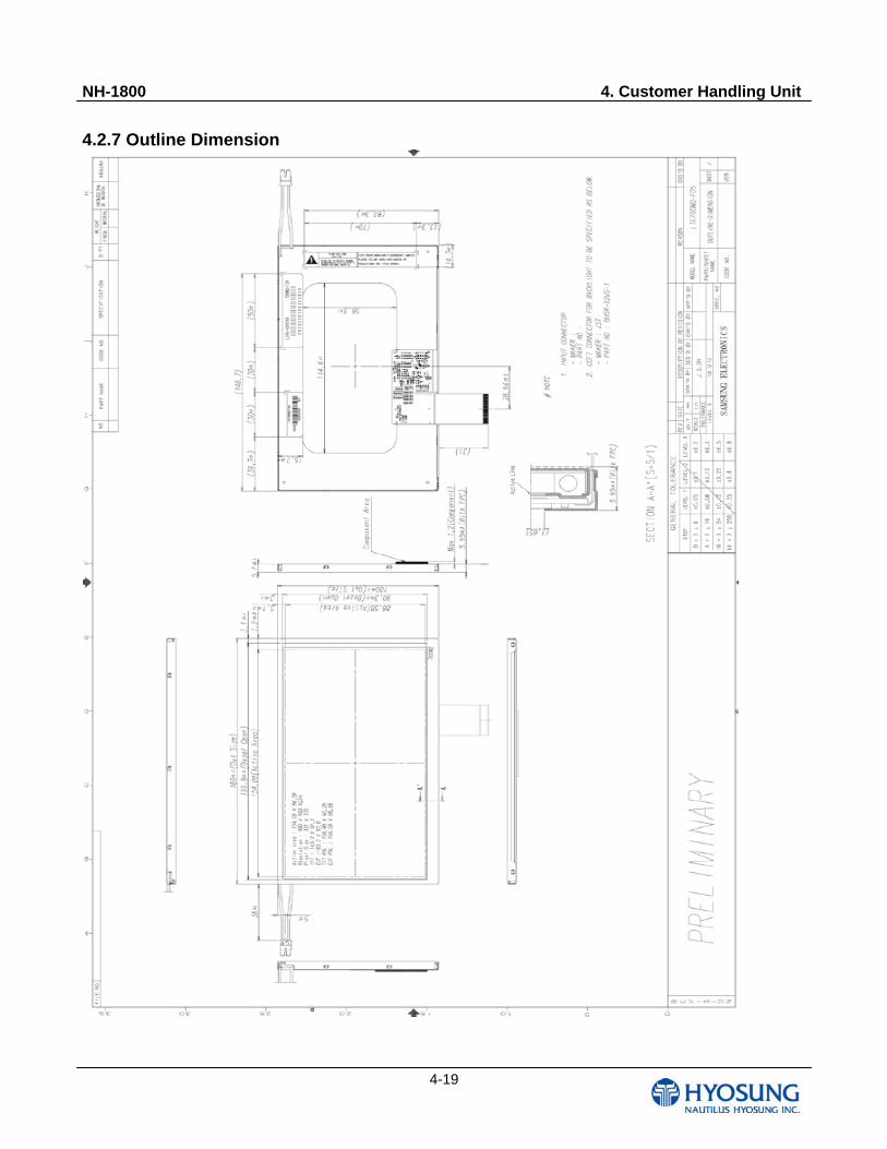
4.2.7 Outline Dimension
NH-1800 4. Customer Handling Unit
4-20
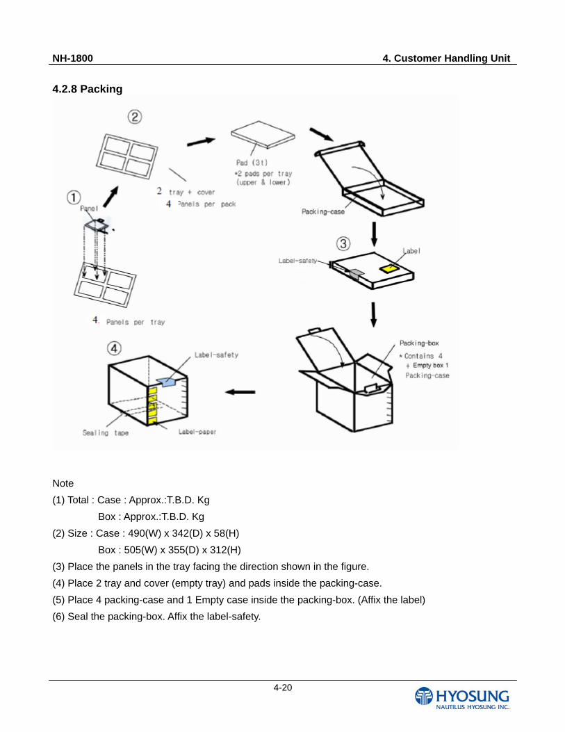
4.2.8 Packing
Note
(1) Total : Case : Approx.:T.B.D. Kg
Box : Approx.:T.B.D. Kg
(2) Size : Case : 490(W) x 342(D) x 58(H)
Box : 505(W) x 355(D) x 312(H)
(3) Place the panels in the tray facing the direction shown in the figure.
(4) Place 2 tray and cover (empty tray) and pads inside the packing-case.
(5) Place 4 packing-case and 1 Empty case inside the packing-box. (Affix the label)
(6) Seal the packing-box. Affix the label-safety.
NH-1800 4. Customer Handling Unit
4-21
4.2.9 General Precautions
Handling
(a) When the module is assembled, it should be attached to the system firmly. Be careful not to twist
and bend the module.
(b) Refrain from strong mechanical shock and / or any force to the module. In addition to damage, this
may cause improper operation or damage to the module and back-light unit.
(c) Note that polarizers are very fragile and could be easily damaged. Do not press or scratch the
surface harder than a HB pencil lead.
(d) Wipe off water droplets or oil immediately. If you leave the droplets for a long time, Staining and
discoloration may occur.
(e) If the surface of the polarizer is dirty, clean it using some absorbent cotton or soft cloth.
(f) The desirable cleaners are water, IPA(Isopropyl Alcohol) or Hexane. Do not use Ketone type
materials (ex. Acetone), Ethyl alcohol, Toluene, Ethyl acid or Methyl chloride. It might permanent
damage to the polarizer due to chemical reaction.
(g) If the liquid crystal material leaks from the panel, it should be kept away from the eyes or mouth. In
case of contact with hands, legs or clothes, it must be washed away thoroughly with soap.
(h) Protect the module from static , it may cause damage to the Integrated Gate Circuit.
(i) Use finger-stalls with soft gloves in order to keep display clean during the incoming inspection and
assembly process.
(j) Do not disassemble the module.
(k) Do not adjust the variable resistor which is located on the back side.
(l) Protection film for polarizer on the module shall be slowly peeled off just before use so that the
electrostatic charge can be minimized.
(m) Pins of I/F connector shall not be touched directly with bare hands
Storage
(a) Do not leave the panel in high temperature, and high humidity for a long time. It is highly
recommended to store the module with temperature from 0 to 35°C and relative humidity of less
than 70%.
(b) Do not store the TFT-LCD module in direct sunlight.
(c) The module shall be stored in a dark place. It is prohibited to apply sunlight or fluorescent light
during the store.
NH-1800 4. Customer Handling Unit
4-22
Operation
(a) Do not connect, disconnect the module in the "Power On" condition.
(b) Power supply should always be turned on/off by the "Power on/off sequence"
(c) Module has high frequency circuits. Sufficient suppression to the electromagnetic interference shall
be done by system manufacturers. Grounding and shielding methods may be important to
minimize the interference.
Others
(a) The Liquid crystal is deteriorated by ultraviolet, do not leave it in direct sunlight and strong
ultraviolet ray for many hours.
(b) Avoid condensation of water. It may result in improper operation or disconnection of electrode.
(c) Do not exceed the absolute maximum rating value. ( the supply voltage variation, input voltage
variation, variation in part contents and environmental temperature, and so on) Otherwise the
panel may be damaged.
(d) If the panel displays the same pattern continuously for a long period of time, it can be the situation
when the image "Sticks" to the screen.
(e) This panel has its circuitry FPC on the bottom side and should be handled carefully in order not to
be stressed.
(f) Avoid shortness between LED soldering pad and TSP soldering pad.
NH-1800 4. Customer Handling Unit
4-23
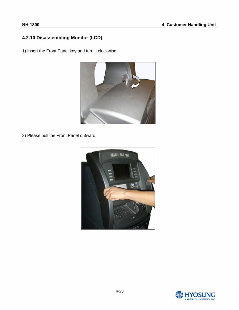
4.2.10 Disassembling Monitor (LCD)
1) Insert the Front Panel key and turn it clockwise.
2) Please pull the Front Panel outward.
NH-1800 4. Customer Handling Unit
4-24
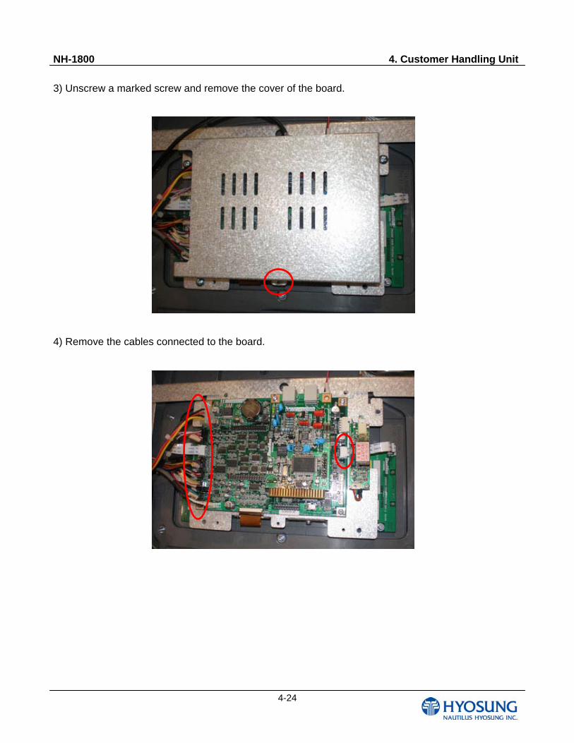
3) Unscrew a marked screw and remove the cover of the board.
4) Remove the cables connected to the board.
NH-1800 4. Customer Handling Unit
4-25
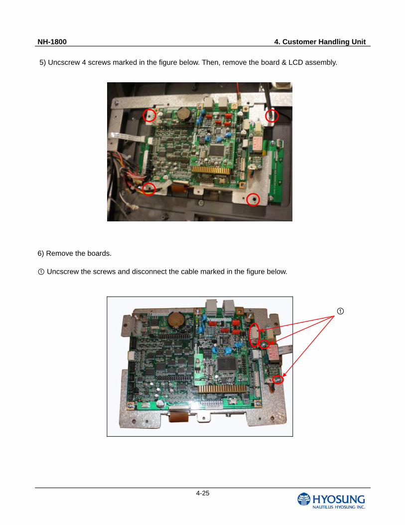
5) Uncscrew 4 screws marked in the figure below. Then, remove the board & LCD assembly.
6) Remove the boards.
① Uncscrew the screws and disconnect the cable marked in the figure below.
①
NH-1800 4. Customer Handling Unit
4-26
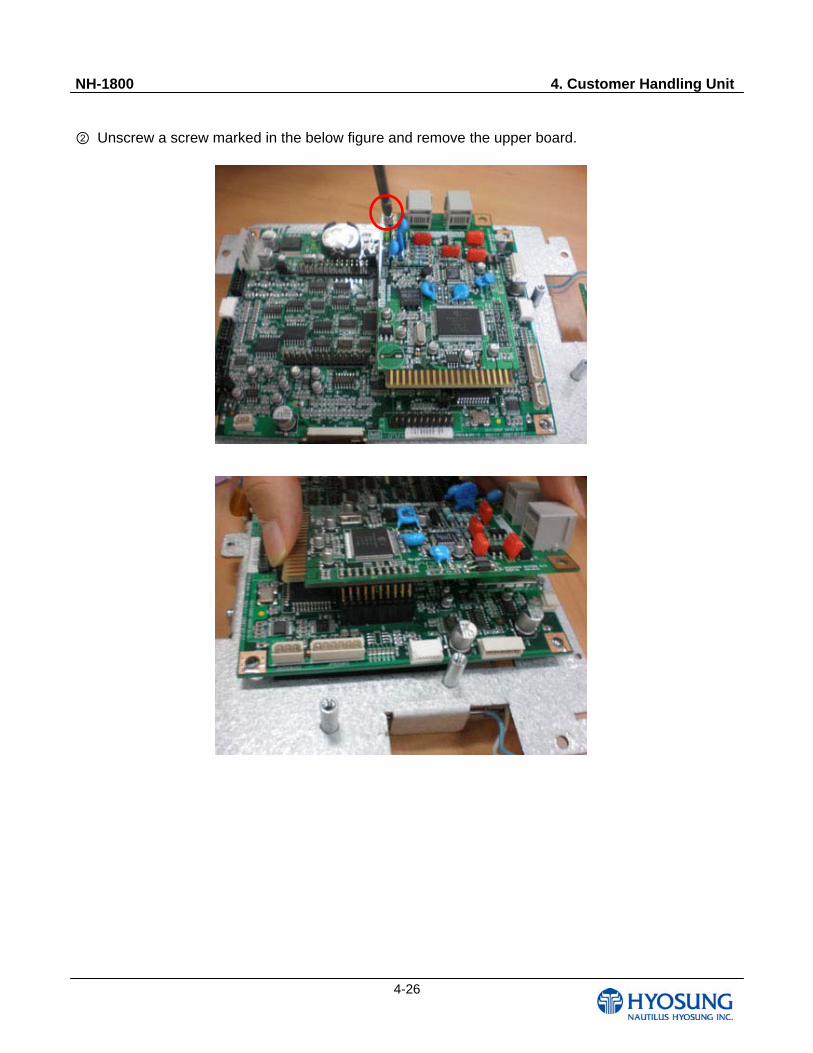
② Unscrew a screw marked in the below figure and remove the upper board.
NH-1800 4. Customer Handling Unit
4-27
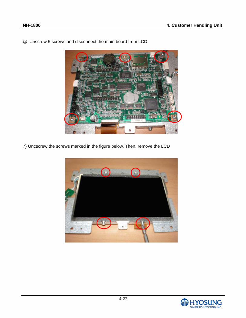
③ Unscrew 5 screws and disconnect the main board from LCD.
7) Uncscrew the screws marked in the figure below. Then, remove the LCD
NH-1800 4. Customer Handling Unit
4-28
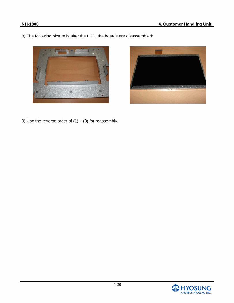
8) The following picture is after the LCD, the boards are disassembled:
9) Use the reverse order of (1) ~ (8) for reassembly.
NH-1800 4. Customer Handling Unit
4-29
4.3 Function Key Pad
4.3.1 Disassembling Function Key Pad
1) Same as Steps 1) ~ 5) of 4.2.10.
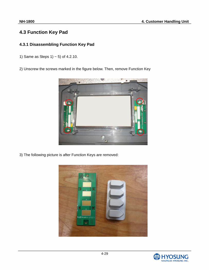
2) Unscrew the screws marked in the figure below. Then, remove Function Key
3) The following picture is after Function Keys are removed:
NH-1800 4. Customer Handling Unit
4-30
4.3.2 Connector for Function Key Pad
Material
Item Material Grade Plated / Color
Housing Material PBT GP2306F WHITE
Terminal Material Phosphor Bronze C5210 * Over plating : Pre-plated tin(1-2)
Rating
Item Standard Data Operating Voltage AC/DC 250V
Current Rating AC/DC 1A Operating Temperature -25 ~ +85
Thickness of film(FFC/FPC) 0.30 ± 0.03 Applicable P.C.B 1.2 ~ 1.6
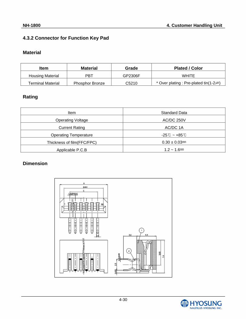
Dimension
NH-1800 4. Customer Handling Unit
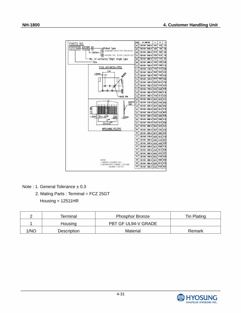
4-31
Note : 1. General Tolerance ± 0.3
2. Mating Parts : Terminal = FCZ 25GT
Housing = 12511HR
2 Terminal Phosphor Bronze Tin Plating
1 Housing PBT GF UL94-V GRADE
1/NO Description Material Remark
NH-1800 4. Customer Handling Unit
4-32
4.4 Customer Display Keys
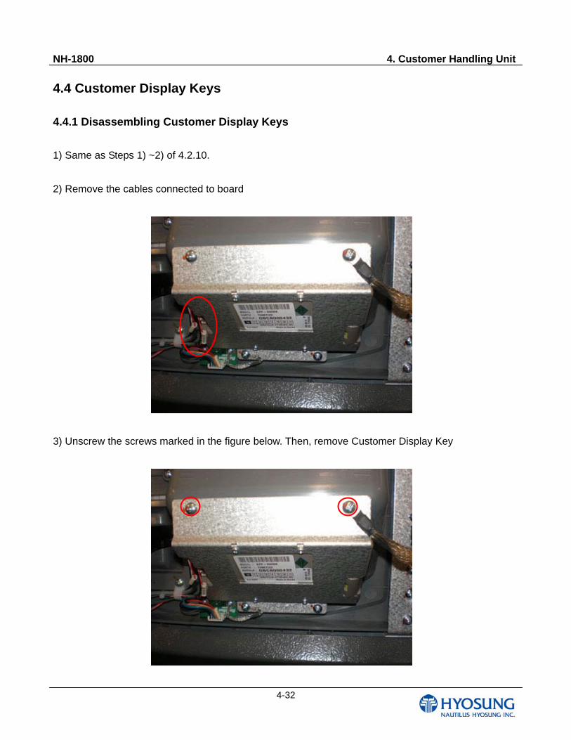
4.4.1 Disassembling Customer Display Keys
1) Same as Steps 1) ~2) of 4.2.10.
2) Remove the cables connected to board
3) Unscrew the screws marked in the figure below. Then, remove Customer Display Key
NH-1800 4. Customer Handling Unit
4-33
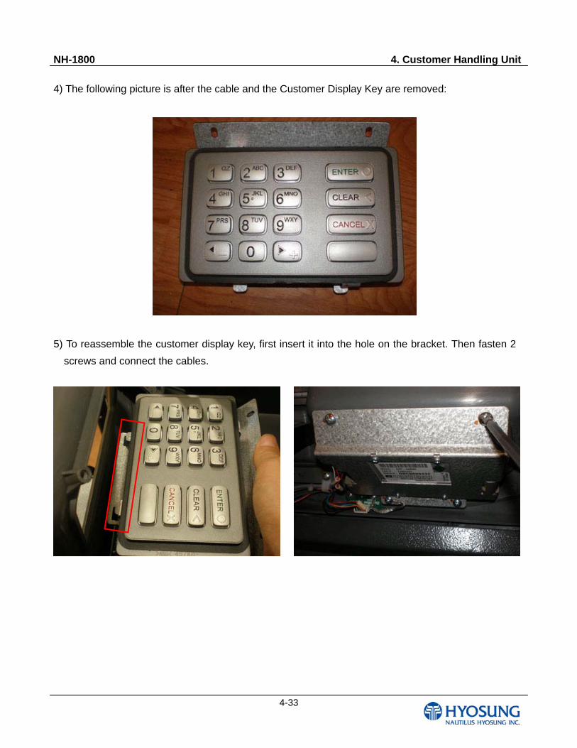
4) The following picture is after the cable and the Customer Display Key are removed:
5) To reassemble the customer display key, first insert it into the hole on the bracket. Then fasten 2
screws and connect the cables.
NH-1800 5. Body Unit
5-1
Chapter 5. Body Unit
NH-1800 5. Body Unit
5-2
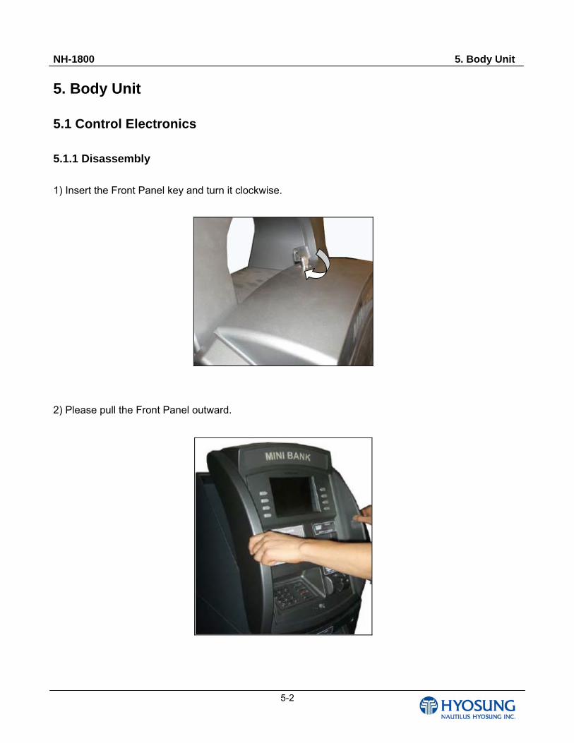
5. Body Unit 5.1 Control Electronics 5.1.1 Disassembly
1) Insert the Front Panel key and turn it clockwise.
2) Please pull the Front Panel outward.
NH-1800 5. Body Unit
5-3
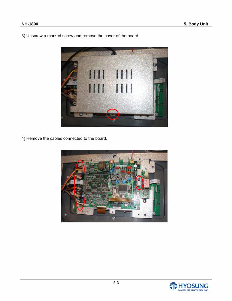
3) Unscrew a marked screw and remove the cover of the board.
4) Remove the cables connected to the board.

NH-1800 5. Body Unit
5-4
5) Disassemble the boards.
① Uncscrew the screws and disconnect the cable marked in the figure below.
② Unscrew a screw marked in the below figure and disassemble the upper board.
①
NH-1800 5. Body Unit
5-5
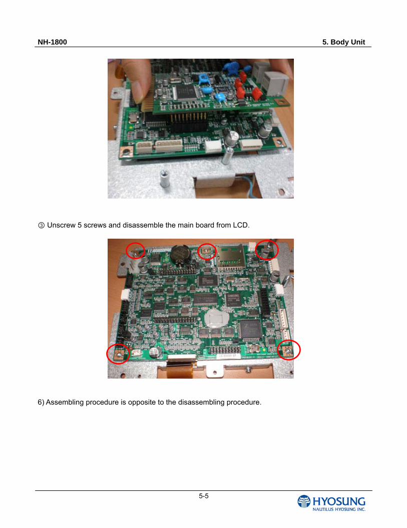
③ Unscrew 5 screws and disassemble the main board from LCD.
6) Assembling procedure is opposite to the disassembling procedure.
NH-1800 5. Body Unit
5-6
5.1.2 Board H/W Specification
Basic Specification
1) CPU
(1) CPU
① Processor : S3C2410X01(ARM920T, 200MHz, SAMSUNG)
② Clock Input : Oscillator - 12MHz
③ Internal MAX CLOCK speed (FCLK) – 202.8MHz
(2) Reset Circuit : Using MAX6361LUT29-T
2) Memory
(1) SDRAM : K4S281632H, 16Bit BUS, SAMSUNG
- 16MB(64MBit)
- Operating Current (Burst Mode) : MAX 160mA
(2) NAND FLASH : K9F5608U0C, 8Bit BUS, SAMSUNG
- 32MB(256MBit)
- Average Operating Current : MAX 35mA
- Standby Current(CMOS) : 10uA
(3) NV-SRAM : IS62WV2568BLL-70HI, 8Bit BUS, ISSA (MOLDING is needed)
- 256KB(2MBit)
- 36mW Operating
- Data Retention Current : Max 10uA
- A multiple use with K6X4008T1F(512K x 8)
3) I/O port
(1) Serial Port with a built in CPU – 3 Port
- DEBUG, for reservation : 2 Line Style Male Connector, SCC0
- EPP, for communication : 2 Line Style Female Connector, SCC1
- EMV, for communication : 2 Line Style, SCC2
(2) External SCC Controller – For Z85C30 2Port
- CDU, for communication : 2 Line Style, SCCA
- SPR, for communication : 2 Line Style, SCCB
(3) MMC/SD interface
(4) USB port (Option)
- Host, Device
NH-1800 5. Body Unit
5-7
- Using this by Daughter board
4) MODEM
(1) Using NH MODEM
- Designed with considering the compatibility
5) Power UNIT
(1) Providing +5V, +12V, GND
(2) Generating 3.3V, 1.8V by using REGULATOR
(3) Providing RTC voltage (1.8V) by CPU
Subsidized by external battery and MIC5233
6) Daughter Board
(1) NOR FLASH (SST39VF040-PLCC) for Download
(2) USB port (HOST, DEVICE)
NH-1800 5. Body Unit
5-8
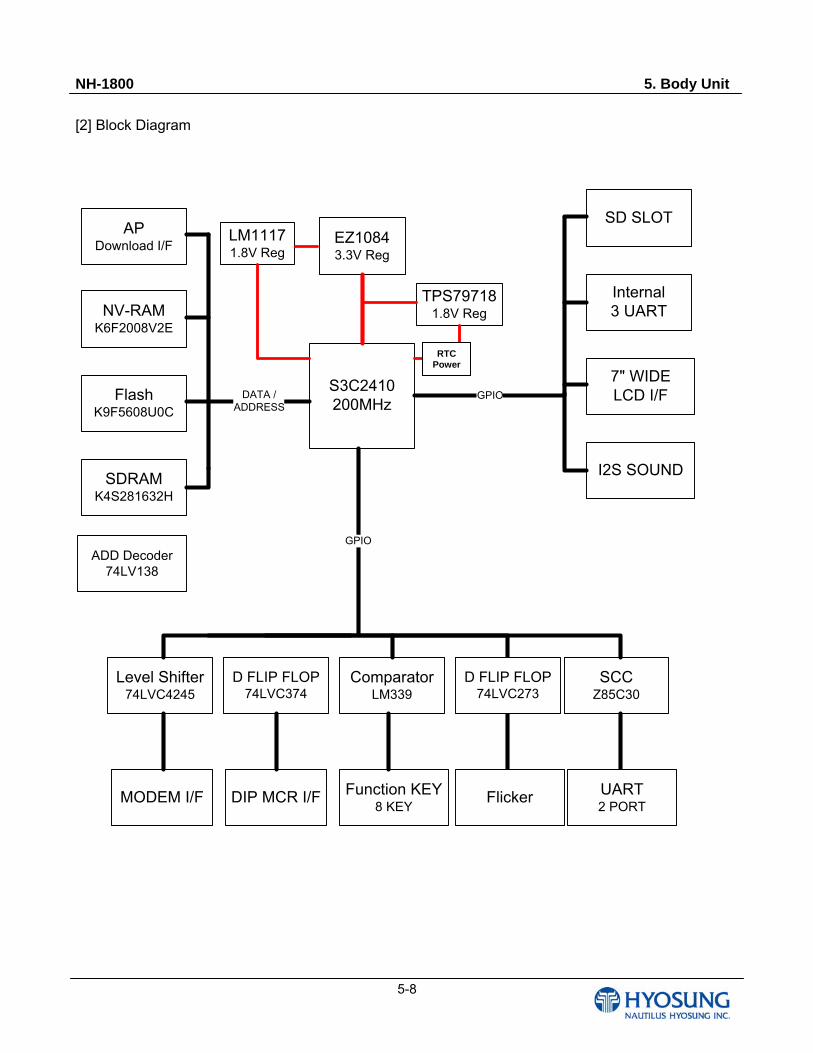
[2] Block Diagram
S3C2410 200MHz
FlashK9F5608U0C
SDRAMK4S281632H
NV-RAMK6F2008V2E
SCCZ85C30
EZ10843.3V Reg
Level Shifter74LVC4245
ComparatorLM339
7" WIDELCD I/F
Internal3 UART
GPIO
GPIO
DATA /ADDRESS
UART2 PORT
FlickerFunction KEY8 KEY
TPS797181.8V Reg
RTC 전원
MODEM I/F
SD SLOT
DIP MCR I/F
I2S SOUND
APDownload I/F
ADD Decoder74LV138
LM11171.8V Reg
D FLIP FLOP74LVC374
D FLIP FLOP74LVC273
RTC Power
NH-1800 5. Body Unit
5-9
MAP
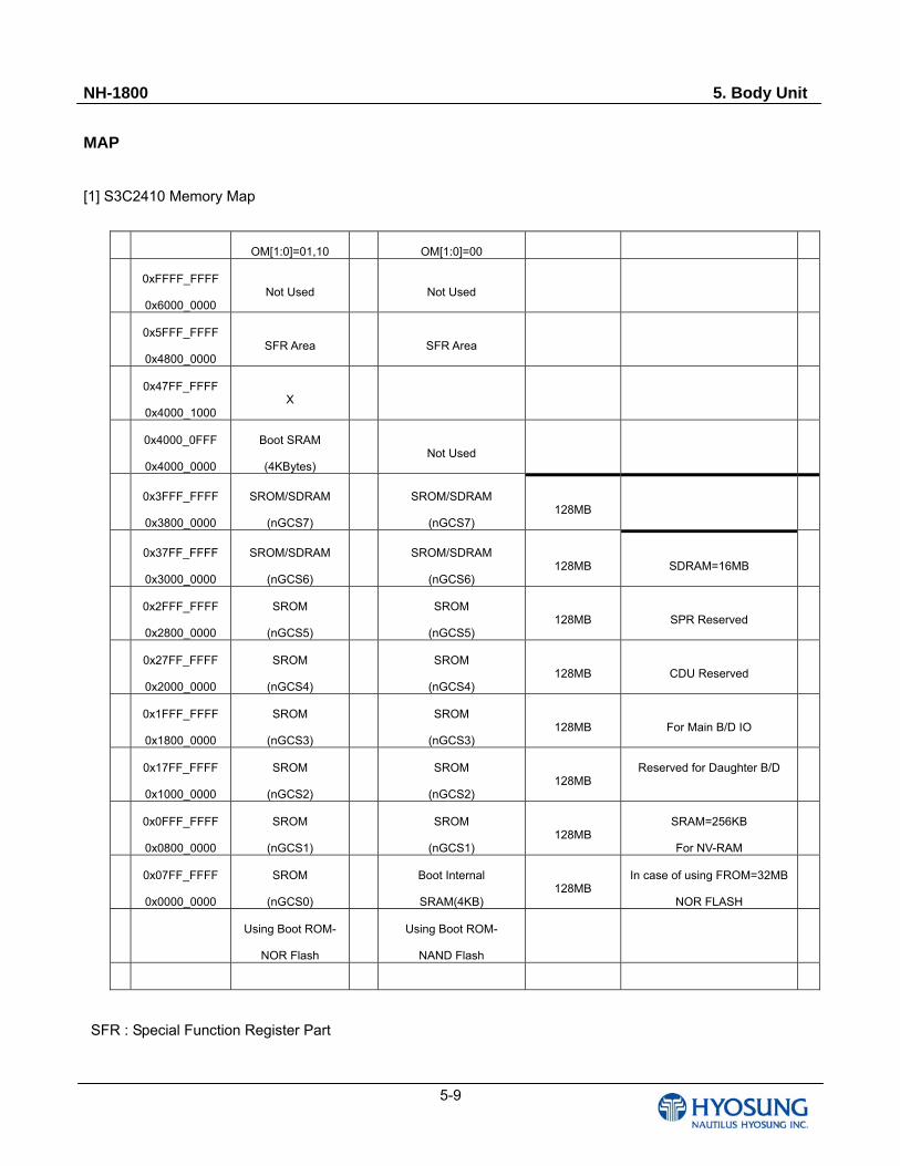
[1] S3C2410 Memory Map
OM[1:0]=01,10 OM[1:0]=00
0xFFFF_FFFF
0x6000_0000 Not Used Not Used
0x5FFF_FFFF
0x4800_0000 SFR Area SFR Area
0x47FF_FFFF
0x4000_1000 X
0x4000_0FFF
0x4000_0000
Boot SRAM
(4KBytes) Not Used
0x3FFF_FFFF
0x3800_0000
SROM/SDRAM
(nGCS7)
SROM/SDRAM
(nGCS7) 128MB
0x37FF_FFFF
0x3000_0000
SROM/SDRAM
(nGCS6)
SROM/SDRAM
(nGCS6) 128MB SDRAM=16MB
0x2FFF_FFFF
0x2800_0000
SROM
(nGCS5)
SROM
(nGCS5) 128MB SPR Reserved
0x27FF_FFFF
0x2000_0000
SROM
(nGCS4)
SROM
(nGCS4) 128MB CDU Reserved
0x1FFF_FFFF
0x1800_0000
SROM
(nGCS3)
SROM
(nGCS3) 128MB For Main B/D IO
0x17FF_FFFF
0x1000_0000
SROM
(nGCS2)
SROM
(nGCS2) 128MB
Reserved for Daughter B/D
0x0FFF_FFFF
0x0800_0000
SROM
(nGCS1)
SROM
(nGCS1) 128MB
SRAM=256KB
For NV-RAM
0x07FF_FFFF
0x0000_0000
SROM
(nGCS0)
Boot Internal
SRAM(4KB) 128MB
In case of using FROM=32MB
NOR FLASH
Using Boot ROM-
NOR Flash
Using Boot ROM-
NAND Flash
SFR : Special Function Register Part
NH-1800 5. Body Unit
5-10
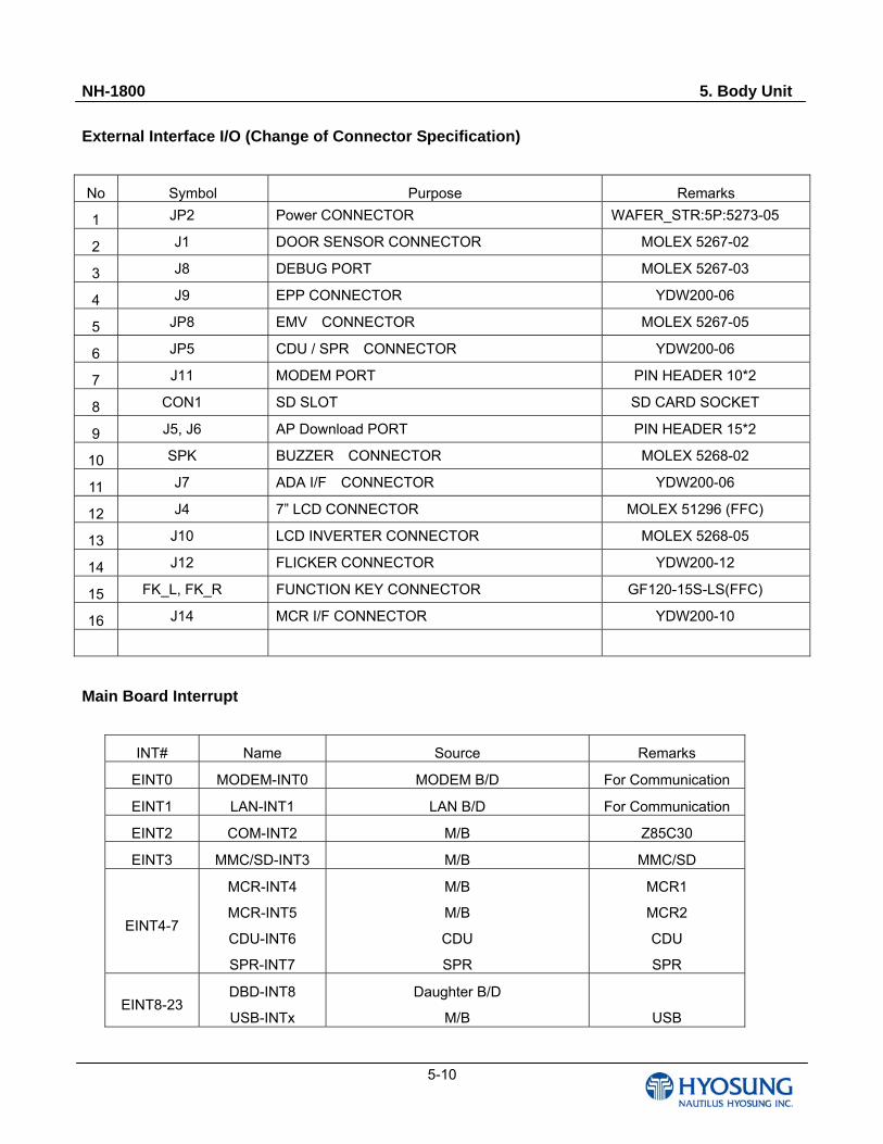
External Interface I/O (Change of Connector Specification)
No Symbol Purpose Remarks
1 JP2 Power CONNECTOR WAFER_STR:5P:5273-05
2 J1 DOOR SENSOR CONNECTOR MOLEX 5267-02
3 J8 DEBUG PORT MOLEX 5267-03
4 J9 EPP CONNECTOR YDW200-06
5 JP8 EMV CONNECTOR MOLEX 5267-05
6 JP5 CDU / SPR CONNECTOR YDW200-06
7 J11 MODEM PORT PIN HEADER 10*2
8 CON1 SD SLOT SD CARD SOCKET
9 J5, J6 AP Download PORT PIN HEADER 15*2
10 SPK BUZZER CONNECTOR MOLEX 5268-02
11 J7 ADA I/F CONNECTOR YDW200-06
12 J4 7” LCD CONNECTOR MOLEX 51296 (FFC)
13 J10 LCD INVERTER CONNECTOR MOLEX 5268-05
14 J12 FLICKER CONNECTOR YDW200-12
15 FK_L, FK_R FUNCTION KEY CONNECTOR GF120-15S-LS(FFC)
16 J14 MCR I/F CONNECTOR YDW200-10
Main Board Interrupt
INT# Name Source Remarks
EINT0 MODEM-INT0 MODEM B/D For Communication
EINT1 LAN-INT1 LAN B/D For Communication
EINT2 COM-INT2 M/B Z85C30
EINT3 MMC/SD-INT3 M/B MMC/SD
EINT4-7
MCR-INT4
MCR-INT5
CDU-INT6
SPR-INT7
M/B
M/B
CDU
SPR
MCR1
MCR2
CDU
SPR
EINT8-23 DBD-INT8
USB-INTx
Daughter B/D
M/B
USB
NH-1800 5. Body Unit
5-11
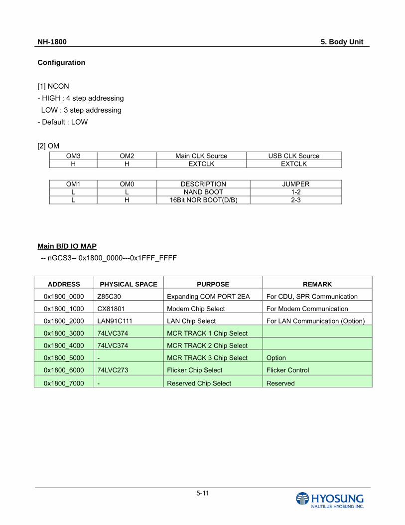
Configuration
[1] NCON
- HIGH : 4 step addressing
LOW : 3 step addressing
- Default : LOW
[2] OM OM3 OM2 Main CLK Source USB CLK Source
H H EXTCLK EXTCLK
OM1 OM0 DESCRIPTION JUMPER L L NAND BOOT 1-2 L H 16Bit NOR BOOT(D/B) 2-3
Main B/D IO MAP
-- nGCS3-- 0x1800_0000---0x1FFF_FFFF
ADDRESS PHYSICAL SPACE PURPOSE REMARK
0x1800_0000 Z85C30 Expanding COM PORT 2EA For CDU, SPR Communication
0x1800_1000 CX81801 Modem Chip Select For Modem Communication
0x1800_2000 LAN91C111 LAN Chip Select For LAN Communication (Option)
0x1800_3000 74LVC374 MCR TRACK 1 Chip Select
0x1800_4000 74LVC374 MCR TRACK 2 Chip Select
0x1800_5000 - MCR TRACK 3 Chip Select Option
0x1800_6000 74LVC273 Flicker Chip Select Flicker Control
0x1800_7000 - Reserved Chip Select Reserved

NH-1800 5. Body Unit
5-12
[2] I/O MAP
Port Description Port Description
GPA[0] ADDR 0 GPC[0] STEP1 BD_SEL
GPA[1] ADDR 16 GPC[1] VCLK
GPA[2] ADDR 17 GPC[2] VLINE
GPA[3] ADDR 18 GPC[3] VFRAME
GPA[4] ADDR 19 GPC[4] VM
GPA[5] ADDR 20 GPC[5] PHONE_DETECT
GPA[6] ADDR 21 GPC[6] DOOR_SENSOR
GPA[7] ADDR 22 GPC[7] LCD_OFF
GPA[8] ADDR 23 GPC[8] VD0
GPA[9] ADDR 24 GPC[9] VD1
GPA[10] ADDR 25 GPC[10] VD2
GPA[11] ADDR 26 GPC[11] VD3
GPA[12] nGCS 1 GPC[12] VD4
GPA[13] nGCS 2 GPC[13] VD5
GPA[14] nGCS 3 GPC[14] VD6
GPA[15] nGCS 4 GPC[15] VD7
GPA[16] nGCS 5 GPD[0] KBDCOL 0 VD8
GPA[17] CLE GPD[1] KBDCOL 1 VD9
GPA[18] ALE GPD[2] KBDCOL 2 VD10
GPA[19] nFWE GPD[3] KBDCOL 3 VD11
GPA[20] nFRE GPD[4] KBDROW 0 VD12
GPA[21] nRSTOUT
GPD[5] KBDROW 1 (Deletion)
VD13
GPA[22] nFCE
GPD[6] KBDROW 2 (Deletion)
VD14
GPB[0] NOT USED KBDROW0
GPD[7] KBDROW 3 (Deletion)
VD15
GPB[1] NOT USED KBDROW5
GPD[8] KBDROW 4 (Deletion)
VD16
GPB[2] NOT USED GPD[9] KBDROW 5 VD17
GPB[3] SPK_SRC
GPD[10] MCRDATA 1 (Deletion)
VD18
GPB[4] NOT USED
GPD[11] MCRDATA 2 (Deletion)
VD19
GPB[5] NOT USED KBDCOL0 GPD[12] CPD VD20
GPB[6] NOT USED KBDCOL1 GPD[13] END_SENS VD21
NH-1800 5. Body Unit
5-13
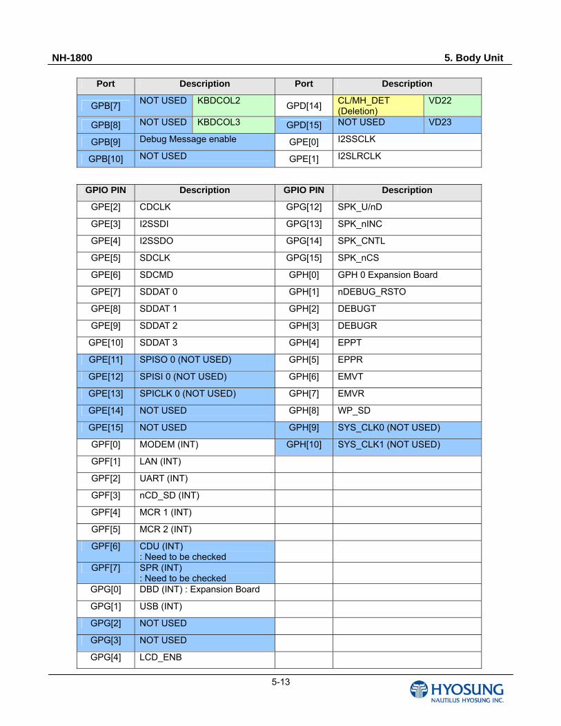
Port Description Port Description
GPB[7] NOT USED KBDCOL2
GPD[14] CL/MH_DET (Deletion)
VD22
GPB[8] NOT USED KBDCOL3 GPD[15] NOT USED VD23
GPB[9] Debug Message enable GPE[0] I2SSCLK
GPB[10] NOT USED GPE[1] I2SLRCLK
GPIO PIN Description GPIO PIN Description
GPE[2] CDCLK GPG[12] SPK_U/nD
GPE[3] I2SSDI GPG[13] SPK_nINC
GPE[4] I2SSDO GPG[14] SPK_CNTL
GPE[5] SDCLK GPG[15] SPK_nCS
GPE[6] SDCMD GPH[0] GPH 0 Expansion Board
GPE[7] SDDAT 0 GPH[1] nDEBUG_RSTO
GPE[8] SDDAT 1 GPH[2] DEBUGT
GPE[9] SDDAT 2 GPH[3] DEBUGR
GPE[10] SDDAT 3 GPH[4] EPPT
GPE[11] SPISO 0 (NOT USED) GPH[5] EPPR
GPE[12] SPISI 0 (NOT USED) GPH[6] EMVT
GPE[13] SPICLK 0 (NOT USED) GPH[7] EMVR
GPE[14] NOT USED GPH[8] WP_SD
GPE[15] NOT USED GPH[9] SYS_CLK0 (NOT USED)
GPF[0] MODEM (INT) GPH[10] SYS_CLK1 (NOT USED)
GPF[1] LAN (INT)
GPF[2] UART (INT)
GPF[3] nCD_SD (INT)
GPF[4] MCR 1 (INT)
GPF[5] MCR 2 (INT)
GPF[6] CDU (INT) : Need to be checked
GPF[7] SPR (INT) : Need to be checked
GPG[0] DBD (INT) : Expansion Board
GPG[1] USB (INT)
GPG[2] NOT USED
GPG[3] NOT USED
GPG[4] LCD_ENB
NH-1800 5. Body Unit
5-14
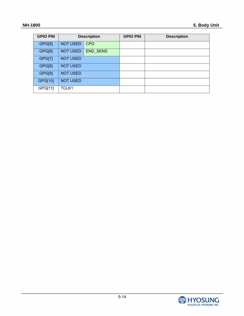
GPIO PIN Description GPIO PIN Description
GPG[5] NOT USED CPD
GPG[6] NOT USED END_SENS
GPG[7] NOT USED
GPG[8] NOT USED
GPG[9] NOT USED
GPG[10] NOT USED
GPG[11] TCLK1
NH-1800 5. Body Unit
5-15
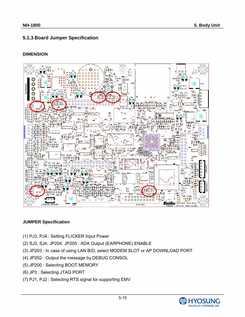
5.1.3 Board Jumper Specification
DIMENSION
JUMPER Specification
(1) PJ3, PJ4 : Setting FLICKER Input Power
(2) SJ3, SJ4, JP204, JP205 : ADA Output (EARPHONE) ENABLE
(3) JP203 : In case of using LAN B/D, select MODEM SLOT or AP DOWNLOAD PORT
(4) JP202 : Output the message by DEBUG CONSOL
(5) JP200 : Selecting BOOT MEMORY
(6) JP3 : Selecting JTAG PORT
(7) PJ1, PJ2 : Selecting RTS signal for supporting EMV
NH-1800 5. Body Unit
5-16
DEFAULT JUMPER Setting
(1) PJ3, PJ4 : PJ3 SHORT
(2) SJ3, SJ4, JP204, JP205 : SJ3, SJ4 SHORT
(3) JP203 : 1, 2 SHORT
(4) JP202 : 1, 2 SHORT
(5) JP200 : 1, 2 SHORT
(6) JP3 : 1, 2 SHORT
(7) PJ2 : SHORT (adding) [07. 08. 21]
NH-1800 5. Body Unit
5-17
5.1.4 Modem
5.1.4.1 Overview
The Conexant. SmartV.XX Modem is a full-featured, worldwide, controller-based modem that
integrates modem controller (MCU), modem data pump (MDP), 256 KB ROM, 32 KB RAM, and
SmartDAA system side device (SSD) functions onto a single
The modem operates by executing firmware from internal ROM and RAM. Optional customized
Firmware is supported with optional external flash ROM memory. Additionally, added/modified country
profiles are supported by internal SRAM patch (maximum of one profile) or serial EEPROM.
Downloadable architecture supports downloading of customized MCU firmware from the host/DTE to
the SmartV.XX modem.
The SmartV.XX Modem device set, consisting of a CX81801 modem device in a 128-pin TQFP and
either a CX20493 SmartDAA Line Side Device (LSD) in a 28-pin QFN or a CX20463 SmartDAA LSD
in a 32-pin TQFP. Conexant’s SmartDAA. technology eliminates the need for a costly analog
transformer, relays and opto-isolations typically used in discrete DAA implementations.
The SmartDAA architecture also simplifies product implementation by eliminating the need for country-
specific board configurations enabling worldwide homologation of a single modem board design and a
single bill of materials (BOM). Low profile, small TQFP and QFN packages with reduced voltage
operation and low power consumption makes this device set an ideal solution for embedded and
palmtop application using parallel host or serial DTE interface.
The SmartV.XX Modem supports data rates up to V.92, data compression, error correction, fax rates
up to 14.4 kbps and speakerphone mode. In V.92 and V.90 (V.92 models) data modes, the modem
can receive data at speeds up to 56 kbps. In V.34 data mode (V.92 and V.34 models), the modem can
receive data at speeds up to 33.6 kbps. In V.32 bis data mode, the modem can receive data at speeds
up to 14.4 kbps. Data compress (V.44/V.42bis/MNP5) and error correction (V.42/MNP 2-4) modes are
supported to maximize data throughput and data transfer integrity. Non-error-correction mode is also
supported. Fax Group 3 send and receive rates are supported up to 14.4 kbps with T.30 protocol.
The SmartV.XX modem operates with PSTN telephone lines worldwide. S models, using the optional
CX20442 Voice Codec (VC) in a 32-pin TQFP, support position independent, full-duplex
speakerphone (FDSP) operation using microphone and speaker, as well as other voice/TAM
applications using handset or headset.
NH-1800 5. Body Unit
5-18
5.1.4.2 Features
- Data modem
Quick connect, Modem-on-Hold, and PCM upstream functions (V.92 models)
ITU-T V.92/V.90 (V.92 models), V.34 (V.92 and V.34 models), V.32bis, V.32,
V.29, FastPOS (V.29), V.22 bis, V.22, V.22 Fast Connect, V.23, V.21,
Bell 212A, and Bell 103
V.250 and V.251 commands
- Data compression and error correction
V.44 data compression
V.42 bis and MNP 5 data compression
V.42 LAPM and MNP 2-4 error correction
- Fax modem send and receive rates up to 14.4 kbps
V.17, V.29, V.27 ter, and V.21 channel 2
EIA/TIA 578 Class 1 and T.31 Class 1.0
- V.80 synchronous access mode supports host-controlled communication protocols with H.324
interface support
- Interfaces to optional external ROM/flash ROM, RAM, and/or optional serial EEPROM
- Data/Fax/Voice call discrimination
- Hardware-based modem controller
- Hardware-based digital signal processor (DSP)
- Worldwide operation
Complies to TBR21 and other country requirements
On-hook and/or off-hook Caller ID detection for selected countries
Call progress, blacklisting
Internal ROM includes default values for 29 countries
Additional and modified country profile can be stored in internal SRAM
- Caller waiting detection
Caller ID detect
On-hook Caller ID detection
Off-hook Call Waiting Caller ID detection during data mode in V.92, V.90, V.34, V.32bis, and V.32
- Distinctive ring detect
- Modem customization available through patch code that can be stored in optional serial EEPROM or
internal SRAM
- Telephony/TAM
V.253 commands
NH-1800 5. Body Unit
5-19
2-bit and 4-bit Conexant ADPCM, 8-bit linear PCM, and 4-bit IMA coding
8 kHz sample rate
Concurrent DTMF, ring, and Caller ID detection
CX81801-7x/8x SmartV.XX Modem Data Sheet
- Full-duplex speakerphone (FDSP) mode using optional CX20442 Voice Codec (S models)
Microphone and speaker interface
Telephone handset or headset interface
Acoustic and line echo cancellation
Microphone gain and muting
Speaker volume control and muting
- Built-in host/DTE interface
Parallel 16550A UART-compatible interface up to 230.4 kbps
Serial ITU-T V.24 (EIA/TIA-232-E) logical interface up to 115.2 kbps
- Downloadable architecture
- Direct mode (serial DTE interface)
- Flow control and speed buffering
- Automatic format/speed sensing
- Serial async/sync data; parallel async data
- Thin packages support low profile designs (1.6 mm max. height)
CX81801 Modem device in 128-pin TQFP
CX20493 LSD in 28-pin QFN or CX20463 LSD in 32-pin TQFP
CX20442 VC in 32-pin TQFP
- +3.3V operation with +5V tolerant digital inputs
NH-1800 5. Body Unit
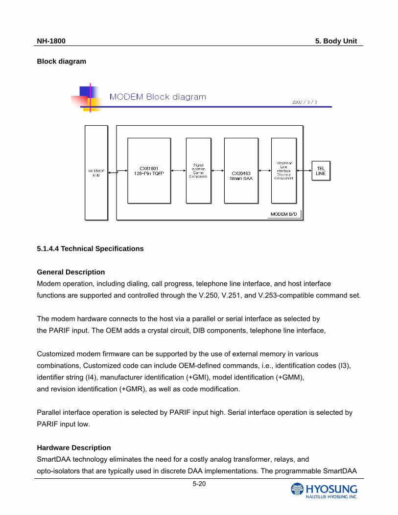
5-20
Block diagram
5.1.4.4 Technical Specifications
General Description
Modem operation, including dialing, call progress, telephone line interface, and host interface
functions are supported and controlled through the V.250, V.251, and V.253-compatible command set.
The modem hardware connects to the host via a parallel or serial interface as selected by
the PARIF input. The OEM adds a crystal circuit, DIB components, telephone line interface,
Customized modem firmware can be supported by the use of external memory in various
combinations, Customized code can include OEM-defined commands, i.e., identification codes (I3),
identifier string (I4), manufacturer identification (+GMI), model identification (+GMM),
and revision identification (+GMR), as well as code modification.
Parallel interface operation is selected by PARIF input high. Serial interface operation is selected by
PARIF input low.
Hardware Description
SmartDAA technology eliminates the need for a costly analog transformer, relays, and
opto-isolators that are typically used in discrete DAA implementations. The programmable SmartDAA
NH-1800 5. Body Unit
5-21
architecture simplifies product implementation in worldwide markets by eliminating the need for
country-specific components.
CX81801 MODEM DEVICE
The CX81801 Modem, packaged in a 128-pin TQFP, includes a Microcontroller (MCU), a Modem
Data Pump (MDP), 256 KB internal ROM, 32 KB internal RAM, and SmartDAA interface functions.
The CX81801 Modem connects to host via a parallel host (PARIF = high) or a logical V.24 (EIA/TIA-
232-E) serial DTE interface (PARIF = low). The CX81801 Modem performs the command processing
and host interface functions. The crystal frequency is 28.224 MHz ± 50 ppm.
The CX81801 Modem optionally connects to an external OEM-supplied serial EEPROM over a
dedicated 2-line serial interface. The capacity of the EEPROM can be 256 bytes up to 32 KB. The
EEPROM can hold information such as firmware configuration customization, and country code
parameters. The CX81801 Modem performs telephone line signal modulation/demodulation in a
hardware digital signal processor (DSP) which reduces computational load on the host
processor.
Digital Isolation Barrier
The OEM-supplied Digital Isolation Barrier (DIB) electrically DC isolates the CX81801 from the LSD
and telephone line. The modem is connected to a fixed digital ground and operates with standard
CMOS logic levels. The LSD is connected to a floating ground and can tolerate high voltage input
(compatible with telephone line and typical surge requirements).
The DIB transformer couples power and clock from the CX81801 to the LSD. The DIB data channel
supports bidirectional half-duplex serial transfer of data, control, and status information between the
CX81801 and the LSD over two lines.
CX20463 SmartDAA Line Side Device
The CX20493/CX20463 SmartDAA Line Side Device (LSD) includes a Line Side DIB Interface (LSDI),
a coder/decoder (codec), and a Telephone Line Interface (TLI). The LSDI communicates with, and
receives power and clock from, the SmartDAA interface in the CX81801 through the DIB. LSD power
is received from the MDP PWRCLKP and PWRCLKN pins via the DIB through a full-wave rectified
bridge and capacitive power filter circuit connected to the DIB transformer secondary winding.
The CLK input is also accepted from the DIB transformer secondary winding through a capacitor and a
NH-1800 5. Body Unit
5-22
resistor in series. Information is transferred between the LSD and the CX81801 through the DIB_P
and DIB_N pins. These pins connect to the CX81801 DIB_DATAP and DIB_DATAN pins, respectively,
through the DIB.
The TLI integrates DAA and direct telephone line interface functions and connects directly to the line
TIP and RING pins, as well as to external line protection components. Direct LSD connection to TIP
and RING allows real-time measurement of telephone line parameters, such as the telephone central
office (CO) battery voltage, individual telephone line (copper wire) resistance, and allows dynamic
regulation of the off-hook TIP and RING voltage and total current drawn from the central office (CO).
This allows the modem to maintain compliance with U.S. and worldwide regulations and to actively
control the DAA power dissipation.
NH-1800 5. Body Unit
5-23
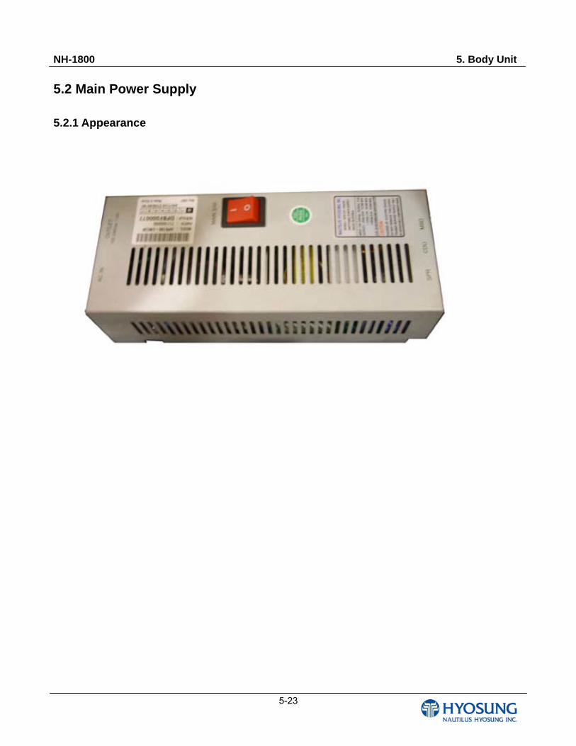
5.2 Main Power Supply 5.2.1 Appearance
NH-1800 5. Body Unit
5-24
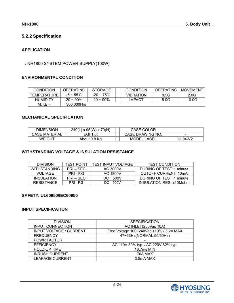
5.2.2 Specification
APPLICATION
√ NH1800 SYSTEM POWER SUPPLY(100W)
ENVIRONMENTAL CONDITION
CONDITION OPERATING STORAGE CONDITION OPERATING MOVEMENTTEMPERATURE -5 ~ 55 -20 ~ 75 VIBRATION 0.5G 2.0G
HUMIDITY 20 ~ 90 20 ~ 90 IMPACT 5.0G 10.0G M.T.B.F 300,000Hrs
MECHANICAL SPECIFICATION
DIMENSION 240(L) x 95(W) x 70(H) CASE COLOR - CASE MATERIAL EGI 1.0t CASE DRAWING NO. -
WEIGHT About 0.8 Kg MODEL LABEL UL94-V2
WITHSTANDING VOLTAGE & INSULATION RESISTANCE
DIVISION TEST POINT TEST INPUT VOLTAGE TEST CONDITION PRI – SEC AC 3000V WITHSTANDING
VOLTAGE PRI - F.G AC 1800V DURING OF TEST: 1 minute CUTOFF CURRENT: 10mA
PRI – SEC DC 500V INSULATION RESISTANCE PRI - F.G DC 500V
DURING OF TEST: 1 minute INSULATION RES: ≥10Mohm
SAFETY: UL60950/IEC60950
INPUT SPECIFICATION
DIVISION SPECIFICATION INPUT CONNECTION AC INLET(250Vac 10A) INPUT VOLTAGE / CURRENT Free Voltage 100~240Vac ±10% / 3.2A MAX FREQUENCY 47~63Hz(NORMAL:50/60Hz) POWR FACTOR - EFFICIENCY AC 110V 80% typ. / AC 220V 82% typ. HOLD-UP TIME 16.7ms MIN INRUSH CURRENT 70A MAX LEAKAGE CURRENT 3.5mA MAX
NH-1800 5. Body Unit
5-25
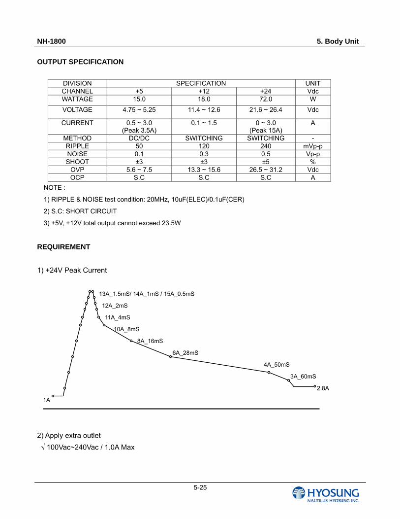
OUTPUT SPECIFICATION
DIVISION SPECIFICATION UNIT CHANNEL +5 +12 +24 Vdc WATTAGE 15.0 18.0 72.0 W
VOLTAGE 4.75 ~ 5.25 11.4 ~ 12.6 21.6 ~ 26.4 Vdc
CURRENT 0.5 ~ 3.0 (Peak 3.5A)
0.1 ~ 1.5 0 ~ 3.0 (Peak 15A)
A
METHOD DC/DC SWITCHING SWITCHING - RIPPLE 50 120 240 mVp-p NOISE 0.1 0.3 0.5 Vp-p SHOOT ±3 ±3 ±5 %
OVP 5.6 ~ 7.5 13.3 ~ 15.6 26.5 ~ 31.2 Vdc OCP S.C S.C S.C A
NOTE :
1) RIPPLE & NOISE test condition: 20MHz, 10uF(ELEC)/0.1uF(CER)
2) S.C: SHORT CIRCUIT
3) +5V, +12V total output cannot exceed 23.5W
REQUIREMENT
1) +24V Peak Current
13A_1.5mS/ 14A_1mS / 15A_0.5mS
12A_2mS
11A_4mS
10A_8mS
8A_16mS
6A_28mS
4A_50mS
3A_60mS
2.8A
1A
2) Apply extra outlet
√ 100Vac~240Vac / 1.0A Max
NH-1800 5. Body Unit
5-26
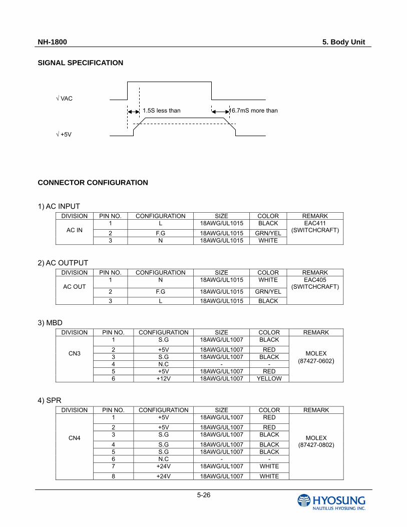
SIGNAL SPECIFICATION
√ VAC
1.5S less than 16.7mS more than
√ +5V
CONNECTOR CONFIGURATION
1) AC INPUT DIVISION PIN NO. CONFIGURATION SIZE COLOR REMARK
1 L 18AWG/UL1015 BLACK
2 F.G 18AWG/UL1015 GRN/YEL
AC IN
3 N 18AWG/UL1015 WHITE
EAC411 (SWITCHCRAFT)
2) AC OUTPUT DIVISION PIN NO. CONFIGURATION SIZE COLOR REMARK
1 N 18AWG/UL1015 WHITE
2 F.G 18AWG/UL1015 GRN/YEL
AC OUT
3 L 18AWG/UL1015 BLACK
EAC405 (SWITCHCRAFT)
3) MBD DIVISION PIN NO. CONFIGURATION SIZE COLOR REMARK
1 S.G 18AWG/UL1007 BLACK
2 +5V 18AWG/UL1007 RED 3 S.G 18AWG/UL1007 BLACK 4 N.C - - 5 +5V 18AWG/UL1007 RED
CN3
6 +12V 18AWG/UL1007 YELLOW
MOLEX (87427-0602)
4) SPR DIVISION PIN NO. CONFIGURATION SIZE COLOR REMARK
1 +5V 18AWG/UL1007 RED
2 +5V 18AWG/UL1007 RED 3 S.G 18AWG/UL1007 BLACK
4 S.G 18AWG/UL1007 BLACK 5 S.G 18AWG/UL1007 BLACK 6 N.C - - 7 +24V 18AWG/UL1007 WHITE
CN4
8 +24V 18AWG/UL1007 WHITE
MOLEX (87427-0802)
NH-1800 5. Body Unit
5-27
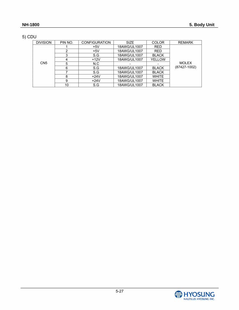
5) CDU DIVISION PIN NO. CONFIGURATION SIZE COLOR REMARK
1 +5V 18AWG/UL1007 RED 2 +5V 18AWG/UL1007 RED 3 S.G 18AWG/UL1007 BLACK 4 +12V 18AWG/UL1007 YELLOW 5 N.C - - 6 S.G 18AWG/UL1007 BLACK 7 S.G 18AWG/UL1007 BLACK 8 +24V 18AWG/UL1007 WHITE 9 +24V 18AWG/UL1007 WHITE
CN5
10 S.G 18AWG/UL1007 BLACK
MOLEX (87427-1002)
NH-1800 6.Cash Dispenser Unit
6-1
Chapter 6. Cash Dispenser Unit
NH-1800 6.Cash Dispenser Unit
6-2
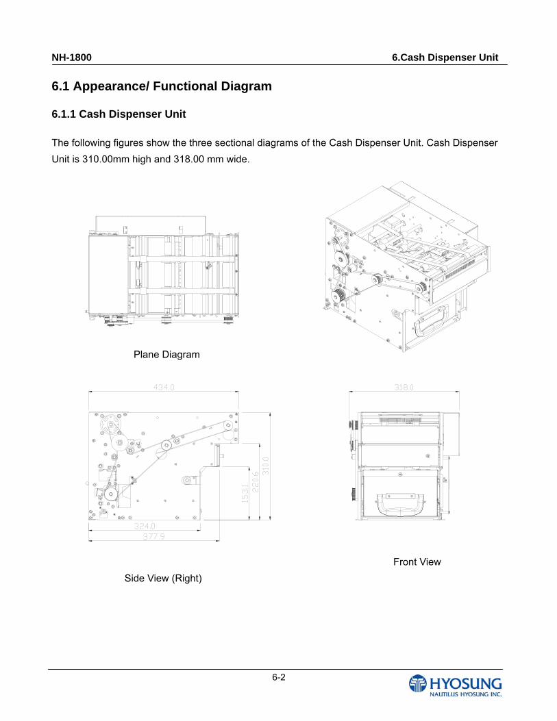
6.1 Appearance/ Functional Diagram
6.1.1 Cash Dispenser Unit
The following figures show the three sectional diagrams of the Cash Dispenser Unit. Cash Dispenser
Unit is 310.00mm high and 318.00 mm wide.
Plane Diagram
Front View
Side View (Right)
NH-1800 6.Cash Dispenser Unit
6-3
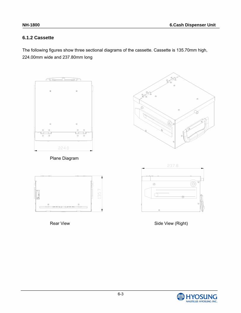
6.1.2 Cassette
The following figures show three sectional diagrams of the cassette. Cassette is 135.70mm high,
224.00mm wide and 237.80mm long
Plane Diagram
Rear View Side View (Right)
NH-1800 6.Cash Dispenser Unit
6-4
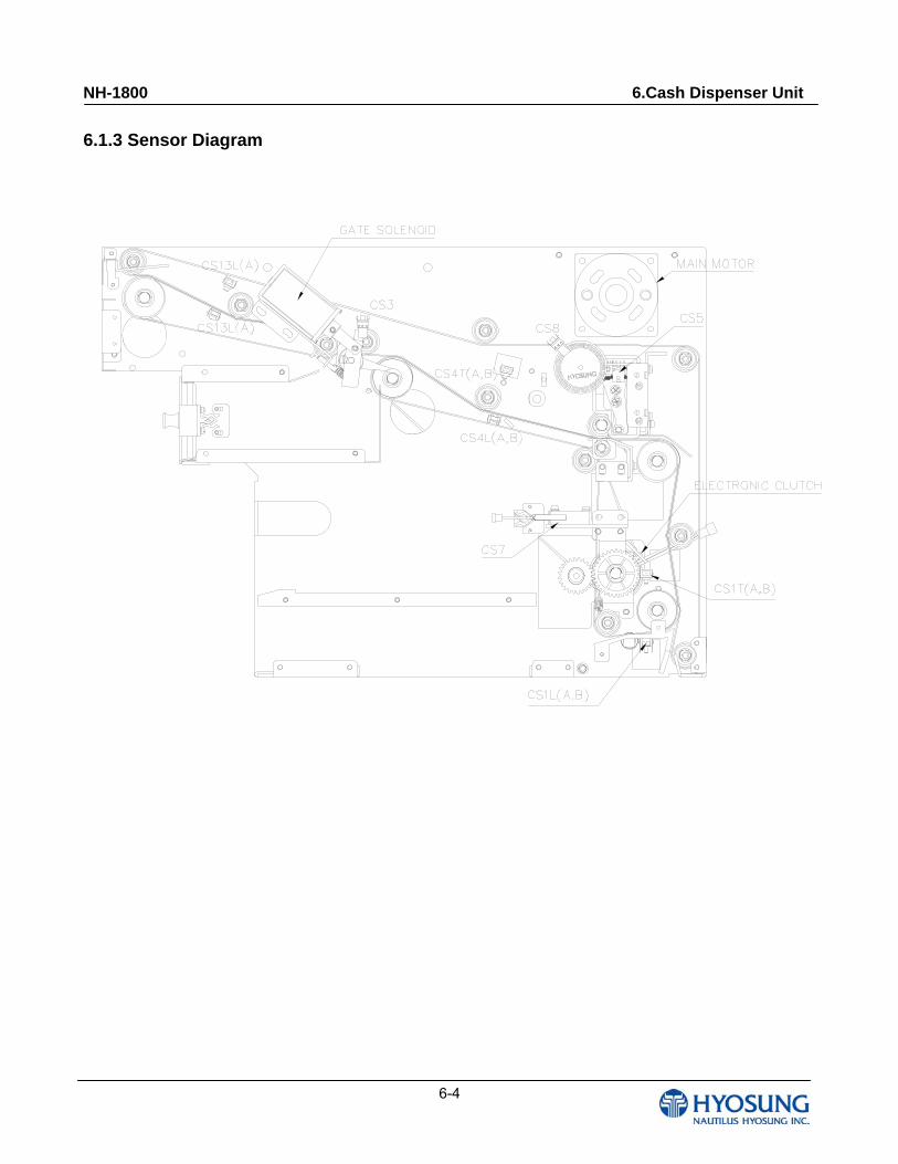
6.1.3 Sensor Diagram
NH-1800 6.Cash Dispenser Unit
6-5
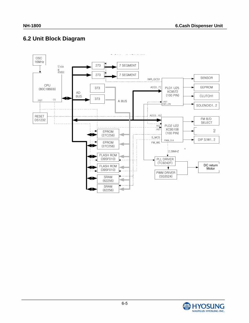
6.2 Unit Block Diagram
CPU(80C186EB) PLD1 U25
XC9572(100 PIN)
SENSOR
EEPROM
CLUTCH1
2매 검지 A,B
DIP S/W1, 2
373
EPROM(27C256)
FLASH ROM(39SF010)
273 7 SEGMENT
CS
AD BUS
A BUS
FLASH ROM(39SF010)
SOLENOID1, 2
DC 반송 MOTOR
EPROM(27C256)
PLL DRIVER(TC9242F)
PWM DRIVER(SG3524)
OCK IAGRAMOSC
16MHz
RESET DS1232
/RST
내부 2분주 8MHz사용
RST
273 7 SEGMENT
/RST
/WR_GCS1
373
SRAM(62256)
SRAM(62256)
S_MCS
PLD2 U22 XC95108(100 PIN)
FM_WE
7분주2.28MHZ
CM1_ON
AD[0..7]
AD[0..15]
PWM_CLK
FM B/D SELECT
RST
Using 8MH
7
2
DC return Motor
NH-1800 6.Cash Dispenser Unit
6-6
6.3 Module and Sensor Replacement
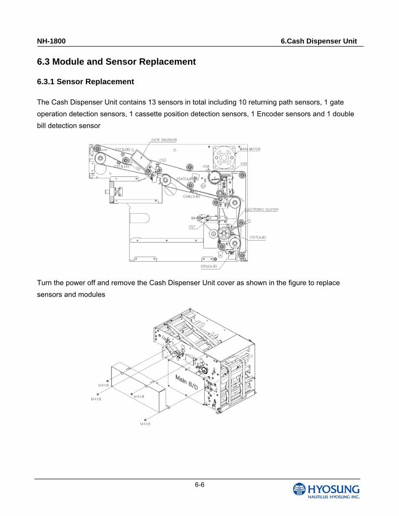
6.3.1 Sensor Replacement
The Cash Dispenser Unit contains 13 sensors in total including 10 returning path sensors, 1 gate
operation detection sensors, 1 cassette position detection sensors, 1 Encoder sensors and 1 double
bill detection sensor
Turn the power off and remove the Cash Dispenser Unit cover as shown in the figure to replace
sensors and modules
NH-1800 6.Cash Dispenser Unit
6-7
6.3.2 Returning Path Sensor
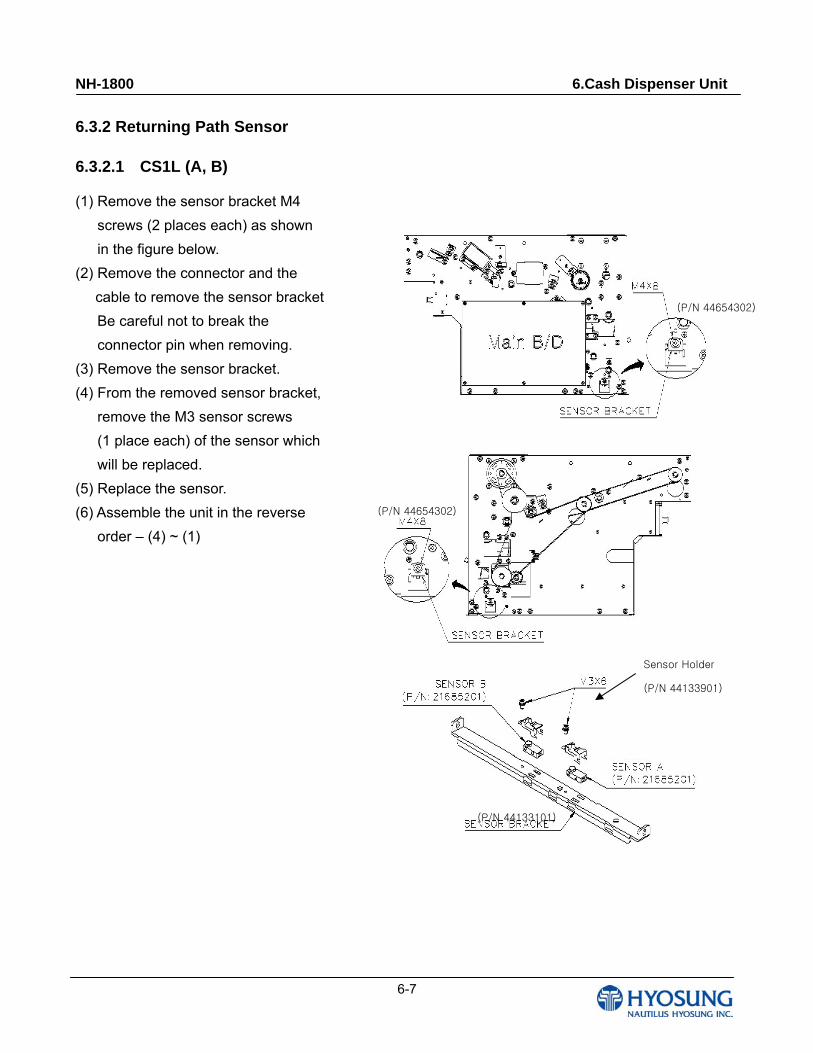
6.3.2.1 CS1L (A, B)
(1) Remove the sensor bracket M4
screws (2 places each) as shown
in the figure below.
(2) Remove the connector and the
cable to remove the sensor bracket
Be careful not to break the
connector pin when removing.
(3) Remove the sensor bracket.
(4) From the removed sensor bracket,
remove the M3 sensor screws
(1 place each) of the sensor which
will be replaced.
(5) Replace the sensor.
(6) Assemble the unit in the reverse
order – (4) ~ (1)
(P/N 44133101)
Sensor Holder
(P/N 44133901)
(P/N 44654302)
(P/N 44654302)
NH-1800 6.Cash Dispenser Unit
6-8
Sensor Holder
(P/N 44133901)
(P/N 44654302)
(P/N 44654302)
(P/N 44133101)
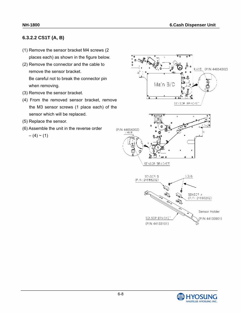
6.3.2.2 CS1T (A, B)
(1) Remove the sensor bracket M4 screws (2
places each) as shown in the figure below.
(2) Remove the connector and the cable to
remove the sensor bracket.
Be careful not to break the connector pin
when removing.
(3) Remove the sensor bracket.
(4) From the removed sensor bracket, remove
the M3 sensor screws (1 place each) of the
sensor which will be replaced.
(5) Replace the sensor.
(6) Assemble the unit in the reverse order
– (4) ~ (1)
NH-1800 6.Cash Dispenser Unit
6-9
(P/N 44611003)
Sensor Holder
(P/N 44133901)
Sensor Support
(P/N 44093201)
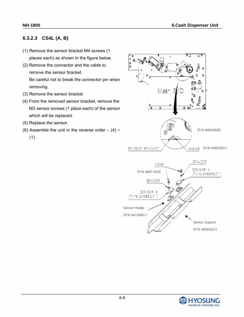
6.3.2.3 CS4L (A, B)
(1) Remove the sensor bracket M4 screws (1
places each) as shown in the figure below.
(2) Remove the connector and the cable to
remove the sensor bracket.
Be careful not to break the connector pin when
removing.
(3) Remove the sensor bracket
(4) From the removed sensor bracket, remove the
M3 sensor screws (1 place each) of the sensor
which will be replaced.
(5) Replace the sensor.
(6) Assemble the unit in the reverse order – (4) ~
(1)
(P/N 44920301)
(P/N 44654305)
NH-1800 6.Cash Dispenser Unit
6-10
(P/N 44654305)
(P/N 44611003)
Sensor Holder
(P/N 44133901)
Sensor Brkt
(P/N 44133301)
(P/N 44654305)
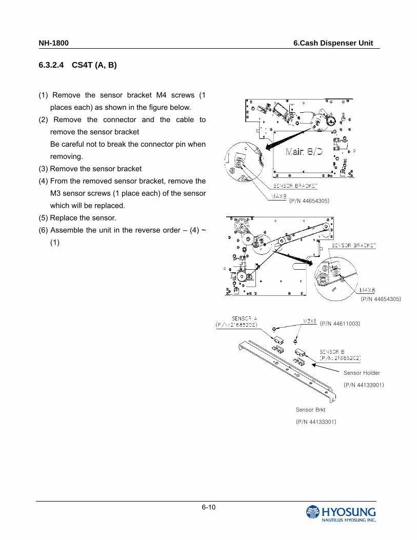
6.3.2.4 CS4T (A, B)
(1) Remove the sensor bracket M4 screws (1
places each) as shown in the figure below.
(2) Remove the connector and the cable to
remove the sensor bracket
Be careful not to break the connector pin when
removing.
(3) Remove the sensor bracket
(4) From the removed sensor bracket, remove the
M3 sensor screws (1 place each) of the sensor
which will be replaced.
(5) Replace the sensor.
(6) Assemble the unit in the reverse order – (4) ~
(1)
NH-1800 6.Cash Dispenser Unit
6-11
(P/N 44654305)
(P/N 44611003)
Sensor Holder
(P/N 44133901)
Sensor BRKT
(P/N 44166501)(P/N 44611003)
(P/N 44920301)
Sensor Holder
(P/N 44133901)
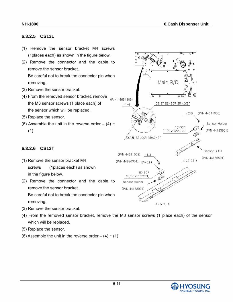
6.3.2.5 CS13L
(1) Remove the sensor bracket M4 screws
(1places each) as shown in the figure below.
(2) Remove the connector and the cable to
remove the sensor bracket.
Be careful not to break the connector pin when
removing.
(3) Remove the sensor bracket.
(4) From the removed sensor bracket, remove
the M3 sensor screws (1 place each) of
the sensor which will be replaced.
(5) Replace the sensor.
(6) Assemble the unit in the reverse order – (4) ~
(1)
6.3.2.6 CS13T
(1) Remove the sensor bracket M4
screws (1places each) as shown
in the figure below.
(2) Remove the connector and the cable to
remove the sensor bracket.
Be careful not to break the connector pin when
removing.
(3) Remove the sensor bracket.
(4) From the removed sensor bracket, remove the M3 sensor screws (1 place each) of the sensor
which will be replaced.
(5) Replace the sensor.
(6) Assemble the unit in the reverse order – (4) ~ (1)
NH-1800 6.Cash Dispenser Unit
6-12
(P/N 44651201)
Sensor BRKT
(P/N 44651201)
(P/N 21683911)
6.3.3 Gate Operation Detection Sensor & Encoder Sensor
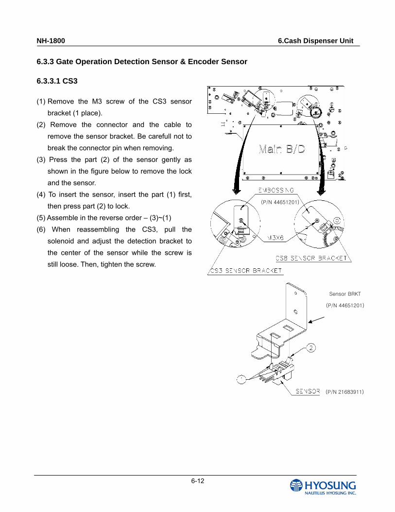
6.3.3.1 CS3
(1) Remove the M3 screw of the CS3 sensor
bracket (1 place).
(2) Remove the connector and the cable to
remove the sensor bracket. Be carefull not to
break the connector pin when removing.
(3) Press the part (2) of the sensor gently as
shown in the figure below to remove the lock
and the sensor.
(4) To insert the sensor, insert the part (1) first,
then press part (2) to lock.
(5) Assemble in the reverse order – (3)~(1)
(6) When reassembling the CS3, pull the
solenoid and adjust the detection bracket to
the center of the sensor while the screw is
still loose. Then, tighten the screw.
NH-1800 6.Cash Dispenser Unit
6-13
(P/N 44654302)
(P/N 44651601)
(P/N 44166101)
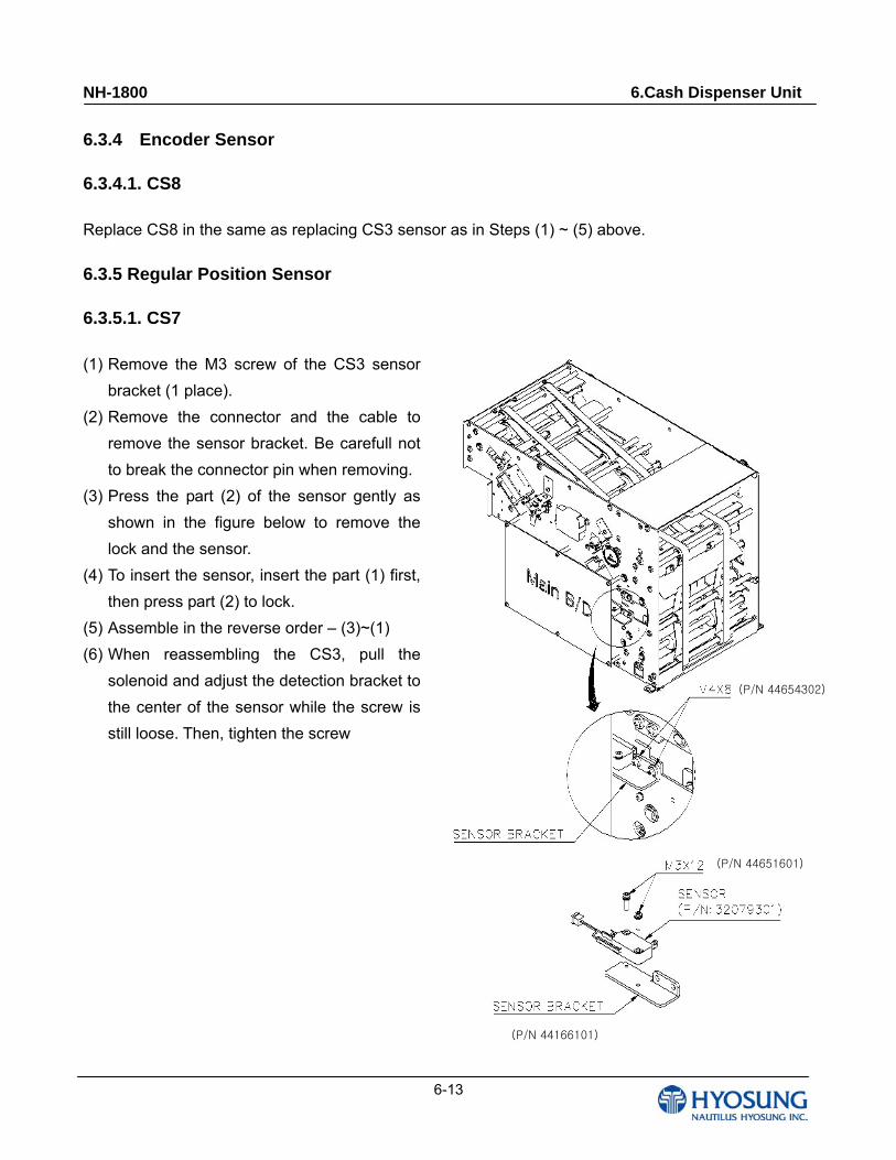
6.3.4 Encoder Sensor
6.3.4.1. CS8
Replace CS8 in the same as replacing CS3 sensor as in Steps (1) ~ (5) above.
6.3.5 Regular Position Sensor
6.3.5.1. CS7
(1) Remove the M3 screw of the CS3 sensor
bracket (1 place).
(2) Remove the connector and the cable to
remove the sensor bracket. Be carefull not
to break the connector pin when removing.
(3) Press the part (2) of the sensor gently as
shown in the figure below to remove the
lock and the sensor.
(4) To insert the sensor, insert the part (1) first,
then press part (2) to lock.
(5) Assemble in the reverse order – (3)~(1)
(6) When reassembling the CS3, pull the
solenoid and adjust the detection bracket to
the center of the sensor while the screw is
still loose. Then, tighten the screw
NH-1800 6.Cash Dispenser Unit
6-14
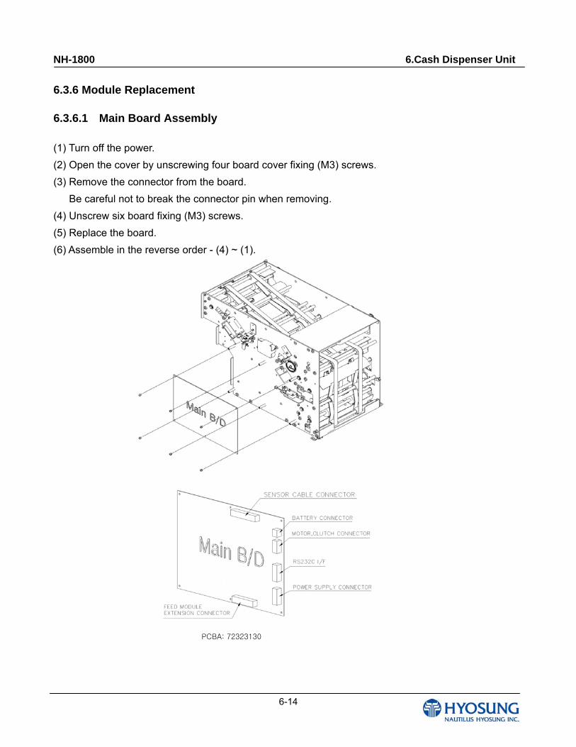
6.3.6 Module Replacement
6.3.6.1 Main Board Assembly
(1) Turn off the power.
(2) Open the cover by unscrewing four board cover fixing (M3) screws.
(3) Remove the connector from the board.
Be careful not to break the connector pin when removing.
(4) Unscrew six board fixing (M3) screws.
(5) Replace the board.
(6) Assemble in the reverse order - (4) ~ (1).
PCBA: 72323130
NH-1800 6.Cash Dispenser Unit
6-15
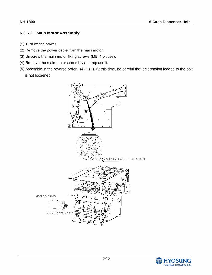
6.3.6.2 Main Motor Assembly
(1) Turn off the power.
(2) Remove the power cable from the main motor.
(3) Unscrew the main motor fixing screws (M5, 4 places).
(4) Remove the main motor assembly and replace it.
(5) Assemble in the reverse order - (4) ~ (1). At this time, be careful that belt tension loaded to the bolt
is not loosened.
(P/N 44656302)
(P/N 56403106)
NH-1800 6.Cash Dispenser Unit
6-16
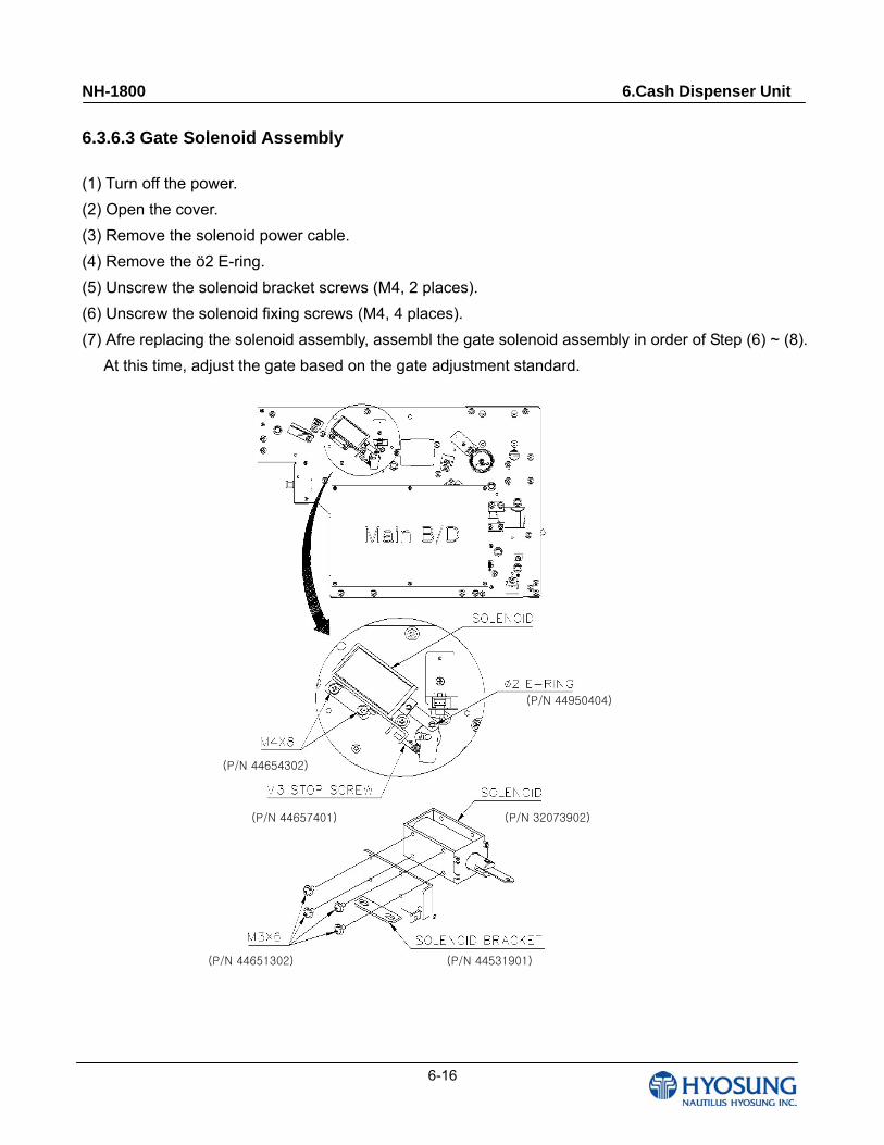
6.3.6.3 Gate Solenoid Assembly
(1) Turn off the power.
(2) Open the cover.
(3) Remove the solenoid power cable.
(4) Remove the ö2 E-ring.
(5) Unscrew the solenoid bracket screws (M4, 2 places).
(6) Unscrew the solenoid fixing screws (M4, 4 places).
(7) Afre replacing the solenoid assembly, assembl the gate solenoid assembly in order of Step (6) ~ (8).
At this time, adjust the gate based on the gate adjustment standard.
(P/N 44950404)
(P/N 44654302)
(P/N 44657401) (P/N 32073902)
(P/N 44651302) (P/N 44531901)

NH-1800 6.Cash Dispenser Unit
6-17
(P/N 44603901)
(P/N 44950409)
(P/N 44974201)
(P/N 72842401) (P/N 44654302)
(P/N 72841904)
6.3.6.4 Clutch Assembly
(1) Turn off the power.
(2) Remove the cassette.
(3) Disconnect the clutch power cable.
(4) Unscrew the tension bracket fixing screw
(M4), and loosen the timing belt.
(5) Remove the gear support spring.
(6) Unscrew M4x16 screws by half on the main
board.
(7) Remove the ö2 E-ring.
(8) Unscrew three clutch bracket fixing screws
(M4).
(9) Remove the clutch assembly.
(10) Replace the clutch assembly and assemble in
the reverse order - (9) ~ (1). At this time,
check if the tension of the timing belt is
enough.
NH-1800 6.Cash Dispenser Unit
6-18
(P/N 44621204)
(P/N 44136802)
(P/N 44651406)
(P/N 72844004)
(P/N 72843901)
(P/N 72843805)
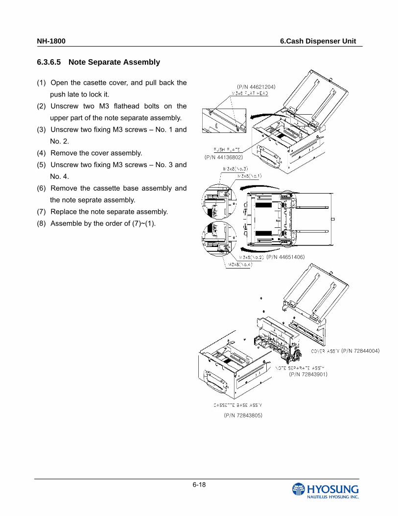
6.3.6.5 Note Separate Assembly
(1) Open the casette cover, and pull back the
push late to lock it.
(2) Unscrew two M3 flathead bolts on the
upper part of the note separate assembly.
(3) Unscrew two fixing M3 screws – No. 1 and
No. 2.
(4) Remove the cover assembly.
(5) Unscrew two fixing M3 screws – No. 3 and
No. 4.
(6) Remove the cassette base assembly and
the note seprate assembly.
(7) Replace the note separate assembly.
(8) Assemble by the order of (7)~(1).
NH-1800 6.Cash Dispenser Unit
6-19
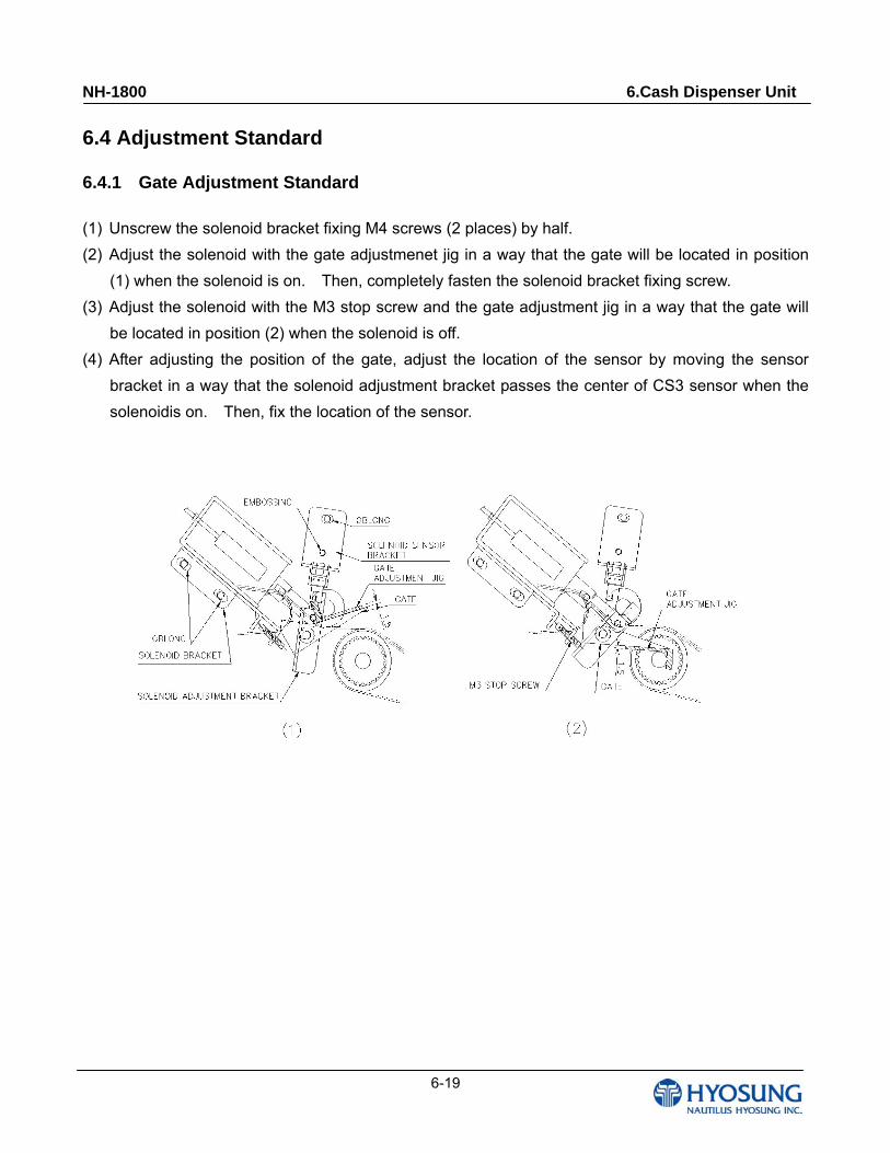
6.4 Adjustment Standard
6.4.1 Gate Adjustment Standard
(1) Unscrew the solenoid bracket fixing M4 screws (2 places) by half.
(2) Adjust the solenoid with the gate adjustmenet jig in a way that the gate will be located in position
(1) when the solenoid is on. Then, completely fasten the solenoid bracket fixing screw.
(3) Adjust the solenoid with the M3 stop screw and the gate adjustment jig in a way that the gate will
be located in position (2) when the solenoid is off.
(4) After adjusting the position of the gate, adjust the location of the sensor by moving the sensor
bracket in a way that the solenoid adjustment bracket passes the center of CS3 sensor when the
solenoidis on. Then, fix the location of the sensor.
NH-1800 6.Cash Dispenser Unit
6-20
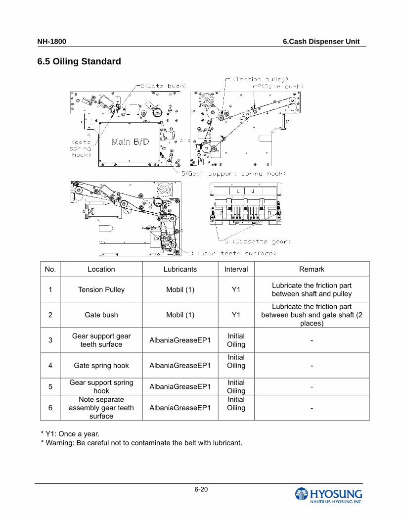
6.5 Oiling Standard
No. Location Lubricants Interval Remark
1 Tension Pulley Mobil (1) Y1 Lubricate the friction part between shaft and pulley
2 Gate bush Mobil (1) Y1 Lubricate the friction part
between bush and gate shaft (2 places)
3 Gear support gear
teeth surface AlbaniaGreaseEP1
Initial Oiling
-
4 Gate spring hook AlbaniaGreaseEP1 Initial Oiling -
5 Gear support spring
hook AlbaniaGreaseEP1
Initial Oiling
-
6 Note separate
assembly gear teeth surface
AlbaniaGreaseEP1 Initial Oiling -
* Y1: Once a year.
* Warning: Be careful not to contaminate the belt with lubricant.
NH-1800 6.Cash Dispenser Unit
6-21
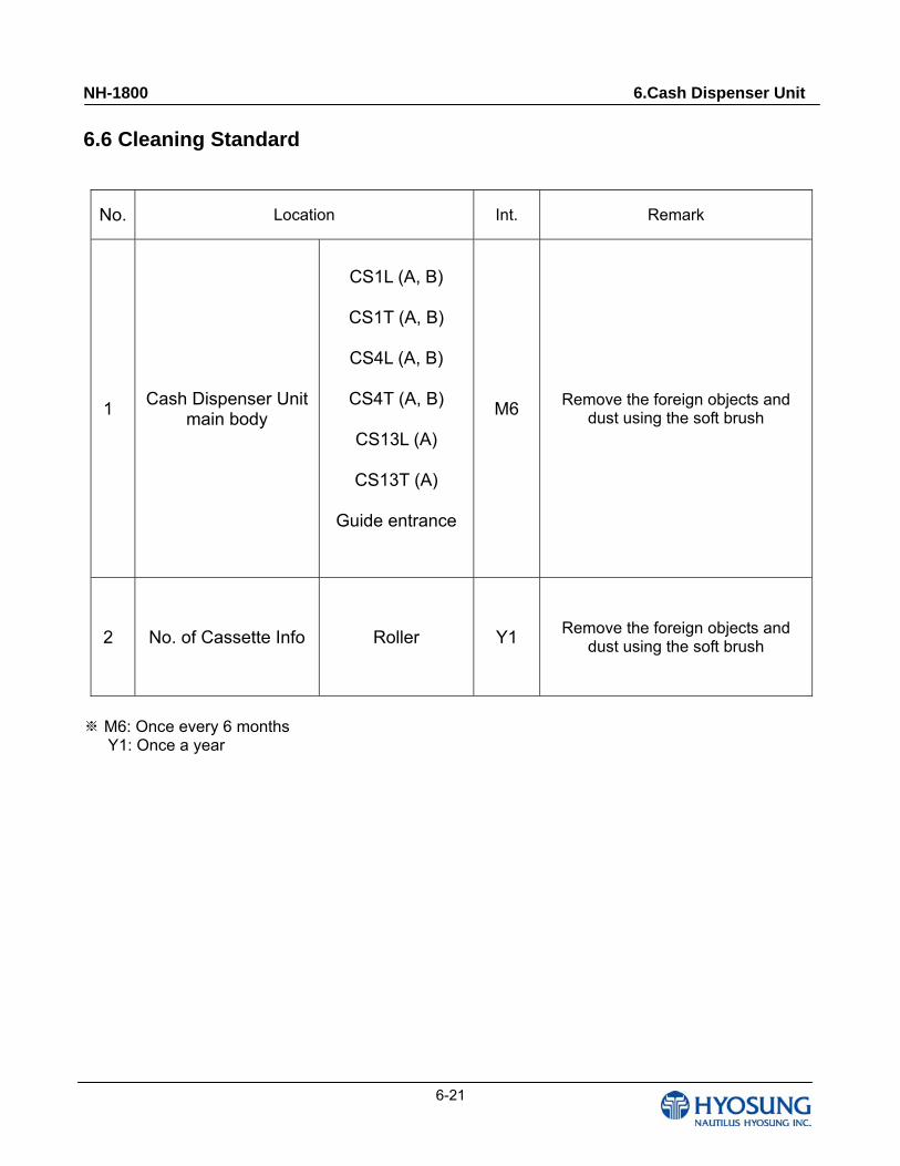
6.6 Cleaning Standard
No. Location Int. Remark
1 Cash Dispenser Unit
main body
CS1L (A, B)
CS1T (A, B)
CS4L (A, B)
CS4T (A, B)
CS13L (A)
CS13T (A)
Guide entrance
M6 Remove the foreign objects and
dust using the soft brush
2 No. of Cassette Info Roller Y1 Remove the foreign objects and
dust using the soft brush
※ M6: Once every 6 months Y1: Once a year
NH-1800 6.Cash Dispenser Unit
6-22
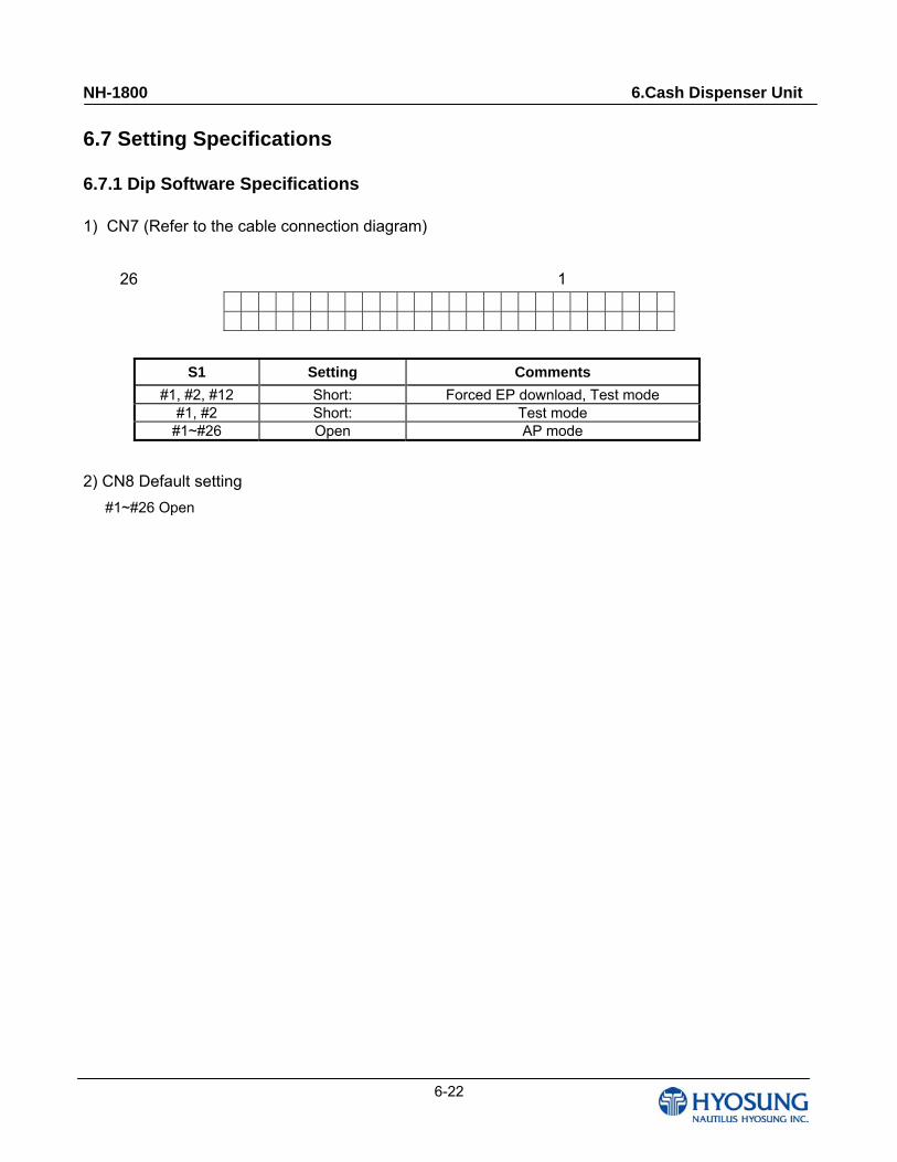
6.7 Setting Specifications
6.7.1 Dip Software Specifications
1) CN7 (Refer to the cable connection diagram)
26 1
S1 Setting Comments
#1, #2, #12 Short: Forced EP download, Test mode #1, #2 Short: Test mode
#1~#26 Open AP mode
2) CN8 Default setting
#1~#26 Open
NH-1800 6.Cash Dispenser Unit
6-23
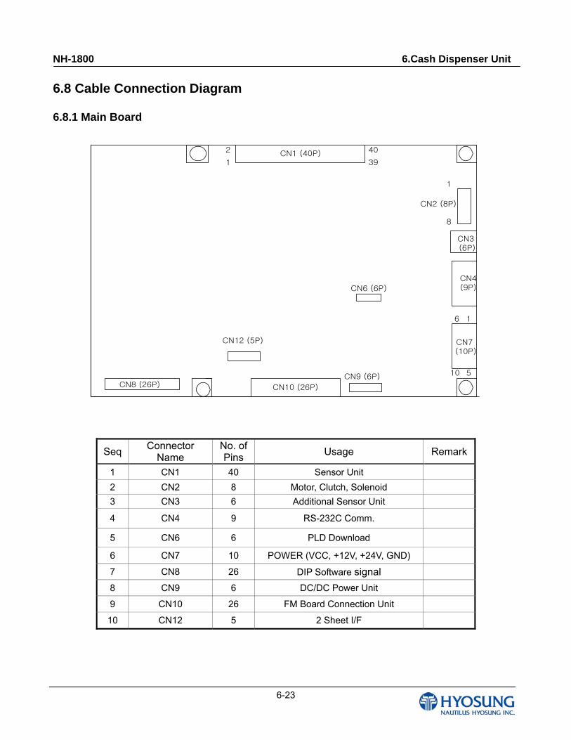
6.8 Cable Connection Diagram
6.8.1 Main Board
CN1 (40P)
CN10 (26P)CN8 (26P)
CN6 (6P)
CN2 (8P)
CN4(9P)
CN7 (10P)
CN3 (6P)
1
10
1
39
2
6 1
40
8
5
CN12 (5P)
CN9 (6P)
Seq Connector
Name No. of Pins
Usage Remark
1 CN1 40 Sensor Unit
2 CN2 8 Motor, Clutch, Solenoid
3 CN3 6 Additional Sensor Unit
4 CN4 9 RS-232C Comm.
5 CN6 6 PLD Download
6 CN7 10 POWER (VCC, +12V, +24V, GND)
7 CN8 26 DIP Software signal
8 CN9 6 DC/DC Power Unit
9 CN10 26 FM Board Connection Unit
10 CN12 5 2 Sheet I/F
NH-1800 6.Cash Dispenser Unit
6-24
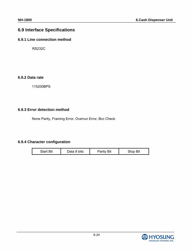
6.9 Interface Specifications
6.9.1 Line connection method
RS232C
6.9.2 Data rate
115200BPS
6.9.3 Error detection method
None Parity, Framing Error, Overrun Error, Bcc Check
6.9.4 Character configuration
Start Bit Data 8 bits Parity Bit Stop Bit

NH-1800 6.Cash Dispenser Unit
6-25
6.9.5 Data Protocol
1) Normal condition
COMMAND ENQ ENQ ACK
GP
CDUM
ACK ACK (starting) Response Stop (Idle)
2) Abnormal condition
COMMAND
GP
CDUM
ACK
Note) 180 SEC: AP sending time out
GP NACK ACK
CDUM Response Response (Idle)
- CDUM can respond only when the request from the GP is received.
t = 180 SEC.
NH-1800 6.Cash Dispenser Unit
6-26
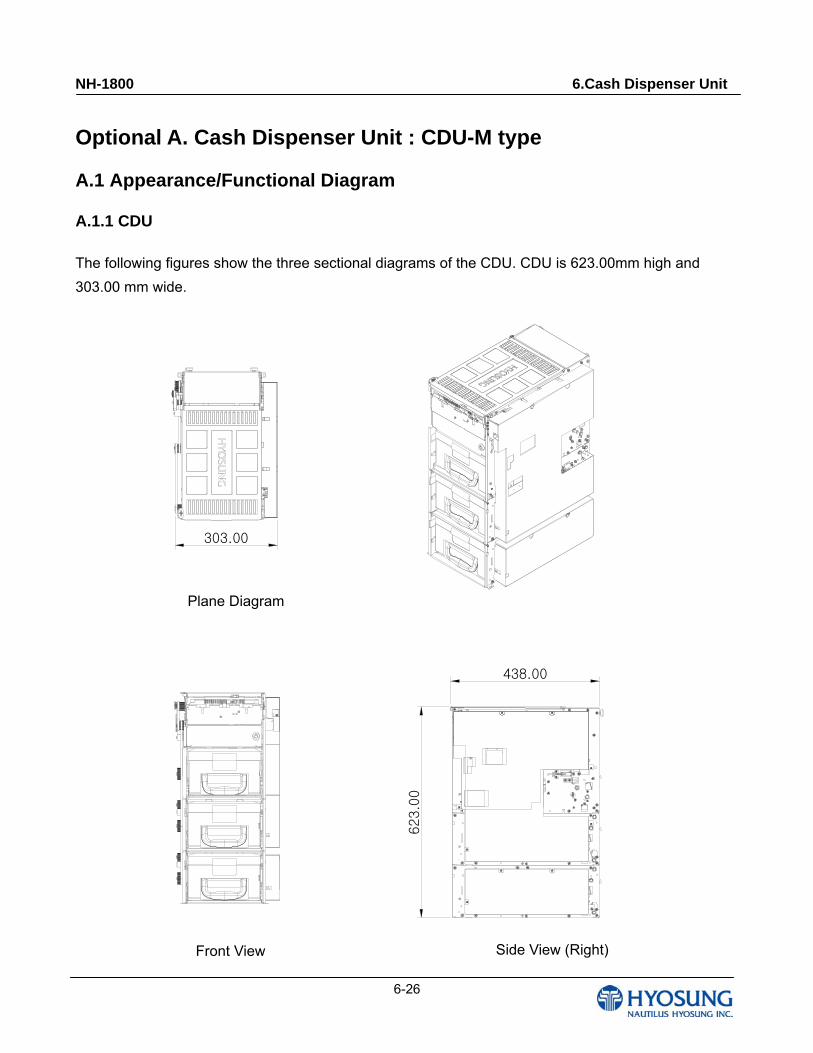
Optional A. Cash Dispenser Unit : CDU-M type
A.1 Appearance/Functional Diagram
A.1.1 CDU
The following figures show the three sectional diagrams of the CDU. CDU is 623.00mm high and
303.00 mm wide.
평면도
정면도 우측면도
303.00
438.00
623.0
0
Plane Diagram
Front View Side View (Right)
NH-1800 6.Cash Dispenser Unit
6-27
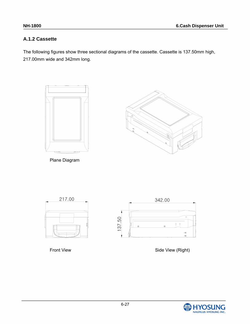
A.1.2 Cassette
The following figures show three sectional diagrams of the cassette. Cassette is 137.50mm high,
217.00mm wide and 342mm long.
우측면도정면도
평면도
217.00 342.00
137.5
0
Front View Side View (Right)
Plane Diagram
NH-1800 6.Cash Dispenser Unit
6-28
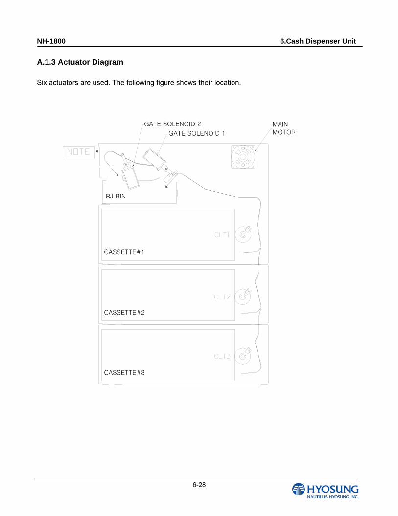
A.1.3 Actuator Diagram
Six actuators are used. The following figure shows their location.
GATE SOLENOID 1
GATE SOLENOID 2 MAINMOTOR
RJ BIN
CASSETTE#1
CASSETTE#2
CASSETTE#3
NH-1800 6.Cash Dispenser Unit
6-29
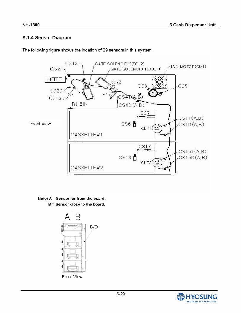
A.1.4 Sensor Diagram
The following figure shows the location of 29 sensors in this system.
Note) A = Sensor far from the board.
B = Sensor close to the board.
A BB/D
정면도
Front View
Front View
NH-1800 6.Cash Dispenser Unit
6-30
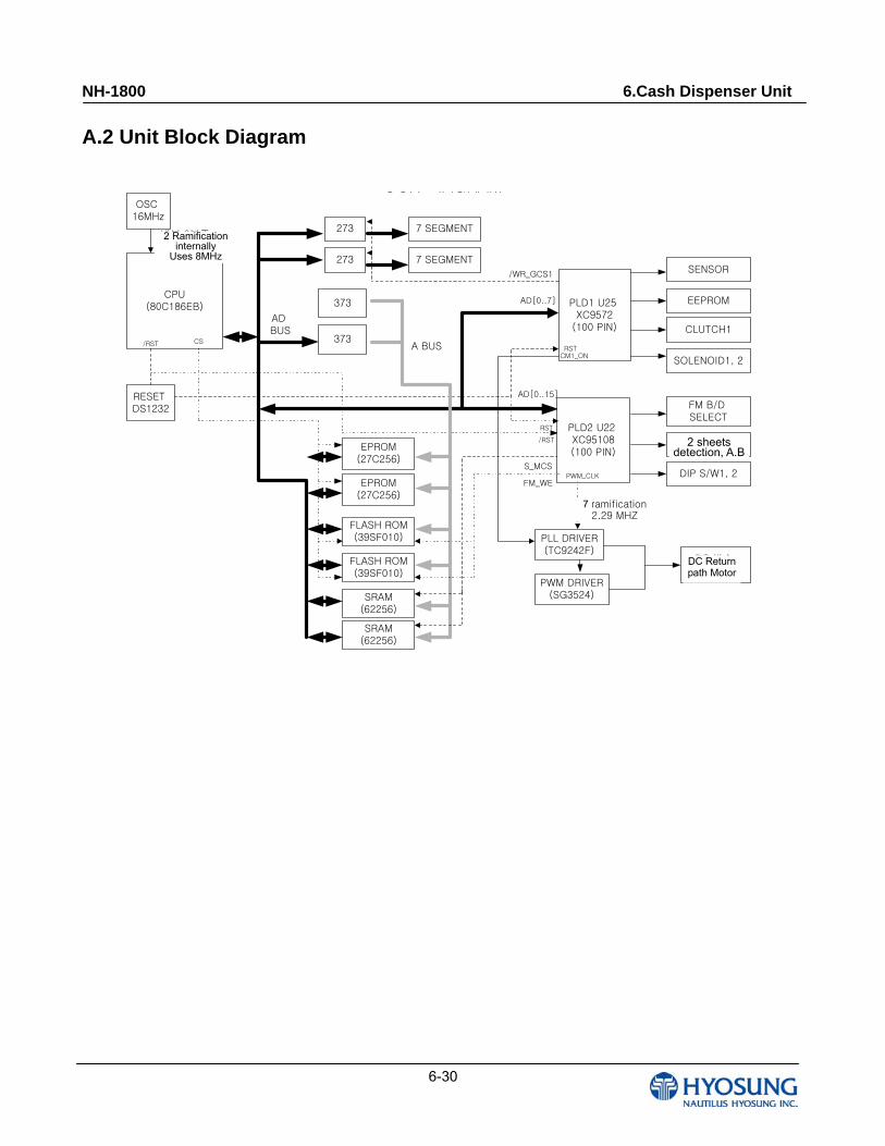
A.2 Unit Block Diagram
CPU(80C186EB) PLD1 U25
XC9572(100 PIN)
SENSOR
EEPROM
CLUTCH1
2매 검지 A,B
DIP S/W1, 2
373
EPROM(27C256)
FLASH ROM(39SF010)
273 7 SEGMENT
CS
AD BUS
A BUS
FLASH ROM(39SF010)
SOLENOID1, 2
DC 반송 MOTOR
EPROM(27C256)
PLL DRIVER(TC9242F)
PWM DRIVER(SG3524)
OCK IAGRAMOSC
16MHz
RESET DS1232
/RST
내부 2분주 8MHz사용
RST
273 7 SEGMENT
/RST
/WR_GCS1
373
SRAM(62256)
SRAM(62256)
S_MCS
PLD2 U22 XC95108(100 PIN)
FM_WE
7분주2.28MHZ
CM1_ON
AD[0..7]
AD[0..15]
PWM_CLK
FM B/D SELECT
RST
2 sheets detection, A.B
7 ramification 2.29 MHZ
2 Ramification internally
Uses 8MHz
DC Return path Motor
NH-1800 6.Cash Dispenser Unit
6-31
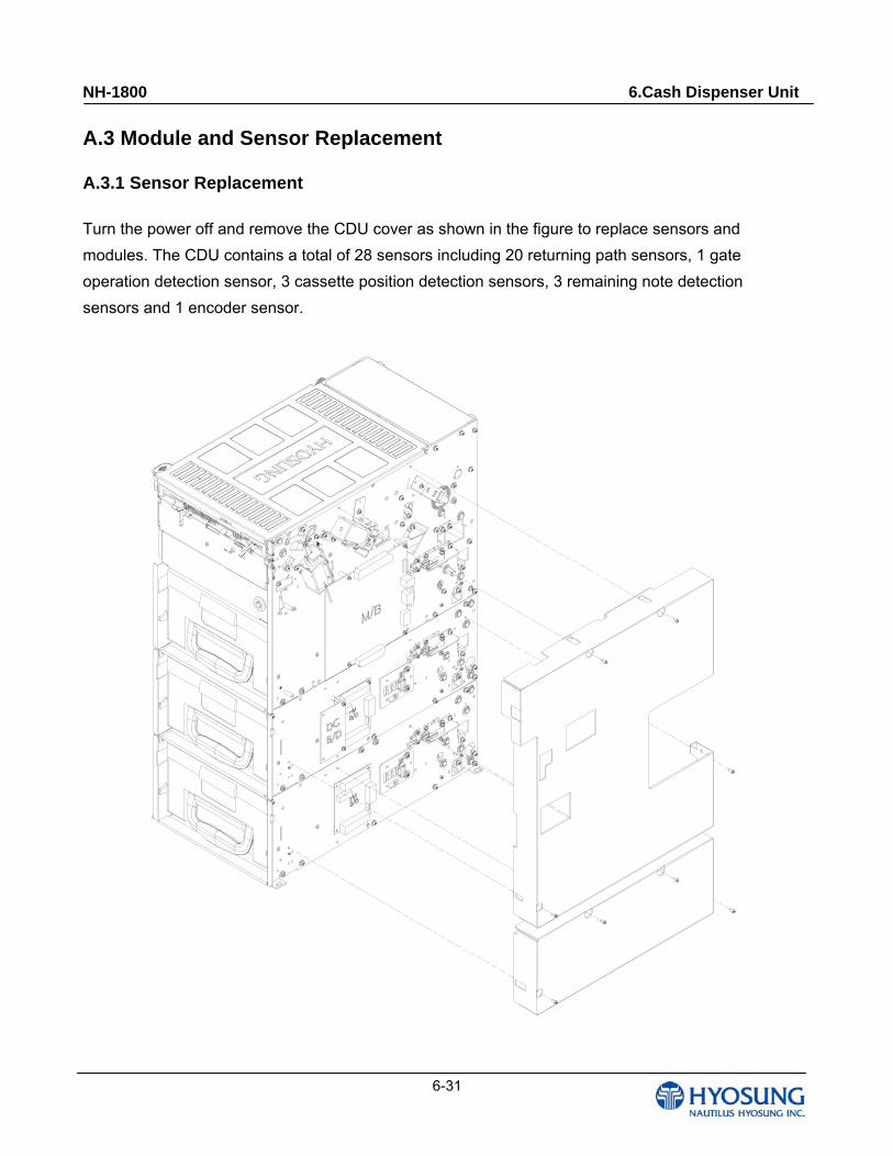
A.3 Module and Sensor Replacement
A.3.1 Sensor Replacement
Turn the power off and remove the CDU cover as shown in the figure to replace sensors and
modules. The CDU contains a total of 28 sensors including 20 returning path sensors, 1 gate
operation detection sensor, 3 cassette position detection sensors, 3 remaining note detection
sensors and 1 encoder sensor.
NH-1800 6.Cash Dispenser Unit
6-32
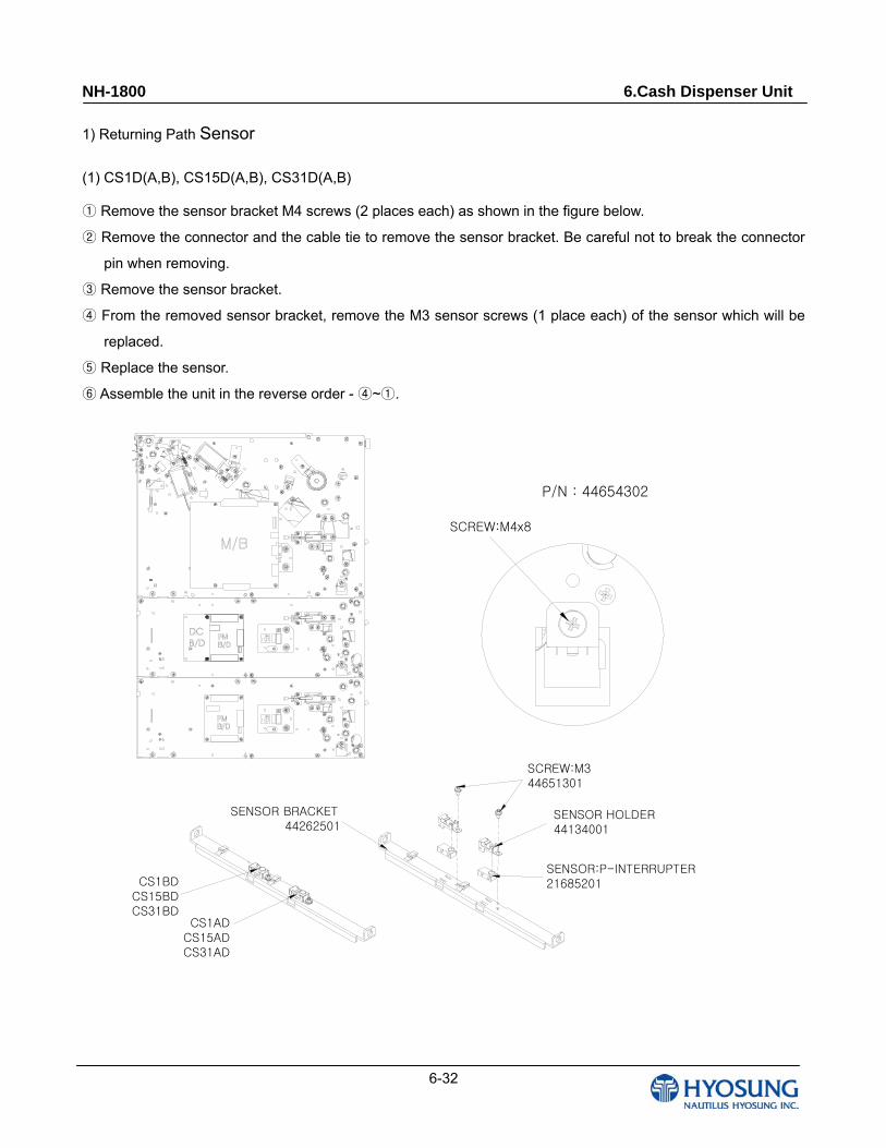
1) Returning Path Sensor
(1) CS1D(A,B), CS15D(A,B), CS31D(A,B)
Remove the sensor bracket M4 screws (2 places each) as shown in the figure below.①
Remove the connector and the cable tie to remove the sensor bracket. Be careful not to break the connector ②
pin when removing.
Remove the sensor bracket.③
From the removed sensor bracket, remove the M3 sensor screws (1 place each) of the sensor which will be ④
replaced.
Replace the sensor.⑤
Assemble the unit in the reverse order ⑥ - ~ .④ ①
SCREW:M4x8
SENSOR BRACKET44262501
CS1ADCS15ADCS31AD
SCREW:M344651301
SENSOR HOLDER44134001
SENSOR:P-INTERRUPTER21685201CS1BD
CS15BDCS31BD
P/N : 44654302
NH-1800 6.Cash Dispenser Unit
6-33
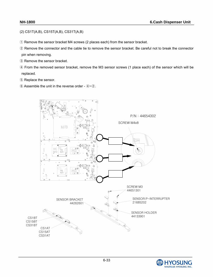
(2) CS1T(A,B), CS15T(A,B), CS31T(A,B)
Remove the sensor bracket M4 screws (2 places each) from the sensor bracket.①
Remove the connector and the cable tie to remove the sensor bracket. Be careful not to break the connector ②
pin when removing.
Remove the sensor bracket.③
④ From the removed sensor bracket, remove the M3 sensor screws (1 place each) of the sensor which will be
replaced.
Replace the sensor.⑤
Assemble the unit in the reverse order ⑥ - ~ .④ ②
SCREW:M4x8
SENSOR BRACKET44262601
CS1ATCS15ATCS31AT
SCREW:M344651301
SENSOR HOLDER44133901
SENSOR:P-INTERRUPTER21685202
CS1BTCS15BTCS31BT
P/N : 44654302
NH-1800 6.Cash Dispenser Unit
6-34
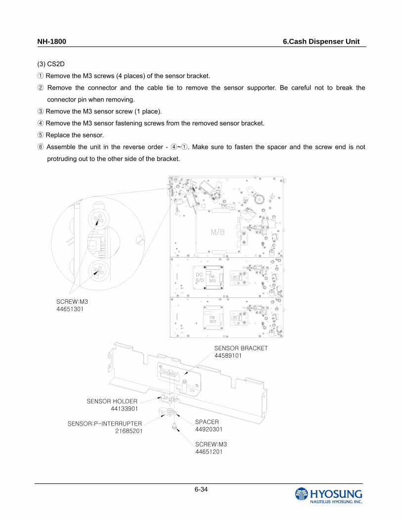
(3) CS2D
Remove the M3 screws (4 p① laces) of the sensor bracket.
Remove the connector and the cable tie to remove the sensor supporter. Be careful not to break the ②
connector pin when removing.
Remove the M3 sensor screw (1 place).③
Remove the M3 sensor fastening screws from the removed④ sensor bracket.
Replace the sensor.⑤
Assemble the unit in the reverse order ⑥ - ~ . Make sure to fasten the spacer and the screw end is not ④ ①
protruding out to the other side of the bracket.
SENSOR BRACKET44589101
SCREW:M344651201
SENSOR:P-INTERRUPTER21685201
SPACER44920301
SCREW:M344651301
SENSOR HOLDER44133901
NH-1800 6.Cash Dispenser Unit
6-35
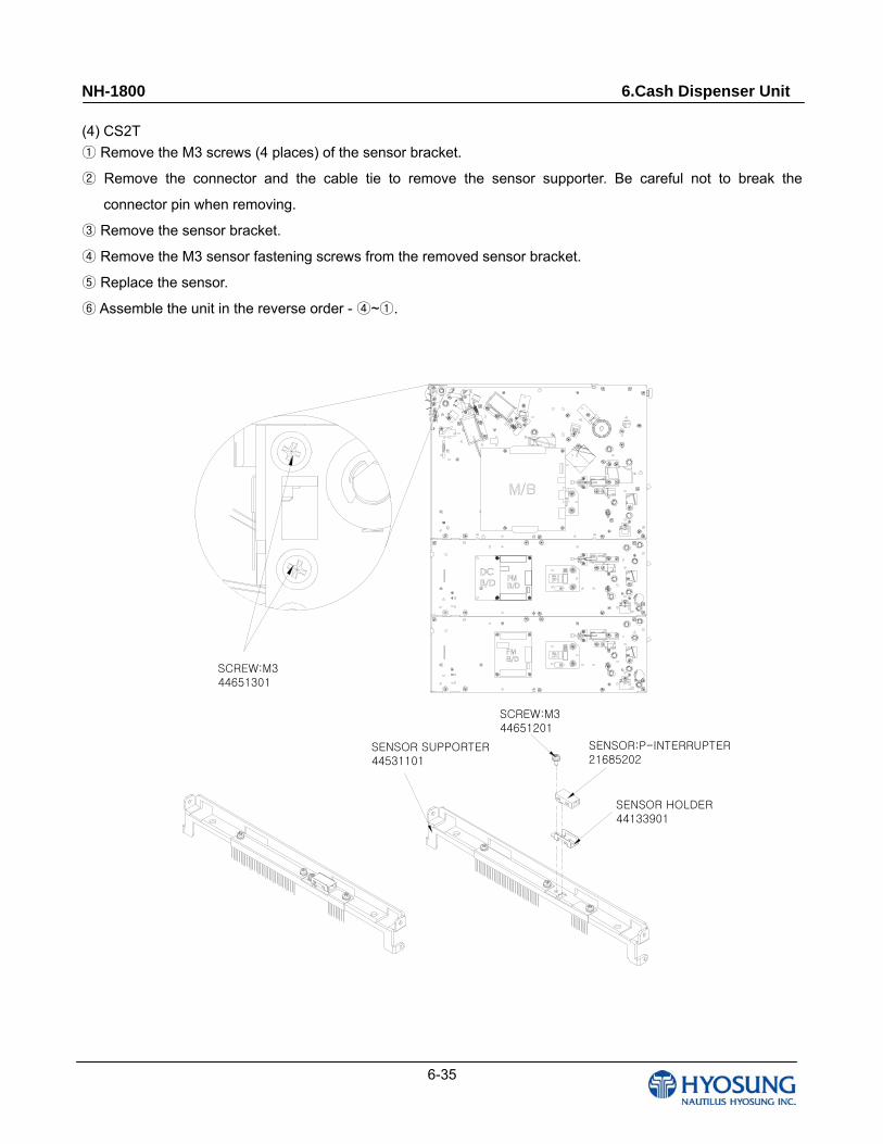
(4) CS2T
Remove the M3 screws (4 places) of the sensor brac① ket.
Remove the connector and the cable tie to remove the sensor supporter. Be careful not to break the ②
connector pin when removing.
Remove the sensor bracket.③
Remove the M3 sensor fastening screws from the removed sensor bracket.④
Replace the senso⑤ r.
Assemble the unit in the reverse order ⑥ - ~ .④ ①
SENSOR SUPPORTER44531101
SCREW:M344651201
SENSOR:P-INTERRUPTER21685202
SCREW:M344651301
SENSOR HOLDER44133901
NH-1800 6.Cash Dispenser Unit
6-36
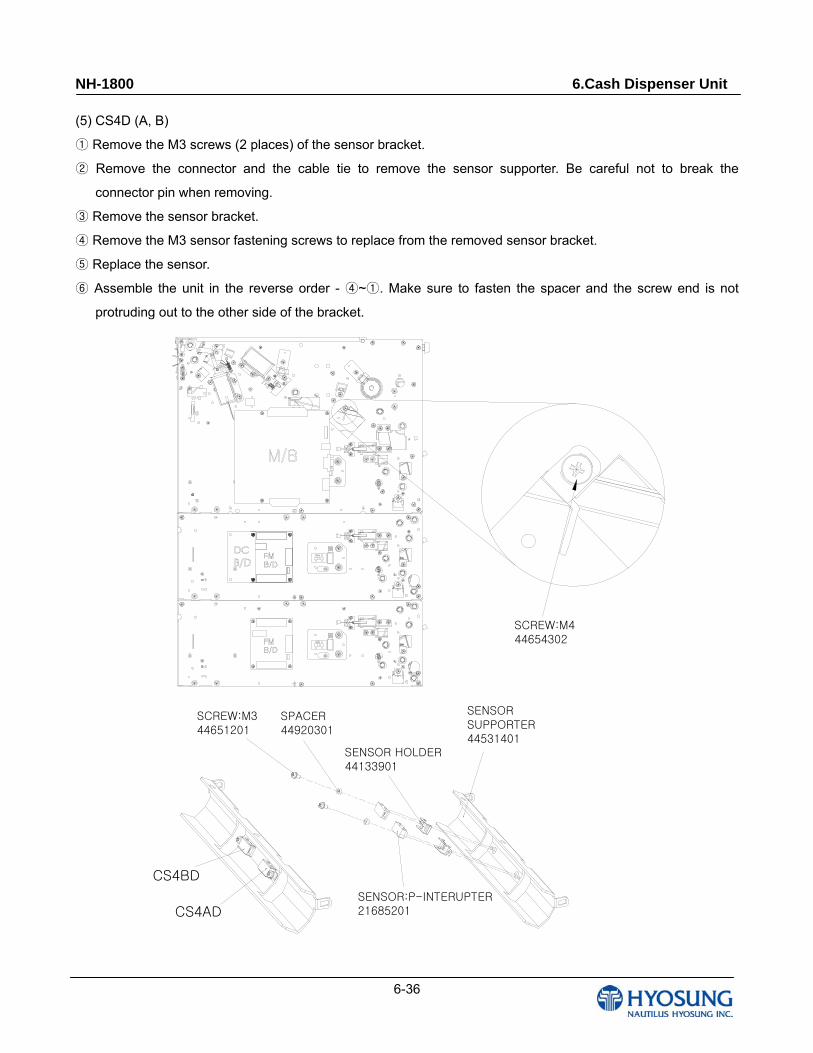
(5) CS4D (A, B)
Remove the M3 screws (2 places) of the sensor bracket.①
Remove the connector and the cable tie to remove the sensor supporter. Be careful not to break the ②
connector pin when removing.
Remove the sensor bracket.③
Remove the M3 sensor fastening screws to replace from the removed sensor bracket.④
Replace the sensor.⑤
Assemble the unit in the reverse order ⑥ - ~ . Make sure to fasten the spacer and the screw end is not ④ ①
protruding out to the other side of the bracket.
CS4BD
CS4AD
SCREW:M444654302
SENSOR HOLDER44133901
SPACER44920301
SCREW:M3 44651201
SENSOR SUPPORTER44531401
SENSOR:P-INTERUPTER21685201
NH-1800 6.Cash Dispenser Unit
6-37
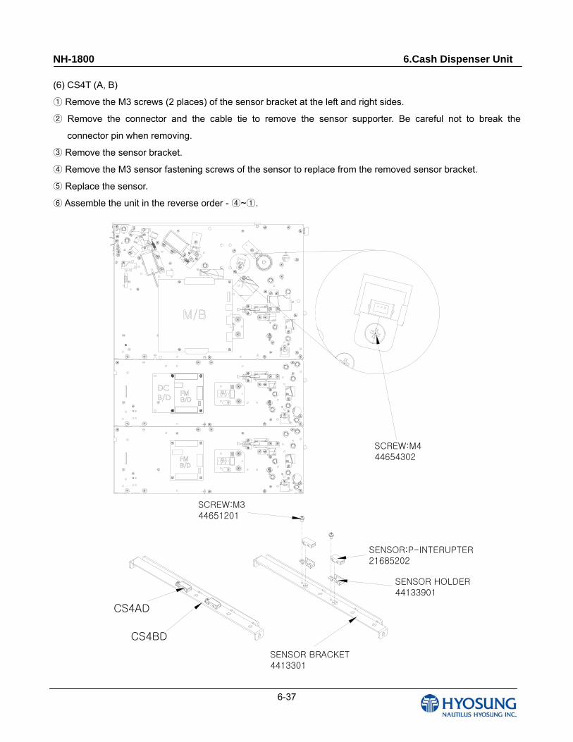
(6) CS4T (A, B)
Remove the M3 screws (2 places) of the sensor bracket at the left and right sides.①
Remove the connector and the cable tie to remove the sensor supporter. Be careful not to break the ②
connector pin when removing.
Remove the sensor bracket.③
Remove the M3 sensor fastening screws of the sensor to replace from the removed sensor bracket.④
Replace the sensor.⑤
Assemble the unit in the reverse order ⑥ - ~ .④ ①
CS4AD
CS4BD
SCREW:M444654302
SENSOR HOLDER44133901
SENSOR:P-INTERUPTER21685202
SENSOR BRACKET4413301
SCREW:M3 44651201
NH-1800 6.Cash Dispenser Unit
6-38
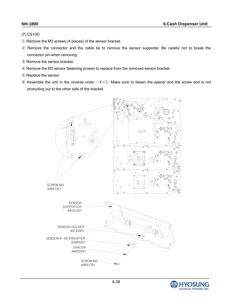
(7) CS13D
Remove the M3 screws (4 places)① of the sensor bracket.
Remove the connector and the cable tie to remove the sensor supporter. Be careful not to break the ②
connector pin when removing.
Remove the sensor bracket.③
Remove the M3 sensor fastening screws to replace from the removed senso④ r bracket.
Replace the sensor.⑤
Assemble the unit in the reverse order ⑥ - ~ . Make sure to fasten the spacer and the screw end is not ④ ①
protruding out to the other side of the bracket.
SCREW:M344651301
SENSOR HOLDER44133901
SCREW:M3 44651201
SENSOR SUPPORTER
44531501
SENSOR:P-INTERRUPTER 20685201
SPACER44920301
NH-1800 6.Cash Dispenser Unit
6-39
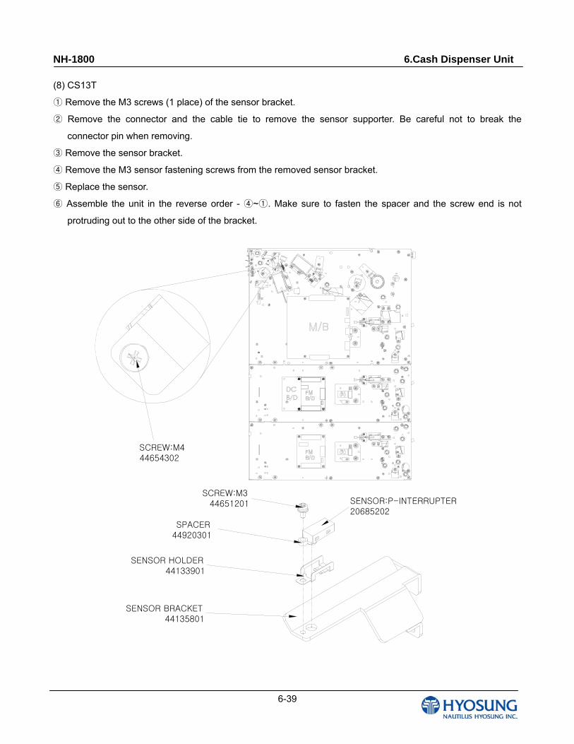
(8) CS13T
Remove the M3 screws (1 place) of the sensor bracket.①
Remove the connector and the cable tie to remove the sensor supporter. Be careful not to break the ②
connector pin when removing.
Remove the sensor bracket.③
Remove the M3 sensor fastening screws from the removed sensor bracket.④
Replace the sensor.⑤
⑥ Assemble the unit in the reverse order - ~ . Make sure to fasten the spacer and the screw end is not ④ ①
protruding out to the other side of the bracket.
SCREW:M444654302
SENSOR HOLDER44133901
SENSOR BRACKET44135801
SENSOR:P-INTERRUPTER 20685202
SPACER44920301
SCREW:M344651201
NH-1800 6.Cash Dispenser Unit
6-40
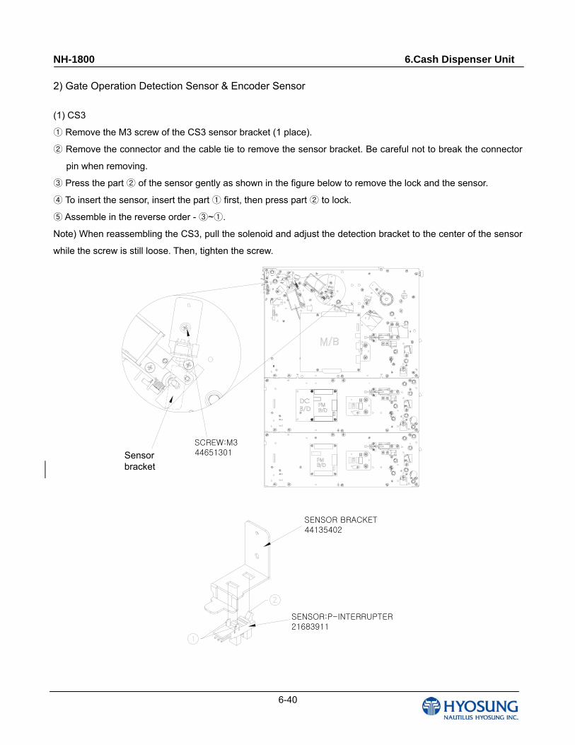
2) Gate Operation Detection Sensor & Encoder Sensor
(1) CS3
Remove the M3 screw of the CS3 sensor ① bracket (1 place).
Remove the connector and the cable tie to remove the sensor bracket. Be careful not to break the connector ②
pin when removing.
Press the part of the sensor gently as shown in the figure below to remove the lock and the sensor.③ ②
To ④ insert the sensor, insert the part first, then press part to lock.① ②
Assemble in the reverse order ⑤ - ~ .③ ①
Note) When reassembling the CS3, pull the solenoid and adjust the detection bracket to the center of the sensor
while the screw is still loose. Then, tighten the screw.
SCREW:M344651301검지
BRACKET
SENSOR BRACKET44135402
SENSOR:P-INTERRUPTER21683911
Sensor bracket
NH-1800 6.Cash Dispenser Unit
6-41
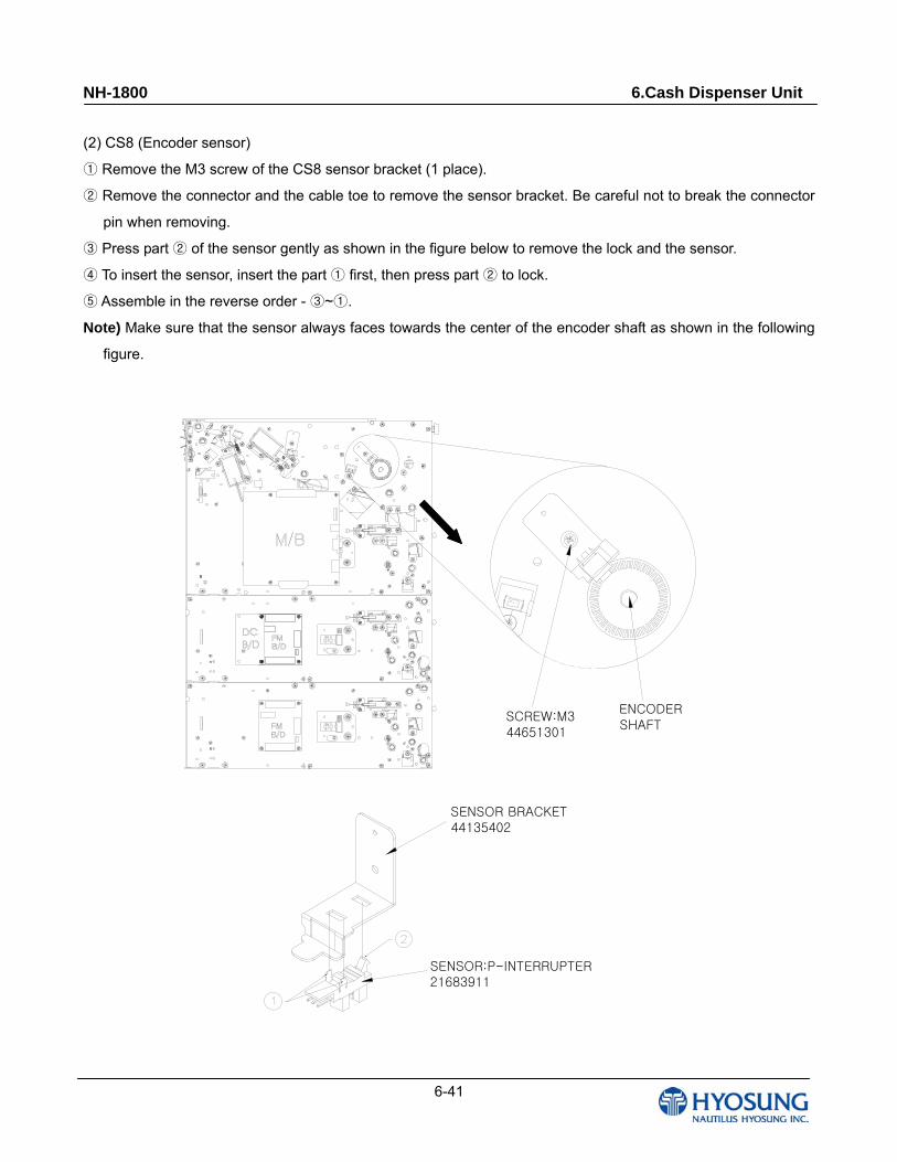
(2) CS8 (Encoder sensor)
Remove the M3 screw of the CS8 sensor bracket (1 place).①
Remove the connector and the cable toe to remove the sensor bracket. Be careful not to break the connector ②
pin when removing.
Press part of③ ② the sensor gently as shown in the figure below to remove the lock and the sensor.
To insert the sensor, insert the part first, then press part to lock.④ ① ②
Assemble in the reverse order ⑤ - ~ .③ ①
Note) Make sure that the sensor always faces towards the center of the encoder shaft as shown in the following
figure.
SCREW:M344651301
SENSOR BRACKET44135402
SENSOR:P-INTERRUPTER21683911
ENCODERSHAFT
NH-1800 6.Cash Dispenser Unit
6-42
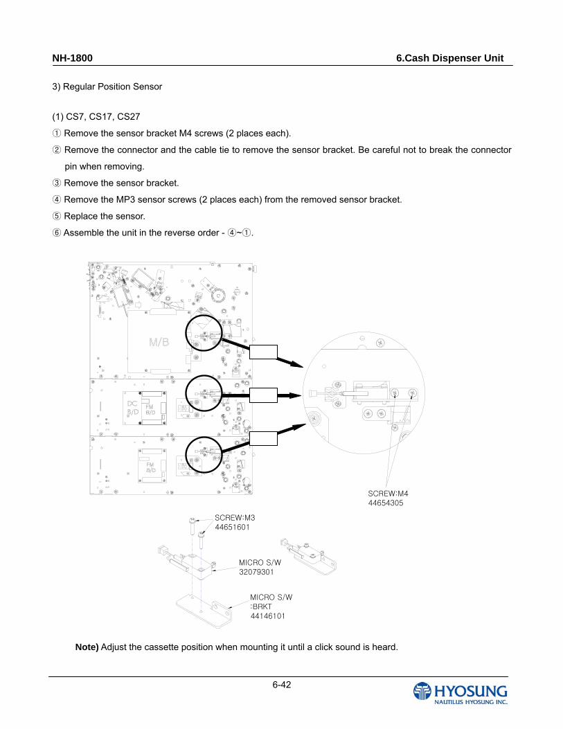
3) Regular Position Sensor
(1) CS7, CS17, CS27
Remove the sensor bracket M4 screws (2 places each).①
Remove the connector and the cable tie to remove the sensor bracket. Be careful not t② o break the connector
pin when removing.
Remove the sensor bracket.③
Remove the MP3 sensor screws (2 places each) from the removed sensor bracket.④
Replace the sensor.⑤
Assemble the unit in the reverse order ⑥ - ~ .④ ①
SCREW:M344651601
MICRO S/W32079301
MICRO S/W :BRKT44146101
SCREW:M444654305
Note) Adjust the cassette position when mounting it until a click sound is heard.
NH-1800 6.Cash Dispenser Unit
6-43
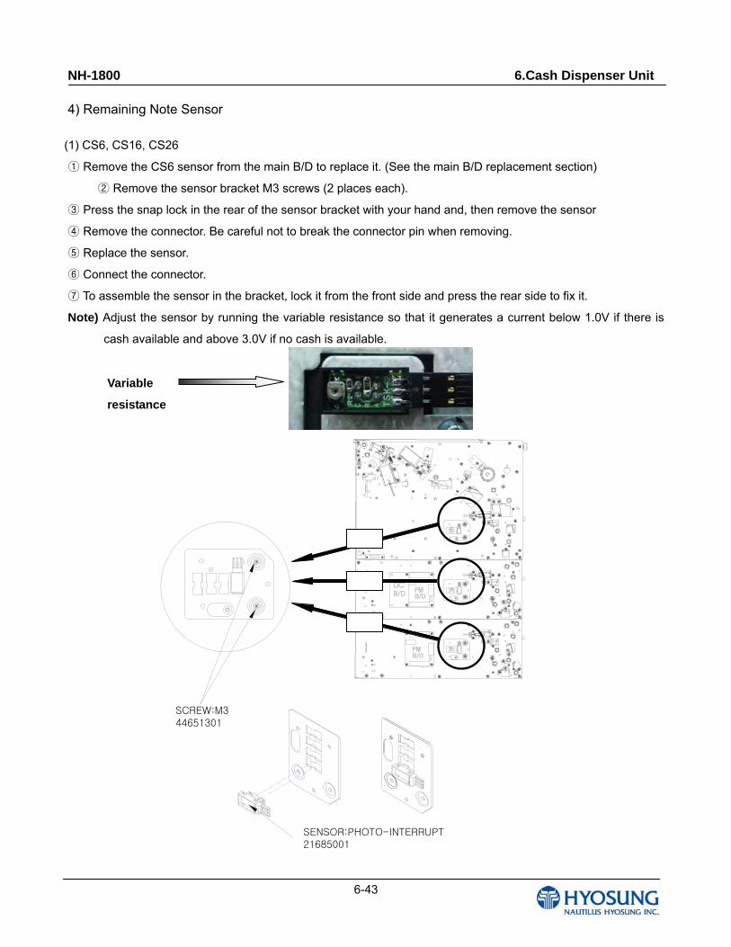
4) Remaining Note Sensor
(1) CS6, CS16, CS26
Remove the CS6 sensor from the main B/D to replace it. (See the main B/D replacement section)①
Remove the sensor bracket M3 screws (2 places each).②
Press③ the snap lock in the rear of the sensor bracket with your hand and, then remove the sensor
Remove the connector. Be careful not to break the connector pin when removing.④
Replace the sensor.⑤
Connect the connector.⑥
To assemble the sensor in the brac⑦ ket, lock it from the front side and press the rear side to fix it.
Note) Adjust the sensor by running the variable resistance so that it generates a current below 1.0V if there is
cash available and above 3.0V if no cash is available.
SCREW:M344651301
SENSOR:PHOTO-INTERRUPT21685001
Variable
resistance

NH-1800 6.Cash Dispenser Unit
6-44
A.3.2 Module Replacement
1) B/D assembly
(1) The board assembly is composed of the main board and the DC converter board as shown in the following
figure.
(2) Remove the connector from the board. Be careful not to break the connector pin.
(3) Remove the board M3 screws (4 places in the main board, 8 places in the FM board (6 screws, 2 jack posts)
and 2 places in the DC board).
(4) Replace the board.
(5) Assemble in the reverse order - (4)~(1).
Main B/D4 X SCREW M344651301
FM B/D6 X SCREW M344651301
FM B/D2 X JACK POST
44824401
DC CONVERTER B/D2 X SCREW M344651301
NH-1800 6.Cash Dispenser Unit
6-45
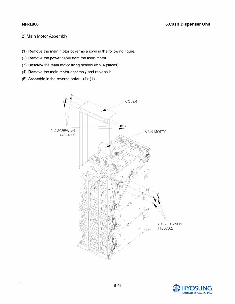
2) Main Motor Assembly
(1) Remove the main motor cover as shown in the following figure.
(2) Remove the power cable from the main motor.
(3) Unscrew the main motor fixing screws (M5, 4 places).
(4) Remove the main motor assembly and replace it.
(5) Assemble in the reverse order - (4)~(1).
5 X SCREW:M444654302
MAIN MOTOR
4 X SCREW:M544656302
COVER
NH-1800 6.Cash Dispenser Unit
6-46
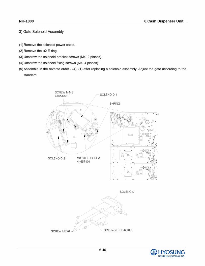
3) Gate Solenoid Assembly
(1) Remove the solenoid power cable.
(2) Remove the φ2 E-ring.
(3) Unscrew the solenoid bracket screws (M4, 2 places).
(4) Unscrew the solenoid fixing screws (M4, 4 places).
(5) Assemble in the reverse order - (4)~(1) after replacing a solenoid assembly. Adjust the gate according to the
standard.
SOLENOID
SOLENOID BRACKET
SCREW M4x844654302
SOLENOID 2
SOLENOID 1
M3 STOP SCREW44657401
E-RING
SCREW:M3X6
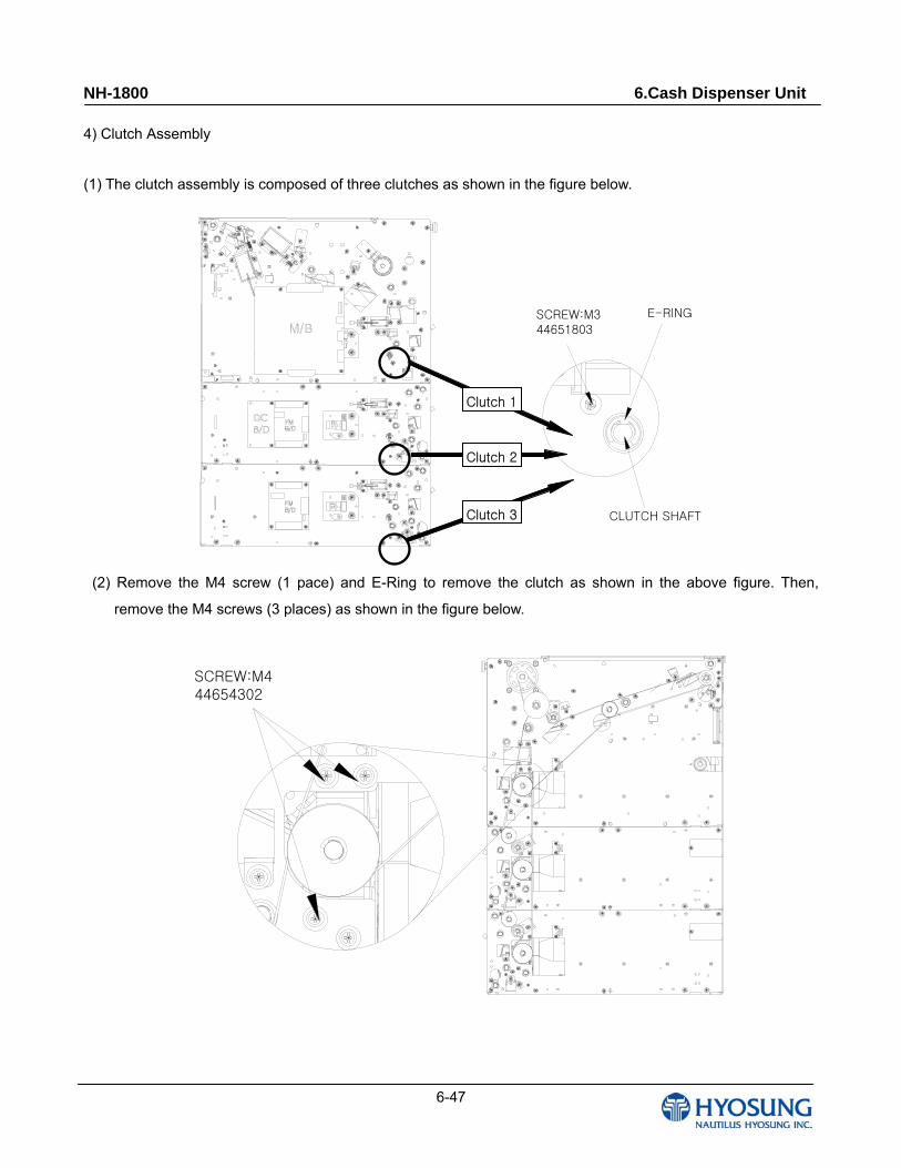
NH-1800 6.Cash Dispenser Unit
6-47
4) Clutch Assembly
(1) The clutch assembly is composed of three clutches as shown in the figure below.
SCREW:M344651803
CLUTCH SHAFT
E-RING
(2) Remove the M4 screw (1 pace) and E-Ring to remove the clutch as shown in the above figure. Then,
remove the M4 screws (3 places) as shown in the figure below.
SCREW:M444654302
Clutch 1
Clutch 2
Clutch 3
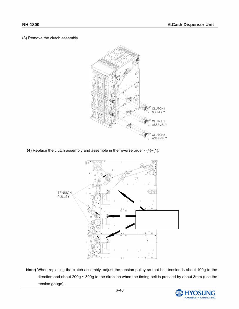
NH-1800 6.Cash Dispenser Unit
6-48
(3) Remove the clutch assembly.
CLUTCH1 SSEMBLY
CLUTCH2ASSEMBLY
CLUTCH3ASSEMBLY
(4) Replace the clutch assembly and assemble in the reverse order - (4)~(1).
TENSION PULLEY
Note) When replacing the clutch assembly, adjust the tension pulley so that belt tension is about 100g to the
direction and about 200g ~ 300g to the direction when the timing belt is pressed by about 3mm (use the
tension gauge).
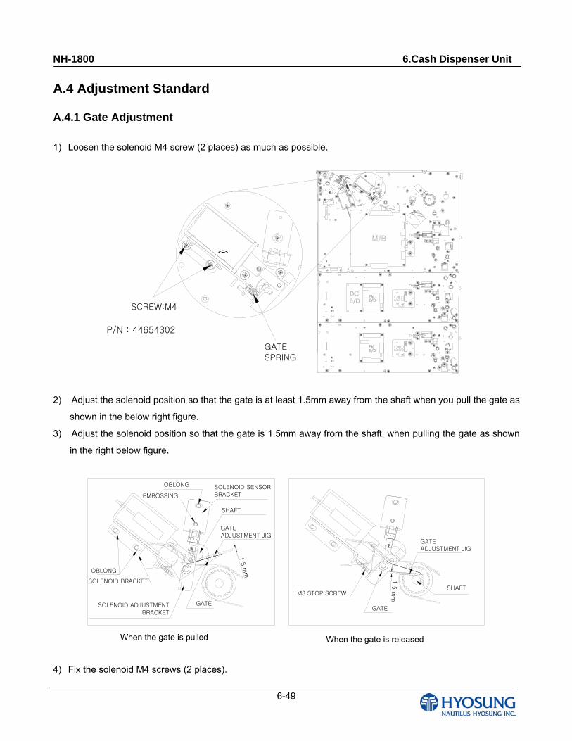
NH-1800 6.Cash Dispenser Unit
6-49
A.4 Adjustment Standard
A.4.1 Gate Adjustment
1) Loosen the solenoid M4 screw (2 places) as much as possible.
GATE SPRING
SCREW:M4
2) Adjust the solenoid position so that the gate is at least 1.5mm away from the shaft when you pull the gate as
shown in the below right figure.
3) Adjust the solenoid position so that the gate is 1.5mm away from the shaft, when pulling the gate as shown
in the right below figure.
GATE를 당겼을 때 GATE를 놓았을 때
1.5
mm
OBLONG
EMBOSSING
M3 STOP SCREW
GATE
GATEADJUSTMENT JIG
SOLENOID BRACKET
SOLENOID ADJUSTMENT BRACKET
GATE
1.5
mm
GATEADJUSTMENT JIG
OBLONG SOLENOID SENSORBRACKET
SHAFT
SHAFT
4) Fix the solenoid M4 screws (2 places).
②
When the gate is pulled When the gate is released
P/N : 44654302
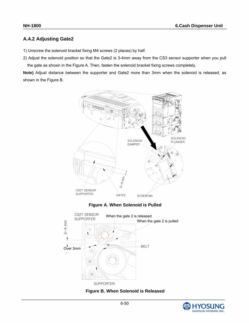
NH-1800 6.Cash Dispenser Unit
6-50
A.4.2 Adjusting Gate2
1) Unscrew the solenoid bracket fixing M4 screws (2 places) by half.
2) Adjust the solenoid position so that the Gate2 is 3-4mm away from the CS3 sensor supporter when you pull
the gate as shown in the Figure A. Then, fasten the solenoid bracket fixing screws completely.
Note) Adjust distance between the supporter and Gate2 more than 3mm when the solenoid is released, as
shown in the Figure B.
CS2T SENSORSUPPORTER GATE2
SOLENOID DAMPER
SOLENOID PLUNGER
3~
4 m
m
SCREW:M4
Figure A. When Solenoid is Pulled
Figure B. When Solenoid is Released
GATE2 (놓았을 때)
SUPPORTER
BELT
CS2T SENSOR SUPPORTER
3mm 이상
GATE2 (당겼을 때)
3~
4 m
m
When the gate 2 is releasedWhen the gate 2 is pulled
Over 3mm
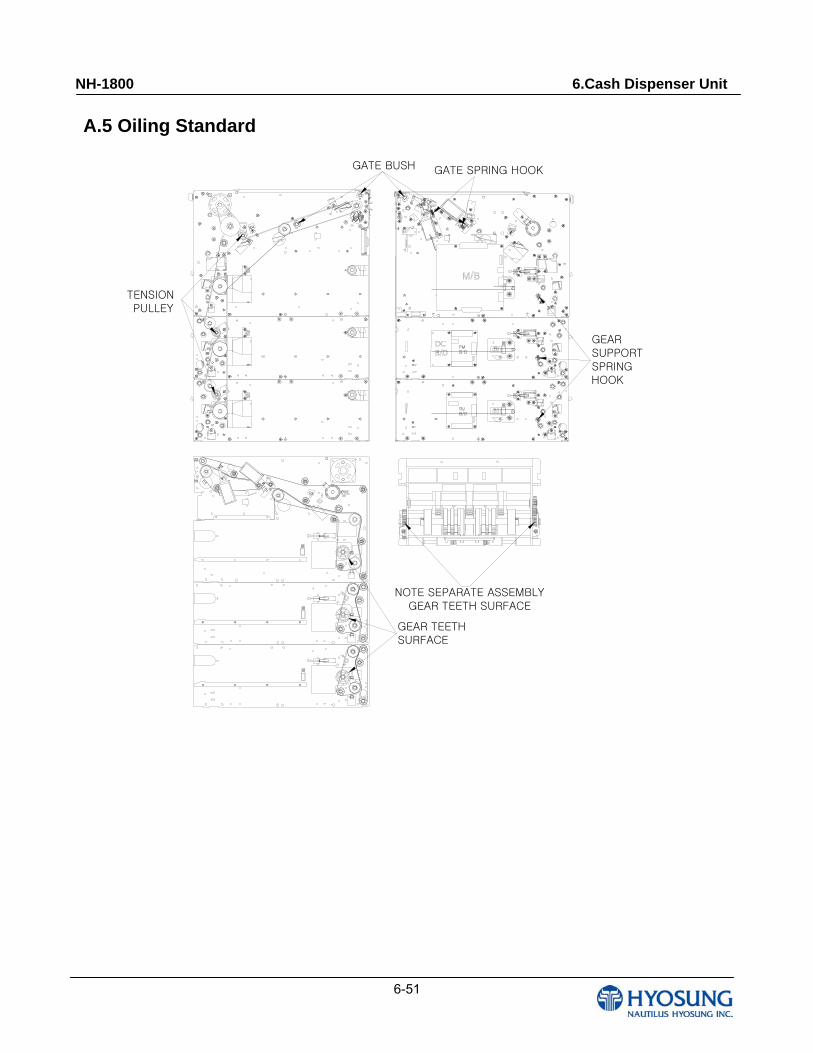
NH-1800 6.Cash Dispenser Unit
6-51
A.5 Oiling Standard
NOTE SEPARATE ASSEMBLY GEAR TEETH SURFACE
GEAR TEETHSURFACE
TENSION PULLEY
GEAR SUPPORT SPRINGHOOK
GATE SPRING HOOKGATE BUSH
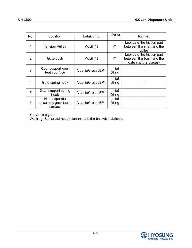
NH-1800 6.Cash Dispenser Unit
6-52
No. Location Lubricants Interva
l Remark
1 Tension Pulley Mobil (1) Y1 Lubricate the friction part between the shaft and the
pulley
2 Gate bush Mobil (1) Y1 Lubricate the friction part between the bush and the
gate shaft (2 places)
3 Gear support gear
teeth surface AlbaniaGreaseEP1
Initial Oiling
-
4 Gate spring hook AlbaniaGreaseEP1Initial Oiling -
5 Gear support spring
hook AlbaniaGreaseEP1
Initial Oiling
-
6 Note separate
assembly gear teeth surface
AlbaniaGreaseEP1Initial Oiling -
* Y1: Once a year. * Warning: Be careful not to contaminate the belt with lubricant.
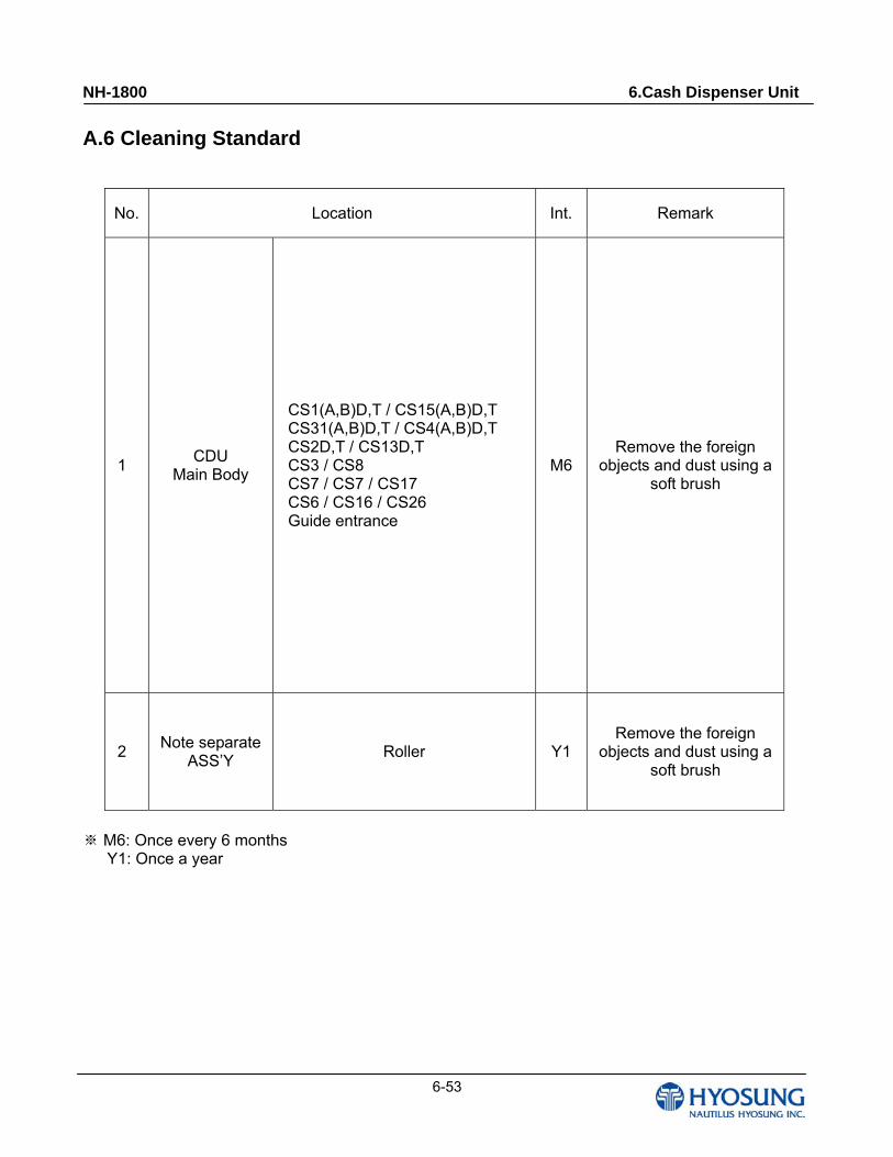
NH-1800 6.Cash Dispenser Unit
6-53
A.6 Cleaning Standard
No. Location Int. Remark
1 CDU
Main Body
CS1(A,B)D,T / CS15(A,B)D,T CS31(A,B)D,T / CS4(A,B)D,T CS2D,T / CS13D,T CS3 / CS8 CS7 / CS7 / CS17 CS6 / CS16 / CS26 Guide entrance
M6 Remove the foreign
objects and dust using a soft brush
2 Note separate
ASS’Y Roller Y1
Remove the foreign objects and dust using a
soft brush
M6: Once every 6 months※
Y1: Once a year
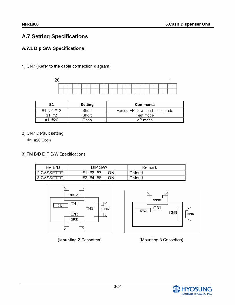
NH-1800 6.Cash Dispenser Unit
6-54
A.7 Setting Specifications
A.7.1 Dip S/W Specifications
1) CN7 (Refer to the cable connection diagram)
26 1
S1 Setting Comments
#1, #2, #12 Short Forced EP Download, Test mode #1, #2 Short Test mode
#1~#26 Open AP mode
2) CN7 Default setting
#1~#26 Open
3) FM B/D DIP S/W Specifications
FM B/D DIP S/W Remark 2 CASSETTE #1, #6, #7 : ON Default 3 CASSETTE #2, #4, #6 : ON Default
(Mounting 2 Cassettes) (Mounting 3 Cassettes)
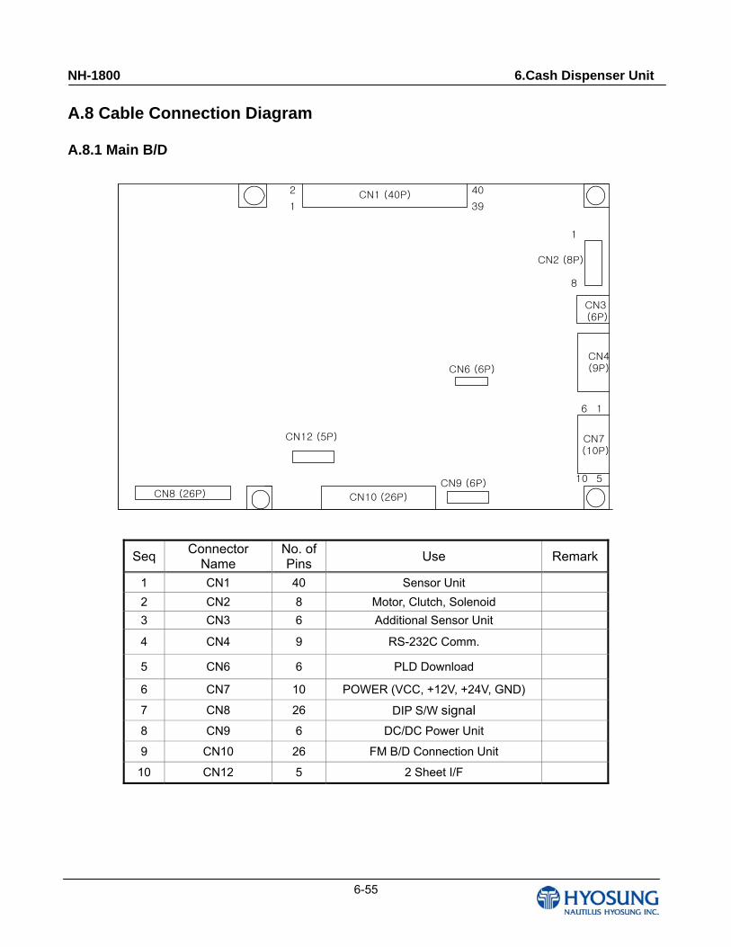
NH-1800 6.Cash Dispenser Unit
6-55
A.8 Cable Connection Diagram
A.8.1 Main B/D
CN1 (40P)
CN10 (26P)CN8 (26P)
CN6 (6P)
CN2 (8P)
CN4(9P)
CN7 (10P)
CN3 (6P)
1
10
1
39
2
6 1
40
8
5
CN12 (5P)
CN9 (6P)
Seq Connector
Name No. of Pins
Use Remark
1 CN1 40 Sensor Unit
2 CN2 8 Motor, Clutch, Solenoid
3 CN3 6 Additional Sensor Unit
4 CN4 9 RS-232C Comm.
5 CN6 6 PLD Download
6 CN7 10 POWER (VCC, +12V, +24V, GND)
7 CN8 26 DIP S/W signal
8 CN9 6 DC/DC Power Unit
9 CN10 26 FM B/D Connection Unit
10 CN12 5 2 Sheet I/F
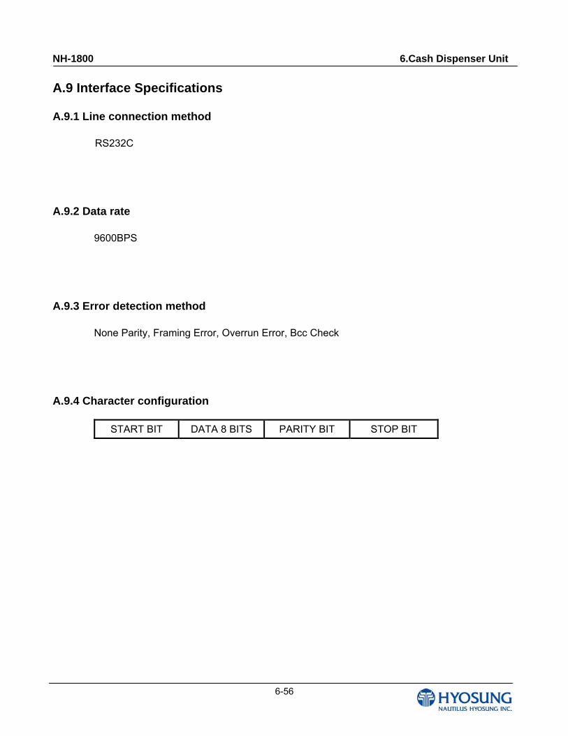
NH-1800 6.Cash Dispenser Unit
6-56
A.9 Interface Specifications
A.9.1 Line connection method
RS232C
A.9.2 Data rate
9600BPS
A.9.3 Error detection method
None Parity, Framing Error, Overrun Error, Bcc Check
A.9.4 Character configuration
START BIT DATA 8 BITS PARITY BIT STOP BIT
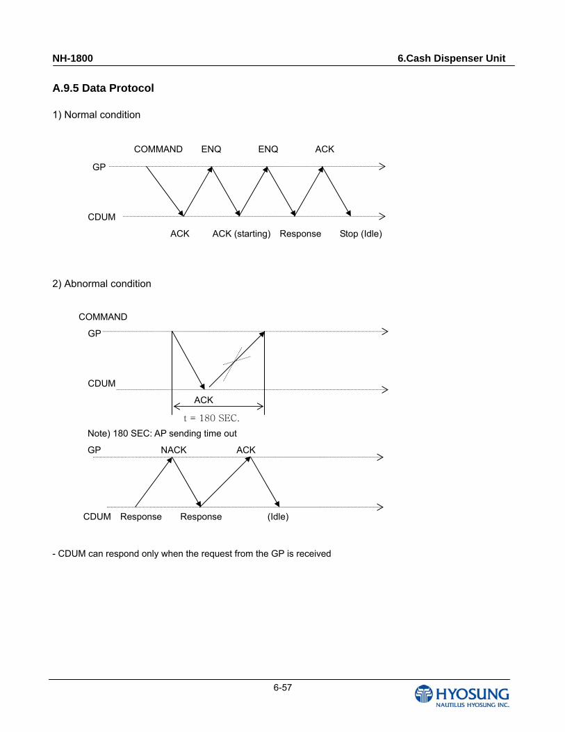
NH-1800 6.Cash Dispenser Unit
6-57
A.9.5 Data Protocol
1) Normal condition
COMMAND ENQ ENQ ACK
GP
CDUM
ACK ACK (starting) Response Stop (Idle)
2) Abnormal condition
COMMAND
GP
CDUM
ACK
Note) 180 SEC: AP sending time out
GP NACK ACK
CDUM Response Response (Idle)
- CDUM can respond only when the request from the GP is received
t = 180 SEC.
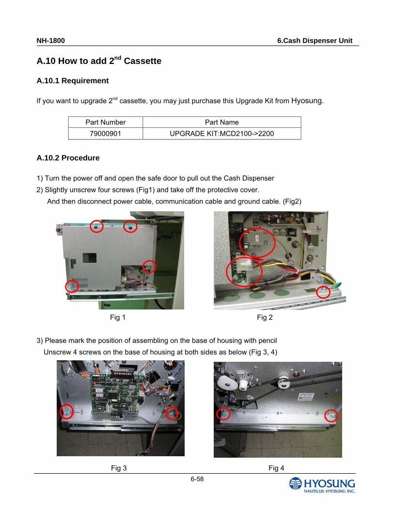
NH-1800 6.Cash Dispenser Unit
6-58
A.10 How to add 2nd Cassette
A.10.1 Requirement
If you want to upgrade 2nd cassette, you may just purchase this Upgrade Kit from Hyosung.
Part Number Part Name
79000901 UPGRADE KIT:MCD2100->2200
A.10.2 Procedure
1) Turn the power off and open the safe door to pull out the Cash Dispenser
2) Slightly unscrew four screws (Fig1) and take off the protective cover.
And then disconnect power cable, communication cable and ground cable. (Fig2)
Fig 1 Fig 2
3) Please mark the position of assembling on the base of housing with pencil
Unscrew 4 screws on the base of housing at both sides as below (Fig 3, 4)
Fig 3 Fig 4
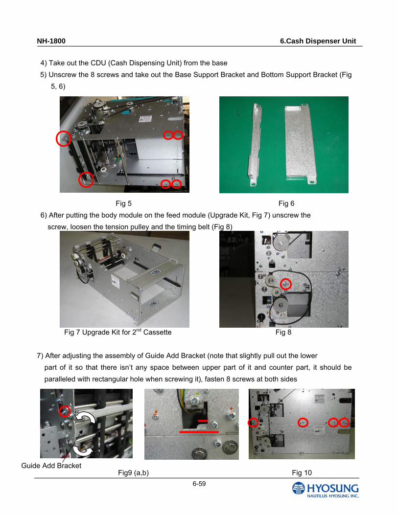
NH-1800 6.Cash Dispenser Unit
6-59
4) Take out the CDU (Cash Dispensing Unit) from the base
5) Unscrew the 8 screws and take out the Base Support Bracket and Bottom Support Bracket (Fig
5, 6)
Fig 5 Fig 6
6) After putting the body module on the feed module (Upgrade Kit, Fig 7) unscrew the
screw, loosen the tension pulley and the timing belt (Fig 8)
Fig 7 Upgrade Kit for 2nd Cassette Fig 8
7) After adjusting the assembly of Guide Add Bracket (note that slightly pull out the lower
part of it so that there isn’t any space between upper part of it and counter part, it should be
paralleled with rectangular hole when screwing it), fasten 8 screws at both sides
Fig9 (a,b) Fig 10 Guide Add Bracket
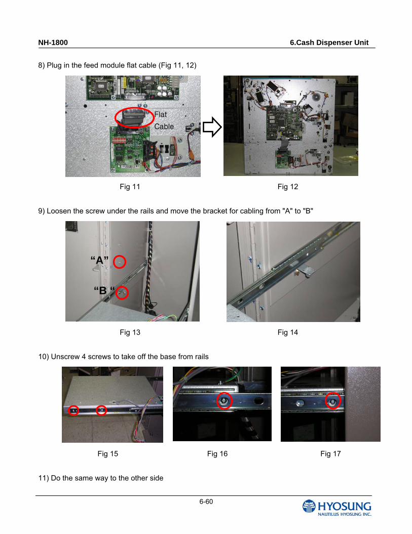
NH-1800 6.Cash Dispenser Unit
6-60
8) Plug in the feed module flat cable (Fig 11, 12)
Fig 11 Fig 12
9) Loosen the screw under the rails and move the bracket for cabling from "A" to "B"
Fig 13 Fig 14
10) Unscrew 4 screws to take off the base from rails
Fig 15 Fig 16 Fig 17
11) Do the same way to the other side
Flat
Cable
“A”
“B “
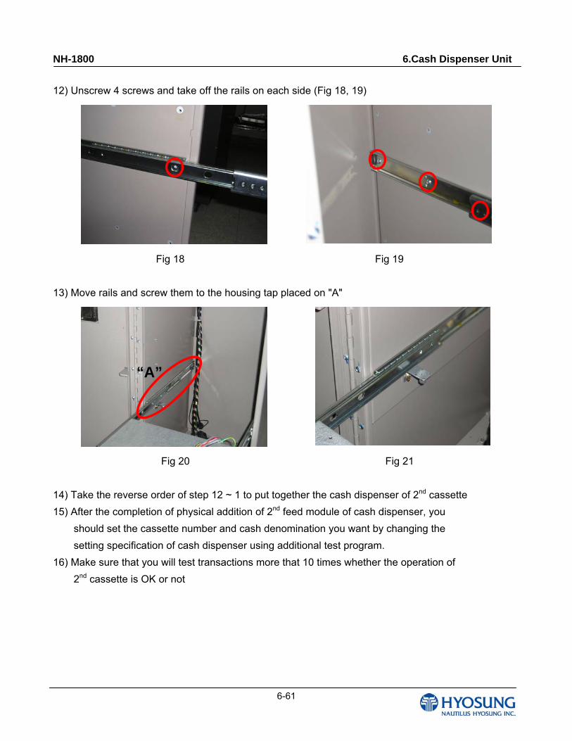
NH-1800 6.Cash Dispenser Unit
6-61
12) Unscrew 4 screws and take off the rails on each side (Fig 18, 19)
Fig 18 Fig 19
13) Move rails and screw them to the housing tap placed on "A"
Fig 20 Fig 21
14) Take the reverse order of step 12 ~ 1 to put together the cash dispenser of 2nd cassette
15) After the completion of physical addition of 2nd feed module of cash dispenser, you
should set the cassette number and cash denomination you want by changing the
setting specification of cash dispenser using additional test program.
16) Make sure that you will test transactions more that 10 times whether the operation of
2nd cassette is OK or not
“A”
NH-1800 7. Magnetic Card Reader
7-1
Chapter 7. Magnetic Card Reader

NH-1800 7. Magnetic Card Reader
7-2
7. Magnetic Card Reader 7.1 Specification
7.1.1 Applicable Range
This specification is applicable to a 2 track read magnetic head for card readers.
7.1.2 Standard Test Condition
- Measurement shall be executed by standard test condition.
- Standard conditions are temperature 20, humidity 65% (10-35, 45-85% allowable).
7.1.3 Electrical Specifications
No. Item Measuring Condition Specification
1 DC resistance 20 110Ω±15%
2 Inductance 1KHz (series circuit) 44mH±20%
3 Read Output 23mVp-p±20%
4 Insulation resistance Case~T.pin DC 500V 50MΩmin
5 Core-earth Core-Case 3Vmax 10Ωmax
6 Measuring tape PM50-7B (Recording density 210BPI)
7 Tape speed 19.05cm/sec (7.5inch/sec)
7.1.4 Production Specifications
Item Spec/Material Item Spec/Material
Gap width 0.01mm Core Permalloy
Gap depth 0.3mm min Shield case Permalloy
Track width 1.0mm±0.1 Case resin Epoxy resin
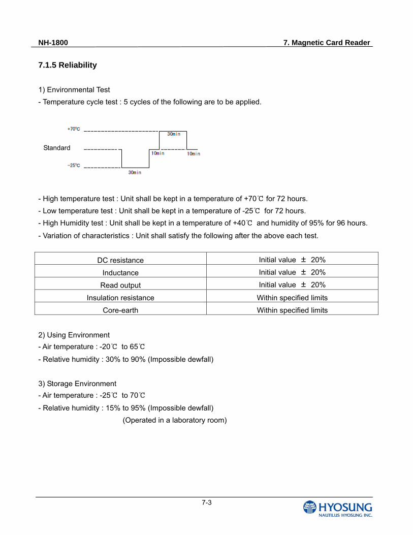
NH-1800 7. Magnetic Card Reader
7-3
7.1.5 Reliability
1) Environmental Test
- Temperature cycle test : 5 cycles of the following are to be applied.
- High temperature test : Unit shall be kept in a temperature of +70 for 72 hours.
- Low temperature test : Unit shall be kept in a temperature of -25 for 72 hours.
- High Humidity test : Unit shall be kept in a temperature of +40 and humidity of 95% for 96 hours.
- Variation of characteristics : Unit shall satisfy the following after the above each test.
DC resistance Initial value ± 20%
Inductance Initial value ± 20%
Read output Initial value ± 20%
Insulation resistance Within specified limits
Core-earth Within specified limits
2) Using Environment
- Air temperature : -20 to 65
- Relative humidity : 30% to 90% (Impossible dewfall)
3) Storage Environment
- Air temperature : -25 to 70
- Relative humidity : 15% to 95% (Impossible dewfall)
(Operated in a laboratory room)
Standard
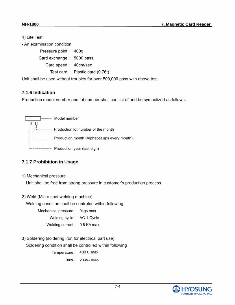
NH-1800 7. Magnetic Card Reader
7-4
4) Life Test
- An examination condition
Pressure point : 400g
Card exchange : 5000 pass
Card speed : 40cm/sec
Test card : Plastic card (0.76t)
Unit shall be used without troubles for over 500,000 pass with above test.
7.1.6 Indication
Production model number and lot number shall consist of and be symbolized as follows :
7.1.7 Prohibition in Usage
1) Mechanical pressure
Unit shall be free from strong pressure in customer’s production process.
2) Weld (Micro spot welding machine)
Welding condition shall be controled within following
Mechanical pressure : 9kgs max.
Welding cycle : AC 1-Cycle
Welding current : 0.8 KA max.
3) Soldering (soldering iron for electrical part use)
Soldering condition shall be controlled within following
Temperature : 400 max
Time : 5 sec. max.
Model number
Production lot number of the month
Production month (Alphabet ups every month)
Production year (last digit)
NH-1800 7. Magnetic Card Reader
7-5
7.1.8 Environmental Managed Substance
1) Materials used parts to not contain any of the following substance.
- Cadmium and cadmium compounds
- PBB and PBDE
- Chlorinated paraffin
- Polychlorinated biphenyl (PCB)
- Polychlorinated naphthalene (PCN)
- Organic tin compounds
- Asbestos
- Azo compounds
- About packing material, the impurities permission
concentration of mercury, cadmium, a lead, and
hexavaten chromium should be less than 100ppm in total.
- Mercury, Lead, Hexavaten chromium
2) This part applicates (Rohs Application)
7.1.9 Consultation
If any doubts arise as to any of the specifications and or not-specified articles, there shall be put to
consultation between the both parties.
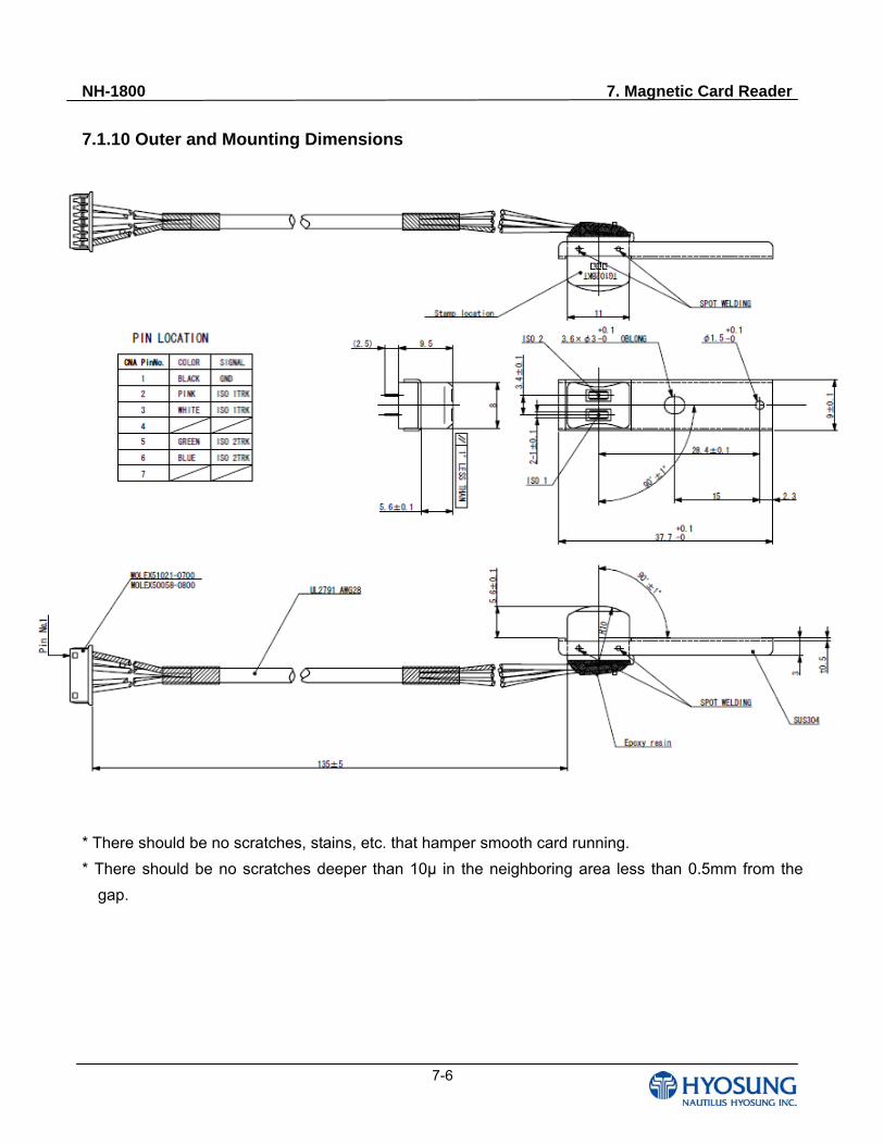
NH-1800 7. Magnetic Card Reader
7-6
7.1.10 Outer and Mounting Dimensions
* There should be no scratches, stains, etc. that hamper smooth card running.
* There should be no scratches deeper than 10μ in the neighboring area less than 0.5mm from the
gap.
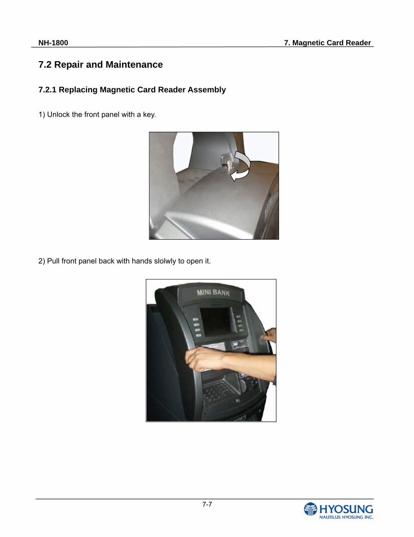
NH-1800 7. Magnetic Card Reader
7-7
7.2 Repair and Maintenance
7.2.1 Replacing Magnetic Card Reader Assembly
1) Unlock the front panel with a key.
2) Pull front panel back with hands slolwly to open it.
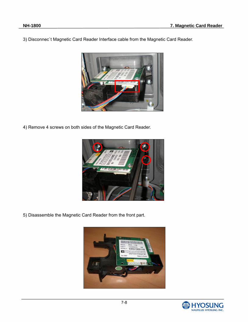
NH-1800 7. Magnetic Card Reader
7-8
3) Disconnec`t Magnetic Card Reader Interface cable from the Magnetic Card Reader.
4) Remove 4 screws on both sides of the Magnetic Card Reader.
5) Disassemble the Magnetic Card Reader from the front part.
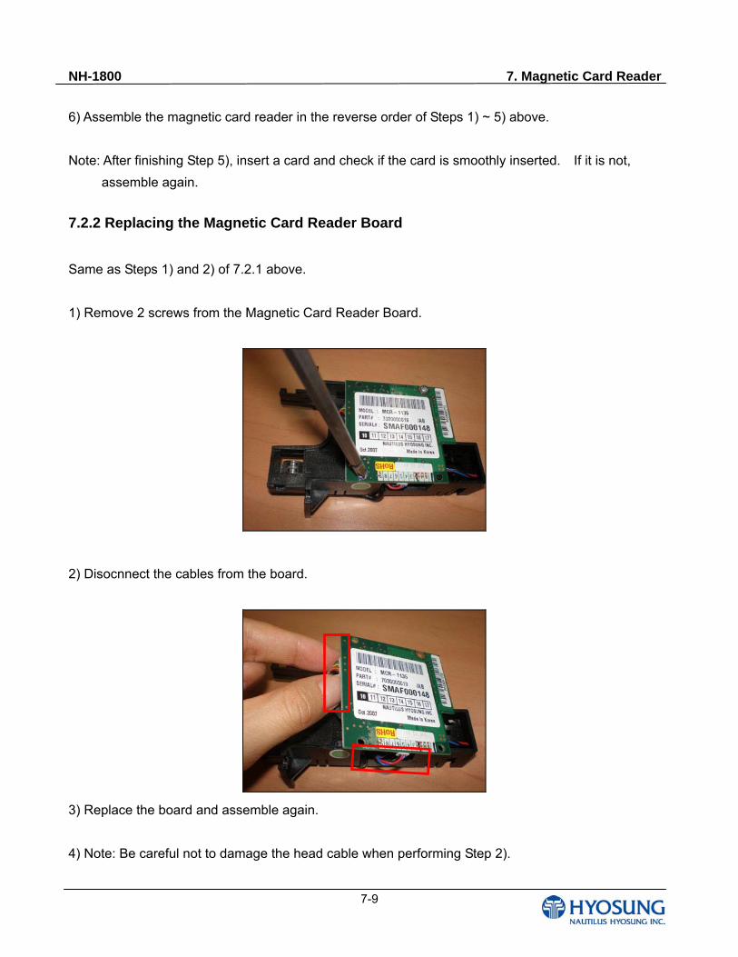
NH-1800 7. Magnetic Card Reader
7-9
6) Assemble the magnetic card reader in the reverse order of Steps 1) ~ 5) above.
Note: After finishing Step 5), insert a card and check if the card is smoothly inserted. If it is not,
assemble again.
7.2.2 Replacing the Magnetic Card Reader Board
Same as Steps 1) and 2) of 7.2.1 above.
1) Remove 2 screws from the Magnetic Card Reader Board.
2) Disocnnect the cables from the board.
3) Replace the board and assemble again.
4) Note: Be careful not to damage the head cable when performing Step 2).
NH-1800 8. Receipt Printer
8-1
Chapter 8. Receipt Printer
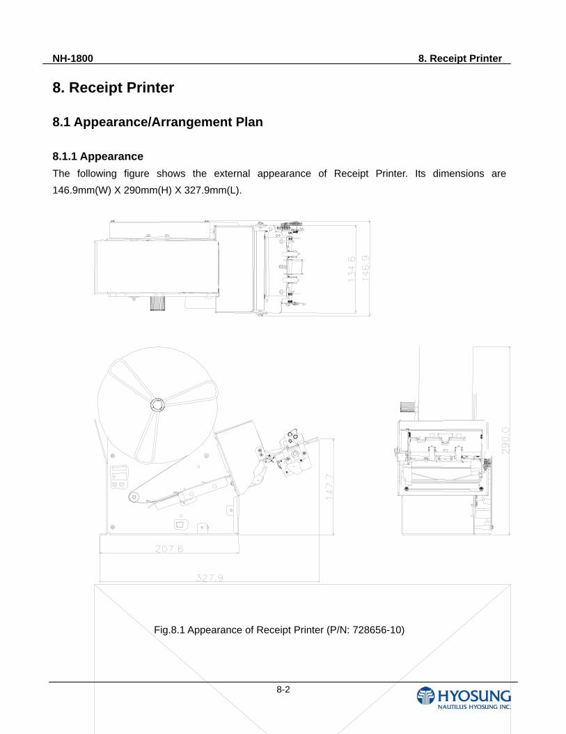
NH-1800 8. Receipt Printer
8-2
8. Receipt Printer
8.1 Appearance/Arrangement Plan 8.1.1 Appearance The following figure shows the external appearance of Receipt Printer. Its dimensions are
146.9mm(W) X 290mm(H) X 327.9mm(L).
Fig.8.1 Appearance of Receipt Printer (P/N: 728656-10)
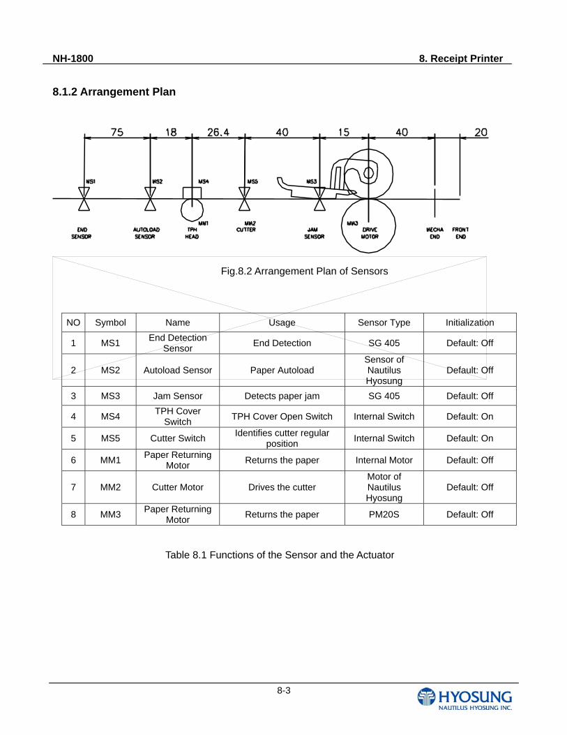
NH-1800 8. Receipt Printer
8-3
8.1.2 Arrangement Plan
Fig.8.2 Arrangement Plan of Sensors
NO Symbol Name Usage Sensor Type Initialization
1 MS1 End Detection
Sensor End Detection SG 405 Default: Off
2 MS2 Autoload Sensor Paper Autoload Sensor of Nautilus Hyosung
Default: Off
3 MS3 Jam Sensor Detects paper jam SG 405 Default: Off
4 MS4 TPH Cover
Switch TPH Cover Open Switch Internal Switch Default: On
5 MS5 Cutter Switch Identifies cutter regular
position Internal Switch Default: On
6 MM1 Paper Returning
Motor Returns the paper Internal Motor Default: Off
7 MM2 Cutter Motor Drives the cutter Motor of Nautilus Hyosung
Default: Off
8 MM3 Paper Returning
Motor Returns the paper PM20S Default: Off
Table 8.1 Functions of the Sensor and the Actuator
NH-1800 8. Receipt Printer
8-4
8.1.3 General Specification
Power DC 24V
Paper Dimension 80mm (Width) 110mm (Length) 72gsm
Operating Environment Temperature: 0 ~ 55 / Humidity: 10 ~ 80%
Rate 100mm/s
Issuance Count Approximately 3,200 transactions (based on 101.6mm per transaction)
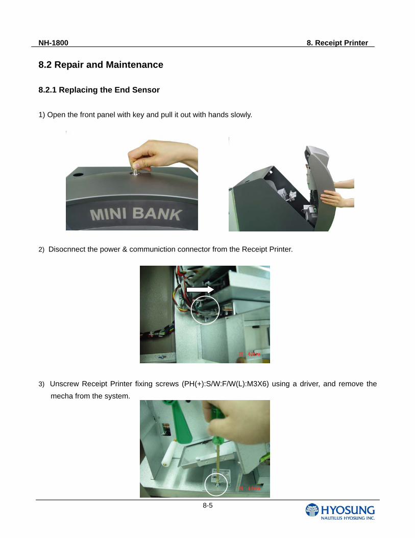
NH-1800 8. Receipt Printer
8-5
8.2 Repair and Maintenance
8.2.1 Replacing the End Sensor
1) Open the front panel with key and pull it out with hands slowly.
2) Disocnnect the power & communiction connector from the Receipt Printer.
3) Unscrew Receipt Printer fixing screws (PH(+):S/W:F/W(L):M3X6) using a driver, and remove the
mecha from the system.
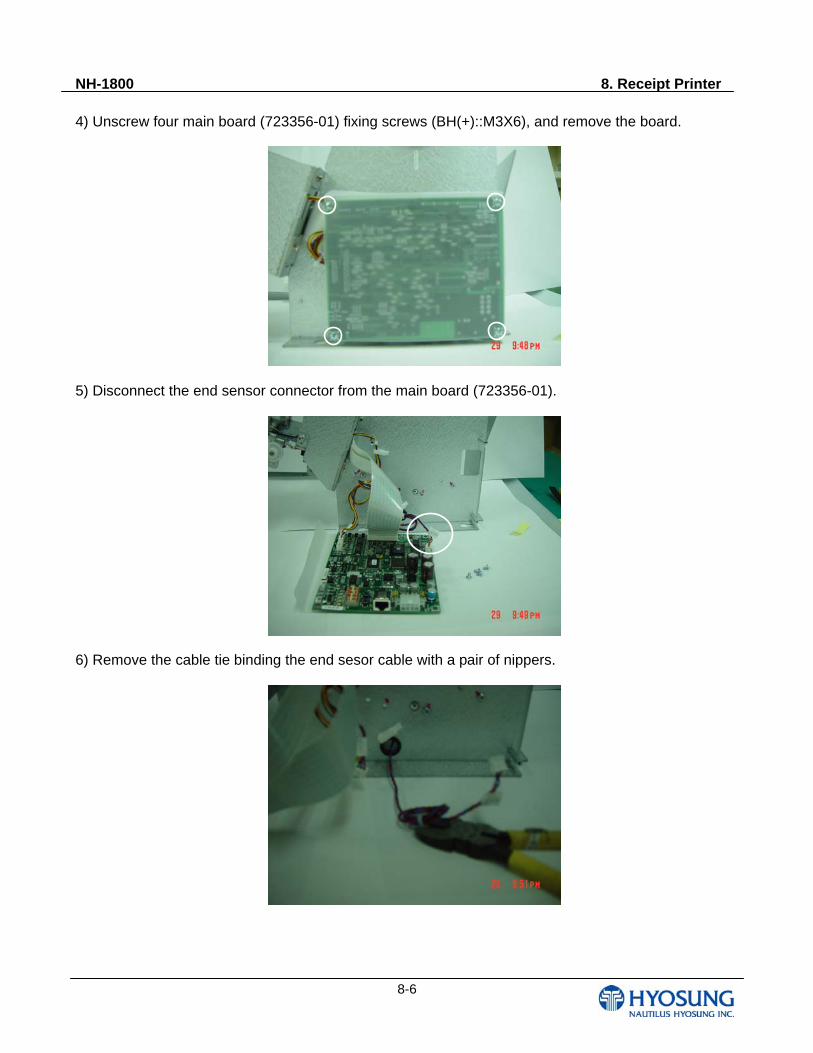
NH-1800 8. Receipt Printer
8-6
4) Unscrew four main board (723356-01) fixing screws (BH(+)::M3X6), and remove the board.
5) Disconnect the end sensor connector from the main board (723356-01).
6) Remove the cable tie binding the end sesor cable with a pair of nippers.
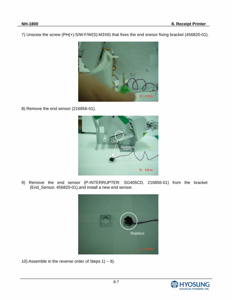
NH-1800 8. Receipt Printer
8-7
7) Unscew the screw (PH(+):S/W:F/W(S):M3X6) that fixes the end snesor fixing bracket (456820-01).
8) Remove the end sensor (216856-01).
9) Remove the end sensor (P-INTERRUPTER: SG405CD, 216856-01) from the bracket (End_Sensor, 456820-01),and install a new end sensor.
10) Assemble in the reverse order of Steps 1) ~ 9).
Remove
Replace
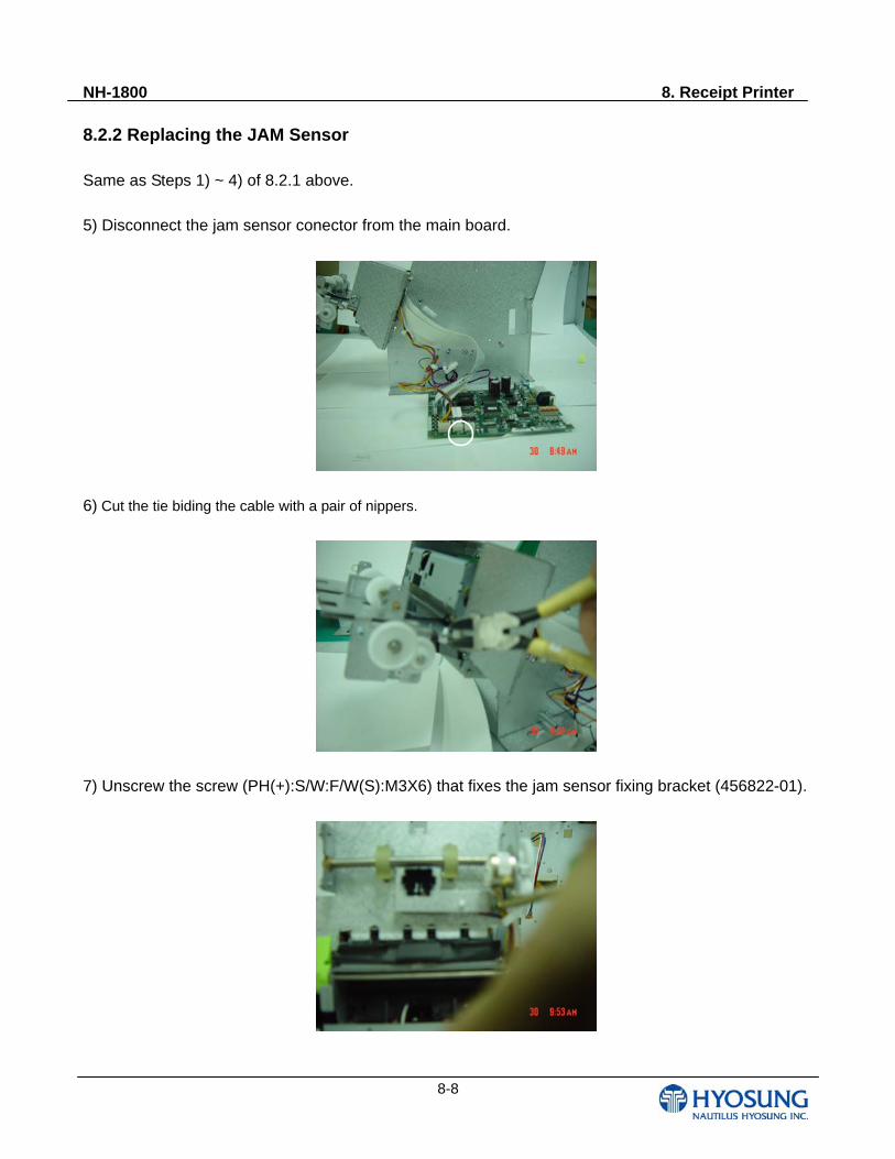
NH-1800 8. Receipt Printer
8-8
8.2.2 Replacing the JAM Sensor Same as Steps 1) ~ 4) of 8.2.1 above.
5) Disconnect the jam sensor conector from the main board.
6) Cut the tie biding the cable with a pair of nippers.
7) Unscrew the screw (PH(+):S/W:F/W(S):M3X6) that fixes the jam sensor fixing bracket (456822-01).
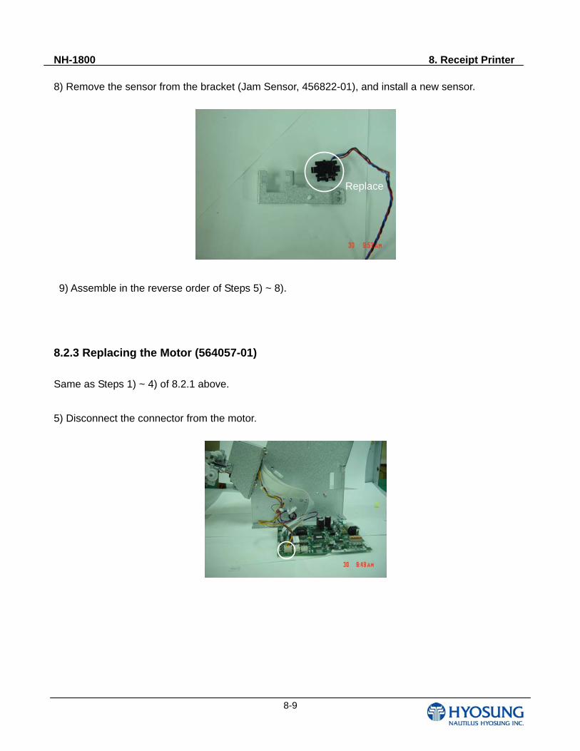
NH-1800 8. Receipt Printer
8-9
8) Remove the sensor from the bracket (Jam Sensor, 456822-01), and install a new sensor.
9) Assemble in the reverse order of Steps 5) ~ 8).
8.2.3 Replacing the Motor (564057-01)
Same as Steps 1) ~ 4) of 8.2.1 above.
5) Disconnect the connector from the motor.
Replace
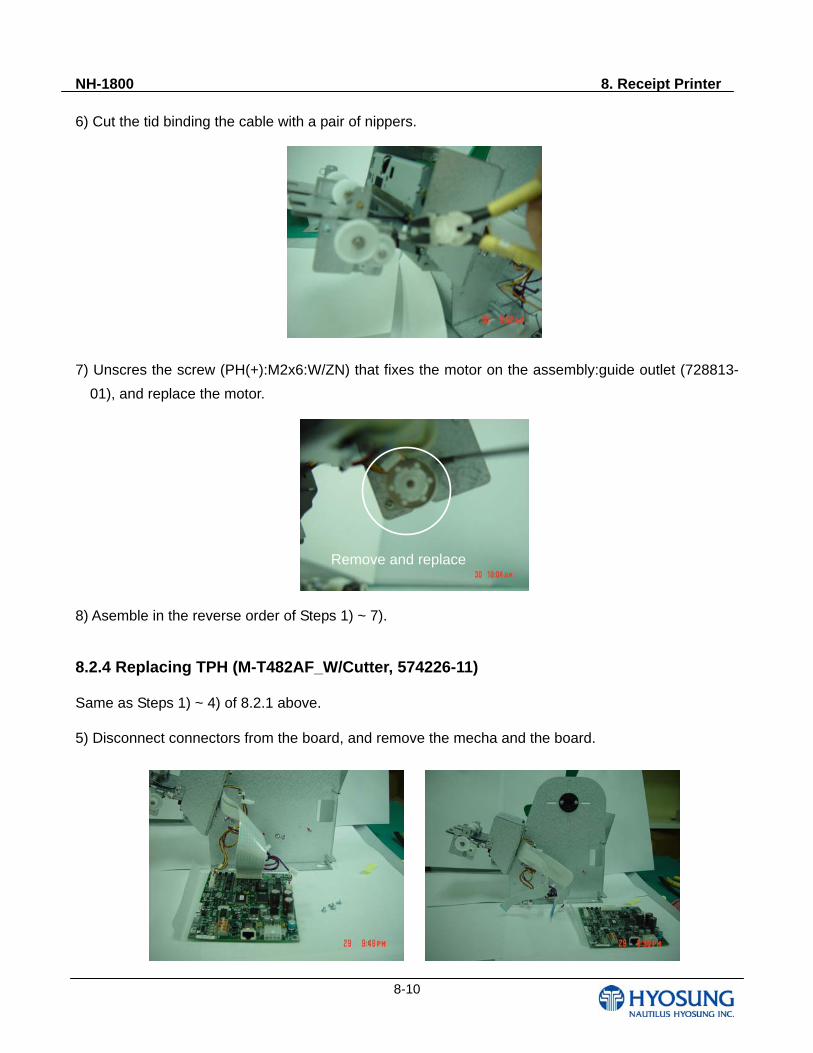
NH-1800 8. Receipt Printer
8-10
6) Cut the tid binding the cable with a pair of nippers.
7) Unscres the screw (PH(+):M2x6:W/ZN) that fixes the motor on the assembly:guide outlet (728813-
01), and replace the motor.
8) Asemble in the reverse order of Steps 1) ~ 7). 8.2.4 Replacing TPH (M-T482AF_W/Cutter, 574226-11) Same as Steps 1) ~ 4) of 8.2.1 above. 5) Disconnect connectors from the board, and remove the mecha and the board.
Remove and replace
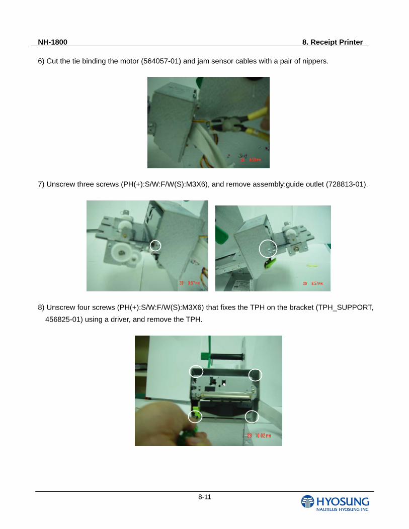
NH-1800 8. Receipt Printer
8-11
6) Cut the tie binding the motor (564057-01) and jam sensor cables with a pair of nippers.
7) Unscrew three screws (PH(+):S/W:F/W(S):M3X6), and remove assembly:guide outlet (728813-01).
8) Unscrew four screws (PH(+):S/W:F/W(S):M3X6) that fixes the TPH on the bracket (TPH_SUPPORT,
456825-01) using a driver, and remove the TPH.
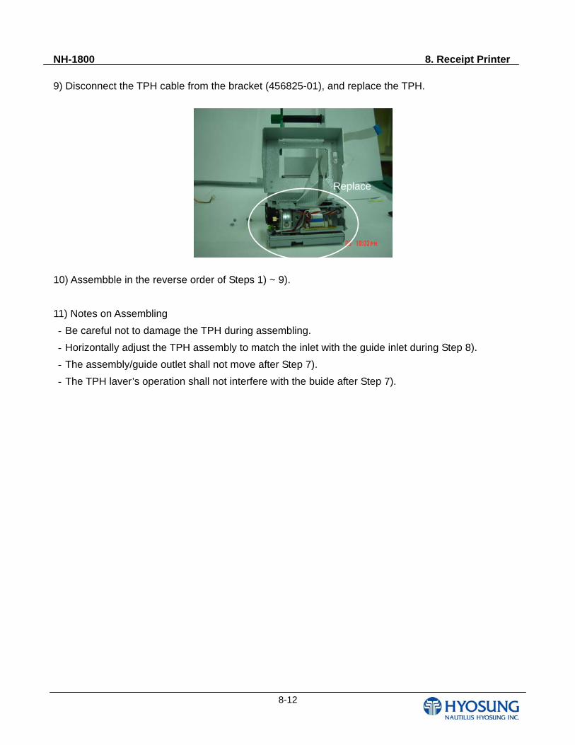
NH-1800 8. Receipt Printer
8-12
9) Disconnect the TPH cable from the bracket (456825-01), and replace the TPH.
10) Assembble in the reverse order of Steps 1) ~ 9).
11) Notes on Assembling
- Be careful not to damage the TPH during assembling.
- Horizontally adjust the TPH assembly to match the inlet with the guide inlet during Step 8).
- The assembly/guide outlet shall not move after Step 7).
- The TPH laver’s operation shall not interfere with the buide after Step 7).
Replace
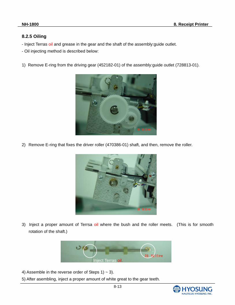
NH-1800 8. Receipt Printer
8-13
8.2.5 Oiling
- Inject Terras oil and grease in the gear and the shaft of the assembly:guide outlet.
- Oil injecting method is described below:
1) Remove E-ring from the driving gear (452182-01) of the assembly:guide outlet (728813-01).
2) Remove E-ring that fixes the driver roller (470386-01) shaft, and then, remove the roller.
3) Inject a proper amount of Terrsa oil where the bush and the roller meets. (This is for smooth
rotation of the shaft.)
4) Assemble in the reverse order of Steps 1) ~ 3).
5) After asembling, inject a proper amount of white great to the gear teeth.
Inject Terras oil.
NH-1800 9. Vault Unit
9-1
Chapter9. Vault Unit
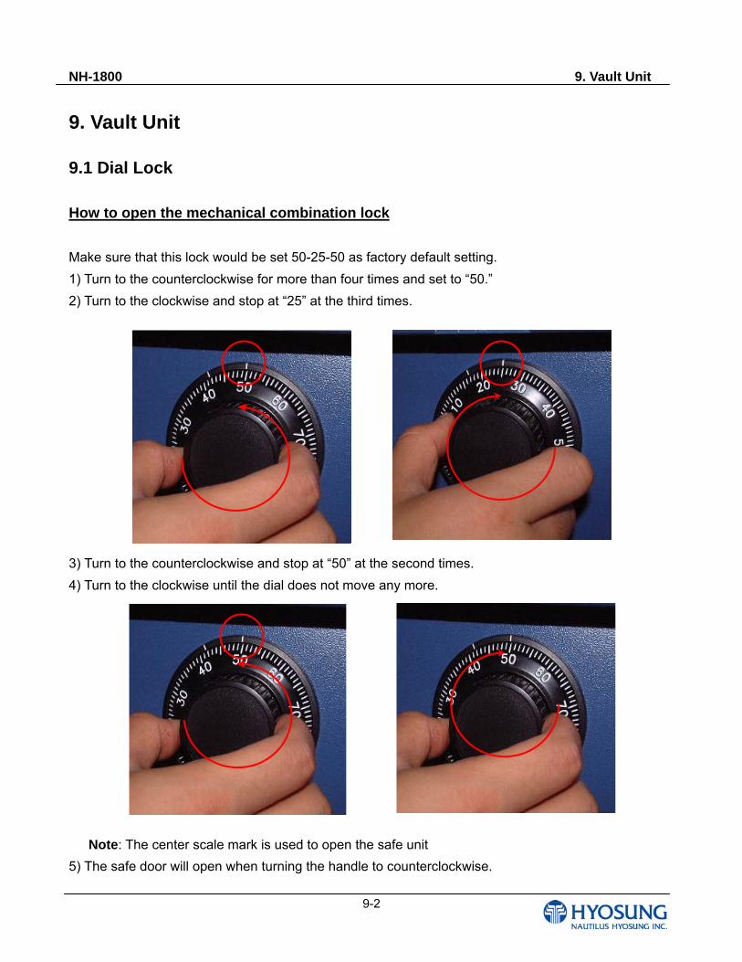
NH-1800 9. Vault Unit
9-2
9. Vault Unit 9.1 Dial Lock How to open the mechanical combination lock
Make sure that this lock would be set 50-25-50 as factory default setting.
1) Turn to the counterclockwise for more than four times and set to “50.”
2) Turn to the clockwise and stop at “25” at the third times.
3) Turn to the counterclockwise and stop at “50” at the second times.
4) Turn to the clockwise until the dial does not move any more.
Note: The center scale mark is used to open the safe unit
5) The safe door will open when turning the handle to counterclockwise.
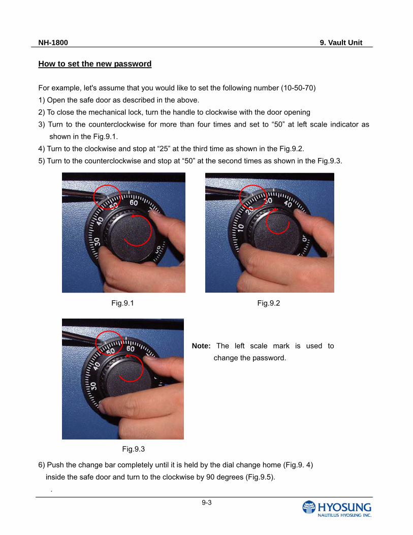
NH-1800 9. Vault Unit
9-3
How to set the new password
For example, let's assume that you would like to set the following number (10-50-70)
1) Open the safe door as described in the above.
2) To close the mechanical lock, turn the handle to clockwise with the door opening
3) Turn to the counterclockwise for more than four times and set to “50” at left scale indicator as
shown in the Fig.9.1.
4) Turn to the clockwise and stop at “25” at the third time as shown in the Fig.9.2.
5) Turn to the counterclockwise and stop at “50” at the second times as shown in the Fig.9.3.
6) Push the change bar completely until it is held by the dial change home (Fig.9. 4)
inside the safe door and turn to the clockwise by 90 degrees (Fig.9.5).
.
Fig.9.1 Fig.9.2
Note: The left scale mark is used to
change the password.
Fig.9.3
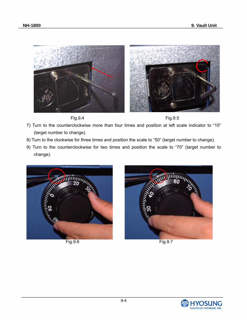
NH-1800 9. Vault Unit
9-4
Fig.9.4 Fig.9.5
7) Turn to the counterclockwise more than four times and position at left scale indicator to “10”
(target number to change).
8) Turn to the clockwise for three times and position the scale to “50” (target number to change).
9) Turn to the counterclockwise for two times and position the scale to “70” (target number to
change).
Fig.9.6 Fig.9.7
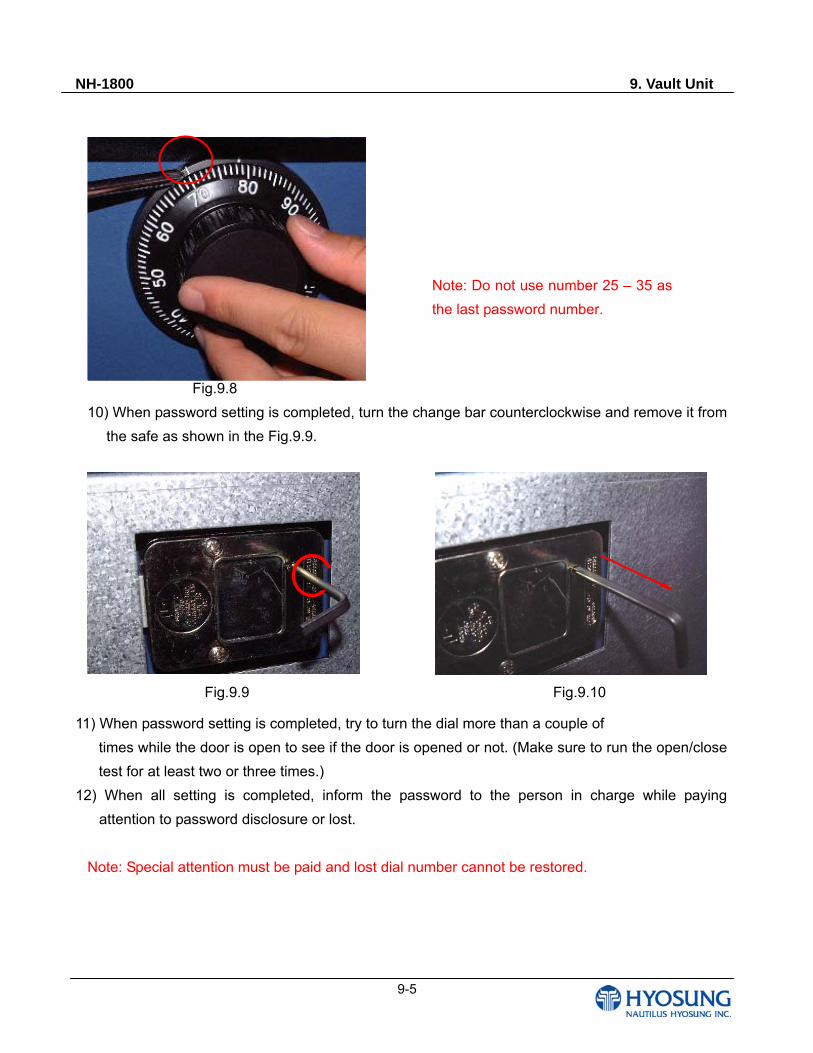
NH-1800 9. Vault Unit
9-5
Fig.9.8
10) When password setting is completed, turn the change bar counterclockwise and remove it from
the safe as shown in the Fig.9.9.
11) When password setting is completed, try to turn the dial more than a couple of
times while the door is open to see if the door is opened or not. (Make sure to run the open/close
test for at least two or three times.)
12) When all setting is completed, inform the password to the person in charge while paying
attention to password disclosure or lost.
Note: Special attention must be paid and lost dial number cannot be restored.
Fig.9.9 Fig.9.10
Note: Do not use number 25 – 35 as
the last password number.
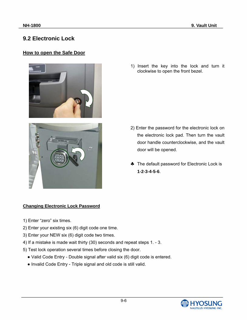
NH-1800 9. Vault Unit
9-6
9.2 Electronic Lock
How to open the Safe Door
1) Insert the key into the lock and turn it clockwise to open the front bezel.
2) Enter the password for the electronic lock on
the electronic lock pad. Then turn the vault
door handle counterclockwise, and the vault
door will be opened.
♣ The default password for Electronic Lock is
1-2-3-4-5-6.
Changing Electronic Lock Password
1) Enter “zero” six times.
2) Enter your existing six (6) digit code one time.
3) Enter your NEW six (6) digit code two times.
4) If a mistake is made wait thirty (30) seconds and repeat steps 1. - 3.
5) Test lock operation several times before closing the door.
Valid Code Entry - Double signal after valid six (6) digit code is entered.
Invalid Code Entry - Triple signal and old code is still valid.
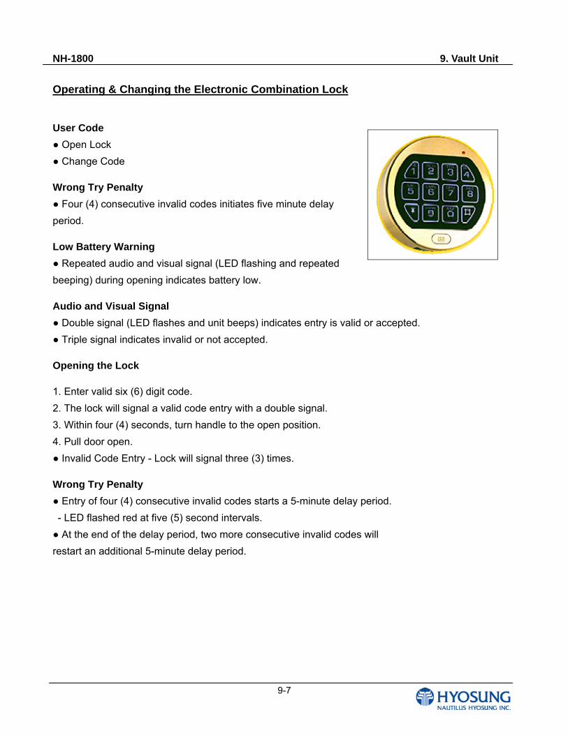
NH-1800 9. Vault Unit
9-7
Operating & Changing the Electronic Combination Lock
User Code
Open Lock
Change Code
Wrong Try Penalty
Four (4) consecutive invalid codes initiates five minute delay
period.
Low Battery Warning
Repeated audio and visual signal (LED flashing and repeated
beeping) during opening indicates battery low.
Audio and Visual Signal
Double signal (LED flashes and unit beeps) indicates entry is valid or accepted.
Triple signal indicates invalid or not accepted.
Opening the Lock
1. Enter valid six (6) digit code.
2. The lock will signal a valid code entry with a double signal.
3. Within four (4) seconds, turn handle to the open position.
4. Pull door open.
Invalid Code Entry - Lock will signal three (3) times.
Wrong Try Penalty
Entry of four (4) consecutive invalid codes starts a 5-minute delay period.
- LED flashed red at five (5) second intervals.
At the end of the delay period, two more consecutive invalid codes will
restart an additional 5-minute delay period.
NH-1800 9. Vault Unit
9-8
Changing Your Code
ALWAYS PERFORM THIS OPERATION WITH THE DOOR OPEN
1. Enter “zero” six times.
2. Enter your existing six (6) digit code one time.
3. Enter your NEW six (6) digit code two times.
4. If a mistake is made wait thirty (30) seconds and repeat steps 1. - 3.
5. Test lock operation several times before closing the door.
Valid Code Entry - Double signal after valid six (6) digit code is entered.
Invalid Code Entry - Triple signal and old code is still valid.
Battery Low Warning
Repeated beeping during an opening indicates that the battery is low and
needs immediate replacement.
Uses one (1) 9-Volt Alkaline Battery. LA GARD recommends the use of
Duracell™ or Everready™ Alkaline batteries.
If battery is depleted and will not allow lock to open, simply follow
instructions below.
Changing Your Battery
Note: Some manufacturers use a small screw to secure the battery compartment cover to the
keypad housing. If your model has this screw, it must be removed first before following the steps
listed below.
1. Remove black plastic battery compartment cover (located at the bottom of the keypad) by gently
pulling downward on it’s handle.
2. Allow the battery and it’s attached leads to drop down and out of the battery compartment. If it
does not drop, gently pull on the battery until it does.
3. The connector is easily removed by unsnapping it from the two terminals on the top of the battery.
Never Pull on the Battery Leads
4. Connect a new 9-Volt Alkaline battery to the battery clip.
5. Push the battery and the leads completely up into the battery compartment.
6. Install the battery cover by placing one side of the cover in position and then pressing the other
side into position with your finger.
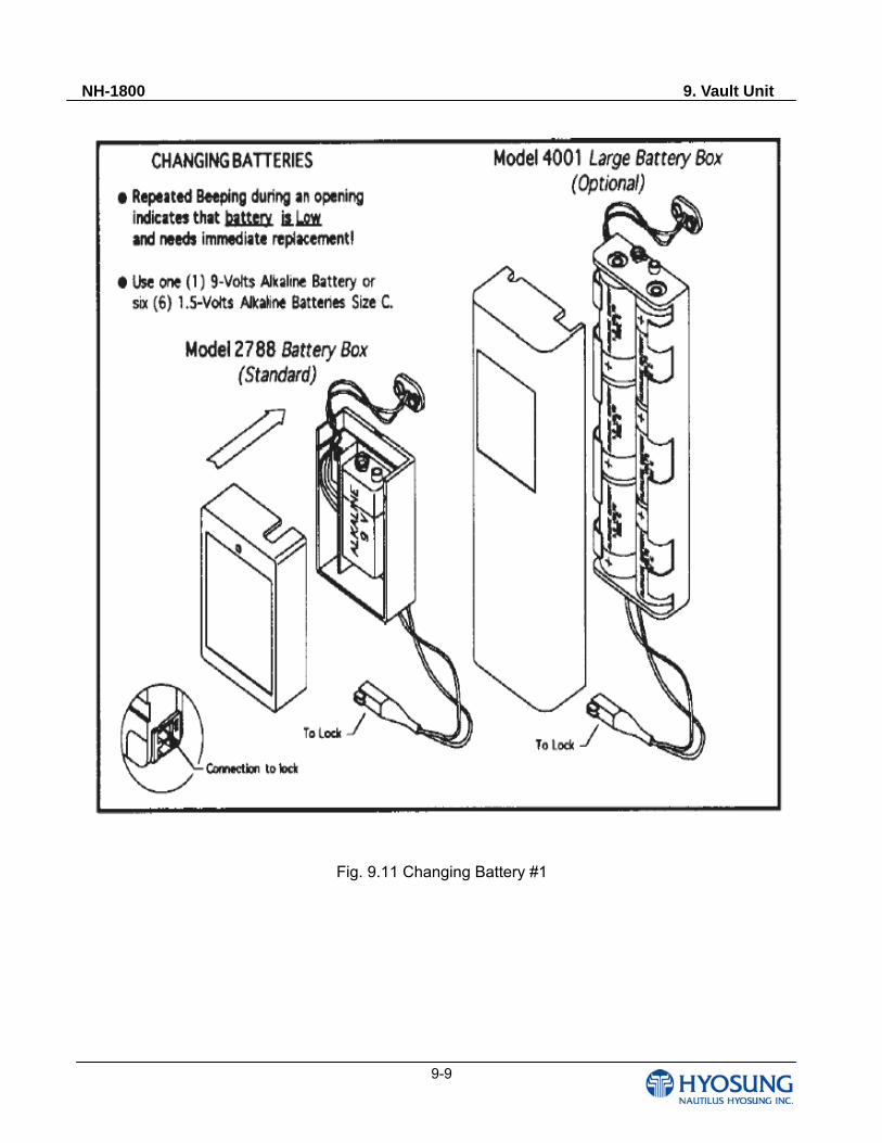
NH-1800 9. Vault Unit
9-9
Fig. 9.11 Changing Battery #1
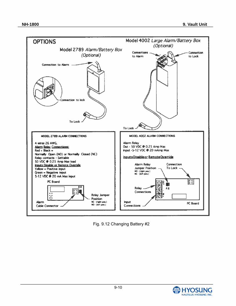
NH-1800 9. Vault Unit
9-10
Fig. 9.12 Changing Battery #2
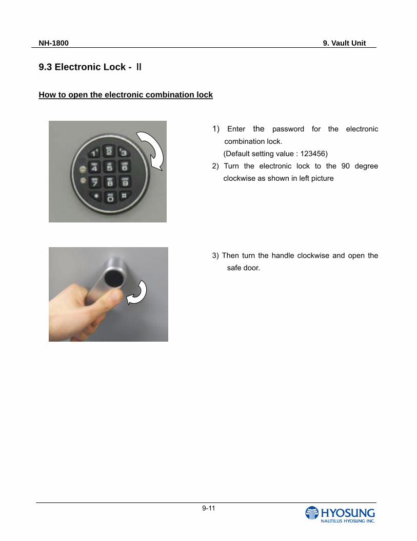
NH-1800 9. Vault Unit
9-11
9.3 Electronic Lock - Ⅱ
How to open the electronic combination lock
1) Enter the password for the electronic
combination lock.
(Default setting value : 123456)
2) Turn the electronic lock to the 90 degree
clockwise as shown in left picture
3) Then turn the handle clockwise and open the
safe door.
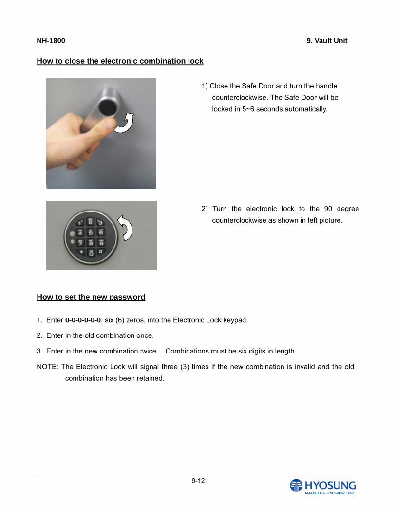
NH-1800 9. Vault Unit
9-12
How to close the electronic combination lock
1) Close the Safe Door and turn the handle
counterclockwise. The Safe Door will be
locked in 5~6 seconds automatically.
2) Turn the electronic lock to the 90 degree
counterclockwise as shown in left picture.
How to set the new password
1. Enter 0-0-0-0-0-0, six (6) zeros, into the Electronic Lock keypad.
2. Enter in the old combination once.
3. Enter in the new combination twice. Combinations must be six digits in length.
NOTE: The Electronic Lock will signal three (3) times if the new combination is invalid and the old
combination has been retained.
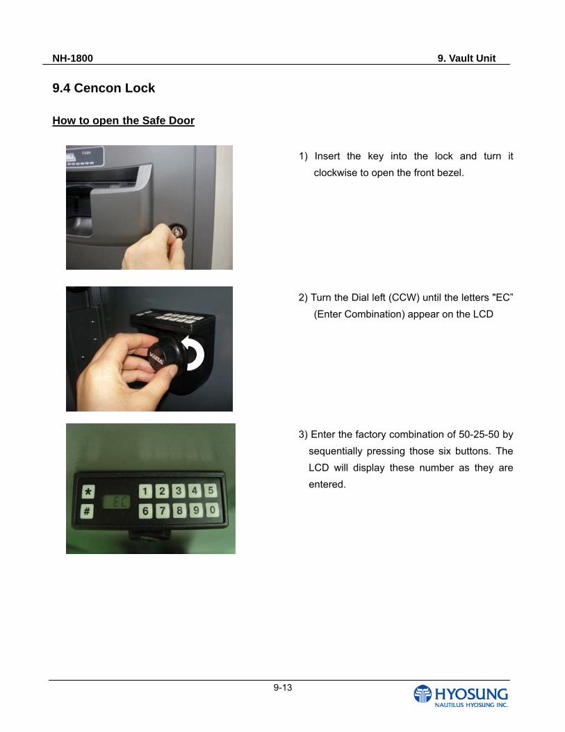
NH-1800 9. Vault Unit
9-13
9.4 Cencon Lock How to open the Safe Door
1) Insert the key into the lock and turn it
clockwise to open the front bezel.
2) Turn the Dial left (CCW) until the letters "EC”
(Enter Combination) appear on the LCD
3) Enter the factory combination of 50-25-50 by
sequentially pressing those six buttons. The
LCD will display these number as they are
entered.
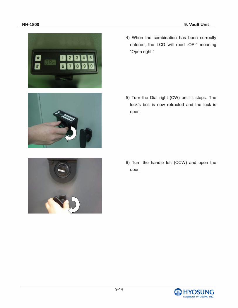
NH-1800 9. Vault Unit
9-14
4) When the combination has been correctly
entered, the LCD will read :OPr” meaning
“Open right.”
5) Turn the Dial right (CW) until it stops. The
lock’s bolt is now retracted and the lock is
open.
6) Turn the handle left (CCW) and open the
door.
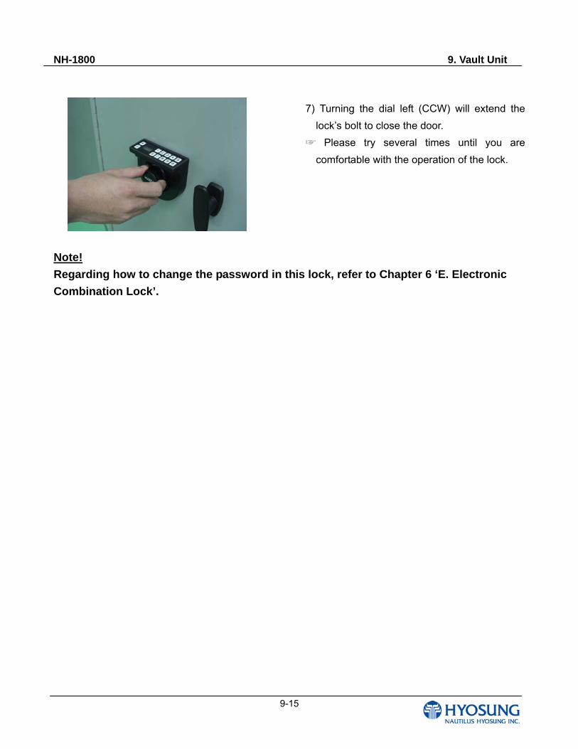
NH-1800 9. Vault Unit
9-15
7) Turning the dial left (CCW) will extend the
lock’s bolt to close the door.
Please try several times until you are
comfortable with the operation of the lock.
Note!
Regarding how to change the password in this lock, refer to Chapter 6 ‘E. Electronic
Combination Lock’.
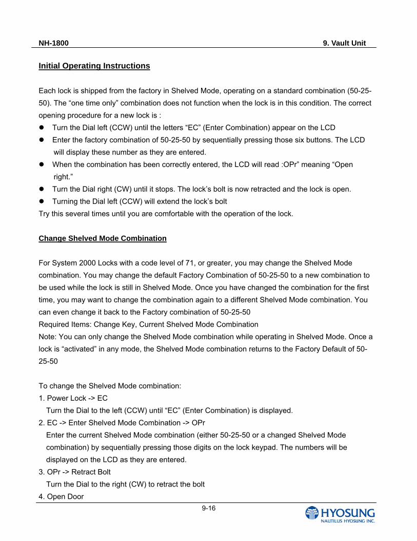
NH-1800 9. Vault Unit
9-16
Initial Operating Instructions
Each lock is shipped from the factory in Shelved Mode, operating on a standard combination (50-25-
50). The “one time only” combination does not function when the lock is in this condition. The correct
opening procedure for a new lock is :
Turn the Dial left (CCW) until the letters “EC” (Enter Combination) appear on the LCD
Enter the factory combination of 50-25-50 by sequentially pressing those six buttons. The LCD
will display these number as they are entered.
When the combination has been correctly entered, the LCD will read :OPr” meaning “Open
right.”
Turn the Dial right (CW) until it stops. The lock’s bolt is now retracted and the lock is open.
Turning the Dial left (CCW) will extend the lock’s bolt
Try this several times until you are comfortable with the operation of the lock.
Change Shelved Mode Combination
For System 2000 Locks with a code level of 71, or greater, you may change the Shelved Mode
combination. You may change the default Factory Combination of 50-25-50 to a new combination to
be used while the lock is still in Shelved Mode. Once you have changed the combination for the first
time, you may want to change the combination again to a different Shelved Mode combination. You
can even change it back to the Factory combination of 50-25-50
Required Items: Change Key, Current Shelved Mode Combination
Note: You can only change the Shelved Mode combination while operating in Shelved Mode. Once a
lock is “activated” in any mode, the Shelved Mode combination returns to the Factory Default of 50-
25-50
To change the Shelved Mode combination:
1. Power Lock -> EC
Turn the Dial to the left (CCW) until “EC” (Enter Combination) is displayed.
2. EC -> Enter Shelved Mode Combination -> OPr
Enter the current Shelved Mode combination (either 50-25-50 or a changed Shelved Mode
combination) by sequentially pressing those digits on the lock keypad. The numbers will be
displayed on the LCD as they are entered.
3. OPr -> Retract Bolt
Turn the Dial to the right (CW) to retract the bolt
4. Open Door
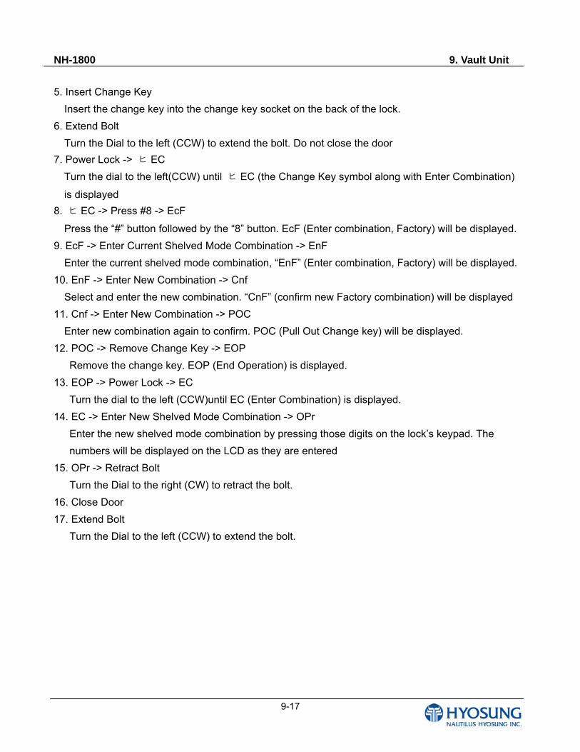
NH-1800 9. Vault Unit
9-17
5. Insert Change Key
Insert the change key into the change key socket on the back of the lock.
6. Extend Bolt
Turn the Dial to the left (CCW) to extend the bolt. Do not close the door
7. Power Lock -> ヒ EC
Turn the dial to the left(CCW) until ヒ EC (the Change Key symbol along with Enter Combination)
is displayed
8. ヒ EC -> Press #8 -> EcF
Press the “#” button followed by the “8” button. EcF (Enter combination, Factory) will be displayed.
9. EcF -> Enter Current Shelved Mode Combination -> EnF
Enter the current shelved mode combination, “EnF” (Enter combination, Factory) will be displayed.
10. EnF -> Enter New Combination -> Cnf
Select and enter the new combination. “CnF” (confirm new Factory combination) will be displayed
11. Cnf -> Enter New Combination -> POC
Enter new combination again to confirm. POC (Pull Out Change key) will be displayed.
12. POC -> Remove Change Key -> EOP
Remove the change key. EOP (End Operation) is displayed.
13. EOP -> Power Lock -> EC
Turn the dial to the left (CCW)until EC (Enter Combination) is displayed.
14. EC -> Enter New Shelved Mode Combination -> OPr
Enter the new shelved mode combination by pressing those digits on the lock’s keypad. The
numbers will be displayed on the LCD as they are entered
15. OPr -> Retract Bolt
Turn the Dial to the right (CW) to retract the bolt.
16. Close Door
17. Extend Bolt
Turn the Dial to the left (CCW) to extend the bolt.
NH-1800 10. Consumable Part Specifications
10-1
Chapter 10. Consumable Part Specifications
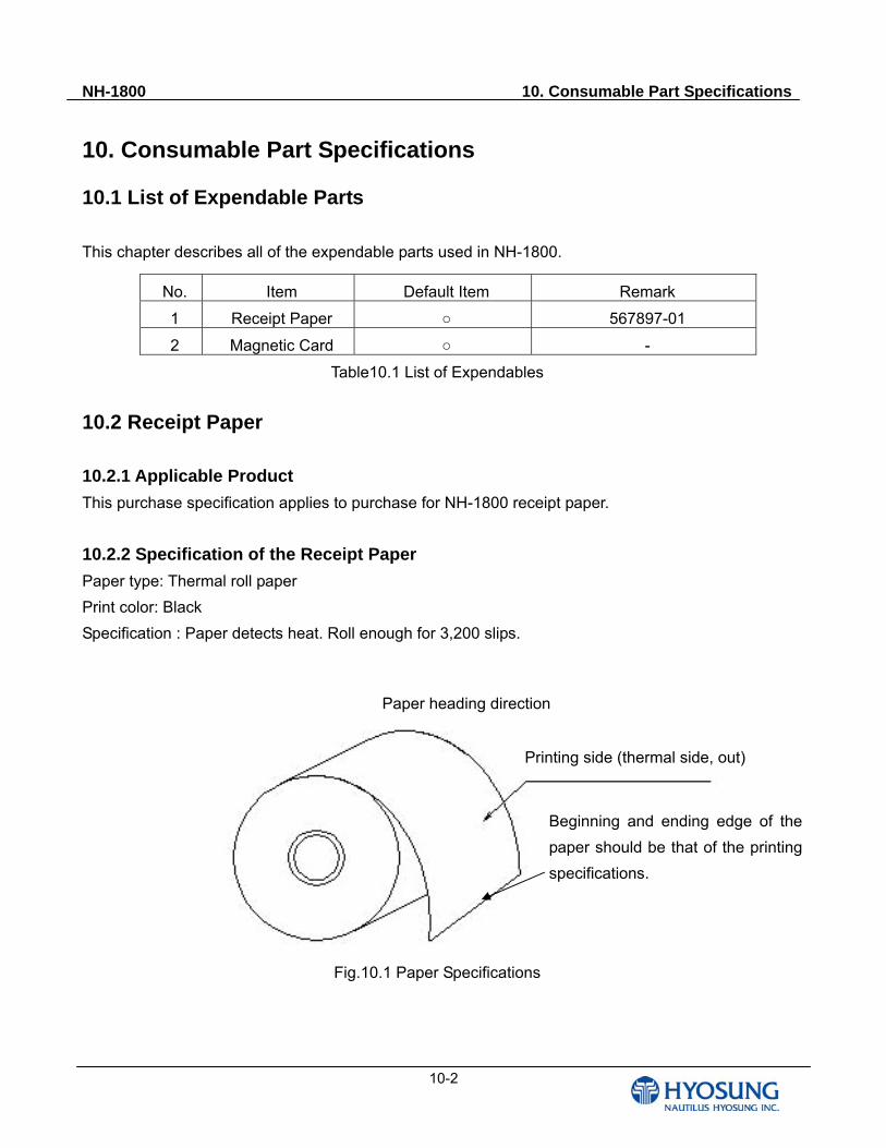
NH-1800 10. Consumable Part Specifications
10-2
10. Consumable Part Specifications
10.1 List of Expendable Parts
This chapter describes all of the expendable parts used in NH-1800.
No. Item Default Item Remark
1 Receipt Paper 567897-01
2 Magnetic Card -
Table10.1 List of Expendables
10.2 Receipt Paper
10.2.1 Applicable Product
This purchase specification applies to purchase for NH-1800 receipt paper.
10.2.2 Specification of the Receipt Paper
Paper type: Thermal roll paper
Print color: Black
Specification : Paper detects heat. Roll enough for 3,200 slips.
Fig.10.1 Paper Specifications
, 내/외측)
Paper heading direction
Printing side (thermal side, out)
Beginning and ending edge of the
paper should be that of the printing
specifications.
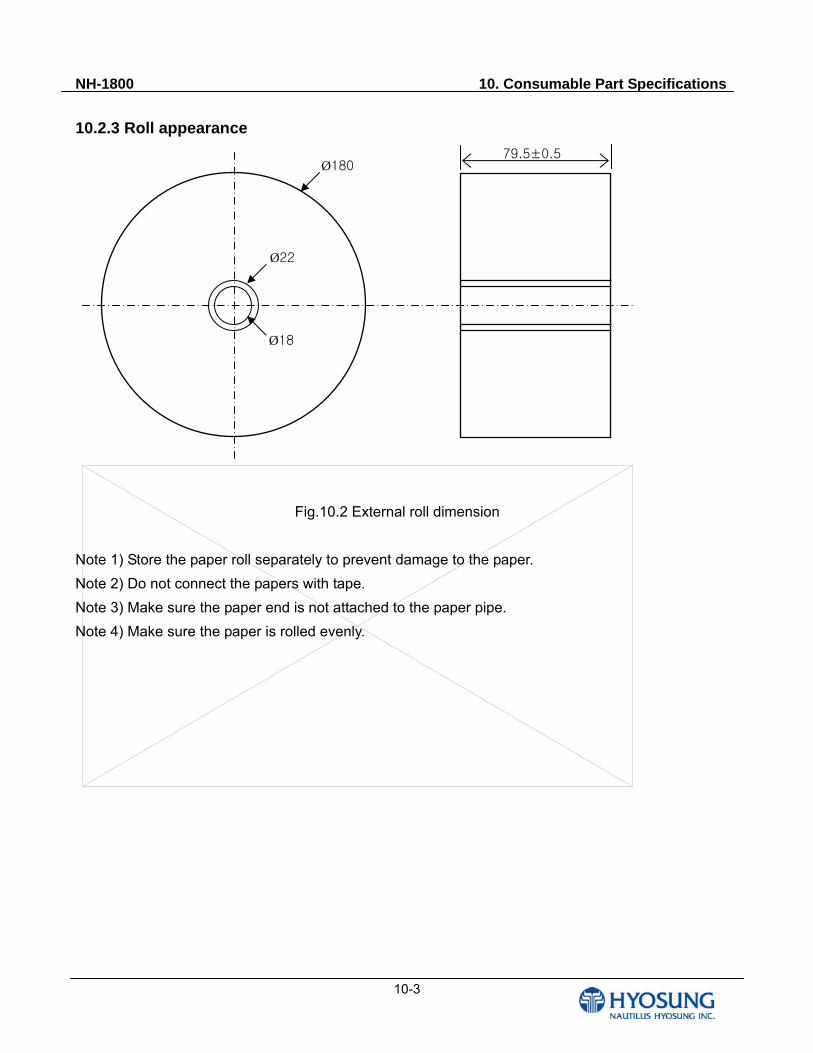
NH-1800 10. Consumable Part Specifications
10-3
10.2.3 Roll appearance
Fig.10.2 External roll dimension
Note 1) Store the paper roll separately to prevent damage to the paper.
Note 2) Do not connect the papers with tape.
Note 3) Make sure the paper end is not attached to the paper pipe.
Note 4) Make sure the paper is rolled evenly.
Ø180
Ø22
Ø18
79.5±0.5
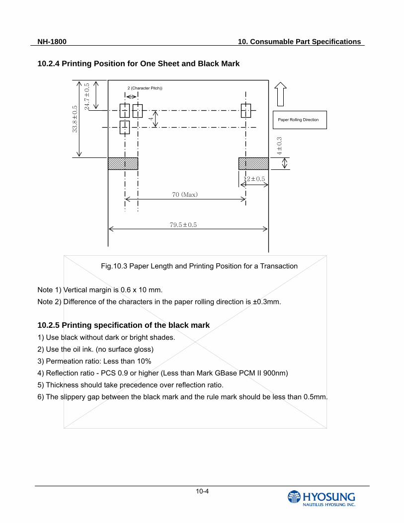
NH-1800 10. Consumable Part Specifications
10-4
10.2.4 Printing Position for One Sheet and Black Mark
Fig.10.3 Paper Length and Printing Position for a Transaction
Note 1) Vertical margin is 0.6 x 10 mm.
Note 2) Difference of the characters in the paper rolling direction is ±0.3mm.
10.2.5 Printing specification of the black mark
1) Use black without dark or bright shades.
2) Use the oil ink. (no surface gloss)
3) Permeation ratio: Less than 10%
4) Reflection ratio - PCS 0.9 or higher (Less than Mark GBase PCM II 900nm)
5) Thickness should take precedence over reflection ratio.
6) The slippery gap between the black mark and the rule mark should be less than 0.5mm.
24.7±
0.5
33.8±
0.5
12±0.5
4±
0.3
70 (Max)
79.5±0.5
2 (Character Pitch))
4
Paper Rolling Direction
NH-1800 10. Consumable Part Specifications
10-5
10.2.6 Paper Handling Precautions
1) Store it away from high temperature and humidity
If the paper is stored in a place where temperature is above 50 or hum idity is above
90% RH, the coloring capability may deteriorate or the paper surface may inflate.
2 Refrain from exposing to direct sunlight
The paper surface can be inflated if you expose it to direct sunlight or leave it under the
fluorescent lamp for a long time.
3) Keep it away form the organic solvents
Paper color may change if the paper comes in contact with organic solvents or glues
containing organic solvent.
4) Keep it away from plastics
If the paper comes in contact with materials containing plastics, its coloring capability
may deteriorate or de-coloring of the paper may occur.
5 Miscellaneous
If the paper comes in contact with carbon copy paper or if the paper surface is
scratched with a metallic object, de-coloring may occur.
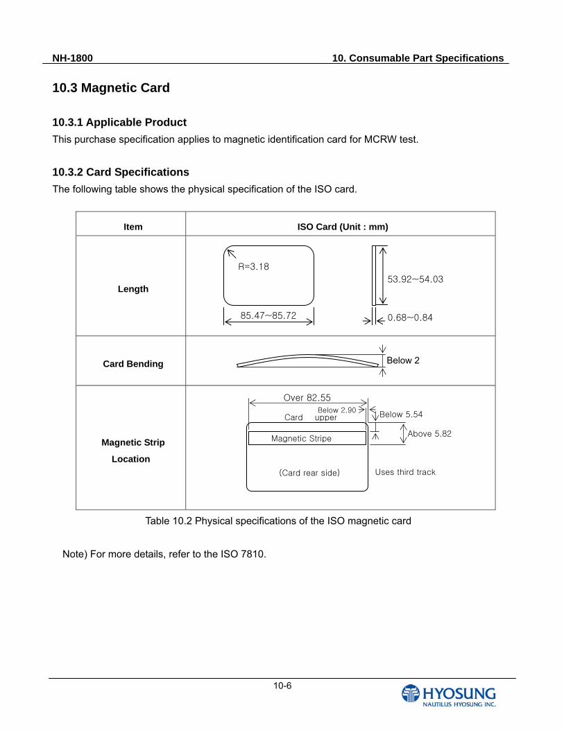
NH-1800 10. Consumable Part Specifications
10-6
10.3 Magnetic Card 10.3.1 Applicable Product
This purchase specification applies to magnetic identification card for MCRW test.
10.3.2 Card Specifications
The following table shows the physical specification of the ISO card.
Item ISO Card (Unit : mm)
Length
Card Bending
Magnetic Strip
Location
Table 10.2 Physical specifications of the ISO magnetic card
Note) For more details, refer to the ISO 7810.
85.47~85.72
53.92~54.03
R=3.18
0.68~0.84
Below 2
(Card rear side)
Magnetic Stripe
Below 2.90Card upper Below 5.54
Above 5.82
Over 82.55
Uses third track
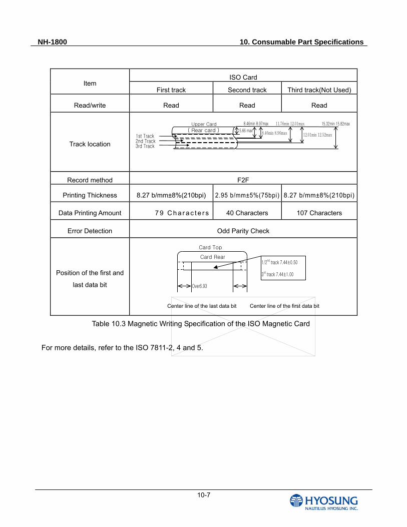
NH-1800 10. Consumable Part Specifications
10-7
ISO Card Item
First track Second track Third track(Not Used)
Read/write Read Read Read
Track location
Record method F2F
Printing Thickness 8.27 b/mm±8%(210bpi) 2.95 b/mm±5%(75bpi) 8.27 b/mm±8%(210bpi)
Data Printing Amount 7 9 C h a r a c t e r s 40 Characters 107 Characters
Error Detection Odd Parity Check
Position of the first and
last data bit
Center line of the last data bit Center line of the first data bit
Table 10.3 Magnetic Writing Specification of the ISO Magnetic Card
For more details, refer to the ISO 7811-2, 4 and 5.
Over6.93
1/2nd track 7.44±0.50
3rd track 7.44±1.00
Card Top
Card Rear
( Rear card ) 5.66 max
15.32min 15.82maxUpper Card
8.46min 8.96max
8.46min 8.97max 11.76min 12.01max
12.01min 12.52max1st Track 2nd Track 3rd Track
NH-1800 11. Error Code and Troubleshooting
11- 1
Chapter 11. Error Code and Troubleshooting
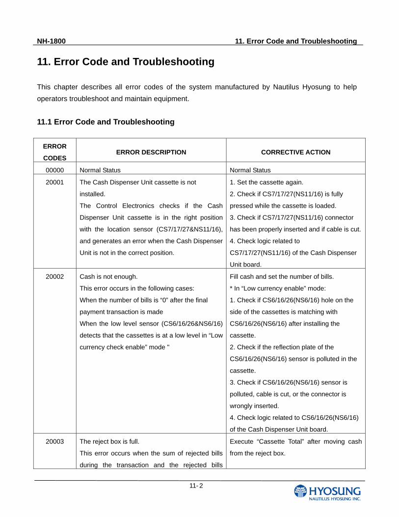
NH-1800 11. Error Code and Troubleshooting
11- 2
11. Error Code and Troubleshooting
This chapter describes all error codes of the system manufactured by Nautilus Hyosung to help
operators troubleshoot and maintain equipment.
11.1 Error Code and Troubleshooting
ERROR
CODES ERROR DESCRIPTION CORRECTIVE ACTION
00000 Normal Status Normal Status
20001 The Cash Dispenser Unit cassette is not
installed.
The Control Electronics checks if the Cash
Dispenser Unit cassette is in the right position
with the location sensor (CS7/17/27&NS11/16),
and generates an error when the Cash Dispenser
Unit is not in the correct position.
1. Set the cassette again.
2. Check if CS7/17/27(NS11/16) is fully
pressed while the cassette is loaded.
3. Check if CS7/17/27(NS11/16) connector
has been properly inserted and if cable is cut.
4. Check logic related to
CS7/17/27(NS11/16) of the Cash Dispenser
Unit board.
20002 Cash is not enough.
This error occurs in the following cases:
When the number of bills is “0” after the final
payment transaction is made
When the low level sensor (CS6/16/26&NS6/16)
detects that the cassettes is at a low level in “Low
currency check enable” mode "
Fill cash and set the number of bills.
* In “Low currency enable” mode:
1. Check if CS6/16/26(NS6/16) hole on the
side of the cassettes is matching with
CS6/16/26(NS6/16) after installing the
cassette.
2. Check if the reflection plate of the
CS6/16/26(NS6/16) sensor is polluted in the
cassette.
3. Check if CS6/16/26(NS6/16) sensor is
polluted, cable is cut, or the connector is
wrongly inserted.
4. Check logic related to CS6/16/26(NS6/16)
of the Cash Dispenser Unit board.
20003 The reject box is full.
This error occurs when the sum of rejected bills
during the transaction and the rejected bills
Execute “Cassette Total” after moving cash
from the reject box.
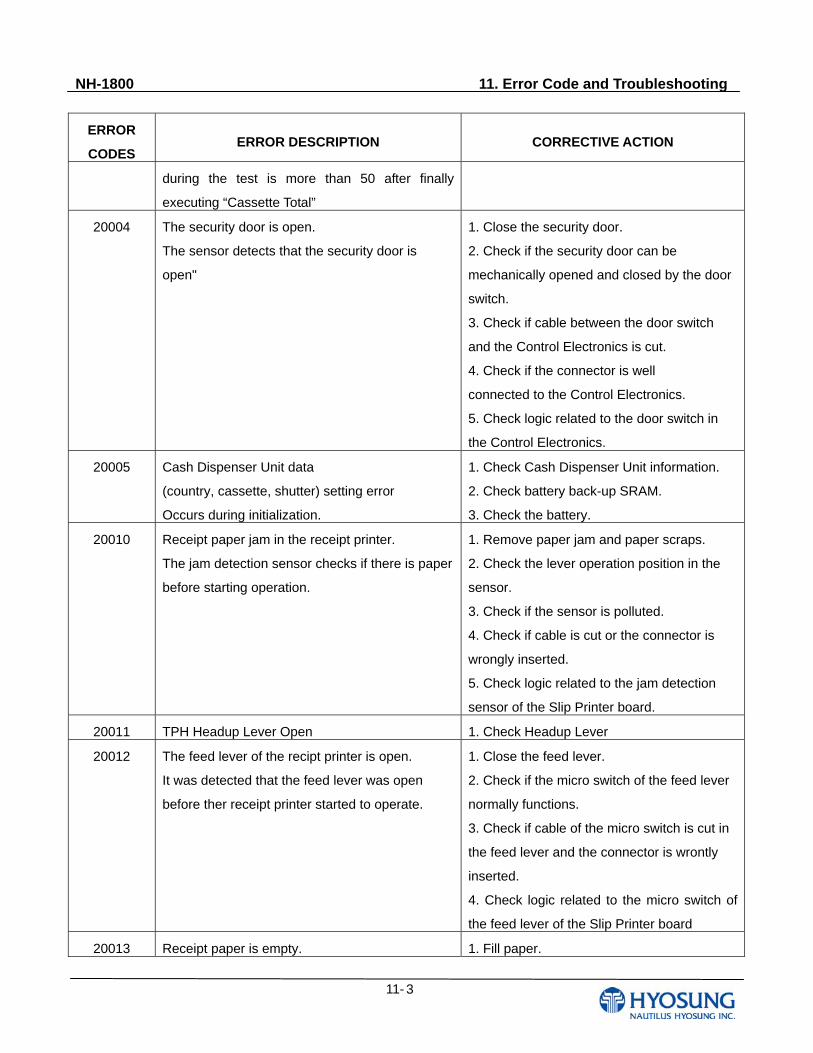
NH-1800 11. Error Code and Troubleshooting
11- 3
ERROR
CODES ERROR DESCRIPTION CORRECTIVE ACTION
during the test is more than 50 after finally
executing “Cassette Total”
20004 The security door is open.
The sensor detects that the security door is
open"
1. Close the security door.
2. Check if the security door can be
mechanically opened and closed by the door
switch.
3. Check if cable between the door switch
and the Control Electronics is cut.
4. Check if the connector is well
connected to the Control Electronics.
5. Check logic related to the door switch in
the Control Electronics.
20005 Cash Dispenser Unit data
(country, cassette, shutter) setting error
Occurs during initialization.
1. Check Cash Dispenser Unit information.
2. Check battery back-up SRAM.
3. Check the battery.
20010 Receipt paper jam in the receipt printer.
The jam detection sensor checks if there is paper
before starting operation.
1. Remove paper jam and paper scraps.
2. Check the lever operation position in the
sensor.
3. Check if the sensor is polluted.
4. Check if cable is cut or the connector is
wrongly inserted.
5. Check logic related to the jam detection
sensor of the Slip Printer board.
20011 TPH Headup Lever Open 1. Check Headup Lever
20012 The feed lever of the recipt printer is open.
It was detected that the feed lever was open
before ther receipt printer started to operate.
1. Close the feed lever.
2. Check if the micro switch of the feed lever
normally functions.
3. Check if cable of the micro switch is cut in
the feed lever and the connector is wrontly
inserted.
4. Check logic related to the micro switch of
the feed lever of the Slip Printer board
20013 Receipt paper is empty. 1. Fill paper.
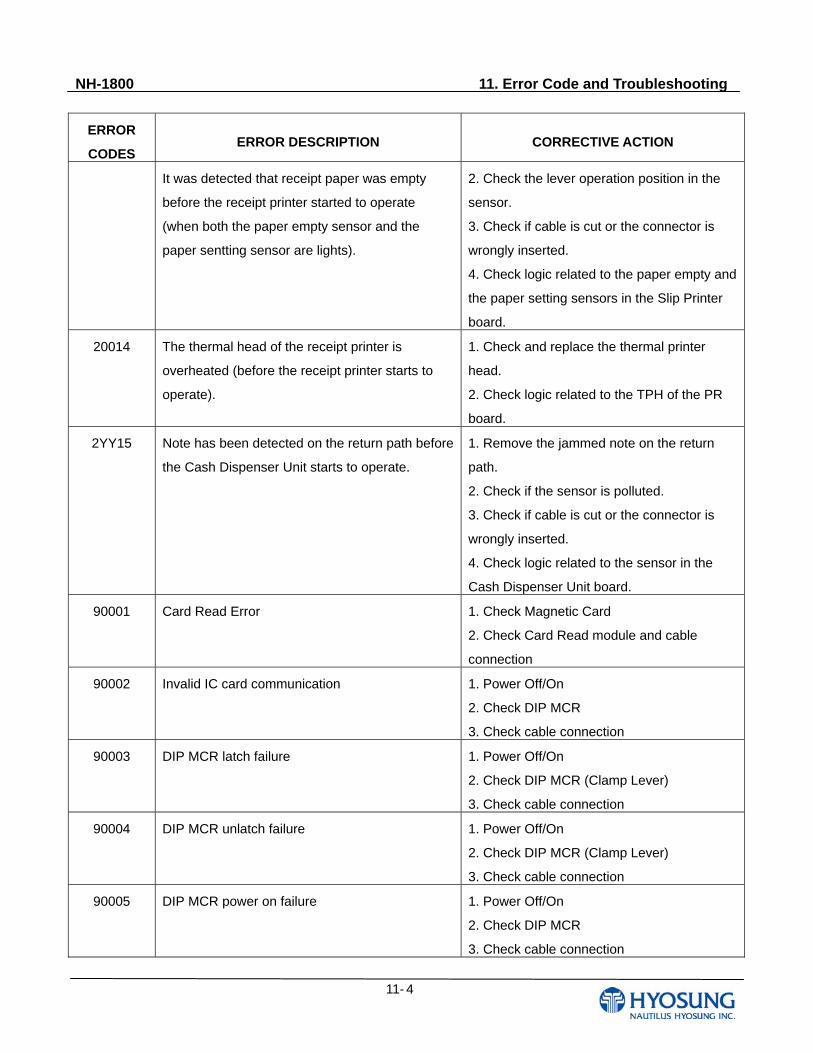
NH-1800 11. Error Code and Troubleshooting
11- 4
ERROR
CODES ERROR DESCRIPTION CORRECTIVE ACTION
It was detected that receipt paper was empty
before the receipt printer started to operate
(when both the paper empty sensor and the
paper sentting sensor are lights).
2. Check the lever operation position in the
sensor.
3. Check if cable is cut or the connector is
wrongly inserted.
4. Check logic related to the paper empty and
the paper setting sensors in the Slip Printer
board.
20014 The thermal head of the receipt printer is
overheated (before the receipt printer starts to
operate).
1. Check and replace the thermal printer
head.
2. Check logic related to the TPH of the PR
board.
2YY15 Note has been detected on the return path before
the Cash Dispenser Unit starts to operate.
1. Remove the jammed note on the return
path.
2. Check if the sensor is polluted.
3. Check if cable is cut or the connector is
wrongly inserted.
4. Check logic related to the sensor in the
Cash Dispenser Unit board.
90001 Card Read Error
1. Check Magnetic Card
2. Check Card Read module and cable
connection
90002 Invalid IC card communication
1. Power Off/On
2. Check DIP MCR
3. Check cable connection
90003 DIP MCR latch failure
1. Power Off/On
2. Check DIP MCR (Clamp Lever)
3. Check cable connection
90004 DIP MCR unlatch failure
1. Power Off/On
2. Check DIP MCR (Clamp Lever)
3. Check cable connection
90005 DIP MCR power on failure
1. Power Off/On
2. Check DIP MCR
3. Check cable connection
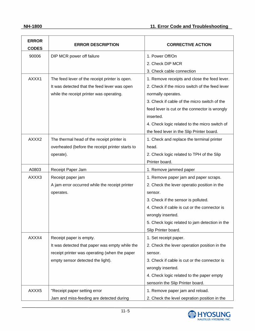
NH-1800 11. Error Code and Troubleshooting
11- 5
ERROR
CODES ERROR DESCRIPTION CORRECTIVE ACTION
90006 DIP MCR power off failure
1. Power Off/On
2. Check DIP MCR
3. Check cable connection
AXXX1 The feed lever of the receipt printer is open.
It was detected that the feed lever was open
while the receipt printer was operating.
1. Remove receipts and close the feed lever.
2. Check if the micro switch of the feed lever
normally operates.
3. Check if cable of the micro switch of the
feed lever is cut or the connector is wrongly
inserted.
4. Check logic related to the micro switch of
the feed lever in the Slip Printer board.
AXXX2 The thermal head of the receipt printer is
overheated (before the receipt printer starts to
operate).
1. Check and replace the terminal printer
head.
2. Check logic related to TPH of the Slip
Printer board.
A0803 Receipt Paper Jam 1. Remove jammed paper
AXXX3 Receipt paper jam
A jam error occurred while the receipt printer
operates.
1. Remove paper jam and paper scraps.
2. Check the lever operatio position in the
sensor.
3. Check if the sensor is polluted.
4. Check if cable is cut or the connector is
wrongly inserted.
5. Check logic related to jam detection in the
Slip Printer board.
AXXX4 Receipt paper is empty.
It was detected that paper was empty while the
receipt printer was operating (when the paper
empty sensor detected the light).
1. Set receipt paper.
2. Check the lever operation position in the
sensor.
3. Check if cable is cut or the connector is
wrongly inserted.
4. Check logic related to the paper empty
sensorin the Slip Printer board.
AXXX5 "Receipt paper setting error
Jam and miss-feeding are detected during
1. Remove paper jam and reload.
2. Check the level oepration position in the
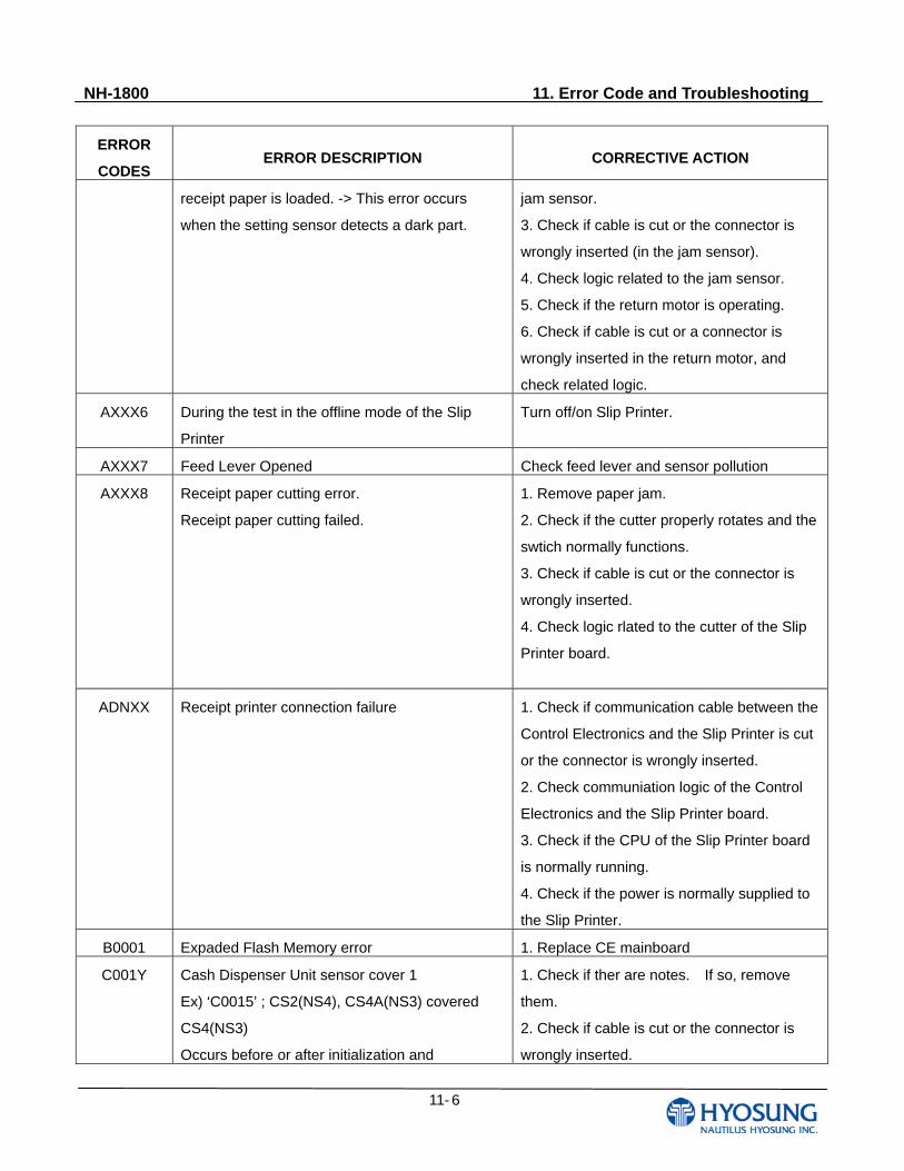
NH-1800 11. Error Code and Troubleshooting
11- 6
ERROR
CODES ERROR DESCRIPTION CORRECTIVE ACTION
receipt paper is loaded. -> This error occurs
when the setting sensor detects a dark part.
jam sensor.
3. Check if cable is cut or the connector is
wrongly inserted (in the jam sensor).
4. Check logic related to the jam sensor.
5. Check if the return motor is operating.
6. Check if cable is cut or a connector is
wrongly inserted in the return motor, and
check related logic.
AXXX6 During the test in the offline mode of the Slip
Printer
Turn off/on Slip Printer.
AXXX7 Feed Lever Opened Check feed lever and sensor pollution
AXXX8 Receipt paper cutting error.
Receipt paper cutting failed.
1. Remove paper jam.
2. Check if the cutter properly rotates and the
swtich normally functions.
3. Check if cable is cut or the connector is
wrongly inserted.
4. Check logic rlated to the cutter of the Slip
Printer board.
ADNXX Receipt printer connection failure 1. Check if communication cable between the
Control Electronics and the Slip Printer is cut
or the connector is wrongly inserted.
2. Check communiation logic of the Control
Electronics and the Slip Printer board.
3. Check if the CPU of the Slip Printer board
is normally running.
4. Check if the power is normally supplied to
the Slip Printer.
B0001 Expaded Flash Memory error 1. Replace CE mainboard
C001Y Cash Dispenser Unit sensor cover 1
Ex) ‘C0015’ ; CS2(NS4), CS4A(NS3) covered
CS4(NS3)
Occurs before or after initialization and
1. Check if ther are notes. If so, remove
them.
2. Check if cable is cut or the connector is
wrongly inserted.
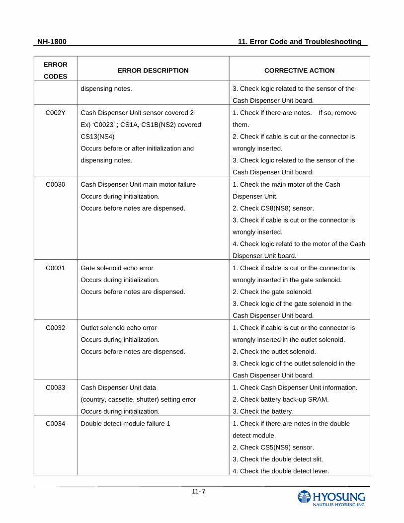
NH-1800 11. Error Code and Troubleshooting
11- 7
ERROR
CODES ERROR DESCRIPTION CORRECTIVE ACTION
dispensing notes. 3. Check logic related to the sensor of the
Cash Dispenser Unit board.
C002Y Cash Dispenser Unit sensor covered 2
Ex) ‘C0023’ ; CS1A, CS1B(NS2) covered
CS13(NS4)
Occurs before or after initialization and
dispensing notes.
1. Check if there are notes. If so, remove
them.
2. Check if cable is cut or the connector is
wrongly inserted.
3. Check logic related to the sensor of the
Cash Dispenser Unit board.
C0030 Cash Dispenser Unit main motor failure
Occurs during initialization.
Occurs before notes are dispensed.
1. Check the main motor of the Cash
Dispenser Unit.
2. Check CS8(NS8) sensor.
3. Check if cable is cut or the connector is
wrongly inserted.
4. Check logic relatd to the motor of the Cash
Dispenser Unit board.
C0031 Gate solenoid echo error
Occurs during initialization.
Occurs before notes are dispensed.
1. Check if cable is cut or the connector is
wrongly inserted in the gate solenoid.
2. Check the gate solenoid.
3. Check logic of the gate solenoid in the
Cash Dispenser Unit board.
C0032 Outlet solenoid echo error
Occurs during initialization.
Occurs before notes are dispensed.
1. Check if cable is cut or the connector is
wrongly inserted in the outlet solenoid.
2. Check the outlet solenoid.
3. Check logic of the outlet solenoid in the
Cash Dispenser Unit board.
C0033 Cash Dispenser Unit data
(country, cassette, shutter) setting error
Occurs during initialization.
1. Check Cash Dispenser Unit information.
2. Check battery back-up SRAM.
3. Check the battery.
C0034 Double detect module failure 1
1. Check if there are notes in the double
detect module.
2. Check CS5(NS9) sensor.
3. Check the double detect slit.
4. Check the double detect lever.
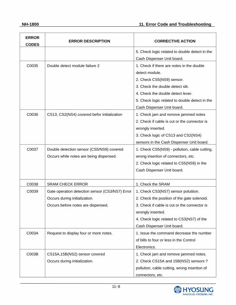
NH-1800 11. Error Code and Troubleshooting
11- 8
ERROR
CODES ERROR DESCRIPTION CORRECTIVE ACTION
5. Check logic related to double detect in the
Cash Dispenser Unit board.
C0035 Double detect module failure 2
1. Check if there are notes in the double
detect module.
2. Check CS5(NS9) sensor.
3. Check the double detect slit.
4. Check the double detect lever.
5. Check logic related to double detect in the
Cash Dispenser Unit board.
C0036 CS13, CS2(NS4) covered befor initialization
1. Check jam and remove jammed notes
2. Check if cable is cut or the connector is
wrongly inserted.
3. Check logic of CS13 and CS2(NS4)
sensors in the Cash Dispenser Unit board.
C0037 Double detection sensor (CS5/NS9) covered
Occurs while notes are being dispensed.
1. Check CS5(NS9) - pollution, cable cutting,
wrong insertion of connectors, etc.
2. Check logic related to CS5(NS9) in the
Cash Dispenser Unit board.
C0038 SRAM CHECK ERROR 1. Check the SRAM
C0039 Gate operation detection sensor (CS3/NS7) Error
Occurs during initialization.
Occurs before notes are dispensed.
1. Check CS3(NS7) sensor poluttion.
2. Check the position of the gate solenoid.
3. Check if cable is cut or the connector is
wrongly inserted.
4. Check logic related to CS3(NS7) of the
Cash Dispenser Unit board.
C003A Request to display four or more notes.
1. Issue the command decrease the number
of bills to four or less in the Control
Electronics.
C003B CS15A,15B(NS2) sensor covered
Occurs during initialization.
1. Check jam and remove jammed notes.
2. Check CS15A and 15B(NS2) sensors ?
pollution, cable cutting, wrong insertion of
connectors, etc.
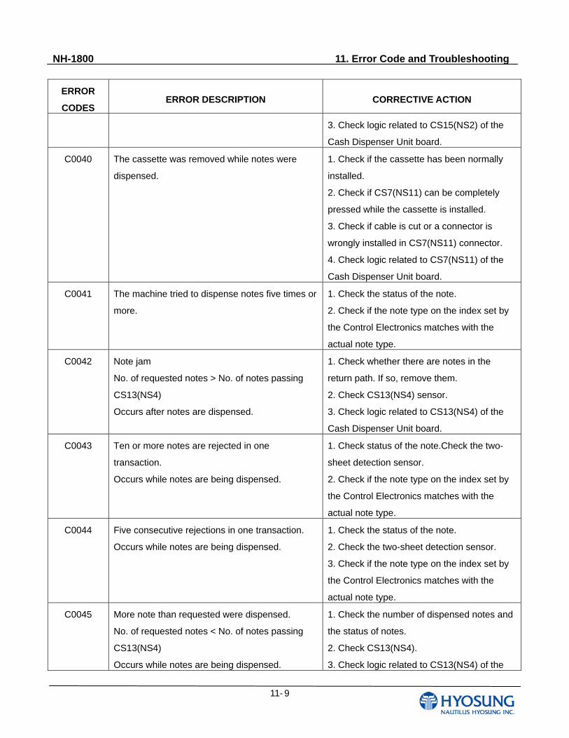
NH-1800 11. Error Code and Troubleshooting
11- 9
ERROR
CODES ERROR DESCRIPTION CORRECTIVE ACTION
3. Check logic related to CS15(NS2) of the
Cash Dispenser Unit board.
C0040 The cassette was removed while notes were
dispensed.
1. Check if the cassette has been normally
installed.
2. Check if CS7(NS11) can be completely
pressed while the cassette is installed.
3. Check if cable is cut or a connector is
wrongly installed in CS7(NS11) connector.
4. Check logic related to CS7(NS11) of the
Cash Dispenser Unit board.
C0041 The machine tried to dispense notes five times or
more.
1. Check the status of the note.
2. Check if the note type on the index set by
the Control Electronics matches with the
actual note type.
C0042 Note jam
No. of requested notes > No. of notes passing
CS13(NS4)
Occurs after notes are dispensed.
1. Check whether there are notes in the
return path. If so, remove them.
2. Check CS13(NS4) sensor.
3. Check logic related to CS13(NS4) of the
Cash Dispenser Unit board.
C0043 Ten or more notes are rejected in one
transaction.
Occurs while notes are being dispensed.
1. Check status of the note.Check the two-
sheet detection sensor.
2. Check if the note type on the index set by
the Control Electronics matches with the
actual note type.
C0044 Five consecutive rejections in one transaction.
Occurs while notes are being dispensed.
1. Check the status of the note.
2. Check the two-sheet detection sensor.
3. Check if the note type on the index set by
the Control Electronics matches with the
actual note type.
C0045 More note than requested were dispensed.
No. of requested notes < No. of notes passing
CS13(NS4)
Occurs while notes are being dispensed.
1. Check the number of dispensed notes and
the status of notes.
2. Check CS13(NS4).
3. Check logic related to CS13(NS4) of the
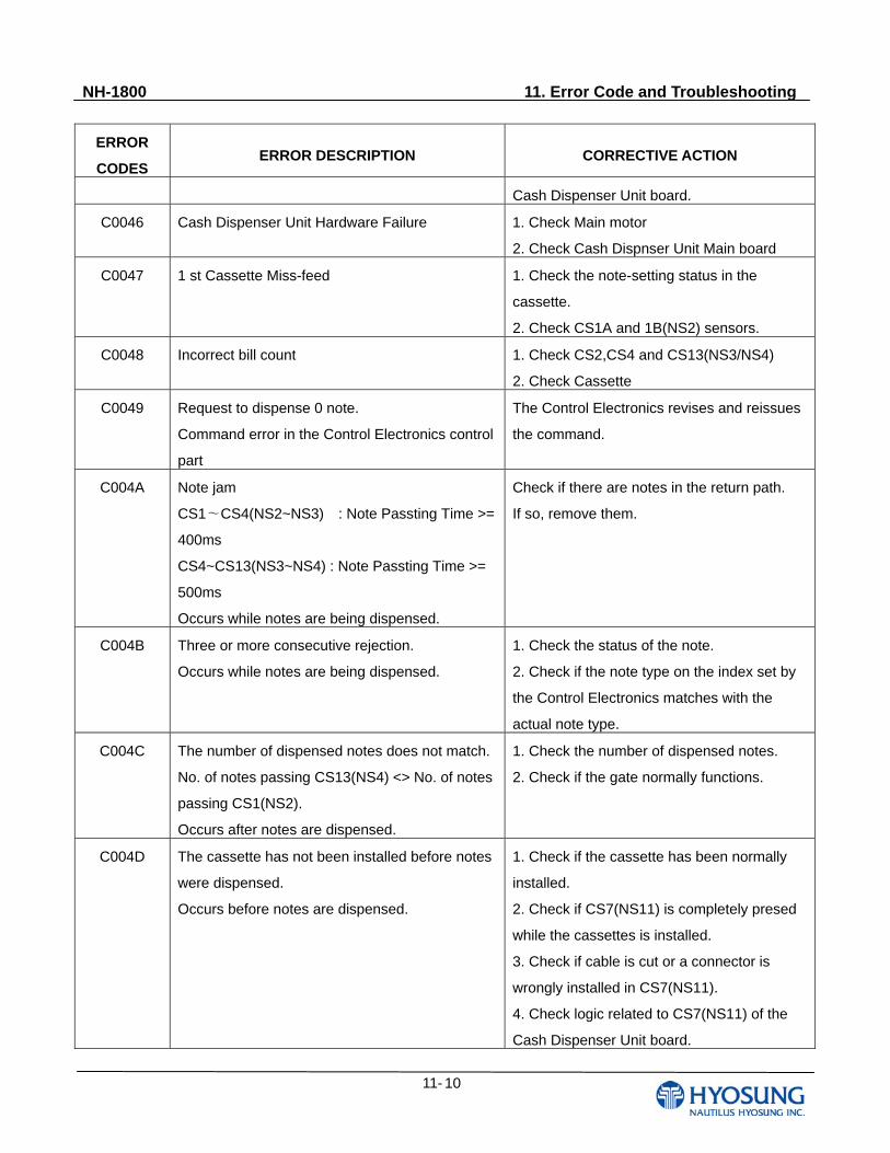
NH-1800 11. Error Code and Troubleshooting
11- 10
ERROR
CODES ERROR DESCRIPTION CORRECTIVE ACTION
Cash Dispenser Unit board.
C0046 Cash Dispenser Unit Hardware Failure 1. Check Main motor
2. Check Cash Dispnser Unit Main board
C0047 1 st Cassette Miss-feed 1. Check the note-setting status in the
cassette.
2. Check CS1A and 1B(NS2) sensors.
C0048 Incorrect bill count
1. Check CS2,CS4 and CS13(NS3/NS4)
2. Check Cassette
C0049 Request to dispense 0 note.
Command error in the Control Electronics control
part
The Control Electronics revises and reissues
the command.
C004A Note jam
CS1 CS4(NS2~NS3) : Note Passting Time >= ∼
400ms
CS4~CS13(NS3~NS4) : Note Passting Time >=
500ms
Occurs while notes are being dispensed.
Check if there are notes in the return path.
If so, remove them.
C004B Three or more consecutive rejection.
Occurs while notes are being dispensed.
1. Check the status of the note.
2. Check if the note type on the index set by
the Control Electronics matches with the
actual note type.
C004C The number of dispensed notes does not match.
No. of notes passing CS13(NS4) <> No. of notes
passing CS1(NS2).
Occurs after notes are dispensed.
1. Check the number of dispensed notes.
2. Check if the gate normally functions.
C004D The cassette has not been installed before notes
were dispensed.
Occurs before notes are dispensed.
1. Check if the cassette has been normally
installed.
2. Check if CS7(NS11) is completely presed
while the cassettes is installed.
3. Check if cable is cut or a connector is
wrongly installed in CS7(NS11).
4. Check logic related to CS7(NS11) of the
Cash Dispenser Unit board.

NH-1800 11. Error Code and Troubleshooting
11- 11
ERROR
CODES ERROR DESCRIPTION CORRECTIVE ACTION
C004E The number of dispensed notes does not match.
Number of requested notes > Number of notes
dispensed and reported to the Cash Dispenser
Unit
The Control Electronics checks after notes are
dispensed.
1. Check the number of dispensed notes.
2. Perform a unit test on the Cash Dispenser
Unit.
C004F The number of dispensed notes does not match.
No. of requested notes < No. of notes dispensed
and reported to the Cash Dispenser Unit.
The Control Electronics checks after notes are
dispensed.
1. Check the number of dispensed notes.
2. Perform a test on the Cash Dispenser Unit.
C0050 The power is cut while notes are being
dispensed.
The Control Electronics checks.
1. Check the number of dispensed notes.
2. Check if there are notes in the return path.
If so, remove them.
C0051 Request to dispense 150 or more notes.
Control command error in the Control Electronics
1. The Control Electronics revises and
reissues the command.
C0052 CS1A,1B(NS2) sensor covered.
Occurs after notes are dispensed.
1. Check if there are notes in the return path.
If so, remove them.
2. Check CS1A and 1B(NS2) sensors.
3. Check logic related to CS1A and 1B(NS2)
of the Cash Dispenser Unit board.
C0053 CDU Double detect module failure 1. Check CS5(NS9) - pollution, cable cutting,
wrong insertion of connectors, etc.
2. Check logic related to CS5(NS9) in the
Cash Dispenser Unit board.
C0054 CDU Program Error 1. Download new EP software
C0055 Outlet sensor (CS13/NS4) senses the length of
the note.
Occurs while notes are being dispensed.
1. Check the status of the note.
2. Check CS13(NS4).
3. Check the main motor speed.
4. Check if the note type on the index set by
the Control Electronics matches
with the actual note type.
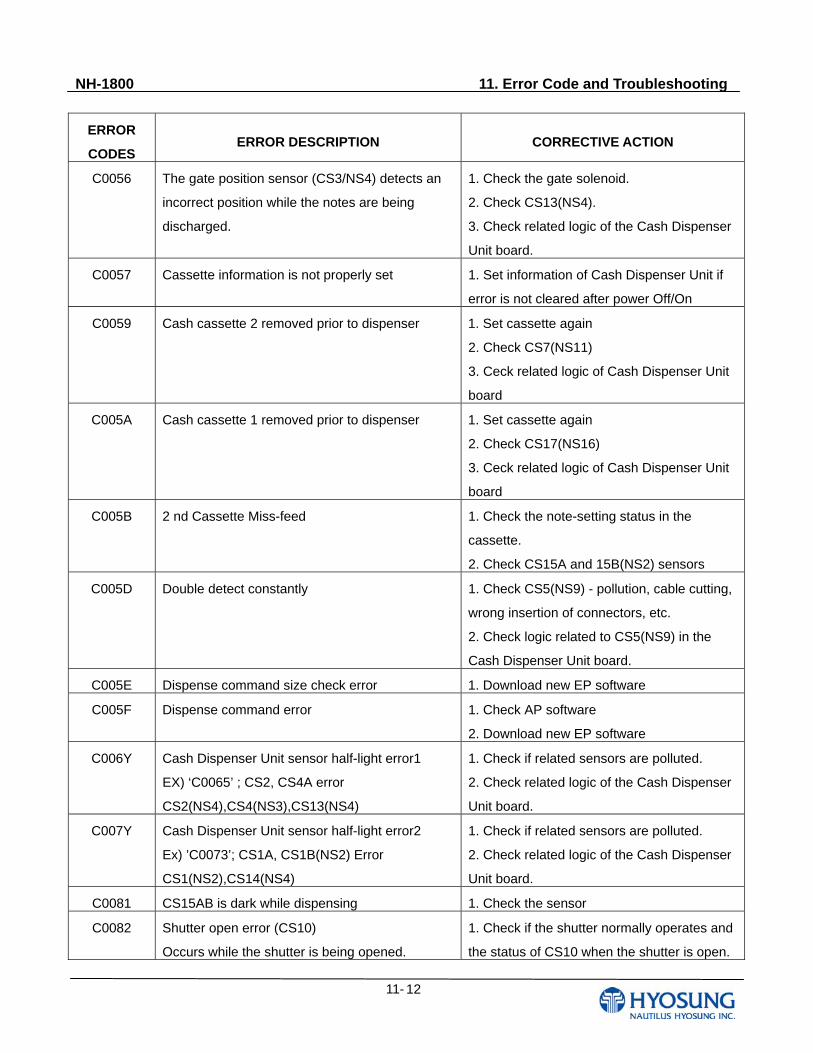
NH-1800 11. Error Code and Troubleshooting
11- 12
ERROR
CODES ERROR DESCRIPTION CORRECTIVE ACTION
C0056 The gate position sensor (CS3/NS4) detects an
incorrect position while the notes are being
discharged.
1. Check the gate solenoid.
2. Check CS13(NS4).
3. Check related logic of the Cash Dispenser
Unit board.
C0057 Cassette information is not properly set
1. Set information of Cash Dispenser Unit if
error is not cleared after power Off/On
C0059 Cash cassette 2 removed prior to dispenser 1. Set cassette again
2. Check CS7(NS11)
3. Ceck related logic of Cash Dispenser Unit
board
C005A Cash cassette 1 removed prior to dispenser 1. Set cassette again
2. Check CS17(NS16)
3. Ceck related logic of Cash Dispenser Unit
board
C005B 2 nd Cassette Miss-feed 1. Check the note-setting status in the
cassette.
2. Check CS15A and 15B(NS2) sensors
C005D Double detect constantly
1. Check CS5(NS9) - pollution, cable cutting,
wrong insertion of connectors, etc.
2. Check logic related to CS5(NS9) in the
Cash Dispenser Unit board.
C005E Dispense command size check error 1. Download new EP software
C005F Dispense command error 1. Check AP software
2. Download new EP software
C006Y Cash Dispenser Unit sensor half-light error1
EX) ‘C0065’ ; CS2, CS4A error
CS2(NS4),CS4(NS3),CS13(NS4)
1. Check if related sensors are polluted.
2. Check related logic of the Cash Dispenser
Unit board.
C007Y Cash Dispenser Unit sensor half-light error2
Ex) ’C0073’; CS1A, CS1B(NS2) Error
CS1(NS2),CS14(NS4)
1. Check if related sensors are polluted.
2. Check related logic of the Cash Dispenser
Unit board.
C0081 CS15AB is dark while dispensing 1. Check the sensor
C0082 Shutter open error (CS10)
Occurs while the shutter is being opened.
1. Check if the shutter normally operates and
the status of CS10 when the shutter is open.
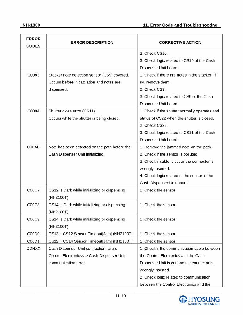
NH-1800 11. Error Code and Troubleshooting
11- 13
ERROR
CODES ERROR DESCRIPTION CORRECTIVE ACTION
2. Check CS10.
3. Check logic related to CS10 of the Cash
Dispenser Unit board.
C0083 Stacker note detection sensor (CS9) covered.
Occurs before initiazliation and notes are
dispensed.
1. Check if there are notes in the stacker. If
so, remove them.
2. Check CS9.
3. Check logic related to CS9 of the Cash
Dispenser Unit board.
C0084 Shutter close error (CS11)
Occurs while the shutter is being closed.
1. Check if the shutter normally operates and
status of CS22 when the shutter is closed.
2. Check CS22.
3. Check logic related to CS11 of the Cash
Dispenser Unit board.
C00AB Note has been detected on the path before the
Cash Dispenser Unit initializing.
1. Remove the jammed note on the path.
2. Check if the sensor is polluted.
3. Check if cable is cut or the connector is
wrongly inserted.
4. Check logic related to the sensor in the
Cash Dispenser Unit board.
C00C7 CS12 is Dark while initializing or dispensing
(NH2100T)
1. Check the sensor
C00C8 CS14 is Dark while initializing or dispensing
(NH2100T)
1. Check the sensor
C00C9 CS14 is Dark while initializing or dispensing
(NH2100T)
1. Check the sensor
C00D0 CS13 ~ CS12 Sensor Timeout[Jam] (NH2100T) 1. Check the sensor
C00D1 CS12 ~ CS14 Sensor Timeout[Jam] (NH2100T) 1. Check the sensor
CDNXX Cash Dispenser Unit connection failure
Control Electronics<-> Cash Dispenser Unit
communication error
1. Check if the communication cable between
the Control Electronics and the Cash
Dispenser Unit is cut and the connector is
wrongly inserted.
2. Check logic related to communication
between the Control Electronics and the
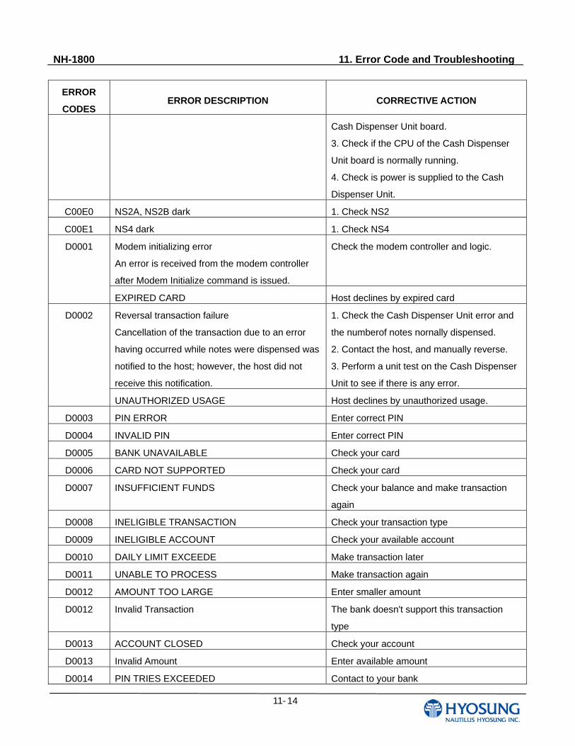
NH-1800 11. Error Code and Troubleshooting
11- 14
ERROR
CODES ERROR DESCRIPTION CORRECTIVE ACTION
Cash Dispenser Unit board.
3. Check if the CPU of the Cash Dispenser
Unit board is normally running.
4. Check is power is supplied to the Cash
Dispenser Unit.
C00E0 NS2A, NS2B dark 1. Check NS2
C00E1 NS4 dark 1. Check NS4
Modem initializing error
An error is received from the modem controller
after Modem Initialize command is issued.
Check the modem controller and logic.
D0001
EXPIRED CARD Host declines by expired card
Reversal transaction failure
Cancellation of the transaction due to an error
having occurred while notes were dispensed was
notified to the host; however, the host did not
receive this notification.
1. Check the Cash Dispenser Unit error and
the numberof notes nornally dispensed.
2. Contact the host, and manually reverse.
3. Perform a unit test on the Cash Dispenser
Unit to see if there is any error.
D0002
UNAUTHORIZED USAGE Host declines by unauthorized usage.
D0003 PIN ERROR Enter correct PIN
D0004 INVALID PIN Enter correct PIN
D0005 BANK UNAVAILABLE Check your card
D0006 CARD NOT SUPPORTED Check your card
D0007 INSUFFICIENT FUNDS Check your balance and make transaction
again
D0008 INELIGIBLE TRANSACTION Check your transaction type
D0009 INELIGIBLE ACCOUNT Check your available account
D0010 DAILY LIMIT EXCEEDE Make transaction later
D0011 UNABLE TO PROCESS Make transaction again
D0012 AMOUNT TOO LARGE Enter smaller amount
D0012 Invalid Transaction The bank doesn't support this transaction
type
D0013 ACCOUNT CLOSED Check your account
D0013 Invalid Amount Enter available amount
D0014 PIN TRIES EXCEEDED Contact to your bank
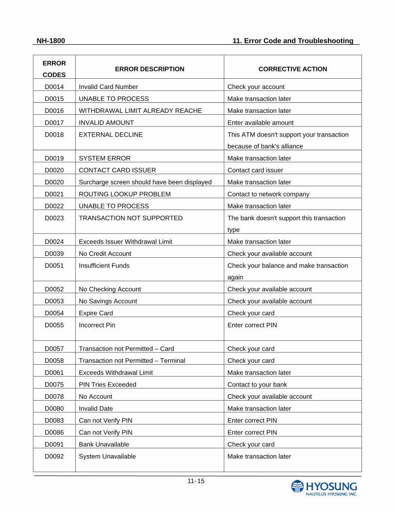
NH-1800 11. Error Code and Troubleshooting
11- 15
ERROR
CODES ERROR DESCRIPTION CORRECTIVE ACTION
D0014 Invalid Card Number Check your account
D0015 UNABLE TO PROCESS Make transaction later
D0016 WITHDRAWAL LIMIT ALREADY REACHE Make transaction later
D0017 INVALID AMOUNT Enter available amount
D0018 EXTERNAL DECLINE This ATM doesn't support your transaction
because of bank's alliance
D0019 SYSTEM ERROR Make transaction later
D0020 CONTACT CARD ISSUER Contact card issuer
D0020 Surcharge screen should have been displayed Make transaction later
D0021 ROUTING LOOKUP PROBLEM Contact to network company
D0022 UNABLE TO PROCESS Make transaction later
D0023 TRANSACTION NOT SUPPORTED The bank doesn't support this transaction
type
D0024 Exceeds Issuer Withdrawal Limit Make transaction later
D0039 No Credit Account Check your available account
D0051 Insufficient Funds Check your balance and make transaction
again
D0052 No Checking Account Check your available account
D0053 No Savings Account Check your available account
D0054 Expire Card Check your card
D0055 Incorrect Pin
Enter correct PIN
D0057 Transaction not Permitted – Card Check your card
D0058 Transaction not Permitted – Terminal Check your card
D0061 Exceeds Withdrawal Limit Make transaction later
D0075 PIN Tries Exceeded Contact to your bank
D0078 No Account Check your available account
D0080 Invalid Date Make transaction later
D0083 Can not Verify PIN Enter correct PIN
D0086 Can not Verify PIN Enter correct PIN
D0091 Bank Unavailable Check your card
D0092 System Unavailable
Make transaction later
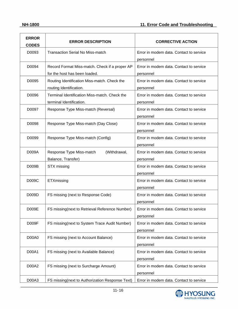
NH-1800 11. Error Code and Troubleshooting
11- 16
ERROR
CODES ERROR DESCRIPTION CORRECTIVE ACTION
D0093 Transaction Serial No Miss-match
Error in modem data. Contact to service
personnel
D0094 Record Format Miss-match. Check if a proper AP
for the host has been loaded.
Error in modem data. Contact to service
personnel
D0095 Routing Identification Miss-match. Check the
routing Identification.
Error in modem data. Contact to service
personnel
D0096 Terminal Identification Miss-match. Check the
terminal Identification.
Error in modem data. Contact to service
personnel
D0097 Response Type Miss-match (Reversal) Error in modem data. Contact to service
personnel
D0098 Response Type Miss-match (Day Close) Error in modem data. Contact to service
personnel
D0099 Response Type Miss-match (Config) Error in modem data. Contact to service
personnel
D009A Response Type Miss-match (Withdrawal,
Balance, Transfer)
Error in modem data. Contact to service
personnel
D009B STX missing Error in modem data. Contact to service
personnel
D009C ETXmissing
Error in modem data. Contact to service
personnel
D009D FS missing (next to Response Code)
Error in modem data. Contact to service
personnel
D009E FS missing(next to Retrieval Reference Number)
Error in modem data. Contact to service
personnel
D009F FS missing(next to System Trace Audit Number)
Error in modem data. Contact to service
personnel
D00A0 FS missing (next to Account Balance) Error in modem data. Contact to service
personnel
D00A1 FS missing (next to Available Balance) Error in modem data. Contact to service
personnel
D00A2 FS missing (next to Surcharge Amount) Error in modem data. Contact to service
personnel
D00A3 FS missing(next to Authorization Response Text) Error in modem data. Contact to service
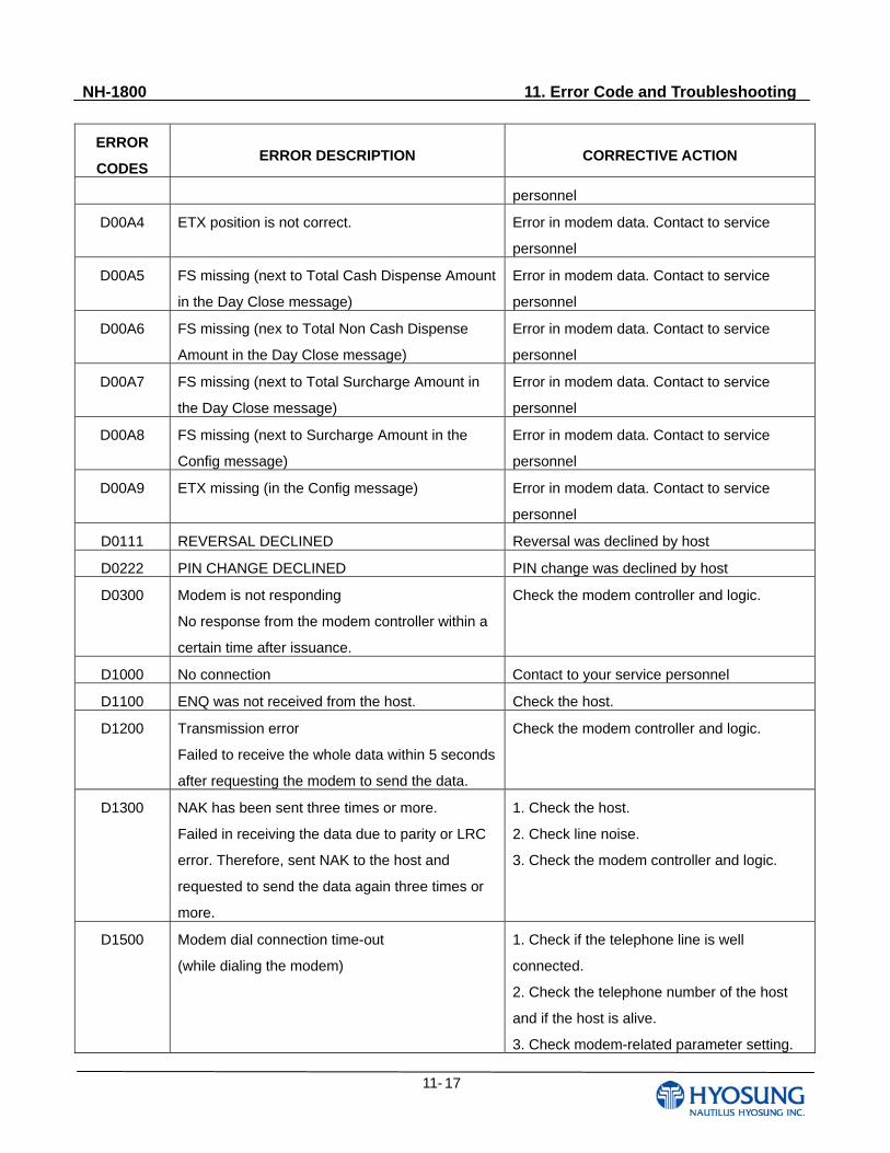
NH-1800 11. Error Code and Troubleshooting
11- 17
ERROR
CODES ERROR DESCRIPTION CORRECTIVE ACTION
personnel
D00A4 ETX position is not correct. Error in modem data. Contact to service
personnel
D00A5 FS missing (next to Total Cash Dispense Amount
in the Day Close message)
Error in modem data. Contact to service
personnel
D00A6 FS missing (nex to Total Non Cash Dispense
Amount in the Day Close message)
Error in modem data. Contact to service
personnel
D00A7 FS missing (next to Total Surcharge Amount in
the Day Close message)
Error in modem data. Contact to service
personnel
D00A8 FS missing (next to Surcharge Amount in the
Config message)
Error in modem data. Contact to service
personnel
D00A9 ETX missing (in the Config message) Error in modem data. Contact to service
personnel
D0111 REVERSAL DECLINED Reversal was declined by host
D0222 PIN CHANGE DECLINED PIN change was declined by host
D0300 Modem is not responding
No response from the modem controller within a
certain time after issuance.
Check the modem controller and logic.
D1000 No connection Contact to your service personnel
D1100 ENQ was not received from the host. Check the host.
D1200 Transmission error
Failed to receive the whole data within 5 seconds
after requesting the modem to send the data.
Check the modem controller and logic.
D1300 NAK has been sent three times or more.
Failed in receiving the data due to parity or LRC
error. Therefore, sent NAK to the host and
requested to send the data again three times or
more.
1. Check the host.
2. Check line noise.
3. Check the modem controller and logic.
D1500 Modem dial connection time-out
(while dialing the modem)
1. Check if the telephone line is well
connected.
2. Check the telephone number of the host
and if the host is alive.
3. Check modem-related parameter setting.
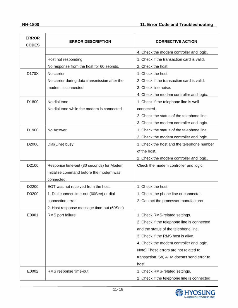
NH-1800 11. Error Code and Troubleshooting
11- 18
ERROR
CODES ERROR DESCRIPTION CORRECTIVE ACTION
4. Check the modem controller and logic.
Host not responding
No response from the host for 60 seonds.
1. Check if the transaction card is valid.
2. Check the host.
D170X No carrier
No carrier during data transmission after the
modem is connected.
1. Check the host.
2. Check if the transaction card is valid.
3. Check line noise.
4. Check the modem controller and logic.
D1800 No dial tone
No dial tone while the modem is connected.
1. Check if the telephone line is well
connected.
2. Check the status of the telephone line.
3. Check the modem controller and logic.
D1900 No Answer
1. Check the status of the telephone line.
2. Check the modem controller and logic.
D2000 Dial(Line) busy
1. Check the host and the telephone number
of the host.
2. Check the modem controller and logic.
D2100 Response time-out (30 seconds) for Modem
Initialize command before the modem was
connected.
Check the modem controller and logic.
D2200 EOT was not received from the host. 1. Check the host.
D3200 1. Dial connect time-out (60Sec) or dial
connection error
2. Host response message time-out (60Sec)
1. Check the phone line or connector.
2. Contact the processor manufacturer.
E0001 RMS port failure
1. Check RMS-related settings.
2. Check if the telephone line is connected
and the status of the telephone line.
3. Check if the RMS host is alive.
4. Check the modem controller and logic.
Note) These errors are not related to
transaction. So, ATM doesn’t send error to
host
E0002 RMS response time-out
1. Check RMS-related settings.
2. Check if the telephone line is connected
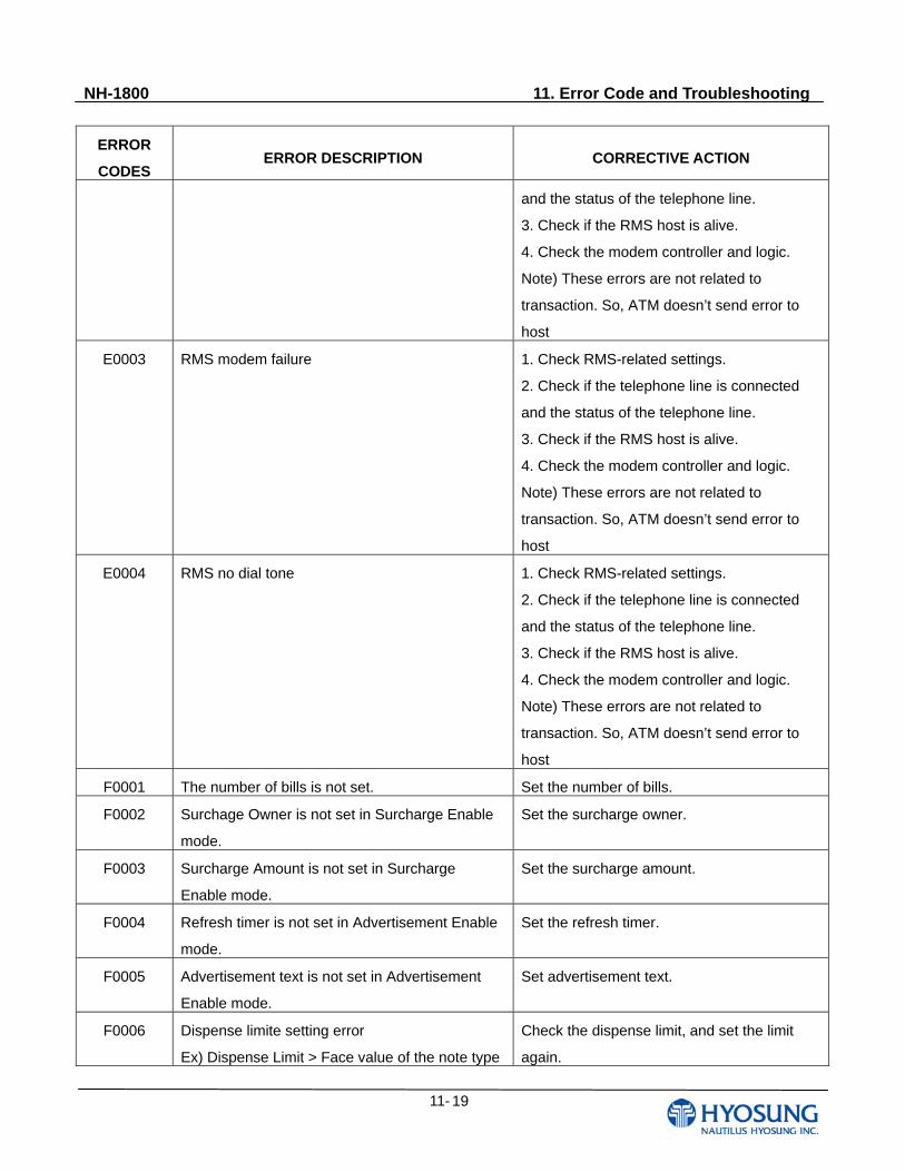
NH-1800 11. Error Code and Troubleshooting
11- 19
ERROR
CODES ERROR DESCRIPTION CORRECTIVE ACTION
and the status of the telephone line.
3. Check if the RMS host is alive.
4. Check the modem controller and logic.
Note) These errors are not related to
transaction. So, ATM doesn’t send error to
host
E0003 RMS modem failure
1. Check RMS-related settings.
2. Check if the telephone line is connected
and the status of the telephone line.
3. Check if the RMS host is alive.
4. Check the modem controller and logic.
Note) These errors are not related to
transaction. So, ATM doesn’t send error to
host
E0004 RMS no dial tone
1. Check RMS-related settings.
2. Check if the telephone line is connected
and the status of the telephone line.
3. Check if the RMS host is alive.
4. Check the modem controller and logic.
Note) These errors are not related to
transaction. So, ATM doesn’t send error to
host
F0001 The number of bills is not set. Set the number of bills.
F0002 Surchage Owner is not set in Surcharge Enable
mode.
Set the surcharge owner.
F0003 Surcharge Amount is not set in Surcharge
Enable mode.
Set the surcharge amount.
F0004 Refresh timer is not set in Advertisement Enable
mode.
Set the refresh timer.
F0005 Advertisement text is not set in Advertisement
Enable mode.
Set advertisement text.
F0006 Dispense limite setting error
Ex) Dispense Limit > Face value of the note type
Check the dispense limit, and set the limit
again.
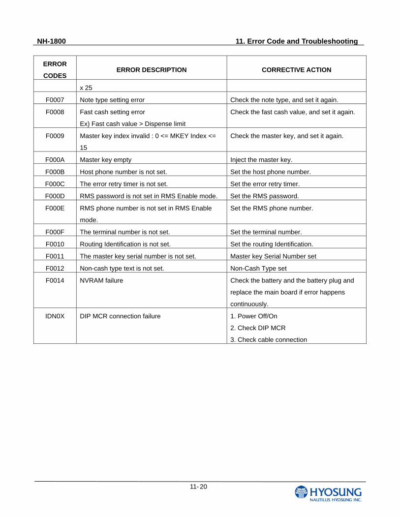
NH-1800 11. Error Code and Troubleshooting
11- 20
ERROR
CODES ERROR DESCRIPTION CORRECTIVE ACTION
x 25
F0007 Note type setting error Check the note type, and set it again.
F0008 Fast cash setting error
Ex) Fast cash value > Dispense limit
Check the fast cash value, and set it again.
F0009 Master key index invalid : 0 <= MKEY Index <=
15
Check the master key, and set it again.
F000A Master key empty Inject the master key.
F000B Host phone number is not set. Set the host phone number.
F000C The error retry timer is not set. Set the error retry timer.
F000D RMS password is not set in RMS Enable mode. Set the RMS password.
F000E RMS phone number is not set in RMS Enable
mode.
Set the RMS phone number.
F000F The terminal number is not set. Set the terminal number.
F0010 Routing Identification is not set. Set the routing Identification.
F0011 The master key serial number is not set. Master key Serial Number set
F0012 Non-cash type text is not set. Non-Cash Type set
F0014 NVRAM failure Check the battery and the battery plug and
replace the main board if error happens
continuously.
IDN0X DIP MCR connection failure 1. Power Off/On
2. Check DIP MCR
3. Check cable connection
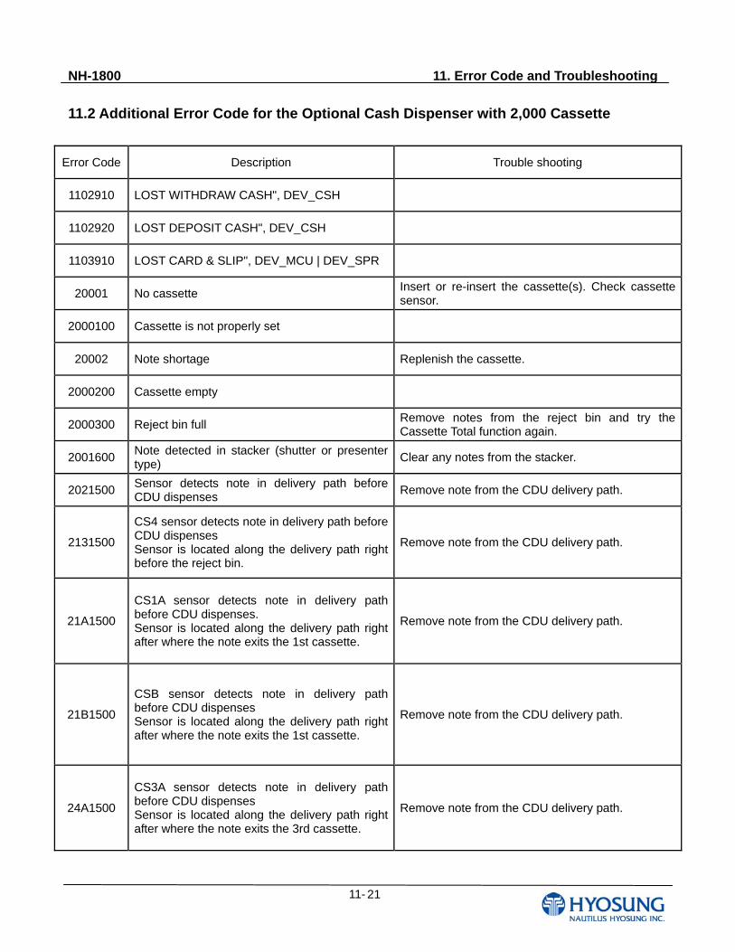
NH-1800 11. Error Code and Troubleshooting
11- 21
11.2 Additional Error Code for the Optional Cash Dispenser with 2,000 Cassette
Error Code Description Trouble shooting
1102910 LOST WITHDRAW CASH", DEV_CSH
1102920 LOST DEPOSIT CASH", DEV_CSH
1103910 LOST CARD & SLIP", DEV_MCU | DEV_SPR
20001 No cassette Insert or re-insert the cassette(s). Check cassette sensor.
2000100 Cassette is not properly set
20002 Note shortage Replenish the cassette.
2000200 Cassette empty
2000300 Reject bin full Remove notes from the reject bin and try the Cassette Total function again.
2001600 Note detected in stacker (shutter or presenter type)
Clear any notes from the stacker.
2021500 Sensor detects note in delivery path before CDU dispenses
Remove note from the CDU delivery path.
2131500
CS4 sensor detects note in delivery path before CDU dispenses Sensor is located along the delivery path right before the reject bin.
Remove note from the CDU delivery path.
21A1500
CS1A sensor detects note in delivery path before CDU dispenses. Sensor is located along the delivery path right after where the note exits the 1st cassette.
Remove note from the CDU delivery path.
21B1500
CSB sensor detects note in delivery path before CDU dispenses Sensor is located along the delivery path right after where the note exits the 1st cassette.
Remove note from the CDU delivery path.
24A1500
CS3A sensor detects note in delivery path before CDU dispenses Sensor is located along the delivery path right after where the note exits the 3rd cassette.
Remove note from the CDU delivery path.
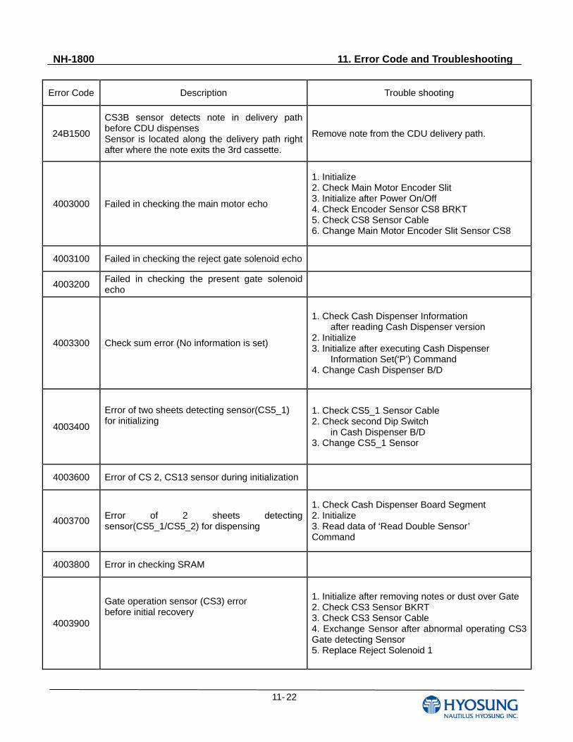
NH-1800 11. Error Code and Troubleshooting
11- 22
Error Code Description Trouble shooting
24B1500
CS3B sensor detects note in delivery path before CDU dispenses Sensor is located along the delivery path right after where the note exits the 3rd cassette.
Remove note from the CDU delivery path.
4003000 Failed in checking the main motor echo
1. Initialize 2. Check Main Motor Encoder Slit 3. Initialize after Power On/Off 4. Check Encoder Sensor CS8 BRKT 5. Check CS8 Sensor Cable 6. Change Main Motor Encoder Slit Sensor CS8
4003100 Failed in checking the reject gate solenoid echo
4003200 Failed in checking the present gate solenoid echo
4003300 Check sum error (No information is set)
1. Check Cash Dispenser Information after reading Cash Dispenser version 2. Initialize 3. Initialize after executing Cash Dispenser Information Set(‘P’) Command 4. Change Cash Dispenser B/D
4003400
Error of two sheets detecting sensor(CS5_1) for initializing
1. Check CS5_1 Sensor Cable 2. Check second Dip Switch in Cash Dispenser B/D 3. Change CS5_1 Sensor
4003600 Error of CS 2, CS13 sensor during initialization
4003700 Error of 2 sheets detecting sensor(CS5_1/CS5_2) for dispensing
1. Check Cash Dispenser Board Segment 2. Initialize 3. Read data of ‘Read Double Sensor’ Command
4003800 Error in checking SRAM
4003900
Gate operation sensor (CS3) error before initial recovery
1. Initialize after removing notes or dust over Gate 2. Check CS3 Sensor BKRT 3. Check CS3 Sensor Cable 4. Exchange Sensor after abnormal operating CS3 Gate detecting Sensor 5. Replace Reject Solenoid 1
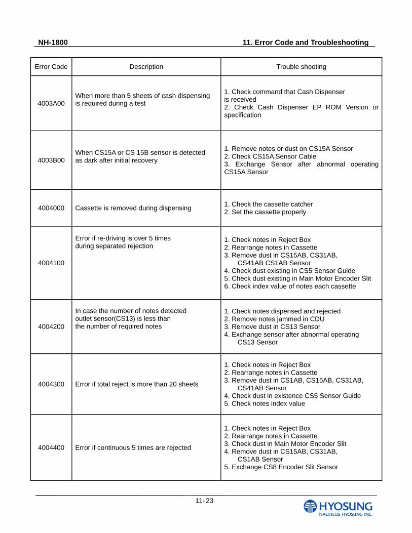
NH-1800 11. Error Code and Troubleshooting
11- 23
Error Code Description Trouble shooting
4003A00 When more than 5 sheets of cash dispensing is required during a test
1. Check command that Cash Dispenser is received 2. Check Cash Dispenser EP ROM Version or specification
4003B00 When CS15A or CS 15B sensor is detected as dark after initial recovery
1. Remove notes or dust on CS15A Sensor 2. Check CS15A Sensor Cable 3. Exchange Sensor after abnormal operating CS15A Sensor
4004000 Cassette is removed during dispensing 1. Check the cassette catcher 2. Set the cassette properly
4004100
Error if re-driving is over 5 times during separated rejection
1. Check notes in Reject Box 2. Rearrange notes in Cassette 3. Remove dust in CS15AB, CS31AB, CS41AB CS1AB Sensor 4. Check dust existing in CS5 Sensor Guide 5. Check dust existing in Main Motor Encoder Slit 6. Check index value of notes each cassette
4004200
In case the number of notes detected outlet sensor(CS13) is less than the number of required notes
1. Check notes dispensed and rejected 2. Remove notes jammed in CDU 3. Remove dust in CS13 Sensor 4. Exchange sensor after abnormal operating CS13 Sensor
4004300 Error if total reject is more than 20 sheets
1. Check notes in Reject Box 2. Rearrange notes in Cassette 3. Remove dust in CS1AB, CS15AB, CS31AB, CS41AB Sensor 4. Check dust in existence CS5 Sensor Guide 5. Check notes index value
4004400 Error if continuous 5 times are rejected
1. Check notes in Reject Box 2. Rearrange notes in Cassette 3. Check dust in Main Motor Encoder Slit 4. Remove dust in CS15AB, CS31AB, CS1AB Sensor 5. Exchange CS8 Encoder Slit Sensor
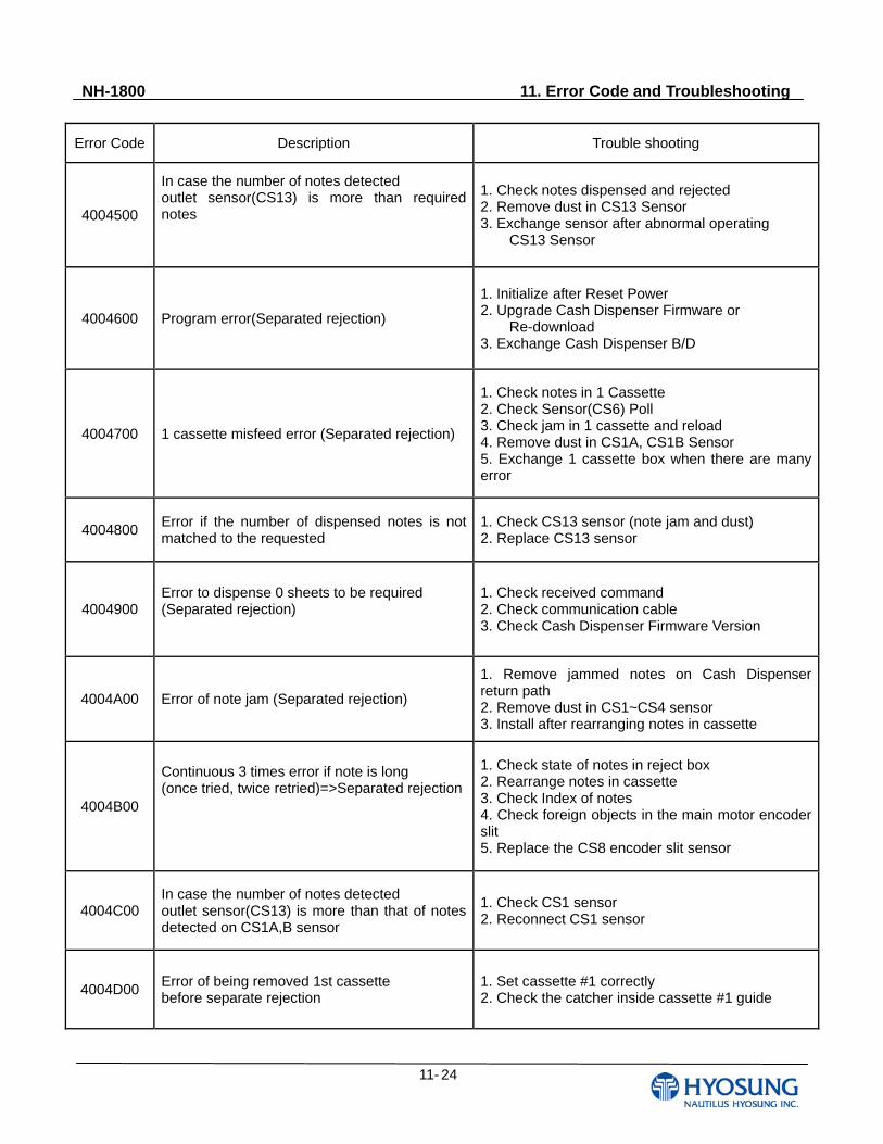
NH-1800 11. Error Code and Troubleshooting
11- 24
Error Code Description Trouble shooting
4004500
In case the number of notes detected outlet sensor(CS13) is more than required notes
1. Check notes dispensed and rejected 2. Remove dust in CS13 Sensor 3. Exchange sensor after abnormal operating CS13 Sensor
4004600 Program error(Separated rejection)
1. Initialize after Reset Power 2. Upgrade Cash Dispenser Firmware or Re-download 3. Exchange Cash Dispenser B/D
4004700 1 cassette misfeed error (Separated rejection)
1. Check notes in 1 Cassette 2. Check Sensor(CS6) Poll 3. Check jam in 1 cassette and reload 4. Remove dust in CS1A, CS1B Sensor 5. Exchange 1 cassette box when there are many error
4004800 Error if the number of dispensed notes is not matched to the requested
1. Check CS13 sensor (note jam and dust) 2. Replace CS13 sensor
4004900 Error to dispense 0 sheets to be required (Separated rejection)
1. Check received command 2. Check communication cable 3. Check Cash Dispenser Firmware Version
4004A00 Error of note jam (Separated rejection)
1. Remove jammed notes on Cash Dispenser return path 2. Remove dust in CS1~CS4 sensor 3. Install after rearranging notes in cassette
4004B00
Continuous 3 times error if note is long (once tried, twice retried)=>Separated rejection
1. Check state of notes in reject box 2. Rearrange notes in cassette 3. Check Index of notes 4. Check foreign objects in the main motor encoder slit 5. Replace the CS8 encoder slit sensor
4004C00 In case the number of notes detected outlet sensor(CS13) is more than that of notes detected on CS1A,B sensor
1. Check CS1 sensor 2. Reconnect CS1 sensor
4004D00 Error of being removed 1st cassette before separate rejection
1. Set cassette #1 correctly 2. Check the catcher inside cassette #1 guide
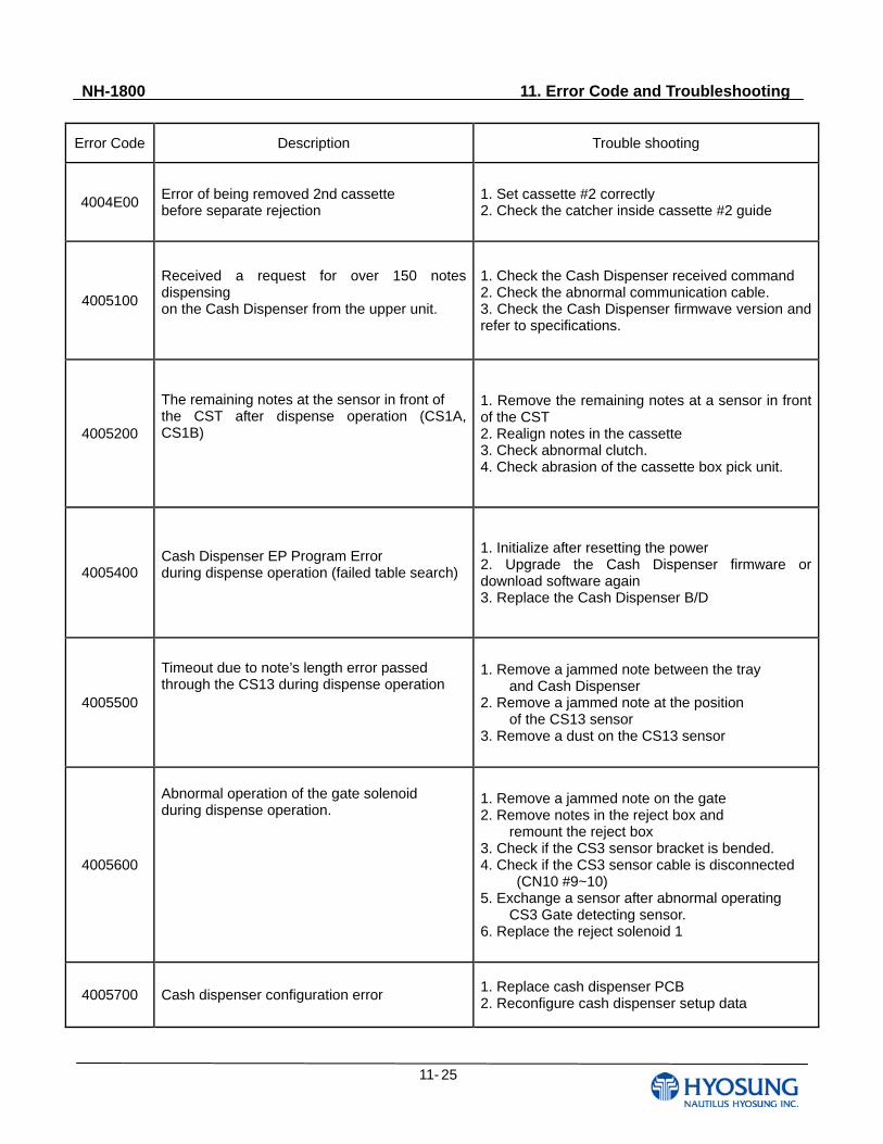
NH-1800 11. Error Code and Troubleshooting
11- 25
Error Code Description Trouble shooting
4004E00 Error of being removed 2nd cassette before separate rejection
1. Set cassette #2 correctly 2. Check the catcher inside cassette #2 guide
4005100
Received a request for over 150 notes dispensing on the Cash Dispenser from the upper unit.
1. Check the Cash Dispenser received command 2. Check the abnormal communication cable. 3. Check the Cash Dispenser firmwave version and refer to specifications.
4005200
The remaining notes at the sensor in front of the CST after dispense operation (CS1A, CS1B)
1. Remove the remaining notes at a sensor in front of the CST 2. Realign notes in the cassette 3. Check abnormal clutch. 4. Check abrasion of the cassette box pick unit.
4005400 Cash Dispenser EP Program Error during dispense operation (failed table search)
1. Initialize after resetting the power 2. Upgrade the Cash Dispenser firmware or download software again 3. Replace the Cash Dispenser B/D
4005500
Timeout due to note’s length error passed through the CS13 during dispense operation
1. Remove a jammed note between the tray and Cash Dispenser 2. Remove a jammed note at the position of the CS13 sensor 3. Remove a dust on the CS13 sensor
4005600
Abnormal operation of the gate solenoid during dispense operation.
1. Remove a jammed note on the gate 2. Remove notes in the reject box and remount the reject box 3. Check if the CS3 sensor bracket is bended. 4. Check if the CS3 sensor cable is disconnected (CN10 #9~10) 5. Exchange a sensor after abnormal operating CS3 Gate detecting sensor. 6. Replace the reject solenoid 1
4005700 Cash dispenser configuration error 1. Replace cash dispenser PCB 2. Reconfigure cash dispenser setup data
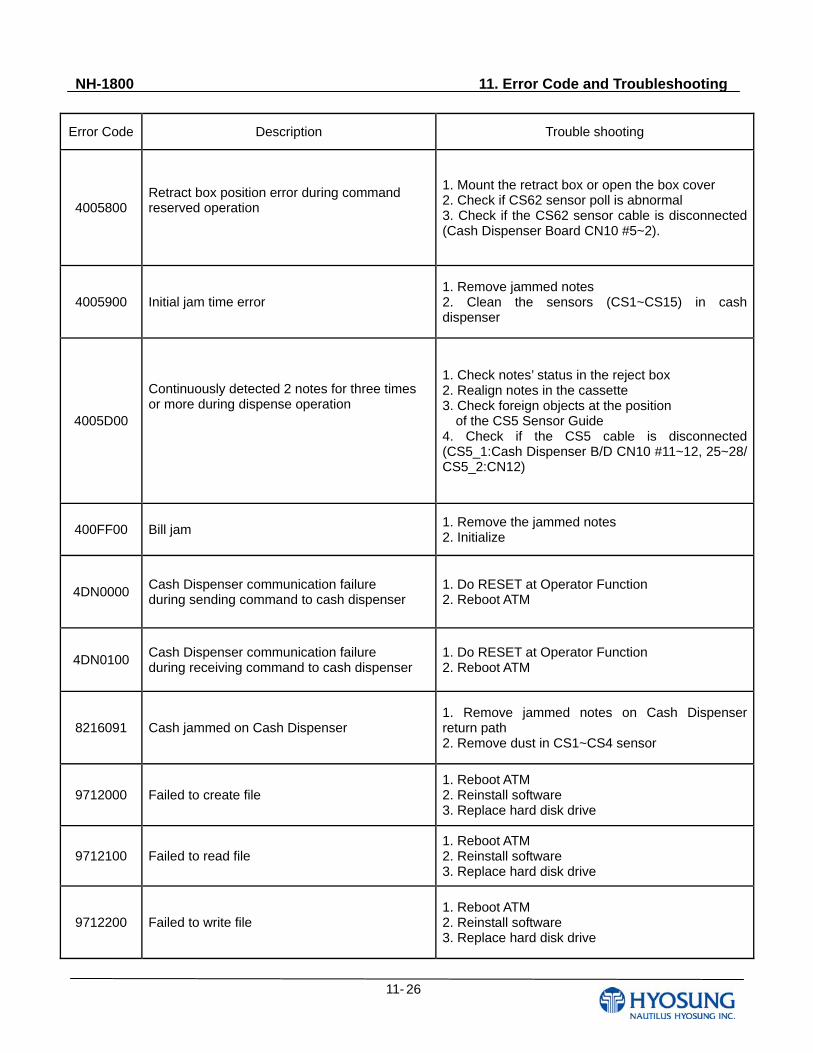
NH-1800 11. Error Code and Troubleshooting
11- 26
Error Code Description Trouble shooting
4005800 Retract box position error during command reserved operation
1. Mount the retract box or open the box cover 2. Check if CS62 sensor poll is abnormal 3. Check if the CS62 sensor cable is disconnected (Cash Dispenser Board CN10 #5~2).
4005900 Initial jam time error 1. Remove jammed notes 2. Clean the sensors (CS1~CS15) in cash dispenser
4005D00
Continuously detected 2 notes for three times or more during dispense operation
1. Check notes’ status in the reject box 2. Realign notes in the cassette 3. Check foreign objects at the position of the CS5 Sensor Guide 4. Check if the CS5 cable is disconnected (CS5_1:Cash Dispenser B/D CN10 #11~12, 25~28/ CS5_2:CN12)
400FF00 Bill jam 1. Remove the jammed notes 2. Initialize
4DN0000 Cash Dispenser communication failure during sending command to cash dispenser
1. Do RESET at Operator Function 2. Reboot ATM
4DN0100 Cash Dispenser communication failure during receiving command to cash dispenser
1. Do RESET at Operator Function 2. Reboot ATM
8216091 Cash jammed on Cash Dispenser 1. Remove jammed notes on Cash Dispenser return path 2. Remove dust in CS1~CS4 sensor
9712000 Failed to create file 1. Reboot ATM 2. Reinstall software 3. Replace hard disk drive
9712100 Failed to read file 1. Reboot ATM 2. Reinstall software 3. Replace hard disk drive
9712200 Failed to write file 1. Reboot ATM 2. Reinstall software 3. Replace hard disk drive
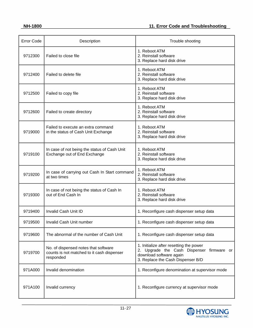
NH-1800 11. Error Code and Troubleshooting
11- 27
Error Code Description Trouble shooting
9712300 Failed to close file 1. Reboot ATM 2. Reinstall software 3. Replace hard disk drive
9712400 Failed to delete file 1. Reboot ATM 2. Reinstall software 3. Replace hard disk drive
9712500 Failed to copy file 1. Reboot ATM 2. Reinstall software 3. Replace hard disk drive
9712600 Failed to create directory 1. Reboot ATM 2. Reinstall software 3. Replace hard disk drive
9719000 Failed to execute an extra command in the status of Cash Unit Exchange
1. Reboot ATM 2. Reinstall software 3. Replace hard disk drive
9719100 In case of not being the status of Cash Unit Exchange out of End Exchange
1. Reboot ATM 2. Reinstall software 3. Replace hard disk drive
9719200 In case of carrying out Cash In Start command at two times
1. Reboot ATM 2. Reinstall software 3. Replace hard disk drive
9719300 In case of not being the status of Cash In out of End Cash In
1. Reboot ATM 2. Reinstall software 3. Replace hard disk drive
9719400 Invalid Cash Unit ID 1. Reconfigure cash dispenser setup data
9719500 Invalid Cash Unit number 1. Reconfigure cash dispenser setup data
9719600 The abnormal of the number of Cash Unit 1. Reconfigure cash dispenser setup data
9719700 No. of dispensed notes that software counts is not matched to it cash dispenser responded
1. Initialize after resetting the power 2. Upgrade the Cash Dispenser firmware or download software again 3. Replace the Cash Dispenser B/D
971A000 Invalid denomination 1. Reconfigure denomination at supervisor mode
971A100 Invalid currency 1. Reconfigure currency at supervisor mode
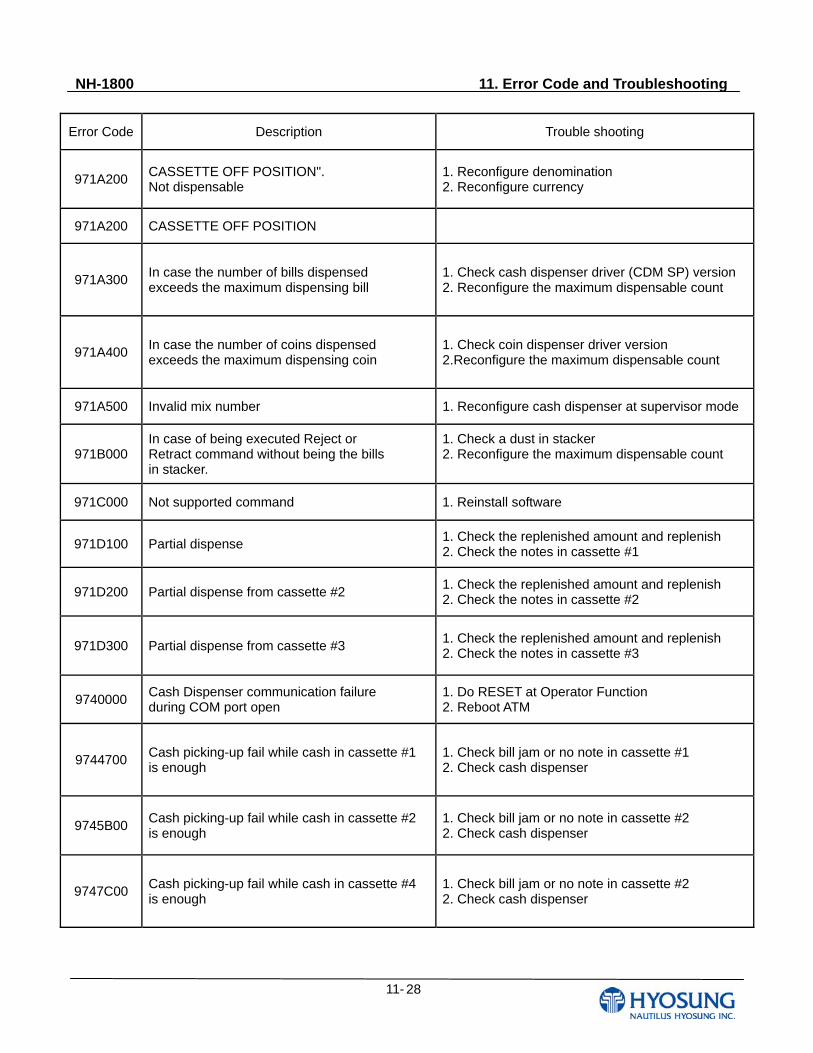
NH-1800 11. Error Code and Troubleshooting
11- 28
Error Code Description Trouble shooting
971A200 CASSETTE OFF POSITION". Not dispensable
1. Reconfigure denomination 2. Reconfigure currency
971A200 CASSETTE OFF POSITION
971A300 In case the number of bills dispensed exceeds the maximum dispensing bill
1. Check cash dispenser driver (CDM SP) version 2. Reconfigure the maximum dispensable count
971A400 In case the number of coins dispensed exceeds the maximum dispensing coin
1. Check coin dispenser driver version 2.Reconfigure the maximum dispensable count
971A500 Invalid mix number 1. Reconfigure cash dispenser at supervisor mode
971B000 In case of being executed Reject or Retract command without being the bills in stacker.
1. Check a dust in stacker 2. Reconfigure the maximum dispensable count
971C000 Not supported command 1. Reinstall software
971D100 Partial dispense 1. Check the replenished amount and replenish 2. Check the notes in cassette #1
971D200 Partial dispense from cassette #2 1. Check the replenished amount and replenish 2. Check the notes in cassette #2
971D300 Partial dispense from cassette #3 1. Check the replenished amount and replenish 2. Check the notes in cassette #3
9740000 Cash Dispenser communication failure during COM port open
1. Do RESET at Operator Function 2. Reboot ATM
9744700 Cash picking-up fail while cash in cassette #1 is enough
1. Check bill jam or no note in cassette #1 2. Check cash dispenser
9745B00 Cash picking-up fail while cash in cassette #2 is enough
1. Check bill jam or no note in cassette #2 2. Check cash dispenser
9747C00 Cash picking-up fail while cash in cassette #4 is enough
1. Check bill jam or no note in cassette #2 2. Check cash dispenser
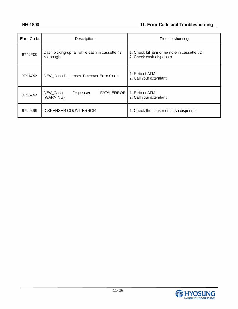
NH-1800 11. Error Code and Troubleshooting
11- 29
Error Code Description Trouble shooting
9749F00 Cash picking-up fail while cash in cassette #3 is enough
1. Check bill jam or no note in cassette #2 2. Check cash dispenser
97914XX DEV_Cash Dispenser Timeover Error Code 1. Reboot ATM 2. Call your attendant
97924XX DEV_Cash Dispenser FATALERROR (WARNING)
1. Reboot ATM 2. Call your attendant
9799499 DISPENSER COUNT ERROR 1. Check the sensor on cash dispenser