
Securing Internet Applications using Homomorphic Encryption Schemes
Upload
khangminh22Category
view
7download
0
NEW APPLICATIONS OF DATA REDUNDANCYSCHEMES IN CLOUD AND DATACENTER
SYSTEMS
A Dissertation
Presented to the Faculty of the Graduate School
of Cornell University
in Partial Fulfillment of the Requirements for the Degree of
Doctor of Philosophy
by
Hussam Abu-Libdeh
January 2015

c© 2015 Hussam Abu-Libdeh
ALL RIGHTS RESERVED
NEW APPLICATIONS OF DATA REDUNDANCY SCHEMES IN CLOUD
AND DATACENTER SYSTEMS
Hussam Abu-Libdeh, Ph.D.
Cornell University 2015
Data redundancy techniques such as replication and erasure coding have
been studied in the context of distributed systems for almost four decades. This
thesis discusses new uses of erasure coding and replication in the context of
cloud computing and datacenter systems. It shows how erasure coding can be
used to protect against vendor lock-in and how the interplay between replica-
tion and data sharding can mitigate the cost of configuration management.
BIOGRAPHICAL SKETCH
Hussam Abu-Libdeh was born in Ithaca, New York, in August of 1984. He
grew up in Ramallah, Palestine, where he attended the Catholic School of Our
Lady Annunciation. Upon graduation, he enrolled in Birzeit Universit in the
West Bank. Due to the upheaval of the second Intifada, he dropped out of
Birzeit a year later and relocated to Chicago, Illinois. He worked in Chicago
for two years while taking classes at Moraine Valley Community College be-
fore transferring to the University of Illinois at Urbana-Champaign in 2004. He
graduated with honors from the University of Illinois three years later with a
degree in Computer Science and minors in Software Engineering and Mathe-
matics. During his undergraduate studies, Hussam co-founded Kindi Software
LLC– a byte-code obfuscation company— and worked in it until starting gradu-
ate studies in Distributed Computer Systems under the tutelage of Robbert van
Renesse at Cornell University’s Department of Computer Science.
iii

To my mom and dad, Wafa and Hasan
and my siblings, Jafar, Haneen, and Hiba;
Thank you for your constant and unconditional love.
I could not have done it without your support.
iv

ACKNOWLEDGMENTS
First, I would like to express my most sincere gratitude to my advisor, Rob-
bert van Renesse. I am forever thankful for your immense patience, guidance,
and sound advice. I could not have possibly asked for a better mentor. I would
also like to extend my heartfelt gratitude to my esteemed committee members,
Fred Schneider, Robert Kleinberg, and Ross Brann; thank you for helpful in-
struction and comments.
Thank you professor Ken Birman for your undying enthusiasm, energy, and
always going out of your way to offer me help. Thank you professor Emin Gun
Sirer for your sage advice, professor Hakim Weatherspoon for your numerous
helpful tips, and professor Ross Tate for your friendship and making the last
two years that much more fun!
I would like to acknowledge my mentors and collaborators at Microsoft Re-
search: Paolo Costa, Antony Rowstron, and Doug Terry. Thank you for the op-
portunity to work with you over multiple summers, for your help, inspiration,
and advice.
To my dear friends, Ashwinkumar Badanidiyuru Varadaraja, Mathieu
Cliche, Robert Escriva, Hu Fu, Ammar Mardawi, Tudor Marian, Eoin
O’Mahony, Marlene Milan, Lev Perelman, Lina Saleh, Renato Paes Leme, Mark
Reitblatt, Marina Shepelev, Yee Jiun Song, Ymir Vigfusson; thank you for being
amazing, for being with me in the highs and lows, and for all the laughs and
memories, I could not have done it without you.
I thank Becky Stewart and Amy Finch for helping me navigate the system
smoothly, and the rest of the faculty, students, and staff of The Department of
Computer Science at Cornell University for creating a fantastic and collegial
environment that I am honored to have been a part of.
v

I would like to thank the distributed systems research community at large,
conference organizers, anonymous reviewers, and paper shepherds for their in-
put and for shaping my different publications included in this thesis. Thanks
to Brewster Kahle from the Internet Archive, Sandy Payette from Fedora Com-
mons/DuraCloud, and Werner Vogels from Amazon for access to their systems,
traces, and initial discussions about RACS.
Finally, I would like to acknowledge the different funding agencies that
made this research possible. This work was funded in part by AFOSR grant
FA9550-06-1-0019, AFRL grants FA8750-09-1-0003, FA8750-08-2-0153, FA8750-
09-1-0209, and NSF grants 0424422 and 0828923.
vi

TABLE OF CONTENTS
Biographical Sketch . . . . . . . . . . . . . . . . . . . . . . . . . . . . . . iiiDedication . . . . . . . . . . . . . . . . . . . . . . . . . . . . . . . . . . . ivAcknowledgments . . . . . . . . . . . . . . . . . . . . . . . . . . . . . . vTable of Contents . . . . . . . . . . . . . . . . . . . . . . . . . . . . . . . viiList of Tables . . . . . . . . . . . . . . . . . . . . . . . . . . . . . . . . . . ixList of Figures . . . . . . . . . . . . . . . . . . . . . . . . . . . . . . . . . x
1 Introduction 1
2 Background 52.1 Erasure Coding . . . . . . . . . . . . . . . . . . . . . . . . . . . . . 52.2 Replication . . . . . . . . . . . . . . . . . . . . . . . . . . . . . . . . 62.3 Strong Consistency . . . . . . . . . . . . . . . . . . . . . . . . . . . 72.4 Reconfiguration . . . . . . . . . . . . . . . . . . . . . . . . . . . . . 82.5 Failure Detection . . . . . . . . . . . . . . . . . . . . . . . . . . . . 82.6 Terminology . . . . . . . . . . . . . . . . . . . . . . . . . . . . . . . 9
3 Using Erasure Coding to Avoid Vendor Lock-in 103.1 Why Diversify? . . . . . . . . . . . . . . . . . . . . . . . . . . . . . 12
3.1.1 Avoiding storage-vendor lock-in . . . . . . . . . . . . . . . 133.1.2 Incentives for redundant striping . . . . . . . . . . . . . . . 15
3.2 Design . . . . . . . . . . . . . . . . . . . . . . . . . . . . . . . . . . 173.2.1 Distributed RACS . . . . . . . . . . . . . . . . . . . . . . . 193.2.2 Failure recovery . . . . . . . . . . . . . . . . . . . . . . . . . 203.2.3 Policy hints . . . . . . . . . . . . . . . . . . . . . . . . . . . 213.2.4 Repository adapters . . . . . . . . . . . . . . . . . . . . . . 213.2.5 Performance overhead . . . . . . . . . . . . . . . . . . . . . 223.2.6 RACS prototype implementation . . . . . . . . . . . . . . . 23
3.3 An Internet Archive in the Cloud . . . . . . . . . . . . . . . . . . . 243.3.1 Trace characteristics . . . . . . . . . . . . . . . . . . . . . . 253.3.2 Cost of moving to the cloud . . . . . . . . . . . . . . . . . . 273.3.3 Cost of vendor lock-in . . . . . . . . . . . . . . . . . . . . . 303.3.4 Tolerating price hikes . . . . . . . . . . . . . . . . . . . . . 31
3.4 Prototype Evaluation . . . . . . . . . . . . . . . . . . . . . . . . . . 323.4.1 Benchmarks . . . . . . . . . . . . . . . . . . . . . . . . . . . 333.4.2 Performance . . . . . . . . . . . . . . . . . . . . . . . . . . . 36
4 Leveraging Sharding in the Design of Scalable Replication Protocols 384.1 Elastic Replication . . . . . . . . . . . . . . . . . . . . . . . . . . . . 40
4.1.1 Environment model . . . . . . . . . . . . . . . . . . . . . . 404.1.2 Replicating single shards . . . . . . . . . . . . . . . . . . . 414.1.3 Safety and refinement mapping . . . . . . . . . . . . . . . . 47
vii

4.1.4 Elastic bands . . . . . . . . . . . . . . . . . . . . . . . . . . 524.1.5 Liveness . . . . . . . . . . . . . . . . . . . . . . . . . . . . . 544.1.6 Practical considerations . . . . . . . . . . . . . . . . . . . . 564.1.7 Implementation . . . . . . . . . . . . . . . . . . . . . . . . . 574.1.8 Reconfiguration discussion . . . . . . . . . . . . . . . . . . 594.1.9 Comparing ER with other protocols . . . . . . . . . . . . . 60
4.2 Evaluation . . . . . . . . . . . . . . . . . . . . . . . . . . . . . . . . 634.2.1 Liveness condition . . . . . . . . . . . . . . . . . . . . . . . 634.2.2 Elastic replication vs. CCM . . . . . . . . . . . . . . . . . . 654.2.3 Experimental setup . . . . . . . . . . . . . . . . . . . . . . . 664.2.4 Key-value store overview . . . . . . . . . . . . . . . . . . . 674.2.5 Single shard performance . . . . . . . . . . . . . . . . . . . 684.2.6 Band maintenance . . . . . . . . . . . . . . . . . . . . . . . 714.2.7 Shard maintenance . . . . . . . . . . . . . . . . . . . . . . . 734.2.8 Failure tolerance . . . . . . . . . . . . . . . . . . . . . . . . 74
5 Future Directions: Unified Partitioning 765.1 System Model and Terminology . . . . . . . . . . . . . . . . . . . . 775.2 Partitioned State Machines . . . . . . . . . . . . . . . . . . . . . . . 795.3 Current Status . . . . . . . . . . . . . . . . . . . . . . . . . . . . . . 81
5.3.1 libdist overview . . . . . . . . . . . . . . . . . . . . . . . . . 825.4 Discussion . . . . . . . . . . . . . . . . . . . . . . . . . . . . . . . . 85
5.4.1 Hybrid replication protocols . . . . . . . . . . . . . . . . . 855.4.2 Availability of flat and nested quorums . . . . . . . . . . . 885.4.3 Beyond new protocols . . . . . . . . . . . . . . . . . . . . . 88
6 Conclusion and Related Work 91
Bibliography 96
viii
LIST OF TABLES
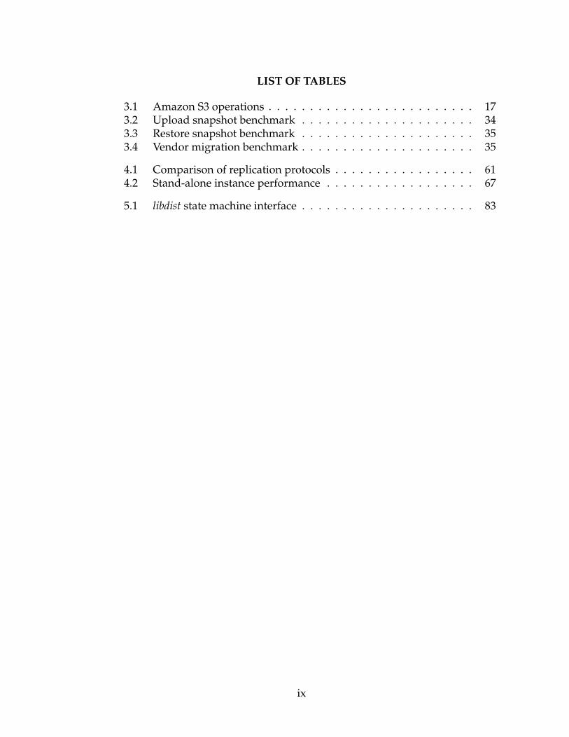
3.1 Amazon S3 operations . . . . . . . . . . . . . . . . . . . . . . . . . 173.2 Upload snapshot benchmark . . . . . . . . . . . . . . . . . . . . . 343.3 Restore snapshot benchmark . . . . . . . . . . . . . . . . . . . . . 353.4 Vendor migration benchmark . . . . . . . . . . . . . . . . . . . . . 35
4.1 Comparison of replication protocols . . . . . . . . . . . . . . . . . 614.2 Stand-alone instance performance . . . . . . . . . . . . . . . . . . 67
5.1 libdist state machine interface . . . . . . . . . . . . . . . . . . . . . 83
ix

LIST OF FIGURES
2.1 ZooKeeper client notification delay . . . . . . . . . . . . . . . . . 9
3.1 RACS single-proxy architecture . . . . . . . . . . . . . . . . . . . 193.2 RACS multi-proxy architecture . . . . . . . . . . . . . . . . . . . . 203.3 Inbound and outbound data transfers in the Internet Archive trace 263.4 Read/write requests in the Internet Archive trace . . . . . . . . . 273.5 Estimated monthly costs of hosting on the cloud . . . . . . . . . . 283.6 Breakdown of monthly cloud storage costs . . . . . . . . . . . . . 293.7 Month-by-month switching benefit (non-RACs solution) . . . . . 303.8 Month-by-month switching costs for various configurations . . . 313.9 Tolerating a vendor price hike . . . . . . . . . . . . . . . . . . . . 323.10 RACS vs. Rackspace put and get latencies . . . . . . . . . . . . 36
4.1 Shard specification . . . . . . . . . . . . . . . . . . . . . . . . . . . 414.2 Specification of elastic replicas . . . . . . . . . . . . . . . . . . . . 454.3 Illustration of an elastic band . . . . . . . . . . . . . . . . . . . . . 524.4 Additional Replica transitions . . . . . . . . . . . . . . . . . . . . . 564.5 Probability of violating the liveness condition . . . . . . . . . . . 654.6 CCM vs elastic band . . . . . . . . . . . . . . . . . . . . . . . . . . 664.7 Shard read/write throughput . . . . . . . . . . . . . . . . . . . . . 694.8 Shard read latency . . . . . . . . . . . . . . . . . . . . . . . . . . . 704.9 Shard read throughput . . . . . . . . . . . . . . . . . . . . . . . . 704.10 Throughput during elastic band reconfiguration . . . . . . . . . . 714.11 Throughput during shard split/merge . . . . . . . . . . . . . . . 734.12 Throughput during shard reconfiguration . . . . . . . . . . . . . 744.13 Downtime due to replica failure . . . . . . . . . . . . . . . . . . . 75
5.1 Architectural view of a chain/broadcast hybrid protocol . . . . . 865.2 Read throughput the hybrid protocol . . . . . . . . . . . . . . . . 875.3 Availability of flat and nested 9-process quorums . . . . . . . . . 89
x

CHAPTER 1
INTRODUCTION
Replication and erasure coding have been studied and compared exten-
sively as two techniques for using data redundancy to build highly available
distributed systems [34, 101, 119]. At its simplest, replication is the creation of
multiple copies of a possibly mutating object with the intention of providing
high availability or performance. The replicated object can be a record, file,
application state, file system, an entire database, and so on. Processes that par-
ticipate in a replication scheme are referred to as replicas. Replication has been
discussed for four decades in database and distributed systems literature, and
a variety of replication protocols have been developed for a variety of systems,
environments, and objectives [43].
There are two general categories of replication protocols: active replication
and passive replication. In active replication, also known as state machine replica-
tion [105], client operations are ordered by a protocol and forwarded to a col-
lection of replicas that execute the operations independently, and in order. In
passive replication, some times referred to as primary backup replication, one of
the replicas is designated as a primary. It executes client operations and sends
the resulting state updates to other replicas. These pure approaches have vari-
ous advantages and drawbacks when compared with one another, and various
hybrid solutions have been developed. For example, active replication cannot
deal with non-deterministic processing and can waste computational resources
if operations are compute-intensive. On the other hand, passive replication can
waste network bandwidth if state updates are large, and it cannot mask the
failure of a primary replica without detection and recovery, which may lead to
performance degradation.
1

Replication protocols differ in replication degree (number of copies) and
replica placement strategies, depending on their design goals. When replicating
for high availability, replicas are assumed to fail independently and that is often
achieved through diversifying the hardware and software stacks, as well as the
network and power connections to the different replicas. On the other hand,
when replicating for high performance, diversity is less important, and a higher
degree of replication is favored in order to have a sufficient number of replicas
to meet the load demands imposed on the replicated object.
Assumptions about the underlying environment model are another axis of
differentiation between replication protocols. Some replication protocols as-
sume a synchronous environment, with its bounds on message and process-
ing delays; other protocols assume an asynchronous environment, with no such
bounds. Similarly, some protocols assume bounds on clock drifts and others do
not. Like synchrony assumptions, failure assumptions affect the complexity of
protocols. A fail-stop model [104] assumes that processes follow their specifica-
tion until they crash, after which, they don’t perform any action, and their crash
is eventually detected by all non-crashed processes that, in turn, do not suspect
any non-crashed process of having crashed. This model makes strong assump-
tions, but it results in very simple protocols. Other models make weaker failure
assumptions, resulting in more complex systems.
The computational complexity of storing and retrieving data is another
tradeoff. Replication protocols store complete copies of replicated objects at the
different replicas. This minimizes the computing cost at the expense of storage
requirements. Erasure coding reduces storage cost by dividing an object into n
fragments where m of which are sufficient to reconstruct it for m < n. This
scheme tolerates the loss of any n − m fragments of the data but comes with
2

the expense of creating fragments from objects and reconstructing objects from
fragments.
In this thesis, we present new uses of redundancy schemes for systems run-
ning in datacenters and/or that rely on cloud computing services. The National
Institute of Standards and Technology defines Cloud computing as a “model for
enabling ubiquitous, convenient, on-demand network access to a shared pool
of configurable computing resources (e.g., networks, servers, storage, appli-
cations, and services) that can be rapidly provisioned and released with min-
imal management effort or service provider interaction” [86]. Cloud service
providers often manage warehouses, referred to as dataceters, with hundreds
of thousands of machines. Access to these machines is offered as services in
many forms, including infrastructure-as-a-service (storage, computation nodes,
virtualized networks), platform-as-a-service (an integrated storage and compu-
tational framework), and application-as-a-service (such as hosted E-Mail and
Customer Relation Management Systems). Cloud computing allows develop-
ers to harness the power of scalable, highly-available, infrastructure systems
without having to invest time and money to build that infrastructure. Cloud
computing, and its pay-as-you-go business model, gained wide-spread popu-
larity with developers and organizations alike. Cloud computing has affected
academic studies, and most of the literature published on distributed systems
today targets cloud computing and datacenter settings.
These environments exhibit many of the traits of environments that have
been studied extensively in the past, but they also add unique characteristics.
In this thesis, we are interested in the economic factors of cloud computing in-
troduced by competing vendors and the pay-as-you-go business model, as well
as ubiquitous use of horizontal scaling via data partitioning (henceforth referred
3

to as data sharding). In subsequent chapters we discuss the use of erasure coding
to protect against cloud-storage vendor lock-in, and we exploit the ubiquitous
use of sharding in datacenter services to avoid centralized configuration man-
agement services.
4

CHAPTER 2
BACKGROUND
To put the discussion in context, we first present some background. Addi-
tional related work is discussed in the other chapters.
2.1 Erasure Coding
Erasure coding is a forward error correction code that provides fault tolerance
and prevents data loss without the overhead of full replication [45, 56, 98, 119].
There are three types of erasure-codes: optimal, near optimal, and rateless. Op-
timal erasure-codes, such as Reed-Solomon [38, 93, 99], encode an object into n
fragments, any m of which are sufficient to reconstruct the object (m < n). We
call r = mn< 1 the rate of encoding. A rate r optimal erasure-code increases
the storage cost by a factor of 1r. For example, an r = 1
4encoding might pro-
duce n = 64 fragments, any m = 16 of which are sufficient to reconstruct the
object, resulting in a total overhead factor of 1r
= nm
= 6416
= 4. Note that m = 1
represents full replication; and RAID level 5 [92] can be described by (m = 4,
n = 5). Unfortunately, optimal erasure-codes are costly (in terms of memory
usage and/or processor time) when m is large, so near optimal erasure codes
such as Tornado codes [81,82] are often used. These near optimal erasure-codes
require (1+ε)m fragments to recover the data object. Reducing ε can be done at
the cost of increasing processor time. Alternatively, rateless erasure codes such
as LT [80], Online [85], or Raptor [107], codes transform a data object of m frag-
ments into a practically infinite encoded form. We assume the use of optimal
erasure-codes unless otherwise noted.
Weatherspoon and Kubiatowicz illustrated that large numbers of fragments
provide greatly increased durability [119]. More importantly, using erasure-
5

coding instead of replication can reduce network bandwidth and storage capac-
ity requirements by an order of magnitude without compromising data dura-
bility or availability [33, 37, 119].
However, there are negative consequences to using erasure-codes. Erasure-
codes and their checksum [120] are expensive to produce. For example,
Pond’s [97] performance was limited by erasure-coding; producing erasure-
encoded fragments contributed more than 72% (566.9 ms out of 782.7 ms for
a 2MB update) of the write latency. So there is a tradeoff between CPU costs
and network efficiency when considering between erasure-codes and replica-
tion. Additionally, if a metadata layer individually accounts for each fragment,
this layer can be overloaded with location pointers. In order to prevent this
problem, fragments need to be aggregated (e.g. extents), so their individual cost
can be amortized. Further, repair is more complicated with erasure-codes, since
a complete data object would have to be reconstructed to produce a new frag-
ment for repair. This repair read adds extra complexity and cost to the erasure
encoded system. However, reconstructed data objects can be cached to reduce
costs (eliminate read requirement) of subsequent repairs.
2.2 Replication
Modern datacenter services rely primarily on two approaches to replication:
Primary-backup and quorum intersection protocols. Primary-backup [22, 40] is
used in systems such as GFS and HDFS [62, 109]. A primary replica receives
all updates, orders them, and forwards them in FIFO order to the non-faulty
backup replicas. In case of an unresponsive primary, another replica may be-
come primary following reconfiguration by a configuration management ser-
vice. If the original primary was mistakenly suspected of having failed, a client
6

may read the result of some update operation to the original primary that is not
applied, and never will be, to the new primary, resulting in divergence. In order
to avoid divergence, clients track the current active configuration as maintained
by the configuration manager.
Quorum intersection protocols are particularly useful for put/get-type
Key-Value Stores such as Amazon’s Dynamo and Apache Cassandra [53, 73].
In these, a put operation, accompanied by a timestamp, is sent to a “put-
quorum,” while a get operation reads from a “get-quorum” (and returns the
result with the highest timestamp). By making quorums smaller than the entire
set of replicas, availability and performance are achieved. By guaranteeing that
any put-quorum and get-quorum intersect, a get can be guaranteed to see
the latest completed put operation. However, divergence can still occur in the
case of dynamic reconfiguration of replicas as quorums may temporarily fail to
intersect [53].
2.3 Strong Consistency
A memory consistency model formally specifies how a system appears to program-
mers, and restricts what values can be returned by a read operation in a shared-
memory program execution [20]. Weak consistency models make few (if any)
restrictions or guarantees, and are often phrased in terms of “in the lack of future
updates, the system will eventually . . . ”. While weak consistency models have
enabled the large-scale distributed systems of today’s cloud computing environ-
ments, such guarantees are not suitable for all applications. So, developers go
to extraordinary lengths to work around weak consistency guarantees [17,108].
In this thesis, chiefly in Chapter 4, linearizable consistency is used as the strong
consistency model. Linearizable consistency stipulates that all operations ap-
7

pear to clients to have executed between the real time of their invocation and
when they receive a response [68]. Strong consistency protocols often rely on
majority voting techniques, where 2f + 1 replicas are required to tolerate f fail-
ures. Using 2f + 1 replicas, as is the case in Paxos and Quorum Replication sys-
tems, is not only expensive in terms of resources, but it is also harder to ensure
that the larger number of replicas fail independently. Also, reconfiguration—
important to service expansion, migration, or software updates in the cloud—is
difficult while maintaining strong consistency.
2.4 Reconfiguration
Deployment parameters, such as machine address, port numbers, file paths,
disk mount points, protocol parameters. . . , are collectively referred to as a con-
figuration of the system. For the purposes of our discussion in Chapter 4, the
configuration of a distributed system describes the list of replicas in a replicated
system. A replicated system is often reconfigured in order to change its replicas,
remove faulty ones, or insert new replicas.
In cloud services, using coordination services or lock services as centralized
configuration services, such as Chubby [41] and ZooKeeper [69], is increasingly
common.
2.5 Failure Detection
Some simple replication protocols, e.g., Primary-backup, assume a fail-stop
model with perfect failure detection [114]. In practice, timeouts are often used
to detect failures in these protocols, and the choice of timeout values involves a
trade-off between the liveness and safety of the system.
8

0
200
400
600
800
1000
1200
100 500 1000 D
elay
afte
r fir
st c
lient
(m
sec)!
Number of clients!
90th Percentile!99th Percentile!
Figure 2.1: ZooKeeper client notification delay
Even with a centralized configuration manager, like Zookeeper or Chubby,
there could be a delay until all clients learn of a new configuration, as demon-
strated in Figure 2.1. In this experiment, we used Zookeeper to manage the con-
figuration of a replicated service, forced a configuration change, and measured
the latency until 90% and 99% of the clients get notified of the new configuration
after the first client is notified. Late notifications about changes could result in
inconsistencies, if clients interact with a defunct primary or an old replica.
2.6 Terminology
In this thesis we use the terms node and server synonymously. A process is a
program executing on a server. A replica is a process that is executing a repli-
cation protocol. In the discussion of replication protocols, all four terms (node,
server, process, replica) will be used synonymously. In a running system, dif-
ferent replicas might be running on the same physical machine. This lessens
the failure-tolerance of the system, as these collocated replicas are not failure-
independent; a failure in the physical machine might cause both replicas to fail.
9

CHAPTER 3
USING ERASURE CODING TO AVOID VENDOR LOCK-IN
An increasing number of companies and organizations are migrating data to
cloud storage providers [111]. Examples include: Storing online users’ account
data, off-site backup storage, and content distribution. One impressive pilot
program and motivating example is the United States Library of Congress’s
move its digitized content to the cloud [21]. Other participants in that program
include the New York Public Library and the Biodiversity Heritage Library.
For a service to depend solely on a particular cloud storage provider brings
risks. Even though different cloud storage providers offer nearly identical com-
modities, customers can experience vendor lock-in: It can be prohibitively ex-
pensive for a client to switch from one provider to another. Storage providers
charge clients for each request, inbound/outbound transfer bandwidth, as well
as for hosting the actual data. Thus, a client moving from one provider to an-
other pays for bandwidth twice, in addition to the actual cost of online stor-
age. This doubled cost of moving data leads to a kind of data inertia; the more
data stored with one provider, the more difficult it becomes to move to another
provider. This cost must be taken into consideration by consumers of cloud stor-
age, lest they be locked-in to less-than-ideal vendors after entrusting them with
their data. The resulting vendor lock-in gives storage providers leverage over
clients with large amounts of data. In particular, clients can become vulnera-
ble to price hikes by vendors, and will not be able to cheaply move to new and
better options when they become available. The quickly-evolving cloud storage
marketplace makes this concern more real: Today’s best decision may leave the
customer trapped with an obsolete provider later due to vendor lock-in.
10

In addition to possible increased costs, vendor lock-in subjects customers to
the possibility of data loss if a provider goes out of business or suffers a catas-
trophe. Even though cloud operators commit to strict service-level agreements
(SLAs) [3, 10, 16] with impressive up-times and response delays, failures and
outages do occur [2, 15]. Recent incidents have shown how failures at cloud
providers can result in mass data loss for customers, and that outages can last
up to several hours [6].
Since cloud storage is, for the most part, a commodity, customers can guard
against vendor lock-in by replicating data at multiple providers. This approach,
however, incurs high storage and bandwidth costs. A more economical ap-
proach is to spread the data across multiple providers and introduce redun-
dancy to tolerate possible failures or outages, but stopping short of full repli-
cation. This is similar to what has been done for years with disks and file sys-
tems. For example, the Redundant Array of Inexpensive Disks (RAID) technol-
ogy stripes data across an array of disks and maintains parity data that can be
used to reconstruct the contents of any individual failed disk.
In this chapter we argue that similar techniques should be employed
with to cloud storage, although the failure model differs somewhat. We de-
scribe RACS (Redundant Array of Cloud Storage), a cloud storage proxy that
transparently stripes data across multiple cloud storage providers. RACS
reduces the one-time cost of switching storage providers in exchange for
additional operational overhead. RACS assumes a small storage interface
(put, get, delete, list) and exposes that interface to its applications.
This system makes several contributions. We show through simulation and
real-life pricing models that, through careful design, it is possible to tolerate out-
ages and mitigate vendor lock-in with reasonable cost overhead. We also show
11

the cost of switching cloud storage vendors for a large organization through
trace-driven simulation. Finally, we build and evaluate a working prototype
of RACS that is compatible with existing Amazon S3 clients and is able to use
multiple storage providers as back-ends; we then demonstrate its effectiveness
on end-user traces.
3.1 Why Diversify?
Hosted data storage is a commodity, and it is fungible. Certainly, cloud stor-
age providers do distinguish themselves by offering services above-and-beyond
basic storage. Often, these services involve integration with other cloud com-
puting products; for example, Amazon’s EC2 and Cloudfront are deeply in-
tertwined with S3. But many consumers just want reliable, elastic, and highly
available online storage. Because of this, cloud storage providers aggressively
compete on price, knowing that price will be the ultimate deciding factor for
many consumers. Providers also compete on guarantees of uptime and avail-
ability, in the form of SLAs. These guarantees are satisfied by systems metic-
ulously designed to handle load balancing, recurring data backup, and repli-
cation to handle component failures seamlessly. So one could understandably
question if there’s really any benefit to be had by adding even more redundancy
to the system and spreading data across multiple providers.
To address this question, we distinguish between two different kinds of fail-
ures:
Outages: Hardware or software failures, misconfigurations, or unfortunate
events leading to data loss in the cloud. As mentioned, cloud providers
already offer strong protection against component failures, so there is a
weak case for adding another safety measure on top of cloud storage sys-
12

tems. Still, it does happen occasionally that an outage strikes the cloud;
for instance, a failure in October 2009 at a Microsoft data center resulted
in data loss for many T-Mobile smart phone users [70].
Economic Failures: We define economic failure to be the situation where a
change in the marketplace renders it prohibitively expensive for a cloud
storage consumer to continue to use a service. For example, prior to June
30, 2010, there were no bandwidth charge for uploading data to Amazon
S3. But on June 30, 2010, Amazon started charging fifteen cents per giga-
byte. A customer who relies on a heavy volume of uploads, such as an
online backup business, might find this change too costly to maintain a
profitable business.
We focus the discussion in this chapter primarily on economic failure.
3.1.1 Avoiding storage-vendor lock-in
Cloud storage services differ in price and performance. Some providers charge
a flat monthly fee, others negotiate contracts with individual clients, and still
others offer discounts for large volume as temporary promotional incentives,
or for off-peak hours. Some providers may be desirable for geographic rea-
sons (Amazon offers different zones for the United States, Europe, Asia Pacific,
and South America), and others might offer extra features, such as publishing
files directly to the web or access via mountable file systems. Changes in these
features, and emergence of new providers with more desirable characteristics,
could incentivize a client to switch from one storage service to another. How-
ever, because of data inertia, clients may not be free to choose a better vendor,
due to prohibitively high costs in switching from one provider to another. This
13

puts the client at a disadvantage when a vendor raises prices or negotiates a
new contract.
Consider a situation where a new provider with a low pricing scheme
emerges on the market. A client at an old storage service provider has to make
an all-or-nothing decision about that service. The client either moves all its data
to the new provider and incurs the cost of switching to gain the benefit of lower
prices, or it stays at the old provider and saves the cost of switching with the
risk of incurring higher costs in the long run. The problem, of course, is that
the client cannot predict the future, so the client cannot know if and when the
current provider will lower prices to compete with the other providers. From
the client’s view, a premature switch can be worse than not switching, and a
late switch might have lost its value. Of course, this dilemma is not limited to
price changes. Clients might remain with an under-performing provider simply
because switching to better providers is deemed too costly.
One way to facilitate client agility for responding to provider changes is to
make switching and data placement decisions at a finer granularity than all-
or-nothing. This fine granularity can be achieved by striping the client’s data
across multiple providers. For example, if a client spreads data across several
providers, then taking advantage of a new fast provider entails switching only
a fraction of the data, which could be more attractive economically.
Of course, striping data across multiple providers adds costs, due to pricing
differences between providers. However, as we show below, the differences are
low and can be mitigated by choosing clever striping schemes.
14

3.1.2 Incentives for redundant striping
We have argued that striping data across multiple providers facilitates client
agility. We now argue that by adding redundancy to data striping, clients can
maintain this mobility while protecting against outages.
Below is a brief description of what clients gain from erasure coding across
multiple providers:
• Tolerating Outages. Although storage providers offer highly available
services, even the best providers suffer occasional mishaps. Inopportune
outages can last for several hours [2,6,15] and can result in severe financial
losses for the providers and consumers of the storage service. Data redun-
dancy across multiple providers allows clients to mask temporary outages
and get higher data availability.
• Tolerating Data Loss. Storage providers implement internal redundancy
and replication schemes to avoid accidental data loss. However, recent
experience shows that hosted data could still be lost [70]. Storing re-
dundant data copies at multiple, failure-independent, storage providers
allows consumers to mask the failure of, or data loss at, any individual
providers.
A simple way to tolerate provider failure is by replicating data at multiple
providers. However, this approach is costly, since the overhead per replica
is 100% the size of the data. A more economically sensible approach is
to lower the redundancy overhead by using erasure coding and striping
the data (and redundant) blocks across multiple providers to tolerate the
failure of one or more of them.
• Adapting to Price Changes. Redundancy via erasure coding allows
clients to make migration decisions at a lower granularity. For example,
15

clients can adapt to changes in storage providers’ prices by fetching era-
sure coded data fragments from cheaper providers. If a provider becomes
too expensive, clients can avoid reading from it and reconstruct its data
from the redundancy at other locations.
• Incorporating New Providers. If a new service provider enters the mar-
ket, clients can include it in future erasure codes.
• Controling Spending. Second-tier cloud storage providers, such as
DreamHost’s DreamObject [7], offer low-priced storage at lower perfor-
mance, compared to leading cloud storage providers such as Amazon’s S3,
Windows Azure Storage, and Rackspace Cloudfiles. By using a mixture of
leading providers, second-tier storage services, and local servers, clients
can control the cost of storing and serving data. For example, second-tier
storage services might not be powerful or reliable enough to handle the
entirety of the storage load, but by storing redundant copies of data on
them, clients can use them in some accesses in order to lower the overall
cost of storage.
• Choice in Data Recovery. In the event of a failure of one or more online
storage providers, redundancy gives clients multiple strategies for recov-
ering the lost data. For example, clients might choose to reconstruct the
missing data from some providers but not others. Another approach is
to reconstruct the data lazily, by reconstructing missing data only in re-
sponse to client requests. Or, if the degree of redundancy is sufficient,
clients might even choose to ignore the failed provider and continue oper-
ation without reconstruction.
In short, if clients use a single provider, then they would not be able to toler-
ate that provider’s failure. Replicating data to multiple providers allows clients
16

put bucket, key, objectget bucket, keydelete bucket, keycreate bucketdelete bucketlist keys in bucketlist all buckets
Table 3.1: Amazon S3 operations
to tolerate failures, but at a high cost. In comparison, erasure coding and strip-
ing data across multiple providers allows clients to tolerate provider failures
at a lower cost than replication. Additionally, data redundancy across storage
providers allows clients to implement different strategies and optimize for dif-
ferent objectives in storing and accessing data.
3.2 Design
RACS exports an interface similar to Amazon S3 which stores data in named
buckets. Each bucket is a flat namespace, containing keys and the associated ob-
jects. A bucket cannot contain other buckets. Objects can be of arbitrary size, up
to 5 gigabytes. Partial writes to objects are not allowed; objects must be writ-
ten in their entirety, but partial reads are allowed. We chose to export Amazon
S3’s interface for two reasons; first, it is simple and easy to work with. Second,
its popularity means that existing client applications can use RACS. In what
follows, we discuss how RACS implements the core subset of S3’s operations,
shown in Table 3.1.
S3 exports two remote procedure call APIs: SOAP and REST, which use stan-
dard HTTP headers and commands. RACS implements only the REST API,
which is more widely used, but there is no reason it could not be extended to
provide a SOAP interface. Most S3 clients have the option to specify a proxy;
17

RACS can be used transparently with these applications, by specifying proxy
and authentication information.
RACS operates as a proxy interposed between the client application and a
set of n repositories, which are cloud storage locations ideally hosted by different
providers. Upon receiving a put request, RACS uses erasure coding to split the
incoming object into n fragments, each of size 1m
, such that only m < n frag-
ments are required to reconstruct the object—m,n are configurable parameters.
The bucket and key associated with the object in the original put request are
associated with each of the n fragments to create n shares. Each share is sent to
a different repository.
When a client issues a get request, RACS fetches m shares and reconstructs
the object. Metadata such as bucket and key names, modification times, and
MIME types are replicated across all servers as part of the shares; these data are
small and replication costs are not prohibitive unless the workload is dominated
by very small objects. RACS also stores a small amount of its own metadata with
each share, including the size of the original object and its content hash. This
allows list requests, which return information including size and MD5 sum
for every key in a bucket, to be satisfied without querying multiple reposito-
ries or reconstructing coded objects. An object metadata is generated whenever
a put operation is invoked. The metadata is included in all of the put object
shares to be stored at all storage providers. RACS does not support direct mod-
ification of metadata. Figure 3.1 illustrates the RACS architecture with a single
proxy.
18

Figure 3.1: RACS single-proxy architecture
3.2.1 Distributed RACS
Because all data must pass through a RACS proxy to be encoded and decoded, a
single RACS proxy could easily become a bottleneck. To avoid this, RACS is run
as a distributed system, with many proxies concurrently communicating with
the same set of repositories. RACS proxies store a limited amount of shared
state: User authentication information and the location and credentials for each
repository. Changes to this state are broadcast to each proxy. Distributing shares
of data to multiple repositories introduces a data race that is not native to S3 se-
mantics. If two clients simultaneously write to the same key using Amazon S3,
Amazon will process the writes in the (arbitrary) order it receives them, and
the later write will trump the earlier. If the same two writes are issued to two
different RACS proxies, then this race will occur at each of the n repositories,
with possibly catastrophic results. In particular, any two repositories for which
the outcome of the race differs will become inconsistent, and RACS would not
be able to determine which of the two objects is correct. Worse, there might no
longer be m shares of either object in the system, leading to data loss. A related
problem occurs when a read and write happen concurrently; the read may re-
turn some combination of old and new shares. To prevent these races, RACS
19

Figure 3.2: RACS multi-proxy architecture
proxies coordinate by using one-writer, many-reader synchronization for each
(bucket,key) pair. RACS relies on Apache ZooKeeper [19] for these distributed
synchronization primitives. ZooKeeper is a distributed system that provides
atomic operations for manipulating distributed tree structures; it can be used
to implement synchronization primitives and abstract data types (ADTs). Such
synchronization primitives cannot be built using only S3 because it lacks strong
consistency guarantees. Figure 3.2 illustrates the RACS architecture with multi-
ple distributed proxies.
3.2.2 Failure recovery
Economic failures, such as price increases, are often announced ahead of time.
Therefore, administrators of a RACS system can begin a migration away from a
given repository even before the failure occurs. During such a migration, RACS
moves shares from the soon-to-fail repository to a fresh repository. While mi-
grating, RACS does not access the failed repository to serve get requests unless
other failures have occurred. put requests are also redirected from the failed
repository to the new repository. If the failures were not announced ahead of
time, RACS must reconstruct the shares stored on failed repositories from shares
20

on other repositories. This is still preferable to replication, though, as only 1/n
of the total number of shares is recreated for each failed repository, instead of
a full copy in the case of replication. Depending on configuration, RACS may
treat all failures as transient, and continue normal operation in the hope that
failed repository returns. Operations such as put and delete that modify data
during such an outage will cause the failed repository to diverge from the oth-
ers; we leave the question of how to recover a repository from a transient outage
for future work.
3.2.3 Policy hints
RACS is compatible with unmodified S3 client applications. However, a RACS-
aware client can include in its requests hints about how RACS should behave.
Many RACS operations involve a choice about which repositories to communi-
cate with, and in which order. Using policy hints, a client can specify preferred
repositories. This has many potential uses: Exploitation of geographic proxim-
ity, navigation of variable pricing schemes (such as off-peak discounts), cost-
balancing, or even load-unbalancing to favor inexpensive repositories. Further,
trade-offs may be made to favor bandwidth over latency or vice versa. For ex-
ample, a list operation normally queries only a single repository, but clients
who value latency above all else might choose to concurrently query all reposi-
tories and take the quickest answer.
3.2.4 Repository adapters
Different cloud storage providers expose different APIs. For the providers that
do not expose S3’s interface that RACS implements, developers must write
21

adapters, also called shims, to translate between the APIs. For some providers,
such as Rackspace, there is a direct correspondence to S3 operations. For others,
such as network mounted filesystems, a more complicated mapping must be
devised.
3.2.5 Performance overhead
The primary goal of RACS is to mitigate the cost of vendor lock-in by reduc-
ing the importance of individual storage providers. In exchange, RACS incurs
higher overhead costs, as follows:
Storage. RACS uses a factor of n−mm
more storage for the redundant (n − m)
shares, plus some additional overhead for metadata associated with each
share. Since storage is split among different providers, some of whom may
have higher rates, the total price paid for storage may be greater than nm
times the cost of using only the least expensive provider.
Number of requests. RACS issues a factor of n more requests to repositories
for put , create , and delete operations than the client would using S3
directly. get requests are multiplied by m. list operations do not use
any additional requests by default.
Bandwidth. RACS increases the bandwidth used by put operations by a factor
of n−mm
, due to the redundant (n −m) shares. get requests do not incur a
commensurate bandwidth increase. list uses no additional bandwidth
by default. However, each operation does require slightly increased band-
width, added requests per operation and the size of the header for each
request; this cost might be significant if relatively small objects are stored.
22

Latency. RACS may introduce slightly higher latency for put requests, as
put operations must wait for the slowest of the repositories to complete.
On the other hand, operations such as list that require only one answer
can optionally query all repositories in parallel and return as soon as the
first response is received. However, there is an inherent tradeoff between
bandwidth and latency. get occupies a middle-ground: Depending on
which subset of m repositories is queried, latency could be better than the
average of all repositories. Erasure coding also introduces latency, since
the proxy must buffer blocks of data to encode or decode. Coordination
with ZooKeeper is another source of latency, although it is expected to be
little more than the round-trip time to ZooKeeper except in the presence
of object contention.
3.2.6 RACS prototype implementation
Our RACS prototype is implemented in approximately 4000 lines of Python
code. Most existing S3 REST clients can be configured to communicate with
S3 through an HTTP proxy; this is generally used to bypass firewalls. By setting
RACS as a proxy, S3 clients can take advantage of RACS without modification.
It is relatively easy to map a basic data model onto others; we might have in-
stead chosen to have RACS present itself as a network file system, but using file
system semantics would have added considerable complexity to the implemen-
tation. Our prototype does not yet implement the complete S3 interface: It has
no provisions for authentication or payment-related queries. It also does not im-
plement RACS policy hints, although a static configuration option can be set to
prioritize bandwidth or latency. ZooKeeper is used to implement readers-writer
locks at per-key granularity for distributed RACS proxies.
23

The design for RACS calls for repositories backed by many different storage
providers. Our implementation supports three kinds of repositories: S3-like
(including S3 and Eucalyptus [89], an open-source Amazon Web Services clone),
Rackspace Cloud Files [14], and a file system mapping that can be used for
mounted network file systems. The Rackspace repository adapter is 258 lines of
Python code, and the file system adapter is 243. Both were written in a matter
of hours; we expect this level of effort to be typical for adding new kinds of
repositories.
The RACS source code is published under the BSD license and is freely avail-
able at http://www.cs.cornell.edu/projects/racs
Before evaluating our prototype, we first estimate the vendor lock-in cost as-
sociated with switching storage providers. We then estimate the cost of avoid-
ing vendor lock-in by using RACS.
3.3 An Internet Archive in the Cloud
One of our motivating examples is the recent decision by the Library of
Congress and a handful of other American public libraries to move their dig-
itized content to the cloud [21]. A pilot program of this initiative is being de-
veloped by the non-profit DuraSpace organization [8]. Publicly released doc-
uments, along with personal conversations with the program directors, reveal
that the project (titled DuraCloud) entails replicating the libraries’ data across
multiple cloud providers to safeguard against sudden failure. We believe that
RACS’ data striping approach is more fit for the task because it minimizes the
cost of redundancy and allows a large organization to switch cloud storage
providers without incurring high costs.
24

We used a trace-driven simulation to predict the costs associated with host-
ing large digital libraries in the cloud. Our trace covers 18 months of activity on
the Internet Archive [12] (IA) servers. The trace represents HTTP and FTP inter-
actions to read and write various documents and media files (images, sounds,
videos) stored at the Internet Archive and served to users. We believe this trace
is a good reflection of the type of workloads induced on online digital library
systems, both in terms of the file sizes and request patterns.
Our goal from using this trace is to answer the following high-level ques-
tions:
• What are the predicted costs associated with storing library-type content,
such as the Library of Congress and the Internet Archive, on the cloud?
• What is the predicted cost of changing storage providers for large organi-
zations? What is the predicted added cost of a DuraCloud-like scheme?
• What is the predicted cost of avoiding vendor lock-in using RACS? And
what is the predicted added cost overhead of using RACS?
Our collaboration with the Internet Archive took place in 2010. Since then,
new cloud storage providers have entered the business, with new services and
pricing structures. We have not been able to run our analysis on newer traces,
but we have updated but our pricing scheme to reflect today’s market.
3.3.1 Trace characteristics
The Internet Archive trace covers the period from November of 2007 to May
of 2009. Figure 3.3 shows how much data is written to the Internet Archive
servers and read back. The volume of data transfers is dominated 1.6:1 by reads
to writes. Figure 3.4 shows the number of read and write requests issued to
25

0
0.5
1
1.5
2
2.5
3
3.5
4
4.5
Oct/2007 Mar/2008 Aug/2008 Jan/2009 Jun/2009
Data
Tra
nsfe
red in T
B
Date
Outbound TransfersInbound Transfers
Figure 3.3: Inbound and outbound data transfers in the Internet Archive trace
the Internet Archive servers during that period. Read requests are issued at a
2.8:1 ratio compared to write requests. It is important to note that while this
trace does not represent read/write patterns for an online library, it does reflect
patterns of accessing archived information. We could not obtain traces from an
online library, but we expect the patterns to be similar to the Internet Archive
trace because they both reflect access to historical documents and multimedia.
Another disclaimer, while the trace was current at the time of conducting this
study, it is 5 years old at this point. While we do not expect the access pat-
terns for historical and archival data to be very different today, it is important
to remember things might have changed. It would be interesting to revisit this
analysis with more up-to-date traces.
In our simulation, we assume that the cloud is not preloaded with any data
before the simulation begins. This does not result in warm-up bias, however,
because clients of a cloud storage provider are charged monthly for the total
data stored online at the provider, and the bandwidth consumed in responding
to data access requests in that month. Thus, starting the simulation with empty
26

0
0.02
0.04
0.06
0.08
0.1
0.12
Oct/2007 Mar/2008 Aug/2008 Jan/2009 Jun/2009
Mill
ions o
f R
ead/W
rite
Opera
tions
Date
Number of ReadsNumber of Writes
Figure 3.4: Read/write requests in the Internet Archive trace
storage providers gives a lower estimate of the monetary cost of switching stor-
age providers.
3.3.2 Cost of moving to the cloud
We estimated the monetary cost of moving the Internet Archive data to the
cloud according to published pricing schemes of the leading public cloud stor-
age providers and the trace described in Section 3.3.1. Storage providers offer
bracket-based pricing schemes depending on the amount of size of stored data,
monthly bandwidth consumption for data transfers, and the total number of
operations issued by customers [1, 9, 11, 13, 14].
In Figure 3.5, we model the cost of servicing the Internet Archive by us-
ing a single storage provider, the DuraCloud scheme of full replication to two
providers (S3 USA and Azure), and RACS using three providers (S3 USA, S3 N.
CA, and Azure)1. Storage providers compete, aggressively, on price. For exam-
1Amazon S3 is offered in multiple regions with different pricing per region [1].
27

0
2
4
6
8
10
Oct/2007 Mar/2008 Aug/2008 Jan/2009 Jun/2009
Cost in
$K
Date
RackspaceDuraCloud
RACSAmazon S3 (N. CA)
Amazon S3 (USA Standard)Azure
Figure 3.5: Estimated monthly costs of hosting on the cloud
ple, it is four times as expensive to host the Internet Archive’s data on Rackspace
than on Amazon S3 given today’s prices. However, this has not always been the
case; Rackspace and Amazon offered comparable prices when we first ran our
study in 2010. This highlights the fluidity of the market, and the consumer need
to quickly adapt to vendor price changes.
As expected, DuraCloud’s approach of using full-replication doubles the
hosting costs and is more expensive than using an erasure coding striping
technique as with RACS. The added overhead cost of RACS depends on the
erasure-code configuration, the more stripes result in lower overhead. Fig-
ure 3.6 shows the breakdown of the cloud storage cost in three configurations:
A single provider, the DuraCloud system, and with RACS using 3 repositories.
In all cases, the monthly bill is dominated by storage costs. This explains why a
simple full replication scheme as proposed in DuraCloud is very costly. It also
explains why striping cloud storage across a large number of providers so as to
limit the overhead added to each individual provider’s share is preferable.
28

0
1
2
3
4
5
Oct/2007 Mar/2008 Aug/2008 Jan/2009 Jun/2009
Cost in
$K
Date
BandwidthStorage
(a) Hosted on Amazon S3, USA region
0
1
2
3
4
5
Oct/2007 Mar/2008 Aug/2008 Jan/2009 Jun/2009
Cost in
$K
Date
BandwidthStorage
(b) Hosted with RACS(m=2,n=3) on S3 USA, S3 N. CA, and Azure
0
1
2
3
4
5
Oct/2007 Mar/2008 Aug/2008 Jan/2009 Jun/2009
Cost in
$K
Date
BandwidthStorage
(c) Hosted with DuraCloud on S3 USA, and Azure
Figure 3.6: Breakdown of monthly cloud storage costs
29

-10
0
10
20
30
40
50
Oct/2007 Mar/2008 Aug/2008 Jan/2009 Jun/2009
$K
Date
Expected savings based on price difference(Price difference) - (Switching costs)
Figure 3.7: Month-by-month switching benefit (non-RACs solution)
3.3.3 Cost of vendor lock-in
To quantify the cost of vendor lock-in, we assumed that the Internet Archive is
hosted on Rackspace and calculated the cost of migrating the data to Amazon
S3 (USA region).
The solid line in Figure 3.7 shows total expected savings by the end of the
trace period if the data was moved to the cheaper provider at different points
in time. If the move happened at the beginning of the trace period, the total
savings based purely on price differences would be more than $40K over the
18 month period. However, if we take into account the actual cost of moving
the data from the old provider to the new provider–the cost of data transfer
bandwidth out of the old provider, then the savings due to price differences
quickly erode as shown by the dashed line. Indeed, by the end of the trace
period, to the cheaper provider will be more costly than staying at the more
expensive provider, simply due to the cost of transferring all the data that has
accumulated at the old provider.
30

0
2
4
6
8
10
12
Oct/2007 Mar/2008 Aug/2008 Jan/2009 Jun/2009
Cost in
$K
Date
Hosting on RackspaceHosting on RACS
Switching out of Rackspace to S3Switching out of Rackspace on RACS
Figure 3.8: Month-by-month switching costs for various configurations
The cost of making the switch to the cheaper storage provider is shown in
Figure 3.8 by the solid line. To put the cost in context, the monthly cost of host-
ing the data on the old provider (Rackspace) is also displayed. Even though
the monthly cost of hosting the data never exceeds $6K, the cost of switching
the entire dataset nearly reaches $9K. The longer an organization stays with a
more expensive storage provider, the more costly it will be to switch to a new
provider. Alternatively, by striping data across multiple providers, the cost of
moving out any single provider is reduced. To highlight the difference, the costs
of hosting the data using RACS (on Azure, S3 N. CA, and Rackspace), and then
migrating the Rackspace portion to S3 USA are also shown in Figure 3.8.
3.3.4 Tolerating price hikes
Switching vendors is not the only recourse to storage provider price in-
creases; RACS can serve read operations using redundant shares from cheaper
providers, without immediately switching out of the expensive provider. As-
31

0.5
1
1.5
2
2.5
Oct/2007 Mar/2008 Aug/2008 Jan/2009 Jun/2009
Ratio to b
ase s
ingle
pro
vid
er
cost
Date
Single ProviderRACS (m=4,n=5)RACS (m=6,n=7)RACS (m=8,n=9)
Figure 3.9: Tolerating a vendor price hike
sume that a single provider doubles its prices halfway through the trace, fig-
ure 3.9 shows the effects of the price increase on hosting with a single storage
provider and with multiple RACS configurations. As expected, striping data
across a larger number of providers results in the greatest dampening of the
hike. Even an (m = 4, n = 5) erasure-code, which is possible today, reduces the
effects of a potential drastic price hike. Coupled with the low cost of switching
vendors, as shown in Figure 3.8, clients can use RACS to ensure against po-
tential mischievous behavior from storage providers. As a result, RACS gives
more client control for switching providers, and protects clients from economic
failures.
3.4 Prototype Evaluation
To evaluate our RACS prototype implementation, we ran several benchmarks
with various (m,n) values to determine RACS’s operational overhead. We also
32

tested RACS’s response time against Rackspace to confirm that RACS does not
introduce unacceptable latency.
3.4.1 Benchmarks
Our benchmarks use Cumulus [118] to back-up a user’s home directory to the
cloud. They were run using a single RACS proxy running on the client machine.
All repositories were backed by Amazon S3 to obtain an apples-to-apples com-
parison between operation counts2. ZooKeeper was disabled, since there was
only a single client. Note that, although S3 objects can be copied inside of S3
without incurring bandwidth charges, we did not do this—to move objects be-
tween repositories, we downloaded and re-uploaded them.
The benchmarks are as follows:
Upload snapshot. Cumulus stores backup snapshots on Amazon S3. Cumulus
packs files into large segments to reduce the number of requests sent to
S3, and it compresses segments before uploading them. Our experiment
used Cumulus to take a snapshot of workstation home directories totaling
about four gigabytes. After compression, the snapshot had 238 segments,
ranging from four to six megabytes each, for a total of 1.2 gigabytes. Cu-
mulus uploads each segment
Vendor Migration. With the backup snapshot already loaded into the cloud,
we instruct the RACS server to migrate the entire contents of one repos-
itory to a new repository. This simulates leaving a vendor in the case of
economic failure or new opportunity.
2In real-world usage, of course, using the same storage provider for every repository negatesthe purpose of RACS
33

S3 RACS (2,3) RACS (4,5) RACS (5,7)put and list requests 241 731 1209 1747get requests 240 485 485 487Data Transfer In (MB) 1199 1811 1486 1656Data Transfer Out (MB) 20 34 34 28One-time cost (USD) $0.12 $0.19 $0.16 $0.18Monthly cost (USD) $0.18 $0.27 $0.22 $0.24One-time cost relative to S3 1 1.55 1.33 1.5Monthly cost relative to S3 1 1.51 1.24 1.38
Table 3.2: Upload snapshot benchmarkCost of running the “upload snapshot” benchmark on S3 and on various RACS deploy-ments using S3 as a storage provider.
Restore snapshot. Retrieves all segments for a particular snapshot from the
cloud storage repository (i.e. use RACS to get each segment), then un-
packs each segment locally into files to give a user a file system view of
the snapshot.
For each run, we collect the metrics used to determine prices for Amazon S3
USA and estimate the cost of the trial.
Table 3.2 shows the relative cost of running RACS for a Cumulus backup as
compared to a baseline running on S3. RACS issues more requests, but the cost
of this benchmark is dominated by large uploads. There are no surprises; we
expect RACS uploads to use a factor of n/m bandwidth and storage compared to
the S3 baseline (i.e. an increase of n−mm
), and total cost reflects this in the bottom
third of Table 3.2. The three RACS deployments have different prices, with (m =
4, n = 5) being the cheapest. Obviously, it is desirable to bring n/m as close to
one as possible. We did not collect data for incremental backup snapshots, but
they should adhere to the same costs relative to the baseline as the full snapshot
upload. One side-effect of RACS is improved bandwidth-saturation of a client
34

S3 RACS (2,3) RACS (4,5) RACS (5,7)put and list requests 4 4 4 4get requests 243 482 972 1215Data Transfer In (MB) 28 30 30 31Data Transfer Out (MB) 1191 1235 1263 1210Cost (USD) $0.20 $0.21 $0.21 $0.21Cost relative to S3 1 1.05 1.05 1.05
Table 3.3: Restore snapshot benchmarkCost of running the “restore snapshot” benchmark on S3 and on various RACSdeployments using S3 as a storage provider.
S3 RACS (2,3) RACS (4,5) RACS (5,7)put and list requests 247 247 247 247get requests 243 241 243 243Data Transfer In (MB) 1211 610 306 244Data Transfer Out (MB) 1214 618 316 242Cost (USD) $0.32 $0.16 $0.09 $0.07Cost relative to migratingall the data from S3 1 0.51 0.26 0.21
Table 3.4: Vendor migration benchmarkCost of running the “migration snapshot” benchmark on S3 and on various RACS de-ployments using S3 as a storage provider. For RACS, all the data on a single repositorywas migrated to a different storage provider.
that issues serial put requests. We observed this with Cumulus, which had dips
in network utilization between sending objects.
Table 3.3 gives the results of downloading the backup snapshot from the
cloud. This consists almost exclusively of get requests, which we expect to
consume roughly the same bandwidth as the baseline plus additional overhead
due to the multiplicative increase in the number of requests. It is clear that
RACS is more flexible for applications that favor get requests.
Table 3.4 confirms that RACS does reduce the cost of vendor migration, giv-
ing consumers greater mobility in the marketplace and more leverage with their
providers. Because RACS breaks up data objects into shares of size 1m
and
35

1
1.1
1.2
1.3
1.4
1.5
1.6
1.7
1.8
1.9
2
100 200 300 400 500 600 700 800 900 1000
Res
pons
e tim
e (s
econ
ds)
Object size (kB)
Rackspace putRACS put
Rackspace getRACS get
Figure 3.10: RACS vs. Rackspace put and get latencies
spreads these shares across providers, the cost of switching providers under
RACS is roughly 1m
that of the baseline as the last line of Table 3.4 shows. Note
that the number of requests is not increased because RACS is simply copying
data from one repository to another.
3.4.2 Performance
Figure 3.10 compares the responsiveness of RACS to directly connecting to
Rackspace. For this experiment, RACS was using a (2,3) configuration, backed
by three Rackspace repositories. RACS and the client were executed on the same
machine at Cornell. We ran RACS at four different periods during the day, to
filter out any transient network conditions. In each period, the benchmark was
run 10 times. The reported results are averages of all runs, and the standard
deviation was too small to plot. RACS does not lag behind. We attribute this to
36

parallelism: Even though RACS is uploading 50% more data for put requests
after erasure coding, it saves time by running repository queries concurrently.
RACS’ major CPU expense is erasure coding. The prototype uses the Zfec
[90] Reed-Solomon erasure coding library. On 2 GHz Core 2 Duo machine, we
clocked Zfec encoding at a rate of 95 MB/sec, and decoding 151 MB/sec, using
only one CPU core. We conclude that erasure coding is not likely to become a
bottleneck until gigabit ethernet speeds are involved. Our RACS proxy’s CPU
usage hovered at around 25% during the benchmarks. Beyond these speeds,
Distributed RACS can be used to scale beyond the limitations of one proxy. Al-
ternately, we might choose to use more efficient erasure codes, such as those
used by RAID 6, to increase erasure coding throughput—albeit at a loss of con-
figurable (m,n) parameters.
Distributed RACS has been tested with two concurrent RACS proxies shar-
ing a single remote ZooKeeper server. The extra overhead was negligible, ex-
cept when contention forced requests to the same key to be serialized. The con-
tention overhead could be reduced by using an even finer-grained locking sys-
tem able to control access to individual repositories while guaranteeing external
consistency, although the potential for long waits and serialized access is fun-
damental. RACS could also hypothetically buffer waiting events on the proxy
and return immediately to the client, giving the client an illusion of not needing
to wait, at the risk of data loss if the RACS proxy crashes.
37

CHAPTER 4
LEVERAGING SHARDING IN THE DESIGN OF SCALABLE
REPLICATION PROTOCOLS
In this chapter we discuss replication in datacenter services underpinning
cloud storage services, from the previous chapter, and other client-facing cloud
computing services. Datacenter services are usually made scalable by parti-
tioning data into independent shards, each then replicated for enhanced avail-
ability and failure tolerance. But with replication comes the question of con-
sistency. A strongly consistent replicated system behaves, logically, identical to
its unreplicated counterpart. However, many large-scale fault-tolerant services
used in datacenters today provide weaker consistency guarantees, such as even-
tual [27,117] or causal [79] consistency. These weaker guarantees are easy scale-
out and offer predictable performance in the face of crash failures or overload.
Although relaxed consistency is useful in many contexts, programming against
weakly consistent services is difficult [108]. As such, there has been a resurgence
in large scale strongly consistent services, such as Spanner, Megastore, Scatter,
and HyperDex [28, 49, 58, 63].
A challenge brought on by scale is configuration management. Node recon-
figuration in strongly consistent services usually relies on having an external
replicated and failure-tolerant centralized configuration management service
(CCM), such as Chubby and ZooKeeper [41, 69]. Internally, most CCMs use
a state machine replication protocol, such as Paxos or Zab [75, 96].
In this chapter, we present an elastic replication protocol that leverages the
sharded nature of modern datacenter services to support flexible reconfigura-
tion without compromising strong consistency semantics or relying on CCMs.
At a high level, each shard in elastic replication serves a dual purpose: It stores
38

application state, and it manages the configuration of another shard. A shard’s
configuration is separated from its state, and a shard can only be reconfigured
when instructed by another shard. This independence of state and configura-
tion eliminates the need for solving consensus to reconfigure the service, as com-
pared with using an external configuration master, such as in Vertical Paxos [76]
or other existing systems.
Shards are organized into monitoring/reconfiguration rings called elastic
bands. Each shard belongs to one ring and monitors the successor shard on the
ring. For liveness, elastic replication makes the following minimal assumptions:
(A0) Each faulty replica is eventually suspected.
(A1) Each shard has at least one non-faulty replica.
(A2) At any time there is at least one shard in which no replicas are suspected
of being faulty.
If these assumptions are violated, the system might lose data or require external
intervention to reconfigure.
Elastic replication offers the following benefits, which we demonstrate
throughout the chapter:
• Minimal cost of replication. In order to survive f simultaneous failures,
a shard requires only f + 1 replicas. Additionally, message and computa-
tional overheads are low.
• No dependency on accurate failure detection. Setting the right values
for ping intervals is notoriously difficulty — choosing an incorrect value
could lead to false positives and incorrect system behavior [106]. As such,
the safety of our protocol does not depend on accurate detection of failures
or the value of ping intervals.
39

• Simple reconfiguration. Reconfiguration does not violate consistency
guarantees [103], and is both fast and straightforward.
• Customizable consistency. Strong consistency guarantees such as lin-
earizability [68] are provided to applications that need them, while other
applications receive improved timeliness, particularly in the face of net-
work partitioning, in exchange for weaker guarantees [52, 94, 117, 123].
4.1 Elastic Replication
In this section, we specify, refine, and compare elastic replication to other repli-
cation protocols. We develop elastic replication in steps. First, we show how a
single shard can be replicated given a sequence of configurations that is defined
a priori. Next, we show how collections of shards can manage configurations of
one another. Our discussion starts with a high-level specification which is then
refined. Section 4.1.7 describes an actual implementation of elastic replication.
4.1.1 Environment model
An asynchronous environment is assumed with no bounds on processing times
or message delays. Faulty replicas cannot be distinguished from slow ones. Fail-
ures are assumed to be either crash or omission failures (although the method
can be generalized to Byzantine failures as well [115]). Communication chan-
nels are assumed to be reliable and deliver messages in FIFO order.
40

specification Shard:var I,O,Hinitially: I = φ,O = [ ],H = [ ]
transition invoke(o):precondition: o 6∈ Iaction: I := I ∪ {o}
transition apply(o):precondition: o ∈ I ∧ o 6∈ Haction:
H := H :: o
transition respond(o):precondition:
o ∈ H∧(pref(H, o′) ∈ O ∀o′ ∈ H | o′ ≺ o)
action:O := O :: [H :: o]
Figure 4.1: Shard specificationNotation:
pref(H, o′) is a prefix ofH ending with o′.o′ ≺ o denotes that o′ appear before o inH.
[ ] denotes an empty sequence.
4.1.2 Replicating single shards
Figure 4.1 shows a high-level specification of a shard in our system. We model
the state of a shard as two variables that are both initially empty:
• I is a set of invoked operations.
• H = o1 :: o2 :: o3 :: ... is a finite history (sequence) of operations.
• O = S1 :: S2 :: S3... is a sequence of outputs. Each element Si is a sequence
of operations such that Si is a prefix of all Sj in O where i < j.
Three transitions are supported:
41

• invoke(o): is a transition whereby an operation, o, is added to the set of
invoked operations.
• apply(o): is a transition whereby an invoked operation, o, not already in
the shard’s history, is appended to the history.
• respond(o): is a transition whereby a sequence Si (that is a prefix of H
ending with operation o) is appended to O on the condition that all pre-
fixes of Si are already in O.
The shard specification has the following two safety properties:
• Persistence: once an operation is added to the shard history, it is never
removed. Clients are also exposed to this property through outputs in O.
For all Si,Sj ∈ O where i < j, it is the case that Si is a prefix of Sj .
• Linearizable consistency: every operation is applied atomically between the
time of invocation and response.
Additionally, the liveness property we are interested in is:
• Termination: for every invoked operation, o, there will eventually be a se-
quence, ending in o, added to O. Simply put, every invocation will even-
tually get a response.
To make the shard highly available, we use replication and dynamically
change the configuration of replicas in order to deal with crash failures and
unresponsiveness. For now, assume the existence of an unbounded sequence of
configurations C = C1 :: C2 :: C3 :: .... The boolean function succ(C,C ′) eval-
uates to true if and only if C ′ directly follows C in C. Each configuration Ci
consists of the following:
• Ci.replicas: a set of replicas; and
42

• Ci.orderer: a designated replica in Ci.replicas.
For simplicity, we initially assume that the replicas of any two configurations
are disjoint. Later, we drop this impractical assumption. Replicas in the same
configuration are called peers. In order to tolerate up to f failures, each config-
uration needs at least f + 1 independent replicas. A replica r has the following
state:
• r.conf: the configuration this replica belongs to;
• r.orderer: the orderer of this configuration;
• r.mode: is either PENDING, ACTIVE, or IMMUTABLE. Initially all replicas in
C1 are ACTIVE, while replicas in other configurations are all PENDING;
• r.history: a sequence of operations o1 :: o2 :: .... In practice, replicas main-
tain a state produced by this history, but this model is easier to understand.
The history of PENDING replicas is empty;
• r.stable: the length of a prefix of the history that r knows to be persistent;
i.e., operations that appear in the history now and forever after. Initially,
r.stable is 0, and the inequality 0 ≤ r.stable ≤ length(r.history) always holds;
• r.ops: a set of operations. Initially empty.
• r.invocations: a set of operations that r knows to have been invoked by a
client and are either in r’s history, or are intended be added to it. Note
that r.history is an ordered sequence while r.invocations is an unordered
set. r.invocations is initially empty.
• r.outputs: a sequence of outputs, each of which is a sequence of operations,
that have been produced by the replica. r.outputs is thus a sequence of
sequences, and it is initially empty.
43

Let gcph(C) be the greatest common prefix of the histories of the replicas
of configuration C. Also,⋂ops(C) is the intersection of all the ops sets of the
different replicas of C. Finally, prefix(r.history, i) is a prefix of length i of the
sequence r.history.
Figure 4.2 shows five atomic transitions that are allowed:
1. addOp(r, o): if r is an active orderer of a configuration, it is allowed to add
an operation o to its set of operations;
2. adoptState(r): a non-IMMUTABLE replica r may adopt the state of the
orderer in its configuration as long as the orderer has a stable prefix that is
at least as long as that of the replica;
3. learnPersistence(r, s): an active replica r may extend its set of in-
voked operations to include the intersection of all operations (ops) at all
replicas in its configuration. If r is the orderer, it also extends its history
with invoked operations that are not in its history yet. The replica ad-
ditionally extends its stable prefix up to the greatest common prefix of all
histories of its peers, and includes all prefixes of its history, up to the stable
prefix, into the set of outputs;
4. wedgeState(r): an active replica r may cease operation, allowing the
next configuration to make progress;
5. inheritHistory(r, r′): a pending replica r may assume the ops, invoca-
tions, history, outputs, and stable prefix of an IMMUTABLE replica r′ in the
prior configuration and become active.
The transitions specify what actions are safe (ensure persistence), but not
when or in what order to do them. We now sketch in a more operational manner
when non-faulty replicas perform transitions in the specification above.
44

specification Replicas:transition addOp(r, o):
precondition:r.mode = ACTIVE ∧ r = r.orderer
action:r.ops := r.ops ∪ {o}
transition adoptState(r):precondition:
r.mode 6= IMMUTABLE ∧ r.orderer.mode 6= PENDING ∧r.history 6= r.orderer.history ∧ r.stable ≤ r.orderer.stable
action:r.ops := r.orderer.opsr.invocations := r.orderer.invocationsr.history := r.orderer.historyr.output := r.orderer.outputr.stable := r.orderer.stable
transition learnPersistence(r, s):precondition:
r.mode = ACTIVEaction:
r.invocations :=⋂ops(r.conf)
if r = r.orderer:r.history := r.history :: [r.invocations\r.history]
if r.stable < s ≤ gcph(r.conf):r.stable := sfor i = r.stable to s:
r.output := r.output :: prefix(r.history, i)
transition wedgeState(r):precondition:
r.mode = ACTIVEaction:
r.mode := IMMUTABLE
transition inheritHistory(r, r′):precondition:
r.mode = PENDING ∧ succ(r′.conf, r.conf) ∧ r′.mode = IMMUTABLEaction:
r.mode := ACTIVEr.ops := r′.opsr.invocations := r′.invocationsr.history := r′.historyr.output := r′.outputr.stable := r′.stable
Figure 4.2: Specification of elastic replicas
45
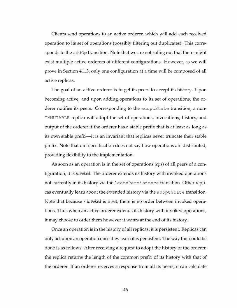
Clients send operations to an active orderer, which will add each received
operation to its set of operations (possibly filtering out duplicates). This corre-
sponds to the addOp transition. Note that we are not ruling out that there might
exist multiple active orderers of different configurations. However, as we will
prove in Section 4.1.3, only one configuration at a time will be composed of all
active replicas.
The goal of an active orderer is to get its peers to accept its history. Upon
becoming active, and upon adding operations to its set of operations, the or-
derer notifies its peers. Corresponding to the adoptState transition, a non-
IMMUTABLE replica will adopt the set of operations, invocations, history, and
output of the orderer if the orderer has a stable prefix that is at least as long as
its own stable prefix—it is an invariant that replicas never truncate their stable
prefix. Note that our specification does not say how operations are distributed,
providing flexibility to the implementation.
As soon as an operation is in the set of operations (ops) of all peers of a con-
figuration, it is invoked. The orderer extends its history with invoked operations
not currently in its history via the learnPersistence transition. Other repli-
cas eventually learn about the extended history via the adoptState transition.
Note that because r.invoked is a set, there is no order between invoked opera-
tions. Thus when an active orderer extends its history with invoked operations,
it may choose to order them however it wants at the end of its history.
Once an operation is in the history of all replicas, it is persistent. Replicas can
only act upon an operation once they learn it is persistent. The way this could be
done is as follows: After receiving a request to adopt the history of the orderer,
the replica returns the length of the common prefix of its history with that of
the orderer. If an orderer receives a response from all its peers, it can calculate
46
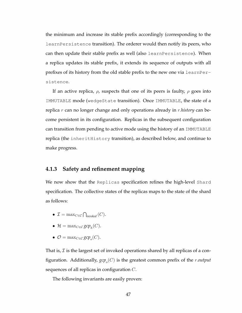
the minimum and increase its stable prefix accordingly (corresponding to the
learnPersistence transition). The orderer would then notify its peers, who
can then update their stable prefix as well (also learnPersistence). When
a replica updates its stable prefix, it extends its sequence of outputs with all
prefixes of its history from the old stable prefix to the new one via learnPer-
sistence.
If an active replica, ρ, suspects that one of its peers is faulty, ρ goes into
IMMUTABLE mode (wedgeState transition). Once IMMUTABLE, the state of a
replica r can no longer change and only operations already in r.history can be-
come persistent in its configuration. Replicas in the subsequent configuration
can transition from pending to active mode using the history of an IMMUTABLE
replica (the inheritHistory transition), as described below, and continue to
make progress.
4.1.3 Safety and refinement mapping
We now show that the Replicas specification refines the high-level Shard
specification. The collective states of the replicas maps to the state of the shard
as follows:
• I = maxC∈C⋂
invoked (C).
• H = maxC∈C gcph(C).
• O = maxC∈C gcpo(C).
That is, I is the largest set of invoked operations shared by all replicas of a con-
figuration. Additionally, gcpo(C) is the greatest common prefix of the r.output
sequences of all replicas in configuration C.
The following invariants are easily proven:
47

• For any replica r, gcph(r.conf) is a prefix of r.history;
• If a configuration C contains a PENDING replica, then gcph(C) is empty;
• Replicas cannot truncate their stable prefix;
• For any configuration that has an ACTIVE or IMMUTABLE replica, all the
predecessor configurations have at least one IMMUTABLE replica.
Unlike other replication protocols such as Primary-Backup, Chain Replica-
tion, or State Machine Replication, it is not an invariant that, given two his-
tories of two different replicas in a configuration, one is a prefix of the other.
This is because there is no order defined on how invoked operations are ap-
pended to an active orderer’s history. However, it is the case that the stable
prefix of any replica is always a prefix of the histories of the other replicas. To
illustrate, consider a configuration C1 consisting of replicas {r1, r2, r3}, where
r1 is the orderer, all replicas are ACTIVE, the history at all the replicas is H,
and operations {o′, o′′} are invoked but not added to the history yet. Also let
configuration C2 be the successor of C1, with C2 being composed of PEND-
ING replicas {r4, r5}, and r4 being the orderer. Let transition r1 extend its
history with [o′ :: o′′] followed by transition adoptState(r2). At this point,
r1.history = [H :: o′ :: o′′], r2.history = [H :: o′ :: o′′], and r3.history = H.
Next, let transitions wedgeState(r2) and wedgeState(r3) take place, fol-
lowed by inheritHistory(r4, r3), then inheritHistory(r5, r2), then r4 ex-
tends its history with [o′′ :: o′]. At this point, r4.history = [H :: o′′ :: o′],
r5.history = [H :: o′ :: o′′], and neither of them is a prefix of the other.
An important invariant that holds over the states of replicas is the following:
Stable Prefix Invariant: The stable prefix of a replica’s history is a prefix of the
history of each of its non-PENDING peers.
48

Proof. Initially, all histories are empty, so the invariant holds in the initial state.
We will now show that each transition maintains the invariant.
1. addOp(r, o): This transition does not change the stable prefix of any
replica;
2. adoptState(r): This transition copies the history and stable prefix from
the orderer. The orderer’s stable prefix satisfies the invariant, and thus the
transition maintains the invariant;
3. learnPersistence(r, s): This transition, as a precondition, requires that
s corresponds to a prefix of all histories of the peers, and thus evidently
enforces the invariant for the state after the transition;
4. wedgeState(r): This transition does not change the stable prefix of any
replica;
5. inheritHistory(r, r′): This transition can only happen to replicas that
are in PENDING mode. Let C = r.conf and C ′ = r′.conf. Observe that the
learnPersistence transition can only happen in a configuration that
has no PENDING replicas, as the history of a PENDING replica is empty.
Thus we know that the learnPersistence transition cannot have oc-
curred at replicas of C. Also note that the initial configuration has no
PENDING replicas, and thus C is not the initial configuration.
All non-PENDING replicas must thus have obtained their history from an
IMMUTABLE replica in C ′ (inheritHistory transition) or from the or-
derer of C (adoptState transition). As the addOp transition does not
affect the invariant, we will for simplicity of exposition assume that no
operations have arrived at the orderer. Because the orderer must have
obtained its history from an IMMUTABLE replica of C ′ all histories at non-
PENDING replicas are from IMMUTABLE replicas in C ′. Since the invariant
49

holds in C ′, and since the histories of PENDING replicas are empty, the
invariant must also hold in C after this transition.
As none of the possible transitions result in a state that violate the property, the
property is invariant.
Lemma 1. For any configuration C and any non-PENDING replica r in the successor
configuration of C, there exists an IMMUTABLE replica in C whose history is a prefix
of r.history.
Proof. If r is the orderer, then its history must have first been inherited from
an IMMUTABLE replica in C, and then possibly extended with new operations
(using learnPersistence transitions). Because no transition can truncate the
history of the orderer, the lemma holds. If r is not the orderer, then its history
was either directly inherited from an IMMUTABLE replica inC, or it was adopted
from the orderer. In either case, the lemma holds.
Corollary 2. For any configurationC and any non-PENDING replica r in the successor
configuration of C, gcph(C) is a prefix of r.history.
Corollary 3. For any two configurations C and C ′, C before C ′ in C, and r a non-
PENDING replica of C ′, gcph(C) is a prefix of r.history.
Lemma 4. For any two configurations C and C ′, either gcph(C) is a prefix of C ′ or
vice versa.
Proof. Note that if either C or C ′ contains PENDING replicas, then its gcph is
empty and the lemma holds trivially. If neither contains PENDING replicas, then
the lemma follows from the corollary above.
Similar arguments are followed for gcpo(C), and⋂
invoked(C).
50

Theorem 5. Specification Replicas refines specification Shard.
Proof. By induction on the number of transitions. For the initial state, all
replica’s invocations, histories, and outputs are empty and thus map to the
empty shard invocations I, history H, and outputs O. We now show that
each Replicas transition corresponds to a transition in Shard or leaves the
state of Shard unchanged (a so-called stutter). A transition at a replica r in
configuration C may change gcph(C), but cannot cause an inconsistency in
maxC∈C gcph(C) because of Lemma 4. Examining each transition:
1. addOp(r, o): This transition only modifies an internal variable and does
not affect invocations, histories, or outputs. Therefore, it is a stutter;
2. adoptState(r): Because r adopts the invocations, history, and outputs of
another replica, it cannot cause the greatest common prefixes (or the inter-
section of invokes) to be truncated. If the transition causes⋂invoked(r.conf)
to be expanded by o, then the transition corresponds to invoke(o). If the
transition causes gcph(r.conf) to be extended by o then the transition cor-
responds to apply(o). If the transition causes gcpo(r.conf) to be extended
by a prefix of the history ending with o, then the transition corresponds to
respond(o). Otherwise the transition is a stutter;
3. learnPersistence(r, s): If the transition causes⋂invoked(r.conf) to be
expanded with o, then the transition corresponds to invoke(o). If the
transition causes gcph(r.conf) to be extended by o, then the transition cor-
responds to apply(o). If the transition causes gcpo(r.conf) to be extended
by a prefix of the history ending with o, then the transition corresponds to
respond(o). Otherwise the transition is a stutter;
4. wedgeState(r): This transition does not affect any invokes, histories, or
outputs. Therefore it is a stutter;
51

Figure 4.3: Illustration of an elastic band
Example of an elastic band. Each (replicated) shard is sequenced by its predecessor onthe band as indicated by the arrows. The sequencer of a shard issues new configurationswhen needed.
5. inheritHistory(r, r′): r starts out with an empty history, and thus the
transition cannot cause the greatest common invokes, histories, or outputs
to be truncated. If the transition causes⋂invoked(r.conf) to be expanded
with o, then the transition corresponds to invoke(o). If the transition
causes gcph(r.conf) to be extended by o, then the transition corresponds to
apply(o). If the transition causes gcpo(r.conf) to be extended by a prefix of
the history ending with o, then the transition corresponds to respond(o).
Otherwise the transition is a stutter.
4.1.4 Elastic bands
Thus far we have assumed a single replicated shard, and an unbounded se-
quence of configurations that has been determined a priori. We now drop these
assumptions and instead assume a dynamic set X of shards. Logically, each
shard x ∈ X has a sequencer that determines its sequence of configurations.
A sequencer can be further subdivided into two distinct functions: sequencing
mechanism and policy.
52

The sequencing mechanism ensures that for every shard there is a non-
branching history of configurations. The policy function determines when a
configuration needs to be changed and what the new configuration should be.
In this section, we focus only on the sequencing mechanism as discussion of
policies is beyond the scope of this document.
In elastic replication, the sequence of configurations of a shard x is estab-
lished by another shard x′. Shards are organized into one or more circular elastic
bands, with the configuration of any shard x on a band being sequenced by ex-
actly one other shard x′ on the same band; its predecessor shard in the band. An
elastic band is composed of at least two shards—because a single shard with a
wedged replica cannot reconfigure itself alone. Since a shard can have only one
sequencer, we conclude that a shard cannot be on two different bands at once.
Figure 4.3 depicts an elastic band.
Each shard has dual responsibilities: to store and manipulate the
application-specific state of its replicated state machine, and to issue new con-
figurations for its successor shard in the band when needed—e.g. in response
to failure.
We will now describe the shard sequencing-interface. Let x.id be a unique
identifier for shard x. The sequencing interface is accessible even when a replica
is wedged and it consists of two operations:
• s.storeConf (x.id, config): This makes s the sequencer of shard x, and makes
config the configuration of x;
• s.removeConf (x.id): If shard s has the configuration of x, it will stop being
the sequencer for x and return the configuration of x. Otherwise, s will
return an error.
53
A configuration itself consists of a tuple 〈id, index, locations, orderer〉. Here
id is the shard identifier, index is the index in its sequence of configurations,
locations is a set of host identifiers (e.g. TCP/IP addresses), and orderer is the
host in locations that runs the orderer replica.
It is easy to insert into and remove shards from a band. Doing so would
be under the control of a configuration management agent m, itself an object in
a shard. Consider shards x and x′ on a band, with x the sequencer of x′. To
insert a shard y in between x and x′, m first obtains the configuration of x′ from
x using removeConf, and then stores the configuration into y using storeConf,
making y the configuration sequencer for x′. Then m stores the configuration
of y into x using storeConf, making x the configuration sequencer for y. This
concludes inserting a new shard into the band. Note that even though shard y
is the new sequencer of x′, shard x′ does not need to be notified of the change
since sequencing is a one-way relationship. Additionally, note that m can only
do this if it has the configuration of y, and should only do this if y does not have
a sequencer already.
To remove y, m first wedges y and removes the configuration of x′ from y,
and then stores this configuration into x, making x the sequencer of x′. Finally,
m can get the configuration of y from x, and destroy y or put its configuration
at a new sequencer.
4.1.5 Liveness
As mentioned in Section 4.1.2, the liveness property of interest to us here is
termination—i.e., every invocation will eventually get a response. Elastic repli-
cation makes the following assumptions:
(A0) Each faulty replica is eventually suspected.
54

(A1) For any band, each shard contains at least one correct replica.
(A2) Each band always has at least one shard that has no replicas suspected of
being faulty.
(A0) is just the completeness property of failure detectors [42]. If an active
replica, ρ, suspects that one of its peers is faulty, ρ becomes IMMUTABLE (and
keeps suspecting the peer). For this transition to occur, we need to assume
that correct replicas eventually suspect faulty peers. The actual mechanism can
be implemented with a simple pinging protocol; aggressive timeouts can be
used to detect failures quickly without jeopardizing the safety guarantees given
that the protocol does not assume anything beyond failure detectors in the �W
class [42].
(A1) is a standard assumption made by all replication protocols, and it is
satisfied by having f + 1 replicas per shard if f replicas can fail simultaneously.
If a shard in an elastic band does not meet (A1), then the history maintained by
its replicas will be lost, thus compromising persistence. Additionally, invoked-
but-not-yet-applied operations maintained by that shard will be lost and never
applied, thus compromising liveness/termination.
(A2) is required because shards are reconfigured by other shards on the same
band rather than by an external centralized configuration management service
(CCM). A replica that suspects one of its peer replicas in its shard of being faulty
wedges itself. Thus, shards with at least one failure suspicion cannot extend
their stable history, and they cannot reconfigure their successor shards. As a
result, if every shard in a band does has at least one suspected-faulty replica,
operations that have been invoked but not applied yet will never be applied,
thus violating the termination property. In systems where shards are reconfig-
ured by a CCM, (A2) is replaced by an assumption:
55

specification Replicas++:transition inheritHistory2(r, C):
precondition:r.mode 6= PENDING ∧ succ(r.conf, C) ∧r ∈ C.replicas
action:r.mode := ACTIVEr.conf := C
transition inheritHistory3(r, r′):precondition:
r.mode = PENDING ∧ r′.conf = r.conf ∧r′.mode 6= PENDING
action:r.mode := ACTIVEr.history := r′.historyr.stable := r′.stable
Figure 4.4: Additional Replica transitions
(A3) The centralized configuration manager does not fail.
In Section 4.2.1 we will provide an exact formulation of the probability that
(A1) and (A2) are met, compare that to the probability that (A3) is met, and
show that organizing shards into elastic bands can result in higher reliability
compared to using a CCM.
4.1.6 Practical considerations
We have thus far assumed that successive configurations do not overlap—i.e.,
they have no replicas in common. We now drop this impractical assumption
by adding two more transitions (Figure 4.4) to the specification Replicas (Fig-
ure 4.2).
Transition inheritHistory2(r, C) allows a replica that is not pending to
move from configuration r.conf to successor configuration C. It inherits its own
history, and does not become IMMUTABLE. This, however, presents a problem,
56

since other replicas in C may now not have an IMMUTABLE replica in the pre-
vious configuration to inherit state from. The extended specification solves this
problem by allowing pending replicas to inherit state from non-pending peers
in the same configuration (transition inheritHistory3(r, r′)).
Another impractical simplification made for ease of specification was that
replicas maintain the entire history of operations. However, instead of the sta-
ble part of the history, replicas can maintain a running state. This is possible, be-
cause the stable part of the history is persistent and never is reversed. Replicas
will need to queue the remaining operations until they are known to be stable or
maintain a running state with a log of “undo” operations in order to be able to
roll back. The latter would make it possible for applications to support weakly
consistent semantics, where updates are exposed quickly but are not known to
be persistent.
4.1.7 Implementation
As mentioned in Section 4.1.2, our specification does not describe how opera-
tions are distributed to replicas. In our implementation, we organized replicas
within a shard in a chain akin to chain replication [116](CR). We chose this con-
struction due to the simplicity of CR and its high-throughput properties.
The orderer is the head of the chain, and it sends operations along the chain.
Each replica on the chain adds the operations to its history. When the tail replica
adds an operation to its history, all replicas have the operations in their histories
and thus the operation is persistent. This allows the tail to respond to the client.
The tail then sends an acknowledgment along the chain in the other direction,
so that other replicas can also learn that the operation is persistent and apply
the operation to their state.
57

While similar, there are some important differences between elastic replica-
tion (ER) and the original CR:
• in ER, when a replica is unresponsive, a new chain is configured, possi-
bly with a new collection of replicas. In CR, faulty replicas are removed
from a chain and new replicas added to the end of the chain. The reason
behind this difference is that CR assumes a fail-stop model [104] in which
failures are detected accurately, whereas ER assumes that crashes cannot
be detected accurately—a weaker assumption;
• in ER, read-only operations must be ordered, just like other updates,
whereas in CR clients read directly from the tail. Again, this difference
is because of the weaker failure detection assumptions made for ER: If the
tail were incorrectly suspected of failure and the chain reconfigured, then
the tail’s state would become stale without it knowing that its configura-
tion is no longer current. In ER, an old configuration is wedged and even
read operations cannot be serviced. This apparent inefficiency of ER can
be addressed by using leases [64] to obtain the same read efficiency as CR.
There are some subtle issues to consider when a chain is reconfigured, be-
cause each chain must satisfy the CR invariant that a server earlier in a chain
has a longer history than a server that appears later [116]. ER thus ensures that
when a chain is reconfigured, the replicas that were in the old configuration ap-
pear early in the new chain in the same order as in the old configuration, while new
replicas appear at the end of the chain with an initially empty history.
Our shard implementation is similar to CRC Shuttle implementation of
Byzantine CR. However, Byzantine CR relies on an external configuration mas-
ter, while ER delegates reconfiguration to other shards on the elastic band.
58

For increased efficiency, we can exploit parallel access and allow clients to
read from any replica, but the result is weaker semantics. If clients read the
stable running state of any replica, then they know the state is persistent, but
possibly stale. If clients read the full history of any replica, then they are not
guaranteed that the state is persistent or that the order of operations stays the
same. It is for the application programmer to know whether such weaker se-
mantics are acceptable.
4.1.8 Reconfiguration discussion
Reconfiguration prompts several natural questions: How is a new shard con-
figuration chosen? How is the new replica membership decided? How is the
next configuration orderer selected? These concerns are matters of policy. Elastic
replication separates mechanism from policy [30] and is only focused on mech-
anism. Thus, any configuration with any set of replicas and any orderer could
be chosen to reconfigure an existing shard without compromising correctness.
In fact, the sequencing shard could be reading a predetermined list of configu-
rations off a disk and it would not affect system safety.
In our implementation of elastic replication, when a replica is being unre-
sponsive, we restore service by wedging the replica’s current configuration and
issuing a new configuration. The new configuration is the old configuration
with the unresponsive replica removed. The overhead is the same as that of any
update operation on the sequencer shard. Next, in order to restore the original
level of fault tolerance, a new replica is allocated, placed at the end of the chain,
and set to inherit the state of a replica in the current configuration in the back-
ground. Finally, once the new replica has the same persistent history as a replica
in the current configuration, the sequencer wedges the current shard configura-
59

tion and issues a new configuration with the new replica at the tail of the chain
of the old configuration.
Replicas in a new configuration can inherit the state of any wedged replica in
the predecessor configuration. In our implementation, replicas of a new shard
configuration issue an anycast request to all replicas of the predecessor config-
uration and adopt the history of the first responder.
If a sequencer fails during reconfiguration, system safety is not compro-
mised. This is because elastic replication requires all replicas of a configuration
to be active for any replica to change its persistent history. Replicas of a config-
uration become active only by successfully inheriting the history of a replica in
a prior configuration. Thus, the worst affect of a failed sequencer is failure to
notify all new replicas of a configuration to inherit the state of their predecessor
configuration, which would result in an inactive shard configuration.
Elastic replication assumes that clients learn about shards and their configu-
ration through out-of-band routing methods. Clients include the expected con-
figuration id with their requests. If a replica receives a request with a configu-
ration id not matching its own, it ignores the request and responds to the client
with its current configuration.
4.1.9 Comparing ER with other protocols
We now briefly discuss how elastic replication (ER) compares to other crash-
tolerant replication protocols, such as Primary-Backup (PB) [22,40], Chain Repli-
cation (CR) [116], asynchronous consensus techniques such as Paxos [75], Ver-
tical Paxos [76], and Quorum Intersection (QI) techniques that provide strong
consistency such as found in [26, 67, 113]. We also compare ER against the CRC
60

PB/CR QI Paxos Vertical Paxos CRC Shuttle ERminimum # replicas needed f + 1 2f + 1 2f + 1 f + 1 f + 1 f + 1strongest consistency provided linearizable atomic R/W linearizable linearizable linearizable linearizablerequires accurate fault detection yes no no no no nouses timeouts for liveness yes no yes yes yes yesrequires external configuration yes no no yes yes nosignatures required none none none none CRC none
Table 4.1: Comparison of replication protocols
Comparison of Primary-Backup (PB), Chain Replication (CR), Quorum Intersection(QI), Paxos, Vertical Paxos, Byzantine Chain Replication (CRC Shuttle), and ElasticReplication (ER) protocols.
Shuttle implementation of Byzantine Chain Replication, which only tolerates
crash and omission failures [115]. A summary is provided in Table 4.1.
PB and CR depend on accurate failure detection (i.e., fail-stop [104]). How-
ever, in practice, failure detection is implemented using timeouts. If timeouts
are chosen conservatively, then the probability of mistakes will be small. But in
the case of a failure, service availability is reduced substantially. If timeouts are
chosen aggressively short, then outages are short, but mistakes are common and
lead to inconsistencies (multiple primaries in the case of PB, or multiple chains
in the case of CR).
Paxos, Vertical Paxos, CRC Shuttle, and ER do not suffer from this safety de-
fect, because they do not depend on accurate failure detection. However, they
rely on failure detection for liveness. In Paxos, a faulty leader must eventually
be replaced by another, causing a so-called view change; in Vertical Paxos, CRC
Shuttle, and ER, a faulty replica must eventually be replaced, leading to a recon-
figuration. The time to recover from a failure depends on the timeout used to
detect failures. If chosen conservatively, then outages can be substantial. But ag-
gressively chosen timeouts can lead to starvation. In practice, timeouts should
be adaptive, so they are as short as practical, but no shorter.
61

Compared to ER, Paxos requires 2f+1 replicas instead of only f+1.1 Vertical
Paxos requires only f + 1 replicas for the read/write quorums but it relies on an
auxiliary configuration master for reconfiguration. Byzantine Chain Replication
provides two protocols: CRC Shuttle (which tolerates crash and omission fail-
ures) and HMAC Shuttle (which tolerates arbitrary failures). The specification
of CRC Shuttle is similar to a single shard in ER, however it relies on an external
configuration manager for reconfiguration while ER does not.
QI techniques do not rely on accurate failure detection and can completely
mask failures altogether, requiring no timeouts. They are typically used to
support read/overwrite operations on file-like objects, and provide atomic
read/write register consistency. However, quorum systems can be used in con-
junction with other protocols and synchronization mechanisms to implement a
wide range of data semantics as demonstrated in [84]. See [72] for a comparison
of quorum replication to other replication techniques. Also, consistent read op-
erations are relatively expensive, since they require two round-trips of message
exchange.
Like Paxos and other consensus techniques, QI protocols are based on ma-
jority voting, and thus they require a relatively large number of replicas. As in
Paxos, techniques exist to make f of the replicas light-weight [91]. Nonetheless,
such light-weight replicas still require independently failing resources (for a to-
tal of 2f + 1). On the other hand, ER leverages the existence of shards, each
having f + 1 replicas. ER explicitly does not work if there is only a single shard
or even if all shards used the same f + 1 locations for replication.
Any of these techniques can be made scalable through partitioning of data,
since both linearizability and atomic R/W register semantics are composable; a
1In Paxos terms, there are 2f+1 acceptors and f+1 learners that are typically co-located withacceptors. As acceptors have to maintain state for every command in the history, we considerthem replicas.
62
system comprised of shards that provide linearizable consistency also provides
linearizable consistency as a whole [59]. Also, all these techniques support
weak forms of consistency for improved efficiency and liveness. For exam-
ple, by allowing any replica to be read and buffering write operations at any
replica [123].
4.2 Evaluation
In this section, we evaluate elastic replication analytically and experimentally.
We analytically formulate the probability that the liveness condition for elastic
replication is met, show its impact on system reliability, and compare the re-
liability of elastic replication with traditional methods using CCMs. Then, we
benchmark a prototype distributed key-value store built using elastic replica-
tion.
4.2.1 Liveness condition
As mentioned in Section 4.1.5, elastic replication assumes that:
(A0) Each faulty replica is eventually suspected.
(A1) For any band, each shard contains at least one correct replica.
(A2) Each band always has at least one shard that has no replicas suspected of
being faulty.
In our analysis, for simplicity, we assume that there are no false failure sus-
picions. In our implementation, we utilize existing literature on distributed-
systems failure detectors [31,44,66,78,110]. For the sake of simplicity, we assume
that our failure detector meets (A0) and focus on the other two assumptions.
63

(A1) and (A2) present an interesting trade-off: The smaller the band, the
more likely assumption (A1) holds, whereas the larger the band, the more likely
assumption (A2) holds. Another variable involved here is the number of repli-
cas, n, in a shard. It suffers from a similar trade-off. The larger n is, the more
likely that at least one replica is correct, but the less likely that there exists a
shard consisting of only correct replicas.
Let p stand for the probability that a particular replica is correct, and let
all configurations of all shards have disjoint sets of replicas with independent
failure probabilities. Let n = f + 1 be the number of replicas in a shard. Then let
Pc = pn be the probability that a shard is correct. Let Ps =∑n−1
i=1
(ni
)pi(1−p)n−i =
1 − (1 − p)n − Pc stand for the probability that a shard is safe, because between
1 and n− 1 replicas are correct. If N denotes the number of shards on the band,
then the probability that at least one shard has only correct replicas while the
other shards each have at least one correct replica is:
P (p, n,N) =N∑i=1
(N
i
)P ic · PN−i
s (4.1)
This is exactly the probability that the liveness condition is met; typically one
would require that P (p, n,N) ≥ (1− ε) for some small constant ε. If the liveness
condition is not met, the system would require external intervention.
To demonstrate the feasibility of meeting the liveness condition, Figure 4.5
plots 1−P (0.99, n,N) for various shard sizes (n) and number of shards (N ). The
0.99 replica correctness probability was chosen to reflect the industry reliability
assumptions of a conventional server [18]. The sharp dip followed by slow rise
seen in Figure 4.5 arises from the tension between shard size and number of
shards on the probability of meeting the liveness condition.
64

1e-10
1e-09
1e-08
1e-07
1e-06
1e-05
0.0001
0.001
0.01
0.1
0 50 100 150 200 250 300
Dow
n p
robabili
ty
Number of nodes
3 nodes/shard4 nodes/shard5 nodes/shard
Figure 4.5: Probability of violating the liveness condition
Probability that the liveness condition is not met, so band requires external intervention,as a function of the number of replicas and size of shards. Shard replicas are assumedto be correct with probability p = 0.99.
4.2.2 Elastic replication vs. CCM
Elastic replication delegates the task of managing configurations to the shards
in the system. Is this more reliable than using a CCM?
A sharded service managed by a CCM still has to meet liveness condition
(A1), but condition (A2) is replaced with (A3): The requirement that centralized
configuration manager does not fail. A replicated CCM running a quorum-
based consensus protocol requires more than half of its replicas to be correct for
liveness. Let m be the number of replicas in a CCM and p the probability that a
replica is correct, then
Q(p,m) =m∑
i=b1+m/2c
(m
i
)pi · (1− p)m−i
is the probability that a replicated CCM is up. Then the probability that a CCM-
managed system does not require external intervention, is precisely the proba-
bility that (A1) and (A3) are met:
65

1e-06
1e-05
0.0001
50 100 150 200 250 300
Dow
n p
robabili
ty
Number of nodes
CCMElastic Replication
Figure 4.6: CCM vs elastic band
Probability that a system gets stuck requiring external intervention. An elastic replica-tion deployment is compared to a collection of shards managed by a CCM comprisedof 5 replicas. Each shard has 3 replicas. All replicas are assumed to have 99% uptime.
Q(p,m) ·
(1−
N∑i=1
(N
i
)(1− p)i·n · (1− (1− p)n)N−i
)Figure 4.6 compares the probability that external intervention is required, be-
cause the liveness condition is not met, for an elastic band and a CCM-managed
system. As the figure shows, a single self-managing elastic band is more reliable
than a CCM for systems with more than 10 replicas.
4.2.3 Experimental setup
We now highlight some of the performance characteristics of elastic replication.
To compare elastic replication to other protocols, we developed an application
library that implements multiple replication protocols. The library defines a
generic state machine module for user applications to customize. The module
is comprised of functions to handle client commands as well as to initialize,
export, and import the user application’s state.
66

Read WriteThroughput (ops/sec) 16,385 12,894Latency (msec) 6.64 8.94
Table 4.2: Stand-alone instance performance
Performance of a single stand-alone instance of our example storage server servicingread/write requests of 2KB objects from a network client and storing them in an ErlangDETS on disk.
The library is written in Erlang [23], and the following examples sketch a
simple distributed service that stores and retrieves binary data to/from disk.
The service is implemented as a server module that relies on our library for
replication and sharding. Our focus is on the protocol layer, so the implementa-
tion relies on Erlang’s built-in Disk Term Storage abstraction (DETS) for storage.
To put our results in perspective, Table 4.2 shows the performance profile of run-
ning a stand-alone instance of our system on a single server servicing read and
write requests for 2KB objects from a network client.
Our experiments ran on a 25-machine cluster. Each machine had an Intel
Xeon Quad Core processor, 4GB of RAM, a 250GB SATA drive, and a quad port
PCIe Intel Gigabit Ethernet card. The machines ran 64-bit Ubuntu 12.04 and Er-
lang R16B. The machines were connected via a Gigabit Ethernet network. Graph
results represent the average of 10 runs and the error bars represent a standard
deviation unit. We believe 10 runs per experiment were enough to get accurate
trends because the variance across different runs in the same experiment was
low.
4.2.4 Key-value store overview
A Key-Value Store (KVS) is a common storage abstraction in today’s datacen-
ters. It maps key from a predefined key space to an arbitrary data object. A
67

distributed KVS partitions the key space into a set of non-overlapping ranges–
i.e., every key is mapped to exactly one range. The ranges are mapped onto
shards such that each shard stores keys for a particular range [p, q) in the key
space. In steady state, the shard covering [p, q) serves as the sequencer for the
adjacent shard covering [q, r), and thus forming an elastic band.
Two important management operations on shards are split and merge. Given
a shard x covering [p, r) and a key q ∈ [p, r), the function split(x, q) results in
shard x covering [p, q) and a new shard x′ covering [q, r). For efficiency, shards
x and x′ will have replicas on the same set of hosts initially, but using reconfig-
uration the set of hosts can be updated subsequently. If x was sequencing the
configuration for some shard y, then after the split x is sequencing x′, and x′ is
sequencing y.
Given a shard x covering [p, q) and a shard x′ covering [q, r), with x sequenc-
ing x′, the function merge(x) results in x covering [p, r). If x′ was sequencing
shard y, then after the configuration the sequencing of y is taken over by x.
Shard x′ can subsequently be garbage collected.
Using split and merge, it is possible to maintain a scalable and linearizable
KVS 2. We note that the composition of linearizable objects is linearizable, con-
sequently the KVS is linearizable.
4.2.5 Single shard performance
We first measure the performance of a single shard in isolation as a function of
the number of its replicas. Figure 4.7 shows the average read and write through-
put for a single shard processing requests from 100 concurrent clients storing2Observe that linearizability is a stronger property than required by a KVS; atomic R/W
consistency suffices. However, protocols for atomic R/W consistency, such as [26] require 2f+1replicas and multiple round-trips for get operations. Also, linearizability allows us to supportoperations beyond put and get only.
68

0
5000
10000
15000
20000
25000
30000
0 2 4 6 8 10 12
Thro
ughput (o
ps/s
ec)
Shard size
Elastic Replication ReadElastic Replication Write
Single Server ReadSingle Server Write
Figure 4.7: Shard read/write throughput
Average read/write throughput of per shard for elastic replication as a function of thenumber of replicas. The read/write throughput of a single unreplicated server is alsoplotted.
and retrieving 2KB objects. Our implementation of elastic replication is based
on chain replication and thus exhibits similar throughput characteristics. The
throughput of a single unreplicated server, as listed in Table 4.2, is also plotted
in Figure 4.7 to highlight the overhead of Elastic Replication.
A concern with elastic replication is that in order to guarantee linearizability
in the presence of failures, requests must propagate to all replicas in a config-
uration before execution. This applies to both read and write requests. How
costly is that propagation?
To lower that cost, our implementation tags each request with the index
number of the configuration that the client assumes for the shard. Before for-
warding a command, each elastic replica checks that the tagged version num-
ber matches its own. If not, the request is dropped and the client is notified of
the new configuration. With that, non-tail replicas handle read requests by just
checking the request tag before forwarding it to their chain successor (without
adding the request to the local unstable history queue or executing). When the
69

0
2
4
6
8
10
1 2 3 4 5
Late
ncy (
msec)
Shard size
Elastic ReplicationChain Replication
Figure 4.8: Shard read latency
95th percentile latency for ping read requests per shard as a function of the numberreplicas.
25000
27500
30000
32500
35000
1 2 3 4 5
Thro
ughput (o
ps/s
ec)
Shard size
Chain ReplicationElastic Replication
Figure 4.9: Shard read throughput
Average throughput of ping read requests per shard as a function of the number replicas.
tail receives a request, it checks the tag and responds to the client. This is a slight
deviation from the original specification of elastic replication, which is agnos-
tic to read/write request. But the modified scheme results in a performance
benefit.
In our implementation, the cost of pipelining read requests to replicas is
dominated by the cost of reading from the disk at the tail. To measure the cost
70

0
10000
20000
30000
40000
50000
60000
0 10 20 30 40 50 60
Thro
ughput (o
ps/s
ec)
Time (sec)
Adding ShardsRemoving Shards
Figure 4.10: Throughput during elastic band reconfiguration
Impact of reconfiguration to add/remove shards on aggregate throughput. A partitionwas added/removed to the system every 20 seconds. When adding shards, the bandoriginally had 2 shards, and when removing it started with 4 shards.
of propagating read requests, we made our clients send “ping read” requests
to the replicated shard. These requests are treated by the replication protocol
as a normal read request, but the underlying server responds without engaging
the disk store. Figures 4.8 and 4.9 show the latency and throughput of handling
ping read requests using both elastic replication and chain replication. As the
figures demonstrate, the overhead of piping read requests through the chain is
small. Elastic replication performs comparably to chain replication. The added
cost is well within the margin of error.
The main conclusion here is that elastic replication has comparable high per-
formance characteristics to chain replication, albeit with minimal overhead cost.
4.2.6 Band maintenance
Because a shard’s configuration is separate from its other state, reconfiguration
in elastic replication is cheap. Figure 4.10 shows a simple elastic band being
71

reconfigured to add/remove a shard every 20 seconds. This operation is trivial
and barely has any impact on system throughput beyond the effects of adding
or removing a shard.
Another technique for reconfiguring an elastic band is by merging/splitting
shards. This technique allows part of the state of a large shard to be transfered
to a new shard. We support two methods of state transfer: one-shot state trans-
fer, and on-demand state transfer. In one-shot transfer, a newly created replica
blocks until it receives all of its seed state from another replica or shard. In
on-demand transfer, the newly created replica asynchronously receives its seed
state “block-by-block” at a specified transfer rate.
A problem with on-demand transfer, however, is that incoming client re-
quests might attempt to access parts of state that have not yet been transferred.
We handle this issue in one of two ways: if the incoming request is write-only
and completely overrides the unavailable block of original state, then that re-
quest is accepted and the block that it modified is marked as up-to-date. If
not, the replica does a page-fetch of the block relevant to the client request and
then executes that client request. On-demand paging relies on an appropri-
ate application-specific definition of “data block”. For our prototype key-value
store, a data block is just a single key-value pair. In practice, more sophisticated
locality-aware mechanisms might be used.
Figure 4.11 shows the impact of splitting/merging a shard every 20 seconds
on an elastic band with on-demand state transfer. The cost of merging shards is
larger than just removing them, because of the state transfer. However, in our
implementation, background state-transfer mitigates the potential high cost.
72

0
10000
20000
30000
40000
50000
60000
0 10 20 30 40 50 60
Thro
ughput (o
ps/s
ec)
Time (sec)
Splitting ShardsMerging Shards
Figure 4.11: Throughput during shard split/merge
Impact of reconfiguration to split/merge shards on aggregate throughput. Thesplit/merge occurred at the 20 and 40 seconds marks. In the split case, the band origi-nally had 2 shards. In the merge case, the band started with 4 shards.
4.2.7 Shard maintenance
When a replica is unresponsive, the configuration needs to be modified. In order
to restore service immediately, the new configuration is simply the old configu-
ration with the unresponsive replica removed. The overhead is the same as that
of any update operation on the sequencer shard. Next, in order to restore the
original fault tolerance, a new replica needs to be allocated. Placement for op-
timal diversity and load balancing consideration need to be considered in that
allocation. Then, a second reconfiguration adds the new replica to the configu-
ration.
Figure 4.12 shows the impact of adding/removing replicas to a single shard
through reconfiguration. The temporary drop in throughput, at the 20 seconds
and 40 seconds time marks, is due to the original configuration being wedged.
Because the choice of timeout values does not affect system safety, clients were
using 5 second timeouts to retry requests. Requests to the old configuration (be-
fore adding/removing replicas) would timeout. When a client’s request times
73

0
2000
4000
6000
8000
10000
12000
0 10 20 30 40 50 60
Thro
ughput (o
ps/s
ec)
Time (sec)
Removing ReplicasAdding Replicas
Figure 4.12: Throughput during shard reconfiguration
Impact of reconfiguration to add/remove replicas to a shard. Replicas wereadded/removed every 20 seconds.
out, it tries to refresh its configuration information by broadcasting a request
to all the replicas of the old shard configuration. By our assumptions, at least
one replica of the old configuration would still be correct and would know of
the new configuration and responds to the client. Once the client receives a
response detailing the new shard configuration, it retries its request.
4.2.8 Failure tolerance
Replicas in each shard monitor the replicas in the shard they are sequencing.
When replica failure is suspected, the wedge command is issued to the victim
shard by both the suspecting replicas in the same shard and the sequencer shard.
This is done to prevent the shard from accepting any new client requests and
guarantee that safety is not violated. Next, the sequencer issues a reconfigura-
tion of the wedged shard and spins up new replicas if needed. Due to elastic
replication’s design, the choice of timeout value for failure detection only im-
pacts the perceived latency and throughput of client requests but not the con-
74

0
2000
4000
6000
8000
10000
12000
14000
30 35 40 45 50 55 60
Thro
ughput (o
ps/s
ec)
Time (sec)
50 msec100 msec
2 sec lease5 sec lease
Figure 4.13: Downtime due to replica failure
Failure tolerance within a shard with various timeouts. Failure was induced at the 40thsecond. Shorter timeouts only result in shorter downtime without compromising safety.
sistency or the correctness of the system. Figure 4.13 highlights the impact of
different timeout values on client throughput.
75

CHAPTER 5
FUTURE DIRECTIONS: UNIFIED PARTITIONING
A Service-Level Objective (SLO) is a collection of measurable capacity, perfor-
mance, and reliability objectives that a datacenter system must meet. Paying
customers of cloud computing services agree to Service-Level Agreements (SLAs)
specifying SLOs in addition to contractual matters such as costs, responsibili-
ties, and other general conditions.
No single machine is large, fast, or reliable enough to run a scalable cloud-
based service. The key to scalability is partitioning the service’s state, computa-
tion, and reliability requirements into smaller chunks. This can be accomplished
by replication and sharding protocols. However, today’s systems combine repli-
cation and sharding in only a limited way: In services internal to a datacenter,
a hash function is typically used to partition state into shards of approximately
the same size; then each shard is replicated onto multiple machines using some
replication protocol. Powerful machines might be responsible for more shards
than small machines, often by a large machine masquerading as a set of small
machines (or “virtual nodes”), creating unnecessary complexity and overhead.
Because of this construction, we dub this approach “shard-then-replicate”.
A different design pattern is used for services across datacenters. Pragmat-
ically, a system designer might want each datacenter to store a replica of the
entire state. However, due to heterogeneity, different datacenters might use
different replication and sharding schemes to provide the desired level of la-
tency, throughput, and reliability. For example, a datacenter with powerful and
reliable servers might partition its replica into a few shards, while another dat-
acenter with low-end servers might create many replicated shards. We dub this
approach “replicate-then-shard”.
76
Neither approach methodically constructs systems to meet SLOs. This re-
sults in complications when systems are maintained, machines are replaced,
or software upgraded and redeployed. In this chapter, we propose a modular
approach to sharding and replication in datacenter and georeplicated cloud ser-
vices. In order to meet a particular SLO given a heterogeneous set of resources,
a system designer follows a top-down “partition-and-conquer” approach, start-
ing with a high-level specification of the required service-level objectives, and
refining that into an implementation with nested replication and sharding pro-
tocols. At each level, the SLO is weakened by the application of replication or
sharding—until it can be satisfied by existing machines or services. We believe
that this model would not only make it easier to build datacenter systems, but
it would also make it possible to verify that an SLO is still satisfied after system
modification or maintenance.
Our modular approach, Unified Partitioning, is a generalization of replication
and sharding, employing Partitioned State Machines to complement Replicated
State Machines, and Service State Machines to incorporate SLOs into the model.
Partitioned State Machines are designed to be nested, with ordinary determin-
istic state machines forming the base case.
5.1 System Model and Terminology
Two basic building blocks are used in our model: The Service State Machine
(SSM) and the Engine. Intuitively, an SSM is a state machine with operational
SLO requirements, and an engine is a machine or service that is capable of run-
ning the SSM and meeting its SLO requirements. Not all engines are capable of
running all SSMs.
77
A finite-state transducer is a finite-state machine with an input tape and an
output tape—i.e., it reads inputs and produces outputs. Formally, a finite-state
transducer, σ, is defined as a sextuple (Σ,Γ, S, s0, δ, ω), where:
• Σ is the input alphabet (an alphabet is a finite non-empty set, the elements
of which are called symbols).
• Γ is the output alphabet.
• S is a finite, non-empty, set of states.
• s0 ∈ S is an initial set.
• δ : S × Σ→ S is the state-transition function.
• ω is the output function. If ω : S ×Σ→ Γ, then σ is called a Mealy machine.
If ω : S → Γ, then σ is called a Moore machine.
A Service state machine (SSM), S, is defined as a septuple: (Σ,Γ, S, s0, δ, ω, SLO).
SLO is a Service-level objective, which specifies measurable metrics required
by the service S, such as how much storage is needed to run S, how
many inputs per second it should be able to handle, and its reliability char-
acteristics. For example, an SLO can be a triple (50 PB, 50000 ops/sec, <
5 minutes of downtime per year). SLOs could be extended to represent other
metrics. To simplify notation, S is shorthanded as (σ, SLO).
An SSM is just a description. An engine is what runs an SSM. Each engine
E has a particular capability that describes which SLOs the engine can satisfy.
An engine runs at most one SSM, maintaining state and producing outputs in
response to a sequence of inputs, assuming that the engine’s capabilities satisfy
the SSM’s SLO. The inputs to an SSM are external messages and output mes-
sages produced by engines running other SSMs.
78

5.2 Partitioned State Machines
An engine might not be able to satisfy the SLO of an SSM in terms of storage,
performance characteristics, reliability, or any combination thereof. However, a
collection of engines running a “distributed version of the SSM” might be able
to satisfy the SLO. In effect, the collection of engines emulate a more powerful
engine. Each of the engines is running an SSM of its own.
A Partitioned Service State Machine (PSSM) is a formulation of a distributed
SSM. To understand what a PSSM is, we first introduce the concept of a PSM. A
Partitioned State Machine (PSM) is described by a tuple S = (V, ρ, π) where:
1. V is a vector of State Machines (SMs) as defined previously.
2. ρ :⋃σ Σ × V → σ is a routing function that assigns each input to one or
more state machine σ ∈ σ in V .
3. π :⋃σ Σ × V → true | false is a boolean filtering function on the
output of the state machines in V .
In a PSM, S , an input i is applied to V [ρ(i)] and updates only the state of that
SM. The output set of S is the union of the output sets of each member in V
filtered by π—the other outputs produced are used internally to the PSM.
A Replicated State Machine (RSM) [105] is an example of a Partitioned State
Machine, partitioning the reliability requirements across a set of replica SMs. An
RSM can be automatically generated from a deterministic state machine using a
protocol such as Paxos [75]. In this case, V is a collection of SMs—some replicas
of a SM S, and some Paxos acceptors. The routing function assigns each input
to all acceptors, each an SM in its own right. Output of the acceptors are filtered
out by the filtering function, leaving only the outputs of the replica SMs in V .
79
Another example of a PSM is what we call a Sharded State Machine, useful
for implementing systems with state, too large to run within a single machine
efficiently. A distributed key-value store is a good example of such system. If
(V, ρ, π) is a Sharded State Machine, each entry in V starts out with the same de-
terministic state machine that implements the key-value store. Routing function
ρ, in this case, is a hash function that assigns each input to one of the entry in
V , and π a function that always returns true. Thus the output of the Sharded
State Machine is the union of the outputs of the SMs in V .
PSMs may be nested. If (V, ρ, π) is a PSM, then the SMs in V may themselves
be PSMs. In the case of the key-value store example, the entire store could be
viewed as a single SM, its state formed by all current key-value pairs, its tran-
sition function the query and update operations available on keys, and its out-
put set simply the set of results produced by those operations. But the KVS is
typically both sharded and replicated. A traditional “shard-then-replicate” ap-
proach to a scalable and reliable Key-Value Store can be implemented by nest-
ing replicated state machines within a sharded state machine, replicating each
shard. Nesting can be done arbitrarily deep. A PTree is a tree of nested PSMs.
A PSSM is a service state machine that extends PSM to account for SLO re-
quirements. A PSSM is described by the four-tuple (V , ρ, π, SLO) where V is
a vector of service state machines. The SLOs of the members of V represent
weaker requirements than those of their parent PSSM. For example, the SLOs
of SSMs in V for a sharding protocol will have aggregate capacity that meet or
exceed the capacity requirement of the parent PSSM. For a replication protocol,
the SLOs of V will have weaker reliability requirements than those of the parent.
The specifics of breaking down SLOs at each level will depend on the particu-
lar replication or sharding protocol and are beyond the scope of this chapter.
80

Another interesting future works direction is monitoring services at runtime to
ensure that SLOs are met, and automatically taking corrective actions if they are
not. We see that value of our proposed model in that it augments replicated and
sharded state machines with SLO requirements, is just as expressive as ad-hoc
techniques such as virtual nodes, and it allows expressing specific SLO require-
ments for different levels of the system.
Nesting PSSMs is related to Finite-State Machine Decomposition; where a state
machine is decomposed into a collection of smaller state machines [25, 47, 54,
55, 61, 65]. This is heavily used in application-specific integrated-circuits, and
integrated-circuit design in general, in order to optimize the logic circuit repre-
senting the FSM for low power, reducing area, wire lengths, reusing circuit com-
ponents, and satisfying other fabrication requirements. FSM decomposition and
PSSM decomposition are both used to meet deployment constraints. However,
nesting PSSMs is different from FSM decomposition in that the nested service
state-machines are not simpler, but rather have weaker SLOs. This is because
PSSM decomposition introduces a new replication or sharding protocol at every
level of the decomposition, in order to weaken the SLO to meet the capabilities
of available engines.
5.3 Current Status
Unified partitioning emerged during the course of our work on comparing mul-
tiple replication protocols including elastic replication and Pileus [112]. We cre-
ated a programming library (libdist) for comparing different protocols and sys-
tem designs under one common implementation. Later, the library was rewrit-
ten to support nested sharding and replication via unified partitioning. The
evaluation results presented in Chapter 4 were rerun on libdist to make sure
81

that the library works and there were no significant performance penalties. In
those experiments, elastic replication was re-implemented as nesting of an intra-
shard replication protocol and an inter-shard sharding protocol for elastic band
management. The performance results were similar to what was reported in
Section 4.2 with a negligible penalty hit of a few Erlang reductions [24] due to
nesting.
5.3.1 libdist overview
Libdist is a library for building sharded and replicated distributed systems. Lib-
dist implements a suite of replication protocols as well as a simple sharding
protocol with support for one-hop routing to the different shards. Additionally,
libdist handles instantiating server processes, monitoring processes, failure han-
dling, tracking configuration changes, and client interaction with the system. To
use libdist, a developer implements a state machine interface that is exposed by
the library. The developer then specifies the desired sharding/replication pro-
tocol to be used as well as a list of host machines that are available to run the
system. Libdist then wraps the developer’s state machine module with the spec-
ified protocol, deploys it on the machines, and returns a configuration handle
that clients can use to interact with the system.
Table 5.1 shows the state machine interface that is exposed by libdist. It is
comprised of functions to initialize the system’s state, handle incoming client
commands, check whether a command is read-only or not, serialize and recon-
struct all or part of the state, as well as handling termination and state clean-up.
We chose to apply partitioning at the granularity of a single process state.
This approach is easier to implement and more flexible than nesting at a coarser
grain, e.g. sharding the whole of a replicated system. To implement partition-
82

Function Input Outputinit sm Initialization parameters Statehandle cmd State, Command, AllowSideEffects New Stateis mutating Command true|falsestop State, Reason success|failureexport State Serialized stateexport State, Condition Serialized part of the state
where condition holds trueimport Seralized State State
Table 5.1: libdist state machine interface
ing at the granularity of a single process, it is helpful to separate the state of the
protocol from that of the application. For example, in a replicated state machine
system with three replicas, there are six “execution engines” at work: three to
run and maintain the replication protocol’s state, and another three to run and
maintain copies of the application’s state. Let’s assume that the replicated ap-
plication is a key-value store; the application state is a list of key-value pairs. We
can shard any copy of the application state, but we might not be able to shard the
state of replication protocol without compromising its correctness. Here, sepa-
rating replication state from application state leads to a clean “replicate-then-
shard” nested construction, where the state of the key-value store is sharded,
but the replication state is not.
To implement protocol nesting, every process in a libdist distributed system
is comprised of three threads: A receiving thread, a protocol thread, and an applica-
tion thread. The receiving thread is implemented as a performance optimization,
and it is responsible only for taking incoming messages from the networking
stack and storing them in a queue that is constantly checked by the protocol
thread. The protocol thread maintains the state of the partitioning protocol,
processes protocol-related messages, and offloads application-related messages
83

to the application thread which, in turn, maintains the application state and
processes related messages.
Libdist supports introducing a new level of nesting to a running system by
partitioning an existing process. Because unified partitioning is always applied
at the granularity of a single process’s state, nesting always happens at the leaf
of a PTree.
To partition the state of an existing process p on a set of machines M using
protocol q, new processes are spawned on machines M and configured to use
protocol q. Let the resulting configuration be C. Next, an inherit command is
sent to p, which thereafter will not accept further commands modifying its ap-
plication state. Then, p serializes the application state using its implementation
of the defined state machine interface, and it transfers that state to processes in
C. After the state transfer is completed, p modifies the current PTree by travers-
ing a to the root. At each node, it replaces its address with that of C and notifies
the node’s siblings of the change. Once traversal reaches the root, the partition-
ing is complete.
Partitioning a running process can result in complications to clients and
other existing processes in the system. To address that, two techniques are used
in our implementation: First, processes in the system communicate with one
another using communication stubs. When a process is partitioned, its communi-
cation stub is updated at other processes in the system during PTree reconfigu-
ration. The new stub communicates based on the partitioning protocol. Since
unified partitioning allows for nesting, communication stubs can be nested as
well. A process communicating with a component that is implemented as a
sharded replicated service uses a protocol-specific replication stub nested in a
sharding stub.
84

Second, partitioning components can result in unintended side-effects. For
example, a component that is expected to produce a single network message
upon receiving a client command could produce multiple messages if it were
replicated. The method to handle client commands in the state machine inter-
face exposed by libdist therefore includes a flag to specify whether side-effects
should be suppressed by the current process. That flag is set by the implemen-
tation of the different replication and sharding protocols in a way that the side-
effect will only be produced when the command is to considered to have been
handled by the partitioned state machine as a whole. Because replication and
sharding protocols implement libdist’s state machine interface, nesting these
protocols does not result in unwanted extra side-effects.
The library is actively maintained and the code is available publicly at:
https://github.com/hussamal/libdist.
5.4 Discussion
Having proposed a model, we discuss two use cases of nesting replication pro-
tocols to improve performance and reliability. Then, we close with other future
directions.
5.4.1 Hybrid replication protocols
Replication protocols can be combined using unified partitioning to create new
hybrid protocols that exhibit improved performance characteristics. For exam-
ple, chain replication provides linearizable consistency semantics and tolerates
the failure of all but one replica, but its read throughput is limited to that of
a single replica. Consider a chain of length two, where the tail of the chain
85

Figure 5.1: Architectural view of a chain/broadcast hybrid protocol
is itself a two-replica system running a protocol that broadcasts writes to both
replicas and randomly directs reads to one of those replicas. This protocol is
similar to a quorum intersection protocol but it makes the stronger failure de-
tection assumptions of chain replication, and relies on an external master for
reconfiguration—as does the chain replication protocol. Figure 5.1 shows an
example of this setup.
Operationally, a client’s write requests is sent to the head of the chain just
like traditional chain replication. The head then forwards the request to the
tail node. Because the tail node is a replicated system, the head’s message is
broadcast to processes T1 and T2 in Figure 5.1 which in turn execute the write
and respond to the client. The client’s communication stub waits for receiving
both responses before considering the write to have completed.
Read requests are forwarded to the tail, as in traditional chain replication.
However, again, because the tail node is a replicated system where reads are
supported by all replicas, the client has the option of either broadcasting read re-
quests to all tail replicas and waiting for the first response, or trying one replica
at a time and switching to the other one in case of a timeout. The latter approach
splits the read load across the tail processes and thus improves read throughput.
To demonstrate the performance improvement, we implemented this hybrid
protocol and compared its read throughput against that of chain replication and
86

0
20000
40000
60000
80000
100000
3 4 5
Thro
ughput (o
ps/s
ec)
Number of replicas
Quorum IntersectionHybrid Protocol
Chain Replication
Figure 5.2: Read throughput the hybrid protocol
A comparison of the read throughput of the hybrid protocol and its constituting parts:Chain replication, and quorum intersection. The average of 10 runs is shown, and thestandard deviation is shown by the error bars above and below each data point.
quorum intersection configured to write-all-read-any for a few deployments, as
reported in Figure 5.2.
Architecturally, the hybrid protocol looks like a multi-tailed chain. How-
ever, there are two important things to note here: First, we did not implement
a new protocol, but instead, we nested two protocols that are unaware of each
other. Chain replication operates at the top level unaware of the nested proto-
col, and the nested protocol operates at the lower level unaware of the top-level
protocol. Second, even though this hybrid protocol resembles an instance of
a primary/backup system [22], reads in primary/backup are handled by the
primary replica in order to guarantee linearizable consistency, but reads in the
hybrid protocol reads are handled by any one of the tail replicas.
87

5.4.2 Availability of flat and nested quorums
Systems are often deployed across multiple failure domains, such as server
racks and datacenters to protect against correlated failures. For example, a sys-
tem might split its processes across servers on multiple server racks to tolerate
rack-level power or network failures. Another example would be to replicate
data across geographically dispersed datacenters to tolerate failures due to nat-
ural disasters.
When replicating across multiple failure domains, developers are faced with
a choice: Should replicas be grouped by failure domain or should they oper-
ate in a “flat structure”? The answer here depends on the reliability of servers
and the failure domain. Figure 5.3 plots an example where 9 processes partici-
pate in a quorum intersection replicated system where every 3 processes are in
a different failure domain. All servers are assumed to have the same reliability
regardless of failure domain. The figure shows that, depending on the failure
probability of individual servers and failure domains, transforming a flat quo-
rum into a nested quorum results in higher overall system reliability.
5.4.3 Beyond new protocols
The top-down approach of creating a system using a PTree of PSSMs defines
contracts between SSMs and engines: SSMs require certain SLOs, engines pro-
vide certain capacity, and the connecting protocols (in the form of PSSMs) en-
sure that the SSM SLOs are met by the engines they are mapped onto. In con-
trast, today’s systems are often built from the bottom up, which makes it hard to
reason about the expected performance and properties of components at design
time. Using unified partitioning, we start with desired SLOs at the top level and
recursively refine that until we reach the low-level components.
88

0.990
0.992
0.994
0.996
0.998
1.000
0.90 0.92 0.94 0.96 0.98 1.00
Failu
re d
om
ain
relia
bili
ty
Server reliability
Figure 5.3: Availability of flat and nested 9-process quorums
In the area under the curve, nesting processes in three 3-process quorums per failuredomain results in higher reliability of the overall system. In the area above the curve, aflat 9-process quorum across all failure domains is more reliable.
The presence of SLOs between the different levels of the PTree simplifies
system maintenance. When an engine is replaced, the replacement must pro-
vide the capabilities requested by the SSM it runs. Otherwise, parts of the PTree
may have to be redesigned, applying unified partitioning once again to obtain a
new architecture suited for the available engines. Similarly, unified partitioning
makes the composition of replication and partitioning in the implementation an
explicit design decision rather than an implicit one, as it often is today. This
simplifies reasoning about system properties.
Additionally, unified partitioning simplifies implementing replica place-
ment policies. Replica placement impacts a system’s performance, availabil-
ity, and failure-tolerance. Even though there has been extensive research into
replica placement strategies [46, 57, 60, 95], integrating these policies into a sys-
tem’s design remains tricky and ad-hoc [4, 5]. However, using nested replica-
tion and sharding in unified partitioning, a system designer can explicitly cre-
89
ate multiple copies of the system state and dictate which engines they run on
explicitly—as long as these engines’ capabilities can satisfy the different SLOs.
Because system replicas are explicitly defined in unified partitioning, they
could be assigned different roles. For example, all client-facing operations could
be routed to one replica of the system, whereas all back-end processing tasks
are routed to a different replica. Similarly, clients could be made to only interact
with one replica of the system. This could guarantee clients a stronger minimum
consistency guarantee than just eventual consistency [79, 112]. For example, a
client that always interacts with the same system replica can be given a Mono-
tonic Read guarantee or even a Bounded-Delay guarantee, where requests are
guaranteed to be consistent with time-bounded staleness—depending on the
deployment and actual implementation of the replication protocol [112].
Finally, there are many possibilities of future work beyond creating new
nested replication protocols. An interesting direction would be to use libdist
to automatically build and maintain a PTree from a top-level SLO. This would
require understanding how different protocols break down a required SLO into
a collection of SLOs with weaker requirements. This might require a combina-
tion of analysis of protocol behavior and profiling the deployment environment
with different protocols. Additionally, maintaining a deployed PTree would re-
quire a monitoring layer and a mechanism to audit potential violations of the
SLO and act accordingly. Automatic deployments have been studied at the level
of VMs and datacenter resources [71] but not at the level of protocols and system
architecture.
90

CHAPTER 6
CONCLUSION AND RELATED WORK
The realities of datacenters and cloud services undoubtedly change how we
build distributed systems. In this thesis, we explored new uses for well-known
redundancy techniques.
Erasure coding can help protect cloud storage customers from vendor lock-
in using schemes like RACS. The cloud services marketplace is in its infancy.
While it might be at the forefront of technology, as a market—an economic en-
tity—it is not unique. In cloud computing, it is fitting that technological devices
should be used to address economic problems, and that is what RACS is: A
simple application of technology to change the structure of a market. In RACS,
consumers have a tool that can be used to adjust the trade-off between overhead
expense and vendor mobility. In the design of RACS, we apply erasure coding
to a different type of failure (economic) than it is usually used for in storage
systems. We built a working implementation and ran microbenchmarks, and
we simulated larger experiments on real-world traces. Based on these simula-
tions and experiments, we conclude that RACS enables cloud storage customers
to explore trade-offs between overhead and mobility, and to better exploit new
developments in the fast-paced cloud storage marketplace.
As more, and larger, organizations turn to cloud computing service
providers for their storage needs, it is imperative that these organizations be
able to change storage providers, for any reason, without prohibitive costs
(monetary, time, etc). RACS attempts to reduce the cost of switching storage
providers. While the problem of optimally choosing from between competing
vendors is related to the domain of Algorithmic Game Theory [88], our work
91

with RACS treats price hikes as failures, and uses data redundancy techniques
(erasure coding) to protect against them.
RACS is similar to implementing RAID across cloud storage providers.
HAIL [39] uses RAID-like techniques across storage providers to ensure high-
availability and integrity of data stored in the cloud. Peer-to-peer storage [48,
50,51,97] employs RAID-like techniques to ensure availability and durability of
data. The difference between systems like HAIL, peer-to-peer storage systems,
and RACS, is that RACS focuses on economic failures and how to prevent them
without excessive overheads, while still benefiting from greater availability and
durability of other RAID-like systems.
IBM’s Multi-cloud Storage Toolkit [29] leverages the heterogeneity of differ-
ent cloud-storage providers to build a storage system with improved intrusion-
tolerance. In a similar vein, Depot [83] makes minimal trust guarantees of cloud-
storage services. Depot replicates data across storage providers to build a data
store with Fork-Join-Causal consistency guarantees. DepSky [32] is similar to
Depot, but it emphasizes data availability by making redundant copies across
multiple cloud providers. SPANStore [122] focuses on using multiple storage
providers for improved performance via geo-replication, and on cost reduc-
tion via price minimization strategies. Furthermore, Xen-blanket [121] works
on computation across multiple cloud providers by allowing a virtual machine
on one provider to migrate to another provider for reduced cost or improved
performance.
Legislatively, the European Union will soon adopt a General Data Protection
Regulation that stipulates, amongst other things, the right to data portability for
the users of cloud-computing services. This law applies to personal data, and it
would allow users to request a copy of their data hosted at a cloud-computing
92

service, obtain the data in a format usable by the person, and transmit it to a
different cloud-computing service. By their nature, cloud-storage services allow
customers to obtain a copy of their data and transmit it to a competing storage
provider. RACS’s motivation is that while data migration is possible between
storage providers, it might be prohibitively costly. RACS reduces the cost of
data migration and helps customers avoid vendor lock-in.
In the implementation of cloud storage services, techniques like Elastic repli-
cation leverage the sharded nature of datacenter systems to mitigate the cost of
configuration management. It supports rapid reconfiguration without the use
of a centralized configuration manager. Elastic replication is novel in that repli-
cated shards are responsible for each others’ configurations. Each shard uses
only f + 1 replicas to tolerate up to f crash failures at a time. Elastic replication
guarantees strong consistency in the presence of reconfiguration and without
relying on accurate failure detection. We formally specified our new protocol,
analyzed its reliability properties, and benchmarked a prototype implementa-
tion.
Elastic replication is best considered a scalable instantiation of the Replicated
State Machine (RSM) approach [74, 105] in which a collection of replicas apply
the same operations in the same order.
Various scalable peer-to-peer storage systems have proposed separating con-
figuration from storage for improved consistency [77, 87, 100, 102]. Similarly,
Vertical Paxos (VP) [76] uses an auxiliary configuration master to reconfig-
ure primary-backup or read/write quorums. Another such approach is Dy-
namic Service Replication [36], a mixture of consensus and virtual synchrony-
based [35] replication strategies. There are two important differences between
these schemes and elastic replication. First, they rely on a majority-based con-
93

sensus protocol for reconfiguration, whereas elastic replication does not. Sec-
ond, they use consensus not only to agree on the sequence of configurations
but also to agree on the initial application state in each configuration. In elas-
tic replication, replicas can be reconfigured without updating their application
state.
Centralized configuration management services, such as Zookeeper and
Chubby, use majority-based consensus protocols to serialize configurations, and
the systems they manage rarely provide strong consistency guarantees. Also,
many of these services provide only atomic read/write operations, while elastic
replication supports the full deterministic state machine model.
Our work is similar to Vertical Paxos, wherein replicated state is separate
from configuration. However, unlike Vertical Paxos, elastic replication does not
rely on an external configuration master to reconfigure. Additionally, it does
not require an instance of the consensus protocol to reconfigure. Furthermore,
the use of shards to monitor and reconfigure each other is novel.
Scatter [63] is another system that is related to elastic replication. Scatter
uses a ring of shards and provides linearizable consistency. Like elastic replica-
tion, Scatter also moves the task of managing shard configurations onto other
shards. However, there are important differences between Scatter and elastic
replication. Scatter uses Paxos in each shard, and reconfiguring a shard is done
via a two-phase commit transaction that runs across the shards. This is not the
case for elastic replication. Additionally, compared to elastic replication, Scatter
requires almost double the number of replicas (2f + 1 instead of f + 1).
Finally, we presented a future work direction whereby replication and shard-
ing are nested to support constructing datacenter systems that adhere to defined
service-level objectives. We argued that our proposed model captures the ex-
94

pressiveness of existing techniques and supports new possibilities such as au-
tomatic deployments and SLO auditing.
95

BIBLIOGRAPHY
[1] Amazon S3. http://aws.amazon.com/s3.
[2] Amazon S3 July 2008 outage. http://www.networkworld.com/news/2008/072108-amazon-outages.html.
[3] Amazon S3 SLA. http://aws.amazon.com/s3-sla.
[4] Cassandra multi data center partitioning. http://www.datastax.com/docs/1.0/cluster_architecture/partitioning#about-partitioning-in-multiple-data-center-clusters.Retreived March 12, 2013.
[5] Cassandra network topology strategy. http://www.datastax.com/docs/1.0/cluster_architecture/replication#networktopologystrategy. Retreived March 12, 2013.
[6] Cloud services outage report. http://bit.ly/cloud_outage.
[7] DreamObjects cloud storage. http://www.dreamhost.com/cloud/dreamobjects/.
[8] DuraCloud project. http://www.duraspace.org/duracloud.php.
[9] GoGrid cloud storage. http://www.gogrid.com/cloud-hosting.
[10] GoGrid SLA. http://www.gogrid.com/legal/sla.php.
[11] Google cloud storage. https://cloud.google.com/products/cloud-storage/.
[12] Internet Archive. http://www.archive.org/.
[13] Microsoft Azure storage. http://azure.microsoft.com/en-us/services/storage/.
[14] Rackspace cloud files. http://www.rackspacecloud.com/cloud_hosting_products/files.
[15] Rackspace June 2009 outage. http://www.bbc.co.uk/blogs/technology/2009/10/the_sidekick_cloud_disaster.html.
96
[16] Rackspace SLA. http://www.rackspacecloud.com/legal/cloudfilessla.
[17] Statebox, an eventually consistent data model for erlang. http://bit.ly/1pcgT61. Retreived May 10, 2014.
[18] Uptime meter. http://www.stratus.com/about/uptimemeter.
[19] The ZooKeeper project. http://hadoop.apache.org/zookeeper.
[20] S. Adve and K. Gharachorloo. Shared memory consistency models: Atutorial. computer, 29(12):66–76, 1996.
[21] E. Allen and C. Morris. Library of congress and duracloud launch pi-lot program using cloud technologies to test perpetual access to digi-tal content. In Library of Congress, News Release, July 14 2009. http://www.loc.gov/today/pr/2009/09-140.html.
[22] P. Alsberg and J. Day. A principle for resilient sharing of distributed re-sources. In Proc. of the 2nd IEEE International Conference on Software Engi-neering, 1976.
[23] J. Armstrong. The development of Erlang. In Proc. of the 2nd ACM SIG-PLAN International Conference on Functional Programming, 1997.
[24] J. Armstrong. Making reliable distributed systems in the presence of softwareerrors. PhD thesis, KTH, Microelectronics and Information Technology,IMIT, 2003.
[25] P. Ashar, S. Devadas, and R. Newton. Finite state machine decomposition.In Sequential Logic Synthesis, pages 117–168. Springer, 1992.
[26] H. Attiya, A. Bar Noy, and D. Dolev. Sharing memory robustly in messagepassing systems. Journal of the ACM, 42(1):121–132, 1995.
[27] P. Bailis and A. Ghodsi. Eventual consistency today: Limitations, exten-sions, and beyond. CACM, 56(5):55–63, May 2013.
[28] J. Baker, C. Bond, J. Corbett, J. Furman, A. Khorlin, J. Larson, J. Leon, Y. Li,A. Lloyd, and V. Yushprakh. Megastore: Providing scalable, highly avail-able storage for interactive services. In Proc. of the 5th Biennial Conferenceon Innovative Data Systems Research, 2011.
97

[29] C. Basescu, C. Cachin, I. Eyal, R. Haas, A. Sorniotti, M. Vukolic, andI. Zachevsky. Robust data sharing with key-value stores. In Proc. of the42nd International Conference on Dependable Systems and Networks, 2012.
[30] N. Belaramani, J. Zheng, A. Nayte, M. Dahlin, and R. Grimm. PADS: APolicy Architecture for building Distributed Storage systems. In Proc. ofthe 6th Symposium on Networked Systems Design and Implementation, 2009.
[31] M. Bertier, O. Marin, and P. Sens. Implementation and performance eval-uation of an adaptable failure detector. In Proc. of the 32nd InternationalConference on Dependable Systems and Networks, 2002.
[32] A. Bessani, M. Correia, B. Quaresma, F. Andre, and P. Sousa. Depsky:Dependable and secure storage in a cloud-of-clouds. ACM Transactions onStorage, 9(4):12, 2013.
[33] R. Bhagwan, D. Moore, S. Savage, and G. Voelker. Replication strategiesfor highly available peer-to-peer storage. In Future directions in distributedcomputing, pages 153–158. Springer, 2003.
[34] R. Bhagwan, K. Tati, Y. Cheng, S. Savage, and G. Voelker. Total recall:System support for automated availability management. In Proc. of the 1stSymposium on Networked Systems Design and Implementation, 2004.
[35] K. Birman and T. Joseph. Exploiting virtual synchrony in distributed sys-tems. In Proc. of the 11th ACM Symposium on Operating Systems Principles,1987.
[36] K. Birman, D. Malkhi, and R. van Renesse. Virtually synchronousmethodology for dynamic service replication. Technical Report MSR-TR-2010-151, Microsoft Research, 2010.
[37] C. Blake and R. Rodrigues. High availability, scalable storage, dynamicpeer networks: Pick two. In Proc. of the 9th Workshop on Hot Topics in Oper-ating Systems, 2003.
[38] J. Bloemer, M. Kalfane, M. Karpinski, R. Karp, M. Luby, and D. Zucker-man. An XOR-based erasure-resilient coding scheme. Technical ReportTR-95-048, The International Computer Science Institute, Berkeley, CA,1995.
98

[39] K. Bowers, A. Juels, and A. Oprea. HAIL: A high-availability and integritylayer for cloud storage. In Proc. of ACM Conference on Computer and Com-munications Security, 2003.
[40] N. Budhiraja, K. Marzullo, F. Schneider, and S. Toueg. The primary-backup approach. In S. Mullender, editor, Distributed systems (2nd Ed.).ACM Press/Addison-Wesley, New York, NY, 1993.
[41] M. Burrows. The Chubby Lock Service for loosely-coupled distributedsystems. In Proc. of the 7th Symposium on Operating Systems Design andImplementation, 2006.
[42] T.D. Chandra and S. Toueg. Unreliable failure detectors for reliable dis-tributed systems. Journal of the ACM, 43(2):225–267, 1996.
[43] B. Charron-Bost, F. Pedone, and A. Schiper. Replication: Theory and Practice,volume 5959. Springer, 2010.
[44] W. Chen, S. Toueg, and M. Aguilera. On the quality of service of failuredetectors. Transactions on Computer Systems, 51(5):561–580, 2002.
[45] Y. Chen, J. Edler, A. Goldberg, A. Gottlieb, S. Sobti, and P. Yianilos. Pro-totype implementation of archival intermemory. In Proc. of the 12th IEEEInternational Conference on Data Engineering, 1996.
[46] Y. Chen, R.H. Katz, and J. Kubiatowicz. Dynamic replica placement forscalable content delivery. In Proc. of the 1st International Workshop on Peer-To-Peer Systems, 2002.
[47] S. Chow, Y. Ho, T. Hwang, and C. Liu. Low power realization of finitestate machinesa decomposition approach. ACM Transactions on DesignAutomation of Electronic Systems, 1(3):315–340, 1996.
[48] B. Chun, F. Dabek, A. Haeberlen, E. Sit, H. Weatherspoon, M. F. Kaashoek,J. Kubiatowicz, and R. Morris. Efficient replica maintenance for dis-tributed storage systems. In Proc. of the 3rd Symposium on Networked Sys-tems Design and Implementation, 2006.
[49] J. Corbett, J. Dean, M. Epstein, A. Fikes, C. Frost, J. Furman, S. Ghemawat,A. Gubarev, C. Heiser, P. Hochschild, et al. Spanner: Google’s globally-distributed database. In Proc. of the 10th Symposium on Operating SystemsDesign and Implementation, 2012.
99

[50] F. Dabek, M. F. Kaashoek, D. Karger, R. Morris, and I. Stoica. Wide-areacooperative storage with CFS. In Proc. of the 18th ACM Symposium on Op-erating Systems Principles, 2001.
[51] F. Dabek, J. Li, E. Sit, J. Robertson, M. F. Kaashoek, and R. Morris. De-signing a DHT for low latency and high throughput. In Proc. of the 1stSymposium on Networked Systems Design and Implementation, 2004.
[52] S. Davidson, H. Garcia-Molina, and D. Skeen. Consistency in partitionednetworks. ACM Computing Surveys, 17(3):341–370, September 1985.
[53] G. DeCandia, D. Hastorun, M. Jampani, G. Kakulapati, A. Lakshman,A. Pilchin, S. Sivasubramanian, P. Vosshall, and W. Vogels. Dynamo:Amazon’s highly available key-value store. In Proc. of the 21st ACM Sym-posium on Operating Systems Principles, 2007.
[54] S. Devadas. General decomposition of sequential machines: relationshipsto state assignment. In Proc. of the 26th IEEE Conference on Design Automa-tion, 1989.
[55] S. Devadas and R. Newton. Decomposition and factorization of sequen-tial finite state machines. Computer-Aided Design of Integrated Circuits andSystems, IEEE Transactions on, 8(11):1206–1217, 1989.
[56] R. Dingledine, M. Freedman, and D. Molnar. The Freehaven Project: Dis-tributed anonymous storage service. In Proc. of the Workshop on DesignIssues in Anonymity and Unobservability, July 2000.
[57] J.R. Douceur and R.P. Wattenhofer. Competitive hill-climbing strategiesfor replica placement in a distributed file system. In Proc. of the 15th Inter-national Symposium on Distributed Computing, 2001.
[58] R. Escriva, B. Wong, and E. Sirer. Hyperdex: A distributed, search-able key-value store. ACM SIGCOMM Computer Communication Review,42(4):25–36, 2012.
[59] A. Fekete and K. Ramamritham. Consistency models for replicated data.In Replication: Theory and Practice, pages 1–17. Springer, 2010.
[60] D. Ford, F. Labelle, F. Popovici, M. Stokely, V.-A. Truong, L. Barroso,C. Grimes, and S. Quinlan. Availability in globally distributed storage
100
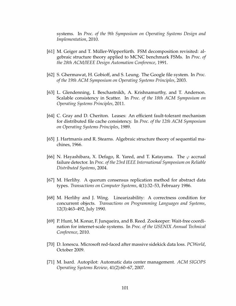
systems. In Proc. of the 9th Symposium on Operating Systems Design andImplementation, 2010.
[61] M. Geiger and T. Muller-Wipperfurth. FSM decomposition revisited: al-gebraic structure theory applied to MCNC benchmark FSMs. In Proc. ofthe 28th ACM/IEEE Design Automation Conference, 1991.
[62] S. Ghermawat, H. Gobioff, and S. Leung. The Google file system. In Proc.of the 19th ACM Symposium on Operating Systems Principles, 2003.
[63] L. Glendenning, I. Beschastnikh, A. Krishnamurthy, and T. Anderson.Scalable consistency in Scatter. In Proc. of the 18th ACM Symposium onOperating Systems Principles, 2011.
[64] C. Gray and D. Cheriton. Leases: An efficient fault-tolerant mechanismfor distributed file cache consistency. In Proc. of the 12th ACM Symposiumon Operating Systems Principles, 1989.
[65] J. Hartmanis and R. Stearns. Algebraic structure theory of sequential ma-chines, 1966.
[66] N. Hayashibara, X. Defago, R. Yared, and T. Katayama. The ϕ accrualfailure detector. In Proc. of the 23rd IEEE International Symposium on ReliableDistributed Systems, 2004.
[67] M. Herlihy. A quorum consensus replication method for abstract datatypes. Transactions on Computer Systems, 4(1):32–53, February 1986.
[68] M. Herlihy and J. Wing. Linearizability: A correctness condition forconcurrent objects. Transactions on Programming Languages and Systems,12(3):463–492, July 1990.
[69] P. Hunt, M. Konar, F. Junqueira, and B. Reed. Zookeeper: Wait-free coordi-nation for internet-scale systems. In Proc. of the USENIX Annual TechnicalConference, 2010.
[70] D. Ionescu. Microsoft red-faced after massive sidekick data loss. PCWorld,October 2009.
[71] M. Isard. Autopilot: Automatic data center management. ACM SIGOPSOperating Systems Review, 41(2):60–67, 2007.
101

[72] R. Jimenez-Peris and M. Patino-Martınez. Are quorums an alternative fordata replication? ACM Transactions on Database Systems, 28(3):257–294,September 2003.
[73] A. Lakshman and P. Malik. Cassandra: A decentralized structured storagesystem. ACM SIGOPS Operating Systems Review, 44(2):35–40, 2010.
[74] L. Lamport. Time, clocks, and the ordering of events in a distributed sys-tem. CACM, 21(7):558–565, July 1978.
[75] L. Lamport. The part-time parliament. Transactions on Computer Systems,16(2):133–169, 1998.
[76] L. Lamport, D. Malkhi, and L. Zhou. Brief announcement: Vertical Paxosand Primary-Backup replication. In Proc. of the 28th International Conferenceon Dependable Systems and Networks, 2009.
[77] L. Lamport and M. Massa. Cheap Paxos. In Proceedings of the 2004 Inter-national Conference on Dependable Systems and Networks, DSN ’04, Washing-ton, DC, 2004. IEEE Computer Society.
[78] J. Leners, H. Wu, W. Hung, M. Aguilera, and M. Walfish. Detecting fail-ures in distributed systems with the FALCON spy network. In Proc. of the23rd ACM Symposium on Operating Systems Principles, 2011.
[79] W. Lloyd, M. Freedman, M. Kaminsky, and D. Andersen. Don’t settle foreventual: Scalable causal consistency for wide-area storage with COPS.In Proc. of the 23rd ACM Symposium on Operating Systems Principles, 2011.
[80] M. Luby. Lt codes. In Proc. of the 43rd IEEE Symposium on Foundations ofComputer Science, 2002.
[81] M. Luby, M. Mitzenmacher, M. Shokrollahi, D. Spielman, and V. Stemann.Practical loss-resilient codes. In Proc. of the 29th ACM Symposium on Theoryof Computing, 1997.
[82] M. Luby, M. Mitzenmacher, M. Shokrollahi, D. Spielman, and V. Ste-mann. Analysis of low density codes and improved designs using irreg-ular graphs. In Proc. of the 30th ACM Symposium on Theory of Computing,1998.
102

[83] P. Mahajan, S. Setty, S. Lee, A. Clement, L. Alvisi, M. Dahlin, and M. Wal-fish. Depot: Cloud storage with minimal trust. ACM Transactions on Com-puter Systems, 29(4):12, 2011.
[84] D. Malkhi and M. Reiter. Byzantine quorum systems. Distributed Comput-ing, 11(4):203–213, 1998.
[85] P. Maymounkov. Online codes. Technical Report TR2002-833, New YorkUniversity, New York, NY, November 2002.
[86] P. Mell and T. Grance. The NIST definition of cloud computing. NISTSpecial Publication 800-145, 2011.
[87] A. Muthitacharoen, S. Gilbert, and R. Morris. Etna: A fault-tolerant algo-rithm for atomic mutable DHT data. Technical Report MIT-LCS-TR-993,MIT Laboratory for Computer Science, June 2004.
[88] N. Nisan, T. Roughgarden, E. Tardos, and V. Vazirani. Algorithmic gametheory. Cambridge University Press, 2007.
[89] D. Nurmi, R. Wolski, C. Grzegorczyk, G. Obertelli, S. Soman, L. Yous-eff, and D. Zagorodnov. The Eucalyptus open-source cloud-computingsystem. In Proc. of the 9th IEEE/ACM International Symposium on ClusterComputing and the Grid, 2009.
[90] Z. O’Whielacronx. zfec forward error correction library. http://allmydata.org/trac/zfec, 2009.
[91] J. Paris. Voting with witnesses: A consistency scheme for replicated files.In Proc. of the 6th IEEE International Conference on Distributed Computer Sys-tems, 1986.
[92] D. Patterson, G. Gibson, and R. Katz. The case for RAID: Redundantarrays of inexpensive disks. In Proc. of ACM SIGMOD Conference, 1988.
[93] J. Plank. A tutorial on Reed-Solomon coding for fault-tolerance in RAID-like systems. Software Practice and Experience, 27(9):995–1012, September1997.
[94] C. Pu and A. Leff. Replica control in distributed systems: An asyn-chronous approach. In Proc. of the 1991 ACM SIGMOD Int Conference onManagement of Data, 1991.
103

[95] L. Qiu, V.N. Padmanabhan, and G.M. Voelker. On the placement of webserver replicas. In Proc. of the 20th IEEE International Conference on Com-puter Communications, 2001.
[96] B. Reed and F. Junqueira. A simple totally ordered broadcast protocol. InProc. of 2nd ACM Workshop on Large-Scale Distributed Systems and Middle-ware, 2008.
[97] S. Rhea, P. Eaton, D. Geels, H. Weatherspoon, B. Zhao, and J. Kubiatowicz.Pond: the OceanStore prototype. In Proc. of 2nd USENIX Conference on Fileand Storage Technologies, 2003.
[98] S. Rhea, C. Wells, P. Eaton, D. Geels, B. Zhao, H. Weatherspoon, and J. Ku-biatowicz. Maintenance free global storage in oceanstore. In Proc. of IEEEInternet Computing, 2001.
[99] L. Rizzo and L. Vicisano. A reliable multicast data distribution protocolbased on software fec. In Proc. of 11th International Symposium on HighPerformance Computing Systems and Applications, 1997.
[100] R. Rodrigues and B. Liskov. Rosebud: A scalable Byzantine-fault-tolerantstorage architecture. Technical Report MIT-LCS-TR-992, MIT Laboratoryfor Computer Science, December 2003.
[101] R. Rodrigues and B. Liskov. High availability in DHTs: Erasure coding vs.replication. In Peer-to-Peer Systems IV, pages 226–239. Springer, 2005.
[102] R. Rodrigues, B. Liskov, and L. Shrira. The design of a robust peer-to-peersystem. In Proc. of the 10th ACM SIGOPS European Workshop, 2002.
[103] S. Sankararaman, B. Chun, C. Yatin, and S. Shenker. Key consistency inDHTs. Technical Report UCB/EECS-2005-21, UC Berkeley, 2005.
[104] R. Schlichting and F. Schneider. Fail-stop processors: An approach to de-signing fault-tolerant computing systems. Transactions on Computer Sys-tems, 1(3):222–238, August 1983.
[105] F. Schneider. Implementing fault-tolerant services using the state machineapproach: A tutorial. ACM Computing Surveys, 22(4):299–319, December1990.
104

[106] T. Shafaat, M. Moser, A. Ghodsi, T. Schutt, S. Haridi, and A. Reinefeld.On consistency of data in structured overlay networks. In Proc. of the 3rdCoreGRID Integration Workshop, 2008.
[107] A. Shokrollahi. Raptor codes. Technical Report DF2003-06-01, DigitalFountain, Inc., Fremont, CA, June 2003.
[108] J. Shute, R. Vingralek, B. Samwel, B. Handy, C. Whipkey, E. Rollins,M. Oancea, K. Littleeld, D. Menestrina, S. Ellner, J. Cieslewicz, I. Rae,T. Stancescu, and H. Apte. F1: A distributed SQL database that scales.In 39th International Conference on Very Large Data Bases, 2013.
[109] K. Shvachko, H. Kuang, S. Radia, and R. Chansler. The Hadoop dis-tributed file system. In IEEE 26th Symposium on Mass Storage Systems andTechnologies, 2010.
[110] K. So and E. Sirer. Latency and bandwidth-minimizing failure detectors.In ACM SIGOPS Operating Systems Review, pages 89–99, 2007.
[111] H. Stevens and C. Pettey. Gartner says cloud computing will be as in-fluential as e-business. In Gartner Newsroom, Online Ed., June 26 2008.http://www.gartner.com/it/page.jsp?id=707508.
[112] D. Terry, V. Prabhakaran, R. Kotla, M. Balakrishnan, M. Aguilera, andH. Abu-Libdeh. Consistency-based service level agreements for cloudstorage. In Proc. of the 24th ACM Symposium on Operating Systems Prin-ciples, 2013.
[113] R. Thomas. A solution to the concurrency control problem for multiplecopy databases. In Proc. of the IEEE Computer Society International Confer-ence, 1978.
[114] R. van Renesse and R. Guerraoui. Replication techniques for availability.In Replication: Theory and Practice, pages 19–40. Springer, 2010.
[115] R. van Renesse, C. Ho, and N. Schiper. Byzantine chain replication. InProc. of the 16th International Conference on Principles of Distributed Systems,2012.
[116] R. van Renesse and F. Schneider. Chain Replication for supporting highthroughput and availability. In Proc. of the 6th Symposium on OperatingSystems Design and Implementation, 2004.
105

[117] W. Vogels. Eventually consistent. ACM Queue, 6(6), December 2008.
[118] M. Vrable, S. Savage, and G. Voelker. Cumulus: Filesystem backup to thecloud. ACM Transactions on Storage, 5(4):1–28, 2009.
[119] H. Weatherspoon and J. Kubiatowicz. Erasure coding vs. replication: Aquantitative comparison. In Proc. of the 1st International Workshop on Peer-To-Peer Systems, 2002.
[120] H. Weatherspoon, C. Wells, and J. Kubiatowicz. Naming and integrity:Self-verifying data in peer-to-peer systems. In Proc. of Intl. Workshop onFuture Directions of Distributed Systems, 2002.
[121] D. Williams, H. Jamjoom, and H. Weatherspoon. The XEN-blanket: Vir-tualize once, run everywhere. In Proc. of the 7th ACM European conferenceon Computer Systems, 2012.
[122] Z. Wu, M. Butkiewicz, D. Perkins, E. Katz-Bassett, and H. Madhyastha.Spanstore: cost-effective geo-replicated storage spanning multiple cloudservices. In Proc. of the 24th ACM Symposium on Operating Systems Princi-ples, 2013.
[123] H. Yu and A. Vahdat. The cost and limits of availability for replicated ser-vices. In Proc. of the 18th ACM Symposium on Operating Systems Principles,2001.
106
Copyright © 2022 FDOKUMEN